embedded systems
771
-
Upload
khangminh22 -
Category
Documents
-
view
2 -
download
0
Transcript of embedded systems


EMBEDDED SYSTEMS :REAL-TIMEINTERFACINGTOARM®
CORTEXTM-MMICROCONTROLLERS
Volume2FourthEdition,July2014
JonathanW.ValvanoFourthedition2ndPrintingJuly2014
ARManduVisionareregisteredtrademarksofARMLimited.
CortexandKeilaretrademarksofARMLimited.
StellarisandTivaareregisteredtrademarksTexasInstruments.
CodeComposerStudioisatrademarkofTexasInstruments.
Allotherproductorservicenamesmentionedhereinarethetrademarksoftheirrespectiveowners.
Inordertoreducecosts,thiscollegetextbookhasbeenself-published.Formoreinformationaboutmyclasses,myresearch,andmybooks,seehttp://users.ece.utexas.edu/~valvano/

Forcorrectionsandcomments,pleasecontactmeat:[email protected]:J.W.Valvano,EmbeddedSystems:Real-TimeInterfacingtoARM ® CortexTM-MMicrocontrollers,http://users.ece.utexas.edu/~valvano/,ISBN:978-1463590154,2014.
Copyright©2014JonathanW.Valvano
Allrightsreserved.Nopartofthisworkcoveredbythecopyrighthereinmaybereproduced,transmitted,stored,orusedinanyformorbyanymeansgraphic,electronic,ormechanical,includingbutnotlimitedtophotocopying,recording,scanning,digitizing,taping,webdistribution,informationnetworks,orinformationstorageandretrieval,exceptaspermittedunderSection107or108ofthe1976UnitedStatesCopyrightAct,withoutthepriorwrittenpermissionofthepublisher.
ISBN-13:978-1463590154
ISBN-10:1463590156

TableofContents
PrefacetoThirdEdition
PrefacetoFourthEdition
Preface
Acknowledgements
1.IntroductiontoEmbeddedSystems
1.1.ComputerArchitecture
1.2.EmbeddedSystems
1.3.TheDesignProcess
1.4.DigitalLogicandOpenCollector
1.5.DigitalRepresentationofNumbers
1.6.Ethics
1.7.Exercises
1.8.LabAssignments
2.ARMCortex-MProcessor
2.1.CortexTM-MArchitecture
2.2.TexasInstrumentsLM3SandTM4CI/Opins
2.3.ARM CortexTM-MAssemblyLanguage
2.4.ParallelI/Oports
2.5.Phase-Lock-Loop
2.6.SysTickTimer
2.7.ChoosingaMicrocontroller
2.8.Exercises
2.9.LabAssignments
3.SoftwareDesign
3.1.Attitude
3.2.QualityProgramming

3.3.SoftwareStyleGuidelines
3.4.ModularSoftware
3.5.FiniteStateMachines
3.6.Threads
3.7.FirstInFirstOutQueue
3.8.MemoryManagementandtheHeap
3.9.IntroductiontoDebugging
3.10.Exercises
3.11.LabAssignments
4.Hardware-SoftwareSynchronization
4.1.Introduction
4.2.Timing
4.3.PetriNets
4.4.KahnProcessNetworks
4.5.Edge-triggeredInterfacing
4.6.ConfiguringDigitalOutputPins
4.7.Blind-cycleInterfacing
4.8.Busy-WaitSynchronization
4.9.UARTInterface
4.10.KeyboardInterface
4.11.Exercises
4.12.LabAssignments
5.InterruptSynchronization
5.1.Multithreading
5.2.InterthreadCommunicationandSynchronization
5.3.CriticalSections
5.4.NVIContheARM Cortex-MProcessor
5.5.Edge-triggeredInterrupts
5.6.Interrupt-DrivenUART

5.7.PeriodicInterruptsusingSysTick
5.8.Low-PowerDesign
5.9.DebuggingProfile
5.10.Exercises
5.11.LabAssignments
6.TimeInterfacing
6.1.InputCaptureorInputEdgeTimeMode
6.2.OutputCompareorPeriodicTimer
6.3.PulseWidthModulation
6.4.FrequencyMeasurement
6.5.BinaryActuators
6.6.IntegralControlofaDCMotor
6.7.Exercises
6.8.LabAssignments
7.SerialInterfacing
7.1.IntroductiontoSerialCommunication
7.2.RS232Interfacing
7.3.RS422/USB/RS423/RS485BalancedDifferentialLines
7.4.LogicLevelConversion
7.5.SynchronousTransmissionandReceivingusingtheSSI
7.6.Inter-IntegratedCircuit(I2C)Interface
7.7.IntroductiontoUniversalSerialBus(USB)
7.8.Exercises
7.9.LabAssignments
8.AnalogInterfacing
8.1.ResistorsandCapacitors
8.2.OpAmps
8.3.AnalogFilters
8.4.DigitaltoAnalogConverters

8.5.AnalogtoDigitalConverters
8.6.Exercises
8.7.LabAssignments
9.System-LevelDesign
9.1.DesignforManufacturability
9.2.Power
9.3Tolerance
9.4.DesignforTestability
9.5.PrintedCircuitBoardLayoutandEnclosures
9.6.Exercises
9.7.LabAssignments
10.DataAcquisitionSystems
10.1.Introduction
10.2.Transducers
10.3.DiscreteCalculus
10.4.DataAcquisitionSystemDesign
10.5.AnalysisofNoise
10.6.DataAcquisitionCaseStudies
10.7.Exercises
10.8.LabAssignments
11.IntroductiontoCommunicationSystems
11.1.Fundamentals
11.2.CommunicationSystemsBasedontheUARTs
11.3.WirelessCommunication
11.4.InternetofThings
11.5.Exercises
11.6.LabAssignments
Appendix1.Glossary
Appendix2.SolutionstoCheckpoints

IndexReferenceMaterial

PrefacetoThirdEditionThereareanewfeaturesaddedtothisthirdedition.ThenewdevelopmentplatformbasedontheTM4C123iscalledTivaLaunchPad.MaterialinthisbookontheTM4CalsoappliestotheLM4FbecauseTexasInstrumentsrebrandedtheLM4FseriesasTM4C(samechipsnewname),andrebrandedStellarisWare™asTivaWare™.Thesenewmicrocontrollersrunat80MHz,includesingle-precisionfloatingpoint,havetwo12-bitADCs,andsupportDMAandUSB.Awonderfulfeatureofthesenewboardsistheirlowcost.AsofDecember2013,theboardsareavailableonTI.comaspartnumberEK-TM4C123GXLfor$12.99.Theyarealsoavailablefrom$13to$24atregularelectronicsretailerslikearrow.com,newark.com,mouser.com,anddigikey.com.ThebookcanbeusedwitheitheraLM3SorTM4Cmicrocontroller.AlthoughthiseditionnowfocusesontheM4,theconceptsstillapplytotheM3,andthewebsiteassociatedwiththisbookhasexampleprojectsbasedontheLM3S811,LM3S1968,andLM3S8962.

PrefacetoFourthEditionThisfourtheditionincludesthenewTM4C1294-basedLaunchPad.MostofthecodeinthebookisspecificfortheTM4C123-basedLaunchPad.However,thebookwebsiteincludescorrespondingexampleprojectsfortheLM3S811,LM3S1968,LM4F120,andTM4C1294,whichareARM ® Cortex™-MmicrocontrollersfromTexasInstruments.Therearenowtwolost-costdevelopmentplatformscalledTivaLaunchPad.TheEK-TM4C123GXLLaunchPadretailsfor$12.99,andtheEK-TM4C1294XLConnectedLaunchPadretailsfor$19.99.ThevariousLM3S,LM4FandTM4Cmicrocontrollersarequitesimilar,sothisbookalongwiththeexamplecodeonthewebcanbeusedforanyofthesemicrocontrollers.ComparedtotheTM4C123,thenewTM4C1294microcontrollerrunsfaster,hasmoreRAM,hasmoreROM,includesEthernet,andhasmoreI/Opins.ThisfourtheditionswitchesthesyntaxfromCtotheindustry-standardC99,addsaline-trackingrobot,designsanintegralcontrollerforaDCmotor,andincludesanexpandedsectiononwirelesscommunicationandInternetofThings.

PrefaceEmbeddedsystemsareaubiquitouscomponentofoureverydaylives.Weinteractwithhundredsoftinycomputerseverydaythatareembeddedintoourhouses,ourcars,ourtoys,andourwork.Asourworldhasbecomemorecomplex,sohavethecapabilitiesofthemicrocontrollersembeddedintoourdevices.TheARM ® CortexTM-Mfamilyrepresentsanewclassofmicrocontrollersmuchmorepowerfulthanthedevicesavailabletenyearsago.Thepurposeofthisbookistopresentthedesignmethodologytotrainyoungengineerstounderstandthebasicbuildingblocksthatcomprisedeviceslikeacellphone,anMP3player,apacemaker,antilockbrakes,andanenginecontroller.
ThisbookisthesecondinaseriesofthreebooksthatteachthefundamentalsofembeddedsystemsasappliedtotheARM ® CortexTM-Mfamilyofmicrocontrollers.Thethreebooksareprimarilywrittenforundergraduateelectricalandcomputerengineeringstudents.TheycouldalsobeusedforprofessionalslearningtheARMplatform.ThefirstbookEmbeddedSystems:IntroductiontoARMCortex-MMicrocontrollersisanintroductiontocomputersandinterfacingfocusingonassemblylanguageandCprogramming.Thissecondbookfocusesoninterfacingandthedesignofembeddedsystems.ThethirdbookEmbeddedSystems:Real-TimeOperatingSystemsforARMCortex-MMicrocontrollersisanadvancedbookfocusingonoperatingsystems,high-speedinterfacing,controlsystems,androbotics.
Anembeddedsystemisasystemthatperformsaspecifictaskandhasacomputerembeddedinside.Asystemiscomprisedofcomponentsandinterfacesconnectedtogetherforacommonpurpose.Thisbookpresentscomponents,interfacesandmethodologiesforbuildingsystems.Specifictopicsincludethearchitectureofmicrocontrollers,designmethodology,verification,hardware/softwaresynchronization,interfacingdevicestothecomputer,timingdiagrams,real-timeoperatingsystems,datacollectionandprocessing,motorcontrol,analogfilters,digitalfilters,real-timesignalprocessing,wirelesscommunication,andtheinternetofthings.
Ingeneral,theareaofembeddedsystemsisanimportantandgrowingdisciplinewithinelectricalandcomputerengineering.TheeducationalmarketofembeddedsystemshasbeendominatedbysimplemicrocontrollerslikethePIC,the9S12,andthe8051.Thisisbecauseoftheirmarketshare,lowcost,andhistoricaldominance.However,asproblemsbecomemorecomplex,somustthesystemsthatsolvethem.Anumberofembeddedsystemparadigmsmustshiftinordertoaccommodatethisgrowthincomplexity.First,thenumberofcalculationspersecondwillincreasefrommillions/sectobillions/sec.Similarly,thenumberoflinesofsoftwarecodewillalsoincreasefromthousandstomillions.Thirdly,systemswillinvolvemultiplemicrocontrollerssupportingmanysimultaneousoperations.Lastly,theneedforsystemverificationwillcontinuetogrowasthesesystemsaredeployedintosafetycriticalapplications.Thesechangesaremorethanasimplegrowthinsizeandbandwidth.Thesesystemsmustemployparallelprogramming,high-speedsynchronization,real-timeoperatingsystems,faulttolerantdesign,priorityinterrupthandling,andnetworking.Consequently,itwillbeimportanttoprovideourstudentswiththesetypesofdesignexperiences.TheARMplatformisbothlowcostandprovidesthehighperformancefeaturesrequiredinfutureembeddedsystems.AlthoughtheARMmarketshareiscurrentlynothuge,itssharewillgrow.Furthermore,students

trainedontheARMwillbeequippedtodesignsystemsacrossthecompletespectrumfromsimpletocomplex.Thepurposeofwritingthesethreebooksatthistimeistobringengineeringeducationintothe21stcentury.
Thisbookemploysmanyapproachestolearning.Itwillnotincludeanexhaustiverecapitulationoftheinformationindatasheets.First,itbeginswithbasicfundamentals,whichallowsthereadertosolvenewproblemswithnewtechnology.Second,thebookpresentsmanydetaileddesignexamples.Theseexamplesillustratetheprocessofdesign.Therearemultiplestructuralcomponentsthatassistlearning.Checkpoints,withanswersintheback,areshorteasytoanswerquestionsprovidingimmediatefeedbackwhilereading.Simplehomework,withanswerstotheoddquestionsontheweb,providesmoredetailedlearningopportunities.Thebookincludesanindexandaglossarysothatinformationcanbesearched.Themostimportantlearningexperiencesinaclasslikethisareofcoursethelaboratories.Eachchapterhassuggestedlabassignments.Moredetailedlabdescriptionsareavailableontheweb.Specifically,lookatthelabassignmentsforEE445LandEE445M.
Thereisawebsiteaccompanyingthisbookhttp://users.ece.utexas.edu/~valvano/arm.PostedhereareARMKeilTMuVision®projectsforeachtheexampleprogramsinthebook.CodeComposerStudioTMversionsarealsoavailableformostexamples.YouwillalsofinddatasheetsandExcelspreadsheetsrelevanttothematerialinthisbook.
ThesethreebookswillcoverembeddedsystemsforARM ® CortexTM-MmicrocontrollerswithspecificdetailsontheLM3S811,LM3S1968,LM3S8962,LM4F120,TM4C123,andTM4C1294.Mostofthetopicscanberunonthelow-costTM4C123.EthernetexamplescanberunontheLM3S8962andTM4C1294.InthesebooksthetermsLM3SandLM4FandTM4CwillrefertoanyoftheTexasInstrumentsARM ® CortexTM-Mbasedmicrocontrollers.AlthoughthesolutionsarespecificfortheLM3SLM4FandTM4Cfamilies,itwillbepossibletousethesebooksforotherARMderivatives.

AcknowledgementsIoweawonderfuldebtofgratitudetoDanielValvano.Hewroteandtestedmostofthesoftwareexamplesfoundinthisbook.Secondly,hecreatedandmaintainstheexamplewebsite,http://users.ece.utexas.edu/~valvano/arm.Lastly,hemeticulouslyproofreadthismanuscript.
Manysharedexperiencescontributedtothedevelopmentofthisbook.FirstIwouldliketoacknowledgethemanyexcellentteachingassistantsIhavehadthepleasureofworkingwith.Someofthesehard-working,underpaidwarriorsincludePankajBishnoi,RajeevSethia,AdsondaRocha,BaoHua,RajRanderi,SantoshJodh,NareshBhavaraju,AshutoshKulkarni,BryanStiles,V.Krishnamurthy,PaulJohnson,CraigKochis,SeanAskew,GeorgePanayi,JeehyunKim,VikramGodbole,AndresZambrano,AnnMeyer,HyunjinShin,AnandRajan,AnilKottam,Chia-lingWei,JigneshShah,IcaroSantos,DavidAltman,NachiketKharalkar,RobinTsang,ByungGeunJun,JohnPorterfield,DanielFernandez,DeepakPanwar,JacobEgner,SandyHermawan,UsmanTariq,SterlingWei,SeilOh,AntoniusKeddis,LevShuhatovich,GlenRhodes,GeoffreyLuke,KarthikSankar,TimVanRuitenbeek,RaffaeleCetrulo,HarshadDesai,JustinCapogna,ArindamGoswami,JunghoJo,MehmetBasoglu,KathrynLoeffler,EvgeniKrimer,NachiappanValliappan,RazikAhmed,SundeepKorrapati,SongZhang,ZahidulHaq,MatthewHalpern,CruzMonrrealII,PohanWu,SaugataBhattacharyya,OmarBacaAdityaSaraf,andMaheshSrinivasan.Theseteachingassistantshavecontributedgreatlytothecontentsofthisbookandparticularlytoitslaboratoryassignments.Since1981,IestimateIhavetaughtembeddedsystemstoover5000students.Mystudentshaverechargedmyenergyeachsemesterwiththeirenthusiasm,dedication,andquestforknowledge.Ihavedecidednottoacknowledgethemallindividually.However,theyknowIfeelprivilegedtohavehadthisopportunity.
Next,IappreciatethepatienceandexpertiseofmyfellowfacultymembershereattheUniversityofTexasatAustin.FromapersonalperspectiveDr.JohnPearceprovidedmuchneededencouragementandsupportthroughoutmycareer.Inaddition,Drs.JohnCogdell,JohnPearce,andFrancisBostickhelpedmewithanalogcircuitdesign.ThebookandaccompanyingsoftwareincludemanyfinitestatemachinesderivedfromthedigitallogicexamplesexplainedtomebyDr.CharlesRoth.Overthelastfewyears,IhaveenjoyedteachingembeddedsystemswithDrs.RameshYerraballi,MattanErez,AndreasGerstlauer,VijayJanapaReddi,NinaTelang,andBillBard.Billhascontributedtoboththeexcitementandsubstanceofourlaboratorybasedonthisbook.WithpushingfromBillandTAsRobin,Glen,Lev,andJohn,wehaveaddedlowpower,PCBlayout,systemsleveldesign,surfacemountsoldering,andwirelesscommunicationtoourlabexperience.YoucanseedescriptionsandphotosofourEE445Ldesigncompetitionathttp://users.ece.utexas.edu/~valvano/.ManyofthesuggestionsandcorrectionsfromChrisShoreandDrewBarbierofARMaboutVolume1appliedequallytothisvolume.AustinBlackstonecreatedanddebuggedtheCodeComposerStudioTMversionsoftheexampleprogramspostedontheweb.AustinalsotaughtmehowtoruntheCC3000andCC3100WiFiexamplesontheLaunchPad.

Sincerely,Iappreciatethevaluablelessonsofcharacterandcommitmenttaughttomebymyparentsandgrandparents.Irecallhowhardmyparentsandgrandparentsworkedtomaketheworldabetterplaceforthenextgeneration.Mostsignificantly,Iacknowledgethelove,patienceandsupportofmywife,Barbara,andmychildren,BenDanielandLiz.Inparticular,DandesignedandtestedmostoftheLM3SandLM4F/TM4Csoftwarepresentedinthisbook.
BythegraceofGod,Iamtrulythehappiestmanontheplanet,becauseIamsurroundedbythesefinepeople.Goodluck.
JonathanW.Valvano
Thetrueengineeringexperienceoccursnotwithyoureyesandears,butratherwithyourfingersandelbows.Inotherwords,engineeringeducationdoesnothappenbylisteninginclassorreadingabook;ratherithappensbydesigningunderthewatchfuleyesofapatientmentor.So,gobuildsomethingtoday,thenshowittosomeoneyourespect!


1.IntroductiontoEmbeddedSystemsChapter1objectivesareto:•Reviewcomputerarchitecture
•Introduceembeddedsystems
•Presentaprocessfordesign
•Discusspracticalaspectsofdigitallogic,includingopencollector
•Reviewhownumbersarerepresentedinbinary
•Defineethics
Theoverallobjectiveofthisbookistoteachthedesignofembeddedsystems.Itiseffectivetolearnnewtechniquesbydoingthem.But,thedilemmainteachingalaboratory-basedtopiclikeembeddedsystemsisthatthereisatremendousvolumeofdetailsthatfirstmustbelearnedbeforehardwareandsoftwaresystemscanbedesigned.Theapproachtakeninthisbookistolearnbydoing,startingwithverysimpleproblemsandbuildinguptomorecomplexsystemslaterinthebook.
Inthischapterwebeginbyintroducingsometerminologyandbasiccomponentsofacomputersystem.Inordertounderstandthecontextofourdesigns,wewilloverviewthegeneralcharacteristicsofembeddedsystems.Itisinthesediscussionsthatwedevelopafeelfortherangeofpossibleembeddedapplications.Nextwewillpresentatemplatetoguideusindesign.Webeginaprojectwitharequirementsdocument.Embeddedsystemsinteractwithphysicaldevices.Often,wecandescribethephysicalworldwithmathematicalmodels.Ifamodelisavailable,wecanthenuseittopredicthowtheembeddedsystemwillinterfacewiththerealworld.Whenwewritesoftware,wemistakenlythinkofitasonedimensional,becausethecodelookssequentialonthecomputerscreen.Dataflowgraphs,callgraphs,andflowchartsaremultidimensionalgraphicaltoolstounderstandcomplexbehaviors.Becausecoursestaughtusingthisbooktypicallyhavealabcomponent,wewillreviewsomepracticalaspectsofdigitallogic.
Next,weshowmultiplewaystorepresentnumbersinthecomputer.Choosingthecorrectformatisnecessarytoimplementefficientandcorrectsolutions.Fixed-pointnumbersarethetypicalwayembeddedsystemsrepresentnon-integervalues.Floating-pointnumbers,typicallyusedtorepresentnon-integervaluesonageneralpurposecomputer,willalsobepresented.
Becauseembeddedsystemscanbeemployedinsafetycriticalapplications,itisimportantforengineersbebotheffectiveandethical.Throughoutthebookwewillpresentwaystoverifythesystemisoperatingwithinspecifications.

1.1.ComputerArchitecture
1.1.1.Computers,microprocessors,memory,andmicrocontrollersAcomputercombinesaprocessor,randomaccessmemory(RAM),readonlymemory(ROM),andinput/output(I/O)ports.ThecommonbusinFigure1.1definesthevonNeumannarchitecture,whereinstructionsarefetchedfromROMonthesamebusasdatafetchedfromRAM.Softwareisanorderedsequenceofveryspecificinstructionsthatarestoredinmemory,definingexactlywhatandwhencertaintasksaretobeperformed.Theprocessorexecutesthesoftwarebyretrievingandinterpretingtheseinstructionsoneatatime.Amicroprocessorisasmallprocessor,wheresmallreferstosize(i.e.,itfitsinyourhand)andnotcomputationalability.Forexample,IntelXeon,AMDFXandSunSPARCaremicroprocessors.AnARM ® CortexTM-Mmicrocontrollerincludesaprocessortogetherwiththebusandsomeperipherals.Amicrocomputerisasmallcomputer,whereagainsmallreferstosize(i.e.,youcancarryit)andnotcomputationalability.Forexample,adesktopPCisamicrocomputer.
Figure1.1.Thebasiccomponentsofacomputersystemincludeprocessor,memoryandI/O.Averysmallmicrocomputer,calledamicrocontroller,containsallthecomponentsofacomputer(processor,memory,I/O)onasinglechip.AsshowninFigure1.2,theAtmelATtiny,theTexasInstrumentsMSP430,andtheTexasInstrumentsTM4C123areexamplesofmicrocontrollers.Becauseamicrocomputerisasmallcomputer,thistermcanbeconfusingbecauseitisusedtodescribeawiderangeofsystemsfroma6-pinATtiny4runningat1MHzwith512bytesofprogrammemorytoapersonalcomputerwithstate-of-the-art64-bitmulti-coreprocessorrunningatmulti-GHzspeedshavingterabytesofstorage.

ThecomputercanstoreinformationinRAMbywritingtoit,oritcanretrievepreviouslystoreddatabyreadingfromit.MostRAMsarevolatile;meaningifpowerisinterruptedandrestoredtheinformationintheRAMislost.MostmicrocontrollershavestaticRAM(SRAM)usingsixmetal-oxide-semiconductorfield-effecttransistors(MOSFET)tocreateeachmemorybit.Fourtransistorsareusedtocreatetwocross-coupledinvertersthatstorethebinaryinformation,andtheothertwoareusedtoreadandwritethebit.
Figure1.2.Amicrocontrollerisacompletecomputeronasinglechip.InformationisprogrammedintoROMusingtechniquesmorecomplicatedthanwritingtoRAM.Fromaprogrammingviewpoint,retrievingdatafromaROMisidenticaltoretrievingdatafromRAM.ROMsarenonvolatile;meaningifpowerisinterruptedandrestoredtheinformationintheROMisretained.SomeROMsareprogrammedatthefactoryandcanneverbechanged.AProgrammableROM(PROM)canbeerasedandreprogrammedbytheuser,buttheerase/programsequenceistypically10000timesslowerthanthetimetowritedataintoaRAM.PROMsusedtoneedultravioletlighttoerase,andthenweprogrammedthemwithvoltages.Now,mostPROMsnowareelectricallyerasable(EEPROM),whichmeanstheycanbebotherasedandprogrammedwithvoltages.WecannotprogramonesintotheROM.WefirsterasetheROM,whichputsonesintoitsstoragememory,andthenweprogramthezerosasneeded.FlashROMisapopulartypeofEEPROM.EachflashbitrequiresonlytwoMOSFETtransistors.Theinput(gate)ofonetransistoriselectricallyisolated,soifwetrapchargeonthisinput,itwillremainthereforyears.Theothertransistorisusedtoreadthebitbysensingwhetherornottheothertransistorhastrappedcharge.InregularEEPROM,youcaneraseandprogramindividualbytes.FlashROMmustbeerasedinlargeblocks.OnmanyofLM3S/LM4F/TM4Cmicrocontrollers,wecanerasetheentireROMorjusta1024-byteblock.BecauseflashissmallerthanregularEEPROM,mostmicrocontrollershavealargeflashintowhichwestorethesoftware.Forallthesystemsinthisbook,wewillstoreinstructionsandconstantsinflashROMandplacevariablesandtemporarydatainstaticRAM.
Checkpoint1.1:Whatarethedifferencesbetweenamicrocomputer,amicroprocessorandamicrocontroller?
Checkpoint1.2:Whichhasahigherinformationdensityonthechipinbitspermm2:staticRAMorflashROM?AssumeallMOSFETsareapproximatelythesamesizeinmm2.
Observation:Memoryisanobjectthatcantransportinformationacrosstime.

Theexternaldevicesattachedtothemicrocontrollerprovidefunctionalityforthesystem.Aninputportishardwareonthemicrocontrollerthatallowsinformationabouttheexternalworldtobeenteredintothecomputer.Themicrocontrolleralsohashardwarecalledanoutputporttosendinformationouttotheexternalworld.MostofthepinsshowninFigure1.2areinput/outputports.
AninterfaceisdefinedasthecollectionoftheI/Oport,externalelectronics,physicaldevices,andthesoftware,whichcombinetoallowthecomputertocommunicatewiththeexternalworld.Anexampleofaninputinterfaceisaswitch,wheretheoperatortogglestheswitch,andthesoftwarecanrecognizetheswitchposition.Anexampleofanoutputinterfaceisalight-emittingdiode(LED),wherethesoftwarecanturnthelightonandoff,andtheoperatorcanseewhetherornotthelightisshining.Thereisawiderangeofpossibleinputsandoutputs,whichcanexistineitherdigitaloranalogform.Ingeneral,wecanclassifyI/Ointerfacesintofourcategories
Parallel-binarydataareavailablesimultaneouslyonagroupoflines
Serial-binarydataareavailableonebitatatimeonasingleline
Analog-dataareencodedasanelectricalvoltage,current,orpower
Time-dataareencodedasaperiod,frequency,pulsewidth,orphaseshift
Checkpoint1.3:Whatarethedifferencesbetweenaninputportandaninputinterface?
Checkpoint1.4:Listthreeinputinterfacesavailableonapersonalcomputer.
Checkpoint1.5:Listthreeoutputinterfacesavailableonapersonalcomputer.
Inthisbook,numbersthatstartwith0x(e.g.,0x64)arespecifiedinhexadecimal,whichisbase16(0x64=6*161+4*160=100).Someassemblersstarthexadecimalnumberswith$(e.g.,$64).Otherassemblylanguagesaddan“H”attheendtospecifyhexadecimal(e.g.,64Hor64h).YalePatt’sLC3assemblerusesjustthe“x”(e.g.,x64).
InasystemwithmemorymappedI/O,asshowninFigure1.1,theI/Oportsareconnectedtotheprocessorinamannersimilartomemory.I/Oportsareassignedaddresses,andthesoftwareaccessesI/OusingreadsandwritestothespecificI/Oaddresses.Thesoftwareinputsfromaninputportusingthesameinstructionsasitwouldifitwerereadingfrommemory.Similarly,thesoftwareoutputsfromanoutputportusingthesameinstructionsasitwouldifitwerewritingtomemory.Abusisdefinedasacollectionofsignals,whicharegroupedforacommonpurpose.Thebushasthreetypesofsignals:addresssignals,datasignals,andcontrolsignals.Together,thebusdirectsthedatatransferbetweenthevariousmodulesinthecomputer.TherearefivebusesonARM ® CortexTM-Mprocessor,asillustratedinFigure1.3.Theaddressspecifieswhichmoduleisbeingaccessed,andthedatacontainstheinformationbeingtransferred.Thecontrolsignalsspecifythedirectionoftransfer,thesizeofthedata,andtiminginformation.TheICodebusisusedtofetchinstructionsfromflashROM.AllICodebusfetchescontain32bitsofdata,whichmaybeoneortwoinstructions.TheDCodebuscanfetchdataordebuginformationfromflashROM.Thesystembuscanread/writedatafromRAMorI/Oports.Theprivateperipheralbus(PPB)canaccesssomeofthe

commonperipheralsliketheinterruptcontroller.Themultiple-busarchitectureallowssimultaneousbusactivity,greatlyimprovingperformanceoversingle-busarchitectures.Forexample,theprocessorcansimultaneouslyfetchaninstructionoutofflashROMusingtheICodebuswhileitwritesdataintoRAMusingthesystembus.Fromasoftwaredevelopmentperspective,thefactthattherearemultiplebusesistransparent.Thismeanswewritecodelikewewouldonanycomputer,andtheparalleloperationsoccurautomatically.TheTM4C123has256kibibytes(218bytes)offlashROMand32768bytesofRAM.TheTM4C1294has1024kibibytes(220bytes)offlashROMand256kibibytesofRAM.TheRAMbeginsat0x2000.0000,andtheflashROMbeginsat0x0000.0000.
TM4C123 TM4C1294
0x0000.0000 256k 0x0000.0000 1024k
∙∙∙ Flash ∙∙∙ Flash
0x0003.FFFF ROM 0x000F.FFFF ROM
0x2000.0000 32k 0x2000.0000 256k
∙∙∙ Static ∙∙∙ Static
0x2000.7FFF RAM 0x2003.FFFF RAM
Figure1.3.HarvardarchitectureofanARM®Cortex -M-basedmicrocontroller.TheCortexTM-M4seriesincludesanadditionalbuscalledtheAdvancedHigh-PerformanceBus(AHBorAHPB).Thisbusimprovesperformancewhencommunicatingwithhigh-speedI/OdeviceslikeUSB.Ingeneral,themoreoperationsthatcanbeperformedinparallel,thefastertheprocessorwillexecute.Insummary:
ICodebusFetchopcodesfromROM

DCodebusReadconstantdatafromROM
SystembusRead/writedatafromRAMorI/O,fetchopcodefromRAM
PPBRead/writedatafrominternalperipheralsliketheNVIC
AHBRead/writedatafromhigh-speedI/Oandparallelports(M4only)
InstructionsanddataareaccessedthesamewayonavonNeumannmachine.TheCortexTM-MprocessorisaHarvardarchitecturebecauseinstructionsarefetchedontheICodebusanddataaccessedonthesystembus.TheaddresssignalsontheARM ®CortexTM-Mprocessorinclude32lines,whichtogetherspecifythememoryaddress(0x0000.0000to0xFFFF.FFFF)thatiscurrentlybeingaccessed.Theaddressspecifiesbothwhichmodule(input,output,RAM,orROM)aswellaswhichcellwithinthemodulewillcommunicatewiththeprocessor.Thedatasignalscontaintheinformationthatisbeingtransferredandalsoinclude32bits.However,onthesystembusitcanalsotransfer8-bitor16-bitdata.Thecontrolsignalsspecifythetiming,thesize,andthedirectionofthetransfer.Wecallacompletedatatransferabuscycle.Twotypesoftransfersareallowed,asshowninTable1.1.Inmostsystems,theprocessoralwayscontrolstheaddress(wheretoaccess),thedirection(readorwrite),andthecontrol(whentoaccess.)
Type AddressDrivenby
DataDrivenby Transfer
ReadCycle Processor RAM,ROMorInput
Datacopiedtoprocessor
WriteCycle Processor Processor DatacopiedtooutputorRAM
Table1.1.Simplecomputersgeneratetwotypesofbuscycles.
Areadcycleisusedtotransferdataintotheprocessor.Duringareadcycletheprocessorfirstplacestheaddressontheaddresssignals,andthentheprocessorissuesareadcommandonthecontrolsignals.Theslavemodule(RAM,ROM,orI/O)willrespondbyplacingthecontentsatthataddressonthedatasignals,andlastlytheprocessorwillacceptthedataanddisablethereadcommand.
TheprocessorusesawritecycletostoredataintomemoryorI/O.Duringawritecycletheprocessoralsobeginsbyplacingtheaddressontheaddresssignals.Next,theprocessorplacestheinformationitwishestostoreonthedatasignals,andthentheprocessorissuesawritecommandonthecontrolsignals.ThememoryorI/Owillrespondbystoringtheinformationintotheproperplace,andaftertheprocessorissurethedatahasbeencaptured,itwilldisablethewritecommand.

ThebandwidthofanI/Ointerfaceisthenumberofbytes/secthatcanbetransferred.IfwewishtotransferdatafromaninputdeviceintoRAM,thesoftwaremustfirsttransferthedatafrominputtotheprocessor,thenfromtheprocessorintoRAM.OntheARM,itwilltakemultipleinstructionstoperformthistransfer.ThebandwidthdependsbothonthespeedoftheI/Ohardwareandthesoftwareperformingthetransfer.InsomemicrocontrollersliketheTM4C123andTM4C1294,wewillbeabletotransferdatadirectlyfrominputtoRAMorRAMtooutputusingdirectmemoryaccess(DMA).WhenusingDMAthesoftwaretimeisremoved,sothebandwidthonlydependsonthespeedoftheI/Ohardware.BecauseDMAisfaster,wewillusethismethodtointerfacehighbandwidthdeviceslikedisksandnetworks.DuringaDMAreadcycledataflowsdirectlyfromthememorytotheoutputdevice.GeneralpurposecomputersalsosupportDMAallowingdatatobetransferredfrommemorytomemory.DuringaDMAwritecycledataflowsdirectlyfromtheinputdevicetomemory.
Input/outputdevicesareimportantinallcomputers,buttheyareespeciallysignificantinanembeddedsystem.InacomputersystemwithI/O-mappedI/O,thecontrolbussignalsthatactivatetheI/Oareseparatefromthosethatactivatethememorydevices.ThesesystemshaveaseparateaddressspaceandseparateinstructionstoaccesstheI/Odevices.TheoriginalIntel8086hadfourcontrolbussignalsMEMR,MEMW,IOR,andIOW.MEMRandMEMWwereusedtoreadandwritememory,whileIORandIOWwereusedtoreadandwriteI/O.TheIntelx86referstoanyoftheprocessorsthatIntelhasdevelopedbasedonthisoriginalarchitecture.Eventhoughwedonotconsiderthepersonalcomputer(PC)anembeddedsystem,thereareembeddedsystemsdevelopedonthisarchitecture.OnesuchplatformiscalledthePC/104Embedded-PC.TheIntelx86processorscontinuetoimplementthisseparationbetweenmemoryandI/O.Ratherthanusetheregularmemoryaccessinstructions,theIntelx86processorusesspecial in and out instructionstoaccesstheI/Odevices.TheadvantagesofI/O-mappedI/OarethatsoftwarecannotinadvertentlyaccessI/Owhenitthinksitisaccessingmemory.Inotherwords,itprotectsI/Odevicesfromcommonsoftwarebugs,suchasbadpointers,stackoverflow,andbufferoverflows.Incontrast,systemswithmemory-mappedI/Oareeasiertodesign,andthesoftwareiseasiertowrite.
1.1.2.CortexTM-MprocessorTheARM ® CortexTM-Mprocessorhasfourmajorcomponents,asillustratedinFigure1.4.Therearefourbusinterfaceunits(BIU)thatreaddatafromthebusduringareadcycleandwritedataontothebusduringawritecycle.BoththeTM4C123andTM4C1294microcontrollerssupportDMA.TheBIUalwaysdrivestheaddressbusandthecontrolsignalsofthebus.Theeffectiveaddressregister(EAR)containsthememoryaddressusedtofetchthedataneededforthecurrentinstruction.CortexTM-MmicrocontrollersexecuteThumb ® instructionsextendedwithThumb-2technology.AnoverviewoftheseinstructionswillbepresentedinChapter2.TheCortexTM-M4Fmicrocontrollersincludeafloating-pointprocessor.However,inthisbookwewillfocusonintegerandfixed-pointarithmetic.

Figure1.4.Thefourbasiccomponentsofaprocessor.Thecontrolunit(CU)orchestratesthesequenceofoperationsintheprocessor.TheCUissuescommandstotheotherthreecomponents.Theinstructionregister(IR)containstheoperationcode(oropcode)forthecurrentinstruction.WhenextendedwithThumb-2technology,opcodesareeither16or32bitswide.Inanembeddedsystemthesoftwareisconvertedtomachinecode,whichisalistofinstructions,andstoredinnonvolatileflashROM.Asinstructionsarefetched,theyareplacedinapipeline.Thisallowsinstructionfetchingtorunaheadofexecution.Instructionsarefetchedinorderandexecutedinorder.However,itcanexecuteoneinstructionwhilefetchingthenext.
Theregistersarehigh-speedstoragedeviceslocatedintheprocessor(e.g.,R0toR15).Registersdonothaveaddresseslikeregularmemory,butrathertheyhavespecificfunctionsexplicitlydefinedbytheinstruction.Registerscancontaindataoraddresses.Theprogramcounter(PC)pointstothememorycontainingtheinstructiontoexecutenext.OntheARM ® CortexTM-Mprocessor,thePCisregister15(R15).Inanembeddedsystem,thePCusuallypointsintononvolatilememorylikeflashROM.Theinformationstoredinnonvolatilememory(e.g.,theinstructions)isnotlostwhenpowerisremoved.Thestackpointer(SP)pointstotheRAM,anddefinesthetopofthestack.Thestackimplementslastinfirstout(LIFO)storage.OntheARM ® CortexTM-Mprocessor,theSPisregister13(R13).Thestackisanextremelyimportantcomponentofsoftwaredevelopment,whichcanbeusedtopassparameters,savetemporaryinformation,andimplementlocalvariables.Theprogramstatusregister(PSR)containsthestatusofthepreviousoperation,aswellassomeoperatingmodeflagssuchastheinterruptenablebit.ThisregisteriscalledtheflagregisterontheIntelcomputers.
Thearithmeticlogicunit(ALU)performsarithmeticandlogicoperations.Addition,subtraction,multiplicationanddivisionareexamplesofarithmeticoperations.And,or,exclusiveor,andshiftareexamplesoflogicaloperations.
Checkpoint1.6:ForwhatdotheacronymsCUDMABIUALUstand?
Ingeneral,theexecutionofaninstructiongoesthroughfourphases.First,thecomputerfetchesthemachinecodefortheinstructionbyreadingthevalueinmemorypointedtobytheprogramcounter(PC).Someinstructionsare16bits,whileothersare32bits.Aftereachinstructionisfetched,thePCisincrementedtothenextinstruction.Atthistime,theinstructionisdecoded,andtheeffectiveaddressisdetermined(EAR).Manyinstructionsrequireadditionaldata,andduringphase2thedataisretrievedfrommemoryattheeffectiveaddress.Next,theactualfunctionforthisinstructionisperformed.Duringthelastphase,theresultsarewrittenbacktomemory.Allinstructionshaveaphase1,buttheotherthreephasesmayormaynotoccurforanyspecificinstruction.

OntheARM ® CortexTM-Mprocessor,aninstructionmayreadmemoryorwritememory,butitdoesnotbothreadandwritememoryinthesameinstruction.Eachofthephasesmayrequireoneormorebuscyclestocomplete.Eachbuscyclereadsorwritesonepieceofdata.Becauseofthemultiplebusarchitecture,mostinstructionsexecuteinoneortwocycles.Formoreinformationonthetimetoexecuteinstructions,seeTable3.1intheCortexTM-MTechnicalReferenceManual.ARMisareducedinstructionsetcomputer(RISC),whichachieveshighperformancebyimplementingverysimpleinstructionsthatrunextremelyfast.
Phase Function Bus Address Comment
1 Instructionfetch
Read PC++ PutintoIR
2 Dataread Read EAR DatapassesthroughALU
3 Operation - - ALUoperations,setPSR
4 Datastore Write EAR Resultsstoredinmemory
Table1.2.Fourphasesofexecution.
AninstructiononaRISCprocessordoesnothavebothaphase2datareadcycleandaphase4datawritecycle.Ingeneral,aRISCprocessorhasasmallnumberofinstructions,instructionshavefixedlengths,instructionsexecutein1or2buscycles,thereareonlyafewinstructions(e.g.,loadandstore)thatcanaccessmemory,nooneinstructioncanbothreadandwritememoryinthesameinstruction,therearemanyidenticalgeneralpurposeregisters,andtherearealimitednumberofaddressingmodes.
Conversely,processorsareclassifiedascomplexinstructionsetcomputers(CISC),becauseoneinstructioniscapableofperformingmultiplememoryoperations.Forexample,CISCprocessorshaveinstructionsthatcanbothreadandwritememoryinthesameinstruction.Assume Data isan8-bitmemoryvariable.ThefollowingIntel8080instructionwillincrementthe8-bitvariable,requiringareadmemorycycle,ALUoperation,andthenawritememorycycle.
INRData;Intel8080

OtherCISCprocessorslikethe6800,9S12,8051,andPentiumalsohavememoryincrementinstructionsrequiringbothaphase2datareadcycleandaphase4datawritecycle.Ingeneral,aCISCprocessorhasalargenumberofinstructions,instructionshavevaryinglengths,instructionsexecuteinvaryingtimes,therearemanyinstructionsthatcanaccessmemory,theprocessorcanbothreadandwritememoryinoneinstruction,theprocessorhasfewerandmorespecializedregisters,andtheprocessorhasmanyaddressingmodes.
1.1.3.HistoryIn1968,twounhappyengineersnamedBobNoyceandGordonMoorelefttheFairchildSemiconductorCompanyandcreatedtheirowncompany,whichtheycalledIntegratedElectronics(Intel).WorkingforIntelin1971,FedericoFaggin,TedHoff,andStanMazorinventedthefirstsinglechipmicroprocessor,theIntel4004.Itwasafour-bitprocessordesignedtosolveaveryspecificapplicationforaJapanesecompanycalledBusicon.Busiconbackedoutofthepurchase,soInteldecidedtomarketitasa“generalpurpose”microprocessingsystem.Theproductwasasuccess,whichleadtoaseriesofmorepowerfulmicroprocessors:theIntel8008in1974,theIntel8080alsoin1974.BoththeIntel8008andtheIntel8080were8-bitmicroprocessorsthatoperatedfromasingle+5VpowersupplyusingN-channelmetal-oxidesemiconductor(NMOS)technology.
Seeingthelongtermpotentialforthistechnology,MotorolareleaseditsMC6800in1974,whichwasalsoan8-bitprocessorwithaboutthesamecapabilitiesofthe8080.Althoughsimilarincomputingpower,the8080and6800hadverydifferentarchitectures.The8080usedisolatedI/Oandhandledaddressesinafundamentallydifferentwaythandata.IsolatedI/Odefinesspecialhardwaresignalsandspecialinstructionsforinput/output.Onthe8080,certainregistershadcapabilitiesdesignedforaddressing,whileotherregistershadcapabilitiesforspecificfordatamanipulation.Incontrast,the6800usedmemory-mappedI/Oandhandledaddressesanddatainasimilarway.Aswedefinedearlier,input/outputonasystemwithmemory-mappedI/Oisperformedinamannersimilartoaccessingmemory.
Duringthe1980sand1990s,MotorolaandInteltraveleddownsimilarpaths.Themicroprocessorfamiliesfrombothcompaniesdevelopedbiggerandfasterproducts:Intel8085,8088,80x86,…andtheMotorola6809,68000,680x0…Duringtheearly1980’sanothertechnologyemerged,themicrocontroller.Insharpcontrasttothemicroprocessorfamily,whichoptimizedcomputationalspeedandmemorysizeattheexpenseofpowerandphysicalsize,themicrocontrollerdevicesminimizedpowerconsumptionandphysicalsize,strivingforonlymodestincreasesincomputationalspeedandmemorysize.OutoftheIntelarchitecturecamethe8051family(www.semiconductors.philips.com),andoutoftheMotorolaarchitecturecamethe6805,6811,and6812microcontrollerfamily(www.freescale.com).Manyofthesamefundamentaldifferencesthatexistedbetweentheoriginal8-bitIntel8080andMotorola6800havepersistedoverfortyyearsofmicroprocessorandmicrocontrollerdevelopments.In1999,Motorolashippedits2billionthMC68HC05microcontroller.In2004,MotorolaspunoffitsmicrocontrollerproductsasFreescaleSemiconductor.Microchipisaleadingsupplierof8-bitmicrocontrollers.

ThefirstARMprocessorwasconceivedinthe1983byAcornComputers,whichatthetimewasoneoftheleadersofbusinesscomputersintheUnitedKingdom.Thefirstchipsweredeliveredin1985.AtthattimeARMreferredtoAcornRISCMachine.In1990,anewcompanyARMLtdwasformedwithAcorn,Apple,andVLSITechnologyasfoundingpartners,changingtheARMacronymtoAdvancedRISCMachine.Asacompany,theARMbusinessmodelinvolvesthedesigningandlicensingofintellectualproperty(IP)ratherthanthemanufacturingandsellingofactualsemiconductorchips.ARMhassold600processorlicensestomorethan200companies.VirtuallyeverycompanythatmanufacturersintegratedcircuitsinthecomputerfieldproducesavariantoftheARMprocessor.ARMcurrentlydominatesthehigh-performancelow-powerembeddedsystemmarket.ARMprocessorsaccountforapproximately90%ofallembedded32-bitRISCprocessorsandareusedinconsumerelectronics,includingPDAs,cellphones,musicplayers,hand-heldgameconsoles,andcalculators.TheARMCortex-Aisusedinapplicationsprocessors,suchassmartphones.TheARMCortex-Risappropriateforreal-timeapplications,andARMCortex-Mtargetsmicrocontrollers.ExamplesofmicrocontrollersbuiltusingtheARM ® CortexTM-McoreareLM3S/TM4CbyTexasInstruments,STM32bySTMicroelectronics,LPC17xxbyNXPSemiconductors,TMPM330byToshiba,EM3xxbyEmber,AT91SAM3byAtmel,andEFM32byEnergyMicro.AsofJune2014over50billionARMprocessorshaveshippedfromover950companies.
Whatwillthefutureunfold?Onewaytopredictthefutureistostudythepast.Howembeddedsystemsinteractwithhumanshasbeenandwillcontinuetobecritical.Improvingthehumanexperiencehasbeenthegoalofmanysystems.Manypredictthenumberofmicrocontrollerswillsoonreachintothetrillions.Asthishappens,communication,security,energy,politics,resources,andeconomicswillbebecomeincreasinglyimportant.Whentherearethismanycomputers,itwillbepossibletomakeguessesabouthowtochange,thenletaprocesslikeevolutionselectwhichchangesarebeneficial.Infact,anetworkofembeddedsystemswithtightcouplingtotherealworld,linkedtogetherforacommonobjective,isnowbeingcalledacyber-physicalsystem(CPS).
Oneconstantdescribingthehistoryofcomputersiscontinuouschangecoupledwithperiodicmonumentalchanges.Therefore,engineersmustfocustheireducationonfundamentalprinciplesratherthanthevoluminousdetails.Theymustembracetheconceptoflifelonglearning.Mosthumansarefundamentallygood,butsomearenot.Therefore,engineersactinginanethicalmannercanguaranteefutureprosperityoftheentireplanet.

1.2.EmbeddedSystemsAnembeddedsystemisanelectronicsystemthatincludesaoneormoremicrocontrollersthatisconfiguredtoperformaspecificdedicatedapplication,drawnpreviouslyasFigure1.1.Tobetterunderstandtheexpression“embeddedsystem,”considereachwordseparately.Inthiscontext,thewordembeddedmeans“acomputerishiddeninsidesoonecan’tseeit.”Theword“system”referstothefactthattherearemanycomponentswhichactinconcertachievingthecommongoal.Asmentionedearlier,input/outputdevicescharacterizetheembeddedsystem,allowingittointeractwiththerealworld.
ThesoftwarethatcontrolsthesystemisprogrammedorfixedintoflashROMandisnotaccessibletotheuserofthedevice.Evenso,softwaremaintenanceisstillextremelyimportant.Softwaremaintenanceisverificationofproperoperation,updates,fixingbugs,addingfeatures,andextendingtonewapplicationsandenduserconfigurations.Embeddedsystemshavethesefourcharacteristics.
First,embeddedsystemstypicallyperformasinglefunction.Consequently,theysolvealimitedrangeofproblems.Forexample,theembeddedsysteminamicrowaveovenmaybereconfiguredtocontroldifferentversionsoftheovenwithinasimilarproductline.But,amicrowaveovenwillalwaysbeamicrowaveoven,andyoucan’treprogramittobeadishwasher.Embeddedsystemsareuniquebecauseofthemicrocontroller’sI/Oportstowhichtheexternaldevicesareinterfaced.Thisallowsthesystemtointeractwiththerealworld.
Second,embeddedsystemsaretightlyconstrained.Typically,systemmustoperatewithinveryspecificperformanceparameters.Ifanembeddedsystemcannotoperatewithspecifications,itisconsideredafailureandwillnotbesold.Forexample,acell-phonecarriertypicallygets832radiofrequenciestouseinacity,ahand-heldvideogamemustcostlessthan$50,anautomotivecruisecontrolsystemmustoperatethevehiclewithin3mphoftheset-pointspeed,andaportableMP3playermustoperatefor12hoursononebatterycharge.
Third,manyembeddedsystemsmustoperateinreal-time.Inareal-timesystem,wecanputanupperboundonthetimerequiredtoperformtheinput-calculation-outputsequence.Areal-timesystemcanguaranteeaworstcaseupperboundontheresponsetimebetweenwhenthenewinputinformationbecomesavailableandwhenthatinformationisprocessed.Anotherreal-timerequirementthatexistsinmanyembeddedsystemsistheexecutionofperiodictasks.Aperiodictaskisonethatmustbeperformedatequaltimeintervals.Areal-timesystemcanputasmallandboundedlimitonthetimeerrorbetweenwhenataskshouldberunandwhenitisactuallyrun.Becauseofthereal-timenatureofthesesystems,microcontrollersintheTM4Cfamilyhavearichsetoffeaturestohandleallaspectsoftime.

Thefourthcharacteristicofembeddedsystemsistheirsmallmemoryrequirementsascomparedtogeneralpurposecomputers.Thereareexceptionstothisrule,suchasthosewhichprocessvideooraudio,butmosthavememoryrequirementsmeasuredinthousandsofbytes.Overtheyears,thememoryinembeddedsystemsasincreased,butthegapmemorysizebetweenembeddedsystemsandgeneralpurposecomputersremains.TheoriginalmicrocontrollershadthousandsofbytesofmemoryandthePChadmillions.Now,microcontrollerscanhavemillionsofbytes,butthePChasbillions.
Therehavebeentwotrendsinthemicrocontrollerfield.Thefirsttrendistomakemicrocontrollerssmaller,cheaper,andlowerpower.TheAtmelATtiny,MicrochipPIC,andTexasInstrumentsMSP430familiesaregoodexamplesofthistrend.Size,cost,andpowerarecriticalfactorsforhigh-volumeproducts,wheretheproductsareoftendisposable.OntheotherendofthespectrumisthetrendoflargerRAMandROM,fasterprocessing,andincreasingintegrationofcomplexI/Odevices,suchasEthernet,radio,graphics,andaudio.Itiscommonforonedevicetohavemultiplemicrocontrollers,wheretheoperationaltasksaredistributedandthemicrocontrollersareconnectedinalocalareanetwork(LAN).Thesehigh-endfeaturesarecriticalforconsumerelectronics,medicaldevices,automotivecontrollers,andmilitaryhardware,whereperformanceandreliabilityaremoreimportantthancost.However,smallsizeandlowpowercontinueasimportantfeaturesforallembeddedsystems.
TheRAMisvolatilememory,meaningitsinformationislostwhenpowerisremoved.Onsomeembeddedsystemsabatterypowersthemicrocontroller.Whenintheoffmode,themicrocontrollergoesintolow-powersleepmode,whichmeanstheinformationinRAMismaintained,buttheprocessorisnotexecuting.TheMSP430andATtinyrequirelessthana Aofcurrentinsleepmode.
Checkpoint1.7:Whatisanembeddedsystem?
Checkpoint1.8:WhatgoesintheRAMonasmartphone?
Checkpoint1.9:WhydoesyoursmartphoneneedsomuchflashROM?
Thecomputerengineerhasmanydesignchoicestomakewhenbuildingareal-timeembeddedsystem.Often,definingtheproblem,specifyingtheobjectives,andidentifyingtheconstraintsareharderthanactualimplementations.Inthisbook,wewilldevelopcomputerengineeringdesignprocessesbyintroducingfundamentalmethodologiesforproblemspecification,prototyping,testing,andperformanceevaluation.
Atypicalautomobilenowcontainsanaverageoftenmicrocontrollers.Infact,upscalehomesmaycontainasmanyas150microcontrollersandtheaverageconsumernowinteractswithmicrocontrollersupto300timesaday.Thegeneralareasthatemployembeddedsystemsencompasseveryfieldofengineering:
•ConsumerElectronics•Home
•Communications•Automotive
•Military•Industrial
•Business•Shipping

•Medical•Computercomponents
Ingeneral,embeddedsystemshaveinputs,performcalculations,makedecisions,andthenproduceoutputs.Themicrocontrollersoftenmustcommunicatewitheachother.Howthesysteminteractswithhumansisoftencalledthehuman-computerinterface(HCI)orman-machineinterface(MMI).Togetasenseofwhat“embeddedsystem”meanswewillpresentbriefdescriptionsoffourexamplesystems.
Example1.1:Thegoalofapacemakeristoregulateandimproveheartfunction.Tobesuccessfultheengineermustunderstandhowtheheartworksandhowdiseasestatescausethehearttofail.Itsinputsaresensorsonthehearttodetectelectricalactivity,anditsoutputscandeliverelectricalpulsestostimulatetheheart.Considerasimplepacemakerwithtwosensors,oneintherightatriumandtheotherintherightventricle.Thesensorallowsthepacemakertoknowifthenormalheartcontractionisoccurring.Thispacemakerhasonerightventricularstimulationoutput.Theembeddedsystemanalyzesthestatusoftheheartdecidingwhereandwhentosendsimulationpulses.Ifthepacemakerrecognizesthenormalbehaviorofatrialcontractionfollowedshortlybyventricularcontraction,thenitwillnotstimulate.Ifthepacemakerrecognizesatrialcontractionwithoutafollowingventricularcontraction,theniswillpacetheventricleshortlyaftereachatrialcontraction.Ifthepacemakersensesnocontractionsorifthecontractionsaretooslow,thenitcanpacetheventricleataregularrate.Apacemakercanalsocommunicateviaradiowiththedoctortodownloadpastperformanceandoptimizeparametersforfutureoperation.Somepacemakerscancallthedoctoronthephonewhenitsensesacriticalproblem.Pacemakersarereal-timesystemsbecausethetimedelaybetweenatrialsensingandventriculartriggeringiscritical.Lowpowerandreliabilityareimportant.
Example1.2:Thegoalofasmokedetectoristowarnpeopleintheeventofafire.Ithastwoinputs.Oneisachemicalsensorthatdetectsthepresenceofsmoke,andtheotherisabuttonthattheoperatorcanpushtotestthebattery.Therearealsotwooutputs:anLEDandthealarm.Mostofthetime,thedetectorisinalow-powersleepmode.Ifthetestbuttonispushed,thedetectorperformsaself-diagnosticandissuesashortsoundifthesensorandbatteryareok.Onceevery30seconds,itwakesupandcheckstoseeifitsensessmoke.Ifitsensessmoke,itwillalarm.Otherwiseitgoesbacktosleep.
Advancedsmokedetectorsshouldbeabletocommunicatewithotherdevicesinthehome.Ifonesensordetectssmoke,allalarmsshouldsound.Ifmultipledetectorsinthehousecollectivelyagreethereisreallyafire,theycouldcommunicatewiththefiredepartmentandwiththeneighboringhouses.Todesignanddeployacollectionofdetectors,theengineermustunderstandhowfiresstartandhowtheyspread.Smokedetectorsarenotreal-timesystems.However,reliabilityandlowpowerareimportant.
Example1.3:Thegoalofamotorcontrolleristocauseamotortospininadesiredmanner.Sometimeswecontrolspeed,asinthecruisecontrolonanautomobile.Sometimeswecontrolpositionasinmovingpaperthroughaprinter.Inacomplexroboticssystem,wemayneedtosimultaneouslycontrolmultiplemotorsandmultipleparameterssuchasposition,speed,andtorque.Torquecontrolisimportantforbuildingarobotthatwalks.Theengineermustunderstandthemechanicsofhowthemotorinteractswithitsworldandthebehavioroftheinterfaceelectronics.Themotorcontrollerusessensorstomeasurethecurrentstateofthemotor,suchasposition,speed,andtorque.Thecontrolleracceptsinputcommandsdefiningthedesiredoperation.Thesystemusesactuators,whichareoutputsthataffectthemotor.Atypicalactuatorallowsthesystemtosettheelectricalpowerdeliveredtothemotor.Periodically,themicrocontrollersensestheinputsandcalculatesthepowerneededtominimizethedifferencebetweenmeasuredanddesiredparameters.Thisneededpowerisoutputtotheactuator.Motorcontrollersarereal-timesystems,becauseperformancedependsgreatlyonwhenandhowfastthecontrollersoftwareruns.Accuracy,stability,andtimeareimportant.
Example1.4:Thegoalofatrafficcontrolleristominimizewaitingtimeandtosaveenergy.Theengineermustunderstandthecivilengineeringofhowcitystreetsarelaidoutandthebehaviorofhumandriversastheyinteractwithtrafficlightsandotherdrivers.Thecontrollerusessensorstoknowthenumberofcarstravelingoneachsegmentofroad.Pedestrianscanalsopushwalkbuttons.Thecontrollerwillacceptinputcommandsfromthefireorpolicedepartmenttohandleemergencies.Theoutputsarethetrafficlightsateachintersection.Thecontrollercollectssensorinputsandcalculatesthetrafficpatternneededtominimizewaitingtime,whilemaintainingsafety.Trafficcontrollersarenotreal-timesystems,becausehumansafetyisnotsacrificedifarequestisdelayed.Incontrast,anairtrafficcontrollermustruninrealtime,becausesafetyiscompromisedifaresponsetoarequestisdelayed.Thesystemmustbeabletooperateunderextremeconditionssuchasrain,snow,freezingtemperature,andpoweroutages.Computationalspeedandsensor/lightreliabilityareimportant.
Checkpoint1.10:Thereisamicrocontrollerembeddedinanalarmclock.Listthreeoperationsthesoftwaremustperform.
Whendesigningembeddedsystemsweneedtoknowhowtointerfaceawiderangeofsignalsthatcanexistindigital,analog,ortimeformats.
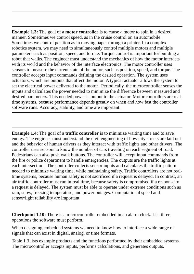
Table1.3listsexampleproductsandthefunctionsperformedbytheirembeddedsystems.Themicrocontrolleracceptsinputs,performscalculations,andgeneratesoutputs.
Functionsperformedbythemicrocontroller
Consumer/Home:WashingmachineControlsthewaterandspincycles,savingwaterandenergy
ExerciseequipmentMeasuresspeed,distance,calories,heartrate
RemotecontrolsAcceptskeytouches,sendsinfraredpulses,learnshowtointeractwithuser
ClocksandwatchesMaintainsthetime,alarm,anddisplay
GamesandtoysEntertainstheuser,joystickinput,videooutput
Audio/videoInteractswiththeoperator,enhancesperformancewithsoundsandpictures
Set-backthermostatsAdjustsday/nightthresholdssavingenergy
Communication:AnsweringmachinesPlaysoutgoingmessagesandsavesincomingmessages
TelephonesystemSwitchessignalsandretrievesinformation
CellularphonesInteractswithkeypad,microphone,andspeaker
SatellitesSendsandreceivesmessages
Automotive:AutomaticbrakingOptimizesstoppingonslipperysurfaces
NoisecancellationImprovessoundquality,removingnoise
TheftdeterrentdevicesAllowskeylessentry,controlsalarm
ElectronicignitionControlssparksandfuelinjectors
WindowsandseatsRememberspreferredsettingsforeachdriver
InstrumentationCollectsandprovidesnecessaryinformation
Military:SmartweaponsRecognizesfriendlytargets
MissileguidanceDirectsordnanceatthedesiredtarget
GlobalpositioningDetermineswhereyouareontheplanet,suggests

paths,coordinatestroops
SurveillanceCollectsinformationaboutenemyactivities
Industrial/Business/Shipping:Point-of-salesystemsAcceptsinputsandmanagesmoney,keepscreditinformationsecure
TemperaturecontrolAdjustsheatingandcoolingtomaintaintemperature
RobotsystemsInputsfromsensors,controlsthemotorsimprovingproductivity
InventorysystemsReadsandprintslabels,maximizingprofit,minimizingshippingdelay
AutomaticsprinklersControlsthewetnessofthesoilmaximizingplantgrowth
Medical:InfantapneamonitorsDetectsbreathing,alarmsifstopped
CardiacmonitorsMeasuresheartfunction,alarmsifproblem
CancertreatmentsControlsdosesofradiation,drugs,orheat
ProstheticdevicesIncreasesmobilityforthehandicapped
MedicalrecordsCollect,organize,andpresentmedicalinformation
ComputerComponents:MouseTranslateshandmovementsintocommandsforthemaincomputer
USBflashdriveFacilitatesthestorageandretrievalofinformation
KeyboardAcceptskeystrokes,decodesthem,andtransmitstothemaincomputerTable1.3.Productsinvolvingembeddedsystems.

Incontrast,ageneral-purposecomputersystemtypicallyhasakeyboard,disk,andgraphicsdisplayandcanbeprogrammedforawidevarietyofpurposes.Typicalgeneral-purposeapplicationsincludewordprocessing,electronicmail,businessaccounting,scientificcomputing,cloudcomputing,andwebservers.General-purposecomputershavetheoppositeofthefourcharacteristicslistedabove.First,theycanperformawideanddynamicrangeoffunctions.Becausethegeneral-purposecomputerhasaremovablediskornetworkinterface,newprogramscaneasilybeaddedtothesystem.Theuserofageneral-purposecomputerdoeshaveaccesstothesoftwarethatcontrolsthemachine.Inotherwords,theuserdecideswhichoperatingsystemtorunandwhichapplicationstolaunch.Second,theyarelooselyconstrained.Forexample,theJavamachineusedbyawebbrowserwilloperateonanextremelywiderangeofcomputerplatforms.Third,general-purposemachinesdonotruninreal-time.Yes,wewouldlikethetimetoprintapageontheprintertobefast,andwewouldlikeawebpagetoloadquickly,buttherearenoguaranteedresponsetimesforthesetypesofactivities.Infact,thereal-timetasksthatdoexist(suchassoundrecording,burningCD,andgraphics)areactuallyperformedbyembeddedsystemsbuiltintothesystem.Fourth,generalpurposecomputersemploybillions,ifnottrillionsofmemorycells.
Themostcommontypeofgeneral-purposecomputeristhepersonalcomputer,whichisbasedonthex86architecture(below$3,000).Computersmorepowerfulthanthepersonalcomputercanbegroupedintheworkstation($3,000to$50,000range)orthesupercomputercategories(above$50,000).Seethewebsitewww.top500.orgforalistofthefastestcomputersontheplanet.Thesecomputersoftenemploymultipleprocessorsandhavemuchmorememorythanthetypicalpersonalcomputer.Theworkstationsandsupercomputersareusedforhandlinglargeamountsofinformation(businessapplications),runninglargesimulations(weatherforecasting),searching(www.google.com),orperforminglargecalculations(scientificresearch).Thisbookwillnotcoverthegeneral-purposecomputer,althoughmanyofthebasicprinciplesofembeddedsystemsdoapplytoalltypesofsystems.
TheI/Ointerfacesareacrucialpartofanembeddedsystembecausetheyprovidenecessaryfunctionality.MostpersonalcomputershavethesamebasicI/Odevices(e.g.,mouse,keyboard,videodisplay,CD,USB,andharddrive.)Incontrast,thereisnocommonsetofI/Othatallembeddedsystemhave.ThesoftwaretogetherwiththeI/Oportsandassociatedinterfacecircuitsgiveanembeddedcomputersystemitsdistinctivecharacteristics.AdevicedriverisasetofsoftwarefunctionsthatfacilitatetheuseofanI/Oport.Anothernamefordevicedriverisapplicationprogrammerinterface(API).InthisbookwewillstudyawiderangeofI/OportssupportedbytheLM3S/TM4Cmicrocontrollers.Parallelportsprovidefordigitalinputandoutputs.Serialportsemployawiderangeofformatsandsynchronizationprotocols.Theserialportscancommunicatewithdevicessuchas:
•Sensors
•LiquidCrystalDisplay(LCD)andlightemittingdiode(LED)displays
•Analogtodigitalconverters(ADC)anddigitaltoanalogconverters(DAC)

Analogtodigitalconvertersconvertanalogvoltagestodigitalnumbers.Digitaltoanalogconvertersconvertdigitalnumberstoanalogvoltages.Thetimerfeaturesinclude:
•Fixedrateperiodicexecution
•PulseWidthModulatedoutputs(PWM)
•Inputcaptureusedforperiodandpulsewidthmeasurement
•Outputcompareusedforgeneratingsignalsandfrequencymeasurement.

1.3.TheDesignProcess
1.3.1.RequirementsdocumentBeforebeginninganyproject,itisagoodideatohaveaplan.Thefollowingisonepossibleoutlineofarequirementsdocument.Althoughoriginallyproposedforsoftwareprojects,itisappropriatetousewhenplanninganembeddedsystem,whichincludessoftware,electronics,andmechanicalcomponents.IEEEpublishesanumberoftemplatesthatcanbeusedtodefineaproject(IEEESTD830-1998).Arequirementsdocumentstateswhatthesystemwilldo.Itdoesnotstatehowthesystemwilldoit.Themainpurposeofarequirementsdocumentistoserveasanagreementbetweenyouandyourclientsdescribingwhatthesystemwilldo.Thisagreementcanbecomealegallybindingcontract.Writethedocumentsothatitiseasytoreadandunderstandbyothers.Itshouldbeunambiguous,complete,verifiable,andmodifiable.
Therequirementsdocumentshouldnotincludehowthesystemwillbedesigned.Thisallowstheengineertomakechoicesduringthedesigntominimizecostandmaximizeperformance.Ratheritshoulddescribetheproblembeingsolvedandwhatthesystemactuallydoes.Itcanincludesomeconstraintsplacedonthedevelopmentprocess.Ideally,itisco-writtenbyboththeengineersandthenon-technicalclients.However,itisimperativethatboththeengineersandtheclientsunderstandandagreeonthespecificsinthedocument.
1.Overview
1.1.Objectives:Whyarewedoingthisproject?Whatisthepurpose?
1.2.Process:Howwilltheprojectbedeveloped?
1.3.RolesandResponsibilities:Whowilldowhat?Whoaretheclients?
1.4.InteractionswithExistingSystems:Howwillitfitin?
1.5.Terminology:Definetermsusedinthedocument.
1.6.Security:Howwillintellectualpropertybemanaged?
2.FunctionDescription
2.1.Functionality:Whatwillthesystemdoprecisely?
2.2.Scope:Listthephasesandwhatwillbedeliveredineachphase.
2.3.Prototypes:Howwillintermediateprogressbedemonstrated?
2.4.Performance:Definethemeasuresanddescribehowtheywillbedetermined.
2.5.Usability:Describetheinterfaces.Bequantitativeifpossible.

2.6.Safety:Explainanysafetyrequirementsandhowtheywillbemeasured.
3.Deliverables
3.1.Reports:Howwillthesystembedescribed?
3.2.Audits:Howwilltheclientsevaluateprogress?
3.3.Outcomes:Whatarethedeliverables?Howdoweknowwhenitisdone?
Observation:Tobuildasystemwithoutarequirementsdocumentmeansyouareneverwrong,butneverdone.
1.3.2.ModelingOneofthecommonthreadsintheexampleembeddedsystemspresentedinSection1.2istheneedtounderstandthebehaviorofthephysicalsystemwithwhichtheembeddedsysteminteracts.Sometimesthisunderstandingisonlyhumanintuition.However,thedesignprocesswillbemuchmoresuccessfulifthisunderstandingcanberepresentedinmathematicalform.Scientistsstrivetodescribephysicalprocesseswithclosed-formmathematicalequations.Forexample,Newton’ssecondlawfordampedharmonicoscillatorsis
wherexistheone-dimensionalpositionoftheobject(m),tistime(s),Fistheappliedforce(N),misthemassoftheobject(kg),ciscalledtheviscousdampingcoefficient(kg/s),andkisthespringconstant(N/m).AnotherexampleisMaxwell–Faradayequation(orFaraday’slawofinduction)
or
whereEistheelectricfield(V/m),Bisthemagneticfield(Wb/m2),CistheclosedcurvealongtheboundaryofsurfaceS,dlisdifferentialvectorelementofpathlengthtangentialtothepath/curve(m),and B,SmagneticfluxthroughanysurfaceS(Wb).Athirdexampleisheatconduction
or
wherekisthermalconductivity(W/m/oC),Tistemperature(oC),xisone-dimensionaldistance(m),qisinternalheatgenerations(W/m3), isdensity(kg/m3),cisspecificheatatconstantpressure(W-s/kg/oC)andtistime(s).Thesystemiscausalifitsoutputdependsonlyoncurrentandpastinputs.LetS(x)definetheoutputofamodelforaninputx.AsystemislinearifS(ax1+bx2)=aS(x1)+bS(x2).Alineartime-invariantsystem(LTI)isasystemthatisbothlinearandtimeinvariant.

Someofthedifficultiesinsolvingclosedformequationssuchastheseincludemultidimensionalspace,irregularboundaries,andnon-constantproperties.Thesedifficultiescanbeovercomeusingcomputationalmethodssuchasthefiniteelementmethod(FEM).Stillmanyproblemsremain.Inaccuraciesinpropertyvaluescauseerrorsinthecomputationalmethod.Thebiggestproblemhoweverisintheequationsthemselves.Manyimportantreallifeproblemsexhibitnonlinearbehaviornotdescribedbyscientificequations.
Consequentially,engineerstendtouseempiricalmodelsoftheworldwithwhichtheembeddedsysteminteracts.Theparametersofanempiricalmodelaredeterminedbyexperimentalmeasurementunderconditionssimilartohowthesystemwillbedeployed.Typicallythemodelsarediscreteintime,becausethemeasurementsarediscreteintime.Themodelscanbelinearornonlinearasneeded.Thesemodelsoftenhavememory,meaningtheoutputsareafunctionofboththecurrentinputsandpreviousinputs/outputs.Oneofthesimplestmeasuresofstabilityiscalledbounded-inputbounded-output,whichmeansifallinputsignalsareboundedthenalloutputsignalswillalsobebounded.Forexample,performancemapsareusedinenginecontroltooptimizeperformance.Theyareempiricalequationsrelatingcontrolparameters(suchasappliedpower)andmeasuredparameters(suchasshaftrotationalspeed)todesiredoutputparameters(suchasgeneratedtorque).Evenifdifficult,itisappropriatetodevelopanabstractmodeldescribingtheinteractionbetweenembeddedsystemandtherealworld.Wewillpresentsomemodelswhendesigningmorecomplexsystemslaterinthebook.
1.3.3.Top-downdesignInthissection,wewillpresentthetop-downdesignprocess.Theprocessiscalledtop-down,becausewestartwiththehigh-leveldesignsandworkdowntolow-levelimplementations.Thebasicapproachisintroducedhere,andthedetailsoftheseconceptswillbepresentedthroughouttheremainingchaptersofthebook.Aswelearnsoftware/hardwaredevelopmenttoolsandtechniques,wecanplacethemintotheframeworkpresentedinthissection.AsillustratedinFigure1.5,thedevelopmentofaproductfollowsananalysis-design-implementation-testingcycle.Forcomplexsystemswithlonglife-spans,wetraversemultipletimesaroundthedevelopmentcycle.Forsimplesystems,aone-timepassmaysuffice.Evenafterasystemisdeployed,itcanreenterthelifecycletoaddfeaturesorcorrectmistakes.

Figure1.5.Systemdevelopmentcycleorlife-cycle.Afterthesystemisdoneitcanbedeployed.Duringtheanalysisphase,wediscovertherequirementsandconstraintsforourproposedsystem.Wecanhireconsultantsandinterviewpotentialcustomersinordertogatherthiscriticalinformation.Arequirementisaspecificparameterthatthesystemmustsatisfy,describingwhatthesystemshoulddo.Webeginbyrewritingthesystemrequirements,whichareusuallywrittenasarequirementsdocument.Ingeneral,specificationsaredetailedparametersdescribinghowthesystemshouldwork.Forexample,arequirementmaystatethatthesystemshouldfitintoapocket,whereasaspecificationwouldgivetheexactsizeandweightofthedevice.Forexample,supposewewishtobuildamotorcontroller.Duringtheanalysisphase,wewoulddetermineobviousspecificationssuchasrange,stability,accuracy,andresponsetime.Thefollowingmeasuresareoftenconsideredduringtheanalysisphase:
Safety:Therisktohumansortheenvironment.
Accuracy:Thedifferencebetweentheexpectedtruthandtheactualparameter
Precision:Thenumberofdistinguishablemeasurements
Resolution:Thesmallestchangethatcanbereliablydetected
Responsetime:Thetimebetweenatriggeringeventandtheresultingaction
Bandwidth:Theamountofinformationprocessedpertime
Signaltonoiseratio:Thequotientofthesignalamplitudedividedbythenoise
Maintainability:Theflexibilitywithwhichthedevicecanbemodified
Testability:Theeasewithwhichproperoperationofthedevicecanbeverified
Compatibility:Theconformanceofthedevicetoexistingstandards
Meantimebetweenfailure:Thereliabilityofthedevicedefiningthelifeifaproduct
Sizeandweight:Thephysicalspacerequiredbythesystemanditsmass

Power:Theamountofenergyittakestooperatethesystem
Nonrecurringengineeringcost(NREcost):Theone-timecosttodesignandtest
Unitcost:Thecostrequiredtomanufactureoneadditionalproduct
Time-to-prototype:Thetimerequiredtodesignbuildandtestanexamplesystem
Time-to-market:Thetimerequiredtodelivertheproducttothecustomer
Humanfactors:Thedegreetowhichourcustomersenjoy/like/appreciatetheproduct
Therearemanyparameterstoconsiderandtheirrelativeimportancemaybedifficulttoascertain.Forexample,inconsumerelectronicsthehumaninterfacecanbemoreimportantthanbandwidthorsignaltonoiseratio.Often,improvingtheperformanceononeparametercanbeachievedonlybydecreasingtheperformanceofanother.Thisartofcompromisedefinesthetradeoffsanengineermustmakewhendesigningaproduct.Aconstraintisalimitation,withinwhichthesystemmustoperate.Thesystemmaybeconstrainedtosuchfactorsascost,safety,compatibilitywithotherproducts,useofspecificelectronicandmechanicalpartsasotherdevices,interfaceswithotherinstrumentsandtestequipment,anddevelopmentschedule.
Checkpoint1.11:What’sthedifferencebetweenarequirementandaspecification?
Whenyouwriteapaper,youfirstdecideonatheme,andnextyouwriteanoutline.Inthesamemanner,ifyoudesignanembeddedsystem,youdefineitsspecification(whatitdoes),andbeginwithanorganizationalplan.Inthissection,wewillpresentthreegraphicaltoolstodescribetheorganizationofanembeddedsystem:dataflowgraphs,callgraphs,andflowcharts.Youshoulddrawallthreeforeverysystemyoudesign.
Duringthehigh-leveldesignphase,webuildaconceptualmodelofthehardware/softwaresystem.Itisinthismodelthatweexploitasmuchabstractionasappropriate.Theprojectisbrokeninmodulesorsubcomponents.ModulardesignwillbepresentedinChapter3.Duringthisphase,weestimatethecost,schedule,andexpectedperformanceofthesystem.Atthispointwecandecideiftheprojecthasahighenoughpotentialforprofit.Adataflowgraphisablockdiagramofthesystem,showingtheflowofinformation.Arrowspointfromsourcetodestination.Itisgoodpracticetolabelthearrowswiththeinformationtypeandbandwidth.Therectanglesrepresenthardwarecomponentsandtheovalsaresoftwaremodules.Weusedataflowgraphsinthehigh-leveldesign,becausetheydescribetheoveralloperationofthesystemwhilehidingthedetailsofhowitworks.Issuessuchassafety(e.g.,IsaacAsimov’sfirstLawofRobotics“Arobotmaynotharmahumanbeing,or,throughinaction,allowahumanbeingtocometoharm”)andtesting(e.g.,weneedtoverifyoursystemisoperational)shouldbeaddressedduringthehigh-leveldesign.

AnexampledataflowgraphforamotorcontrollerisshowninFigure1.6.Noticethatthearrowsarelabeledwithdatatypeandbandwidth.Therequirementofthesystemistodeliverpowertoamotorsothatthespeedofthemotorequalsthedesiredvaluesetbytheoperatorusingakeypad.Inordertomakethesystemeasiertouseandtoassistintesting,aliquidcrystaldisplay(LCD)isadded.Thesensorconvertsmotorspeedanelectricalvoltage.Theamplifierconvertsthissignalintothe0to+3.3VvoltagerangerequiredbytheADC.TheADCconvertsanalogvoltageintoadigitalsample.TheADCroutines,usingtheADCandtimerhardware,collectsamplesandcalculatevoltages.Next,thissoftwareusesatabledatastructuretoconvertvoltagetomeasuredspeed.Theuserwillbeabletoselectthedesiredspeedusingthekeypadinterface.Thedesiredandmeasuredspeeddataarepassedtothecontrollersoftware,whichwilladjustthepoweroutputinsuchamannerastominimizethedifferencebetweenthemeasuredspeedandthedesiredspeed.Finally,thepowercommandsareoutputtotheactuatormodule.Theactuatorinterfaceconvertsthedigitalcontrolsignalstopowerdeliveredtothemotor.ThemeasuredspeedandspeederrorwillbesenttotheLCDmodule.
Figure1.6.Adataflowgraphshowinghowsignalspassthroughamotorcontroller.

Thenextphaseisengineeringdesign.Webeginbyconstructingapreliminarydesign.Thissystemincludestheoveralltop-downhierarchicalstructure,thebasicI/Osignals,shareddatastructuresandoverallsoftwarescheme.Atthisstagethereshouldbeasimpleanddirectcorrelationbetweenthehardware/softwaresystemsandtheconceptualmodeldevelopedinthehigh-leveldesign.Next,wefinishthetop-downhierarchicalstructure,andbuildmock-upsofthemechanicalparts(connectors,chassis,cablesetc.)andusersoftwareinterface.Sophisticated3-DCADsystemscancreaterealisticimagesofoursystem.Detailedhardwaredesignsmustincludemechanicaldrawings.Itisagoodideatohaveasecondsource,whichisanalternativesupplierthatcansellourpartsifthefirstsourcecan’tdeliverontime.Acallgraphisadirectedgraphshowingthecallingrelationshipsbetweensoftwareandhardwaremodules.IfafunctioninmoduleAcallsafunctioninmoduleB,thenwedrawanarrowfromAtoB.IfafunctioninmoduleAinput/outputsdatafromhardwaremoduleC,thenwedrawanarrowfromAtoC.IfhardwaremoduleCcancauseaninterrupt,resultinginsoftwarerunninginmoduleA,thenwedrawanarrowfromCtoA.Ahierarchicalsystemwillhaveatree-structuredcallgraph.
AcallgraphforthismotorcontrollerisshowninFigure1.7.Again,rectanglesrepresenthardwarecomponentsandovalsshowsoftwaremodules.Anarrowpointsfromthecallingroutinetothemoduleitcalls.TheI/Oportsareorganizedintogroupsandplacedatthebottomofthegraph.Ahigh-levelcallgraph,liketheoneshowninFigure1.7,showsonlythehigh-levelhardware/softwaremodules.AdetailedcallgraphwouldincludeeachsoftwarefunctionandI/Oport.Normally,hardwareispassiveandthesoftwareinitiateshardware/softwarecommunication,butaswewilllearninChapter5,itispossibleforthehardwaretointerruptthesoftwareandcausecertainsoftwaremodulestoberun.Inthissystem,thetimerhardwarewillcausetheADCsoftwaretocollectasampleataregularrate.Thecontrollersoftwarecallsthekeypadroutinestogetthedesiredspeed,callstheADCsoftwaretogetthemotorspeedatthatpoint,determineswhatpowertodelivertothemotorandupdatestheactuatorbysendingthepowervaluetotheactuatorinterface.ThecontrollersoftwarecallstheLCDroutinestodisplaythestatusofthesystem.Acquiringdata,calculatingparameters,outputtingresultsataregularrateisstrategicwhenperformingdigitalsignalprocessinginembeddedsystems.
Figure1.7.Acallgraphforamotorcontroller.

Checkpoint1.12:WhatconfusioncouldariseiftwosoftwaremoduleswereallowedtoaccessthesameI/Oport?ThissituationwouldbeevidentonacallgraphifthetwosoftwaremoduleshadarrowspointingtothesameI/Oport.
Observation:IfmoduleAcallsmoduleB,andBreturnsdata,thenadataflowgraphwillshowanarrowfromBtoA,butacallgraphwillshowanarrowfromAtoB.
Datastructuresincludeboththeorganizationofinformationandmechanismstoaccessthedata.Againsafetyandtestingshouldbeaddressedduringthislow-leveldesign.
Thenextphaseisimplementation.Anadvantageofatop-downdesignisthatimplementationofsubcomponentscanoccurconcurrently.Themostcommonapproachtodevelopingsoftwareforanembeddedsystemistouseacross-assemblerorcross-compilertoconvertsourcecodeintothemachinecodeforthetargetsystem.Themachinecodecanthenbeloadedintothetargetmachine.Debuggingembeddedsystemswiththissimpleapproachisverydifficultfortworeasons.First,theembeddedsystemlackstheusualkeyboardanddisplaythatassistuswhenwedebugregularsoftware.Second,thenatureofembeddedsystemsinvolvesthecomplexandreal-timeinteractionbetweenthehardwareandsoftware.Thesereal-timeinteractionsmakeitimpossibletotestsoftwarewiththeusualsingle-steppingandprintstatements.
Thenexttechnologicaladvancementthathasgreatlyaffectedthemannerinwhichembeddedsystemsaredevelopedissimulation.Becauseofthehighcostandlongtimesrequiredtocreatehardwareprototypes,manypreliminaryfeasibilitydesignsarenowperformedusinghardware/softwaresimulations.Asimulatorisasoftwareapplicationthatmodelsthebehaviorofthehardware/softwaresystem.Ifboththeexternalhardwareandsoftwareprogramaresimulatedtogether,evenalthoughthesimulatedtimeisslowerthantheclockonthewall,thereal-timehardware/softwareinteractionscanbestudied.
Duringtheinitialiterationsofthedevelopmentcycle,itisquiteefficienttoimplementthehardware/softwareusingsimulation.Onemajoradvantageofsimulationisthatitisusuallyquickertoimplementaninitialproductonasimulatorversusconstructingaphysicaldeviceoutofactualcomponents.Rapidprototypingisimportantintheearlystagesofproductdevelopment.Thisallowsformoreloopsaroundtheanalysis-design-implementation-testingcycle,whichinturnleadstoamoresophisticatedproduct.
Duringthetestingphase,weevaluatetheperformanceofoursystem.First,wedebugthesystemandvalidatebasicfunctions.Next,weusecarefulmeasurementstooptimizeperformancesuchasstaticefficiency(memoryrequirements),dynamicefficiency(executionspeed),accuracy(differencebetweenexpectedtruthandmeasured),andstability(consistentoperation.)Debuggingtechniqueswillbepresentedthroughoutthebook.Testingisnotperformedattheendofprojectwhenwethinkwearedone.Rathertestingmustbeintegratedintoallphasesofthedesigncycle.Oncetestedthesystemcanbedeployed.

Maintenanceistheprocessofcorrectingmistakes,addingnewfeatures,optimizingforexecutionspeedorprogramsize,portingtonewcomputersoroperatingsystems,andreconfiguringthesystemtosolveasimilarproblem.Nosystemisstatic.Customersmaychangeoraddrequirementsorconstraints.Tobeprofitable,weprobablywillwishtotailoreachsystemtotheindividualneedsofeachcustomer.Maintenanceisnotreallyaseparatephase,butratherinvolvesadditionalloopsaroundthedevelopmentcycle.
1.3.4.FlowchartsInthissection,weintroducetheflowchartsyntaxthatwillbeusedthroughoutthebook.Programsthemselvesarewritteninalinearorone-dimensionalfashion.Inotherwords,wetypeonelineofsoftwareafteranotherinasequentialfashion.Writingprogramsthiswayisanaturalprocess,becausethecomputeritselfusuallyexecutestheprograminatop-to-bottomsequentialfashion.Thisone-dimensionalformatisfineforsimpleprograms,butconditionalbranchingandfunctioncallsmaycreatecomplexbehaviorsthatarenoteasilyobservedinalinearfashion.Eventhesimplesystemshavemultiplesoftwaretasks.Furthermore,acomplexapplicationwillrequiremultiplemicrocontrollers.Therefore,weneedamulti-dimensionalwaytovisualizesoftwarebehavior.Flowchartsareonewaytodescribesoftwareinatwo-dimensionalformat,specificallyprovidingconvenientmechanismstovisualizemulti-tasking,branching,andfunctioncalls.Flowchartsareveryusefulintheinitialdesignstageofasoftwaresystemtodefinecomplexalgorithms.Furthermore,flowchartscanbeusedinthefinaldocumentationstageofaprojectinordertoassistinitsuseormodification.
Figuresthroughoutthissectionillustratethesyntaxusedtodrawflowcharts.Theovalshapesdefineentryandexitpoints.Themainentrypointisthestartingpointofthesoftware.Eachfunction,orsubroutine,alsohasanentrypoint,whichistheplacethefunctionstarts.Ifthefunctionhasinputparameterstheyarepassedinattheentrypoint.Theexitpointreturnstheflowofcontrolbacktotheplacefromwhichthefunctionwascalled.Ifthefunctionhasreturnparameterstheyarereturnedattheexitpoint.Whenthesoftwarerunscontinuously,asistypicallythecaseinanembeddedsystem,therewillbenomainexitpoint.

Weuserectanglestospecifyprocessblocks.Inahigh-levelflowchart,aprocessblockmightinvolvemanyoperations,butinalow-levelflowchart,theexactoperationisdefinedintherectangle.Theparallelogramwillbeusedtodefineaninput/outputoperation.Someflowchartartistsuserectanglesforbothprocessesandinput/output.Sinceinput/outputoperationsareanimportantpartofembeddedsystems,wewillusetheparallelogramformat,whichwillmakeiteasiertoidentifyinput/outputinourflowcharts.Thediamond-shapedobjectsdefineabranchpointordecisionblock.Therectanglewithdoublelinesonthesidespecifiesacalltoapredefinedfunction.Inthisbook,functions,subroutinesandproceduresaretermsthatallrefertoawell-definedsectionofcodethatperformsaspecificoperation.Functionsusuallyreturnaresultparameter,whileproceduresusuallydonot.Functionsandproceduresaretermsusedwhendescribingahigh-levellanguage,whilesubroutinesoftenusedwhendescribingassemblylanguage.Whenafunction(orsubroutineorprocedure)iscalled,thesoftwareexecutionpathjumpstothefunction,thespecificoperationisperformed,andtheexecutionpathreturnstothepointimmediatelyafterthefunctioncall.Circlesareusedasconnectors.
Commonerror:Ingeneral,itisbadprogrammingstyletodevelopsoftwarethatrequiresalotofconnectorswhendrawingitsflowchart.
Thereareaseeminglyunlimitednumberoftasksonecanperformonacomputer,andthekeytodevelopinggreatproductsistoselectthecorrectones.Justlikehikingthroughthewoods,weneedtodevelopguidelines(likemapsandtrails)tokeepusfromgettinglost.Oneofthefundamentalissueswhendevelopingsoftware,regardlesswhetheritisamicrocontrollerwith1000linesofassemblycodeoralargecomputersystemwithbillionsoflinesistomaintainaconsistentstructure.Onesuchframeworkiscalledstructuredprogramming.Agoodhigh-levellanguagewillforcetheprogrammertowritestructuredprograms.Structuredprogramsarebuiltfromthreebasicbuildingblocks:thesequence,theconditional,andthewhile-loop.Atthelowestlevel,theprocessblockcontainssimpleandwell-definedcommands.I/Ofunctionsarealsolow-levelbuildingblocks.Structuredprogramminginvolvescombiningexistingblocksintomorecomplexstructures,asshowninFigure1.8.
Figure1.8.Flowchartshowingthebasicbuildingblocksofstructuredprogramming.MaintenanceTip:Remembertoupdatetheflowchartsasmodificationsaremadetothesoftware

Next,wewillrevisitthepacemakerexampleinordertoillustratetheflowchartsyntax.Athreadisthesequenceofactionscausedbyexecutingsoftware.TheflowchartinFigure1.9definesasingle-threadedexecutionbecausethereisonesequence.
Example1.1(continued):Useaflowcharttodescribeanalgorithmthatapacemakermightusetoregulateandimproveheartfunction.
Solution:Thisexampleillustratesacommontraitofanembeddedsystem,thatis,theyperformthesamesetoftasksoverandoverforever.Theprogramstartsatmainwhenpowerisapplied,andthesystembehaveslikeapacemakeruntilthebatteryrunsout.Figure1.9showsaflowchartforaverysimplealgorithm.Iftheheartisbeatingnormallywitharategreaterthanorequalto1beat/sec(60BPM),thentheatrialsensorwilldetectactivityandthefirstdecisionwillgoright.Sincethisisnormalbeating,theventricularactivitywilloccurwithinthenext200ms,andtheventricularsensorwillalsodetectactivity.Inthissituation,nooutputpulseswillbeissued.Ifthedelaybetweenatrialcontractionandventricularcontractwerelongerthanthenormal200ms,thenthepacemakerwillactivatetheventricles200msaftereachatrialcontraction.Iftheventricleisbeatingfasterthan60BPMwithoutanyatrialcontractions,thennoventricularstimulationswillbeissued.Ifthereisnoactivityfromeitheratriumortheventricle(orifthatrateisslowerthan60BPM),thentheventriclesarepacedat60BPM.
Figure1.9.Flowchartillustratingasimplepacemakeralgorithm.

Checkpoint1.13:Assumeyouaregivenasimplewatchthatjusttellsyouthetimeinhours,minutes,andseconds.Lettbeaninputparameter.Explainhowyoucouldusethewatchtowaittseconds.
1.3.5.Parallel,distributed,andconcurrentprogrammingManyproblemscannotbeimplementedusingthesingle-threadedexecutionpatterndescribedintheprevioussection.Parallelprogrammingallowsthecomputertoexecutemultiplethreadsatthesametime.State-of-theartmulti-coreprocessorscanexecuteaseparateprogramineachofitscores.Forkandjoinarethefundamentalbuildingblocksofparallelprogramming.Afterafork,twoormoresoftwarethreadswillberuninparallel.I.e.,thethreadswillrunsimultaneouslyonseparateprocessors.
Twoormoresimultaneoussoftwarethreadscanbecombinedintooneusingajoin.TheflowchartsymbolsforforkandjoinareshowninFigure1.10.Softwareexecutionafterthejoinwillwaituntilallthreadsabovethejoinarecomplete.Asananalogy,ifIwanttodigabigholeinmybackyard,Iwillinvitethreefriendsoverandgiveeveryoneashovel.Theforkoperationchangesthesituationfrommeworkingalonetofourofusreadytodig.Thefourdiggingtasksareruninparallel.Whentheoveralltaskiscomplete,thejoinoperationcausesthefriendstogoaway,andIamworkingaloneagain.Acomplexsystemmayemploymultiplemicrocontrollers,eachrunningitsownsoftware.Weclassifythisconfigurationasparallelordistributedprogramming.
Figure1.10.Flowchartsymbolstodescribeparallel,distributed,andconcurrentprogramming.Concurrentprogrammingallowsthecomputertoexecutemultiplethreads,butonlyoneatatime.Interruptsareonemechanismtoimplementconcurrencyonreal-timesystems.Interruptshaveahardwaretriggerandasoftwareaction.Aninterruptisaparameter-lesssubroutinecall,triggeredbyahardwareevent.TheflowchartsymbolsforinterruptsarealsoshowninFigure1.10.Thetriggerisahardwareeventsignalingitistimetodosomething.Examplesofinterrupttriggerswewillseeinthisbookincludenewinputdatahasarrived,outputdeviceisidle,andperiodicevent.Thesecondcomponentofaninterrupt-drivensystemisthesoftwareactioncalledaninterruptserviceroutine(ISR).Theforegroundthreadisdefinedastheexecutionofthemainprogram,andthebackgroundthreadsareexecutionsoftheISRs.

Considertheanalogyofsittinginacomfychairreadingabook.Readingabookislikeexecutingthemainprogramintheforeground.Becausethereisonlyoneofyou,thisscenarioisanalogoustoacomputerwithoneprocessor.Youstartreadingatthebeginningofthebookandbasicallyreadonepageatatimeinasequentialfashion.Youmightjumptothebackandlooksomethingupintheglossary,thenjumpbacktowhereyouwere,whichisanalogoustoafunctioncall.Similarly,ifyoumightreadthesamepageafewtimes,whichisanalogoustoaprogramloop.Eventhoughyouskiparoundalittle,theorderofpagesyoureadfollowsalogicalandwell-definedsequence.Conversely,ifthetelephonerings,youplaceabookmarkinthebook,andanswerthephone.Whenyouarefinishedwiththephoneconversation,youhangupthephoneandcontinuereadinginthebookwhereyouleftoff.TheringingphoneisanalogoustohardwaretriggerandthephoneconversationislikeexecutingtheISR.
Example1.2(continued):Useaflowcharttodescribeanalgorithmthatastand-alonesmokedetectormightusetowarnpeopleintheeventofafire.
Solution:Thisexampleillustratesacommontraitofalow-powerembeddedsystem.Thesystembeginswithapoweronreset,causingittostartatmain.Theinitializationenablesthetimerinterrupts,andthenitshutsoffthealarm.Inalow-powersystemthemicrocontrollergoestosleepwhentherearenotaskstoperform.Every30secondsthetimerinterruptwakensthemicrocontrollerandexecutestheinterruptserviceroutine.Thefirsttaskistoreadthesmokesensor.Ifthereisnofire,itwillflashtheLEDandreturnfrominterrupt.Atthispoint,themainprogramwillputthemicrocontrollerbacktosleep.Theletters(A-K)inFigure1.11specifythesoftwareactivitiesinthismultithreadedexample.InitiallyitexecutesA-B-Candgoestosleep.Every30seconds,assumingthereisnofire,itexecutes<-D-E-F-G-J-K-J-K-···-J-K-H->CThissequencewillexecuteinabout1ms,dominatedbythetimeittakestoflashtheLED.Thisisalow-powersolutionbecausethemicrocontrollerispoweredforabout0.003%ofthetime,or1msevery30seconds.

Figure1.11.Flowchartillustratingasimplesmokedetectoralgorithm.
Toillustratetheconceptofparallelprogramming,assumewehaveamulti-corecomputerwithfourprocessors.Considertheproblemoffindingthemaximumvalueinalargebuffer.First,wedividethebufferintofourequalparts.Next,weexecuteafork,asshownintheleft-mostflowchartinFigure1.10,launchingfourparallelthreads.Thefourprocessorsruninparalleleachfindingthemaximumofitssubset.Whenallfourthreadsarecomplete,theyperformajoinandcombinethefourresultstofindtheoverallmaximum.Itisimportanttodistinguishparallelprogramminglikethisfrommultithreadingimplementingconcurrentprocessingwithinterrupts.Becausemostmicrocontrollershaveasingleprocessor,thisbookwithfocusonconcurrentprocessingwithinterruptsanddistributedprocessingwithanetworkinvolvingmultiplemicrocontrollers.
1.3.6.Creativediscoveryusingbottom-updesignFigure1.5describestop-downdesignasacyclicprocess,beginningwithaproblemstatementandendingupwithasolution.Withabottom-updesignwebeginwithsolutionsandbuilduptoaproblemstatement.Manyinnovationsbeginwithanidea,“whatif…?”Inabottom-updesign,onebeginswithdesigning,building,andtestinglow-levelcomponents.Figure1.12illustratesatwo-levelprocess,combiningthreesubcomponentstocreatetheoverallproduct.Thishierarchicalprocesscouldhavemorelevelsand/ormorecomponentsateachlevel.Thelow-leveldesignscanoccurinparallel.Thedesignofeachcomponentiscyclic,iteratingthroughthedesign-build-testcycleuntiltheperformanceisacceptable.

Figure1.12.Systemdevelopmentprocessillustratingbottom-updesign.Bottom-updesignisinefficientbecausesomesubsystemsaredesigned,built,andtested,butneverused.Furthermore,inatrulycreativeenvironmentmostideascannotbesuccessfullyconvertedtooperationalsubsystems.Creativelaboratoriesarefilledwithfinished,half-finished,andfailedsubcomponents.Asthedesignprogressesthecomponentsarefittogethertomakethesystemmoreandmorecomplex.Onlyafterthesystemiscompletelybuiltandtesteddoesonedefineitsoverallspecifications.
Thebottom-updesignprocessallowscreativeideastodrivetheproductsacompanydevelops.Italsoallowsonetoquicklytestthefeasibilityofanidea.Ifonefullyunderstandsaproblemareaandthescopeofpotentialsolutions,thenatop-downdesignwillarriveataneffectivesolutionmostquickly.Ontheotherhand,ifonedoesn’treallyunderstandtheproblemorthescopeofitssolutions,abottom-upapproachallowsonetostartoffbylearningabouttheproblem.
Observation:Agoodengineerknowsbothbottom-upandtop-downdesignmethods,choosingtheapproachmostappropriateforthesituationathand.

1.4.DigitalLogicandOpenCollectorDigitallogichastwostates,withmanyenumerationssuchashighandlow,1and0,trueandfalse,onandoff.Therearefourcurrentsofinterest,asshowninFigure1.13,whenanalyzingiftheinputsofthenextstageareloadingtheoutput.IIHandIILarethecurrentsrequiredofaninputwhenhighandlowrespectively.Furthermore,IOHandIOLarethemaximumcurrentsavailableattheoutputwhenhighandlow.Inorderfortheoutputtoproperlydrivealltheinputsofthenextstage,themaximumavailableoutputcurrentmustbelargerthanthesumofalltherequiredinputcurrentsforboththehighandlowconditions.
and
Absolutevalueoperatorsareputintheaboverelationsbecausedatasheetsareinconsistentaboutspecifyingpositiveandnegativecurrents.ThearrowsinFigure1.13definethedirectionofcurrentregardlessofwhetherthedatasheetdefinesitasapositiveornegativecurrent.Itisyourresponsibilitytochoosepartssuchthattheaboveinequalitieshold.
Figure1.13.Sometimesoneoutputmustdrivemultipleinputs.Kirchhoff’sCurrentLaw(KCL)statesthesumofallthecurrentsintoonenodemustbezero.TheaboveinequalitiesarenotaviolationofKCL,becausetheoutputcurrentsaretheavailablecurrentsandtheinputcurrentsaretherequiredcurrents.Oncethesystemisbuiltandrunning,theactualoutputcurrentwillofcourseexactlyequalthesumoftheactualinputcurrents.Asamatterofcompleteness,weincludeKirchhoff’sVoltageLaw(KVL),whichstatesthesumofallthevoltagesinaclosedloopmustbezero.Table1.4showstypicalcurrentvaluesforthevariousdigitallogicfamilies.TheLM3S/TM4Cmicrocontrollersgiveyouthreechoicesofoutputcurrentforthedigitaloutputpins.TheTM4C1294addsa12-mAmode.
Family Example IOH IOL IIH IIL
StandardTTL 7404 0.4mA 16mA 40µA 1.6mA
SchottkyTTL 74S04 1mA 20mA 50µA 2mA
LowPowerSchottky
74LS04 0.4mA 4mA 20µA 0.4mA
74HC04 4mA 4mA 1µA 1µA

HighSpeedCMOS
AdvHighSpeedCMOS
74AHC04 4mA 4mA 1µA 1µA
TM4C2mA-drive
TM4C123 2mA 2mA 2µA 2µA
TM4C4mA-drive
TM4C123 4mA 4mA 2µA 2µA
TM4C8mA-drive
TM4C123 8mA 8mA 2µA 2µA
TM4C12mA-drive
TM4C1294 12mA 12mA 2µA 2µA
Table1.4.Theinputandoutputcurrentsofvariousdigitallogicfamiliesandmicrocontrollers.
Observation:ForTTLdevicesthelogiclowcurrentsaremuchlargerthanthelogichighcurrents.
Whenwedesigncircuitsusingdevicesallfromasinglelogicfamily,wecandefinefanoutasthemaximumnumberofinputs,oneoutputcandrive.Fortransistor-transistorlogic(TTL)logicwecancalculatefanoutfromtheinputandoutputcurrents:
Fanout=minimum((IOH/IIH),(IOL/IIL))

Conversely,thefanoutofhigh-speedcomplementarymetal-oxidesemiconductor(CMOS)devices,whichincludesmostmicrocontrollers,isdeterminedbycapacitiveloadingandnotbythecurrents.Figure1.14showsasimplecircuitmodelofaCMOSinterface.TheidealvoltageoftheoutputdeviceislabeledV1.Forinterfacesincloseproximity,theresistanceRresultsfromtheoutputimpedanceoftheoutputdevice,andthecapacitanceCresultsfromtheinputcapacitanceoftheinputdevice.However,iftheinterfacerequiresacabletoconnectthetwodevices,boththeresistanceandcapacitancewillbeincreasedbythecable.ThevoltagelabeledV2istheeffectivevoltageasseenbytheinput.IfV2isbelow1.3V,theLM3S/LM4F/TM4Cmicrocontrollerswillinterpretthesignalaslow.Conversely,thevoltageisabove2.0V,thesemicrocontrollerswillconsiderithigh.Theslewrateofasignalistheslopeofthevoltageversustimeduringthetimewhenthelogiclevelswitchesbetweenlowandhigh.Asimilarparameteristhetransitiontime,whichisthetimeittakesforanoutputtoswitchfromonelogicleveltoanother.InFigure1.14,thetransitiontimeisdefinedasthetimeittakesV2togofrom1.3to2.0V.Thereisacapacitiveloadfortheoutputandeachinput.Asthiscapacitanceincreasestheslewratedecreases,whichwillincreasethetransitiontime.Signalswithahighslewratecanradiatealotofnoise.So,toreducenoiseemissionswesometimeslimittheslewrateofthesignals.
TherearetwowaystodeterminethefanoutofCMOScircuits.First,somecircuitshaveaminimumtimeitsinputcanexistinthetransitionrange.Forexample,itmightspecifythesignalcannotbeabove1.3andbelow2.0Vformorethan20ns.Clockinputsareoftenspecifiedthisway.Asecondwayistocalculatethetimeconstant,whichisR*Cforthiscircuit.LetTbethepulsewidthofthedigitalsignal.IfTislargecomparedto ,thentheCMOSinterfacefunctionsproperly.Forcircuitsthatmixdevicesfromonefamilywithanother,wemustlookindividuallyattheinputandoutputcurrents,voltagesandcapacitiveloads.Thereisnosimpleformula.
Figure1.14.CapacitanceloadingisanimportantfactorwheninterfacingCMOSdevices.

Figure1.15comparestheinputandoutputvoltagesformanyofthedigitallogicfamilies.VIListhevoltagebelowwhichaninputisconsideredalogiclow.Similarly,VIHisthevoltageabovewhichaninputisconsideredalogichigh.Theoutputvoltagedependsstronglyoncurrentrequiredtodrivetheinputsofthenextstage.VOHistheoutputvoltagewhenthesignalishigh.Inparticular,iftheoutputisalogichigh,andthecurrentislessthanIOH,thenthevoltagewillbegreaterthanVOH.Similarly,VOListheoutputvoltagewhenthesignalislow.Inparticular,iftheoutputisalogiclow,andthecurrentislessthanIOL,thenthevoltagewillbelessthanVOL.ThedigitalinputpinsontheLM3S/LM4F/TM4Cmicrocontrollersare5V-tolerant,meaninganinputhighsignalcanbeanyvoltagefrom2.0to5.0V.
Figure1.15.Voltagethresholdsforvariousdigitallogicfamilies.
Fortheoutputofonecircuittoproperlydrivetheinputsofthenextcircuit,theoutputlowvoltageneedstobelowenough,andtheoutputhighvoltageneedstobehighenough.
forallinputsand forallinputs
ThemaximumoutputcurrentspecificationontheLM3S/LM4F/TM4Cfamilyis25mA,whichisthecurrentabovewhichwillcausedamage.However,wecanselectIOHandIOLtobe2,4,or8mA.Normally,wedesignthesystemsotheoutputcurrentsarelessthanIOHandIOL.Vtisthetypicalthresholdvoltage,whichisthevoltageatwhichtheinputusuallyswitchesbetweenlogiclowandhigh.Formallyhowever,aninputisconsideredinthetransitionregion(valueindeterminate)forvoltagesbetweenVILandVIH.Thefiveparametersthataffectourchoiceoflogicfamiliesare
•Powersupplyvoltage(e.g.,+5V,3.3Vetc.)
•Powersupplycurrent(e.g.,willthesystemneedtorunonbatteries?)
•Speed(e.g.,clockfrequencyandpropagationdelays)

•Outputdrive,IOL,IOH(e.g.,doesitneedtodrivemotorsorlights?)
•Noiseimmunity(e.g.,electromagneticfieldinterference)
•Temperature(e.g.,electromagneticfieldinterference)
Checkpoint1.14:HowwilltheTM4C123interpretaninputpinastheinputvoltagechangesfrom0,1,2,3,4,to5V?I.e.,foreachvoltage,willitbeconsideredasalogiclow,asalogichighorasindeterminate?
Checkpoint1.15:Consideringbothvoltageandcurrent,cantheoutputofa74HC04drivetheinputofa74LS04?Assumebotharerunningat5V.
Checkpoint1.16:Consideringbothvoltageandcurrent,cantheoutputofa74LS04drivetheinputofa74HC04?Assumebotharerunningat5V.
Averyimportantconceptusedincomputertechnologyistristatelogic,whichhasthreeoutputstates:high,low,andoff.OthernamesfortheoffstateareHiZ,floating,andtristate.Tristatelogicisdrawnasatriangleshapewithasignalonthetopofthetriangle.InthisFigure1.16,Aisthedatainput,Gisthegateinput,andBisthedataoutput.Whenthereisnocircleonthegate,itoperatesinpositivelogic,meaningifthegateishigh,thentheoutputdataequalstheinputdata.Ifthepositive-logicgateislow,thentheoutputwillfloat.Whenthereisacircleonthegate,itoperatesinnegativelogic,meaningifthegateislow,thentheoutputdataequalstheinputdata.Ifthenegative-logicgateishigh,thentheoutputwillfloat.
Figure1.16.Digitallogicdrawingoftristatedrivers.Thereareawiderangeoftechnologiesavailablefordigitallogicdesign.Tostudythesedifferencesconsiderthe74LVT245,the74ALVC245,the74LVC245,the74ALB245,the74AC245,the74AHC245,andthe74LV245.
Eachofthesechipsisan8-input8-outputbidirectionaltristatedriver.Table1.5listssomeoftheinterfacingparametersforeachtechnology.ICCisthetotalsupplycurrentrequiredtodrivethechip.tpdisthepropagationdelayfrominputtooutput.VCCisthesupplyvoltage.
FamilyTechnology VILVIH VOLVOH IOL IOH ICC tpd
LVT-Low-VoltageBiCMOS LVTTL LVTTL 64 -32 190 3.5
ALVC-AdvancedLow-VoltageCMOS
LVTTL LVTTL 24 -24 40 3.0
LVC-Low-VoltageCMOS LVTTL LVTTL 24 -24 10 4.0

ALB-AdvancedLow-VoltageBiCMOS
LVTTL LVTTL 25 -25 800 2.0
AC-AdvancedCMOS CMOS CMOS 12 -12 20 8.5
AHC-AdvancedHighSpeedCMOS
CMOS CMOS 4 -4 20 11.9
LV-Low-VoltageCMOS LVTTL LVTTL 8 -8 20 14
units mA mA µA ns
Table1.5.Comparisonoftheoutputdrive,supplycurrentandspeedofvarious3.3Vlogic‘245gates.
Observation:ThereisaninverserelationshipbetweensupplycurrentICCandpropagationdelaytpd.
The74LS04isalow-powerSchottkyNOTgate,asshownontheleftinFigure1.17.ItiscalledSchottkylogicbecausethedevicesaremadefromSchottkytransistors.TheoutputishighwhenthetransistorQ4isactive,drivingtheoutputtoVcc.TheoutputislowwhenthetransistorQ5isactive,drivingtheoutputto0.
Figure1.17.Twotransistor-levelimplementationsofaNOTgate.Itisobviouslynecessarytoreadthedatasheetforyourmicrocontroller.However,itisalsogoodpracticetoreviewtheerratapublishedbythemanufactureraboutyourmicrocontroller.Theerratadefinesituationswheretheactualchipdoesnotfollowspecificationsinthedatasheet.Forexample,theregularTM4C123datasheetstatestheI/Opinsare+5Vtolerant.However,readingtheerratafortheLM3S811versionC2announcesthat“PB6,PC5,andPC6arenot5-Vtolerant.”

The74HC04isahigh-speedCMOSNOTgate,shownontherightinFigure1.17.TheoutputishighwhenthetransistorQ1isactive,drivingtheoutputto3.3V.TheoutputislowwhenthetransistorQ2isactive,drivingtheoutputto0.Sincemostmicrocontrollersaremadewithhigh-speedCMOSlogic,itsoutputsbehaveliketheQ1/Q2“push/pull”transistorpair.Outputportsarenotinverting.I.e.,whenyouwritea“1”toanoutputport,thentheoutputvoltagegoeshigh.Similarly,whenyouwritea“0”toanoutputport,thentheoutputvoltagegoeslow.AnalysesofthecircuitinFigure1.17revealsomeofthebasicpropertiesofhigh-speedCMOSlogic.First,becauseofthecomplementarynatureoftheP-channel(theoneonthetop)andN-channel(theoneonthebottom)transistors,whentheinputisconstant(continuouslyhighorcontinuouslylow),thesupplycurrent,Icc,isverylow.Second,thegatewillrequiresupplycurrentonlywhentheoutputswitchesfromlowtohighorfromhightolow.Thisobservationleadstothedesignrulethatthepowerrequiredtorunahigh-speedCMOSsystemislinearlyrelatedtothefrequencyofitsclock,becausethefrequencyoftheclockdeterminesthenumberoftransitionspersecond.Alongthesamelines,weseethatifthevoltageoninputAexistsbetweenVILandVIHforextendedperiodsoftime,thenbothQ1andQ2arepartiallyactive,causingashortfrompowertoground.Thisconditioncancausepermanentdamagetothetransistors.Third,sincetheinputAisconnectedtothegateofthetwoMOStransistors,theinputcurrentswillbeverysmall(≈1 A).Inotherwords,theinputimpedance(inputvoltagedividebyinputcurrent)ofthegateisveryhigh.Normally,ahighinputimpedanceisagoodthing,exceptiftheinputisnotconnected.Iftheinputisnotconnectedthenittakesverylittleinputcurrentstocausethelogicleveltoswitch.
Commonerror:IfunusedinputpinsonaCMOSmicrocontrollerareleftunconnected,thentheinputsignalmayoscillateathighfrequenciesdependingontheEMfieldsintheenvironment,wastingpowerunnecessarily.
Observation:ItisagooddesignpracticetoconnectunusedCMOSinputstogroundorconnectthemto+3.3V.
NowthatweunderstandthatCMOSdigitallogicisbuiltwithPNPandNPNtransistors,wecanrevisittheinterfacerequirementsforconnectingadigitaloutputfromonemoduletoadigitalinputofanothermodule.Figure1.18showsthemodelwhentheoutputishigh.Tomaketheoutputhigh,aPNPtransistorintheoutputmoduleisconducting(Q1)driving+3.3Vtotheoutput.ThehighvoltagewillactivatethegateofNPNtransistorsintheinputmodule(Q4).TheIIHisthecurrentintotheinputmoduleneededtoactivateallgatesconnectedtotheinput.TheactualcurrentIwillbebetween0andIIH.Forahighsignal,currentflowsfrom+3.3V,acrossthesource-drainofQ1,intothegateofQ4,andthentoground.AstheactualcurrentIincreases,theactualoutputvoltageVwilldrop.IOHisthemaximumoutputcurrentthatguaranteestheoutputvoltagewillbeaboveVOH.AssumingtheactualIislessthanIOH,theactualvoltageVwillbebetweenVOHand+3.3V.IftheinputvoltageisbetweenVIHand+3.3V,theinputsignalisconsideredhighbytheinput.Forthehighsignaltobetransferredproperly,VOHmustbelargerthanVIHandIOHmustbelargerthanIIH.
Figure1.19showsthemodelwhentheoutputislow.Tomaketheoutputlow,anNPN

transistorintheoutputmoduleisconducting(Q2)drivingtheoutputto0V.ThelowvoltagewillactivatethegateofPNPtransistorsintheinputmodule(Q3).TheIIListhecurrentoutoftheinputmoduleneededtoactivateallgatesconnectedtotheinput.TheactualcurrentIwillbebetween0andIIL.Foralowsignal,currentflowsfrom+3.3Vintheinputmodule,acrossthesource-gateofQ3,acrossthesource-draingateofQ2,andthentoground.AstheactualcurrentIincreases,theactualoutputvoltageVwillincrease.IOListhemaximumoutputcurrentthatguaranteestheoutputvoltagewillbelessthanVOL.AssumingtheactualIislessthanIOL,theactualvoltageVwillbebetween0andVOL.Iftheinputvoltageisbetween0andVIL,theinputsignalisconsideredlowbytheinput.Forthelowsignaltobetransferredproperly,VOLmustbelessthanVILandIOLmustbelargerthanIIL.
Figure1.18.Modelfortheinput/outputcharacteristicswhentheoutputishigh.
Figure1.19.Modelfortheinput/outputcharacteristicswhentheoutputislow.Opencollectorlogichasoutputswithtwostates:lowandoff.The74LS05isalow-powerSchottkyopencollectorNOTgate,asshowninFigure1.20.Whendrawinglogicdiagrams,weaddthe‘x’ontheoutputtospecifyopencollectorlogic.

The74HC05isahigh-speedCMOSopencollectorNOTgateisalsoshowninFigure1.20.ItiscalledopencollectorbecausethecollectorpinofQ2isnotconnected,orleftopen.Theoutputisoffwhenthereisnoactivetransistordrivingtheoutput.Inotherwords,whentheinputislow,theoutputfloats.This“notdriven”conditioniscalledtheopencollectorstate.Whentheinputishigh,theoutputwillbelow,causedbymakingthetransistorQ2isactivedrivingtheoutputto0.Technically,the74HC05implementsopendrainratherthanopencollector,becauseitisthedrainpinofQ2thatisleftopen.Inthisbook,wewillusethetermsopencollectorandopendraininterchangeablytorefertodigitallogicwithtwooutputstates(lowandoff).Becauseofthemultipleusesofopencollector,manymicrocontrollerscanimplementopencollectorlogic.OnLM3S/TM4Cmicrocontrollers,wecanaffectthismodebydefininganoutputasopendrain.
Figure1.20.TwotransistorimplementationsofanopencollectorNOTgate.Wecanuseabipolarjunctiontransistor(BJT)tosourceorsinkcurrent.Formostofthecircuitsinthisbookthetransistorsareusedinsaturatedmode.Ingeneral,wewilluseNPNtransistorstosinkcurrenttoground.WeturnonanNPNtransistorbyapplyingapositiveVbe.ThismeanswhentheNPNtransistorison,currentflowsfromthecollectortotheemitter.WhentheNPNtransistorisoff,nocurrentflowsfromthecollectortotheemitter.Eachtransistorhasaninputandoutputimpedance,hieandhoerespectively.Thecurrentgainishfeor .Thehybrid-pismallsignalmodelforthebipolarNPNtransistorisshowninFigure1.21.
Figure1.21.NPNtransistormodel.TherearefivebasicdesignruleswhenusingindividualbipolarNPNtransistorsinsaturatedmode:
1)NormallyVc>Ve

2)Currentcanonlyflowinthefollowingdirections
frombasetoemitter(inputcurrent)
fromcollectortoemitter(outputcurrent)
frombasetocollector(doesn’tusuallyhappen,butcouldifVb>Vc)
3)Eachtransistorhasmaximumvaluesforthefollowingtermsthatshouldnotbeexceeded
IbIcVceandIc•Vce4)Thetransistoractslikeacurrentamplifier
Ic=hfe•Ib5)ThetransistorwillactivateifVb>Ve+Vbe(SAT)whereVbe(SAT)istypicallyabove0.6V
Ingeneral,wewillusePNPtransistorstosourcecurrentfromapositivevoltagesupply.WeturnonaPNPtransistorbyapplyingapositiveVeb.ThismeanswhenthePNPtransistorison,currentflowsfromtheemittertothecollector.WhenthePNPtransistorisoff,nocurrentflowsfromtheemittertothecollector.Eachtransistorhasaninputandoutputimpedance,hieandhoerespectively.Thecurrentgainishfeor .Thehybrid-pismallsignalmodelforthebipolarPNPtransistorisshowninFigure1.22.
Figure1.22.PNPtransistormodel.
TherearefivebasicdesignruleswhenusingindividualbipolarPNPtransistorsinsaturatedmode:
1)NormallyVe>Vc2)Currentcanonlyflowinthefollowingdirections
fromemittertobase(inputcurrent)
fromemittertocollector(outputcurrent)
fromcollectortobase(doesn’tusuallyhappen,butcouldifVc>Vb)
3)Eachtransistorhasmaximumvaluesforthefollowingtermsthatshouldnotbeexceeded
IbIcVceandIc•Vce

4)Thetransistoractslikeacurrentamplifier
Ic=hfe•Ib5)ThetransistorwillactivateifVb<Ve-Vbe(SAT)whereVbe(SAT)istypicallyabove0.6V
PerformanceTip:Agoodtransistordesignisonethattheinput/outputresponseisindependentofhfe.WecandesignasaturatedmodecircuitsothatIbis2to5timesaslargeasneededtosupplythenecessaryIc.
TheTable1.6illustratesthewiderangeofbipolartransistorsthatwecanuse.
Type NPN PNP package Vbe(SAT) Vce(SAT) hfemin/max
Ic
generalpurpose
2N3904 2N3906 TO-92 0.85V 0.2V 100 10mA
generalpurpose
PN2222 PN2907 TO-92 1.2V 0.3V 100 150mA
generalpurpose
2N2222 2N2907 TO-18 1.2V 0.3V 100/300 500mA
powertransistor
TIP29A TIP30A TO-220 1.3V 0.7V 15/75 1A
powertransistor
TIP31A TIP32A TO-220 1.8V 1.2V 25/50 3A
powertransistor
TIP41A TIP42A TO-220 2.0V 1.5V 15/75 3A
powerdarlington
TIP120 TIP125 TO-220 2.5V 2.0V 1000min
3A
Table1.6.Parametersoftypicaltransistorsusedtosourceorsinkcurrent.

UndermostconditionsweplacearesistorinserieswiththebaseofaBJTwhenusingitasacurrentswitch.Thevalueofthisresistoristypically100 to10k .Thepurposeofthisbaseresistoristolimitthecurrentintothebase.Thehieistypicallyaround60 .ItyouconnectamicrocontrolleroutputportdirectlytothebaseofaBJT(withouttheresistor),thenwhentheoutputishighitwilltryandgenerateacurrentof3.3V/60 =50mA,potentiallydamagingthemicrocontroller.Ifthereisa1k resistorbetweenthemicrocontrollerandbaseoftheNPN,thentheVbevoltagegoestoVbeSAT(0.7)and(3.3-0.7)/1000 or2.6mA.
Ingeneral,wecanuseanopencollectorNOTgatetocontrolthecurrenttoadevice,suchasarelay,alightemittingdiode(LED),asolenoid,asmallmotor,andasmalllight.The74HC05canhandleupto4mA.The7405and7406canhandleupto16and40mArespectively,buttheymustbepoweredat+5V.Forcurrentsupto150mAwecanuseaPN2222transistor,asshowninFigure1.23,tocreatealow-costbuteffectivesolution.Whenoutputofthemicrocontrollerishigh,thetransistorison,makingitsoutputlow(VOLorVCE).Inthisstate,a10mAcurrentisappliedtothediode,anditlightsup.Butwhenoutputofthemicrocontrollerislow,thetransistorisoff,makingitsoutputfloat,whichisneitherhighnorlow.ThisfloatingoutputstatecausestheLEDcurrenttobezero,andthediodeisdark.TheresistorisselectedtosettheLEDcurrent.AssumetheVCEis0.3V,andthedesiredLEDoperatingpointis1.9V10mA.Inthiscase,thecorrectresistorvalueis(3.3-1.9-0.3V)/10mA=110 .
Figure1.23.Opencollectorusedtointerfacealightemittingdiode.Checkpoint1.17:WhatresistorvaluewouldyouchoosetooperatetheLEDat2V20mA?
Whenneededfordigitallogic,wecanconvertanopencollectoroutputtoadigitalsignalusingapull-upresistorfromtheoutputtoVCC.Inthisway,whentheopencollectoroutputfloats,thesignalwillbeadigitalhigh.Howdoweselectthevalueofthepull-upresistor?Ingeneralthesmallertheresistor,thelargertheIOHitwillbeabletosupplywhentheoutputishigh.Ontheotherhand,alargerresistordoesnotwasteasmuchIOLcurrentwhentheoutputislow.Onewaytocalculatethevalueofthispull-upresistoristofirstdeterminetherequiredoutputhighvoltage,Vout,andoutputhighcurrent,Iout.TosupplyacurrentofatleastIoutatavoltageaboveVout,theresistormustbelessthan:
R≤(VCC-Vout)/Iout

AsanexamplewewillcalculatetheresistorvalueforthesituationwherethecircuitneedstodrivefiveregularTTLloads,withVCCequalto5V.WeseefromFigure1.15thatVoutmustbeaboveVIH(2V)inorderfortheTTLinputstosenseahighlogiclevel.WecanaddasafetyfactorandsetVoutat3V.InorderforthehighoutputtodriveallfiveTTLinputs,IoutmustbemorethanfiveIIH.FromTable1.4,weseethatIIHis40µA,soIoutshouldbelargerthan5times40µAor0.2mA.Forthissituation,theresistormustbelessthan(5-3V)/0.2mA=10kΩ.
Anotherexampleofopencollectorlogicoccurswheninterfacingswitchestothemicrocontroller.ThecircuitontheleftofFigure1.24showsamechanicalswitchwithoneterminalconnectedtoground.Inthiscircuit,whentheswitchispressed,thevoltageriszero.Whentheswitchisnotprocessed,thesignalrfloats.
ThecircuitonthemiddleofFigure1.24showsthemechanicalswitchwitha10k pull-upresistorattachedtheotherside.Whentheswitchispressedthevoltageatsstillgoestozero,becausetheresistanceoftheswitch(lessthan0.1 )ismuchlessthanthepull-upresistor.Butnowwhentheswitchisnotpressedthepull-upresistorcreatesa+3.3Vats.Thiscircuitisshownconnectedtoaninputpinofthemicrocontroller.Thesoftware,byreadingtheinputport,candeterminewhetherornottheswitchispressed.Iftheswitchispressedthesoftwarewillreadzero,andiftheswitchisnotpressedthesoftwarewillreadone.Thismiddlecircuitiscallednegativelogicbecausetheactivestate,switchisbeingpressed,hasalowervoltagethantheinactivestate.
ThecircuitontherightofFigure1.24alsointerfacesamechanicalswitchtothemicrocontroller,butitimplementspositivelogicusingapull-downresistor.Thesignaltwillbehighiftheswitchispressedandlowifitisreleased.Thisrightcircuitiscalledpositivelogicbecausetheactivestate,switchisbeingpressed,hasahighervoltagethantheinactivestate.
Figure1.24.SinglePoleSingleThrow(SPST)Switchinterface.Observation:Wecanactivatepull-uporpull-downresistorsontheportsonmostmicrocontrollers,sotheinterfacesinFigure1.24canbemadewithouttheexternalresistor.
Earlierweusedavoltageandcurrentargumenttodeterminethevalueofthepull-upresistor.Inthissectionwepresentanothermethodonecouldusetoselectthisresistor.TheLM3S/TM4Cmicrocontrollershaveaninputcurrentof2 A.At3.3V,thisistheequivalentofaninputimpedanceofabout1M .Aswitchhasanon-resistanceoflessthan1 .Wewanttheresistortobesmallwhencomparedto1M ,butlargecomparedto1 .The10k pull-upresistoris100timessmallerthantheinputimpedanceand10,000timeslargerthantheswitchresistance.Theinternalpull-upmodeonLM3Smicrocontrollersrangesfromanequivalentof50to110k .Theinternalpull-downmode

rangesfromanequivalentof55to180k .FortheTM4C,theinternalpull-upresistorrangesfrom13to30k ,andtheinternalpull-downresistorrangesfrom13to35k .

1.5.DigitalRepresentationofNumbers
1.5.1.FundamentalsInformationisstoredonthecomputerinbinaryform.Abinarybitcanexistinoneoftwopossiblestates.Inpositivelogic,thepresenceofavoltageiscalledthe‘1’,true,asserted,orhighstate.Theabsenceofavoltageiscalledthe‘0’,false,notasserted,orlowstate.Converselyinnegativelogic,thetruestatehasalowervoltagethanthefalsestate.Figure1.25showstheoutputofatypicalcomplementarymetaloxidesemiconductor(CMOS)circuit.Theleftsideshowstheconditionwithatruebit,andtherightsideshowsafalse.Theoutputofeachdigitalcircuitconsistsofap-typetransistor“ontopof”ann-typetransistor.Indigitalcircuits,eachtransistorisessentiallyonoroff.Ifthetransistorison,itisequivalenttoashortcircuitbetweenitstwooutputpins.Conversely,ifthetransistorisoff,itisequivalenttoanopencircuitbetweenitsoutputspins.OnLM3S/TM4Cmicrocontrollerspoweredwith3.3Vsupply,avoltagebetween2and5Visconsideredhigh,andavoltagebetween0and1.3Visconsideredlow.Separatingthetworegionsby0.7Vallowsdigitallogictooperatereliablyatveryhighspeeds.Thedesignoftransistor-leveldigitalcircuitsisbeyondthescopeofthisbook.However,itisimportanttoknowthatdigitaldataexistasbinarybitsandencodedashighandlowvoltages.
Figure1.25.Abinarybitistrueifavoltageispresentandfalseifthevoltageis0.
Numbersarestoredonthecomputerinbinaryform.Inotherwords,informationisencodedasasequenceof1’sand0’s.Onmostcomputers,thememoryisorganizedinto8-bitbytes.Thismeanseach8-bitbytestoredinmemorywillhaveaseparateaddress.Precisionisthenumberofdistinctordifferentvalues.Weexpressprecisioninalternatives,decimaldigits,bytes,orbinarybits.AlternativesaredefinedasthetotalnumberofpossibilitiesaslistedinTable1.7.Lettheoperation[[x]]bethegreatestintegerofx.E.g.,[[2.1]]isroundedupto3.Forexample,an8-bitnumberschemecanrepresent256differentnumbers,whichmeans256alternatives.An8-bitdigitaltoanalogconverter(DAC)cangenerate256differentanalogoutputs.An8-bitanalogtodigitalconverter(ADC)canmeasure256differentanaloginputs.

Binarybits Bytes Alternatives
8 1 256
10 1024
12 4096
16 2 65,536
20 1,048,576
24 3 16,777,216
30 1,073,741,824
32 4 4,294,967,296
n [[n/8]] 2n
Table1.7.Relationshipbetweenbits,bytesandalternativesasunitsofprecision.
Observation:Agoodruleofthumbtorememberis210•nisapproximately103•n.
Decimaldigitsareusedtospecifyprecisionofmeasurementsystemsthatdisplayresultsasnumericalvalues,asdefinedinTable1.8.Afulldecimaldigitcanbeanyvalue0,1,2,3,4,5,6,7,8,or9.Adigitthatcanbeeither0or1isdefinedasa½decimaldigit.Theterminologyofa½decimaldigitdidnotarisefromamathematicalperspectiveofprecision,butratheritarosefromthephysicalwidthoftheLED/LCDmoduleusedtodisplayablankor’1’ascomparedtothewidthofafulldigit.Similarly,wedefineadigitthatcanbe+or-alsoasahalfdecimaldigit,becauseithastwochoices.Adigitthatcanbe0,1,2,3isdefinedasa¾decimaldigit,becauseitiswiderthana½digitbutnarrowerthanafulldigit.Wealsodefineadigitthatcanbe-1,-0,+0,or+1asa¾decimaldigit,becauseitalsohasfourchoices.Weusetheexpression4½decimaldigitstomean20,000alternativesandtheexpression4¾decimaldigitstomean40,000alternatives.Theuseofa½decimaldigittomeantwicethenumberofalternativesoroneadditionalbinarybitiswidelyaccepted.Ontheotherhand,theuseof¾decimaldigittomeanfourtimesthenumberofalternativesortwoadditionalbinarybitsisnotascommonlyaccepted.Forexample,considerthetwoohmmeters.Assumebotharesettothe0to200k range.A3½digitohmmeterhasaresolutionof0.1k withmeasurementsrangingfrom0.0to199.9k .Ontheotherhand,a4½digitohmmeterhasaresolutionof0.01k withmeasurementsrangingfrom0.00to199.99k .Table1.8illustratesdecimal-digitrepresentationofprecision.

Decimaldigits Alternatives
3 1000
3½ 2000
3¾ 4000
4 10,000
4½ 20,000
4¾ 40,000
5 100,000
n 10n
Table1.8.Definitionofdecimaldigitsasaunitofprecision.
Checkpoint1.18:Howmanybinarybitscorrespondto2½decimaldigits?
Checkpoint1.19:Howmanydecimaldigitscorrespondto10binarybits?
Checkpoint1.20:Howmanybinarybitscorrespondto6½decimaldigits?
Checkpoint1.21:Abouthowmanydecimaldigitscanbepresentedina64-bit8-bytenumber?Youcananswerthiswithoutacalculator,justusingthe“ruleofthumb”.
Thehexadecimalnumbersystemusesbase16asopposedtoourregulardecimalnumbersystemthatusesbase10.Hexadecimalisaconvenientmechanismforhumanstorepresentbinaryinformation,becauseitisextremelysimpleforustoconvertbackandforthbetweenbinaryandhexadecimal.Hexadecimalnumbersystemisoftenabbreviatedas“hex”.Anibbleisdefinedasfourbinarybits,whichwillbeonehexadecimaldigit.Inmathematics,asubscriptof2meansbinary,butinthisbookwewilldefinebinarynumbersbeginningwith%.Inassemblylanguagehowever,wewillusehexadecimalformatwhenweneedtodefinebinarynumbers.Thehexadecimaldigitsare0,1,2,3,4,5,6,7,8,9,A,B,C,D,E,andF.Someassemblylanguagesusetheprefix$tosignifyhexadecimal,andinCweusetheprefix0x.Toconvertfrombinarytohexadecimal,yousimplyseparatethebinarynumberintogroupsoffourbinarybits(startingontheright),thenconverteachgroupoffourbitsintoonehexadecimaldigit.Forexample,ifyouwishedtoconvert101001112,firstyouwouldgroupitintonibbles10100111,thenyouwouldconverteachgroup1010=Aand0111=7,yieldingtheresultof0xA7.Toconverthexadecimaltobinary,yousimplysubstitutethe4-bitbinaryforeachhexadecimaldigit.Forexample,ifyouwishedtoconvert0xB5D1,yousubstituteB=1011,5=0101,D=1101,and1=0001,yieldingtheresultof10110101110100012.
Checkpoint1.22:Convertthebinarynumber1110111010112tohexadecimal.

Checkpoint1.23:Convertthehexnumber0x3800tobinary.
Checkpoint1.24:Howmanybinarybitsdoesittaketorepresent0x12345?
Agreatdealofconfusionexistsovertheabbreviationsweuseforlargenumbers.In1998theInternationalElectrotechnicalCommission(IEC)definedanewsetofabbreviationsforthepowersof2,asshowninTable1.9.ThesenewtermsareendorsedbytheInstituteofElectricalandElectronicsEngineers(IEEE)andInternationalCommitteeforWeightsandMeasures(CIPM)insituationswheretheuseofabinaryprefixisappropriate.Theconfusionarisesoverthefactthatthemainstreamcomputerindustry,suchasMicrosoft,Apple,andDell,continuestousetheoldterminology.Accordingtothecompaniesthatmarkettoconsumers,a1GHzis1,000,000,000Hzbut1Gbyteofmemoryis1,073,741,824bytes.ThecorrectterminologyistousetheSI-decimalabbreviationstorepresentpowersof10,andtheIEC-binaryabbreviationstorepresentpowersof2.Thescientificmeaningof2kilovoltsis2000volts,but2kibibytesistheproperwaytospecify2048bytes.Thetermkibibyteisacontractionofkilobinarybyteandisaunitofinformationorcomputerstorage,abbreviatedKiB.
1KiB=210bytes=1024bytes
1MiB=220bytes=1,048,576bytes
1GiB=230bytes=1,073,741,824bytes
Theseabbreviationscanalsobeusedtospecifythenumberofbinarybits.Thetermkibibitisacontractionofkilobinarybit,andisaunitofinformationorcomputerstorage,abbreviatedKibit.
1Kibit=210bits=1024bits
1Mibit=220bits=1,048,576bits
1Gibit=230bits=1,073,741,824bits
Amebibyte(1MiBis1,048,576bytes)isapproximatelyequaltoamegabyte(1MBis1,000,000bytes),butmistakingthetwohasnonethelessledtoconfusionandevenlegaldisputes.Intheengineeringcommunity,itisappropriatetousetermsthathaveaclearandunambiguousmeaning.
Value SIDecimal
SIDecimal
Value IECBinary
IECBinary
10001 k kilo- 10241 Ki kibi-
10002 M mega- 10242 Mi mebi-
10003 G giga- 10243 Gi gibi-

10004 T tera- 10244 Ti tebi-
10005 P peta- 10245 Pi pebi-
10006 E exa- 10246 Ei exbi-
10007 Z zetta- 10247 Zi zebi-
10008 Y yotta- 10248 Yi yobi-
Table1.9.Commonabbreviationsforlargenumbers.
1.5.2.8-bitnumbersAbytecontains8bitsasshowninFigure1.26,whereeachbitb7,…,b0isbinaryandhasthevalue1or0.Wespecifyb7asthemostsignificantbitorMSB,andb0astheleastsignificantbitorLSB.InC,theunsignedcharoruint8_tdatatypecreatesanunsigned8-bitnumber.
Figure1.26.8-bitbinaryformat,createdusingeithercharorunsignedchar(inC99int8_toruint8_t).Ifabyteisusedtorepresentanunsignednumber,thenthevalueofthenumberis
N=128•b7+64•b6+32•b5+16•b4+8•b3+4•b2+2•b1+b0Noticethatthesignificanceofbitnis2n.Thereare256differentunsigned8-bitnumbers.Thesmallestunsigned8-bitnumberis0andthelargestis255.Forexample,100001002is128+4or132.
Checkpoint1.25:Convertthebinarynumber011010012tounsigneddecimal.
Checkpoint1.26:Convertthehexnumber0x23tounsigneddecimal.
Thebasisofanumbersystemisasubsetfromwhichlinearcombinationsofthebasiselementscanbeusedtoconstructtheentireset.Thebasisrepresentsthe“places”ina“place-value”system.Forpositiveintegers,thebasisistheinfiniteset1,10,100…andthe“values”canrangefrom0to9.Eachpositiveintegerhasauniquesetofvaluessuchthatthedot-productofthevalue-vectortimesthebasis-vectoryieldsthatnumber.Forexample,2345is(…,2,3,4,5)•(…,1000,100,10,1),whichis2*1000+3*100+4*10+5.Fortheunsigned8-bitnumbersystem,thebasisis
1,2,4,8,16,32,64,128

Thevaluesofabinarynumbersystemcanonlybe0or1.Evenso,each8-bitunsignedintegerhasauniquesetofvaluessuchthatthedot-productofthevaluestimesthebasisyieldsthatnumber.Forexample,69is(0,1,0,0,0,1,0,1)•(128,64,32,16,8,4,2,1),whichequals0*128+1*64+0*32+0*16+0*8+1*4+0*2+1*1.
Checkpoint1.27:Givetherepresentationsofdecimal37in8-bitbinaryandhexadecimal.
Checkpoint1.28:Givetherepresentationsofdecimal202in8-bitbinaryandhexadecimal.
Oneofthefirstschemestorepresentsignednumberswascalledone’scomplement.Itwascalledone’scomplementbecausetonegateanumber,youcomplement(logicalnot)eachbit.Forexample,if25equals00011001inbinary,then–25is11100110.An8-bitone’scomplementnumbercanvaryfrom127to+127.Themostsignificantbitisasignbit,whichis1ifandonlyifthenumberisnegative.Thedifficultywiththisformatisthattherearetwozeros+0is00000000,and–0is11111111.Anotherproblemisthatonescomplementnumbersdonothavebasiselements.Theselimitationsledtotheuseoftwo’scomplement.
InC,thecharorint8_tdatatypecreatesasigned8-bitnumber.Thetwo’scomplementnumbersystemisthemostcommonapproachusedtodefinesignednumbers.Itwascalledtwo’scomplementbecausetonegateanumber,youcomplementeachbit(likeone’scomplement),andthenadd1.Forexample,if25equals00011001inbinary,then‑25is11100111.Ifabyteisusedtorepresentasignedtwo’scomplementnumber,thenthevalueis
N=-128•b7+64•b6+32•b5+16•b4+8•b3+4•b2+2•b1+b0Thereare256differentsigned8-bitnumbers.Thesmallestsigned8-bitnumberis-128andthelargestis127.Forexample,100000102equals-128+2or-126.
Checkpoint1.29:Arethesignedandunsigneddecimalrepresentationsofthe8-bithexnumber0x35thesameordifferent?
Forthesigned8-bitnumbersystemthebasisis
1,2,4,8,16,32,64,-128
Themostsignificantbitinatwo’scomplementsignednumberwillspecifythesign.Anerrorwilloccurifyouusesignedoperationsonunsignednumbers,oruseunsignedoperationsonsignednumbers.Toimprovetheclarityofoursoftware,alwaysspecifytheformatofyourdata(signedversusunsigned)whendefiningoraccessingthedata.
Checkpoint1.30:Givetherepresentationsof-31in8-bitbinaryandhexadecimal.
Observation:Totakethenegativeofatwo’scomplementsignednumber,wefirstcomplement(flip)allthebits,thenadd1.

Manybeginningstudentsconfuseasignednumberwithanegativenumber.Asignednumberisonethatcanbeeitherpositiveornegative.Anegativenumberisonelessthanzero.Noticethatthesamebinarypatternof111111112couldrepresenteither255or-1.Itisveryimportantforthesoftwaredevelopertokeeptrackofthenumberformat.Thecomputercannotdeterminewhetherthe8-bitnumberissignedorunsigned.You,astheprogrammer,willdeterminewhetherthenumberissignedorunsignedbythespecificassemblyinstructionsyouselecttooperateonthenumber.Someoperationslikeaddition,subtraction,andshiftleft(multiplyby2)usethesamehardware(instructions)forbothunsignedandsignedoperations.Ontheotherhand,multiply,divide,andshiftright(divideby2)requireseparatehardware(instruction)forunsignedandsignedoperations.
1.5.3.CharacterinformationWecanusebytestorepresentcharacterswiththeAmericanStandardCodeforInformationInterchange(ASCII)code.StandardASCIIisactuallyonly7bits,butisstoredusing8-bitbyteswiththemostsignificantbyteequalto0.Somecomputersystemsusethe8thbitoftheASCIIcodetodefineadditionalcharacterssuchasgraphicsandlettersinotheralphabets.The7-bitASCIIcodedefinitionsaregivenintheTable1.10.Forexample,theletter‘V’isinthe0x50rowandthe6column.Puttingthetwotogetheryieldshexadecimal0x56.TheNULcharacterhasthevalue0andisusedtoterminatestrings.The‘0’characterhasvalue0x30andrepresentsthezerodigit.InC,weusethechardatatypeforcharacters.
BITS4to6
0 1 2 3 4 5 6 7
0 NUL DLE SP 0 @ P ` p
B 1 SOH XON ! 1 A Q a q
I 2 STX DC2 “ 2 B R b r
T 3 ETX XOFF # 3 C S c s
S 4 EOT DC4 $ 4 D T d t
5 ENQNAK % 5 E U e u
0 6 ACKSYN & 6 F V f v
7 BEL ETB ‘ 7 G W g w
T 8 BS CAN ( 8 H X h x

O 9 HT EM ) 9 I Y i y
A LF SUB * : J Z j z
3 B VT ESC + ; K [ k
C FF FS , < L \ l |
D CR GS - = M ] m
E SO RS . > N ^ n ~
F SI US / ? O _ o DEL
Table1.10.Standard7-bitASCII.
Checkpoint1.31:Howisthecharacter‘0’representedinASCII?
Onewaytoencodeacharacterstringistousenull-termination.Inthisway,thecharactersofthestringarestoredonerightaftertheother,andtheendofthestringissignifiedbytheNULcharacter(0).Forexample,thestring“Valvano”isencodedasthefollowingeightbytes0x56,0x61,0x6C,0x76,0x61,0x6E,0x6F,and0x00.
Checkpoint1.32:Howis“HelloWorld”encodedasanull-terminatedASCIIstring?
1.5.4.16-bitnumbersAhalfwordorshortcontains16bits,whereeachbitb15,…,b0isbinaryandhasthevalue1or0,asshowninFigure1.27.Whenwestore16-bitdataintomemoryitrequirestwobytes.Thememorysystemsonmostcomputersarebyteaddressable,whichmeansthereisauniqueaddressforeachbyte.Therefore,therearetwopossiblewaystostoreinmemorythetwobytesthatconstitutethe16-bitdata.Datacouldbestoredineitherlittle-endianorbig-endianformat.Littleendianmeanstheleastsignificantbyteisattheloweraddressandthemostsignificantbyteisatthehigheraddress.Bigendianmeansthemostsignificantbyteisattheloweraddressandtheleastsignificantbyteisatthehigheraddress.Freescalemicrocontrollersimplementthebig-endianformat.Intelcomputersimplementthelittle-endianformat.Someprocessors,liketheARMandthePowerPCarebiendian,becausetheycanbeconfiguredtoefficientlyhandlebothbigandlittleendian.Bit15oftheApplicationInterruptandResetControl(APINT)registerontheARM ®CortexTM-Mspecifieslittle-endian(0)orbig-endian(1)dataaccess.TheStellaris ® andTiva ® microcontrollers(LM3S/TM4C),however,onlyuselittle-endianmode.Whencommunicatingdatabetweencomputersonemustknowtheformatused.

Figure1.27.Ahalfwordisa16-bitbinarynumber.InC99int16_toruint16_t.Ifahalfwordisusedtorepresentanunsignednumber,definedasanunsignedshortoruint16_t,thenthevalueofthenumberis
N=32768•b15+16384•b14+8192•b13+4096•b12+2048•b11+1024•b10+512•b9+256•b8+128•b7+64•b6+32•b5+16•b4+8•b3+4•b2+2•b1+b0
Thereare65536differentunsigned16-bitnumbers.Thesmallestunsigned16-bitnumberis0andthelargestis65535.Forexample,00100001100001002or0x2184is8192+256+128+4or8580.Fortheunsigned16-bitnumbersystemthebasisis
1,2,4,8,16,32,64,128,256,512,1024,2048,4096,8192,16384,32768
Therearealso65536differentsigned16-bitnumbers,definedeitherasshort,signedshort,orint16_t.Thesmallesttwo’scomplementsigned16-bitnumberis-32768andthelargestis32767.Forexample,11010000000001002or0xD004is32768+16384+4096+4or12284.Ifahalfwordisusedtorepresentasignedtwo’scomplementnumber,thenthevalueis
N=-32768•b15+16384•b14+8192•b13+4096•b12+2048•b11+1024•b10+512•b9+256•b8+128•b7+64•b6+32•b5+16•b4+8•b3+4•b2+2•b1+b0
Anerrorwilloccurifyouuse16-bitoperationson8-bitnumbers,oruse8-bitoperationson16-bitnumbers.Toimprovetheclarityofyoursoftware,alwaysspecifytheprecisionofyourdatawhendefiningoraccessingthedata.Forthesigned16-bitnumbersystemthebasisis
1,2,4,8,16,32,64,128,256,512,1024,2048,4096,8192,16384,-32768
1.5.5.32-bitnumbersThenativenumberontheARMisa32-bitword,whereeachbitb31,…,b0isbinaryandhasthevalue1or0,asshowninFigure1.28,whichisstoredinlittle-endianformat.

Figure1.28.Awordis32-bitnumber.InC99int32_toruint32_t.Wedefineunsignedlongoruint32_ttobeanunsigned32-bitnumber.Thevalueis
N=231•b31+230•b30+…+22•b2+21•b1+20b0
Thereare4,294,967,296(232)differentunsigned32-bitnumbers.Thesmallestunsigned32-bitnumberis0andthelargestis4,294,967,295(232).Fortheunsigned32-bitnumbersystemthebasisis
20,21,22,…,230,231
Wedefinelong,signedlong,orint32_ttobeasigned32-bitnumber.Thevalueis
N=-231•b31+230•b30+…+4•b2+2•b1+b0
Thereare4,294,967,296(232)differentsigned32-bitnumbers.Thesmallestunsigned32-bitnumberis-2,147,483,648(-231)andthelargestis+2,147,483,647(231-1).Forthesigned32-bitnumbersystemthebasisis
20,21,22,…,230,-231
Whendealingwith16or32-bitnumberswenormallywouldnotpickoutindividualbytes,butrathercapturetheentiremultiple-bytedataasonenon-divisiblepieceofinformation.Ontheotherhand,ifeachbyteinamultiple-bytedatastructureisindividuallyaddressable,thenboththebig-andlittle-endianschemesstorethedatainfirsttolastsequence.Forexample,assumewewishtostorethefourASCIIcharacters“LM3S”asastring.Thesefivebytes,whichare0x4C4D335300,wouldexistatfivelocationsinmemory.Thefirstletter,theASCII‘L’=0x4Cwouldbestoredinfirstlocation,regardlessofwhichendianformatthecomputeruses.

Theterms“bigandlittleendian”comesfromJonathanSwift’ssatireGulliver’sTravels.InSwift’sbook,thelittlepeopleofBlefuscubelievedthecorrectwaytocrackaneggisonthebigend;hencetheywerecalledBig-Endians.Intherivalkingdom,thelittlepeopleofLilliputwerecalledLittle-Endiansbecausetheyinsistedthattheonlyproperwayistobreakaneggonthelittleend.TheLilliputiansconsideredthepeopleofBlefuscuasinferiors.TheBig-andLittle-Endiansfoughtalongandsenselesswaroverwhichendisbesttocrackanegg.LilliputandBlefuscuweresatiricalreferencesto18thcenturyGreatBritainandFrance.However,onemightarguetheyalsorefertoIntelandMotoroladuringthe1980’s.
1.5.6.Fixed-pointnumbersWewillusefixed-pointnumberswhenwewishtoexpressvaluesinourcomputerthathavenonintegervalues.Afixed-pointnumbercontainstwoparts.Thefirstpartisavariableinteger,calledI.Thesecondpartofafixed-pointnumberisafixedconstant,calledtheresolution.Theintegermaybesignedorunsigned.Anunsignedfixed-pointnumberisonethathasanunsignedvariableinteger.Asignedfixed-pointnumberisonethathasasignedvariableinteger.Theprecisionofanumbersystemisthetotalnumberofdistinguishablevaluesthatcanberepresented.Theprecisionofafixed-pointnumberisdeterminedbythenumberofbitsusedtostorethevariableinteger.OntheARM,wecanuse8,16or32bitsfortheinteger.Extendedprecisionwithmorethe32bitscanbeimplemented,buttheexecutionspeedwillbeslowerbecausethecalculationswillhavetobeperformedusingsoftwarealgorithmsratherthanwithhardwareinstructions.Thisintegerpartissavedinmemoryandismanipulatedbysoftware.Thesemanipulationsincludebutarenotlimitedtoadd,subtract,multiply,divide,andsquareroot.Theresolutionisfixed,andcannotbechangedduringexecutionoftheprogram.Theresolutionisnotstoredinmemory.Usuallywespecifythevalueoftheresolutionusingsoftwarecommentstoexplainourfixed-pointalgorithm.Thevalueofthefixed-pointnumberisdefinedastheproductofthevariableintegerandthefixedconstant:
Fixed-pointvalue≡I•Δ
Observation:Iftherangeofnumbersisknownandsmall,thenthenumberscanberepresentedinafixed-pointformat.
Wespecifytherangeofafixed-pointnumbersystembygivingthesmallestandlargestpossiblevalue.Therangedependsonboththevariableintegerandthefixedconstant.Forexample,ifthesystemuseda16-bitunsignedvariable,thentheintegerpartcanvaryfrom0to65535.Therefore,therangeofanunsigned16-bitfixed-pointsystemis0to65535• .Ingeneral,therangeofthefixed-pointsystemis
Smallestfixed-pointvalue=Imin•,whereIministhesmallestintegervalue
Largestfixed-pointvalue=Imax•,whereImaxisthelargestintegervalue
Checkpoint1.33:Whatistherangeofa16-bitsignedfixed-pointnumberwith =0.001?

Wheninteractingwithahumanoperator,itisusuallyconvenienttousedecimalfixed-point.Withdecimalfixed-pointthefixedconstantisapowerof10.
Decimalfixed-pointvalueI•10mforsomeconstantintegerm
Again,themisfixedandisnotstoredinmemory.Decimalfixed-pointwillbeeasytodisplay,whilebinaryfixed-pointwillbeeasiertousewhenperformingmathematicalcalculations.TheARMprocessorisveryefficientperformingleftandrightshifts.Withbinaryfixed-pointthefixedconstantisapowerof2.AnexampleisshowninFigure1.29.
Binaryfixed-pointvalueI•2nforsomeconstantintegern
Figure1.29.16-bitbinaryfixed-pointformatwith=2-6.Itisgoodpracticetoexpressthefixed-pointresolutionwithunits.Forexample,adecimalfixed-pointnumberwitharesolutionof0.001VisreallythesamethingasanintegerwithunitsofmV.Considerananalogtodigitalconverter(ADC)thatconvertsananalogvoltageintherangeof0to+5Vintoadigitalnumberbetween0and255.ThisADChasaprecisionof8bitsbecauseithas256distinctalternatives.ADCresolutionisdefinedasthesmallestdifferenceininputvoltagethatcanbereliablydistinguished.Becausethe256alternativesarespreadevenlyacrossthe0to+5Vrange,weexpecttheADCresolutiontobeabout5V/256or0.02V.Whenwechooseafixed-pointnumbersystemtorepresentthevoltageswemustsatisfytwoconstraints.First,wewanttheresolutionofthenumberformattobebetterthantheADCresolution( <0.02).Second,wewanttherangeofthenumbersystemtoencompassallofthevoltagesintherangeoftheADC(65535• >5).Itwouldbeappropriatetostorevoltagesas16-bitunsigneddecimalfixed-pointnumberswitharesolutionof0.01V,0.001V,or0.0001V.
Using =0.01V,westore4.23Vbymakingtheintegerpartequalto423.Ifwewishedtousebinaryfixed-point,thenwecouldchoosearesolutionanywhereintherangeof2-6to2-13V.Ingeneral,wewanttochoosethelargestresolutionthatsatisfiesbothconstraints,sotheintegerpartshavesmallervalues.Smallernumbersarelesslikelytocauseoverflowduringcalculations.Morediscussionofoverflowwillbepresentedinthenextchapter.
Checkpoint1.34:Giveanapproximationof usingthedecimalfixed-pointwith =0.001.
Checkpoint1.35:Giveanapproximationof usingthebinaryfixed-pointwith =2-8.

MicrocontrollersintheLM3Sfamilyhavea10-bitADCandarangeof0to+3V.MicrocontrollersintheTM4Cfamilyprovidea12-bitADCandarangeof0to+3.3V.Witha12-bitADC,theresolutionis3.3V/4096orabout0.001V.Itwouldbeappropriatetostorevoltagesas16-bitunsignedfixed-pointnumberswitharesolutionofeither10-3or2-10V.LetVinbetheanalogvoltageinvoltsandNbetheintegerADCoutput,thentheanalogtodigitalconversionisapproximately
N=4096*Vin/3.3
Assumeweuseafixed-pointresolutionof10-3V.Weusethisequationtocalculatetheintegerpartofafixed-pointnumbergiventheADCresultN.Thedefinitionofthefixed-pointis
Vin=I•10-3
Combiningtheabovetwoequationsyields
I=(3300*N)/4096
Itisveryimportanttocarefullyconsidertheorderofoperationswhenperformingmultipleintegercalculations.Therearetwomistakesthatcanhappenwhenwecalculate3300*N/1024.Thefirsterrorisoverflow,anditiseasytodetect.Overflowoccurswhentheresultofacalculationexceedstherangeofthenumbersystem.Inthisexample,ifthemultiplyisimplementedas16-bitoperation,then3000*Ncanoverflowthe0to65535range.Onesolutionoftheoverflowproblemispromotion.Promotionistheactionofincreasingtheinputstoahigherprecision,performingthecalculationatthehigherprecision,checkingforoverflow,thendemotingtheresultbacktothelowerprecision.Inthisexample,the3300,N,and4096areallconvertedto32-bitunsignednumbers.(3300*N)/4096iscalculatedin32-bitprecision.BecauseweknowtherangeofNis0to4095,weknowthecalculationofIwillyieldnumbersbetween0and3300,andthereforeitwillfitbackina16-bitvariableduringdemotion.Theothererroriscalleddrop-out.Drop-outoccursduringarightshiftoradivide,andtheconsequenceisthatanintermediateresultloosesitsabilitytorepresentallofthevalues.Toavoiddrop-out,itisveryimportanttodividelastwhenperformingmultipleintegercalculations.Ifwedividedfirst,e.g.,I=3300*(N/4096),thenthevaluesofIwouldalwaysbe0.WecouldhavecalculatedI=(3300*N+2048)/4096toimplementroundingtotheclosestinteger.Thevalue2048isselectedbecauseitisaboutonehalfofthedenominator.Sometimeswecansimplifythenumbersinanattempttopreventoverflow.InthiscausewecouldhavecalculatedI=(825*N+256)/1024.However,thisformulationcouldstilloverflowandrequirespromotionto32bitstooperatecorrectly.
Whenaddingorsubtractingtwofixed-pointnumberswiththesame ,wesimplyaddorsubtracttheirintegerparts.First,letx,y,andzbethreefixed-pointnumberswiththesame .Letx=I• ,y=J• ,andz=K• .Toperformz=x+y,wesimplycalculateK=I+J.Similarly,toperformz=x-y,wesimplycalculateK=I-J.

Whenaddingorsubtractingfixed-pointnumberswithdifferentfixedparts,thenwemustfirstconvertthetwoinputstotheformatoftheresultbeforeaddingorsubtracting.Thisiswherebinaryfixed-pointismoreefficient,becausetheconversionprocessinvolvesshiftingratherthanmultiplication/division.ManyinstructionsontheARMallowadatashiftoperationtobeperformedatnoaddedexecutiontime.
Formultiplication,wehavez=x•y.Again,wesubstitutethedefinitionsofeachfixed-pointparameter,andsolvefortheintegerpartoftheresult.Ifallthreevariableshavethesameresolution,thenz=x•ybecomesK• =I• •J• yieldingK=I•J• .Ifthethreevariableshavedifferentresolutions,suchasx=I•2n,y=J•2m,andz=K•2p,thenz=x•ybecomesK•2p=I•2n•J•2myieldingK=I•J•2n+m-p.
Fordivision,wehavez=x/y.Again,wesubstitutethedefinitionsofeachfixed-pointparameter,andsolvefortheintegerpartoftheresult.Ifallthreevariableshavethesameresolution,thenz=x/ybecomesK• =(I• )/(J• )yieldingK=I/J/ .Ifthethreevariableshavedifferentresolutions,suchasx=I•2n,y=J•2m,andz=K•2p,thenz=x/ybecomesK•2p=(I•2n)/(J•2m)yieldingK=(I/J)•2n-m-p.Again,itisveryimportanttocarefullyconsidertheorderofoperationswhenperformingmultipleintegercalculations.Wemustworryaboutoverflowanddrop-out.If(n-m-p)ispositivethentheleftshift(I•2n-m-p)shouldbeperformedbeforethedivide(/J).Conversely,if(n-m-p)isnegativethentherightshiftshouldbeperformedafterthedivide(/J).
Wecanapproximateanon-integerconstantasthequotientoftwointegers.Forexample,thedifferencebetween41/29and√2is0.00042.Ifweneedamoreaccuraterepresentation,wecanincreasethesizeoftheintegers;thedifferencebetween239/169and√2isonly1.2E-05.Usingabinaryfixed-pointapproximationwillbefasterontheARMbecauseoftheefficiencyoftheshiftoperation.Forexample,approximating√2as181/128yieldsanerrorof0.0002.Furthermore,approximating√2as11585/8192yieldsanerrorofonly2.9E-05.
Observation:Formostrealnumbersintherangeof0.5to2,wecanfindtwo3-digitintegersIandJsuchthatthedifferencebetweentheapproximationI/Jandtruthislessthan1E-5.
Checkpoint1.36:Whatistheerrorinapproximating√5by161/72?By682/305?
Wecanusefixed-pointnumberstoperformcomplexoperationsusingtheintegerfunctionsofourmicrocontroller.Forexample,considerthefollowingdigitalfiltercalculation.
y=x-0.0532672•x1+x2+0.0506038•y1-0.9025•y2
Inthiscase,thevariablesy,y1,y2,x,x1,andx2areallintegers,buttheconstantswillbeexpressedinbinaryfixed-pointformat.Thevalue-0.0532672willbeapproximatedby-14•2-8.Thevalue0.0506038willbeapproximatedby13•2-8.Lastly,thevalue-0.9025willbeapproximatedby-231•2-8.Thefixed-pointimplementationofthisdigitalfilteris
y=x+x2+(-14•x1+13•y1-231•y2)>>8
CommonError:Lazyorincompetentprogrammersusefloating-pointinmanysituationswherefixed-pointwouldbepreferable.

Observation:Asthefixedconstantismadesmaller,theaccuracyofthefixed-pointrepresentationisimproved,butthevariableintegerpartalsoincreases.Unfortunately,largerintegerswillrequiremorebitsforstorageandcalculations.
Checkpoint1.37:Usingafixedconstantof10-3,rewritethedigitalfiltery=x+0.0532672•x1+x2+0.0506038•y1-0.9025•y2indecimalfixed-pointformat.
Example1.5:Implementafunctiontocalculatethesurfaceareaofacylinderusingfixed-pointcalculations.risradiusofthecylinder,whichcanvaryfrom0to1cm.Theradiusisstoredasafixed-pointnumberwithresolution0.001cm.Thesoftwarevariablecontainingtheintegerpartoftheradiusis n ,whichcanvaryfrom0to1000.Theheightofthecylinderis1cm.Thesurfaceareaisapproximatedby
s=2 *(r2+r)
Solution:Thesurfaceareacanrangefrom0to12.566cm2(2 *(12+1)).Thesurfaceareaisstoredasafixed-pointnumberwithresolution0.001cm2.Thesoftwarevariablecontainingtheintegerpartofthesurfaceareais m ,whichcanvaryfrom0to12566.Inordertobetterunderstandtheproblem,wemakeatableofexpectedresults.
r n s m
0.000 0 0.000 0
0.001 1 0.006 6
0.010 10 0.063 63
0.100 100 0.691 691
1.000 1000 12.566 12566
Tosolvethisproblemweusethedefinitionofafixed-pointnumber.Inthiscase,risequalto n /1000andsisequaltom/1000.Wesubstitutionthesedefinitionsintothedesiredequation.
s=(6.283)*(r2+r)
m /1000=6.283*(( n /1000)2+( n /1000))
m =6.283*( n 2/1000+ n )
m =6283*( n 2+1000* n )/1000000
m =(6283*( n +1000)* n )/1000000

Ifwewishtoroundtheresulttotheclosestintegerwecanadd½thedivisorbeforedividing.
m =(6283*( n +1000)* n +500000)/1000000
Oneoftheproblemswiththisequationistheintermediateresultcanoverflowa32-bitcalculation.Onewaytoremovetheoverflowistoapproximate2 by6.28.However,thisintroduceserror.Abetterwaytoeliminateoverflowistoapproximate2 by289/46.
m =(289*( n +1000)* n +23000)/46000
Ifweset n toitslargestvalue, n =1000,wecalculatethelargestvaluethenumeratorcanbeas(289*(1000+1000)*1000+23000)=578023000,whichfitsina30-bitnumber.
1.5.7.Floating-pointnumbersWecanusefixed-pointwhentherangeofvaluesissmallandknown.Therefore,wewillnotneedfloating-pointoperationsformostembeddedsystemapplicationsbecausefixed-pointissufficient.Furthermore,iftheprocessordoesnothavefloating-pointinstructionsthenafloating-pointimplementationwillrunmuchslowerthanthecorrespondingfixed-pointimplementation.However,itisappropriatetoknowthedefinitionoffloating-point.NASAbelievesthatthereareontheorderof1021starsinourUniverse.Manipulatinglargenumbersliketheseisnotpossibleusingintegerorfixed-pointformats.Otherlimitationwithintegerorfixed-pointnumbersistherearesomesituationswheretherangeofvaluesisnotknownatthetimethesoftwareisbeingdesigned.InaPhysicsresearchproject,youmightbeaskedtocounttherateatwhichparticlesstrikeasensor.Sincetheexperimenthasneverbeenperformedbefore,youdonotknowinadvancewhethertherewillbe1persecondor1trillionpersecond.Theapplicationswithnumbersoflargeorunknownrangecanbesolvedwithfloating-pointnumbers.Floating-pointissimilarinformattobinaryfixed-point,excepttheexponentisallowedtochangeatruntime.Consequently,boththeexponentandthemantissawillbestored.Justlikewithfixed-pointnumberswewillusebinaryexponentsforinternalcalculations,anddecimalexponentswheninterfacingwithhumans.Thisnumbersystemiscalledfloating-pointbecauseastheexponentvariesthebinarypointordecimalpointmoves.
Observation:Iftherangeofnumbersisunknownorlarge,thenthenumbersmustberepresentedinafloating-pointformat.
Observation:Floating-pointimplementationsoncomputersliketheCortexTM-M3thatdonothavehardwaresupportareextremelylongandveryslow.So,ifyoureallyneedfloatingpoint,anLM4F/TM4Cwithfloatingpointhardwaresupportishighlydesirable.

TheIEEEStandardforBinaryFloating-PointArithmeticorANSI/IEEEStd754-1985isthemostwidely-usedformatforfloating-pointnumbers.ThesingleprecisionfloatingpointoperationsontheLM4F/TM4Cmicrocontrollersarecompatiblewiththisstandard.TherearethreecommonIEEEformats:single-precision(32-bit),double-precision(64-bit),anddouble-extendedprecision(80-bits).Onlythe32-bitshortrealformatispresentedhere.Thefloating-pointformat,f,forthesingle-precisiondatatypeisshowninFigure1.30.Computersusebinaryfloating-pointbecauseitisfastertoshiftthanitistomultiply/divideby10.
Bit31Mantissasign,s=0forpositive,s=1fornegative
Bits30:238-bitbiasedbinaryexponent0≤e≤255
Bits22:024-bitmantissa,m,expressedasabinaryfraction,
Abinary1asthemostsignificantbitisimplied.
m=1.m1m2m3…m23
Figure1.30.32-bitsingle-precisionfloating-pointformat.Thevalueofasingle-precisionfloating-pointnumberis
f=(-1)s•2e-127•m
Therangeofvaluesthatcanberepresentedinthesingle-precisionformatisabout±10-38to±10+38.The24-bitmantissayieldsaprecisionofabout7decimaldigits.Thefloating-pointvalueiszeroifbotheandmarezero.Becauseofthesignbit,therearetwozeros,positiveandnegative,whichbehavethesameduringcalculations.Toillustratefloating-point,wewillcalculatethesingle-precisionrepresentationofthenumber10.Tofindthebinaryrepresentationofafloating-pointnumber,firstextractthesign.
10=(-1)0•10
Step2,multiplyordividebytwountilthemantissaisgreaterthanorequalto1,butlessthan2.
10=(-1)0•23•1.25
Step3,theexponenteisequaltothenumberofdividebytwosplus127.
10=(-1)0•2130-127•1.25
Step4,separatethe1fromthemantissa.Recallthatthe1willnotbestored.
10=(-1)0•2130-127•(1+0.25)
Step5,expressthemantissaasabinaryfixed-pointnumberwithafixedconstantof2-23.
10=(-1)0•2130-127•(1+2097152•2-23)
Step6,converttheexponentandmantissacomponentstohexadecimal.

10=(-1)0•2$82-127•(1+$200000•2-23)
Step7,extracts,e,mterms,converthexadecimaltobinary
10=(0,$82,$200000)=(0,10000010,01000000000000000000000)
Sometimesthisconversiondoesnotyieldanexactrepresentation,asinthecaseof0.1.Inparticular,thefixed-pointrepresentationof0.6isonlyanapproximation.
Step10.1=(-1)0•0.1
Step20.1=(-1)0•2-4•1.6
Step30.1=(-1)0•2123-127•1.6
Step40.1=(-1)0•2123-127•(1+0.6)
Step50.1 (-1)0•2123-127•(1+5033165•2-23)
Step60.1 (-1)0•2$7B-127•(1+$4CCCCD•2-23)
Step70.1 (0,$7B,$4CCCCD)=(0,01111011,10011001100110011001101)
Thefollowingexampleshowsthestepsinfindingthefloating-pointapproximationfor .
Step1 =(-1)0•
Step2 (-1)0•21•1.570796327
Step3 (-1)0•2128-127•1.570796327
Step4 (-1)0•2128-127•(1+0.570796327)
Step5 (-1)0•2128-127•(1+4788187•2-23)
Step6 (-1)0•2$80-127•(1+$490FDB•2-23)
Step7 (0,$80,$490FDB)=(0,10000000,10010010000111111011011)
Therearesomespecialcasesforfloating-pointnumbers.Wheneis255,thenumberisconsideredasplusorminusinfinity,whichprobablyresultedfromanoverflowduringcalculation.Wheneis0,thenumberisconsideredasdenormalized.Thevalueofthemantissaofadenormalizednumberislessthan1.Adenormalizedshortresultnumberhasthevalue,
f=(-1)s•2-126•mwherem=0.m1m2m3…m23
Observation:Thefloating-pointzeroisstoredindenormalizedformat.

Whentwofloating-pointnumbersareaddedorsubtracted,thesmalleroneisfirstunnormalized.Themantissaofthesmallernumberisshiftedrightanditsexponentisincrementeduntilthetwonumbershavethesameexponent.Then,themantissasareaddedorsubtracted.Lastly,theresultisnormalized.Toillustratethefloating-pointaddition,considerthecaseof10+0.1.First,weshowtheoriginalnumbersinfloating-pointformat.Themantissaisshowninbinaryformat.
10.0=(-1)0•23•1.01000000000000000000000
+0.1=(-1)0•2-4•1.10011001100110011001101
Everytimetheexponentisincrementedthemantissaisshiftedtotheright.Noticethat7binarydigitsarelost.The0.1numberisunnormalized,butnowthetwonumbershavethesameexponent.Oftentheresultoftheadditionorsubtractionwillneedtobenormalized.Inthiscasethesumdidnotneednormalization.
10.0=(-1)0•23•1.01000000000000000000000
+0.1=(-1)0•23•0.000000110011001100110011001101
10.1=(-1)0•23•1.01000011001100110011001
Whentwofloating-pointnumbersaremultiplied,theirmantissasaremultipliedandtheirexponentsareadded.Whendividingtwofloating-pointnumbers,theirmantissasaredividedandtheirexponentsaresubtracted.Aftermultiplicationanddivision,theresultmustbenormalized.Toillustratethefloating-pointmultiplication,considerthecaseof10*0.1.Letm1,m2bethevaluesofthetwomantissas.Sincetherangeis1≤m1,m2<2,theproductm1*m2willvaryfrom1≤m1*m2<4.
10.0=(-1)0•23•1.01000000000000000000000
*0.1=(-1)0•2-4•1.10011001100110011001101
1.0=(-1)0•2-1•10.00000000000000000000000
Theresultneedstobenormalized.
1.0=(-1)0•20•1.00000000000000000000000
Roundoffistheerrorthatoccursasaresultofanarithmeticoperation.Forexample,themultiplicationoftwo32-bitmantissasyieldsa64-bitproduct.Thefinalresultisnormalizedintoanormalizedfloating-pointnumberwitha32-bitmantissa.Roundoffistheerrorcausedbydiscardingtheleastsignificantbitsoftheproduct.Roundoffduringadditionandsubtractioncanoccurintwoplaces.First,anerrorcanresultwhenthesmallernumberisshiftedright.Second,whentwon-bitnumbersareaddedtheresultisn+1bits,soanerrorcanoccurasthen+1sumissqueezedbackintoann-bitresult.

Truncationistheerrorthatoccurswhenanumberisconvertedfromoneformattoanother.Forexample,whenan80-bitfloating-pointnumberisconvertedto32-bitfloating-pointformat,40bitsarelostasthe64-bitmantissaistruncatedtofitintothe24-bitmantissa.Recall,thenumber0.1couldnotbeexactlyrepresentedasashortrealfloating-pointnumber.Thisisanexampleoftruncationasthetruefractionwastruncatedtofitintothefinitenumberofbitsavailable.
Iftherangeisknownandsmallandafixed-pointsystemcanbeused,thena32-bitfixed-pointnumbersystemwillhavebetterresolutionthana32-bitfloating-pointsystem.Forafixedrangeofvalues(i.e.,onewithaconstantexponent),a32-bitfloating-pointsystemhasonly23bitsofprecision,whilea32-bitfixed-pointsystemhas9morebitsofprecision.
PerformanceTip:Thesingleprecisionfloating-pointprogramswritteninassemblyontheTM4CrunmuchfasterthanequivalentCcodebecauseyoucanwriteassemblytoperformoperationsinthenativefloatingpointassemblyinstructions.

1.6.EthicsBecauseembeddedsystemsareemployedinmanysafety-criticaldevices,injuryordeathmayresultiftherearehardwareand/orsoftwarefaults.Table1.11listsdictionarydefinitionsoftherelatedtermsmoralsandethics.Amoralpersonisonewhoknowsrightfromwrong,butanethicalpersondoestherightthing.
Morals
1.of,pertainingto,orconcernedwiththeprinciplesorrulesofrightconductorthedistinctionbetweenrightandwrong;ethical:moralattitudes.
2.expressingorconveyingtruthsorcounselastorightconduct,asaspeakeroraliterarywork;moralizing:amoralnovel.
3.foundedonthefundamentalprinciplesofrightconductratherthanonlegalities,enactment,orcustom:moralobligations.
4.capableofconformingtotherulesofrightconduct:amoralbeing.
5.conformingtotherulesofrightconduct(opposedtoimmoral):amoralman.
6.virtuousinsexualmatters;chaste.
7.of,pertainingto,oractingonthemind,feelings,will,orcharacter:moralsupport.
8.restinguponconvincinggroundsofprobability;virtual:amoralcertainty.
Ethics
1.(usedwithasingularorpluralverb)asystemofmoralprinciples:theethicsofaculture.
2.therulesofconductrecognizedinrespecttoaparticularclassofhumanactionsoraparticulargroup,culture,etc.:medicalethics;Christianethics.
3.moralprinciples,asofanindividual:Hisethicsforbadebetrayalofaconfidence.
4.(usuallyusedwithasingularverb)thatbranchofphilosophydealingwithvaluesrelatingtohumanconduct,withrespecttotherightnessandwrongnessofcertainactionsandtothegoodnessandbadnessofthemotivesandendsofsuchactions.
Table1.11.Dictionarydefinitionsofmoralsandethicshttp://dictionary.reference.com

Mostcompanieshaveaspecificanddetailedcodeofethics,similartotheIEEECodeofEthicspresentedbelow.Furthermore,patentandcopyrightlawsprovidealegalperspectivetowhatisrightandwrong.Nevertheless,manysituationspresentthemselvesinthegreyarea.Inthesecases,youshouldseekadvicefrompeoplewhoseethicsyoutrust.However,youareultimatelyresponsibleforyourownactions.
IEEECodeofEthics
We,themembersoftheIEEE,inrecognitionoftheimportanceofourtechnologiesinaffectingthequalityoflifethroughouttheworld,andinacceptingapersonalobligationtoourprofession,itsmembersandthecommunitiesweserve,doherebycommitourselvestothehighestethicalandprofessionalconductandagree:
1.toacceptresponsibilityinmakingdecisionsconsistentwiththesafety,health,andwelfareofthepublic,andtodisclosepromptlyfactorsthatmightendangerthepublicortheenvironment;
2.toavoidrealorperceivedconflictsofinterestwheneverpossible,andtodisclosethemtoaffectedpartieswhentheydoexist;
3.tobehonestandrealisticinstatingclaimsorestimatesbasedonavailabledata;
4.torejectbriberyinallitsforms;
5.toimprovetheunderstandingoftechnology;itsappropriateapplication,andpotentialconsequences;
6.tomaintainandimproveourtechnicalcompetenceandtoundertaketechnologicaltasksforothersonlyifqualifiedbytrainingorexperience,orafterfulldisclosureofpertinentlimitations;
7.toseek,accept,andofferhonestcriticismoftechnicalwork,toacknowledgeandcorrecterrors,andtocreditproperlythecontributionsofothers;
8.totreatfairlyallpersonsregardlessofsuchfactorsasrace,religion,gender,disability,age,ornationalorigin;
9.toavoidinjuringothers,theirproperty,reputation,oremploymentbyfalseormaliciousaction;
10.toassistcolleaguesandco-workersintheirprofessionaldevelopmentandtosupporttheminfollowingthiscodeofethics.

AgreatvolumeofsoftwareexistsinbooksandontheInternet.Howyouusethisinformationinyourclassesisuptoyourprofessor.Whenyoubecomeapracticingengineermakingproductsforprofit,youwillwishtousesoftwarewrittenbyothers.Examplesofsoftwareinbooksandontheinternetarecomprisedoftwocomponents.Thefirstcomponentisthesoftwarecodeitself,andthesecondcomponentisthealgorithmusedtosolvetheproblem.Tousethealgorithm,youshouldsearchtoseeifithaspatentprotection.Ifitisprotected,youcouldpurchaseorlicensethetechnology.Ifthealgorithmisnotprotectedandyouwishtousethesoftwarecode,youshouldaskpermissionfromtheauthorandgivecitationtosource.Ifthealgorithmisnotprotectedandtheauthordoesnotgrantpermission,youcanstillimplementthealgorithmbywritingyourownsoftware.Inallcases,youareresponsiblefortesting.
Averydifficultsituationresultswhenyouleaveonecompanyandbeginworkforanother.Technicalexpertise(thingsyouknow)andprocedures(thingsyouknowhowtodo)thatyouhavelearnedwhileworkingforacompanybelongtoyou,notyouremployer.Thisissuchahugeproblemthatmanyemployershaveadetailedandlegalcontractemployeesmustsigntobehired.Anon-competeclause(NCC),alsocalledacovenantnottocompete(CNC),certifiestheemployeeagreesnottopursueasimilarjobwithanycompanyincompetitionwiththeemployer.Companiesusetheseagreementstopreventpresentandformeremployeesfromworkingwiththeircompetitors.Anexampleagreementfollows:
EMPLOYEENON-COMPETEAGREEMENT
Forgoodconsiderationandasaninducementfor________________(Company)toemploy_________________(Employee),theundersignedEmployeeherebyagreesnottodirectlyorindirectlycompetewiththebusinessoftheCompanyanditssuccessorsandassignsduringtheperiodofemploymentandforaperiodof_____yearsfollowingterminationofemploymentandnotwithstandingthecauseorreasonfortermination.Theterm“notcompete”asusedhereinshallmeanthattheEmployeeshallnotown,manage,operate,consultortobeemployeeinabusinesssubstantiallysimilartoorcompetitivewiththepresentbusinessoftheCompanyorsuchotherbusinessactivityinwhichtheCompanymaysubstantiallyengageduringthetermofemployment.TheEmployeeacknowledgesthattheCompanyshallormayinrelianceofthisagreementprovideEmployeeaccesstotradesecrets,customersandotherconfidentialdataandgoodwill.Employeeagreestoretainsaidinformationasconfidentialandnottousesaidinformationonhisorherbehalfordisclosesametoanythirdparty.Thisagreementshallbebindinguponandinuretothebenefitoftheparties,theirsuccessors,assigns,andpersonalrepresentatives.

Signedthis_____dayof_______________________________________________________________Company
_______________________________________Employee

1.7.Exercises1.1IsRAMvolatileornonvolatile?
1.2IsflashROMvolatileornonvolatile?
1.3Foreachtermgiveadefinitionin16wordsorless:microprocessor,microcomputer,andmicrocontroller.
1.4Foreachtermgiveadefinitionin16wordsorless:bandwidth,real-time,latency.
1.5Foreachtermgiveadefinitionin16wordsorless:volatile,nonvolatile.
1.6Listthefourcomponentsofaprocessoranddefineeachin16wordsorless
1.7Foreachparametergiveadefinitionin16wordsorless:precision,range,resolution
1.8WhatarethedifferencesbetweenCISCandRISCprocessors?
1.9Describestructuredprogrammingin16wordsorless.
1.10Whatarethedifferencesbetweenparallelprogrammingandconcurrentprogramming?
1.11Definedistributedprogrammingin16wordsorless.
1.12Whatarethedifferencesbetweentristateandopencollectorlogic?
1.13Defineopendrainlogicin16wordsorless?
1.14Define5-Vtolerantin16wordsorless?
1.15Consideringjustcurrent,howmany74SSchottkyinputscanonemicrocontrolleroutputdriverunningin8mAoutputmode?
1.16Consideringjustcurrent,howmany74LSlow-powerSchottkyinputscanonemicrocontrolleroutputdriverunningin2mAoutputmode?
1.17WhatisthequalitativedifferenceinsupplycurrentbetweentheCMOSdevicesandthenon-CMOSdevices?Whatistheexplanationforthedifference?
1.18UsingthecircuitinFigure1.23,whatresistorvalueoperatesanLEDat1.8Vand15mA?
1.19UsingthecircuitinFigure1.23,whatresistorvalueoperatesanLEDat1.6Vand12mA?
1.20In16wordsorlessdescribethedifferencesbetweenpositivelogicandnegativelogic.
1.21ForeachADCparametergiveadefinitionin20wordsorless:precision,range,resolution
1.22Howmanyalternativesdoesa12-bitADChave?
1.23Ifasystemusesan11-bitADC,abouthowmanydecimaldigitswillithave?
1.24Whatisthedifferencebetweenthetermskilobitandkibibit?

1.25Howmanyalternativesdoesa13-bitADChave?
1.26Ifasystemusesan14-bitADC,abouthowmanydecimaldigitswillithave?
1.27Ifasystemrequires3½decimaldigitsofprecision,whatisthesmallestnumberofbitstheADCneedstohave?
1.28Ifasystemrequires5decimaldigitsofprecision,whatisthesmallestnumberofbitstheADCneedstohave?
1.29Convertthefollowingdecimalnumbersto8-bitunsignedbinary:26,65,124,and202.
1.30Convertthefollowingdecimalnumbersto8-bitsignedbinary:23,61,-122,and-5.
1.31Convertthefollowinghexnumberstounsigneddecimal:0x2A,0x69,0xB3,and0xDE.
1.32Convertthe16-bitbinarynumber00100010011010102tounsigneddecimal.
1.33Convertthe16-bithexnumber0x5678tounsigneddecimal.
1.34Converttheunsigneddecimalnumber12345to16-bithexadecimal.
1.35Converttheunsigneddecimalnumber20000to16-bitbinary.
1.36Convertthe16-bithexnumber0x7654tosigneddecimal.
1.37Convertthe16-bithexnumber0xBCDEtosigneddecimal.
1.38Convertthesigneddecimalnumber23456to16-bithexadecimal.
1.39Convertthesigneddecimalnumber–20000to16-bitbinary.
1.40Giveanapproximationof√7usingthedecimalfixed-point( =0.001)format.
1.41Giveanapproximationof√7usingthebinaryfixed-point( =2-8)format.
1.42Giveanapproximationof√103usingthedecimalfixed-point( =0.01)format.
1.43Giveanapproximationof√93usingthebinaryfixed-point( =2-4)format.
1.44Asigned16-bitbinaryfixed-pointnumbersystemhasa resolutionof1/256.Whatisthecorrespondingvalueofthenumberiftheintegerpartstoredinmemoryis385?
1.45Anunsigned16-bitdecimalfixed-pointnumbersystemhasa resolutionof1/100.Whatisthecorrespondingvalueofthenumberiftheintegerpartstoredinmemoryis385?
1.46Givetheshortrealfloating-pointrepresentationof√ 2.
1.47Givetheshortrealfloating-pointrepresentationof–134.4.
1.48Givetheshortrealfloating-pointrepresentationof–0.0123.
D1.49DrawaflowchartfortheembeddedsystemdescribedinExample1.3.
D1.50Drawaflowchartfortheembeddedsysteminasimplewatchthatjusttellstime.
D1.51SearchtheinternetforadesignofaflashROMcellthatuses2transistors.Labelonthecircuitthevoltagesoccurringwhenthebitiszero,andwhenthebitishigh.

D1.52SearchtheinternetforadesignofaRAMcellthatuses6transistors.Labelonthecircuitthevoltagesoccurringwhenthebitiszero,andthevoltagesoccurringwhenthebitishigh.
D1.53Designthecircuitthatinterfacesa1.5V5mALEDtothemicrocontroller.
D1.53Designthecircuitthatinterfacesa2.5V1mALEDtothemicrocontroller.
D1.55AssumeMandNaretwointegers,eachlessthan1000.FindthebestsetofMandN,suchthatM/Nisapproximately√6.(Like27/11,butmuchmoreaccurate).
D1.56AssumeMandNaretwointegers,eachlessthan1000.FindthebestsetofMandN,suchthatM/Nisapproximately√7.(Like8/3,butmuchmoreaccurate).
D1.57AssumeMandNaretwointegers,eachlessthan1000.FindthebestsetofMandN,suchthatM/Nisapproximatelye.(Like19/7,butmuchmoreaccurate).
D1.58AssumeMandNaretwointegers,eachlessthan1000.FindthebestsetofMandN,suchthatM/Nisapproximatelyln(2).(Like9/13,butmuchmoreaccurate).
D1.59First,rewritethefollowingdigitalfilterusingdecimalfixed-pointmath.Assumetheinputsareunsigned8-bitvalues(0to255).Then,rewriteitsothatitcanbecalculatedwithintegermathusingthefactthat0.22222isabout2/9and0.088889isabout4/45and0.8is4/5.Inbothcases,thecalculationsaretobeperformedin16-bitunsignedintegerformwithoutoverflow.y=0.22222•x+0.08889•x1+0.80000•y1
D1.60Performtheoperation2+ inshortrealfloating-pointformat.Determinethedifferencebetweenwhatyougotandwhatyoushouldhavegotten(2+ ).Thiserrorhastwocomponents:truncationerrorthatresultsintheapproximation itselfandroundofferrorthatoccursduringtheaddition.
D1.61Performtheoperation0.2*0.2inshortrealfloating-pointformat.Determinethedifferencebetweenwhatyougotandwhatyoushouldhavegotten(0.04).Thiserrorhastwocomponents:truncationerrorthatresultsintheapproximationof0.2itselfandroundofferrorthatoccursduringthemultiplication.
D1.62Performtheoperation 1+1E9inshortrealfloating-pointformat.Determinethedifferencebetweenwhatyougotandwhatyoushouldhavegotten.
D1.63Considerthefollowingsituation:Supposethatyouareadevelopmentengineerwithresponsibilityforanembeddedsystememployedinoneofyourcompany’smajorproducts.Youseektoimprovetheefficiencyoftheembeddedsystemand,followingsomeresearch,youdiscoveranalgorithmpostedontheWebthatwouldprovideavastimprovementforyoursystem.Thealgorithmiswritteninthesamelanguageasthatusedbyyoursystem.
a)Woulditeverbeethicaltocopythecodethatimplementsthealgorithmandincorporateitinyourembeddedsystem?
b)Woulditeverbegoodengineeringpracticetoincorporatethecodethatimplementsthealgorithmandinyourembeddedsystem?

D1.64SupposethattheWebarticlecontainingthecodestatesthatitmaybecopiedandusedinanymannerprovidingthatitisnotusedinaproductforsale.Arethereanycircumstancesthatwouldpermittheethicaluseofthealgorithm?
D1.65Youareadevelopmentengineerthathasrecentlyleftapositionwithalargecorporationtoworkforasmallembeddedsystemcompany.Yourteamatthenewcompanyisworkingonaprojectthatwouldbevastlyimprovedthroughtheuseofanewprocedurethatwasdevelopedbyyourpreviouscompany.Whileyoudidnotparticipateintheprocedure’sdevelopment,youareawareofallthetechnicaldetailsnecessarytoeffectivelyemployit.Pleaseanswerandexplainyourresponsetoeachofthefollowingquestions:
a)Woulditeverbeethicaltodisclosetheproceduretoyourteamatthenewcompany?
b)Woulditeverbegoodengineeringpracticetoincorporatetheprocedureinyournewteam’sembeddedsystem?
c)Assumingthatyoufeelitcouldbeethicaltodisclosetheprocedure,whatconsiderationsorcircumstanceswouldinfluenceyourdecision?
d)Supposethattheconsiderations/circumstancesin(c)aboveleadyoutotheconclusionthatitwouldnotbeethicaltodisclosetheprocedure.Whatchangestotheconsiderationsandcircumstanceswouldbenecessarytopermityoutoethicallydisclosetheproceduretoyournewteam?

1.8.LabAssignmentsLab1.1Yourmicrocontrollerdevelopmentboardcomeswithstartercode.FindtheexamplethatflashesanLED.Usethisexampletodiscoverhowtoperformthefollowingtasks.1)Howdoyouopenasoftwareproject?2)Howdoyoucompilethesoftwareproject?3)Canthesoftwareberuninasimulator?Ifso,howdoyourunonthesimulator?4)Howdoyoudownloadobjectcodeontotherealboard?5)Withinthedebuggerhowdoyouperformtheseoperations:seetheregisters,observeRAM,start/stopexecution,andsetbreakpoints?ChangethesoftwaresotheLEDblinkstwiceasslow.
Lab1.2Yourmicrocontrollerdevelopmentboardcomeswithstartercode.FindtheexamplethatoutputstoeitheraserialportoranLCD.Usethisexampletodiscoverhowtoperformthefollowingtasks.1)Howdoyouopenasoftwareproject?2)Howdoyoucompilethesoftwareproject?3)Canthesoftwareberuninasimulator?Ifso,howdoyourunonthesimulator?4)Howdoyoudownloadobjectcodeontotherealboard?5)Withinthedebuggerhowdoyouperformtheseoperations:seetheregisters,observeRAM,start/stopexecution,andsetbreakpoints?Changethesoftwaresothesystemoutputsyourname.
Lab1.3ThesystemhasoneLED,twoswitches,andresistors.Inthislabyouwillnotuseamicrocontroller.Design,implement,andtestacircuitthatturnsonanLEDifbothswitchesarepressed.UsingdifferentresistorsmeasurefivedifferentvoltageandcurrentpointsontheLEDoperatingcurvelikeFigure1.23.ComparemeasureddatatoparametersfromtheLEDdatasheet.
Lab1.4ThesystemhasoneLED,twoswitches,andresistors.Inthislabyouwillnotuseamicrocontroller.Design,implement,andtestacircuitthatturnsonanLEDifeitherswitchispressed.UsingdifferentresistorsmeasurefivedifferentvoltageandcurrentpointsontheLEDoperatingcurvelikeFigure1.23.ComparemeasureddatatoparametersfromtheLEDdatasheet.


2.ARMCortex-MProcessorChapter2objectivesareto:•IntroduceCortexTM-Mprocessorarchitecture
•PresentanoverviewoftheCortexTM-Mcoreassemblylanguage
•Definethememory-mappedI/OstructureoftheLM3S/TM4Cfamily
•DescribetheparallelportsontheLM3S/TM4Cfamily
•PresenttheSysTicktimer
•Describethesystemclocks
•Presentgeneralthoughtsabouthowtochooseamicrocontroller
InthischapterwepresentageneraldescriptionoftheARMCortexTM-Mprocessor.Ratherthanreproducingthevoluminousdetailsthatcanbefoundinthedatasheets,wewillpresentgeneralconceptsandgivespecificexamplesillustratingtheseconcepts.Afterreadingthischapter,youshouldbeabletolookupandunderstanddetailedspecificsintheARM CortexTM-MTechnicalReferenceManual.DatasheetscanbefoundonthewebsitesofeitherARMorthecompaniesthatmakethemicrocontrollers,likeTexasInstruments.Someofthesedatasheetsarealsopostedonthewebsiteaccompanyingthisbook.Thiswebsitecanbefoundathttp://users.ece.utexas.edu/~valvano/arm.
Therearetworeasonswemustlearntheassemblylanguageofthecomputerwhichweareusing.Sometimes,butnotoften,wewishtooptimizeourapplicationformaximumexecutionspeedorminimummemorysize,andwritingpiecesofourcodeinassemblylanguageisoneapproachtosuchoptimizations.Themostimportantreason,however,isthatbyobservingtheassemblycodegeneratedbythecompilerforourCcodewecantrulyunderstandwhatoursoftwareisdoing.Basedonthisunderstanding,wecanevaluate,debug,andoptimizeoursystem.
Ourfirstinput/outputinterfaceswillusetheparallelports,allowingustoexchangedigitalinformationwiththeexternalworld.Specifically,wewilllearnhowtoconnectswitchesandLEDstothemicrocontroller.Thesecondtechniquewewilllearnistocontroltime.Wecanselecttheexecutionspeedofthemicrocontrollerusingthephase-lock-loop,andwecanperformtimedelaysusingtheSysTicktimer.
EventhoughwewilldesignsystemsbasedspecificallyontheLM3S/TM4Cfamily,thesesolutionscan,withlittleeffort,beimplementedonotherversionsoftheCortexTM-Mfamily.Wewilldiscussprototypingmethodstobuildembeddedsystemsandpresentasimpleexamplewithbinaryinputsandoutputs.

2.1.CortexTM-MArchitectureFigure2.1showsasimplifiedblockdiagramofamicrocontrollerbasedontheARM ®CortexTM-Mprocessor.ItisaHarvardarchitecturebecauseithasseparatedataandinstructionbuses.TheCortexTM-Minstructionsetcombinesthehighperformancetypicalofa32-bitprocessorwithhighcodedensitytypicalof8-bitand16-bitmicrocontrollers.InstructionsarefetchedfromflashROMusingtheICodebus.DataareexchangedwithmemoryandI/Oviathesystembusinterface.OntheCortexTM-M4thereisasecondI/Obusforhigh-speeddeviceslikeUSB.TherearemanysophisticateddebuggingfeaturesutilizingtheDCodebus.Thenestedvectoredinterruptcontroller(NVIC)managesinterrupts,whicharehardware-triggeredsoftwarefunctions.Someinternalperipherals,liketheNVICcommunicatedirectlywiththeprocessorviatheprivateperipheralbus(PPB).Thetightintegrationoftheprocessorandinterruptcontrollerprovidesfastexecutionofinterruptserviceroutines(ISRs),dramaticallyreducingtheinterruptlatency.
Figure2.1.HarvardarchitectureofanARM® CortexTM-M-basedmicrocontroller.
2.1.1.RegistersTheregistersaredepictedinFigure2.2.R0toR12aregeneralpurposeregistersandcontaineitherdataoraddresses.RegisterR13(alsocalledthestackpointer,SP)pointstothetopelementofthestack.Actually,therearetwostackpointers:themainstackpointer(MSP)andtheprocessstackpointer(PSP).Onlyonestackpointerisactiveatatime.Inahigh-reliabilityoperatingsystem,wecouldactivatethePSPforusersoftwareandtheMSPforoperatingsystemsoftware.Thiswaytheuserprogramcouldcrashwithoutdisturbingtheoperatingsystem.Becauseofthesimpleanddedicatednatureoftheembeddedsystemsdevelopedinthisbook,wewillexclusivelyusethemainstackpointer.RegisterR14(alsocalledthelinkregister,LR)isusedtostorethereturnlocationforfunctions.TheLRisalsousedinaspecialwayduringexceptions,suchasinterrupts.InterruptsarecoveredinChapter5.RegisterR15(alsocalledtheprogramcounter,PC)pointstothenextinstructiontobefetchedfrommemory.TheprocessorfetchesaninstructionusingthePCandthenincrementsthePCby2or4.

Figure2.2.RegistersontheARM® CortexTM-Mprocessor.TheARMArchitectureProcedureCallStandard,AAPCS,partoftheARMApplicationBinaryInterface(ABI),usesregistersR0,R1,R2,andR3topassinputparametersintoaCfunction.AlsoaccordingtoAAPCSweplacethereturnparameterinRegisterR0.
TherearethreestatusregistersnamedApplicationProgramStatusRegister(APSR),theInterruptProgramStatusRegister(IPSR),andtheExecutionProgramStatusRegister(EPSR)asshowninFigure2.3.TheseregisterscanbeaccessedindividuallyorincombinationastheProgramStatusRegister(PSR).TheN,Z,V,C,andQbitsgiveinformationabouttheresultofapreviousALUoperation.Ingeneral,theNbitissetafteranarithmeticalorlogicaloperationsignifyingwhetherornottheresultisnegative.Similarly,theZbitissetiftheresultiszero.TheCbitmeanscarryandissetonanunsignedoverflow,andtheVbitsignifiessignedoverflow.TheQbitisthestickysaturationflag,indicatingthat“saturation”hasoccurred,andissetbythe SSAT and USAT instructions.
Figure2.3.TheprogramstatusregisteroftheARM® CortexTM-Mprocessor.

TheTbitwillalwaysbe1,indicatingtheARM ® CortexTM-MisexecutingThumbinstructions.TheICI/ITbitsareusedbyinterruptsandbytheIF-THENinstructions.TheISR_NUMBERindicateswhichinterruptifanytheprocessorishandling.Bit0ofthespecialregisterPRIMASKistheinterruptmaskbit.Ifthisbitis1mostinterruptsandexceptionsarenotallowed.Ifthebitis0,theninterruptsareallowed.Bit0ofthespecialregisterFAULTMASKisthefaultmaskbit.Ifthisbitis1allinterruptsandfaultsarenotallowed.Ifthebitis0,theninterruptsandfaultsareallowed.Thenonmaskableinterrupt(NMI)isnotaffectedbythesemaskbits.TheBASEPRIregisterdefinesthepriorityoftheexecutingsoftware.Itpreventsinterruptswithlowerorequalprioritybutallowshigherpriorityinterrupts.ForexampleifBASEPRIequals3,thenrequestswithlevel0,1,and2caninterrupt,whilerequestsatlevels3andhigherwillbepostponed.ThedetailsofinterruptprocessingwillbepresentedinChapter5.
2.1.2.MemoryMicrocontrollerswithinthesamefamilydifferbytheamountofmemoryandbythetypesofI/Omodules.AllLM3SandLM4F/TM4CmicrocontrollershaveaCortexTM-Mprocessor.Therearehundredsofmembersinthisfamily;someofthemarelistedinTable2.1.
Partnumber RAM Flash I/O I/Omodules
LM3S811 8 64 32 PWM
LM3S1968 64 256 52 PWM
LM3S2110 16 64 40 PWM,CAN
LM3S3748 64 128 61 PWM,DMA,USB
LM3S8962 64 256 42 PWM,CAN,Ethernet,IEEE1588
LM4F120H5QR 32 256 43 floatingpoint,CAN,DMA,USB
TM4C123GH6PGE 32 256 105 floatingpoint,CAN,DMA,USB,PWM
TM4C123GH6PM 32 256 43 floatingpoint,CAN,DMA,USB,PWM
TM4C123GH6ZRB 32 256 120 floatingpoint,CAN,DMA,USB,PWM
TM4C1294NCPDT 256 1024 90

floatingpoint,CAN,DMA,USB,PWM,Ethernet
KiB KiB pins
Table2.1.MemoryandI/Omodules(allhaveSysTick,RTC,timers,UART,I2C,SSI,andADC).
ThememorymapofTM4C123isillustratedinFigure2.4.AlthoughspecificfortheTM4C123,allARM ® CortexTM-Mmicrocontrollershavesimilarmemorymaps.Ingeneral,FlashROMbeginsataddress0x0000.0000,RAMbeginsat0x2000.0000,theperipheralI/Ospaceisfrom0x4000.0000to0x5FFFF.FFFF,andI/Omodulesontheprivateperipheralbusexistfrom0xE000.0000to0xE00F.FFFF.Inparticular,theonlydifferencesinthememorymapforthevariousmembersoftheLM3SandLM4F/TM4CfamiliesaretheendingaddressesoftheflashandRAM.Havingmultiplebusesmeanstheprocessorcanperformmultipletasksinparallel.Thefollowingissomeofthetasksthatcanoccurinparallel
ICodebusFetchopcodefromROM
DCodebusReadconstantdatafromROM
SystembusRead/writedatafromRAMorI/O,fetchopcodefromRAM
PPBRead/writedatafrominternalperipheralsliketheNVIC
AHBRead/writedatafromhigh-speedI/Oandparallelports(M4only)
TheARM ® CortexTM-Musesbit-bandingtoallowread/writeaccesstoindividualbitsinRAMandsomebitsintheI/Ospace.Therearetwoparametersthatdefinebit-banding:theaddressandthebityouwishtoaccess.AssumeyouwishtoaccessbitbofRAMaddress0x2000.0000+n,wherebisanumber0to7.Thealiasedaddressforthisbitwillbe
0x2200.0000+32*n+4*b
Readingthisaddresswillreturna0ora1.Writinga0or1tothisaddresswillperformanatomicread-modify-writemodificationtothebit.

Figure2.4.MemorymapoftheTM4C123.TheTM4C1294issimilarbutwith1024kROM,256kRAM.Ifweconsider32-bitword-aligneddatainRAM,thesamebit-bandingformulastillapplies.Letthewordaddressbe0x2000.0000+n.nstartsat0andincrementsby4.Inthiscase,wedefinebasthebitfrom0to31.Inlittle-endianformat,bit1ofthebyteat0x2000.0001isthesameasbit9ofthewordat0x2000.0000.Thealiasedaddressforthisbitwillstillbe
0x2200.0000+32*n+4*b
Examplesofbit-bandedaddressingarelistedinTable2.2.Writinga1tolocation0x2200.0018willsetbit6ofRAMlocation0x2000.0000.Readinglocation0x2200.0024willreturna0or1dependingonthevalueofbit1ofRAMlocation0x2000.0001.
Checkpoint2.1:Whataddressdoyouusetoaccessbit5ofthebyteat0x2000.1003?
Checkpoint2.2:Whataddressdoyouusetoaccessbit20ofthewordat0x2000.1000?
Theotherbit-bandingregionistheI/Ospacefrom0x4000.0000through0x400F.FFFF.Inthisregion,lettheI/Oaddressbe0x4000.0000+n,andletbrepresentthebit0to7.Thealiasedaddressforthisbitwillbe
0x4200.0000+32*n+4*b
RAMaddress
Offsetn
Bitb
Bit-bandedalias
0x2000.0000 0 0 0x2200.0000
0x2000.0000 0 1 0x2200.0004
0x2000.0000 0 2 0x2200.0008
0x2000.0000 0 3 0x2200.000C
0x2000.0000 0 4 0x2200.0010

0x2000.0000 0 5 0x2200.0014
0x2000.0000 0 6 0x2200.0018
0x2000.0000 0 7 0x2200.001C
0x2000.0001 1 0 0x2200.0020
0x2000.0001 1 1 0x2200.0024
Table2.2.Examplesofbit-bandedaddressing.
Checkpoint2.3:Whataddressdoyouusetoaccessbit2ofthebyteat0x4000.0003?
2.1.3.StackThestackisalast-in-first-outtemporarystorage.Tocreateastack,ablockofRAMisallocatedforthistemporarystorage.OntheARM ® CortexTM-M,thestackalwaysoperateson32-bitdata.Thestackpointer(SP)pointstothe32-bitdataonthetopofthestack.Thestackgrowsdownwardsinmemoryaswepushdataontoitso,althoughwerefertothemostrecentitemasthe“topofthestack”itisactuallytheitemstoredatthelowestaddress!Topushdataonthestack,thestackpointerisfirstdecrementedby4,andthenthe32-bitinformationisstoredattheaddressspecifiedbySP.Topopdatafromthestack,the32-bitinformationpointedtobySPisfirstretrieved,andthenthestackpointerisincrementedby4.SPpointstothelastitempushed,whichwillalsobethenextitemtobepopped.Theprocessorallowsfortwostacks,themainstackandtheprocessstack,withtwoindependentcopiesofthestackpointer.TheboxesinFigure2.5represent32-bitstorageelementsinRAM.Thegreyboxesinthefigurerefertoactualdatastoredonthestack,andthewhiteboxesrefertolocationsinmemorythatdonotcontainstackdata.ThisfigureillustrateshowthestackisusedtopushthecontentsofRegistersR0,R1,andR2inthatorder.AssumeRegisterR0initiallycontainsthevalue1,R1contains2andR2contains3.Thedrawingontheleftshowstheinitialstack.Thesoftwareexecutesthesesixinstructions
PUSHR0
PUSHR1
PUSHR2
POPR3
POPR4
POPR5

Theinstruction PUSHR0 savesthevalueofR0onthestack.ItfirstdecrementsSPby4,andthenitstoresthe32-bitcontentsofR0intothememorylocationpointedtobySP.Thefourbytesarestoredlittleendian.Theright-mostdrawingshowsthestackafterthepushoccursthreetimes.Thestackcontainsthenumbers12and3,with3ontop.
Figure2.5.Stackpictureshowingthreenumbersfirstbeingpushed,thenthreenumbersbeingpopped.Theinstruction POPR3 retrievesdatafromthestack.ItfirstmovesthevaluefrommemorypointedtobySPintoR3,andthenitincrementsSPby4.AfterthepopoccursthreetimesthestackrevertstoitsoriginalstateandregistersR3,R4andR5contain321respectively.Wedefinethe32-bitwordpointedtobySPasthetopentryofthestack.Ifitexists,wedefinethe32-bitdataimmediatelybelowthetop,atSP+4,asnexttotop.Properuseofthestackrequiresfollowingtheseimportantrules
1.Functionsshouldhaveanequalnumberofpushesandpops
2.Stackaccesses(pushorpop)shouldnotbeperformedoutsidetheallocatedarea
3.Stackreadsandwritesshouldnotbeperformedwithinthefreearea
4.StackpushshouldfirstdecrementSP,thenstorethedata
5.Stackpopshouldfirstreadthedata,andthenincrementSP
Functionsthatviolaterulenumber1willprobablycrashwhenincorrectdataarepoppedoffatalatertime.Violationsofrulenumber2canbecausedbyastackunderfloworoverflow.Overflowoccurswhenthenumberofelementsbecamelargerthantheallocatedspace.Stackunderflowiscausedwhentherearemorepopsthanpushes,andisalwaystheresultofasoftwarebug.Astackoverflowcanbecausedbytworeasons.Ifthesoftwaremistakenlypushesmorethanitpops,thenthestackpointerwilleventuallyoverflowitsbounds.Evenwhenthereisexactlyonepopforeachpush,astackoverflowcanoccurifthestackisnotallocatedlargeenough.Theprocessorwillgenerateabusfaultwhenthesoftwaretriesreadfromorwritetoanaddressthatdoesn’texist.IfvalidRAMexistsbelowthestackthenpushingtoanoverflowedstackwillcorruptdatainthismemory.

First,wewillconsiderthesituationwheretheallocatedstackareaisplacedatthebeginningofRAM.Forexample,assumeweallocate4096bytesforthestackfrom0x2000.0000to0x2000.0FFF,seetheleftsideofFigure2.6.TheSPisinitializedto0x2000.1000,andthestackisconsideredempty.IftheSPbecomeslessthan0x2000.0000astackoverflowhasoccurred.Thestackoverflowwillcauseabusfaultbecausethereisnothingataddress0x1FFF.FFFC.Ifthesoftwaretriestoreadfromorwritetoanylocationgreaterthanorequalto0x2000.1000thenastackunderflowhasoccurred.Atthispointthestackandglobalvariablesmayexistatoverlappingaddresses.Stackunderflowisaverydifficultbugtorecognize,becausethefirstconsequencewillbeunexplainedchangestodatastoredinglobalvariables.
Figure2.6.DrawingsshowingtwopossiblewaystoallocatethestackareainRAM.Next,wewillconsiderthesituationwheretheallocatedstackareaisplacedattheendofRAM.TheTM4C123has32KiBofRAMfrom0x2000.0000to0x2000.7FFF.Sointhiscaseweallocatethe4096bytesforthestackfrom0x2000.7000to0x2000.7FFF,shownontherightsideofFigure2.6.TheSPisinitializedto0x2000.8000,andthestackisconsideredempty.IftheSPbecomeslessthan0x2000.7000astackoverflowhasoccurred.Thestackoverflowwillnotcauseabusfaultbecausethereismemoryataddress0x2000.6FFC.Stackoverflowinthiscaseisaverydifficultbugtorecognize,becausethefirstconsequencewillbeunexplainedchangestodatastoredbelowthestackregion.Ifthesoftwaretriestoreadfromorwritetoanylocationgreaterthanorequalto0x2000.8000thenastackunderflowhasoccurred.Inthiscase,stackunderflowwillcauseabusfault.
Executinganinterruptserviceroutinewillautomaticallypushinformationonthestack.Sinceinterruptsaretriggeredbyhardwareevents,exactlywhentheyoccurisnotundersoftwarecontrol.Therefore,violationsofrules3,4,and5willcauseerraticbehaviorwhenoperatingwithinterrupts.Rules4and5arefollowedautomaticallybythe PUSH and POP instructions.
2.1.4.Operatingmodes

TheARM ® CortexTM-Mhastwoprivilegelevelscalledprivilegedandunprivileged.Bit0oftheCONTROLregisteristhethreadmodeprivilegelevel(TPL).IfTPLis1theprocessorlevelisprivileged.Ifthebitis0,thenprocessorlevelisunprivileged.Runningattheunprivilegedlevelpreventsaccesstovariousfeatures,includingthesystemtimerandtheinterruptcontroller.Bit1oftheCONTROLregisteristheactivestackpointerselection(ASPSEL).IfASPSELis1,theprocessorusesthePSPforitsstackpointer.IfASPSELis0,theMSPisused.Whendesigningahigh-reliabilityoperatingsystem,wewillruntheusercodeatanunprivilegedlevelusingthePSPandtheOScodeattheprivilegedlevelusingtheMSP.
Theprocessorknowswhetheritisrunningintheforeground(i.e.,themainprogram)orinthebackground(i.e.,aninterruptserviceroutine).ARMdefinestheforegroundasthreadmode,andthebackgroundashandlermode.Switchingfromthreadmodetohandlermodeoccurswhenaninterruptistriggered.Theprocessorbeginsinthreadmode,signifiedbyISR_NUMBER=0.Wheneveritisservicinganinterruptitswitchestohandlermode,signifiedbysettingISR_NUMBERtospecifywhichinterruptisbeingprocessed.AllinterruptserviceroutinesrunusingtheMSP.Attheendoftheinterruptserviceroutinetheprocessorisswitchedbacktothreadmode,andthemainprogramcontinuesfromwhereitleftoff.
2.1.5.ResetAresetoccursimmediatelyafterpowerisappliedandcanalsooccurbypushingtheresetbuttonavailableonmostboards.Afterareset,theprocessorisinthreadmode,runningataprivilegedlevel,andusingtheMSPstackpointer.The32-bitvalueatflashROMlocation0isloadedintotheSP.Allstackaccessesarewordaligned.Thus,theleastsignificanttwobitsofSPmustbe0.Aresetalsoloadsthe32-bitvalueatlocation4intothePC.Thisvalueiscalledtheresetvector.Allinstructionsarehalfwordaligned.Thus,theleastsignificantbitofPCmustbe0.However,theassemblerwillsettheleastsignificantbitintheresetvector,sotheprocessorwillproperlyinitializethethumbbit(T)inthePSR.OntheARM ® CortexTM-M,theTbitshouldalwaysbesetto1.Onreset,theprocessorinitializestheLRto0xFFFFFFFF.

2.2.TexasInstrumentsLM3SandTM4CI/OpinsTable2.1listedthememoryconfigurationforsomeoftheTexasInstrumentsmicrocontrollers.Inthissection,wepresenttheI/OpinconfigurationsfortheLM3S811,LM3S1968,TM4C123andTM4C1294microcontrollers.TheregularfunctionofapinistoperformparallelI/O,describedlaterinSection2.4.Mostpins,however,haveanalternativefunction.Forexample,portpinsPA1andPA0canbeeitherregularparallelportpins,oranasynchronousserialportcalleduniversalasynchronousreceiver/transmitter(UART).
JointTestActionGroup(JTAG),standardizedastheIEEE1149.1,isastandardtestaccessportusedtoprogramanddebugthemicrocontrollerboard.EachmicrocontrollerusesfourorfiveportpinsfortheJTAGinterface.
Commonerror:Eventhoughitispossibletousethefour/fiveJTAGpinsasgeneralI/O,debuggingmostmicrocontrollerboardswillbemorestableifthesepinsareleftdedicatedtotheJTAGdebugger.
I/OpinsonStellaris ® andTiva ® microcontrollershaveawiderangeofalternativefunctions:
•UARTUniversalasynchronousreceiver/transmitter•SSISynchronousserialinterface•I2CInter-integratedcircuit•I2SInter-ICSound,IntegratedInterchipSound•TimerPeriodicinterrupts,inputcapture,andoutputcompare•PWMPulsewidthmodulation•ADCAnalogtodigitalconverter,measurementanalogsignals•AnalogComparatorComparingtwoanalogsignals•QEIQuadratureencoderinterface•USBUniversalserialbus•EthernetHighspeednetwork•CANControllerareanetwork

TheUARTcanbeusedforserialcommunicationbetweencomputers.Itisasynchronousandallowsforsimultaneouscommunicationinbothdirections.TheSSIisalternatelycalledserialperipheralinterface(SPI).Itisusedtointerfacemedium-speedI/Odevices.Inthisbook,wewilluseittointerfaceagraphicsdisplay,asecuredigitalcard(SDC),andadigitaltoanalogconverter(DAC).I2CisasimpleI/Obusthatwewillusetointerfacelowspeedperipheraldevices.TheI2Sprotocolisusedtocommunicatesoundinformation.Inputcaptureandoutputcomparewillbeusedtocreateperiodicinterrupts,andtakemeasurementsperiod,pulsewidth,phaseandfrequency.PWMoutputswillbeusedtoapplyvariablepowertomotorinterfaces.Inatypicalmotorcontroller,inputcapturemeasuresrotationalspeedandPWMcontrolspower.APWMoutputcanalsobeusedtocreateaDAC.TheADCwillbeusedtomeasuretheamplitudeofanalogsignals,andwillbeimportantindataacquisitionsystems.Theanalogcomparatortakestwoanaloginputsandproducesadigitaloutputdependingonwhichanaloginputisgreater.TheQEIcanbeusedtointerfaceabrushlessDCmotor.USBisahigh-speedserialcommunicationchannel.TheEthernetportcanbeusedtobridgethemicrocontrollertotheInternetoralocalareanetwork.TheCANcreatesahigh-speedcommunicationchannelbetweenmicrocontrollersandiscommonlyfoundinautomotiveandotherdistributedcontrolapplications.
2.2.1.TexasInstrumentsLM3S811I/OpinsFigure2.7drawstheI/OportstructurefortheLM3S811microcontroller.Mostpinshavetwonames:theportpin(PA0)andthealternatefunctionname(U0Rx).BecausetheI/Oportsareconnectedtothesystembusinterface,themicrocontrollercanperformI/ObuscyclessimultaneouswithinstructionfetchesfromflashROM.Thereare32digitalI/Olinesand4ADCinputs.TheADChas10bitsofprecisionandcansampleupto500ktimespersecond.Table2.3liststheregularandalternatenamesoftheportpins.PC4hasnoalternatefunction.
Regular AlternatePinName AlternateFunction
PA0–PA1 U0RX,U0TX UniversalAsynchronousReceiver/Transmitter,UART0
PA2–PA5 SCLK,SFSS,SRX,STX
SynchronousSerialInterface,SSI0
PB0,PB1 PWM2,PWM3 PulseWidthModulator1
PB2–PB3 SCL,SDA Inter-IntegratedCircuit,I2C0
PB4,PB6,PD7
C0-,C0+,C0o AnalogComparator0

PB5 CCP5 Timer2BCapture/Compare
PB7,PC0–PC3
TRST,TCLK,TMS,TDI,TDO
JTAGDebugger
PC5 CCP1 Timer0BCapture/Compare
PC6 CCP3 Timer1BCapture/Compare
PC7 CCP4 Timer2ACapture/Compare
PD0,PD1 PWM0,PWM1 PulseWidthModulator0
PD2–PD3 U1RX,U1TX UniversalAsynchronousReceiver/Transmitter,UART1
PD4 CCP0 Timer0ACapture/Compare
PD5 CCP2 Timer1ACapture/Compare
PD6 Fault HoldallPWMoutputsinsafestate
PE0,PE1 PWM4,PWM5 PulseWidthModulator2
Table2.3.LM3S811I/Opinsthathavealternatefunctions.

Figure2.7.I/OportpinsfortheLM3S811microcontroller.SysTickandthetimerscangenerateperiodicinterrupts,whichwillbeusefulforexecutingperiodicsoftwaretaskslikedataacquisitionandcontrol.Eachtimermodulehastwopins,whichcanbeinputcaptureoroutputcompare.Therefore,thethreetimermodulesprovidesixtimerpins.EachUARThastwopins,onetransmitterandonereceiver.TheI2Cporthastwobidirectionalpins.TheSSImoduleusesfourpins.TherearesixpossiblePWMoutputpins.TheonefaultinputcanbeconfiguredtoaffectallsixPWMsignals.PortpinPC4hasnoalternatefunction.
TexasInstrumentssellsanevaluationkitfortheLM3S811.ThereisoneswitchandoneLEDontheboard,seeFigure2.8.ThepartnumbersforthekitareEKK-LM3S811,EKI-LM3S811,EKC-LM3S811,EKT-LM3S811,andEKS-LM3S811.ThedifferentversionsspecifywhichcompilerisincludedontheCDinthekit.Table2.4liststhephysicaldevicesattachedtopinsonthekit.Theseconnectionscanbebrokenbyremovingajumperontheboard.Thiswaythepinisavailableforyourcircuits.
Pin Function ToIsolate,Remove…
ADC0 ADCInputfromThumbwheelPotentiometer
JP5
PA0/U0RX VirtualCOMPortReceive JP3
PA1/U0TX VirtualCOMPortTransmit JP4
PB2/I2CSCL I2CSCL0toOLEDDisplay JP1
PB3/I2CSDA I2CSDA0toOLEDDisplay JP2
PB7/TRST JTAGDebuggerTestReset DoNotUse
PC0/TCK/SWCLK JTAGDebuggerClock DoNotUse
PC1/TMS/SWDIO JTAGDebuggerModeSelect DoNotUse
PC2/TDI JTAGDebuggerDataIn DoNotUse
PC3/TDO/SWO JTAGDebuggerDataOut DoNotUse
PC4 UserMomentaryNegativeLogicPushButton
JP6
PC5/CCP1 UserLED JP7

PD7/C0O OLEDDisplayPowerEnable JP8
Table2.4.PortpinsconnectedtophysicaldevicesontheLM3S811evaluationkit.
Figure2.8.SwitchandLEDinterfacesontheLM3S811evaluationboard.
2.2.2.TexasInstrumentsLM3S1968I/OpinsFigure2.9drawstheI/OportstructurefortheLM3S1968microcontroller.Mostpinshavetwonames:theportpin(PA0)andthealternatefunctionname(U0Rx).However,pinsPF5,PF7,PG3,PG5,andPH2havenoalternatefunction.BecausetheI/Oportsareconnectedtothesystembusinterface,themicrocontrollercanperformI/ObuscyclessimultaneouswithinstructionfetchesfromflashROM.Ithas3UARTports,2SSIports,2I2Cports,a10-bitADC,6PWMoutputs,4timerinputcapture/outputcomparepins,2quadratureencoderinterfaces,andthreeanalogcomparators.TheADCcansampleupto1000kpersecond.Thereare52digitalI/Olinesand8ADCinputs.Table2.5liststheregularandalternatenamesoftheportpins.
Figure2.10showsaTexasInstrumentsevaluationkitfortheLM3S1968.TherearefiveswitchesandoneLEDontheboard,seeFigure2.11.ThepartnumbersforthesekitsareEKK-LM3S1968,EKI-LM3S1968,EKC-LM3S1968,EKT-LM3S1968,andEKS-LM3S1968.ThedifferentversionsspecifywhichcompilerisincludedontheCDinthekit.Table2.6liststhephysicaldevicesattachedtopinsonthekit.Theseconnectionscanbebrokenbyremovingajumperontheboard.Byremovingthejumperthepinisavailableforyourcircuits.Youmustenableinternalpull-upstousetheswitchesontheboard.
Figure2.9.I/OportpinsfortheLM3S1968microcontroller.Observation:TousetheswitchesontheLM3S1968boardyouneedtoactivatetheinternalpull-upresistorsfortheport,setbits3 – 7inGPIO_PORTG_PUR_R.
Observation:TheswitchesontheLM3S1968boardarenegativelogic.
Observation:TheLED(PG2)ontheLM3S1968boardispositivelogic.
Observation:ThedebuggerfunctionalitywillbelostifyouconfigurePB7,PC3–0asregulardigitalI/O.
Regular AlternatePinName AlternateFunction
PA0–PA1 U0RX,U0TX UniversalAsynchronousReceiver/Transmitter,UART0
PA2–PA5 S0CLK,S0FS,S0RX,S0TX
SynchronousSerialInterface,SSI0
PA6–PA7 SCL1,SDA1 Inter-IntegratedCircuit,I2C1
PB0 CCP0 Timer0ACapture/Compare

PB1 CCP2 Timer1ACapture/Compare
PB2–PB3 SCL0,SDA0 Inter-IntegratedCircuit,I2C0
PB4,PB6,PF4
C0-,C0+,C0o AnalogComparator0
PB5,PC5 C1-,C1+ AnalogComparator1
PB7,PC0–PC3
TRST,TCLK,TMS,TDI,TDO
JTAGDebugger
PC4,PF0,PD0
PHA0,PHB0,IDX0 QuadratureEncoderInterface,QEI0
PC6,PC7 C2+,C2- AnalogComparator2
PD2–PD3 U1RX,U1TX UniversalAsynchronousReceiver/Transmitter,UART1
PE0–PE3 S1CLK,S1FS,S1RX,S1TX
SynchronousSerialInterface,SSI1
PF2,PF3 PWM4,PWM5 PulseWidthModulator2
PF6 CCP1 Timer0BCapture/Compare
PG0–PG1 U2RX,U2TX UniversalAsynchronousReceiver/Transmitter,UART2
PG2,PD1 PWM0,PWM1 PulseWidthModulator0
PG4 CCP3 Timer1BCapture/Compare
PG6,PG7,PF1
PHA1,PHB1,IDX1 QuadratureEncoderInterface,QEI1
PH0,PH1 PWM2,PWM3 PulseWidthModulator1
PH3 Fault HoldallPWMoutputsinsafestate
Table2.5.LM3S1968I/Opinsthathavealternatefunctions.
Pin Function

ToIsolate,Remove…
PA0/U0RX VirtualCOMPortReceive JP4
PA1/U0TX VirtualCOMPortTransmit JP13
PA2/S0CLK OLEDDisplayClock JP11
PA3/S0FS OLEDDisplayChipSelect JP5
PA5/S0TX OLEDDisplayDataIn JP10
PB7/TRST JTAGDebuggerTestReset DoNotUse
PC0/TCK/SWCLK JTAGDebuggerClock DoNotUse
PC1/TMS/SWDIO JTAGDebuggerModeSelect DoNotUse
PC2/TDI JTAGDebuggerDataIn DoNotUse
PC3/TDO/SWO JTAGDebuggerDataOut DoNotUse
PG2/PWM0 UserLED JP2
PG3 SW3UpMomentaryNegativeLogicPushButton
JP1
PG4 SW4DownMomentaryNegativeLogicPushButton
JP9
PG5 SW5LeftMomentaryNegativeLogicPushButton
JP8
PG6/PHA1 SW6RightMomentaryNegativeLogicPushButton
JP6
PG7/PHB1 SelectMomentaryNegativeLogicPushButton
JP7
PH0/PWM2 Sound+ JP14
PH1/PWM3 Sound- JP15
PH2 OLEDDisplayData/ControlSelect JP12

PH3/Fault OLEDDisplayPowerEnable JP3
Table2.6.PortpinsconnectedtophysicaldevicesontheLM3S1968evaluationkit.
Figure2.10.EvaluationkitfortheLM3S1968microcontroller.Thereareanumberofpossibilitiesfordesigningprototypesystemsusingevaluationkits.Oneoptionistosolderindividualwirestopinsasneeded.Thisapproachissimpleandreliable.Itisappropriateifthekitisbeingusedforoneapplicationandthechoiceofpinsisunlikelytochange.Thedisadvantageischangingpinsrequiresunsolderingandresoldering.
Figure2.11.SwitchandLEDinterfacesontheLM3S1968evaluationboard.Asecondapproachistosolderafemalesocketontotheevaluationkit.Toconnectapintoyourexternalcircuit,youplaceasolidwireintothesocket.Thismethodisconvenientifyouplantomovewiresasthedesignchanges.Afteralongperiod,thefemalesocketcanwearoutortheendsofwiresmaybreakoffinsidethesocket.Changingthesocketisverydifficult.

AthirdapproachisillustratedinFigure2.10.ThebreadboardinterfacewasbuiltusingSamtecTSW-133-09-L-S-REandTSW-133-08-L-S-RAconnectors.Right-anglemale-maleheadersaresolderedtotheboardinsuchawaythatthemalepinscanbeinsertedintoastandardsolderlessbreadboard.Thisapproachisconvenientifyouareprototypingonasolderlessbreadboard.Thisconfigurationisextremelyrobustandcanwithstandmultipleinsertionsandextractions.Pushstraightdowntoinserttheboardintothebreadboard.Toremovetheboard,usetwosmallscrewdriversandwedgebetweentheboardandthebreadboardoneachsidealittleatatime.Toassemblethisinterface,itmaybehelpfultoseparatelyinserteachunsolderedheaderintothebreadboardtoholditinplacewhileitisbeingsoldered.Ifthespacingbetweentheheadersandthedevelopmentboardisnotcorrect,thenitwillnotfitintothebreadboard.Noticehowthedevelopmentboardfitsintotheslitinthemiddleofthebreadboard.
2.2.3.TexasInstrumentsTM4C123LaunchPadI/OpinsFigure2.12drawstheI/OportstructurefortheLM4F120H5QRandTM4C123GH6PM.ThesemicrocontrollersareusedontheEK-LM4F120XLandEK-TM4C123GXLLaunchPads.PinsontheLM3Sfamilyhavetwopossibilities:digitalI/Ooranalternativefunction.However,pinsontheLM4F/TM4CfamilycanbeassignedtoasmanyaseightdifferentI/Ofunctions.PinscanbeconfiguredfordigitalI/O,analoginput,timerI/O,orserialI/O.ForexamplePA0canbedigitalI/Oorserialinput.TherearetwobusesusedforI/O.ThedigitalI/Oportsareconnectedtoboththeadvancedperipheralbus(liketheLM3Sfamily)andtheadvancedhigh-performancebus(runsfaster).Becauseofthemultiplebuses,themicrocontrollercansimultaneouslyperformI/ObuscycleswithinstructionfetchesfromflashROM.TheLM4F120H5QRhaseightUARTports,fourSSIports,fourI2Cports,two12-bitADCs,twelvetimers,aCANport,andaUSBinterface.TheTM4C123GH6PMaddsupto16PWMoutputs.Thereare43I/Olines.TherearetwelveADCinputs;eachADCcanconvertupto1millionsamplespersecond.Table2.7liststheregularandalternatenamesoftheportpins.
EachpinhasoneconfigurationbitintheAMSELregister.WesetthisbittoconnecttheportpintotheADCoranalogcomparator.Fordigitalfunctions,eachpinalsohasfourbitsinthePCTLregister,whichwesettospecifythealternativefunctionforthatpin(0meansregularI/Oport).Table2.7showsthe4-bitPCTLconfigurationusedtoconnecteachpintoitsalternatefunction.Forexample,column“7”meansset4-bitfieldinPCTLto01112.
PinsPC3–PC0wereleftoffTable2.7becausethesefourpinsarereservedfortheJTAGdebuggerandshouldnotbeusedforregularI/O.Notice,mostalternatefunctionmodules(e.g.,U0Rx)onlyexistononepin(PA0).Whileotherfunctionscouldbemappedtotwoorthreepins(e.g.,CAN0Rxcouldbemappedtooneofthefollowing:PB4,PE4,orPF0.)
Forexample,ifwewishedtouseSSI2onpinsPB7–4,wewouldsetbits7–4intheDENregister(enabledigital),clearbits7–4intheAMSELregister(disableanalog),writea0010,0010,0010,0010tobits31–16inthePCTLregister(enableSSI2functionality),andsetbits7–4intheAFSELregister(enablealternatefunction).IfwewishedtosampleananalogsignalonPD3,wewouldsetbit3inthealternatefunctionselectregisterAFSEL,

clearbit3inthedigitalenableregisterDEN(disabledigital),setbit3intheanalogmodeselectregisterAMSEL(enableanalog),andactivateoneoftheADCstosamplechannel4.Additionalexampleswillbepresentedthroughoutthebook.
TheTexasInstrumentsLaunchPadevaluationboard(Figure2.13)isalow-costdevelopmentboardavailableaspartnumberEK-TM4C123GXLfromwww.ti.comandfromregularelectronicdistributorslikeDigikey,Mouser,Newark,Arrow,andAvnet.ThekitprovidesanintegratedIn-CircuitDebugInterface(ICDI),whichallowsprogramminganddebuggingoftheonboardLM4Fmicrocontroller.OneUSBcableisusedbythedebugger(ICDI),andtheotherUSBallowstheusertodevelopUSBapplications(device).Theusercanselectboardpowertocomefromeitherthedebugger(ICDI)ortheUSBdevice(device)bysettingthePowerselectionswitch.
Figure2.12.I/OportpinsfortheLM4F120H5QR/TM4C123GH6PMmicrocontrollers.TherearenoPWMmodulesontheLM4F120.Also,theUSBontheLM4F120supportsdevicemode,whiletheTM4C123addshostandon-the-go(OTG)modes.PinsPA1–PA0createaserialport,whichislinkedthroughthedebuggercabletothePC.TheseriallinkisaphysicalUARTasseenbytheLM4F/TM4CandmappedtoavirtualCOMportonthePC.TheUSBdeviceinterfaceusesPD4andPD5.TheJTAGdebuggerrequirespinsPC3–PC0.TheLaunchPadconnectsPB6toPD0,andPB7toPD1.IfyouwishtousebothPB6andPD0youwillneedtoremovetheR9resistor.Similarly,tousebothPB7andPD1removetheR10resistor.TheUSBconnectoronthesideoftheLM4F120LaunchPadhasfourwiresbecauseitsupportsonlydevicemode.However,theUSBconnectoronthesideoftheTM4C123LaunchPadhasfivewiresbecauseitsupportsdevice,host,andOTGmodes.

IO Ain 0 1 2 3 4 5 6 7 8 9 14
PA0 Port U0Rx CAN1Rx
PA1 Port U0Tx CAN1Tx
PA2 Port SSI0Clk
PA3 Port SSI0Fss
PA4 Port SSI0Rx
PA5 Port SSI0Tx
PA6 Port I2C1SCL M1PWM2
PA7 Port I2C1SDA M1PWM3
PB0 USB0ID Port U1Rx T2CCP0
PB1 USB0VBUS Port U1Tx T2CCP1
PB2 Port I2C0SCL T3CCP0
PB3 Port I2C0SDA T3CCP1
PB4 Ain10 Port SSI2Clk M0PWM2 T1CCP0 CAN0Rx
PB5 Ain11 Port SSI2Fss M0PWM3 T1CCP1 CAN0Tx
PB6 Port SSI2Rx M0PWM0 T0CCP0
PB7 Port SSI2Tx M0PWM1 T0CCP1
PC4 C1- Port U4Rx U1Rx M0PWM6 IDX1 WT0CCP0 U1RTS
PC5 C1+ Port U4Tx U1Tx M0PWM7 PhA1 WT0CCP1 U1CTS
PC6 C0+ Port U3Rx PhB1 WT1CCP0 USB0epen
PC7 C0- Port U3Tx WT1CCP1 USB0pflt
PD0 Ain7 Port SSI3Clk SSI1Clk I2C3SCL M0PWM6 M1PWM0 WT2CCP0
PD1 Ain6 Port SSI3Fss SSI1Fss I2C3SDAM0PWM7 M1PWM1 WT2CCP1
PD2 Ain5 Port SSI3Rx SSI1Rx M0Fault0 WT3CCP0 USB0epen
PD3 Ain4 Port SSI3Tx SSI1Tx IDX0 WT3CCP1 USB0pflt
PD4 USB0DM Port U6Rx WT4CCP0

PD5 USB0DP Port U6Tx WT4CCP1
PD6 Port U2Rx M0Fault0 PhA0 WT5CCP0
PD7 Port U2Tx PhB0 WT5CCP1 NMI
PE0 Ain3 Port U7Rx
PE1 Ain2 Port U7Tx
PE2 Ain1 Port
PE3 Ain0 Port
PE4 Ain9 Port U5Rx I2C2SCL M0PWM4 M1PWM2 CAN0Rx
PE5 Ain8 Port U5Tx I2C2SDAM0PWM5 M1PWM3 CAN0Tx
PF0 Port U1RTS SSI1Rx CAN0Rx M1PWM4 PhA0 T0CCP0 NMI C0o
PF1 Port U1CTS SSI1Tx M1PWM5 PhB0 T0CCP1 C1o TRD1
PF2 Port SSI1Clk M0Fault0 M1PWM6 T1CCP0 TRD0
PF3 Port SSI1Fss CAN0Tx M1PWM7 T1CCP1 TRCLK
PF4 Port M1Fault0 IDX0 T2CCP0 USB0epen
Table2.7.PMCxbitsintheGPIO_PORTx_PCTL_RregisterontheLM4F/TM4Cspecifyalternatefunctions.PB1,PB0,PD4andPD5arehardwiredtotheUSBdevice.PA0andPA1arehardwiredtotheserialport.PWMisnotavailableonLM4F120.
Each32-bitGPIO_PORTx_PCTL_R registerdefinesthealternatefunctionfortheeightpinsofthatport,4bitsforeachpin.Forexample,ifwewishedtospecifyPA5-2asSSI0,wewouldsetPortAPCTLbits23-16to0x2222likethis:
GPIO_PORTA_PCTL_R=(GPIO_PORTA_PCTL_R&0xFF0000FF)+0x00222200;

Figure2.13.TexasInstrumentsLaunchPadbasedontheLM4F120H5QRorTM4C123GH6PM.TheTexasInstrumentsLaunchPadevaluationboardhastwoswitchesandone3-colorLED,asshowninFigure2.14.Theswitchesarenegativelogicandwillrequireactivationoftheinternalpull-upresistors.Inparticular,youwillsetbits0and4in GPIO_PORTF_PUR_R register.TheLEDinterfacesonPF3–PF1arepositivelogic.TousetheLED,makethePF3–PF1pinsanoutput.Toactivatetheredcolor,outputaonetoPF1.ThebluecolorisonPF2,andthegreencoloriscontrolledbyPF3.The0- resistors(R1,R2,R11,R12,R13,R25,andR29)canberemovedtodisconnectthecorrespondingpinfromtheexternalhardware.
Figure2.14.SwitchandLEDinterfacesontheTexasInstrumentsLaunchPadEvaluationBoard.Thezeroohmresistorscanberemovedsothecorrespondingpincanbeusedforitsregularpurpose.

TheLaunchPadhasfour10-pinconnectors,labeledasJ1J2J3J4inFigures2.13and2.15,towhichyoucanattachyourexternalsignals.Thetopsideoftheseconnectorshasmalepinsandthebottomsidehasfemalesockets.Theintentistostackboardstogethertomakealayeredsystem,seeFigure2.15.TexasInstrumentsalsosuppliesBoosterPacks,whicharepre-madeexternaldevicesthatwillplugintothis40-pinconnector.TheBoosterPacksfortheMSP430LaunchPadarecompatible(onesimplyplugsthese20-pinconnectorsintotheoutertworows)withthisboard.Theinner10-pinheaders(connectorsJ3andJ4)arenotintendedtobecompatiblewithotherTILaunchPads.J3andJ4applyonlytoCortex-M4BoosterPacks.
TherearetwomethodstoconnectexternalcircuitstotheLaunchPad.Onemethodistopurchaseamaletofemalejumpercable(e.g.,itemnumber826atwww.adafruit.com).Youcouldcreatelow-costmaletofemalejumperwiresbysolderingasolidwireintoafemalesockets(e.g.,HiroseDF11-2428SCA).Asecondmethodistousesolid22-gaugeor24-gaugewireandconnectoneendofthesolidwireintothebottomorfemalesideoftheLaunchPad.
Figure2.15.InterfaceconnectorsontheTexasInstrumentsLM4F120/TM4C123LaunchPadEvaluationBoard.
2.2.4.TexasInstrumentsTM4C1294ConnectedLaunchPadI/OpinsFigure2.16showsthe90I/OpinsavailableontheTM4C1294NCPDT,whichisthemicrocontrollerusedontheConnectedLaunchPad.PinsontheTM4CfamilycanbeassignedtoasmanyassevendifferentI/Ofunctions,seeTable2.8.PinscanbeconfiguredfordigitalI/O,analoginput,timerI/O,orserialI/O.ForexamplePA0canbedigitalI/O,serialinput,I2Cclock,TimerI/O,orCANreceiver.TherearetwobusesusedforI/O.UnliketheTM4C123,thedigitalI/Oportsareonlyconnectedtotheadvancedhigh-performancebus.ThemicrocontrollercanperformI/ObuscyclessimultaneouswithinstructionfetchesfromflashROM.TheTM4C1294NCPDThaseightUARTports,fourSSIports,tenI2Cports,two12-bitADCs,eighttimers,twoCANports,aUSBinterface,8PWMoutputs,andanEthernetport.Ofthe90I/Olines,twentypinscanbeusedforanaloginputstotheADC.TheADCcanconvertupto1Msamplespersecond.Table2.8liststheregularandalternatefunctionsoftheportpins.
Each32-bit GPIO_PORTx_PCTL_R registerdefinesthealternatefunctionfortheeightpinsofthatport,4bitsforeachpin.Forexample,ifwewishedtospecifyPD5–PD4asUART2,wewouldsetPortDPCTLbits23-16to0x11likethis:

GPIO_PORTD_PCTL_R=(GPIO_PORTD_PCTL_R&0xFF00FFFF)+0x00110000;
Figure2.16.I/OportpinsfortheTM4C1294NCPDTmicrocontroller.Figure2.17showsthepinlocationsofthetwoBoosterPackconnectors.TherearethreemethodstoconnectexternalcircuitstotheConnectedLaunchPad.Onemethodusesmaletofemalejumpercable(e.g.,itemnumber826atwww.adafruit.com)orsolderasolidwireintoafemalesocket(e.g.,HiroseDF11-2428SCA)creatingamale-to-femalejumperwire.Inthismethod,youconnectthefemalesockettothetopoftheLaunchPadandthemalepinintoasolderlessbreadboard.Thesecondmethodusesmale-to-malewiresinterfacingtothebottomoftheLaunchPad.Thethirdmethodusestwo49-pinright-angleheaderssotheentireLaunchPadcanbepluggedintoabreadboard.YouwillneedoneeachofSamtecpartsTSW-149-09-L-S-REandTSW-149-08-L-S-RA.ThisconfigurationisshowninFigure2.18,anddirectionscanbefoundathttp://users.ece.utexas.edu/~valvano/arm/TM4C1294soldering.pdf
TheConnectedLaunchPadhastwoswitchesandfourLEDs.SwitchSW1isconnectedtopinPJ0,andSW2isconnectedtoPJ1.Thesetwoswitchesarenegativelogicandrequireenablingtheinternalpullup(PUR).Aresetswitchwillresetthemicrocontrollerandyoursoftwarewillstartwhenyoureleasetheswitch.PositivelogicLEDsD1,D2,D3,andD4areconnectedtoPN1,PN0,PF4,andPF0respectively.ApowerLEDindicatesthat3.3voltpowerispresentontheboard.R19isa0ΩresistorconnectingPA3andPQ2.Similarly,R20isa0ΩresistorconnectingPA2andPQ3.YouneedtoremoveR19ifyouplantousebothPA3andPQ2.YouneedtoremoveR20ifyouplantousebothPA2andPQ3.SeeFigures2.18and2.19.

Figure2.17.InterfaceconnectorsontheEK-TM4C1294-XLLaunchPadEvaluationBoard.JumperJP1hassixpinscreatingthreerowsoftwo.ExactlyonejumpershouldbeconnectedintheJP1block,whichselectsthepowersource.ThetoppositionisforBoosterPackpower.ThemiddlepositiondrawspowerfromtheUSBconnector,labeledOTG,ontheleftsideoftheboardneartheEthernetjack.WerecommendplacingtheJP1jumpinthebottompositionsopowerisdrawnfromtheICDI(Debug)USBconnection.Undernormalconditions,youshouldplacejumpersinbothJ2andJ3.JumpersJ2andJ3facilitatemeasuringcurrenttothemicrocontroller.WerecommendyouplaceJP4andJP5inthe“UART”positionsoPA1andPA0areconnectedtothePCasavirtualCOMport.Yourcoderunsonthe128-pinTM4C1294microcontroller.ThereisasecondTM4Cmicrocontrollerontheboard,whichactsastheJTAGdebuggerforyourTM4C1294.YouconnecttheDebugUSBtoaPCinordertodownloadanddebugsoftwareontheboard.TheotherUSBisforuserapplications.
Figure2.18.EK-TM4C1294-XLConnectedLaunchPad.
Pin Analog 1 2 3 5 6 7 11 13 14
PA0 - U0Rx I2C9SCL T0CCP0 - - CAN0Rx - - -
PA1 - U0Tx I2C9SDA T0CCP1 - - CAN0Tx - - -
PA2 - U4Rx I2C8SCL T1CCP0 - - - - - -

PA3 - U4Tx I2C8SDA T1CCP1 - - - - - -
PA4 - U3Rx I2C7SCL T2CCP0 - - - - - -
PA5 - U3Tx I2C7SDA T2CCP1 - - - - - -
PA6 - U2Rx I2C6SCL T3CCP0 USB0EPEN - - - SSI0XDAT2 -
PA7 - U2Tx I2C6SDA T3CCP1 USB0PFLT - - USB0EPEN SSI0XDAT3 -
PB0 USB0ID U1Rx I2C5SCL T4CCP0 - - CAN1Rx - - -
PB1 USB0VBUS U1Tx I2C5SDA T4CCP1 - - CAN1Tx - - -
PB2 - - I2C0SCL T5CCP0 - - - - - USB0STP
PB3 - - I2C0SDA T5CCP1 - - - - - USB0CLK
PB4 AIN10 U0CTS I2C5SCL - - - - - - -
PB5 AIN11 U0RTS I2C5SDA - - - - - - -
PC4 C1- U7Rx - - - - - - - -
PC5 C1+ U7Tx - - - - RTCCLK - - -
PC6 C0+ U5Rx - - - - - - - -
PC7 C0- U5Tx - - - - - - - -
PD0 AIN15 - I2C7SCL T0CCP0 C0o - - - - -
PD1 AIN14 - I2C7SDA T0CCP1 C1o - - - - -
PD2 AIN13 - I2C8SCL T1CCP0 C2o - - - - -
PD3 AIN12 - I2C8SDA T1CCP1 - - - - - -
PD4 AIN7 U2Rx - T3CCP0 - - - - - -
PD5 AIN6 U2Tx - T3CCP1 - - - - - -
PD6 AIN5 U2RTS - T4CCP0 USB0EPEN - - - - -
PD7 AIN4 U2CTS - T4CCP1 USB0PFLT - - - - -
PE0 AIN3 U1RTS - - - - - - - -
PE1 AIN2 U1DSR - - - - - - - -
PE2 AIN1 U1DCD - - - - - - - -
PE3 AIN0 U1DTR - - - - - - - -

PE4 AIN9 U1RI - - - - - - - -
PE5 AIN8 - - - - - - - - -
PF0 - - - - EN0LED0 M0PWM0 - - - SSI3XDAT1
PF1 - - - - EN0LED2 M0PWM1 - - - SSI3XDAT0
PF2 - - - - - M0PWM2 - - - SSI3Fss
PF3 - - - - - M0PWM3 - - - SSI3Clk
PF4 - - - - EN0LED1 M0FAULT0 - - - SSI3XDAT2
PG0 - - I2C1SCL - EN0PPS M0PWM4 - - - -
PG1 - - I2C1SDA - - M0PWM5 - - - -
PH0 - U0RTS - - - - - - - -
PH1 - U0CTS - - - - - - - -
PH2 - U0DCD - - - - - - - -
PH3 - U0DSR - - - - - - - -
PJ0 - U3Rx - - EN0PPS - - - - -
PJ1 - U3Tx - - - - - - - -
PK0 AIN16 U4Rx - - - - - - - -
PK1 AIN17 U4Tx - - - - - - - -
PK2 AIN18 U4RTS - - - - - - - -
PK3 AIN19 U4CTS - - - - - - - -
PK4 - - I2C3SCL - EN0LED0 M0PWM6 - - - -
PK5 - - I2C3SDA - EN0LED2 M0PWM7 - - - -
PK6 - - I2C4SCL - EN0LED1 M0FAULT1 - - - -
PK7 - U0RI I2C4SDA - RTCCLK M0FAULT2 - - - -
PL0 - - I2C2SDA - - M0FAULT3 - - - USB0D0
PL1 - - I2C2SCL - - PhA0 - - - USB0D1
PL2 - - - - C0o PhB0 - - - USB0D2
PL3 - - - - C1o IDX0 - - - USB0D3

PL4 - - - T0CCP0 - - - - - USB0D4
Pin Analog 1 2 3 5 6 7 11 13 14
PL5 - - - T0CCP1 - - - - - USB0D5
PL6 USB0DP - - T1CCP0 - - - - - -
PL7 USB0DM - - T1CCP1 - - - - - -
PM0 - - - T2CCP0 - - - - - -
PM1 - - - T2CCP1 - - - - - -
PM2 - - - T3CCP0 - - - - - -
PM3 - - - T3CCP1 - - - - - -
PM4 TMPR3 U0CTS - T4CCP0 - - - - - -
PM5 TMPR2 U0DCD - T4CCP1 - - - - - -
PM6 TMPR1 U0DSR - T5CCP0 - - - - - -
PM7 TMPR0 U0RI - T5CCP1 - - - - - -
PN0 - U1RTS - - - - - - - -
PN1 - U1CTS - - - - - - - -
PN2 - U1DCDU2RTS - - - - - - -
PN3 - U1DSR U2CTS - - - - - - -
PN4 - U1DTR U3RTS I2C2SDA - - - - - -
PN5 - U1RI U3CTS I2C2SCL - - - - - -
PP0 C2+ U6Rx - - - - - - - -
PP1 C2- U6Tx - - - - - - - -
PP2 - U0DTR - - - - - - - USB0NXT
PP3 - U1CTS U0DCD - - - RTCCLK - - USB0DIR
PP4 - U3RTS U0DSR - - - - - - USB0D7
PP5 - U3CTS I2C2SCL - - - - - - USB0D6
PQ0 - - - - - - - - - SSI3Clk

PQ1 - - - - - - - - - SSI3Fss
PQ2 - - - - - - - - - SSI3XDAT0
PQ3 - - - - - - - - - SSI3XDAT1
PQ4 - U1Rx - - - - DIVSCLK - - -
Table2.8.PMCxbitsintheGPIO_PORTx_PCTL_RregisterontheTM4C1294specifyalternatefunctions.PD7canbeNMIbysettingPCTLbits31-28to8.PL6andPL7arehardwiredtotheUSB.
Figure2.19.SwitchandLEDinterfacesontheConnectedLaunchPadEvaluationBoard.Thezeroohmresistorscanberemovedsoallthepinscanbeused.EachpinhasoneconfigurationbitintheAMSELregister.WesetthisbittoconnecttheportpintotheADCoranalogcomparator.Fordigitalfunctions,eachpinalsohasfourbitsinthePCTLregister,whichwesettospecifythealternativefunctionforthatpin(0meansregularI/Oport).Table2.8showsthe4-bitPCTLconfigurationusedtoconnecteachpintoitsalternatefunction.Forexample,column“3”meansset4-bitfieldinPCTLto0011.
PinsPC3–PC0wereleftoffTable2.8becausethesefourpinsarereservedfortheJTAGdebuggerandshouldnotbeusedforregularI/O.Notice,somealternatefunctionmodules(e.g.,U0Rx)onlyexistononepin(PA0).Whileotherfunctionscouldbemappedtotwoorthreepins.Forexample,T0CCP0couldbemappedtooneofthefollowing:PA0,PD0,orPL4.

ThePCTLbitsinTable2.8canbetrickytounderstand.Forexample,ifwewishedtouseUART6onpinsPP0andPP1,wewouldsetbits1,0intheDENregister(enabledigital),clearbits1,0intheAMSELregister(disableanalog),writea0001,0001tobits7–0inthePCTLregister(enableUART6functionality),andsetbits1,0intheAFSELregister(enablealternatefunction).IfwewishedtosampleananalogsignalonPD0,wewouldsetbit0inthealternatefunctionselectregisterAFSEL,clearbit0inthedigitalenableregisterDEN(disabledigital),setbit0intheanalogmodeselectregisterAMSEL(enableanalog),andactivateoneoftheADCstosamplechannel15.Additionalexampleswillbepresentedthroughoutthebook.
JumpersJP4andJP5selectwhethertheserialportonUART0(PA1–PA0)oronUART2(PD5–4)islinkedthroughthedebuggercabletothePC.TheseriallinkisaphysicalUARTasseenbytheTM4C1294andismappedtoavirtualCOMportonthePC.TheUSBdeviceinterfaceusesPL6andPL7.TheJTAGdebuggerrequirespinsPC3–PC0.
Tousethenegativelogicswitches,makethepinsdigitalinputs,andactivatetheinternalpull-upresistors.Inparticular,youwillactivatethePortJclock,clearbits0and1in GPIO_PORTJ_DIR_R register,setbits0and1in GPIO_PORTJ_DEN_R register,andsetbits0and1in GPIO_PORTJ_PUR_R register.TheLEDinterfacesarepositivelogic.TousetheLEDs,makethePN1,PN0,PF4,andPF0pinsanoutput.YouwillactivatethePortNclock,setbits0and1in GPIO_PORTN_DIR_R register,andsetbits0and1in GPIO_PORTN_DEN_R register.YouwillactivatethePortFclock,setbits0and4in GPIO_PORTF_DIR_R register,andsetbits0and4in GPIO_PORTF_DEN_Rregister.

2.3.ARM CortexTM-MAssemblyLanguageThissectionfocusesontheARM ® CortexTM-Massemblylanguage.TherearemanyARM®processors,andthisbookfocusesonCortexTM-Mmicrocontrollers,whichexecutesThumb ® instructionsextendedwithThumb-2technology.ThissectiondoesnotpresentalltheThumbinstructions.Rather,wepresentafewbasicinstructionsinordertounderstandhowtheprocessorworks.Forfurtherdetails,pleaserefertoVolume1(EmbeddedSystems:IntroductiontoARM ® CortexTM-MMicrocontrollers),andtotheARM ® CortexTM-MTechnicalReferenceManual.
2.3.1.SyntaxAssemblylanguageinstructionshavefourfieldsseparatedbyspacesortabs.Thelabelfieldisoptionalandstartsinthefirstcolumnandisusedtoidentifythepositioninmemoryofthecurrentinstruction.Youmustchooseauniquenameforeachlabel.Theopcodefieldspecifiestheprocessorcommandtoexecute.Theoperandfieldspecifieswheretofindthedatatoexecutetheinstruction.Thumbinstructionshave0,1,2,3,or4operands,separatedbycommas.Thecommentfieldisalsooptionalandisignoredbytheassembler,butallowsyoutodescribethesoftwaremakingiteasiertounderstand.Youcanaddoptionalspacesbetweenoperandsintheoperandfield.However,asemicolonmustseparatetheoperandandcommentfields.Goodprogrammersaddcommentstoexplainthesoftware.
LabelOpcodeOperandsComment
FuncMOVR0,#100;thissetsR0to100
BXLR;thisisafunctionreturn
Whendescribingassemblyinstructionswewillusethefollowinglistofsymbols
Ra Rd Rm Rn Rt andRt2 representregisters
#imm12 representsa12-bitconstant,0to4095
#imm16 representsa16-bitconstant,0to65535
operand2 representstheflexiblesecondoperandasdescribedinSection2.2.2
cond representsanoptionallogicalconditionaslistedinTable2.9
type enclosesanoptionaldatatypeaslistedinTable2.10
S isanoptionalspecificationthatthisinstructionsetstheconditioncodebits
Rm,shift specifiesanoptionalshifton Rm asdescribedinSection2.2.2
Rn,#offset specifiesanoptionaloffsetto Rn asdescribedinSection2.2.2
Suffix Flags Meaning

EQ Z=1 Equal
NE Z=0 Notequal
CS or HS C=1 Higherorsame,unsigned≥
CC or LO C=0 Lower,unsigned<
MI N=1 Negative
PL N=0 Positiveorzero
VS V=1 Overflow
VC V=0 Nooverflow
HI C=1andZ=0 Higher,unsigned>
LS C=0orZ=1 Lowerorsame,unsigned≤
GE N=V Greaterthanorequal,signed≥
LT N≠V Lessthan,signed<
GT Z=0andN=V Greaterthan,signed>
LE Z=1andN≠V Lessthanorequal,signed≤
AL Canhaveanyvalue
Always.Thisisthedefaultwhennosuffixisspecified.
Table2.9.Conditioncodesuffixesusedtooptionallyexecutioninstruction.
Forexample,thegeneraldescriptionoftheadditioninstruction
ADDcondRd,Rn,#imm12
couldrefertoanyofthefollowingexamples
ADDR0,#1;R0=R0+1
ADDR0,R1,#10;R0=R1+10
ADDGER5,#100;ifN==V,thenR5=R5+100
ADDEQR12,R1,#100;ifZ=1,thenR12=R1+100

Allobjectcodeishalfword-aligned.Thismeansinstructionscanbe16or32bitswide,andtheprogramcounterbit0willalwaysbe0.Thestackmustremainwordaligned,meaningthebottomtwobitsoftheSPwillalwaysremain0.
2.3.2.AddressingmodesandoperandsAfundamentalissueinprogramdevelopmentisthedifferentiationbetweendataandaddress.Itisinassemblylanguageprogrammingingeneralandaddressingmodesinspecificthatthisdifferentiationbecomesclear.Whenweputthenumber1000intoregisterR0,whetherthisisdataoraddressdependsonhowthe1000isused.Torunefficientlywetrytokeepfrequentlyaccesseddatainregisters.However,weneedtoaccessmemorytofetchparametersorsaveresults.Theaddressingmodeistheformattheinstructionusestospecifythememorylocationtoreadorwritedata.Allinstructionsbeginbyfetchingthemachineinstruction(opcodeandoperand)pointedtobythePC.Someinstructionsoperatecompletelywithintheprocessorandrequirenomemorydatafetches.Forexample,the ADD R1,R2 instructionperformsR1+R2andstoresthesumbackintoR1.Ifthedataisfoundintheinstructionitself,likeMOVR0,#1 ,theinstructionusesimmediateaddressingmode.Aregisterthatcontainstheaddressorlocationofdataiscalledapointerorindexregister.Indexedaddressingmodeusesaregisterpointertoaccessmemory.TheaddressingmodethatusesthePCasthepointeriscalledPC-relativeaddressingmode.Itisusedforbranching,forcallingfunctions,andaccessingconstantdatastoredinROM.TheaddressingmodeiscalledPC-relativebecausethemachinecodecontainstheaddressdifferencebetweenwheretheprogramisnowandtheaddresstowhichtheprogramwillaccess.Therearemanymoreaddressingmodes,butfornow,thesefewaddressingmodes,asillustratedbelow,areenoughtogetusstarted.The LDRinstructionwillreada32-bitwordfrommemoryandplacethedatainaregister.WithPC-relativeaddressing,theassemblerautomaticallycalculatesthecorrectPCoffset.
FuncPUSHR1,R2,LR;saveregistersandreturnaddress
MOVR2,#100;R2=100,immediateaddressing
LDRR1,=Count;R1pointstovariableCount,usingPC-relative
LDRR0,[R1];R0=valueofvariableCount
LDRR0,[R1,#4];R0=wordpointedtobyR1+4
LDRR0,[R1,#4]!;firstR1=R1+4,thenR0=wordpointedtobyR1
LDRR0,[R1],#4;R0=wordpointedtobyR1,thenR1=R1+4
LDRR0,[R1,R2];R0=wordpointedtobyR1+R2
LDRR0,[R1,R2,LSL#2];R0=wordpointedtobyR1+4*R2
BLSubroutine;callSubroutine,usingPC-relativeaddressing
POPR1,R2,PC;restoreregistersandreturn
Checkpoint2.4:Whatistheaddressingmodeusedfor?

Checkpoint2.5:AssumeR3equals0x2000.0000atthetime LDRR2,[R3,#8]isexecuted.Whataddresswillbeaccessed?IfR3ischanged,towhatvaluewillR3become?
Checkpoint2.6:AssumeR3equals0x2000.0000atthetime LDRR2,[R3],#8 isexecuted.Whataddresswillbeaccessed?IfR3ischanged,towhatvaluewillR3become?
Theoperationscausedbythefirsttwo LDR instructionsareillustratedinFigure2.20.Assumea32-bitvariable Count islocatedindataspaceatRAMaddress0x2000.0000.First,LDRR1,=Count makesR1equalto0x2000.0000.I.e.,R1pointsto Count .Theassemblerplacesaconstant0x2000.0000incodespaceandtranslatesthe =Count intothecorrectPC-relativeaccesstotheconstant(e.g., LDRR1,[PC,#28] ).Second,theLDRR0,[R1] instructionwilldereferencethispointer,bringingthecontentsatlocation0x2000.0000intoR0.Since Count islocatedat0x2000.0000,thisinstructionwillreadthevalueofthevariableintoR0.
Figure2.20.IndexedaddressingusingR1asaregisterpointertoaccessmemory.DataismovedintoR0.Codespaceiswhereweplaceprogramsanddataspaceiswhereweplacevariables.Manygeneraldataprocessinginstructionshaveaflexiblesecondoperand.Thisisshownas Operand2 inthedescriptionsofthesyntaxofeachinstruction. Operand2 canbeaconstantoraregisterwithoptionalshift.Wespecifyan Operand2 constantintheform #constant :
ADDRd,Rn,#constant;Rd=Rn+constant
where constant canbe( X and Y arehexadecimaldigits):
Constantproducedbyshiftingan8-bitvalueleftbyanynumberofbitsConstantoftheform 0x00XY00XYConstantoftheform 0xXY00XY00Constantoftheform 0xXYXYXYXY
Wecanalsospecifyan Operand2 registerintheform Rm,shift .Forexample:
ADDRd,Rn,Rm,shift;Rd=Rn+Rm

where Rm istheregisterholdingthedataforthesecondoperand,and shift isanoptionalshifttobeappliedto Rm . shift canbeoneof:
ASR#n Arithmeticshiftright n bits,1≤ n ≤32.
LSL#n Logicalshiftleft n bits,1≤n ≤31.
LSR#n Logicalshiftright n bits,1≤ n ≤32.
ROR#n Rotateright n bits,1≤ n ≤31.
RRX Rotaterightonebit,withextend.
Ifweomittheshift,orspecify LSL#0 ,theinstructionusesthevaluein Rm .Ifwespecifyashift,theshiftisappliedtothevaluein Rm ,andtheresulting32-bitvalueisusedbytheinstruction.However,thecontentsintheregister Rm remainunchanged.Forexample,
ADDR0,R1,LSL#4;R0=R0+R1*16(R1unchanged)
ADDR0,R1,ASR#4;signedR0=R0+R1/16(R1unchanged)
Analignedaccessisanoperationwhereaword-alignedaddressisusedforaword,dualword,ormultiplewordaccess,orwhereahalfword-alignedaddressisusedforahalfwordaccess.Byteaccessesarealwaysaligned.The T specifiestheinstructionisunprivileged.TheCortexTM-Mprocessorsupportsunalignedaccessonlyforthefollowinginstructions:
LDR , LDRT Load32-bitwordLDRH , LDRHT Load16-bitunsignedhalfwordLDRSH , LDRSHT Load16-bitsignedhalfwordSTR , STRT Store32-bitwordSTRH , STRHT Store16-bithalfword
Allotherreadandwritememoryoperationsgenerateausagefaultexceptioniftheyperformanunalignedaccess,andthereforetheiraccessesmustbeaddressaligned.
CommonError:Sincenoteveryinstructionsupportseveryaddressingmode,itwouldbeamistaketouseanaddressingmodenotavailableforthatinstruction.
2.3.3.MemoryaccessinstructionsThissectionpresentsmechanismstoreadfromandwritetomemory.AsillustratedinFigure2.20,toaccessmemorywefirstestablishapointertotheobject,thenuseindexedaddressing.UsuallycodespaceisinROM,butitispossibletoassigncodespacetoRAM.Dataspaceiswhereweplacevariables.Therearefourtypesofmemoryobjects,andtypicallyweuseaspecificregistertoaccessit.

MemoryobjecttypeRegisterExampleoperand
ConstantsincodespacePC =ConstantLocalvariablesonthestackSP [SP,#0x04]GlobalvariablesinRAMR0 – R12 [R0]I/OportsR0 – R12 [R0]The ADR usesPC-relativeaddressingandcanbeusedtoestablishapointertoaconstantinROMortoanaddresswithintheprogram.Thegeneralformfor ADR is
ADRcondRd,label
where cond isanoptionalcondition, Rd isthedestinationregister,and label isalabelwithinthecodespacewithintherangeof-4095to+4095fromtheaddressinthePC.Inreality,theassemblerwillgeneratean ADD or SUB instructiontocalculatethedesiredaddressusinganoffsettothePC. DCD isanassemblerdirectivethatdefinesa32-bitconstant.Weuseittocreateconstantsincodespace(ROM).Inthefollowingexample,afterexecutingthe ADR instruction,R5pointsto Pi ,andafterexecutingthe LDRinstruction,R6containsthedata.
AccessADRR5,Pi;R5=&Pi
LDRR6,[R5];R6=314159
…
BXLR
PiDCD314159
Weusethe LDR instructiontoloaddatafrommemoryintoaregister.Thereisaspecialformof LDR whichinstructstheassemblertoloadaconstantoraddressintoaregister.Thisisa“pseudo-instruction”andtheassemblerwilloutputsuitableinstructionstogeneratethespecifiedvalueintheregister.Thisformfor LDR is
LDRcondRd,=number
LDRcondRd,=label
where cond isanoptionalcondition(seeTable2.9), Rd isthedestinationregister,and label isalabelanywhereinmemory.Figure2.20illustrateshowtocreateapointertoavariableinRAM.AsimilarapproachcanbeusedtoaccessI/Oports.OntheTM4C123,PortAexistsataddress0x4000.43FC.Afterexecutingthefirst LDR instruction,R5equals0x4000.43FC,whichisapointertoPortA,andafterexecutingthesecond LDRinstruction,R6containsthevalueatPortA.
InputLDRR5,=0x400043FC;R5=0x400043FC,R5=&PortA

LDRR6,[R5];InputfromPortAintoR6
;…
BXLR
Theassemblertranslatedtheaboveassemblyintothisequivalent
InputLDRR5,[PC,#16];PC+16istheaddressoftheDCD
LDRR6,[R5]
;…
BXLR
DCD0x400043FC
Weusethe LDR instructiontoloaddatafromRAMtoaregisterandthe STR instructiontostoredatafromaregistertoRAM.Inreallife,whenwemoveaboxtothebasement,pushabroomacrossthefloor,loadbulletsintoagun,storespoonsinadrawer,popacandyintoyourmouth,ortransferemployeestoanewlocation,thereisaphysicalobjectandtheactionchangesthelocationofthatobject.Assemblylanguageusesthesesameverbs,buttheactionwillbedifferent.Inmostcases,itcreatesacopyofthedataandplacesthecopyatthenewlocation.Inotherwords,sincetheoriginaldatastillexistsinthepreviouslocation,therearenowtwocopiesoftheinformation.Theexceptiontothismemory-access-creates-two-copies-ruleisastackpop.Whenwepopdatafromthestack,itnolongerexistsonthestackleavingusjustonecopy.ForexampleinFigure2.20,theinstruction LDRR0,[R1] loadsthecontentsofthevariable Count intoR0.Atthispoint,therearetwocopiesofthedata,theoriginalinRAMandthecopyinR0.Ifwenextadd1toR0,thetwocopieshavedifferentvalues.WhenwelearnaboutinterruptsinChapter5,wewilltakespecialcaretohandlesharedinformationstoredinglobalRAM,makingsureweaccessthepropercopy.
Whenaccessingmemorydata,thetypeofdatacanbe8,16,32,or64bitswide.For8-bitand16-bitaccessesthetypecanalsobesignedorunsigned.Tospecifythedatatypeweaddanoptionalmodifier,aslistedinTable2.10.Whenweloadan8-bitor16-bitunsignedvalueintoaregister,themostsignificantbitsarefilledwith0,calledzeropad.
Whenweloadan8-bitor16-bitsignedvalueintoaregister,thesignbitofthevalueisfilledintothemostsignificantbits,calledsignextension.Thisway,ifweloadan8-bit-10(0xF6)intoa32-bitregister,wegetthe32-bit-10(0xFFFF.FFF6).Whenwestorean8-bitor16-bitvalue,onlytheleastsignificantbitsareused.
type Datatype Meaning
32-bitword 0to4,294,967,295or-2,147,483,648to+2,147,483,647
B Unsigned8-bitbyte 0to255,Zeropadto32bitsonload

SB Signed8-bitbyte -128to+127,Signextendto32bitsonload
H Unsigned16-bithalfword
0to65535,Zeropadto32bitsonload
SH Signed16-bithalfword
-32768to+32768,Signextendto32bitsonload
D 64-bitdata Usestworegisters
Table2.10.Optionalmodifiertospecifydatatypewhenaccessingmemory.
Mostoftheaddressingmodeslistedintheprevioussectioncanbeusedwithloadandstore.Thefollowingliststhegeneralformforsomeoftheloadandstoreinstructions
LDRtypecondRd,[Rn];loadmemoryat[Rn]toRd
STRtypecondRt,[Rn];storeRttomemoryat[Rn]
LDRtypecondRd,[Rn,#n];loadmemoryat[Rn+n]toRd
STRtypecondRt,[Rn,#n];storeRttomemory[Rn+n]
LDRtypecondRd,[Rn,Rm,LSL#n];loadmemoryat[Rn+Rm*2n]toRd
STRtypecondRt,[Rn,Rm,LSL#n];storeRttomemory[Rn+Rm*2n]
Program2.1setseachelementofanarraytotheindex.The AREADATA directivespecifiesthefollowinglinesareplacedindataspace(typicallyRAM).The DataSPACE40 allocatestenuninitializedwords.The AREACODE directivespecifiesthefollowinglinesareplacedincodespace(typicallyROM).The |.text| connectsthisprogramtotheCcodegeneratedbythecompiler. ALIGN=2 willforcethemachinecodetobehalfword-alignedasrequired.Thelocalvariable i containsthearrayindex.Inassembly,theindexi iskeptinregisterR0.The LDR instructionestablishesR1asapointertothebeginningofthearray,orthebaseaddress.Sinceeacharrayelementis32bits,theaddressoftheithelementofthearrayisbase+4*i.Thelogicalshiftleftby2implementsthemultiplyby4.Inparticular,theaddressingmode[R1,R0,LSL#2] createsaneffectiveaddressofR1+4*R0,withneitherR1norR0beingchangedbytheinstruction.
AREADATA
DataSPACE40;32-bitdata,length=10
AREA|.text|,CODE,READONLY,ALIGN=2
SetMOVSR0,#0x00;indexi=0
LDRR1,=Data;R1=&Data
//Clanguageimplementation
uint32_tData[10];
voidSet(void)
inti;

loopSTRR0,[R1,R0,LSL#2]
ADDSR0,R0,#1;i=i+1
CMPR0,#10
BLTloop;repeatifi<10
BXLR
for(i=0;i<10;i++)
Data[i]=i;
Program2.1.AssemblyandCversionsthatinitializeaglobalarrayoftenelements.Checkpoint2.7:ExplainhowtochangeProgram2.1ifthearraywereten16-bitnumbers?
2.3.4.LogicaloperationsSoftwareuseslogicalandshiftoperationstocombineinformation,toextractinformationandtotestinformation.Aunaryoperationproducesitsresultgivenasingleinputparameter.Examplesofunaryoperationsincludenegate,complement,increment,anddecrement.Indiscretedigitallogic,thecomplementoperationiscalledaNOTgate,previouslyshowninFigure1.17,seealsoTable2.11.CMOScircuitsarebuiltwithp-typeandn-typetransistors.TherearejustafewrulesoneneedstoknowforunderstandinghowCMOStransistor-levelcircuitswork.Eachtransistoractslikeaswitchbetweenitssourceanddrainpins.Ingeneral,currentcanflowfromsourcetodrainacrossanactivep-typetransistor,andnocurrentwillflowiftheswitchisopen.Fromafirstapproximation,wecanassumenocurrentflowsintooroutofthegate.Forap-typetransistor,theswitchwillbeclosed(transistoractive)ifitsgateislow.Ap-typetransistorwillbeoff(itsswitchisopen)ifitsgateishigh.Thegateonthen-typeworksinacomplementaryfashion,hencethenamecomplementarymetaloxidesemiconductor.Forann-typetransistor,theswitchwillbeclosed(transistoractive)ifitsgateishigh.Ann-typetransistorwillbeoff(itsswitchisopen)ifitsgateislow.Therefore,considerthetwopossibilitiesforthecircuitinFigure1.17.IftheinputAishigh(+3.3V),thenthep-typeisoffandthen-typeisactive.Theclosedswitchacrossthesource-drainofthen-typewillmaketheoutputlow(0V).Conversely,ifAislow(0V),thenp-typeisactiveandthen-typeisoff.Theclosedswitchacrossthesource-drainofthep-typewillmaketheoutputhigh(+3.3V).
A ~A
0 1
1 0
Table2.11.Logicalcomplement.
Abinaryoperationproducesasingleresultgiventwoinputs.Thelogicaland(&)

operationyieldsatrueresultifbothinputparametersaretrue.Thelogicalor(|)operationyieldsatrueresultifeitherinputparameteristrue.Theexclusiveor(^)operationyieldsatrueresultifexactlyoneinputparameteristrue.ThelogicaloperatorsaresummarizedinTable2.12andshownasdigitalgatesinFigure2.21.ThelogicalinstructionsontheARM ® CortexTM-Mtaketwoinputs,onefromaregisterandtheotherfromtheflexiblesecondoperand.Theseoperationsareperformedinabit-wisefashionontwo32-bitparametersyieldinga32-bitresult.Theresultisstoredintothedestinationregister.Forexample,thecalculationr=m&nmeanseachbitiscalculatedseparately,r31=m31&n31,r30=m30&n30,…,r0=m0&n0.
InC,whenwewrite r=m&n; r=m|n; r=m^n; thelogicaloperationoccursinabit-wisefashionasdescribedbyTable2.12.However,whenwewrite r=m&&n; r=m||n; ,thelogicaloperationoccursinaword-wisefashion.Forexample, r=m&&n; meansr willbecomezeroifeither m iszeroor n iszero.Conversely, r willbecome1ifboth m isnonzeroand n isnonzero.
A
Rn
B
Operand2
A&B
AND
A|B
ORR
A^B
EOR
A&(~B)
BIC
A|(~B)
ORN
0 0 0 0 0 0 1
0 1 0 1 1 0 0
1 0 0 1 1 1 1
1 1 1 1 0 0 1
Table2.12.LogicaloperationsperformedbytheCortex-M.
WecanunderstandtheoperationoftheANDgatebyobservingthebehaviorofitssixtransistors.IfbothinputsAandBarehigh,bothT3andT4willbeactive.Furthermore,ifAandBarebothhigh,T1andT2willbeoff.Inthiscase,thesignallabeled~(A&B)willbelowbecausetheT3–T4switchcombinationwillshortthissignaltoground.IfAislow,T1willbeactiveandT3off.Similarly,ifBislow,T2willbeactiveandT4off.ThereforeifeitherAisloworifBislow,thesignallabeled~(A&B)willbehighbecauseoneorbothoftheT1,T2switcheswillshortthissignalto+3.3V.TransistorsT5andT6createalogicalcomplement,convertingthesignal~(A&B)intothedesiredresultofA&B.Wecanusetheandoperationtoextract,ormask,individualbitsfromavalue.

Figure2.21.Logicaloperationscanbeimplementedwithdiscretetransistorsordigitalgates.WecanunderstandtheoperationoftheORgatebyobservingthebehaviorofitssixtransistors.IfbothinputsAandBarelow,bothT1andT2willbeactive.Furthermore,ifAandBarebothlow,T3andT4willbeoff.Inthiscase,thesignallabeled~(A|B)willbehighbecausetheT1–T2switchcombinationwillshortthissignalto+3.3V.IfAishigh,T3willbeactiveandT1off.Similarly,ifBishigh,T4willbeactiveandT2off.ThereforeifeitherAishighorifBishigh,thesignallabeled~(A|B)willbelowbecauseoneorbothoftheT3,T4switcheswillshortthissignaltoground.TransistorsT5andT6createalogicalcomplement,convertingthesignal~(A|B)intothedesiredresultofA|B.Weusetheoroperationtosetindividualbits.
Allinstructionsplacetheresultintothedestinationregister Rd .If Rd isomitted,theresultisplacedinto Rn ,whichistheregisterholdingthefirstoperand.IftheoptionalSsuffixisspecified,theNandZconditioncodebitsareupdatedontheresultoftheoperation.Let B bethe32-bitvaluegeneratedbytheflexiblesecondoperand, Operand2 .SomeflexiblesecondoperandsmayaffecttheCbit.TheselogicalinstructionswillleavetheVbitunchanged.
ANDScondRd,Rn,Operand2; Rd=Rn&B
ORRScondRd,Rn,Operand2; Rd=Rn|B
EORScondRd,Rn,Operand2; Rd=Rn^B
BICScondRd,Rn,Operand2; Rd=Rn&(~B)
ORNScondRd,Rn,Operand2; Rd=Rn|(~B)
OtherconvenientlogicaloperatorsaresummarizedinTable2.13andshownasdigitalgatesinFigure2.22.TheNANDoperationisdefinedbyanANDfollowedbyaNOT.Ifyoucomparethetransistor-levelcircuitsinFigures2.21and2.22,itwouldbemoreprecisetosayANDisdefinedasaNANDfollowedbyaNOT.Similarly,theORoperationisaNORfollowedbyaNOT.TheexclusiveNORoperationimplementsthebit-wiseequalsoperation.

A B NAND NOR exclusiveNOR
0 0 1 1 1
0 1 1 0 0
1 0 1 0 0
1 1 0 0 1
Table2.13.Convenientlogicaloperations.
Theoutputofanopencollectorgate,drawnwiththe‘x’,hastwostateslow(0V)andHiZ(floating.)Considertheoperationofthetransistor-levelcircuitforthe74HC05.IfAishigh(+3.3V),thetransistorisactive,andtheoutputislow(0V).IfAislow(0V),thetransistorisoff,andtheoutputisneitherhighnorlow.Ingeneral,wecanuseanopencollectorNOTgatetocontrolthecurrenttoadevice,suchasarelay,anLED,asolenoid,orasmallmotor.The74HC05,the7405,andthe7406areallopencollectorNOTgates.74HC04ishighspeedCMOSandcanonlysinkupto4mAwhenitsoutputislow.Sincethe7405and7406aretransistor-transistor-logic(TTL)theycansinkmorecurrent.Inparticular,the7405hasamaximumoutputlowcurrent(IOL)of16mA,whereasthe7406hasamaximumIOLof40mA.
Checkpoint2.8:Usingjustthe74HCgatesshowninFigures1.17,2.21,and2.22,designone-bitBICandORNcircuitsasdefinedinTable2.12.
Figure2.22.Otherlogicaloperationscanalsobeimplementedwithdiscretelogic.

Digitalstoragedevicesareessentialcomponentsusedtomakeregistersandmemory.Thesimpleststoragedeviceistheset-resetflipflop.OnewaytobuildoneisshownontheleftsideofFigure2.23.IftheinputsareS*=0andR*=1,thentheQoutputwillbe1.Conversely,iftheinputsareS*=1andR*=0,thentheQoutputwillbe0.Normally,weleaveboththeS*andR*inputshigh.WemakethesignalS*golow,thenbackhightosettheflip-flip,makingQ=1.Conversely,wemakethesignalR*golow,thenbackhightoresettheflip-flip,makingQ=0.IfbothS*andR*are1,thevalueonQwillberememberedorstored.ThisflipflopentersanunpredictablemodewithS*andR*aresimultaneouslylow.
ThegatedDflipflopisalsoshowninFigure2.23.Thefront-endcircuitstakeadatainput,D,andacontrolsignal,W,andproducetheS*andR*commandsfortheset-resetflipflop.Forexample,ifW=0,thentheflipflopisinitsquiescentstate,rememberingthevalueonQthatwaspreviouslywritten.However,ifW=1,thenthedatainputisstoredintotheflipflop.Inparticular,ifD=1andW=1,thenS*=0andR*=1,makingQ=1.Furthermore,ifD=0andW=1,thenS*=1andR*=0,makingQ=0.So,tousethegatedflipflop,wefirstputthedataontheDinput,nextwemakeWgohigh,thenwemakeWgolow.ThiscausesthedatavaluetobestoredatQ.AfterWgoeslow,thedatadoesnotneedtoexistattheDinputanymore.IftheDinputchangeswhileWishigh,thentheQoutputwillchangecorrespondingly.However,thelastvalueontheDinputisrememberedorlatchedwhentheWfalls,asshowninTable2.14.
TheDflip-flop,shownontherightofFigure2.23,canalsobeusedtostoreinformation.Dflip-flipsarethebasicbuildingblockofRAMandregistersonthecomputer.Tosaveinformation,wefirstplacethedigitalvaluewewishtorememberontheDinput,andthengivearisingedgetotheclockinput.Aftertherisingedgeoftheclock,thevalueisavailableattheQoutput,andtheDinputisfreetochange.TheoperationoftheclockedDflipflopisdefinedontherightsideofTable2.14.The74HC374isan8-bitDflip-flop,suchthatall8bitsarestoredontherisingedgeofasingleclock.The74HC374issimilarinstructureandoperationtoaregister,whichishighspeedmemoryinsidetheprocessor.Ifthegate(G)inputonthe74HC374ishigh,itsoutputswillbeHiZ(floating),andifthegateislow,theoutputswillbehighorlowdependingonthestoredvaluesontheflipflop.
Figure2.23.Digitalstorageelements.
D W Q D clock Q
0 0 Qold 0 0 Qold
1 0 Qold 0 1 Qold
0 1 0 1 0 Qold

1 1 1 1 1 Qold
0 ↓ 0 0 ↑ 0
1 ↓ 1 1 ↑ 1
Table2.14.Dflip-flopoperation.QoldisthevalueoftheDinputatthetimeoftheactiveedgeofonWorclock.
Second,thetristatedriver,showninFigure2.24,canbeuseddynamicallycontrolsignalswithinthecomputer.Thetristatedriverisanessentialcomponentfromwhichcomputersarebuilt.Toactivethedriver,wemakeitsgate(G*)low.Whenthedriverisactive,itsoutput(Y)equalsitsinput(A).Todeactivatethedriver,wemakeitsG*high.Whenthedriverisnotactive,itsoutputYfloatsindependentofA.Wesawthisfloatingstatewiththeopencollectorlogic,anditisalsocalledHiZorhighimpedance.TheHiZoutputmeanstheoutputisneitherdrivenhighnorlow.TheoperationofatristatedriverisdefinedinTable2.15.The74HC244isan8-bittristatedriver,suchthatall8bitsareactiveornotactivecontrolledbyasinglegate.The74HC3748-bitDflip-flopincludestristatedriversonitsoutputs.Normally,wecan’tconnecttodigitaloutputstogether.Thetristatedriverprovidesawaytoconnectmultipleoutputstothesamesignal,aslongasatmostoneofthegatesisactiveatatime.
Figure2.24.A1-bitandan8-bittristatedriver(G*isinnegativelogic).Table2.15describeshowatristatedriverinFigure2.24works.TransistorsT1andT2createthelogicalcomplementofG*.Similarly,transistorsT3andT4createthecomplementofA.AninputofG*=0causesthedrivertobeactive.Inthiscase,bothT5andT8willbeon.WithT5andT8on,thecircuitbehaveslikeacascadeoftwoNOTgates,sotheoutputYequalstheinputA.However,iftheinputG*=1,bothT5andT8willbeoff.SinceT5isinserieswiththe+3.3V,andT8inserieswiththeground,theoutputYwillbeneitherhighnorlow.I.e.,itwillfloat.
A G* T1 T2 T3 T4 T5 T6 T7 T8 Y
0 0 on off on off on off on on 0

1 0 on off off on on on off on 1
0 1 off on on off off off on off HiZ
1 1 off on off on off on off off HiZ
Table2.15.Tristatedriveroperation.HiZisthefloatingstate,suchthattheoutputisnothighorlow.
2.3.5.ShiftoperationsLikeprogramminginC,theassemblyshiftisabinaryoperation.InC,the<<and>>operatorstaketwoinputsandyieldoneoutput,e.g.,therightshiftisR=M>>N.Thelogicalshiftright(LSR)issimilartoanunsigneddivideby2n,wherenisthenumberofbitsshifted,asshowninFigure2.25.Azeroisshiftedintothemostsignificantposition,andthecarryflagwillholdthebitshiftedout.Therightshiftoperationsdonotround.Ingeneral,theLSRdiscardsbitsshiftedout,andtheUDIVtruncatestowards0.Thus,whenusingUDIVtodivideunsignednumbersbyapowerof2,UDIVandLSRyieldidenticalresults.Thearithmeticshiftright(ASR)issimilartoasigneddivideby2n.Noticethatthesignbitispreserved,andthecarryflagwillholdthebitshiftedout.Thisrightshiftoperationalsodoesnotround.Ingeneral,theASRdiscardsbitsshiftedout,andtheSDIVtruncatestowards0.Thelogicalshiftleft(LSL)operationworksforbothunsignedandsignedmultiplyby2n.Azeroisshiftedintotheleastsignificantposition,andthecarrybitwillcontainthebitthatwasshiftedout.Thetworotateoperationscanbeusedtocreatemultiple-wordshiftfunctions.Thereisnorotateleftinstruction,becausearotateleft10bitsisthesameasrotateright22bits.
Allinstructionsplacetheresultintothedestinationregister Rd . Rm istheregisterholdingthevaluetobeshifted.Thenumberofbitstoshiftiseitherinregister Rs ,orspecifiedasaconstant n .Iftheoptional S suffixisspecified,theNandZconditioncodebitsareupdatedontheresultoftheoperation.TheCbitisthecarryoutaftertheshiftasshowninFigure2.25.TheseshiftinstructionswillleavetheVbitunchanged.
LSRScondRd,Rm,Rs; logicalshiftrightRd=Rm>>Rs(unsigned)
LSRScondRd,Rm,#n; logicalshiftrightRd=Rm>>n(unsigned)
ASRScondRd,Rm,Rs; arithmeticshiftrightRd=Rm>>Rs(signed)
ASRScondRd,Rm,#n; arithmeticshiftrightRd=Rm>>n(signed)
LSLScondRd,Rm,Rs; shiftleftRd=Rm<<Rs(signedandunsigned)
LSLScondRd,Rm,#n; shiftleftRd=Rm<<n(signedandunsigned)

RORScondRd,Rm,Rs; rotateright
RORScondRd,Rm,#n; rotateright
RXXScondRd,Rm; rotaterightwithextension
Observation:Uselogicshiftoperationsonunsignednumbersandusearithmeticshiftoperationsonsignednumbers.
Figure2.25.Shiftoperations.
2.3.6.ArithmeticoperationsWhensoftwareexecutesarithmeticinstructions,theoperationsareperformedbydigitalhardwareinsidetheprocessor.Eventhoughthedesignofsuchlogiciscomplex,wewillpresentabriefintroduction,inordertoprovidealittleinsightastohowthecomputerperformsarithmetic.Itisimportanttorememberthatarithmeticoperations(addition,subtraction,multiplication,anddivision)haveconstraintswhenperformedwithfiniteprecisiononaprocessor.Anoverflowerroroccurswhentheresultofanarithmeticoperationcannotfitintothefiniteprecisionoftheregisterintowhichtheresultistobestored.
Forexample,consideran8-bitunsignednumbersystem,wherethenumberscanrangefrom0to255.Ifweaddtwonumberstogethertheresultcanrangefrom0to510,whichisa9-bitunsignednumber.Thesenumbersaresimilartothenumbers1–12onaclock,asdrawninFigure2.26.Ifitis11o’clockandwewait3hours,itbecomes2o’clock.ShowninthemiddleofFigure2.26,ifweadd64to224,theresultbecomes32.Inmostcases,wewouldconsiderthisanerror.Anunsignedoverflowoccursduringadditionwhenwecrossthe255–0barrier(carrysetonoverflow).Ifwesubtracttwo8-bitunsignednumberstheresultcanrangefrom‑255to+255,whichisa9-bitsignednumber.Subtractionmovesinacounter-clockwisedirectiononthenumberwheel.AsshownontherightsideofFigure2.26,ifwesubtract64from32(32-64),wegettheincorrectresultof224.Anunsigned

overflowoccursduringsubtractionifwecrossthe255–0barrierintheotherdirection(carryclearonoverflow).AfterasubtractionontheCortex-Mthecarryisclearifanerroroccurred,andthecarryissetifnoerroroccurredandtheansweriscorrect.
Figure2.26.Thecarrybitissetonadditionwhencrossingthe255–0boundary.Thecarrybitisclearedonsubtractionwhencrossingthe255–0boundary.Similarly,whentwo32-bitnumbersareaddedorsubtracted,theresultmaynotfitbackintoa32-bitregister.Thesameadditionandsubtractionhardware(instructions)canbeusedtooperateoneitherunsignedorsignednumbers.Althoughweusethesameinstructions,wemustuseseparateoverflowdetectionforsignedandunsignedoperations.
Checkpoint2.9:Howmanybitsdoesittaketostoretheresultoftwounsigned32-bitnumbersaddedtogether?
Checkpoint2.10:Howmanybitsdoesittaketostoretheresultoftwosigned32-bitnumbersaddedtogether?
Checkpoint2.11:Whereisthebarrier(discontinuity)onasigned8-bitnumberwheel?
LetMbethe32-bitvaluespecifiedbythe #imm12 constantorgeneratedbytheflexiblesecondoperand, Operand2 .When Rd isabsent,theresultisplacedbackin Rn .Thecompareinstructions CMP and CMN donotsavetheresultofthesubtraction,butalwayssettheconditioncode.Thecompareinstructionsareusedtocreateconditionalexecution,suchasif-then,forloops,andwhileloops.Thecompilermayuse RSB or CMN tooptimizeexecutionspeed.
ADDScondRd,Rn,Operand2; Rd=Rn+M
ADDScondRd,Rn,#imm12; Rd=Rn+M
SUBScondRd,Rn,Operand2; Rd=Rn-M
SUBScondRd,Rn,#imm12; Rd=Rn-M
RSBScondRd,Rn,Operand2; Rd=M-Rn
RSBScondRd,Rn,#imm12; Rd=M-Rn
CMPcondRn,Operand2; Rn-M
CMNcondRn,Operand2; Rn-(-M)

Iftheoptional S suffixispresent,additionandsubtractionsettheconditioncodebitsasshowninTable2.16.Theadditionandsubtractioninstructionsworkforbothsignedandunsignedvalues.Asdesigners,wemustknowinadvancewhetherwehavesignedorunsignednumbers.Thecomputercannottellfromthebinarywhichtypeitis,soitsetsbothCandV.OurjobasprogrammersistolookattheCbitifthevaluesareunsignedandlookattheVbitifthevaluesaresigned.
Bit Name Meaningafteradditionorsubtraction
N negative Resultisnegative
Z zero Resultiszero
V overflow Signedoverflow
C carry Unsignedoverflow
Table2.16.Conditioncodebitscontainthestatusofthepreviousarithmeticoperation.
Ifthetwoinputstoanadditionoperationareconsideredasunsigned,thentheCbit(carry)willbesetiftheresultdoesnotfit.Inotherwords,afteranunsignedaddition,theCbitissetiftheansweriswrong.Ifthetwoinputstoasubtractionoperationareconsideredasunsigned,thentheCbit(carry)willbecleariftheresultdoesnotfit.Ifthetwoinputstoanadditionorsubtractionoperationareconsideredassigned,thentheVbit(overflow)willbesetiftheresultdoesnotfit.Inotherwords,afterasignedaddition,theVbitissetiftheansweriswrong.Iftheresultisunsigned,theN=1meanstheresultisgreaterthanorequalto231.Conversely,iftheresultissigned,theN=1meanstheresultisnegative.Assumingtheoptional S suffixispresent,conditioncodebitsaresetaftertheadditionR=X+M,whereXisinitialregistervalueandRisthefinalregistervalue.
N:resultisnegativeN=R31
Z:resultiszero
V:signedoverflow
C:unsignedoverflow
Iftheoptional S suffixispresent,conditioncodebitsaresetafterthesubtractionR=X-M,whereXisinitialregistervalueandRisthefinalregistervalue.IftheCbitisclearafteranunsignedsubtraction(R=X-M),thentheresultisincorrectbecauseanunsignedoverflowoccurred.
N:resultisnegativeN=R31
Z:resultiszero

V:signedoverflow
C:unsignedoverflow
Webeginthedesignofanaddercircuitwithasimplesubcircuitcalledabinaryfulladder,asshowninFigure2.27.TherearetwobinarydatainputsA,Bandacarryinput,Cin.ThereisonedataoutputSout,andonecarryoutput,Cout.AsshowninTable2.17,CinA,andBarethreeindependentbinaryinputseachofwhichcouldbe0or1.Thesethreeinputsareaddedtogether(thesumcouldbe0,1,2,or3)andtheresultisencodedinthetwo-bitbinaryresultwithCoutasthemostsignificantbitandSoutastheleastsignificantbit.Coutistrueifthesumis2or3,andSoutistrueifthesumis1or3.
Figure2.27.Abinaryfulladder.
A B Cin A+B+Cin Cout Sout
0 0 0 0 0 0
0 0 1 1 0 1
0 1 0 1 0 1
0 1 1 2 1 0
1 0 0 1 0 1
1 0 1 2 1 0
1 1 0 2 1 0
1 1 1 3 1 1
Table2.17.Input/outputresponseofabinaryfulladder.
Webuild32-bitadderbyconcatenating32binaryfulladderstogether.Thecarryintothe32-bitadderiszero,andthecarryoutwillbesavedinthecarrybit.

Checkpoint2.12:Howmanybitsdoesittaketostoretheresultoftwounsigned32-bitnumbersmultipliedtogether?
Checkpoint2.13:Howmanybitsdoesittaketostoretheresultoftwosigned32-bitnumbersmultipliedtogether?
Multiply(MUL ),multiplywithaccumulate(MLA ),andmultiplywithsubtract(MLS )use32-bitoperands,andproducinga32-bitresult.Thesethreemultiplyinstructionsonlysavethebottom32bitsoftheresult.Theycanbeusedforeithersignedorunsignednumbers,butnooverflowflagsaregenerated.Ifthe Rd registerisomitted,the Rnregisteristhedestination.Ifthe S suffixisaddedtoMUL ,thentheZandNbitsaresetaccordingtotheresult.Thedivisioninstructionsdonotsetconditioncodeflags,andwillroundtowardszeroifthedivisiondoesnotevenlydivideintoanintegerquotient.
MULScondRd,Rn,Rm; Rd=Rn*Rm
MLAcondRd,Rn,Rm,Ra; Rd=Ra+Rn*Rm
MLScondRd,Rn,Rm,Ra; Rd=Ra-Rn*Rm
UDIVcondRd,Rn,Rm; Rd=Rn/Rmunsigned
SDIVcondRd,Rn,Rm; Rd=Rn/Rmsigned
Thefollowingfourmultiplyinstructionsuse32-bitoperandsandproducea64-bitresult.Thetworegisters RdLo and RdHi containtheleastsignificantandmostsignificantpartsrespectivelyofthe64-bitresult,signifiedas Rd .Thesemultiplyinstructionsdonotsetconditioncodeflags
UMULLcondRdLo,RdHi,Rn,Rm; Rd=Rn*Rm
SMULLcondRdLo,RdHi,Rn,Rm; Rd=Rn*Rm
UMLALcondRdLo,RdHi,Rn,Rm; Rd=Rd+Rn*Rm
SMLALcondRdLo,RdHi,Rn,Rm; Rd=Rd+Rn*Rm
Checkpoint2.14:Canthe32by32bitmultiplyinstructionsUMULLorSMULLoverflow?
2.3.7.FunctionsandcontrolflowNormallythecomputerexecutesoneinstructionafteranotherinalinearfashion.Inparticular,thenextinstructiontoexecuteisfoundimmediatelyfollowingthecurrentinstruction.Weusebranchinstructionstodeviatefromthisstraightlinepath.Table2.9liststheconditionalexecutionavailableontheARM ® CortexTM-M.Inthissection,wewillusetheconditionalbranchinstructiontoimplementif-then,while-loopandfor-loopcontrolstructures.

Bcondlabel; branchtolabel
BXcondRm; branchindirecttolocationspecifiedbyRm
BLcondlabel; branchtosubroutineatlabel
BLXcondRm; branchtosubroutineindirectspecifiedbyRm
Subroutines,procedures,andfunctionsareprogramsthatcanbecalledtoperformspecifictasks.Theyareimportantconceptualtoolsbecausetheyallowustodevelopmodularsoftware.TheprogramminglanguagesPascal,Fortran,andAdadistinguishbetweenfunctions,whichreturnvalues,andprocedures,whichdonot.Ontheotherhand,theprogramminglanguagesC,C++,Java,andLispdonotmakethisdistinctionandtreatfunctionsandproceduresassynonymous.Object-orientedprogramminglanguagesusethetermmethodtodescribeprogramsthatarepartofobjects;itisalsousedinconjunctionwithtypeclasses.Inassemblylanguage,weusethetermsubroutineforallsubprogramswhetherornottheyreturnavalue.Modularprogrammingallowsustobuildcomplexsystemsusingsimplecomponents.Inthissectionwepresentashortintroductiononthesyntaxfordefiningsubroutines.Wedefineasubroutinebygivingitanameinthelabelfield,followedbyinstructions,whichwhenexecuted,performthedesiredeffect.Thelastinstructioninasubroutinewillbe BXLR ,whichweusetoreturnfromthesubroutine.InProgram2.2,wedefinethesubroutinenamed Change ,whichadds25tothevariable Num .TheflowchartforthisexampleisdrawninFigure2.28.Inassemblylanguage,wewillusethe BL instructiontocallthissubroutine.Atruntime,the BLinstructionwillsavethereturnaddressintheLRregister.Thereturnaddressisthelocationoftheinstructionimmediatelyafterthe BL instruction.Attheendofthesubroutine,the BXLR instructionwillgetthereturnaddressfromtheLRregister,returningtheprogramtotheplacefromwhichthesubroutinewascalled.Moreprecisely,itreturnstotheinstructionimmediatelyaftertheinstructionthatperformedthesubroutinecall.Thecommentsspecifytheorderofexecution.Thewhile-loopcausesinstructions4–10toberepeatedoverandover.
Figure2.28.Aflowchartofasimplefunctionthatadds25toaglobalvariable.
ChangeLDRR1,=Num;5)R1=&Num
LDRR0,[R1];6)R0=Num
ADDR0,R0,#25;7)R0=Num+25
uint32_tNum;
voidChange(void)
Num=Num+25;

STRR0,[R1];8)Num=Num+25
BXLR;9)return
mainLDRR1,=Num;1)R1=&Num
MOVR0,#0;2)R0=0
STRR0,[R1];3)Num=0
loopBLChange;4)functioncall
Bloop;10)repeat
voidmain(void)
Num=0;
while(1)
Change();
Program2.2.AssemblyandCversionsthatdefineasimplefunction.InC,inputparameters,ifany,arepassedinR0–R3.Theoutputparameter,ifneeded,isreturnedinR0.
Recallthatallobjectcodeishalfwordaligned,meaningbit0ofthePCisalwaysclear.Whenthe BL instructionisexecuted,bits31–1ofregisterLRareloadedwiththeaddressoftheinstructionafterthe BL ,andbit0issettoone.Whenthe BXLR instructionisexecuted,bits31–1ofregisterLRareputbackintothePC,andbit0ofLRgoesintotheTbit.OntheARM ® CortexTM-M,theTbitshouldalwaysbe1,meaningtheprocessorisalwaysintheThumbstate.Normally,thepropervalueofbit0isassignedautomatically.
Decisionmakingisanimportantaspectofsoftwareprogramming.Twovaluesarecomparedandcertainblocksofprogramareexecutedorskippeddependingontheresultsofthecomparison.Inassemblylanguageitisimportanttoknowtheprecision(e.g.,16-bit,32-bit)andtheformatofthetwovalues(e.g.,unsigned,signed).Ittakesthreestepstoperformacomparison.Webeginbyreadingthefirstvalueintoaregister.Thesecondstepistocomparethefirstvaluewiththesecondvalue.Wecanuseeitherasubtractinstruction( subs )oracompareinstruction( cmp ).Theseinstructionssettheconditioncodebits.Thelaststepisaconditionalbranch.TheavailableconditionsarelistedinTable2.9.Thebranchwilloccuriftheconditionistrue.
Program2.3illustratesanif-thenstructureinvolvingtestingforunsignedgreaterthanorequalto.Itwillincrement Num ifitislessthan25600.Sincethevariableisunsigned,weuseanunsignedconditional.Furthermore,wewanttoexecutetheincrementif Num islessthan25600,soweperformtheoppositeconditionalbranch(greaterthanorequalto)toskipover.
ChangeLDRR1,=Num;R1=&Num
LDRR0,[R1];R0=Num
CMPR0,#25600
BHSskip
ADDR0,R0,#1;R0=Num+1
STRR0,[R1];Num=Num+1
skipBXLR;return
uint32_tNum;
voidChange(void)
if(Num<25600)
Num=Num+1;

Program2.3.AssemblyandCsoftwareshowinganif-thencontrolstructure.Program2.4illustratesanif-then-elsestructureinvolvingsignednumbers.Itwillincrement Num ifitislessthan100,otherwiseitwillsetitto-100.Sincethevariableissigned,weuseansignedconditional.Again,wewanttoexecutetheincrementif Num islessthan100,soweperformtheoppositeconditionalbranch(greaterthanorequalto)toskipover.
ChangeLDRR1,=Num;R1=&Num
LDRR0,[R1];R0=Num
CMPR0,#100
BGEelse
ADDR0,R0,#1;R0=Num+1
Bskip
elseMOVR0,#-100;-100
skipSTRR0,[R1];updateNum
BXLR;return
int32_tNum;
voidChange(void)
if(Num<100)
Num=Num+1;
else
Num=-100;
Program2.4.AssemblyandCsoftwareshowinganif-then-elsecontrolstructure.Checkpoint2.15:WhydoesProgram2.3use BHS andProgram2.4use BGE ?
If-then-elsecontrolstructuresarecommonlyfoundincomputersoftware.Ifthe BHS inProgram2.3orthe BGE inProgram2.4weretobranch,theinstructionpipelinewouldhavetobeflushedandrefilled.Inordertooptimizeexecutionspeedforshortif-thenandif-then-elsecontrolstructures,theARM ® CortexTM-Memploysconditionalexecution.Theconditionalexecutionbeginswiththe IT instruction,whichspecifiesthenumberofinstructionsinthecontrolstructure(1to4)andtheconditionalforthefirstinstruction.Thesyntaxis
ITxyzcond
where x y and z specifytheexistenceoftheoptionalsecond,third,orfourthconditionalinstructionrespectively.Wecanspecifyx y and z as T forexecuteiftrueor E forelse.The cond fieldchoicesarelistedinTable2.9.Theconditionalsuffixesforthe1to4followinginstructionmustmatchtheconditionalfieldofthe IT instruction.Inparticular,theconditionalforthetrueinstructionsexactlymatchtheconditionalforthe ITinstruction.Furthermore,theelseinstructionsmusthavethelogicalcomplementconditional.Iftheconditionistruetheinstructionisexecuted.Iftheconditionisfalse,theinstructionisfetched,butnotexecuted.Forexample,Program2.3couldhavebeenwrittenasfollows.ThetwoT’sin ITT meanstherearetwotrueinstructions.

ChangeLDRR1,=Num;R1=&Num
LDRR0,[R1];R0=Num
CMPR0,#25600
ITTLO
ADDLOR0,R0,#1;if(R0<25600)R0=Num+1
STRLOR0,[R1];if(R0<25600)Num=Num+1
BXLR;return
Program2.4couldhavebeenwrittenasfollows.TheoneTandoneEin ITE meansthereisonetrueandoneelseinstruction.
ChangeLDRR1,=Num;R1=&Num
LDRR0,[R1];R0=Num
CMPR0,#100
ITELT
ADDLTR0,R0,#1;if(R0<100)R0=Num+1
MOVGER0,#-100;if(R0>=100)R0=-100
STRR0,[R1];updateNum
BXLR;return
Thefollowingassemblyconvertsonehexdigit(0–15)inR0toASCIIinR1.TheoneTandoneEin ITE meansthereisonetrueandoneelseinstruction.
CMPR0,#9;ConvertR0(0to15)intoASCII
ITEGT;Next2areconditional
ADDGTR1,R0,#55;Convert0xA->‘A’
ADDLER1,R0,#48;Convert0x0->‘0’
Bythemselves,theconditionalbranchinstructionsdonotrequireapreceding ITinstruction.However,aconditionalbranchcanbeusedasthelastinstructionofan ITblock.TherearealotofrestrictionsonIT.Formoredetails,refertotheprogrammingreferencemanual.
2.3.8.Stackusage

Figure2.5showsthe push and pop instructionscanbeusedtostoretemporaryinformationonthestack.Ifasubroutinemodifiesaregister,itisamatterofprogrammerstyleastowhetherornotitshouldsaveandrestoretheregister.AccordingtoAAPCSasubroutinecanfreelychangeR0–R3andR12,butsaveandrestoreanyotherregisteritchanges.Inparticular,ifonesubroutinecallsanothersubroutine,thenitmustsaveandrestoretheLR.AAPCSalsorequirespushingandpoppingmultiplesof8bytes,whichmeansanevennumberofregisters.Inthefollowingexample,assumethefunctionmodifiesregisterR0,R4,R7,R8andcallsanotherfunction.TheprogrammingstyledictatesregistersR4R7R8andLRbesaved.NoticethereturnaddressispushedonthestackasLR,butpoppedoffintoPC.Whenmultipleregistersarepushedorpopped,thedataexistinmemorywiththelowestnumberedregisterusingthelowestmemoryaddress.Inotherwords,theregistersinthecanbespecifiedinanyorder.Ofcourseremembertobalancethestackbyhavingthesamenumberofpopsaspushes.
FuncPUSHR4,R7,R8,LR;saveregistersasneeded
;bodyofthefunction
POPR4,R7,R8,PC;restoreregistersandreturn
TheARMprocessorhasalotofregisters,andweappropriatelyshouldusethemfortemporaryinformationsuchasfunctionparametersandlocalvariables.However,whentherearealotofparametersorlocalvariableswecanplacethemonthestack.Program2.5issimilartoProgram2.1,exceptthe data bufferisnowlocal,andplacedonthestack.The SUB instructionallocates10wordsonthestack.Figure2.29showsthestackbeforeandaftertheallocation.TheSPpointstothefirstlocationof data .Thelocalvariable i isheldinR0.TheflexiblesecondoperandfortheSTRinstructionusesSPasthebasepointer,andR0*4astheoffset.The ADD instructiondeallocatesthelocalvariable,balancingthestack.
SetSUBsp,sp,#0x28;allocate
MOVSr0,#0x00;i=0
Btest
loopSTRr0,[sp,r0,LSL#2]
ADDSr0,r0,#1;i++
testCMPr0,#0x0A
BLTloop
ADDsp,sp,#0x28;deallocate
BXLR
//Clanguageimplementation
voidSet(void)
uint32_tdata[10];
inti;
for(i=0;i<10;i++)
data[i]=i;
Program2.5.AssemblyandCversionsthatinitializealocalarrayoftenelements.

Figure2.29.Astackpictureshowingalocalarrayoftenelements(40bytes).
2.3.9.AssemblerdirectivesWeuseassemblerdirectivestoassistandcontroltheassemblyprocess.Thefollowingdirectiveschangethewaythecodeisassembled.
AREACODE; placescodeincodespace(flashROM)
AREADATA; placesobjectsindataspace(RAM)
THUMB; usesThumbinstructions
ALIGN; skips0to3bytestomakenextwordaligned
END; endoffile
Thefollowingdirectivescanaddvariablesandconstants.
DCBexpr,expr; places8-bitbyte(s)intomemory
DCWexpr,expr; places16-bithalfword(s)intomemory
DCDexpr,expr; places32-bitword(s)intomemory
SPACEsize; reservessizebytes,unitialized
The EQU directivegivesasymbolicnametoanumericconstant,aregister-relativevalueoraprogram-relativevalue.*isasynonymfor EQU .WewilluseittodefineI/Oportaddresses.Forexample,thesefourdefinitionswillbeusedtoinitializeandoperatePortD.
GPIO_PORTD_DATA_Requ0x400073FC
GPIO_PORTD_DIR_Requ0x40007400
GPIO_PORTD_DEN_Requ0x4000751C
SYSCTL_RCGCGPIO_Requ0x400FE608
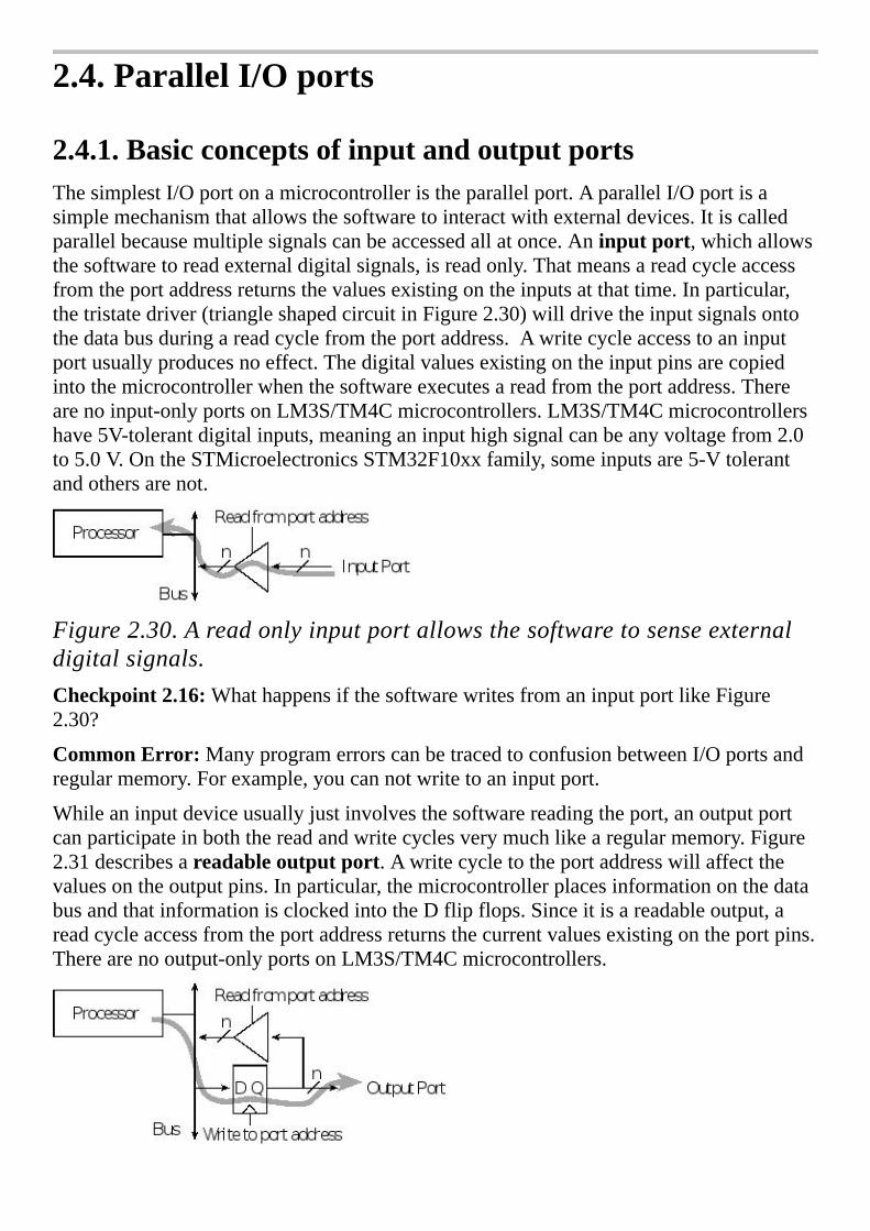
2.4.ParallelI/Oports
2.4.1.BasicconceptsofinputandoutputportsThesimplestI/Oportonamicrocontrolleristheparallelport.AparallelI/Oportisasimplemechanismthatallowsthesoftwaretointeractwithexternaldevices.Itiscalledparallelbecausemultiplesignalscanbeaccessedallatonce.Aninputport,whichallowsthesoftwaretoreadexternaldigitalsignals,isreadonly.Thatmeansareadcycleaccessfromtheportaddressreturnsthevaluesexistingontheinputsatthattime.Inparticular,thetristatedriver(triangleshapedcircuitinFigure2.30)willdrivetheinputsignalsontothedatabusduringareadcyclefromtheportaddress.Awritecycleaccesstoaninputportusuallyproducesnoeffect.Thedigitalvaluesexistingontheinputpinsarecopiedintothemicrocontrollerwhenthesoftwareexecutesareadfromtheportaddress.Therearenoinput-onlyportsonLM3S/TM4Cmicrocontrollers.LM3S/TM4Cmicrocontrollershave5V-tolerantdigitalinputs,meaninganinputhighsignalcanbeanyvoltagefrom2.0to5.0V.OntheSTMicroelectronicsSTM32F10xxfamily,someinputsare5-Vtolerantandothersarenot.
Figure2.30.Areadonlyinputportallowsthesoftwaretosenseexternaldigitalsignals.Checkpoint2.16:WhathappensifthesoftwarewritesfromaninputportlikeFigure2.30?
CommonError:ManyprogramerrorscanbetracedtoconfusionbetweenI/Oportsandregularmemory.Forexample,youcannotwritetoaninputport.
Whileaninputdeviceusuallyjustinvolvesthesoftwarereadingtheport,anoutputportcanparticipateinboththereadandwritecyclesverymuchlikearegularmemory.Figure2.31describesareadableoutputport.Awritecycletotheportaddresswillaffectthevaluesontheoutputpins.Inparticular,themicrocontrollerplacesinformationonthedatabusandthatinformationisclockedintotheDflipflops.Sinceitisareadableoutput,areadcycleaccessfromtheportaddressreturnsthecurrentvaluesexistingontheportpins.Therearenooutput-onlyportsonLM3S/TM4Cmicrocontrollers.

Figure2.31.Areadableoutputportallowsthesoftwaretogenerateexternaldigitalsignals.Checkpoint2.17:WhathappensifthesoftwarereadsfromanoutputportlikeFigure2.31?
Tomakethemicrocontrollermoremarketable,mostportscanbesoftware-specifiedtobeeitherinputsoroutputs.Microcontrollersusetheconceptofadirectionregistertodeterminewhetherapinisaninput(directionregisterbitis0)oranoutput(directionregisterbitis1),asshowninFigure2.32.Wedefineaninitializationritualasaprogramexecutedduringstartupthatinitializeshardwareandsoftware.Iftheritualsoftwaremakesdirectionbitzero,theportbehaveslikeasimpleinput,andifitmakesthedirectionbitone,itbecomesareadableoutputport.Eachdigitalportpinhasadirectionbit.Thismeanssomepinsonaportmaybeinputswhileothersareoutputs.Thedigitalportpinsonmostmicrocontrollersarebidirectional,operatingsimilartoFigure2.32.
Figure2.32.Abidirectionalportcanbeconfiguredasaread-onlyinputportorareadableoutputport.
2.4.2.I/OProgrammingandthedirectionregister

Onmostembeddedmicrocontrollers,theI/Oportsarememorymapped.Thismeansthesoftwareaccessesaninput/outputportsimplybyreadingfromorwritingtotheappropriateaddress.TomakeoursoftwaremorereadableweincludesymbolicdefinitionsfortheI/Oports.Wesetthedirectionregister(e.g., GPIO_PORTD_DIR_R )tospecifywhichpinsareinputandwhichareoutput.Bydefault,thealternatefunctionregisteriszero,specifyingthecorrespondingbitsareregularportpins(e.g., GPIO_PORTD_AFSEL_R ).WewillsetbitsinthealternativefunctionregisterwhenwewishtoactivatethefunctionslistedinTables2.3,2.52.7,and2.8.Typically,wewritetothedirectionandalternatefunctionregistersonceduringtheinitializationphase.Weusethedataregister(e.g., GPIO_PORTD_DATA_R )toperforminput/outputontheport.Conversely,wereadandwritethedataregistermultipletimestoperforminputandoutputrespectivelyduringtherunningphase.Table2.18showstheparallelportregistersfortheTM4C123.TheotherTexasInstrumentsmicrocontrollersaresimilar.TheCR,AMSEL,PCTL,andLOCKregistersexistonlyonLM4F/TM4C.FortheLM3Ssoftware,simplyremoveaccessestothesefourregisters.TheonlydifferencesamongvariousmembersoftheTexasInstrumentsmicrocontrollerfamilayarethenumberofportsandavailablepinsineachport.
Forexample,theTM4C1294hasfifteendigitalI/OportsA(8bits),B(6bits),C(8bits),D(8bits),E(6bits),F(5bits),G(2bits),H(4bits),J(2bits),K(8bits),L(8bits),M(8bits),N(6bits),P(6bits),andQ(5bits).Furthermore,theTM4C1294hasdifferentaddressesforports.Refertothefiletm4c1294ncpdt.hortothedatasheetformorethespecificaddressesofitsI/Oports
ToinitializeanLM3SI/Oportforgeneraluseweperformfoursteps.First,weactivatetheclockfortheport.Second,wesetitsdirectionregister.Third,weclearbitsinthealternatefunctionregister,andlastly,weenablethedigitalport.Weneedtoaddashortdelaybetweenactivatingtheclockandaccessingtheportregisters.Thedirectionregisterspecifiesbitforbitwhetherthecorrespondingpinsareinput(0)oroutput(1).
WeusethePURregistertoactivateaninternalpull-upresistor,andweusethePDRregistertoactivateaninternalpull-downresistor.
CommonError:Youwillgetabusfaultifyouaccessaportwithoutenablingitsclock.Also,youhavetowaitabout5buscyclesafterenablingtheclock,beforeyouaccesstheregisters.

InthisfirstexamplewewillmakePD7-4input,andwewillmakePD3-0output,asshowninProgram2.6.Touseaportwefirstmustactivateitsclockinthe SYSCTL_RCGCGPIO_R register.Thesecondstepistounlocktheport(LM4F/TM4Conly),bywritingaspecialvaluetotheLOCKregister,followedbysettingbitsintheCRregister.PC3-0arelockedtothedebugger.OnlyPD7andPF0ontheTM4C123needtobeunlocked.OntheTM4C1294onlyPD7needstobeunlocked.Alltheotherbitsonthetwomicrocontrollersarealwaysunlocked.Thethirdstepistodisabletheanalogfunctionality(TM4Conly),byclearingbitsintheAMSELregister.ThefourthstepistoselectGPIOfunctionality(LM4F/TM4Conly),byclearingbitsinthePCTLregister,asdescribedinTables2.7and2.8.ThefifthstepistospecifywhetherthepinisaninputoranoutputbyclearingorsettingbitsintheDIRregister.BecauseweareusingthepinsasregulardigitalI/O,thesixthstepistoclearthecorrespondingbitsintheAFSELregister.
Address 7 6 5 4 3 2 1 0 Name
0x400FE608 - - GPIOF GPIOE GPIOD GPIOC GPIOB GPIOA SYSCTL_RCGCGPIO_R
0x400FEA08 - - GPIOF GPIOE GPIOD GPIOC GPIOB GPIOA SYSCTL_PRGPIO_R
0x400043FC DATA DATA DATA DATA DATA DATA DATA DATA GPIO_PORTA_DATA_R
0x40004400 DIR DIR DIR DIR DIR DIR DIR DIR GPIO_PORTA_DIR_R
0x40004420 SEL SEL SEL SEL SEL SEL SEL SEL GPIO_PORTA_AFSEL_R
0x40004510 PUE PUE PUE PUE PUE PUE PUE PUE GPIO_PORTA_PUR_R
0x4000451C DEN DEN DEN DEN DEN DEN DEN DEN GPIO_PORTA_DEN_R
0x40004524 1 1 1 1 1 1 1 1 GPIO_PORTA_CR_R
0x40004528 0 0 0 0 0 0 0 0 GPIO_PORTA_AMSEL_R
0x400053FC DATA DATA DATA DATA DATA DATA DATA DATA GPIO_PORTB_DATA_R
0x40005400 DIR DIR DIR DIR DIR DIR DIR DIR GPIO_PORTB_DIR_R
0x40005420 SEL SEL SEL SEL SEL SEL SEL SEL GPIO_PORTB_AFSEL_R
0x40005510 PUE PUE PUE PUE PUE PUE PUE PUE GPIO_PORTB_PUR_R
0x4000551C DEN DEN DEN DEN DEN DEN DEN DEN GPIO_PORTB_DEN_R
0x40005524 1 1 1 1 1 1 1 1 GPIO_PORTB_CR_R
0x40005528 0 0 AMSEL AMSEL 0 0 0 0 GPIO_PORTB_AMSEL_R
0x400063FC DATA DATA DATA DATA JTAG JTAG JTAG JTAG GPIO_PORTC_DATA_R
0x40006400 DIR DIR DIR DIR JTAG JTAG JTAG JTAG GPIO_PORTC_DIR_R

0x40006420 SEL SEL SEL SEL JTAG JTAG JTAG JTAG GPIO_PORTC_AFSEL_R
0x40006510 PUE PUE PUE PUE JTAG JTAG JTAG JTAG GPIO_PORTC_PUR_R
0x4000651C DEN DEN DEN DEN JTAG JTAG JTAG JTAG GPIO_PORTC_DEN_R
0x40006524 1 1 1 1 JTAG JTAG JTAG JTAG GPIO_PORTC_CR_R
0x40006528 AMSEL AMSEL AMSEL AMSEL JTAG JTAG JTAG JTAG GPIO_PORTC_AMSEL_R
0x400073FC DATA DATA DATA DATA DATA DATA DATA DATA GPIO_PORTD_DATA_R
0x40007400 DIR DIR DIR DIR DIR DIR DIR DIR GPIO_PORTD_DIR_R
0x40007420 SEL SEL SEL SEL SEL SEL SEL SEL GPIO_PORTD_AFSEL_R
0x40007510 PUE PUE PUE PUE PUE PUE PUE PUE GPIO_PORTD_PUR_R
0x4000751C DEN DEN DEN DEN DEN DEN DEN DEN GPIO_PORTD_DEN_R
0x40007524 CR 1 1 1 1 1 1 1 GPIO_PORTD_CR_R
0x40007528 0 0 AMSEL AMSEL AMSEL AMSEL AMSEL AMSEL GPIO_PORTD_AMSEL_R
0x400243FC - - DATA DATA DATA DATA DATA DATA GPIO_PORTE_DATA_R
0x40024400 - - DIR DIR DIR DIR DIR DIR GPIO_PORTE_DIR_R
0x40024420 - - SEL SEL SEL SEL SEL SEL GPIO_PORTE_AFSEL_R
0x40024510 - - PUE PUE PUE PUE PUE PUE GPIO_PORTE_PUR_R
0x4002451C - - DEN DEN DEN DEN DEN DEN GPIO_PORTE_DEN_R
0x40024524 - - 1 1 1 1 1 1 GPIO_PORTE_CR_R
0x40024528 - - AMSEL AMSEL AMSEL AMSEL AMSEL AMSEL GPIO_PORTE_AMSEL_R
0x400253FC - - - DATA DATA DATA DATA DATA GPIO_PORTF_DATA_R
0x40025400 - - - DIR DIR DIR DIR DIR GPIO_PORTF_DIR_R
0x40025420 - - - SEL SEL SEL SEL SEL GPIO_PORTF_AFSEL_R
0x40025510 - - - PUE PUE PUE PUE PUE GPIO_PORTF_PUR_R
0x4002551C - - - DEN DEN DEN DEN DEN GPIO_PORTF_DEN_R
0x40025524 - - - 1 1 1 1 CR GPIO_PORTF_CR_R
0x40025528 - - - 0 0 0 0 0 GPIO_PORTF_AMSEL_R

31-28 27-24 23-20 19-16 15-12 11-8 7-4 3-0
0x4000452C PMC7 PMC6 PMC5 PMC4 PMC3 PMC2 PMC1 PMC0 GPIO_PORTA_PCTL_R
0x4000552C PMC7 PMC6 PMC5 PMC4 PMC3 PMC2 PMC1 PMC0 GPIO_PORTB_PCTL_R
0x4000652C PMC7 PMC6 PMC5 PMC4 0x1 0x1 0x1 0x1 GPIO_PORTC_PCTL_R
0x4000752C PMC7 PMC6 PMC5 PMC4 PMC3 PMC2 PMC1 PMC0 GPIO_PORTD_PCTL_R
0x4002452C ---- ---- PMC5 PMC4 PMC3 PMC2 PMC1 PMC0 GPIO_PORTE_PCTL_R
0x4002552C ---- ---- ---- PMC4 PMC3 PMC2 PMC1 PMC0 GPIO_PORTF_PCTL_R
0x40006520 LOCK(write0x4C4F434Btounlock,otherlocks)(reads1iflocked,0ifunlocked) GPIO_PORTC_LOCK_R
0x40007520 LOCK(write0x4C4F434Btounlock,otherlocks)(reads1iflocked,0ifunlocked) GPIO_PORTD_LOCK_R
0x40025520 LOCK(write0x4C4F434Btounlock,otherlocks)(reads1iflocked,0ifunlocked) GPIO_PORTF_LOCK_R
Table2.18.SomeTM4C123parallelports.Eachregisteris32bitswide.ForPCTLbits,seeTables2.7and2.8.JTAGmeansdonotusethesepinsanddonotchangeanyofthesebits.
ThelaststepistoenablethecorrespondingI/OpinsbywritingonestotheDENregister.TorunthisexampleontheTexasInstrumentsLaunchPad,wealsosetbitsinthePURregisterforthetwoswitchinputs(Figure2.14)tohaveaninternalpull-upresistor.
Whenthesoftwarereadsfromlocation0x400073FCthebottom8bitsarereturnedwiththecurrentvaluesonPortD.Thetop24bitsarereturnedzero.AsshowninFigure2.32,theinputpinsshowthecurrentdigitalstate,andtheoutputpinsshowthevaluelastwrittentotheport.Thefunction PortD_Input willreadfromthefourinputpinsandreturnavalue,0x00to0x0F,dependingonthecurrentstatusoftheinputs.Thefunction PortD_Output willwritenewvaluestothefouroutputpins.
#defineGPIO_PORTD_DATA_R(*((volatileuint32_t*)0x400073FC))
#defineGPIO_PORTD_DIR_R(*((volatileuint32_t*)0x40007400))
#defineGPIO_PORTD_AFSEL_R(*((volatileuint32_t*)0x40007420))
#defineGPIO_PORTD_DEN_R(*((volatileuint32_t*)0x4000751C))
#defineGPIO_PORTD_LOCK_R(*((volatileuint32_t*)0x40007520))
#defineGPIO_PORTD_AMSEL_R(*((volatileuint32_t*)0x40007528))
#defineGPIO_PORTD_PCTL_R(*((volatileuint32_t*)0x4000752C))
#defineSYSCTL_RCGCGPIO_R(*((volatileuint32_t*)0x400FE608))
voidPortD_Init(void)
SYSCTL_RCGCGPIO_R|=0x08;//1)activateclockforPortD

while((SYSCTL_PRGPIO_R&0x08)==0);//ready?
GPIO_PORTD_LOCK_R=0x4C4F434B;//2)unlockGPIOPortD
GPIO_PORTD_CR_R=0xFF;//allowchangestoPD7-0
GPIO_PORTD_AMSEL_R=0x00;//3)disableanalogonPD
GPIO_PORTD_PCTL_R=0x00000000;//4)PCTLGPIOonPD7-0
GPIO_PORTD_DIR_R=0x0F;//5)PD7-4in,PD3-0out
GPIO_PORTD_AFSEL_R=0x00;//6)disablealtfunctonPD7-0
GPIO_PORTD_DEN_R=0xFF;//7)enabledigitalI/OonPD7-0
uint32_tPortD_Input(void)
return(GPIO_PORTD_DATA_R>>4);//readPD7-PD4inputs
voidPortD_Output(uint32_tdata)
GPIO_PORTD_DATA_R=data;//writePD3-PD0outputs
Program2.6.AsetoffunctionsusingPD7 –PD4asinputsandPD3 –PD0asoutputs.Checkpoint2.18:Doestheentireportneedtobedefinedasinputoroutput,orcansomepinsbeinputwhileothersareoutput?
InProgram2.6theassumptionwasthesoftwaremodulehadaccesstoallofPortD.Inotherwords,thissoftwareownedalleightpinsofPortD.Inmostcases,asoftwaremoduleneedsaccesstoonlysomeoftheportpins.Iftwoormoresoftwaremodulesaccessthesameport,aconflictwilloccurifonemodulechangesmodesoroutputvaluessetbyanothermodule.Itisgoodsoftwaredesigntowritefriendlysoftware,whichonlyaffectstheindividualpinsasneeded.Friendlysoftwaredoesnotchangetheotherbitsinasharedregister.Conversely,unfriendlysoftwaremodifiesmorebitsofaregisterthanitneedsto.Thedifficultyofunfriendlycodeiseachmodulewillrunproperlywhentestedbyitself,butweirdbugsresultwhentwoormoremodulesarecombined.
ConsidertheproblemthatasoftwaremoduleneedtooutputtojustPortDbit1.AfterenablingtheclockforPortD,weuseread-modify-writesoftwaretoinitializejustpin1.RememberonlyPD7andPF0requireunlockingontheTM4C123,andonlyPD7requiresunlockingontheTM4C1294,sothiscodedoesnotneedtounlock.
SYSCTL_RCGCGPIO_R|=0x08;//1)activateclockforPortD
while((SYSCTL_PRGPIO_R&0x08)==0);//ready?
GPIO_PORTD_DIR_R|=0x02;//PD1isanoutput
GPIO_PORTD_AFSEL_R&=~0x02;//regularportfunction

GPIO_PORTD_AMSEL_R&=~0x02;//disableanalogonPD1
GPIO_PORTD_PCTL_R&=~0x000000F0;//PCTLGPIOonPD1
GPIO_PORTD_DEN_R|=0x02;//PD1isenabledasadigitalport
ThereisnoconflictiftwoormoremodulesenabletheclockforPortD.TherearetwowaysontheCortexTM-Mtoaccessindividualportbits.Thefirstmethodistouseread-modify-writesoftwaretochangejustpin1.Aread-or-writesequencecanbeusedtosetoneormorebits.
GPIO_PORTD_DATA_R|=0x02;//makePD1high
Aread-and-writesequencecanbeusedtoclearoneormorebits.
GPIO_PORTD_DATA_R&=~0x02;//makePD1low
Thesecondmethodusesthebit-specificaddressing.TheLM3S/LM4F/TM4Cfamilyimplementsamoreflexiblewaytoaccessportpinsthanthebit-bandingdescribedearlierinthechapter.Thisbit-specificaddressingdoesn’tworkforalltheI/Oregisters,justtheparallelportdataregisters.TheLM3S/LM4F/TM4Cmechanismallowscollectiveaccessto1to8bitsinadataport.WedefineeightaddressoffsetconstantsinTable2.19.Basically,ifweareinterestedinbitb,theconstantis4*2b.Thereare256possiblebitcombinationswemightbeinterestedinaccessing,fromallofthemtononeofthem.Eachpossiblebitcombinationhasaseparateaddressforaccessingthatcombination.Foreachbitweareinterestedin,weaddupthecorrespondingconstantsfromTable2.19andthenaddthatsumtothebaseaddressfortheport.ThebaseaddressesforthedataportscanbefoundinGPIOchapterofthemicrocontrollerdatasheet.Forexample,assumeweareinterestedinPortAbits1,2,and3.ThebaseaddressforPortAis0x4000.4000,andtheconstantsare0x0020,0x0010and0x008.Thesumof0x4000.4000+0x0020+0x0010+0x008istheaddress0x4000.4038.Ifwereadfrom0x4000.4038onlybits1,2,and3willbereturned.Ifwewritetothisaddressonlybits1,2,and3willbemodified.
Ifwewishtoaccessbit Constant
7 0x0200
6 0x0100
5 0x0080
4 0x0040
3 0x0020

2 0x0010
1 0x0008
0 0x0004
Table2.19.Addressoffsetsusedtospecifyindividualdataportbits.
ThebaseaddressforPortDis0x4000.7000.Ifwewanttoreadandwriteall8bitsofthisport,theconstantswilladdupto0x03FC.Noticethatthesumofthebaseaddressandtheconstantsyieldsthe0x4000.73FCaddressusedinProgram2.6.Inotherwords,readandwriteoperationsto GPIO_PORTD_DATA_R willaccessall8bitsofPortD.Ifweareinterestedinjustbit1ofPortD,weadd0x0008to0x4000.7000,andwecandefinethisinCas
#definePD1(*((volatileuint32_t*)0x40007008))
Now,asimplewriteoperationcanbeusedtosetPD1.Thefollowingcodeisfriendlybecauseitdoesnotmodifytheother7bitsofPortD.
PD1=0x02;//makePD1high
AsimplewritesequencewillclearPD1.Thefollowingcodeisalsofriendly.
PD1=0x00;//makePD1low
AreadfromPD1 willreturn0x01or0x00dependingonwhetherthepinishighorlow,respectively.Thefollowingcodeisalsofriendly.
PD1=PD1^0x01;//togglePD1
Checkpoint2.19:AccordingtoTable2.3,whathappenstoPortDbit5ifwesetbit5initsalternativefunctionregister?E.g., GPIO_PORTD_AFSEL_R|=0x20;
Checkpoint2.20:Whathappensifwewritetolocation0x4000.7000?
Checkpoint2.21:Specifya#definethatallowsustoaccessbits7and2ofPortD.Usethis#definetomakebothbits7and2ofPortDhigh.
Checkpoint2.22:Specifya#definethatallowsustoaccessbits6,5,0ofPortB.Usethis#definetomakebits6,5and0ofPortBhigh.
YoucanfindthecodeforthenextthreeexamplesonthebookwebsiteasSSR_xxx.zip,GPIO_xxx.zip,andSwitch_xxx.zip,wherexxxreferstothespecificmicrocontrolleronwhichtheexamplewastested.

Example2.1:ThegoalisdevelopameansforthemicrocontrollertoturnonandturnoffanAC-poweredappliance.Theinterfacewilluseasolidstaterelay(SSR)havingacontrolportionequivalenttoanLEDwithparametersof2Vand10mA.Includeappropriatefunctions.
Solution:SinceweneedtointerfaceanLED,weuseanopencollectorNOTgatejustlikeFigure1.23.Wechooseanelectroniccircuitthathasanoutputcurrentlargerthanthe10mAneededbytheSSR.SincethemaximumICEofthePN2222is150mA,itcansinkthe10mArequiredbytheSSR.A7405or7406couldalsohavebeenused,buttheyrequirea+5Vsupply.Theresistorisselectedtocontrolthecurrenttothediode.UsingtheLEDdesignequation,R=(3.3-Vd-VCE)/Id=(3.3-2-0.3V)/0.01A=100 .Thereisastandardvalue5%resistorat100.ThespecificationVCE=0.3Visamaximum.IfVCEisactuallybetween0.1and0.3V,then10to12mAwillflow,andtherelaywillstillactivateproperly.WhentheinputtothePN2222ishigh(p=3.3V),theoutputislow(q=0.3V),seeFigure2.33.Inthisstate,a10mAcurrentisappliedtothediode,andrelayswitchactivates.Thiscauses120VACpowertobedeliveredtotheappliance.But,whentheinputislow(p=0),theoutputfloats(q=HiZ,whichisneitherhighnorlow).ThisfloatingoutputstatecausestheLEDcurrenttobezero,andtherelayswitchopens.Inthiscase,noACpowerisdeliveredtotheappliance.
Figure2.33.SolidstaterelayinterfaceusingaPN2222NPNtransistor.
Theinitializationwillsetbit1ofthedirectionregistertomakePD1anoutput,seeProgram2.7.Thisfunctionshouldbecalledonceatthestartofthesystem.Afterinitialization,theonandofffunctionscanbecalledtocontroltheappliance.
#definePD1(*((volatileuint32_t*)0x40007008))
voidSSR_Init(void)
SYSCTL_RCGCGPIO_R|=0x08;//1)activateclockforPortD
while((SYSCTL_PRGPIO_R&0x08)==0);//ready?
GPIO_PORTD_DIR_R|=0x02;//PD1isanoutput
GPIO_PORTD_AFSEL_R&=~0x02;//regularportfunction
GPIO_PORTD_AMSEL_R&=~0x02;//disableanalogonPD1
GPIO_PORTD_PCTL_R&=~0x000000F0;//PCTLGPIOonPD1
GPIO_PORTD_DEN_R|=0x02;//PD1isenabledasadigitalport

voidSSR_Off(void)
PD1=0x00;//turnofftheappliance
voidSSR_On(void)
PD1=0x01;//turnontheappliance
Program2.7.AsetoffunctionsusingPD7 –PD4asinputsandPD3 –PD0asoutputs(SSR_xxx.zip).
Someproblemsaresouniquethattheyrequiretheengineertoinventcompletelyoriginalsolutions.Mostofthetime,however,theengineercansolveevencomplexproblemsbybuildingthesystemfromcomponentsthatalreadyexist.Creativitywillstillberequiredinselectingthepropercomponents,makingsmallchangesintheirbehavior(tweaking),arrangingtheminaneffectiveandefficientmanner,andthenverifyingthesystemsatisfiesboththerequirementsandconstraints.Whenyoungengineersbegintheirfirstjob,theyaresometimessurprisedtoseethateducationdoesnotstopwithcollegegraduation,butratherisalife-longactivity.Infact,itistheeducationalgoalofallengineerstocontinuetolearnbothprocesses(rulesabouthowtosolveproblems)andproducts(hardwareandsoftwarecomponents).Astheengineerbecomesmoreexperienced,heorshehasalargertoolboxfromwhichprocessesandcomponentscanbeselected.
Thehardeststepformostnewengineersisthefirstone:wheretobegin?Webeginbyanalyzingtheproblemtocreateasetofspecificationsandconstraintsintheformofarequirementsdocument.Next,welookforcomponents,intheformofpreviouslydebuggedsolutions,whicharesimilartoourneeds.Oftenduringthedesignprocess,additionalquestionsorconcernsarise.Weatthatpointconsultwithourclientstoclarifytheproblem.Nextwerewritetherequirementsdocumentandgetitreapprovedbytheclients.
Itisoftendifficulttodistinguishwhetheraparameterisaspecificationoraconstraint.Inactuality,whendesigningasystemitoftendoesn’tmatterintowhichcategoryaparameterfalls,becausethesystemmustsatisfyallspecificationsandconstraints.Nevertheless,whendocumentingthedeviceitisbettertocategorizeparametersproperly.Specificationsgenerallydefineinaquantitativemannertheoverallsystemobjectivesasgiventousbyourcustomers.

Constraints,ontheotherhand,generallydefinetheboundaryspacewithinwhichwemustsearchforasolutiontotheproblem.Ifwemustuseaparticularcomponent,itisoftenconsideredaconstraint.Inthisbook,weconstrainmostdesignstoincludeanLM3S/TM4Cmicrocontroller.Constraintsalsoareoftendefinedasaninequality,suchasthecostmustbelessthan$50,orthebatterymustlastforatleastoneweek.Specificationsontheotherhandareoftendefinedasaquantitativenumber,andthesystemsatisfiestherequirementifthesystemoperateswithinaspecifiedtoleranceofthatparameter.Tolerancecanbedefinedasapercentageerrororasarangewithminimumandmaximumvalues.
Thehigh-leveldesignusesdataflowgraphs.Wethencombinethepiecesanddebugthesystem.Asthepiecesarecombinedwecandrawacallgraphtoorganizetheparts.Ifnewcomponentsaredesigned,wecanuseflowchartstodevelopnewalgorithms.Themorewecansimulatethesystem,themoredesignpossibilitieswecanevaluate,andthequickerwecanmakechanges.Debugginginvolvesbothmakingsureitworks,togetherwithsatisfyingallrequirementsandconstraints.
Observation:Definingrealistictolerancesonourspecificationswillhaveaprofoundeffectonsystemcost.
Checkpoint2.23:Whataretheeffectsofspecifyingatightertolerance(e.g.,1%whentheproblemaskedfor5%)?
Checkpoint2.24:Whataretheeffectsofspecifyingaloosertolerance(e.g.,10%whentheproblemaskedfor5%)?
Example2.2:DesignanembeddedsystemthatflashesLEDsina0101,0110,1010,1001binaryrepeatingpattern.
Solution:ThissystemwillneedfourLEDs,andthecomputermustbeabletoactivate/deactivatethem.Sincetheproblemdidn’tspecifypowersource,speed,color,orbrightness,wecouldeitherputoffthesedecisionsuntiltheengineeringdesignstageinordertosimplifythedesignorminimizecost,orwecouldgobacktotheclientsandaskforadditionalrequirements.Inthiscase,theclientsdidn’tcareaboutpower,speed,colororbrightness,butdidthinkminimizingcostwasagoodidea.Duetothenatureofthisbook,wewillconstrainalldesignstoincludeaLM3S/TM4Cmicrocontroller.Becausewehave+3.3Vmicrocontrollersystems,wewillspecifythesystemtorunon+3.3Vpower.WehaveinstockHLMP-4740greenLEDsthatoperateat1.9Vand2mA,sowewillusethem.Table2.20summarizesthespecificationsandconstraints.Wewillusestandard5%resistorstominimizecost.
Specifications Constraints
Repeatingpatternof5,6,10,9
TM4C123-based

Four1.9V,2mAgreenLEDs
Minimizecost
+3.3Vpowersupply Standard5%resistors
Table2.20.SpecificationsandconstraintsoftheLEDoutputsystem.
ToleranceforthisLEDoutputsystemsaysitisacceptableifithasfourLEDs,butunacceptableifithasthreeorfiveofthem.Similarly,itwillbeacceptableaslongastheLEDcurrentisbetween1.5and2.5mA.Ifthecurrentdropsbelow1.5mA,wewon’tbeabletoseetheLED,andifitgoesabove2.5mA,itmightdamagetheLED.ThedataflowgraphinFigure2.34showsinformationasitflowsfromthecontrollersoftwaretothefourLEDs.Thedataflowgraphwillbeimportantduringthesubsequentdesignphasesbecausethehardwareblockscanbeconsideredasapreliminaryhardwareblockdiagramofthesystem.Thecallgraph,alsoshowninFigure2.34,illustratesthisismaster/slaveconfigurationwherethecontrollersoftwarewillmanipulatethefourLEDs.
Figure2.34.DataflowgraphandcallgraphoftheLEDoutputsystem.
ThehardwaredesignofthissystemcouldhaveusedfourcopiesoftheLEDinterfacepresentedearlierinFigure1.23.However,fromTable1.4weseeLM3S/TM4Cmicrocontrollerscansourceorsinkupto8mA.Wecansavemoneybyusinglow-currentLEDs,whichcanbeconnecteddirectlytothemicrocontrollerwithoutadriver.Figure2.35showsfoursimplenegativelogicLEDinterfaces.AlowoutputwillturnontheLEDandahighoutputwillturnitoff.NoticethesimilarityofthedataflowgraphinFigure2.34withthehardwarecircuitinFigure2.35.IftheVOLofthemicrocontrolleris0.4V,andthevoltageacrosstheLEDis1.9V,thenthevoltageacrosstheresistorshouldbe3.3-1.9-0.4Vor1V.WecalculatetheresistorvalueusingOhm’sLaw,Ris1V/2mAor500Ω.Usingstandardresistorvalueswitha5%tolerancewillbecheapertobuild(seeSection9.1).Inparticular,470Ωand510Ωaretwostandardresistorvaluesnear500Ω.Ifweweretouse470Ω,thentheLEDcurrentwouldbe(3.3-1.9-0.4V)/470Ωor2.1mA.Similarly,ifweweretouse510Ω,thentheLEDcurrentwouldbe(3.3-1.9-0.4V)/510Ωor1.96mA.Bothwouldhavebeenacceptable,butwewillusethe510Ωresistorbecauseitisacceptableforawiderangeofmicrocontrolleroutputvoltages.Morespecifically,ifVOLrangesfrom0.13to0.63V,thentheLEDcurrentremainswithinthe1.5to2.5mA

specification.Itwouldhavebeenmoreexpensivetouse500Ωresistors.
Pseudo-codeissimilartohigh-levellanguages,butwithoutarigidsyntax.Thismeansweutilizewhateversyntaxwelike.Flowchartsaregoodwhenthesoftwareinvolvescomplexalgorithmswithmanydecisionspointscausingcontrolpaths.Ontheotherhand,pseudo-codemaybebetterwhenthesoftwareismoresequentialandinvolvescomplexmathematicalcalculations.
Figure2.35.HardwarecircuitfortheLEDoutputsystem.
Thesoftwaredesignofthissystemalsoinvolvesusingexamplespresentedearlierwithsomeminortweaking.Theonlydatarequiredinthisproblemisthe5–6–10–9sequence.LaterinChapter3,wewillconsidersolutionstothistypeofproblemusingdatastructures,butinthisfirstexample,wewilltakeasimpleapproach,notusingadatastructure.Figure2.36illustratesasoftwaredesignprocessusingflowcharts.Westartwithgeneralapproachontheleft.Flowchart1showsthesoftwarewillinitializetheoutputport,andperformtheoutputsequence.Aswedesignthesoftwaresystem,wefillinthedetails.Thisdesignprocessiscalledsuccessiverefinement.Itisalsoclassifiedastop-down,becausewebeginwithhigh-levelissues,andendatthelow-level.InFlowchart2,wesetthedirectionregister,andthenoutputthesequence5–6–10–9.Itisatthisstagewefiguredouthowtocreatetherepeatingsequence.Flowchart3fillsintheremainingdetails.Tooutputthenegativelogicpattern1010totheLEDs,wewilloutputa5tothebottom4bitsofPortEonthemicrocontroller.
Manysoftwaredevelopersusepseudo-coderatherthanflowcharts,becausethepseudo-codeitselfcanbeembeddedintothesoftwareascomments.Program2.8showstheCimplementationforthissystem.NoticethesimilarityinstructurebetweenFlowchart3andthiscode.The LEDS definitionimplementsfriendlyaccesstopinsPE3–PE0.
Inordertotestthesystemweneedtobuildaprototype.Oneoptionissimulation.AsecondoptionistouseadevelopmentsystemliketheonesshowninFigures2.10,2.13and2.18.Inthisapproach,youbuildtheexternalcircuitsonaprotoboardandusethedebuggertodownloadandtestthesoftware.Athirdapproachistypicallyusedafterasuccessfulevaluationwithoneofthepreviousmethods.Inthisapproach,wedesignaprintedcircuitboard(PCB)includingboththeexternalcircuitsandthemicrocontrolleritself.
DuringthetestingphaseoftheprojectweobservethatallfouroftheLEDsare

continuouslyon.Weusethesoftwaredebuggertosinglestepourprogram,whichcorrectlyoutputsthe1010,1001,0101,0110binaryrepeatingpattern.DuringthissinglesteppingtheLEDsdocomeonandoffintheproperpattern.Usingavoltmeteronthecircuitweobservea0.25Vsignalontheoutputofthemicrocontrolleranda1.9VvoltagedropacrossthediodewheneverthesoftwarewishestoturntheLEDon.BecausetheLEDsareflashingfasterthanoureyescansee,wetestthesystematfullspeedandobservethefouroutputsonalogicanalyzer,collectingdatapresentedasFigure2.37.IfwewishedtobeabletoseetheLEDsflashwithoureyes,wecouldadda0.1seconddelayaftereachoutput.
Portabilityisameasureofhoweasyitistoconvertsoftwarethatrunsononemachinetorunonanothermachine.IngeneralCcodeismoreportablethanassemblylanguage.
Figure2.36.SoftwaredesignfortheLEDoutputsystemusingflowcharts.
#defineLEDS(*((volatileuint32_t*)0x4002403C))
intmain(void)
SYSCTL_RCGCGPIO_R|=0x10;//1)activateclockforPortE
while((SYSCTL_PRGPIO_R&0x10)==0);//ready?
GPIO_PORTE_DIR_R|=0x0F;//PE3-0isanoutput
GPIO_PORTE_AFSEL_R&=~0x0F;//regularportfunction
GPIO_PORTE_AMSEL_R&=~0x0F;//disableanalogonPE3-0
GPIO_PORTE_PCTL_R&=~0x0000FFFF;//PCTLGPIOonPE3-0
GPIO_PORTE_DEN_R|=0x0F;//PE3-0enabledasadigitalport
while(1)
LEDS=10;//1010,LEDis0101
LEDS=9;//1001,LEDis0110
LEDS=5;//0101,LEDis1010

LEDS=6;//0110,LEDis1001
Program2.8.CsoftwarefortheLEDoutputsystem(GPIO_xxx.zip).
Figure2.37.LogicanalyzerwaveformscollectedduringthetestingtheLEDoutputsystem.
Example2.3:Interfaceapushbuttonswitchtothemicrocontrollerandwritesoftwarefunctionsthatinitializeandreadtheswitch.
Solution:Thefirststepistodrawahardwarecircuitconnectingtheswitchtoaninputportofthemicrocontroller.Wewillusepositivelogicinterfacebecausewewantthedigitalsignaltobehighifandonlyiftheswitchispressed,asshowninFigure2.38.SimilartoFigure1.24, PB1 containsasignalthatishighorlowdependingonthepositionoftheswitch.Iftheswitchisnotpressed,the10k resistorcreatesa0Vsignalontheportpin,andvirtuallynocurrentflowsthroughtheresistor(IILis2 A).Iftheswitchispressed,a3.3Vsignalisontheportpinand0.33mAflowsthroughthe10k resistor.Someswitchesbounce,whichmeanstherewillbemultipleopen/closedcycleswhentheswitchischanged.Thissimplesolutioncanbeusediftheswitchdoesn’tbounceorifthebouncingdoesn’tmatter.Thesoftwaresolutionrequirestwofunctions.Theinitializationfunctioniscalledoncewhenthesystemstarts.Wheneverthesoftwarewishestoknowtheswitchstatus,itcallstheinputfunction.WhenthecomputerreadsPortBitgetsall8bitsoftheinputport.ThefollowingCcodewillsetavariabletotrue(nonzero)ifandonlyiftheswitchispressed.
Pressed=GPIO_PORTB_DATA_R&0x02;//trueiftheswitchispressed
Figure2.38.Positivelogicinterfaceofaswitchtoamicrocontrollerinput.

TheinitializationinProgram2.9activatestheclock,clearsthedirectionregisterbitforPB1,andenablesPortBbit1asadigitalport.Thedefinitionof PB1 inProgram2.9usesbit-specificaddressingsothesoftwarejustseesbit1.
#definePB1(*((volatileuint32_t*)0x40005008))
voidSwitch_Init(void)
SYSCTL_RCGCGPIO_R|=0x02;//1)activateclockforPortB
while((SYSCTL_PRGPIO_R&0x02)==0);//ready?
GPIO_PORTB_DIR_R&=~0x02;//PB1isaninput
GPIO_PORTB_AFSEL_R&=~0x02;//regularportfunction
GPIO_PORTB_AMSEL_R&=~0x02;//disableanalogonPB1
GPIO_PORTB_PCTL_R&=~0x000000F0;//PCTLGPIOonPB1
GPIO_PORTB_DEN_R|=0x02;//PB3-0enabledasadigitalport
uint32_tSwitch_Input(void)
returnPB1;//0x02ifpressed,0x00ifnotpressed
Program2.9.AsetoffunctionsthatinterfaceaninputswitchtoPB1(Switch_xxx.zip).

2.5.Phase-Lock-LoopNormally,theexecutionspeedofamicrocontrollerisdeterminedbyanexternalcrystal.BothLaunchPadboardshavea16MHzcrystal.Mostmicrocontrollershaveaphase-lock-loop(PLL)thatallowsthesoftwaretoadjusttheexecutionspeedofthecomputer.Typically,thechoiceoffrequencyinvolvesthetradeoffbetweensoftwareexecutionspeedandelectricalpower.Inotherwords,slowingdownthebusclockwillrequirelesspowertooperateandgeneratelessheat.Speedingupthebusclockobviouslyallowsformorecalculationspersecondatthecostofrequiringmorepowertooperateandgeneratingmoreheat.
ThedefaultbusspeedofanLM3S811microcontrolleristhatofthecrystalattachedtotheOSC1andOSC0pins,meaningthePLLisinitiallynotactiveThedefaultbusspeedofanLM3S1968andTM4Cmicrocontrollersisthatoftheinternaloscillator,alsomeaningthatthePLLisnotinitiallyactive.ThedefaultbusspeedfortheTM4Cinternaloscillatoris16MHz±1%.Theinternaloscillatorissignificantlylessprecisethanthecrystal,butitrequireslesspoweranddoesnotneedanexternalcrystal.ThismeansformostapplicationswewillactivatethemainoscillatorandthePLLsowecanhaveastablebusclock.
TherearetwowaystoactivatethePLL.Wecouldcallalibraryfunction,orwecouldaccesstheclockregistersdirectly.Ingeneral,usinglibraryfunctionscreatesabetterdesignbecausethesolutionwillbemorestable(lessbugs)andwillbemoreportable(easiertoswitchmicrocontrollers).However,theobjectiveofthebookistopresentmicrocontrollerfundamentals.ShowingthedirectaccessdoesillustratesomeconceptsofthePLL.First,wecanincludetheStellaris/Tivalibraryandcallthe SysCtlClockSetfunctiontochangethespeed.Thisfunctionisdefinedinthesysctl.cfile.ThelibraryfunctionactivatesthePLLbecauseofthe SYSCTL_USE_PLL parameter.Themainoscillatoristheonewiththeexternalcrystalattached.Thelastparameterspecifiesthefrequencyoftheattachedcrystal.AssumewewishtorunanTM4Cwitha16MHzcrystalat80MHz.Thedivideby2.5createsabusfrequencyof80MHz,implementedas400MHzdividedby5.
SysCtlClockSet(SYSCTL_SYSDIV_2_5|SYSCTL_USE_PLL|
SYSCTL_OSC_MAIN|SYSCTL_XTAL_16MHZ);
Tomakeourcodemoreportable,itisagoodideatouselibraryfunctionswheneverpossible.However,wewillpresentanexplicitexampleillustratinghowthePLLworks.AnexternalcrystalisattachedtotheTM4Cmicrocontroller,asshowninFigure2.39.ThePLLsontheotherTexasInstrumentsmicrocontrollersoperateinthesamebasicmanner.Table2.21showstheclockregistersusedtodefinewhatspeedtheprocessoroperates.Theoutputofthemainoscillator(MainOsc)isaclockatthesamefrequencyasthecrystal.BysettingtheOSCSRCbitsto0,themultiplexercontrolwillselectthemainoscillatorastheclocksource.
Forexample,themainoscillatorfortheTM4Contheevaluationboardwillbe16MHz.Thismeansthereferenceclock(RefClk)inputtothephase/frequencydetectorwillbe16

MHz.Fora16MHzcrystal,wesettheXTALbitsto10101(seeTable2.21).Inthisway,a400MHzoutputofthevoltagecontrolledoscillator(VCO)willyielda16MHzclockattheotherinputofthephase/frequencydetector.Ifthe400MHzclockistooslow,theupsignalwilladdcharge,increasingtheinputtotheVCO,leadingtoanincreaseinthe400MHzfrequency.Ifthe400MHzclockistoofast,downsignaltothechargepumpwillsubtractcharge,decreasingtheinputtotheVCO,leadingtoadecreaseinthe400MHzfrequency.ThefeedbackloopinthePLLwilldrivetheoutputtoastable400MHzfrequency.
Figure2.39.BlockdiagramofthemainclocktreeontheTM4CincludingthePLL(othersaresimilar).Program2.10showsaprogramtoactivateamicrocontrollerwitha16MHzmainoscillatortorunat80MHz.0)UseRCC2becauseitprovidesformoreoptions.1)ThefirststepissetBYPASS2(bit11).AtthispointthePLLisbypassedandthereisnosystemclockdivider.2)ThesecondstepistospecifythecrystalfrequencyinthefourXTALbitsusingthecodeinTable2.21.TheOSCSRC2bitsareclearedtoselectthemainoscillatorastheoscillatorclocksource.3)ThethirdstepistoclearPWRDN2(bit13)toactivatethePLL.4)Thefourthstepistoconfigureandenabletheclockdividerusingthe7-bitSYSDIV2field.Ifthe7-bitSYSDIV2isn,thentheclockwillbedividedbyn+1.Togetthedesired80MHzfromthe400MHzPLL,weneedtodivideby5.So,weplacea4intotheSYSDIV2field.5)ThefifthstepistowaitforthePLLtostabilizebywaitingforPLLRIS(bit6)inthe SYSCTL_RIS_R tobecomehigh.6)ThelaststepistoconnectthePLLbyclearingtheBYPASS2bit.Tomodifythisprogramtooperateonothermicrocontrollers,youwillneedtochangeXTALandtheSYSDIV2.
XTAL CrystalFreq(MHz)
XTAL CrystalFreq(MHz)
0x4 3.579545MHz 0x10 10.0MHz
0x5 3.6864MHz 0x11 12.0MHz

0x6 4MHz 0x12 12.288MHz
0x7 4.096MHz 0x13 13.56MHz
0x8 4.9152MHz 0x14 14.31818MHz
0x9 5MHz 0x15 16.0MHz
0xA 5.12MHz 0x16 16.384MHz
0xB 6MHz(resetvalue)
0x17 18.0MHz
0xC 6.144MHz 0x18 20.0MHz
0xD 7.3728MHz 0x19 24.0MHz
0xE 8MHz 0x1A 25.0MHz
0xF 8.192MHz others reserved
Address 26-23 22 13 11 10-6 5-4 Name
$400FE060 SYSDIV USESYSDIV PWRDN BYPASS XTAL OSCSRC SYSCTL_RCC_R
$400FE050 PLLRIS SYSCTL_RIS_R
31 30 28-22 13 11 6-4
$400FE070 USERCC2 DIV400 SYSDIV2 PWRDN2 BYPASS2 OSCSRC2 SYSCTL_RCC2_R
Table2.21.Mainclockregisters(RCC2inLM4F/TM4Conly)(othervaluesofXTALarereserved).
voidPLL_Init(void)
SYSCTL_RCC2_R|=0x80000000;//0)UseRCC2
SYSCTL_RCC2_R|=0x00000800;//1)bypassPLLwhileinitializing
SYSCTL_RCC_R=(SYSCTL_RCC_R&~0x000007C0)+0x00000540;//2)16MHz
SYSCTL_RCC2_R&=~0x00000070;//configureformainoscillatorsource
SYSCTL_RCC2_R&=~0x00002000;//3)activatePLLbyclearingPWRDN
SYSCTL_RCC2_R|=0x40000000;//4)use400MHzPLL

SYSCTL_RCC2_R=(SYSCTL_RCC2_R&~ 0x1FC00000)+(4<<22);//80MHz
while((SYSCTL_RIS_R&0x00000040)==0);//5)waitforthePLLtolock
SYSCTL_RCC2_R&=~0x00000800;//6)enablePLLbyclearingBYPASS
Program2.10.ActivatetheLM4F/TM4Cwitha16MHzcrystaltorunat80MHz(PLL_xxx.zip).Checkpoint2.25:HowwouldyouchangeProgram2.10ifyourLM4F/TM4Cmicrocontrollerhadan8MHzcrystalandyouwishtorunat50MHz?
Wecanmakeafirstorderestimateoftherelationshipbetweenworkdoneinthesoftwareandelectricalpowerrequiredtorunthesystem.Therearetwofactorsinvolvedintheperformanceofsoftware.Wedefinesoftwareworkasthedesiredactionsperformedbyexecutingsoftware:
Softwarework=algorithm*speed(ininstructions/sec)
Inotherwords,ifwewanttoimprovesoftwareperformancewecanwritebettersoftwareorincreasetherateatwhichthecomputerexecutesinstructions.RecallthatthecompilerconvertsourCsoftwareintoCortexMmachinecode,sotheefficiencyofthecompilerwillalsoaffectthisrelationship.Furthermore,mostcompilershaveoptimizationsettingsthatallowyoutomakeyoursoftwarerunfasterattheexpenseofusingmorememory.OntheCortexM,mostinstructionsexecutein1or2buscycles.Seesection3.3inCortexM4_TRM_r0p1.pdfformoredetails.InCMOSlogic,mostoftheelectricalpowerrequiredtorunthesystemoccursinmakingsignalschange,thatis,whenadigitalsignalrisesfrom0to1,orfallsfrom1to0.Thereforeweseealinearrelationshipbetweenbusfrequencyandelectricalpower.Letmbetheslopeofthislinearrelationship
Power=m*fBusSomeofthefactorsthataffecttheslopemareoperatingvoltageandfundamentalbehaviorofhowtheCMOStransistorsaredesigned.IfweapproximatetheCortexMprocessorasbeingabletoexecuteoneinstructioneverytwobuscycles,wecancombinetheabovetwoequationstoseethespeed-powertradeoff.
Softwarework=algorithm*½fBus=algorithm*½Power/m
Observation:Tosavepower,weslowdownthebusfrequencyremovingasmuchofthewastedbuscycleswhilestillperformingalloftherequiredtasks.

2.6.SysTickTimerSysTickisasimplecounterthatwecanusetocreatetimedelaysandgenerateperiodicinterrupts.ItexistsonallCortexTM-Mmicrocontrollers,sousingSysTickmeansthesystemwillbeeasytoporttoothermicrocontrollers.Table2.22showssomeoftheregisterdefinitionsforSysTick.CURRENTisa24-bitdowncounterthatrunsatthebusclockfrequency.
Address 31-24
23-17
16 15-3 2 1 0 Name
$E000E010 0 0 COUNT 0 CLK_SRC INTEN ENABLE NVIC_ST_CTRL_R
$E000E014 0 24-bitRELOADvalue NVIC_ST_RELOAD_R
$E000E018 0 24-bitCURRENTvalueofSysTickcounter NVIC_ST_CURRENT_R
Table2.22.SysTickregisters.
TherearefourstepstoinitializetheSysTicktimer.First,wecleartheENABLEbittoturnoffSysTickduringinitialization.Second,wesettheRELOADregister.Third,wewritetothe NVIC_ST_CURRENT_R valuetoclearthecounter.Lastly,wewritethedesiredmodetothecontrolregister,NVIC_ST_CTRL_R .WesettheCLK_SRCbitspecifyingthecoreclockwillbeused.WemustsetCLK_SRC=1,becauseCLK_SRC=0modeisnotimplementedontheLM3Sfamily.LM4F/TM4CmicrocontrollersdosupportCLK_SRC=0internaloscillatormode.InChapter5,wewillsetINTENtoenableinterrupts,butinthisfirstexampleweclearINTENsointerruptswillnotberequested.WeneedtosettheENABLEbitsothecounterwillrun.WhentheCURRENTvaluecountsdownfrom1to0,theCOUNTflagisset.Onthenextclock,theCURRENTisloadedwiththeRELOADvalue.Inthisway,theSysTickcounter(CURRENT)iscontinuouslydecrementing.IftheRELOADvalueisn,thentheSysTickcounteroperatesatmodulon+1(…n,n-1,n-2…1,0,n,n-1,…).Inotherwords,itrollsovereveryn+1counts.TheCOUNTflagcouldbeconfiguredtotriggeraninterrupt.However,inthisfirstexampleinterruptswillnotbegenerated.WesetRELOADto0x00FFFFFFforageneralcounter.Foradelaytimeroraperiodicinterruptthevalue(RELOAD+1)*busperiodwilldeterminethedelaytimeorinterruptperiod.IfweactivatethePLLtorunthemicrocontrollerat80MHz,thentheSysTickcounterdecrementsevery12.5ns.Ingeneral,iftheperiodofthecorebusclockist,thentheCOUNTflagwillbesetevery(n+1)t.Readingthe NVIC_ST_CTRL_R controlregisterwillreturntheCOUNTflaginbit16,andthencleartheflag.Also,writinganyvaluetothe NVIC_ST_CURRENT_R registerwillresetthecountertozeroandcleartheCOUNTflag.
Program2.11usestheSysTicktimertoimplementatimedelay.Forexample,theusercalls SysTick_Wait10ms(123); andthefunctionreturns1.23secondslater.Inthefunction SysTick_Wait() ,the NVIC_ST_RELOAD_R valueissettospecifythedelay.WritingtoCURRENTclearstheCOUNTflagandreloadsthecounter.Whenthecountergoesfrom1to0,theflagCOUNTisset.

TheaccuracyofSysTickdependsontheaccuracyoftheclock.WeusethePLLtoderiveabusclockbasedonthe16MHzcrystal,thetimemeasuredorgeneratedusingSysTickwillbeveryaccurate.Morespecifically,theaccuracyoftheNX5032GAcrystalontheLaunchPadboardis±50partspermillion(PPM),whichtranslatesto0.005%,whichisabout±5secondsperday.Onecouldspendmoremoneyonthecrystalandimprovetheaccuracybyafactorof10.Notonlyarecrystalsaccurate,theyarestable.TheNX5032GAcrystalwillvaryonly±150PPMastemperaturevariesfrom-40to+150ºC.Crystalsaremorestablethantheyareaccurate,typicallyvaryingbylessthan5PPMperyear.
#defineNVIC_ST_CTRL_R(*((volatileuint32_t*)0xE000E010))
#defineNVIC_ST_RELOAD_R(*((volatileuint32_t*)0xE000E014))
#defineNVIC_ST_CURRENT_R(*((volatileuint32_t*)0xE000E018))
voidSysTick_Init(void)
NVIC_ST_CTRL_R=0;//1)disableSysTickduringsetup
NVIC_ST_RELOAD_R=0x00FFFFFF;//2)maximumreloadvalue
NVIC_ST_CURRENT_R=0;//3)anywritetocurrentclearsit
NVIC_ST_CTRL_R=0x00000005;//4)enableSysTickwithcoreclock
voidSysTick_Wait(uint32_tdelay)//delayisin12.5nsunits
NVIC_ST_RELOAD_R=delay-1;//numberofcountstowait
NVIC_ST_CURRENT_R=0;//anyvaluewrittentoCURRENTclears
while((NVIC_ST_CTRL_R&0x00010000)==0)//waitforCOUNTflag
voidSysTick_Wait10ms(uint32_tdelay)//delayisin10msunits
uint32_ti;
for(i=0;i<delay;i++)
SysTick_Wait(800000);//800000*12.5nsequals10ms
Program2.11.Timerfunctionsthatimplementatimedelay(SysTick_xxx.zip).Checkpoint2.26:Howwouldyouchange SysTick_Wait10ms inProgram2.11ifyourmicrocontrollerwererunningat50MHz?
2.7.ChoosingaMicrocontrollerIchosetofocusthisbookontheLM3S/TM4Cfamilyofmicrocontrollers,becauseithasarichsetoffeaturesneededtoteachthefundamentalsrequiredforbothtoday’sandtomorrow’sembeddedsystems.Sometimes,thecomputerengineerisfacedwiththetaskofselectingthemicrocontrollerfortheproject.Whenfacedwiththisdecisionsomeengineerswillonlyconsiderthosedevicesforwhichtheyhavehardwareandsoftwareexperience.Fortunately,thisblindapproachoftenstillyieldsaneffectiveandefficientproduct,becausemanymicrocontrollersoverlapintheircostandperformance.Inotherwords,ifafamiliarmicrocontrollercanimplementthedesiredfunctionsfortheproject,thenitisoftenefficienttobypassthatmoreperfectpieceofhardwareinfavorofafasterdevelopmenttime.Ontheotherhand,sometimeswewishtoevaluateallpotentialcandidates.Itmaybecost-effectivetohireortraintheengineeringpersonnelsothattheyareproficientinawidespectrumofpotentialmicrocontrollerdevices.Therearemanyfactorstoconsiderwhenselectingamicrocontroller.
Afirstgroupoffactorsdealswithcost,maintenanceandproduction:
•Laborcostsincludestraining,development,andtesting
•Materialcostsincludespartsandsupplies
•Manufacturingcostsdependonthenumberandcomplexityofthecomponents
•Maintenancecostsinvolverevisionstofixbugsandperformupgrades
•Secondsourceavailability
Asecondgroupoffactorsdealswithmemoryandtheprocessor:
•ROMsizemustbebigenoughtoholdinstructionsandfixeddataforthesoftware
•RAMsizemustbebigenoughtoholdlocals,parameters,andglobalvariables
•EEPROMtoholdnonvolatilefixedconstantsthatarefield-configurable
•Processormustbecapableofperformingallcalculationsinrealtime
•8-,16-,or32-bitdatasizeshouldmatchmostofthedatatobeprocessed
•Numericaloperationslikemultiply,divide,saturation,floatingpoint
•Specialfunctionslikemultiply/accumulate,fuzzylogic,complexnumbers
•Availabilityofhigh-levellanguagecross-compilers,simulators,anddebuggers
Athirdgroupoffactorsdealswithinputandoutput:
•I/Obandwidthdeterminestheinput/outputrate
•Parallelportsfortheinput/outputdigitalsignals

•SerialportstointerfacewithothercomputersorI/Odevices
•Timerfunctionstogeneratesignals,measurefrequency,andmeasureperiod
•Pulsewidthmodulationfortheoutputsignalsinmanycontrolapplications
•ADCthatisusedtoconvertanaloginputstodigitalnumbers
•DACthatisusedtoconvertdigitalnumberstoanalogoutputs
•SpecialI/OfunctionssuchasCAN,EthernetandUSB
Afourthgroupoffactorsdealswithsystemleveldesign:
•Packagesizeandenvironmentalissuesaffectmanyembeddedsystems
•Powerrequirementsbecausemanysystemswillbebatteryoperated
Whenconsideringspeeditisbesttocomparetimetoexecuteabenchmarkprogramsimilartoyourspecificapplication,ratherthanjustcomparingbusfrequency.Oneofthedifficultiesisthatthemicrocontrollerselectiondependsonthespeedandsizeofthesoftware,butthesoftwarecannotbewrittenwithoutthecomputer.Giventhisuncertainty,itisbesttoselectafamilyofdeviceswitharangeofexecutionspeedsandmemoryconfigurations.Inthiswayaprototypesystemwithlargeamountsofmemoryandperipheralscanbepurchasedforsoftwareandhardwaredevelopment,andoncethedesignisinitsfinalstages,thespecificversionofthecomputercanbeselectednowknowingthememoryandspeedrequirementsfortheproject.Inconclusion,whilethisbookfocusesontheARM ® CortexTM-Mmicrocontrollers,itisexpectedthatoncethestudyofthisbookiscompleted,thereaderwillbeequippedwiththeknowledgetoselectthepropermicrocontrollerandcompletethesoftwaredesign.

2.8.Exercises2.1WhatisspecialaboutRegister13?Register14?Register15?
2.2In20wordsorlessdescribethedifferencesbetweenvonNeumannandHarvardarchitectures.
2.3WhathappenswhenyouloadavalueintoRegister15withbit0set?
2.4WriteCcodethatsetsbit31ofmemorylocation0x2000.1234usingbit-banding.
2.5WriteCcodethatclearsbit16ofmemorylocation0x2000.8000usingbit-banding.
2.6WriteCcodethatsetsbit1ofmemorylocation0x4000.5400usingbit-banding.Whateffectdoesthisoperationhave?
2.7WriteCcodethatclearsbit2ofmemorylocation0x4000.7400usingbit-banding.Whateffectdoesthisoperationhave?
2.8HowmuchRAMandROMareinTM4C123?Whatarethespecificaddressrangesofthesememorycomponents?
2.9HowmuchRAMandROMareinLM3S1968?Whatarethespecificaddressrangesofthesememorycomponents?
2.10HowmuchRAMandROMareinLM3S8962?Whatarethespecificaddressrangesofthesememorycomponents?
2.11WhatarethebitsintheProgramStatusRegister(PSR)ofARM ® CortexTM-M?
2.12Whathappensifyouexecutethesefourassemblyinstructions?
PUSHR1
PUSHR2
POPR1
POPR2
2.13WriteassemblycodethatpushesregistersR1R3andR5ontothestack.
2.14Howdoyouinitializethestack?
2.15Howdoyouspecifywheretobeginexecutionafterareset?
2.16Whatdoesword-alignedmean?
2.17WhendoestheLRhavetobepushedonthestack?
2.18Doestheassociativeprincipleholdforsignedintegermultiplyanddivide?Assume Out1Out2ABC areallthesameprecision(e.g.,32bits).InparticulardothesetwoCcalculationsalwaysachieveidenticaloutputs?Ifnot,giveanexample.
Out1=(A*B)/C;
Out2=A*(B/C);

2.19Doestheassociativeprincipleholdforsignedintegeradditionandsubtraction?Assume Out3Out4ABC areallthesameprecision(e.g.,32bits).InparticulardothesetwoCcalculationsalwaysachieveidenticaloutputs?Ifnot,giveanexample.
Out3=(A+B)-C;
Out4=A+(B-C);
2.20WhatareparallelportsareavailableontheTM4C123?
2.21WhatareparallelportsareavailableontheLM3S1968?
2.22WhatareparallelportsareavailableontheLM3S8962?
2.23Whatisadirectionregister?Whydoesthemicrocontrollerhavedirectionregisters?
2.24Whatisthealternativefunctionregister?
D2.25WritesoftwarethatinitializesLM3S/LM4F/TM4CPortA,sopins7,5,3,1areoutputandtherestareinput.
D2.26WritesoftwarethatinitializesLM3S/LM4F/TM4CPortA,sopins5,4areoutputandtherestareinput.
D2.27WritesoftwarethatinitializesLM3S/LM4F/TM4CPortA,sopins5,4,and3areoutput.Maketheinitializationfriendly.Designanoutputfunctionthattakesa3-bitparameter(0to7)andwritesthevaluetothesethreepins.Usebit-specificaddressingfortheoutput.
D2.28WritesoftwarethatinitializesLM3S/LM4F/TM4CPortE,sopin1isanoutput.Maketheinitializationfriendly.Designanoutputfunctionthattakesa1-bitparameter(0or1)andwritesthevaluetothispin.Usebit-specificaddressingfortheoutput.
D2.29RedesigntheSSRinterfaceshowninFigure2.33usinga+5Vsource.Inparticular,recalculatetherequiredresistorvalueifweweretochangethe+3.3Vto+5V.
D2.30RedesigntheLEDinterfaceshowninFigure2.35ifthefourLEDsoperatedat1.9Vand1mA.Inparticular,recalculatetherequiredresistorvaluesifweweretochangetotheseLEDs.
D2.31RewritethesoftwareinProgram2.8sotheLEDpatternchangesevery0.1sec.
D2.32Designaswitchinterfacethatitisnegativelogic.I.e.,theinputislowiftheswitchispressedandhighiftheswitchisnotpressed.

2.9.LabAssignmentsThelabsinthisbookinvolvethefollowingsteps:
Parta)Duringtheanalysisphaseoftheprojectdetermineadditionalspecificationsandconstraints.Inparticular,discoverwhichmicrocontrolleryouaretouse,whetheryouaretodevelopinassemblylanguageorinC,andwhethertheprojectistobesimulatedthenbuilt,justbuiltorjustsimulated.Forexample,inputscanbecreatedwithswitchesandoutputscanbegeneratedwithLEDs.TheUARTcanbeinterfacedtoaPC,andacommunicationprogramlikePuTTYcanbeusedtointeractwiththesystem.
Partb)Design,build,andtestthehardwareinterfaces.Useacomputer-aided-drawing(CAD)programtodrawthehardwarecircuits.Labelallpins,chips,andresistorvalues.Inthischapter,therewillbeoneswitchforeachinputandoneLEDforeachoutput.Connecttheswitchinterfacestomicrocontrollerinputpins,andconnecttheLEDinterfacestomicrocontrolleroutputpins.Pressingtheswitchwillsignifyahighinputlogicvalue.YoushouldactivatetheLEDtosignifyahighoutputlogicvalue.
Partc)Design,implementandtestthesoftwarethatinitializestheI/Oportsandperformsthespecifiedfunction.Oftenamainprogramisusedtodemonstratethesystem.
Lab2.1TheoverallobjectiveistocreateaNOTgate.Thesystemhasonedigitalinputandonedigitaloutput,suchthattheoutputisthelogicalcomplementoftheinput.Implementthedesignsuchthatthecomplementfunctionoccursinthesoftwareofthemicrocontroller.
Lab2.2Theoverallobjectiveistocreatea3-inputANDgate.Thesystemhasthreedigitalinputsandonedigitaloutput,suchthattheoutputisthelogicalandofthethreeinputs.ImplementthedesignsuchthattheANDfunctionoccursinthesoftwareofthemicrocontroller.
Lab2.3Theoverallobjectiveistocreatea2-inputEXCLUSIVEORgate.Thesystemhastwodigitalinputsandonedigitaloutput,suchthattheoutputisthelogicalexclusiveorofthetwoinputs.ImplementthedesignsuchthattheEXCLUSIVEORfunctionoccursinthesoftware.
Lab2.4Theoverallobjectiveistocreatea3-inputvotinglogic.Thesystemhasthreedigitalinputsandonedigitaloutput,suchthattheoutputishighifandonlyiftwoormoreinputsarehigh.Thismeanstheoutputwillbelowiftwoformoreinputsarelow.Implementthedesignsuchthatthevotingfunctionoccursinthesoftwareofthemicrocontroller.
Lab2.5Theoverallobjectiveistoavariablefrequencyoscillator.Thesystemhastwodigitalinputsandtwodigitaloutputs.Ifinput1istruethedigitaloutput1oscillatesat262Hz.Iftheinput1isfalsetheoutput1remainslow.Ifinput2istruethedigitaloutput2oscillatesat392Hz.Iftheinput2isfalsetheoutput2remainslow.Ifyouconnecteachoutputtoa10k resistorasshowninthefigure,thenyoucanhearthetonesasmiddleCandmiddleG.


3.SoftwareDesignChapter3objectivesareto:•Presentthesoftwaredesignprocess
•Describeasoftwarecodingstyle
•Definemodules,boardsupportpackage,anddevicedrivers
•Presentadesignmethodusingfinitestatemachines
•Definetheconceptofthreads
•ImplementFIFOqueues
•Presentasimplememorymanagerasanintroductiontotheheap
•Introducetheartofdebugging
Theultimatesuccessofanembeddedsystemprojectdependsbothonitssoftwareandhardware.Computerscientistspridethemselvesintheirabilitytodevelopqualitysoftware.Similarlyelectricalengineersarewell-trainedintheprocessestodesignbothdigitalandanalogelectronics.Manufacturers,inanattempttogetdesignerstousetheirproducts,provideapplicationnotesfortheirhardwaredevices.Themainobjectiveofthisbookistocombineeffectivedesignprocessestogetherwithpracticalsoftwaretechniquesinordertodevelopqualityembeddedsystems.Asthesizeandcomplexityofthesoftwareincrease,softwaredevelopmentchangesfromsimple“coding”to“softwareengineering”.Naturally,asthesystemcomplexityincreasessodotheengineeringskillsrequiredtodesignsuchsystems.Thesesoftwareskillspresentedinthischapterincludemodulardesign,layeredarchitecture,abstraction,andverification.Evenifreal-timeembeddedsystemsareonthesmallendofthesizescale,nevertheless,thesesystemscanbequitecomplex.Therefore,theabovementionedskillsareessentialfordevelopingembeddedsystems.Thischapteronsoftwaredevelopmentisplacedearlyinthebookbecausewritinggoodsoftwareisanartthatmustbedevelopedandcannotbeaddedonattheendofaproject.Goodsoftwarecombinedwithaveragehardwarewillalwaysoutperformaveragesoftwareongoodhardware.Inthischapterwewilloutlinevarioustechniquesfordevelopingqualitysoftwareandthenapplythesetechniquesthroughouttheremainderofthebook.

3.1.AttitudeGoodengineersemploywell-defineddesignprocesseswhendevelopingcomplexsystems.Whenweworkwithinastructuredframework,itiseasiertoproveoursystemworks(verification)andtomodifyoursysteminthefuture(maintenance).Asoursoftwaresystemsbecomemorecomplex,itbecomesincreasinglyimportanttoemploywell-definedsoftwaredesignprocesses.Throughoutthisbook,averydetailedsetofsoftwaredevelopmentruleswillbepresented.Thisbookfocusesonreal-timeembeddedsystemswritteninC.Atfirst,itmayseemradicaltoforcesucharigidstructuretosoftware.Wemightwonderifcreativitywillbesacrificedintheprocess.Truecreativityismoreabouteffectivesolutionstoimportantproblemsandnotaboutbeingsloppyandinconsistent.Becausesoftwaremaintenanceisacriticaltask,thetimespentorganizing,documenting,andtestingduringtheinitialdevelopmentstageswillreaphugedividendsthroughoutthelifeofthesoftwareproject.
Observation:Theeasiestwaytodebugistowritesoftwarewithoutanybugs.
Wedefineclientsaspeoplewhowilluseoursoftware.Sometimes,theclientistheend-userwhousestheembeddedsystem.Othertimes,wedevelophardware/softwarecomponentsthatplugintoalargersystem.Inthiscase,theclientdevelopssoftwarethatwillcallourfunctions.Wedefinecoworkersasengineerswhowillmaintainoursoftware.Wemustmakeiteasyforacoworkertodebug,use,andextendoursoftware.
Writingqualitysoftwarehasalottodowithattitude.Weshouldbeembarrassedtoaskourcoworkerstomakechangestoourpoorlywrittensoftware.Sincesomuchsoftwaredevelopmenteffortinvolvesmaintenance,weshouldcreatesoftwaremodulesthatareeasytochange.Inotherwords,weshouldexpecteachpieceofourcodewillbereadbyanotherengineerinthefuture,whosejobitwillbetomakechangestoourcode.Wemightbetemptedtoquitasoftwareprojectoncethesystemisrunning,butthisshorttimewemightsavebynotorganizing,documenting,andtestingwillbelostmanytimesoverinthefuturewhenitistimetoupdatethecode.
Asprojectmanagers,wemustrewardgoodbehaviorandpunishbadbehavior.Acompany,inanefforttoimprovethequalityoftheirsoftwareproducts,implementedthefollowingpolicies.“Theemployeesinthecustomerrelationsdepartmentreceiveabonusforeverysoftwarebugthattheycanidentify.Thesebugsarereportedtothesoftwaredevelopers,whointurnreceiveabonusforeverybugtheyfix.”
Checkpoint3.1:Whydidtheabovepolicyfailhorribly?
Weshoulddemandofourselvesthatwedeliverbug-freesoftwaretoourclients.Again,weshouldbeembarrassedwhenourclientsreportbugsinourcode.Weshouldbeashamedwhenotherprogrammersfindbugsinourcode.Therearefourstepswecantaketofacilitatethisimportantaspectofsoftwaredesign.

Testitnow.Whenwefindabug,fixitimmediately.Thelongerweputofffixingamistakethemorecomplicatedthesystembecomes,makingithardertofind.Rememberthatbugsdonotgoawayautomatically,butwecanmakethesystemsocomplexthatthebugswillmanifestthemselvesinamysteriousandobscurefashion.Forthesamereason,weshouldcompletelytesteachmoduleindividually,beforecombiningthemintoalargersystem.Weshouldnotaddnewfeaturesbeforeweareconvincedtheexistingfeaturesarebug-free.Inthisway,westartwithaworkingsystem,addfeatures,andthendebugthissystemuntilitisworkingagain.
Thisincrementalapproachmakesiteasiertotrackprogress.Itallowsustoundobaddecisions,becausewecanalwaysrevertbacktoapreviousworkingsystem.Addingnewfeaturesbeforetheoldonesaredebuggedisveryrisky.Withthissloppyapproach,wecouldeasilyreachtheprojectdeadlinewith100%ofthefeaturesimplemented,buthaveasystemthatdoesn’trun.Inaddition,onceabugisintroduced,thelongerwewaittoremoveit,theharderitwillbetocorrect.Thisisparticularlytruewhenthebugsinteractwitheachother.Conversely,withtheincrementalapproach,whentheprojectscheduleslips,wecandeliveraworkingsystematthedeadlinethatsupportssomeofthefeatures.
MaintenanceTip:Gofromworkingsystemtoworkingsystem.
Planfortesting.Howtotestshouldbeconsideredatthebeginning,middle,andendofaproject.Inparticular,testingshouldbeincludedaspartoftheinitialdesign.Ourtestingandtheclient’susagegohandinhand.Inparticular,howwetestthesoftwaremodulewillhelptheclientunderstandthecontextandlimitationsofhowoursoftwareistobeused.Itoftenmakessensetoexplainthetestingprocedurestotheclientasanefforttocommunicatethefeaturesandlimitationsofthemodule.Furthermore,aclearunderstandingofhowtheclientwishestouseoursoftwareiscriticalforboththesoftwaredesignanditstesting.Forexample,afterseeinghowyoutestedthemodule,theclientmayrespond,“That’snice,butwhatIreallywantittodois…”.Ifthishappens,itmakessensetorewritetherequirementsdocumenttoreflectthisnewunderstandingoftheclient’sexpectation.
MaintenanceTip:Itisbettertohavesomepartsofthesystemthatrunwith100%reliabilitythantohavetheentiresystemwithbugs.
Gethelp.Usewhateverfeaturesareavailablefororganizationanddebugging.Payattentiontowarnings,becausetheyoftenpointtomisunderstandingsaboutdataorfunctions.Misunderstandingofassumptionscancausebugswhenthesoftwareisupgraded,orreusedinadifferentcontextthanoriginallyconceived.Rememberthatcomputertimeisalotcheaperthanprogrammertime.Itisamistaketodebuganembeddedsystemsimplybyobservingitsinputsandoutputs.Weneedtousebothsoftwareandhardwaredebuggingtoolstovisualizeinternalparameterswithinthesystem.
MaintenanceTip:Itisbettertohaveasystemthatrunsslowlythantohaveonethatdoesn’trunatall.

Divideandconquer.Intheearlydaysofmicrocomputersystems,softwaresizecouldbemeasuredinhundredsoflinesofsourcecodeorthousandsofbytesofobjectcode.Theseearlysystems,duetotheirsmallsize,wereinherentlysimple.Theexplosionofhardwaretechnology(bothinspeedandsize)hasledtoasimilarincreaseinthesizeofsoftwaresystems.Theonlyhopeforsuccessinalargesoftwaresystemwillbetobreakitintosimplemodules.Inmostcases,thecomplexityoftheproblemitselfcannotbeavoided.E.g.,thereisjustnosimplewaytogettothemoon.Nevertheless,acomplexsystemcanbecreatedoutofsimplecomponents.Arealcreativeeffortisrequiredtoorchestratesimplebuildingblocksintolargermodules,whichthemselvesaregrouped.Weuseourcreativitytobreakacomplexproblemintosimplecomponents,ratherthandevelopingcomplexsolutionstosimpleproblems.
Observation:Therearetwowaysofconstructingasoftwaredesign:onewayistomakeitsosimplethatthereareobviouslynodeficienciesandtheotherwayismakeitsocomplicatedthattherearenoobviousdeficiencies.C.A.R.Hoare,“TheEmperor’sOldClothes,”CACMFeb.1981.

3.2.QualityProgrammingSoftwaredevelopmentissimilartootherengineeringtasks.Wecanchoosetofollowwell-definedproceduresduringthedevelopmentandevaluationphases,orwecanmeanderinahaphazardwayandproducecodethatishardtotestandhardertochange.Theultimategoalofthesystemistosatisfythestatedobjectivessuchasaccuracy,stability,andinput/outputrelationships.Neverthelessitisappropriatetoseparatelyevaluatetheindividualcomponentsofthesystem.Thereforeinthissection,wewillevaluatethequalityofoursoftware.Therearetwocategoriesofperformancecriteriawithwhichweevaluatethe“goodness”ofoursoftware.Quantitativecriteriaincludedynamicefficiency(speedofexecution),staticefficiency(ROMandRAMprogramsize),andaccuracyoftheresults.Qualitativecriteriacenteroneaseofsoftwaremaintenance.Anotherqualitativewaytoevaluatesoftwareiseaseofunderstanding.Ifyoursoftwareiseasytounderstandthenitwillbe:
Easytodebug,includingbothfindingandfixingmistakesEasytoverify,meaningwecanproveitiscorrectEasytomaintain,meaningwecanaddnewfeatures
Commonerror:Programmerswhosacrificeclarityinfavorofexecutionspeedoftendevelopsoftwarethatrunsfastbutiserror-proneanddifficulttochange.
GoldenRuleofSoftwareDevelopment:Writesoftwareforothersasyouwishtheywouldwriteforyou.
3.2.1.QuantitativePerformanceMeasurementsInordertoevaluateoursoftwarequality,weneedperformancemeasures.Thesimplestapproachestothisissuearequantitativemeasurements.Dynamicefficiencyisameasureofhowfasttheprogramexecutes.Itismeasuredinsecondsorprocessorbuscycles.BecauseofthecomplexityoftheCortexTM-M,itwillbehardtoestimateexecutionspeedbyobservingtheassemblylanguagegeneratedbythecompiler.Rather,wewillemploymethodstoexperimentallymeasureexecutionspeed.Staticefficiencyisthenumberofmemorybytesrequired.SincemostembeddedcomputersystemshavebothRAMandROM,wespecifymemoryrequirementinglobalvariables,stackspace,fixedconstants,andprogramobjectcode.TheglobalvariablesplusmaximumstacksizemustfitintotheavailableRAM.Similarly,thefixedconstantsplusprogramsizemustfitintotheavailableROM.Wecanjudgeoursoftwaresystemaccordingtowhetherornotitsatisfiesgivenconstraints,likesoftwaredevelopmentcosts,memoryavailable,andtimetable.Manyofthesystemspecificationsarequantitative,andhenceareanappropriatemeasureofquality.
3.2.2.QualitativePerformanceMeasurements

Qualitativeperformancemeasurementsincludethoseparameterstowhichwecannotassignadirectnumericalvalue.Ofteninlifethemostimportantquestionsaretheeasiesttoask,butthehardesttoanswer.Suchisthecasewithsoftwarequality.Sothereforeweaskthefollowingqualitativequestions.Canweproveoursoftwareworks?Isoursoftwareeasytounderstand?Isoursoftwareeasytochange?Sincethereisnosingleapproachtowritingqualitysoftware,Icanonlyhopetopresentsometechniquesthatyoumaywishtointegrateintoyourownsoftwarestyle.Infact,wewilldevotemostthischaptertotheimportantissueofdevelopingqualitysoftware.Inparticular,wewillstudyself-documentedcode,abstraction,modularity,andlayeredsoftware.Theseparametersindeedplayaprofoundeffectonthebottom-linefinancialsuccessofourprojects.Althoughquitereal,becausethereisoftennotanimmediateanddirectrelationshipbetweensoftwarequalityandprofit,wemaybetemptedtodismissitsimportance.
Observation:Mostpeoplegetbetterwithpractice.Soifyouwishtobecomeabetterprogrammer,Isuggestyouwritegreatquantitiesofsoftware.
Togetabenchmarkonhowgoodaprogrammeryouare,Ichallengeyoutotwotests.Inthefirsttest,findamajorpieceofsoftwarethatyouhavewrittenover12monthsago,andthenseeifyoucanstillunderstanditenoughtomakeminorchangesinitsbehavior.Thesecondtestistoexchangewithapeeramajorpieceofsoftwarethatyouhavebothrecentlywritten(butnotwrittentogether),theninthesamemanner,ifyoucanmakeminorchangestoeachother’ssoftware.
Observation:Youcantellifyouareagoodprogrammerif1)youcanunderstandyourowncode12monthslater,and2)otherscanmakechangestoyourcode.

3.3.SoftwareStyleGuidelinesOneoftherecurringthemesofthissoftwarestylesectionisconsistency.Maintainingaconsistentstylewillhelpuslocateandunderstandthedifferentcomponentsofoursoftware,aswellaspreventusfromforgettingtoincludeacomponentorworseincludingittwice.
3.3.1.OrganizationofacodefileThefollowingregionsshouldoccurinthisorderineverycodefile(e.g.,file.c).
Openingcomments.Thefirstlineofeveryfileshouldcontainthefilename.Thisisbecausesomeprintersdonotautomaticallyprintthenameofthefile.Rememberthattheseopeningcommentswillbeduplicatedinthecorrespondingheaderfile(e.g.,file.h)andareintendedtobereadbytheclient,theonewhowillusetheseprograms.Ifmajorportionsofthissoftwarearecopiedfromcopyrightedsources,thenwemustsatisfythecopyrightrequirementsofthosesources.Therestoftheopeningcommentsshouldinclude
•Theoverallpurposeofthesoftwaremodule
•Thenamesoftheprogrammers
•Thecreation(optional)andlastupdatedates
•Thehardware/softwareconfigurationrequiredtousethemodule
•Copyrightinformation
Including.hfiles.Next,wewillplacethe #include statementsthataddthenecessaryheaderfiles.Addingothercodefiles,ifnecessary,willoccurattheendofthefile,buthereatthetopofthefileweincludejusttheheaderfiles.Normallytheorderdoesn’tmatter,sowewilllisttheincludefilesinahierarchicalfashionstartingwiththelowestlevelandendingatthehighesthigh.Iftheorderofthesestatementsisimportant,thenwriteacommentdescribingbothwhattheproperorderisandwhytheorderisimportant.Puttingthemtogetheratthetopwillhelpusdrawacallgraph,whichwillshowushowourmodulesareconnected.Inparticular,ifweconsidereachcodefiletobeaseparatemodule,thenthelistof#include statementsspecifieswhichothermodulescanbecalledfromthismodule.Ofcourseoneheaderfileisallowedtoincludeotherheaderfiles.However,weshouldavoidhavingoneheaderfileincludeotherheaderfiles.Thisrestrictionmakestheorganizationalstructureofthesoftwaresystemeasiertoobserve.Becarefultoincludeonlythosefilesthatareabsolutelynecessary.Addingunnecessaryincludestatementswillmakeoursystemseemmorecomplexthanitactuallyis.

externreferences.Afterincludingtheheaderfiles,wecandeclareanyexternalvariablesorfunctions.Externalreferenceswillberesolvedbythelinker,whenvariousmodulesarelinkedtogethertocreateasingleexecutableapplication.Placingthemtogetheratthetopofthefilewillhelpusseehowthissoftwaresystemfitstogether(i.e.,islinkedto)othersystems.
#definestatements.Afterexternalreferences,weshouldplacethe #define macros.Thesemacroscandefineoperationsorconstants.Sincethesedefinitionsarelocatedinthecodefile(e.g.,file.c),theywillbeprivate.Thismeanstheyareavailablewithinthisfileonly.Iftheclientdoesnotneedtouseorchangethemacrooperationorconstant,thenitshouldbemadeprivatebyplacingithereinthecodefile.Conversely,ifwewishtocreatepublicmacros,thenweplacethemintheheaderfileforthismodule.
structunionenumstatements.Afterthedefinestatements,weshouldcreatethenecessarydatastructuresusing struct union and enum .Again,sincethesedefinitionsarelocatedinthecodefile(e.g.,file.c),theywillbeprivate.
Globalvariablesandconstants.Afterthestructuredefinitions,weshouldincludetheglobalvariablesandconstants.Therearetwoaspectsofdatathatareimportant.First,wecanspecifywherethedataisallocated.Ifitisavariablethatneedstoexistpermanently,wewillplaceitinRAMasaglobalvariable.Ifitisaconstantthatneedstoexistpermanently,wewillplaceitinROMusing const .Ifthedataisneededtemporarily,wecandefineitasalocal.Thecompilerwillallocatelocalsinregistersoronthestackinwhicheverwayismostefficient.
int32_tPublicGlobal;//accessiblebyanymodule
staticint32_tPrivateGlobal;//accessibleinthisfileonly
constint32_tConstant=1234567;//inROM
voidfunction(void)
staticint32_tveryPrivateGlobal;//accessiblebythisfunctiononly
int32_tprivateLocal;//accessiblebythisfunctiononly
Wedefineaglobalvariableasonewithpermanentallocation.Intheaboveexamples, PublicGlobal PrivateGlobal and veryPrivateGlobal areglobal. ConstantwillbedefinedinROM,andcannotbechanged.Wedefinealocalvariableasonewithtemporaryallocation.ThevariableprivateLocal islocalandmayexistonthestackorinaregister.

Thesecondaspectofthedataisitsscope.Scopespecifieswhichsoftwarecanaccessthedata.Publicvariablescanbeaccessedbyanysoftware.Privatevariableshaverestrictedscope,whichcanbelimitedtotheonefile,theonefunction,oreventoone programblock.Ingeneral,wewishtominimizethescopeofourdata.Minimizingscopereducescomplexityandsimplifiestesting.Ifwespecifytheglobalwithstatic ,thenitwillbeprivateandcanonlybeaccessedbyprogramsinthisfile.Ifwedonotspecifytheglobalwithstatic thenitwillbepublic,andcanbeaccessedanyprogram.Forexample,the PublicGlobal variablecanbedefinedinothermodulesusingextern andthelinkerwillresolvethereference.However,the PrivateGlobal cannotbeaccessedfromsoftwareinanotherfile.Weputalltheglobalstogetherbeforeanyfunctiondefinitionstosymbolizethefactthatanyfunctioninthisfilehasaccesstotheseglobals.Ifwehaveapermanentvariablethatisonlyaccessbyonefunction,thenitshouldbedefinedinsidethefunctionwith static .Forexample,thevariable veryPrivateGlobal ispermanentlyallocatedinRAM,butcanonlybeaccessedbythefunction.
MaintenanceTip:Reducecomplexityinoursystembyrestrictingdirectaccesstoourdata.
Prototypesofprivatefunctions.Aftertheglobals,weshouldaddanynecessaryprototypes.Justlikeglobalvariables,wecanrestrictaccesstoprivatefunctionsbydefiningthemasstatic.Prototypesforthepublicfunctionswillbeincludedinthecorrespondingheaderfile.Ingeneral,wewillarrangethecodeimplementationsinatop-downfashion.Althoughnotnecessary,wewillincludetheparameternameswiththeprototypes.Descriptiveparameternameswillhelpdocumenttheusageofthefunction.Forexample,whichofthefollowingprototypesiseasiertounderstand?
staticvoidplot(int16_t,int16_t);
staticvoidplot(int16_ttime,int16_tpressure);
Implementationsofthefunctions.Theheartoftheimplementationfilewillbe,ofcourse,theimplementations.Again,privatefunctionsshouldbedefinedasstatic.Thefunctionsshouldbesequencedinalogicalmanner.Themosttypicalsequenceistop-down,meaningwebeginwiththehighestlevelandfinishwiththelowestlevel.Anotherappropriatesequencemirrorsthemannerinwhichthefunctionswillbeused.Forexample,startwiththeinitializationfunctions,followedbytheoperations,andendwiththeshutdownfunctions.Forexample:
OpenInputOutputClose

Including.cfiles.Ifthecompilerdoesnotsupportprojects,thenwewouldendthefilewith#include statementsthataddthenecessarycodefiles.Sincemostcompilerssupportprojects,weshoulduseitsorganizationalfeaturesandavoidincludingcodefiles.Theprojectsimplifiesthemanagementoflargesoftwaresystemsbyprovidingorganizationalstructuretothesoftwaresystem.Again,ifweuseprojects,thenincludingcodefileswillbeunnecessary,andhenceshouldbeavoided.
Employrun-timetesting.Ifourcompilersupports assert() functions,usethemliberally.Inparticular,placethematthebeginningoffunctionstotestthevalidityoftheinputparameters.Placethemaftercalculationstotestthevalidityoftheresults.Placetheminsideloopstoverifyindicesandpointersarevalid.Thereisasecondarybenefittousing assert() .The assert() statementsprovideinherentdocumentationoftheassumptions.
3.3.2.OrganizationofaheaderfileOnceagain,maintainingaconsistentstylefacilitatesunderstandingandhelpstoavoiderrorsofomission.Definitionsmadeintheheaderfilewillbepublic,i.e.,accessiblebyallmodules.Asstatedearlier,itisbettertomakeglobalvariablesprivateratherthanplacingthemintheheaderfile.Similarly,weshouldavoidplacingactualcodeinaheaderfile.
Therearetwotypesofheaderfiles.Thefirsttypeofheaderfilehasnocorrespondingcodefile.Inotherwords,thereisafile.h,butnofile.c.Inthistypeofheader,wecanlistglobalconstantsandhelpermacros.ExamplesofglobalconstantsareI/Oportaddresses(seelm3s1968.h),datatypes(seeinteger.h)andcalibrationcoefficients.Debuggingmacroscouldbegroupedtogetherandplacedinadebug.hfile.Wewillnotconsidersoftwareinthesetypesofheaderfilesasbelongingtoaparticularmodule.
Thesecondtypeofheaderfiledoeshaveacorrespondingcodefile.Thetwofiles,e.g.,file.h,andfile.c,formasoftwaremodule.Inthistypeofheader,wedefinetheprototypesforthepublicfunctionsofthemodule.Thefile.hcontainsthepolicies(behaviororwhatitdoes)andthefile.cfilecontainsthemechanisms(functionsorhowitworks.)Thefollowingregionsshouldoccurinthisorderineveryheaderfile.
Openingcomments.Thefirstlineofeveryfileshouldcontainthefilename.Thisisbecausesomeprintersdonotautomaticallyprintthenameofthefile.Rememberthattheseopeningcommentsshouldbeduplicatedinthecorrespondingcodefile(e.g.,file.c)andareintendedtobereadbytheclient,theonewhowillusetheseprograms.Weshouldrepeatcopyrightinformationasappropriate.Therestoftheopeningcommentsshouldinclude
•Theoverallpurposeofthesoftwaremodule
•Thenamesoftheprogrammers
•Thecreation(optional)andlastupdatedates
•Thehardware/softwareconfigurationrequiredtousethemodule
•Copyrightinformation

Including.hfiles.Nestedincludesintheheaderfileshouldbeavoided.Asstatedearlier,nestedincludesobscurethemannerinwhichthemodulesareinterconnected.
#definestatements.Publicconstantsandmacrosarenext.Specialcareisrequiredtodetermineifadefinitionshouldbemadeprivateorpublic.Oneapproachtothisquestionistobeginwitheverythingdefinedasprivate,andthenshiftdefinitionsintothepubliccategoryonlywhendeemednecessaryfortheclienttoaccessinordertousethemodule.Iftheparameterrelatestowhatthemoduledoesorhowtousethemodule,thenitshouldprobablybepublic.Ontheotherhand,ifitrelatestohowitworksorhowitisimplemented,itshouldprobablybeprivate.
structunionenumstatements.Thedefinitionsofpublicstructuresallowtheclientsoftwaretocreatedatastructuresspecificforthismodule.
Globalvariablesandconstants.Ifatallpossible,publicglobalvariablesshouldbeavoided.Publicconstantsfollowthesamerulesaspublicdefinitions.Iftheclientmusthaveaccesstoaconstanttousethemodule,thenitcouldbeplacedintheheaderfile.
Prototypesofpublicfunctions.Theprototypesforthepublicfunctionsarelast.Justliketheimplementationfile,wewillarrangethecodeimplementationsinatop-downfashion.Commentsshouldbedirectedtotheclient,andthesecommentsshouldclarifywhatthefunctiondoesandhowthefunctioncanbeused.Examplesofhowtousethemodulecouldbeincludedinthecomments.
Oftenwewishtoplacedefinitionsintheheaderfilethatmustbeincludedonlyonce.Ifmultiplefilesincludethesameheaderfile,thecompilerwillincludethedefinitionsmultipletimes.Somedefinitions,suchasfunctionprototypes,canbedefinedthenredefined.However,acommonapproachtoheaderfilesuses #ifndef conditionalcompilation.Iftheobjectisnotdefined,thenthecompilerwillincludeeverythingfromthe #ifndef untilthematching #endif .Insideofcourse,wedefinethatobjectsothattheheaderfileisskippedonsubsequentattemptstoincludeit.Eachheaderfilemusthaveauniqueobject.Onewaytoguaranteeuniquenessistousethenameoftheheaderfileitselfintheobjectname.
#ifndef__File_H__
#define__File_H__
structPosition
intbValid;//trueifpointisvalid
int16_tx;//incm
int16_ty;//incm
;
typedefstructPositionPositionType;
#endif

3.3.3.FormattingTherulessetoutinthissubsectionarenotnecessaryfortheprogramtocompileortorun.Rathertheintentoftherulesaretomakethesoftwareeasiertounderstand,easiertodebug,andeasiertochange.Justlikebeginninganexerciseprogram,theserulesmaybehardtofollowatfirst,butthedisciplinewillpaydividendsinthefuture.
Makethesoftwareeasytoread.Istronglyobjecttohardcopyprintoutsofcomputerprogramsduringthedevelopmentphaseofaproject.Atthistime,therearefrequentupdatesmadebymultiplemembersofthesoftwaredevelopmentteam.Becauseahardcopyprintoutwillbequicklyobsolete,weshoulddevelopanddebugsoftwarebyobservingitonthecomputerscreen.Inordertoeliminatehorizontalscrolling,nolineofcodeshouldbewiderthanthesizeoftheeditorscreen.Ifwedomakehardcopyprintoutsofthesoftwareattheendofaproject,thisrulewillresultinaprintoutthatiseasytoread.
Indentationshouldbesetat2spaces.Whentransportingcodefromonecomputertoanother,thetabsettingsmaybedifferent.So,whatlooksgoodononecomputermaylookuglyonanother.Forthisreason,weshouldavoidtabsandusejustspaces.Localvariabledefinitionscangoonthesamelineasthefunctiondefinition,orinthefirstcolumnonthenextline.
Beconsistentaboutwhereweputspaces.SimilartoEnglishpunctuation,thereshouldbenospacebeforeacommaorasemicolon,butthereshouldbeatleastonespaceoracarriagereturnafteracommaorasemicolon.Thereshouldbenospacebeforeorafteropenorcloseparentheses.Assignmentandcomparisonoperationsshouldhaveasinglespacebeforeandaftertheoperation.Oneexceptiontothesinglespaceruleisiftherearemultipleassignmentstatements,wecanlineuptheoperatorsandvalues.Forexample
data=1;
pressure=100;
voltage=5;
Beconsistentaboutwhereweputbraces .Misplacedbracescausebothsyntaxandsemanticerrors,soitiscriticaltomaintainaconsistentstyle.Placetheopeningbraceattheendofthelinethatopensthescopeofthemulti-stepstatement.Theonlycodethatcangoonthesamelineafteranopeningbraceisalocalvariabledeclarationoracomment.Placingtheopenbraceneartheendofthelineprovidesavisualcluethatanewcodeblockhasstarted.Placetheclosingbraceonaseparatelinetogiveaverticalseparationshowingtheendofthemulti-stepstatement.Thehorizontalplacementoftheclosebracegivesavisualcluethatthefollowingcodeisinadifferentblock.Forexample
voidmain(void)inti,j,k;
j=1;
if(sub0(j))
for(i=0;i<6;i++)
sub1(i);
k=sub2(i,j);
else
k=sub3();
Usebracesafterall if , else , for , do , while , case ,and switch commands,eveniftheblockisasinglecommand.Thisforcesustoconsiderthescopeoftheblockmakingiteasiertoreadandeasiertochange.Forexample,assumewestartwiththefollowingcode.
if(flag)
n=0;
Now,weaddasecondstatementthatwewanttoexecutealsoiftheflagistrue.Thefollowingerrormightoccurifwejustaddthenewstatement.
if(flag)
n=0;
c=0;
Ifallofourblocksareenclosedwithbraces,wewouldhavestartedwiththefollowing.
if(flag)
n=0;
Now,whenweaddasecondstatement,wegetthecorrectsoftware.
if(flag)
n=0;
c=0;
3.3.4.CodeStructure

Makethepresentationeasytoread.Wedefinepresentationasthelookandfeelofoursoftwareasdisplayedonthescreen.Ifatallpossible,thesizeofourfunctionsshouldbesmallenoughsothemajorityofa“singleidea”fitsonasinglecomputerscreen.Wemustconsiderthepresentationasatwo-dimensionalobject.Consequently,wecanreducethe2-Dareaofourfunctionsbyencapsulatingcomponentsanddefiningthemasprivatefunctions,orbycombiningmultiplestatementsonasingleline.Inthehorizontaldimension,weareallowedtogroupmultiplestatementsonasinglelineonlyifthecollectionmakessense.Weshouldlistmultiplestatementsonasingleline,ifwecandrawacirclearoundthestatementsandassignasimplecollectiveexplanationtothecode.
Observation:Mostprofessionalprogrammersdonotcreatehardcopyprintoutsofthesoftware.Rather,softwareisviewedonthecomputerscreen,anddevelopersuseacoderepositorylikeGitorSVNtostoreandsharetheirsoftware.
Anotherconsiderationrelatedtolistingmultiplestatementsonthesamelineisdebugging.Thecompileroftenplacesdebugginginformationoneachlineofcode.Breakpointsinsomesystemscanonlybeplacedatthebeginningofaline.Considerthefollowingthreepresentations.Sincethecompilergeneratesexactlythesamecodeineachcase,thecomputerexecutionwillbeidentical.Therefore,wewillfocusonthedifferencesinstyle.Thefirstexamplehasahorrificstyle.
voidtestFilter(int32_tstart,int32_tstop,int32_tstep)int32_tx,y;
initFilter();UART_OutString(“x(n)y(n)”);UART_OutChar(CR);
for(x=start;x<=stop;x=x+step)y=filter(x);UART_OutUDec(x);
UART_OutChar(SP);UART_OutUDec(y);UART_OutChar(CR);
Thesecondexampleplaceseachstatementonaseparateline.Althoughwritteninanadequatestyle,itisunnecessarilyvertical.
voidtestFilter(int32_tstart,int32_tstop,int32_tstep)
int32_tx;
int32_ty;
initFilter();
UART_OutString(“x(n)y(n)”);
UART_OutChar(CR);
for(x=start;x<=stop;x=x+step)
y=filter(x);
UART_OutUDec(x);
UART_OutChar(SP);
UART_OutUDec(y);
UART_OutChar(CR);

Thefollowingimplementationgroupsthetwovariabledefinitionstogetherbecausethecollectioncanbeconsideredasasingleobject.Thevariablesarerelatedtoeachother.Obviously, x and y arethesametype(32-bitsigned),butinaphysicalsense,theywouldhavethesameunits.Forexample,if x representsasignalinmV,then y isalsoasignalinmV.Similarly,theUARToutputsequencescausesimplewell-definedoperations.
voidtestFilter(int32_tstart,int32_tstop,int32_tstep)int32_tx,y;
initFilter();
UART_OutString(“x(n)y(n)”);UART_OutChar(CR);
for(x=start;x<=stop;x=x+step)
y=filter(x);
UART_OutUDec(x);UART_OutChar(SP);UART_OutUDec(y);UART_OutChar(CR);
The“makethepresentationeasytoread”guidelinesometimescomesinconflictwiththe“beconsistentwhereweplacebraces”guideline.Forexample,thefollowingexampleisobviouslyeasytoread,butviolatestheplacementofbracerule.
for(i=0;i<6;i++)dataBuf[i]=0;
Whenindoubt,wewillalwaysbeconsistentwhereweplacethebraces.Thecorrectstyleisalsoeasytoread.
for(i=0;i<6;i++)
dataBuf[i]=0;
Employmodularprogrammingtechniques.Complexfunctionsshouldbebrokenintosimplecomponents,sothatthedetailsofthelower-leveloperationsarehiddenfromtheoverallalgorithmsatthehigherlevels.Aninterestingquestionarises:Shouldasubfunctionbedefinedifitwillonlybecalledfromasingleplace?Theanswertothisquestion,infacttheanswertoallquestionsaboutsoftwarequality,isyesifitmakesthesoftwareeasiertounderstand,easiertodebug,andeasiertochange.

Minimizescope.Ingeneral,wehidetheimplementationofoursoftwarefromitsusage.Thescopeofavariableshouldbeconsistentwithhowthevariableisused.Inamilitarysense,weaskthequestion,“Whichsoftwarehastheneedtoknow?”Globalvariablesshouldbeusedonlywhenthelifetimeofthedataispermanent,orwhendataneedstobepassedfromonethreadtoanother.Otherwise,weshoulduselocalvariables.Whenonemodulecallsanother,weshouldpassdatausingthenormalparameter-passingmechanisms.Asmentionedearlier,weconsiderI/Oportsinamannersimilartoglobalvariables.ThereisnosyntacticmechanismtopreventamodulefromaccessinganI/Oport,sincetheportsareatfixedandknownabsoluteaddresses.ProcessorsusedtobuildgeneralpurposecomputershaveacomplexhardwaresystemtopreventunauthorizedsoftwarefromaccessingI/Oports,butthedetailsarebeyondthescopeofthisbook.Inmostembeddedsystems,however,wemustrelyonthedoes-accessratherthanthecan-accessmethodwhendealingwithI/Odevices.Inotherwords,wemusthavethedisciplinetorestrictI/Oportaccessonlyinthemodulethatisdesignedtoaccessit.Forsimilarreasons,weshouldconsidereachinterruptvectoraddressseparately,groupingitwiththecorrespondingI/Omodule.
Usetypes.Usinga typedef willclarifytheformatofavariable.Itisanotherexampleoftheseparationofmechanismandpolicy.Newdatatypesandstructureswillbeginwithanuppercaseletter.The typedef allowsustohidetherepresentationoftheobjectanduseanabstractconceptinstead.Forexample
typedefint16_tTemperature;
voidmain(void)TemperaturelowT,highT;
Thisallowsustochangetherepresentationoftemperaturewithouthavingtofindallthetemperaturevariablesinoursoftware.Noteverydatatyperequiresa typedef .Wewillusetypesforthoseobjectsoffundamentalimportancetooursoftware,andforthoseobjectsforwhichachangeinimplementationisanticipated.Asalways,thegoalistoclarify.Ifitdoesn’tmakeiteasiertounderstand,easiertodebug,oreasiertochange,don’tdoit.
Prototypeallfunctions.Publicfunctionsobviouslyrequireaprototypeintheheaderfile.Intheimplementationfile,wewillorganizethesoftwareinatop-downhierarchicalfashion.Sincethehighestlevelfunctionsgofirst,prototypesforthelower-levelprivatefunctionswillberequired.Groupingthelow-levelprototypesatthetopprovidesasummaryoverviewofthesoftwareinthismodule.Includeboththetypeandnameoftheinputparameters.Specifythefunctionasvoidevenifithasnoparameters.Theseprototypesareeasytounderstand:
voidstart(int32_tperiod,void(*functionPt)(void));
int16_tdivide(int16_tdividend,int16_tdivisor);
Theseprototypesarehardertounderstand:
start(int32_t,(*)());

int16_tdivide(int16_t,int16_t);
Declaredataandparametersasconstwheneverpossible.Declaringanobjectasconsthastwoadvantages.Thecompilercanproducemoreefficientcodewhendealingwithparametersthatdon’tchange.Thesecondadvantageistocatchsoftwarebugs,i.e.,situationswheretheprogramincorrectlyattemptstomodifydatathatitshouldnotmodify.
gotostatementsarenotallowed.Debuggingishardenoughwithoutaddingthecomplexitygeneratedwhenusing goto .Acorollarytothisruleiswhendevelopingassemblylanguagesoftware,weshouldrestrictthebranchingoperationstothesimplestructuresallowedinC.
++and—shouldnotappearincomplexstatements.Theseoperationsshouldonlyappearascommandsbythemselves.Again,thecompilerwillgeneratethesamecode,sotheissueisreadability.Thestatement
*(—pt)=buffer[n++];
shouldhavebeenwrittenas
—pt;
*(pt)=buffer[n];
n++;
Ifitmakessensetogroup,thenputthemonthesameline.Thefollowingcodeisallowed
buffer[n]=0;n++;
Beaparenthesiszealot.Whenmixingarithmetic,logical,andconditionaloperations,explicitlyspecifytheorderofoperations.Donotrelyontheorderofprecedence.Asalways,themajorstyleissueisclarity.Evenifthefollowingcodewereactuallytoperformtheintendedoperation(whichinfactitdoesnot),itwouldbepoorstyle.
if(x+1&0x0F==y|0x04)
Theprogrammerassignedtomodifyitinthefuturewillhaveabetterchanceifwehadwritten
if(((x+1)&0x0F)==(y|0x04))
Useenuminsteadof#defineorconst.Theuseofenumallowsforconsistencycheckingduringcompilation,andprovidesforeasytoreadsoftware.Agoodoptimizingcompilerwillcreateexactlythesameobjectcodeforthefollowingfourimplementationsofthesameoperation.Soonceagain,wefocusonstyle.Inthefirstimplementationweneededcommentstoexplaintheoperations.Inthesecondimplementationnocommentsareneededbecauseofthetwo#definestatements.

//implementation1
intMode;//0meanserror
voidfunction1(void)
Mode=1;//noerror
voidfunction2(void)
if(Mode==0)//error?
UART_OutString(“error”);
//implementation2
#defineNOERROR1
#defineERROR0
intMode;
voidfunction1(void)
Mode=NOERROR;
voidfunction2(void)
if(Mode==ERROR)
UART_OutString(“error”);
Inthethirdimplementation,shownbelowontheleft,thecompilerperformsatype-match,makingsureMode , NOERROR ,and ERROR arethesametype.Considerafourthimplementationthatusesenumerationtoprovideacheckofbothtypeandvalue.Wecanexplicitlysetthevaluesoftheenumeratedtypesifneeded.
//implementation3
constintNOERROR=1;
constintERROR=0;
intMode;
voidfunction1(void)
Mode=NOERROR;
voidfunction2(void)
if(Mode==ERROR)
UART_OutString(“error”);
//implementation4
enumMode_stateERROR,
NOERROR;
enumMode_stateMode;
voidfunction1(void)
Mode=NOERROR;
voidfunction2(void)
if(Mode==ERROR)
UART_OutString(“error”);
#define statements,ifusedproperly,canclarifyoursoftwareandmakeoursoftwareeasytochange.Itispropertousesizeinallplacesthatrefertothesizeofthedataarray.
#defineSIZE10

int16_tData[SIZE];
voidinitialize(void)int16_tj;
for(j=0;j<SIZE;j++)
Data[j]=0;
Don’tusebit-shiftforarithmeticoperations.Computerarchitecturesandcompilersusedtobesolimitedthatitmadesensetoperformmultiply/divideby2usingashiftoperation.Forexample,whenmultiplyinganumberby4,wemightbetemptedtowrite data<<2 .Thisiswrong;iftheoperationismultiply,weshouldwrite data*4 .Compileroptimizationhasdevelopedtothepointwherethecompilercanchoosetoimplement data*4 aseitherashiftormultiplydependingontheinstructionsetofthecomputer.Whenwewritemultiplywhenwemeanmultiply,andwriteshiftwhenwemeanshiftwecreatecodethatiseasytounderstand.
3.3.5.NamingconventionChoosingnamesforvariablesandfunctionsinvolvescreativethought,anditisintimatelyconnectedtohowwefeelaboutourselvesasprogrammers.Ofthepoliciespresentedinthissection,namingconventionsmaybethehardesthabitforustochange.Thedifficultyisthattherearemanyconventionsthatsatisfythe“easytounderstand”objective.Goodnamesreducetheneedfordocumentation.Poornamespromoteconfusion,ambiguity,andmistakes.Poornamescanoccurbecausecodehasbeencopiedfromadifferentsituationandinsertedintooursystemwithoutproperintegration(i.e.,changingthenamestobeconsistentwiththenewsituation.)Theycanalsooccurintheclutteredmindofasecond-rateprogrammer,whohurriestodeliversoftwarebeforeitisfinished.
Namesshouldhavemeaning.Ifweobserveanameoutofthecontextoftheplaceatwhichitwasdefined,themeaningoftheobjectshouldbeobvious.Theobject TxFifo isclearlyatransmitfirstinfirstoutcircularqueue.Thefunction UART_OutString willoutputastringtotheserialport.
Avoidambiguities.Don’tusevariablenamesinoursystemthatarevagueorhavemorethanonemeaning.Forexample,itisvaguetouse temp ,becausetherearemanypossibilitiesfortemporarydata,infact,itmightevenmeantemperature.Don’tusetwonamesthatlooksimilar,buthavedifferentmeanings.
Givehintsaboutthetype.Wecanfurtherclarifythemeaningofavariablebyincludingphrasesinthevariablenamethatspecifyitstype.Forexample, dataPt , timePt ,and putPt arepointers.Similarly, voltageBuf , timeBuf ,and pressureBuf aredatabuffers.Othergoodphrasesinclude FlagModeU16LIndexCnt ,whichrefertoBooleanflag,systemstate,unsigned16-bit,signed32-bit,indexintoanarray,andacounterrespectively.

Usethesamenametorefertothesametypeofobject.Forexample,everywhereweneedalocalvariabletostoreanASCIIcharacterwecouldusethename letter .Anothercommonexampleistousethenames i , j ,and k forindicesintoarrays.Thenames V1and R1 mightrefertoavoltageandaresistance.Theexactcorrespondenceisnotpartofthepoliciespresentedinthissection,justthefactthatacorrespondenceshouldexist.Onceanotherprogrammerlearnswhichnamesweuseforwhichobjecttypes,understandingourcodebecomeseasier.
Useaprefixtoidentifypublicobjects.Inthisstylepolicy,anunderlinecharacterwillseparatethemodulenamefromthefunctionname.Asanexceptiontothisrule,wecanusetheunderlinetodelimitwordsinallupper-casename(e.g., #defineMIN_PRESSURE10 ).Functionsthatcanbeaccessedoutsidethescopeofamodulewillbeginwithaprefixspecifyingthemoduletowhichitbelongs.Itispoorstyletocreatepublicvariables,butiftheyneedtoexist,theytoowouldbeginwiththemoduleprefix.Theprefixmatchesthefilenamecontainingtheobject.Forexample,ifweseeafunctioncall, UART_OutString(“Helloworld”); weknowthispublicfunctionbelongstotheUARTmodule,wherethepoliciesaredefinedinUART.handtheimplementationinUART.c.Noticethesimilaritybetweenthissyntax(e.g., UART_Init() )andthecorrespondingsyntaxwewoulduseifprogrammingthemoduleasaclassinobject-orientedlanguagelikeC++orJava(e.g., UART.Init() ).Usingthisconvention,wecaneasilydistinguishpublicandprivateobjects.
Useupperandlowercasetospecifytheallocationofanobject.WewilldefineI/Oportsandconstantsusingnolower-caseletters,liketypingwithcaps-lockon.Inotherwords,nameswithoutlower-caselettersrefertoobjectswithfixedvalues. TRUE , FALSE ,and NULL aregoodexamplesoffixed-valuedobjects.Asmentionedearlier,constantnamesformedfrommultiplewordswilluseanunderlinecharactertodelimittheindividualwords.E.g.,MAX_VOLTAGE , UPPER_BOUND ,and FIFO_SIZE .Permanently-allocatedglobalswillbeginwithacapitalletter,butincludesomelower-caseletters.Localvariableswillbeginwithalower-caseletter,andmayormaynotincludeuppercaseletters.Sinceallfunctionsarepermanentlyallocated,wecanstartfunctionnameswitheitheranupper-caseorlower-caseletter.Usingthisconvention,wecandistinguishconstants,globalsandlocals.Anobject’sproperties(public/private,local/global,constant/variable)arealwaysperfectlyclearattheplacewheretheobjectisdefined.Theimportanceofthenamingpolicyistoextendthatclarityalsototheplaceswheretheobjectisused.
Usecapitalizationtodelimitwords.Namesthatcontainmultiplewordsshouldbedefinedusingacapitallettertosignifythefirstletteroftheword.CreatingasinglenameoutputofmultiplewordsbycapitalizingthemiddlewordsandsqueezingoutthespacesiscalledCamelCase.Recallthatthecaseofthefirstletterspecifieswhetheristhelocalorglobal.Someprogrammersusetheunderlineasaword-delimiter,butexceptforconstants,wewillreserveunderlinetoseparatethemodulenamefromthevariablename.Table3.1presentsexamplesofthenamingconventionusedinthisbook.
Type Examples
Constants

CRSAFE_TO_RUNPORTASTACK_SIZESTART_OF_RAM
Localvariables maxTemperaturelastCharTypederrorCnt
Privateglobalvariable
MaxTemperatureLastCharTypedErrorCnt
Publicglobalvariable
DAC_MaxVoltageKey_LastCharTypedNetwork_ErrorCnt
Privatefunction ClearTimewrapPointerInChar
Publicfunction Timer_ClearTimeRxFifo_PutKey_InChar
Table3.1.Examplesofnames.Useunderlinetodefinethemodulename.Useuppercaseforconstants.UseCamelCaseforvariablesandfunctions.
Checkpoint3.2:Howcanyoutellifafunctionisprivateorpublic?
Checkpoint3.3:Howcanyoutellifavariableislocalorglobal?
3.3.6.CommentsDiscussionaboutcommentswasleftforlast,becausetheyaretheleastimportantaspectinvolvedinwritingqualitysoftware.Itismuchbettertowritewell-organizedsoftwarewithsimpleinterfaceshavingoperationssoeasytounderstandthatcommentsarenotnecessary.Thegoalofthissectionistopresentideasconcerningsoftwaredocumentationingeneral,andwritingcommentsinparticular.Becausemaintenanceisthemostimportantphaseofsoftwaredevelopment,documentationshouldassistsoftwaremaintenance.Inmanysituationsthesoftwareisnotstatic,butcontinuouslyundergoingchanges.Becauseofthisliquidity,Ibelievethatflowchartandsoftwaremanualsarenotgoodmechanismsfordocumentingprogramsbecauseitisdifficulttokeepthesetypesofdocumentationuptodatewhenmodificationsaremade.Therefore,thetermdocumentationinthisbookrefersalmostexclusivelytocommentsthatareincludedinthesoftwareitself.
Thebeginningofeveryfileshouldincludethefilename,purpose,hardwareconnections,programmer,date,andcopyright.Forexample,wecouldwrite:
//filenameadtest.c
//TestofTM4C123ADC
//1HzsamplingonPD3andoutputtotheserialport
//Lastmodified6/21/14byJonathanW.Valvano
//Copyright2014byJonathanW.Valvano
//Youmayuse,edit,runordistributethisfile

//aslongastheabovecopyrightnoticeremains
Thebeginningofeveryfunctionshouldincludealinedelimitingthestartofthefunction,purpose,inputparameters,outputparameters,andspecialconditionsthatapply.Thecommentsatthebeginningofthefunctionexplainthepolicies(e.g.,howtousethefunction.)Thesecomments,whicharesimilartothecommentsfortheprototypesintheheaderfile,areintendedtobereadbytheclient.Forexample,wecouldexplainafunctionthisway:
//––-––––UART_InUDec–––––––-
//InUDecacceptsASCIIinputinunsigneddecimal
//andconvertstoa32-bitunsignednumber
//validrangeis0to4294967295
//Input:none
//Output:32-bitunsignednumber
//Ifyouenteranumberabove2^32-1,itwilltruncate
//Backspacewillremovelastdigittyped
Commentscanbeaddedtoavariableorconstantdefinitiontoclarifytheusage.Inparticular,commentscanspecifytheunitsofthevariableorconstant.Forcomplicatedsituations,wecanuseadditionallinesandincludeexamples.E.g.,
int16_tV1;//voltageatnode1inmV,
//range-5000mVto+5000mV
uint16_tFs;//samplingrateinHz
intFoundFlag;//0ifkeywordnotyetfound,
//1iffound
uint16_tMode;//determinessystemaction,
//asoneofthefollowingthreecases
#defineIDLE0
#defineCOLLECT1
#defineTRANSMIT2
Commentscanbeusedtodescribecomplexalgorithms.Thesetypesofcommentsareintendedtobereadbyourcoworkers.Thepurposeofthesecommentsistoassistinchangingthecodeinthefuture,orapplyingthiscodeintoasimilarbutslightlydifferentapplication.Commentsthatrestatethefunctionprovidenoadditionalinformation,andactuallymakethecodehardertoread.Examplesofbadcommentsinclude:

time++;//addonetotime
mode=0;//setmodetozero
Goodcommentsexplainwhytheoperationisperformed,andwhatitmeans:
time++;//maintainelapsedtimeinmsec
mode=0;//switchtoidlemodebecausenodata
Wecanaddspacessothecommentfieldslineup.Asstatedearlier,weavoidtabsbecausetheyoftendonottranslatefromonesystemtoanother.Inthisway,thesoftwareisontheleftandthecommentscanbereadontheright.
MaintenanceTip:Ifitisnotwrittendown,itdoesn’texist.
Assoftwaredevelopers,ourgoalistoproducecodethatnotonlysolvesourcurrentproblembutcanalsoserveasthebasisofourfuturesolutions.Inordertoreusesoftwarewemustleaveourcodeinaconditionsuchthatfutureprogrammers(includingourselves)caneasilyunderstanditspurpose,constraints,andimplementation.Documentationisnotsomethingtackedontosoftwareafteritisdone,butratheritisadisciplinebuiltintoitateachstageofthedevelopment.Writingcommentsaswedevelopthesoftwareforcesustothinkaboutwhatthesoftwareisdoingandmoreimportantlywhywearedoingit.Therefore,weshouldcarefullydevelopaprogrammingstylethatprovidesappropriatecomments.Ifeelacommentthattellsuswhyweperformcertainfunctionsismoreinformativethancommentsthattelluswhatthefunctionsare.
Commonerror:Acommentthatsimplyrestatestheoperationdoesnotaddtotheoverallunderstanding.
Commonerror:Puttingacommentoneverylineofsoftwareoftenhidestheimportantinformation.
Goodcommentsassistusnowwhilewearedebuggingandwillassistuslaterwhenwearemodifyingthesoftware,addingnewfeatures,orusingthecodeinadifferentcontext.Whenavariableisdefined,weshouldaddcommentstoexplainhowthevariableisused.Ifthevariablehasunitsthenitisappropriatetoincludetheminthecomments.Itmayberelevanttospecifytheminimumandmaximumvalues.Atypicalvalueandwhatitmeansoftenwillclarifytheusageofthevariable.Forexample:
int16_tSetPoint;
//Thedesiredtemperatureforthecontrolsystem
//16-bitsignedtemperaturewithresolutionof0.5C,
//Therangeis-55Cto+125C
//Avalueof25means12.5C,
//Avalueof-25means-12.5C

Whenaconstantisused,wecouldaddcommentstoexplainwhattheconstantmeans.Ifthenumberhasunitsthenitisappropriatetoincludetheminthecomments.Forexample:
V=999;//999mVisthemaximumvoltage
Err=1;//errorcodeof1meansoutofrange
Therearetwotypesofreadersofourcomments.Ourclientissomeonewhowilluseoursoftwareincorporatingitintoalargersystem.Clientcommentsfocusonthepoliciesofthesoftware.Whatarethepossiblevalidinputs?Whataretheresultingoutputs?Whataretheerrorconditions?Justlikeavariable,itmayberelevanttospecifytheminimumandmaximumvaluesfortheinput/outputparameters.Typicalinput/outputvaluesandwhattheymeanoftenwillclarifytheusageofthefunction.Oftenwegiveentiresoftwareexamplesshowinghowthefunctionscouldbeused.
Thesecondtypeofcommentsisdirectedtotheprogrammerresponsiblefordebuggingandsoftwaremaintenance(coworker).Coworkercommentsfocusonthemechanismsofthesoftware.Thesecommentsexplainhowthefunctionworks.
Generallyweseparatethesecommentsfromtheonesintendedfortheuserofthefunction.Thisseparationisthefirstofmanyexamplesinthisbookoftheconcept“separationofpoliciesfrommechanisms”.Thepolicyiswhatthefunctiondoes,andthemechanismishowitworks.Specifically,weplacethissecondtypeofcommentswithinthebodyofthefunction.IfwearedevelopinginC,thenthesecommentsshouldbeincludedinthe*.cfilealongwiththefunctionimplementation.
Self-documentingcodeissoftwarewritteninasimpleandobviousway,suchthatitspurposeandfunctionareself-apparent.Descriptivenamesforvariables,constants,andfunctionswillgoalongwaytoclarifytheirusage.Towritewonderfulcodelikethis,wefirstmustformulatetheproblembyorganizingitintoclearwell-definedsubproblems.Howwebreakacomplexproblemintosmallpartsgoesalongwaytowardmakingthesoftwareself-documenting.Theconceptsofabstraction,modularity,andlayeredsoftware,allpresentedlaterinthischapter,addressthisimportantissueofsoftwareorganization.
Observation:Thepurposeofacommentistoassistindebuggingandmaintenance.
Weshouldusecarefulindentinganddescriptivenamesforvariables,functions,labels,andI/Oports.Liberaluseof #define provideexplanationofsoftwarefunctionwithoutcostofexecutionspeedormemoryrequirements.Adisciplinedapproachtoprogrammingistodeveloppatternsofwritingthatyouconsistentlyfollow.Softwaredevelopersareunlikeshortstorywriters.Whenwritingsoftwareitisagooddesignpracticetousethesamefunctionoutlineoverandoveragain.
Observation:Itisbettertowriteclearandsimplesoftwarethatiseasytounderstandwithoutcommentsthantowritecomplexsoftwarethatrequiresalotofextraexplanationtounderstand.

3.4.ModularSoftwareInthissectionweintroducetheconceptofmodularprogramminganddemonstratethatitisaneffectivewaytoorganizeoursoftwareprojects.Therearethreereasonsforformingmodules.First,functionalabstractionallowsustoreuseasoftwaremodulefrommultiplelocations.Second,complexityabstractionallowsustodivideahighlycomplexsystemintosmallerlesscomplicatedcomponents.Thethirdreasonisportability.IfwecreatemodulesfortheI/Odevicesthenwecanisolatetherestofthesystemfromthehardwaredetails.Portabilitywillbeenhancedwhenwecreateadevicedriverorboardsupportpackage.
3.4.1.VariablesVariablesareanimportantcomponentofsoftwaredesign,andtherearemanyfactorstoconsiderwhencreatingvariables.Someoftheobviousconsiderationsaretheallocation,size,andformatofthedata.However,animportantfactorinvolvingmodularsoftwareisscope.Thescopeofavariabledefineswhichsoftwaremodulescanaccessthedata.Variableswitharestrictedaccessareclassifiedasprivate,andvariablessharedbetweenmultiplemodulesarepublic.Wecanrestrictthescopetoasinglefile,asinglefunction,orevenasingleprogramblockwithinamatchingpairofbraces, .Ingeneral,whenwelimitthescopeofourvariablesasystemiseasiertodesign(becausethemodulesaresmallerandsimpler),easiertochange(becausecodecanbereused),andeasiertoverify(becauseinteractionsbetweenmodulesarewell-defined).However,sincemodulesarenotcompletelyindependentweneedamechanismtotransferinformationfromonetoanother.Theallocationofavariablespecifieswhereorhowitexists.Becausetheircontentsareallowedtochange,allvariablesmustbeallocatedinregistersorinRAM,butnotinROM.ConstantscanandshouldbeallocatedinROM.GlobalvariablescontaininformationthatispermanentandareusuallyassignedafixedlocationinRAM.Ontheotherhand,localvariablescontaintemporaryinformationandarestoredinaregisterorallocatedonthestack.Insummary,therearethreetypesofvariables:publicglobals(sharedpermanent),privateglobals(unsharedpermanent),andprivatelocals(unsharedtemporary).WewilllearnlaterinSection3.7howtocreatetemporaryvariablesontheheap,whichcanbepublicorprivateasneeded.Becausethereisnoappropriatewaytocreateapubliclocalvariable,weusuallyrefertoprivatelocalvariablessimplyaslocalvariables,andthefactthattheyareprivateisunderstood.

Alocalvariablehastemporaryallocationbecausewecreatelocalvariablesonthestackorinregisters.Becausethestackandregistersareuniquetoeachfunction,thisinformationcannotbesharedwithothersoftwaremodules.Therefore,undermostsituations,wecanfurtherclassifythesevariablesasprivate.Localvariablesareallocated,used,andthendeallocated,inthisspecificorder.Forspeedreasons,wewishtoassignlocalvariablestoaregister.Whenweassignlocalvariabletoaregister,wecandosoinaformalmanner.Therewillbeacertainlineintheassemblysoftwareatwhichtheregisterbeginstocontainthevariable(allocation),followedbylineswheretheregistercontainstheinformation(accessorusage),andacertainlineinthesoftwareafterwhichtheregisternolongercontainstheinformation(deallocation).InC,wedefinelocalvariablesafteranopeningbrace.
voidMyFunction(void)uint16_ti;//iisalocal
for(i=0;i<10;i++)uint32_tj;//jisalocal
j=i+100;
UART_OutUDec(j);
Theinformationstoredinalocalvariableisnotpermanent.Thismeansifwestoreavalueintoalocalvariableduringoneexecutionofthemodule,thenexttimethatmoduleisexecutedthepreviousvalueisnotavailable.Examplesincludeloopcountersandtemporarysums.Weusealocalvariabletostoredatathataretemporaryinnature.Wecanimplementalocalvariableusingthestackorregisters.Somereasonswhywechooselocalvariablesoverglobalvariables:
•Dynamicallocation/releaseallowsforreuseofRAM
•Limitedscopeofaccess(makingitprivate)providesfordataprotection
Onlytheprogramthatcreatedthelocalvariablecanaccessit
•Sinceaninterruptwillsaveregistersandcreateitsownstackframe
Workscorrectlyifcalledfrommultipleconcurrentthreads(reentrant)
•Sinceabsoluteaddressingisnotused,thecodeisrelocatable
AglobalvariableisallocatedatapermanentandfixedlocationinRAM.Apublicglobalvariablecontainsinformationthatissharedbymorethanoneprogrammodule.Wemustuseglobalvariablestopassdatabetweenthemainprogram(i.e.,foregroundthread)andanISR(i.e.,backgroundthread).IfafunctioncalledfromtheforegroundbelongstothesamemoduleastheISR,thenaglobalvariableusedtopassdatabetweenthefunctionandtheISRisclassifiedasaprivateglobal(assumingsoftwareoutsidethemoduledoesnotdirectlyaccessthedata).Globalvariablesareallocatedatcompiletimeandneverdeallocated.AllocationofaglobalvariablemeansthecompilerassignsthevariableafixedlocationinRAM.Theinformationtheystoreispermanent.Examplesincludetime

ofday,date,calibrationtables,username,temperature,FIFOqueues,andmessageboards.Whendealingwithcomplexdatastructures,pointerstothedatastructuresareshared.Ingeneral,itisapoordesignpracticetoemploypublicglobalvariables.Ontheotherhand,privateglobalvariablesarenecessarytostoreinformationthatispermanentinnature.InC,wedefineglobalvariablesoutsideofthefunction.
int32_tCount=0;//Countisaglobalvariable
voidMyFunction(void)
Count++;//numberoftimesfunctionwascalled
Checkpoint3.4:HowdoyoucreatealocalvariableinC?
Sometimeswestoretemporaryinformationinglobalvariablesoutoflaziness.Thispracticeistobediscouragedbecauseitwastesmemoryandmaycausethemoduletoworkincorrectlyifcalledfrommultipleconcurrentthreads(non-reentrant).Non-reentrantprogramscanproduceverysneakybugs,sincetheymightonlycrashinraresituationswhenthesamecodecalledfromdifferentthreadswhenthefirstthreadisinaparticularcriticalsection.Suchabugisdifficulttoreproduceanddiagnose.Ingeneral,itisgooddesigntolimitthescopeofavariableasmuchaspossible.
Checkpoint3.5:HowdoyoucreateaglobalvariableinC?
InC,a static localhaspermanentallocation,whichmeansitmaintainsitsvaluefromonecalltothenext.Itisstilllocalinscope,meaningitisonlyaccessiblefromwithinthefunction.I.e.,modifyingalocalvariablewith static changesitsallocation(itisnowpermanent),butdoesn’tchangeitsscope(itisstillprivate).Inthefollowingexample, count containsthenumberoftimesMyFunction iscalled.Theinitializationofastaticlocaloccursjustonce,duringstartup.
voidMyFunction(void)staticint32_tcount=0;
count++;//numberoftimesfunctionwascalled
InC,wecreateaprivateglobalvariableusingthe static modifier.Modifyingaglobalvariablewith static doesnotchangeitsallocation(itisstillpermanent),butdoesreduceitsscope.Regularglobalscanbeaccessedfromanyfunctioninthesystem(public),whereasa static globalcanonlybeaccessedbyfunctionswithinthesamefile. Staticglobalsareprivatetothatparticularfile.Functionscanbestaticalso,meaningtheycanbecalledonlyfromotherfunctionsinthefile.E.g.,
staticint16_tmyPrivateGlobalVariable;//thisfileonly
voidstaticMyPrivateFunction(void)
InC,a const globalisread-only.ItisallocatedintheROM.Constants,ofcourse,mustbeinitializedatcompiletime.E.g.,
constint16_tSlope=21;

constuint8_tSinTable[8]=0,50,98,142,180,212,236,250;
Checkpoint3.6:Howdoesthe static modifieraffectlocals,globals,andfunctionsinC?
Checkpoint3.7:Howdoesthe const modifieraffectaglobalvariableinC?
Commonerror:Ifyouleaveoffthe const modifierinthe SinTable example,thetablewillbeallocatedtwice,onceinROMcontainingtheinitialvalues,andonceinRAMcontainingdatatobeusedatruntime.Uponstartup,thesystemcopiestheROM-versionintotheRAM-version.
MaintenanceTip:Itisgoodpracticetospecifytheunitsofavariable(e.g.,volts,cmetc.).
Commonerror:InC,globalvariablesareinitializedtozerobydefault,butlocalvariablesarenotinitialized.
3.4.2.DividingtasksintosubtasksThekeytocompletinganycomplextaskistobreakitdownintomanageablesubtasks.Modularprogrammingisastyleofsoftwaredevelopmentthatdividesthesoftwareproblemintodistinctandindependentmodules.Thepartsareassmallaspossible,yetrelativelyindependent.Complexsystemsdesignedinamodularfashionareeasiertodebugbecauseeachmodulecanbetestedseparately.Industryexpertsestimatethat50to90%ofsoftwaredevelopmentcostisspentinmaintenance.Allfiveaspectsofsoftwaremaintenancearesimplifiedbyorganizingthesoftwaresystemintomodules.
•Correctingmistakes
•Addingnewfeatures
•Optimizingforexecutionspeedorprogramsize
•Portingtonewcomputersoroperatingsystems
•Reconfiguringthesoftwaretosolvesimilarrelatedprograms
Theapproachisparticularlyusefulwhenataskislargeenoughtorequireseveralprogrammers.

Aprogrammoduleisaself-containedsoftwaretaskwithclearentryandexitpoints.WemakethedistinctionbetweenmoduleandaClanguagefunction.Amodulecanbeacollectionoffunctionsthatinitsentiretyperformsawell-definedsetoftasks.ThecollectionofserialportI/Ofunctionspresentedlaterinsection3.4.4canbeconsideredonemodule.Acollectionof32‑bitmathoperationsisanotherexampleofamodule.Themainprogramandotherhigh-levelfunctionsmayconstituteamodule,butusuallyasetoffunctionsthatperformawell-definedtaskcanalsobewrittenasmodules.Modularprogramminginvolvesboththespecificationoftheindividualmodulesandtheconnectionschemebywhichthemodulesareconnectedtogethertoformthesoftwaresystem.Whilethemodulemaybecalledfrommanylocationsthroughoutthesystem,thereshouldbewell-definedentrypoints.
Theoverallgoalofmodularprogrammingistoenhanceclarity.Thesmallerthetask,theeasieritwillbetounderstand.Couplingisdefinedastheinfluenceonemodule’sbehaviorhasonanothermodule.Inordertomakemodulesmoreindependentwestrivetominimizecoupling.Obviousandappropriateexamplesofcouplingaretheinput/outputparametersexplicitlypassedfromonemoduletoanother.Ontheotherhand,informationstoredinsharedglobalvariablescanbequitedifficulttotrack.InasimilarwaysharedaccessestoI/Oportscanalsointroduceunnecessarycomplexity.Globalvariablescausecouplingbetweenmodulesthatcomplicatethedebuggingprocessbecausenowthemodulesmaynotbeabletobeseparatelytested.Ontheotherhand,wemustuseglobalvariablestopassinformationintoandoutofaninterruptserviceroutine,andfromonecalltoaninterruptserviceroutinetothenextcall.
Anotherproblemspecifictoembeddedsystemsistheneedforfastexecution.ForthisreasontheARMarchitecturehasenoughregisterssothatsomecanbeusedtostorelocalvariables.Allocatinglocalvariablesinregistersproducesshorterandfastercodeascomparedtoglobalsandstack-basedlocals.Whenpassinginformationthroughglobalvariablesisrequired,itisbettertouseawell-definedabstracttechniquelikeamailboxorfirst-in-first-out(FIFO)queue.
Assignalogicallycompletetasktoeachmodule.Themoduleislogicallycompletewhenitcanbeseparatedfromtherestofthesystemandplacedintoanotherapplication.Theinterfacesareextremelyimportant.Theinterfacesdeterminethepoliciesofourmodules.Inotherwords,theinterfacesdefinetheoperationsofoursoftwaresystem.Theinterfacesalsorepresentthecouplingbetweenmodules.Ingeneralwewishtominimizetheamountofinformationpassingbetweenthemodulesyetmaximizethenumberofmodules.Ofthefollowingthreeobjectiveswhendividingasoftwareprojectintosubtasks,itisreallyonlythefirstonethatmatters.
•Makethesoftwareprojecteasiertounderstand
•Increasethenumberofmodules
•Decreasetheinterdependency(minimizecoupling)

Wecandevelopandconnectmodulesinahierarchicalmanner.Constructnewmodulesbycombiningexistingmodules.Inahierarchicalsystemthemodulesareorganizedintoatree-structuredcallgraph.Inthecallgraph,anarrowpointsfromthecallingroutinetothemoduleitcalls.TheI/Oportsareorganizedintogroups(e.g.,alltheserialportI/Oregistersareinonegroup).Thecallgraphallowsustoseetheorganizationoftheproject.Tomakesimplercallgraphsonlargeprojectswecancombinemultiplerelatedfunctionsintoasinglemodule.ThemainprogramisatthetopandtheI/Oportsareatthebottom.Inahierarchicalsystemthemodulesareorganizedbothinahorizontalfashion(groupedtogetherbyfunction)andinaverticalfashion(overallpoliciesdecisionsatthetopandimplementationdetailsatthebottom).Sinceoneoftheadvantagesofbreakingalargesoftwareprojectintosubtasksisconcurrentdevelopment,itmakessensetoconsiderconcurrencywhendividingthetasks.Inotherwords,themodulesshouldbepartitionedinsuchawaythatmultipleprogrammerscandevelopthesubtasksasindependentlyaspossible.Ontheotherhandcarefulandconstantsupervisionisrequiredasmodulesareconnectedtogetherandtested.
Observation:IfmoduleAcallsmoduleB,andmoduleBcallsmoduleA,thenyouhavecreatedaspecialsituationthatmustaccountforthesemutualcalls.
Therearetwoapproachestohierarchicalprogramming.Thetop-downapproachstartswithageneraloverview,likeanoutlineofapaper,andbuildsrefinementintosubsequentlayers.Atop-downprogrammerwasoncequotedassaying,
“Writenosoftwareuntileverydetailisspecified”
Itprovidesabetterglobalapproachtotheproblem.Managersliketop-downbecauseitgivesthemtightercontrolovertheirworkers.Thetop-downapproachworkwellwhenanexistingoperationalsystemisbeingupgradedorrewritten.Ontheotherhandthebottom-upapproachstartswiththesmallestdetail,buildsupthesystem“onebrickatatime.”Thebottom-upapproachprovidesarealisticappreciationoftheproblembecauseweoftencannotappreciatethedifficultyorthesimplicityofaproblemuntilwehavetriedit.Itallowsprogrammerstostartimmediatelycoding,andgivesprogrammersmoreinputintothedesign.Forexample,alow-levelprogrammermaybeabletopointoutfeaturesthatarenotpossibleandsuggestotherfeaturesthatareevenbetter.Somesoftwareprojectsareflawedfromtheirconception.Withbottom-updesign,theobviousflawssurfaceearlyinthedevelopmentcycle.
Ibelievebottom-upisbetterwhendesigningacomplexsystemandspecificationsareopen-ended.Ontheotherhand,top-downisbetterwhenyouhaveaveryclearunderstandingoftheproblemspecificationsandtheconstraintsofyourcomputersystem.ThebestsoftwareIhaveeverproducedwasactuallywrittentwice.Thefirstpasswasprogrammedbottomupandservedonlytoprovideaclearunderstandingoftheproblem,clarificationofthefeaturesIwanted,andthelimitationsofmyhardware.Iliterallythrewallthesourcecodeinthetrash,andprogrammedthesecondpassinatop-downmanner.
ArthurC.Clarke’sThirdLaw:Anysufficientlyadvancedtechnologyisindistinguishablefrommagic.
J.PorterClark’sLaw:Sufficientlyadvancedincompetenceisindistinguishablefrommalice.

OneofthebiggestmistakesbeginningprogrammersmakeistheinappropriateusageofI/Ocalls(e.g.,screenoutputandkeyboardinput).Anexplanationfortheirfoolishbehavioristhattheyhaven’thadtheexperienceyetoftryingtoreusesoftwaretheyhavewrittenforoneprojectinanotherproject.Softwareportabilityisdiminishedwhenitislitteredwithuserinput/output.ToreusesoftwarewithuserI/Oinanothersituation,youwillalmostcertainlyhavetoremovetheinput/outputstatements.Ingeneral,weavoidinteractiveI/Oatthelowestlevelsofthehierarchy,ratherreturndataandflagsandletthehigherlevelprogramdotheinteractiveI/O.Oftenweaddkeyboardinputandscreenoutputcallswhentestingoursoftware.ItisimportanttoremovetheI/Othatnotdirectlynecessaryaspartofthemodulefunction.Thisallowsyoutoreusethesefunctionsinsituationswherescreenoutputisnotavailableorappropriate.Obviouslyscreenoutputisallowedifthatisthepurposeoftheroutine.
CommonError:PerformingunnecessaryI/Oinasubroutinemakesithardertoreuseatalatertime.
Fromaformalperspective,I/Odevicesareconsideredasglobal.ThisisbecauseI/Odevicesresidepermanentlyatfixedaddresses.FromasyntacticviewpointanymodulehasaccesstoanyI/Odevice.InordertoreducethecomplexityofthesystemwewillrestrictthenumberofmodulesthatactuallydoaccesstheI/Odevice.ItwillbeimportanttoclarifywhichmoduleshaveaccesstoI/Odevicesandwhentheyareallowedtoaccessit.WhenmorethanonemoduleaccessesanI/Odevice,thenitisimportanttodevelopwaystoarbitrate(whichmodulegoesfirstiftwoormorewanttoaccesssimultaneously)orsynchronize(makeasecondmodulewaituntilthefirstisfinished.)ThesearbitrationissueswillbepresentedinChapters4and5.
Informationhidingissimilartominimizingcoupling.Itisbettertoseparatethemechanismsofsoftwarefromitspolicies.Weshouldseparatewhatthefunctiondoes(therelationshipbetweenitsinputsandoutputs)fromhowitdoesit.Itisgoodtohidecertaininnerworkingsofamodule,andsimplyinterfacewiththeothermodulesthroughthewell-definedinput/outputparameters.ForexamplewecouldimplementaFIFObymaintainingthecurrentnumberofelementsinaglobalvariable, Count .Agoodmodulewillhidehow Count isimplementedfromitsusers.IftheuserwantstoknowhowmanyelementsareintheFIFO,itcallsa TxFifo_Size() routinethatreturnsthevalueof Count .Abadlywrittenmodulewillnothide Count fromitsusers.Theusersimplyaccessestheglobalvariable Count .IfweupdatetheFIFOroutines,makingthemfasterorbetter,wemighthavetoupdatealltheprogramsthataccess Count too.Theobject-orientedprogrammingenvironmentsprovidewell-definedmechanismstosupportinformationhiding.Thisseparationofpoliciesfrommechanismscanbeseenalsoinlayeredsoftware.
TheKeepItSimpleStupidapproachtriestogeneralizetheproblemsothatitfitsanabstractmodel.Unfortunately,thepersonwhodefinesthesoftwarespecificationsmaynotunderstandtheimplicationsandalternatives.Sometimeswecanrestatetheproblemtoallowforasimpler(andpossiblymorepowerful)solution.Asasoftwaredeveloper,wealwaysaskourselvesthesequestions:
“Howimportantisthisfeature?”
“Whatalternativewayscouldthissystembestructured?”

“HowcanIredefinetheproblemtomakeitsimpler?”
Wecanclassifythecouplingbetweenmodulesashighlycoupled,looselycoupled,oruncoupled.Ahighly-coupledsystemisnotdesirable,becausethereisagreatdealofinterdependencebetweenmodules.Aloosely-coupledsystemisoptimal,becausethereissomedependencebutinterconnectionsareweak.Anuncoupledsystem,onewithnointerconnectionsatall,istypicallyinappropriateinanembeddedsystem,becauseallcomponentsshouldbeactingtowardsacommonobjective.Therearethreewaysinwhichmodulescanbecoupled.Thenaturalwayinwhichmodulesarecouplediswhereonemodulecallsorinvokesafunctioninasecondmodule.Thistypeofcoupling,calledinvocationcoupling,canbevisualizedwithacallgraph.Asecondwaymodulescanbecoupledisbydatatransfer.Ifinformationflowsfromonemoduletoanother,weclassifythisasbandwidthcoupling.Bandwidth,whichistheinformationtransferrate,isaquantitativemeasureofcoupling.Bandwidthcouplingcanbevisualizedwithadataflowgraph.Thethirdtypeofcoupling,calledcontrolcoupling,occurswhenactionsinonemoduleaffectthecontrolpathwithinanothermodule.Forexample,ifModuleAsetsaglobalflagandModuleBusestheglobalflagtodecideitsexecutionpath.Controlcouplingishardtovisualizeandhardtodebug.Therefore,itisapoordesigntoemploythistypeofcoupling.
Anotherwaytocategorizecouplingistoexaminehowinformationispassedorsharedbetweenmodules.Wewilllistthemechanismsfrompoortoexcellent.ItisextremelypoordesigntoallowModuleAdirectlymodifydataorflagswithinModuleB.Similarlypoordesignistoorganizeimportantdataintoacommonsharedglobalspaceandallowmodulestoreadandwritethesedata.ItisoktoallowModuleAtocallModuleBandpassitacontrolflag.ThiscontrolflagwillinturnaffecttheexecutionwithinModuleB.Itisgooddesigntohaveonemodulepassdatatoanothermodule.Astampisdefinedasstructureddatapassedfromonemoduletoanother.Primitivedatapassedbetweenmodulesisunstructured.
Couplingisawaytodescribehowmodulesconnectwitheachother,butitisalsoimportanttoanalyzehowvariouscomponentswithinonemoduleinteractwitheachother.Cohesionisthedegreeofinterrelatednessofinternalpartswithinthemodule.Ingeneral,wewishtomaximizecohesion.Acohesivemodulehasallcomponentsofthemodulearedirectedtowardsandessentialforthesametask.Itisalsoimportanttoanalyzehowcomponentsarerelatedaswedesignmodules.Coincidentalcohesionoccurswhencomponentsofthemoduleareunrelated,resultingpoordesign.Examplesofcoincidentalcohesionwouldbeacollectionoffrequentlyusedroutines,acollectionofroutineswrittenbyasingleprogrammer,oracollectionofroutineswrittenduringacertaintimeinterval.
Logicalcohesionisagroupingofcomponentsintoasinglemodule(becausetheyperformsimilarfunctions).Anexampleoflogicalcohesionisacollectionofserialoutput,LCDoutput,andprinteroutputroutinesintoonemodule(becauseallroutinesperformoutput).Organizingmodulesinthisfashionisapoordesignandresultsinmodulesthatarehardtoreuse.

Temporalcohesioncombinescomponentsiftheyareconnectedintimesequence.Ifwearebakingbread,weactivatetheyeastinwarmwaterinonebowl,andthenwecombinetheflour,sugar,andspicesinanotherbowl.Thesetwostepsareconnectedonlyinasensethatwefirstdoone,andthenwedoanotherwhenmakingbread.Ifweweremakingcookies,wewouldneedtheflour,sugar,andspicesbutnottheyeast.Wewanttomixandmatchexistingmodulestocreatenewdesigns,assuch,weexpectthesequenceofmoduleexecutiontochange.
Anotherpoordesign,calledproceduralcohesion,groupsfunctionstogetherinordertoensuremandatoryordering.Forexample,anembeddedsystemmighthaveaninputport,anoutputport,andatimermodule.Inordertoworkproperly,allthreemustbeinitialized.Itwouldbehardtoreusecodeifweplacedallthreeinitializationroutinesintoonemodule.
Wenextpresentappropriatereasonstogroupcomponentsintoonemodule.Communicationalcohesionexistswhencomponentsoperateonthesamedata.Anexampleofcommunicationalcohesionwouldbeacollectionofroutinesthatfilterandextractfeaturesfromthedata.
Sequentialcohesionoccurswhencomponentsaregroupedintoonemodule,becausetheoutputfromonecomponentistheinputtoanothercomponent.Sequentialcohesionisanaturalconsequenceofminimizingbandwidthbetweenmodules.Anexampleofsequentialcohesionisafuzzylogiccontroller.Thiscontrollerhasfivestages:crispinput,fuzzification,rules,defuzzification,andcrispoutput.Theoutputofeachstageistheinputtothenextstage.Theinputbandwidthtothecontrollerandtheoutputbandwidthfromthecontrollercanbequitelow,buttheamountofinformationtransferredbetweenstagescanbethousandsoftimeslarger.
Thebestkindofcohesionisfunctionalcohesion,whereallcomponentscombinetoimplementasingleobjective,andeachcomponenthasanecessarycontributiontotheobjective.I/Odevicedrivers,whichareacollectionofroutinesforasingleI/Odevice,exhibitfunctionalcohesion.
Anotherwaytoclassifygoodandbadmodularityistoobservefaninandfanoutbehavior.Inadataflowgraph,thetailofanarrowdefinesadataoutput,andtheheadofanarrowdefinesadatainput.Thefaninofamoduleisthenumberofothermodulesthathavedirectcontrolonthatparticularmodule.Fanincanbevisualizedbycountingthenumberofarrowheadsthatterminateonthemoduleinthedataflowgraph,shownpreviouslyinFigure1.9.Thefanoutofamoduleisnumberofothermodulesdirectlycontrolledbythismodule.Fanoutcanbevisualizedbycountingthenumberoftailsofarrowsthatoriginateonthemoduleinthedataflowgraph.Ingeneral,asystemwithhighfanoutispoorlydesigned,becausethatonemodulemayconstituteabottleneckoracriticalsafetypath.Inotherwords,themodulewithhighfanoutisprobablydoingtoomuch,performingthetasksthatshouldbedistributedtoothermodules.Highfaninisnotnecessarilyapoordesign,dependingontheapplication.
3.4.3.DeviceDriversandBoardSupportPackage

Asthesizeandcomplexityofoursoftwaresystemsincrease,welearntoanticipatethechangesthatoursoftwaremustundergointhefuture.Inparticular,wecanexpecttoredesignoursystemtorunonnewandmorepowerfulhardwareplatforms.Asimilarexpectationisthatbetteralgorithmsmaybecomeavailable.Theobjectiveofthissectionistousealayeredsoftwareapproachtofacilitatethesetypesofchanges.
WecanusethecallgraphliketheonedrawninFigure3.1tovisualizesoftwarelayers.Thearrowspointfromthecallingfunctiontothefunctionitcalls.Figure3.1showsonlyonemoduleateachlayer,butacomplexsystemmighthavemultiplemodulesateachlayer.Afunctioninalayercancallafunctionwithinthesamemodule,oritcancallapublicfunctioninamoduleofthesameorlowerlayer.Somelayeredsystemsrestrictthecallsonlytomodulesinthemostadjacentlayerbelowit.IfweplaceallthefunctionsthataccesstheI/Ohardwareinthebottommostlayer,wecancallthislayerahardwareabstractionlayer(HAL).Thisbottom-mostlayercanalsobecalledaboardsupportpackage(BSP)ifI/Odevicesarereferencedinanabstractmanner.Eachmiddlelayerofmodulesonlycallslowerlevelmodules,butnotmodulesatahigherlevel.Usuallythetoplayerconsistsofthemainprogram.Inamulti-threadedenvironmenttherecanbemultiplemainprogramsatthetop-mostlevel,butfornowassumethereisonlyonemainprogram.
AnexampleofalayeredsystemisTransmissionControlProtocol/InternetProtocol(TCP/IP),whichconsistsofatleastfourdistinctlayers:application(http,telnet,SMTP,FTP),transport(UDP,TCP),internet(IP,ICMP,IGMP),andnetworklayers(Ethernet).
Figure3.1.Alayeredapproachtointerfacingaprinter.ThebottomlayeristheBSP.

Todevelopalayeredsoftwaresystemwebeginwithamodularsystem.Themainadvantageoflayeredsoftwareistheabilitytoseparatethemodulesintogroupsorlayerssuchthatonelayermaybereplacedwithoutaffectingtheotherlayers.Forexample,youcouldchangewhichmicrocontrolleryouareusing,bymodifyingthelowlevelwithoutanychangestotheotherlevels.Figure3.1depictsalayeredimplementationofaprinterinterface.Inasimilarway,youcouldreplacetheprinterwithasolidstatediskbyreplacingjustthemiddleandlowerlayers.Ifweweretoemploybufferingand/ordatacompressiontoenhancecommunicationbandwidth,thenthesealgorithmswouldbeaddedtothemiddlelevel.Alayeredsystemshouldallowyoutochangetheimplementationofonelayerwithoutrequiringredesignoftheotherlayers.
Agateisusedtoconnectonelayertothenext.AnothernameforthisgateisapplicationprograminterfaceorAPI.Thegatesprovideamechanismtolinkthelayers.Becausethesizeofthesoftwareonanembeddedsystemissmall,itispossibleandappropriatetoimplementalayeredsystemusingstandardfunctioncallsbysimplycompilingandlinkingallsoftwaretogether.Wewillseeinthenextsectionthatthegatecanbeimplementedbycreatingaheaderfilewithprototypestopublicfunctions.Thefollowingrulesapplytolayeredsoftwaresystems:
1.Amodulemaymakeasimplecalltoothermodulesinthesamelayer.
2.Amodulemaymakeacalltoalowerlevelmoduleonlybyusingthegate.
3.Amodulemaynotdirectlyaccessanyfunctionorvariableinanotherlayer
withoutgoingthroughthegate.
4.Amodulemaynotcallahigherlevelroutine.
5.Amodulemaynotmodifythevectoraddressofanotherlevel’shandler(s).
6.(optional)Amodulemaynotcallfartherdownthantheimmediately
adjacentlowerlevel.
7.(optional)AllI/Ohardwareaccessisgroupedinthelowestlevel.
8.(optional)AlluserinterfaceI/Oisgroupedinthehighestlevel
unlessitisthepurposeofthemoduleitselftodosuchI/O.
Thepurposeofrule6istoallowmodificationsatthelowlayertonotaffectoperationatthehighestlayer.Ontheotherhand,forefficiencyreasonsyoumaywishtoallowmodulecallsfurtherdownthantheimmediatelyadjacentlowerlayer.Togetthefulladvantageoflayeredsoftware,itiscriticaltodesignfunctionallycompleteinterfacesbetweenthelayers.Theinterfaceshouldsupportallcurrentfunctionsaswellasprovideforfutureexpansions.
AdevicedriverconsistsofthesoftwareroutinesthatprovidethefunctionalityofanI/Odevice.AdevicedriverusuallydoesnothidewhattypeofI/Omoduleitis.E.g.,inthenextsection,weconsideradevicedriverforaserialport.Aboardsupportpackageis

similartoadevicedriver,exceptthatthereismoreofanattempttohidewhattheI/Odeviceactuallyis.Aboardsupportpackageprovidesahigherlevelofabstractionthanaregulardevicedriver.Thedriverconsistsoftheinterfaceroutinesthattheoperatingsystemorsoftwaredeveloper’sprogramcallstoperformI/Ooperationsaswellasthelow-levelroutinesthatconfiguretheI/Odeviceandperformtheactualinput/output.Theissueoftheseparationofpoliciesfrommechanismsisveryimportantindevicedriverdesign.Thepoliciesofadriverincludethelistoffunctionsandtheoverallexpectedresults.Inparticular,thepoliciescanbesummarizedbytheinterfaceroutinesthattheOSorsoftwaredevelopercancalltoaccessthedevice.Themechanismsofthedevicedriverincludethespecifichardwareandlow-levelsoftwarethatactuallyperformtheI/O.Asanexample,considerthewidevarietyofmassstoragedevicesthatareavailable.Floppydisk,RAMdisks,integrateddeviceelectronics(IDE)harddrive,SerialAdvancedTechnologyAttachment(SATA)harddrive,flashEEPROMdrive,andevenanetworkcanbeusedtosaveandrecalldatafiles.AsimplemassstoragesystemmighthavethefollowingC-levelinterfacefunctions,asexplainedinthefollowingprototypes(ineachcasethefunctionsreturn0ifsuccessfulandanerrorcodeiftheoperationfails:
inteFile_Init(void);//initializefilesystem
inteFile_Create(charname[]);//createnewfile,makeitempty
inteFile_WOpen(charname[]);//openafileforwriting
inteFile_Write(int8_tdata);//streamdataintoopenfile
inteFile_WClose(void);//closethefileforwriting
inteFile_ROpen(charname[]);//openafileforreading
inteFile_ReadNext(int8_t*pt);//streamdataoutofopenfile
inteFile_RClose(void);//closethefileforreading
inteFile_Delete(charname[]);//removethisfile
Buildingahardwareabstractionlayer(HAL)isthesameideaasseparationofpoliciesfrommechanisms.AdiagramofthislayeredconceptwasshowninFigure3.1.Intheabovefileexample,aHALorBSPwouldtreatallthepotentialmassstoragedevicesthroughthesamesoftwareinterface.Anotherexampleofthisabstractionisthewaysomecomputerstreatpicturesonthevideoscreenandpicturesprintedontheprinter.Withtheabstractionlayer,thesoftwaredeveloper’sprogramdrawslinesandcolorsbypassingthedatainastandardformattothedevicedriver,andtheOSredirectstheinformationtothevideographicsboardorcolorLaserWriterasappropriate.Thislayeredapproachallowsonetomixandmatchhardwareandsoftwarecomponentsbutdoessuffersomeoverheadandinefficiency.
Low-leveldevicedriversnormallyexistintheBasicInput/OutputSystem(BIOS)ROMandhavedirectaccesstothehardware.Theyprovidetheinterfacebetweenthehardwareandtherestofthesoftware.Goodlow-leveldevicedriversallow:
1.Newhardwaretobeinstalled;
2.Newalgorithmstobeimplemented

a.Synchronizationwithbusywait,interrupts,orDMA
b.Errordetectionandrecoverymethods
c.Enhancementslikeautomaticdatacompression
3.Higherlevelfeaturestobebuiltontopofthelowlevel
a.OSfeatureslikeblockingsemaphores
b.Additionalfeatureslikefunctionkeys
andstillmaintainthesamesoftwareinterface.Inlargersystemslikethepersonalcomputer(PC),thelow-levelI/OsoftwareiscompiledandburnedinROMseparatefromthecodethatwillcallit,itmakessensetoimplementthedevicedriversassoftwareinterrupts(sometimescalledtraps)andspecifythecallingsequencelanguage-independent.Wedefinethe“clientprogrammer”asthesoftwaredeveloperthatwillusethedevicedriver.Inembeddedsystemslikeweuse,itisappropriatetoprovidedevice.handdevice.cfilesthattheclientprogrammercancompilewiththeirapplication.Inacommercialsetting,youmaybeabletodelivertotheclientonlythedevice.htogetherwiththeobjectfile.Linkingistheprocessofresolvingaddressestocodeandprogramsthathavebeencompliedseparately.Inthisway,theroutinescanbecalledfromanyprogramwithoutrequiringcomplicatedlinking.Inotherwords,whenthedevicedriverisimplementedwithasoftwareinterrupt,thelinkingoccursatruntimethroughthevectoraddressofthesoftwareinterrupt.Inourembeddedsystemhowever,thelinkingwillbestaticoccurringatthetimeofcompilation.
3.4.4.SerialPortDriverTheconceptofadevicedrivercanbeillustratedwiththefollowingdesignofaserialportdevicedriver.Inthissection,thecontentsoftheheaderfile(UART.h)willbepresented,andtheimplementationswillbedevelopedinthenextchapter.Thedevicedriversoftwareisgroupedintofourcategories.Protecteditemscanonlybedirectlyaccessedbythedevicedriveritself,andpublicitemscanbeaccessedbyothermodules.
1.Datastructures:global(private)Thefirstcomponentofadevicedriverincludesprivateglobaldatastructures.Tobeprivateglobalmeansonlyprogramswithinthedriveritselfmaydirectlyaccessthesevariables.Iftheuserofthedevicedriver(e.g.,aclient)needstoreadorwritetothesevariables,thenthedriverwillincludepublicfunctionsthatallowappropriateread/writefunctions.Oneexampleofaprivateglobalvariablemightbean OpenFlag ,whichistrueiftheserialporthasbeenproperlyinitialized.TheimplementationdevelopedinChapter4willhavenoprivateglobalvariables,buttheUARTimplementationdevelopedinChapter5willincludeaprivateFIFOqueue.
intOpenFlag=0;//trueifdriverhasbeeninitialized

2.Initializationroutines(public,calledbytheclientonceinthebeginning)Thesecondcomponentofadevicedriverincludesthepublicfunctionsusedtoinitializethedevice.Tobepublicmeanstheuserofthisdrivercancallthesefunctionsdirectly.Aprototypetopublicfunctionswillbeincludedintheheaderfile(UART.h).Thenamesofpublicfunctionswillbeginwith UART_ .ThepurposeofthisfunctionistoinitializetheUARThardware.
//––––UART_Init––––
//InitializeSerialportUART
//Input:none
//Output:none
voidUART_Init(void);
3.RegularI/Ocalls(public,calledbyclienttoperformI/O)Thethirdcomponentofadevicedriverconsistsofthepublicfunctionsusedtoperforminput/outputwiththedevice.Becausethesefunctionsarepublic,prototypeswillbeincludedintheheaderfile(UART.h).Theinputfunctionsaregrouped,followedbytheoutputfunctions.
//––––UART_InChar––––
//Waitfornewserialportinput
//Input:none
//Output:ASCIIcodeforkeytyped
charUART_InChar(void);
//––––UART_InString––––
//Waitforasequenceofserialportinput
//Input:maxSizeisthemaximumnumberofcharacterstolookfor
//Output:Null-terminatedstringinbuffer
voidUART_InString(char*buffer,uint16_tmaxSize);
//––––UART_InUDec––––
//InUDecacceptsASCIIinputinunsigneddecimalformat
//andconvertstoa32-bitunsignednumber(0to4294967295)
//Input:none
//Output:32-bitunsignednumber

uint32_tUART_InUDec(void);
//––––UART_OutChar––––
//Output8-bittoserialport
//Input:letterisan8-bitASCIIcharactertobetransferred
//Output:none
voidUART_OutChar(charletter);
//––––UART_OutString––––
//OutputString(NULLtermination)
//Input:pointertoaNULL-terminatedstringtobetransferred
//Output:none
voidUART_OutString(char*buffer);
//––––UART_OutUDec––––
//Outputa32-bitnumberinunsigneddecimalformat
//Input:32-bitnumbertobetransferred
//Output:none
//Variableformat1-10digitswithnospacebeforeorafter
voidUART_OutUDec(uint32_tnumber);
4.Supportsoftware(private)Thelastcomponentofadevicedriverconsistsofprivatefunctions.Becausethesefunctionsareprivate,prototypeswillnotbeincludedintheheaderfile(UART.h).Weplacehelperfunctionsandinterruptserviceroutinesinthecategory.
NoticethatthisUARTexampleimplementsalayeredapproach,similartoFigure3.1.Thelow-levelfunctionsprovidethemechanismsandareprotected(hidden)fromtheclientprogrammer.Thehigh-levelfunctionsprovidethepoliciesandareaccessible(public)totheclient.WhenthedevicedriversoftwareisseparatedintoUART.handUART.cfiles,youneedtopaycarefulattentionastohowmanydetailsyouplaceintheUART.hfile.Agooddevicedriverseparatesthepolicy(overalloperation,howitiscalled,whatitreturns,whatitdoes,etc.)fromtheimplementation(accesstohardware,howitworks,etc.)Ingeneral,youplacethepoliciesintheUART.hfile(tobereadbytheclient)andtheimplementationsintheUART.cfile(tobereadbyyouandyourcoworkers).Thinkofitthisway:ifyouweretowritecommercialsoftwarethatyouwishedtosellforprofitandyoudeliveredtheUART.hfileanditscompiledobjectfile,howlittleinformationcouldyouplaceintheUART.hfileandstillhavethesoftwaresystembefullyfunctional.Insummary,thepolicieswillbepublic,andtheimplementationswillbeprivate.

Observation:AlayeredapproachtoI/Oprogrammingmakesiteasierforyoutoupgradetonewertechnology.
Observation:AlayeredapproachtoI/Oprogrammingallowsyoutodoconcurrentdevelopment.
3.4.5.AbstractOutputDeviceDriverIntheUARTdrivershownintheprevioussection,theroutinesclearlyinvolveaUART.AnotherapproachtoI/Oistoprovideahigh-levelabstractioninsuchawaythattheI/Odeviceitselfishiddenfromtheuser.Therearemultipleprojectsonthebook’swebsitethatimplementthisabstraction.Theoverallpurposeoftheseexamplesistoprovideanoutputstreamforthestandard printf featuretowhichmostCprogrammersareaccustomed.FortheTM4C123andTM4C1293LaunchPadboards,wecansendoutputtothePCusingUART0,toaST7735colorgraphicsLCD,ortoalow-costNokia5110graphicsLCD.TheimplementationsfortheLM3SStellaris ® kitsusetheorganiclightemittingdiode(OLED)display.Eventhoughallthesedisplaysarequitedifferent,theyallbehaveinasimilarfashion.
InC,wecanspecifytheoutputstreamusedby printf bywritinga fputc function.The fputc functionisaprivateandimplementedinsidethedriver.Itsendscharacterstothedisplayandmanagesthecursor,tab,linefeedandcarriagereturnfunctionalities.Theusercontrolsthedisplaybycallingthefollowingfivepublicfunctions.
voidOutput_Init(void);//Initializesthedisplayinterface.
voidOutput_Clear(void);//Clearsthedisplay
voidOutput_Off(void);//Turnsoffthedisplay
voidOutput_On(void);//Turnsonthedisplay
voidOutput_Color(uint32_tnewColor);//Setcoloroffutureoutput
Theuserperformsoutputbycalling printf .Thisabstractionclearlyseparateswhatitdoes(outputinformation)fromhowitworks(sendspixeldatatothedisplayoverUART,SSI,orI2C).Intheseexamplesalloutputissenttothedisplay;however,wecouldmodifythe fputc functionandredirecttheoutputstreamtootherdevicessuchastheUSB,Ethernet,ordisk.FortheLM3Sboards,thisexampleiscalledOLED_xxx.zip.FortheTM4Cboards,thisexamplecanbefoundasST7735_xxx.zip,Printf_Nokia5110_xxx.zip,andPrintf_UART_xxx.zip.

3.5.FiniteStateMachinesSoftwareabstractioniswhenwedefineacomplexproblemwithasetofbasicabstractprinciples.Ifwecanconstructoursoftwaresystemusingthesebuildingblocks,thenwehaveabetterunderstandingoftheproblem.Thisisbecausewecanseparatewhatwearedoingfromthedetailsofhowwearegettingitdone.Thisseparationalsomakesiteasiertooptimize.Itprovidesforaproofofcorrectfunctionandsimplifiesbothextensionsandcustomization.AgoodexampleofabstractionistheFiniteStateMachine(FSM)implementations.TheabstractprinciplesofFSMdevelopmentaretheinputs,outputs,states,andstatetransitions.IfwecantakeacomplexproblemandmapitintoaFSMmodel,thenwecansolveitwithasimpleFSMsoftwaretools.OurFSMsoftwareimplementationwillbeeasytounderstand,debug,andmodify.OtherexamplesofsoftwareabstractionincludeProportionalIntegralDerivativedigitalcontrollers,fuzzylogicdigitalcontrollers,neuralnetworks,andlinearsystemsofdifferentialequations(e.g.,PSPICE.)Ineachcase,theproblemismappedintowell-definedmodelwithasetofabstractyetpowerfulrules.Then,thesoftwaresolutionisamatterofimplementingtherulesofthemodel.
Linkedlistsarelistsornodeswhereoneormoreoftheentriesisa(link)toothernodesofsimilarstructure.Wecanhavestatically-allocatedfixed-sizelinkedliststhataredefinedatassembleorcompiletimeandexistthroughoutthelifeofthesoftware.Ontheotherhand,weimplementdynamically-allocatedvariable-sizelinkedliststhatareconstructedatruntimeandcangrowandshrinkinsize.Wewilluseadatastructuresimilartoalinkedlistcalledalinkedstructuretobuildafinitestatemachinecontroller.Linkedstructuresareveryflexibleandprovideamechanismtoimplementabstractions.
Awell-definedmodelorframeworkisusedtosolveourproblem(implementedwithalinkedstructure).Thethreeadvantagesofabstractionare1)itcanbefastertodevelopbecausealotofthebuildingblockspreexist;2)itiseasiertodebug(provecorrect)becauseitseparatesconceptualissuesfromimplementation;and3)itiseasiertochange.
Animportantfactorwhenimplementingfinitestatemachinesusinglinkedstructuresisthatthereshouldbeaclearandone-to-onemappingbetweenthefinitestatemachineandthelinkedstructure.I.e.,thereshouldbeonestructureforeachstate.
Wewillpresenttwotypesoffinitestatemachines.TheMooreFSMhasanoutputthatdependsonlyonthestate,andthenextstatedependsonboththeinputandcurrentstate.WewilluseaMooreimplementationifthereisanassociationbetweenastateandanoutput.Therecanbemultiplestateswiththesameoutput,buttheoutputdefinesinpartwhatitmeanstobeinthatstate.Forexample,inatrafficlightcontroller,thestateofgreenlightontheNorthroad(redlightontheEastroad)iscausedbyoutputtingaspecificpatterntothetrafficlight.

Ontheotherhand,theMealyFSMhasanoutputthatdependsonboththeinputandthestate,andthenextstatealsodependsoninputandcurrentstate.WewilluseaMealyimplementationiftheoutputcausesthestatetochange.Inthissituation,wedonotneedaspecificoutputtobeinthatstate;rathertheoutputsarerequiredtocausethestatetransition.Forexample,tomakearobotstandup,weperformaseriesofoutputscausingthestatetochangefromsittingtostanding.AlthoughwecanrewriteanyMealymachineasaMooremachineandviceversa,itisbettertoimplementtheformatthatismorenaturalfortheparticularproblem.Inthiswaythestategraphwillbeeasiertounderstand.
Checkpoint3.8:WhatarethedifferencesbetweenaMealyandMoorefinitestatemachine?
Oneofthecommonfeaturesinmanyfinitestatemachinesisatimedelay.WewilllearnveryelaboratemechanismstohandletimeinChapters5-6,butinthissectionwewillusetheSysTickdelayfunctionspresentedinProgram2.11.
Example3.1.Designaline-trackingrobotthathastwodrivewheelsandtwolinesensorsusingaFSM.Thegoalistodrivetherobotalongalineplacedinthecenteroftheroad.Therobothastwodrivewheelsandathirdfreeturningbalancewheel.Figure3.2showsthatPF1drivestheleftwheelandPF2drivestherightwheel.Ifbothmotorsareon(PF2–1=11),therobotgoesstraight.Ifjusttheleftmotorison(PF2–1=01),therobotwillturnright.Ifjusttherightmotorison(PF2–1=10),therobotwillturnleft.Thelinesensorsareundertherobotandcandetectwhetherornottheyseetheline.ThetwosensorsareconnectedtoPortF,suchthat:
PF4,PF0equalto0,0meanswearelost,wayofftotherightorwayofftotheleft.
PF4,PF0equalto0,1meansweareoffjustalittlebittotheright.
PF4,PF0equalto1,0meansweareoffjustalittlebittotheleft.
PF4,PF0equalto1,1meansweareonline.

Figure3.2.Robotwithtwodrivewheelsandtwolinesensors(seesections6.5and8.2forcircuitdetails).Solution:ThefocusofthisexampleistheFSM,buttheQRB1134sensorinterfacewillbedescribedlaterinexample6.1,andtheDCmotorinterfacewillbedescribedinSection6.5.ThefirststepindesigningaFSMistocreatesomestates.TheoutputsofaMooreFSMareonlyafunctionofthecurrentstate.AMooreimplementationwaschosenbecausewedefineourstatesbywhatbelievetobetrueandwewillhaveoneaction(output)thatdependsonthestate.Eachstateisgivenasymbolicnamewherethestatenameeitherdescribes“whatweknow”or“whatwearedoing”.Wecouldhavedifferentiatedbetweenalittleofftotheleftandwayofftotheleft,butthissolutioncreatesasimplesolutionwith3states.
Thefinitestatemachineimplementsthisline-trackingalgorithm .Eachstatehasa2-bitoutputvalue,andfournextstatepointers.Thestrategywillbeto:

Gostraightifweareontheline.
Turnrightifweareofftotheleft.
Turnleftifweareofftotheright.
Finally,weimplementtheheuristicsbydefiningthestatetransitions,asillustratedinFigure3.3andTable3.2.Ifweusedtobeintheleftstateandcompletelyloosetheline(input00),thenweknowweareleftoftheline.Similarlyifweusedtobeintherightstateandcompletelyloosetheline(input00),thenweknowwearerightoftheline.However,weusedtobeonthecenterofthelineandthencompletelyloosetheline(input00),wedonotknowwearerightorleftoftheline.Themachinewillguesswewentrightoftheline.Inthisimplementationweputaconstantdelayof10msineachstate.Weputthetimetowaitintothemachineasaparameterforeachstatetoprovideforclarityofhowitworksandsimplifypossiblechangesinthefuture.Ifweareofftotheright(input10),thenitwilloscillatebetweenCenterandRightstates,makingaslowturnleft.Ifweareofftotheleft(input01),thenitwilloscillatebetweenCenterandLeftstates,makingaslowturnright.
Figure3.3.GraphicalformofaMooreFSMthatimplementsalinetrackingrobot.
Input
State Motor Delay 00 01 10 11
Center 1,1 1 Right Left Right Center
Left 1,0 1 Left Center Right Center
Right 0,1 1 Right Left Center Center
Table3.2.TabularformofaMooreFSMthatimplementsalinetrackingrobot.
Thefirststepindesigningthesoftwareistodecideonthesequenceofoperations.
1)Initializetimeranddirectionsregisters
2)Specifyinitialstate

3)PerformFSMcontroller
a)OutputtoDCmotors,whichdependsonthestate
b)Delay,whichdependsonthestate
c)Inputfromlinesensors
d)Changestates,whichdependsonthestateandtheinput
ThesecondstepistodefinetheFSMgraphusingadatastructure.Program3.1showsatableimplementationoftheMooreFSM.Thisimplementationusesatabledatastructure,whereeachstateisanentryinthetable,andstatetransitionsaredefinedasindicesintothistable.Thefour Next parametersdefinetheinput-dependentstatetransitions.Thewaittimesaredefinedinthesoftwareasfixed-pointdecimalnumberswithunitsof0.01s.ThelabelCenter ismoredescriptivethanthestatenumber0.Noticethe1-1correspondencebetweenthetabularforminTable3.2andthesoftwarespecificationof fsm[3] .This1-1correspondencemakesitpossibletoprovethesoftwareexactlyexecutestheFSMasdescribedinthetable.
structState
uint32_tOut;//2-bitoutput
uint32_tDelay;//timein10ms
uint8_tNext[4];;
typedefconststructStateSTyp;
#defineCenter0
#defineLeft1
#defineRight2
StateTypefsm[3]=
0x03,1,Right,Left,Right,Center,//Center
0x02,1,Left,Center,Right,Center,//Left
0x01,1,Right,Left,Center,Center//Right
;
#definePF21(*((volatileunsignedlong*)0x40025018))
#definePF4(*((volatileunsignedlong*)0x40025040))
#definePF0(*((volatileunsignedlong*)0x40025004))
intmain(void)uint32_tS;//indextothecurrentstate
uint32_tinput,output;//stateI/O
Robot_Init();//InitializePortF,SysTick

S=Center;//initialstate
while(1)
output=fsm[S].Out;//setoutputfromFSM
PF21=output<<1;//dooutputtotwomotors
SysTick_Wait10ms(fsm[S].Delay);//wait
input=PF0+(PF4>>3);//readsensors
S=fsm[S].Next[input];//nextdependsoninputandstate
voidRobot_Init(void)
SYSCTL_RCGCGPIO_R|=0x20;//1)activateclockforPortF
SysTick_Init();//initializeSysTick(program2.11)
GPIO_PORTF_LOCK_R=0x4C4F434B;//2)unlockGPIOPortF
GPIO_PORTF_CR_R=0x1F;//allowchangestoPF4-0
GPIO_PORTF_AMSEL_R=0x00;//3)disableanalogonPF
GPIO_PORTF_PCTL_R=0x00000000;//4)PCTLGPIOonPF4-0
GPIO_PORTF_DIR_R=0x0E;//5)PF4,PF0in,PF3-1out
GPIO_PORTF_AFSEL_R=0x00;//6)disablealtfunctonPF7-0
GPIO_PORTF_DEN_R=0x1F;//7)enabledigitalI/OonPF4-0
Program3.1.TableimplementationofaMooreFSM(LineTrackerTable_xxx.zip).Program3.2usesalinkedstructure,whereeachstateisanode,andstatetransitionsaredefinedaspointerstoothernodes.Again,noticethe1-1correspondencebetweenTable3.2andthesoftwarespecificationof fsm[3] .
structState
uint32_tOut;//2-bitoutput
uint32_tDelay;//timein10ms
conststructState*Next[4];;
typedefconststructStateSTyp;
#defineCenter&fsm[0]
#defineLeft&fsm[1]

#defineRight&fsm[2]
StateTypefsm[3]=
0x03,1,Right,Left,Right,Center,//Center
0x02,1,Left,Center,Right,Center,//Left
0x01,1,Right,Left,Center,Center//Right
;
intmain(void)STyp*pt;//statepointer
uint32_tinput,output;//stateI/O
Robot_Init();//InitializePortF,SysTick
pt=Center;//initialstate
while(1)
output=pt->Out;//setoutputfromFSM
PF21=output<<1;//dooutputtotwomotors
SysTick_Wait10ms(pt->Delay);//wait
input=PF0+(PF4>>3);//readsensors
pt=pt->Next[input];//nextdependsoninputandstate
Program3.2.PointerimplementationofaMooreFSM(LineTrackerLinked_xxx.zip).
YoucanfindatrafficlightcontrollerinVolume1andonthebookwebsiteasTableTrafficLight_xxx.zipPointerTrafficLight_xxx.zipandPortableTrafficLight_xxx.zip,wherexxxreferstothespecificmicrocontrolleronwhichtheexamplewastested.
Observation:ThetableimplementationrequireslessmemoryspacefortheFSMdatastructure,butthepointerimplementationwillrunfaster.
SomemicrocontrollershaveROMthatisone-timeprogrammedatthefactory.TheseROMscannotbeerasedandrewritten.OnmicrocontrollersthathavebothROMandEEPROMwecanplacetheFSMdatastructureinEEPROMandtheprograminROM.Thisallowsustomakeminormodificationstothefinitestatemachine(add/deletestates,changeinput/outputvalues)bychangingthelinkedstructureinEEPROMwithoutmodifyingtheprograminROM.InthiswaysmallmodificationstothefinitestatemachinecanbemadebyreprogrammingtheEEPROMwithouthavingtoproducenewmicrocontrollerchips.

ThepurposeofaboardsupportpackageistohideasmuchoftheI/Odetailsaspossible.WeimplementaBSPwhenweexpectthehigh-levelsystemwillbedeployedontomanylow-levelplatforms.ThesolutioninProgram3.3canbequicklyadaptedtoanyLM3S/LM4F/TM4Cusinganyportandanycontiguoussetofbitssimplybychangingthe #define statements.
#defineBSP_InPortGPIO_PORTB_DATA_R
#defineBSP_InPort_DIRGPIO_PORTB_DIR_R
#defineBSP_InPort_DENGPIO_PORTB_DEN_R
#defineBSP_OutPortGPIO_PORTD_DATA_R
#defineBSP_OutPort_DIRGPIO_PORTD_DIR_R
#defineBSP_OutPort_DENGPIO_PORTD_DEN_R
#defineBSP_GPIO_ENSYSCTL_RCGCGPIO_R
#defineBSP_InPort_Mask0x00000008//bitmaskforPortD
#defineBSP_In_M0x00000003//bitmaskforpins1,0
#defineBSP_In_Shift0x00000000//shiftvalueforInputpins
#defineBSP_OutPort_Mask0x00000002//bitmaskforPortB
#defineBSP_Out_M0x0000003F//bitmaskforpins5-0
#defineBSP_Out_Shift0x00000000//shiftvalueforOutputpins
structState
uint32_tOut;
uint32_tTime;
conststructState*Next[4];;
typedefconststructStateSTyp;
#definegoN&FSM[0]
#definewaitN&FSM[1]
#definegoE&FSM[2]
#definewaitE&FSM[3]
STypFSM[4]=
0x21,3000,goN,waitN,goN,waitN,
0x22,500,goE,goE,goE,goE,
0x0C,3000,goE,goE,waitE,waitE,
0x14,500,goN,goN,goN,goN;
intmain(void)STyp*pt;//statepointer

uint32_tinput;//activateclocksoninputandoutputports
BSP_GPIO_EN|=BSP_InPort_Mask|BSP_OutPort_Mask;
SysTick_Init();//initializeSysTicktimer,program2.11
BSP_InPort_DIR&=~BSP_In_M;//makeInPortpinsinputs
BSP_InPort_DEN|=BSP_In_M;//enabledigitalI/OonInPort
BSP_OutPort_DIR|=BSP_Out_M;//makeOutPortpinsout
BSP_OutPort_DEN|=BSP_Out_M;//enabledigitalI/OonOutPort
pt=goN;
while(1)
BSP_OutPort=(BSP_OutPort&(~BSP_Out_M))|((pt->Out)>>BSP_Out_Shift);
SysTick_Wait10ms(pt->Time);
input=(BSP_InPort&BSP_In_M)>>BSP_In_Shift;//00,01,10,11
pt=pt->Next[input];
Program3.3.EnhancedCimplementationofaTrafficLightFSM(inputonPB1-0,outputPD5-0).Checkpoint3.9:ChangeProgram3.3toplacetheinputonPA5-4andtheoutputonPB6-1.
TheFSMapproachmakesiteasytochange.Tochangethewaittimeforastate,wesimplychangethevalueinthedatastructure.Toaddmorestates,wesimplyincreasethesizeofthe fsm[] structureanddefinethe Out , Time ,and Next fieldsforthesenewstates.
Toaddmoreoutputsignals,wesimplyincreasetheprecisionofthe Out field.Toaddmoreinputlines,weincreasethesizeofthenextfield.Ifthereareninputbits,thenthesizeofthenextfieldwillbe2n.Forexample,iftherearefourinputlines,thenthereare16possiblecombinations,whereeachinputpossibilityrequiresa Next valuespecifyingwheretogoifthiscombinationoccurs.
Example3.2.Thegoalistodesignafinitestatemachinerobotcontroller,asillustratedinFigure3.4.Becausetheoutputscausetherobottochangestates,wewilluseaMealyimplementation.TheoutputsofaMealyFSMdependonboththeinputandthecurrentstate.ThisrobothasmoodsensorsthatareinterfacedtoPortB.Therobothasfourpossibleconditions:
00 OK ,therobotisfeelingfine

01 Tired ,therobotenergylevelsarelow10 Curious ,therobotsensesactivityaroundit11 Anxious ,therobotsensesdangerTherearefouractionsthisrobotcanperform,whicharetriggeredbypulsing(makehigh,thenmakelow)oneofthefoursignalsinterfacedtoPortD.
PD3 SitDown ,assumingitisstanding,itwillperformmovestositdown
PD2 StandUp ,assumingitissitting,itwillperformmovestostandup
PD1 LieDown ,assumingitissitting,itwillperformmovestoliedown
PD0 SitUp ,assumingitissleeping,itwillperformmovestositupSolution:Forthisdesignwecanlistheuristicsdescribinghowtherobotistooperate:
IftherobotisOK,itwillstayinitscurrentstate.
Iftherobot’senergylevelsarelow,itwillgotosleep.
Iftherobotsensesactivityaroundit,itwillawakenfromsleep.
Iftherobotsensesdanger,itwillstandup.
Figure3.4.Robotinterface.
Theserulesareconvertedintoafinitestatemachinegraph,asshowninFigure3.5.Eacharrowspecifiesbothaninputandanoutput.Forexample,the“ Tired/SitDown ”arrowfrom Stand to Sit statesmeansifweareinthe Stand stateandtheinputis Tired ,thenwewilloutputthe SitDown commandandgotothe Sit state.Mealymachinescanhavetimedelays,butthisexamplejustdidn’thavetimedelays.

Figure3.5.MealyFSMforarobotcontroller.
Thefirststepindesigningthesoftwareistodecideonthesequenceofoperations.
1)Initializedirectionsregisters
2)Specifyinitialstate
3)PerformFSMcontroller
a)Inputfromsensors
b)Outputtotherobot,whichdependsonthestateandtheinput
c)Changestates,whichdependsonthestateandtheinput
ThesecondstepistodefinetheFSMgraphusingalinkeddatastructure.TwopossibleimplementationsoftheMealyFSMarepresented.TheimplementationinProgram3.4definestheoutputsassimplenumbers,whereeachpulseisdefinedasthebitmaskrequiredtocausethataction.Thefour Next parametersdefinetheinput-dependentstatetransitions.
structState
uint32_tOut[4];//outputs
conststructState*Next[4];//next
;
typedefconststructStateStateType;
#defineStand&FSM[0]
#defineSit&FSM[1]
#defineSleep&FSM[2]
#defineNone0x00

#defineSitDown0x08//pulseonPD3
#defineStandUp0x04//pulseonPD2
#defineLieDown0x02//pulseonPD1
#defineSitUp0x01//pulseonPD0
StateTypeFSM[3]=
None,SitDown,None,None,//Standing
Stand,Sit,Stand,Stand,
None,LieDown,None,StandUp,//Sitting
Sit,Sleep,Sit,Stand,
None,None,SitUp,SitUp,//Sleeping
Sleep,Sleep,Sit,Sit
;
intmain(void)StateType*pt;//currentstate
uint32_tinput;
SYSCTL_RCGCGPIO_R|=0x0000000A;//clockonPortsBandD
pt=Stand;//initialstate
GPIO_PORTB_DIR_R&=~0x03;//makePB1-0inputfrommoodsensor
GPIO_PORTB_AMSEL_R&=~0x03;//disableanalogonPB
GPIO_PORTB_PCTL_R&=~0x000000FF;//PCTLGPIOonPB1-0
GPIO_PORTB_DEN_R|=0x03;//enabledigitalI/OonPB1-0
GPIO_PORTD_DIR_R|=0x0F;//makePD3-0outputtorobot
GPIO_PORTD_AMSEL_R&=~0x0F;//disableanalogonPD
GPIO_PORTD_PCTL_R&=~0x0000FFFF;//PCTLGPIOonPD3-0
GPIO_PORTD_DEN_R|=0x0F;//enabledigitalI/OonPD3-0
while(1)
input=GPIO_PORTB_DATA_R&0x03;//input=0-3
GPIO_PORTD_DATA_R|=pt->Out[Input];//pulse
GPIO_PORTD_DATA_R&=~0x0F;
pt=pt->Next[Input];//nextstate
Program3.4.OutputsdefinedasnumbersforaMealyFiniteState

Machine(PointerRobot_xxx.zip).
Program3.5usesfunctionstoaffecttheoutput.Althoughthefunctionsinthissolutionperformsimpleoutput,thisimplementationcouldbeusedwhentheoutputoperationsarecomplex.Againpropermemoryallocationisrequiredifwewishtoimplementastand-aloneorembeddedsystem.The const qualifierisusedtoplacetheFSMdatastructureinEEPROM.Bit-specificoutputsareimplementedonPortD.
structState
void*CmdPt[4];//outputsarefunctionpointers
conststructState*Next[4];//next
;
typedefconststructStateStateType;
#defineStand&FSM[0]
#defineSit&FSM[1]
#defineSleep&FSM[2]
voidNone(void);
#defineGPIO_PORTD0(*((volatileuint32_t*)0x40007004))
#defineGPIO_PORTD1(*((volatileuint32_t*)0x40007008))
#defineGPIO_PORTD2(*((volatileuint32_t*)0x40007010))
#defineGPIO_PORTD3(*((volatileuint32_t*)0x40007020))
voidSitDown(void)
GPIO_PORTD3=0x08;
GPIO_PORTD3=0x00;//pulseonPD3
voidStandUp(void)
GPIO_PORTD2=0x04;
GPIO_PORTD2=0x00;//pulseonPD2
voidLieDown(void)
GPIO_PORTD1=0x02;
GPIO_PORTD1=0x00;//pulseonPD1

voidSitUp(void)
GPIO_PORTD0=0x01;
GPIO_PORTD0=0x00;//pulseonPD0
StateTypeFSM[3]=
(void*)&None,(void*)&SitDown,(void*)&None,(void*)&None,//Standing
Stand,Sit,Stand,Stand,
(void*)&None,(void*)LieDown,(void*)&None,(void*)&StandUp,//Sitting
Sit,Sleep,Sit,Stand,
(void*)&None,(void*)&None,(void*)&SitUp,(void*)&SitUp,//Sleeping
Sleep,Sleep,Sit,Sit
;
intmain(void)StateType*pt;//currentstate
uint32_tinput;
SYSCTL_RCGCGPIO_R|=0x0000000A;//clockonPortsBandD
pt=Stand;//initialstate
GPIO_PORTB_DIR_R&=~0x03;//makePB1-0inputfrommoodsensor
GPIO_PORTB_AMSEL_R&=~0x03;//disableanalogonPB
GPIO_PORTB_PCTL_R&=~0x000000FF;//PCTLGPIOonPB1-0
GPIO_PORTB_DEN_R|=0x03;//enabledigitalI/OonPB1-0
GPIO_PORTD_DIR_R|=0x0F;//makePD3-0outputtorobot
GPIO_PORTD_AMSEL_R&=~0x0F;//disableanalogonPD
GPIO_PORTD_PCTL_R&=~0x0000FFFF;//PCTLGPIOonPD3-0
GPIO_PORTD_DEN_R|=0x0F;//enabledigitalI/OonPD3-0
while(1)
input=GPIO_PORTB_DATA_R&0x03;//input=0-3
((void(*)(void))pt->CmdPt[Input])();//function
pt=pt->Next[input];//nextstate
Program3.5.OutputsdefinedasfunctionsforaMealyFiniteStateMachine(FunctionRobot_xxx.zip).
Observation:InordertomaketheFSMrespondquicker,wecouldimplementatimedelayfunctionthatreturnsimmediatelyifanalarmconditionoccurs.Ifnoalarmexists,itwaitsthespecifieddelay.
Checkpoint3.10:Whathappensiftherobotissleepingthenbecomesanxious?

3.6.ThreadsSoftware(e.g.,program,code,module,procedure,function,subroutineetc.)isalistofinstructionsforthecomputertoexecute.Athreadontheotherhandisdefinedasthepathofactionofsoftwareasitexecutes.Theexpression“thread”comesfromtheanalogyshowninFigure3.6.Thissimpleprogramprintsthe8-bitnumbers000001002…Ifweconnectthestatementsofourexecutingprogramwithacontinuousline(thethread)wecanvisualizethedynamicbehaviorofoursoftware.
Figure3.6.Illustrationofthedefinitionofathread.Theexecutionofthemainprogramiscalledtheforegroundthread.Inmostembeddedapplications,theforegroundthreadexecutesaloopthatneverends.Wewilllearnlater,thatthisthreadcanbebroken(executionsuspended,thenrestarted)byinterruptsanddirectmemoryaccess.
Withinterruptswecancreatemultiplethreads.Somethreadswillbecreatedstatically,meaningtheyexistthroughoutthelifeofthesoftware,whileotherswillbecreatedanddestroyeddynamically.Therewillusuallybeoneforegroundthreadrunningthemainprogramliketheaboveexample.Inadditiontothisforegroundthread,eachinterruptsourcehasitsownbackgroundthread,whichisstartedwhenevertheinterruptisrequested.Figure3.7showsasoftwaresystemwithoneforegroundthreadandtwobackgroundthreads.The“Key”threadisinvokedwheneverakeyistouchedonthekeyboardandthe“Time”threadisinvokedevery1msinaperiodicfashion.

Figure3.7.Interruptsallowustohavemultiplebackgroundthreads.Becausethereisbutoneprocessor,thecurrentlyrunningthreadmustbesuspendedinordertoexecuteanotherthread.Intheabovefigure,thesuspensionofthemainprogramisillustratedbythetwobreaksintheforegroundthread.Whenakeyistouched,themainprogramissuspended,anda Keyhandler threadiscreatedwithan“empty”stackanduninitializedregisters.Whenthe Keyhandler isdoneitexecutesareturnfrominterrupttorelinquishcontrolbacktothemainprogram.Theoriginalstackandregistersofthemainprogramwillberestoredtothestatebeforetheinterrupt.Inasimilarway,whenthe1mstimeroccurs,themainprogramissuspendedagain,anda Timehandler threadiscreatedwithitsown“empty”stackanduninitializedregisters.Wecanthinkofeachthreadashavingitsownregistersanditsownstackarea.InChapter5,wewilldiscussindetailthisapproachtomultithreadedprogramming.Inareal-timeoperatingsystem(RTOS)thereisapreemptivethreadschedulerthatallowsoursoftwaretohavemultipleforegroundthreadsandmultiplestacks.ThefocusofVolume3willbethedesignandanalysisofreal-timeoperatingsystems.
Parallelprogrammingallowsthecomputertoexecutemultiplethreadsatthesametime.State-of-the-artmulti-coreprocessorscanexecuteaseparateprogramineachofitscores.Forkandjoinarethefundamentalbuildingblocksofparallelprogramming.Afterafork,twoormoresoftwarethreadswillberuninparallel,i.e.,thethreadswillrunsimultaneouslyonseparateprocessors.Twoormoresimultaneoussoftwarethreadscanbecombinedintooneusingajoin.TheflowchartsymbolsforforkandjoinareshowninFigure3.8.
Softwareexecutionafterthejoinwillwaituntilallthreadsabovethejoinarecomplete.Asananalogyofparallelexecution,whenafarmerwantstobuildabarn,heinviteshisthreeneighborsoverandgiveseveryoneahammer.Theforkoperationchangesthesituationfromthefarmerworkingalonetofourpeoplereadytobuild.Thefourpeoplenowworkinparalleltoaccomplishthesinglegoalofbuildingthebarn.Whentheoveralltaskiscomplete,thejoinoperationcausestheneighborstogohome,andthefarmerisworkingaloneagain.

Parallelprogrammingisadifficultconceptformanysoftwaredevelopers,becausewehavebeenclassicallytrainedtothinkofcomputerexecutionasasingletime-linearthread.However,therearenumerousreal-worldscenariosfromwhichtolearntheartofparallelprogramming.Amanagerofabusiness,anArmygeneral,andairtrafficcontrolareobviousexamplesthatemployparalleloperations.Fromtheseillustrationsweobservehierarchicaldecisionmaking,delegationofresponsibilities,andhavinganelaboratesystemofchecksandbalances.Alloftheseconceptstranslateintocomplexsoftwaresystemsinvolvingparallelexecution.
Toimplementparallelexecutionweneedacomputerthatcanexecutemorethanoneinstructionatatime.Amulti-coreprocessorhastwoormoreindependentcentralprocessingunits,calledcores.Thecoressharedsomememorybutalsohavesomeprivatestorage.Thecorescanfetchandexecuteinstructionsatthesametime,thusincreasingoverallperformance.TheforkoperationinFigure3.8willactivatethreecoreslaunchingsoftwaretobeexecutedonthosethreenewcores.Thejoinoperationwillwaituntilallfourbrancheshavecompleted,anddeactivatethreeofthecores.
Figure3.8.Flowchartsymbolstodescribeparallelandconcurrentprogramming.Concurrentprogrammingallowsthecomputertoexecutemultiplethreads,butonlyonerunsatatime.Interruptsareonemechanismtoimplementconcurrencyonreal-timesystems.Interruptshaveahardwaretriggerandasoftwareaction.Aninterruptisaparameter-lesssubroutinecall,triggeredbyahardwareevent.TheflowchartsymbolsforinterruptsarealsoshowninFigure3.8.Thetriggerisahardwareeventsignalingitistimetodosomething.Examplesofinterrupttriggerswewillseeinthisbookincludenewinputdatahasarrived,outputdeviceisidle,andperiodicevent.Thesecondcomponentofaninterrupt-drivensystemisthesoftwareactioncalledaninterruptserviceroutine(ISR).Theforegroundthreadisdefinedastheexecutionofthemainprogram,andthebackgroundthreadsareexecutionsoftheISRs.Considertheanalogyofsittinginacomfychairreadingabook.Readingabookislikeexecutingthemainprogramintheforeground.Youstartreadingatthebeginningofthebookandbasicallyreadonepageattimeinasequentialfashion.Youmightjumptothebackandlooksomethingupintheglossary,thenjumpbacktowhereyouwhere,whichisanalogoustoafunctioncall.Similarly,youmightreadthesamepageafewtimes,whichisanalogoustoaprogramloop.Eventhoughyouskiparoundalittle,theorderofpagesyoureadfollowsalogicalandwell-definedsequence.Conversely,ifthetelephonerings,youplaceabookmarkinthebookandanswerthephone.Whenyouarefinishedwiththephoneconversation,youhangupthephoneandcontinuereadinginthebookwhereyouleftoff.TheringingphoneisanalogoustohardwaretriggerandthephoneconversationislikeexecutingtheISR.

Aprogramsegmentisreentrantifitcanbeconcurrentlyexecutedbytwo(ormore)threads.InFigure3.7wecanconceiveofthesituationwherethemainprogramstartsexecutingafunction,isinterrupted,andthebackgroundthreadcallsthatsamefunction.Inorderfortwothreadstoshareafunction,thefunctionmustbereentrant.Toimplementreentrantsoftware,placelocalvariablesonthestack,andavoidstoringintoI/Odevicesandglobalmemoryvariables.TheissueofreentrancywillbecoveredindetaillaterinChapter5.

3.7.FirstInFirstOutQueue
3.7.1.ClassicaldefinitionofaFIFOThefirstinfirstoutcircularqueue(FIFO)isquiteusefulforimplementingabufferedI/Ointerface(Figure3.9).Itcanbeusedforbothbufferedinputandbufferedoutput.Theorderpreservingdatastructuretemporarilysavesdatacreatedbythesource(producer)beforeitisprocessedbythesink(consumer).TheclassofFIFOsstudiedinthissectionwillbestaticallyallocatedglobalstructures.Becausetheyareglobalvariables,itmeanstheywillexistpermanentlyandcanbecarefullysharedbymorethanoneprogram.TheadvantageofusingaFIFOstructureforadataflowproblemisthatwecandecoupletheproducerandconsumerthreads.WithouttheFIFOwewouldhavetoproduce1pieceofdata,thenprocessit,produceanotherpieceofdata,thenprocessit.WiththeFIFO,theproducerthreadcancontinuetoproducedatawithouthavingtowaitfortheconsumertofinishprocessingthepreviousdata.Thisdecouplingcansignificantlyimprovesystemperformance.
Figure3.9.TheFIFOisusedtobufferdatabetweentheproducerandconsumer.YouhaveprobablyalreadyexperiencedtheconvenienceofFIFOs.Forexample,aFIFOisusedwhilestreamingaudiofromtheInternet.AssounddataarereceivedfromtheInternettheyareput(calls Fifo_Put )inaFIFO.Whenthesoundboardneedsdataitcalls Fifo_Get .AslongastheFIFOnevercomesfullorempty,thesoundisplayedinacontinuousmanner.AFIFOisalsousedwhenyouaskthecomputertoprintafile.Ratherthanwaitingfortheactualprintingtooccurcharacterbycharacter,theprintcommandwillputthedatainaFIFO.Whenevertheprinterisfree,itwillgetdatafromtheFIFO.TheadvantageoftheFIFOisitallowsyoutocontinuetouseyourcomputerwhiletheprintingoccursinthebackground.Toimplementthismagicofbackgroundprintingwewillneedinterrupts.Therearemanyproducer/consumerapplications.InTable3.3theprocessesontheleftareproducersthatcreateorinputdata,whiletheprocessesontherightareconsumerswhichprocessoroutputdata.
Source/Producer Sink/Consumer
Keyboardinput Programthatinterprets
Programwithdata Printeroutput
Programsendsmessage Programreceivesmessage

MicrophoneandADC Programthatsavessounddata
Programthathassounddata
DACandspeaker
Table3.3.Producerconsumerexamples.
TheproducerputsdataintotheFIFO.The Fifo_Put operationdoesnotdiscardinformationalreadyintheFIFO.IftheFIFOisfullandtheusercalls Fifo_Put ,the Fifo_Put routinewillreturnafullerrorsignifyingthelast(newest)datawasnotproperlysaved.ThesinkprocessremovesdatafromtheFIFO.The Fifo_Get routinewillmodifytheFIFO.Afteraget,theparticularinformationreturnedfromthegetroutineisnolongersavedontheFIFO.IftheFIFOisemptyandtheusertriestoget,the Fifo_Get routinewillreturnanemptyerrorsignifyingnodatacouldberetrieved.TheFIFOisorderpreserving,suchthattheinformationisreturnedbyrepeatedcallsof Fifo_Get inthesameorderasthedatawassavedbyrepeatedcallsof Fifo_Put .
Therearemanywaystoimplementastatically-allocatedFIFO.WecanuseeitherapointeroranindextoaccessthedataintheFIFO.Wecanuseeithertwopointers(ortwoindices)ortwopointers(ortwoindices)andacounter.ThecounterspecifieshowmanyentriesarecurrentlystoredintheFIFO.ThereareevenhardwareimplementationsofFIFOqueues.Webeginwiththetwo-pointerimplementation.Itisalittlehardertoimplement,butitdoeshavesomeadvantagesovertheotherimplementations.
3.7.2.Two-pointerFIFOimplementationThetwo-pointerimplementationhas,ofcourse,twopointers.Ifweweretohaveinfinitememory,aFIFOimplementationiseasy(Figure3.10). GetPt pointstothedatathatwillberemovedbythenextcallto Fifo_Get ,and PutPtpointstotheemptyspacewherethedatawillstoredbythenextcallto Fifo_Put ,seeProgram3.6.
Figure3.10.TheFIFOimplementationwithinfinitememory.int8_tstaticvolatile*PutPt;//putnext
int8_tstaticvolatile*GetPt;//getnext
intFifo_Put(int8_tdata)//callbyvalue
*PutPt=data;//Put
PutPt++;//next

return(1);//trueifsuccess
intFifo_Get(int8_t*datapt)
*datapt=*GetPt;//returnbyreference
GetPt++;//next
return(1);//trueifsuccess
Program3.6.CodefragmentsshowingthebasicideaofaFIFO.Therearefourmodificationsthatarerequiredtotheabovesubroutines.IftheFIFOisfullwhen Fifo_Put iscalledthenthefunctionshouldreturnafullerror.Similarly,iftheFIFOisemptywhen Fifo_Get iscalled,thenthefunctionshouldreturnanemptyerror. PutPtmustbewrappedbackuptothetopwhenitreachesthebottom(Figure3.11).
Figure3.11.TheFIFOFifo_Put operationshowingthepointerwrap.The GetPt mustalsobewrappedbackuptothetopwhenitreachesthebottom(Figure3.12).
Figure3.12.TheFIFOFifo_Get operationshowingthepointerwrap.TherearetwomechanismstodeterminewhethertheFIFOisemptyorfull.AsimplemethodistoimplementacountercontainingthenumberofbytescurrentlystoredintheFIFO. Fifo_Get woulddecrementthecounterand Fifo_Put wouldincrementthecounter.Wewillnotimplementacounterbecauseincrementinganddecrementingacountercausesaracecondition,meaningthecountercouldbecomeincorrectwhensharedinamultithreadedenvironment.RaceconditionsandcriticalsectionswillbepresentedinChapter5.

ThesecondmethodistopreventtheFIFOfrombeingcompletelyfull.TheimplementationofthisFIFOmoduleisshowninProgram3.7.YoucanfindalltheFIFOsofthissectiononthebookwebsiteasFIFO_xxx.zip,wherexxxreferstothespecificmicrocontrolleronwhichtheexamplewastested.
#defineFIFOSIZE10//canbeanysize
#defineFIFOSUCCESS1
#defineFIFOFAIL0
typedefint8_tDataType;
DataTypevolatile*PutPt;//putnext
DataTypevolatile*GetPt;//getnext
DataTypestaticFifo[FIFOSIZE];
//initializeFIFO
voidFifo_Init(void)
PutPt=GetPt=&Fifo[0];//Empty
//addelementtoFIFO
intFifo_Put(DataTypedata)
DataTypevolatile*nextPutPt;
nextPutPt=PutPt+1;
if(nextPutPt==&Fifo[FIFOSIZE])
nextPutPt=&Fifo[0];//wrap
if(nextPutPt==GetPt)
return(FIFOFAIL);//Failed,FIFOfull
else
*(PutPt)=data;//Put
PutPt=nextPutPt;//Success,update
return(FIFOSUCCESS);
//removeelementfromFIFO
intFifo_Get(DataType*datapt)
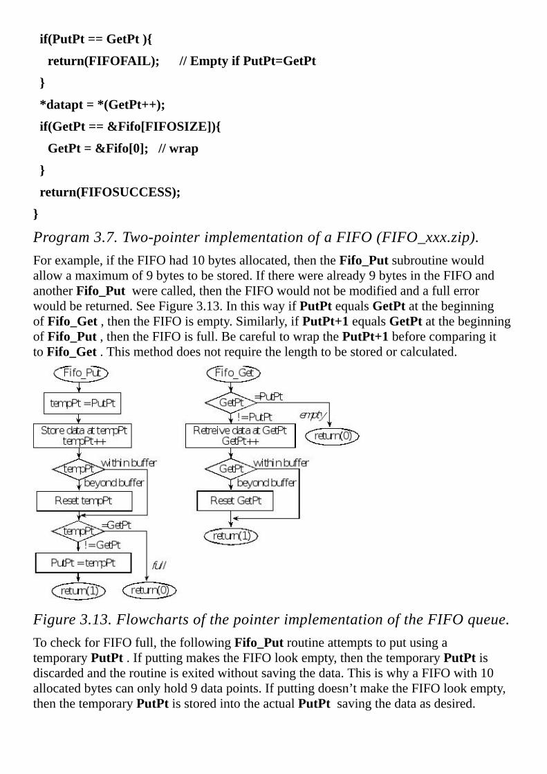
if(PutPt==GetPt)
return(FIFOFAIL);//EmptyifPutPt=GetPt
*datapt=*(GetPt++);
if(GetPt==&Fifo[FIFOSIZE])
GetPt=&Fifo[0];//wrap
return(FIFOSUCCESS);
Program3.7.Two-pointerimplementationofaFIFO(FIFO_xxx.zip).Forexample,iftheFIFOhad10bytesallocated,thenthe Fifo_Put subroutinewouldallowamaximumof9bytestobestored.Iftherewerealready9bytesintheFIFOandanother Fifo_Put werecalled,thentheFIFOwouldnotbemodifiedandafullerrorwouldbereturned.SeeFigure3.13.Inthiswayif PutPt equals GetPt atthebeginningof Fifo_Get ,thentheFIFOisempty.Similarly,if PutPt+1 equals GetPt atthebeginningof Fifo_Put ,thentheFIFOisfull.Becarefultowrapthe PutPt+1 beforecomparingitto Fifo_Get .Thismethoddoesnotrequirethelengthtobestoredorcalculated.
Figure3.13.FlowchartsofthepointerimplementationoftheFIFOqueue.TocheckforFIFOfull,thefollowing Fifo_Put routineattemptstoputusingatemporary PutPt .IfputtingmakestheFIFOlookempty,thenthetemporary PutPt isdiscardedandtheroutineisexitedwithoutsavingthedata.ThisiswhyaFIFOwith10allocatedbytescanonlyhold9datapoints.Ifputtingdoesn’tmaketheFIFOlookempty,thenthetemporary PutPt isstoredintotheactual PutPt savingthedataasdesired.

TocheckforFIFOempty,the Fifo_Get routineinProgram3.7simplycheckstoseeif GetPt equals PutPt .Iftheymatchatthestartoftheroutine, thenFifo_Get returnswiththe“empty”conditionsignified.
Since Fifo_Put and Fifo_Get havereadmodifywriteaccessestoglobalvariablestheyarethemselvesnotreentrant.Similarly Fifo_Init hasamultiplestepwriteaccesstoglobalvariables.Therefore Fifo_Init isnotreentrant.
Oneadvantageofthispointerimplementationisthatifyouhaveasinglethreadthatcallsthe Fifo_Get (e.g.,themainprogram)andasinglethreadthatcallsthe Fifo_Put (e.g.,theserialportreceiveinterrupthandler),thenthis Fifo_Put functioncaninterruptthis Fifo_Get functionwithoutlossofdata.Sointhisparticularsituation,interruptswouldnothavetobedisabled.Itwouldalsooperateproperlyiftherewereasingleinterruptthreadcalling Fifo_Get (e.g.,theserialporttransmitinterrupthandler)andasinglethreadcalling Fifo_Put (e.g.,themainprogram.)Ontheotherhand,ifthesituationismoregeneral,andmultiplethreadscouldcall Fifo_Put ormultiplethreadscouldcall Fifo_Get ,thentheinterruptswouldhavetobetemporarilydisabled.
3.7.3.TwoindexFIFOimplementationTheothermethodtoimplementaFIFOistouseindicesratherthanpointers.ThisFIFOhastherestrictionthatthesizemustbeapowerof2.InProgram3.8, FIFOSIZE is16andthelogic PutI&(FIFOSIZE-1) returnsthebottomfourbitsoftheputindex.Similarly,thelogic GetI&(FIFOSIZE-1) returnsthebottomfourbitsofthegetindex.Usingthebottombitsoftheindexremovesthenecessarytocheckforoutofboundsandwrapping.
//Two-indeximplementationofthetransmitFIFO
//canhold0toFIFOSIZEelements
#defineFIFOSIZE16//mustbeapowerof2
#defineFIFOSUCCESS1
#defineFIFOFAIL0
typedefint8_tDataType;
uint32_tvolatilePutI;//putnext
uint32_tvolatileGetI;//getnext
DataTypestaticFifo[FIFOSIZE];
//initializeindexFIFO
voidFifo_Init(void)
PutI=GetI=0;//Empty
//addelementtoendofindexFIFO
intFifo_Put(DataTypedata)

if((PutI-GetI)&~(FIFOSIZE-1))
return(FIFOFAIL);//Failed,fifofull
Fifo[PutI&(FIFOSIZE-1)]=data;//put
PutI++;//Success,update
return(FIFOSUCCESS);
//removeelementfromfrontofindexFIFO
intFifo_Get(DataType*datapt)
if(PutI==GetI)
return(FIFOFAIL);//EmptyifPutI=GetI
*datapt=Fifo[GetI&(FIFOSIZE-1)];
GetI++;//Success,update
return(FIFOSUCCESS);
Program3.8.Implementationofatwo-indexFIFO.Thesizemustbeapoweroftwo(FIFO_xxx.zip).IftheFIFOisfull,then (PutI-GetI) willequal16,meaningallelementsofthebufferhavedata.Theexpression ~(FIFOSIZE-1) yieldstheconstant0xFFFFFFF0.Forallsizesthatareapowerof2,theifstatementinputwillbenonzeroifthereare FIFOSIZEelementsintheFIFO.WiththisimplementationaFIFOwith16allocatedbytescanactuallyhold16datapoints.TheFIFOisemptyif PutI equals GetI .Ifempty,theFifo_Get functionreturnswiththe FIFOFAIL condition.
3.7.4.FIFObuildmacrosWhenweneedmultipleFIFOsinoursystem,wecouldswitchovertoC++anddefinetheFIFOasaclass,andtheninstantiatemultipleobjectstocreatetheFIFOs.Asecondapproachwouldbetouseatexteditor,openthesourcecodecontainingProgram3.7or3.8,copy/pasteit,andthenchangenamessothefunctionsareunique.AthirdapproachisshowninPrograms3.9and3.10,whichdefinesmacrosallowingustocreateasmanyFIFOsasweneed.
//macrotocreateapointerFIFO
#defineAddPointerFifo(NAME,SIZE,TYPE,SUCCESS,FAIL)\
TYPEvolatile*NAME##PutPt;\

TYPEvolatile*NAME##GetPt;\
TYPEstaticNAME##Fifo[SIZE];\
voidNAME##Fifo_Init(void)\
NAME##PutPt=NAME##GetPt=&NAME##Fifo[0];\
\
intNAME##Fifo_Put(TYPEdata)\
TYPEvolatile*nextPutPt;\
nextPutPt=NAME##PutPt+1;\
if(nextPutPt==&NAME##Fifo[SIZE])\
nextPutPt=&NAME##Fifo[0];\
\
if(nextPutPt==NAME##GetPt)\
return(FAIL);\
\
else\
*(NAME##PutPt)=data;\
NAME##PutPt=nextPutPt;\
return(SUCCESS);\
\
\
intNAME##Fifo_Get(TYPE*datapt)\
if(NAME##PutPt==NAME##GetPt)\
return(FAIL);\
\
*datapt=*(NAME##GetPt##++);\
if(NAME##GetPt==&NAME##Fifo[SIZE])\
NAME##GetPt=&NAME##Fifo[0];\
\
return(SUCCESS);\
Program3.9.Two-pointermacroimplementationofaFIFO(FIFO_xxx.zip).

Tocreatea20-elementFIFOstoringunsigned16-bitnumbersthatreturns1onsuccessand0onfailureweinvoke
AddPointerFifo(Rx,20,uint16_t,1,0)
creatingthethreefunctionsRxFifo_Init() , RxFifo_Get() ,and RxFifo_Put() .
Program3.10isamacroallowingustocreatetwo-indexFIFOssimilartoProgram3.8.
//macrotocreateanindexFIFO
#defineAddIndexFifo(NAME,SIZE,TYPE,SUCCESS,FAIL)\
uint32_tvolatileNAME##PutI;\
uint32_tvolatileNAME##GetI;\
TYPEstaticNAME##Fifo[SIZE];\
voidNAME##Fifo_Init(void)\
NAME##PutI=NAME##GetI=0;\
\
intNAME##Fifo_Put(TYPEdata)\
if((NAME##PutI-NAME##GetI)&~(SIZE-1))\
return(FAIL);\
\
NAME##Fifo[NAME##PutI&(SIZE-1)]=data;\
NAME##PutI##++;\
return(SUCCESS);\
\
intNAME##Fifo_Get(TYPE*datapt)\
if(NAME##PutI==NAME##GetI)\
return(FAIL);\
\
*datapt=NAME##Fifo[NAME##GetI&(SIZE-1)];\
NAME##GetI##++;\
return(SUCCESS);\
\
uint16_tNAME##Fifo_Size(void)\
return((uint16_t)(NAME##PutI-NAME##GetI));\

Program3.10.Macroimplementationofatwo-indexFIFO.Thesizemustbeapoweroftwo(FIFO_xxx.zip).Tocreatea32-elementFIFOstoringsigned32-bitnumbersthatreturns0onsuccessand1onfailureweinvoke
AddIndexFifo(Tx,32,int32_t,0,1)
creatingthethreefunctionsTxFifo_Init() , TxFifo_Get() ,and TxFifo_Put() .
Checkpoint3.11:ShowCcodetocreatethreeFIFOscalledCAN1CAN2andCAN3.EachFIFOstores8-bitbytesandmustbeabletostoreupto99elements.
Checkpoint3.12:ShowCcodetocreatetwoFIFOscalledF1andF2.EachFIFOstores16-bithalfwordsandmustbeabletostoreupto256elements.

3.8.MemoryManagementandtheHeapSofar,wehaveseentwotypesofallocation:permanentallocationinglobalvariablesandtemporaryallocationinlocalvariables.Whenweallocatelocalvariablesinregistersoronthestackthesevariablesmustbeprivatetothefunctionandcannotbesharedwithotherfunctions.Furthermore,eachtimethefunctionisinvokednewlocalvariablesarecreated,anddatafrompreviousinstantiationsarenotavailable.Thisbehaviorisusuallyexactlywhatwewanttohappenwithlocalvariables.However,wecanusetheheap(ormemorymanager)tohavetemporaryallocationinawaythatismuchmoreflexible.Inparticular,wewillbeabletoexplicitlydefinewhendataareallocatedandwhentheyaredeallocatedwiththeonlyrestrictionbeingwefirstallocate,nextweuse,andthenwedeallocate.Furthermore,wecancontrolthescopeofthedatainaflexiblemanner.
Theuseoftheheapinvolvestwosystemfunctions: malloc and free .Whenwewishtoallocatespacewecallmalloc andspecifyhowmanybytesweneed. malloc willreturnapointertothenewobject,whichwemuststoreinapointervariable.Iftheheaphasnomorespace,malloc willreturna0,whichmeansnullpointer.Theheapimplementstemporaryallocation,sowhenwearedonewiththedata,wereturnittotheheapbycalling free .Considerthefollowingsimpleexamplewiththreefunctions.
int32_t*Pt;
voidBegin(void)
Pt=(*int32_t)malloc(4*20);//allocate20words
voidUse(void)inti;
for(i=0;i<20;i++)
Pt[i]=i;//putdataintoarray
voidEnd(void)
free(Pt);
Thepointer Pt ispermanentlyallocated.TheleftsideofFigure3.14showsthatinitially,eventhoughthepointerexists,itdoesnotpointtoanything.Morespecifically,thecompilerwillinitializeitto0;this0isdefinedasanullpointer,meaningitisnotvalid.Whenmalloc iscalledthepointerisnowvalidandpointstoa20-wordarray.Thearrayisinsidetheheapand Pt pointstoit.Anytimeaftermalloc iscalledandbefore free iscalledthearrayexistsandcanbeaccessedviathepointer Pt .Afteryoucallfree,thepointerhasthesamevalueasbefore.However,thearrayitselfdoesnotexist.I.e.,these80bytesdonotbelongtoyourprogramanymore.Inparticular,afteryoucallfreetheheapisallowedtoallocatethesebytestosomeotherprogram.Weirdandcrazyerrorswilloccurifyouattempttodereferencethepointerbeforethearrayisallocated,orafteritisreleased.

Figure3.14.Theheapisusedtodynamicallyallocatememory.Thisarrayexistsandthepointerisvalidfromwhenyoucall malloc upuntilthetimeyoucall free .InC,theheapdoesnotmanagethepointerstoallocatedblock;yourprogrammust.Ifyoucallmalloc tentimesinarow,youmustkeeptrackofthetenpointersyoureceived.Thescopeofthisarrayisdeterminedbythescopeofthepointer, Pt .If Pt ispublic,thenthearrayispublic.Ifstaticweretobeaddedtothedefinitionof Pt ,thenthescopeofthearrayisrestrictedtosoftwarewithinthisfile.Inthefollowingexample,thescopeofthearrayisrestrictedtotheonefunction.Withinoneexecutionofthefunction,thearrayisallocated,used,andthendeallocated,justlikealocalvariable.
voidFunction(void)inti;
int32_t*pt;
pt=(*int32_t)malloc(4*20);//allocate20words
for(i=0;i<20;i++)
pt[i]=i;//putdataintoarray
free(pt);
Amemoryleakoccursifsoftwareusestheheaptoallocatespacebutforgetstodeallocatethespacewhenitisfinished.Thefollowingisanexampleofamemoryleak.Eachtimethefunctioniscalled,ablockofmemoryisallocated.Thepointertotheblockisstoredinalocalvariable.Whenthefunctionreturns,thepointernolongerexists.Thismeanstheallocatedblockintheheapexists,buttheprogramhasnopointertoit.Inotherwords,eachtimethisfunctionreturns80bytesfromtheheaparepermanentlylost.
voidLeakyFunction(void)inti;
int32_t*pt;
pt=(*int32_t)malloc(4*20);//allocate20words
for(i=0;i<20;i++)
pt[i]=i;//putdataintoarray
Ingeneral,theheapmanagerallowstheprogramtoallocateavariableblocksize,butinthissectionwewilldevelopasimplifiedheapmanagerhandlesjustfixedsizeblocks.Inthisexample,theblocksizeisspecifiedbytheconstantSIZE .Theinitializationwillcreatealinkedlistofallthefreeblocks(Figure3.15).

Figure3.15.Theinitialstateoftheheaphasallofthefreeblockslinkedinalist.Program3.11ashowstheglobalstructuresfortheheap.TheseentriesaredefinedinRAM. SIZE isthenumberof8-bitbytesineachblock.Allblocksallocatedandreleasedwiththismemorymanagerwillbeofthisfixedsize. NUM isthenumberofblockstobemanaged. FreePt pointstothefirstfreeblock.
#defineSIZE80
#defineNUM5
#defineNULL0//emptypointer
int8_t*FreePt;
int8_tHeap[SIZE*NUM];
Program3.11a.Privateglobalstructuresforthefixed-blockmemorymanager.Initializationmustbeperformedbeforetheheapcanbeused.Program3.11bshowsthesoftwarethatpartitionstheheapintoblocksandlinksthemtogether. FreePt pointstoalinearlinkedlistoffreeblocks.Initiallythesefreeblocksarecontiguousandinorder,butasthemanagerisusedthepositionsandorderofthefreeblockscanvary.Itwillbethepointersthatwillthreadthefreeblockstogether.
voidHeap_Init(void)
int8_t*pt;
FreePt=&Heap[0];
for(pt=&Heap[0];
pt!=&Heap[SIZE*(NUM-1)];
pt=pt+SIZE)
*(int32_t*)pt=(int32_t)(pt+SIZE);
*(int32_t*)pt=NULL;
Program3.11b.Functionstoinitializetheheap.Toallocateablocktomanagerjustremovesoneblockfromthefreelist.Program3.11cshowstheallocateandreleasefunctions.The Heap_Allocate functionwillfailandreturnanullpointerwhentheheapbecomesempty.The Heap_Release returnsablocktothefreelist.Thissystemdoesnotchecktoverifyareleasedblockactuallywaspreviouslyallocated.

void*Heap_Allocate(void)
int8_t*pt;
pt=FreePt;
if(pt!=NULL)
FreePt=(char*)*(char**)pt;
return(pt);
voidHeap_Release(void*pt)
int8_t*oldFreePt;
oldFreePt=FreePt;
FreePt=(char*)pt;
*(int32_t*)pt=(int32_t)oldFreePt;
Program3.11c.Functionstoallocateandreleasememoryblocks(HeapFixedBlock_xxx.zip).Checkpoint3.13:Thereare5blocksinthissimpleheap.HowcouldthememorymanagerdetermineifblockI(where0≤I≤4)isallocatedorfree?
Checkpoint3.14:Usingthismemorymanager,writeamallocandfreefunctionssuchthatthesizeisrestrictedtoamaximumof100bytes.I.e.,youmayassumetheuserneverasksformorethan100bytesatatime.

3.9.IntroductiontoDebuggingEveryprogrammerisfacedwiththeneedtodebugandverifythecorrectnessoftheirsoftware.Inthissectionwewillstudyhardwarelevelprobesliketheoscilloscope,logicanalyzer,JTAG,andin-circuit-emulator(ICE);softwareleveltoolslikesimulators,monitors,andprofilers;andmanualtoolslikeinspectionandprintstatements.
3.9.1.DebuggingToolsMicrocontroller-relatedproblemsoftenrequiretheuseofspecializedequipmenttodebugthesystemhardwareandsoftware.Usefulhardwaretoolsincludealogicprobe,anoscilloscope,alogicanalyzer,andaJTAGdebugger.AlogicprobeisahandhelddevicewithanLEDorbuzzer.YouplacetheprobeonyourdigitalcircuitandLED/buzzerwillindicatewhetherthesignalishighorlow.Anoscilloscope,orscope,graphicallydisplaysinformationaboutanelectroniccircuit,wherethevoltageamplitudeversustimeisdisplayed.Ascopehasoneortwochannels,withmanywaystotriggerorcapturedata.AscopeisparticularlyusefulwheninterfacinganalogsignalsusinganADCorDAC.ThePicoScope2104(fromhttp://www.picotech.com/)isalow-costbuteffectivetoolfordebuggingmicrocontrollercircuits.Alogicanalyzerisessentiallyamultiplechanneldigitalstoragescopewithmanywaystotrigger.AsshowninFigure3.16,wecanconnectthelogicanalyzertodigitalsignalsthatarepartofthesystem,orwecanconnectthelogicanalyzerchannelstounusedmicrocontrollerpinsandaddsoftwaretotogglethosepinsatstrategictimes/places.Asatroubleshootingaid,itallowstheexperimentertoobservenumerousdigitalsignalsatvariouspointsintimeandthusmakedecisionsbaseduponsuchobservations.Oneproblemwithlogicanalyzersisthemassiveamountofinformationthatitgenerates.Touseananalyzereffectivelyonemustlearnpropertriggeringmechanismstocapturedataatappropriatetimeseliminatingtheneedtosiftthroughvolumesofoutput.ThelogicanalyzerfiguresinthisbookwerecollectedwithalogicanalyzerUSBee(fromhttp://www.usbee.com).SomeofthemodelsfromUSBeecombinealogicanalyzerwithanoscilloscope,creatinganextremelyeffectivedebuggingtool.
MaintenanceTip:First,findthethingsthatwillbreakyou.Second,breakthem.
Commonerror:Sometimestheoriginalsystemoperatesproperly,andthedebuggingcodehasmistakes.
Figure3.16.Alogicanalyzerandexampleoutput.

Figure3.17showsalogicanalyzeroutput,wheresignalsRxCANandTxCANaredigitalinput/output,butsignalsPB3,PB1,andPB5aredebuggingoutputstomeasuringtimingrelationshipsbetweensoftwareexecutionanddigitalI/O.TherisingedgeofPB3isusedtotriggerthedatacollection.
Figure3.17.USBeeSXlogicanalyzeroutput(alsoconsiderAnalogDiscoveryfromwww.digilentinc.com).Anemulatorisahardwaredebuggingtoolthatrecreatestheinput/outputsignalsoftheprocessorchip.Touseanemulator,weremovetheprocessorchipandinserttheemulatorcableintothechipsocket.Inmostcases,theemulator/computersystemoperatesatfullspeed.Theemulatorallowstheprogrammertoobserveandmodifyinternalregistersoftheprocessor.Emulatorsareoftenintegratedintoapersonalcomputer,sothatitseditor,harddrive,andprinterareavailableforthedebuggingprocess.
Theonlydisadvantageofthein-circuitemulatorisitscost.Toprovidesomeofthebenefitsofthishigh-priceddebuggingequipment,manymicrocontrollersuseaJTAGdebugger.TheJTAGhardwareexistsbothonthemicrocontrollerchipitselfandasanexternalinterfacetoapersonalcomputer.AlthoughnotasflexibleasanICE,theJTAGcanprovidetheabilitytoobservesoftwareexecutioninreal-time,theabilitytosetbreakpoints,theabilitytostopthecomputer,andtheabilitytoreadandwriteregisters,I/Oportsandmemory.
3.9.2.DebuggingTheory

Debuggingisanessentialcomponentofembeddedsystemdesign.Weneedtoconsiderdebuggingduringallphasesofthedesigncycle.Itisimportanttodevelopastructureormethodwhenverifyingsystemperformance.Thissectionwillpresentanumberoftoolswecanusewhendebugging.Termssuchasprogramtesting,diagnostics,performancedebugging,functionaldebugging,tracing,profiling,instrumentation,visualization,optimization,verification,performancemeasurement,andexecutionmeasurementhavespecializedmeanings,buttheyarealsousedinterchangeably,andtheyoftendescribeoverlappingfunctions.Forexample,thetermsprofiling,tracing,performancemeasurement,orexecutionmeasurementmaybeusedtodescribetheprocessofexaminingaprogramfromatimeviewpoint.But,tracingisalsoatermthatmaybeusedtodescribetheprocessofmonitoringaprogramstateorhistoryforfunctionalerrors,ortodescribetheprocessofsteppingthroughaprogramwithadebugger.Usageofthesetermsamongresearchersandusersvary.
Black-boxtestingissimplyobservingtheinputsandoutputswithoutlookinginside.Black-boxtestinghasanimportantplaceindebuggingamoduleforitsfunctionality.Ontheotherhand,white-boxtestingallowsyoutocontrolandobservetheinternalworkingsofasystem.Acommonmistakemadebynewengineersistojustperformblackboxtesting.Effectivedebuggingusesboth.Onemustalwaysstartwithblack-boxtestingbysubjectingahardwareorsoftwaremoduletoappropriatetest-cases.Oncewedocumentthefailedtest-cases,wecanusethemtoaidusineffectivelyperformingthetaskofwhite-boxtesting.
Wedefineadebugginginstrumentassoftwarecodethatisaddedtotheprogramforthepurposeofdebugging.Aprintstatementisacommonexampleofaninstrument.Usingtheeditor,weaddprintstatementstoourcodethateitherverifyproperoperationordisplayrun-timeerrors.Akeytowritinggooddebugginginstrumentsistoprovideforamechanismtoreliablyandefficientlyremoveallthemwhenthedebuggingisdone.Considerthefollowingmechanismsasyoudevelopyourownuniquedebuggingstyle.
•Placeallprintstatementsinauniquecolumn(e.g.,firstcolumn.),sothattheonlycodethatexistsinthiscolumnwillbedebugginginstruments.
•Definealldebugginginstrumentsasfunctionsthatallhaveaspecificpatternintheirnames(e.g.,beginwith Debug_ ).Inthisway,thefind/replacemechanismoftheeditorcanbeusedtofindallthecallstotheinstruments.
•Definetheinstrumentssothattheytestaruntimeglobalflag.Whenthisflagisturnedoff,theinstrumentsperformnofunction.Noticethatthismethodleavesapermanentcopyofthedebuggingcodeinthefinalsystem,causingittosufferaruntimeoverhead,butthedebuggingcodecanbeactivateddynamicallywithoutrecompiling.Manycommercialsoftwareapplicationsutilizethismethodbecauseitsimplifies“on-site”customersupport.

•Useconditionalcompilation(orconditionalassembly)toturnonandofftheinstrumentswhenthesoftwareiscompiled.Whenthecompilersupportsthisfeature,itcanprovidebothperformanceandeffectiveness.
Somecompilerssupportaconfigurationmodethatcanbesettodebugorrelease.Indebugmode,debugginginstrumentsareadded.Inreleasemode,theinstrumentsareremoved.
Checkpoint3.15:Considerthedifferencebetweenaruntimeflagthatactivatesadebuggingcommandversusacompile-timeflag.Inbothcasesitiseasytoactivate/deactivatethedebuggingstatements.Listonefactorforwhicheachmethodissuperiortotheother.
Checkpoint3.16:Whatistheadvantageofleavingdebugginginstrumentsinafinaldeliveredproduct?
Nonintrusivenessisthecharacteristicorqualityofadebuggerthatallowsthesoftware/hardwaresystemtooperatenormallyasifthedebuggerdidnotexist.Intrusivenessisusedasameasureofthedegreeofperturbationcausedinprogramperformancebythedebugginginstrumentitself.Lettbethetimerequiredtoexecutetheinstrument,andlet tbetheaveragetimeinbetweenexecutionsoftheinstrument.Onequantitativemeasureofintrusivenessist/ t,whichisthefractionofavailableprocessortimeusedbythedebugger.Forexample,aprintstatementaddedtoyoursourcecodemaybeveryintrusivebecauseitmightsignificantlyaffectthereal-timeinteractionofthehardwareandsoftware.Observingsignalsthatalreadyexistaspartofthesystemwithanoscilloscopeorlogicanalyzerisnonintrusive.Adebugginginstrumentisclassifiedasminimallyintrusiveifithasanegligibleeffectonthesystembeingdebugged.Inarealmicrocontrollersystem,breakpointsandsingle-steppingarealsointrusive,becausetherealhardwarecontinuestochangewhilethesoftwarehasstopped.Whenaprograminteractswithreal-timeevents,theperformancecanbesignificantlyalteredwhenusingintrusivedebuggingtools.Tobeeffectivewemustemploynonintrusiveorminimallyintrusivemethods.
Checkpoint3.17:Whatdoesitmeanforadebugginginstrumenttobeminimallyintrusive?Givebothageneralanswerandaspecificcriterion.
Although,awidevarietyofprogrammonitoringanddebuggingtoolsareavailabletoday,inpracticeitisfoundthatanoverwhelmingmajorityofuserseitherstillpreferorrelymainlyupon“roughandready”manualmethodsforlocatingandcorrectingprogramerrors.Thesemethodsincludedesk-checking,dumps,andprintstatements,withprintstatementsbeingoneofthemostpopularmanualmethods.Manualmethodsareusefulbecausetheyarereadilyavailable,andtheyarerelativelysimpletouse.But,theusefulnessofmanualmethodsislimited:theytendtobehighlyintrusive,andtheydonotprovideadequatecontroloverrepeatability,eventselection,oreventisolation.Areal-timesystem,wheresoftwareexecutiontimingiscritical,usuallycannotbedebuggedwithsimpleprintstatements,becausetheprintstatementitselfwillrequiretoomuchtimetoexecute.

Thefirststepofdebuggingistostabilizethesystem.Inthedebuggingcontext,westabilizetheproblembycreatingatestroutinethatfixes(orstabilizes)alltheinputs.Inthisway,wecanreproducetheexactinputsoverandoveragain.Oncestabilized,ifwemodifytheprogram,wearesurethatthechangeinouroutputsisafunctionofthemodificationwemadeinoursoftwareandnotduetoachangeintheinputparameters.
Accelerationmeanswewillspeedupthetestingprocess.Whenwearetestingonemodulewecanincreasehowfastthefunctionsarecalledinanattempttoexposepossiblefaults.Furthermore,sincewecancontrolthetestenvironment,wewillvarythetestconditionsoverawiderangeofpossibleconditions.Stresstestingmeanswerunthesystembeyondtherequirementstoseeatwhatpointitbreaksdown.
Whenasystemhasasmallnumberofpossibleinputs(e.g.,lessthanamillion),itmakessensetotestthemall.Whenthenumberofpossibleinputsislargeweneedtochooseasetofinputs.Coveragedefinesthesubsetofpossibleinputsselectedfortesting.Acornercaseisdefinedasasituationattheboundarywheremultipleinputsareattheirmaximum,likethecornerofa3-Dcube.Atthecornersmallchangesininputmaycauselotsofinternalandexternalchanges.Inparticular,weneedtotestthecaseswethinkmightbedifficult(e.g.,theclockoutputincrementsonesecondfrom11:59:59PMDecember31,1999.)Therearemanywaystodecideonthecoverage.Wecanselectvalues:
•Neartheextremesandinthemiddle
•Mosttypicalofhowourclientswillproperlyusethesystem
•Mosttypicalofhowourclientswillimproperlyusethesystem
•Thatdifferbyone
•Youknowyoursystemwillfinddifficult
•UsingarandomnumbergeneratorTostabilizethesystemwedefineafixedsetofinputstotest,runthesystemontheseinputs,andrecordtheoutputs.Debuggingisaprocessoffindingpatternsinthedifferencesbetweenrecordedbehaviorandexpectedresults.Theadvantageofmodularprogrammingisthatwecanperformmodulardebugging.Wemakealistofmodulesthatmightbecausingthebug.Wecanthencreatenewtestroutinestostabilizethesemodulesanddebugthemoneatatime.Unfortunately,sometimesallthemodulesseemtowork,butthecombinationofmodulesdoesnot.Inthiscasewestudytheinterfacesbetweenthemodules,lookingforintendedandunintended(e.g.,unfriendlycode)interactions.
Theemergenceofconcurrentsystems(e.g.,distributednetworksofmicrocontrollers),optimizingarchitectures(e.g.,pipelines,cache,branchprediction,outoforderexecution,conditionalexecution,andmulti-coreprocessors),andtheincreasingneedforsecurityandreliablyplacefurtherdemandsondebuggers.Thecomplexitiesintroducedbytheinteractionofmultipleeventsortimedependentprocessesaremuchmoredifficulttodebugthanerrorsassociatedwithsequentialprograms.Thebehaviorofnon-real-timesequentialprogramsisreproducible:foragivensetofinputstheiroutputsremainthesame.Inthecaseofconcurrentorreal-timeprogramsthisdoesnotholdtrue.Controloverrepeatability,eventselection,andeventisolationisevenmoreimportantforconcurrentorreal-timeenvironments.
Sometimes,themeaningandscopeofthetermdebuggingitselfisnotclear.Weholdtheviewthatthegoalofdebuggingistomaintainandimprovesoftware,andtheroleofadebuggeristosupportthisendeavor.Wedefinethedebuggingprocessastesting,stabilizing,localizing,andcorrectingerrors.Andinouropinion,althoughtesting,stabilizing,andlocalizingerrorsareimportantandessentialtodebugging,theyareauxiliaryprocesses:theprimarygoalofdebuggingistoremedyfaultsandverifythesystemisoperatingwithinspecifications.
3.9.3.FunctionalDebuggingFunctionaldebugginginvolvestheverificationofinput/outputparameters.Itisastaticprocesswhereinputsaresupplied,thesystemisrun,andtheoutputsarecomparedagainsttheexpectedresults.Wewillpresentsevenmethodsoffunctionaldebugging.
1.SingleSteppingorTrace.Manydebuggersallowyoutosettheprogramcountertoaspecificaddressthenexecuteoneinstructionatatime.StepOverwillexecuteoneinstruction,unlessthatinstructionisasubroutinecall,inwhichcasethesimulatorwillexecutetheentiresubroutineandstopattheinstructionfollowingthesubroutinecall.StepOutassumestheexecutionhasalreadyenteredafunctionandwillfinishexecutionofthefunctionandstopattheinstructionfollowingthefunctioncall.
2.Breakpointswithoutfiltering.Thefirststepofdebuggingistostabilizethesystemwiththebug.Inthedebuggingcontext,westabilizetheproblembycreatingatestroutinethatfixes(orstabilizes)alltheinputs.Inthisway,wecanreproducetheexactinputsoverandoveragain.Oncestabilized,ifwemodifytheprogram,wearesurethatthechangeinouroutputsisafunctionofthemodificationwemadeinoursoftwareandnotduetoachangeintheinputparameters.Abreakpointisamechanismtotagplacesinoursoftware,whichwhenexecutedwillcausethesoftwaretostop.
3.Conditionalbreakpoints.Oneoftheproblemswithbreakpointsisthatsometimeswehavetoobservemanybreakpointsbeforetheerroroccurs.Onewaytodealwiththisproblemistheconditionalbreakpoint.Addaglobalvariablecalled count andinitializeittozerointheritual.Addthefollowingconditionalbreakpointtotheappropriatelocation,andrunthesystemagain(youcanchangethe32tomatchthesituationthatcausestheerror).
if(++count==32)

breakpoint();//<=placebreakpointhere
Noticethatthebreakpointoccursonlyonthe32ndtimethebreakisencountered.Anyappropriateconditioncanbesubstituted.
4.Instrumentation:printstatements.Theuseofprintstatementsisapopularandeffectivemeansforfunctionaldebugging.Thedifficultywithprintstatementsinembeddedsystemsisthatastandard“printer”maynotbeavailable.Anotherproblemwithprintingisthatmostembeddedsystemsinvolvetime-dependentinteractionswithitsexternalenvironment.Theprintstatementitselfmaysoslowthatthedebugginginstrumentitselfcausesthesystemtofail.Therefore,theprintstatementisusuallyintrusive.Oneexceptiontothisruleisiftheprintingchanneloccursinthebackgroundusinginterrupts,andthetimebetweenprintstatements(t2)islargecomparedtothetimetoexecutiononeprint(t1),thentheprintstatementswillbeminimallyintrusive.Nevertheless,thisbookwillfocusondebuggingmethodsthatdonotrelyontheavailabilityofaprinter.
5.Instrumentation:dumpintoarraywithoutfiltering.Oneofthedifficultieswithprintstatementsisthattheycansignificantlyslowdowntheexecutionspeedinreal-timesystems.Manytimesthebandwidthoftheprintfunctionscannotkeeppacewithdatabeinggeneratedbythedebuggingprocess.Forexample,oursystemmaywishtocallafunction1000timesasecond(orevery1ms).Ifweaddprintstatementstoitthatrequire50mstoperform,thepresenceoftheprintstatementswillsignificantlyaffectthesystemoperation.Inthissituation,theprintstatementswouldbeconsideredextremelyintrusive.Anotherproblemwithprintstatementsoccurswhenthesystemisusingthesameoutputhardwareforitsnormaloperation,asisrequiredtoperformtheprintfunction.Inthissituation,debuggeroutputandnormalsystemoutputareintertwined.
Tosolveboththesesituations,wecanaddadebuggerinstrumentthatdumpsstrategicinformationintoarraysatruntime.Wecanthenobservethecontentsofthearrayatalatertime.OneoftheadvantagesofdumpingisthattheJTAGdebuggingallowsyoutovisualizememoryevenwhentheprogramisrunning.Program3.12showsadumpinstrument.
#defineSIZE100
uint32_tDebug_Buffer[SIZE][2];
unsignedintDebug_Cnt=0;
voidDebug_Dump(void)//dumpHappyandSad
if(Debug_Cnt<SIZE)
Debug_Buffer[Debug_Cnt][0]=Happy;
Debug_Buffer[Debug_Cnt][1]=Sad;
Debug_Cnt++;

Program3.12.Instrumentationdumpwithoutfiltering.Assume Happy and Sad arestrategic32-bitvariables.ThefirststepwheninstrumentingadumpistodefineabufferinRAMtosavethedebuggingmeasurements.The Debug_Cnt willbeusedtoindexintothebuffers. Debug_Cnt mustbeinitializedtozero,beforethedebuggingbegins.Thedebugginginstrument,showninProgram3.13,savesthestrategicvariablesintothebuffer.
Next,youadd Debug_Dump(); statementsatstrategicplaceswithinthesystem.Youcaneitherusethedebuggertodisplaytheresultsoraddsoftwarethatprintstheresultsaftertheprogramhasrunandstopped.Inthisway,youcancollectinformationintheexactsamemanneryouwouldifyouwereusingprintstatements.
6.Instrumentation:dumpintoarraywithfiltering.Oneproblemwithdumpsisthattheycangenerateatremendousamountofinformation.Ifyoususpectacertainsituationiscausingtheerror,youcanaddafiltertotheinstrument.Afilterisasoftware/hardwareconditionthatmustbetrueinordertoplacedataintothearray.Inthissituation,ifwesuspecttheerroroccurswhenthepointernearstheendofthebuffer,wecouldaddafilterthatsavesinthearrayonlywhenthepointerisaboveacertainvalue.IntheexampleshowninProgram3.13,theinstrumentsavesthestrategicvariablesintothebufferonlywhen Sad isgreaterthan100.
#defineSIZE100
uint32_tDebug_Buffer[SIZE][2];
unsignedintDebug_Cnt=0;
voidDebug_FilteredDump(void)//dumpHappyandSad
if((Sad>100)&&(Debug_Cnt<SIZE))
Debug_Buffer[Debug_Cnt][0]=Happy;
Debug_Buffer[Debug_Cnt][1]=Sad;
Debug_Cnt++;
Program3.13.Instrumentationdumpwithfilter.7.MonitorusingtheLEDheartbeat.Anothertoolthatworkswellforreal-timeapplicationsisthemonitor.Amonitorisanindependentoutputprocess,somewhatsimilartotheprintstatement,butonethatexecutesmuchfasterandthusismuchlessintrusive.TheOLEDorLCDcanbeaneffectivemonitorforsmallamountsofinformationifthetimebetweenoutputsismuchlargerthanthetimetooutput.AnotherpopularmonitoristheLED.YoucanplaceoneormoreLEDsonindividualotherwiseunusedoutputbits.SoftwaretogglestheseLEDstoletyouknowwhatpartsoftheprogramarerunning.AnLEDisanexampleofaBooleanmonitororheartbeat.AssumeanLEDisattachedtoPortDbit1.Program3.14willtoggletheLED.
#definePD1(*((volatileuint32_t*)0x40007008))
#defineDebug_HeartBeat()(PD1^=0x02)
Program3.14.AnLEDmonitor.Next,youadd Debug_HeartBeat(); statementsatstrategicplaceswithinthesystem.PortDmustbeinitializedsothatbit1isanoutputbeforethedebuggingbegins.YoucaneitherobservetheLEDdirectlyorlookattheLEDcontrolsignalswithahigh-speedoscilloscopeorlogicanalyzer.WhenusingLEDmonitorsitisbettertomodifyjusttheonebit,leavingtheother7asis.Inthisway,youcanhavemultiplemonitorsononeport.
Checkpoint3.18:WriteadebugginginstrumentthattogglesPortAbit3.
3.9.4.PerformanceDebuggingPerformancedebugginginvolvestheverificationoftimingbehaviorofoursystem.Itisadynamicprocesswherethesystemisrun,andthedynamicbehaviorofthesystemiscomparedagainsttheexpectedresults.Wewillpresentthreemethodsofperformancedebugging,thenapplythetechniquestomeasureexecutionspeed.
1.Countingbuscycles.Forsimpleprogramswithlittleandnobranchingandforsimplemicrocontrollers,wecanestimatetheexecutionspeedbylookingattheassemblycodeandaddingupthetimetoexecuteeachinstruction.
2.Instrumentationmeasuringwithanindependentcounter.SysTickisa24-bitcounterdecrementedeverybusclock.Itautomaticallyrollsoverwhenitgetsto0.Ifwearesuretheexecutionspeedofourfunctionislessthan224buscycles,wecanusethistimertocollecttiminginformationwithonlyaminimalamountofintrusiveness.
3.InstrumentationOutputPort.Anothermethodtomeasurereal-timeexecutioninvolvesanoutputportandanoscilloscope.Connectamicrocontrolleroutputbittoyourscope.Adddebugginginstrumentsthatset/cleartheseoutputbitsatstrategicplaces.Remembertosettheport’sdirectionregisterto1.AssumeanoscilloscopeisattachedtoPortDbit1.Program3.15canbeusedtosetandclearthebit.
#definePD1(*((volatileuint32_t*)0x40007008))
#defineDebug_Set()(PD1=0x02)
#defineDebug_Clear()(PD1=0x00)
Program3.15.Instrumentationoutputport.Next,youadd Debug_Set(); and Debug_Clear(); statementsbeforeandafterthecodeyouwishtomeasure.PortDmustbeinitializedsothatbit1isanoutputbeforethedebuggingbegins.Youcanobservethesignalwithahigh-speedoscilloscopeorlogicanalyzer.
Debug_Set();
Stuff();//Usercodetobemeasured
Debug_Clear();

Toillustratethesethreemethods,wewillconsidermeasuringtheexecutiontimeofanintegersquarerootfunctionaspresentedProgram3.16.
Thefirstmethodistocountbuscyclesusingtheassemblylisting.Thisapproachisonlyappropriateforveryshortprograms,andbecomesdifficultforlongprogramswithmanyconditionalbranchinstructions.ThetimetoexecuteeachassemblyinstructioncanbefoundintheCortexTM-MTechnicalReferenceManual.BecauseofthecomplexityoftheARM ® CortexTM-M,thismethodisonlyapproximate.Forexamplethetimetoexecuteadividedependsonthedata,andthetimetoexecuteabranchdependsonthealignmentoftheinstructionpipeline.AportionoftheassemblyoutputgeneratedbytheARMKeilTMuVision®compilerispresentedontheleftsideofProgram3.16.Noticethatthetotalcyclecountforcouldrangefrom155to353cycles.At8MHztheexecutiontimecouldrangefrom19.4to44.1µs.Formostprogramsitisactuallyverydifficulttogetanaccuratetimemeasurementusingthistechnique.
sqrtMOVr1,r0[1]
MOVSr3,#0x01[1]
ADDr0,r3,r1,LSR#4[1]
MOVSr2,#0x10[1]
Bchck[2-4]
loopMLAr3,r0,r0,r1[2]*16
UDIVr3,r3,r0[2-12]*16
LSRSr0,r3,#1[1]*16
SUBSr2,r2,#1[1]*16
chckCMPr2,#0x00[1]*17
BNEloop[2-4]*17
BXlr[2-4]
//Newton’smethod
//sisaninteger
//sqrt(s)isaninteger
uint32_tsqrt(uint32_ts)
uint32_tt;//t*tbecomess
intn;//loopcounter
t=s/10+1;//initialguess
for(n=16;n;—n)//willfinish
t=((t*t+s)/t)/2;
returnt;
Program3.16.AssemblylistingandCcodeforasqrtfunction.

ThesecondmethodusesaninternaltimercalledSysTick.TheARM ® CortexTM-Mmicrocontrollersprovidethe24-bitSysTickregister( NVIC_ST_CURRENT_R )thatisautomaticallydecrementedatthebusfrequency.Whenthecounterhitszero,itisreloadedto0xFFFFFFandcontinuestocountdown.Ifwearesurethefunctionwillcompleteinatimelessthan224buscycles,thentheinternaltimercanbeusedtomeasureexecutionspeedempirically.ThecodeinProgram3.17firstreadstheSysTickcounter,executesthefunction,andthenreadstheSysTickcounteragain.Theelapsedtimeisthedifferenceinthecounterbeforeandafter.Sincetheexecutionspeedmaybedependentontheinputdata,itisoftenwisetomeasuretheexecutionspeedforawiderangeofinputparameters.Thereisaslightoverheadinthemeasurementprocessitself.Tobeaccurate,youcouldmeasurethisoverheadandsubtractitoffyourmeasurements.Inthiscase,aconstant7issubtractedsothatifthecalltothefunctionwerecompletelyremovedtheelapsedtimewouldreturn0.Noticethatinthisexample,thetotaltimeincludingparameterpassingismeasured.Experimentalresultsshowthisfunctionexecutesin238buscycles.At8MHz,thiscorrespondsto29.8µs.
uint32_tBefore,Elapsed;
voidmain(void)volatileuint32_tOut;
SysTick_Init();//Program2.11
Before=NVIC_ST_CURRENT_R;
Out=sqrt(1000);
Elapsed=(Before-NVIC_ST_CURRENT_R–7)&0x00FFFFFF;
Program3.17:Empiricalmeasurementofdynamicefficiency.Thethirdtechniquecanbeusedinsituationswhereatimerisunavailableorwheretheexecutiontimemightbelargerthan224counts.Inthisempiricaltechniqueweattachanunusedoutputpintoanoscilloscopeortoalogicanalyzer.Wewillsetthepinhighbeforethecalltothefunctionandsetthepinlowafterthefunctioncall.Inthiswayapulseiscreatedonthedigitaloutputwithadurationequaltotheexecutiontimeofthefunction.WeassumePortDisavailable,andbit0isconnectedtothescope.Byplacingthefunctioncallinaloop,thescopecanbetriggered.Withastoragescopeorlogicanalyzer,thefunctionneedbecalledonlyonce.Togetherwithanoscilloscopeorlogicanalyzer,Program3.18measurestheexecutiontimeofthefunction sqrt (Figure3.18).Westabilizethesystembycallingitoverandover.Usingthescope,wecanmeasurethewidthofthepulseonPD1,whichwillbeexecutiontimeofthefunction sqrt .Runningat8MHz,theresultsinFigure3.18showittakes30.5 stoexecute sqrt(1000) ,whichis244buscycles.
intmain(void)uint32_tOut;
PortD_Init();//Program2.6
while(1)
Debug_Set();//Program3.15

Out=sqrt(1000);
Debug_Clear();//Program3.15
Program3.18.Anotherempiricalmeasurementofdynamicefficiency.
Figure3.18.LogicanalyzeroutputmeasuredfromProgram3.18usinganUSBeeAX.Checkpoint3.19:IfyouweretoremovetheOut=sqrt(1000);lineinProgram3.18,whatwouldyouexpectthepulsewidthonPD0tobe?WhydoesProgram3.17yieldaresultsmallerthanProgram3.18?
3.9.5.ProfilingProfilingisatypeofperformancedebuggingthatcollectsthetimehistoryofprogramexecution.Profilingmeasureswhereandwhenoursoftwareexecutes.Itcouldalsoincludewhatdataisbeingprocessed.Forexampleifwecouldcollectthetime-dependentbehavioroftheprogramcounter,thenwecouldseetheexecutionpatternsofoursoftware.Wecanprofiletheexecutionofamultiplethreadsoftwaresystemtodetectreentrantactivity.
Profilingusingasoftwaredumptostudyexecutionpattern.Inthissection,wewilldiscusssoftwareinstrumentsthatstudytheexecutionpatternofoursoftware.Inordertocollectinformationconcerningexecutionwewilladddebugginginstrumentsthatsavethetimeandlocationinarrays(Program3.19).Byobservingthesedata,wecandeterminebothatimeprofile(when)andanexecutionprofile(where)ofthesoftwareexecution.Runningthisprofilerevealedthesequenceofplacesas0,1,2,2,2,2,2,2,2,2,2,2,2,2,2,2,2,2,and3.Eachcallto Debug_Profilerequires32cyclestoexecute.Therefore,thisinstrumentisalotlessintrusivethanaprintstatement.
uint32_tDebug_time[20];
uint8_tDebug_place[20];
uint32_tn;
voidDebug_Profile(uint8_tp)

if(n<20)
Debug_time[n]=NVIC_ST_CURRENT_R;//recordcurrenttime
Debug_place[n]=p;
n++;
uint32_tsqrt(uint32_ts)
uint32_tt;//t*tbecomess
intn;//loopcounter
Debug_Profile(0);
t=s/10+1;//initialguess
Debug_Profile(1);
for(n=16;n;—n)//willfinish
Debug_Profile(2);
t=((t*t+s)/t)/2;
Debug_Profile(3);
returnt;
Program3.19:Atime/positionprofiledumpingintoadataarray.
ProfilingusinganOutputPort.Inthissection,wewilldiscussahardware/softwarecombinationtovisualizeprogramactivity.OurdebugginginstrumentwillsetoutputportbitsD3–D0(Program3.20).Wewillplacetheseinstrumentsatstrategicplacesinthesoftware.Inparticular,wewilloutput1,2,4,or8toPortD,whereeachbituniquelyspecifieswhereintheprogramweareexecuting(Figure3.19).Weconnectthefouroutputpinstoalogicanalyzerandobservetheprogramactivity.Eachdebugginginstrumentrequiresonly4cyclestoexecute.SotheprofileinProgram3.20islessintrusivethantheoneinProgram3.19.
#definePROFILE(*((volatileuint32_t*)0x4000703C))
uint32_tsqrt(uint32_ts)
uint32_tt;//t*tbecomess
intn;//loopcounter
PROFILE=1;

t=s/10+1;//initialguess
PROFILE=2;
for(n=16;n;—n)//willfinish
PROFILE=4;
t=((t*t+s)/t)/2;
PROFILE=8;
PROFILE=0;
returnt;
Program3.20:Atime/positionprofileusingfouroutputbits.
Figure3.19.LogicanalyzeroutputmeasuredfromProgram3.20usinganUSBeeAX.ThreadProfile.Whenmorethanoneprogram(multiplethreads)isrunning,youcouldusethetechniqueinProgram3.20tovisualizethethreadthatiscurrentlyactive(theonerunning).Foreachthread,weassignoneoutputpin.Thedebugginginstrumentwouldsetthecorrespondingbithighwhenthethreadstartsandclearthebitwhenthethreadstops.Wewouldthenconnecttheoutputpinstoalogicanalyzertovisualizeinrealtimethethreadthatiscurrentlyrunning.

3.10.Exercises3.1List3factorsthatwecanusetoevaluatethe“quality”ofaprogram.
3.2In32wordsorless,describethemeaningofeachofthefollowingterms.
a)Dynamicefficiencyb)Staticefficiencyc)Scoped)Cohesion
3.3Considerthereasonswhyonechooseswhichtechniquetocreateavariable.
a)Listthreereasonswhyonewouldimplementavariableusingaregister.
b)ListthreereasonswhyonewouldimplementavariableonthestackandaccessitusingSPindexedmodeaddressing.
c)ListthreereasonswhyonewouldimplementavariableinRAMandaccessitusingextendedmodeaddressing.
3.4In32wordsorless,giveanexampleofeachofthefollowingterms.
a)Invocationcouplingb)Bandwidthcouplingc)Controlcoupling3.5Foreachtermspecifyifitisaconstantoravariable.Forthevariablesspecifyifitispermanentortemporaryandifitispublicorprivate.
a)FIFO_SIZE
b)Fifo_Size
c)FifoSize
d)fifoSize
3.6In32wordsorless,giveanexampleofeachofthefollowingterms.

a)Logicalcohesionb)Temporalcohesionc)Proceduralcohesiond)Communicationalcohesione)Sequentialcohesionf)Functionalcohesion
3.7Describehowyoucouldcreateanarraythatistemporaryinallocationbutpublicinscope.
3.8In32wordsorless,explainthedifferencesbetweenaMealyandMooreFSM.ForwhichtypesofproblemsshouldyouimplementwithMealy?ForwhichtypesofproblemsshouldyouimplementwithMoore?
3.9In32wordsorless,describethemeaningofeachofthefollowingterms.
a)Module
b)BSPc)HALd)Devicedriver
3.10Giveaquantitativemeasureofmodularity.E.g.,systemAismoremodularthansystemBif…
3.11In32wordsorless,describethemeaningofeachofthefollowingdebuggingterms.
a)Profileb)Intrusivec)Stabilized)Heartbeate)Monitor
f)Dump

g)Logicanalyzerh)Filter
D3.12WritesoftwaretoimplementtheMooreFSMshowninFigure3.20.IncludetheFSMstatemachine,portinitialization,timerinitializationandtheFSMcontroller.Thecommandsequencewillbeoutput,waitthespecifiedtimeinms,input,thenbranchtonextstate.The2-bitinputisonPortG(PG1andPG0)andthe3-bitoutputisalsoonPortG(PG7,PG6,PG5).
Figure3.20.FSMforExercise3.12.D3.13WritesoftwaretoimplementtheMealyFSMshowninFigure3.21.IncludetheFSMstatemachine,portinitialization,timerinitializationandtheFSMcontroller.Thecommandsequencewillbeinput,output,wait10ms,input,andthenbranchtonextstate.The1-bitinputisonPortG(PG0)andthe3-bitoutputisonPortF(PF3,PF2,PF1).
Figure3.21.FSMforExercise3.13.D3.14Rewritethe SysTick_Wait functioninProgram2.11,sothatitcontinuouslychecksanalarminputonPA7.AslongasPA7islow(normal),itwillwaittheprescribedtime.But,ifPA7goeshigh(alarm),thewaitfunctionreturns.

3.11.LabAssignmentsLab3.1Theoverallobjectiveistocreatea4-keydigitallock.Thesystemhasfourdigitalinputsandonedigitaloutput.TheLEDwillbeinitiallyon,signifyingthedoorislocked.Definetwoseparatekeycodes,onetolockandonetounlockthedoor.Forexample,ifthekeysarenumbers1,2,3and4,onepossiblekeycodeis23.Thismeansifyoupushboththe2and3keys(notpushingthe1,4keys)thedoorwillunlock.Implementthedesignsuchthattheunlockfunctionoccursinthesoftwareofthemicrocontroller.
Lab3.2Theoverallobjectiveistocreatealinetrackingrobot.Thesystemhastwodigitalinputsandtwodigitaloutputs.YoucansimulatethesystemwithtwoswitchesandtwoLEDs,orbuildarobotwithtwoDCmotorsandtwoopticalreflectancesensors.Bothsensorinputswillbeonifthemachineiscompletelyontheline.Onesensorinputwillbeonandtheotheroffifthemachineisjustgoingoffthetrack.Ifthemachineistotallyofftheline,thenbothsensorinputswillbeoff.Implementthecontrollerusingafinitestatemachine.ChooseaMooreorMealyformatasappropriate.
Lab3.3Theoverallobjectiveistocreateanenhancedtrafficlightcontroller.Thesystemhasthreedigitalinputsandsevendigitaloutputs.YoucansimulatethesystemwiththreeswitchesandsevenLEDs.TheinputsareNorth,East,andWalk.Theoutputsaresixforthetrafficlightandoneforawalksignal.Implementthecontrollerusingafinitestatemachine.ChooseaMooreorMealyformatasappropriate.
Lab3.4Theoverallobjectiveistocreatean8-keydigitallock.Thesystemhaseightdigitalinputsandonedigitaloutput.TheLEDwillbeinitiallyoff,signifyingthedoorislocked.Defineakeysequencetounlockthedoor.Forexample,ifthekeysarenumbers1,2,…and8,onepossiblekeycodeis556.Thismeansifyoupushthe5,releasethe5,pushthe5,releasethe5andpushthe6,thenthedoorwillunlock.TheunlockoperationwillbeatwosecondpulseontheLED.
Lab3.5Theoverallobjectiveistodesignavendingmachinecontroller.Thesystemhasfivedigitalinputsandthreedigitaloutputs.YoucansimulatethesystemwithfiveswitchesandthreeLEDs.Theinputsare quarter , dime , nickel , soda ,and diet .The quarter inputwillgohigh,thengolowwhena25¢coinisaddedtothemachine.The dime and nickel inputsworkinasimilarmannerforthe10¢and5¢coins.Thesodascost35¢each.Theuserpressesthe soda buttontoselectaregularsodaandthe diet buttontoselectadietsoda.The GiveSoda outputwillreleasearegularsodaifpulsedhigh,thenlow.Similarly,the GiveDiet outputwillreleaseadietsodaifpulsedhigh,thenlow.The Change outputwillreleasea5¢coinifpulsedhigh,thenlow.Implementthecontrollerusingafinitestatemachine.ChooseaMooreorMealyformatasappropriate.Sincetherearesomanyinputsandatmostoneisactiveatatime,youmaywishtoimplementaFSMwithadifferentformatthantheexamplesinthebook.


4.Hardware-SoftwareSynchronizationChapter4objectivesareto:•IntroducebasicperformancemeasuresforI/Ointerfacing
•Formalizetimingusingequationsandgraphicaldiagrams
•PresentPetriNetsasawaytodescribesynchronization
•IntroduceKahnProcessNetworks(KPN)todescribedistributedsystems
•Compareandcontrastpossibleapproachestosynchronization
•Presentthebasichardware/softwareforaparallelportLCDinterface
•Interfaceasteppermotorusingblind-cyclesynchronization
•Discussthebasicconceptsofbusy-waitsynchronization
•Introducethegeneralconceptofahandshakeinterface
•Implementabusy-waitserialportdevicedriver
•Interfaceakeypadusingbusy-waitsynchronization
Oneofthefactorsthatmakeembeddedsystemsdifferentfromregularcomputersisthespecializedinput/outputdevicesweattachtoourembeddedsystems.Whiletheentirebookaddressesthedesignandanalysisofembeddedsystems,thischapterservesasanintroductiontothecriticaltaskofI/Ointerfacing.Interfacingincludesboththephysicalconnectionsofthehardwaredevicesandthesoftwareroutinesthataffectinformationexchange.Keytothistaskistheneedtosynchronizethesoftwareandhardwarecomponents.Thechapterbeginswithperformancemeasurestoevaluatetheeffectivenessofoursystem(latency,bandwidth,priority).Asengineerswearenotsimplyaskedtodesignandbuilddevices,butwearealsorequiredtoevaluateourproducts.Latencyandbandwidtharetwoquantitativeperformanceparameterswecanmeasureonourreal-timeembeddedsystem.Anumberofformaltoolswillbepresentedincludingtimingequations,timingdiagrams,PetriNets,andKahnProcessNetworks(KPN).Theedge-triggeredI/OportsontheLM3S/LM4F/TM4Cmicrocontrollerswillbepresented.Next,fivebasicapproachestohardware/softwaresynchronizationarepresented,whichincludeblindcycle,busywait,interrupts,periodicpolling,anddirectmemoryaccess.AmorethoroughtreatmentofinterruptswillbepresentedinChapter5.However,thediscussionsinthischapterwillpointtosituationsthatrequireinterruptsynchronization.Therestofchapterpresentssimpleexamplestoillustratethe“blind-cycle”and“busy-wait”approachestointerfacing.

4.1.Introduction
4.1.1.PerformanceMeasuresLatencyisthetimebetweenwhentheI/Odeviceindicatedserviceisrequiredandwhenserviceisinitiated.Latencyincludeshardwaredelaysinthedigitalgatespluscomputerhardwaredelays.Latencyalsoincludessoftwaredelays.Foraninputdevice,softwarelatency(orsoftwareresponsetime)isthetimebetweennewinputdatareadyandthesoftwarereadingthedata.Foranoutputdevice,latencyisthedelayfromoutputdeviceidleandthesoftwaregivingthedevicenewdatatooutput.Inthisbook,wewillalsohaveperiodicevents.Forexample,inourdataacquisitionsystems,wewishtoinvoketheADCatafixedtimeinterval.Inthiswaywecancollectasequenceofdigitalvaluesthatapproximatethecontinuousanalogsignal.SoftwarelatencyinthiscaseisthetimebetweenwhentheADCissupposedtobestartedandwhenitisactuallystarted.Themicrocontroller-basedcontrolsystemalsoemploysperiodicsoftwareprocessing.Similartothedataacquisitionsystem,thelatencyinacontrolsystemisthetimebetweenwhenthecontrolsoftwareissupposedtoberunandwhenitisactuallyrun.Areal-timesystemisonethatcanguaranteeaworst-caselatency.Inotherwords,thereisanupperboundonthesoftwareresponsetime.Throughputorbandwidthisthemaximumdataflow(bytespersecond)thatcanbeprocessedbythesystem.SometimesthebandwidthislimitedbytheI/Odevice,whileothertimesitislimitedbycomputersoftware.Bandwidthcanbereportedasanoverallaverageorashort-termmaximum.Prioritydeterminestheorderofservicewhentwoormorerequestsaremadesimultaneously.Priorityalsodeterminesifahigh-priorityrequestshouldbeallowedtosuspendalow-priorityrequestthatiscurrentlybeingprocessed.Wemayalsowishtoimplementequalprioritysothatnoonedevicecanmonopolizethecomputer.Insomecomputerliterature,thetermsoftreal-timeisusedtodescribeasystemthatsupportspriority.
4.1.2.SynchronizingthesoftwarewiththestateoftheI/OOnecanthinkofthehardwareasbeinginoneofthreestates.Theidlestateoccurswhenthedeviceisdisabledorinactive.NoI/Ooccursintheidlestate.Whenactive(notidle),thehardwaretogglesbetweenthebusyanddonestates,asillustratedinFigure4.1.Foraninputdevice,astatusflagissetwhennewinputdataareavailable.Thebusy-to-donestatetransitionwillcauseabusy-waitloop(gadflyloop)tocomplete.Thisbusy-to-donetransitioncouldalsotriggeraninterrupt.Oncethesoftwarerecognizesthattheinputdevicehasnewdata,itwillreadthedataandasktheinputdevicetocreatemoredata.Itisthebusy-to-donestatetransitionthatsignalstothecomputerthatserviceisrequired.Whenthehardwareisinthedonestate,theI/Otransactioniscomplete.Oftenthesimpleprocessofreadingthedatawillcleartheflagandrequestanotherinput.

Foranoutputdevice,astatusflagissetwhentheoutputisidleandreadytoacceptmoredata.The“busytodone”statetransitioncausesabusy-waitlooptocomplete.Oncethesoftwarerecognizestheoutputisidle,itgivestheoutputdeviceanotherpieceofdatatooutput.Itwillbeimportanttomakesurethesoftwareclearstheflageachtimenewoutputisstarted.
Figure4.1.Initiallythedeviceisidle.Whileactive,itmaybeinthebusyordonestate.Theinputdevicesetsaflagwhenithasnewdata.Theoutputdevicesetsaflagwhenithasfinishedoutputtingthelastdata.TheproblemwithI/Odevicesisthattheyareusuallymuchslowerthansoftwareexecution.Therefore,weneedsynchronization,whichistheprocessofthehardwareandsoftwarewaitingforeachotherinamannersuchthatdataisproperlytransmitted.Awaytovisualizethissynchronizationistodrawastateversustimeplotoftheactivitiesofthehardwareandsoftware.Foraninputdevice,thesoftwarebeginsbywaitingfornewinput(Figure4.2).Whentheinputdeviceisbusy,itisintheprocessofcreatingnewinput.Whentheinputdeviceisdone,newdataareavailable.Whentheinputdevicemakesthetransitionfrombusytodone,itreleasesthesoftwaretogoforward.Inasimilarway,whenthesoftwareacceptstheinput,itcanreleasetheinputdevicehardware.Thearrowsfromonegraphtotheotherrepresentthesynchronizingevents.Inthisexample,thetimeforthesoftwaretoreadandprocessthedataislessthanthetimefortheinputdevicetocreatenewinput.ThissituationiscalledI/Obound.
Figure4.2.Thesoftwaremustwaitfortheinputdevicetobeready.Iftheinputdevicewerefasterthanthesoftware,asituationcalledCPUbound,thenthesoftwarewaitingtimewouldbezero.Ingeneral,thebandwidthdependsonboththehardwareandthesoftware.Inagivensystem,iftheproducerandconsumerratesvary,thesystemmayoscillatebetweenI/OboundandCPUbound.

Thisconfigurationisalsolabeledasunbufferedbecausethehardwareandsoftwaremustwaitforeachotherduringthetransmissionofeachpieceofdata.Abufferedsystemallowstheinputdevicetoruncontinuously,fillingaFIFOasfastasitcan.Inthesameway,thesoftwarecanemptytheFIFOwheneveritisreadyandwheneverthereisdatainthebuffer.WewillimplementbufferedinterfacesinChapter5usinginterrupts.
Figure4.3containsastateversustimeplotoftheactivitiesoftheoutputdevicehardwareandsoftware.Foranoutputdevice,thesoftwarebeginsbygeneratingdatathensendingittotheoutputdevice.Whentheoutputdeviceisbusy,itisprocessingthedata.Normallywhenthesoftwarewritesdatatoanoutputport,thatonlystartstheoutputprocess.Thetimeittakesanoutputdevicetoprocessdataisusuallylongerthanthesoftwareexecutiontime.Whentheoutputdeviceisdone,itisreadyfornewdata.Whentheoutputdevicemakesthetransitionfrombusytodone,itreleasesthesoftwaretogoforward.Inasimilarway,whenthesoftwarewritesdatatotheoutput,itreleasestheoutputdevicehardware.TheoutputinterfaceillustratedinFigure4.3isalsoI/Oboundbecausethetimefortheoutputdevicetoprocessdataislongerthanthetimeforthesoftwaretogenerateandwriteit.
Figure4.3.Thesoftwaremustwaitfortheoutputdevicetofinishthepreviousoperation.Thisoutputinterfaceisalsounbuffered,becausewhenthehardwareisdone,itwillwaitforthesoftware,andafterthesoftwaregeneratesdata,itwaitsforthehardware.Abufferedsystemwouldallowthesoftwaretoruncontinuously,fillingaFIFOasfastasitwishes.Inthesameway,thehardwarecanemptytheFIFOwheneveritisreadyandwheneverthereisdatainthebuffer.WewillimplementbufferedinterfacesinChapter5usinginterrupts.
ThepurposeofourinterfaceistoallowthemicroprocessortointeractwithitsexternalI/Odevice.TherearefivemechanismstosynchronizethemicroprocessorwiththeI/Odevice.EachmechanismsynchronizestheI/Odatatransfertothebusytodonetransition.Thefivemethodsarediscussedinthefollowingparagraphs.
BlindcycleisamethodwherethesoftwaresimplywaitsafixedamountoftimeandassumestheI/Owillcompleteafterthatfixeddelay.Foraninputdevice,thesoftwaretriggers(starts)theexternalinputhardware,waitaspecifiedtime,thenreadsdatafromthedevice(leftsideofFigure4.4.)Foranoutputdevice,thesoftwarewritesdatatotheoutputdevice,triggers(starts)thedevice,thenwaitsaspecifiedtime(leftsideofFigure4.5.)Wecallthismethodblind,becausethereisnostatusinformationabouttheI/Odevicereportedtothesoftware.ThismethodisappropriateforsituationswheretheI/Ospeedisshortandpredictable.

Figure4.4.Flowchartsshowinganinputinterfaceusingblind-cycle,busywaitandinterrupts.
Figure4.5.Flowchartsshowinganoutputinterfaceusingblind-cycle,busywaitandinterrupts.BusywaitorgadflyisasoftwareloopthatcheckstheI/Ostatuswaitingforthedonestate.Foraninputdevice,thesoftwarewaitsuntiltheinputdevicehasnewdata,andthenreadsitfromtheinputdevice(middleofFigure4.4.)Foranoutputdevice,thesoftwarewritesdata,triggerstheoutputdevicethenwaitsuntilthedeviceisfinished.Anotherapproachtooutputdeviceinterfacingisforthesoftwaretowaituntiltheoutputdevicehasfinishedthepreviousoutput,writedata,andthentriggerthedevice(middleofFigure4.5.)Wewilldiscussthesetwoapproachestooutputdeviceinterfacinglaterinthechapter.Busy-waitsynchronizationwillbeusedinsituationswherethesoftwaresystemisrelativelysimpleandreal-timeresponseisnotimportant.
Aninterruptuseshardwaretocausespecialsoftwareexecution.Withaninputdevice,thehardwarewillrequestaninterruptwheninputdevicehasnewdata.Thesoftwareinterruptservicewillreadfromtheinputdeviceandsaveinaglobalstructure(rightsideofFigure4.4).Withanoutputdevice,thehardwarewillrequestaninterruptwhentheoutputdeviceisidle.Thesoftwareinterruptservicewillgetdatafromaglobalstructure,andthenwritetothedevice(rightsideofFigure4.5).
Sometimesweconfigurethehardwaretimertorequestinterruptsonaperiodicbasis.Thesoftwareinterruptservicewillperformaspecialfunction.AdataacquisitionsystemneedstoreadtheADCataregularrate.DetailsofdataacquisitionsystemscanbefoundinChapter10.Somecomputerscanbeconfiguredtorequestaninterruptonanaccesstoanillegaladdressoradividebyzero.Interruptsynchronizationwillbeusedinsituationswherethesoftwaresystemisfairlycomplexorwhenreal-timeresponseisimportant.

PeriodicpollingusesaclockinterrupttoperiodicallychecktheI/Ostatus.Withaninputdevice,areadyflagissetwhentheinputdevicehasnewdata.Atthenextperiodicinterrupt,thesoftwarewillreadthedataandsavetheminaglobalstructure.Withanoutputdevice,areadyflagissetwhentheoutputdeviceisidle.Atthenextperiodicinterrupt,thesoftwarewillgetdatafromaglobalstructureandwriteit.Periodicpollingwillbeusedinsituationsthatrequireinterrupts,buttheI/Odevicedoesnotsupportinterruptrequests.
DMA,ordirectmemoryaccessisaninterfacingapproachthattransfersdatadirectlyto/frommemory.Withaninputdevice,thehardwarewillrequestaDMAtransferwhentheinputdevicehasnewdata.Withoutthesoftware’sknowledgeorpermissiontheDMAcontrollerwillreadfromtheinputdeviceandsaveinmemory.Withanoutputdevice,thehardwarewillrequestaDMAtransferwhentheoutputdeviceisidle.TheDMAcontrollerwillgetdatafrommemory,andthenwritetothedevice.SometimesweconfigurethehardwaretimertorequestDMAtransfersonaperiodicbasis.DMAcanbeusedtoimplementahigh-speeddataacquisitionsystem.DMAsynchronizationwillbeusedwhenbandwidthandlatencyareimportant.
4.1.3.VarietyofAvailableI/OPortsMicrocontrollersperformdigitalI/Ousingtheirports.Inthischapterwewillfocusontheinputandoutputofdigitalsignals.Microcontrollershaveawidevarietyofconfigurations,onlyfewofwhichareillustratedinTable4.1.EachmicrocontrollermanufacturerhasmultiplefamiliesconsistingofawiderangeofpartswithvaryingnumbersandtypesofI/Odevices.Forexample,theTM4C123GH6ZRBhas120GPIOpins.ItistypicalforportpinstobeprogrammedviasoftwareforalternativefunctionsotherthanparallelI/O.Eachmicrocontrollerfamilycomeswithamechanismtodownloadcodeanddebug.The9S12familyincludesabackgrounddebugmodule.TheTexasInstrumentsMSP430,Stellaris ®andTiva ® familiesincludeeitheraJTagorSpy-Bi-Wiredebugginginterface.TheMicrochipPICfamilydebugsinavarietyofwaysincludingIn-CircuitSerialProgramming,In-CircuitEmulator,PICSTARTandPROMATE.TheAtmelfamilycanbedevelopedwithaJTagdebugger.Basically,wefirstchoosetheprocessortype(e.g.,PIC,MSP430,9S12,LM3S,orLM4F)dependingonoursoftwareprocessingneeds.Next,wechoosethefamilydependingonourI/Orequirements.Lastly,wechoosetheparticularpartdependingonourmemoryrequirements.
Portpins
Alternativefunctions.
PIC12F629 6 Verylowcost,ADC,timer
MSP430F2013 10 Verylowpower,ADC,SCI,SPI,I2C,andtimer
MC9S12C32 60 Serial,timer,ADC,SPI,CAN

AT91RM Upto122
ARMThumb,ADC,serial,DMA,USB,Ethernet,Smartcard
LM3S/LM4F/TM4C Upto120
Cortex-M,ADC,serial,DMA,USB,Ethernet,LCD,CAN,QEI
Table4.1.ThenumberofI/Oportsandalternativefunction.
Thecurrenttrendinthecomputerindustryiscustomerspecificintegratedcircuits(CSIC).Asimilartermforthisdevelopmentprocessisapplicationspecificintegratedcircuits(ASIC).Withtheseapproaches,thedesignengineers(customer)firstevaluatetheneedsoftheirproject.Thedesignengineersworkingcloselywiththecomputermanufacturermakealistoffeaturesthemicrocontrollerrequires.Forexample
CPUtypeCISC,RISC,multiplebuses,multiplecores
CoprocessorsFloatingpoint,DMA,graphics
MemoryRAM,EEPROM,FlashROM,OTPROM,ROM
PowerPLL,sleepstates,variablesupply,reducedoutputdrive
Analog8to16-bitADC,8to12-bitDAC,analogcomparators
TimerPulsewidthmodulation,Inputcapture,Outputcompare
ParallelPortsEdgetriggerinterrupts,pull-up,pull-down,opencollector
SerialAsynchronous(UART),synchronous(SPI),peripheral(I2C)
SoundIntegratedInterchipSound(I2S)
MotorQuadratureEncoderInterface(QEI)
NetworksUSB,CAN,Ethernet,wireless
Thedesignengineerseitherchooseamicrocontrollerfromexistingproductsthatmeetstheirneeds,ortheengineerscontractwiththemanufacturertoproduceamicrocontrollerwiththeexactspecificationsforthatproject.Manymanufacturersdistributestartercode,referencedesigns,orwhitepapersshowingcompleteimplementationsusingthatparticularmicrocontrollertosolveactualproblems.Theavailabilityofsuchsolutionswillbeextremelyhelpful,eveniftheapplicationsarejustremotelysimilartoyourproblem.

4.2.Timing
4.2.1.TimingEquationsWheninterfacingdevices,itisimportanttomanagewheneventsoccur.Typicaleventsincludetheriseorfallofcontrolsignals,whendatapinsneedtobecorrect,andwhendatapinsactuallycontainthepropervalues.Inthisbook,wewillusetwomechanismstodescribethetimingofevents.Inthissection,wepresentaformalsyntaxcalledtimingequations,whicharealgebraicmechanismstodescribetime.Inthenextsection,wewillpresentgraphicalmechanismscalledtimingdiagrams.
Whenusingatimingequation,weneedtodefineazero-timereference.Forsynchronoussystems,whicharesystemsbasedonaglobalclock,wecandefineoneedgeoftheclockastime=0.Timingequationscancontainnumberconstantstypicallygiveninns,variables,andedges.Forexample,↓AmeansthetimewhensignalAfalls,and↑Ameansthetimewhenitrises.Tospecifyanintervaloftime,wegiveitsstartandstoptimesbetweenparenthesesseparatedbyacomma.Forexample,(400,520)meansthetimeintervalbeginsat400nsandendsat520ns.Thesetwonumbersarerelativetothezero-timereference.
Wecanusealgebraicvariables,edges,andexpressionstodescribecomplexbehaviors.Sometimingintervalsarenotdependentonthezero-timereference.Forexample,(↑A-10,↑A+t)meansthetimeintervalbegins10nsbeforetherisingedgeofsignalAandendsattimetafterthatsamerisingedge.Sometimingvariablesweseefrequentlyindatasheetsinclude
tpdpropagationdelayfromachangeininputtoachangeinoutput
tpHLpropagationdelayfrominputtooutput,astheoutputgoesfromhightolow
tpLHpropagationdelayfrominputtooutput,astheoutputgoesfromlowtohigh
tpZLpropagationdelayfromcontroltooutput,astheoutputgoesfromfloatingtolow
tpZHpropagationdelayfromcontroltooutput,astheoutputgoesfromfloatingtohigh
tpLZpropagationdelayfromcontroltooutput,astheoutputgoesfromlowtofloating
tpHZpropagationdelayfromcontroltooutput,astheoutputgoesfromhightofloating
tenpropagationdelayfromfloatingtodriveneitherhighorlow,sameastpZLandtpZHtdispropagationdelayfromdrivenhigh/lowtofloating,sameastpLZandtpHZtsusetuptime,thetimebeforeaclockinputdatamustbevalid

thholdtime,thetimeafteraclockinputdatamustcontinuetobevalid
Sometimeswearenotquitesureexactlywhenaneventstartsorstops,butwecangiveupperandlowerbounds.Wewillusebracketstospecifythistiminguncertainty.Forexample,assumeweknowtheintervalstartssomewherebetween400and430ns,andstopssomewherebetween520and530ns,wewouldthenwrite([400,430],[520,530]).
Asexamples,wewillconsiderthetimingofanotgate,atristatedriver,andanoctalDflip-flop,asshowninFigure4.6.Iftheinputtothe74HC04islow,itsoutputwillbehigh.Conversely,iftheinputtothe74HC04ishigh,itsoutputwillbelow.Thereareeightdatainputstothe74HC244,labeledasA.ItseightdataoutputsarelabeledY.The74HC244tristatedriverhastwomodes.Whentheoutputenable,OE*,islow,theoutputYequalstheinputA.WhenOE*ishigh,theoutputYfloats,meaningitisnotdrivenhighorlow.Theslashwithan8overtopmeansthereareeightsignalsthatalloperateinasimilarorcombinedfashion.The74HC374octalDflip-flophaseightdatainputs(D)andeightdataoutputs(Q).ADflip-flipwillstoreorlatchitsDinputsontherisingedgeofitsClk.TheOE*signalonthe74HC374worksinamannersimilartothe74HC244.WhenOE*islow,thestoredvaluesintheflip-flopareavailableatitsQoutputs.WhenOE*ishigh,theQoutputsfloat.ThemakingOE*gohighorlowdoesnotchangetheinternalstoredvalues.OE*onlyaffectswhetherornotthestoredvaluesaredrivenontheQoutputs.
Positivelogicmeansthetrueorassertedstateisahighervoltagethanthefalseornotassertedstate.Negativelogicmeansthetrueorassertedstateisalowervoltagethanthefalseornotassertedstate.The*inthenameOE*meansnegativelogic.Othersyntaxstylesthatmeannegativelogicincludeaslashbeforethesymbol(e.g.,\OE),theletterninthename(OEn),oralineoverthetop(e.g., ).
Figure4.6.ANOTgate,atristatedriver,andanoctalDflip-flop.Wewillbeginwiththetimingofthe74HC04notgate.Thetypicalpropagationdelaytime(tpd)forthisnotgateis8ns.Consideringjustthetypicaldelay,wespecifytimewhenYrisesintermsofthetimewhenAfalls.Thatis
↑Y=↓A+tpd=↓A+8
Fromthe74HC04datasheet,weseethemaximumpropagationdelayis15ns,andnominimumisgiven.Sincethedelaycannotbenegative,wesettheminimumtozeroandwrite
↑Y=[↓A,↓A+15]=↓A+[0,15]
WespecifythetimeintervalwhenYishighas
(↑Y,↓Y)=([↓A,↓A+15],[↑A,↑A+15])=(↓A+[0,15],↑A+[0,15])

Whendataistransferredfromonelocation(thesource)andstoredintoanother(thedestination),therearetwotimeintervalsthatwilldetermineifthetransferwillbesuccessful.Thedataavailableintervalspecifieswhenthedatadrivenbythesourceisvalid.Thedatarequiredintervalspecifieswhenthedatatobestoredintothedestinationmustbevalid.Forasuccessfultransferthedataavailableintervalmustoverlap(startbeforeandendafter)thedatarequiredinterval.Leta,b,c,dbetimesrelativetothesamezero-timereference,letthedataavailableintervalbe(a,d),andletthedatarequiredintervalbe(b,c),asshowninFigure4.7.Thedatawillbesuccessfullytransferredif
a≤bandc≤d
Figure4.7.Thedataavailableintervalshouldoverlapthedatarequiredinterval.TheexampleshowninFigure4.8illustratesthefundamentalconceptoftimingforadigitalinterface.Theobjectiveistotransferthedatafromtheinput,In,totheoutput,Out.First,weassumethesignalattheIninputofthe74HC244isalwaysvalid.Whenthetristatecontrol,G*,islowthentheIniscopiedtotheBus.OntherisingedgeofC,the74HC374Dflip-flopwillcopythisdatatotheoutputOut.
Figure4.8.Simplecircuittoillustratethatthedataavailableintervalshouldoverlapthedatarequiredinterval.ThedataavailableintervaldefineswhenthesignalBuscontainsvaliddataandisdeterminedbythetimingofthe74HC244.Fromitsdatasheet,theoutputofthe74HC244isvalidbetween0and38nsafterthefallofG*.Itwillremainvaliduntil0to38nsaftertheriseofG*.Thedataavailableintervalis
DA=(↓G*+ten,↑G*+tdis)=(↓G*+[0,38],↑G*+[0,38])
Thedatarequiredintervalisdeterminedbythetimingofthe74HC374.The74HC374input,Bus,mustbevalidfrom25nsbeforetheriseofCandremainvaliduntil5nsafterthatsameriseofC.Thetimebeforetheclockthedatamustbevalidiscalledthesetuptime.Thesetuptimeforthe74HC374is25ns.Thetimeaftertheclockthedatamustcontinuetobevalidiscalledtheholdtime.Theholdtimeforthe74HC374is5ns.Thedatarequiredintervalis
DR=(↑C-tsu,↑C+th)=(↑C-25,↑C+5)

Sincetheobjectiveistomakethedataavailableintervaloverlapthedatarequiredwindow,theworstcasesituationwillbetheshortestdataavailableandthelongestdatarequiredintervals.Withoutlossofinformation,wecanwritetheshortestdataavailableintervalas
DA=(↓G*+38,↑G*)
Thusthedatawillbeproperlytransferredifthefollowingaretrue:
↓G*+38≤↑C-25and↑C+5≤↑G*
NoticeinFigure4.8,thesignalbetweenthe74HC244and74HC374islabeledBus.Abusisacollectionofsignalsthatfacilitatethetransferofinformationfromonepartofthecircuittoanother.Considerasystemwithmultiple74HC244’sandmultiple74HC374’s.TheYoutputsofallthe74HC244’sandtheDinputsofallthe74HC374’sareconnectedtothisbus.Ifthesystemwishedtotransferfrominput6tooutput5,itwouldclearG6*low,makeC5rise,andthensetG6*high.AtsomepointC5mustfall,buttheexacttimeisnotcritical.Oneoftheproblemswithsharedbuswillbebusarbitration,whichisamechanismtohandlesimultaneousrequests.
4.2.2.TimingDiagramsAnalternativemechanismfordescribingwheneventsoccurusesvoltageversustimegraphs,calledtimingdiagrams.Itisveryintuitivetodescribetimingeventsusinggraphsbecauseitiseasytovisuallysorteventsintotheirpropertimesequence.Figure4.9definesthesymbolswewillusetodrawtimingdiagramsinthisbook.Arrowswillbeaddedtodescribethecausalrelationsinourinterface.Numbersorvariablescanbeincludedthatdefinehowfaraparteventswillbeorshouldbe.Itisimportanttohaveitclearinourmindswhetherwearedrawinganinputoranoutputsignal,becausewhatasymbolmeansdependsonwhetherwearedrawingthetimingofaninputoranoutputsignal.Manydatasheetsusethetristatesymbolwhendrawinganinputsignaltomean“don’tcare”.
Figure4.9.Nomenclaturefordrawingtimingdiagrams.

Toillustratethegraphicalrelationshipofdynamicdigitalsignals,wewilldrawtimingdiagramsforthethreedevicespresentedinthelastsection,seeFigure4.10.Thearrowsinthe74HC04timingdiagramdescribethecausalbehavior.Iftheinputweretorise,thentheoutputwillfalltpHLtimelater.ThesubscriptHLreferstotheoutputchangingfromhightolow.Similarly,iftheinputweretofall,thentheoutputwillrisetpLHtimelater.
Figure4.10.TimingdiagramsforthecircuitsinFigure4.6.
Thearrowsinthe74HC244timingdiagramalsodescribethecausalbehavior.IftheinputAisvalidandiftheOE*weretofall,thentheoutputwillgofromfloatingtoproperlydrivententimelater.IftheOE*islowandiftheinputAweretochange,thentheoutputwillchangetpdtimelater.IftheOE*weretorise,thentheoutputwillgofromdriventofloatingtdistimelater.
TheparallellinesontheDtimingofthe74HC374meantheinputmustbevalid.“Mustbevalid”meanstheDinputcouldbehighorlow,butitmustbecorrectandnotchanging.Ingeneral,arrowsrepresentcausalrelationships(i.e.,“this”causes“that”).Hence,arrowsshouldbedrawnpointingtotheright,towardsincreasingtime.Thesetuptimearrowisanexceptiontothe“arrowspointtotheright”rule.Thesetuparrow(labeledwithtsu)defineshowlongbeforeanedgemusttheinputbestable.Theholdarrow(labeledwithth)defineshowlongafterthatsameedgetheinputmustcontinuetobestable.
Thetimingofthe74HC244mimicsthebehaviorofdevicesonthecomputerbusduringareadcycle,andthetimingofthe74HC374clockmimicsthebehaviorofdevicesduringawritecycle.Figure4.11showsthetimingdiagramfortheinterfaceproblempresentedinFigure4.8.AgainweassumetheinputInisvalidatalltimes.Thedataavailable(DA)anddatarequired(DR)intervalsrefertodataontheBus.Inthistimingdiagram,weseegraphicallythesamedesignconstraintdevelopedwithtimingequations.↓G*+38mustbelessthanorequalto↑C‑25and↑C+5 mustbelessthanorequalto↑G*.Oneoftheconfusingpartsaboutatimingdiagramisthatitcontainsmoreinformationthanactuallymatters.Forexample,noticethatthefallofCisdrawnbeforetheriseofG*.Inthisinterface,therelativetimingof↑G*and↓Cdoesnotmatter.However,wedraw↓CsothatwecanspecifythewidthoftheCpulsemustbeatleast20ns.

Figure4.11.TimingdiagramoftheinterfaceshowninFigure4.8.

4.3.PetriNetsInthelastchapter,wepresentedfinitestatemachinesasaformalmechanismtodescribesystemswithinputsandoutputs.Inthischapter,wepresenttwomethodstodescribesynchronizationincomplexsystems:PetriNetsandKahnProcessNetworks.PetriNetscanbeusedtostudythedynamicconcurrentbehaviorofnetwork-basedsystemswherethereisdiscreteflow,suchaspacketsofdata.APetriNetiscomprisedofPlaces,Transition,andArcs.Places,drawnascirclesinFigure4.12,cancontainzero,one,ormoretokens.Considerplacesasvariables(orbuffers)andtokensasdiscretepacketsofdata.Tokensaredrawninthenetasdotswitheachdotrepresentingonetoken.Formally,thetokensneednotcomprisedataandcouldsimplyrepresenttheexistenceofanevent.Transitions,drawnasverticalbars,representsynchronizingactions.Considertransitionsassoftwarethatperformsworkforthesystem.Fromaformalperspective,aPetriNetdoesnotmodeltimedelay.But,fromapracticalviewpointweknowexecutingsoftwaremustconsumetime.Thearcs,drawnasarrows,connectplacestotransitions.Anarcfromaplacetoatransitionisaninputtothetransition,andanarcfromatransitiontoaplaceisanoutputofthetransition.
Figure4.12.PetriNetsarebuiltwithplaces,transitionsandarcs.Placescanholdtokens.Forexample,aninputswitchcouldbemodeledasadevicethatinsertstokensintoaplace.Thenumberoftokenswouldthenrepresentthenumberoftimestheswitchhasbeenpressed.Analphanumerickeyboardcouldalsobemodeledasaninputdevicethatinsertstokensintoaplace.However,wemightwishtoassignanASCIIstringtothetokengeneratedbyakeyboarddevice.AnoutputdeviceinaPetriNetcouldbemodeledasatransitionwithonlyinputarcsbutnooutputarcs.Anoutputdeviceconsumestokens(data)fromthenet.
Arcsareneverdrawnfromplacetoplace,norfromtransitiontotransition.Transitionnodeisreadytofireifandonlyifthereisatleastonetokenateachofitsinputplaces.Conversely,atransitionwillnotfireifoneormoreinputplacesisempty.Firingatransitionproducessoftwareaction(ataskisperformed).Formally,firingatransitionwillconsumeonetokenfromeachofitsinputplacesandgenerateonetokenforeachofitsoutputplaces.Figure4.13illustratesanexamplefiring.Inthiscase,thetransitionwillwaitfortheretobeatleastonetokeninbothitsinputplaces.Whenitfiresitwillconsumetwotokensandmergethemintoonetokenaddedtoitsoutputplace.Ingeneral,onceatransitionisreadytofire,thereisnoguaranteewhenitwillfire.OneusefulextensionofthePetriNetassignsaminimumandmaximumtimedelayfrominputtooutputforeachtransitionthatisreadytofire.

Figure4.13.Firingatransitionconsumesonetokenateachinputandproducesonetokenateachoutput.Figure4.14illustratesasequentialoperation.Thethreetransitionswillfireinastrictlyorderedsequence:firstt1,nextt2,andthent3.
Figure4.14.APetriNetusedtodescribeasequentialoperation.Figure4.15illustratesconcurrentoperation.Oncetransitiont1fires,transitionst2andt3arerunningatthesametime.Onadistributedsystemt2andt3mayberunninginparallelonseparatecomputers.Onasystemwithoneprocessor,twooperationsaresaidtoberunningconcurrentlyiftheyarebothreadytorun.Becausethereisasingleprocessor,thetasksmustrunoneatatime.
Figure4.15.APetriNetusedtodescribeconcurrentoperations.Figure4.16demonstratesaconflictorracecondition.Botht1andt2arereadytofire,butthefiringofoneleadstothedisablingoftheother.Itwouldbeamistaketofirethemboth.Agoodsolutionwouldbetotaketurnsinsomefairmanner(flipacoinoralternate).Adeterministicmodelwillalwaysproducethesameoutputfromagivenstartingconditionorinitialstate.Becauseoftheuncertaintywhenorifatransitionwillfire,asystemdescribedwithaPetriNetisnotdeterministic.
Figure4.16.Ift1weretofire,itwoulddisablet2.Ift2weretofire,itwoulddisablet1.

Figure4.17describesanassemblylineonamanufacturingplant.Therearetworobots.ThefirstrobotpicksuponePart1andonePart2,placingthepartstogether.Aftertherobotplacesthetwoparts,itdrillsaholethroughthecombination,andthenplacesthepartialassemblyintothePartialbin.ThesecondrobotfirstcombinesPart3withthepartialassemblyandscrewsthemtogether.ThefinishedproductisplacedintotheDonebin.Thetokensrepresentthestateofthesystem,andtransitionsareactionsthatcausethestatetochange.
Thethreesupplytransitionsareinputmachinesthatplacepartsintotheirrespectivepartsbins.ThetokensinplacesPart1,Part2,Part3,Partial,andDonerepresentthenumberofcomponentsintheirrespectivebins.Thefirstrobotperformstwooperationsbutcanonlyperformoneatatime.TheRdy-to-P&Pplacehasatokenifthefirstrobotisidleandreadytopickandplace.TheRdy-to-drillplacehasatokenifthefirstrobotisholdingtwopartsandisreadytodrill.ThePick&Placetransitionistheactioncausedbythefirstrobotasitpicksuptwopartsplacingthemtogether.TheDrilltransitionistheactioncausedbythefirstrobotasitdrillsaholeandplacesthepartialassemblyintothePartialbin.
Figure4.17.APetriNetusedtodescribeanassemblyline.Thefirstrobotperformstwooperationsbutcanonlyperformoneatatime.TheRdy-to-P&Pplacehasatokenifthefirstrobotisidleandreadytopickandplace.TheRdy-to-drillplacehasatokenifthefirstrobotisholdingtwopartsandisreadytodrill.ThePick&Placetransitionistheactioncausedbythefirstrobotasitpicksuptwopartsplacingthemtogether.TheDrilltransitionistheactioncausedbythefirstrobotasitdrillsaholeandplacesthepartialassemblyintothePartialbin.
Thesecondrobotperformstwooperations.TheRdy-to-combineplacehasatokenifthesecondrobotisidleandreadytocombine.TheRdy-to-screwplacehasatokenifthesecondrobotisholdingtwopartsandisreadytoscrew.TheCombinetransitionistheactioncausedbythesecondrobotasitpicksupaPart3andaPartialcombiningthemtogether.TheScrewtransitionistheactioncausedbythesecondrobotasitscrewsittogetherandplacesthecompletedassemblyintotheDonebin.TheShiptransitionisanoutputmachinethatsendscompletedassembliestotheirproperdestination.
Checkpoint4.1:Assumingnoadditionalinputmachinesarefired,runthePetriNetshowninFigure4.17untilitstalls.Howmanycompetedassembliesareshipped?

4.4.KahnProcessNetworksGillesKahnfirstintroducedtheKahnProcessNetwork(KPN).WeuseKPNstomodeldistributedsystemsaswellassignalprocessingsystems.EachnoderepresentsacomputationblockcommunicatingwithothernodesthroughunboundedFIFOchannels.ThecirclesinFigure4.18arecomputationalblocksandthearrowsareFIFOqueues.Theresultingprocessnetworkexhibitsdeterministicbehaviorthatdoesnotdependonthevariouscomputationorcommunicationdelays.Assuch,KPNshavefoundmanyapplicationsinmodelingembeddedsystems,high-performancecomputingsystems,andcomputationaltasks.
Figure4.18.AKahnProcessNetworkconsistsofprocessnodeslinkedbyunboundedFIFOqueues.ForeachFIFO,onlyoneprocessputs,andonlyoneprocessgets.Figure4.18showsaKPNwithfourprocessesandthreeedges(communicationchannels).ProcessesP1andP2areproducers,generatingdataintochannelsAandBrespectively.ProcessP3consumesonetokenfromchannelAandanotherfromchannelB(ineitherorder)andthenproducesonetokenintochannelC.ProcessP4isaconsumerbecauseitconsumestokens.
WecanuseaKPNtodescribesignalprocessingsystemswhereinfinitestreamsofdataaretransformedbyprocessesexecutinginsequenceorparallel.Streamingdatameansweinput/analyze/outputonedatapacketatatimewithoutthedesiretoseetheentirecollectionofdataallatonce.Despiteparallelprocesses,multitaskingorparallelismarenotrequiredforexecutingthismodel.InaKPN,processescommunicateviaunboundedFIFOchannels.Processesreadandwriteatomicdataelements,oralternativelycalledtokens,fromandtochannels.ThereadtokenisequivalenttoaFIFOgetandthewritetokenisaFIFOput.InaKPN,writingtoachannelisnon-blocking.ThismeansweexpecttheputFIFOcommandtoalwayssucceed.Inotherwords,theFIFOneverbecomesfull.Fromapracticalperspective,wecanuseKPNmodelingforsituationswheretheFIFOsneveractuallydobecomefull.Furthermore,theapproximatebehaviorofasystemcanbestillbedeemedforsystemswhereFIFOfullerrorsareinfrequent.FortheseapproximationswecoulddiscarddatawiththeFIFObecomesfullonaputinsteadofwaitingfortheretobefreespaceintheFIFO.
Ontheotherhandreadingfromachannelrequiresblocking.Aprocessthatreadsfromanemptychannelwillstallandcanonlycontinuewhenthechannelcontainssufficientdataitems(tokens).Processesarenotallowedtotestaninputchannelforexistenceoftokenswithoutconsumingthem.Givenaspecificinput(token)historyforaprocess,theprocessmustbedeterministicsothatitalwaysproducesthesameoutputs(tokens).Timingorexecutionorderofprocessesmustnotaffecttheresultandthereforetestinginputchannelsfortokensisforbidden.

InordertooptimizeexecutionsomeKPNsdoallowtestinginputchannelsforemptinessaslongasitdoesnotaffectoutputs.Itcanbebeneficialand/orpossibletodosomethinginadvanceratherthanwaitforachannel.IntheexampleshowninFigure4.18,processP3mustgetfrombothchannelAandchannelB.TheleftsideofProgram4.1showstheprocessstallsiftheAFifoisempty(evenifthereisdataintheBFifo).IfthefirstFIFOisempty,itmightbeefficienttoseeifthereisdataintheotherFIFOtosavetime(rightsideofProgram4.1).
ProcessesofaKPNaredeterministic.Forthesameinputhistorytheymustalwaysproduceexactlythesameoutput.Processescanbemodeledassequentialprogramsthatdoreadsandwritestoportsinanyorderorquantityaslongasthedeterminismpropertyispreserved.
KPNprocessesaremonotonic,whichmeansthattheyonlyneedpartialinformationoftheinputstreaminordertoproducepartialinformationoftheoutputstream.Monotonicityallowsparallelism.InaKPNthereisatotalorderofeventsinsideasignal.However,thereisnoorderrelationbetweeneventsindifferentsignals.Thus,KPNsareonlypartiallyordered,whichclassifiesthemasanuntimedmodel.
voidProcess3(void)
int32_tinA,inB,out;
while(1)
while(AFifo_Get(&inA));
while(BFifo_Get(&inB));
out=compute(inA,inB);
CFifo_Put(out);
voidProcess3(void)
int32_tinA,inB,out;
while(1)
if(AFifo_Size()==0)
while(BFifo_Get(&inB));
while(AFifo_Get(&inA));
else
while(AFifo_Get(&inA));
while(BFifo_Get(&inB));
out=compute(inA,inB);
CFifo_Put(out);
Program4.1.TwoCimplementationsofaprocessonaKPN.Theoneontherightisoptimized.

4.5.Edge-triggeredInterfacingSynchronizingsoftwaretohardwareeventsrequiresthesoftwaretorecognizewhenthehardwarechangesstatesfrombusytodone.Manytimesthebusytodonestatetransitionissignifiedbyarising(orfalling)edgeonastatussignalinthehardware.Forthesesituations,weconnectthisstatussignaltoaninputofthemicrocontroller,andweuseedge-triggeredinterfacingtoconfiguretheinterfacetosetaflagontherising(orfalling)edgeoftheinput.Usingedge-triggeredinterfacingallowsthesoftwaretorespondquicklytochangesintheexternalworld.Ifweareusingbusy-waitsynchronization,thesoftwarewaitsfortheflag.Ifweareusinginterruptsynchronization,weconfiguretheflagtorequestaninterruptwhenset.EachofthedigitalI/OpinsontheLM3S/LM4F/TM4Cfamilycanbeconfiguredforedgetriggering.Table2.18listedsomeoftheI/OregistersassociatedwiththeLM3S1968andTM4C123.Table4.2expandsthislisttoincludealltheregistersavailableforPortA.ThedifferencesbetweenmembersoftheLM3S/LM4F/TM4Cfamilyincludethenumberofports(e.g.,theLM3S1968hasportsA–H,whiletheTM4C123hasportsA–F)andthenumberofpinsineachport(e.g.,theLM3S1968haspins7–0inPortF,whiletheTM4C123haspins4–0inPortF).Formoredetails,refertothedatasheetforyourspecificmicrocontroller.AnyorallofdigitalI/Opinscanbeconfiguredasanedge-triggeredinput.WhenwritingCcodeusingtheseregisters,includetheheaderfileforyourparticularmicrocontroller(e.g.,tm4c123gh6pm.h).
TouseanyofthefeaturesforadigitalI/Oport,wefirstenableitsclockintheSYSCTL_RCGCGPIO_R.ForeachbitwewishtousewemustsetthecorrespondingDEN(DigitalEnable)bit.Touseapinasregulardigitalinputoroutput,weclearitsAFSEL(AlternateFunctionSelect)bit.SettingtheAFSELwillactivatethepin’sspecialfunction(e.g.,UART,I2C,CANetc.)Forregulardigitalinput/output,weclearDIR(Direction)bitstomaketheminput,andwesetDIRbitstomakethemoutput.
TherearefouradditionalregistersfortheLM4F/TM4C.WeclearbitsintheAMSELregistertousetheportfordigitalI/O.AMSELbitsexistforthosepinswhichhaveanalogfunctionality.WhichpinshavewhichfunctionalitywasshowninTables2.7and2.8.WesetthealternativefunctionusingbothAFSELandPCTLregisters.WeneedtounlockPD7andPF0ifwewishtousethem.BecausePC3-0implementstheJTAGdebugger,wewillneverunlockthesepins.PinsPC3-0,PD7andPF0aretheonlyonesthatimplementtheCRbitsintheircommitregisters,where0meansthepinislockedand1meansthepinisunlocked.Tounlockapin,wefirstwrite0x4C4F434BtotheLOCKregister,andthenwewritezerostotheCRregister.
Address 7 6 5 4 3 2 1 0 Name
$4000.43FC DATA DATA DATA DATA DATA DATA DATA DATA GPIO_PORTA_DATA_R
$4000.4400 DIR DIR DIR DIR DIR DIR DIR DIR GPIO_PORTA_DIR_R
$4000.4404 IS IS IS IS IS IS IS IS GPIO_PORTA_IS_R
$4000.4408 IBE IBE IBE IBE IBE IBE IBE IBE GPIO_PORTA_IBE_R

$4000.440C IEV IEV IEV IEV IEV IEV IEV IEV GPIO_PORTA_IEV_R
$4000.4410 IME IME IME IME IME IME IME IME GPIO_PORTA_IM_R
$4000.4414 RIS RIS RIS RIS RIS RIS RIS RIS GPIO_PORTA_RIS_R
$4000.4418 MIS MIS MIS MIS MIS MIS MIS MIS GPIO_PORTA_MIS_R
$4000.441C ICR ICR ICR ICR ICR ICR ICR ICR GPIO_PORTA_ICR_R
$4000.4420 SEL SEL SEL SEL SEL SEL SEL SEL GPIO_PORTA_AFSEL_R
$4000.4500 DRV2 DRV2 DRV2 DRV2 DRV2 DRV2 DRV2 DRV2 GPIO_PORTA_DR2R_R
$4000.4504 DRV4 DRV4 DRV4 DRV4 DRV4 DRV4 DRV4 DRV4 GPIO_PORTA_DR4R_R
$4000.4508 DRV8 DRV8 DRV8 DRV8 DRV8 DRV8 DRV8 DRV8 GPIO_PORTA_DR8R_R
$4000.450C ODE ODE ODE ODE ODE ODE ODE ODE GPIO_PORTA_ODR_R
$4000.4510 PUE PUE PUE PUE PUE PUE PUE PUE GPIO_PORTA_PUR_R
$4000.4514 PDE PDE PDE PDE PDE PDE PDE PDE GPIO_PORTA_PDR_R
$4000.4518 SLR SLR SLR SLR SLR SLR SLR SLR GPIO_PORTA_SLR_R
$4000.451C DEN DEN DEN DEN DEN DEN DEN DEN GPIO_PORTA_DEN_R
$4000.4524 CR CR CR CR CR CR CR CR GPIO_PORTA_CR_R
$4000.4528 AMSEL AMSEL AMSEL AMSEL AMSEL AMSEL AMSEL AMSEL GPIO_PORTA_AMSEL_R
31-28 27-24 23-20 19-16 15-12 11-8 7-4 3-0
$4000.452C PMC7 PMC6 PMC5 PMC4 PMC3 PMC2 PMC1 PMC0 GPIO_PORTA_PCTL_R
$4000.4520 LOCK(write0x4C4F434Btounlock,otherlocks)(reads1iflocked,0ifunlocked) GPIO_PORTA_LOCK_R
Table4.2.PortAregisters.CRAMSELLOCKandPCTLonlyonLM4F/TM4C
Toconfigureanedge-triggeredpin,wefirstenabletheclockontheportandconfigurethepinasaregulardigitalinput.ClearingtheIS(InterruptSense)bitconfiguresthebitforedgetriggering.IftheISbitweretobeset,thetriggeroccursonthelevelofthepin.Sincemostbusytodoneconditionsaresignifiedbyedges,wetypicallytriggeronedgesratherthanlevels.NextwewritetotheIBE(InterruptBothEdges)andIEV(InterruptEvent)bitstodefinetheactiveedge.Wecantriggerontherising,falling,orbothedges,aslistedinTable4.3.WecleartheIME(InterruptMaskEnable)bitsifweareusingbusy-waitsynchronization,andwesettheIMEbitstouseinterruptsynchronization.
DIR AFSEL IS IBE IEV IME Portmode

0 0 0 0 0 0 Input,fallingedgetrigger,busywait
0 0 0 0 1 0 Input,risingedgetrigger,busywait
0 0 0 1 - 0 Input,bothedgestrigger,busywait
0 0 0 0 0 1 Input,fallingedgetrigger,interrupt
0 0 0 0 1 1 Input,risingedgetrigger,interrupt
0 0 0 1 - 1 Input,bothedgestrigger,interrupt
Table4.3.Edge-triggeredmodes.
ThehardwaresetsanRIS(RawInterruptStatus)bit(calledthetrigger)andthesoftwareclearsit(calledtheacknowledgement).ThetriggeringeventlistedinTable4.3willsetthecorrespondingRISbitinthe GPIO_PORTA_RIS_R registerregardlessofwhetherornotthatbitisallowedtorequestacontrollerinterrupt.Inotherwords,clearinganIMEbitdisablesthecorrespondingpin’sinterrupt,butitwillstillsetthecorrespondingRISbitwhentheinterruptwouldhaveoccurred.ThesoftwarecanacknowledgetheeventbywritingonestothecorrespondingIC(InterruptClear)bitinthe GPIO_PORTA_IC_Rregister.TheRISbitsarereadonly,meaningifthesoftwareweretowritetothisregisters,itwouldhavenoeffect.Forexample,toclearbits2,1,and0inthe GPIO_PORTA_RIS_R register,wewritea0x07tothe GPIO_PORTA_IC_Rregister.WritingzerosintoICbitswillnotaffecttheRISbits.
Forinputsignalswehavetheoptionofaddingeitherapull-upresistororapull-downresistor.IfwesetthecorrespondingPUE(Pull-UpEnable)bitonaninputpin,theequivalentofa50to110k resistorto+3.3Vpowerisinternallyconnectedtothepin.Similarly,ifwesetthecorrespondingPDE(Pull-DownEnable)bitonaninputpin,theequivalentofa55to180k resistortogroundisinternallyconnectedtothepin.Wecannothavebothpull-upandapull-downresistor,sosettingabitinoneregisterautomaticallyclearsthecorrespondingbitintheotherregister.
Atypicalapplicationofpull-upandpull-downmodeistheinterfaceofsimpleswitches.Usingthesemodeseliminatestheneedforanexternalresistorwheninterfacingaswitch.ComparetheinterfacesonPortAtotheinterfacesonPortBillustratedinFigure4.19.ThePortAinterfacesemploysoftware-configuredinternalresistors,whilethePortBinterfacesrequireactualresistors.ThePA2andPB2interfacesinFigure4.19a)implementnegativelogicswitchinputs,andthePA3andPB3interfacesinFigure4.19b)implementpositivelogicswitchinputs.

Checkpoint4.2:Whatdonegativelogicandpositivelogicmeaninthiscontext?
Figure4.19.Edge-triggeredinterfacescangenerateinterruptsonaswitchtouch.Checkpoint4.3:WhatvaluestoyouwriteintoDIR,AFSEL,PUE,andPDEtoconfiguretheswitchinterfacesofPA2andPA3inFigure4.19?
Usingedgetriggeringtosynchronizesoftwaretohardwarecentersaroundtheoperationofthetriggerflags,RIS.Abusy-waitinterfacewillreadtheappropriateRISbitoverandover,untilitisset.WhentheRISbitisset,thesoftwarewillcleartheRISbit(bywritingaonetothecorrespondingICbit)andperformthedesiredfunction.Withinterruptsynchronization,theinitializationphasewillarmthetriggerflagbysettingthecorrespondingIMEbit.Inthisway,theactiveedgeofthepinwillsettheRISandrequestaninterrupt.Theinterruptwillsuspendthemainprogramandrunaspecialinterruptserviceroutine(ISR).ThisISRwillcleartheRISbitandperformthedesiredfunction.AttheendoftheISRitwillreturn,causingthemainprogramtoresume.Inparticular,fiveconditionsmustbesimultaneouslytrueforanedge-triggeredinterrupttoberequested:
•Thetriggerflagbitisset(RIS)
•Thearmbitisset(IME)
•Theleveloftheedge-triggeredinterruptmustbelessthanBASEPRI
•Theedge-triggeredinterruptmustbeenabledintheNVIC_EN0_R
•Bit0ofthespecialregisterPRIMASKis0
Inthischapterwewilldevelopblind-cycleandbusy-waitsolutions,andtheninthenextchapterwewillredesignthesystemsusinginterruptsynchronization.

4.6.ConfiguringDigitalOutputPinsTouseadigitalport,wemustfirstenableitsclockinthe SYSCTL_RCGCGPIO_Rregister.Similartousinganinputpin,wemustsettheDENbitsandcleartheAFSELbits.Tomakeapinanoutput,wesetthecorrespondingDIRbit.Thereareanumberofchoiceswhenconfiguringdigitaloutputpins.TheregistersforPortAarelistedinTable4.2.TheavailableIOHandIOLforadigitaloutputcanbespecifiedwithitsDRV2,DRV4,orDRV8bits.Foreachbit,exactlyoneoftheDRV2,DRV4,orDRV8bitsisset,specifyingtheoutputdrivecurrenttobe2mA,4mA,or8mArespectively.Youcansavepowerbychoosingthesmallestcurrentrequiredtodrivetheinterface.Inparticular,determinetheIIHandIILofthedeviceconnectedtotheoutputpinandmake|IOH|>|IIH|and|IOL|>|IIL|.TheTM4C1294microcontrolleraddsa12mAoutputmode.Toactivate12mAoutputonPA2ontheTM4C1294,weexecute
GPIO_PORTA_PC_R=(GPIO_PORTA_PC_R&0xFFFFFFCF)+0x0030;
GPIO_PORTA_DR4R_R|=0x02;//2mA
GPIO_PORTA_DR8R_R|=0x02;//+4mAmore
GPIO_PORTA_DR12R_R|=0x02;//+4mAmore
Anoutputpincanbeconfiguredasopendrain,whichissimilartoopencollector,bysettingtheODE(OpenDrainEnable)bitforthepin.Inopendrainmode,theoutputstatesarezeroandoff.Inparticular,ifweoutputa0,thepinwillgolow(VOL,IOL).Ifweoutputa1,thepinwillfloat,whichisneitherhighnorlow.Inthefloatingstate,theoutputwillnotsourceorsinkanycurrent.WecanuseopendrainmodeforinterfacingnegativelogicLEDsandtocreateamulti-dropnetwork.
Anadditionalconfigurationbitforoutputpinsistheslewratecontrol.TheslewrateofanoutputsignalisdefinedasthemaximumdV/dtoccurringwhentheoutputisswitching.Formostdigitalinterfaces,wewantthefastestpossibleslewratesothedigitaloutputspendsaslittletimeinthetransitionrangeaspossible.However,forsomenetworkinterfaceswewillwanttolimittheslewratetopreventnoisecouplingacrossthewiresofacable.Whentheoutputpinisconfiguredat8mAdrive,wecansetSRL(SlewRateLimit)bitsinthe GPIO_PORTA_SRL_R registertolimittheslewrateonthepin.WhentheSRLbitis0,an8-mAoutputwillrisefrom20%to80%ofitsvoltagein[6,9ns]andwillfallfrom80%to20%in[6,10ns].WhentheSRLbitis1,theriseandfalltimesincreaseto[10,12ns]and[11,13ns]respectively.

4.7.Blind-cycleInterfacingThebasicapproachforblind-cyclesynchronizationistoissueanI/Ocommandthenwaitafixedtimedelayfortheoperationtocomplete.Itsadvantageissimplicity.ItisappropriateforI/Odevicesthatarefastandpredicable.Itisrobustbecauseitcannotcrash(i.e.,neverreturning).Unfortunately,thereareseveraldisadvantagesofblind-cyclesynchronization.Iftheoutputrateisvariable(likea“carriagereturn”,“tab”,“graphics”,or“formfeed”)thenthistechniqueisawkward.Iftheinputrateisunknown(likeakeyboard)thistechniqueisinappropriate.Thedelayrepresentswastedtime.Forasimplesystem,thiswasteusuallydoesn’tmatter.Butforamorecomplexsystem,thistimecouldbeusedbythesoftwaretoperformotheroperations.
4.7.1.HD44780-controlledLCDBecausethereisnostatusfeedbackfromthedevice,ifthedeviceismissingorbrokenthesoftwarewillnotknow.Nevertheless,blindcyclecountingcanbeappropriateforsimplehigh-speedinterfaces.Inthissection,wewillusetheblindcyclemethodtointerfaceanLCDbecausemostoperationswillcompleteinlessthan40 s.Liquidcrystaldisplaysoperateatlowpowerandhaveflexiblegraphics.Many5V-poweredLCDsuseanindustrystandardHD44780Scontroller.TheHD44780UandST7066ULCDdriversshowninFigure4.20workinasimilarwaybutoperateatasupplyvoltageof3.3V.Thelow-levelsoftwareinitializesandoutputstotheLCDcontroller.ThemicrocontrollersimplywritesASCIIcharacterstotheLCDcontroller.EachASCIIcharacterismappedintoa5by8bitpixelimage,calledafont.A1by8LCDis40pixelswideby8pixelstall,andtheLCDcontrollerisresponsibleforrefreshingthepixelsinaraster-scannedmannersimilartomaintaininganimageonaTVscreen.
TherearefourtypesofaccesscyclestotheLCDcontrollerdependingonRSandR/WasshowninTable4.4.Normally,youwriteASCIIcharactersintothedatabuffer(calledDDRAMinthedatasheets)tohavethemdisplayedonthescreen.However,youcancreateupto8newcharactersbywritingtothecharactergeneratorRAM(CGRAM).ThesenewcharactersexistasASCIIdata0to7.
RS R/W Operation
0 0 WriteacommandtotheLCDinstructionregister
0 1 ReadBusyFlag(bit7)
1 0 WritedatatotheLCDdatabuffer
1 1 ReaddatafromtheLCDtothemicrocontroller
Table4.4.TwocontrolsignalsspecifythetypeofaccesstotheLCD.

Wecoulduseeitherblind-cycleorbusy-waitsynchronization.Mostoperationsrequire37µstocompletewhilesomerequire1.52ms.Programs4.2and4.3usetheSysTicktimertocreatetheblind-cyclewait.Busy-waitsynchronizationwouldhaveprovidedfeedbacktodetectafaultyinterface,butbusywaithastheproblemofcreatingasoftwarecrashiftheLCDneverfinishes.Abetterinterfacewouldhaveutilizedbothbusywaitandblind-cycle,sothatthesoftwarecanreturnwithanerrorcodeifadisplayoperationdoesnotfinishontime(duetoabrokendisplay).Withblind-cyclesynchronizationweonlyusethewritecommandandwritedataoperations.Consequently,wecoulddisconnectthePG1pinandgroundtheLCDR/Wline.
Figure4.20.InterfaceofanLCD.First,wepresentalow-levelprivatehelperfunction,seeProgram4.2.ThisfunctionwouldnothaveaprototypeintheLCD.hfile.Thedefinemacrosspecifythemappingfromthelogicnametothephysicaloutputpin.AsshowninTable4.4,anoutputcommandiscreatedwithR/W=0andRS=0.TooutputacommandtotheLCD,wefirstwritethe8-bitcommandtothedatalines,thenwepulsetheEpin(E=1,E=0.)
#defineE0x80//onPA7
#defineRS0x40//onPA6
#defineLCDDATA(*((volatileuint32_t*)0x400053FC))//PORTB
#defineLCDCMD(*((volatileuint32_t*)0x40004300))//PA7-PA6
#defineBusFreq50//assuminga50MHzbusclock
#defineT500nsBusFreq/2//500ns
#defineT40us40*BusFreq//40us
#defineT160us160*BusFreq//160us
#defineT1600us1600*BusFreq//1.60ms

#defineT5ms5000*BusFreq//5ms
#defineT15ms15000*BusFreq//15ms
//sendacommandbytetotheLCD
voidOutCmd(uint8_tcommand)
LCDDATA=command;
LCDCMD=0;//E=0,R/W=0,RS=0
SysTick_Wait(T500ns);//wait500ns
LCDCMD=E;//E=1,R/W=0,RS=0
SysTick_Wait(T500ns);//wait500ns
LCDCMD=0;//E=0,R/W=0,RS=0
SysTick_Wait(T40us);//wait40us
Program4.2.PrivatefunctionsforanLCD.(LCD_xxx.zip).Figure4.21showsaroughsketchoftheE,RS,R/Wanddatasignalsasthe OutCmdfunctionisexecuted.Astimeadvances,theprogramexecutesfromtoptobottom,andtheoutputsignalsinthetimingdiagramprogresslefttoright.The500-nswaitsaretosatisfythesetupandholdtimesfortheLCD,andthe40- swaitistheblind-cycledelaytoallowthecommandtocomplete.Theclearandhomecommandswillrequirea1.6-msblindwait.
Figure4.21.TimingdiagramoftheLCDsignalsasacommandissenttotheLCD.//InitializeLCD
voidLCD_Init(void)
SYSCTL_RCGCGPIO_R|=0x03;//1)activateclockforPortsAandB
while((SYSCTL_PRGPIO_R&0x03)!=0x03);//ready?
GPIO_PORTB_AMSEL_R&=~0xFF;//3)disableanalogfunctiononPB7-0
GPIO_PORTA_AMSEL_R&=~0xC0;//disableanalogfunctiononPA7-6
GPIO_PORTB_PCTL_R=0x00000000;//4)configurePB7-0asGPIO
GPIO_PORTA_PCTL_R&=~0xFF000000;//configurePA7-6asGPIO

GPIO_PORTB_DIR_R=0xFF;//5)setdirectionregister
GPIO_PORTA_DIR_R|=0xC0;
GPIO_PORTB_AFSEL_R=0x00;//6)regularportfunction
GPIO_PORTA_AFSEL_R&=~0xC0;
GPIO_PORTB_DEN_R=0xFF;//7)enabledigitalport
GPIO_PORTA_DEN_R|=0xC0;
GPIO_PORTB_DR8R_R=0xFF;//enable8mAdrive
GPIO_PORTA_DR8R_R|=0xC0;
SysTick_Init();//Program2.11
LCDCMD=0;//E=0,R/W=0,RS=0
SysTick_Wait(T15ms);//seedatasheetforspecificwaittime
OutCmd(0x30);//command0x30=Wakeup
SysTick_Wait(T5ms);//mustwait5ms,busyflagnotavailable
OutCmd(0x30);//command0x30=Wakeup#2
SysTick_Wait(T160us);//mustwait160us,busyflagnotavailable
OutCmd(0x30);//command0x30=Wakeup#3
SysTick_Wait(T160us);//mustwait160us,busyflagnotavailable
OutCmd(0x38);//Functionset:8-bit/2-line
OutCmd(0x10);//Setcursor
OutCmd(0x0C);//DisplayON;CursorON
OutCmd(0x06);//Entrymodeset
//Inputs:letterisASCIIcharacter,0to0x7FOutputs:none
voidLCD_OutChar(charletter)
LCDDATA=letter;
LCDCMD=RS;//E=0,R/W=0,RS=1
SysTick_Wait(T500ns);//wait500ns
LCDCMD=E+RS;//E=1,R/W=0,RS=1
SysTick_Wait(T500ns);//wait500ns
LCDCMD=RS;//E=0,R/W=0,RS=1
SysTick_Wait(T40us);//wait40us
//Inputs:noneOutputs:none

voidLCD_Clear(void)
OutCmd(0x01);//ClearDisplay
SysTick_Wait(T1600us);//wait1.6ms
OutCmd(0x02);//Cursortohome
SysTick_Wait(T1600us);//wait1.6ms
Program4.3.PublicfunctionsfortheLCD(LCD_xxx.zip).Thehigh-levelpublicfunctionsareshowninProgram4.3.ThesefunctionswouldhaveprototypesintheLCD.hfile.TheinitializationsequenceiscopiedfromthedatasheetoftheLCDcontroller.Figure4.22showsaroughsketchoftheE,RS,R/Wanddatasignalsasthe LCD_OutChar functionisexecuted.ThisinterfacecanoperatewithanLCDpoweredwith+5V.ForsomeLCDs,theVOHoftheLM3S/LM4F/TM4CisnotquitehighenoughfortheVIHoftheLCDwhentheLCDispoweredwith+5V.Inthesecases,the T500ns delaysneedtobeincreasedbyafactorof10.
Figure4.22.TimingdiagramoftheLCDsignalsasdataissenttotheLCD.
4.7.2.StepperMotorInterfaceSteppermotorsareverypopularformicrocontroller-controlledmachinesbecauseoftheirinherentdigitalinterface.Itiseasyforamicrocontrollertocontrolboththepositionandvelocityofasteppermotorinanopen-loopfashion.AlthoughthecostofasteppermotoristypicallyhigherthananequivalentDCpermanentmagneticfieldmotor,theoverallsystemcostisreducedbecausesteppermotorsmaynotrequirefeedbacksensors.Forthesereasons,theyareusedinmanycomputerperipheralssuchasharddiskdrives,scanners,andprinters.Figure4.23showsasteppermotorismadewithEMcoilsandpermanentmagnets(teeth).

Figure4.23.Steppermotorshavepermanentmagnetsontherotorandelectromagneticsaroundthestator.Figure4.24showsasimplifiedsteppermotor.Thepermanentmagnetstepperhasarotorandastator.Therotorismanufacturedfromagear-shapedpermanentmagnet.ThissimplerotorhasoneNorthtoothandoneSouthtooth.NorthandSouthteethareequallyspacedandoffsetfromeachotherbyhalfthetoothpitchasillustratedbytherotorwith12teeth.Thestatorconsistsofmultipleiron-coreelectromagnetswhosepolesarealsoequallyspaced.Thestatorofthissimplesteppermotorhasfourelectromagnetsandfourpoles.ThesteppermotorsinFigure4.23have50Northteethand50Southteeth,resultinginmotorswith200stepsperrevolution.Thestatorofasteppermotorwith200stepsperrevolutionhaseightelectromagnetseachwithfivepoles,makingatotalof40poles.
Figure4.24.Simplesteppermotorwith4steps/revolutionandarotorwith12teeth.TheoperationofthissimplesteppermotorisillustratedinFigure4.25.Ingeneral,iftherearenNorthteethandnSouthteeth,theshaftwillrotate360°/(4∙n)perstep.ForthissimplemotorinFigure4.25,eachstepcauses90°rotation.
Figure4.25.Thefull-stepsequencetorotateasteppermotor.

Output=0101.Assumetheinitialpositionistheoneontheleftwiththeoutputequalto0101.TherearestrongattractiveforcesbetweenNorthandSouthmagnets.ThisisastablestatebecausetheNorthtoothisequallypositionedbetweenthetwoSouthelectromagnets,andtheSouthtoothisequallypositionedbetweenthetwoNorthelectromagnets.Thereisnonettorqueontheshaft,sothemotorwillstayfixedatthisangle.Infact,ifthereisanattempttorotatetheshaftwithanexternaltorque,thesteppermotorwillopposethatrotationandtrytomaintaintheshaftanglefixedatthisposition.Infact,steppermotorsareratedaccordingtotheirholdingtorque.Typicalholdingtorquesrangefrom10to300oz·in.
Output=0110.Whenthesoftwarechangestheoutputto0110,thepolarityofPhaseBisreversed.Therotorisinanunstablestate,becausetheNorthtoothisneartheNorthelectromagnetonthetop,andtheSouthtoothisneartheSouthelectromagnetonthebottom.Therotorwillmovebecausetherearestrongrepulsiveforcesfromthetopandbottompoles.Byobservingtheleftandrightpoles,thecloseststablestateoccursiftherotorrotatesclockwise,resultinginthestablestateillustratedasthepictureinFigure4.25labeled“Output=0110”.The“Output=0110”stateisexactly90°clockwisefromthe“Output=0101”state.Now,onceagaintheNorthtoothisneartheSouthpolesandtheSouthtoothisneartheNorthpoles.Thisnewpositionhasstrongattractiveforcesfromallfourpoles,holdingtherotoratthisnewposition.
Output=1010.Next,thesoftwareoutputs1010,causingthepolarityofPhaseAtobereversed.Thistime,therotorisinanunstablestatebecausetherearestrongrepulsiveforcesontheleftandrightpoles.Thecloseststablestateoccursiftherotorrotatesclockwise,resultinginthestablestateillustratedinthepictureFigure4.25labeledas“Output=1010”.Thisnewstateisexactly90°clockwisefromthelaststate,movingtopositiontheNorthtoothneartheSouthpolesandtheSouthtoothneartheNorthpoles.
Output=1001.Whenthesoftwareoutputs1001,thepolarityofPhaseBisreversed.Thiscausesarepulsiveforceonthetopandbottompolesandtherotorrotatesclockwiseagainby90°,resultinginthestablestateshownasthepicturelabeled“Output=1001”.Aftereachchangeinsoftware,therearetwopolesthatrepelandtwopolesthatattract,causingtheshafttorotate.TherotormovesuntilitreachesanewstablestatewiththeNorthtoothclosetoSouthpolesandtheSouthtoothclosetoNorthpoles.Whenthesoftwareoutputsa0101,itwillrotate90°resultinginapositionsimilartotheoriginal“Output=0101”state.Ifthesoftwareoutputsanewvaluefromthe5,6,10,9sequenceevery250ms,themotorwillspinclockwiseat1rps.Therotorwillspininacounterclockwisedirectionifthesequenceisreversed.
Thereisaneight-numbersequencecalledhalf-stepping.Infullstepping,thedirectionofcurrentinoneofthecoilsisreversedineachstep.Inhalf-stepping,thecoilgoesthroughano-currentstatebetweenreversals.Thehalf-steppingsequenceis0101,0100,0110,00101010,1000,1001,and0001.Ifacoilisdrivenwiththe00command,itisnotenergized,andtheelectromagnetappliesnoforcetotherotor.Amotorthatrequires200fullstepstorotateoncewillrequire400half-stepstorotateonce.Inotherwords,thehalf-stepangleis½ofafull-stepangle.

Inafour-wire(orbipolar)steppermotor,theelectromagnetsarewiredtogether,creatingtwophases.Thefive-andsix-wire(orunipolar)steppermotorsalsohavetwophases,buteachiscenter-tappedtosimplifythedrivecircuitry.Inabipolarstepperallcopperinthewindingscarriescurrentatalltimes;whereasinaunipolarstepper,onlyhalfthecopperinthewindingsisusedatanyonetime.
Tospinthesteppermotorataconstantspeedthesoftwareoutputsthe5–6–10–9sequenceseparatedbyafixedtimebetweenoutputs.Thisisanexampleofblind-cycleinterfacing,becausethereisnofeedbackfromthemotortothesoftwaregivingtheactualspeedand/orpositionofthemotor.If tisthetimebetweenoutputsinseconds,andthemotorhasnstepsperrevolution,themotorspeedwillbe60/(n* t)inRPM.
Thetimebetweenstatesdeterminestherotationalspeedofthemotor.Let∆tbethetimebetweensteps,andletθbethestepanglethentherotationalvelocity,v,isθ/∆t.Aslongastheloadontheshaftisbelowtheholdingtorqueofthemotor,thepositionandspeedcanbereliablymaintainedwithanopenloopsoftwarecontrolalgorithm.Inordertopreventslips(digitalcommandsthatproducenorotormotion)itisimportanttolimitthechangeinaccelerationorjerk.Let∆t(n-2),∆t(n-1),∆t(n)bethediscretesequenceoftimesbetweensteps.Theinstantaneousrotationalvelocityisgivenby
v(n)=θ/∆t
Theaccelerationisgivenby
a(n)=(v(n)-v(n-1))/∆t(n)=(θ/∆t(n)-θ/∆t(n-1))/∆t(n)=θ/∆t(n)2-θ/(∆t(n-1)∆t(n))
Thechangeinacceleration,orjerk,isgivenby
b(n)=(a(n)-a(n-1))/∆t(n)
Forexampleifthetimebetweenstepsistobeincreasedfrom1000to2000µs,anineffectiveapproachasshowninTable4.5wouldbesimplytogodirectlyfrom1000to2000.Thisproducesaverylargejerkthatmaycausethemotortoslip.
n ∆t(µs) v(n)(°/sec)
a(n)(°/sec2) b(n)(°/sec3)
1 1000 1800
2 1000 1800 0.00E+00
3 2000 900 -2.50E+05 0.00E+00
4 2000 900 0.00E+00 -2.25E+08
5 2000 900 0.00E+00 2.25E+08
6 2000 900 0.00E+00 0.00E+00

Table4.5.Anineffectiveapproachtochangingmotorspeed.
Table4.6showsthatamoregradualchangefrom1000to2000producesa10timessmallerjerk,reducingthepossibilityofslips.Theoptimalsolution(theonewiththesmallestjerk)occurswhenv(t)hasaquadraticshape.Thiswillmakea(t)linear,andb(t)aconstant.Limitingthejerkisparticularlyimportantwhenstartingtomoveastoppedmotor.
n ∆t(µs) v(n)(°/sec)
a(n)(°/sec2) b(n)(°/sec3)
1 1000 1800
2 1000 1800 0.00E+00
3 1000 1800 0.00E+00 0.00E+00
4 1008 1786 -1.39E+04 -1.38E+07
5 1032 1744 -4.11E+04 -2.64E+07
6 1077 1671 -6.77E+04 -2.47E+07
7 1152 1563 -9.37E+04 -2.26E+07
8 1275 1411 -1.19E+05 -1.96E+07
9 1500 1200 -1.41E+05 -1.48E+07
10 1725 1044 -9.06E+04 2.91E+07
11 1848 974 -3.78E+04 2.86E+07
12 1923 936 -1.96E+04 9.44E+06
13 1968 915 -1.09E+04 4.43E+06
14 1992 904 -5.65E+03 2.63E+06
15 2000 900 -1.77E+03 1.94E+06
16 2000 900 0.00E+00 8.85E+05
17 2000 900 0.00E+00 0.00E+00

Table4.6.Aneffectiveapproachtochangingmotorspeed.
ThebipolarsteppermotorcanbecontrolledwithtwoH-bridgedrivers.WecoulddesigntwoH-bridgedriversusingindividualtransistors,butusinganintegrateddriverusuallyprovidesbetterperformanceatlowercost.Inthissection,wewillpresentsteppermotorinterfacesthatemployintegratedcircuitstocontrolthesteppermotor.Inadditiontothedevicespresentedinthissection,Allegro,TexasInstruments,andSTMicroelectronicsofferavarietyofsteppermotorcontrollers,e.g.,A3972,A3980,UCN5804B,andL6203.TheL293isapopularICforinterfacingsteppermotors.ItusesDarlingtontransistorsinadoubleH-bridgeconfiguration(asshowninFigure4.26),whichcanhandleupto1Aperchannelandvoltagesfrom4to36V.AsimilarH-bridgeinterfacechipthatcandrive5AistheL6203fromSTMicroelectronics.
Figure4.26.BipolarsteppermotorinterfaceusingaL293driver.The1N914snubberdiodesprotecttheelectronicsfromthebackEMFgeneratedwhencurrentsareswitchedonandoff.TheL293Dhasinternalsnubberdiodes,butcanhandleonly600mA.Figure4.26showsfourdigitaloutputsfromthemicrocontrollerconnectedtothe1A,2A,3A,4Ainputs.Thesoftwarerotatesthesteppermotorusingeitherthestandardfull-step(5–6–10–9…)orhalf-step(5–4–6–2–10–8–9–1…)sequence.
Theunipolarstepperarchitectureprovidesforbi-directionalcurrentsbyusingacentertaponeachphase,asshowninFigure4.27.Thecentertapisconnectedtothe+VpowersourceandthefourendsofthephasesarecontrolledwithdriversintheL293.Onlyhalfoftheelectromagnetsareenergizedatonetime.TheL293providesupto1Acurrent.

Figure4.27.Unipolarsteppermotorinterface.Checkpoint4.4:Whatchangescouldyoumaketoasteppermotorsystemtoincreasetorque,increasingtheprobabilitythatastepcommandactuallyrotatestheshaft?
Checkpoint4.5:Doyouneedasensorfeedbacktomeasuretheshaftpositionwhenusingasteppermotor?
Example4.1:Interfacea5-V,200-mAunipolarsteppermotor.Themotorhas200stepsperrevolution.Writesoftwarethatcansetthemotorangle.
Solution:Thecomputercanmakethemotorspinbyoutputtingthesequence…,10,9,5,6,10,9,5,6,…overandover.Foramotorwith200steps/revolutioneachnewoutputwillcausethemotortorotate1.8°.Ifthetimeinbetweenoutputsisfixedat∆tseconds,thentheshaftrotationspeedwillbe0.005/∆tinrps.Ineachsystem,wewillconnectthesteppermotortotheleastsignificantbitsofoutputPortDusingFigure4.27.The1N914diodeswillprotecttheL293fromthebackEMFthatwilldevelopacrossthecoilwhenthecurrentisshutoff.Wedefinetheactivestateofthecoilwhencurrentisflowing.ThebasicoperationissummarizedinTable4.7.
PortDoutput
A1 A2 B1 B2
10 Activate Deactivate Activate Deactivate
9 Activate Deactivate Deactivate Activate
5 Deactivate Activate Deactivate Activate
6 Deactivate Activate Activate Deactivate
Table4.7.Steppermotorsequence.

Wewillimplementalinked-listdatastructuretoholdtheoutputpatterns(Figure4.28andProgram4.4).Thisapproachyieldsasolutionthatiseasytounderstandandchange.Ifthecomputeroutputsthesequencebackwardsthenthemotorwillspinintheotherdirection.Inensureproperoperation,this…,10,9,5,6,10,9,5,6,…sequencemustbefollowed.Forexample,assumethecomputeroutputs…,9,5,6,10,and9.Nowitwishestoreversedirection,sincetheoutputisalreadyat9,thenitshouldbeginat10,andcontinuewith6,5,9,…Inotherwordsifthecurrentoutputis“9”thentheonlytwovalidnextoutputswouldbe“5”ifitwantedtospinclockwiseor“10”ifitwantedtospincounterclockwise.Maintainingthispropersequencewillbesimplifiedbyimplementingadoublecircularlinked-list.Foreachnodeinthelinked-listtherearetwovalidnextstatesdependinguponwhetherthecomputerwishestospinclockwiseorcounterclockwise.
Figure4.28.Adoublecircularlinked-listusedtocontrolthesteppermotor.
Aslipiswhenthecomputerissuesasequencechange,butthemotordoesnotmove.Aslipcanoccuriftheloadontheshaftexceedstheavailabletorqueofthemotor.Aslipcanalsooccurifthecomputertriestochangetheoutputstoofast.Ifthesystemknowstheinitialshaftangle,andthemotorneverslips,thenthecomputercancontrolboththeshaftspeedandanglewithoutapositionsensor.TheroutinesCWandCCWwillstepthemotoronceintheclockwiseandcounterclockwisedirectionsrespectively.IfeverytimethecomputercallsCWorCCWitweretowaitfor5ms,thenthemotorwouldspinat1rps.ThelinkeddatastructurewillbestoredinflashROM.ThevariablesareallocatedintoRAMandinitializedatruntimeintheritual.
structState
uint8_tOut;//Output
conststructState*Next[2];//CW/CCW
;
typedefconststructStateStateType;
typedefStateType*StatePtr;
#defineclockwise0//Nextindex
#definecounterclockwise1//Nextindex
StateTypefsm[4]=
10,&fsm[1],&fsm[3],

9,&fsm[2],&fsm[0],
5,&fsm[3],&fsm[1],
6,&fsm[0],&fsm[2]
;
uint8_tPos;//between0and199
conststructState*Pt;//CurrentState
Program4.4.Adoublecircularlinkedlistusedtocontrolthesteppermotor.
Theprogramsthatstepthemotoralsomaintainthepositionintheglobal, Pos .Ifthemotorslips,thenthesoftwarevariablewillbeinerror.Alsoitisassumedthemotorisinitiallyinposition0atthetimeoftheinitialization(Program4.5).
#defineSTEPPER(*((volatileuint32_t*)0x4000703C))
voidStepper_CW(uint32_tdelay)//Move1.8degreesclockwise
Pt=Pt->Next[clockwise];//circular
STEPPER=Pt->Out;//stepmotor
if(Pos==199)//shaftangle
Pos=0;//reset
else
Pos++;//CW
SysTick_Wait(delay);
voidStepper_CCW(uint32_tdelay)//Move1.8degcounterclockwise
Pt=Pt->Next[counterclockwise];//circular
STEPPER=Pt->Out;//stepmotor
if(Pos==0)//shaftangle
Pos=199;//reset
else
Pos—;//CCW

SysTick_Wait(delay);//blind-cyclewait
voidStepper_Init(void)//InitializeStepperinterface
SYSCTL_RCGCGPIO_R|=0x08;//activateportD
SysTick_Init();//program2.11
Pos=0;Pt=&fsm[0];
GPIO_PORTD_AFSEL_R&=~0x0F;//GPIOfunctiononPD3-0
GPIO_PORTD_AMSEL_R&=~0x0F;//disableanalogfunctiononPD3-0
GPIO_PORTD_PCTL_R&=~0x0000FFFF;//configurePD3-0asGPIO
GPIO_PORTD_DIR_R|=0x0F;//makePD3-0out
GPIO_PORTD_DEN_R|=0x0F;//enabledigitalI/OonPD3-0
GPIO_PORTD_DR8R_R|=0x0F;//enable8mAdrive
Program4.5.Helperandinitializationfunctionsusedtocontrolthesteppermotor.
InProgram4.6,thesoftwarewillstepthemotortothedesiredposition.Wecanusethecurrentposition, pos ,todetermineifitwouldbefastertogoCWorCCW. CWsteps iscalculatedasthenumberofstepsfrom pos todesiredifthemotorwheretospinclockwise.Ifitisgreaterthan100,thenitwouldbefastertogettheregoingcounterclockwise.
//Turnsteppermotortodesiredposition(0<=desired<=199)
//timeisthenumberofbuscyclestowaitaftereachstep
voidStepper_Seek(uint8_tdesired,uint32_ttime)
int16_tCWsteps;
if((CWsteps=(desired-Pos))<0)
CWsteps+=200;
//CWstepsis0to199
if(CWsteps>100)
while(desired!=Pos)
Stepper_CCW(time);
else
while(desired!=Pos)
Stepper_CW(time);
Program4.6.High-levelfunctiontocontrolthesteppermotor(Stepper_xxx.zip).
Therearenineconsiderationswhenselectingasteppermotor:speed,torque,holdingtorque,bipolar/unipolar,voltage,current,steps/rotation,size,andweight.Thefirsttwoparametersarespeedandtorque.Speedistherateinrotationsperminute(RPM)thatthemotorwillspin,andtorqueistheavailableforcetimesdistancethesteppermotorcanprovideatthatspeed.Steppermotorsalsohaveaholdingtorque,whichistheforcetimesdistancethatthemotorwillremainstoppedwhentheinputpatternisconstant.Weselectthemotorvoltagetomatchtheavailablepowersupply.UnlikeLEDs,weMUSTnotusearesistorinserieswithamotortoreducethevoltage.Ingeneral,themotorvoltagematchesthepowersupplyvoltage.Wheninterfacingwewillneedtoknowmaximumcurrent.Wechooseabipolarstepperforsituationswherespeed,torque,andefficiencyareimportant.Unipolarsteppersareappropriateforlow-costsystems.Ifwearetryingtocontrolshaftangleitwillbebettertohaveamotorwithmorestepsperrotation.

4.8.Busy-WaitSynchronizationTosynchronizethesoftwarewiththeI/Odevice,themicrocontrollermustbeabletorecognizethebusytodonetransition.Withbusy-waitsynchronization,thesoftwarechecksastatusbitintheI/Odeviceandloopsbackuntilthedeviceisready.Anothernameforbusy-waitisgadfly.Thebusy-waitloopmustprecedethedatatransferforaninputdevice,butforanoutputdevicethebusy-waitloopcanbeeitherbeforeorafterthedatatransfer(Figure4.29).
Figure4.29.Softwareflowchartsforbusy-waitI/O.Thetermgadflywaschosenasanalternatetobusywait,becauseithasanegativecontextoutsidethecomputerfield.PlatoinhisbookApologydescribesSocratesasagadfly,meaningheisaconstantandannoyingpesttotheAthenianpoliticalscene.Inbiology,agadflyisalargebuginthehorse-flyfamily.Asocialgadflyisanirritatingpersonwhoconstantlyupsetsthestatusquo.Aswewilllearninthisbook,interruptsynchronizationwillprovidemoreelegantandeffectivesolutionsovergadflysynchronizationforcomplexsystemswhenconsideringissuessuchaslatency,bandwidth,priority,andlow-power.
Observation:Busy-waitisappropriateforsimplesystemsthathaveonlyafewtasks.
Toperformanoutputthesoftwaremusttransferthedataandwaitforcompletion.Thetransferusuallyexecutesinashortamountoftimebecauseitinvolvesjustafewinstructionswithnobackwardjumps.Ontheotherhand,thetimewaitinguntiltheoutputdeviceisreadyisusuallylongcomparedtothedatatransfer.TheinterfaceisI/Oboundwhenthetimeforthehardwaretoperformtheoutputislongcomparedtothetimeforthesoftwaretoproducethedata.Thesetwostepscanbeperformedineitherorder,aslongasthatorderisconsistentlymaintained,andweassumethedeviceisinitiallyready.Pollingbeforetheoutput,allowsthecomputertoperformadditionaltaskswhiletheoutputisoccurring.Therefore,pollingbeforetheoutputwillhaveahigherbandwidththanpollingaftertheoutput.Ontheotherhand,pollingaftertheoutput,allowsthecomputertoknowexactlywhentheoutputhasbeencompleted.
Toillustratethedifferencesbetweenpollingbeforeandafterthe“writedata”operation,considerasystemwith3printers(Figure4.30).Eachprintercanprintacharacterin1ms.Inotherwords,aprinterwillbeready1msafterthe“writedata”operation.Wewillalsoassumeallthreeprintersareinitiallyready.Sincetheexecutionspeedofthemicrocontrollerisfastcomparedtothe1msittakestoprintacharacter,wewillneglectthesoftwareexecutiontime(I/Obound).Inthe“busywaitbeforeoutput”system,allthree

outputsarestartedtogetherandwilloperateconcurrently.Inthe“busywaitafteroutput”system,thesoftwarewaitsfortheoutputonprinter1tofinishbeforestartingtheoutputonprinter2.Inthissystem,thethreeoutputsareperformedsequentially,thatisaboutthreetimesslowerthanthefirstcase.
Time(ms) Busywaitbeforeoutput
Busywaitafteroutput
0 Start1,2,3 Start1
from0to1
Waitfor1 Waitfor1
1 Start1,2,3 Start2
from1to2
Waitfor1 Waitfor2
2 Start1,2,3 Start3
from2to3
Waitfor1 Waitfor3
3 Start1,2,3 Start1
from3to4
Waitfor1 Waitfor1
4 Start1,2,3 Start2
from4to5
Waitfor1 Waitfor2

Figure4.30.Twosoftwareflowchartsformultiplebusy-waitoutputs.PerformanceTip:WheneverwecanestablishconcurrentI/Ooperations,wecanexpectanimprovementintheoverallsystembandwidth.
Toimplementbusy-waitsynchronizationwithmultipleI/Odevices,simplypolltheminsequenceandperformserviceasrequired.TheexampleinFigure4.31implementsafixedpollingorder,anddoesnotallowhighprioritydevicestosuspendtheserviceoflowerprioritydevices.Considertheinterfacelatencyfordevice1,whichisthetimebetweenwhenStatus1becomereadyuntilthetimethesoftwareperformstheinput/outputserviceondata1.TheworstcasewouldbefortheStatus1signaltobecomereadyrightafterthesoftwarepolledit.Forthisworstcasescenario,thesoftwaremighthavetoservicedevice2,servicedevice3,andexecuteotherfunctionsbeforepollingdevice1again.WhentherearemultipleI/Odevices,theinterfacelatencywithbusy-waitsynchronizationwillbepoor.

Figure4.31.Asoftwareflowchartformultiplebusy-waitinputsandoutputs.Aparallelinterfaceencodestheinformationasseparatebinarybitsonindividualportpins,andtheinformationisavailablesimultaneously.ForexampleifwearetransmittingASCIIcharacters,thentheASCIIcodeisrepresentedbydigitalvoltageson7(or8)digitalsignals.Wheninterfacingadevicetoamicrocontroller,ahandshakedinterfaceprovidesamechanismforthedevicetowaitforthemicrocontrollerandforthemicrocontrollertowaitforthedevice.
Youcanfindthethreeexamplesthatimplementbusy-waitonthebookwebsiteasParallelKeypad_xxx.zip,Handshake_xxx.zip,andParallelPrinter_xxx.zip.Thebookwebsiteisathttp://users.ece.utexas.edu/~valvano/arm/.
Example4.2:Designaone-directionalcommunicationchannelbetweentwomicrocontrollersusingahandshakedprotocol.

Solution:Handshakingallowseachdevicetowaitfortheother.Thisisparticularlyimportantwhencommunicatingbetweentwocomputers.TherightsideofFigure4.32showsthetimingasonebyteistransferredfromtransmittertoreceiver.Thekeytodesigningahandshakedprotocolistorequireeachsidetowaituntiltheothersideisready.ThetransmitterwillbegincommunicationbyputtingnewdataontheDatalinesandissuingarisingedgeonReady.Furthermore,noticethedataisproperlydrivenwheneverReadyishigh.Next,thereceiversignalsitisabouttoreadthedatabymakingitsacknowledge,calledAck,low.ThereceiverthenreadstheresultwhileAckislow.Finally,thereceiveracknowledgesacceptanceofthedatabyoutputtingarisingedgeonAck,signalingitisreadytoacceptanother.ThehandshakeendswithafallingedgeonReady.
Figure4.32.Handshakedinterfacebetweentwomicrocontrollers(LM3S1968solution).
TheinitializationforthetransmitterisgiveninProgram4.7.PG1isconfiguredasaninput.PG0andPortFaredigitaloutputs.TheinitializationforthereceiverisgiveninProgram4.8.PG1andPortFareconfiguredasinputs.PG0isasimpledigitaloutput.
#defineReady(*((volatileuint32_t*)0x40026004))//PG0
#defineAck(*((volatileuint32_t*)0x40026008))//PG1
#defineData(*((volatileuint32_t*)0x400253FC))//PortF
voidXmt_Init(void)volatileuint32_tdelay;
SYSCTL_RCGCGPIO_R|=0x60;//activateclockforPortsF,G
while((SYSCTL_PRGPIO_R&0x60)!=0x60);//ready?
Ready=0;
GPIO_PORTG_DIR_R|=0x01;//PG0isReadyout
GPIO_PORTG_DIR_R&=~0x02;//PG1isAckin
GPIO_PORTG_DEN_R|=0x03;//enabledigitalI/OonPG1-0
GPIO_PORTF_DIR_R=0xFF;//makePF7-0outdata
GPIO_PORTF_DEN_R=0xFF;//enabledigitalI/OonPF7-0
Program4.7.Initializationofthetransmitter.

#defineAck(*((volatileuint32_t*)0x40026004))//PG0
#defineReady(*((volatileuint32_t*)0x40026008))//PG1
#defineData(*((volatileuint32_t*)0x400253FC))//PortF
voidRcv_Init(void)
SYSCTL_RCGCGPIO_R|=0x60;//activateclockforPortsF,G
Ack=1;//allowtimetofinishactivating
GPIO_PORTG_DIR_R|=0x01;//PG0isAckout
GPIO_PORTG_DIR_R&=~0x02;//PG1isReadyin
GPIO_PORTG_DEN_R|=0x03;//enabledigitalI/OonPG1-0
GPIO_PORTF_DIR_R=0x00;//makePF7-0inputdata
GPIO_PORTF_DEN_R=0xFF;//enabledigitalI/OonPF7-0
Program4.8.Initializationofthereceiver.
Thisinterfaceiscalledhandshakedorinterlockedbecauseeachevent(1to7)followsinsequenceoneeventaftertheother(Program4.9).ThearrowsinFigure4.32representcausalevents.Inahandshakedinterface,oneeventcausesthenexttooccur,andthearrowscreatea“headtotail”sequence.Thereisnospecificminimumormaximumtimedelayforthesecausalevents,excepttheymustoccurinsequence.
1TransmitteroutputsnewData2TransmittermakesarisingedgeofReadysignifyingnewDataavailable3ReceivermakesafallingedgeofAcksignifyingitisstartingtoprocessdata4ThereceiverreadstheData5ReceivermakesarisingedgeonAcksignifyingithascapturedtheData6TransmittermakesafallingedgeonReadymeaningDataisnotvalid7TransmitternolongerneedstomaintainDataonitsoutputs
//Transmitter
voidOut(uint8_tdata)
Data=data;//1)
Ready=1;//2)
while(Ack);//3)
while(Ack==0);//5)
//Receiver
uint8_tIn(void)
uint8_tdata;
while(Ready==0);//2)
Ack=0;//3)
data=Data;//4)

Ready=0;//6)
Ack=1;//5)
while(Ready);//6)
return(data);
Program4.9.Handshakingroutinestoinitializeandtransferdata.
Oneoftheissuesinvolvedinhandshakedinterfacesiswhetherthereceivershouldwaitforbothsteps2and6orjuststep2.Similarly,shouldthetransmitterwaitforbothsteps3and5?Itisamorerobustdesigntoaffectallfourofthesewaits.Ifthereceiverdidnotwaitforstep6(Ready=0),thenasubsequentcallto In mayfindReadystillhighfromthelastcall,andreturnthesameDataasecondtime.Wecouldhaveemployededgetriggering,butsincetheinterfaceisinterlocked,thereisnoneedtocapturetheedges.Edge-triggeredmodeonthePG1wouldberequiredifinterruptsynchronizationweredesired.Program4.9showsthesolutionusingbusy-waitsynchronization.
Checkpoint4.6:AssumebothcomputersinProgram4.9haveexecutedtheinitialization.AssumeOutiscalledbeforeIn.Listthetime-sequencedexecutioninbothcomputers.RepeatforthecasethatIniscalledbeforeOut.
Observation:Programswrittenforembeddedcomputersaretightlycoupled(dependhighly)onthehardware,thereforeitisgoodprogrammingpracticetodocumentthehardwareconfigurationinthesoftware.
Performancetip:Wheninitializingoutputpins,itisbettertofirstwritethedesiredinitialoutputvalue,andthensetthedirectionregistertooutput.Thiswaythepingoesfrominputtooutputofthecorrectvalue,ratherthanfrominputtooutputofthewrongvalue,andthenoutputwiththecorrectvalue.
Handshakingisaveryreliablesynchronizationmethodwhenconnectingdevicesfromdifferentmanufacturersanddifferentspeeds.Italsoallowsyoutoupgradeonedevice(e.g.,getanewerandfastersensor)withoutredesigningbothsidesoftheinterface.HandshakingisusedfortheSmallComputerSystemsInterface(SCSI)andtheIEEE488instrumentationbus.
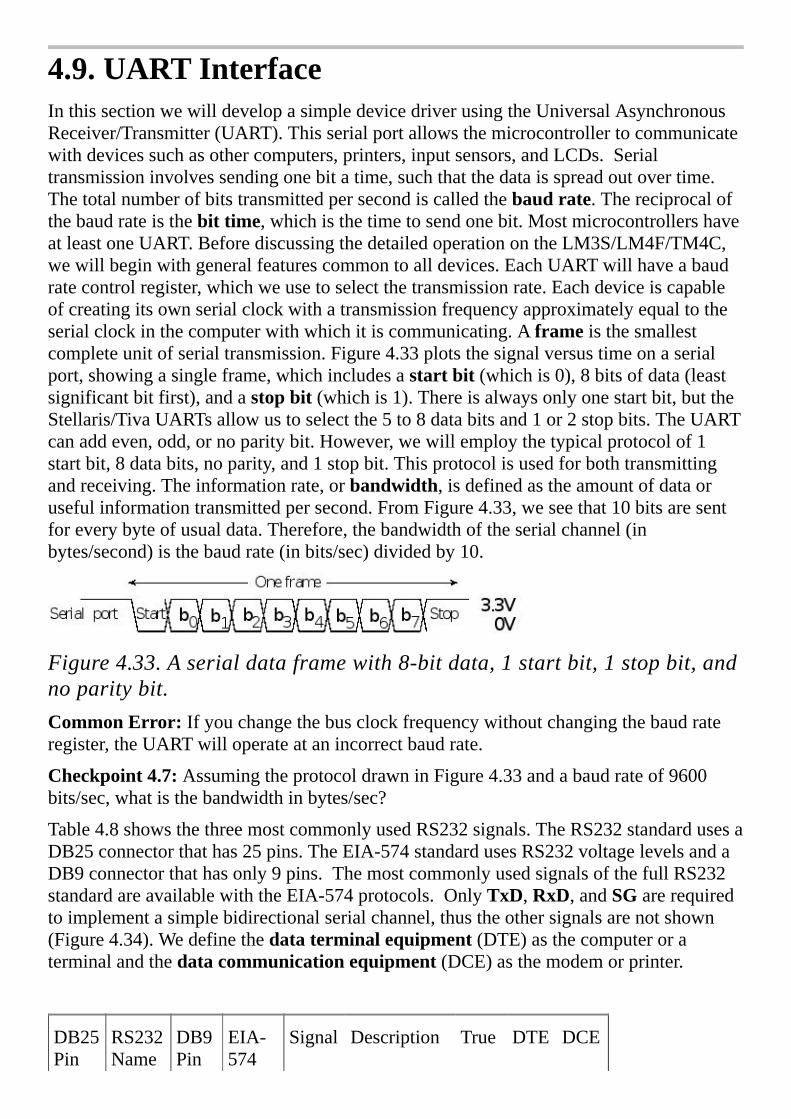
4.9.UARTInterfaceInthissectionwewilldevelopasimpledevicedriverusingtheUniversalAsynchronousReceiver/Transmitter(UART).Thisserialportallowsthemicrocontrollertocommunicatewithdevicessuchasothercomputers,printers,inputsensors,andLCDs.Serialtransmissioninvolvessendingonebitatime,suchthatthedataisspreadoutovertime.Thetotalnumberofbitstransmittedpersecondiscalledthebaudrate.Thereciprocalofthebaudrateisthebittime,whichisthetimetosendonebit.MostmicrocontrollershaveatleastoneUART.BeforediscussingthedetailedoperationontheLM3S/LM4F/TM4C,wewillbeginwithgeneralfeaturescommontoalldevices.EachUARTwillhaveabaudratecontrolregister,whichweusetoselectthetransmissionrate.Eachdeviceiscapableofcreatingitsownserialclockwithatransmissionfrequencyapproximatelyequaltotheserialclockinthecomputerwithwhichitiscommunicating.Aframeisthesmallestcompleteunitofserialtransmission.Figure4.33plotsthesignalversustimeonaserialport,showingasingleframe,whichincludesastartbit(whichis0),8bitsofdata(leastsignificantbitfirst),andastopbit(whichis1).Thereisalwaysonlyonestartbit,buttheStellaris/TivaUARTsallowustoselectthe5to8databitsand1or2stopbits.TheUARTcanaddeven,odd,ornoparitybit.However,wewillemploythetypicalprotocolof1startbit,8databits,noparity,and1stopbit.Thisprotocolisusedforbothtransmittingandreceiving.Theinformationrate,orbandwidth,isdefinedastheamountofdataorusefulinformationtransmittedpersecond.FromFigure4.33,weseethat10bitsaresentforeverybyteofusualdata.Therefore,thebandwidthoftheserialchannel(inbytes/second)isthebaudrate(inbits/sec)dividedby10.
Figure4.33.Aserialdataframewith8-bitdata,1startbit,1stopbit,andnoparitybit.CommonError:Ifyouchangethebusclockfrequencywithoutchangingthebaudrateregister,theUARTwilloperateatanincorrectbaudrate.
Checkpoint4.7:AssumingtheprotocoldrawninFigure4.33andabaudrateof9600bits/sec,whatisthebandwidthinbytes/sec?
Table4.8showsthethreemostcommonlyusedRS232signals.TheRS232standardusesaDB25connectorthathas25pins.TheEIA-574standardusesRS232voltagelevelsandaDB9connectorthathasonly9pins.ThemostcommonlyusedsignalsofthefullRS232standardareavailablewiththeEIA-574protocols.OnlyTxD,RxD,andSGarerequiredtoimplementasimplebidirectionalserialchannel,thustheothersignalsarenotshown(Figure4.34).Wedefinethedataterminalequipment(DTE)asthecomputeroraterminalandthedatacommunicationequipment(DCE)asthemodemorprinter.
DB25Pin
RS232Name
DB9Pin
EIA-574
Signal Description True DTE DCE
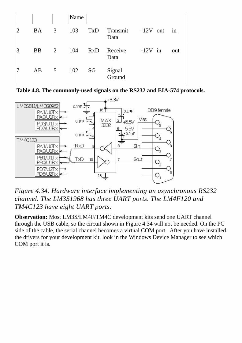
Name
2 BA 3 103 TxD TransmitData
-12V out in
3 BB 2 104 RxD ReceiveData
-12V in out
7 AB 5 102 SG SignalGround
Table4.8.Thecommonly-usedsignalsontheRS232andEIA-574protocols.
Figure4.34.HardwareinterfaceimplementinganasynchronousRS232channel.TheLM3S1968hasthreeUARTports.TheLM4F120andTM4C123haveeightUARTports.Observation:MostLM3S/LM4F/TM4CdevelopmentkitssendoneUARTchannelthroughtheUSBcable,sothecircuitshowninFigure4.34willnotbeneeded.OnthePCsideofthecable,theserialchannelbecomesavirtualCOMport.Afteryouhaveinstalledthedriversforyourdevelopmentkit,lookintheWindowsDeviceManagertoseewhichCOMportitis.

RS232isanon-return-to-zero(NRZ)protocolwithtruesignifiedasavoltagebetween-5and‑15V.Falseissignifiedbyavoltagebetween+5and+15V.AMAX3232converterchipisusedtotranslatebetweenthe+5.5/-5.5VRS232levelsandthe0/+3.3Vdigitallevels,asshowninFigure4.34.Thecapacitorsinthiscircuitareimportant,becausetheyformachargepumpusedtocreatethe±5.5voltagesfromthe+3.3Vsupply.TheRS232timingisgeneratedautomaticallybytheUART.Duringtransmission,theMaximchiptranslatesadigitalhighonmicrocontrollersideto-5.5VontheRS232/EIA‑574cable,andadigitallowistranslatedto+5.5V.Duringreceiving,theMaximchiptranslatesnegativevoltagesonRS232/EIA‑574cabletoadigitalhighonthemicrocontrollerside,andapositivevoltageistranslatedtoadigitallow.ThecomputerisclassifiedasDTE,soitsserialoutputispin3intheEIA‑574cable,anditsserialinputispin2intheEIA‑574cable.WhenconnectingaDTEtoanotherDTE,weuseacablewithpins2and3crossed.I.e.,pin2ononeDTEisconnectedtopin3ontheotherDTEandpin3ononeDTEisconnectedtopin2ontheotherDTE.WhenconnectingaDTEtoaDCE,thenthecablepassesthesignalsstraightacross.Inallsituations,thegroundsareconnectedtogetherusingtheSGwireinthecable.Thischannelisclassifiedasfullduplex,becausetransmissioncanoccurinbothdirectionssimultaneously.
4.9.1.TransmittinginasynchronousmodeWewillbeginwithtransmission,becauseitissimple.ThetransmitterportionoftheUARTincludesadataoutputpin,withdigitallogiclevelsasdrawninFigure4.33.Thetransmitterhasa16-elementFIFOanda10-bitshiftregister,whichcannotbedirectlyaccessedbytheprogrammer(Figure4.35).TheFIFOandshiftregisterinthetransmitterareseparatefromtheFIFOandshiftregisterassociatedwiththereceiver.TooutputdatausingtheUART,thesoftwarewillfirstchecktomakesurethetransmitFIFOisnotfull(itwillwaitifTXFFis1)andthenwritetothetransmitdataregister(e.g., UART0_DR_R ).Thebitsareshiftedoutinthisorder:start,b0,b1,b2,b3,b4,b5,b6,b7,andthenstop,whereb0istheLSBandb7istheMSB.Thetransmitdataregisteriswriteonly,whichmeansthesoftwarecanwritetoit(tostartanewtransmission)butcannotreadfromit.Eventhoughthetransmitdataregisterisatthesameaddressasthereceivedataregister,thetransmitandreceivedataregistersaretwoseparateregisters.
Figure4.35.Dataandshiftregistersimplementtheserialtransmission.
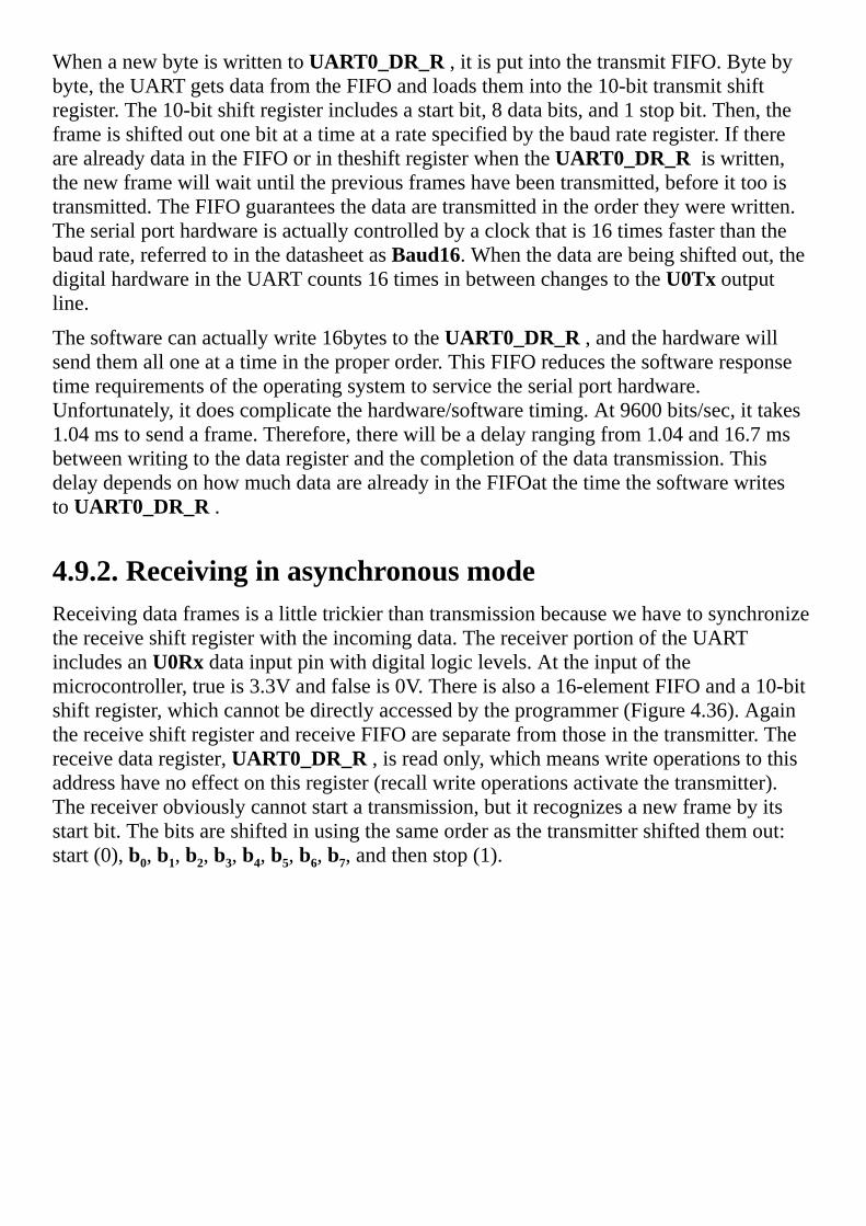
WhenanewbyteiswrittentoUART0_DR_R ,itisputintothetransmitFIFO.Bytebybyte,theUARTgetsdatafromtheFIFOandloadsthemintothe10-bittransmitshiftregister.The10-bitshiftregisterincludesastartbit,8databits,and1stopbit.Then,theframeisshiftedoutonebitatatimeataratespecifiedbythebaudrateregister.IftherearealreadydataintheFIFOorintheshiftregisterwhenthe UART0_DR_R iswritten,thenewframewillwaituntilthepreviousframeshavebeentransmitted,beforeittooistransmitted.TheFIFOguaranteesthedataaretransmittedintheordertheywerewritten.Theserialporthardwareisactuallycontrolledbyaclockthatis16timesfasterthanthebaudrate,referredtointhedatasheetasBaud16.Whenthedataarebeingshiftedout,thedigitalhardwareintheUARTcounts16timesinbetweenchangestotheU0Txoutputline.
Thesoftwarecanactuallywrite16bytestothe UART0_DR_R ,andthehardwarewillsendthemalloneatatimeintheproperorder.ThisFIFOreducesthesoftwareresponsetimerequirementsoftheoperatingsystemtoservicetheserialporthardware.Unfortunately,itdoescomplicatethehardware/softwaretiming.At9600bits/sec,ittakes1.04mstosendaframe.Therefore,therewillbeadelayrangingfrom1.04and16.7msbetweenwritingtothedataregisterandthecompletionofthedatatransmission.ThisdelaydependsonhowmuchdataarealreadyintheFIFOatthetimethesoftwarewritesto UART0_DR_R .
4.9.2.ReceivinginasynchronousmodeReceivingdataframesisalittletrickierthantransmissionbecausewehavetosynchronizethereceiveshiftregisterwiththeincomingdata.ThereceiverportionoftheUARTincludesanU0Rxdatainputpinwithdigitallogiclevels.Attheinputofthemicrocontroller,trueis3.3Vandfalseis0V.Thereisalsoa16-elementFIFOanda10-bitshiftregister,whichcannotbedirectlyaccessedbytheprogrammer(Figure4.36).AgainthereceiveshiftregisterandreceiveFIFOareseparatefromthoseinthetransmitter.Thereceivedataregister, UART0_DR_R ,isreadonly,whichmeanswriteoperationstothisaddresshavenoeffectonthisregister(recallwriteoperationsactivatethetransmitter).Thereceiverobviouslycannotstartatransmission,butitrecognizesanewframebyitsstartbit.Thebitsareshiftedinusingthesameorderasthetransmittershiftedthemout:start(0),b0,b1,b2,b3,b4,b5,b6,b7,andthenstop(1).

Therearesixstatusbitsgeneratedbyreceiveractivity.TheReceiveFIFOemptyflag,RXFE,isclearwhennewinputdataareinthereceiveFIFO.Whenthesoftwarereadsfrom UART0_DR_R ,dataareremovedfromtheFIFO.WhentheFIFObecomesempty,theRXFEflagwillbeset,meaningtherearenomoreinputdata.Thereareotherflagsassociatedwiththereceiver.ThereisaReceiveFIFOfullflagRXFF,whichissetwhentheFIFOisfull.Therearefourstatusbitsassociatedwitheachbyteofdata.Forthisreason,thereceiveFIFOis12bitswide.Theoverrunerror,OE,issetwheninputdataarelostbecausetheFIFOisfullandmoreinputframesarearrivingatthereceiver.Anoverrunerroriscausedwhenthereceiverinterfacelatencyistoolarge.Thebreakerror,BE,issetwhentheinputisheldlowformorethanaframe.ThePEbitissetonaparityerror.Becausetheerrorrateissolow,mostsystemsdonotimplementparity.Theframingerror,FE,issetwhenthestopbitisincorrect.Framingerrorsareprobablycausedbyamismatchinbaudrate.
Figure4.36.Dataregistershiftregistersimplementthereceiveserialinterface.Thereceiverwaitsforthe1to0edgesignifyingastartbit,thenshiftsin10bitsofdataoneatatimefromtheU0Rxline.TheinternalBaud16clockis16timesfasterthanthebaudrate.Afterthe1to0edge,thereceiverwaits8Baud16clocksandsamplesthestartbit.16Baud16clockslateritsamplesb0.Every16Baud16clocksitsamplesanotherbituntilitreachesthestopbit.TheUARTneedsaninternalclockfasterthanthebaudratesoitcanwaitthehalfabittimebetweenthe1to0edgebeginningthestartbitandthemiddleofthebitwindowneededforsampling.Thestartandstopbitsareremoved(checkedforframingerrors),the8bitsofdataand4bitsofstatusareputintothereceiveFIFO.TheFIFOimplementshardwarebufferingsodatacanbesafelystoredifthesoftwareisperformingothertasks.
Observation:IfthereceivingUARTdevicehasabaudratemismatchofmorethan5%,thenaframingerrorcanoccurwhenthestopbitisincorrectlycaptured.
Anoverrunoccurswhenthereare16elementsinthereceiveFIFO,anda17thframecomesintothereceiver.Inordertoavoidoverrun,wecandesignareal-timesystem,i.e.,onewithamaximumlatency.ThelatencyofaUARTreceiveristhedelaybetweenthetimewhennewdataarrivesinthereceiver(RXFE=0)andthetimethesoftwarereadsthedataregister.Ifthelatencyisalwayslessthan160bittimes,thenoverrunwillneveroccur.

Observation:Withaserialportthathasashiftregisterandonedataregister(noFIFObuffering),thelatencyrequirementoftheinputinterfaceisthetimeittakestotransmitonedataframe.
IntheexampleillustratedinFigure4.37,assumetheUARTreceiveshiftregisterandreceiveFIFOareinitiallyempty(RXFE=1).17incomingserialframesoccuronerightafteranother(lettersA–Q),butthesoftwaredoesnotrespond.Attheendofthefirstframe,the0x41goesintothereceiveFIFO,andtheRXFEflagiscleared.Normally,the UART_InChar functionwouldrespondtoRXFEbeingclearandreadthedatafromtheUART.Inthisscenariohowever,thesoftwareisbusydoingotherthingsanddoesnotrespondtothepresenceofdatainthereceiveFIFO.Next,15moreframesareshiftedinandenteredintothereceiveFIFO.Attheendofthe16thframe,theFIFOisfull(RXFF=1).Ifthesoftwareweretorespondatthispoint,thenall16characterswouldbeproperlyreceived.Ifthe17thframeoccursbeforethefirstisreadbythesoftware,thenanoverrunerroroccurs,andaframeislost.WecanseefromthisworstcasescenariothatthesoftwaremustreadthedatafromtheUARTwithin160bittimesoftheclearingofRXFE.
Figure4.37.Seventeenreceivedataframesresultinanoverrun(OE)error.
4.9.3.LM3S/LM4F/TM4CUARTDetailsNextwewilloverviewthespecificUARTfunctionsontheLM3S/LM4F/TM4Cmicrocontrollers.ThissectionisintendedtosupplementratherthanreplacetheTexasInstrumentsmanuals.WhendesigningsystemswithanyI/Omodule,youmustalsorefertothereferencemanualofyourspecificmicrocontroller.Itisalsogooddesignpracticetoreviewtheerrataforyourmicrocontrollertoseeifanyquirks(mistakes)existinyourmicrocontrollerthatmightapplytothesystemyouaredesigning.
TheLM3S/LM4F/TM4CmicrocontrollershaveonetoeightUARTs.ThespecificportpinsusedtoimplementtheUARTsvaryfromonechiptothenext.Tofindwhichpinsyourmicrocontrolleruses,youwillneedtoconsultitsdatasheet.Table4.9showssomeoftheregistersfortheUART0.IfthemicrocontrollerhasmultipleUARTs,theregisternameswillreplacethe0witha1–7.Fortheexactregisteraddresses,youshouldincludetheappropriateheaderfile(e.g.,tm4c1294ncpdt.h).ToactivateaUARTyouwillneedtoturnontheUARTclockintheSYSCTL_RCGCUART_Rregister.YoushouldalsoturnontheclockforthedigitalportintheSYSCTL_RCGCGPIO_Rregister.Youneedtoenablethetransmitandreceivepinsasdigitalsignals.Thealternativefunctionforthesepinsmustalsobeselected.

TheOE,BE,PE,andFEareerrorflagsassociatedwiththereceiver.Youcanseetheseflagsintwoplaces:associatedwitheachdatabytein UART0_DR_R orasaseparateerrorregisterin UART0_RSR_R .Theoverrunerror(OE)issetifdatahasbeenlostbecausetheinputdriverlatencyistoolong.BEisabreakerror,meaningtheotherdevicehassentabreak.PEisaparityerror(however,wewillnotbeusingparity).Theframingerror(FE)willgetsetifthebaudratesdonotmatch.Thesoftwarecanclearthesefourerrorflagsbywritinganyvalueto UART0_RSR_R .
ThestatusofthetwoFIFOscanbeseeninthe UART0_FR_R register.TheBUSYflagissetwhilethetransmitterstillhasunsentbits.ItwillbecomezerowhenthetransmitFIFOisemptyandthelaststopbithasbeensent.Ifyouimplementbusy-waitoutputbyfirstoutputtingthenwaitingforBUSYtobecome0(middleflowchartofFigure4.29),thentheroutinewillwritenewdataandreturnafterthatparticulardatahasbeencompletelytransmitted.
The UART0_CTL_R controlregistercontainsthebitsthatturnontheUART.TXEistheTransmitterEnablebit,andRXEistheReceiverEnablebit.WesetTXE,RXE,andUARTENequalto1inordertoactivatetheUARTdevice.However,weshouldclearUARTENduringtheinitializationsequence.
31–12 11 10 9 8 7–0 Name
$4000.C000 OE BE PE FE DATA UART0_DR_R
31–3 3 2 1 0
$4000.C004 OE BE PE FE UART0_RSR_R
31–8 7 6 5 4 3 2–0
$4000.C018 TXFE RXFF TXFF RXFE BUSY UART0_FR_R
31–16 15–0
$4000.C024 DIVINT UART0_IBRD_R
31–6 5–0
$4000.C028 DIVFRAC UART0_FBRD_R

31–8 7 6–5 4 3 2 1 0
$4000.C02C SPS WLEN FEN STP2 EPS PEN BRK UART0_LCRH_R
31–10 9 8 7 6–3 2 1 0
$4000.C030 RXE TXE LBE SIRLP SIREN UARTEN UART0_CTL_R
31–6 5-3 2-0
$4000.C034 RXIFLSEL TXIFLSEL UART0_IFLS_R
31-11 10 9 8 7 6 5 4
$4000.C038 OEIM BEIM PEIM FEIM RTIM TXIM RXIM UART0_IM_R
$4000.C03C OERIS BERIS PERIS FERIS RTRIS TXRIS RXRIS UART0_RIS_R
$4000.C040 OEMIS BEMIS PEMIS FEMIS RTMIS TXMIS RXMIS UART0_MIS_R
$4000.C044 OEIC BEIC PEIC FEIC RTIC TXIC RXIC UART0_ICR_R
Table4.9.SomeUARTregisters.Eachregisteris32bitswide.Shadedbitsarezero.
The UART0_IBRD_R andUART0_FBRD_R registersspecifythebaudrate.Thebaudratedividerisa22-bitbinaryfixed-pointvaluewitharesolutionof2-6.TheBaud16clockiscreatedfromthesystembusclock,withafrequencyof(Busclockfrequency)/divider.Thebaudrateis16timesslowerthanBaud16
Baudrate=Baud16/16=(Busclockfrequency)/(16*divider)
Forexample,ifthebusclockis8MHzandthedesiredbaudrateis19200bits/sec,thenthedividershouldbe8,000,000/16/19200or26.04167.Asabinaryfixed-pointnumber,thisnumberisabout11010.000011.Wecanestablishthisbaudratebyputtingthe11010into UART0_IBRD_R andthe000011into UART0_FBRD_R .Inreality,11010.000011isequalto1667/64or26.046875.Thebaudratesinthetransmitterandreceivermustmatchwithin5%forthechanneltooperateproperly.Theerrorforthisexampleis0.02%.
Thethreeregisters UART0_LCRH_R , UART0_IBRD_R ,and UART0_FBRD_R formaninternal30-bitregister.Thisinternalregisterisonlyupdatedwhenawriteoperationto UART0_LCRH_R isperformed,soanychangestothebaud-ratedivisormustbefollowedbyawritetothe UART0_LCRH_R registerforthechangestotakeeffect.Outofreset,bothFIFOsaredisabledandactas1-byte-deepholdingregisters.TheFIFOsareenabledbysettingtheFENbitin UART0_LCRH_R .

Checkpoint4.8:Assumethebusclockis6MHz.WhatisthebaudrateifUART0_IBRD_Requals10andUART0_FBRD_Requals20?
Checkpoint4.9:Assumethebusclockis50MHz.WhatvaluesshouldyouputinUART0_IBRD_RandUART0_FBRD_Rtomakeabaudrateof38400bits/sec?
TouseinterruptswewillenabletheFIFOsbysettingtheFENbitinthe UART0_LCRH_R register.RXIFLSELspecifiesthereceiveFIFOlevelthatcausesaninterrupt.TXIFLSELspecifiesthetransmitFIFOlevelthatcausesaninterrupt.
RXIFLSELRXFIFOSetRXMISinterrupttriggerwhen
0x0≥⅛fullReceiveFIFOgoesfrom1to2characters
0x1≥¼fullReceiveFIFOgoesfrom3to4characters
0x2≥½fullReceiveFIFOgoesfrom7to8characters
0x3≥¾fullReceiveFIFOgoesfrom11to12characters
0x4≥⅞fullReceiveFIFOgoesfrom13to14characters
TXIFLSELTXFIFOSetTXMISinterrupttriggerwhen
0x0≤⅞emptyTransmitFIFOgoesfrom15to14characters
0x1≤¾emptyTransmitFIFOgoesfrom13to12characters
0x2≤½emptyTransmitFIFOgoesfrom9to8characters
0x3≤¼emptyTransmitFIFOgoesfrom5to4characters
0x4≤⅛emptyTransmitFIFOgoesfrom3to2characters
TherearesevenpossibleinterrupttriggerflagsthatareintheUART0_RIS_R register.ThesettingoftheTXRISandRXRISflagsisdefinedabove.TheOERISflagissetonanoverrun,newincomingframereceivedbutthereceiveFIFOisfull.TheBERISflagissetonabreakerror.ThePERISflagissetonaparityerror.TheFERISflagissetonaframingerror(stopbitisnothigh).TheRTRISissetonareceivertimeout,whichiswhenthereceiverFIFOisnotemptyandnoincomingframeshaveoccurredina32-bittimeperiod.Eachoftheseventriggerflagshasacorrespondingarmbitinthe UART0_IM_Rregister.AbitintheUART0_MIS_R registersetifthetriggerflagisbothsetandarmed.Toacknowledgeaninterrupt(makethetriggerflagbecomezero),softwarewritesa1tothecorrespondingbitin UART0_IC_R .
4.9.4.UARTdevicedriverSoftwarethatsendsandreceivesdatamustimplementamechanismtosynchronizethesoftwarewiththehardware.Inparticular,thesoftwareshouldreaddatafromtheinputdeviceonlywhendataisindeedready.Similarly,softwareshouldwritedatatoanoutputdeviceonlywhenthedeviceisreadytoacceptnewdata.Withbusy-waitsynchronization,

thesoftwarecontinuouslychecksthehardwarestatuswaitingforittobeready.Inthissection,wewillusebusy-waitsynchronizationtowriteI/OprogramsthatsendandreceivedatausingtheUART.Afteraframeisreceived,thereceiveFIFOwillbenotempty(RXFEbecomes0)andthe8-bitdataisavailabletoberead.Togetnewdatafromtheserialport,thesoftwarefirstwaitsforRXFEtobezero,thenreadstheresultfrom UART0_DR_R .Recallthatwhenthesoftwarereads UART0_DR_R itgetsdatafromthereceiveFIFO.ThisoperationisillustratedinFigure4.38andshowninProgram4.10.Inasimilarfashion,whenthesoftwarewishestooutputviatheserialport,itfirstwaitsforTXFFtobeclear,thenperformstheoutput.Whenthesoftwarewrites UART0_DR_R itputsdataintothetransmitFIFO.AninterruptsynchronizationmethodwillbepresentedinChapter5.
Figure4.38.FlowchartsofInCharandOutCharusingbusy-waitsynchronization.Theinitializationprogram, UART_Init ,enablestheUARTdeviceandselectsthebaudrate.TheinputroutinewaitsinaloopuntilRXFEis0(FIFOnotempty),thenreadsthedataregister.TheoutputroutinefirstwaitsinaloopuntilTXFFis0(FIFOnotfull),thenwritesdatatothedataregister.Pollingbeforewritingdataisanefficientwaytoperformoutput.
//Assumesan80MHzbusclock,creates115200baudrate
voidUART_Init(void)//shouldbecalledonlyonce
SYSCTL_RCGCUART_R|=0x0001;//activateUART0
SYSCTL_RCGCGPIO_R|=0x0001;//activateportA
UART0_CTL_R&=~0x0001;//disableUART
UART0_IBRD_R=43;//IBRD=int(80000000/(16*115,200))=int(43.40278)
UART0_FBRD_R=26;//FBRD=round(0.40278*64)=26
UART0_LCRH_R=0x0070;//8-bitwordlength,enableFIFO
UART0_CTL_R=0x0301;//enableRXE,TXEandUART
GPIO_PORTA_PCTL_R=(GPIO_PORTA_PCTL_R&0xFFFFFF00)+0x00000011;//UART
GPIO_PORTA_AMSEL_R&=~0x03;//TM4C,disableanalogonPA1-0

GPIO_PORTA_AFSEL_R|=0x03;//enablealtfunctonPA1-0
GPIO_PORTA_DEN_R|=0x03;//enabledigitalI/OonPA1-0
//Waitfornewinput,thenreturnASCIIcode
charUART_InChar(void)
while((UART0_FR_R&0x0010)!=0);//waituntilRXFEis0
return((char)(UART0_DR_R&0xFF));
//Waitforbuffertobenotfull,thenoutput
voidUART_OutChar(chardata)
while((UART0_FR_R&0x0020)!=0);//waituntilTXFFis0
UART0_DR_R=data;
Program4.10.DevicedriverfunctionsthatimplementserialI/O(UART_xxx.zip).Checkpoint4.10:HowdoesthesoftwareclearRXFE?
Checkpoint4.11:HowdoesthesoftwareclearTXFF?
Checkpoint4.12:Describewhathappensifthereceivingcomputerisoperatingonabaudratethatistwiceasfastasthetransmittingcomputer?
Checkpoint4.13:Describewhathappensifthetransmittingcomputerisoperatingonabaudratethatistwiceasfastasthereceivingcomputer?

4.10.KeyboardInterfaceInthissectionweattempttointerfaceswitchestodigitalI/Opinsandwillconsiderthreeinterfacingschemes,asshowninFigure4.39.Inadirectinterfaceweconnecteachswitchuptoaseparatemicrocontrollerinputpin.Forexampleusingjustone8-bitparallelport,wecanconnect8switchesusingthedirectscheme.Anadvantageofthisinterfacingapproachisthatthesoftwarecanrecognizeall256(28)possibleswitchpatterns.Iftheswitcheswereremotefromthemicrocontroller,wewouldneeda9-wirecabletoconnectittothemicrocontroller.Ingeneral,iftherearenswitches,wewouldneedn/8parallelportsandn+1wiresinthecable.Thismethodwillbeusedwhenthereareasmallnumberofswitches,orwhenwemustrecognizemultiplesimultaneouskeypresses.Wewillusethedirectapproachformusickeyboardsandformodifierkeyssuchasshift,control,andalt.
Figure4.39.Threeapproachestointerfacingmultiplekeys.Inascannedinterfacetheswitchesareplacedinarow/columnmatrix.The atthefouroutputssignifiesopendrain(anoutputwithtwostates:HiZandlow.)Thesoftwaredrivesonerowatatimetozero,whileleavingtheotherrowsatHiZ.Byreadingthecolumn,thesoftwarecandetectifakeyispressedinthatrow.Thesoftware“scans”thedevicebycheckingallrowsonebyone.TheTable4.10illustratesthesequencetoscanthe4rows.
Row Out3 Out2 Out1 Out0
3 0 HiZ HiZ HiZ
2 HiZ 0 HiZ HiZ
1 HiZ HiZ 0 HiZ
0 HiZ HiZ HiZ 0
Table4.10.Scanningpatternsfora4by4matrixkeyboard.

Forcomputerswithoutanopendrainoutputmode,thedirectionregistercanbetoggledtosimulatethetwooutputstates,HiZ/0,oropendrainlogic.ThismethodcaninterfacemanyswitcheswithasmallnumberofparallelI/Opins.Inourexamplesituation,thesingle8-bitI/Oportcanhandle16switcheswithonlyan8-wirecable.Thedisadvantageofthescannedapproachoverthedirectapproachisthatitcanonlyhandlesituationswhere0,1or2switchesaresimultaneouslypressed.Thismethodisusedformostoftheswitchesinourstandardcomputerkeyboard.Theshift,alt,andcontrolkeysareinterfacedwiththedirectmethod.Wecan“arm”thisinterfaceforinterruptsbydrivingalltherowstozero.Theedge-triggeredinputcanbeusedtogenerateinterruptsontouchandrelease.Becauseoftheswitchbounce,anedge-triggeredinterruptwilloccurwhenanyofthekeyschange.Inthissectionwewillinterfacethekeypadusingbusy-waitsynchronization.
Withascannedapproach,wegiveuptheabilitytodetectthreeormorekeyspressedsimultaneously.Ifthreekeysarepressedinan“L”shape,thenthefourthkeythatcompletestherectanglewillappeartobepressed.Therefore,specialkeysliketheshift,control,option,andaltarenotplacedinthescannedmatrix,butratherareinterfaceddirectly,eachtoaseparateinputport.Ingeneral,annbymmatrixkeypadhasn*mkeys,butrequiresonlyn+mI/Opins.Youcandetectany0,1,or2keycombinations,butithastroublewhen3ormorearepressed.Thescannedkeyboardoperatesproperlyif
1.Nokeyispressed2.Exactlyonekeyispressed3.Exactlytwokeysarepressed.
Inamultiplexedinterface,thecomputeroutputsthebinaryvaluedefiningtherownumber,andahardwaredecoder(ordemultiplexer)willoutputthezeroontheselectedrowandHiZ’sontheotherrows.Thedecodermusthaveopencollectoroutputs(illustratedagainbythe intheabovecircuit.)Thecomputersimplyoutputsthesequence0x00,0x10,0x20,0x30,…,0xF0toscanthe16rows,asshownintheTable4.11.
Computeroutput Decoder
Row Out3 Out2 Out1 Out0 15 14 … 0
15 1 1 1 1 0 HiZ HiZ
14 1 1 1 0 HiZ 0 HiZ
…
1 0 0 0 1 HiZ HiZ HiZ

0 0 0 0 0 HiZ HiZ 0
Table4.11.Scanningpatternsforamultiplexed16by16matrixkeyboard.
Inasimilarway,thecolumninformationispassedtoahardwareencoderthatcalculatesthecolumnpositionofanyzerofoundintheselectedrow.Oneadditionalsignalisnecessarytosignifytheconditionthatnokeysarepressedinthatrow.Sincethisinterfacehas16rowsand16columns,wecaninterfaceupto256keys!Wecouldsacrificeoneofthecolumnstodetectthenokeypressedinthisrowsituation.Inthisway,wecaninterface240(15•16)keysonthesingle8-bitparallelport.Ifmorethanonekeyispressedinthesamerow,thismethodwillonlydetectoneofthem.Thereforeweclassifythisschemeasonlybeingabletohandlezerooronekeypressed.
Applicationsthatcanutilizethisapproachincludetouchscreensandtouchpadsbecausetheyhavealotofswitchesbutareonlyinterestedinthe0or1touchsituation.Implementinganinterruptdriveninterfacewouldrequiretoomuchadditionalhardware.Inthiscase,periodicpollinginterruptsynchronizationwouldbeappropriate.Ingeneral,annbymmatrixkeypadhasn*mkeys,butrequiresonlyx+y+1I/Opins,where2x=nand2y=m.Theextrainputisusedtodetecttheconditionwhennokeyispressedinthat
Example4.3:Interfacea16-keymatrixkeyboard.Therewillbeeitheronekeytouchedornokeystouched.
Solution:Thismatrixkeyboarddividesthesixteenkeysintofourrowsandfourcolumns,asshowninFigure4.40.Eachkeyexistsatauniquerow/columnlocation.ItwilltakeeightI/Opinstointerfacetherowsandcolumns.AnyoutputportontheLM3S/LM4F/TM4Ccouldhavebeenusedtointerfacetherows.Toscanthematrix,thesoftwarewilldrivetherowsoneatatimewithopencollectorlogicthenreadthecolumns.Theopencollectorlogic,withoutputsHiZand0,willbecreatedbytogglingthedirectionregisteronthefourrows.Actual10k pull-upresistorswillbeplacedonthecolumninputs(PA5-PA2)ratherthanconfiguredinternally,becausetheinternalpull-upsarenotfastenoughtohandlethescanningprocedure.

Figure4.40.Amatrixkeyboardinterfacedtothemicrocontroller.
Program4.11showstheinitializationsoftware.Thedatastructurewillassistinthescanningalgorithm,anditprovidesavisualmappingfromthephysicallayoutofthekeystotheASCIIcodeproducedwhentouchingthatkey.Thestructurealsomakesiteasytoadaptthissolutiontootherkeyboardinterfaces.Aperiodicinterruptcanbeusedtodebouncetheswitches.Thekeytodebouncingistonotobservetheswitchesmorefrequentlythanonceevery10ms.
voidMatrixKeypad_Init(void)
SYSCTL_RCGCGPIO_R|=0x09;//1)activateclockforPortsAandD
while((SYSCTL_PRGPIO_R&0x09)!=0x09);//ready?
GPIO_PORTA_AFSEL_R&=~0x3C;//GPIOfunctiononPA5-2
GPIO_PORTA_AMSEL_R&=~0x3C;//disableanalogfunctiononPA5-2
GPIO_PORTA_PCTL_R&=~0x00FFFF00;//configurePA5-2asGPIO
GPIO_PORTA_DEN_R|=0x3C;//enabledigitalI/OonPA5-2
GPIO_PORTA_DIR_R&=~0x3C;//makePA5-2in(PA5-2columns)
GPIO_PORTD_AFSEL_R&=~0x0F;//GPIOfunctiononPD3-0
GPIO_PORTD_AMSEL_R&=~0x0F;//disableanalogfunctiononPD3-0
GPIO_PORTD_PCTL_R&=~0x0000FFFF;//configurePD3-0asGPIO
GPIO_PORTD_DATA_R&=~0x0F;//DIRn=0,OUTn=HiZ;DIRn=1,OUTn=0
GPIO_PORTD_DEN_R|=0x0F;//enabledigitalI/OonPD3-0
GPIO_PORTD_DIR_R&=~0x0F;//makePD3-0in(PD3-0rows)
GPIO_PORTD_DR8R_R|=0x0F;//enable8mAdrive
Program4.11.Initializationsoftwareforamatrixkeyboard.
Program4.12showsthescanningsoftware.ThescanningsequenceislistedinTable4.12.Therearetwostepstoscanaparticularrow:
1.Selectthatrowbydrivingitlow,whiletheotherrowsareHiZ,2.Readthecolumnstoseeifanykeysarepressedinthatrow,0meansthekeyispressed

1meansthekeyisnotpressed
Itisimportanttoobservecolumnandrowsignalsonadualtraceoscilloscopewhilerunningthesoftwareatfullspeed,becauseittakestimeforcorrectsignaltoappearonthecolumnaftertherowischanged.Insomecases,asoftwaredelayshouldbeinsertedbetweensettingtherowandreadingthecolumn.Thelengthofthedelayyouwillneeddependsonthesizeofthepull-upresistorandanystraycapacitancethatmayexistinyourcircuit.
direction PD0 PD1 PD2 PD3 PA2 PA3 PA4 PA5
0x01 0 HiZ HiZ HiZ 1 2 3 A
0x02 HiZ 0 HiZ HiZ 4 5 6 B
0x04 HiZ HiZ 0 HiZ 7 8 9 C
0x08 HiZ HiZ HiZ 0 * 0 # D
Table4.12.Patternsfora4by4matrixkeyboard.
structRow
uint8_tdirection;
charkeycode[4];;
typedefconststructRowRowType;
RowTypeScanTab[5]=
0x01,“123A”,//row0
0x02,“456B”,//row1
0x04,“789C”,//row2
0x08,“*0#D”,//row3
0x00,“”;
/*ReturnsASCIIcodeforkeypressed,
Numisthenumberofkeyspressed
bothequalzeroifnokeypressed*/
charMatrixKeypad_Scan(int32_t*Num)
RowType*pt;

uint32_tcolumn;charkey;
uint32_tj;
(*Num)=0;
key=0;//defaultvalues
pt=&ScanTab[0];
while(pt->direction)
GPIO_PORTD_DIR_R=pt->direction;//oneoutput
GPIO_PORTD_DATA_R&=~0x0F;//DIRn=0,OUTn=HiZ;DIRn=1,OUTn=0
for(j=1;j<=10;j++);//veryshortdelay
column=((GPIO_PORTA_DATA_R&0x3C)>>2);//readcolumns
for(j=0;j<=3;j++)
if((column&0x01)==0)
key=pt->keycode[j];
(*Num)++;
column>>=1;//shiftintoposition
pt++;
returnkey;
/*Waitsforakeybepressed,thenreleased
ReturnsASCIIcodeforkeypressed,
Numisthenumberofkeyspressed
bothequalzeroifnokeypressed*/
charMatrixKeypad_In(void)int32_tn;
charletter;
do
letter=MatrixKeypad_Scan(&n);
while(n!=1);//repeatuntilexactlyone
do
letter=MatrixKeypad_Scan(&n);

while(n!=0);//repeatuntilrelease
returnletter;
Program4.12.Scanningsoftwareforamatrixkeyboard(MatrixKeypad_xxx.zip).
Two-keyrolloveroccurswhentheoperatoristypingquickly.Forexample,iftheoperatoristypingtheA,B,thenC,he/shemighttypeA,AB,B,BC,C,andthenrelease.Withrollover,thekeyboarddoesnotgothroughano-keystateinbetweentyping.ThehardwareinterfaceinFigure4.40couldhandletwo-keyrollover,butthesoftwaresolutioninProgram4.12doesnot.AninterruptversionofthisinterfacewillbepresentedinChapter5.

4.11.Exercises4.1In16wordsorless,describethemeaningofeachofthefollowingterms.
a)Latency
b)Real-time
c)Bandwidth
d)I/Obound
e)CPUbound
f)Blind-cyclesynchronization
g)Busy-waitsynchronization
h)Interruptsynchronization
i)Monotonic
j)Non-blocking
k)Deterministic
l)Slewrate
m)Opendrain
n)Handshake
4.2In16wordsorless,describethemeaningofeachofthefollowingterms.
a)Frame
b)Baudrate
c)Bandwidth
d)Fullduplex
e)DTE
f)DCE
g)Framingerror
h)Overrunerror
i)Devicedriver
j)NRZ
k)Bittime

l)Startandstopbits
4.3ListfivedifferentmethodsforI/Osynchronization.In16wordsorless,describeeachmethod.
4.4Listoneadvantageofblind-cyclesynchronization.Listonedisadvantage.
4.5Whatisdifferencebetweenbusy-waitandgadflysynchronization?
4.6In16wordsorless,definesetuptime.In16wordsorless,defineholdtime.
4.7Simplify↓A=5+[10,20]-[5,15]
4.8ConsideracircuitlikeFigure4.8,exceptusing74LS244and74LS374.Reworkthetimingequationstofindtheappropriatetimingrelationshipbetween↓G*,↑C,↑Cand↑G*sotheinterfacestillworks.Lookupthedatasheetsonwww.ti.com.
4.9ConsideracircuitinFigure4.8runningatvoltagesupplyVCCof2Vat25C.Reworkthetimingequationstofindtheappropriatetimingrelationshipbetween↓G*,↑C,↑Cand↑G*sotheinterfacestillworks.Lookupthedatasheetsonwww.ti.com.
4.10HighspeedCMOSlogicwillrunatawidevarietyofsupplyvoltages.Lookinthedatasheetsforthe74HC0474HC244and74HC374.MakeageneralobservationabouttherelationshipbetweenhowfastthechipoperatesandthepowersupplyvoltageforHClogic.
4.11Whatistheeffectofcapacitanceaddedtoadigitalline?
4.12WritecodetoconfigurePortDbit5asarisingedge-triggeredinput.WritecodethatwaitsforarisingedgeonPD5.
4.13WritecodetoconfigurePortAbit2asafallingedgeedge-triggeredinput.WritecodethatwaitsforafallingedgeonPA2.
4.14WritecodetoinitializeallofPortDasoutputs,inpowersavingmode.
4.15InterfaceapositivelogicswitchtoPA5withoutanexternalresistor.WritecodetoconfigurePortAbit5asneeded.Writecodethatwaitsfortheswitchtobetouched,thenreleased.Youmayassumetheswitchdoesnotbounce.
4.16InterfaceanegativelogicswitchtoPB6withoutanexternalresistor.WritecodetoconfigurePortBbit6asneeded.Writecodethatwaitsfortheswitchtobetouched,thenreleased.Youmayassumetheswitchdoesnotbounce.
4.17AssumeyouareusingtheFIFOimplementationsinProgram3.7.WhathappensintheKPNofProgram4.1ifaFIFObecomesempty?WhathappensinProgram4.1ifaFIFObecomesfull?
4.18Assumingthebusclocktobe8MHz,writecodetomakethebaudrate19200bits/sec.
4.19Assumingthebusclocktobe24MHz,whatvaluegoesinto UART0_IBRD_R and UART0_FBRD_R tomakethebaudrate9600bits/sec?

4.20LookuptheUARTmoduleinthedatasheetanddescribethesimilaritiesanddifferencesbetweenBUSYandTXFF.
4.21LookuptheUARTmoduleinthedatasheetanddescribethetwobitsofWLEN.
4.22LookuptheUARTmoduleinthedatasheet.
a)RedrawFigure4.33with1start,6data,noparityand1stopbit.
b)RedrawFigure4.33with1start,8data,noparityand2stopbits.
c)RedrawFigure4.33with1start,8data,evenparityand1stopbit.
4.23AssumeyouaregivenaworkingsystemwithaUARTconnectedtoanexternaldevice.Tosavepower,youdecidetoslowdownthebusclockbyafactorof4.BrieflyexplainthechangesrequiredfortheUARTsoftwaredriver.
4.24LookupinthedatasheethowtheUARToperatedwhentheFIFOsaredisabled.WouldthesolutioninProgram4.10stillworkiftheFIFOenablebit( UART0_LCRH_R bit4)werecleared?Ifitdoeswork,inwhatwayisitlessefficient?
4.25IsthewriteaccesstoPortAinProgram4.2friendly?WhatwouldyouchangeifyouwishedtoswitchthetwopinsonPortAtoPortE?
D4.26DrawtheequivalentoftheleftsideoftheKPNinProgram4.1usingaPetriNet.
D4.27LookatthedatasheetfortheNewhavenDisplayNHD-0108BZ-RN-YBW-3V3.WriteasoftwarefunctionusingtheLCDhardwareinSection4.7.1thatreadstheLCDstatusbit.Usethisfunctiontoconvert LCD_OutChar fromblindcycletobusywait.
D4.28Writethe Stepper_Seek functioninProgram4.6tominimizejerk.Slowlyrampuptheaccelerationasthemotorgoesfromstoppedtofullspeed( time parameter).Similarly,slowlyrampdowntheaccelerationasthemotorgoesfromfullspeedtostopped.
D4.29RewritetheprogramsinExample4.2touseUART0insteadoftheparallelports.Assumethebusclockis50MHz.Doitissuchawaythatthefunctionprototypesareidentical.LookupthemaximumallowablebaudratefortheUART.OpenoneoftheprojectsforExample4.2(Handshake_xxx.zip)fromthewebsiteandcountthenumberofassemblyinstructionsinboth Out and In .Addthesetwocountstogether(becausetheywaitforeachother).Multiplythetotalnumberofinstructionsby2busperiods(40ns).Usethisnumbertoestimatehowlongittakestosendonebyte.Comparethebandwidthsoftheserialandparallelapproaches.Mosthighspeedinterfacesuseaserialprotocol(e.g.,SATA,Ethernet.)Mostprocessorscommunicatewithmemoryusingaparallelprotocol.Listthreereasonsotherthanbandwidthforusingaseriallinkoveraparallelportwhencommunicatingbetweentwocomputers.
D4.30Rewrite UART_OutChar inProgram4.10tousebusy-waitsynchronizationontheBUSYbit.UsethemiddleflowchartinFigure4.29sotheroutinereturnsafterthedatahasbeentransmitted.
D4.31RewritethematrixkeypaddriverinPrograms4.12and4.13touseopendrainmodeonpinsPD3–PD0.Inotherwords,thedirectionregisterissetonceduringinitialization,andthedataregisterismodifiedduringscanning.

4.12.LabAssignmentsLab4.1Theoverallobjectiveistocreateaserialportdevicedriverthatsupportsfixed-pointinput/output.Theformatwillbe32-bitunsigneddecimalfixed-pointwitharesolutionof0.001.Youwillbeabletofindontheimplementationsofaserialportdriverthatsupportscharacter,string,andintegerI/O,UART_xxx.zip.Inparticular,youwilldesign,implement,andtesttworoutinescalled UART_FixIn and UART_FixOut . UART_FixIn willacceptinputfromtheUARTsimilartothefunction UART_InUDec . UART_FixOut willtransmitoutputtotheUARTsimilartothefunction UART_OutUDec .Duringthedesignphaseofthislab,youshoulddefinetherangeoffeaturesavailable.Youshoulddesign,implement,andtestamainprogramthatillustratestherangeofcapabilities.
Lab4.2ThesameasLab4.1excepttheformatwillbe32-bitsignedbinaryfixed-pointwitharesolutionof2-8.
Lab4.3Designafourfunction(add,subtract,multiply,divide)calculatorusingfixed-pointmathandtheUARTforinput/output.Theformatshouldbe32-bitsigneddecimalfixed-pointwitharesolutionof0.01.Youarefreetodesignthesyntaxofthecalculatorhoweveryouwish.
Lab4.4Designafourfunction(add,subtract,multiply,divide)calculatorusingfixed-pointmath.TakeinputfromamatrixkeypadandputoutputonanLCDorOLED.Theformatshouldbe32-bitsigneddecimalfixed-pointwitharesolutionof0.001.Youarefreetodesignthesyntaxofthecalculatorhoweveryouwish.
Lab4.5Theoverallobjectiveofthislabistodesign,implementandtestaparallelportexpander.Usinglessthan16I/Opinsofyourmicrocontroller,youwilldesignhardwareandsoftwarethatsupportstwo8-bitlatchedinputportsandtwostrobedoutputports.Eachinputporthas8datalinesandonelatchsignal.Ontherisingeachofthelatch,yoursystemshouldcapture(latch),thedatalines.Eachoutputporthas8datalinesandonestrobesignal.Thehardware/softwaresystemshouldgenerateapulseoutonstrobewhenevernewoutputissent.Theoutputportsdonotneedtobereadable.
Lab4.6Theoverallobjectiveofthislabistodesign,implementandtestaparalleloutputportexpander.UsingjustthreeI/Opinsofyourmicrocontroller,youwilldesignhardwareandsoftwarethatsupportsfour8-bitoutputports.Theoutputportsdonotneedtobereadable.
Lab4.7Theoverallobjectiveofthislabistodesign,implementandtestaparallelinputportexpander.UsingjustthreeI/Opinsofyourmicrocontroller,youwilldesignhardwareandsoftwarethatsupportsfour8-bitinputports.Theinputportsdonotneedtobelatched.

Lab4.8TheoverallobjectiveistocreateaHD44780-controlledLCDdevicedriverthatsupportsfixed-pointoutput.Theformatwillbe32-bitunsigneddecimalfixed-pointwithresolutionsof0.1,0.01and0.001.YouwillbeabletofindonthebookwebsiteimplementationsofaHD44780-controlledLCDdevicedriverthatsupportscharacter,string,andintegerI/O.Inparticular,youwilldesign,implement,andtestthreeroutinescalled LCD_FixOut1 LCD_FixOut2 and LCD_FixOut3 ,implementingfixed-pointresolutions0.1,0.01and0.001respectively.Duringthedesignphaseofthislab,youshoulddefinetherangeoffeaturesavailable.Youshoulddesign,implement,andtestamainprogramthatillustratestherangeofcapabilities.
Lab4.9ThesameasLab4.8excepttheformatwillbe32-bitsigneddecimalfixed-pointwithresolutionsof0.1,0.01and0.001.Youwilldesign,implement,andtestthreeroutines.
Lab4.10ThesameasLab4.8excepttheformatwillbe32-bitsignedbinaryfixed-pointwithresolutionsof2-4,2-8and2-12.Youwilldesign,implement,andtestthreeroutines.
Lab4.11ThesameasLab4.8excepttheformatswillbe12,24and32-bitunsignedintegers.Youwilldesign,implement,andtestthreeroutines.
Lab4.12TheoverallobjectiveistocreateaHD44780-controlledLCDdevicedriverthatsupportsvoltageversustimegraphicaloutput.Thedisplaywillbe8pixelshighby40pixelswide,using8characterpositionsontheLCD.YouwillneedtocontinuouslywritetotheCGRAMcreatingnewfonts,thenoutputthenewfontasdatatocreatetheimages.Theinitializationroutinewillclearthegraphandsettheminimumandmaximumrangescaleonthevoltageaxis(y-axis).Theplotroutinetakesavoltagedatapointbetweenminimumandmaximumanddrawsonepixelonthe8by40display.Ittakes40callstoplottocompleteoneimageonthedisplayasillustratedinFigure4.41.
Figure4.41.Imageafter40callstoplotwiththeLCDisinitializedtoMax=32,Min=0.Thesoftwareoutputsthisrepeatingpattern0,4,8,12,16,20,24,28,0,4,8,12,16…
Subsequentcallstoplotshouldremovethepointfrom40callsagoanddrawthenewpoint.Iftheplotiscalledatafixedperiod,thedisplayshouldshowacontinuoussweepofthevoltageversustimedata,likeanuntriggeredoscilloscope.Duringthedesignphaseofthislab,youshoulddefinetherangeoffeaturesavailable.Youshoulddesign,implement,andtestamainprogramthatillustratestherangeofcapabilities.
Lab4.13YouwillbeabletofindontheimplementationsofaOLEDdriverthatsupportstheprintfI/O,OLED_xxx.zip.Youwilldesign,implement,andtestthreeroutinescalled OLED_FixOut1 , OLED_FixOut2 ,and UART_FixOut3 .Thesethreefunctionsshouldimplement16-bitunsignedfixed-pointresolutions0.1,0.01and0.001respectively.Createfunctionslike Fixed_uDecOut2s thatconverttheintegerportionofthefixed-pointnumberwith =0.01toanASCIIstring.Youshouldbeabletocontrolthepositionandcoloroftheseoutputsinaconvenientmanner.Duringthedesignphaseofthislab,youshoulddefinetherangeoffeaturesavailable.Youshoulddesign,implement,andtestamainprogramthatillustratestherangeofcapabilities.

Lab4.14ThesameasLab4.13excepttheformatwillbe16-bitsigneddecimalfixed-pointwithresolutionsof0.1,0.01and0.001.Createfunctionslike Fixed_sDecOut2s thatconverttheintegerportionofthefixed-pointnumberwith =0.01toanASCIIstring.Youwilldesign,implement,andtestthreeroutines.
Lab4.15ThesameasLab4.13excepttheformatwillbe16-bitunsignedbinaryfixed-pointwithresolutionsof2-4,2-8and2-12.Youwilldesign,implement,andtestthreeroutines.Forexamplethefunction, Fixed_uBinOut8s convertstheintegerportionoftheunsigned16-bitfixed-pointnumberwith =2-8toanASCIIstring.
Lab4.16ThesameasLab4.13excepttheoutputwillgothroughtheUARTtoaCOMportonthePC.RunatermimalprogramlikePuTTyonthePC.
Lab4.17ThesameasLab4.14excepttheoutputwillgothroughtheUARTtoaCOMportonthePC.RunatermimalprogramlikePuTTyonthePC.
Lab4.18ThesameasLab4.15excepttheoutputwillgothroughtheUARTtoaCOMportonthePC.RunatermimalprogramlikePuTTyonthePC.


5.InterruptSynchronizationChapter5objectivesareto:•Introducetheconceptofinterruptsynchronization
•Discusstheissuesinvolvedinreentrantprogramming
•UsethefirstinfirstoutcircularqueueforbufferedI/O
•DiscussthespecificdetailsofusinginterruptsonCortex-M
•Interfacedevicesusingedge-triggeredinterrupts
•CreateperiodicinterruptsusingSysTick
•ImplementbackgroundI/Oforsimpledevicesusingperiodicpolling
Therearemanyreasonstoconsiderinterruptsynchronization.Thefirstconsiderationisthatthesoftwareinareal-timesystemmustrespondtohardwareeventswithinaprescribedtime.Givenachangeininput,itisnotonlynecessarytogetthecorrectresponse,butitwillbenecessarytogetthecorrectresponseatthecorrecttime.Toillustratetheneedforinterrupts,considerakeyboardinterfacewherethetimebetweennewkeyboardinputsmightbeassmallas10ms.Inthissituation,thesoftwarelatencyisthetimefromwhenthenewkeyboardinputisreadyuntilthetimethesoftwarereadsthenewdata.Inordertopreventlossofdatainthiscase,thesoftwarelatencymustbelessthan10ms.Wecanimplementreal-timesoftwareusingbusy-waitpollingonlywhenthesizeandcomplexityofthesystemisverysmall.Interruptsareimportantforreal-timesystemsbecausetheyprovideamechanismtoguaranteeanupperboundonthesoftwareresponsetime.Interruptsalsogiveusawaytorespondtoinfrequentbutimportantevents.Alarmconditionslikelowbatterypoweranderrorconditionscanbehandledwithinterrupts.Periodicinterrupts,generatedbythetimerataregularrate,willbenecessarytoimplementdataacquisitionandcontrolsystems.Intheunbufferedinterfacesofthepreviouschapter,thehardwareandsoftwaretookturnswaitingforeachother.Interruptsprovideawaytobufferthedata,sothatthehardwareandsoftwarespendlesstimewaiting.Inparticular,thebufferwewilluseisafirstinfirstoutqueueplacedbetweentheinterruptroutineandthemainprogramtoincreasetheoverallbandwidth.Wewillbeginourdiscussionwithgeneralissues,thenpresentthespecificdetailsabouttheLM3S/LM4F/TM4Cmicrocontrollers.Afterthat,anumberofsimpleinterruptexampleswillbepresented,andattheendofthechapterwewilldiscusssomeadvancedconceptslikepriorityandperiodicpolling.

5.1.MultithreadingAninterruptistheautomatictransferofsoftwareexecutioninresponsetoahardwareeventthatisasynchronouswiththecurrentsoftwareexecution.Thishardwareeventiscalledatrigger.ThehardwareeventcaneitherbeabusytoreadytransitioninanexternalI/Odevice(liketheUARTinput/output)oraninternalevent(likebusfault,memoryfault,oraperiodictimer.)Whenthehardwareneedsservice,signifiedbyabusytoreadystatetransition,itwillrequestaninterruptbysettingitstriggerflag.Athreadisdefinedasthepathofactionofsoftwareasitexecutes.Theexecutionoftheinterruptserviceroutineiscalledabackgroundthread.Thisthreadiscreatedbythehardwareinterruptrequestandiskilledwhentheinterruptserviceroutinereturnsfrominterrupt(e.g.,executingaBXLR ).Anewthreadiscreatedforeachinterruptrequest.Itisimportanttoconsidereachindividualrequestasaseparatethreadbecauselocalvariablesandregistersusedintheinterruptserviceroutineareuniqueandseparatefromoneinterrupteventtothenextinterrupt.Inamultithreadedsystem,weconsiderthethreadsascooperatingtoperformanoveralltask.Consequentlywewilldevelopwaysforthethreadstocommunicate(e.g.,FIFO)andsynchronizewitheachother.Mostembeddedsystemshaveasinglecommonoverallgoal.Ontheotherhand,general-purposecomputerscanhavemultipleunrelatedfunctionstoperform.Aprocessisalsodefinedastheactionofsoftwareasitexecutes.Processesdonotnecessarilycooperatetowardsacommonsharedgoal.ThreadsshareaccesstoI/Odevices,systemresources,andglobalvariables,whileprocesseshaveseparateglobalvariablesandsystemresources.ProcessesdonotshareI/Odevices.
Therearenostandarddefinitionsforthetermsmask,enableandarmintheprofessional,ComputerScience,orComputerEngineeringcommunities.Nevertheless,inthisbookwewilladheretothefollowingspecificmeanings.Toarm(disarm)adevicemeanstoenable(shutoff)thesourceofinterrupts.Eachpotentialinterruptingdevicehasaseparatearmbit.Onearms(disarms)adeviceifoneis(isnot)interestedininterruptsfromthissource.Toenable(disable)meanstoallowinterruptsatthistime(postponinginterruptsuntilalatertime).OntheARM ® CortexTM-Mprocessorthereisoneinterruptenablebitfortheentireinterruptsystem.Wedisableinterruptsifitiscurrentlynotconvenienttoacceptinterrupts.Inparticular,todisableinterruptswesettheIbitinPRIMASK.
Thesoftwarehasdynamiccontroloversomeaspectsoftheinterruptrequestsequence.First,eachpotentialinterrupttriggerhasaseparatearmbitthatthesoftwarecanactivateordeactivate.Thesoftwarewillsetthearmbitsforthosedevicesitwishestoacceptinterruptsfrom,andwilldeactivatethearmbitswithinthosedevicesfromwhichinterruptsarenottobeallowed.Inotherwordsitusesthearmbitstoindividuallyselectwhichdeviceswillandwhichdeviceswillnotrequestinterrupts.Thesecondaspectthatthesoftwarecontrolsistheinterruptenablebit.Specifically,bit0ofthespecialregisterPRIMASKistheinterruptmaskbit,I.Ifthisbitis1mostinterruptsandexceptionsarenotallowed,wewilldefineasdisabled.Ifthebitis0,theninterruptsareallowed,wewilldefineasenabled.TheBASEPRIregisterpreventsinterruptswithlowerpriorityinterrupts,butallowshigherpriorityinterrupts.ForexampleifBASEPRIequals3,thenrequestswithlevel0,1,and2caninterrupt,whilerequestsatlevels3andhigherwillbepostponed.Thesoftwarecanspecifytheprioritylevelofeachinterruptrequest.IfBASEPRIiszero,thenthepriorityfeatureisdisabledandallinterruptsareallowed.Four

conditionsmustbetrueforaninterrupttobegenerated:arm,enable,level,andtrigger.Adevicemustbearmed;interruptsmustbeenabled(I=0);theleveloftherequestedinterruptmustbelessthanBASEPRI;andanexternaleventmustoccursettingatriggerflag(e.g.,newUARTinputisready).Aninterruptcausesthefollowingsequenceofevents.First,thecurrentinstructionisfinished.Second,theexecutionofthecurrentlyrunningprogramissuspended,pushingeightregistersonthestack(R0,R1,R2,R3,R12,LR,PC,andPSRwiththeR0ontop).Third,theLRissettoaspecificvaluesignifyinganinterruptserviceroutine(ISR)isbeingrun(bits[31:8]to0xFFFFFF,bits[7:1]specifythetypeofinterruptreturntoperform,bit0willalwaysbe1ontheCortex-MmeaningThumbmode).Fourth,theIPSRissettotheinterruptnumberbeingprocessed.Lastly,thePCisloadedwiththeaddressoftheISR(vector).Thesefivesteps,calledacontextswitch,occurautomaticallyinhardwareasthecontextisswitchedfromforegroundtobackground.Next,thesoftwareexecutestheISR.
Ifatriggerflagisset,buttheprocessorisdisabled,theinterruptlevelisnothighenough,ortheflagisdisarmed,therequestisnotdismissed.Rathertherequestisheldpending,postponeduntilalatertime,whenthesystemdeemsitconvenienttohandletherequests.Clearingatriggerflagiscalledacknowledgement,whichoccursonlybyspecificsoftwareaction.Eachtriggerflaghasaspecificactionsoftwaremustperformtoclearthatflag.Wewillpayspecialattentiontotheseenable/disablesoftwareactions.Inparticularwewillneedtodisableinterruptswhenexecutingnonreentrantcodebutdisablinginterruptswillhavetheeffectofincreasingtheresponsetimeofsoftwaretoexternalevents.TheSysTickperiodicinterruptwillbetheonlyexampleofanautomaticacknowledgement.ForSysTick,theperiodictimerrequestsaninterrupt,butthetriggerflagwillbeautomaticallycleared.Foralltheothertriggerflags,theISRmustexplicitlyexecutecodethatclearstheflag.
Theinterruptserviceroutine(ISR)isthesoftwaremodulethatisexecutedwhenthehardwarerequestsaninterrupt.TheremaybeonelargeISRthathandlesallrequests(polledinterrupts),ormanysmallISRsspecificforeachpotentialsourceofinterrupt(vectoredinterrupts).TheCortex-Mhasbothpolledandvectoredinterrupts.Thedesignoftheinterruptserviceroutinerequirescarefulconsiderationofmanyfactors.TheISRmustacknowledgethetriggerflagthatcausedtheinterrupt.AftertheISRprovidesthenecessaryservice,itwillexecute BXLR .BecauseLRcontainsaspecialvalue,thisinstructionpullsthe8registersfromthestack,whichreturnscontroltothemainprogram.Therearetwostackpointers:PSPandMSP.ThesoftwareinthisbookwillexclusivelyusetheMSP.ItisimperativethattheISRsoftwarebalancethestackbeforeexiting.Executionofthemainprogramwillthencontinuewiththeexactstackandregistervaluesthatexistedbeforetheinterrupt.Althoughinterrupthandlerscancreateanduselocalvariables,parameterpassingbetweenthreadsmustbeimplementedusingsharedglobalmemoryvariables.Aprivateglobalvariablecanbeusedifaninterruptthreadwishestopassinformationtoitself,e.g.,fromoneinterruptinstancetoanother.Theexecutionofthemainprogramiscalledtheforegroundthread,andtheexecutionsofthevariousinterruptserviceroutinesarecalledbackgroundthreads.
AnaxiomwithinterruptsynchronizationisthattheISRshouldexecuteasfastaspossible.Theinterruptshouldoccurwhenitistimetoperformaneededfunction,andtheinterruptserviceroutineshouldperformthatfunction,andreturnrightaway.Placingbackwardbranches(busy-waitloops,iterations)intheinterruptsoftwareshouldbeavoidedifpossible.ThepercentageoftimespentexecutinganyoneISRshouldbeminimized.Foraninputdevice,theinterfacelatencyisthetimebetweenwhennewinputisavailable,andthetimewhenthesoftwarereadstheinputdata.WecanalsodefinedevicelatencyastheresponsetimeoftheexternalI/Odevice.Forexample,ifwerequestthatacertainsectorbereadfromadisk,thenthedevicelatencyisthetimeittaketofindthecorrecttrackandspinthedisk(seek)sothepropersectorispositionedunderthereadhead.Foranoutputdevice,theinterfacelatencyisthetimebetweenwhentheoutputdeviceisidle,andthetimewhenthesoftwarewritesnewdata.Areal-timesystemisonethatcanguaranteeaworstcaseinterfacelatency.
Manyfactorsshouldbeconsideredwhendecidingthemostappropriatemechanismtosynchronizehardwareandsoftware.Oneshouldnotalwaysusebusywaitbecauseoneistoolazytoimplementthecomplexitiesofinterrupts.Ontheotherhand,oneshouldnotalwaysuseinterruptsbecausetheyarefunandexciting.Busy-waitsynchronizationisappropriatewhentheI/Otimingispredicable,andwhentheI/Ostructureissimpleandfixed.BusywaitshouldbeusedfordedicatedsinglethreadsystemswherethereisnothingelsetodowhiletheI/Oisbusy.InterruptsynchronizationisappropriatewhentheI/Otimingisvariable,andwhentheI/Ostructureiscomplex.Inparticular,interruptsareefficientwhenthereareI/Odeviceswithdifferentspeeds.Interruptsallowforquickresponsetimestoimportantevents.Inparticular,usinginterruptsisonemechanismtodesignreal-timesystems,wheretheinterfacelatencymustbeshortandbounded.
Interruptscanalsobeusedforinfrequentbutcriticaleventslikepowerfailure,memoryfaults,andmachineerrors.Periodicinterruptswillbeusefulforreal-timeclocks,dataacquisitionsystems,andcontrolsystems.Forextremelyhighbandwidthandlowlatencyinterfaces,DMAshouldbeused.
Anatomicoperationisasequencethatoncestartedwillalwaysfinish,andcannotbeinterrupted.AllinstructionsontheARM ® CortexTM-Mprocessorareatomicexceptstoreandloadmultiple, STMLDM .Ifwewishtomakeasectionofcodeatomic,wecanrunthatcodewithI=1.Inthisway,interruptswillnotbeabletobreakapartthesequence.Again,requestedthataretriggeredwhileI=1arenotdismissed,butsimplypostponeduntilI=0.Inparticular,toimplementanatomicoperationwewill1)savethecurrentvalueofthePRIMASK,2)disableinterrupts,3)executetheoperation,and4)restorethePRIMASKbacktoitspreviousvalue.
Checkpoint5.1:Whatfourconditionsmustbetrueforaninterrupttooccur?
Checkpoint5.2:Howdoyouenableinterrupts?
Checkpoint5.3:Whatarethestepsthatoccurwhenaninterruptisprocessed?

Asyoudevelopexperienceusinginterrupts,youwillcometonoticeafewcommonaspectsthatmostcomputersshare.Thefollowingparagraphsoutlinethreeessentialmechanismsthatareneededtoutilizeinterrupts.Althougheverycomputerthatusesinterruptsincludesallthreemechanismsthereareawidespectrumofimplementationmethods.
Allinterruptingsystemsmusthavetheabilityforthehardwaretorequestactionfromcomputer.Theinterruptrequestscanbegeneratedusingaseparateconnectiontoprocessorforeachdevice,orusingasharednegativelogicwire-orrequestsusingopencollectorlogic.TheLM3S/TM4Cmicrocontrollersuseseparateconnectionstorequestinterrupts.
Allinterruptingsystemsmusthavetheabilityforthecomputertodeterminethesource.Avectoredinterruptsystememploysseparateconnectionsforeachdevicesothatthecomputercangiveautomaticresolution.Youcanrecognizeavectoredsystembecauseeachdevicehasaseparateinterruptvectoraddress.Withapolledinterruptsystem,theinterruptsoftwaremustpolleachdevice,lookingforthedevicethatrequestedtheinterrupt.MostinterruptsontheLM3S/TM4Cmicrocontrollersarevectored,buttherearesometriggers,likeedge-triggeredinterruptsontheGPIOpins,thatsharethesamevector.FortheseinterruptstheISRmustpolltoseewhichtriggercausedtheinterrupt.
Thethirdnecessarycomponentoftheinterfaceistheabilityforthecomputertoacknowledgetheinterrupt.Normallythereisatriggerflagintheinterfacethatissetonthebusytoreadystatetransition,i.e.,whenthedeviceneedsservice.Inessencethistriggerflagisthecauseoftheinterrupt.Acknowledgingtheinterruptinvolvesclearingthisflag.Itisimportanttoshutofftherequest,sothatthecomputerwillnotmistakenlyrequestasecond(andinappropriate)interruptserviceforthesamecondition.ThefirstIntelx86processorsusedahardwareacknowledgmentthatautomaticallyclearstherequest.ExceptforperiodicSysTick,LM3S/TM4Cmicrocontrollersusesoftwareacknowledge.Sowhendesigninganinterruptinginterface,itwillbeimportanttoknowexactlywhathardwareconditionswillsetthetriggerflag(andrequestaninterrupt)andhowthesoftwarewillclearit(acknowledge)intheISR.
CommonError:Thesystemwillcrashiftheinterruptserviceroutinedoesn’teitheracknowledgeordisarmthedevicerequestingtheinterrupt.
CommonError:TheISRsoftwareshouldnotdisableinterruptsatthebeginningnorshoulditreenableinterruptsattheend.WhichinterruptsareallowedtorunisautomaticallycontrolledbytheNVIC.

5.2.InterthreadCommunicationandSynchronizationForregularfunctioncallsweusetheregistersandstacktopassparameters,butinterruptthreadshavelogicallyseparateresistersandstack.Inparticular,registersareautomaticallysavedbytheprocessorasitswitchesfrommainprogram(foregroundthread)tointerruptserviceroutine(backgroundthread).ExitinganISRwillrestoretheregistersbacktotheirpreviousvalues.Thus,allparameterpassingmustoccurthroughglobalmemory.Onecannotpassdatafromthemainprogramtotheinterruptserviceroutineusingregistersorthestack.
Inthischapter,multithreadingmeansonemainprogram(foregroundthread)andmultipleISRs(backgroundthreads).Anoperatingsystemallowsmultipleforegroundthreads.Synchronizingthreadsisacriticaltaskaffectingefficiencyandeffectivenessofsystemsusinginterrupts.Inthissection,wewillpresentingeneralformthreeconstructstosynchronizethreads:binarysemaphore,mailbox,andFIFOqueue.
Abinarysemaphoreissimplyasharedflag,asdescribedinFigure5.1.Therearetwooperationsonecanperformonasemaphore.Signalistheactionthatsetstheflag.Waitistheactionthatcheckstheflag,andiftheflagisset,theflagisclearedandimportantstuffisperformed.ThisflagmustexistasaprivateglobalvariablewithrestrictedaccesstoonlytheWaitandSignalfunctions.InC,weaddthequalifier static toaglobalvariabletorestrictaccesstosoftwarewithinthesamefile.Inordertoreducecomplexityofthesystem,itwillbeimportanttolimittheaccesstothisflagtoasfewmodulesaspossible.
Thehistoryofsemaphoresdatesbacktotheinventionoffire.Manhasusedopticaltelegraphssuchasfire,smoke,andflagstocommunicateovershortdistances.Thetransmitterencodestheinformationasrecognizableimages.Theobserveratadistantlocationsees(receives)thesignalsproducedbythetransmitter.Semaphoreswereusedintheearlyrailroadstoallowmultipletrainstoshareaccesstoacommontrack.Thepositionofthesemaphoreflagdescribedthestatusoftheupcomingtrack.ThebasicideaofthesephysicalsemaphoresisusedinI/Ointerfacing.Asharedflagdescribesthestatus,andthreadscanobserveorchangetheflag.
Figure5.1.Asemaphorecanbeusedtosynchronizethreads.

Withbinarysemaphores,theflaghastwostates:0and1.Itisgooddesigntoassignameaningtothisflag.Forexample,0mightmeantheswitchhasnotbeenpressed,and1mightmeantheswitchhasbeenpressed.Figure5.1showstwoexamplesofthebinarysemaphore.Thebigarrowsinthisfiguresignifythesynchronizationlinkbetweenthethreads.Intheexampleontheleft,theISRsignalsthesemaphoreandthemainprogramwaitsonthesemaphore.Noticethe“importantstuff”isrunintheforegroundonceperexecutionoftheISR.Intheexampleontheright,themainprogramsignalsthesemaphoreandtheISRwaits.ItisgooddesigntohaveNObackwardsjumpsinanISR.Inthisparticularapplication,iftheISRisrunningandthesemaphoreis0,theactionisjustskippedandthecomputerreturnsfromtheinterrupt.
Acountingsemaphoreisasharedcounter,representingthenumberofobjects.Whenanewobjectiscreated,thecounterisincremented,andwhenanobjectisdestroyedthecounterisdecremented.Acounterdescribesthestatus,andthreadscanobserve,incrementordecrement.
Thesecondinterthreadsynchronizationschemeisthemailbox.Themailboxisabinarysemaphorewithassociateddatavariable.Figure5.2illustratesaninputdeviceinterfacedusinginterruptsynchronization.
Figure5.2.Amailboxcanbeusedtopassdatabetweenthreads.ThebigarrowinFigure5.2signifiesthecommunicationandsynchronizationlinkbetweenthebackgroundandforeground.Themailboxstructureisimplementedwithtwosharedglobalvariables.Mail containsdata,and Status isabinarysemaphorespecifyingwhetherthemailboxisfullorempty.Theinterruptisrequestedonitshardwaretrigger,signifyingnewdataarereadyfromtheinputdevice.TheISRwillreadthedatafromtheinputdeviceandstoreitinthesharedglobalvariableMail ,thenupdateitsstatustofull.Themainprogramwillperformothercalculations,whileoccasionallycheckingthestatusofthemailbox.Whenthemailboxhasdata,themainprogramwillprocessit.Thisapproachisadequateforsituationswheretheinputbandwidthisslowcomparedtothesoftwareprocessingspeed.

Onewaytovisualizetheinterruptsynchronizationistodrawastateversustimeplotoftheactivitiesofthehardware,themailbox,andthetwosoftwarethreads.Figure5.3showsthatattime(a)themailboxisempty,theinputdeviceisidleandthemainprogramisperformingothertasks,becausemailboxisempty.Whennewinputdataareready,thetriggerflagwillbeset,andaninterruptwillberequested.Attime(b)theISRreadsdatafrominputdeviceandsavesitinMail ,andthenitsets Status tofull.Attime(c)themainprogramrecognizes Status isfull.Attime(d)themainprogramprocessesdatafromMail ,sets Status toempty.Noticethateventhoughtherearetwothreads,onlyoneisactiveatatime.TheinterrupthardwareswitchestheprocessorfromthemainprogramtotheISR,andthereturnfrominterruptswitchestheprocessorback.
Figure5.3.Hardware/softwaretimingofaninputinterfaceusingamailbox.ThethirdsynchronizationtechniqueistheFIFOqueue,showninFigure5.4.Withmailboxsynchronization,thethreadsexecuteinlock-step:one,theother,one,theother…However,withtheFIFOqueueexecutionofthethreadsismorelooselycoupled.Theclassicproducer/consumerproblemhastwothreads.Onethreadproducesdataandtheotherconsumesdata.Foraninputdevice,thebackgroundthreadistheproducerbecauseitgeneratesnewdata,andtheforegroundthreadistheconsumerbecauseitusesupthedata.Foranoutputdevice,thedataflowsintheotherdirectionsotheproducer/consumerrolesarereversed.ItisappropriatetopassdatafromtheproducerthreadtotheconsumerthreadusingaFIFOqueue.Figure5.4showsoneproducerlinkedtooneconsumer.However,itispossibletohavemultipleproducersconnectedtomultipleconsumers.AnexampleofmultipleproducersisaUSBhuborEthernetrouter,wherepacketscanarrivefrommultipleessentiallyequivalentports.Anothernameforthisisclient-server,wheretheserverproducesdataandtheclientconsumesdata.
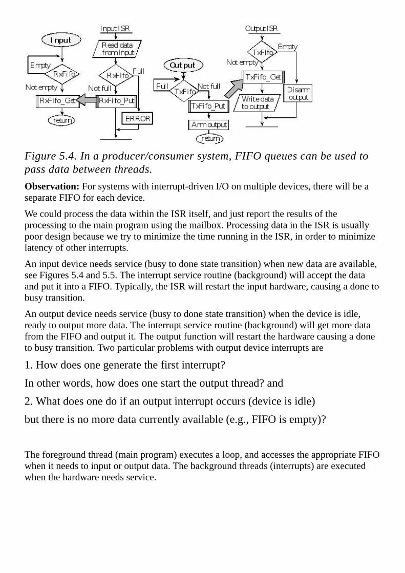
Figure5.4.Inaproducer/consumersystem,FIFOqueuescanbeusedtopassdatabetweenthreads.Observation:Forsystemswithinterrupt-drivenI/Oonmultipledevices,therewillbeaseparateFIFOforeachdevice.
WecouldprocessthedatawithintheISRitself,andjustreporttheresultsoftheprocessingtothemainprogramusingthemailbox.ProcessingdataintheISRisusuallypoordesignbecausewetrytominimizethetimerunningintheISR,inordertominimizelatencyofotherinterrupts.
Aninputdeviceneedsservice(busytodonestatetransition)whennewdataareavailable,seeFigures5.4and5.5.Theinterruptserviceroutine(background)willacceptthedataandputitintoaFIFO.Typically,theISRwillrestarttheinputhardware,causingadonetobusytransition.
Anoutputdeviceneedsservice(busytodonestatetransition)whenthedeviceisidle,readytooutputmoredata.Theinterruptserviceroutine(background)willgetmoredatafromtheFIFOandoutputit.Theoutputfunctionwillrestartthehardwarecausingadonetobusytransition.Twoparticularproblemswithoutputdeviceinterruptsare
1.Howdoesonegeneratethefirstinterrupt?
Inotherwords,howdoesonestarttheoutputthread?and
2.Whatdoesonedoifanoutputinterruptoccurs(deviceisidle)
butthereisnomoredatacurrentlyavailable(e.g.,FIFOisempty)?
Theforegroundthread(mainprogram)executesaloop,andaccessestheappropriateFIFOwhenitneedstoinputoroutputdata.Thebackgroundthreads(interrupts)areexecutedwhenthehardwareneedsservice.

Figure5.5.Theinputdeviceinterruptswhenithasnewdata,andtheoutputdeviceinterruptswhenidle.Onewaytovisualizetheinterruptsynchronizationistodrawastateversustimeplotoftheactivitiesofthehardwareandthetwosoftwaremodules.Figure5.6isdrawntodescribeasituationwherethetimebetweeninputsisabouttwiceaslongasittakesthesoftwaretoprocessthedata.Forthisexample,themainthreadbeginsbywaitingbecausetheFIFOisempty(a).Whentheinputdeviceisbusyitisintheprocessofcreatingnewinput.Whentheinputdeviceisdone,newdataareavailableandaninterruptisrequested.TheinterruptserviceroutinewillreadthedataandputitintotheFIFO(b).OncedataareintheFIFO,themainprogramisreleasedtogoonbecausethegetfunctionwillreturnwithdata(c).Themainprogramprocessesthedata(d)andthenwaitsformoreinput(a).Thearrowsfromonegraphtotheotherrepresentthesynchronizingevents.Becausethetimeforthesoftwaretoreadandprocessthedataislessthanthetimefortheinputdevicetocreatenewinput,thissituationiscalledI/Obound.Inthissituation,theFIFOhaseither0or1entry,andtheuseofinterruptsdoesnotenhancethebandwidthoverthebusy-waitimplementationspresentedinthepreviouschapter.EvenwithanI/Obounddeviceitmaybemoreefficienttoutilizeinterruptsbecauseitprovidesastraight-forwardapproachtoservicingmultipledevices.
Figure5.6.Hardware/softwaretimingofanI/Oboundinputinterface.

Inthissecondexample,theinputdevicestartswithaburstofhighbandwidthactivity.Figure5.7isdrawntodescribeasituationwheretheinputrateistemporarilytwotothreetimesfasterthanthesoftwarecanhandle.Aslongastheinterruptserviceroutineisfastenoughtokeepupwiththeinputdevice,andaslongastheFIFOdoesnotbecomefullduringtheburst,nodataarelost.Thesoftwarewaitsforthefirstdata(a),butthendoesnothavetowaituntiltheburstisover.Inthissituation,theoverallbandwidthishigherthanitwouldbewithabusy-waitimplementation,becausetheinputdevicedoesnothavetowaitforeachdatabytetobeprocessed(b).Thisistheclassicexampleofa“buffered”input,becausetheISRputsdatatheFIFO.ThemainprogramgetsdatafromtheFIFO(c),andthenprocessesit(d).WhentheI/Odeviceisfasterthanthesoftware,thesystemiscalledCPUbound.Aswewillseelater,thissystemwillworkonlyiftheproducerratetemporarilyexceedstheconsumerrate(ashortburstofhighbandwidthinput).Iftheexternaldevicesustainedthehighbandwidthinputrate,thentheFIFOwouldbecomefullanddatawouldbelost.
Figure5.7.Hardware/softwaretimingofaninputinterfaceduringahighbandwidthburst.Foraninputdevice,iftheFIFOisusuallyempty,theinterfaceisI/Obound.Duringtimeswhentherearemanyelements,theinterfaceisCPUbound.
Foranoutputdevice,theinterruptisrequestedwhentheoutputisidleandreadytoacceptmoredata.The“busytodone”statetransitioncausesaninterrupt.Theinterruptserviceroutinegivestheoutputdeviceanotherpieceofdatatooutput.Again,wecanvisualizetheinterruptsynchronizationbydrawingastateversustimeplotoftheactivitiesofthehardwareandthetwosoftwaremodules.Figure5.8isdrawntodescribeasituationwherethetimebetweenoutputsisabouthalfaslongasittakesthesoftwaretogeneratenewdata.Foranoutputdeviceinterface,theoutputdeviceisinitiallydisarmedandtheFIFOisempty.Themainthreadbeginsbygeneratingnewdata(a).AfterthemainprogramputsthedataintotheFIFOitarmstheoutputinterrupts(b).ThisfirstinterruptoccursimmediatelyandtheISRgetssomedatafromtheFIFOandoutputsittotheexternaldevice(c).Theoutputdevicebecomesbusybecauseitisintheprocessofoutputtingdata.Itisimportanttorealizethatitonlytakesthesoftwareontheorderof1µsectowritedatatooneofitsoutputports,butusuallyittakestheoutputdevicemuchlongertofullyprocessthedata.Whentheoutputdeviceisdone,itisreadytoacceptmoredataandaninterruptisrequested.IftheFIFOisemptyatthispoint,theISRwilldisarmtheoutputdevice(d).IftheFIFOisnotempty,theinterruptserviceroutinewillgetfromtheFIFO,andwriteitouttotheoutputport.Oncedataarewrittentotheoutputport,theoutput

deviceisreleasedtogoon.Inthisfirstexample,thetimeforthesoftwaretogeneratedataislargerthanthetimefortheexternaldevicetooutputit.ThisisanexampleofaCPUboundsystem.Inthissituation,theFIFOhaseither0or1entry,andtheuseofinterruptsdoesnotenhancethebandwidthoverthebusy-waitimplementationspresentedinthepreviouschapter.Neverthelessinterruptsprovideawell-definedmechanismfordealingwithcomplexsystems.
Figure5.8.Hardware/softwaretimingofaCPUboundoutputinterface.Inthissecondoutputexample,thesoftwarestartswithaburstofhighbandwidthactivity.Figure5.9isdrawntodescribeasituationwherethesoftwareproducesdataataratethatistemporarilymuchfasterthanthehardwarecanhandle.AslongastheFIFOdoesnotbecomefull,nodataarelost.Inthissituation,theoverallbandwidthishigherthanitwouldbewithabusy-waitimplementation,becausethesoftwaredoesnothavetowaitforeachdatabytetobeprocessedbythehardware.Thesoftwaregeneratesdata(a)andputsitintotheFIFO(b).Whentheoutputisidle,itgeneratesaninterrupt.TheISRgetsdataandrestartstheoutputdevice(c).
Figure5.9.Hardware/softwaretimingofanI/Oboundoutputinterface.Thisistheclassicexampleofa“buffered”output,becausedataentersthesystem(viathemainprogram)istemporarilystoredinabuffer(putintotheFIFO)andthedataareprocessedlater(bytheISR,getfromtheFIFO,writetoexternaldevice.)WhentheI/Odeviceisslowerthanthesoftware,thesystemiscalledI/Obound.Justliketheinputscenario,theFIFOmightbecomefulliftheproducerrateistoohighfortoolong.

Thereareothertypesofinterruptthatarenotaninputoroutput.Forexamplewewillconfigurethecomputertorequestaninterruptonaperiodicbasis.Thismeansaninterrupthandlerwillbeexecutedatfixedtimeintervals.Thisperiodicinterruptwillbeessentialfortheimplementationofreal-timedataacquisitionandreal-timecontrolsystems.Forexampleifweareimplementingadigitalcontrollerthatexecutesacontrolalgorithm100timesasecond,thenwewillsetuptheinternaltimerhardwaretorequestaninterruptevery10ms.Theinterruptserviceroutinewillexecutethedigitalcontrolalgorithmandreturntothemainthread.WewilluseperiodicinterruptsinChapters10and12.
PerformanceTip:ItispoordesigntoemploybackwardjumpsinanISR,becausetheymayaffectthelatencyofotherinterruptrequests.Wheneveryouarethinkingaboutusingabackwardjump,considerredesigningthesystemwithmoreordifferenttriggerstoreducethenumberofbackwardjumps.
Asyourecall,theFIFOpassesthedatafromtheproducertotheconsumer.Ingeneral,theratesatwhichdataareproducedandconsumedcanvarydynamically.Humansdonotenterdataintoakeyboardataconstantrate.Evenprintersrequiremoretimetoprintcolorgraphicsversusblackandwhitetext.Lettpbethetime(insec)betweencallsto Fifo_Put ,andrpbethearrivalrate(producerrateinbytes/sec)intothesystem,sorp=1/tp.Similarly,lettgbethetime(insec)betweencallsto Fifo_Get ,andrgbetheservicerate(consumerrateinbytes/sec)outofthesystem,sorg=1/tg.
Iftheminimumtimebetweencallsto Fifo_Put isgreaterthanthemaximumtimebetweencallsto Fifo_Get ,thenaFIFOisnotnecessaryandthedataflowcouldbesolvedwithamailbox.I.e.,noFIFOisneededifmin(tp)≥max(tg).Ontheotherhand,ifthetimebetweencallsto Fifo_Put becomeslessthanthetimebetweencallsto Fifo_Get becauseeither
•Thearrivalratetemporarilyincreases
•Theserviceratetemporarilydecreases
theninformationwillbecollectedintheFIFO.Forexample,apersonmighttypeveryfastforawhile,followedbylongpause.TheFIFOcouldbeusedtocapturewithoutlossallthedataasitcomesinveryfast.Clearlyonaveragethesystemmustbeabletoprocessthedata(theconsumerthread)atleastasfastastheaveragerateatwhichthedataarrives(producerthread).Iftheaverageproducerrateislargerthantheaverageconsumerrate
Ave(rp)>Ave(rg)
thentheFIFOwilleventuallyoverflownomatterhowlargetheFIFO.Iftheproducerrateistemporarilyhigh,andthatcausestheFIFOtobecomefull,thenthisproblemcanbesolvedbyincreasingtheFIFOsize.
Thereisfundamentaldifferencebetweenanemptyerrorandafullerror.ConsidertheapplicationofusingaFIFObetweenyourcomputeranditsprinter.Thisisagoodideabecausethecomputercantemporarilygeneratedatatobeprintedataveryhighratefollowedbylongpauses.Theprinterislikeaturtle.Itcanprintataslowbutsteady

rate.ThecomputerwillputabyteintotheFIFOthatitwantsprinted.TheprinterwillgetabyteoutoftheFIFOwhenitisreadytoprintanothercharacter.Afullerroroccurswhenthecomputercalls Fifo_Put attoofastarate.Afullerrorisserious,becauseifignoreddatawillbelost.RecallthatoneofthedefinitionsofaKahnProcessNetworkisthattheFIFOsareneverfull.So,implementingthedataflowinsuchawaythattheFIFOsneverbecomefullallowsustomodelthesystemasaKPN.Ontheotherhand,anemptyerroroccurswhentheprinterisreadytoprintbutthecomputerhasnothinginmind.Anemptyerrorisnotserious,becauseinthiscasetheprinterjustsitstheredoingnothing.
Checkpoint5.4:IftheFIFObecomesfull,canthesituationalwaysbesolvedbyincreasingthesize?
ConsideraFIFOthathasafeaturewherewecandeterminethenumberofelementsbycalling Fifo_Size .Ifweplacethisdebugginginstrumentinsidetheproducer,wecanmeasureahistogramofFIFOsizestellingus1)iftheFIFOeverbecamefull;2)iftheinterfaceisCPUbound;or3)iftheinterfaceisI/Obound.
uint32_tHistogram[FIFOSIZE];
#defineCollect()(Histogram[Fifo_Size()]++;)

5.3.CriticalSectionsIngeneral,iftwothreadsaccessthesameglobalmemoryandoneoftheaccessesisawrite,thenthereisacausaldependencybetweenthethreads.Thismeans,theexecutionordermayaffecttheoutcome.Sharedglobalvariablesareveryimportantinmultithreadedsystemsbecausetheyarerequiredtopassdatabetweenthreads,buttheyarecomplicatedanditishardtofindbugsthatresultwiththeiruse.
Aprogramsegmentisreentrantifitcanbeconcurrentlyexecutedbytwo(ormore)threads.Toimplementreentrantsoftware,weplacevariablesinregistersoronthestack,andavoidstoringintoglobalmemoryvariables.Whenwritinginassembly,weuseregisters,orthestackforparameterpassingtocreatereentrantsubroutines.Typicallyeachthreadwillhaveitsownsetofregistersandstack.Anonreentrantsubroutinewillhaveasectionofcodecalledavulnerablewindoworcriticalsection.Anerroroccursif
1)Onethreadcallsthefunctioninquestion
2)Itisexecutinginthecriticalsectionwheninterruptedbyasecondthread
3)Thesecondthreadcallsthesamefunction.
Thereareanumberofscenariosthatcanhappennext.Inthemostcommonscenario,thesecondthreadisallowedtocompletetheexecutionofthefunction,controlisthenreturnedtothefirstthread,andthefirstthreadfinishesthefunction.Thisfirstscenarioistheusualcasewithinterruptprogramming.Inthesecondscenario,thesecondthreadexecutespartofthecriticalsection,isinterruptedandthenre-enteredbyathirdthread,thethirdthreadfinishes,thecontrolisreturnedtothesecondthreadanditfinishes,lastlythecontrolisreturnedtothefirstthreadanditfinishes.Thissecondscenariocanhappenininterruptprogrammingifthesecondinterrupthashigherprioritythanthefirst.Acriticalsectionmayexistwhentwodifferentfunctionsthataccessandmodifythesamememory-residentdatastructure.
Program5.1showsaCfunctionandtheassemblycodegeneratedbytheARMKeilTMuVision®compiler.Thefunctionisnonreentrantbecauseoftheread-modify-writenonatomicaccesstotheglobalvariable, num .
numSPACE4
CountLDRr0,[pc,#116];R0=&num
;*******startofcriticalsection***
LDRr0,[r0,#0x00];R0=num
;couldbebadifinterruptoccurshere
uint32_tvolatilenum;
voidCount(void)
num=num+1;

ADDSr0,r0,#1
;couldbebadifinterruptoccurshere
LDRr1,[pc,#108];R1=&num
;couldbebadifinterruptoccurshere
STRr0,[r1,#0x00];updatenum
;*******endofcriticalsection***
BXlr
ptrDCDnum
Program5.1.Thisfunctionisnonreentrantbecauseoftheread-modify-writeaccesstoaglobal.Assumetherearetwoconcurrentthreads(themainprogramandabackgroundISR)thatbothcallthisfunction.Concurrentmeansthatboththreadsarereadytorun.Becausethereisonlyonecomputer,exactlyonethreadwillberunningatatime.Typically,theoperatingsystemswitchesexecutioncontrolbackandforthusinginterrupts.TherearethreeplacesintheassemblycodeatwhichifaninterruptweretooccurandtheISRcalledthesamefunction,theendresultwouldbe num wouldbeincrementedonlyonce,eventhoughthefunctionwascalledtwice.Assumeforthisexample num isinitially100.Anerroroccursif:
1.Themainprogramcalls Count2.Themainexecutes LDR r0,[r0,#0x00]makingR0=100
3.TheOShaltsthemain(usinganinterrupt)andstartstheISR4.theISRcalls CountExecutesnum=num+1; makingequalto101
5.TheOSreturnscontrolbacktothemainprogramR0isbacktoitsoriginalvalueof100
6.Themainprogramfinishedthefunction(adding1toR0)Making num equalto101

Anatomicoperationisonethatoncestartedisguaranteedtofinish.Inmostcomputers,onceaninstructionhasbegun,theinstructionmustbefinishedbeforethecomputercanprocessaninterrupt.Ingeneral,nonreentrantcodecanbegroupedintothreecategoriesallinvolving1)nonatomicsequences,2)writesand3)globalvariables.WewillclassifyI/Oportsasglobalvariablesfortheconsiderationofcriticalsections.Wewillgroupregistersintothesamecategoryaslocalvariablesbecauseeachthreadwillhaveitsownregistersandstack.
Thefirstgroupistheread-modify-writesequence:
1.Thesoftwarereadstheglobalvariableproducingacopyofthedata2.Thesoftwaremodifiesthecopy(originalvariableisstillunmodified)3.Thesoftwarewritesthemodificationbackintotheglobalvariable.
Inthesecondgroup,wehaveawritefollowedbyread,wheretheglobalvariableisusedfortemporarystorage:
1.Thesoftwarewritestotheglobalvariable(onlycopyoftheinformation)2.Thesoftwarereadsfromtheglobalvariableexpectingtheoriginaldatatobethere.
Inthethirdgroup,wehaveanon-atomicmulti-stepwritetoaglobalvariable:
1.Thesoftwarewritespartofthenewvaluetoaglobalvariable2.Thesoftwarewritestherestofthenewvaluetoaglobalvariable.
Observation:WhenconsideringreentrantsoftwareandvulnerablewindowsweclassifyaccessestoI/Oportsthesameasaccessestoglobalvariables.
Observation:Sometimeswestoretemporaryinformationinglobalvariablesoutoflaziness.Thispracticeistobediscouragedbecauseitwastesmemoryandmaycausethemoduletonotbereentrant.
Sometimewecanhaveacriticalsectionbetweentwodifferentsoftwarefunctions(onefunctioncalledbyonethread,andanotherfunctioncalledbyadifferentthread).Inadditiontoabovethreecases,anon-atomicmulti-stepreadwillbecriticalwhenpairedwithamulti-stepwrite.Forexample,assumeadatastructurehasmultiplecomponents(e.g.,hours,minutes,andseconds).Inthiscase,thewritetothedatastructurewillbeatomicbecauseitoccursinahighpriorityISR.Thecriticalsectionexistsintheforegroundbetweensteps1and3.Inthiscase,acriticalsectionexistseventhoughnosoftwarehasactuallybeenreentered.

Foreground thread
1.Themainreadssomeofthedata
3.Themain reads the rest ofthedata
Background thread
2. ISR writes to the datastructure
In a similar case, a non-atomic multi-step write will be critical when paired with amulti-stepread. Again,assumeadatastructurehasmultiplecomponents. In thiscase,the read from thedatastructurewillbeatomicbecause itoccurs inahighpriority ISR.Thecriticalsectionexistsintheforegroundbetweensteps1and3.
Foreground thread
1.Themainwrites someof thedata
3. The main writes the rest ofthedata
Backgroundthread
2. ISR reads from the datastructure
Whenmultiplethreadsareactive,itispossiblefortwothreadstobeexecutingthesameprogram.Forexample,thesystemmayberunningintheforegroundandcalls Func .Partwaythroughexecutionthe Func ,aninterruptoccurs.IftheISRalsocalls Func ,twothreadsaresimultaneouslyexecutingthefunction.Toexperimentallydetermineifafunctionhasbeenreentered,wecouldusetwoflagsortwooutputpins.Setoneofthem(PD1, Entered )atthestartandclearitattheend.Thethreadhasbeenre-enteredifthisflagorpinissetatthestartofthefunction,asshowninProgram3.7.Inthisexample,PortDbits1,0arenotpartoftheoriginalcode,butratherusedjustforthepurposeofdebugging.PD1is1whenonethreadstartsexecutingthefunction.However,ifPD0becomes1,thenthefunctionhasbeenreentered.
#definePD0(*((volatileuint32_t*)0x40007004))
#definePD1(*((volatileuint32_t*)0x40007008))
//functiontobetested
volatileintEntered=0,Flag=0;
voidFunc(void)
//functiontobetested
voidFunc(void)
if(PD1)PD0=1;

if(Entered)Flag=1;
Entered=1;
//theregularfunction
Entered=0;
PD1=2;
//theregularfunction
PD1=0;
Program5.2.Detectionofre-entrantbehaviorusingtwoflagsortwooutputpins.Ifcriticalsectionsdoexist,wecaneithereliminateitbyremovingtheaccesstotheglobalvariableorimplementmutualexclusion,whichsimplymeansonlyonethreadatatimeisallowedtoexecuteinthecriticalsection.Ingeneral,ifwecaneliminatetheglobalvariables,thenthesubroutinebecomesreentrant.Withoutglobalvariablesthereareno“vulnerable”windowsbecauseeachthreadhasitsownregistersandstack.Sometimesonemustaccessglobalmemorytoimplementthedesiredfunction.RememberthatallI/Oportsareconsideredglobal.Furthermore,globalvariablesarenecessarytopassdatabetweenthreads.
;***********DisableInterrupts***************
;disableinterrupts
;inputs:none
;outputs:none
DisableInterrupts
CPSIDI
BXLR
;***********EnableInterrupts***************
;disableinterrupts
;inputs:none
;outputs:none
EnableInterrupts
CPSIEI
BXLR
;***********StartCritical************************
;makeacopyofpreviousIbit,disableinterrupts
;inputs:none
;outputs:previousIbit
StartCritical
MRSR0,PRIMASK;saveoldstatus

CPSIDI;maskall(exceptfaults)
BXLR
;***********EndCritical************************
;usingthecopyofpreviousIbit,restoreIbittopreviousvalue
;inputs:previousIbit
;outputs:none
EndCritical
MSRPRIMASK,R0
BXLR
Program5.3.Assemblyfunctionsneededforinterruptenablinganddisabling.Asimplewaytoimplementmutualexclusionistodisableinterruptswhileexecutingthecriticalsection.Itisimportanttodisableinterruptsforasshortatimeaspossible,soastominimizetheeffectonthedynamicperformanceoftheotherthreads.Whilewearerunningwithinterruptsdisabled,time-criticaleventslikepowerfailureanddangerwarningscannotbeprocessed.Noticealsothattheinterruptsarenotsimplydisabledthenenabled.Beforethecriticalsection,theinterruptstatusissaved,andtheinterruptsdisabled.Afterthecriticalsection,theinterruptstatusisrestored.Youcannotsavetheinterruptstatusinaglobalvariable,ratheryoushouldsaveiteitheronthestackorinaregister.WewilladdtheassemblycodeofProgram5.3totheStartup.sfileinourprojectsthatuseinterrupts.Program5.4illustrateshowtoimplementmutualexclusionandeliminatethecriticalsection.
uint32_tvolatilenum;
voidCount(void)int32_tsr;
sr=StartCritical();
num=num+1;
EndCritical(sr);
Program5.4.Thisfunctionisreentrantbecauseoftheread-modify-writeaccesstotheglobalisatomic.Checkpoint5.5:Considerthesituationofnestedcriticalsections.Forexample,afunctionwithacriticalsectioncallsanotherfunctionthatalsohasacriticalsection.Whatwouldhappenifyousimplyaddeddisableinterruptatthebeginningandareenableinterruptattheendofeachcriticalsection?

Anothercategoryoftiming-dependentbugs,similartocriticalsections,iscalledaracecondition.Araceconditionoccursinamulti-threadedenvironmentwhenthereisacausaldependencybetweentwoormorethreads.Inotherwords,differentbehavioroccursdependingontheorderofexecutionoftwothreads.Inthisexampleofaracecondition,Thread-1initializesPortBbits3–0tobeoutputusingGPIO_PORTB_DIR_R=0x0F;Thread-2initializesPortBbits6–4tobeoutputusing GPIO_PORTB_DIR_R=0x70;Inparticular,ifThread-1runsfirstandThread-2runssecond,thenPortBbits3–0willbesettoinputs.Conversely,ifThread-2runsfirstandThread-1runssecond,thenPortBbits6–4willbesettoinputs.Thisisaraceconditioncausedbyunfriendlycode.Thesolutiontothisproblemistowritethetwoinitializationsinafriendlymanner.
Inasecondexample,assumetwothreadsaretryingtogetdatafromthesameinputdevice.Bothcallthefunction UART_InChar giveninProgram4.10.Whendataarrivesattheinput,thethreadthatexecutesfirstwillcapturethedata.ThisexampleisequivalenttothePetriNetconflictdrawninFigure4.16.

5.4.NVIContheARM Cortex-MProcessorOntheARM ® CortexTM-Mprocessor,exceptionsincluderesets,softwareinterruptsandhardwareinterrupts.Eachexceptionhasanassociated32-bitvectorthatpointstothememorylocationwheretheISRthathandlestheexceptionislocated.VectorsarestoredinROMatthebeginningofmemory.Program5.5showsthefirstfewvectorsasdefinedintheStartup.sfile. DCD isanassemblerpseudo-opthatdefinesa32-bitconstant.ROMlocation0x0000.0000hastheinitialstackpointer,andlocation0x0000.0004containstheinitialprogramcounter,whichiscalledtheresetvector.Itpointstoafunctioncalledtheresethandler,whichisthefirstthingexecutedfollowingreset.Thereareupto240(77ontheTM4C123microcontroller)possibleinterruptsourcesandtheir32-bitvectorsarelistedinorderstartingwithlocation0x0000.0008.Fromaprogrammingperspective,wecanattachISRstointerruptsbywritingtheISRsasregularCfunctionswithnoinputoroutputparametersandeditingtheStartup.sfiletospecifythosefunctionsfortheappropriateinterrupt.Forexample,ifwewroteaPortCinterruptserviceroutinenamed PortCISR ,thenwewouldreplace GPIOPortC_Handler with PortCISR .Inthisbook,wewillwriteourISRsusingstandardfunctionnamessothattheStartup.sfileneednotbeedited.I.e.,wewillsimplycalltheISRforedge-triggeredinterruptsonPortCas GPIOPortC_Handler .FormoredetailsseetheStartup.sfileswithintheinterruptexamplespostedonthebookwebsite.
EXPORT__Vectors
__Vectors;addressISR
DCDStackMem+Stack;0x00000000TopofStack
DCDReset_Handler;0x00000004ResetHandler
DCDNMI_Handler;0x00000008NMIHandler
DCDHardFault_Handler;0x0000000CHardFaultHandler
DCDMemManage_Handler;0x00000010MPUFaultHandler
DCDBusFault_Handler;0x00000014BusFaultHandler
DCDUsageFault_Handler;0x00000018UsageFaultHandler
DCD0;0x0000001CReserved
DCD0;0x00000020Reserved
DCD0;0x00000024Reserved
DCD0;0x00000028Reserved
DCDSVC_Handler;0x0000002CSVCallHandler
DCDDebugMon_Handler;0x00000030DebugMonitorHandler
DCD0;0x00000034Reserved
DCDPendSV_Handler;0x00000038PendSVHandler
DCDSysTick_Handler;0x0000003CSysTickHandler

DCDGPIOPortA_Handler;0x00000040GPIOPortA
DCDGPIOPortB_Handler;0x00000044GPIOPortB
DCDGPIOPortC_Handler;0x00000048GPIOPortC
DCDGPIOPortD_Handler;0x0000004CGPIOPortD
DCDGPIOPortE_Handler;0x00000050GPIOPortE
DCDUART0_Handler;0x00000054UART0
DCDUART1_Handler;0x00000058UART1
DCDSSI0_Handler;0x0000005CSSI
DCDI2C0_Handler;0x00000060I2C
DCDPWMFault_Handler;0x00000064PWMFault
DCDPWM0_Handler;0x00000068PWMGenerator0
Program5.5.SoftwaresyntaxtosettheinterruptvectorsfortheLM3S/LM4F/TM4C.Table5.1explainswheretofindtheprioritybitsforsomeoftheinterruptsontheLM3S/TM4C.Inparticular,thistableshowsthevectoraddress,interruptnumber,IRQnumber,ISRnameasdefinedinthefileStartup.s,whichregistercontainsprioritybitsandwhichbitstomodifywhenconfiguringpriority.Eachprocessorisalittledifferentsocheckthedatasheet.
Vectoraddress Number IRQ ISRnameinStartup.s NVIC Prioritybits
0x00000038 14 -2 PendSV_Handler NVIC_SYS_PRI3_R 23–21
0x0000003C 15 -1 SysTick_Handler NVIC_SYS_PRI3_R 31–29
0x00000040 16 0 GPIOPortA_Handler NVIC_PRI0_R 7–5
0x00000044 17 1 GPIOPortB_Handler NVIC_PRI0_R 15–13
0x00000048 18 2 GPIOPortC_Handler NVIC_PRI0_R 23–21
0x0000004C 19 3 GPIOPortD_Handler NVIC_PRI0_R 31–29
0x00000050 20 4 GPIOPortE_Handler NVIC_PRI1_R 7–5
0x00000054 21 5 UART0_Handler NVIC_PRI1_R 15–13
0x00000058 22 6 UART1_Handler NVIC_PRI1_R 23–21
0x0000005C 23 7 SSI0_Handler NVIC_PRI1_R 31–29
0x00000060 24 8 I2C0_Handler NVIC_PRI2_R 7–5

0x00000064 25 9 PWMFault_Handler NVIC_PRI2_R 15–13
0x00000068 26 10 PWM0_Handler NVIC_PRI2_R 23–21
0x0000006C 27 11 PWM1_Handler NVIC_PRI2_R 31–29
0x00000070 28 12 PWM2_Handler NVIC_PRI3_R 7–5
0x00000074 29 13 Quadrature0_Handler NVIC_PRI3_R 15–13
0x00000078 30 14 ADC0_Handler NVIC_PRI3_R 23–21
0x0000007C 31 15 ADC1_Handler NVIC_PRI3_R 31–29
0x00000080 32 16 ADC2_Handler NVIC_PRI4_R 7–5
0x00000084 33 17 ADC3_Handler NVIC_PRI4_R 15–13
0x00000088 34 18 WDT_Handler NVIC_PRI4_R 23–21
0x0000008C 35 19 Timer0A_Handler NVIC_PRI4_R 31–29
0x00000090 36 20 Timer0B_Handler NVIC_PRI5_R 7–5
0x00000094 37 21 Timer1A_Handler NVIC_PRI5_R 15–13
0x00000098 38 22 Timer1B_Handler NVIC_PRI5_R 23–21
0x0000009C 39 23 Timer2A_Handler NVIC_PRI5_R 31–29
0x000000A0 40 24 Timer2B_Handler NVIC_PRI6_R 7–5
0x000000A4 41 25 Comp0_Handler NVIC_PRI6_R 15–13
0x000000A8 42 26 Comp1_Handler NVIC_PRI6_R 23–21
0x000000AC 43 27 Comp2_Handler NVIC_PRI6_R 31–29
0x000000B0 44 28 SysCtl_Handler NVIC_PRI7_R 7–5
0x000000B4 45 29 FlashCtl_Handler NVIC_PRI7_R 15–13
0x000000B8 46 30 GPIOPortF_Handler NVIC_PRI7_R 23–21
0x000000BC 47 31 GPIOPortG_Handler NVIC_PRI7_R 31–29
0x000000C0 48 32 GPIOPortH_Handler NVIC_PRI8_R 7–5
0x000000C4 49 33 UART2_Handler NVIC_PRI8_R 15–13
0x000000C8 50 34 SSI1_Handler NVIC_PRI8_R 23–21

0x000000CC 51 35 Timer3A_Handler NVIC_PRI8_R 31–29
0x000000D0 52 36 Timer3B_Handler NVIC_PRI9_R 7–5
0x000000D4 53 37 I2C1_Handler NVIC_PRI9_R 15–13
0x000000D8 54 38 Quadrature1_Handler NVIC_PRI9_R 23–21
0x000000DC 55 39 CAN0_Handler NVIC_PRI9_R 31–29
0x000000E0 56 40 CAN1_Handler NVIC_PRI10_R 7–5
0x000000E4 57 41 CAN2_Handler NVIC_PRI10_R 15–13
0x000000E8 58 42 Ethernet_Handler NVIC_PRI10_R 23–21
0x000000EC 59 43 Hibernate_Handler NVIC_PRI10_R 31–29
0x000000F0 60 44 USB0_Handler NVIC_PRI11_R 7–5
0x000000F4 61 45 PWM3_Handler NVIC_PRI11_R 15–13
0x000000F8 62 46 uDMA_Handler NVIC_PRI11_R 23–21
0x000000FC 63 47 uDMA_Error NVIC_PRI11_R 31–29
Table5.1.SomeoftheinterruptvectorsfortheLM3S/TM4C(goestonumber154ontheM4).
InterruptsontheCortexTM-MprocessorarecontrolledbytheNestedVectoredInterruptController(NVIC).ToactivateaninterruptsourceweneedtosetitspriorityandenablethatsourceintheNVIC.Thisactivationisinadditiontothearmandenablesteps.Table5.1liststheinterruptsourcesavailableontheLM3S/LM4F/TM4Cfamilyofmicrocontrollers.Interruptnumbers0to15containthefaults,softwareinterruptandSysTick;theseinterruptswillbehandleddifferentlyfrominterrupts16to63.
Table5.2showsthetwelvepriorityregistersontheNVICoftheLM3S.Thereare35suchregistersontheTM4C.Eachregistercontainsan8-bitpriorityfieldforfourdevices.OntheLM3S/TM4Cmicrocontrollers,onlythetopthreebitsofthe8-bitfieldareused.Thisallowsustospecifytheinterruptprioritylevelforeachdevicefrom0to7,with0beingthehighestpriority.Theinterruptnumber(numbercolumninTable5.1)isloadedintotheIPSRregister.TheservicingofinterruptsdoesnotsettheIbitinthePRIMASK,soahigherpriorityinterruptcansuspendtheexecutionofalowerpriorityISR.IfarequestofequalorlowerpriorityisgeneratedwhileanISRisbeingexecuted,thatrequestispostponeduntiltheISRiscompleted.Inparticular,thosedevicesthatneedpromptserviceshouldbegivenhighpriority.
Address 31–29 23–21 15–13 7–5 Name
0xE000E400 GPIOPortD
GPIOPortC GPIOPortB
GPIOPortA
NVIC_PRI0_R

0xE000E404 SSI0,RxTx
UART1,RxTx
UART0,RxTx
GPIOPortE
NVIC_PRI1_R
0xE000E408 PWMGen1
PWMGen0 PWMFault
I2C0 NVIC_PRI2_R
0xE000E40C ADCSeq1 ADCSeq0 QuadEncoder
PWMGen2
NVIC_PRI3_R
0xE000E410 Timer0A Watchdog ADCSeq3
ADCSeq2
NVIC_PRI4_R
0xE000E414 Timer2A Timer1B Timer1A Timer0B NVIC_PRI5_R
0xE000E418 Comp2 Comp1 Comp0 Timer2B NVIC_PRI6_R
0xE000E41C GPIOPortG
GPIOPortF FlashControl
SystemControl
NVIC_PRI7_R
0xE000E420 Timer3A SSI1,RxTx UART2,RxTx
GPIOPortH
NVIC_PRI8_R
0xE000E424 CAN0 QuadEncoder1
I2C1 Timer3B NVIC_PRI9_R
0xE000E428 Hibernate Ethernet CAN2 CAN1 NVIC_PRI10_R
0xE000E42C uDMAError
uDMASoftTfr
PWMGen3
USB0 NVIC_PRI11_R
0xE000ED20 SysTick PendSV — Debug NVIC_SYS_PRI3_R
Table5.2.SomeoftheLM3S/TM4CNVICregisters.Bitsnotshownarezero.
TherearetwoenableregistersNVIC_EN0_R and NVIC_EN1_R ontheLM3S(fiveontheLM4F/TM4C).The32bitsin NVIC_EN0_R controltheIRQnumbers0to31(interruptnumbers16–47).InTable5.1weseeUART0isIRQ=5.ToenableUART0interruptswesetbit5in NVIC_EN0_R .Thebottom16bitsin NVIC_EN1_R controltheIRQnumbers32to47(interruptnumbers48–63).InTable5.1weseeTimer3AisIRQ=35.ToenableTimer3Ainterruptswesetbit3(35-32=3)in NVIC_EN1_R .NoteveryinterruptsourceisavailableoneveryLM3S/LM4F/TM4Cmicrocontroller,soyouwillneedtorefertothedatasheetforyourmicrocontrollerwhendesigningI/Ointerfaces.Writingzerostothe NVIC_EN0_R NVIC_EN1_R registershasnoeffect.Todisableinterruptswewriteonestothecorrespondingbitinthe NVIC_DIS0_Ror NVIC_DIS1_R register.
Figure5.10showsthecontextswitchfromexecutingintheforegroundtorunninganedge-triggeredISRfromPortC.AssumePortCinterruptsareconfiguredforaprioritylevelof5.TheIbitinthePRIMASKis0signifyinginterruptsareenabled.Theinterruptnumber(ISRNUM)intheIPSRregisteris0,meaningwearerunninginThreadmode(i.e.,themainprogram,andnotanISR).Handlermodeissignifiedbyanonzerovaluein

IPSR.WhenBASEPRIregisteriszero,allinterruptsareallowedandtheBASEPRIregisterisnotactive.
WhenaPortCinterruptistriggered,thecurrentinstructionisfinished.(a)EightregistersarepushedonthestackwithR0ontop.Theseregistersarepushedontothestackusingwhicheverstackpointerisactive:eithertheMSPorPSP.(b)ThevectoraddressisloadedintothePC(“Vectoraddress”columninTable5.2).(c)TheIPSRregisterissetto18(“Number”columninTable5.2)(d)Thetop24bitsofLRaresetto0xFFFFFF,signifyingtheprocessorisexecutinganISR.Bits[7:1]specifyhowtoreturnfrominterrupt.Bit0meansThumbmode.
0xE1ReturntoHandlermodeMSP(usingfloatingpointstateonLM4F/TM4C)
0xE9ReturntoThreadmodeMSP(usingfloatingpointstateonLM4F/TM4C)
0xEDReturntoThreadmodePSP(usingfloatingpointstateonLM4F/TM4C)
0xF1ReturntoHandlermodeMSP
0xF9ReturntoThreadmodeMSP
0xFDReturntoThreadmodePSP
Afterpushingtheregisters,theprocessoralwaysusesthemainstackpointer(MSP)duringtheexecutionoftheISR.Eventsb,c,anddcanoccursimultaneously
Figure5.10.Stackbeforeandafteraninterrupt.Toreturnfromaninterrupt,theISRexecutesthetypicalfunctionreturn BXLR .However,sincethetop24bitsofLRare0xFFFFFF,itknowstoreturnfrominterruptbypoppingtheeightregistersoffthestack.SincethebottomeightbitsofLRinthiscaseare0xF9,itreturnstothreadmodeusingtheMSPasitsstackpointer,inThumbmode.SincetheIPSRispartofthePSRthatispulled,soitisautomaticallyresetitspreviousstate.

AnestedinterruptoccurswhenahigherpriorityinterruptsuspendsanISR.ThelowerpriorityinterruptwillfinishafterthehigherpriorityISRcompletes.Whenoneinterruptpreemptsanother,theLRissetto0xFFFFFFF1,soitknowstoreturntohandlermode.TailchainingoccurswhenoneISRexecutesimmediatelyafteranother.Optimizationoccursbecausetheeightregistersneednotbepoppedonlytobepushedonceagain.Ifaninterruptistriggeredandisintheprocessofstackingregisterswhenahigherpriorityinterruptisrequested,thislatearrivalinterruptwillbeexecutedfirst.
OntheCortexTM-M4,ifaninterruptoccurswhileinfloatingpointstate,anadditional18wordsarepushedonthestack.These18wordswillsavethestateofthefloatingpointprocessor.Bits7-4oftheLRwillbe0b1110(0xE),signifyingitwasinterruptedduringafloatingpointstate.WhentheISRreturns,itknowstopullthese18wordsoffthestackandrestorethestateofthefloatingpointprocessor.
Prioritydeterminestheorderofservicewhentwoormorerequestsaremadesimultaneously.Priorityalsoallowsahigherpriorityrequesttosuspendalowerpriorityrequestcurrentlybeingprocessed.Usually,iftworequestshavethesamepriority,wedonotallowthemtointerrupteachother.NVICassignsapriorityleveltoeachinterrupttrigger.ThismechanismallowsahigherprioritytriggertointerrupttheISRofalowerpriorityrequest.Conversely,ifalowerpriorityrequestoccurswhilerunninganISRofahigherprioritytrigger,itwillbepostponeduntilthehigherpriorityserviceiscomplete.

5.5.Edge-triggeredInterruptsTable4.2listedtheregistersforPortA.Theotherportshavesimilarregisters.WewillbeginwithasimpleexamplethatcountsthenumberofrisingedgesonPortCbit4(Program5.6).Theinitializationrequiresmanysteps.(a)Theclockfortheportmustbeenabled.(b)Theglobalvariablesshouldbeinitialized.(c)Theappropriatepinsmustbeenabledasinputs.(d)Wemustspecifywhethertotriggerontherise,thefall,orbothedges.InthiscasewewilltriggerontheriseofPC4.(e)Itisgooddesigntoclearthetriggerflagduringinitializationsothatthefirstinterruptoccursduetothefirstrisingedgeaftertheinitializationhasbeenrun.Wedonotwishtotriggeronarisingedgethatmighthaveoccurredduringthepowerupphaseofthesystem.(f)Wearmtheedge-triggerbysettingthecorrespondingbitsintheIMregister.(g)WeestablishthepriorityofPortCbysettingbits23–21inthe NVIC_PRI0_R registeraslistedinTable5.2.WeactivatePortCinterruptsintheNVICbysettingbit2inthe NVIC_EN0_R register(“IRQnumber”inTable5.1).Thisinitializationisshowntoenableinterruptsinstep(i).However,inmostsystemswewouldnotenableinterruptsinthedeviceinitialization.Rather,itisgooddesigntoinitializealldevicesinthesystem,thenenableinterrupts.OntheLM4F/TM4CwealsoclearthecorrespondingbitsinAMSELandPCTL.
volatileuint32_tFallingEdges=0;
voidEdgeCounter_Init(void)
SYSCTL_RCGCGPIO_R|=0x04;//(a)activateclockforPortC
FallingEdges=0;//(b)initializecounter
GPIO_PORTC_DIR_R&=~0x10;//(c)makePC4in
GPIO_PORTC_DEN_R|=0x10;//enabledigitalI/OonPC4
GPIO_PORTC_IS_R&=~0x10;//(d)PC4isedge-sensitive
GPIO_PORTC_IBE_R&=~0x10;//PC4isnotbothedges
GPIO_PORTC_IEV_R&=~0x10;//PC4fallingedgeevent
GPIO_PORTC_ICR_R=0x10;//(e)clearflag4
GPIO_PORTC_IM_R|=0x10;//(f)arminterruptonPC4
NVIC_PRI0_R=(NVIC_PRI0_R&0xFF00FFFF)|0x00A00000;//(g)priority5
NVIC_EN0_R=4;//(h)enableinterrupt2inNVIC
EnableInterrupts();//(i)Program5.3
voidGPIOPortC_Handler(void)
GPIO_PORTC_ICR_R=0x10;//acknowledgeflag4
FallingEdges=FallingEdges+1;

Program5.6.Interrupt-drivenedge-triggeredinputthatcountsrisingedgesofPC4(EdgeInterrupt_xxx.zip).AllISRsmustacknowledgetheinterruptbyclearingthetriggerflagthatrequestedtheinterrupt.Foredge-triggeredPC4,thetriggerflagisbit4ofthe GPIO_PORTC_RIS_R register.Thisflagcanbeclearedbywritinga0x10to GPIO_PORTC_ICR_R .
Iftwoormoretriggerssharethesamevector,theserequestsarecalledpolledinterrupts,andtheISRmustdeterminewhichtriggergeneratedtheinterrupt.Iftherequestshaveseparatevectors,thentheserequestsarecalledvectoredinterruptsandtheISRknowswhichtriggercausedtheinterrupt.Example5.1illustratesthesedifferences.
Example5.1.Interfacetwoswitchesandsignalassociatedsemaphoreswheneachswitchispressed.
Solution:Wewillassumetheswitchesdonotbounce(interfacingswitchesthatbouncewillbecoveredlaterinthechapter).ThesemaphoreSW1willbesignaledwhenswitchSW1ispressed,andsimilarly,semaphoreSW2willbesignedwhenswitchSW2ispressed.Inthefirstsolution,wewillusevectoredinterruptsbyconnectingoneswitchtoPortCandtheotherswitchtoPortE.Sincethetwosourceshaveseparatevectors,theswitchonPortCwillautomaticallyactivate GPIOPortC_Handler andswitchonPortEwillautomaticallyactivate GPIOPortE_Handler .TheleftsideofFigures5.11and5.12showthesolutionwithvectoredinterrupts.
Figure5.11.Twosolutionsofswitch-triggeredinterrupts.
ThesoftwaresolutionusingvectoredinterruptsisinProgram5.7.WeinitializetwoI/Opinsasinputswithrisingedgeinterrupttriggers.Inthisway,wegetaninterruptrequestwhentheswitchistouched.I.e.,aninterruptoccursonthe0to1risingedgeeitherofPC4orPE4.Toacknowledgeaninterruptweclearthetriggerflag.Writinga0x10totheflagregister, GPIO_PORTn_ICR_R ,willclearbit4withoutaffectingtheotherbitsintheregister.Noticethattheacknowledgementusesan“ = ”insteadofan“ |= ”toavoidclearingallthebits.
volatileuint8_tSW1,SW2;//semaphores

voidVectorButtons_Init(void)
SYSCTL_RCGCGPIO_R|=0x14;//activateclockforPortsCandE
SW1=0;//clearsemaphores
SW2=0;
GPIO_PORTC_DIR_R&=~0x10;//makePC4in(PC4built-inbutton)
GPIO_PORTC_DEN_R|=0x10;//enabledigitalI/OonPC4
GPIO_PORTC_IS_R&=~0x10;//PC4isedge-sensitive(defaultsetting)
GPIO_PORTC_IBE_R&=~0x10;//PC4isnotbothedges(defaultsetting)
GPIO_PORTC_IEV_R|=0x10;//PC4risingedgeevent
GPIO_PORTC_ICR_R=0x10;//clearflag4
GPIO_PORTC_IM_R|=0x10;//arminterruptonPC4
NVIC_PRI0_R=(NVIC_PRI0_R&0xFF00FFFF)|0x00400000;//PortC=priority2
GPIO_PORTE_DIR_R&=~0x10;//makePE4in(PE4button)
GPIO_PORTE_DEN_R|=0x10;//enabledigitalI/OonPE4
GPIO_PORTE_IS_R&=~0x10;//PE4isedge-sensitive(defaultsetting)
GPIO_PORTE_IBE_R&=~0x10;//PE4isnotbothedges(defaultsetting)
GPIO_PORTE_IEV_R|=0x10;//PE4risingedgeevent
GPIO_PORTE_ICR_R=0x10;//clearflag4
GPIO_PORTE_IM_R|=0x10;//arminterruptonPE4
NVIC_PRI1_R=(NVIC_PRI1_R&0xFFFFFF00)|0x00000040;//PortE=priority2
NVIC_EN0_R=(NVIC_EN0_INT2+NVIC_EN0_INT4);//enableinterrupts2,4
EnableInterrupts();
voidGPIOPortC_Handler(void)
GPIO_PORTC_ICR_R=0x10;//acknowledgeflag4
SW1=1;//signalSW1occurred
voidGPIOPortE_Handler(void)
GPIO_PORTE_ICR_R=0x10;//acknowledgeflag4
SW2=1;//signalSW2occurred
Program5.7.Exampleofavectoredinterrupt(TwoButtonVector_xxx.zip).

Figure5.12.Flowchartsforavectoredandpolledinterrupt.
TherightsidesofFigures5.11and5.12showthesolutionwithpolledinterrupts.TouchingeitherswitchwillcauseaPortEinterrupt.TheISRmustpolltoseewhichoneorpossiblybothcausedtheinterrupt.Fortunately,eventhoughtheyshareavector,theacknowledgementsareseparate.Thecode GPIO_PORTE_ICR_R=0x10; willclearbit4inthestatusregisterwithoutaffectingbit5,andthecode GPIO_PORTE_ICR_R=0x20;willclearbit5inthestatusregisterwithoutaffectingbit4.Thismeansthetimingofoneswitchdoesnotaffectwhetherornotpushingtheotherswitchwillsignalitssemaphore.Ontheotherhand,whetherweareusingpolledorvectoredinterrupt,becausethereisonlyoneprocessor,thetimingofoneinterruptmaydelaytheservicingofanotherinterrupt.
ThepolledsolutionisProgram5.8.Ittakesthreeconditionstocauseaninterrupt.1)ThePE4andPE5arearmedintheinitialization;2)TheLM3S/LM4F/TM4Cisenabledforinterruptswiththe EnableInterrupts() function;3)Thetrigger GPIO_PORTE_RIS_RissetontherisingedgeofPE4orthetrigger GPIO_PORTE_RIS_R issetontherisingedgeofPE5.Becausethetwotriggershaveseparateacknowledgments,ifbothtriggersareset,bothwillgetserviced.Furthermore,thepollingsequencedoesnotmatter.
volatileuint8_tSW1,SW2;
voidPolledButtons_Init(void)
SYSCTL_RCGCGPIO_R|=0x10;//activateclockforPortE
SW1=0;SW2=0;//clearsemaphores
GPIO_PORTE_DIR_R&=~0x30;//makePE5-4in(PE5-4buttons)
GPIO_PORTE_DEN_R|=0x30;//enabledigitalI/OonPE5-4
GPIO_PORTE_IS_R&=~0x30;//PE5-4isedge-sensitive
GPIO_PORTE_IBE_R&=~0x30;//PE5-4isnotbothedges
GPIO_PORTE_IEV_R|=0x30;//PE5-4risingedgeevent
GPIO_PORTE_ICR_R=0x30;//clearflag5-4
GPIO_PORTE_IM_R|=0x30;//arminterruptsonPE5-4

NVIC_PRI1_R=(NVIC_PRI1_R&0xFFFFFF00)|0x00000040;//PortE=priority2
NVIC_EN0_R=NVIC_EN0_INT4;//enableinterrupt4inNVIC
EnableInterrupts();
voidGPIOPortE_Handler(void)
if(GPIO_PORTE_RIS_R&0x10)//pollPE4
GPIO_PORTE_ICR_R=0x10;//acknowledgeflag4
SW1=1;//signalSW1occurred
if(GPIO_PORTE_RIS_R&0x20)//pollPE5
GPIO_PORTE_ICR_R=0x20;//acknowledgeflag5
SW2=1;//signalSW2occurred
Program5.8.Exampleofapolledinterrupt(TwoButtonPoll_xxx.zip).

5.6.Interrupt-DrivenUARTFigure5.13showsadataflowgraphwithbufferedinputandbufferedoutput.FIFOsimplementedinthissectionarestaticallyallocatedglobalstructures.Becausetheyareglobalvariables,itmeanstheywillexistpermanentlyandcanbecarefullysharedbytheforegroundandbackgroundthreads.TheadvantageofusingaFIFOstructureforadataflowproblemisthatwecandecoupletheproducerandconsumerthreads.WithouttheFIFOwewouldhavetoproduceonepieceofdata,thenprocessit,produceanotherpieceofdata,thenprocessit.WiththeFIFO,theproducerthreadcancontinuetoproducedatawithouthavingtowaitfortheconsumertofinishprocessingthepreviousdata.Thisdecouplingcansignificantlyimprovesystemperformance.
Figure5.13.AdataflowgraphshowingtwoFIFOsthatbufferdatabetweenproducersandconsumers.Checkpoint5.6:WhatdoesitmeaniftheRxFifoinFigure5.13isempty?
Checkpoint5.7:WhatdoesitmeaniftheTxFifoinFigure5.13isempty?
ThesystemshowninFigure5.13hastwochannels,oneforinputandoneforoutput,andeachchannelemploysaseparateFIFOqueue.Program5.9showstheinterrupt-drivenUARTdevicedriver.TheflowchartforthisinterfacewasshownpreviouslyasFigure5.4.Duringinitialization,PortApins0and1areenabledasalternatefunctiondigitalsignals.ThetwosoftwareFIFOsofProgram3.10areinitialized.Thebaudrateissetat115200bits/sec,andthehardwareFIFOsareenabled.AtransmitinterruptwilloccurasthetransmitFIFOgoesfrom2elementsdownto1element.NotwaitinguntilthehardwareFIFOiscompletelyemptyallowsthesoftwaretorefillthehardwareFIFOandmaintainacontinuousoutputstream,achievingmaximumbandwidth.Therearetwoconditionsthatwillrequestareceiveinterrupt.First,ifthereceiveFIFOgoesfrom2to3elementsareceiveinterruptwillberequested.Atthistimethereisstill13freespacesinthereceiveFIFOsothelatencyrequirementforthisreal-timeinputwillbe130bittimes(about1ms).Theotherpotentialsourceofreceiverinterruptsisthereceivertimeout.ThistriggerwilloccurifthereceiverbecomesidleandtherearedatainthereceiverFIFO.Thistriggerwillallowtheinterfacetoreceiveinputdatawhenitcomesjustoneortwoframesatatime.IntheNVIC,thepriorityissetat2andUART0(IRQ=5)isactivated.Normally,onedoesnotenableinterruptsintheindividualinitializationfunctions.Rather,interruptsshouldbeenabledinthemainprogram,afterallinitializationfunctionshavecompleted.
Whenthemainthreadwishestooutputitcalls UART_OutChar ,whichwillputthedata

intothesoftwareFIFO.Next,itcopiesasmuchdatafromthesoftwareFIFOintothehardwareFIFOandarmsthetransmitter.ThetransmitterinterruptservicewillalsogetasmuchdatafromthesoftwareFIFOandputitintothehardwareFIFO.The copySoftwareToHardware functionhasacriticalsectionandiscalledbyboth UART_OutChar andtheISR.Toremovethecriticalsectionthetransmitteristemporarilydisarmedinthe UART_OutChar functionwhen copySoftwareToHardwareiscalled.Thishelperfunctionguaranteesdataistransmittedinthesameorderitwasproduced.
WheninputframesarereceivedtheyareplacedintothereceivehardwareFIFO.IfthisFIFOgoesfrom2to3elements,orifthereceiverbecomesidlewithdataintheFIFO,areceiveinterruptoccurs.Thehelperfunction copyHardwareToSoftware willgetfromthereceivehardwareFIFOandputintothereceivesoftwareFIFO.Whenthemainthreadwishedtoinputdataitcalls UART_InChar .ThisfunctionsimplygetsfromthesoftwareFIFO.IfthereceivesoftwareFIFOisempty,itwillspin.
#defineFIFOSIZE16//sizeoftheFIFOs(mustbepowerof2)
#defineFIFOSUCCESS1//returnvalueonsuccess
#defineFIFOFAIL0//returnvalueonfailure
AddIndexFifo(Rx,FIFOSIZE,char,FIFOSUCCESS,FIFOFAIL)
AddIndexFifo(Tx,FIFOSIZE,char,FIFOSUCCESS,FIFOFAIL)
//Assumesan80MHzbusclock,creates115200baudrate
voidUART_Init(void)//shouldbecalledonlyonce
SYSCTL_RCGCUART_R|=0x0001;//activateUART0
SYSCTL_RCGCGPIO_R|=0x0001;//activateportA
RxFifo_Init();//initializeemptyFIFOs
TxFifo_Init();
UART0_CTL_R&=~UART_CTL_UARTEN;//disableUART
UART0_IBRD_R=43;//IBRD=int(80000000/(16*115,200))=int(43.40278)
UART0_FBRD_R=26;//FBRD=round(0.40278*64)=26
UART0_LCRH_R=0x0070;//8-bitwordlength,enableFIFO
UART0_IFLS_R&=~0x3F;//clearTXandRXinterruptFIFOlevelfields
//configureinterruptforTXFIFO<=1/8full
//configureinterruptforRXFIFO>=1/8full
UART0_IFLS_R+=(UART_IFLS_TX1_8|UART_IFLS_RX1_8);
//enableTXandRXFIFOinterruptsandRXtime-outinterrupt
UART0_IM_R|=(UART_IM_RXIM|UART_IM_TXIM|UART_IM_RTIM);
UART0_CTL_R|=0x0301;//enableRXETXEUARTEN

GPIO_PORTA_PCTL_R=(GPIO_PORTA_PCTL_R&0xFFFFFF00)+0x00000011;//UART
GPIO_PORTA_AMSEL_R&=~0x03;//disableanalogonPA1-0
GPIO_PORTA_AFSEL_R|=0x03;//enablealtfunctonPA1-0
GPIO_PORTA_DEN_R|=0x03;//enabledigitalI/OonPA1-0
NVIC_PRI1_R=(NVIC_PRI1_R&0xFFFF00FF)|0x00004000;//UART0=priority2
NVIC_EN0_R=NVIC_EN0_INT5;//enableinterrupt5inNVIC
EnableInterrupts();
//copyfromhardwareRXFIFOtosoftwareRXFIFO
//stopwhenhardwareRXFIFOisemptyorsoftwareRXFIFOisfull
voidstaticcopyHardwareToSoftware(void)charletter;
while(((UART0_FR_R&UART_FR_RXFE)==0)&&(RxFifo_Size()<(FIFOSIZE-1)))
letter=UART0_DR_R;
RxFifo_Put(letter);
//copyfromsoftwareTXFIFOtohardwareTXFIFO
//stopwhensoftwareTXFIFOisemptyorhardwareTXFIFOisfull
voidstaticcopySoftwareToHardware(void)charletter;
while(((UART0_FR_R&UART_FR_TXFF)==0)&&(TxFifo_Size()>0))
TxFifo_Get(&letter);
UART0_DR_R=letter;
//inputASCIIcharacterfromUART
//spinifRxFifoisempty
charUART_InChar(void)
charletter;
while(RxFifo_Get(&letter)==FIFOFAIL);
return(letter);

//outputASCIIcharactertoSCI
//spinifTxFifoisfull
voidUART_OutChar(chardata)
while(TxFifo_Put(data)==FIFOFAIL);
UART0_IM_R&=~UART_IM_TXIM;//disableTXFIFOinterrupt
copySoftwareToHardware();
UART0_IM_R|=UART_IM_TXIM;//enableTXFIFOinterrupt
//atleastoneofthreethingshashappened:
//hardwareTXFIFOgoesfrom3to2orlessitems
//hardwareRXFIFOgoesfrom1to2ormoreitems
//UARTreceiverhastimedout
voidUART0_Handler(void)
if(UART0_RIS_R&UART_RIS_TXRIS)//hardwareTXFIFO<=2items
UART0_ICR_R=UART_ICR_TXIC;//acknowledgeTXFIFO
//copyfromsoftwareTXFIFOtohardwareTXFIFO
copySoftwareToHardware();
if(TxFifo_Size()==0)//softwareTXFIFOisempty
UART0_IM_R&=~UART_IM_TXIM;//disableTXFIFOinterrupt
if(UART0_RIS_R&UART_RIS_RXRIS)//hardwareRXFIFO>=2items
UART0_ICR_R=UART_ICR_RXIC;//acknowledgeRXFIFO
//copyfromhardwareRXFIFOtosoftwareRXFIFO
copyHardwareToSoftware();
if(UART0_RIS_R&UART_RIS_RTRIS)//receivertimedout
UART0_ICR_R=UART_ICR_RTIC;//acknowledgereceivertimeout
//copyfromhardwareRXFIFOtosoftwareRXFIFO
copyHardwareToSoftware();

Program5.9.Interrupt-drivendevicedriverfortheUARTusestwohardwareFIFOsandtwosoftwareFIFOstobufferdata(UART2_xxx.zip).

5.7.PeriodicInterruptsusingSysTickTheSysTicktimerisasimplewaytocreateperiodicinterrupts.Aperiodicinterruptisonethatisrequestedonafixedtimebasis.Thisinterfacingtechniqueisrequiredfordataacquisitionandcontrolsystems,becausesoftwareservicingmustbeperformedataccuratetimeintervals.Foradataacquisitionsystem,itisimportanttoestablishanaccuratesamplingrate.ThetimeinbetweenADCsamplesmustbeequal(andknown)inorderforthedigitalsignalprocessingtofunctionproperly.Similarlyformicrocontroller-basedcontrolsystems,itisimportanttomaintainboththeADCandDACtiming.LaterinChapter6,wewillseethegeneralpurposetimerscanalsocreateperiodicinterrupts.
Anotherapplicationofperiodicinterruptsiscalled“intermittentpolling”or“periodicpolling”.Figure5.14showsbusywaitsidebysidewithperiodicpolling.Inbusy-waitsynchronization,themainprogrampollstheI/Odevicescontinuously.Withperiodicpolling,theI/Odevicesarepolledonaregularbasis(establishedbytheperiodicinterrupt.)Ifnodeviceneedsservice,thentheinterruptsimplyreturns.Ifthepollingperiodis t,thenonaveragetheinterfacelatencywillbe½ t,andtheworstcaselatencywillbe t.Periodicpollingisappropriateforlowbandwidthdeviceswherereal-timeresponseisnotnecessary.ThismethodfreesthemainprogramfromtheI/Otasks.
Figure5.14.AnISRflowchartthatimplementsperiodicpolling.Weuseperiodicpollingifthefollowingtwoconditionsapply:
1.TheI/Ohardwarecannotgenerateinterruptsdirectly
2.WewishtoperformtheI/Ofunctionsinthebackground

Table5.3showstheSysTickregistersusedtocreateaperiodicinterrupt.SysTickhasa24-bitcounterthatdecrementsatthebusclockfrequency.LetfBUSbethefrequencyofthebusclock,andletnbethevalueoftheRELOADregister.ThefrequencyoftheperiodicinterruptwillbefBUS/(n+1).First,wecleartheENABLEbittoturnoffSysTickduringinitialization.Second,wesettheRELOADregister.Third,wewritetothe NVIC_ST_CURRENT_Rvaluetoclearthecounter.Lastly,wewritethedesiredmodetothecontrolregister,NVIC_ST_CTRL_R .WemustsetCLK_SRC=1,becauseCLK_SRC=0externalclockmodeisnotimplemented.
Address 31-24
23-17
16 15-3 2 1 0 Name
$E000E010 0 0 COUNT 0 CLK_SRC INTEN ENABLE NVIC_ST_CTRL_R
$E000E014 0 24-bitRELOADvalue NVIC_ST_RELOAD_R
$E000E018 0 24-bitCURRENTvalueofSysTickcounter NVIC_ST_CURRENT_R
Address 31-29 28-24
23-21 20-8
7-5 4-0 Name
$E000ED20 TICK 0 PENDSV 0 DEBUG 0 NVIC_SYS_PRI3_R
Table5.3.SysTickregisters.
WesetINTENtoenableinterrupts.WeestablishthepriorityoftheSysTickinterruptsusingtheTICKfieldinthe NVIC_SYS_PRI3_R register.WeneedtosettheENABLEbitsothecounterwillrun.WhentheCURRENTvaluecountsdownfrom1to0,theCOUNTflagisset.Onthenextclock,theCURRENTisloadedwiththeRELOADvalue.Inthisway,theSysTickcounter(CURRENT)iscontinuouslydecrementing.IftheRELOADvalueisn,thentheSysTickcounteroperatesatmodulon+1(…n,n-1,n-2…1,0,n,n-1,…).Inotherwords,itrollsovereveryn+1counts.Thus,theCOUNTflagwillbeconfiguredtotriggeraninterrupteveryn+1counts.
volatileuint32_tCounts;
#definePD0(*((volatileuint32_t*)0x40007004))
//periodhasunitsofthebusclock(e.g.,12.5nsor20ns)
voidSysTick_Init(uint32_tperiod)
SYSCTL_RCGCGPIO_R|=0x00000008;//activateportD
Counts=0;
GPIO_PORTD_DIR_R|=0x01;//makePD0out
GPIO_PORTD_PCTL_R&=~0x0000000F;//GPIO
GPIO_PORTD_AMSEL_R&=~0x01;//disableanalogonPD0

GPIO_PORTD_AFSEL_R|=0x03;//disablealtfunctonPD0
GPIO_PORTD_DEN_R|=0x01;//enabledigitalI/OonPD0
NVIC_ST_CTRL_R=0;//disableSysTickduringsetup
NVIC_ST_RELOAD_R=period-1;//reloadvalue
NVIC_ST_CURRENT_R=0;//anywritetocurrentclearsit
NVIC_SYS_PRI3_R=(NVIC_SYS_PRI3_R&0x00FFFFFF)|0x40000000;//priority2
NVIC_ST_CTRL_R=0x00000007;//enablewithcoreclockandinterrupts
EnableInterrupts();
voidSysTick_Handler(void)
PD0^=0x01;//togglePD0
Counts=Counts+1;
Program5.10.ImplementationofaperiodicinterruptusingSysTick(PeriodicSysTickInts_xxx.zip).Oneoftheproblemswithswitchesiscalledswitchbounce.Manyinexpensiveswitcheswillmechanicallyoscillateforuptoafewmillisecondswhentouchedorreleased.Itbehaveslikeanunderdampedoscillator.Thesemechanicaloscillationscauseelectricaloscillationssuchthataportpinwilloscillatehigh/lowduringthebounce.Insomecasesthisbounceshouldberemoved.
Example5.2.RedesignExample4.3ofamatrixkeyboardinterfaceusinginterruptsynchronization.TheISRwillputASCIIdataintotheFIFO.ThemainwillgetdatafromtheFIFO.
Solution:Figure4.40isredrawnhereasFigure5.15.Therearetwogoodsolutionstousinginterruptsynchronizationforthekeyboard.Theapproachimplementedhereusesperiodicpolling,becauseitaffordsasimplesolutiontobothbouncingandtwo-keyrollover.Thetimebetweeninterruptsisselectedtobelongerthanthemaximumbouncetime,butshorterthantheminimumtimebetweenkeystrikes.Ifyoutypetencharacterspersecond,theminimumtimebetweenrisingandfallingedgesisabout50ms.Sinceswitchbouncetimesarelessthan10ms,wewillpollthekeyboardevery25ms.Thismeanstheaveragelatencywillbe12.5ms,andthemaximumlatencywillbe25ms.

Figure5.15.Amatrixkeyboardinterfacedtothemicrocontroller(sameasFigure4.40).
TheinitializationcombinesProgram4.11withProgram5.10withtheadditionalinitializationoftheFIFO.ThePD0debuggingwillhavetoberemovedfromSysTickbecausePD0isusedtointerruptthekeyboard.Akeyisrecognizedifthescanningreturnsonekeyfound,andthiskeyisdifferentfromwhatitscanned25msago.
AddIndexFifo(Matrix,16,char,1,0)//createaFIFO
charstaticLastKey;
voidMatrix_Init(void)
LastKey=0;//nokeytyped
MatrixFifo_Init();
MatrixKeypad_Init();//Program4.11
SysTick_Init(1250000);//Program5.10,25mspolling
voidSysTick_Handler(void)charthisKey;int32_tn;
thisKey=MatrixKeypad_Scan(&n);//scan
if((thisKey!=LastKey)&&(n==1))
MatrixFifo_Put(thisKey);
LastKey=thisKey;
else
LastKey=0;//invalid
charMatrix_InChar(void)charletter;

while(MatrixFifo_Get(&letter)==FIFOFAIL);
return(letter);
Program5.11.Periodicpollinginterfaceofascannedkeyboard(MatrixKeypadPeriodic_xxx.zip).
OneoftheadvantagesofProgram5.11istwo-keyrollover.Whenpeopletypeveryfast,theysometimestypethenextkeybeforethereleasethefirstkey.Forexample,whentheoperatortypestheletters“BCD”slowlywithonefinger,thekeyboardstatusgoesinthissequence
<none>,<B>,<none>,<C>,<none>,<D>,<none>
Conversely,iftheoperatortypesquickly,therecanbetwo-keyrollover,whichcreatesthissequence
<none>,<B>,<BC>,<C>,<CD>,<D>,<none>
where<BC>meansbothkeys‘B’and‘C’aretouched.Two-keyrollovermeansthekeyboarddoesnotgothroughastatewherenokeysaretouchedbetweentypingthe‘B’andthe‘C’.Sinceeachofthekeysgoesthroughastatewhereexactlyonekeyispressedandisdifferentthanitwas25msago,Program5.11willhandletwo-keyrollover.
Asecondapproachistoarmthedeviceforinterruptsbydrivingallrowstozero.Inthismanner,wewillreceiveafallingedgeononeofthePortDinputswhenanykeyistouched.DuringtheISRwecouldscanthekeyboardandputthekeyintotheFIFO.Tosolvethebounceproblemthissolutionimplementsatimedelayfromkeytouchtowhenthesoftwarescansforkeys.Thisapproachusesacombinationofedge-triggeredinputsandoutputcompareinterruptstoperforminputinthebackground.Whenarmingforinterrupts,wesetallfourrowstooutputzero.Inthisway,afallingedgeinterruptwilloccuronanykeytouched.Whenanedge-triggeredinterruptoccurswewilldisarmthisinputandarmanoutputcomparetotriggerin10ms.ItisduringtheoutputcompareISRwescanthematrix.Ifthereisexactlyonekey,weenteritintotheFIFO.Aninterruptmayoccuronreleaseduetobounce.However,10msaftertherelease,whenwescanduringtheTimer0A_HandlertheMatrixKeypad_ScanfunctionwillreturnaNumofzero,andwewillignoreit.Thissolutionsolvesswitchbounce,butnottwo-keyrollover.YoucanfindthissolutiononthewebsiteasMatrixKeypadInt_xxx.zip.
Therearethreesolutionstodebounceanindividualswitchpostedontheexamplepage
1)Blindsynchronization:readswitch,andthenwait10msDebounceSysTick_xxx.zip
2)Periodicpolling:useaperiodicinterruptat10msDebounceSysTick_xxx.zip
3)Interrupt:edge-triggeredinterrupt,thentimedelayinterruptDebounceCombo_xxx.zip

5.8.Low-PowerDesignReducingtheamountofpowerusedbyanembeddedsystemwillsavemoneyandextendbatterylife.InCMOSdigitallogic,powerisrequiredtomakesignalsriseorfall.Mostmicrocontrollersallowyoutoadjustthefrequencyofthebusclock.MostmicrocontrollersallowyoutochangethebusclockusingaPLL.Selectingthebusclockfrequencyisatradeoffbetweenpowerandperformance.Tooptimizeforpower,wechoosetheslowestbusclockfrequencythatsatisfiestheminimumrequirementsofthesystem.Whenweimplementthesoftwaresystemwithinterrupts,itallowsustofocustheprocessoronexecutingtasks,whentheyneedtorun.Becausetherearefewerbackwardjumpswastingtime,interrupt-drivensystemstypicallywillbeabletoperformthesamefunctionsataslowerbusclock.
Capacitanceplaysamajorroleinhighspeeddigitalsystems.Thecurrent/voltagerelationshipacrossacapacitorisI=CdV/dt.Foragivendigitalcircuitthecapacitancesareapproximatelyfixed.AsweincreasethebusfrequencyusingthePLL,theslewratesinthesignalsmustincrease(largerdV/dt),requiringmorecurrenttooperate.Furthermore,CMOSlogicrequireschargetocreateatransition,soasthefrequencyincreasesthenumberoftransitionspersecondincreases,requiringmorecurrent(chargepersecondiscurrent).
Asecondfactorinlow-powerdesignfollowstheaxiom“turnthelightoffwhenyouleavetheroom.”Basically,weturnoffdeviceswhentheyarenotbeingused.MostI/Odevicesonthemicrocontrollerareinitializedasoff,sowehavetoturnthemontousethem.However,ratherthanturningitononceintheinitializationandleavingitoncontinuously,wecoulddynamicallyturnitonwhenneededthenturnitoffwhendone.InChapter9,wewilllearnwaystoturnoffexternalanalogcircuitswhentheyarenotneeded.
Ingeneral,aswereducethevoltage,thepowerisreduced.Somemicrocontrollerfamilieshaveversionsthatwillrunatdifferentvoltages.ForexampletheMC9S12C32canoperateateither3.3or5V.Ifadevicehasafixedresistancefromsupplyvoltagetoground,reducingfrom5to3.3Vwilldropthepowerbyafactorof(52-3.32)/52=56%.TheMSP430F2012canoperateonasupplyvoltagerangingfrom1.8to3.6V.ReducingthevoltageontheMSP430willdecreasethemaximumspeedatwhichwecanrunthebusclock.
Manymicrocontrollersallowustocontrolthecurrentoutputontheoutputpins.Reducingthecurrentonanoutputpinwillmakeitoperateslowerbutdrawlesscurrent.Anyunusedinputpinsshouldhaveinternalorexternalpull-up(orpull-down).Aninputpinnotconnectedtoanythingmayoscillateatafrequencyofanexternalfield,wastingpowerunnecessarily.Unusedpinscanalsobemadeoutputs.OnLM3S/LM4F/TM4CmicrocontrollerswecanturnoffindividualpinsthatwearenotusingbyclearingbitsintheDENregister(e.g., GPIO_PORTD_DEN_R ).Ifwehaveanentireportnotbeingused,wekeepitcompletelyoff.

Onewaytosavepoweristoperformalloperationsasbackgroundtasksandputtheprocessortosleepwhenintheforeground.The wfi instructionstopsthebusclock,andtheprocessorstopsexecutinginstructions.OnewaytouseitistomakeafunctionthatCprogramscancall.
WaitForInterrupt
WFI
BXLR
Aninterruptwillwakeupthesleepingprocessor.ALM3S811consumesabout100mAwhilerunningat50MHz.However,insleepmode,thesupplycurrentdropstoabout20mA,dependingonwhatelseisactive.TheLM3S/LM4F/TM4Cfamilyalsohasadeepsleepmode,whereitconsumesabout1mA.Toillustratethisapproach,considerthetwosystemsinProgram5.12.Bothsystemsexecute Stuff atafixedrate,buttheonewiththewaitforinterruptrequireslesspower.
intmain(void)
SysTick_Init(50000);
while(1)
WaitForInterrupt();
voidSysTick_Handler(void)
Stuff();
intmain(void)
SysTick_Init(50000);
while(1)
//runsatfullpower
voidSysTick_Handler(void)
Stuff();
Program5.12.Exampleshowinghowtosavepowerbyputtingtheprocessortosleep.MaintenanceTip:Wheneveryoursoftwareperformsabackwardjump(e.g.,waitingforanevent),itmaybepossibletoputtheprocessortosleep,thussavingpower.

5.9.DebuggingProfileOnewaytoseebothhowlongittakestoexecuteanISRandhowoftenitexecutesistotoggleanoutputpinthreetimes,asshowninProgram5.13.Figure5.16showsthetimebetweeninterruptsis1ms,andthetimetoexecuteoneISRis650ns.
Figure5.16.Profileshowingbothtimebetweeninterruptsandtimewithintheinterrupt(TM4C123,50MHz).#definePF2(*((volatileuint32_t*)0x40025010))
voidSysTick_Handler(void)
PF2^=0x04;//togglePF2
PF2^=0x04;//togglePF2
Stuff();
PF2^=0x04;//togglePF2
Program5.13.ProfilingboththeexecutiontimeforStuff()andthetimebetweenISRs.

5.10.Exercises5.1Syntactically,I/Oportsarepublicglobals.Inordertoseparatemechanismsfrompolicies(i.e.,improvethequalityofthesoftwaresystem),howshouldI/Obeactuallyused?
a)Localinallocation
b)Privateinscope
c)Globalinallocation
d)Likevolatilememory
e)Publicinscope
f)Likenonvolatilememory
5.2Whydoweaddthe volatile qualifierinallI/Oportdefinitions?
5.3Whathappensifaninterruptserviceroutinedoesnotacknowledgeordisarm?
a)Softwarecrashesbecausenomoreinterruptswillberequested
b)Thenextinterruptislost
c)Thisinterruptislost
d)Softwarecrashesbecauseinterruptsarerequestedoverandover.
5.4Themainprogramsynthesizesdataandaperiodicinterruptwilloutputthedataseparatedbyafixedtime.AFIFOqueueisusedtobufferdatabetweenamainprogram(e.g.,mainprogramcalls Fifo_Put ).Theinterruptserviceroutinecalls Fifo_Get andactuallyoutputs.ExperimentalobservationsshowthisFIFOisusuallyempty,andhasatmost3elements.Whatdoesitmean?Choosea-f.
a)ThesystemisCPUboundb)BandwidthcouldbeincreasedbyincreasingFIFOsize
c)ThesystemisI/Oboundd)TheFIFOcouldbereplacedbyaglobalvariable
e)Thelatencyissmallandboundedf)Interruptsarenotneededinthissystem
5.5Answerquestion5.4,undertheconditionthattheFIFOoftenbecomesfull.

5.6Anedge-triggeredinputisarmedsothatinterruptsoccurwhennewdataarrivesintothemicrocontroller.ConsiderthesituationinwhichaFIFOqueueisusedtobufferdatabetweentheISRandthemainprogram.TheISRinputsthedataandsavesthedatabycalling Fifo_Put .Whenthemainprogramwantsinputitcalls Fifo_Get .ExperimentalobservationsshowthisFIFOisusuallyempty,havingatmost3elements.Whatdoesitmean?Choosea-f.
a)ThesystemisCPUbound
b)BandwidthcouldbeincreasedbyincreasingFIFOsize
c)ThesystemisI/Obound
d)TheFIFOcouldbereplacedbyaglobalvariable
e)Thelatencyissmallandbounded
f)Interruptsarenotneededinthissystem
5.7Answerquestion5.6,undertheconditionthattheFIFOoftenbecomesfull.
5.8Considerthefollowinginterruptserviceroutine.Thegoalistomeasuretheelapsedtimefromoneinterruptcalltotheother.Whatqualifierdoyouplaceinthe XX positiontomakethismeasurementoperational?Choosefrom volatile static float const or public .
uint32_tElapsed;//timebetweeninterrupt
voidhandler(void)
XXuint16_tlast=0;
Elapsed=(NVIC_ST_CURRENT_R–last)&0x00FFFFFF;
last=NVIC_ST_CURRENT_R;
5.9WhatpurposemighttherebetousethePLLandslowdownthemicrocontroller?
a)ThesystemisCPUbound
b)Tomakethebatterieslastlongeronabattery-poweredsystem
c)Inordertoadjustthebaudratetoaconvenientvalue
d)Inordertobalancetheloadbetweenforegroundandbackgroundthreads
e)Toreducelatency
f)Noneoftheabove,becausethereisneverareasontorunslower

5.10Thisisafunctionaldebuggingquestion.However,thedebugginginstrumentstillneedstobeminimallyintrusive.Assumey= Function(x) isafunctionwith16-bitinput xand16-bitoutputyandiscalledfromanISRaspartofareal-timesystem.TheUART,PortFandPortGareunusedbythesystem,andPortFandPortGaredigitaloutputs.Thedebuggingcodewillbeplacedattheendjustbeforethereturn,unlessotherwisestated. UART_OutSDec outputsa16-bitsignedinteger. BufX and BufY are16-bitsignedglobalbuffersoflength100, n isaglobalvariableinitializedto0.Whichdebuggingcodewouldyouaddtoverifythecorrectnessofthisfunction?
a) GPIO_PORTF_DATA_R=x;GPIO_PORTG_DATA_R=y;
b) UART_OutSDec(x);UART_OutSDec(y);//busywait
c) if(n<100)BufX[n]=x;BufY[n]=y;n++;
d) GPIO_PORTF_DATA_R|=0x01;//atbeginning
GPIO_PORTF_DATA_R&=~0x01;//atend
e) if(n<100)BufX[n]=x;BufY[n]=TCNT;n++;
5.11Foureventsmustoccurforanedge-triggeredinterruptonPortEbit1tobegenerated:
1)Softwaresetsthearmbit(IMbit1)
2)Softwareenablesinterrupts(I=0)
3)Hardwaresetstheflagbit(RISbit1)
4)SoftwareconfigurestheNVICtoallowPortEinputinterrupts
Whichtimesequenceofthesefoureventscausetheinterrupttobegenerated?
a)Onlytheorder1,2,3,4
b)Onlytheorder1,2,4,3
c)Onlytheorder4,1,2,3
d)Anyorderwillgenerateaninterrupt
5.12Thefollowingmultithreadedsystemhasacriticalsection.Modifytheseprogramstoremovetheerror.Youmayassumetheinterruptsareenabledandarerunning.
uint32_tSec,Min;
voidmain(void)
while(1)
if((Min==10)&&(Sec==0))
UART_OutString(“done”);
voidInterruptHandler(void)
if(Sec==59)
Sec=0;Min++;
else
Sec++;

5.13ThefollowingmultithreadedsystemusesPortFasadebuggingprofile.Oneinterrupthashigherprioritythantheother.Stuff1 and Stuff2 areunrelated.Isthereacriticalsection?Ifyes,editthecodetoremovethecriticalsection.Ifno,justifyyouranswerin16wordsorless.
voidInterruptHandler1(void)
GPIO_PORTF_DATA_R^=0x02;
Stuff1();
voidInterruptHandler2(void)
GPIO_PORTF_DATA_R^=0x04;
Stuff2();
TheassemblycodefortheInterruptHandler1is
PUSHlr
LDRr0,[pc,#180];R0pointstoPortF
LDRr0,[r0,#0x00];R0isthevaluefromPortF
EORr0,r0,#0x02;togglebit1
LDRr1,[pc,#152];R1pointstoPortF
STRr0,[r1,#0x3FC];writenewvaluetoPortF
BL.WStuff0;callfunction
POPpc;returnfrominterrupt
5.14Whathappensiftwointerruptrequestsaremadeduringthesameinstruction?Isonelost?Ifbothareserviced,whichonegoesfirst?
5.15SpecifywhethereachstatementisTRUEorFALSE.
a)A signed char or int8_t variablecanstorevaluesfrom–128to+128.
b)Consideraninputdevice.Theinterfacelatencyisthetimefromwhenthesoftwareasksfornewdatauntilthetimenewdataareready.

c)Consideranoutputdevice.Theinterfacelatencyisthetimefromwhenthesoftwaresendsnewdatatotheoutputdeviceuntilthetimetheoutputoperationiscomplete.
d)The static qualifierisusedwithfunctionstospecifythefunctionispermanent,createdatcompiletimeandisneverdestroyed.E.g.,
staticint16_tAddTwo(int16_tin)returnin+2;
e)The static qualifierisusedwithavariabledefinedinsideafunctiontospecifythevariableispermanent,createdatcompiletime,initializedto0,andisneverdestroyed.E.g.,
voidfunction(int16_tin)staticint16_tmyData;
f)The const qualifierisusedwithaglobalvariabletospecifythevariableshouldbeallocatedinROM.E.g., constint16_tmyData=5;
g)Codethatisfriendlymeansitcanbeexecutedbymorethanonethreadwithoutcausingacrashorlossofdata.
h)The volatile qualifierisusedwithvariablestotellthecompilerthatcodethataccessesthisvariableshouldbeoptimizedasmuchaspossible.
i)Aread-modify-writeaccesstoasharedglobalvariablealwayscreatesacriticalsection.
j)ThecompilerautomaticallysetsI=1atthebeginningoftheinterruptserviceroutineandclearsI=0attheendsothatthecomputerrunswithinterruptsdisabledwhileservicingtheinterrupt.
5.16ModifyProgram5.9assumingthebusclockis8MHzandwanttoabaudrateof9600bits/sec.
5.17ModifyProgram5.9assumingthebusclockis6MHzandwanttoabaudrateof38400bits/sec.
5.18ModifyProgram5.9assumingthebusclockis25MHzandwanttoabaudrateof19200bits/sec.
5.19ModifyProgram5.9touseUART1,assumingthebusclockis50MHzandwanttoabaudrateof115200bits/sec.
5.20Whichofthefollowingdebugginginstrumentsisfaster?
GPIO_PORTD0^=0x01;
or
GPIO_PORTD0=0x01;GPIO_PORTD0=0x00;

5.21ModifyProgram5.10assumingthebusclockis8MHzandyouwanttointerruptevery1ms.
5.22ModifyProgram5.10assumingthebusclockis50MHzandyouwanttointerruptevery100 s.
5.23ModifyProgram5.10assumingthebusclockis6MHzandyouwanttointerruptevery1sec.
5.24TheseseveneventsalloccurduringeachSysTickinterrupt.Ordertheseeventsintoapropertimesequence.Morethanoneanswermaybecorrect.
1)TheCURRENTequals0andthehardwaresetstheSysTicktriggerflag
2)TheSysTickvectoraddressisloadedintothePC
3)TheSysTicktriggerflagisautomaticallyclearedbyhardware
4)ThesoftwareexecutestheSysTickISR
5)TheR0,R1,R2,R3,R12,LR,PCandPSRarepushedonthestack
6)TheR0,R1,R2,R3,R12,LR,PCandPSRarepulledfromthestack
7)Thesoftwareexecutes bxlr
D5.25DesignandimplementaFIFOthatcanholdupto4elements.Eachelementis10bytes.Therewillbethreefunctions: Init , Put oneelementintoFIFOand Get oneelementfromtheFIFO.ShowtheprivateRAM-basedvariables.WriteafunctionthatinitializestheFIFO.Writeafunctionthatputsone10-byteelementintotheFIFO.Writeafunctionthatgetsone10-byteelementfromtheFIFO.Documenthowparametersarepassedineachfunction.
D5.26DesignandimplementaFIFOthatusesthememorymanagertoallocatespace.Eachelementis32-bits.Callmallocandfreeonblocksof1024bytes(256words).IftheFIFOneedsmorespaceallocateitbycallingmalloc(1024).AfterallthedatafromoneblockisreturnedviaGet,thendeallocatethatblockbycallingFree.Youareallowedtopermanentlydefinepointersandcounters,butnopermanentbuffersareallowed.Therewillbethreefunctions: Fifo_Init , Fifo_Put oneelementintoFIFOand Fifo_Get oneelementfromtheFIFO,usingthesameprototypesasProgram3.7.

D5.27SolvetheFSMdescribedinExerciseD3.12usingSysTickinterrupts.Includethreecomponents:theFSMstructure,aninitializationfunction,andtheSysTickISR.Thereshouldbenobackwardsjumps.
D5.28SolvetheFSMdescribedinExerciseD3.13usingSysTickinterrupts.RunonepassthroughtheFSMevery10ms.Includethreecomponents:theFSMstructure,aninitializationfunction,andtheSysTickISR.Thereshouldbenobackwardsjumps.
D5.29SolvethetrafficlightFSMdescribedinExample3.1usingSysTickinterrupts.RuntheFSMintheISR.Includethreecomponents:theFSMstructure,aninitializationfunction,andtheSysTickISR.Thereshouldbenobackwardsjumps.
D5.30YouwilldesignandimplementtheExample3.2FSMusingtheedge-triggeredinterrupts.OneofthelimitationsoftheFSMimplementationsinChapter3isthattheyrequire100%oftheprocessortimeandrunintheforeground.Inthissystem,therearetwoinputsandtwooutputs.WewillimplementaFSMwherestatetransitionsonlyoccurontheedgesofoneofthetwoinputs.Theseedgesshouldcauseaninterrupt,andtheFSMcontrollerwillberunintheinterrupthandler.

5.11.LabAssignmentsLab5.1Theoverallobjectiveistocreateanalarmclock.Aperiodicinterruptestablishesthetimeofday.Input/outputofthesystemusesaninterruptingUARTport.Inputisusedtosetthetime,andsetthealarm.Designacommandinterpreterthatperformsthenecessaryoperations.Outputisusedtodisplaythecurrenttime.AflashingLEDorsoundbuzzercanbeusedtosignifythealarm.
Lab5.2Theoverallobjectiveistocreateasoftware-drivenvariable-frequencydigitalsquarewaveoutput.Aperiodicinterruptwillsetanoutputpinhigh/low.Input/outputofthesystemusesaninterruptingUARTport.Inputisusedtosetthefrequencyofthewave.Designacommandinterpreterthatperformsthenecessaryoperations.Connecttheoutputtoanoscilloscope.
Lab5.3Theoverallobjectiveistocreateaninterrupt-drivenLEDlightdisplay.Interface8to16coloredLEDstoindividualoutputpins.AperiodicinterruptwillchangetheLEDpattern.Connectoneortwoswitchestothesystem,andusethemtocontrolwhichLEDlightpatternisbeingdisplayed.Designalinkeddatastructurethatcontainsthelightpatterns.CreatedevicedriversfortheLEDoutputs,switchinputs,andperiodicinterrupt.ThemainprogramwillinitializetheLEDoutputs,switchinputs,andperiodicinterrupt.Alloftheinput/outputwillbeperformedintheISR.Youshouldcreateageneralpurposetimersystemthatacceptsafunctiontoexecuteandaperiod.E.g.,
voidmain(void)
LED_Init();//InitializeLEDoutputsystem
Switch_Init();//Initializeswitchinputsystem
SysTick_Init(&FSMcontroller,250);//RunFSMcontroller()every250ms
while(1)
Lab5.4Theoverallobjectiveistocreateaninterrupt-driventrafficlightcontroller.Thesystemhasthreedigitalinputsandsevendigitaloutputs.YoucansimulatethesystemwiththreeswitchesandsevenLEDs.TheinputsareNorth,East,andWalk.Theoutputsaresixforthetrafficlightandoneforawalksignal.Implementthecontrollerusingafinitestatemachine.ChooseaMooreorMealydatastructureasappropriate.AperiodicinterruptwillruntheFSM.ThemainprogramwillinitializetheLEDoutputs,switchinputs,andperiodicinterrupt.Alloftheinput/outputwillbeperformedintheISR.Youshouldcreateageneralpurposetimersystemthatacceptsafunctiontoexecuteandaperiod.E.g.,
voidmain(void)
Traffic_Init();//InitializeswitchesandLED
Timer_Init(&Traffic_Controller,100);//RunFSMevery100ms
while(1)


6.TimeInterfacingChapter6objectivesareto:•Useinputcapturetogenerateinterruptsandmeasureperiodorpulsewidth
•Useoutputcomparetocreateperiodicinterruptsandgeneratesquarewaves
•Usebothinputcaptureandoutputcomparetomeasurefrequency
•Interfacecoil-activateddeviceslikeaDCmotor,solenoid,andrelay
•Interfaceanopticaltachometer
•Generatewaveformsusingthepulse-widthmodulator
Thetimersystemsonstate-of-the-artmicrocontrollersareveryversatile.Overthelast30years,theevolutionofthesetimerfunctionshasparalleledthegrowthofnewapplicationspossiblewiththeseembeddedcomputers.Inotherwords,inexpensiveyetpowerfulembeddedsystemshavebeenmadepossiblebythecapabilitiesofthetimersystem.Inthischapterwewillintroducethesefunctions,thenusethemthroughouttheremainderofthebook.ToadjustpowertoaDCmotorwewilluseatime-basedmethodcalledpulse-widthmodulation.Tomeasuremotorspeedwewilluseatachometeranemploythetimertomeasureperiod.Inthisbook,wewillnotusethereal-timeclock(RTC).Forinformationaboutthesemodes,refertothedatasheetforyourspecificmicrocontroller.Ifwereviewtheapplicationsintroducedinthefirstchapter(seeSection1.1),wewillfindthatvirtuallyallofthemmakeextensiveuseofthetimerfunctionsdevelopedinthischapter.

6.1.InputCaptureorInputEdgeTimeMode
6.1.1.BasicPrinciplesTheTexasInstrumentsmicrocontrollershavetimersthatareseparateanddistinctfromSysTick,seeFigure6.1.Inputedgetimemode(orinputcapturemode)isusedtomaketimemeasurementsoninputsignals.Wecanuseinputcapturetomeasuretheperiodorpulsewidthofdigital-levelsignals.Theinputcapturesystemcanalsobeusedtotriggerinterruptsonrisingorfallingtransitionsofexternalsignals.AGeneralPurposeTimerModule(GPTM)hastwo16-bittimers,whichcanbeextendedto24bits.EachGPTMinputcapturemodulehas
Anexternalinputpin,e.g.,CCP0Atriggerflagbit,calledRawInterruptStatus,e.g.,CAERISTwoedgecontrolbits,Eventbits,e.g.,TAEVENTAnarmbit,calledinterruptmask,e.g.,CAEIMA16-bitor24-bitinputcaptureregister,e.g.,TARThevariousmembersoftheLM3S/TM4Cfamilyhavefromzerototwelveinputcapturemodules.Figure6.1showstheportpinsusedforinputcapturevaryfrommicrocontrollertomicrocontroller.TheinputcaptureandoutputcomparepinsarelabeledCCP0,CCP1,…AtimermodulehasassociatedI/Opins.TheevenCCPpinisattachedtoSubmoduleAandtheoddpintoSubmoduleB.SometimermodulesarenotattachedtoanyI/OpinsForexample,theTM4C1294haseighttimers,butTimer6andTimer7donothaveI/Opins.Timerswithoutpinscanbeusedtogenerateperiodicinterrupts,butnotforinputcapture.Tables2.7and2.8describehowtoattachI/OpinstothetimermodulesontheTM4C123andTM4C1294.

Figure6.1.InputcapturepinsontheLM3S811,theLM3S1968,theTM4C123,andtheTM4C1294.Inthisbookweusethetermarmtodescribethebitthatallows/deniesaspecificflagfromrequestinganinterrupt.TheTexasInstrumentsmanualsrefertothisbitasamask.I.e.,thedeviceisarmedwhenthemaskbitis1.Typically,thereisaseparatearmbitforeveryflagthatcanrequestaninterrupt.Anexternalinputsignalisconnectedtotheinputcapturepin.Duringinitializationwespecifywhethertherisingorfallingedgeoftheexternalsignalwilltriggeraninputcaptureevent.The16-bitcounterdecrementsattherateofthebusclock,whenithits0,itautomaticallyrollsoverto0xFFFFandcontinuestocountdown(Figure6.2).Twoorthreeactionsresultfromaninputcaptureevent:1)thecurrenttimervalueiscopiedintotheinputcaptureregister(TARorTBR),2)theinputcaptureflagisset(RIS)and3)aninterruptisrequestedifarmed(IM).Thismeansaninterruptcanberequestedonacaptureevent.WhenusingtheprescalerontheTM4C,thecountercanbeextendedto24bits(notonLM3Sparts).
31–3 2–0 Name
$4003.0000 GPTMCFG TIMER0_CFG_R
31–4 3 2 1-0
$4003.0004 TAAMS TACMR TAMR TIMER0_TAMR_R

31–4 3 2 1-0
$4003.0008 TBAMS TBCMR TBMR TIMER0_TBMR_R
14 13 11-10 8 6 5 3-2 0
$4003.000CTBPWMLTBOTE TBEVENTTBEN TAPWMLTAOTE TAEVENTTAEN TIMER0_CTL_R
31-11 10 9 8 7-4 2 1 0
$4003.0018 CBEIM CBMIM TBTOIM CAEIM CAMIM TATOIM TIMER0_IMR_R
31-11 10 9 8 7-4 2 1 0
$4003.001C CBERIS CBMRIS TBTORIS CAERIS CAMRIS TATORIS TIMER0_RIS_R
31-11 10 9 8 7-4 2 1 0
$4003.0020 CBEMIS CBMMIS TBTOMIS CAEMIS CAMMIS TATOMIS TIMER0_MIS_R
31-11 10 9 8 7-4 2 1 0
$4003.0020 CBECINT CBMCINTTBTOCINT CAECINTCAMCINT TATOCINTTIMER0_ICR_R
31–16 15–0
$4003.0028 TAILRH TAILRL TIMER0_TAILR_R
31–16 15–0
$4003.002C TBILRL TIMER0_TBILR_R
31–16 15–0
$4003.0030 TAMRH TAMRL _TAMATCHR_R

31–16 15–0
$4003.0034 TBMRL _TBMATCHR_R
31–8 7-0
$4003.0038 TAPSR TIMER0_TAPR_R
31–8 7-0
$4003.003C TBPSR TIMER0_TBPR_R
31–8 7-0
$4003.0040 TAPSMR TIMER0_TAPMR_R
31–8 7-0
$4003.0044 TBPSMR TIMER0_TBPMR_R
31–16 15-0
$4003.0048 TARH TARL TIMER0_TAR_R
31–16 15-0
$4003.004C TBRL TIMER0_TBR_R
Table6.1.Timer0registers.RTCbitsnotshown.Eachregisteris32bitswide.Shadedbitsarezero.Thebitsshowninboldwillbeusedinthissection.Timers1,2,…havethesameformats.
Theinputcapturemechanismhasmanyuses.Threeofcommonapplicationsare:
1.AnISRisexecutedontheactiveedgeoftheexternalsignal

2.Performtworisingedgeinputcapturesandsubtractthetwotogetperiod3.Performarisingedgeandthenafallingedgecaptureandsubtractthetwomeasurementstogetpulsewidth
Figure6.2.RisingorfallingedgeofCCP0causesthecountertobelatchedintoTAR,settingCAERIS.Checkpoint6.1:Whendoesaninputcaptureeventoccur?
Checkpoint6.2:Whathappensduringaninputcaptureevent?
Observation:Thetimerisveryaccuratebecauseofthestabilityofthecrystalclock.
Observation:Whenmeasuringperiodorpulse-width,themeasurementresolutionwillequalthebusclockperiod.
6.1.2.InputCaptureDetailsontheLM3S/TM4CNextwewilloverviewthespecificinputcapturefunctionsontheLM3S/TM4Cfamily.Thissectionisintendedtosupplementratherthanreplacethedatasheets.Whendesigningsystemswithinputcapture,pleaserefertothereferencemanualofyourspecificmicrocontroller.Table6.1showssomeoftheregistersforTimer0.Webegininitializationbyenablingtheclockforthetimerandforthedigitalportwewillbeusing.Weenablethedigitalpinandselectitsalternativefunction.WewilldisablethetimerduringinitializationbyclearingtheTAEN(orTBEN)bitinthe TIMER0_CTL_R register.Touse16-bitmode,wesetGPTMCFGfieldto4.WecleartheTAAMS(orTBAMS)bitforcapturemode.WesettheTACMR(orTBCMR)bitforinputedgetimemode.TheTAMR(orTBMR)fieldissetto3forcapturemode.Insummary,wewritea0x0007tothe TIMER0_TAMR_R registertoselectinputcapturemode.Table6.2liststheedgecapturemodesforTAEVENT(orTBEVENT.)
TAEVENT Activeedge
00 Captureonrising
01 Captureonfalling
10 Reserved

11 Captureonbothrisingandfalling
Table6.2.Twocontrolbitsdefinetheactiveedgeusedforinputcapture(TBEVENTisthesame).
Whenwearemeasuringtimewithprescaler,suchasperiodmeasurementandpulsewidthmeasurement,wesetthe24-bitreloadvalueto0xFFFFFF.Inthisway,the24-bitsubtractionoftwocaptureeventsyieldsthetimedifferencebetweenevents.Inparticular,wewillinitialize TIMER0_TAILR_R to0xFFFFand TIMER0_TAPR_R to0xFF.WearmtheinputcapturebysettingtheCAEIM(orCBEIM)bitinthe TIMER0_IMR_Rregister.Itisgoodpracticetoclearthetriggerflagintheinitializationsothatthefirstinterruptoccursdotoactionsoccurringaftertheinitialization,andnotduetoedgesthatmighthaveoccurredduringpowerup.Thetriggerflagsareinthe TIMER0_RIS_Rregister.Theseflagsareclearedbywriting1’sintocorrespondingbitsinthe TIMER0_ICR_R register.Afterallconfigurationbitsareset,theTimercanbeenabledbysettingtheTAEN(orTBEN)bitinthe TIMER0_CTL_R register.IfinterruptsarerequiredthentheNVICmustbeconfiguredbysettingthepriorityandenablingtheappropriateinterruptnumber.
Thereisan8-bitprescalerdefinedforeachsubmodulesAandB: TIMER0_TAPMR_R and TIMER0_TBPMR_R .TheseprescalersarenotactiveduringinputcapturemodeonLM3S,buttheprescalersontheTM4Careusedtoextendthe16-bittimerto24bits.
TheTAEVENTbitsof TIMER0_CTL_R registerspecifywhethertherisingorfallingedgeofCCP0willtriggeraninputcaptureeventonTimer0A.Twoorthreeactionsresultfromaninputcaptureevent:1)thecurrenttimervalueiscopiedintotheinputcaptureregister, TIMER0_TAR_R ,2)theinputcaptureflag(CAERIS)isset,and3)aninterruptisrequestedifthemaskbit(CAEIM)is1.TheCAERISandCBERISflagbitsinthe TIMER0_RIS_R registerdonotbehavelikearegularmemorylocation.Inparticular,theflagcannotbesetbysoftware.Rather,aninputcaptureoroutputcomparehardwareeventwillsettheflag.Theotherpeculiarbehavioroftheflagisthatthesoftwaremustwriteaonetothe TIMER0_ICR_R registerinordertocleartheflag.IfthesoftwarewritesazerototheTIMER0_ICR_R register,nochangewilloccur.FromTable6.1,weseetheCAERIStriggerflagisinbit2ofthe TIMER0_RIS_R register.Theproperwaytoclearthistriggerflagis
TIMER0_ICR_R=0x0004;
Writesthe TIMER0_RIS_R registerhavenoeffect.Noeffectoccursinthebitstowhichwewriteazerointhe TIMER0_ICR_R register.
Observation:Thephase-lock-loop(PLL)ontheARMwillaffectthetimerperiod.
Example6.1.Designameasurementsystemfortherobotthatcountsthenumberoftimesawheelturns.Thiscountwillbeameasureofthetotaldistancetravelled.Thedesiredresolutionis1/32ofaturn

Solution:Wheneveryoumeasuresomething,itisimportanttoconsidertheresolutionandrange.Thebasicideaistouseanopticalsensor(QRB1134)tovisualizethepositionofthewheel.Ablack/whitestripedpatternisattachedtothewheel,andanopticalreflectivesensorplacednearthestripes.ThesensorhasaninfraredLEDoutputandalightsensitivetransistor.Theresolutionwillbedeterminedbythenumberofstripesandtheabilityofthesensortodistinguishonestripefromanother.Therangewillbedeterminedbytheprecisionofthesoftwareglobalvariableusedtocountedges.
TheanodeandcathodeleadsofthesensorcontroltheamountofemittedIRlight.TheoperatingpointfortheLEDintheQRB1134is15mAat1.8V.ThecurrenttotheLEDiscontrolledbytheR1resistor.Inthiscircuit,theLEDcurrentwillbe(3.3-1.8V)/R1,whichwesetto15mAbymakingR1equalto100 .TheR2pull-upresistoronthetransistorcreatesanoutputswingatV1dependingonwhetherthesensorseesablackstripeorwhitestripe.Unfortunately,thesignalV1isnotdigital.Therail-to-railopamp,inopenloopmode,createsacleandigitalsignalatV2,whichhasthesamefrequencyasV1.ThenegativeterminalissettoavoltageapproximatelyinthecenterofV1,shownas+2VinFigure6.3.SlewrateisdefinedasdV/dt.Anuncertaintyinvoltage Vwilltranslatetoanuncertaintyintime,t= V/(dV/dt).Thustominimizetimeerror,wechooseaplacewithmaximumslewrate.Inotherwords,weshouldselectthethresholdattheplaceinthewavewheretheslopeisatmaximum.
WetheninterfaceV2toaninputcapturepin,andconfigurethesystemtotriggeraninterruptoneachrisingedge.SeveraloftheGPIOpinscouldhavebeenused,butweselectedPD4(CCP0)asshowninFigure6.3.ThismeansthatTimer0Awillbeused.
Becausethereare32stripesonthewheel,therewillbe32interruptseachtimethewheelrotatesonce.A32-bitglobalvariablewillbeusedtocountthenumberofrisingedges.Thiscountisabinaryfixed-pointnumberwitharesolutionof2-5revolutions.E.g.,ifthecountis100,thismeans100/32or3.125revolutions.Ifthecircumferenceofthewheelisfixed,andifthewheeldoesnotslip,thenthiscountisalsoameasureofdistancetraveled.WesolvedasimilarprobleminProgram5.6usingedge-triggeredinputs.Howeverinthissolution,wewilluseinputcapture.
Theinitializationsetsthedirectionregisterbit64to0,soPB6isaninput.Bit6in GPIO_PORTB_AFSEL_R isset,makingtimerchannel4aninputcapture.Bits2and3(TAEVENT)in TIMER0_CTL_R specifywewantTimer0AtocaptureontherisingedgeofPB6.Wearmtheinputcapturechannelbysettingbit2(CAEIM)in TIMER0_IMR_R .Itisgooddesignpracticetocleartriggerflagsintheinitialization,sothefirstinterruptisduetoarisingedgeontheinputoccurringaftertheinitializationandnotduetoeventsoccurringduringpoweruporbeforeinitialization.

Figure6.3.Anexternalsignalisconnectedtotheinputcapture.
volatileuint32_tCount;//incrementedoninterrupt
voidTimerCapture_Init(void)
SYSCTL_RCGCTIMER_R|=0x01;//activatetimer0
SYSCTL_RCGCGPIO_R|=0x00000002;//activateportB
Count=0;//allowtimetofinishactivating
GPIO_PORTB_DEN_R|=0x40;//enabledigitalI/OonPB6
GPIO_PORTB_AFSEL_R|=0x40;//enablealtfunctonPB6
GPIO_PORTB_PCTL_R=(GPIO_PORTB_PCTL_R&0xF0FFFFFF)+0x07000000;
TIMER0_CTL_R&=~0x00000001;//disabletimer0Aduringsetup
TIMER0_CFG_R=0x00000004;//configurefor16-bittimermode
TIMER0_TAMR_R=0x00000007;//configureforinputcapturemode
TIMER0_CTL_R&=~(0x000C);//TAEVENTisrisingedge
TIMER0_TAILR_R=0x0000FFFF;//startvalue
TIMER0_IMR_R|=0x00000004;//enablecapturematchinterrupt
TIMER0_ICR_R=0x00000004;//cleartimer0Acaptureflag
TIMER0_CTL_R|=0x00000001;//enabletimer0A
NVIC_PRI4_R=(NVIC_PRI4_R&0x00FFFFFF)|0x40000000;//Timer0A=priority2
NVIC_EN0_R=0x00080000;//enableinterrupt19inNVIC
EnableInterrupts();
voidTimer0A_Handler(void)
TIMER0_ICR_R=0x00000004;//acknowledgetimer0Acapturematch

Count=Count+1;
Program6.1.Countinginterruptusinginputcapture(InputCapture_xxx.zip).
AninputcaptureinterruptoccursoneachriseofCCP0.Thelatencyofthesystemisdefinedasthetimedelaybetweentheriseoftheinputcapturesignaltotheincrementof Count .Assumingtherearenootherinterrupts,andassumingthemainprogramdoesnotdisableinterrupts,thedelaywillbeontheorderof1ms.Thelatencymaybelargerifthereareothersectionsofcodethatexecutewiththeinterruptsdisabled,oriftherearehigherpriorityinterruptsactive.Theritual, TimerCapture_Init() ,setsinputcapturetointerruptontherise,andinitializestheglobal, Count .Theinterruptsoftwareperformsapoll,acknowledgestheinterruptandincrementstheglobalvariable.ActualmeasurementscollectedwiththisinterfaceareshowninFigure6.4.
Figure6.4.MeasuredV1andV2fromthecircuitinFigure6.3.
Checkpoint6.3:ExplainhowtochangeProgram6.1torunonaLM3S1968withtheinputconnectedtoCCP0/PB0.
Checkpoint6.4:ExplainhowtochangeProgram6.1tostillrunonaLM3S811butwiththeinputconnectedtoCCP2/PD5.
Checkpoint6.5:WritecodetoclearCBMRISinTimer1.
CommonError:Whentwosoftwaremodulesbothneedtosetthesameconfigurationregister,apoorlywritteninitializationbyonesoftwaremoduleundoestheinitializationperformedbytheother.
OntheLM4F120/TM4C123,theCCP0inputofTimer0canbeconnectedtoeitherPB6ortoPF0asdescribedinTables2.7and2.8.TousePB6,wesetPCTLbitsforPB6to7.TousePF0,wesetPCTLbitsforPF0to7.E.g.,
GPIO_PORTF_AFSEL_R|=0x01;
GPIO_PORTF_PCTL_R=(GPIO_PORTF_PCTL_R&0xFFFFFFF0)+0x00000007;
6.1.3.PeriodMeasurement

Beforeoneimplementsasystemthatmeasuresperiod,itisappropriatetoconsidertheissuesofresolution,precisionandrange.Theresolutionofaperiodmeasurementisdefinedasthesmallestchangeinperiodthatcanreliablybedetected.InExample6.2,thebusclockis80MHz.Thismeans,iftheperiodincreasesby12.5ns,thentherewillbeonemoreTimerclockbetweenthefirstrisingedgeandthesecondrisingedge.Inthissituation,the24-bitsubtractionwillincreaseby1,thereforetheperiodmeasurementresolutionis12.5ns.Theresolutionisthesmallestmeasurablechange.Resolutiondefinestheunitsofthemeasurement.Inthisfirstexample,ifthecalculationof Periodresultsin1000,thenitrepresentsaperiodof1000•12.5nsor12.5µs.Theprecisionoftheperiodmeasurementisdefinedasthenumberofseparateanddistinguishablemeasurements.Ifthe24-bitcounterisused,thereareabout16milliondifferentperiodsthatcanbemeasured.Wecanspecifytheprecisioninalternatives,e.g.,224,orinbits,e.g.,24bits.Thelastissuetoconsideristherangeoftheperiodmeasurement,whichisdefinedastheminimumandmaximumvaluesthatcanreliablybemeasured.Weareconcernedwhathappensiftheperiodistoosmallortoolarge.Agoodmeasurementsystemshouldbeabletodetectoverflowsandunderflows.Inaddition,wewouldnotlikethesystemtocrash,orhang-upiftheinputperiodisoutofrange.Similarly,itisdesirableifthesystemcandetectwhenthereisnoperiod.Foredgedetection,theinputmustbehighforatleasttwosystemclockperiodsandlowforatleasttwosystemclockperiods.
Example6.2.Designasystemthatmeasurestherotationalspeedofamotorshaftusingperiodmeasurementwithaprecisionof24bitsandaresolutionof12.5ns.
Solution:FordetailsofthesensorreferbacktoFigure6.3.Inthisexample,thedigitalinputsignalisconnectedtoaninputcapturepin,CCP0.IfthemotorshaftrotatesoncetherewillbeNrisingedgesonCCP0.Wewillmakethebusclockequal80MHz.EachrisingedgewillcauseTimer0Atogenerateaninputcaptureinterrupt(Figure6.5).
Figure6.5.Tomeasureperiodweconnecttheexternalsignalaninputcapture,PB6ontheTM4C123.
Theperiodiscalculatedasthedifferencein TIMER0_TAR_R latchvaluesfromonerisingedgetotheother.IfN=100,andthemotorisspinningat300RPM,thentheperiodwillbe[(60000ms/min)/(300RPM)/100edges/rotation)],whichwillbe2.00ms/edge,asshowninFigure6.6.

Forexample,iftheperiodis2000µs,theTimer0Ainterruptswillberequestedevery160,000cycles,andthe24-bitdifferencebetween TIMER0_TAR_R latchvalueswillbe160,000.ThissubtractionremainsvalidevenifthetimerreacheszeroandwrapsaroundinbetweenTimer0Ainterrupts.Ontheotherhand,thismethodwillnotoperateproperlyiftheperiodislargerthan224cycles,orabout209ms.
Figure6.6.Timingexampleshowingcounterrolloverduring24-bitperiodmeasurement.
Theresolutionis12.5nsbecausetheperiodmustincreasebyatleastthisamountbeforethedifferencebetweenTimer0Ameasurementswillreliablychange.Eventhougha24-bitcounterisused,theprecisionisalittlelessthan24bits,becausetheshortestperiodthatcanbehandledwiththisinterrupt-drivenapproachisabout1s.Ittakesabout1 stocompletethecontextswitch,executetheISRsoftware,andreturnfrominterrupt.Thisfactorisdeterminedbyexperimentalmeasurement.Inotherwords,astheperiodapproaches1s,ahigherandhigherpercentageofthecomputerexecutionisutilizedjustinthehandleritself.
Becausetheinputcaptureinterrupthasaseparatevectorthesoftwaredoesnotpoll.Aninterruptisrequestedoneachrisingedgeoftheinputsignal.Inthissituationwecountallthecyclesrequiredtoprocesstheinterrupt.TheperiodmeasurementsystemwrittenfortheTM4C123ispresentedinProgram6.2.The24-bitsubtractionisproducedbyandingthedifferencewith0x0FFFFFF,calculatingthenumberofbusclocksbetweenrisingedges.Thefirstperiodmeasurementwillbeincorrectandshouldbeneglected.
uint32_tPeriod;//24-bit,12.5nsunits
uint32_tstaticFirst;//Timer0Afirstedge,12.5nsunits
int32_tDone;//mailboxstatusseteachrising
voidPeriodMeasure_Init(void)
SYSCTL_RCGCTIMER_R|=0x01;//activatetimer0
SYSCTL_RCGCGPIO_R|=0x02;//activateportB
First=0;//firstwillbewrong
Done=0;//setonsubsequent

GPIO_PORTB_DIR_R&=~0x40;//makePB6input
GPIO_PORTB_AFSEL_R|=0x40;//enablealtfunctonPB6
GPIO_PORTB_DEN_R|=0x40;//configurePB6asT0CCP0
GPIO_PORTB_PCTL_R=(GPIO_PORTB_PCTL_R&0xF0FFFFFF)+0x07000000;
TIMER0_CTL_R&=~0x00000001;//disabletimer0Aduringsetup
TIMER0_CFG_R=0x00000004;//configurefor16-bitcapturemode
TIMER0_TAMR_R=0x00000007;//configureforrisingedgeevent
TIMER0_CTL_R&=~0x0000000C;//risingedge
TIMER0_TAILR_R=0x0000FFFF;//startvalue
TIMER0_TAPR_R=0xFF;//activateprescale,creating24-bit
TIMER0_IMR_R|=0x00000004;//enablecapturematchinterrupt
TIMER0_ICR_R=0x00000004;//cleartimer0Acapturematchflag
TIMER0_CTL_R|=0x00000001;//timer0A24-b,+edge,interrupts
NVIC_PRI4_R=(NVIC_PRI4_R&0x00FFFFFF)|0x40000000;//Timer0A=priority2
NVIC_EN0_R=1<<19;//enableinterrupt19inNVIC
EnableInterrupts();
voidTimer0A_Handler(void)
TIMER0_ICR_R=0x00000004;//acknowledgetimer0Acapture
Period=(First-TIMER0_TAR_R)&0x00FFFFFF;//12.5nsresolution
First=TIMER0_TAR_R;//setupfornext
Done=1;//setsemaphore
Program6.2.24-bitperiodmeasurement(PeriodMeasure_xxx.zip).
Example6.3.Designanohmmeterwitharangeof0to250k andaresolutionof10 .
Solution:Onewaytomeasureresistanceorcapacitanceisconverttheelectricalparametertotime.Inparticular,wewilluseaTLC555toconverttheinputresistance(Rin)toatimeperiod(P).Figure6.7showsthehardwarecircuit.The555iscalledanastablemultivibrator,createdasignalwavewithaperiodequaltoCT*(RA+2*RB)*ln(2).CTand

RAareconstants,butRBis10k plustheunknowninput,Rin.WecanthenusetheperiodmeasurementsoftwarefromProgram6.2.Theresistancemeasurementresolution( R)dependsontheperiodmeasurementresolution( t)andthecapacitorCT, t=CT* R*ln(2).Atabusfrequencyof50MHz,theperiodmeasurementresolutionis20ns.Ifwedesirea10 resistanceresolution,thecapacitorwillbeabout3nF.Inthiscircuit,a3.3nFcapacitorwasusedbecauseitisastandardvalue.Astheinputresistancevariesfrom0to250k ,theperiod(in20nsunits)variesfromabout3000to60000.Alinearfunctionisusedtoconvertthemeasuredperiod(20nsunits)toresistance(10 units).ThesameinitializationofProgram6.2canbeused.
Figure6.7.TheTLC555outputsasquarewavewithaperioddependingonRARBandCT.
Program6.3showstheISRofProgram6.2extendedtoincludetheperiodtoresistanceconversion.ThecoefficientsofthislinearfitweredeterminedbyempiricalcalibrationRin= 0.4817* Period -1466.5 .Thisequationisimplementedwithfixed-pointmath.
Althoughmathematically,itseemslikethesystemhasa10 resolutionandaprecisionof25000alternatives,theactualresolutionwillbelimitedbythestabilityoftheTLC555,thestabilityofcapacitor,andanyaddednoiseintothecircuit.
uint32_tPeriod;//16-bit,20nsunits
uint32_tResistance;//16-bit,10ohmunits
uint32_tstaticFirst;//Timer0Afirstedge
uint32_tDone;//mailboxstatusseteachrising
voidTimer0A_Handler(void)
TIMER0_ICR_R=0x00000004;//acknowledgetimer0Acapture
Period=(First-TIMER0_TAR_R)&0xFFFF;//20nsresolution
Resistance=(1973*Period-6006784)>>12;//conversion
First=TIMER0_TAR_R;//setupfornext
Done=0xFF;//setmailboxflag

Program6.3.16-bitperiodmeasurementusedtomeasureresistance(ResistanceMeasure_xxx.zip).
6.1.4.PulseWidthMeasurementThebasicideaofpulsewidthmeasurementistocauseaninputcaptureeventonboththerisingandfallingedgesofaninputsignal.Eachedgecapturesatimervalue.Thedifferencebetweenthesetwocapturedtimeswillbethepulsewidth.Justlikeperiodmeasurement,theresolutionisdeterminedbytherateatwhichthetimerisdecremented.Themaximumpulsewidthis216timestheresolution,andislimitedbythe16-bittimer.Whenconsideringmeasurementresolutionitisimportanttoconsidervoltagenoiseaswell.Forexample,inFigures6.3and6.5,anyvoltagenoiseonthesensorwillcauseatime-jitter,whichisanoiseinthetimemeasurement.IftheslewrateofthesensoratthethresholdvoltageisdV/dt,thenavoltagenoiseofVwillcauseatimeerrorof t,accordingto t= V/(dV/dt).
Example6.4.Designasystemtomeasureresistanceanduseittointerfacea10kΩjoystick.
Solution:Clearly,youcouldjustconnectthepotentiometeracrossthepowerrailsandmeasurethevoltagedropusingtheADC(whichwillbedescribedlater).However,itismuchcheaperandeasiertomeasuretimepreciselythantomeasurevoltageprecisely.Thismakessense,consideringthataninexpensiveclockcanrunformonthsbeforeitneedstobereset,butevenahighqualityvoltmetermeasurestoonlyafewdigitsofprecision.Therefore,wewillconverttheresistancetoapulsewidthusingexternalcircuitryandmeasurethepulseusinginputcapture.TheTM4C123microcontrollerrunsat80MHz,sothepulsewidthresolutionwillbe12.5ns.Therangewillbe1sto209ms.Withtheminimumdeterminedbythetimetoexecutesoftwareandthemaximumdeterminedbythe24-bitcounter(12.5ns*224.)
Theobjectiveistouseinputcapturepulsewidthmeasurementtomeasureresistance.Thisbasicapproachisemployedbymostjoystickinterfaces.Theresistancemeasurementrangeis0≤R≤10kΩ.Thedesiredresolutionis1Ω.Wewillusebusy-waitsynchronization.
Mostjoystickshavetwovariableresistances,butwewillshowthesolutionforjustoneofthepotentiometers.ThevariableresistanceRinFigure6.8isonechannelofthejoystick.Weuseamonostabletoconvertunknownresistance,R,totimedifferencet.Toperformhighqualitymeasurementswewillneedahighqualitycapacitor,becauseofthebasicconversionfollows t=R*C.PB5isadigitaloutputandPB6isaninputcaptureinput.A

risingedgeonPB5causesamonostablepositivelogicpulseonthe“Q”outputofthe74HC123.WechooseR1andC,sothattheresistanceresolutionmapsintoapulsewidthmeasurementresolutionof12.5ns,andtheresistancerange0≤R≤10kΩmapsinto125≤t≤250µs.Thefollowingequationdescribesthepulsewidthgeneratedbythe74HC123monostableasafunctionoftheresistancesandcapacitance.
t=0.45•(R+R1)•C
Foralinearsystem,withxasinputandyasoutput,wecanusecalculustorelatethemeasurementresolutionoftheinputandoutput.
Therefore,therelationshipbetweenthepulsewidthmeasurementresolution,∆t,andtheresultingresistancemeasurementresolutionisdeterminedbythevalueofthecapacitor.
t=0.45• R•C
Tomakea∆tof12.5nscorrespondtoa∆Rof1Ω,wechoose
C=∆t/(0.45∆R)=12.5ns/(0.45•1Ω)=27.8nF
WewilluseaC0Ghigh-stability27nFceramiccapacitor.Todesignfortheminimumpulsewidth,wesetR=0,t=0.45•R1•C.WechooseR1tomaketheminimumpulsewidth125 s,
R1=t/(0.45•C)=125µs/(0.45•27nF)=10.288kΩ
Wewillusea1%metalfilm10kΩresistorforR1.TochecktheminimumandmaximumpulsewidthswesetR=0andR=10kΩ,andcalculatet=0.45•(10kΩ)•27nF=121.5µs(closeto125),andt=0.45•(20kΩ)•27nF=243µs(closeto250).Theimportanceparametersforthe74HC123,R1andCarethelongtermstability.I.e.,theirperformanceshouldbeconstantovertime.Anydifferencesbetweenassumedvaluesandrealvaluesforthecapacitorandthe0.45constantcanbecompensatedforwithsoftwarecalibration.
Figure6.8.Tomeasureresistanceusingpulsewidthweconnecttheexternalsignalaninputcapture.

Themeasurementfunctionreturnstheresistance,R,inΩ.Forexample,iftheresistance,R,is1234Ω,thenreturnparameterwillbe1234.Wewillnotworryaboutresistances,R,greaterthan55535ΩorifRisdisconnected.ThesolutionisshownasProgram6.4.
#defineCALIBRATION0
voidResistanceMeasure_Init(void)
SYSCTL_RCGCTIMER_R|=0x01;//activatetimer0
SYSCTL_RCGCGPIO_R|=0x02;//activateportB
while((SYSCTL_PRGPIO_R&0x02)!=0x02);
GPIO_PORTB_DATA_R|=0x20;//setPB5high
GPIO_PORTB_DIR_R=(GPIO_PORTB_DIR_R&~0x40)|0x20;//PB5out,PB6in
GPIO_PORTB_DEN_R|=0x60;//enabledigitalPB5andPB6
GPIO_PORTB_AFSEL_R|=0x40;//enablealtfunctonPB6
GPIO_PORTB_PCTL_R=(GPIO_PORTB_PCTL_R&0xF0FFFFFF)+0x07000000;
TIMER0_CTL_R&=~0x00000001;//disabletimer0Aduringsetup
TIMER0_CFG_R=0x00000004;//configurefor16-bittimermode
TIMER0_TAMR_R=0x00000007;//configureforinputcapturemode
TIMER0_TAILR_R=0x0000FFFF;//startvalue
TIMER0_IMR_R&=~0x7;//disableallinterruptsfortimer0A
TIMER0_ICR_R=0x00000004;//cleartimer0Acapturematchflag
TIMER0_CTL_R|=0x00000001;//enabletimer0Aedge,nointerrupts
//returnresistanceinohms,rangeis0to10000ohm
uint16_tResistanceMeasure(void)uint16_trising;
GPIO_PORTB_DATA_R&=~0x20;//turnoffPB5
TIMER0_CTL_R&=~(0x000C);//risingedge
TIMER0_ICR_R=0x00000004;//cleartimer0Acaptureflag
GPIO_PORTB_DATA_R|=0x20;//turnonPB5,trigger74HC123
while((TIMER0_RIS_R&0x00000004)==0);//waitforrise
rising=TIMER0_TAR_R;//timerA0atrisingedge
TIMER0_ICR_R=0x00000004;//cleartimer0Aflag

TIMER0_CTL_R&=~(0x000C);
TIMER0_CTL_R+=0x00000004;//fallingedge
while((TIMER0_RIS_R&0x00000004)==0);//waitforfall
TIMER0_ICR_R=0x00000004;//cleartimer0Aflag
return(rising-TIMER0_TAR_R-CALIBRATION)&0xFFFF;
Program6.4.Measuringresistanceusingpulse-widthmeasurement.
Thedifficultywithpulsewidthmeasurementinthepreviousexamplewastheneedtoswitchfromrisingtofallingedgeduringeachmeasurement.Itwasnotaproblemwiththisproblembecausethesmallestpulsewidthwas1250 s.However,tohandleshorterpulseswewillneedtousetwoinputcapturepins.Onepinmeasuresthetimeoftheriseandtheotherpinmeasuresthetimeofthefall.Inorderforinputcapturetooperate,theinputmustbehighforatleasttwobusclocksandlowforatleasttwobusclocks.Otherwisetheminimumpulsewidthdoesnotdependonsoftwareexecutiontimeorinterruptlatency.Howevertheminimumperiodwilldependonsoftwarespeed.
Example6.5.Designasystemtomeasurepulsewidthusinginterrupts,withaprecisionof24bitsandaresolutionof12.5ns.
Solution:Inthisexample,thedigital-levelinputsignalisconnectedtotwoinputcapturepins,CCP0andCCP1(Figure6.9).Thebusclockisselectedtobe80MHzsothemeasurementresolutionwillbe12.5ns.TherisingedgetimewillbemeasuredbyTimer0BwithouttheneedofaninterruptandthefallingedgeinterruptswillbehandledbyTimer0A.Thepulsewidthiscalculatedasthedifferencein TIMER0_TBR_R-TIMER0_TAR_R latchvalues.InthisexampletheTimer0Ainterrupthandlersimplysetstheglobalvariable, PW ,atthetimeofthefallingedge.BecausenosoftwareisrequiredtoprocesstheTimer0Bmeasurement,thereisnosoftwarelimittotheminimumpulsewidth.Thereisthehardwarelimitrequiringatleasttwobusclockperiodswhilehighandtwobusclockperiodswhilelow.Ontheotherhand,softwareprocessingisrequiredtohandletheTimer0Asignal,sothereisaminimumperiod.E.g.,theremustbemorethan2µsfromonefallingedgetothenextfallingedge.ThistimedependsonsoftwareexecutionspeedintheISR,andthecontextswitch.Thisminimumperiodwillbelargerforsystemswithhigherpriorityinterrupts.Again,thefirstmeasurementmayormaynotbeaccurate.

Figure6.9.TherisingedgeismeasuredwithTimer0B,andfallingedgeismeasuredwithTimer0A.
Thepulsewidthmeasurementisperformedfromrisingedgetofallingedge.Theresolutionis12.5ns,determinedbythesystembusclock.Therangeisabout25nsto209mswithnooverflowchecking.Timer0Ainterruptsonlyoccuronthefallingedges.Theglobal, PW ,containsthemostrecentmeasurement. Done issetatthefallingedgebyTimer0Asignifyinganewmeasurementisavailable.Ifthefirstedgeafterthe PWMeasure2_Init(); isexecutedisafallingedge,thenthefirstmeasurementwillbeincorrect(because TIMER0_TBR_R isincorrect).Ifthefirstedgeafterthe PWMeasure2_Init(); isexecutedisarisingedge,thenthefirstmeasurementwillbecorrect.Noticehowlittlesoftwareoverheadisrequiredtoperformthesemeasurements(Program6.5).
uint32_tPW;//24bits,12.5nsunits
intDone;//seteachfalling
voidPWMeasure2_Init(void)//TM4C123code
SYSCTL_RCGCTIMER_R|=0x01;//activatetimer0
SYSCTL_RCGCGPIO_R|=0x02;//activateportB
Done=0;//allowtimetofinishactivating
GPIO_PORTB_DIR_R&=~0xC0;//makePB6,PB7inputs
GPIO_PORTB_DEN_R|=0xC0;//enabledigitalPB6,PB7
GPIO_PORTB_AFSEL_R|=0xC0;//enablealtfunctonPB6,PB7
GPIO_PORTB_PCTL_R=(GPIO_PORTB_PCTL_R&0x00FFFFFF)+0x77000000;
TIMER0_CTL_R&=~0x00000003;
TIMER0_CFG_R=0x00000004;//configurefor16-bittimermode
//****timer0Ainitialization****
TIMER0_TAMR_R=0x00000007;
TIMER0_CTL_R=(TIMER0_CTL_R&(~0x0C))+0x04;//fallingedge
TIMER0_TAILR_R=0x0000FFFF;//startvalue
TIMER0_TAPR_R=0xFF;//activateprescale,creating24-bit
TIMER0_IMR_R|=TIMER_IMR_CAEIM;//enablecapturematchinterrupt
TIMER0_ICR_R=TIMER_ICR_CAECINT;//cleartimer0Acapturematchflag
//****timer0Binitialization****
TIMER0_TBMR_R=0x00000007;
TIMER0_CTL_R=(TIMER0_CTL_R&(~0x0C00))+0x00;//risingedge

TIMER0_TBILR_R=0x0000FFFF;//startvalue
TIMER0_TBPR_R=0xFF;//activateprescale,creating24-bit
TIMER0_IMR_R&=~0x700;//disableallinterruptsfortimer0B
TIMER0_CTL_R|=0x00000003;//enabletimers
//****interruptinitialization****
NVIC_PRI4_R=(NVIC_PRI4_R&0x00FFFFFF)|0x40000000;//Timer0=priority2
NVIC_EN0_R=1<<19;//enableinterrupt19inNVIC
EnableInterrupts();
voidTimer0A_Handler(void)
TIMER0_ICR_R=0x00000004;//acknowledgetimer0Acaptureflag
PW=(TIMER0_TBR_R-TIMER0_TAR_R)&0x00FFFFFF;//fromrisetofall
Done=1;
Program6.5.Pulse-widthmeasurementusingtwoinputcaptures(HighPulseMeasureHW_xxx.zip).

6.2.OutputCompareorPeriodicTimerInoutputcompare(periodictimer)modethetimerisconfiguredasa16-bitdown-counterwithanoptional8-bitprescalerthateffectivelyextendsthecountingrangeofthetimerto24bits.Whenthetimercountsfrom1to0itsetsthetriggerflag.Onthenextcount,thetimerisreloadedwiththevalueinTIMER0_TAILR_R(or TIMER0_TBILR_R ).Weselectperiodictimermodebysettingthe2-bitTAMR(orTBMR)fieldofthe TIMER0_TAMR_R (or TIMER0_TBMR_R )to0x02.Ifwesetthisfieldto0x01,thetimerisinoneshotmode.Inperiodicmodethetimerrunscontinuously,andinoneshotmode,itrunsonceandstops.Theperiodicmodecanalsobeusedtocreatepulsewidthmodulatedoutputs.
Wewilluseoutputcomparetocreatetimedelays,triggeraperiodicinterrupts,andcontrolADCsampling.Wewillalsouseoutputcomparetogetherwithinputcapturetomeasurefrequency.Outputcompareandinputcapturecanalsobecombinedtomeasureperiodandfrequencyoverawiderangeofrangesandresolutions.Wemayruntheoutputcomparemodeswithorwithoutanexternaloutputpinattached.Eachperiodictimermodulehas
Anexternaloutputpin,e.g.,CCP0,
Aflagbit,e.g.,TATORIS
AcontrolbittoconnecttheoutputtotheADCasatrigger,e.g.,TAOTE,
Aninterruptarmbit,e.g.,TATOIM
A16-bitreloadregister,e.g., TIMER0_TAILR_RA8-bitprescaleregister,e.g., TIMER0_TAPR_RA8-bitprescalematchregister,e.g., TIMER0_TAPMR_R
ThemembersoftheLM3S/LM4F/TM4Cfamilyhavevaryingnumberoftimers.Whendesigningasystemusingthetimers,youwillneedtoconsultthedatasheetforyourparticularmicrocontroller.Inparticular,someofthechannelsdonothaveanassociatedoutputpin.Forexample,theTM4C1294haseighttimers,creatinguptoeightperiodicinterrupts,buthasonlysixI/Opins,asshowninFigure6.10.

Figure6.10.OutputcomparepinsontheLM3S811,theLM3S1968,theTM4C123,andtheTM4C1294.Toconnecttheoutputpintothetimer,wemustsetthealternativefunctionbitforthatpin.Tables2.7and2.8describehowtoattachI/OpinstothetimermoduleontheTM4C123andTM4C1294.Theoutputcomparepinisanoutputofthecomputer,hencecanbeusedfordebuggingortocontrolanexternaldevice.Anoutputcompareeventoccurs,changingthestateoftheoutputpin,whenthe16-bittimermatchesthe16-bit TIMER0_TAILR_Rregister.Thetimerwillbeusedwithouttheoutputpinifthecorrespondingalternativefunctionbitisclear.
Theoutputcompareeventoccurswhenatimercountsdowntozero.Thetimermodespecifieswhateffecttheoutputcompareeventwillhaveontheoutputpinortherestofthesystem.Ifthetimerisinone-shotorperiodictimermode,theTATORIS(orTBTORIS)bitoftheRawInterruptStatusregister( TIMER0_RIS_R )isset.IfthearmbitTATOIM(orTBTOIM)intheTIMER0_IMR_R registerisset,atimerinterruptisrequested.ThehardwarecanalsotriggeranADCconversionatthistime.Ifthetimerisinone-shotmode,itstopscountingafterthefirstoutputcompareevent.Inperiodictimermode,thetimercontinuescountingindefinitelyuntilexplicitlydisabledbyclearingtheTAEN(orTBEN)enablebitintheTIMER0_CTL_R register.Justliketheinputcapture,theoutputcompareflagisclearedbywritinga1toitscorrespondingbitintheInterruptClearRegister( TIMER0_ICR_R ).
Onesimpleapplicationofoutputcompareistocreateafixedtimedelay.Let delay bethenumberofbuscyclesyouwishtowait,upto65,535.Thestepstocreatethedelayare:
0)EnabletheGeneral-PurposeTimerModuleinofRCGCTIMER1)Ensurethatthetimerisdisabledbeforemakinganychanges(clearTAEN)

2)Putthetimermodulein16-bitmodebywriting0x4to TIMER0_CFG_R3)Write0x1toTAMR4)Loadthedesired delay into TIMER0_TAILR_R5)Writea1toCATOCINTof TIMER0_ICR_R toclearthetime-outflag
6)SettheTAENbittostartthetimerandbegincountingdownfrom delay7)PollTATORISof TIMER0_RIS_R ,waitisoverwhenthisbitisset
Asecondapplicationofoutputcompareistocreateaperiodicinterrupt.Let prescale bean8-bitnumberloadedinto TIMER0_TAPR_R .Thetimerfrequencywillbebusfrequencydividedbyprescale+1.Thedefaultprescaleis0,meaningthetimerfrequencyequalsthebusfrequency.Let period bethe16-bitvalueloadedinto TIMER0_TAILR_R .Thestepstocreatetheperiodicinterruptare:
0)EnabletheGeneral-PurposeTimerModuleinofRCGCTIMER1)Ensurethatthetimerisdisabledbeforemakinganychanges(clearTAEN)2)Putthetimermodulein32-bitmodebywriting0x00to TIMER0_CFG_R3)Write0x2toTAMRtoconfigureforperiodicmode4)Load period into TIMER0_TAILR_R5)Load prescale into TIMER0_TAPR_R6)Writea1toCATOCINTof TIMER0_ICR_R toclearthetime-outflag
7)SetTATOIENof TIMER0_IMR_R toarmthetime-outinterrupt
8)SetthepriorityinthecorrectNVICPriorityregister
9)EnablethecorrectinterruptinthecorrectNVICInterruptEnableregister
10)SettheTAENbittostartthetimerandbegincountingdownfrom period
Ifthebusperiodis t,thenthetimerinterruptperiodwillbe
t*( prescale +1)*( period +1).
AfewcyclesofinstructionsshouldseparateSteps0and1toensurethatthetimerisreceivingaclockbeforetheprogramattemptstouseit.MoveStep0earlierinyourprogramorinsertdummyinstructionsbetweenSteps0and1ifyouevergetaHardwareFault.Themaximum period canbe24bitsusingprescaleror32bitsusingTimerAandTimerBtogetherin32-bitmode.Resolutionis1buscycle.
Checkpoint6.6:Whendoesanoutputcompareeventoccurwheninone-shot/periodictimermode?

Checkpoint6.7:Whathappensduringanoutputcompareeventinone-shot/periodictimermode?
Example6.6.Designasystemtoexecuteausertaskataperiodicratewithunitsof12.5ns.
Solution:WewillgenerateaperiodicinterruptandcalltheusertaskfromtheISR.Assuminga80MHzbusclock,wedisabletheprescale,meaningthetimercountsevery12.5ns.Todefinetheusertaskwewillcreateaprivateglobalvariablecontainingapointertotheuser’sfunction.Wewillsetthevariableduringinitializationandcallthatfunctionatruntime.Anothernameforadynamicallysetfunctionpointerisahook.Themaximumpossiblevaluefor period is12.5ns*232,whichisabout53seconds.
void(*PeriodicTask)(void);//userfunction
Theinitializationsequencefollowsthe1–10outlinelistedabove(Program6.6).
voidTimer2A_Init(void(*task)(void),uint32_tperiod)
SYSCTL_RCGCTIMER_R|=0x04;//0)activatetimer2
PeriodicTask=task;//userfunction
TIMER2_CTL_R=0x00000000;//1)disabletimer2Aduringsetup
TIMER2_CFG_R=0x00000000;//2)configurefor32-bitmode
TIMER2_TAMR_R=0x00000002;//3)configureforperiodicmode
TIMER2_TAILR_R=period-1;//4)reloadvalue
TIMER2_TAPR_R=0;//5)busclockresolution
TIMER2_ICR_R=0x00000001;//6)cleartimer2Atimeoutflag
TIMER2_IMR_R=0x00000001;//7)armtimeoutinterrupt
NVIC_PRI5_R=(NVIC_PRI5_R&0x00FFFFFF)|0x80000000;//8)priority4
NVIC_EN0_R=1<<23;//9)enableIRQ23inNVIC
TIMER2_CTL_R=0x00000001;//10)enabletimer2A
EnableInterrupts();
voidTimer2A_Handler(void)
TIMER2_ICR_R=0x00000001;//acknowledgetimer2Atimeout
(*PeriodicTask)();//executeusertask

Program6.6.ImplementationofaperiodicinterruptusingTimer2A(PeriodicTimer0AInts_xxx.zip).
Example6.7.Designasystemthatgeneratesa50%dutycycle100HzsquarewaveonPB5.
Solution:Thisexamplegeneratesa50%dutycyclesquarewaveusingoutputcompare.Theoutputishighfor Period cyclesthenlowfor Period cycles.Program6.6willbeusedtorequestinterruptsataratetwiceasfastastheresultingsquarewavefrequency.Oneinterruptisrequiredfortherisingedgeandanotherforthefallingedge.Theoutputcompareinterrupthandlersimplyacknowledgestheinterruptandtogglestheoutputpin.
#definePB5(*((volatileuint32_t*)0x40005080))
voidTogglePB5(void)PB5^=0x20;
Therewillbesomesoftwarejitterduetothelatencyinprocessingtheinterrupt.Weaddtheselinestotheinitialization
SYSCTL_RCGCGPIO_R|=0x00000002;//activateclockforPortB
while((SYSCTL_PRGPIO_R&0x00000002)==0);//ready?
GPIO_PORTB_DEN_R|=0x20;//enabledigitalI/OonPB5
GPIO_PORTB_DIR_R|=0x20;//PB5isanoutput
TostartthesquarewavewecallinitializationinProgram6.6sointerruptsoccur200timesasecond(every5ms),creatingthe100Hzwave.
Timer2A_Init(&TogglePB5,400000);//400,000*12.5ns=5ms

6.3.PulseWidthModulationTheproblemwiththesolutiontoExample6.7isthattheminimumperiodisdeterminedbysoftwareexecutionspeed,thetimerunningwithinterruptsdisabled,andtheexistenceofhigherpriorityinterrupts.Generatingoutputwavesisanessentialtaskforreal-timesystems,sothemicrocontrollershavemultiplemethodstocreateoutputwaves.
6.3.1.PulseWidthModulationusingtheTimerModulePulsewidthmodulationisaneffectiveandthuspopularmechanismfortheembeddedmicrocontrollerstocontrolexternaldevices.ThetimercancreatePWMoutputsbysettingtheTAAMSbitandselectingperiodicmodeinTAMRfieldintheTIMER0_TAMR_Rregister.Theoutputisonefor High cyclesthenzerofor Low cycles.Thisexamplegeneratesavariabledutycyclesquarewaveusingoutputcompare.Outputcompareeventswillagainberequestedataratetwiceasfastastheresultingsquarewavefrequency.Oneeventisrequiredfortherisingedgeandanotherforthefallingedge.Intheexamplesbelow,wemakeHigh plus Low beaconstant.ByadjustingtheratioofHigh andLowthesoftwarecancontrolthedutycycle.
Thisimplementationoccursinhardwareanddoesnotrequireinterrupts.Therefore,itcangeneratewavescloseto0or100%dutycycle.IfwecleartheTAPWMLbitofthecontrolregisterweselectnormalPWMmode.Innormalmode,thecorrespondingoutputpinissetwhenthetimerisloadedwiththevalueinthe TIMER0_TAILR_R register.Whenitreachesthevaluestoredinthe TIMER0_TAMATCHR_R register,thepiniscleared.TheTAPWMLbitofthecontrolregisterinvertsthisbehavior.Inallmodes,thetimerisreloadedwiththevalueinthe TIMER0_TAILR_R registeronthecycleafteritreaches0x0000.InPWMoutputmode,thetimercontinuescountingindefinitelyuntilexplicitlydisabledbyclearingtheTAEN(orTBEN)bitinthe TIMER0_CTL_R register.Figure6.11showsthePWMoutputcanbeusedtointerfaceaDCmotortothemicrocontroller.
Figure6.11.ThePWMoutputofTimer0AcanadjustthepowertotheDCmotor.Program6.7configuresTimer0AforPWMoutput.Theusercalls PWM_Init oncetoturniton,andthencalls PWM_Duty toadjustthedutycycle.
//periodisnumberofbusclockcyclesinthePWMperiod
//highisnumberofbusclockcyclesthesignalishigh

voidPWM_Init(uint16_tperiod,uint16_thigh)
SYSCTL_RCGCTIMER_R|=0x01;//activatetimer0
SYSCTL_RCGCGPIO_R|=0x02;//activateportB
while((SYSCTL_PRGPIO_R&0x02)==0);
GPIO_PORTB_DEN_R|=0x01;//enabledigitalI/OonPB0
GPIO_PORTB_AFSEL_R|=0x01;//enablealtfunctonPB0
TIMER0_CTL_R&=~0x00000001;//disabletimer0Aduringsetup
TIMER0_CFG_R=0x00000004;//configurefor16-bittimermode
//configureforalternate(PWM)mode
TIMER0_TAMR_R=0x0000000A;//PWMandperiodicmode
TIMER0_TAILR_R=period-1;//timerstartvalue
TIMER0_TAMATCHR_R=period-high-1;//dutycycle=high/period
TIMER0_CTL_R|=0x00000001;//enabletimer0A16-b,PWM
voidPWM_Duty(uint16_thigh)//dutycycleishigh/period
TIMER0_TAMATCHR_R=TIMER0_TAILR_R-high;//dutycycle=high/period
Program6.7.SoftwaretogenerateaPWMoutputusingTimer0A(Timer0APWM_xxx.zip).Checkpoint6.8:WhendoesanoutputcompareeventoccurwheninPWMmode?
Checkpoint6.9:WhathappensduringanoutputcompareeventinPWMmode?
6.3.2.PulseWidthModuleusingthePWMModulePWMoutputsaresoimportant,themanymicrocontrollershavededicatedPWMmodules.ThenumberofPWMsandassociatedpinsvaryfromonemicrocontrollertothenext,seeFigure6.12.TheLM4F120hasnone,theTM4C123hassixteenandtheTM4C1294haseight.RefertoTables2.7and2.8.

Figure6.12.PWMpinsontheLM3S1968,theTM4C123,andtheTM4C1294.ThePWM0blockproducesthePWM0andPWM1outputs,thePWM1blockproducesthePWM2andPWM3outputs,thePWM2blockproducesthePWM4andPWM5outputs,andthePWM3ontheTM4C123blockproducesthePWM6andPWM7outputs.TheTM4C123hasasecondblockprovidingforanadditionaleightPWMoutputs.ThedesignofaPWMsystemconsidersthreefactors.ThefirstfactorisperiodofthePWMoutput.Mostapplicationschooseaperiod,initializethewaveformatthatperiod,andadjustthedutycycledynamically.Thesecondfactorisprecision,whichisthetotalnumberofdutycyclesthatcanbecreated.A16-bitchannelcanpotentiallycreateupto65536differentdutycycles.However,sincethedutycycleregistermustbelessthanorequaltotheperiodregister,theprecisionofthesystemisdeterminedbythevaluewrittentotheperiodregister.Thelastconsiderationisthenumberofchannels.DifferentmembersoftheLM3S/LM4F/TM4CfamilyhavefromzerotosixteenPWMoutputs.RefertothedatasheetforyourspecificmicrocontrollertodeterminehowmanyPWMoutputsithasandtowhichportsthePWMisconnected.
Program6.8showstheinitializationonaTM4C123forgeneratingaPWMonthePB6/PWM0pin.1)First,weactivatetheclockforthePWMmodule.2)Second,weactivatetheoutputpinasadigitalalternatefunction.3)Next,weselecttheclocktobeusedforthePWMinRCCregister.IfwedonotusethePWMdivider,thenitisclockedfromthebusclock.Withthedividerwecanchoose/2,/4,/8,/16,/32,or/64.AssumingtheLM3S1968isrunningat50MHz,thisprogramspecifiesthePWMclocktobe25MHz.4)WesetthePWMtocountdownmode.Wespecifyinthe PWM_0_GENA_Rregisterthatthecomparatoractionistosettoone,andtheloadactionissettozero.5)WespecifytheperiodinthePWM_0_LOAD_R register.6)WespecifythedutycycleinthePWM_0_CMPA_R register.7)Lastly,westartandenablethePWM.Wecall PWM0_Init oncetoturniton,andthencall PWM0_Duty toadjustthedutycycle.Assumethebusclockis6MHz,wecall PWM0_Init(30000,15000); tocreatea10msperiod50%dutycycleoutputonPWM0(PD0).
//periodis16-bitnumberofPWMclockcyclesinoneperiod(3<=period)
//dutyisnumberofPWMclockcyclesoutputishigh(2<=duty<=period-1)
//PWMclockrate=processorclockrate/SYSCTL_RCC_PWMDIV
//=BusClock/2(inthisexample)
voidPWM0_Init(uint16_tperiod,uint16_tduty)
SYSCTL_RCGCPWM_R|=0x01;//1)activatePWM0
SYSCTL_RCGCGPIO_R|=0x02;//2)activateportB
while((SYSCTL_PRGPIO_R&0x02)==0);
GPIO_PORTB_AFSEL_R|=0x40;//enablealtfunctonPB6
GPIO_PORTB_PCTL_R=(GPIO_PORTB_PCTL_R&0xF0FFFFFF)+0x04000000;//PWM0

GPIO_PORTB_AMSEL_R&=~0x40;//disableanalogfunonPB6
GPIO_PORTB_DEN_R|=0x40;//enabledigitalI/OonPB6
SYSCTL_RCC_R=0x00100000|//3)usePWMdivider
(SYSCTL_RCC_R&(~0x000E0000));//configurefor/2divider
PWM0_0_CTL_R=0;//4)re-loadingdown-countingmode
PWM0_0_GENA_R=0xC8;//lowonLOAD,highonCMPAdown
PWM0_0_LOAD_R=period-1;//5)cyclesneededtocountdownto0
PWM0_0_CMPA_R=duty-1;//6)countvaluewhenoutputrises
PWM0_0_CTL_R|=0x00000001;//7)startPWM0
PWM0_ENABLE_R|=0x00000001;//enablePB6/M0PWM0
voidPWM0_Duty(uint16_tduty)
PWM_0_CMPA_R=duty-1;//6)countvaluewhenoutputrises
Program6.8.Implementationofa16-bitPWMoutput.lowonLOAD,highonCMPA(PWM_xxx.zip).

6.4.FrequencyMeasurement
6.4.1.FrequencyMeasurementConceptsThedirectmeasurementoffrequencyinvolvescountinginputpulsesforafixedamountoftime.Thebasicideaistouseinputcapturetocountpulses,anduseoutputcomparetocreatethefixedtimeinterval, t.Forexample,wecouldinitializeinputcapturetodecrementacounterin TIMER0_TAR_R oneveryrisingedgeofourinputsignal.Atthebeginningofourfixedtimeinterval, TIMER0_TAR_R isinitializedto TIMER0_TAILR_R ,andattheendoftheinterval,wecancalculatefrequency:
f=( TIMER0_TAILR_R - TIMER0_TAR_R )/ t
Thefrequencyresolution,∆f,isdefinedtobethesmallestchangeinfrequencythatcanbereliablymeasuredbythesystem.Inorderforthesystemtodetectachange,thefrequencymustincrease(ordecrease)enoughsothatthereisonemore(oroneless)pulseduringthefixedtimeinterval.Therefore,thefrequencyresolutionis
∆f=1/ t
Thisfrequencyresolutionalsospecifiestheunitsofthemeasurement.
Example6.8.Designasystemthatmeasuresfrequencywitharesolutionof100Hz.
Solution:Ifwecountpulsesina10mstimeinterval,thenthenumberofpulsesrepresentsthesignalfrequencywithunits1/10msor100Hz.E.g.,ifthereare7pulsesduringthe10msintervalthenthefrequencyis700Hz.Forthissystem,themeasurementresolutionis100Hz,sothefrequencywouldhavetoincreaseto800Hz(ordecreaseto600Hz)forthechangetobedetected(Figure6.13.)
Figure6.13.Frequencymeasurementusingbothinputcaptureandoutputcompare.

ThehighestfrequencythatcanbemeasuredwillbedeterminedbyhowfasttheInputCapturehardwarecancountpulses.Sincetheremustbetwoclockperiodswhileitishighandtwoclockpulseswhileitislow,thefastestfrequencythatcanbemeasuredisthebusfrequencydividedbyfour.Theprecisionofthemeasurementisdeterminedbythenumberofbitsintheinputcaptureregister,whichinthiscaseis16bits.Inthisexample,thedigitallogicinputsignalisconnectedtoPC5(CCP1,attachedtoTimer0B).Therisingedgewilldecrementthecounterin TIMER0_TBR_R .
ThefrequencymeasurementsoftwareisgivenasProgram6.9.Thefrequencymeasurementcountsthenumberofrisingedgesina10msinterval.Themeasurementresolutionis100Hz(determinedbythe10msinterval).ATimer0Binputcaptureeventoccursoneachrisingedge,andaTimer0Aperiodicinterruptoccursevery10ms.Theforeground/backgroundthreadscommunicateviaamailbox.ThebackgroundthreadwillupdatethedatainFreq withanewmeasurementandsettheflagDone .When Done isset,theforegroundthreadwillreadtheglobal Freq andclear Done .
uint16_tFreq;/*Frequencywithunitsof100Hz*/
intDone;/*Seteachmeasurement,every10ms*/
Ifthebusclockis6MHz,thelargestfrequencywecanmeasurewillbe1.5MHz.Therefore,themaximumvaluesofthefrequencymeasurementwillbe15000,whichwillnotoverflowthe16-bitcounter.Afrequencyof0willresultinnoinputcaptureinterruptsandthesystemwillproperlyreportthefrequencyof0.Theprecisionofthissystemis15001alternativesorabout14bits.
voidFreqMeasure_Init(void)//****generalinitialization****
SYSCTL_RCGCTIMER_R|=0x01;//activatetimer0
SYSCTL_RCGCGPIO_R|=0x0C;//activateportsC,D
Freq=0;//allowtimetofinishactivating
Done=0;
GPIO_PORTC_DEN_R|=0x20;//enabledigitalI/OonPC5
GPIO_PORTC_AFSEL_R|=0x20;//enablealtfunctonPC5
GPIO_PORTD4=0x00;//turnoffPD4
GPIO_PORTD_DIR_R|=0x10;//makePD4out(PD4debugheartbeat)
GPIO_PORTD_DEN_R|=0x10;//enabledigitalI/OonPD4
TIMER0_CTL_R&=~(TIMER_CTL_TAEN|TIMER_CTL_TBEN);
TIMER0_CFG_R=TIMER_CFG_16_BIT;//configurefor16-bittimermode
//****timer0Ainitialization****
TIMER0_TAMR_R=TIMER_TAMR_TAMR_PERIOD;//periodicmode

TIMER0_TAILR_R=60000;//startvaluefor100Hzinterrupts
TIMER0_IMR_R|=TIMER_IMR_TATOIM;//enabletimeout(rollover)interrupt
TIMER0_ICR_R=TIMER_ICR_TATOCINT;//cleartimer0Atimeoutflag
//****timer0Binitialization****
TIMER0_TBMR_R=TIMER_TBMR_TBMR_CAP;//configureforcapturemode
TIMER0_CTL_R&=~TIMER_CTL_TBEVENT_M;
TIMER0_CTL_R+=TIMER_CTL_TBEVENT_POS;//risingedge
TIMER0_TBILR_R=0x0000FFFF;//maximumstartvalue
TIMER0_TBMATCHR_R=0;//countdowntozero
TIMER0_IMR_R&=~0x700;//disableallinterruptsfortimer0B
TIMER0_CTL_R|=(TIMER_CTL_TAEN|TIMER_CTL_TBEN);//enabletimers
//****interruptinitialization****
NVIC_PRI4_R=(NVIC_PRI4_R&0x00FFFFFF)|0x40000000;//priority2
NVIC_EN0_R=NVIC_EN0_INT19;//enableinterrupt19inNVIC
EnableInterrupts();
voidTimer0A_Handler(void)
GPIO_PORTD4=0x10;//heartbeat
TIMER0_ICR_R=TIMER_ICR_TATOCINT;//acknowledgetimer0Atimeout
Freq=(0xFFFF-TIMER0_TBR_R);//f=(pulses)/(fixedtime)
Done=-1;
//timer0Bneedstobere-initialized
TIMER0_CTL_R&=~TIMER_CTL_TBEN;//disabletimer0Bduringsetup
TIMER0_TBMR_R=TIMER_TBMR_TBMR_CAP;
TIMER0_CTL_R&=~TIMER_CTL_TBEVENT_M;
TIMER0_CTL_R+=TIMER_CTL_TBEVENT_POS;
TIMER0_TBILR_R=0x0000FFFF;//maximumstartvalue
TIMER0_TBMATCHR_R=0;//countdowntozero
TIMER0_IMR_R&=~0x700;//disableallinterruptsfortimer0B
TIMER0_CTL_R|=TIMER_CTL_TBEN;//re-enabletimer0B
GPIO_PORTD4=0x00;

Program6.9.Softwaretomeasurefrequencywitharesolutionof100Hz(FreqMeasure_xxx.zip).
6.4.2.UsingPeriodMeasurementtoCalculateFrequencyPeriodandfrequencyareobviouslyrelated,sowhenfacedwithaproblemthatrequiresfrequencyinformationwecouldmeasureperiod,andcalculatefrequencyfromtheperiod.
Ifwehaveabusclockof8MHz,theaperiodmeasurementsystemwillhavearesolutionof125ns.Assumepis16-bitperiodmeasurement.Witharesolutionof125ns,theperiodcanrangefromabout40to8192 s . Thiscorrespondstoafrequencyrangeof122Hzto25kHz.Wecancalculatefrequencyffromthisperiodmeasurement,f=8000000/p
Itiseasytoseehowthe40to8192 speriodrangemapsintothe122Hzto25kHzfrequencyrange,butmappingthe125nsperiodresolutionintoanequivalentfrequencyresolutionisalittletrickier.Ifthefrequencyisf,thenthefrequencymustchangetof+∆fsuchthattheperiodchangesbyatleast∆p=125ns.1/fistheinitialperiod,and1/(f+∆f)isthenewperiod.Thesetwoperiodsdifferby125ns.Inotherwords,
Wecanrearrangethisequationtorelate∆fasafunctionof∆pandf.
Thisverynonlinearrelationship,showninTable6.3,illustratesthatalthoughtheperiodresolutionisfixedat125ns,theequivalentfrequencyresolutionvariesfrom500Hzto0.0005Hz.Ifthesignalfrequencyisrestrictedtotherangefrom125to2828Hz,thenwecansaythefrequencyresolutionwillbebetterthan1Hz.
Frequency(Hz)
Period(µsec)
∆f(Hz)
25000 40 78.370
16000 63 32.064
8000 125 8.008
2000 500 0.500
1000 1000 0.125
500 2000 0.031

250 4000 0.008
125 8000 0.002
Table6.3.Relationshipbetweenfrequencyresolutionandfrequencywhencalculatedusingperiodmeasurement.
6.4.3.UsingFrequencyMeasurementtoCalculatePeriodSimilarly,whenfacedwithaproblemthatrequiresaperiodmeasurementwecouldmeasurefrequency,andcalculateperiodfromthefrequencymeasurement.Asimilarnonlinearrelationshipexistsbetweenthefrequencyresolutionandperiodresolution.Ingeneral,theperiodmeasurementapproachwillbefaster,butthefrequencymeasurementapproachwillbemorerobustinthefaceofmissededgesorextrapulses.
6.4.4.PeriodMeasurementwithFlexibleResolutionandRangeOneofthelimitationsofusinginputcapturealoneisthechoiceofresolutionandprecision.Inparticular,themeasurementresolutionofExample6.2istheperiodofthebusclock.Furthermoretheprecisionisfixedat16bits.Whenrunningat50MHz,thismeansthemaximumperiodthatcanbemeasuredisonly1.3ms.Inordertoextendtherangeofthemeasurementwewillusebothinputcaptureandoutputcompare.
Aperiodicinterruptwillincrementasoftwarecounter.Theperiodofthisinterruptspecifiesthemeasurementresolution.Theprecisionofthecountersetsthemeasurementprecision.ThesysteminExample6.9canmeasureperiodsofupto50days.Theinputcaptureinterruptwillbeusedtocollectthecounterinformationandtransmitthedatatoothersoftwareinthesystem.
Example6.9.Designasystemthatmeasuresperiodwitharesolutionof1ms.
Solution:Theobjectiveistomeasureperiodwitharesolutionof1ms.Thedigitallogicinputsignalisconnectedtoaninputcapture,PD4(CCP0).EachrisingedgewillcauseTimer0Atogenerateaninputcaptureinterrupt.Inaddition,Timer0Bisconfiguredforoutputcompareandisusedtoincrementasoftwarecounter, Cnt ,every1ms.Theperiodiscalculatedasthenumberof1msoutputcompareinterruptsbetweenonerisingedgeoftheinputcapturepintothenextrisingedgeoftheinputcapturepin.Forexample,iftheperiodis8192µs,therewillbe8outputcompareinterruptsbetweensuccessiveinputcaptureinterrupts.

ThesoftwaresolutionispresentedasProgram6.10.Theperiodmeasurementcountsthenumberof1msintervalsbetweensuccessiverisingedges.Theperiodmeasurementresolutionis1ms,becausetheperiodmustincreasebyatleast1msinorderfortheretobeadifferentnumberofcounts.Therangeis0to232-1ms,andtheprecisionof32bitsisdeterminedbythesizeofthe Cnt counter.ThereisaTimer0Ainterrupteachperiod,andtheexternalsignalisconnectedtoPD4(CCP0).Aperiodicinterruptata1000HzrateiscreatedwithTimer0B.Theforeground/backgroundthreadscommunicateviaamailboxcreatedwith3sharedglobals.Thebackgroundthreadwillupdate Period withanewmeasurementandset Done .When Done isset,theforegroundthreadwillreadtheglobal Period andclear Done . OverFlow issetbythebackgroundandreadbytheforegroundiftheperiodislargerthan4,294,967seconds(about50days).Thefirstmeasurementisincorrect. Cnt isaprivateglobal(onlyaccessedbytheperiodmeasurementmoduleandnotthemodulereadingthemailbox.)
uint32_tPeriod;//32-bitperiodinmsec
intOverFlow;//SetifPeriodistoobig
intDone;//SeteachrisingedgeofPD4
uint32_tstaticCnt;//numberofmsecinoneperiod
voidPeriodMeasure32_Init(void)
//****generalinitialization****
SYSCTL_RCGCTIMER_R|=0x01;//activatetimer0
SYSCTL_RCGCGPIO_R|=0x0C;//activateportsC,D
Period=0;//allowtimetofinishactivating
OverFlow=0;
Done=0;
Cnt=0;
GPIO_PORTC_DIR_R|=0x20;//makePC5out(PC5built-inLED)
GPIO_PORTC_DEN_R|=0x20;//enabledigitalI/OonPC5
GPIO_PORTD_AFSEL_R|=0x10;//enablealtfunctonPD4
TIMER0_CTL_R&=~(TIMER_CTL_TAEN|TIMER_CTL_TBEN);
TIMER0_CFG_R=TIMER_CFG_16_BIT;//configurefor16-bittimermode
//****timer0Ainitialization****
TIMER0_TAMR_R=(TIMER_TAMR_TACMR|TIMER_TAMR_TAMR_CAP);
TIMER0_CTL_R&=~TIMER_CTL_TAEVENT_M;
TIMER0_CTL_R+=TIMER_CTL_TAEVENT_POS;//risingedgeevent
TIMER0_TAILR_R=TIMER_TAILR_TAILRL_M;//maximumstartvalue

TIMER0_IMR_R|=TIMER_IMR_CAEIM;//enablecapturematchinterrupt
TIMER0_ICR_R=TIMER_ICR_CAECINT;//cleartimer0Acapturematchflag
//****timer0Binitialization****
TIMER0_TBMR_R=TIMER_TBMR_TBMR_PERIOD;
TIMER0_TBILR_R=6000;//startvaluefor1000Hz
TIMER0_IMR_R|=TIMER_IMR_TBTOIM;//enabletimeoutinterrupt
TIMER0_ICR_R=TIMER_ICR_TBTOCINT;//cleartimer0Btimeoutflag
TIMER0_CTL_R|=TIMER_CTL_TAEN;//enabletimer0A
//****interruptinitialization****
NVIC_PRI4_R=(NVIC_PRI4_R&0x00FFFFFF)|0x40000000;//priority2
NVIC_PRI5_R=(NVIC_PRI5_R&0xFFFFFF00)|0x00000040;//priority2
NVIC_EN0_R=NVIC_EN0_INT19+NVIC_EN0_INT20;
EnableInterrupts();
//InterruptonrisingedgeofPD4(CCP0)
voidTimer0A_Handler(void)
TIMER0_ICR_R=TIMER_ICR_CAECINT;//acknowledgetimer0Acapturematch
if(OverFlow)
Period=4294967295;//actualperiodmaybegreater
OverFlow=0;
else
Period=Cnt;
Cnt=0;
Done=-1;
//restartTimer0B
TIMER0_CTL_R&=~TIMER_CTL_TBEN;
TIMER0_TBILR_R=6000;//startvaluefor1000Hzinterrupts
TIMER0_ICR_R=TIMER_ICR_TBTOCINT;//cleartimer0Btimeoutflag
TIMER0_CTL_R|=TIMER_CTL_TBEN;//enabletimer0B

//Interruptevery1msafterrisingedgeofPD4(CCP0)
voidTimer0B_Handler(void)
GPIO_PORTC5=0x20;//heartbeat
TIMER0_ICR_R=TIMER_ICR_TBTOCINT;//acknowledgetimer0Btimeout
Cnt=Cnt+1;
if(Cnt==0)
OverFlow=-1;
GPIO_PORTC5=0x00;
Program6.10.Softwaretomeasureperiodwitharesolutionof1ms(LongPeriodMeasure_xxx.zip).

6.5.BinaryActuators
6.5.1.ElectricalInterfaceRelays,solenoids,andDCmotorsaregroupedtogetherbecausetheirelectricalinterfacesaresimilar.Wecanaddspeakerstothisgroupifthesoundisgeneratedwithasquarewave.Ineachcase,thereisacoil,andthecomputermustdrive(ornotdrive)currentthroughthecoil.Tointerfaceacoil,weconsidervoltage,currentandinductance.Weneedapowersupplyatthedesiredvoltagerequirementofthecoil.Iftheonlyavailablepowersupplyislargerthanthedesiredcoilvoltage,weuseavoltageregulator(ratherthanaresistordividertocreatethedesiredvoltage.)Weconnectthepowersupplytothepositiveterminalofthecoil,shownas+VinFigure6.14.Wewilluseatransistordevicetodrivethenegativesideofthecoiltoground.Thecomputercanturnthecurrentonandoffusingthistransistor.Thesecondconsiderationiscurrent.Inparticular,wemusthoweverselectthepowersupplyandaninterfacedevicethatcansupportthecoilcurrent.The7406isanopencollectordrivercapableofsinkingupto40mA.The2N2222isabipolarjunctiontransistor(BJT),NPNtype,withmoderatecurrentgain.TheTIP120isaDarlingtontransistor,alsoNPNtype,whichcanhandlelargercurrents.TheIRF540isaMOSFETtransistorthatcanhandleevenmorecurrent.BJTandDarlingtontransistorsarecurrent-controlled(meaningtheoutputisafunctionoftheinputcurrent),whiletheMOSFETisvoltage-controlled(outputisafunctionofinputvoltage).Wheninterfacingacoiltothemicrocontroller,weuseinformationlikeTable6.4toselectaninterfacedevicecapablethecurrentnecessarytoactivatethecoil.Itisagooddesignpracticetoselectadriverwithamaximumcurrentatleasttwicetherequiredcoilcurrent.WhenthedigitalPortoutputishigh,theinterfacetransistorisactiveandcurrentflowsthroughthecoil.WhenthedigitalPortoutputislow,thetransistorisnotactiveandnocurrentflowsthroughthecoil.
Thethirdconsiderationisinductanceinthecoil.The1N914diodeinFigure6.14providesprotectionfromthebackemfgeneratedwhentheswitchisturnedoff,andthelargedI/dtacrosstheinductorinducesalargevoltage(onthenegativeterminalofthecoil),accordingtoV=L∙dI/dt.Forexample,ifyouaredriving0.1Athrougha0.1mHcoil(Portoutput=1)usinga2N2222,thendisablethedriver(Portoutput=0),the2N2222willturnoffinabout20ns.ThiscreatesadI/dtofatleast5·106A/s,producingabackemfof500V!The1N914diodeshortsoutthisvoltage,protectingtheelectronicsfrompotentialdamage.The1N914iscalledasnubberdiode.
Device Type Maximumcurrent
LM3S/TM4C CMOS 8mA
7406 TTLlogic 40mA
PN2222 BJTNPN 150mA
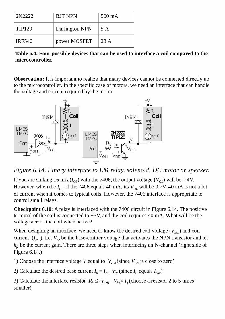
2N2222 BJTNPN 500mA
TIP120 DarlingtonNPN 5A
IRF540 powerMOSFET 28A
Table6.4.Fourpossibledevicesthatcanbeusedtointerfaceacoilcomparedtothemicrocontroller.
Observation:Itisimportanttorealizethatmanydevicescannotbeconnecteddirectlyuptothemicrocontroller.Inthespecificcaseofmotors,weneedaninterfacethatcanhandlethevoltageandcurrentrequiredbythemotor.
Figure6.14.BinaryinterfacetoEMrelay,solenoid,DCmotororspeaker.Ifyouaresinking16mA(IOL)withthe7406,theoutputvoltage(VOL)willbe0.4V.However,whentheIOLofthe7406equals40mA,itsVOLwillbe0.7V.40mAisnotalotofcurrentwhenitcomestotypicalcoils.However,the7406interfaceisappropriatetocontrolsmallrelays.
Checkpoint6.10:Arelayisinterfacedwiththe7406circuitinFigure6.14.Thepositiveterminalofthecoilisconnectedto+5V,andthecoilrequires40mA.Whatwillbethevoltageacrossthecoilwhenactive?
Whendesigninganinterface,weneedtoknowthedesiredcoilvoltage(Vcoil)andcoilcurrent(Icoil).LetVbebethebase-emittervoltagethatactivatestheNPNtransistorandlethfebethecurrentgain.TherearethreestepswheninterfacinganN-channel(rightsideofFigure6.14.)
1)ChoosetheinterfacevoltageVequaltoVcoil(sinceVCEisclosetozero)
2)CalculatethedesiredbasecurrentIb=Icoil/hfe(sinceICequalsIcoil)
3)CalculatetheinterfaceresistorRb≤(VOH-Vbe)/Ib(choosearesistor2to5timessmaller)

WithanN-channelswitch,likeFigure6.14,currentisturnedonandoffbyconnecting/disconnectingonesideofthecoiltoground,whiletheothersideisfixedatthevoltagesupply.AsecondtypeofbinaryinterfaceusesP-channelswitchestoconnect/disconnectonesideofthecoiltothevoltagesupply,whiletheothersidefixedatground,asshowninFigure6.15.InothertoactivateaPNPtransistor(e.g.,PN2907orTIP125),theremustbeaVEBgreaterthan0.7V.InordertodeactivateaPNPtransistor,theVEBvoltagemustbe0.Becausethetransistorisacurrentamplifier,theremustbearesistorintothebaseinordertolimitthebasecurrent.
Figure6.15.PNPinterfacetoEMrelay,solenoid,DCmotororspeaker.TounderstandhowthePNPinterfaceontherightofFigure6.15operates,considerthebehaviorforthetwocases:thePortoutputishighandthePortoutputislow.IfthePortoutputishigh,itsoutputvoltagewillbebetween2.4and3.3V.ThiswillcausecurrenttoflowintothebaseofthePN2222,anditsVbewillsaturateto0.7V.ThebasecurrentintothePN2222couldbefrom(2.4-0.7)/1000to(3.3-0.7)/1000,or1.7to2.6mA.Themicrocontrollerwillbeabletosourcethiscurrent.ThiswillsaturatethePN2222anditsVCEwillbe0.3V.ThiswillcausecurrenttoflowoutofthebaseofthePN2907,anditsVEBwillsaturateto0.7V.IfthesupplyvoltageisV,thenthePN2907basecurrentis(V-0.7-0.3)/Rb.SincethePNPtransistorison,VECwillbesmallandcurrentwillflowfromthesupplytothecoil.Iftheportoutputislow,thevoltageoutputwillbebetween0and0.4V.ThisnothighenoughtoactivatethePN2222,sotheNPNtransistorwillbeoff.SincethereisnoICcurrentinthePN2222,the10kandRbresistorswillplace+VatthebaseofthePN2907.SincetheVEBofthePN2907is0,thistransistorwillbeoff,andnocurrentwillflowintothecoil.ForparametervaluesreferbacktoTable1.6.
MOSFETscanhandlesignificantlymorecurrentthanBJTorDarlingtontransistors.MOSFETsarevoltagecontrolledswitches.ThedifficultywithinterfacingMOSFETstoamicrocontrolleristhelargegatevoltageneededtoactivateit.TheleftsideofFigure6.16isanN-channelinterface.TheIRF540N-channelMOSFETcansinkupto28Awhenthegate-sourcevoltageisabove7V.Thiscircuitisnegativelogic.Whentheportpinishigh,the2N2222isactivemakingtheMOSFETgatevoltage0.3V(VCEofthePN2222).AVGSof0.3VturnsofftheMOSFET.Whentheportpinislow,the2N2222isoffmakingtheMOSFETgatevoltage+V(pulledupthroughthe10k resistor).TheVGSis+V,whichturnstheMOSFETon.

TherightsideofFigure6.16showsaP-channelMOSFETinterface.TheIRF9540P-channelMOSFETcansourceupto20Awhenthesource-gatevoltageisabove7V.TheFQP27P06P-channelMOSFETcansourceupto27Awhenthesource-gatevoltageisabove6V.Thiscircuitispositivelogic.Whentheportpinishigh,the2N2222isactivemakingtheMOSFETgatevoltage0.3V.ThismakesVSGequalto+V-0.3,whichturnsontheMOSFET.Whentheportpinislow,the2N2222isoff.Sincethe2N2222isoff,the10k pull-upresistormakestheMOSFETgatevoltage+V.InthiscaseVSGequals0,whichturnsofftheMOSFET.
Figure6.16.MOSFETinterfacestoEMrelay,solenoid,DCmotororspeaker.AnH-bridgeusesfourtransistors,allowingcurrenttoflowineitherdirection.Figures4.26and4.27showapplicationsoftheL293H-bridge,whileFigure6.17showsoneoftheH-bridgecircuitsinternaltotheL293.Eachoutputisatotem-poledrivecircuitwithaDarlingtontransistorsinkandapseudo-Darlingtonsource.If1Aishigh,Q1isonandQ2isoff.If1Aislow,Q1isoffandQ2ison.2AcontrolsQ3andQ4inasimilarfashion.If1Aishighand2Aislow,thenQ1Q4areonandcurrentflowslefttorightacrosscoilA.If1Aislowand2Aishigh,thenQ2Q3areonandcurrentflowsrighttoleftacrosscoilA.
Observation:WeusedtheL293tointerfaceunipolarandbipolarsteppermotorsbackinSection4.7.2.

Figure6.17.AnH-bridgecandrivecurrentineitherdirection.
6.5.2.ElectromagneticandSolidStateRelaysArelayisadevicethatrespondstoasmallcurrentorvoltagechangebyactivatingswitchesorotherdevicesinanelectriccircuit.Itisusedtoremotelyswitchsignalsorpower.Theinputcontrolisusuallyelectricallyisolatedfromtheoutputswitch.Theinputsignaldetermineswhethertheoutputswitchisopenorclosed.Relaysareclassifiedintothreecategoriesdependinguponwhethertheoutputswitchespower(i.e.,highcurrentsthroughtheswitch)orelectronicsignals(i.e.,lowcurrentsthroughtheswitch).Anotherdifferenceishowtherelayimplementstheswitch.Anelectromagnetic(EM)relayusesacoiltoapplyEMforcetoacontactswitchthatphysicallyopensandcloses.Thesolidstaterelay(SSR)usestransistorswitchesmadefromsolidstatecomponentstoelectronicallyalloworpreventcurrentflowacrosstheswitch).Thethreetypesare1.TheclassicgeneralpurposerelayhasanEMcoilandcanswitchACpower2.ThereedrelayhasanEMcoilandcanswitchlow-levelDCelectronicsignals3.Thesolidstaterelay(SSR)hasaninputtriggeredsemiconductorpowerswitchThreesolidstaterelaysareshowninFigure6.18.InterfacingaSSRissimilartointerfacinganLED.ASSRinterfacewasdevelopedasExample2.1andFigure2.33.SSRsallowthemicrocontrollertoswitchACloadsfrom1to30A.Theyareappropriateinsituationswherethepoweristurnedonandoffmanytimes.
TheinputcircuitofanEMrelayisacoilwithanironcore.Theoutputswitchincludestwosetsofsilverorsilver-alloycontacts(calledpoles.)Onesetisfixedtotherelayframe,andtheothersetislocatedattheendofleafspringpolesconnectedtothearmature.Thecontactsareheldinthe“normallyclosed”positionbythearmaturereturnspring.WhentheinputcircuitenergizestheEMcoil,a“pullin”forceisappliedtothearmatureandthe“normallyclosed”contactsarereleased(calledbreak)andthe“normallyopen”contactsareconnected(calledmake.)Thearmaturepullincaneitherenergizeorde-energizetheoutputcircuitdependingonhowitiswired.Relaysaremountedinspecialsockets,ordirectlysolderedontoaPCboard.
Thenumberofpoles(e.g.,singlepole,doublepole,3P,4Petc.)referstothenumberofswitchesthatarecontrolledbytheinput.Therelayshownbelowisadoublepolebecauseithastwoswitches.Single-throwmeanseachswitchhastwocontactsthatcanbeopenorclosed.Double-throwmeanseachswitchhasthreecontacts.Thecommoncontactwillbeconnectedtooneoftheothertwocontacts(butnotbothatthesametime.)TheparametersoftheoutputswitchincludemaximumAC(orDC)power,maximumcurrent,maximumvoltage,onresistance,andoffresistance.ADCsignalwillweldthecontactstogetheratalowercurrentvaluethananACsignal,thereforethemaximumratingsforDCareconsiderablesmallerthanforAC.Otherrelayparametersincludeturnontime,turnofftime,lifeexpectancy,andinput/outputisolation.Lifeexpectancyismeasuredin

numberofoperations.Figure6.19illustratesthevariousconfigurationsavailable.ThesequenceofoperationisdescribedinTable6.5.
Figure6.18.SolidstaterelayscanbeusedtocontrolpowertoanACappliance.
Figure6.19.Standardrelayconfigurations.
Form ActivationSequence
DeactivationSequence
A Make1 Break1
B Break1 Make1
C Break1,Make2 Break2,Make1
D Make1,Break2 Make2,Break1
E Break1,Make2,Break3
Table6.5.Standarddefinitionsforfiverelayconfigurations.
6.5.3.SolenoidsSolenoidsareusedindiscretemechanicalcontrolsituationssuchasdoorlocks,automaticdisk/tapeejectors,andliquid/gasflowcontrolvalves(on/offtype).MuchlikeanEMrelay,thereisaframethatremainsmotionless,andanarmaturethatmovesinadiscretefashion(on/off).Asolenoidhasanelectro-magnet.Whencurrentflowsthroughthecoil,a

magneticforceiscreatedcausingadiscretemotionofthearmature.EachofthesolenoidsshownFigure6.20hasacylindrically-shapedarmaturethemovesinthehorizontaldirectionrelativetothephotograph.Thesolenoidonthetopisusedinadoorlock,andthesecondfromtopisusedtoejectthetapefromavideocassetteplayer.Whenthecurrentisremoved,themagneticforcestops,andthearmatureisfreetomove.Themotionintheoppositedirectioncanbeproducedbyaspring,gravity,orbyasecondsolenoid.
Figure6.20.Photooffoursolenoids.
6.5.4.DCMotorInterfacewithPWMSimilartothesolenoidandEMrelay,theDCmotorhasaframethatremainsmotionless,andanarmaturethatmoves.Inthiscase,thearmaturemovesinacircularmanner(shaftrotation).
Inthepreviousinterfacesthemicrocontrollerwasabletocontrolelectricalpowertoadeviceinabinaryfashion:eitherallonoralloff.Sometimesitisdesirableforthemicrocontrollertobeabletovarythedeliveredpowerinavariablemanner.Oneeffectivewaytodothisistousepulsewidthmodulation(PWM).ThebasicideaofPWMistocreateadigitaloutputwaveoffixedfrequency,butallowthemicrocontrollertovaryitsdutycycle.ThesystemisdesignedinsuchawaythatHigh+Lowisconstant(meaningthefrequencyisfixed).Thedutycycleisdefinedasthefractionoftimethesignalishigh:
Hence,dutycyclevariesfrom0to1.Weinterfacethisdigitaloutputwavetoanexternalactuator(likeaDCmotor),suchthatpowerisappliedtothemotorwhenthesignalishigh,andnopowerisappliedwhenthesignalislow.WepurposelyselectafrequencyhighenoughsotheDCmotordoesnotstart/stopwitheachindividualpulse,butratherrespondstotheoverallaveragevalueofthewave.TheaveragevalueofaPWMsignalislinearlyrelatedtoitsdutycycleandisindependentofitsfrequency.LetP(P=V*I)bethepowertotheDCmotor,showninFigure6.21,whenthePP0signalishigh.NoticethecircuitinFigure6.21isoneoftheexamplespreviouslydescribedinFigure6.14.Underconditionsofconstantspeedandconstantload,thedeliveredpowertothemotoris

linearlyrelatedtodutycycle.
DeliveredPower=
Unfortunately,asspeedandtorquevary,thedevelopedemfwillaffectdeliveredpower.Nevertheless,PWMisaveryeffectivemechanism,allowingthemicrocontrollertoadjustdeliveredpower.
ADCmotorhasanelectro-magnetaswell.Whencurrentflowsthroughthecoil,amagneticforceiscreatedcausingarotationoftheshaft.Brushespositionedbetweentheframeandarmatureareusedtoalternatethecurrentdirectionthroughthecoil,sothataDCcurrentgeneratesacontinuousrotationoftheshaft.Whenthecurrentisremoved,themagneticforcestops,andtheshaftisfreetorotate.Theresistanceinthecoil(R)comesfromthelongwirethatgoesfromthe+terminaltothe–terminalofthemotor.Theinductanceinthecoil(L)arisesfromthefactthatthewireiswoundintocoilstocreatetheelectromagnetics.Thecoilitselfcangenerateitsownvoltage(emf)becauseoftheinteractionbetweentheelectricandmagneticfields.IfthecoilisaDCmotor,thentheemfisafunctionofboththespeedofthemotorandthedevelopedtorque(whichinturnisafunctionoftheappliedloadonthemotor.)Becauseoftheinternalemfofthecoil,thecurrentwilldependonthemechanicalload.Forexample,aDCmotorrunningwithnoloadmightdraw50mA,butunderload(friction)thecurrentmayjumpto500mA.
TherearesixconsiderationswhenselectingaDCmotor:speed,torque,voltage,current,size,andweight.Speedistherateinrotationsperminute(RPM)thatthemotorwillspin,andtorqueistheavailableforcetimesdistancethemotorcanprovideatthatspeed.Weselectthemotorvoltagetomatchtheavailablepowersupply.UnlikeLEDs,weMUSTnotusearesistorinserieswithamotortoreducethevoltage.Ingeneral,themotorvoltagematchesthepowersupplyvoltage.Wheninterfacingwewillneedtoknowmaximumcurrent.
Therearelotsofmotordriverchips,buttheyarefundamentallysimilartothecircuitsshowninFigure6.14.Forthe2N2222andTIP120NPNtransistors,iftheportoutputislow,nocurrentcanflowintothebase,sothetransistorisoff,andthecollectorcurrent,IC,willbezero.Iftheportoutputishigh,currentdoesflowintothebaseandVBEgoesaboveVBEsatturningonthetransistor.ThetransistorisinthelinearrangeifVBE≤VBEsatandIc=hfe·Ib.ThetransistorisinthesaturatedmodeifVBE≥VBEsat,VCE=0.3VandIc<hfe·Ib.WeselecttheresistorfortheNPNtransistorinterfacestooperaterightatthetransitionbetweenlinearandsaturatedmode.Westartwiththedesiredcoilcurrent,Icoil(thevoltageacrossthecoilwillbe+V-VCEwhichwillbeabout+V-0.3V).Next,wecalculatetheneededbasecurrent(Ib)giventhecurrentgainoftheNPN
Ib=Icoil/hfeknowingthecurrentgainoftheNPN(hfe),seeTable6.6.Finally,giventheoutputhighvoltageofthemicrocontroller(VOHisabout3.3V)andbase-emittervoltageoftheNPN(VBEsat)neededtoactivatethetransistor,wecancalculatethedesiredinterfaceresistor.
Rb≤(VOH-VBEsat)/Ib=hfe*(VOH-VBEsat)/Icoil

Theinequalitymeanswecanchooseasmallerresistor,creatingalargerIb.Becausetheofthetransistorscanvaryalot,itisagooddesignpracticetomaketheRbresistorabout½thevalueshownintheaboveequation.Sincethetransistorissaturated,theincreasedbasecurrentproducesthesameVCEandthusthesamecoilcurrent.
Parameter PN2222(IC=150mA)
2N2222(IC=500mA)
TIP120(IC=3A)
hfe 100 40 1000
hie 60 250to8000 70to7000
VBEsat 0.6 2 2.5V
VCEatsaturation
0.3 1 2V
Table6.6.Designparametersforthe2N2222andTIP120.
TheIRF540MOSFETisavoltage-controlleddevice,ifthePortoutputishigh,the2N2222ison,theMOSFETisoff,andthecoilcurrentwillbezero.IfthePortoutputislow,the2N2222isoff,thegatevoltageoftheMOSFETwillbe+V,theMOSFETison,andtheVDSwillbeverycloseto0.TheIRF540needsalargegatevoltage(>10V)tofullyturnsothedrainwillbeabletosinkupto28A.
Becauseoftheresistanceofthecoil,therewillnotbesignificantdI/dtwhenthedeviceisturnedon.ConsideraDCmotorasshowninFigure6.21withV=12V,R=50 andL=100 H.Assumeweareusinga2N2222withaVCEof1Vatsaturation.Initiallythemotorisoff(nocurrenttothemotor).Attimet=0,thedigitalportgoesfrom0to+3.3V,andtransistorturnson.Assumeforthissection,theemfiszero(motorhasnoexternaltorqueappliedtotheshaft)andthetransistorturnsoninstantaneously,wecanderiveanequationforthemotor(Ic)currentasafunctionoftime.ThevoltageacrossbothLCtogetheris12-VCE=11Vattime=0+.Attime=0+,theinductorisanopencircuit.Conversely,attime=∞,theinductorisashortcircuit.TheIcattime0-is0,andthecurrentwillnotchangeinstantaneouslybecauseoftheinductor.Thus,theIcis0attime=0+.TheIcis11V/50 =220mAattime=∞.
11V=Ic*R+L*dIc/dt
Generalsolutiontothisdifferentialequationis
Ic=I0+I1e-t/ dIc/dt=-(I1/ )e-t/
Weplugthegeneralsolutionintothedifferentialequationandboundaryconditions.
11V=(I0+I1e-t/ )*R-L*(I1/ )e-t/

Tosolvethedifferentialequation,thetimeconstantwillbe =L/R=2 sec.Usinginitialconditions,weget
Ic=220mA*(1-e-t/2 s)
Example6.10.Designaninterfacefortwo+12V1AgearedDCmotors.Thesetwomotorswillbeusedtopropelarobotwithtwoindependentdrivewheels.
Solution:WewillusetwocopiesoftheTIP120circuitinFigure6.21becausetheTIP120cansinkatleastthreetimesthecurrentneededforthismotor.Weselecta+12Vsupplyandconnectittothe+Vinthecircuit.Theneededbasecurrentis
Ib=Icoil/hfe=1A/1000=1mA
Thedesiredinterfaceresistor.
Rb≤(VOH-Vbe)/Ib=(5-2.5)/1mA=2.5k
Tocoverthevariabilityinhfe,wewillusea1k resistorinsteadofthe2.5k .Theactualvoltageonthemotorwhenactivewillbe+12-2=10V.
Thecoilsandtransistorscanvaryalot,soitisappropriatetoexperimentallyverifythedesignbymeasuringthevoltagesandcurrents.TwocopiesofProgram6.8areusedtocontroltherobot.TheperiodofthePWMoutputischosentobeabout10timesshorterthanthetimeconstantofthemotor.Theelectronicdriverwillturnonandoffatthisrate,butthemotoronlyrespondstotheaveragelevel.ThesoftwaresetsthedutycycleofthePWMtoadjustthedeliveredpower.Whenactive,theinterfacewilldrive+10Vacrossthemotor.Thecurrentwillbeafunctionofthefrictionappliedtotheshaft.
Figure6.21.DCmotorinterface.

SimilartothesolenoidandEMrelay,theDCmotorhasaframethatremainsmotionless(calledthestator),andanarmaturethatmoves(calledtherotor).AbrushedDCmotorhasanelectromagneticcoilaswell,locatedontherotor,andtherotorispositionedinsidethestator.InFigure6.22,NorthandSouthrefertoapermanentmagnet,generatingaconstantBfieldfromlefttoright.Inthiscase,therotormovesinacircularmanner.Whencurrentflowsthroughthecoil,amagneticforceiscreatedcausingarotationoftheshaft.AbrushedDCmotorusescommutatorstoflipthedirectionofthecurrentinthecoil.Inthisway,thecoilontherightalwayshasanupforce,andtheoneontheleftalwayshasadownforce.Hence,aconstantcurrentgeneratesacontinuousrotationoftheshaft.Whenthecurrentisremoved,themagneticforcestops,andtheshaftisfreetorotate.Inapulse-widthmodulatedDCmotor,thecomputeractivatesthecoilwithacurrentoffixedmagnitudebutvariesthedutycycleinordertoadjustthepowerdeliveredtothemotor.
Figure6.22.AbrushedDCmotorusesacommutatortoflipthecoilcurrent.AbrushlessDCmotor(BLDC),asthenameimplies,doesnothavemechanicalcommutatorsorbrushestoflipthecurrents.Itisasynchronouselectricmotorpoweredbydirectcurrentandhasanelectroniccommutationsystem,ratherthanamechanicalcommutatorandbrushes.InBLDCmotors,current-to-torqueandvoltage-to-rpmarelinearrelationships.ThecontrolleruseseitherthebackemfofthemotoritselforHall-effectsensorstoknowtherotationalangleoftheshaft.Thecontrollerusesthisangletosetthedirectionofthecurrentsintheelectromagnets,shownasthesixstepsequenceinFigure6.23.OtherdifferencesfromabrushedDCmotorarethattheBLDCpermanentmagnetsareintherotorandtheelectromagnetsareinthestator.Typically,therearethreeelectromagneticcoils,labeledPhaseA,PhaseB,andPhaseC,whicharearrangedinaWyeformation.Eachcoilcanbemodeledasaresistance,inductance,andemf,aspreviouslyshowninFigure6.14.TheHallsensorgoesthroughthesequence001,000,

100,110,111,011eachtimetheshaftrotatesonce.Itisasynchronousmotorbecausethecontrolleradjuststhephasecurrentaccordingtothesix-stepsequence.Forexample,iftheHallsensorreads001,thenthecontrollerplaces+VonPhaseAandgroundonPhaseC(step1).Inotherwords,thephasecurrentsaresynchronizedtotheshaftposition.Torotatethemotorintheotherdirection,wereversethecurrentsineachstep.Wewillseelaterforsteppermotorsthattheprocessisreversed.Forsteppermotors,thecontrollersetsthephasecurrentsandthemotormovestothatposition.ToadjustthepowertoaBLDCmotor,wechangethevoltage,V,orusePWMonthecontrolsignalsthemselves.ThePWMperiodshouldbeatleast10timesshorterthanthetimeforeachofthesixsteps.Inotherwords,thePWMfrequencyshouldbe60timesfasterthantheshaftrotationalfrequency.
BLDCmotorshavemanyadvantagesandfewdisadvantageswhencomparedtobrushedDCmotors.Becausetherearenobrushes,theyrequirelessmaintenanceandhencehavealongerlife.Therefore,theyareappropriateforapplicationswhereservicingisinconvenientorexpensive.BLDCmotorsproducemoreoutputtorqueperweightthanbrushedDCmotorsandhenceareusedforpilotlessairplanesandhelicopters.Becausetherotorismadeofpermanentmagnets,therotorinertiaisless,allowingittospinfasterandtochangequicker.Inotherwords,ithasfasteraccelerationanddeceleration.Removingthebrushesreducesfriction,whichalsocontributestotheimprovedspeedandacceleration.Ithasalinearspeed/torquerelationship.Becausethereisnobrushcontact,BLDCmotorsoperatemorequietlyandhavelessElectromagneticInterference(EMI).Theonlydisadvantagesarethecomplexcontrollerandincreasedcost.
Figure6.23.AbrushlessDCmotorusesanelectroniccommutator.

Example6.11.Interfacea24-V2-AbrushlessDCmotor.
Solution:AbrushlessDCmotorhasthreecoilsconnectedinaWyepattern.Eachofthephasescanbedrivenintooneofthreestates:24V,ground,orfloating.WewilluseMOSFETstosourceandsinkthecurrentrequiredbythemotor(Figure6.16).Remember,whenthemotorisunderload,thecurrentwillincrease.TheP-channelMOSFETwillconnectthe24Vtothephasewhenitsgatevoltageisbelow24V.TheN-channelMOSFETwilldrivethephasetogroundwhenitsgateisabovezero.ItwillbeimportanttopreventturningonbothMOSFETsatthesametime.Forsafetyreasons,wewillusedigitallogicintheinterfacesothedrivercanonlybeinthethreevalidstates.Table6.7showsthedesignspecificationforPhaseA.WhenEnAislow,bothMOSFETsareoffandthephasewillfloat(HiZ).WhenEnAishigh,theInAdetermineswhetherthephaseishighorlow.ThesixgatevoltagesarelabeledinFigure6.24asG1toG6.Thesegatevoltagesare24V,producedbythe10k pull-up,whenthecorresponding7406driveroutputisfloating.Alternatively,thesegatevoltagesare0.5Vwhenthe7406driveroutputislow.ItisgooddesigntouseintegrateddriversliketheULN2074,L293,TPIC0107,andMC3479ratherthanindividualtransistors.Inparticular,theentireinterfacecircuitinFigure6.24couldbereplacedwiththreeL6203fullbridgedrivers.
EnA InA G1 G2 P-chan N-chan PhaseA
1 1 Low Low On Off +24V
1 0 High High Off On Ground
0 X High Low Off` Off HiZ
Table6.7.ControlsignalsforonephaseofthebrushlessDCmotor.
Figure6.24.BrushlessDCmotorinterface.

TheInA,InB,andInCsignalsinFigure6.24areconnectedtoanyoutputports,whereastheEnA,EnB,andEnCsignalswillbeattachedtoPWMoutputs.ThePWMperiodwillbeselected60timesfasterthanthemotorspeedinrps.ThethreeHall-effectsensorsignalswillbeattachedtoinputcapturepins.Interruptswillbearmedforboththeriseandfallofthesethreesensors.Inthisway,anISRwillberunatthebeginningofeachofthesixsteps.TheBLDCmotorisasynchronousmotor,sothesixcontrolsignalsareafunctionoftheshaftposition.Inparticular,theISRwilllookuptheHallsensorsandoutputthepattern,asshowninTable6.8.
Step HS1 HS2 HS3 EnA InA EnB InB EnC InC A B C
1 0 0 1 PWM 1 0 X PWM 0 24V HiZ 0V
2 0 0 0 PWM 1 PWM 0 0 X 24V 0V HiZ
3 1 0 0 0 X PWM 0 PWM 1 HiZ 0V 24V
4 1 1 0 PWM 0 0 X PWM 1 0V HiZ 24V
5 1 1 1 PWM 0 PWM 1 0 X 0V 24V HiZ
6 0 1 1 0 X PWM 1 PWM 0 HiZ 24V 0V
Table6.8.Input-outputrelationshipsforthesynchronouscontroller.
Furthermore,whenanyoftheenablesignalsarescheduledtobehigh,theywillbepulsedusingpositivelogicPWM.ThesoftwarecanadjustthedeliveredpowertotheBLDCmotorbysettingthedutycycleofthePWM.ThesoftwareimplementationhasbeenleftasLab6.4.

6.6.IntegralControlofaDCMotorAcontrolsystemisacollectionofmechanicalandelectricaldevicesconnectedforthepurposeofcommanding,directing,orregulatingaphysicalplant.InthissectionthephysicalplantisaDCmotorasdescribedpreviouslyinSection6.5.4.Therealstatevariablesarethepropertiesofthephysicalplantthataretobecontrolled.Inthisexample,wewishtospinthemotorat1500RPM,or25rps.Thus,thestatevariableinthiscasewillbemotorspeed.Thesensorandstateestimatorcompriseadataacquisitionsystem.Thegoalofthisdataacquisitionsystemistoestimatethestatevariables.Wewillattachatachometertothemotorsothesystemcanmeasurespeed.Figures6.4and6.4illustrateonetypeoftachometerandhowthesignalisinterfacedtothemicrocontroller.Theestimatedstatevariables,X’(t),inthissystemwillbethemeasuredspeedin0.1rps.Theactuatorisatransducerthatconvertsthecontrolsystemcommands,U(t),intodrivingforces,V(t),thatareappliedthephysicalplant.InthisexamplewewillusethecircuitinFigure6.21,whichallowsthemicrocontrollertoadjustpowertothemotorusingthefunctionsinProgram6.8.Inthisexample,thebusclockis80MHz,sothePWMclockis40MHz.WewillfixthePWMperiod1ms,andinitializethePWMoutputat0.1%bycalling PWM0_Init(40000,40) .Wedefinetheactuatorcommand,U(t),astheparameter40to39960thatwepassinwhenwecall PWM0_Duty .Thereforewecanadjustthepowerfrom0.1%to99.9%.
Ingeneral,thegoalofthecontrolsystemistodrivetherealstatevariablestoequalthedesiredstatevariables.Inactualitythough,thecontrollerattemptstodrivetheestimatedstatevariablestoequalthedesiredstatevariables.Itisimportanttohaveanaccuratestateestimator,becauseanydifferencesbetweentheestimatedstatevariablesandtherealstatevariableswilltranslatedirectlyintocontrollererrors.Ifwedefinetheerrorasthedifferencebetweenthedesiredandestimatedstatevariables:
e(t)=X*(t)-X’(t)
Aclosed-loopcontrolsystemusestheoutputofthestateestimatorinafeedbacklooptodrivetheerrorstozero.ThecontrolsystemcomparesX’(t),tothedesiredstatevariables,X*(t),inordertodecideappropriateaction,U(t).SeeFigure6.25.
Figure6.25.Blockdiagramofamicrocomputer-basedclosed-loopcontrol

system.WecancombinetheperiodmeasurementfromSection6.1,thePWMoutputofSection6.3,andtheDCmotorinterfaceofSection6.5.4tobuildamotorcontroller.Oneeffectiveyetsimplecontrolalgorithmsisanintegralcontroller.Wespecifytheactuatoroutputastheintegraloftheaccumulatederrors.
whereKiisacontrollerconstant.Forthiscontroller,iftheerroriszerotheactuatorcommandremainsconstant.Ifthemotorisspinningtooslowly,thecontrollerwillincreasepower.Ifthemotorisspinningtooquickly,itwilldecreasepower.Foranintegralcontroller,theamountofincreaseordecreaseislinearlyrelatedtotheerror.Soiftheerrorislargeitadds(orsubtracts)alot,andiftheerrorissmallitadds(orsubtracts)alittle.Ifthetimeconstantofthemotoris100ms,thenwewillrunthecontroller10timesfaster.TheTimer2AISRinProgram6.11issettoexecuteevery10ms.ThesoftwareinProgram6.2willsettheglobalvariable Period withthemeasuredperiodin12.5nsunits.
uint32_tPeriod;//24-bit,12.5nsunits
uint32_tSpeed;//motorspeedin0.1rps
int32_tE;//speederrorin0.1rps
int32_tU;//dutycycle40to39960
voidTimer2A_Handler(void)
TIMER2_ICR_R=0x01;//acknowledgetimer2Atimeout
Speed=800000000/Period;//0.1rps
E=250-Speed;//0.1rps
U=U+(3*E)/64;//discreteintegral
if(U<40)U=40;//Constrainoutput
if(U>39960)U=39960;//40to39960
PWM0A_Duty(U);//output
Program6.11.ISRtoimplementanintegralcontroller

6.7.Exercises6.1ShowthechangesyouneedtomaketoProgram6.1torunonaLM3S1968withtheinputconnectedtoCCP2/PB1.
6.2ShowthechangesyouneedtomaketoProgram6.1torunonaLM3S1968withtheinputconnectedtoCCP3/PG4.
6.3IfTimer0AandTimer0Barebotharmedforinterrupt,arethetwosourcespolledorvectored?IfTimer0AandTimer1Aarebotharmedforinterrupt,arethetwosourcespolledorvectored?
6.4HowdoyouchangetheresolutionoftheperiodmeasurementresolutioninProgram6.2?
6.5Ifthebusclockwerechangedto50MHzwithoutanychangestoProgram6.2,whatwouldthenewperiodmeasurementrangebe?
6.6ShowthechangesyouneedtomaketoProgram6.6torunTimer1A.
6.7ShowthechangesyouneedtomaketoProgram6.6torunTimer2B.
6.8ShowthechangesyouneedtomaketoProgram6.7torunonaLM3S1968withtheoutputconnectedtoCCP2/PB1.
6.9ShowthechangesyouneedtomaketoProgram6.8torunonaLM3S1968withtheoutputconnectedtoPWM3/PH1.
D6.10Createtwosynchronized50%dutycyclesquarewavesusingPWMchannels.InterfacethetwoPWMoutputstoasteppermotorusingaL293.Ifyouusejust2PWMoutputsyouwillneedtoadddigitallogicinverters.WritesoftwarethatinitializedthePWMgiventhedesiredshaftspeedin1RPM,witharangeofspeedsfrom0to100RPM.Assumethereare200steps/revolution.Thestepperwillspinwithoutsoftwareoverheaduntilthefunctioniscalledagain.Ifthedesiredspeediszero,stopthemotoratoneofthevalidstates(5,6,10or9).

D6.11TheobjectiveofthisproblemistomeasurethefrequencyofasquarewaveconnectedtoCCP2.Thefrequencyrangeis0to2000Hzandtheresolutionis0.1Hz.Forexample,ifthefrequencyis567.83Hz,thenyoursoftwarewillsettheglobal Freq to5678.Don’tworryaboutfrequenciesabove2000Hz.
D6.12Theobjectiveofthisproblemistomeasurebodytemperatureusinginputcapture(periodmeasurement).Ashuntresistorisplacedinparallelwithathermistor.Thethermistor-shuntcombination,R,hasthefollowinglinearrelationshipfortemperaturesfrom90to110˚F.
R=100kΩ-(T-90˚F)•1kΩ/˚FwhereRistheresistanceofthethermistor-shunt
Inotherwords,theresistancevariesfrom100kΩto80kΩasthetemperaturevariesfrom90to110˚F.Therangeofyoursystemis90to110˚Fandtheresolutionshouldbebetterthan0.01˚F.YouwilluseaTLC555toconverttheresistancetoaperiod.TheperiodofaTLC555timeris0.693•CT•(RA+2RB).SetRA=R,andRB=50kΩ.
a)Thepulsewidthmeasurementresolutionwillbe125nsbecausethebusclockis8MHz.Choosethecapacitorvaluesothatthispulsewidthmeasurementresolutionmatchesthedesiredtemperatureresolutionof0.01˚F.
b)GiventhisvalueofC,whatisthepulsewidthat90˚F?Givetheanswerbothinµsandbusclockcycles.
c)GiventhisvalueofC,whatisthepulsewidthat110˚F?Givetheanswerbothinµsandbusclockcycles.
d)Writetheinitializationthatconfigurestheinputcaptureinterrupts.
e)Showtheinterrupthandlerthatperformsthetemperaturemeasurementtasksinthebackgroundandsetsaglobal, Temperature .Temperature willvaryfrom9000to11000astemperaturevariesfrom90to110˚F.
D6.13Designawinddirectionmeasurementinstrumentusingtheinputcapturetechnique.Again,youaregivenatransducerthathasaresistancethatislinearlyrelatedtothewinddirection.Asthewinddirectionvariesfrom0to360degrees,thetransducerresistancevariesfrom0to1000Ω.Thefrequenciesofinterestare0to0.5Hz,andthesamplingratewillbe1Hz.OnewaytointerfacethetransducertothecomputeristouseanastablemultivibratorliketheTLC555.TheperiodofaTLC555timeris0.693•CT•(RA+2RB).
a)Showthehardwareinterface
b)Writetheinitializationandinterruptserviceroutinethatmeasuresthewinddirectionandcreatesa16-bitunsignedresultwithunitsofdegrees.I.e.,thevaluevariesfrom0to359.Youdonothavetowritesoftwarethatsamplesat1Hz,simplyafunctionthatmeasureswinddirectioninthebackground.
D6.14Theobjectiveofthisproblemistodesignanunderwaterultrasonicrangingsystem.Thedistancetotheobject,d,canvaryfrom1to100m.Theultrasonictransducerwill

sendashort5µssoundpulseintothewaterinthedirectionofinterest.Thesoundwavewilltravelat1500m/secandreflectoffthefirstobjectitrunsinto.Thereflectedwavewillalsotravelat1500m/secbacktothetransducer.Thereflectedpulseissensedbythesametransducer.Yoursystemwilltriggertheelectronics(givea5µsdigitalpulse),measurethetimeofflight,thencalculatethedistancetotheobject.Usingperiodicinterrupts,thesoftwarewillissuea5µspulseoutonceasecond.Usinginterruptinginputcapture,thesoftwarewillmeasurethetimeofflight,∆t.Theinputcaptureinterrupthandlerwillcalculatedistance,d,asadecimalfixed-pointvaluewithunitsof0.01m,andenteritintoaFIFOqueue.Themainprogramwillcalltheritual,thengetdataoutoftheFIFOqueue.Themainprogramwillcall Alarm() ifthedistanceislessthan15m.Youdonothavetogivetheimplementationof Alarm() .YoumayuseanyoftheFIFOsinChapter3withoutshowingitsimplementation.Assumethebusclockis8MHz.
Figure6.25.InterfaceforQuestionD6.14.a)Deriveanequationthatrelatesthedistance,d,tothetimeofflight,∆t.
b)Usethisequationtocalculatetheminimumandmaximumpossibletimeofflight,∆t.
c)Givetheinitializationroutine.
d)GivetheISRsthatmeasuredistance.

6.8.LabAssignmentsLab6.1Theoverallobjectiveistointerfaceajoysticktothemicrocontroller.Thejoystickismadewithtwopotentiometers.Youcanusetwoastablemultivibrators(TLC555)toconvertthetworesistancesintotwoperiods.UsetwoperiodmeasurementchannelstoestimatetheX-Ypositionofthejoystick.Organizethesoftwareinterfaceintoadevicedriver,andwriteamainprogramtotesttheinterface.
Lab6.2Theoverallobjectiveistomeasuretemperature.Athermistorisatransducerwitharesistancethatisafunctionofitstemperature.Youcanuseanastablemultivibrator(TLC555)toconverttheresistanceintoaperiod.Useaperiodmeasurementchanneltoestimatetheresistanceofthethermistor.Useatablelookupwithlinearinterpolationtoconvertresistancetotemperature.Organizethesoftwareinterfaceintoadevicedriver,andwriteamainprogramthatoutputstemperaturetotheUARTchannel.
Lab6.3Theoverallobjectiveistomeasurelinearposition.Aslide-potisatransducerwitharesistancethatisafunctionofthelinearpositionoftheslide.Youcanuseanastablemultivibrator(TLC555)toconverttheresistanceintoaperiod.Useaperiodmeasurementchanneltoestimatetheresistanceofthepotentiometer.Useatablelookupwithlinearinterpolationtoconvertresistancetoposition.Organizethesoftwareinterfaceintoadevicedriver,andwriteamainprogramthatoutputspositiontotheUARTchannel.
Lab6.4Theobjectiveofthislabistocontrolaservomotor.InterfaceaservomotortothePWMoutputpinofthemicrocontroller.ThedesiredangleisinputfromtheUARTchannel(connectedtoPCrunningPuTTY.)Organizethesoftwareinterfaceintoadevicedriver,andwriteamainprogramthatinputsfromtheUARTchannelandmaintainsthePWMoutputtotheservo.Servosareapopularmechanismtoimplementsteeringinrobotics.Rangingfrommicroservoswith15oz-intorquetopowerfulheavy-dutysailboatservos,theyallshareseveralcommoncharacteristics.Aservoisessentiallyapositionablemotor.Theservo“knows”twothings:whereitis(theactualposition)andwhereitwantstobe(thedesiredposition).Whentheservoreceivesaposition,itattemptstomovetheservohorntothedesiredposition.Thetaskoftheservo,then,istomaketheactualpositionthedesiredposition.Thefirststeptounderstandinghowservosworkistounderstandhowtocontrolthem.Powerisusuallybetween4Vand6Vandshouldbeseparatefromsystempower(asservosareelectricallynoisy).Evensmallservoscandrawoveranampunderheavyloadsothepowersupplyshouldbeappropriatelyrated.Thoughnotrecommended,servosmaybedriventohighervoltagestoimprovetorqueandspeedcharacteristics.Servosarecommandedthrough“PulseWidthModulation,”orPWM,signalssentthroughthecommandwire.Essentially,thewidthofapulsedefinestheposition.Forexample,sendinga1.5mspulsetotheservo,tellstheservothatthedesiredpositionis90degrees.Inorderfortheservotoholdthisposition,thecommandmustbesentatabout50Hz,orevery20ms.Ifyouweretosendapulselongerthan2.5msorshorterthan0.5ms,theservowouldattempttooverdrive(andpossiblydamage)itself.Oncetheservohasreceivedthedesiredposition(viathePWMsignal)theservomustattempttomatchthedesiredandactualpositions.Itdoesthisbyturningasmall,gearedmotorleftorright.If,forexample,thedesiredpositionislessthantheactualposition,theservowillturntotheleft.Ontheotherhand,ifthedesiredpositionisgreaterthanthe

actualposition,theservowillturntotheright.Inthismanner,theservo“zeros-in”onthecorrectposition.Shouldaloadforcetheservohorntotherightorleft,theservowillattempttocompensate.Notethatthereisnocontrolmechanismforthespeedofmovementand,formostservos,thespeedisspecifiedindegrees/second.Formoreinformationrefertothedatasheetofyourservo.
Figure6.26.Exampleservomotor.
Lab6.5Theoverallobjectiveistomeasurecapacitance.Thesystemwillmeasurefrom100pFto1uFwitharesolutionof100pF.Youcanuseanastablemultivibrator(TLC555)toconvertthecapacitanceintoaperiod.Useaperiodmeasurementchanneltoestimatethecapacitance.Useatablelookupwithlinearinterpolationtoconvertperiodtocapacitance.Organizethesoftwareinterfaceintoadevicedriver,andwriteamainprogramthatoutputspositiontotheUARTchanneloronalocaldisplay.
Lab6.6.TheobjectiveofthislabistointerfaceabrushlessDCmotor.RatherthanusediscretetransistorslikeFigure6.21,useanintegratedmotorinterfacechipliketheL293orL6103.UsingthreepowerresistorsinaWyeshape,testthemotordrivecircuit.Writetwosoftwarefunctions:InitializationandPowerSet.Thesecondfunctioncanbeusedtoadjustthepowertothemotorfrom0to100%.AddperiodmeasurementstotheinputcaptureISRs,andusethemtomeasureshaftspeedinRPM.UsealogicanalyzertocollectdatasimilartoFigure8.62.Takemeasurementsofshaftspeedversusdutycycle.Taketransientmeasurementsofspeedversustime,asthedutycyclechangesfrom25to75%.


7.SerialInterfacingChapter7objectivesareto:•Presentthephysicaldriversandprotocolsforserialinterfacing
•DescribetheRS232standard
•Designinterfacesthatconvertbetween+5and+3.3Vdigitallogic
•PresentdifferentiallineprotocolssuchasRS422andUSB
•DescribeandemploytheSSIsynchronousserialprotocol
•DescribeandemploytheI2Cserialbus
•IntroducetheUSBprotocol
Inmanyapplications,asinglededicatedmicrocontrollerisinsufficienttoperformallthetasksoftheembeddedsystem.Onesolutionwouldbetousealargerandmorepowerfulmicrocontroller,andanotherapproachwouldbetodistributethetasksamongmultiplemicrocontrollers.Thissecondapproachhastheadvantagesofmodularityandexpandability.Toimplementadistributedsystem,weneedamechanismtosendandreceiveinformationbetweenthemicrocontrollers.Asecondscenariothatrequirescommunicationisacentralgeneral-purposecomputerlinkedtomultipleremoteembeddedsystemsforthepurposeofdistributeddatacollectionordistributedcontrol.Forsituationswheretherequiredbandwidthislessthanabout100,000bytes/sec,thebuilt-inserialportsofthemicrocontrollercanbeused.
InthischapterwewillinterfaceDACandADCdevicestothesynchronousserialport.InChapters8and10wecontinuebyshowinghowtoemploytheDACandADCforsignalgenerationanddataacquisition.WecanusetheI2Cbustointerfacesensorsandactuators.Inthischapterwewillfocusonserialchannelsthatemployadirectphysicalconnectionbetweenthemicrocontrollers,andlaterinChapter11weexpandthecommunicationsystemtoincludenetworks.

7.1.IntroductiontoSerialCommunicationSerialcommunicationinvolvesthetransmissionofonebitofinformationatatime.Onebitissent,atimedelayoccurs,thenthenextbitissent.Thissectionwillintroducetheuseofserialcommunicationasaninterfacingtechniqueforvariousmicrocontrollerperipherals.Sincemanyperipheraldevicessuchasprinters,keyboards,scanners,andmiceoperatehavetheirowncomputers,thecommunicationproblemcanbegeneralizedtooneoftransmittinginformationbetweentwocomputers.Theuniversalasynchronousreceiver/transmitter(UART)istheinterfacedevicethatimplementstheserialdatatransmission.Theserialchannelisthecollectionofsignals(orwires)thatimplementthecommunication,seeFigure7.1.Toimprovebandwidth,removenoiseandincreaserange,weplaceinterfacelogicbetweenthedigitallogicUARTdeviceandtheserialchannel.Wedefinethedataterminalequipment(DTE)asthecomputeroraterminalandthedatacommunicationequipment(DCE)asthemodemorprinter.
Figure7.1.Aserialchannelconnectstwodataterminalequipment(DTE)devices.Whentransmittinginaserialfashion,therearemanywaystoencodebinaryinformationontheline,asshowninFigure7.2.Thegoalistomaximizebandwidthandminimizeerrors.Non-return-to-zero(NRZ)encodingisabinarycodeinwhichthesignalisneveratzerovoltage.ThereismoreenergyinthewirecomparedtotypicalVOL/VOHdigitallogic,becausethereisalwaysavoltagecausingcurrenttoflowcontinuously.Energyisthefundamentalpropertyneededtocommunicateinformationoveradistance.Onasinglewire,voltagesaremeasuredrelativetoground(e.g.,RS232).Onatwistedpair,voltagesaredifferential(e.g.,RS422,USB).Thebinaryvaluesof1and0areencodedaspositiveornegativevoltagedifferences.Inpositivelogic,1isapositivevoltagedifferenceand0isanegativevoltagedifference.Innegativelogic,thevoltagerepresenting0ishigherthanthevoltagerepresenting1.
Non-return-to-zero-inverted(NRZI)isamethodofencodingbinarysignalastransitionsorchangesinthesignal.SimilartoNRZ,thesignalinaNRZIprotocolisneverzero.Thebinaryinformationisencodedasthepresenceorabsenceofatransitionataclockboundary,illustratedbythearrowsinFigure7.2.Boththetransmitterandreceiverwillsynchronizetheirclockssothereceiverknowswhentolookforthetransition.Atransitionisachangefrompositivetonegativeorfromnegativetopositive.Forexample,wecouldsenda1byplacingatransitiononthesignal,orsenda0bycausingnotransition.Also,NRZImighttaketheoppositeconvention,asinUniversalSerialBus(USB),whereatransitionmeans0andasteadylevelmeans1.

Manchesterencodingcodeencodesbinarybitsaseitheralow-to-hightransition,orahigh-to-lowtransition.Manchesterencodingisatypeofphaseencoding,whichmeanstheinformationtransmittedasphaseshifts.ItisusedwiththeIEEE802.3Ethernetprotocol.Thereisafixedtimeperiodinsidewhichonebitistransmitted.TheoriginalManchesterencodingschemedefined0asalow-to-high,and1asahigh-to-low.However,theIEEE802.3conventiondefinesthebitsintheoppositemanner.Thetransitionsthatsignify0or1occuratthemidpointofaperiod,shownasarrowsinFigure7.2.Theremaybeanadditionaltransitionsatthestartofaperiod;theseareextraanddonotsignifydata.Sinceeverybithasatleastonetransition,itiseasierforthereceivertoaligncorrectlyortosynchronizeitsclockwiththetransmitterclock.However,thecostofthiseaseofsynchronizationisadoublingofthebandwidthrequirementofthephysicalchannelascomparedtoNRZorNZRIencoding.Considerthecasewhereasystemiscommunicatingalongsequenceofzerosat1Mb/s.UsingtheNRZIUSBencoding,thelinewillbeasquarewaveat1MHz.However,usingIEEE802.3encoding,thelinewillbeasquarewaveat2MHz.
Figure7.2.Fourencodingsofthebinary10011011.Figure7.3showstheUARTpinsavailableonsomeLM3S/TM4Cmicrocontrollers.ThedescriptionsandsoftwaredriverswerepresentedearlierasProgram4.10and5.11.Tables2.7and2.8describehowtoattachI/OpinstotheUARTmodulesontheTM4C123/TM4C1294.
Figure7.3.SerialportpinsavailableonvariousLM3S/LM4F/TM4Cmicrocontrollers.

Theinterfacelogic(e.g.,MAX3232)convertsbetweendigitallogiclevelsandRS232logiclevels.Inthisprotocol,atypicalbidirectionalchannelrequires3wires(Rx,Tx,Ground.)WeuseRS422voltagelevelswhenwewantlongcablelengthsandhighbandwidths.ThebinarysignalisencodedontheRS422lineasavoltagedifference(e.g.,MAX485).Inthisprotocol,atypicalbidirectionalchannelrequires5wires(RxD+,RxD-,TxD+,TxD-,Ground.)TypicalvoltagelevelsareshowninTable7.1.Ifthetwocomputersareinthesamebox,wecanimplementtheserialchannelwithouttheinterfacedrivers.
+3.3Vlogic
+5Vlogic RS232level
RS422level
True Mark +3V +5V TxD=-5.5V
(TxD+-TxD-)=-3V
False Space +0.1V +0.1V TxD=+5.5V
(TxD+-TxD-)=+3V
Table7.1.Typicalvoltagelevelsforthedigitallogic,RS232andRS422protocols.
Aframeisacompleteandnondivisiblepacketofbits.Aframeincludesbothinformation(e.g.,data,characters)andoverhead(startbit,errorchecking,andstopbits.)Aframeisthesmallestpacketthatcanbetransmitted.TheRS232andRS422protocolshave1startbit,7/8databits,no/even/oddparity,and1/1.5/2stopbits.TheRS232idlelevelistrue(-5V).Thestartbitisfalse(+5V.)Atruedatabitis-5V,andafalsedatabitis+5V(Figure7.4).
Observation:RS232andRS422datachannelsareinnegativelogicbecausethetruevoltageislessthanthefalsevoltage.
Observation:TheRS232protocolalwayshasonestartbitandatleastonestopbit.
Checkpoint7.1:IftheRS232protocolhaseightdatabits,noparity,andonestop
bit,howmanytotalbitsareinaframe?
Figure7.4.ARS232frameshowing1start,8data,noparity,and1stopbit.

Paritycanbeusedtodetecterrors.Parityisgeneratedbythetransmitterandcheckedbythereceiver.Forevenparity,thenumberofonesinthedataplusparityisanevennumber.Foroddparity,thenumberofonesinthedataplusparityisanoddnumber.Iferrorsareunlikely,thenoperatingwithoutparityisfasterandsimpler.
Thebittimeisthebasicunitoftimeusedinserialcommunication.Itisthetimebetweeneachbit.Thetransmitteroutputsabit,waitsonebittime,andthenoutputsthenextbit.Thestartbitisusedtosynchronizethereceiverwiththetransmitter.Thereceiverwaitsontheidlelineuntilastartbitisfirstdetected.Afterthetruetofalsetransition,thereceiverwaitsahalfofabittime.Thehalfofabittimewaitplacestheinputsamplingtimeinthemiddleofeachdatabit,givingthebesttolerancetovariationsbetweenthetransmitterandreceiverclockrates.Inordertooperateproperlythedataavailableintervalmustoverlapthedatarequiredinterval(Section4.2).Next,thereceiverreadsonebiteverybittime.Thebaudrateisthetotalnumberofbits(information,overhead,andidle)pertimethataretransmittedintheserialcommunication.
baudrate=1/(bittime)
Wewilldefineinformationasthedatathatthe“user”intendstobetransmittedbythecommunicationsystem.Examplesofinformationinclude
•Characterstobeprintedonyourprinter
•Apicturefiletobetransmittedtoanothercomputer
•Adigitallyencodedvoicemessagecommunicatedtoyourfriend
•TheobjectcodefiletobedownloadedfromthePCtothemicrocontroller
Wewilldefineoverheadassignalsaddedtothecommunicationinordertoaffectreliabletransmission.Examplesofoverheadinclude
•Startbit(s)startbyte(s)orstartcode(s)
•Stopbit(s)stopbyte(s)orstopcode(s)
•Errorcheckingbitslikeparity,CRC(cyclicredundancycheck),andchecksum
•SynchronizationmessageslikeACK,NAK,XON,XOFF

Bandwidth,latency,andreliabilityarethefundamentalperformancemeasuresforacommunicationsystem.Although,inageneralsenseoverheadsignalscontain“information”,overheadsignalsarenotincludedwhencalculatingbandwidthorconsideringfullduplex,halfduplex,andsimplex.Insimilarway,ifwearesending2bitsofdata,butadd6bitsofzerostofillthebytefieldintheframe,weconsiderthatthereare2bitsofinformationperframe(not8bits.)Wewillusethethreetermsbandwidth,bitrateandthroughputinterchangeablytospecifythenumberofinformationbitspertimethataretransmitted.Thesetermsapplytoallformsofcommunication:
•Parallel
•Serial
•Mixedparallel/serial
Forserialcommunicationsystems,wecancalculate:
Latencyisthetimedelaybetweenwhenamessageissentandwhenitisreceived.Forthesimplesystemsinthischapter,atthephysicallayer,latencycanbecalculatedastheframesizeinbitsdividedbythebaudrateinbits/sec.ForexampleaRS232protocolwith10-bitframesrunningat9600-bpsbaudratewilltake1.04mstogofromtransmittertoreceiver.
Reliabilityisdefinedastheprobabilityofcorrupteddataorthemeantimebetweenfailures(MTBF).Oneoftheconfusingaspectsofbandwidthisthatitcouldmeantwothings.Thepeakbandwidthisthemaximumachievabledatatransferrateovershortperiodsduringtimeswhennothingelseiscompetingforresources.Whenwesaythebandwidthofaserialchannelwith10-bitframesandabaudrateof9600bpsis960bytes/s,wearedefiningpeakbandwidth.Atthecomponentlevel,itisappropriatetospecifypeakbandwidth.However,onacomplexsystem,therewillbedelayscausedbythetimeittakessoftwaretorun,andtherewillbetimeswhenthetransmissionwillbestalledduetoconditionslikefulloremptyFIFOs.Thesustainedbandwidthistheachievabledatatransferrateoverlongperiodsoftimeandundertypicalusageandconditions.Atthesystemlevel,itisappropriatetospecifysustainedbandwidth.
Thedesignparametersthataffectbandwidthareresistance,capacitanceandpower.Ittakesenergytoencodeeachbit,thereforethebandwidthinbitspersecondisrelatedtothepower,whichisenergypersecond.Capacitanceexistsbecauseofthephysicalproximityofthewiresinthecable.Thetimeconstant ofasimpleRCcircuitisR·C.Anincreaseincapacitancewilldecreasetheslewrateofthesignal(seeFigure1.14),limitingtherateatwhichsignalscanchange,therebyreducingthebandwidthofthedigitaltransmission.However,wecanincreasetheslewratebyusingmorepower.Wecanincreasetheenergyoverthesametimeperiodbyincreasingvoltage,increasingcurrent,ordecreasingresistance.

Afullduplexcommunicationsystemallowsinformation(data,characters)totransfersimultaneouslyinbothdirections.Afullduplexchannelallowsbits(information,errorchecking,synchronizationoroverhead)totransfersimultaneouslyinbothdirections,shownpreviouslyinFigure7.1.
Ahalfduplexcommunicationsystemallowsinformationtotransferinbothdirections,butinonlyonedirectionatatime.Halfduplexisatermusuallydefinedformodemcommunications,butinthisbookwewillexpanditsmeaningtoincludeanyserialprotocolthatallowscommunicationinbothdirections,butonlyonedirectionatatime.Afundamentalproblemwithhalfduplexisthedetectionandrecoveryfromacollision.Acollisionoccurswhenbothcomputerssimultaneouslytransmitdata.Fortunately,everytransmissionframeisechoedbackintoitsownreceiver.Thetransmitterprogramcanoutputaframe,waitfortheframetobetransmitted(whichwillbeechoedintoitsownreceiver)thenchecktheincomingparityandcomparethedatainordertodetectacollision.Ifacollisionoccurs,thenitwillprobablybedetectedbybothcomputers.Afteracollision,thetransmittercanwaitawhileandretransmittheframe.Thetwocomputersneedtodecidewhichonewilltransmitfirstafteracollisionsothatasecondcollisioncanbeavoided.
Observation:Mostpeoplecommunicateinhalfduplex.
Acommonhardwaremechanismforhalfduplexutilizesopendrainlogic.Themicrocontrolleropendrainmodehastwooutputstates:zeroandHiZ(Figure7.5).Thelogichighiscreatedwiththepassivepull-up.Withopendrain,thehalfduplexchannelisthelogicalANDofthetwoTxDoutputs.Inthissystem,thetransmittersimplytransmitsitsframewithoutneedingtoenableordisableadriver.Ifbothmicrocontrollerstransmitatthesametime,thezerosonthechannelwilldominatetheones,andthedatawillbecorrupted.
Figure7.5.Ahalfduplexserialchannelcanbeimplementedwithopendrainlogic.Checkpoint7.2:Whatisthedifferencebetweenfullduplexandhalfduplex?
Asimplexcommunicationsystemallowsinformationtotransferonlyinonedirection.TheXON/XOFFprotocolthatwewillcoverlaterisanexampleofacommunicationsystemthathasafullduplexchannel,butimplementssimplexcommunication.Thisissimplexbecauseinformationistransmittedfromthecomputertotheprinter,butonlyXON/XOFF(errorcheckingflags)aresentfromtheprinterbacktocomputer.Inthiscase,nodataissentfromprintertocomputer.

Inordertotransferinformationcorrectly,bothsidesofthechannelmustoperateatthesamebaudrate.Inanasynchronouscommunicationsystem,thetwodeviceshaveseparateanddistinctclocks.Becausethesetwoclocksaregeneratedseparately(oneoneachside),theywillnothaveexactlythesamefrequencyorbeinphase.Ifthetwobaudrateclockshavedifferentfrequencies,thephasebetweentheclockswillalsodriftovertime.Transmissionwilloccurproperlyaslongastheperiodsofthetwobaudrateclocksarecloseenough.The-5Vto+5Vedgeatthebeginningofthestartbitisusedtosynchronizethereceiverwiththetransmitter.IfthetwobaudrateclockperiodsinaRS232systemdifferbylessthan5%,thenafter10bitsthereceiverwillbeoffbylessthanahalfabittime(andnoerrorwilloccur.)Anylargerdifferencebetweenthetwoperiodsmaycauseanerror.
Inasynchronouscommunicationsystem,thetwodevicessharethesameclock(Figure7.6).Typicallyaseparatewireintheserialcablecarriestheclock.Inthisway,veryhighbaudratescanbeobtained.Anotheradvantageofsynchronouscommunicationisthatverylongframescanbetransmitted.Largerframesreducetheoperatingsystemoverheadforlongtransmissionsbecausefewerframesneedbeprocessedpermessage.Eventhoughinthischapter,wewilldesignvariouslowbandwidthsynchronoussystemsusingtheSSI,synchronouscommunicationisbestappliedtosystemsthatrequirebandwidthsabove1Mbps.Thecostofthisincreasedperformanceistheadditionalwireinthecable.Theclockmustbeinterfacedwithchanneldrivers(e.g.,RS232,RS422,optocouplers)similartothetransmitandreceivedatasignals.Ifthetwocomputersareinthesamebox,wecanimplementcommunicationwithouttheinterfacedrivers.
Checkpoint7.3:Whatisthedifferencebetweensynchronousandasynchronouscommunication?
Observation:Self-centeredpeopleemploysimplexcommunication.
Figure7.6.Nodesonasynchronouschanneloperateoffacommonclock.Checkpoint7.4:HowdoestheMAX3232inFigures7.1and7.6makeitbetter?

7.2.RS232InterfacingThebaudrateinaRS232systemcanbeashighas115,200bits/sec.Becauseatypicalcablehas50pF/foot,themaximumdistanceforRS232transmissionislimitedto50feet.Thereare21signalsdefinedforfullMODEM(MOdulate/DEModulate)communication(Figure7.7.)TheRS232standardusesaDB25connectorthathas25pins.TheEIA-574standardusesRS232voltagelevelsandaDB9connectorthathasonly9pins.TheEIA-561standardalsousesRS232voltagelevelsbutwithaRJ45connectorthathasonly8pins.
Figure7.7.RS232,EIA-574andEIA-561connectorsusedinmanyserialapplications.Table7.2showstheentiresetofRS232signals.ThemostcommonlyusedsignalsofthefullRS232standardareavailablewiththeEIA-561/EIA-574protocols.
Theframegroundisconnectedononesidetothegroundshieldofthecable.Theshieldwillprovideprotectionfromelectricfieldinterference.Thetwistedcablehasasmallareabetweenthewires.Thesmallerthearea,thelessthemagneticfieldpickup.Thereisonedisadvantagetoreducingtheareabetweentheconnectors.Thecapacitancetogroundisinverselyrelatedtotheseparationdistancebetweenthewires.Thusastheareadecreases,thecapacitancewillincrease.Thisincreasedcapacitiveloadwilllimitboththedistanceandthebaudrate.
DB25Pin
RS232Name
DB9Pin
EIA-574
Name
RJ45Pin
EIA-561
Name
Signal Description True DTE DCE
1 FG FrameGround/Shield
2 BA 3 103 6 103 TxD TransmitData -5V out in
3 BB 2 104 5 104 RxD ReceiveData -5V in out
4 CA 7 105/133 8 105/133 RTS RequesttoSend
+5V out in
5 CB 8 106 7 106 CTS CleartoSend +5V in out
6 CC 6 107 DSR DataSetReady +5V in out
7 AB 5 102 4 102 SG SignalGround

8 CF 1 109 2 109 DCD DataCarrierDetect
+5V in out
9 PositiveTestVoltage
10 NegativeTestVoltage
11 NotAssigned
12 sDCD secondaryDCD
+5V in out
13 sCTS secondaryCTS +5V in out
14 sTxD secondaryTxD -5V out in
15 DB TxC TransmitClk(DCE)
in out
16 sRxD secondaryRxD -5V in out
17 DD RxC ReceiveClock in out
18 LL LocalLoopback
19 sRTS secondaryRTS +5V out in
20 CD 4 108 3 108 DTR DataTerminalRdy
+5V out in
21 RL SQ SignalQuality +5V in out
22 CE 9 125 1 125 RI RingIndicator +5V in out
23 SEL SpeedSelectorDTE
in out
24 DA TCK SpeedSelectorDCE
out in
25 TM TM Testmode +5V in out
Table7.2.PinassignmentsfortheRS232EIA-574andEIA-561protocols.

Thesignalgroundisconnectedonbothsidestothesupplyreturn.Aseparatewireshouldbeusedforsignalground(donotusethegroundshieldtoconnectthetwosignalgrounds.)Thenoiseimmunitywillbedegradedifthegroundshieldisconnectedonbothsides.TherearemanyavailableRS232driverchips(e.g.,MaximMAX3232).Thesechipsemployachargepump(usingthe100nFcapacitors)tocreatethestandard+5and-5outputvoltageswithonlya+3.3Vsupply.ThefollowingoverviewstheRS232specificationsforanoutputsignal
MustbeabletowithstandashorttogroundorshorttoanotherwireTruevoltageisbetween-5and-15V(operatingrange)Falsevoltageisbetween+5and+15V(operatingrange)Shortcircuitcurrentlessthan0.5ASpendslessthan4%ofthetimeinthetransitionrangefrom-3to+3V
Similarly,thefollowingoverviewstheRS232specificationsforaninputsignal
Themaximumslewrateis30V/ sTrueinputis-3to-15VFalseinputis+3to+15VThetransitionrangeis-3to+3VTheinputimpedancebetween3000and7000Theinputcapacitanceincludingcablemustbelessthan2500pFTheinputopencircuitvoltagemustbelessthan2V
Onthedatalines,atrueormarkvoltageisnegative.Converselyforthecontrollines,atruesignalhasapositivevoltage.RequesttoSend(RTS)isasignalfromthecomputertotheMODEMrequestingtransmissionbeallowed.CleartoSend(CTS)istheacknowledgesignalbackfromtheMODEMsignifyingtransmissioncanproceed.DataSetReady(DSR)isaMODEMsignalspecifyingthatinput/outputcanoccur.DataCarrierDetect(DCD)isamodemsignalspecifyingthatthecarrierfrequencieshavebeenestablishedonitstelephoneline.RingIndicator(RI)isamodemsignalthatistruewhenthephonerings.TheReceiveClockandTransmitClockareusedtoestablishsynchronousserialcommunication.DataTerminalReady(DTR)isaprintersignalspecifyingthestatusoftheprinter.WhenDTRis+5V,theprinterisreadyandcanacceptmorecharacters.ConverselywhenDTRis-5V,theprinterisbusyandcannotacceptmorecharacters.Mostmicrocontrollersdonotsupportthesecontrollinesexplicitly.Ontheotherhand,itisstraightforwardtoimplementthesehardwarehandshakingsignalsusingsimpleinput/outputlines.Ifwewishtogenerateinterruptsonedgesoftheselines,thenwewoulduseedge-triggeredinputfeatures.
Example7.1.DesignasimplexprinterdriverwithDTRsynchronization.

Solution:Oneproblemwithprintersisthattheprinterbandwidth(theactualnumberofcharacterspersecondthatcanbeprinted)maybelessthanthemaximumbandwidthsupportedbytheserialchannel.Therearefiveconditionsthatmightleadtoasituationwherethecomputeroutputsserialdatatotheprinter,buttheprinterisn’treadytoacceptthedata.First,specialcharactersmayrequiremoretimetoprint(e.g.,carriagereturn,linefeed,tab,formed,andgraphics).Second,mostprintershaveinternalFIFOsthatcouldgetfull.IftheFIFOisnotfull,thenitcanacceptdataasfastasthechannelwillallow,butwhentheFIFObecomesfull,thecomputershouldstopsendingdata.Third,theprintercablemaybedisconnected.Fourth,theprintermaybedeselectedorattachedtodifferentcomputer.Fifth,theprinterpowermaybeoff.Theoutputinterfacesshownpreviouslyprovidenofeedbackfromtheprinterthatcouldbeusedtodetect/correctthesefiveproblems.Therearetwomechanisms,calledflowcontrol,tosynchronizethecomputerwithavariablerateoutputdevice.ThesetwoflowcontrolprotocolsarecalledDTRandXON/XOFF.
Thefirstmethodusesahardwaresignal,DTR(pin4ontheDB9connector),asfeedbackfromtheprintertothemicrocontroller,seeFigure7.8.DTRis–5Viftheprinterisbusyandisnotcurrentlyabletoaccepttransmission.DTRis+5Viftheprinterisreadyandabletoaccepttransmission.Thismechanismcanhandleallfiveoftheaboveconditionswheretheprinterisnotready.ThecomputerinputmechanismwillhandletheDTRprotocolusingadditionalsoftwarechecking.
WithastandardRS232interfacewhenDTRis–5V,PC4willbe+3.3V(whichwillstoptheoutputeveniftheUARTtransmitFIFOisnotfull).Thus,whenDTRis–5V,transmissionistemporarilysuspended.WhenDTRis+5V,PC4willbe0Vandtransmissioncanproceednormally.Inthisdesign,edge-triggeredinputonPC4willbeusedtodetectchangesintheDTRsignal.
TheDTRsignalfromtheprinterprovidesfeedbackinformationabouttheprinterstatus.WhenDTRis‑5V(PC4ishigh),theprinterisnotreadytoacceptmoredata.Inthiscase,ourcomputerwillpostponetransmittingmoreframes.WhenDTRis+5V(PC4islow),theprinterisreadytoacceptmoredata.Atthispoint,thecomputerwillresumetransmission.The Printer_OutChar(data) inProgram7.1iscalledbythemainprogramtoprint.

Figure7.8.HardwareinterfaceimplementingaRS232simplexchannelwithDTRhandshaking.
voidPrinter_Init2(void)
SYSCTL_RCGCUART_R|=0x01;//activateUART0
SYSCTL_RCGCGPIO_R|=0x05;//activateportsA,C
TxFifo_Init();//initializeemptyFIFOs
GPIO_PORTC_DIR_R&=~0x10;//makePC4in
GPIO_PORTC_DEN_R|=0x10;//enabledigitalI/OonPC4
GPIO_PORTC_IS_R&=~0x10;//PC4isedge-sensitive
GPIO_PORTC_IBE_R|=0x10;//PC4isbothedges
GPIO_PORTC_ICR_R=0x10;//clearflag4
GPIO_PORTC_IM_R|=0x10;//enableinterruptonPC4
UART0_CTL_R&=~UART_CTL_UARTEN;//disableUART
UART0_IBRD_R=43;//IBRD=int(80000000/(16*115,200))=int(43.40278)
UART0_FBRD_R=26;//FBRD=round(0.40278*64)=26
UART0_LCRH_R=0x0070;//8-bitwordlength,enableFIFO
UART0_IFLS_R&=~0x07;//clearTXinterruptFIFOlevelfield
UART0_IFLS_R+=UART_IFLS_TX1_8;//interruptforTXFIFO<=1/8full
UART0_IM_R|=UART_IM_TXIM;//enableTXFIFOinterrupt
UART0_CTL_R|=UART_CTL_UARTEN;//enableUART
GPIO_PORTA_PCTL_R=(GPIO_PORTA_PCTL_R&0xFFFFFF00)+0x00000011;//UART
GPIO_PORTA_AMSEL_R&=~0x03;//disableanalogonPA1-0
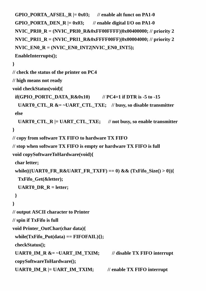
GPIO_PORTA_AFSEL_R|=0x03;//enablealtfunctonPA1-0
GPIO_PORTA_DEN_R|=0x03;//enabledigitalI/OonPA1-0
NVIC_PRI0_R=(NVIC_PRI0_R&0xFF00FFFF)|0x00400000;//priority2
NVIC_PRI1_R=(NVIC_PRI1_R&0xFFFF00FF)|0x00004000;//priority2
NVIC_EN0_R=(NVIC_EN0_INT2|NVIC_EN0_INT5);
EnableInterrupts();
//checkthestatusoftheprinteronPC4
//highmeansnotready
voidcheckStatus(void)
if(GPIO_PORTC_DATA_R&0x10)//PC4=1ifDTRis-5to-15
UART0_CTL_R&=~UART_CTL_TXE;//busy,sodisabletransmitter
else
UART0_CTL_R|=UART_CTL_TXE;//notbusy,soenabletransmitter
//copyfromsoftwareTXFIFOtohardwareTXFIFO
//stopwhensoftwareTXFIFOisemptyorhardwareTXFIFOisfull
voidcopySoftwareToHardware(void)
charletter;
while(((UART0_FR_R&UART_FR_TXFF)==0)&&(TxFifo_Size()>0))
TxFifo_Get(&letter);
UART0_DR_R=letter;
//outputASCIIcharactertoPrinter
//spinifTxFifoisfull
voidPrinter_OutChar(chardata)
while(TxFifo_Put(data)==FIFOFAIL);
checkStatus();
UART0_IM_R&=~UART_IM_TXIM;//disableTXFIFOinterrupt
copySoftwareToHardware();
UART0_IM_R|=UART_IM_TXIM;//enableTXFIFOinterrupt

//interruptwhenhardwareTXFIFOgoesfrom3to2orlessitems
voidUART0_Handler(void)
if(UART0_RIS_R&UART_RIS_TXRIS)//hardwareTXFIFO<=2items
UART0_ICR_R=UART_ICR_TXIC;//acknowledgeTXFIFO
//copyfromsoftwareTXFIFOtohardwareTXFIFO
copySoftwareToHardware();
if(TxFifo_Size()==0)//softwareTXFIFOisempty
UART0_IM_R&=~UART_IM_TXIM;//disableTXFIFOinterrupt
//interruptonanychangeofthestatusoftheprinteronPC4
voidGPIOPortC_Handler(void)
GPIO_PORTC_ICR_R=0x10;//acknowledgeflag4
checkStatus();
Program7.1.SoftwareimplementationofaprinterinterfacewithDTRsynchronization(SyncPrinter_xxx.zip).

7.3.RS422/USB/RS423/RS485BalancedDifferentialLinesInordertoincreasethebaudrateandmaximumdistance,thebalanceddifferentiallineprotocolswereintroduced.TheRS422signalisencodedinadifferentialsignal,A-B.TherearemanyRS422interfacechips,forexample,SP301orMAX13433.AfullduplexRS422channelisimplementedinFigure7.9withMAX13433drivers.Oftenterminatingresistorsareplacedattheendsoflongcables.E.g.,wecanplacea100 resistoratacrosstheA’B’inputs.
Figure7.9.RS422serialchannel.Becauseeachsignalrequires2wires,5wires(groundincluded)areneededtoimplementafullduplexchannel.WithRS232onetypicallyconnectsonereceivertoonetransmitter.ButwithRS422,upto10receiverscanbeconnectedtoonetransmitter.Table7.3summarizesfourcommonEIAstandards.
Specification RS232D RS423A RS422 RS485
Modeofoperation single-ended
single-ended
differential differential
Driversononeline 1 1 1 32
Receiversononeline
1 10 10 32
Maximumdistance(feet)
50 4,000 4,000 4,000
Maximumdatarate 20kb/s 100kb/s 10Mb/s 10Mb/s
Maximumdriveroutput
±25V ±6V -0.25to+6V
-7to+12V
±5V ±3.6V ±2V ±1.5V

DriverOutput(loaded)
DriverOutput(unloaded)
±15V ±6V ±5V ±5V
DriverLoadImpedance
3kΩto7kΩ 450Ωmin 100Ω 54Ω
Receiverinputvoltage
±15V ±12V ±7V -7to+12V
Receiverinputsensitivity
±3V ±200mV ±200mV ±200mV
Receiverinputresistance
3kΩto7kΩ 4kΩmin 4kΩmin 12kΩmin
Table7.3.SpecificationsfortheRS232RS423ARS422andRS485protocols.
Themaximumbaudrateat40feetis10Mbps.At4000feet,thebaudratecanonlybeashighas100Kbps.Table7.4showstwoimplementationsoftheRS422protocol.
DB25Pin
EIA-530Name
DB37Pin
RS449
Name
Signal Description DTE DCE
1 1 FG FrameGround/Shield
2 BA(A) 4 SD(A) TxD TransmitData out in
14 BA(B) 22 SD(B) TxD TransmitData out in
3 BB(A) 6 RD(A) RxD ReceiveData in out
16 BB(B) 24 RD(B) RxD ReceiveData in out
4 CA(A) 7 RS(A) RTS RequesttoSend out in
19 CA(B) 25 RS(B) RTS RequesttoSend out in
5 CB(A) 9 CS(A) CTS CleartoSend in out
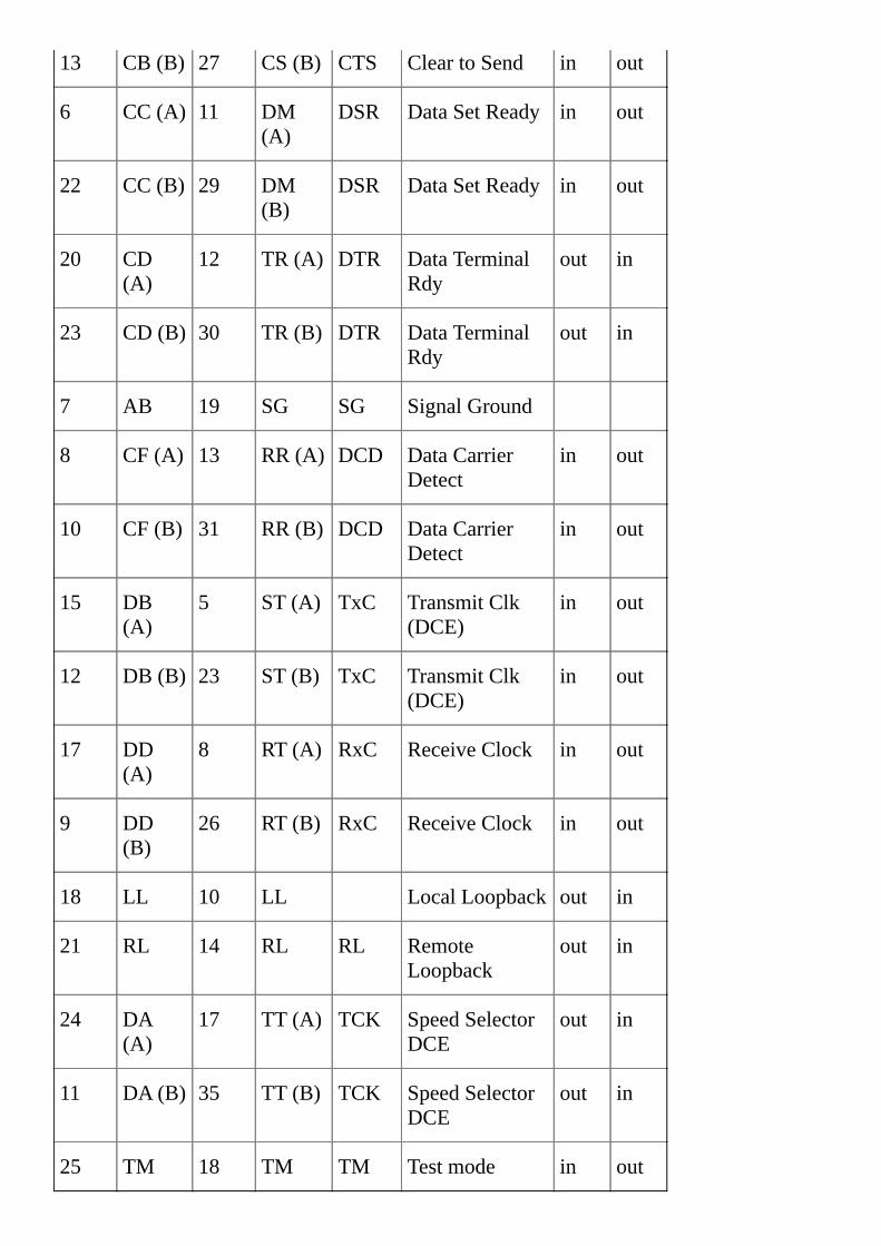
13 CB(B) 27 CS(B) CTS CleartoSend in out
6 CC(A) 11 DM(A)
DSR DataSetReady in out
22 CC(B) 29 DM(B)
DSR DataSetReady in out
20 CD(A)
12 TR(A) DTR DataTerminalRdy
out in
23 CD(B) 30 TR(B) DTR DataTerminalRdy
out in
7 AB 19 SG SG SignalGround
8 CF(A) 13 RR(A) DCD DataCarrierDetect
in out
10 CF(B) 31 RR(B) DCD DataCarrierDetect
in out
15 DB(A)
5 ST(A) TxC TransmitClk(DCE)
in out
12 DB(B) 23 ST(B) TxC TransmitClk(DCE)
in out
17 DD(A)
8 RT(A) RxC ReceiveClock in out
9 DD(B)
26 RT(B) RxC ReceiveClock in out
18 LL 10 LL LocalLoopback out in
21 RL 14 RL RL RemoteLoopback
out in
24 DA(A)
17 TT(A) TCK SpeedSelectorDCE
out in
11 DA(B) 35 TT(B) TCK SpeedSelectorDCE
out in
25 TM 18 TM TM Testmode in out

Table7.4.PinassignmentsfortheEIA-530andRS449protocols.
InthissectionwewillintroducetheelectricalspecificationsoftheUniversalSerialBus(USB).Figure7.10showsthetwotypesofUSBconnectors.AsinglehostcomputercontrolstheUSB,andtherecanonlybeonehostperbus.Thehostcontrolstheschedulingofalltransactionsusingatoken-basedprotocol.TheUSBarchitectureisatieredstartopology,similarto10BaseTEthernet.Thehostisatthecenterofthestar,devicesareattachedtothehost.ThenumberofnodesonthebuscanbeextendedusingUSBhubs.Upto127devicescanbeconnectedtoanyoneUSBbusatanyonegiventime.USBplug’n’plugisimplementedwithdynamicallyloadableandunloadabledrivers.WhentheuserplugsthedeviceintotheUSBbus,thehostwilldetecttheconnection,interactwiththenewlyinserteddevice,andloadtheappropriatedriver.TheUSBdevicecanbeusedwithoutexplicitlyinstallingdriversorrebooting.Whenthedeviceisunplugged,thehostwillautomaticallyunloaditsdriver.
Figure7.10.USBconnectors.
USBusesfourshieldedwires,+5Vpower,GND,andatwistedpairdifferentialdatasignals,aslistedinTable7.5.ItusesaNRZI(NonReturntoZeroInvert)encodingschemetosenddatawithasyncfieldtosynchronizethehostandreceiverclocks.TheD+signalhasa15k pull-downresistortoground,andtheD-signalhasa1.5k pull-upresistorto+3.6V.Liketheotherprotocolsinthissection,thedataisencodedasadifferentialsignalbetweenD+andD-.Ingeneral,adifferential‘1’existswhenD+isgreaterthanD-.Morespecifically,adifferential‘1’istransmittedbypullingD+over2.8VandD-under0.3V.Thetransmittercreatesadifferential‘0’bymakingD-greaterthan2.8VandD+lessthan0.3V.Thereceiverrecognizesthedifferential‘1’whenD+is0.2VgreaterthanD-.Thereceiverwillconsidertheinputasadifferential‘0’whenD+0.2VlessthanD-.Thepolarityofthesignalisinverteddependingonthespeedofthebus.Thereforetheterms‘J’and‘K’statesareusedinsignifyingthelogiclevels.Atlowspeed,a‘J’stateisadifferential‘0’.Athighspeed,a‘J’stateisadifferential‘1’.USBinterfacesemploybothdifferentialandsingleendedoutputs.CertainbusstatesareindicatedbysingleendedsignalsonD+,D-orboth.Forexample,asingleendedzero(SE0)signifiesdeviceresetwhenheldformorethan10mS.Morespecifically,SE0isgeneratedbyholdingbothD-andD+low(<0.3V).USBcanoperateatthreespeeds.Thelowspeed/fullspeedbushasacharacteristicimpedanceof90 .HighSpeedmodeusesaconstantcurrentprotocoltoreducenoise.
Highspeeddataisclockedat480Mb/s
Fullspeeddataisclockedat12Mb/s

Lowspeeddataisclockedat1.5Mb/s
PinNumber
Color Function PinNumber
Function
1 Red VBUS(5V)
1 VBUS(5V)
2 White D- 2 D-
3 Green D+ 3 D+
4 Black Ground 4 ID
5 Ground
Table7.5.USBsignals.
7.3.1.RS422OutputSpecificationsTable7.6showstheoutputvoltagelevelsforRS422.
OutputVoltage
TrueorMark
-6≤A-B≤-2V
Transition -2≤A-B≤+2V
FalseorSpace
+2≤A-B≤+6V
Table7.6.OutputvoltagelevelsfortheRS422differentiallineprotocol.
AkeyRS422specificationisthattheoutputimpedanceoftheAandBoutputsshouldbebalanced.Iftheinput/outputimpedancesarebalancedthenaddednoiseinthecablecreatesacommonmodevoltage,andthecommonmoderejectionoftheinputwilleliminateit.
RAout=RBout≤100

Thetimeinthetransitionregionmustbelessthan
10%forbaudratesabove5Mbps,and
20nsforbaudratesbelow5Mbps
7.3.2.RS422InputSpecificationsLetA’andB’bethevoltagesattheinput.Table7.7definestheinputencoding.
InputVoltage
TrueorMark A’-B’≤-0.2V
Transition -0.2V≤A’-B’≤+0.2V
FalseorSpace +0.2V≤A’-B’
Table7.7.InputvoltagethresholdsfortheRS422differentiallineprotocol.
Asmentionedearlier,toprovidenoiseimmunitythecommonmodeinputimpedancesmustalsobebalanced
4kΩ≤RA’in=RB’in
Thebalancednatureoftheinterfaceproducesgoodnoiseimmunity.ThedifferentialinputimpedanceisspecifiedbyFigure7.11.Anypointwithintheshadedregionisallowed.
Figure7.11.RS422inputcurrentversusinputvoltagerelationship.EventhoughthegroundconnectionintheRS422cableisoptional,itisassumedthegroundsareconnectedsomewhere.Inparticular,theinterfacewilloperatewithacommonmodevoltageupto7volts.
|A’+B’|/2≤+7V

Checkpoint7.5:Whatistheeffectofcapacitanceonaserialchannel?
7.3.3.RS485HalfDuplexchannelRS485canbeeitherhalfduplexorfullduplex.TheRS485protocol,illustratedinFigure7.12,implementsahalfduplexchannelusingdifferentialvoltagesignals.TheSipexSP483orMaximMAX13431implementsthehalfduplexRS485channel.OneoftheadvantagesofRS485isthatupto32devicescanbeconnectedontoasingleserialbus.Whenmorethanonetransmittercandrivertheserialbus,theprotocolisalsocalled“multi-drop”.Normally,wemakebothDEandREactiveonalldevices.TotransmitthecomputersendstheserialframefromtheTxDoutputoftheUARTport.ThetransmittedframeisechoedintotheserialreceiveroftheSCIRxDline.ToreceiveaframethecomputeracceptsaserialframeontheRxDlineintheusualmanner.Whencarefulwhenselectingtheresistancesonahalfduplexnetworksothatthetotaldriverimpedanceisabout54Ω.
Figure7.12.AhalfduplexserialchannelisimplementedwithRS485logic.
RS422,RS485,Ethernet,andCANarehigh-speedcommunicationchannels.ThismeansthebandwidthandslewrateonthesignalsarehigherthanRS232.Thereisacorrespondencebetweenrisetime( )ofadigitalsignalandequivalentsinusoidalfrequency(f).ThederivativeofA∙sin(2 ft)is2 f∙A∙cos(2 ft).Themaximumslewrateofthissinusoidis2 f∙A.ApproximatingtheslewrateasA/ ,wegetacorrespondencebetweenfand
f=1/
Forexample,iftherisetimeis5ns,theequivalentfrequencyis200MHz.Noticethatthisequivalentfrequencyisindependentofbaudrate.Soevenat1000bits/sec,iftherisetimeis5ns,thenthesignalhasastrong200MHzfrequencycomponent!Todealwiththisissue,theRS232protocollimitstheslewratetoamaximumof30V/ s.Thismeansitwilltakeabout1 sforasignaltorisefrom-12to+12V.Consequently,RS232signals

havefrequencycomponentslessthan1MHz.However,totransmitfasterthanRS232,theprotocolmusthavefasterrisetimes.Electricalsignalstravelatabout0.6to0.9timesthespeedoflight.Thisvelocityfactor(VF)isapropertyofthecable.Forexample,VFforRG-6/Ucoaxcableis0.75,whereasVFisonly0.66forRG-58/Ucoaxcable.Usingtheslower0.66estimate,thespeedisv=2∙108m/s.Accordingtowavetheory,thewavelengthis =v/f.Estimatingthefrequencyfromrisetime,weget
λ=v*τ
Inourexample,arisetimeof5nsisequivalenttoawavelengthofabout1m.Asaruleofthumb,wewillconsiderthechannelasatransmissionlineifthelengthofthewireisgreaterthan /4.Anotherrequirementisforthediameterofthewiretobemuchsmallerthanthewavelength.Inatransmissionline,thesignalstraveldownthewiresaswavesaccordingtothewaveequation.Analysisofthewaveequationisoutsidethescopeofthisbook.However,youneedtoknowthatwhenawavemeetsachangeinimpedance,someoftheenergywilltransmit(agoodthing)andsomeoftheenergywillreflect(abadthing).Reflectionsareessentiallynoiseonthesignal,andiflargeenough,theywillcausebiterrorsintransmission.Wecanreducethechangeinimpedancebyplacingterminatingresistorsonbothendsofalonghigh-speedcable,asshowninFigure7.12.Theseresistorsreducereflections;hencetheyimprovesignaltonoiseratio.

7.4.LogicLevelConversionTherearemany3.3-Vdeviceswewishtointerfacetoa5-Vmicrocontroller,andtherearemany5-Vdeviceswewishtointerfacetoa3.3-Vmicrocontroller.Thissectionwillstudyvariousmethodstoconvertonelogicleveltoanother.Webeginwitha5-Voutputinterfacedtoa3.3-Vinput.Many3.3-Vinputsare5-Vtolerant,whichmeansnospecialinterfacecircuitsarerequired.Oneofthesimplestwaystoconvert5-Vlogicinto3.3-VlogicistousearesistordividerasshowninFigure7.13.ASchottkydiodecanalsobeusedtoconvert5Vinto3.3V,andconverta0.4Vintoa0.5V.TheSchottkydiodemustbefastandhavealowvoltagedrop.The7407isanotherwaytoconvertbetweenlogicfamilies.Whenthe7407inputis5V,itsoutputfloats,andthe3.3-Vpull-upmakesa3.3-Vsignal.Whenthe7407inputislow,itsoutputislow.
Many5Vinputsare3.3Vtolerant,whichmeansnospecialinterfacecircuitsarerequired.The7407canalsobeusedtointerface3.3-Vlogicinto5-Vlogic.TheVIHofthe7407is2V,sowhenthe7407inputis3.3V,itsoutputfloats,andthe5-Vpull-upmakesa5-Vsignal.Whenthe7407inputislow,itsoutputislow.AMOSFET,liketheBSS138,isapopularmethodtoconvertlogiclevelsbecauseitisfastandefficient.SparkFunmakesabreakoutboardwithresistor-dividerandBSS138circuits(www.sparkfun.comBOB-0874).
WecanproducethesameopencollectorbehaviorofanyI/Oportthathasadirectionregister.Weinitializetheportbywritingazerotothedataport.Onsubsequentaccessestotheopencollectorport,wewritethecomplementtothedirectionregister.I.e.,ifwewanttheI/Oportbittodrivelow,wesetthedirectionregisterbitto1,andifwewanttheI/Oportbittofloat(opencollector),wesetthedirectionregisterbitto0.
Itisgooddesignpracticetoreadtheerrataforthemicrocontrollersinyoursystem.Forexample,theLM3S811erratastates,“GPIObuffersarenot5-Vtolerantwhenusedinopen-drainmode.Pullinguptheopen-drainpinabove4Vresultsinhighcurrentdraw.”Furthermore,“ThepinsassociatedwithGPIOsignalsPB6,PC5,andPC6arenot5-Vtolerant.ApplyingavoltagetoanyofthesepinsthatisgreaterthanVDD(3.3V)willhaveundeterminedresults.”TheseparticularmistakesapplyspecificallytosiliconversionC0fortheLM3S811.However,ingeneralonemustreadtheerrataforthemicrocontrolleryouareusing.

Figure7.13.Circuitstointerfacebetween5-Vlogicand3.3-Vlogic.

7.5.SynchronousTransmissionandReceivingusingtheSSISSIallowsmicrocontrollerstocommunicatesynchronouslywithperipheraldevicesandothermicrocontrollers.TheSSIsystemcanoperateasamasterorasaslave.Thechannelcanhaveonemasterandoneslave,oritcanhaveonemasterandmultipleslaves.Withmultipleslaves,theconfigurationcanbeastar(centralizedmasterconnectedtoeachslave),oraring(eachnodehasonereceiverandonetransmitter,wherethenodesareconnectedinacircle.)Themasterinitiatesalldatacommunication.
StellarisandTivamicrocontrollershave0to4SynchronousSerialInterfaceorSSImodules.AnothernameforthisprotocolisSerialPeripheralInterfaceorSPI.ThefundamentaldifferencebetweenaUART,whichimplementsanasynchronousprotocol,andaSSI,whichimplementsasynchronousprotocol,isthemannerinwhichtheclockisimplemented.Twodevicescommunicatingwithasynchronousserialinterfaces(UART)operateatthesamefrequency(baudrate)buthavetwoseparateclocks.WithaUARTprotocol,theclocksignalisnotincludedintheinterfacecablebetweendevices.TwoUARTdevicescancommunicatewitheachotheraslongasthetwoclockshavefrequencieswithin±5%ofeachother.Twodevicescommunicatingwithsynchronousserialinterfaces(SSI)operatefromthesameclock(synchronized).WithaSSIprotocol,theclocksignalisincludedintheinterfacecablebetweendevices.Typically,themasterdevicecreatestheclock,andtheslavedevice(s)usestheclocktolatchthedatainandsenddataout.
TheSSIprotocolincludesfourI/Olines.TheslaveselectSSI0Fssisanoptionalnegativelogiccontrolsignalfrommastertoslavesignalsignifyingthechannelisactive.Thesecondline,SCK,isa50%dutycycleclockgeneratedbythemaster.TheSSI0Tx(masteroutslavein,MOSI)isadatalinedrivenbythemasterandreceivedbytheslave.TheSSI0Rx(masterinslaveout,MISO)isadatalinedrivenbytheslaveandreceivedbythemaster.Inordertoworkproperly,thetransmittingdeviceusesoneedgeoftheclocktochangeitsoutput,andthereceivingdeviceusestheotheredgetoacceptthedata.Figure7.14showstheI/Oportlocationsofthesynchronousserialportsforthethreemicrocontrollersdiscussedinthisbook.Tables2.7and2.8describehowtoattachI/OpinstotheSSImodulesontheTM4C123/TM4C1294.

Figure7.14.SynchronousserialportpinsonfourLM3S/TM4Cmicrocontrollers.OntheLM3S/TM4Ctheshiftregistercanbeconfiguredfrom4to16bits.Theshiftregisterinthemasterandtheshiftregisterintheslavearelinkedtoformadistributedregister.Figure7.15illustratescommunicationbetweenmasterandslave.Typically,themicrocontrollerandtheI/Odeviceslavearesophysicallyclosewedonotuseinterfacelogic.
TheSSIontheLM3S/TM4CemploystwohardwareFIFOs.BothFIFOsare8elementsdeepand4to16bitswide,dependingontheselecteddatawidth.WhenperformingI/OthesoftwareputsintothetransmitFIFObywritingtothe SSI0_DR_R registerandgetsfromthereceiveFIFObyreadingfromthe SSI0_DR_R register.
IfthereisdatainthetransmitFIFO,theSSImodulewilltransmitit.WithSSIittransmitsandreceivesbitsatthesametime.Whenadatatransferoperationisperformed,thisdistributed8-to32-bitregisterisseriallyshifted4to16bitpositionsbytheSCKclockfromthemastersothedataiseffectivelyexchangedbetweenthemasterandtheslave.Datainthemastershiftregisteraretransmittedtotheslave.Dataintheslaveshiftregisteraretransmittedtothemaster.Typically,themicrocontrollerismasterandtheI/Omoduleistheslave,butonecanoperatethemicrocontrollerinslavemode.WhendesigningwithSSI,youwillneedtoconsultthedatasheetsforyourspecificmicrocontroller.
Figure7.15.AsynchronousserialinterfacebetweenamicrocontrollerandanI/Odevice.Table7.8liststheSSI0registersontheLM3S/TM4C.TheLM3S/TM4Ccanoperateinslavemode,butwewillfocusonmastermode.ThePCTLbitsaredefinedinTables4.3and4.4.
Address 31-6 3 2 1 0 Name
$400F.E61C SSI3 SSI2 SSI1 SSI0 SYSCTL_RCGCSSI_R
31-16 15-8 7 6 5-4 3-0
$4000.8000 SCR SPH SPO FRF DSS SSI0_CR0_R

31-16 15-0
$4000.8008 Data SSI0_DR_R
7 6 5 4 3 2 1 0
$4000.8004 SOD MS SSE LBM SSI0_CR1_R
$4000.800C BSY RFF RNE TNF TFE SSI0_SR_R
$4000.8010 CPSDVSR SSI0_CPSR_R
$4000.8014 TXIM RXIM RTIM RORIM SSI0_IM_R
$4000.8018 TXRIS RXRIS RTRIS RORRIS SSI0_RIS_R
$4000.801C TXMIS RXMIS RTMIS RORMIS SSI0_MIS_R
$4000.8020 RTIC RORIC SSI0_ICR_R
$4005.8420 SEL SEL SEL SEL SEL SEL SEL SEL GPIO_PORTA_AFSEL_R
$4005.841C DEN DEN DEN DEN DEN DEN DEN DEN GPIO_PORTA_DEN_R
$4005.8400 DIR DIR DIR DIR DIR DIR DIR DIR GPIO_PORTA_DIR_R
$400F.E608 GPIOH GPIOG GPIOF GPIOE GPIOD GPIOC GPIOB GPIOA SYSCTL_RCGCGPIO_R
Table7.8.TheLM3S/TM4CSSI0registers.Eachregisteris32bitswide.Bits31–8arezero.
TheSSIclockfrequencyisestablishedbythe8-bitfieldSCRfieldinthe SSI0_CR0_Rregisterandthe8-bitfieldCPSDVSRfieldinthe SSI0_CPSR_R register.SCRcanbeany8‑bitvaluefrom0to255.CPSDVSRmustbeanevennumberfrom2to254.LetfBUSbethefrequencyofthebusclock.ThefrequencyoftheSSIis
fSSI=fBUS/(CPSDVSR*(1+SCR))
CommoncontrolfeaturesfortheSSImoduleinclude:
Baudratecontrolregister,usedtoselectthetransmissionrate
Datasize4to16bits,set4-bitDSSfieldequaltosize-1
Modebitsinthecontrolregistertoselect
Masterversusslave

Freescalemodewithclockpolarityandclockphase
TIsynchronousserialmode
Microwiremode
Interruptarmbit
Abilitytomaketheoutputsopendrain(opencollector)
CommonstatusbitsfortheSPImoduleinclude:
BSY,SSIiscurrentlytransmittingand/orreceivingaframe,
orthetransmitFIFOisnotempty
RFF,SSIreceiveFIFOisfull
RNE,SSIreceiveFIFOisnotempty
TNF,SSItransmitFIFOisnotfull
TFE,SSItransmitFIFOisempty
Thekeytopropertransmissionistoselectoneedgeoftheclock(shownas“T”inFigure7.16)tobeusedbythetransmittertochangetheoutput,andusetheotheredge(shownas“R”)tolatchthedatainthereceiver.Inthiswaydataislatchedduringthetimewhenitisstable.Dataavailableisthetimewhentheoutputdataisactuallyvalid,anddatarequiredisthetimewhentheinputdatamustbevalid.
Duringtransmission,theoutputdatawillbevalidfromS5maxaftertheclockedgeuntilS5minafterthenextclockedge.ThemaximumS5timeis1systembusperiod(e.g.,20ns)andtheminimumis0.Whenreceivingthesetuptime(S8)is1systembusperiodandtheholdtime(S9)is2systembusperiods.Inorderforthecommunicationtooccurwithouterror,thedataavailablefromthedevicethatisdrivingthedatalinemustoverlap(startbeforeandendafter)thedatarequiredbytheotherdevicethatisreceivingthedata.Itisthisoverlapthatwilldeterminethemaximumfrequencyatwhichsynchronousserialcommunicationcanoccur.TheconceptsofdataavailableanddatarequiredwerepresentedpreviouslyinSection4.2.

Figure7.16.Synchronousserialtimingshowingthedataavailableintervaloverlapsthedatarequiredinterval.Checkpoint7.6:Whatarethedefinitionsofsetuptimeandholdtime?
Observation:Becausetheclocksareshared,ifyouchangethebusclockfrequency,thetransferratewillchangeinbothmasterandslave.
TheFreescaleSPItimingisshowninFigure7.17(FRF=00).
Figure7.17.SynchronousserialFreescalesingletransfermode(nis4to16bits).TheSPItransmitsdataatthesametimeasitreceivesinput.IntheFreescalemodes,theSPIchangesitsoutputontheoppositeedgeoftheclockasitusestoshiftdatain.Therearethreemodecontrolbits(MS,SPO,SPH)thataffectthetransmissionprotocol.Ifthedeviceisamaster(MS=0)itgeneratestheSCLK,anddataisoutputontheSSI0Txpin,andinputontheSSI0Rxpin.TheSPOcontrolbitspecifiesthepolarityoftheSCLK.Inparticular,theSPObitspecifiesthelogicleveloftheclockwhendataisnotbeingtransferred.TheSPHbitaffectsthetimingofthefirstbittransferredandreceived.IfSPHis0,thenthedevicewillshiftdatainonthefirst(and3rd,5th,7th,…etc.)clockedge.IfSPHis1,thenthedevicewillshiftdatainonthesecond(and4th,6th,8th,…etc.)clockedge.ThedataistransmittedMSBfirst.
TheTIsynchronousserialtimingisshowninFigure7.18(FRF=01).ThereisathirdprotocolcalledMicrowire(FRF=10).Refertothedatasheetsfordetailsofthesemodes.

Figure7.18.SynchronousserialTIsingletransfermode.
Example7.2.InterfacetheMaximMAX5353digitaltoanalogconverter.
Solution:ThisfirstexampleshowsasynchronousserialinterfacebetweenthemicrocontrollerandaMaximMAX535312-bitdigitaltoanalogconverterasdrawninFigure7.19.Adigitaltoanalogconverter(DAC)acceptsadigitalinput(inourcaseanumberbetween0and4095)andcreatesananalogoutput(inourcaseavoltagebetween0andVREF*GAIN.)DetaileddiscussionofconverterswillbepresentedlaterinChapter8.Hereinthissectionwewillfocusonthedigitalhardwareandsoftwareaspectsoftheserialinterface.
Figure7.19.A12-bitDACinterfacedtotheSSIport.
Table7.9andFigure7.20describetheprotocol.Thefirst3bitssentwillbezero,thenthe12databitsthatspecifytheanalogoutput,andthenonemorezerowillbesent.TheSSI0Fsscontrolsignalwillbelowduringthe16-bittransmission.AswithanySPIinterface,therearebasicinterfacingissuestoconsider.
Wordsize.Inthiscaseweneedtotransmit16bitstotheDAC.TheMAX5353datasheetspecifiesthatthefirstthreebitsarecommandcodes,thenext12bitsaretheDACoutput(MSBtransmittedfirst),andthelastbitiszero.Bitorder.TheMAX5353requiresthemostsignificantbitsfirst.
Clockphase,clockpolarity.Therearetwoissuestoresolve.SincetheMAX5353samplesitsserialinputdataontherisingedgeoftheclock,theSSImustchangethedataonthefallingedge.SPO=SPH=0(Figure7.17)andSPO=SPH=1bothsatisfythisrequirement.Thesecondissueiswhichedgecomesfirsttheriseorthefall.Inthisinterfaceitprobablydoesn’tmatter.
Bandwidth.WelookatthetimingspecificationsoftheMAX5353.Theminimumclocklowwidthof40nsmeanstheshortestSSIperiodwecanuseis100ns.Thecommandsare:

C2 C1 C0 D11:D0
MSBLSB
S0 Description
X 0 0 12bitsofdata 0 Loadinputregister;DACregisterimmediatelyupdated.
X 0 1 12bitsofdata 0 Loadinputregister;DACregisterunchanged.
X 1 0 XXXXXXXXXXXX X UpdateDACregisterfrominputregister.
1 1 1 XXXXXXXXXXXX X Shutdown
0 1 1 XXXXXXXXXXXX X Nooperation
Table7.9.MAX5353protocols
Figure7.20.MAX5353DACserialtiming.
TheritualinitializestheFreescaleSPImastermode,16-bitdata,and8MHzbandwidth(Program7.2).TochangetheDACoutput,one16-bittransmissionissent( DAC_Out ).ThedatareturnedinthiscaseisnotsignificantbecausetheSSI0RxpininFigure7.19isleftnotconnected.Inthisexample,thebusclockis16MHz,andtheSSIclockwillbe8MHz.
voidDAC_Init(uint16_tdata)
SYSCTL_RCGCSSI_R|=0x01;//activateSSI0
SYSCTL_RCGCGPIO_R|=0x01;//activateportA
while((SYSCTL_PRGPIO_R&0x01)==0);//ready?
GPIO_PORTA_AFSEL_R|=0x2C;//enablealtfunctonPA2,3,5

GPIO_PORTA_DEN_R|=0x2C;//configurePA2,3,5asSSI
GPIO_PORTA_PCTL_R=(GPIO_PORTA_PCTL_R&0xFF0F00FF)+0x00202200;
GPIO_PORTA_AMSEL_R=0;//disableanalogfunctionalityonPA
SSI0_CR1_R=0x00000000;//disableSSI,mastermode
SSI0_CPSR_R=0x02;//8MHzSSIClk
SSI0_CR0_R&=~(0x0000FFF0);//SCR=0,SPH=0,SPO=0Freescale
SSI0_CR0_R|=0x0F;//DSS=16-bitdata
SSI0_DR_R=data;//load‘data’intotransmitFIFO
SSI0_CR1_R|=0x00000002;//enableSSI
voidDAC_Out(uint16_tcode)
while((SSI0_SR_R&0x00000002)==0);//SSITransmitFIFONotFull
SSI0_DR_R=code;//dataout,noreply
//sendthe16-bitcodetotheSSI,returnareply
//youwillneedtoenablePA4asSSI0Rxtousethisroutine
uint16_tDAC_Out2(uint16_tcode)uint16_treceive;
while((SSI0_SR_R&0x00000002)==0);//SSITransmitFIFONotFull
SSI0_DR_R=code;//dataout
while((SSI0_SR_R&0x00000004)==0);//SSIReceiveFIFONotEmpty
receive=SSI0_DR_R;//acknowledgeresponse
returnreceive;
Program7.2.FunctionstoinitializeandtosenddatatotheDACusingtheSSI(MAX5353_xxx.zip).
Example7.3.InterfacetheMaximMAX1246analogtodigitalconverter.

Solution:ThissecondSSIexampleshowsasynchronousserialinterfacebetweenthecomputerandaMaximMAX1246analogtodigitalconverter.Ananalogtodigitalconverteracceptsananaloginput(inourcaseavoltagebetween0and+2.5VononeofthefouranaloginputsCH3–CH0)andcreatesadigitaloutput(inourcaseanumberbetween0and4095.)DetaileddiscussionofconverterswillalsobepresentedlaterinChapter8.Hereinthissectionwewillfocusonthehardwareandsoftwareaspectsoftheserialinterface(Figure7.21).Again,thebasicinterfacingissuestoconsiderforthisinterfaceare:
Wordsize.Inthiscaseweneedtofirsttransmit8bitstotheADC,thenreceive12bitsbackfromtheADC.TheMAX1246datasheetsuggeststhatitwillembedthe12bitdataintotwo8-bittransmissions.
Bitorder.TheMAX1246requiresthemostsignificantbitsfirst.
Clockphase,clockpolarity.SincetheMAX1246samplesitsserialinputdataontherisingedgeoftheclock,theSPImustchangesthedataonthefallingedge.SPO=SPH=0andSPO=SPH=1bothsatisfythisrequirement.WewillusetheSPO=SPH=0modeassuggestedintheMaximdatasheet,referbacktoFigure7.17.
Bandwidth.WelookatthetimingspecificationsoftheMAX1246.ThemaximumSCLKfrequencyis2MHz,andtheminimumclocklow/highwidthsis200ns,sotheshortestSPIperiodwecanuseis500ns.
Figure7.21.Afourchannel12-bitADCinterfacedtotheSSIport.
Thefirst8bitssentwillspecifythechannelandADCmodeasshowninFigure7.22.Afterconversion,the12databitresultisreturned.Noticethatbit7ofthemodeselectisalwayshigh,andthe12-bitADCresultisembeddedintothemiddleofthetwo8-bittransmissions.Thesoftwarewillshiftthe16-bitdata3bitstotherightinordertoproducethe0to4095result.

Figure7.22.MAX1247ADCserialtiming.
BecausewewanttheCSsignaltoremainlowfortheentire24-bittransfer,wewillimplementitusingtheregularI/Opinfunctions.Theritualinitializesthedirectionregister,FreescaleSPImode,andbandwidth(Program7.3).Inthisexample,thebusclockis6MHz,andtheSSIclockwillbe1.5MHz.
RecallthatwhenthesoftwareoutputstotheSSIdataregister,the8-bitregisterintheSSIisexchangedwiththe8-bitregisterintheADC.ToreadtheADC,three8-bittransmissionsareexchanged.Onthefirstexchange,thesoftwarespecifiesthechannelandADCmode,thenthe12-bitADCdatareturnedduringthe2ndand3rdtransmission.AlloftheADCmodesinthe #define statementsimplementunipolarvoltagerange,singleended,andexternalclock.
#defineGPIO_PORTA3(*((volatileuint32_t*)0x40004020))
voidADC_Init2(void)
SYSCTL_RCGCSSI_R|=0x01;//activateSSI0
SYSCTL_RCGCGPIO_R|=0x01;//activateportA
while((SYSCTL_PRGPIO_R&0x01)==0);//ready?
GPIO_PORTA_PCTL_R=(GPIO_PORTA_PCTL_R&0xFF0F00FF)+0x00202200;
GPIO_PORTA_AMSEL_R=0;//disableanalogfunctionalityonPA
GPIO_PORTA_AFSEL_R|=0x34;//enablealtfunctonPA2,4,5
GPIO_PORTA_DIR_R|=0x08;//makePA3out(PA3!CSsignal)
GPIO_PORTA_DEN_R|=0x3C;//enabledigitalI/OonPA2,3,4,5
GPIO_PORTA3=0x08;//!CS=1
SSI0_CR1_R&=~SSI_CR1_SSE;//disableSSI
SSI0_CR1_R&=~SSI_CR1_MS;//mastermode(defaultsetting)
SSI0_CPSR_R=(SSI0_CPSR_R&~SSI_CPSR_CPSDVSR_M)+4;//1.5MHzSSIClk
SSI0_CR0_R&=~(SSI_CR0_SCR_M|//SCR=0
SSI_CR0_SPH|//SPH=0
SSI_CR0_SPO);//SPO=0
SSI0_CR0_R=(SSI0_CR0_R&~SSI_CR0_FRF_M)+SSI_CR0_FRF_MOTO;//Freescale
SSI0_CR0_R=(SSI0_CR0_R&~SSI_CR0_DSS_M)+SSI_CR0_DSS_8;//8-bitdata
SSI0_CR1_R|=SSI_CR1_SSE;//enableSSI

#defineSSI_SR_RNE0x00000004//SSIReceiveFIFONotEmpty
#defineSSI_SR_TFE0x00000001//SSITransmitFIFOEmpty
#defineCH00x9F//sampleonchannel0
#defineCH10xDF//sampleonchannel1
#defineCH20xAF//sampleonchannel2
#defineCH30xEF//sampleonchannel3
//sendthe8-bitcodetotheSSIafterwaitingforFIFOstoempty
//returnareply
uint8_tsendAfterWaiting(uint8_tcode)
while((SSI0_SR_R&SSI_SR_TFE)==0);//waituntilFIFOempty
SSI0_DR_R=code;//dataout
while((SSI0_SR_R&SSI_SR_RNE)==0);//waituntilresponse
returnSSI0_DR_R;//acknowledgeresponse
//takeoneADCmeasurementandreturntheresult
//NOTE:toensurecorrectoperation,useoneoftheCHndefinitions
uint16_tADC_In2(uint8_tcode)
uint16_tdata;
GPIO_PORTA3=0;//!CS=0
sendAfterWaiting(code);//sendchannel,mode
data=sendAfterWaiting(0)<<8;//msbyteofADC
data+=sendAfterWaiting(0);//lsbyteofADC
GPIO_PORTA3=0x08;//!CS=1
returndata>>3;//rightjustify
Program7.3.FunctionstoinitializeandtoreceivedatafromtheADCusingtheSSI(MAX1246_xxx.zip).
Example7.4.DesignanoutputportexpanderusingashiftregisterandSSI.

Solution:Sometimesweneedmoreoutputpinsthanavailableonourmicrocontroller.Ingeneral,theproperdesignapproachwouldbetoupgradetoamicrocontrollerwithmorepins.Howeverinsituationswherewedonothavethetimeormoneytochangemicrocontrollers,wecaninterfacea74HC595shiftregistertotheSSIportforaquicksolutionprovidingadditionaloutputpins.Basically,threepinsoftheSSI(SS,MOSI,andSCLK)willbeconvertedtoeightdigitaloutputsQonthe74HC595,asshowninFigure7.23.
Additionalshiftregisterscanbechainedtogether(connecttheQH’outputsofonetotheSERinputsofthenext)toprovideadditionaloutputswithoutrequiringmoreLM3S811pins.Thegateinput,G*,ofthe74HC595isgroundedsotheeightQoutputswillbecontinuouslydriven.TheSPIclockoutputisconnectedtothe74HC595clockinput(SCK)andtheSPIdataoutputisconnectedtothe74HC595datainput(SER).TheFreescaleSPImode(SPO=0,SPH=0)isselectedtotheLM3S811changestheoutputdataonthefalloftheclockandthe74HC595shiftsdatainontherise.Becausethe74HC595isfast(maximumclock25MHz,andsetuptimeof20ns),weruntheSSIasfastaspossible.Inthisexample,thebusclockis6MHz,andtheSSIclockwillbe3MHz.
AftereightbitsaretransferredfromtheLM3S811tothe74HC595,softwarewillcreatearisingedgeofRCK,causingthenewdatatobelatchedintothe74HC595.Ifthereisjustone74HC595likeFigure7.23,wecanusetheautomaticSSfeatureoftheSPItocreatearisingedgelatchonRCLK.Toenablethisfeature,wesetbit3AFSEL3ofGPIO_PORTA_AFSEL_R.Inthissolution,weperformoneSSItransmissiontochangeall8bitsoftheportoutput(Program7.4).TheSSpulse,seeFigure7.17,accordsautomaticallyanddoesnotrequiresoftwareoverheadtoproduce.However,ifwewerechainingmultipleshiftregisters,wewouldnotusetheautomaticSSfeature;ratherwewouldoutputallthedataandthenmanuallylatchitinwithexplicitoutputsonRCKbyusingPA3asaregularGPIOport.
Figure7.23.InterfacebetweentheLM3S811anda74HC595shiftregister.voidPort_Init(void)
SYSCTL_RCGCSSI_R|=0x01;//activateSSI0
SYSCTL_RCGCGPIO_R|=0x01;//activateportA
while((SYSCTL_PRGPIO_R&0x01)==0);//ready?
GPIO_PORTA_AFSEL_R|=0x2C;//enablealtfunctonPA2,3,5
GPIO_PORTA_PCTL_R=(GPIO_PORTA_PCTL_R&0xFF0F00FF)+0x00202200;

GPIO_PORTA_AMSEL_R=0;//disableanalogfunctionalityonPA
GPIO_PORTA_DEN_R|=0x2C;//enabledigitalI/OonPA2,3,5
SSI0_CR1_R&=~SSI_CR1_SSE;//disableSSI
SSI0_CR1_R&=~SSI_CR1_MS;//mastermode(defaultsetting)
SSI0_CPSR_R=(SSI0_CPSR_R&~SSI_CPSR_CPSDVSR_M)+2;//3MHzSSIClk
SSI0_CR0_R&=~(SSI_CR0_SCR_M|SSI_CR0_SPH|SSI_CR0_SPO);//SPO=SPH=0
SSI0_CR0_R=(SSI0_CR0_R&~SSI_CR0_FRF_M)+SSI_CR0_FRF_MOTO;//Freescale
SSI0_CR0_R=(SSI0_CR0_R&~SSI_CR0_DSS_M)+SSI_CR0_DSS_8;//8-bitdata
SSI0_CR1_R|=SSI_CR1_SSE;//enableSSI
uint8_tPort_Out(uint16_tcode)
while((SSI0_SR_R&SSI_SR_TNF)==0);//waituntilroominFIFO
SSI0_DR_R=code;//dataout
while((SSI0_SR_R&SSI_SR_RNE)==0);//waituntilresponse
returnSSI0_DR_R;//acknowledgeresponse
Program7.4.SoftwaretocontrolanoutputparallelportexpandedusingtheSSI(74HC595_xxx.zip).
Checkpoint7.7:HowwouldyouchangeProgram7.4torunat1MHz?

7.6.Inter-IntegratedCircuit(I2C)Interface
7.6.1.TheFundamentalsofI2CEversincemicrocontrollershavebeendeveloped,therehasbeenadesiretoshrinkthesizeofanembeddedsystem,reduceitspowerrequirements,andincreaseitsperformanceandfunctionality.TwomechanismstomakesystemssmalleraretointegratefunctionalityintothemicrocontrollerandtoreducethenumberofI/Opins.Theinter-integratedcircuitI2CinterfacewasproposedbyPhilipsinthelate1980sasameanstoconnectexternaldevicestothemicrocontrollerusingjusttwowires.TheSSIinterfacehasbeenverypopular,butittakes3wiresforsimplexand4wiresforfullduplexcommunication.In1998,theI2CVersion1protocolbecomeanindustrystandardandhasbeenimplementedintothousandsofdevices.TheI2Cbusisasimpletwo-wirebi-directionalserialcommunicationsystemthatisintendedforcommunicationbetweenmicrocontrollersandtheirperipheralsovershortdistances.Thisistypically,butnotexclusively,betweendevicesonthesameprintedcircuitboard,thelimitingfactorbeingthebuscapacitance.Italsoprovidesflexibility,allowingadditionaldevicestobeconnectedtothebusforfurtherexpansionandsystemdevelopment.Theinterfacewilloperateatbaudratesofupto100kbpswithmaximumcapacitivebusloading.Themodulecanoperateuptoabaudrateof400kbpsprovidedtheI2Cbusslewrateislessthan100ns.Themaximuminterconnectlengthandthenumberofdevicesthatcanbeconnectedtothebusarelimitedbyamaximumbuscapacitanceof400pFinallinstances.Theseparameterssupportthegeneraltrendthatcommunicationspeedcanbeincreasedbyreducingcapacitance.Version2.0supportsahighspeedmodewithabaudrateupto2.4MHz(supportedbyLM4F/TM4C).
Figure7.24showsablockdiagramofacommunicationsystembasedontheI2Cinterface.Themaster/slavenetworkmayconsistofmultiplemastersandmultipleslaves.TheSerialClockLine(SCL)andtheSerialDataline(SDA)arebothbidirectional.Eachlineisopendrain,meaningadevicemaydriveitloworletitfloat.Alogichighoccursifalldeviceslettheoutputfloat,andalogiclowoccurswhenatleastonedevicedrivesitlow.Thevalueofthepull-upresistordependsonthespeedofthebus.4.7k isrecommendedforbaudratesbelow100kbps,2.2k isrecommendedforstandardmode,and1k isrecommendedforfastmode.
Checkpoint7.8:Whyistherecommendedpull-upresistorrelatedtothebusspeed?
Checkpoint7.9:Whatdoesopendrainmean?

TheSCLclockisusedinasynchronousfashiontocommunicateonthebus.Eventhoughdatatransferisalwaysinitiatedbyamasterdevice,boththemasterandtheslaveshavecontroloverthedatarate.Themasterstartsatransmissionbydrivingtheclocklow,butifaslavewishestoslowdownthetransfer,ittoocandrivetheclocklow(calledclockstretching).Inthisway,devicesonthebuswillwaitforalldevicestofinish.Bothaddress(fromMastertoSlaves)andinformation(bidirectional)arecommunicatedinserialfashiononSDA.
Figure7.24.BlockdiagramofanI2Ccommunicationnetwork.ThebusisinitiallyidlewherebothSCLandSDAarebothhigh.ThismeansnodeviceispullingSCLorSDAlow.Thecommunicationonthebus,whichbeginswithaSTARTandendswithaSTOP,consistsoffivecomponents:
START(S)isusedbythemastertoinitiateatransferDATAissentin8-bitblocksandconsistsof7-bitaddressand1-bitdirectionfromthemaster
controlcodeformastertoslaves
informationfrommastertoslave
informationfromslavetomaster
ACK(A)isusedbyslavetorespondtothemasteraftereach8-bitdatatransfer
RESTART(R)isusedbythemastertoinitiateadditionaltransferswithoutreleasingthebus
STOP(P)isusedbythemastertosignalthetransferiscompleteandthebusisfree
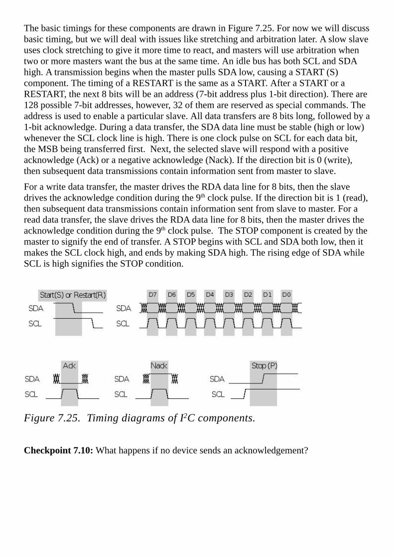
ThebasictimingsforthesecomponentsaredrawninFigure7.25.Fornowwewilldiscussbasictiming,butwewilldealwithissueslikestretchingandarbitrationlater.Aslowslaveusesclockstretchingtogiveitmoretimetoreact,andmasterswillusearbitrationwhentwoormoremasterswantthebusatthesametime.AnidlebushasbothSCLandSDAhigh.AtransmissionbeginswhenthemasterpullsSDAlow,causingaSTART(S)component.ThetimingofaRESTARTisthesameasaSTART.AfteraSTARToraRESTART,thenext8bitswillbeanaddress(7-bitaddressplus1-bitdirection).Thereare128possible7-bitaddresses,however,32ofthemarereservedasspecialcommands.Theaddressisusedtoenableaparticularslave.Alldatatransfersare8bitslong,followedbya1-bitacknowledge.Duringadatatransfer,theSDAdatalinemustbestable(highorlow)whenevertheSCLclocklineishigh.ThereisoneclockpulseonSCLforeachdatabit,theMSBbeingtransferredfirst.Next,theselectedslavewillrespondwithapositiveacknowledge(Ack)oranegativeacknowledge(Nack).Ifthedirectionbitis0(write),thensubsequentdatatransmissionscontaininformationsentfrommastertoslave.
Forawritedatatransfer,themasterdrivestheRDAdatalinefor8bits,thentheslavedrivestheacknowledgeconditionduringthe9thclockpulse.Ifthedirectionbitis1(read),thensubsequentdatatransmissionscontaininformationsentfromslavetomaster.Forareaddatatransfer,theslavedrivestheRDAdatalinefor8bits,thenthemasterdrivestheacknowledgeconditionduringthe9thclockpulse.TheSTOPcomponentiscreatedbythemastertosignifytheendoftransfer.ASTOPbeginswithSCLandSDAbothlow,thenitmakestheSCLclockhigh,andendsbymakingSDAhigh.TherisingedgeofSDAwhileSCLishighsignifiestheSTOPcondition.
Figure7.25.TimingdiagramsofI2Ccomponents.
Checkpoint7.10:Whathappensifnodevicesendsanacknowledgement?

Figure7.26illustratesthecasewherethemastersends2bytesofdatatoaslave.Theshadedregionsdemarksignalsdrivenbythemaster,andthewhiteareasshowthosetimeswhenthesignalisdrivenbytheslave.Regardlessofformat,allcommunicationbeginswhenthemastercreatesaSTARTcomponentfollowedbythe7-bitaddressand1-bitdirection.Inthisexample,thedirectionislow,signifyingawriteformat.The1stthrough8thSCLpulsesareusedtoshifttheaddress/directionintoalltheslaves.Inordertoacknowledgethemaster,theslavethatmatchestheaddresswilldrivetheSDAdatalinelowduringthe9thSCLpulse.Duringthe10ththrough17thSCLpulsessendsthedatatotheselectedslave.TheselectedslavewillacknowledgebydrivingtheSDAdatalinelowduringthe18thSCLpulse.Aseconddatabyteistransferredfrommastertoslaveinthesamemanner.Inthisparticularexample,twodatabytesweresent,butthisformatcanbeusedtosendanynumberofbytes,becauseoncethemastercapturesthebusitcantransferasmanybytesasitwishes.Iftheslavereceiverdoesnotacknowledgethemaster,theSDAlinewillbelefthigh(Nack).ThemastercanthengenerateaSTOPsignaltoabortthedatatransferoraRESTARTsignaltocommenceanewtransmission.ThemastersignalstheendoftransmissionbysendingaSTOPcondition.
Figure7.26.I2CtransmissionoftwobytesfrommastertoslaveFigure7.27illustratesthecasewhereaslavesends2bytesofdatathemaster.Again,themasterbeginsbycreatingaSTARTcomponentfollowedbythe7-bitaddressand1-bitdirection.Inthisexample,thedirectionishigh,signifyingareadformat.Duringthe10ththrough17thSCLpulsestheselectedslavesendsthedatatothemaster.TheselectedslavecanonlychangethedatalinewhileSCLislowandmustbeheldstablewhileSCLishigh.ThemasterwillacknowledgebydrivingtheSDAdatalinelowduringthe18thSCLpulse.OnlytwodatabytesareshowninFigure7.27,butthisformatcanbeusedtoreceiveasanymanybytesthemasterwishes.Exceptforthelastbytealldataaretransferredfromslavetomasterinthesamemanner.Afterthelastdatabyte,themasterdoesnotacknowledgetheslave(Nack)signifying‘endofdata’totheslave,sotheslavereleasestheSDAlineforthemastertogenerateSTOPorRESTARTsignal.ThemastersignalstheendoftransmissionbysendingaSTOPcondition.
Figure7.27.I2Ctransmissionoftwobytesfromslavetomaster.
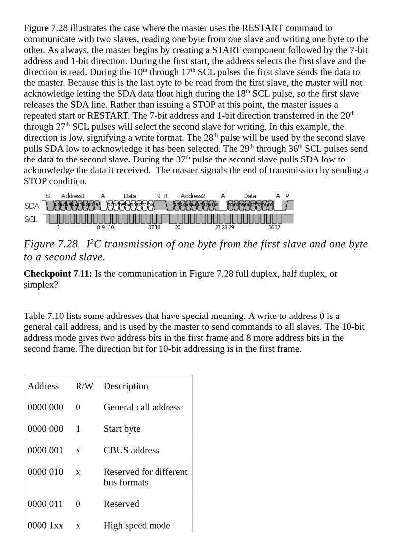
Figure7.28illustratesthecasewherethemasterusestheRESTARTcommandtocommunicatewithtwoslaves,readingonebytefromoneslaveandwritingonebytetotheother.Asalways,themasterbeginsbycreatingaSTARTcomponentfollowedbythe7-bitaddressand1-bitdirection.Duringthefirststart,theaddressselectsthefirstslaveandthedirectionisread.Duringthe10ththrough17thSCLpulsesthefirstslavesendsthedatatothemaster.Becausethisisthelastbytetobereadfromthefirstslave,themasterwillnotacknowledgelettingtheSDAdatafloathighduringthe18thSCLpulse,sothefirstslavereleasestheSDAline.RatherthanissuingaSTOPatthispoint,themasterissuesarepeatedstartorRESTART.The7-bitaddressand1-bitdirectiontransferredinthe20ththrough27thSCLpulseswillselectthesecondslaveforwriting.Inthisexample,thedirectionislow,signifyingawriteformat.The28thpulsewillbeusedbythesecondslavepullsSDAlowtoacknowledgeithasbeenselected.The29ththrough36thSCLpulsessendthedatatothesecondslave.Duringthe37thpulsethesecondslavepullsSDAlowtoacknowledgethedataitreceived.ThemastersignalstheendoftransmissionbysendingaSTOPcondition.
Figure7.28.I2Ctransmissionofonebytefromthefirstslaveandonebytetoasecondslave.Checkpoint7.11:IsthecommunicationinFigure7.28fullduplex,halfduplex,orsimplex?
Table7.10listssomeaddressesthathavespecialmeaning.Awritetoaddress0isageneralcalladdress,andisusedbythemastertosendcommandstoallslaves.The10-bitaddressmodegivestwoaddressbitsinthefirstframeand8moreaddressbitsinthesecondframe.Thedirectionbitfor10-bitaddressingisinthefirstframe.
Address R/W Description
0000000 0 Generalcalladdress
0000000 1 Startbyte
0000001 x CBUSaddress
0000010 x Reservedfordifferentbusformats
0000011 0 Reserved
00001xx x Highspeedmode

11110xx x 10-bitaddress
11111xx X Reserved
Table7.10.SpecialaddressesusedintheI2Cnetwork.
7.6.2.I2CSynchronizationTheI2Cbussupportsmultiplemasters.IftwoormoremasterstrytoissueaSTARTcommandonthebusatthesametime,bothclocksynchronizationandarbitrationwilloccur.Clocksynchronizationisprocedurethatwillmakethelowperiodequaltothelongestclocklowperiodandthehighisequaltotheshortestoneamongthemasters.Figure7.29illustratesclocksynchronization,wherethetopsetoftracesisgeneratedbythefirstmaster,andthesecondsetoftracesisgeneratedbythesecondmaster.Sincetheoutputsareopendrain,theactualsignalswillbethewired-ANDofthetwooutputs.Eachmasterrepeatsthesestepswhenitgeneratesaclockpulse.Itisduringstep3)thatthefasterdevicewillwaitfortheslowerdevice
1.DriveitsSCLclocklowforafixedamountoftime2.LetitsSCLclockfloat3.WaitfortheSCLtobehigh
4.Waitforafixedamountoftime,stopwaitingiftheclockgoeslow
Becausetheoutputsareopendrain,thesignalwillbepulledtoalogichighbythe2k resistoronlyifalldevicesreleasetheline(outputalogichigh).Conversely,thesignalwillbealogiclowifanydevicedrivesitlow.WhenmasterscreateaSTART,theyfirstdriveSDAlow,thendriveSCLlow.IfagroupofmastersareattemptingtocreateSTARTcommandsataboutthesametime,thenthewire-ANDoftheirSDAlineshasits1to0transitionbeforethewire-ANDoftheirSCLlineshasits1to0transition.Thus,avalidSTARTcommandwilloccurcausingalltheslavestolistentotheupcomingaddress.IntheexampleshowninFigure7.29,Master#2isthefirsttodriveitsclocklow.Ingeneral,theSCLclockwillbelowfromthetimethefirstmasterdrivesitlow(time1inthisexample),untilthetimethelastmasterreleasesitsclock(time2inthisexample.)Similarly,theSCLclockwillbehighfromthetimethelastmasterreleasesitsclock(time2inthisexample),untilthetimethefirstmasterdrivesitsclocklow(time3inthisexample.)

Figure7.29.I2Ctimingillustratingclocksynchronizationanddataarbitration.Therelativepriorityofthecontendingmastersisdeterminedbyadataarbitrationprocedure.Abusmasterlosesarbitrationifittransmitslogic“1”whileanothermastertransmitslogic“0”.ThelosingmastersimmediatelyswitchovertoslavereceivemodeandstopdrivingtheSCLandSDAoutputs.Inthiscase,thetransitionfrommastertoslavemodedoesnotgenerateaSTOPcondition.Meanwhile,astatusbitissetbyhardwaretoindicatelossofarbitration.IntheexampleshowninFigure7.29,master#1isgeneratinganaddresswithA7=1andA6=0,whilemaster#2isgeneratinganaddresswithA7=1andA6=1.Betweentimes2and3,bothmastersareattemptingtosendA7=1,andnoticetheactualSDAlineishigh.Attime4,master#2attemptstomaketheSDAhigh(A6=1),butnoticestheactualSDAlineislow.Ingeneral,themastersendingamessagetothelowestaddresswillwinarbitration.
Checkpoint7.12:IfMaster1sendsaddress0x30andMaster2sendsaddress#0x0F,whichonewinsarbitration?
Thethirdsynchronizationmechanismoccursbetweenmasterandslave.Iftheslaveisfastenoughtocapturedataatthemaximumrate,thetransferisasimplesynchronousserialmechanism.Inthiscasethetransferofeachbitfrommastertoslaveisillustratedbythefollowinginterlockedsequences,seeFigure7.25.
MastersequenceSlavesequence(nostretch)
1.DriveitsSCLclocklow
2.SettheSDAline
3.Waitforafixedamountoftime
4.LetitsSCLclockfloat
5.WaitfortheSCLtobehigh
6.Waitforafixedamountoftime6.CaptureSDAdataonlowtohighedgeofSCL
7.Stopwaitingiftheclockgoeslow

Iftheslaveisnotfastenoughtocapturedataatthemaximumrate,itcanperformanoperationcalledclockstretching.IftheslaveisnotreadyfortherisingedgeofSCL,itwillholdtheSCLclocklowitselfuntilitisready.Slavesarenotallowedtocauseany1to0transitionsontheSCLclock,butrathercanonlydelaythe0to1edge.Thetransferofeachbitfrommastertoslavewithclockstretchingisillustratedbythefollowingsequences
MastersequenceSlavesequence(clockstretching)
1.DriveitsSCLclocklow1.WaitfortheSCLclocktobelow
2.SettheSDAline2.DriveSCLclocklow
3.Waitforafixedamountoftime3.Waituntilit’sreadytocapture
4.LetitsSCLclockfloat4.LetitsSCLfloat
5.WaitfortheSCLclocktobehigh5.WaitfortheSCLclocktobehigh
6.Waitforafixedamountoftime6.CapturetheSDAdata
7.Stopwaitingiftheclockgoeslow
Clockstretchingcanalsobeusedwhentransferringabitfromslavetomaster
MastersequenceSlavesequence(clockstretching)
1.DriveitsSCLclocklow1.WaitfortheSCLclocktobelow
2.Waitforafixedamountoftime2.DriveSCLclocklow
3.Waituntilnextdatabitisready
4.LetitsSCLclockfloat4.LetitsSCLfloat
5.WaitfortheSCLclocktobehigh5.WaitfortheSCLclocktobehigh
6.CapturetheSDAinput
7.Waitforafixedamountoftime,
8.Stopwaitingiftheclockgoeslow
Observation:ClockstretchingallowsfastandslowdevicestoexistonthesameI2CbusFastdeviceswillcommunicatequicklywitheachother,butslowdownwhencommunicatingwithslowerdevices.
Checkpoint7.13:Arbitrationcontinuesuntilonemastersendsazerowhiletheothersendsaone.Whathappensiftwomastersattempttosenddatatothesameaddress?
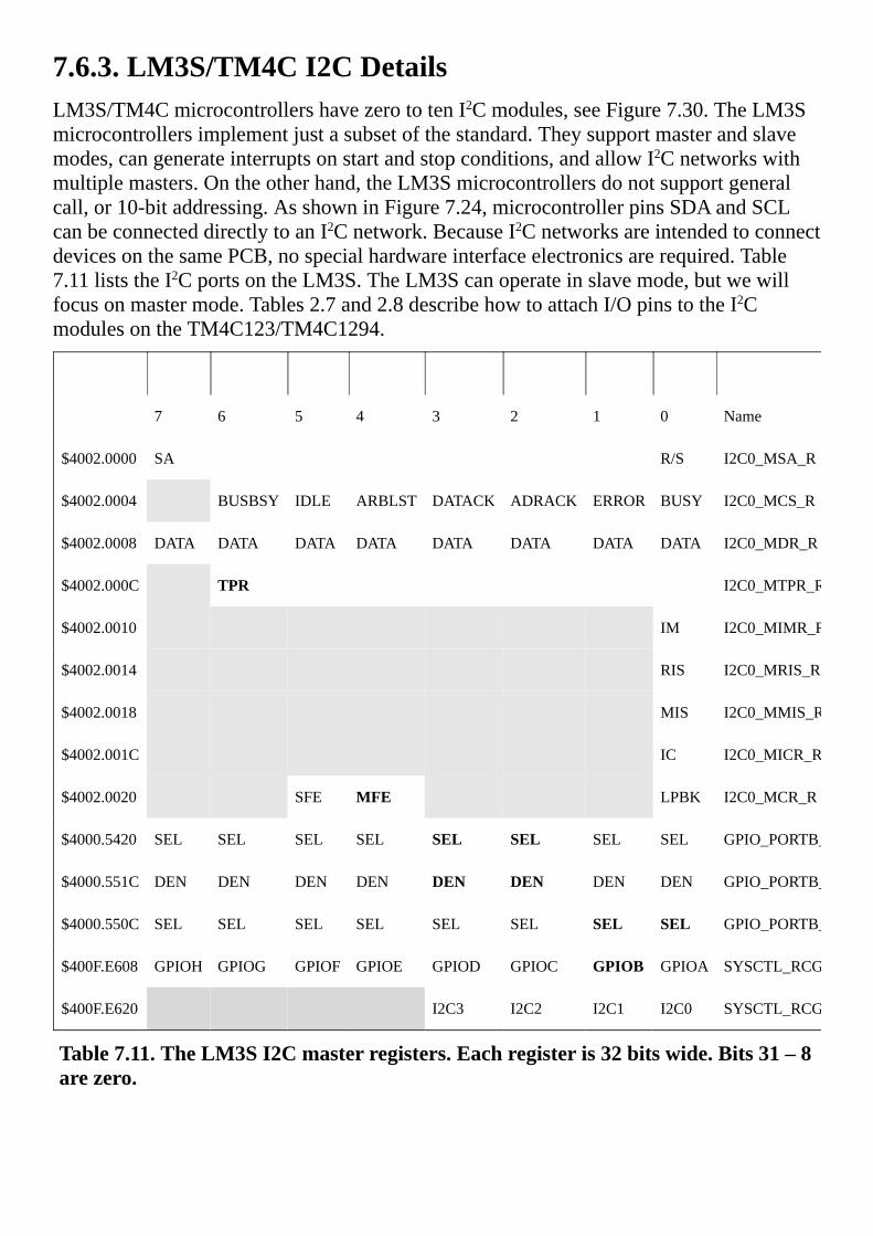
7.6.3.LM3S/TM4CI2CDetailsLM3S/TM4CmicrocontrollershavezerototenI2Cmodules,seeFigure7.30.TheLM3Smicrocontrollersimplementjustasubsetofthestandard.Theysupportmasterandslavemodes,cangenerateinterruptsonstartandstopconditions,andallowI2Cnetworkswithmultiplemasters.Ontheotherhand,theLM3Smicrocontrollersdonotsupportgeneralcall,or10-bitaddressing.AsshowninFigure7.24,microcontrollerpinsSDAandSCLcanbeconnecteddirectlytoanI2Cnetwork.BecauseI2CnetworksareintendedtoconnectdevicesonthesamePCB,nospecialhardwareinterfaceelectronicsarerequired.Table7.11liststheI2CportsontheLM3S.TheLM3Scanoperateinslavemode,butwewillfocusonmastermode.Tables2.7and2.8describehowtoattachI/OpinstotheI2CmodulesontheTM4C123/TM4C1294.
7 6 5 4 3 2 1 0 Name
$4002.0000 SA R/S I2C0_MSA_R
$4002.0004 BUSBSY IDLE ARBLST DATACK ADRACK ERROR BUSY I2C0_MCS_R
$4002.0008 DATA DATA DATA DATA DATA DATA DATA DATA I2C0_MDR_R
$4002.000C TPR I2C0_MTPR_R
$4002.0010 IM I2C0_MIMR_R
$4002.0014 RIS I2C0_MRIS_R
$4002.0018 MIS I2C0_MMIS_R
$4002.001C IC I2C0_MICR_R
$4002.0020 SFE MFE LPBK I2C0_MCR_R
$4000.5420 SEL SEL SEL SEL SEL SEL SEL SEL GPIO_PORTB_AFSEL_R
$4000.551C DEN DEN DEN DEN DEN DEN DEN DEN GPIO_PORTB_DEN_R
$4000.550C SEL SEL SEL SEL SEL SEL SEL SEL GPIO_PORTB_ODR_R
$400F.E608 GPIOH GPIOG GPIOF GPIOE GPIOD GPIOC GPIOB GPIOA SYSCTL_RCGCGPIO_R
$400F.E620 I2C3 I2C2 I2C1 I2C0 SYSCTL_RCGCI2C_R
Table7.11.TheLM3SI2Cmasterregisters.Eachregisteris32bitswide.Bits31–8arezero.
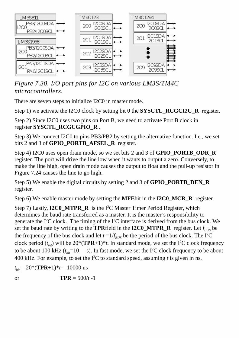
Figure7.30.I/OportpinsforI2ConvariousLM3S/TM4Cmicrocontrollers.TherearesevenstepstoinitializeI2C0inmastermode.
Step1)weactivatetheI2C0clockbysettingbit0the SYSCTL_RCGCI2C_R register.
Step2)SinceI2C0usestwopinsonPortB,weneedtoactivatePortBclockinregister SYSCTL_RCGCGPIO_R .
Step3)WeconnectI2C0topinsPB3/PB2bysettingthealternativefunction.I.e.,wesetbits2and3of GPIO_PORTB_AFSEL_R register.
Step4)I2C0usesopendrainmode,sowesetbits2and3of GPIO_PORTB_ODR_Rregister.Theportwilldrivethelinelowwhenitwantstooutputazero.Conversely,tomakethelinehigh,opendrainmodecausestheoutputtofloatandthepull-upresistorinFigure7.24causesthelinetogohigh.
Step5)Weenablethedigitalcircuitsbysetting2and3of GPIO_PORTB_DEN_Rregister.
Step6)WeenablemastermodebysettingtheMFEbitinthe I2C0_MCR_R register.
Step7)Lastly,I2C0_MTPR_R istheI2CMasterTimerPeriodRegister,whichdeterminesthebaudratetransferredasamaster.Itisthemaster’sresponsibilitytogeneratetheI2Cclock.ThetimingoftheI2Cinterfaceisderivedfromthebusclock.WesetthebaudratebywritingtotheTPRfieldinthe I2C0_MTPR_R register.LetfBUSbethefrequencyofthebusclockandlett=1/fBUSbetheperiodofthebusclock.TheI2Cclockperiod(tbit)willbe20*(TPR+1)*t.Instandardmode,wesettheI2Cclockfrequencytobeabout100kHz(tbit=10 s).Infastmode,wesettheI2Cclockfrequencytobeabout400kHz.Forexample,tosettheI2Ctostandardspeed,assuming tisgiveninns,
tbit=20*(TPR+1)*t=10000ns
orTPR=500/t-1

TheR/Sbit(bit0)oftheMaster’sSlaveAddressRegister,I2C0_MSA_R ,specifieswhetherthenextdatatransferwillbeareceivefromslave(equals1)orawritetoslave(equals0).Bits7through1oftheMaster’sSlaveAddressRegistercontaintheunique7-bitaddressoftheslavethatthemasterisaddressing.Generally,notwodevicesshouldhavethesameslaveaddress.Manydevicescanpermanentlyacceptanewslaveaddressfromthemaster.I2C_MCS_ACK specifieswhetherornotthemasteracknowledgesdatareceivedfromtheslave.I2C_MCS_ACK isonlyusedwhentheI2CBusisareceiver,notatransmitter.
Whenreceivingdataasamaster,thisbitdeterminesifanacknowledgementwillbesentduringthe9thclockbit.1meansanacknowledgementwillbesent(Ack),and0meansnoacknowledgementwillbesent(Nack).Themastermaynotacknowledgethefinalbytesentbyaslave.ItmustissueaSTOPorrepeatedSTARTconditionafterthenegativeacknowledge.TheI2Cmodulewillalwaysacknowledgeaddressmatches,provideditisenabled.ASTARTorrepeatedstart(RESTART)willbesentifsoftwarewritesa1tothe I2C_MCS_START bit,providedthismicrocontrolleristhecurrentbusmaster.Attemptingarepeatedstartwhenthebusisownedbyanothermasterwillresultinlossofarbitration. I2C_MCS_START ispartoftheMaster’sControl/StatusRegister,whichisaspecialregister.Readsfromthisregisterreturninformationaboutthemaster’sstatus,andwritestothisregistercontrolthemaster’snexttransmission.Forexample,setthe I2C_MCS_ACK , I2C_MCS_STOP ,and/or I2C_MCS_START bitsandthe I2C_MCS_RUN bittobeginthenexttransmission.Afterwards,readthe I2C_MCS_ARBLST or I2C_MCS_ERROR bitstoseeifthemasterhaslostarbitrationofthebus.Manyapplicationsmayalsorequirereadingthe I2C_MCS_ADRACK and I2C_MCS_DATACK bitstoensurethattheslavehasacknowledgeditsaddressandanydata.Anunresponsivedevicemayrepresentaserioushardwareproblemtowhichthesystemmustreact.
Themastercanbeinthreemodes:idle,transmitandreceive.Table7.12summarizesthemodesandoperationofI2C.Combinationsnotlistedinthistableareeitherillegalornooperation.
State R/S ACK STOP START Run Action(andnewstate)
Idle 0 X 0 1 1 STARTconditionfollowedbySEND(goestoMasterTransmit)
0 X 1 1 1 STARTconditionfollowedbyaSENDandSTOPcondition(remainsinIdle).

1 0 0 1 1 STARTcondition,RECEIVEoperationwithnegativeACK(goestotheMasterReceive)
1 0 1 1 1 STARTconditionfollowedbyRECEIVEandSTOPcondition(remainsinIdlestate)
1 1 0 1 1 STARTconditionfollowedbyRECEIVE(goestotheMasterReceivestate)
MasterTransmit
X X 0 0 1 SENDoperation(remainsinMasterTransmit
state)
X X 1 0 0 STOPcondition(goestoIdlestate)
X X 1 0 1 SENDfollowedbySTOPcondition(goestoIdle
state)
0 X 0 1 1 RepeatedSTARTconditionfollowedbyaSEND(remainsinMasterTransmitstate)
0 X 1 1 1 RepeatedSTARTconditionfollowedbySENDandSTOPcondition(goestoIdlestate)
1 0 0 1 1

RepeatedSTART,thenRECEIVEoperationwithanegativeACK(goestoMasterReceivestate)
1 0 1 1 1 RepeatedSTARTconditionfollowedbyaSENDandSTOPcondition(goestoIdlestate)
1 1 0 1 1 RepeatedSTARTconditionfollowedbyRECEIVE(goestoMasterReceivestate)
Master
Receive
X 0 0 0 1 RECEIVEoperationwithnegativeACK(remains
inMasterReceivestate)
X X 1 0 0 STOPcondition(goestoIdlestate)
X 0 1 0 1 RECEIVEfollowedbySTOPcondition(goestoIdlestate)
X 1 0 0 1 RECEIVEoperation(remainsinMasterReceivestate)
1 0 0 1 1 RepeatedSTART,thenRECEIVEoperationwithanegativeACK(remainsinMasterReceivestate).
1 0 1 1 1 RepeatedSTART,thenRECEIVEandSTOPcondition(goestoIdlestate)

1 1 0 1 1 RepeatedSTARTconditionfollowedbyRECEIVE(remainsinMasterReceivestate)
0 X 0 1 1 RepeatedSTARTconditionfollowedbySEND(goestoMasterTransmitstate)
0 X 1 1 1 RepeatedSTARTconditionfollowedbySENDandSTOPcondition(goestoIdlestate)
Table7.12.I2Ccommands,actions,andstatechanges.
Figure7.31andTable7.13describethetimingofI2C.LettbitbetheI2CperiodasdefinedbythebusclockandtheTPRfieldinthe I2C0_MTPR_R register.BecauseSCLandSDAareopen-drain-typeoutputs,whichthecontrollercanonlyactivelydrivelow.Thesetuptime,tsetup,isthetimebeforetheriseofSCLthatthedataonSDAwillbevalid.ThedataremainsvalidthroughoutthetimeSCLishigh.Theholdtime,thold,isthetimeafterthefallofSCLthatthedataonSDAcontinuestobevalid.Therisetime,trise,ofSDAandSCLdependsonexternalsignalcapacitanceandpull-upresistorvalues(**).Thefalltime,tfall,isspecifieduptoamaximum50pFload.
Figure7.31.I2Ctimingintervals.
Parameter Minimum Typical Maximum
tstart 36t
thigh 24t
tlow 36t
18t

tsetup
thold 2t
trise ** ** **
tfall 9ns 10ns
tstop 24t
Table7.13.I2Ctimingintervals,wheretisthesystembusperiod(**dependsonexternalfactors).
7.6.4.I2CSingleMasterExampleTheobjectiveofthisexampleistopresentalow-leveldevicedriverforanI2Cnetworkwherethismicrocontrolleristheonlymaster,asshowninProgram7.5.Thissimpleexamplewillemploybusy-waitsynchronization. I2C_Init firstenablestheI2Cinterface,startingoutinmastermode.Sincethisistheonlymaster,itneedtoinitializeanyoftheslavemodesettings.
//Assumesa50MHzbusclock,20*(TPR+1)*20ns=10us,withTPR=24
#defineTPR(500/20–1)
voidI2C_Init(void)
SYSCTL_RCGCI2C_R|=0x0001;//activateI2C0
SYSCTL_RCGCGPIO_R|=0x0002;//activateportB
while((SYSCTL_PRGPIO_R&0x0002)==0);//ready?
GPIO_PORTB_AFSEL_R|=0x0C;//enablealtfunctonPB2,3
GPIO_PORTB_ODR_R|=0x0C;//enableopendrainonPB2,3
GPIO_PORTB_PCTL_R=(GPIO_PORTB_PCTL_R&0xFFFF00FF)+0x00003300;//I2C
GPIO_PORTB_DEN_R|=0x0C;//enabledigitalI/OonPB2,3
I2C0_MCR_R=0x00000010;//masterfunctionenable
I2C0_MTPR_R=TPR;//configurefor100kbpsclock
Program7.5.TM4C123I2Cinitializationinsinglemastermode(I2C_xxx.zip).

Program7.6containsthefunction I2C_Send2 thattransmitstwobytestoaslave,creatingatransmissionshowninFigure7.26.Inasystemwithmultiplemastersthisshouldchecktoseeifthebusisidlefirst.Becausethissystemhasjustonemaster,thebusshouldbeidle.However,thefirstlineofthefunctionmakescertainthattheI2Chardwareisfreeandthereisnotalreadyanothertransactionpending.Bysettingthe I2C_MCS_START bitoftheI2CMasterControl/StatusRegister, I2C0_MCS_R ,themicrocontrollerwillcreateaSTARTcondition.Inasystemwithmultiplemasters,itshouldchecktoseeifitlostbusarbitration( I2C_MCS_ARBLST ).Theslaveaddress(withbit0equalto0)willbesent.Thetwodatabytesaresent,thentheSTOPisissued.Ifthereisapossibilitytheslavedoesn’texist,datadoesn’tgetacknowledged,orbusarbitrationislostthenthisprogramcouldhavechecked I2C_MCS_ERROR aftereachtransfer.
uint32_tI2C_Send2(uint8_tslave,uint8_tdata1,uint8_tdata2)
while(I2C0_MCS_R&0x00000001);//waitforI2Cready
I2C0_MSA_R=(slave<<1)&0xFE;//MSA[7:1]isslaveaddress
I2C0_MSA_R&=~0x01;//MSA[0]is0forsend
I2C0_MDR_R=data1&0xFF;//preparefirstbyte
I2C0_MCS_R=(I2C_MCS_START//generatestart/restart
|I2C_MCS_RUN);//noack,nostop,masterenable
while(I2C0_MCS_R&0x00000001);//waitfortransmissiondone
//checkerrorbits
if((I2C0_MCS_R&
(I2C_MCS_DATACK|I2C_MCS_ADRACK|I2C_MCS_ERROR))!=0)
I2C0_MCS_R=I2C_MCS_STOP;//stop,noack,disable
return(I2C0_MCS_R&//returnerrorbitsifnonzero
(I2C_MCS_DATACK|I2C_MCS_ADRACK|I2C_MCS_ERROR));
I2C0_MDR_R=data2&0xFF;//preparesecondbyte
I2C0_MCS_R=(I2C_MCS_STOP//noack,stop,nostart
|I2C_MCS_RUN);//masterenable
while(I2C0_MCS_R&0x00000001);//waitfortransmissiondone
return(I2C0_MCS_R&//returnerrorbits
(I2C_MCS_DATACK|I2C_MCS_ADRACK|I2C_MCS_ERROR));
Program7.6.I2Ctransmissioninsinglemastermode(I2C_xxx.zip).Program7.7containsthefunction I2C_Recv2 thatreceivestwobytesfromaslave,

creatingatransmissionshowninFigure7.27.Bysettingthe I2C_MCS_START bit,themicrocontrollerwillcreateaSTARTcondition.Duringthefirsttransfer,theTx/Rxbitis1,sotheslaveaddress(withbit0equalto1)willbesent,andthemastergoesintoreceivemode.Duringthenexttwotransfers,themasterisinreceivemode,sodataflowsintothemicrocontroller.Totriggeranydatatransfer,thesoftwarewritesavalidvalueto I2C0_MCS_R withthe I2C_MCS_RUN bitset.Duringthefirstdatatransfer I2C_MCS_ACK is1,creatingapositiveacknowledgement.Converselyduringtheseconddatatransfer I2C_MCS_ACK is0,creatinganegativeacknowledgementandsignalingtotheslavethatthisisthelastdatatobetransferred.TheSTOPisrequestedwhenthe I2C_MCS_STOP bitofthe I2C0_MCS_R registerisset,anditautomaticallyisissuedafterthefinaldatatransfer.
Thisisasimpleconceptthatmayseemcomplicatedatfirst.Basically:
0)Initialize:turnonGPIOBandI2Cmodules,setupGPIOBpins,setupI2Cmaster
1)Putslaveaddressinto I2C0_MSA_R [7:1]
2)(receiveonly)Set I2C0_MSA_R [0]
2)(transmitonly)Clear I2C0_MSA_R [0]andputfirstbyteinto I2C0_MDR_R [7:0]
3)Writeavalidvalueto I2C0_MCS_R [3:0]tostarttransfer
4)Waitfortransfertofinish: while(I2C0_MCS_R&0x00000001);
5)(receiveonly)Readfirstbytefrom I2C0_MDR_R [7:0]
6)repeatSteps2-5untildone
Timingiscomplicatedandpotentiallyconfusing.Fortunately,itishandledbyhardwareyouarealreadygiven.Therearetwocomplicatedthingsforwhichyouareresponsible.ThefirstissueisunderstandingwhatcodestosendtotheI2Cslave.ThesecondcomplicatedissueisStep3.Thereare4bitstowriteto I2C0_MCS_R [3:0],andtheydependonthemaster’scurrentstateandnextstateasdescribedinTable7.12.
#defineI2C_MCS_ACK0x00000008//DataAcknowledgeEnable
#defineI2C_MCS_ADRACK0x00000004//AcknowledgeAddress
#defineI2C_MCS_STOP0x00000004//GenerateSTOP
#defineI2C_MCS_START0x00000002//GenerateSTART
#defineI2C_MCS_ERROR0x00000002//Error
#defineI2C_MCS_RUN0x00000001//I2CMasterEnable
#defineMAXRETRIES5//numberofreceiveattemptsbeforegivingup
uint16_tI2C_Recv2(uint8_tslave)uint8_tdata1,data2;
intretryCounter=1;

do
while(I2C0_MCS_R&0x00000001);//waitforI2Cready
I2C0_MSA_R=(slave<<1)&0xFE;//MSA[7:1]isslaveaddress
I2C0_MSA_R|=0x01;//MSA[0]is1forreceive
I2C0_MCS_R=(I2C_MCS_ACK//positivedataack
|I2C_MCS_START//nostop,yesstart/restart
|I2C_MCS_RUN);//masterenable
while(I2C0_MCS_R&0x00000001);//waitfortransmissiondone
data1=(I2C0_MDR_R&0xFF);//MSBdatasentfirst
I2C0_MCS_R=(I2C_MCS_STOP//generatestop,nostart
|I2C_MCS_RUN);//masterenable
while(I2C0_MCS_R&0x00000001);//waitfortransmissiondone
data2=(I2C0_MDR_R&0xFF);//LSBdatasentlast
retryCounter=retryCounter+1;//incrementretrycounter
//repeatiferror
while(((I2C0_MCS_R&(I2C_MCS_ADRACK|I2C_MCS_ERROR))!=0)
&&(retryCounter<=MAXRETRIES));
return(data1<<8)+data2;//usuallyreturns0xFFFFonerror
Program7.7.I2Creceptioninsinglemastermode(I2C_xxx.zip).Figure7.32showsalogicanalyzermeasurementtakenwithProgram7.7communicatingwithaTexasInstrumentsTMP102thermometer.Themainprogramcalls I2C_Recv2(0x48); Thefirsttransmissionsendsthe0x91(slaveaddress,read)command.Itthenreceivestwotransmissions,whichisthetemperatureencodedwith0.0625°Cresolution.
Figure7.32.LogicanalyzertransmissionofI2C_Recv2,withoneoutputandtwoinputs.

I2Ccanbeverydifficulttoconfigure.WesuggestyouobvervetheSCLandSDLonanoscilloscope.Firstchecktheclockrateandsecondverifytheoutputhighandoutputlowvoltagesarewithinspecification.LookupVIHandVILofboththemicrocontrollerandtheremotesensor.ThehighvoltagemeasuredbythescopeshouldbehigherthanVIHofbothdevices.ThelowvoltagemeasuredbythescopeshouldbelowerthanVILofbothdevices.

7.7.IntroductiontoUniversalSerialBus(USB)
7.7.1.BasicPrinciplesTheUniversalSerialBus(USB)isahost-controlled,token-basedhigh-speedserialnetworkthatallowscommunicationbetweenmanyofdevicesoperatingatdifferentspeeds.TheobjectiveofthissectionisnottoprovideallthedetailsrequiredtodesignaUSBinterface,butratheritservesasanintroductiontothenetwork.Thereis650-pagedocumentontheUSBstandard,whichyoucandownloadfromhttp://www.usb.org.Inaddition,therearequiteafewwebsitessetuptoassistUSBdesigners,suchastheonetitled“USBinaNutShell”athttp://www.beyondlogic.org/usbnutshell/.
Thestandardismuchmorecomplexthantheothernetworkspresentedinthischapter.Fortunately,however,thereareanumberofUSBproductsthatfacilitateincorporatingUSBintoanembeddedsystem.Inaddition,theUSBcontrollerhardwarehandlesthelow-levelprotocol.USBdevicesusuallyexistwithinthesameroom,andaretypicallylessthan4metersfromeachother.USB2.0supportsthreespeeds.
HighSpeed-480Mbits/s
FullSpeed-12Mbits/s
LowSpeed-1.5Mbits/sTheoriginalUSBversion1.1supportedjustfullspeedmodeandalowspeedmode.TheUniversalSerialBusishost-controlled,whichmeansthehostregulatescommunicationonthebus,andtherecanonlybeonehostperbus.Ontheotherhand,theOn-The-Gospecification,addedinversion2.0,includesaHostNegotiationProtocolthatallowstwodevicesnegotiatefortheroleofhost.TheUSBhostisresponsibleforundertakingalltransactionsandschedulingbandwidth.Datacanbesentbyvarioustransactionmethodsusingatoken-basedprotocol.USBusesatieredstartopology,usingahubtoconnectadditionaldevices.Ahubisatthecenterofeachstar.Eachwiresegmentisapoint-to-pointconnectionbetweenthehostandahuborfunction,orahubconnectedtoanotherhuborfunction,asshowninFigure7.33.Becausethehubprovidespower,itcanmonitorpowertoeachdeviceswitchingoffadevicedrawingtoomuchcurrentwithoutdisruptingotherdevices.Thehubcanfilterouthighspeedandfullspeedtransactionssolowerspeeddevicesdonotreceivethem.BecauseUSBusesa7-bitaddress,upto127devicescanbeconnected.

Figure7.33.USBnetworktopology.
TheelectricalspecificationforUSBwasintroducedinFigure7.10andTable7.5,usingfourshieldedwires(+5Vpower,D+,D-andground).TheD+andD-aretwistedpairdifferentialdatasignals.ItusesNonReturntoZeroInvert(NRZI)encodingtosenddatawithasyncfieldtosynchronizethehostandreceiverclocks.
USBdriverswilldynamicallyloadandunload.Whenadevicepluggedintothebus,thehostwilldetectthisaddition,interrogatethedeviceandloadtheappropriatedriver.Similarly,whenthedeviceisunplugged,thehostwilldetectitsabsenceandautomaticallyunloadthedriver.TheUSBarchitecturecomprehendsfourbasictypesofdatatransfers:
•ControlTransfers:Usedtoconfigureadeviceatattachtimeandcanbeusedforotherdevice-specificpurposes,includingcontrolofotherpipesonthedevice.
•BulkDataTransfers:Generatedorconsumedinrelativelylargequantitiesandhavewidedynamiclatitudeintransmissionconstraints.
•InterruptDataTransfers:Usedfortimelybutreliabledeliveryofdata,forexample,charactersorcoordinateswithhuman-perceptibleechoorfeedbackresponsecharacteristics.
•IsochronousDataTransfers:OccupyaprenegotiatedamountofUSBbandwidthwithaprenegotiateddeliverylatency.(Alsocalledstreamingreal-timetransfers).
Isochronoustransferallowsadevicetoreserveadefinedaboutofbandwidthwithguaranteedlatency.Thisisappropriateforreal-timeapplicationslikeinaudioorvideoapplications.Anisochronouspipeisastreampipeandis,therefore,alwaysunidirectional.Anendpointdescriptionidentifieswhetheragivenisochronouspipe’scommunicationflowisintooroutofthehost.Ifadevicerequiresbidirectionalisochronouscommunicationflow,twoisochronouspipesmustbeused,oneineachdirection.
AUSBdeviceindicatesitsspeedbypullingeithertheD+orD-lineto3.3V,asshowninFigure7.34.Apull-upresistorattachedtoD+specifiesfullspeed,andapull-upresistorattachedtoD-meanslowspeed.Thesedevice-sideresistorsarealsousedbythehostorhubtodetectthepresenceofadeviceconnectedtoitsport.Withoutapull-upresistor,thehostorhubassumesthereisnothingconnected.Highspeeddevicesbeginasafullspeeddevice(1.5kto3.3V).Onceithasbeenattached,itwilldoahighspeedchirpduringresetandestablishahighspeedconnectionifthehubsupportsit.Ifthedeviceoperatesinhighspeedmode,thenthepull-upresistorisremovedtobalancetheline.

Figure7.34.Pull-upresistorsonUSBdevicessignalspecifythespeed.Likemostcommunicationsystems,USBismadeupofseverallayersofprotocols.LiketheCANnetworkpresentedearlier,theUSBcontrollerswillberesponsibleforestablishingthelow-levelcommunication.EachUSBtransactionconsistsofthreepackets
TokenPacket(header),OptionalDataPacket,(information)andStatusPacket(acknowledge)
Thehostinitiatesallcommunication,beginningwiththeTokenPacket,whichdescribesthetypeoftransaction,thedirection,thedeviceaddressanddesignatedendpoint.Thenextpacketisgenerallyadatapacketcarryingtheinformationandisfollowedbyahandshakingpacket,reportingifthedataortokenwasreceivedsuccessfully,oriftheendpointisstalledornotavailabletoacceptdata.Dataistransmittedleastsignificantbitfirst.SomeUSBpacketsareshowninFigure7.35.Allpacketsmuststartwithasyncfield.Thesyncfieldis8bitslongatlowandfullspeedor32bitslongforhighspeedandisusedtosynchronizetheclockofthereceiverwiththatofthetransmitter.PID(PacketID)isusedtoidentifythetypeofpacketthatisbeingsent,asshowninTable7.14.
Theaddressfieldspecifieswhichdevicethepacketisdesignatedfor.Being7bitsinlengthallowsfor127devicestobesupported.Address0isnotvalid,asanydevicewhichisnotyetassignedanaddressmustrespondtopacketssenttoaddresszero.Theendpointfieldismadeupof4bits,allowing16possibleendpoints.Lowspeeddevices,howevercanonlyhave2additionalendpointsontopofthedefaultpipe.CyclicRedundancyChecksareperformedonthedatawithinthepacketpayload.Alltokenpacketshavea5-bitCRCwhiledatapacketshavea16-bitCRC.EOPstandsforEndofpacket.StartofFramePackets(SOF)consistofan11-bitframenumberissentbythehostevery1ms±500nsonafullspeedbusorevery125µs±0.0625µsonahighspeedbus.
Figure7.35.USBpackettypes.

Group PIDValue
PacketIdentifier
Token
0001 OUTToken,Address+endpoint
1001 INToken,Address+endpoint
0101 SOFToken,Start-of-Framemarkerandframenumber
1101 SETUPToken,Address+endpoint
Data
0011 DATA0
1011 DATA1
0111 DATA2(highspeed)
1111 MDATA(highspeed)
Handshake
0010 ACKHandshake,Receiveracceptserror-freedatapacket
1010 NAKHandshake,devicecannotacceptdataorcannotsenddata
1110 STALLHandshake,Endpointishaltedorpiperequestnotsupported
0110 NYET(NoResponseYetfromreceiver)
Special
1100 PREamble,Enablesdownstreambustraffictolow-speeddevices.
1100 ERR,SplitTransactionErrorHandshake
1000 Split,High-speedSplitTransactionToken
0100 Ping,High-speedflowcontrolprobeforabulk/controlendpoint
Table7.14.USBPIDnumbers.

USBfunctionsareUSBdevicesthatprovideacapabilityorfunctionsuchasaPrinter,ZipDrive,Scanner,Modemorotherperipheral.Mostfunctionswillhaveaseriesofbuffers,typically8byteslong.Endpointscanbedescribedassourcesorsinksofdata,shownas EP0In , EP0Out etc.inFigure7.36.Asthebusishostcentric,endpointsoccurattheendofthecommunicationschannelattheUSBfunction.Thehostsoftwaremaysendapackettoanendpointbufferinaperipheraldevice.Ifthedevicewishestosenddatatothehost,thedevicecannotsimplywritetothebusasthebusiscontrolledbythehost.Therefore,itwritesdatatoendpointbufferspecifiedforinput,andthedatasitsinthebufferuntilsuchtimewhenthehostsendsaINpackettothatendpointrequestingthedata.Endpointscanalsobeseenastheinterfacebetweenthehardwareofthefunctiondeviceandthefirmwarerunningonthefunctiondevice.
Figure7.36.USBdataflowmodel.Whilethedevicesendsandreceivesdataonaseriesofendpoints,theclientsoftwaretransfersdatathroughpipes.Apipeisalogicalconnectionbetweenthehostandendpoint(s).Pipeswillalsohaveasetofparametersassociatedwiththemsuchashowmuchbandwidthisallocatedtoit,whattransfertype(Control,Bulk,IsoorInterrupt)ituses,adirectionofdataflowandmaximumpacket/buffersizes.StreamPipescanbeusedsendunformatteddata.Dataflowssequentiallyandhasapre-defineddirection,eitherinorout.Streampipeswillsupportbulk,isochronousandinterrupttransfertypes.Streampipescaneitherbecontrolledbythehostordevice.MessagePipeshaveadefinedUSBformat.Theyarehost-controlled,whichareinitiatedbyarequestsentfromthehost.Dataisthentransferredinthedesireddirection,dictatedbytherequest.Thereforemessagepipesallowdatatoflowinbothdirectionsbutwillonlysupportcontroltransfers.
7.7.2.ModularUSBInterfaceTherearetwoapproachestoimplementingaUSBinterfaceforanembeddedsystem.In

themodularapproach,wewillemployaUSB-to-parallel,orUSB-to-serialconverter.ThemodularapproachisappropriateforaddingUSBfunctionalitytoanexistingsystem.Forabout$30,wecanbuyaconvertercablewithaUSBinterfacetoconnecttothepersonalcomputer(PC)andaserialinterfacetoconnecttotheembeddedsystem,asshowninFigure7.37.TheembeddedsystemhardwareandsoftwareisstandardRS232serial.ThesesystemscomewithPCdevicedriverssothattheUSB-serial-embeddedsystemlookslikeastandardserialport(COM)tothePCsoftware.TheadvantageofthisapproachisthatsoftwaredevelopmentonthePCandembeddedsystemissimple.ThedisadvantageofthisapproachisnoneofthepowerandflexibilityofUSBisutilized.Inparticular,thebandwidthislimitedbytheRS232line,andthedatastreamisunformatted.SimilarproductsareavailablethatconvertUSBtotheparallelport.Companiesthatmaketheseconvertersinclude
IOGearInc.http://www.iogear.com
WyseTechnologyhttp://www.wyse.com
D-LinkCorporationhttp://www.dlink.com
ComputerPeripheralSys,Inc.http://www.cpscom.com
Jo-DanInternational,Inc.http://www.jditech.com
Figure7.37.ModularapproachtoUSBinterfacing.ThesecondmodularapproachistopurchaseaUSBparallelinterfacemodule.Thesedevicesallowyoutosendandreceivedatausingparallelhandshakeprotocolssimilartotheinput/outputexamplesinChapter3.TheytypicallyincludeaUSB-enabledmicrocontrollerandreceiver/transmitFIFObuffers.Thisapproachismoreflexiblethantheserialcablemethod,becauseboththemicrocontrollermoduleandtheUSBdriverscanbetailoredpersonalized.Inparticular,somemodulesallowyoutoburnPIDandVIDnumbersintoEEPROM.Theadvantages/disadvantagesofthisapproacharesimilartotheserialcable,inthatthedataisunformattedandyouwillnotbeabletoimplementhigh

bandwidthbulktransfersornegotiateforreal-timebandwidthavailablewithisochronousdatatransfers.Companiesthatmakethesemodulesinclude
FutureTech.DevicesInter.Ltd.http://www.ftdichip.com/
ActiveWire,Inc.http://www.activewireinc.com
DLPDesign,Inc.http://www.dlpdesign.com
ElexolPtyLtd.http://www.elexol.com
7.7.3.IntegratedUSBInterfaceThesecondapproachtoimplementingaUSBinterfaceforanembeddedsystemistointegratetheUSBcapabilityintothemicrocontrolleritself.Thismethodaffordsthegreatestflexibilityandperformance,butrequirescarefulsoftwaredesignonboththemicrocontrollerandthehost.Overthelast15yearsUSBhasbeenreplacingRS232serialcommunicationasthepreferredmethodforconnectingembeddedsystemstothepersonalcomputer.ManufacturersofmicrocontrollershaveintroducedversionsoftheproductwithUSBcapability.EverycompanythatproducesmicrocontrollershasmembersofthefamilywithUSBfunctionality.ExamplesincludetheMicrochipPIC18F2455,AtmelAT89C5131A,FTDIFT245BM,FreescaleMCF51Jx,STMicrosystemsSTM32F102,TexasInstrumentsMSP430F5xx,andTexasInstrumentsLM4F120/TM4C123.Figure7.38showstheUSBconfigurationontheEK-TM4C123GXLLaunchPadEvaluationKit,whichiscapableofoperatingasadevice,ahostoron-the-go(OTG).TouseUSBpopulateR25andR29.TheLM4F120canbeonlyconfiguredasaUSBdevice.TheTivaWare ® softwarelibraryhas14exampleprojectsforthisevaluationboard,includingserialporttranslator,securedigitalcard,mouse,andkeyboardinterface.
Figure7.38.TheTM4C123LaunchPadkitsupportsUSBhost,device,andOTGmodes.TooperateaUSBinterfaceatfullspeedDMAsynchronizationwillberequired,sothatdataistransferreddirectlyfrommemorytoUSBoutput,orfromUSBinputtomemory.

7.8.Exercises7.1Foreachtermgiveadefinitionin32wordsorless.
a)Asynchronousb)Baudratec)Bandwidth
d)Breake)DCEf)DTE
g)Evenparityh)Fullduplexi)Frame
j)Framingerrork)Halfduplexl)Mark
m)Negativelogicn)NRZo)NRZI
p)Opendrainq)Overrunr)Positivelogic
s)Simplext)Spaceu)Synchronous
7.2In32wordsorless,describethesimilaritiesanddifferencesbetweenthesepairsofterms
a)Baudrateversusbandwidthb)Positivelogicversusnegativelogic
c)XONversusXOFFd)Fullduplexversushalfduplex
e)DS275versusMAX232f)SCIversusSPI
g)NRZversusNRZIh)DTEversusDCE
7.3Whatfundamentalelectricalpropertyisusedtotransferdigitaldataacrossadistance?
A)VoltageD)Frequency
B)CurrentE)Phase
C)EnergyF)Wavelength
7.4LookupintheLM3S/LM4F/TM4CdatasheetwhattheBUSYbitintheUARToperates.Inparticular,whenisitset?Whenisitclear?Canthesoftwareclearit?Canittriggeraninterrupt?
7.5In16wordsorless,explainwhytheUARTreceiverISRinProgram5.9interruptsonbothRXRISandRTRIS.InparticularwhendoesRXRIStriggerandwhendoesRTRIStrigger?
7.6DrawaplotsimilartoFigure7.2forthebinarydata00110111.
7.7DrawaplotsimilartoFigure7.2forthebinarydata10011100.

7.8Consideraserialportoperatingwithabaudrateof10,000bitspersecond.DrawthewaveformoccurringattheU0Txoutput(voltagelevelsare+3.3and0)whentheASCII‘a’(0x61)istransmittedonUART0.Theprotocolis1start,8dataand1stopbit.UART0isinitiallyidle,andthesoftwarewritesthe0x61to UART0_DR_R attime=0.ShowtheU0Txlinebeforeandaftertheframe,assumingthechannelisidlebeforeandaftertheframe.
7.9Consideraserialportoperatingwithabaudrateof1000bitspersecond.DrawthewaveformoccurringattheU1Txoutput(voltagelevelsare+3.3and0)whentheASCII‘B’(0x42)istransmittedonUART1.Theprotocolis1start,8dataand1stopbit.UART1isinitiallyidle,andthesoftwarewritesthe0x42to UART1_DR_R attime=0.ShowtheU1Txlinebeforeandaftertheframe,assumingthechannelisidlebeforeandaftertheframe.
7.10AssumetheUARTbaudrateis1000bits/secandtheprotocolis1start,8data,noparityand1stopbit.Whatisthechannelbandwidth?Ifweused2stopbitsinsteadof1withoutchangingthebaudrate,wouldthebandwidthbehigher,lowerorthesame?
7.11ThedatainFigure7.39wasmeasuredonaU0Rxserialinput,whichwethinkisoneframe,butitmightbetwoframes.Theserialformatis1-start,8-bit,and1-stopbit.
a)WhatisthebaudrateinCaseA?
b)WhatdataisbeingtransferredinCaseA?Givethenumber(s)inhexadecimal.
c)WhatisthebaudrateinCaseB?
d)WhatdataisbeingtransferredinCaseB?Givethenumber(s)inhexadecimal.
Figure7.39.Serialtransmissionforexercise7.11.7.12RXRISandRTRISinterruptsarearmedsothatinterruptsoccurwhennewdataarrivesintotheLM3S/LM4F/TM4C.ConsiderthesituationlikeProgram5.9inwhichasoftwareFIFOqueueisusedtobufferdatabetweentheISRandthemainprogram.TheISRreadsdatafromtheUARTandsavesthedatabycalling Fifo_Put .Whenthemainprogramwantsinputitcalls UART_InChar ,whichinturncalls Fifo_Get .ExperimentalobservationsshowthisFIFOisusuallyempty,andhasatmost3elements.Whatdoesitmean?ChooseA-F.
A)ThesystemisCPUbound
B)BandwidthcouldbeincreasedbyincreasingFIFOsize
C)ThesystemisI/Obound
D)TheFIFOcouldbereplacedbyaglobalvariable
E)Thelatencyissmallandbounded

F)Interruptsarenotneededinthissystem
7.13AslavedevicewillbeinterfacedtothemasterLM3S/LM4F/TM4CusingSSI.ThetimingisshowninFigure7.40.TherearethreesignalsthatwillbeoutputsoftheLM3S/LM4F/TM4Candinputstothedevice(Enable,Clock,andData).Thetimingoftheexternaldeviceisshownbelow.AssumingaFreescaleSPIprotocol,whatSPH,SPOmodeshouldyouuse?
Figure7.40.Serialtransmissionforexercise7.13.D7.14.WritesoftwarethatcreatestheSSIprotocolonaregulardigitalport.Morespecifically,interfacetheDACinExample7.2toportpinsPD3,PD2,PD1,andPD0.(PD0isnotused).
D7.15.WritesoftwarethatcreatestheSSIprotocolonaregulardigitalport.Morespecifically,interfacetheADCinExample7.3toportpinsPB3,PB2,PB1,andPB0.
D7.16.WritesoftwarethatcreatestheSSIprotocolonaregulardigitalport.Morespecifically,interfacethe74HC595inExample7.4toportpinsPD3,PD2,PD1,andPD0.(PD0isnotused).
D.7.17Thisproblemaddressestheissueofcapacitiveloadingonahigh-speedserialtransmissionlinelikeSSI.TheSSIportsoftwomicrocontrollersareconnectedwithaVERYlongcable.Wewillmodelthiscableasasingleresistorinserieswithacapacitor,asshowninFigure7.41.Forthisquestion,assumeanidealtransmitter(outputimpedanceof0)andanidealreceiver(inputimpedanceofinfinity).LettheresistanceRbe1 ,andthecapacitanceCbe10nF.Considera3.3-V100-nspulse(T=100ns)ontheoutputofthetransmitter(labeledasVin)asmightoccurwitha5-MbpsSSItransmission.DeriveanequationforVoutasafunctionoftimeforthefirst100ns.Showyourwork.CalculatevaluesforVoutattimeequals0andtimeequals100ns.CreateaVinversustimesketchsimilartotherightofFigure7.41,andaddasketchofVoutonthissameplot.Showboth0totimeTandtimeTtotime2T.
Figure7.41.CircuitmodelforexercisesD7.17andD7.18.D.7.18SolveexerciseD7.17withR=10 ,C=100nFandT=10ns.Justifywhetherornotthissystemwillwork?

D7.19Theoutputofoneshiftregisterisconnectedtotheinputofasecondshiftregister,asshowninFigure7.42.Thetworegistersarecontrolledbythesame50%dutycycleClock.Theperiodoftheclockist1.ThedataisshiftedoutonthefallingedgeofClock.Thetimet2=[10nsmin,200nsmax]isthedelayfromthefallingedgeofClockuntilwhentheoutputisvalid.ThedataisshiftedintothesecondregisterontherisingedgeofClock.Thetimet3=50nsisthetimebeforetherisingedgeofClockthatthedatamustbevalid.Thetimet4=20nsisthetimeafterthatsamerisingedgeofClockthatthedatamustcontinuetobevalid.Whatisthesmallestt1clockperiodthatreliablytransversesdatafromoneshiftregistertotheother?
Figure7.42.CircuitandtimingforexerciseD7.19.

7.9.LabAssignmentsLab7.1TheoverallobjectiveistoredesigntheLab6.2or6.3dataacquisitionsystemtoemploytwomicrocontrollers.Theslavemicrocontrollerwillperformthedataacquisition(positionortemperature),andthemastermicrocontrollerwillinterfacetothePC.ThetwomicrocontrollerswillbelinkedusingtheirSSIports.Themastermicrocontrollerwillfetchdatafromtheslave,andtransmitittothePC,usingUARTinterruptsynchronization.TheuserwillinteractwithaPCrunningPuTTY.
Lab7.2TheoverallgoalistodevelopaninterruptingUARTdevicedriverthatimplementsfixed-pointinput/output.Thefixed-pointconstantis0.001.Thefull-scalerangeisfrom0to65.534.The Fix_InDec functionshouldprovideforflexibleoperation.Forexample“50.5”isreturnedas50500,and“1.4595”isreturnedas1460.Theoperatorcreatestheinputbytypingonthekeyboard,andtheoutputisanumberpassedbackasthereturnparameterofthefunction.Noticethat Fix_InDecroundstheinputtotheclosestfixed-pointresult(e.g.,1.4595roundsto1.460and1.4604alsoroundsto1.460).Somenumberslike1.2345678mightbeconsideredillegalbecausetheycauseoverflowofintermediateresults.Inthecommentsofyoursoftware,pleasediscusswhyyouchoseyourparticularimplementationmethodovertheotheravailablechoices.Pleasehandlethebackspacecharacter,allowingtheoperatortoerasecharacters.Inparticular,youarefreetouseiterativeorrecursivealgorithms.Youarefreetomodifytheprototypesaswellashandleillegalinputsinanywayyoufeelisappropriate.Youmustdetectillegalinput,butyouhaveachoiceastohowyoursystemrespondstotheillegalinput.Onepossibilityforhandlinganillegalnumberwouldbetoreturn65535,whichyoucoulddefineasanillegalnumber.Asecondpossibilityforwhenanillegalnumberistypedistooutputanerrormessage,andrequiretheoperatortoenterthenumberagain.Forexample,50isoutputas“0.050”and12345isoutputas“12.345”.
Lab7.3.TheoverallgoalistointerfaceaDS1620temperaturecontrollertothemicrocontroller.Createthefunctionstoinitialize,sethightemperature,setlowtemperatureandreadcurrenttemperature.Whenreadingthetemperatureyouwillhavetostartaconversionandwaitfortheconversiontobecomplete.Performexperimentstodeterminetheaccuracyofthetemperaturemeasurement.InterfacethreeLEDstoTHTLTCOMoutputs,andperformexperimentstoverifythetemperaturecontrollerintheDS1620isoperatingproperly.
Lab7.4.Theoverallobjectiveofthislabistodesign,implementandtestanoutputportexpander.YouwillusethreeI/Opinsofthemicrocontroller,andfour74HC595shiftregisters.Youwilldesignhardwareandsoftwarethatsupportsfour8-bitoutputports.Theoutputportsdonotneedtobereadable.Measurehowlongittakesforthemicrocontrollertoperformoutputstoall32bits.

Lab7.5Theoverallobjectiveofthislabistodesign,implementandtestaninputportexpander.YouwillusetheeI/Opinsofthemicrocontroller,andfour74HC165shiftregisters.Youwilldesignhardwareandsoftwarethatsupportsfour8-bitinputports.Theinputportsdonotneedtobelatchedbyanexternalsignal.Measurehowlongittakesforthemicrocontrollertoperforminputsfromall32bits.
Lab7.6TheobjectiveofthislabistodesignadigitalclockusingaDS1307externalclockchip.ThefirststepistointerfacetheclockchiptothemicrocontrollerusinganI2Cnetwork.Thesecondstepistodesignlow-leveldriverstoallowthemicrocontrollertosendandreceivedatafromtheDS1307.Thenextsoftwarelayerincludesfunctionslike SetTime FormatTime and ReadTime .ThehighestlevelisamainprogramthatimplementsadigitalclockusinganLEDorLCDdisplay.2,3,or4momentaryswitcheswillbeusedtocontroltheoperationofthedigitalclock.
Lab7.7TheobjectiveofthislabistodesignadigitalthermometerusingaDS1631Aexternalthermometerchip.ThefirststepistointerfacethethermometerchiptothemicrocontrollerusinganI2Cnetwork.Thesecondstepistodesignlow-leveldriverstoallowthemicrocontrollertosendandreceivedatafromtheDS1631A.Thenextsoftwarelayerincludesfunctionslike SetMode and ReadTemperature .ThehighestlevelisamainprogramthatimplementsadigitalthermometerusinganLEDorLCDdisplay.2or3momentaryswitcheswillbeusedtocontroltheoperationofthedigitalthermometer.


8.AnalogInterfacingChapter8objectivesareto:• Designanalogamplifiersandfilters
•StudybuildingblocksfordataacquisitionincludingDACandADC
•DiscussthefunctionalityoftheADContheLM3SandTM4C
Mostembeddedsystemsincludecomponentsthatmeasureand/orcontrolrealworldparameters.Theserealworldparameters,likeposition,speed,temperature,andvoltage,usuallyexistinacontinuousoranalogform.Therefore,thedesignofanembeddedsysteminvolvingtheseparametersrarelyusesonlybinaryordigitallogic.Rather,wewilloftenneedtoamplify,filterandeventuallyconverttodigitalformthesesignals.Inthischapterwewilldeveloptheanalogcircuitbuildingblocksusedinthedesignofdataacquisitionsystemsandcontrolsystems. Acomputerengineerinterestedinthefieldofembeddedsystemswillfindmorejobopportunitiesifheorshecandevelopmicrocontrollerskillsalongwithanalogcircuitdesignskills.

8.1.ResistorsandCapacitors
8.1.1.ResistorsAsengineers,weuseresistorsandcapacitorsformanypurposes.Theresistororcapacitortypeisdefinedbythemanufacturingprocess,thematerialsused,andthetestingperformed.Theperformanceandcostofthesedevicesvarysignificantly.Forexample,a5%1/4wattcarbonresistorcostslessthan1¢,whilea0.01%thinfilmorwirewoundresistormaycost$6.Itisimportanttounderstandbothourcircuitrequirementsandtheresistorparameterssothatwematchthecorrectresistortypetoeachapplicationyieldinganacceptablecost-performancebalance.Wemustspecifyinourtechnicaldrawingsthedevicetypeandtolerance(e.g.,1%metalfilm),sothatyourprototypecanbeeffectivelymanufactured.ThecharacteristicsofvariousresistortypesareshowninTable8.1.
Type Range Tolerance Temperaturecoef
MaxPower
Carboncomposition
1Ωto22MΩ 5to10% 200to700ppm/˚C
1W
Carbonfilm 1Ωto22MΩ 1to10% 200to1500ppm/˚C
2W
Metalfilm 0.01Ωto68MΩ
>0.05% 2to300ppm/˚C 1W
Thickandthinfilm
0.001Ωto100GΩ
0.1to20%
5to1000ppm/˚C
100W
Wirewound 0.005Ωto167kΩ
>0.0005%
10to900ppm/˚C
30W
Table8.1.Generalspecificationofvarioustypesofresistorcomponents.
Carboncompositionresistorsaremanufacturedwithhot-pressedcarbongranules.Variousamountsoffillerareaddedtoachieveawiderangeofresistancevalues.Filmresistorsaremadebydepositingpuremetals,suchasnickel,oranoxidefilm,suchastin-oxide,ontoaninsulatingceramicrodorsubstrate.Awirewoundresistor,ismadebywindingathinmetalalloywiresuchasNichromeontoaninsulatingceramicintheformofaspiralhelix.

Theleastexpensivetypeofathrough-holeresistoriscarbonfilm.Weaddthemtodigitalcircuitsas+3.3-Vpull-ups.Inordertoimprovetheaccuracyandstabilityofourprecisionanalogcircuits,wewilluseresistorswithalowertoleranceandsmallertemperaturecoefficient.Formostapplications1%thickfilmormetalfilmresistorswillbesufficienttobuildouranalogamplifiercircuits.Forsurfacemountconstructionweuseeitherthickfilmorthinfilmresistors,whichcomeinawiderangeofsizesandtolerances.Wirewoundresistorsaremanufacturedbytwistingaverylongverythinwirelikeaspring.Thewireiscoiledupanddownashaftinsuchawaytotryandcanceltheinductance.Sincesomeinductanceremains,wirewoundresistorsshouldnotbeusedforhighfrequency(above1MHz)applications.
Observation:Allresistorsproducewhite(thermal)noise.
Observation:Wirewoundresistorsdonotgenerate1/fnoise,whereastheothertypesdo.
8.1.2.CapacitorsSimilarly,capacitorscomeinawidevarietyofsizesandtolerances.Polarizedcapacitorsoperatebestwhenonlypositivevoltagesareapplied.Nonpolarizedorbipolarcapacitorsoperateforbothpositiveandnegativevoltages.Weselectacapacitorbasedonthefollowingparameters:capacitancevalue,polarized/nonpolarized,maximumvoltagelevel,tolerance,leakagecurrent(resistance),temperaturecoefficient,usefulfrequencyresponse,andtemperaturerange.Themaximumvoltageratingisimportantforhighvoltagecircuits,butisoflesserimportanceforembeddedmicrocontrollersystems.Table8.2comparesvariouscapacitortypeswecoulduseinourcircuit.
Type Range Tolerance Tempcoef
Leakage Frequencies
Polystyrene 10pFto2.7µF
±0.5% Excellent 10GΩ 0to1010Hz
Polypropylene 100pFto50µF
Excellent Good Excellent
Teflon 1000pFto2µF
Excellent Best Best
Mica 1pFto0.1µF ±1to±20% 1000MΩ 103to1010Hz
Ceramic 1pFto0.01µF
±5to±20% Poor 1000MΩ 103to1010Hz
100MΩ

Paper(oil-soaked)
1000pFto50µF
±10to±20%
100to108Hz
Mylar(polyester)
5000pFto10µF
±20% Poor 10GΩ 103to1010Hz
Tantalum 0.1µFto220µF
±10% Poor
Electrolytic 0.47µFto0.01F
±20% Ghastly 1MΩ 10to104Hz
Table8.2.Generalspecificationofvarioustypesofcapacitorcomponents(WolfandSmith,StudentReferenceManual,PrenticeHall,pg.302,1990andHorowitzandHill,TheArtofElectronics,CambridgeUniversityPress,pg.22,1989).
Wewillusecapacitorsfortwopurposesinourmicrocontroller-basedembeddedsystems.First,wewillplacethemontheDCpowerlinestofilterthesupplyvoltagetoourcircuits.Avoltagesupplytypicallywillincluderipple,whichisaddednoiseontopoftheDCvoltagelevel.Therearetwophysicallocationstoplacethesupplyfilters.Thefirstlocationisattheentrypointofthesupplyvoltageontothecircuitboard.Therearetwoapproachestothisboard-levelfilter.Ifthesupplynoiseismostlyvoltageripple,thentwocapacitorsinparallelcanbeused.Thelargeamplitudepolarizedcapacitor(e.g.,1to47µFelectrolyticortantalum)willremovelowfrequencylargeamplitudevoltagenoise,andthenonpolarizedcapacitor(e.g.,0.01to0.47µFceramic)willremovehighfrequencyvoltagenoise.Twodifferenttypesofcapacitorsareusedbecausetheyareeffective(i.e.,behavelikeacapacitor)atdifferentfrequencies.The∏filter(CLC)isveryeffectiveinremovingcurrentspikenoise.TheCLCparametersdependontheamplitudeofthecurrentripple.TheinductorinFigure8.1canbeaferritebead.AtDCthebeadisessentiallyashortcurrent.Theferritebeadincreasesbothitsrealandreactiveimpedanceathighfrequencies.Thebeadshouldbeselectedtohavelargeimpedanceatthedigitalclockfrequency.Panasonicmakesaseriesofferritebeads.ThePanasonicEXC-ELDR25ChasaDCresistanceof0.08 ,canconduct7ADC,buthasan80- impedanceat24MHz.
Figure8.1.DCsupplyfilters.

Inadditiontotheboard-levelsupplyfilter,wewilladdbypasscapacitorsatthesupplypinsofeachchip.ItwillbeimportanttoplacethesecapacitorsasclosetothepinasphysicallypossibleasillustratedinFigure8.2.Anonpolarizedcapacitor(e.g.,0.01to0.1µFceramic)willsmooththesupplyvoltageasseenbythechip.Placingthecapacitorclosetothechippreventscurrentsurgesfromonechipfromaffectingthevoltagesupplyofanother.
Figure8.2.PCBlayoutpositioningthebypasscapacitorclosetothechip.Thesecondapplicationofcapacitorsinourembeddedsystemswillbeinthelinearanalogcircuitsofthelowpassfilter,thehighpassfilter,thederivativecircuit,andtheintegratorcircuit.Fortheseapplicationswewillselectanonpolarizedcapacitorevenifthesignalamplitudeisalwayspositive.Inaddition,weusuallywantalow-tolerance,low-leakagecapacitortoimprovetheaccuracyofthelinearanalogcircuit.Ceramiccapacitorsarealow-costmedium-qualitychoiceforanalogcircuitdesign.Theycomeinthreetolerances,seeTable8.2.ThebestceramicisC0G,whichhasa1to10%toleranceandatemperaturecoefficientof30ppm/oCor±0.3%over-55to125oC.ThemiddlegradeisX7Rceramic,whichhasa5to20%toleranceandatemperaturecoefficientof±15%over-55to125oC.ThelowestcostceramicisZ5U,whichhasa20%toleranceandatemperaturecoefficientof22to-56%over10to86oC.WecanuseZ5Uforbypasscapacitorsonpowerlines,butweshoulduseeitherC0GorX7Rforanalogfilters.
Partnumber Type Tolerance Cost
06035A102FAT2A C0G ±1% $0.846
06035C102JAT2A X7R ±5% $0.11
06035C102KAT2A X7R ±10% $0.022
Table8.3.CostofAVXceramiccapacitors:1000pF,50V,surfacemount0603package(2013pricesonwww.digikey.comforquantity10).
Observation:Themaximumvoltageratingofacapacitorislimitedtoitssize.
Commonerror:Polarizedcapacitorsoftenhaveanonlinearcapacitanceversusfrequencyresponse,thereforeusingtheminananalogfilterwillcausedistortion.
Commonerror:Ifyoudesignanelectroniccircuitandneglecttoexplicitlyspecifytheresistorandcapacitortypes,thenanincorrectsubstitutionmayoccurinthelayout/manufacturingstageoftheproject.


8.2.OpAmps
Whilethedesignofanalogelectronicsisnotanexplicitobjectiveofthisbook,wewillincludeabriefdiscussionofanalogcircuitdesignissuesoftenrelatedtoembeddedsystems.Forexample,lowcost,smallsize,singlevoltagesupply,andlowpowerarefourcharacteristicstypicalofembeddedsystems.Otherfactorstoconsiderarereliability,noise,frequencyresponse,availability,andtemperaturerange.
Overadozenmanufacturersproducethousandsofanalogintegratedcircuits.Manufacturersinclude:AnalogDevices,AvagoTechnologies,CirrusLogic,Fairchild,Honeywell,Intersil,LinearTechnology,MaximIC,Microchip,NationalSemiconductor,NXPSemiconductors,ONSemiconductor,SiliconLaboratories,TexasInstruments,andToshiba.Thefactthattherearesomanyopampsavailablemakesthechoiceconfusing.Themanufacturersdopublishaselectionguideoftheirproductstoassistinfindinganappropriatepart.
Table8.4listsperformanceparametersoffouropamps,andthechoiceoftheseparticulardevicestypifythekindsofopampsusedinanembeddedsystem,buttheselectionoftheseparticularfourisnotmeantasarecommendation.Manyopampscomeinavarietyofpackagesizesandareavailablein1,2,or4opampsperpackage.Wewilluserail-to-railopamps,liketheonesinTable8.4todesignanalogcircuitsthatrunonasingle+3.3Vsupply.TheOPA330andMAX494arelow-powerdevices.
Theopamprailsareitstwopowersupplies,-Vsand+Vs.Atypicalopamppoweredwith±12‑Vrailsoperatesproperlywhenitsinputsandoutputsarebetween-10to+10V.Arail-to-railopampoperatesinalinearfashionforoutputvoltagesallthewayfromtheminusrailtotheplusrail.Someopampsoperate“rail-to-rail”forboththeinputsandoutput.
Singleopamp
Doubleopamp
Quadopamp
OPA330
OPA2330
OPA4330
OPA350
OPA2350
OPA4350
TLC2272
TLC2274
MAX492
MAX494
Description Lowpower
Highspeed Rail-to-Rail
Rail-to-Rail
K,Openloopgain
100dB 122dB 104dB 108dB
Rcm,Inputimpedance
4pF 1013Ω||6.5pF
1012Ω||8pF
2pF 2MΩ

Rdiff,Inputimpedance
1013Ω||2.5pF
1012Ω||8pF
Vos,Offsetvoltage
50V 0.5mV 3mV 0.5mV
Ios,Offsetcurrent 500pA 10pA 100pA 6nA
Ib,Biascurrent 1nA 10pA 100pA 60nA
en,Noisedensity 55nV/√Hz 5nV/√Hz 50nV/√Hz
25nV/√Hz
f1,Gain*bandwidthproduct
350kHz 38MHz 2.18MHz 500kHz
dV/dt,Slewrate 0.16V/ s 22V/ s 3.6V/ s 0.2V/ s
+Vs,Voltagesupply
1.5to5.5V
2.7to5.5V
0to5or±5V
2.7to6V
Is,Supplycurrent 35A 7.5mA 3mA 170 A
Cost $2 $4 $2 $6
Table8.4.Parametersforvariousrail-to-railCMOSopampsusedinthischapter(with–Vsgrounded).
Checkpoint8.1:Whatistherelationshipbetweenbandwidthandsupplycurrent?
Observation:Theopampshouldbemuchfasterthanthesignalyouaretryingtoprocess.
8.2.1.IdealOpAmpModelWewillbeginourdiscussionofopampswiththeidealopamp.Forsimpleanalogcircuitsusinghighqualitydevices,theidealmodelwillbesufficient.Withanidealopamp,theoutputvoltage,Vout,islinearlyrelatedtothedifferencebetweentheinputvoltages,
Vout=K•(Vy–Vx)
wherethegain,K,isaverylargenumber,asshowninFigure8.3.

Voltagerangesoftheinputsandoutputsareboundedbythesupplyvoltages,+Vsand-Vs.Opampcircuitsfoundinmanytraditionalanalogdesigntextbooksarepoweredwith±12-Vsupplies.Ontheotherhand,itwillreducesystemcosttopowerourembeddedsystemswithasinglevoltage.Morespecifically,ifthemicrocontrolleroperateswith+3.3-Vsupply,wewillruntheanalogcircuitsalsoon+3.3V.Inparticular,wewilluserail-to-railopampsandset+Vsto+3.3Vand-Vstoground.
Nomatterhowwepowertheanalogcircuits,weassumetheinputandoutputvoltageswillexistbetween-Vsand+Vs.Theinputcurrentsintotheopampareverysmall.Becausetheinputimpedanceoftheopampislarge,theidealmodelassumesIxandIyarezero.
Figure8.3.Regularopampandasinglesupplyrail-to-railopamp.Ifafeedbackresistorisplacedbetweentheoutputandthenegativeterminaloftheopamp,thenthisnegativefeedbackwillselectanoutputsuchthatVxisveryclosetoVy.Intheidealmodel,weletVx=Vy.OnewaytojustifythisbehavioristorecallthatVout=K•(Vy-Vx).SinceKisverylarge,theonlywayforVouttobebetween-Vsand+VsisforVxtobeveryclosetoVy.
Wecandesignathresholddetectorusingpositiveornofeedback.Athresholddetectorhasabinaryoutput(trueorfalse)dependingonwhetherornotaninputsignalisgreaterthanathresholdvalue.PositivefeedbackornofeedbackdrivesVouttoequal-Vsor+VsIfafeedbackresistorisplacedbetweentheoutputandthepositiveterminaloftheopamp,thenthisfeedbackwillsaturatetheoutputtoeitherthepositiveornegativesupply.Withnofeedback,theoutputwillalsosaturate.InbothcasestheoutputwillsaturatetothepositivesupplyifVy>Vx,andtothenegativesupplyifVx>Vy.Wewillseelater,thatpositivefeedbackcanbeusedtocreatehysteresis.
8.2.2.RealisticOpAmpModelAlthoughtheinputimpedanceofanopampislarge,itisnotinfiniteandsomecurrententerstheinputterminals.Figure8.4illustratesthedefinitionofinputimpedance.Wedefinethecommon-modeinputimpedance,Rcm,asthecommonmodevoltagedividedbythecommonmodecurrent.Wedefinethedifferentialinputimpedance,Rdiffasthedifferentialvoltagedividedbythedifferentialcurrent.Theseparametersvaryconsiderablyfromopamptoopamp.TheCMOSandFETdeviceshaveverylargeinputimpedances.

Figure8.4.Definitionofopampinputimpedance.Thenextrealisticparameterwewilldefineisopen-loopoutputimpedance.Whentheopampisusedwithoutfeedback,theopampoutputimpedanceisdefinedastheopencircuitvoltagedividedbytheshortcircuitcurrent.Theoutputimpedanceisameasureofhowmuchcurrenttheopampcansourceorsink.TheopenloopoutputimpedanceoftheTLC2274is140Ω.
Checkpoint8.2:TheMAX494hasanoutputshort-circuitcurrentof30mA.Assuminganoutputof5V,whatisitsoutputimpedance?
Observation:Theinputandoutputimpedance’softheopamparenotnecessarilythesameastheinputandoutputimpedance’softheentireanalogcircuit.
AsillustratedinFigure8.5,theopampoffsetvoltageVosisdefinedasthevoltagedifferencebetweenVyandVxwhichyieldsanoutputofzero.TheoffsetcurrentIosisdefinedasthecurrentdifferencebetweeninputs.Therewillbeanoutputerrorequaltotheoffsetvoltagetimesthegainofamplifier.Similarly,theoffsetcurrentcreatesanoffsetvoltagethroughtheresistorsofthecircuit.Someopampsprovidethecapabilitytoaddanexternalpotentiometertonullifythetwooffseterrors.Theuseofanulloffsetpotincreasesmanufacturingcostsandincursalaborcosttoadjustitperiodically.Therefore,theoverallsystemcostmaybereducedbyusingmoreexpensiveopampsthatdonotrequireanulloffsetpot.Alternatively,ifthegainandoffsetaresmallenoughnottosaturatetheoutput,thentheoffseterrorcanbecorrectedinsoftwarebyadding/subtractinganappropriatecalibrationconstant.
TheopampbiascurrentIbisdefinedasthecommoncurrentcomingoutofbothVyandVx.Wecanreducetheeffectofbiascurrentbyselectingresistorsinourcircuitinordertoequalizetheeffectiveimpedancetogroundfromthetwoinputterminals.
Figure8.5.Definitionofopampoffsetvoltage,offsetcurrent,andbiascurrent.Checkpoint8.3:ConsiderthesituationwhereaMAX494isusedtocreateananalogamplifierwithgain100.Whatwillbetheoutputerrorduetooffsetvoltage?

Checkpoint8.4:Whycan’taTLC2274isbeusedtocreateanamplifierwithgain1000?
Theinputvoltagenoise,Vn,arisesfromthethermalnoisegeneratedintheresistivecomponentswithintheopamp.Duetothewhite-noiseprocess,themagnitudeofthenoiseisafunctionofthebandwidth(BW)oftheanalogcircuit.Thisparametervariesquiteabitfromopamptoopamp.TocalculatetheRMSamplitudeoftheinputvoltagenoise,weneedtocalculate,Vn=en•√(BW).Toreducetheeffectofnoisewecanlimitthebandwidthoftheanalogsystemusingananaloglowpassfilterorbuyabetteropamp.Theoutputvoltagenoisewillbetheinputvoltagenoisemultipliedbythegainofthecircuit.
Therearetwoapproachestodefiningthetransientresponseofouranalogcircuits.Inthefrequencydomainwecanspecifythefrequencyandphaseresponse.Inthetimedomain,wecanspecifythestepresponse.Formostsimpleanalogcircuitsdesignedwithopamps,thefrequencyresponsedependsontheopampperformanceandtheanalogcircuitgain.Iftheunity-gainopampfrequencyresponseisf1,thenthefrequencyresponseatgain,G,willbef1/G.Thebandwidth,BW,isdefinedasthefrequencyatwhichthegain(Vout/Vin)dropsto0.707oftheoriginal.ThevoltagegainindecibelsGdbisrelatedtothevoltagegaininV/V.WhenVout/Vinequals0.707(√½),theGdb=-3dB.
Theoutputslewrateisthemaximumslopethattheoutputcangenerate.Slewrateisimportantifthecircuitmustresponsequicklytochangesininput(e.g.,asensordetectingdiscreteevents).Alternatively,bandwidthisimportantifthecircuitisrespondingtoacontinuouslychanginginput(e.g.,audioandvideo).
Checkpoint8.5:ConsiderthesituationwhereaMAX494isusedtocreateananalogamplifierwithagainof100.Whatwillbethebandwidthofthiscircuit?Giventhisbandwidth,whatwillbetheRMSoutputvoltagenoise?
Whenweconsidertheperformanceofalinearamplifiernormallywespecifythevoltagegain,inputimpedanceandoutputimpedance.Thesethreeparameterscanbelumpedintoasingleparameter,Adb,calledthepowergain.LetVinRinbetheinputsandVoutRoutbetheoutputsofouramplifier.TheinputandoutputpowersarePin=V2in/RinandPout=V2out/Routrespectively.Thenthepowergainindecibelshasvoltagegainandimpedancecomponents.
8.2.3.OpAmpCircuitDesignTheopenlooporsaturatedmodeperformanceofaOPA2350opampcanbestudiedbylookingatthesimplecircuitinFigure8.6.Weusesaturatedmodetocreateathresholddetector.Whentheinput,V1,isabovethereference,Vt,thentheoutput,V2,saturatesto+3.3V.Similarly,whenV1isbelowVtthenV2saturatesto0V.

Figure8.6.ApositivelogicvoltagecomparatorusingaOPA2350opamp.TheOPA2350willoperateonasupplyrangeof2.7to5.5V.Noticethatitwillcreateadigitaloutputwhen+Vsis3.3Vand-Vsisground.TheinputvoltagesoninputpinsoftheOPA2350mustbebetween-0.3and+3.6V.TheshortcircuitoutputcurrentoftheOPA2350is80mA.TheOPA2350slewrateis22V/µsec,withasettlingtimeof500ns.
Awiderangeofanalogcircuitscanbedesignedbyfollowingthesesimpledesignrules.1.Choosequalitycomponents.
Itisimportanttouseopampswithgoodenoughparameters.Similarlyweshoulduselowtoleranceresistorsandcapacitors.Ontheotherhand,oncethepreliminaryprototypehasbeenbuiltandtested,thenwecouldcreatealternativedesignswithlessexpensivecomponents.Becauseaworkingprototypeexists,wecanexplorethecost/performancetradeoff.
2.Negativefeedbackisrequiredtocreatealinearmodecircuit.
Asmentionedearlier,thenegativefeedbackwillproducealinearinput/outputresponse.Inparticular,weplacearesistorbetweenthenegativeinputterminalandtheoutput(Figure8.7).Acorollarytothisiswealmostneverplacearesistorbetweenthepositiveinputterminalandtheoutput.
Figure8.7.Negativefeedbackiscreatedbyplacingaresistorbetweenthe-inputandoutput.3.Assumenocurrentflowsintotheopampinputs.
Sincetheinputimpedanceoftheopampislargecomparedtotheotherresistancesinthecircuit,wecanassumethatIx=Iy=0.
4.Assumenegativefeedbackequalizestheopampinputvoltages.

Iftheanalogcircuitisinlinearmodewithnegativefeedback,thenwecanassumeVx=Vy.
5.Chooseresistorvaluesinthe1kΩto1MΩrange.
Inordertohavetheresistorsinthecircuitbemuchlargerthantheoutputimpedanceoftheopampandmuchsmallerthantheinputimpedanceoftheopamp,wechooseresistorsinthe1kΩto1MΩrange.Ifwecan,itisbettertorestrictvaluestothe10kΩto100kΩrange.Ifwechooseresistorsbelow1kΩ,thencurrentswillincrease.Ifthecurrentsgettoolargethebatterieswilldrainfasterandtheopampmaynotbeabletosourceorsinkenoughcurrent.Astheresistorsgoabove1MΩ,thewhitenoiseincreases,thecurrenterrors(IosIbIn)becomemoresignificant.Inaddition,lowtoleranceresistorsareexpensiveinsizesabove2MΩ.
6.Theanalogcircuitbandwidthdependsonthegainandtheopampperformance.
Lettheunity-gainopampfrequencyresponsebef1,andlettheanalogcircuitgainbeG.Thefrequencyresponseorbandwidthoftheanalogcircuit,BW,willbef1/G.Designthecircuitbandwidth10timesfasterthanthesignalyouaretryingtoprocess.
7.Equalizetheeffectiveresistancetogroundatthetwoopampinputterminals.
Tostudythebiascurrents,considerallothervoltagesourcesasshortstoground,andallothercurrentsourcesasopencircuits.Adjusttheresistancevaluesinthecircuitsothattheimpedancefromthe+terminaltogroundisthesameastheimpedancefromthe-terminaltoground.Inthisway,thebiascurrentswillcreateacommonmodevoltage,whichwillnotappearattheopampoutputbecauseofthecommonmoderejectionoftheopamp.
8.Theimpedanceisthevoltagedividedbythecurrent.
Iftheanalogcircuithasasingleinputvoltage,thentheinputimpedance,Zin,issimplytheinputvoltagedividedbytheinputcurrentasshowninFigure8.8.Theoutputimpedance,Zout,istheopencircuitoutputvoltagedividedbytheshortcircuitoutputcurrent.
Figure8.8.Definitionofinputandoutputimpedanceforananalogcircuitwithasingleinput.Iftheinputstageoftheanalogcircuitisadifferentialamplifierwithtwoinputvoltages,thenwecanspecifythecommonmodeinputimpedance,Zcm,andthedifferentialmodeinputimpedance,Zdiff.SeeFigure8.9.

Figure8.9.Definitionofinputimpedanceforananalogcircuitwithtwoinputs.Observation:Inmostcases,thedifferentialmodeinputimpedanceoftheanalogcircuitwillbethedifferentialmodeinputimpedanceoftheopamp.
9.MatchinputimpedancestoimproveCMRR.
Iftheinputstageoftheanalogcircuitisadifferentialamplifierwithtwoinputvoltages,averyimportantperformanceparameteriscalledthecommonmoderejectionratio(CMRR).Itisassumedthatthesignalofinterestisthedifferentialvoltage,whereascommonmodevoltagesareconsiderednoise.I.e.,VdiffwillbethedesiredsignalandVcmistheaddednoise.TheCMRRisdefinedtobetheratioofthedifferentialgaindividedbythecommonmodegain.SeeFigure8.10.ThereforeadifferentialamplifierwithalargeCMRRwillpassthesignalandrejectthenoise.Indecibels,itiscalculatedas
CMRR=20•log10(Gdiff/Gcm)
Figure8.10.Definitionofcommonmoderejectionratio(CMRR).Remember,VdiffisthesignalandVcmisnoise.TherearetwosetsofimpedanceswemustmatchtoachieveagoodCMRR.Eachamplifierinputhasaseparateinputimpedancetoground,shownasZin1andZin2inFigure8.11.ToimproveCMRR,wemakeZin1equaltoZin2.Similarly,thesignalsource(Vdiff)hasaseparateoutputimpedance,Zout1andZout2.Again,wetrytomakeZout1equaltoZout2.Unfortunately,ifZin1doesnotequalZin2orifZout1
doesnotequalZout2thenacommonmodesignal(e.g.,addednoiseinthecable)willappearasadifferentialsignaltotheanalogcircuitandthusbepresentintheoutput.

Figure8.11.Circuitmodelforimprovingcommonmoderejectionratio(CMRR).10.Rail-to-railconsiderations.
Whendesigningwithrail-to-railopamps,wemustguaranteethatthevoltagesatallinputandoutputpinsoftheopampsnevergooutsidetherangeof-Vsto+Vs.
Wewillbeginwithaninvertingamplifier(Figure8.12),whichisasimplelinearmodeanalogcircuit.ThegainistheR2/R1ratio.NoticethatthegainresponseisindependentofR3.Thus,wecanchooseR3tobetheparallelcombinationofR1||R2sothattheeffectofthebiascurrentsisreduced.BecauseIyiszero,Vyisalsozero.Becauseofnegativefeedback,VxequalsVy.Thus,Vxequalszerotoo.BecauseVxiszero,IinisVin/R1andI2is-Vout/R2.BecauseIxiszero,IinequalsI2.SettingIinequaltoI2yields
Vout=-(R2/R1)•Vin
Theinputimpedance(Zin)ofthiscircuit(definedasVin/Iin)isR1.IfthecircuitwerebuiltwithanOPA227,whichhasagainbandwidthproductof8MHz,thebandwidthofthiscircuitwillbe8MHzdividedbythegain,R2/R1.
Figure8.12.Invertingamplifier,builtwithOP227,poweredwith+12and-12V.Commonerror:ThislowinputimpedanceofZinmaycauseloadingonthepreviousanalogstage.
Observation:Theinvertingamplifierinputimpedanceisindependentoftheopampinputimpedance.
Thenegativefeedbackwillreducetheoutputimpedanceoftheamplifier,Zout,toavaluemuchlessthantheoutputimpedanceoftheopampitself,Rout.TocalculateZout,wefirstdeterminetheopencircuitvoltage

Vopen=-(R2/R1)•Vin
Wenextdeterminetheshortcircuitcurrent,Ishort.Thismeansweconsiderwhatwouldhappeniftheoutputwereshortedtoground.Iftheoutputisshorted,thecircuitisnolongerinfeedbackmode,andVxwillnotequalVy.Infact,VxwillbeasimplevoltagedividerfromVinthroughR1andR2toground,
Vx=Vin•R2/(R1+R2)
Becauseofthelargeopen-loopgain,theidealoutputwillattempttobecome
Vo=K•(Vy-Vx)=-K•Vin•R2/(R1+R2)
Theshortcircuitcurrentwillbeafunctionoftheidealoutputvoltage,andtheoutputresistanceoftheopamp,
Ishort=Vo/Rout
Theoutputimpedanceofthecircuitisdefinedtobetheopencircuitvoltagedividedbytheshortcircuitcurrent,whichforthisinvertingamplifieris
Zout=Vopen/Ishort=Rout•(R2+R1)/(K•R1)
Observation:Theoutputimpedanceofanalogcircuitsusingopampswithnegativefeedbackistypicallyinthem s.
Amixed-signaldesignincludesbothanaloganddigitalcomponents.Theclassicapproachtocombininganaloganddigitalcircuitsistopowertheanalogsystemwithalownoise±12Vpowersupply,maintainseparateanaloganddigitalgrounds,andconnecttheanaloggroundtothedigitalgroundonlyattheADC.OneofthelimitationsoftheADCbuiltintoamicrocontrolleristhatanalogsignalsextendingbeyondthe0to+3.3Vrangewillpermanentlydamagethemicrocontroller.Oneapproachtoallowingsignedanalogvoltages,whilestillusingasinglevoltagesupplyandprotectingthemicrocontrolleristocreateananaloggroundthatisatadifferentpotentialfromthedigitalground.Forourmicontrollersystems,whicharepoweredwitha+3.3Vsupply,wewillcreateananaloggroundthatisat1.5Vrelativetothedigitalground.Thus,analogsignalsrangingfrom-1.5to+1.5Vareactually0to+3Vrelativetothemicrocontrollerdigitalground.Thefirststeptoimplementingthisapproachistouseananalogreferencechip,liketheonesshowninTable8.5,tocreatealow-noise+1.50Vsignal(theanalogground).Thesecondstepistoconnectpowertotheanalogcircuitswith-Vssettodigitalground,andthe+Vssettothe+3.3Vsupply.Wewilluserail-to-railopampsthatoperateon3.3Vpower.Thelaststepistoreplaceallconnectionstoanaloggroundwiththelow-noise+1.50Vreferencevoltage.Figure8.13showstheinvertingamplifier,redesignedfromFigure8.12

tooperateonasingle+3.3Vsupply.ThesignalsVinandVoutareallowedtovaryfrom0to+3Vrelativetodigitalground,butrelativetotheanalogground,thesesignalswillvaryfrom-1.5to+1.5V.AnadjustableshuntvoltagereferencesliketheLM4041alsocanbeusedtocreateconstantanalogvoltages.
Part Voltage(V)
±Accuracy(mV)
AD1580,AD589,REF1004,MAX6120,LT1034,LM385
1.2 1to15
MAX6101,REF3312,ADR1581 1.25 2
MAX6108 1.6 3
ADR420,ADR520,REF191,MAX6191,LT1790,LM4120
2.048 1to10
AD580,REF03,REF1004,MAX6192,MAX6225,LT1389,LM336
2.5 1to75
AD1583,ADR530,ADR423,REF193,MAX6163,LT1461,LM4120
3 1.5to10
ADR366,REF196,MAX6331,LT1461,LM3411,LM4120
3.3 4to10
AD1584,ADR540,ADR292,REF198,MAX6241,LT1790,LM4040
4.096 2to8
Table8.5.Parametersofvariousprecisionreferencevoltagechips.
CommonError:Precisionreferencechipsdonotprovidemuchoutputcurrentandshouldnotbeusedtopowerotherchips.
WecananalyzetheresponseofthecircuitinFigure8.13byassuminganidealopamp.Sincetherearenocurrentsintotheinputs,thevoltageatthepositiveinputwillbe1.50V.Becauseofnegativefeedback,thevoltageatthenegativeinputwillalsobe1.50V.ThecurrentthroughR1willbe(Vin-1.5)/R1.ThecurrentthroughR2willbe(1.5-Vout)/R2.Sincetherearenocurrentsintotheinputsoftheopamp,thesetwocurrentsareequal,
(Vin-1.5)/R1=(1.5-Vout)/R2orVout=1.5-(Vin-1.5)R2/R1Definetheanalogsignalsrelativeto1.5V,i.e.,V’in(Vin-1.5)andV’out(Vout-1.5).ThecircuitinFigure8.13implementsanegativegaininverter.

V’out=-(R2/R1)V’inObservation:Itisimportantinthisschemetoseparatethedigitalandanaloggroundsavoidingdirectconnectionsbetweenthetwogrounds.
Figure8.13.Invertingamplifierwithaneffective-1.5Vto+1.5Vanalogsignalrange.Thesecondlinearmodecircuitwewillstudyisthenoninvertingamplifier,asshowninFigure8.14.Thegainis1+R2/R1.Thenoninvertingamplifiercannothaveagainlessthan1.Justliketheinvertingamp,thegainresponseisindependentofR3.So,wechooseR3tobetheparallelcombinationR1||R2sothattheeffectofthebiascurrentsisreduced.
Figure8.14.Noninvertingamplifier.BecauseIyiszero,VyequalsVin.BecauseofnegativefeedbackVxequalsVy.Thus,VxequalsVintoo.Calculatingcurrentsweget,I1isVin/R1andI2is(Vout-Vin)/R2.BecauseIxiszero,I1equalsI2.SettingI1equaltoI2yields
Vout=(1+R2/R1)•Vin
UsingthesimpleopamprulesIyiszero,sotheinputimpedance(Zin)ofthiscircuit(definedasVin/Iin)wouldbeinfinite.Inthissituationwespecifytheamplifierinputimpedancetobetheopampinputimpedance.IfthecircuitwerebuiltwithanOPA350,whichhasagainbandwidthproductof38MHz,thebandwidthofthiscircuitwillbe38MHzdividedbythegain.
Checkpoint8.6:IfthenoninvertingamplifierinFigure8.14werebuiltwithanOPA350,whatwouldbetheinputimpedanceoftheamplifier?

Thecalculationoftheoutputimpedanceofthisampfollowsthesameapproachastheinvertingamp,
Zout=Rout•(R2+R1)/(K•R1)
Thefollowingdesignprocesscanbeusedtobuildanyanalogcircuitintheformof
Vout=A1V1+A2V2+…+AnVn+B
whereA1A2…AnBareconstantsandV1V2…Vnareinputvoltages.ThecircuitwillbedesignedwithoneopampbeginningwiththeboilerplateshowninFigure8.15.
Figure8.15.Boilerplatecircuitmodelforlinearcircuitdesign.Thefirststepistochooseareferencevoltagefromavailablereferencevoltagechips,likeonesshownintheTable8.5.SomeofthemanufacturersthatproducevoltagereferencesareAnalogDevices,TexasInstruments,LinearTechnology,Maxim,andNationalSemiconductor.Theparameterstoconsiderwhenchoosingavoltagereferencearevoltage,packageconfiguration,accuracy,temperaturecoefficient,andpower.Inparticular,letVrefbethisreferencevoltage.
CommonError:Ifyouuseresistordividerfromthepowersupplytocreateavoltageconstant,thenthepowersupplyripplewillbeaddeddirectlytoyouranalogsignal.
Thesecondstepistorewritethedesignequationintermsofthereferencevoltage,Vref.Inparticular,wemakeAref=B/Vref.
Vout=A1V1+A2V2+…+AnVn+ArefVref
whereA1A2…AnArefareconstantsandV1V2…Vnareinputvoltages.Thethirdstepistoaddagroundinputtotheequation.Groundiszerovolts(Vg=0),butitisnecessarytoaddthisgroundsothatthesumofallthegainsisequaltoone.
Vout=A1V1+A2V2+…+AnVn+ArefVref+AgVg
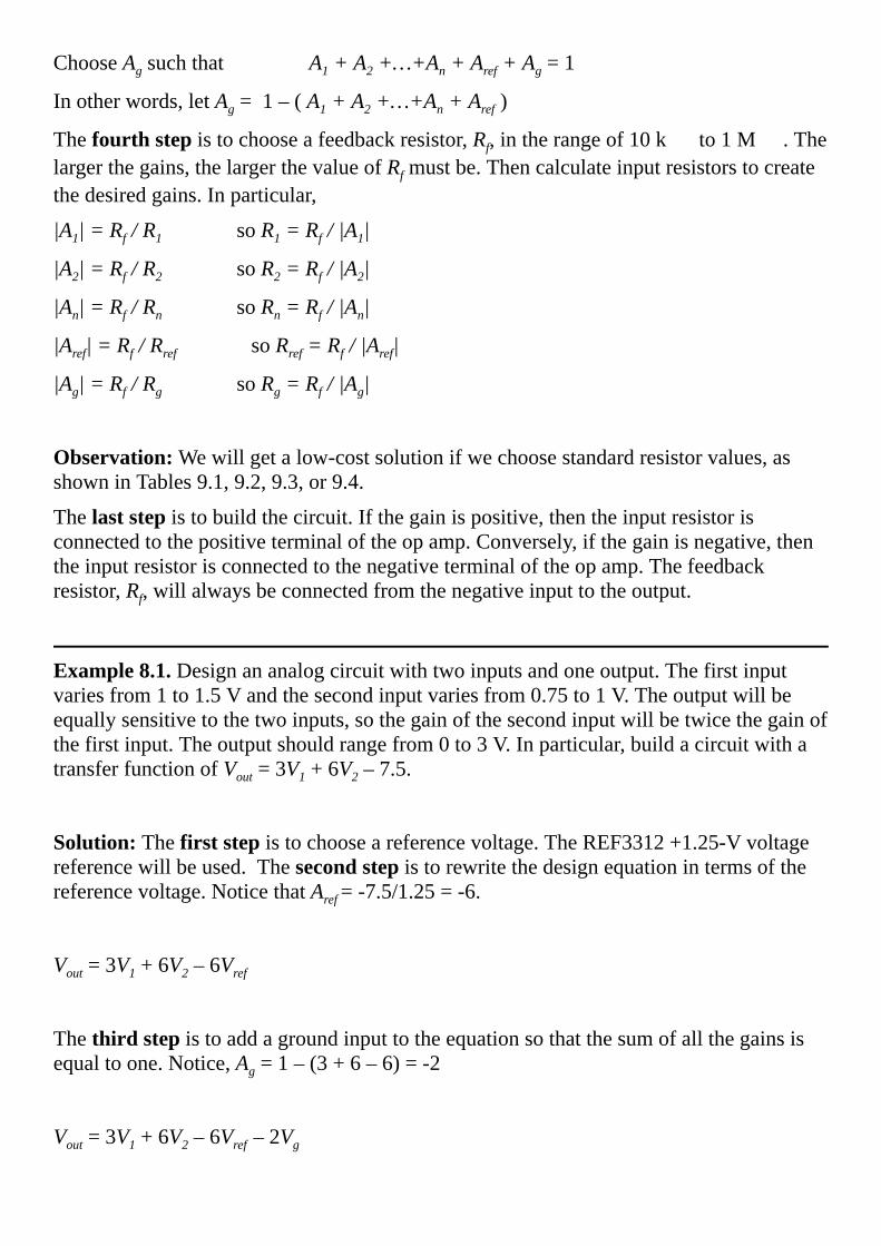
ChooseAgsuchthatA1+A2+…+An+Aref+Ag=1
Inotherwords,letAg=1–(A1+A2+…+An+Aref)
Thefourthstepistochooseafeedbackresistor,Rf,intherangeof10k to1M .Thelargerthegains,thelargerthevalueofRfmustbe.Thencalculateinputresistorstocreatethedesiredgains.Inparticular,
|A1|=Rf/R1soR1=Rf/|A1|
|A2|=Rf/R2soR2=Rf/|A2|
|An|=Rf/RnsoRn=Rf/|An|
|Aref|=Rf/RrefsoRref=Rf/|Aref|
|Ag|=Rf/RgsoRg=Rf/|Ag|
Observation:Wewillgetalow-costsolutionifwechoosestandardresistorvalues,asshowninTables9.1,9.2,9.3,or9.4.
Thelaststepistobuildthecircuit.Ifthegainispositive,thentheinputresistorisconnectedtothepositiveterminaloftheopamp.Conversely,ifthegainisnegative,thentheinputresistorisconnectedtothenegativeterminaloftheopamp.Thefeedbackresistor,Rf,willalwaysbeconnectedfromthenegativeinputtotheoutput.
Example8.1.Designananalogcircuitwithtwoinputsandoneoutput.Thefirstinputvariesfrom1to1.5Vandthesecondinputvariesfrom0.75to1V.Theoutputwillbeequallysensitivetothetwoinputs,sothegainofthesecondinputwillbetwicethegainofthefirstinput.Theoutputshouldrangefrom0to3V.Inparticular,buildacircuitwithatransferfunctionofVout=3V1+6V2–7.5.
Solution:Thefirststepistochooseareferencevoltage.TheREF3312+1.25-Vvoltagereferencewillbeused.Thesecondstepistorewritethedesignequationintermsofthereferencevoltage.NoticethatAref=-7.5/1.25=-6.
Vout=3V1+6V2–6Vref
Thethirdstepistoaddagroundinputtotheequationsothatthesumofallthegainsisequaltoone.Notice,Ag=1–(3+6–6)=-2
Vout=3V1+6V2–6Vref–2Vg

Thefourthstepistochooseafeedbackresistor,Rf=60k .Thisvalueisacommonmultipleofthegains:6,3,2.Thencalculateinputresistorstocreatethedesiredgains.
R1=Rf/2=20k
R2=Rf/6=10k
Rref=Rf/6=10k
Rg=Rf/2=30k
Thelaststepistobuildthecircuit,asshowninFigure8.16.Thepositivegaininputsareconnectedtotheplusinputoftheopampandthenegativegaininputsareconnectedtotheminusinputoftheopampinput.
Figure8.16.Alinearopampcircuit.
Tables9.1,9.2,9.3and9.4liststandardresistancevalues.Wedesigninganalogcircuitsweneedtoselectfromthesespecificvaluestoreducecostandsimplifymanufacturing.
Theinstrumentationampwillamplifyadifferentialvoltage,Vout=G•(V2-V1).Weuseinstrumentationampsinapplicationsthatrequirealargegain(above100),ahighinputimpedance,andagoodcommonmoderejectionratio.AninstrumentationampcanbebuiltusingthreehighqualityopampsasshowninFigure8.17.
Figure8.17.Instrumentationamplifiermadewiththreeopamps.

Observation:Inordertoachievequalityperformancewitha3-op-ampinstrumentationampcircuit,wemustuseprecisionresistorsandqualityopamps.
CommonError:Ifyouuseapotentiometerinplaceofonethegainresistorsintheabovecircuit,thenfluctuationsinthepotentiometerresistancethatcanoccurwithtemperature,vibration,andtimewillhaveastrongeffectontheamplifiergain.
Becauseofthewiderangeofapplicationsthatrequireinstrumentationamplifiers,chipmanufacturershavedevelopedintegratedsolutions.Inmanycaseswecanachievehigherperformanceatreducedcostbyutilizinganintegratedcircuit.Thegainisselectedbyexternaljumpersorexternalresistors.TheMAX4460,AD627,andINA122aresingle-supplyrail-to-railinstrumentationamps.TheAD627andINA122havethesamepinsandthesameformulaforcalculatinggain,asshowninFigure8.18.
Figure8.18.IntegratedinstrumentationamplifiermadewithINA122orAD627.CommonError:IfyouuseapotentiometerastheRGgainresistorsintheabovecircuit,thenfluctuationsinthepotentiometerresistancethatcanoccurwithtemperature,vibration,andtimewillhaveastrongeffectontheamplifiergain.
Wecanuseavoltagecomparatortodetecteventsinananalogwaveform.Theinputvoltagerangeisdeterminedbytheanalogsupplyvoltagesofthecomparator.Theoutputistakesontwovalues,shownanVhandVlinFigure8.19.Acomparatorwithhysteresishastwothresholds,Vt+andVt-.Inboththepositiveandnegativelogiccasesthethreshold(Vt+orVt-)dependsonthepresentvalueoftheoutput.
Figure8.19.Input/outputresponseofvoltageconverterswithhysteresis.Hysteresispreventssmallnoisespikesfromcreatingafalsetrigger.
PerformanceTip:Inordertoeliminatefalsetriggering,weselectahysteresislevel(Vt+–Vt-)greaterthanthenoiselevelinthesignal.

InFigure8.20,arail-to-railopampisusedtodesignavoltagecomparator.Sincetheoutputswingsfrom0to3.3V,itcanbeconnecteddirectlytoaninputpinofthemicrocontroller.Ontheotherhand,since+3.3and0areusedtopowertheopamp,theanaloginputmustremaininthe0to+3.3Vrange.ThehysteresislevelisdeterminedbytheamplitudeoftheoutputandtheR1/(R1+R2)ratio.Iftheoutputisat0V,thevoltageatthe+terminalisVin*R2/(R1+R2).Theoutputswitcheswhenthevoltageatthe+terminalgoesabove1.65.BysolvingforVin*200k/(10k+200k)=1.65,weseeVinmustgoabove+1.73fortheoutputtoswitch.Similarly,iftheoutputisat+3.3V,thevoltageatthe+terminalcanbecalculatedasVin+(3.3-Vin)*R1/(R1+R2).Theoutputswitchesbackwhenthevoltageatthe+terminalgoesbelow1.65.BysolvingforVin+(3.3-Vin)*R1/(R1+R2)=1.65,weseeVingobelow+1.57beforethe+terminaloftheopampfallsbelow1.65V.Inlinearmodecircuitsweshouldnotusethesupplyvoltagetocreatevoltagereferences,butinasaturatedmodecircuit,powersupplyripplewillhavelittleeffectontheresponse.
Figure8.20.Avoltagecomparatorwithhysteresisusingarailtorailopamp.Insomemedicalandindustrialapplicationsweneedtodesignanaloginstrumentationthatisisolatedfromearthground.Inanindustrialsetting,isolationisonewaytoreducenoisepickupfromlargeEMfieldsproducedbyheavymachinery.Inmedicalapplicationsweneedtoprotectthepatientfrompotentiallydangerousmicroshocks,Thus,themedicalinstrumentmustbeisolated.Therearethreeapproachestoisolation,asshowninFigure8.21.Inthefirstapproach,shownatthetopofFigure8.21,ananalogisolationbarrieriscreatedbetweenthepreampandamp.Thiswastheoriginalapproachusedinanaloginstrumentsbeforetheadventofmixedanalog-digitalsystems.Itisexpensive,bulkyandintroducesaverylargetransfererror.Itisnotappropriateforembeddedapplicationsthatuseamicrocontroller.Inthesecondapproach,weusedigitalisolation.The6N139opticalisolatorisaneffectivelow-costmechanismtoimplementdigitalisolation.Thisisthemostcommonapproachusedfornewdesignswhenahardconnectionbetweenthedataacquisitionsystemandbuildingisrequired.Itisfast,small,cheap,andwillnotintroduceerrors.Thethirdapproachrunstheentiresystemwithbatteries.Thisisaveryattractiveapproachduetotheavailabilityofhigh-qualitylow-powerLED/LCDdisplaysandwirelessnetworks,suchasBluetooth,ZigBee,and802.11b.

Figure8.21.Analogisolation,digitalisolation,andbattery-poweredallprovideprotectionfrommicroshocks.
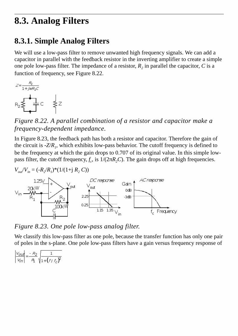
8.3.AnalogFilters
8.3.1.SimpleAnalogFiltersWewillusealow-passfiltertoremoveunwantedhighfrequencysignals.Wecanaddacapacitorinparallelwiththefeedbackresistorintheinvertingamplifiertocreateasimpleonepolelow-passfilter.Theimpedanceofaresistor,R2inparallelthecapacitor,Cisafunctionoffrequency,seeFigure8.22.
Figure8.22.Aparallelcombinationofaresistorandcapacitormakeafrequency-dependentimpedance.InFigure8.23,thefeedbackpathhasbotharesistorandcapacitor.Thereforethegainofthecircuitis-Z/R1,whichexhibitslow-passbehavior.Thecutofffrequencyisdefinedtobethefrequencyatwhichthegaindropsto0.707ofitsoriginalvalue.Inthissimplelow-passfilter,thecutofffrequency,fc,is1/(2πR2C).Thegaindropsoffathighfrequencies.
Vout/Vin=(-R2/R1)*(1/(1+j R2C))
Figure8.23.Onepolelow-passanalogfilter.Weclassifythislow-passfilterasonepole,becausethetransferfunctionhasonlyonepairofpolesinthes-plane.Onepolelow-passfiltershaveagainversusfrequencyresponseof
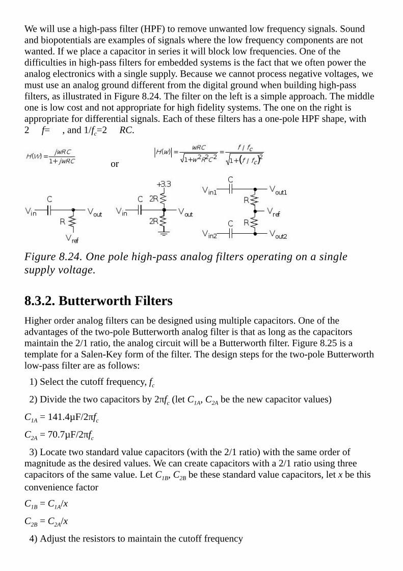
Wewilluseahigh-passfilter(HPF)toremoveunwantedlowfrequencysignals.Soundandbiopotentialsareexamplesofsignalswherethelowfrequencycomponentsarenotwanted.Ifweplaceacapacitorinseriesitwillblocklowfrequencies.Oneofthedifficultiesinhigh-passfiltersforembeddedsystemsisthefactthatweoftenpowertheanalogelectronicswithasinglesupply.Becausewecannotprocessnegativevoltages,wemustuseananaloggrounddifferentfromthedigitalgroundwhenbuildinghigh-passfilters,asillustratedinFigure8.24.Thefilterontheleftisasimpleapproach.Themiddleoneislowcostandnotappropriateforhighfidelitysystems.Theoneontherightisappropriatefordifferentialsignals.Eachofthesefiltershasaone-poleHPFshape,with2 f= ,and1/fc=2 RC.
or
Figure8.24.Onepolehigh-passanalogfiltersoperatingonasinglesupplyvoltage.
8.3.2.ButterworthFiltersHigherorderanalogfilterscanbedesignedusingmultiplecapacitors.Oneoftheadvantagesofthetwo-poleButterworthanalogfilteristhataslongasthecapacitorsmaintainthe2/1ratio,theanalogcircuitwillbeaButterworthfilter.Figure8.25isatemplateforaSalen-Keyformofthefilter.Thedesignstepsforthetwo-poleButterworthlow-passfilterareasfollows:
1)Selectthecutofffrequency,fc2)Dividethetwocapacitorsby2πfc(letC1A,C2Abethenewcapacitorvalues)
C1A=141.4µF/2πfcC2A=70.7µF/2πfc3)Locatetwostandardvaluecapacitors(withthe2/1ratio)withthesameorderofmagnitudeasthedesiredvalues.Wecancreatecapacitorswitha2/1ratiousingthreecapacitorsofthesamevalue.LetC1B,C2Bbethesestandardvaluecapacitors,letxbethisconveniencefactor
C1B=C1A/x
C2B=C2A/x
4)Adjusttheresistorstomaintainthecutofffrequency

R=10kΩ•x
5)Vrefcanbesettoanalogground,e.g.,1.50Vor0V.
Figure8.25.Two-poleButterworthlow-passanalogfilter(seethefileLPF.xls).Theanalogfiltersinthissectionallrequirelowleakage,highaccuracyandlowtemperaturecoefficientcapacitorslikeC0Gceramic.
PerformanceTip:Ifyouchoosestandardvalueresistorsnearthedesiredvalues,youwillsavemoneyandthecircuitwillstillbeaButterworthfilter.Theonlydifferenceisthatthecutofffrequencywillbeslightlyofffromtheoriginalspecification.
Wecanuseasimilarapproachtodesignatwo-poleButterworthhigh-passfilter.Figure8.26isatemplateforaSalen-KeyformoftheHPF.Thedesignstepsforthetwo-poleButterworthhigh-passfilterareasfollows:
1)Selectthecutofffrequency,fc2)Dividethetwocapacitorsby2πfc(letCAbethenewcapacitorvalues)
CA=10µF/2πfc3)Locateastandardvaluecapacitorwiththesameorderofmagnitudeasthedesiredvalue.LetCB,bethisstandardvalue,letxbethisconveniencefactor
CB=CA/x
4)Adjustthetworesistorstomaintainthecutofffrequency
R1=70.7kΩ•xandR2=141.4kΩ•x
5)Vrefshouldbesettoanalogground,e.g.,1.50V.

Figure8.26.Two-poleButterworthhigh-passanalogfilter.ManyanalogICmanufacturersprovidedesigntools.FilterProisafreedesigntoolfromTexasInstrumentsyoucanusetodesignanalogfilters(www.ti.com).Usingthesedesigntoolsyouwillbeabletocreatefiltersmuchbetterthantheonespresentedinthisbook.

8.4.DigitaltoAnalogConvertersAnanalogsignalisonethatiscontinuousinbothamplitudeandtime.Neglectingquantumphysics,mostsignalsintheworldexistascontinuousfunctionsoftimeinananalogfashion(e.g.,voltage,current,position,angle,speed,force,pressure,temperature,andflowetc.)Inotherwords,thesignalhasanamplitudethatcanvaryovertime,butthevaluecannotinstantaneouslychange.Torepresentasignalinthedigitaldomainwemustapproximateitintwoways:amplitudequantizingandtimequantizing.Fromanamplitudeperspective,wewillfirstplacelimitsonthesignalrestrictingittoexistbetweenaminimumandmaximumvalue(e.g.,0to+3V),andsecond,wewilldividethisamplituderangeintoafinitesetofdiscretevalues.Therangeofthesystemisthemaximumminustheminimumvalue.Theprecisionofthesystemdefinesthenumberofvaluesfromwhichtheamplitudeofthedigitalsignalisselected.Precisioncanbegiveninnumberofalternatives,binarybits,ordecimaldigits.Theresolutionisthesmallestchangeinvaluethatissignificant.Figure8.27showsatemperaturewaveform(solidline),withacorrespondingdigitalrepresentationsampledat1Hzandstoredasa5-bitintegernumberwitharangeof0to31oC.Becauseitisdigitizedinbothamplitudeandtime,thedigitalsamples(individualdots)inFigure8.27mustexistatanintersectionofgreylines.Becauseitisatime-varyingsignal(mathematically,thisiscalledafunction),wehaveoneamplitudeforeachtime,butitispossiblefortheretobe0,1,ormoretimesforeachamplitude.
Thesecondapproximationoccursinthetimedomain.Timequantizingiscausedbythefinitesamplinginterval.Forexample,thedataaresampledevery1secondinFigure8.27.Inpracticewewilluseaperiodictimertotriggerananalogtodigitalconverter(ADC)todigitizeinformation,convertingfromtheanalogtothedigitaldomain.Similarly,ifweareconvertingfromthedigitaltotheanalogdomain,weusetheperiodictimertooutputnewdatatoadigitaltoanalogconverter(DAC).TheNyquistTheoremstatesthatifthesignalissampledwithafrequencyoffs,thenthedigitalsamplesonlycontainfrequencycomponentsfrom0to½fs.Conversely,iftheanalogsignaldoescontainfrequencycomponentslargerthan½fs,thentherewillbeanaliasingerrorduringthesamplingprocess.Aliasingiswhenthedigitalsignalappearstohaveadifferentfrequencythantheoriginalanalogsignal.
Figure8.27.Ananalogsignalisrepresentedinthedigitaldomainas5-bit

discretesamples.
8.4.1.DACOperationandPerformanceMeasuresADACconvertsdigitalsignalsintoanalogformasillustratedinFigure8.28.AlthoughonecaninterfaceaDACtoaregularoutputport,mostDACsareinterfacedusinghigh-speedsynchronousprotocols.TheDACoutputcanbecurrentorvoltage.Additionalanalogprocessingmayberequiredtofilter,amplifyormodulatethesignal.WecanalsouseDACstodesignvariablegainorvariableoffsetanalogcircuits.
TheDACprecisionisthenumberofdistinguishableDACoutputs(e.g.,4096alternatives,12bits).TheDACrangeisthemaximumandminimumDACoutput.TheDACresolutionisthesmallestdistinguishablechangeinoutput.Theresolutionisthechangeinoutputthatoccurswhenthedigitalinputchangesby1.Theunitsofrangeandresolutionareinvoltsorampsdependingonwhethertheoutputisvoltageorcurrent.
Range(volts)=Precision(alternatives)•Resolution(volts)
Figure8.28.A12-bitDACprovidesanalogoutput.A12-bitADCprovidesanaloginput.TheDACaccuracyis(Actual-Ideal)/IdealwhereIdealisreferredtotheNationalInstituteofStandardsandTechnology(NIST).OnecanchoosethefullscalerangeoftheDACtosimplifytheuseoffixed-pointmath.Forexample,ifan8-bitDAChadafullscalerangeof0to2.55volts,thentheresolutionwouldbeexactly10mV.ThismeansthatiftheDACdigitalinputwere123(decimal),thentheDACoutputvoltagewouldbe1.23volts.

ADACgainerrorisashiftintheslopeoftheVoutversusdigitalinputstaticresponse.ADACoffseterrorisashiftintheVoutversusdigitalinputstaticresponse.TheDACtransientresponsehasthreecomponents:delayphase,slewingphase,ringingphase.Duringthedelayphase,theinputhaschangedbuttheoutputhasnotyetbeguntochange.Duringtheslewingphase,theoutputchangesrapidly.Duringtheringingphase,theoutputoscillateswhileitstabilizes.Forpurposesoflinearity,letm,nbedigitalinputs,andletf(n)betheanalogoutputoftheDAC,seeFigure8.29.Onequantitativemeasureoflinearityisthecorrelationcoefficientofalinearregressionfitofthef(n)responses.If∆istheDACresolution,itislinearif
f(n+1)-f(n)=f(m+1)-f(m)=∆foralln,m
TheDACismonotonicif
sign(f(n+1)-f(n))=sign(f(m+1)-f(m))foralln,m
Conversely,theDACisnonlinearif
f(n+1)-f(n)≠f(m+1)-f(m)forsomen,m
PracticallyspeakingallDACsarenonlinear,buttheworstnonlinearityisnonmonotonicity.TheDACisnonmonotonicif
sign(f(n+1)-f(n))≠sign(f(m+1)-f(m))forsomen,m
Figure8.29.NonlinearandnonmonotonicDACs.
Example8.2.Designa2-bitbinary-weightedDACwitharangeof0to+3.3Vusingresistors.
Solution:Webeginbyspecifyingthedesiredinput/outputrelationshipofthe2-bitDAC.Therearetwopossiblesolutionsdependinguponwhetherwewantaresolutionof0.825Vor1.1V,asshownasV1andV2inTable8.6.BothsolutionsarepresentedinFigure8.30.
N Q1Q0 V1(V) V2(V)
0 00 0.000 0.0
1 03.3 0.825 1.1

2 3.30 1.650 2.2
3 3.33.3 2.475 3.3
Table8.6.Specificationsofthe2-bitDAC.
Assumetheoutputhighvoltage(VOH)ofthemicrocontrolleris3.3V,anditsoutputlowvoltage(VOL)is0.Withabinary-weightedDAC,wechoosetheresistorratiotobe2/1soQ1bitistwiceassignificantastheQ0bit,asshowninFigure8.30.Consideringthecircuitontheright,ifbothQ1andQ0are0,theoutputV2iszero.IfQ1is0andQ0is+3.3V,theoutputV2isdeterminebytheresistordividernetwork
whichis1.1V.IfQ1is+3.3VandQ0is0,theoutputV2isdeterminebythenetwork
whichis2.2V.IfbothQ1andQ0are+3.3V,theoutputV2is+3.3V.TheoutputimpedanceofthisDACisapproximately20k ,whichmeansitcannotsourceorsinkmuchcurrent.
Figure8.30.Twosolutionsfora2-bitDAC.
Example8.3.Designa6-bitDACwitharangeof0to+3.3VusingE961%standardresistors.
Solution:1%errorisofcourse1partoutof100,while6-bitprecisionwillbeonly1partoutof64.Soweexpectitwillbepossibletobuilda6-bitDACwith1%parts.Webeginthedesignbyspecifyingthedesiredinput/outputrelationshipofthe6-bitDAC.AllzeroswillmaptoVout=0,andalloneswillmaptoVout=3.3V.Theexponentialweightingofthebitscorrespondstothebasiselementsina6-bitnumber.Letb5,b4,b3,b2,b1,b0bethe6-bitDACinput,thedesiredperformanceis
Vout=3.3V*(32*b5+16*b4+8*b3+4*b2+2*b1+b0)/63
OnesetofE96standardresistorswithvaluesapproximatingthedesiredexponentialweightingisshownontheleftofFigure8.31.TheperformanceoftheDACisshownontheleft.ThisDACremainsmonotoniceveniftheresistorsarevariedby±1%.

Figure8.31.A6-bitbinary-weightedDAC.
ItisnotfeasibletoconstructaDACwithmorethan8bitsusingthebinaryweightedtechniqueforthreereasons.First,ifonechoosestheresistorvaluesfromthepractical10kΩto1MΩrange,thenthemaximumprecisionwouldbe1MΩ/10kΩ,whichequals100orabout7bits.Thesecondproblemisthatitwouldbedifficulttoavoidnonmonotonicitybecauseasmallpercentagechangeinthesmallresistor(e.g.,theonecausingthelargestgain)wouldoverwhelmtheeffectsofthelargeresistor(e.g.,theonecausingthesmallestgain.)Forexample,ifyoutriedtoadda7thbittotheDACinFigure8.31usinga523k 1%resistor,theDACcouldbecomenonmonotonic.Third,thesummingDACincludestheerrors,uncertaintyandnoiseinthedigitalpowersupply.Toaddressallthreeoftheselimitations,theR-2Rladderisused.Itispracticaltobuildresistornetworkssuchthatalltheresistancesareequal.Tocreatea2Rcomponent,weusetworesistorsinseries.Resistanceerrorswillchangeallresistorsequally.Thistypeoferroraffectstheslope,Vfs,butnotthelinearityorthemonotonicity.InFigure8.32eachofthethreedigitalinputs(bit2,bit1,bit0)controlsacurrentswitch.Whenthedigitalsignalistrue,thereferencevoltageisappliedtotheladder.Whenthedigitalsignalisfalse,thatpositionontheladderisavirtualground(0V).UsingareferencevoltageinsteadoftheVOHofthemicrocontrollergreatlyreducesthenoiseintheoutput.
Figure8.32.3-bitunsignedR-2RDAC.Toanalyzethiscircuitwewillconsiderthethreebasiselements(1,2,and4).Ifthesethreecasesaredemonstrated,thenthelawofsuperpositionguaranteestheotherfivewillwork.WhenoneofthedigitalinputsistruethenVrefisconnectedtotheR-2Rladder,andwhenthedigitalinputisfalse,thentheconnectionisgrounded.SeeFigure8.33.

Figure8.33.Analysisofthethreebasiselements100,010,001ofthe3-bitunsignedR-2RDAC.Ineachofthethreetestcases,thecurrentacrosstheactiveswitchisI0=Vref/(3R).Thiscurrentisdividedby2ateachbranchpoint.I.e.,I1=I0/2,andI2=I1/2.Currentinjectedfromthelowerbitswillbedividedmoretimes.Sinceeachstagedividesbytwo,theexponentialbehaviorisproduced.AnactualDACisimplementedwithacurrentswitchratherthanavoltageswitch.Nevertheless,thissimplycircuitillustratestheoperationoftheR-2Rladderfunction.Whentheinputis001,Vrefispresentedtotheleft.Theeffectiveimpedancetogroundis3R,sothecurrentinjectedintotheR-2RladderisI0=Vref/(3R).Thecurrentisdividedinhalfthreetimes,andI001=Vref/(24R).
Whentheinputis010,Vrefispresentedinthemiddle.Theeffectiveimpedancetogroundisstill3R,sothecurrentinjectedintotheR-2RladderisI0=Vref/(3R).Thecurrentisdividedinhalftwice,andI010=Vref/(12R).
Whentheinputis100,Vrefispresentedontheright.Theeffectiveimpedancetogroundisonceagain3R,sothecurrentinjectedintotheR-2RladderisI0=Vref/(3R).Thecurrentisdividedinhalfonce,andI100=Vref/(6R).
UsingtheLawofSuperposition,theoutputvoltageisalinearcombinationofthethreedigitalinputs,Iout=(4b2+2b1+b0)Vref/(3R).Acurrenttovoltagecircuitisusedtocreateavoltageoutput.ToincreasetheprecisiononesimplyaddsmorestagestotheR-2Rladder.
Manymanufacturers,likeAnalogDevices,TexasInstruments,SipexandMaximproduceDACs.TheseDACshaveawiderangeofperformanceparametersandcomeinmanyconfigurations.ThefollowingparagraphsdiscussthevariousissuestoconsiderwhenselectingaDAC.AlthoughweassumetheDACisusedtogenerateananalogwaveform,theseconsiderationswillgenerallyapplytomostDACapplications.
Precision/range/resolution.Thesethreeparametersaffectthequalityofthesignalthatcanbegeneratedbythesystem.ThemorebitsintheDACthefinerthecontrolthesystemhasoverthewaveformitcreates.Asimportantasthisparameteris,itisoneofthemoredifficultspecificationstoestablishapriori.Asimpleexperimentalproceduretoaddressthisquestionistodesignaprototypesystemwithaveryhighprecision(e.g.,12,14,16,or20bits.)Thesoftwarecanbemodifiedtouseonlysomeoftheavailableprecision.Forexample,the12-bitMax5353hardwaredevelopedinExample7.2,canbereducedto4,8,or10bitsusingthefollowingfunctions.Thebottombitsaresettozero,insteadofshiftingsotherestofthesystemwilloperatewithoutchange.

voidDAC_Out4(uint16_tcode)
DAC_Out(code&0xFF00);//ignorebottom8bits
voidDAC_Out8(uint16_tcode)
DAC_Out(code&0xFFF0);//ignorebottom4bits
voidDAC_Out10(unsignedintcode)
DAC_Out(code&0xFFFC);//ignorebottom2bits
Program8.1.Softwareusedtotesthowmanybitsarereallyneeded.Multipleversionsofthesoftware(e.g.,4-bit,8-bit,10-bit,and12-bitDAC)areusedtoseeexperimentallytheeffectofDACprecisionontheoverallsystemperformance.Figure8.34illustrateshowDACprecisionaffectsthequalityofthegeneratedwaveform.
Figure8.34.Thewaveformontheleftusesa4-bitDAC,whileononeontherightusesa12-bitDAC.Channels.EventhoughmultiplechannelscouldbeimplementedusingmultipleDACchips,itisusuallymoreefficienttodesignamultiplechannelsystemusingamultiplechannelDAC.SomeadvantagesofusingaDACwithmorechannelsthanoriginallyconceivedarefutureexpansion,automatedcalibration,andautomatedtesting.AmultiplechannelDACallowsyoutoupdateallchannelsatthesametime.
Configuration.DACscanhavevoltageorcurrentoutputs.CurrentoutputDACscanbeusedinawidespectrumofapplications(e.g.,addinggainandfiltering),butdorequireexternalcomponents.DACscanhaveinternalorexternalreferences.AninternalreferenceDACiseasiertouseforstandarddigitalinput/analogoutputapplications,buttheexternalreferenceDACcanoftenbeusedinvariablegainapplications(multiplyingDAC).SometimestheDACgeneratesaunipolaroutput,whileothertimestheDACproducesbipolaroutputs.

Speed.ThereareacoupleofparametersmanufacturersusetospecifythedynamicbehavioroftheDAC.Themostcommonissettlingtime,anotherismaximumoutputrate.WhenoperatingtheDACinvariablegainmode,wearealsointerestedinthegain/bandwidthproductoftheanalogamplifier.Whencomparingspecificationsreportedbydifferentmanufacturersitisimportanttoconsidertheexactsituationusedtocollecttheparameter.Inotherwords,onemanufacturermaydefinesettlingtimeasthetimetoreach0.1%ofthefinaloutputafterafullscalechangeininputgivenacertainloadontheoutput,whileanothermanufacturermaydefinesettlingtimeasthetimetoreach1%ofthefinaloutputaftera1voltchangeininputunderadifferentload.ThespeedoftheDACtogetherwiththespeedofthecomputer/softwarewilldeterminetheeffectivefrequencycomponentsinthegeneratedwaveforms.Boththesoftware(rateatwhichthesoftwareoutputsnewvaluestotheDAC)andtheDACspeedmustbefastenoughforthegivenapplication.Inotherwords,ifthesoftwareoutputsnewvaluestotheDACataratefasterthantheDACcanrespond,thenerrorswilloccur.Figure8.35illustratestheeffectofDACoutputrateonthequalityofthegeneratedwaveform.AccordingtotheNyquistTheoremstatesthedigitaldataratemustbegreaterthantwicethemaximumfrequencycomponentofthedesiredanalogwaveform.However,bothwaveformsinFigure8.35satisfytheNyquistTheorem,butincreasingtheoutputratebyeightimprovesthesignaltonoiseratiobyeight.31dBisaratioofabout35to1,and49dBisaratioofabout281to1.Ifthegoalistocreateasinewaveatafixedfrequency,wecouldimprovetheSNRgreatlybyusingananaloglowpassfilter.
Experimentaldataofa32-output523Hzsine-waveExperimentaldataofa256-output523Hzsine-wave
Signal/noiseratiois31dB(3dB–-28dB)Signal/noiseratiois49dB(3dB–-46dB)
Figure8.35.Thewaveformontherightwascreatedbya12-bitDACwitheighttimestheoutputratethantheleft.VoltageversustimedataontopandtheFourierTransform(frequencyspectrumdBversuskHz)ofthedataonthebottom.Thereisapointinthespectrumat0,whichistheDC

component.However,thesignalisthe523Hzbumpwithamagnitudeof3dB,representingthesinewave.Thenoisesarealltheotherpointsnotat0or523Hz.Thelargestnoiseontheleftis-28dB.Thelargestnoiseontherightis-46dB.Power.Therearethreepowerissuestoconsider.Thefirstconsiderationisthetypeofpowerrequired.Olderdevicesrequirethreepowervoltages(e.g.,+5and-5V),whilemostdeviceswilloperateonasinglevoltagesupply(e.g.,+2.7,+3.3,or+5V.)Ifasinglesupplycanbeusedtopowerallthedigitalandanalogcomponentsthentheoverallsystemcostswillbereduced.Thesecondconsiderationistheamountofpowerrequired.Somedevicescanoperateonlessthan0.1mWandareappropriateforbattery-operatedsystemsorforsystemswhereexcessheatisaproblem.Thelastconsiderationistheneedforalow-powersleepmode.SomebatteryoperatedsystemsneedtheDAConlyintermittently.Intheseapplications,wewishtogiveashutdowncommandtotheDAC,sothatitdrawslesscurrentwhennotneeded.
Interface.ThreeapproachesexistforinterfacingtheDACtothecomputer.Inadigitallogicorparallelinterface,theindividualdatabitsareconnectedtoadedicatedcomputeroutputport.Forexample,a12-bitDACrequiresa12-bitoutputportbitstointerface.Thesoftwaresimplywritestotheparallelport(s)tochangetheDACoutput.ThesecondapproachiscalledµP-busormicroprocessor-compatible.Thesedevicesareintendedtobeinterfacedontotheaddress/databusofanexpandedmodemicrocontroller.Thethirdapproachisahigh-speedserialinterfacelikeI2CorSPI.TheSSI/MAX5353interfaceisanexampleofahigh-speedserialinterface.ThisapproachrequiresthefewestnumberofI/Opins.EvenifthemicrocontrollerdoesnotsupporttheSPIinterfacedirectly,thesedevicescanbeinterfacedtoregularI/Opinsviathebit-bangingsoftwareapproach.
Package.DIPpackagesareconvenientforcreatingandtestinganoriginalprototype.Ontheotherhandsurfacemountpackagesrequirelessboardspace.BecausesurfacemountpackagesdonotrequireholesinthePCboard,circuitswiththesedevicesareeasier/cheapertoproduce.
Cost.Costisalwaysafactorinengineeringdesign.BesidethedirectcostsoftheindividualcomponentsintheDACinterface,otherconsiderationsthataffectcostinclude:1)powersupplyrequirements;2)manufacturingcosts;3)thelaborinvolvedinindividualcalibrationifrequired;and4)softwaredevelopmentcosts.
8.4.2.DACWaveformGeneration

OneapplicationthatrequiresaDACiswaveformgeneration.Inthissection,wewilldiscussvarioussoftwaremethodsforcreatinganalogwaveformswithaDAC.Ineachcase,wewillbeusingtheMAX5353hardware/softwareinterfaceintroducedinExample7.2.Inaddition,wewilluseanoutputcaptureinterruptforthetiming,sothatthewaveformgenerationoccursinthebackground.TheritualsforinitializingtheperiodicinterruptareshowninChapter6.Inordertogetafaircomparisonbetweenthevariousmethods,eachimplementationwillgenerate32interruptsperwaveform.Inthefirstapproach,weassumethereexistsatimetovoltagefunction,called Wave() ,whichwecancalltodeterminethenextDACvaluetooutput.ThewaveformontheleftofFigure8.36couldbegeneratedbyPrograms8.2and8.3.
constfloatA=2048.0,B=1000.0,C=2*pi*31.25,D=-500.0,E=2*pi*125.0;
uint16_tWave(floattime)floatresult;
result=A+B*cos(C*time)+D*sin(E*time);
return(uint16_t)result;
Program8.2.Waveformisdefinedbyamathematicalfunction.Thesimplestsolutiongeneratesanoutputcompareinterruptataregularrate.Theadvantageofthisapproachisthatcomplexwaveformscanbeencodedwithasmallamountofdata.Inthisparticularexample,theentirewaveformcanbestoredas5datapoints( 2048.01000.031.25-500.0125.0 ).Thedisadvantageofthistechniqueisthatnotallwaveformshaveasimplefunction,andthissoftwarewillrunslowerascomparedtotheothertechniques.Ifyouweretoimplementthisapproach,performancewouldbeimprovedbyreplacingthefloating-pointmathwithfixed-point.
floatTime;//incrementedevery1ms
voidTimer0A_Handler(void)
TIMER0_ICR_R=TIMER_ICR_CAECINT;//acknowledge
Time=Time+0.001;
DACout(Wave(Time));
Program8.3.Periodicinterruptusedtocreatetheanalogoutputwaveform.Inthesecondapproach,weputthewaveforminformationinalargestaticallyallocatedglobalarray,seeProgram8.4.EveryinterruptwefetchanewvalueoutofthedatastructureandoutputittotheDAC.Inthiscasetheoutputcompareinterruptalsooccursataregularrate.Assumetheritualinitializes Time=0 .Runningat50MHzbusclock,theISRinProgram8.4executesinlessthan1 s.
uint16_tTime;//incrementedevery1ms,0-31
constuint16_tWave[32]=3048,2675,2472,2526,2755,2957,

2931,2597,2048,1499,1165,1139,1341,1570,1624,1421,1048,714,624,863,
1341,1846,2165,2206,2048,1890,1931,2250,2755,3233,3472,3382;
uint16_tTime;//every1ms
voidTimer0A_Handler(void)
TIMER0_ICR_R=TIMER_ICR_CAECINT;//acknowledge
Time=(Time+1)&0x1F;
DACout(Wave[Time]));
Program8.4.Periodicinterruptusedtocreatetheanalogoutputwaveform.SincetheoutputrateisequalandfixedthesefirsttwomethodshavethesameperformanceasillustratedintheleftofFigure8.36.Thesolidlineisthedesiredwaveformandthedottedlineistheactualgeneratedcurve.
Figure8.36.Generatedwaveforms.Leftuseseitherthefunctionorthetablelookuptechnique.Centerusesasmalltableandinterpolation.Rightusesavariableoutputrate.Ifthesizeofthetablegetslargeitispossibletostoreasmallertableinmemoryanduselinearinterpolationtorecoverthedatapointsinbetweenthestoredsamples.ThecenterofFigure8.36showsthegeneratedwaveformderivedfromonly9oftheoriginal32datapoints.Tosimplifythesoftware,thefirstdatapointisrepeatedasthelastdatapoint.ForeachpointwewillneedtosaveboththeDACvalueandtimelengthofthecurrentlinesegment.Forthe9saveddatapointswesimplyoutputthedata,butfortheotherpoints,wemustperformalinearinterpolationtogetthevaluetooutputtotheDAC,seeProgram8.5.Assumetheritualinitializes I=J=0 .Signed16-bitnumbersareusedsothesubtractionsoperateproperly.Inotherwords,someoftheintermediatecalculationscanbenegative.
int16_tI;//incrementedevery1ms
int16_tJ;//indexintothesetwotables
constint16_tTime[10]=0,2,6,10,14,18,22,25,30,32;//timeinmsec
constint16_tWave[10]=3048,2472,2931,1165,1624,624,2165,1890,3472,3048;//last=first

uint16_tTime;//every1ms
voidTimer0A_Handler(void)
TIMER0_ICR_R=TIMER_ICR_CAECINT;//acknowledge
if((++I)==32)I=0;J=0;
if(I==Time[J])
DACout(Wave[J]);
elseif(I==Time[J+1])
J++;
DACout(Wave[J]);
else
DACout(Wave[J]+((Wave[J+1]-Wave[J])*(I-t[J]))/(Time[J+1]-Time[J]));
Program8.5.Periodicinterruptusedtocreatetheanalogoutputwaveform.ThesoftwareintheprevioustechniqueschangestheDACatafixedrate.Whilemostofthetimethisisadequate,therearesomewaveformsforwhichuneventimesbetweenoutputsseemappropriate.Inourtestsignal,thereareplacesinthewavewherethesignalvariesslowlyinadditiontoplacesinthewavewithrapidlychangingvalues.Noticethedatapointsinthisfigureareplacedatuneventimeintervalstomatchthevariousphasesofthissignal.Thisgeneratedwaveformisstillcreatedwith32points,butplacingthepointsclosertogetherduringphaseswithlargeslopesimprovestheoverallaccuracy,seeProgram8.6.Thetabledatastructurewillencodeboththevoltage(asaDACvalue)andthetime.Thetimeparameterisstoredasa∆tinTimer0cyclestosimplifyservicingtheoutputcompareinterrupt.
uint16_tTime;//incrementedeverysample,0to31
constuint16_tWave[32]=
3048,2675,2472,2526,2817,2981,2800,2337,1901,1499,1165,1341,1570,1597,
1337,952,662,654,863,1210,1605,1950,2202,2141,1955,1876,2057,
2366,2755,3129,3442,3382;
constuint16_tdt[32]=//timeincrementinTimer0cycles
2000,2000,2000,2500,2500,2000,2000,1500,1500,2000,4000,2000,2500,
2000,2000,2000,2000,1500,1500,1500,1500,2000,2500,2000,2000,2000,
1500,1500,1500,2000,2500,2000;
voidTimer0A_Handler(void)

Time=(Time+1)&0x1F;
DACout(Wave[Time]);//thisoutputamplitude
TIMER0_TAILR_R=dt[Time];//thistimeduration
TIMER0_ICR_R=TIMER_ICR_CAECINT;//acknowledge
Program8.6.Periodicinterruptatunequalratesusedtocreatetheanalogoutputwaveform.
8.4.3.PWMDACWecanusethePWMmoduletocreateaDAC.ThePWMdigitalsignalisfeedthroughananaloglow-passfiltertocreateaDCvoltagelinearlyrelatedtothedutycycleofthePWMwave.TheprecisionoftheDACwillbetheprecisionofthecounterusedtocreatethePWM.Inparticular,theprecisionwillbethenumberweputintothe PWM_0_LOAD_RregisteroftheLM3S/TM4C.Forexample,ifwecallProgram6.8with PWM0_Init(1024,512) ,thentheDACprecisionwillbe1024alternativesor10bits.ThefrequencyoftheDACistherateatwhichtheDACoutputcanbechangedanddependsonthefrequencyofthePWMoutput.Inparticular,wecanchangethePWMdutycycleonlyoncepercycle.Ifthebusclockis8MHz,andweinitializewith PWM0_Init(4000,2000) ,thePWMperiodwillbe1ms.Thismeanswecanupdatethe12-bitDAC1000timesasecond.However,ifthebusclockis50MHz,andweinitializewith PWM0_Init(250,125) ,thePWMperiodwillbe10 s.Thismeanswecanupdatethe8-bitDAC100,000timesasecond.ItisusuallybestforthePWMsignalfrequencytobe10to100timeshigherthanthedesiredbandwidthofanalogsignalstobeproduced.Generally,thehigherthePWMfrequency,thelowertheorderoffilterrequired,andtheeasieritistobuildasuitablefilter.Letfmaxbethehighestfrequencycomponentwewishtocreateintheanalogoutput,andletfPWMbethePWMfrequency.WewanttheanalogLPFtorejectfPWMandpassfmax.
Example8.4.Designasystemthatoutputsa1-kHzsinewaveusingaPWMDAC.

Solution:ThissolutionwillusetheperiodictimershowninProgram6.6andthePWMdrivershowninProgram6.8.WewillrunthePWMoutputwaveat100kHz,whichismuchfasterthanthedesiredsinewave.Wecancreatean8-bitPWMDACusingabusclockof50MHzandinitializingwith PWM0_Init(250,125) .50MHz/100kHzis250alternatives,whichabout8bits.TochangetheamplitudeoftheDACweadjustthedutycycleofthePWMbycalling PWM0_SetDuty() .Wewilloutput32pointstothe8-bitPWMDACforeachcycleinthesinewave,seeProgram8.7.TheLPFmustpass1kHzandreject100kHz.WechoosetheLPFcutoffat3kHz,whichisbetweenfPWMandfmax.ApassiveLPFcanbemadewitharesistorandcapacitor,fc=1/(2 RC).AnRequalto22k andCequalto2.2nFwillcreateaLPFat3.3kHz,asshowninFigure8.37.Ifweneedlowoutputimpedance,wecouldreplacethepassivefilterwithanactivefilterlikeFigure8.25.
Figure8.37.PWMDACusedtocreatea1kHzsinewave.constuint16_tWave[32]=
125,143,159,175,189,200,208,213,215,213,208,
200,189,175,159,143,125,107,91,75,61,50,
42,37,35,37,42,50,61,75,91,107
;
voidOutputSineWave(void)
staticuint8_tindex=0;//countingindexofoutputsequence
PWM0_Duty(Wave[index]);//outputnextvalueinsequence
index=(index+1)&0x1F;//incrementcounter
intmain(void)//PWMcodeinProgram6.8
SysCtlClockSet(SYSCTL_SYSDIV_4|SYSCTL_USE_PLL|SYSCTL_OSC_MAIN|
SYSCTL_XTAL_8MHZ);
PWM0_Init(250,125);//initializePWM0,100kHz
Timer0A_Init(&OutputSineWave,31);//Program6.6,31us,32kHz
while(1)
WaitForInterrupt();

Program8.7.SoftwareforPWMDACcreatinga1kHzsinewave(PWMSine_xxx.zip).

8.5.AnalogtoDigitalConverters
8.5.1.ADCParametersAnADCconvertsananalogsignalintodigitalform.Theinputsignalisusuallyananalogvoltage(Vin),andtheoutputisabinarynumber.TheADCprecisionisthenumberofdistinguishableADCinputs(e.g.,4096alternatives,12bits).TheADCrangeisthemaximumandminimumADCinput(volts,amps).TheADCresolutionisthesmallestdistinguishablechangeininput(volts,amps).Theresolutionisthechangeininputthatcausesthedigitaloutputtochangeby1.
Range(volts)=Precision(alternatives)•Resolution(volts)
Normallywedon’tspecifyaccuracyforjusttheADC,butratherwegivetheaccuracyoftheentiresystem(includingtransducer,analogcircuit,ADCandsoftware).Therefore,accuracywillbedescribedlaterinChapter10aspartofthesystemsapproachtodataacquisitionsystems.AnADCismonotonicifithasnomissingcodes.Thismeansiftheanalogsignalisaslowrisingvoltage,thenthedigitaloutputwillhitallvaluessequentially.TheADCislineariftheresolutionisconstantthroughtherange.Letf(x)betheinput/outputADCtransferfunction.Onequantitativemeasureoflinearityisthecorrelationcoefficientofalinearregressionfitofthef(x)responses.TheADCspeedisthetimetoconvert,calledtc.TheADCcostisafunctionofthenumberandpriceofinternalcomponents.TherearefourcommonencodingschemesforanADC.Table8.7showstwoencodingschemesfora12-bitunipolarADC,andTable8.8showstwoencodingschemesfora12-bitbipolarADC.
UnipolarCodes
StraightBinary ComplementaryBinary
+Vmax 1111,1111,1111 0000,0000,0000
+Vmax/2 1000,0000,0000 0001,1111,1111
+Vmax/1024 0000,0000,0001 1111,1111,1110
+0.00 0000,0000,0000 1111,1111,1111
Table8.7.Unipolarcodesfora12-bitADCwitharangeof0to+Vmax.
BipolarCodes
OffsetBinary Two’sComplementBinary
+Vmax 1111,1111,1111 0111,1111,1111

+Vmax/2 1000,0000,0000 0100,0000,0000
+Vmax/512 1000,0000,0001 0000,0000,0001
+0.00 1000,0000,0000 0000,0000,0000
-Vmax/512 0111,1111,1111 1111,1111,1111
-Vmax/2 0100,0000,0000 1100,0000,0000
-Vmax 0000,0000,0000 1000,0000,0000
Table8.8.Bipolarcodesfora12-bitADCwitharangeof-Vmaxto+Vmax.
TheTM4Cusesstraightbinary,hasaprecisionof12bits,andhasarangeof0to3.3V.TheLM3Shasa10-bitADCwitharangeof0to3V.Toconvertbetweenstraightbinaryandcomplementarybinarywesimplycomplement(change0to1,change1to0)allthebits.Toconvertbetweenoffsetbinaryand2’scomplement,wecomplementjustthemostsignificantbit.Theexclusive-oroperationcanbeusedtocomplementbits.
JustliketheDAC,onecanchoosethefullscalerangetosimplifytheuseoffixed-pointmath.Forexample,ifa12-bitADChadafullscalerangeof0to4.095volts,thentheresolutionwouldbeexactly1mV.ThismeansthatiftheADCinputvoltagewere1.234volts,thentheresultwouldbe1234(decimal).
Thetotalharmonicdistortion(THD)ofasignalisameasureoftheharmonicdistortionpresentandisdefinedastheratioofthesumofthepowersofallharmoniccomponentstothepowerofthefundamentalfrequency.Basically,itisameasureofallthenoiseprocessesinanADCandusuallyisgivenindBfullscale.Asimilarparameterissignal-to-noiseanddistortionratio(SINAD),whichismeasuredbyplacingapuresinewaveattheinputoftheADC(signal)andmeasuringtheADCoutput(signalplusnoise).Wecancompareprecisioninbitstosignal-to-noiseratioindBusingtherelationdB=20log10(2n).Forexample,the12-bitMAX1247ADChasaSINADof73dB.Noticethat20log10(212)is72dB.
Dynamicrange,expressedindB,isdefinedastherangebetweenthenoisefloorofadeviceanditsspecifiedmaximumoutputlevel.ThedynamicrangeistherangeofsignalamplitudeswhichtheADCcanresolve.IfanADCcanresolvesignalsfrom1mVto1V,ithasadynamicrangeof20*log(1V/1mV)=60dB.Dynamicrangeisimportantincommunicationapplications,wheresignalstrengthsvarydramatically.Ifthesignalistoolarge,itsaturatestheADCinput.Ifthesignalistoosmall,itgetslostinthequantizationnoise.
Theeffectivenumberofbits(ENOB)specifiesthedynamicperformanceofanADCataspecificinputfrequencyandsamplingrate.Inanidealsituation,ADCerrorconsistsonlyofquantizationnoise(resolution=range/precision).Astheinputfrequencyincreases,the

overallnoise(particularlyinthedistortioncomponents)alsoincreases,therebyreducingtheENOBandSINAD.
8.5.2.ADCConversionTechniquesThemostpervasivemethodforADCconversionisthesuccessiveapproximationtechnique,asillustratedinFigure8.38.A12-bitsuccessiveapproximationADCisclocked12times.Ateachclockanotherbitisdetermined,startingwiththemostsignificantbit.Foreachclock,thesuccessiveapproximationhardwareissuesanew“guess”onVdacbysettingthebitundertesttoa“1”.IfVdacisnowhigherthantheunknowninput,Vin,thenthebitundertestiscleared.IfVdacislessthanVin,thenthebitundertestisremains1.Inthisdescription,bitisanunsignedintegerthatspecifiesthebitundertest.Fora12-bitADC,bitgoes2048,1024,512,256,128,64,…,1.DoutistheADCdigitaloutput,andZisthebinaryinputthatistrueifVdacisgreaterthanVin.
Figure8.38.A12-bitsuccessiveapproximationADC.Observation:ThespeedofasuccessiveapproximationADCrelateslinearlywithitsprecisioninbits.
Thesigmadeltaanalogtodigitalconverterisusedinmanyaudioapplications.Itisacosteffectiveapproachto16-bit44kHzsampling(CDqualityaudio).SigmadeltaconvertershaveaDAC,acomparatoranddigitalprocessingsimilartothesuccessiveapproximationtechnique.WhilesuccessiveapproximationconvertershaveDACswiththesameprecisionastheADC,sigmadeltaconvertersuseDACswithamuchsmallerprecisionthantheADC.A1-bitDACissimplyadigitalsignalitself.ThedigitalsignalprocessingwillrunataclockfrequencyfasterthantheoverallADCsystem,calledoversampling.ItusescomplexsignalprocessingtodrivetheoutputvoltageV0toequaltheunknowninputVininatime-averagedsense.The“delta”partofthesigmadeltaconverteristhesubtractor,whereV1=V0–Vin.Nextcomesthe“sigma”partthatimplementsananalogintegration.IfV0toequaltheunknowninputVininatime-averagedsense,thenV2willbezero.ThecomparatorteststheV2signal.IfV2ispositivethenV0ismadesmaller.IfV2isnegativethenV0ismadelarger.ThisDAC-subtractor-integrator-comparator-digitalloopisexecutedataratemuchfasterthantheeventualdigitaloutputrate.
Averysimplealgorithm,showninFigure8.39isruncontinuously.ForeverytimethroughtheouterwhileloopthereisoneADCoutput.Thisalgorithmismuchtoosimpletobeappropriateinanactualconverter,butitdoesillustratethesigmadeltaapproach.Fora10-bitconversion,theDACoutputrateis1024timestheADCconversionrate.Weassumetheinputvoltage,Vin,isbetween0and+3V.DACisanoutputofthesigma-delta

processingthatsetsthe1-bitDAC.Zisthecomparatoroutput,whichisaninputtothesignalprocessing.
Figure8.39.Blockdiagramofthesigma-deltaADCconversiontechnique.Inthisverysimplesolution,theDACissetto1(V0=+3)ifZis0(V2<0).Conversely,theDACissetto0(V0=0)ifZis1(V2>0).EachtimetheDACissetto1,sumisincremented.Attheendof1024passes,thevaluesumisrecordedastheADCsample.Sincethereare1024passesthroughtheloop,sumwillvaryfrom0to1023.Forexample,iftheVinis1.5V,thenhalfoftheDACoutputswillbe1andtheotherhalf0.ThiswillmakeV0oscillatebetween0and3V,witha50%dutycycle,V1willoscillatebetween-1.5and+1.5witha50%dutycycle,andthetime-averagedV2willbezero.
AsecondexampleisillustratedinFigure8.40.TheinputVinis2.25V,sotheoutputshouldbe2.25/3*1024or768.ThesigmadeltawilladjusttheDACoutputsothatV1=V0–Vin.isequalto0inatime-averagedsense.V1is2.25Vfor25%ofthetimeand‑0.75Vfor75%ofthetime.ThreeoutofeveryfourDACoutputsarehigh,sothreeoutofeveryfourtime,V2willbeabove0.Thereforeafter1024timesthroughtheloop,768ofthemwillincrementsum,yieldingthecorrectADCresult.IftheVininputrises,ahigherpercentageofDACoutputswillbehigh,increasingsum.IftheVininputfalls,alowerpercentageofDACoutputswillbehigh,decreasingsum.
Figure8.40.Exampleoperationofasigma-deltaconversion.Inarealsigmadeltatheoverclockrateistypically8to1or16to1.Multiplebitsareobtainedeachtimethroughtheoutput-inputcycleusingDSPalgorithms.
AnotherADCtechniqueiscalledflash.Flashconvertersareveryexpensiveandveryfast.Figure8.41showsa3-bitflash.TheMAX104isa±5V,1Gsps,8-BitADCwithon-chip2.2GHzsample/hold.

Figure8.41.Blockdiagramofa3-bitflashADC.
8.5.3.Sample/HoldAsampleandhold(S/H)isananaloglatch,illustratedinFigure8.42.Analternativenameforthisanalogcomponentistrackandhold.ThepurposeoftheS/HistoholdtheADCanaloginputconstantduringtheconversion.ThereisS/HattheinputofmostADC,includingtheonesontheStellaridandTivamicrocontrollers.Thefirstphaseofmostanalogtodigitalconversionsisthesamplingphase,wheretheinputvoltageVin,isrecordedasachargeonthecapacitorC.
Figure8.42.Thesampleandholdhasadigitalinput,ananaloginputandananalogoutput.Thedigitalinput,Control,determinestheS/Hmode.TheS/Hisinsamplemode,whereVoutequalsVin,withtheswitchisclosed.TheS/Hisinholdmode,Voutisfixedbecausetheswitchisopen.Theacquisitiontimeisthetimefortheoutputtoequaltheinputafterthecontrolisswitchedfromholdtosample.ThisisthetimetochargethecapacitorC.Theaperturetimeisthetimefortheoutputtostabilizeafterthecontrolisswitchedfromsampletohold.Thisisthetimetoopentheswitch,whichisusuallyquitefast.Thedrooprateistheoutputvoltageslope(dVout/dt)whenControlequalshold.Normallythegain,K,shouldbeoneandtheoffset,Voff,shouldbezero.ThegainandoffseterrorspecifyhowcloseistheVouttothedesiredVinwhenControlequalssample,
Vout=KVin+VoffTochoosethecapacitor,C:

1)Oneshoulduseahighqualitycapacitorwithhigh
insulationresistanceandlowdielectricabsorption.
2)AlargervalueofCwilldecrease(improve)thedrooprate.
IfthedroopcurrentisIDR,thenthedroopratewillbedVout/dt=IDR/C
3)AsmallerCwilldecrease(improve)theacquisitiontime.
ThesystemwillrequireasampleandholdiftheinputsignalcouldchangeduringanADCconversion.TherewillbeatimeduringwhichtheADCsamplestheinputvoltage,tsamp.LetthemaximumslewrateoftheinputsignalbedVin/dt.IftheslewratetimesthesamplingtimeislargerthantheADCresolution,weshouldaddasampleandholdmoduletokeeptheanaloginputstableduringconversion.TheLM3S/LM4F/TM4CADCmoduleshaveabuilt-inS/H.
8.5.4.InternalADCTable8.9showstheADCregisterbitsrequiredtoperformperiodicsampling.Wewillshowtimertriggeringononeandontwochannels.Formorecomplexconfigurationsrefertothespecificdatasheet.ThevalueinADC0_PC_Rspecifiesthemaximumsamplingrate,seeTable8.10.TheLM3S1968,TM4C123,andTM4C1294cansampleupto1millionsamplespersecond,butthemaximumsamplingrateonmanyLM3Smicrocontrollersisonly500K.Refertothedatasheetofyourspecificmicrocontrollerformaximumpossiblesamplingrate,thenumberofchannels,andthenumberofbits.TheADChasfoursequencers,butwewillpresentcodeusingsequencers2and3.WesettheADC0_SSPRI_Rregisterto0x3210tomakesequencer0thehighestandsequencer3thelowestpriority.Weneedtomakesureeachsequencerhasauniquepriority.Wesetbits15–12(EM3)intheADC0_EMUX_Rregistertospecifyhowsequencer3willbetriggered.Similarly,wesetbits11–8(EM2)tospecifyhowsequencer2willbetriggered.Table8.11showsthevariouswaystotriggeranADCconversion.Inthissection,wewillusetimertriggering(EM3=0x5).
Address 31-2 1 0 Name
$400F.E638 ADC1 ADC0 SYSCTL_RCGCADC_R
31-14 13-12 11-10 9-8 7-6 5-4 3-2 1-0
$4003.8020 SS3 SS2 SS1 SS0 ADC0_SSPRI_R
31-16 15-12 11-8 7-4 3-0
$4003.8014 EM3 EM2 EM1 EM0 ADC0_EMUX_R

31-4 3 2 1 0
$4003.8000 ASEN3 ASEN2 ASEN1 ASEN0 ADC0_ACTSS_R
$4003.8028 SS3 SS2 SS1 SS0 ADC0_PSSI_R
$4003.8004 INR3 INR2 INR1 INR0 ADC0_RIS_R
$4003.8008 MASK3MASK2 MASK1MASK0 ADC0_IM_R
$4003.8FC4 Speed ADC0_PC_R
$4003.800C IN3 IN2 IN1 IN0 ADC0_ISC_R
31-28 27-24 23-20 19-16 15-12 11-8 7-4 3-0
$4003.8040 MUX7 MUX6 MUX5 MUX4 MUX3 MUX2 MUX1 MUX0 ADC0_SSMUX0_R
31-16 15-12 11-8 7-4 3-0
$4003.8060 MUX3 MUX2 MUX1 MUX0 ADC0_SSMUX1_R
$4003.8080 MUX3 MUX2 MUX1 MUX0 ADC0_SSMUX2_R
$4003.80A0 MUX0 ADC0_SSMUX3_R
31 30 29 28 27 26 … 8 7 6 5 4 3 2 1 0
$4003.8044 TS7IE7END7D7TS6IE6… D2TS1IE1 END1D1TS0IE0 END0D0ADC0_SSCTL0_R
15 14 13 12 11 10 9 8 7 6 5 4 3 2 1 0
$4003.8064 TS3IE3END3D3TS2IE2END2D2TS1IE1 END1D1TS0IE0 END0D0ADC0_SSCTL1_R
$4003.8084 TS3IE3END3D3TS2IE2END2D2TS1IE1 END1D1TS0IE0 END0D0ADC0_SSCTL2_R
$4003.80A4 TS0IE0 END0D0ADC0_SSCTL3_R
31-10 11-0
$4003.8048 DATA ADC0_SSFIFO0_R
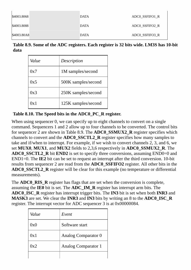
$4003.8068 DATA ADC0_SSFIFO1_R
$4003.8088 DATA ADC0_SSFIFO2_R
$4003.80A8 DATA ADC0_SSFIFO3_R
Table8.9.SomeoftheADCregisters.Eachregisteris32bitswide.LM3Shas10-bitdata
Value Description
0x7 1Msamples/second
0x5 500Ksamples/second
0x3 250Ksamples/second
0x1 125Ksamples/second
Table8.10.TheSpeedbitsintheADC0_PC_Rregister.
Whenusingsequencer0,wecanspecifyuptoeightchannelstoconvertonasinglecommand.Sequencers1and2allowuptofourchannelstobeconverted.Thecontrolbitsforsequencer2areshowninTable8.9.TheADC0_SSMUX2_RregisterspecifieswhichchannelstoconvertandtheADC0_SSCTL2_Rregisterspecifieshowmanysamplestotakeandif/whentointerrupt.Forexample,ifwewishtoconvertchannels2,3,and6,wesetMUX0,MUX1,andMUX2fieldsto2,3,6respectivelyinADC0_SSMUX2_R.TheADC0_SSCTL2_RbitEND2issettospecifythreeconversions,assumingEND0=0andEND1=0.TheIE2bitcanbesettorequestaninterruptafterthethirdconversion.10-bitresultsfromsequencer2arereadfromtheADC0_SSFIFO2register.AllotherbitsintheADC0_SSCTL2_Rregisterwillbeclearforthisexample(notemperatureordifferentialmeasurements).
TheADC0_RIS_Rregisterhasflagsthataresetwhentheconversioniscomplete,assumingtheIE0bitisset.TheADC_IM_Rregisterhasinterruptarmbits.TheADC0_ISC_Rregisterhasinterrupttriggerbits.TheIN3bitissetwhenbothINR3andMASK3areset.WecleartheINR3andIN3bitsbywritingan8totheADC0_ISC_Rregister.TheinterruptvectorforADCsequencer3isat0x00000084.
Value Event
0x0 Softwarestart
0x1 AnalogComparator0
0x2 AnalogComparator1

0x3 AnalogComparator2
0x4 External(GPIOPB4)
0x5 Timer
0x6 PWM0
0x7 PWM1
0x8 PWM2
0xF Always(continuouslysample)
Table8.11.TheADCEM3,EM2,EM1,andEM0bitsintheADC0_EMUX_Rregister.
Thereare13stepstoconfiguretheADCtosampleasinglechannelataperiodicrate.Themostaccuratesamplingmethodistimer-triggeredsampling(EM3=0x5).OntheTM4C123,theMUXfieldsare4bitswide,allowingustospecifychannels0to11.OntheTM4C1294,thechannelrangesfrom0to19(seeTable3.2).
Step1.WeenabletheADCclockintheSYSCTL_RCGCADC_Rregister.
Step2.Bits3–0oftheADC0_PC_RregisterspecifythemaximumsamplingrateoftheADC.Inthisexample,wewillsampleslowerthan125kHz,sothemaximumsamplingrateissetat125kHz.ThiswillrequirelesspowerandproducealongersamplingtimeasdescribedtheS/Hsection,creatingamoreaccurateconversion.
Step3.Wewillsetthepriorityofeachofthefoursequencers.Inthiscase,weareusingjustonesequencer,sotheprioritiesareirrelevant,exceptforthefactthatnotwosequencersshouldhavethesamepriority.ThedefaultconfigurationhasSampleSequencer0withthehighestpriority,andSampleSequencer3asthelowestpriority.
Step4.Next,weneedtoconfigurethetimertorunatthedesiredsamplingfrequency.WeenabletheTimer0clockbysettingbit0oftheSYSCTL_RCGCTIMER_Rregister.ThisinitializationissimilartoProgram6.6withtwochanges.Firstwesetbit5oftheTIMER0_CTL_RregistertoactivateTAOTE,whichistheTimerAoutputtriggerenable.Secondly,wedonotarmanyTimer0interrupts.Therateatwhichthetimerrollsoverdeterminesthesamplingfrequency.LetprescalebethevalueloadedintoTIMER0_TAPR_R,andletperiodbethevalueloadedintoTIMER0_TAILR_R.Iftheperiodofthebusclockfrequencyis t,thentheADCsamplingperiodwillbe
t*(prescale+1)*(period+1)

ThefastestsamplingrateisdeterminedbythespeedoftheprocessorhandlingtheADCinterruptsandbythespeedofthemainprogramconsumingthedatafromtheFIFO.Ifthebusclockis80MHz,theslowestpossiblesamplingrateforthisexampleis80MHz/232,whichisabout0.018Hz,whichisevery53seconds.
Step5.Beforeconfiguringthesequencer,weneedtodisableit.Todisablesequencer3,wewritea0tobit3(ASEN3)intheADC0_ACTSS_Rregister.Disablingthesequencerduringprogrammingpreventserroneousexecutionifatriggereventweretooccurduringtheconfigurationprocess.
Step6.WeconfigurethetriggereventforthesamplesequencerintheADC0_EMUX_Rregister.Forthisexample,wewritea0101tobits15–12(EM3)specifyingtimertriggermodeforsequencer3.
Step7.Foreachsampleinthesamplesequence,configurethecorrespondinginputsourceintheADC0_SSMUXnregister.Inthisexample,wewritethechannelnumber(0,1,2,or3)tobits3–0intheADC0_SSMUX3_Rregister.
Step8.Foreachsampleinthesamplesequence,weconfigurethesamplecontrolbitsinthecorrespondingnibbleintheADC0_SSCTLnregister.Whenprogrammingthelastnibble,ensurethattheENDbitisset.FailuretosettheENDbitcausesunpredictablebehavior.Sequencer3hasonlyonesample,sowewritea0110totheADC0_SSCTL3_Rregister.Bit3istheTS0bit,whichweclearbecausewearenotmeasuringtemperature.Bit2istheIE0bit,whichwesetbecausewewanttorequestaninterruptwhenthesampleiscomplete.Bit1istheEND0bit,whichissetbecausethisisthelast(andonly)sampleinthesequence.Bit0istheD0bit,whichweclearbecausewedonotwishtousedifferentialmode.
Step9.Ifinterruptsaretobeused,writea1tothecorrespondingmaskbitintheADC0_IM_Rregister.Wewantaninterrupttooccurwhentheconversioniscomplete(setbit3,MASK3).
Step10.Weenablethesamplesequencerlogicbywritinga1tothecorrespondingASENn.Toenablesequencer3,wewritea1tobit3(ASEN3)intheADC0_ACTSS_Rregister.
Step11.ThepriorityoftheADC0sequencer3interruptsareinbits13–15oftheNVIC_PRI4_Rregister.
Step12.Sincewearerequestinginterrupts,weneedtoenableinterruptsintheNVIC.ADCsequencer3interruptsareenabledbysettingbit17intheNVIC_EN0_Rregister.
Step13.Lastly,wemustenableinterruptsinthePRIMASKregister.
Thetimerstartstheconversionataregularrate.Bit3(INR3)intheADC0_RIS_Rregisterwillbesetwhentheconversionisdone.Thisbitisarmedandenabledforinterrupting,soconversioncompletewilltriggeraninterrupt.TheIN3bitintheADC0_ISC_Rregistertriggerstheinterrupt.TheISRacknowledgestheinterruptbywritinga1tobit3(IN3).The12-bitresultisreadfromtheADC0_SSFIFO3_Rregister.Thebookwebsiteforhasexamplecode.Inordertoreducelatencyofotherinterruptrequestsinthesystem,thisISRsimplystoresthe12-bitconversioninaFIFO,tobeprocessedlaterinthemainprogram.Program8.8showstheinitializationandinterrupt

serviceroutinetoaffecttheperiodicsampling.Fortheportpin,wedisableitsDEN,clearitsDIR,setitsAFSELandenableitsAMSELbit.
voidADC0_InitTimer0ATriggerSeq3PD3(uint32_tperiod)
volatileuint32_tdelay;
SYSCTL_RCGCADC_R|=0x01;//1)activateADC0
SYSCTL_RCGCGPIO_R|=0x08;//PortDclock
delay=SYSCTL_RCGCGPIO_R;//allowtimeforclocktostabilize
GPIO_PORTD_DIR_R&=~0x08;//makePD3input
GPIO_PORTD_AFSEL_R|=0x08;//enablealternatefunctiononPD3
GPIO_PORTD_DEN_R&=~0x08;//disabledigitalI/OonPD3
GPIO_PORTD_AMSEL_R|=0x08;//enableanalogfunctionalityonPD3
ADC0_PC_R=0x01;//2)configurefor125Ksamples/sec
ADC0_SSPRI_R=0x3210;//3)seq0ishighest,seq3islowest
SYSCTL_RCGCTIMER_R|=0x01;//4)activatetimer0
delay=SYSCTL_RCGCGPIO_R;
TIMER0_CTL_R=0x00000000;//disabletimer0Aduringsetup
TIMER0_CTL_R|=0x00000020;//enabletimer0AtriggertoADC
TIMER0_CFG_R=0;//configurefor32-bittimermode
TIMER0_TAMR_R=0x00000002;//configureforperiodicmode
TIMER0_TAPR_R=0;//prescalevaluefortrigger
TIMER0_TAILR_R=period-1;//startvaluefortrigger
TIMER0_IMR_R=0x00000000;//disableallinterrupts
TIMER0_CTL_R|=0x00000001;//enabletimer0A32-b,periodic
ADC0_ACTSS_R&=~0x08;//5)disablesamplesequencer3
ADC0_EMUX_R=(ADC0_EMUX_R&0xFFFF0FFF)+0x5000;//6)timertrigger
ADC0_SSMUX3_R=4;//7)PD3isanalogchannel4
ADC0_SSCTL3_R=0x06;//8)setflagandendafterfirstsample
ADC0_IM_R|=0x08;//9)enableSS3interrupts
ADC0_ACTSS_R|=0x08;//10)enablesamplesequencer3
NVIC_PRI4_R=(NVIC_PRI4_R&0xFFFF00FF)|0x00004000;//11)priority2
NVIC_EN0_R=1<<17;//12)enableinterrupt17inNVIC
EnableInterrupts();//13)enableinterrupts

voidADC0Seq3_Handler(void)
ADC0_ISC_R=0x08;//acknowledgeADCsequence3completion
Fifo_Put(ADC0_SSFIFO3_R);//passtoforeground
Program8.8.SoftwaretosampledatausingtheADC(ADCT0ATrigger_xxx.zip).Checkpoint8.7:Iftheinputvoltageis1.0V,whatvalue,in10-bitunsignedright-justifiedmode,willtheLM3SADCreturn?WhatwillaTM4Cwitha12-bitADCreturn?
Sequencer3canonlysampleoneanaloginput.Whenwewishtosamplemultiplechannelswithonetrigger,weneedtousesequencers0,1,or2.Thenextexampleshowshowtosampletwochannelsusingsequencer2.TheTM4C123haspinsthatcouldbe12analoginputandtheTM4C1294has20possibleanalogpins.BothofthesemicrocontrollershavetwoADCmodulesandeachmodulehas4sequencers.
Example8.5.WritesoftwaretosampleADCchannels4and5at1kHz.Channel4ontheTM4C123isPD3andchannel5isPD2.
Solution:Thissolutionwillusetheperiodictimertoestablishthe1000Hzsamplingrate,similartoProgram8.8.WespecifythechannelstosampleintheADC0_SSMUX2_Rregister.0x0054meansfirstsamplechannel4thensamplechannel5.TheADC0_SSCTL2_RbitEND1issettospecifytwoconversions,assumingEND0=0.TheIE1bitissettorequestaninterruptafterthesecondconversion.Wereadthetwo12-bitresultsfromtheADC0_SSFIFO2register.AllotherbitsintheADC0_SSCTL2_Rregisterwillbeclearforthisexample(notemperatureordifferentialmeasurements).
voidADC_Init(void)//assumesa80MHzbusclock
SYSCTL_RCGCADC_R|=0x01;//1)activateADC0
SYSCTL_RCGCGPIO_R|=0x08;//PortDclock
SYSCTL_RCGCTIMER_R|=0x01;//4)activatetimer0
Ch1Fifo_Init();//initializeFIFOs
Ch3Fifo_Init();//waitforclockstostabilize
GPIO_PORTD_DIR_R&=~0x0C;//makePD3-2input
GPIO_PORTD_AFSEL_R|=0x0C;//enablealternatefunctiononPD3-2
GPIO_PORTD_DEN_R&=~0x0C;//disabledigitalI/OonPD3-2
GPIO_PORTD_AMSEL_R|=0x0C;//enableanalogfunctionalityonPD3-2
ADC0_PC_R=0x01;//2)configurefor125Ksamples/sec
ADC0_SSPRI_R=0x3210;//3)Priorityofsequencers
TIMER0_CTL_R=0x00000000;//disabletimer0Aduringsetup

TIMER0_CTL_R|=0x00000020;//enabletimer0AtriggertoADC
TIMER0_CFG_R=0;//configurefor32-bittimermode
TIMER0_TAMR_R=0x00000002;//configureforperiodicmode
TIMER0_TAPR_R=0;//prescalevaluefortrigger
TIMER0_TAILR_R=79999;//80000cyclesis1ms
TIMER0_IMR_R=0x00000000;//disableallinterrupts
TIMER0_CTL_R|=0x00000001;//enabletimer0A32-b,periodic
ADC0_ACTSS_R&=~0x04;//5)disablesamplesequencer2
ADC0_EMUX_R=(ADC0_EMUX_R&0xFFFFF0FF)+0x0500;//6)timertrigger
ADC0_SSMUX2_R=0x0054;//7)PD3-2arechannel4,5
ADC0_SSCTL2_R=0x0060;//8)setflagandendaftersecond
ADC0_IM_R|=0x04;//9)enableSS2interrupts
ADC0_ACTSS_R|=0x04;//10)enablesamplesequencer2
NVIC_PRI4_R=(NVIC_PRI4_R&0xFFFFFF00)|0x00000040;//ADC2priority2
NVIC_EN0_R=1<<16;//12)enableinterrupt16
EnableInterrupts();//13)enableallinterrupts
voidADC0Seq2_Handler(void)
ADC0_ISC_R=0x04;//acknowledgeADCsequence2completion
Ch1Fifo_Put(ADC0_SSFIFO2_R);//PD3,Channel4first
Ch3Fifo_Put(ADC0_SSFIFO2_R);//PD3,Channel5second
Program8.9.Softwaretosamplechannels4and5at1kHz(ADC_TwoChan_xxx.zip).
8.5.5.MultipleAccessCircularQueueAmultipleaccesscircularqueue(MACQ)isusedfordataacquisitionandcontrolsystems.AMACQisafixedlengthorderpreservingdatastructure,seeFigure8.43.Thesourceprocess(ADCsamplingsoftware)placesinformationintotheMACQ.Onceinitialized,theMACQisalwaysfull.TheoldestdataisdiscardedwhenthenewestdataisPutintoaMACQ.ThesinkprocesscanreadanyofthedatafromtheMACQ.TheReadfunctionisnon-destructive.ThismeansthattheMACQisnotchangedbytheReadoperation.

Figure8.43.Whendataisputintoamultipleaccesscircularqueue,theoldestdataislost.ForexampleconsidertheproblemofweatherforecastingasshowninFigure8.44.
Figure8.44.Applicationofthemultipleaccesscircularqueue.Theweathermanmeasuresthetemperatureeverydayat12noon,andputsthetemperatureintotheMACQ.Topredicttomorrow’stemperature,shelooksatthetrendoverthelast3days.LetT(0)betoday’stemperature,T(1)beyesterday’stemperature,etc.Wecouldpredicttomorrow’sbyexecutingthisdigitalequation
U=(170•T(0)+60•T(1)+36•T(2))/256
TheMACQisusefulforimplementingdigitalfiltersandlinearcontrolsystems.OnecommonapplicationoftheMACQisthereal-timecalculationofderivative.AlsoassumetheADCsamplingistriggeredevery1ms.x(n)willrefertothecurrentsample,andx(n-1)willbethesample1msago.Thereareacoupleofwaystoimplementthediscretetimederivative.Thesimpleapproachis
d(n)=(x(n)–x(n-1))/Δt
Inpractice,thisfirstorderequationisquitesusceptibletonoise.Anapproachgeneratinglessnoisecalculatesthederivativeusingahigherorderequationlike
d(n)=(x(n)+3x(n-1)–3x(n-2)–x(n-3))/Δt
TheCimplementationofthisdiscretederivativeusesaMACQ.Since∆tis1ms,wesimplyconsiderthederivativetohaveunitsmV/msandnotactuallyexecutethedivideby∆toperation.Signedarithemeticisusedbecausetheslopemaybenegative.
int32_tx[4];//MACQ(mV)
int32_td;//derivative(V/s)
voidADC3_Handler(void)
ADC0_ISC_R=0x08;//acknowledgeADCsequence3completion
x[3]=x[2];//shiftdata
x[2]=x[1];//unitsofmV

x[1]=x[0];
x[0]=(3300*ADC_SSFIFO3_R)/4096;//inmV
d=x[0]+3*x[1]-3*x[2]-x[3];//inV/s
Fifo_Put(d);//passtoforeground
Program8.9.Softwareimplementationoffirstderivativeusingamultipleaccesscircularqueue.WhentheMACQholdsmanydatapointsitcanbeimplementedusingapointerorindextothenewestdata.Inthisway,thedataneednotbeshiftedeachtimeanewsampleisadded.ThedisadvantageofthisapproachisthataddresscalculationisrequiredduringtheReadaccess.Forexample,wecouldimplementa16-elementaveragingfilter.Morespecifically,wewillcalculatetheaverageofthelast16samples.
uint32_tData[32];//twocopies
uint32_t*Pt;//pointertocurrent
uint32_tSum;//sumofthelast16samples
voidLPF_Init(void)
Pt=&Data[0];Sum=0;
//calculateonefilteroutput
//calledatsamplingrate
//Input:newADCdata
//Output:filteroutput,DACdata
uint32_tLPF_Calc(uint32_tnewdata)
Sum=Sum-*(Pt+16);//subtracttheone16samplesago
if(Pt==&Data[0])
Pt=&Data[16];//wrap
else
Pt—;//makeroomfordata
*Pt=*(Pt+16)=newdata;//twocopiesofthenewdata
returnSum/16;
Program8.10.Digitallowpassfilterimplementedbyaveragingtheprevious16samples(cutoff=fs/32).


8.6.Exercises8.1Foreachtermgiveadefinitionin32wordsorless.
a)Thermalnoiseb)CLCor filter
c)Voltagecomparatord)Differentialamplifier
e)Lowpassfilterf)Railtorail
g)Commonmoderejectionratioh)Outputimpedance
i)Shuntreferencej)Hysteresis
k)Analogisolationl)Complementarybinary
m)Analogmultiplexorn)Sampleandhold
8.2Foreachopampparametergiveadefinitionin32wordsorless.
a)Openloopgainb)Gainbandwidthproduct
c)Offsetvoltaged)Offsetcurrent
e)Biascurrentf)Commonmodeinputimpedance
g)Differentialmodeinputimpedanceh)Slewrate
i)Noisedensityj)Supplycurrent
8.3ForeachDACparametergiveadefinitionin32wordsorless.
a)Precisionb)Range
c)Resolutiond)Monotonic
e)Linearityf)Settlingtime
g)Supplycurrenth)Slewrate
8.4ForeachADCparametergiveadefinitionin32wordsorless.
a)Precisionb)Range
c)Resolutiond)Totalharmonicdistortion
e)Nomissingcodesf)Conversiontime
g)Supplycurrenth)Bandwidth
8.5Foreachpairoftermsexplainthesimilaritiesanddifferencesin32wordsorless
a)Carbonversusmetalfilmresistorb)Ceramicversustantalumcapacitor

c)Linearversusbuck-boostregulatord)Regularversusrail-to-railopamp
e)Opampversusinstrumentationampf)One-poleversustwo-polefilter
g)Li-ionversusNiMHbatteryh)Negativefeedbackversuspositivefeedback
8.6DescribeeachADCtypein32wordsorless.
a)Flashb)Sigmadelta
c)Successiveapproximationd)Pipeline
8.7Amicrocontrollerwithan8-bitDACisusedtocreateasoftware-controlledanalogoutput.The8-bitsignedDACusesoffsetbinaryformatisconnectedtoaparallelportofthemicrocontrollerandhasa-2Vto+2Vrange.Nistheportoutput(DACinput)andVistheDACoutput.
a)DerivethelinearrelationshipbetweenNandV.ShowboththeequationthatexpressesVintermsofN,andtheequationthatexpressesNintermsofV.
b)WhatistheDACprecision?Statetheunits.
c)WhatistheDACresolution?Statetheunits.
8.8Amicrocontrollerwitha10-bitDACisusedtocreateasoftware-controlledanalogoutput.The10-bitsignedDACusestwo’scomplementformatisconnectedtoaparallelportofthemicrocontrollerandhasa-1Vto+1Vrange.Nistheportoutput(DACinput)andVistheDACoutput.
a)DerivethelinearrelationshipbetweenNandV.ShowboththeequationthatexpressesVintermsofN,andtheequationthatexpressesNintermsofV.
b)WhatistheDACprecision?Statetheunits.
c)WhatistheDACresolution?Statetheunits.
8.9Ifa10-bitADChasarangeof0to+10volts,whatisitsresolution?
8.10Givethreeequivalentwaystospecifytheprecisionofa12-bitADC.
8.11Ifan8-bitADChasarangeof0to3volts,whatwillbeoutputforaninputvoltageof1voltassumingstraightbinaryencoding?

8.12Ifan8-bitADCtakesinputsrangingfrom-2.5Vto+2.5V,whatwilltheoutputcorrespondingto+1Vassumingoffsetbinaryencoding?
D8.13.Design2-bitanalogtodigitalconverter.Therangeis0to3.2V.Forinputvoltagesbetween0and0.8Vmaketheoutput00,forinputsbetween0.8and1.6Vmaketheoutput01,forinputsbetween1.6and2.4Vmaketheoutput10,andforinputsbetween2.4and3.2Vmaketheoutput11.Userail-to-railopampspoweredat3.3V.Specifyresistorvaluesandcapacitorvalues.
D8.14.Designavariablegainanalogamplifier.TheanaloginputisVin,the3-bitdigitalinputs(connectedtoamicrocontrolleroutputdigitaloutput)areB2,B1,B0andtheanalogoutputisVout.Useananalogswitch,suchasaMAX4783.Exactlyoneofthedigitalinputswillbeone,andthegainshouldbe
B2,B1,B0 Gain(Vout/Vin)
001 1
010 10
100 100
D8.15.Designananalogcircuitwiththefollowingspecifications
twosingle-endedinputs(notdifferential)
anyinputimpedanceisOK
transferfunctionVout=5•V1-3•V2+5
YouarelimitedtooneOPA227opampandonereferencechip(youchooseit).Givechipnumbersbutnotpinnumbers.Specifyallresistorvalues.Youwilluse+12and–12Vanalogsupplyvoltages.
D8.16.Designaninstrumentationamp,usinganAD627,withthefollowingtransferfunction.
Vout=500*(V2-V1)
D8.17.DesignananalogcircuitwiththefollowingtransferfunctionVout=3-2*Vin.Theinputisasinglevoltage(notdifferential).Theinputrangeis0to1.5Vandtheoutputrangeis0to3V.Useananalogreferenceandonerail-to-railopamp.Showyourworkandlabelallchipnumbersandresistorvalues.Youdonothavetoshowpinnumbers.

D8.18Theinput,Vin,isdifferential,notsingle-ended.DesignananalogcircuitwithatransferfunctionofVout=30*Vin+1.5poweredbyasingle+3.3Vsupply.Youmayuseanyoftheanalogchipsinthischapter.Theinputrangeis-0.05Vto+0.05V,andtheoutputrangeis0to+3V.Labelallchips,resistorsandcapacitorsasneeded.
D8.19.Theinput,Vin,issingle-ended,notdifferential.DesignananalogcircuitwithatransferfunctionofVout=30*Vin-3usingonerail-to-railopamppoweredbyasingle+3.3Vsupply.Theinputrangeis0.1Vto0.2V,andtheoutputrangeis0to+3V.
D8.20.Designatwo-poleButterworthanaloghighpassfilterwithacutoffof10Hz.
D8.21.Designatwo-poleButterworthanaloglowpassfilterwithacutoffof250Hz.
D8.22.Designatwo-poleButterworthanaloglowpassfilterwithacutoffof10000Hz.
D8.23.Designananalogbandpassfilterwithacutoffsof1and1000Hz.First,designatwo-poleButterworthanaloghighpassfilter,andthenfollowitwithatwo-poleButterworthanaloglowpassfilter.

8.7.LabAssignmentsLab8.1.Theoverallobjectiveofthislabistodesignavariablegainamplifier,wherethegainiscontrolledbyadigitaloutputofthemicrocontroller.Thegainsettingsare10,20,50,and100.Aspreparation,designtwoseparatecircuitsusingdifferentapproaches.Evaluatethebandwidth,noise,errorduetooffsetvoltage,andcost.Buildandexperimentallymeasurebandwidth,noise,andoffseterror.
Lab8.2.Mostdigitalmusicdevicesrelyonhigh-speedDACstocreatetheanalogwaveformsrequiredtoproducehigh-qualitysound.InthislabyouwillcreateaverysimplesoundgenerationsystemthatillustratesthisapplicationoftheDAC.Yourgoalistoplayyourfavoritesong.Forthefirststep,youwillbuildaDAC.YouarefreetodesignyourDACwithaprecisionanywherefrom5to8bits.Youwillconvertthebinarybits(digital)toananalogoutputcurrentusingasimpleresistornetwork.ThethirdstepistoconverttheDACanalogoutputtospeakercurrentusinganaudioamplifier.Thefourthstepistodesignalow-leveldevicedriverfortheDAC.Thefifthstepistodesignadatastructuretostorethesoundwaveform.Thesixthstepistoorganizethemusicsoftwareintoadevicedriver.Thelaststepistowriteamainprogramthatinputsfromthreebinaryswitchesandperformsthethreepublicfunctions.
Lab8.3.TheoverallobjectiveofthislabisdesignthemusicplayerdescribedinLab8.2withatwochannelDACchip,anddesigntwoaudioamplifiers.Thesystemwillimplementtwo-channelstereosound.


9.System-LevelDesignChapter9objectivesareto:•Discussissuesassociatedwithmanufacturabilityandtestability
•Describepowersources
•Designmethodstochargebatteries
•Presentapproachesforlow-powerdesign
•IntroducePCBdesign
Chapters1to8ofthisbookhavepresentedembeddedsystemsfromaninterfacingorcomponentlevel.Theremainingchapterswillfocusonsystemsleveldesign.Thechapterbeginswithadiscussionofselectingresistorandcapacitorcomponents.Next,itwilldescribepowersources,includingbatteriesandbatterychargers.Oneoftheimportantaspectsofembeddedsystemsislow-poweroperation.ThechapterwillconcludewithanintroductiontoPCBdesign.

9.1.DesignforManufacturabilityUsingstandardvaluesforresistorsandcapacitorsmakesfindingpartsquicker.Standardvaluesfor1%resistorsrangefrom10 to2.2M .WecanmultiplyanumberinTables9.1,9.2,9.3,and9.4bypowersof10toselectastandardvalueresistor.Forexample,ifweneeda5k 1%resistor,theclosestnumberis49.9*100,or4.99k .
Sometimesweneedapairofresistorswithaspecificratio.Thereare19pairsofresistorswitha2to1ratio(e.g.,20/10).Thereisonlyonepairwitha3to1ratio,102/34.Similarly,thereisonlyonepairwitha4to1ratio,102/25.5.Thereare19pairsofresistorswitha5to1ratio(e.g.,100/20).Thereare5pairsofresistorswitha7to1ratio(e.g.,93.1/13.3,105/15,140/20,147/21,196/28).Therearenopairswithratiosof6,8,or9.
Usingstandardvaluescangreatlyreducemanufacturingcostsbecausepartsarelessexpensive,andpartsforoneprojectcanbeusedinotherprojects.CeramiccapacitorscanbereadilypurchasedasE6,E12,orE24standards.Filtersscaleoverafairlywiderange.Ifaresistorisincreasedbyafactorofxandthecapacitorisreducedbybyafactorofx,thefilterresponsewillremainunchanged.Forexample,theresponseofafilterthatuses100k and0.1 Fwillbethesameasafilterwith20k and0.5F.Resistorsthataretoolowwillincreasepowerconsumptioninthecircuit,andresistorvaluesthataretoohighwillincreasenoise.1%resistorsbelow100 andabove10M arehardtoobtain.Precisioncapacitorsbelow10pFandabove1 Farehardtoobtain.High-speedapplicationsuselowervaluesofresistorsinthe100 to1k range,precisionequipmentoperatesbestwithresistorsinthe100k to1M range,whileportableequipmentuseshighervaluesinthe100k to10M range.
E12standardvaluesfor10%resistorsrangefrom10 to22M .WecanmultiplyanumberinTable9.1bypowersof10toselectastandardvalue10%resistororcapacitor.TheE6seriesiseveryothervalueandtypicallyavailablein20%tolerances.
10 12 15 18 22 27 33 39 47 56 68 82
Table9.1.E12Standardresistorandcapacitorvaluesfor10%tolerance.
E24standardvaluesfor5%resistorsrangefrom10 to22M .WecanmultiplyanumberinTable9.2bypowersof10toselectastandardvalue5%resistor.Forexample,ifweneeda25k 5%resistor,theclosestnumberis24*1000,or24k .Capacitorsrangefrom10pFto10 F,althoughceramiccapacitorsabove1 Fcanbequitelarge.Thephysicaldimensionsofacapacitoralsodependontheratedvoltage.Youcanalsoget1%resistorsand1%capacitorsintheE24series.Forexample,ifyouneeda0.05 Fcapacitor,youcanchoosean0.047 FE12,ora0.051 FE24capacitor.
10 11 12 13 15 16 18 20 22 24 27 30
33 36 39 43 47 51 56 62 68 75 82 91
Table9.2.E24Standardresistorandcapacitorvaluesfor5%tolerance.

Table9.3showstheE96standardresistancevaluesfor1%resistors.Table9.4showsE192standardresistancevaluesfor0.5,0.25,0.1%tolerances.Tables9.1and9.2refertobothresistorsandcapacitors,buttheE96andE192standardsreferonlytoresistors.
10.0 10.2 10.5 10.7 11.0 11.3 11.5 11.8 12.1 12.4 12.7 13.0
13.3 13.7 14.0 14.3 14.7 15.0 15.4 15.8 16.2 16.5 16.9 17.4
17.8 18.2 18.7 19.1 19.6 20.0 20.5 21.0 21.5 22.1 22.6 23.2
23.7 24.3 24.9 25.5 26.1 26.7 27.4 28.0 28.7 29.4 30.1 30.9
31.6 32.4 33.2 34.0 34.8 35.7 36.5 37.4 38.3 39.2 40.2 41.2
42.2 43.2 44.2 45.3 46.4 47.5 48.7 49.9 51.1 52.3 53.6 54.9
56.2 57.6 59.0 60.4 61.9 63.4 64.9 66.5 68.1 69.8 71.5 73.2
75.0 76.8 78.7 80.6 82.5 84.5 86.6 88.7 90.9 93.1 95.3 97.6
Table9.3.E96Standardresistorvaluesfor1%tolerance(resistorsonly,notforcapacitors).
Checkpoint9.1:LetR=100k .FindanE24capacitorsuchthat1/(2 RC)isascloseto1000Hzaspossible.
Checkpoint9.2:RatherthanusinganE96resistor,findtwoE24resistorssuchthattheseriescombinationisascloseto127k aspossible.
10.0 10.1 10.2 10.4 10.5 10.6 10.7 10.9 11.0 11.1 11.3 11.4
11.5 11.7 11.8 12.0 12.1 12.3 12.4 12.6 12.7 12.9 13.0 13.2
13.3 13.5 13.7 13.8 14.0 14.2 14.3 14.5 14.7 14.9 15.0 15.2
15.4 15.6 15.8 16.0 16.2 16.4 16.5 16.7 16.9 17.2 17.4 17.6
17.8 18.0 18.2 18.4 18.7 18.9 19.1 19.3 19.6 19.8 20.0 20.3
20.5 20.8 21.0 21.3 21.5 21.8 22.1 22.3 22.6 22.9 23.2 23.4
23.7 24.0 24.3 24.6 24.9 25.2 25.5 25.8 26.1 26.4 26.7 27.1
27.4 27.7 28.0 28.4 28.7 29.1 29.4 29.8 30.1 30.5 30.9 31.2

31.6 32.0 32.4 32.8 33.2 33.6 34.0 34.4 34.8 35.2 35.7 36.1
36.5 37.0 37.4 37.9 38.3 38.8 39.2 39.7 40.2 40.7 41.2 41.7
42.2 42.7 43.2 43.7 44.2 44.8 45.3 45.9 46.4 47.0 47.5 48.1
48.7 49.3 49.9 50.5 51.1 51.7 52.3 53.0 53.6 54.2 54.9 55.6
56.2 56.9 57.6 58.3 59.0 59.7 60.4 61.2 61.9 62.6 63.4 64.2
64.9 65.7 66.5 67.3 68.1 69.0 69.8 70.6 71.5 72.3 73.2 74.1
75.0 75.9 76.8 77.7 78.7 79.6 80.6 81.6 82.5 83.5 84.5 85.6
86.6 87.6 88.7 89.8 90.9 92.0 93.1 94.2 95.3 96.5 97.6 98.8
Table9.4.E192Standardresistorvaluesfortolerancesbetterthan1%(resistorsonly,notforcapacitors).

9.2.Power
9.2.1.RegulatorsOneoftheimportantaspectsofasystemispower.ManyembeddedsystemsarepoweredwithanACadapter.Othernamesforthisadapterthattakes120VACinandoutputsanunregulatedDCvoltageincludepoweradapter,powerblock,wallwart,wallcube,andpowerbrick.A9-V,500-mAunregulatedACadaptermeansthevoltageisabove9Vforallcurrentslessthan500mA.However,theactualvoltagecanvaryconsiderably.Forexample,thevoltagemightrangefrom13Vatnocurrentdownto9.5Vat500mA.Therefore,aregulatorwillbeusedtoprovideaconstantvoltagetopowerthesystem.Therearemanyconsiderationswhenchoosingaregulator.Linearregulators,likethe78x05seriesandtheLP2981,usetransistors,areferencediode,andfeedbacktocreateaconstantoutputvoltage(Figure9.1).Linearregulatorsneedaninputvoltage,Vin,largerthantheoutputvoltage,Vout.IfthecurrentisIout,thenpowerislostintheregulatoranddissipatedasheatintheamountof(Vin‑Vout)*Iout.Linearregulatorshaveavoltagedropout,whichspecifieshowmuchhigherVinneedstobeaboveVoutinorderforittowork.Thedropoutvoltageforthe5-V78L05regulatoris2V,meaningVinmustbelargerthan+7Vfortheoutputtobe+5V.Conversely,thedropoutvoltagefortheLP2981isonly0.2V.Forexample,a3.7-VLi‑ionbatterywithaLP2981-3.3regulatorcouldbeusedtopowera3.3Vsystem.
Abuck-boostregulatorusesaninductorandaswitchingcircuittocreatetheconstantoutputvoltage.TheTPS63002buck-boostregulatorwillcreatea+5Voutputaslongastheinputisbetween1.8and5.5V,makingitsuitableforbattery-poweredapplications.Buck-boostregulatorsareratedfortheirefficiencyandhaveasizeable100-kHzswitchingnoiseinthepowerline.Sincelinearregulatorshavelowernoise,theyaremoresuitableforprecisionanalogelectronics.
Regulatorscanbefixedoutput(e.g.,3.3or5V)oradjustable.Adjustableregulatorsusetworesistorstosettheoutputvoltagelevel.ManyregulatorfamilieshavebothfixedoutputandadjustableversionssuchasLM1086,LM1117,LT1761,andTPS6300x.Adjustableregulatorsareconvenientifthesystemneedstohaveauser-controlledswitchtodecidewhetherthesystemispoweredat3.3or5V.Wechoosearegulatorthathasamaximumcurrentlargerthanthecurrentrequirementsofthesystem.Forexample,themaximumcurrentsforthe78L05,78M05,7805,and78S05are100mA,500mA,1A,and2A,respectively.Thelineregulationparameterspecifieshowtheoutputvoltagewillvaryasafunctionofinputvoltage.Theloadregulationparameterspecifieshowtheoutputvoltagewillvaryasafunctionofthecurrenttothesystem.

Figure9.1.Regulatorscanbeusedtocreateaconstantvoltagetopowerthesystem.TheTPS6300xdevicesarebuck-boost,whiletheothersarelinearregulators.Observation:Regulatorsareverydifferentfromeachother,soitisessentialtoreadthedatasheetandfollowallthedesignrecommendationsconcerningexternalcomponents,heatsinks,andlayout.
Checkpoint9.3:WhichregulatorinFigure9.1cancreatea5Vsupplyfroma3.7Vbattery?
9.2.2.Low-PowerDesignTosaveenergy,ourparentstaughtusto“turnoffthelightwhenyouleavetheroom.”Wecanusethissameapproachtoconserveenergyinourembeddedsystem.Therearemanywaystoplaceanalogcircuitsinlow-powermode.Someanalogcircuitshavealow-powermodethatthesoftwarecanselect.Forexample,theMAX535312-bitDACrequires280 Afornormaloperation,butthesoftwarecanplaceitintoshut-downmode,reducingthesupplycurrentto2A.Someanalogcircuitshaveadigitalinputthatthemicrocontrollercancontrolplacingthecircuitinactiveorlow-powermode.Forexample,theMC34119audioamplifierhasaCDpin,seeFigure9.2.Whenthispinislow,theamplifieroperatesnormallywithasupplycurrentof3mA.However,whenCDpinisabove2V,thesupplycurrentdropsdownto65 A.So,whenthesoftwarewishestooutputsound,itsendsacommandtotheMAX5353toturnonandmakesPB0equalto0.Conversely,whenthesoftwarewishestosavepower,itsendsashutdowncommandtotheMAX5353andmakesPB0high.

Figure9.2.Audioamplifierthatcanbeplacedintolow-powermode.Themosteffectivewaytoplaceanalogcircuitinalow-powerstateistoactuallyshutoffitspower.Someregulatorshaveadigitalsignalthemicrocontrollercancontroltoapplyorremovepowertotheanalogcircuit.Forexample,whentheOFFpinoftheMAX604regulatorishigh,thevoltageoutputisregulatedto+3.3V,asshowninFigure9.3.Conversely,whentheOFFpinislow,theregulatorgoesintoshut-downmode,andnocurrentissuppliedtotheanalogcircuit.Whenthesoftwarewishestoturnoffpowertotheanalogcircuit,itmakesPB0equalto0.Conversely,whenthesoftwarewishesenabletheanalogcircuit,itmakesPB0high.Themicrocontrolleritselfalwayswillbepowered.However,mostmicrocontrollerscanputthemselvesintoalow-powerstate.
Wecansavepowerbydesigningwithlow-powercomponents.Manyanalogcircuitsrequireasmallamountofcurrent,evenwhenactive.TheMAX494requiresonly200 Aperamplifier.Iftherearetenopampsinthecircuit,thetotalsupplycurrentwillbe2mA.Forcurrentslessthan8mA,wecanusetheoutputportitselftopowertheanalogcircuit,asshowninFigure9.4.Toactivatetheanalogcircuit,themicrocontrollermakesthePB0high.Toturnthepowertotheanalogcircuitoff,themicrocontrollermakesPB0low.
Figure9.3.Powertoanalogcircuitscanbecontrolledbyswitchingon/offtheregulator.

Figure9.4.Powertoanalogcircuitscanbedeliveredfromaportoutputpin.AswementionedinChapter1,considerablepowercanbesavedbyreducingthesupplyvoltage.Amicrocontrolleroperatingat3.3Vrequireslessthanhalfthepowerforanequivalent+5Vsystem.Powercanbesavedbyturningoffmodules(likethetimer,ADC,UART,andSSI)whennotinuse.Wheneverpossible,slowingdownthebusclockwiththePLLwillsavepower.Manymicrocontrollerscanputthemselvesintoalow-powersleepmodetobeawakenedbyatimerorexternalevent.
Thereareanumberoffactorsthataffectthesupplycurrenttoamicrocontroller.Thefirstisbusfrequency;powerincreaseslinearlywithbusfrequency.Asecondfactoristurningon/offI/Oports.Athirdfactorisactivatingasleepmode.TheLM3S/LM4F/TM4Chasasleepmode,adeepsleepmode,andahibernatemode.ThedeepsleepmodeonaLM3S811requiresabout1mAofsupplycurrent.HibernatemodeontheTM4C123requires5 A.Conversely,thedeepsleepmodeonaMSP430F2012microcontrollerislessthan1 A.
9.2.3.BatteryPowerAbatteryisasourceofenergythatcanbeusedinanembeddedsystemtomakethesystemportable.Anotherapplicationofbatteriesistosupplypowertoamission-criticalsystemwhentheregularACpowerislosttemporarily.Typically,abatteryhasthreeparts.Theanodeisthenegativeterminalofthebattery,thecathodeisthepositiveterminal,andtheelectrolyteisaliquidsolutionthatacceptsstoresandreleasesenergy.Thesethreecomponentscanbeconstructedfrommanydifferentmaterialsandconfiguredinanalmostendlessarrayofsizesandshapes.Thetype,size,andshapeofthematerialsplayamajorroleindeterminingthebatteryperformance.Aprimarybatteryisusedonceanddiscarded,andasecondarybatterycanberechargedandreused.

Therearemanyparameterstoconsiderwhenselectingabattery.Nominalvoltageisthetypicalvoltageofthebatterywhenfullycharged.Somebatteriesmaintainafairlyconstantvoltageoutputwhileenergyisbeingdischarged.However,otherbatterieswilldropthevoltagesteadilyduringusage.Physicalparametersofthebattery(suchasvolume,weight,andshape)oftenplayasignificantroleintheoverallappealofanembeddedsystem.Peakcurrentisthemaximumcurrentthebatterycandeliver.Shelf-life,operatingtemperature,andstoragetemperatureareotherparameterstoconsiderwhenchoosingabattery.Memoryeffectisanobservableconditioninsomerechargeablebatteriesthatcausesthemtoholdlesschargeovertime.Theenergystorageofabatteryistypicallydefinedinamp-hours,becausethevoltageisassumedconstant.Thestandardunitsofenergyarewatt-hours(1W-hris3600J).Onecanestimatetheoperationtimeofabattery-poweredembeddedsystembydividingtheenergystoragebytheaveragecurrentrequiredtorunthesystem.Thepowerbudgetembodiesthisconcept.LetEbethebatteryspecificationinamp-hoursandtlifebethedesiredlifetimeoftheproduct;thenwecanestimatetheaveragecurrentoursystemisallowedtodraw:
AverageCurrent≤E / tlifeCheckpoint9.4:Amedicaldeviceimplantedinsidethebodyhasa500mA-hourbatterythatmustlast5years.Whatisyourpowerbudget?
Heavy-dutybatteries,werefirstmadewithzinc-carboninthemid-1800s,butnowaremadewithzincchloride.Theyarealow-cost,low-performancebatterybutarenotappropriateformostembeddedapplications.Analkalinebatteryismadewithalkalinemanganese.Alkalinebatteriesareappropriateforsituationsthatrequirelongshelflife,butsizeandweightarenotimportant.Therearetwokindsofleadacidbatteries.Floodedlead-acidventinflammablegassesandrequireadditionalwatertomaintaintheproperspecificgravityoftheacid.Valve-regulatedlead-acid(VRLAalsocalledsealedleadbattery)haveaboutatwo-to-oneadvantageoverthefloodedtypebatteryinspecificenergyandenergydensity.IntheVRLAcell,theventforthegasspaceincorporatesapressurereliefvalvetominimizethegaslossandtopreventdirectcontactbetweentheheadspaceandoutsideair.Leadacidbatteriescanbeusedforbackinguppoweronsystemsthatrequirelargecurrents.Leadacidbatterieshaveamaximumstoragetimeofsixmonthsattemperaturesbetween20and30°C,afterwhichtheyrequireafresheningcharge.Zincchloride,alkaline,andlead-acidbatteriesallhavevoltagesthatdropasenergyisdrainedfromthem.Inthesesystems,thevoltagecanbemonitoredasameasureoftheenergyleftinthebattery.However,embeddedsystemsthatusethesetypesofbatterywillrequireavoltageregulatortomaintainaconstantvoltagefortheelectronics.Forexample,theMSP430microcontrollerwilloperatewithapowersupplyvoltageanywherefrom1.8to3.6V.TheLM3S/TM4Cmicrocontrollerswillrunwithasupplyvoltagefrom3.0to3.6V.
Nickel-cadmium(NiCad)andnickel-metalhydride(NiMH)arelow-costrechargeablebatteriesthatusedtobepopularforembeddedsystems.NiMHbatterieshaveabouttwicethestoragecapacityasNiCad.CertainNiCadbatteriesgraduallylosetheirmaximumenergycapacityiftheyarerepeatedlyrechargedafterbeingonlypartiallydischarged.MostNiMHbatteriesdonotsufferfromamemory-effect.TheNiMHbatteriesoperatebetween10to55°C,andhaveaprojectedlifeofsevenandahalfyearsat30°C.You

shouldcyclenewNiMHbatteriesthreetofivetimestoachievepeakperformance.CyclingorconditioningaNiMHbatteryisperformedbycompletelydischargingitthencompletelyrechargingit.Atroomtemperature,NiMHbatterieswillself-dischargein30to60dayswithoutusage,dependingonenvironmentalconditions.Ingeneral,youcanexpectNiMHbatteriestolastupto500recharges.
Thesearchforalighterbatterythatusesmetalliclithiumasitsanodewasdrivenbythefactthatlithiumisthelightestandthemostelectropositiveofmetals.Thespecificenergyoflithiummetal(1727Ah/lb)isgreaterthanlead(118Ah/lb)andcadmium(218Ah/lb).ThereareawholerangeofbatteriesbasedonLithium,bothsingleuse(usedincameras)andrechargeable.ThemostcommonrechargeabletypeiscalledLithium-ion(Li-ion).Whenenergyisbeingdischarged,thelithiumionmovesfromtheanodetothecathode.Duringcharging,thelithiumionmovesfromthecathodetotheanode.Becauseoftheirexcellentenergy-to-weightandenergy-to-sizeratios,Lithium-ionrechargeablebatteriesarecommonlyemployedinportableembeddedsystems.Table9.5showsenergystoragefortypicalAA-sizedbatteries(50mmtallby14mmdiameter).Table9.6listssomeLi-Ionrechargeablebatteries.
Battery Voltage(V)
Energy(mAh)
Type
Alkaline 1.5 2000 Primary
Lithium 1.5 3000 Primary
NiCad 1.2 1200 Secondary
NiMH 1.2 1800 Secondary
Li-ion 3.6 1900 Secondary
Table9.5.EnergystoragefordifferentAA-sizedbatterytypes.
Battery Shape Energy(mAh)
Size(mm) Weight(g)
GMBpowerGM041124
ThinPack 60 4.0×11×24
1.2
GMBpowerGM041429
ThinPack 120 4.0×14×29
2.8
GMBpowerGM041842
ThinPack 250 4.0×18×42
5.5
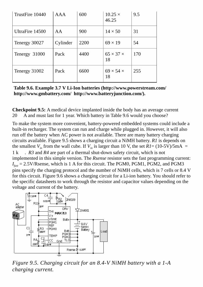
TrustFire10440 AAA 600 10.25×46.25
9.5
UltraFire14500 AA 900 14×50 31
Tenergy30027 Cylinder 2200 69×19 54
Tenergy31000 Pack 4400 65×37×18
170
Tenergy31002 Pack 6600 69×54×18
255
Table9.6.Example3.7VLi-Ionbatteries(http://www.powerstream.com/http://www.gmbattery.com/http://www.batteryjunction.com/).
Checkpoint9.5:Amedicaldeviceimplantedinsidethebodyhasanaveragecurrent20 Aandmustlastfor1year.WhichbatteryinTable9.6wouldyouchoose?
Tomakethesystemmoreconvenient,battery-poweredembeddedsystemscouldincludeabuilt-inrecharger.Thesystemcanrunandchargewhilepluggedin.However,itwillalsorunoffthebatterywhenACpowerisnotavailable.Therearemanybatterychargingcircuitsavailable.Figure9.5showsachargingcircuitaNiMHbattery.R1isdependsonthesmallestVinfromthewallcube.IfVinislargerthan10V,thesetR1=(10-5V)/5mA=1k .R3andR4arepartofathermalshut-downsafetycircuit,whichisnotimplementedinthissimpleversion.TheRsenseresistorsetsthefastprogrammingcurrent:Ifast=2.5V/Rsense,whichis1Aforthiscircuit.ThePGM0,PGM1,PGM2,andPGM3pinsspecifythechargingprotocolandthenumberofNiMHcells,whichis7cellsor8.4Vforthiscircuit.Figure9.6showsachargingcircuitforaLi-ionbattery.Youshouldrefertothespecificdatasheetstoworkthroughtheresistorandcapacitorvaluesdependingonthevoltageandcurrentofthebattery.
Figure9.5.Chargingcircuitforan8.4-VNiMHbatterywitha1-Achargingcurrent.

Figure9.6.Chargingcircuitfora7.2-VLi-ionwitha1.2-Achargingcurrent.

9.3ToleranceThefirststepineffectivecommunicationisestablishingaclearagreementonthedefinitionofterms.Broadlyput,tolerancemeansputtingupwitherror.However,thedictionarydefinitionsoftoleranceanderrorarenotadequateforengineeringdesignaslistedinTable9.7.Fromanengineeringperspective,toleranceisthequantitativedifferencebetweenthedesiredparameterandtheactualvalue.Forexample,a±1%1000 resistormayhaveanactualvaluefrom990 to1010 .Sometimesaparameterislistedastheminimumandmaximumvalues.Forexample,theoffsetvoltageofanOPA2350opampwillbebetween-500and+500 V.Specifyingtolerancewillhaveaprofoundimpactonbothpriceandperformance.Ifweoverspecify(use1%resistorswhen5%wouldhavebeenOK),thenthesystemcostsincrease.However,ifweunderspecify(use5%resistorsforasystemneeding1%),thensomeofthedeviceswemanufacturewillnotoperateproperly.
Tolerance
1)afair,objective,andpermissiveattitudetowardthosewhoseopinions,practices,race,religion,nationality,etc.,differfromone’sown;freedomfrombigotry.
2)afair,objective,andpermissiveattitudetowardopinionsandpracticesthatdifferfromone’sown.
3)interestinandconcernforideas,opinions,practices,etc.,foreigntoone’sown;aliberal,undogmaticviewpoint.
4)theactorcapacityofenduring;endurance:Mytoleranceofnoiseislimited.
Error
1)adeviationfromaccuracyorcorrectness;amistake,asinactionorspeech:Hisspeechcontainedseveralfactualerrors.
2)beliefinsomethinguntrue;theholdingofmistakenopinions.
3)theconditionofbelievingwhatisnottrue:inerroraboutthedate.
4)amoraloffense;wrongdoing;sin.
5)Baseball.amisplaythatenablesabaserunnertoreachbasesafelyoradvanceabase,orabattertohaveaturnatbatprolonged,asthedroppingofaballbattedintheair,thefumblingofabattedorthrownball,orthethrowingofawildball,butnotincludingapassedballorwildpitch.

5)Medicine/Medical,Immunology.a)thepowerofenduringorresistingtheactionofadrug,poison,etc.:atolerancetoantibiotics.b)thelackoforlowlevelsofimmuneresponsetotransplantedtissueorotherforeignsubstancethatisnormallyimmunogenic.
Table9.7.Dictionarydefinitionsoftoleranceanderrorhttp://dictionary.reference.com
Anotherfactorrelatedtotoleranceistemperaturecoefficient.Propertiesofmostdeviceswillchangewithtemperature.Forexample,theTemperatureCoefficientofResistance(TCR)isdefinedas
TCR(ppm/ºC)=
whereR25isthetemperatureat25ºC,andRistheresistanceattemperatureT,asTvariesfrom‑55ºCto+125ºC.Wewilldoasimpleexampleillustratingtheeffectoftoleranceonperformance.WewillrevisittheLEDinterfaceinitiallypresentedinFigure1.23.BackinChapter1,weassumedtheVCEofthePN2222was0.3V,thedesiredLEDoperatingpointwas1.9V10mA,andwecalculatedtheresistorvaluetobe(3.3-1.9-0.3V)/10mA=110 .
Figure1.23.Opencollectorusedtointerfacealightemittingdiode.TheLEDdatasheetspecifiesthelightintensityislinearwithcurrent.SowewilldeterminetheeffectoftoleranceonLEDcurrent.InparticularwewillinvestigateanE245%-resistorwithnominalvalueof110.Thisresistorcanvaryfrom104.5to115.5,causingtheLEDcurrenttovaryfrom9.5to10.5mA.Inthiscasethe±5%resistancetoleranceconvertedsimplytoa±5%variabilityinlightintensity.ToconsidertheeffectoftoleranceinthePN2222transistor,weneedtoknowthepossiblerangeforVCE.Atsaturation,theVCEhasamaximumof0.3V.AssumingaworstcaseofVCEequalto0,theLEDcurrentcouldincreaseto12.7mA.PuttingthesetwoeffectstogetherispresentedinTable9.8.Realistically,theVCEprobablyvariesonlyfrom0.2to0.3V,sotheLEDcurrentcouldvaryfrom9.5to11.5mA,or-5%to+15%fromdesired.
VCE=0

VCE=0.1
VCE=0.2
VCE=0.3
R=104.5 13.4 12.4 11.5 10.5
R=110 12.7 11.8 10.9 10.0
R=115.5 12.1 11.3 10.4 9.5
Table9.8.LEDcurrentvarieswithRandVCE.
Table9.8isasimpletwo-dimensionalanalysis.Ifweaddedtheeffectoftemperature,thentheproblembecomesthreedimensional.Asthenumberofparametersincreasessodoesthecomplexityoftheproblem.Itisimportanttodeterminewhichparametershavethelargesteffectonoutput.Theseparameterswillthenrequirelowertolerance.Forexample,assumethecircuithasthreeresistors(R1,R2,andR3)andtheoutputisthevoltageV.Eachresistorhasanerrorduetotoleranceand/ortemperaturedrift(± 1,± 2,and± 3).Wecouldusedifferentialcalculustodeterminetherelativesensitivitytoeachparameter(S1,S2,andS3).Weshouldfocusourmoneyandattentionontheparametershavingthelargesteffectonperformance.WecancalculatetheerrorinV( V)duetoerrorsinR.Letxbethemeasurandandlet xbethedesiredresolution.UsingthesensitivityofVtox,wecandetermineadesignmetric.
S1=∂V/∂R1S2=∂V/∂R2S3=∂V/∂R3
V=±(∂V/∂R1) • 1±(∂V/∂R2) • 2±(∂V/∂R3) • 3
x=(±(∂V/∂R1) • 1±(∂V/∂R2) • 2±(∂V/∂R3) • 3)/(∂V/∂x)≤ x

9.4.DesignforTestabilityDesignfortest(DFT)isimportantandshouldbeincorporatedateverystageofadesign.Wecangreatlyincreasereliabilitybytestingthedevicebeforeitisused,whileitisbeingused,andafterithasbeenused.Havingaplanfortestingshouldbeapartofeveryproject.Insoftwarewecanaddverboseoutput,eventlogging,assertions,diagnostics,resourcemonitoring,testpoints,andfaultinjectionhooks.Theapproachtohardwaretestingmimicsthetwoimportantfactorsforsoftwaretesting:visibilityandcontrol.Visibilityallowsthetestengineertoobservesystembehavior,andcontrolallowsthetestproceduretomanipulateinputstomoduleswithinthesystem.Weneedtoobservetheoutputs,sideeffectsandinternalstates.Animportantparameteristheintrusivenessoftheobservation.Inotherwords,weneedtobecarefultonotintroducedelaysthataffectthedynamicbehavior.Storingdataintoanarray(softwaredump)atruntimecanusuallybeperformedwithdelayoverheadsoflessthan1 s.
Wecanaddhardwarefeaturestooursystemtofacilitatetesting.Thefirstistheabilitytoquicklyandreliableattachhardwaretestequipmenttothedevice.Forlowproductionproductswecanaddtestpointstothecircuittomakeiteasytoattachoscilloscopesandvoltmeters.Forhigherproductionprojectswecanaddtestconnectorsthatdirectlyconnecttotestequipmentlikelogicanalyzersorsignalgenerators.Basically,weneedtocreateknowninputs,andrecordresponsesatstrategicpointsinthesystem.
Theverbosemodesfoundinsomecompilersadddebuggingoutputalongwithdataoutput.Thisapproachmaycausesignificantslowdownindynamicbehavior,soitwillbeimportanttomeasuretimingbehaviorwithandwithoutverbosemode.Foraspectsofthesystemthatarenotrealtime,verboseisanexcellenttestingfeature.Whenyouaddthe“-v”switchwithacommandinUnix,themailprogramwilldisplayitscommunicationwiththelocalmailserver.
Loggingorasoftwaredumpisanexcellenttoolforreal-timesystems.Ifyouplacethefollowingdumpatstrategicplacesinyoursystem,afterashortwhile,the Buffer containsthelast256timesthedebugginginstrumentwasinvoked.Subtracting“3”compensatesforthetimeittakestoruntheinstrumentuptothepointatwhichitreadstheSysTicktimer.Theentireinstrumentis12assemblyinstructionsandrunsinabout16buscycles.Inmostcasesthiswillbeminimallyintrusive.
uint32_tBuffer[256];
uint8_tN=0;
__inlinevoidRecordTime(void)
Buffer[N]=NVIC_ST_CURRENT_R-3;
N++;//8-bitvariablegoes0to255
Faultinjectionistheabilitytointroduceerrorconditionstoseeifthesystemproperlyhandlesthem.Amonitorisadebuggingmechanismtoobserveinternalbehavior.Agoodexampleofamonitorisconfiguringunusedpinsasoutputsandwritingstrategicinformationtothesepinsduringexecution.Ifweconnectthepinstoalogicanalyzer,wehaveaminimallyintrusivedebugginginstrument.OtherexamplesofmonitorsincludestreamingdataoutunusedportssuchasaUART,CAN,orSPI.Wecouldlogdebugdataontoflashdrive.Atestinginterfaceisahardwareorsoftwareconnectionbetweenthesystemandtestprocedure.
Checkpoint9.6:IdentifythreedesignfortestfeaturesonthePCBshownonpage451.

9.5.PrintedCircuitBoardLayoutandEnclosuresBeginwithchoosingaPCBsizeyouneedtoholdallthecomponents.Nextyouchooseaboxwithwhichtoenclosethesystem.Theenclosureisanimportantaspectofthedesign.Itdeterminesthelookandfeelofthedevice.ManymanufacturersgivesuggestedPCBsizesfortheirenclosures.Onewaytomakesureeverythingwillfitistocreateamockup.Onecollectsalltheelectricalandmechanicalcomponentsofthesystem.ThePCBdesignisprintedonpaperandgluedtocardboardorwoodmatchingthethicknessofthePCB.MountingholesaredrilledandcomponentsareattachedtothePCBmockup.Allcomponentsareassembledandmountedintotheenclosuretoverifyproperfit.TheleftsideofFigure9.7showsamockupofanLM3S811-basedrecorderwithanLCDtouchscreen.Therightsideshowsthefinalsystem.Thehardware,software,andPCBlayoutforthissystemcanbedownloadedfromthebookwebsiteasezLCD_811.zip.
Figure9.7.MockupandPCBforanLM3S811systemusingaPacTecenclosure.LayingoutaPCBisanartthatisbestlearnedbypracticeunderthewatchfuleyeofamastercraftsman.So,showyourPCBarttoothersandsolicitfeedback.Formanyyears,ithasbeencommonPCBdesignpracticetoavoid90°cornersinPCBtraces.Manyclaimthata90°turnproducesa¼turninductor,whichwillaffectthefrequencyresponseofthesignals.Thestandardpracticeistouseamiteredcornerreplacinga90°turnwithtwo45°turns.Therealityisthatthesignal-integritybenefitsofavoiding90°anglesareinsignificantatthefrequencies/edge-ratesseeninmicrocontrollercircuits(evenuptoandpast1GHz/100ps).[Johnson,HandGraham,M,High-SpeedDigitalDesign:aHandbookofBlackMagic,PrenticeHall:NewJersey,1993.]However,thereareafewsimplereasonstocontinuetoavoid90°angles.Thereisahigherpossibilityofanacid-trapformingduringetchingontheinsideoftheangle(especiallyinacuteangles).Anacidtrapcausesover-etchingthatcanbeayieldissueinPCboardswithsmalltracewidths.Routingat45°typicallyreducesoveralltracelengthanduseslessboardarea.MostPCBdesignersthinkitlooksbetter.LookinggoodisanimportantfactorforanyonewhoappreciatestheartofPCBlayout.
ThisparagraphcontainssuggestionstoconsiderwhenlayingoutaPCB.Makesurethe“SnaptoGrid”modeisactive.Youshouldexperimentwithdifferentsettingsofthesnap.Anetdefineswhichpinsandpadsmustbeconnected.Justlikesoftwarevariables,nets

shouldhavedescriptivenames.Youshouldvisualizetheunconnectednetswhileplacingcomponentsontheboard.Placeallcomponentsinitiallyontheboardtofacilitateinput/outputconnectors.Youalsowanttominimizethelengthsandthecrossingsofthenets.Extratimespentplacingnetswillberecoveredmanytimesoverwhilethedrawingthetraces.Thinkabouthowitwillbesoldered,byplacingthough-holecomponentsonthetopsidesosolderingwilloccuronthebottom.Surfacemountcomponentscangooneitherside.Addtopandbottomsilklabelingtoassistinconstruction,debugging,anddeviceoperation.Forexample,allcomponentsneedlabels(e.g.,U1R1C1J1etc.),shownbothontheboardandthecircuitdiagram.Addtestpointsatstrategicpointstoassistindebugging.Oneinexpensivetestpointcanbemadebyplacingtwoholes0.1inchapartthensolderingaUwireintoit.YoucanalsopurchasetestpointhardwaresuchasKeystoneElectronics5000through5004,whichusesa0.090inpadwith0.043inhole.Onewaytoconnectalltracesistogoleft-rightononesideandup-downontheotherside.Table9.7showsthetracewidthisafunctionofthelengthandcurrentinthetrace.1oz/ft2isatypicaltracethickness.
Length TemperatureRise
Current Thickness Resistance TraceWidth
5” 1C 100mA 1oz/ft2 1 2mil
5” 1C 200mA 1oz/ft2 0.47 5mil
5” 1C 500mA 1oz/ft2 0.13 20mil
5” 1C 1A 1oz/ft2 0.05 50mil
5” 1C 2A 1oz/ft2 0.02 120mil
Table9.7.Minimumtracewidthforvariouscurrentlevels
Inordertoverifyallcomponentswillfit,youmustanalyzedimensionsin3-D.YoucanuseadesigntoollikeAutoCAD,oryoucanfabricateamockupwithactualparts.YoucancutcardboardintheshapeofthePCB,drillholesinthecardboard,andgluethepartsontothecardboard.Figure9.8showsanembeddedsystemusingaLM3S8962,placedinanenclosure.

Figure9.8.AnEEGsystemdesignedwithaLM3S8962thatfitsintoacase(designedbyKatyLoeffler).Itisimportanttoreaddatasheetsandapplicationnotesforeachcomponentofthesystem.Themanufacturerwillsuggesttipsandreferencedesignsfortheirparts.Figures9.9and9.10showthesuggestedlayoutsforTexasInstrumentsmicrocontrollers.InFigure9.9,thelayoutsshowconnectionstopowerandgroundonthemicrocontroller.Itisrecommendedtoplaceacapacitorasclosetothechipaspossible.ThecirclesinFigure9.9representviastothepowerandgroundplanes.A)isthebestpracticebecausethereisminimalinductancebetweencapacitor,pinsandpowerplanes.B)isnotrecommendedbecausethedistancefrompinstoviasincreasesinductanceinpowerrails.C)isacceptablebecausethedistancefrompintoviaisshort.
Figure9.9.Capacitorlayoutsuggestions(SystemDesignGuidelinesforStellaris® Microcontrollers,AN01283).

Figure9.10showsasuggestedcrystallayout,whereanimportantobjectiveistominimizetheeffectivecapacitancefromOSC0togroundandfromOSC1togroundinherentintheboardlayoutitself(calledCboard).Whencalculatingthecapacitorvaluesneededfortheoscillatoronemustaccountforthisboardcapacitance.Thevaluesofthesecapacitorsalsodependonthecrystalloadcapacitance,CL.AtypicalequationisC1=C2=2×(CL-Cboard).ThismeansoneshouldnotplacepowerorgroundplanesunderthecrystalortheOSC0andOSC1signals.
Figure9.10.Crystallayoutsuggestion(SystemDesignGuidelinesforStellaris® Microcontrollers,AN01283).

9.6.Exercises9.1FindacombinationofanE12capacitorandE24resistorwithafrequencyresponse,1/(2 RC)of1000Hz.Selecttheresistorascloseto100k aspossible.
9.2FindacombinationofanE12capacitorandE24resistorwithafrequencyresponse,1/(2 RC)of12kHz.Selecttheresistorascloseto100k aspossible.
9.3FindtwoE24resistorsthatcanbecombinedtocreatearesistanceascloseto5.12k aspossible.
9.4FindtwoE24resistorsthatcanbecombinedtocreatearesistanceascloseto25.6k aspossible.
9.5Assumethesystemrequires50mAat3.3V.WhatisthedropoutvoltageofanLM317LZ?Usethisregulatortodesigna3.3Vregulatedpowersupply.Whatistherangeofinputvoltagesthatcanbeusedforyourcircuit?
9.6Assumethesystemrequires25mAat2.5V.WhatisthedropoutvoltageofanLM317LZ?Usethisregulatortodesigna2.5Vregulatedpowersupply.Whatistherangeofinputvoltagesthatcanbeusedforyourcircuit?
9.7Alow-powersystemrequiresanaveragecurrentof50 Aat3.7V.Thesystemmustrunfor6months.WhichbatteryinTable9.6wouldyouuse?
9.8Alow-powersystemrequiresanaveragecurrentof25 Aat3.7V.Thesystemmustrunfor3months.WhichbatteryinTable9.6wouldyouuse?
9.9IfyourARMmicrocontrollerrequires50mAtorun,howdoyoubuildthesystemwithanaveragecurrentoflessthan10mA?
9.10Ifyourcrystalhasaloadcapacitanceof18pF,andthePCBhasaboardcapacitanceof6pF,whatcapacitorvalueswouldyouusetobuildtheoscillator?
D9.11WriteaCprogramthatknowstheE24capacitorsvaluesandE192resistorsvalues.Theinputtotheprogramisthedesiredfrequencyresponse,1/(2 RC),andtheoutputisanE192resistorvalueandanE24capacitorvaluethatcombinestocreatethedesiredfrequency.

9.7.LabAssignmentsLab9.1Design,buildandtestaLi-Ionbatterycharger.Assumethebatteryvoltageis3.7V.
Lab9.2Design,buildandtestaNiMHbatterycharger.Assumethebatteryvoltageis4.2V.
Lab9.3Design,buildandtestcompletebattery-poweredembeddedsystem.Beginwitharequirementsdocument.DesignandlayoutaPCB.PlacethecomponentsinanenclosureliketheoneshowninFigure9.8.Includedesignfortestfeatures.


10.DataAcquisitionSystemsChapter10objectivesareto:•Defineperformancecriteriatoevaluateouroveralldataacquisitionsystem
•Introducespecificationsnecessarytoselectthepropertransducer
•Developamethodologyfordesigningdataacquisitionsystems
•Analyzethesourcesofnoiseandsuggestmethodstoreducetheireffect
•Illustrateconceptsofthischapterwithcasestudies
Embeddedsystemsaredifferentfromgeneral-purposecomputersinasensethatembeddedsystemshaveadedicatedpurpose.Aspartofthispurpose,manyembeddedsystemsarerequiredtocollectinformationabouttheenvironment.Asystemthatcollectsinformationiscalledadataacquisitionsystem.Inthischapter,wewillusethetwoterms,dataacquisitionsystemandinstrumentinterchangeably.Previouschapterspresentedthebasicbuildingblockstoacquiredataintothecomputer,andinthischapterwewillcombinetheseblocksintodataacquisitionsystems.Sometimestheacquisitionofdataisfundamentalpurposeofthesystem,suchaswithavoltmeter,athermometer,atachometer,anaccelerometer,analtimeter,amanometer,abarometer,ananemometer,anaudiorecorder,oracamera.Atothertimes,theacquisitionofdataisanintegralpartofalargersystemsuchasacontrolsystemorcommunicationsystem.ControlsystemswillbepresentedinVolume3,andcommunicationsystemswillbediscussedinChapter11.
InteL
Highlight
InteL
Highlight

10.1.IntroductionFigure10.1illustratestheintegratedapproachtoinstrumentdesign.Inthissection,webeginwiththeclearunderstandingoftheproblem.Wecanusethedefinitionsinthissectiontoclarifythedesignparametersaswellastoreporttheperformancespecifications.NextinSection10.2,wewilldefinetheparametersanddiscussthephysicsinordertoselectasuitabletransducer.PerformingdifferentiationandintegrationisdescribedinSection10.3.InSection10.4,weputtogethertheanaloganddigitalcomponents,introducedinChapter8,tobuilddataacquisitionsystems.Theuseofperiod/pulse/frequencyasameansofcollectinginformationwasdevelopedinChapter6.Noisecanneverbeeliminated,butwewillstudytechniquesinSection10.5toreduceitseffectonoursystem.TheintegratedapproachtodesignwillbeillustratedusingthecasestudiesinSection10.6.
Themeasurandisthephysicalquantity,property,orconditionthattheinstrumentmeasures.SeeFigure10.2.Themeasurandcanbeinherenttotheobject(likeposition,mass,orcolor),locatedonthesurfaceoftheobject(likethehumanEKG,orsurfacetemperature),locatedwithintheobject(e.g.,fluidpressure,orinternaltemperature),orseparatedfromtheobject(likeemittedradiation.)
Figure10.1.Individualcomponentsareintegratedintoadataacquisitionsystem.Ingeneral,atransducerconvertsoneenergytypeintoanother.Inthecontextofthisbook,thetransducerconvertsthemeasurandintoanelectricalsignalthatcanbeprocessedbythemicrocontroller-basedinstrument.Typically,atransducerhashavingaprimarysensingelementandavariableconversionelement.Theprimarysensingelementinterfacesdirectlytotheobjectandconvertsthemeasurandintoamoreconvenientenergyform.Theoutputofthevariableconversionelementisanelectricalsignalthathopefully
InteL
Highlight
InteL
Highlight
InteL
Highlight
InteL
Highlight

dependsonthemeasurand.Forexample,theprimarysensingelementofapressuretransduceristhediaphragm,whichconvertspressureintoadisplacementofaplunger.Thevariableconversionelementisastraingaugethatconvertstheplungerdisplacementintoachangeinelectricalresistance.Ifthestraingaugeisplacedinabridgecircuit,thevoltageoutputisdirectlyproportionaltothepressure.Sometransducersperformadirectconversionwithouthavingaseparateprimarysensingelementandvariableconversionelement.Theinstrumentationcontainssignalprocessing,whichmanipulatesthetransducersignaloutputtoselect,enhance,ortranslatethesignaltoperformthedesiredfunction,usuallyinthepresenceofdisturbingfactors.Thesignalprocessingcanbedividedintostages.Theanalogsignalprocessingconsistsofinstrumentationelectronics,isolationamplifiers,amplifiers,analogfilters,andanalogcalculations.Thefirstanalogprocessinginvolvescalibrationsignalsandpreamplification.Calibrationisnecessarytoproduceaccurateresults.Anexampleofacalibrationsignalisthereferencejunctionofathermocouple.Thesecondstageoftheanalogsignalprocessingincludesfilteringandrangeconversion.TheanalogsignalrangeshouldmatchtheADCanaloginputrange.Examplesofanalogcalculationsinclude:RMScalculation,integration,differentiation,peakdetection,thresholddetection,phaselockloops,AMFMmodulation/demodulation,andthearithmeticcalculationsofaddition,subtraction,multiplication,division,andsquareroot.Whenperiod,pulsewidth,orfrequencymeasurementisused,wetypicallyuseananalogcomparatortocreateadigitallogicsignaltomeasure(seeFigures8.6and8.20).WhereastheFigure10.1outlineddesigncomponents,Figure10.2showsthedataflowgraphforadataacquisitionsystemorcontrolsystem.Thecontrolsystemusesanactuatortodriveaparameterintherealworldtoadesiredvaluewhilethedataacquisitionsystemhasnoactuatorbecauseitsimplymeasurestheparameterinanonintrusivemanner.
Figure10.2.Signalpathsadataacquisitionsystem.
InteL
Highlight
InteL
Highlight
InteL
Highlight
InteL
Highlight

Thedataconversionelementperformstheconversionbetweentheanaloganddigitaldomains.Thispartoftheinstrumentincludes:hardwareandsoftwarecomputerinterfaces,ADC,DAC,S/H,analogmultiplexer,andcalibrationreferences.TheADCconvertstheanalogsignalintoadigitalnumber.InChapter6,wesawtheperiod,pulsewidth,andfrequencymeasurementapproachprovidesalow-costhigh-precisionalternativetothetraditionalADC.Thedigitalsignalprocessingincludes:dataacquisition(samplingthesignalatafixedrate),dataformatting(scaling,calibration),dataprocessing(filtering,curvefitting,FFT,eventdetection,decisionmaking,analysis),controlalgorithms(openorclosedloop).Thehumaninterfaceincludestheinputandoutputwhichisavailabletothehumanoperator.Theadvantageofcomputer-basedinstrumentationisthatsophisticatedbuteasytouseandunderstanddevicesarepossible.Theinputstotheinstrumentcanbeaudio(voice),visual(lightpens,cameras),ortactile(keyboards,touchscreens,buttons,switches,joysticks,rollerballs).Theoutputsfromtheinstrumentcanbenumericdisplays,CRTscreens,graphs,buzzers,bells,lights,andvoice.Ifthesystemcandeliverenergytotherealworldthenitisclassifiedasacontrolsystem.Controlsystemswillbedevelopedinthenextbook(Volume3).Inthischapter,wefocusondataacquisition.
Wheneverreportingspecificationsofourinstrument,itisimportanttogivethedefinitionsofeachparameter,themagnitudesofeachparameter,andtheexperimentalconditionsunderwhichtheparameterwasmeasured.Thisisbecauseengineersandscientistsapplyawiderangeofinterpretationsfortheseterms.
10.1.1.AccuracyTheinstrumentaccuracyistheabsoluteerrorreferencedtotheNationalInstituteofStandardsandTechnology(NIST)oftheentiresystemincludingtransducer,electronics,andsoftware.Letxmibethevaluesasmeasuredbytheinstrument,andletxtibethetruevaluesfromNISTreferences.Insomeapplications,thesignalofinterestisarelativequantity(liketemperatureordistancebetweenobjects).Forrelativesignals,accuracycanbeappropriatelydefinedmanyways:
Averageaccuracy(withunitsofx)=
Maximumerror(withunitsofx)=max
Standarderror(withunitsofx)=
Inotherapplications,thesignalofinterestisanabsolutequantity.Forthesesituations,wecanspecifyerrorsasapercentageofreadingorasapercentageoffullscale:
Averageaccuracyofreading(%)=
InteL
Highlight
InteL
Highlight
InteL
Highlight
InteL
Highlight

Averageaccuracyoffullscale(%)=
Maximumaccuracyofreading(%)=100max
Maximumaccuracyorfullscale(%)=100max
Observation:Thedefinitionsofthetermsaccuracy,resolution,andprecisionvaryconsiderablyinthetechnicalliterature.Itisgoodpracticetoincludeboththedefinitionsofyourtermsaswellastheirvaluesinyourtechnicalcommunication.
SincetheCelsiusandFahrenheittemperaturescaleshavearbitraryzeroes(e.g.,0˚Cisthefreezingpointofwater),itisinappropriatetospecifytemperatureerrorasapercentageofreadingorasapercentageoffullscalewhenCelsiusandFahrenheitscalesareused.Whenspecifyingtemperatureerror,weshoulduseaverageaccuracy,maximumerror,orstandarderror.Theseerrorshaveunitsof˚Cor˚F.
Typically,wecalibrateaquantitativedataacquisitionsystembydeterminingatransferfunctionthatrelatesthemeasuredvariable,x,torawmeasurementssuchastheADCsample.Accuracyislimitedbytwofactors:resolutionandcalibrationdrift.Calibrationdriftisthechangeinthetransferfunctionoccurringovertimeusedtocalculatethemeasuredvariablefromtherawmeasurements.
10.1.2.ResolutionTheinstrumentresolutionisthesmallestinputsignaldifference,∆xthatcanbedetectedbytheentiresystemincludingtransducer,electronics,andsoftware.Theresolutionofthesystemissometimeslimitedbynoiseprocessesinthetransduceritself(e.g.,thermalimaging)andsometimeslimitedbynoiseprocessesintheelectronics(e.g.,thermistors,RTDs,andthermocouples).
Thespatialresolution(orspatialfrequencyresponse)ofthetransduceristhesmallestdistancebetweentwoindependentmeasurements.Thesizeandmechanicalpropertiesofthetransducerdetermineitsspatialresolution.Whenmeasuringtemperature,ametalprobewilldisturbtheexistingmediumtemperaturefieldmorethanaglassprobe.Hence,aglassprobehasasmallerspatialresolutionthanametalprobeofthesamesize.Noninvasiveimagingsystemsexhibitexcellentspatialresolutionbecausetheinstrumentdoesnotdisturbthemedium,whichisbeingmeasured.Thespatialresolutionofanimagingsystemisthemediumsurfaceareafromwhichtheradiationoriginatesthatiseventuallyfocusedontothedetectorduringtheimagingofasinglepixel,theso-calledinstantaneousfieldofview,IFOV.Whenmeasuringforce,pressure,orflow,thespatialresolutionistheeffectiveareaoverwhichthemeasurementisobtained.Anotherwaytoillustratespatialresolutionistoattempttocollecta2-Dor3-Dimageofthemeasurand.Thespatialresolutionisthedistancebetweenpointsinourimage.
InteL
Highlight
InteL
Highlight
InteL
Highlight
InteL
Highlight

10.1.3.PrecisionPrecisionisthenumberofdistinguishablealternatives,nx,fromwhichthegivenresultisselected.Precisioncanbeexpressedinalternatives,bitsordecimaldigits.Considerathermometerinstrumentwithatemperaturerangeof0to100˚C.Thesystemdisplaystheoutputusing3digits(e.g.,12.3˚C).Inaddition,thesystemcanresolveeachtemperatureTfromthetemperatureT+0.1˚C.Thissystemhas1001distinguishableoutputs,andhencehasaprecisionof1001alternativesorabout10bits.Foralinearsystem,thereisasimplerelationshipbetweenrange(rx),resolution(∆x)andprecision(nx).Rangeisequaltoresolutiontimesprecision
rx(100˚C)=∆x(0.1˚C)•nx(1001alternatives)
where“range”isthemaximumminusminimumtemperature,andprecisionisspecifiedintermsofnumberofalternatives.Table10.1illustratestherelationshipbetweenalternativesanddecimaldigits.
Alternatives Decimaldigits
1000 3
2000 3½
4000 3¾
10000 4
Table10.1.Definitionofdecimaldigits.
Observation:Agoodruleofthumbtorememberis210•n≈103•n.
10.1.4.ReproducibilityandRepeatabilityReproducibility(orrepeatability)isaparameterthatspecifieswhethertheinstrumenthasequaloutputsgivenidenticalinputsoversomeperiodoftime.Thisparametercanbeexpressedasthefullrangeorstandarddeviationofoutputresultsgivenafixedinput,wherethenumberofsamplesandtimeintervalbetweensamplesarespecified.Oneofthelargestsourcesofthistypeoferrorcomesfromtransducerdrift.Statisticalcontrolisasimilarparameterbasedonaprobabilisticmodelthatalsodefinestheerrorsduetonoise.Theparameterincludesthenoisemodel(e.g.,normal,chi-squared,uniform,saltandpepper)andtheparametersofthemodel(e.g.,average,standarddeviation).
InteL
Highlight
InteL
Highlight

10.2.TransducersInthissection,wewillstartwithquantitativeperformancemeasuresforthetransducer.Next,specifictransducerswillbeintroduced.Ratherthangiveanexhaustivelistofallavailabletransducers,theintentinthissectionistoillustratetherangeofpossibilities,andtoprovidespecificdevicestouseinthedesignsectionslaterinthechapter.
10.2.1.StaticTransducerSpecificationsTheinputormeasurandisx.Theoutputisy.Atransducerconvertsxintoy.Inthissubsection,weassumetheinputparameter,x,isconstantorstatic.
Figure10.3.Transducersinthisbookconvertaphysicalsignalintoanelectricalsignal.Theinputxandtheoutputycanbeeitherabsoluteordifferential.Anabsolutesignalrepresentsaparameterthatexistsinasingleplaceatasingletime.Adifferentialsignalisderivedfromthedifferencebetweentwosignalsthatexistatdifferentplacesoratdifferenttimes.Voltageisindeeddefinedasapotentialdifference,butwhenthevoltageisreferredtoground,weconsideritanabsolutequantity.Ontheotherhand,ifthesignalisrepresentedbythevoltagedifferencebetweentwopointsneitherofwhichareground,thenweconsiderthesignalasdifferential.Table10.2illustratesfourtypesoftransducers.
Type Input->output
Example
Absolute→absolute
x→y Thermistorconvertsabsolutetemperaturetoaresistance
Relative→absolute
∆x→y Massbalanceconvertsmassdifferencetoanangle
Absolute→relative
x→∆y Straingaugeconvertsdisplacementtoaresistancedifference
Relative→relative
∆x→∆y Thermocoupleconvertstemperaturedifferencetovoltagedifference
Table10.2.Fourtypesoftransducers.
InteL
Highlight

Thestaticsensitivityistheslope,m,ofthestraightlinethroughthestaticcalibrationcurvethatgivesminimalmeansquarederror.Letxi,yibetheinput/outputsignalsofthetransducerasshowninthefigurebelow.Thelinearityisameasureofthestraightnessofthestaticcalibrationcurve.Letyi=f(xi)bethetransferfunctionofthetransducer.Alineartransducersatisfies:
f(ax1+bx2)=af(x1)+bf(x2)
foranyarbitrarychoiceoftheconstantsaandb.Letyi=mxi+bbethebestfitlinethroughthetransducerdata.Linearity(ordeviationfromit)asafigure-of-meritcanbeexpressedaspercentageofreadingorpercentageoffullscale.Letymaxbethelargesttransduceroutput.
Averagelinearityofreading(percent)=
Averagelinearityoffullscale(percent)=
Twodefinitionsforsensitivityareusedfortemperaturetransducers.Thestaticsensitivityis:
Ifthetransducerislinearthenthestaticsensitivityistheslope,m,ofthestraightlinethroughthestaticcalibrationcurvewhichgivestheminimummeansquarederror.Ifxiandyirepresentmeasuredinput/outputresponsesofthetransducer,thentheleastsquaresfittoyi=mxi+bis
m=andb=
Thermistorscanbemanufacturedtohavearesistancevalueat25˚Crangingfrom4Ωto20MΩ.Becausetheinterfaceelectronicscanjustaseasilyconvertanyresistanceintoavoltage,a20MΩthermistorisnotmoresensitivethana30Ωthermistor.Inthissituation,itmakesmoresensetodefinefractionalsensitivityas:
= (units1/˚C) =
Unfortunately,transducersareoftensensitivetofactorsotherthanthesignalofinterest.Environmentalissuesinvolvehowthetransducerinteractswithitsexternalsurroundings(e.g.,temperature,humidity,pressure,motion,acceleration,vibration,shock,radiationfields,electricfieldsandmagneticfields.)Specificityisameasureofrelativesensitivityofthetransducertothedesiredsignalcomparedtothesensitivityofthetransducerstotheseotherunwantedinfluences.Atransducerwithagoodspecificitywillrespondonlytothesignalofinterestandbeindependentofthesedisturbingfactors.Ontheotherhand,a
InteL
Highlight
InteL
Highlight

transducerwithapoorspecificitywillrespondtothesignalofinterestaswellastosomeofthesedisturbingfactors.Ifallthesedisturbingfactorsaregroupedtogetherasnoise,thenthesignal-to-noiseratio(S/N)isaquantitativemeasureofthespecificityofthetransducer.
Theinputrangeistheallowedrangeofinput,x.Theinputimpedanceisthephasorequivalentofthesteadystatesinusoidaleffort(voltage,force,pressure)inputvariabledividedbythephasorequivalentofsteadystateflow(current,velocity,flow)inputvariable.Theoutputsignalstrengthofthetransducercanbespecifiedbytheoutputresistance,Rout,andoutputcapacitance,Cout.
Figure10.4.Outputmodelofatransducer.Theinputimpedanceofathermalsensorisameasureofthethermalperturbationthatoccursduetothepresenceoftheprobeitselfinthemedium.Forexample,athermocoupleneedleinsertedintoalaser-irradiatedmediumwillaffectthemediumtemperaturebecauseheatwillconductdownthestainlesssteelshaft.Athermocouplehasalowinputimpedance(whichisbad)becausethetransduceritselfloads(reduces)themediumtemperature.Ontheotherhand,aninfrareddetectormeasuressurfacemediumtemperaturewithoutphysicalcontact.Infrareddetectorsthereforehaveaveryhighinputimpedance(whichisgood)becausethepresenceofthetransducerhasnoeffectonthetemperaturetobemeasured.Inthecaseoftemperaturesensors,thedrivingforceforheattransferisthetemperaturedifference,∆T.Theresultingheatflow,q,canbeexpressedusingFourier’slawofthermalconduction:
wherekistheprobethermalconductivity,andAistheprobesurfaceareaandaistheradiusofasphericaltransducer.Thesteadystateinputimpedanceofasphericaltemperatureprobecanthusbeapproximatedby:
Again,theapproximationintheaboveequationassumesasphericaltransducer.Similardiscussionscanbeconstructedforthesinusoidalinputimpedance.Sincemostthermaleventscanbeclassifiedasstepeventsratherthansinusoidallyvaryingevents,mostresearchersprefertheuseoftimeconstanttodescribethetransientbehavioroftemperaturetransducers.
InteL
Highlight

Sometransducersarecompletelypassive(e.g.,thermocouple,EKGelectrode),andothersareactiverequiringexternalpower(e.g.ultrasoniccrystals,straingauge,microphone,andthermistors.)Electricalisolationisacriticalfactorinmedicalinstrumentation.Sometransducersareinherentlyisolated(e.g.,thermistors,thermocouples,microphones),whileothersarenotisolated(e.g.,EKGelectrodes,pacemakers,bloodpressurecatheters.)Minimizationoferrorsisimportantforallinstruments.Thesensitivitytodisturbingfactors(electricfields,magneticfields,radiation,vibration,shock,acceleration,temperature,humidity)mustbedeterminedbeforeadevicecanbeused.
Thezerodriftisthechangeinthestaticsensitivitycurveintercept,b,asafunctionoftimeorotherfactor(seetheFigure10.5).Thesensitivitydriftisthechangeinthestaticsensitivitycurveslope,m,asafunctionoftimeorsomeotherfactor.Thesedriftfactorsdeterminehowoftenthetransducermustbecalibrated.Forexample,thermistorshaveadriftmuchlargerthanthatofRTDsorthermocouples.Transducersmaybeagedathightemperaturesforlongperiodsoftimetoimprovetheirreproducibility.
Figure10.5.Thetwotypesoftransducerdrift:sensitivitydriftandzerodrift.Thetransducerisoftenacriticaldeviceinvolvingboththecostandperformanceoftheentiresystem.Aqualitytransducermayproducebettersignalsbutatanincreasedcost.Animportantmanufacturingissueistheavailabilityofcomponents.Theavailabilityofadevicemaybeenhancedbyhavingasecondsource(morethanonemanufacturerproducesthedevice).Theuseofstandardcablesandconnectorswillsimplifytheconstructionofyoursystem.Thepowerrequirements,sizeandweightofthedeviceareimportantinsomesystems,andthusshouldbeconsideredwhenselectingatransducer.
10.2.2.DynamicTransducerSpecificationsThetransientresponseisthecombinationofthedelayphase,theslewingphase,andtheringingphaseasshowninFigure10.6.Thetotaltransientresponseisthetimefortheoutput,y(t),toreach99%ofitsfinalvalueafterastepchangeininput,x(t)=u0(t).
InteL
Highlight
InteL
Highlight
InteL
Highlight
InteL
Highlight

Figure10.6.Thestepresponseoftenhasdelay,slewingandringingphases.Thetransientresponseofatemperaturetransducertoasuddenchangeinsignalinputcansometimesbeapproximatedbyanexponentialequation(assumingfirst-orderresponse):
y(t)=yf+(y0-yf)e-t/
wherey0andyfaretheinitialandfinaltransduceroutputsrespectively.Thetimeconstant, ,ofatransduceristhetimetoreach63.2%ofthefinaloutputaftertheinputisinstantaneouslyincreased.Thistimeisdependentonboththetransducerandtheexperimentalsetup.Manufacturersoftenspecifythetimeconstantofthermistorsandthermocouplesinwell-stirredoil(fastest)orstillair(slowest).Inyourapplications,onemustconsiderthesituation.Ifthetransducerisplacedinahighflowliquidlikeanarteryorawaterpipe,itmaybereasonabletousethestirredoiltimeconstant.Ifthetransducerisinairorembeddedinasolid,thenthermalconductioninthemediumwilldeterminethetimeconstantalmostindependentlyofthetransducer.
Thefrequencyresponseisastandardtechniquetodescribethedynamicbehavioroflinearsystems.Lety(t)bethesystemresponsetox(t).Let
x(t)=Asin( t)y(t)=Bsin( t+ ) =2πf
ThemagnitudeB/Aandthephase responsesarebothdependentonfrequency.Differentialequationscanbeusedtomodellineartransducers.Letx(t)bethetimedomaininputsignal.LetX(j )bethefrequencydomaininputsignal.Lety(t)bethetimedomainoutputsignal.LetY(j )bethefrequencydomainoutputsignal.
Classification differentialequation gainresponse phaseresponse
ZEROORDER y(t)=mx(t) Y/X=m=staticsensitivity
FIRSTORDER y’(t)+ay(t)=bx(t) Y/X=b/sqrt(a2+ 2) =arctan(- /a)
InteL
Highlight

SECONDORDER
y”(t)+ay’(t)+by(t)=cx(t)
TIMEDELAY y(t)=x(t-T) Y/X=exp(-j T)
Table10.3.Classificationsofsimplelinearsystems.
10.2.3.NonlinearTransducersNonlinearcharacteristicsincludehysteresis,saturation,bang-bang,breakdown,anddeadzone.Hysteresisiscreatedwhenthetransducerhasmemory.WecanseeintheFigure10.7thatwhentheinputwaspreviouslyhighitfallsalongthehighercurve,andwhentheinputwaspreviouslylowitfollowsalongthelowercurve.Hysteresiswillcauseameasurementerror,becauseforanygivensensoroutput,y,theremaybetwopossiblemeasurandinputs.Saturationoccurswhentheinputsignalexceedstheusefulrangeofthetransducer.Withsaturation,thesensordoesnotrespondtochangesininputvaluewhentheinputiseithertoohighortoolow.Breakdowndescribesasecondpossibleresultthatmayoccurwhenintheinputexceedstheusefulrangeofthetransducer.Withbreakdown,thesensoroutputchangesrapidly,usuallytheresultofpermanentdamagetothetransducer.Hysteresis,bangbanganddeadzonealloccurwithintheusefulrangeofthetransducer.Bangbangisasuddenlargechangeintheoutputforasmallchangeintheinput.Ifthebangbangoccurspredictably,thenitcanbecorrectedforinsoftware.Adeadzoneisaconditionwherealargechangeintheinputcauseslittleornochangeintheoutput.Deadzonescannotbecorrectedforinsoftware,thusifpresentwillcausemeasurementerrors.
Figure10.7.Nonlineartransducerresponses.
InteL
Highlight
InteL
Highlight
InteL
Highlight
InteL
Highlight
InteL
Highlight
InteL
Highlight
InteL
Highlight
InteL
Highlight
InteL
Highlight
InteL
Highlight
InteL
Highlight

Therearemanywaystomodelnonlineartransducers.Anonlineartransducercanbedescribedasapiecewiselinearsystem.Thefirststepistodividetherangeofxintoafinitesubregions,assumingthesystemislinearineachsubregion.Thesecondstepistosolvethecoupledlinearsystemssothatthesolutioniscontinuous.Anothermethodtomodelanonlinearsystemistouseempiricallydeterminednonlinearequations.Thefirststepinthisapproachistoobservethetransducerresponseexperimentally.Givenatableofxandyvalues,thesecondstepistofittheresponsetoanonlinearequation.Engineerscalltheseempiricalfitsperformancemaps.
Athirdapproachtomodelanonlineartransducerusesalookuptablelocatedinmemory.Thismethodisconvenientandflexible.Letxbethemeasurandandybethetransduceroutput.Thetablecontainsxvaluesandthemeasuredyvalueisusedtoindexintothetable.Sometimesasmalltablecoupledwithlinearinterpolationachievesequivalentresultstoalargetable.ThespreadsheetTherm12.xls,whichcanbefoundonthewebsite,isanexampleofthisapproach.
Anonmonotonicresponseisaninput/outputfunctionthatdoesnothaveamathematicalinverse.Forexample,iftwoormoreinputvaluesyieldthesameoutputvalue,thenthetransducerisnonmonotonic.Softwarewillhaveadifficulttimecorrectinganonmonotonictransducer.Forexample,theSharpGP2Y0A21YKIRdistancesensorhasatransferfunctionasshowninFigure10.8.Ifyoureadatransducervoltageof2V,youcannottelliftheobjectis3cmawayor12cmaway.
Figure10.8.TheSharpIRdistancesensorexhibitsnonmonotonicbehavior.
10.2.4.PositionTransducersOneofthesimplestmethodstoconvertpositionintoanelectricalsignalusesapositionsensitivepotentiometer.Thesedevicesareinexpensivetobuildandaresensitivetosmalldisplacements.Thetransducerisconstructedfromapotentiometer.Thefixedpartofthepotentiometeriscalledtheframe,andthemovablepartisthearmature.Thearmatureisfreetomoveupanddownalongthemeasurementaxis,seeFigure10.9.Theframeisfixedandthearmatureisattachedtotheobjectbeingmeasured.Thetotalelectricalresistanceofthetransducerisfixed,buttheresistancetotheslidearmvarieswithdistance,d.
InteL
Highlight
InteL
Highlight
InteL
Highlight
InteL
Highlight
InteL
Highlight
InteL
Highlight
InteL
Highlight
InteL
Highlight
InteL
Highlight

Rout=Rmax*d/dmax
wheredmaxisdistanceatfullscaleandRmaxistheresistanceatfullscale.Ifthematerialinthepotentiometerhasuniformresistance,thenRoutwillbelinearlyrelatedtodisplacement,d.Thedisadvantagesofthistransducerareitslowfrequencyresponse,itshighmechanicalinputimpedance,anditdegenerateswithtime.Nevertheless,thistypeoftransducerisadequateformanyapplications.ThistransducerwillbeinterfacedtwowayslaterinExample10.3.
Figure10.9.Potentiometer-basedpositionsensor.ThetransducerinFigure10.8usesIRlighttomeasuredistancetoareflectingobject.Thesesensorsrequireanonuniformpower,soplacinga10 Fnearthepowerlineofthesensorreducesnoiseonothercomponents.Iftheobjectismorethan6cmaway,theoutputvoltageisinverselyrelatedtovoltage.IfNistheADCsample,thendistancecanbecalculatedas
d=c/Nwherecisacalibrationconstant
Anothermethodtomeasurethedistancebetweentwoobjectsistotransmitaultrasonicwavefromoneobjectattheotherandlistenforthereflection(Figure10.10).Theinstrumentmustbeabletogeneratethesoundpulse,heartheechoandmeasurethetime,tin,betweenpulseandecho.Ifthespeedofsound,c,isknown,thenthedistance,d,canbecalculated.Ourmicrocontrollersalsohavemechanismstomeasurethepulsewidthtin.
d=ctin/2
Figure10.10.Anultrasonicpulse-echotransducermeasuresthedistancetoanobject,Ping))).
10.2.5.SoundTransducers
InteL
Highlight
InteL
Highlight
InteL
Highlight

Amicrophoneisatypeofdisplacementtransducer.Soundwaves,whicharepressurewavestravellinginair,causeadiaphragmtovibrate,andthediaphragmmotioncausesthedistancebetweencapacitorplatestochange.Thisvariablecapacitancecreatesavoltage,whichcanbeamplifiedandrecorded.Theelectretcondensermicrophone(ECM)isaninexpensivechoiceforconvertingsoundtoanalogvoltage.Electretmicrophonesareusedinconsumerandcommunicationaudiodevicesbecauseoftheirlowcostandsmallsize.Forapplicationsrequiringhighsensitivity,lownoise,andlinearresponse,wecouldusethedynamicmicrophone,liketheonesusedinhigh-fidelityaudiorecordingequipment.TheECMcapsuleactsasanacousticresonatorforthecapacitiveelectretsensorshowninFigure10.11.TheECMhasaJunctionFieldEffectTransistor(JFET)insidethetransducerprovidingsomeamplification.ThisJFETrequirespowerassuppliedbytheR1resistor.ThislocalamplificationallowstheECMtofunctionwithasmallercapsulethantypicallyfoundwithothermicrophones.ECMdevicesarecylindricallyshaped,haveadiameterrangingfrom3to10mm,andhaveathicknessrangingfrom1to5mm.
Figure10.11.PhysicalandelectricalviewofanECMwithJFETbuffer(Vccdependsonmicrophone)AnECMconsistsofapre-charged,non-conductivemembranebetweentwoplatesthatformacapacitor.Thebackplateisfixed,andtheotherplatemoveswithsoundpressure.Movementoftheplateresultsinacapacitancechange,whichinturnresultsinachangeinvoltageduetothenon-conductive,pre-chargedmembrane.Anelectricalrepresentationofsuchanacousticsensorconsistsofasignalvoltagesourceinserieswithasourcecapacitor.Themostcommonmethodofinterfacingthissensorisahigh-impedancebuffer/amplifier.AsingleJFETwithitsgateconnectedtothesensorplateandbiasedasshowninFigure10.11providesbufferingandamplification.ThecapacitorCprovideshigh-passfiltering,sothevoltageattheoutputwillbelessthan±100mVfornormalvoice.Audiomicrophonesneedadditionalamplificationandband-passfiltering.Typicalaudiosignalsexistfrom100Hzto10kHz.ThepresenceoftheR1resistoriscalled“phantombiasing”.Theelectrethastwoconnections:GndandSignal/bias.Typically,themetalliccapsuleisconnectedtoGnd.
10.2.6.ForceandPressureTransducers
InteL
Highlight
InteL
Highlight

Acommondevicetomeasureforceandpressureisthestraingauge.Asawireisstretcheditslengthincreasesanditscross-sectionalareadecreases.Thesegeometricchangescauseanincreaseintheelectricalresistanceofthewire,R.Thetransducerisconstructedwithfoursetsofwiresmountedbetweenastationarymember(frame)andamovingmember(armature.)Asthearmaturemovesrelativetotheframe,twowiresarestretched(increaseinR1R4),andtwowiresarecompressed(decreaseinR2R3),asshowninFigure10.13.Thestraingaugeisadisplacementtransducer,suchthatachangeintherelativepositionbetweenthearmatureandframe,∆x,causesachangeinresistance,∆R.Thesensitivityofastraingaugeiscalleditsgaugefactor.
Figure10.12.Straingaugesusedforforceorpressuremeasurement.ThegaugefactorforanAdvancestraingaugeis2.1.Thetypicalresistance,R,is120Ω.Ifthegaugeisbondedontoamaterialwithaspringcharacteristic:
F=-kx
thenthetransducercanbeusedtomeasureforce.Thewireseachhaveasignificanttemperaturedrift.Whenthefourwiresareplacedintoabridgeconfiguration,thetemperaturedependencecancels.Ahighgain,highinputimpedance,highCMRRdifferentialamplifierisrequired.
Figure10.13.Fourstraingaugesareplacedinabridgeconfiguration.Forceandpressuresensorscanalsobemadefromsemiconductormaterials.Thesesiliconsensorscanbemademuchsmallerthanstraingauges,buttendtomuchmorenonlinear.Aforcesensingresistor(FSR)ismadewitharesistivefilmandconvertsforceintoresistance.Thesesensorsarelowcostandeasytointerface,buttendtobequitenonlinear.
InteL
Highlight
InteL
Highlight

10.2.7.TemperatureTransducersThermistorsareapopulartemperaturetransducermadefromaceramic-likesemiconductor.ANTC(negativetemperaturecoefficient)thermistorismadefromcombinationsofmetaloxidesofmanganese,nickel,cobalt,copper,iron,andtitanium.Amixtureofmilledsemiconductoroxidepowdersandabinderisshapedintothedesiredgeometry.Themixtureisdriedandsintered(underpressure)atanelevatedtemperature.Thewireleadsareattachedandthecombinationiscoatedwithglassorepoxy.Byvaryingthemixtureofoxides,arangeofresistancevaluesfrom30Ωto20MΩ(at25˚C)ispossible.Table10.4liststhetradeoffsbetweenthermistorsandthermocouples.
Thermistors Thermocouples
Moresensitive Moresturdy
Bettertemperatureresolution
Fasterresponse
Lesssusceptibletonoise
Inert,interchangeableVvs.Tcurves
Lessthermalperturbation
Requireslessfrequentcalibration
Doesnotrequireareference
Morelinear
Table10.4.Tradeoffsbetweenthermistorsandthermocouples.
Aprecisionthermometer,anohmmeter,andawaterbatharerequiredtocalibratethermistorprobes.Thefollowingempiricalequationyieldsanaccuratefitoveranarrowrangeoftemperature:
or
whereTisthetemperatureinKelvin,andRisthethermistorresistanceinohms.0degreesCelsiusis273.15degreesKelvin.Itispreferabletousetheohmmeterfunctionoftheeventualinstrumentforcalibrationpurposessothatinfluencesoftheresistancemeasurementhardwareandsoftwareareincorporatedintothecalibrationprocess.
Thefirststepinthecalibrationprocessistocollecttemperature(measuredbyaprecisionthermometer)andresistancedata(measuredbytheohmmeterprocessoftheinstrument).Thethermistor(s)tobecalibratedshouldbeplacedasclosetothesensingelementoftheprecisionthermometeraspossible.Thewaterbathcreatesastableyetcontrollableenvironmentinwhichtoperformthecalibration.SeethespreadsheetTherm12.xlsonthebookwebsiteforanexamplethermistorcalibration.
Athermocoupleisconstructedbyspotweldingtwodifferentmetalwirestogether.Probe
InteL
Highlight
InteL
Highlight
InteL
Highlight
InteL
Highlight
InteL
Highlight

transducersincludeaprotectivecasingwhichsurroundsthethermocouplejunction.Probescomeinmanyshapesincludingroundtips,conicalneedlesandhypodermicneedles.Barethermocouplejunctionsprovidefasterresponsebutaremoresusceptibletodamageandnoisepickup.Ungroundedprobesallowelectricalisolationbutarenotasresponsiveasgroundedprobes.Commercialthermocoupleshavebeenconstructedin16to30gaugehypodermicneedles—a30gaugeneedlehasanoutsidediameterofabove0.03cm.Barethermocouplescanbemadefrom30-µmwireproducingatipwithan80µmdiameter.Aspotweldisproducedbypassingalargecurrentthroughthemetaljunctionthatfusesthetwometalstogether.Ifthewiresformaloop,andthejunctionsareatdifferenttemperatures,thenacurrentwillflowintheloop.ThisthermaltoelectricalenergyconversioniscalledtheSeebeckeffect(seeFigure10.14).Ifthetemperaturedifferenceissmall,thenthecurrent,I,islinearlyproportionaltothetemperaturedifferenceT1-T2.
Figure10.14.Whenthetwothermocouplejunctionsareatdifferenttemperaturescurrentwillflow.Iftheloopisbroken,andanelectricalvoltageisapplied,thenheatwillbeabsorbedatonejunctionandreleasedattheother.ThiselectricaltothermalenergyconversioniscalledthePeltiereffect,seeFigure10.15.Ifthevoltageissmall,thentheheattransferredislinearlyproportionaltothevoltage,V.
Figure10.15.Whenvoltageisappliedtotwothermocouplejunctionsheatwillflow.Iftheloopisbroken,andthejunctionsareatdifferenttemperatures,thenavoltagewilldevelopbecauseoftheSeebeckeffect.Ifthetemperaturedifferenceissmall,thenthevoltage,V,isnearlylinearlyproportionaltothetemperaturedifferenceT1-T2.AnamplifierisrequiredtomatchthetransduceroutputrangetotheADCrange,seeFigure10.16.Undermostconditionswewilladdananaloglowpassfilter.
Type-Thermocouple µV/˚Cat20˚C
Usefulrange˚C
Comments
T-Copper/Constantan 45 -150to+350 Moistenvironment
InteL
Highlight
InteL
Highlight

J-Iron/Constantan 53 -150to+1000
Reducingenvironment
K-Chromel/alumel 40 -200to+1200
Oxidizingenvironment
E-Chromel/constantan 80 0to+500 Mostsensitive
RS-Platinum/platinum-rhodium
6.5 0to+1500 Corrosiveenvironment
C–Tungsten/rhenium 12 0to2000 Hightemperature
Table10.5.Temperaturesensitivityandrangeofvariousthermocouples.
Figure10.16.Athermocoupleconvertstemperaturedifferencetovoltage.Thermocouplesarecharacterizedby:1)lowimpedance(resistanceofthewires),2)lowtemperaturesensitivity(45µV/˚Cforcopper/constantan),3)low-powerdissipation,4)fastresponse(becauseofthemetal),5)highstability(becauseofthepurityofthemetals),and6)interchangeability(againbecauseofthephysicsandthepurityofthemetals).
Ifthetemperaturerangeislessthan25˚C,thenthelinearapproximationcanbeusedtomeasuretemperature.LetNbethedigitalsamplefromtheADCfortheunknownmediumtemperature,T1.Acalibrationisperformedundertheconditionsofaconstantreferencetemperature:typically,oneusestheextremesofthetemperaturerange(TminandTmax).Aprecisionthermometersystemisusedtomeasurethe“truth”temperatures.LetNminandNmaxbethedigitalsamplesatTminandTmaxrespectively.Thenthefollowingequationcanbeusedtocalculatetheunknownmediumtemperaturefromthemeasureddigitalsample.
T1=Tmin+(N-Nmin)•
Becausethethermocoupleresponseisnotexactlylinear,theerrorsintheabovelinearequationwillincreaseasthetemperaturerangeincreases.Forinstrumentswithalargertemperaturerange,aquadraticequationcanbeused,
T1=H0+H1•N+H2•N2
InteL
Highlight

whereH0H1andH2aredeterminedbycalibrationoftheinstrumentovertherangeofinterest.
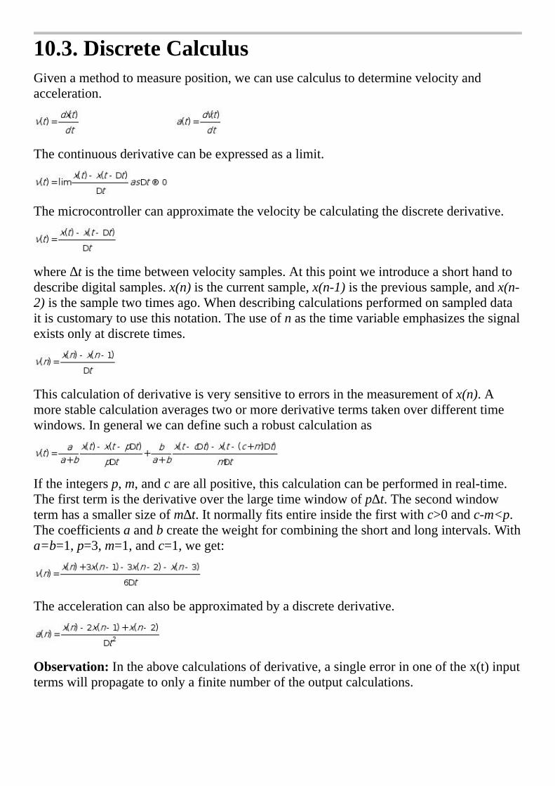
10.3.DiscreteCalculusGivenamethodtomeasureposition,wecanusecalculustodeterminevelocityandacceleration.
Thecontinuousderivativecanbeexpressedasalimit.
Themicrocontrollercanapproximatethevelocitybecalculatingthediscretederivative.
where∆tisthetimebetweenvelocitysamples.Atthispointweintroduceashorthandtodescribedigitalsamples.x(n)isthecurrentsample,x(n-1)istheprevioussample,andx(n-2)isthesampletwotimesago.Whendescribingcalculationsperformedonsampleddataitiscustomarytousethisnotation.Theuseofnasthetimevariableemphasizesthesignalexistsonlyatdiscretetimes.
Thiscalculationofderivativeisverysensitivetoerrorsinthemeasurementofx(n).Amorestablecalculationaveragestwoormorederivativetermstakenoverdifferenttimewindows.Ingeneralwecandefinesucharobustcalculationas
Iftheintegersp,m,andcareallpositive,thiscalculationcanbeperformedinreal-time.Thefirsttermisthederivativeoverthelargetimewindowofp∆t.Thesecondwindowtermhasasmallersizeofm∆t.Itnormallyfitsentireinsidethefirstwithc>0andc-m<p.Thecoefficientsaandbcreatetheweightforcombiningtheshortandlongintervals.Witha=b=1,p=3,m=1,andc=1,weget:
Theaccelerationcanalsobeapproximatedbyadiscretederivative.
Observation:Intheabovecalculationsofderivative,asingleerrorinoneofthex(t)inputtermswillpropagatetoonlyafinitenumberoftheoutputcalculations.

Observation:Althoughthecentraldifferencecalculationofv(t)=(x(t+∆t)-x(t-∆t))/2∆tistheoreticallyvalid,wecannotuseitforreal-timeapplications,becauseitrequiresknowledgeaboutthefuture,x(t+∆t),whichisunavailableatthetimev(t)isbeingcalculated.
Similarly,wecanperformintegrationofvelocitytodetermineposition.
Themicrocontrollercanperformadiscreteintegrationbysummation.
Therearetwoproblemswiththisapproach.Thefirstdifficultyisdeterminingx(0).Thesecondproblemistheaccumulationoferrors.Ifoneiscalculatingvelocityfrompositionandanerroroccursinthemeasurementofx(n),thenthaterroraffectsonlytwocalculationsofv(n).Unfortunately,ifoneiscalculatingpositionfromvelocityandanerroroccursinthemeasurementofv(n),thenthaterrorwillaffectallsubsequentcalculationsofx(n).
Observation:Intheabovecalculationofintegration,asingleerrorinoneofthex(t)inputtermswillpropagateintoallremainingoutputcalculations.
Thefollowingfunction,whichisquitesimilartothederivative,isactuallyalowpassdigitalfilter.
Furthermore,ifyousampleaninputataregularrate,fs,thenthefollowingisadigitallowpassfilterwithacutoffofaboutfs/2k.Thisfiltercalculatestheaverageofthelastksamples(seeProgram8.10).
Checkpoint10.1:Ifyousampleat1000Hz,howdoyoucreateadigitallowpassfilterwithacutoffof10Hz?

10.4.DataAcquisitionSystemDesign
10.4.1.IntroductionandDefinitionsBeforedesigningadataacquisitionsystem(DAS)wemusthaveaclearunderstandingofthesystemgoals.WecanclassifysystemasaQuantitativeDAS,ifthespecificationscanbedefinedexplicitlyintermsofdesiredrange(rx),resolution(∆x),precision(nx),andfrequenciesofinterest(fmintofmax).Ifthespecificationsaremorelooselydefined,weclassifyitasaQualitativeDAS.Examplesofqualitativesystemsincludethosewhichmimicthehumansenseswherethespecificationsaredefinedusingtermslike“soundsgood”,“lookspretty”,and“feelsright.”Otherqualitativesystemsinvolvethedetectionofevents.Wewillconsidertwoexamples,aburglardetector,andaninstrumenttodiagnosecancer.Forbinarydetectionsystemslikethepresence/absenceofaburglarorthepresence/absenceofcancer,wedefineatruepositive(TP)whentheconditionexists(thereisaburglar)andthesystemproperlydetectsit(thealarmrings.)Wedefineafalsepositive(FP)whentheconditiondoesnotexist(thereisnoburglar)butthesystemthinksthereis(thealarmrings.)Afalsenegative(FN)occurswhentheconditionexists(thereisaburglar)butthesystemdoesnotthinkthereis(thealarmissilent.)Atruenegative(TN)occurswhentheconditiondoesnotexist(thepatientdoesnothavecancer)andthesystemproperlydetectsit(theinstrumentsaysthepatientisnormal.)Prevalenceistheprobabilitytheconditionexists,sometimescalledpre-testprobability.Inthecaseofdiagnosingthedisease,prevalencetellsuswhatpercentageofthepopulationhasthedisease.Sensitivityisthefractionofproperlydetectedevents(aburglarcomesandthealarmrings)overthetotalnumberofevents(numberofrobberies.)Itisameasureofhowwelloursystemcandetectanevent.Fortheburglardetector,asensitivityof1meanswhenaburglarbreaksinthealarmwillgooff.Forthediagnosticinstrument,asensitivityof1meanseverysickpatientwillgettreatment.Specificityisthefractionofproperlyhandlednon-events(apatientdoesn’thavecancerandtheinstrumentclaimsthepatientisnormal)overthetotalnumberofnon-events(thenumberofnormalpatients.)Aspecificityof1meansnopeoplewillbetreatedforacancertheydon’thave.Thepositivepredictivevalueofasystem(PPV)istheprobabilitythattheconditionexistswhenrestrictedtothosecaseswheretheinstrumentsaysitexists.Itisameasureofhowmuchwebelievethesystemiscorrectwhenitsaysithasdetectedanevent.APPVof1meanswhenthealarmrings,thepolicewillcomeandarrestaburglar.Similarly,aPPVof1meansifourinstrumentsaysapatienthasthedisease,thenthatpatientissick.Thenegativepredictivevalueofasystem(NPV)istheprobabilitythattheconditiondoesnotexistswhenrestrictedtothosecaseswheretheinstrumentsaysitdoesn’texist.ANPVof1meansifourinstrumentsaysapatientdoesn’thavecancer,thenthatpatientisnotsick.Sometimesthetruenegativeconditiondoesn’treallyexist(howmanytimesadaydoesaburglarnotshowupatyourhouse?)Iftherearenotruenegatives,onlysensitivityandPPVarerelevant.
Prevalence=(TP+FN)/(TP+TN+FP+FN)
Sensitivity=TP/(TP+FN)
InteL
Highlight
InteL
Highlight
InteL
Highlight
InteL
Highlight
InteL
Highlight
InteL
Highlight
InteL
Highlight
InteL
Highlight
InteL
Highlight
InteL
Highlight
InteL
Highlight
InteL
Highlight
InteL
Highlight

Specificity=TN/(TN+FP)
PPV=TP/(TP+FP)
NPV=TN/(TN+FN)
Thetransducerconvertsthephysicalsignalintoanelectricalsignal.TheamplifierconvertstheweaktransducerelectricalsignalintotherangeoftheADC(e.g.,0to+3V).Theanalogfilterremovesunwantedfrequencycomponentswithinthesignal.TheanalogfilterisrequiredtoremovealiasingerrorcausedbytheADCsampling.Theanalogmultiplexerisusedtoselectonesignalfrommanysources.ThesampleandholdisananaloglatchusedtokeeptheADCinputvoltageconstantduringtheADCconversion.Theclockisusedtocontrolthesamplingprocess.InherentindigitalsignalprocessingistherequirementthattheADCbesampledonafixedtimebasis.Thecomputerisusedtosaveandprocessthedigitaldata.Adigitalfiltermaybeusedtoamplifyorrejectcertainfrequencycomponentsofthedigitizedsignal.Themultipleaccesscircularqueueisaconvenientdatastructuretousewiththedigitalfilter.
10.4.2.UsingNyquistTheorytoDetermineSamplingRateTherearetwoerrorsintroducedbythesamplingprocess.VoltagequantizingiscausedbythefinitewordsizeoftheADC.TheprecisionisdeterminedbythenumberofbitsintheADC.IftheADChasnbits,thenthenumberofdistinguishablealternativesis
nz=2n
Timequantizingiscausedbythefinitediscretesamplinginterval.TheNyquistTheoremstatesthatifthesignalissampledatfs,thenthedigitalsamplesonlycontainfrequencycomponentsfrom0to0.5fs.Conversely,iftheanalogsignaldoescontainfrequencycomponentslargerthan½fs,thentherewillbeanaliasingerror.Aliasingiswhenthedigitalsignalappearstohaveadifferentfrequencythantheoriginalanalogsignal.Simplyput,ifonesamplesasinewaveatasamplingrateoffs,
V(t)=Asin(2πft+ )
isitpossibletodetermineAfand fromthedigitalsamples?NyquistTheorysaysthatiffsisstrictlygreaterthantwicef,thenonecandetermineAfand fromthedigitalsamples.Inotherwords,theentireanalogsignalcanbereconstructedfromthedigitalsamples.Butiffslessthanorequaltof,thenonecannotdetermineAfand .Inthiscase,theapparentfrequency,aspredictedbyanalyzingthedigitalsamples,willbeshiftedtoafrequencybetween0and½fs.
Inthisexample,thesamplingrateisfixedat1600Hzandthesignalfrequencyisvaried.Whensamplingrateisexactlytwicetheinputfrequency,theoriginalsignalmayormaynotbeproperlyreconstructed.Inthisspecificcase,itisfrequencyshifted(aliased)toDCandlost.
InteL
Highlight
InteL
Highlight

100Hzsinewave(properlysampled)400Hzsinewave(properlysampled)
800Hzsinewave(aliased)1500Hzsinewave(aliased)
Figure10.17.Aliasingdoesnotoccurwhenthesamplingrateismorethantwicethesignalfrequency.Whensamplingrateisslowerthantwicetheinputfrequency,theoriginalsignalcannotbeproperlyreconstructed.Itisfrequencyshifted(aliased)toafrequencybetween0and½fs.Inthiscasethe1500Hzwavewasaliasedto100Hz.
Thechoiceofsamplingrate,fs,isdeterminedbythemaximumusefulfrequencycontainedinthesignal.Onemustsampleatleasttwicethismaximumusefulfrequency.Fastersamplingratesmayberequiredtoimplementadigitalfilterandotherdigitalsignalprocessing.
fs>2fmax
Eventhoughthelargestsignalfrequencyofinterestisfmax,theremaybesignificantsignalmagnitudesatfrequenciesabovefmax.Thesesignalsmayarisefromtheinputx,fromaddednoiseinthetransducerorfromaddednoiseintheanalogprocessing.Oncethesamplingrateischosenatfs,thenalowpassanalogfiltermayberequiredtoremovefrequencycomponentsabove½fs.Adigitalfiltercannotbeusedtoremovealiasing.
Aninterestingquestionarises:howdowedeterminethemaximumfrequencycomponentinourinput?Ifweknowenoughaboutoursystemwemightbeabletoderiveanequationtodeterminethemaximumfrequency.Forexample,ifamechanicalsystemconsistsofamass,frictionandaspring,thenwecanwriteadifferentialequationrelatingtheappliedforcetothepositionoftheobject.Thesecondwaytofindthemaximumfrequencycomponentinoursignalistomeasureitwithaspectrumanalyzer.
InteL
Highlight

ValvanoPostulate:Iffmaxisthelargestfrequencycomponentoftheanalogsignal,thenyoumustsamplemorethantentimesfmaxinorderforthereconstructeddigitalsamplestolookliketheoriginalsignalwhenplottedonavoltageversustimegraph.
10.4.3.HowManyBitsDoesOneNeedfortheADC?ThechoiceoftheADCprecisionisacompromiseofvariousfactors.ThedesiredresolutionofthedataacquisitionsystemwilldictatethenumberofADCbitsrequired.Ifthetransducerisnonlinear,thentheADCprecisionmustbelargerthantheprecisionspecifiedintheproblemstatement.Forexample,letybethetransduceroutput,andletxbetherealworldsignal.Assumefornow,thatthetransduceroutputisconnectedtotheADCinput.Lettherangeofxberx.Lettherangeofybery.Lettherequiredprecisionofxbenx.Theresolutionsofxandyare∆xand∆yrespectively.Letthefollowingdescribethenonlineartransducer.
y=f(x)
TherequiredADCprecision,ny,(inalternatives)canbecalculatedby:
∆x=rx/nx
∆y=minf(x+∆x)-f(x)forallxinrx
ny=ry/∆y
Forexample,considerthenonlineartransducery=x2.Therangeofxis0≤x≤1.Thus,therangeofyisalso0≤y≤1.Letthedesiredresolutionbe∆x=0.01.nx=rx ∆x=100alternativesorabout7bits.Fromtheaboveequation,∆y=min(x+0.01)2-x2=min0.02x+0.0001=0.0001.Thus,ny=ry ∆y=10000alternativesoralmost15bits.
Checkpoint10.2:Whatistherelationshipbetweennxandnyifthetransducerislinear?
10.4.4.SpecificationsfortheAnalogSignalProcessing
InteL
Highlight
InteL
Highlight

IngeneralwewishtheanalogsignalprocessingtomapthefullscalerangeofthetransducerintothefullscalerangeoftheADC.IftheADCprecisionisN=2ninalternatives,andtheoutputimpedanceofthetransducerisRout,thenweneedaninputimpedancelargerthanN*Routtoavoidloadingthesignal.Weneedtheanalogcircuittopassthefrequenciesofinterest.Whenconsideringnoise,wedeterminethesignalequivalentnoise.Forexample,considerthethermistorcircuitinFigure10.16.IfwewishtoconsidernoiseonsignalVout,wecalculatetherelationshipbetweeninputtemperatureTandthesignalVout.Next,wedeterminethesensitivityofthesignaltotemperature,dVout/dT.IfthenoiseisVn,thenthetemperatureequivalentnoiseisTn=Vn/(dVout/dT).Ingeneral,wewishallequivalentnoisestobelessthanthesystemresolution.
Ananaloglowpassfiltermayberequiredtoremovealiasing.Thecutoffofthisanalogfiltershouldbelessthan½fs.Sometransducersautomaticallyremovetheseunwantedfrequencycomponents.Forexample,athermistorisinherentlyalowpassdevice.Othertypesoffilters(analoganddigital)maybeusedtosolvethedataacquisitionsystemobjective.Oneusefulfilterisa60Hzbandrejectfilter.
Inordertopreventaliasing,onemustknowthefrequencyspectrumoftheADCinputvoltage.Thisinformationcanbemeasuredwithaspectrumanalyzer.Typically,aspectrumanalyzersamplestheanalogsignalataveryhighrate(>1MHz),performsaDiscreteFourierTransform(DFT),anddisplaysthesignalmagnitudeversusfrequency.AsdefinedinFigure10.2,z(t)istheinputtotheADC.Let|Z(f)|bethemagnitudeoftheADCinputvoltageasafunctionoffrequency.Thereare3regionsinthemagnitudeversusfrequencygraphshowninFigure10.18.
Figure10.18.Topreventaliasingthereshouldbenomeasurablesignalabove½fs.WewillclassifyanysignalwithanamplitudelessthantheADCresolution,∆z,tobeundetectable.Thisregionislabeled“Undetectable”.Undetectablesignalscannotcausealiasingregardlessoftheirfrequency.
WewillclassifyanysignalwithanamplitudelargerthantheADCresolutionatfrequencieslessthan½fstobeproperlysampled.Thisregionislabeled“Properlysampled”.Itisinformationinthisregionthatisavailabletothesoftwarefordigitalprocessing.
ThelastregionincludessignalswithamplitudeabovetheADCresolutionatfrequenciesgreaterthanorequalto½fs.Signalsinthisregionwillbealiased,whichmeanstheirapparentfrequencieswillbeshiftedintothe0to½fsrange.
InteL
Highlight
InteL
Highlight
InteL
Highlight
InteL
Highlight
InteL
Highlight
InteL
Highlight
InteL
Highlight
InteL
Highlight

Mostspectrumanalyzersgivetheoutputindecibelsfullscale(dBFS).ForanADCsystemwitharangeof0to3V,thefullscalepeak-to-peakamplitudeforanyACsignalis3V.IfVistheDFToutputmagnitudeinvolts
dBFS=20log10(V/3)
Table10.6calculatestheADCresolutionindBFS.ForarealADC,theresolutionwillbeafunctionofotherfactorsotherthanbits.Forexample,theMAX124612-bitADChasaminimumSignal-to-Noise+DistortionRatio(SINAD)of70dB,meaningitisnotquite12bits.ThetypicalSINADis73dB,whichisslightlybetterthan12bits.
Bits dBFS
8 -48.2
9 -54.2
10 -60.2
11 -66.2
12 -72.2
13 -78.3
14 -84.3
Table10.6.ADCresolutionindBFS,assumingfullscaleisdefinedaspeak-to-peakvoltage.
Aliasingwilloccurif|Z|islargerthantheADCresolutionforanyfrequencylargerthanorequalto½fs.Inordertopreventaliasing,|Z|mustbelessthantheADCresolution.Ourdesignconstraintwillincludeasafetyfactorof≤1.Thus,topreventaliasingwewillmake:
|Z|< ∆zforallfrequencieslargerthanorequalto½fsThisconditionusuallybecanbesatisfiedbyincreasingthesamplingrateorincreasingthenumberofpolesintheanaloglowpassfilter.Wecannotremovealiasingwithadigitallowpassfilter,becauseoncethehighfrequencysignalsareshiftedintothe0to½fsrange,wewillbeunabletoseparatethealiasedsignalsfromtheregularones.Todetermine ,thesumofallerrors(e.g.,ADC,aliasing,andnoise)mustbelessthanthedesiredresolution.

10.5.AnalysisofNoiseTheconsiderationofnoiseiscriticalforallinstrumentationsystems.Thesuccessofaninstrumentdoesdependoncarefultransducerdesign,precisionanalogelectronics,andcleversoftwarealgorithms.Butanysystemwillfailifthesignalisoverwhelmedbynoise.Fundamentalnoiseisdefinedasaninherentandnonremovableerror.Itexistsbecauseoffundamentalphysicalorstatisticaluncertainties.Wewillconsiderthreetypesoffundamentalnoise:
Thermalnoise,WhitenoiseorJohnsonnoise
Shotnoise
1/fnoiseAlthoughfundamentalnoisecannotbeeliminated,therearewaystoreduceitseffectonthemeasurementobjective.Ingeneral,addednoiseincludesthemanydisturbingexternalfactorsthatinterferewithorareaddedtothesignal.Wewillconsiderthreetypesofaddednoise:
Galvanicnoise
Motionartifact
Electromagneticfieldinduction
10.5.1.ThermalNoiseThermalfluctuationsoccurinallmaterialsattemperaturesaboveabsolutezero.Brownianmotion,therandomvibrationofparticles,isafunctionofabsolutetemperature.Astheparticlesvibrate,thereisanuncertaintyastothepositionandvelocityoftheparticles.Thisuncertaintyisrelatedtothethermalenergy
Theabsolutetemperature,T(K)
Boltzmann’sconstant,k=1.6710-23joules/K
Uncertaintyinthermalenergy 1/2kT
Becausetheelectricalpowerofaresistorisdissipatedasthermalpower,theuncertaintyinthermalenergyproducesanuncertaintyinelectricalenergy.Theelectricalenergyofaresistordependson
Resistance,R(Ω)
voltage,V(volts)
Time,(sec).
Electricalpower=V2/R(watts)
InteL
Highlight
InteL
Highlight
InteL
Highlight
InteL
Highlight
InteL
Highlight
InteL
Highlight

Electricalenergy=V2*time/R(watt-sec)
Byequatingthesetwoenergieswecanderive(handwave)anequationforvoltagenoisesimilartotheempiricalfindingsofJ.B.Johnson.In1928,hefoundthattheopencircuitroot-mean-square(RMS)voltagenoiseofaresistorisgivenby:
VJ2=4kTR∆ where∆ =fmax-fminwherefmax-fministhefrequencyinterval,orbandwidthoverwhichthemeasurementwastaken.Forinstance,ifthesystembandwidthisDCto1000Hzthen∆ is1000cycles/sec.Similarly,ifthesystemisabandpassfrom10kHzto11kHz,then∆ isalso1000cycles/sec.Theterm“whitenoise”comesfromthefactthatthermalnoisecontainsthesuperpositionofallfrequenciesandisindependentoffrequency.Itisanalogoustoopticswhere“whitelight”isthesuperpositionofallwavelengths.
1Hz 10Hz 100Hz 1kHz 10kHz 100kHz 1MHz
10kΩ 14nV 45nV 142nV 448nV 1.4µV 4.5µV 14µV
100kΩ 45nV 142nV 448nV 1.4µV 4.5µV 14µV 45µV
1MΩ 142nV 448nV 1.4µV 4.5µV 14µV 45µV 142µV
Table10.7.Whitenoiseforresistorsat300K=27˚C.
Interestingly,onlyresistivebutnotcapacitiveorinductiveelectricaldevicesexhibitthermalnoise.Thusatransducerwhichdissipateselectricalenergywillhavethermalnoise,andatransducerwhichsimplystoreselectricalenergywillnot.
Figure10.19definesroot-mean-squaredasthesquarerootofthetimeaverageofthevoltagesquared.RMSnoiseisproportionaltonoisepower.ThecrestfactoristheratioofpeakvaluedividedbyRMS.Thepeakvalueis1/2ofthepeaktopeakamplitude,andcanbeeasilymeasuredfromrecordeddata.FromTable10.8,weseethatthecrestfactorisabout4.Thecrestfactorcanbedefinedforothertypesofnoise.
Percentofthetimethepeakisexceeded
Crestfactor(peak/RMS)
1.0 2.6
0.1 3.3
0.01 3.9
InteL
Highlight
InteL
Highlight

0.001 4.4
0.0001 4.9
Table10.8.Crestfactorforthermalnoise.
Figure10.19.Root-mean-squared(RMS)isatimeaverageofthevoltagesquared.Observation:Whenmeasuredwithaspectrumanalyzer,theresponseisuniformamplitudeatallfrequencies,whichiswhyitisclassifiedaswhitenoise.
10.5.2.ShotNoiseShotnoisearisesfromthestatisticaluncertaintyofcountingdiscreteevents.Thermalcameras,radioactivedetectors,photomultipliers,andO2electrodescountindividualphotons,gammarays,electrons,andO2particlesrespectivelyastheyimpingeuponthetransducer.Letdn/dtbethecountrateofthetransducer.Lettbethemeasurementintervalorcounttime.Theaveragecountis
n=dn/dt•t
Ontheotherhand,thestatisticaluncertaintyofcountingrandomeventsis√n.Thustheshotnoiseis
shotnoise=
Thesignaltonoiseratio(S/N)is
S/N=
Thesolutionsaretomaximizethecountrate(bymovingcloserorincreasingthesource)andtoincreasethecounttime.Thereisacleartradeoffbetweenaccuracyandmeasurementtime.
InteL
Highlight

10.5.3.1/f,Flicker,orPinkNoisePinknoiseissomewhatmysterious.Theoriginof1/fnoiselacksrigoroustheory.Itispresentindevicesthathaveconnectionsbetweenconductors.Garrettdescribesitasafluctuatingconductivity.Itisofparticularinteresttolowbandwidthapplicationsduetothe1/fbehavior.Wirewoundresistorsdonothave1/fnoise,butsemiconductors(likeMOSFETs)andcarbonresistorsdo.Oneoftheconfusingaspectsof1/fnoiseisitsbehaviorasthefrequencyapproaches0Hz.ThenoiseatDCisnotinfinitebecausealthough1/fisinfiniteatDC,∆ iszero.Garrettgivesanequationtocalculatethe1/fnoiseofacarbonresistor.
whereVcisthe1/fvoltagenoiseinvolts
fisthefrequencyinHz
RistheresistanceinΩ
IistheaverageDCcurrentinamps
∆ isthesystembandwidthinHz
f(Hz) Vc(µV)
1 316
10 100
100 32
1000 10
Table10.9.VcversusfrequencyforR=10kΩ,I=1mA,∆ =1kHz.
10.5.4.GalvanicNoiseThecontactbetweendissimilarmetalswillinduceavoltage,duetotheelectrochemistryatthemetal-metalinterface.Voltageswillalsodevelopwhenaconductiveliquidcontactsametal.Thisproblemusuallyarisesasametalsurfacewithinaconnectoroxidizes(corrosionduetomoisture).Thematerialsleastsusceptibletocorrosionaresilver,graphite,goldandplatinum.Forthisreason,weusegold-platedconnectorpinsandsockets.
10.5.5.MotionArtifact
InteL
Highlight
InteL
Highlight

Motioncanintroduceerrorsinmanyways.AccordingtoFaraday’sLaw,aconductingwirethatmovesinamagneticfieldwillinduceanEMF.Thisvoltageerrorisproportionaltothestrengthofthemagneticfield,thelengthofthewirethatismoving,thevelocityofthemotion,andtheanglebetweenthevelocityandthefield.Anotherproblemoccurringwithmovingcablesistheconnectorimpedancemaychangeordisconnect.Accelerationofthetransducerwillinduceforcesinsidethedeviceoftenaffectingitsresponse.
10.5.6.ElectromagneticfieldinductionUsually,thelargestsourceofnoiseiscausedbyelectromagneticfieldinduction.AccordingtoFaraday’sLaw,changingmagneticfieldscaninduceavoltageintoourcircuits.Thechangingmagneticfieldmustpassthroughawireloop,drawnastheshadedareainFigure10.20.Thisvoltagenoise(Vm)isproportionalto,thestrengthofthemagneticfield,B(wb/m2),theareaoftheloopS(m2),andageometricfactor,K(volts/wb.)ThedrawingontheleftofFigure10.20illustratesthephysicalsituationcausingmagneticfieldpickup.AtypicalsituationcausingmagneticfieldnoiseoccurswhenACpowerbeingdeliveredtoalow-impedanceload,suchasamotor.ThevoltageV1isthe120VAC60Hzpowerline,andVsisasignalinourinstrument.Thealternatingcurrent(I1)willcreateamagneticfield,B.Thismagneticfield(B)alsoalternatesasitflowsthroughthelooparea(S)formedbythewiresinourcircuit(suchastheleadwiresbetweenthetransducerandtheinstrumentbox.)Thiswillinduceacurrent(Im)alongthewire,causingavoltageerror(Vm).Wecantestforthepresenceofmagneticfieldpickupbydeliberatelychangingtheloopareaandobservingthemagnitudeofthenoiseasafunctionofthelooparea.ThedrawingontherightofFigure10.20illustratesanequivalentcircuitwecanusetomodelmagneticfieldpickup.Basically,wecanmodelmagneticfieldinducednoiseasamutualinductancebetweenanACcurrentflowandourelectronics.
Figure10.20.Magneticfieldnoisepickupcanbemodeledasatransformer.
InteL
Highlight
InteL
Highlight

ThesecondwayEMfieldscancoupleintoourcircuitsisviatheelectricfield.Changingelectricfieldswillcapacitivelycoupleintotheleadwires.ThedrawingontheleftofFigure10.21illustratesthephysicalsituationcausingelectricfieldpickup.Thealternatingvoltage(V1)willcreateanelectricfield.Thiselectricfieldalsotraversesnearthewiresinourcircuit(suchastheleadwiresbetweenthetransducerandtheinstrumentbox.)Thiswillinduceadisplacementcurrent(Id)alongthewire.Wecantestforthepresenceofelectricfieldpickupbyplacingashieldseparatingourelectronicsfromthesourceofthefieldandobservingthemagnitudeofthenoise.ThedrawingontherightofFigure10.21illustratesanequivalentcircuitwecanusetomodelelectricfieldpickup.Basically,wecanmodelelectricfieldinducednoiseasastraycapacitancebetweenanACvoltageandourelectronics.
Figure10.21.Electricfieldnoisepickupcanbemodeledasastraycapacitance.Observation:SometimestheEMfieldsoriginatefrominsidetheinstrumentbox,suchashighfrequencydigitalclocksandswitchingpowersupplies.
10.5.7.TechniquestoMeasureNoiseTherearetwoobjectiveswhenmeasuringnoise.Thefirstobjectiveistoclassifythetypeofnoise.Inparticular,wewishtoknowifthenoiseisbroadband(i.e.,allfrequencies,likewhitenoise)ordoesthenoisecertainspecificfrequencies(e.g.,60,120,180Hz,…like60HzEMfieldpickup).Thetypeofnoiseisofgreatimportancewhendeterminingwherethenoiseiscomingfrom.Classifyingthenoisetypeisessentialindevelopingastrategyforreducingtheeffectofthenoise.Thesecondobjectiveistoquantifythemagnitudeofthenoise.Quantifyingthenoiseishelpfulindeterminingifachangetothesystemdesignhasincreasedordecreasedthenoise.ThemeasurementresolutionofmanydataacquisitionsystemsislimitedbynoiseratherthanbyADCprecisionandsoftwarealgorithms.Forthesesystems,quantitativenoisemeasurementsareanimportantperformanceparameteroftheinstrument.
InteL
Highlight
InteL
Highlight

Digitalvoltmeter(DVM)inACmode.Root-mean-squared(RMS)isdefinedthesquarerootofthetime-averageofthevoltagesquared(Figure10.19).Ifyouremovetheinputsignal,theoutputofthesystemcontainsjustnoise.Becausetheresistanceloadisusuallyconstant,squaringthevoltageresultsinasignalproportionaltonoisepower.Theaveragingcalculationgivesameasurerelatedtoaveragepower,andthesquarerootproducesaresultwithunitsinvolts.RMSnoiseofasignalcanbemeasuredwithaDVMusingACmode.MostDVMsinACmodeperformadirectmeasurementofRMS;hencethismethodisthemostprecise.Forexample,a3½digitDVMhasaprecisionofabout11bits.AcalibratedvoltmeterinACmodewillbethemostaccuratequantitativemethodtomeasurenoise.
Analogoscilloscope.Thesecondmethodistoconnectthesignaltoanoscilloscopeandmeasurethepeak-to-peaknoiseamplitude,asillustratedinFigure10.22.ThecrestfactoristheratioofpeakvaluedividedbyRMS.Thepeakvalueis½ofthepeak-to-peakamplitude,andcanbeestimatedfromthescopetracing.FromTable10.8,weseeforwhitenoisethatthecrestfactorisabout4,sowecanapproximatetheRMSnoiseamplitudebydividingthepeak-to-peaknoiseby8.Becausethequantitativeassessmentofnoisewithascoperequiresvisualobservation,thismethodcanonlybeusedtoapproximatethequantitativelevelofnoise.Onetheotherhand,oscilloscopehaveveryhighbandwidth,andthereforetheyaregoodforclassifyinghighfrequencynoise.Whitenoiseand1/fnoiselookrandom,likeleftgraphinFigure10.22.Forwhiteand1/fnoise,thescopetriggerwillnotbeabletocapturearepeatingwaveform.NoisefromEMfieldsontheotherhandarerepeatingandcanbetriggeredbythescope.Infacttheline-triggersettingonthescopecanbeusedspecificallytoseeifthenoiseiscorrelatedtothe60Hz120VACpowerline.Inparticular,60Hznoisewilltriggerwhenusingtheline-triggersettingofthescope.Theshapeofthenoisevariesdependingontherelativestrengthsofthefundamentalandharmonicfrequencies.Thegraphontherightisaperiodicwavewithafundamentalplusa50%strengthfirstharmonic.
Figure10.22.Quantifyingnoisemymeasuringpeak-to-peakamplitude.
InteL
Highlight
InteL
Highlight

Figure10.23.Classifyingnoisemymeasuringtheamplitudeversusfrequencywithaspectrumanalyzer.Spectrumanalyzer.Thethirdmethodusesaspectrumanalyzer,whichcombinesacomputer,high-speedADCsamplingandtheFast-Fourier-Transform(FFT),asillustratedinFigure10.23.Beingabletoseethenoiseinthefrequencydomainisparticularlyusefultoclassifythetypeofnoise.Both1/fandwhitenoisecomponentsexistinatypicalanalogamplifier,buttheamplitudeisusuallysmallcomparedtoEMfieldnoise.The1/fandwhitenoiselevelsoccurringinelectronicscanbereducedbydroppingthetemperatureorspendingmoremoneybuyingabettercomponents.Typically,weseethefundamentalandmultipleharmonicsforEMfieldnoise.Forexample,60Hznoisealsoincludescomponentsat120,180,240Hzetc.
10.5.8.TechniquestoReduceNoiseItismuchsimplertoreducenoiseearlyinthedesignprocess.Conversely,itcanbequiteexpensivetoeliminatenoiseafteraninstrumenthasbeenbuilt.Therefore,itisimportanttoconsidernoiseateverystageofthedevelopmentcycle.Wecandividenoisereductiontechniquesintothreecategories.Thefirstcategoryinvolvesreducingnoisefromthesource.Youcanenclosenoisysourcesinagroundedmetalbox.Ifacablecontainsahighfrequencynoisesignal,thenthatsignalcouldbefiltered.MagneticandelectricfieldstrengthdependsondI/dtanddV/dt.Sowheneverpossible,youshouldlimittherise/falltimesofnoisysignals,asshowninFigure10.24.Forexample,thesquarewaveontheleftwillradiatemorenoisethanthesmoothsignalontheright.WhenoperatingaGPIOoutputpinin8mAdrivemode,wecansetthecorrespondingbitintheSLRregistertolimittheslewrateontheoutput.
Figure10.24.Limitingrise/falltimescanreduceradiatednoise.
InteL
Highlight
InteL
Highlight

Motorshavecoilstocreateelectromagnets,andnoisecanbereducedbylimitingthedI/dtinthecoil.Cableswithnoisysignalsshouldbetwistedtogether,sotheradiatedmagneticfieldswillcancel.Thesecablesshouldalsobeshieldedtoreduceelectricfieldradiation,andthisshieldshouldbegroundedonbothsides.
Thesecondcategoryofnoisereductioninvolveslimitingthecouplingbetweenthenoisesourceandyourinstrument.Wheneverpossiblemaximizethedistancebetweenthenoisysourceandthedelicateelectronics.Alltransducercablesshouldusetwistedwire,asshowninFigure10.25.
Figure10.25.Propercablingcanreducenoisewhenconnectingaremotetransducerorwhenconnectingtwoinstruments.Forsituationswherearemotesensorisattachedtoaninstrument,thegroundshieldshouldbeconnectedonlyontheinstrumentside.Ifthecableisconnectedbetweentwoinstruments,thenconnectthegroundshieldonbothinstruments.Forhighfrequencysignalscoaxialcableisrequired.Theshieldshouldbeelectricallyinsulatedtoeliminatedirectelectricalconnectiontootherdevices.Ifnoisysignalsmustexistinthesamecableaslow-levelsignals,thenseparatethetwowithagroundwireinbetween.Wheneverpossiblereducethelengthofacable.Similarlyminimizethelengthofleadsthatextendbeyondthegroundshield.Placethedelicateelectronicsinagroundedcase.Youcanuseopticalortransformerisolationcircuitstoseparatethenoisygroundfromthegroundofthedelicateelectronics.
InteL
Highlight
InteL
Highlight

Thelastcategoryinvolvestechniquesthatreducenoiseatthereceiver.Thebandwidthofthesystemshouldbeassmallaspossible.Inparticular,youcanuseananaloglowpassfiltertoreducethebandwidth,whichwillalsoreducethenoise.Youcanaddfrequency-rejectdigitalfilterstoreducespecificnoisefrequencieslike60,120,180Hz.Youshouldusepowersupplydecouplingcapacitorsoneachchiptoreducethenoisecouplingfromthepowersupplytotheelectronics.Figure10.26illustrateshowEMfieldnoisewillaffectourinstrument.IfthecablehastwistedwiresthenId1shouldequalId2.Theinputimpedanceoftheamplifierisusuallymuchlargerthanthesourceimpedanceofthesignal.Thus,V1-V2=Rs1Id1-Rs2Id2.
Figure10.26.Capacitivelycoupleddisplacementcurrents.Somecapacitorshaveafoilwrapsurroundingitscylindricalshape.Thisfoilshouldbegrounded.FormoreinformationaboutnoiserefertoHenryOtt,NoiseReductionTechniquesinElectronicSystems,Wiley,1988orRalphMorrison,GroundingandShieldingTechniques,Wiley,1998.
InteL
Highlight

10.6.DataAcquisitionCaseStudiesWeintroducedthedesignprocessbackinChapter1.Inthissection,wewillpresentthedesignsoffourdataacquisitionsystems.Thefirstexampleisaquantitativemeasurementoftemperature,thesecondexampleisaqualitativemeasurementofelectrocardiogramsignals,andthethirdexamplecomparesmeasurementsmadewiththeADCversustimingmeasurementsusinginputcapture.Thelastexampleinputsfromamicrophoneandoutputstoaspeaker.Intheanalysisphase,wedeterminetherequirementsandconstraintsforourproposedsystem.Inthehigh-leveldesignphase,wedefineourinput/output,breakthesysteminmodules,andshowtheinterconnectionusingdataflowgraphs.Intheengineeringdesignphasewedesignthehardware/softwaresubcomponentsusingtechniquessuchassimulation,mechanicalmockups,andcallgraphs.WedefinespecificI/Osignals,analogcircuits,powersources,noisefilters,softwarealgorithms,datastructures,andtestingprocedures.Duringtheimplementationandtestingphaseswebuildandtestthemodules.Modularityallowsforconcurrentdevelopment.
Example10.1.Designaninstrumentthatmeasurestemperaturewitharangeof30to40˚C,andaresolutionis0.01˚C.Thefrequencyrangeofinterestis0to20Hz.
Solution:Thefirstdecisiontomakeisthechoiceoftransducer.TheRTDhasalinearresistanceversustemperatureresponse.RTDsareexpensive,butagoodchoiceforeaseofcalibration,interchangeability,andaccuracy.Thermocouplesareinexpensiveandagoodchoiceforlargetemperatureranges,harshmeasurementconditions,fastresponsetime,interchangeability,andlargetemperatureranges.Interchangeabilitymeanswecanbuymultipletransducersandtheywillallhavesimilartemperaturecurves.ThermistorswillbeusedinthisdesignbecausetheyareinexpensiveandhavebettersensitivitythanRTDsandthermocouples.Athermometerbuiltusingathermistorwillbehardertomass-producebecauseeachtransducermustbeseparatelycalibratedinordertocreateanaccuratemeasurement.Fromafirstglance,wemightexpecta10-bitADCwillgenerateatemperatureresolutionof0.01˚C.Recallthatrangeequalsresolutiontimesprecision.Ontheotherhand,becausethethermistorisnonlinear,wewillneedtoverifytheresolutionspecificationismet.Figure10.27showstheblockdiagramoftheinstrument,whichalsoillustratesthedataflowinoursystem.
Figure10.27.Dataflowgraphofatemperaturemeasurementsystemusingathermistor.
InteL
Highlight

Theresistancebridgeisaclassicmeanstoconvertresistancetovoltage.Table10.10isusedduringthedesignphasetoshowthesignalvaluesastheytransversetheelectronics.A+2.50Vreferencedrivesthebridge.ThevalueofresistorR1ischosentoeliminateerrorsduetoself-heatingthethermistor(100kΩ).ThefirsttwocolumnsofTable10.10givethethermistorcalibration.Sincewewillbeusingrail-to-railelectronics,weneedtohaveallvoltagesbetweenthe0to+3.3Vrange.Wecanmakethebridgeoutput(V1-V2)positivebyselectingthevalueofresistorR2lessthanthethermistorresistanceatthemaximumtemperature(18.3kΩ).Forthisthermistor,R2isselectedat18k becauseitisastandardresistorlessthan18.3kΩ.Next,wechoosethegainoftheamplifiertomaptheminimumtemperatureintothe+3VlimitoftheADC(17.5).UsinganINA122orAD627,againresistorof16k createsthedesiredgainof17.5.Sincethethermistorisnonlinear,wewilltabulateexplicitvaluestodeterminetheADCprecisionrequired(Table10.10).Therearetwopossibleapproachestothedesignoftheamplifier.Ifweuseaninstrumentationamp,theinputimpedancewillbelargeenoughnottoaffectthebridge.Ifweuseasingleopampdifferentialamp,thentheamplifierwillloadthebridgeandaffectthebridgeresponse.Inthissystem,theinstrumentationampwillbeused.ThefirsttwocolumnsofTable10.10showtheresistancetemperaturecalibrationofthethermistor.Thethirdcolumn,V1,isthevoltageacrossthethermistor.Thefourthcolumnistheoutputofthebridge,V1-V2.Vout,theoutputoftheinstrumentationamp,isshowninthefifthcolumn.TheADCvaluegivesthedigitaloutputofa10-bitconverter,andthelastcolumnwillbecalculatedbyoursoftwareasadecimalfixed-pointwithresolution0.01˚C.Weusethistableintwoways.Initially,weusetheoreticalvaluestodesigntheelectronicsandsoftware.Duringtheimplementationphase,wesubstituteresistorswithstandardvaluestobringdownthecost.Duringthetestingphase,wemeasureactualvaluestoverifyproperoperation.Measuredvaluesforthelasttwocolumnswillbestoredinsoftwareasacalibrationtable.Tomeasuretemperature,thesoftwaremeasurestheADCvalue,andthenusesatablelook-upandlinearinterpolationtogetthedecimalfixed-pointtemperature(lastcolumn).Thefixed-pointnumberisoutputtoanOLEDdisplay.
Observation:ThereisanExcelworksheetnamedTherm10.xlsthatwasusedtocreatethisdesign.Youcanfinditonthebookwebsite.
T(°C) Rt(kΩ) V1(V) V1-V2(V) Vout(V) ADC T(0.01˚C)
30.0 28.241 0.551 0.169 2.961 1009 3000
32.0 25.837 0.513 0.132 2.309 787 3200
34.0 23.665 0.478 0.097 1.698 579 3400
36.0 21.700 0.446 0.064 1.127 384 3600
38.0 19.921 0.415 0.034 0.594 202 3800

40.0 18.307 0.387 0.005 0.096 32 4000
Table10.10.Signalsastheypassthroughthetemperaturedataacquisitionsystem.
InordertopreventnoiseintheADCsamples,thenoisemustbelessthantheresolution.TheresolutionofV1-V2isitsrange(0.169V)dividedbyitsprecision(1024),whichisabout0.1mV.Againasafetyfactorof1/2isincluded.Thusinthefrequencyrange0to20Hz,themaximumallowablenoisereferredtotheinputofthedifferentialampshouldbe
amplifiernoise≤=50V
Atwo-polelowpassanalogfilter(Figure8.25)isusedtopassthetemperaturesignalhavingfrequenciesfrom0to20Hz,rejectnoisehavingfrequenciesabove½fs.Inordertopreventaliasing,ZmustbelessthantheADCresolutionforallfrequencieslargerthanorequalto½fs.Asanextrameasureofsafety,wemaketheamplitudelessthan0.5∆zforfrequenciesabove½fs.Thus,
|Z|<0.5∆z=3/2048≈1mV
Theeffectiveoutputimpedanceofthebridgeis18k .TheinputimpedanceofthedifferentialampmustbehighenoughtonotaffecttheADCconversion.
Zin>18k •2n+1=36M
Figure10.28.Amplifierandlowpassfilter.
Todeterminetheresolutionweworkbackwards,asillustratedinTable10.11.Thebasicapproachtoverifyingthetemperatureresolutionistoworkbackwardsthroughthecircuit,showingthatachangeinADCvalueof1correspondstoatemperaturechangeof0.01˚C.
ADC V3(V) V1-V2(V) V1(V) RT(kΩ) T(°C) ∆T(˚C)

1023 2.997 0.1713 0.5526 28.3774 29.892
1022 2.994 0.1711 0.5524 28.3664 29.901 0.0087
512 1.500 0.0857 0.4671 22.9752 34.679
511 1.497 0.0855 0.4669 22.9651 34.690 0.0102
1 0.003 0.0002 0.3815 18.0093 40.391
0 0.000 0.0000 0.3814 18.0000 40.404 0.0124
Table10.11.Equationscalculatedinreversetoshowthattheresolutionmeetsthedesignspecification.
TherearethreepossibleapproachestoconvertingADCsampletotemperature(thelasttwocolumnsofTable10.10).First,wecouldfitthetransferfunctiontoapolynomialequation,andsavethecoefficientsofthatequationasthecalibrationfile.Thisapproachperformswellforsimplesituations.AplotofthisdataisshownasFigure10.29.Second,wecouldcalculatethetemperatureoutputforeachpossibleADCandsaveitina1024-entrylookuptable.ThisconversionisfastbecausewejustneedtousetheADCdatatoindexintothebigtable.Thismethodisfast,butrequiresalotofROM.Thethirdapproach,showninProgram10.1,usesatableofpaired(ADC,T)data.Thesepointsaredeterminedfromexperimentalcalibration.TofindthecorrespondingtemperatureforagivenADCvalue,theprogramfirstsearchesthetableforapairofADC-valuesthatsurroundtheinput.Extraentrieswereaddedatthebeginningandendofthetabletoguaranteethesearchstepwillalwaysbesuccessful.Then,ituseslinearinterpolationtocalculatethetemperature,giventhe53entriesinthetableandtheADCinput.Theoutputresultisafixed-pointnumberwitharesolutionof0.01˚C.
Typically,theresolutionofthisthermometerwilldependonanalognoiseratherthanADCresolution.Theaccuracywilldependonbothresolutionandcalibrationdrift.DriftisdefinedasachangeovertimeofthedatainFigure10.29andthenumbersinProgram10.1.
InteL
Highlight
InteL
Highlight
InteL
Highlight

Figure10.29.Transferfunctionbetweensampled10-bitADCandfixed-pointtemperature.
Thecalibrationdatain ADCdata and Tdata arestoredinEEPROM.Ingeneral,weperformtime-criticaltaskslikeADCsamplinginthebackground,andnoncriticalfunctionslikeconversiontotemperatureandOLEDoutputintheforeground.Therefore,theinterruptserviceroutinepassesthemeasuredtemperaturetotheforegroundthroughaFIFOqueue,andthemainprogramhastheresponsibilityofoutputtingtheresulttotheOLED.Thecompletionofthissystemisleftasalaboratoryexercise.
//tableofmultipleunsigned(x,y),piece-wiselinearfunction
uint16_tconstADCdata[53]=0,32,49,65,82,99,116,133,150,167,184,
202,220,237,255,273,291,310,328,346,365,
384,403,422,441,460,480,499,519,539,559,
579,599,619,640,660,681,702,723,744,765,
787,808,830,852,874,896,918,941,964,986,1009,1024
;
uint16_tconstTdata[53]=4000,4000,3980,3960,3940,3920,3900,3880,
3860,3840,3820,3800,3780,3760,3740,3720,3700,3680,3660,3640,3620,
3600,3580,3560,3540,3520,3500,3480,3460,3440,3420,
3400,3380,3360,3340,3320,3300,3280,3260,3240,3220,
3200,3180,3160,3140,3120,3100,3080,3060,3040,3020,3000,3000
;
Program10.1.Calibrationdataforthermistor.
Checkpoint10.3:WhatwouldbethetemperatureresolutioniftheADCprecisionweredecreasedfrom10to8bits?
Tomeasuretemperatureresolution,weusethestudent’st-testtodetermineifthesystemisabletodetectthechange.Tousethestudent’sttestweneedtomakethefollowingassumptions:
1)Errorsinonedatasetareindependent,notcorrelatedtoerrorsintheotherdataset;
2)Errorsineachdatasampleareindependent,notcorrelatedtoerrorswithinthatset;
3)Errorsarenormallydistributed;
4)Varianceisunknown;
5)Variancesinthetwosetsareequal.

Ifarandomvariable,X,isnormallydistributedwithameanis andastandarddeviationofσ,thentheprobabilitythatitfallsbetween±1σis68%.I.e.,
P( -σ<X< +σ)=0.68
Similarly,
P( -1.96σ<X< +1.96σ)=0.95
P( -2σ<X< +2σ)=0.954
P( -2.58σ<X< +2.58σ)=0.99
P( -3σ<X<+3σ)=0.9997
Thesquareofthestandarddeviationiscalledvariance,σ2.Inmostsituations,wedonotknowthemeanandstandarddeviation,sowecollectdataandestimatethem.Inparticular,wetakemultiplemeasurementsassumingthetemperatureisconstant.LetXiberepeatedmeasurementsunderthesameconditions,andNisthenumberofmeasurements(e.g.,N=10).
TheN-1termisusedinthecalculationofSbecausethereareN-1degreesoffreedom.Theseexpressionsareunbiasedestimatesof andσ,meaningasthesamplesizeincreasestheestimatesapproachtruth.Formally,wesaytheexpectedvalueof is ,orE( )=.Similarly,theexpectedvalueofS2isσ2,orE(S2)= σ2.Forexample,wecollecttwosetsofdata(e.g.,10measurementsineachset,N=10),andwewanttoknowifthemeansoftwosamplesetsaredifferent.Considerthemeasurementsinthetwodatasetsasthesumofthetruevalueplusanerror:
X01= 0+e0iXi1= 1+e1iAssumption1statesthate0iarenotcorrelatedtoe1i.Assumption2statesthate0iarenotcorrelatedtoe0jande1iarenotcorrelatedtoe1j.Thermalnoisewillsatisfytheseassumptions.WeemployateststatistictotestthehypothesisH0:µ0=µ1.First,weestimatethemeansandvariancesofthedata(assumingequalsizedsamples)
Fromthese,wecalculatetheteststatistict:

Thetwosetsofdata,together,have2N-2degreesoffreedom.Thestudent’sttable,shownasTable10.12,hastwodimensions.Intheverticaldirection,wespecifythedegreesoffreedom,df.Forexample,ifthereare10datapointsineachdataset,thendfequals18.Inthehorizontaldirectionweselecttheprobabilityofbeingcorrect.Forexample,ifwewishtobe99%sureofthetest,thenweselectthe99%column.Selectingtherowandthecolumnallowsustopickanumberthreshold.Forexample,thenumberinthedf=18row,confidence=99%columnis2.878.
ThismeansifH0istrue,thentheprobabilityoft<-2.878=0.005andtheprobabilityoft>2.878=0.005.
Therefore,theprobabilityof-2.878<t<2.878=0.99(confidenceintervalof99%)
Ifwecollectdataandcalculatetsuchthattheteststatistictisgreaterthan2.878orlessthan‑2.878,thenweclaim“werejectthehypothesisH0”.Iftheteststatistictisbetween-2.878and2.878wedonotclaimthehypothesistobetrue.Inotherwordswehavenotproventhemeanstobeequal.Rather,wesay“wedonotrejectthehypothesisH0”.
confidence 80% 90% 98% 99% 99.8% 99.9%
dfp=
0.10 0.05 0.01 0.005 0.001 0.0005
8 1.397 1.860 2.896 3.355 4.501 5.041
9 1.383 1.833 2.821 3.250 4.297 4.781
10 1.372 1.812 2.764 3.169 4.144 4.587
11 1.363 1.796 2.718 3.106 4.025 4.437
12 1.356 1.782 2.681 3.055 3.930 4.318
13 1.350 1.771 2.650 3.012 3.852 4.221
14 1.345 1.761 2.624 2.977 3.787 4.140
15 1.341 1.753 2.602 2.947 3.733 4.073
16 1.337 1.746 2.583 2.921 3.686 4.015

17 1.333 1.740 2.567 2.898 3.646 3.965
18 1.330 1.734 2.552 2.878 3.610 3.922
19 1.328 1.729 2.539 2.861 3.579 3.883
20 1.325 1.725 2.528 2.845 3.552 3.850
21 1.323 1.721 2.518 2.831 3.527 3.819
22 1.321 1.717 2.508 2.819 3.505 3.792
23 1.319 1.714 2.500 2.807 3.485 3.767
24 1.318 1.711 2.492 2.797 3.467 3.745
25 1.316 1.708 2.485 2.787 3.450 3.725
26 1.315 1.706 2.479 2.779 3.435 3.707
27 1.314 1.703 2.473 2.771 3.421 3.690
28 1.313 1.701 2.467 2.763 3.408 3.674
29 1.311 1.699 2.462 2.756 3.396 3.659
30 1.310 1.697 2.457 2.750 3.385 3.646
40 1.303 1.684 2.423 2.704 3.307 3.551
50 1.299 1.676 2.403 2.678 3.261 3.496
60 1.296 1.671 2.390 2.660 3.232 3.460
80 1.292 1.664 2.374 2.639 3.195 3.416
100 1.290 1.660 2.364 2.626 3.174 3.390
120 1.289 1.658 2.358 2.617 3.160 3.373
∞ 1.282 1.645 2.326 2.576 3.090 3.291
Table10.12.Student’stdistributiontable.

Figure10.30.ResolutionmeansifthetemperatureincreasesbyT,thesystemwillprobablynotice.
Example10.2.Designasystemtomeasuretheelectricalactivityintheheart.Inparticular,wewishtomeasureheartrate.
Solution:Biopotentialsareimportantmeasurementsinmanyresearchandclinicalsituations.Biopotentialsareelectricvoltagesproducedbyindividualcellsandcanbemeasuredontheskinsurface.Thestatusoftheheart,brain,muscles,andnervescanbestudiedbymeasuringbiopotentials.Electrodes,whichareattachedtotheskin,interfacethemachinetothebody.Electronicinstrumentationamplifiesandfiltersthesignal.Forexample,Figure10.31showsanormalLeadIIelectrocardiogram,orEKG,whichismeasuredwiththepositiveterminalattachedtotheleftarm,thenegativeterminalattachedtotherightarm,andgroundconnectedtotherightleg.Eachwaverepresentsoneheartbeat,andtheshapeandrhythmofthiswavecontainsalotofinformationaboutthehealthandstatusoftheheart.
Figure10.31.NormalII-leadelectrocardiogram.
Therearetwotypesofelectrodesusedtorecordbiopotentials.Nonpolarizableelectrodeslikesilver/silverchlorideinvolvethefollowingchemicalreactionintheelectrodeattheelectrode/tissueinterface:
AgCl+e-↔Ag+Cl-
Anonpolarizableelectrodehasalowelectricalimpedancebecauseelectronscanfreelypasstheelectrode/tissueinterface.Intheelectrode,currentflowsbymovingelectrons,butinthetissuecurrentflowsbyphysicalmotionofchargedions(e.g.,Na+,K+andCl-).Asilver/silverchlorideelectrodedoesincludeahalf-cellpotentialof0.223V,butsince

biopotentialsarealwaysmeasuredwithtwoelectrodes,thesehalf-cellpotentialscancel.Ontheotherhand,ifyoutriedtousetheseelectrodestomeasureDCvoltages,thentheabovechemicalreactionwouldsaturateandfail.Fortunately,biopotentialsmeasuredproducedbymusclesandnervesareAConlyandhavenoDCcomponent.
Polarizableelectrodes,madefrommetalslikeplatinumgoldorsilver,haveahighelectricalimpedancebecauseelectronscannotfreelypasstheelectrode/tissueinterface.Chargecandevelopattheelectrode/tissueinterfaceeffectivelycreatingacapacitivebarrier.Displacementcurrentcanflowacrossthecapacitor,allowingtheACbiopotentialstobemeasuredbytheelectronics.Themetallicelectrodesalsoincludeahalf-cellpotential,butagain,thesepotentialswillcancel.
Ag++e-↔Ag
ThegraphicaldisplayofEKGversustimeisanexampleofaqualitativedataacquisitionsystem.Themeasurementofheartrateisquantitative.TheparametersofanEKGamplifierinclude:highinputimpedance(largerthan1M ),highgain,0.05to100Hzbandpassfilterandgoodcommonmoderejectionratio.TheEKGsignalisabout±1mV,soanoverallgainofabout2000willproducearangeof0to+3VonV3.ThedataflowgraphofthissystemissimilartoFigure10.27.ThisEKGamp(Figure10.32)beginswithapreampstagehavingagoodCMRR,highinputimpedance,andagainof10.Ifthesystemisbatteryoperated,thenitdoesnotneedathirdorgroundelectrode.Pin5oftheAD627istheanalogground,whichinthiscircuitisthe1.233Vreferencevoltage.TheAD627israil-to-rail.A0.05HzpassivehighpassfilteriscreatedbyR4andC4.Low-leakagecapacitorsforC1,C2,andC4arecriticalforeliminationofDCoffsetdrift.Apolypropyleneorpolystyrenewouldbeagoodchoice,butaC0Gceramicisacceptable.Theremaininggainisperformedwithanoninvertingamplifier(U2a).TheLPFisimplementedasa2-poleButterworthLPF.The153Hzcutoffwaschosenbecauseitisgreaterthan100Hzandcanbeimplementedwithstandardcomponents.IfthesignalV1saturates,youcanreducethegainofthepreampandincreasethegainoftheamp.

Figure10.32.Abattery-powerEKGinstrument.Program10.2showsthereal-timedataacquisitionand60Hzdigitalnotchfilter.Thedesignofdigitalfilterswillbepresentedinthesecondvolumeofthisbook.TheADCsamplingoccursinthebackgroundandthedataarepassedtotheforegroundusingaFIFOqueue.ThelargepulseintheEKG,originatingfromthecontractionoftheventricles,iscalledtheR-waveanditoccursonceaheartbeat.Program10.3showstheforegroundprocess,wheretherearefourcalculationstepsperformedontheEKGdata.Alowpassfilterfollowedbyahighpassfiltercaptureanarrowbandofinformationaround8Hz.Thesquarefunctioncalculatespowerandthe200mswidemovingaveragegivesanoutputveryspecificfortheR-wave.Hysteresisisimplementedwithtwothresholds.Aheartbeatiscounted( RCount++ )whenthemovingaveragegoesbelowthe LOW threshold,thenabovethe HIGH threshold.Thissoftwareusesacombinedfrequency-periodmethodtocalculateheartrate.ThealgorithmtomeasureheartratesearchesforR-wavesina5-secondinterval. Rfirst isthetime(in1/120secunits)ofthefirstR-waveand Rlast isthetime(alsoin1/120secunits)ofthelastR-wave.( RCount-1 )isthenumberofbeat-to-beatintervalsbetween Rfirst and Rlast .Thenumber7200istheconversionbetweenthesampleperiod(1/120sec)andoneminute.Forexampleat72BPM,therewillbe6R-wavesdetectedinthe5-secondinterval,making( Rcount-1) equalto5andthedifference Rlast-Rfirst willbe500.FormoreinformationonEKGsystems,seeWebster’sbookMedicalInstrumentation,publishedbyWiley1997,orPanandTompkins,“AReal-TimeQRSDetectionAlgorithm,”IEEETransactionsonBiomedicalEngineering,pp.230-236,March1985.
Warning:IfyouaregoingtobuildanEKG,pleasehaveatrainedengineerverifythesafetyofyourhardwareandsoftwarebeforeyouattachpeopletoyourmachine.
voidADC3_Handler(void)int16_tdata;
ADC_ISC_R=0x08;//acknowledgeADCsequence3

data=ADC_SSFIFO3_R-512;//twoscomplement
Fifo_Put(data);//passtoforeground
Program10.2.Real-timesamplingofEKG(seeprogram8.8),sampledat120Hz.
int16_tData;//ADCsample,-512to+512,10-bitsignedADCsample
int16_tx[50];//sampledEKG,120Hz
int16_ty[50];//lowpassfilter,120Hz
int16_tz[50];//highpassfilter,120Hz
int16_tw[50];//squaredresult,R-wavepower,120Hz
int16_tRwav;//movingaverageofR-wavepower,energy
uint16_tn=25;//25,26,…,49
uint16_tTrigger;
#defineHIGH100//triggerwhenoverthis
#defineLOW20//resetwhenunderthis
uint16_tRcount;//numberofR-waves
uint16_tRfirst;//timeoffirstR-wave
uint16_tRlast;//timeoflastR-wave
uint16_tHeartRate;//unitsbpm
voidmain(void)uint16_ttime;//units1/120sec
int16_tlpfSum=0,hpfSum=0,RwavSum=0;//usesProgram8.8
ADC_InitTimer0ATriggerSeq3(0,49,8332);//120Hzsampling
Fifo_Init();
Trigger=0;//lookingforHIGH
for(;;)
Rcount=0;
Rlast=0;
for(time=0;time<600;time++)//120Hz,every5second
while(Fifo_Get(&Data));//Getdatafrombackgroundthread
Plot(Data);//drawvoltageversustimeplot
n++;if(n==50)n=25;

x[n]=x[n-25]=Data;//newdata
lpfSum=lpfSum+x[n]-x[n-4];
y[n]=y[n-25]=lpfSum/4;//LowPassFilter
hpfSum=hpfSum+y[n]-y[n-10];
z[n]=z[n-25]=y[n]-hpfSum/10;//HighPassFilter
w[n]=w[n-25]=(z[n]*z[n])/10;//Powercalculation
RwavSum=RwavSum+w[n]-w[n-24];//200mswidemovingaverage
Rwav=RwavSum/24;
if(Trigger)
if(Rpow<LOW)
Trigger=0;//foundlow
else
if((Rpow>HIGH)&&((time-Rlast)>30))//maxHR=240bpm
Trigger=1;//foundhigh
if(Rcount)
Rlast=time;//marktimeoflastR-wave,units1/120sec
else
Rfirst=time;//marktimeoffirstR-wave
Rcount++;
if(Rcount>=2)
HeartRate=(7200*(int32_t)(Rcount-1))/(int32_t)(Rlast-Rfirst);
else
HeartRate=0;
Output(HeartRate);//displayresults

Program10.3.Measurementofheartrate.
Checkpoint10.4:WhatisthetheoreticalheartrateresolutionofthisapproachwhentheHRis60BPM?
Commonerror:TherearetworeasonsforEKGcircuitstofail.ThefirstpoorcontactbetweentheskinandelectrodecausingareductioninCMRR,andsecondisresistiveleakageincapacitorC4.Cleantheskinwell,usenewelectrodesandselectahighqualityC4.
Example10.3.Designasystemtomeasureposition.Therangeis0to2cmandtheresolutionatleast0.01cm.
Solution:ABournsSSHA20B20300potentiometercanbeusedtoconvertpositionintoresistance,seeFigure10.33.Inthisparticulartransducertheresistancebetweenpins1and3isfixedat20kΩ,whiletheresistancebetweenpins2and3(Rout)variesfrom0to20kΩ.
Rout=5•x
wheretheunitsofRoutandxareink andcmrespectively.TointerfacethistransducertothemicrocontrollerwedrivethepotentiometerwithastableDCvoltageusingaprecisionvoltagereference.Ifweweretodrivethecircuitwiththe+3.3Vpower,thenanynoiserippleinthepowerlinewouldcoupledirectlyintothemeasurement.Rather,weimplementthe3.00Vwithaprecisionreference.TheADCproducesadigitaloutputdependentonitsanaloginput.Thepositionresolutionis2cm/1024,whichisabout0.002cm.
Figure10.33.PotentiometerinterfaceusinganADC.

Anotherapproachtointerfacethistransducertothemicrocontrollerwouldbetouseastablemultivibrator.Theperiodofa555timeris0.693•CT•(RA+2RB).Inourcircuit,RAisRout,RBis1kΩ,andCTis2.2µF.GivenafixedRB,CT,theperiodofthesquarewave,Pout,isalinearfunctionofRout.Ourmicrocontrollershavearichsetofmechanismstomeasurefrequency,pulsewidthorperiod.TochangetheslopeandoffsetoftheconversionbetweenRoutandPout,thevaluesofRBandCTcanbeadjusted.Eventhoughtheperioddoesnotincludezero,theprecisionofthismeasurementisover3000alternativesormorethan11bits.Theprecisioncanbeimprovedbyincreasingthecapacitor,CT,ordecreasingtheperiodonthemeasurementclock.Thepositionresolutionis2cm/3049,whichisabout0.001cm.Theactualresolutionwillprobablybedominatedbynoiseandnotperiodmeasurementresolution.
Figure10.34.Potentiometerinterfaceusinginputcapture.
Example10.4.Designasystemthatcaninputandoutputsound.
Solution:TheelectretmicrophonewasdescribedpreviouslyinFigure10.11asalow-cost,small-sizetransducercapableofconvertingsoundintovoltage.ManyelectretdatasheetssuggestanR1of2k ,butsignal-to-noiseratiocanbeimprovedbyusinga10k resistor.BecausetheoutputofaHPFwouldnormallyincludepositiveandnegativevoltages,wewillneedawaytooffsetthecircuitsoallvoltagesexistfrom0to+3.3V,allowingtheuseofasinglesupplyandrail-to-railopamps.R2andR3provideanoffsetfortheHPF,sothesignalV2willbethesoundsignalplus1.65V.TheeffectiveimpedancefromV2togroundis11k ,sotheHPFcutoffis1/(2 *1 F*11k )=14Hz.Thegainofthesystemis1+R6/R5,whichwillbe101.ThecapacitorC2willmakethesignalV3betheamplifiedsoundplus1.65V.ThegainisselectedsotheV3signalis1.65±1Vforthesoundswewishtorecord.ThecapacitorC3providesalittlelowpassfiltering,causingtheamplifiergaintodroptooneforfrequenciesabove1/(2 *220pF*100k )=7.2kHz.AbetterLPFwouldbetoaddanactiveLPF.TheLPFwouldneeda1.65VoffsetliketheoneinFigure10.35.Ifwewishtoprocesssoundwithfrequencycomponentsfrom100to5kHz,thenweshouldsampleatorabove10kHz.Ifwesampledsoundwitha12-bitADC,weshouldselecta12-bitDACtooutputthesound.Wecouldimprovesignaltonoisebyreplacingthe+3.3VconnectedtoR1andR2inFigure10.35withaLM4041adjustablereferenceandcreatealownoise3.0Vvoltage.

Figure10.35.Anelectretmicrophonecanbeusedtorecordsound(PD3onTM4C123).
TheLM4041CILPisashuntreferenceusedtomaketheanalogreferencerequiredbytheMAX535312-bitDAC.ThisDACwaspreviouslyinterfacedinExample7.2.TheMC34119audioamp,firstshowninFigure9.2,canbeusedtoamplifytheDACoutputprovidingthecurrentneededtodriveatypical8 speaker.Thegainoftheaudioamplifieris2*R11/R10,whichforthiscircuitwillbeone.Thismeansa2-Vpeak-to-peaksignaloutoftheDACwilltranslatetoa2-Vpeak-to-peaksignalonthespeaker.ThemaximumpowerthattheMC34119candelivertothespeakeris250mW,sothesoftwareshouldlimitthesoundsignalbelow1.4Vrmswhendrivingan8 speaker.Thequalityofsoundcanbeincreasedbyselectingabetterspeakerandplacingthespeakerintoanenclosure.Formoreinformationonhowtodesignaspeakerbox,performawebsearchon“speakerenclosure”.
SoftwareinProgram7.2canbeusedtointerfacetheMAX535312-bitDAC.Program10.4performsthesoundinputandoutput.Thesamplingrateis10kHz.TheADCcodewaspreviouslyshownasProgram8.8.
voidADC0Seq3_Handler(void)int32_tdata;
ADC0_ISC_R=0x08;//acknowledgeADCsequence3
data=ADC0_SSFIFO3_R-2048;//sound,-2048to+2047
//process,filter,recordetc.
DAC_Out(data);//output,Program7.2
voidmain(void)PLL_Init();//80MHzTM4C123
ADC0_InitTimer0ATriggerSeq3PD3(7999);//sampleat10kHz
DAC_Init(2048);//Program7.2
while(1)
WaitForInterrupt();

Program10.4.Real-timesoundoutputinput/output.
Figure10.36.A12-bitDACandanaudioamplifierallowthemicrocontrollertooutputsound.

10.7.Exercises10.1Foreachtermgiveadefinitionin16wordsorless.
a)Measurandb)Transducerc)Hysteresis
d)Saturatione)Breakdownf)Bangbang
g)Deadzoneh)Phantombiasi)Prevalence
j)Triplepointk)Positivepredictivevaluel)Negativepredictivevalue
m)Impedanceloadingn)Crestfactor
10.2Foreachtransducerparametergiveadefinitionin16wordsorless.
a)Accuracyb)Linearityc)Sensitivityd)Specificitye)Inputimpedance
f)Driftg)Firstorderh)Slewratei)Secondorderj)Frequencyresponse
10.3Foreachinstrumentparametergiveadefinitionin16wordsorless.
a)Accuracyb)Maximumerror
c)Resolutiond)Precision
e)Reproducibilityf)Signaltonoiseratio
10.4Foreachtransducergiveitsmeasurand.
a)Thermistorb)LVDT
c)Electretd)Straingauge
e)Thermocouplef)Ultrasoniccrystal
g)Shaftencoderh)RTD
i)ADXL202j)Ag-AgClelectrode
10.5Foreachconceptgiveadefinitionin16wordsorless.
a)NyquistTheoryb)Aliasing
c)Voltagequantizationd)Timequantization
e)Timejitterf)Samplingrate

10.6Fortypeofnoisegiveadefinitionin16wordsorless.Alsogiveonewaytoreducetheeffectofthisnoise
a)Whitenoiseb)1/fnoise
c)Magneticfieldnoised)Electricfieldnoise
10.7Giveashortanswerin16wordsorless.
a)Howdowechoosethesamplingrate?
b)Howdowechoosethegainofouramplifier?
c)WhendoweneedaS/Hmodule?
d)Whendoesadataacquisitionsystemhavealiasing?
10.8Thefollowinginput/outputdatawascollectedforadistancetransducer(0,5),(1,7),(2,8),(3,11),(4,14),wherethefirstnumberisdistanceincm,andthesecondnumberisresistanceink .Calculateaveragelinearityofreading(percent)andaveragelinearityoffullscale(percent).Calculatethesensitivityofthistransducer.Isthistransducermonotonicornonmonotonic?
10.9Thefollowinginput/outputdatawascollectedforadistancetransducer(0,10),(1,12),(2,14),(3,12),(4,10),wherethefirstnumberisdistanceincm,andthesecondnumberisresistanceink .Calculateaveragelinearityofreading(percent)andaveragelinearityoffullscale(percent).Calculatethesensitivityofthistransducer.Isthistransducermonotonicornonmonotonic?
10.9bExplainhowanultrasonicdistancetransduceristemperaturesensitive.
10.10Letx(n)beasampleddatarepresentingtheangularpositionofashaft.Itisstoredasa0.01radiandecimalfixed-pointnumber.E.g.x(n)rangesfrom0to628.Thisdataissampledevery10ms.Deriveequationsforangularvelocityandangularacceleration.
10.11Considerthenonlineartransducery=x2.Therangeofxis1≤x≤2.Thus,therangeofyis1≤y≤4.Letthedesiredresolutionbe∆x=0.01.nx=rx/∆x=100alternativesorabout7bits.HowmanyADCbitswillbeneeded?
10.12Considerthelineartransducery=2x+1.Therangeofxis0≤x≤1.Thus,therangeofyis1≤y≤3.Letthedesiredresolutionbe∆x=0.01.nx=rx/∆x=100alternativesorabout7bits.HowmanyADCbitswillbeneeded?
10.13Whatistheresolutionofa13-bitADCindBFS?

10.14Howmuchwhitenoiseina10M resistorifthesystembandwidthis100kHz?
10.15Howmuchwhitenoiseina100M resistorifthesystembandwidthis10MHz?
10.16Howcanyouexperimentallydifferentiatebetweenwhitenoiseandpinknoise?
10.17Whatdoyouseeifyoutouchthemeasurementprobeofanoscilloscope?Explain.
D10.18Designacomputerbaseddataacquisitionsystemthatmeasurespressure.ThepressuretransducerisbuiltwithfourresistivestraingaugesplacedinaDCbridge.Whenthepressureiszero,eachgaugehasa120Ωresistancemakingthebridgeoutput,y,zero.Whenpressureisappliedtothetransducertwogaugesarecompressed(whichlowerstheirresistance)andtwoareexpanded(whichincreasestheirresistance.)Atfullscalepressure(p=±100dynes/cm2),eachresistorchangesby±2 .Thetransducer/bridgeoutputimpedanceistherefore120Ω.Youmayassumethetransducerislinear.Thedesiredpressureresolutionis1dyne/cm2.Thefrequenciesofinterestare0to100Hz,andthe2poleButterworthanaloglowpassfilterwillhaveacutoff(gain=0.707)frequencyof100Hz(youwilldesignitinb).Intermsofchoosingasamplingrate,youmayassumetheLPFremovesallsignalsabove100Hz.
D10.19Designatemperatureacquisitionsystemusingatype-Tthermocouple.Therangeis1≤T≤200˚C.Thedesiredresolutionis∆T=1˚C.ThefrequenciesofinterestareDCto5Hz.Showtheanaloginterfaceanddataacquisitionsoftware.
D10.20Oneofthedifficultiesinmassproducingatransduceristocreatemultiplecopiesthatcanbeusedinterchangeably.Inthispressuremeasurementdevice,theR3nodeisthetransducerthatissensitivetopressure.AssumeR3equals100 (1+mP+ T),where100misthepressuresensitivity,andpistheinputpressure.TheR4nodeisadummydevicebutisnotaffectedbypressure.R4equals100 (1+ T).BothR1andR4haveequaltemperaturesensitivity, R3/ T= R4/ T=100 .AssumetheINAgainis10.TheresistorsR1andR2aretheotherpartofthebridge.

a)AssumeR1andR2arenottemperaturedependentShowthattheoutputismuchlesssensitivetotemperaturethanifR4wereafixedvalue.
b)IfR2isreplacedwithapotentiometerwecanadjusttheoffset.DeriveanequationofshowingtheoutputvoltageasafunctionofpandR2.
c)IfR1isreplacedwithapotentiometerwecanadjustthesensitivity.DeriveanequationofshowingtheoutputvoltageasafunctionofpandR1.
D10.21Thisproblemdealswiththeclassificationandreductionofnoise.
a)Describeasingleexperimentalprocedure(measurement)whichcouldidentify(ordifferentiate)thetype(s)ofnoiseexistingonthecircuit.
b)Foreachofthesethreetypesofnoise(whitenoise,60Hznoise,or1/fnoise),giveatypicaloutcomeoftheexperimentalprocedure.
c)Giveoneapproach(otherthananalogordigitalfiltering)whichwillreducewhitenoise.
d)Giveoneapproach(otherthananalogordigitalfiltering)whichwillreduce60Hznoise.
e)Giveoneapproach(otherthananalogordigitalfiltering)whichwillreduce1/fnoise.
D10.22Atemperaturetransducerhasthefollowingrelationship
R=200+10TwhereRisinΩandTisin˚C.
Theproblemspecificationsarerangeis30≤T≤50˚C.Theresolutionshouldbe0.01˚C.Thefrequenciesofinterestare0to100Hz.Thetransducerdissipationconstantis20mW/˚C.TheADCrangeis0to+3voltsandthesamplingrateis1000Hz.
a)HowmanyADCbitsarerequired?
b)Whatisthemaximumallowablenoiseattheampoutput?
c)Designtheanalogamplifier/filter.
D10.23Designawinddirectionmeasurementinstrument.Youaregivenatransducerthathasaresistancethatislinearlyrelatedtothewinddirection.Asthewinddirectionvariesfrom0to360degrees,thetransducerresistancevariesfrom0to1000Ω.Thefrequenciesofinterestare0to0.5Hz,andthesamplingratewillbe1Hz.

a)ShowtheanaloginterfacebetweenthetransducerandtheADC.Onlythe+3.3Vsupplycanbeused.Showhowtheanalogcomponentsarepowered.Givechipnumbersbutnotpinnumbers.Specifythetypeandtoleranceofresistorsandcapacitors.
b)Writetheinitializationandfunctionthatmeasuresthewinddirectionandreturnsa16-bitunsignedresultwithunitsofdegrees.I.e.,thevaluevariesfrom0to359.Youdonothavetowritesoftwarethatsamplesat1Hz,simplyafunctionthatmeasureswinddirectiononce.

10.8.LabAssignmentsLab10.1.ThisexperimentwilluseathermistorandtheADCtoconstructadigitalthermometer.Thetemperaturerangeshouldbe20to40˚C.Ifthecurrenttemperatureisabovetheupperlimitinthespecifiedrange,aredLEDshouldbeturnedon.Youcantestthisfeaturebyshortingthethermistorleadstogether(zeroresistance.)Ifitisbelowthelowerlimitofthespecifiedrange,ayellowLEDshouldbeturnedon.Similarly,youcantestthisfeaturebydisconnectingonewireofthethermistor(infiniteresistance.)Otherwise,agreenLEDwillstayonindicatingthetemperatureiswithinthespecifiedrange.Thetemperaturemeasurementswillbedisplayedasfixed-pointnumbersonanLCDorOLED.Designyoursystemwiththebestpossibleresolution.Thetemperaturecomponentis0to1Hz.Experimentallyverifynoiselevel,time-constant,andaccuracyofyoursystem.
Lab10.2.Theobjectiveofthislabistobuildadigitalsoundrecorderforhumanspeech.YouwillfirstneedtointerfaceanexternalRAMtostorethedata.Next,youwillneedtodesignananalogcircuitthatinterfacesamicrophonetotheADCofthemicrocontroller.Investigatethefrequencycomponentsofhumanspeechanddesignyoursystemtopassthesefrequencies.Youwillalsoneedamechanismtoplaybacktherecordedsound,sodesignanaudioamplifierthatinterfacesaDACtoaspeaker.Yourhumaninterfaceshouldincludeabuttonstotriggersoundrecording,stoprecording,startplayback,andstopplayback.
Lab10.3.Designathermocouple-basedthermometerwitharangeof0to50˚C.Youcanuseanicebucketforthereference,oryoucoulddesignthethermistor-basedthermometerofLab10.1anduseittocompensateforthecoldjunctionofthethermocouple.Designyoursystemwiththebestpossibleresolution.Thetemperaturemeasurementswillbedisplayedasfixed-pointnumbersonanLCDorOLED.Thetemperaturecomponentis0to1Hz.Experimentallyverifynoiselevel,time-constant,andaccuracyofyoursystem.
Lab10.4.Designadigitalscaleusingastraingaugeforcetransducer.Selecttherangeofthescaletomatchthelinearrangeofyourforcetransducer.Youcanbuildaforcetransducerusingaslidepotandaspring.Designyoursystemwiththebestpossibleresolution.Theforcemeasurementswillbedisplayedasfixed-pointnumbersonanLCDorOLED.Experimentallyverifynoiselevel,time-constant,andaccuracyofyoursystem.
Lab10.5.Designtwodigitalpositionmeasurementsystemsusingaslidepotentiometerasthetransducer.Selecttherangeofthescaletomatchthelinearrangeofyourtransducer.Thepositionmeasurementswillbedisplayedasfixed-pointnumbersonanLCD.ThefirstsystemwillusetheADC,andthesecondsystemwilluseanastablemultivibrator(TLC555)andinputcapture.Designyoursystemswiththebestpossibleresolution.Experimentallyverifynoiselevel,time-constant,andaccuracyofbothsystems.

Lab10.6.Designanautorangingvoltmeter.Thethreerangesare0to2V,0to0.2V,and0to0.02V.Thehardware/softwaresystemautomaticallyadjuststherangeprovidingthebestpossiblemeasurementresolution.DisplayboththenumericalandgraphicalresultsonanLCDorOLEDdisplay.WriteagraphicaldevicedriverfortheLCDorOLEDanduseittographthetime-varyingvoltageinrealtime.Experimentallydeterminethemeasurementresolutionforeachrangeandcompareittotheexpectedtheoreticalresolution.Analyzethevarioussourcesofmeasurementerrorinyoursystem.
Lab10.7.DesignadataacquisitionsystemusinganIRdistancesensor.SeeFigure10.8.Designasystemforstaticmeasurementoftiltandadynamicmeasurementofmotion.
Lab10.8.Designadataacquisitionsystemusinganaccelerometer.Ifthesensorisnotmoving,itresponsetotheearth’sgravityandcanbeusedtodeterminethetiltangle.Ifthesensorismovingitresponsestobothgravityandtheaccelerationofthesensor.Designasystemforstaticmeasurementoftiltandadynamicmeasurementofmotion.
Lab10.9.Designadataacquisitionsystemusingaforcesensingresistor(FSR).Thesensorresistancedependsonthepressurebeingappliedtothesensingarea.WhennopressureisappliedtotheFSRitsresistancewillbelargerthan1MΩ.Designastaticmeasurementofpressureandtestitwithstandardweights.


11.IntroductiontoCommunicationSystemsChapter11objectivesareto:•Introducebasicconceptsofnetworks
•Presentmaster/slave,ringandmultidropnetworksbasedonUARTs
•Introducetheconceptofwirelesscommunications
Thegoalofthischapteristoprovideabriefintroductiontocommunicationsystems.Communicationtheoryisarichlydevelopeddiscipline,andmuchofthecommunicationtheoryisbeyondthescopeofthisbook.Nevertheless,thetrendinembeddedsystemsistoemploymultipleintelligentdevices,thereforetheinterconnectionwillbeastrategicfactorintheperformanceofthesystem.Thesedeviceswillbedevelopedbydifferentmanufacturers,thustheinterconnectionnetworkmustbeflexible,robust,andreliable.Consequently,thischapterfocusesonimplementingcommunicationsystemsappropriateforembeddedsystems.Thecomponentsofanembeddedsystemtypicallycombinedtosolveacommonobjective,thusthenodesonthecommunicationnetworkwillcooperatetowardsthatsharedgoal.Inparticular,requirementsofanembeddedsystem,ingeneral,involverelativelylowbandwidth,staticconfiguration,andalowprobabilityofcorrupteddata.Wewillintroducetheinternetofthings(IoT)bydesigningatwosystemsthatconnecttotheinternet,onewiredandonewireless.

11.1.FundamentalsIntheserialinterfacingchapter,weconsideredthehardwareinterfacesbetweencomputers.Inthischapter,wewillbuildonthoseideasandintroducetheconceptsofnetworksbyinvestigatingacoupleofsimplenetworks.Acommunicationnetworkincludesboththephysicalchannel(hardware)andthelogicalprocedures(software)thatallowusersorsoftwareprocessestocommunicatewitheachother.Thenetworkprovidesthetransferofinformationaswellasthemechanismsforprocesssynchronization.ItisconvenienttovisualizethenetworkinahierarchicalfashionasshowninFigure11.1.
Figure11.1.Alayeredapproachtocommunicationsystems.TheInternationalStandardsOrganization(ISO)definesa7-layermodelcalledtheOpenSystemsInterconnection(OSI),describedinChapter9ofVolume3.Figure11.1showsasimple3-layermodel.
Atthelowestlevel,framesaretransferredbetweenI/Oportsofthetwo(ormore)computersalongthephysicallinkorhardwarechannel.Atthenextlogicallevel,theoperatingsystem(OS)ofonecomputersendsmessagesorpacketstotheOSontheothercomputer.Themessageprotocolwillspecifythetypesandformatsofthesemessages.Typically,errordetectionandcorrectionishandledatthislevel.Messagestypicallycontainfourfields:
1)Addressinformationfield
physicaladdressspecifyingthedestination/sourcecomputers
logicaladdressspecifyingthedestination/sourceprocesses
2)Synchronizationorhandshakefield
Physicalsynchronizationlikesharedclock,startandstopbits
OSsynchronizationlikerequestconnectionoracknowledge
Processsynchronizationlikesemaphores
3)Datafield
ASCIItext(raworcompressed)

Binary(raworcompressed)
4)Errordetectionandcorrectionfield
Verticalandhorizontalparity
Checksum
Blockcorrectioncodes(BCC)
Observation:Communicationsystemsoftenspecifybandwidthintotalbits/sec,buttheimportantparameteristhedatatransferrate.
Observation:Oftenthebandwidthislimitedbythesoftwareandnotthehardwarechannel.
Atthehighestlevel,weconsidercommunicationbetweenusersortasks.Aprocessisacompletesoftwaretaskthathasawell-definedgoal.Forexample,whenafileistobeprintedonanetworkprinter,theOScreatesaprocessthat
1)establishesconnectionwiththeremoteprinter,
2)readsblocksfromtheharddiskdriveandsendsthedatatotheprinter
mayhavetomanipulategraphics/colorsforthespecificprinter
networkdriverwillbreakthedataintomessagepackets,
3)disconnecttheprinter.
Manyembeddedsystemsrequirethecommunicationofcommandordatainformationtoothermodulesateitheranearoraremotelocation.Becausethefocusofthisbookisembeddedsystems,wewilllimitourdiscussionwithcommunicationwithdeviceswithinthesameroom.Afullduplexchannelallowsdatatotransferinbothdirectionsatthesametime.Inahalfduplexsystem,datacantransferinbothdirectionsbutonlyinonedirectionatatime.Halfduplexispopularbecauseitislessexpensive(2wires)andallowstheadditionofmoredevicesonthechannelwithoutchangetotheexistingnodes.

Information,suchastext,sound,picturesandmovies,canbeencodedindigitalformandtransmittedacrossachannel,asshowninFigure11.2.Thechannelwillhaveamaximuminformationperseconditcantransmit,calledchannelcapacity.Inordertoimprovetheeffectivebandwidthmanycommunicationsystemswillcompresstheinformationatthesource,transmitthecompressedversion,andthendecompressthedataatthedestination.Compressionessentiallyremovesredundantinformationinsuchawaythatthedecompresseddataisidentical(lossless)orslightlyalteredbutsimilarenough(lossy).Forexample,a400pixels/inchphotocompressedusingtheJPEGalgorithmwillbe5to30timessmallerthantheoriginal.Aguidedmediumfocusesthetransmissionenergyintoawell-definedpath,suchascurrentflowingalongcopperwireofatwistedpaircable,orlighttravelingalongafiberopticcable.Conversely,anunguidedmediumhasnofocus,andtheenergyfielddiffusesasinpropagates,suchassoundorEMfieldsinairorwater.Ingeneral,forcommunicationtooccur,thetransmittermustencodeinformationasenergy,thechannelmustallowtheenergytomovefromtransmittertoreceiver,andthereceivermustdecodetheenergybackintotheinformation,seeFigure11.2.Inananalogcommunicationsystem,energycanvarycontinuouslyinamplitudeandtime.Adigitalcommunicationsignalexistsatafinitenumberofenergylevelsfordiscreteamountsoftime.Alongtheway,theenergymaybelostduetoattenuation.Forexample,asimpleV=I*Rvoltagedropisinactualityalossofenergyaselectricalenergyconvertedtothermalenergy.AsecondexampleofattenuationisanRFcablesplitter.Foreachsplitter,therewillbe50%attenuation,wherehalftheenergygoesleftandtheotherhalfgoesrightthroughthesplitter.Unguidedmediawillhaveattenuationastheenergypropagatesinmultipledirections.Attenuationcausesthereceivedenergytobelowerinamplitudethanthetransmittedenergy.Asecondproblemisdistortion.Thetransfergainandphaseinthechannelmaybefunctionoffrequency,time,oramplitude.Distortioncausesthereceivedenergytobedifferentshapethanthetransmittedenergy.Athirdproblemisnoise.Thenoiseenergyiscombinedwiththeinformationenergytocreateanewsignal.WhitenoiseandEMfieldnoisewerediscussedinChapter10.Crosstalkisaproblemwhereenergyinonewirecausesnoiseinanadjacentwire.Wequantifynoisewithsignal-to-noiseratio(SNR),whichistheratiooftheinformationsignalpowertonoisepower.
Checkpoint11.1:WhydowemeasureSNRaspowerandnotvoltage?

Figure11.2.Informationisencodedasenergy,buterrorscanoccurduringtransmission.Wecanmakeaninterestinganalogybetweentimeandspace.AcommunicationsystemallowsustransferinformationfrompositionAtopositionB.AdigitalstoragesystemallowsustransferinformationfromtimeAtotimeB.Manyoftheconcepts(encoding/decodinginformationasenergy,noise,errordetection/correction,security,andcompression)applyinananalogousmannertobothtypesofsystems.
Checkpoint11.2:Wemeasuretheperformanceofacommunicationsystemasbandwidthinbits/sec.Whatistheanalogousperformancemeasureofadigitalstoragesystem?
Errorscanoccurwhencommunicatingthroughachannelwithattenuation,distortionandaddednoise.Ifthereceiverdetectsanerror,itcansendanegativeacknowledgementsothetransmitterwillretransmitthedata.TheCANandZigBeeprotocolshandlethisdetection-retransmissionprocessautomatically.NetworksbasedontheUARTportwillneedtodefineandimplementerrordetection.I.e.,wecanaddanadditionalbittotheserialframeforthepurposeofdetectingerrors.Withevenparity,thesumofthedatabitsplustheparitybitwillbeanevennumber.TheframingerrorintheUARTcanalsobeusedtosignifythedatamaybecorrupted.TheCANnetworksendsalongitudinalredundancycheck,LRC,whichistheexclusiveorofthebytesintheframe.TheZigBeenetworkaddsachecksum,whichisthesumofallthedata.
Therearemanywaystoimprovetransmissioninthechannel,reducingtheprobabilityoferrors.Thefirstdesignchoiceistheselectionoftheinterfacedriver.ForexampleRS422islesslikelytoexhibiterrorsthanRS232.Ofcoursehavingadriverwillbemorereliablethannothavingadriver.Thesecondconsiderationisthecable.PropershieldingcanimproveSNR.Forexample,Cat6Ethernetcableshaveaseparatorbetweenthefourpairsoftwistedwire,whichreducethecrosstalkbetweenlinesascomparedtoCat5ecable.Ifwecanseparateoreliminatethesourceofaddednoise,theSNRwillimprove.Reducingthedistanceandreducingthebandwidthoftenwillreducetheprobabilityoferror.Ifwemusttransmitlongdistances,wecanusearepeater,whichacceptstheinputandretransmitsthedataagain.

Errorcorrectingcodesarebeyondthescopeofthisbook.However,wecanpresenttwosimpleerrorcorrectingcodes.Thefirsterrorcorrectingcodeinvolvessendingthreecopiesofeachdata.Thereceiverwillcomparethethreeversionsreceivedandmajorityvotewilldecidewhichvaluetouse.AseconderrorcorrectingcodeusesbothparityandLRC.Forexample,assumewewishedtosendthemessage“Ciao”.EncodedasASCIIcharactersthedataare0x43,0x69,0x61,and0x6F.Thefirststepistodisplaythebinarydatain2-D.
Byte0 Byte1 Byte2 Byte3
Bit7 0 0 0 0
Bit6 1 1 1 1
Bit5 0 1 1 1
Bit4 0 0 0 0
Bit3 0 1 0 1
Bit2 0 0 0 1
Bit1 1 0 0 1
Bit0 1 1 1 1
ThesecondstepistoaddanevenparitytoeachbyteandaddaLRCattheend.NoticethattheevenparityistheexclusiveORofeachbitintheverticalcolumnandtheLRCistheexclusiveORofeachbitinthehorizontalrow.TheparitybitfortheLRC(ortheLRCbitfortheparity)willbetheexclusiveORofallthedatabits.
Byte0 Byte1 Byte2 Byte3 LRC
Parity 1 0 1 0 0
Bit7 0 0 0 0 0
Bit6 1 1 1 1 0
Bit5 0 1 1 1 1
Bit4 0 0 0 0 0
Bit3 0 1 0 1 0

Bit2 0 0 0 1 1
Bit1 1 0 0 1 0
Bit0 1 1 1 1 0
Now,ifanyonebitinthis9-rowby5-columnmatrixisflipped,wecandeterminewhichbyteisinerrorbytheparityandwhichbitisinerrorbytheLRC.Ratherthanaskingforretransmission,wesimplycorrecttheerror.Theseareverysimpleerrorcorrectingcodes,buttheyillustratethatwecansendmorebitsthantheminimumandusethoseextrabitsinacreativewaytoeitherdetectorcorrecterrors.

11.2.CommunicationSystemsBasedontheUARTsInthissection,wewillpresentthreecommunicationsystemsthatutilizetheUARTport.Ifthedistancesareshort,halfduplexcanbeimplementedwithsimpleopencollectororopen-draindigital-levellogic.Opendrainlogichastwooutputstates:lowandoff.Intheoffstatetheoutputisnotdrivenhighorlow,itjustfloats.The10k pull-upresistorwillpassivelymakethesignalhighifnoneoftheopendrainoutputsarelow.ThemicrocontrollercanmakeitsTxDserialoutputsbeopendrain(ODEontheLM3S/LM4F/TM4C).Thismodeallowsahalfduplexnetworktobecreatedwithoutanyexternallogic(althoughpull-upresistorsareoftenused).Threefactorswilllimittheimplementationofthissimplehalfduplexnetwork:1)thenumbernodesonthenetwork,2)thedistancebetweennodes;and3)presenceofcorruptingnoise.InthesesituationsahalfduplexRS485driverchipliketheSP483madebySipexorMaximcanbeused.
Thefirstcommunicationsystemismaster-slaveconfiguration,wherethemastertransmitoutputisconnectedtoallslavereceiveinputs,asshowninFigure11.3.Thisprovidesforbroadcastofcommandsfromthemaster.Allslavetransmitoutputsareconnectedtogetherusingwire-oropendrainlogic,allowingfortheslavestorespondoneatatime.TheODE(OpenDrainEnable)intheslavesshouldbesettoactivateopendrainmodeontransmitters.Thelow-leveldevicedriverforthiscommunicationsystemisidenticaltotheUARTdriverdevelopedinProgram5.9.WhenthemasterperformsUARToutputitisbroadcasttoalltheslaves.Therecanbenoconflictwhenthemastertransmits,becauseasingleoutputisconnectedtomultipleinputs.Whenaslavereceivesinput,itknowsitisacommandfromthemaster.Intheotherdirection,however,apotentialproblemexistsbecausemultipleslavetransmittersareconnectedtothesamewire.Iftheslavesonlytransmitafterspecificallybeingtriggeredbythemaster,nocollisionscanoccur.
Figure11.3.Amaster-slavenetworkimplementedwithmultiplemicrocontrollers.

Checkpoint11.3:WhatvoltagelevelwillthemasterRxDobserveiftwoslavessimultaneouslytransmit,onemakingitalogichighandtheotheralogiclow?
Thenextcommunicationsystemisaringnetwork.Thisisthesimplestdistributedsystemtodesign,becauseitcanbeconstructedusingstandardserialports.Infact,wecanbuildaringnetworksimplybychainingthetransmitandreceivelinestogetherinacircle,asshowninFigure11.4.BuildingaringnetworkisamatterassimpleassolderingaRS232cableinacirclewithoneDB9connectorforeachnode.Messageswillincludesourceaddress,destinationaddressandinformation.IfcomputerAwishestosendinformationtocomputerC,itsendsthemessagetoB.ThesoftwareincomputerBreceivesthemessage,noticesitisnotforitself,anditresendsthemessagetoC.ThesoftwareincomputerCreceivesthemessage,noticesitisforitself,anditkeepsthemessage.Althoughsimpletobuild,thissystemhasslowperformance(responsetimeandbandwidth),anditisdifficulttoadd/subtractnodes.
Figure11.4.Aringnetworkimplementedwiththreemicrocontrollers.Checkpoint11.4:Assumetheringnetworkhas10nodes,thebaudrateis100,000bits/sec,andthereare10bits/frame.Whatisaveragetimeittakestosenda10bytemessagefromonecomputertoanother?
Thethirdcommunicationsystemisaverycommonapproachtodistributedembeddedsystems,calledmulti-drop,asshowninFigure11.5.Totransmitabytetotheothercomputers,thesoftwareactivatestheSP483driverandoutputstheframe.Sinceitishalfduplex,theframeisalsosenttothereceiverofthecomputerthatsentit.Thisechocanbecheckedtoseeifacollisionoccurred(twodevicessimultaneouslyoutputting.)Ifmorethantwocomputersexistonthenetwork,weusuallysendaddressinformationfirst,sothattheproperdevicereceivesthedata.Manycollisionscanbeavoidedlookingtoseeifthereceiverisactivebeforetransmitting.

Figure11.5.AmultidropnetworkiscreatedusingahalfduplexserialchannelimplementedwithopendrainlogicorwithRS485drivers.Checkpoint11.5:Howcanthetransmitterdetectacollisionhadcorrupteditsoutput?
Checkpoint11.6:Howcanthereceiverdetectacollisionhadcorrupteditsinput?
Therearemanywaystocheckfortransmissionerrors.Youcouldusealongitudinalredundancycheck(LRC)orhorizontalevenparity.Theerrorcheckbyteissimplytheexclusive-ORofallthemessagebytes(excepttheLRCitself).Thereceiveralsoperformsanexclusive-ORonthemessageaswellastheerrorcheckbyte.Theresultwillequalzeroiftheblockhasbeentransmittedsuccessfully.Anotherpopularmethodischecksum,whichissimplythemodulo256(8-bit)ormodulo65536(16-bit)sumofthedatapacket.Inaddition,eachbytecouldhave(butdoesn’thaveto)includeevenparity.
Therearetwomechanismsthatallowthetransmissionofvariableamountsofdata.Someprotocolsusestart(STX=0x02)andstop(ETX=0x03)characterstosurroundavariableamountofdata.Thedisadvantageofthis“terminationcode”methodisthatbinarydatacannotbesentbecauseadatabytemightmatchtheterminationcharacter(ETX).Therefore,thisprotocolisappropriateforsendingASCIIcharacters.Anotherpossibilityistouseabytecounttospecifythelengthofamessage.Manyprotocolsuseabytecount.TheZigBeeframes,forexample,haveabytecountineachframe.
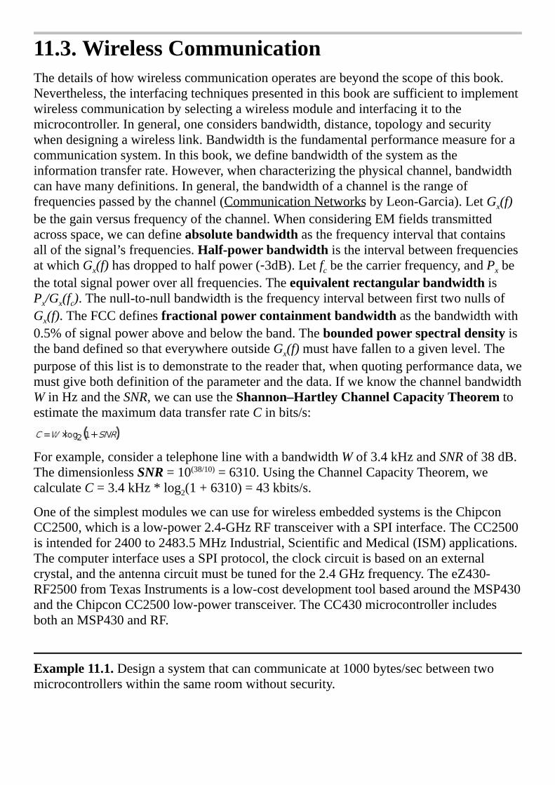
11.3.WirelessCommunicationThedetailsofhowwirelesscommunicationoperatesarebeyondthescopeofthisbook.Nevertheless,theinterfacingtechniquespresentedinthisbookaresufficienttoimplementwirelesscommunicationbyselectingawirelessmoduleandinterfacingittothemicrocontroller.Ingeneral,oneconsidersbandwidth,distance,topologyandsecuritywhendesigningawirelesslink.Bandwidthisthefundamentalperformancemeasureforacommunicationsystem.Inthisbook,wedefinebandwidthofthesystemastheinformationtransferrate.However,whencharacterizingthephysicalchannel,bandwidthcanhavemanydefinitions.Ingeneral,thebandwidthofachannelistherangeoffrequenciespassedbythechannel(CommunicationNetworksbyLeon-Garcia).LetGx(f)bethegainversusfrequencyofthechannel.WhenconsideringEMfieldstransmittedacrossspace,wecandefineabsolutebandwidthasthefrequencyintervalthatcontainsallofthesignal’sfrequencies.Half-powerbandwidthistheintervalbetweenfrequenciesatwhichGx(f)hasdroppedtohalfpower(‑3dB).Letfcbethecarrierfrequency,andPxbethetotalsignalpoweroverallfrequencies.TheequivalentrectangularbandwidthisPx/Gx(fc).Thenull-to-nullbandwidthisthefrequencyintervalbetweenfirsttwonullsofGx(f).TheFCCdefinesfractionalpowercontainmentbandwidthasthebandwidthwith0.5%ofsignalpoweraboveandbelowtheband.TheboundedpowerspectraldensityisthebanddefinedsothateverywhereoutsideGx(f)musthavefallentoagivenlevel.Thepurposeofthislististodemonstratetothereaderthat,whenquotingperformancedata,wemustgivebothdefinitionoftheparameterandthedata.IfweknowthechannelbandwidthWinHzandtheSNR,wecanusetheShannon–HartleyChannelCapacityTheoremtoestimatethemaximumdatatransferrateCinbits/s:
Forexample,consideratelephonelinewithabandwidthWof3.4kHzandSNRof38dB.ThedimensionlessSNR=10(38/10)=6310.UsingtheChannelCapacityTheorem,wecalculateC=3.4kHz*log2(1+6310)=43kbits/s.
OneofthesimplestmoduleswecanuseforwirelessembeddedsystemsistheChipconCC2500,whichisalow-power2.4-GHzRFtransceiverwithaSPIinterface.TheCC2500isintendedfor2400to2483.5MHzIndustrial,ScientificandMedical(ISM)applications.ThecomputerinterfaceusesaSPIprotocol,theclockcircuitisbasedonanexternalcrystal,andtheantennacircuitmustbetunedforthe2.4GHzfrequency.TheeZ430-RF2500fromTexasInstrumentsisalow-costdevelopmenttoolbasedaroundtheMSP430andtheChipconCC2500low-powertransceiver.TheCC430microcontrollerincludesbothanMSP430andRF.
Example11.1.Designasystemthatcancommunicateat1000bytes/secbetweentwomicrocontrollerswithinthesameroomwithoutsecurity.

Solution:Thislowbandwidthcanbesolvedwitharadio-frequency(RF)linkwithoutthecomplexitiesnecessarytosupportBluetoothor802.11.ThisshortdistanceisclassifiedasaShortRangeDevice(SRD).TherearemanyRFcommunicationmodulesthatcouldhavebeenused.AsillustratedinFigure11.6,theCC2500interfacehasthreeparts.Thesystemwilloperateupto500Kbits/sec,andthechipimplementsdual64-bitFIFOsfortransmitandreceive.Basically,themicrocontrolleronthelefttransmitsdataviaitsSPI,andthemicrocontrollerontherightreceivesthedatawithitsSPI.Itisatransceiver,meaningdatacanflowacrossthelinkinbothdirections.
Figure11.6.Blockdiagramofawirelesslinkbetweentwomicrocontrollersystems.
ZigBeeisanotherlow-costwirelesssolutionforembeddedsystems.Thenameisderivedfromthebehaviorofhoneybees.Honeybeesdistributedacrossalargeopenfieldimplementameshnetworkinordertocommunicateinformationtotheirhive.Theydothisbymessagerelaying.Abeedistantfromthehivewillflyaparticularzigzagpatternthatrepresentstheinformation.Asecondbeenearerthehivewillrepeatthepattern.Therelaycontinuesuntiltheinformationreachesthehive.ZigBeeisastandardthatdefinesasetofcommunicationprotocolsforlow-data-rate,verylow-power,short-rangewirelessnetworking.Itcanoperateunderbatterypower,andlastforyearsbecausetherearemultipletypesoflow-powersleepmodes.Itisanappropriatesolutionforsensornetworks,meterreading,industrialautomation,securitysystems,andpatientmonitoring.ZigBeeisanextensionoftheIEEE802.15.4bstandard.ItislowercostandlowerperformancethanBluetoothorIEEE801.11b,asshowninTable11.1.Therangevaluesinthistablerepresentperformanceindoors–outdoors.ZigBeemodulescomeinavarietyofpowerversusperformancemodels.Inotherwords,youcanrunatlowerpowerifyouarewillingtosacrificedistanceanddatarate.
Datarate Range Wirelessapplications
ZigBee 20to250Kbps
10–100m SensorNetworks
Bluetooth 1to3Mbps 2–10m Headset,mouse
IEEE802.11b 1to11Mbps 38–140m Internetconnection
IEEE802.11g 1to54Mbps 38–140m

Internetconnection
IEEE802.11n 1to72Mbps 70–250m Internetconnection
Table11.1.Comparisonofwirelessprotocols.
TheZigBeeprotocolislayered.Thetoplayeristheapplicationlayer,implementedastheuserprogram.Atthislayersoftwareinonenodesendsmessagestoanothernode.Thissectionwillfocusonthislayer,becausewewillpurchaseaZigBeemodulethatperformsthelowerlayersautomatically.Thesecondlayeristheapplicationsupportsublayer(APS).BelowtheAPSisthenetworklayer(NWK).BelowtheNWKisthemediaaccesscontrol(MAC)layer.BelowtheMACisthephysicallayer,whichincludestheRFtransmitterandreceiver.FormoreinformationabouthowZigBeeworks,seehttp://www.zigbee.org/.YoualsocoulddoawebsearchonXBee,whichisalow-costimplementationofZigBee.
ZigBeeisapersonalareanetwork(PAN),asshowninFigure11.7.Therecanbeacoordinator,devicesthatsupportallfunctions,ordevicesthatsupportsomefunctions.AtypicalapplicationofZigBeeisaremotesensornetwork.ConsidereachofthenodesinFigure11.7iscapableofcollectingsensordata.ThesensordatabasecanbecentralizedatthePANcoordinatorordistributedacrosstheentiresystem.
Figure11.7.ZigBeeusedtocreatearemotesensornetwork.Onelow-costimplementationofZigBeeistheXBeemodulefromDigi(formallyMaxStream).ThesemodulestakeZigBeeandwrapitintoasimple-to-useserialcommandset,calledATcommands.Thesemodulesallowaveryreliableandsimplecommunicationbetweenmicrocontrollerswithaserialport.Bothpoint-to-pointandmulti-pointnetworksaresupported.Thehardwareinvolvesinterfacing3.3VfullduplexserialchanneltotheXBeemodule,asshowninFigure11.8.

Figure11.8.Circuitdiagramfora2-nodeZigBeenetwork.PowerandgroundsaresharedbetweenthemicrocontrolleranditsXBeebutnotbetweenXBees.ThefullsoftwaresolutiontothisnetworkwillbeleftasLab11.2.Inthissimpleconfiguration,therecanbeupto256nodesonthenetwork.Theinitializationsoftwaremustestablishthebaudrateat9600bits/sec.Thesystembandwidththereforewillbeontheorderof960bytes/sec.The<CR>symbolreferstothecarriagereturn,character13,existingasone8-bitASCIIcharacter.ToplacetheXBeeinATcommandmode,weexecutesteps1to5overandoveruntilwegetanOKresponse.
1.Sendadummycharacterlike‘X’.
2.Wait1.1second(greaterthantheonesecondguardtime).
3.Output“+++”.
4.Wait1.1second(greaterthantheonesecondguardtime).
5.Waitforresponse,shouldbeOK<CR>.
Eachnodemustestablishitsaddress(calledmy)andthedestinationaddress.Forexample,ifthiscomputerisataddress0x01andwishestosendpacketstothecomputerataddress0x02,thenthiscomputerexecutestheseATcommands.Thesoftwareshouldwait20msaftereachATcommand.WhenanATcommandisexecutedcorrectly,theXBeerespondswithOK<CR>.OneofthesimplestmodesisApplicationProgrammingInterface(API)mode1,whichallowsthenodestosendandreceivepackets:
ATDL02<CR>Setsdestinationaddressto2(numbergiveninhexadecimal)
ATDH0<CR>Setsdestinationhighaddressto0
ATMY01<CR>Setsmyaddressto1(numbergiveninhexadecimal)
ATAP1<CR>SetsAPImode1(packets)
ATCN<CR>Endscommandmode
Theothernodeinthepoint-to-pointconnectionperformsasimilarinitialization,butobviouslywiththemyanddestinationaddressesreversed.UsingtheAPImodesimplifiestheapplicationsoftware,becauseallmessagerouting,errordetection/retransmission,andmessageacknowledgementoccursatlowerlevelsautomatically.Adatatransmissionframehasthefollowingformat:

0x7E,LengthHi,LengthLo,0x01,ID,DestHi,DestLo,0x00,b1,…,bn,Chksum
AllAPImode1framesbeginwith0x7E.Thenexttwobytesarethelengthofthemessage,whichwillbethenumberofbytesafterthelengthandbeforethechecksum.Thelengthdoesnotincludethefourbytescomprisingthe0x7E,whichisthelengthitselfandthechecksum.Thefourthbyte0x01signifiesthisisatransmitdatapacket.TheIDshouldbeusedasamessagesequencenumber.I.e.,asthiscomputersendspacketstothedestinationcomputer,theIDissequencedas1,2,…255,1,2,…AnIDof0isnotused.Thissequencenumberguaranteesthepacketsarriveatthedestinationinthesameorderastheyweresent.
ThetwobytesDestHi,DestLospecifythedestinationnodeaddress.Thehighbyteshouldbezeroforthisconfiguration.Thenextbyteprovidesoptionsfortheframe,whichshouldbe0.Bytesb1throughbnarethedatatobetransmitted.Becausethereisaframelength,thisdatacanbeformattedhoweveryouwish.Thelastbyteoftheframewillbeachecksum.Letsumbethe8-bitadditionofallbytesnotincluding0x7Edelimiterandthelength.WecalculateChksumas0xFF-sum.InthiswaythereceivercanaddupallthebytesafterthelengthandincludingtheChksuminordertogettheresult0xFF.
Forexample,assumewewishtosendthemessage“He”tonode2.Alsoassumethisisthe254thframesent,sotheIDwillbe0xFD.Themessagehasalengthof7.Thechecksumiscalculatedas
0xFF‑(0x01+0xFD+0x00+0x02+0x00+0x48+0x65)=0x52.TheoscilloscoperecordingforthisframeisshowninFigure11.9.
Figure11.9.APItransmitframemeasuredontheDinpinoftheXBeemodule.Whenthetransmittedframeisproperlydelivered,theXBeesendsanacknowledgmenttothetransmitter.Thelengthisalways3bytes.TheAPIcodeis0x89.TheIDmatchesthecorrespondingvalueofthetransmittedframe.Thenextbyteisastatusfield,and0x00meanssuccess.Astatusof0x01meansnoacknowledgementreceived,whichmaymeanthedestinationnodedoesnotexistoristurnedoff.Astatusof0x02meansCCAfailureand0x03meansthemessagewaspurged.TheChksumbyteiscalculatedinthesamemannerasalltheAPIframes.
0x7E,0x00,0x03,0x89,ID,0x00,Chksum

Figure11.10showsascopetracewhenanacknowledgeframewasreportedtothetransmitter.TheIDofthisframeis0xC1.Thechecksumforthisframeis0xFF-(0x89+0xC1+0x00)=0xB5.
Figure11.10.APIacknowledgeframemeasuredontheDoutpinoftheXBeemodule.ThereceiverwithamyaddressmatchingthedestinationaddressofthetransmittedframewillbegiventhatframeasanAPIpackettype0x81.Adatareceiveframehasthefollowingformat:
0x7E,LengthHi,LengthLo,0x81,SourceHi,SourceLo,RSSI,0x00,b1,…,bn,Chksum
Thesourcefieldidentifiesthenodethatsentthemessage.TheRSSI(receivedsignalstrengthindictor)isthedecimalequivalentmeasureofthesignal.Forexample0x3Ameansthereceivedsignalstrengthis58dBm.Theoptionfieldshouldbezero.Bytesb1throughbncontainsthedata.Figure11.11showsascopetraceofthereceivedmessagecorrespondingtothetransmittedmessageinFigure11.9
Figure11.11.APIreceiveframemeasuredontheDoutpinoftheXBeemodule.

11.4.InternetofThings
11.4.1.BasicConceptsWiththeproliferationofembeddedsystemsandthepervasivenessoftheinternet,itisonlynaturaltoconnectthetwo.Theinternetofthings(IoT)isthecombinationofembeddedsystems,whichhavesensorstocollectdataandactuatorstoaffectthesurrounding,andtheinternet,whichprovidesforubiquitousremoteandsecurecommunication.Thissectionwillnotdescribehowtheinternetworks,butratherwewilldiscussboththegeneralandspecificapproachesforconnectingembeddedsystemstotheinternet.ForanexcellentdescriptionoftheTCP/IP(TransmissionControlProtocol/InternetProtocol)protocolthereaderisreferredtoW.RichardStevens,TCP/IPIllustrated,Volume1:TheProtocols.Forageneraldescriptionoftheinternetofthings,seeVasseurandDunkels,InterconnectingSmartObjectswithIP.Thesetwobooksprovidesgoodoverviewsofnetworktechnologiesusedforconnectingdevices.
Figure11.12illustratesthedistributedapproachtakenwiththeinternetofthings.Adistributedsolutiondeploysmultiplesensorsandactuatorsconnectedbytheinternet.Anothernamegivenforanembeddedsystemconnectedtotheinternetissmartobject.Smartobjectsincludesensorstocollectdata,processingtodetecteventsandmakedecisions,andactuatorstomanipulatethelocalenvironment.Therearemanyreasonstoconsideradistributedsolution(network)overacentralizedsolution.Oftenmultiplesimplemicrocontrollerscanprovideahigherperformanceatlowercostcomparedtoonecomputerpowerfulenoughtoruntheentiresystem.Someembeddedapplicationsrequireinput/outputactivitiesthatarephysicallydistributed.Forreal-timeoperationtheremaynotbeenoughtimetoallowcommunicationbetweenaremotesensorandacentralcomputer.Anotheradvantageofdistributedsystemisimproveddebugging.Forexample,wecoulduseonenodeinanetworktomonitoranddebugtheothers.Often,wedonotknowthelevelofcomplexityofourproblematdesigntime.Similarly,overtimethecomplexitymayincreaseordecrease.Adistributedsystemcanoftenbedeployedthatcanbescaled.Forexample,asthecomplexityincreasesmorenodescanbeadded,andifthecomplexityweretodecreasenodescouldberemoved.Table11.2listssomeexistingapplicationsandthethingstheysenseorcontrol.
Figure11.12.Theinternetofthingsplacesinput,outputandprocessing

atmultiplelocationsconnectedtogetherovertheinternet.IndustrialAutomationFactories,machines,shipping
EnvironmentWeather,pollution,publicsafety
SmartGridElectricpower,energydelivery
SmartCitiesTransportation,hazards,publicservices
SocialNetworksIdeas,politics,sales,andcommunication
HomeNetworksLighting,heat,security,information
BuildingNetworksEnergy,hazards,security,maintenance
StructuralMonitorsBridges,roads,building
HealthCareHeartfunction,medicaldata,remotecare
LawenforcementCrime,publicsafetyTable11.2.Applicationsofsmartobjects.
Challenges.Onalocalscale,thedesignofsmartobjectsfacesthesamechallengesexistinginallembeddedsystems:power,size,reliability,longevity,andcost.Luckilythedeploymentofbillionsofmicrocontrollersintothemarkethascreatedatechnologyracetoreducepower,sizeandcostwhileincreasingtheperformance.Atthemicrocontrollerlevelthingsaregettingsmaller,butatthenetworklevel,complexityisincreasingandprotocolsareconstantlychangingastheworld’sthirstforinformationandcommunicationrapidlygrows.
Standardization.Theexistenceofstandardsallowsforawidevarietyofobjectstocommunicatewitheachother.Adheringtoastandardwillincreasetheacceptanceofourdevicebycustomers,andallowourcustomerstoapplyourdevicetosolveproblemsweneverenvisioned.uIPisalight-weightimplementationoftheIPstackspecificallydesignedtooperatewiththeavailablememoryresourcesofsmartobjects.InthissectionwewillstartwithamicrocontrollerwiththehardwareandsoftwaretoimplementTCP/IPprotocols,andbuildourapplicationontopofthisstandard.
Interoperabilitymeansourdevicecanfunctionwithawiderangeofotherdevicesmadewithdifferenttechnologies,soldbydifferentvendors,andproducedbydifferentcompanies.
Evolutionisprocessofhownewtechnologiesareintroducedintothemarket.Ifthereisoneconstantinthisworld,itisthatthingswillchange.Everythousandyears,onebigdiscoveryfundamentlychangeshowweoperate(fire,language,metaltools).Morefrequently,changeisintroducedgraduallysuchthatthosetechnologiesthatgiveusacompetitiveadvantagesurvive.Ifwebuildourbusinessmodelonthepremiseevolutionarychange,thenwecanbenimbletodeploynewtechnologywhenitprovideslowercostand/orbetterperformance.

Stability.Eventhoughtechnologywilladvance,ourcustomersdemandproductsthatworkreliably,foralongtime,andinamannerwithwhichtheyarecomfortable.Overthelast50yearsautomotivetechnologyhasdrasticallyimproved,butthedrivingexperience,howwedrive,hasremainedalmostconstant.
Abstraction.Youwillnoticetheapproachinthissectiondifferswidelyfromtheotherexamplesinthisbook.Therestofthebookdeploysabottomupapproach.Withbottom-upeducation,thedetailsarefirstexplained,sothereisnomagic,andthenabstractionoccursbyencapsulatingthatwefullyunderstand.Inthissectionwewillpurchasehardwareandsoftwarewithcapabilitiestocommunicatewiththeinternet,andusethisabstractionwithoutfullyunderstandinghowsomeofthelowerlevelsoperate.
Scalability.ARMreportsover50milliondeviceswithanARMcorehavebeenshippedfrom1993to2013,andpredictsanother50billionbeforetheendofthisdecade.Inordertobeeffectiveandprofitable,weneedtodevelopsystemsthatcanscale.
Security.Becauseembeddedsystemsaredeployedinlife-criticalsituations,andbecausethequalityofserviceaffectourprofits,wemustprotectthesystemfromadeterminedadversary.Achainisonlyasstrongasitsweakestlink.Securitycannotbeobtainedsimplybyoperatinginsecret,becauseoncethesecretisout,thesystemwillbeextremelyvulnerable.“Securitybyobscurity”isaverypoordesignmethod.Securityinvolvesmorethanencryptingthedata.Thefirstaspectofsecurityisconfidentiality.Wemustdecidewhatitmeanstoview/changethedataandwhohastherighttoread/write.Authenticationisthemeanstoensuretheidentityofthesenderiscorrect.Confidentialitywillrequirebothlogicalandphysicalmeasurestoprotectagainanattack.Encryptionmakesitharderforanunauthorizedpartytoviewamessage.Thesecondaspectisdataintegrity.FormostoftheapplicationslistedinTable11.2itisimportantthatdatareachtherightfulrecipientinanunalteredfashion.Tosupportnetworkintegrityweneedtechniquesthatsupportbothdetectionandprevention.Thethirdaspectisavailability.Asecurecommunicationnotonlyrequiresthecorrectdataarriveatthecorrectplace,butalsoatthecorrecttime.ADenialofService(DoS)attackattemptstobreachtheavailabilityofthenetwork.Forwirednetworks,wecanreroutetrafficalongmultiplepaths.Withwirelessnetworks,wecanchannelhopbyswitchingchannelsonapseudorandomfashion,makingitharderforanattackertojam.Formoreinformationonsecurity,seeFrankStajano,SecurityforUbiquitousComputing.
11.4.2.LayeredModel
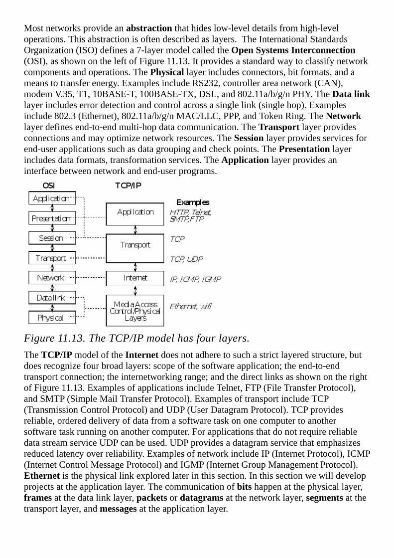
Mostnetworksprovideanabstractionthathideslow-leveldetailsfromhigh-leveloperations.Thisabstractionisoftendescribedaslayers.TheInternationalStandardsOrganization(ISO)definesa7-layermodelcalledtheOpenSystemsInterconnection(OSI),asshownontheleftofFigure11.13.Itprovidesastandardwaytoclassifynetworkcomponentsandoperations.ThePhysicallayerincludesconnectors,bitformats,andameanstotransferenergy.ExamplesincludeRS232,controllerareanetwork(CAN),modemV.35,T1,10BASE-T,100BASE-TX,DSL,and802.11a/b/g/nPHY.TheDatalinklayerincludeserrordetectionandcontrolacrossasinglelink(singlehop).Examplesinclude802.3(Ethernet),802.11a/b/g/nMAC/LLC,PPP,andTokenRing.TheNetworklayerdefinesend-to-endmulti-hopdatacommunication.TheTransportlayerprovidesconnectionsandmayoptimizenetworkresources.TheSessionlayerprovidesservicesforend-userapplicationssuchasdatagroupingandcheckpoints.ThePresentationlayerincludesdataformats,transformationservices.TheApplicationlayerprovidesaninterfacebetweennetworkandend-userprograms.
Figure11.13.TheTCP/IPmodelhasfourlayers.TheTCP/IPmodeloftheInternetdoesnotadheretosuchastrictlayeredstructure,butdoesrecognizefourbroadlayers:scopeofthesoftwareapplication;theend-to-endtransportconnection;theinternetworkingrange;andthedirectlinksasshownontherightofFigure11.13.ExamplesofapplicationsincludeTelnet,FTP(FileTransferProtocol),andSMTP(SimpleMailTransferProtocol).ExamplesoftransportincludeTCP(TransmissionControlProtocol)andUDP(UserDatagramProtocol).TCPprovidesreliable,ordereddeliveryofdatafromasoftwaretaskononecomputertoanothersoftwaretaskrunningonanothercomputer.ForapplicationsthatdonotrequirereliabledatastreamserviceUDPcanbeused.UDPprovidesadatagramservicethatemphasizesreducedlatencyoverreliability.ExamplesofnetworkincludeIP(InternetProtocol),ICMP(InternetControlMessageProtocol)andIGMP(InternetGroupManagementProtocol).Ethernetisthephysicallinkexploredlaterinthissection.Inthissectionwewilldevelopprojectsattheapplicationlayer.Thecommunicationofbitshappenatthephysicallayer,framesatthedatalinklayer,packetsordatagramsatthenetworklayer,segmentsatthetransportlayer,andmessagesattheapplicationlayer.

11.4.3.MessageProtocolsThelayeredformatcanbeseeninthemessagepacketformats,asoverviewedinFigure11.14.Atthelowestlevelarephysicalframes.Ethernetframescontainaheader,46to1500bytesofpayload,andatrailer.Theheaderincludesaddress,typeandlengthinformation.Ifthethereislessthan46bytesofEthernetdata,zerosareadded(padding)tomaketheEthernetpayloadatleast46bytes.Thetrailerincludeserrorchecking(CRC).AttheIPlevel,packetsincludeaheaderandpayload.TheheaderofanIPpacketincludesa32-bitdestinationIPaddress,typicallyshownasfour8-bitnumbers(e.g.,176.31.244.1).SomeoftheseIPaddressesarereservedforcommunicatingwithinnodesonalocalnetwork.TheDomainNameSystem(DNS)hostcanbeusedtotranslatedomainnamestoIPaddresses.ComputersthatcommunicateonlywitheachotherviaTCP/IP,butarenotconnectedtotheInternet,neednothavegloballyuniqueIPaddresses.IPaddressesforprivatenetworksarelistedinTable11.3.TheseIPaddressescouldbeusedforembeddedsystemsthatuseTCP/IPtocommunicate,butarenotconnectedtotheinternet.
Start End Numberofaddresses
10.0.0.0 10.255.255.255 224
172.16.0.0 172.31.255.255 220
192.168.0.0 192.168.255.255 216
Table11.3.PrivateIPaddresses.
Becauseofthegrowthoftheinternet,the32-bitIPaddress(IPv4)isbeingreplacedwitha128-bitaddress(IPv6),whichwillprovideforabout3∙1038addresses.TheIPheaderis20to40bytesandcontainsthesourceIPaddress,destinationIPaddress,andlength.
TheUDPheaderis8bytesandcontainsthesourceport,destinationport,length,andchecksum,seeTable11.4.TheIPaddressspecifiesthenode,andportsareaddresseswithinthesourceanddestinationnodes.
Sourceport:16-bitnumberoftheprocessthatsentthepacket,couldbezero
Destinationport:16-bitnumberoftheprocesstoreceivethepacket.
Length:16-bitnumberspecifyingthesizeinbytesofthedatatofollow
Checksum:16-bitmoduloadditionofalldata,UDPheader,andIPheaderTable11.4.UDPheaderformat.

TheTCPheaderis20byteswiththepossibilityofadditionalandoptionalinformation,seeTable11.5.Thesequenceandacknowledgmentnumbersallowthereceivertoproperlysortsegmentsofdatathatwerereceivedoutoforder.TheflagsspecifydifferentmodesoftheTCPcommunication.TheSYNflagmeansthefirstofasequenceofpackets,andtheFINflagmeansthelast.TheRSTflagterminatesaconnection.TheURGflagmeanstheurgentpointerspecifiesapieceofdatatheapplicationurgentlyneeds.
Figure11.14.Overviewofmessagepacketsusedatvariouslayers.
Sourceport:16-bitnumberoftheprocessthatsentthepacket,couldbezero
Destinationport:16-bitnumberoftheprocesstoreceivethepacket.
Sequencenumber:32-bitnumberdefiningthepositionofthisdata
Acknowledgement:32-bitnumberofthenextdataexpectedtobereceived
Hlen:4-bitfieldoftheheadersize(includingoptions)dividedby4
Flags:6-bitfieldwithFIN,SYN,RST,PSH,ACK,andURG
Window:16-bitnumberspecifyingthenumberofbytesthereceivercanaccept
Checksum:16-bitmoduloadditionofalldata,TCPheader,andIPheader
Urgentpointer:16-bitfieldpointingtoaplaceinthestreamurgentlyneededTable11.5.TCPheaderformat.
11.4.4.Webserver
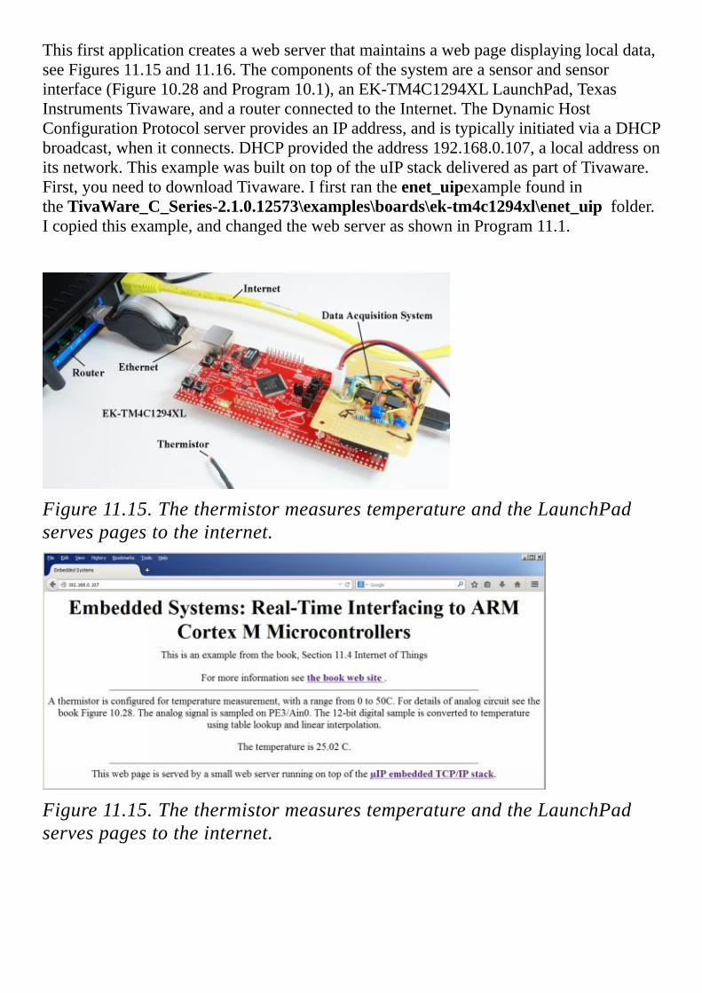
Thisfirstapplicationcreatesawebserverthatmaintainsawebpagedisplayinglocaldata,seeFigures11.15and11.16.Thecomponentsofthesystemareasensorandsensorinterface(Figure10.28andProgram10.1),anEK-TM4C1294XLLaunchPad,TexasInstrumentsTivaware,andarouterconnectedtotheInternet.TheDynamicHostConfigurationProtocolserverprovidesanIPaddress,andistypicallyinitiatedviaaDHCPbroadcast,whenitconnects.DHCPprovidedtheaddress192.168.0.107,alocaladdressonitsnetwork.ThisexamplewasbuiltontopoftheuIPstackdeliveredaspartofTivaware.First,youneedtodownloadTivaware.Ifirstrantheenet_uipexamplefoundinthe TivaWare_C_Series-2.1.0.12573\examples\boards\ek-tm4c1294xl\enet_uip folder.Icopiedthisexample,andchangedthewebserverasshowninProgram11.1.
Figure11.15.ThethermistormeasurestemperatureandtheLaunchPadservespagestotheinternet.
Figure11.15.ThethermistormeasurestemperatureandtheLaunchPadservespagestotheinternet.

Program11.1showsthecodeyouneedtomodifytocreateyourownremotesensorsmartobject.Whenanothernodesendsarequesttothisserver,thisnodewillrespondwithhtmlcodetorenderthepage.Thepageisdividedintothreeparts.Thefirstpart( default_page_buf1of3 )andlastpart( default_page_buf3of3 )arefixed.Theapplicationcallbackfunction, httpd_appcall ,isinvokedwhenthewebpageisrequested.Thiscallbackfunctioncallsourapplicationfunction Board_Update whichcollectssensordatafromthethermistorandrebuildsthemiddlepartofthehtmlcode( default_page_buf2of3 ).Themetacodeautomaticallyrefreshesevery5seconds.constchardefault_page_buf1of3[]=
“HTTP/1.0200OK\r\n”
“Server:UIP/1.0(http://www.sics.se/~adam/uip/)\r\n”
“Content-type:text/html\r\n\r\n”
“<!DOCTYPEHTMLPUBLIC\”-//W3C//DTDHTML4.01Transitional//EN”
“http://www.w3.org/TR/html4/loose.dtd\”>”
“<html><head>”
“<metahttp-equiv=\“refresh\”content=\“5\”>”
“<title>EmbeddedSystems</title></head>”
“<body><center>”
“<h1>EmbeddedSystems:Real-TimeInterfacing”
“toARMCortexMMicrocontrollers</h1>”
“<p>Thisisanexamplefromthebook,Section11.4InternetofThings</p>”
“<p>Formoreinformationsee“
“<ahref=\“http://users.ece.utexas.edu/~valvano/arm/outline.htm\”>”
“<b>thebookwebsite</b></a>.”
“<hrwidth=\“75%\”>”
“<p>Athermistorisconfiguredfortemperaturemeasurement,“
“witharangefrom0to50C.“
“FordetailsofanalogcircuitseethebookFigure10.28.“
“TheanalogsignalissampledonPE3/Ain0.“
“The12-bitdigitalsampleisconvertedtotemperatureusingtablelookup“
“andlinearinterpolation.</p>“
“<p>Thetemperatureis“;
uint32_tconstbuf1of3_Size=(sizeof(default_page_buf1of3)-1);
chardefault_page_buf2of3[]=“12.01”;
uint32_tbuf2of3_Size=(sizeof(default_page_buf2of3)-1);
constchardefault_page_buf3of3[]=
”C.</p>”
“<hrwidth=\“75%\”>”
“<p>Thiswebpageisservedbyasmallwebserverrunningontopof“

“the<ahref=\“http://www.sics.se/~adam/uip/\”><b>µIPembeddedTCP/IP“
“stack</b></a>.</center></body></html>”;
uint32_tconstbuf3of3_Size=(sizeof(default_page_buf3of3)-1);
voidBoard_Update(void)uint32_tdata,temperature;
data=ADC0_InSeq3();//12-bitADC,0to4095
temperature=ADC2Temperature(data);//temperature,0.01C
Fix2Str(temperature,default_page_buf2of3);//5ASCIIcharacters
buf2of3_Size=5;//inthiscaseitisfixedsize(butitcouldvary)
Program11.1.ThethermistormeasurestemperatureandtheLaunchPadservespagestotheinternet.ToruntheinternetexamplesdescribedinthissectiondownloadandunziptheIoTexamplesintoexamples\boardssothedirectorypathlookslikethis
TivaWare_C_Series-2.1.0.12573
examples
boards
CC31xxxx
ek-tm4c1294xl-enet_uip_temperature
ek-tm4c123gxl-boost-cc3100_basic_wifi_UDP
ek-tm4c123gxl-boost-cc3100_starter
ek-tm4c1294xl-boost-cc3100_starter
11.4.5.UDPcommunicationoverwifiTheapproachforimplementingasmartobjectoverwifiistobeginwithahardware/softwareplatformthatimplementsIEEE801.11wifi.TheCC3100BOOSTisaboosterpackthatcanbeusedwiththeMSP430LaunchPad,theTM4C123LaunchPad,theTM4C1294LaunchPad,orwithaCC31XXEMUBOOSTemulationmodule,seeFigure11.16.Theemulationmodulecanbeusedearlyinaprojecttodevelopwirelessapplicationsusinga“generic”microcontroller.Afteraprototypeisconfigured,theprojectcanselectamicrocontrolleranddesigntheactualsmartobject.InthisdesignwewilluseeitherofthetwoTM4CLaunchPadsanddevelopasolutionthattransmitsUDPpacketsfromonesmartobjecttoanother.UDPissimplerthanTCPandappropriateforapplicationsrequiringsimplicityandspeed.Furthermore,touseUDPtheapplicationmusttoleratelostoroutoforderpackets.UDPprovidesabest-effortdatagramdeliveryservice.

Figure11.16.TheCC3100boosterpacketprovidesIEEE802.11wirelessconnectivity.TheactualTCP/IPsoftwarestackresidesinfirmwareontheboosterpackitself.Therefore,whenusinganyofthewirelessboosterpacksthefirststepistoupgradethefirmware.OnewaytoupgradethefirmwareistousetheCC31XXEMUBOOSTemulationmodule.Theexamplesofthissectionranonversion3.3boosterpackswithoutneedingtoupgradethefirmare.
Program11.2showstheclientsoftware,whichsamplestheADCandsendsUDPpackets.Line1specifiesthenameoftheaccesspoint(AP)towhichthenodewillconnect.ThereisamechanismusingSmartConfigtoautomatethisdiscovery,butinthisexampleInamedtheAPValvanosoIusedamanualmethodtodefinetheconnectionbetweenthenodeandAP.TheUDPpayloadwillhaveatypefield,whichisdefinedinline2.ThedestinationIPaddressishard-codedinline3.Forthisapplication,theserverwasatIPaddressaddress192.168.0.101,whichinhexisC0.A8.00.65.Theportnumber,whichisa16-bitvaluedefiningwhichprocessintheservershouldreceivethedata,isspecifiedinline4.Therearealonglistofregisteredportnumbersthathavespecialpurposes,soIchoseaportnumberlargerthan1024toavoidselectinganyofthesespecialpurposeportnumbers.Lines5and6definethepayloadfortheUDPpacket.Line15setsthebusclockto50MHz.ThePLLneedstobeactivefortheADCtooperate.Line16initializestheADCchannel7usingPD0.Line17initializestheCC3100.Afterexecutingline18wewillbeconnectedandhaveIPaddress.Line19willreturnthenetworkconfiguration.Lines21-24definetheaddressandporttowhichtheUSPpacketwillbesent.Line25definesandopensasocket.Inthisexampleweleavethesocketopen,butitisoktoclosethesocket,gointolow-powermode,andreopentheconnectionaftersleeping.Lines26-29willsampletheADCandcreateanewmessage.Line30sendstheUDPpacketthroughtheopensocket.Thewaitinline32definestherateatwhichpacketsaresent.Eachofthewififunctionswillreturnasuccessflag(errorcode).Inthissimpleprogramweignoredthereturnvalues,assumingitwasok.Intheversionontheweb,theprocessisrestartedonerror.
#defineSSID_NAME“Valvano”//APtoconnectto1
#defineATYPE‘a’//analogdatatype2

#defineIP_ADDR0xC0A80065//serverIP3
#definePORT_NUM5001//Portnumbertobeused4
#defineBUF_SIZE12//5
UINT8uBuf[BUF_SIZE];//UDPpacketpayload6
intmain(void)
UINT8IsDHCP=0;
_NetCfgIpV4Args_tipV4;
SlSockAddrIn_tAddr;
UINT16AddrSize=0;
INT16SockID=0;
UINT32data;
unsignedcharlen=sizeof(_NetCfgIpV4Args_t);
initClk();//PLL50MHz,ADCneedsPPLactive15
ADC0_InitSWTriggerSeq3(7);//Ain7isonPD016
sl_Start(0,0,0);//InitializingtheCC3100device17
WlanConnect();//connecttoAP18
sl_NetCfgGet(SL_IPV4_STA_P2P_CL_GET_INFO,&IsDHCP,&len,//19
(unsignedchar*)&ipV4);//20
Addr.sin_family=SL_AF_INET;//21
Addr.sin_port=sl_Htons((UINT16)PORT_NUM);//22
Addr.sin_addr.s_addr=sl_Htonl((UINT32)IP_ADDR);//23
AddrSize=sizeof(SlSockAddrIn_t);//24
SockID=sl_Socket(SL_AF_INET,SL_SOCK_DGRAM,0);//25
while(1)
uBuf[0]=ATYPE;//analogdatatype26
uBuf[1]=‘=’;//27
data=ADC0_InSeq3();//0to4095,Ain7isonPD028
Int2Str(data,(char*)&uBuf[2]);//6digitnumber29
sl_SendTo(SockID,uBuf,BUF_SIZE,0,//30
(SlSockAddr_t*)&Addr,AddrSize);//31
ROM_SysCtlDelay(ROM_SysCtlClockGet()/25);//40ms32

Program11.2.ClientsoftwarethatmeasuresADCdataandsendsUDPpackets.Program11.3showstheserversoftware,whichacceptsUDPpacketsandplotsthedataonanST7735graphicsLCD.Line1specifiesthenameoftheaccesspoint(AP)towhichthenodewillconnect.TheclientandserverusethesameAP,whichInamedValvano,soIusedthemanualmethodtodefinetheconnectionbetweenthenodeandAP.TheUDPpayloadwillhaveatypefield,whichisdefinedinline2.Lines16,22-25configurethewificonnectioninasimilarwayastheclient.Lines17-20initializetheST7735LCDandoutputawelcomemessage.Line21configurestheLCDgraphicsroutinesspecifyingtherangeonthey-axisoftheplot.RawADCdatawillbeplottedversustime.Lines26-29defineanIPaddressandporttouse.Line31definesandopensasocket,andlines32-33bindtheporttothatsocket.Lines34-35receiveaUDPpacket.Justliketheclient,weleavethesocketopen.Ifwewishedtosavepower,wecouldclosethesocket,gointolow-powermode,andreopentheconnectionaftersleeping.Lines36-51decodethepacketandplotthedataontheLCD.
#defineSSID_NAME“Valvano”//APtoconnectto1
#defineATYPE‘a’//analogdatatype2
#defineIP_ADDR0xC0A80065//serverIP3
#definePORT_NUM5001//Portnumbertobeused4
#defineBUF_SIZE12//5
UINT8uBuf[BUF_SIZE];//UDPpacketpayload6
intmain(void)
UINT8IsDHCP=0;
_NetCfgIpV4Args_tipV4;
SlSockAddrIn_tAddr,LocalAddr;
UINT16AddrSize=0;
INT16SockID=0;
INT16Status=1;//ok
UINT32data;
unsignedcharlen=sizeof(_NetCfgIpV4Args_t);
initClk();//PLL50MHz,ADCneedsPPLactive16
ST7735_InitR(INITR_REDTAB);//Initialize17
ST7735_OutString(“InternetofThings\n”);//18
ST7735_OutString(“EmbeddedSystems\n”);//19
ST7735_OutString(“Vol.2,Valvano”);//20

ST7735_PlotClear(0,4095);//rangefrom0to409521
sl_Start(0,0,0);//InitializingtheCC3100device22
WlanConnect();//connecttoAP23
sl_NetCfgGet(SL_IPV4_STA_P2P_CL_GET_INFO,&IsDHCP,&len,//24
(unsignedchar*)&ipV4);//25
LocalAddr.sin_family=SL_AF_INET;//26
LocalAddr.sin_port=sl_Htons((UINT16)PORT_NUM);//27
LocalAddr.sin_addr.s_addr=0;//28
AddrSize=sizeof(SlSockAddrIn_t);//29
while(1)
SockID=sl_Socket(SL_AF_INET,SL_SOCK_DGRAM,0);//31
Status=sl_Bind(SockID,(SlSockAddr_t*)&LocalAddr,//32
AddrSize);//33
Status=sl_RecvFrom(SockID,uBuf,BUF_SIZE,0,//34
(SlSockAddr_t*)&Addr,(SlSocklen_t*)&AddrSize);//35
if((uBuf[0]==ATYPE)&&(uBuf[1]==‘=’))//36
inti,bOk;uint32_tplace;//37
data=0;bOk=1;//38
i=4;//ignorepossiblenegativesign39
for(place=1000;place;place=place/10)//40
if((uBuf[i]&0xF0)==0x30)//ignorespaces41
data+=place*(uBuf[i]-0x30);//42
else//43
if((uBuf[i]&0xF0)!=‘‘)//44
bOk=0;//45
//46
//47
i++;//48
//49
if(bOk)//50
ST7735_PlotLine(data);//51
ST7735_PlotNextErase();//51

Program11.3.ServersoftwarethatreceivesUDPpacketsandplotsresultsontheLCD.SinceUDPtransmissionis“besteffort”wecouldloosepacketsorreceivepacketsoutoforder.Inthissimpleexamplewewillnotknowifeitheroftheseerrorsweretooccur.Ifwewishedtohaveamorereliabletransmission,wecouldhaveusedTCP.Program11.2line25wouldhavespecifiedasocketstreaminsteadofadatagram.TocreateaTCPcommunication,usetheexamplesoftwareinthe tcp_socket folder.
SockID=sl_Socket(SL_AF_INET,SL_SOCK_STREAM,0);//TCPsocket
11.4.6.OtherCC3100ApplicationsThissectionliststhesampleapplicationsarealsoprovidedforMSP430F5739,TM4C123GH6PMandSimpleLinkStudio.ThesourcecodefortheseexamplescanbefoundintheexamplesdirectoryafterdownloadingCC3100SDK,theSimpleLinkWi-FiCC3100SoftwareDevelopmentKit(SDK)fromtheTIwebsite.Formoredetailsoneachexample,seethedocsfolderincludedintheCC3100SDKdownload.TheCC3100comespreloadedwithCC3100BoosterPackcomespreloadedwithOutofBoxHTMLpages.Outofboxdemohighlightsthefollowingfeatures:SimpleWLANConnectionUsingSmartConfig,andeasyaccesstoCC3100usingmDNSandHTTPServer.
AntennaSelection.Thisisareferenceimplementationforantenna-selectionschemerunningonthehostMCU,toenableimprovedradioperformanceinsidebuildings
ConnectionPolicies.ThisapplicationdemonstratestheusageoftheCC3100profilesandconnection-policies.
SendEmail.ThisapplicationsendsanemailusingSMTPtoauser-configurableemailaddressatthepushofabutton.
EnterpriseNetworkConnection.ThisapplicationdemonstratestheprocedureforconnectingtheCC3100toanenterprisenetwork.
FileDownload.ThisapplicationdemonstratesfiledownloadfromacloudservertotheonboardserialFlash.
FileSystem.ThisapplicationdemonstratestheuseofthefilesystemAPItoreadandwritefilesfromtheserialFlash.
GetTime.ThisapplicationconnectstoanSNTPcloudserverandreceivestheaccuratetime.

GetWeather.Thisapplicationconnectsto‘OpenWeatherMap’cloudserviceandreceivesweatherdata.
GettingStartedinAPMode.ThisapplicationconfigurestheCC3100inAPmode.Itverifiestheconnectionbypingingtheconnectedclient.
GettingStartedinStationMode.ThisapplicationconfigurestheCC3100inSTAmode.ItverifiestheconnectionbypingingtheconnectedAccessPoint.
HTTPServer.Thisapplicationdemonstratesusingtheon-chipHTTPServerAPIstoenablestaticanddynamicwebpagecontent.
IPConfiguration.ThisapplicationdemonstrateshowtoenablestaticIPconfigurationinsteadofusingDHCP.
mDNS.ThisapplicationregistersthemDNSserviceforbroadcastingandattemptstogettheservicebythenamebroadcastedbyanotherdevice.
ModeConfiguration.ThisapplicationdemonstratesswitchingbetweenSTAandAPmodes.
NWPFilters.ThisapplicationdemonstratestheconfigurationofRx-filteringtoreducetheamountoftraffictransferredtothehost,andtoachievelowerpowerconsumption.
NWPPowerPolicy.Thisapplicationshowshowtoenabledifferentpowerpoliciestoreducepowerconsumptionbasedonusecaseinthestationmode.
P2P(Wi-FiDirect).ThisapplicationconfiguresthedeviceinP2P(Wi-FiDirect)modeanddemonstrateshowtocommunicatewitharemotepeerdevice.
ProvisioningAP.ThisapplicationdemonstratestheuseoftheonChipHTTPserverforWi-FiprovisioninginAPMode,buildinguponexampleapplication7.8above.
ProvisioningwithSmartConfig.ThisapplicationdemonstratestheusageofTI’sSmartConfig™Wi-Fiprovisioningtechnology.TheWi-FiStarterApplicationforiOSandAndroidisrequiredtousethisapplication.Itcanbedownloadedfromfollowinglink:http://www.ti.com/tool/wifistarterorfromtheAppleAppstoreandGooglePlay.
ProvisioningwithWPS.ThisapplicationdemonstratestheusageofWPSWi-FiprovisioningwithCC3100.
ScanPolicy.Theapplicationdemonstratesthescan-policysettingsinCC3100.
SPIDiagnosticsTool.ThisisadiagnosticsapplicationfortroubleshootingthehostSPIconfiguration.
SSL/TLS.TheapplicationdemonstratestheusageofcertificateswithSSL/TLSforapplicationtrafficprivacyanddeviceoruserauthentication
TCPSocket.TheapplicationdemonstratessimpleconnectionwithTCPtraffic.
TransceiverMode.TheapplicationdemonstratestheCC3100transceivermodeofoperation.
UDPSocket.TheapplicationdemonstratessimpleconnectionwithUDPtraffic.

XMPPClient.TheapplicationdemonstratesinstantmessagingusingacloudbasedXMPPserver.
ThesewerethestepsIusedtocreatetheUDPcommunicationexampleinSection11.4.5.Ibeganwiththestarterapplication, ek-tm4c123gxl-boost-cc3100_starter .Ifirstchanged SSID_NAME tomatchouraccesspoint
#defineSSID_NAME“Valvano”//APtoconnectto
Next,Icompiled,downloadedandranthisapplicationontotwoLaunchPad+CC3100systems,observingtheoperatingonPuTTy.TheinterpreteroutputshouldshowithasconnectedandshowstheIPassignedtothesetwonodesbytheAP.IcouldrunthepingcommandtocheckthewificonnectiontomyAP.
OnceIwassuremytwoLaunchPad+CC3100systemscouldcommunicatewithmyAP,Imadeacopyofthestarterapplicationbycopy-pastingtheentirefolder.Irenamedthisnewfolderto ek-tm4c123gxl-boost-cc3100_basic_wifi_UDP .IopenedthenewprojectinthecompilerIDEandopenedthemain.cfromthe udp_socket examplefolder.Iaddedand/ormergedthesourcecodefrommain.cof udp_socket intostarter.cofthenewproject.Theeventhandlersandthemainprojectneededmerging,butthe BsdUdpClient and BsdUdpServer functionsweresimplyadded.IchangedtheIPaddresstomatchtheaddressgiventotheserver.
#defineIP_ADDR0xC0A80068
Ithenloadedaversionthatcalledtheclient(sendUDP)ononesystem
while(1)BsdUdpClient(PORT_NUM);
andloadedaversionthatcalledtheserver(receiveUDP)ontheothersystem
while(1)BsdUdpServer(PORT_NUM);
Iranthetwosystemsinthedebuggertoseethatpacketswerebeingsent.IdidnotuseSmartConfig,becauseIknewthenameoftheAP.Thelaststepwastomodifytheclientandserversotheclientcollectsdataandtheserverdisplaysit.

11.5.Exercises11.1Foreachtermgiveadefinitionin32wordsorless.
a)Master-slaveb)Multidrop
c)Channelcapacityd)Ringnetwork
e)Lossycompressionf)Crosstalk
g)Stuffbitsh)Frequencyshiftkey
i)Phaseencodingj)Compression
11.2Foreachpairoftermscompareandcontrastin32wordsorless.
a)Fullduplexversushalfduplex
b)Losslessversuslossycompression
c)Guidedversusunguidedmedia
d)LRCversuschecksum
e)Originateversusanswer
11.3Whatfundamentalpropertyisusedtotransmitinformationthroughachannel?
11.4Consideratelephonelinewithachannelbandwidthof2kHzandSNRof40dB.Whatisthemaximumdataratepossible?
11.5Consideratelephonelinewithachannelbandwidthof4kHzandSNRof30dB.Whatisthemaximumdataratepossible?
11.6Assumenode0x31wishestosendthemessage“Hello”tonode0x32.LetID=0.LetRSSI=0x3A.
a)GivetheAPImode1framenode0x31sendstoitsXBeemodule.Includetheentiremessagefrom0x7Euptoandincludingthechecksum.
b)GivetheAPImode1frame0x32willreceivefromitsXBeemodule.
11.7Assumenode0x41wishestosendthemessage“Ciao”tonode0x42.LetID=0x12.LetRSSI=0x3A.
a)GivetheAPImode1framenode0x41sendstoitsXBeemodule.Includetheentiremessagefrom0x7Euptoandincludingthechecksum.

b)GivetheAPImode1frame0x42willreceivefromitsXBeemodule.
D11.8.Theobjectiveofthisproblemistodesignacommunicationnetworkusingfoursinglechipmicrocontrollersplacedinaring.Developamessageprotocolthatsupportsaddressingandvariablelengthdata.PerformtheI/Ointhebackgroundusinginterruptsynchronization.

11.6.LabAssignmentsLab11.1.Theoverallgoalofthislabistodesign,implementandtestapeer-to-peercommunicationsystem.Peer-to-peermeanspeopleontwocomputerscommunicatewithoutthepeopleontheothercomputersseeingtheinformation.Thesystemmustusearing-connectedRS232serialchannel(Figure11.3),mustuseinterrupt-drivenI/O,andmusthavealayeredsoftwareconfiguration.Thelowest-levelsoftwareperformsserialI/O.Themiddle-levelsoftwaresendsmessagepacketsfromonecomputertoanother.Thehighestlevelsoftwareinterfaceswiththehumanoperator(keypad/LCD)andprovidesamechanismtocreateapeer-to-peerconnection.Inalayeredsystem,softwareinonelayercanonlycallroutineswithinthatlayerorthelayerimmediatelybelowit.Youneedawaytoseewhoisonthenetwork,andawaytorequest/accept/terminateconnectionbetweentwooperators.Localoperatorinput/outputwilloccurviaakeypadandLCD.Youmayassumeallnodesonthesystemarewillingtocooperateandnotperformmaliciousactivity.Ontheotherhanditispossiblethatanothercomputeronthenetworkmaynotbepluggedin,orthenetworkconnectionmaybebroken.
Thecommunicationsystembetweentwoormoremicrocontrollerswillbedesignedinthreelayers.Thefirstlayer,thephysicallayerisimplementedbytheUARThardwareandtheinterrupt-drivendevicedriver.Thesecondlayermayconsistofasimplifiedbinarysynchronouscommunicationprotocol(BSC).Atthislevelmessagepacketswillbetransmittedbetweenthetwomachines.ThehighestlevelwillbeakeypadinterpreterandanLCDdisplay.TheLCDshouldshowinteractivefeedbacktotheoperatorcreatesmessagestobesentanddisplaysmessagesreceived.
Lab11.2.Theobjectiveofthislabistodesignapoint-to-pointZigBeenetworkusingtheXBeemodule.Eachmicrocontrollerwillhaveakeypadandatwo-lineLCDdisplay.Whentheoperatortypesonthekeypad,charactersaredisplayedononelineoftheLCD.Whentheoperatorhitsthesendkey,thosecharactersaresentandeventuallydisplayedonthesecondlineoftheLCDoftheothermicrocontroller.Debugthesysteminabottom-upmanner.WritesimplemainprogramsintheRxandTxsystemstotestthelow-levelfunctionalityoftheinterface.Addappropriatedebugginginstruments,suchasprofilesanddumps.Connectunusedpinsfrombothdevicestoasinglelogicanalyzerandrecordathreadprofile(whichprogramrunswhen)asastreamofdataispassedfromtheTxsystemtotheRxsystem.Writeamainprogramtomeasuremaximumbandwidthofyourchannelwithoutusinghardwareflowcontrol.Furthermore,youshoulddeterminewhichcomponentlimitsbandwidth.Modifythetransmittersoitoutputspseudodataasfastaspossible.ModifythereceiversoitdoesnotdisplaydataontheLCD.Rather,thereceiverwillcheckforthispatternofcharactersandcountthenumberoferrors.Addminimallyintrusivedebugginginstrumentstodetermineifandwheredataislost.Measurethemaximumrangeofyoursystem.Inparticular,findthemaximumdistancewherethesystemperformsreliablecommunication.


Appendix1.Glossary1/fnoiseAfundamentalnoiseinresistivedevicesarisingfromfluctuatingconductivity.Sameaspinknoise.
2’scomplement(seetwo’scomplement).
60HznoiseAnaddednoisefromelectromagneticfieldscausedbyeithermagneticfieldinductionorcapacitivecoupling.
accumulatorHigh-speedmemorylocatedintheprocessorusedtoperformarithmeticorlogicalfunctions.AnyoftheregistersR0toR12ontheARMCortex-Mprocessorcanbeusedasaccumulators.
accuracyAmeasureofhowcloseourinstrumentmeasuresthedesiredparameterreferredtotheNIST.
acknowledgeClearingtheinterruptflagbitthatrequestedtheinterrupt.
activethreadAthreadthatisintheready-to-runcircularlinkedlist.Itiseitherrunningorisreadytorun.
actuatorElectro-mechanicalorelectro-chemicaldevicethatallowscomputercommandstoaffecttheexternalworld.
ADCAnalogtodigitalconverter,anelectronicdevicethatconvertsanalogsignals(e.g.,voltage)intodigitalform(i.e.,integers).
addressbusAsetofdigitalsignalsthatconnecttheCPU,memoryandI/Odevices,specifyingthelocationtoreadorwriteforeachbuscycle.Seealsocontrolbusanddatabus.
addressdecoderAdigitalcircuithavingtheaddresslinesasinputandaselectlineasoutput(seeselectsignal)
agingAtechniqueusedinpriorityschedulersthattemporarilyincreasesthepriorityoflowprioritytreadssotheyarerunoccasionally.(Seestarvation)
aliasingWhendigitalvaluessampledatfscontainfrequencycomponentsabove½fs,thentheapparentfrequencyofthedataisshiftedintothe0to½fsrange.SeeNyquistTheory.
alternativesThetotalnumberofpossibilities.E.g.,an8-bitnumberschemecanrepresent256differentnumbers.An8-bitdigitaltoanalogconverter(DAC)cangenerate256differentanalogoutputs.
anodeThepositivesideofadiode.Currententerstheanodesideofadiode.Contrastwithcathode.
answermodemThedevicethatreceivesthetelephonecall.
anti-reset-windupEstablishinganupperboundonthemagnitudeoftheintegralterminaPIDcontroller,sothistermwillnotdominate,whentheerrorsarelarge.

arithmeticlogicunit(ALU)Componentoftheprocessorthatperformsarithmeticandlogicoperations.
armActivatesothatinterruptsarerequested.Triggerflagsthatcanrequestinterruptswillhaveacorrespondingarmbittoallowordisallowthatflagtorequestinterrupts.Contrasttoenable.
armatureThemovingstructureinarelay,thepartthatmoveswhentherelayisactivated.Contrasttoframe.
ASCIIAmericanStandardCodeforInformationInterchange,acodeforrepresentingcharacters,symbols,andsynchronizationmessagesas7bit,8-bitor16-bitbinaryvalues.
assemblerSystemsoftwarethatconvertsanassemblylanguageprogram(humanreadableformat)intoobjectcode(machinereadableformat).
assemblydirectiveOperationsincludedintheprogramthatarenotexecutedbythecomputeratruntime,butratherareinterpretedbytheassemblerduringtheassemblyprocess.Sameaspseudo-op.
assemblylistingInformationgeneratedbytheassemblerinhumanreadableformat,typicallyshowingtheobjectcode,theoriginalsourcecode,assemblyerrors,andthesymboltable.
asynchronousbusAcommunicationprotocolwithoutacentralclockwhereisthedataistransferredusingtwoorthreecontrollinesimplementingahandshakedinteractionbetweenthememoryandthecomputer.
asynchronousprotocolAprotocolwherethetwodeviceshaveseparateanddistinctclocks
atomicSoftwareexecutionthatcannotbedividedorinterrupted.Oncestarted,anatomicoperationwillruntoitscompletionwithoutinterruption.Onmostcomputerstheassemblylanguageinstructionsareatomic.AllinstructionsontheARM®Cortex-Mprocessorareatomicexceptstoreandloadmultiple, STMLDM .
autoinitializationTheprocessofautomaticallyreloadingtheaddressregistersandblocksizecountersattheendofapreviousblocktransfer,sothatDMAtransfercanoccurindefinitelywithoutsoftwareinteraction.
availabilityTheportionofthetotaltimethatthesystemisworking.MTBFisthemeantimebetweenfailures,MTTRisthemeantimetorepair,andavailabilityisMTBF/(MTBF+MTTR).
bandwidthIncommunicationsystems,theinformationtransferrate,theamountofdatatransferredpersecond.Sameasthroughput.Inanalogcircuits,thefrequencyatwhichthegaindropsto0.707ofthenormalvalue.Foralowpasssystem,thefrequencyresponserangesfrom0toamaximumvalue.Forahighpasssystem,thefrequencyresponserangesfromaminimumvaluetoinfinity.Forabandpasssystem,thefrequencyresponserangesfromaminimumtoamaximumvalue.Comparetofrequencyresponse.
bandwidthcouplingModuleAisconnectedtoModuleB,becausedataflowsfromAtoB.

bang-bangAcontrolsystemwheretheactuatorhasonlytwostates,andthesystem“bangs”allthewayinonedirectionor“bangs”allthewayintheother,sameasbinarycontroller.
bank-switchedmemoryAmemorymodulewithtwobanksthatinterfacestotwoseparateaddress/databuses.Atanygiventimeonememorybankisattachedtooneaddress/databustheotherbankisattachedtotheotherbus,butthisattachmentcanbeswitched.
basisSubsetfromwhichlinearcombinationscanbeusedtoreconstructtheentireset.
baudrateIngeneral,thebaudrateisthetotalnumberofbits(information,overhead,andidle)pertimethataretransmitted.Inamodemapplicationitisthetotalnumberofsoundspertimearetransmitted
bi-directionalDigitalsignalsthatcanbeeitherinputoroutput.
biendianTheabilitytoprocessnumbersinbothbigandlittle-endianformats.
bigendianMechanismforstoringmultiplebytenumberssuchthatthemostsignificantbyteexistsfirst(inthesmallestmemoryaddress).Seealsolittleendian.
binaryAsystemthathastwostates,onandoff.
binarycontrollerSameasbang-bang.
binaryrecursionArecursivetechniquethatmakestwocallstoitselfduringtheexecutionofthefunction.Seealsorecursion,linearrecursion,andtailrecursion.
binarysemaphoreAsemaphorethatcanhavetwovalues.Thevalue=1meansOKandthevalue=0meansbusy.Comparetocountingsemaphore.
bipolartransistorEitheraNPNorPNPtransistor.
bipolarsteppermotorAsteppermotorwherethecurrentflowsinbothdirections(in/out)alongtheinterfacewires;astepperwithfourinterfacewires.Contrasttounipolarsteppermotor.
bitBasicunitofdigitalinformationtakingonthevalueofeither0or1.
bitrateTheinformationtransferrate,giveninbitspersecond.Sameasbandwidthandthroughput.
bittimeThebasicunitoftimeusedinserialcommunication.Withserialchannelbittimeis1/baudrate.
blind-cycleAsoftware/hardwaresynchronizationmethodwherethesoftwarewaitsaspecifiedamountoftimeforthehardwareoperationtocomplete.Thesoftwarehasnodirectinformation(blind)aboutthestatusofthehardware.
blockcorrectioncode(BCC)Acode(e.g.,horizontalparity)attachedtotheendofamessageusedtodetectandcorrecttransmissionerrors.
blockedthreadAthreadthatisnotscheduledforrunningbecauseitiswaitingonanexternalevent.

blockingsemaphoreAsemaphorewherethethreadswillblock(sootherthreadscanperformusefulfunctions)whentheyexecutewaitonabusysemaphore.Contrasttospinlocksemaphore.
BoardSupportPackage(BSP)AsetofsoftwareroutinesthatabstracttheI/Ohardwaresuchthatthesamehigh-levelcodecanrunonmultiplecomputers.
borrowDuringsubtraction,ifthedifferenceistoosmall,thenweuseaborrowtopasstheexcessinformationintothenexthigherplace.Forexample,indecimalsubtraction36-27requiresaborrowfromtheonestotensplacebecause6-7istoosmalltofitintothe0to9rangeofdecimalnumbers.
boundedwaitingTheconditionwhereonceathreadbeginstowaitonaresource,thereareafinitenumberofthreadsthatwillbeallowedtoproceedbeforethisthreadisallowedtoproceed.
break-before-makeInadouble-throwrelayordouble-throwswitch,thereisonecommoncontactandtwoseparatecontacts.Break-before-makemeansasthecommoncontactmovesfromoneofseparatecontactstoanother,itwillbreakoff(finishbouncingandnolongertouch)thefirstcontactbeforeitmakes(beginstobounceandstartstotouch)theothercontact.AformCrelayhasabreak-before-makeoperation.
breakortrapAbreakoratrapisadebugginginstrumentthathaltstheprocessor.Witharesidentdebugger,thebreakiscreatedbyreplacingspecificopcodewithasoftwareinterruptinstruction.Whenencountereditwillstopyourprogramandjumpintothedebugger.Therefore,abreakhaltsthesoftware.Theconditionofbeinginthisstateisalsoreferredtoasabreak.
breakdownAtransducerthatstopsfunctioningwhenitsinputgoesaboveamaximumvalueorbelowaminimumvalue.Contrasttodeadzone.
breakpointTheplacewhereabreakisinserted,thetimewhenabreakisencountered,orthetimeperiodwhenabreakisactive.
brushedDCmotorAmotorwherethecurrentreversalsareproducedwithbrushesbetweenthestatorandrotor.TheyarelessexpensivethanbrushlessDCmotors.
brushlessDCmotor(BLDC)Amotorwherethecurrentreversalsareproducedwithshaftsensorsandanelectroniccontroller.TheyarefasterandmorereliablethanbrushedDCmotors.
bufferedI/OAFIFOqueueisplacedinbetweenthehardwareandsoftwareinanattempttoincreasebandwidthbyallowingbothhardwareandsoftwaretoruninparallel.
burnTheprocessofprogrammingaROM,PROMorEEPROM.
burstDMAAnI/Osynchronizationschemethattransfersanentireblockofdataallatoncedirectlyfromaninputdeviceintomemory,ordirectlyfrommemorytoanoutputdevice.
busAsetofdigitalsignalsthatconnecttheCPU,memoryandI/Odevices,consistingofaddresssignals,datasignalsandcontrolsignals.Seealsoaddressbus,controlbusanddatabus.
busbandwidthThenumberofbytestransferredpersecondbetweentheprocessorandmemory.
businterfaceunit(BIU)Componentoftheprocessorthatreadsandwritesdatafromthebus.TheBIUdrivestheaddressandcontrolbuses.
busy-waitsynchronizationAsoftware/hardwaresynchronizationmethodwherethesoftwarecontinuouslyreadsthehardwarestatuswaitingforthehardwareoperationtocomplete.Thesoftwareusuallyperformsnoworkwhilewaitingforthehardware.Sameasgadfly.
byteDigitalinformationcontainingeightbits.
calibrationdriftAchangeoccurringovertimeinthetransferfunctionusedtocalculatethemeasuredvariablefromtherawmeasurements.Forexample,assumewehaveavoltmeterthatusestheequationV=C1*n/1024+C2tocalculatevoltageVinmVfromarawADCvaluen.C1andC2arecalibrationconstantsdeterminedbymeasurementsonknownvoltages.CalibrationdriftoccurswhenthecorrectvaluesforC1andC2varyovertime.
carrierfrequencytheaverageormidvaluesoundfrequencyinthemodem.
carryDuringaddition,ifthesumistoolarge,thenweuseacarrytopasstheexcessinformationintothenexthigherplace.Forexample,indecimaladdition36+27requiresacarryfromtheonestotensplacebecause6+7istoobigtofitintothe0to9rangeofdecimalnumbers.
cathodeThenegativesideofadiode.Currentexitsthecathodesideofadiode.Contrasttoanode.
cathoderaytube(CRT)terminalAnI/Odeviceusedtoinputdatafromakeyboardandoutputcharacterdatatoascreen.Theelectricalinterfaceisusuallyasynchronousserial.
causalThepropertywheretheoutputdependsonthepresentandpastinputs,butnotonanyfutureinputs.
ceilingEstablishinganupperboundontheresultofanoperation.Seealsofloor.
certificationAprocesswhereagoverningbody(e.g.,FDA,NASA,FCC,DODetc.)givesapprovalfortheuseofthedevice.Itusuallyinvolvesdemonstratingthedevicemeetsorexceedssafetyandperformancecriteria.
channelThehardwarethatallowscommunicationtooccur.
checksumThesimplesumofthedata,usuallyinfiniteprecision(e.g.,8,16,24bits).
closedloopcontrolsystemAcontrolsystemthatincludessensorstomeasurethecurrentstatevariables.Theseinputsareusedtodrivethesystemtothedesiredstate.
CMOSAdigitallogicsystemcalledcomplementarymetaloxidesemiconductor.Ithaspropertiesoflowpowerandsmallsize.Itspowerisafunctionofthenumberoftransitionspersecond.Itsspeedisoftenlimitedbycapacitiveloading.
cohesionAcohesivemoduleisonesuchthatallpartsofthemodulearerelatedtoeachothertosatisfyacommonobjective.

commandsignalsThelinesthatspecifygeneralinformationaboutthecurrentcycle;signalsthatspecifywhetherornottoactivateduringthiscycle;thespecifictimesfortheriseandfalledgesareuncertain.Contrasttotimingsignals.
commonanodeLEDdisplayAdisplaywithmultipleLEDs,configuredwithalloftheLEDanodesconnectedtogether,thereareseparateconnectionstothecathodes(currentflowsinthecommonanodeandouttheindividualcathodes).
commoncathodeLEDdisplayAdisplaywithmultipleLEDs,configuredwithalloftheLEDcathodesconnectedtogether,thereareseparateconnectionstotheanodes(currentflowsintheindividualanodesandoutthecommoncathode).
commonmodeForasystemwithdifferentialinputs,thecommonmodepropertiesaredefinedassignalsappliedtobothinputssimultaneously.Contrasttodifferentialmode.
commonmodeinputimpedanceCommonmodeinputvoltagedividedbycommonmodeinputcurrent.
commonmoderejectionratioForadifferentialamplifier,CMRRistheratioofthecommonmodegaindividedbythedifferentialmodegain.AperfectCMRRwouldbezero.
compilerSystemsoftwarethatconvertsahigh-levellanguageprogram(humanreadableformat)intoobjectcode(machinereadableformat).
complexinstructionsetcomputer(CISC)Acomputerwithmanyinstructions,instructionsthathavevaryinglengths,instructionsthatexecuteinvaryingtimes,manyinstructionscanaccessmemory,instructionsthatcanreadandwritememoryinthesamebuscycle,fewerandmorespecializedregisters,andmanydifferenttypesofaddressingmodes.ContrasttoRISC.
compressionratioTheratioofthenumberoforiginalbytestothenumberofcompressedbytes.
concurrentprogrammingAsoftwaresystemthatsupportstwotaskstobeactiveatthesametime.Acomputerwithinterruptsimplementsconcurrentprogramming.
conditioncoderegister(CCR)RegisterintheprocessorthatcontainsthestatusofthepreviousALUoperation,aswellassomeoperatingmodeflagssuchastheinterruptenablebit.
controlbusAsetofdigitalsignalsthatconnecttheCPU,memoryandI/Odevices,specifyingwhentoreadorwriteforeachbuscycle.Seealsoaddressbusanddatabus.
controlcouplingModuleAisconnectedtoModuleB,becauseactionsinAaffectthecontrolpathinB.
controlunit(CU)Componentoftheprocessorthatdeterminesthesequenceofoperations.
cooperativemulti-taskingAschedulerthatcannotsuspendexecutionofathreadwithoutthethread’spermission.Thethreadmustcooperateandsuspenditself.Sameasnonpreemptivescheduler.

countingsemaphoreAsemaphorethatcanhaveanysignedintegervalue.Thevalue>0meansOKandthevalue≤0meansbusy.Comparetobinarysemaphore.
CPUboundAsituationwheretheinputoroutputdeviceisfasterthanthesoftware.InotherwordsittakeslesstimefortheI/Odevicetoprocessdata,thanforthesoftwaretoprocessdata.ContrasttoI/Obound.
CPUcycleAmemorybuscyclewheretheaddressandR/Warecontrolledbytheprocessor.OnmicrocontrollerswithoutDMA,allcyclesareCPUcycles.ContrasttoDMAcycle.
crispinputAninputparametertothefuzzylogicsystem,usuallywithunitslikecm,cm/sec, Cetc.
crispoutputAnoutputparameterfromthefuzzylogicsystem,usuallywithunitslikedynes,wattsetc.
criticalsectionLocationswithinasoftwaremodule,whichifaninterruptweretooccuratoneoftheselocations,thenanerrorcouldoccur(e.g.,datalost,corrupteddata,programcrash,etc.)Sameasvulnerablewindow.
cross-assemblerAnassemblerthatrunsononecomputerbutcreatesobjectcodeforadifferentcomputer.
cross-compilerAcompilerthatrunsononecomputerbutcreatesobjectcodeforadifferentcomputer.
cyclestealDMAAnI/Osynchronizationschemethattransfersdataonebyteatatimedirectlyfromaninputdeviceintomemory,ordirectlyfrommemorytoanoutputdevice.
cyclestretchTheactionwheresomememorycyclesarelongerallowingtimeforcommunicationwithslowermemories,sometimesthememoryitselfrequeststheadditionaltimeandsometimesthecomputerhasapreprogrammedcyclestretchforcertainmemoryaddresses
DACDigitaltoanalogconverter,anelectronicdevicethatconvertsdigitalsignals(i.e.,integers)toanalogform(e.g.,voltage).
dataacquisitionsystemAsystemthatcollectsinformation,sameasinstrument.
databusAsetofdigitalsignalsthatconnecttheCPU,memoryandI/Odevices,specifyingthevaluethatisbeingreadorwrittenforeachbuscycle.Seealsoaddressbusandcontrolbus.
datacommunicationequipment(DCE)Amodemorprinterconnectedaserialcommunicationnetwork.
dataterminalequipment(DTE)Acomputeroraterminalconnectedaserialcommunicationnetwork.
deadzoneAconditionofatransducerwhenalargechangeintheinputcauseslittleornochangeintheoutput.Contrasttobreakdown.
deadlockAscenariothatoccurswhentwoormorethreadsareallblockedeachwaitingfortheotherwithnohopeofrecovery.

decibelAmeasureoftherelativeamplitudeoftwovoltages:dB=20log10(V1/V2).Itisalsoreferstotherelativeamplitudeoftwopowers:dB=10log10(P1/P2).
defuzzificationConversionfromthefuzzylogicoutputvariablestothecrispoutputs.
deskcheckingordryrunWeperformadeskcheck(ordryrun)bydetermininginadvance,eitherbyanalyticalalgorithmorexplicitcalculations,theexpectedoutputsofstrategicintermediatestagesandfinalresultsforasetoftypicalinputs.Wethenrunourprogramcancomparetheactualoutputswiththistemplateofexpectedresults.
devicedriverAcollectionofsoftwareroutinesthatperformI/Ofunctions.
differentialmodeForasystemwithdifferentialinputs,thedifferentialmodepropertiesaredefinedassignalsappliedasadifferencebetweenthetwoinputs.Contrasttocommonmode.
differentialmodeinputimpedanceDifferentialmodeinputvoltagedividedbydifferentialmodeinputcurrent.
digitalsignalprocessingProcessingofdatawithdigitalhardwareorsoftwareafterthesignalhasbeensampledbytheADC,e.g.,filters,detectionandcompression/decompression.
directmemoryaccess(DMA)theabilitytotransferdatabetweentwomodulesonthebus,thistransferisusuallyinitiatedbythehardware(deviceneedsservice)andthesoftwareconfiguresthecommunication,butthedataistransferredwithoutexplicitsoftwareactionforeachindividualpieceofdata
directionregisterSpecifieswhetherabi-directionalI/Opinisaninputoranoutput.Wesetadirectionregisterbitto0(or1)tospecifythecorrespondingI/Opintobeinput(oroutput.)
disarmDeactivatesothatinterruptsarenotrequested,performedbyclearingthearmbit.
DiscreteFourierTransform(DFT)Atechniquetoconvertdatainthetimedomaintodatainthefrequencydomain.Ndatapointsaresampledatfs.Theresultingfrequencyresolutionisfs/N.
DMADirectMemoryAccessisasoftware/hardwaresynchronizationmethodwherethehardwareitselfcausesadatatransferbetweentheI/Odeviceandmemoryattheappropriatetimewhendataneedstobetransferred.Thesoftwareusuallycanperformotherworkwhilewaitingforthehardware.Nosoftwareactionisrequiredforeachindividualbyte.
DMAcycleAmemorybuscyclewheretheaddressandR/WarecontrolledbytheDMAcontroller.ContrasttoCPUcycle.
doublebyteTwobytescontaining16bits.Sameashalfword.
double-polerelayTwoseparateandcompleterelays,whichareactivatedtogether.Contrasttosinglepole.

double-poleswitchTwoseparateandcompleteswitches.Thetwoswitchesareelectricallyseparate,butmechanicallyconnected.Suchthatbothswitchesareactivatedtogether.Contrasttosinglepole.
double-throwrelayArelaywiththreecontactconnections,onecommonandtwothrows.Thecommonwillbeconnectedtoexactlyofonethetwothrows(seesingle-throw).
double-throwswitchAswitchwiththreecontactconnections.Thecentercontactwillbeconnectedexactlyoneoftheothertwocontacts.Contrastwithsingle-throw.
doublewordTwowordscontaining64bits.
downloadTheprocessoftransferringobjectcodefromthehost(e.g.,thePC)tothetargetmicrocontroller.
drop-outAnerrorthatoccursafterarightshiftoradivide,andtheconsequenceisthatanintermediateresultlosesitsabilitytorepresentallofthevalues.E.g.,I=100*(N/51)canonlyresultinthevalues0,100,or200,whereasI=(100*N)/51properlycalculatesthedesiredresult.
dualaddressDMADirectmemoryaccessthatrequirestwobuscyclestotransferdatafromaninputdeviceintomemory,orfrommemorytoanoutputdevice.
dualportmemoryAmemorymodulethatinterfacestotwoseparateaddress/databuses,andallowsbothsystemsread/writeaccessthedata.
dutycycleForaperiodicdigitalwave,itisthepercentageoftimethesignalishigh.WhenanLEDdisplayisscanned,itisthepercentageoftimeeachLEDisactive.Amotorinterfacedusingpulse-width-modulationallowsthecomputertocontroldeliveredpowerbyadjustingthedutycycle.
dynamicallocationDatastructuresliketheTCBthatarecreatedatruntimebycallingmalloc()andexistuntilthesoftwarereleasesthememoryblockbacktotheheapbycallingfree().Contrasttostaticallocation.
dynamicRAMVolatileread/writestoragebuiltfromacapacitorandasingletransistorhavingalowcost,butrequiringrefresh.ContrastwithstaticRAM.
EEPROMElectricallyerasableprogrammablereadonlymemorythatisnonvolatileandeasytoreprogram.EEPROMcanbeerasedandreprogrammedmultipletimes.
embeddedcomputersystemAsystemthatperformsaspecificdedicatedoperationwherethecomputerishiddenorembeddedinsidethemachine.
emulatorAnin-circuitemulatorisanexpensivedebugginghardwaretoolthatmimicstheprocessorpinouts.Todebugwithanemulator,youwouldremovetheprocessorchipandattachtheemulatorcableintotheprocessorsocket.Theemulatorwouldsensetheprocessorinputsignalsandrecreatetheprocessoroutputssignalsonthesocketasifanactualprocessorwereactuallythere,runningatfullspeed.Insidetheemulatoryouhaveinternalread/writeaccesstotheregistersandprocessorstate.Mostemulatorsallowyoutovisualize/recordstrategicinformationinreal-timewithouthaltingtheprogramexecution.YoucanalsoremoveROMchipsandinserttheconnectorofaROM-emulator.Thistypeofemulatorislessexpensive,anditallowsyoutodebugROM-basedsoftwaresystems.

EPROMSameasPROM.Electricallyprogrammablereadonlymemorythatisnonvolatileandrequiresexternaldevicestoeraseandreprogram.ItisusuallyerasedusingUVlight.
eraseTheprocessofclearingtheinformationinaPROMorEEPROM,usingelectricityorUVlight.Theinformationbitsareusuallyallsettologic1.
EVBEvaluationBoard,aboard-levelproductusedtodevelopmicrocontrollersystems.
evenparityAcommunicationprotocolwherethenumberofonesinthedataplusaparitybitisanevennumber.Contrastwithoddparity.
externalfragmentationAconditionwhenthelargestfileormemoryblockthatcanbeallocatedislessthanthetotalamountoffreespaceonthediskormemory.
fanoutThenumberofinputsthatasingleoutputcandriveifthedevicesareallinthesamelogicfamily.
FastFourierTransform(FFT)Afasttechniquetoconvertdatainthetimedomaintodatainthefrequencydomain.Ndatapointsaresampledatfs.Theresultingfrequencyresolutionisfs/N.Mathematically,theFFTisthesameastheDFT,justfaster.
FETFieldeffecttransistor,alsoJFET.
filterInthedebuggingcontext,afilterisaBooleanfunctionorconditionaltestusedtomakerun-timedecisions.Forexample,ifweprintinformationonlyiftwovariablesx,yareequal,thentheconditional(x==y)isafilter.Filterscaninvolvehardwarestatusaswell.
finiteimpulseresponsefilter(FIR)Adigitalfilterwheretheoutputisafunctionofafinitenumberofcurrentandpastdatasamples,butnotafunctionofpreviousfilteroutputs.
FiniteStateMachine(FSM)Anabstractdesignmethodtobuildamachinewithinputsandoutputs.Themachinecanbeinoneofafinitenumberofstates.Whichstatethesystemisinrepresentsmemoryofpreviousinputs.Theoutputandnextstateareafunctionoftheinput.Theremaybetimedelaysaswell.
fixed-pointAtechniquewherecalculationsinvolvingnonintegersareperformedusingasequenceofintegeroperations.E.g.,0.123*xisperformedindecimalfixed-pointas(123*x)/1000orinbinaryfixed-pointas(126*x)>>10.
flashEEPROMElectricallyerasableprogrammablereadonlymemorythatisnonvolatileandeasytoreprogram.FlashEEPROMsaretypicallylargerthanregularEEPROM.
floatingAlogicstatewheretheoutputdevicedoesnotdrivehighorpulllow.Theoutputsofopencollectorandtristatedevicescanbeinthefloatingstate.SameasHiZ.
floorEstablishingalowerboundontheresultofanoperation.Seealsoceiling.
followerAnanalogcircuitwithgainequalto1,largeinputimpedanceandsmalloutputimpedance.Sameasvoltagefollower.
frameAcompleteanddistinctpacketofbitsoccurringinaserialcommunicationchannel.

frameThefixedstructureinarelayortransducer.Contrasttoarmature.
framingerrorAnerrorwhenthereceiverexpectsastopbit(1)andtheinputis0.
frequencyresponseThefrequencyatwhichthegaindropsto0.707ofthenormalvalue.Foralowpasssystem,thefrequencyresponserangesfrom0toamaximumvalue.Forahighpasssystem,thefrequencyresponserangesfromaminimumvaluetoinfinity.Forabandpasssystem,thefrequencyresponserangesfromaminimumtoamaximumvalue.Sameasbandwidth.
frequencyshiftkey(FSK)Amodemthatmodulatesthedigitalsignalsintofrequencyencodedsinewaves.
friendlyFriendlysoftwaremodifiesjustthebitsthatneedtobemodified,leavingtheotherbitsunchanged,makingtoeasiertocombinemodules.
fullduplexchannelHardwarethatallowsbits(information,errorchecking,synchronizationoroverhead)totransfersimultaneouslyinbothdirections.Contrastwithsimplexandhalfduplexchannels.
fullduplexcommunicationAsystemthatallowsinformation(data,characters)totransfersimultaneouslyinbothdirections.
functionaldebuggingTheprocessofdetecting,locating,orcorrectingfunctionalandlogicalerrorsinaprogram,typicallynotinvolvingtime.Theprocessofinstrumentingaprogramforsuchpurposesiscalledfunctionaldebuggingoroftensimplydebugging.
fuzzificationConversionfromthecrispinputstothefuzzylogicinputvariables.
fuzzylogicBooleanlogic(true/false)thatcantakeonarangeofvaluesfromtrue(255)tofalse(0).Fuzzylogicandiscalculatedastheminimum.Fuzzylogicoristhemaximum.
gadflyAsoftware/hardwaresynchronizationmethodwherethesoftwarecontinuouslyreadsthehardwarestatuswaitingforthehardwareoperationtocomplete.Thesoftwareusuallyperformsnoworkwhilewaitingforthehardware.Sameasbusywait.
gaugefactorThesensitivityofastraingaugetransducer,i.e.,slopeoftheresistanceversusdisplacementresponse.
gibibyte(GiB)230or1,073,741,824bytes.Comparetogigabyte,whichis1,000,000,000bytes.
halfduplexchannelHardwarethatallowsbits(information,errorchecking,synchronizationoroverhead)totransferinbothdirections,butinonlyonedirectionatatime.Contrastwithsimplexandfullduplexchannels.
halfduplexcommunicationAsystemthatallowsinformationtotransferinbothdirections,butinonlyonedirectionatatime.
halfwordTwobytescontaining16bits.Sameasdoublebyte.
handshakeAsoftware/hardwaresynchronizationmethodwherecontrolandstatussignalsgobothdirectionsbetweenthetransmitterandreceiver.Thecommunicationisinterlockedmeaningeachdevicewillwaitfortheother.

hardreal-timeAsystemthatcanguaranteethataprocesswillcompleteacriticaltaskwithinacertainspecifiedrange.Indataacquisitionsystems,hardreal-timemeansthereisanupperboundonthelatencybetweenwhenasampleissupposedtobetaken(every1/fs)andwhentheADCisactuallystarted.Hardreal-timealsoimpliesthatnoADCsamplesaremissed.
heartbeatAdebuggingmonitor,suchasaflashingLED,weaddforthepurposeofseeingifourprogramisrunning.
hexadecimalAnumbersystemthatusesbase16.
HiZAlogicstatewheretheoutputdevicedoesnotdrivehighorpulllow.Theoutputsofopencollectorandtristatedevicescanbeinthefloatingstate.Sameasfloating.
holdtimeWhenlatchingdataintoadevicewitharisingorfallingedgeofaclock,theholdtimeisthetimeaftertheactiveedgeoftheclockthatthedatamustcontinuetobevalid.Seesetuptime.
hookAnindirectfunctioncalladdedtoasoftwaresystemthatallowstheusertoattachtheirprogramstorunatstrategictimes.Theseattachmentsarecreatedatruntimeanddonotrequirerecompiling.
hysteresisAconditionwhentheoutputofasystemdependsnotonlyontheinput,butalsoonthepreviousoutputs,e.g.,atransducerthatfollowsadifferentresponsecurvewhentheinputisincreasingthanwhentheinputisdecreasing.
I/OboundAsituationwheretheinputoroutputdeviceisslowerthanthesoftware.InotherwordsittakeslongerfortheI/Odevicetoprocessdata,thanforthesoftwaretoprocessdata.ContrasttoCPUbound.
I/OdeviceHardwareandsoftwarecomponentscapableofbringinginformationfromtheexternalenvironmentintothecomputer(inputdevice),orsendingdataoutfromthecomputertotheexternalenvironment(outputdevice.)
I/OportAhardwaredevicethatconnectstheinternalsoftwarewithexternalhardware.
IIHInputcurrentwhenthesignalishigh.
IILInputcurrentwhenthesignalislow.
immediateAnaddressingmodewheretheoperandisafixeddataoraddressvalue.
impedanceloadingAconditionwhentheinputofstagen+1ofananalogsystemaffectstheoutputofstagen,becausetheinputimpedanceofstagen+1istoosmallandtheoutputimpedanceofstagenistoolarge.
impedanceTheratiooftheeffort(voltage,force,pressure)dividedbytheflow(current,velocity,flow).
incrementalcontrolsystemAcontrolsystemwheretheactuatorhasmanypossiblestates,andthesystemincrementsordecrementstheactuatorvaluedependingoneitherinerrorispositiveornegative.
indexedAnaddressingmodewherethedataoraddressvaluefortheinstructionislocatedinmemorypointedtobyanindexregister.

infiniteimpulseresponsefilter(IIR)Adigitalfilterwheretheoutputisafunctionofaninfinitenumberofpastdatasamples,usuallybymakingthefilteroutputafunctionofpreviousfilteroutputs.
inputbiascurrentDifferencebetweencurrentsofthetwoopampinputs.
inputcaptureAmechanismtosetaflagandcapturethecurrenttime(TCNTvalue)ontherising,fallingorrising&fallingedgeofanexternalsignal.Theinputcaptureeventcanalsorequestaninterrupt.
inputimpedanceInputvoltagedividedbyinputcurrent.
inputnoisecurrentCurrentnoiserefereedtotheopampinputs.
inputnoisevoltageVoltagenoiserefereedtotheopampinputs.
inputoffsetcurrentAveragecurrentintothetwoopampinputs.
inputoffsetvoltageVoltagedifferencebetweenthetwoopampinputsthatmakestheoutputzero.
instructionregister(IR)Registerinthecontrolunitthatcontainstheopcodeforthecurrentinstruction.
instrumentAninstrumentisthecodeinjectedintoaprogramfordebuggingorprofiling.Thiscodeisusuallyextraneoustothenormalfunctionofaprogramandmaybetemporaryorpermanent.Aprintstatementaddedtoyoursourcecodeisanexampleofapermanentinstrument,becauseremovalrequireseditingandrecompiling.
instrumentAembeddedsystemthatcollectsinformation,sameasdataacquisitionsystem.
instrumentationThedebuggingprocessofinjectingorinsertinganinstrument.
instrumentationampAdifferentialamplifieranalogcircuit,whichcanhavelargegain,largeinputimpedance,smalloutputimpedance,andagoodcommonmoderejectionration.
internalfragmentationStoragethatisallocatedfortheconvenienceoftheoperatingsystembutcontainsnoinformation.Thisspaceiswasted.
interruptAsoftware/hardwaresynchronizationmethodwherethehardwarecausesaspecialsoftwareprogram(interrupthandler)toexecutewhenitsoperationtocomplete.Thesoftwareusuallycanperformotherworkwhilewaitingforthehardware.
interruptflagAstatusbitthatissetbythetimerhardwaretosignifyanexternaleventhasoccurred.
interruptmaskAcontrolbitthat,ifprogrammedto1,willcauseaninterruptrequestwhentheassociatedflagisset.Sameasarm.
interruptserviceroutine(ISR)Programthatrunsasaresultofaninterrupt.
interruptvector32-bitvaluesinROMspecifyingwherethesoftwareshouldexecuteafteraninterruptrequest.Thereisauniqueinterruptvectorforeachtypeofinterruptincludingreset.

intrusiveThedebuggeritselfaffectstheprogrambeingtested.Seenonintrusive.
InverseDiscreteFourierTransform(IDFT)Atechniquetoconvertdatainthefrequencydomaintodatainthetimedomain.ThereareNdatapointsandthesamplingrateisfs.Theresultingfrequencyresolutionisfs/N.
invocationcouplingModuleAisconnectedtoModuleB,becauseAcallsB.
IOHOutputcurrentwhenthesignalishigh.ThisisthemaximumcurrentthathasavoltageaboveVOH.
IOLOutputcurrentwhenthesignalislow.ThisisthemaximumcurrentthathasavoltagebelowVOL.
isolatedI/OAconfigurationwheretheI/Odevicesareinterfacedtothecomputerinamannerdifferentthanthewaymemoriesareconnected.
jerkThechangeinacceleration;thederivativeoftheacceleration.Thirdderivativeofshaftangle.
JohnsonnoiseAfundamentalnoiseinresistivedevicesarisingfromtheuncertaintyaboutthepositionandvelocityofindividualmolecules.Sameasthermalnoiseandwhitenoise.
Karnaughmaptabularrepresentationoftheinput/outputrelationshipforacombinationaldigitalfunction,theinputspossibilitiesareplacedintherowandcolumnlabels,andtheoutputvaluesareplacedinsidethetable
kibibyte(KiB)210or1024bytes.Comparetokilobyte,whichis1000bytes.
latchAsanoun,itmeansaregister.Asaverb,itmeanstostoredataintotheregister.
latchedinputportAninputportwherethesignalsarelatched(saved)onanedgeofanassociatedstrobesignal.
latencyInthisbooklatencyusuallyreferstotheresponsetimeofthecomputertoexternalevents.Forexample,thetimebetweennewinputbecomingavailableandthetimetheinputisreadbythecomputer.Forexample,thetimebetweenanoutputdevicebecomingidleandthetimetheinputisthecomputerwritesnewdatatoit.TherecanalsobealatencyforanI/Odevice,whichistheresponsetimeoftheexternalI/Odevicehardwaretoasoftwarecommand.
LCDLiquidCrystalDisplay,wherethecomputercontrolsthereflectanceortransmittanceoftheliquidcrystal,characterizedbyitsflexibledisplaypatterns,lowpower,andslowspeed.
LEDLightEmittingDiode,wherethecomputercontrolstheelectricalpowertothediode,characterizedbyitssimpledisplaypatterns,mediumpower,andhighspeed.
light-weightprocessSameasathread.
linearfilterAfilterwheretheoutputisalinearcombinationofitsinputs.

linearrecursionArecursivetechniquethatmakesonlyonecalltoitselfduringtheexecutionofthefunction.Linearrecursivefunctionsareeasiertoimplementiteratively.Wedrawtheexecutionpatternasastraightorlinearpath.Seealsorecursion,binaryrecursion,andtailrecursion.
linearvariabledifferentialtransformer(LVDT)Atransducerthatconvertspositionintoelectricvoltage.
littleendianMechanismforstoringmultiplebytenumberssuchthattheleastsignificantbyteexistsfirst(inthesmallestmemoryaddress).Contrastwithbigendian.
loaderSystemsoftwarethatplacestheobjectcodeintothemicrocontroller’smemory.IftheobjectcodeisstoredinEPROM,theloaderisalsocalledaEPROMprogrammer.
LocalAreaNetwork(LAN)Aconnectionbetweencomputersconfinedtoasmallspace,suchasaroomorabuilding.
logicanalyzerAhardwaredebuggingtoolthatallowsyoutovisualizemanydigitallogicsignalsversustime.Reallogicanalyzershaveatleast32channelsandcanhaveupto200channels,withsophisticatedtechniquesfortriggering,savingandanalyzingthereal-timedata.
LSBTheleastsignificantbitinanumbersystemisthebitwiththesmallestsignificance,usuallytheright-mostbit.WithsignedorunsignedintegersthesignificanceoftheLSBis1.
maintenanceProcessofverifying,changing,correcting,enhancing,andextendingasystem.
makebeforebreakinadouble-throwrelayordouble-throwswitch,thereisonecommoncontactandtwoseparatecontacts.Makebeforebreakmeansasthecommoncontactmovesfromoneofseparatecontactstoanother,itwillmake(finishingbouncing)thesecondcontactbeforeitbreaksoff(startbouncing)thefirstcontact.AformDrelayhasamakebeforebreakoperation.
mailboxAformalcommunicationstructure,similartoaFIFOqueue,wherethesourcetaskputsdataintothemailboxandthesinktaskgetsdatafromthemailbox.Themailboxcanholdatmostonepieceofdataatatime,andhastwostates:mailboxhasvaliddataormailboxisempty.
markAdigitalvalueoftrueorlogic1.Contrastwithspace.
maskAsaverb,maskistheoperationthatselectscertainbitsoutofmanybits,usingthelogicalandoperation.Thebitsthatarenotbeingselectedwillbeclearedtozero.Whenusedasanoun,maskreferstothespecificbitsthatarebeingselected.
MealyFSMAFSMwheretheboththeoutputandnextstateareafunctionoftheinputandstate
measurandAsignalmeasuredbyadataacquisitionsystem.
mebibyte(MiB)220or1,048,576bytes.Comparetomegabyte,whichis1,000,000bytes.
membershipsetsFuzzylogicvariablesthatcantakeonarangeofvaluesfromtrue(255)tofalse(0).

memoryAcomputercomponentcapableofstoringandrecallinginformation.
memory-mappedI/OAconfigurationwheretheI/Odevicesareinterfacedtothecomputerinamanneridenticaltothewaymemoriesareconnected.
microcomputerAsmallelectronicdevicecapableofperforminginput/outputfunctionscontainingamicroprocessor,memory,andI/Odevices,wheresmallmeansyoucancarryit.
microcontrollerAsinglechipmicrocomputerliketheTIMSP430,Freescale9S12,Intel8051,PIC16,ortheTexasInstrumentsTM4C123.
mnemonicThesymbolicnameofanoperationcode,likemovstrpush .
modemAnelectronicdevicethatMOdulatesandDEModulatesacommunicationsignal.Usedinserialcommunicationacrosstelephonelines.
monitorAmonitorisadebuggerfeaturethatallowsustopassivelyviewstrategicsoftwareparametersduringthereal-timeexecutionofourprogram.Aneffectivemonitorisonethathasminimaleffectontheperformanceofthesystem.Whendebuggingsoftwareonawindows-basedmachine,wecanoftensetupadebuggerwindowthatdisplaysthecurrentvalueofcertainsoftwarevariables.
MooreFSMAFSMwheretheboththeoutputisonlyafunctionofthestateandthenextstateisafunctionoftheinputandstate
MOSFETMetaloxidesemiconductorfieldeffecttransistor.
MSBThemostsignificantbitinanumbersystemisthebitwiththegreatestsignificance,usuallytheleft-mostbit.Ifthenumbersystemissigned,thentheMSBsignifiespositive(0)ornegative(1).
multipleaccesscircularqueueMACQAdatastructureusedindataacquisitionsystemstoholdthecurrentsampleandafinitenumberofprevioussamples.Itisalwaysfullandnewdataoverwritestheoldest.
multi-threadedAsystemwithmultiplethreads(e.g.,mainprogramandinterruptserviceroutines)thatcooperatetowardsacommonoverallgoal.
mutualexclusionormutexThreadsynchronizationwhereatmostonethreadatatimeisallowedtoenter.
negativefeedbackAnanalogsystemwithnegativegainfeedbackpaths.Thesesystemsareoftenstable.
negativelogicAsignalwherethetruevaluehasalowervoltagethanthefalsevalue,indigitallogictrueis0andfalseis1,inTTLlogictrueislessthan0.7voltsandfalseisgreaterthan2volts,inRS232protocoltrueis-12voltsandfalseis+12volts.Contrastwithpositivelogic.
nibble4binarybitsor1hexadecimaldigit.

nonatomicSoftwareexecutionthatcanbedividedorinterrupted.MostlinesofCcoderequiremultipleassemblylanguageinstructionstoexecute,thereforeaninterruptmayoccurinthemiddleofalineofCcode.Theinstuctionsstoreandloadmultiple, STMLDM ,arenonatomic.
nonintrusiveAcharacteristicwhenthepresenceofthecollectionofinformationitselfdoesnotaffecttheparametersbeingmeasured.Nonintrusivenessisthecharacteristicorqualityofadebuggerthatallowsthesoftware/hardwaresystemtooperatenormallyasifthedebuggerdidnotexist.Intrusivenessisusedasameasureofthedegreeofperturbationcausedinprogramperformancebyaninstrument.Forexample,aprintstatementaddedtoyoursourcecodeandsingle-steppingareveryintrusivebecausetheysignificantlyaffectthereal-timeinteractionofthehardwareandsoftware.Whenaprograminteractswithreal-timeevents,theperformanceissignificantlyaltered.Ontheotherhand,aninstrumentthattogglesanLEDonandoff(requiringjust1µstoexecute)ismuchlessintrusive.Alogicanalyzerthatpassivelymonitorstheaddressanddatabyiscompletelynonintrusive.Anin-circuitemulatorisalsonon-intrusivebecausethesoftwareinput/outputrelationshipswillbethesamewithandwithoutthedebuggingtool.
nonlinearfilterAfilterwheretheoutputisnotalinearcombinationofitsinputs.E.g.,median,minimum,maximumareexamplesofnonlinearfilters.Contrasttolinearfilter.
nonpreemptiveschedulerAschedulerthatcannotsuspendexecutionofathreadwithoutthethread’spermission.Thethreadmustcooperateandsuspenditself.Sameascooperativemulti-tasking.
nonreentrantAsoftwaremodulewhichoncestartedbyonethread,shouldnotbeinterruptedandexecutedbyasecondthread.AnonreentrantmodulesusuallyinvolvenonatomicaccessestoglobalvariablesorI/Oports:readmodifywrite,writefollowedbyread,oramultistepwrite.
nonvolatileAconditionwhereinformationisnotlostwhenpowerisremoved.Whenpowerisrestored,thentheinformationisinthestatethatoccurredwhenthepowerwasremoved.
NyquistTheoremIfainputsignaliscapturedbyanADCattheregularrateoffssamples/sec,thenthedigitalsequencecanaccuratelyrepresentthe0to½fsfrequencycomponentsoftheoriginalsignal.
objectcodeProgramsinmachinereadableformatcreatedbythecompilerorassembler.TheS19recordscontainobjectcode.
oddparityAcommunicationprotocolwherethenumberofonesinthedataplusaparitybitisanoddnumber.Contrastwithevenparity.
opampAnintegratedanalogcomponentwithtwoinputs,(V2,V1)andanoutput(Vout),whereVout=K•(V2-V1).Theamphasaverylargegain,K.Sameasoperationalamplifier.
opcode,opcode,oroperationcodeAspecificinstructionexecutedbythecomputer.Theopcodealongwiththeoperandcompletelyspecifiesthefunctiontobeperformed.Inassemblylanguageprogramming,theopcodeisrepresentedbyitsmnemonic,like LDR .Duringexecution,theopcodeisstoredasamachinecodeloadedinmemory.

opencollectorAdigitallogicoutputthathastwostateslowandHiZ.Sameasopendrainandwire-or-mode.
opendrainAdigitallogicoutputthathastwostateslowandHiZ.Sameasopencollectorandwire-or-mode.
openloopcontrolsystemAcontrolsystemthatdoesnotincludesensorstomeasurethecurrentstatevariables.Ananalogsystemwithnofeedbackpaths.
operandThesecondpartofaninstructionthatspecifieseitherthedataortheaddressforthatinstruction.Anassemblyinstructiontypicallyhasanopcodeandanoperand(e.g.,#55).Instructionsthatuseinherentaddressingmodehavenooperandfield.
operatingsystemSystemsoftwareformanagingcomputerresourcesandfacilitatingcommonfunctionslikeinput/output,memorymanagement,andfilesystem.
originatemodemthedevicethatplacesthetelephonecall.
oscilloscopeAhardwaredebuggingtoolthatallowsyoutovisualizeoneortwoanalogsignalsversustime.
outputcompareAmechanismtocauseaflagtobesetandanoutputpintochangewhenthetimermatchesapresetvalue.Theoutputcompareeventcanalsorequestaninterrupt.
outputimpedanceOpencircuitoutputvoltagedividedbyshortcircuitoutputcurrent.
overflowAnerrorthatoccurswhentheresultofacalculationexceedstherangeofthenumbersystem.Forexample,with8-bitunsignedintegers,200+57willyieldtheincorrectresultof1.
overrunerrorAnerrorthatoccurswhenthereceivergetsanewframebutthereceiveFIFOandshiftregisteralreadyhaveinformation.
parallelportAportwhereallsignalsareavailablesimultaneously.E.g.,PortAisan8-bitparallelport.
parallelprogrammingAsoftwaresystemthatsupportstwoormoreprogramsbeingexecutedatthesametime.Acomputerwithmultiplecoresimplementsparallelprogramming.
partiallyasynchronousbusacommunicationprotocolthathasacentralclockbutthememorymodulecandynamicallyextendthelengthofabuscycle(cyclestretch)ifitneedsmoretime
pathexpressionAsoftwaretechniquetoguaranteesubfunctionswithinamoduleareexecutedinapropersequence.Forexample,itforcestheusertoinitializeI/OdevicebeforeattemptingtoperformI/O.
PC-relativeaddressingAnaddressingmodewheretheeffectiveaddressiscalculatedbyitspositionrelativetothecurrentvalueoftheprogramcounter.
performancedebuggingorprofilingTheprocessofacquiringormodifyingtimingcharacteristicsandexecutionpatternsofaprogramandtheprocessofinstrumentingaprogramforsuchpurposesiscalledperformancedebuggingorprofiling.

periodicpollingAsoftware/hardwaresynchronizationmethodthatisacombinationofinterruptsandbusywait.Aninterruptoccursataregularrate(periodic)independentofthehardwarestatus.Theinterrupthandlerchecksthehardwaredevice(polls)todetermineifitsoperationiscomplete.Thesoftwareusuallycanperformotherworkwhilewaitingforthehardware.
PersonalAreaNetwork(PAN)Aconnectionbetweencomputerscontrolledbyasinglepersonorallworkingtowardforawell-definedsingletask.
phaseshiftkey(PSK)aprotocolthatencodestheinformationasphasechangesbetweenthesounds.
photosensorAtransducerthatconvertsreflectedortransmittedlightintoelectriccurrent.
physicalplantThephysicaldevicebeingcontrolled.
PIDcontrollerAcontrolsystemwheretheactuatoroutputdependsonalinearcombinationofthecurrenterror(P),theintegraloftheerror(I)andthederivativeoftheerror(D).
pinknoiseAfundamentalnoiseinresistivedevicesarisingfromfluctuatingconductivity.Sameas1/fnoise.
poleAplaceinthefrequencydomainwherethefiltergainisinfinite.
pollingAsoftwarefunctiontolookandseewhichofthepotentialsourcesrequestedtheinterrupt.
portExternalpinsthroughwhichthemicrocontrollercanperforminput/output.SameasI/Oport.
positivefeedbackAnanalogsystemwithpositivegainfeedbackpaths.Thesesystemswillsaturate.
positivelogicasignalwherethetruevaluehasahighervoltagethanthefalsevalue,indigitallogictrueis1andfalseis0,inTTLlogictrueisgreaterthan2voltsandfalseislessthan0.7volts,inRS232protocoltrueis+12voltsandfalseis-12volts.Contrastwithnegativelogic.
potentiometerAtransducerthatconvertspositionintoelectricresistance.
precisionAtermspecifyingthedegreesoffreedomfromrandomerrors.Foraninputsignal,itisthenumberofdistinguishableinputsignalsthatcanbereliablydetectedbythemeasurement.Foranoutputsignal,itisthenumberofdifferentoutputparametersthatcanbeproducedbythesystem.Foranumbersystem,precisionisthenumberofdistinctordifferentvaluesofanumbersysteminunitsof“alternatives”.Theprecisionofanumbersystemisalsothenumberofbinarydigitsrequiredtorepresentallitsnumbersinunitsof“bits”.
preemptiveschedulerAschedulerthathasthepowertosuspendexecutionofathreadwithoutthethread’spermission.
priorityWhentworequestsforservicearemadesimultaneously,prioritydetermineswhichordertoprocessthem.

privateCanbeaccessedonlybysoftwaremodulesinthatlocalgroup.
privatevariableAvariablethatisusedbyasinglethread,andnotsharedwithotherthreads.
processTheexecutionofsoftwarethatdoesnotnecessarilycooperatewithotherprocesses.
producer-consumerAmultithreadedsystemwheretheproducersgeneratenewdata,andtheconsumersprocessoroutputthedata.
profilingSeeperformancedebugging.
programcounter(PC)Aregisterintheprocessorthatpointstothememorycontainingtheinstructiontoexecutenext.
PROMSameasEPROM.Programmablereadonlymemorythatisnonvolatileandrequiresexternaldevicestoeraseandreprogram.ItisusuallyerasedusingUVlight.
promotionIncreasingtheprecisionofanumberforconvenienceortoavoidoverflowerrorsduringcalculations.
pseudointerruptvectorAsecondaryplacefortheinterruptvectorsfortheconvenienceofthedebugger,becausethedebuggercannotordoesnotwanttheusertomodifytherealinterruptvectors.Theyprovideflexibilityfordebuggingbutincuraruntimedelayduringexecution.
pseudoopOperationsincludedintheprogramthatarenotexecutedbythecomputeratruntime,butratherareinterpretedbytheassemblerduringtheassemblyprocess.Sameasassemblydirective.
pseudo-codeAshorthandfordescribingasoftwarealgorithm.Theexactformatisnotdefined,butmanyprogrammersusetheirfavoritehigh-levellanguagesyntax(likeC)withoutpayingrigorousattentiontothepunctuation.
publicCanbeaccessedbyanysoftwaremodule.
publicvariableAglobalvariablethatissharedbymultipleprogramsorthreads.
pulsewidthmodulationAtechniquetodeliveravariablesignal(voltage,power,energy)usinganon/offsignalwithavariablepercentageoftimethesignalison(dutycycle).Sameasvariabledutycycle.
QTheQofabandpassfilter(passesfmintofmax)isthecenterpassfrequency(fo=(fmax+fmin)/2)dividedbythewidthofthepassregion,Q=fo/(fmax-fmin).TheQofabandrejectfilter(rejectsfmintofmax)isthecenterrejectfrequency(fo=(fmax+fmin)/2)dividedbythewidthoftherejectregion,Q=fo/(fmax-fmin).
quadratureamplitudemodem(QAM)aprotocolthatusedboththephaseandamplitudetoencodeupto6bitsontoeachbaud.
qualitativeDASADASthatcollectsinformationnotintheformofnumericalvalues,butratherintheformofthequalitativesenses,e.g.,sight,hearing,smell,tasteandtouch.AqualitativeDASmayalsodetectthepresenceorabsenceofconditions.

quantitativeDASADASthatcollectsinformationintheformofnumericalvalues.
RAMRandomAccessMemory,atypeofmemorywhereistheinformationcanbestoredandretrievedeasilyandquickly.Sinceitisvolatiletheinformationislostwhenpowerisremoved.
rangeIncludesboththesmallestpossibleandthelargestpossiblesignal(inputoroutput).Thedifferencebetweenthelargestandsmallestinputthatcanbemeasuredbytheinstrument.Theunitsareintheunitsofthemeasurand.Whenprecisionisinalternatives,range=precision•resolution.Sameasspan
readcycledataflowsfromthememoryorinputdevicetotheprocessor,theaddressbusspecifiesthememoryorinputdevicelocationandthedatabuscontainstheinformationatthataddress
readdataavailableThetimeinterval(start,end)duringwhichthedatawillbevalidduringareadcycle,determinedbythememorymodule
real-timeAcharacteristicofasystemthatcanguaranteeanupperbound(worstcase)onlatency.
real-timesystemAsystemwheretime-criticaloperationsoccurwhenneeded.
recursionAprogrammingtechniquewhereafunctioncallsitself.
reducedinstructionsetcomputer(RISC)Acomputerwithafewinstructions,instructionswithfixedlengths,instructionsthatexecutein1or2buscycles,onlyloadandstorecanaccessmemory,instructionsthatcannotreadandwritememoryinthesamebuscycle,manyidenticalgeneralpurposeregisters,andalimitednumberofaddressingmodes.ContrasttoCISC.
reentrantAsoftwaremodulethatcanbestartedbyonethread,interruptedandexecutedbyasecondthread.Areentrantmoduleallowboththreadstoproperlyexecutethedesiredfunction.Contrastwithnon-reentrant.
registersHigh-speedmemorylocatedintheprocessor.TheregistersintheARM ®Cortex-MincludeR0throughR15.
relayAmechanicalswitchthatcanbeturnedonandoffbythecomputer.
reliabilityTheabilityofasystemtooperatewithinspecifiedparametersforastatedperiodoftime.Givenintermsofmeantimebetweenfailures(MTBF).
reproducibility(orrepeatability)Aparameterspecifyinghowconsistentovertimethemeasurementiswhentheinputremainsfixed.
requirementsdocumentAformaldescriptionofwhatthesystemwilldoinaverycompleteway,butnotincludinghowitwillbedone.Itshouldbeunambiguous,complete,verifiable,andmodifiable.
resetvectorThe32-bitvalueatmemorylocations0x0000.0004specifyingwherethesoftwareshouldstartafterpoweristurnedonorafterahardwarereset.
resistancetemperaturedevice(RTD)Alineartransducerthatconvertstemperatureintoelectricresistance.

resolutionForaninputsignal,itisthesmallestchangeintheinputparameterthatcanbereliablydetectedbythemeasurement.Foranoutputsignal,itisthesmallestchangeintheoutputparameterthatcanbeproducedbythesystem,rangeequalsprecisiontimesresolution.Theunitsareintheunitsofthemeasurand.Whenprecisionisinalternatives,range=precision•resolution.
responsetimeSimilartolatency,itisthedelaybetweenwhenthetimeaneventoccursandthetimethesoftwarerespondstotheevent.
ritualSoftware,usuallyexecutedonceatthebeginningoftheprogram,thatdefinestheoperationalmodesoftheI/Oports.
ROMReadOnlyMemory,atypeofmemorywhereistheinformationisprogrammedintothedeviceonce,butcanbeaccessedquickly.Itislowcost,mustbepurchasedinhighvolumeandcanbeprogrammedonlyonce.SeealsoEPROM,EEPROM,andflashEEPROM.
rotorThepartofamotorthatrotates.
roundrobinschedulerAschedulerthatrunseachactivethreadequally.
roundoffTheerrorthatoccursinafixed-pointorfloating-pointcalculationwhentheleastsignificantbitsofanintermediatecalculationarediscardedsotheresultcanfitintothefiniteprecision.
RTDResistancetemperaturedevice,asensorusedtomeasuretemperature,usuallymadefromplatinum
sampleandholdAcircuitusedtolatcharapidlychanginganalogsignal,capturingitsinputvalueandholdingitsoutputconstant.
samplingrateTherateatwhichdataiscollectedinadataacquisitionsystem.
saturationAdevicethatisnolongersensitivetoitsinputswhenitsinputgoesaboveamaximumvalueorbelowaminimumvalue.
scanorscanpointAnyinstrumentusedtoproduceasideeffectwithoutcausingabreak(halt)isascan.Therefore,ascanmaybeusedtogatherdatapassivelyortomodifyfunctionsofaprogram.Examplesincludesoftwareaddedtoyoursourcecodethatsimplyoutputsormodifiesaglobalvariablewithouthalting.Ascanpointistriggeredinamannersimilartoabreakpointbutascanpointsimplyrecordsdataatthattimewithouthaltingexecution.
schedulerSystemsoftwarethatsuspendsandlaunchesthreads.
SchmittTriggerAdigitalinterfacewithhysteresismakingitlesssusceptibletonoise.
scopeAlogicanalyzeroranoscilloscope,hardwaredebuggingtoolsthatallowsyoutovisualizemultipledigitaloranalogsignalsversustime.
SCSISmallComputerSystemsInterface,ahighspeedhandshakingparallelI/Ostandard.
selectsignalTheoutputoftheaddressdecoder(eachmoduleonthebushasaseparateaddressdecoder);aBoolean(true/false)signalspecifyingwhetherornotthecurrentaddressofthebusmatchesthedeviceaddress

semaphoreAsystemfunctionwithtwooperations(waitandsignal)thatprovideforthreadsynchronizationandresourcesharing.
sensitivityThesensitivityofatransduceristheslopeoftheoutputversusinputresponse.ThesensitivityofaqualitativeDASthatdetectseventsisthepercentageofactualeventsthatareproperlyrecognizedbythesystem.
serialcommunicationAprocesswhereinformationistransmittedonebitatatime.
serialcommunicationsinterface(SCI)AFreescaletermforadevicetotransmitdatawithasynchronousserialcommunicationprotocol(sameasUARTandACIA.)
serialperipheralinterface(SPI)Adevicetotransmitdatawithsynchronousserialcommunicationprotocol.SameasSSI.
serialportAnI/Oportwithwhichthebitsareinputoroutputoneatatime.
servoADCmotorwithbuiltincontroller.Themicrocontrollerspecifiesdesiredpositionandtheservoadds/subtractspowertomovetheshafttothatposition.
setuptimeWhenlatchingdataintoaregisterwithaclock,itisthetimebeforeanedgetheinputmustbevalid.Contrastwithholdtime.
shotnoiseAfundamentalnoisethatoccursindevicesthatcountdiscreteevents.
signedtwo’scomplementbinaryAmechanismtorepresentsignedintegerswhere1followedbyall0’sisthemostnegativenumber,all1’srepresentsthevalue-1,all0’srepresentsthevalue0,and0followedbyall1’sisthelargestpositivenumber.
sign-magnitudebinaryAmechanismtorepresentsignedintegerswherethemostsignificantbitissetifthenumberisnegative,andtheremainingbitsrepresentthemagnitudeasanunsignedbinary.
simplexchannelHardwarethatallowsbits(information,errorchecking,synchronizationoroverhead)totransferonlyinonedirection.Contrastwithhalfduplexandfullduplexchannels.
simplexcommunicationAsystemthatallowsinformationtotransferonlyinonedirection.
simulatorAsimulatorisasoftwareapplicationthatsimulatesormimicstheoperationofaprocessororcomputersystem.MostsimulatorsrecreateonlysimpleI/Oportsandoftendonoteffectivelyduplicatethereal-timeinteractionsofthesoftware/hardwareinterface.Ontheotherhand,theydoprovideasimpleandinteractivemechanismtotestsoftware.
singleaddressDMADirectmemoryaccessthatrequiresonlyonebuscycletotransferdatafromaninputdeviceintomemory,orfrommemorytoanoutputdevice.
single-polerelayAsimplerelaywithonlyonecopyoftheswitchmechanism.Contrastwithdoublepole.
single-poleswitchAsimpleswitchwithonlyonecopyoftheswitchmechanism.Oneswitchthatactsindependentfromotherswitchesinthesystem.Contrastwithdouble-pole.
single-throwswitchAswitchwithtwocontactconnections.Thetwocontactsmaybeconnectedordisconnected.Contrastwithdouble-throw.

slewrateThemaximumslopeofasignal.Ifthetime-varyingsignalV(t)isinvolts,theslewrateisthemaximumdV/dtinvolts/s.
softwareinterruptSeetrap.
softwaremaintenanceProcessofverifying,changing,correcting,enhancing,andextendingsoftware.
solenoidAdiscretemotiondevice(on/off)thatcanbecontrolledbythecomputerusuallybyactivatinganelectromagnet.Forexample,electronicdoorlocksonautomobiles.
sourcecodeProgramsinhumanreadableformatcreatedwithaneditor.
spaceAdigitalvalueoffalseorlogic0.Contrastwithmark.
spanSameasrange.
spatialresolutionThevolumeoverwhichtheDAScollectsinformationaboutthemeasurand.
specificityThespecificityofatransduceristherelativesensitivityofthedevicetothesignalofinterestversusthesensitivityofthedevicetootherunwantedsignals.ThesensitivityofaqualitativeDASthatdetectseventsisthepercentageofeventsdetectedbythesystemthatareactuallytrueevents.
spinlocksemaphoreAsemaphorewherethethreadswillspin(runbutdonousefulfunction)whentheyexecutewaitonabusysemaphore.Contrasttoblockingsemaphore.
stabilizeThedebuggingprocessofstabilizingasoftwaresysteminvolvesspecifyingallitsinputs.Whenasystemisstabilized,theoutputresultsareconsistentlyrepeatable.Stabilizingasystemwithmultiplereal-timeevents,likeinputdevicesandtime-dependentconditions,canbedifficulttoaccomplish.Itofteninvolvesreplacinginputhardwarewithsequentialreadsfromanarrayordiskfile.
stackLastinfirstoutdatastructurelocatedinRAMandusedtotemporarilysaveinformation.
stackpointer(SP)AregisterintheprocessorthatpointstotheRAMlocationofthestack.
startbitAnoverheadbit(s)specifyingthebeginningoftheframe,usedinserialcommunicationtosynchronizethereceivershiftregisterwiththetransmitterclock.Seealsostopbit,evenparityandoddparity.
starvationAconditionthatoccurswithapriorityschedulerwherelowprioritythreadsareneverrun.
staticallocationDatastructuressuchasanFSMorTCBthataredefinedatassemblyorcompiletimeandexistthroughoutthelifeofthesoftware.Contrasttodynamicallocation.
staticRAMVolatileread/writestoragebuiltfromthreetransistorshavingfastspeed,andnotrequiringrefresh.ContrastwithdynamicRAM.
statorThepartofamotorthatremainsstationary.Sameasframe.
steppermotorAmotorthatmovesindiscretesteps.

stopbitAnoverheadbit(s)specifyingtheendoftheframe,usedinserialcommunicationtoseparateoneframefromthenext.Seealsostartbit,evenparityandoddparity.
straingaugeAtransducerthatconvertsdisplacementintoelectricresistance.Itcanalsobeusedtomeasureforceorpressure.
stringAsequenceofASCIIcharacters,usuallyterminatedwithazero.
symboltableAmappingfromasymbolicnametoitscorresponding16-bitaddress,generatedbytheassemblerinpassoneanddisplayedinthelistingfile.
synchronousbusacommunicationprotocolthathasacentralclock;thereisnofeedbackfromthememorytotheprocessor,soeverymemorycycletakesexactlythesametime;datatransfers(putdataonbus,takedataoffbus)aresynchronizedtothecentralclock
synchronousprotocolasystemwherethetwodevicessharethesameclock.
synchronousserialinterface(SSI)Adevicetotransmitdatawithsynchronousserialcommunicationprotocol.SameasSPI.
tachometerasensorthatmeasurestherevolutionspersecondofarotatingshaft.
tailrecursionAtechniquewheretherecursivecalloccursasthelastactiontakenbythefunction.Seealsorecursion,binaryrecursion,andlinearrecursion.
thermalnoiseAfundamentalnoiseinresistivedevicesarisingfromtheuncertaintyaboutthepositionandvelocityofindividualmolecules.SameasJohnsonnoiseandwhitenoise.
thermistorAnonlineartransducerthatconvertstemperatureintoelectricresistance.
thermocoupleAtransducerthatconvertstemperatureintoelectricvoltage.
threadTheexecutionofsoftwarethatcooperateswithotherthreads.Athreadembodiestheactionofthesoftware.Oneconceptdescribesathreadasthesequenceofoperationsincludingtheinputandoutputdata.
threadcontrolblockTCBInformationabouteachthread.
three-polerelayThreeseparateandcompleterelays,whichareactivatedtogether(seesinglepole).
three-poleswitchThreeseparateandcompleteswitches.Theswitchesareelectricallyseparate,butmechanicallyconnected.Thethreeswitchesturnedonandofftogether(seesinglepole).
throughputTheinformationtransferrate,theamountofdatatransferredpersecond.Sameasbandwidth.
timeconstantThetimetoreach63.2%ofthefinaloutputaftertheinputisinstantaneouslyincreased.
timeprofileandexecutionprofileTimeprofilereferstothetimingcharacteristicofaprogramandexecutionprofilereferstotheexecutionpatternofaprogram.
timingsignalsThelinesusedtoclockdataontooroffofthebus;signalsthatspecifywhentoactivateduringthiscycle;thespecifictimesfortheriseandfalledgesaresynchronizedtoaclock.Contrasttocommandsignals.

toleranceThemaximumdeviationofaparameterfromaspecifiedvalue.
totalharmonicdistortion(THD)Ameasureoftheharmonicdistortionpresentandisdefinedastheratioofthesumofthepowersofallharmoniccomponentstothepowerofthefundamentalfrequency.
transducerAdevicethatconvertsonetypeofsignalintoanothertype.
trapAtrapissimilartoaregularorhardwareinterrupt:thereisatriggerthatinvokestheexecutionofanISR.OntheCortex-M,therearetwosoftwareinterrupts:supervisorcallandPendSV.Hardwareinterruptsaretriggeredbyhardwareevents,whilesoftwareinterruptsaretriggeredexplicitlybysoftware.ToinvokeaPendSV,thesoftwaresetsbit28oftheNVIC_INT_CTRL_Rregister.Sameassoftwareinterrupt.
tristateThestateofatristatelogicoutputwhenoffornotdriven.
tristatelogicAdigitallogicdevicethathasthreeoutputstateslow,high,andoff(HiZ).
truncationTheactofdiscardingbitsasanumberisconvertedfromoneformattoanother.
two’scomplementAnumbersystemusedtodefinesignedintegers.TheMSBdefineswhetherthenumberisnegative(1)orpositive(0).Tonegateatwo’scomplementnumber,onefirstcomplements(flipfrom0to1orfrom1to0)eachbit,thenadd1tothenumber.
two-polerelaytwoseparateandcompleterelays,whichareactivatedtogether(sameasdoublepole).
two-poleswitchTwoseparateandcompleteswitches.Theswitchesareelectricallyseparate,butmechanicallyconnected.Thetwoswitchesturnedonandofftogetherwhichareactivatedtogether,sameasdouble-pole.
ultrasoundAsoundwithafrequencytoohightobeheardbyhumans,typically40kHzto100MHz.
unbufferedI/OThehardwareandsoftwarearetightlycoupledsothatbothwaitforeachotherduringthetransmissionofdata.
unipolarsteppermotorAsteppermotorwherethecurrentflowsinonlyonedirection(on/off)alongtheinterfacewires;astepperwith5or6interfacewires.
universalasynchronousreceiver/transmitter(UART)Adevicetotransmitdatawithasynchronousserialcommunicationprotocol.
unsignedbinaryAmechanismtorepresentunsignedintegerswhereall0’srepresentsthevalue0,andall1’srepresentsisthelargestpositivenumber.
vectorA32-bitaddressinROMcontainingthelocationoftheinterruptserviceroutines.Seealsoresetvectorandinterruptvector.
velocityfactor(VF)Theratioofthespeedatwhichinformationtravelsrelativetothespeedoflight.
verticalparitythenormalparitybitcalculatedoneachindividualframe,canbeevenoroddparity

VOHThesmallestpossibleoutputvoltagewhenthesignalishigh,andthecurrentislessthanIOH.
VOLThelargestpossibleoutputvoltagewhenthesignalislow,andthecurrentislessthanIOL.
volatileAconditionwhereinformationislostwhenpowerisremoved.
volatileApropertyofavariableinC,suchthatthevalueofthevariablecanchangeoutsidetheimmediatescopeofthesoftwareaccessingthevariable.
voltagefollowerAnanalogcircuitwithgainequalto1,largeinputimpedanceandsmalloutputimpedance.Sameasfollower.
vulnerablewindowLocationswithinasoftwaremodule,whichifaninterruptweretooccuratoneoftheselocations,thenanerrorcouldoccur(e.g.,datalost,corrupteddata,programcrash,etc.)Sameascriticalsection.
whitenoiseAfundamentalnoiseinresistivedevicesarisingfromtheuncertaintyaboutthepositionandvelocityofindividualmolecules.SameasJohnsonnoiseandthermalnoise.
wire-or-modeAdigitallogicoutputthathastwostateslowandHiZ.Sameasopencollector.
wordFourbytescontaining32bits.
workstationApowerfulgeneralpurposecomputersystemhavingapriceinthe$3Kto50Krangeandusedforhandlinglargeamountsofdataandperformingmanycalculations.
writecycledataissentfromtheprocessortothememoryoroutputdevice,theaddressbusspecifiesthememoryoroutputdevicelocationandthedatabuscontainstheinformation
writedataavailabletimeinterval(start,end)duringwhichthedatawillbevalidduringawritecycle,determinedbytheprocessor
writedatarequiredtimeinterval(start,end)duringwhichthedatashouldbevalidduringawritecycle,determinedbythememorymodule
XON/XOFFAprotocolusedbyprinterstofeedbacktheprinterstatustothecomputer.XOFFissentfromtheprintertothecomputerinordertostopdatatransfer,andXONissentfromtheprintertothecomputerinordertoresumedatatransfer.
ZTransformAtransformequationconvertingadigitaltime-domainsequenceintothefrequencydomain.Inboththetimeandfrequencydomainitisassumedthesignalisbandlimitedto0to½fs.
zeroAplaceinthefrequencydomainwherethefiltergainiszero.

Appendix2.SolutionstoCheckpointsCheckpoint1.1:Amicrocomputerisasmallcomputerthatincludesaprocessor,memory,andinput/output.Amicroprocessorisasmallprocessorthatincludesregisters,ALU,controlunitandabusinterfaceunit.Amicrocontrollerisasinglechipmicrocomputer.
Checkpoint1.2:FlashROMishigherdensitybecauseitrequiresfewertransistorsperbit.
Checkpoint1.3:Aninputportishardwarethatispartofthecomputer,anditisthechannelthroughwhichinformationentersintothecomputer.Aninputinterfaceincludeshardwarecomponentsexternaltothecomputer,theinputport,andsoftware,whichalltogetherperformtheinputfunction.
Checkpoint1.4:Typicalinputdevicesincludethekeysonthekeyboard,mouseanditsbuttons,touchpad,DVDreader,andmicrophone.USBdrives,Ethernet,andwirelesscanbeusedforinputandoutput.
Checkpoint1.5:TypicaloutputdevicesincludetheLEDsonthekeyboard,monitor,speaker,printer,CDburner,andspeaker.Thefloppydiskcanbeusedforinputandoutput.
Checkpoint1.6:CU(controlunit)BIU(businterfaceunit)andALU(arithmeticlogicunit)areallpartoftheprocessor.DMAstandsfordirectmemoryaccess,whichisahigh-speedmechanismtomovedatadirectlyfrominputtomemory,ormovedatadirectlyfrommemorytooutput.
Checkpoint1.7:Anembeddedsystemisamicrocomputerwithmechanical,chemicalandelectricaldevicesattachedtoit,programmedforaspecificdedicatedpurpose,andpackagedupasacompletesystem.
Checkpoint1.8:Westoretemporaryinformationlikepictures,soundrecordings,andtextmessages.
Checkpoint1.9:Westorenonvolatileinformationlikeprograms,addressbook,music,andcalendar.
Checkpoint1.10:Thesoftwareinthealarmclockmustmaintaintimeusingareal-timeclock,outputthecurrenttimeonthedisplay,respondtobuttonpushesupdatingparametersasrequired,checkandseeifthecurrenttimematchesthealarmtime.
Checkpoint1.11:Arequirementisadetailedperformanceparameterthatthesystemmustsatisfy,generallyderivedfromtheoverallobjectiveofthesystem.Aconstraintisaconditiondefininghowthesystemwillbedeveloped,generallyrestrictingtherangeofsolutionsfromwhichthesystemwillbebuilt.
Checkpoint1.12:Iftwomodulesoutputtothesameport,thenthesecondmodulewillundothefunctionofthefirstone.Forexampleifonemodulesays“go”andtheotheronesays“stop”,thentheorderofexecutiondeterminestheresultingfunction.Asimilarerrorcanoccurforinputports.
Checkpoint1.13:WhenIstartthewait,Iobservethecurrenttime.Next,Iaddttothistime,callingitendTime.Lastly,IwaitforthetimeonthewaittopassendTime.

Checkpoint1.14:0and1VareconsideredlowbecausetheyarelesstheVIL.2,3,4,and5VareconsideredhighbecausetheyaremorethanVIH.LM3S/LM4F/TM4Cinputsare5Vtolerant.
Checkpoint1.15:Wemustcheckfourinequalities.Yes,VOL(0.5V)islessthanVIL(0.8V),VOH(4.4V)isgreaterthanVIH(2V),IOH(4mA)isgreaterthanIIH(20µA),andIOL(4mA)isgreaterthanIIL(0.4mA).
Checkpoint1.16:No,onlythreeofthefourinequalitiesaretrue.VOL(0.4V)islessthanVIL(1.5V),VOH(2.4V)isNOTgreaterthanVIH(3.5V),IOH(0.4mA)isgreaterthanIIH(1µA),andIOL(4mA)isgreaterthanIIL(1 A).
Checkpoint1.17:Thecorrectresistorvalueis(3.3-2-0.5V)/20mA=40 .
Checkpoint1.18:2½decimaldigitsis200alternatives,whichisabout8bits.
Checkpoint1.19:10binarybitsis1024alternatives,whichisabout3decimaldigits.
Checkpoint1.20:6½decimaldigitsis2,000,000alternatives,whichisabout21bits.
Checkpoint1.21:Theruleofthumbsays260isabout1018,whichis18decimaldigits.24is16,whichisabout1½decimaldigits.Together,wehave19½decimaldigits.
Checkpoint1.22:First,breakintonibbles1110,1110,1011,thenconverteach,0xEEB.
Checkpoint1.23:First,converteachhexdigitoneatatime0011100000000000,thencombinetoget2_0011100000000000.
Checkpoint1.24:Eachhexdigitneeds4bits,soatotalof20bitswillberequired
Checkpoint1.25:2_01101010equals64+32+8+2=106.
Checkpoint1.26:0x23equals2*16+3=35.
Checkpoint1.27:37equals32+4+1=2_00100101=0x25.
Checkpoint1.28:202equals128+64+8+2=2_11001010=0xCA.
Checkpoint1.29:Theyarethesame,bothequally53(3*16+5=.48+5)
Checkpoint1.30:-31equals–128+64+32+1=2_11100001=0xE1.
Checkpoint1.31:Thecharacter‘0’isrepresentedinASCIIas0x30.
Checkpoint1.32:ConvertingeachcharactertoASCIIyields“48656C6C6F20576F726C6400”
Checkpoint1.33:Theintegerpartrangesfrom-32768to+32767,sothevalueofthefixed-pointnumberrangesfrom-32.768to+32.767.
Checkpoint1.34: isabout3142,witharesolutionof0.001.
Checkpoint1.35: isabout804,witharesolutionof1/256.
Checkpoint1.36:Usingacalculator,wefind 5-(161/72)is-0.000043. 5-(682/305)is0.000002.
Checkpoint1.37:y=(1000•x‑53•x1+1000•x2+51•y1-903•y2)/1000.

Checkpoint2.1:0x2200.0000+32*n+4*b=0x2200.0000+32*0x1003+4*5=0x2200.0000+0x20060+0x14=0x2202.0074.
Checkpoint2.2:0x2200.0000+32*n+4*b=0x2200.0000+32*0x1000+4*20=0x2200.0000+0x20000+0x50=0x2202.0050.
Checkpoint2.3:0x4200.0000+32*n+4*b=0x4200.0000+32*3+4*2=0x4200.0000+0x00060+0x08=0x4200.0068.
Checkpoint2.4:Theaddressingmodespecifieswheretheinstructionwillreadorwritedata.
Checkpoint2.5:Itwillaccessthe32-bitvalueat0x2000.0008.R3isnotupdated.
Checkpoint2.6:Itwillaccessthe32-bitvalueat0x2000.0000,thenR3isupdatedto0x2000.0008.
Checkpoint2.7:InC,changethe int32_t to int16_t .Inassembly,change40to20,and LSL#2 to LSL#1 .
Checkpoint2.8:
Checkpoint2.9:Thesumoftwounsigned32-bitnumbersisa33-bitunsignednumber.Considersmallestandlargestvalues.0+0=0,and(232-1)+(232-1)=(233-2).
Checkpoint2.10:Thesumoftwosigned32-bitnumbersisa33-bitsignednumber.Considersmallestandlargestvalues.(-231)+(-231)=(-232),and(231-1)+(231-1)=(232-2).
Checkpoint2.11:Thediscontinuityisbetween-128and+127,whichareadjacentonthewheel.
Checkpoint2.12:Theproductoftwounsigned32-bitnumbersisa64-bitunsignednumber.Considersmallestandlargestvalues.0*0=0,and(232-1)*(232-1)=(264-233+1).
Checkpoint2.13:Theproductoftwosigned32-bitnumbersisa64-bitsignednumber.Considersmallestandlargestproducts.(-231)*(231-1)=(-262-232),and(-231)*(-231)=(262).(262)willnotfitintoasigned63-bitnumber.
Checkpoint2.14:No,becausetheproductgoesinto64bits.SeeCheckpoints2.12and2.13.
Checkpoint2.15:Theconditional BHS isusedwithunsignedcomparisonsand BGEwithsigned.
Checkpoint2.16:Nothinghappensifthesoftwarewritestoaninputport.
Checkpoint2.17:Ifthesoftwarereadsthisoutputportitgetsthevaluesonthepins.Forexample,iftheusermistakenlygroundedtheoutputpin(verybadthingtodo),andthesoftwarewritesa‘1’;whenitreadsitwillget‘0’.
Checkpoint2.18:Sincethereare8bitsinaportand8bitsinthedirectionregister,eachbitcanbeindividuallyprogrammedasinputoroutput.

Checkpoint2.19:ThealternativefunctionforPD5onaLM3S811isTimer1ACapture/Compare.
Checkpoint2.20:Nothinghappens.Sincenoneoftheaddressbitsareselected,noneoftheportbitsareaffected.
Checkpoint2.21:ThebaseaddressforPortDis0x4000.7000.#definePD72(*((volatileuint32_t*)0x40007210))
PD72=0x84;//setsPD7PD2,other6bitsarenotaffected
Checkpoint2.22:ThebaseaddressforPortBis0x4000.5000.#definePB650(*((volatileuint32_t*)0x40005184))
PB650=0x61;//setsPB6PB5PB0,other5bitsarenotaffected
Checkpoint2.23:Itwillstilloperateaccordingtospecifications,butitmaybemoreexpensivetobuildoritmaybehardertoordercomponentstobuildit.
Checkpoint2.24:Itwillnolongeroperateaccordingtospecifications.
Checkpoint2.25:Changethespecificationfrom6MHzto8MHz.Changetheline
SYSCTL_RCC_R+=0x00000540;//10101,configurefor16MHzcrystal
to
SYSCTL_RCC_R+=0x00000380;//01110,configurefor8MHzcrystal
Changetheline(400/8is50MHz,soSYSDIV2is7)
SYSCTL_RCC2_R+=(4<<22);//configurefor80MHzclock
to
SYSCTL_RCC2_R+=(7<<22);//configurefor50MHzclock
Checkpoint2.26:Change60000to80000.
Checkpoint3.1:Thepolicyrewardsbadbehavior.Abetterpolicywouldbetorewardgoodbehavior.
Checkpoint3.2:Aprivatefunctionhasnounderlineinthename(e.g., OutNibble ).Apublicfunctionhasthemodulename,underline,thenoperationinthename(e.g., FIFO_Put ).
Checkpoint3.3:Alocalvariablebeginswithalowercaseletter.Aglobalvariablebeginswithanuppercaseletter.
Checkpoint3.4:Alocalvariableiscreatedbydefiningitafteranopenbrace butbeforeanyexecutablecode.E.g.,thisroutineasthreelocalvariables littleVarmediumVarlargeVar
voidProcess(void)
int8_tlittleVar;
int16_tmediumVar;

int32_tlargeVar;
Checkpoint3.5:Aglobalvariableiscreatedbydefiningitoutsidethefunction.E.g.,thisprogramasthreeglobalvariables LittleVarMediumVarLargeVar
int8_tLittleVar;
int16_tMediumVar;
int32_tLargeVar;
voidProcess(void)
Youcanalsodefineglobalvariablesinsidethefunctionusing static .Thescopeofstaticvariablesisrestrictedtothefunction.E.g.,
voidProcess(void)
staticint8_tLittleVar;
staticint16_tMediumVar;
staticint32_tLargeVar;
Checkpoint3.6: static changesalocalvariablefromtemporarytopermanentallocation. static doesnotchangethescopeofalocalvariable. static changesaglobalvariablefrompublictoprivatescope(thisfileonly). static doesnotchangetheallocationofaglobalvariable. static changesafunctionfrompublictoprivatescope(thisfileonly).Itdoesnotchangehowthefunctionrunsorhowitisstored.
Checkpoint3.7: const changesaglobalvariablefromRAMallocationtoROMallocation. const doesnotchangethescopeofavariable.
Checkpoint3.8:InaMooreFSM,theoutputdependsonlyonthestate.InaMealyFSM,theoutputdependsonthestateandtheinput.
Checkpoint3.9:Redefinetheseparameters
#defineBSP_InPortGPIO_PORTA_DATA_R
#defineBSP_InPort_DIRGPIO_PORTA_DIR_R
#defineBSP_InPort_DENGPIO_PORTA_DEN_R
#defineBSP_OutPortGPIO_PORTB_DATA_R
#defineBSP_OutPort_DIRGPIO_PORTB_DIR_R
#defineBSP_OutPort_DENGPIO_PORTB_DEN_R
#defineBSP_GPIO_ENSYSCTL_RCGCGPIO_R
#defineBSP_InPort_Mask0x00000001//bitmaskforPortA
#defineBSP_In_M0x00000030//bitmaskforpins5,4
#defineBSP_In_Shift0x00000004//shiftvalueforInputpins
#defineBSP_OutPort_Mask0x00000002//bitmaskforPortB
#defineBSP_Out_M0x0000006E//bitmaskforpins6-1

#defineBSP_Out_Shift0x00000001//shiftvalueforOutputpins
Checkpoint3.10:Itwillfirstsitup,thenitwillstandup.
Checkpoint3.11: AddIndexFifo(CAN1,100,char,0,1)AddIndexFifo(CAN2,100,char,0,1)AddIndexFifo(CAN3,100,char,0,1)Checkpoint3.12: AddIndexFifo(F1,256,int16_t,0,1)AddIndexFifo(F2,256,int16_t,0,1)Checkpoint3.13:Searchthefreelisttoseeiftheaddress&Heap[SIZE*i] isfree.
Checkpoint3.14:Ignoresizeparameter,return100bytesregardlessoftherequest.
Checkpoint3.15:Aruntimeflagcanbeturnedonduringacheckupprocedurewhilethedeviceisinservice.Acompiletimeflagremovesalldebuggingsothesoftwaresystemisfasterandsmaller.
Checkpoint3.16:Therearethreeadvantagesofleavingtheinstruments.First,thesystemwastestedwiththeinstrumentsandworkstospecificationwiththeinstruments.Thereisnoguaranteethesystemwillstillworkiftheinstrumentsareremoved.Second,theinstrumentscouldprovideruntimecheckstocatchfailuresduringoperation.Third,theinstrumentscouldbeusedduringsystemcheckup(recalibration,diagnosticcheckupetc.)
Checkpoint3.17:Theexistenceoftheinstrumenthasasmallbutinconsequentialeffectonthesystemperformance.Thetimetoexecutetheinstrumentissmallcomparedtothetimebetweenexecutionsoftheinstrument.
Checkpoint3.18:ThebaseaddressofPortAis0x4000.0000.4*23=0x20.
#defineGPIO_PORTA3(*((volatileuint32_t*)0x40000020))
#defineDebug_HeartBeat()(GPIO_PORTA3^=0x08)
Checkpoint3.19:Eachoutputisabout3instructions,soIexpectittobe4to6buscycleswide.ThistimedelayexplainswhyProgram3.18hadameasurementvalue6cycleslargerthanProgram3.17(244-238).
Checkpoint4.1:Eachoutputisabout3instructions,soIexpectittobe4to6buscycleswide.
Checkpoint4.2:Negativelogicmeanswhenwetouchtheswitchthevoltagegoesto0(low).Formally,negativelogicmeansthetruevoltageislowerthanthefalsevoltage.Positivelogicmeanswhenwetouchtheswitchthevoltagegoesto+3.3(high).Formally,positivelogicmeansthetruevoltageishigherthanthefalsevoltage.
Checkpoint4.3:ForPA2,weneedinputwithpull-up.DIRbit2islow(input),AFSELbit2islow(notalternate),PUEbit2high(pull-up)andPDEbit2low(notpull-down).ForPA3,weneedinputwithpull-down.DIRbit3islow(input),AFSELbit3islow(notalternate),PUEbit3low(nopull-up)andPDEbit3high(pull-down).

Checkpoint4.4:Increasingvoltagewillincreasetorque.Toincreasecurrentyouwouldhavetoreplacethemotorwithamotorhavinglowerresistance.
Checkpoint4.5:No,ifyouknowtheinitialposition,youstepslowenough,andthesystemdoesnotloadthemotor.Yesiftheyoudonotknowinitialposition,yousteptoofast,orifyouloadthemotor.
Checkpoint4.6:IfOutgoesfirst,Outgoes1,2,3,andwaitson5,Ingoes2,3.Nowbotharerunning(Outruns6,andInruns4,5,andwaitson6).AfterOutruns6,Infinishes6.
IfIngoesfirst,Inwaitson2.Thenthestepsarethesameasabove.
Checkpoint4.7:Thereis1byteofdataper10bitsoftransmission.So,thereare960bytes/sec.
Checkpoint4.8:divider=1010.0101002.or10and20/64=10.3125.Thebaudrateis6MHz/10.3125/16whichis36.36kHz.
Checkpoint4.9:50,000,000/38400/16is81.3802,whichissimilarto81and24/64. UART0_IBRD_R is81 UART0_FBRD_R is24.Thebaudrateis50MHz/(81+24/64)/16whichis38402bits/sec.
Checkpoint4.10:RXFEissetandclearedbyhardware.ItmeansreceiveFIFOempty.Tomakeit0meanstoputdataintotheFIFO.Softwarecannotclearthisflag.AnincomingUARTframewillclearRXFE.
Checkpoint4.11:TXFFissetandclearedbyhardware.ItmeanstransmitFIFOfull.Tomakeit0meanstogetdatafromtheFIFO.Softwarecannotclearthisflag.AnoutgoingUARTframewillclearTXFF.
Checkpoint4.12:Thedatawillbereceivedinerror(valueswillnotbecorrect).Thereceivercouldappeartogettwoinputframesforeveryoneframetransmitted.Itwillprobablycauseframingerrors(FE).Itwouldcauseparityerrorsifactive.
Checkpoint4.13:Thedatawillbereceivedinerror(valueswillnotbecorrect).Thereceiverwillappeartogetoneinputframeforeveryoneframetransmitted.Itwillprobablynotcauseframingerrors(FE).Itwouldcauseparityerrorsifactive.
Checkpoint5.1:Triggerflagsetbyhardware;thedeviceisarmedbysoftware;thedeviceisenabledforinterruptsintheNVIC;theprocessorisenabledforinterrupts(PRIMASKIbitisclear).
Checkpoint5.2:TheprocessorisenabledforinterruptsbyclearingtheIbitinthePRIMASK.Execute
CPSIEI
Checkpoint5.3:Instructionisfinished;registersR0–R3,R12,LR,PC,andPSRarepushed;PCissetwithinterruptvectoraddress;LR=0xFFFFFFF9.Thelasttwostepscanoccurineitherorder.
Checkpoint5.4:No,iftheaverageproducerrateexceedstheaverageconsumerrate,theFIFOwillalwaysfillregardlessofsize.However,iftheaverageproducerrateislessthantheaverageconsumerrate,theFIFOfullerrorscanbeeliminatedbyincreasingsize.

Checkpoint5.5:Attheendoftheinnernestedprogram,interruptswouldbeenabled.So,thelastpartoftheoutersectionwouldberunningwithinterruptsenabled.Inthisexample Stuff2B runswithinterruptsenabled.
Critical1Critical2
DisableDisable
Stuff1AStuff2A
CallCritical2Enable
Stuff1Breturn
Enable
return
Checkpoint5.6:TheRxFifoisemptywhenthereisnoinputdata.Softwareiswaitingforhardware.
Checkpoint5.7:TheTxFifoisemptywhenthereisnooutputdata.Hardwareiswaitingforsoftware.
Checkpoint6.1:Aninputcaptureeventoccursontheselectededgeonaninputpin.
Checkpoint6.2:Timervalueiscopiedintotheinputcapturelatch,theflagisset,andifarmedaninterruptisrequested.
Checkpoint6.3:SwitchingmicrocontrollersmeanschangingtheI/Opin.
voidTimerCapture_Init(void)
SYSCTL_RCGCTIMER_R|=0x0001;//activatetimer0
SYSCTL_RCGCGPIO_R|=0x0002;//activateportB
Count=0;//allowtimetofinishactivating
GPIO_PORTB_DEN_R|=0x01;//enabledigitalI/OonPB0
GPIO_PORTB_AFSEL_R|=0x01;//enablealtfunctonPB0
TIMER0_CTL_R&=~0x00000001;//disabletimer0Aduringsetup
TIMER0_CFG_R=0x00000004;//configurefor16-bittimermode
TIMER0_TAMR_R=0x00000007;//configureforinputcapturemode
TIMER0_CTL_R&=~(0x000C);//TAEVENTisrisingedge
TIMER0_TAILR_R=0x0000FFFF;//startvalue
TIMER0_IMR_R|=0x00000004;//enablecapturematchinterrupt
TIMER0_ICR_R=0x00000004;//cleartimer0Acaptureflag
TIMER0_CTL_R|=0x00000001;//enabletimer0A
NVIC_PRI4_R=(NVIC_PRI4_R&0x00FFFFFF)|0x40000000;//Timer0A=priority2
NVIC_EN0_R=0x00080000;//enableinterrupt19inNVIC

EnableInterrupts();
voidTimer0A_Handler(void)
TIMER0_ICR_R=TIMER_ICR_CAECINT;//acknowledgetimer0Acapturematch
Count=Count+1;
Checkpoint6.4:SwitchingtimersmeanschangingtheI/Opinandthetimer.
voidTimerCapture_Init(void)
SYSCTL_RCGCTIMER_R|=0x0002;//activatetimer1
SYSCTL_RCGCGPIO_R|=0x0008;//activateportD
Count=0;//allowtimetofinishactivating
GPIO_PORTD_DEN_R|=0x20;//enabledigitalI/OonPD5
GPIO_PORTD_AFSEL_R|=0x20;//enablealtfunctonPD5
TIMER1_CTL_R&=~0x00000001;//disabletimer1Aduringsetup
TIMER1_CFG_R=0x00000004;//configurefor16-bittimermode
TIMER1_TAMR_R=0x00000007;//configureforinputcapturemode
TIMER1_CTL_R&=~(0x000C);//TAEVENTisrisingedge
TIMER1_TAILR_R=0x0000FFFF;//startvalue
TIMER1_IMR_R|=0x00000004;//enablecapturematchinterrupt
TIMER1_ICR_R=0x00000004;//cleartimer0Acaptureflag
TIMER1_CTL_R|=0x00000001;//enabletimer0A
NVIC_PRI5_R=(NVIC_PRI5_R&0xFFFF00FF)|0x00004000;//Timer1A=priority2
NVIC_EN0_R=0x00200000;//enableinterrupt21inNVIC
EnableInterrupts();
voidTimer1A_Handler(void)
TIMER1_ICR_R=TIMER_ICR_CAECINT;//acknowledgetimer1Acapturematch
Count=Count+1;
Checkpoint6.5: TIMER1_ICR_R=TIMER_ICR_CBECINT;//bit10=0x0400
Checkpoint6.6:One-shot/periodic:onthecyclewhenthetimercountsdownto0.
Checkpoint6.7:One-shot/periodic:TnTORISbitisset,interruptmayberequested,theoutputpinistoggled,andADCconversionmaybetriggered.
Checkpoint6.8:PWM:onthecyclewhenthetimerequalsthevalueintheMatchRegisterortheIntervalLoadRegister.
Checkpoint6.9:PWM:outputpincleared(setifinvertingmode)onmatchorset(clearedifinvertingmode)onreload.

Checkpoint6.10:TheVOLofthe7406at40mAwillbe0.7V.Thismeanstherewillbe4.3Vacrossthecoil.
Checkpoint7.1:Thereisalways1startbit.Sowith8databitsandonestop,therewillbe10totalbits.
Checkpoint7.2:Fullduplexisbothdirectionsatthesametime,whilehalfduplexisbothdirections,butonlyonedirectionatatime.
Checkpoint7.3:Withsynchronousserial(SSI),thetransmitterandreceiveroperateonthesameclock,whichisincludedinthecable.Withasynchronousserial(UART),thetransmitterandreceiveroperatewithclocksofsimilarfrequencies,andthereceiverusestransitionsinthedatatosynchronizewiththetransmitter.
Checkpoint7.4:TheMAX3232allowsthesignaltotravelfartherandbelesssensitivetonoise.
Checkpoint7.5:Capacitancereducestheslewrateofthesignalscausingareductioninthemaximumpossiblebaudrate.Theendresultiscapacitancereducesthebandwidthofthechannel.
Checkpoint7.6:Setuptimeisthetimebeforeaclockedgetheinputdatamustbevalid.Holdtimeisthetimeafteraclockedgethedatamustcontinuetobevalid.
Checkpoint7.7:Change SSI0_CPSR_R froma2toa6.
Checkpoint7.8:ThelowertheresistancethehighertheIOH.Thehigherthecurrentthefastertherisetime.Afasterrisetimemeansthebusoperatesfaster.
Checkpoint7.9:Opendrainisthesameasopencollector.Therearetwooutputstatesfloatandlow.Formally,opendrainmeansthedrainpinoftheN-channelMOStransistorisopen.SeeFigure1.20.
Checkpoint7.10:Ifnodevicesendsanacknowledgement,theSDAsignalwillfloathigh,generatinganegativeacknowledgement.
Checkpoint7.11:Halfduplexbecausecommunicationgoesbothdirections,butonlyonewayatatime.
Checkpoint7.12:Master2winsbecausethe0inaddressbit4dominatesoverthe1.
Checkpoint7.13:Iftheybothsendthesameaddressandthesamesequenceofdatabits,bothwillfinishwithoutgettingalost-arbitrationerror.Iftheybothsendthesameaddressandbutdifferentdatavalues,anarbitrationwilloccurduringthedatatransfer,andthemasterwiththesmallerdatavaluewillwinarbitration.
Checkpoint8.1:Speedrequirespower.Thepowergoesupasbandwidthincreases.
Checkpoint8.2:Outputimpedanceisopencircuitvoltagedividedbyshortcircuitcurrent.5V/30mAis167 .
Checkpoint8.3:Theoffsetvoltageis0.5mV.Theerrorwillbe0.5mVtimes100,whichwillbe50mV.

Checkpoint8.4:Theoffsetvoltageis3mV.Theerroris3mVtimes1000,whichwouldbe3V.
Checkpoint8.5.Thegain-bandwidthproductoftheMAX494is500kHz.Thebandwidthofthecircuitwillbe500kHzdividedbythegain,whichwillbe5kHz.ThenoisedensityoftheMAX494is25nV/√Hz.Thenoisewillbe25nV*sqrt(5000),whichisabout1.8 V.
Checkpoint8.6.Theinputimpedanceoftheopampdeterminestheinputimpedanceofanoninvertingamplifier,whichfortheOPA227is10M .
Checkpoint8.7.LM3S:1*1024/3=341or1*1023/3=341.LM4F/TM4C:1*4096/3=1365or1*4095/3=1365.
Checkpoint9.1:Thisisaonedimensionalsearchofatmost24possibilities.ChooseC=1.6nF,so1/(2 *100e3*1.6e-9)=995Hz..
Checkpoint9.2:Thisisatwodimensionalsearchofatmost½242possibilities.ChooseR1=47k andR2=82k .
Checkpoint9.3:Aswitchingorbuck-boostregulatorcanincreasevoltage,e.g.,TPS63002.
Checkpoint9.4:Averagecurrentis500mA-hr/5years*(1day/24hour)*(1year/365days)=20 A.
Checkpoint9.5:Energystorageis20 A*1year*(24hour/1day)*(365days/1year)=175mA-hr.So,choosetheGM041842thathas250mA-hr.
Checkpoint9.6:ThereisaJTAGdebuggerinterface,alogicanalyzerinterface,andtherearetestpoints.
Checkpoint10.1:Set10=1000/2k,sok=50.ForeveryADCsample,calculatetheaverageoftheprevious50samples.
Checkpoint10.2:Ifthesystemislinear,theprecisionsareequal.
Checkpoint10.3:SincetheresponseinFigure10.29isapproximatelylinear,theresolutionwillbe10˚C/256,whichisabout0.04˚C.
Checkpoint10.4:At60BPM,the Rcount willbe4andthedifference Rlast-Rfirst willbe480.Iftheheartrateincreasesalittle,thenthedifferencewillreduceto479,givingameasurementof60.13.Thustheinherentmeasurementresolutionisabout0.12BPM.Becauseintegermathisused,thesystemwillhavearesolutionof1BPM.
Checkpoint11.1:Sinceinformationisencodedasenergy,anddataistransferredatafixedrate,eachenergypacketwillexistforafinitetime.Energypertimeispower.
Checkpoint11.2:Theperformancemeasureforastoragesystemisinformationdensityinbits/cm3.
Checkpoint11.3:Withopencollectoroutputs,thelowwilldominateoverHiZ.Thesignalwillbelow.

Checkpoint11.4:Onaverage,itwilltakeN/2transmissionsforthemessagetogofromonecomputertoanother.Thereare10bits/frame,sothereare10,000bytes/sec.Becausethereare10bytes/message,ittakes1mstotransmitamessage.Becauseithastobesent5times,ittakes5msonaverage.
Checkpoint11.5:Theframesentbyatransmitterisechoedtoitsownreceiver.Ifthedatadoesnotmatch,orifthereareanyframingornoiseerrorsthenacollisionoccurred.
Checkpoint11.6:Paritycouldbeusedtodetectcollisions.Alsothemessagecouldhavechecksumadded.Framingornoiseerrorscanalsoindicateacollision.


ReferenceMaterial
Vectoraddress Number IRQ ISRnameinStartup.s NVIC Prioritybits
0x00000038 14 -2 PendSV_Handler
0x0000003C 15 -1 SysTick_Handler
0x00000040 16 0 GPIOPortA_Handler NVIC_PRI0_R 7–5
0x00000044 17 1 GPIOPortB_Handler NVIC_PRI0_R 15–13
0x00000048 18 2 GPIOPortC_Handler NVIC_PRI0_R 23–21
0x0000004C 19 3 GPIOPortD_Handler NVIC_PRI0_R 31–29
0x00000050 20 4 GPIOPortE_Handler NVIC_PRI1_R 7–5
0x00000054 21 5 UART0_Handler NVIC_PRI1_R 15–13
0x00000058 22 6 UART1_Handler NVIC_PRI1_R 23–21
0x0000005C 23 7 SSI0_Handler NVIC_PRI1_R 31–29
0x00000060 24 8 I2C0_Handler NVIC_PRI2_R 7–5
0x00000064 25 9 PWMFault_Handler NVIC_PRI2_R 15–13
0x00000068 26 10 PWM0_Handler NVIC_PRI2_R 23–21
0x0000006C 27 11 PWM1_Handler NVIC_PRI2_R 31–29
0x00000070 28 12 PWM2_Handler NVIC_PRI3_R 7–5
0x00000074 29 13 Quadrature0_Handler NVIC_PRI3_R 15–13
0x00000078 30 14 ADC0_Handler NVIC_PRI3_R 23–21
0x0000007C 31 15 ADC1_Handler NVIC_PRI3_R 31–29
0x00000080 32 16 ADC2_Handler NVIC_PRI4_R 7–5
0x00000084 33 17 ADC3_Handler NVIC_PRI4_R 15–13
0x00000088 34 18 WDT_Handler NVIC_PRI4_R 23–21
0x0000008C 35 19 Timer0A_Handler NVIC_PRI4_R 31–29
0x00000090 36 20 Timer0B_Handler NVIC_PRI5_R 7–5
0x00000094 37 21 Timer1A_Handler NVIC_PRI5_R 15–13

0x00000098 38 22 Timer1B_Handler NVIC_PRI5_R 23–21
0x0000009C 39 23 Timer2A_Handler NVIC_PRI5_R 31–29
0x000000A0 40 24 Timer2B_Handler NVIC_PRI6_R 7–5
0x000000A4 41 25 Comp0_Handler NVIC_PRI6_R 15–13
0x000000A8 42 26 Comp1_Handler NVIC_PRI6_R 23–21
0x000000AC 43 27 Comp2_Handler NVIC_PRI6_R 31–29
0x000000B0 44 28 SysCtl_Handler NVIC_PRI7_R 7–5
0x000000B4 45 29 FlashCtl_Handler NVIC_PRI7_R 15–13
0x000000B8 46 30 GPIOPortF_Handler NVIC_PRI7_R 23–21
0x000000BC 47 31 GPIOPortG_Handler NVIC_PRI7_R 31–29
0x000000C0 48 32 GPIOPortH_Handler NVIC_PRI8_R 7–5
0x000000C4 49 33 UART2_Handler NVIC_PRI8_R 15–13
0x000000C8 50 34 SSI1_Handler NVIC_PRI8_R 23–21
0x000000CC 51 35 Timer3A_Handler NVIC_PRI8_R 31–29
0x000000D0 52 36 Timer3B_Handler NVIC_PRI9_R 7–5
0x000000D4 53 37 I2C1_Handler NVIC_PRI9_R 15–13
0x000000D8 54 38 Quadrature1_Handler NVIC_PRI9_R 23–21
0x000000DC 55 39 CAN0_Handler NVIC_PRI9_R 31–29
0x000000E0 56 40 CAN1_Handler NVIC_PRI10_R 7–5
0x000000E4 57 41 CAN2_Handler NVIC_PRI10_R 15–13
0x000000E8 58 42 Ethernet_Handler NVIC_PRI10_R 23–21
0x000000EC 59 43 Hibernate_Handler NVIC_PRI10_R 31–29
0x000000F0 60 44 USB0_Handler NVIC_PRI11_R 7–5
0x000000F4 61 45 PWM3_Handler NVIC_PRI11_R 15–13
0x000000F8 62 46 uDMA_Handler NVIC_PRI11_R 23–21
0x000000FC 63 47 uDMA_Error NVIC_PRI11_R 31–29

Table5.1.SomeoftheinterruptvectorsfortheLM3S/TM4C.
CDatatype C99Datatype Precision Range
unsignedchar
uint8_t 8-bitunsigned 0to+255
signedchar int8_t 8-bitsigned -128to+127
char char 8-bit ASCIIcharacters
unsignedint unsignedint compiler-dependent
int int compiler-dependent
unsignedshort
uint16_t 16-bitunsigned 0to+65535
short int16_t 16-bitsigned -32768to+32767
unsignedlong uint32_t unsigned32-bit 0to4294967295L
long int32_t signed32-bit -2147483648Lto2147483647L
float float 32-bitfloat ±10-38to±10+38
double double 64-bitfloat ±10-308to±10+308
DatatypesinC( 1 somecompilerstreatcharasunsigned,sometreatcharassigned)
BITS4to6
0 1 2 3 4 5 6 7
0 NUL DLE SP 0 @ P ` p
B 1 SOH XON ! 1 A Q a q
I 2 STX DC2 “ 2 B R b r
T 3 ETX XOFF # 3 C S c s

S 4 EOT DC4 $ 4 D T d t
5 ENQNAK % 5 E U e u
0 6 ACKSYN & 6 F V f v
7 BEL ETB ‘ 7 G W g w
T 8 BS CAN ( 8 H X h x
O 9 HT EM ) 9 I Y i y
A LF SUB * : J Z j z
3 B VT ESC + ; K [ k
C FF FS , < L \ l |
D CR GS - = M ] m
E SO RS . > N ^ n ~
F SI US / ? O _ o DEL
Table1.10.Standard7-bitASCII.
Parameter
PN2222(IC=150mA)
PN2907(IC=150mA)
2N2222(IC=500mA)
2N2907(IC=500mA)
TIP120(IC=3A)
TIP125(IC=3A)
hfe 100 40 1000
VBEsat 0.6 2 2.5V
VCEatsaturation
0.3 1 2V
Designparametersforthe2N2222andTIP120.

Chip Current Comment
MC3479 0.35A Stepperdriver
L293D 0.6A Dual,diodes
L293 1A Dual
TPIC0107 3A Direction,faultstatus
L6203 5A Dual
H-bridgedrivers
Family Example IOH IOL IIH IIL fanout
StandardTTL 7404 0.4mA 16mA 40µA 1.6mA
10
SchottkyTTL 74S04 1mA 20mA 50µA 2mA 10
LowPowerSchottky
74LS04 0.4mA 4mA 20µA 0.4mA
10
HighspeedCMOS
74HC04 4mA 4mA 1µA 1µA
LM3S/TM4C2mA-drive
TM4C 2mA 2mA 2µA 2µA
LM3S/TM4C4mA-drive
TM4C 4mA 4mA 2µA 2µA
LM3S/TM4C8mA-drive
TM4C 8mA 8mA 2µA 2µA
Table1.4.Theinputandoutputcurrentsofvariousdigitallogicfamiliesandmicrocontrollers.

Figure1.15.Voltagethresholdsforvariousdigitallogicfamilies.Memoryaccessinstructions
LDRRd,[Rn];load32-bitnumberat[Rn]toRd
LDRRd,[Rn,#off];load32-bitnumberat[Rn+off]toRd
LDRRd,[Rn,#off]!;load32-bitnumberat[Rn+off]toRd,preindex
LDRRd,[Rn],#off;load32-bitnumberat[Rn]toRd,postindex
LDRTRd,[Rn,#off];load32-bitnumberunprivileged
LDRRd,=value;setRdequaltoany32-bitvalue(PCrel)
LDRHRd,[Rn];loadunsigned16-bitat[Rn]toRd
LDRHRd,[Rn,#off];loadunsigned16-bitat[Rn+off]toRd
LDRHRd,[Rn,#off]!;loadunsigned16-bitat[Rn+off]toRd,pre
LDRHRd,[Rn],#off;loadunsigned16-bitat[Rn]toRd,postindex
LDRHTRd,[Rn,#off];loadunsigned16-bitunprivileged
LDRSHRd,[Rn];loadsigned16-bitat[Rn]toRd
LDRSHRd,[Rn,#off];loadsigned16-bitat[Rn+off]toRd
LDRSHRd,[Rn,#off]!;loadsigned16-bitat[Rn+off]toRd,pre
LDRSHRd,[Rn],#off;loadsigned16-bitat[Rn]toRd,postindex
LDRSHTRd,[Rn,#off];loadsigned16-bitunprivileged
LDRBRd,[Rn];loadunsigned8-bitat[Rn]toRd
LDRBRd,[Rn,#off];loadunsigned8-bitat[Rn+off]toRd
LDRBRd,[Rn,#off]!;loadunsigned8-bitat[Rn+off]toRd,pre

LDRBRd,[Rn],#off;loadunsigned8-bitat[Rn]toRd,postindex
LDRBTRd,[Rn,#off];loadunsigned8-bitunprivileged
LDRSBRd,[Rn];loadsigned8-bitat[Rn]toRd
LDRSBRd,[Rn,#off];loadsigned8-bitat[Rn+off]toRd
LDRSBRd,[Rn,#off]!;loadsigned8-bitat[Rn+off]toRd,pre
LDRSBRd,[Rn],#off;loadsigned8-bitat[Rn]toRd,postindex
LDRSBTRd,[Rn,#off];loadsigned8-bitunprivileged
LDRDRd,Rd2,[Rn,#off];load64-bitat[Rn+off]toRd,Rd2
LDRDRd,Rd2,[Rn,#off]!;load64-bitat[Rn+off]toRd,Rd2,pre
LDRDRd,Rd2,[Rn],#off;load64-bitat[Rn]toRd,Rd2,postindex
LDMFDRn!,Reglist;loadregfromlistatRn(inc),!updateRn
LDMIARn!,Reglist;loadregfromlistatRn(inc),!updateRn
LDMDBRn!,Reglist;loadregfromlistatRn(dec),!updateRn
STMIARn!,Reglist;storeregfromlisttoRn(inc),!updateRn
STMFDRn!,Reglist;storeregfromlisttoRn(dec),!updateRn
STMDBRn!,Reglist;storeregfromlisttoRn(dec),!updateRn
STRRt,[Rn];store32-bitRtto[Rn]
STRRt,[Rn,#off];store32-bitRtto[Rn+off]
STRRt,[Rn,#off]!;store32-bitRtto[Rn+off],pre
STRRt,[Rn],#off;store32-bitRtto[Rn],postindex
STRTRt,[Rn,#off];store32-bitRtto[Rn+off]unprivileged
STRHRt,[Rn];storeleastsig.16-bitRtto[Rn]
STRHRt,[Rn,#off];storeleastsig.16-bitRtto[Rn+off]
STRHRt,[Rn,#off]!;storeleastsig.16-bitRtto[Rn+off],pre
STRHRt,[Rn],#off;storeleastsig.16-bitRtto[Rn],postindex
STRHTRt,[Rn,#off];storeleastsig.16-bitunprivileged
STRBRt,[Rn];storeleastsig.8-bitRtto[Rn]
STRBRt,[Rn,#off];storeleastsig.8-bitRtto[Rn+off]
STRBRt,[Rn,#off]!;storeleastsig.8-bitRtto[Rn+off],pre
STRBRt,[Rn],#off;storeleastsig.8-bitRtto[Rn],postindex
STRBTRt,[Rn,#off];storeleastsig.unprivileged
STRDRd,Rd2,[Rn,#off];store64-bitRd,Rd2to[Rn+off]

STRDRd,Rd2,[Rn,#off]!;store64-bitRd,Rd2to[Rn+off],pre
STRDRd,Rd2,[Rn],#off;store64-bitRd,Rd2to[Rn],postindex
PUSHReglist;push32-bitregistersontostack
POPReglist;pop32-bitnumbersfromstackintoregisters
ADRRd,label;setRdequaltotheaddressatlabel
MOVSRd,<op2>;setRdequaltoop2
MOVRd,#im16;setRdequaltoim16,im16is0to65535
MOVTRd,#im16;setRdbits31-16equaltoim16
MVNSRd,<op2>;setRdequalto-op2
Branchinstructions
Blabel;branchtolabelAlways
BEQlabel;branchifZ==1Equal
BNElabel;branchifZ==0Notequal
BCSlabel;branchifC==1Higherorsame,unsigned≥
BHSlabel;branchifC==1Higherorsame,unsigned≥
BCClabel;branchifC==0Lower,unsigned<
BLOlabel;branchifC==0Lower,unsigned<
BMIlabel;branchifN==1Negative
BPLlabel;branchifN==0Positiveorzero
BVSlabel;branchifV==1Overflow
BVClabel;branchifV==0Nooverflow
BHIlabel;branchifC==1andZ==0Higher,unsigned>
BLSlabel;branchifC==0orZ==1Lowerorsame,unsigned≤
BGElabel;branchifN==VGreaterthanorequal,signed≥
BLTlabel;branchifN!=VLessthan,signed<
BGTlabel;branchifZ==0andN==VGreaterthan,signed>
BLElabel;branchifZ==1orN!=VLessthanorequal,signed≤
BXRm;branchindirecttolocationspecifiedbyRm
BLlabel;branchtosubroutineatlabel
BLXRm;branchtosubroutineindirectspecifiedbyRm
CBNZRn,label;branchifRnnotzero

CBZRn,label;branchifRnzero
ITxyzcond;ifthenblockwithx,y,zT(true)orF(false)
TBB[Rn,Rm];tablebranchbyte
TBH[Rn,Rm,LSL#1];tablebranchhalfword
Mutualexclusiveinstructions
CLREX;clearexclusive
LDREXcondRt,[Rn,#offset];load32-bitexclusive
STREXcondRd,Rt,[Rn,#offset];store32-bitexclusive
LDREXBcondRt,[Rn];load8-bitexclusive
STREXBcondRd,Rt,[Rn];store8-bitexclusive
LDREXHcondRt,[Rn];load16-bitexclusive
STREXHcondRd,Rt,[Rn];store16-bitexclusive
Miscellaneousinstructions
BKPT#imm;executebreakpoint,debugstate0to255
CPSIEF;clearfaultmaskF=0
CPSIEI;enableinterrupts(I=0)
CPSIDF;setfaultmaskF=1
CPSIDI;disableinterrupts(I=1)
DMB;datamemorybarrier,memoryaccesstofinish
DSB;datasynchronizationbarrier,instructionstofinish
ISB;instructionsynchronizationbarrier,finishpipeline
MRSRd,SpecReg;movespecialregistertoRd
MSRRd,SpecReg;moveRdtospecialregister
NOP;nooperation
SEV;SendEvent
SVC#im8;supervisorcall(0to255)
WFE;waitforevent
WFI;waitforinterrupt

Logicalinstructions
ANDSRd,Rn,<op2>;Rd=Rn&op2(op2is32bits)
BFCRd,#lsb,#width;clearbitsinRn
BFIRd,Rn,#lsb,#width;bitfieldinsert,RnintoRd
ORRSRd,Rn,<op2>;Rd=Rn|op2(op2is32bits)
EORSRd,Rn,<op2>;Rd=Rn^op2(op2is32bits)
BICSRd,Rn,<op2>;Rd=Rn&(~op2)(op2is32bits)
ORNSRd,Rn,<op2>;Rd=Rn|(~op2)(op2is32bits)
TSTRn,<op2>;Rn&op2(op2is32bits)
TEQRn,<op2>;Rn^op2(op2is32bits)
LSRSRd,Rm,Rs;logicalshiftrightRd=Rm>>Rs(unsigned)
LSRSRd,Rm,#n;logicalshiftrightRd=Rm>>n(unsigned)
ASRSRd,Rm,Rs;arithmeticshiftrightRd=Rm>>Rs(signed)
ASRSRd,Rm,#n;arithmeticshiftrightRd=Rm>>n(signed)
LSLSRd,Rm,Rs;shiftleftRd=Rm<<Rs(signed,unsigned)
LSLSRd,Rm,#n;shiftleftRd=Rm<<n(signed,unsigned)
REVRd,Rn;Reversebyteorderinaword
REV16Rd,Rn;Reversebyteorderineachhalfword
REVSHRd,Rn;Reversebyteorderinthebottomhalfword,
;andsignextendsto32bits
RBITRd,Rn;Reversethebitorderina32-bitword
SBFXRd,Rn,#lsb,#width;signedbitfieldandextract
UBFXRd,Rn,#lsb,#width;unsignedbitfieldandextract
SXTBRd,Rm,ROR#n;Signextendbyte
SXTHRd,Rm,ROR#n;Signextendhalfword
UXTBRd,Rm,ROR#n;Zeroextendbyte
UXTHRd,Rm,ROR#n;Zeroextendhalfword
Arithmeticinstructions

ADDSRd,Rn,<op2>;Rd=Rn+op2
ADDSRd,Rn,#im12;Rd=Rn+im12,im12is0to4095
CLZRd,Rm;Rd=numberofleadingzerosinRm
SUBSRd,Rn,<op2>;Rd=Rn-op2
SUBSRd,Rn,#im12;Rd=Rn-im12,im12is0to4095
RSBSRd,Rn,<op2>;Rd=op2-Rn
RSBSRd,Rn,#im12;Rd=im12–Rn
CMPRn,<op2>;Rn–op2setstheNZVCbits
CMNRn,<op2>;Rn-(-op2)setstheNZVCbits
MULSRd,Rn,Rm;Rd=Rn*Rmsignedorunsigned
MLARd,Rn,Rm,Ra;Rd=Ra+Rn*Rmsignedorunsigned
MLSRd,Rn,Rm,Ra;Rd=Ra-Rn*Rmsignedorunsigned
UDIVRd,Rn,Rm;Rd=Rn/Rmunsigned
SDIVRd,Rn,Rm;Rd=Rn/Rmsigned
UMULLRdLo,RdHi,Rn,Rm;Unsignedlongmultiply32by32into64
UMLALRdLo,RdHi,Rn,Rm;Unsignedlongmultiply,withaccumulate
SMULLRdLo,RdHi,Rn,Rm;Signedlongmultiply32by32into64
SMLALRdLo,RdHi,Rn,Rm;Signedlongmultiply,withaccumulate
SSATRd,#n,Rm,shift#s;signedsaturationtonbits
USATRd,#n,Rm,shift#s;unsignedsaturationtonbits
Notes RaRdRmRnRtrepresent32-bitregisters
valueany32-bitvalue:signed,unsigned,oraddress
SifSispresent,instructionwillsetconditioncodes
#im8anyvaluefrom0to255
#im12anyvaluefrom0to4095
#im16anyvaluefrom0to65535
Rd,ifRdispresentRdisdestination,otherwiseRn
#nanyvaluefrom0to31
#offanyvaluefrom-255to4095
labelanyaddresswithintheROMofthemicrocontroller
SpecRegAPSR,IPSR,EPSR,IEPSR,IAPSR,EAPSR,PSR,MSP,PSP,

PRIMASK,BASEPRI,BASEPRI_MAX,FAULTMASK,orCONTROL.
Reglistisalistofregisters.E.g.,R1,R3,R12
op2thevaluegeneratedby<op2>
Examplesofflexibleoperand <op2> creatingthe32-bitnumber.E.g., Rd=Rn+op2
ADDRd,Rn,Rm;op2=Rm
ADDRd,Rn,Rm,LSL#n;op2=Rm<<nRmissigned,unsigned
ADDRd,Rn,Rm,LSR#n;op2=Rm>>nRmisunsigned
ADDRd,Rn,Rm,ASR#n;op2=Rm>>nRmissigned
ADDRd,Rn,#constant;op2=constant , where X and Y arehexadecimaldigits:
producedbyshiftingan8-bitunsignedvalueleftbyanynumberofbits
intheform 0x00XY00XYintheform 0xXY00XY00intheform 0xXYXYXYXY