Embedded Systems Programming and Architectures
23
Embedded Systems Programming and Architectures Dr John Kalomiros Assis. Professor Department of Post Graduate studies in Communications and Informatics Lecture No 8 : Programming timers and interrupts in assembly
-
Upload
khangminh22 -
Category
Documents
-
view
1 -
download
0
Transcript of Embedded Systems Programming and Architectures
Embedded Systems
Programming and Architectures
Dr John Kalomiros
Assis. Professor
Department of Post Graduate studies in Communications and Informatics
Lecture No 8 : Programming timers and interrupts in assembly

What is a timer?
1. It is a peripheral to almost every microprocessor system
2. Its functionality is based on a digital counter
3. It can be used (a) to count events or (b) to measure time intervals with accuracy
The resolution of the timer is determined by the resolution of the clock signal

Timer0 module in the 16F series
The counter is associated with register TMR0, which can be written in order to load initial value. Reading TMR0 can be translated to elapsed time.

Internal Timing issues
If external frequency is fosc, then Tosc=1/ fosc
For example with fosc=4MHz, Tosc=0,25µs
Execution of one instruction takes 4 cycles of the external clock:
fetch, decode, execute and store = 1 instruction cycle
In other words: Duration of 1 instruction cycle = 4*Tosc
For example with fosc=4MHz, 1 instruction takes 1µs
This is the internal instruction clock: fint = fosc /4

OPTION register (bank 1)

Timer0 Prescaler
The clock frequency that increments the timer can be divided by using the prescaler. In this case PSA=0 and PS2, PS1, PS0 are set to a dividing configuration, as above.

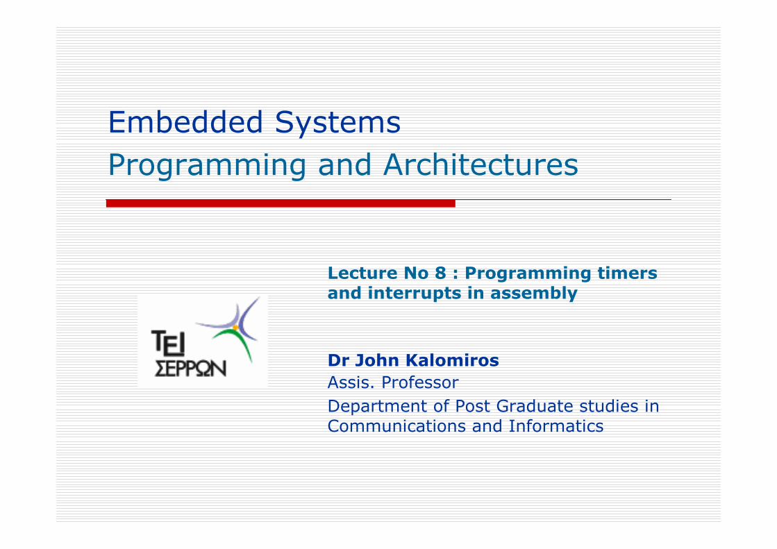
Except from OPTION Reg, INTCON Reg is also connected to the function of Timer0
INTCON is in Bank 0, and controls the function of interrupt signals.
A Flag in INTCON is associated with timer0.
This is T0IF (timer0 interrupt flag) which is set when the timer
overflows.

When you load Timer0, the following series of events takes place
1. TMR0 value is incremented at each cycle of the instruction clock
(nominally after each instruction is executed, unless it is a branch instruction)
2. When the counter reaches 255 it overflows at the very next clock cycle
3. Upon overflow T0IF is set in INTCON Reg
4. If you want the timer to run again then you have to clear T0IF and reload
In order to enable the timer and have it running you need to initialize it:
1. Go to bank 1
2. Write OPTION Reg using the necessary timer and prescaler settings
3. Clear Timer0 interrupt Flag (T0IF) in INTCON Reg
4. Load the initial counting value in TMR0

How the timer delay is calculated
the time interval from loading the counter until overflow is given by the following relation
For example: fosc= 8MHz, prescaler is 1:256
(OPTION Reg is written with 11010111)
initial TMR0 value =178

Example timer0 programming, for simulation
#include "P16F877.inc"
;initialization
Org 0 ;Reset vector
bsf STATUS, RP0 ;switch to bank 1
movlw b'11010001' ;prescaler set to division by 4
movwf OPTION_REG ;write to OPTION REG
bcf STATUS, RP0 ;return to bank 0
movlw 0F0h ;Set TMR0 to initial value 240 (decimal)
movwf TMR0
bcf INTCON, T0IF ;clear Timer 0 interrupt flag
;main loop
loop goto loop ;wait for timer overflow
end

Measure 5 sec with Timer0
suppose external crystalwith frequency fosc=8MHz
CENT holds hundredths of secSEC holds number of seconds
START
Initialize PORTB
for output
Increment CENT
Is SEC=5?No Yes
Toggle LEDs
Endless
wait
Define variables
CENT 0
SEC
Initialize Timer0
and prescaler
Clear T0IF
TMR0 178
Is T0IF set?
Is CENT=100?
Clear CENT
decrement SEC
No
Yes
No
Yes

Measure 5 sec with Timer0
� #include "P16F877.INC"
� Org 0
� CENT equ 20h ; define memory location CENT (hundredths of second)
� SEC equ 21h ; define memory location SEC (it holds seconds)
� movlw d'5'
� movwf SEC ;Variable SEC is 5 (decimal)
� clrf CENT ;Clear CENT
� bsf STATUS, RP0 ; Go to bank 1
� movlw b‘00000000'
� movwf TRISB ; PORTB is output
� movlw b'11010111'
� movwf OPTION_REG ; define prescaler 1/256 PS2:PS0=111
� bcf STATUS, RP0 ;return to bank 0
� movlw b'01010101' ;Output a light motive to PORTB
� movwf PORTB

� loop1 movlw d'178'
� movwf TMR0 ;Delay=(256-178)*256*4/8 in µsec (=0,01 sec)
� bcf INTCON, T0IF ;Clear flag T0IF
� loop2 btfss INTCON, T0IF ;Wait for 0,01 sec
� goto loop2
� incf CENT,1
� movlw d'100'
� subwf CENT,w
� btfss STATUS,Z
� goto loop1 ;Repeat timer delay 100 times for total delay 1 sec
� clrf CENT
� decfsz SEC,f
� goto loop1 ; Repeat SEC times
� comf PORTB ;Toggle the LEDs
� loop3 goto loop3
� END
Measure 5 sec with Timer0 (continued)

Project No 4
� Design a real-time clock that toggles an LED at b7 of PORTB
every one second, while it uses the LEDs at the lower 6 bits of
PORTB in order to count up to 60 secs. The system is reset
every minute.

Interrupt signals in the 16F series
� An embedded system often needs to respond to external events
in a timely manner.
Such events can be
1. a subsystem dealing with an emergency and needing the intervention of
the CPU (for example, power failure, overheating, a dangerous occurrence
in the external world etc).
2. an on-chip peripheral needing to exchange data with the CPU
Therefore, an interrupt signal can originate from various sources
Upon receiving an interrupt, the CPU disables the orderly execution of the
program as soon as possible and starts executing another routine in order
to service the interrupt. This is the ISR (interrupt service routine).

Generic interrupt structure
An interrupt that can be disabled is a maskable interrupt
Interrupts are “stored” at an S-R bistable latch.
Different maskable sources are ORed before reaching a CPU and a priority may be given

Interrupt sources in the 16F series:
External interrupt (RB0 or INT)Timer0 overflowPORTB interrupt on changeEEPROM write complete
Each interrupt source is associated with an enable bit and an Interrupt flag. These are bits in the INTCON Register.
External interrupts are edge-triggered. The edge the interrupt responds to is controlled by the setting of the INTEDG bit of the OPTION Register
The INTCON Register

The CPU response to an interrupt

How to program interrupts
� Start the ISR at the interrupt vector (location 0004 of program memory)
� Enable the interrupt that is to be used, by setting the enable bit in the INTCON Reg
� Set the Global Interrupt Enable (GIE) bit
� Clear the Interrupt flag within the ISR� End the ISR with a retfie instruction
� Don’t forget to set up the interrupt source as an input!
Beware: upon interrupt the 16F series CPU loads PC with 04h.
This is the interrupt vector.You may write the ISR starting from this address or you may have
the program jump to the ISR using a goto ISR instruction in 04h.

A program that uses interrupts. Appropriate for simulation!
#include "P16F877.inc"TEMP equ 20h
Org 0 ;Reset vector is 00hgoto start ; Go to the main programOrg 4 ;Interrupt vector is 04hincf TEMP, F ;Increment TEMP, count interrupts!movf TEMP,Wmovwf PORTC ;Contents of TEMP are shown on LEDs of PORTCbcf INTCON, INTF ;Clear Interrupt flag INTFretfie ;Return form interrupt and enable GIE
startclrf TEMP ;zero TEMPbsf STATUS, RP0 ;go to bank 1movlw b'00000000'movwf TRISC ;Initialize PORTC as outputbcf STATUS, RP0 ;go back to bank 0bsf INTCON, INTE ;Enable external interrupt INTbcf INTCON, INTF ;Clear interrupt flag INTFbsf INTCON, GIE ;Enable Interrupts
loop goto loop ;main loop: wait for interrupt!END

Project 5: The timer triggers an interrupt
Design an application which uses Timer0 in order to produce an interrupt signal with frequency 20 Hz. Consider fosc=4MHz.The ISR increments the content of a memory location.Back in main program the result is displayed on PORTB.

Required reading:
You are expected to study chapter 6 (Working with time: Interrupts, counters and timers) in Designing Embedded Systems with PIC microcontrollers by Tim Wilmshurst.