
Security architectures III - IS MUNI
27
Security architectures III Outline: 1. Resilient architecture 1.1 HACMP 1.2 IP address takeover 1.2.1 IP address takeover via IP aliases 1.2.2 IP add ress takeover via IP replacement 1.3 Network Address Translation 1.4 Resilient Overlay Network 2. Privacy 2.1 Isolation 2.2 Anonymization (Tor, I2P) 2.3 Covert channels
-
Upload
khangminh22 -
Category
Documents
-
view
0 -
download
0
Transcript of Security architectures III - IS MUNI
Security architectures III
Outline:
1. Resilient architecture
1.1 HACMP
1.2 IP address takeover
1.2.1 IP address takeover via IP aliases
1.2.2 IP add ress takeover via IP replacement
1.3 Network Address Translation
1.4 Resilient Overlay Network
2. Privacy
2.1 Isolation
2.2 Anonymization (Tor, I2P)
2.3 Covert channels

1. Resilience architecture [1]
The resilience architecture adopts a modular design that requires information from
a monitoring facility. As showed in Figure No. 1, the Capturing Brick (CB) sends information
of monitored packets to the Detection Engine (DE) of the system where those are received on
the designated Information Dispatch Point (IDP). After processing packet data and grouping
flows at a desired level of granularity, the DE internally performs entropy estimation on
selected packet features in order to detect an anomaly, and applies runtime classification via
a supervised Naive Bayes estimator [4]. By these actions, the DE decides whether the
observed flows are the result of a local or compartment-wide anomaly. As soon as a concrete
decision regarding the precise nature of the anomaly is denoted, the DE composes a summary
specification message that sends to its closest Remediation Engine (RE). In the case of
a compartment-wide threat the RE distributes the threat information to regionally close REs.
These subsequently decide at which compartment region they should take action for facing
the event (or perform load balancing over multiple links to relax network congestion).
Figure No. 1: The Resilience Architecture

Local and Inter-Compartment Communication
Resilience within an ANA node
Figure No. 2, shows how messages are exchanged within an ANA (Autonomic
Network Architecture) node in case all parts of the resilience system running locally. A
scenario that can occur locally is a purpose specific DoS attack that has an intention to cause a
buffer overflow status on the OS, and the target system needs to detect the attack and alleviate
its effects. Through this figure we present from a high-level system overview how the DE, CB
and RE interact via passing messages through the Minmex. The DE, CB and RE are bricks
listed within the Minmex’s brick table and therefore in order for each one to be aware of the
others’ existence (i.e. spot the public IDPs provided by each), it is required to initially
communicate with the Minmex.
Figure No. 2: The Resilience Architecture within an ANA node
The DE sends binding and configuration requests to the CB via the Minmex and afterwards
a binding under the correct configuration is established between the DE and the CB. At the
same time and in a similar manner, the DE is bound and configured with the RE. A vital
configuration setting between the DE and the RE that has to be determined before binding is
the notification time interval. The notification time interval is the time in which a DE needs to

get information from the CB and further compose a conclusive profile regarding the exact
traffic behaviour.
After the DE is bound and configured with the RE, measurements produced by the CB
are passed through the Minmex to the DE. The DE performs the detection/classification
procedure and constructs the notification update within the notification time interval. In the
case of an anomaly to be dealt with locally, the DE sends the update to the RE and
subsequently the RE initiates the appropriate remediation algorithms. For example, in case of
a (D)DoS attack that needs to be alleviated at the local system (either an end host or
a gateway), the RE will apply a dropping algorithm and possibly blacklist the sources
involved.
Resilience within an Inter-Compartment scenario
Apart from the case where a particular challenge is detected and action to remediate its effects
is taken at a local system level, remediation can also be distributed across the network to
facilitate early anomaly prevention and service restoration. In the case of a flashcrowd for
example, load balancing based on physical path diversity can be the most effective
remediation mechanism albeit it needs to take place in-network, as opposed to the target
system locally. In such scenario, although early detection by the target system is crucial,
knowledge of path diversity needs to be acquired by remote systems, such as the local or even
neighbouring gateways.
Figure No. 3: A high-level representation of the Resilience Architecture Inter-Compartment
Communication

Assuming that two nodes residing on different IP segments (compartments) need to take
synergistic detection/remediation action, a Resilience Overlay Compartment needs to be
established, as shown in Figure No. 3.
Node A will need to be aware of the ANA node that acts as a gateway to its local
compartment, which will in turn be in a position to initiate a further connection to node B in
the adjacent IP compartment. Node B is then connected with node A via the Gateway ANA
node and the REs from both nodes may exchange information related to the behaviour of the
distributed defence mechanism to be employed. The information exchange between REs is
performed within a dedicated Resilience Overlay Compartment as shown on a high-level in
Figure No. 3.
Detection Engine (DE) internal architecture
The DE as shown in Figure No.4 is composed by the Logic Brick, the Classifier, the
Notification Brick and a Configuration Manager.
The Predictor unit in the Logic Brick acts according to the estimates given by the distribution
of selected packet features (e.g. checksum field) and applies entropy estimation in order to
characterise the evolution of selected fields in each received flow. Entropy estimation
provides a detailed and more accurate identification of events that may not be extracted in
large traffic volumes.
Figure No. 4: The Detection Engine internal architecture

DE specification
Configuration Manager (CM)
The CM infrastructure unit is in charge of handling all configuration settings in order for the
DE to bind and configure itself with the Capturing Brick. Additionally, it is the unit that
allows the binding and configuration of the Remediation Engine (RE) with the DE. It has two
IDPs, one for managing the binding request coming from the RE (DE Binding IDP) and the
other for handling the RE’s configuration requests (DE Config IDP). As soon as the RE binds
with the DE, it is ready to accept any alarm or update triggered by the Notification Brick. The
configuration property accepted by the (DE Config IDP) is the time interval set by the RE for
receiving system and network updates.
Logic Brick (LB)
The LB is the main control processing component in the DE. This is where the two most basic
capabilities exist, prediction and learning. The prediction unit (Predictor) is in charge of
applying all the prediction algorithms based on the runtime measurements taken by the
capturing brick and which are received on the DEP Measurements IDP. In order for the
prediction algorithms to improve their accuracy and efficiency, there is a need for a dedicated
unit to learn (Learner) from previous and current experiences, and to be able to understand
a specific type of anomaly in a small temporal interval. This learning process is based on
comparing information already stored in the Classifier (see below) from previous incidents
with the attributes of the real-time traffic flow. The Predictor and Learner do not need to
depend on each other since each one may have different algorithms for prediction and
learning respectively.
Classifier
This unit acts purely as the anomalies’ database by storing classified anomalies that took
place in the past on a system or compartment-wise context. It communicates in real-time with
the Logic Brick in order to facilitate real-time inexpensive comparison between known
anomalies and the current traffic flow. Newly identified anomalies are stored in the classifier
from the Logic Brick for further reference. Finally, this unit passes all the flow information
needed to the RE when requested, and it also sends the conclusion of traffic anomaly
classification to the Notification brick.
Notification Brick (NB)
This brick is in charge of sending periodical updates to the RE. Updates given to the RE are
initially classifications passed to the NB by the Classifier. According to the nature of the
already classified event, it instructs the RE to take either a local or a distributed remediation
action. In case of no anomaly being reported, the NB still updates the RE within the time
interval defined from the configuration made at the CM’s (DE Config IDP). There are four
notification info states: None, Low, Medium and High.
Remediation Engine (RE) internal architecture
Figure No. 5 shows the RE which is the component in charge of mitigating the effects of an
anomaly (e.g. high system load, increased bandwidth consumption, congestion, etc.) we
currently consider two families of remediation algorithms, namely traffic shaping and
blocking (in response to an e.g. DDoS attack), and region-aware clustering (in response to
a flash crowd). The second category in particular that tries to perform load balancing and
prioritise traffic to ensure path diversity and maximise throughput, empowers the property of
self-optimization. In addition, due to path diversity increasing in network, this remediation
algorithm is inherently distributed, where on RE instructs a peer take a clustering action on its
behalf. To a lesser extent, the same holds for remediation based on datagram dropping since
distribution among multiple REs can be exploited as an efficient pushback mechanism that
enhances system and network self-protection and alleviates the detrimental effects of an
attack at the “last mile” the overall this distributed operation of the RE attributes autonomic
properties to the overall architecture.
The RE is composed by two main functional modules; the Defender and the
Messenger. The former executes the system-local remediation algorithms whereas the latter
distributes the instance of an event to remote REs within or across network compartments as
required.

RE Specification
Figure No. 5: The Remediation Engine internal architecture
Configuration Manager (CM)
The CM is the infrastructure unit holding the responsibility for dynamic binding and
configuration of the overall RE with a local or remote Detection Engine (DE). All outgoing
requests are always passed through the Minmex.
Defender Brick (DB)
The DB is the main functional block within the RE architecture. It holds one IDP
(FlowInfoIDP) responsible for getting all the grouped flows sent from the DE. The grouped
flows will be the subjects of the remediation algorithm employed, since they have been
identified by the DE to cause the abnormal behaviour. The remediation algorithms are
enforced by two action units, depending on whether a system-local or distributed action is
required. The Local Action Unit (LAU) is the main control entity enforcing local traffic
control on the ANA node, such as for example, datagram dropping on the local link. If
a distributed remediation action is required, such as for example grouping of flows based the
compartment’s egress links they are routed to, then the Compartment Action Unit (CAU) is
responsible to form a control request that is going to be transmitted to a remote RE for
execution. Based on the particular remediation scenario, one of the two or both action units
can operate within the DB. In addition, the DB is the first element in the architecture that gets
all the information passed on from the DE to the Notification Info IDP.
Messenger Brick (MB)
The MB is the component within the architecture in charge of the distributed interaction
between remote REs in the Resilience Overlay Compartment. Interaction among REs may be
committed within an intra or inter compartment scenario depending on whether the Resilience
Overlay resides on top of the IP or the Ethernet Compartment. MB handles the message
passing between REs by encapsulating requests formed by the CAU of the Defender Brick,
and is also responsible for the exchange of control information between the REs that
communicate the status of remote requests. The MB holds one IDP to receive remote data.
1.1 High availability cluster multi-processing for AIX (HACMP)
The IBM HACMP software provides a low-cost commercial computing environment that
ensures quick recovery of mission-critical applications from hardware and software failures.
HACMP has two major components: high availability (HA) and cluster multi-
processing (CMP). With HACMP software, critical resources remain available. For example,
an HACMP cluster could run a database server program that services client applications. The
clients send queries to the server program that responds to their requests by accessing
a database, stored on a shared external disk.
This high availability system combines custom software with industry-standard
hardware to minimize downtime by quickly restoring services when a system, component, or
application fails. Although not instantaneous, the restoration of service is rapid, usually within
30 to 300 seconds.
In an HACMP cluster, to ensure the availability of these applications, the applications
are put under HACMP control. HACMP takes measures to ensure that the applications remain
available to client processes even if a component in a cluster fails. To ensure availability, in
case of a component failure, HACMP moves the application (along with resources that ensure
access to the application) to another node in the cluster.

HACMP has many benefits and helps you with the following:
The HACMP planning process and documentation include tips and advice on the best
practices for installing and maintaining a highly available HACMP cluster.
Once the cluster is operational, HACMP provides the automated monitoring and
recovery for all the resources on which the application depends.
HACMP provides a full set of tools for maintaining the cluster while keeping the
application available to clients.
HACMP allows you to:
Quickly and easily set up a basic two-node HACMP cluster by using the Two-Node
Cluster Configuration Assistant.
Set up an HACMP environment using online planning worksheets to simplify the
initial planning and setup.
Test your HACMP configuration by using the Cluster Test Tool. You can evaluate
how a cluster behaves under a set of specified circumstances, such as when a node
becomes inaccessible; a network becomes inaccessible, and so forth.
Ensure high availability of applications by eliminating single points of failure in an
HACMP environment.
Leverage high availability features available in AIX.
Manage how a cluster handles component failures.
Secure cluster communications.
Set up fast disk takeover for volume groups managed by the Logical Volume Manager
(LVM).
Monitor HACMP components and diagnose problems that may occur.
1.2 IP address takeover (IPAT)
IP Address Takeover is a mechanism for recovering a service IP label by moving it to another
NIC (Network Interface Controller) on another node, when the initial NIC fails.
If the physical network interface card on one node fails, and if there are no other
accessible physical network interface cards on the same network on the same node (and,
therefore, swapping IP labels of these NICs within the same node cannot be performed),
HACMP may use the IP Address Takeover (IPAT) operation. IPAT is useful because it
ensures that an IP label over which services are provided to the client nodes remains
available. HACMP supports two methods for performing IPAT:
IPAT via IP Aliases (this is the default)
IPAT via IP Replacement
1.2.1 IP address takeover via IP aliases
You can configure IP Address Takeover on certain types of networks using the IP aliasing
network capabilities of AIX.
Defining IP aliases to network interfaces allows creation of more than one IP label and
address on the same network interface. IPAT via IP Aliases utilizes the gratuitous ARP
capabilities available on many types of networks.
In a cluster with a network configured with IPAT via IP Aliases, when the resource
group containing the service IP label falls over from the primary node to the target node, the
service IP labels are added (and removed) as alias addresses on top of the base IP addresses
on an available NIC. Unlike in IPAT via IP Replacement, this allows a single NIC to support
more than one service IP label placed on it as an alias. Therefore, the same node can host
more than one resource group at the same time.
If the IP configuration mechanism for an HACMP network is via IP Aliases, the
communication interfaces for that HACMP network must use routes that are different from
the one used by the service IP address. However, this is not required when a network has
a single adapter.
IPAT via IP Aliases provides the following advantages over the IPAT via IP Replacement
scheme:
Running IP Address Takeover via IP Aliases is faster than running IPAT via IP
Replacement, because moving the IP address and the hardware address takes
considerably longer than simply moving the IP address,
IP aliasing allows co-existence of multiple service labels on the same network
interface - you can use fewer physical network interface cards in your cluster. Note
that upon fallover, HACMP equally distributes aliases between available network
interface cards.
1.2.2 IP address takeover via IP replacement
The IP Address Takeover via IP Replacement facility moves the service IP label (along with
the IP address associated with it) off a NIC on one node to a NIC on another node, should the
NIC on the first node fail.
IPAT via IP Replacement ensures that the service IP label that is included as
a resource in a resource group in HACMP is accessible through its IP address, no matter,
which physical network interface card this service IP label is currently placed on.
If the IP address configuration mechanism is IP Replacement, only one
communication interface for that HACMP network must use a route that is the same as the
one used by the service IP address.
In conjunction with IPAT via IP Replacement (also, previously known as traditional
IPAT), you may also configure Hardware Address Takeover (HWAT) to ensure that the
mappings in the ARP cache are correct on the target adapter.
1.3 Network Address Translation (NAT) [11]
Each computer and device within an IP network is assigned a unique IP address that identifies
the host. Because of a shortage of public IPv4 addresses, most of these IP addresses are
private, not routable anywhere outside of the private company network. RFC 1918 defines the
private IP addresses you can use internally that should not be advertised:
10.0.0.0 through 10.255.255.255,
172.16.0.0 through 172.31.255.255,
192.168.0.0 through 192.168.255.255.
One of the main functions of NAT is to enable private IP networks to connect to the
Internet. NAT replaces a private IP address with a public IP address, translating the private
addresses in the internal private network into legal, routable addresses that can be used on the
public Internet. In this way, NAT conserves public addresses because it can be configured to
advertise at a minimum only one public address for the entire network to the outside world.
Other functions of NAT include:
Security - Keeping internal IP addresses hidden discourages direct attacks,

IP routing solutions - Overlapping IP addresses are not a problem when you use NAT,
Flexibility - You can change internal IP addressing schemes without affecting the
public addresses available externally; for example, for a server accessible to the
Internet, you can maintain a fixed IP address for Internet use, but internally, you can
change the server address,
Translating between IPv4 and IPv6 (Routed mode only) - If you want to connect an
IPv6 network to an IPv4 network, NAT lets you translate between the two types of
addresses.
NAT has four types:
Static NAT,
Dynamic NAT,
Dynamic PAT,
Identity NAT.
Static NAT
Static NAT creates a fixed translation of a real address to a mapped address. Because the
mapped address is the same for each consecutive connection, static NAT allows bidirectional
connection initiation, both to and from the host (if an access rule exists that allows it). With
dynamic NAT and PAT, on the other hand, each host uses a different address or port for each
subsequent translation, so bidirectional initiation is not supported.
Figure No. 6 shows a typical static NAT scenario. The translation is always active so
both real and remote hosts can initiate connections.
Figure No. 6: Static NAT

Dynamic NAT
Dynamic NAT translates a group of real addresses to a pool of mapped addresses that are
routable on the destination network. The mapped pool typically includes fewer addresses than
the real group. When a host you want to translate accesses the destination network, the ASA
(Adaptive Security Appliance) assigns the host an IP address from the mapped pool. The
translation is created only when the real host initiates the connection. The translation is in
place only for the duration of the connection, and a given user does not keep the same IP
address after the translation times out. Users on the destination network, therefore, cannot
initiate a reliable connection to a host that uses dynamic NAT, even if the connection is
allowed by an access rule.
Figure No. 7 shows a typical dynamic NAT scenario. Only real hosts can create a
NAT session, and responding traffic is allowed back.
Figure No. 7: Dynamic NAT
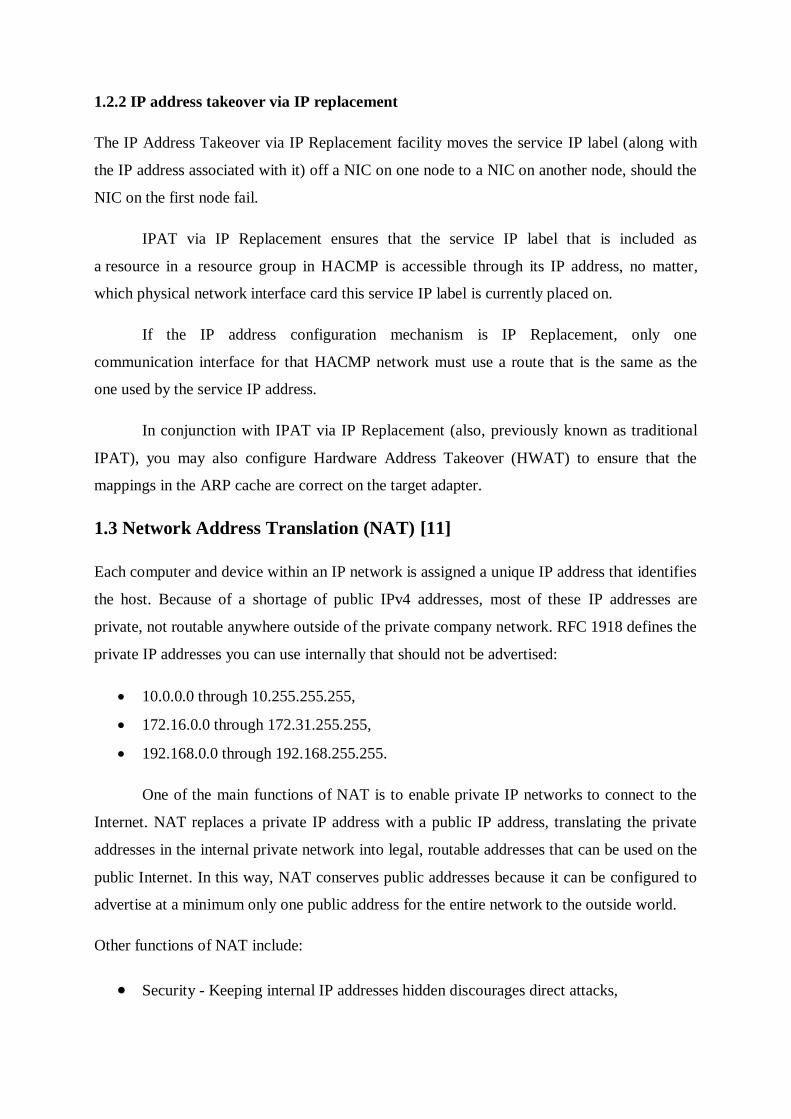
Dynamic PAT
Dynamic PAT translates multiple real addresses to a single mapped IP address by translating
the real address and source port to the mapped address and a unique port. If available, the real
source port number is used for the mapped port. However, if the real port is not available, by
default the mapped ports are chosen from the same range of ports as the real port number: 0 to
511, 512 to 1023, and 1024 to 65535. Therefore, ports below 1024 have only a small PAT
pool that can be used. If you have a lot of traffic that uses the lower port ranges, you can
specify a flat range of ports to be used instead of the three unequal-sized tiers.
Each connection requires a separate translation session because the source port differs
for each connection. For example, 10.1.1.1:1025 requires a separate translation from
10.1.1.1:1026.
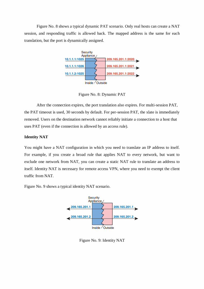
Figure No. 8 shows a typical dynamic PAT scenario. Only real hosts can create a NAT
session, and responding traffic is allowed back. The mapped address is the same for each
translation, but the port is dynamically assigned.
Figure No. 8: Dynamic PAT
After the connection expires, the port translation also expires. For multi-session PAT,
the PAT timeout is used, 30 seconds by default. For per-session PAT, the xlate is immediately
removed. Users on the destination network cannot reliably initiate a connection to a host that
uses PAT (even if the connection is allowed by an access rule).
Identity NAT
You might have a NAT configuration in which you need to translate an IP address to itself.
For example, if you create a broad rule that applies NAT to every network, but want to
exclude one network from NAT, you can create a static NAT rule to translate an address to
itself. Identity NAT is necessary for remote access VPN, where you need to exempt the client
traffic from NAT.
Figure No. 9 shows a typical identity NAT scenario.
Figure No. 9: Identity NAT

1.4 Resilient Overlay Network (RON) [3]
Figure 10: The general approach used in the RON system
Resilient Overlay Network (Figure No. 10) is a technique to make distributed applications
more reliable. In this approach, each application layers a “resilient overlay network” over the
underlying Internet routing substrate. The nodes comprising a RON reside in multiple
autonomous systems (ASes), and cooperate with each other to forward data on behalf of any
pair of communicating nodes in the RON. Because ASes are independently administered and
configured, they generally fail independently of each other. As a result, if the underlying
topology has physical path redundancy, it is often possible for RONs to find paths between
RON nodes, even if Internet routing protocols cannot.
Figure 11: RON Architecture

The Internet is organized as independently operating autonomous systems (ASes) that
peer together. In this architecture (Figure No. 11), detailed routing information is maintained
only within a single AS and its constituent networks, usually operated by some network
service provider. The information that is shared with other providers and ASes is heavily
filtered and summarized using the Border Gateway Protocol (BGP-4) running at the border
routers between ASes, which allows the Internet to scale to millions of networks.
This wide-area routing scalability comes at the cost of the reduced reliability of end-
to-end communication between Internet hosts. This cost arises because BGP scales by greatly
limiting the number of network links (and therefore, paths), and the amount of information
about those links, considered by the protocol running at each border router in the Internet.
BGP’s fault recovery mechanisms sometimes take many minutes before routes converge
consistently, and there are times when path outages even lead to significant disruptions in
communication. The result is that today’s Internet is easily vulnerable to link failures, router
faults, configuration errors, and malice—hardly a week goes by without some serious
problem affecting the connectivity provided by one or more Internet Service Providers (ISPs).
An overlay network is a “virtual” network created on top of an existing network. The
nodes in the overlay network use each other as routers to send data. The connections between
the overlay nodes are carried over the underlying network; in this case, the Internet. Overlay
networks have the potential to improve the reliability perceived by applications because they
permit aggressive path exploration and maintenance. The Internet is less aggressive, but
scales well; in contrast, RONs can be more aggressive by deliberately limiting the size of any
given RON to between two and fifty nodes. This size limitation also allows a RON to embed
application-specific choices and constraints in its path selection. As a result, RONs can be
used in a variety of ways. A multimedia conferencing program may link directly against the
RON library, transparently forming an overlay between all participants in the conference, and
using loss rates, delay jitter, or application-observed throughput as metrics by which to choose
paths. An administrator may wish to use a RON-based router application to form an overlay
network between multiple LANs as an “Overlay VPN”.
Goals of RON in short: [5]
Small group of hosts cooperate to find better-than-native IP paths
o ~50 hosts max., though working to improve

Multiple criteria, application selectable per packet
o Latency, loss rate, throughput
Better reliability too
Fast response to outages or performance change
o 10-20 seconds
Policy routing
o Avoid paths that violate the AUP (Acceptable Usage Policy) of the
underlying IP network
General-purpose library that many applications may use
o C++
In addition: http://nms.lcs.mit.edu/publications/andersen-ms-thesis.pdf.
2. Privacy [7]
Internet privacy is the privacy and security level of personal data published via the Internet. It
is a broad term that refers to a variety of factors, techniques and technologies used to protect
sensitive and private data, communications, and preferences.
Internet privacy and anonymity are paramount to users, especially as e-commerce
continues to gain traction. Privacy violations and threat risks are standard considerations for
any website under development.
2.1 Isolation [9]
For instance, we described three different types of network isolation:
Path Isolation [10]
Path isolation refers to the creation of independent logical traffic paths over a shared physical
network infrastructure. This involves the creation of VPNs with various mechanisms as well
as the mapping between various VPN technologies, Layer 2 segments, and transport circuits
to provide end-to-end isolated connectivity between various groups of users.
The main goal when segmenting the network is to preserve and in many cases improve
scalability, resiliency, and security services available in a non-segmented network. Any
technology used to achieve virtualization must also provide the necessary mechanisms to
preserve resiliency and scalability, and to improve security.
A hierarchical IP network is a combination of Layer 3 (routed) and Layer 2 (switched)
domains. Both types of domains must be virtualized and the virtual domains must be mapped
to each other to keep traffic segmented. This can be achieved when combining the
virtualization of the network devices (also referred to as "device virtualization") with the
virtualization of their interconnections (known as "data path virtualization").
In traditional (that is, not virtualized) deployments, high availability and scalability are
achieved through a hierarchical and modular design based on the use of three layers: access,
distribution, and core.
In a cloud configuration tenants share the same underlying physical infrastructure.
Without network isolation, tenants could intentionally or unintentionally consume a large part
of the network, intrusively see data on the network that does not belong to them, or invoke
side-channel tenant attacks. A proper network design that includes resource control and
security ensures these issues are mitigated.
Cloud Providers typically want network isolation for resource management or network
security. In most cases, these Cloud Providers choose to combine both as a means to satisfy
tenant requirements.
Network Traffic Isolation
In a Cloud environment there may be cases where certain user traffic needs to be isolated on
its own network. For example, traffic isolation can be used to provide an initial layer of
security, higher bandwidth for specific tenants, implement specialized chargeback policies, or
to support tiered networks. Other examples include isolating network traffic for LAN based
backups, ftp, or replication traffic. In this paper we will focus on isolating database Sql*Net
network traffic.
Network Security Isolation
Networks in a consolidated environment must ensure database traffic is secure and
authenticated against trusted clients. Network security is built on top of network isolated
traffic, and can be implemented using encryption (SQL*Net, TLS/SSL, or https) or

authentication; i.e., allow or deny database service access using validation rules. The
following sections will cover the two different types of network isolation.
Network Traffic Isolation
Monitoring and controlling both physical and virtual network resources are key to
understanding how bandwidth is being consumed. Cloud Providers must be able to:
Identify bottlenecks to prevent network congestion and avoid downtime,
Establish network service-level agreements (SLAs) and meet network quality of
service (QoS) goals,
Understand network traffic trends and consumption in order to charge for network-
related services,
Gather security information that could help prevent denial of service attacks (DoS).
The first aspect of network traffic isolation is the creation of segmented networks. This can be
done physically, or logically. In physical network isolation, network interface cards will be
dedicated to a specific application or group of applications, and thus physical segmentation is
provided between networks.
Logical network isolation uses software such as VLANs, network interface
virtualization (vNICs), or multiple logical listening endpoints to partition physical network
resources. Traffic for multiple applications share the same physical interfaces, but each
application sees only the network traffic and resources assigned to it, and cannot see traffic or
resources assigned to other applications.
The second aspect of network traffic isolation is resource control or Quality of Service
management (QoS). This needs to be in place to monitor and manage network traffic, and
ensure that tenants consume only their fair-share of network bandwidth. Network resource
management is generally applied at the vNIC level, i.e., currently, there is no network
governor that provides class of service (CoS) at the application or tenant level. Since vNICs
are a tool for creating logical network isolation, network resource QoS is most practical with
logical network isolation environments. In this section, we will describe how network traffic
bandwidth and network resource management are handled differently between the Private
Cloud architectures.

Network Security Isolation
With compliance mandates and regulatory requirements, network isolation along with
network security has become essential elements of any cloud deployment. The technology
used for network traffic isolation, discussed in the earlier section, does not cover issues with
security breaches that stem from external networks, side-channel attacks, or regulatory
concerns between tenants. In addition to network security, Cloud Providers must ensure that
other aspects of security, such as OS and database security are also in place. As part of
enterprise network security and ‘secure by default’ framework, customers generally have
standardized on the following network security solutions:
Network Firewall – Also called packet filters, operate at a relatively low level of the
TCP/IP protocol stack, and are often situated at the borders of networks as a way to
filter potential security threats coming from untrusted sources. A DMZ is a firewall
configuration. Incoming data packets are blocked unless they match the established
and configurable rule sets. Network firewalls may be hardware devices, software such
as soft switches, or a combination of the two.
VLAN Tagging - VLANs allow multiple logically separated networks to use the
same physical medium, thus two separate VLANs cannot communicate with each
other without a layer 3 device (router). This VLAN configuration is done at the switch
and defines mapping between VLANs and ports. VLANs created over vNICs provide
an extra layer of security and bandwidth control. Packets sent by a vNIC on a VLAN
cannot be seen by vNICs on other VLANs, and broadcast and multicast packets sent
from a vNIC on a VLAN will be distributed only to the vNICs on the same VLAN.
Typically vNICs will be used in conjunction with VLANs. However, customers have
fears of packet leaks from one VLAN to another (revealing sensitive information), or
a specially crafted packet that is injected into another VLAN. There are features that
mitigate this risk. For example, Solaris 11 ensures that VLAN tagging is performed in
the global zone; i.e., the local zone’s vNICs are not exposed to VLAN ids and headers
and thus cannot send packets which contain VLAN headers. NIC classification also
ensures that a zone will receive packets only from the VLAN it belongs to.
Role Based Security – A sound network security architecture requires a solid
“endpoint security” (client workstation and database server) design. On the client side,
the workstation or mobile devices must have hardened user authentication.

Additionally, application-based authorization and authentication ensures clients have
only the required access to the application. On the database server, Role Based
Security, or Role Based Access Control (RBAC), needs to be employed. Oracle
Database Vault’s RBAC approach extends the database’s native “least privileges
approach” to security by employing a fine grained authorization to database objects.
There are various tools and features offered by the Oracle stack that also provide a deeper
level of network security. These network security solutions can be divided into three
areas: features that validate data origin authentication (DOA), provide in-band data security,
and prevent denial of service attacks (DoS). Many of these products work at different layers
of the network path. Cloud Providers should determine which features make business sense
based on existing architecture and standards. For example, it is generally considered a best
practice to stop DoS attacks at the edge of the network, i.e., closest to the source of the attack.
2.2 Anonymization (Tor, I2P) [8]
“Dark net” is the word in and of itself brings to mind visions of the seedy underbelly of the
internet; a virtual red-light district, back alley, and digital ghetto all rolled into one. Despite
this threatening image that the media and many governments would like to imprint on the
public consciousness, privacy-aware individuals know that in today’s world of ISP data
retention being measured in petabytes and massive supercomputing resources being thrown at
traffic analysis by both governments and private industry alike, individuals must take it upon
themselves to ensure the freedoms that come with anonymous information access and
communication. Two of the most popular tools for doing so on the internet are Tor and I2P.
Both will be compared and contrasted below.
Tor
We will begin by examining the underlying technology of the Tor network with an eye
towards how it works to protect your anonymity online. The Tor network is comprised of
three different types of nodes: directory servers, exit points (also referred to as exit relays),
and internal relays. When you connect to Tor, the first thing your client does is acquire
a current list of relays from one of the trusted directory servers. The addresses of these servers
are included with the basic configuration files shipped with the client (of course, as with any
reputable privacy tool, you have the option to alter what directory servers you trust to provide
you with valid relays).

After retrieving a list of currently operational relays from the directory servers, your
client then determines the optimal route for your traffic across the Tor network and finally
terminating (from the Tor network perspective) at an exit node. This circuit created consists of
your computer, the relay to which you are connecting and multiple internal relays before
reaching an exit node. Note that this is substantially different that the traditional IP forwarding
that occurs between routers on the internet. Traditional IP routers follow a best possible route
on a per-packet basis, there are no “stateful” circuits from an IP perspective (as a qualifier to
this statement, it is necessary to grant that it is within the technical realm of possibility that
every router between you and the computer you are connecting to could have single, static
routes to one another, though in practice this is a near impossibility). In short, for the life of
a circuit, all of your traffic will follow the same route within the Tor network and exit at the
same point. Later, we will see how this is fundamentally different that the way the I2P
network operates.
During the circuit creation process, your client exchanges cryptographic keys with the
first relay it connects to and begins encrypting traffic back and forth. Further each hop in
transit between the various relays is encrypted using those relays’ cryptographic keys. You
can visualize this as layers of encryption being wrapped around your data: this is where the
phrase “onion routing” comes from when describing the type of network Tor establishes.
Finally, your encrypted traffic is decrypted at the exit relay where it is then forwarded out
onto the “regular” internet. This is one of the ways that Tor helps maintain your privacy
online – each exit node is aggregating traffic from many other Tor users and putting it out
onto the internet all at once. Your traffic becomes a small stream in the giant swath of data
coming from and entering back into any given exit node. It is also important to note that your
exit node only knows which intermediate node to send receiving data back to (this is also true
for each internal to internal leg of the circuit). What this means is that your identity and the
content of your traffic are cryptographically bifurcated – your entry node knows who you are
but not what you are doing and your exit node knows what you are doing but not who you are.
All the relays in between only know to forward the encrypted payload to the next relay on the
circuit. Assuming that the content of your traffic does not reveal your identity, this permits
you to browse the internet completely anonymously.
As a side note, Tor also allows you to run and access what are called “hidden
services.” These are servers that are accessible only from within the Tor network itself. While
this is not the primary purpose for Tor, it does provide an opportunity for one to use dedicated
in-network services in a cryptographically secure manner. Among the various hidden services
are various blogs, email servers, and forums. We will see later how I2P provides a better
framework for providing these hidden services, but if one’s primary goal is to access
“regular” internet services in an anonymous fashion, Tor is a vital tool in one’s arsenal.
I2P
On the surface, I2P appears to provide many of the same benefits that Tor does. Both allow
anonymous access to online content. Both make use of a peer-to-peer-like routing structure,
and both operate using layered encryption. However, I2P was designed from the ground up to
provide a different set of benefits. As we saw above, the primary use case for Tor is enabling
anonymous access of the public internet with hidden services as an ancillary benefit. I2P on
the other hand, was designed from day one to be a true “dark net.” Its primary function is to
be a “network within the internet,” with traffic staying contained in its borders. Very few
outbound relays exist in the I2P network, and the few that do exist are rarely usable.
As mentioned above, I2P routes traffic differently than Tor. At its heart, I2P performs
packet based routing as opposed to Tor’s circuit based routing. This has the benefit of
permitting I2P to dynamically route around congestion and service interruptions in a manner
similar to the internet’s IP routing. This provides a higher level of reliability and redundancy
to the network itself. Additionally, I2P does not rely on a trusted directory service to get route
information. Instead, network routes are formed and constantly updated dynamically, with
each router constantly evaluating other routers and sharing what it finds. Finally, I2P
establishes two independent simplex tunnels for traffic to traverse the network to and from
each host as opposed to Tor’s formation of a single duplex circuit. This provides the
additional benefit of only disclosing half the traffic in the case of an in-network eavesdropper.
From an application-level perspective there is a fundamental difference between the
I2P and Tor networks as well. Tor functions by providing a proxy on your local machine that
you must configure your applications to use (of download specially configured application
bundles). In contrast, I2P is generally used by applications that are written specifically to run
on the I2P network. These include, but are not limited to, instant message, file sharing, email,
and distributed storage applications (yes, you can store encrypted data in the I2P “cloud,”
similar to Freenet).

Next applications for anonymization are, for examaple: GNUnet, RetroShare, Freenet,
Goldbug or Konserten etc.
2.3 Covert channels
To illustrate the problem we show an example. Alice and Bob have been incarcerated and
placed in two separate jail cells. They want to coordinate an escape plan. However, they have
a small problem. All messages that they send to each other must first be read by the warden
before being passed on. In order to be able to coordinate their plans while at the same time
keeping them hidden from the warden, they communicate with each other in code. Each word
with an even number of letters is read as a 1. Each word with an odd number of letters is read
as a 0. For example, if Bob sent a message to Alice asking “Hey, what are you up to”, Alice
would interpret is as “010011”. The warden, in this case, has been used as a covert channel.
Although no prisoners would probably attempt that in real life, it works very well as
an analogy for how a covert channel operates. According to the Department of Defense’s
(DoD) Trusted Computer System Evaluation Criteria (TSEC), “A covert channel is any
communication channel that can be exploited by a process to transfer information in a manner
that violates the system’s security policy”. There are two different types of covert channels,
known as covert storage channels and covert timing channels.
2.3.1 Storage Channels
Covert storage channels are methods of communication that “include all vehicles that would
allow the direct or indirect writing of a storage location by one process and the direct or
indirect reading of it by another”. In other words, one process writes to a shared resource,
while another process reads from it. Storage channels can be used between processes within a
single computer or between multiple computers across a network. A good example of
a storage channel is a printing queue. The process with higher security privileges, the sending
process, either fills up the printer queue to signal a 1 or leaves it as it is to signal a 0. The
process with lower security privileges, the receiving process, polls the printer queue to see
whether or not it is full and determines the value accordingly.
2.3.2 Timing Channels
Covert timing channels are methods of communication that “include all vehicles that would
allow one process to signal information to another process by modulating its own use of
system resources in such a way that the change in response time observed by the second
process would provide information”. In other words, it is essentially any method that uses
a clock or measurement of time to signal the value being sent over channel. Similarly to
storage channels, timing channels can exist both in a single-computer setting and a network
setting. However, they are less practical in a network setting. An example of a timing channel
can be found in a movable head I/O device, such as a hard disk. One process with higher
security privileges, the sending process, has access to the entire device while another process
with lower security privileges, the receiving process, only has access to a small portion of the
device. Requests to the device are processed serially. To signal a 1, the sending process makes
a read request far away from the section that the receiving process has access to. To signal
a 0, it does nothing. The receiving process makes a read request within its own section and
uses the time it takes for the head to travel to the section and finish the read request to
determine the value accordingly.
2.3.3 Noise in Covert Channels
One of the major problems in a successful implementation of a covert channel is noise.
“A noisy channel intentionally or accidentally corrupts the data signal with errors so that the
information rate is slower than the data rate”. Because it is a primary problem in their
implementation, it is also the best defences against covert channels. If enough noise is
introduced into a covert channel, it can hinder the use of that channel. The receiving process
would have to request the same data continuously and wait for a very high level of
redundancy before knowing that it is reliable. This process may take many hours for a request
that would only take a few clock cycles if the channel was noise-free. Although this does not
halt the covert channel, it can considerably decrease its speed. [6]

Sources:
[1] ANA network architecture. 2008. ANA Project [online]. [cit. 2015-05-15]. Dostupné z:
http://www.ana-project.org/deliverables/2008/ana-d3.10-final.pdf
[2] Concepts and facilities guide. 2014. IBM [online]. [cit. 2015-05-15]. Dostupné z:
http://www-01.ibm.com/support/knowledgecenter/SSPHQG_6.1.0/com.ibm.
hacmp.concepts/hacmpconcepts_pdf.pdf.
[3] Resilient Overlay Networks. 2001. Networks and Mobile Systems [online]. [cit. 2015-05-
15]. Dostupné z: http://nms.lcs.mit.edu/publications/andersen-ms-thesis.pdf.
[4] Rish, I., An empirical study of the naive Bayes classifier, IJCAI 2001 Workshop on
Empirical Methods in Artificial Intelligence, Seattle, USA, August 4, 2001
[5] BIRMAN, Kenneth. Overlay Networks. Cornell University [online]. 2005 [cit. 2015-05-
17]. Dostupné z: http://www.cs.cornell.edu/ken/book/New%20514%20slide%20set/24-
OverlayNetworks.ppt
[6] An overview of covert channels. 2014. Course hero [online]. [cit. 2015-05-15]. Dostupné
z: https://www.coursehero.com/file/10824556/An-Overview-of-Covert-Channels/.
[7] Internet Privacy. Techopedia [online]. [cit. 2015-05-15]. Dostupné z:
http://www.techopedia.com/definition/24954/internet-privacy.
[8] An Introduction to Tor vs I2P. 2013. IVPN [online]. [cit. 2015-05-15]. Dostupné z:
https://www.ivpn.net/privacy-guides/an-introduction-to-tor-vs-i2p.
[9] Network Isolation in Private Database Clouds. 2012. Oracle [online]. [cit. 2015-05-15].
Dostupné z: http://www.oracle.com/technetwork/database/database-cloud/ntwk-isolation-
pvt-db-cloud-1587225.pdf.
[10] Network Virtualization--Path Isolation Design Guide. Cisco [online]. [cit. 2015-05-
15]. Dostupné z: http://www.cisco.com/c/en/us/td/docs/solutions/Enterprise
/Network_Virtualization/PathIsol.html.
[11] Information About NAT. Cisco [online]. [cit. 2015-05-15]. Dostupné z:
http://www.cisco.com/c/en/us/td/docs/security/asa/asa90/configuration/guide/asa_90_cli_
config/nat_overview.pdf.