A Conceptual Data Model for the Architecture Exploration of Automotive Distributed Embedded...
6
A Conceptual Data Model for the Architecture Exploration of Automotive Distributed Embedded Architectures Paolo Giusto + Sri Kanajan * Claudio Pinello % Max Chiodo # + General Motors Research and Development Redwood Shores, CA 94065 * General Motors Research and Development, Warren, MI 48090 % Cadence Berkeley Labs, Berkeley, CA 94704 #Magma Design Automation, Santa Clara, CA 95054 Abstract As design complexities increase exponentially, automotive designers need integrated tool environments enabling system-level analyses of alternative architectural solutions. Hence, a huge amount of heterogeneous design data must be made available easily and quickly for the analysis. In this paper, we introduce the AETM (Architecture Exploration Tools and Methods) data model, a key enabler for an integrated model-based tool environment. The data model encompasses several important aspects of the design of any embedded architecture (not only an automotive one), as it supports design capture at different levels of abstraction (e.g., functional, logical, and physical) and across application domains. 1. Introduction The design of in-vehicle distributed embedded architectures, composed of Electronic Control Units (ECU) and buses, has been traditionally component or sub-system focused as one function (e.g. ABS) corresponds to one ECU box. This function-ECU binding is frozen very early in the development cycle, based on experience, intuition, and qualitative criteria, while the evaluation of the binding against the requirements, is performed late on HW-based test-benches. Potentially, this leads to costly design changes and sub-optimal solutions. In recent years, tool and model-based design paradigms have emerged that enable early verification of requirements and late binding [7], however with no support for verification of timing requirements. In [1], [2], a methodology based upon the following tenets, for early verification and late binding has been proposed (Figure 1): • An Iterative Process in which design alternatives are produced and scored. • A conceptual Data-Model that describes the modeling artifacts used to build the system model, with their semantic and syntactic relationships. • The definition of the Degrees of Freedom (e.g., allocation of functions to ECUs) that are allowed, and where, in the application of the process. • A set of Metrics (quantitative) and Criteria (qualitative) by which each design alternative is scored. • A Federation of tools (see an example of it in Figure 2) for the design, analysis, verification and synthesis /configuration of different aspects of the architecture, and sharing data defined according to the common AETM data model. • Use cases with roles of each tool in each use case. The data model presented in this paper is a key tenet of the methodology described in [1], [2]. Currently, the data model includes only syntactic information. As future work, we plan to enrich the data model with semantics information (e.g., task activation policies). In the rest of the paper, we first cite some existing formats and data models. Then, we sketch a set of requirements for a data model for architecture exploration. Next, we describe the AETM data model explaining how and why it fulfills the requirements, and lastly, we sketch some conclusions and opportunities for future work. 2. Previous Work As we describe only the two most relevant data models in the automotive domain, this citation is far from being exhaustive. 582 1-4244-1500-4/07/$25.00 ©2007 IEEE
Transcript of A Conceptual Data Model for the Architecture Exploration of Automotive Distributed Embedded...

A Conceptual Data Model for the Architecture Exploration of Automotive
Distributed Embedded Architectures
Paolo Giusto+ Sri Kanajan* Claudio Pinello% Max Chiodo#
+ General Motors Research and Development
Redwood Shores, CA 94065 * General Motors Research and Development, Warren, MI 48090
% Cadence Berkeley Labs, Berkeley, CA 94704 #Magma Design Automation, Santa Clara, CA 95054
Abstract As design complexities increase exponentially, automotive designers need integrated tool environments enabling system-level analyses of alternative architectural solutions. Hence, a huge amount of heterogeneous design data must be made available easily and quickly for the analysis. In this paper, we introduce the AETM (Architecture Exploration Tools and Methods) data model, a key enabler for an integrated model-based tool environment. The data model encompasses several important aspects of the design of any embedded architecture (not only an automotive one), as it supports design capture at different levels of abstraction (e.g., functional, logical, and physical) and across application domains. 1. Introduction The design of in-vehicle distributed embedded architectures, composed of Electronic Control Units (ECU) and buses, has been traditionally component or sub-system focused as one function (e.g. ABS) corresponds to one ECU box. This function-ECU binding is frozen very early in the development cycle, based on experience, intuition, and qualitative criteria, while the evaluation of the binding against the requirements, is performed late on HW-based test-benches. Potentially, this leads to costly design changes and sub-optimal solutions. In recent years, tool and model-based design paradigms have emerged that enable early verification of requirements and late binding [7], however with no support for verification of timing requirements. In [1], [2], a methodology based upon the following tenets, for early verification and late binding has been proposed (Figure 1):
• An Iterative Process in which design alternatives are produced and scored.
• A conceptual Data-Model that describes the modeling artifacts used to build the system model, with their semantic and syntactic relationships.
• The definition of the Degrees of Freedom (e.g., allocation of functions to ECUs) that are allowed, and where, in the application of the process.
• A set of Metrics (quantitative) and Criteria (qualitative) by which each design alternative is scored.
• A Federation of tools (see an example of it in Figure 2) for the design, analysis, verification and synthesis /configuration of different aspects of the architecture, and sharing data defined according to the common AETM data model.
• Use cases with roles of each tool in each use case. The data model presented in this paper is a key tenet of the methodology described in [1], [2]. Currently, the data model includes only syntactic information. As future work, we plan to enrich the data model with semantics information (e.g., task activation policies). In the rest of the paper, we first cite some existing formats and data models. Then, we sketch a set of requirements for a data model for architecture exploration. Next, we describe the AETM data model explaining how and why it fulfills the requirements, and lastly, we sketch some conclusions and opportunities for future work. 2. Previous Work As we describe only the two most relevant data models in the automotive domain, this citation is far from being exhaustive.
5821-4244-1500-4/07/$25.00 ©2007 IEEE
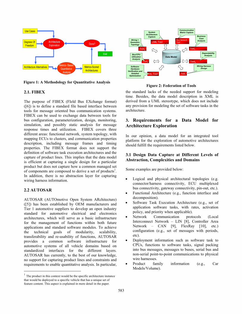
2.1. FIBEX The purpose of FIBEX (FIeld Bus EXchange format) ([6]) is to define a standard file based interface between tools for message oriented bus communication systems. FIBEX can be used to exchange data between tools for bus configuration, parameterization, design, monitoring, simulation, and possibly static analysis for message response times and utilization. FIBEX covers three different areas: functional network, system topology, with mapping ECUs to clusters, and communication properties description, including message frames and timing properties. The FIBEX format does not support the definition of software task execution architectures and the capture of product lines. This implies that the data model is efficient at capturing a single design for a particular product but does not capture how a common managed set of components are composed to derive a set of products1. In addition, there is no abstraction layer for capturing wiring harness information. 2.2 AUTOSAR AUTOSAR (AUTOmotive Open System ARchitecture) ([5]) has been established by OEM manufacturers and Tier 1 automotive suppliers to develop an open industry standard for automotive electrical and electronics architectures, which will serve as a basic infrastructure for the management of functions within both future applications and standard software modules. To achieve the technical goals of modularity, scalability, transferability and re-usability of functions, AUTOSAR provides a common software infrastructure for automotive systems of all vehicle domains based on standardized interfaces for the different layers. AUTOSAR has currently, to the best of our knowledge, no support for capturing product lines and constraints and requirements to enable quantitative analysis. In particular,
1 The product in this context would be the specific architecture instance that would be deployed to a specific vehicle that has a unique set of feature content. This aspect is explained in more detail in the paper.
the standard lacks of the needed support for modeling time. Besides, the data model description in XML is derived from a UML stereotype, which does not include any provision for modeling the set of software tasks in the architecture. 3. Requirements for a Data Model for Architecture Exploration In our opinion, a data model for an integrated tool platform for the exploration of automotive architectures should fulfill the requirements listed below. 3.1 Design Data Capture at Different Levels of Abstraction, Complexities and Domains Some examples are provided below: • Logical and physical architectural topologies (e.g.
connector/harness connectivity, ECU multiplexed bus connectivity, gateway connectivity, pin-out, etc.).
• Functional Architecture (e.g., function interface and decomposition).
• Software Task Execution Architecture (e.g., set of application software tasks, with rates, activation policy, and priority when applicable).
• Network Communication protocols (Local Interconnect Network – LIN [8], Controller Area Network – CAN [9], FlexRay [10], etc.) configuration (e.g., set of messages with periods, etc).
• Deployment information such as software task to CPUs, functions to software tasks, signal packing into bus messages, messages to buses, serial bus and non-serial point-to-point communications to physical wire harnesses.
• Product family information (e.g., Car Models/Volume).
Data Model
UML Tool
Toole
Toolb
HIL Tool Toolc
Toold
Toola
Business Case
Analysis
Dependability Analysis
Wiring Harness Design
Software-Hardware
Verification and Detailed
Optimization
Bus/CPU Utilization Analysis
Wiring + Geometric Topology
System Architecture
CaptureBus Network Tool
Communication Matrix Capture
Figure 2: Federation of Tools
Degrees Of Freedom
Use Cases
Architecture Alternatives
Architecture Exploration
Metrics- Based Quantitative
Analysis
Done?
End
Metrics-Scored Architectures
Figure 1: A Methodology for Quantitative Analysis
583

3.2 Support of Iterative Exploration, Design Refinement, and Design (back-) Annotation As design details cannot be fully available at the time the development process commences, it must be possible to capture a design at different levels of refinement. Design refinements must be possible across two orthogonal dimensions: from higher to lower level of abstractions (e.g., by adding physical details to the logical view of a design) and/or at the same level of abstraction (e.g., by replacing a black box behavior with a behavioral description). Designs must be easily annotatable with cost (e.g., recurring and non-recurring), dependability-related information (e.g., failure rates), timing and architecture deployment information (e.g., CPU dependent task worst-case execution times), at different levels of the design hierarchy. As one of the key tenets of the architecture exploration methodology ([1],[2]) is the product line/metric-based quantitative analysis, the data model must support the easy and selective modification of the captured design, while allowing the rest of the design to be invariant (e.g., changing software task deployment without modifying the functional architecture). 3.3 Support for Data Extraction and Analysis The data model must support easy extraction of data for requirement verification (e.g., end-to-end latency) across product lines and on a single design instance. The data model must support the extraction of AUTOSAR and/or FIBEX compliant design view. 4. The AETM Data Model We now focus on the main features of the AETM data model, which fulfill the requirements defined in the previous section. First, the data model provides full support to design flows that are based upon platform-based design methodologies ([3], [4]) which advocate a separation between function, architecture, and platform model, and between communication and computation. Specifically, it allows: • Decoupling of the description of a design2 from the
primitive library elements instantiated in the design itself.
• Definition and instantiation of primitive library elements.
2 The term design here is used to refer to a specific set of relations (hierarchy, mapping, connectivity) of primitive library elements.
• Capture of connectivity and deployment information between instances, decoupled from the library primitive elements.
• Separation between functional, logical and physical architecture abstraction layers, as well as the deployment (platform model) ([1], [2], [3], [4]).
• Functional, physical3 and logical interconnections are captured within the same design file yet as separate modeling elements from the data model standpoint.
Secondly, the data model provides full support to manage design complexity:
• An instance of a library element can be a hierarchical design itself.
• ECUs can be hierarchical models (e.g., multicore).
• Sub-Systems and Sub-Architectures are hierarchical.
• Heterogeneous design styles are enabled such as black box (no behavior/only interfaces) and white box (e.g. function/task mappings) within the same design to enable design refinement and re-mapping when possible
• Heterogeneous interfaces/black box models are available for designs: serial-data interface, middleware interface, etc., enable different types of compositions between instances of library elements (e.g., a sub-system may connect to the rest of the design via a serial-data interface).
• The data model is extensible in the sense that the conceptual specification provides guidelines on how to implement it, for example as an XML schema. However, the XML schema can be extended easily by adding attributes to the existing elements, and/or by adding new elements.
Third, the data model supports product family oriented analysis:
• Relationships of design alternatives4 and design instances of a product family architecture are captured.
• Any element (instance) of the design can be annotated at any level of granularity (e.g. component, ECU, design, etc.) with cost figures.
4.1 The AETM Data Model Abstraction Layers The AETM data model defines different abstraction layers for capturing functional and architecture views. In 3 Example of physical interconnection is the harness-connectors topology. 4 These relationships are described later in the paper.
584

Figure 3, the functional and logical architecture layers are shown. The separation between the function implementation/interface and its connections enables re-use of a function in different designs as different instances of the same function can be connected to different functions in different designs as long as the interface is compatible. In Figure 3 and in the following figures, the blue boxes represent interfaces, while the purple boxes represent connectivity relations. Connectivity is defined both at the functional and at the architecture level. In Figure 3 a function is connected to another function by connecting a signal to the output and input ports of the functions. A signal is part of the data path (e.g., shared variable). As we will see later in the paper, the control path is captured in task and message activation policies (system platform model). Two ECUs are connected by creating a relation between the controller and I/O driver ports of each ECU and the multiplexed bus element, and for non-serial link connections, using the non-multiplexed medium element. In Figure 4 an additional layer is shown. While a function has only a functional interface, an ECU owns both a logical interface and a physical interface (connectors). An ECU can also be re-used across different designs as its connectivity is determined by the assignment of controller/IO-drivers and connectors to communication media and harnesses respectively (Figure 4). In Figure 5, an example of mapping of functionality and signals to software tasks and frames (we use the term messages and frames interchangeably) is shown. Software execution
architectures are captured by assigning software tasks to a SOFTWARE SCHEDULER mapped to an ECU, while a bus schedule is defined by assigning frames to a multiplexed bus medium using the deployment element named MUX-BUS-SCHEDULE. Notice that the term schedule may be misleading in this context, as in reality this entity captures the frame activation policies (e.g., periodic vs. data-driven) – the bus schedule may be not known a priori unless a time-trigger protocol is used. The mapping/deployment artifacts are the big diamond boxes in the light blue color in Figure 5 (e.g., PHYSICAL-NET). This deployment layer captures the system platform model ([3], [4]). Point-to-point, non-serial link communications are captured by deploying a signal to non-multiplexed medium using the HARDWIRED-SIGNAL deployment element (Figure 5). Finally, Figure 6 shows an example of deploying the logical to physical levels. The PHYSICAL-NET modeling artifact is used to deploy any communication (multiplexed and point-to-point) to a wiring harness. It can be annotated with physical information such as the number and the size of wires used to implement the communication. The physical net captures the routing and costs that depend on the geometrical positioning of the actual physical connectivity elements. As the AETM data is extensible more attribute can be added, to support other analyses (e.g., power).
FunctionA
FunctionBSignalBehavior
LogicalArchitecture
ECU1
ECU2
Non-MultiplexedMedium
MultiplexedBusLogicalArchitecture
ECU1
ECU2
Non-MultiplexedMedium
MultiplexedBus
ECU1
ECU2
Harness
PhysicalArchitecture
ECU1
ECU2
Harness
PhysicalArchitecture
Figure 4: Physical Architecture Layer
FunctionA
FunctionB
Signal
Behavior
LogicalArchitecture
ECU1
ECU2
Non-MultiplexedMedium
MultiplexedBusLogicalArchitecture
ECU1
ECU2
Non-MultiplexedMedium
MultiplexedBus
SOFTWARE-SCHEDULER
FunctionC
MUX-BUS-SCHEDULE
Signal
FRAMEFRAME
SW-TASKSW-TASK
HARDWIRED-SIGNAL
Figure 5: Deployments of Tasks and Messages
LogicalArchitecture
ECU1
ECU2
Non-MultiplexedMedium
MultiplexedBus
ECU1
ECU2
Harness
PhysicalArchitecture
PHYSICAL-NET
PHYSICAL-NET
LogicalArchitecture
ECU1
ECU2
Non-MultiplexedMedium
MultiplexedBusLogicalArchitecture
ECU1
ECU2
Non-MultiplexedMedium
MultiplexedBus
ECU1
ECU2
Harness
PhysicalArchitecture
PHYSICAL-NET
PHYSICAL-NET
Figure 6: Deployment of Logical Communications
FunctionA
FunctionBSignalBehavior
LogicalArchitecture
ECU1
ECU2
Non-MultiplexedMedium
MultiplexedBusLogicalArchitecture
ECU1
ECU2
Non-MultiplexedMedium
MultiplexedBus
Figure 3: Behavior and Logical Architecture Layers
585

4.2 Describing Product Families The term product family (hereafter referred as family) is commonly used to indicate a set of architectures. Each architecture5 represents a binding between a set of features (e.g., Door Lock) and a set of physical components (e.g., ECU1) that implements them. For example, a specific XYZ family (product line in Figure 9) can include an architecture that features OnStar, and High End Stability Control (called ST3), and another architecture that features the low-end version of the Stability Control (ST2). As the AETM data model captures orthogonal dimensions, each family can be implemented by a set of mutually exclusive architectural alternatives, for example High End (content) Stability Control can be implemented by different bus architectures (e.g., two high speed buses or one high speed bus and one low speed bus) as shown in Figure 7. The example in Figure 7 is the third row of the matrix described in Figure 8. We call each row an architecture instance as it includes the different alternatives for one instance of architecture (e.g., ST3) of the family. Each alternative of the product family represents a different implementation shared across the content dimension (called configuration/optional content in Figure 8). The example in Figure 9 shows how the same bus solution (one high-speed bus) may be used to implement different optional contents. This is equivalent to a column in the matrix of Figure 9. We call the column an architectural alternative for the entire family.
An architecture can reference a design alternative. In the AETM data model, the DESIGN element captures the deployment of the features to components (e.g., ECUs) depending upon the architectural alternative it belongs
5 In this discussion, the term architecture is not to be confused with the terms PHYSICAL-ARCHITECTURE and LOGICAL-ARCHITECTURE introduced in the previous section.
too. It is important to notice that some architecture alternatives might include some architectures (e.g. Medium Feature Content and High Feature Content only – Figure 9) because the types of components that are used in the deployment do not support some of the features (e.g., because of the low bus bandwidth).
To enable the calculation of the degree of reuse of a component across product families and enable a first rough estimate of the costs involved with a specific architecture alternative, the AETM data model allows capturing several families, therefore enabling analyses at the enterprise level. A product family is represented by four elements: CAR-MODELS, VIN-SETS, ARCHITECTURES, and FAMILIES.
4.3 AETM Data Model Key Elements In describing some of the elements of the data model, we will refer, without any loss of generality, to the XML schema implementation. Conceptually, the main elements of the AETM Data Model are grouped in the following categories:
Architecture Alternatives for a Product Family
A1.Alt. 3A1.Alt. 2 A1.Alt. 1
A2.Alt. 3A2.Alt. 2 A2Alt. 1
A3.Alt. 3A3.Alt. 2 A3.Alt. 1
Configurations
Low
Medium
High
First row
Second row
Third row
Alternative 2 Alternative 1 Alternative 3
Figure 8: Configuration/Alternative Matrix
ST2
Medium Content A2
XYZ product line
Low Content A1 Low Content A1
ST3
High Content A3
ST3
High Content A3
N/A 1 HS Bus 1 HS Bus
Figure 9: Same Architecture implementing different
Optional Contents
ST3
High Content A3 (Alternative 1)
High Content A3 (Alternative 2)
ST3
2 HS Buses
High Content A3 (Alternative 2)
ST3
1 HS Bus
ST3
High Content A3(Alternative 3)
1 HS Bus1 CAN
ST3
High Content A3(Alternative 3)
1 LS Bus
Figure 7: Different Arch. Alternatives implementing
same Optional Content
586

• Product Family elements including CAR-MODELS, VIN-SETS, ARCHITECTURES, and FAMILIES.
• Design elements rooted by the LIBRARY element. • Miscellaneous elements including QUERIES,
CONSTRAINTS, REQUIREMENTS, and CODINGS (signal coding).
• Type elements including COST, DEPENDABILITY. The LIBRARY element includes the primitive elements (e.g., CPUs) that are available for instantiation in a design. The elements of the library are conceptually grouped together in a functional, logical architecture, and physical architecture level. Implementations capture the leaf block model (e.g., a Simulink model [11]).
A DESIGN can become part of library, once created, and instantiated in one or many another designs. Thus, the design element enables design re-use. The DESIGN element includes a collection of element instances (LIST-OF-ELEMENTS) of master elements from a library, and a CONFIGURATION6 that specifies the relations (e.g., deployment, connectivity, etc.) between the element instances. This is not different from declaring a variable of a certain type in a programming language and then using the variable in an assignment or a sum.
The data model supports several designs to be captured in the same XML document. The design element, a key element in the AETM Data Model, has three important pieces of information: the INTERFACE, which is mandatory, the LIST-OF-ELEMENTS used in the design to declare the elements that are used in its configuration, and the CONFIGURATION. To support design refinements and/or IP protection during the exploration, a design could simply be defined by its interface – this is a black box view of it. A design interface can be of three different types: • Serial data interface, meaning the design declares the
legal types of frames that is exchanging (reading/writing) with other designs.
• Middleware interface, meaning the legal type of signals exchanged with the rest of communication stack.
• Other physical interfaces. A design can have as many interface declarations as needed. Besides, the different types of interfaces support the heterogeneous design styles (e.g., black box, white box, etc.). For instance, the middleware interface can be used to instantiate a design (in another design) that models the application layer plus software execution
6 Not to be confused with the configuration in Figure 8.
architecture. Yet, in the same design, another design can be instantiated that uses a serial data interface. The design elements are invariant in the sense that they exist in the library. Of course their instantiation may vary across designs, e.g., one design may need a CAN bus, while another one may not. Notice that elements declared in the LIST-OF-ELEMENTS reference elements in the library: they are instances, with instance ids that are then used in the configuration element. The behavior, logical architecture, and the physical architecture elements in the LIST-OF-ELEMENTS element capture references to library elements such as signals, functions, multiplexed-buses, etc. 3. Conclusions and Future Work The proposed data model is the result of a thorough analysis of existing data models, and features concepts that fulfill the requirements set forth in Section 3. Now, the most challenging task is the implementation of automated mechanisms for populating and merging a target database that implements the data model with data produced from different tools. Besides, further extensions that make semantics concept explicit and not left to the interpretation of the implementer should be further investigated. 6. References [1] Patrick Popp , Marco Di Natale, Paolo Giusto, Sri Kanajan, Claudio Pinello, “Towards a Methodology for the Quantitative Evaluation of Automotive Architectures”, submitted at DATE 2007, April 2007. [2] Patrick Popp , Marco Di Natale, Paolo Giusto, Sri Kanajan, Claudio Pinello, Architecture Exploration for Time-Critical and Cost-Sensitive Distributed Systems, submitted at SAE 2007, April, 2007. [3] Grant Martin, Henry Chang. “Winning the Soc Revolution: Experiences in Real Design”, Springer, 2003 [4] Sangiovanni-Vincentelli, A.L.: “Defining platform-based design,” EEDesign, February 2002. [5] AUTOSAR, www.autosar.org. [6] FIBEX, http://www.asam.net/03_standards_06.php. [7] Telelogic Rhapsody, http://www.telelogic.com/products/rhapsody/index.cfm [8] LIN Consortium, http://www.lin-subbus.org/ [9] FlexRay Consortium, http://www.flexray.com/ [10] CAN 2.0 Specification, http://www.semiconductors.bosch.de/pdf/can2spec.pdf [11]The Mathworks-Simulink, http://www.mathworks.com/products/simulink/
587