DESIGN OF AN AUTOMOTIVE DIFFERENTIAL WITH REDUCTION RATIO GREATER THAN 6
Upload
independentCategory
view
0download
0
Summary
• Introduction
• Components.
• Differential working.
• Basic Differential Mathematical Model.
• Differential Mathematical Model.
• Failure Mode Analyses
• Axial Forces on Gear.
• Wheel Speed and Forces
• New Differential Designs.
• Q&A.

Introduction

Internal Wheel Path
External Wheel Path
The objective conditions of vehicle travel require that its wheels move at different velocities. This iscaused by the fact that paths traveled by each of the wheels are not the same.[1] The drivingwheels accommodated the inequality in the velocities by use a differential.
The modern differential was invented in 1827 by Pecquer and was first used on steam tractorengines for the same reason that it is still used today.[5]
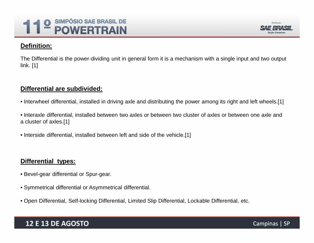
Definition:
The Differential is the power-dividing unit in general form it is a mechanism with a single input and two outputlink. [1]
Differential are subdivided:
• Interwheel differential, installed in driving axle and distributing the power among its right and left wheels.[1]
• Interaxle differential, installed between two axles or between two cluster of axles or between one axle anda cluster of axles.[1]
• Interside differential, installed between left and side of the vehicle.[1]
Differential types:
• Bevel-gear differential or Spur-gear.
• Symmetrical differential or Asymmetrical differential.
• Open Differential, Self-locking Differential, Limited Slip Differential, Lockable Differential, etc.

Components

Components of Differential [2]:
1- Bevel Drive Gear.
2- Differential Housing
3- Bevel Pinions
4- Side Gear/ Drive Bevel Gear
5- Differential Axles (Pin/Spider)
6- Axle Shafts

Components of Differential [3]:
Material supplied by Prof. E. Kirchner
1- Ring Gear2- Screw Fitting3- Left Housing half4- Right Housing half5- Four Differential Axles(pin/spider)6- Bevel Pinions7- Side Gear/ Drive Bevel Gear8- Axle Shafts9- Central Bodies10- Elastic Circlip11- Thrust Washer12- Taper Roller Bearing13- Screw Fitting

Differential Working

The Power Path on Differential:
Drive Gear -> Driven Gear -> Differential House -> Differential Axle Spider -> Bevel Pinions ->Side Gears

Differential Working:
Basic Differential Dynamic Model[4]

)(21
SDGRSDGLDREa
)(21
SDGRSDGLHSE
)(21 SDGRSDGLBEV a
)(22 SDGLSDGRBEV a
MDRE
MSDGRMSDGL
DRE
SDGRSDGL
HSE
BEV1
BEV2
SDGLSDGR ;
Differential has 2 degree of freedom and theremaining rotation angles can be correlated withgeneralized coordinates by:
Definition:DRE – Rotation angle of drive gear.
HSE – Rotation angle of house.
BEV1/2 – Rotation angle of gear bevel 1 and 2.
SDGR – Rotation angle of side gear right.
SDGL – Rotation angle of side gear left.MDRE – Torque on drive gear.MSDGR – Resistive torque on side gear rightMSDGL – Resistive torque on side gear left
2
3
4
1

IDRE
IHSE
ISDGL ISDGR
IBEV1
• Kinetic Energy - Lagrange’s Equations
Definition:IDRE – Inertia of drive gear.IHSE – Inertia of house + components.IBEV1/2 – Inertia of bevel gear 1 and 2.ISDGR – Inertia of side gear right.ISDGL – Inertia of side gear left.
26
121
ii
iIT
]
[21
222
211
2222
BEVBEVBEVBEV
SDGRSDGRSDGLSDGLHSEHSEDREDRE
II
IIIIT
])()(
)(41)(
4[
21
2222
2221
2
22221
SDGLSDGRBEVSDGRSDGLBEVSDGRSDGR
SDGLSDGLSDGRSDGLHSESDGRSDGLDRE
aIaII
IIaIT
5
6

• Considering ISDGL = ISDGR and IBEV1 = IBEV2 rewrite the equations:
SDGRSDGLSDGRSDGL BAT )(21 22
22
21 2
44aIIIaIA BEVSDG
HSEDRE
22
21 2
44aIIaIB BEV
HSEDRE
Where the abbreviations:
• Principles of d’Alembert and Jourdain, virtual work:
SDGRSDGRSDGLSDGLDREDREe MMMW
SDGRSDGRDRESDGLSDGLDRESDGRSDGRSDGLSDGLSDGRSDGLDREe MaMMaMMMaMW )
2()
2()(
2111
• Generalized torques:
)2
( 1SDGLDRESDGL MaMq )
2( 1
SDGRDRESDGR MaMq
• Lagrangian equation of motion:
kkk
qTTdtd
7
8
9
10
11
12 13

SDGRDRESDGRSDGL
SDGLDRESDGRSDGL
MaMAB
MaMBA
1
1
2121
• Appling Lagrangian Equation Of Motion:
• Vehicle Straight ahead with constant speed:
0SDGL 0SDGR.constSDGLSDGR SDGRSDGLDRE MMaM 121
• Vehicle Straight ahead in accelerate:
SDGRSDGLDRESDGRSDGL MMaMBABA 1)()( SDGHSEDRE IIaIBA22
)(21
SDGLSDGRSDGRSDGL MMABBA )()( 224)( aIIBA BEVSDG
224)( aIIAB BEVSDG
SDGRSDGLDRE MMaM 1 and SDGRSDGL MM
• Vehicle Start Curve with constant torque:
constaMDRE 1 SDGRSDGL MMand
14
15
16
17
18
22
21 2
44aIIIaIA BEVSDG
HSEDRE
22
21 2
44aIIaIB BEV
HSEDRE
8
9

Differential Dynamic Model

DREDREDREDRETDRE IMArFM 1
• Drive Gear:
• Driving Gear + Housing:
• Bevel Pinion Gear:
HSEHSEHSEPINTDRNT IMArFrF 21
BEVBEVPINHSEBEVTBEVT IMArFrF /43
432 TTT FFF
rDRE
rDRN
rPIN
rBEVrBEV
19
20
21
22
FT4
FT2
FT3
BEV

• Side Gear Left:
• Side Gear Right:
SDGLSDGLSDGLSDGLSDGLT IMAMrF 4
rSDGL rSDGR
SDGRSDGRSDGRSDGRSDGRT IMAMrF 3
Definition:rDRE – radius of drive gear.rDRN – radius of driven gear.rPIN – radius axle spider bevel contact area.rBEV – radius of bevel gear.rSDGR – radius of side gear right.rSDGL – radius of side gear left.
Definition:MADRE – Losses on drive gear axle.MAHSE – Losses on driven gear axle.MAHSE/PIN – Losses on bevel pinion gear axle.MASDGR – Losses on side gear right axle.MASDGL – Losses on side gear left axle.
The dynamic model include the friction loss from differential components and it can help tounderstand the effect separated.
23
24

• Considering equations 19 - 20:
HSE
DRE
HSE
DREa1HSEHSEDREHSEDREPINTDRE IaIMAaMArFaM 21121
DRE
DRN
rra1
• Merger of equations 21, 22 and 23:
• Merger of equations 21, 22 and 24:
BEV
SDGRBEVBEVSDGRSDGRSDGR
BEV
SDGRPINHSESDGR
SDGRT r
rIIMAr
rMAMrF222 /2
BEV
SDGLBEVBEVSDGLSDGLSDGL
BEV
SDGLPINHSESDGL
SDGLT r
rIIMAr
rMAMrF222 /2
• Combination of equations 22 - 23 and 22 - 24:
22
23
24
21
21
222122/
11HSEHSEDREBEVBEVSDGLSDGLSDGLPINHSEHSEDRESDGLDRE IaIaIIMAaMAMAaMAMaM
21
21
222122/
11HSEHSEDREBEVBEVSDGRSDGRSDGRPINHSEHSEDRESDGRDRE IaIaIIMAaMAMAaMAMaM
BEV
SDGR
BEV
SDGL
rr
rra
222
1PIN
SDGR
PIN
SDGL
rr
rr
25
26

• Solving the right hand side of equations 25 - 26, Kinematic Approach:
34C
BEVBEVC rvv4
BEVBEVC rvv3
• Considering the other components:
SDGLSDGLrv4
SDGRSDGRrv3
PINHSEC rv
• Replace on first equations:
BEVBEVPINHSESDGLSDGL rrr
BEVBEVPINHSESDGRSDGR rrr
• Considering both equation to achieve:
BEVBEVSDGRSDGRSDGLSDGL rrr 2BEV
SDGRSDGR
BEV
SDGLSDGLBEV r
rr
r22
PINHSESDGRSDGRSDGLSDGL rrr 2PIN
SDGRSDGR
PIN
SDGLSDGLHSE r
rr
r22
27
28
2aSDGRSDGLBEV
2SDGRSDGL
HSE

• Considering the right wheel locked and input the movement by house:
22 aHSEBEVHSESDGL 2
22 22 aa SDGRSDGLBEVSDGLSDGR
• Considering the house locked and input the movement by one wheel:
0BEVSDGRSDGLHSE
• For vehicle in straight ahead:2aSDGRSDGLBEV
2SDGRSDGL
HSE
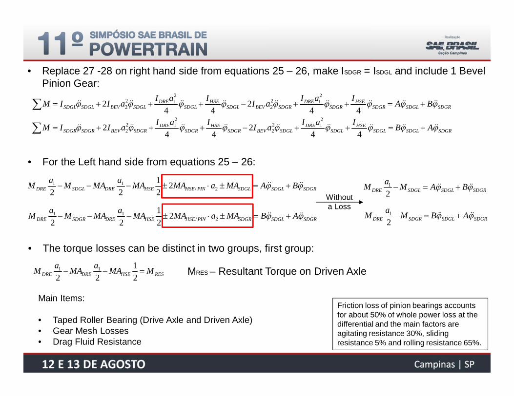
• Replace 27 -28 on right hand side from equations 25 – 26, make ISDGR = ISDGL and include 1 BevelPinion Gear:
SDGRSDGLSDGRHSE
SDGRDRE
SDGRBEVSDGLHSE
SDGLDRE
SDGLBEVSDGLSDGL BAIaIaIIaIaIIM44
244
2212
2
212
2
SDGRSDGLSDGLHSE
SDGLDRE
SDGLBEVSDGRHSE
SDGRDRE
SDGRBEVSDGRSDGR ABIaIaIIaIaIIM44
244
2212
2
212
2
• For the Left hand side from equations 25 – 26:
SDGRSDGLSDGLPINHSEHSEDRESDGLDRE BAMAaMAMAaMAMaM 2/11 2
21
22
SDGRSDGLSDGRPINHSEHSEDRESDGRDRE ABMAaMAMAaMAMaM 2/11 2
21
22
SDGRSDGLSDGLDRE BAMaM21
SDGRSDGLSDGRDRE ABMaM21
Withouta Loss
• The torque losses can be distinct in two groups, first group:
RESHSEDREDRE MMAaMAaM21
2211 MRES – Resultant Torque on Driven Axle
Main Items:
• Taped Roller Bearing (Drive Axle and Driven Axle)• Gear Mesh Losses• Drag Fluid Resistance
Friction loss of pinion bearings accountsfor about 50% of whole power loss at thedifferential and the main factors areagitating resistance 30%, slidingresistance 5% and rolling resistance 65%.

2/ aMA PINHSE
SDGMA
• The torque losses can be distinct in two groups, second group:
Positive for - BEV or FT3 >FT4 on bevel pinion reference.
Negative for + BEV or FT3 <FT4 on bevel pinion reference.
FT4
FT2
FT3
BEV
Positive for HSE> SDG or FT3 >FT4 on bevel pinion reference.
Negative for HSE< SDG or FT3 <FT4 on bevel pinion reference.
Main Items:
• Friction between Pinion and Bevel Gear• Friction between Bevel Gear and House• Gear Mesh Losses• Liquid drag torque on lubricant
Main Items:
• Friction between Side Gear and House• Gear Mesh Losses• Liquid drag torque on lubricant
• The two main equation can be write:
SDGRSDGLSDGLPINHSESDGLRES BAMAaMAMM 2/2
SDGRSDGLSDGRPINHSESDGRRES ABMAaMAMM 2/2
29
30

• Friction Components:

Failure Mode Analyses

• Failure Mode Analyses
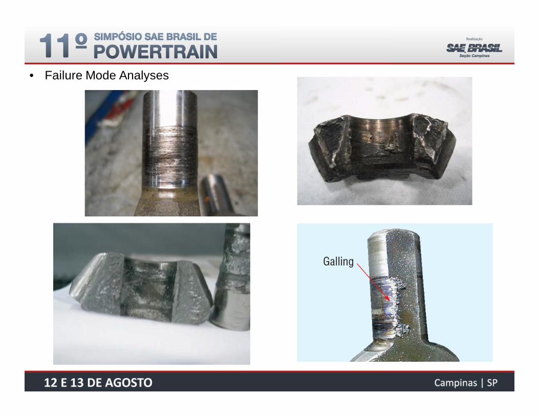
• Failure Mode Analyses

• Failure Mode Analyses
Axial Forces on Gears

cwpa FQ costan´'
cwcwa rgT
rgTQ costan
8costan
)2)(4(00'
cwa rgTQ costan4
0'
• Axial Force on Side Gear Mesh:
• For a Four Pinions
• For a Two Pinions
• Axial Force on Side Gear
31
32

cwpa FQ sintan´'
cwcwa rgT
rgTQ sintan
4sintan
)1)(4(00'
cwa rgTQ costan2
0'
• Axial Force on Bevel Pinion Gear Mesh:
• For a Four Pinions
• For a Two Pinions
• Axial Force on Bevel Pinion Gear
33
34

• Axial Force on Side Gear Mesh:
)]sintancos(sin1[cos)tan(
80'
wkww
ck
ga r
TQ 35
)]sintancos(sin1[cos)tan(
40'
wkww
ck
ga r
TQ 36
• For a Four Pinions
• For a Two Pinions
Equations 31 to 34 do not considererimportant items like gear tooth frictionand motion of contact point along thepressure line. The influences of twoitems was include on equations 35and 36 and it can be verified ongraphic above.

Wheel Speed and Forces

CoG
vx
vy
v
VX
VY
VX
VY
VX
VY
VX
VY
CoG
lF
lR
bR /2
vX
vY
v
bF /2 bF /2
bR /2
• Wheel Speed on Curve:
cosVVX sinVVY
Vehicle Speed 2F
FLXFRXbVV
2R
RLXRRXbVV
RRLYRRY lVV
FFLYFRY lVV
Rotation Speed
22 )()( YXRES VVV
Resultant Speed
VRLX
VRLY
VFLX
VFRX
VRRX
VFLY
VRRY
VFRY

“Rolling Resistance is the mechanical energy converted into heat by tire moving for unit distance on roadway”.
• Wheel Resistance Force (Rolling Resistance) [6]:
SAE J2452 – Coastdown Test (from 115kph to 15kph)
)( 2cvbvaFPF ZRoll
P – Tire Pressure.Fz – Tire Vertical Load.v – Linear Speed.

• Wheel Resistance Force (Uneven Road Force) [7]:
X
WF
X
Runeven0
• The uneven in the road are cushioned andabsorbed by tire.
• The spring work does not have a effect on thewheel resistance because the energyintroduce on compression are regained onrebounding.
• The damper work relative to the covereddistance constitutes the additional componentof wheel resistance.
X
M
Distance x
Distance x
Spr
ing
Forc
eD
ampe
rFor
ce
Whe
elFo
rce
introducedenergy
regainedenergy
damperwork
springwork
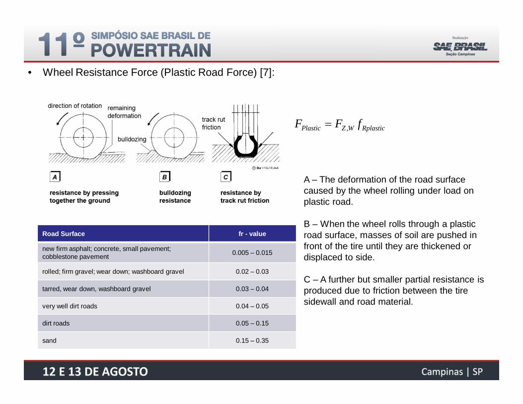
• Wheel Resistance Force (Plastic Road Force) [7]:
RplasticWZPlastic fFF ,
A – The deformation of the road surfacecaused by the wheel rolling under load onplastic road.
B – When the wheel rolls through a plasticroad surface, masses of soil are pushed infront of the tire until they are thickened ordisplaced to side.
C – A further but smaller partial resistance isproduced due to friction between the tiresidewall and road material.
Road Surface fr - value
new firm asphalt; concrete, small pavement;cobblestone pavement 0.005 – 0.015
rolled; firm gravel; wear down; washboard gravel 0.02 – 0.03
tarred, wear down, washboard gravel 0.03 – 0.04
very well dirt roads 0.04 – 0.05
dirt roads 0.05 – 0.15
sand 0.15 – 0.35

• Wheel Resistance Force (Component Resulting from Slip):
Lateral Force:
wheelplane
motiondirection
lateralforce
roll resistanceforce
centrifugalforce
LF
RollF
v
CoG
vx
vy
v
sinLF cosRollF
FL
FR
RL
RR
cossin RollLR FFF

• Wheel Resistance Force (Toe-Angle and Camber Angle):
)sin(LTOE FF
CAMBERF
toe-in toe-out
positive camber negative camber

• Drive Shafts with Difference Torsional Stiffness
)( SDGLWHLTLSDGL kMSDGRSDGLSDGLPINHSESDGLRES BAMAaMAMM 2/2
SDGRSDGLSDGRPINHSESDGRRES ABMAaMAMM 2/2 )( SDGRWHRTRSDGR kM
)2
(2mrITrFM WHLWHLBLRLSDGL
)2
(2mrITrFM WHRWHRBRRRSDGR
Considering a vehicle in straight line and vehicle resistance force divided between the tractive wheels.
Definition:
IWHL – Inertia of left wheel.IWHR – Inertia of right wheel.m – Vehicle mass.kTL – Stiffness of left drive shaft.kTR – Stiffness of right drive shaft.TBR – Drag brake torque right.TBL– Drag brake torque Left.FRL – Drag force on left wheel.FRR – Drag force on right wheel.
37
38
39
40

• Results of Simulation – Different Drive Shaft Stiffness
Increasethe friction
5% of Stiffnessdifference
SameStiffness
Reduce theinput torque Reduce the
input torque

• Results of Simulation – Different Drive Shaft Stiffness
Increasethe friction
Increasethe friction

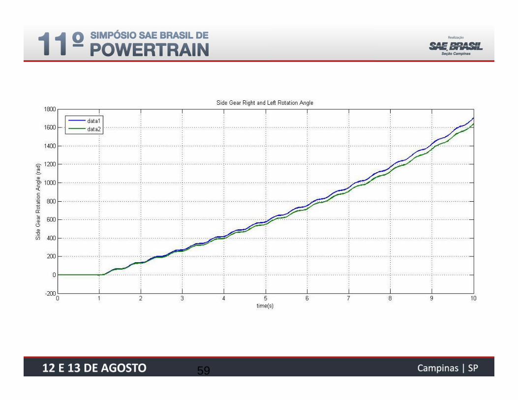
• Results of Simulation – Drag Brake Torque
Increase the dragbrake torque
Considering the same drive shaft stiffness onleft and right sides, the drag brake torque wasintroduced on one wheel side and increasedto see the influence on bevel gear rotationangle. The simulations were performedwithout a friction of differential components.
The drag brake torque on one wheel sidemake the bevel gear rotate but the rotationdifference is smaller between the side gearsand it can be verified on right side graphic.

New Differential Design

• New Neumayer Tekfor Differential:

• New Schaeffler Differential:

• New Powertrain:
• Hybrid Powertrain Transmission
• Electric Powertrain Transmission

Q&A

• Bibliography:
[1] Driveline Systems of Ground Vehicles, Theory and Design. A.F. Andreev; V.I.Kabanau; V.V.Vantsevich.
[2] Automotive Transmissions Fundamentals, Selection, Design and Application. H. Naunheimer; B. Bertsche; J.Ryborz; W. Novak.
[3] Leistungsübertragung inFahrzeuggetrieben Grundlagen der Auslegung, Entwicklung und Validierung vonFahrzeuggetrieben und deren Komponenten. E. Kirchner.
[4] Ground Vehicle Dynamics. K. Popp; W. Schiehlen
[5] Race Car Vehicle Dynamics. W.F.Milliken; D.L.Milliken
[6] The Pneumatic Tire. A.N.Gent; J.D.Walter.
[7] Lecture Longitudinal Dynamics of Vehicles (IKA – institut kraftfahrwesen Aachen). H. Wallentowitz.
[8] Lecture Notes - Vehicle Dynamics. G. Rill.
[9] Video Youtube - http://www.youtube.com/watch?v=p3rGjyvNTF0

Backup
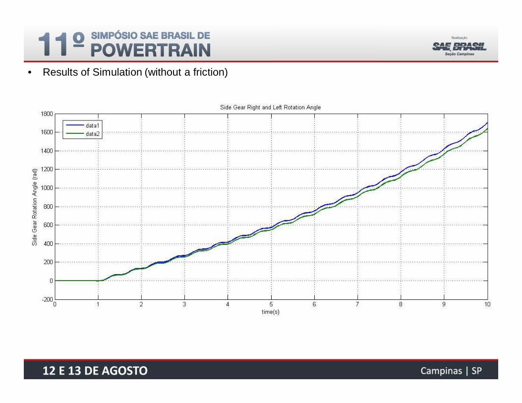
• Results of Simulation (without a friction)

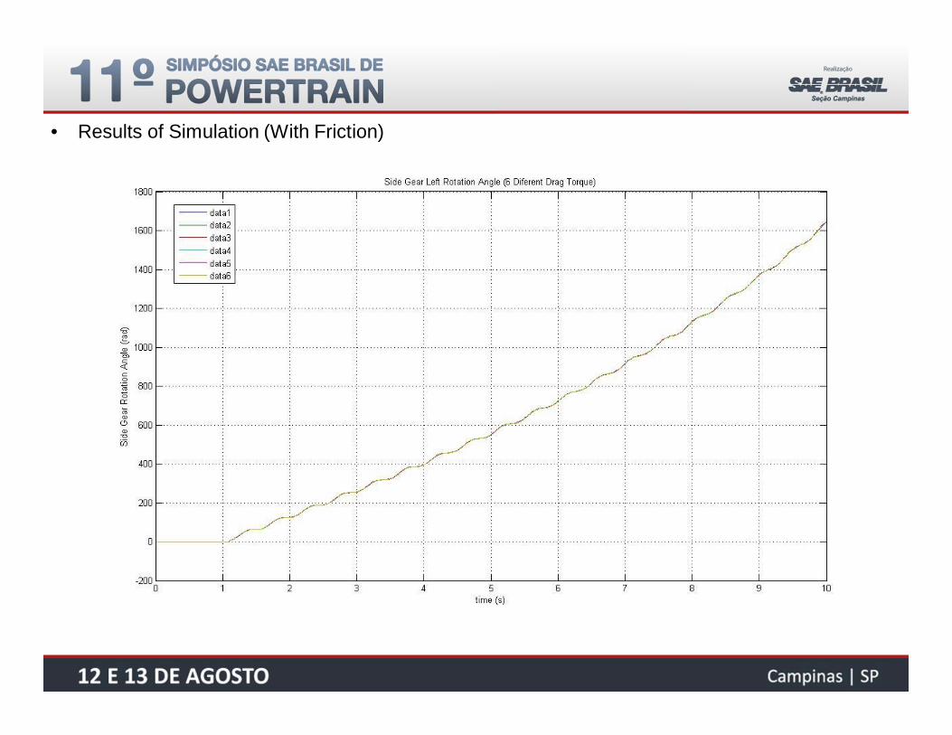
• Results of Simulation (With Friction)

• Results of Simulation (Brake Drag Torque)
• Results of Simulation (With Friction)

• Results of Simulation (With Friction)

• Results of Simulation (With Friction)

• Results of Simulation (With Friction)
59

Failure Mode Analyses


X0
Y0
x
y
x
y
090
0180
1
2

• Axial Force on Side Gear Mesh:

• Axial Force on Side Gear Mesh:
Copyright © 2022 FDOKUMEN