SAUA1302 AUTOMOTIVE PETROL ENGINE
84
1 SCHOOL OF MECHANICAL ENGINEERING DEPARTMENT OF AUTOMOBILE ENGINEERING SAUA1302 AUTOMOTIVE PETROL ENGINE
-
Upload
khangminh22 -
Category
Documents
-
view
0 -
download
0
Transcript of SAUA1302 AUTOMOTIVE PETROL ENGINE

1
SCHOOL OF MECHANICAL ENGINEERING
DEPARTMENT OF AUTOMOBILE ENGINEERING
SAUA1302 AUTOMOTIVE PETROL ENGINE

2
UNIT I ENGINE CONSTRUCTION & OPERATION

3
UNIT 1 ENGINE CONSTRUCTION AND OPERATION
Constructional details of four stroke petrol engine, working principle, air standard Otto cycle,
actual indicator diagram, fuel air analysis, two stroke engine construction and operation,
comparison of four stroke and two stroke engines operation, firing order and its significance.
Theoretical and actual Port Timing, Valve Timing of petrol engines.
Heat engine:
A heat engine is a device which transforms the chemical energy of a fuel into thermal energy and
uses this energy to produce mechanical work. It is classified into two types-
(a) External combustion engine
(b) Internal combustion engine
External combustion engine:
In this engine, the products of combustion of air and fuel transfer heat to a second fluid which is
the working fluid of the cycle.
Examples:
In the steam engine or a steam turbine plant, the heat of combustion is employed to
generate steam which is used in a piston engine (reciprocating type engine) or a turbine
(rotary type engine) for useful work.
In a closed cycle gas turbine, the heat of combustion in an external furnace is transferred
to gas, usually air which the working fluid of the cycle.
Internal combustion engine:
In this engine, the combustion of air and fuels take place inside the cylinder and are used as the
direct motive force. It can be classified into the following types:
1. According to the basic engine design- (a) Reciprocating engine (Use of cylinder piston
arrangement), (b) Rotary engine (Use of turbine)
2. According to the type of fuel used- (a) Petrol engine, (b) diesel engine, (c) gas engine (CNG,
LPG), (d) Alcohol engine (ethanol, methanol etc)
3. According to the number of strokes per cycle- (a) Four stroke and (b) Two stroke engine
4. According to the method of igniting the fuel- (a) Spark ignition engine, (b) compression
ignition engine and (c) hot spot ignition engine
5. According to the working cycle- (a) Otto cycle (constant volume cycle) engine, (b) diesel
cycle (constant pressure cycle) engine, (c) dual combustion cycle (semi diesel cycle) engine.

4
6. According to the fuel supply and mixture preparation- (a) Carburetted type (fuel supplied
through the carburettor), (b) Injection type (fuel injected into inlet ports or inlet manifold, fuel
injected into the cylinder just before ignition).
7. According to the number of cylinder- (a) Single cylinder and (b) multi-cylinder engine
8. Method of cooling- water cooled or air cooled
9. Speed of the engine- Slow speed, medium speed and high speed engine
10. Cylinder arrangement-Vertical, horizontal, inline, V-type, radial, opposed cylinder or piston
engines.
11. Valve or port design and location- Overhead (I head), side valve (L head); in two stroke
engines: cross scavenging, loop scavenging, uniflow scavenging.
12. Method governing- Hit and miss governed engines, quantitatively governed engines and
qualitatively governed engine
13. Application- Automotive engines for land transport, marine engines for propulsion of ships,
aircraft engines for aircraft propulsion, industrial engines, prime movers for electrical
generators.
Comparison between external combustion engine and internal combustion engine:
External combustion engine Internal combustion engine
Combustion of air-fuel is outside the engine cylinder (in a boiler)
Combustion of air-fuel is inside the engine cylinder (in a boiler)
The engines are running smoothly and
silently due to outside combustion
Very noisy operated engine
Higher ratio of weight and bulk to
output due to presence of auxiliary
apparatus like boiler and condenser.
Hence it is heavy and cumbersome.
It is light and compact due to lower
ratio of weight and bulk to output.
Working pressure and temperature
inside the engine cylinder is low; hence
ordinary alloys are used for the
manufacture of engine cylinder and its
parts.
Working pressure and temperature
inside the engine cylinder is very much
high; hence special alloys are used
It can use cheaper fuels including solid fuels
High grade fuels are used with proper filtration
Lower efficiency about 15-20% Higher efficiency about 35-40%
Higher requirement of water for
dissipation of energy through cooling system
Lesser requirement of water

5
High starting torque IC engines are not self-starting
IC ENGINE COMPONENTS
Internal combustion engine consists of a number of parts which are given below
Cylinder:
It is a part of the engine which confines the expanding gases and forms the combustion
space. It is the basic part of the engine. It provides space in which piston operates to suck the air
or air-fuel mixture. The piston compresses the charge and the gas is allowed to expand in the
cylinder, transmitting power for useful work. Cylinders are usually made of high grade cast iron.
Cylinder block:
It is the solid casting body which includes the cylinder and water jackets (cooling fins in
the air cooled engines).
:
Figure 1: Constructional view of a single cylinder SI engine
Cylinder head:
It is a detachable portion of an engine which covers the cylinder and includes the
combustion chamber, spark plugs or injector and valves.
Cylinder liner or sleeve:
It is a cylindrical lining either wet or dry type which is inserted in the cylinder block in
which the piston slides. Liners are classified as: (1) Dry liner and (2) Wet liner. Dry liner makes
metal to metal contact with the cylinder block casing. wet liners come in contact with the cooling
water, whereas dry liners do not come in contact with the cooling water.

6
Piston:
It is a cylindrical part closed at one end which maintains a close sliding fit in the engine
cylinder. It is connected to the connecting rod by a piston pin. The force of the expanding gases
against the closed end of the piston, forces the piston down in the cylinder. This causes the
connecting rod to rotate the crankshaft. Cast iron is chosen due to its high compressive strength.
Aluminum and its alloys preferred mainly due to it lightness.
Figure 2: Piston and piston ring assembly
Head (Crown) of piston: It is the top of the piston.
Skirt: It is that portion of the piston below the piston pin which is designed to adsorb
the side movements of the piston.
Piston ring:
It is a split expansion ring, placed in the groove of the piston. They are usually made of
cast iron or pressed steel alloy. The function of the ring are as follows :
a) It forms a gas tight combustion chamber for all positions of piston.
b) It reduces contact area between cylinder wall and piston wall preventing friction losses
and excessive wear.
c) It controls the cylinder lubrication.
d) It transmits the heat away from the piston to the cylinder walls. Piston rings are of two
types: (1) Compression ring and (2) Oil ring
Compression ring:
Compression rings are usually plain, single piece and are always placed in the grooves
of the piston nearest to the piston head. They prevent leakage of gases from the cylinder and
helps increasing compression pressure inside the cylinder.
Oil ring:
Oil rings are grooved or slotted and are located either in lowest groove above the piston

7
pin or in a groove above the piston skirt. They control the distribution of lubrication oil in the
cylinder and the piston.
Piston Pin:
It is also called wrist pin or gudgeon pin. Piston pin is used to join the connecting rod to
the piston.
Connecting rod:
It is special type of rod, one end of which is attached to the piston and the other end to
the crankshaft. It transmits the power of combustion to the crankshaft and makes it rotate
continuously. It is usually made of drop forged steel.
Crankshaft:
It is the main shaft of an engine which converts the reciprocating motion of the piston
into rotary motion of the flywheel. Usually the crankshaft is made of drop forged steel or cast
steel. The space that supports the crankshaft in the cylinder block is called main journal, whereas
the part to which connecting rod is attached is known as crank journal. Crankshaft is provided
with counter weights throughout its length to have counter balance of the unit.
Figure 3: Connecting rod assembly
Flywheel:
Flywheel is made of cast iron. Its main functions are as follows :
a) It stores energy during power stroke and returns back the energy during the idle strokes,
providing a uniform rotary motion of flywheel.
b) The rear surface of the flywheel serves as one of the pressure surfaces for the clutch
plate.
c) Engine timing marks are usually stamped on the flywheel, which helps in adjusting the
timing of the engine.
d) Sometime the flywheel serves the purpose of a pulley for transmitting power.
Crankcase:
The crankcase is that part of the engine which supports and encloses the crankshaft and
camshaft. It provides a reservoir for the lubricating oil. It also serves as a mounting unit for such
8
accessories as the oil pump, oil filter, starting motor and ignition components. The upper portion
of the crankcase is usually integral with cylinder block. The lower part of the crankcase is
commonly called oil pan and is usually made of cast iron or cast aluminum.
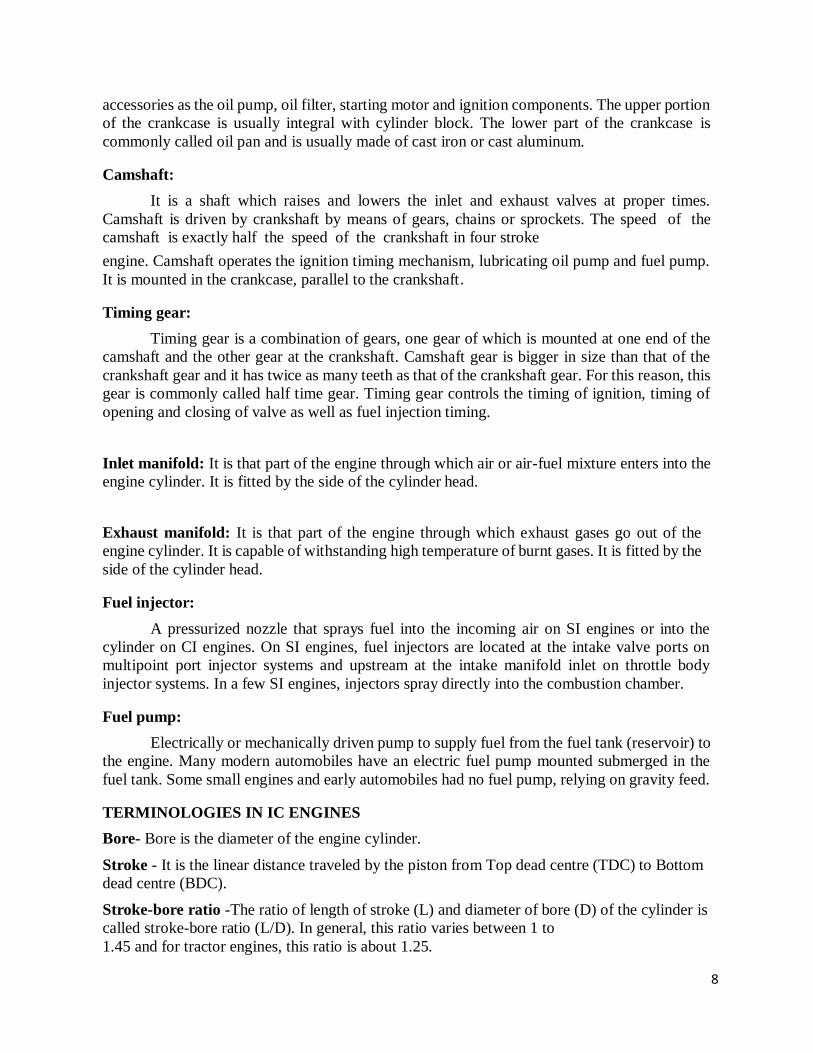
Camshaft:
It is a shaft which raises and lowers the inlet and exhaust valves at proper times.
Camshaft is driven by crankshaft by means of gears, chains or sprockets. The speed of the
camshaft is exactly half the speed of the crankshaft in four stroke
engine. Camshaft operates the ignition timing mechanism, lubricating oil pump and fuel pump.
It is mounted in the crankcase, parallel to the crankshaft.
Timing gear:
Timing gear is a combination of gears, one gear of which is mounted at one end of the
camshaft and the other gear at the crankshaft. Camshaft gear is bigger in size than that of the
crankshaft gear and it has twice as many teeth as that of the crankshaft gear. For this reason, this
gear is commonly called half time gear. Timing gear controls the timing of ignition, timing of
opening and closing of valve as well as fuel injection timing.
Inlet manifold: It is that part of the engine through which air or air-fuel mixture enters into the
engine cylinder. It is fitted by the side of the cylinder head.
Exhaust manifold: It is that part of the engine through which exhaust gases go out of the
engine cylinder. It is capable of withstanding high temperature of burnt gases. It is fitted by the
side of the cylinder head.
Fuel injector:
A pressurized nozzle that sprays fuel into the incoming air on SI engines or into the
cylinder on CI engines. On SI engines, fuel injectors are located at the intake valve ports on
multipoint port injector systems and upstream at the intake manifold inlet on throttle body
injector systems. In a few SI engines, injectors spray directly into the combustion chamber.
Fuel pump:
Electrically or mechanically driven pump to supply fuel from the fuel tank (reservoir) to
the engine. Many modern automobiles have an electric fuel pump mounted submerged in the
fuel tank. Some small engines and early automobiles had no fuel pump, relying on gravity feed.
TERMINOLOGIES IN IC ENGINES
Bore- Bore is the diameter of the engine cylinder.
Stroke - It is the linear distance traveled by the piston from Top dead centre (TDC) to Bottom
dead centre (BDC).
Stroke-bore ratio -The ratio of length of stroke (L) and diameter of bore (D) of the cylinder is
called stroke-bore ratio (L/D). In general, this ratio varies between 1 to
1.45 and for tractor engines, this ratio is about 1.25.

9
Swept volume - It is the volume (A x L) displaced by one stroke of the piston where A is the
cross sectional area of piston and L is the length of stroke
Top dead centre - When the piston is at the top of its stroke, it is said to be at the
top dead centre (TDC),
Bottom dead centre - when the piston is at the bottom of its stroke, it is said to be at its bottom dead
centre (BDC).
Figure 4: Location of dead centre in the cylinder area
Compression ratio - It is the ratio of the volume of the cylinder at the beginning of the
compression stroke to that at the end of compression stroke, i.e. ratio of total cylinder volume to
clearance volume. The Compression ratio of diesel engine varies from 14:1 to 22:1 and that of
carburetor type engine (spark ignition engine) varies from 4:1 to 8:1.
Power - It is the rate of doing work. S.I. unit of power is watt.
Watt = Joule/sec. (4.2 Joules = 1 Calorie).
In metric unit the power can be expressed in kg.m/sec.
Horse power (HP) - It is the rate of doing work. Expressed in horse power Conversion factors
from work to power
4500 kg m of work /minute = 1.0 hp 75
kg. m of work /second = 1.0 hp.
Indicated horse power (IHP) - It is the power generated in the engine cylinder and received by
the piston. It is the power developed in a cylinder without accounting frictional losses.
Brake horse power (BHP) - It is the power delivered by the engine at the end of the crankshaft.
It is measured by a dynamometer.
Ignition Delay(ID) - Time interval between ignition initiation and the actual start of
combustion.
Air-Fuel Ratio (AF) Ratio of mass of air to mass of fuel input into engine.
Fuel-Air Ratio (FA) Ratio of mass of fuel to mass of air input into engine.
10
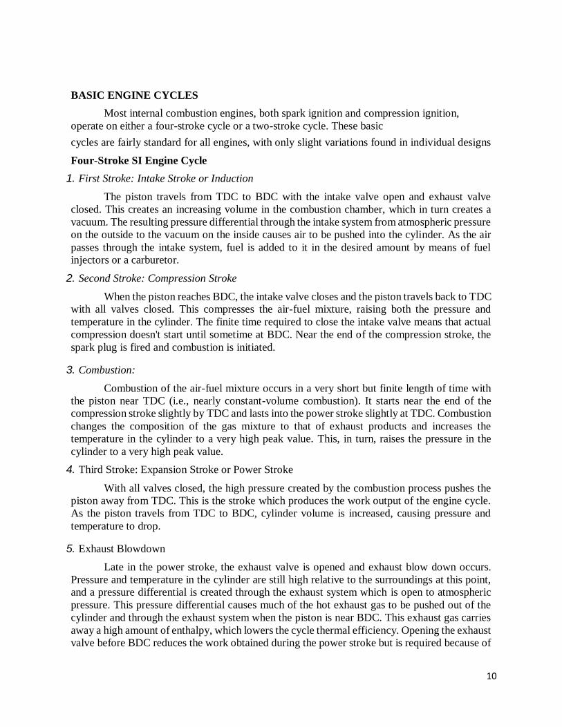
BASIC ENGINE CYCLES
Most internal combustion engines, both spark ignition and compression ignition,
operate on either a four-stroke cycle or a two-stroke cycle. These basic
cycles are fairly standard for all engines, with only slight variations found in individual designs
Four-Stroke SI Engine Cycle
1. First Stroke: Intake Stroke or Induction
The piston travels from TDC to BDC with the intake valve open and exhaust valve
closed. This creates an increasing volume in the combustion chamber, which in turn creates a
vacuum. The resulting pressure differential through the intake system from atmospheric pressure
on the outside to the vacuum on the inside causes air to be pushed into the cylinder. As the air
passes through the intake system, fuel is added to it in the desired amount by means of fuel
injectors or a carburetor.
2. Second Stroke: Compression Stroke
When the piston reaches BDC, the intake valve closes and the piston travels back to TDC
with all valves closed. This compresses the air-fuel mixture, raising both the pressure and
temperature in the cylinder. The finite time required to close the intake valve means that actual
compression doesn't start until sometime at BDC. Near the end of the compression stroke, the
spark plug is fired and combustion is initiated.
3. Combustion:
Combustion of the air-fuel mixture occurs in a very short but finite length of time with
the piston near TDC (i.e., nearly constant-volume combustion). It starts near the end of the
compression stroke slightly by TDC and lasts into the power stroke slightly at TDC. Combustion
changes the composition of the gas mixture to that of exhaust products and increases the
temperature in the cylinder to a very high peak value. This, in turn, raises the pressure in the
cylinder to a very high peak value.
4. Third Stroke: Expansion Stroke or Power Stroke
With all valves closed, the high pressure created by the combustion process pushes the
piston away from TDC. This is the stroke which produces the work output of the engine cycle.
As the piston travels from TDC to BDC, cylinder volume is increased, causing pressure and
temperature to drop.
5. Exhaust Blowdown
Late in the power stroke, the exhaust valve is opened and exhaust blow down occurs.
Pressure and temperature in the cylinder are still high relative to the surroundings at this point,
and a pressure differential is created through the exhaust system which is open to atmospheric
pressure. This pressure differential causes much of the hot exhaust gas to be pushed out of the
cylinder and through the exhaust system when the piston is near BDC. This exhaust gas carries
away a high amount of enthalpy, which lowers the cycle thermal efficiency. Opening the exhaust
valve before BDC reduces the work obtained during the power stroke but is required because of

11
the finite time needed for exhaust blow down.
6. Exhaust Stroke:
Exhaust Stroke By the time the piston reaches BDC, exhaust blow down is complete, but
the cylinder is still full of exhaust gases at approximately atmospheric pressure. With the exhaust
valve remaining open, the piston now travels from BDC to TDC in the exhaust stroke. This
pushes most of the remaining exhaust gases out of the cylinder into the exhaust system at about
atmospheric pressure, leaving only that trapped in the clearance volume when the piston reaches
TDC. Near the end of the exhaust stroke by TDC, the intake valve starts to open, so that it is
fully open by TDC when the new intake stroke starts the next cycle. Near TDC the exhaust valve
starts to close and finally is fully closed sometime at TDC. This period when both the intake
valve and exhaust valve are open is called valve overlap.
Figure 5: Four stroke SI engine operating cycle.

12
Two-Stroke SI Engine Cycle
1. Combustion
With the piston at TDC combustion occurs very quickly, raising the temperature and
pressure to peak values, almost at constant volume.
2. First Stroke: Expansion Stroke or Power Stroke
Very high pressure created by the combustion process forces the piston down in the
power stroke. The expanding volume of the combustion chamber causes pressure and
temperature to decrease as the piston travels towards BDC.
3. Exhaust Blow down
At about 75° by BDC, the exhaust valve opens and blow down occurs. The exhaust valve
may be a poppet valve in the cylinder head, or it may be a slot in the side of the cylinder which
is uncovered as the piston approaches BDC. After blow down the cylinder remains filled with
exhaust gas at lower pressure.
4. Intake and Scavenging
When blow down is nearly complete, at about 50° by BDC, the intake slot on the side of
the cylinder is uncovered and intake air-fuel enters under pressure. Fuel is added to the air with
either a carburetor or fuel injection. This incoming mixture pushes much of the remaining
exhaust gases out the open exhaust valve and fills the cylinder with a combustible air-fuel
mixture, a process called scavenging. The piston passes BDC and very quickly covers the intake
port and then the exhaust port (or the exhaust valve closes). The higher pressure at which the air
enters the cylinder is established in one of two ways. Large two stroke cycle engines generally
have a supercharger, while small engines will intake the air through the crankcase. On these
engines the crankcase is designed to serve as a compressor in addition to serving its normal
function.
5. Second Stroke:
Compression Stroke With all valves (or ports) closed, the piston travels towards TDC
and compresses the air-fuel mixture to a higher pressure and temperature. Near the end of the
compression stroke, the spark plug is fired; by the time the piston gets to IDC, combustion occurs
and the next engine cycle begins.
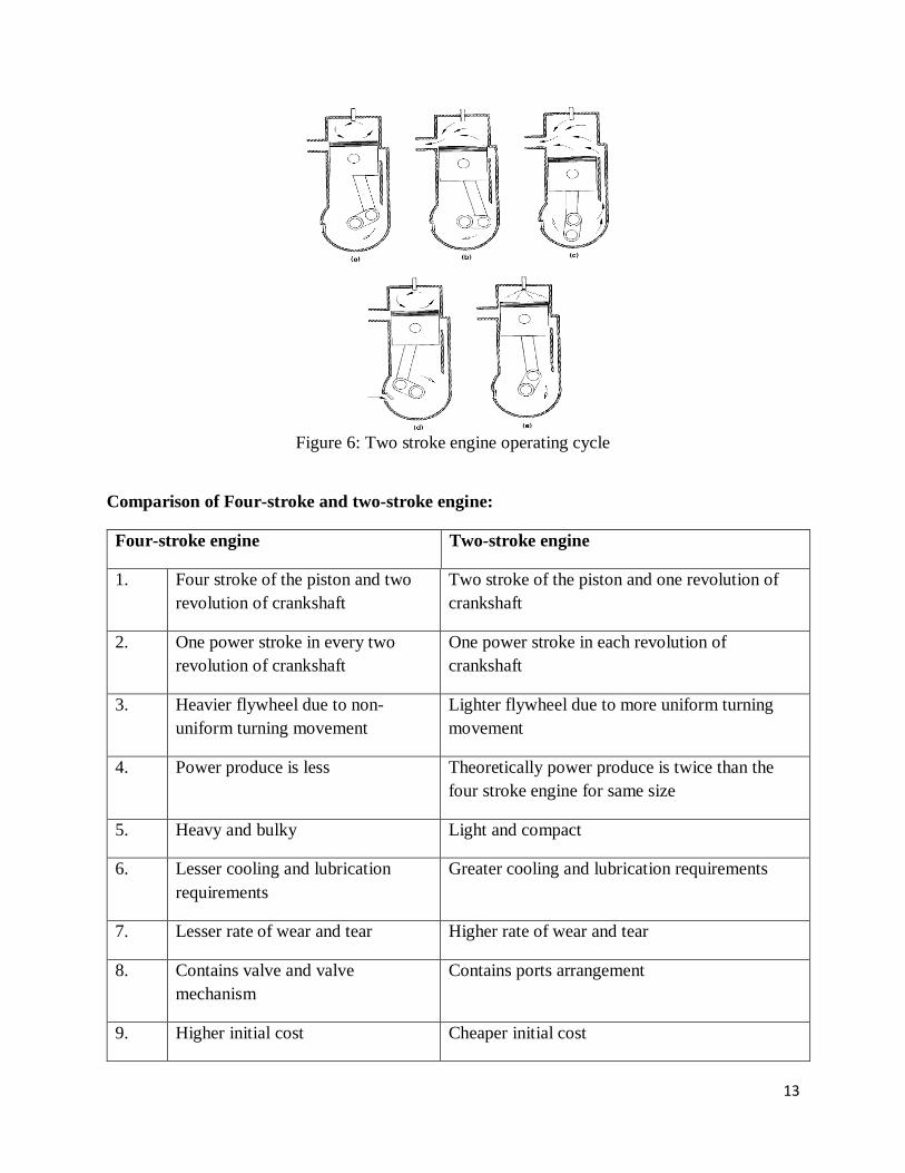
13
Figure 6: Two stroke engine operating cycle
Comparison of Four-stroke and two-stroke engine:
Four-stroke engine Two-stroke engine
1. Four stroke of the piston and two
revolution of crankshaft
Two stroke of the piston and one revolution of
crankshaft
2. One power stroke in every two
revolution of crankshaft
One power stroke in each revolution of
crankshaft
3. Heavier flywheel due to non-
uniform turning movement
Lighter flywheel due to more uniform turning
movement
4. Power produce is less Theoretically power produce is twice than the
four stroke engine for same size
5. Heavy and bulky Light and compact
6. Lesser cooling and lubrication
requirements
Greater cooling and lubrication requirements
7. Lesser rate of wear and tear Higher rate of wear and tear
8. Contains valve and valve
mechanism
Contains ports arrangement
9. Higher initial cost Cheaper initial cost

14
10. Volumetric efficiency is more due
to greater time of induction
Volumetric efficiency less due to lesser time of
induction
11. Thermal efficiency is high and also
part load efficiency better
Thermal efficiency is low, part load efficiency
lesser
12. It is used where efficiency is
important.
Ex-cars, buses, trucks, tractors,
industrial engines, aero planes,
power generation etc.
It is used where low cost, compactness and light
weight are important.
Ex-lawn mowers, scooters, motor cycles,
mopeds, propulsion ship etc.
Comparison of SI and CI engine:
SI engine CI engine
Working cycle is Otto cycle. Working cycle is diesel cycle.
Petrol or gasoline or high octane fuel is
used.
Diesel or high cetane fuel is used.
High self-ignition temperature. Low self-ignition temperature.
Fuel and air introduced as a gaseous mixture
in the suction stroke.
Fuel is injected directly into the combustion
chamber at high pressure at the end of
compression stroke.
Carburettor used to provide the mixture.
Throttle controls the quantity of mixture
introduced.
Injector and high pressure pump used to supply
of fuel. Quantity of fuel regulated in pump.
Use of spark plug for ignition system Self-ignition by the compression of air which
increased the temperature required for
combustion
Compression ratio is 6 to 10.5 Compression ratio is 14 to 22
Higher maximum RPM due to lower weight Lower maximum RPM
Maximum efficiency lower due to lower
compression ratio
Higher maximum efficiency due to higher
compression ratio
Lighter Heavier due to higher pressures

15
Valve timing diagram:
The exact moment at which the inlet and outlet valve opens and closes with reference to the
position of the piston and crank shown diagrammatically is known as valve timing diagram. It is
expressed in terms of degree crank angle. The theoretical valve timing diagram is shown in Figure
below
Figure 7: Theoretical valve timing diagram
But actual valve timing diagram is different from theoretical due to two factors-mechanical and
dynamic factors. Figure 4 shows the actual valve timing diagram for four stroke low speed or
high speed engine.
Opening and closing of inlet valve
-Inlet valve opens 12 to 30ᵒ CA before TDC to facilitate silent operation of the engine under high
speed. It increases the volumetric efficiency.
-Inlet valve closes 10-60ᵒ CA after TDC due to inertia movement of fresh charge into cylinder
i.e. ram effect.
Figure below represents the actual valve timing diagram for low and high speed engine.

16
Figure 8: Actual valve timing diagram for low and high speed engine
Opening and closing of exhaust valve
Exhaust valve opens 25 to 55ᵒ CA before BDC to reduce the work required to expel out the burnt
gases from the cylinder. At the end of expansion stroke, the pressure inside the chamber is high,
hence work to expel out the gases increases.
Exhaust valve closes 10 to 30ᵒ CA after TDC to avoid the compression of burnt gases in next
cycle. Kinetic energy of the burnt gas can assist maximum exhausting of the gas. It also increases
the volumetric efficiency.
Note: For low and high speed engine, the lower and upper values are used respectively
Valve overlap
During this time both the intake and exhaust valves are open. The intake valve is opened before
the exhaust gases have completely left the cylinder, and their considerable velocity assists in
drawing in the fresh charge. Engine designers aim to close the exhaust valve just as the fresh charge
from the intake valve reaches it, to prevent either loss of fresh charge or unscavenged exhaust gas.

17
Figure 10: Actual valve timing diagram for low speed and high speed engines.
Port timing diagram:
-Drawn for 2-stroke engine
-No valve arrangement
-3 ports- inlet, transfer and exhaust
Figure11: port timing diagram for 2-stroke engine
Otto cycle- thermodynamic cycle for SI/petrol engine
-Reversible adiabatic compression and expansion process
-Constant volume heat addition (combustion) and heat rejection process (exhaust)
Figure below depicts the Otto cycle

18
Figure 12: P-V and T-S diagram of Otto cycle.
To find the air standard efficiency

19
References
1. Ganesan V, “Internal Combustion Engines”4th edition, Tata McGraw Hill publication 2017
2. Rajput R. K, “A textbook of Internal Combustion Engines”, Third edition Laxmi
Publications,2016
3. Mathur and Sharma “Internal Combustion Engines” “Dhanpat Rai and Sons Publication,
2010
4. John B. Heywood, “Fundamentals of Internal Combustion Engine, Second edition, McGraw-
Hill Education; 2018
5. Heinz Heisler “Advanced Engine Technology “2nd edition SAE Publication, 2002.

20
UNIT II SI ENGINE FUEL SYSTEM

21
UNIT 2 SI ENGINE FUEL SYSTEM
Carburetor working principle, requirements of an automotive carburetor, Solex, S.U, Carter
carburetor. starting, idling, acceleration and normal circuits of carburetors. Compensation,
maximum power devices, constant choke and constant vacuum carburetors, fuel feed systems;
mechanical and electrical fuel feed pumps. Petrol injection, GDI, MPFI.
CARBURETION
Introduction
Spark-ignition engines normally use volatile liquid fuels. Preparation of fuel-air mixture is done
outside the engine cylinder and formation of a homogeneous mixture is normally not completed
in the inlet manifold. Fuel droplets, which remain in suspension, continue to evaporate and mix
with air even during suction and compression processes. The process of mixture preparation is
extremely important for spark-ignition engines. The purpose of carburetion is to provide a
combustible mixture of fuel and air in the required quantity and quality for efficient operation
of the engine under all conditions.
Definition of Carburetion
The process of formation of a combustible fuel-air mixture by mixing the proper amount of fuel
with air before admission to engine cylinder is called carburetion and the device which does this
job is called a carburetor.
Factors Affecting Carburetion
Of the various factors, the process of carburetion is influenced by
i. The engine speed
ii. The vaporization characteristics of the fuel
iii. The temperature of the incoming air and
iv. The design of the carburetor
Principle of Carburetion
Both air and gasoline are drawn through the carburetor and into the engine cylinders by the
suction created by the downward movement of the piston. This suction is due to an increase in
the volume of the cylinder and a consequent decrease in the gas pressure in this chamber. It is
the difference in pressure between the atmosphere and cylinder that causes the air to flow into
the chamber. In the carburetor, air passing into the combustion chamber picks up discharged
from a tube. This tube has a fine orifice called carburetor jet that is exposed to the air path. The
rate at which fuel is discharged into the air depends on the pressure difference or pressure head
between the float chamber and the throat of the venturi and on the area of the outlet of the tube.

22
In order that the fuel drawn from the nozzle may be thoroughly atomized, the suction effect must
be strong and the nozzle outlet comparatively small. In order to produce a strong suction, the
pipe in the carburetor carrying air to the engine is made to have a restriction. At this restriction
called throat due to increase in velocity of flow, a suction effect is created. The restriction is
made in the form of a venturi to minimize throttling losses. The end of the fuel jet is located at
the venturi or throat of the carburetor. The geometry of venturi tube is as shown in Fig.3. It has
a narrower path at the center so that the flow area through which the air must pass is considerably
reduced. As the same amount of air must pass through every point in the tube, its velocity will
be greatest at the narrowest point. The smaller the area, the greater will be the velocity of the
air, and thereby the suction is proportionately increased
As mentioned earlier, the opening of the fuel discharge jet is usually loped where the suction is
maximum. Normally, this is just below the narrowest section of the venturi tube. The spray of
gasoline from the nozzle and the air entering through the venturi tube are mixed together in this
region and a combustible mixture is formed which passes through the intake manifold into the
cylinders. Most of the fuel gets atomized and simultaneously a small part will be vaporized.
Increased air velocity at the throat of the venturi helps he rate of evaporation of fuel. The
difficulty of obtaining a mixture of sufficiently high fuel vapour-air ratio for efficient starting
of the engine and for uniform fuel-air ratio indifferent cylinders (in case of multi cylinder
engine) cannot be fully met by the increased air velocity alone at the venturi throat.
The Simple Carburetor
Carburetors are highly complex. Let us first understand the working principle bf a simple or
elementary carburetor that provides an air fuel mixture for cruising or normal range at a single
speed. Later, other mechanisms to provide for the various special requirements like starting,
idling, variable load and speed operation and acceleration will be included. Figure 3. shows the
details of a simple carburetor.
Figure 1: Schematic diagram of Simple Carburetor
The simple carburetor mainly consists of a float chamber, fuel discharge nozzle and a metering

23
orifice, a venturi, a throttle valve and a choke. The float and a needle valve system maintain a
constant level of gasoline in the float chamber. If the amount of fuel in the float chamber falls
below the designed level, the float goes down, thereby opening the fuel supply valve and
admitting fuel. When the designed level has been reached, the float closes the fuel supply valve
thus stopping additional fuel flow from the supply system. Float chamber is vented either to the
atmosphere or to the” upstream side of the venturi. During suction stroke air is drawn through
the venturi.
As already described, venturi is a tube of decreasing cross-section with a minimum area at the
throat, Venturi tube is also known as the choke tube and is so shaped that it offers minimum
resistance to the air flow. As the air passes through the venturi the velocity increases reaching a
maximum at the venturi throat. Correspondingly, the pressure decreases reaching a minimum.
From the float chamber, the fuel is fed to a discharge jet, the tip of which is located in the throat
of the venturi. Because of the differential pressure between the float chamber and the throat of
the venturi, known as carburetor depression, fuel is discharged into the air stream. The fuel
discharge is affected by the size of the discharge jet and it is chosen to give the required air-fuel
ratio. The pressure at the throat at the fully open throttle condition lies between 4 to 5 cm of Hg,
below atmospheric and seldom exceeds8 cm Hg below atmospheric. To avoid overflow of fuel
through the jet, the level of the liquid in the float chamber is maintained at a level slightly below
the tip of the discharge jet. This is called the tip of the nozzle. The difference in the height between
the top of the nozzle and the float chamber level is marked h in Fig.3.
The gasoline engine is quantity governed, which means that when power output is to be
varied at a particular speed, the amount of charge delivered to the cylinder is varied. This is
achieved by means of a throttle valve usually of the butterfly type that is situated after the venturi
tube. As the throttle is closed less air flows through the venturi tube and less is the quantity of
air-fuel mixture delivered to the cylinder and hence power output is reduced. As the” throttle is
opened, more air flows through the choke tube resulting in increased quantity of mixture being
delivered to the engine. This increases the engine power output. A simple carburetor of the type
described above suffers from a fundamental drawback in that it provides the required A/F ratio
only at one throttle position. At the other throttle positions the mixture is either leaner or richer
depending on whether the throttle is opened less or more. As the throttle opening is varied, the
air flow varies and creates a certain pressure differential between the float chamber and the
venturi throat. The same pressure differential regulates the flow of fuel through the nozzle.
Therefore, the velocity of flow of air II and fuel vary in a similar manner. At the same time, the
density I of air decrease as the pressure at the venturi throat decrease with increasing air flow
whereas that of the fuel remains unchanged. This results in a simple carburetor producing a
progressively rich mixture with increasing throttle opening.
The Choke and the Throttle
When the vehicle is kept stationary for a long period during cool winter seasons, may be
overnight, starting becomes more difficult. As already explained, at low cranking speeds and
intake temperatures a very rich mixture is required to initiate combustion. Some times air-fuel
ratio as rich as 9:1 is required. The main reason is that very large fraction of the fuel may remain
as liquid suspended in air even in the cylinder. For initiating combustion, fuel-vapour and air in

24
the form of mixture at a ratio that can sustain combustion is required. It may be noted that at
very low temperature vapour fraction of the fuel is also very small and this forms combustible
mixture to initiate combustion. Hence, a very rich mixture must be supplied. The most popular
method of providing such mixture is by the use of choke valve. This is simple butterfly valve
located between the entrance to the carburetor and the venturi throat as shown in Fig.3.
When the choke is partly closed, large pressure drop occurs at the venturi throat that
would normally result from the quantity of air passing through the venturi throat. The very large
depression at the throat inducts large amount of fuel from the main nozzle and provides a very
rich mixture so that the ratio of the evaporated fuel to air in the cylinder is within the
combustible limits. Sometimes, the choke valves are spring loaded to ensure that large
carburetor depression and excessive choking does not persist after the engine has started, and
reached a desired speed. This choke can be made to operate automatically by means of a
thermostat so that the choke is closed when engine is cold and goes out of operation when engine
warms up after starting. The speed and the output of an engine is controlled by the use of the
throttle valve, which is located on the downstream side of the venturi.
The more the throttle is closed the greater is the obstruction to the flow of the mixture
placed in the passage and the less is the quantity of mixture delivered to .the cylinders. The
decreased quantity of mixture gives a less powerful impulse to the pistons and the output of the
engine is reduced accordingly. As the throttle is opened, the output of the engine increases.
Opening the throttle usually increases the speed of the engine. But this is not always the case as
the load on the engine is also a factor. For example, opening the throttle when the motor vehicle
is starting to climb a hill may or may not increase the vehicle speed, depending upon the
steepness of the hill and the extent of throttle opening. In short, the throttle is simply a means to
regulate the output of the engine by varying the quantity of charge going into the cylinder.
Compensating Devices
An automobile on road has to run on different loads and speeds. The road conditions play a vital
role. Especially on city roads, one may be able to operate the vehicle between 25 to 60% of the
throttle only. During such conditions the carburetor must be able to supply nearly constant air-
fuel ratio mixture that is economical (16:1).However, the tendency of a simple carburetor is to
progressively richen the mixture as the throttle starts opening. The main metering system alone
will not be sufficient to take care of the needs of the engine. Therefore, certain compensating
devices are usually added in the carburetor along with the main metering system so as to supply
a mixture with the required air- fuel ratio. A number of compensating devices are in use. The
important ones are
i. Air-bleed jet
ii. Compensating jet
iii. Emulsion tube
iv. Back suction control mechanism
v. Auxiliary air valve
vi. Auxiliary air port

25
As already mentioned, in modern carburetors automatic compensating devices are provided to
maintain the desired mixture proportions at the higher speeds. The type of compensation
mechanism used determines the metering system of the carburetor. The principle of operation
of various compensating devices are discussed briefly in the following sections.
Air-bleed jet
Figure 2: Air bleed principle in a typical carburetor
Figure 2. illustrates a principle of an air-bleed system in atypical modern downdraught
carburetor. As could be seen it contains an air-bleed into the main nozzle. An orifice restricts
the flow of air through this bleed and therefore it is called restricted air-bleed jet that is very
popular. When the engine is not operating the main jet and the air bleed jet will be filled with
fuel. When the engine starts, initially the fuel starts coming through the main as well as the air
bleed jet (A). As the engine picks up, only air starts coming through the air bleed and mixes
with fuel at B making a air fuel emulsion. Thus the fluid stream that has become an emulsion of
air and liquid has negligible viscosity and surface tension. Thus the flow rate of fuel is
augmented and more fuel is sucked at low suctions. ‘By proper design of hole size at B
compatible with the entry hole at A, it is possible to maintain a fairly uniform mixture ratio for
the entire power range of the operation of an engine. If the fuel flow nozzle of the air-bleed
system is placed in the centre of the venturi, both the air-bleed nozzle and the venturi are
subjected to same engine suction resulting approximately same fuel-air mixture for the entire
power range of operation.

26
Compensating Jet
Figure 3: Compensating Jet device
The principle of compensating jet device is to make the mixture leaner as the throttle opens
progressively. In this method, as can be seen from Fig.5 in addition to the main jet, a
compensating jet is incorporated. The compensating jet is connected to the compensation well.
The compensating well is also vented to atmosphere like the main float chamber. The
compensating well is supplied with fuel from the main float chamber through a restricting
orifice. With the increase in airflow rate, there is decrease of fuel level in the compensating well,
with the result that fuel supply through the compensating jet decreases. The compensating jet
thus progressively makes the mixture leaner as the main jet progressively makes the mixture
richer. The main jet curve and the compensating jet curve are more or less reciprocals of each
other.
Emulsion Tube
Figure 4: Emulsion Tube
The mixture correction is attempted by air bleeding in modern carburetor. In one such

27
arrangement as shown in Fig.6, the main metering jet is kept at a level of about 25 mm below
the fuel level in the float chamber. Therefore, it is also called submerged jet. The jet is located
at the bottom of a well. The sides of the well have holes. As can be seen from the figure these
holes are in communication with the atmosphere. In the beginning the level of petrol in the float
chamber and the well is the same. When the throttle is opened the pressure at the venturi throat
decreases and petrol is drawn into the air stream. This results in progressively uncovering the
holes in the central tube leading to increasing air-fuel ratios or decreasing richness of mixture
when all holes have been uncovered. Normal flow takes place from the main jet. The air is drawn
through these holes in the well, and the fuel is emulsified and the pressure differential across the
column of fuel is not as high as that in simple carburetor.
Acceleration Pump System
Acceleration is a transient phenomenon. In order to accelerate the vehicle and consequently its
engine, the mixture required is very rich and the richness of the mixture has to be obtained
quickly and very rapidly. In automobile engines situations arise when it is necessary to
accelerate the vehicle. This requires an increased output from the engine in a very short time.
If the throttle is suddenly opened there is a corresponding increase in the air flow. However,
because of the inertia of the liquid fuel, the fuel flow does not increase in proportion to the
increase in air flow. This results in a temporary lean mixture ca11singtheengine to misfire and
a temporary reduction in power output.
To prevent this condition, all modern carburetors are equipped with an accelerating system.
Figure 7. illustrates simplified sketch of one such device. The pump comprises of a spring loaded
plunger that takes care of the situation with the rapid opening of the throttle valve. The plunger
moves into the cylinder and forces an additional jet of fuel at the venturi throat. When the throttle
is partly open, the spring sets the plunger back. There is also an arrangement which ensures that
fuel in the pump cylinder is not forced through the jet when valve is slowly opened or leaks past
the plunger or some holes into the float chamber.
Mechanical linkage system, in some carburetor, is substituted by an arrangement where by the
pump plunger is held up by manifold vacuum. When this vacuum is decreased by rapid opening
of the throttle, a spring forces the plunger down pumping the fuel through the jet.

28
Figure 5: Acceleration pump system
AUTOMOBILE CARBURETORS
Following three types of automobile carburetors are available.
1. Solex carburetor
2. Carter carburetor
3. S.U carburetor
1. Solex carburetor
Solex Carburetor is one of the famous Carburetor for the ease of starting the engine and the best
performance of the engine. Solex Carburetor is a downdraught Carburetor. This is used mostly in
the automobile engines. As we already discussed the main drawback of the simple Carburetor is
the maintaining one air-fuel ratio at one throttle position. This Solex Carburetor can provide the
rich mixture when the engine needs to start and supply the lean mixture when the cruising
(Travelling with smoothly with economical speed) the vehicle.
This Carburetor has different fuel discharge circuits so that it can deliver different mixtures for
the different operating conditions such as the Engine Starting, Engine Idling, Low-speed
Operation, Normal Operating and Acceleration
Construction of Solex Carburetor
A float with a tapered valve at the top face of the float is arranged in the float chamber to take
care of the fuel level in it as shown in the below schematic representation. (Figure 6)

29
Figure 8 : Cross sectional view of solex carburetor
The Main metering Jet will discharge the fuel into the venturi throat tube.
The fuel from the main metering jet will go into the air-bleed emulsion system, this has the
lateral holes as shown in the schematic diagram.
Air correction jet calibrates the air entering through it and ensures the air-fuel balance.
The metered emulsion of fuel and air is supplied through the spraying orifice or nozzles.
These nozzles are drilled horizontally on the vertical pipe in the choke tube as shown in the
schematic diagram.
There is a throttle valve provided at the end of the tube to control the air-fuel mixture
quantity supply into the engine. This valve also knows as the conventional butterfly valve.
With this circuit, the engine can run at the normal running with this Solex Carburetor. But for the
other operating conditions of the engine, we will use different fuel circuits for different operating
conditions.
Cold starting and warming
The main advantage with the Solex Carburetor is that it has the Bi-Starter also known as the
progressive starter. Initially, the engine needs a richer mixture and the after starting of the engine,
the mixture supposed to be lean. So this progressive starter will do the job for the engine.
This starter is in the form of a flat disc with the holes of different sizes.
The starter petrol jet and the starter jet (Air) are connected together by the holes present in
the starter disc and open into the passage arranged to below the throttle valve.
There is a starter lever that used to adjust the hole sizes so that the amount of the fuel and
the air will be passed to the engine cylinder in the suction stroke.

30
When we starting the engine we will close the throttle and provide the air-fuel mixture from
the starting passage which is having a richer mixture from this Bi-Starter setup.
Once the engine started, we have to warm it up by accelerating a couple of times and then release
the throttle valve and pass the lean/normal mixture thru the venturi throat.
Idling and Slow Running of the Engine (Cruising)
Idling of the engine is at where the engine will not deliver any work it only delivers enough power
for its auxiliaries. During this idling or slow running of the engine needs to have a rich mixture
and because of the cylinder pressure is less and then there is a chance of re sucking of the exhaust
gases and cause the poor combustion to make the engine stumble. So this rich mixture helps in
making it happen smooth.
During the Idling, the throttle valve is closed completely.
The suction created by the suction stroke is acted on the pilot jet directly.
The fuel will be inducted from the pilot jet and mixed with the less amount of air sucked
from the pilot air-bleed orifice from the outside atmosphere.
This rich mixture will be directly sent to the cylinder by a tube directly opened right
below the throttle valve as shown in the schematic diagram.
There is an idle speed adjustment screw is arranged so that we can set the idle speed of
the engine by controlling the amount of mixture injected.
For the smooth running adjustment, we will have an additional by-pass adjustment. (Not
shown in the schematic representation) Which will make the less rich mixture and the
throttle will also open a little bit. so that engine can run smoothly with the full movement
of the air-fuel mixture.
Acceleration of Engine
For the Engine acceleration, and additional acceleration pump injector equipment is arranged right
side of the floating chamber as you can see from the schematic diagram. This acceleration pump
will supply the additional fuel for the engine with the help of the Acceleration pump injector
directly on top of the venture. The operating of the Carburetor is the same as the normal running
but with the additional fuel drops the engine get excited when we press the accelerator pedal. When
you release the pedal the accelerator pump will suck the fuel from the float chamber and stores for
the next pedal movement.
2. Carter Carburetor
Carter Carburetor is an automobile Carburetor used mostly in jeeps
It was first founded by William Carter for the jeeps run by four-cylinder engines.
Carter Carburetor is a downdraught type Carburetor. It is having multiple jets, a plain tube
with only one adjustment for the idling or low speed running of the engine.
Construction of Carter carburetor
The schematic diagram of carter carburetor has been shown in figure 9.

31
A float with a tapered valve at the top face of the float is arranged in the float chamber to take
care of the fuel level in it
Figure 9: schematic diagram of carter carburetor
The air enters at the top of the tube operated by the choke valve. During normal operation, the
choke valve will be fully opened. This Carburetor is comprised of 3 venturi tubes. Among these,
the smallest one is maintained a little bit above to the level of fuel in the float chamber. The other
two will be below the level of the fuel in the float chamber.
The fuel nozzle injects the fuel at the primary venturi and throws the fuel against the air flow
coming from the top. The air and the fuel mixed at the primary venturi and flow thru the secondary
venturi and exposed to some more air steam and further flow thru the third venturi as well. After
this, the fuel mixture enters into the engine during the suction stroke.There is a metering rod
provided at the float chamber, which controls the quantity of fuel supply to the engine.
Engine starting circuit
During the engine starting a richer mixture need to be provided. The suction created by the piston
during the engine starting is exerted on to the nozzle to provide the correct quantity of the fuel.
The choke valve also provides less air. So that correct quantity of the richer mixture is prepared
and inducted into the engine cylinder to start the engine smoothly.
After the engine starts, the spring controlled choke valve is open to allow the correct quantity of
the air during the period of warm up.
Idle and Low-speed(Cruising) circuit
For the idle speed, the richer mixture is required in small quantity. In this operating condition, the
throttle valve is slightly open. So that the suction created by the piston downward movement is

32
exerted on to the ideal port. This is how the rich mixture is provided by the idle/slow speed jet.
The air-fuel ratio can be controlled by the idle adjustment screw.
For the low-speed operation, the throttle can be further open to run the engine smoothly above the
idle speed operation.
Acceleration of Engine
There is an acceleration pump arrangement as shown in the above diagram. This will helps to
accelerate the engine by supplying the additional amount of fuel with the help of jet at the direct
throat.
This acceleration pump consists of non-return inlet check valve and the outlet check valve, plunger
and a spring operated accelerator pedal. When we push the accelerator pedal, this will push a small
amount of petrol to the throat by means of non-return inlet check valve to the outlet check valve
and to the jet as shown in the above diagram. Now when you release the pedal, it will suck some
amount of fuel from the float chamber.
3. SU Carburetor
S.U Carburetor is a constant vacuum with an automatic variable choke. There are three different
types of Carburetors available in the market. the H-type, HD-type(Diaphragm-jet), HS-type and
the DU6-type (dual choke) is in limited quantity. Out of these, the H-type is the most familiar
type Carburetor.
S.U Carburetor Construction
Figure 10: Cross sectional view of SU carburetor
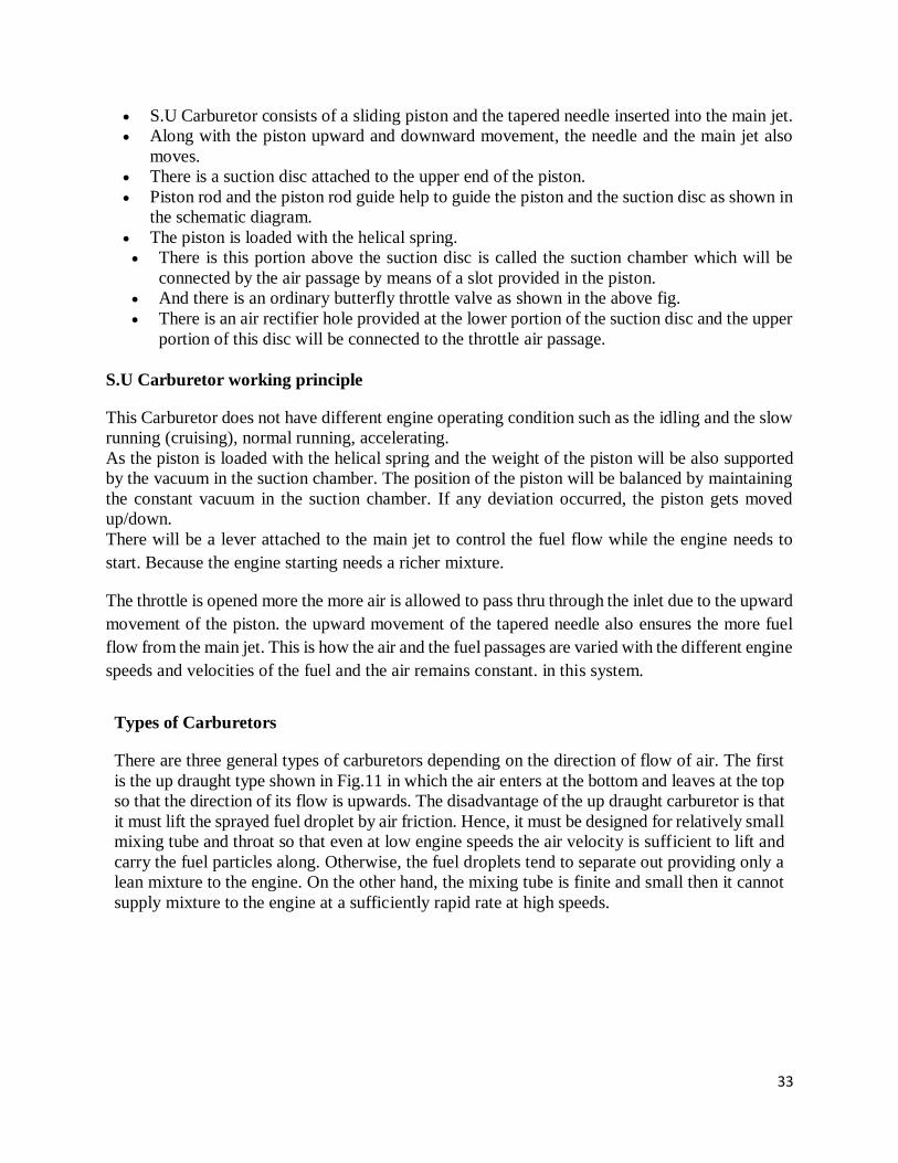
33
S.U Carburetor consists of a sliding piston and the tapered needle inserted into the main jet.
Along with the piston upward and downward movement, the needle and the main jet also
moves.
There is a suction disc attached to the upper end of the piston.
Piston rod and the piston rod guide help to guide the piston and the suction disc as shown in
the schematic diagram.
The piston is loaded with the helical spring.
There is this portion above the suction disc is called the suction chamber which will be
connected by the air passage by means of a slot provided in the piston.
And there is an ordinary butterfly throttle valve as shown in the above fig.
There is an air rectifier hole provided at the lower portion of the suction disc and the upper
portion of this disc will be connected to the throttle air passage.
S.U Carburetor working principle
This Carburetor does not have different engine operating condition such as the idling and the slow
running (cruising), normal running, accelerating.
As the piston is loaded with the helical spring and the weight of the piston will be also supported
by the vacuum in the suction chamber. The position of the piston will be balanced by maintaining
the constant vacuum in the suction chamber. If any deviation occurred, the piston gets moved
up/down.
There will be a lever attached to the main jet to control the fuel flow while the engine needs to
start. Because the engine starting needs a richer mixture.
The throttle is opened more the more air is allowed to pass thru through the inlet due to the upward
movement of the piston. the upward movement of the tapered needle also ensures the more fuel
flow from the main jet. This is how the air and the fuel passages are varied with the different engine
speeds and velocities of the fuel and the air remains constant. in this system.
Types of Carburetors
There are three general types of carburetors depending on the direction of flow of air. The first
is the up draught type shown in Fig.11 in which the air enters at the bottom and leaves at the top
so that the direction of its flow is upwards. The disadvantage of the up draught carburetor is that
it must lift the sprayed fuel droplet by air friction. Hence, it must be designed for relatively small
mixing tube and throat so that even at low engine speeds the air velocity is sufficient to lift and
carry the fuel particles along. Otherwise, the fuel droplets tend to separate out providing only a
lean mixture to the engine. On the other hand, the mixing tube is finite and small then it cannot
supply mixture to the engine at a sufficiently rapid rate at high speeds.

34
Figure: 11 Types of Carburetors
In order to overcome this drawback the downdraught carburetor [Fig.11 (b)] is adopted. It is
placed at a level higher than the inlet manifold and in which the air and mixture generally follow
a downward course. Here the fuel does not have to be lifted by air friction as in the up draught
carburetors but move into the cylinders by gravity even if the air velocity is low. Hence, the
mixing tube and throat can be made large which makes high engine speeds and high specific
outputs possible.
A cross-draught carburetor consists of a horizontal mixing tube with a float chamber on one side
of it [Fig.11(c)]. By using across-draught carburetor in engines, one right-angled turn in the inlet
passage is eliminated and the resistance to flow is reduced.
Constant Choke Carburetor:
In the constant choke carburetor, the air and fuel flow areas are always maintained to be
constant. But the pressure difference or depression, which causes the flow of fuel and air, is
being varied as per the demand on the engine. Solex and Zenith carburetors belong to this class.
Constant Vacuum Carburetor:
In the constant vacuum carburetor, (sometimes called variable choke carburetor) air and fuel
flow areas are being varied as per the demand on the engine, while the vacuum is maintained to
be always same. The S.U. and Carter carburetors belong to tills class.
Multiple Venturi Carburetor:

35
Multiple venturi system uses double or triple venturi. The boost venturi is located concentrically
within the main venturi. The discharge edge of the boost venturi is located at the throat of the
main venturi. The boost venturi is positioned upstream of the throat of the larger main venturi.
Only a fraction of the total air flows though the boost venturi. Now the pressure at the boost
venturi exit equals the pressure at the main venturi throat. The fuel nozzle is located at the throat
of the boost venturi.
Electronic Unit Injectors
Figure 12: Electronic Fuel injectors
Unit Injectors are less commonly also called Combined Pump and Nozzle
Acronyms are: MUI, (Mechanical Unit Injectors) EUI, (Electronic Unit Injectors) and HEUI.
(Hydraulically actuated Electronic Unit Injector)
The pumping plunger and nozzle are located in the same body and a camshaft actuates the
injector. A common fuel manifold will supply all the injectors.
Functions
Electronic unit injectors are mechanically pressurized and electronically controlled. This means
injection timing, duration, and metering are controlled by the ECM or electronic governor.
Unit injection systems functions are incorporated into one unit the following functions:
• Time fuel delivery
Pressurize the fuel for combustion
• Atomize and distribute fuel in the combustion chamber

36
References
1. Ganesan V, “Internal Combustion Engines”4th edition, Tata McGraw Hill publication 2017
2. Rajput R. K, “A textbook of Internal Combustion Engines”, Third edition Laxmi
Publications,2016
3. Mathur and Sharma “Internal Combustion Engines” “Dhanpat Rai and Sons Publication, 2010
4. John B. Heywood, “Fundamentals of Internal Combustion Engine, Second edition, McGraw-
Hill Education; 2018
5. Heinz Heisler “Advanced Engine Technology “2nd edition SAE Publication, 2002.

37
UNIT III IGNITION SYSTEM

38
UNIT 3 IGNITION SYSTEM
Types and working of battery coil and magneto ignition systems, relative merits and demerits,
centrifugal and vacuum advance mechanisms. Types and construction of spark plugs, electronic
ignition systems- Transistorized coil ignition system Capacitive discharge ignition system.
IGNITION SYSTEM
The ignition system takes electricity from the vehicle’s battery, increases the battery
voltage to a much higher voltage, and then sends this high voltage to the spark plugs.
The high voltage causes the spark plugs to produce a powerful, hot spark.
Each spark plug is threaded into a hole that leads directly into a cylinder’s
combustion chamber.
In simple terms, a spark plug is a device that electricity flows through. At the very end of
the spark plug are a pair of metal contacts called electrodes. These contacts are separated
from one another by a small air space.
When electricity flows through a spark plug, it jumps across this air space from one
electrode to the other.
As the electricity jumps across the space, a powerful spark is produced. This spark ignites
the air-and-fuel mixture that surrounds it inside the cylinder. The resulting “explosion” in
the combustion chamber forces the piston down and gets the crankshaft turning.
An ignition system must produce a very high voltage in order to force electric current—
moving electrons—across the spark.
The spark that’s produced must be very powerful so that it can quickly ignite the air-and-
fuel mixture in the cylinder.
The more completely the fuel is burned, the more power that’s produced. The spark must
plug gap also occur near the end of each cylinder’s compression stage in order to properly
ignite and burn the air-and-fuel mixture.
Also, an engine requires many sparks per minute in order to keep running at the proper
speed
if a typical six-cylinder engine is operating at a speed of 3,000 rpms, a spark occurs 1,500
times per minute in each cylinder. Since the engine has six cylinders, this is a total of 9,000
spark occurrences for all of the cylinders
TYPES OF IGNITION SYSTEM

39
BATTERY IGNITION SYSTEM
This basic battery ignition system contains a battery, an ignition switch, an ignition coil, a
distributor, a triggering device, a spark plug wire, and a spark plug.
Figure 1: schematic diagram of battery ignition system
Functions of each components The battery supplies electricity to the system.
The ignition switch turns the system on and off.
The ignition coil strengthens the electricity from the battery.
The distributor directs the electricity to the spark plug.
The triggering device controls when the spark occurs.
The spark plug wire carries the electricity to the spark plug.
The spark plug produces the spark in the cylinder that ignites the air-and-fuel mixture
Battery
In most automobiles, the power source for the ignition is a battery and an alternator. In a
battery ignition system, the battery provides power to the ignition coil.
The battery used in this type of system is a lead acid storage battery. In addition to
providing electricity to the ignition coil, the battery may also be used to power lights, horns,
and other accessory circuits.
A typical lead-acid storage battery is made up of several individual compartments called
cells.

40
Each cell is made up of a series of lead plates. Small spaces between the plates are filled
with an electrolyte solution.
This solution is usually made from sulphuric acid diluted with water.
Each cell produces approximately 2 V when the battery is fully charged, so a 12 V battery
contains six cells
A typical lead-acid storage battery is made up of several individual compartments called
cells.
Each cell is made up of a series of lead plates.
Small spaces between the plates are filled with an electrolyte solution. This solution is
usually made from sulfuric acid diluted with water.
Each cell produces approximately 2 V when the battery is fully charged, so a 12 V battery
contains six cells
Normally, a battery has a total output voltage of 12 volts of direct current, or 12 DC.
The current produced by the battery is often measured in units called ampere/hours (Ah).
In a battery ignition system, the alternator is used to recharge the battery as the engine
operates.
Figure 2. Cut section of a battery
The Ignition Switch
The switch assembly is usually mounted a short distance down the steering column from
the key lock cylinder assembly. The two assemblies are then connected by an ignition
switch actuator rod.
Turning the key moves a gear-and-rack assembly. The gear-and-rack assembly, in turn,
moves the ignition switch actuator rod and plunger to the various positions required for
performing ignition switch functions.

41
Several different types of ignition switches are commonly used.
The most common is the five-position switch.
Figure 3 : Ignition switch circuit diagram
In the accessory or ACT position, the engine is shut off and a connection is made from the
battery terminal to the accessory terminal of the switch. This allows accessories such as
the radio, heater, blower, and windshield wiper to be operated when the ignition, fuel gage,
and indicator light circuits are off.
In the OFF and LOCK positions, accessories that are supplied with power through the
ignition switch can’t be operated. Also, it’s general practice to ground the resistance wire
circuit to the ignition coil when the switch is in the LOCK position.
This prevents the engine from being operated with a jumper to the coil.
Generally, in the START position, all accessories that are supplied with power through the
switch are temporarily disconnected.
One connection is made to the starter solenoid, and a second connection is made directly
to the ignition coil.
Because the battery voltage lowers when an engine is started, the ballast resistor, which
supplies the switch with power, is bypassed to provide a higher secondary winding voltage
to start the engine.
When the ignition switch is released from the START position, a spring returns the switch
to the ON position.
Ignition Coil

42
All ignition systems contain an ignition coil. The ignition coil is actually a type of electric
transformer that changes low-voltage electricity to high-voltage electricity.
Ignition coils work on the principles of magnetic induction.
An ignition coil contains two coils of wire called the primary winding and the secondary
winding.
The primary winding is made of turns of heavy-gage wire; in contrast, the secondary
winding is made of many turns of very fine-gage wire wrapped around a soft iron core.
The secondary winding has many more turns of wire than the primary winding.
The difference in the number of turns of wire between the two is what allows the ignition
coil to increase voltage.
In an ignition system, a triggering device is attached to the primary winding of the ignition
coil.
The triggering device is used to turn the current flow in the primary winding on and off at
the proper time.
The secondary coil winding is connected to the spark plug wire.
The spark plug wire is a heavily insulated wire that leads directly to the spark plug
All ignition coils contain the following basic components:
1. A small number of turns of heavy wire
2. A large number of turns of fine wire
3. A central core of soft iron
4. Insulation between each turn of wire, and between the turns and the iron core
5. External electrical connections
Figure 4: Cross sectional view of Ignition coil

43
Spark Plug wire
Ignition system wires can be classified into two general types: primary wires and secondary
wires.
Primary wires carry high-current loads at low voltages from the battery to the ignition
components. These wires are made of large-diameter conductors that are covered with light
insulation.
In contrast, secondary wires are used to carry small amounts of current, but at very high
voltages. Therefore, secondary wires are made of small-diameter conductors that are
covered with thick coatings of rubber, plastic, or neoprene insulation.
Both ends of a spark plug wire have metal connectors called terminals attached to them.
Figure 6: spark plug wire
Spark Plugs
A spark plug is designed to allow a voltage to jump across a gap, producing a spark that
ignites the engine’s fuel. Four stroke engines contain one spark plug for each cylinder.
A spark plug has two metal electrodes or terminals. The metal electrodes are conductors
through which current flows. One electrode runs through the entire length of the spark plug.
This is called the center electrode.
The second electrode is connected to the threaded part of the spark plug. This electrode is
sometimes called the side electrode or the grounding electrode.
The grounding electrode bends around so that it’s very close to the end of the center
electrode. The small air space between the two electrodes is called the gap.

44
Figure 7: sectional view of spark plug
Each spark plug has a heat range. A spark plug’s heat range determines, to a large extent,
engine performance under different conditions and speeds.
A heat range classifies a spark plug according to its ability to transfer heat from the gap
end of the plug to the engine’s cooling system.
A spark plug is called a cold plug if it can easily transfer combustion heat from the firing
end of the plug out to the cylinder head. In a hot plug, the center electrode is more isolated
from the shell and the cylinder head. Therefore, a hot plug tends to retain its heat.
Cold plugs have shorter insulator tips than hot plugs.
Figure 8: sectional view of hot & cold spark plug.
Distributor
A device called a distributor is used to direct the high voltage from the ignition coil to the
spark plugs.
The distributor directs the high voltage to the cylinder that’s currently on its compression
stroke and ready to have the air-and-fuel mixture ignited to produce power.
The distributor is usually mounted to an engine with its housing placed in a hole in the
engine block or cylinder head.

45
Figure 9: schematic view of distributor
When a distributor is installed in an engine, the gear on the end of the distributor shaft is
driven by a similar gear that’s attached to the engine’s camshaft.
Therefore, whenever the engine is running, the distributor shaft turns with the camshaft at
the same speed. Therefore, one camshaft rotation results in one distributor rotation.
Dwell period
An ignition system’s dwell is the number of degrees that the distributor cam rotates during the time that the contact points are closed. When the rubbing block reaches the lobe or corner of the distributor cam, the points open and the dwell period ends. After the rubbing block passes a cam lobe, the block returns to the flat side of the cam, and the next dwell period begins. The dwell setting is very important to the proper operation of an ignition system. There are 360 degrees in a circle, so the maximum dwell for any engine is 360 degrees divided by the number of engine cylinders. One complete rotation of the distributor cam equals 360 degrees.
An 8-cylinder engine has 8 cam lobes, so 45 degrees of rotation is between each cam lobe (360 8
= 45). A 6-cylinder engine has 60 degrees between each cam lobe (360 6 = 60). A 4-cylinder
engine has 90 degrees between each cam lobe (360 4 = 90).
Figure 10: sectional view of contact breaker.

46
MAGNETO IGNITION SYSTEM
The source that generates energy in the Magneto Ignition System is the Magneto.
Generally, a magneto is a small generator that works on electricity.
When magneto is rotated by the engine, it produces the voltage.
The higher the rotation, the greater will be the amount of voltage produced by the system.
The magneto does not need any external power source such as a battery to kick start it as
it itself is a source for generating energy.
There are two types of winding in it. It has a primary binding and a secondary binding.
In addition to this, magneto has 3 types based on its engine rotation
Armature rotating type
Magnet rotating type
Polar inductor type
In the armature rotating type, armature rotates between the stationary magnet whereas in
the magnet rotating type, the armature is stationary and the magnets are rotating around the
armature.
In the polar inductor type, both the magnet and the windings remain stationary but the
voltage is generated by reversing the flux field with the help of soft iron polar projections,
called inductors.
WORKING PRINCIPLE
The working principle of this ignition system is similar to the working principle of coil or
battery ignition system except that in it magneto is used to produce energy but not the battery.
Here are the following scenarios that occur in it.
Figure 11: Schematic diagram of magneto ignition system

47
When engine in the system starts it help magneto to rotate and thereby producing the energy
in the form of high voltage.
The one end of the magneto is grounded through contact breaker and the ignition capacitor
is connected to it parallel.
The contact breaker is regulated by the cam and when the breaker is open, current flows
through the condenser and charges it.
As the condenser is acting like a charger now, the primary current flow is reduced thereby
reducing the overall magnetic field generated in the system. This increases the voltage in
the condenser.
This increased high voltage in the condenser will act as an EMF thereby producing the
spark at the right spark plug through the distributor.
At the initial stage, the speed of the engine is low and hence the voltage generated by the
magneto is low but as the rotating speed of the engine increases, it also increases the voltage
generated by the magneto and flow of the current is also increased. To kick start the engine,
we can use an external source such as the battery to avoid the slow start of the engine.
Advantages It is a self-energizing type ignition system, so there is no need for an external energy
source/ heavy battery, and it is compact.
More reliable as there is no battery.
It gives good quality spark at high speed.
Since there no battery, it does not require high maintenance.
Disadvantages
It has a starting problem due to the low rotating speed at the starting of the engine.
It is more expensive when compared to a battery ignition system.
There is a possibility of misfire due to leakage because the variation of voltage in the
wiring can occur.
Application
Here is the partial list of the applications of engines equipped with a magneto ignition
system.
Tractors, Oil Burners, and Outboard Motors
Trucks and Cement Mixers
Buses
Airplane Engines
Power Units, Marine Engines and Natural Gas Engines
Difference between Battery Ignition System and Magneto Ignition System
Battery Ignition System Magneto Ignition System
Current required for spark or primary is
circuit is obtained from a battery.
It produces the electricity required for spark
plug or primary with its own electric
generator.
48
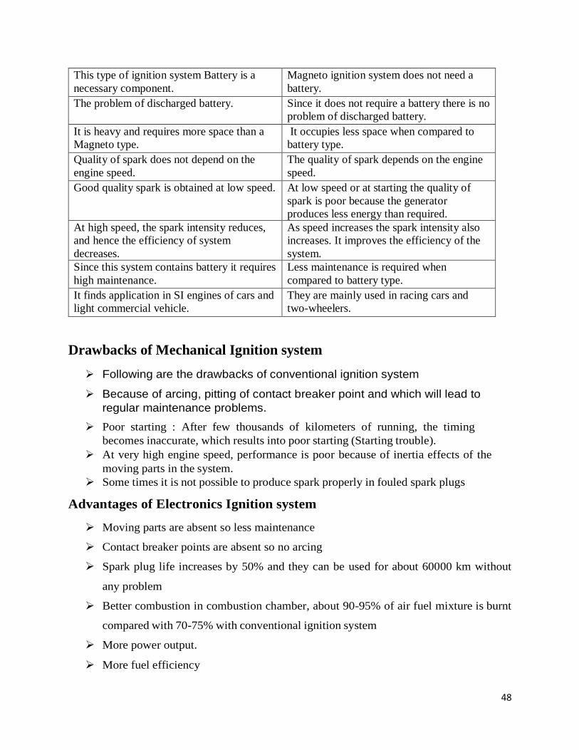
This type of ignition system Battery is a
necessary component.
Magneto ignition system does not need a
battery.
The problem of discharged battery. Since it does not require a battery there is no
problem of discharged battery.
It is heavy and requires more space than a
Magneto type.
It occupies less space when compared to
battery type.
Quality of spark does not depend on the
engine speed.
The quality of spark depends on the engine
speed.
Good quality spark is obtained at low speed. At low speed or at starting the quality of
spark is poor because the generator
produces less energy than required.
At high speed, the spark intensity reduces,
and hence the efficiency of system
decreases.
As speed increases the spark intensity also
increases. It improves the efficiency of the
system.
Since this system contains battery it requires
high maintenance.
Less maintenance is required when
compared to battery type.
It finds application in SI engines of cars and
light commercial vehicle.
They are mainly used in racing cars and
two-wheelers.
Drawbacks of Mechanical Ignition system
Following are the drawbacks of conventional ignition system
Because of arcing, pitting of contact breaker point and which will lead to
regular maintenance problems.
Poor starting : After few thousands of kilometers of running, the timing
becomes inaccurate, which results into poor starting (Starting trouble).
At very high engine speed, performance is poor because of inertia effects of the
moving parts in the system.
Some times it is not possible to produce spark properly in fouled spark plugs
Advantages of Electronics Ignition system
Moving parts are absent so less maintenance
Contact breaker points are absent so no arcing
Spark plug life increases by 50% and they can be used for about 60000 km without
any problem
Better combustion in combustion chamber, about 90-95% of air fuel mixture is burnt
compared with 70-75% with conventional ignition system
More power output.
More fuel efficiency

49
TYPES OF ELECTRONIC IGNITION SYSTEM
Electronic Ignition System is as follow :
(a) Capacitance Discharge Ignition system
(b) Transistorized system
(c) Piezo-electric Ignition system
(d) The Texaco Ignition system
Capacitive Discharge Ignition system
It mainly consists of 6-12 V battery, ignition switch, DC to DC convertor, charging
resistance, tank capacitor, Silicon Controlled Rectifier (SCR), SCR-triggering device,
step up transformer, spark plugs
A 6-12 volt battery is connected to DC to DC converter i.e. power circuit through the
ignition switch, which is designed to give or increase the voltage to 250-350 volts. This
high voltage is used to charge the tank capacitor (or condenser) to this voltage through
the charging resistance. The charging resistance is also so designed that it controls the
required current in the SCR
Figure 12: Capacitive ignition system
Charging Coil
The charging coil is one coil in the stator, which is used to produce 6 volts to charge the capacitor
C1. Based on the flywheel’s movement the single pulsed power is produced and is supplied to the
sparking plug by the charging coil to ensure the maximum spark.

50
Hall Sensor
The Hall Sensor measures the Hall effect, the instantaneous point where the flywheel’s magnet
changes from a north to a south pole. When the pole change occurs, the device sends a single, tiny
pulse to the CDI box which triggers it to dump the energy from the charging capacitor into the
high voltage transformer.
Timing Mark
The timing mark is an arbitrary alignment point shared by the engine case and stator plate. It
indicates the point at which the top of the piston’s travel is equivalent to the trigger point on the
flywheel and stator.
By rotating the stator plate left and right, you effectively change the trigger point of the CDI, thus
advancing or retarding your timing, respectively. As the flywheel turns fast, the charging coil
produces an AC current from +6V to -6V.
The CDI box has a collection of semiconductor rectifiers that connected to G1 on the box allows
only the positive pulse to enter the capacitor (C1). While the wave entering into the CDI, the
rectifier allows only the positive wave.
Trigger Circuit
• The trigger circuit is a switch, probably using a Transistor, Thyristor or SCR. This triggered
by a pulse from the Hall Sensor on the stator. They only allow current from one side of the
circuit until they are triggered.
• Once the Capacitor C1 is fully charged, the circuit can be triggered again. This is why there
is timing involved with the motor. If the capacitor and stator coil were perfect, they would
charge instantaneously and we can trigger them as fast as our wish. However, they require
a fraction of a second to full charge.
• If the circuit triggers too fast, then the spark from the spark plug will be enormously weak.
Certainly, with the higher accelerating motors, we may have the triggering faster than the
capacitor full charge, which will affect performance. Whenever the capacitor is discharged,
then the switch turns itself off and the capacitor charges again.
• The trigger pulse from the Hall sensor feeds into the gate latch and allows all the stored
charge to rush through the primary side of the high-voltage transformer. The transformer
has a common ground between the primary and secondary windings, known as an auto
step-up transformer.
• Therefore, as if we increase the windings on the secondary side, you will multiply the
voltage. Since a spark plug needs a good 30,000 volts to sparks, there must be many
thousands of wraps of wire around the high voltage or secondary side.
• When the gate opens and dumps all the current into the primary side, it saturates the low-
voltage side of the transformer and sets up a short but immensely magnetic field. As the

51
field reduces gradually, a large current in the primary windings forces the secondary
windings to produce extremely high voltage.
• However, the voltage is now so high that it can arc through the air, so rather than being
absorbed or retained by the transformer, the charge travels up the plug wire and jumps the
plug gap.
• When we want to shut down the motor engine, we have two switches the key switch or the
kill switch. The switches ground out the charging circuit so the entire charging pulse is sent
to the ground. Since the CDI can no longer charge, it will cease to provide the spark and
the engine will slow to a stop.
Advantages of CDI
The major advantage of CDI is that the capacitor can be fully charged in a very short time
(typically 1ms). So the CDI is suited to an application where the insufficient dwell time is
available.
The capacitor discharge ignition system has a short transient response, a fast voltage rise
(between 3 to 10 kV/ µs) compared to inductive systems (300 to 500 V/ µs) and shorter spark
duration (about 50-80 µs).
The fast voltage rising makes CDI systems unaffected to shunt resistance.
Disadvantages of CDI
The capacitor discharge ignition system generates huge electromagnetic noise and this is the
main reason why CDIs are rarely used by automobile manufacturers.
The short spark duration is not good for lighting relatively lean mixtures as used at low power
levels. To solve this problem many CDI ignitions release multiple sparks at low engine speeds.
Transistorized coil ignition system The breaker-point type of transistor ignition system was developed to replace the standard
or conventional ignition system.
To obtain the maximum power and speed that this engine can produce, you must install an
ignition system that outperforms the conventional one.
Electronic type of ignition systems provide a hotter, more uniform spark at a more precise
interval.
This promotes more efficient burning of the air/fuel mixture in the combustion chamber,
producing less exhaust emissions, and resulting in better engine performance and increased
mileage.
The increased reliability of electronic ignition allows less frequent maintenance by
increasing parts life. At high speeds, the breaker points of a conventional ignition system
cannot handle the increased current flowing across them without pitting too much.

52
Also, the dwell angle of the breaker points is too small for complete saturation of
the ignition coil. The transistorized ignition system takes care of both drawbacks.
Figure 13: Transistorized coil ignition system
Piezo-electric Ignition System
The development of synthetic piezo-electric materials producing about 22 kV by mechanical
loading of a small crystal resulted in some ignition systems for single cylinder engines. But due to
difficulties of high mechanical loading need of the order of 500 kg timely control and ability to
produce sufficient voltage, these systems have not been able to come up.
The Texaco Ignition System
Due to the increased emphasis on exhaust emission control, there has been a sudden interest in
exhaust gas recirculation systems and lean fuel-air mixtures. To avoid the problems of burning of
lean mixtures, the Texaco Ignition system has been developed. It provides a spark of controlled
duration which means that the spark duration in crank angle degrees can be made constant at all
engine speeds. It is a AC system. This system consists of three basic units, a power unit, a control
unit and a distributor sensor. This system can give stable ignition up to A/F ratios as high as 24 :
1.
Ignition Advance Mechanism Ignition timing is very important, since the charge is to be ignited just before (few degrees before
TDC) the end of compression, since when the charge is ignited, it will take some time to come to
the required rate of burning.
Ignition Advance

53
The purpose of spark advance mechanism is to assure that under every condition of engine
operation, ignition takes place at the most favorable instant in time i.e. most favorable from a
standpoint of engine power, fuel economy and minimum exhaust dilution. By means of these
mechanisms the advance angle is accurately set so that ignition occurs before TDC point of the
piston. The engine speed and the engine load are the control quantities required for the automatic
adjustment of the ignition timing. Most of the engines are fitted with mechanisms which are
integral with the distributor and automatically regulate the optimum spark advance to account for
change of speed and load. The two mechanisms used are :
Centrifugal advance mechanism, and
Vacuum advance mechanism
Centrifugal Advance Mechanism
The centrifugal advance mechanism controls the ignition timing for full- load operation. The
adjustment mechanism is designed so that its operation results in the desired advance of the spark.
The cam is mounted, movably, on the distributor shaft so that as the speed increases, the flyweights
which are swung farther and farther outward, shaft the cam in the direction of shaft rotation. As a
result, the cam lobes make contact with the breaker lever rubbing block somewhat earlier, thus
shifting the ignition point in the early or advance direction. Depending on the speed of the engine,
and therefore of the shaft, the weights are swung outward a greater or a lesser distance from the
center. They are then held in the extended
position, in a state of equilibrium corresponding to the shifted timing angle, by a retaining spring
which exactly balances the centrifugal force. The weights shift the cam either or a rolling contact
or sliding contact basis; for this reasons we distinguish between the rolling contact type and the
sliding contact type of centrifugal advance mechanism.
The beginning of the timing adjustment in the range of low engine speeds and the continues
adjustment based on the full load curve are determined by the size of the weights by the shape of
the contact mechanisms (rolling or sliding contact type), and by the retaining springs, all of which
can be widely differing designs. The centrifugal force controlled cam is fitted with a lower limit
stop for purposes of setting the beginning of the adjustment, and also with an upper limit stop to
restrict the greatest possible full load adjustment. A typical sliding contact type centrifugal advance
mechanism is shown in Figures below

54
Figure 14: Sliding contact type centrifugal type advanced mechanism
Vacuum Advance Mechanism
Vacuum advance mechanism shifts the ignition point under partial load operation. The adjustment
system is designed so that its operation results in the prescribed partial load advance curve. In this
mechanism the adjustment control quantity is the static vacuum prevailing in the carburetor, a
pressure which depends on the position of the throttle valve at any given time and which is at a
maximum when this valve is about half open. This explains the vacuum maximum. The diaphragm
of a vacuum unit is moved by changes in gas pressure. The position of this diaphragm is determined
by the pressure differential at any given moment between the prevailing vacuum and atmospheric
pressure. The beginning of adjustment is set by the pre-established tension on a compression
spring. The diaphragm area, the spring force, and the spring rigidity are all selected in accordance
with the partial –load advance curve which is to be followed and are all balanced with respect to
each other. The diaphragm movement is transmitted through a vacuum advance arm connected to
the movable breaker plate, and this movement shifts the breaker plate an additional amount under
partial load condition in a direction opposite to the direction of rotation of the distributor shaft.
Limit stops on the vacuum advance arm in the base of the vacuum unit restrict the range of
adjustment.
The vacuum advance mechanism operates independent of the centrifugal advance mechanism. The
mechanical interplay between the two advance mechanisms, however, permits the total adjustment
angle at any given time to be the result of the addition of the shifts provided by the two individual
mechanisms operates in conjunction with the engine is operating under partial load. A typical
vacuum advance mechanism is shown in Figure below.

55
Figure 15 : Vacuum advanced mechanism
References
5. Ganesan V, “Internal Combustion Engines”4th edition, Tata McGraw Hill publication 2017
6. Rajput R. K, “A textbook of Internal Combustion Engines”, Third edition Laxmi
Publications,2016
7. Mathur and Sharma “Internal Combustion Engines” “Dhanpat Rai and Sons Publication,
2010
8. John B. Heywood, “Fundamentals of Internal Combustion Engine, Second edition, McGraw-
Hill Education; 2018
5. Heinz Heisler “Advanced Engine Technology “2nd edition SAE Publication, 2002.

56
UNIT IV COOLING AND LUBRICATION SYSTEM

57
UNIT 4 COOLING AND LUBRICATION SYSTEM
Need for cooling system, Types of cooling system: air cooling system, liquid cooling system,
Comparison, forced circulation system, pressure cooling system. Lubrication system-
Requirements, mist, wet sump lubrication system, properties of lubricants.
ENGINE COOLING In a SI engine, cooling must be satisfactory to avoid pre-ignition and knock. In a compression
ignition engine, since a normal combustion is aided, cooling must be sufficient to allow the parts
to operate properly. In short, cooling is a matter of equalization of internal temperature to prevent
local overheating as well as to remove sufficient heat energy to maintain a practical overall
working temperature.
Requirements of cooling system in the IC engine The cooling system is provided in the IC engine for the following reasons:
The temperature of the burning gases in the engine cylinder reaches up to 1500 to 2000°C,
which is above the melting point of the material of the cylinder body and head of the engine.
(Platinum, a metal which has one of the highest melting points, melts at 1750 °C, iron at
1530°C and aluminium at 657°C.) Therefore, if the heat is not dissipated, it would result
in the failure of the cylinder material.
Due to very high temperatures, the film of the lubricating oil will get oxidized, thus
producing carbon deposits on the surface. This will result in piston seizure.
Due to overheating, large temperature differences may lead to a distortion of the engine
components due to the thermal stresses set up. This makes it necessary for, the temperature
variation to be kept to a minimum.
Higher temperatures also lower the volumetric efficiency of the engine.
There are mainly two types of cooling systems:
(a) Air cooled system, and
(b) Water cooled system
Air Cooled System: Air cooled system is generally used in small engines say up to 15-20 kW and in aero
plane engines.
In this system fins or extended surfaces are provided on the cylinder walls, cylinder head,
etc. Heat generated due to combustion in the engine cylinder will be conducted to the fins
and when the air flows over the fins, heat will be dissipated to air.
The amount of heat dissipated to air depends upon:
(a) Amount of air flowing through the fins
(b) Fin surface area
(c) Thermal conductivity of metal used for fins
For efficient cooling the length of the fins and the spacing between them is quite
important
Larger inter spacing between the fins offers larger area for cooling air but the heating of
the air is less, so more cooling air is required
Smaller inter spacing between the fins results in smaller flow area of cooling air and
hence input cooling air is less
Usually fin height varies from 15 to 25 mm

58
Figure 1 : Air cooling system
Advantages of air cooled engines
Air cooled engines have the following advantages:
Its design of air-cooled engine is simple.
It is lighter in weight than water-cooled engines due to the absence of water jackets,
radiator, circulating pump and the weight of the cooling water.
It is cheaper to manufacture.
It needs less care and maintenance.
This system of cooling is particularly advantageous where there are extreme climatic
conditions in the arctic or where there is scarcity of water as in deserts.
No risk of damage from frost, such as cracking of cylinder jackets or radiator water tubes.
Disadvantages of air cooled engines Relatively large amount of power is used to drive the cooling fan.
Engines give low power output.
Cooling fins under certain conditions may vibrate and amplify the noise level.
Cooling is not uniform.
Engines are subjected to high working temperature.
Water cooling system: Cooling water jackets are provided around the cylinder, cylinder head, valve seats etc. The water
when circulated through the jackets, it absorbs heat of combustion. This hot water will then be
cooling in the radiator partially by a fan and partially by the flow developed by the forward motion
of the vehicle. The cooled water is again recirculated through the water jackets.

59
Figure 2: Water cooling system
Types of Water Cooling System
There are two types of water cooling system
1. Thermo siphon cooling system.
2, Pump circulation cooling system
1. Thermo Siphon System
This system works on the principle that hot water being lighter rises up and the cold water being
heavier goes down. In this system the radiator is placed at a higher level than the engine for the
easy flow of water towards the engine. Heat is conducted to the water jackets from where it is
taken away due to convection by the circulating water. As the water jacket becomes hot, it rises to
the top of the radiator. Cold water from the radiator takes the place of the rising hot water and in
this way a circulation of water is set up m the system. This helps in keeping the engine at working
temperature.
Figure 3: Thermo-syphon cooling
Disadvantages of Thermo-syphon system,
-Rate of circulation is too slow.
-Circulation commences only when there is a marked difference in temperature.
-Circulation stops as the level of water falls below the top of the delivery pipe of the radiator.
Forthese reasons this system has become obsolete and is no more in use.
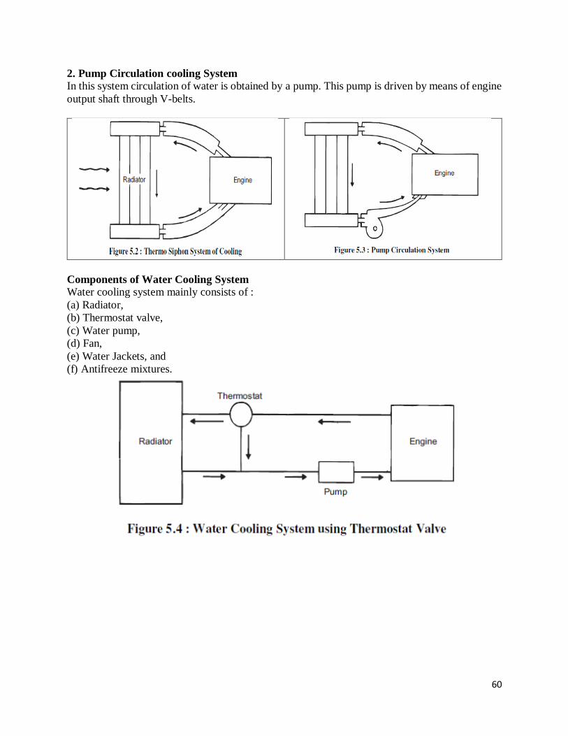
60
2. Pump Circulation cooling System In this system circulation of water is obtained by a pump. This pump is driven by means of engine
output shaft through V-belts.
Components of Water Cooling System Water cooling system mainly consists of :
(a) Radiator,
(b) Thermostat valve,
(c) Water pump,
(d) Fan,
(e) Water Jackets, and
(f) Antifreeze mixtures.

61
Water Pump
The water pump forces coolant through the engine cylinder block and head channels.
Coolant is drawn into the centre of the water pump via the lower hose of the radiator.
Centrifugal force, due to the rotation of the water pump impeller, throws the liquid out at
the edge and into the cylinder block.
If a mechanical cooling fan is used, it may often be attached to the water pump hub.
Radiator
The function of the radiator is to transfer unwanted heat energy from the coolant to the
outside air.
Hoses connect the radiator to the engine cylinder block (water jacket) and passenger
compartment heater.
Fan(s) draw air through and over the radiator to increase the air flow and improve cooling
efficiency.
A thermostat controls the coolant flow during warm-up, so that the engine reaches
operating temperature quickly.
It mainly consists of an upper tank and lower tank and between them is a core. The upper
tank is connected to the water outlets from the engines jackets by a hose pipe and the lover
tank is connect to the jacket inlet through water pump by means of hose pipes.
There are 2-types of cores :
(a) Tubular
(b) Cellular.
When the water is flowing down through the radiator core, it is cooled partially by the fan
which blows air and partially by the air flow developed by the forward
motion of the vehicle. As shown through water passages and air passages, wafer and air
will be flowing for cooling purpose.
It is to be noted that radiators are generally made out of copper and brass and their joints
are made by soldering

62
Figure 6: Cross sectional view of radiator tubes.
Radiator Cap
The radiator pressure cap pressurizes the coolant system in order to raise the coolant’s
boiling point to about 125ºC (255ºF), this overcomes the production of steam.
The pressure valve opens when the coolant system temperature rises significantly, to
allow the escape of excess coolant to an expansion bottle.
The surplus coolant is released and held in an expansion tank (in a closed system). Or in
older vehicles, spills to the ground (in an open system).
Figure 7: Radiator cap
Thermostat Valve It is a valve which prevents flow of water from the engine to radiator, so that engine
readily reaches to its maximum efficient operating temperature.
After attaining maximum efficient operating temperature, it automatically begins
functioning. Generally, it prevents the water below 70°C.
Figure shows the Bellow type thermostat valve which is generally used.
It contains a bronze bellow containing liquid alcohol. Bellow is connected to the butterfly
valve disc through the link.
When the temperature of water increases, the liquid alcohol evaporates and the bellow
expands and in turn opens the butterfly valve, and allows hot water to the radiator, where
it is cooled.

63
Figure 8: Thermostat valve
Engine-Powered Cooling Fan
Mechanical fans provide air flow across the radiator core tubes and may be bolted to the
water pump hub.
A spacer may be needed in order to place the fan near to the radiator.
The blades of the fan may be flexible or fixed.
Fluid coupling fan clutches are arranged to slip at higher speeds when natural air flow is
likely to be increased.
Thermostatic fan clutches slip at cold temperatures, reducing air flow through the radiator
and speed warm-up. When the
coolant reaches the operating temperature, the clutch locks and the fan rotates in a fixed
manner.
Figure 9: Cooling Fan

64
Fan
It is driven by the engine output shaft through same belt that drives the pump. It is provided
behind the radiator and it blows air over the radiator for cooling purpose.
Water Jackets
Cooling water jackets are provided around the cylinder, cylinder head, valve seats and any hot
parts which are to be cooled. Heat generated in the engine cylinder, conducted through the
cylinder walls to the jackets. The water flowing through the jackets absorbs this heat and gets
hot. This hot water will then be cooled in the radiator
Figure 10: Water jacket in engine cylinder
Antifreeze Mixture
In western countries if the water used in the radiator freezes because of cold
climates, then ice formed has more volume and produces cracks in the cylinder
blocks, pipes, and radiator. So, to prevent freezing antifreeze mixtures or solutions
are added in the cooling water.
The ideal antifreeze solutions should have the following properties :
(a) It should dissolve in water easily.
(b) It should not evaporate.
(c) It should not deposit any foreign matter in cooling system.
(d) It should not have any harmful effect on any part of cooling system.
(e) It should be cheap and easily available.
(f) It should not corrode the system.
No single antifreeze satisfies all the requirements. Normally following are used as antifreeze
solutions :
(a) Methyl, ethyl and isopropyl alcohols.
(b) A solution of alcohol and water.
(c) Ethylene Glycol.
(d) A solution of water and Ethylene Glycol.

65
(e) Glycerin along with water, etc.
Advantages and Disadvantages of Water Cooling System
Advantages (a) Uniform cooling of cylinder, cylinder head and valves.
(b) Specific fuel consumption of engine improves by using water cooling
system.
(c) If we employ water cooling system, then engine need not be provided at the front end of
moving vehicle.
(d) Engine is less noisy as compared with air cooled engines, as it has water for damping noise.
Disadvantages
(a) It depends upon the supply of water.
(b) The water pump which circulates water absorbs considerable power.
(c) If the water cooling system fails then it will result in severe damage of engine.
(d) The water cooling system is costlier as it has more number of parts. Also it
(d) Pressurised water cooling system:
In the case of the ordinary water-cooling system where the cooling water is subjected to
atmospheric pressure, the water boils at 212°F. But, when water is heated in a closed radiator under
high pressure, the boiling temperature of water increases. The higher water temperature gives more
efficient engine performance and affords additional protection under high altitude and tropical
conditions for long hard driving periods. Therefore, a pressure-type radiator cap is used with the
forced circulation cooling system. The cap is fitted on the radiator neck with an air tight seal. The
pressure-release valve or safety valve is set to open at a pressure between 4 and 13 psi. With this
increase in pressure, the boiling temperature of water increases to 243°F (at 4 psi boiling tap 225°F
and 13 psi boiling temperature 243°F). Any increase in pressure is released by the pressure release
valve or safety valve to the atmosphere. On cooling, the vapours will condense and a partial
vacuum will be created which will result in the collapse of the hoses and tubes. To overcome this
problem the pressure release valve is associated with a vacuum valve which opens the radiator to
the atmosphere.

66
Figure 11: Pressurized cooling system
Figure. Pressurised system
(e) Evaporative cooling system: This is predominately used in stationary engine and in many types of industrial engines..
In this system , the engine will be cooled because of the evaporation of the water in the
cylinder jackets into steams.
In this system, the water evaporates and becomes steam due high temperatures of the
cylinder jackets. This steams is naturally Circulated into Radiator without pump
Figure 11: Evaporative cooling system.
The figure shows the evaporative cooling with air cooled condenser.
In this case water is circulated by the pump A and when delivered to the overhead tank B
part of it boils out.
The tank has portion C. The vapors rise above the portion C and because of the
condensing action of the radiator tube D, condensate flow into the lower tank E from
which it is picked up and return to the tank B by the small pump F.
The vertical pipe G is in communication with the side atmosphere to prevent the
collapsing of the tank B and E when the pressure inside them due to condensation fall
below the atmosphere.
LUBRICATION SYSTEM IC engine is made of many moving parts. Due to continuous movement of two metallic surfaces
over each other, there is wearing moving parts, generation of heat and loss of power in the engine.
Hence, lubrication of moving parts is essential to prevent all these harmful effects.
Function of lubrication:
Lubrication produces the following effects: (a) Reducing friction effect (b) Cooling effect (c)
Sealing effect and (d) Cleaning effect.
67
(a) Reducing frictional effect: The primary purpose of the lubrication is to reduce friction and
wear between two rubbing surfaces. Two rubbing surfaces always produce friction. The
continuous friction produce heat which causes wearing of parts and loss of power. In order to avoid
friction, the contact of two sliding surfaces must be reduced as far as possible. This can be done
by proper lubrication only. Lubrication forms an oil film between two moving surfaces.
Lubrication also reduces noise produced by the movement of two metal surfaces over each other.
(b) Cooling effect: The heat, generated by piston, cylinder, and bearings is removed by lubrication
to a great extent. Lubrication creates cooling effect on the engine parts.
(c) Sealing effect: The lubricant enters into the gap between the cylinder liner, piston and piston
rings. Thus, it prevents leakage of gases from the engine cylinder.
(d) Cleaning effect: Lubrication keeps the engine clean by removing dirt or carbon from inside of
the engine along with the oil.
Lubrication system: Various lubrication system used for IC engines are,
(a) Mist lubrication system
(b) Wet sump lubrication system
(c) Dry sump lubrication system
(a) Mist lubrication system:
Used where crankcase lubrication is not suitable
Generally adopted in two stroke petrol engine line scooter and motor cycle. It is the
simplest form of lubricating system.
It is the simplest form of lubricating system. It does not consist of any separate part like oil
pump for the purpose of lubrication.
In this system the lubricating oil is mixed into the fuel (petrol) while filling in the petrol
tank of the vehicle in a specified ratio (ratio of fuel and lubricating oil is from 12:1 to 50:10
as per manufacturers specifications or recommendations.
When the fuel goes into the crank chamber during the engine operation, the oil particles go
deep into the bearing surfaces due to gravity and lubricate then. The piston rings, cylinder
walls, piston pin etc. are lubricated in the same way.
If the engine is allowed to remain unused for a considerable time, the lubricating oil
separates oil from petrol & leads to clogging (blocking) of passages in the carburettor,
results in the engine starting trouble. This is the main disadvantage of this system.
It causes heavy exhaust smoke due to burning of lubricating oil partially or fully
Increase deposits on piston crown and exhaust ports which affect engine efficiency
Corrosion of bearing surfaces due to acids formation thorough mixing can fetch effective
lubrication
Engine suffers insufficient lubrication during closed throttle i.e. vehicle moving down the
hill.
(b) Wet sump lubrication system:
Bottom of the crankcase contains oil pan or sump from which the lubricating oil is pumped to
various engine components by a pump. After lubrication, oil flows back to the sump by gravity.
Three types of wet sump lubrication system,
(i) Splash system

68
(ii) Splash and pressure system
(iii) Pressure feed system
(i) Splash system:
In this system of lubrication the lubricating oil is stored in an oil sump. A scoop or dipper is made
in the lower part of the connecting rod. When the engine runs, the dipper dips in the oil once in
every revolution of the crank shaft, the oil is splashed on the cylinder wall. Due to this action
engine walls, piston ring, crank shaft bearings are lubricated.
-It is used for light duty engine
Figure 12: Splash lubricating system
(ii) Splash and pressure system:
Lubricating oil is supplied under pressure to main, camshaft bearings and pipes which direct a
stream of oil against the dippers on the big end of connecting rod bearing cup and thus crankpin
bearings are lubricated by the splash or spray of oil thrown up by the dipper.

69
Figure 13: Splash and pressure lubricating system
(iii) Pressure feed system:
In this system of lubrication, the engine parts are lubricated under pressure feed. The lubricating
oil is stored in a separate tank (in case of dry sump system) or in the sump (in case of wet sump
system), from where an oil pump (gear pump) delivers the oil to the main oil gallery at a pressure
of 2-4 kg/cm2 through an oil filter. The oil from the main gallery goes to main bearing, from where
some of it falls back to the sump after lubricating the main bearing and some is splashed to lubricate
the cylinder walls and remaining goes through a hole to the crank pin. From the crank pin the
lubricating oil goes to the piston pin through a hole in the connecting rod, where it lubricates the
piston rings. For lubricating cam shaft and gears the oil is led through a separate oil line from the
oil gallery. The oil pressure gauge used in the system indicates the oil pressure in the system. Oil
filter & strainer in the system clear off the oil from dust, metal particles and other harmful particles.
Figure 14: Pressure feed lubricating system
References
1. Ganesan V, “Internal Combustion Engines”4th edition, Tata McGraw Hill publication 2017

70
2. Rajput R. K, “A textbook of Internal Combustion Engines”, Third edition Laxmi
Publications,2016
3. Mathur and Sharma “Internal Combustion Engines” “Dhanpat Rai and Sons Publication,
2010
4. John B. Heywood, “Fundamentals of Internal Combustion Engine, Second edition,
McGraw- Hill Education; 2018
5. Heinz Heisler “Advanced Engine Technology “2nd edition SAE Publication, 2002.

71
UNIT V COMBUSTION AND COMBUSTION CHAMBER

72
UNIT 5 COMBUSTION AND COMBUSTION CHAMBERS
Combustion in SI engine; stages of combustion, flame propagation, rate of pressure rises, abnormal
combustion, detonation, effect of engine variables on knock, knock rating. Combustion chambers;
different types, factors controlling combustion chamber design.
SI ENGINE COMBUSTION CHAMBER DESIGN
The design of the combustion chamber for an SI engine has an important influence on the engine
performance and its knocking tendencies. The design involves
The shape of the combustion chamber,
The location of spark plug and
The location of inlet and exhaust valves.
The important requirements of an SI engine combustion chamber are
Smooth engine operation.
High thermal efficiency and
Provide high power output with minimum octane requirement
I Smooth engine operation
The aim of any engine design is to have a smooth operation and a good economy.
These can be achieved by the following:
a. Moderate Rate of Pressure Rise
Limiting the rate of pressure rise as well as the position of the peak pressure with respect to
TDC affect smooth engine operation
b. Reducing the Possibility of Knocking
Reducing the distance of the flame travel by centrally locating the spark plug and also
by avoiding pockets of stagnant charge.
Satisfactory cooling of the spark plug and of exhaust valve area which are the source
of hot spots in the majority of the combustion chambers.
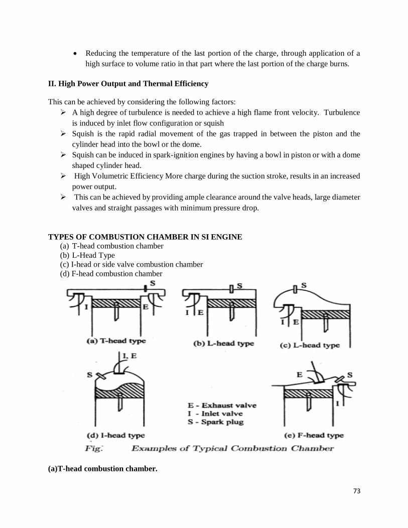
73
Reducing the temperature of the last portion of the charge, through application of a
high surface to volume ratio in that part where the last portion of the charge burns.
II. High Power Output and Thermal Efficiency
This can be achieved by considering the following factors:
A high degree of turbulence is needed to achieve a high flame front velocity. Turbulence
is induced by inlet flow configuration or squish
Squish is the rapid radial movement of the gas trapped in between the piston and the
cylinder head into the bowl or the dome.
Squish can be induced in spark-ignition engines by having a bowl in piston or with a dome
shaped cylinder head.
High Volumetric Efficiency More charge during the suction stroke, results in an increased
power output.
This can be achieved by providing ample clearance around the valve heads, large diameter
valves and straight passages with minimum pressure drop.
TYPES OF COMBUSTION CHAMBER IN SI ENGINE
(a) T-head combustion chamber
(b) L-Head Type
(c) I-head or side valve combustion chamber
(d) F-head combustion chamber
(a)T-head combustion chamber.

74
The T-head combustion chambers were used in the early stage of engine development.
Since the distance across the combustion chamber is very long, knocking tendency is high
in this type of engines.
This configuration provides two valves on either side of the cylinder, requiring two
camshafts. From the manufacturing point of view, providing two camshafts is a
disadvantage.
(b) L-Head type combustion chamber.
A modification of the T-head type of combustion chamber is the L-head type which provides
the two valves on the same side of the cylinder and the valves are operated by a single camshaft.
The main objectives of the Ricardo's turbulent head design, Fig (c), axle to obtain fast flame
speed and reduced knock
(c)I-head or side valve combustion chamber
In this combustion chamber, both the valves are located on the cylinder head.
The overhead valve engine is superior to a side valve or an L-head engine at high compression
ratios.
Some of the important characteristics of this type of valve arrangement are:
less surface to volume ratio and therefore less heat loss
less flame travel length and hence greater freedom from knock
higher volumetric efficiency from larger valves or valve lifts
(d) F-head combustion chamber
The F-head type of valve arrangement is a compromise between L-head and I-head types.
Combustion chambers in which one valve is in the cylinder head and the other in the cylinder
block are known as F-head combustion chambers
Modern F-head engines have exhaust valve in the head and inlet valve in the cylinder block.
The main disadvantage of this type is that the inlet valve and the exhaust valve are separately
actuated by two cams mounted on to camshafts driven by the crankshaft through gears.
Advantages and drawbacks of S I Engine combustion chambers
Sr. no.
Combustion
Chamber Type
Advantages Disadvantages
1 T- head combustion
chamber
1. Easy to manufacture flat
cylinder head,
2. Lower height of engine and
front hood for better frontal
visibility of vehicle.
1. Longer length of
flame travel.
2.Increased detonation
tendency.
2 L- head or side head
combustion chamber
1. Neat and compact layout
2. Easy to lubricate valves, easy
to decarbonize engine.
1. Lack of turbulence
2. Extremely prone to
detonation

75
3. Extremely sensitive
to ignition timing slow
combustion.
3 Ricardo Turbulent
head side valve
combustion chamber
1. Faster flame speed,
2. Reduced detonation
3. Homogeneous air: fuel
mixture formation.
1. Inefficient operation
as compared to latest
engines with
compression ratio of
10:1
4 F- head combustion
chamber
1. Flat roof allows use of an
inlet valve bigger than
exhaust valve.
2. Valve and plug cooling is
efficient.
Complex valve
operating mechanism.
5 I – head combustion
chamber (Wedge
form and Bath tub
form of combustion
chamber)
1. Lower pumping losses and
higher volumetric efficiency.
2. Lesser distance of flame
travel. Therefore low octane
requirement.
3. More uniform cooling of
cylinder and piston.
4. Lower surface to volume ratio
and therefore less heat loss.
5. Easier to cast and hence lower
casting cost.
1. Large sized valves
cannot be
accommodated.
2. Valve operating
mechanism gets
disturbed while
decarbonizing
combustion chamber.
STAGES OF SI ENGINE COMBUSTION
In SI engine homogeneous mixture of vaporised fuel, air and residual gases is ignited by a single
intense and high temperature spark between the spark plug electrode (electrodes exceeds 10,000
ᵒC) and generate pre-flame which spreads to envelope of mixture for combustion.
The combustion in SI engine has divided into three stages.
1. Ignition lag or preparation phase (A-B)
II. Propagation of flame (B-C)
III. Period of after burning (C-D

76
Stage I - Ignition lag or preparation phase (AB)
Growth and development of a semi propagating nucleus of flame.
chemical process depending upon the nature of the fuel, upon both temperature and
pressure, the proportion of the exhaust gas, and also upon the temperature coefficient of
the fuel, that is, the relationship of oxidation or burning
Point A shows the passage of spark and point B is the first rise of pressure
Ignition lag is generally expressed in terms of crank angle
Ignition lag is very small and lies between 0.00015 to 0.0002 seconds
Ignition lag of 0.002 seconds corresponds to 35 degree crank rotation when the engine is
running at 3000 RPM
Angle of advance increase with the speed
Stage II- Propagation of flame (BC)
Period from the point B where the line of combustion departs from the compression line to
point C, the maximum rise of pressure in P-θ diagram
Flame propagates at the constant velocity
Heat transfer to the cylinder wall is low
Rate of heat release depends upon the turbulence intensity and reaction rate
During this second stage, the flame spreads throughout the combustion chamber. The
second stage ends as maximum pressure (on indicator diagram) is reached.
III-After burning (CD)
After point C, the heat release is due to the fuel injection in reduced flame front after the
starts of expansion stroke.
No pressure rise during this period.

77
End of second stage means completion of flame travel. But it does not result in complete
heat release (burning of fuel).
Even after the passage of flame, some chemical adjustments continue throughout the
expansion stroke- near the walls and behind the turbulent flame front. The rate of
combustion reduces due to surface of the flame front becoming smaller and reduction in
turbulence.
Effect of engine variables on Ignition Lag
Ignition lag is a chemical process. The ignition lag in term of crank angle is 10o to 20o& in terms
of second, 0.0015 second. The duration of ignition lag depend on
Fuel- it is depend on chemical nature of fuel. The higher, the self ignition temp of fuel, the longer,
the ignition lag
Mixture Ratio-The ignition lag is smallest for the mixture ratio which gives the maximum
temperature this mixture ratio is some what richer than the stoichiometric ratio.
Initial pressure and temperature –increasing the intake temp, pressure, compression ratio and
retarding spark, all reduce the ignition lag.
Electrode gap- It affects establishment of the nucleus of flame. If the gap is too small, quenching
of the flame nucleus may occur & rang of fuel –air ratio for the development of a flame nucleus is
reduced.
Turbulence- measured in degree of crank-rotation the ignition lag increases almost linearly with
engine speed. For this reason. It becomes necessary to advance the spark timing at higher speed.
Excessive turbulence of the mixture in the area of the spark plug is harmful, since it
increases the heat transfer from the combustion zone & leads to unstable development of the
nucleus of flame. That is way the spark plug is usually arranged in a small recess in the wall of the
combustion chamber.
Effect of engine variables on Flame Propagation
Rate of flame propagation affects the combustion process in SI engines. Higher combustion
efficiency and fuel economy can be achieved by higher flame propagation velocities.
Unfortunately flame velocities for most of fuel range between 10 to 30 m/second.
The factors which affect the flame propagations are
1. Air fuel ratio
2. Compression ratio
3. Load on engine
4. Turbulence
5. engine speed
6. Engine size
7. Other factors

78
1. Air-Fuel ratio:
The mixture strength influences the rate of combustion and amount of heat generated. The
maximum flame speed for all hydrocarbon fuels occurs at nearly 10% rich mixture. Flame speed
is reduced both for lean and as well as for very rich mixture. Lean mixture releases less heat
resulting lower flame temperature and lower flame speed. Very rich mixture results incomplete
combustion and also results in production of less heat and flame speed remains low.
2. Compression ratio:
The higher compression ratio increases the pressure and temperature of the mixture and also
decreases the concentration of residual gases. All these factors reduce the ignition lag and help to
speed up the second phase of combustion. The maximum pressure of the cycle as well as mean
effective pressure of the cycle with increase in compression ratio. Figure above shows the effect
of compression ratio on pressure (indirectly on the speed of combustion) with respect to crank
angle for same A: F ratio and same angle of advance. Higher compression ratio increases the
surface to volume ratio and thereby increases the part of the mixture which after-burns in the third
phase.
3. Load on Engine:
With increase in load, the cycle pressures increase and the flame speed also increases. In S.I.
engine, the power developed by an engine is controlled by throttling. At lower load and higher
throttle, the initial and final pressure of the mixture after compression decrease and mixture is also
diluted by the more residual gases. This reduces the flame propagation and prolongs the ignition
lag. This is the reason, the advance mechanism is also provided with change in load on the engine.
This difficulty can be partly overcome by providing rich mixture at part loads but this definitely
increases the chances of afterburning. The after burning is prolonged with richer mixture. In fact,
poor combustion at part loads and necessity of providing richer mixture are the main disadvantages
of SI engines which causes wastage of fuel and discharge of large amount of CO with exhaust
gases.
4. Turbulence:
Turbulence plays very important role in combustion of fuel as the flame speed is directly
proportional to the turbulence of the mixture. This is because, the turbulence increases the mixing
and heat transfer coefficient or heat transfer rate between the burned and unburned mixture. The
turbulence of the mixture can be increased at the end of compression by suitable design of the
combustion chamber (geometry of cylinder head and piston crown). Insufficient turbulence
provides low flame velocity and incomplete combustion and reduces the power output. But
excessive turbulence is also not desirable as it increases the combustion rapidly and leads to
detonation. Excessive turbulence causes to cool the flame generated and flame propagation is
reduced. Moderate turbulence is always desirable as it accelerates the chemical reaction, reduces
ignition lag, increases flame propagation and even allows weak mixture to burn efficiently.
5. Engine Speed
The turbulence of the mixture increases with an increase in engine speed. For this reason the flame
speed almost increases linearly with engine speed. If the engine speed is doubled, flame to traverse

79
the combustion chamber is halved. Double the original speed and half the original time give the
same number of crank degrees for flame propagation. The crank angle required for the flame
propagation, which is main phase of combustion will remain almost constant at all speeds. This is
an important characteristic of all petrol engines.
6. Engine Size
Engines of similar design generally run at the same piston speed. This is achieved by using small
engines having larger RPM and larger engines having smaller RPM. Due to same piston speed,
the inlet velocity, degree of turbulence and flame speed are nearly same in similar engines
regardless of the size. However, in small engines the flame travel is small and in large engines
large. Therefore, if the engine size is doubled the time required for propagation of flame through
combustion space is also doubled. But with lower RPM of large engines the time for flame
propagation in terms of crank would be nearly same as in small engines. In other words, the number
of crank degrees required for flame travel will be about the same irrespective of engine size
provided the engines are similar.
7. Other Factors:
Among the other factors, the factors which increase the flame speed are supercharging of the
engine, spark timing and residual gases left in the engine at the end of exhaust stroke. The air
humidity also affects the flame velocity but its exact effect is not known. Anyhow, its effect is not
large compared with A:F ratio and turbulence.
DETONATION OR KNOCKING IN SI ENGINE
Knocking is due to auto ignition of end portion of unburned charge in combustion chamber. As
the normal flame proceeds across the chamber, pressure and temperature of unburned charge
increase due to compression by burned portion of charge. This unburned compressed charge may
auto ignite under certain temperature condition and release the energy at a very rapid rate compared
to normal combustion process in cylinder. This rapid release of energy during auto ignition causes
a high pressure differential in combustion chamber and a high pressure wave is released from auto
ignition region. The motion of high pressure compression waves inside the cylinder causes
vibration of engine parts and pinging noise and it is known as knocking or detonation. This
pressure frequency or vibration frequency in SI engine can be up to 5000 Cycles per second.
Denotation is undesirable as it affects the engine performance and life, as it abruptly increases
sudden large amount of heat energy. It also put a limit on compression ratio at which engine can
be operated which directly affects the engine efficiency and output.

80
Figure. Detonation in SI engine
A= Source of ignition causing hollow
nucleus to be formed and flame front to
propagate further.
BB’Type equation here.= intermediate
position of the flame front
CC’ = intermediate position of flame front
CC’D = unburnt end charge reaching critical
temperature
In abnormal combustion, the end charge
auto-ignites before the flame front reaches it.
Detonation type of abnormal combustion.
Figure shows combustion with detonation. The flame front has reached BB’ and the unburnt charge
BB’D has reached the critical conditions for auto-ignition. In this case there is a possibility of
detonation. If the flame front can proceed from BB’ to D and consume the unburnt charge in a
normal manner, prior to completion of the Ignition delay period, there will be no detonation.
If, however, the flame front is able to proceed only as far as, say CC’, during the ignition delay
period, then the remaining portion of the unburnt charge CC’D will auto-ignite and cause extreme
pressure fluctuations from about 50 bar to 150-200 bar.
Effects of detonation
Noise and vibration: the presence of vibratory motion causes crankshaft vibrations and the
engine runs rough.
Mechanical damage: the cylinder head and valves may be pitted, increased rate of wear
may occur.
Carbon Deposits: detonation results in increased carbon deposits.
Increase in heat transfer: occurs due to scouring away of protective layer of inactive
stagnant gas on the cylinder walls due to pressure waves.
Decrease in power output and efficiency: due to increase in the rate of heat transfer the
power output as well as efficiency of a detonating engine decreases.
Pre-ignition: The increased rate of heat transfer to walls causes local overheating of spark
plug, which ignites charge before the spark, thus causing Pre- ignition.
Control of detonation in SI engines
Methods of controlling detonation:
By controlling following engine variables, detonation can be controlled.

81
Increasing engine rpm.
Retarding spark timing
Reducing pressure in inlet manifold by throttling. In supercharged engines reducing
supercharging pressures reduces detonation.
Making the ratio too lean or too rich, preferably latter.
Water injection.
By design features, detonation can be reduced.
Use of low compression ratio.
Increasing turbulence
Relocating spark plugs or use of two or more spark plugs.
Suitable combustion chamber design to reduce flame length and to reduce temperature of
end gas.
It can be eliminated by using High octane fuels, or by adding additives known as dopes to
petrol.
PRE-IGNITION COMBUSTION
The increase in the rate of heat transfer to the walls may cause local overheating specially
of the spark plug, which may reach a temperature high enough to ignite the charge before
the passage of spark. This phenomenon is called Pre-ignition.
Pre-ignition may also be caused by overheated exhaust valves or glowing carbon deposits
in the combustion chamber.
Some part of the cylinder surface may be hot enough (nearly 1100°) to ignite the charge
before the spark does so. This is equivalent to advancing the ignition, but since the hot spot
surface is larger than the spark, the combustion rate would be faster than that of normal
combustion.
Creating very high cylinder pressures and temperatures and thus resulting in excessive
negative compression work and increased heat loss to the walls. The overall effect will be
the loss in power.
Pre-ignition will also cause higher temperatures and pressures in the end-gas than those
caused by normal ignition because of its earlier occurrence on the compression stroke. Thus
pre-ignition leads to auto-ignition and hence knock. And auto-ignition encourages pre-
ignition.
Knock and pre-ignition are different phenomena. Knock is due to the rapid combustion of
the last part of the mixture following the initiation of flame by the spark, whereas pre-
ignition is the ignition of the charge by a hot body before the spark occurs.
The result of pre-ignition are to increase the work of the compression stroke, decrease the
net work of the cycle, increase the engine pressures, increase the heat loss from the engine
and decrease the efficiency. Pre-ignition if not checked gets progressively worse,
culminating in severe engine damage.

82
Pre-ignition can be detected by switching off the ignition when irregular firing might
occur for a few strokes before the engine speed drops. The sudden loss of power with no
evidence of mechanical malfunctioning may also indicate pre-ignition.
SURFACE IGNITION
Under certain conditions, air-fuel mixture is ignited by a hot spot in the cylinder.
Initiation of a flame front by a hot surface other than the spark is called surface ignition.
The hot surface may be the spark plug insulator or electrode, the exhaust valve head, the
combustion deposits on the combustion chamber surfaces etc.
Surface ignition occurring before the spark is called pre-ignition and that occurring after
the spark is called post-ignition.
Run-on, run-away, wild ping and rumble are caused by surface ignition which are harmful.
EFFECT OF ENGINE OPERATING VARIABLES ON THE ENGINE KNOCKING
DETONATION
The various engine variables affecting knocking can be classified as:
Temperature factors
Density factors
Time factors
Composition factors
(a) Temperature factors:
Increasing the temperature of the unburned mixture increase the possibility of knock in SI
engine, the effect of following engine parameters on the temperature of the unburned
mixture:
Raising the compression ratio: Increasing the compression ratio increases both the
temperature and pressure (density of the unburned mixture). Increase in temperature
reduces the delay period of the end gas which in turn increases the tendency to knock.
Supercharging: It also increases both temperature and density, which increase the knocking
tendency of engine
Coolant temperature: Delay period decreases with increase of coolant temperature,
decreased delay period increase the tendency to knock
Temperature of the cylinder and combustion chamber walls: The temperature of the end
gas depends on the design of combustion chamber. Sparking plug and exhaust valve are
two hottest parts in the combustion chamber and uneven temperature leads to pre-ignition
and hence the knocking.
(b) Density factors:
Increasing the density of unburnt mixture will increase the possibility of knock in the
engine. The engine parameters which affect the density are as follows:
Increased compression ratio increase the density
Increasing the load opens the throttle valve more and thus the density
Supercharging increase the density of the mixture

83
Increasing the inlet pressure increases the overall pressure during the cycle. The high
pressure end gas decreases the delay period which increase the tendency of knocking.
Advanced spark timing: quantity of fuel burnt per cycle before and after TDC position
depends on spark timing. The temperature of charge increases by increasing the spark
advance and it increases with rate of burning and does not allow sufficient time to the end
mixture to dissipate the heat and increase the knocking tendency
(c) Time factors
Increasing the time of exposure of the unburned mixture to auto-ignition conditions
increase the possibility of knock in SI engines. Flame travel distance: If the distance of
flame travel is more, then possibility of knocking is also more. This problem can be solved
by combustion chamber design, spark plug location and engine size. Compact combustion
chamber will have better anti-knock characteristics, since the flame travel and combustion
time will be shorter. Further, if the combustion chamber is highly turbulent, the combustion
rate is high and consequently combustion time is further reduced; this further reduces the
tendency to knock.
Location of sparkplug: A spark plug which is centrally located in the combustion chamber
has minimum tendency to knock as the flame travel is minimum. The flame travel can be
reduced by using two or more spark plugs.
Location of exhaust valve: The exhaust valve should be located close to the spark plug so
that it is not in the end gas region; otherwise there will be a tendency to knock.
Engine size: Large engines have a greater knocking tendency because flame requires a
longer time to travel across the combustion chamber. In SI engine therefore, generally
limited to 100mm
Turbulence of mixture: decreasing the turbulence of the mixture decreases the flame speed
and hence increases the tendency to knock. Turbulence depends on the design of
combustion chamber and one engine speed.
(d) Composition factor
The properties of fuel and A/F ratio are primary means to control knock:
Molecular Structure: The knocking tendency is markedly affected by the type of the fuel
used. Petroleum fuels usually consist of many hydro-carbons of different molecular
structure. The structure of the fuel molecule has enormous effect on knocking tendency.
Increasing the carbon-chain increases the knocking tendency and centralizing the carbon
atoms decreases the knocking tendency. Unsaturated hydrocarbons have less knocking
tendency than saturated hydrocarbons.

84
References
1. Ganesan V, “Internal Combustion Engines”4th edition, Tata McGraw Hill publication 2017
2. Rajput R. K, “A textbook of Internal Combustion Engines”, Third edition Laxmi
Publications,2016
3. Mathur and Sharma “Internal Combustion Engines” “Dhanpat Rai and Sons Publication,
2010
4. John B. Heywood, “Fundamentals of Internal Combustion Engine, Second edition, McGraw-
Hill Education; 2018
5. Heinz Heisler “Advanced Engine Technology “2nd edition SAE Publication, 2002.