Petrol Brush Cutter
28
AFTER SALES SUPPORT UK / IRELAND HELPLINE NO 0151 6491500 REP. IRELAND HELPLINE NO 1890 946244 WEB SUPPORT www.einhell-uk.co.uk MODEL NUMBER: QG-BC 30 MANUFACTURERS ARTICLE NUMBER: 34.018.90 30cc Petrol Brush Cutter Original Operating Instructions EASY PULL STARTING SYSTEM WITH ROTOCHOKE Quick and easy to start CARRY STRAP / HARNESS INCLUDED For greater control and comfort POWERFUL 30CC 2 STROKE PETROL ENGINE WITH TWIN HEAD ATTACHMENT Can be used as a Grass Trimmer or Brush Cutter 23CM CUTTING WIDTH WHEN BRUSH CUTTING, 43CM CUTTING WIDTH WHEN GRASS TRIMMING Large cutting area for efficiency TWIN HEAD ATTACHMENT With Automatic line feed for continuous trimming
-
Upload
khangminh22 -
Category
Documents
-
view
4 -
download
0
Transcript of Petrol Brush Cutter

AFTER SALES SUPPORT UK / IRELAND HELPLINE NO 0151 6491500REP. IRELAND HELPLINE NO 1890 946244WEB SUPPORT www.einhell-uk.co.uk
MODEL NUMBER: QG-BC 30MANUFACTURERS ARTICLE NUMBER: 34.018.90
30ccPetrol Brush CutterOriginal Operating Instructions
EASY PULL STARTING SYSTEM WITH ROTOCHOKEQuick and easy to start
CARRY STRAP / HARNESS INCLUDEDFor greater control and comfort
POWERFUL 30CC 2 STROKE PETROL ENGINE WITH TWIN HEAD ATTACHMENTCan be used as a Grass Trimmer or Brush Cutter
23CM CUTTING WIDTH WHEN BRUSH CUTTING, 43CM CUTTING WIDTH WHEN GRASS TRIMMINGLarge cutting area for efficiency
TWIN HEAD ATTACHMENTWith Automatic line feed for continuous trimming

02
Contents
03. Safety Guide
06. Assembly and Parts list
14. Getting Started
16. Operation
21. Trouble Shooting
23. Declaration of Conformity
24. Guarantee Certificate
Helpline No. UK 0151 649 1500 / IRE 189 094 6244Helpline No. UK 0151 649 1500 / IRE 189 094 6244

03Helpline No. UK 0151 649 1500 / IRE 189 094 6244Helpline No. UK 0151 649 1500 / IRE 189 094 6244
15 m
1
2
3
4
5
6
7
8
9
10
11
Explanation of the information signs on the equipment:
1. Warning!2. Read the instructions for use before
operating the equipment.3. Wear safety goggles, a face guard
and ear defenders.4. Wear sturdy, non-slip footwear.5. Wear safety gloves.6. Protect the equipment from rain and damp.7. Be careful of objects being thrown out!8. Always switch off the equipment and pull out
the spark boot plug before carrying out any maintenance work.
9. All bystanders must be kept at least 15 m from the equipment.
10. The tool continues to rotate!11. Caution: Hot parts. Keep your distance.

04 Helpline No. UK 0151 649 1500 / IRE 189 094 6244Helpline No. UK 0151 649 1500 / IRE 189 094 6244
Safety Information
1. Read the instructions with due care. Familiarize yourself with the settings and proper operation of the machine.
2. Never allow children or other persons who are not familiar with the operating instructions to use the petrol grass trimmer.
3. Never mow in the direct vicinity of persons - especially children - or animals.
Warning: Maintain a safety distance of 15m. If approached, switch off the appliance immediately. Always keep in mind that the machine operator or user is responsible for accidents involving other persons and/or their property.
Preliminary measures1. Always wear sturdy, non-slip footwear and long
trousers when operating the machine. Never operate the machine barefoot or in sandals.
2. Check the grounds on which the machine will be used and remove all objects that could be caught up and violently flung out.
3. Warning: Petrol is highly flammable! • Only store petrol in containers designed to
hold petroleum-based liquids.• Only refuel out in the open and do not smoke
during the refueling process.• Always refuel before starting the engine.
Do not open fuel tank cap and do not refuel when the engine is running or when the brush cutter is hot.
• If petrol has overflowed, do not under any circumstances attempt to start the engine. Instead, remove the machine from the affected area. Avoid starting the engine until the petrol fumes have completely evaporated.
• For safety reasons, the petrol tank and other tank closures must be replaced if they are damaged.
4. Replace defective exhausts.5. Before using the petrol brush cutter, visually
inspect it to ensure that the mounting bolts and the entire cutting apparatus are in good working order (i.e. not worn out or damaged). To prevent any imbalance, replace worn out blades or damaged mounting bolts as a set only (if applicable).
Handling
1. Wear close fitting, tough work clothing that will provide protection, such as long slacks or trousers, protective footware, heavy duty work gloves, hard hat, a safety face shield, or safety glasses for eye protection and a good grade of ear defenders or other sound barriers for hearing protection.
2. Store in a safe place. Open fuel cap slowly to release any pressure which may have formed in fuel tank. To prevent a fire hazard, move at least 10 feet (3 meters) from fueling area before starting.
3. Turn unit off before setting it down.4. Always hold unit firmly with both hands,
the thumb and fingers encircling the handles.5. Keep all screws and fasteners tight. Never operate
your equipment when it is improperly adjusted or not completely and securely assembled.
6. Keep handles dry, clean and free of fuel mixture.7. Keep the cutting head as close to ground as
practical. Avoid hitting small objects with the line spool. When cutting on a slope, stand below stringhead. NEVER cut or trim on a hill or slope, etc. if there is the slightest chance of slipping, sliding or losing firm footing.
8. Check the area you will be trimming for debris that may be struck or thrown during operation.
9. Keep all parts of your body and clothing away from the cutting head when starting or running engine. Before starting the engine, make sure the cutting head will not come in contact with any obstructions.
10. Stop the engine before examining cutting line.11. Store equipment away from possible
flammable materials, such as gas-powered water heaters, clothes dryers, or oil-fired furnaces, portable heaters, etc.
12. Always keep the safety guard, the cutting head, and engine free of debris build-up.
13. Operation of equipment should always be restricted to mature and properly instructed individuals.
14. If unfamiliar with trimming techniques, practice the procedures with engine in “OFF” position.
15. Always clear work area of debris such as cans, bottles, rocks, etc. Striking objects can cause serious injury to the operator or bystanders and also damage equipment. If an object is hit accidentally, turn the

05Helpline No. UK 0151 649 1500 / IRE 189 094 6244Helpline No. UK 0151 649 1500 / IRE 189 094 6244
engine off immediately and examine the equipment. Never operate unit with damaged or defective equipment.
16. Always trim or cut at high engine speeds. Do not run engine slowly at start or during trimming operations.
17. Do not use equipment for purposes other than trimming or mowing weeds.
18. Never raise the cutting head above knee height during operation.
19. Do not operate unit with other people or animals in the immediate vicinity. Allow a minimum of 50 feet (15 meters) between operator and other people and animals when trimming or mowing. Allow a distance of 100 feet (30 meters) between operator and other people and animals when operating the petrol grass trimmer.
20. If operating on a slope, stand below the cutting attachment. Do not operate on a slope or hilly incline if there is the slightest chance of slipping or losing your footing.
Additional instructions1. DO NOT USE ANY OTHER FUEL other than that
recommended in your manual. Always follow instructions in the Fuel and Oil section of this manual. Never use petrol unless it is properly mixed with 2-stroke engine oil. Permanent damage to engine will result, voiding manufacturer’s warranty.
2. DO NOT SMOKE while refueling or operating equipment.
3. DO NOT OPERATE UNIT WITHOUT AN EXHAUST and properly installed exhaust shield.
4. DO NOT TOUCH or let your hands or body come in contact with the exhaust. Hold unit with thumbs and fingers encircling the handles.
5. DO NOT OPERATE UNIT IN AWKWARD POSITIONS, off balance, outstretched arms, or one-handed. Always use two hands when operating unit with thumbs and fingers encircling the handles.
6. DO NOT RAISE THE LINE SPOOL above ground level while unit is operating. Injury to operator could result.
7. DO NOT USE UNIT FOR ANY PURPOSES OTHER than trimming lawn or garden areas.
8. DO NOT OPERATE UNIT FOR PROLONGED PERIODS. Rest periodically.
9. DO NOT OPERATE UNIT WHILE UNDER THE
INFLUENCE OF ALCOHOL OR DRUGS.10. DO NOT OPERATE UNIT UNLESS SAFETY GUARD
IS INSTALLED AND IN GOOD CONDITION.11. DO NOT ADD, REMOVE OR ALTER ANY
COMPONENTS OF THIS PRODUCT. Doing so could cause personal injury and/or damage the unit voiding the warranty.
12. DO NOT operate your unit near or around flammable liquids or gases whether in or out of doors. An explosion and/or fire may result.
13. DO NOT USE ANY OTHER CUTTING TOOLS. For your own safety only use the accessories and additional equipment specified in the operating manual. The use of tools or accessories other than those recommended in this operating manual may place you in danger of personal injury.
Safety when handling the blade1. FOLLOW ALL WARNINGS and instructions forusing the machine and for installing the blade.2. The blade may suddenly jump away out of control if it comes up against objects which it cannot cut through. This may result in Serious injury. Keep onlookers and animals at least 15 m away from where you are working. If the machine strikes a foreign body, stop theengine immediately and bring the blade to astandstill. Check the blade for signs of damage.Always replace the blade if it is bent or damaged.3. THE BLADE WILL THROW UP OBJECTS ATHIGH SPEED: This may cause injuries to eyes,face and legs. Always wear eye, face and legprotection. Remove all objects from the workingarea before using the blade. Keep other peopleand animals at least 15 m away from themachine in all directions.4. Check your machine and other equipmentcarefully for signs of damage. Do not use themachine unless all the blade mountings havebeen installed correctly.5. THE BLADE WILL SLOW DOWN AND STOP IFYOU RELEASE THE THROTTLE VALVE.While it is slowing down, the blade can still cause injury to you or onlookers. Before you carry out any work on the blade, switch off the engine and make sure that the blade has stopped.6. DANGER ZONE WITH A DIAMETER OF 15METRES. Onlookers may suffer injuries. Keeponlookers and animals at least 15 m away fromwhere you are working.

B C
06 Helpline No. UK 0151 649 1500 / IRE 189 094 6244Helpline No. UK 0151 649 1500 / IRE 189 094 6244
13 17
21
22
23
20
302
244
8
6
7
A
5
16
14
10
18
9 11
1512
19
2
4
13

07Helpline No. UK 0151 649 1500 / IRE 189 094 6244Helpline No. UK 0151 649 1500 / IRE 189 094 6244
D1
D3
D5
D2
D4
25
26
19
24
26
25
19
26
19
D6

08
E2
E4
E1
E3
F1
Helpline No. UK 0151 649 1500 / IRE 189 094 6244Helpline No. UK 0151 649 1500 / IRE 189 094 6244
2
2729
28
28
29 3
4
1
D7
D8
F4
F6
F5
G
09
F2 F3
Helpline No. UK 0151 649 1500 / IRE 189 094 6244Helpline No. UK 0151 649 1500 / IRE 189 094 6244
2 3
9

10 Helpline No. UK 0151 649 1500 / IRE 189 094 6244Helpline No. UK 0151 649 1500 / IRE 189 094 6244
G3
G5
G4
G6
G1 G2

11Helpline No. UK 0151 649 1500 / IRE 189 094 6244Helpline No. UK 0151 649 1500 / IRE 189 094 6244
H H1
I J1
J2 K1

12 Helpline No. UK 0151 649 1500 / IRE 189 094 6244Helpline No. UK 0151 649 1500 / IRE 189 094 6244
K2 M1
M5M4
M2 M3

Helpline No. UK 0151 649 1500 / IRE 189 094 6244Helpline No. UK 0151 649 1500 / IRE 189 094 6244
N1 N2
N3 N4
N5 N6
13

Helpline No. UK 0151 649 1500 / IRE 189 094 6244Helpline No. UK 0151 649 1500 / IRE 189 094 6244r
O1 O2
14
Important!When using the equipment, safety precautions must be observed to avoid injuries and damage.Please read the complete operating instructions and safety regulations with due care. Keep this manual in a safe place, so that the information is available at all times. If you give the equipment to any other person, hand over these operating instructions and safety regulations as well. We cannot accept any liability for damage or accidents which arise due to a failure tofollow these instructions and the safety instructions.
1. Safety information
CAUTION!Read all safety regulations and instructions.Any errors made in following the safety regulations and instructions may result in an electric shock, fire and/or serious injury.Keep all safety regulations and instructions in a safe place for future use.
Safety devicesWhen working with the blade the metal guard hood must be installed and when working with the cutting spool the plastic guard hood must also be installed to prevent objects being thrown out by the machine. The integrated blade in the plastic guard hood automatically cuts the line to the optimum length.
2. Machine description and itemssupplied (Fig. A – C)
1. Line Spool Assembly2. Guard for blade with screws3. Guard for cutting line with screws4. Blade5. Handle6. Engine switch “ON/OFF” (1/0)7. Throttle lever “release”8. Throttle lever9. Fastening eyelet10. Choke (swivelling)11. Starter cable12. Spark plug boot13. Air filter housing cover14. Fuel tank15. Housing for engine cooler and starter16. Fuel pump “primer”17. Carrying strap18. Connecting piece for long handle19. Long handle with drive shaft20. Fuel mixture bottle21. Spark plug wrench22. 2-stroke oil23. Locking bar24. Allen Key (size 4mm)25. Additional half-handle (LH)26. Additional half-handle (RH)27. LH Threaded nut28. Drive Collar29. Blade clamp collar30. Cable clip

Helpline No. UK 0151 649 1500 / IRE 189 094 6244Helpline No. UK 0151 649 1500 / IRE 189 094 6244r 15
3. Proper useThe machine is designed for cutting lawns andgrassed areas.
Important. Due to the high risk of bodily injury to the user, the brush cutter must not be used to carry out the following work: to clean (suck up) dirt and debris off walkways, or to chop up tree or hedge clippings. Moreover, the brush cutter may not be used to level out high areas such as molehills. For safety reasons, the brush cutter may not be used as a drive unit for other work tools or toolkits of any kind.
The machine is to be used only for its prescribed purpose. Any other use is deemed to be a case of misuse. The user / operator will be liable for any damage or injuries of any kind caused as a result of this. Please note that our equipment has not been designed for use in commercial, trade or industrial applications. Our warranty will be voided if the machine is used in commercial, trade or industrial businesses or for equivalent purposes.
4. Technical dataEngine type: 2-stroke engine, air-cooled, chrome cylinderEngine power (max.): 0.76 kW/1.03 hpDisplacement: 29.7 ccIdle speed of engine: 2900 rpmMax. engine speed: 11000 rpmMax. twin line speed: 8000 rpmMax. blade speed: 11000rpmIgnition: ElectronicDrive: Centrifugal clutchWeight (with empty tank): 7.5 kgLong handle length: 135 cmCutting circle diameter of line: Ø 43 cmCutting blade diameter: Ø 23 cmCutting line length: 5.0 mCutting line diameter: 2.0 mmTank capacity: 0.6 lSpark plug: Torch L8RTCVibration ahv rear handle: 9.319 m/s2
Uncertainty of vibration level: 3.7m/s2
LpA sound pressure level: 92 dB (A)LWA sound power level: 112 dB (A)
Uncertainty sound level: 1dB
5. Before starting the equipment 5.1 Assembly
5.1.1 Installing the additional handleInstall the additional handle (LH and RH halves) as shown in Figures D1 - D4.Do not fully tighten the screws until you have set the perfect working position with the carrying strap. The additional handle halves should be aligned as shown in Figure A.
5.1.2 Assembly of the long handle (Fig.D6 to D8)Remove the transport guard cap from the lower long handle. Slacken the star grip screw (Fig. D6/Item A) on the connecting piece on the upper long handle (Fig. D6/Item C). Then press the lever catch (Fig. D6/Item B) and carefully slide the lower long handle (Fig. D6/Item D) into the connecting piece on the upper long handle. When doing so, take care to ensure that the drive shafts on the insides of the long handles slide into each other (turn the spool head gently, if required) and that the front lug on the lever catch (Fig. D7/Item 6) locks into the corresponding hole in the lower long handle (Fig. D7/Item 5). Then retighten the star grip screw (Fig. D6/Item 1 & Fig. D8). To dismantle, proceed in reverse order.
5.1.3 Fitting/Replacing the blade (Fig. E1-E4)- Fit the Blade Guard (Fig. E1/Item 2) to the bottom of the drive unit & secure with the 3 screws.
- Fit the Drive Collar (Fig. E3/Item 28) over the splines on the drive shaft. Line up the hole in the collar with the ‘u’ shaped recess in the drive housing (Fig. E1 & E3). Then fit the blade (Item 4) onto the shoulder of the collar. (The blade is reversible, so either way up, is O.K).
- Fit the Blade Clamp Collar (Fig. E2/Item 29) on top of the blade, and then fit the LH Threaded nut (Fig. E2/Item 27), counter-clockwise until finger tight. Insert the locking Bar (Fig. C/Item 23) into the hole in the Drive Collar & use the Spark Plug Wrench (Fig. C/Item 21) to tighten the nut. (Important, LH thread = rotate the part/spanner counter-clockwise to tighten and clockwise to loosen).
- To remove the Blade, rotate the assembly until the hole in the Drive Collar lines up with the ‘u’ shaped recess in the drive housing, before using the tools and proceeding in the reverse
Sound and vibration were measured in accordance with EN ISO 27917, 10884/7916.

Helpline No. UK 0151 649 1500 / IRE 189 094 6244Helpline No. UK 0151 649 1500 / IRE 189 094 624416
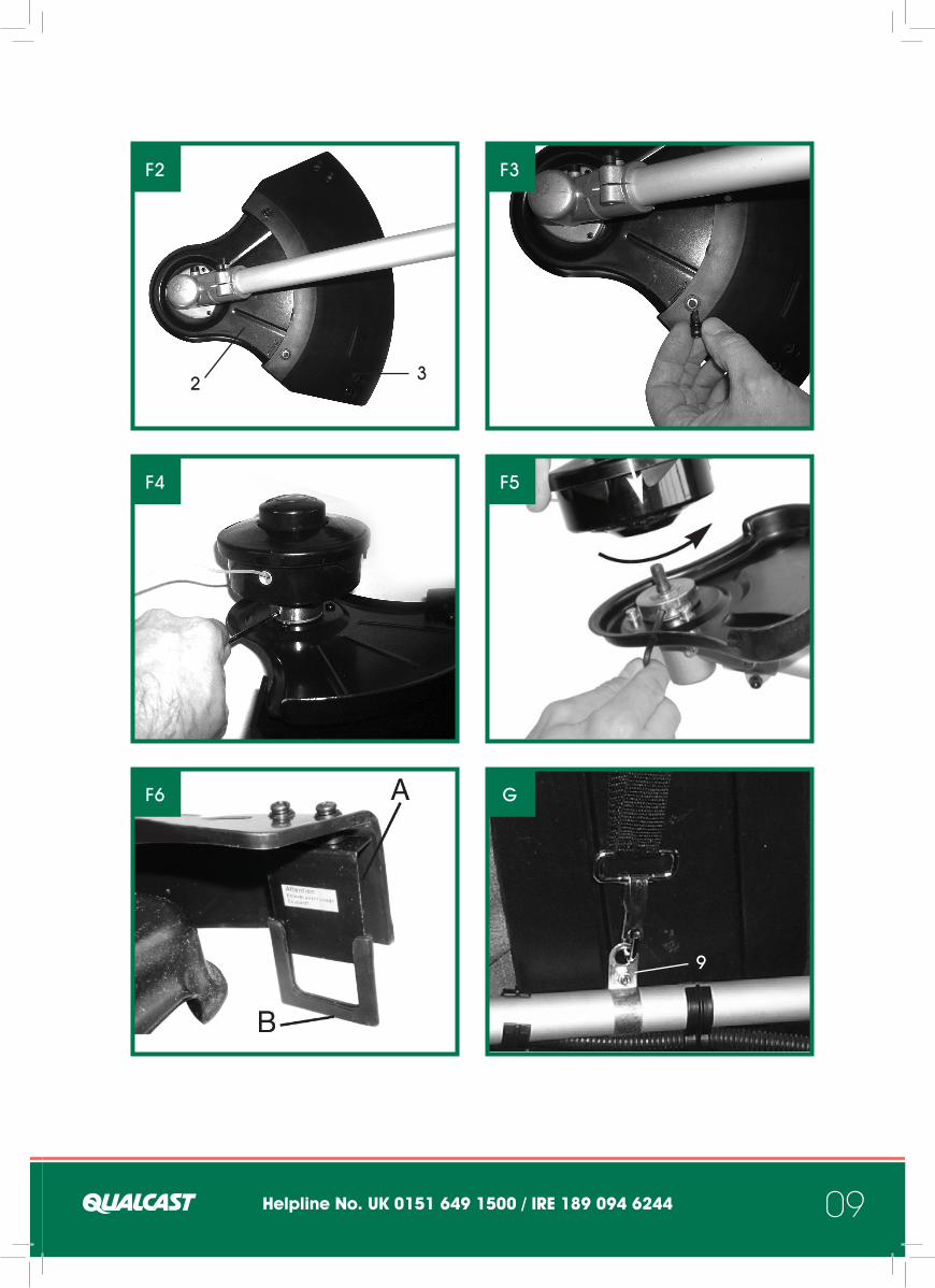
order to remove the blade.5.1.4 Installing the cutting line guard hoodImportant: The cutting line guard hood must be fitted if you wish to work with the cutting line. The guard hood for the cutting line must be installedusing the 3 screws as shown in Figures F1 - F3.
A blade (Fig. F6/ Item A) on the underside of theguard hood automatically cuts the cutting line to the optimum length. This is covered by a ‘u’ shaped guard (Fig. F6/Item B).
Remove the ‘u’ shaped guard before you start working and replace it when you have finished working.
5.1.5 Fitting / Replacing the line spoolLine up the hole in the collar with the ‘u’ shaped recess in the drive housing, and use the locking Bar to secure the drive shaft, whist you fit the line spool assembly (Fig. F4/F5).
Important: Left-hand thread! Rotate the spool counter-clockwise to tighten and clockwise to loosen).
To dismantle, proceed in reverse order.
5.2 Setting the cutting height (Fig. G1-G6)Fit the carrying strap.Hook the machine to the carrying belt (Fig. G5). Adjust the perfect working and cutting position using the various strap adjuster on the carrying strap (Fig. G1 - G4). In order to establish the optimum length of the carrying strap, you should then make a few swinging movements without starting the engine (Fig. G6).
Please note: Always use the shoulder strap when using the machine. Attach the strap as soon as you have started the engine and the engine is running in idle mode. Switch off the engine before you take off the shoulder strap.Check the machine for the following each time before use:• That there are no leaks in the fuel system• That the cutting unit and all safety devices
are in perfect condition• That all screws are securely fastened
5.3 Fuel and oilRecommended fuelsUse only a mixture of normal unleaded petrol and special 2-stroke engine oil. Mix the fuel mixture as indicated on the fuel mixing table.Please note: Do not use a fuel mixture which has been kept for longer than 90 days.Please note: Do not use 2-stroke oil with arecommended mixing ration of 100:1. If inadequate lubrication causes engine damage, the manufacturer’s engine warranty will be voided.Please note: Only use containers designed and approved for the purpose to transport and store fuel. Pour the correct quantities of petrol and 2-stroke oil into the mixing bottle (Fig. C/Item 22 see scale printed on the bottle). Then shake the bottle well.
5.4 Fuel mixture tableMixing procedure: 40 parts petrol to 1 part oil
Petrol 2-stroke oil1 litres 25 ml5 litres 125 ml
6. Operation
Important. A blade (Fig. F6/ Item A) on the underside of the safety guard automatically cuts the cutting line to the optimum length.
6.1 Starting the engine when coldFill the tank with the required amount of oil/petrol mix. See “Fuel and oil”.1. Set the machine down on a hard, level
surface.2. Set the choke position (Fig. A/Item 10) to „ “.3. Press the fuel pump (primer) (Fig H/Item 16)
10 times.4. Switch the ON/OFF switch (Fig. A/Item 6) to “I”.5. Hold the machine firmly in position with one
hand.6. With the other hand pull out the starter
cable (Fig. A/Item 11) until you feel it starts to resist. Then tug sharply on the starter cable 10 times.

Helpline No. UK 0151 649 1500 / IRE 189 094 6244Helpline No. UK 0151 649 1500 / IRE 189 094 6244 17
Important: Never allow the starter cable to snap back. This may damage the machine. Important: The cutting tool starts to operatewhen the engine is started.
7. If the motor has already been started, let it warm up for about 30 seconds. As soon as you press the throttle lock (Fig. A/Item 7) and use the throttle (Fig. A/Item 8), the swivelling choke automatically jumps to Run „ “ (See Fig. H2).
If the engine does not start up, repeat steps 1-7 above.
Please note: If the engine does not start up even after several attempts, read the section “Engine Troubleshooting”.
Please note: Always pull the starter cable out in a straight line. If it is pulled out at an angle, then friction will occur on the eyelet. As a result of this friction, the cable will become frayed and will wear away faster.Always hold the starter handle when the cable retracts.Never allow the cable to snap back when it has been pulled out. This may also cause damage to the cable or the starter.
6.2 Starting the engine when warm (if theequipment has not been switched off formore than 15 – 20 minutes)1. Set the equipment down on a hard, level
surface.2. Switch the ON/OFF switch to “I”.3. Fully depress the throttle lever (See Fig. H1).4. Hold the equipment firmly and pull out the
starter cable until you feel it start to resist. Then tug sharply on the starter cable. The equipment should start after 1 - 2 pulls. If the equipment does not start after 6 pulls, repeat steps 1 – 7 of the procedure for starting the engine from cold.
6.3 Switching off the engineEmergency Stop procedure:If it becomes necessary to stop the machine immediately, set the ON/OFF switch to “Stop” or “0”.
Normal procedure:Let go of the throttle lever and wait until the engine has changed to idling speed. Then set the ON/OFF switch to “Stop” or “0”.
6.4 Practical tipsPractice all operating techniques with the engine switched off before you start to use the machine.
EXTENDING THE CUTTING LINEWARNING: Do not use any kind of metal wire or metal wire encased in plastic in the cutting head. This may cause serious injuries to the user. To extend the cutting line run the motor at full speed and tap (“BUMP”) the cutting head on the ground.This will automatically extend the line. The blade on the safety shield will cut the line to the appropriate length (Fig. M1).
Caution: Remove all grass and weed remains at regular intervals to prevent the shaft tubeoverheating. Grass and weed remains become trapped under the safety guard (Fig. M2) and they prevent the shaft tube receiving adequate ventilation. Remove the remains carefully using a screwdriver or the like.
DIFFERENT CUTTING METHODSIf the machine is correctly assembled with the safety hood and cutting head it will cut weeds and long grass in places with difficult access, for example along fences, walls and foundations and also around trees. It can also be used for mowing work to removevegetation to allow the better preparation of a garden or to clear a certain area down to the soil.PLEASE NOTE: Even if it is used carefully, cutting around foundations, stone or concrete walls, etc. will result in the line suffering more than normal wear.
TRIMMING / MOWINGSwing the trimmer in a side to side motion. Always keep the cutting head parallel to the ground. Check the site and decide what cutting height you require. Guide and hold the cutting head at the required height to ensure that you cut evenly (Fig. M3).

Helpline No. UK 0151 649 1500 / IRE 189 094 6244 Helpline No. UK 0151 649 1500 / IRE 189 094 624418
LOWER TRIMMINGHold the trimmer right in front of you at a slight angle so that the underside of the cutter head is above the ground and the line strikes the correct target. Always cut away from yourself. Never draw the trimmertowards yourself.
CUTTING ALONG FENCES / FOUNDATIONSWhen cutting approach wire mesh fences, lath fences, natural stone walls and foundations slowly so that you can cut close to them without striking the obstacle with the line. If, for example, the line strikes stones, stone walls or foundations, it will wear or fray.If the line strikes wire fencing it will break.
TRIMMING AROUND TREESWhen trimming around tree trunks, approach slowly so that the line does not strike the bark. Walk around the tree, cutting from left to right. Approach grass or weeds with the tip of the line and tilt the cutting head forwards slightly.
WARNING: Take extreme care during mowing work. When doing such work keep a distance of 30 meters between yourself and other people or animals.
SAWINGThe equipment is not suitable for sawing.
JAMMINGIf the blade jams as a result of attempting to cut vegetation that is too dense, switch off the motor immediately.Remove the grass and scrub from the equipment before you restart it.PREVENTING RECOILWhen you work with the blade there is a risk of recoil if it strikes solid objects such as tree trunks, branches, tree stumps, stones or the like. This will throw the equipment backwards in the direction opposite to the rotation of the tool. This can cause you to lose control of the equipment. Do not use the metal blade near fences, metal posts, boundary stones or foundations.For cutting dense stalks, position it as shown in Fig. I5/Item A to prevent recoil.
MOWINGFor mowing you should cut all the vegetation down to the ground. To do this, set the cutting head at an angle of 30° to the right. Place the handle in the required position. Remember the increased risk of injury to the user, watchers and animals and the danger of damaging other items due to objects (for example stones) being thrown out (Fig. M4).
WARNING: Do not remove any objects fromfootpaths, etc. using the trimmer.The trimmer is a powerful tool and can throw small stones and other objects a distance of 15 meters or more, causing injuries and damage to cars, houses and windows.
7. Cleaning, maintenance, storage, transport and ordering of spare parts
7.1 Cleaning• Keep all safety devices, air vents and the
motor housing free of dirt and dust as far as possible. Wipe the equipment with a clean cloth or using compressed air at low pressure (ensure to blow it in a safe direction).
• We recommend that you clean the device immediately each time you have finished using it.
• Clean the equipment regularly with a moist cloth and some soft soap. Do not use cleaning agents or solvents; these could attack the plastic parts of the equipment. Ensure that no water can seep into the device.
7.2. MaintenanceAlways switch off the machine and pull out the spark boot plug before carrying out any maintenance work.
7.2.1 Replacing the line spool / cutting lineRemove the line spool assembly from the drive shaft1. Press the line spool housing together (Fig. N1)
below the two lugs (Fig. N2/Item 1) and remove the line spool cover (Fig. N2/Item 2).
2. Take the line spool out of the line spool

Helpline No. UK 0151 649 1500 / IRE 189 094 6244 Helpline No. UK 0151 649 1500 / IRE 189 094 6244 19
housing (Fig. N3). Make sure that you do not lose the spring or the washers.3. Remove any remaining cutting line.4. Place the new cutting line in the center
and attach the resulting loop to the recess in the spool splitter (Fig. N4)
5. Wind the line on to the spool counter-clockwise with tension. The spool splitter will separate the two halves of the nylon line (Fig. N5)
6. Hook the last 15 cm of the two ends of the line to the line holders opposite the line spool (Fig. N6)
7. Thread the two ends of the line through the metal eyelets in the line spool housing (Fig. N3).
8. Press the line spool into the line spool housing. Ensure that the spring and washers are in the correct position (Fig. N3).
9. Press the line spool cover on to the line spool housing. Ensure that the two lugs (Fig. N2/Item 1) in the line spool housing lock into the appropriate recesses (Fig. N2/Item 2) in the line spool cover.
10. Pull the two line ends briefly and powerfully to release them from the line holders in the line spool.
11. Cut the excess line to a length of around 13 cm. This will reduce the load on the engine when starting up and warming up.
12. Fit the line spool again. See point 5.1.5.If you are replacing the complete line spool, ignore points 3-6.
7.2.2 Maintenance of the air filter (Fig. J1-J2)Soiled air filters reduce the engine output by preventing the air reaching the carburettor.Regular checks are therefore essential. The air filter should be checked after every 25 hours of use and cleaned if necessary. If the air contains a lot of dust, the air filter should be checked more frequently.1. Remove the air filter cover (Fig.J1-J2)2. Remove the filter element.3. Clean the filter element by tapping it or
blowing it.4. Assemble in reverse order.
Please note: Never clean the air filter with petrol or inflammable solvents. Clean the air filter with compressed air or by tapping it.
7.2.3 Maintenance of the spark plug (Fig. K1-K2)
Spark plug gap = 0,6 mm. Tighten the spark plug with a torque of 12-15 Nm.
Check the spark plug for dirt and grime after 50 hours of operation and if necessary clean it with a copper wire brush. Thereafter service the spark plug after every 50 hours of operation.1. Pull off the spark plug boot (Fig. K1)
by twisting.2. Remove the spark plug (Fig. K2) with
the supplied spark plug wrench.3. Assemble in reverse order.
7.2.4 Grinding the safety guard bladeThe safety guard blade (Fig. L/Item F) can become blunt over time. Clamp the blade in a vise. Sharpen the blade with a flat file and make sure that the angle of the cutting edge is not altered in the process. File in one direction only.
7.2.5 Carburettor settingsImportant. Settings on the carburettor may only be made by an authorised petrol repair agent.

Helpline No. UK 0151 649 1500 / IRE 189 094 6244 Helpline No. UK 0151 649 1500 / IRE 189 094 624420
Setting the throttle cable:If the maximum speed of the machine falls over time and you have ruled our all the other causes listed in section 9 Troubleshooting, it may be necessary toadjust the throttle cable.First of all check whether the carburettor opens fully when the throttle lever is pressed fully. This is the case if the carburetor slide (Fig. O1/Item 1) rests against the stop (Fig. O1/Item 2) when the throttle is fully open. Figure 16 shows the correct setting. If thecarburetor slide does not touch the stop, it must be adjusted.The following work is required to adjust the throttle cable:• Undo the lock nut (Fig. O2/Item 3)
a few turns.• Undo the adjusting screw (Fig. O2/Item
4) until the carburettor slide rests against the stop when the throttle is fully open, as shown in Figure O1.
• Retighten the lock nut.
Setting the idling speed:Important. Set the idling speed when the machine is warm.
If the engine stalls when the throttle is not pressedand you have ruled out all the other causes listed in section 9 Troubleshooting, the idling speed must be adjusted. To do this turn the idling speed screw (Fig. O2/Item 5) clockwise until the machine runs smoothly at idling speed.
If the idling speed is so fast that the cutting tool turns as well, it has to be reduced by turning the idling speed screw counter-clockwise (Fig. O2/ Item 5) for as long as is required for the cutting tool to stop turning as well.
7.3 StoragePlease note: If you fail to follow these instructionscorrectly, deposits may form on the interior of thecarburetor which may result in the engine being more difficult to start or the machine suffering permanent damage.1. Carry out all of the maintenance work.
2. Drain the fuel out of the tank (You can use a plastic petrol pump for this purpose, which can be bought via our HELPLINE 0151 649 1500).
3. When the fuel has been drained, start the engine.
4. Allow the engine to run at idling speed until it stops. This will clean the remainder of the fuel out of the carburetor.
5. Leave the machine to cool (approx. 5 minutes).
6. Remove the spark plug.7. Place a teaspoon full of 2-stroke engine oil
into the combustion chamber. Pull the starter cable several times carefully to wet the internal components with the oil. Fit the spark plug again.
8. Clean the exterior housing of the machine.9. Store the machine in a cold, dry place where
it is out of the reach of ignition sources and inflammable substances.
Fertilizers and other chemical garden products often contain substances that accelerate the rate of corrosion of metals. Do not store the machine on or near fertilizers or other chemicals.
Restarting1. Remove the spark plug.2. Pull the starter cable several times to clean
the oil residue out of the combustion chamber.
3. Clean the spark plug contacts or fit a new spark plug.
4. Fill the tank. See the section entitled Fuel and oil.
5. Complete steps 1-7 described under the point entitled “Starting the engine from cold”.
7.4 TransportTo transport the machine, first empty the petrol tank as described in section 2 in the section entitled “Storage”. Clean coarse dirt off the machine with a brush or hand brush. Dismantle the long handle as described 5.1.1

Helpline No. UK 0151 649 1500 / IRE 189 094 6244 Helpline No. UK 0151 649 1500 / IRE 189 094 6244 21
The machine does not start. - Correct starting procedure not followed.
- Sooted or damp spark plug.
- Incorrect carburettor setting.
- Follow the instructions for starting.
- Clean the spark plug or replace it with a new one.
- Contact Helpline: 0151 649 1500
The machine starts but does not develop its full output.
- Incorrect choke lever setting.
- Soiled air filter.- Incorrect
carburettor setting.
- Set choke lever to - Clean the air filter.- Contact Helpline:
0151 649 1500
The engine does not run smoothly
- Incorrect electrode gap on the spark plug.
- Incorrect
carburettor setting.
- Clean the spark plug and adjust the electrode gap or fit a new spark plug.
- Contact Helpline: 0151 649 1500
Engine smokes excessively - Incorrect fuel mix.- Incorrect
carburettor setting.
- Use the correct fuel mix (see fuel mixing table).
- Contact Helpline: 0151 649 1500
FAULT POSSIBLE CAUSES TROUBLESHOOTING
9. Troubleshooting
7.5 Ordering replacement partsPlease quote the following data when ordering replacement parts: • Type of model/Machine QG-BC 30• Article number of the machine 34.018.90• Identification number of the machine (11010)• Replacement part number of the part
required
For our latest prices and information please go to www.einhell-uk.co.uk
8. Disposal and recycling
The unit is supplied in packaging to prevent its being damaged in transit. This packaging is raw material and can therefore be reused or can be returned to the raw material system.The unit and its accessories are made of various types of material, such as metal and plastic. Defective components must be disposed of as special waste. Ask your dealer or your local council.

Helpline No. UK 0151 649 1500 / IRE 189 094 6244 Helpline No. UK 0151 649 1500 / IRE 189 094 624422
Beforeeach use
After anoperating
period of 20hours
After anoperating
period of 50hours
After anoperating
period of 100hours
After anoperating
period of 300hours
Check the air filter X
Change the
filter element if
necessary
Clean the air filter X
Clean the petrol filter X
Visual inspection of the unit X
Clean the spark plug
Distance:0.6mm,Replace ifnecessary
Check and readjust thecarburetor's throttle valve
X*
Clean the cylinder head X*
Set the valveclearance X*
.
Please adhere to the following maintenance periods in order to ensure a failure-free operation.
Important: The positions marked with ”X*” should only be carried out by a repair agent.
Important! Fill in engine oil and fuel before starting up the engine for the first time.
(2-STROKE)

Helpline No. UK 0151 649 1500 / IRE 189 094 6244 Helpline No. UK 0151 649 1500 / IRE 189 094 6244 23
The reprinting or reproduction by any other means, in whole or in part, of documentation and papers accompanying products is permitted only with the express consent of ISC GmbH.

Helpline No. UK 0151 649 1500 / IRE 189 094 6244Helpline No. UK 0151 649 1500 / IRE 189 094 624424
GUARANTEE CERTIFICATE
Dear Customer,
In the unlikely event that your device develops a fault, please contact our Customer service department on the telephone number shown below.
1. These guarantee terms cover additional guarantee rights and do not affect your statutory warranty rights. Claims must be accompanied by Proof of Purchase. This must be in the form of a Sales receipt or Bank statement and must show that the product has been purchased within 2 years prior to the claim from the retailer that it was originally sold to.
2. Our guarantee covers problems caused by material or manufacturing defects, and will result in the repair of these defects or replacement of the device with a like for like or similar article. Please note that our devices have not been designed for use in commercial, trade or industrial applications. Consequently, the guarantee is invalidated if the equipment is used in commercial, trade or industrial applications or for other equivalent activities.
3. The following are also excluded from our guarantee:
A) Faults due to accidents, customer misuse, or unauthorized repairs B) Consumable Parts such as Blades/Chains/Trimmer lines/Spooles/Vacuum bags/Spark plugs or Filters C) Failure due to lack of routine maintenance D) Failure as a result of not using the equipment in accordance with the manual and
safety instructions E) The adjustment or lubrication cables, drive belts, or recoil starters
4. The guarantee is valid for a period of 2 years starting from the purchase date of the device. Guarantee claims should be submitted before the end of the guarantee period within two weeks of the defect being noticed. No guarantee claims will be accepted after the end of the guarantee period. The original guarantee period remains applicable to the device even if repairs are carried out or parts are replaced. In such cases, the work performed or parts fitted will not result in an extension of the guarantee period, and no new guarantee will become active for the work performed or parts fitted. This also applies when an on-site Service is used.
5. Please keep your sales receipt in a safe place. If the defect is covered by our guarantee your device will either be repaired under the terms of guarantee or we will send you a replacement device. This device may be re-conditioned or Like for like replacement.
EINHELL UK LTD HELPLINE: + 44 151 649 1500 REP. IRELAND HELPLINE: 1890 946244 HOME RETAIL GROUP 489-499 AVEBURY BOULEVARD, SAXON GATE WEST, CENTRAL MILTON KEYNES, MK9 2NW

Helpline No. UK 0151 649 1500 / IRE 189 094 6244Helpline No. UK 0151 649 1500 / IRE 189 094 6244 25
Notes

Helpline No. UK 0151 649 1500 / IRE 189 094 6244Helpline No. UK 0151 649 1500 / IRE 189 094 624426
Notes

Helpline No. UK 0151 649 1500 / IRE 189 094 6244Helpline No. UK 0151 649 1500 / IRE 189 094 6244 27
Notes

AFTER SALES SUPPORT UK / IRELAND HELPLINE NO 0151 6491500REP. IRELAND HELPLINE NO 1890 946244WEB SUPPORT www.einhell-uk.co.uk
MODEL NUMBER: QG-BC 30MANUFACTURERS ARTICLE NUMBER: 34.018.90