BRUSH BANDIT® - Arborist Supply
80
BRUSH BANDIT ® BRUSH CHIPPER MODEL 65 & 65 CHIPBOX OPERATING & PARTS MANUAL BUILT WITH QUALITY AND DESIGN FIRST ATTENTION: Depending on what replacement parts you are ordering, we will need the following information: CHIPPER COMPONENTS Serial Number Model Number of Chipper ENGINE COMPONENTS Engine Size Engine Serial Number Engine Spec. Number CLUTCH COMPONENTS Name of Manufacturer Serial Number Assembly of Clutch Model No: _________________ Serial No: _________________ DEALER: Name: ____________________ Address: __________________ City/State: _________________ Phone No: _________________ Delivery Date: ______________ Engine Make: ______________ Serial No: _________________ Clutch Make: _______________ Model: _________ S/N _______ PRINTED 5/01 65 MANUFACTURED BY BANDIT INDUSTRIES, INC. 6750 Millbrook Road REMUS, MICHIGAN 49340 PHONE: (989) 561-2270 OR 561-2272 FAX: (989) 561-2273 ~ SALES DEPT. FAX: (989) 561-2962 ~ PARTS/SERVICE
-
Upload
khangminh22 -
Category
Documents
-
view
0 -
download
0
Transcript of BRUSH BANDIT® - Arborist Supply

BRUSH BANDIT ®
BRUSH CHIPPERMODEL 65 & 65 CHIPBOX
OPERATING & PARTS MANUAL
BUILT WITH QUALITY AND DESIGN FIRST
ATTENTION:Depending on what replacementparts you are ordering, we willneed the following information:
CHIPPER COMPONENTSSerial Number
Model Number of Chipper
ENGINE COMPONENTSEngine Size
Engine Serial NumberEngine Spec. Number
CLUTCH COMPONENTSName of Manufacturer
Serial NumberAssembly of Clutch
Model No: _________________
Serial No: _________________
DEALER:
Name: ____________________
Address: __________________
City/State: _________________
Phone No: _________________
Delivery Date: ______________
Engine Make: ______________
Serial No: _________________
Clutch Make: _______________
Model: _________ S/N _______
PRINTED 5/01
65
MANUFACTURED BYBANDIT INDUSTRIES, INC.
6750 Millbrook RoadREMUS, MICHIGAN 49340
PHONE: (989) 561-2270 OR 561-2272FAX: (989) 561-2273 ~ SALES DEPT.
FAX: (989) 561-2962 ~ PARTS/SERVICE


5-01 FORM #WV-110IT IS VERY IMPORTANT THAT THIS FORM IS FILLED OUT COMPLETELY & ACCURATELY. IF WE CANNOT READ THEPURCHASER’S INFORMATION OR IT IS INCORRECT, OUR CUSTOMER LIST WILL NOT BE ACCURATE.
IMPORTANT - THIS FORM MUST BE RETURNED TO THECUSTOMER DATA DEPARTMENT WITHIN TEN (10)DAYS IN ORDER TO VALIDATE WARRANTY
Customer Data Department6750 Millbrook RoadRemus, MI 49340Phone: (989) 561-2270Fax: (989) 561-2273
WARRANTY VALIDATION FORMPURCHASER INFORMATION:
Company Name ____________________________________ Mailing/Street Address ____________________________
City __________________________________________ State _________________ Zip Code ___________________
Telephone Number ( ____ ) ___________________________ Contact Name __________________________________
Chipper Model No. __________________________________ Serial No. ______________________________________
Date Chipper Put Into Service _________________________ Engine Make & S/N ______________________________
DEALER INFORMATION:
Dealer Name _____________________________________ Mailing/Street Address ____________________________
City __________________________________________ State _________________ Zip Code ___________________
Telephone Number ( ____ ) ___________________________ Contact Name __________________________________
1. _______ Customer has been instructed and understands operation and all safety aspects of operating the equipment.
2. _______ Customer has been instructed and understands that everyone within 100 feet of machine must wear personalsafety equipment (i.e. hard hat, safety glasses, etc.)
3. _______ Customer has been instructed and understands equipment maintenance schedules, procedures, and that it istheir responsibility to perform maintenance that includes periodic relief valve adjustments, retightening allfasteners as needed, periodic cleaning of flow divider, clutch and belt adjustments etc.
4. _______ Customer has been advised and understands not to reach into the infeed hopper with hands or feet. Themachine operators must always be located within easy reach of all feed control and shut down devices.
5. _______ Customer understands that the wooden pusher paddle must be used to push small debris into the chipper and,that they are not to reach or kick debris into the infeed hopper area of the machine.
6. _______ Customer understands the purpose of and how to operate the last chance device, and if used the machine hasbeen operated in an unsafe manner, and never attempt to override any shut down devices.
7. _______ Customer has been instructed and understands to always remove the engine key or completely disconnectbattery from cables, wait for the cutter wheel to come to a complete stop, and to install the disc lock beforeperforming any type of maintenance on the machine. Allow at least 3 minutes for the cutter wheel to cometo a complete stop before opening cutter wheel housing or starting any maintenance or service procedures.
8. _______ Customer has been instructed and understands: To Not operate this machine without the hood pin assembly inplace and pad locked. To Not operate this machine with any kind of make shift hood pin. To Not operate thismachine under any circumstances with the chipper hood open.
9. _______ Customer has reviewed and understands limited warranty, and all written and visual instructions.
10. _______ Customer has received, been advised, and understands the manuals, and the Safety/Service videotape isnow inside a manual holder on the chipper. A videotape is supplied for equipment models as available.
11. _______ All Danger, Warning and Operational decals are properly displayed on equipment and fully understood bycustomer.
12. _______ Customer has been instructed, understands, and agrees that all potential operators must: See the suppliedvideotape, be instructed on all the Danger, Warning and Operational decals, read the manual and follow theprocedures.
I have inspected this equipment and find it in correct working condition. To the best of my knowledge, the customer andhis personnel are aware of, and agree to the above procedures.
Date: _______________________________________________ Signed: _________________________________________
The equipment has been thoroughly checked by the above named dealer representative, and I am satisfied withhis instructions.Date: _______________________________________________ Signed: _________________________________________
Dealer Representative
Purchaser


5-01 FORM #Q-104DATE PURCHASED: _________________
MODEL: ___________________________
SERIAL NUMBER: ___________________
DEALER NAME: _____________________
____________________________________
TO BE RETURNED AFTER THIRTY (30) DAYS OF OPERATION
Please return to: Customer Data Department6750 Millbrook RoadRemus, MI 49340
PH: (989) 561-2270FAX (989) 561-2273
CHIPPER QUALITY REPORTAll of the employees that build your equipment strive to manufacturer the very best quality product on the market.We would appreciate your efforts in letting us know how we are doing.
We would like you to operate your machine for thirty (30) days and then fill out this questionnaire and mail it to us.This will help us to keep producing a good product and improving our products through your recommendations.
1. Did your chipper perform to your expectations? ____________________________________________
2. Was the machine delivered on schedule? ________________________________________________
3. Was the paint color and finish to your satisfaction? _________________________________________
4. Was machine equipment as ordered? ___________________________________________________
5. Did all welds appear to be of high quality? ________________________________________________
6. Was the overall machine to your liking? __________________________________________________
7. What problems have you experienced? __________________________________________________
8. Have any components regularly loosened that caused problems? _____________________________
9. Does the hydraulic system seem to have adequate power for feeding wood into the chipper? ________
10. Is the machine manufactured to accommodate service in an adequate manner? If not, please explain:
__________________________________________________________________________________
11. General comments and/or suggestions: __________________________________________________
__________________________________________________________________________________
__________________________________________________________________________________
12. Would you like to be contacted concerning more of our equipment? ____________________________
YOUR COMPANY: _________________
NAME: ___________________________
ADDRESS: _______________________
CITY: ____________________________
STATE & ZIP: _____________________
PHONE: ( ____ ) ___________________


BanditPRINTED 5/01 PAGE 1
TABLE OF CONTENTS
NOTE- ANY PART, PORTION, DESIGN, NUMBER, SPECIFICATION, AND/ORDIMENSION IN THIS MANUAL IS SUBJECT TO CHANGE WITHOUTNOTICE BY THE MANUFACTURER.
MODEL 65MODEL 65 CHIPBOX TABLE OF CONTENTS
PAGESINTRODUCTION & WARRANTY ...................................................2SAFETY PROCEDURES ............................................................... 7SAFETY DECALS ........................................................................11EQUIPMENT OPTIONS ............................................................... 17CONTROLS .................................................................................24START-UP PROCEDURES ......................................................... 28OPERATING PROCEDURES ...................................................... 31MAINTENANCE ........................................................................... 33
HYDRAULIC SECTION ....................................................... 41CHIPPER SECTION .............................................................46LUBRICATION .....................................................................47ELECTRICAL SECTION ......................................................48
REPLACEMENT PARTS SECTION ............................................ 49INFEED HOPPER COMPONENTS ..................................... 50CHIPPER COMPONENTS ...................................................52HYDRAULIC COMPONENTS ..............................................54FRAME & ACCESSORY COMPONENTS ........................... 58PTO CHIPPER COMPONENTS .......................................... 62FEEDWHEEL COUPLER SECTION ................................... 64

BanditPRINTED 5/01 PAGE 2
INTRODUCTIONThe purpose of this manual is to provide the user with specifications and procedures for theoperation, maintenance and repair of the BANDIT CHIPPER. As with any piece of equipment, safetyshould always be a constant thought while the machine is being operated, serviced or stored. Inorder to highlight this consideration, the material which addresses safety is proceeded by thefollowing signal words:
Signal Word Likelihood of OccurenceDegree of PotentialInjury or Damage
DANGER!
WARNING!
CAUTION! NOTICE
Will occur if warning is ignored
Can occur if warning is ignored
Will or can occur if warning is ignored
Important, but not hazard related
Severe
Severe
Minor to Severe
Minor
The chipper is designed and manufactured in accordance with the latest chipper industry standards.This alone does not prevent injury. It is the operator’s responsibility to use good judgement andfollow the warnings and instructions as indicated in this manual.
WARNING!Improper use of the chipper can result in severe personal injury. Personnel using the chipper mustbe qualified, trained and familiar with the operating procedures as defined in this manual.
WARNING!It is the responsibility of the owner or employer to insure that the operator is trained and practicessafe operation while using and servicing the machine. It is also the owner’s responsibility to provideand follow a regularly scheduled preventative maintenance and repair program on the chipper, usingonly factory approved replacement parts. Any unapproved repairs or modifications may not onlydamage the machine and its performance, but could result in severe personal injury. Consult theequipment manufacturer!!!
Each machine is shipped with a manual, a customer’s check sheet on the chipper, and any availableparts & service manuals on component parts not produced by this manufacturer. Additional copiesof these manuals and check sheets can be purchased from the manufacturer, or through the dealer.Engine parts, service and maintenance manuals MUST be purchased through the enginemanufacturer or their dealer.
NOTE - The producer of the Bandit Chipper reserves the right to make anymodifications or revisions to the design or specifications of its machine withoutadvance notice. The producer also reserves the right to change machine andpart prices as needed without advance notice.
MODEL 65MODEL 65 CHIPBOX INTRODUCTION & WARRANTY


BanditPRINTED 5/01 PAGE 6
SERVICE RECORDDATE DESCRIPTION AMOUNT
MODEL 65MODEL 65 CHIPBOX SERVICE RECORD

BanditPRINTED 5/01 PAGE 7
SAFETY PROCEDURES DANGER!
The words Danger!, Warning!, Caution!, andNotice are used on the safety decals and throughoutthis manual, to make you aware of the safetyprocedures. These procedures are very important,read and obey them.YOUR SAFETY IS VERY IMPORTANT TO US!
This machine is equipped with safety decals, guardsand designs for your protection.
Don’t ever take the machine for granted, always becautious and careful when operating your equipment.
Read and follow all the instructions in your manualthoroughly. Your safety is dependent on yourknowledge of how to operate and maintain thismachine. You may obtain additional copies of thismanual from your Bandit Dealer.
Before operating chipper, you must have allpotential operators; read and understand manuals, andfollow the recommendations.
DANGER!NEVER work inside the chipper unless the engine
ignition is shut off, the ignition key is removed and inyour pocket, and the battery is disconnected.
ALWAYS install the lock pin into the chipper disclock tube before working on the chipper.
Simply slide the lock pin into the disc lock tube.This is to insure that the disc cannot be started whileyou are working inside the chipper. If for somereason the disc would start to turn, it would simply hitthe lock pin.
DANGER!Do not work inside the mouth of the chipper or
around the feedwheels, until you have installed theyoke lock pin to keep the top feedwheel in the raisedposition.
DO NOT attempt to operate this machine withoutproper training and becoming very familiar with theoperator’s manual. The hydraulic feed wheels aredesigned to pull wood into the chipper. They do notknow the difference between a hand or wood. If aguard is removed, it must be replaced or severe
injury can result. The cutter-wheel coasts for several min-utes after the power is shutdown. DO NOT attempt anymaintenance while the wheel isturning. NEVER open or closethe cutterwheel cover while thedisc is still turning.
DO NOT feed vines or viney typematerial!
DO NOT pile vines or viney typematerial in front of the infeed hopperwhich may cause you to trip or fall!
DO NOT allow vines or limbs to becomeentangled with you or your clothing!
DO cut viney material into 4 to 5 footlength’s, away from the chipper area!
DO stop the feed system before feedingthe cut viney material into the infeedhopper!
DO use a wooden push paddle whenfeeding the cut vines into feed wheels!
ALWAYS be positioned and preparedto activate the feed control handle!
MODEL 65MODEL 65 CHIPBOX SAFETY PROCEDURES

BanditPRINTED 5/01 PAGE 8
SAFETY PROCEDURES
DANGER!Pay attention to the direction of the discharge pipe
before chipping. Never stand in front of the chipperdischarge pipe. Never direct the pipe towardsanyone or anything that could cause an accident orproblems. Wood chips flying out of the dischargepipe can be very dangerous!
Torn or loose clothing is more likely to get caught inmoving machinery parts or tree branches. Keep suchitems as long hair, shirt sleeves, and shirt tailsproperly contained. Avoid wearing necklaces, rings,watches, and especially neckties while operating thismachinery. Make sure the machine is in excellentcondition, and all the guards are in place, tight andsecure.
Keep children, bystanders and animals clear ofworking area. Never operate equipment that is in needof repair or adjustment.
Wear all applicable safety equipment examples:hard hat, safety glasses, gloves, ear protection, etc.You should always keep a fully charged fireextinguisher with you while chipping and servicing themachine.
DO NOT remove the hood pin until the chipper dischas came to a complete stop. The chipper disc willcoast for several minutes after the engine is shutdown.Always wait at least 3 minutes.
DO NOT operate this machine without the HoodPin in place. Do not operate the machine with anytype of makeshift hood pin! The Hood Pin MUST bepadlocked.
DO NOT operate the machine with the chipper hoodopen under any circumstances.
DO NOT slam the chipper hood to the openposition. This will cause damage to the hinge. If yourhinge has become damaged by slamming the hoodto the open position, Replace The Hinge Immediately!If the hinge has become damaged it will causemisalignment of the hood, the chipper disc may thenhit the hood and cause a serious accident!
Never turn the chipper disc by hand always use apry bar. This will prevent the person turning the discfrom being injured should the disc break loose.
We have provided a sight hole in the chipper beltshield. If belts can be seen moving do not openchipper hood. Do not stick fingers in sight hole.
Never reach into the infeed hopper area of thechipper. There is never any reason to. If you haveshort pieces, or leaves and twigs, just leave them untilyou are feeding longer pieces. While the long piecesare feeding, simply toss the short pieces on top ofthem. The longer pieces will take them on into thechipper.
Always block the tires and the machine tonguewhenever the Bandit is unhooked for operation. DONOT rely on the tongue jack for operationalstabilization.
DANGER!
DANGER!
DANGER!
DANGER!
DANGER!
A wooden push paddle has been provided to assistyou in feeding smaller material. DO NOT use anybody parts or any steel devices inside the infeedhopper area.
If you have larger diameter wood, try to feed it withsmaller diameter wood. Start a small diameter limbwhich will partially open the feedwheel. Once thefeedwheel is partially open it is much easier to insertthe larger diameter wood.
MODEL 65MODEL 65 CHIPBOX SAFETY PROCEDURES

BanditPRINTED 5/01 PAGE 9
SAFETY PROCEDURES
WARNING!Most of the nuts used on the Bandit Chipper are
self locking. After the nut has been removed fivetimes, it should be replaced to insure propertightness. This is especially critical on the chipperknife lock nuts!
After the engine is started, let the chipper disc turnat the lowest RPM’s possible. Listen for any type ofnoise that is foreign. Any steel on steel noise isforeign. If you hear a noise, stop the engine, find theproblem and fix it.
Regardless of how hard a manufacturer tries toproduce a safe machine, accidents still happen.Normally accidents are caused by people makingmistakes. They do not read the manual, they ignorewarning decals or do not use lockouts provided fortheir safety. This normally happens after the personhas become accustomed to the machinery. In theinitial start up and operation of the machinery, theyare cautious, they are very careful because they donot understand the machine.
Never throw in any materials that might containwires, stones, nails, or other metal objects whichmay damage the knives and become dangerousprojectiles.
DO NOT operate this machine indoors! Exhaustfumes can be fatal. When you are refueling themachine, DO NOT SMOKE, make sure the engine isshut off, do not allow any hot or burning materialsnear the chipper.
Never check for hydraulic leaks by touching hosesor fittings with your bare hands. Hydraulic fluid underpressure can penetrate the skin. Use a piece ofcardboard to find leaks. Never use your bare hands.
To obtain the most from your chipper, for the leastamount of cost, it is a good practice to set and followa scheduled preventative maintenance program. Itwill eliminate many possible problems and down time.
Before starting the machine, take a minute to checka few things. The chipper should be in an arearestricted from people passing by. This area aroundthe chipper must be free of all objects that canobstruct your movement when working with thechipper. The machine should be checked for loosetools or foreign objects, especially in the infeedhopper area. All tools not in use should be secured ina tool box.
Do not work on the machine if the engine is runningwith the clutch disengaged. A clutch can self-engageif either the pilot or throw-out bearing happens to seizeto the main output shaft.
Remember, it should take most of your strength toengage the clutch. If the clutch engages easily, DONOT OPERATE this chipper until the clutch has beenadjusted.
The clutch is an expensive component part of theBandit. It needs proper maintenance (seemaintenance section and manufacturers manual fordetailed information). The operator must take carein the engagement and disengagement of theengine, RPM should always be below 1000 RPM.When the engine has sufficiently warmed up, bumpthe clutch handle against engagement to start the discturning. This will have to be repeated until thechipper disc is turning at proper ratio with engine RPM.Then push the handle all the way in gear until it locksinto position securely. If clutch engages anddisengages loosely, it needs adjustment. Afterengagement raise engine RPM to full throttle.Engaging and disengaging the clutch at high engineRPM will quickly and excessively wear out clutchplates as well as bearings.
DANGER!
DANGER!
DANGER!
MODEL 65MODEL 65 CHIPBOX SAFETY PROCEDURES

BanditPRINTED 5/01 PAGE 10
SAFETY PROCEDURES
NEVER sit, stand or ride at any time in the infeedhopper area or anywhere else on this machine. Youcan be severely injured.
DO NOT GO NEAR HYDRAULIC LEAKS!High pressure oil easily punctures skin causingserious injury, gangrene, or death.DO NOT use fingers or skin to check for leaks.Lower load or relieve hydraulic pressure beforeloosening fittings.
WARNING!
DANGER!
WARNING!Operators must at all times be located within easy
reach of all feed control and shut-off devices whenthe unit is running.
WARNING!The machine was built with a chipper hood engine
disable plug which disables the engine if it is notinstalled properly with the hood pin holding thechipper hood in the closed position. Correctly installedand maintained, the engine will not start or it willshut off if the chipper hood engine disable plug isdisconnected. The chipper hood must NEVERbe opened, or pushed closed if the chipper disc isturning.
DANGER!Make sure that there is reflective striped tape
installed on the feed control handle. This tape isreflective, self adhesive and has contrasting colors.The tape helps make the feed control handlestand out more and it also makes the rear of thechipper more visible to a vehicle behind you whiletransporting chipper. Striped tape can be obtainedthrough your local Bandit Dealer.
Before you begin to transport your machine makesure that the tongue jack has been raised to the properheight and attach it securely to the towing vehicle.Once secured to vehicle locate tongue jack andsecure it in the transport position. Always hook safetychains to vehicle by crossing them under the tongueallowing enough slack to avoid binding when makingturns. Check brakes and highway lights make surethat they are all operating properly. Make sure thatthe discharge pipe is in the transport position pointedover the tongue of chipper and be sure to check tirepressure before you begin to transport the machine.
WARNING!
DANGER!DO NOT feed vines or viney type material!
DO NOT pile vines or viney type material in front ofthe infeed hopper which may cause you to trip or fall!
DO NOT allow vines or limbs to become entangledwith you or your clothing!
DO cut viney material into 4 to 5 foot length’s, awayfrom the chipper area!
DO stop the feed system before feeding the cut vineymaterial into the infeed hopper!
DO use a wooden pusher paddle when feeding thecut vines into the feedwheels!
ALWAYS be in position and prepared to activate thefeed control handle!
WARNING!When feeding material into the infeed hopper,
always feed from the side of the infeed tray and thenturn away from material and walk away as wood feedsin. Chippers should be fed from curbside (right side)whenever possible. Anytime operator is near infeedhopper, they must be within easy reach of feedcontrol devices.
This chipper is designed to be “HAND FED” only!DO NOT feed wood with any type of knuckle boomloader, front end loader, or mechanical device. It willcause damage to the machine. If this happens, themachine WILL NOT be covered under warranty.
WARNING!
MODEL 65MODEL 65 CHIPBOX SAFETY PROCEDURES

BanditPRINTED 5/01 PAGE 11
SAFETY DECALS
REACHING OR KICKING INTO THE INFEED HOPPERWILL CAUSE SERIOUS INJURY OR DEATH!
DO NOT reach with your hand or kick with your foot inside the infeed hopper. The feedrolls are very powerful. Onceyour hand or foot is grabbed by the feedrolls, you can be pulled into the chipper.Do not think that you will be able to pull yourself out of the feedrolls. They will not let go!
There is absolutely no reason to work inside of the infeed hopper. If the feedrolls become tangled or clogged, stopthe machine and wait a minimum of three (3) minutes to clean them out.
Warning! When feeding material into the infeed hopper, always feed from the side of the infeed tray and thenturn away from material and walk away as wood feeds in. Chippers should be fed from curbside (right side)whenever possible. Anytime operator is near infeed hopper. HE MUST be within easy reach of feed controldevices. Always be in a position to activate the Forward-Off-Reverse Control Bar.
DANGER! DO NOT use any body part or steel devices inside infeedhopper area. Always use a “Wooden Push Paddle” with this chipper to assistfeeding material. It is owner’s and operator’s responsibility to use and keep a“Wooden Push Paddle” with chipper, also to secure it when transportingchipper. DO NOT operate this machine unless you have read the operator’smanual and have been trained for safe operating procedures!
MODEL 65MODEL 65 CHIPBOX SAFETY DECALS

BanditPRINTED 5/01 PAGE 12
DECAL LOCATIONS - MODEL 65ALTHOUGH LOCATIONS MAY VARY, ALL DECALS MUST BE ON MACHINE DURING OPERATION
IF ANY DECALS BECOME DAMAGED, REPLACE IMMEDIATELY.
MODEL 65 SAFETY DECALS
64
43
11,28,40,60
5
9,12,19,52
17,53
8,42 58
15,30
50
1,2
1,2
597,20,27,48
47
3,6,39,51,62
55
64
44
32,3816,31,34,45
14,15,30
1,246
41,5622,26,2935,36
4,10,13,3321
15,25,49,54,57,61,63
18,37

BanditPRINTED 5/01 PAGE 13
DECAL LOCATIONS - MODEL 65/65 CHIPBOXModifications and/or additions of decals to this list will happen.
Consult chipper dealer or manufacturer for most current decal package.
KEY: SOME DECALS ARE FOR OPTIONAL COMPONENTS
MODEL 65MODEL 65 CHIPBOX SAFETY DECALS
LOCATION KEY NUMBER DESCRIPTION
1. OBW-108 Brush Bandit®2. OOB-112 Bandit Industries, Inc....3. OOB-139 Model 654. Optional OOB-155 Property Of Bandit Industries....5. OOB-213 Do Not Attempt To Operate....6. OOB-220 Yoke Lock Hole7. OOB-221 Yoke Lock Bar8. OOB-223 3 1/4” Arrow9. OOB-227 Notice Hydraulic Trouble Shooting....10. Optional OOB-230 Do Not Over Work Engine...11. OOB-242 Notice Remove This Guard....12. OOB-243 Notice Owners Responsibility....13. Optional OOB-244 Notice Protect Main Throttle...14. OOB-272 Motor Coupler Guard....15. OOB-275 Grease Daily16. OOB-277 Notice Proper Bearing Lubrication....17. OOB-278 Notice Hydraulic Oil Tank....18. OOB-289 Push To Reverse19. OOB-2002 Distributed By Bandit Industries....20. OOB-2003 Notice The Owner Is Responsible....21. OOB-2004 Notice Belt Tension Slot....22. Optional OOB-2005 Notice The Clutch Handle....23. Optional OOB-2015 Selector Chip Box Feed24. Optional OOB-2016 Chip Box Lift Up Down25. OOB-2019 This Machine Is Covered...26. OOB-301 Caution! This Machine Operates....27. OOB-307 Notice For Safety And Accurate...28. OOB-311 Notice Important Information....29. Optional OOB-320 Notice Frequently Adjust....

BanditPRINTED 5/01 PAGE 14
DECAL LOCATIONS - MODEL 65 CHIPBOXALTHOUGH LOCATIONS MAY VARY, ALL DECALS MUST BE ON MACHINE DURING OPERATION
IF ANY DECALS BECOME DAMAGED, REPLACE IMMEDIATELY.
MODEL 65 CHIPBOX SAFETY DECALS
1,2,41 56
1,2,52 35,
36
10,60
8,42 6,7,
15,58
1,2
8,18,37
6150,45
30,39,47,55,62
48,59433
4,25
8,13,37
46
14,15,44
9,17,53
11,21,22,43
1,5,13,19,24
1,2
1,2
310,28,29,38
32,42,44
12,16,23,26
20,25,2754,58,63
30
31,34,49,51,57,61

BanditPRINTED 5/01 PAGE 15
DECAL LOCATIONS - MODEL 65/65 CHIPBOXModifications and/or additions of decals to this list will happen.
Consult chipper dealer or manufacturer for most current decal package.
KEY: SOME DECALS ARE FOR OPTIONAL COMPONENTS
MODEL 65MODEL 65 CHIPBOX SAFETY DECALS
LOCATION KEY NUMBER DESCRIPTION30. OBR-400 Danger! Keep Hands Clear31. OBR-401 Danger! Never Open or Close....32. OBR-404 Danger! Flying Chips Are....33. Optional OBR-405 Danger! This Machine is Direct...34. OBR-407 Danger! Never Perform Any....35. Optional OBR-408 Warning! Flammable Fluid Diesel....36. Optional OBR-409 Warning! Flammable Fluid Gasoline....37. OBR-410 Danger! Moving Parts....38. OBR-412 Warning! Do Not Attempt....39. OBR-413 Danger! Stop To Think....40. Optional OBR-425 Warning! Only Use This....41. OBR-441 Warning! Keep Lug Nuts....42. OBR-451 Danger! Failure To Follow....43. OBR-454 Danger! Failure To Comply....44. OBR-456 Danger! Before Moving....45. OBR-458 Danger! Moving Parts...46. OBR-460 Danger! Operation Tips...47. OBR-463 Danger! Feed Plate Anvil Bolts...48. OBR-464 Warning! Failure To Perform....49. (For 1/2” x 4” x 7 1/4” Knives) OBR-467 Warning! This Chipper Disc...50. OBR-469 Warning! Maintaining Your Brush...51. Optional OBR-471 Warning! Do Not Close....52. OBR-480 Warning! Never Use Jumper....53. OBR-482 Warning! Hydraulic Oil....54. OBR-490 Danger! Do Not Use A....55. OBR-491 Danger! Last Chance Stop....56. OBR-493 Danger! Brush Chippers Are....57. OBR-494 Warning! Severe Injury Or....58. OBR-495 Warning! Severe Injury Or....59. OBR-496 Danger! Serious Injury Or....60. OBR-497 Danger! Through This....61. (For 1/2” x 3” x 7 1/4” Knives) OBR-4009 Warning! This Chipper Disc...62. OBR-4010 Danger! Never, Sit, Stand....63. OBR-4028 Danger! Do Not Feed....64. Bandit Model 65 Vinyl
Optional California Proposition 65....Optional Spanish/English Decals....Optional Portuguese Decals....

BanditPRINTED 5/01 PAGE 16
SAFETY DECALSSafety Decals located on your Bandit Chipper contain useful information to assist you in operating your
equipment safely. Some of the decals on your machine and their location are shown in this section.It is very important that all decals remain in place and in good condition on your machine. Please follow the
care and instructions given below:
1) You should use soap and water to keep your decals clean. Never use mineral spirits orany other abrasive cleaners.
2) Replace immediately any missing or damaged decals. The location the decal is goingto be applied to must be clean and dry, and at least 40° F (5°C) before applying decal.
3) When the need arises to replace a machine component with a decal attached, be sureand replace the decal.
4) Replacement decals are available, and can be purchased from the manufacturer oryour Bandit Dealer.
5) Spanish, Portuguese and other foreign language decals are available.
EXAMPLES:
MODEL 65MODEL 65 CHIPBOX SAFETY DECALS
KEEP HANDS CLEAR
THE CLUTCH HANDLE SHOULD NOTBE ENGAGED OR DISENGAGED ATSPEEDS ABOVE 1000 RPMIf the clutch handle engages easily DO NOT operate this chip-per until the clutch plate tension has been properly adjusted.To properly engage the clutch it should take most of yourstrength. A new clutch requires frequent adjustments.
GOOD OPERATORSDON’T WASTE MONEY!Clutches will fail, glaze over, and burn up fromimproper adjustment. This will cost the ownerof this machine over $1,000 to repair. A wellmaintained, correctly adjusted clutch shouldfunction properly for over three years.
THE OWNER IS RESPONSIBLETO REPLACE ANY REMOVED
OR DAMAGED DECALS.You may also purchase decals in another language.Mail the translated decals you require to:PARTS DEPARTMENT6750 MILLBROOK RD., REMUS, MI 49340.We will contact you with cost and availabilityof the translated decals.
SERIOUS INJURY OR DEATH CAN OCCUR!UNLESS THESE INSTRUCTIONS ARE FOLLOWED!
DO NOT OPERATE THIS CHIPPER WITH THE HOOD OPEN UNDER ANY CIRCUMSTANCES!
DO NOT OPEN THIS CHIPPER HOOD WHILE THE CHIPPER DISC IS TURNING!
THE CHIPPER DRIVE SHEAVE MUST HAVE STOPPED BEFORE OPENING HOOD!! THE CUTTER-
WHEEL COASTS AFTER THE ENGINE IS SHUT OFF. DO NOT REMOVE THE HOOD PIN FOR AT
LEAST THREE (3) MINUTES AFTER THE ENGINE IS SHUT OFF. DO NOT REMOVE THE HOOD PIN
UNTIL YOU HAVE VISUALLY LOOKED THROUGH THE HOLE IN THE BELT SHIELD OR LOOKED INTO
THE OPEN AREA OF THE BELT SHIELD BETWEEN THE CHIPPER HOUSING AND THE BELT SHIELD.
DO NOT OPERATE THIS CHIPPER WITH ANY TYPE OF MAKESHIFT HOOD PIN.
DO NOT OPERATE THIS CHIPPER UNLESS THE PADLOCK IS LOCKED INTO THE HOOD PIN.
DO NOT SLAM THE CHIPPER HOOD TO THE OPEN POSITION.
THIS WILL CAUSE DAMAGE TO THE HINGE. IF YOUR HINGE
HAS BECOME DAMAGED BY SLAMMING THE HOOD TO
THE OPEN POSITION, REPLACE HINGE IMMEDIATELY!
IF THE HINGE HAS BECOME DAMAGED IT WILL CAUSE
MIS-ALIGNMENT OF THE HOOD, THE CUTTERWHEEL MAY
THEN HIT THE HOOD AND CAUSE A SERIOUS ACCIDENT!!
FAILURE TO FOLLOW THESE INSTRUCTIONSCAN CAUSE SERIOUS INJURY OR DEATH!

BanditPRINTED 5/01 PAGE 17
EQUIPMENT OPTIONS
PROTECT MAIN THROTTLECONTROL BY USING IT PROPERLYDo not increase your RPM’s by turning your throttle control.This causes too much stress on the Cable. Loosen the lockingdevice, push the throttle control button in and pull throttle outall the way.
Do not use the push button to decrease RPM’s. Loosen thelocking device and turn the throttle control clockwise. Do notkeep turning the throttle control once the engine hasdecreased RPM’s. Engaging the push button and pushing thethrottle control in will exert too much strain on the cable.
NOTICE
MODEL 65MODEL 65 CHIPBOX EQUIPMENT OPTIONS
DO NOT OVERWORKTHIS ENGINE!
This machine is powered by an engine that is capable of chipping3” to 4” diameter brush with sharp chipper knives. The machinewill chip large diameter material as long as the operator uses cau-tion. An occasional large diameter can be chipped if the hydraulicfeed wheels are stopped immediately when the engine begins tolug down. Do not chip continuous large diameter material.Excessive engine overwork will overheat the engine and causeengine failure.
NOTICE

BanditPRINTED 5/01 PAGE 18
EQUIPMENT OPTIONS
Digital E-287 Autofeed Bandit Part Number 900-2903-56
TP8 GREEN - TO AUTOFEED
HYDRAULIC SOLENOID VALVE
TP10TP9 GREEN
TP7 RED TO 12VDC
TP6 BLACK - TO GROUND
TP5 WHITE - T
O ALTERNATOR A/C SIGNAL
TP1
WHITEBLACKREDGREEN
RED LED
TP2
TP3
TP4
MODEL 65MODEL 65 CHIPBOX EQUIPMENT OPTIONS

BanditPRINTED 5/01 PAGE 19
Digital E-287 Autofeed Bandit Part Number 900-2903-56
Digital E-287 with hour meter and RPM display
OPTIONAL AUTOFEED CIRCUIT TESTER PART NUMBER 900-2903-43
A
B
C
D
Light is on when signal from alternator is present(engine must be running).
Battery Ground.
Light is on when battery is switched positive(autofeed and key switch must be on).
Light is on when signal to feed solenoid is made(This will NOT show if solenoid or wiring is shorted).
Features of the E-287
- Speed Switch, Hour Meter, and Tachometer all in one package.
- Push-button programmability (no computer connection required).
- LED indicates output activation.
- Quick-connect for faster and easy installation.
- Fits standard tachometer hole size for easy retrofit.
OUTPUT PLUG WIRING
GREEN - SWITCHED OUT
RED - (+) 12 VDC
BLACK - GROUND
WHITE - SIGNAL
MODEL 65MODEL 65 CHIPBOX EQUIPMENT OPTIONS

BanditPRINTED 5/01 PAGE 20
Digital E-287 Autofeed Bandit Part Number 900-2903-56
Operating InstructionsNormal Operating Mode
During normal operating mode, the user may view the Hours, RPMs, or Total Hours. To view any ofthese displays, simply press the corresponding button.
Displays the number of hours theengine has been run since power up.
Displays the engine speed (RPM).
Displays the total number of hours thathave been put on the engine.
Determining the proper PPR (pulses per revolution) value- If a magnetic pickup is being used, the PPR is determined by the number of teeth on the ring gear.
For example, it there are 152 teeth on the ring gear, then the proper PPR value would by 152.
- If an alternator is being used for the signal, contact your dealer to obtain the proper PPR value.
During programming mode
Adjusts desired setting in downwardincrements.
Initiates programming mode & savesdesired setting.
Adjusts desired setting in upwardincrements.
MODEL 65MODEL 65 CHIPBOX EQUIPMENT OPTIONS

BanditPRINTED 5/01 PAGE 21
Digital E-287 Autofeed Bandit Part Number 900-2903-56
1) Press and hold SET button while turning key on.
Unit briefly displays the letters “PPR” (Pulses Per Revolution)followed by a number indicating the current PPR value.
2) Adjust PPR to desired value using UP and DOWN buttons.
3) Press SET button to save desired PPR value.
4) Adjust RPM to desired maximum rate using UP and DOWN buttons.
5) Press SET button to save desired maximum RPM rate.
6) Adjust RPM to desired minimum rate using UP and DOWN buttons.
7) Press SET button to save desired minimum RPM rate.
Unit goes to normal operating mode displayingthe current engine speed (RPM).
Unit briefly displays the word ”OFF” followed by a numberindicating the current maximum RPM rate the engine will reachbefore deactivating the feed stop solenoid (feedwheels on whenred LED is off).
NOTE: The maximum RPM rate must be HIGHER than theminimum RPM rate.
Programing The E-287
Unit briefly displays the word “ON” followed by a numberindicating the current minimum RPM rate the engine will reachbefore activating the feed stop solenoid (feedwheels off whenred LED is on).
NOTE: The maximum RPM rate must be HIGHER than theminimum RPM rate.
MODEL 65MODEL 65 CHIPBOX EQUIPMENT OPTIONS

BanditPRINTED 5/01 PAGE 22
Digital E-287 Autofeed Bandit Part Number 900-2903-56
TROUBLE SHOOTING GUIDE
IF THE POWER TO CHECK THE FEED SOLENOID IS INCONSISTENT ORDOES NOT WORK, CHECK THE FOLLOWING WITH A MULTIMETER:
MULTIMETER SET AT RX100 RANGE
TP1 to TP5 0 ohmsTP2 to TP6 0 ohmsTP3 to TP7 0 ohmsTP4 to TP9 0 ohmsTP10 to TP8 0 ohmsTP4 to TP8 0 ohms with ON-OFF switch ON
AC VOLTAGE TEST
With the engine running and the multimeter set to the 0-50 Volts AC range, TP1 or TP5 should showa reading of 6-40 Volts AC to ground.
DC VOLTAGE TEST
With the autofeed turned on, the engine at idle, and the multimeter set to DC Volts, TP4 or TP8should show a reading of 12-16 Volts DC to ground. The feedwheels should not be turning.
1. Select DC volts on the multimeter.
2. Put the red (+) lead on the multimeter to the red lead supplying power to the speed sensor.If there is no voltage:a. Check the 7.5 amp in line fuse and replace if bad.b. Check the switch. It is in series with the fuse and turns on the speed sensor.c. Check the wires to the quick connectors on both sides of the speed sensor control
(Making sure they are not broken).d. Check the wires at the solenoid valve.
NOTE: The solenoid will be ON when the engine is off (with key turned to the on position) or when theRPM is at a low idle. If the above adjustments and voltage checks do not work, then replace theautofeed control. Call your dealer and they can send another control already programmed for theengine used on the chipper.
MODEL 65MODEL 65 CHIPBOX EQUIPMENT OPTIONS

BanditPRINTED 5/01 PAGE 23
Digital E-287 Autofeed Bandit Part Number 900-2903-56
TROUBLE SHOOTING GUIDEPOSSIBLE CAUSES WHY AUTOFEED DOES NOT WORK OR ISINTERMITTENT:1. Switch is not turned on.2. Engine not coming back to full rated RPM.3. Bad ON/OFF switch.4. Bad or corroded fuse holder.5. Bad fuse.6. Loose or corroded wire ends.7. Not wired properly.8. Alternator belt loose.9. Alternator not working.10. Hydraulic valve not working.11. Hydraulic valve stuck in OPEN or CLOSED position.12. Hydraulic coil bad.13. Hydraulic coil not grounded properly.14. Not adjusted properly.15. Perkins engine not wired correctly.16. Chipper belts loose.17. Clutch slipping, not adjusted correctly.
APPROXIMATE DIGITAL AUTOFEED SETTINGS(FOR REFERENCE ONLY)
MODEL 65MODEL 65 CHIPBOX EQUIPMENT OPTIONS
Engine Type
Deutz30-45-65-75-83
Kohler25 H.P.
Honda20 H.P.
Perkins 103-1023 1/2 H.P.
Perkins 103-1533 H.P.
Wisconsin30-35 H.P.
MaximumRPM
2800
3400
3600
3400
2800
2800
AlternatorPPR
12
9
3
9
9
N/A
Ignition CoilPPR
N/A
N/A
N/A
N/A
N/A
2
OffRPM
2700
3300
3400
3300
2700
2700
OnRPM
2400
2650
2700
2650
2400
2400
ALRSetting
50
N/A
N/A
N/A
30
N/A
Magnetic Pick-UpPPR
N/A
N/A
N/A
96
N/A
N/A

BanditPRINTED 5/01 PAGE 24
CONTROLS
MODEL 65MODEL 65 CHIPBOX CONTROLS
ADJUST PIVOT TENSION WITH THETIGHTNESS OF INSIDE FRICTION NUTS.
SECURE ADJUSTMENT WITHOUTSIDE JAM NUTS.
ADJUSTING TENSION FOR CONTROL HANDLE PIVOTAND LAST CHANCE CABLE PULL.
NORMAL WEAR REQUIRES PERIODICAL ADJUSTMENT OF PIVOT TENSION.
FEED CONTROL HANDLE SHOULD PIVOT WITH LITTLE EFFORT, BY HAND ORWITH A PULL ON “LAST CHANCE” CABLES.
CORRECT OPERATION OF FEED CONTROL HANDLE
FOR ALL CHIPPERS DESIGNEDTO BE “HAND FED”.
IF YOU ARE IN THE AREA OFINFEED HOPPER, ALWAYS BEPREPARED TO OPERATE ANDWITHIN EASY REACH OF FEEDCONTROL HANDLE.
USE THE 1” JAM NUT TO ADJUSTCONTROL HANDLE PIVOT TENSION.
FEEDINGPUSH TOREVERSEFEEDING

BanditPRINTED 5/01 PAGE 25
CONTROLSModel 65 Basic Location of Controls and Adjustments
LOCATION SHOWN NOT SHOWN
1. Foot Pad Jack Chipper Belts2. Engine Controls, Adjusters Pump Sheave3. Discharge Deflector Adjuster Motor Coupler4. Swivel Discharge Optional Autofeed Control5. Feedwheel Control Bar All Bolts & Nuts6. Engine Throttle Adjuster Lug Nuts7. Hydraulic Control Valves Knives & Hardware8. Wooden Push Paddle (Not Shown)
MODEL 65 CONTROLS
1
3
2
4
7
5
8
6

BanditPRINTED 5/01 PAGE 26
MODEL 65 CHIPBOX CONTROLS
CONTROLSModel 65 Chipbox Basic Location of Controls and Adjustments
LOCATION SHOWN NOT SHOWN
1. Foot Pad Jack Chipper Belts2. Engine Controls, Adjusters Pump Sheave3. Hydraulic Control Valves Motor Coupler4. Swivel Discharge Optional Autofeed Control5. Feedwheel Control Bar All Bolts & Nuts6. Engine Throttle Adjuster Lug Nuts7. Wooden Push Paddle (Not Shown) Knives & Hardware
1
6
2
4
3
75

BanditPRINTED 5/01 PAGE 27
CONSULT THE ENGINE MANUFACTURER’S MANUAL FORSPECIFIC CONTROLS FOR TYPICAL GASOLINE ENGINES
1)a. Ignition Switch:Turn the ignition switch key clockwise one stop (on position) to turn theelectrical system on. The key should remain in the on position while theengine is running. Turn the key fully clockwise (start position) this willstart the engine. To shut off the engine, return the key to the off position.
1)b. On/Off Switch - Push Button Start:Some gasoline engines may have a Toggle Switch or an On/Off Switchcombined with a push button to start the engine. First turn the On/OffSwitch or Toggle Switch to the on position, then depress and hold thePush Button Start until the engine starts, then release the button. To shutoff the engine, return the On/Off Switch or Toggle Switch to the off position.
2) Choke Adjustment:Pull the choke lever out to choke the engine.Push the choke lever in for normal engine operations.
3) Throttle Adjustment:Some gasoline engines may have a knob or a handle for the throttleadjustment. Typically you would pull the knob out, or turn the handle toincrease the engine R.P.M.’s. To decrease you would push in the knobor turn the handle the opposite way.
CONSULT THE ENGINE MANUFACTURER’S MANUALFOR SPECIFIC CONTROLS FOR TYPICAL DIESEL ENGINES
1) Ignition Switch With Preheat:The typical diesel engine may have a preheat system to assist in startingthe engine during cold weather. To activate the preheat system, continueto hold the ignition key in the Preheat position for 15 to 20 seconds, thenattempt to start the engine. If the engine fails to start within 15 seconds,return the key to the Preheat position, hold 10 seconds, and try startingagain.
2) Throttle Adjustment Knob:Some diesel engines will have a throttle adjustment knob. Typically youwould pull the knob out to increase engine R.P.M.’s. To decrease theengine R.P.M.’s you would push in the knob.
3) Alternator Warning Light:This light will glow when the alternator is not charging, or when the ignition switch is turned on and the engine is not running.
4) Oil Pressure Warning Light:This light will glow when the oil pressure is to low, or whenthe ignition switch is turned on and the engine is not running.
5) Engine Temperature Warning Light:This light will glow when the engine, or engine coolant, is above normal operating temperature. If this occurs allowthe engine temperature to cool down. If the engine is overheating because of a loss of coolant, or a broken fan belt,shut the engine off immediately.
MODEL 65MODEL 65 CHIPBOX CONTROLS

BanditPRINTED 5/01 PAGE 28
MODEL 65MODEL 65 CHIPBOX START-UP PROCEDURES
DAILY START UP CHECK LISTEach day before starting your machine these checks must be made:
Observe all safety procedures, on decals and from manual.
Wear all applicable safety equipment; hard hat, gloves, eye protection, ear protection, etc.
Inspect / replace axle dust caps, or grease axles per MFG. Manual. Inspect and adjustbrakes as needed per axle MFG. Manual.
Check entire machine for any loose nuts, bolts, or parts.
Check hydraulic pump and motor shaft for fit and tightness.
Check infeed hopper for any foreign objects.
Daily grease all chipper related bearings.
Check radiator, debris screen. Clean as necessary. Clean cooling fan, shroud on aircooled engines.
Check fuel level. (Running out and repriming is time consuming).
Inspect all hoses and fittings for damage. Replace if necessary.
Make sure hood hinge operates correctly, and is lubricated. You must replace if damaged.
After opening hood, check for any foreign objects.
Check the condition of the knives, anvil, hardware, and fan blades.
Carefully rotate the chipper disc by hand to insure proper anvil clearance.
After closing chipper hood, reinsert the hood pin and padlock, make sure hood pin istight and secure. Make sure the chipper hood engine disable plug is installed correctly,and the spring lock for hood pin springs back to the correct operating position.
Check and/or adjust belt tension on chipper belt drives.
Make sure engine oil and coolant are at proper levels. You must follow the specificENGINE MFG. manual recommendations for radiator coolant, additives, etc.
Check and always maintain hydraulic oil level at 7/8 full.
Check air cleaner, precleaner, clean as necessary.
Make sure all guards are tight and securely in place.
Check around the machine for tools, cans, saws, etc.
Make sure discharge direction is pointed safely.
Check clutch for proper engagement tension and lubrication, frequently adjust andgrease, per PTO manufacturers manual recommendations.
Block tires and tongue for stability.
Maintain and service the “Last Chance Stop” system so it is always operational if needed.
Remember to check EVERYTHING on the checklist.
START-UP PROCEDURES

BanditPRINTED 5/01 PAGE 29
MODEL 65MODEL 65 CHIPBOX START-UP PROCEDURES
START-UP PROCEDURESDANGER!
Do not let anyone operate or maintain this machine until they have thoroughly read this manual. You canpurchase additional Bandit manuals for a nominal fee.
WARNING!Consult your engine manual for proper break-in procedures. Various engines require somewhat differentprocedures, but basically the engines need to operate at lower R.P.M.’s and loads for a specific time.
WARNING!Failure to properly break-in your engine will result in poor bearing and piston ring surfaces.
WARNING!The Bandit has only been run for a short time to test proper hydraulic pressures, possible leaks, etc. The fueltank will be empty. Fuel is provided through a small auxiliary tank for testing. This immensely helps maintainsafety in our manufacturing facility and while shipping.
BEFORE STARTING ENGINE
1) Observe all safety procedures on decals andfrom manual.
2) Make sure you have on all of your safetyequipment; hard hat, gloves, eye protection, earprotection, etc.
3) Inspect / replace axle dust caps, or grease axlesper axle MFG. manual. Inspect and adjustbrakes as needed per axle MFG. manual.
4) Check the entire machine for any loose parts orcomponents. Check for loose nuts or bolts, torque,tighten or replace.
5) Check hydraulic pump and motor shaft for fitand tightness.
6) Check the infeed hopper for any foreign objects.
7) Daily grease all chipper related bearings.
8) Check radiator, debris screen. Clean asnecessary. Clean cooling fan, shroud on aircooled engines.
9) Check the fuel level, check the fuel lines, fueltank, and fittings for fuel leaks. (Running outand repriming is time consuming.)
10) Inspect all hoses, and hydraulic fittings fordamage or leaks. Replace if necessary.
11) Make sure hood hinge operates correctly, and islubricated. You must replace hinge if damaged.
12) Before opening the hood always remove theignition key disconnect battery cables. Removethe hood lock pin and padlock, and install thedisc lock pin into the disc lock tube. Afteropening hood look for any foreign objects.
13) Check the condition of your knives, anvil,inspect the hardware and fan blades.

BanditPRINTED 5/01 PAGE 30
MODEL 65MODEL 65 CHIPBOX START-UP PROCEDURES
BEFORE STARTING ENGINE, cont.
14) Now very carefully, manually turn the chipperdisc a full revolution by hand. This is to insurethe anvil and knives have the proper clearance.
15) After closing chipper hood, reinsert the hood pinand padlock, make sure hood pin is tight andsecure. Make sure the chipper hood enginedisable plug is installed correctly, and the springlock for hood pin springs back to the correctoperating position.
16) Check and/or adjust belt tension on chipper beltdrives.
18) Check engine oil and coolant levels, make surethey are at the proper level for operation.
19) Check hydraulic oil level, this should always be7/8 full. Remember to check DAILY to avoidexcessive heat build up.
20) Check the air cleaner or precleaner. Clean asnecessary.
21) Make sure all guards are tight and securely inplace.
22) Check around the machine for tools, cans,saws, etc.
23) Make sure discharge direction is pointed safely.
24) Check clutch for proper engagement tensionand lubrication, frequently adjust and grease,per PTO manufacturers manualrecommendations.
25) Block tires and tongue for stability beforeoperation.
26) Maintain and service the “Last Chance Stop”system so it is always operational if needed.
27) Remember to check EVERYTHING on thechecklist.
THIS CHIPPER IS EQUIPPED WITHHEAVY-DUTY 1/2” THICK CHIPPER KNIVES.
- MUST KEEP KNIVES SHARP-CHIPPING WITH DULL KNIVES WILL OVERSTRESS KNIFE
BOLTS, AND THEY WILL BREAK CAUSING MAJOR DAMAGE.
NEVER ALLOW THESE KNIVES TO WEAR BEYOND THEABSOLUTE MINIMUM OF 1 13/16” FROM THE CENTER
LINE OF BOLT.
To order 1/2” X 4” X 7 1/4” knives • Use part No. 900-9902-00
1 13/16”1 13/16”
THIS CHIPPER IS EQUIPPED WITHHEAVY-DUTY 1/2” THICK CHIPPER KNIVES.
- MUST KEEP KNIVES SHARP-CHIPPING WITH DULL KNIVES WILL OVERSTRESS KNIFE
BOLTS, AND THEY WILL BREAK CAUSING MAJOR DAMAGE.
NEVER ALLOW THESE KNIVES TO WEAR BEYOND THEABSOLUTE MINIMUM OF 1 3/8” FROM THE CENTER
LINE OF BOLT.
To order 1/2” X 3” X 7 1/4” knives • Use part No. 900-9900-90
1 3/8”1 3/8”
DANGER!DO NOT ATTEMPT TO OPERATE A CHIPPER WHICH IS DESIGNED FOR 1/2” X 3” X 7 1/4”KNIVES USING THE NEW STYLE 1/2” X 4” X 7 1/4” KNIVES. THIS CAN CAUSE EXTENSIVEDAMAGE TO THE CHIPPER AND MAY CAUSE SEVERE INJURY TO OPERATOR.
1/2” X 4” X 7 1/4” Knives (New Style) 1/2” X 3” X 7 1/4” Knives (Old Style)

BanditPRINTED 5/01 PAGE 31
OPERATING PROCEDURES
WARNING!When feeding material into the infeed hopper, always feed from the side of the infeed tray thenturn away from material and walk away as wood feeds in. Chippers should be fed fromcurbside (right side) whenever possible. Anytime operator is near infeed hopper, he must bewithin easy reach of feed control devices.
Use the wooden push paddle to push small materialinto the chipper, not your hands or feet.
WARNING!
1) WHEN FEEDING MATERIAL INTO THE INFEED HOPPER, ALWAYS FEED FROM THE SIDEOF THE INFEED TRAY AND THEN TURN AWAY FROM MATERIAL AND WALK AWAY ASWOOD FEEDS IN. CHIPPERS SHOULD BE FED FROM CURBSIDE (RIGHT SIDE)WHENEVER POSSIBLE. ANYTIME OPERATOR IS NEAR INFEED HOPPER, HE MUST BEWITHIN EASY REACH OF FEED CONTROL DEVICES.
2) DO NOT WASTE TIME WATCHING THE WOOD FEEDING. INSERT THE MATERIAL, GET MOREMATERIAL AND LAY IT ON TOP OF THE FEEDING WOOD. IT SAVES TIME!
3) IF YOU HAVE LARGE DIAMETER WOOD TO CHIP, TRY TO INSERT IT IN THE FEED WHEELSWHILE SMALLER PIECES ARE GOING THROUGH, THE SMALL PIECES WILL PARTIALLY OPENTHE FEED WHEELS WHICH ALLOWS EASIER ACCESS FOR THE LARGER DIAMETER WOOD.
4) DO NOT LUG THE ENGINE ON LARGE DIAMETER MATERIAL. LISTEN FOR THE ENGINE, IF ITSTARTS LOSING RPM, STOP THE FEED WHEELS FOR A FEW SECONDS TO ALLOWRECOVERY OF ENGINE RPM.
5) KEEP THE TOP WHEEL SPRINGS ADJUSTED ONLY TIGHT ENOUGH TO KEEP THE FEEDWHEEL TEETH FROM SLIPPING ON THE MATERIAL. DO NOT OVERTIGHTEN! THIS WOULDOVERWORK THE HYDRAULIC SYSTEM AND MAKES IT VERY HARD TO FEED LARGERDIAMETER MATERIAL.
6) ALWAYS START THE LARGER END (BASE END) OF THE WOOD INTO THE FEED WHEELSFIRST.
7) KEEP THE CHIPPER RPM UP WHETHER CHIPPING BRUSH OR ROUNDWOOD. THE RPM ISNECESSARY FOR THROWING POWER. LOW RPM CAUSES WEAK THROWING AND CANCAUSE PLUGGING IN DISCHARGE.
8) NEVER OPEN CHIPPER HOOD WHILE DISC IS TURNING . AFTER SHUT OFF, ALLOW AT LEAST3 MINUTES FOR CUTTERWHEEL TO COME TO A COMPLETE STOP.
DO NOT REACH INTO THE INFEED HOPPER FOR ANY REASON!IF YOU HAVE SHORT PIECES, SIMPLY LAY THEM ON TOPOF LONGER MATERIAL WHILE IT IS FEEDING INTO THE MACHINE.
OPERATION TIPS FOR BRUSH BANDIT
MODEL 65MODEL 65 CHIPBOX OPERATING PROCEDURES

BanditPRINTED 5/01 PAGE 32
MODEL 65MODEL 65 CHIPBOX OPERATING PROCEDURES
OPERATING PROCEDURESDANGER!
Never for any reason should you place your hands, orany other body part, near the feedwheel while it isturning.
DANGER!Never climb into the infeed hopper area, or attempt toclean, service, or unclog this area while the machineis in operation.
WARNING!If you have short pieces of wood, leaves, or twigs,
simply lay them on top of longer material while it isfeeding into the chipper. You can also use the woodenpush paddle supplied with the machine.
Always stand to the side of the infeed hopper wheninserting material. This will allow you to turn awayfrom the wood, and walk away, without passing throughthe material.
To increase production, don’t waste timewatching the material being fed. Once the limbs havestarted into the machine, you can walk away and getmore material.
If you have larger diameter wood, try to feed itwhile smaller pieces are going through. The smallerpieces will open the feedwheel, and allow the largerpieces through.
If you are feeding larger diameter wood, listen forthe engine to possibly lug down. If it starts luggingdown stop the feedwheel by pushing the hydrauliccontrol handle to off, and let the engine recover to fullspeed. This will stop the chipper from plugging thedischarge pipe.
Keep the feedwheel tension springs adjusted onlytight enough to keep the feedwheel teeth fromslipping on the material. DO NOT OVERTIGHTEN!This will overwork the hydraulic system, and make itdifficult to feed larger material.
Always start the larger end (base end) of the logor branch into the feedwheel first.
Keep the engine R.P.M’s up whether you arechipping brush or round wood. Lower R.P.M.’s willcause weak throwing power, and can cause pluggingin the discharge.
DANGER!Never open the chipper hood while the disc is still
turning. After shutting off the chipper, allow at least 3minutes for the chipper disc to come to a complete stop.
It is very important after you have operated the newmachine for approximately an hour, shut down themachine and recheck all nuts and bolts. It is normal for
bolts to loosen once on a newpiece of machinery. If you tightenthem now, there’s a goodpossibility they won’t loosenagain. In cold weather situationslet your hydraulic system idle for
approximately 15 minutes to allow the system to warm upto operating temperature.
Never refuel while the chipper is running. Neverrefuel in the shop or building. Always refuel in a wellventilated area, away from sparks or open flames.Extinguish all smoking materials. Wipe up all spilled fuelbefore restarting the engine.
This equipment is intended for use by personnel whoare experienced with similar equipment. Always operatesafely. It is also recommended that someone else ispresent while chipping or servicing in case an injuryoccurs. Never operate any machine while under theinfluence of drugs or alcohol.
BanditPRINTED 5/01 PAGE 33
MAINTENANCE SECTION
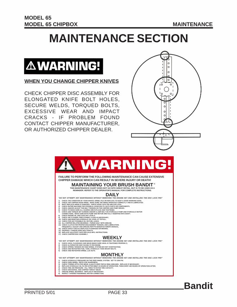
WHEN YOU CHANGE CHIPPER KNIVES
CHECK CHIPPER DISC ASSEMBLY FORELONGATED KNIFE BOLT HOLES,SECURE WELDS, TORQUED BOLTS,EXCESSIVE WEAR AND IMPACTCRACKS - IF PROBLEM FOUNDCONTACT CHIPPER MANUFACTURER,OR AUTHORIZED CHIPPER DEALER.
FAILURE TO PERFORM THE FOLLOWING MAINTENANCE CAN CAUSE EXTENSIVECHIPPER DAMAGE WHICH CAN RESULT IN SEVERE INJURY OR DEATH!
MAINTAINING YOUR BRUSH BANDITTHIS MAINTENANCE CHART DOES NOT GO INTO GREAT DETAIL, BUT IS TO BE USED AS A
REMINDER. REFER TO THE OPERATOR’S MANUAL FOR COMPLETE INSTRUCTIONS.
®
DAILY“DO NOT ATTEMPT ANY MAINTENANCE WITHOUT REMOVING THE ENGINE KEY AND INSTALLING THE DISC LOCK PIN!”
1) CHECK THE CONDITION OF YOUR KNIVES; GRIND, FILE OR REPLACE TO KEEP A GOOD WORKING EDGE.2) CHECK THE CHIPPER HOOD HINGE - MAKE SURE THE HINGE OPERATES CORRECTLY AND IS LUBRICATED.3) MUST REPLACE HINGE IF DAMAGED. CHECK HOOD LOCK PIN AND PAD LOCK.4) CHECK ENTIRE MACHINE FOR POSSIBLE LOOSE BOLTS, NUTS PARTS OR COMPONENTS.5) CHECK AND/OR ADJUST THE BELT TENSION ON THE CHIPPER AND PUMP DRIVES.6) CHECK TO MAKE SURE ALL GUARDS ARE IN PLACE AND TIGHTENED.7) CHECK AND TORQUE SET SCREWS AND/OR CLAMP BOLT ON HYDRAULIC PUMP AND HYDRAULIC MOTOR
CONNECTIONS. MAKE SURE BOTH PUMP AND MOTOR ARE FULLY INSERTED INTO SHAFT.8) CHECK ENGINE OIL AND COOLANT LEVELS.9) CHECK AIR CLEANER, PRECLEANER, CLEAN AS NECESSARY.10) CHECK AND MAINTAIN HYDRAULIC OIL LEVEL AT 7/8 FULL.11) CHECK FOR ANY POSSIBLE OIL OR FUEL LEAKS.12) ALL CHIPPER RELATED BEARINGS - PURGE DAILY WITH GREASE.13) CHECK CLUTCH FOR PROPER ENGAGEMENT TENSION, AND LUBRICATION.
FREQUENTLY ADJUST AND GREASE PER PTO MANUFACTURER’S MANUAL.14) CHECK SAFETY DECALS REPLACE IF DAMAGED OR MISSING.15) PROPERLY TORQUE KNIFE BOLTS/NUTS.16) REPLACE AXLE DUST CAPS PER AXLE MFG. INSTRUCTIONS.17) CHECK CHIPPER DISC ASSEMBLY.
WEEKLY“DO NOT ATTEMPT ANY MAINTENANCE WITHOUT REMOVING THE ENGINE KEY AND INSTALLING THE DISC LOCK PIN!”1) CHECK ANVIL CLEARANCE AND WEAR (MAKE SURE ANVIL IS TIGHTENED PROPERLY).2) CHECK ALTERNATOR AND FAN BELTS ON ENGINE.3) CHECK SPRING TENSION ON FEED WHEEL SYSTEM (DO NOT OVERTIGHTEN)4) CHECK AND RETIGHTEN FUEL TANK, HYDRAULIC TANK MOUNT BOLTS.5) CHECK AND RETIGHTEN WHEEL LUG NUTS.
“DO NOT ATTEMPT ANY MAINTENANCE WITHOUT REMOVING THE ENGINE KEY AND INSTALLING THE DISC LOCK PIN!”MONTHLY
1) CHECK HYDRAULIC PRESSURE ON THE FEED WHEEL SYSTEM. SET TO 1500 PSI.2) CHECK FEED WHEEL TEETH FOR SHARPNESS.3) CHECK TOWING HITCH FOR WEAR, ALWAYS KEEP PINTLE RING GREASED. REPLACE IF NECESSARY.4) REPLACE HYDRAULIC OIL FILTER AFTER FIRST 10 HOURS OF OPERATION. THEN EVERY 400 HOURS OF OPERATION AFTER.5) CHECK TIRE AIR PRESSURE - FILL TIRES TO RATED TIRE CAPACITY.6) CHECK DISCHARGE, AND CHIPPER THROAT WEAR.7) GREASE WHEEL BEARINGS - REPLACE IF NECESSARY.8) INSPECT TAPERED FEEDWHEEL MOTOR CONNECTION.
MODEL 65MODEL 65 CHIPBOX MAINTENANCE

BanditPRINTED 5/01 PAGE 34
MAINTENANCE CHECK SHEET
O.K. Repaired
WEEKLY1) Check anvil clearance, tightness, and wear.2) Check alternator and fan belts on engine.3) Check spring tension on feedwheel system.4) Check and retighten fuel tank, hydraulic tank mount bolts.5) Check, retighten wheel lug nuts.
1) Check hydraulic pressure on the feedwheel system. Set to 1500 PSI.2) Check feedwheel teeth for sharpness.3) Check towing hitch for wear, keep greased.4) Replace hydraulic oil filter every 3 months or 400 hours.5) Check and fill tires to rated pressure.6) Check discharge, and infeed hopper for wear.7) Check and grease wheel bearings, follow axle MFG. instructions.8) Inspect tapered feedwheel motor connection.
MONTHLY
1) Check the condition of your knives.2) Check chipper hood hinge.3) Check hood lock pin and padlock.4) Check entire machine for loose parts or components.5) Check and/or adjust belt tension.6) Check and secure all guards.7) Check and torque set screws and/or clamp bolt on hydraulic motor
connection. Make sure both pump and motor are fully inserted into shaft.8) Check engine oil, coolant levels, and correct engine speed.
Follow ENGINE MFG. manual specs.9) Check air cleaner, pre-cleaner.10) Check hydraulic oil level.11) Check for oil or fuel leaks.12) Grease all bearings daily.13) Check clutch engagement, tension and lubrication.
Frequently adjust and grease, per PTO manufacturers manual.14) Check the safety decals, replace if damaged.15) Properly torque knife bolts and nuts.16) Inspect / replace axle dust caps, or grease axles.17) Check chipper disc assembly.
DAILY
O.K. Repaired
O.K. Repaired
MODEL 65MODEL 65 CHIPBOX MAINTENANCE

BanditPRINTED 5/01 PAGE 35
MAINTENANCE PROCEDURES
ITEMS TO BE SERVICED DAY WEEK MONTH PROCEDURE (Always Replace If Needed)
Chipper Knives, Nuts X Check tightness, wear, replace if needed
Chipper Disc, Fan Blades X Check for proper security, damage, wear
Chipper Hood Hinge X Operating correctly, not damaged, lubricated
Hood Lock Pin & Padlock X Make sure pin is tight and padlocked
Check Entire Machine X For any loose parts or components
Check Draw Ring Bolts, All Other Nuts & Bolts X Torque, tighten, replace if needed
Chipper Drive Belts, Pump Drive Belts X Tighten to correct tension, don’t over tighten
Check All Guards X All in place, tightened and secure
Engine Oil, Coolant X Increase to full, check for leaks repair
Correct Engine Speed X Per Engine Manufacturer’s recommendations
Radiator Coolant System X Follow ENGINE MFG. manual specs.
Radiator, Debris Screen (If equiped) X Clean, power wash as necessary
Clean Cooling Fan, Shroud X On air cooled engines
Air Cleaner, Pre-Cleaner X Clean or replace element
Hydraulic Oil X Minimum 7/8 Full. Replace once a year.
Hydraulic Oil Leaks, Hoses, Fittings X Inspect, tighten, repair or replace
Chipper Bearings (Infeed & Belt Side) X Grease daily
Fuel Lines and Tanks X Check for leaks, repair or replace
Feedwheel Bearings X Grease daily
Clutch X Lubricate, adjust per Manufacturer’s Manual
Safety Decals, Engine Gauges X Replace immediately if damaged
Knife Bolts, Nuts X Torque set to 70-80 ft./lbs.
Inspect / Replace Axle Dust Caps X Or grease axles per MFG. Manual
Inspect and Adjust Brakes X As needed per axle MFG. Manual
Check Chipper Disc Assembly X If problem found contact chipper MFG.
Chipper Feed Plate Anvil X Check clearance, readjust or replace
Alternator, Fan Belts X Check tension, readjust
Feedwheel Spring Tension X Tighten just enough not to slip on wood
Tank Mount Bolts X Check fuel, hydraulic bolts, retighten
Wheel Lug Nuts X Check and tighten, or replace
Hydraulic Pressures X Check all, set feedwheel to 1500 PSI
Tire Air Pressure X Fill to tire rated capacity
Discharge, Chipper Hopper Wear X Check, repair, or replace
Motor Connection X Inspect, torque feedwheel motor connection
Machine Lubrication ------ ------ ------ SEE LUBRICATION CHART
Engine Lubrication ------ ------ ------ SEE ENGINE MANUFACTURER’S MANUAL
Feedwheel Teeth X Check Sharpness
Towing Hitch X Check for wear, keep greased
Hydraulic Oil Filter X Replace after 3 months or 400 hours
CHECK
MODEL 65MODEL 65 CHIPBOX MAINTENANCE

BanditPRINTED 5/01 PAGE 36
MAINTENANCE SECTION
The Bandit is a very simple machine to maintain. If you will follow a regular scheduled preventativemaintenance program you should have years of trouble free operation.
DANGER!
DAILY MAINTENANCE1) Check the condition of your knives, nuts,anvil, hardware, disc, and fan blades:Grind, file, or replace your knives to keep them sharp.Check the anvil, hardware, disc, and fan blades.Replace if necessary.
2) Check Chipper Hood Hinge:Make sure the hood hinge operates correctly, and islubricated. Must replace hinge if damaged.
3) Hood Lock Pin and Padlock:Make sure pin is tight and padlocked. If worn replaceimmediately. Don’t use a worn or makeshift hood pin.
4) Check entire machine for loose bolts, nuts,parts, or components:Look for, find and tighten anything that has loosenedup.
5) Check and/or adjust the chipper drivebelt tension:The belts will need to be tightened several times inthe first few days of operation . A loose belt will slipand then glaze over. Once they slip you must replacethem. Maximum of 3/8” deflection with approximately14 to 16 lbs. of force.
6) Check to make sure all guards are in placeand secured.
7) Check engine oil and coolant levels:Follow the engine manufacturer manual recommen-dations for fluid levels. You MUST follow specificENGINE MFG. manual recommendations for radiatorcoolant, additives, correct engine speed, ETC.
8) Check and torque:Check and torque set screws and/or clamp bolt onhydraulic motor connection. Make sure both pumpand motor are fully inserted into shaft.
BELT BELT BELT
SHEAVE SHEAVE SHEAVE
WORN BELTWORN SHEAVE GOOD BELT Maximun of 3/8” deflection withapproximately 14 to 16 lbs. of force.
CHIPPER BELTS
SPACE
Before attempting any type of maintenance disengage clutch, turn off engine, wait for the disc tocome to a complete stop, install the disc lock pin, disconnect battery, and make sure the ignition keyis in your possession.
Worn or misaligned belts and sheaves in the power train causes beltslippage, thus power loss. Keep the power train working for you, notagainst you, by checking for needed adjustment or replacement.
MODEL 65MODEL 65 CHIPBOX MAINTENANCE

BanditPRINTED 5/01 PAGE 37
DAILY MAINTENANCE (cont.)9) Check air cleaner or pre-cleaner, clean orreplace as necessary:Clean or replace element following engine manualrecommendations.
10) Check hydraulic oil level:In the hydraulic oil reservoir tank the level should alwaysremain at 7/8 full.
11) Check for any oil, or fuel fitting leaks:Inspect for any oil, fuel, hydraulic oil, or engine coolant leaks.Check all hoses, fittings, lines, tanks, repair or replace.
12) Grease all feedwheel, and chipper bearingsdaily:Use an EP-2 Lithium type grease only for all bearings.
13) Check clutch for proper lubrication, andengagement tension adjustment, frequently adjustand lubricate per PTO clutch manufacturersmanual. Bandit Industries Inc. does not warrantyclutch failures.
14) Check the safety decals and engine gauges,replace if missing or damaged. Check the enginemanufacturer’s manual to make sure yourchipper engine is running properly.
15) All knife bolts and nuts must be of premiumquality, and meet all SAE standards for “Grade 8”hardness. Bolts and nuts must be replaced aftermaximum of 4-5 knife rotations/changes to insuresafe clamping ability. Torque set to 70-80 ft./lbs.AT ALL TIMES.
16) Inspect/replace axle dust caps, or greaseaxles per axle MFG. manual. Inspect and adjustbrakes as needed per axle MFG. manual.
17) Check Chipper disc assembly for elongatedbolt holes, secure welds, torqued bolts,excessive wear and impact cracks - if problemfound, contact chipper manufacturer.
WEEKLY MAINTENANCE1) Check anvil clearance, tightness, and wear:Measure the anvil clearance at the top and bottom ofthe knife anvil by using a feeler gauge, the clearanceshould be .045 to .065 from highest knife. Check theanvil hardware, make sure the bolts are at the propertightness. The anvil is a normal wear item, if it is wornyou can rotate it to a new working edge. Alwaysremove yoke springs, and use a top wheel block, lockpin, and safety chain when working inside infeedhopper area. Always use sight slot to see if belts arestopped before servicing.
2) Check alternator and fan belts on engine (asapplicable):Adjust and maintain per the engine manufacturer’smanual.
3) Check spring tension on feedwheel system:Do not over tighten. Keep tight for small diametermaterial and progressively looser for larger diametermaterial.
4) Check and retighten fuel tank mount bolts:Check the hydraulic tank mount bolts also at thistime.
5) Check wheel lug nuts:Keep lug nuts tight, retorque, replace if needed.
DANGER!WHEN WORKING INSIDETHE INFEED HOPPERAREA, ALWAYS REMOVEYOKE SPRINGS, INSTALLLOCK PIN, HOOK UPSAFETY CHAIN, ANDINSERT BLOCK.
AE-10MICRONFILTER
APPROXIMATE2” X 8” X 12”
WOODEN BLOCK
MODEL 65MODEL 65 CHIPBOX MAINTENANCE
WOODEN BLOCK TOHOLD FEEDWHEEL UP

BanditPRINTED 5/01 PAGE 38
MONTHLY MAINTENANCE1) Check hydraulic pressures on the feedwheelsystem:Check, reset and maintain hydraulic feedwheelpressure setting to a maximum of 1500 P.S.I. Thisprovides the best performance from the hydraulic feedsystem.
2) Check feedwheel teeth for sharpness:Replace if needed.
3) Check towing hitch:Check for excessive damage or wear. Replace ifneeded. Keep greased to reduce wear.
4) Hydraulic oil filter:Must be replaced after FIRST 10 HOURS OFOPERATION, USE AE-10 MICRON FILTER. Afterfirst change replace oil filter every 3 months or 400hours. Change hydraulic suction screen quarterly orevery 400 hours.
BOLT TORQUE CHART(THESE TORQUES ARE BASED ON DRY, CLEAN THREADS)
DESCRIPTION BOLT SIZE FT./LBS. TORQUE
Chipper Bearing Bolts (Belt Side) 5/8” - 11 NC 150Chipper Bearing Bolts (Infeed Side) 1/2” - 13 NC 70Chipper Shaft Bearing Retainer 5/8” - 11 NC 150Feed Plate Anvil 1/2” - 13 NC 65-75Feedwheel Bearing Set Screws 3/8” - 24 NF 20Engine Hold Downs 3/8” - 16 NC 35Engine Hold Downs 1/2” - 13 NC 60Wheel Lug Nuts 1/2” - 20 NF 90Knife Bolts 1/2” - 13 NC 70-80Self Locking Nut (RS Hydraulic Motor) 3/4” - NUT 150-170
Before tightening bolts be sure you have the correct size bolt for the correct amount oftorque. Knife Bolts Must Be Premium Quality, Grade 8 Hardness!
5) Tire air pressure:Fill tires to rated tire capacity.
6) Check discharge, and infeed hopper wear:Check for wear on discharge, infeed hopper, anddischarge direction adjustor, build up, repair or replaceas needed.
7) Inspect tapered feedwheel motor connections.Check and maintain correct torque, on feedwheelmotor connections.
8) Check bearing lock collars:Check, retighten all bearing lock collars to correcttorques.
MODEL 65MODEL 65 CHIPBOX MAINTENANCE

BanditPRINTED 5/01 PAGE 39
MAINTENANCE
PROCEDURE FOR UNPLUGGING YOUR CHIPPER
If your chipper is plugging, it is usually caused by allowing the engine to drop below requiredR.P.M.’s. This can be resolved by simply shutting the feedwheel off when the engine begins to lugdown. Operating the engine at speeds lower than full R.P.M.’s causes your chipper to plug. Always runthe chipper at full engine speed. If your chipper is equipped with the optional autofeed feature, makesure it is set correctly. The setting for the low R.P.M. stop must be high enough not to allow the chipperdischarge to plug. Dull chipper knives also contribute to chipper plugging. Dull knives can createslivers and chunks, causing the engine to lug excessively. Both of the aforementioned conditions causea plugging situation.
STEPS TO FOLLOW WHEN UNPLUGGING YOUR CHIPPER
1. Before attempting any type of maintenance disengage clutch, turn off engine, wait for the disc tocome to a complete stop, install the disc lock pin, disconnect battery, and make sure the ignitionkey is in your possession.
2. Make sure the chipper disc is NOT turning and then open the hinged portion of the chipper hood.
3. Using your gloved hands and some type of raking tool, dig the chips out of the chipper housing.
4. If the discharge pipe is plugged, use a raking tool to pull the majority of chips out of the openoutlet end of the pipe. Then, two people must remove the pipe. Do not attempt this with oneperson, because the pipe can fall causing injury.
5. Never allow one person to turn the chipper wheel when someone else is working inside thechipper housing. More than likely, the wheel will turn hard then loosen causing it to turn faster.If another person is anywhere near the cutter wheel, they may be injured.
6. Never turn the chipper disc by hand. Always use a pry bar. This will prevent the person turningthe disc from being injured should the disc break loose.
7. Reinstall the discharge pipe, mount securely and point it in a safe direction away from anything.
8. Never leave the chipper hood open and try to start the engine when engaging the wheel to blowchips out of the housing, this is very hard on the P.T.O. of the chipper and may burn clutchplates. Also, the flying debris is very dangerous. An exposed chipper disc turning very fastcreates an unsafe condition. In other words, DO NOT start the chipper with the hood openbecause it is just too dangerous.
9. Once the disc turns freely by hand, close the chipper hood, insert the hood pin, install thepadlock in the hood pin, re install the chipper hood engine disable plug, make sure the springlock for hood pin springs back to the correct operating position, start engine, properlyengage clutch and throttle to full speed. Insert a small branch into the feedwheel. If the chipsdischarge properly, the chipper is clear and normal operation may resume.
MODEL 65MODEL 65 CHIPBOX MAINTENANCE

BanditPRINTED 5/01 PAGE 40
TIRE WEAR DIAGNOSTIC CHART Wear Pattern Cause Action
Center Wear Over Inflation Adjust pressure to particularload per tire catalog
Edge Wear Under Inflation Adjust pressure to particularload per tire catalog
Side Wear Not Hauling Trailer Level Must be hauled parallel to groundBent Axles Replace as neededWide Tires Characteristic of wide flotation tiresWheel Bearings Adjust or replace
Cupping Out-Of-Balance Check bearing adjustment and balance tiresWheel Bearings Adjust or replace
Flat Spots Wheel Lock Up & Tire Avoid sudden stops when possible andSkidding adjust brakes.
The wear pattern and tread life of tires involves many variables that the user has control of, but DOES NOTfall under faulty manufacture or design.
The following is a list of some causes supplied by tire suppliers and axle manufacturers:
• Misalignment - from rough roads, pot holes, excessive speeds and hitting curbs.• Tire Width - the wider the tire for flotation, the more uneven the tire wear.• Tire Air Pressure - to much or too little, for the load.• Vehicle Hitch Height - if trailer is not level with ground, axle camber is misaligned.• Maintenance - wheel bearing lubrication and adjustment. Follow axle MFG. instructions.• Brakes - uneven or mis-adjusted brakes cause irregular brake activation.
RECOMMENDED BRAKE ADJUSTMENT PROCEDURE PER AXLE MANUFACTURER.The proper clearance between the shoe and drum surfaces will be set up initially from our factory to assureproper operation during the normal break in period. No further adjustment will be necessary until the vehiclecompletes the recommended break in period of 200 miles.
Since all brakes of this type must be burnished or “run in” before their full effectiveness can be achieved, theMFG. maintenance manuals call for readjustment after the first 200 miles of operation. This usually allowsample time for the burnishing to take place. Readjustments is not necessary for brakes fitted withself-adjustment features although periodic inspection is suggested.
The following shows the correct adjustment for the MFG. brakes of 7”, 10”, and 12 1/4” diameter.
Caution! Clearances that are too small will result in excessive drag and overheating while too muchclearance can render the brake nonfunctional.
For additional brake adjustment procedures consult the axle manufacturer manual.
MODEL 65MODEL 65 CHIPBOX MAINTENANCE
AXLE SIZE
2200 LBS.
2200 LBS.
3500 LBS.
3500 LBS.
7000 LBS.
7000 LBS.
SIZE
7” x 1.25”
7” x 1.75”
10” x 2.25”
10” x 2.25”
12 1/4” x 2.5”
12 1/4” x 2.5”
TYPE
Electric
Hydraulic
Electric
Hydraulic
Electric
Hydraulic
DIAMETRAL CLEARANCE
.030”
.030”
.040”
.040”
.040”
.040”
CLICKS TO BACK OFF
9 To 18
6 To 13
10 To 16
10 To 16
7 To 13
7 To 13

BanditPRINTED 5/01 PAGE 41
TYPICAL HYDRAULIC RELIEF PRESSURE SETTINGSTYPICAL HYDRAULIC FLOWS AND RPM SETTINGS
(Approximate, For Reference Only, Engine At Full RPM)
HYDRAULIC SECTION
CAUTION!DO NOT UNDER ANY CIRCUMSTANCES OVER-SET THESE RELIEF PRESSURES, BECAUSE IT WILLCAUSE DAMAGE TO COMPONENT PARTS AS WELL AS HYDRAULIC PARTS.
NOTE: These Typical Hydraulic Flows And Relief Pressure Settings Are With The Engine At Full RPM. AllSettings Are Subject To Change!
MODEL 65MODEL 65 CHIPBOX HYDRAULIC SECTION
EquipmentModel
Pump GPM
GPM TopFeedwheel
FeedwheelRPM
IF EquippedMain Relief
PSI
Feed ReliefPSI
Disch.Rotate PSI
Disch.Flipper PSI
Front Stab.PSI
ChipboxCylinder PSI
652-Knife
3.25
3.25
31 - 32
1500
1500
900
400
2200
-----
653-Knife
4.75
4.75
44 - 45
1500
1500
900
400
2200
-----
65 PTO2-Knife
540 RPM
3.25
3.25
29 - 30
1500
1500
900
400
-----
-----
65 PTO3-Knife
540 RPM
4.25
4.25
38 - 39
1500
1500
900
400
-----
-----
65 PTO2-Knife
1000 RPM
N/A
N/A
N/A
1500
1500
900
400
-----
-----
65 PTO3-Knife
1000 RPM
N/A
N/A
N/A
1500
1500
900
400
-----
-----
65Chipbox2-Knife
3.25
3.25
31 - 32
1500
1500
900
400
2500
2500
65Chipbox3-Knife
4.75
4.75
44 - 45
1500
1500
900
400
2500
2500

BanditPRINTED 5/01 PAGE 42
HYDRAULIC SECTIONTHE BANDIT HYDRAULIC SYSTEM
The Bandit is equipped with a very efficient,simple hydraulic system. Each component iscapable of withstanding a specified PSI and stilloperate for a very long time. See page 41.
If you follow the simple rules mentioned below,the hydraulic components will last for years:
• Do not operate the machine if the hydraulic oillevel is low. This will cause the pump tocavitate and over heat. Keep min. 7/8 full tank.
• Do not increase the feedwheel relief valvesetting beyond 1500 PSI. This will causedamage to hydraulic components.
• Keep your oil clean. Dirty oil will causeexcessive wear and loss of feedwheel power.Replace spin on filter per maintenance chart.
• Replace the hydraulic oil suction screen & oilfilter with each 400 hours of operation or 3months. See page 47 for hydraulic oilrequirements.
• Replace your hydraulic oil once yearly. This isalso a very good time to flush and clean the tank.
• If you keep the Bandit’s hydraulic system cleanand do not increase the feedwheel hydraulicpressure beyond 1500 PSI, you will get themaximum use and life out of your Banditchipper.
• If you encounter a problem, it will more thanlikely be located in the relief valve or somethingas simple as belts slipping, check these first.
MAINTAIN FEEDWHEEL HYDRAULIC PRESSUREAT 1500 PSI.
HYDRAULIC COMPONENTS
FEEDWHEEL HYDRAULIC MOTOR:The hydraulic motor is attached to the feedwheel by atapered feedwheel motor connection.
PUMP:The hydrauic pump could be bolted directly tothe engine, or may be driven by a sheave/beltcombination off of the chipper shaft.
SUCTION STRAINER:This strainer stops contaminants from reaching thehydraulic pump. The suction strainer should bereplaced every 400 hours or 3 months.
HYDRAULIC TANK:This tank must be kept clean and filled minimum 7/8full. Clean tank yearly.
FILTER:This spin-on cartridge filter must be replaced permaintenance schedule.
FILTER MOUNT:The filter is tightened on the Filter Mount.
FEEDWHEEL VALVE:This valve is actuated by the control bar. The valveactuates the feedwheel for forward, off or reverse. Italso contains an adjustable relief valve.
MODEL 65MODEL 65 CHIPBOX HYDRAULIC SECTION

BanditPRINTED 5/01 PAGE 43
HYDRAULIC PRESSURE ADJUSTMENT PROCEDUREFOR YOUR BANDIT CHIPPER.
The relief valve is typically located internally in the control valve. Do not adjust this relief valve above1500 PSI. The relief valve system is a simple spring tension design but small pieces of debris can stick thevalve partially open which weakens the feedwheel power. The relief as well as hydraulic oil, and screenmust be kept clean. 1. POPPIT VALVE:
This ball opens and closes to relieve excesspressure on hydraulic system.
2. RELIEF SPRING:This spring tensions the amount of pressurerequired to open the relief valve ball. Thisspring weakens and must be readjusted every3 months,
3. SLOTTED SET SCREW:Turn clockwise to increase pressure, but do notsurpass maximum of 1500 PSI.
4. HEX HEAD PLUG:Remove to access the relief valve.
CHECKING AND ADJUSTING OF RELIEF VALVE PRESSURE
1. First put control handle in neutral position.2. Disconnect one hose going from hydraulic motor
to control valve and plug that hose.3. Leave all other hydraulic hoses connected.4. Install pressure gauge in port left open from
the disconnected hose on the control valve.5. Start engine, and engage control handle to
normal operating position.6. Adjust engine to full throttle to activate reading
on pressure gauge.
7. Pressure gauge should read maximum 1500 PSI.ONLY RUN ENGINE FOR 4-5 SECONDS TOSET PRESSURE OR YOU MAY DAMAGEHYDRAULICS.
8. Readjust relief pressure setting if needed, if notneeded, shut off engine remove plug and gauge.Reassemble hydraulic hose to control valve.
9. Check for hydraulic leaks.10. Relief valve pressure should be checked and/or
readjusted every 3 months for best performance.
MAINTAIN FEEDWHEEL HYDRAULIC PRESSURE AT 1500 P.S.I.
WARNING!Before attempting any hydraulic pressure settings, make sure engine is shut off, engine key removed and inyour pocket. To correctly check relief valve pressure, gauge MUST be installed correctly.
12
34
Plug
Gauge
Hyd. Motor
Hyd. Hose
Hyd. Hose
Hyd. Hose
Hyd. Hose
Hyd. Hose
Hyd. Hose
ControlValve
T
P
Relief Block
Hyd. Pump
Hyd. Tank
Hyd. Hose
MODEL 65MODEL 65 CHIPBOX HYDRAULIC SECTION

BanditPRINTED 5/01 PAGE 44
TROUBLE SHOOTING - HYDRAULIC SYSTEMBEFORE ATTEMPTING ANY TYPE OF MAINTENANCE DISENGAGE CLUTCH, TURN OFFENGINE, WAIT FOR THE DISC TO COME TO A COMPLETE STOP, INSTALL THE DISC LOCKPIN, DISCONNECT BATTERY, AND MAKE SURE THE IGNITION KEY IS IN YOUR POSSESSION.
PROBLEM POSSIBLE CAUSE SOLUTION
Feedwheel turns 1. Dull Knives 1. Replace knivesat normal speed 2. Worn feedwheel teeth 2. Replacebut does not chip 3. Low relief valve setting 3. Readjust to 1500 PSIwood properly 4. Worn pump 4. Replace
5. Feedwheel springs to loose 5. Adjust
Feedwheel slows 1. Dull knives 1. Replace knivesor stops when 2. Relief valve is worn or dirty 2. Clean, reset or replacefeeding 3. Pump is worn 3. Replace
4. Motor is worn 4. Replace5. Feedwheel springs to tight 5. Adjust
Feedwheel turns 1. Relief valve stuck open 1. Clean or replaceslowly or not at all 2. Worn hydraulic motor 2. Replace
3. Pump worn 3. Replace4. Relief pressure off 4. Reset to 1500 PSI5. Pinched or damaged hydraulic hose 5. Replace6. Feedwheel valve (control valve) 6. Replace
worn & leaking internally7. Low hydraulic oil level 7. Fill 7/8 full minimum8. Plugged oil screen 8. Replace9. Binding such as worn bearings, etc. 9. Repair
10. Control lever improperly shifting valve 10. Readjust, valve must opencompletely
Hydraulic oil very 1. Dull knives 1. Replace kniveshot, causing 2. Low oil level 2. Fill 7/8 full minimumsystem to 3. Worn pump 3. Replaceoperate slowly 4. Relief valve stuck open or opens 4. Clean, reset or replace
easily5. Damaged hose 5. Replace6. Oil suction screen or filter plugged 6. Clean or replace7. Worn motor 7. Replace8. Binding 8. Repair9. Operator running oil over relief 9. Don’t
pressure to much
MAINTAIN FEEDWHEEL HYDRAULIC PRESSURE AT 1500 P.S.I.Follow typical hydraulic flow and relief settings on page 41.
Follow proper hydraulic oil requirements on page 47.
MODEL 65MODEL 65 CHIPBOX HYDRAULIC SECTION

BanditPRINTED 5/01 PAGE 45
MAINTAIN FEEDWHEEL HYDRAULIC PRESSURE AT 1500 P.S.I.Follow typical hydraulic flow and relief settings on page 41.
Follow proper hydraulic oil requirements on page 47.
CORRECTING HYDRAULIC PROBLEMS
COMPONENT PROCEDURE
Checking relief Refer to the hydraulic pressure adjustment procedure section of thevalve setting manual to find the correct procedure for checking relief valve setting.
(pg. 41)
Adjusting relief Refer to the hydraulic pressure adjustment procedure section of thevalve setting manual to find the correct procedure for adjusting relief valve pressure
settings. (pg. 41)
Cleaning relief valve 1. Remove plug from feedwheel valve (control valve), see illustration(with engine shut off) of relief valve components. (pg. 41)
2. Unscrew slotted set screw completely out of the valve.3. Remove poppit spring.4. Remove poppit ball.5. Clean all parts, inspect for damage and blow out relief hole with air.6. Reassemble, set and maintain feedwheel hydraulic pressure at 1500 PSI.
Checking for 1. Disconnect the hose from the feedwheel motor to the feedwheel valve.defective pump 2. Install this same hose into flow meter and hose from meter to valve.
3. Start engine and adjust to full throttle with the control handle pulled forward in normal working position.4. The pump should be pumping between the rated range of gallons per minute. DO NOT run hydraulic tank out of oil.
Checking for 1. If everything checks out as correct, it may be time to check thedefective motor hydraulic motor.
2. The procedure to check the motor is simple but it requires great caution. Do not attempt to check your hydraulic motor without first consulting your local dealer or Bandit Industries.
BEFORE ATTEMPTING ANY TYPE OF MAINTENANCE DISENGAGE CLUTCH, TURN OFFENGINE, WAIT FOR THE DISC TO COME TO A COMPLETE STOP, INSTALL THE DISC LOCKPIN, DISCONNECT BATTERY, AND MAKE SURE THE IGNITION KEY IS IN YOUR POSSESSION.
MODEL 65MODEL 65 CHIPBOX HYDRAULIC SECTION
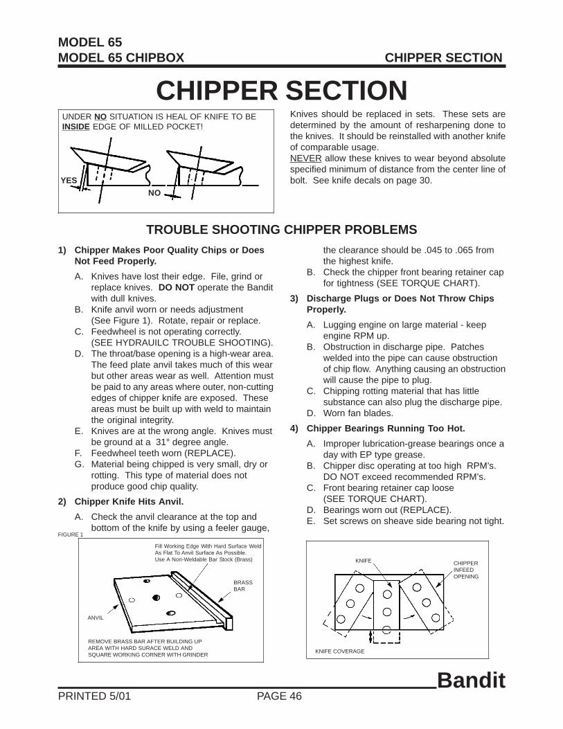
BanditPRINTED 5/01 PAGE 46
CHIPPER SECTIONKnives should be replaced in sets. These sets aredetermined by the amount of resharpening done tothe knives. It should be reinstalled with another knifeof comparable usage.NEVER allow these knives to wear beyond absolutespecified minimum of distance from the center line ofbolt. See knife decals on page 30.
TROUBLE SHOOTING CHIPPER PROBLEMS
1) Chipper Makes Poor Quality Chips or DoesNot Feed Properly.
A. Knives have lost their edge. File, grind orreplace knives. DO NOT operate the Banditwith dull knives.
B. Knife anvil worn or needs adjustment(See Figure 1). Rotate, repair or replace.
C. Feedwheel is not operating correctly.(SEE HYDRAUILC TROUBLE SHOOTING).
D. The throat/base opening is a high-wear area.The feed plate anvil takes much of this wearbut other areas wear as well. Attention mustbe paid to any areas where outer, non-cuttingedges of chipper knife are exposed. Theseareas must be built up with weld to maintainthe original integrity.
E. Knives are at the wrong angle. Knives mustbe ground at a 31° degree angle.
F. Feedwheel teeth worn (REPLACE).G. Material being chipped is very small, dry or
rotting. This type of material does notproduce good chip quality.
2) Chipper Knife Hits Anvil.
A. Check the anvil clearance at the top andbottom of the knife by using a feeler gauge,
the clearance should be .045 to .065 fromthe highest knife.
B. Check the chipper front bearing retainer capfor tightness (SEE TORQUE CHART).
3) Discharge Plugs or Does Not Throw ChipsProperly.
A. Lugging engine on large material - keepengine RPM up.
B. Obstruction in discharge pipe. Patcheswelded into the pipe can cause obstructionof chip flow. Anything causing an obstructionwill cause the pipe to plug.
C. Chipping rotting material that has littlesubstance can also plug the discharge pipe.
D. Worn fan blades.
4) Chipper Bearings Running Too Hot.
A. Improper lubrication-grease bearings once aday with EP type grease.
B. Chipper disc operating at too high RPM’s.DO NOT exceed recommended RPM’s.
C. Front bearing retainer cap loose(SEE TORQUE CHART).
D. Bearings worn out (REPLACE).E. Set screws on sheave side bearing not tight.
YES
NO
UNDER NO SITUATION IS HEAL OF KNIFE TO BEINSIDE EDGE OF MILLED POCKET!
Fill Working Edge With Hard Surface WeldAs Flat To Anvil Surface As Possible.Use A Non-Weldable Bar Stock (Brass)
BRASSBAR
ANVIL
REMOVE BRASS BAR AFTER BUILDING UPAREA WITH HARD SURACE WELD ANDSQUARE WORKING CORNER WITH GRINDER
KNIFE COVERAGE
KNIFE CHIPPERINFEEDOPENING
FIGURE 1
MODEL 65MODEL 65 CHIPBOX CHIPPER SECTION

BanditPRINTED 5/01 PAGE 47
MODEL 65MODEL 65 CHIPBOX LUBRICATION SECTION
LUBRICATION
HYDRAULIC OIL REQUIREMENTSThis machine is equipped with 10W-30 MOTOR OIL with a designation of SC, SA, or SE. Useonly MOTOR OILS with this designation. 10W-30 MOTOR OIL fits a range of operatingtemperatures: 0° Fahrenheit to 210° Fahrenheit.Cold temperatures require the motor oil to be properly warmed up at a low RPM. This is especiallytrue with live power hydraulic systems that operate the pump directly off the engine.Temperatures below 0° Fahrenheit require the use of 5W-20 MOTOR OIL.
ENGINE ........................................................... Follow original equipment manufacturers requirementsfor both changing oils and filters.
CLUTCH ..........................................................Follow original equipment manufacturers requirementsfor both greasing and adjusting. Frequently adjust, andgrease per PTO manufacturers manual.
HYDRAULIC RESERVOIR TANK .................. Completely change oil and flush tank anually.
Change hydrauilc oil suction screen every 400 hoursor 3 months.
Change hydraulic oil filter AFTER FIRST 10 HOURS OFOPERATION. Then change hydraulic oil filter every 400hours or 3 months thereafter. Maintain hydraulicoil level 7/8 full. See hydraulic oil requirements below.
Check hydraulic oil level in tank daily.
CHIPPER BEARINGS .................................... Purge chipper bearings!!! You can not over greasethese bearings, make sure all the old grease ispumped out. Do this daily. Use EP-2 Lithium grease.
FEEDWHEEL BEARINGS ............................. Grease daily with one shot of grease on each of the(2) bearings.
YOKE PIVOT BEARINGS .............................. Grease daily with one shot of grease on each of the(2) bearings.
DISCHARGE SWIVEL .................................... Grease swivel plates for discharge every 3 months.
HOOD HINGE ................................................. Make sure the hood hinge operates correctly, and islubricated. Must replace hinge if damaged.
PINTLE EYE RING ......................................... Keep greased to reduce wear and extend the normallife of your pintle eye ring.

BanditPRINTED 5/01 PAGE 48
2 Wire Main Cable Color Code
Black B (Hot)
White W (Ground)
4 Wire Main Cable Color Code
Black B (Hot)
White W (Ground)
Red R (Right Turn)
Green G (Left Turn)
6 Wire Main Cable Color Code
Black B (Hot)
White W (Ground)
Red R (Right Turn)
Green G (Left Turn)
Blue BL (Electric Brakes)
Orange OR (Breakaway Switch)
TYPICAL ELECTRICAL WIRING DIAGRAMS
TAIL LIGHT ASSEMBLYSTOP, TAIL, & TURN LIGHTS
BANDIT PART #’S
Bolt On Mount Rubber Housing900-2902-54
Push Out LensReplaceable #1157 Light Bulb
(Optional)Heavy Duty Tail Light Covers
980-0507-91
RIGHT TURN - RED WIRE
RT
S
GD
LT
TM
A
RUNNING LIGHTS - BLACK WIRE
GROUND - WHITE WIRE
ELECTRIC BRAKES - BLUE WIRE
LEFT TURN - GREEN WIRE
MODEL 65MODEL 65 CHIPBOX ELECTRICAL SECTION
BATTERY
BREAKAWAY SWITCH
BLACK
BLACK
TO BLUE WIREOF MAIN CABLE
WIRE MAIN CABLE6 62
22
J 42
W B
BL
RG
ELECTRICBRAKES
LICENSEPLATELIGHT
JUNCTION BOXWIRES SPLICED TOGETHERWHITE WIRES GROUNDED
J
ELECTRICBRAKES
BL
B
B
BW
B B
B B
R R
TO ORANGEWIRE OFMAIN CABLE
2
2
J
W B
BL
ELECTRIC BRAKESDUAL BRAKESFOR CHIPBOX
BL
BW
ELECTRIC BRAKESDUAL BRAKESFOR CHIPBOX

BanditPRINTED 5/01 PAGE 49
REPLACEMENT PARTS SECTION
Depending on what replacement parts you are orderingwe will need the following information:
CHIPPER COMPONENTSSerial Number
Model Number of Chipper
ENGINE COMPONENTSEngine Size
Engine Serial NumberEngine Spec. Number
CLUTCH COMPONENTSName of Manufacturer
Serial NumberAssembly Number of Clutch
Bandit Industries Inc. reserves the right to make changes in models, size,design, installations and applications on any part without notification.
MODEL 65MODEL 65 CHIPBOX REPLACEMENT PARTS

BanditPRINTED 5/01 PAGE 50
MODEL 65MODEL 65 CHIPBOX INFEED HOPPER COMPONENTS
20

BanditPRINTED 5/01 PAGE 51
MODEL 65MODEL 65 CHIPBOX INFEED HOPPER COMPONENTS
LOCATION PART NUMBER DESCRIPTION
1. 626-0500-38 Folding Pan Assembly For Infeed Hopper2. 900-4902-29 Bottom Yoke Spring Adjuster3. 900-4900-04 Feedwheel Tension Spring4. 900-4901-83 Spring Lock For Folding Pan5. 626-0000-52 Wooden Push Paddle6. 980-0122-55 Wodden Push Paddle Mount7. 900-1901-26 Feedwheel Bearing8. 900-1901-08 Yoke Pivot Bearing9. 626-0500-15 Top Yoke Assembly10. 900-4903-99 Feedwheel Coupler Pin11 a. 626-0001-69 Feedwheel Coupler (RS Motor - Tapered Shaft)
b. 626-0001-54 Feedwheel Coupler (RE Motor - Straight Shaft)12. 900-7900-38 Rubber Feedwheel Coupler Guard13. 980-0124-98 Feedwheel Torque Arm14. 900-3908-64 Feedwheel Hydraulic Motor15. 626-0500-25 Feedwheel Assembly16. 926-1001-62 Feedwheel Teeth17. 626-0001-80 Hydrauilc Control Arm18 a. 626-0001-12 Infeed Pan Pivot Pins
b. 900-4900-44 Jam Nuts19. 626-0500-39 Control Handle20. 626-0500-66 Last Chance Stop Cable Assembly21. 980-0126-15 Torque Arm Stop (Not Shown)
NOTE: Nuts, bolts, washers, and all other components can be ordered by physical description.

BanditPRINTED 5/01 PAGE 52
MODEL 65MODEL 65 CHIPBOX CHIPPER COMPONENTS
Knife Bolt Must Be Installed ThroughThe Knife Nut As Shown!!!
25

BanditPRINTED 5/01 PAGE 53
** Components vary with engine and disc options - order by physical description.NOTE: Nuts, bolts, washers, and all other components
can be ordered by physical description.
MODEL 65MODEL 65 CHIPBOX CHIPPER COMPONENTS
LOCATION PART NUMBER DESCRIPTION
1 a. 626-0500-69 Anvil Assembly (Eye Bolt - New Style)b. 626-0500-14 Anvil Assembly (2 Piece - Old Stlye)
2. 626-0001-47 Feedwheel Guard3 a. 900-4905-42 Bearing Retainer Bolt
b. 900-4900-32 Bearing Retainer Lockwasher4. 626-0001-71 Bearing Retainer5. 900-4901-19 Chipper Bearing Bolt6. 900-1904-13 Front Chipper Bearing7. 626-0000-66 Front Chipper Bearing Backer Plate8 a. 900-4901-04 Chipper Knife Bolt
b. 900-4900-27 Chipper Knife Nut9 a. 900-9902-02 1/2” X 4” X 7 1/4” Chipper Knife (New Style)
b. 900-9900-90 1/2” X 3” X 7 1/4” Chipper Knife (Old Style)10. 626-0500-68 Chipper Hood Hinged Half11. 626-0500-40 Chipper Hood Stationary Half12 a. 986-0501-98 Discharge Assembly (Model 65 - 77” Long - New Style)
b. 922-0500-03 Discharge Assembly (Model 65 - 63” Long - Old Style)c. 986-0501-85 Discharge Assembly Handcrank Swivel (Model 65 - 77” Long)d. 910-0500-34 Discharge Assembly (Model 65 Chipbox)
13. 980-0509-26 Discharge Deflector14. 980-4901-83 Deflector Height Adjuster Spring15. ** Chipper Sheave Bushing16. ** Engine Sheave Bushing17. ** Engine Sheave18. ** Chipper Belts19. ** Chipper Sheave20. 900-1903-30 Rear Chipper Bearing21. 926-1002-61 Rear Chipper Bearing Backer Plate22 a. 626-0500-46 2-Knife Disc Assembly With Fan Blades
b. 626-0500-47 3-Knife Disc Assembly With Fan Blades23 a. 626-0001-93 Disc Spacer 1/16”
b. 626-0001-94 Disc Spacer 1/8”c. 626-0001-95 Disc Spacer 3/16”d. 626-0001-96 Disc Spacer 1/4”
24. ** Belt Shield25 a. 980-0509-57 Chipper Hood Engine Disable Plug (6-Way Connector - New Style)
b. 980-0509-04 Chipper Hood Engine Disable Plug (4-Way Connector - Old Style)26. 981-1006-48 Hood Pin (Not Shown)

BanditPRINTED 5/01 PAGE 54
MODEL 65 HYDRAULIC COMPONENTS
TYPICAL MODEL 65 HYDRAULIC SCHEMATIC
1 2
3
4
5
7
P
TSol.
6
T
P
6 b.6 c.
6 a.

BanditPRINTED 5/01 PAGE 55
** Hydraulic components, fittings, hoses will very depending onoptional equipment. Order by physical description.
** Hydraulic pumps can be ordered by physical description.
MODEL 65 HYDRAULIC COMPONENTS
LOCATION PART NUMBER DESCRIPTION
1. 626-0500-73 Hydraulic Tank2. 900-3900-07 Hydraulic Tank Strainer3 a. 900-3900-10 Hydraulic Tank Filter
b. 900-3900-09 Hydraulic Tank Filter Mount4. 900-3909-89 Feedwheel Control Valve5 a. 900-3908-64 Hydraulic Motor RS-24 (Tapered Shaft)
b. 900-3907-14 Hydraulic Motor RE-24 (Straight Shaft)6 a. 900-3907-56 Autofeed Block W/Solenoid (No Main Relief)
b. 900-3908-21 Autofeed Cartridge Only (SV1-10-C-0-00)c. 30534 12 Volt Autofeed Solenoid Only
7 a. 900-3907-49 Hydraulic Pump 2-Knife Discb. 900-3905-23 Hydraulic Pump 3-Knife Disc
TYPICAL MODEL 65 HYDRAULIC COMPONENTS

BanditPRINTED 5/01 PAGE 56
MODEL 65 CHIPBOX HYDRAULIC COMPONENTS
TYPICAL MODEL 65 CHIPBOX HYDRAULIC SCHEMATIC
T
P
4 b.
4 a.
4 c.
1 2
3
5
6
11
P
TSol.
47
8
10
99

BanditPRINTED 5/01 PAGE 57
** Hydraulic components, fittings, hoses will very depending onoptional equipment. Order by physical description.
** Hydraulic pumps can be ordered by physical description.
MODEL 65 CHIPBOX HYDRAULIC COMPONENTS
TYPICAL MODEL 65 CHIPBOX HYDRAULIC COMPONENTS
LOCATION PART NUMBER DESCRIPTION
1. 922-0500-19 Hydraulic Tank2. 900-3900-07 Hydraulic Tank Strainer3 a. 900-3900-10 Hydraulic Tank Filter
b. 900-3900-09 Hydraulic Tank Filter Mount4 a. 900-3907-56 Autofeed Block W/Solenoid (No Main Relief)
b. 900-3908-21 Autofeed Cartridge Only (SV1-10-C-0-00)c. 30534 12 Volt Autofeed Solenoid
5. 900-3909-89 Feedwheel Control Valve6 a. 900-3908-64 Hydraulic Motor RS-24
b. 900-3907-14 Hydraulic Motor RE-247. 900-3905-44 Selector Valve8. 900-3901-42 Chipbox Lift Control Valve9. 900-3906-84 Quick Disconnect10. 900-3906-77 Chipbox Lift Cylinder11 a. 900-3907-49 Hydraulic Pump 2-Knife Disc
b. 900-3905-23 Hydraulic Pump 3-Knife Disc

BanditPRINTED 5/01 PAGE 58
MODEL 65 FRAME & ACCESSORY COMPONENTS

BanditPRINTED 5/01 PAGE 59
MODEL 65 FRAME & ACCESSORY COMPONENTS
LOCATION PART NUMBER DESCRIPTION
1 a. 900-5904-28 2” Ball Bolt On Hitch Single Position (Standard)b. 900-5901-46 2” Ball Coupler (Croft - Optional)c. 900-5901-45 2 1/2” Pintle Ring (Croft - Optional)
2 a. 626-0001-70 Battery Box Mountb. 900-7900-01 Plastic Strap On Battery Box (Not Shown)c. 986-0501-89 Locking Steel Battery Box (Not Shown - Optional)
3 a. 926-0500-66R Right Fender Assemblyb. 922-0500-26 H.D. Right Fender Assembly (Optional)
4. 900-2903-93 Flat Dial Sight Gauge For Fuel Tank5. 626-0500-71 Fuel Tank6. 626-0500-72 Fuel Tank Mount7 a. 900-5902-84 530 X 12” Tire
b. 900-5901-58 530 X 12” Rimc. 900-5901-57 530 X 12” Rim And Tired. 900-5903-08 185 X 14” Tire (Optional)e. 900-5903-06 185 X 14” Rim (Optional)f. 900-5903-09 185 X 14” Rim And Tire (Optional)
8 a. 900-5902-45 2200 LBS No Brake Axleb. 900-5902-46 3500 LBS No Brake Axle (Optional)c. 900-5902-47 3500 LBS Electric Brake Axle (Optional)
9. 900-2903-93 Flat Dial Sight Gauge For Hydraulic Tank10. 626-0500-73 Hydraulic Tank11. 626-0500-74 Hydraulic Tank Mount12 a. 900-5903-79 2000 LBS Pivoting Tongue Jack
b. 900-5900-78 1000 LBS Castor Wheel Tongue Jack13 a. 626-0500-41 Safety Chain Kit
b. 626-0500-42 Safety Chain Kit With Hydraulic Surge (Optional)14 a. 926-0500-66L Left Fender Assembly
b. 922-0500-27 H.D. Left Fender Assembly
** Order Brake Hub And Drum Assembly According To Axle Type.(Grease Type, Oil Type, Never Lube Type).
NOTE: Nuts, bolts, washers, and all other components can be ordered by physical description.
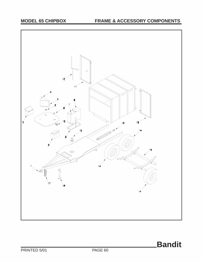
BanditPRINTED 5/01 PAGE 60
MODEL 65 CHIPBOX FRAME & ACCESSORY COMPONENTS

BanditPRINTED 5/01 PAGE 61
MODEL 65 CHIPBOX FRAME & ACCESSORY COMPONENTS
** Order Brake Hub And Drum Assembly According To Axle Type.(Grease Type, Oil Type, Never Lube Type).
NOTE: Nuts, bolts, washers, and all other components can be ordered by physical description.
LOCATION PART NUMBER DESCRIPTION
1 a. 900-5900-13 2 1/2” Heavy Duty Pintle Ring Hitchb. 900-5900-71 3” Heavy Duty Pintle Ring Hitchc. ** Other Hitch Options Available
2. 986-0501-94 Metal Tool Box3 a. 986-0501-97 Metal Battery Box (For 460 CCA Battery & Manual Holder)
b. 980-0509-37 Metal Battery Box (For 660 CCA Battery & Manual Holder)c. 900-9901-81 Manual Holder (Not Shown)
4. 900-2903-93 Hydraulic Tank Flat Dial Sight Gauge5. 626-0500-73 Hydraulic Tank Assembly6. 900-1903-01 Turntable Roller Bearing7. 900-2903-93 Fuel Tank Flat Dial Sight Gauge8. 626-0500-71 Fuel Tank Assembly9. 626-0500-72 Fuel Tank Mount10. 900-5904-15 Turntable Spindle And Hub Assembly11. 910-0500-31 Curb Side Door Assembly12. 910-0500-32 Door Lock Handle Assembly13. 910-0500-30 Road Side Door Assembly14 a. 900-5904-20 Tire And White Spoked Rim
b. 900-5904-40 Tire And Black Spoked Rimc. 900-5904-18 245/75R X 16”, 10-Ply Rated Tire Onlyd. 900-5904-22 White Spoked Rim Onlye. 900-5904-19 Black Spoked Rim Only
15 a. 900-RC05-16 7,000 LBS. Electric Brake Tandem Axleb. 900-5904-54 7,000 LBS. Hydraulic Brake Tandem Axle (Optional)
16. 900-5903-86 5,000 LBS. Foot Pad Tongue Jack17. 980-0508-83 Safety Chains With Latches18. 900-3906-77 Chipbox Hydraulic Lift Cylinder19. 900-3901-42 Chipbox Lift Cylinder Control Valve

BanditPRINTED 5/01 PAGE 62
MODEL 65MODEL 65 CHIPBOX PTO CHIPPER COMPONENTS
1
2
3
45
67
8
9
10
11
12
13

BanditPRINTED 5/01 PAGE 63
MODEL 65MODEL 65 CHIPBOX PTO CHIPPER COMPONENTS
2-Knife PTO 3-Knife PTOLOCATION PART NUMBER PART NUMBER DESCRIPTION
1. 626-0500-28 626-0500-28 Hinged Hood2. 900-3900-12 900-3900-12 Hydraulic Control Valve3. 900-3905-23 900-3905-06 Hydraulic Pump4. 900-1905-53 900-1906-92 Hydraulic Pump Sheave5. 900-1901-13 900-1901-13 Pump Bushing6. 900-1901-08 900-1901-08 P.T.O. Bearing7. 980-0110-21 980-0110-21 P.T.O. Shaft 1 3/8” Diameter8. 910-1902-27 910-1902-27 Drive Shaft Bushing9. 910-1902-22 910-1902-22 Power (Drive) Sheave10. 900-1902-65 900-1902-65 Chipper Sheave Bushing11. 900-1902-64 900-1902-64 Chipper Sheave12. 900-1903-30 900-1903-30 Rear Chipper Bearing13. 626-0500-29 626-0500-29 Discharge Hood14. 626-0500-31 626-0500-32 Chipper Disc (Not Shown)15 a. 900-9902-02 900-9902-02 1/2” X 4” X 7 1/4” Chipper Knife (New Style - Not Shown)
b. 900-9900-90 900-9900-90 1/2” X 3” X 7 1/4” Chipper Knife (Old Style - Not Shown)16. 900-1905-51 900-1905-51 Chipper Belt (Not Shown)17. 900-1905-49 900-1905-49 Pump Belt (Not Shown)
NOTE: Nuts, bolts, washers, and all other components can be ordered by physical description.

BanditPRINTED 5/01 PAGE 64
MODEL 65MODEL 65 CHIPBOX FEEDWHEEL COUPLER SECTION
PROPER PROCEDURE FOR INSTALLATION AND REMOVALOF J.B. COUPLER AND TAPERED FEEDWHEEL MOTOR
A. Proper Equipment Needed:
1. Feedwheel motor with tapered shaft. 5. Emery cloth and/or a file.2. 3/16” x 3/16” x 3/4” long key for RS motor. 6. A degreaser agent.3. Correct feedwheel shaft, coupler and taper 7. Pack nut.
pin assembly. 8. Hammer.4. Loctite-271. 9. Torque wrench and
1 3/16” socket RS motor
B. Installation Procedure1. Remove any sharp edges on the coupler bores or the motor shaft.
Example: Emery cloth or file for burrs on keyways or shafts.2. Clean the coupler bores and motor shaft with a degreasing solvent.3. Install the correct key in the feedwheel motor shaft.4. Slide the coupler onto the motor shaft, making sure that the two mate tightly.
Example: The coupler does not rock or slop on the shaft.5. Install the pack nut with Loctite-271 on the threads.6. Tighten to the correct torque of 150-170 ft. lbs.7. Slightly tap with a hammer on the coupler face to insure proper seating.8. Re-torque pack nut.9. Deburr and degrease the feedwheel shaft.10. Install the motor and coupler assembly onto the feedwheel shaft.11. Install the correct tapered pin through the coupler and feedwheel motor.12. Hammer the pin into the coupler to secure the coupler and feedwheel shaft.
PRESS TOOL FOR COUPLER PIN REMOVAL CAUTION! Always wear proper safety equipment and take caution withtapered pin when attempting to remove. The use of this tool will assist inthe removal of tapered pin in feedwheel coupler. Lubricate end of bolt andthreads with grease. Position the press tool so that it cradles the coupler,
with the large end of the tapered pin at the side opposite the press bolt. You may want to remove yoke springsto get easier access to coupler. Set the tool as described and hand tighten press bolt to snug tool againstcoupler. Make sure press bolt is set on small end of tapered pin, and that pin will go thru hole in tool withoutinterference. Use of a 1/2” impact wrench is recommended. Run impact on bolt to start pin removal, thenusually a good hit with hammer on the end of bolt will knock out the pin. You may have to run impact on bolt andhit with hammer a few times to remove pin.
HAMMER FIT TAPER PIN SECURE IN PLACE
COUPLER
HYDRAULICMOTORFEEDWHEEL
SHAFT
NO LOCTITEBUT SURFACECLEAN AND DRY NO LOCTITE BUT SURFACE
CLEAN AND DRY
TORQUE & THREAD LOCTITE NUTS“RS” MOTORS = 150-170 FT/LBS TORQUE
PRESSTOOL
PRESSBOLT
COUPLERPIN
COUPLER