electromen dc brush motor speed controllers
64
TECHNICAL SPECIFICATIONS ELECTROMEN DC BRUSH MOTOR SPEED CONTROLLERS
-
Upload
khangminh22 -
Category
Documents
-
view
2 -
download
0
Transcript of electromen dc brush motor speed controllers

TECHNICAL SPECIFICATIONS
ELECTROMEN DC BRUSH MOTOR SPEED CONTROLLERS

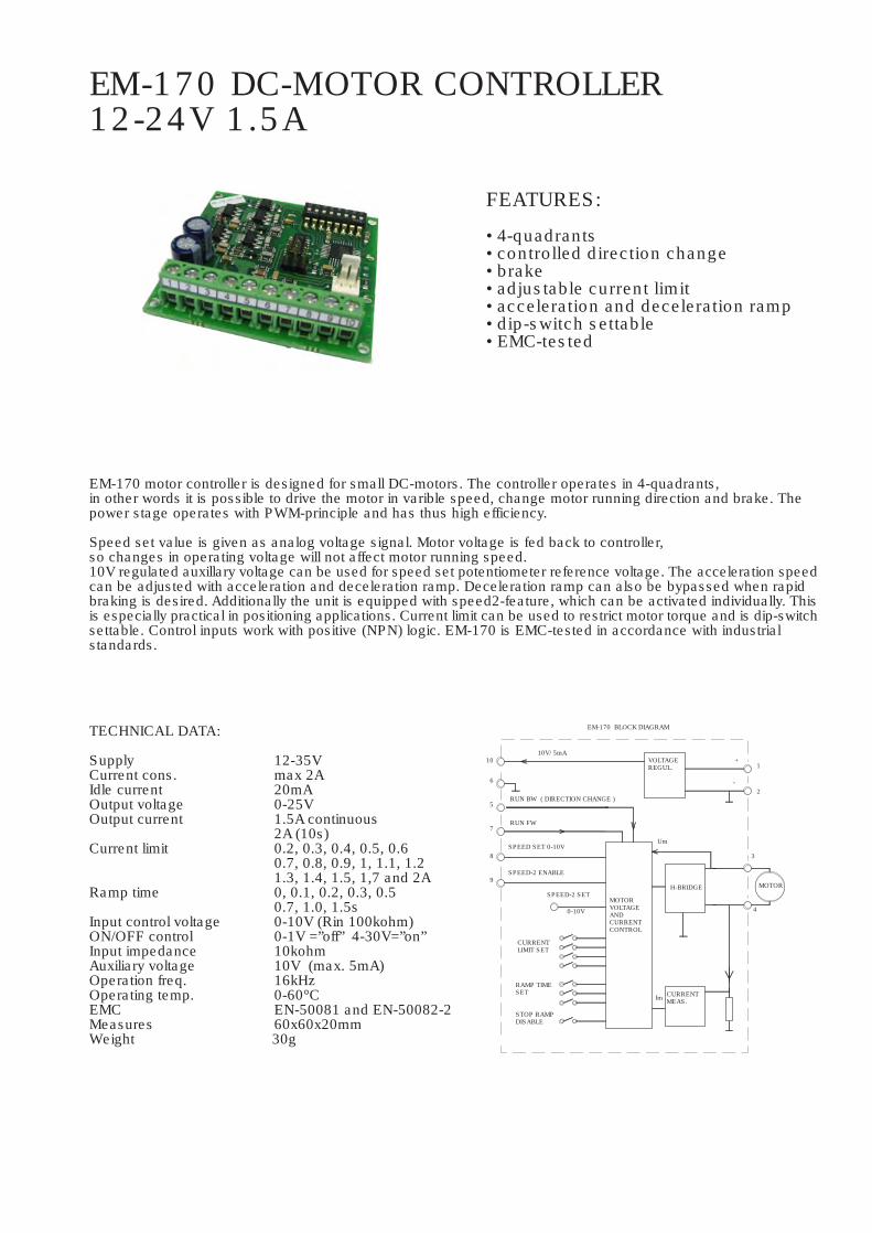
EM-170 motor controller is designed for small DC-motors. The controller operates in 4-quadrants,in other words it is possible to drive the motor in varible speed, change motor running direction and brake. Thepower stage operates with PWM-principle and has thus high efficiency.
Speed set value is given as analog voltage signal. Motor voltage is fed back to controller,so changes in operating voltage will not affect motor running speed.10V regulated auxillary voltage can be used for speed set potentiometer reference voltage. The acceleration speedcan be adjusted with acceleration and deceleration ramp. Deceleration ramp can also be bypassed when rapidbraking is desired. Additionally the unit is equipped with speed2-feature, which can be activated individually. Thisis especially practical in positioning applications. Current limit can be used to restrict motor torque and is dip-switchsettable. Control inputs work with positive (NPN) logic. EM-170 is EMC-tested in accordance with industrialstandards.
TECHNICAL DATA:
Supply 12-35VCurrent cons. max 2AIdle current 20mAOutput voltage 0-25VOutput current 1.5A continuous
2A (10s)Current limit 0.2, 0.3, 0.4, 0.5, 0.6
0.7, 0.8, 0.9, 1, 1.1, 1.21.3, 1.4, 1.5, 1,7 and 2A
Ramp time 0, 0.1, 0.2, 0.3, 0.50.7, 1.0, 1.5s
Input control voltage 0-10V (Rin 100kohm)ON/OFF control 0-1V =”off” 4-30V=”on”Input impedance 10kohmAuxiliary voltage 10V (max. 5mA)Operation freq. 16kHzOperating temp. 0-60°CEMC EN-50081 and EN-50082-2Measures 60x60x20mmWeight 30g
FEATURES:
• 4-quadrants• controlled direction change• brake• adjustable current limit• acceleration and deceleration ramp• dip-switch settable• EMC-tested
EM-170 DC-MOTOR CONTROLLER12-24V 1.5A
10
CURRENTMEAS.
H-BRIDGESPEED-2 SET
0-10V
STOP RAMPDISABLE
RAMP TIMESET
CURRENTLIMIT SET
MOTORVOLTAGEANDCURRENTCONTROL
Im
RUN BW ( DIRECTION CHANGE )
10V/ 5mA
9
8
7
5
6
SPEED-2 ENABLE
SPEED SET 0-10V
RUN FW
VOLTAGEREGUL.
Um
EM-170 BLOCK DIAGRAM
4
MOTOR
3
-
+1
2

EXAMPLE 2
Speed set with voltage 0-10V.Speed-2 set with external trimmer.Controls using 4-30Vdc signal.
SPEE
D-2
CONTROL VOLTAGE
SETTINGS AND CONNECTING UNIT
Switch off power before connecting motorand power supply to EM-170. Prepare thecontrol circuit. Set current limit andramp time according to application.
Control input value 0-10V correspond tomotor output 0-25V, so with a supply of 12V0-5V will output 0-12.5V.Speed-2 set value is connected to molex-connector. Scale is the same as withspeed-1. If speed-2 feature is notrequired, this potentiometer can simplybe left out. Recommended speed controlpotentiometer value is 2..50kohm forboth speed-1 and speed-2.
Control inputs can be used with switches,analog voltage or NPN outputs of a logic.A voltage signal greater than 4V is logic 1,maximum input voltage 30V.Forward input will start up the motor in forwarddirection.Reverse input will start up the motor in reversedirection. When motor is already running forward,direction will change.Speed-2 will set the running speed according to input signal in molex connector. Notice:Speed-2 input will start up the motor in forwarddirection even if no other inputs are activated.
Control voltage and speed set value are inreference with 0V gnd potential (pin6).
EXAMPLE 1
Speed set with potentiometer.Speed-2 set with external trimmer.Controls using switches.
control voltage / motor voltage
GND
0V
REVE
RSE
FORW
ARD
65 7 8
+10V
SPEE
D-2
9 10
GND
0V
REVE
RSE
FORW
ARD
5 6 7 8
EM-170 OPERATING INSTRUCTIONS
Supply filtered 12-35VDC withripple < 20% with full loadd.CAUTION ! reverse polarity can damage the unitCAUTION ! no internal fuse-
current limit / Adip-switches 1-4
0.2 0.3 0.4
0.5
0.6
0.7
0.8
0.9
1
1.1
1.2
1.3
1.4
1.5
1.7
2
ramp time / sdip-switches 5-7
0
0.1 0.2 0.3 0.5 0.7 1.0 1.5
dip-switch 8
"off" = decel. ramp OFF
"on" = decel. ramp ON
9 10
EM-170
56mm
60mm
3.2mm
+24V
NOTE. With one shuntvalues will be halved.
fuse
offon
0V DIRE
CTIO
N
60mm
height 25mm
30mm
Shunt resistors
10Vn20
RUN
/ STO
P
0V G
ND 10V
SPEE
D-2
SPEE
D-1
molex-connector
speed-2
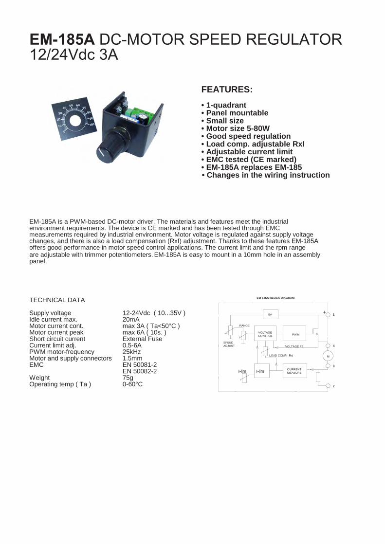
EM-185A DC-MOTOR SPEED REGULATOR12/24Vdc 3A
FEATURES:
• 1-quadrant• Panel mountable• Small size• Motor size 5-80W• Good speed regulation• Load comp. adjustable RxI• Adjustable current limit• EMC tested (CE marked)• EM-185A replaces EM-185
TECHNICAL DATA
Supply voltage 12-24Vdc ( 10...35V )Idle current max. 20mAMotor current cont. max 3A ( Ta<50°C )Motor current peak max 6A ( 10s. )Short circuit current External FuseCurrent limit adj. 0.5-6APWM motor-frequency 25kHzMotor and supply connectors 1.5mmEMC EN 50081-2
EN 50082-2Weight 75gOperating temp ( Ta ) 0-60°C
EM-185A is a PWM-based DC-motor driver. The materials and features meet the industrialenvironment requirements. The device is CE marked and has been tested through EMCmeasurements required by industrial environment. Motor voltage is regulated against supply voltagechanges, and there is also a load compensation (RxI) adjustment. Thanks to these features EM-185Aoffers good performance in motor speed control applications. The current limit and the rpm rangeare adjustable with trimmer potentiometers. EM-185A is easy to mount in a 10mm hole in an assemblypanel.
VOLTAGE FB
CURRENTMEASUREI-lim
RANGE
SPEEDADJUST
I-lim
LOAD COMP. RxI
VOLTAGECONTROL PWM
5V
3
2
M
4
1+
EM-185A BLOCK DIAGRAM
• Changes in the wiring instruction

EM-185A OPERATING INSTRUCTIONS
Supply should be filtered 10-35Vdc,max. ripple <20% on full load.
Current limit (I-lim) limits the motor current, in otherwords the motor torque. This adjustment is setaccording to the motor nominal current or withinapplication.
RxI is always set to minimum in the beginning.After this set a motor rpm of 20-30%, slowlyincrease the compensation and try loading themotor simultaneously. When motor rpm is nolonger affected by the loading, the compensationadjustment is in balance. If motor starts to twitch oraccelerate when loading is applied, there is toomuch compensation.
I-lim.
12-2
4V
38.0mm
RANGE
0V
321
M
4
2.0mm
37.0
mm
RxI 10.0mm
30.0mm
16.0mm
5.0m
m
37.0
mm
Potentiometer position / Motor voltage
0% = potentiomer full counter clockwise100% = potentiometer full clockwise
Range is adjustable with range trim
Potentiometer position / %
10
00
5
15
20
17 6735 50
RxI
I-lim./ A
Um/V
29
25
30
2 1
40.7
0.5
3
6
min max
max. range
85 100
min. range
We recomended the use of fuse for supplyline. Fuse max 6.3A
Fuse max 6.3A
mt18
Text Box
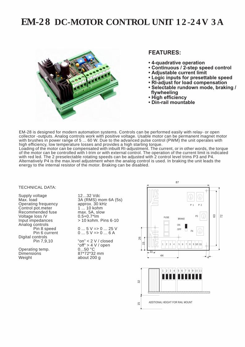
EM-28 DC-MOTOR CONTROL UNIT 12-24V 3A
EM-28 is designed for modern automation systems. Controls can be performed easily with relay- or opencollector -outputs. Analog controls work with positive voltage. Usable motor can be permanent magnet motorwith brushes in power range of 5 ... 60 W. Due to the advanced pulse control (PWM) the unit operates withhigh efficiency, low temperature losses and provides a high starting torque.Loading of the motor can be compensated with inbuilt RI-adjustment. The current, or in other words, the torqueof the motor can be controlled with I-trim or with external control. The operation of the current limit is indicatedwith red led. The 2 preselectable rotating speeds can be adjusted with 2 control level trims P3 and P4.Alternatively P4 is the max.level adjustment when the analog control is used. In braking the unit leads theenergy to the internal resistor of the motor. Braking can be disabled.
FEATURES:• 4-quadrative operation• Continuous / 2-step speed control• Adjustable current limit• Logic inputs for presettable speed• RI-adjust for load compensation• Selectable rundown mode, braking / flywheeling• High efficiency• Din-rail mountable
TECHNICAL DATA:
Supply voltage 12...32 VdcMax. load 3A (RMS) mom 6A (5s)Operating frequency approx. 30 kHzControl pot.meter 1 ... 10 kohmRecommended fuse max. 5A, slowVoltage loss /V 0.5+0.7*Im Input impedances > 10 kohm. Pins 6-10Analog controls
Pin 8 speed 0 ... 5 V => 0 ... 25 VPin 6 current 0 ... 5 V => 0 ... 6 A
Digital controlsPin 7,9,10 “on” < 2 V / closed
“off” > 4 V / openOperating temp. 0...50 °CDimensions 87*72*32 mmWeight about 200 g
87
ADDTIONAL HEIGHT FOR RAIL MOUNT
5 6 7 8 9
5 6 7 8 9
ON
OFF
BRAKE
1 2 3 4
FUSE
1 2 3 4
1 0 1 1
P 1 P 2
P4
P3
4411
1526
4
63 72
10 11
3215

EM-28 OPERATING AND CONNECTION INSTRUCTIONS
INTRODUCTIONAlways disconnect supply before making connections. Operating voltage must be filtered DC-voltage with lessthan 25 % ripple at full load.
ADJUSTMENTSSet all trims to the middle position. With analog control the maximum running speed is set with trim P4. Whenusing the 2-step speed adjustment set the “fast” speed on (pin 9). Adjust the running speed to desired value withtrim P4. Then change to the “slow” speed on (pin 10) and adjust the running speed to desired value with trim P3.
The current limit adjustment is linear between 0 ... 6 A. The set value can be approximately determined from theposition of the trim. When more precise adjustment is needed a current meter must be connected to motor circuit.The operation of the current limit is indicated with red led light. During the load compensation adjustment (P1)the load of the motor should be adjusted while observing the speed changes of the motor running speed. Thecompensation can be increased to point where the motor starts to twitch. Twitching is a sign of overcompensation. The compensation adjustment has a slight effect on the running speed settings. _
“FAST" IS SET WITH TRIM P4“SLOW" IS SET WITH TRIM P3
5 6 7 8 9
TRIM P2 TO POSITION MIN
ADJUSTMENT OF TORQUE(CURRENT) WITH POTENTIOMETER
WITH SELECTION CONTACT
5 6 7 8 9
SELECTION OF PRESET SPEED
POTENTIOMETER 1...10 kohm
max.
max.
max.
“RESVERSE” CLOSE OR VOLTAGE < 2 V
MAX. SET WITH TRIM P4
WITH POTENTIOMETER
1 0 11
1 0 11
“FORWARD” OPEN OR VOLTAGE > 4 V
POT 1...10kohm
5 6 7 8 9
DIRECTION SHIFT
SPEED ADJUSTMENT
5 6 7 8 9
SPEED“FAST”“
ADJUSTMENTS
P1 LOAD COMPENSATION
P3 PRESETTABLE SPEED “SLOW”
P4 PRESETTABLE SPEED “FAST”OR MAX. LEVEL LIMIT
P2 CURRENT LIMIT (IF NO EXT. CONTROL)
CONNECTION OF MOTORAND SUPPLY
1 2 3 4
-M
+
+ --
min.
min.
0
min.
6A
CONTROL 0...5 V
CONTROL 0 ... 5 VMAX. SET WITH TRIM P4
5 6 7 8 9
ADJUSTMENT OF TORQUEWITH VOLTAGE SIGNAL
5 6 7 8 9
SPEED ADJUSTMENTWITH VOLTAGE SIGNAL
Uin
1 0 11
SPEED“SLOW
10 11
-
Uin-
+
1 0 11
+
1 0 11
CONNECTIONS
1 MOTOR - (MINUS)2 SUPPLY VOLTAGE 12 ... 32 V3 MOTOR + (PLUS)4 SUPPLY VOLTAGE (GND)5 CONTROL VOLTAGE 0V (GND)6 CURRENT LIMIT INPUT7 DIRECTION CHANGE8 SPEED CONTROL INPUT9 SELECTION OF PRESET SPEED (FAST)10 SELECTION OF PRESET SPEED (SLOW)11 +5.5 V REFERENCE OUTPUT MAX. 50 mA
TRIM P2 TO POSITION MIN.

EM-67 DC-MOTOR CONTROLLER 24V 3A
EM-67 DC-motor controller is designed for 24V permanent magnet motors with brushes in the power range of5-70W (0,2-3A). Due to advanced PWM-controlling the unit runs with high efficiency and low thermal loss. Thebraking energy is fed to a power resistor.
The output voltage of the unit is regulated so that changes in supply voltage won’t affect the motor speed.Additionally the unit has RI-compensation, that can be used to minimize motor speed changes in changingloading situations.The required amount of RI-compensation depends on the motor used and is set with a trim. With this feature,a good motor speed versus control voltage ratio can be reached. Speed adjustment can be made withpotentiometer or voltage signal. Alternatively the unit can also be used in two speed mode. In this case thespeeds are set with trimmers on the card, and activation is done with switch or control voltage. The unit givesadditional 10V for potentiometer and control switches.
Acceleration / braking ramp can be adjusted depending on the situation, this feature gives controlled andsmooth direction change. Direction change can be controlled with either switch or control voltage.The psupply inputos protected against overcurrent and reversed polarity using a self recovery fuse. EM-67 isEMC-tested and meets heavy industry standards.
FEATURES:• Direction change• Braking• Continuous / 2-step speed control• Adjustable acceleration / braking ramp• Adjustable current limit• Adjustable load compensation• Supply voltage variation compensated• High efficiency• Self recovery fuse• Rail mountable
TECHNICAL DATA:
Supply 20...34 VdcIdle current approx. 40mAControl voltage 0...5V / 0...10VControl current 3A rms / 5A momControl power 70W rmsBraking power 30W (1/10 duty cycle)Voltage loss 1V @ Im=3ACurrent limit 0.2...5AFuse 3A self recoveryRamp 0.5...10sControl potentiometer 1...10kohmDigital control “on” @ Uin=4...30V
“off” @ Uin=0...1V or openEMC-testing EN 50081-2 & 50082-2Dimensions 65x72x30mmWeight approx. 70g
CONTROLLOGIC
REVERSE
FORWARDor
EM-67 BLOCK DIAGRAM
CONTROL VOLTAGE
I-LIM.
IR-COMP.
ACTIVATE SPEED-2
RUN/STOP
CONTROL GND
SPEED SCALEOR SPEED-1
SPEED SET
REVERSE RUN
10V 10mA
8
9
6
7
5
10
RAMP
SPEED-2
CURRENTMEAS.
3A PTC FUSE
STAGE
VOLTAGEMEAS.
POWER
POWERREGUL.
MOTOR
4
3
SUPPLYIN
1+
-2

EM-67 OPERATING AND CONNECTION INSTRUCTIONS
Supply voltage must be DC-voltage 20...34V(recommended 26...32V) with less than 20% ripple.At first set all trims to the middle position, except P5in the minimum position.
ADJUSTMENTS
P1 RAMPUse trim to set acceleration and braking ramp.Adjustment range is 0.5...10s.
P2 SPEED SET FOR SPEED2Use trim to change the preset value of speed2.Adjustment range is 0...100%.
P3 CURRENT LIMITUse trim to set the maximum current of the motor. Ared light indicates the activation of the current limit.Adjustment range is 0.2...5A
P4 CONTROL RANGEUse trim to set the desired control range. Theminimum range is 0...5V and maximum 0...50V.Also used for speed1 without potentiometer.
P5 LOAD COMPENSATION (RI)Use trim to compensate the load affecting the motorspeed. Compensation level can be increased untilthe motor starts to twitch. Set the initial value to theminimum.
6
1. Supply 20-34Vdc2. Supply GND 0V3. Motor (-)4. Motor (+)5. Control GND 0V
3
+ -
1 2 4 5
+M-
I-LIM.
RED LEDDETECT.
P10.5s
5s
10s.
87
P4MAX.
9 10
P5MAX.
MIN.
P2
MIN.
P30.2A
MIN.
MAX.
2.5A
5A
6. Speed control input7. Direction change +run8. Run / Stop.9. Switch preset speed210. Additional voltage 10V 10mA
65 mm
58.5 mm
66 m
m
72.5
mm
Speed set using potentiometer,activation using run/stop switch.
75 6 108 9
Direction change can be addedto following examples if needed.Note that direction change alsostarts the motor.
75 6 108 9
Speed set using voltage signal.
U-cont. 0-5V... 0-50V
5 6 7 1098
U-cont. forward 0...1Vbackwards 4...30V
Direction change using controlvoltage. Can be used with otherexamples if needed.
5 6 7 8 9 10
85 6 7 109
Speed set using potentiometer.Scale range with trim P4.
Two speed mode.Speeds are set using trimsP2 (pin9) and P4 (pin6).Activation using switches.
85 6 7 109
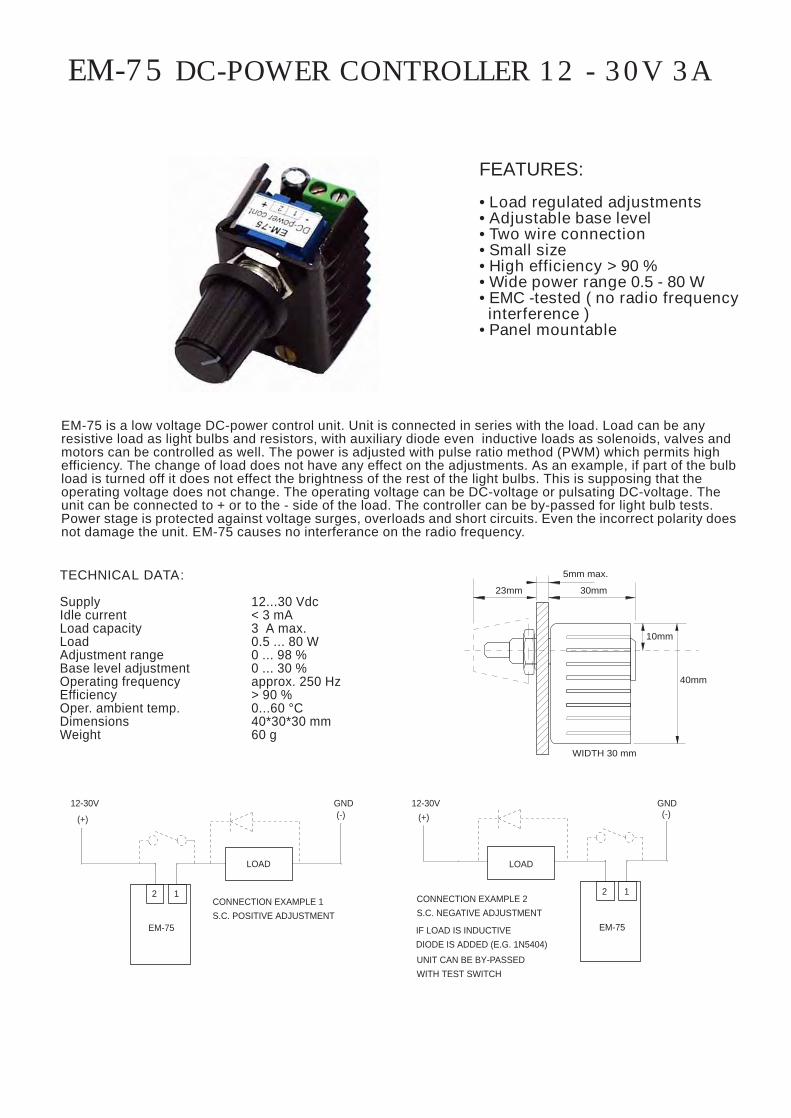
EM-75 DC-POWER CONTROLLER 12 - 30V 3A
TECHNICAL DATA:
Supply 12...30 VdcIdle current < 3 mALoad capacity 3 A max.Load 0.5 ... 80 WAdjustment range 0 ... 98 %Base level adjustment 0 ... 30 %Operating frequency approx. 250 HzEfficiency > 90 %Oper. ambient temp. 0...60 °CDimensions 40*30*30 mmWeight 60 g
EM-75 is a low voltage DC-power control unit. Unit is connected in series with the load. Load can be anyresistive load as light bulbs and resistors, with auxiliary diode even inductive loads as solenoids, valves andmotors can be controlled as well. The power is adjusted with pulse ratio method (PWM) which permits highefficiency. The change of load does not have any effect on the adjustments. As an example, if part of the bulbload is turned off it does not effect the brightness of the rest of the light bulbs. This is supposing that theoperating voltage does not change. The operating voltage can be DC-voltage or pulsating DC-voltage. Theunit can be connected to + or to the - side of the load. The controller can be by-passed for light bulb tests.Power stage is protected against voltage surges, overloads and short circuits. Even the incorrect polarity doesnot damage the unit. EM-75 causes no interferance on the radio frequency.
FEATURES:
• Load regulated adjustments• Adjustable base level• Two wire connection• Small size• High efficiency > 90 %• Wide power range 0.5 - 80 W• EMC -tested ( no radio frequency interference )• Panel mountable
CONNECTION EXAMPLE 1S.C. POSITIVE ADJUSTMENT
GND12-30V
(+)
2 1
EM-75
(-)
LOAD
CONNECTION EXAMPLE 2S.C. NEGATIVE ADJUSTMENT
12-30V(+)
GND
12
EM-75
(-)
LOAD
IF LOAD IS INDUCTIVEDIODE IS ADDED (E.G. 1N5404)
UNIT CAN BE BY-PASSEDWITH TEST SWITCH
WIDTH 30 mm
5mm max.
30mm23mm
10mm
40mm
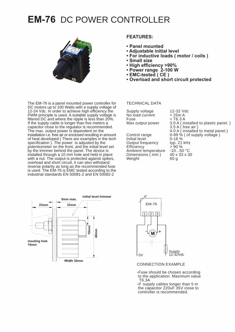
EM-76 DC POWER CONTROLLER
FEATURES:
• Panel mounted• Adjustable initial level• For inductive loads ( motor / coils )• Small size• High efficiency >90%• Power range 2-100 W• EMC-tested ( CE )• Overload and short circuit protected
The EM-76 is a panel mounted power controller forDC motors up to 100 Watts with a supply voltage of12-24 Vdc. In order to achieve high efficiency thePWM principle is used. A suitable supply voltage isfiltered DC and where the ripple is less than 20%.If the supply cable is longer than five meters acapacitor close to the regulator is recommended.The max. output power is dependent on theinstallation i.e. free air or enclosed resulting in amountof heat developed ( There are examples in the techspecification ). The power is adjusted by thepotentiometer on the front, and the initial level setby the trimmer behind the panel. The device isinstalled through a 10 mm hole and held in placewith a nut. The output is protected against spikes,overload and short circuit, it can also withstandreverse polarity as long as the recommended fuseis used. The EM-76 is EMC tested according to theindustrial standards EN 50081-2 and EN 50082-2
TECHNICAL DATA
Supply voltageNo load currentFuseMax output power
Control rangeInitial levelOutput frequencyEfficiencyAmbient temperatureDimensions ( mm )Weight
12-32 Vdc< 25m A< T6.3 A3.0 A ( installed to plastic panel. )3.5 A ( free air )4.0 A ( installed to metal panel.)0-99 % ( of supply voltage )0-16 %typ. 21 kHz> 90 %-10...50 °C40 x 33 x 3060 g
0V
++-- M
1 32
EM-76
Supply12-32Vdc
CONNECTION EXAMPLE
-Fuse should be chosen according to the application. Maximum value T6.3A-If supply cables longer than 5 m the capacitor 220uF 35V close to controller is recommended.
5mm max.
10mmmouting hole
23mm
Width 30mm
initial level trimmer
33mm
10m
m
40m
m

EM-101 DC-MOTOR CONTROLLER 24V 3A4-QUAD
FEATURES:
• 4-quadrant• Protection with self recovering fuse• Settable current limit• Settable acceleration/brake ramp• Load compensation• Special braking options• Supply voltage compensation• Continuous / 2-step speed controlling• Positive driving logic• Mounting with DIN-rail or screws• High efficiency
TECHNICAL DATA EM-101
Supply voltage 20-34VdcOver voltage protection 36VIdle current app. 50mAControl current 3A, mom. 4AControl power 70WCurrent limit 0,2...4.2AVoltage loss 1V when Im=3AFuse 3A, self recoveryRamp 0,5s...5sControl voltage 0-5V, 0-10VControl pot.meter 2...10kohmDigital control “on” when Uin 4-30V
“off” when Uin=0-1V or NCDimensions 89x73x26Weight app. 70g
EM-101 is designed for modern automation systems. Controls can be performed easily with relay- or open collector-outputs. Analog controls work with positive voltage. Usable motor can be permanent magnet motor with brushesin power range of 5 ... 70 W. Due to the advanced pulse control (PWM) the unit operates with high efficiency, lowtemperature losses and provides a high starting torque.Loading of the motor can be compensated with inbuilt RI-adjustment. The current, or in other words, the torqueof the motor can be controlled with DIP-switch. The operation of the current limit is indicated with a red led.There are a variety of braking options available in this device. For most effective braking “reverse braking”-modecan be used. In this mode reversed driving is used for braking, which effects extremely fast function. Additionallythe card utilises short circuit braking which short circuits the motor circuit during the braking.EM-101 also has inbuild settable time acceleration- and braking ramps.
EM-101 BLOCK DIAGRAM
IR-KOMP.
I-LIM.
REVERSEBRAKE TIME
Rk
Rbs
SPEED-2
RAMP.
RUN SPEED-2
RUN SPEED-1
SPEED SCALEOR SPEED-1
SPEED SET
REVERSE RUN
CONTROL GND
10V 5mA
8
9
6
10
7
5
CONTROLLOGIC
CONTROL VOLTAGE
REVERSE
FORWARDor
CURRENTMEAS.
3A PTC FUSE
VOLTAGEMEAS.
POWER STAGEH-BRIDGE
POWERREGUL.
+
4
MOTOR
3-
SUPPLYIN
1+
-2

CONNECTORS:
1. Supply voltage 20-34Vdc2. Supply voltage GND 0V3. Motor (-)4. Motor (+)5. Control GND6. Controlling voltage7. Reverse/driving direction8. Run speed1 (potentiometer)9. Run speed210. Helping voltage for potentiometer ( 10V, 5mA )
THE CURRENT LIMIT
Limitation of the current ( torque )Controlled with DIP-switches
on
0.9A
1.8A
2.0A
1.5A
1.2A
210A
0.5A
0.2A
3 4
3.1A
4.0A
4.2A
3.7A
3.4A
3212.3A
2.9A
2.6A
4
THE RAMP & BRAKING
In the map below the first two ramp settings are specialbraking options. The first position is so called reversebraking; the motor is controlled in opposite direction.Reverse braking time is set with resistor (rbs). The secondposition is so called short circuit braking where the motorcircuit is short circuited during the braking. Other positionsare for normal acceleration and braking settings which areset with DIP-switches.
MODULAR-6 CONNECTORRun speed2Run speed1 (potentiometer)Helping voltage for potentiometer ( 10V, 5mA )Reverse start/driving directionControling voltageControl GND OV
THE COMPENSATION
With compensation you can compensate the loadeffect to motor rpm. This feature increases controllingif current increases in the motor circuit. The needfor compensation depends on application and motor.Typically small motors require more compensationthan big ones. Over compensation occurs as twichingof the motor.
Example:The smaller resistor the bigger compensation.Typical settings: motor < 10W Rk= 50...500ohm
motor > 10W Rk= 200...2000ohm
THE CONTROLLING
The max value of controlling voltage ranges 5...10V. Thefull range is thus maintained on 0...5V. The range can beset with trim P1. When driving with double speed controlling( run / set ) the driving speed is set with trim P1 and thesetting speed with trim P2.
range 0-5V (0...100%)
range 0-10V (0...100%)P1 100%
0%
50%
0%
P2100%
50%
EM-101 INSTRUCTIONS
Supply voltage must be DC with ripple less than 20%. Supplyvoltage 20...34V ( 26...32V recommended ). In the beginningset all trimmers in the middle position.
NOTE! When reversed braking is used the controller will takea very high current peak. Capacitor for the power supplyshould be at least 4700uF at 1A.
Cr
POWERSOURCE
1+
MOTOR
2-
3 4+-
Opposite control braking, no ramp
Short circuit braking, no ramp
1on
4s. Ramp
5s. Ramp
1s. Ramp
2s. Ramp
3s. Ramp
0,5s. Ramp
32
t(ms) = (256 x Rbs) / (Rbs + 10kohm)Rbs max. 10 kohm. ( t = 256ms )Rbst min. 0,1kohm. ( t = n. 3ms )
REVERSE BRAKING TIMESET RESISTOR
COMPENSATION Rk
Rbs
MODULAR-6
RAMP
2
FUSET3A
1 32
SPEED-1 /POT. RANGE
64 5 7 8 9 10
ON
CURRENTLIMIT
OFF
P1
1 2 3 4
SPEED2
1
P2ON
OFF3
89 mm
66 m
m
73 m
m
82 mm
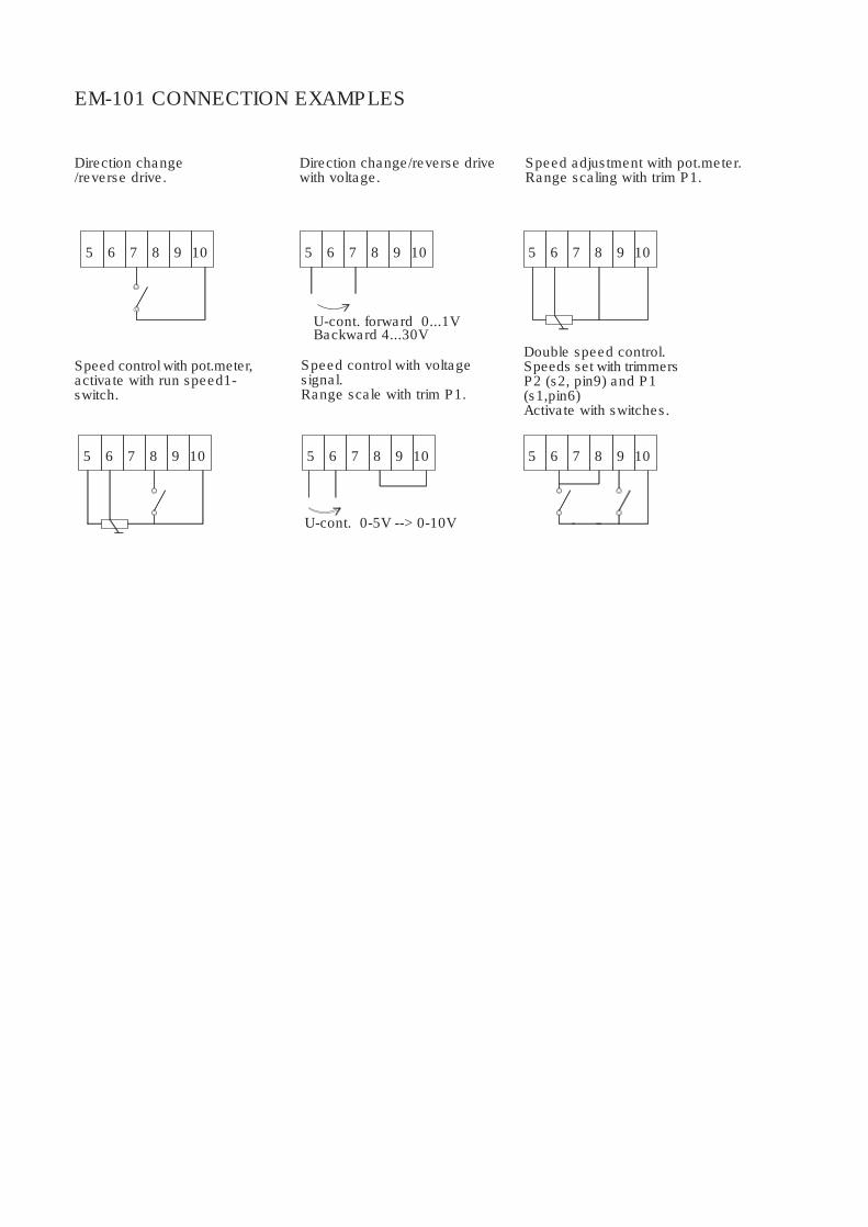
EM-101 CONNECTION EXAMPLES
Speed control with pot.meter,activate with run speed1-switch.
75 6 108 9
Direction change/reverse drive.
75 6 108 9
U-cont. 0-5V --> 0-10V
5 6 7 108 9
Speed control with voltagesignal.Range scale with trim P1.
Direction change/reverse drivewith voltage.
U-cont. forward 0...1VBackward 4...30V
5 6 7 98 10
85 6 7 9 10
Speed adjustment with pot.meter.Range scaling with trim P1.
Double speed control.Speeds set with trimmersP2 (s2, pin9) and P1(s1,pin6)Activate with switches.
85 6 7 9 10

CONTROL VOLTAGE
EM-101-BI MOTOR CONTROLLER 24V 4A 4-QUAD
FEATURES
- 4 Quadrants- Self recovery fuse- Adjustable current limit- Adjustable accel./braking ramp- Load compensation- Special braking options- Supply voltage compensation- Speed control ±10V ( ±5V )- Positive control logic- Mounting with DIN-rail or screws- High efficiency
EM-101-BI is designed for modern automation systems. Controls can be performed easily with relay- or open collectoroutputs. Analog controls work with ±10V voltage. Usable motor can be permanent magnet motor with brushesin power range of 5...80 W. Due to the advanced pulse control (PWM) the unit operates with high efficiency, lowtemperature losses and provides a high starting torque.Loading of the motor can be compensated with inbuilt RI-adjustment. The current, or in other words, the torqueof the motor can be controlled with DIP-switch. The operation of the current limit is indicated with a red led.There are a variety of braking options available in this device. For most effective braking “reverse braking”-modecan be used. In this mode reversed driving is used for braking, which effects extremely fast function. Additionallythe card utilises short circuit braking which short circuits the motor circuit during the braking.EM-101 also has inbuild settable time acceleration- and braking ramps.
12-34Vdc36Vapprox. 50mA4A continuous, 5A max.80W continuous0-15V ( 12V range )0-29V ( 24V range )0.3...5A 1V when Im=4A4A self recovery.0,5s...5s-5...0...5V -->-10...0...10V2...10kohm"on" when Uin 4 -30V"off" when Uin 0-1V or open89x73x26mmapprox. 70g
SupplyOver volt. protect.Idle currentControl currentControl powerMotor voltage
Current limitVoltage lossFuseRampControl voltageControl pot.Digital cont.
DimensionsWeight
TECHNICAL DATA
IR-KOMP.
REVERSEBRAKE TIME
RAMP.
I-LIM.
CONTROL GND5
SPEED SET8
SPEED SCALE
RUN/STOP6
-5V 5mA7
5V 5mA9
-
+4
2
1
CURRENTMEAS.
VOLTAGEMEAS.
12V / 24V
POWERREGUL.
-5V
CONTROLLOGIC
EM-101-BI BLOCK DIAGRAM
-
3
POWER STAGE H-BRIDGE
4A PTC FUSE+
IN
MOTOR
SUPPLY
89mm
82mm
OFF
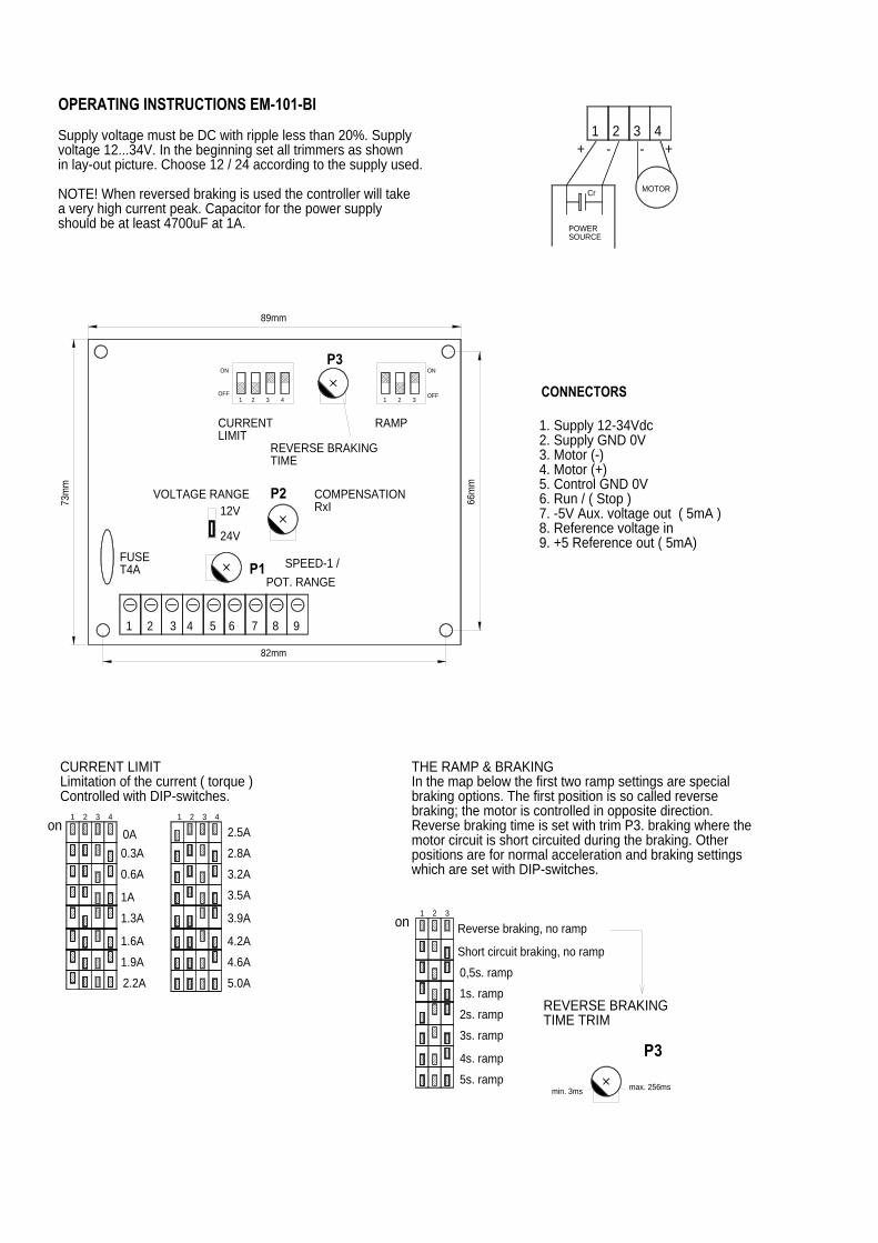
Supply voltage must be DC with ripple less than 20%. Supplyvoltage 12...34V. In the beginning set all trimmers as shownin lay-out picture. Choose 12 / 24 according to the supply used.
NOTE! When reversed braking is used the controller will takea very high current peak. Capacitor for the power supplyshould be at least 4700uF at 1A.
THE RAMP & BRAKINGIn the map below the first two ramp settings are specialbraking options. The first position is so called reversebraking; the motor is controlled in opposite direction.Reverse braking time is set with trim P3. braking where themotor circuit is short circuited during the braking. Otherpositions are for normal acceleration and braking settingswhich are set with DIP-switches.
73m
m
1 2 3 4 5 6 7 8 9
4
CURRENT LIMITLimitation of the current ( torque )Controlled with DIP-switches.
1.6A
1.9A2.2A
43on
21
1.3A
0.6A
1A
3
0A21
0.3A
4.2A
4.6A5.0A
3.9A
3.2A3.5A
2.5A2.8A
21on
OFF
OPERATING INSTRUCTIONS EM-101-BI
CURRENTLIMIT
VOLTAGE RANGE
FUSET4A
P3
COMPENSATIONRxI
POT. RANGESPEED-1 /
REVERSE BRAKINGTIME
P1
24V
12VP2
1 2 3 4
ON
21 3
ON
RAMP
66m
m
max. 256ms
P3
REVERSE BRAKINGTIME TRIM
Reverse braking, no ramp
Short circuit braking, no ramp0,5s. ramp1s. ramp
3s. ramp
5s. ramp
4s. ramp
2s. ramp
min. 3ms
3
MOTOR
4
1. Supply 12-34Vdc2. Supply GND 0V3. Motor (-)4. Motor (+)5. Control GND 0V6. Run / ( Stop )7. -5V Aux. voltage out ( 5mA )8. Reference voltage in9. +5 Reference out ( 5mA)
CONNECTORS
POWERSOURCE
Cr
2+ -
1-
3+

Vähäheikkiläntie 56B, 20810 Turku, FINLAND Tel. +358-2-4693050 Fax. +358-2-4693052
P1
Two direction drive with switch.Speed with external potentiometer.Run continuous on.
Two direction drive.Speed and direction controlwith potentiometer.
CONTROLLINGThe max value of controlling voltage ranges ±( 5...10V ). Thefull range is thus maintained on 0...5V. The range can beset with trim P1.
One direction drive.Speed adjustment withpotentiometer.
ELECTROMEN Oy
Two direction drive with switch.Run continuous on.
REWIND FORWARD
65
5
7 8 9
6 7 108 9
SPEEDRUN
SPEED FORWARD
6
5 6
5
7 8 9
REWIND
7 8 9
RUNSPEED
COMPENSATIONWith compensation you can compensate the loadeffect to motor rpm. This feature increases controllingif current increases in the motor circuit. The needfor compensation depends on application and motor.Typically small motors require more compensationthan big ones. Over compensation occurs as twichingof the motor.
EM-101 CONNECTION EXAMPLES
increase compensation
P2max.min.
Two direction drive with voltage signal.Run continuous on.
Two direction drive with voltage signal,run with voltage control.
CONTROL VOLTAGE -5..0..5 or -10..0..-10V
CONTROL VOLTAGE -5..0..5 or -10..0..-10V
Ucont.
Ucont.
Uk
5 6
RUN WHENUk > 4V
5 6
7 8 9
7 8 9
range -10..0..10V (-100...0...100%)
range -5..0..5V (-100...0...100%)100%
50%0%
mt18
Text Box
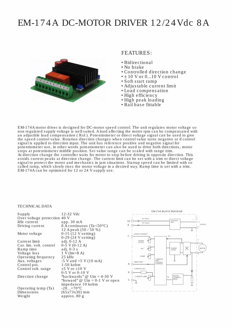
EM-174A DC-MOTOR DRIVER 12/24Vdc 8A
FEATURES:
• Bidirectional• No brake• Controlled direction change• ± 10 V or 0...10 V control• Soft start ramp• Adjustable current limit• Load compensation• High efficiency• High peak loading• Rail base fittable
EM-174A motor driver is designed for DC-motor speed control. The unit regulates motor voltage sonon regulated supply voltage is well suited. A load affecting the motor rpm can be compensated withan adjustble load compensation ( RxI ). Potentiometer or direct voltage signal can be used to givethe speed control value. Rotation direction changes when control value turns negative or if controlsignal is applied to direction input. The unit has reference positive and negative signal forpotentiometer use, in other words potentiometer can also be used to drive both directions, motorstops at potentiometer middle position. Set value range can be scaled with range trim.At direction change the controller waits for motor to stop before driving in opposite direction. Thisavoids current peaks at direction change. The current limit can be set with a trim or direct voltagesignal to protect the motor and mechanics in jam situations. Startup speed can be limited with socalled ramp, which slowly rises the motor voltage in a desired way. Ramp time is set with a trim.EM-174A can be optimised for 12 or 24 V supply use.
TECHNICAL DATA
SupplyOver voltage protectionIdle currentDriving current
Motor voltage
Current limitCur. lim. volt. controlRamp timeVoltage lossOperating frequencyAux. voltagesControl pot.Control volt. range
Direction change
Operating temp (Ta)DimensionsWeight
12-32 Vdc40 Vapp. 30 mA8 A continuous (Ta<50°C)12 A peak (50 / 50 %)0-15 (12 V setting)0-29 (24 V setting)adj. 0-12 A0-5 V (0-12 A)adj. 0-3 s1 V (Im=8 A)25 kHz-5 V and +5 V (10 mA)1-50 kohm±5 V or ±10 V0-5 V or 0-10 V“backwards” @ Uin = 4-30 V“forward” @ Uin = 0-1 V or openimpedance 10 kohm-20...+70°C(65x73x30) mmapprox. 80 g
CURRENTANDVOLTAGECONTROL
EM-174A BLOCK DIAGRAM
CURRENT SET
CURRENT LIMIT
5
6
RAMP
DIRECTION
RANGESCALE
SPEED CONTROL
8
7
109
RxI
-5V/ 10mA
5V/ 10mA
Im MOTORCURRENTMEAS.
POWERSTAGE
Um
VOLTAGEREG
2
MOTOR
3
-1
4SUPPLY
+
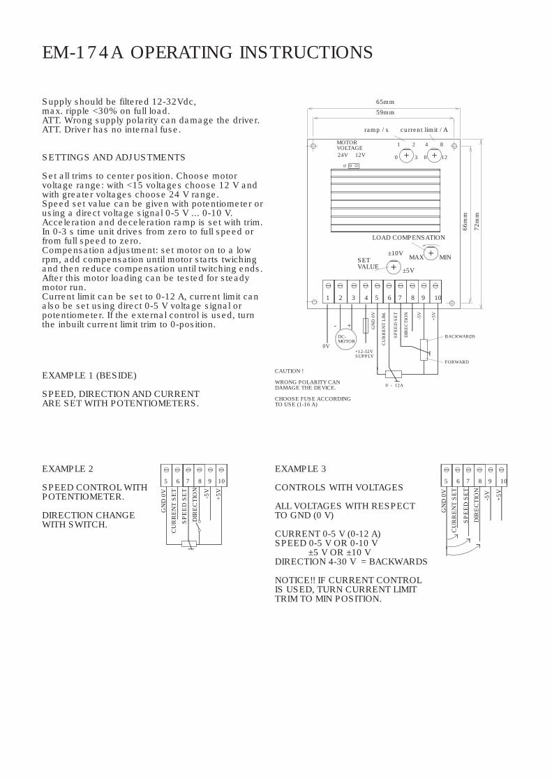
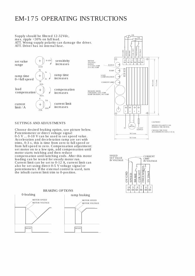
EM-174A OPERATING INSTRUCTIONS
Supply should be filtered 12-32Vdc,max. ripple <30% on full load.ATT. Wrong supply polarity can damage the driver.ATT. Driver has no internal fuse.
SETTINGS AND ADJUSTMENTS
Set all trims to center position. Choose motorvoltage range: with <15 voltages choose 12 V andwith greater voltages choose 24 V range.Speed set value can be given with potentiometer orusing a direct voltage signal 0-5 V ... 0-10 V.Acceleration and deceleration ramp is set with trim.In 0-3 s time unit drives from zero to full speed orfrom full speed to zero.Compensation adjustment: set motor on to a lowrpm, add compensation until motor starts twichingand then reduce compensation until twitching ends.After this motor loading can be tested for steadymotor run.Current limit can be set to 0-12 A, current limit canalso be set using direct 0-5 V voltage signal orpotentiometer. If the external control is used, turnthe inbuilt current limit trim to 0-position.
EXAMPLE 1 (BESIDE)
SPEED, DIRECTION AND CURRENTARE SET WITH POTENTIOMETERS.
EXAMPLE 3
CONTROLS WITH VOLTAGES
ALL VOLTAGES WITH RESPECTTO GND (0 V)
CURRENT 0-5 V (0-12 A)SPEED 0-5 V OR 0-10 V
±5 V OR ±10 VDIRECTION 4-30 V = BACKWARDS
NOTICE!! IF CURRENT CONTROLIS USED, TURN CURRENT LIMITTRIM TO MIN POSITION.
EXAMPLE 2
SPEED CONTROL WITHPOTENTIOMETER.
DIRECTION CHANGEWITH SWITCH.
CU
RR
EN
T S
ET
GN
D 0
V
5
SP
EE
D S
ET
DIR
EC
TIO
N
+5V
106 7 8 9
-5V
CU
RR
EN
T S
ET
GN
D 0
V
5D
IRE
CTI
ON
SP
EE
D S
ET
6 7 8 9 10-5
V
+5V
CAUTION !
WRONG POLARITY CANDAMAGE THE DEVICE.
CHOOSE FUSE ACCORDINGTO USE (1-16 A)
+12-32VSUPPLY
SETVALUE
DC-MOTOR
0V
32
+-
1 4
24V 12V
MOTORVOLTAGE
0 - 12A
5 6 7 8 9
±10V
±5V
MAX
FORWARD
BACKWARDS
MIN
10
LOAD COMPENSATION
current limit / A
00 3
421
59mm
ramp / s
65mm
12
8
66m
m
72m
m
GN
D 0
V
CU
RR
EN
T LI
M.
SP
EE
D S
ET
DIR
EC
TIO
N
-5V
+5V
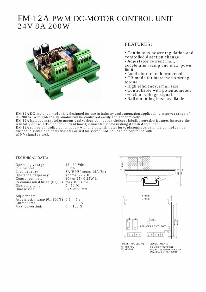
EM-12A PWM DC-MOTOR CONTROL UNIT24V 8A 200W
EM-12A DC-motor control unit is designed for use in industry and automation applications in power range of0...200 W. With EM-12A DC-motor can be controlled easily and economically.EM-12A includes many adjustments and various connection choices. Inbuilt protection features increase thereliability of use. CB-function (current boost) eliminates motor rushing if started with load.EM-12A can be controlled continuously with one potentiometer forward/stop/reverse or the control can bedivided to switch and potentiometer or just for switch. EM-12A can be controlled with±10 V signal as well.
FEATURES:
• Continuous power regulation andcontrolled direction change• Adjustable current limit, acceleration ramp and max. powerlimit• Load short circuit protected• CB-mode for increased startingtorque• High efficiency, small size• Controllable with potentiometer,switch or voltage signal• Rail mounting base available
TECHNICAL DATA:
Operating voltage 18...30 VdcIdle current 50mALoad capacity 8A (RMS) mom. 15A (5s)Operating frequency approx. 22 kHzControl pot.meter 10k or 25k 0.25W lin.Recommended fuses (F1,F2) max. 8A, slowOperating temp. 0...50 °CDimensions 87*72*28 mm
Adjustments:Acceleration ramp (0...100%) 0.5 ... 5 sCurrent limit 0.5 ... 20 AMax. power limit 0 ... 100 %
7
F2, MOTORP3, MAX. POWER LIMITP2, ACCELERATION RAMPP1, CURRENT LIMIT
LED, CURRENT LIMIT
ADJUSTMENTSF1, SUPPLY
21
F1
3 4 5 6
P1F2
28mm
87mm77mm
8 9P3
P2
62mm
72mm
57mm
52mm
FUSES (8A, SLOW)

EM-12A INSTRUCTIONS
CONNECTIONSConnection choices are displayed in figures 2a, 2b, 2c and 2d. If the operating direction of the connectedpotentiometer is not as desired, the outer wires should be switched. If the rotating direction of the motor is not aswanted, the motor wires should be switched.CAUTION. When the card is supplied from a transformer, capacitor should be added as shown in figures.With battery supply the capacitor is needed only if supply leads are extensive (over 5m). _______
INTRODUCTIONAdjust the max. power limit to 100 % (P3 clockwise), acceleration ramp to 5 s position (P2 counterclockwise) andthe current limit to 20 A (P1 clockwise).
CONTROL LIMITDrive the motor full forward or full reverse. If the maximum running speed of the motor needs to be restricted,adjust P3 counter-clockwise until the running speed of the motor is acceptable.
ACCELERATION RAMPWith the preset ramp length of 5 s and maximum power, reversing the motor (full forward <=> full reverse) takesapproximately 10 s. If the application can be stopped faster, the acceleration ramp can be set to shorter value byturning the P2 clockwise. DO NOT ADJUST THE RAMP TO SO SHORT VALUE THAT THE REVERSING OCCURSWHILE THE MOTOR IS STILL RUNNING.
CURRENT LIMITThe purpose of the current limit is to protect the motor from overloading. Adjust the current limit so that the redled on the card is not lit during normal load conditions. NOTE: by adjusting the current limit too low, the torque ofthe motor is decreased. The operation of the current limit can be checked by overloading the motor.CAUTION: Do not use the control card in applications with high inertia (eg. flywheel drive) or where theload rotates the motor (eg. automotive devices going downhill).
EM-12A
1 2 3 4
C
24VDC+-
2200uf
5 6 7 8 9
M
FIGURE 2c. CONTROL WITH SWITCH. FUNCTIONS FORWARD/STOP/REVERSE.
0
FIGURE 2b. SPEED CONTROL WITH POT.METER, DIRECTION WITH SWITCH. STOP FUNCTION IS ACHIEVED WITH THREE POSITION SWITCH.
EM-12A
1 2 3 4
C
24VDC+-
2200uf
5 6 7 8 9
M
0
0
EM-12A
1 2 3 4
C
24VDC+-
2200uf
5 6 7 8 9
M
FIGURE 2d. VOLTAGE CONTROL. VOLTAGE SHOULD BEGALVANICALLY ISOLATED FROM DRIVER VOLTAGE.
± 10V
0V
EM-12A
1 2 3 4
C
24VDC+-
2200uf
5 6 7 8 9
M
FIGURE 2a. POTENTIOMETER CONTROL. MIDDLE POSITION OF POT.METERFUNCTION STOP. CONTINUOS CONTROL IN BOTH DIRECTIONS
0
0,5A
P1 CURRENT LIMIT P2 ACCELERATION RAMP P3 MAX. POWER LIMIT
FIGURE 3. EM-12A ADJUSTMENTS.
10A
20A 5s
2,5s
00,5s 100 %
50 %
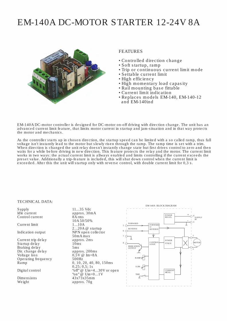
EM-140A DC-MOTOR STARTER 12-24V 8A
EM-140A DC-motor controller is designed for DC-motor on-off driving with direction change. The unit has anadvanced current limit feature, that limits motor current in startup and jam-situation and in that way protectsthe motor and mechanics.
As the controller starts up in chosen direction, the startup speed can be limited with a so called ramp, thus fullvoltage isn't instantly lead to the motor but slowly risen through the ramp. The ramp time is set with a trim.When direction is changed the unit relay doesn't instantly change state but first drives control to zero and thenwaits for a while before driving in new direction. This feature protects the relay and the motor. The current limitworks in two ways: the actual current limit is allways enabled and limits controlling if the current exceeds thepreset value. Additionally a trip-feature is included, this will shut down control when the current limit isexceeded. After this the unit will startup only with reverse control, with double current limit for 0,3 s.
FEATURES
• Controlled direction change• Soft startup, ramp• Trip or continuous current limit mode• Settable current limit• High efficiency• High momentary load capasity• Rail mounting base fittable• Current limit indication• Replaces models EM-140, EM-140-12 and EM-140ind
TECHNICAL DATA:
Supply 11...35 VdcIdle current approx. 30mAControl current 8A rms
10A 50/50%Current limit 1...10A
2...20A @ startupIndication output NPN open collector
50mA maxCurrent trip delay approx. 2msStartup delay 10msBraking delay 5msDir. change delay approx. 200msVoltage loss 0,5V @ Im=8AOperating frequency 500HzRamp 0, 10, 20, 40, 80, 150ms
0,25; 0,5; 1sDigital control “off” @ Uin=4...30V or open
“on” @ Uin=0...1VDimensions 43x73x35mmWeight approx. 70g
SUPPLYIN
EM-140A BLOCK DIAGRAM
CURRENTMEAS.
STAGEPOWER
POWERREGUL.
I-LIM.
TRIP.
RAMP.
REVERSE
INDICATIONOUTPUT
6
7
8
FORWARD5
CONTROLLOGIC
REVERSE
FORWARDor
2
1
+
-
MOTOR
4
3
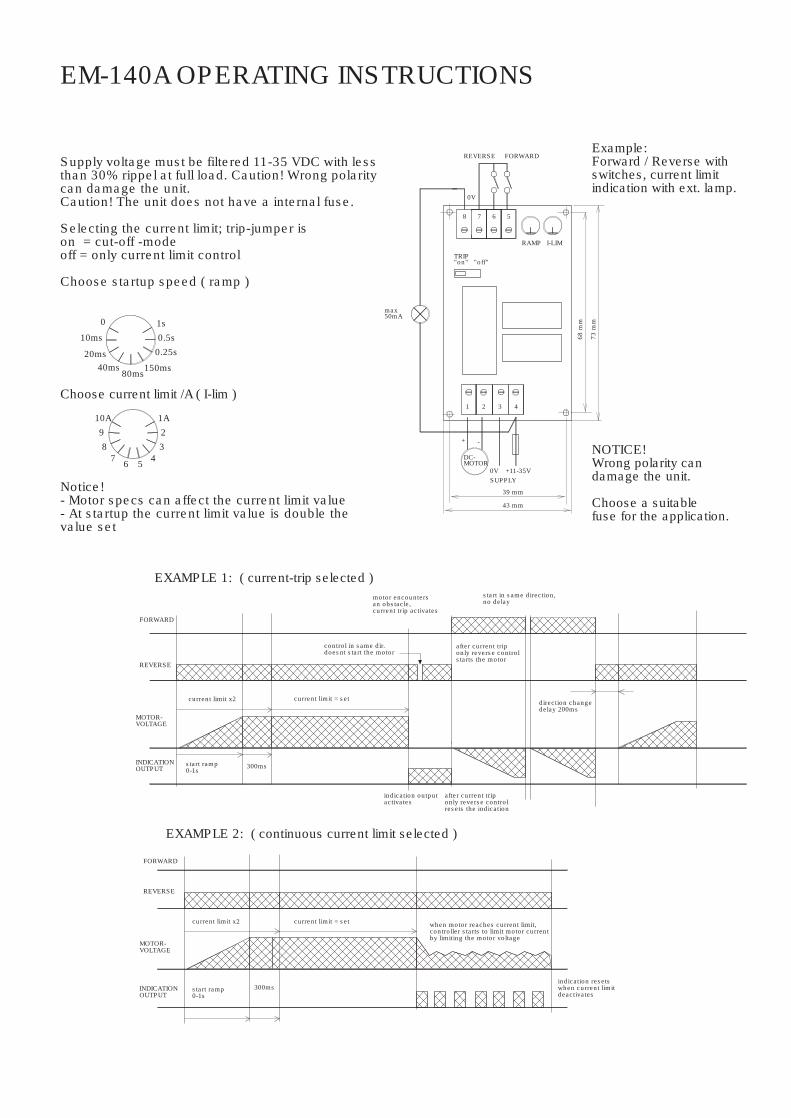
EM-140A OPERATING INSTRUCTIONS
Supply voltage must be filtered 11-35 VDC with lessthan 30% rippel at full load. Caution! Wrong polaritycan damage the unit.Caution! The unit does not have a internal fuse.
Selecting the current limit; trip-jumper ison = cut-off -modeoff = only current limit control
Choose startup speed ( ramp )
Notice!- Motor specs can affect the current limit value- At startup the current limit value is double thevalue set
Choose current limit /A ( I-lim )
20ms
10ms
10A 1A238
9
57 6 4
0.5s1s
0.25s
150ms40ms
0
80ms
start in same direction,no delay
when motor reaches current limit,controller starts to limit motor currentby limiting the motor voltage
after current triponly reverse controlstarts the motor
after current triponly reverse controlresets the indication
EXAMPLE 1: ( current-trip selected )
EXAMPLE 2: ( continuous current limit selected )
current limit = set
300ms
current limit x2
REVERSE
FORWARD
start ramp0-1s
300ms
motor encountersan obstacle,current trip activates
indication outputactivates
control in same dir.doesnt start the motor
direction changedelay 200ms
MOTOR-VOLTAGE
INDICATIONOUTPUT
indication resetswhen current limitdeactivates
REVERSE
FORWARD
MOTOR-VOLTAGE
INDICATIONOUTPUT
current limit x2
current limit = set
start ramp0-1s
NOTICE!Wrong polarity candamage the unit.
Choose a suitablefuse for the application.
RAMP
43 mm
MOTORDC-
39 mm
+
1
-
2 3 4
TRIP"on" "off"
max50mA
5
0V
7 68
68 m
m
73 m
m
I-LIM
SUPPLY0V +11-35V
REVERSE FORWARDExample:Forward / Reverse withswitches, current limitindication with ext. lamp.
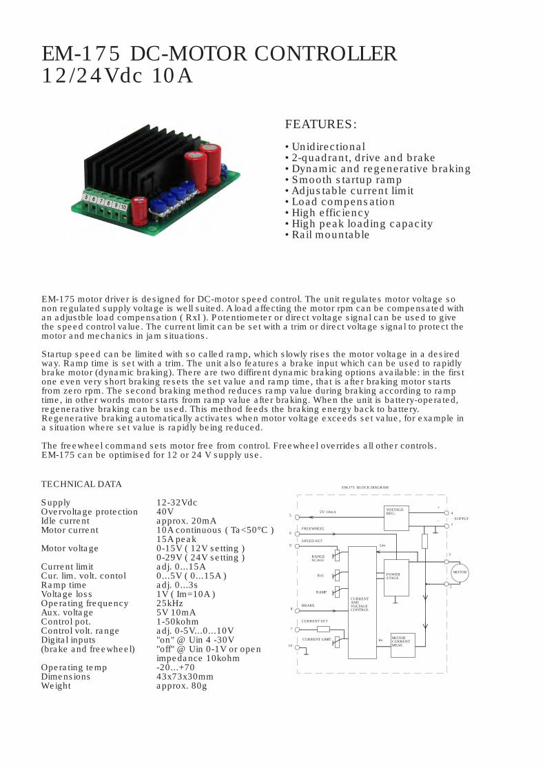
EM-175 DC-MOTOR CONTROLLER12/24Vdc 10A
FEATURES:
• Unidirectional• 2-quadrant, drive and brake• Dynamic and regenerative braking• Smooth startup ramp• Adjustable current limit• Load compensation• High efficiency• High peak loading capacity• Rail mountable
TECHNICAL DATA
SupplyOvervoltage protectionIdle currentMotor current
Motor voltage
Current limitCur. lim. volt. contolRamp timeVoltage lossOperating frequencyAux. voltageControl pot.Control volt. rangeDigital inputs(brake and freewheel)
Operating tempDimensionsWeight
EM-175 motor driver is designed for DC-motor speed control. The unit regulates motor voltage sonon regulated supply voltage is well suited. A load affecting the motor rpm can be compensated withan adjustble load compensation ( RxI ). Potentiometer or direct voltage signal can be used to givethe speed control value. The current limit can be set with a trim or direct voltage signal to protect themotor and mechanics in jam situations.
Startup speed can be limited with so called ramp, which slowly rises the motor voltage in a desiredway. Ramp time is set with a trim. The unit also features a brake input which can be used to rapidlybrake motor (dynamic braking). There are two diffirent dynamic braking options available: in the firstone even very short braking resets the set value and ramp time, that is after braking motor startsfrom zero rpm. The second braking method reduces ramp value during braking according to ramptime, in other words motor starts from ramp value after braking. When the unit is battery-operated,regenerative braking can be used. This method feeds the braking energy back to battery.Regenerative braking automatically activates when motor voltage exceeds set value, for example ina situation where set value is rapidly being reduced.
The freewheel command sets motor free from control. Freewheel overrides all other controls.EM-175 can be optimised for 12 or 24 V supply use.
12-32Vdc40Vapprox. 20mA10A continuous ( Ta<50°C )15A peak0-15V ( 12V setting )0-29V ( 24V setting )adj. 0...15A0...5V ( 0...15A )adj. 0...3s1V ( Im=10A )25kHz5V 10mA1-50kohmadj. 0-5V...0...10V"on" @ Uin 4 -30V"off" @ Uin 0-1V or openimpedance 10kohm-20...+7043x73x30mmapprox. 80g
Im
EM-175 BLOCK DIAGRAM
Um
CURRENT LIMIT
7
10
CURRENT SET
SPEED SET
RAMP
5V/ 10mA
RxI
RANGESCALE
9
BRAKE8
FREEWHEEL
5
6
CURRENTANDVOLTAGECONTROL
MOTORCURRENTMEAS.
POWERSTAGE
VOLTAGEREG.
-
+
2
MOTOR
3
1
4SUPPLY
EM-175 OPERATING INSTRUCTIONS
Supply should be filtered 12-32Vdc,max. ripple <30% on full load.ATT. Wrong supply polarity can damage the driver.ATT. Driver has no internal fuse.
SETTINGS AND ADJUSTMENTS
Choose desired braking option, see picture below.Potentiometer or direct voltage signal0-5 V ... 0-10 V can be used to set speed value.Acceleration and deceleration ramp are set withtrims, 0-3 s, this is time from zero to full speed orfrom full speed to zero. Compensation adjustment:set motor on to a low rpm, add compensation untilmotor starts twiching and then reducecompensation until twitching ends. After this motorloading can be tested for steady motor run.Current limit can be set to 0-12 A, current limit canalso be set using direct 0-5 V voltage signal orpotentiometer. If the external control is used, turnthe inbuilt current limit trim to 0-position.
10A
5A
0-10V
currentlimit / A
15A
ramp time0->full speed
loadcompensation
set valuerange
1s
0max.
min.
2s3s
0-5V0s
current limitincreases
ramp timeincreases
compensationincreases
sensitivityincreases
MOTOR SPEEDMOTOR VOLTAGE
BRAKING OPTIONS0-braking
BRAKE
ramp brakingMOTOR SPEEDMOTOR VOLTAGE
BRAKE
CURRENTLIMITIN VOLTAGE
SPEEDSET VALUEIN VOLTAGE
OV
GN
D
CU
R.S
ET
5V 1
0mA
BR
AK
E
SP
EE
D
78910 6
FRE
EW
HE
EL
5
BRAKING MODE0-BRAKING, USE JUMPRAMP BRAKING, NO JUMP
MOTORVOLTAGERANGE12 V USE JUMP24 V NO JUMP
CAUTION!!
WRONG POLARITY CANDAMAGE THE DEVICE.
CHOOSE THE FUSEACCORDINGTO USE (1-16 A)
SP
EE
D0V
1
LOADCOMPENSATION
10
RAMP
RANGE
OV
GN
D
-
DC-MOTOR
+12-32VSUPPLY
2 3 4
5789 6
CU
R. S
ET
5V 1
0mA
BR
AK
E
FRE
EW
HE
EL
10K
10K
36.5 mm
42.5 mm
66.5
mm
72.5
mm
+
CURRENT LIMIT

EM-176 DC-MOTOR CONTROLLER12/24Vdc 10A
FEATURES:
• 4 Quadrants• Braking• Freewheeling• Reversal• 0...10V control• Optional ±10V control• Soft start ramp• Adjustable current limit• Load compensation ( RxI )• High efficiency• High peak loading capacity• Rail mountable
EM-176 is designed for DC-motor speed control. The unit can be used with unregulated DC supply. Motorloading can be compensated with inbuilt RxI-type adjustment. EM-176 utilizes PWM driven H-bridge, thusachieves high efficiency and extensive controlling options. Speed control value can be set with voltage signalor with potentiometer, there is an auxiliary voltage signal output for potentiometer use. The scale trimmer canbe used to scale set value to correspond better the motor rpm. An auxiliary card can be fitted into EM-176 forbipolar input controlling with voltage signal or potentiometer. The ramp feature is used to limit the motor startand brake speed, in other words soften the operation and prevent the occurrence of current spikes. Thecurrent limit limits motor torque that is current; this protects the motor and the mechanics. The unit hasseparate inputs for brake, freewheel and reverse. Brake short-circuits the motor poles and produces powerfulbraking. Freewheel detaches the power stage from the motor and leaves motor rotating freely. Reversechanges motor rotating direction, this is done using the set ramp times.Brake and freewheel bypass the ramp feature.
TECHNICAL DATA:
SupplyOver voltage protectionIdle currentMotor current
Motor voltageCurrent limitCurrent lim. volt. ctrlRamp timeVoltage lossOperating freq.Aux. voltagesSet value range
Set value input imp.Control voltage
Control input imp.
Operating temp ( Ta )MeasuresWeight
12-35Vdc39Vappox. 30mA10A cont. ( Ta<50°C )15A peak ( 20% on/ 80% off )0-29V ( 0-100%)adj. 0...15A0...5V ( 0...15A )adj. 0...3s1.2V ( Im=10A )25kHz+5V 10mA ( option -5V )0...5 or 0...10V ( ±5V or ±10V option )100kohm ( pin 7 and 9 )"on" when Uin 4 -30V"off" when Uin 0-1V or open10kohm ( pin 5, 6 and 8 )
-20...+7065x73x30mmapprox. 100g
CURRENTANDVOLTAGECONTROL
EM-176 BLOCK DIAGRAM
BRAKE
CURRENT SET
CURRENT LIMIT
7
4
5
DIR
RANGESCALE
SPEEDSET
5V/ 10mA
9
8
6
10
FREEWHEEL
RxI
RAMP
EM-A1bipolarcard
optional
MOTOR-CURRENTMEAS.
Im
+
POWERSTAGE
Um
VOLTAGEREG.
-
2
M
3
SUPPLY
4
1100R
Recom. control pot. 4.7...47k
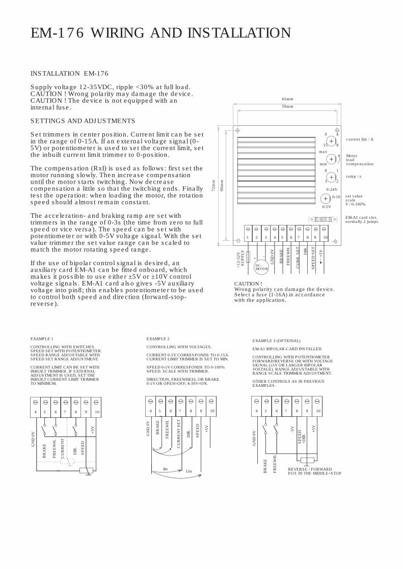
INSTALLATION EM-176
Supply voltage 12-35VDC, ripple <30% at full load.CAUTION ! Wrong polarity may damage the device.CAUTION ! The device is not equipped with aninternal fuse.
SETTINGS AND ADJUSTMENTS
Set trimmers in center position. Current limit can be setin the range of 0-15A. If an external voltage signal (0-5V) or potentiometer is used to set the current limit, setthe inbuilt current limit trimmer to 0-position.
The compensation (RxI) is used as follows: first set themotor running slowly. Then increase compensationuntil the motor starts twitching. Now decreasecompensation a little so that the twitching ends. Finallytest the operation: when loading the motor, the rotationspeed should almost remain constant.
The acceleration- and braking ramp are set withtrimmers in the range of 0-3s (the time from zero to fullspeed or vice versa). The speed can be set withpotentiometer or with 0-5V voltage signal. With the setvalue trimmer the set value range can be scaled tomatch the motor rotating speed range.
If the use of bipolar control signal is desired, anauxiliary card EM-A1 can be fitted onboard, whichmakes it possible to use either ±5V or ±10V controlvoltage signals. EM-A1 card also gives -5V auxiliaryvoltage into pin8; this enables potentiometer to be usedto control both speed and direction (forward-stop-reverse).
EM-176 WIRING AND INSTALLATION
EXAMPLE 2
CONTROLLING WITH VOLTAGES.
CURRENT 0-5V CORRESPONDS TO 0-15A.CURRENT LIMIT TRIMMER IS SET TO MIN.
SPEED 0-5V CORRESPONDS TO 0-100%SPEED. SCALE WITH TRIMMER.
DIRECTION, FREEWHEEL OR BRAKE0-1V OR OPEN=OFF, 4-30V=ON.
EXAMPLE 1
CONTROLLING WITH SWITCHES.SPEED SET WITH POTENTIOMETER.SPEED RANGE ADJUSTABLE WITHSPEED SET RANGE ADJUSTMENT.
CURRENT LIMIT CAN BE SET WITHINBUILT TRIMMER. IF EXTERNALADJUSTMENT IS USED, SET THEINBUILT CURRENT LIMIT TRIMMERTO MINIMUM.
EXAMPLE 3 (OPTIONAL)
EM-A1 BIPOLAR-CARD INSTALLED.
CONTROLLING WITH POTENTIOMETERFORWARD/REVERSE OR WITH VOLTAGESIGNAL (±5V OR LARGER BIPOLARVOLTAGE). RANGE ADJUSTABLE WITHRANGE SCALE TRIMMER ADJUSTMENT.
OTHER CONTROLS AS IN PREVIOUSEXAMPLES.
10
BR
AK
EGN
D 0
V
4 5
FRE
EW
H.
6 7
CU
RR
EN
T
98
+5V
10
DIR
.
SP
EE
D
Im Um
BR
AK
E
54
GN
D 0
V
FRE
EW
H.
CU
RR
EN
T S
ET
DIR
.
SP
EE
D
+5V
9876
REVERSE / FORWARDPOT. IN THE MIDDLE=STOP
10
BR
AK
E
FRE
EW
H.
5
GN
D 0
V
4 9
-5V
876
+5V
SP
EE
D+D
IR.
EM-A1 card slot,normally 2 jumps
set valuescaleV / 0-100%
BR
AK
ECAUTION !Wrong polarity can damage the device.Select a fuse (1-16A) in accordancewith the application.
+12-
32V
MOTOR
321S
UP
PLY
DC-
-+
4
GN
D 0
V
72m
m
66m
m
10
0-5V
SP
EE
D S
ET
5 6 7 8 9
DIR
.
+5V
CU
RR
. SE
T
FRE
EW
H.
min
max
15
59mm
65mm
8
0-10
0-24V
0
3ramp / s
1
2
Motorloadcompensation
0current lim / A
4
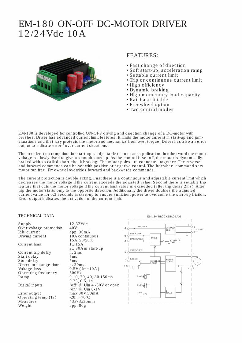
EM-180 ON-OFF DC-MOTOR DRIVER12/24Vdc 10A
FEATURES:
• Fast change of direction• Soft start-up, acceleration ramp• Settable current limit• Trip or continuous current limit• High efficiency• Dynamic braking• High momentary load capacity• Rail base fittable• Freewheel option• Two control modes
EM-180 is developed for controlled ON-OFF driving and direction change of a DC-motor withbrushes. Driver has advanced current limit features. It limits the motor current in start-up and jam-situations and that way protects the motor and mechanics from over torque. Driver has also an erroroutput to indicate error / over current situations.
The acceleration ramp time for start-up is adjustable to suit each application. In other word the motorvoltage is slowly rised to give a smooth start-up. As the control is set off, the motor is dynamicallybraked with so called short-circuit braking. The motor poles are connected together. The reverseand forward commands can be set with positive or negative control. The freewheel command setsmotor run free. Freewheel overrides forward and backwards commands.
The current protection is double acting. First there is a continuous and adjustable current limit whichdecreases the motor voltage if the current exceeds the adjusted value. Second there is settable tripfeature that cuts the motor voltage if the current limit value is exceeded (after trip delay 2ms). Aftertrip the motor starts only to the opposite direction. Additionally the driver doubles the adjustedcurrent value for 0.3 seconds in start-up to ensure sufficient power to overcome the start-up friction.Error output indicates the activation of the current limit.
SUPPLYIN
CONTROLLOGIC
EM-180 BLOCK DIAGRAM
DRIVE
RAMP.
I-LIM.
TRIP.
FORWARD
BACKWARDS
ERROR
9
10
8
7
5
69V/ 10mA
IMEAS.
CONTROLTYPE
POWERSTAGE
VOLTAGEREG
2
3
M
- 1
+4
FREEWHEEL
-
+
TECHNICAL DATA
SupplyOver voltage protectionIdle currentDriving current
Current limit
Current trip delayStart delayStop delayDirection change timeVoltage lossOperating frequencyRamp
Digital inputs
Error outputOperating temp (Ta)MeasuresWeight
12-32Vdc40Vapp. 30mA10A continuous15A 50/50%1...15A2...30A in start-upn. 2ms5ms5msn. 20ms0.5V ( Im=10A )500Hz0.10, 20, 40, 80 150ms0.25, 0.5, 1s"off" @ Uin 4 -30V or open"on" @ Uin 0-1Vmax 30V 50mA-20...+70ºC43x73x35mmapp. 80g

EM-180 OPERATING INSTRUCTIONS
Supply should be filtered 12-32Vdc,max. ripple <30% on full load.ATT. Wrong supply polarity can damage the driver.ATT. Driver has no fuse in it.
Choose the current limit mode: continuous/trippingTrip jumper: on=tripping limit, off=continuous limit
Choose control mode (forward / backwards)pos = PNP positive controlneg = NPN negative control
Choose the ramp time
ATTENTION- The current limit values canbe affected by the used motor.- In start-up the current limitvalue is doubled (for 0.3s).
Choose the current limit value / Amps.
7
9
150ms
40ms
15A1311
80ms
20ms10ms 0
1A5
3
0.5s 1s0.25s
motor brakes
no delay between the start-ups (same direction)
after trip starts only tothe opposite direction
OPERATIONAL EXAMPLE: tripping current limit
MOTORVOLTAGE
REVERSE
FORWARD
I lim. =2 x set
REVERSE
VOLTAGEMOTOR
FORWARD
no start-up tothe same direction
I lim = set
motorbrakes
direction changedelay 20ms
OPERATION EXAMPLE: continuous current limit
motor meets an obstacledriver limits the current
motor meets an obstaclecurrent trip cuts the voltage
300ms
300ms
start-up cycle(ramp) 0-1s
current limit x2
start-up cycle(ramp) 0-1s
I lim = set
5 mm FREE SPACEREQUIRED AT BOTTOM SIDE
SUPPLY
TRIP"off" “on”
CONTROLMODEneg. pos.
FRE
EW
HE
EL
+ -
0V +12-32VMOTORDC-
1 2 3 4B
AC
KW
AR
DS
910
0V
78 6 5
9V
ER
RO
R
FOR
WA
RD
NOTICE!
WRONG POLARITY MAYDAMAGE THE DEVICE.
USE EXTERNAL FUSEACCORDING TO USE(1-16 A).
CURRENT
RAMP
FASTENING HOLES 3.2mm
5 mm23 mm
43 mm
37 mm66
.5 m
m
72.5
mm

EM-213 1-QUADRANT POWER CONTROLLER12-24Vdc 10A
FEATURES:
• Low cost• High efficiency• Operating voltage compensated• For resistive or inductive loads• Applications: motor speed control, lamp dimmer• Rail base fittable
TECHNICAL DATA
Supply voltage 10-35VMotor current cont. max 10A (Ta<50°C)
peak max 15A (10s)Voltage drop 0.4V at 10APWM frequency 300Hz or 19kHzSoft-start time 0..4s adjustableControl range 0-5V or more, adjustableControl input imp. 100kohmConnectors 1.5mmEMC EN-50081-2 & EN-50082-2
(industrial)Temp. protection 110°CWeight 70gOperating temp (Ta) -20...70°C
EM-213 is a 1-quadrant power controller. The controller uses PWM principle with high efficiency.The PWM frequency can be set to high or low mode. High frequency is used with inductive (motor)load and low with resistive (lamp) load. The output of the device is compensated against powersupply changes, so the device can be used succesfully with unregulated power supply. Output isoverload (overheat) protected. The protection recovers by itself as temperature decreases. Controlof device is done with analog voltage signal 0-5V or more, range of this signal is adjustable.EM-213 also includes a soft-start ramp with adjustable time.
CONTROL WITHVOLTAGE SIGNAL or POTENTIOMETER
6
5
0-5Vor0-10V
7
RANGE6
5
7
8 300Hz / 19kHz
RAMP
5V
PWMCONT.
frequency select
temp sense
U-sense
5V
EM-213 BLOCK DIAGRAM
SUPPLY
10-35V
0VSUPPLY
3
4
1
2
LOAD
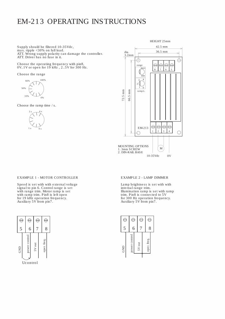
EM-213 OPERATING INSTRUCTIONS
Supply should be filtered 10-35Vdc,max. ripple <30% on full load.ATT. Wrong supply polarity can damage the controller.ATT. Driver has no fuse in it.
Choose the operating frequency with pin8,0V..1V or open for 19 kHz , 2..5V for 300 Hz.
Choose the range
10-35Vdc
EM-213
MOUNTING OPTIONS1. 3mm SCREW2. DIN-RAIL BASE
ramp/s.01
72.5
mm
66.5
mm
dia.3.2mm
min
maxrange
4
2
3
1
HEIGHT 25mm
M
2 3 4
0V
567
42.5 mm
8
36.5 mm
Choose the ramp time / s.
4 s3 s
50%
33%0%
0 s1 s
100%66%
EXAMPLE 1 - MOTOR CONTROLLER
Speed is set with with external voltagesignal to pin 6. Control range is setwith range trim. Motor ramp is setwith ramp trim. Pin8 is left openfor 19 kHz operation frequency.Auxiliary 5V from pin7.
EXAMPLE 2 - LAMP DIMMER
Lamp brightness is set with withinternal range trim.Illumination ramp is set with ramptrim. Pin8 is connected to 5Vfor 300 Hz operation frequency.Auxiliary 5V from pin7.
5 876
GN
D
oper
. fre
q.
pow
er c
ontro
l
Ucontrol
5V o
ut
875 6
oper
. fre
q.
pow
er c
ontro
l
5V o
ut
GN
D

13FAULT
14
8
9FW
10BW
11 STOP orI-limit set
SPEED-2 12
EM-241C-48V DC-MOTOR CONTROLLER 24-48V 10A
TECHNICAL DATA ( prog ver. 241C-48 v1.0 )
EM-241C-48V is a full bridge DC-motor starter for nominal voltage 24, 36 or 48V. It is designed to work with DC-motor in applications where some special functions are needed. Starter has adjustable acceleration and deceleration ramps, which make possible the smoothstarts and stops. Adjustable current limit protects motor against overcurrent and it can also be used as an end-stop. This device has alsotwo settable speeds, which are usefull in positioning applications. Control inputs FW and BW start the forward and backward run. STOP is for the motor soft shut-down but there are also available individual limit inputs for FW and BW directions. SPEED-2 input activates preset speed-2, but it can also be used as input for analog speed control signal 0-5V. STOP input can be set to work as current limit setting. FAULT terminal has at the same time input and output function, the pin is normally high, but is pulled down inoverheat and conditionally also in current trip situation. If FAULT-line is pulled down externally it will cause a stop and prevent the new start. For example, it is possible to link fault pins of several units together and achieve a synchronous stop. C-version includes wo new parameter: freewheel options for realease the rotor of motor. and pwm frequency select, but notice, that in silence 16kHz pwmfrequency. the output current is smaller!There are two selectable control modes, continuous and impulse. In continuous mode the motor runs as long as the control is active. In impulse mode a short comand starts the motor, and only a new impulse will change the status. There is also few special settings start-kick and auto reverse. The card has selectable input logics. Inputs are divided in two groups, control and limit -inputs. Groups can beindividually set for NPN or PNP logic.For parameters setting there is next options: EM-236 interface unit, EM-268 with EmenTool-Lite PC-program and EM-326 withEmenTool-App application for smartphone
Supply voltage range nom. 24-48V / max. 20-60VOvervoltage limit adjustable 15-60V Start up voltage 14V, shutdown voltage 12VContinuous current output when ambient temp is <50°C ) 10A at 100% speed / 7A at 5-99% speed pwm=2kHz 7A at 100% speed / 4A at 5-99% speed pwm=16kHz Peak ( 5s.) 25A at 2khz pwm and 20A at 16kHz pwmCurrent limit adjustable 0.1-25A ( at start max 30A )Overheat limit 100°CStart and stop ramp adjustable 0-5sPWM frequency 2kHz / 16kHzSpeed input scale ( speed-2 ) 0-5V = 0-100% pwmI-limit input scale ( stop input ) 0-5V = 0-20AInput control logic: high =4-30V, low=0-1VControl input impedances typ. 47kohmLimit FW / BW input imped. typ 10kohmControl input response time typ 5ms.Fault out. NPN open coll. max 30V / 50mAFault in actives Uin < 1V ( NPN )Motor and supply connectors 2.5mmControl connectors 1mmDimensions 42x72x25mmDimensions in DIN-rail base 45x80x45mmCE-tested for industrial environment ( emc )Operating temp ( Ta ) -40...60°CWeight 75g
SUPPLY24/48Vdc
MOTORCURRENT
1
parametersettingconnector
100k
5V
100R
data
fault out
fault in
47k
10k
5V
npn / pnp
10k
47k
47k
1
2
3
limit FW
limit BW
EM-241C-48V BLOCK DIAGRAM
socket
47k
47k
DRIVELOGIC
U-reg
npn / pnp select
DIP switch2
47k
47k
47k
47k
5V/ 10mA
7
H-BRIDGE
OVER VOLTAGE
-
MOTOR
5
4
6
+
- small size- high current output- current limit- zero current limit- overvoltage brake- speed setting- flexible control inputs- impulse / continuous mode- rail base mountable- digital parameter setting - 48V version of EM-241C- current limit setting input ( new )- freewheel options ( new )- 2 or 16kHz PWM freq. ( new )
www.electromen.comELECTROMEN Oy
mt18
Text Box

FAULT-LED signal codes
1. power on one blink2. current on limit led is lit3. current trip fast blinking...4. zero-cur trip long blink- short pause...5. overvoltage 4 x blink -pause...6. overheat short blink- long pause...7. timeout 3 x blink + long blink...8. fault input 2 x short + 1x long blink...
CONNECTIONS
Supply voltage must be filtered DC of 10-35V, and ripple should be less than 30% at full load.CAUTION ! Wrong polarity can damage the unit.CAUTION ! Unit doesn't have an internal fuse, soan external fuse should be added if fuse required.
MONITORABLE VALUES
1/5 Motor current 0-20A ( 0-200)2/5 PWM-level-% 0-100% (0-100)3/5 hour counter (max.65535h)4/5 start counter (max.65535)5/5 carry counter for start counter
SETTABLE PARAMETERS 20pcs. ( defaults in brackets )
1- command mode: 0,1 and 2 ( 0 ) 0= continuos FW / REV 1= impulse commands FW / REV. with stop 2=impulse commands FW / REV without stop2- start condition combinations: 0-3 ( 1 ) 0= start both direction after I-trip and Stop 1= start only opposite direction after I-trip 2= start only opposite direction after Stop 3= start only opposite direction after I- and Stop3- input logic combinations 0-3 PNP/NPN ( 0 ) 0= command and limit inputs as PNP ( positive ) 1= command inputs NPN, and limit inputs PNP 2= command inputs PNP. and limit input NPN 3= command and limit inputs NPN ( negative )4- running speed-1: 0-100% / 0-100 ( 100 )5- running speed-2: 0-100% / 0-100 ( 50 ) special parameter values of param. 5 0= "speed 2-input" is used as analog 0-5V speed control input. 1= FW direction is automatically "on" and FW input works as direction change input.6- current limit FW: 0-25A / 0-250 ( 30 )7- current limit REV: 0-25A / 0-250 ( 30 ) notice! If both 6 & 7 is set = 0, then I-limit input is enabled, and works as current limit adjust input.8- Trip combinations: 0-3 ( 1 ) 0= no I-trip, no zero-current-trip 1= only I-trip 2= only zero-current-trip 3= both I-trip and zero-current-trip9- I-trip delay: 0-255ms / 0-255 ( 20 )10- Fault output combinations: 0-3 ( 1 ) 0= I-trip and zero current won´t cause fault output signal 1= only I-trip causes fault output signal 2= only zero current causes fault output signal 3= both I-trip and zero current causes fault output signal.11- overvoltage limit: 15-60V / 15-60 ( 55 ) Overvoltage can be caused by load driving the motor or when braking the speed down but supply can not accept the current back from driver. Exceeding the limit will cause the power stageset to free-wheel state, and if voltage still rises then powerstages shorted to brake motor more In battery supply use the brake current is charging the battery and the voltage will not normally rice.12- load compensation: 0-255 / 0-255 ( 0 ) Load compensation ( RxI ) improves low speed and start torgue, but too high compensation achieve unstable running. Run motor at low speed ( 30% ) Increase compensation with small steps until motor start behaviour unstable, then decrease value about 10%13- timeout: 0-255s. / 0-255 (0=not in use) ( 0 )14- Reset for start and hour-counter 0/1 ( 0 ) selecting 1 and push SAVE => reset counters15- start ramp: 0-5s / 0-500 ( 100 )16- stop ramp: 0-5s / 0-500 ( 100 )17- start-kick 0-200ms / 0-200 ( 0 ) This gives full drive at start and I-lim is 30A The start kick length is 0-200ms.18- I-trip auto reversing 0-5s / 0-500 ( 0 ) Change automatically run direction when I-trip occurs the revesing time will select with this parameter 19- Freewheel options 0-3 ( 0 ) 0= no freewheel 1= freewheel when stopped 2= freewheel during stop ramp. 3= freewheel during stop ramp and if stopped20- Pwm frequency 1=2kHz / 2=16kHz
ADJUSTMENT AND SETTINGS ( prog ver. EM-241C-48V v.1.0 )
Settings can be done with three interface device options.1. EM-236 interface unit2. EM-268 interface unit with EmenTool Lite PC-software3. EM-326 interface unit with EmenTool App smartphone application When using App you can set device-specific access code, which protects device against unauthorized smartphone connections. The access code can be reset with simultaneous FW and BW comand, when power switch on.
www.electromen.comELECTROMEN Oy
mt18
Text Box
One new feature is SAFETY REVERSE function, which automatically reversing when motors meet obstacle and will beoverloadedThe parameters are set with a handy interface unit EM-236. There is also possibility to use EmenTool Lite PC-sofware with EM-268 and EmenTool App with smartphones for parameter setting.
TECHNICAL DATA
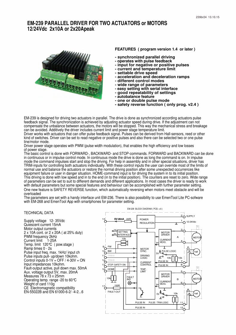
Supply voltage 12- 35VdcQuiescent current 15mAMotor output currents 2 x 10A cont. or 2 x 20A ( at 25% duty)PWM frequency 2kHzCurrent limit 1-25ATemp. limit 120°C ( pow.stage )Ramp times 0 - 2sPulse input freq. max. 1kHz/ input chPulse inputs pull- up/down 10kohm.Control inputs 0-1V = OFF / 4-30V = ONInput impedances 10kohm.Fault-output active, pull down max. 50mAAux. voltage output 5V, max. 20mAMeasures 78 x 73 x 25mmOperating temp. range -20 to 60°CWeight of card 110gCE Electromagnetic compatibility EN-55022B and EN 61000-6-2/ -4-2...6
EM-239 is designed for driving two actuators in parallel. The drive is done as synchronized according actuators pulse feedback signal. The synchronization is achieved by adjusting actuator speed during drive. If the adjustment can not compensate the unbalance between actuators, the motors will be stopped. This way the mechanical stress and breakagecan be avoided. Additively the driver includes current limit and power stage temperature limit.Driver works with actuators that can offer pulse feedback signal. Pulses can be derived from Hall-sensors, reed or otherkind of switches. Driver can be set to read negative or positive pulses and also there can be selected two or one pulseline/motor mode.Driver power stage operates with PWM (pulse width modulation), that enables the high efficiency and low lossesof power stage.The basic control is done with FORWARD-, BACKWARD- and STOP-commands. FORWARD and BACKWARD can be donein continuous or in impulse control mode. In continuous mode the drive is done as long the command is on. In impulsemode the command impulses start and stop the driving. For help in assembly and in other special situations, driver hasTRIM-inputs for controlling both actuators individually. With these control inputs the user can override most of the limits ofnormal use and balance the actuators or restore the normal driving position after some unexpected occurrences like equipment failure or user in danger situation. HOME-command input is for driving the system in to its initial position. This driving is done with low speed and in to the end (in to the initial position). The counters are reset to zero. Wide rangeof parameters can be set to suit to different demands and different applications. In most cases the driver is ready to work with default parameters but some special features and behaviour can be accomplished with further parameter setting.
MOTOR
MOTOR
PULSE LOGICMOTORSYNC.
DRIVINGLOGIC
CURRENTCONTROL
TEMP.LIMIT
10 BW hall
TRIM-A
HOME
FAULT-OUT
TRIM-B
STOP/ SAFETY SW.
11
16
13
12
17
10k
5V hall10k
PULSE / TRIM LOGIC
PULSE IN
PULSE IN
12
11
MOTORDRIVER
CURRENTMEAS.
PULSE IN
PULSE IN
100R
FAULT IND.
Im
5V
10k10k
B
5
6
8
7
FW9
14
EM-239 BLOCK DIAGRAM ( PCB. v.6 )
MOTORDRIVER
CURRENTMEAS.
REGULATION
5V/ 20mA5V/ 20mA5V/ 20mA 22R POWER
INTERFACE
SETTINGrx
tx
10k
Im
2
4
A
3
SUPPLY
12-24Vdc1
FEATURES ( program version 1.4 or later )
- synchronized parallel driving- operates with pulse feedback- input for negative or positive pulses- current and temperature limit- settable drive speed- acceleration and deceleration ramps- different control modes- wide range of parameters- easy setting with serial interface- good repeatability of settings- autobalance feature- one or double pulse mode- safety reverse function ( only prog. v2.4 )
239br24 13.10.15
EM-239 PARALLEL DRIVER FOR TWO ACTUATORS or MOTORS12/24Vdc 2x10A or 2x20Apeak
mt18
Text Box

PARAMETER DESCRIPTION
"Running speed" is the speed which is used in normal mode.
"Home speed" is the low speed used during home-routine.
"Start and stop ramps" define the acceleration and deceleration time to 0-100%-0 speed.
"Current limit" is limit value for current trip. If current limit value is exceeded the motors will be stopped. During the period of start ramp + 1s the current limit is 1.5 times the current limit set value.
"Difference limit" is the value for largest allowable difference between A and B pulse counters. If this value is exceeded motors will be stopped.
"Adjust behaviour" defines how fast and intensively the driver will adjust the syncronisation between motors A and B. Smooth 1 --> Aggressive 10
"I-trip-indication" FAULT output can be set to go ON also in current trip situation.
"Start condition" enables the device to re-start the motor to both or only to opposite direction after a trip or stop situation.
"Mode" sets the driver control mode. In continuous mode the motor runs as long as command ( fw or bw ) is ON. In impulse mode a short command starts the motor and the direction is changed with opposite command. Motor will stop only with stop command. In impulse-2 mode motor starts with short (FW/BW) impulse. Following command stops the motor, and next command(FW/BW) starts the motor again. Of course in all modes the difference limit, current limit and STOP-command will stop the motors.
"Safety reverse" means automatic reverse run if device has stopped result of overload = I-trip. This function can be disabledor the reversing running time can be set with parameter.Also stop input trigs safety reverse function
" autobalance trigger " parameter value sets the starting point for auto balancing. Value is the number of pulses counted from mechanical home. The autobalance runs athome-speed which can be set with parameter 2.
"double pulse mode" makes posible to use two pulse sensorsfor one motor and this way driver can always detect the right direction of the movement. This is recommended allwayswhen double pulses are available. NOTICE. the TRIM function is not possible to use in double pulse mode. See example 4
"end limit fw" is a pulse counter "end stop" for FW direction. The position is determined in pulse edges from 1 to 32000.Value 0 means that end stop is not in use
CONNECTION
Connect motors and supply as in picture. Supply voltage 12-35Vdc must be filtered, ripple less than 20% .Pulse inputs can work with positive (PNP) or negative (NPN) pulses. Selection is made with PULSE LOGIC selection switch. Other inputs work only with positive commands.NOTE. also TRIM-inputs work only with positive signal also in feedback use.
ADJUSTMENT AND SETTINGS ( prog ver. EM-239 v2.4 )
Settings can be done with three interface device options.1. EM-236 interface unit2. EM-268 interface unit with EmenTool Lite PC-software3. EM-326 interface unit with EmenTool App smartphone application When using App you can set device-specific access code, which protects device against unauthorized smartphone connections. The access code can be reset with simultaneous FW and BW comand, when power switch on.
parameter list with : quality ( set range ) -default
1 Running speed 40-100% ( 40-100 ) -100%2 Home speed 20-60% ( 20-60 ) -60%3 Start ramp 0-2s ( 0-20 ) -0,5s4 Stop ramp 0-2s ( 0-20 ) -0s5 Current limit 1-25A ( 10-250 ) -5A6 Difference limit 3-50pulses ( 3-50) -107 Behaviour smo.-> aggr. ( 1-10 ) -58 I-trip indication disabled =0 enabled=1 -09 Start condition 0-3 -1 0= starts both direction after I-trip or stop comm. 1= starts only for opposite direction. after I-trip, 2= starts only for opps. dir. after stop command. 3= starts only for opps. dir. after I-trip or stop comm. 10 Control Mode 1-4 -1 1=continuous ( runs as long as command is active ) 2=impulse ( short command starts run ) 3=impulse-2 ( as par-2, but dir. change without stop ) 4=continuous + continuous home command11 Safety reverse time 0-30 ( 0 or 0.1-3.0s) -0 0= safety reverse disabled, 1-30= reverse time12 Auto bal. trigger 0-255 / ( 0-255 ) 0=not in use -0 13 Double pulse mode 0=disable / 1= enabled -014 End limit FW 0-65535 / ( 0-65535 ) 0=disabled -0
INPUTS / OUTPUTS
PULSE A and B inputs are for incoming feedback pulselines. Parameter 13 enables also the use of two pulselines/motor. If chosen the input pin order is changed and TRIM-inputs are disabled. In board v.6 theinput logic can be selected for all pulse inputs with pulse and trim in logic jumpers. pos.= PNP, neg.= NPN
FW & BW are command inputs forward / backward.
STOP input is for the use of external stop command (eg. end switches). Stop input trigs also safety reversefunction, so this input can be used as SAFETY SWITCHinput.
HOME input is for starting the "drive home" routine
TRIM inputs enable driving of only one motor for setting the balance of the system or an emergency over-riding of motors, one or both. Trim inputs are changed to Pulse B and pulse B-90° input, if double pulse mode is chosen (param.13). In bord v.6 also the trim input logic can be changed with jumper to be positive= PNP or negative = NPN.
FAULT output is activated in the following situations: -difference limit exceeded -pulses have disappeared -too high temperature -current limit exceeded ( if enabled ) Notice! fault output is pulled down on alarm.
Inputs, 4-30Vdc (as HIGH) signal levels 0-1V, (as LOW)
Output, NPN open collector max. 50mA
EM-239 INSTRUCTION GUIDE prog. version 2.4, pcb ver.6

BW10
TRIM and override
TRIM input allowes the balance trimming and emergency use.When one of TRIM inputs is activated only the correspondingmotor will run. During trim-run the balance adjust and pulse counters are disabled. If both TRIM inputs A and B areactivated, it is possible to override motors and only the current limit is active.
MONITORING.
During the normal use it is possible to monitor the function of driver with EM-236. Select the monitor mode in EM-236 andyou can check the following values:- 1 current, motor A 10-200 = 1-20A- 2 current, motor B 10-200 = 1-20A- 3 pulse count / run cycle ( only motor A )- 4 pulse count difference- 5 position counter A 0-65535- 6 position counter B 0-65535
FEEDBACK PULSES
Pulse inputs can work with positive or negative feedback pulses.When pulse logic switch is in negative position, the inputs are internally pulled to 5V with 10kohm resistor. When positive logicis chosen the inputs are pulled to 0V correspondingly.The driver counts pulse edges so the counted value is double compared to the actual number of pulses.
BLUE4
FAULT-OUT
12-35V
STOP
HOME
5V out
FW
BW
TRIM-A
TRIM-B
EXAMPLE 3.MOTOR WITH HALL PULSE-SENSOR , PULSE LOGIC LINK SHOULD BE IN POS. POSITION
FAULT-OUT
12-35V
TRIM-A
TRIM-B
STOP
HOME
2
1
15
16
13
10
11
12
9
14
2
1
11
16
15
13
12
GRN. 14 7 HH
FAULT-OUT
12-35V
HOME
5V out
15
0V
MOTOR
BLUE6
BR.5
2
10V
H
+ RED
RED+7
MOTOR
GRN.
BLUE
BLK.
BR.
8
4
3
H
16
9
13STOP
10
FW
BW
+ RED
MOTOR
5
6BLUE
BR.
MOTOR
11GRN.
12
RED+8
BLUE
BLK.
4
BR.3
YEL.
GRN.
HH
EXAMPLE 4.MOTOR WITH HALL DOUBLE PULSE-SENSOR , PULSE LOGIC LINK SHOULD BE IN POS. POSITION
pos.pos. BLK.
LINAK LA36
MOTORS
0V
MOTOR
BLUE4
WH.
RED
BLK.
7
3
LINAK LA36
BLK.
YEL.
MOTORS
EXAMPLE 2.4-WIRE MOTOR WITH REED-SWITCH PULSE SENSOR, PULSE LOGICLINK SHOULD BE IN NEG. POSITION
FAULT-OUT
12-35V
FW
5V out
HOME
EXAMPLE 1. 3-WIRE MOTOR WITH REED SWITCHPULSE SENSOR, PULSE LOGICLINK SHOULD BE IN POS. POSITION
TRIM-B
STOP
TRIM-A
BW
FW
5V out
16
14
9
1
15
2
12
13
11
10
9
14
DRIVE HOME ROUTINE ( balancing )
Drive home routine is a calibration cycle for balancing the system. Home routine can be started by giving FW and BW commands at the same time for 3s or with incoming signalto HOME input. If "power-on home" parameter is enabled the home routine is started every time when power comes on. Drive home routine can be interrupted with new FW or BW command or signal to STOP input. When drive home routine starts, both motors start to run to same direction and will run until current limit stops the motor or pulses stop coming. During the drive home routine the fault led is blinking slowly.When blinking stops and both motors have stopped the device has reset the pulse counters. Now device is ready for use.If there is need to change the home drive direction, swap the motor wires. In double feedback pulse mode the hall signal wires should be swapped too (A to A-90 and B to B-90).
AUTO BALANCE ( soft ending to home position )
Auto balance starts balancing ruotine before "real" home.The trigger point is set with parameter 12 . If auto balance is active it balances the system automatically in the end of stroke. This will prevent the possible pulse error cumulation.Auto balance works always to the home direction and with"home-speed" speed ( parameter 2 ). The auto balance can beused also as soft ending to home position, because the motorswill decrease speed to "home-speed" before reach mechanical end.
FAULT situations:
motor is jammed (current trip), pulses disappear or,pulse counter difference is too high (difference limit). The driver will stop the motors and FAULT output will be pulled down (also in I-trip if indication is enabled).When motor is re-started the FAULT output is reset. Faults are also indicated with fault LED as followes:
1 slow blink = position corrupted2 blinks = current trip, 3 blinks = pulses disappeared, 4 blinks= difference limit, 5 blink = over temperature.
neg.
MOTOR
WH.
RED
7
3
MOTORS
LINAK LA12
BLK.
0V
BLK.5
MOTOR
BR.6
pos.
BLUE7
MOTOR
BLUE
BR.
BLK.
8
4
3
MOTORSLA28
239br24 13.10.15
mt18
Text Box
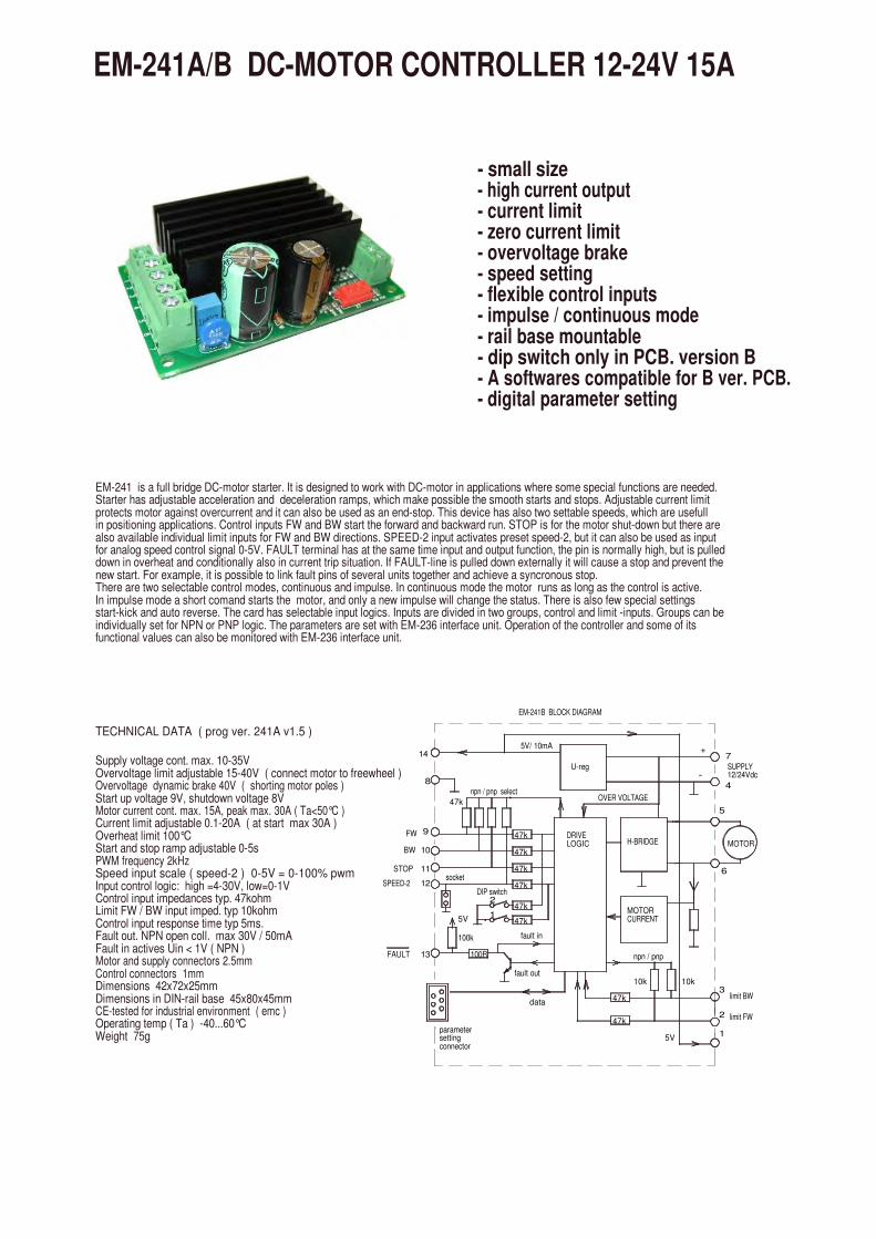
EM-241 is a full bridge DC-motor starter. It is designed to work with DC-motor in applications where some special functions are needed.Starter has adjustable acceleration and deceleration ramps, which make possible the smooth starts and stops. Adjustable current limitprotects motor against overcurrent and it can also be used as an end-stop. This device has also two settable speeds, which are usefull in positioning applications. Control inputs FW and BW start the forward and backward run. STOP is for the motor shut-down but there arealso available individual limit inputs for FW and BW directions. SPEED-2 input activates preset speed-2, but it can also be used as inputfor analog speed control signal 0-5V. FAULT terminal has at the same time input and output function, the pin is normally high, but is pulled down in overheat and conditionally also in current trip situation. If FAULT-line is pulled down externally it will cause a stop and prevent thenew start. For example, it is possible to link fault pins of several units together and achieve a syncronous stop. There are two selectable control modes, continuous and impulse. In continuous mode the motor runs as long as the control is active. In impulse mode a short comand starts the motor, and only a new impulse will change the status. There is also few special settings start-kick and auto reverse. The card has selectable input logics. Inputs are divided in two groups, control and limit -inputs. Groups can beindividually set for NPN or PNP logic. The parameters are set with EM-236 interface unit. Operation of the controller and some of its functional values can also be monitored with EM-236 interface unit.
npn / pnp select
DIP switch
Supply voltage cont. max. 10-35VOvervoltage limit adjustable 15-40V ( connect motor to freewheel ) Overvoltage dynamic brake 40V ( shorting motor poles )Start up voltage 9V, shutdown voltage 8VMotor current cont. max. 15A, peak max. 30A ( Ta<50°C )Current limit adjustable 0.1-20A ( at start max 30A )Overheat limit 100°CStart and stop ramp adjustable 0-5sPWM frequency 2kHzSpeed input scale ( speed-2 ) 0-5V = 0-100% pwmInput control logic: high =4-30V, low=0-1VControl input impedances typ. 47kohmLimit FW / BW input imped. typ 10kohmControl input response time typ 5ms.Fault out. NPN open coll. max 30V / 50mAFault in actives Uin < 1V ( NPN )Motor and supply connectors 2.5mmControl connectors 1mmDimensions 42x72x25mmDimensions in DIN-rail base 45x80x45mmCE-tested for industrial environment ( emc )Operating temp ( Ta ) -40...60°CWeight 75g
parametersettingconnector
13FAULT 100R
100k
15V
TECHNICAL DATA ( prog ver. 241A v1.5 )
14
2
8
47k
9FW
10BW
11
12SPEED-2socket
STOP
MOTORCURRENT
47k
10k
5V
data
npn / pnp
fault out
fault in
10k
47k
47k
47k
1
2
3
limit FW
limit BW
-
H-BRIDGEDRIVELOGIC
47k
47k
47k
47k
OVER VOLTAGE
U-reg
5V/ 10mA
EM-241B BLOCK DIAGRAM
+7
SUPPLY12/24Vdc
MOTOR
5
4
6
EM-241A/B DC-MOTOR CONTROLLER 12-24V 15A
- small size- high current output- current limit- zero current limit- overvoltage brake- speed setting- flexible control inputs- impulse / continuous mode- rail base mountable- dip switch only in PCB. version B- A softwares compatible for B ver. PCB.- digital parameter setting

SETTABLE PARAMETERS 18pcs. ( defaults in brackets )
1- command mode: 0,1 and 2 ( 0 ) 0= continuos FW / REV 1= impulse commands FW / REV. with stop 2=impulse commands FW / REV without stop2- start condition combinations: 0-3 ( 1 ) 0= start both direction after I-trip and Stop 1= start only opposite direction after I-trip 2= start only opposite direction after Stop 3= start only opposite direction after I- and Stop3- input logic combinations 0-3 PNP/NPN ( 0 ) 0= command and limit inputs as PNP ( positive ) 1= command inputs NPN, and limit inputs PNP 2= command inputs PNP. and limit input NPN 3= command and limit inputs NPN ( negative )4- running speed-1: 0-100% / 0-100 ( 100 )5- running speed-2: 0-100% / 0-100 ( 50 ) Note: If selected to 0 or 1 "speed2-input" is used as analog 0-5V speed control input, and when 1 is selected FW direction is automatically "on" and FWD input works as direction change6- current limit FW: 0.1-20A / 1-200 ( 30 )7- current limit REV: 0.1-20A / 1-200 ( 30 )8- Trip combinations: 0-3 ( 1 ) 0= no I-trip, no zero-current-trip 1= only I-trip 2= only zero-current-trip 3= both I-trip and zero-current-trip9- I-trip delay: 0-255ms / 0-255 ( 20 )10- Fault output combinations: 0-3 ( 1 ) 0= I-trip and zero current won´t cause fault output signal 1= only I-trip causes fault output signal 2= only zero current causes fault output signal 3= both I-trip and zero currenT causes fault output signal.
11- overvoltage limit: 15-40V / 15-40 ( 35 ) Overvoltage can be caused by load driving the motor or when braking the speed down but supply can not accept the current back from driver. Exceeding the limit will cause the power stage set to free-wheel state. With a direct battery supply the brake current is charging the battery and the voltage will not normally rice. There is also 40V fixed dynamic brake point = motor pole shorted12- load compensation: 0-255 / 0-255 ( 0 ) Load compensation ( RxI ) improves low speed and start torgue, but too high compensation achieve unstable running. Run motor at low speed ( 30% ) Increase compensation with small steps until motor start behaviour unstable, t hen decrease value about 10%13- timeout: 0-255s. / 0-255 (0=not in use) ( 0 )14- Reset for start and hour-counter 0/1 ( 0 ) selecting 1 and push SAVE => reset counters15- start ramp: 0-5s / 0-500 ( 100 )16- stop ramp: 0-5s / 0-500 ( 100 )17- start-kick 0-200ms / 0-200 ( 0 ) This gives full drive at start and I-lim is 30A The start kick length is 0-200ms.18- I-trip auto reversing 0-5s / 0-500 ( 0 ) Change automatically run direction when I-trip occurs the revesing time will select with this parameter
ADJUSTMENT AND SETTINGS ( prog ver. EM-241A v.1.5 )
Adjusting and parameter setting of eg.current limit value, ramp times and speed-2 value is done with the EM-236 interface unit. With EM-236 the parameters and adjusted values can also be copied to multible devices accurately and reliably.
FAULT-LED signal codes
1. power on one blink2. current on limit led is lit3. current trip fast blinking...4. zero-cur trip long blink- short pause...5. overvoltage 4 x blink -pause...6. overheat short blink- long pause...7. timeout 3 x blink + long blink...8. fault input 2 x short + 1x long blink...
CONNECTIONS
Supply voltage must be filtered DC of 10-35V, and ripple should be less than 30% at full load.CAUTION ! Wrong polarity can damage the unit.CAUTION ! Unit doesn't have an internal fuse, soan external fuse should be added if fuse required.
MONITORABLE VALUES
1/5 Motor current 0-20A ( 0-200)2/5 PWM-level-% 0-100% (0-100)3/5 hour counter (max.65535h)4/5 start counter (max.65535)5/5 carry counter for start counter

TECHNICAL DATA ( prog ver. 241Cv1.4 )
Supply voltage cont. max. 10-35VOvervoltage limit adjustable 15-40V Start up voltage 9V, shutdown voltage 8VContinuous current output when ambient temp is <50°C ) 15A at 100% speed / 10A at 5-99% speed pwm=2kHz 10A at 100% speed / 5A at 5-99% speed pwm=16kHz Peak ( 5s.) 30A at 2khz pwm and 25A at 16kHz pwmCurrent limit adjustable 0.1-25A ( at start max 30A )NOTICE! during start ramp current limit is 50% boostedOverheat limit 100°CStart and stop ramp adjustable 0-5sPWM frequency 2kHz / 16kHzSpeed input scale ( speed-2 ) 0-5V = 0-100% pwmI-limit input scale ( stop input ) 0-5V = 0-20AInput control logic: high =4-30V, low=0-1VControl input impedances typ. 47kohmLimit FW / BW input imped. typ 10kohmControl input response time typ 5ms.Fault out. NPN open coll. max 30V / 50mAFault in actives Uin < 1V ( NPN )Motor and supply connectors 2.5mmControl connectors 1mmMolex connector option KK 508 / KK 6410 (see page 2)Dimensions 42x72x25mmDimensions in DIN-rail base 45x80x45mmCE-tested for industrial environment ( emc )Operating temp ( Ta ) -40...60°CWeight 75g
EM-241C is a full bridge DC-motor starter. It is designed to work with DC-motor in applications where some special functions are needed.Starter has adjustable acceleration and deceleration ramps, which make possible the smooth starts and stops. Adjustable current limitprotects motor against overcurrent and it can also be used as an end-stop. This device has also two settable speeds, which are usefull in positioning applications. Control inputs FW and BW start the forward and backward run. STOP is for the motor shut-down but there arealso available individual limit inputs for FW and BW directions. SPEED-2 input activates preset speed-2, but it can also be used as inputfor analog speed control signal 0-5V. STOP input can be set to work as current limit setting. FAULT terminal has at the same time input and output function, the pin is normally high, but is pulled down in overheat and conditionally also in current trip situation. If FAULT-line is pulled down externally it will cause a stop and prevent thenew start. For example, it is possible to link fault pins of several unitstogether and achieve a synchronous stop. C-version includes wo new parameter: freewheel options for realease the rotor of motor. andpwm frequency select, but notice, that in silence 16kHz pwm frequency. the output current is smaller!There are two selectable control modes, continuous and impulse. In continuous mode the motor runs as long as the control is active. In impulse mode a short comand starts the motor, and only a new impulse will change the status. There is also few special settings start-kick and auto reverse. The card has selectable input logics. Inputs are divided in two groups, control and limit -inputs. Groups can beindividually set for NPN or PNP logic.For parameters setting there is next options: EM-236 interface unit, EM-268 with EmenTool-Lite PC-program and EM-326 withEmenTool-App application for smartphone
npn / pnp select
DIP switch
13FAULT
100k
parametersettingconnector
100R
8
9
10
11
12
FW
BW
STOP orI-limit set
SPEED-2
1
2
socket
Vcc
14
47k
npn / pnp
fault in
data
fault out10k
47k
47k
10k
5V1
2
3
limit FW
limit BW
U-reg
MOTORCURRENT
H-BRIDGE
47k
47k
47k
47k
47k
DRIVELOGIC
-
47k
OVER VOLTAGE
EM-241C BLOCK DIAGRAM
5V/ 10mA+
Vcc
SUPPLY12/24Vdc
4
MOTOR
5
6
7
EM-241-C DC-MOTOR CONTROLLER 12-24V 15A
- small size- high current output- current limit- zero current limit- overvoltage brake- speed setting- flexible control inputs- impulse / continuous mode- rail base mountable- digital parameter setting- C-version replaces A and B versions- C-firmware can be loadad B ver. card- C.version available with molex connector- current limit setting input ( new )- freewheel options ( new )- 2 or 16kHz PWM freq. ( new )
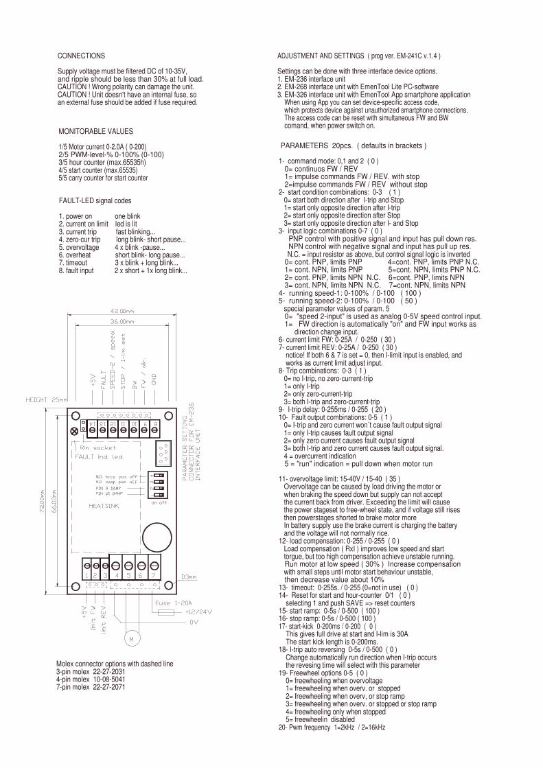
PARAMETERS 20pcs. ( defaults in brackets )
1- command mode: 0,1 and 2 ( 0 )0= continuos FW / REV1= impulse commands FW / REV. with stop2=impulse commands FW / REV without stop
2- start condition combinations: 0-3 ( 1 ) 0= start both direction after I-trip and Stop 1= start only opposite direction after I-trip 2= start only opposite direction after Stop 3= start only opposite direction after I- and Stop
3- input logic combinations 0-7 ( 0 )PNP control with positive signal and input has pull down res.NPN control with negative signal and input has pull up res.
N.C. = input resistor as above, but control signal logic is inverted 0= cont. PNP, limits PNP 4=cont. PNP, limits PNP N.C. 1= cont. NPN, limits PNP 5=cont. NPN, limits PNP N.C. 2= cont. PNP, limits NPN N.C. 6=cont. PNP, limits NPN 3= cont. NPN, limits NPN N.C. 7=cont. NPN, limits NPN
4- running speed-1: 0-100% / 0-100 ( 100 )5- running speed-2: 0-100% / 0-100 ( 50 ) special parameter values of param. 50= "speed 2-input" is used as analog 0-5V speed control input.1= FW direction is automatically "on" and FW input works as
direction change input.6- current limit FW: 0-25A / 0-250 ( 30 )7- current limit REV: 0-25A / 0-250 ( 30 )
notice! If both 6 & 7 is set = 0, then I-limit input is enabled, and works as current limit adjust input.
8- Trip combinations: 0-3 ( 1 ) 0= no I-trip, no zero-current-trip 1= only I-trip 2= only zero-current-trip 3= both I-trip and zero-current-trip
9- I-trip delay: 0-255ms / 0-255 ( 20 )10- Fault output combinations: 0-5 ( 1 ) 0= I-trip and zero current won´t cause fault output signal 1= only I-trip causes fault output signal 2= only zero current causes fault output signal 3= both I-trip and zero current causes fault output signal. 4 = overcurrent indication5 = "run" indication = pull down when motor run
Molex connector options with dashed line3-pin molex 22-27-20314-pin molex 10-08-50417-pin molex 22-27-2071
ADJUSTMENT AND SETTINGS ( prog ver. EM-241C v.1.4 )
Settings can be done with three interface device options.1. EM-236 interface unit2. EM-268 interface unit with EmenTool Lite PC-software3. EM-326 interface unit with EmenTool App smartphone application
When using App you can set device-specific access code, which protects device against unauthorized smartphone connections.The access code can be reset with simultaneous FW and BW comand, when power switch on.
FAULT-LED signal codes
1. power on one blink2. current on limit led is lit3. current trip fast blinking...4. zero-cur trip long blink- short pause...5. overvoltage 4 x blink -pause...6. overheat short blink- long pause...7. timeout 3 x blink + long blink...8. fault input 2 x short + 1x long blink...
CONNECTIONS
Supply voltage must be filtered DC of 10-35V, and ripple should be less than 30% at full load.CAUTION ! Wrong polarity can damage the unit.CAUTION ! Unit doesn't have an internal fuse, soan external fuse should be added if fuse required.
MONITORABLE VALUES
1/5 Motor current 0-2.0A ( 0-200)2/5 PWM-level-% 0-100% (0-100)3/5 hour counter (max.65535h)4/5 start counter (max.65535)5/5 carry counter for start counter
11- overvoltage limit: 15-40V / 15-40 ( 35 ) Overvoltage can be caused by load driving the motor or when braking the speed down but supply can not accept the current back from driver. Exceeding the limit will cause the power stageset to free-wheel state, and if voltage still rises then powerstages shorted to brake motor more In battery supply use the brake current is charging the battery and the voltage will not normally rice.
12- load compensation: 0-255 / 0-255 ( 0 ) Load compensation ( RxI ) improves low speed and start torgue, but too high compensation achieve unstable running.Run motor at low speed ( 30% ) Increase compensation
with small steps until motor start behaviour unstable, then decrease value about 10%
13- timeout: 0-255s. / 0-255 (0=not in use) ( 0 )14- Reset for start and hour-counter 0/1 ( 0 )
selecting 1 and push SAVE => reset counters15- start ramp: 0-5s / 0-500 ( 100 )16- stop ramp: 0-5s / 0-500 ( 100 )17- start-kick 0-200ms / 0-200 ( 0 )
This gives full drive at start and I-lim is 30A The start kick length is 0-200ms.
18- I-trip auto reversing 0-5s / 0-500 ( 0 ) Change automatically run direction when I-trip occurs the revesing time will select with this parameter
19- Freewheel options 0-5 ( 0 ) 0= freewheeling when overvoltage 1= freewheeling when overv. or stopped 2= freewheeling when overv, or stop ramp 3= freewheeling when overv. or stopped or stop ramp 4= freewheeling only when stopped 5= freewheelin disabled
20- Pwm frequency 1=2kHz / 2=16kHz
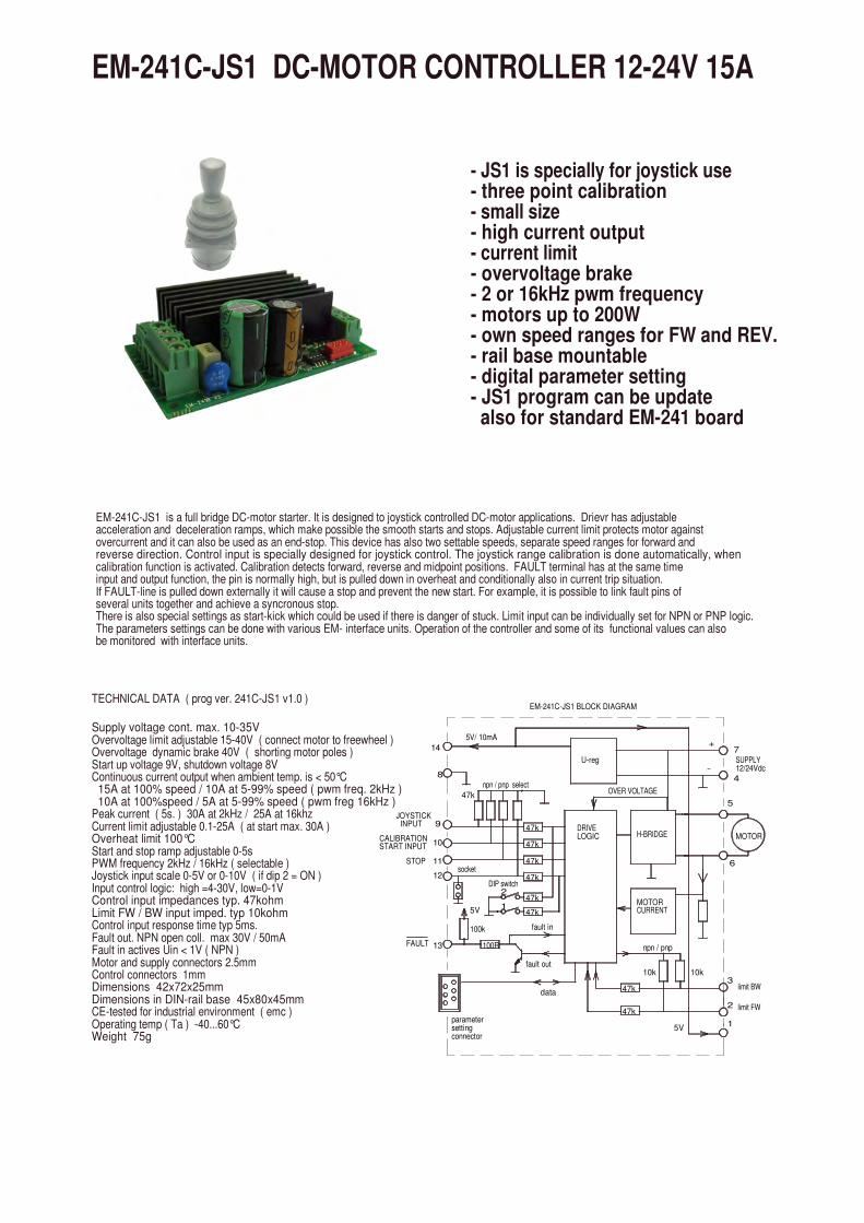
EM-241C-JS1 is a full bridge DC-motor starter. It is designed to joystick controlled DC-motor applications. Drievr has adjustable acceleration and deceleration ramps, which make possible the smooth starts and stops. Adjustable current limit protects motor againstovercurrent and it can also be used as an end-stop. This device has also two settable speeds, separate speed ranges for forward and reverse direction. Control input is specially designed for joystick control. The joystick range calibration is done automatically, when calibration function is activated. Calibration detects forward, reverse and midpoint positions. FAULT terminal has at the same timeinput and output function, the pin is normally high, but is pulled down in overheat and conditionally also in current trip situation. If FAULT-line is pulled down externally it will cause a stop and prevent the new start. For example, it is possible to link fault pins of several units together and achieve a syncronous stop. There is also special settings as start-kick which could be used if there is danger of stuck. Limit input can be individually set for NPN or PNP logic. The parameters settings can be done with various EM- interface units. Operation of the controller and some of its functional values can also be monitored with interface units.
13
9
10
11
12
14
Supply voltage cont. max. 10-35VOvervoltage limit adjustable 15-40V ( connect motor to freewheel ) Overvoltage dynamic brake 40V ( shorting motor poles )Start up voltage 9V, shutdown voltage 8VContinuous current output when ambient temp. is < 50°C 15A at 100% speed / 10A at 5-99% speed ( pwm freq. 2kHz ) 10A at 100%speed / 5A at 5-99% speed ( pwm freg 16kHz )Peak current ( 5s. ) 30A at 2kHz / 25A at 16khzCurrent limit adjustable 0.1-25A ( at start max. 30A )Overheat limit 100°CStart and stop ramp adjustable 0-5sPWM frequency 2kHz / 16kHz ( selectable )Joystick input scale 0-5V or 0-10V ( if dip 2 = ON )Input control logic: high =4-30V, low=0-1VControl input impedances typ. 47kohmLimit FW / BW input imped. typ 10kohmControl input response time typ 5ms.Fault out. NPN open coll. max 30V / 50mAFault in actives Uin < 1V ( NPN )Motor and supply connectors 2.5mmControl connectors 1mmDimensions 42x72x25mmDimensions in DIN-rail base 45x80x45mmCE-tested for industrial environment ( emc )Operating temp ( Ta ) -40...60°CWeight 75g
FAULT
TECHNICAL DATA ( prog ver. 241C-JS1 v1.0 )
STOP
CALIBRATIONSTART INPUT
JOYSTICK INPUT
1MOTORCURRENT
parametersettingconnector
100k
100R
data
fault out
fault in
47k
47k
5V 47k
5V
npn / pnp
10k 10k
1
2
3
limit FW
limit BW
EM-241C-JS1 BLOCK DIAGRAM
OVER VOLTAGE
8
socket
47k
npn / pnp select
DIP switch2
47k
47k
47k
47k
47k
DRIVELOGIC
U-reg
5V/ 10mA
7
H-BRIDGE
SUPPLY12/24Vdc-
MOTOR
5
4
6
+
EM-241C-JS1 DC-MOTOR CONTROLLER 12-24V 15A
- JS1 is specially for joystick use- three point calibration- small size- high current output- current limit- overvoltage brake- 2 or 16kHz pwm frequency- motors up to 200W- own speed ranges for FW and REV.- rail base mountable- digital parameter setting - JS1 program can be update also for standard EM-241 board

ADJUSTMENT AND SETTINGS ( prog ver. EM-241C-JS1 v1.0 )
Adjusting and parameter setting of eg.current limit value, ramp times and speed-2 value can be done with various EM-interface unitsEM-236 is basic parameter setting device.EM-268 and EM- 328 are USB-serial converters, which makes possible to set parameters also with computer where is installed EmenTool Liteprogram. EM-326 is Bluetooth -dongle which can be used in smart devices with EmenTool App.
11- overvoltage limit: 15-40V / 15-40 ( 35 ) Overvoltage can be caused by load driving the motor or when braking the speed down but supply can not accept the current back from driver. Exceeding the limit will cause the power stage set to free-wheel state. With a direct battery supply the brake current is charging the battery and the voltage will not normally rise. There is also 40V fixed dynamic brake point = motor pole shorted12- load compensation: 0-255 / 0-255 ( 0 ) Load compensation ( RxI ) improves low speed and start torgue, but too high compensation achieve unstable running. Run motor at low speed ( 30% ) Increase compensation with small steps until motor start behaviour unstable, then decrease value about 10%13- timeout: 0-255s. / 0-255 (0=not in use) ( 0 )14- reset for start and hour-counter 0/1 ( 0 ) selecting 1 and push SAVE => reset counters15- start ramp: 0-5s / 0-500 ( 50 )16- stop ramp: 0-5s / 0-500 ( 20)17- start-kick 0-200ms / 0-200 ( 0 ) This gives full drive at start and I-lim is 30A The start kick length is 0-200ms.18- Dead band wide 0-50% / 0-50 ( 5 )19- Freewheel options 0-3 ( 0 ) 0= no freewheel 1= freewheel when stopped 2= freewheel during stop ramp. 3= freewheel during stop ramp and if stopped20- Pwm frequency 1=2kHz / 2=16kHz
JOYSTICK CALIBRATION
Give about 3s. control signal to CALIB input. when Fault-Ied of device will be lit:-push joystick full forward, then-pull joystick full reverse, then-release joystick to mid position, then-wait until led start to blink = calibration done
NOTICE ! calibration above defines joystickfull fw, full rev. and mid point positions.But the max. speed can be set with parameters 4 and 5
MONITORABLE VALUES
1/6 Motor current 0-20A ( 0-200)2/6 PWM-level-% 0-100% (0-100)3/6 hour counter (max.65535h)4/6 start counter (max.65535)5/6 carry counter for start counter6/6 joystick position 0-1024
FAULT-LED signal codes
1. power on one blink2. current on limit led is lit3. current trip fast blinking...4. zero-cur trip long blink- short pause...5. overvoltage 4 x blink -pause...6. overheat short blink- long pause...7. timeout 3 x blink + long blink...8. fault input 2 x short + 1x long blink...
Special codes for calibration modesolid light = calibration can be doneblink light = calibration is done
CONNECTIONS
Supply voltage must be filtered DC of 10-35V, and ripple should be less than 30% at full load.CAUTION ! Wrong polarity can damage the unit.CAUTION ! Unit doesn't have an internal fuse, soan external fuse should be added if fuse required.
SETTABLE PARAMETERS 20pcs. ( defaults in brackets )
1- not in use2- not in use3- input logic for limit inputs 1 or 2 PNP/NPN ( 1 ) 1= limit inputs PNP 2= limit input NPN4- max. speed FW. 0-100% / 0-100 ( 100 )5- max. speed REV. 0-100% / 0-100 ( 100 )6- current limit FW. 0.1-20A / 1-200 ( 30 )7- current limit REV. 0.1-20A / 1-200 ( 30 )8- current trip 0= disabled, 1= enabled : ( 1 )9- not in use10- Fault output combinations: 0-2 ( 0 ) 0= overtemp, current trip. overvoltage 1= as above + calibration indication 2= current limit indication NOTICE ! fault input is disabled in setting 2
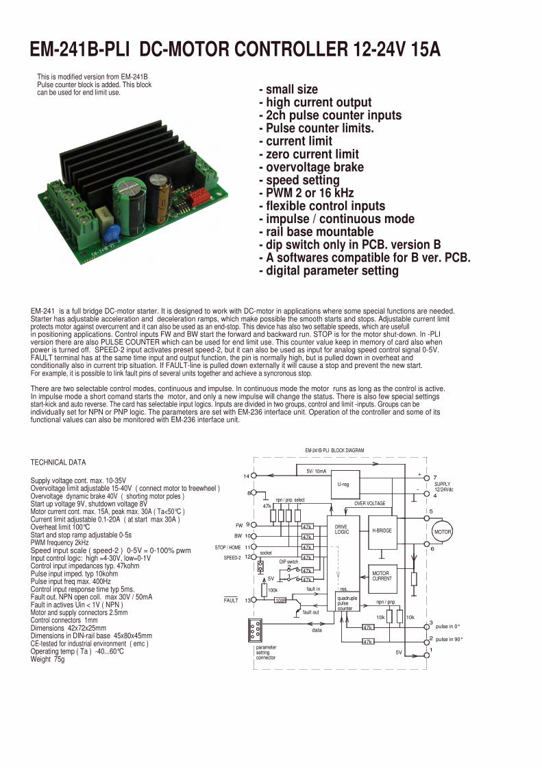
EM-241 is a full bridge DC-motor starter. It is designed to work with DC-motor in applications where some special functions are needed.Starter has adjustable acceleration and deceleration ramps, which make possible the smooth starts and stops. Adjustable current limitprotects motor against overcurrent and it can also be used as an end-stop. This device has also two settable speeds, which are usefull in positioning applications. Control inputs FW and BW start the forward and backward run. STOP is for the motor shut-down. In -PLI version there are also PULSE COUNTER which can be used for end limit use. This counter value keep in memory of card also whenpower is turned off. SPEED-2 input activates preset speed-2, but it can also be used as input for analog speed control signal 0-5V. FAULT terminal has at the same time input and output function, the pin is normally high, but is pulled down in overheat and conditionally also in current trip situation. If FAULT-line is pulled down externally it will cause a stop and prevent the new start. For example, it is possible to link fault pins of several units together and achieve a syncronous stop.
There are two selectable control modes, continuous and impulse. In continuous mode the motor runs as long as the control is active. In impulse mode a short comand starts the motor, and only a new impulse will change the status. There is also few special settings start-kick and auto reverse. The card has selectable input logics. Inputs are divided in two groups, control and limit -inputs. Groups can beindividually set for NPN or PNP logic. The parameters are set with EM-236 interface unit. Operation of the controller and some of its functional values can also be monitored with EM-236 interface unit.
npn / pnp select
DIP switch
1
2
Supply voltage cont. max. 10-35VOvervoltage limit adjustable 15-40V ( connect motor to freewheel ) Overvoltage dynamic brake 40V ( shorting motor poles )Start up voltage 9V, shutdown voltage 8VMotor current cont. max. 15A, peak max. 30A ( Ta<50°C )Current limit adjustable 0.1-20A ( at start max 30A )Overheat limit 100°CStart and stop ramp adjustable 0-5sPWM frequency 2kHzSpeed input scale ( speed-2 ) 0-5V = 0-100% pwmInput control logic: high =4-30V, low=0-1VControl input impedances typ. 47kohmPulse input imped. typ 10kohmPulse input freq max. 400HzControl input response time typ 5ms.Fault out. NPN open coll. max 30V / 50mAFault in actives Uin < 1V ( NPN )Motor and supply connectors 2.5mmControl connectors 1mmDimensions 42x72x25mmDimensions in DIN-rail base 45x80x45mmCE-tested for industrial environment ( emc )Operating temp ( Ta ) -40...60°CWeight 75g
FAULT 100R
parametersettingconnector
13
100k
5V
TECHNICAL DATA
14
SPEED-2
STOP / HOME
8
47k
9FW
10BW
11
12socket
MOTORCURRENT
47k
47k
fault in res.
data
fault out
quadruplepulsecounter
47k
10k
5V
npn / pnp
10k
1
2
3pulse in 0°
pulse in 90°
-
OVER VOLTAGE
47k
DRIVELOGIC
47k
47k
47k
47k
U-reg
H-BRIDGE
EM-241B-PLI BLOCK DIAGRAM
5V/ 10mA
7
4
6
5
SUPPLY12/24Vdc
MOTOR
+
EM-241B-PLI DC-MOTOR CONTROLLER 12-24V 15A
- small size- high current output- 2ch pulse counter inputs- Pulse counter limits.- current limit- zero current limit- overvoltage brake- speed setting- PWM 2 or 16 kHz- flexible control inputs- impulse / continuous mode- rail base mountable- dip switch only in PCB. version B- A softwares compatible for B ver. PCB.- digital parameter setting
This is modified version from EM-241BPulse counter block is added. This blockcan be used for end limit use.
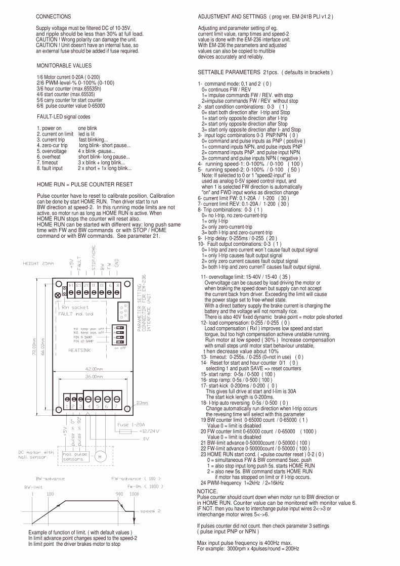
11- overvoltage limit: 15-40V / 15-40 ( 35 ) Overvoltage can be caused by load driving the motor or when braking the speed down but supply can not accept the current back from driver. Exceeding the limit will cause the power stage set to free-wheel state. With a direct battery supply the brake current is charging the battery and the voltage will not normally rice. There is also 40V fixed dynamic brake point = motor pole shorted12- load compensation: 0-255 / 0-255 ( 0 ) Load compensation ( RxI ) improves low speed and start torgue, but too high compensation achieve unstable running. Run motor at low speed ( 30% ) Increase compensation with small steps until motor start behaviour unstable, t hen decrease value about 10%13- timeout: 0-255s. / 0-255 (0=not in use) ( 0 )14- Reset for start and hour-counter 0/1 ( 0 ) selecting 1 and push SAVE => reset counters15- start ramp: 0-5s / 0-500 ( 100 )16- stop ramp: 0-5s / 0-500 ( 100 )17- start-kick 0-200ms / 0-200 ( 0 ) This gives full drive at start and I-lim is 30A The start kick length is 0-200ms.18- I-trip auto reversing 0-5s / 0-500 ( 0 ) Change automatically run direction when I-trip occurs the revesing time will select with this parameter 19 BW counter limit 0-65000 count / 0-65000 ( 1 ) Value 0 = limit is disabled20 FW counter limit 0-65000 count / 0-65000 ( 1000 ) Value 0 = limit is disabled21 BW-limit advance 0-50000count / 0-50000 ( 100 )22 FW-limit advance 0-50000count / 0-50000 ( 100 )23 HOME RUN start cond. ( =pulse counter reset ) 0-2 ( 0 ) 0 = simultaneous FW & BW command 5sec. push 1 = also stop input long push 5s. starts HOME RUN 2 = also new 5s. BW command starts HOME RUN if motor has stopped on limit or if I-trip occurs.24 PWM-frequency 1=2kHz / 2=16kHz
NOTICE.Pulse counter should count down when motor run to BW direction orin HOME RUN. Counter value can be monitored with monitor value 6.IF NOT. then you have to interchange pulse input wires 2<->3 orinterchange motor wires 5<->6.
If pulses counter did not count. then check parameter 3 settings( pulse input PNP or NPN )
Max input pulse frequency is 400Hz max.For example: 3000rpm x 4pulses/round = 200Hz
Example of function of limit. ( with default values )In limit advance point changes speed to the speed-2In limit point the driver brakes motor to stop
SETTABLE PARAMETERS 21pcs. ( defaults in brackets )
1- command mode: 0,1 and 2 ( 0 ) 0= continuos FW / REV 1= impulse commands FW / REV. with stop 2=impulse commands FW / REV without stop2- start condition combinations: 0-3 ( 1 ) 0= start both direction after I-trip and Stop 1= start only opposite direction after I-trip 2= start only opposite direction after Stop 3= start only opposite direction after I- and Stop3- input logic combinations 0-3 PNP/NPN ( 0 ) 0= command and pulse inputs as PNP ( positive ) 1= command inputs NPN, and pulse inputs PNP 2= command inputs PNP. and pulse input NPN 3= command and pulse inputs NPN ( negative )4- running speed-1: 0-100% / 0-100 ( 100 )5- running speed-2: 0-100% / 0-100 ( 50 ) Note: If selected to 0 or 1 "speed2-input" is used as analog 0-5V speed control input, and when 1 is selected FW direction is automatically "on" and FWD input works as direction change6- current limit FW: 0.1-20A / 1-200 ( 30 )7- current limit REV: 0.1-20A / 1-200 ( 30 )8- Trip combinations: 0-3 ( 1 ) 0= no I-trip, no zero-current-trip 1= only I-trip 2= only zero-current-trip 3= both I-trip and zero-current-trip9- I-trip delay: 0-255ms / 0-255 ( 20 )10- Fault output combinations: 0-3 ( 1 ) 0= I-trip and zero current won´t cause fault output signal 1= only I-trip causes fault output signal 2= only zero current causes fault output signal 3= both I-trip and zero currenT causes fault output signal.
ADJUSTMENT AND SETTINGS ( prog ver. EM-241B PLI v1.2 )
Adjusting and parameter setting of eg.current limit value, ramp times and speed-2 value is done with the EM-236 interface unit. With EM-236 the parameters and adjusted values can also be copied to multible devices accurately and reliably.
FAULT-LED signal codes
1. power on one blink2. current on limit led is lit3. current trip fast blinking...4. zero-cur trip long blink- short pause...5. overvoltage 4 x blink -pause...6. overheat short blink- long pause...7. timeout 3 x blink + long blink...8. fault input 2 x short + 1x long blink...
HOME RUN = PULSE COUNTER RESET
Pulse counter have to reset to calibrate position. Calibrationcan be done by start HOME RUN. Then driver start to runBW direction at speed-2. In this running mode limits are not active, so motor run as long as HOME RUN is active. WhenHOME RUN stops the counter will reset also.HOME RUN can be started with different way: long push same time with FW and BW commands or with STOP / HOMEcommand or with BW commands. See parameter 21.
CONNECTIONS
Supply voltage must be filtered DC of 10-35V, and ripple should be less than 30% at full load.CAUTION ! Wrong polarity can damage the unit.CAUTION ! Unit doesn't have an internal fuse, soan external fuse should be added if fuse required.
MONITORABLE VALUES
1/6 Motor current 0-20A ( 0-200)2/6 PWM-level-% 0-100% (0-100)3/6 hour counter (max.65535h)4/6 start counter (max.65535)5/6 carry counter for start counter6/6 pulse counter value 0-65000

EM-285 is a PWM-based DC-motor driver. The materials and features meet the industrial standards. Motor voltage is regulated against supply voltage changes, and there is also a load compensation adjustment ( RxI ), which enables steady speed during motor loading. Because of these features EM-285 can offer a good DC-motor speed regulation. In the power line of EM-285 there is an overvoltage limit, which trips the power stage in case the voltage would try to rise too high. This is possible in deceleration situation (emf voltage generation in braking). If potentiometer is turned on zero-position, the driver will make a shorting on motor wires for 5s.This creates a powerfull braking (dynamic brake) which can be used to stop or lower the motor speed fast.The current limit and potentiometer range can be adjusted with on-board trimmer potentiometer. The device is EMC measured and meets industrial requirements in typical installation. EM-285 is easy to mount to a D10mm hole in the assembly panel. The power stage is not short circuit protected, so it is recommended to use an external fuse in application supply wiring.
EM-285 DC-MOTOR SPEED REGULATOR12 / 24V 20A
TECHNICAL DATA
Supply voltage 10-35Vdc Overvoltage shut down 38VUndervoltage shut down 10VStart up voltage 11VIdle current typ. 20mAMotor current cont. max 20A ( Ta<50°C )Motor current peak max 30A ( 10s. )Power losses 5W ( at 20A and 16kHz )Power losses 4W ( at 20A and 2kHz )Current limit adj. 1-30APWM frequency 2kHz or 16kHzTemperature limit 90°CMotor and supply connectors 2.5mmEMC EN 50081-2 & EN 50082-2Weight 85gOperating temp ( Ta ) -20...60°C
ELECTROMEN Oywww.electromen.com
CURRENTMEASURE
LOAD COMP. RxI
PWM
VOLTAGE SENSE
2/16kHz
I-lim I-lim
RANGE
SPEEDADJUST
VOLTAGECONTROL
5V
EM-285
3
EM285BROE 01.12.09
4
2
M
1
FEATURES
- Speed cont. to 1-direction- Panel mountable- Small size- Motor size 30-200W- Good speed regulation- Load comp. adjustable RxI- Adjustable current limit- Overheating protection- EMC tested.
mt18
Text Box
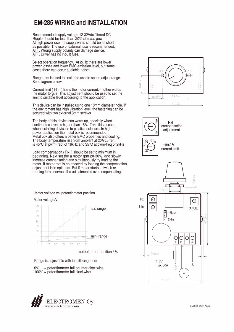
10 1
Recommended supply voltage 12-32Vdc filtered DCRipple should be less than 20% at max. power.At high power use the supply wires should be as shortas possible. The use of external fuse is recommended.ATT. Wrong supply polarity can damage device.ATT. Driver has no inbuilt fuse.
Select operation frequency. At 2kHz there are lowerpower losses and lower EMC emission level, but somecases there can occur audiable noise.
Range trim is used to scale the usable speed adjust range. See diagram below.
Current limit ( I-lim ) limits the motor current, in other words the motor torgue. This adjustment should be used to set thelimit to suitable level according to the application.
This device can be installed using one 10mm diameter hole. Ifthe enviroment has high vibration level, the fastening can be secured with two external 3mm screws.
The body of this device can warm up, specially whencontinuos current is higher than 15A. Take this accountwhen installing device in to plastic enclosure. In highpower application the metal box is recommended.Metal box also offers a better EMC properties and cooling.The body temperature rise from ambient at 20A currentis 45°C at pwm-freq. of 16kHz and 35°C at pwm-freq of 2kHz
Load compensation ( RxI ) should be set to minimum inbeginning. Next set the a motor rpm 20-30%. and slowly increase compensation and simultanously try loading themotor. If motor rpm is no affected by loading the compensationadjustment is in optimum. But if motor starts to twitch or running turns nervous the adjustment is overcompensating.
ELECTROMEN Oy
potentimeter position / %
Range is adjustable with inbuilt range trim
0% = potentiometer full counter clockwise100% = potentiometer full clockwise
www.electromen.com
min. range
Motor voltage vs. potentiometer position
Motor voltage/V
max. range
1 2
12
-24
V
FUSEmax. 30A
3
M
EM285BROE 01.12.09
4
0V
RANGE
RxI
I-lim.
16khz
2khz
5
EM-285 WIRING and INSTALLATION
15
20
3025
min
max
RxIcompensation adjustment
current limitI-lim./ A
mt18
Text Box

EM-115 DC-MOTOR CONTROL UNIT12-36V 25A 4-QUAD.
FEATURES:
• Small size• Four quadrant drive• High efficiency >92%• Motor range 50-500W• Rail mounting base fittable• Adjustable current limit• Adjustable ramp
EM-115 motor control unit is designed for big permanent magnet DC-motors. The power control is done withPWM method (Pulse Width Modulation). This facilitates high efficiency and small temperature losses. Thanksto a high switching frequency the unit operates quietly. A battery or a filtered DC-supply will do as a powersource.The maximum output given by the unit depends on the installation. When operating at maximum power outputsufficient air ventilation has to be taken care of. The unit operates in 4-quadrants so it drives and brakes inboth directions. The braking is done with regenerative way feeding braking energy back to power supply. Whena battery is not used as a power source the braking energy will be fed to the internal resistance of the motor.The motor rpm can be set either with potentiometer, trim or external voltage signal. The output accelerationramp and current limit are set with trims, the current limit is indicated with a red LED. A load affecting the motorrpm can be eliminated with a compensation trim. The power stage is protected against voltage peaks, overloadand temporary shortcuts. Even the incorrect polarity does not damage the unit as long as a fuse ofrecommended value is used.
TECHNICAL DATA:
Supply voltage 12...36 VdcIdle current < 50mARecommended fuse 5-30AControl potentiometer 1k..50kLoad capacity 25A RMS
50A mom. (5s)Motor voltage 0-30VControl voltage range from 0-5V to 0-10VVoltage loss /V <1V when Im=25ACurrent limit 4..50AOperating frequency approx. 21kHzRamp time 0.3..10sOn / Off control >4V “on”
<1V “off”Input impedance pins 6,7 and 8 = 10kohm
pin 9 = 100kohmEfficiency >92%Operating temp. -10..50 °CDimensions 107*107*45 mmWeight approx. 270 g
2
3
1
P1
P3
10V 80mA
10
9
speed set
8
7
P2
activ. sp 2
forward
5
6 reverse
PWM
currentlimit
compens.
P5
P4level.adjust
ramp.
4
10V reg
M
changepole

EM-115 OPERATING AND CONNECTING INSTRUCTIONS
IMPORTANT!
Check polarity before connecting!Use filtered 12-36VDC (ripple <20%)as operating voltage.
When motor current constantly exceeds 20A,proper air ventilation must be taken care of.Ambient temperature should not be over 50°C.
CONTROLS
P1-maximum level.Use to set maximum level. This is alsothe speed set for speed-1 in 2-step speed mode.
P2-speed-2When using 2-step speed mode use P2 toset speed-2.
P3-acceleration / braking rampUse ramp adj. to obtain smoothstarting and running. The right valuecan be found just by testing the set.
P4-current limitThe operation of the current limit is indicatedby a red LED next to the trim. Use it to set thedesired maximum current to the motor, in otherwords max. torque.
P5-compensationUse this trim to compensate the load affectingthe motor rpm. Set the motor rpm to approx.50%, adjust ccw until the motor starts to twitch,then adjust carefully backwards till the twitching ends.
FUSE
The fuse type is ATO 5-30A, according tothe application.
1. Supply voltage 12-36V2. Motor out +3. Motor out -4. Supply voltage 0V gnd
5. Control voltage approx. 10V 80mA6. Reverse (master)7. Forward8. Speed-2 activation9. Control input (U / pot.)10. Signal 0V gnd
TERMINALS
10
SUPPLY 12-36V DC
EM-115
99mm
107mm
5 6 7 8 9
P5comp.
-
4 3 2 1
M+
I-lim
99m
m
FUSES
107m
m
4mm
max.min.
50% 50% 7s 25A
P1max.lev.
P2speed2
P3ramp.
P4I-lim
0 100% 0 100% 0 15s 4A 50A
Continuous rpm control,set with pot.meter, adjustrange with P1.Switch to forward.Switch to change direction.
2-step speed mode(run / positioning)P1-speed1, P2-speed2Activation with speed1& speed2.
Continuous rpm control,set with voltage, adjustrange with trim P1.Reverse and forward withTTL, CMOS or 0-24V signal.
INPUT DC
Forward, OFF 0-1V, ON 4-30VReverse, OFF 0-1V, ON 4-30VSpeed (Uset) 0-5V to 0-10V = 0-100%
spee
d
8
10V
rev
forw
ard
5 6 7
M
34
-
GN
D
9 10
2
INPUT DC
1
+M
10V
rev
5 6
34
-
GN
D
spee
d2
spee
d1
7 8 9 10
+ INPUT DC
12 3
10V
6
forw
ard
5
4
-
GN
D
rev
Use
t
7 8 9 10
+
12
M

EM-115-48 DC-MOTOR CONTROL UNIT20-60V 25A 4-QUAD.
FEATURES:
• Small size• Four quadrant drive• High efficiency >92%• Motor range 50-500W• Rail mounting base fittable• Adjustable current limit• Adjustable ramp
EM-115-48 motor control unit is designed for big permanent magnet DC-motors. The power control is donewith PWM method (Pulse Width Modulation). This facilitates high efficiency and small temperature losses.Thanks to a high switching frequency the unit operates quietly. A battery or a filtered DC-supply will do as apower source.The maximum output given by the unit depends on the installation. When operating at maximum power outputsufficient air ventilation has to be taken care of. The unit operates in 4-quadrants so it drives and brakes inboth directions. The braking is done with regenerative way feeding braking energy back to power supply. Whena battery is not used as a power source the braking energy will be fed to the internal resistance of the motor.The motor rpm can be set either with potentiometer, trim or external voltage signal. The output accelerationramp and current limit are set with trims, the current limit is indicated with a red LED. A load affecting the motorrpm can be eliminated with a compensation trim. The power stage is protected against voltage peaks, overloadand temporary shortcuts. Even the incorrect polarity does not damage the unit as long as a fuse ofrecommended value is used.
TECHNICAL DATA:
Supply voltage 20...60 VdcIdle current < 50mARecommended fuse 5-30AControl potentiometer 1k..50kLoad capacity 25A RMS
50A mom. (5s)Motor voltage 0-58VControl voltage range from 0-5V to 0-10VVoltage loss /V <0.5V when Im=30ACurrent limit 4..50AOperating frequency approx. 21kHzRamp time 0.3..10sOn / Off control >4V “on”
<1V “off”Input impedance pins 6,7 and 8 = 10kohm
pin 9 = 100kohmEfficiency >92%Operating temp. -10..50 °CDimensions 107*107*45 mmWeight approx. 270 g
2
3
1
P1
P3
10V 80mA
10
9
speed set
8
7
P2
activ. sp 2
forward
5
6 reverse
PWM
currentlimit
compens.
P5
P4level.adjust
ramp.
4
10V reg
M
changepole
Notice: With this higher voltage version it is more important to use motorin accordance to the recommend motor power range (<500W)..
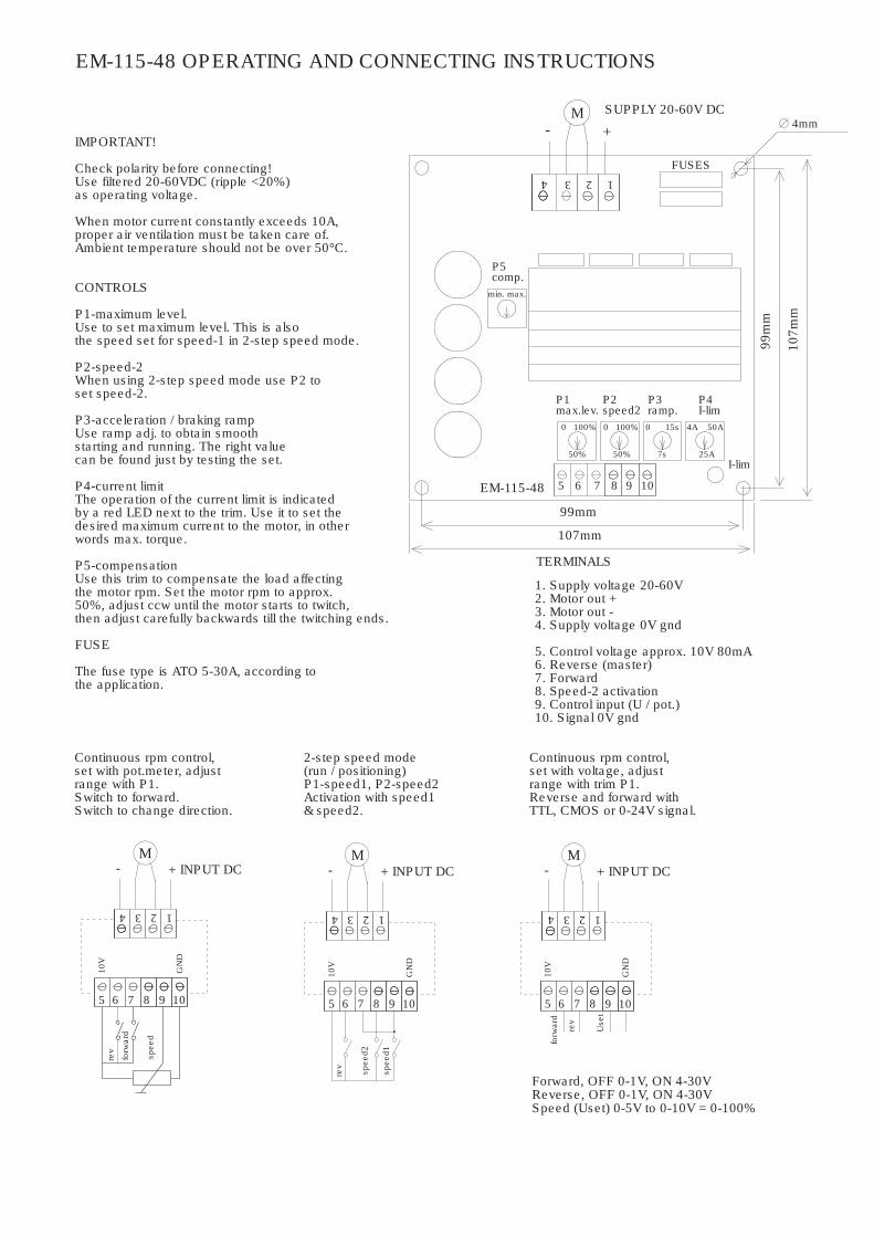
EM-115-48 OPERATING AND CONNECTING INSTRUCTIONS
IMPORTANT!
Check polarity before connecting!Use filtered 20-60VDC (ripple <20%)as operating voltage.
When motor current constantly exceeds 10A,proper air ventilation must be taken care of.Ambient temperature should not be over 50°C.
CONTROLS
P1-maximum level.Use to set maximum level. This is alsothe speed set for speed-1 in 2-step speed mode.
P2-speed-2When using 2-step speed mode use P2 toset speed-2.
P3-acceleration / braking rampUse ramp adj. to obtain smoothstarting and running. The right valuecan be found just by testing the set.
P4-current limitThe operation of the current limit is indicatedby a red LED next to the trim. Use it to set thedesired maximum current to the motor, in otherwords max. torque.
P5-compensationUse this trim to compensate the load affectingthe motor rpm. Set the motor rpm to approx.50%, adjust ccw until the motor starts to twitch,then adjust carefully backwards till the twitching ends.
FUSE
The fuse type is ATO 5-30A, according tothe application.
1. Supply voltage 20-60V2. Motor out +3. Motor out -4. Supply voltage 0V gnd
5. Control voltage approx. 10V 80mA6. Reverse (master)7. Forward8. Speed-2 activation9. Control input (U / pot.)10. Signal 0V gnd
TERMINALS
10
SUPPLY 20-60V DC
EM-115-48
99mm
107mm
5 6 7 8 9
P5comp.
-
4 3 2 1
M+
I-lim
99m
m
FUSES
107m
m
4mm
max.min.
50% 50% 7s 25A
P1max.lev.
P2speed2
P3ramp.
P4I-lim
0 100% 0 100% 0 15s 4A 50A
Continuous rpm control,set with pot.meter, adjustrange with P1.Switch to forward.Switch to change direction.
2-step speed mode(run / positioning)P1-speed1, P2-speed2Activation with speed1& speed2.
Continuous rpm control,set with voltage, adjustrange with trim P1.Reverse and forward withTTL, CMOS or 0-24V signal.
INPUT DC
Forward, OFF 0-1V, ON 4-30VReverse, OFF 0-1V, ON 4-30VSpeed (Uset) 0-5V to 0-10V = 0-100%
spee
d
8
10V
rev
forw
ard
5 6 7
M
34
-
GN
D
9 10
2
INPUT DC
1
+M
10V
rev
5 6
34
-
GN
D
spee
d2
spee
d1
7 8 9 10
+ INPUT DC
12 3
10V
6
forw
ard
5
4
-
GN
D
rev
Use
t
7 8 9 10
+
12
M

EM-243A DC-MOTOR CONTROLLER 12-42V 50A
EM-243A is a full bridge DC-motor starter. It is designed to work with DC-motor in applications where some special functions are needed.Starter has adjustable acceleration and deceleration ramps, which make possible the smooth starts and stops. Adjustable current limitprotects motor against overcurrent and it can also be used as an end-stop. This device has also two settable speeds, which are usefull in positioning applications. Control inputs FW and BW start the forward and backward run. STOP is for the motor shut-down but there arealso available individual limit inputs for FW and BW directions. SPEED-2 input activates preset speed-2, but it can also be used as inputfor analog speed control signal 0-5V. FAULT terminal has at the same time input and output function, the pin is normally high, but is pulled down in overheat and conditionally also in current trip situation. If FAULT-line is pulled down externally it will cause a stop and prevent thenew start. For example, it is possible to link fault pins of several units together and achieve a syncronous stop. There are 2 selectable control modes, contionuous and impulse. In continuous mode the motor runs as long as the control is active. In impulse mode a short comand starts the motor, and only a new impulse will change the status. The card has selectable input logics.Inputs are divided in two groups, control and limit -inputs. Groups can be individually set for NPN or PNP logic. The parameters are set withEM-236 interface unit. Operation of the controller and some of its functional values can also be monitored with EM-236 interface unit.
47k
47k
5V/ 10mA
Supply voltage nominal 12-42V, limits 10-55VStart up voltage 9V, shutdown voltage 8VIdle current typ 15mAMotor current max. continous 50A ( at 25°C amb temp),40A ( at 60° amb temp ) and peak 100A ( 5s )Current limit adjustable 1-100A ( at start 1.5 times )Overheat limit 100°CStart and stop ramp adjustable 0-5sPWM frequency 2kHzSpeed input scale ( speed-2 ) 0-5 or 0-10V= 0-100% pwmInput control logic: high =4-30V, low=0-1VControl input impedances typ. 10kohmControl input response time typ 5ms.Fault out. NPN open coll. max. 50V / 1AFault in actives Uin < 1V ( NPN )Motor and supply connectors 2.5mmControl connectors 1mmDimensions 107x72x40mmDimensions in DIN-rail base 110x80x55mmCE-tested for industrial environment ( EMC )Operating ambient temp ( Ta ) -40...60°CWeight 190g
3
parametersettingconnector
FAULT
10
TECHNICAL DATA
npn / pnp
SPEED-2
FW
5
6
BW7
STOP8
9
10k
1
2
11 100R
MOTORCURRENT
100R
fault in
fault spc.
data
fault out npn / pnp
limit FW
limit BW
10k
5V/ 10mA
10k14
13
12
+
47k
47k
H-BRIDGE
U-reg
U-OVER
DRIVELOGIC
-
EM-243A BLOCK DIAGRAM
MOTOR
4
2
3
SUPPLY12/42Vdc
1
FEATURES
- small size- high current output- current limit- zero current limit- speed setting- flexible control inputs- impulse / continuous mode- rail base mountable- digital parameter setting - A-vers. compatible with older version +higher supply voltage area +higher fault output current. +input damping with dip-switch

11 overvoltage limit: 15-60V / 15-60 ( 55 ) Overvoltage can be caused by load driving the motor or when braking the speed down but supply can not accept the current back from driver. Exceeding the limit will cause the power stage set to free-wheel state. With a direct battery supply the brake current is charging the battery and the voltage will not normally rice.12 load compensation: 0-255 / 0-255 ( 0 ) Load compensation ( RxI ) improves low speed and start torgue, but too high compensation achieve unstable running. Run motor at low speed ( 30% ) Increace compensation with small steps until motor start behaviour unstable, then decrease value about 10%13 timeout: 0-255s. / 0-255 (0=not in use) ( 0 )14 reset for start and hour-counter 0/1 ( 0 ) selecting 1 and push save = reset counters15 start ramp: 0-5s / 0-500 ( 100 )16 stop ramp: 0-5s / 0-500 ( 100 )17 start kick 0-200ms / 0-200 ( 0 ) gives short 0-200ms full drive pulse for start
ADJUSTMENT AND SETTINGS
Adjusting and parameter setting of eg.current limit value, ramp times and speed-2 value is done with the EM-236 interface unit. With EM-236 the parameters and adjusted values can also be copied to multible devices accurately and reliably.
DIP SWITCHES
A-version has a dip swithes, When switch are in OFF position the card will be compatible withearlier version.
Dip-1 ON pos. damping FWD inputDip-2 ON pos. damping Speed-2 input with 2Dip-3 ON pos. special Fault output selectDip-4 ON pos. special clock
EM-243A
on1 2 3 4Speed-2Rin socket
FAULT-LED signal codes
1. power on one blink2. current on limit led is lit3. current trip fast blinking...4. zero-cur trip long blink- short pause...5. overvoltage 4 x blink -pause...6. overheat short blink- long pause...7. timeout 3 x blink + long blink...8. fault input 2 x short + 1x long blink...
MONITORABLE VALUES
1/5 Motor current 0-100A ( 0-100)2/5 PWM-level-% 0-100% (0-100)3/5 hour counter (max.65535h)4/5 start counter (max.65535)5/5 carry counter for start counter
CONNECTIONS
Supply voltage recomendation is 12-42VDC and ripple should be less than 30% at full load.Supply voltage limit is 55VdcCAUTION ! Wrong polarity can damage the unit.CAUTION ! Unit doesn't have an internal fuse, soan external fuse should be added if fuse required.
SETTABLE PARAMETERS prog. 243A v1.0 ( defaults in brackets )
1 command mode: continuous = 0, impulse= 1 ( 0 )2 start condition combinations: 0-3 ( 1 ) 0= start both direction after I-trip and Stop 1= start only opposite direction after I-trip 2= start only opposite direction after Stop 3= start only opposite direction after I- and Stop3 input logic combinations 0-3 PNP/NPN ( 0 ) 0= command and limit inputs as PNP ( positive ) 1= command inputs NPN, and limit inputs PNP 2= command inputs PNP. and limit input NPN 3= command and limit inputs NPN ( negative )4 running speed-1: 0-100% / 0-100 ( 100 )5 running speed-2: 0-100% / 0-100 ( 50 ) Note: If selected to 0 "speed2-input" is used as analog 0-5V speed control input.6 current limit FW: 1-100A / 1-100 ( 10 )7 current limit REV: 1-100A / 1-100 ( 10 )8 Trip combinations: 0-3 ( 1 ) 0= no I-trip, no zero-current-trip 1= only I-trip 2= only zero-current-trip 3= both I-trip and zero-current-trip9 I-trip delay: 0-255ms / 0-255 ( 20 )10 Fault output combinations: 0-3 ( 1 ) 0= I-trip and zero current won´t cause fault output signal 1= only I-trip causes fault output signal 2= only zero current causes fault output signal 3= both I-trip and zero currenT causes fault output signal.

EM-243C-JS1 is a full bridge DC-motor starter. It is designed for joystick controlled DC-motor applications. The driver has adjustable acceleration and deceleration ramps, which enable the smooth starts and stops. Adjustable current limit protects the motor againstovercurrent and it can also be used as an end-stop. This device has also two settable speeds, separate speed ranges for forward and reverse direction. Control input is specially designed for joystick control. The joystick range calibration is done automatically, when calibration function is activated. Calibration detects forward, reverse and midpoint positions. FAULT terminal has simultaneously bothinput and output functions, the pin is normally high, but is pulled down in overheat and conditionally also in current trip situation. If FAULT-line is pulled down externally it will cause a stop and prevent it from starting again. For example, it is possible to link fault pins of several units together and achieve a syncronous stop. There are also special settings as start-kick which can be used in case the device is in danger of being jammed. Limit input can be individually set for NPN or PNP logic. The parameter's settings can be done with various EM- interface units. Operation of the controller and some of its functional values can also be monitored with interface units.
JOYSTICK INPUT
CALIBRATIONSTART INPUT
Supply voltage nominal 12-42V, limits 10-55VStart up voltage 9V, shutdown voltage 8VIdle current typ 15mAMotor current max. with 2kHz pwm100% pwm 50A , 20-99pwm% 35A and peak 100A ( 5s )Motor current max. with 16kHz pwm100% pwm 40A , 20-99pwm% 20A and peak 60A ( 5s )Current limit adjustable 1-100A Notice! current limit is increased 50% at startOverheat limit 100°CStart and stop ramp adjustable 0-5sPWM frequency 2kHz or 16kHz ( selectable )joystick input scale 0-5 or 0-10V ( if dip 1 is ON )Input control logic: high =4-30V, low=0-1VControl input impedances typ. 10kohmControl input response time typ 5ms.Fault out. NPN open coll. max. 50V / 1AFault in actives Uin < 1V ( NPN )Motor and supply connectors 4mmControl connectors 1mmDimensions 107x72x40mmDimensions in DIN-rail base 110x80x55mmCE-tested for industrial environment ( EMC )Operating ambient temp ( Ta ) -40...60°CWeight 190g
TECHNICAL DATA
STOP
limit FW
limit BW
10
parametersettingconnector
FAULT
fault out
data
100R
npn / pnp
5V/ 10mA
10k 10k
12
14
13
EM-243C BLOCK DIAGRAM
npn / pnp5
2
3
1
8
9
6
7
fault in
fault spc.47k
47k
47k
47k DRIVELOGIC
10k
11 100R5V/ 10mA
U-reg
4
U-OVER
MOTORCURRENT
H-BRIDGE MOTOR
3
2
SUPPLY12/42Vdc-
+1
EM-243C-JS1 DC-MOTOR CONTROLLER 12-42V 50A
- JS1 is specially for joystick use- three point calibration- compact size- for motor up to 500W- high current output- current limit- overvoltage brake- own speed ranges for FW and REV.- rail base mountable- digital parameter setting- JS1 program can be update
also for standard EM-243A or243C boards

ADJUST AND SETTINGS ( prog ver. EM-243C-JS1 v1.1 )
Adjusting and parameter setting of eg.current limit value, ramp times and speed-2 value can be done with various EM-interface unitsEM-236 is basic parameter setting device.EM-268 and EM- 328 are USB-serial converters, which makes it possible to set parameters also with computer where is installed EmenTool Liteprogram. EM-326 is Bluetooth -dongle which can be used in smart devices with the EmenTool App.
11- overvoltage limit: 15-60V / 15-60 ( 55 ) Overvoltage can be caused by load driving the motor or when braking the speed down but supply can not accept the current back from driver. Exceeding the limit will cause the power stage set to free-wheel state. With a direct battery supply the brake current is charging the battery and the voltage will not normally rise. There is also 60V fixed dynamic brake point = motor pole shorted
12- load compensation: 0-255 / 0-255 ( 0 ) Load compensation ( RxI ) improves low speed and start torgue, but too high compensation achieve unstable running.Run motor at low speed ( 30% ) Increase compensation
with small steps until motor start behaviour becomes unstable, then decrease value about 10%
13- timeout: 0-255s. / 0-255 (0=not in use) ( 0 )14- reset for start and hour-counter 0/1 ( 0 )
selecting 1 and push SAVE => reset counters15- start ramp: 0-5s / 0-500 ( 50 )16- stop ramp: 0-5s / 0-500 ( 20)17- start-kick 0-200ms / 0-200 ( 0 )
This gives full drive at start and I-lim is 30A The start kick length is 0-200ms.
18- Dead band wide 0-50% / 0-50 ( 5 )19- Freewheel options 0-3 ( 0 )
0= no freewheel 1= freewheel when stopped 2= freewheel during stop ramp. 3= freewheel during stop ramp and if stopped
20- Pwm frequency 1=2kHz / 2=16kHz ( 1 )
onSpeed-2Rin socket
4321
DIP SWITCHES
Dip-1 Damping pin 6 if set ON ( joystick input )Dip-2 Damping pin 9 if set ONDip-3 NOT in use keep always OFFDip-4 NOT in use keep always OFF
EM-243C-JS1
JOYSTICK CALIBRATION
Give about 3s. control signal to CALIB input. when Fault-Ied of device will be lit:-push joystick full forward, then-pull joystick full reverse, then-release joystick to mid position, then-wait until led starts to blink = calibration done
NOTICE ! calibration above defines joystickfull fw, full rev. and mid point positions.But the max. speed can be set with parameters 4 and 5
FAULT-LED signal codes
1. power on one blink2. current on limit led is lit3. current trip fast blinking...4. zero-cur trip long blink- short pause...5. overvoltage 4 x blink -pause...6. overheat short blink- long pause...7. timeout 3 x blink + long blink...8. fault input 2 x short + 1x long blink...
Special codes for calibration modesolid light = calibration can be doneblink light = calibration is done
CONNECTIONS
Supply voltage recomendation is 12-42VDC and ripple should be less than 30% at full load.Supply voltage limit is 55VdcCAUTION ! Wrong polarity can damage the unit.CAUTION ! Unit doesn't have an internal fuse, soan external fuse should be added if fuse required.
MONITORABLE VALUES
1/6 Motor current 0-20A ( 0-200)2/6 PWM-level-% 0-100% (0-100)3/6 hour counter (max.65535h)4/6 start counter (max.65535)5/6 carry counter for start counter6/6 joystick position 0-1024
SETTABLE PARAMETERS 20pcs. ( defaults in brackets )
1- not in use2- not in use3- input logic for limit inputs 1 or 4 PNP/NPN ( 1 )
1= limit inputs PNP 2= limit input NPN3= limit inputs PNP N.C. 4=limits inputs NPN N.C
( N.C.= normally closed = open circuits stops. )4- max. speed FW. 0-100% / 0-100 ( 100 )5- max. speed REV. 0-100% / 0-100 ( 100 )6- current limit FW. 1-100A / 1-100 ( 30 )7- current limit REV. 1-100A / 1-100 ( 30 )8- current trip 0= disabled, 1= enabled : ( 1 )9- not in use10- Fault output combinations: 0-2 ( 0 )
0= overtemp, current trip. overvoltage1= as above + calibration indication2= current limit indication
NOTICE ! fault input is disabled in setting 2
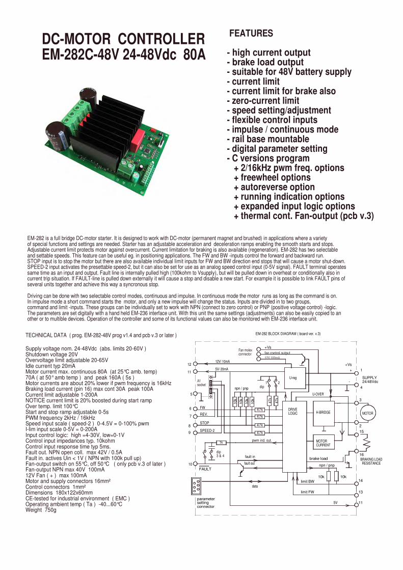
EM-282 is a full bridge DC-motor starter. It is designed to work with DC-motor (permanent magnet and brushed) in applications where a varietyof special functions and settings are needed. Starter has an adjustable acceleration and deceleration ramps enabling the smooth starts and stops. Adjustable current limit protects motor against overcurrent. Current limitation for braking is also available (regeneration). EM-282 has two selectableand settable speeds. This feature can be useful eg. in positioning applications. The FW and BW -inputs control the forward and backward run. STOP input is to stop the motor but there are also available individual limit inputs for FW and BW direction end stops that will cause a motor shut-down. SPEED-2 input activates the presettable speed-2, but it can also be set for use as an analog speed control input (0-5V signal). FAULT terminal operates same time as an input and output. Fault line is internally pulled high (100kohm to Vsupply), but will be pulled down in overheat or conditionally also in current trip situation. If FAULT-line is pulled down externally it will cause a stop and disable a new start. For example it is possible to link FAULT pins of several units together and achieve this way a syncronous stop.
Driving can be done with two selectable control modes, continuous and impulse. In continuous mode the motor runs as long as the command is on.In impulse mode a short command starts the motor, and only a new impulse will change the status. Inputs are divided in to two groups, command and limit -inputs. These groups can be individually set to work with NPN (connect to zero control) or PNP (positive voltage control) -logic. The parameters are set digitally with a hand held EM-236 interface unit. With this unit the same settings (adjustments) can also be easily copied to another or to multible devices. Operation of the controller and some of its functional values can also be monitored with EM-236 interface unit.
parametersettingconnector
FAULT
SPEED-2
A1 socket
FW
REV.
STOP
9
Supply voltage nom. 24-48Vdc (abs. limits 20-60V )Shutdown voltage 20VOvervoltage limit adjustable 20-65VIdle current typ 20mAMotor current max. continuous 80A (at 25°C amb. temp)70A ( at 50° amb temp ) and peak 160A ( 5s )Motor currents are about 20% lower if pwm frequency is 16kHzBraking load current (pin 16) max cont 30A peak 100ACurrent limit adjustable 1-200A NOTICE current limit is 20% boosted during start rampOver temp. limit 100°CStart and stop ramp adjustable 0-5sPWM frequency 2kHz / 16kHzSpeed input scale ( speed-2 ) 0-4.5V = 0-100% pwmI-lim input scale 0-5V = 0-200AInput control logic: high =4-30V, low=0-1VControl input impedances typ. 10kohmControl input response time typ 5ms.Fault out. NPN open coll. max 42V / 0.5AFault in. actives Uin < 1V ( NPN with 100k pull up)Fan-output switch on 55°C, off 50°C ( only pcb v.3 of later )Fan-output NPN max 40V 100mA12V Fan ( + ) max 100mAMotor and supply connectors 16mm²Control connectors 1mm²Dimensions 180x122x60mmCE-tested for industrial environment ( EMC )Operating ambient temp ( Ta ) -40...60°CWeight 750g
10
TECHNICAL DATA ( prog. EM-282-48V prog v1.4 and pcb v.3 or later )
12
5
6
11
7
8
47k
limit FW
limit BW
1k
dip3 & 4
pwm ind. out.
data
fault out
fault in
MOTORCURRENT
brake load
10k
5V
npn / pnp
10k
11
BRAKING LOAD RESISTANCE
14
13
16
EM-282 BLOCK DIAGRAM ( board ver. v.3)
12V/ 10mA
5V/ 20mA
47k
47k
47k
47k
npn / pnp
10k
10k
10k
10k
dip1
DRIVELOGIC
U-reg
2
47k
12V 100mA12V 100mA
+Vs
fan control outputFan molexconnector
+Vs
H-BRIDGE
U-OVER
15
+
-
1
MOTOR
3
4
2
SUPPLY24/48Vdc
DC-MOTOR CONTROLLEREM-282C-48V 24-48Vdc 80A
FEATURES
- high current output- brake load output- suitable for 48V battery supply- current limit- current limit for brake also- zero-current limit- speed setting/adjustment- flexible control inputs- impulse / continuous mode- rail base mountable- digital parameter setting- C versions program
+ 2/16kHz pwm freq. options+ freewheel options+ autoreverse option+ running indication options+ expanded input logic options+ thermal cont. Fan-output (pcb v.3)
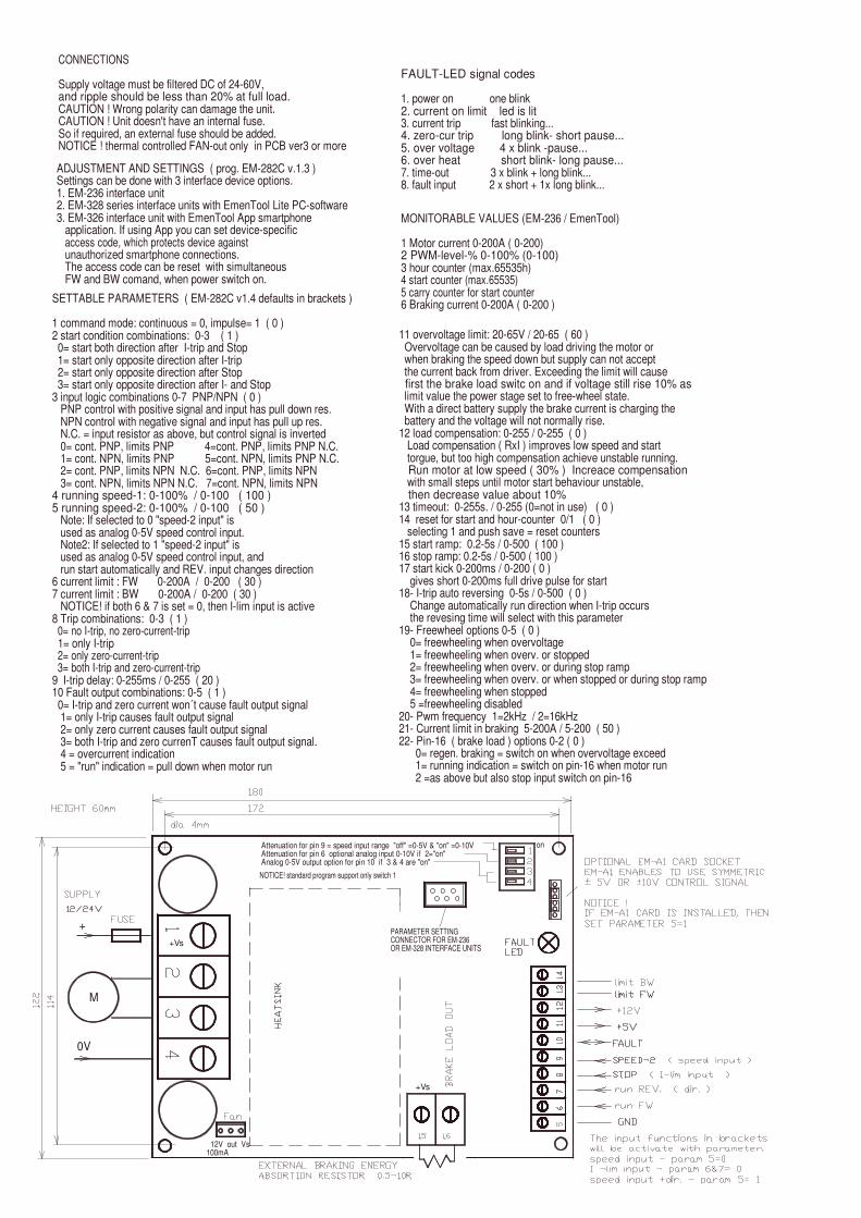
11 overvoltage limit: 20-65V / 20-65 ( 60 ) Overvoltage can be caused by load driving the motor or when braking the speed down but supply can not accept the current back from driver. Exceeding the limit will cause first the brake load switc on and if voltage still rise 10% as limit value the power stage set to free-wheel state. With a direct battery supply the brake current is charging the battery and the voltage will not normally rise.12 load compensation: 0-255 / 0-255 ( 0 ) Load compensation ( RxI ) improves low speed and start torgue, but too high compensation achieve unstable running. Run motor at low speed ( 30% ) Increace compensation with small steps until motor start behaviour unstable, then decrease value about 10%
13 timeout: 0-255s. / 0-255 (0=not in use) ( 0 )14 reset for start and hour-counter 0/1 ( 0 ) selecting 1 and push save = reset counters15 start ramp: 0.2-5s / 0-500 ( 100 )16 stop ramp: 0.2-5s / 0-500 ( 100 )17 start kick 0-200ms / 0-200 ( 0 ) gives short 0-200ms full drive pulse for start
18- I-trip auto reversing 0-5s / 0-500 ( 0 ) Change automatically run direction when I-trip occurs the revesing time will select with this parameter
19- Freewheel options 0-5 ( 0 ) 0= freewheeling when overvoltage 1= freewheeling when overv. or stopped 2= freewheeling when overv. or during stop ramp 3= freewheeling when overv. or when stopped or during stop ramp 4= freewheeling when stopped 5 =freewheeling disabled
20- Pwm frequency 1=2kHz / 2=16kHz21- Current limit in braking 5-200A / 5-200 ( 50 )22- Pin-16 ( brake load ) options 0-2 ( 0 )
0= regen. braking = switch on when overvoltage exceed 1= running indication = switch on pin-16 when motor run 2 =as above but also stop input switch on pin-16
SETTABLE PARAMETERS ( EM-282C v1.4 defaults in brackets )
1 command mode: continuous = 0, impulse= 1 ( 0 )2 start condition combinations: 0-3 ( 1 ) 0= start both direction after I-trip and Stop 1= start only opposite direction after I-trip 2= start only opposite direction after Stop 3= start only opposite direction after I- and Stop3 input logic combinations 0-7 PNP/NPN ( 0 ) PNP control with positive signal and input has pull down res. NPN control with negative signal and input has pull up res. N.C. = input resistor as above, but control signal is inverted 0= cont. PNP, limits PNP 4=cont. PNP, limits PNP N.C. 1= cont. NPN, limits PNP 5=cont. NPN, limits PNP N.C. 2= cont. PNP, limits NPN N.C. 6=cont. PNP, limits NPN 3= cont. NPN, limits NPN N.C. 7=cont. NPN, limits NPN 4 running speed-1: 0-100% / 0-100 ( 100 )5 running speed-2: 0-100% / 0-100 ( 50 ) Note: If selected to 0 "speed-2 input" is used as analog 0-5V speed control input. Note2: If selected to 1 "speed-2 input" is used as analog 0-5V speed control input, and run start automatically and REV. input changes direction6 current limit : FW 0-200A / 0-200 ( 30 )7 current limit : BW 0-200A / 0-200 ( 30 ) NOTICE! if both 6 & 7 is set = 0, then I-lim input is active8 Trip combinations: 0-3 ( 1 ) 0= no I-trip, no zero-current-trip 1= only I-trip 2= only zero-current-trip 3= both I-trip and zero-current-trip9 I-trip delay: 0-255ms / 0-255 ( 20 )10 Fault output combinations: 0-5 ( 1 ) 0= I-trip and zero current won´t cause fault output signal 1= only I-trip causes fault output signal 2= only zero current causes fault output signal 3= both I-trip and zero currenT causes fault output signal. 4 = overcurrent indication 5 = "run" indication = pull down when motor run
PARAMETER SETTINGCONNECTOR FOR EM-236OR EM-328 INTERFACE UNITS
Attenuation for pin 9 = speed input range "off" =0-5V & "on" =0-10V Attenuation for pin 6 optional analog input 0-10V if 2="on"Analog 0-5V output option for pin 10 if 3 & 4 are "on"
+Vs
+
12V out Vs100mA
M
+Vs
0V
NOTICE! standard program support only switch 1
on
FAULT-LED signal codes
1. power on one blink2. current on limit led is lit3. current trip fast blinking...4. zero-cur trip long blink- short pause...5. over voltage 4 x blink -pause...6. over heat short blink- long pause...7. time-out 3 x blink + long blink...8. fault input 2 x short + 1x long blink...
MONITORABLE VALUES (EM-236 / EmenTool)
1 Motor current 0-200A ( 0-200)2 PWM-level-% 0-100% (0-100)3 hour counter (max.65535h)4 start counter (max.65535)5 carry counter for start counter6 Braking current 0-200A ( 0-200 )
ADJUSTMENT AND SETTINGS ( prog. EM-282C v.1.3 )Settings can be done with 3 interface device options.1. EM-236 interface unit2. EM-328 series interface units with EmenTool Lite PC-software3. EM-326 interface unit with EmenTool App smartphone application. If using App you can set device-specificaccess code, which protects device against unauthorized smartphone connections. The access code can be reset with simultaneous FW and BW comand, when power switch on.
CONNECTIONS
Supply voltage must be filtered DC of 24-60V, and ripple should be less than 20% at full load.CAUTION ! Wrong polarity can damage the unit.CAUTION ! Unit doesn't have an internal fuse. So if required, an external fuse should be added.NOTICE ! thermal controlled FAN-out only in PCB ver3 or more

EM-282 is a full bridge DC-motor starter. It is designed to work with DC-motor (permanent magnet and brushed) in applications where a varietyof special functions and settings are needed. Starter has an adjustable acceleration and deceleration ramps enabling the smooth starts and stops. Adjustable current limit protects motor against overcurrent. Current limitation for braking is also available (regeneration). EM-282 has two selectableand settable speeds. This feature can be useful eg. in positioning applications. The FW and BW -inputs control the forward and backward run. STOP input is to stop the motor but there are also available individual limit inputs for FW and BW direction end stops that will cause a motor shut-down. SPEED-2 input activates the presettable speed-2, but it can also be set for use as an analog speed control input (0-5V signal). FAULT terminal operates same time as an input and output. Fault line is internally pulled high (100kohm to Vsupply), but will be pulled down in overheat or conditionally also in current trip situation. If FAULT-line is pulled down externally it will cause a stop and disable a new start. For example it is possible to link FAULT pins of several units together and achieve this way a syncronous stop.
Driving can be done with two selectable control modes, continuous and impulse. In continuous mode the motor runs as long as the command is on.In impulse mode a short command starts the motor, and only a new impulse will change the status. Inputs are divided in to two groups, command and limit -inputs. These groups can be individually set to work with NPN (connect to zero control) or PNP (positive voltage control) -logic. The parameters are set digitally with a hand held EM-236 interface unit. With this unit the same settings (adjustments) can also be easily copied to another or to multible devices. Operation of the controller and some of its functional values can also be monitored with EM-236 interface unit.
fault out
fault in
10k
Fan molexconnector
Supply voltage nom. 12-42Vdc (abs. limits 10-50V )Shutdown voltage 10VOvervoltage limit adjustable 15-50VIdle current typ 20mAMotor current max. continuous 100A (at 25°C amb. temp)80A ( at 60° amb temp ) and peak 200A ( 5s )Motor currents are about 20% lower if pwm frequency is 16kHzBraking load current (pin 16) max cont 50A peak 100ACurrent limit adjustable 1-200A NOTICE! current limit is 20% boosted during start ramp.Over temp. limit 100°CStart and stop ramp adjustable 0-5sPWM frequency 2kHz / 16kHzSpeed input scale ( speed-2 ) 0-4.5V = 0-100% pwmI-lim input scale 0-5V = 0-200AInput control logic: high =4-30V, low=0-1VControl input impedances typ. 10kohmControl input response time typ 5ms.Fault out. NPN open coll. max 42V / 0.5AFault in. actives Uin < 1V ( NPN with 100k pull up)Fan-output switch on 55°C, off 50°C ( only pcb v.3 of later )Fan-output NPN max 40V 100mA12V Fan ( + ) max 100mAMotor and supply connectors 16mm²Control connectors 1mm²Dimensions 180x122x60mmCE-tested for industrial environment ( EMC )Operating ambient temp ( Ta ) -40...60°CWeight 750g
parametersettingconnector
dip3 & 4
1k
10
FAULT
TECHNICAL DATA ( prog. EM-282C v1.4 and pcb v.3 or later )
12
5V/ 20mA
9SPEED-2
5
6
11
7
8
A1 socket
FW
REV.
STOP
npn / pnp
10k
10k
10k
12V/ 10mA
BRAKING LOAD RESISTANCE
MOTORCURRENT
brake load
pwm ind. out.
data
limit FW
limit BW
npn / pnp
10k
5V 11
10k14
13
15
SUPPLY12/24Vdc
+Vs
H-BRIDGE
U-OVER
47k
47k
47k
47k
47k
dip1
DRIVELOGIC
U-reg
2
47k
16
+
-
1
MOTOR
3
4
2
EM-282 BLOCK DIAGRAM ( board ver. v.3)
12V 100mA12V 100mA
+Vs
fan control output
FEATURES
- high current output- brake load output- current limit- current limit for brake also- zero-current limit- speed setting/adjustment- flexible control inputs- impulse / continuous mode- rail base mountable- digital parameter setting- C versions program
+ 2/16kHz pwm freq. options+ freewheel options+ autoreverse option+ running indication options+ expanded input logic options+ thermal cont. Fan-output (pcb v.3)
DC-MOTOR CONTROLLEREM-282C 12-42V 100A
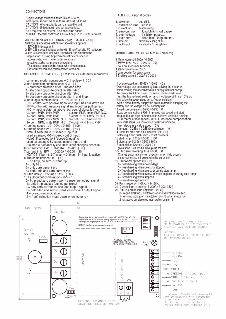
ADJUSTMENT AND SETTINGS ( prog. EM-282C v.1.3 )Settings can be done with 3 interface device options.1. EM-236 interface unit2. EM-328 series interface units with EmenTool Lite PC-software3. EM-326 interface unit with EmenTool App smartphone application. If using App you can set device-specificaccess code, which protects device against unauthorized smartphone connections. The access code can be reset with simultaneous FW and BW comand, when power switch on.
CONNECTIONS
Supply voltage must be filtered DC of 12-42V, and ripple should be less than 20% at full load.CAUTION ! Wrong polarity can damage the unit.CAUTION ! Unit doesn't have an internal fuse. So if required, an external fuse should be added.NOTICE ! thermal controlled FAN-out only in PCB ver3 or more
SETTABLE PARAMETERS ( EM-282C v1.4 defaults in brackets )
1 command mode: continuous = 0, impulse= 1 ( 0 )2 start condition combinations: 0-3 ( 1 ) 0= start both direction after I-trip and Stop 1= start only opposite direction after I-trip 2= start only opposite direction after Stop 3= start only opposite direction after I- and Stop
3 input logic combinations 0-7 PNP/NPN ( 0 ) PNP control with positive signal and input has pull down res. NPN control with negative signal and input has pull up res.N.C. = input resistor as above, but control signal is inverted
0= cont. PNP, limits PNP 4=cont. PNP, limits PNP N.C. 1= cont. NPN, limits PNP 5=cont. NPN, limits PNP N.C. 2= cont. PNP, limits NPN N.C. 6=cont. PNP, limits NPN 3= cont. NPN, limits PNP N.C. 7=cont. NPN, limits PNP
4 running speed-1: 0-100% / 0-100 ( 100 )5 running speed-2: 0-100% / 0-100 ( 50 )
Note: If selected to 0 "speed-2 input" is used as analog 0-5V speed control input. Note2: If selected to 1 "speed-2 input" is used as analog 0-5V speed control input, and run start automatically and REV. input changes direction
6 current limit : FW 0-200A / 0-200 ( 30 )7 current limit : BW 0-200A / 0-200 ( 30 ) NOTICE! if both 6 & 7 is set = 0, then I-lim input is active8 Trip combinations: 0-3 ( 1 ) 0= no I-trip, no zero-current-trip 1= only I-trip 2= only zero-current-trip 3= both I-trip and zero-current-trip
9 I-trip delay: 0-255ms / 0-255 ( 20 )10 Fault output combinations: 0-5 ( 1 ) 0= I-trip and zero current won´t cause fault output signal 1= only I-trip causes fault output signal 2= only zero current causes fault output signal 3= both I-trip and zero currenT causes fault output signal. 4 = overcurrent indication 5 = "run" indication = pull down when motor run
+
0V
M
+Vs
11 overvoltage limit: 15-65V / 15-65 ( 40 ) Overvoltage can be caused by load driving the motor or when braking the speed down but supply can not accept the current back from driver. Exceeding the limit will cause first the brake load switc on and if voltage still rise 10% as limit value the power stage set to free-wheel state. With a direct battery supply the brake current is charging the battery and the voltage will not normally rise.12 load compensation: 0-255 / 0-255 ( 0 ) Load compensation ( RxI ) improves low speed and start torgue, but too high compensation achieve unstable running. Run motor at low speed ( 30% ) Increace compensation with small steps until motor start behaviour unstable, then decrease value about 10%
13 timeout: 0-255s. / 0-255 (0=not in use) ( 0 )14 reset for start and hour-counter 0/1 ( 0 ) selecting 1 and push save = reset counters15 start ramp: 0.2-5s / 0-500 ( 100 )16 stop ramp: 0.2-5s / 0-500 ( 100 )17 start kick 0-200ms / 0-200 ( 0 )
gives short 0-200ms full drive pulse for start18- I-trip auto reversing 0-5s / 0-500 ( 0 )
Change automatically run direction when I-trip occursthe revesing time will select with this parameter
19- Freewheel options 0-5 ( 0 ) 0= freewheeling when overvoltage 1= freewheeling when overv. or stopped 2= freewheeling when overv. or during stop ramp 3= freewheeling when overv. or when stopped or during stop ramp 4= freewheeling when stopped 5 =freewheeling disabled
20- Pwm frequency 1=2kHz / 2=16kHz21- Current limit in braking 5-200A / 5-200 ( 50 )22- Pin-15 ( brake load ) options 0-2 ( 0 )
0= regen. braking = switch on when overvoltage exceed 1= running indication = switch on pin-16 when motor run2 =as above but also stop input switch on pin-16
PARAMETER SETTINGCONNECTOR FOR EM-236OR EM-328 INTERFACE UNITS
12V out Vs100mA
+Vs
Attenuation for pin 9 = speed input range "off" =0-5V & "on" =0-10V Attenuation for pin 6 optional analog input 0-10V if 2="on"Analog 0-5V output option for pin 10 if 3 & 4 are "on"
NOTICE! standard program support only switch 1
on
FAULT-LED signal codes
1. power on one blink2. current on limit led is lit3. current trip fast blinking...4. zero-cur trip long blink- short pause...5. over voltage 4 x blink -pause...6. over heat short blink- long pause...7. time-out 3 x blink + long blink...8. fault input 2 x short + 1x long blink...
MONITORABLE VALUES (EM-236 / EmenTool)
1 Motor current 0-200A ( 0-200)2 PWM-level-% 0-100% (0-100)3 hour counter (max.65535h)4 start counter (max.65535)5 carry counter for start counter6 Braking current 0-200A ( 0-200 )

EM-231A CONTROL UNIT FOR DOORS ANDHATCHES
FEATURES:
• supply from 230Vac• for 24Vdc motors• motor current limit• safety reverse• end switch inputs• pulse encoder input• radar input• remote control option• CE marked
EM-231A is designed for door and hatch controlling. Control unit includes the 230Vac isolated mainspower which converts the voltage to the 24Vdc for control electronics and door motor. Motor can bea normal low voltage DC-motor. In the basic operating mode the end stop can be realized withcurrent limit or end switches. More sophisticated behaviour can be achieved with pulse encoderfeedback. In this pulse mode the controller can be learned with a push of a button. After the controllerhas learned the stroke length it executes the open/close cycles smoothly anticipating the end stopswith slow down ramps. In all operating modes the current limit is active and ready to stop the motorif the adjusted value is exceeded. If desired a safety reverse action can be set to follow this currenttrip. With safety reverse active eg. a person who is in the way of a closing door will cause the motorto reverse and door to open. Unit includes the inputs for end switches, door radar, OPEN/CLOSEbuttons and for pulse encoder. Additionally there are inputs also for emergency drive and learning,and a serial connector for an interface unit. An optional remote control feature can be achieved witha remote control unit and by plugging a receiver hybrid (EM-A6) in to its holder. Speed, ramp timesand current limit can be adjusted with trimmers. Operating mode, safety reverse and learning canbe enabled and determined with dip switches. To achieve more sophisticated operation andcustomized settings the serial interface unit EM-236 can be connected to serial connector. Withserial interface user can adjust the approaching speed, acceleration zone length, approachingcurrent limit and radar off delay.EM-231A is housed to a plastic IP30 (IP65) ABS(PC) housing. Unit is CE-marked.
TECHNICAL DATA
Supply voltage 230Vac / max. 100WFuse T1A 20x5mmOutput voltage nom. 24VdcOutput current 1.5A (Uout=24V)
3A (Uout=18V) 30% dutyCurrent limit 0-4ARamp time 0-2sSpeed range 0-100%Pulse frequency max. 1000Hz/50/50%Pulse length min. 0,5msInput signals 4-30V=ON / 0-1V=OFFInput impedances 10kohmAux. outputs Total current 50mA
24V max.40mA5V max. 40mA
Fault output NPN open col. (100mA)Remote Control 433Mhz typ. range 10mHousing ABS(PC) 130x130x60 / IP30 (IP65)Operating temp. 0-50°CMains isolation 1000V
CLOSED LIMIT SWITCH
OPEN LIMIT SWITCH
PULSE SENSOR IN
CURRENTMEAS.
24VMOTORDRIVERMOTOR
VOLTAGEANDCURRENTCONTROLRADAR
DOOR STROKE LEARNING
BASIC / PULSE MODE
CURRENT LIM.
SAFETY REVERSE
RAMP. TIME
SPEED
RC-LEARNING/
FAULT Im
EM-231A BLOCK DIAGRAM
24V
5V
RC 433MHz
optional
PROG
EMERG.
CLOSE
OPEN
5V/ 30mA
24V/ 30mA
Serial Interface
SYSTEM
MOTOR
DOOR4
3
isolation
PE
230VAC
LT1A
N

130mm
OPE
N
CONNECTIONSMake sure that the mains supply is not on when making the connections. NOTICE! that there is 230Vac area in this device. Do not let any other than 230Vac wiring in this area. Do not use the same inlet for others than 230Vac cabling. Device has a terminal for connectingthe protective earth (PE). It can be used if there is need for leading the PE to the auxiliary devices. Check that the current consumption of limit switches, pulse encoders and radar do not exceed the max. currentfeed capability of 24/5V auxiliary outputs (altogether 50mA).Control inputs operate with positive 4-30Vdc signals, with input impedance of 10kohm. The pulse encoder input canbe configured for PNP or NPN signal, that is with up or downpullin transducers. Eg. Hall-transducers are mostly of the NPN-type (pull down), in that case the 39kohm line pull upresistor should be in its holder.
SETTINGSSet the desired operating mode with dip-switch (see the page OPERATING MODES). Adjust the speed,ramp time and current limit with trimmers. If you need more detailed setting, attache the EM-236 serial interface to this control unit, and you have access toa lot wider range of parameters (see the page 3OPERATING MODES). Especially in pulse mode can be achieved better adjustability with EM-236.The safety reverse can be enabled with dip switch 2. When safety reverse is enabled, the motor will automatically reverse after exceeding the adjusted current limit eg. in case of encountering an obstacle during close run.
DIP-switch settings
1. basic mode=OFF / pulse mode=ON2. safety reverse active, ON / OFF3. RC-learning = OFF / door stroke learning = ON
ramp / s
currentlimit / A
optio
nal R
F-re
ceiv
er fo
r RC
plug-in card holder for optionalRC-receiver
speed
0 224
V
39k pull-up resistor in holder.
24V
mot
or
mot
or 5V
M
10
1
2
serial interfacefor additionalsettings
39k
0VFaul
t
24V
EMER
.
rada
r
puls
e
faultLED
LEARN buttononoff
%
3456
50100%
0%
12
3
130m
m
DANGER230VACAREA
LEARNINGIn pulse mode the control device must be learned for the right driving cycle of a door or hatch. This is done by switching thedip-switch 3 to ON-position and pressing the learn button. After this the device will execute the learning cycle (see page 3OPERATING MODES). After this the functionality can be adjusted with parameters. NOTICE. Learning can be triggeredalso with a 4-30V signal to the prog. terminal.
RC-learning (if the optional RC receiver EM-A6 is attached)To be able to remotely control the device it has to be learnedthe code of the specific remote control unit. Set the dip-switch 3 to OFF position, keep the learn button pressed and press the remote controllers OPEN button so long that the door is started (about 1s). Afterwards return the dip switch 3 to ON position.Also in this case the prog. input can be used instead of the learn button. NOTICE. Remote control will not work at the same time as the interface unit is connected to the control unit.
CLO
SE
LIM
-O
LIM
-C 0VPR
OG
L N
230V
230V
fuse T1A
transformer 40VA
230/24

ADDITIONAL SETTINGS VIA SERIAL INTERFACE
The next settings are possible to set individually if serial interfaceunit is connected to device. If serial interface is selected to be active( param.1) the interface unit will over write trimmer- and automaticsettings. With interface unit it is also possible to monitor the current and pulse counter values during drive.
1. serial interface active 0=no / 1=yes 2. "travel speed" 0-100% ( 0-100 ) 3. "approaching speed 0-100% ( 0-100 ) 4. "current limit" 0-6A ( 0-60 ) 0.1A/step 5. "approaching current lim." 0-6A ( 0-60 ) 0.1A/step 6. "approaching zone" 3-30% of full stroke ( 3-30 ) 7. "end zone" 1-5% of full stroke ( 1-5 ) 8. radar input off delay 0-255s. ( 0-255 )9. "ramp" 0-2s (0-20 ) 0.1s/step MONITOR VALUES
1. motor current 0-60 ( 0-6A )2. pulse counter value 0-65535
pulse rate nearto the limit value
limit switch
current limit
approaching zone
decelerate
ramp time
SETTINGS & PARAMETERS
Trimmer setting ranges
"ramp" 0-2s"travel speed" 0-100%"current limit" 0-6A
Automatically set parameters
"approaching speed" 50% of travel speed"approaching current limit" = current limit"approaching zone" 10% of full range"end zone" 2% of full stroke radar input make off delay 5s.
Dip switch settings
1. Basic mode = off / Pulse mode = on2. safety reverse active on / off3. RC-learning = off / door stroke learning = on
encoder pulses
accelerating
encoder pulses
rampmotor voltage ( speed )
motor current
travel speed
approaching speed
door stroke learning = counting number of pulses/stroke
ramp time
ramp time
start
completedlearning
motoraccelerating
start
motoraccelerating
home cycle = run home until end is reached
motor voltage ( speed )
learningstart
motor current
half speed for both directions
motor voltage ( speed )
motor current
PULSE MODE
In this mode the device uses pulse counting to control the stroke lenght of the door. Recommended pulse rate is 200-10000 pulses/stroke,and pulse frequency should be below 1000Hz
When system is taken in use for the first time, run the " learning" routine first:
- push learning button- motor starts to run at approaching speed until the door reaches the end of stroke.- Then motor starts automatically to opposite direction. During this calibration cycle the device counts the number of pulses of the full stroke and in the end of this cycle the motor stops and the number of pulses is stored to memory.
After learning has been done the system is ready to run
- open/close command starts the motor- motor accelerates with "ramp"- motor runs at "travel speed"- door reaches the edge of "approaching zone", motor speed is changed to "approaching speed" and current limit to "appr. current lim."- motor is stopped if: - current limit is exceed - pulses stop coming - if motor stops inside the "end zone ", the device will reset the pulse counter and is ready for re-start- but if shut down happens before counter has reached the "end zone" value, the device will go to "limb mode" and next cycle will be driven with approaching speed.- If "safety reverse" setting is actived and the door meets an obstacle during closing cycle, the door will stop and reverse (open) automatically.
default settings 0 100 50 30 30 10 2 5 10
end zone
BASIC MODE with a limit switch
-open / close command starts motor-motor accelerates with ramp-motor runs with adjusted speed-door reaches the limit switch and motor will be shut down.-door slides with decelerating speed to the end of stroke.-If door meets an obstacle inside stroke, the current limit will shut down the motor. -If safety reverse function is activated, and current limit is exceeded during close cycle, the door will stop and then start automatically to open direction.
BASIC MODE with current trip
-open/close command starts motor-motor accelerates with ramp-motor runs with adjusted speed-door meets the end point and motor current starts to rise until it exceeds the current limit, which causes the motor shut down -the current limit also shuts down the motor, if the door meets an obstacle during drive cycle-the action is same to both directions-the safety reverse function is not available in this mode-Notice ! In this mode there should be some kind of bumper in the end of stroke to smoothen up the end stop.
OPERATING MODES OF EM-231A
motordecelerating(freewheeling)

Other Electromen
A) Brushless Controllers
B) Stepper Motor Controllers
Other Motion Tech Products