
MOD 30 RetroPAK Controllers
13
MOD 30 RetroPAK Controllers Replaces aging controllers in logical increments Combines the functionality of MOD 30 Controllers, Math Unit, SLU Fits same bezel & cutout Accepts MOD 30 termination cables Communicates via ICN with MOD 30, Local Control Panel and Communication Link High visibility display, easier to operate Front panel tuning Portable Memory Module option Specification Sheet S-RETROPAK-MOD30 July 2008 “The Right Fit for Retrofit”
-
Upload
khangminh22 -
Category
Documents
-
view
7 -
download
0
Transcript of MOD 30 RetroPAK Controllers

MOD 30 RetroPAK Controllers
Replaces aging controllers in logicalincrements
Combines the functionality of MOD 30Controllers, Math Unit, SLU
Fits same bezel & cutout
Accepts MOD 30 termination cables
Communicates via ICN with MOD 30,Local Control Panel and CommunicationLink
High visibility display, easier to operate
Front panel tuning
Portable Memory Module option
Specification SheetS-RETROPAK-MOD30July 2008
“The Right Fit for Retrofit”

2
S-RETROPAK-MOD30MOD 30 RETROPAK
The MOD 30 RetroPAK provides the easiest migrationpath from Taylor MOD 30 instruments to the latesttechnology. It combines the functions of the 1700Series Controller, Controller XL, Math Unit, and Se-quence and Logic Unit (SLU) into one instrument, andoffers all the features that made the Taylor MOD 30 sopopular. In addition it offers a host of other powerfulfeatures and up-to-date communication strategies thatmake RetroPAK the logical choice for replacing agingMOD 30 controllers.
HARDWARE PLATFORMThe basis of the MOD 30 RetroPAK, the MOD 30ML,was designed as the next generation of MOD 30 instru-ment. It fits the same panel cutout and bezel, making iteasy to replace old MOD 30’s one at a time or in logicalgroups.
There are two termination versions available, dependingon the existing MOD 30 installation. The RetroPAKstyle termination is designed to easily replace MOD 30instruments connected to the 1720F Standard Termina-tion Panel using the 1750F series cables. Simplyremove the MOD 30 and its housing, install theRetroPAK controller and connect the cable. Field wiringand 24V dc power connections remain in place at the1720F Termination Panel.
The second termination option provides a fifty-position, two-piece terminal block assembly for directconnection of field wiring at the back of the instrument.The terminal blocks can be temporarily unplugged fromthe controller to facilitate wiring. This version istypically used when the original MOD 30 installationconsists of Unified Instruments, or when replacingtwo or more MOD 30 instruments with one MOD30ML controller and eliminating the original MOD 30termination panels. This version is available with ACor DC power and makes additional I/O and commu-nications available for control strategies. For moreinformation on this version, refer to S-MOD-1800R.
FUNCTIONALITYThe MOD 30 RetroPAK includes all the functionality ofthe MOD 30 series, making it suitable for replacingany MOD 30 installation. Algorithms and functionsinclude:
• Up to six control loops, each with:- 18 variations of PID control- Adaptive tuning- Cascade- Feedforward- External feedback- MICROSCANTM Reset- Bumpless mode transfer- Setpoint and output tracking & limiting- Ratio & Bias
• Signal selection
• Timers
• Math calculations with unlimited steps
• Discrete and continuous logic
• Linearization
• Configurable process alarms - unlimited
• Totalization
• Sequence control
• ICN Communications
• Comprehensive diagnostics
3
S-RETROPAK-MOD30MOD 30 RETROPAK
PROCESS I/OThe RetroPAK controller can be ordered with thesame I/O complement as the MOD 30 Controller XL(1701R) for a one-to-one replacement:
• 3 analog inputs, 1-5 volts
• 2 milliamp outputs
• 2 digital inputs
• 3 digital outputs
For replacing Math Units or an SLU withoutexpanded I/O, the Conversion style RetroPAKcontroller will accept up to two MOD 30 Instru-ment cables. If the original installation is MOD 30Unified instruments, or the MOD 30 StandardTermination Panel is being removed from thesystem architecture, a standard MOD 30ML istypically used. In both cases, the controllerprovides two universal analog inputs and two 4-20mA outputs, and up to 11 additional I/O pointscan be added by choosing from any of thefollowing plug-in modules. Each module providesone input or one output:
• Current input, with or without transmitter powersupply
• 3-wire, 100 ohm RTD or 2-wire, 1000 ohm RTDinput with upscale burnout detection
• Thermocouple input with upscale burnoutdetection (all standard thermocouple types;cold junction compensation provided)
• Volt/millivolt input
• Isolated digital input (2.5-28Vdc, 4-16Vdc, 10-32Vdc, 12-32Vac)
• Non isolated (contact sense) digital input
• Isolated digital output (5-60Vdc, 5-200Vdc, 12-140Vac, 24-280Vac)
• Non isolated digital output
• Mechanical relay output (two Form A outputs,two Form B outputs or one Form C output)
All analog I/0 modules, and the solid state digital I/Omodules are individually isolated channel-to-channeland channel-to ground to provide maximum protec-tion.
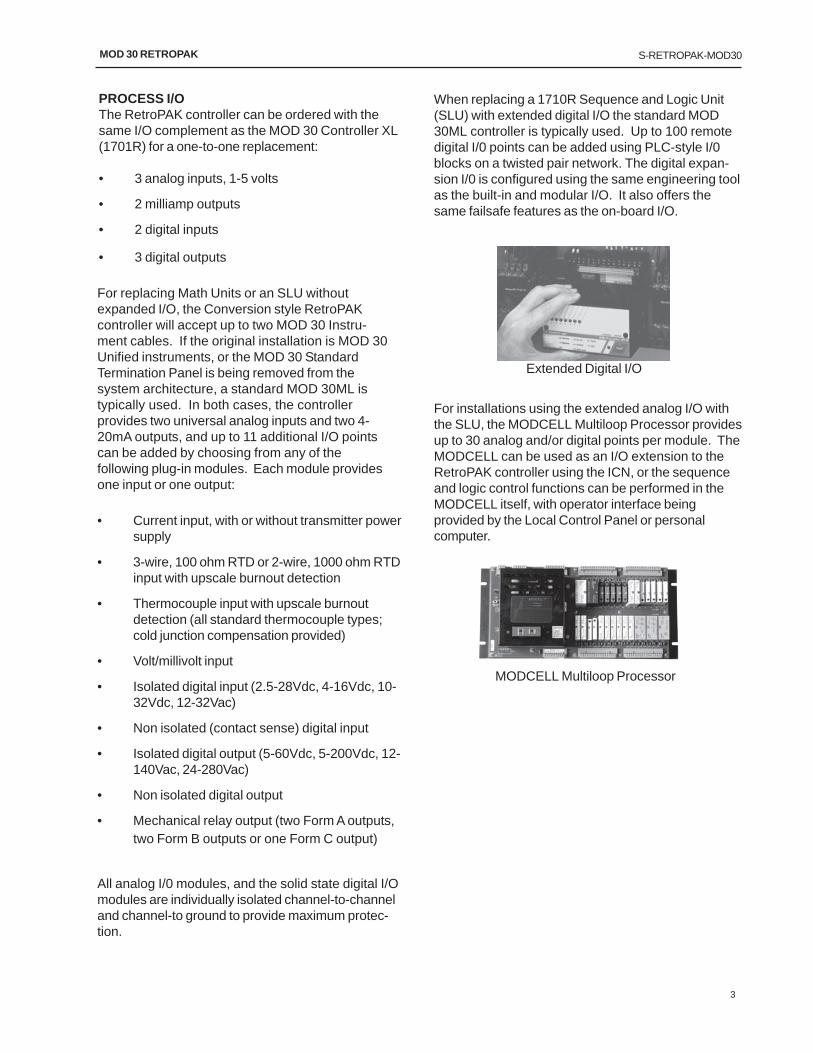
When replacing a 1710R Sequence and Logic Unit(SLU) with extended digital I/O the standard MOD30ML controller is typically used. Up to 100 remotedigital I/0 points can be added using PLC-style I/0blocks on a twisted pair network. The digital expan-sion I/0 is configured using the same engineering toolas the built-in and modular I/O. It also offers thesame failsafe features as the on-board I/O.
Extended Digital I/O
For installations using the extended analog I/O withthe SLU, the MODCELL Multiloop Processor providesup to 30 analog and/or digital points per module. TheMODCELL can be used as an I/O extension to theRetroPAK controller using the ICN, or the sequenceand logic control functions can be performed in theMODCELL itself, with operator interface beingprovided by the Local Control Panel or personalcomputer.
MODCELL Multiloop Processor

4
S-RETROPAK-MOD30MOD 30 RETROPAK
OPERATOR DISPLAYThe MOD 30 RetroPAK has a bright, highly visible vacuumfluorescent front screen which is easily viewed from agreater distance and provides even more processinformation than the MOD 30 instruments. In addition,operation of the RetroPAK controller is simpler and moreuser-friendly.
Standard Operating ScreensIn normal operating mode each screen shows threebargraphs representing Process, Setpoint, and Output.Three eight-character alphanumeric lines indicate the LoopTag; the process value in engineering units; and thenumeric value of the variable indicated by the StatusIndicator (typically Output and Setpoint). Three-characterStatus Indicators display controller Mode (Auto/Manual),Setpoint status (Local/Remote), and the variable whosevalue is being displayed on the bottom line of the screen.The up/down arrow keys are used for changing this value.The standard ramping method allows the operator toselect the desired value without any overshoot, and unlikeMOD 30, it is not necessary to hold down more than onekey for fast ramping.
User-definable Alarm ScreensActive process and diagnostic alarms are indicated by theflashing red LED on the keypad, and/or flashing displayand audible alarm. Like MOD 30, complete alarminformation including value, alarm type (high, low, deviationetc.) and user-configured label can be viewed by pressingthe Alarm key. Any number of alarms may be configuredfor an analog or a digital signal, and there is no fixed limitto the total number of alarms per RetroPAK controller.
Tuning and Commissioning ScreensControl loops are tuned through Tuning displays,accessed by a user-specified password from the frontpanel of the RetroPAK controller. Standard tuningparameters, recipe parameters, and X,Y table coordinatescan be entered through the faceplate, without the need fora handheld terminal or computer, thus eliminating theMOD 30 Portable Configurator.. The controller alsodisplays raw input values for commissioning and startup,as well as detailed diagnostic information before andduring normal operation. An Event Queue of up to 1024entries is maintained by the instrument, and can beviewed from the front panel.
Custom DisplaysIn addition to standard displays, application-specificscreens can be configured for sequence and batchoperations, discrete device operation, recipe selection,and multiple variable indication. Keys can be assigneddifferent functions on a per-display basis through a scriptlanguage. The number of screens per controller is limitedonly by operator preference and plant operatingphilosophy. It is also possible to configure hidden screensaccessed through a tuning-level password. This is anideal way of providing local operator interface to functionswhich previously required an operator panel or personalcomputer.
MOD 30MLMOD 30ML
40.0
UAKRET
OXYGENLOW ALRM
MOD 30ML
40.0
UAKRET
OXYGENLOW ALRM
40.0
UAKRET
OXYGENLOW ALRM
MOD 30ML
OIL
NXT
SELECTFUEL
/
MOD 30ML
0
CLRLOGTOT
FW FLOW20.0
MOD 30ML
0.0
MANPRVNXT
DRUM LVLFW OP X1
MOD 30MLOIL
NXT
SELECTFUEL
/
MOD 30ML
OIL
NXT
SELECTFUEL
/OIL
NXT
SELECTFUEL
//
MOD 30ML
0
CLRLOGTOT
FW FLOW20.0
MOD 30ML
0
CLRLOGTOT
FW FLOW20.0
0
CLRLOGTOT
FW FLOW20.0
MOD 30ML
0.0
MANPRVNXT
DRUM LVLFW OP X1
MOD 30ML
0.0
MANPRVNXT
DRUM LVLFW OP X1
0.0
MANPRVNXT
DRUM LVLFW OP X1
MOD 30ML
5
S-RETROPAK-MOD30MOD 30 RETROPAK
Signal Quality DetectionAll inputs and outputs have quality detection andan associated alarm bit, allowing the controllers tochange mode based on signal quality forstrategies such as manual override. In addition, allinternal signals can be configured for qualitychecking. The configured information is stored inthe controller’s non-volatile memory. This featurecan accelerate the restart process andsignificantly reduce downtime.
Failsafe output settingsThe user also has the option to select failsafevalues, either ‘previous’ or a user-determined value,on all outputs should the controller I/0 losecommunication with the CPU. These values areindependently configurable for each output, andreside in the modules. The Expansion I/O alsoallows failsafe settings.
Single-point isolation, Cut-wire detectionInputs, outputs and built-in communications areindividually isolated, channel-to-channel andchannel-to-ground. This helps eliminatepropagation of noise and spikes on signal andpower lines when the controller is properlygrounded. Each I/0 point includes short-circuit andcut-wire detection with associated diagnostics,and a digital flag that can be used to initiatealternate control logic such as safe shutdown.Out-of-range and quality diagnostics are alsoassociated with each point.
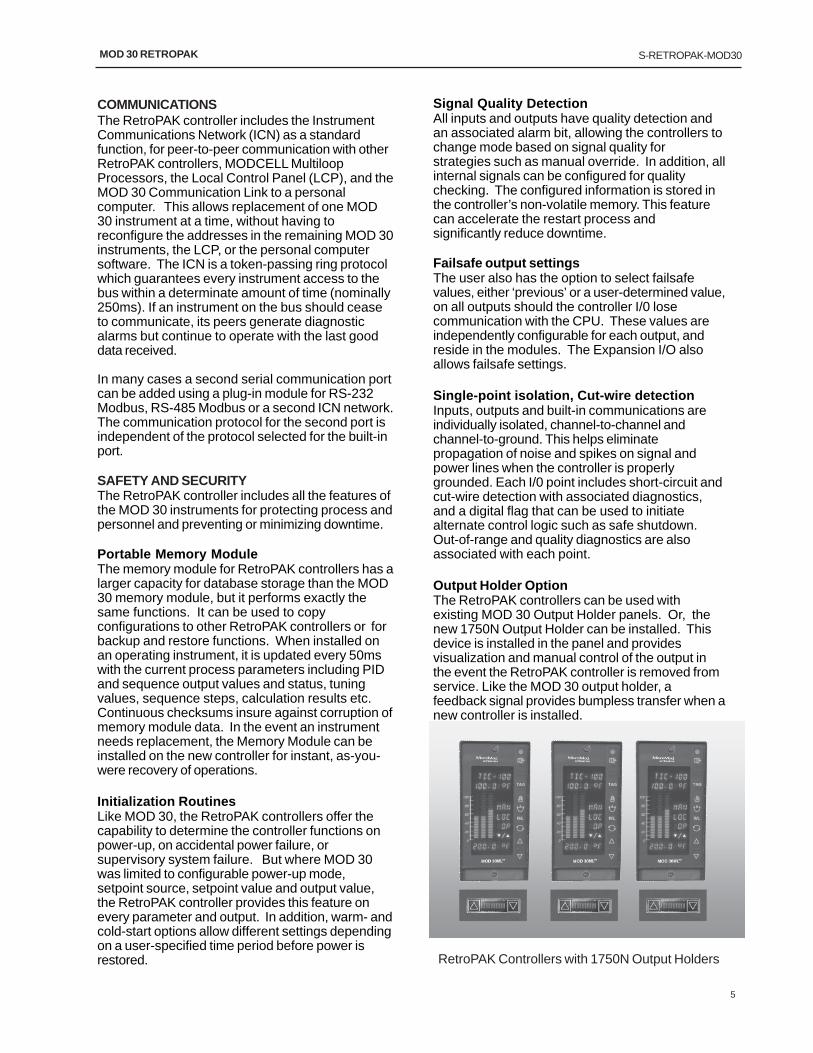
Output Holder OptionThe RetroPAK controllers can be used withexisting MOD 30 Output Holder panels. Or, thenew 1750N Output Holder can be installed. Thisdevice is installed in the panel and providesvisualization and manual control of the output inthe event the RetroPAK controller is removed fromservice. Like the MOD 30 output holder, afeedback signal provides bumpless transfer when anew controller is installed.
COMMUNICATIONSThe RetroPAK controller includes the InstrumentCommunications Network (ICN) as a standardfunction, for peer-to-peer communication with otherRetroPAK controllers, MODCELL MultiloopProcessors, the Local Control Panel (LCP), and theMOD 30 Communication Link to a personalcomputer. This allows replacement of one MOD30 instrument at a time, without having toreconfigure the addresses in the remaining MOD 30instruments, the LCP, or the personal computersoftware. The ICN is a token-passing ring protocolwhich guarantees every instrument access to thebus within a determinate amount of time (nominally250ms). If an instrument on the bus should ceaseto communicate, its peers generate diagnosticalarms but continue to operate with the last gooddata received.
In many cases a second serial communication portcan be added using a plug-in module for RS-232Modbus, RS-485 Modbus or a second ICN network.The communication protocol for the second port isindependent of the protocol selected for the built-inport.
SAFETY AND SECURITYThe RetroPAK controller includes all the features ofthe MOD 30 instruments for protecting process andpersonnel and preventing or minimizing downtime.
Portable Memory ModuleThe memory module for RetroPAK controllers has alarger capacity for database storage than the MOD30 memory module, but it performs exactly thesame functions. It can be used to copyconfigurations to other RetroPAK controllers or forbackup and restore functions. When installed onan operating instrument, it is updated every 50mswith the current process parameters including PIDand sequence output values and status, tuningvalues, sequence steps, calculation results etc.Continuous checksums insure against corruption ofmemory module data. In the event an instrumentneeds replacement, the Memory Module can beinstalled on the new controller for instant, as-you-were recovery of operations.
Initialization RoutinesLike MOD 30, the RetroPAK controllers offer thecapability to determine the controller functions onpower-up, on accidental power failure, orsupervisory system failure. But where MOD 30was limited to configurable power-up mode,setpoint source, setpoint value and output value,the RetroPAK controller provides this feature onevery parameter and output. In addition, warm- andcold-start options allow different settings dependingon a user-specified time period before power isrestored. RetroPAK Controllers with 1750N Output Holders

6
S-RETROPAK-MOD30MOD 30 RETROPAK
CONFIGURATIONBasic PID loops, without math or logic, can beconfigured from the front panel of the RetroPAKcontroller. For strategies with additional controlfunctions, the Visual Application Designer softwareis required.
The Visual Application Designer software providesa Windows-based environment for creating, editing,downloading, documenting and debuggingcontroller databases. It provides automatic, on-screen documentation of the configuration,including signal source and destination. On-line,context sensitive help is available for each blockand function. Standard templates for single loopcontrol, single station cascade and other commonstrategies are provided in the software library.
Live debug and runtime facilities allow on-lineverification of the database and process logic, andtrend windows simplify loop tuning atcommissioning time. There is also a set of drawingtools that can be used to construct runtimedisplays or place dynamic process symbols nextto the algorithm blocks in the configuration foreasier debugging, without using a separate HMIpackage.
Automatic report generation includes tabularreports containing all blocks in the system, theirinternal parameters, and all connections, as wellas graphical reports showing the database diagramexactly as it is drawn.
STEAMPAK SERIESFor standard boiler control applications, MicroModoffers pre-engineered, pre-configured packagesthat perform all the functions of the MOD 30instruments with less hardware, less engineeringand less startup time. Each package is designedby our boiler experts to meet the needs of themajority of installations. One simple modelnumber includes a preconfigured controller,detailed installation instructions specific to theapplication, and a clear operating guide tailored tothe individual loops. Several packages alsoinclude pre-ranged field instruments.
• DRUMPAK – two and three-element drumlevel control packages
• TRIMPAK – dual fuel combustion controlupgrade package with O2 trim for jackshaftboilers
• METERPAK – dual fuel, fully meteredcombustion control system with cross-limits,furnace pressure control and O2 trim in justthree controllers

7
S-RETROPAK-MOD30MOD 30 RETROPAK
GENERAL SPECIFICATIONS
PID Loopssix single or four cascade
Execution TimeBuilt-in I/O: 100mSec.Analog Module I/O: 150mSec. nominalDigital I/O: 50mSec.
Operating RangeAC option: 85-250V rms, 50-400HzDC option: 20-50V dcMOD 30 termination style: 24V dc
Fuse2.5 Amps (ac), 4.0 Amps (dc)
Power Consumption (120V rms, 60Hz, Full load)50W maximum
Data Retention (Non volatile RAM memory andPortable Memory Module)
Typically 10 years with instrument unpowered
Operating temperature0 to +50°C
Storage Temperature-40 to +75°C
Humidity5 to 95% RH, noncondensing
Open Input Fault DetectionController recovery is user configurable for all inputs
Fault OutputBuilt-in outputs - last value or 0%Module outputs - user defined between0 and 100%
ICN Baud rate31.25K Baud
Modbus Baud rate150 to 38.4K Baud
PHYSICAL SPECIFICATIONS
HeightBezel - 5.69" (144.5 mm)Panel cutout - 5.47" (138.9 mm)
WidthBezel - 2.87” (72.9 mm)Panel Cutout - 2.69” (68.3mm)
Safety ApprovalsABB Instrumentation General PurposeFM Approved and CSA Certified Class I, Division 2,Groups A, B, C, D
DepthBehind the panel - 15.75” (400 mm)Front of panel - 1.13" (28.7 mm)
WeightBase instrument with identity module: 4.7 lbs.Fully module loaded: 6.0 lbs.
MountingInstrument mounts directly in a panel or may bemounted in a 1705FZ Instrument Trim Bezel.

8
S-RETROPAK-MOD30MOD 30 RETROPAK
I/O PERFORMANCE SPECIFICATIONS Built-In Universal Analog Inputs and Outputs Analog Inputs (2)
Transmitter power Isolated 24Vdc, one per input
Range/Span Configured as: Min Max. Min span Impedance Millivolt -10 120 10 10MΩ min Volts 0 6.0 0.1 10MΩ min Milliamps 0 22 1.0 100Ω nominal Resistance 500 ohms (20 Ω min. with 3.9KΩ resistor added)
Temperature Input Linearization Themocouple – per NBS 125 and IEC 584 standards RTD – per IEC751 and DIN43760 standards
Measuring Range Limits – Thermocouple or RTD °F Lower °F Upper °C Lower °C Upper Type B 392 3308 200 1820 Type E -328 1832 -200 1000 Type J -346 1400 -210 760 Type K -328 2501 -200 1372 Type N 32 2372 0 1300 Type R&S 32 3214 0 1768 Type T -430 752 -257 400 RTD -328 1562 -200 850 Note: Performance accuracy is not guaranteed below 7520F (4000C) for Type B thermocouple. RTD, 3-wire
platinum, 100 ohm per DIN 43760 (IEC751), with range of 0-430 ohms (normal) or 0-55 ohms (low).
Common Mode 45Vdc
Isolation Full galvanic isolation using transformers and opto isolators Analog Outputs (2) Range 0 to 22mA non-isolated with user set span (minimum 1mA)
Load 22mA at 1000 ohms maximum
Modular Inputs and Outputs - Analog Input Modules
Voltage 2001A Current 2002A Range (0-100%) ±10V dc, ±100 mV dc Range (0-100%) 4 to 20mA
Low limit -11V, -110mV Low limit 0 mA Upper limit +11V, +110 mV Upper limit 24 MA Input Resistance 1 megohm Input Resistance 2.5 ohm Noise filter 3db at 5 Hz, 3 db at 3 Hz Noise filter 3db at 5 Hz Resolution 16 bits Resolution 13 bits Sensitivity 0.4mV, 4uV Sensitivity 1.6 uA Accuracy (calibrated) 0.1% Accuracy 0.2% Isolation 250V rms Isolation 250V rms Max. Survivable Input ±300V dc or 250V ac (Differential) Max. Survivable Input 50 mA dc (Differential) Common mode rejection 100 db at 60 Hz minimum Normal mode rejection 40 db at 60 Hz minimum Thermocouple 2013A Types B,E,J,K,N,R,S,T
Current with 2-wire transmitter power 2012A Range ±100 mV dc Range 4 to 20mA Low limit -110 mV Low limit 0 mA Upper limit +110 mV Upper limit 27.5 mA Input Resistance 10 Megohms Input Resistance 50 ohms Noise filter 3 db at 3 Hz Noise filter 3db at 5 Hz Resolution 16 bits Resolution 14 bits Sensitivity 4 uV Sensitivity 1µA Accuracy (calibrated) 0.1% Accuracy 0.2% Isolation 250V rms Isolation 250V rms Normal mode rejection 40 db at 60 Hz typical Normal mode rejection 40 db at 60 Hz minimum

9
S-RETROPAK-MOD30MOD 30 RETROPAK
I/O PERFORMANCE SPECIFICATIONS Modular Inputs and Outputs - Analog Input Modules (continued)
RTD 2009A
Input Range Range Low Limit Upper Limit 2-wire 0-4000 ohms (1000 ohms nominal) 0 ohms 4200 ohms 3-wire 0-400 ohms (100 ohms nominal) 0 ohms 400 ohms
Input Resistance 100 ohms each lead Noise Filter 3 db at 5 Hz Resolution 2-wire: 0.08 ohms/count Accuracy (absolute) 2-wire: ±2 ohms Isolation 250 V rms Common Mode Rejection 100 db at 60 Hz minimum Normal Mode Rejection 40 db at 60 Hz minimum
Analog Output Module
Current Output 2003A Range (0-100%) 4 to 20 mA Low limit 0 mA Upper limit 25 mA Open circuit voltage 26 Volts maximum Isolation 250V rms Resolution 12 bits Sensitivity 5 uA Accuracy ±0.2% Load Limit 0 - 800 ohms
Digital Input Modules
Isolated Digital Inputs 2004A 2004AP10… …100A …110A …120A …130A …140A …150A Input voltage ranges 2.5-28Vdc 4-16Vdc 10-32Vdc
12-32Vac 35-60V ac/dc 90-140V ac/dc 180-280V ac/dc
Max Logic Low Input 1V 1V 3V 9V 45V 80V Max Input current 30mA 45mA 25mA 6mA 11mA 6.5mA Response time 1.5 msec 0.1 msec 5 msec 10 msec 20 msec 20 msec Input resistance 900 ohms 300 ohms 1000 ohms dc
1500 ohms ac
10K ohms 14K ohms 43K ohms
Non isolated digital inputs 2006A Contact sense 5V/ 0.5 mA dc typical Logic Low Input 0 to 0.65V dc or 50K ohms minimum Logic High Input 2.2 to 24V dc or 50 ohms maximum Max Input current 2.5 mA dc Response time 1 msec
Digital Output Modules
Isolated digital outputs 2005A 2005AP21… …100A …110A …120A …130A/140A Output voltage ranges 5-60V dc 5-200V dc 12-140V ac 24-280V ac Max Output current 1A 0.55A 1A 1A Response time 0.75 msec 0.75 msec 1/2 cycle 1/2 cycle Nonisolated digital outputs 2007A Mechanical Relay Output 2011A Output voltage range +5 to +24V dc Types Dual independent relays (NO/NO, NC/NC, NO/NC)
or Form C single relay

10
S-RETROPAK-MOD30MOD 30 RETROPAK
____ __ __ __ __ __- __ __ __06 07-08 09 10 11 12 13 14 15
Base Controller 1800RZ
ApprovalsGeneral Purpose 10CE (European Community destinations only) 12
Power Supply24V dc 0
I/O Options - see Note 1Standard I/O only (two universal analog inputs, two current outputs) 1Pre-installed I/O modules (one additional analog input, 2 digital inputs, 3 digital outputs) 2Standard I/O only, NEMA 4, conformal coating 5
Not Used 0
Design ModelGeneral Purpose, FM/CSA approval AEuropean Approval (CE Certification - for European Community destinations) B
Programming / Special Features - see Note 2None S T DConfigured to customer's MOD 30 specifications M 3 0
ACCESSORIESICN Termination Assembly (1 per ICN network) 2030FZ00001APortable Memory Module (optional) 2010PZ10000AUpgrade to Version 2 Identity Module 1800PZ10102CHousing & termination assembly only (no instrument) - MOD 30 conversion 1800FZ00002AOutput Holder / Manual Loader (see S-MOD-1750N) 1750NZ10001A
MOD30 RETROPAK
VIZAPP - __ - DEV - __ - __
VIZAPP
Com m unications Inte rfaceDeluxe - ICN and XModbus OPC Servers Included DLX
ICN OPC Server Included ICNExtended Modbus OPC Server Included XMB
Netw ork (No OPC Server included) NET
FunctionalityDevelopment DEV
Softw are Ke y TypeParallel Port PAR
USB (Universal Serial Port) USB
Extende d Support Services (ESS)None 000One Year Technical Support & Version Updates ESS
Includes one 109S1854 downloading cab le for MOD30ML
Includes one 109S1854 downloading cab le for MOD30ML
Configuration software for RetroPAK Controllers and MODCELL Multiloop Processors

11
S-RETROPAK-MOD30MOD 30 RETROPAK
I/O MODULESPositions Power
Analog Input - isolatedVoltage (+/- 100mv, +/- 10V) 1 80mA 2001AZ10101BCurrent (4-20mA) 1 80mA 2002AZ10101BCurrent (4-20mA) with 2-wire transmitter power (Note 1) 350mA 2012AZ10101BRTD (2-wire, 1000 ohm nominal resistance) 1 80mA 2009AZ10220BRTD (3-wire, 100 ohm nominal resistance) 2 80mA 2009AZ10130BRTD for Cold Junction Compensation (1 per base instrument). Required if 1 80mA 2009AZ10240B
built-in input 1 is not used as tc+cjc and thermocouple inputs are used.Thermocouple (supports type B,E,J,K,N,R,S,T and calibrated) 1 80mA 2013AZ10101B
Analog Output - isolatedCurrent (4-20mA / 0-20mA) (Note 1) 350mA 2003AZ10101A
Digital Input - Isolated2.5 to 28V dc 1 12mA 2004AP10100A4 to 16V dc 1 12mA 2004AP10110A10 to 32V dc, 12 to 32V ac 1 12mA 2004AP10120A35 to 60V ac/dc 1 12mA 2004AP10130A90 to 140V ac/dc 1 12mA 2004AP10140A180 to 280V ac/dc 1 12mA 2004AP10150A
Digital Output - Isolated5 to 60V dc 1 12mA 2005AP10100A5 to 200V dc 1 12mA 2005AP10110A12 to 140V ac, SPST, NO 1 12mA 2005AP10120A24 to 280V ac, SPST, NO 1 12mA 2005AP10130A24 to 280V ac, SPST, NC 1 12mA 2005AP10140A
Digital Input - Nonisolated2.2V to 24V dc (contains internal 5V supply for direct hardwire connection) 1 10mA 2006AZ10100A
Digital Output - Nonisolated25V, 50mA TTL (open collector switch supports 5V TTL) 1 20mA 2007AZ10100A
Mechanical Relay Output - isolatedDual SPST, NO/NO (2 outputs) 2 140mA 2011AZ10100ADual SPST, NC/NC (2 outputs) 2 140mA 2011AZ10110ADual SPST, NO/NC (2 outputs) 2 140mA 2011AZ10120AForm C (1 output) 2 140mA 2011AZ10200A
Extended I/O Interface (see SS Remote-I/O for remote modules)Extended I/O Interface Module (one per Remote I/O Network; 2 max) 2 400mA 2020NZ10000B
Note 1: These active current modules use one position, however they require that one module space on each side be unused.
Communication Modules and Accessories on following page
COMMUNICATION MODULES AND ACCESSORIESCommunication Modules (one per instrument in addition to built-in communication channel)
Instrument Communications Network (ICN)* 2 300mA† 2030NZ10000BSerial Communications for Modbus RTU:
RS-232** 2 180mA 2033NZ10000ARS-485, 4-wire** 2 180mA 2034NZ10000A
AccessoriesICN Termination Assembly (1 per ICN network) 2030FZ00001APortable Memory Module (optional) 2010PZ10000AOutput Holder / Manual Loader (see S-MOD-1750N) 1750NZ10001A
*
** Provides pull-up/pull-down resistors for Modbus network, and address switch. Required when using MOD 30ML as master.† 2030F terminator assembly adds 200mA for total ICN module load of 500mA to controller unit on which it is installed.
One ICN module is required in the MOD 30 Replacement instrument if the built-in communications port is used for RS-232 through the front panel.

12
S-RETROPAK-MOD30MOD 30 RETROPAK
1.5 inch (38.1mm) clearance for optional communications jack.
Center-to-Center Distance F GRecommended 4 8Minimum 3.5 7
Inches mm Inches mm
0.6 15.2 5.43 137.9
0.87 22.1 5.47 138.9
1.13 28.7 5.69 144.5
2.69 68.3 7 177.8
2.87 72.9 8 203.2
3.5 88.9 15.75 400
4 101.6

13
S-RETROPAK-MOD30MOD 30 RETROPAK
The Company’s policy is one of continuous product improvementand the right is reserved to modify the information contained
herein without notice.
Printed in USA (July 2008)
© MicroMod Automation, Inc. 2004
www.micromod.com
MicroMod Automation, Inc.75 Town Centre Dr.Rochester, NY 14623 USATel: (585) 321-9200Toll Free: 1-800-480-1975Fax: (585) 321-9291Email: [email protected]
S-R
ET
RO
PA
K-M
OD
30