Post-Mod Structural Analysis Report - CT.gov
80
-
Upload
khangminh22 -
Category
Documents
-
view
1 -
download
0
Transcript of Post-Mod Structural Analysis Report - CT.gov


TES Project Number: 70654 Page 1 June 5, 2019
Phone (972) 483-0607, Fax (972) 975-9615
1320 Greenway Drive, Suite 600, Irving, Texas 75038
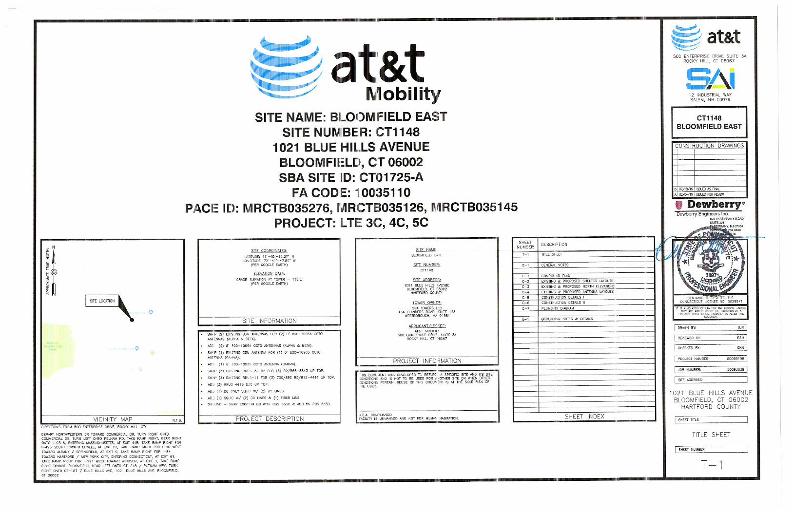
Post-Mod Structural Analysis Report
Existing 125 ft Nudd Corporation Self Supporting Tower Customer Name: SBA Communications Corp
Customer Site Number: CT01725-A Customer Site Name: Bloomfield
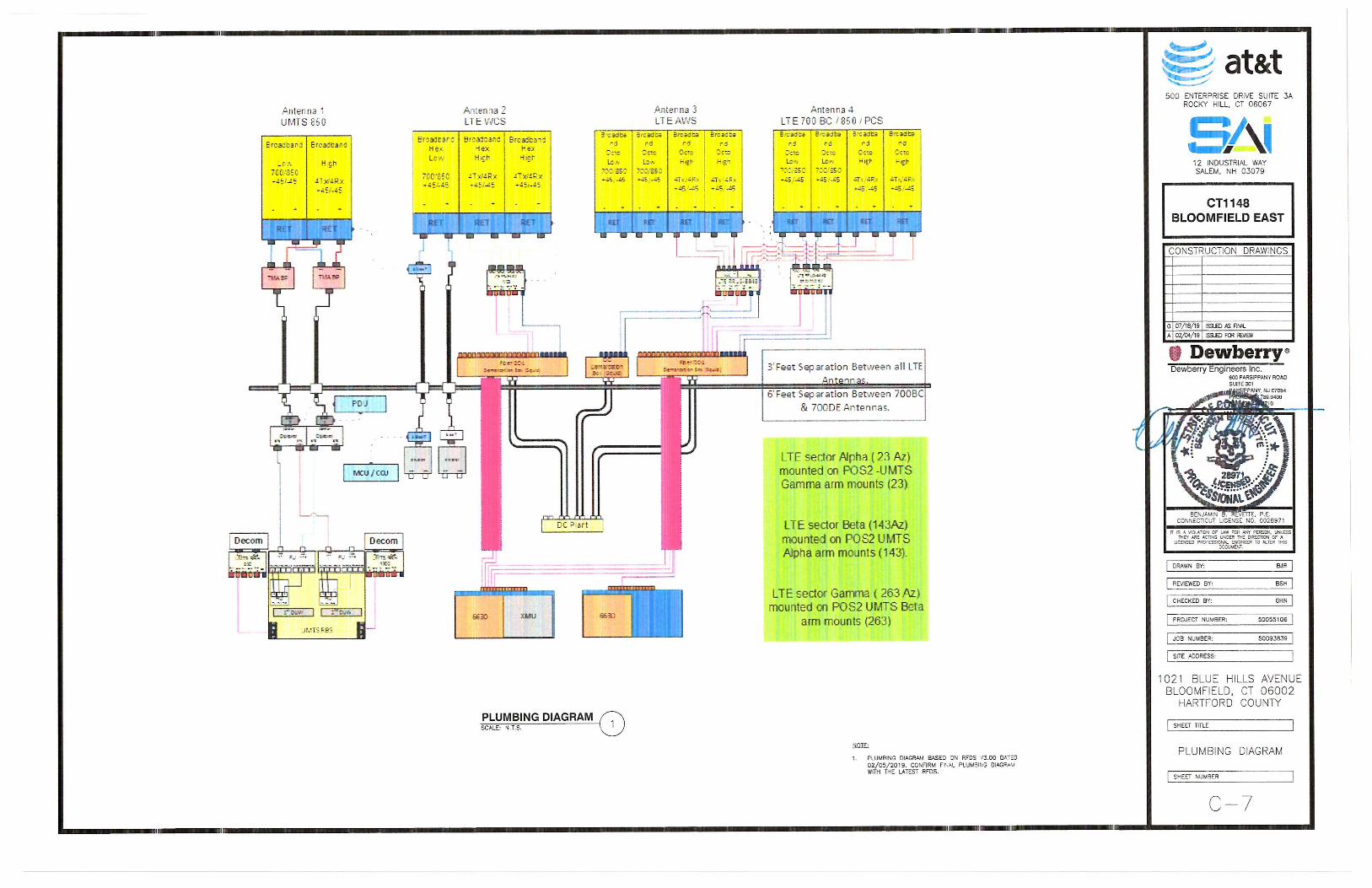
Carrier Name: AT&T (App#: 106446, V1) Carrier Site ID / Name: CT1148 / Bloomfield East
Site Location: 1021 Blue Hills Avenue Bloomfield, Connecticut
Hartford County Latitude: 41.820119
Longitude: -72.696514
Analysis Result: Max Structural Usage: 99.8% [Pass]
Max Foundation Usage: 44.0% [Pass]
Report Prepared By : Fabiyaye Arinyedokiari
TES Project Number: 70654 Page 2 June 5, 2019
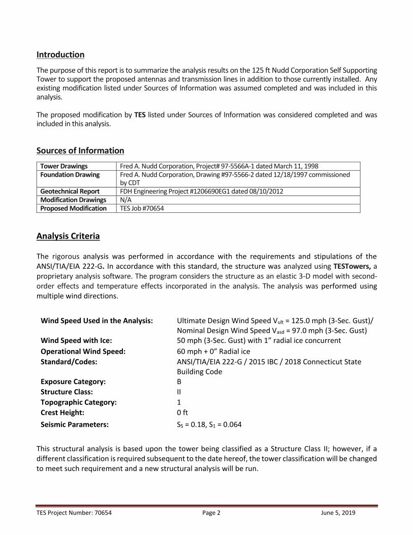
Introduction
The purpose of this report is to summarize the analysis results on the 125 ft Nudd Corporation Self Supporting Tower to support the proposed antennas and transmission lines in addition to those currently installed. Any existing modification listed under Sources of Information was assumed completed and was included in this analysis. The proposed modification by TES listed under Sources of Information was considered completed and was included in this analysis. Sources of Information
Tower Drawings Fred A. Nudd Corporation, Project# 97-5566A-1 dated March 11, 1998 Foundation Drawing Fred A. Nudd Corporation, Drawing #97-5566-2 dated 12/18/1997 commissioned
by CDT Geotechnical Report FDH Engineering Project #1206690EG1 dated 08/10/2012 Modification Drawings N/A Proposed Modification TES Job #70654
Analysis Criteria The rigorous analysis was performed in accordance with the requirements and stipulations of the ANSI/TIA/EIA 222-G. In accordance with this standard, the structure was analyzed using TESTowers, a proprietary analysis software. The program considers the structure as an elastic 3-D model with second-order effects and temperature effects incorporated in the analysis. The analysis was performed using multiple wind directions.
Wind Speed Used in the Analysis:
Ultimate Design Wind Speed Vult = 125.0 mph (3-Sec. Gust)/ Nominal Design Wind Speed Vasd = 97.0 mph (3-Sec. Gust)
Wind Speed with Ice: 50 mph (3-Sec. Gust) with 1” radial ice concurrent Operational Wind Speed: 60 mph + 0” Radial ice Standard/Codes: ANSI/TIA/EIA 222-G / 2015 IBC / 2018 Connecticut State
Building Code Exposure Category: B Structure Class: II Topographic Category: 1 Crest Height: 0 ft Seismic Parameters: SS = 0.18, S1 = 0.064
This structural analysis is based upon the tower being classified as a Structure Class II; however, if a different classification is required subsequent to the date hereof, the tower classification will be changed to meet such requirement and a new structural analysis will be run.

TES Project Number: 70654 Page 3 June 5, 2019
Existing Antennas, Mounts and Transmission Lines The table below summarizes the antennas, mounts and transmission lines that were considered in the analysis as existing on the tower.
Items Elevation (ft) Qty. Antenna Descriptions Mount Type & Qty. Transmission
Lines Owner
1 135.0
2 Cellwave PD455
Platform w/ Hand Rails w/ (3) PRK-FMA Mount
Reinforcement Kit
(1) 1 1/4" (2) 1/2" (2) 7/8"
Blue Hills Fire & PD
2 1 Cellwave AS MONR 31 3
125.0
1 Cellwave PD165S 4 5 Cellwave PD455 5 3 Ericsson AIR 21 B2A/B4P - Panel
(11) 1 5/8" (2) 1-1/4"
Hybrid T-Mobile
6 3 RFS APXVAARR24_43-U-NA20 - Panel 7 3 Ericsson AIR32 KRD901146-1_B66A 8 3 Ericsson KRY 112 144/2 - TMA 9 3 Ericsson Radio 4449 B71+B12 RRU
10
120.0
2 Samsung U-RAS Flexible
(3) Sector Frame (3) 1/2" (7) 5/16" Clearwire
11 2 Dragonwave Horizon DUO 12 3 Kathrein 840 10054 - Panel 13 2 Andrew VHLP2.5 - Dish 14 1 Motorola Timing 2000 15
110.0
3 Amphenol BXA-70063-4CF-EDIN-6
(3) Sector Frame
(18) 1 5/8" (2) 1 5/8"
Hybrid (2) 1/2" GPS
Verizon
16 9 Andrew SBNHH-1D65B - Panel 17 3 Alcatel Lucent RRH2X60-AWS radio 18 3 Alcatel Lucent RRH2x60-700 radio 19 3 Alcatel Lucent RRH 4x45-PCS radio 20 2 Andrew GPS
21 1 RFS Cellwave DB‐T1‐6Z‐8AB‐0Z distribution box
-
98.0
6 Powerwave 7770
(3) Sector Frame
(12) 7/8" (2) 3/4" DC & (1) 1/2" Fiber Inside (1) 3"
conduits
AT&T
- 2 CCI HPA‐65R‐BUU‐H8 - 1 CCI HPA‐65R‐BUU‐H6 - 6 Powerwave LGP21401 TMA - 12 Powerwave 7020 RET - 6 Ericsson RRUS 11 - 3 Ericsson RRUS 32 B2 - 6 Powerwave LGP21903 diplexer - 3 Kathrein 782 10253 - 1 Raycap DC6‐48‐60‐18‐8F
37
87.0
3 Alcatel Lucent 1900MHz RRH
(3) Sector Frame (1) 0.7" (3) 1 1/4" Sprint
38 3 Alcatel Lucent 800MHZ RRH 39 3 Alcatel Lucent TD-RRH8x20-25 40 4 RFS ACU-A20-N 41 3 RFS APXVSPP18-C-A20 - Panel 42 3 RFS APXVTM14-C-120 - Panel 43 3 Samsung 800MHz Filter 44 75.0 3 RFS Cellwave APXV18-206517S-C Direct Mount (6) 1 5/8" Metro - 65.0 1 Nokia CS72188.01 LMU - Omni (1) Standoff Mount (1) ½” AT&T
TES Project Number: 70654 Page 4 June 5, 2019
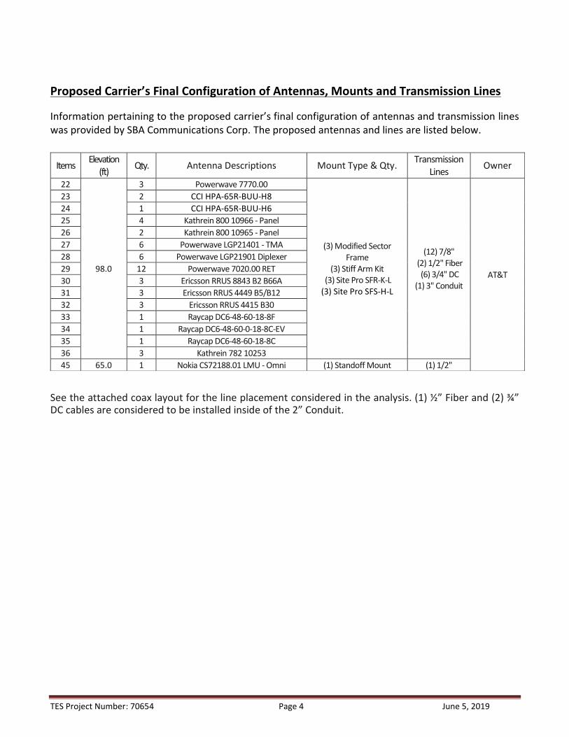
Proposed Carrier’s Final Configuration of Antennas, Mounts and Transmission Lines Information pertaining to the proposed carrier’s final configuration of antennas and transmission lines was provided by SBA Communications Corp. The proposed antennas and lines are listed below.
See the attached coax layout for the line placement considered in the analysis. (1) ½” Fiber and (2) ¾” DC cables are considered to be installed inside of the 2” Conduit.
Items Elevation (ft) Qty. Antenna Descriptions Mount Type & Qty. Transmission
Lines Owner
22
98.0
3 Powerwave 7770.00
(3) Modified Sector Frame
(3) Stiff Arm Kit (3) Site Pro SFR-K-L (3) Site Pro SFS-H-L
(12) 7/8" (2) 1/2" Fiber (6) 3/4" DC
(1) 3" Conduit AT&T
23 2 CCI HPA‐65R‐BUU‐H8 24 1 CCI HPA‐65R‐BUU‐H6 25 4 Kathrein 800 10966 - Panel 26 2 Kathrein 800 10965 - Panel 27 6 Powerwave LGP21401 - TMA 28 6 Powerwave LGP21901 Diplexer 29 12 Powerwave 7020.00 RET 30 3 Ericsson RRUS 8843 B2 B66A 31 3 Ericsson RRUS 4449 B5/B12 32 3 Ericsson RRUS 4415 B30 33 1 Raycap DC6-48-60-18-8F 34 1 Raycap DC6-48-60-0-18-8C-EV 35 1 Raycap DC6-48-60-18-8C 36 3 Kathrein 782 10253 45 65.0 1 Nokia CS72188.01 LMU - Omni (1) Standoff Mount (1) 1/2"

TES Project Number: 70654 Page 5 June 5, 2019
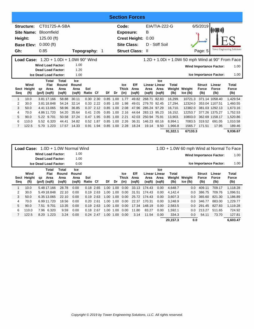
Analysis Results The results of the structural analysis, performed for the wind and ice loading and antenna equipment as defined above, are summarized as the following:
Tower Component Legs Diagonals Horizontals
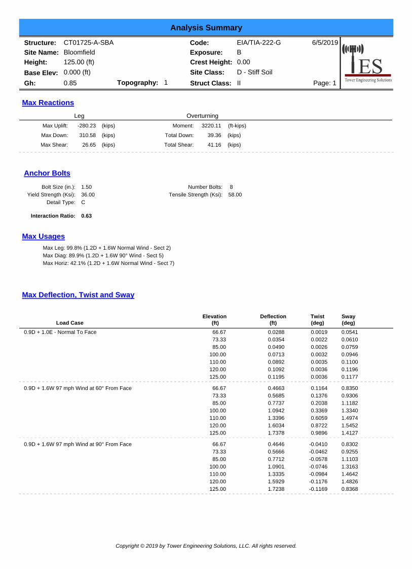
Max. Usage: 99.8% 89.9% 42.1% Pass/Fail Pass Pass Pass
Foundations
Compression (Kips) Uplift (Kips) Shear (Kips)
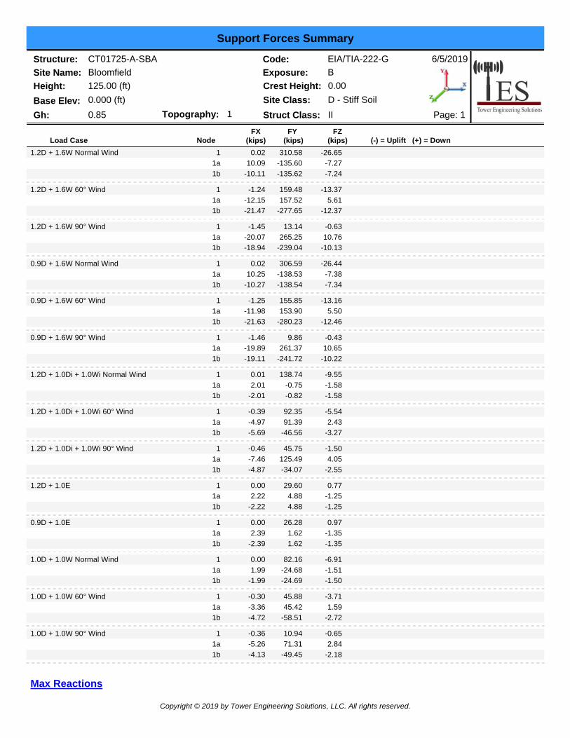
Analysis Reactions 310.6 280.2 26.6 The foundation has been investigated using the supplied documents and soils report and was found adequate. Therefore, no modification to the foundation will be required.
TES Project Number: 70654 Page 6 June 5, 2019
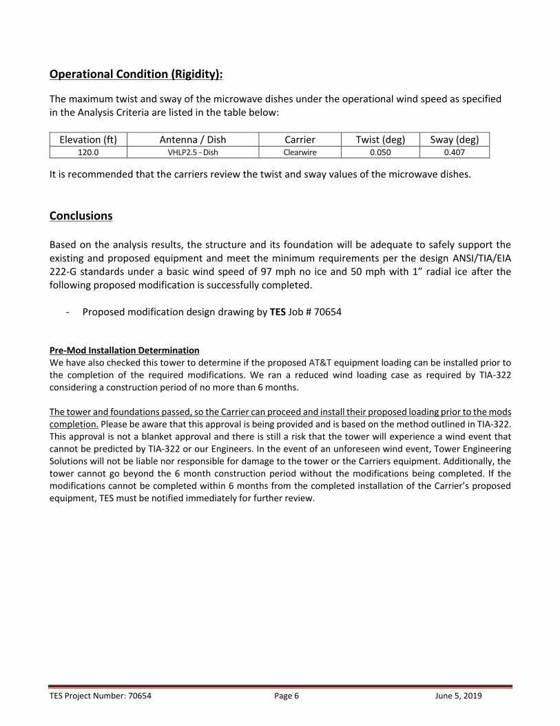
Operational Condition (Rigidity): The maximum twist and sway of the microwave dishes under the operational wind speed as specified in the Analysis Criteria are listed in the table below:
Elevation (ft) Antenna / Dish Carrier Twist (deg) Sway (deg) 120.0 VHLP2.5 - Dish Clearwire 0.050 0.407
It is recommended that the carriers review the twist and sway values of the microwave dishes. Conclusions Based on the analysis results, the structure and its foundation will be adequate to safely support the existing and proposed equipment and meet the minimum requirements per the design ANSI/TIA/EIA 222-G standards under a basic wind speed of 97 mph no ice and 50 mph with 1” radial ice after the following proposed modification is successfully completed.
- Proposed modification design drawing by TES Job # 70654 Pre-Mod Installation Determination We have also checked this tower to determine if the proposed AT&T equipment loading can be installed prior to the completion of the required modifications. We ran a reduced wind loading case as required by TIA-322 considering a construction period of no more than 6 months. The tower and foundations passed, so the Carrier can proceed and install their proposed loading prior to the mods completion. Please be aware that this approval is being provided and is based on the method outlined in TIA-322. This approval is not a blanket approval and there is still a risk that the tower will experience a wind event that cannot be predicted by TIA-322 or our Engineers. In the event of an unforeseen wind event, Tower Engineering Solutions will not be liable nor responsible for damage to the tower or the Carriers equipment. Additionally, the tower cannot go beyond the 6 month construction period without the modifications being completed. If the modifications cannot be completed within 6 months from the completed installation of the Carrier’s proposed equipment, TES must be notified immediately for further review.

TES Project Number: 70654 Page 7 June 5, 2019
Standard Conditions 1. This analysis was performed based on the information supplied to (TES) Tower Engineering Solutions,
LLC. Verification of the information provided was not included in the Scope of Work for TES. The accuracy of the analysis is dependent on the accuracy of the information provided.
2. The structural analysis was performance based upon the evidence available at the time of this report. All information provided by the client is considered to be accurate.
3. The analyses will be performed based on the codes as specified by the client or based on the best
knowledge of the engineering staff of TES. In the absence of information to the contrary, all work will be performed in accordance with the latest relevant revision of ANSI/TIA-222. If wind speed and/or ice loads are different from the minimum values recommended by the EIA/TIA-222 standard or other codes, TES should be notified in writing and the applicable minimum values provided by the client.
4. The configuration of the existing mounts, antennas, coax and other appurtenances were supplied by
the customer for the current structural analysis. TES has not visited the tower site to verify the adequacy of the information provided. If there is any discrepancy found in the report regarding the existing conditions, TES should be notified immediately to evaluate the effect of the discrepancy on the analysis results.
5. The client will assume responsibility for rework associated with the differences in initially provided
information, including tower and foundation information, existing and/or proposed equipment and transmission lines.
6. If a feasibility analysis was performed, final acceptance of changed conditions shall be based upon a
rigorous structural analysis.
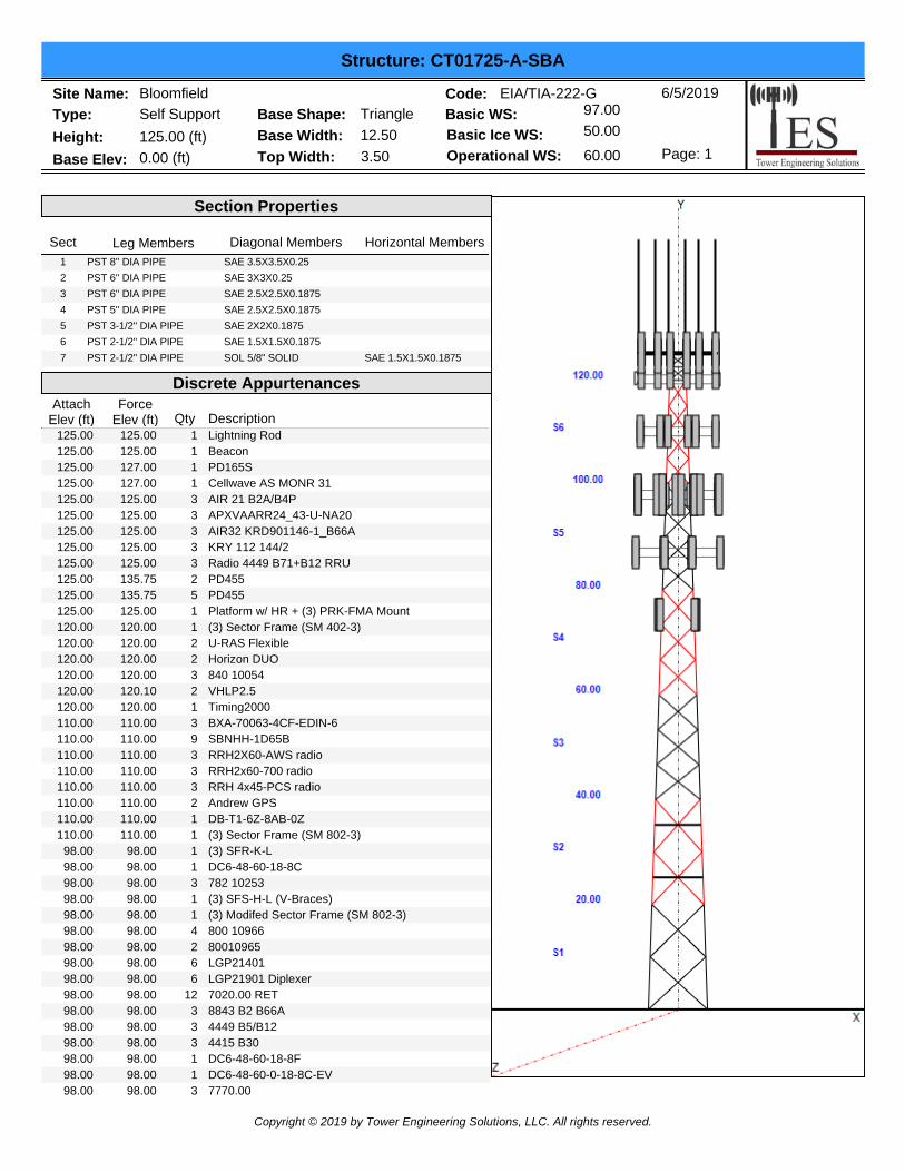
Type: Self SupportSite Name: Bloomfield
Height: 125.00 (ft)
6/5/2019
Page: 1
Base Shape: TriangleBase Width: 12.50
Base Elev: 0.00 (ft)
Structure: CT01725-A-SBA
Top Width: 3.50
Basic WS: 97.00
Basic Ice WS: 50.00
Operational WS: 60.00
Code: EIA/TIA-222-G
Section Properties
Sect Leg Members Diagonal Members Horizontal MembersSAE 3.5X3.5X0.25 1 PST 8" DIA PIPESAE 3X3X0.25 2 PST 6" DIA PIPESAE 2.5X2.5X0.1875 3 PST 6" DIA PIPESAE 2.5X2.5X0.1875 4 PST 5" DIA PIPESAE 2X2X0.1875 5 PST 3-1/2" DIA PIPESAE 1.5X1.5X0.1875 6 PST 2-1/2" DIA PIPESOL 5/8" SOLID SAE 1.5X1.5X0.18757 PST 2-1/2" DIA PIPE
Discrete AppurtenancesAttach
Elev (ft)Force
Elev (ft) Qty Description125.00 1 Lightning Rod125.00125.00 1 Beacon125.00125.00 1 PD165S127.00125.00 1 Cellwave AS MONR 31127.00125.00 3 AIR 21 B2A/B4P125.00125.00 3 APXVAARR24_43-U-NA20125.00125.00 3 AIR32 KRD901146-1_B66A125.00125.00 3 KRY 112 144/2125.00125.00 3 Radio 4449 B71+B12 RRU125.00125.00 2 PD455135.75125.00 5 PD455135.75125.00 1 Platform w/ HR + (3) PRK-FMA Mount125.00120.00 1 (3) Sector Frame (SM 402-3)120.00120.00 2 U-RAS Flexible120.00120.00 2 Horizon DUO120.00120.00 3 840 10054120.00120.00 2 VHLP2.5120.10120.00 1 Timing2000120.00110.00 3 BXA-70063-4CF-EDIN-6110.00110.00 9 SBNHH-1D65B110.00110.00 3 RRH2X60-AWS radio110.00110.00 3 RRH2x60-700 radio110.00110.00 3 RRH 4x45-PCS radio110.00110.00 2 Andrew GPS110.00110.00 1 DB-T1-6Z-8AB-0Z110.00110.00 1 (3) Sector Frame (SM 802-3)110.00
98.00 1 (3) SFR-K-L98.0098.00 1 DC6-48-60-18-8C98.0098.00 3 782 1025398.0098.00 1 (3) SFS-H-L (V-Braces)98.0098.00 1 (3) Modifed Sector Frame (SM 802-3)98.0098.00 4 800 1096698.0098.00 2 8001096598.0098.00 6 LGP2140198.0098.00 6 LGP21901 Diplexer98.0098.00 12 7020.00 RET98.0098.00 3 8843 B2 B66A98.0098.00 3 4449 B5/B1298.0098.00 3 4415 B3098.0098.00 1 DC6-48-60-18-8F98.0098.00 1 DC6-48-60-0-18-8C-EV98.0098.00 3 7770.0098.00
Copyright © 2019 by Tower Engineering Solutions, LLC. All rights reserved.

Type: Self SupportSite Name: Bloomfield
Height: 125.00 (ft)
6/5/2019
Page: 2
Base Shape: TriangleBase Width: 12.50
Base Elev: 0.00 (ft)
Structure: CT01725-A-SBA
Top Width: 3.50
Basic WS: 97.00
Basic Ice WS: 50.00
Operational WS: 60.00
Code: EIA/TIA-222-G
98.00 2 HPA-65R-BUU-H898.0098.00 1 HPA-65R-BUU-H698.0087.00 3 1900MHz RRH87.0087.00 3 800MHZ RRH87.0087.00 3 TD-RRH8x20-2587.0087.00 4 ACU-A20-N87.0087.00 3 APXVSPP18-C-A2087.0087.00 1 (3) Sector Frame (SM 502-3)87.0087.00 3 APXVTM14-C-12087.0087.00 3 800MHz Filter87.0075.00 3 APXV18-206517S-C75.0065.00 1 Standoff Mount65.0065.00 1 CS72188.01 LMU65.00
Linear AppurtenancesElev
From (ft)Elev
To (ft) Qty Description0.00 125.00 1 1 1/4" Coax0.00 125.00 11 1 5/8" Coax0.00 125.00 2 1-1/4" Hybrid0.00 125.00 2 1/2" Coax0.00 125.00 2 7/8" Coax0.00 125.00 1 W/G Ladder0.00 125.00 1 W/G Ladder0.00 120.00 3 1/2" Coax0.00 120.00 7 5/16" Coax0.00 120.00 1 W/G Ladder0.00 110.00 18 1 5/8" Coax0.00 110.00 2 1 5/8" Hybrid0.00 110.00 2 1/2" GPS0.00 110.00 1 W/G Ladder0.00 98.00 2 1/2" Fiber0.00 98.00 1 3" Conduit0.00 98.00 6 3/4" DC0.00 98.00 12 7/8" Coax0.00 98.00 1 W/G Ladder0.00 87.00 1 0.7" 0.00 87.00 3 1 1/4" Coax0.00 87.00 1 W/G Ladder0.00 75.00 6 1 5/8" Coax0.00 65.00 1 1/2" Coax
Base Reactions
Max Uplift:
Max Down:
-280.23
Leg Overturning
310.58
Max Shear: 26.65
Moment: 3220.11
Total Down:
Total Shear:
39.36
41.16
(kips
(kips
(kips
(ft-kips)
(kips)
(kips)
Copyright © 2019 by Tower Engineering Solutions, LLC. All rights reserved.

6/5/2019
Page: 3
Structure: CT01725-A-SBA
Type: Self SupportSite Name: Bloomfield
Height: 125.00 (ft)Base Shape: TriangleBase Width: 12.50
Base Elev: 0.00 (ft) Top Width: 3.50
Basic WS: 97.00
Basic Ice WS: 50.00
Operational WS: 60.00
Code: EIA/TIA-222-G
Copyright © 2019 by Tower Engineering Solutions, LLC. All rights reserved.

Type: Self Support
Site Name: Bloomfield
Height: 125.00 (ft)
6/5/2019
Page: 4
Structure: CT01725-A-SBA - Coax Line Placement
Copyright © 2019 by Tower Engineering Solutions, LLC. All rights reserved.
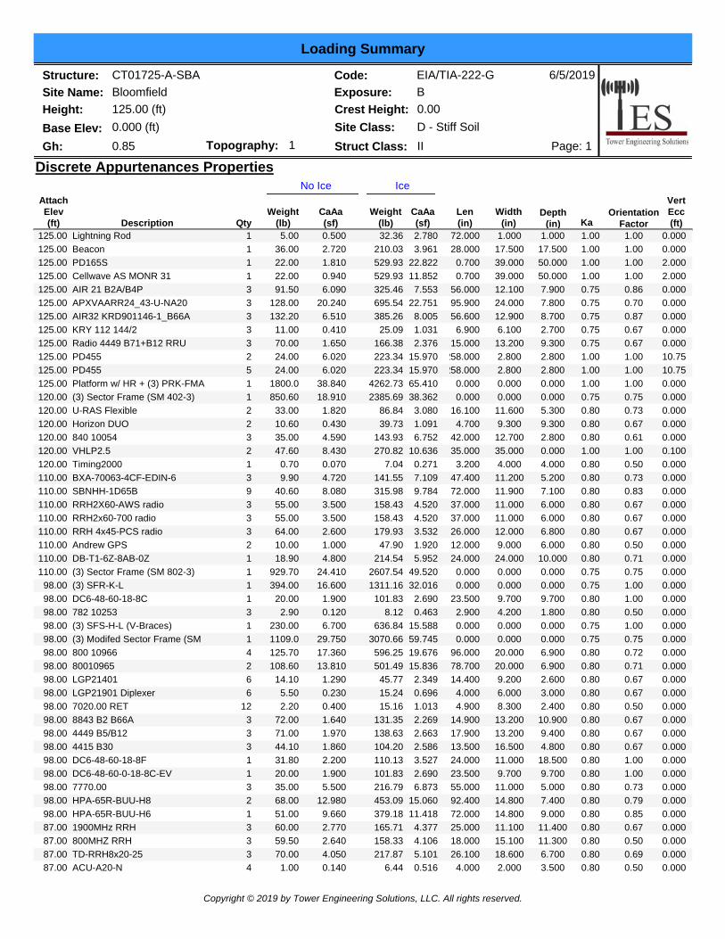
Loading Summary
Structure: CT01725-A-SBASite Name: BloomfieldHeight: 125.00 (ft)
6/5/2019
Page: 1
Code: EIA/TIA-222-GExposure: B
Gh: 0.85Base Elev: 0.000 (ft)
Crest Height: 0.00Site Class:
IIStruct Class:D - Stiff Soil
Topography: 1
Discrete Appurtenances PropertiesIceNo Ice
AttachElev(ft) Description Qty
Weight(lb)
CaAa(sf)
Weight(lb)
CaAa(sf)
Len(in)
Width(in)
VertEcc(ft)
Depth(in) Ka
OrientationFactor
Lightning Rod 1 5.00 0.500 2.78032.36125.00 72.000 1.000 1.000 0.0001.00 1.00Beacon 1 36.00 2.720 3.961210.03125.00 28.000 17.500 17.500 0.0001.00 1.00PD165S 1 22.00 1.810 22.822529.93125.00 0.700 39.000 50.000 2.0001.00 1.00Cellwave AS MONR 31 1 22.00 0.940 11.852529.93125.00 0.700 39.000 50.000 2.0001.00 1.00AIR 21 B2A/B4P 3 91.50 6.090 7.553325.46125.00 56.000 12.100 7.900 0.0000.75 0.86APXVAARR24_43-U-NA20 3 128.00 20.240 22.751695.54125.00 95.900 24.000 7.800 0.0000.75 0.70AIR32 KRD901146-1_B66A 3 132.20 6.510 8.005385.26125.00 56.600 12.900 8.700 0.0000.75 0.87KRY 112 144/2 3 11.00 0.410 1.03125.09125.00 6.900 6.100 2.700 0.0000.75 0.67Radio 4449 B71+B12 RRU 3 70.00 1.650 2.376166.38125.00 15.000 13.200 9.300 0.0000.75 0.67PD455 2 24.00 6.020 15.970223.34125.00 258.000 2.800 2.800 10.751.00 1.00PD455 5 24.00 6.020 15.970223.34125.00 258.000 2.800 2.800 10.751.00 1.00Platform w/ HR + (3) PRK-FMA 1 1800.0 38.840 65.4104262.73125.00 0.000 0.000 0.000 0.0001.00 1.00(3) Sector Frame (SM 402-3) 1 850.60 18.910 38.3622385.69120.00 0.000 0.000 0.000 0.0000.75 0.75U-RAS Flexible 2 33.00 1.820 3.08086.84120.00 16.100 11.600 5.300 0.0000.80 0.73Horizon DUO 2 10.60 0.430 1.09139.73120.00 4.700 9.300 9.300 0.0000.80 0.67840 10054 3 35.00 4.590 6.752143.93120.00 42.000 12.700 2.800 0.0000.80 0.61VHLP2.5 2 47.60 8.430 10.636270.82120.00 35.000 35.000 0.000 0.1001.00 1.00Timing2000 1 0.70 0.070 0.2717.04120.00 3.200 4.000 4.000 0.0000.80 0.50BXA-70063-4CF-EDIN-6 3 9.90 4.720 7.109141.55110.00 47.400 11.200 5.200 0.0000.80 0.73SBNHH-1D65B 9 40.60 8.080 9.784315.98110.00 72.000 11.900 7.100 0.0000.80 0.83RRH2X60-AWS radio 3 55.00 3.500 4.520158.43110.00 37.000 11.000 6.000 0.0000.80 0.67RRH2x60-700 radio 3 55.00 3.500 4.520158.43110.00 37.000 11.000 6.000 0.0000.80 0.67RRH 4x45-PCS radio 3 64.00 2.600 3.532179.93110.00 26.000 12.000 6.800 0.0000.80 0.67Andrew GPS 2 10.00 1.000 1.92047.90110.00 12.000 9.000 6.000 0.0000.80 0.50DB-T1-6Z-8AB-0Z 1 18.90 4.800 5.952214.54110.00 24.000 24.000 10.000 0.0000.80 0.71(3) Sector Frame (SM 802-3) 1 929.70 24.410 49.5202607.54110.00 0.000 0.000 0.000 0.0000.75 0.75(3) SFR-K-L 1 394.00 16.600 32.0161311.1698.00 0.000 0.000 0.000 0.0000.75 1.00DC6-48-60-18-8C 1 20.00 1.900 2.690101.8398.00 23.500 9.700 9.700 0.0000.80 1.00782 10253 3 2.90 0.120 0.4638.1298.00 2.900 4.200 1.800 0.0000.80 0.50(3) SFS-H-L (V-Braces) 1 230.00 6.700 15.588636.8498.00 0.000 0.000 0.000 0.0000.75 1.00(3) Modifed Sector Frame (SM 1 1109.0 29.750 59.7453070.6698.00 0.000 0.000 0.000 0.0000.75 0.75800 10966 4 125.70 17.360 19.676596.2598.00 96.000 20.000 6.900 0.0000.80 0.7280010965 2 108.60 13.810 15.836501.4998.00 78.700 20.000 6.900 0.0000.80 0.71LGP21401 6 14.10 1.290 2.34945.7798.00 14.400 9.200 2.600 0.0000.80 0.67LGP21901 Diplexer 6 5.50 0.230 0.69615.2498.00 4.000 6.000 3.000 0.0000.80 0.677020.00 RET 12 2.20 0.400 1.01315.1698.00 4.900 8.300 2.400 0.0000.80 0.508843 B2 B66A 3 72.00 1.640 2.269131.3598.00 14.900 13.200 10.900 0.0000.80 0.674449 B5/B12 3 71.00 1.970 2.663138.6398.00 17.900 13.200 9.400 0.0000.80 0.674415 B30 3 44.10 1.860 2.586104.2098.00 13.500 16.500 4.800 0.0000.80 0.67DC6-48-60-18-8F 1 31.80 2.200 3.527110.1398.00 24.000 11.000 18.500 0.0000.80 1.00DC6-48-60-0-18-8C-EV 1 20.00 1.900 2.690101.8398.00 23.500 9.700 9.700 0.0000.80 1.007770.00 3 35.00 5.500 6.873216.7998.00 55.000 11.000 5.000 0.0000.80 0.73HPA-65R-BUU-H8 2 68.00 12.980 15.060453.0998.00 92.400 14.800 7.400 0.0000.80 0.79HPA-65R-BUU-H6 1 51.00 9.660 11.418379.1898.00 72.000 14.800 9.000 0.0000.80 0.851900MHz RRH 3 60.00 2.770 4.377165.7187.00 25.000 11.100 11.400 0.0000.80 0.67800MHZ RRH 3 59.50 2.640 4.106158.3387.00 18.000 15.100 11.300 0.0000.80 0.50TD-RRH8x20-25 3 70.00 4.050 5.101217.8787.00 26.100 18.600 6.700 0.0000.80 0.69ACU-A20-N 4 1.00 0.140 0.5166.4487.00 4.000 2.000 3.500 0.0000.80 0.50
Copyright © 2019 by Tower Engineering Solutions, LLC. All rights reserved.
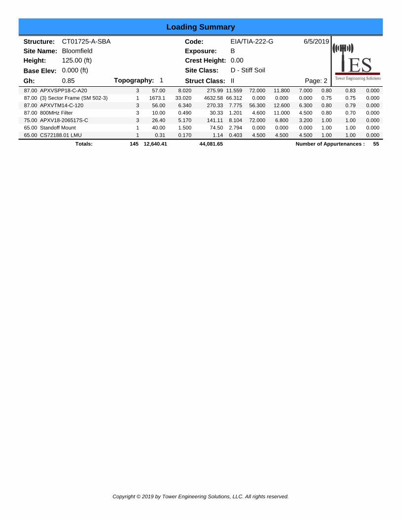
Loading Summary
Structure: CT01725-A-SBASite Name: BloomfieldHeight: 125.00 (ft)
6/5/2019
Page: 2
Code: EIA/TIA-222-GExposure: B
Gh: 0.85Base Elev: 0.000 (ft)
Crest Height: 0.00Site Class:
IIStruct Class:D - Stiff Soil
Topography: 1APXVSPP18-C-A20 3 57.00 8.020 11.559275.9987.00 72.000 11.800 7.000 0.0000.80 0.83(3) Sector Frame (SM 502-3) 1 1673.1 33.020 66.3124632.5887.00 0.000 0.000 0.000 0.0000.75 0.75APXVTM14-C-120 3 56.00 6.340 7.775270.3387.00 56.300 12.600 6.300 0.0000.80 0.79800MHz Filter 3 10.00 0.490 1.20130.3387.00 4.600 11.000 4.500 0.0000.80 0.70APXV18-206517S-C 3 26.40 5.170 8.104141.1175.00 72.000 6.800 3.200 0.0001.00 1.00Standoff Mount 1 40.00 1.500 2.79474.5065.00 0.000 0.000 0.000 0.0001.00 1.00CS72188.01 LMU 1 0.31 0.170 0.4031.1465.00 4.500 4.500 4.500 0.0001.00 1.00
44,081.65 55Number of Appurtenances : Totals: 12,640.41145
Copyright © 2019 by Tower Engineering Solutions, LLC. All rights reserved.

Loading Summary
Structure: CT01725-A-SBASite Name: BloomfieldHeight: 125.00 (ft)
6/5/2019
Page: 3
Code: EIA/TIA-222-GExposure: B
Gh: 0.85Base Elev: 0.000 (ft)
Crest Height: 0.00Site Class:
IIStruct Class:D - Stiff Soil
Topography: 1
Linear Appurtenances Properties
Weight(lb/ft)
Width(in)
PctIn
Block
SpreadOn
FacesBundling
Arrangement
Elev.From
(ft) Description
Elev.To(ft) Qty
ClusterDia(in)
Outof
ZoneSpacing
(in)Orientation
FactorKa
Override0.00 125.00 1 1/4" Coax 1.55 100.00 2 Individual NR 1 0.66 N 1.00 1.000.00 125.00 1 5/8" Coax 1.98 50.00 3 Block11 1.04 N 1.00 1.000.00 125.00 1-1/4" Hybrid 1.25 50.00 3 Block 2 0.95 N 1.00 1.000.00 125.00 1/2" Coax 0.65 100.00 2 Individual NR 2 0.16 N 1.00 1.000.00 125.00 7/8" Coax 1.11 100.00 2 Individual NR 2 0.52 N 1.00 1.000.00 125.00 W/G Ladder 2.50 100.00 3 Individual NR 1 6.00 N 1.00 1.000.00 125.00 W/G Ladder 2.00 100.00 2 Individual NR 1 6.00 N 1.00 1.000.00 120.00 1/2" Coax 0.65 100.00 1 Individual NR 3 0.16 N 1.00 1.000.00 120.00 5/16" Coax 0.44 50.00 1 Block 7 0.08 N 1.00 1.000.00 120.00 W/G Ladder 2.00 100.00 1 Individual NR 1 6.00 N 1.00 1.000.00 110.00 1 5/8" Coax 1.98 50.00 3 Block18 1.04 N 1.00 1.000.00 110.00 1 5/8" Hybrid 2.00 50.00 3 Block 2 1.10 N 1.00 1.000.00 110.00 1/2" GPS 0.65 50.00 3 Block 2 0.16 N 1.00 1.000.00 110.00 W/G Ladder 2.00 100.00 3 Individual NR 1 6.00 N 1.00 1.000.00 98.00 1/2" Fiber 0.65 50.00 2 Block 2 0.16 N 1.00 1.000.00 98.00 3" Conduit 3.00 100.00 2 Individual NR 1 1.61 N 1.00 1.000.00 98.00 3/4" DC 0.75 50.00 2 Block 6 0.40 N 1.00 1.000.00 98.00 7/8" Coax 1.11 50.00 2 Block12 0.52 N 1.00 1.000.00 98.00 W/G Ladder 2.00 100.00 2 Individual NR 1 6.00 N 1.00 1.000.00 87.00 0.7" 0.75 100.00 1 Individual NR 1 0.40 N 1.00 1.000.00 87.00 1 1/4" Coax 1.55 100.00 1 Individual NR 3 0.66 N 1.00 1.000.00 87.00 W/G Ladder 2.00 100.00 1 Individual NR 1 6.00 N 1.00 1.000.00 75.00 1 5/8" Coax 1.98 50.00 1 Block 6 1.04 N 1.00 1.000.00 65.00 1/2" Coax 0.65 100.00 2 Individual NR 1 0.16 N 1.00 1.00
Copyright © 2019 by Tower Engineering Solutions, LLC. All rights reserved.

Structure: CT01725-A-SBASite Name: BloomfieldHeight: 125.00 (ft)
6/5/2019Code: EIA/TIA-222-GExposure: B
Base Elev: 0.000 (ft)
Section Forces
Page: 1IIStruct Class:Topography: 1Gh: 0.85
Crest Height: 0.00Site Class: D - Stiff Soil
SectSeq
qz(psf)
TotalFlatArea(sqft)
IceRoundArea(sqft)
SolRatio Cf Df
WindHeight
(ft) Dr
IceThick(in)
EffArea(sqft)
LinearArea(sqft)
IceLinearArea(sqft)
TotalWeight
(lb)WeightIce (lb)
StructForce
(lb)
LinearForce
(lb)
TotalForce
(lb)
Ice Dead Load Factor: 0.00
1.2D + 1.6W 97 mph Wind at Normal To FaceWind Load Factor: 1.60
TotalRoundArea(sqft)
Wind Importance Factor: 1.00Dead Load Factor: 1.20
Ice Importance Factor: 1.00
1.2D + 1.6W Normal WindLoad Case:
14.33 17.166 0.00 0.18 2.65 1.00 1 10.0 1.00 0.00 30.43 174.43 0.00 5,578.4 0.0 1571.30 2965.57 4,536.8828.7814.34 18.848 0.00 0.19 2.63 1.00 2 30.0 1.00 0.00 30.33 174.43 0.00 4,970.9 0.0 1556.88 2968.08 4,524.9522.1016.60 13.065 0.00 0.19 2.63 1.00 3 50.0 1.00 0.00 24.23 174.43 0.00 4,328.8 0.0 1440.23 3434.47 4,874.7122.1018.27 11.720 0.00 0.20 2.61 1.00 4 70.0 1.00 0.00 21.58 170.31 0.00 3,898.7 0.0 1398.82 3692.51 5,091.3218.5619.63 9.701 0.00 0.19 2.63 1.00 5 90.0 1.00 0.00 17.34 148.19 0.00 3,100.3 0.0 1218.78 3461.80 4,680.5813.3520.79 6.320 0.00 0.18 2.67 1.00 6 110.0 1.00 0.00 11.80 83.27 0.00 1,910.6 0.0 891.84 2139.62 3,031.459.5921.44 1.223 0.00 0.24 2.47 1.00 7 122.5 1.00 0.00 3.14 11.54 0.00 401.1 0.0 226.28 308.21 534.493.24
24,188.8 0.0 27,274.38
SectSeq
qz(psf)
TotalFlatArea(sqft)
IceRoundArea(sqft)
SolRatio Cf Df
WindHeight
(ft) Dr
IceThick(in)
EffArea(sqft)
LinearArea(sqft)
IceLinearArea(sqft)
TotalWeight
(lb)WeightIce (lb)
StructForce
(lb)
LinearForce
(lb)
TotalForce
(lb)
Ice Dead Load Factor: 0.00
1.2D + 1.6W 97 mph Wind at 60° From FaceWind Load Factor: 1.60
TotalRoundArea(sqft)
Wind Importance Factor: 1.00Dead Load Factor: 1.20
Ice Importance Factor: 1.00
1.2D + 1.6W 60° WindLoad Case:
14.33 17.166 0.00 0.18 2.65 0.80 1 10.0 1.00 0.00 26.99 174.43 0.00 5,578.4 0.0 1394.00 2965.57 4,359.5828.7814.34 18.848 0.00 0.19 2.63 0.80 2 30.0 1.00 0.00 26.56 174.43 0.00 4,970.9 0.0 1363.38 2968.08 4,331.4622.1016.60 13.065 0.00 0.19 2.63 0.80 3 50.0 1.00 0.00 21.62 174.43 0.00 4,328.8 0.0 1284.93 3434.47 4,719.4022.1018.27 11.720 0.00 0.20 2.61 0.80 4 70.0 1.00 0.00 19.24 170.31 0.00 3,898.7 0.0 1246.87 3692.51 4,939.3818.5619.63 9.701 0.00 0.19 2.63 0.80 5 90.0 1.00 0.00 15.40 148.19 0.00 3,100.3 0.0 1082.44 3461.80 4,544.2413.3520.79 6.320 0.00 0.18 2.67 0.80 6 110.0 1.00 0.00 10.53 83.27 0.00 1,910.6 0.0 796.27 2139.62 2,935.899.5921.44 1.223 0.00 0.24 2.47 0.80 7 122.5 1.00 0.00 2.90 11.54 0.00 401.1 0.0 208.65 308.21 516.863.24
24,188.8 0.0 26,346.81
Copyright © 2019 by Tower Engineering Solutions, LLC. All rights reserved.

Structure: CT01725-A-SBASite Name: BloomfieldHeight: 125.00 (ft)
6/5/2019Code: EIA/TIA-222-GExposure: B
Base Elev: 0.000 (ft)
Section Forces
Page: 2IIStruct Class:Topography: 1Gh: 0.85
Crest Height: 0.00Site Class: D - Stiff Soil
SectSeq
qz(psf)
TotalFlatArea(sqft)
IceRoundArea(sqft)
SolRatio Cf Df
WindHeight
(ft) Dr
IceThick(in)
EffArea(sqft)
LinearArea(sqft)
IceLinearArea(sqft)
TotalWeight
(lb)WeightIce (lb)
StructForce
(lb)
LinearForce
(lb)
TotalForce
(lb)
Ice Dead Load Factor: 0.00
1.2D + 1.6W 97 mph Wind at 90° From FaceWind Load Factor: 1.60
TotalRoundArea(sqft)
Wind Importance Factor: 1.00Dead Load Factor: 1.20
Ice Importance Factor: 1.00
1.2D + 1.6W 90° WindLoad Case:
14.33 17.166 0.00 0.18 2.65 0.85 1 10.0 1.00 0.00 27.85 174.43 0.00 5,578.4 0.0 1438.33 2965.57 4,403.9028.7814.34 18.848 0.00 0.19 2.63 0.85 2 30.0 1.00 0.00 27.50 174.43 0.00 4,970.9 0.0 1411.75 2968.08 4,379.8322.1016.60 13.065 0.00 0.19 2.63 0.85 3 50.0 1.00 0.00 22.27 174.43 0.00 4,328.8 0.0 1323.75 3434.47 4,758.2322.1018.27 11.720 0.00 0.20 2.61 0.85 4 70.0 1.00 0.00 19.82 170.31 0.00 3,898.7 0.0 1284.86 3692.51 4,977.3718.5619.63 9.701 0.00 0.19 2.63 0.85 5 90.0 1.00 0.00 15.89 148.19 0.00 3,100.3 0.0 1116.52 3461.80 4,578.3313.3520.79 6.320 0.00 0.18 2.67 0.85 6 110.0 1.00 0.00 10.85 83.27 0.00 1,910.6 0.0 820.16 2139.62 2,959.789.5921.44 1.223 0.00 0.24 2.47 0.85 7 122.5 1.00 0.00 2.96 11.54 0.00 401.1 0.0 213.06 308.21 521.273.24
24,188.8 0.0 26,578.70
SectSeq
qz(psf)
TotalFlatArea(sqft)
IceRoundArea(sqft)
SolRatio Cf Df
WindHeight
(ft) Dr
IceThick(in)
EffArea(sqft)
LinearArea(sqft)
IceLinearArea(sqft)
TotalWeight
(lb)WeightIce (lb)
StructForce
(lb)
LinearForce
(lb)
TotalForce
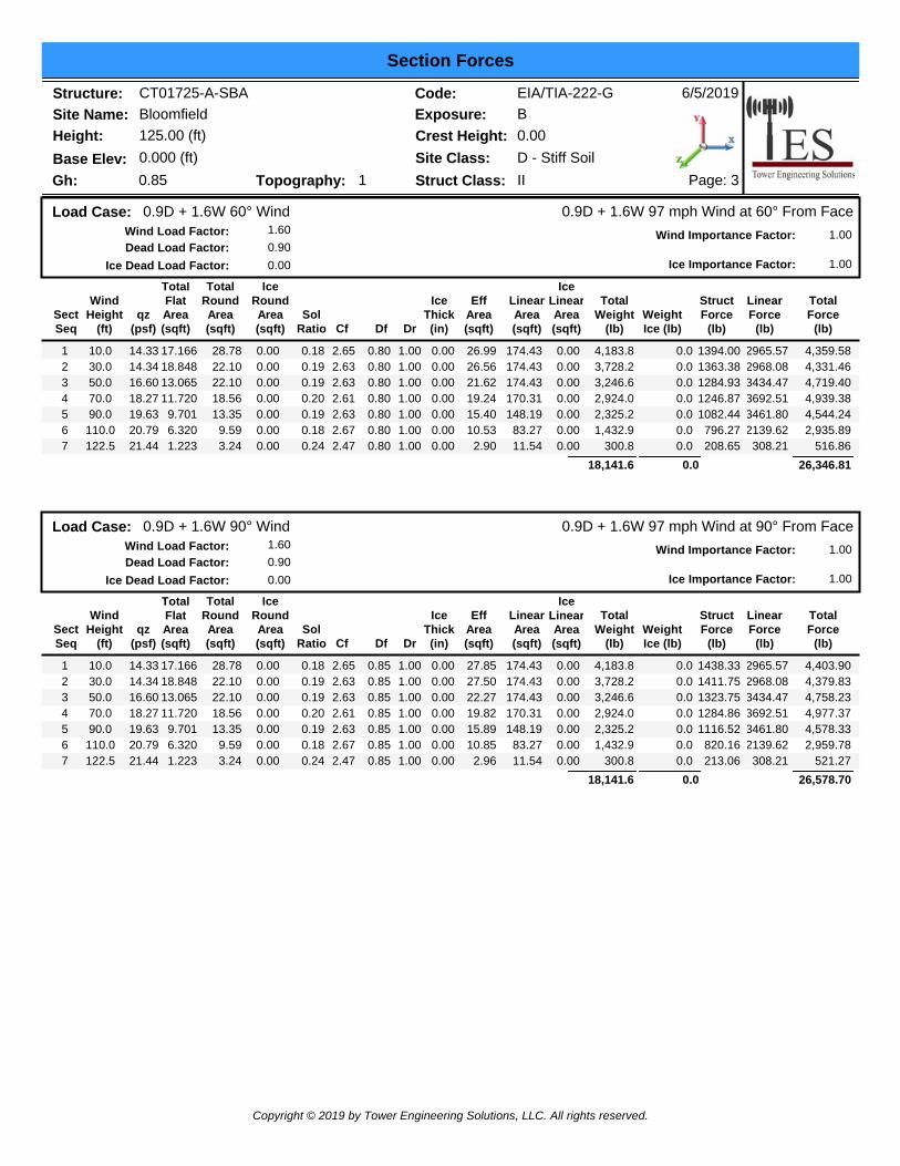
(lb)
Ice Dead Load Factor: 0.00
0.9D + 1.6W 97 mph Wind at Normal To FaceWind Load Factor: 1.60
TotalRoundArea(sqft)
Wind Importance Factor: 1.00Dead Load Factor: 0.90
Ice Importance Factor: 1.00
0.9D + 1.6W Normal WindLoad Case:
14.33 17.166 0.00 0.18 2.65 1.00 1 10.0 1.00 0.00 30.43 174.43 0.00 4,183.8 0.0 1571.30 2965.57 4,536.8828.7814.34 18.848 0.00 0.19 2.63 1.00 2 30.0 1.00 0.00 30.33 174.43 0.00 3,728.2 0.0 1556.88 2968.08 4,524.9522.1016.60 13.065 0.00 0.19 2.63 1.00 3 50.0 1.00 0.00 24.23 174.43 0.00 3,246.6 0.0 1440.23 3434.47 4,874.7122.1018.27 11.720 0.00 0.20 2.61 1.00 4 70.0 1.00 0.00 21.58 170.31 0.00 2,924.0 0.0 1398.82 3692.51 5,091.3218.5619.63 9.701 0.00 0.19 2.63 1.00 5 90.0 1.00 0.00 17.34 148.19 0.00 2,325.2 0.0 1218.78 3461.80 4,680.5813.3520.79 6.320 0.00 0.18 2.67 1.00 6 110.0 1.00 0.00 11.80 83.27 0.00 1,432.9 0.0 891.84 2139.62 3,031.459.5921.44 1.223 0.00 0.24 2.47 1.00 7 122.5 1.00 0.00 3.14 11.54 0.00 300.8 0.0 226.28 308.21 534.493.24
18,141.6 0.0 27,274.38
Copyright © 2019 by Tower Engineering Solutions, LLC. All rights reserved.
Structure: CT01725-A-SBASite Name: BloomfieldHeight: 125.00 (ft)
6/5/2019Code: EIA/TIA-222-GExposure: B
Base Elev: 0.000 (ft)
Section Forces
Page: 3IIStruct Class:Topography: 1Gh: 0.85
Crest Height: 0.00Site Class: D - Stiff Soil
SectSeq
qz(psf)
TotalFlatArea(sqft)
IceRoundArea(sqft)
SolRatio Cf Df
WindHeight
(ft) Dr
IceThick(in)
EffArea(sqft)
LinearArea(sqft)
IceLinearArea(sqft)
TotalWeight
(lb)WeightIce (lb)
StructForce
(lb)
LinearForce
(lb)
TotalForce
(lb)
Ice Dead Load Factor: 0.00
0.9D + 1.6W 97 mph Wind at 60° From FaceWind Load Factor: 1.60
TotalRoundArea(sqft)
Wind Importance Factor: 1.00Dead Load Factor: 0.90
Ice Importance Factor: 1.00
0.9D + 1.6W 60° WindLoad Case:
14.33 17.166 0.00 0.18 2.65 0.80 1 10.0 1.00 0.00 26.99 174.43 0.00 4,183.8 0.0 1394.00 2965.57 4,359.5828.7814.34 18.848 0.00 0.19 2.63 0.80 2 30.0 1.00 0.00 26.56 174.43 0.00 3,728.2 0.0 1363.38 2968.08 4,331.4622.1016.60 13.065 0.00 0.19 2.63 0.80 3 50.0 1.00 0.00 21.62 174.43 0.00 3,246.6 0.0 1284.93 3434.47 4,719.4022.1018.27 11.720 0.00 0.20 2.61 0.80 4 70.0 1.00 0.00 19.24 170.31 0.00 2,924.0 0.0 1246.87 3692.51 4,939.3818.5619.63 9.701 0.00 0.19 2.63 0.80 5 90.0 1.00 0.00 15.40 148.19 0.00 2,325.2 0.0 1082.44 3461.80 4,544.2413.3520.79 6.320 0.00 0.18 2.67 0.80 6 110.0 1.00 0.00 10.53 83.27 0.00 1,432.9 0.0 796.27 2139.62 2,935.899.5921.44 1.223 0.00 0.24 2.47 0.80 7 122.5 1.00 0.00 2.90 11.54 0.00 300.8 0.0 208.65 308.21 516.863.24
18,141.6 0.0 26,346.81
SectSeq
qz(psf)
TotalFlatArea(sqft)
IceRoundArea(sqft)
SolRatio Cf Df
WindHeight
(ft) Dr
IceThick(in)
EffArea(sqft)
LinearArea(sqft)
IceLinearArea(sqft)
TotalWeight
(lb)WeightIce (lb)
StructForce
(lb)
LinearForce
(lb)
TotalForce
(lb)
Ice Dead Load Factor: 0.00
0.9D + 1.6W 97 mph Wind at 90° From FaceWind Load Factor: 1.60
TotalRoundArea(sqft)
Wind Importance Factor: 1.00Dead Load Factor: 0.90
Ice Importance Factor: 1.00
0.9D + 1.6W 90° WindLoad Case:
14.33 17.166 0.00 0.18 2.65 0.85 1 10.0 1.00 0.00 27.85 174.43 0.00 4,183.8 0.0 1438.33 2965.57 4,403.9028.7814.34 18.848 0.00 0.19 2.63 0.85 2 30.0 1.00 0.00 27.50 174.43 0.00 3,728.2 0.0 1411.75 2968.08 4,379.8322.1016.60 13.065 0.00 0.19 2.63 0.85 3 50.0 1.00 0.00 22.27 174.43 0.00 3,246.6 0.0 1323.75 3434.47 4,758.2322.1018.27 11.720 0.00 0.20 2.61 0.85 4 70.0 1.00 0.00 19.82 170.31 0.00 2,924.0 0.0 1284.86 3692.51 4,977.3718.5619.63 9.701 0.00 0.19 2.63 0.85 5 90.0 1.00 0.00 15.89 148.19 0.00 2,325.2 0.0 1116.52 3461.80 4,578.3313.3520.79 6.320 0.00 0.18 2.67 0.85 6 110.0 1.00 0.00 10.85 83.27 0.00 1,432.9 0.0 820.16 2139.62 2,959.789.5921.44 1.223 0.00 0.24 2.47 0.85 7 122.5 1.00 0.00 2.96 11.54 0.00 300.8 0.0 213.06 308.21 521.273.24
18,141.6 0.0 26,578.70
Copyright © 2019 by Tower Engineering Solutions, LLC. All rights reserved.

Structure: CT01725-A-SBASite Name: BloomfieldHeight: 125.00 (ft)
6/5/2019Code: EIA/TIA-222-GExposure: B
Base Elev: 0.000 (ft)
Section Forces
Page: 4IIStruct Class:Topography: 1Gh: 0.85
Crest Height: 0.00Site Class: D - Stiff Soil
SectSeq
qz(psf)
TotalFlatArea(sqft)
IceRoundArea(sqft)
SolRatio Cf Df
WindHeight
(ft) Dr
IceThick(in)
EffArea(sqft)
LinearArea(sqft)
IceLinearArea(sqft)
TotalWeight
(lb)WeightIce (lb)
StructForce
(lb)
LinearForce
(lb)
TotalForce
(lb)
Ice Dead Load Factor: 1.00
1.2D + 1.0Di + 1.0Wi 50 mph Wind at Normal From FaceWind Load Factor: 1.00
TotalRoundArea(sqft)
Wind Importance Factor: 1.00Dead Load Factor: 1.20
Ice Importance Factor: 1.00
1.2D + 1.0Di + 1.0Wi Normal WindLoad Case:
3.81 17.166 30.11 0.30 2.30 1.00 1 10.0 1.00 1.77 52.39 268.71 82.83 16,299. 10721.3 390.33 1058.40 1,448.7258.883.81 18.848 32.14 0.33 2.22 1.00 2 30.0 1.00 1.98 51.84 279.70 92.45 17,294. 12324.0 373.40 1107.51 1,480.9254.244.41 13.065 36.85 0.37 2.12 1.00 3 50.0 1.00 2.08 49.92 285.24 97.29 16,710. 12382.0 396.60 1292.13 1,519.2358.964.86 11.720 35.64 0.41 2.05 1.00 4 70.0 1.00 2.16 46.40 283.13 95.23 16,152. 12253.7 392.12 1375.27 1,767.3954.205.22 9.701 37.24 0.47 1.95 1.00 5 90.0 1.00 2.21 43.48 250.94 75.91 13,903. 10803.0 375.25 1158.17 1,533.4250.585.52 6.320 34.82 0.52 1.87 1.00 6 110.0 1.00 2.26 37.26 146.23 60.16 8,994.1 7083.5 327.86 691.05 1,018.9244.415.70 1.223 14.33 0.91 1.94 1.00 7 122.5 1.00 2.28 18.42 19.14 9.50 1,966.8 1565.7 173.23 17.95 191.1817.57
91,322.1 67133.3 8,959.77
SectSeq
qz(psf)
TotalFlatArea(sqft)
IceRoundArea(sqft)
SolRatio Cf Df
WindHeight
(ft) Dr
IceThick(in)
EffArea(sqft)
LinearArea(sqft)
IceLinearArea(sqft)
TotalWeight
(lb)WeightIce (lb)
StructForce
(lb)
LinearForce
(lb)
TotalForce
(lb)
Ice Dead Load Factor: 1.00
1.2D + 1.0Di + 1.0Wi 50 mph Wind at 60° From FaceWind Load Factor: 1.00
TotalRoundArea(sqft)
Wind Importance Factor: 1.00Dead Load Factor: 1.20
Ice Importance Factor: 1.00
1.2D + 1.0Di + 1.0Wi 60° WindLoad Case:
3.81 17.166 30.11 0.30 2.30 0.80 1 10.0 1.00 1.77 48.96 268.71 82.83 16,299. 10721.3 364.75 1058.40 1,423.1458.883.81 18.848 32.14 0.33 2.22 0.80 2 30.0 1.00 1.98 48.07 279.70 92.45 17,294. 12324.0 346.25 1107.51 1,453.7654.244.41 13.065 36.85 0.37 2.12 0.80 3 50.0 1.00 2.08 47.30 285.24 97.29 16,710. 12382.0 375.84 1292.13 1,667.9758.964.86 11.720 35.64 0.41 2.05 0.80 4 70.0 1.00 2.16 44.05 283.13 95.23 16,152. 12253.7 372.31 1375.27 1,747.5854.205.22 9.701 37.24 0.47 1.95 0.80 5 90.0 1.00 2.21 41.54 250.94 75.91 13,903. 10803.0 358.50 1158.17 1,516.6750.585.52 6.320 34.82 0.52 1.87 0.80 6 110.0 1.00 2.26 36.00 146.23 60.16 8,994.1 7083.5 316.74 691.05 1,007.8044.415.70 1.223 14.33 0.91 1.94 0.80 7 122.5 1.00 2.28 18.18 19.14 9.50 1,966.8 1565.7 170.93 17.95 188.8817.57
91,322.1 67133.3 9,005.80
Copyright © 2019 by Tower Engineering Solutions, LLC. All rights reserved.
Structure: CT01725-A-SBASite Name: BloomfieldHeight: 125.00 (ft)
6/5/2019Code: EIA/TIA-222-GExposure: B
Base Elev: 0.000 (ft)
Section Forces
Page: 5IIStruct Class:Topography: 1Gh: 0.85
Crest Height: 0.00Site Class: D - Stiff Soil
SectSeq
qz(psf)
TotalFlatArea(sqft)
IceRoundArea(sqft)
SolRatio Cf Df
WindHeight
(ft) Dr
IceThick(in)
EffArea(sqft)
LinearArea(sqft)
IceLinearArea(sqft)
TotalWeight
(lb)WeightIce (lb)
StructForce
(lb)
LinearForce
(lb)
TotalForce
(lb)
Ice Dead Load Factor: 1.00
1.2D + 1.0Di + 1.0Wi 50 mph Wind at 90° From FaceWind Load Factor: 1.00
TotalRoundArea(sqft)
Wind Importance Factor: 1.00Dead Load Factor: 1.20
Ice Importance Factor: 1.00
1.2D + 1.0Di + 1.0Wi 90° WindLoad Case:
3.81 17.166 30.11 0.30 2.30 0.85 1 10.0 1.00 1.77 49.82 268.71 82.83 16,299. 10721.3 371.14 1058.40 1,429.5458.883.81 18.848 32.14 0.33 2.22 0.85 2 30.0 1.00 1.98 49.01 279.70 92.45 17,294. 12324.0 353.04 1107.51 1,460.5554.244.41 13.065 36.85 0.37 2.12 0.85 3 50.0 1.00 2.08 47.96 285.24 97.29 16,710. 12382.0 381.03 1292.13 1,673.1658.964.86 11.720 35.64 0.41 2.05 0.85 4 70.0 1.00 2.16 44.64 283.13 95.23 16,152. 12253.7 377.26 1375.27 1,752.5354.205.22 9.701 37.24 0.47 1.95 0.85 5 90.0 1.00 2.21 42.03 250.94 75.91 13,903. 10803.0 362.69 1158.17 1,520.8650.585.52 6.320 34.82 0.52 1.87 0.85 6 110.0 1.00 2.26 36.31 146.23 60.16 8,994.1 7083.5 319.52 691.05 1,010.5844.415.70 1.223 14.33 0.91 1.94 0.85 7 122.5 1.00 2.28 18.24 19.14 9.50 1,966.8 1565.7 171.51 17.95 189.4617.57
91,322.1 67133.3 9,036.67
SectSeq
qz(psf)
TotalFlatArea(sqft)
IceRoundArea(sqft)
SolRatio Cf Df
WindHeight
(ft) Dr
IceThick(in)
EffArea(sqft)
LinearArea(sqft)
IceLinearArea(sqft)
TotalWeight
(lb)WeightIce (lb)
StructForce
(lb)
LinearForce
(lb)
TotalForce
(lb)
Ice Dead Load Factor: 0.00
1.0D + 1.0W 60 mph Wind at Normal To FaceWind Load Factor: 1.00
TotalRoundArea(sqft)
Wind Importance Factor: 1.00Dead Load Factor: 1.00
Ice Importance Factor: 1.00
1.0D + 1.0W Normal WindLoad Case:
5.48 17.166 0.00 0.18 2.65 1.00 1 10.0 1.00 0.00 33.13 174.43 0.00 4,648.7 0.0 409.11 709.17 1,118.2828.785.49 18.848 0.00 0.19 2.63 1.00 2 30.0 1.00 0.00 31.51 174.43 0.00 4,142.4 0.0 386.75 709.76 1,096.5122.106.35 13.065 0.00 0.19 2.63 1.00 3 50.0 1.00 0.00 25.72 174.43 0.00 3,607.3 0.0 365.60 821.30 1,186.8922.106.99 11.720 0.00 0.20 2.61 1.00 4 70.0 1.00 0.00 22.37 170.31 0.00 3,248.9 0.0 346.77 883.00 1,229.7718.567.51 9.701 0.00 0.19 2.63 1.00 5 90.0 1.00 0.00 17.34 148.19 0.00 2,583.5 0.0 291.45 827.83 1,119.2813.357.96 6.320 0.00 0.18 2.67 1.00 6 110.0 1.00 0.00 11.80 83.27 0.00 1,592.1 0.0 213.27 511.65 724.929.598.20 1.223 0.00 0.24 2.47 1.00 7 122.5 1.00 0.00 3.14 11.54 0.00 334.3 0.0 54.11 73.70 127.813.24
20,157.3 0.0 6,603.47
Copyright © 2019 by Tower Engineering Solutions, LLC. All rights reserved.

Structure: CT01725-A-SBASite Name: BloomfieldHeight: 125.00 (ft)
6/5/2019Code: EIA/TIA-222-GExposure: B
Base Elev: 0.000 (ft)
Section Forces
Page: 6IIStruct Class:Topography: 1Gh: 0.85
Crest Height: 0.00Site Class: D - Stiff Soil
SectSeq
qz(psf)
TotalFlatArea(sqft)
IceRoundArea(sqft)
SolRatio Cf Df
WindHeight
(ft) Dr
IceThick(in)
EffArea(sqft)
LinearArea(sqft)
IceLinearArea(sqft)
TotalWeight
(lb)WeightIce (lb)
StructForce
(lb)
LinearForce
(lb)
TotalForce
(lb)
Ice Dead Load Factor: 0.00
1.0D + 1.0W 60 mph Wind at 60° From FaceWind Load Factor: 1.00
TotalRoundArea(sqft)
Wind Importance Factor: 1.00Dead Load Factor: 1.00
Ice Importance Factor: 1.00
1.0D + 1.0W 60° WindLoad Case:
5.48 17.166 0.00 0.18 2.65 0.80 1 10.0 1.00 0.00 29.69 174.43 0.00 4,648.7 0.0 366.71 709.17 1,075.8828.785.49 18.848 0.00 0.19 2.63 0.80 2 30.0 1.00 0.00 27.74 174.43 0.00 4,142.4 0.0 340.48 709.76 1,050.2422.106.35 13.065 0.00 0.19 2.63 0.80 3 50.0 1.00 0.00 23.11 174.43 0.00 3,607.3 0.0 328.46 821.30 1,149.7522.106.99 11.720 0.00 0.20 2.61 0.80 4 70.0 1.00 0.00 20.03 170.31 0.00 3,248.9 0.0 310.44 883.00 1,193.4418.567.51 9.701 0.00 0.19 2.63 0.80 5 90.0 1.00 0.00 15.40 148.19 0.00 2,583.5 0.0 258.85 827.83 1,086.6813.357.96 6.320 0.00 0.18 2.67 0.80 6 110.0 1.00 0.00 10.53 83.27 0.00 1,592.1 0.0 190.41 511.65 702.079.598.20 1.223 0.00 0.24 2.47 0.80 7 122.5 1.00 0.00 2.90 11.54 0.00 334.3 0.0 49.90 73.70 123.603.24
20,157.3 0.0 6,381.65
SectSeq
qz(psf)
TotalFlatArea(sqft)
IceRoundArea(sqft)
SolRatio Cf Df
WindHeight
(ft) Dr
IceThick(in)
EffArea(sqft)
LinearArea(sqft)
IceLinearArea(sqft)
TotalWeight
(lb)WeightIce (lb)
StructForce
(lb)
LinearForce
(lb)
TotalForce
(lb)
Ice Dead Load Factor: 0.00
1.0D + 1.0W 60 mph Wind at 90° From FaceWind Load Factor: 1.00
TotalRoundArea(sqft)
Wind Importance Factor: 1.00Dead Load Factor: 1.00
Ice Importance Factor: 1.00
1.0D + 1.0W 90° WindLoad Case:
5.48 17.166 0.00 0.18 2.65 0.85 1 10.0 1.00 0.00 30.55 174.43 0.00 4,648.7 0.0 377.31 709.17 1,086.4828.785.49 18.848 0.00 0.19 2.63 0.85 2 30.0 1.00 0.00 28.68 174.43 0.00 4,142.4 0.0 352.04 709.76 1,061.8122.106.35 13.065 0.00 0.19 2.63 0.85 3 50.0 1.00 0.00 23.76 174.43 0.00 3,607.3 0.0 337.74 821.30 1,159.0422.106.99 11.720 0.00 0.20 2.61 0.85 4 70.0 1.00 0.00 20.61 170.31 0.00 3,248.9 0.0 319.52 883.00 1,202.5218.567.51 9.701 0.00 0.19 2.63 0.85 5 90.0 1.00 0.00 15.89 148.19 0.00 2,583.5 0.0 267.00 827.83 1,094.8313.357.96 6.320 0.00 0.18 2.67 0.85 6 110.0 1.00 0.00 10.85 83.27 0.00 1,592.1 0.0 196.13 511.65 707.789.598.20 1.223 0.00 0.24 2.47 0.85 7 122.5 1.00 0.00 2.96 11.54 0.00 334.3 0.0 50.95 73.70 124.653.24
20,157.3 0.0 6,437.11
Copyright © 2019 by Tower Engineering Solutions, LLC. All rights reserved.

Structure: CT01725-A-SBASite Name: BloomfieldHeight: 125.00 (ft)
6/5/2019Code: EIA/TIA-222-GExposure: B
Base Elev: 0.000 (ft)
Force/Stress Compression Summary
Page: 1IIStruct Class:Topography: 1Gh: 0.85
Crest Height: 0.00Site Class: D - Stiff Soil
MemberForce(kips) Load Case
Len(ft)
Bracing %KL/R
Fy(ksi)
MemCap
(kips)Leg
Use % ControlsX Y ZSectTopElev
LEG MEMBERS
PST - 8" DIA PIPE -297.79 1.2D + 1.6W Normal Wind 10.01 100 100 100 40.85 357.83 83.2 Member X54.001 20PST - 6" DIA PIPE -255.72 1.2D + 1.6W Normal Wind 10.01 50 50 50 26.69 256.35 99.8 Member X54.002 40PST - 6" DIA PIPE -212.09 1.2D + 1.6W Normal Wind 6.67 100 100 100 35.59 245.38 86.4 Member X54.003 60PST - 5" DIA PIPE -160.17 1.2D + 1.6W Normal Wind 6.67 100 100 100 42.59 181.09 88.4 Member X54.004 80PST - 3-1/2" DIA PIPE -106.75 1.2D + 1.6W Normal Wind 5.00 100 100 100 44.82 111.14 96.0 Member X54.005 100PST - 2-1/2" DIA PIPE -49.49 1.2D + 1.6W Normal Wind 5.00 100 100 100 63.42 60.28 82.1 Member X54.006 120PST - 2-1/2" DIA PIPE -11.52 1.2D + 1.6W Normal Wind 2.50 100 100 100 31.68 76.50 15.1 Member X54.007 125
Splices
Load CaseSectTopElev
Force(kips)
Cap(kips)
Bolt Type
NumBolts
Use%
Force(kips)
Cap(kips)
Use%
Top Splice Bottom SpliceBolt Type
NumBolts Load Case
1.2D + 1.6W Normal Wind1 20 268.22 0.00 0.0 310.79 0.001.2D + 1.6W Normal Wind1.2D + 1.6W Normal Wind2 40 220.47 0.00 1/4 A325 80.0 268.22 0.001.2D + 1.6W Normal Wind1.2D + 1.6W Normal Wind3 60 169.48 0.00 1 A325 80.0 220.47 0.001.2D + 1.6W Normal Wind1.2D + 1.6W Normal Wind4 80 114.10 0.00 1 A325 80.0 169.48 0.001.2D + 1.6W Normal Wind1.2D + 1.6W Normal Wind5 100 56.34 0.00 1 A325 60.0 114.10 0.001.2D + 1.6W Normal Wind1.2D + 1.6W Normal Wind6 120 14.36 0.00 3/4 A325 60.0 56.34 0.001.2D + 1.6W Normal Wind1.2D + 1.0Di + 1.0Wi 90° Wind7 125 4.13 0.00 3/4 A325 40.0 14.36 0.001.2D + 1.6W Normal Wind
Force(kips) Load Case
Len(ft)
Bracing %KL/R
Fy(ksi)
MemCap
(kips)Num Bolts
NumHoles
ShearCap
(kips)
BearCap
(kips)Use % ControlsX Y Z
HORIZONTAL MEMBERS
MemberSectTopElev
1 20 0.00 0 02 40 0.00 0 03 60 0.00 0 04 80 0.00 0 05 100 0.00 0 06 120 0.00 0 07 125 SAE - 1.5X1.5X0.1875 1.2D + 1.6W Normal Wind 3.50 100 100 100 100.34 10.11 2 1 35.78 27.73 42 Member Z-4.25 36.00
Force(kips) Load Case
Len(ft)
Bracing %KL/R
Fy(ksi)
MemCap
(kips)Num Bolts
NumHoles
ShearCap
(kips)
BearCap
(kips)Use % ControlsX Y Z
DIAGONAL MEMBERS
MemberSectTopElev
1 20 SAE - 3.5X3.5X0.25 1.2D + 1.6W Normal Wind 15.72 50 50 50 135.89 20.67 1 1 12.43 13.0 79 Bolt Shear -9.80 36.002 40 SAE - 3X3X0.25 1.2D + 1.6W 90° Wind 14.59 50 50 50 147.90 14.87 1 1 12.43 13.0 79 Bolt Shear -9.87 36.003 60 SAE - 2.5X2.5X0.1875 1.2D + 1.6W 90° Wind 11.00 50 50 50 133.35 11.46 1 1 12.43 9.79 82 Bolt Bear -7.99 36.004 80 SAE - 2.5X2.5X0.1875 1.2D + 1.6W 90° Wind 10.22 50 50 50 123.93 13.02 2 1 15.90 18.6 61 Member Z-7.91 36.005 100 SAE - 2X2X0.1875 1.2D + 1.6W 90° Wind 8.05 50 50 50 122.64 10.42 1 1 7.95 7.50 89 Bolt Bear -6.70 36.006 120 SAE - 1.5X1.5X0.1875 1.2D + 1.6W 90° Wind 6.94 50 50 50 142.13 5.93 1 1 7.95 7.50 74 Member Z-4.36 36.007 125 SOL - 5/8" SOLID 1.2D + 1.6W Normal Wind 4.30 50 50 50 148.89 3.13 0 0 T-Only-2.02 36.00
Copyright © 2019 by Tower Engineering Solutions, LLC. All rights reserved.

Structure: CT01725-A-SBASite Name: BloomfieldHeight: 125.00 (ft)
6/5/2019Code: EIA/TIA-222-GExposure: B
Base Elev: 0.000 (ft)
Force/Stress Tension Summary
Page: 2IIStruct Class:Topography: 1Gh: 0.85
Crest Height: 0.00Site Class: D - Stiff Soil
MemberForce(kips) Load Case
Fy(ksi)
MemCap
(kips)Leg
Use % ControlsTopElevSect
LEG MEMBERS
1 20 PST - 8" DIA PIPE 269.60 0.9D + 1.6W 60° Wind 54 66.0 Member408.242 40 PST - 6" DIA PIPE 230.65 0.9D + 1.6W 60° Wind 54 85.1 Member271.193 60 PST - 6" DIA PIPE 189.98 0.9D + 1.6W 60° Wind 54 70.1 Member271.194 80 PST - 5" DIA PIPE 141.19 0.9D + 1.6W 60° Wind 54 67.6 Member208.985 100 PST - 3-1/2" DIA PIPE 90.15 0.9D + 1.6W 60° Wind 54 69.2 Member130.256 120 PST - 2-1/2" DIA PIPE 38.35 0.9D + 1.6W 60° Wind 54 46.3 Member82.817 125 PST - 2-1/2" DIA PIPE 4.58 0.9D + 1.6W Normal Wind 54 5.5 Member82.81
Splices
Load CaseSectTopElev
Force(kips)
Cap(kips)
Bolt Type
NumBolts
Use%
Force(kips)
Cap(kips)
Use%
Top Splice Bottom SpliceBolt Type
NumBolts Load Case
0.9D + 1.6W 60° Wind1 20 240.97 0.00 0.0 281.5 0.000.9D + 1.6W 60° Wind0.9D + 1.6W 60° Wind2 40 196.55 0.00 1 1/4 A325 80.0 240.9 610.56 39.50.9D + 1.6W 60° Wind0.9D + 1.6W 60° Wind3 60 149.24 0.00 1 A325 80.0 196.5 424.08 46.30.9D + 1.6W 60° Wind0.9D + 1.6W 60° Wind4 80 96.57 0.00 1 A325 80.0 149.2 424.08 35.20.9D + 1.6W 60° Wind0.9D + 1.6W 60° Wind5 100 42.41 0.00 1 A325 60.0 96.57 318.06 30.40.9D + 1.6W 60° Wind0.9D + 1.6W Normal Wind6 120 4.65 0.00 3/4 A325 60.0 42.41 180.60 23.50.9D + 1.6W 60° Wind
7 125 0.00 0.00 3/4 A325 40.0 4.65 120.40 3.90.9D + 1.6W Normal Wind
MemberForce(kips) Load Case
Fy(ksi)
MemCap
(kips)Num Bolts
NumHoles
ShearCap
(kips)
BearCap
(kips)Use % Controls
TopElevSect
HORIZONTAL MEMBERSB.S.Cap
(kips)1 20 - 36 0 00.002 40 - 36 0 00.003 60 - 36 0 00.004 80 - 36 0 00.005 100 - 36 0 00.006 120 - 36 0 00.007 125 SAE - 1.5X1.5X0.1875 1.2D + 1.6W Normal W 36 2 1 35.78 27.73 15.6 Blck Shear15.922.06 13.18
MemberForce(kips) Load Case
Fy(ksi)
MemCap
(kips)Num Bolts
NumHoles
ShearCap
(kips)
BearCap
(kips)Use % Controls
TopElevSect
DIAGONAL MEMBERSB.S.Cap
(kips)
1 20 SAE - 3.5X3.5X0.25 0.9D + 1.6W 60° Wind 36 1 1 12.43 13.05 72.2 Bolt Shear54.768.98 16.792 40 SAE - 3X3X0.25 0.9D + 1.6W 90° Wind 36 1 1 12.43 13.05 73.5 Bolt Shear46.669.14 14.073 60 SAE - 2.5X2.5X0.1875 1.2D + 1.6W 90° Wind 36 1 1 12.43 9.79 80.5 Blck Shear29.227.67 9.534 80 SAE - 2.5X2.5X0.1875 1.2D + 1.6W 90° Wind 36 2 1 15.90 18.60 55.8 Blck Shear29.227.63 13.665 100 SAE - 2X2X0.1875 1.2D + 1.6W 90° Wind 36 1 1 7.95 7.50 89.9 Blck Shear23.006.51 7.256 120 SAE - 1.5X1.5X0.1875 1.2D + 1.6W 90° Wind 36 1 1 7.95 7.50 84.1 Blck Shear17.174.38 5.217 125 SOL - 5/8" SOLID 1.2D + 1.6W Normal W 36 0 0 79.0 Member9.947.86
Copyright © 2019 by Tower Engineering Solutions, LLC. All rights reserved.
Seismic Section ForcesStructure: CT01725-A-SBASite Name: BloomfieldHeight: 125.00 (ft)
6/5/2019Code: EIA/TIA-222-GExposure: B
Base Elev: 0.000 (ft)Page: 1IIStruct Class:Topography: 1Gh: 0.85
Crest Height: 0.00Site Class: D - Stiff Soil
Dead Load Factor 1.20
1.00
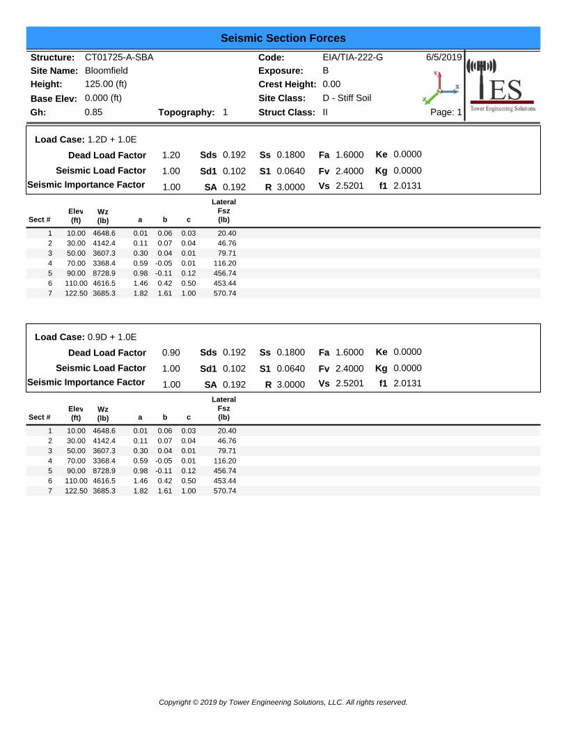
Load Case: 1.2D + 1.0E
Seismic Load Factor
R 3.0000Seismic Importance FactorS1
SsSds
Sd1SA
0.192
0.102
0.192
0.1800
0.0640
1.00
Fv
Fa 1.6000
2.4000Vs 2.5201
Kg
Ke 0.0000
0.0000f1 2.0131
Sect #Elev(ft) a
LateralFsz(lb)b c
Wz(lb)
10.00 1 0.01 0.06 20.400.034648.630.00 2 0.11 0.07 46.760.044142.450.00 3 0.30 0.04 79.710.013607.370.00 4 0.59 -0.05 116.200.013368.490.00 5 0.98 -0.11 456.740.128728.9110.00 6 1.46 0.42 453.440.504616.5122.50 7 1.82 1.61 570.741.003685.3
Dead Load Factor 0.90
1.00
Load Case: 0.9D + 1.0E
Seismic Load Factor
R 3.0000Seismic Importance FactorS1
SsSds
Sd1SA
0.192
0.102
0.192
0.1800
0.0640
1.00
Fv
Fa 1.6000
2.4000Vs 2.5201
Kg
Ke 0.0000
0.0000
f1 2.0131
Sect #Elev(ft) a
LateralFsz(lb)b c
Wz(lb)
10.00 1 0.01 0.06 20.400.034648.630.00 2 0.11 0.07 46.760.044142.450.00 3 0.30 0.04 79.710.013607.370.00 4 0.59 -0.05 116.200.013368.490.00 5 0.98 -0.11 456.740.128728.9110.00 6 1.46 0.42 453.440.504616.5122.50 7 1.82 1.61 570.741.003685.3
Copyright © 2019 by Tower Engineering Solutions, LLC. All rights reserved.
Support Forces Summary
Structure: CT01725-A-SBASite Name: BloomfieldHeight: 125.00 (ft)
6/5/2019
Page: 1
Code: EIA/TIA-222-GExposure: B
Gh: 0.85Base Elev: 0.000 (ft)
Crest Height: 0.00Site Class:
IIStruct Class:D - Stiff Soil
Topography: 1
Load Case FX
(kips)FY
(kips)FZ
(kips) (-) = Uplift (+) = DownNode1 0.02 310.581.2D + 1.6W Normal Wind -26.65
1a 10.09 -135.60 -7.271b -10.11 -135.62 -7.24
1 -1.24 159.481.2D + 1.6W 60° Wind -13.371a -12.15 157.52 5.611b -21.47 -277.65 -12.37
1 -1.45 13.141.2D + 1.6W 90° Wind -0.631a -20.07 265.25 10.761b -18.94 -239.04 -10.13
1 0.02 306.590.9D + 1.6W Normal Wind -26.441a 10.25 -138.53 -7.381b -10.27 -138.54 -7.34
1 -1.25 155.850.9D + 1.6W 60° Wind -13.161a -11.98 153.90 5.501b -21.63 -280.23 -12.46
1 -1.46 9.860.9D + 1.6W 90° Wind -0.431a -19.89 261.37 10.651b -19.11 -241.72 -10.22
1 0.01 138.741.2D + 1.0Di + 1.0Wi Normal Wind -9.551a 2.01 -0.75 -1.581b -2.01 -0.82 -1.58
1 -0.39 92.351.2D + 1.0Di + 1.0Wi 60° Wind -5.541a -4.97 91.39 2.431b -5.69 -46.56 -3.27
1 -0.46 45.751.2D + 1.0Di + 1.0Wi 90° Wind -1.501a -7.46 125.49 4.051b -4.87 -34.07 -2.55
1 0.00 29.601.2D + 1.0E 0.771a 2.22 4.88 -1.251b -2.22 4.88 -1.25
1 0.00 26.280.9D + 1.0E 0.971a 2.39 1.62 -1.351b -2.39 1.62 -1.35
1 0.00 82.161.0D + 1.0W Normal Wind -6.911a 1.99 -24.68 -1.511b -1.99 -24.69 -1.50
1 -0.30 45.881.0D + 1.0W 60° Wind -3.711a -3.36 45.42 1.591b -4.72 -58.51 -2.72
1 -0.36 10.941.0D + 1.0W 90° Wind -0.651a -5.26 71.31 2.841b -4.13 -49.45 -2.18
Max Reactions
Copyright © 2019 by Tower Engineering Solutions, LLC. All rights reserved.

Max Uplift:
Max Down:
-280.23
Leg Overturning
310.58
Max Shear: 26.65
Moment: 3220.11
Total Down:
Total Shear:
39.36
41.16
(kips)
(kips)
(kips)
(ft-kips)
(kips)
(kips)
Copyright © 2019 by Tower Engineering Solutions, LLC. All rights reserved.
Analysis Summary
Structure: CT01725-A-SBASite Name: BloomfieldHeight: 125.00 (ft)
6/5/2019
Page: 1
Code: EIA/TIA-222-GExposure: B
Gh: 0.85Base Elev: 0.000 (ft)
Crest Height: 0.00Site Class:
IIStruct Class:D - Stiff Soil
Topography: 1
Max Reactions
Max Uplift:
Max Down:
-280.23
Leg Overturning
310.58
Max Shear: 26.65
Moment: 3220.11
Total Down:
Total Shear:
39.36
41.16
(kips)
(kips)
(kips)
(ft-kips)
(kips)
(kips)
Anchor Bolts
Interaction Ratio: 0.63
Bolt Size (in.): Number Bolts:1.50 8Tensile Strength (Ksi):Yield Strength (Ksi):
Detail Type:58.0036.00
C
Max UsagesMax Leg: 99.8% (1.2D + 1.6W Normal Wind - Sect 2)Max Diag: 89.9% (1.2D + 1.6W 90° Wind - Sect 5)Max Horiz: 42.1% (1.2D + 1.6W Normal Wind - Sect 7)
Load Case Elevation
(ft)Deflection
(ft)Twist(deg)
Sway(deg)
Max Deflection, Twist and Sway
0.9D + 1.0E - Normal To Face 66.67 0.0288 0.0019 0.054173.33 0.0354 0.0022 0.061085.00 0.0490 0.0026 0.0759
100.00 0.0713 0.0032 0.0946110.00 0.0892 0.0035 0.1100120.00 0.1092 0.0036 0.1196125.00 0.1195 0.0036 0.1177
0.9D + 1.6W 97 mph Wind at 60° From Face 66.67 0.4663 0.1164 0.835073.33 0.5685 0.1376 0.930685.00 0.7737 0.2038 1.1182
100.00 1.0942 0.3369 1.3340110.00 1.3396 0.6059 1.4974120.00 1.6034 0.8722 1.5452125.00 1.7378 0.9896 1.4127
0.9D + 1.6W 97 mph Wind at 90° From Face 66.67 0.4646 -0.0410 0.830273.33 0.5666 -0.0462 0.925585.00 0.7712 -0.0578 1.1103
100.00 1.0901 -0.0746 1.3163110.00 1.3335 -0.0984 1.4642120.00 1.5929 -0.1176 1.4826125.00 1.7238 -0.1169 0.8368
Copyright © 2019 by Tower Engineering Solutions, LLC. All rights reserved.
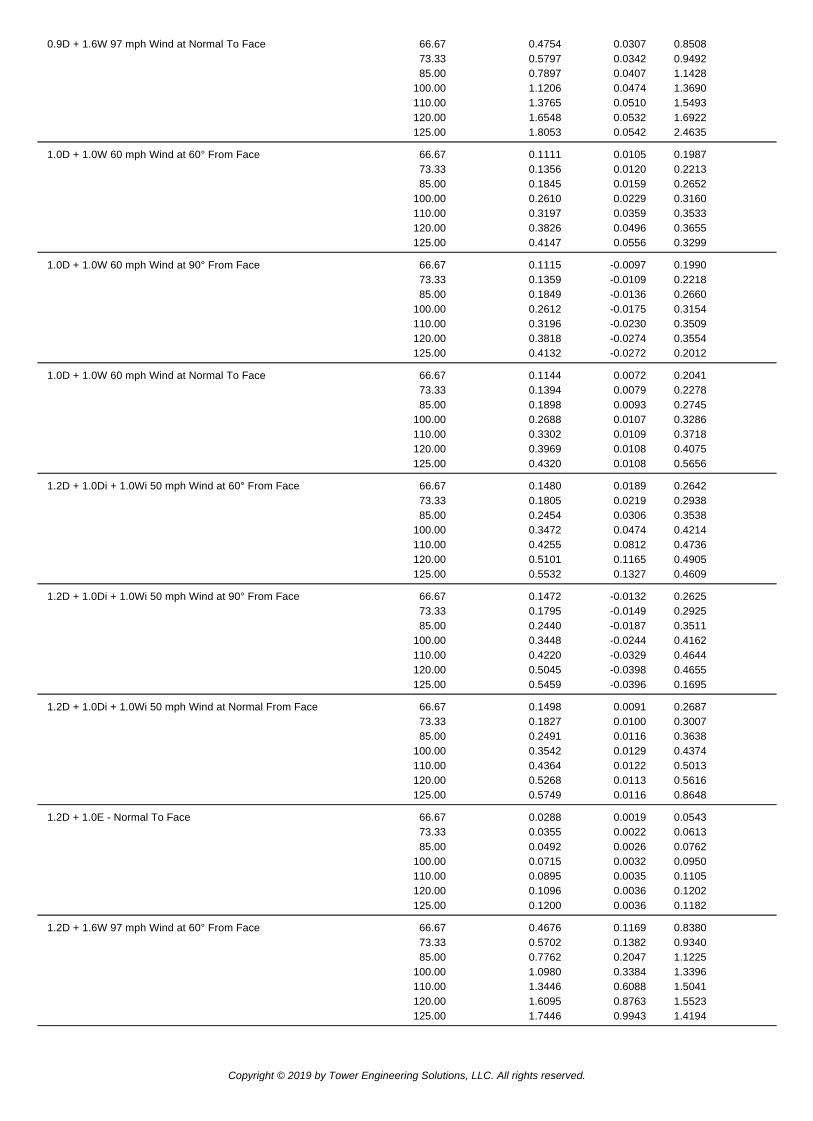
0.9D + 1.6W 97 mph Wind at Normal To Face 66.67 0.4754 0.0307 0.850873.33 0.5797 0.0342 0.949285.00 0.7897 0.0407 1.1428
100.00 1.1206 0.0474 1.3690110.00 1.3765 0.0510 1.5493120.00 1.6548 0.0532 1.6922125.00 1.8053 0.0542 2.4635
1.0D + 1.0W 60 mph Wind at 60° From Face 66.67 0.1111 0.0105 0.198773.33 0.1356 0.0120 0.221385.00 0.1845 0.0159 0.2652
100.00 0.2610 0.0229 0.3160110.00 0.3197 0.0359 0.3533120.00 0.3826 0.0496 0.3655125.00 0.4147 0.0556 0.3299
1.0D + 1.0W 60 mph Wind at 90° From Face 66.67 0.1115 -0.0097 0.199073.33 0.1359 -0.0109 0.221885.00 0.1849 -0.0136 0.2660
100.00 0.2612 -0.0175 0.3154110.00 0.3196 -0.0230 0.3509120.00 0.3818 -0.0274 0.3554125.00 0.4132 -0.0272 0.2012
1.0D + 1.0W 60 mph Wind at Normal To Face 66.67 0.1144 0.0072 0.204173.33 0.1394 0.0079 0.227885.00 0.1898 0.0093 0.2745
100.00 0.2688 0.0107 0.3286110.00 0.3302 0.0109 0.3718120.00 0.3969 0.0108 0.4075125.00 0.4320 0.0108 0.5656
1.2D + 1.0Di + 1.0Wi 50 mph Wind at 60° From Face 66.67 0.1480 0.0189 0.264273.33 0.1805 0.0219 0.293885.00 0.2454 0.0306 0.3538
100.00 0.3472 0.0474 0.4214110.00 0.4255 0.0812 0.4736120.00 0.5101 0.1165 0.4905125.00 0.5532 0.1327 0.4609
1.2D + 1.0Di + 1.0Wi 50 mph Wind at 90° From Face 66.67 0.1472 -0.0132 0.262573.33 0.1795 -0.0149 0.292585.00 0.2440 -0.0187 0.3511
100.00 0.3448 -0.0244 0.4162110.00 0.4220 -0.0329 0.4644120.00 0.5045 -0.0398 0.4655125.00 0.5459 -0.0396 0.1695
1.2D + 1.0Di + 1.0Wi 50 mph Wind at Normal From Face 66.67 0.1498 0.0091 0.268773.33 0.1827 0.0100 0.300785.00 0.2491 0.0116 0.3638
100.00 0.3542 0.0129 0.4374110.00 0.4364 0.0122 0.5013120.00 0.5268 0.0113 0.5616125.00 0.5749 0.0116 0.8648
1.2D + 1.0E - Normal To Face 66.67 0.0288 0.0019 0.054373.33 0.0355 0.0022 0.061385.00 0.0492 0.0026 0.0762
100.00 0.0715 0.0032 0.0950110.00 0.0895 0.0035 0.1105120.00 0.1096 0.0036 0.1202125.00 0.1200 0.0036 0.1182
1.2D + 1.6W 97 mph Wind at 60° From Face 66.67 0.4676 0.1169 0.838073.33 0.5702 0.1382 0.934085.00 0.7762 0.2047 1.1225
100.00 1.0980 0.3384 1.3396110.00 1.3446 0.6088 1.5041120.00 1.6095 0.8763 1.5523125.00 1.7446 0.9943 1.4194
Copyright © 2019 by Tower Engineering Solutions, LLC. All rights reserved.
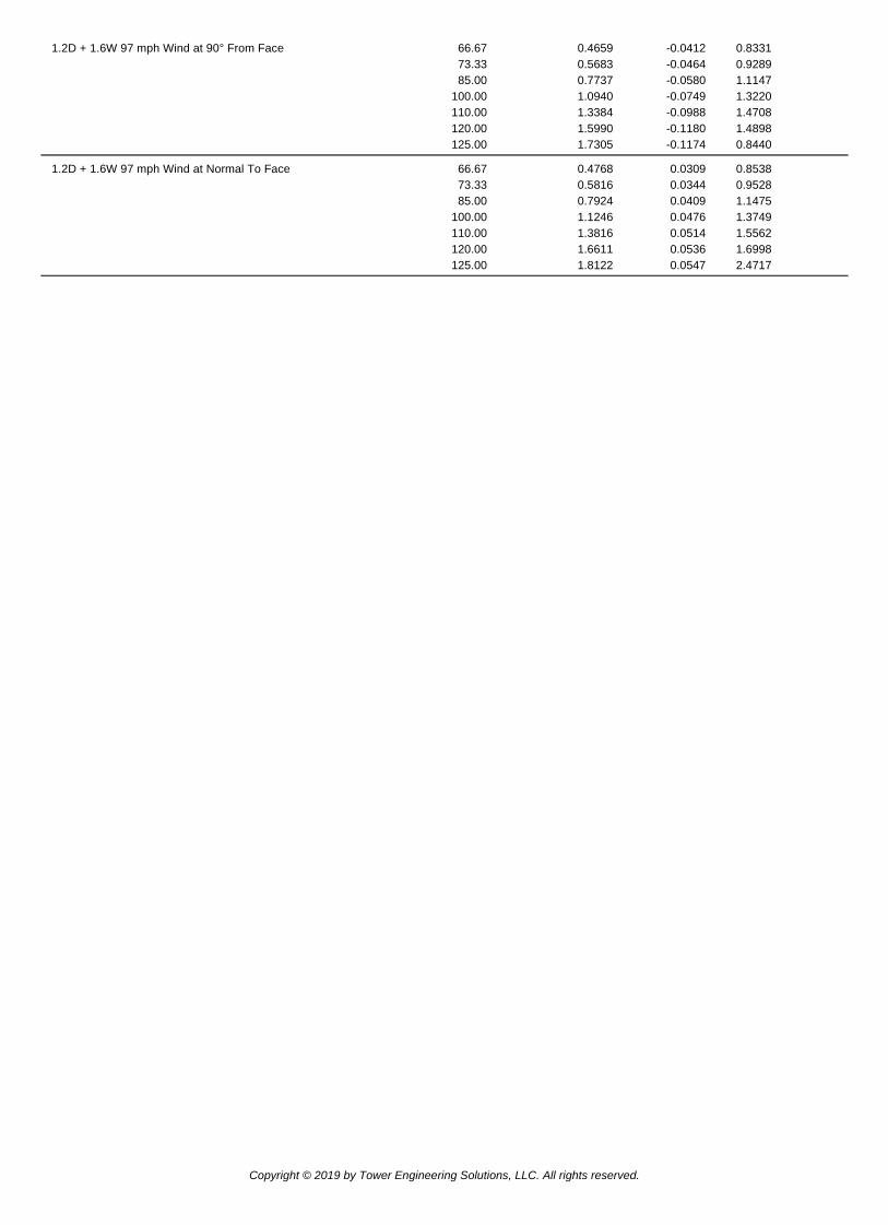
1.2D + 1.6W 97 mph Wind at 90° From Face 66.67 0.4659 -0.0412 0.833173.33 0.5683 -0.0464 0.928985.00 0.7737 -0.0580 1.1147
100.00 1.0940 -0.0749 1.3220110.00 1.3384 -0.0988 1.4708120.00 1.5990 -0.1180 1.4898125.00 1.7305 -0.1174 0.8440
1.2D + 1.6W 97 mph Wind at Normal To Face 66.67 0.4768 0.0309 0.853873.33 0.5816 0.0344 0.952885.00 0.7924 0.0409 1.1475
100.00 1.1246 0.0476 1.3749110.00 1.3816 0.0514 1.5562120.00 1.6611 0.0536 1.6998125.00 1.8122 0.0547 2.4717
Copyright © 2019 by Tower Engineering Solutions, LLC. All rights reserved.

Last revised on June 29, 2018
Customer Name:Site Name:Site Nmber:Engr. Number:
Drawings/Calculations
Analysis
3 Legs
0.00
(1). Individual Leg: 0'
Axial Load (Kips): 310.6 Uplift Force (Kips): 280.2
Shear Force (Kips): 26.6
(2). Tower Base: 2 # 4
Total Vertical Load (Kips): 39.4 Total Shear Force (Kips): 41.2 6' 8 # 11
Moment (Kips-ft): 3220.1 4.3'
Foundation Geometries: 27 # 8
12.5 Mods required -Yes/No ?: No 27 # 8
Diameter of Pier (ft.): Square 1.5 Pier Height A. G. (ft.): 0.00
Tower center to mat center (ft): 0.00 Depth of Base BG (ft.): 4.3 #
Length of Pad (ft.): 29 Width of Pad (ft.): 29 4.3'
Thickness of Pad (ft): 4.25
27 # 8 27 # 8
3.608
Mat Center
Concrete Strength (psi): 3000 Steel Elastic Modulus: 29000 ksi (W) 0.00 Tower Center
Vertical bar yield (ksi) 60 Tie steel yield (ksi): 60 29' 12.5
Vertical Rebar Size #: 11 Tie / Stirrup Size #: 4
Qty. of Vertical Rebars: 8 Tie Spacing (in): 45.0
Pad Rebar Yield (Ksi): 60 Pad Steel Rebar Size (#): 8 7.28 7.217
Concrete Cover (in.): 3 Unit Weight of Concrete: 150.0 pcf
Rebar at the bottom of the concrete pad: 10.825
Qty. of Rebar in Pad (L): 27 Qty. of Rebar in Pad (W): 27
Rebar at the top of the concrete pad: 29' (L)
Qty. of Rebar in Pad (L): 27 Qty. of Rebar in Pad (W): 27
Soil Design Parameters:
Soil Unit Weight (pcf): 100.0 Soil Buoyant Weight: 50.0 Pcf
Water Table B.G.S. (ft): 6.0 Unit Weight of Water: 62.4 pcf
Ultimate Bearing Pressure (psf): 10000 Consider ties in concrete shear strength: No
(W) Mat Center Tower Center
Notes: 29'
1. Dimension unit in sketches is in feet.
6/5/2019Mat Foundation Design for Self Supporting Tower Date
Engineer Name:
EIA/TIA Standard: EIA-222-G
Structure Height (Ft.): 125SBA Communications Corp
F. ArinyedokiaTESEngineer Login ID:
10.892
1.5'
Foundation Info Obtained from:
Analysis or Design?
70654CT01725-A-SBA
14.5
Base Reactions (Factored):
Material Properties and Reabr Info:
Leg distance (Center-to-Center ft.):
Number of Tower Legs:

Allowable overstress %: 5.00% TES Engr. Number: Page 2/2 Date:Apply 1.35 for e/w per G/H: 1
Foundation Analysis and Design: Uplift Strength Reduction Factor: 0.75 Compression Strength Reduction Factor: 0.750.00 Total Dry Soil Weight (Kips): 0.000.00 Total Buoyant Soil Weight (Kips): 0.000.00 Weight from the Concrete Block at Top (K): 0.00
3574.28 Total Dry Concrete Weight (Kips): 536.140.00 Total Buoyant Concrete Weight (Kips): 0.00
536.14 Total Vertical Load on Base (Kips): 575.50Load/ Capacity Ratio
Calculated Maxium Net Soil Pressure under the base (psf): 1491.05 < Allowable Factored Soil Bearing (psf): 7500 0.20 OK!Allowable Foundation Overturning Resistance (kips-ft.): 7567.3 > Design Factored Momont (kips-ft): 3367 0.44 OK!Factor of Safety Against Overturning (O. R. Moment/Design Moment): 2.25 OK!
Check the capacities of Reinforceing Concrete:Strength reduction factor (Flexure and axial tension): 0.90 Strength reduction factor (Shear): 0.75Strength reduction factor (Axial compresion): 0.65 Wind Load Factor on Concrete Design: 1.00
(1) Concrete Pier:
Load/Capacity Ratio
Vertical Steel Rebar Area (sq. in./each): 1.56 Tie / Stirrup Area (sq. in./each): 0.20Calculated Moment Capacity (Mn,Kips-Ft): 210.7 > Design Factored Moment (Mu, Kips-Ft) 0.1 0.00 OK!Calculated Shear Capacity (Kips): -15.4 < Design Factored Shear (Kips): 26.6 -1.73 NG!Calculated Tension Capacity (Tn, Kips): 673.9 > Design Factored Tension (Tu Kips): 280.2 0.42 OK!Calculated Compression Capacity (Pn, Kips): 413.1 > Design Factored Axial Load (Pu Kips): 310.6 0.75 OK!Moment & Tension Strength Combination: 0.00 OK! Check Tie Spacing (Design/Req'd): 5.5389183 NG!Pier Reinforcement Ratio: 0.039
(2).Concrete Pad:One-Way Design Shear Capacity (L or W Direction, Kips): 1358.1 > One-Way Factored Shear (L/W-Dir Kips 309.5 0.23 OK!One-Way Design Shear Capacity (Diagonal Dir., Kips): 1048.6 > One-Way Factored Shear (Dia. Dir, Kips 277.9 0.27 OK!Lower Steel Pad Reinforcement Ratio (L or W-Direct. ): 0.0013 Lower Steel Reinf. Ratio (Dia. Dir.): 0.0011Lower Steel Pad Moment Capacity (L or W-Dir. Kips-ft): 4490.1 > Moment at Bottom ( L-Direct. K-Ft): 1887.9 0.42 OK!Lower Steel Pad Moment Capacity (Dia. Direction,K-ft): 4499.3 > Moment at Bottom ( Dia. Dir. K-Ft): 1381.8 0.31 OK!Upper Steel Pad Reinforcement Ratio (L or W -Direction): 0.0013 Upper Steel Reinf. Ratio (Dia. Dir.): 0.0011Upper Steel Pad Moment Capacity (L or W-Dir., Kips-ft): 4490.1 > Moment at the top (L-Dir Kips-Ft): 991.2 0.22 OK!Upper Steel Pad Moment Capacity (Dia. Direction, K-ft): 4499.3 > Moment at the top (Dia. Dir., K-Ft): 557.6 0.12 OK!Punching Failure Capacity (Kips): 1662.7 > Punch. Failure Factored Shear (K): 310.6 0.19 OK!
Total Buoyant Soil Volume (cu. Ft.):
6/5/2019
Reinforcement Ratio is satisfied per ACI
70654
Total Dry Soil Volume (cu. Ft.):
Total Effective Soil Weight (Kips): Total Dry Concrete Volume (cu. Ft.): Total Buoyant Concrete Volume (cu. Ft.): Total Effective Concrete Weight (Kips):
Check Soil Capacities:

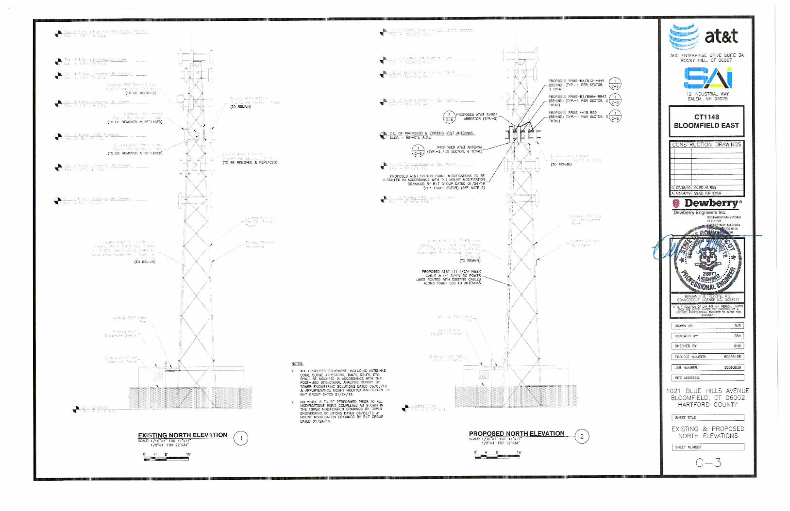
January 24, 2019 Carl Aquilina B+T Group SAI Communications, LLC. 1717 S. Boulder, Suite 300 12 Industrial Way Tulsa, OK 74119 Salem, NH 03079 (918) 587-4630 (603) 560-6185 [email protected] Subject: Appurtenance Mount Modification Report Carrier Designation: Site Number: 10035110 Site Name: CT1148 Engineering Firm Designation: B+T Group Project Number: 130654.003.01 Site Data: 1021 Blue Hills Avenue, Bloomfield, CT 06002 in Hartford County Latitude 41.82010°, Longitude -72.69652° Self-Support Tower (3) 10.5’ Sector Mount Dear Mr. Aquilina, B+T Group is pleased to submit this “Appurtenance Mount Modification Report” to determine the structural integrity of the antenna mount on the above-mentioned structure. The purpose of the analysis is to determine acceptability of the mount’s stress level. Based on our analysis we have determined the stress level for the mount under the following load case to be: Existing + Proposed Equipment Sufficient Capacity Note: See Table 1 for the final loading configuration (Passing at 78.0%) The analysis has been performed in accordance with the ANSI/TIA-222-G Standard. This analysis utilizes an ultimate 3-second gust wind speed of 125 mph (converted to an equivalent 97 mph nominal 3-second gust wind speed per Section 1609.3.1 for use with ANSI/TIA-222 G) as required by the 2018 Connecticut State Building Code. Exposure Category C and Risk Category II were used in this analysis. All modifications and equipment proposed in this report shall be installed in accordance with the attached drawings for the determined available structural capacity to be effective. We at B+T Group appreciate the opportunity of providing our continuing professional services to you and SAI Communications, LLC. If you have any questions or need further assistance on this or any other projects, please give us a call. Mount structural modification prepared by: Phanindra Kosaraju, E.I.T. Respectfully submitted by: B&T Engineering, Inc. COA: PEC.0001564 Expires: 02/10/2020 Scott S. Vance, P.E. Engineer of record

January 24, 2019 Appurtenance Mount Structural Modification Report Site No. 10035110 Project Number 130654.003.01, CT1148 Page 2
TABLE OF CONTENTS 1) INTRODUCTION 2) ANALYSIS CRITERIA Table 1 - Proposed and Existing Equipment Information Table 2 - Documents Provided 3) ANALYSIS PROCEDURE 3.1) Analysis Method 3.2) Assumptions 4) ANALYSIS RESULTS Table 3 – Mount Component Stresses vs. Capacity 4.1) Structural Notes 5) APPENDIX A RISA-3D Output 6) APPENDIX B Modification Drawings

January 24, 2019 Appurtenance Mount Structural Modification Report Site No. 10035110 Project Number 130654.003.01, CT1148 Page 3
1) INTRODUCTION
The appurtenance mount consists of sector mount at 99 ft. attached to self-support tower at 1021 Blue Hills Avenue, Bloomfield, CT 06002, Hartford County. The proposed antenna loading information was obtained from SAI Communications, LLC. All information provided to B+T Group was assumed accurate and complete.
2) ANALYSIS CRITERIA
The structural analysis was performed for this mount in accordance with the ANSI/TIA-222-G-2-2005 Structural Standard for Antenna Supporting Structures and Antennas – Addendum 2 using a 3-second gust wind speed of 97 mph with no ice and 50 mph with 1 inch escalated ice thickness. Exposure Category C, Topographic Category 1 and Risk Category II were used in this analysis. In addition, the sector mount has been analyzed for various live loading conditions consisting of a 250-lb man live load applied individually at the midpoint and cantilevered ends of horizontal members as well as a 250-pound man live load applied individually at mount pipe locations using a 3-second gust of 30mph. The mount was analyzed under 30º increments in the wind direction. The analyzed loading is detailed in Table 1.
Table 1 – Proposed and Existing Equipment Information
Loading RAD Ctr. Elev. (ft.) Position Qty. Manufacturer Model / Type Note
Proposed 98
4,5,4,5 4 Kathrein 800-10966 1
4,5 2 Kathrein 800-10965 2 3 Ericsson 4415 B30
2 4 3 Ericsson B2/B66A 8843 5 3 Ericsson B5/B12 4449 - 2 Raycap DC6‐48‐60‐18‐8F 3
Existing 100
1 3 Powerwave 7770
4 2 2 CCI HPA-65R-BUU-H8 1 CCI HPA-65R-BUU-H6
1 6 Powerwave LGP 21401 - 1 Raycap DC6‐48‐60‐18‐8F 5
Note: (1) Proposed Antenna to be installed on the existing Mount Pipe. (2) Proposed Equipment to be installed with RRUS Support, directly behind the Antenna. (3) Proposed Equipment to be installed on the mount. (4) Existing Equipment installed on the Mount. (5) Existing Equipment installed on the tower leg.
Table 2 - Documents Provided
Documents Remarks Reference Source
RFDS Existing Loading Proposed Loading Date: 10/18/2018 SAI Communications,
LLC. Mount Mapping
By B+T Group Date: 12/13/2018
On File Appurtenance Mount analysis Report Date: 01/14/2019

January 24, 2019 Appurtenance Mount Structural Modification Report Site No. 10035110 Project Number 130654.003.01, CT1148 Page 4
3) ANALYSIS PROCEDURE 3.1) Analysis Method
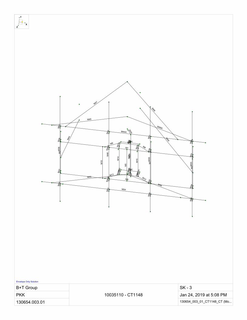
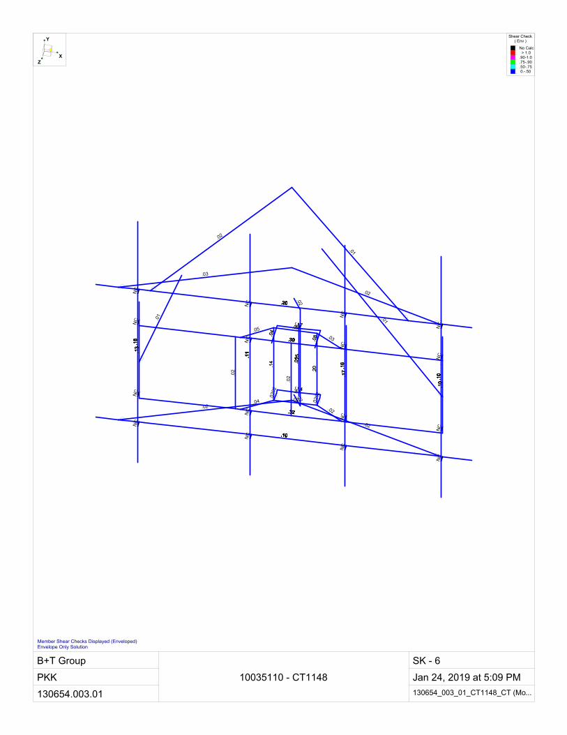
RISA-3D (Version 17.0.2), a commercially available analysis software package, was used to create a three-dimensional model of the mount and calculate member stresses and deflections for various loading cases. Selected output from the analysis is included in Appendix A.
3.2) Assumptions
1. The mount was built in accordance with the manufacturer’s specifications. 2. The mount has been maintained in accordance with the manufacturer’s specifications and is free of
damage. 3. The configuration of antennas and other appurtenances are as specified in Table 1. 4. All mount components have been assumed to be in sufficient condition to carry their full design
capacity for the analysis. 5. Mount areas and weights are determined from field measurements, standard material properties,
and/or manufacturer product data. 6. Serviceability with respect to antenna twist, tilt, roll or lateral translation is not checked and is left to
the carrier or tower owner to ensure conformance. 7. All prior structural modifications, if any are assumed to be correctly installed and fully effective. 8. All member connections are assumed to have been designed to meet or exceed the load carrying
capacity of the connected member unless otherwise specified in this report. 9. The following material grades were assumed (Unless Noted Otherwise):
a. Channels ASTM A36 (GR 36) b. Solid Rods ASTM A36 (GR 36) c. Angles ASTM A36 (GR 36) d. Plates ASTM A36 (GR 36) e. HSS (Rectangular) ASTM 500 (GR B-46) f. HSS (Round) ASTM 500 (GR B-42) g. Pipes ASTM A53 (GR 35) h. Connection Bolts ASTM A325
This analysis may be affected if any assumptions are not valid or have been made in error. B+T Group should be notified to determine the effect on the structural integrity of the antenna mounting system.
4) ANALYSIS RESULTS
Table 3 – Mount Component Stresses vs. Capacity
Notes Component Elevation (ft.) % Capacity Pass / Fail
- Face Horizontals 99 71.9 Pass - Support Arms 99 23.9 Pass - Vertical Angles 99 23.3 Pass - Vertical Channel 99 22.4 Pass - Vertical Pipes 99 32.3 Pass - Connection Pipe 99 46.9 Pass - Supporting Channels 99 59.3 Pass - Connection Plates 99 78.0 Pass - Mount Pipes 99 50.2 Pass - Tieback 99 10.1 Pass
Proposed Reinforcement Kit 99 47.7 Pass Proposed Stabilizer Kit 99 25.5 Pass
January 24, 2019 Appurtenance Mount Structural Modification Report Site No. 10035110 Project Number 130654.003.01, CT1148 Page 5
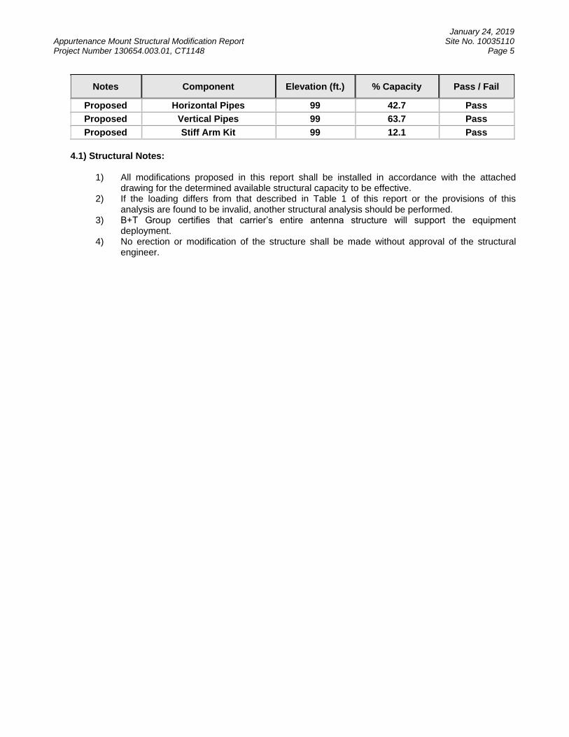
Notes Component Elevation (ft.) % Capacity Pass / Fail
Proposed Horizontal Pipes 99 42.7 Pass Proposed Vertical Pipes 99 63.7 Pass Proposed Stiff Arm Kit 99 12.1 Pass
4.1) Structural Notes:
1) All modifications proposed in this report shall be installed in accordance with the attached drawing for the determined available structural capacity to be effective.
2) If the loading differs from that described in Table 1 of this report or the provisions of this analysis are found to be invalid, another structural analysis should be performed.
3) B+T Group certifies that carrier’s entire antenna structure will support the equipment deployment.
4) No erection or modification of the structure shall be made without approval of the structural engineer.

January 24, 2019 Appurtenance Mount Structural Modification Report Site No. 10035110 Project Number 130654.003.01, CT1148 Page 6
APPENDIX A (RISA-3D Output)
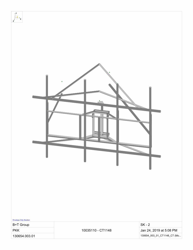
B+T Group
PKK
130654.003.01
10035110 - CT1148
SK - 2
Jan 24, 2019 at 5:08 PM
130654_003_01_CT1148_CT (Mo...
Y
XZ
Envelope Only Solution
B+T Group
PKK
130654.003.01
10035110 - CT1148
SK - 3
Jan 24, 2019 at 5:08 PM
130654_003_01_CT1148_CT (Mo...
M1
M2
M3
M4
M5
M6
M7
M8
M9
M10
M11
M12
M13
M14
M15
M16
M21
M22
M24
M25
M26
M27
M28
M29
M30
M31
M33
M34
M35
M36
M37
M38
M39
M40
M44
M46
M42
M41
M40
AM
40B
M41
A
M42
A
M43 M44A
M45
M46A
M47
M48
M49
M50
M51
M52
M53 M54
M55
M56
M57
M58
M59
Y
XZ
Envelope Only Solution

B+T Group
PKK
130654.003.01
10035110 - CT1148
SK - 4
Jan 24, 2019 at 5:08 PM
130654_003_01_CT1148_CT (Mo...
L2x2x.22
PIP
E_2
.0
PIP
E_2
.0
L3x2x.22
PIP
E_2
.0
L2x2x.22
PIP
E_2
.0
L3x2x.22
L3x2x.22
PIP
E_2
.0
L3x2x.22L3x2x.22
L3x2x.22
L2x2
x.22
L2x2
x.22
C3x1.5x0.22
C3x
1.5x
0.22
C3x
1.5x
0.22
C3x1.5x0.22
C3x
1.5x
0.22
PIP
E_2
.48x
0.22
PL 3/8x6
PL 3/8x6
PIP
E_2
.0
PIP
E_2
.0
PIP
E_2
.0
PIP
E_1
.25
PIP
E_2
.0
PL3
/8x3
_HR
A
PL3
/8x3
_HR
A
PL3
/8x3
_HR
A
PL3
/8x3
_HR
A
PIPE_2.5
L2.5x2.5x3
L2.5x2.5x3
L2.5x2.5x3
L2.5x2.5x3
PIPE_2.0
PIPE_2.5
L2.5x2.5x3
L2.5x2.5x3
Y
XZ
Envelope Only Solution

B+T Group
PKK
130654.003.01
10035110 - CT1148
SK - 5
Jan 24, 2019 at 5:08 PM
130654_003_01_CT1148_CT (Mo...
.25
.78
.10
.64
.17
.12
.17
.47
.17
NC
NC.45
.22
.04
.22
.17
.45
.50
.08
.08
.64
.32
NC
.19.17
NC
.72
.17
.46
.16
.47
.22
.32
.50
.72.72
NC
NC .72
.12
.17.3
6
.23
.50
.72
.17.17
.22 .4
6
.72
.17N
C
.64
NC
.17
.59
.64
.32
.22 .4
7
.59
NC
.09
.16
.72
.47
.36
.06
.29
.23
.50.3
2
.16
NC
NC
.19
.22
.67
.48
.47
.19
.17
.32
.29
.67.67.4
6
.43
.64 NC .67
.24
.43.43
NC
.67
.36
.67
.43
.43
.17
.29
.50
.24
NC
.67.1
7
NC
.29
.43
.46
NC
.64
.36
.29
.23
NC
.43
.36
.43.43
.50
.43
NC
.36
.46
.36
Y
XZ
Code Check( Env )
No Calc > 1.0.90-1.0.75-.90.50-.75 0.-.50
Member Code Checks Displayed (Enveloped)Envelope Only Solution
B+T Group
PKK
130654.003.01
10035110 - CT1148
SK - 6
Jan 24, 2019 at 5:09 PM
130654_003_01_CT1148_CT (Mo...
.02
.02
.01
.18
.10
.01
.10
.25
.10
NC
NC.14
.01
.02
.02
.10
.14
.11
.02
.02
.18
.13
NC
.02.02
NC
.32
.10
.16
.04
.25
.01
.13
.11
.32.32
NC
NC .32
.02
.10.1
0
.14
.11
.32
.10.10
.20 .1
6
.32
.10N
C
.18
NC
.17
.17
.02
.13
.01 .2
5
.17
NC
.02
.04
.32
.08
.10
.02
.10
.14
.11.1
3
.04
NC
NC
.02
.20
.39
.03
.08
.05
.17
.13
.10
.39.39.1
6
.20
.18 NC .39
.03
.20.20
NC
.39
.10
.39
.02
.20
.17
.10
.11
.02
NC
.39.1
7
NC
.10
.20
.16
NC
.18
.10
.10
.01
NC
.20
.10
.20.20
.11
.20
NC
.10
.16
.10
Y
XZ
Shear Check( Env )
No Calc > 1.0.90-1.0.75-.90.50-.75 0.-.50
Member Shear Checks Displayed (Enveloped)Envelope Only Solution

Company : B+T Group Jan 24, 20195:09 PMDesigner : PKK
Job Number : 130654.003.01 Checked By:_____Model Name : 10035110 - CT1148
Hot Rolled Steel Section SetsLabel Shape Type Design List Material Design Rul... A [in2] Iyy [in4] Izz [in4] J [in4]
1 MF-H1 L2x2x.22 Beam Single Angle A36 Gr.36 Typical .832 .312 .312 .0122 F1-SA1 L3x2x.22 Beam Single Angle A36 Gr.36 Typical 1.052 .352 .971 .0163 F1-CH1 C3x1.5x0.22 Beam Channel A36 Gr.36 Typical 1.223 .25 1.585 .0184 F1-V1 L2x2x.22 Column Single Angle A36 Gr.36 Typical .832 .312 .312 .0125 F1-V2 C3x1.5x0.22 Column Channel A36 Gr.36 Typical 1.223 .25 1.585 .0186 F1-P1 PIPE_2.48x0.22 Column Pipe A53 Gr.B Typical 1.562 1.007 1.007 2.0137 Tieback PIPE_1.25 Beam Pipe A53 Gr.B Typical .625 .184 .184 .3688 MF-P1 PIPE_2.0 Column Pipe A53 Gr.B Typical 1.02 .627 .627 1.259 F1-CP1 PL 3/8x6 Beam RECT A36 Gr.36 Typical 2.25 .026 6.75 .10110 F1-CP2 PL3/8x3_HRA Beam RECT A36 Gr.36 Typical 1.125 .013 .844 .04911 SF-P1 PIPE_2.5 Beam Pipe A53 Gr.B Typical 1.61 1.45 1.45 2.8912 SF-H1 L2.5x2.5x3 Beam Single Angle A36 Gr.36 Typical .901 .535 .535 .01113 Tieback1 PIPE_2.0 Beam Pipe A53 Gr.B Typical 1.02 .627 .627 1.25
Member Primary DataLabel I Joint J Joint K Joint Rotate(deg) Section/Shape Type Design List Material Design Rules
1 M1 N1 N2 90 MF-H1 Beam Single Angle A36 Gr.36 Typical2 M2 N3 N7 MF-P1 Column Pipe A53 Gr.B Typical3 M3 N4 N8 MF-P1 Column Pipe A53 Gr.B Typical4 M4 N18 N17 180 F1-SA1 Beam Single Angle A36 Gr.36 Typical5 M5 N5 N6 MF-P1 Column Pipe A53 Gr.B Typical6 M6 N7 N8 MF-H1 Beam Single Angle A36 Gr.36 Typical7 M7 N9 N10 MF-P1 Column Pipe A53 Gr.B Typical8 M8 N11 N18 180 F1-SA1 Beam Single Angle A36 Gr.36 Typical9 M9 N17 N12 180 F1-SA1 Beam Single Angle A36 Gr.36 Typical10 M10 N13 N14 MF-P1 Column Pipe A53 Gr.B Typical11 M11 N20 N22 F1-SA1 Beam Single Angle A36 Gr.36 Typical12 M12 N22 N15 F1-SA1 Beam Single Angle A36 Gr.36 Typical13 M13 N16 N20 F1-SA1 Beam Single Angle A36 Gr.36 Typical14 M14 N17 N20 180 F1-V1 Column Single Angle A36 Gr.36 Typical15 M15 N18 N22 270 F1-V1 Column Single Angle A36 Gr.36 Typical16 M16 N27 N21 F1-CH1 Beam Channel A36 Gr.36 Typical17 M21 N28 N24 F1-CH1 Beam Channel A36 Gr.36 Typical18 M22 N29 N25 180 F1-CH1 Beam Channel A36 Gr.36 Typical19 M24 N28 N29 F1-CH1 Beam Channel A36 Gr.36 Typical20 M25 N30 N31 F1-V2 Column Channel A36 Gr.36 Typical21 M26 N32 N33 RIGID None None RIGID Typical22 M27 N34 N35 RIGID None None RIGID Typical23 M28 N38 N36 F1-P1 Column Pipe A53 Gr.B Typical24 M29 N36 N37 90 F1-CP1 Beam RECT A36 Gr.36 Typical25 M30 N38 N39 90 F1-CP1 Beam RECT A36 Gr.36 Typical26 M31 N40 N41 RIGID None None RIGID Typical27 M33 N44 N45 MF-P1 Column Pipe A53 Gr.B Typical28 M34 N46 N47 RIGID None None RIGID Typical29 M35 N48 N49 MF-P1 Column Pipe A53 Gr.B Typical30 M36 N50 N51 MF-P1 Column Pipe A53 Gr.B Typical31 M37 N52 N53 RIGID None None RIGID Typical32 M38 N54 N55 RIGID None None RIGID Typical33 M39 N56 N57 RIGID None None RIGID Typical34 M40 N58 N59 RIGID None None RIGID Typical35 M44 N63 N64 Tieback Beam Pipe A53 Gr.B Typical36 M46 N67 N68 MF-P1 Column Pipe A53 Gr.B Typical37 M42 N27 N74A 180 F1-CP2 Beam RECT A36 Gr.36 Typical38 M41 N22 N73C 180 F1-CP2 Beam RECT A36 Gr.36 Typical
RISA-3D Version 17.0.2 Page 1 [S:\...\...\...\...\003.01-Mt.Mod\130654_003_01_CT1148_CT (Modified).R3D]
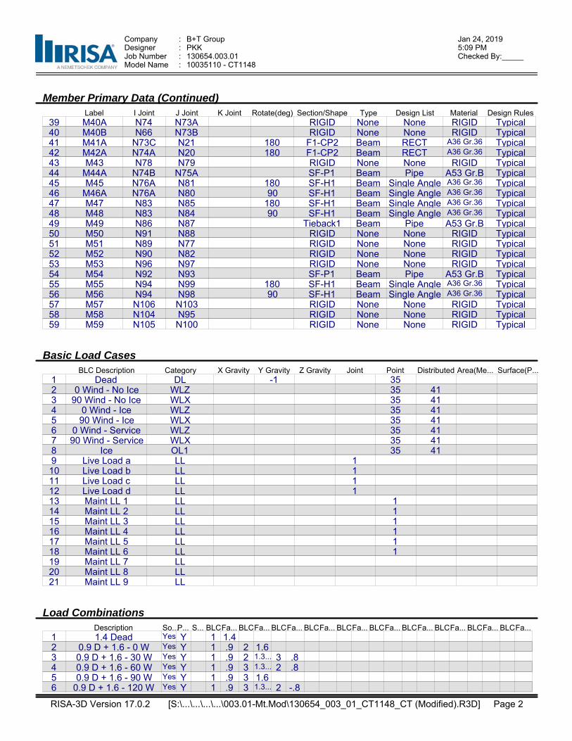
Company : B+T Group Jan 24, 20195:09 PMDesigner : PKK
Job Number : 130654.003.01 Checked By:_____Model Name : 10035110 - CT1148
Member Primary Data (Continued)Label I Joint J Joint K Joint Rotate(deg) Section/Shape Type Design List Material Design Rules
39 M40A N74 N73A RIGID None None RIGID Typical40 M40B N66 N73B RIGID None None RIGID Typical41 M41A N73C N21 180 F1-CP2 Beam RECT A36 Gr.36 Typical42 M42A N74A N20 180 F1-CP2 Beam RECT A36 Gr.36 Typical43 M43 N78 N79 RIGID None None RIGID Typical44 M44A N74B N75A SF-P1 Beam Pipe A53 Gr.B Typical45 M45 N76A N81 180 SF-H1 Beam Single Angle A36 Gr.36 Typical46 M46A N76A N80 90 SF-H1 Beam Single Angle A36 Gr.36 Typical47 M47 N83 N85 180 SF-H1 Beam Single Angle A36 Gr.36 Typical48 M48 N83 N84 90 SF-H1 Beam Single Angle A36 Gr.36 Typical49 M49 N86 N87 Tieback1 Beam Pipe A53 Gr.B Typical50 M50 N91 N88 RIGID None None RIGID Typical51 M51 N89 N77 RIGID None None RIGID Typical52 M52 N90 N82 RIGID None None RIGID Typical53 M53 N96 N97 RIGID None None RIGID Typical54 M54 N92 N93 SF-P1 Beam Pipe A53 Gr.B Typical55 M55 N94 N99 180 SF-H1 Beam Single Angle A36 Gr.36 Typical56 M56 N94 N98 90 SF-H1 Beam Single Angle A36 Gr.36 Typical57 M57 N106 N103 RIGID None None RIGID Typical58 M58 N104 N95 RIGID None None RIGID Typical59 M59 N105 N100 RIGID None None RIGID Typical
Basic Load CasesBLC Description Category X Gravity Y Gravity Z Gravity Joint Point Distributed Area(Me... Surface(P...
1 Dead DL -1 352 0 Wind - No Ice WLZ 35 413 90 Wind - No Ice WLX 35 414 0 Wind - Ice WLZ 35 415 90 Wind - Ice WLX 35 416 0 Wind - Service WLZ 35 417 90 Wind - Service WLX 35 418 Ice OL1 35 419 Live Load a LL 110 Live Load b LL 111 Live Load c LL 112 Live Load d LL 113 Maint LL 1 LL 114 Maint LL 2 LL 115 Maint LL 3 LL 116 Maint LL 4 LL 117 Maint LL 5 LL 118 Maint LL 6 LL 119 Maint LL 7 LL20 Maint LL 8 LL21 Maint LL 9 LL
Load CombinationsDescription So...P... S... BLCFa... BLCFa... BLCFa... BLCFa... BLCFa... BLCFa... BLCFa... BLCFa... BLCFa... BLCFa...
1 1.4 Dead Yes Y 1 1.42 0.9 D + 1.6 - 0 W Yes Y 1 .9 2 1.63 0.9 D + 1.6 - 30 W Yes Y 1 .9 2 1.3... 3 .84 0.9 D + 1.6 - 60 W Yes Y 1 .9 3 1.3... 2 .85 0.9 D + 1.6 - 90 W Yes Y 1 .9 3 1.66 0.9 D + 1.6 - 120 W Yes Y 1 .9 3 1.3... 2 -.8
RISA-3D Version 17.0.2 Page 2 [S:\...\...\...\...\003.01-Mt.Mod\130654_003_01_CT1148_CT (Modified).R3D]
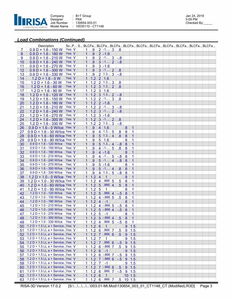
Company : B+T Group Jan 24, 20195:09 PMDesigner : PKK
Job Number : 130654.003.01 Checked By:_____Model Name : 10035110 - CT1148
Load Combinations (Continued)Description So...P... S... BLCFa... BLCFa... BLCFa... BLCFa... BLCFa... BLCFa... BLCFa... BLCFa... BLCFa... BLCFa...
7 0.9 D + 1.6 - 150 W Yes Y 1 .9 2 -1.... 3 .88 0.9 D + 1.6 - 180 W Yes Y 1 .9 2 -1.69 0.9 D + 1.6 - 210 W Yes Y 1 .9 2 -1.... 3 -.810 0.9 D + 1.6 - 240 W Yes Y 1 .9 3 -1.... 2 -.811 0.9 D + 1.6 - 270 W Yes Y 1 .9 3 -1.612 0.9 D + 1.6 - 300 W Yes Y 1 .9 3 -1.... 2 .813 0.9 D + 1.6 - 330 W Yes Y 1 .9 2 1.3... 3 -.814 1.2 D + 1.6 - 0 W Yes Y 1 1.2 2 1.615 1.2 D + 1.6 - 30 W Yes Y 1 1.2 2 1.3... 3 .816 1.2 D + 1.6 - 60 W Yes Y 1 1.2 3 1.3... 2 .817 1.2 D + 1.6 - 90 W Yes Y 1 1.2 3 1.618 1.2 D + 1.6 - 120 W Yes Y 1 1.2 3 1.3... 2 -.819 1.2 D + 1.6 - 150 W Yes Y 1 1.2 2 -1.... 3 .820 1.2 D + 1.6 - 180 W Yes Y 1 1.2 2 -1.621 1.2 D + 1.6 - 210 W Yes Y 1 1.2 2 -1.... 3 -.822 1.2 D + 1.6 - 240 W Yes Y 1 1.2 3 -1.... 2 -.823 1.2 D + 1.6 - 270 W Yes Y 1 1.2 3 -1.624 1.2 D + 1.6 - 300 W Yes Y 1 1.2 3 -1.... 2 .825 1.2 D + 1.6 - 330 W Yes Y 1 1.2 2 1.3... 3 -.826 0.9 D + 1.6 - 0 W/Ice Yes Y 1 .9 4 1.6 8 127 0.9 D + 1.6 - 30 W/Ice Yes Y 1 .9 4 1.3... 5 .8 8 128 0.9 D + 1.6 - 60 W/Ice Yes Y 1 .9 5 1.3... 4 .8 8 129 0.9 D + 1.6 - 90 W/Ice Yes Y 1 .9 5 1.6 8 130 0.9 D + 1.6 - 120 W/Ice Yes Y 1 .9 5 1.3... 4 -.8 8 131 0.9 D + 1.6 - 150 W/Ice Yes Y 1 .9 4 -1.... 5 .8 8 132 0.9 D + 1.6 - 180 W/Ice Yes Y 1 .9 4 -1.6 8 133 0.9 D + 1.6 - 210 W/Ice Yes Y 1 .9 4 -1.... 5 -.8 8 134 0.9 D + 1.6 - 240 W/Ice Yes Y 1 .9 5 -1.... 4 -.8 8 135 0.9 D + 1.6 - 270 W/Ice Yes Y 1 .9 5 -1.6 8 136 0.9 D + 1.6 - 300 W/Ice Yes Y 1 .9 5 -1.... 4 .8 8 137 0.9 D + 1.6 - 330 W/Ice Yes Y 1 .9 4 1.3... 5 -.8 8 138 1.2 D + 1.0 - 0 W/Ice Yes Y 1 1.2 4 1 8 139 1.2 D + 1.0 - 30 W/Ice Yes Y 1 1.2 4 .866 5 .5 8 140 1.2 D + 1.0 - 60 W/Ice Yes Y 1 1.2 5 .866 4 .5 8 141 1.2 D + 1.0 - 90 W/Ice Yes Y 1 1.2 5 1 8 142 1.2 D + 1.0 - 120 W/Ice Yes Y 1 1.2 5 .866 4 -.5 8 143 1.2 D + 1.0 - 150 W/Ice Yes Y 1 1.2 4 -.866 5 .5 8 144 1.2 D + 1.0 - 180 W/Ice Yes Y 1 1.2 4 -1 8 145 1.2 D + 1.0 - 210 W/Ice Yes Y 1 1.2 4 -.866 5 -.5 8 146 1.2 D + 1.0 - 240 W/Ice Yes Y 1 1.2 5 -.866 4 -.5 8 147 1.2 D + 1.0 - 270 W/Ice Yes Y 1 1.2 5 -1 8 148 1.2 D + 1.0 - 300 W/Ice Yes Y 1 1.2 5 -.866 4 .5 8 149 1.2 D + 1.0 - 330 W/Ice Yes Y 1 1.2 4 .866 5 -.5 8 150 1.2 D + 1.5 LL a + Service...Yes Y 1 1.2 6 1 9 1.551 1.2 D + 1.5 LL a + Service...Yes Y 1 1.2 6 .866 7 .5 9 1.552 1.2 D + 1.5 LL a + Service...Yes Y 1 1.2 7 .866 6 .5 9 1.553 1.2 D + 1.5 LL a + Service...Yes Y 1 1.2 7 1 9 1.554 1.2 D + 1.5 LL a + Service...Yes Y 1 1.2 7 .866 6 -.5 9 1.555 1.2 D + 1.5 LL a + Service...Yes Y 1 1.2 6 -.866 7 .5 9 1.556 1.2 D + 1.5 LL a + Service...Yes Y 1 1.2 6 -1 9 1.557 1.2 D + 1.5 LL a + Service...Yes Y 1 1.2 6 -.866 7 -.5 9 1.558 1.2 D + 1.5 LL a + Service...Yes Y 1 1.2 7 -.866 6 -.5 9 1.559 1.2 D + 1.5 LL a + Service...Yes Y 1 1.2 7 -1 9 1.560 1.2 D + 1.5 LL a + Service...Yes Y 1 1.2 7 -.866 6 .5 9 1.561 1.2 D + 1.5 LL a + Service...Yes Y 1 1.2 6 .866 7 -.5 9 1.562 1.2 D + 1.5 LL b + Service...Yes Y 1 1.2 6 1 10 1.563 1.2 D + 1.5 LL b + Service...Yes Y 1 1.2 6 .866 7 .5 10 1.5
RISA-3D Version 17.0.2 Page 3 [S:\...\...\...\...\003.01-Mt.Mod\130654_003_01_CT1148_CT (Modified).R3D]
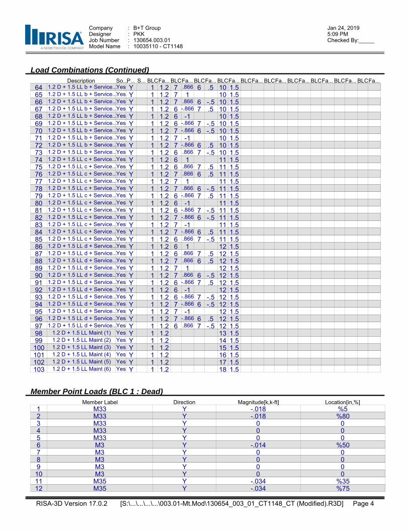
Company : B+T Group Jan 24, 20195:09 PMDesigner : PKK
Job Number : 130654.003.01 Checked By:_____Model Name : 10035110 - CT1148
Load Combinations (Continued)Description So...P... S... BLCFa... BLCFa... BLCFa... BLCFa... BLCFa... BLCFa... BLCFa... BLCFa... BLCFa... BLCFa...
64 1.2 D + 1.5 LL b + Service...Yes Y 1 1.2 7 .866 6 .5 10 1.565 1.2 D + 1.5 LL b + Service...Yes Y 1 1.2 7 1 10 1.566 1.2 D + 1.5 LL b + Service...Yes Y 1 1.2 7 .866 6 -.5 10 1.567 1.2 D + 1.5 LL b + Service...Yes Y 1 1.2 6 -.866 7 .5 10 1.568 1.2 D + 1.5 LL b + Service...Yes Y 1 1.2 6 -1 10 1.569 1.2 D + 1.5 LL b + Service...Yes Y 1 1.2 6 -.866 7 -.5 10 1.570 1.2 D + 1.5 LL b + Service...Yes Y 1 1.2 7 -.866 6 -.5 10 1.571 1.2 D + 1.5 LL b + Service...Yes Y 1 1.2 7 -1 10 1.572 1.2 D + 1.5 LL b + Service...Yes Y 1 1.2 7 -.866 6 .5 10 1.573 1.2 D + 1.5 LL b + Service...Yes Y 1 1.2 6 .866 7 -.5 10 1.574 1.2 D + 1.5 LL c + Service...Yes Y 1 1.2 6 1 11 1.575 1.2 D + 1.5 LL c + Service...Yes Y 1 1.2 6 .866 7 .5 11 1.576 1.2 D + 1.5 LL c + Service...Yes Y 1 1.2 7 .866 6 .5 11 1.577 1.2 D + 1.5 LL c + Service...Yes Y 1 1.2 7 1 11 1.578 1.2 D + 1.5 LL c + Service...Yes Y 1 1.2 7 .866 6 -.5 11 1.579 1.2 D + 1.5 LL c + Service...Yes Y 1 1.2 6 -.866 7 .5 11 1.580 1.2 D + 1.5 LL c + Service...Yes Y 1 1.2 6 -1 11 1.581 1.2 D + 1.5 LL c + Service...Yes Y 1 1.2 6 -.866 7 -.5 11 1.582 1.2 D + 1.5 LL c + Service...Yes Y 1 1.2 7 -.866 6 -.5 11 1.583 1.2 D + 1.5 LL c + Service...Yes Y 1 1.2 7 -1 11 1.584 1.2 D + 1.5 LL c + Service...Yes Y 1 1.2 7 -.866 6 .5 11 1.585 1.2 D + 1.5 LL c + Service...Yes Y 1 1.2 6 .866 7 -.5 11 1.586 1.2 D + 1.5 LL d + Service...Yes Y 1 1.2 6 1 12 1.587 1.2 D + 1.5 LL d + Service...Yes Y 1 1.2 6 .866 7 .5 12 1.588 1.2 D + 1.5 LL d + Service...Yes Y 1 1.2 7 .866 6 .5 12 1.589 1.2 D + 1.5 LL d + Service...Yes Y 1 1.2 7 1 12 1.590 1.2 D + 1.5 LL d + Service...Yes Y 1 1.2 7 .866 6 -.5 12 1.591 1.2 D + 1.5 LL d + Service...Yes Y 1 1.2 6 -.866 7 .5 12 1.592 1.2 D + 1.5 LL d + Service...Yes Y 1 1.2 6 -1 12 1.593 1.2 D + 1.5 LL d + Service...Yes Y 1 1.2 6 -.866 7 -.5 12 1.594 1.2 D + 1.5 LL d + Service...Yes Y 1 1.2 7 -.866 6 -.5 12 1.595 1.2 D + 1.5 LL d + Service...Yes Y 1 1.2 7 -1 12 1.596 1.2 D + 1.5 LL d + Service...Yes Y 1 1.2 7 -.866 6 .5 12 1.597 1.2 D + 1.5 LL d + Service...Yes Y 1 1.2 6 .866 7 -.5 12 1.598 1.2 D + 1.5 LL Maint (1) Yes Y 1 1.2 13 1.599 1.2 D + 1.5 LL Maint (2) Yes Y 1 1.2 14 1.5100 1.2 D + 1.5 LL Maint (3) Yes Y 1 1.2 15 1.5101 1.2 D + 1.5 LL Maint (4) Yes Y 1 1.2 16 1.5102 1.2 D + 1.5 LL Maint (5) Yes Y 1 1.2 17 1.5103 1.2 D + 1.5 LL Maint (6) Yes Y 1 1.2 18 1.5
Member Point Loads (BLC 1 : Dead)Member Label Direction Magnitude[k,k-ft] Location[in,%]
1 M33 Y -.018 %52 M33 Y -.018 %803 M33 Y 0 04 M33 Y 0 05 M33 Y 0 06 M3 Y -.014 %507 M3 Y 0 08 M3 Y 0 09 M3 Y 0 010 M3 Y 0 011 M35 Y -.034 %3512 M35 Y -.034 %75
RISA-3D Version 17.0.2 Page 4 [S:\...\...\...\...\003.01-Mt.Mod\130654_003_01_CT1148_CT (Modified).R3D]

Company : B+T Group Jan 24, 20195:09 PMDesigner : PKK
Job Number : 130654.003.01 Checked By:_____Model Name : 10035110 - CT1148
Member Point Loads (BLC 1 : Dead) (Continued)Member Label Direction Magnitude[k,k-ft] Location[in,%]
13 M35 Y -.044 %2014 M35 Y 0 015 M35 Y 0 016 M46 Y -.057 %1517 M46 Y -.057 %9518 M46 Y -.072 %2519 M46 Y 0 020 M46 Y 0 021 M36 Y -.057 %522 M36 Y -.057 %9523 M36 Y 0 024 M36 Y 0 025 M36 Y 0 026 M28 Y -.033 %5027 M28 Y 0 028 M28 Y 0 029 M28 Y 0 030 M28 Y 0 031 M2 Y -.073 %3532 M2 Y 0 033 M2 Y 0 034 M2 Y 0 035 M2 Y 0 0
Member Point Loads (BLC 2 : 0 Wind - No Ice)Member Label Direction Magnitude[k,k-ft] Location[in,%]
1 M33 Z -.08 %52 M33 Z -.08 %803 M33 Z 0 04 M33 Z 0 05 M33 Z 0 06 M3 Z -.01 %507 M3 Z 0 08 M3 Z 0 09 M3 Z 0 010 M3 Z 0 011 M35 Z -.188 %3512 M35 Z -.188 %7513 M35 Z -.048 %2014 M35 Z 0 015 M35 Z 0 016 M46 Z -.251 %1517 M46 Z -.251 %9518 M46 Z -.048 %2519 M46 Z 0 020 M46 Z 0 021 M36 Z -.251 %522 M36 Z -.251 %9523 M36 Z 0 024 M36 Z 0 025 M36 Z 0 026 M28 Z -.035 %5027 M28 Z 0 028 M28 Z 0 029 M28 Z 0 030 M28 Z 0 0
RISA-3D Version 17.0.2 Page 5 [S:\...\...\...\...\003.01-Mt.Mod\130654_003_01_CT1148_CT (Modified).R3D]

Company : B+T Group Jan 24, 20195:09 PMDesigner : PKK
Job Number : 130654.003.01 Checked By:_____Model Name : 10035110 - CT1148
Member Point Loads (BLC 2 : 0 Wind - No Ice) (Continued)Member Label Direction Magnitude[k,k-ft] Location[in,%]
31 M2 Z -.048 %3532 M2 Z 0 033 M2 Z 0 034 M2 Z 0 035 M2 Z 0 0
Member Point Loads (BLC 3 : 90 Wind - No Ice)Member Label Direction Magnitude[k,k-ft] Location[in,%]
1 M33 X -.036 %52 M33 X -.036 %803 M33 X 0 04 M33 X 0 05 M33 X 0 06 M3 X -.036 %507 M3 X 0 08 M3 X 0 09 M3 X 0 010 M3 X 0 011 M35 X -.094 %3512 M35 X -.094 %7513 M35 X -.019 %2014 M35 X 0 015 M35 X 0 016 M46 X -.087 %1517 M46 X -.087 %9518 M46 X -.039 %2519 M46 X 0 020 M46 X 0 021 M36 X -.087 %522 M36 X -.087 %9523 M36 X 0 024 M36 X 0 025 M36 X 0 026 M28 X -.035 %5027 M28 X 0 028 M28 X 0 029 M28 X 0 030 M28 X 0 031 M2 X -.038 %3532 M2 X 0 033 M2 X 0 034 M2 X 0 035 M2 X 0 0
Member Point Loads (BLC 4 : 0 Wind - Ice)Member Label Direction Magnitude[k,k-ft] Location[in,%]
1 M33 Z -.032 %52 M33 Z -.032 %803 M33 Z 0 04 M33 Z 0 05 M33 Z 0 06 M3 Z -.009 %507 M3 Z 0 08 M3 Z 0 09 M3 Z 0 010 M3 Z 0 0
RISA-3D Version 17.0.2 Page 6 [S:\...\...\...\...\003.01-Mt.Mod\130654_003_01_CT1148_CT (Modified).R3D]
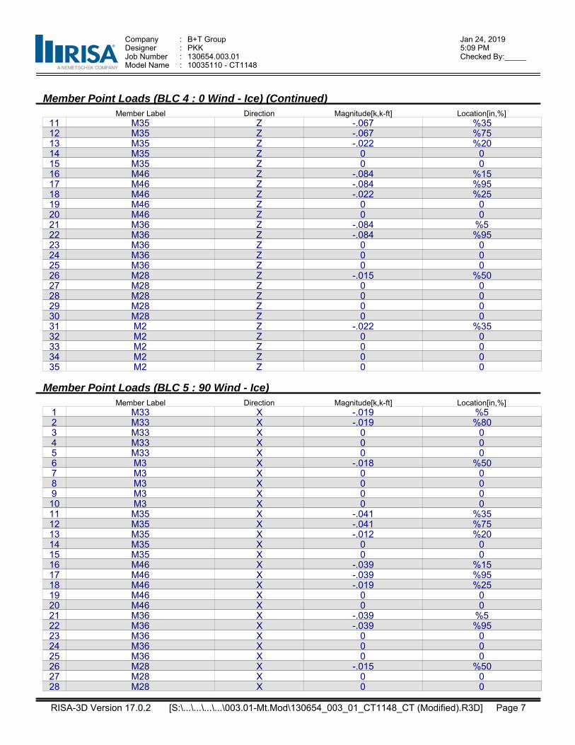
Company : B+T Group Jan 24, 20195:09 PMDesigner : PKK
Job Number : 130654.003.01 Checked By:_____Model Name : 10035110 - CT1148
Member Point Loads (BLC 4 : 0 Wind - Ice) (Continued)Member Label Direction Magnitude[k,k-ft] Location[in,%]
11 M35 Z -.067 %3512 M35 Z -.067 %7513 M35 Z -.022 %2014 M35 Z 0 015 M35 Z 0 016 M46 Z -.084 %1517 M46 Z -.084 %9518 M46 Z -.022 %2519 M46 Z 0 020 M46 Z 0 021 M36 Z -.084 %522 M36 Z -.084 %9523 M36 Z 0 024 M36 Z 0 025 M36 Z 0 026 M28 Z -.015 %5027 M28 Z 0 028 M28 Z 0 029 M28 Z 0 030 M28 Z 0 031 M2 Z -.022 %3532 M2 Z 0 033 M2 Z 0 034 M2 Z 0 035 M2 Z 0 0
Member Point Loads (BLC 5 : 90 Wind - Ice)Member Label Direction Magnitude[k,k-ft] Location[in,%]
1 M33 X -.019 %52 M33 X -.019 %803 M33 X 0 04 M33 X 0 05 M33 X 0 06 M3 X -.018 %507 M3 X 0 08 M3 X 0 09 M3 X 0 010 M3 X 0 011 M35 X -.041 %3512 M35 X -.041 %7513 M35 X -.012 %2014 M35 X 0 015 M35 X 0 016 M46 X -.039 %1517 M46 X -.039 %9518 M46 X -.019 %2519 M46 X 0 020 M46 X 0 021 M36 X -.039 %522 M36 X -.039 %9523 M36 X 0 024 M36 X 0 025 M36 X 0 026 M28 X -.015 %5027 M28 X 0 028 M28 X 0 0
RISA-3D Version 17.0.2 Page 7 [S:\...\...\...\...\003.01-Mt.Mod\130654_003_01_CT1148_CT (Modified).R3D]
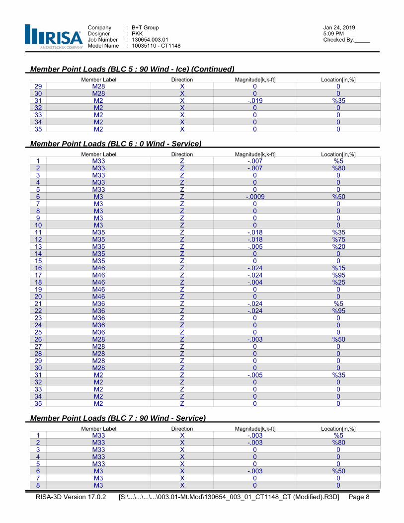
Company : B+T Group Jan 24, 20195:09 PMDesigner : PKK
Job Number : 130654.003.01 Checked By:_____Model Name : 10035110 - CT1148
Member Point Loads (BLC 5 : 90 Wind - Ice) (Continued)Member Label Direction Magnitude[k,k-ft] Location[in,%]
29 M28 X 0 030 M28 X 0 031 M2 X -.019 %3532 M2 X 0 033 M2 X 0 034 M2 X 0 035 M2 X 0 0
Member Point Loads (BLC 6 : 0 Wind - Service)Member Label Direction Magnitude[k,k-ft] Location[in,%]
1 M33 Z -.007 %52 M33 Z -.007 %803 M33 Z 0 04 M33 Z 0 05 M33 Z 0 06 M3 Z -.0009 %507 M3 Z 0 08 M3 Z 0 09 M3 Z 0 010 M3 Z 0 011 M35 Z -.018 %3512 M35 Z -.018 %7513 M35 Z -.005 %2014 M35 Z 0 015 M35 Z 0 016 M46 Z -.024 %1517 M46 Z -.024 %9518 M46 Z -.004 %2519 M46 Z 0 020 M46 Z 0 021 M36 Z -.024 %522 M36 Z -.024 %9523 M36 Z 0 024 M36 Z 0 025 M36 Z 0 026 M28 Z -.003 %5027 M28 Z 0 028 M28 Z 0 029 M28 Z 0 030 M28 Z 0 031 M2 Z -.005 %3532 M2 Z 0 033 M2 Z 0 034 M2 Z 0 035 M2 Z 0 0
Member Point Loads (BLC 7 : 90 Wind - Service)Member Label Direction Magnitude[k,k-ft] Location[in,%]
1 M33 X -.003 %52 M33 X -.003 %803 M33 X 0 04 M33 X 0 05 M33 X 0 06 M3 X -.003 %507 M3 X 0 08 M3 X 0 0
RISA-3D Version 17.0.2 Page 8 [S:\...\...\...\...\003.01-Mt.Mod\130654_003_01_CT1148_CT (Modified).R3D]
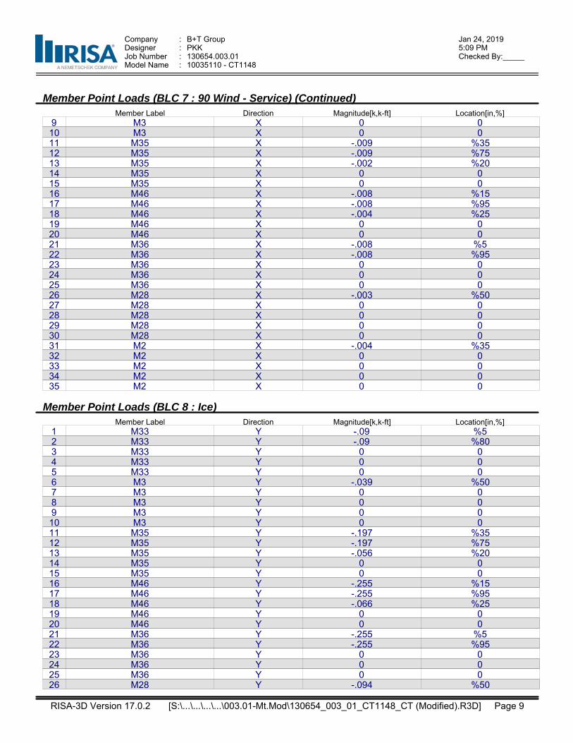
Company : B+T Group Jan 24, 20195:09 PMDesigner : PKK
Job Number : 130654.003.01 Checked By:_____Model Name : 10035110 - CT1148
Member Point Loads (BLC 7 : 90 Wind - Service) (Continued)Member Label Direction Magnitude[k,k-ft] Location[in,%]
9 M3 X 0 010 M3 X 0 011 M35 X -.009 %3512 M35 X -.009 %7513 M35 X -.002 %2014 M35 X 0 015 M35 X 0 016 M46 X -.008 %1517 M46 X -.008 %9518 M46 X -.004 %2519 M46 X 0 020 M46 X 0 021 M36 X -.008 %522 M36 X -.008 %9523 M36 X 0 024 M36 X 0 025 M36 X 0 026 M28 X -.003 %5027 M28 X 0 028 M28 X 0 029 M28 X 0 030 M28 X 0 031 M2 X -.004 %3532 M2 X 0 033 M2 X 0 034 M2 X 0 035 M2 X 0 0
Member Point Loads (BLC 8 : Ice)Member Label Direction Magnitude[k,k-ft] Location[in,%]
1 M33 Y -.09 %52 M33 Y -.09 %803 M33 Y 0 04 M33 Y 0 05 M33 Y 0 06 M3 Y -.039 %507 M3 Y 0 08 M3 Y 0 09 M3 Y 0 010 M3 Y 0 011 M35 Y -.197 %3512 M35 Y -.197 %7513 M35 Y -.056 %2014 M35 Y 0 015 M35 Y 0 016 M46 Y -.255 %1517 M46 Y -.255 %9518 M46 Y -.066 %2519 M46 Y 0 020 M46 Y 0 021 M36 Y -.255 %522 M36 Y -.255 %9523 M36 Y 0 024 M36 Y 0 025 M36 Y 0 026 M28 Y -.094 %50
RISA-3D Version 17.0.2 Page 9 [S:\...\...\...\...\003.01-Mt.Mod\130654_003_01_CT1148_CT (Modified).R3D]
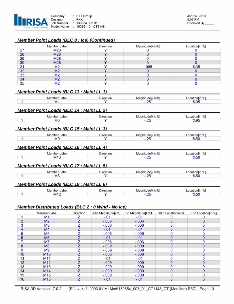
Company : B+T Group Jan 24, 20195:09 PMDesigner : PKK
Job Number : 130654.003.01 Checked By:_____Model Name : 10035110 - CT1148
Member Point Loads (BLC 8 : Ice) (Continued)Member Label Direction Magnitude[k,k-ft] Location[in,%]
27 M28 Y 0 028 M28 Y 0 029 M28 Y 0 030 M28 Y 0 031 M2 Y -.065 %3532 M2 Y 0 033 M2 Y 0 034 M2 Y 0 035 M2 Y 0 0
Member Point Loads (BLC 13 : Maint LL 1)Member Label Direction Magnitude[k,k-ft] Location[in,%]
1 M1 Y -.25 %95
Member Point Loads (BLC 14 : Maint LL 2)Member Label Direction Magnitude[k,k-ft] Location[in,%]
1 M6 Y -.25 %95
Member Point Loads (BLC 15 : Maint LL 3)Member Label Direction Magnitude[k,k-ft] Location[in,%]
1 M9 Y -.25 %50
Member Point Loads (BLC 16 : Maint LL 4)Member Label Direction Magnitude[k,k-ft] Location[in,%]
1 M13 Y -.25 %50
Member Point Loads (BLC 17 : Maint LL 5)Member Label Direction Magnitude[k,k-ft] Location[in,%]
1 M8 Y -.25 %50
Member Point Loads (BLC 18 : Maint LL 6)Member Label Direction Magnitude[k,k-ft] Location[in,%]
1 M12 Y -.25 %50
Member Distributed Loads (BLC 2 : 0 Wind - No Ice)Member Label Direction Start Magnitude[k/ft,... End Magnitude[k/ft,F... Start Location[in,%] End Location[in,%]
1 M1 Z -.01 -.01 0 02 M2 Z -.006 -.006 0 03 M3 Z -.006 -.006 0 04 M4 Z -.01 -.01 0 05 M5 Z -.006 -.006 0 06 M6 Z -.01 -.01 0 07 M7 Z -.006 -.006 0 08 M8 Z -.009 -.009 0 09 M9 Z -.009 -.009 0 010 M10 Z -.006 -.006 0 011 M11 Z -.01 -.01 0 012 M12 Z -.009 -.009 0 013 M13 Z -.009 -.009 0 014 M14 Z -.009 -.009 0 015 M15 Z -.009 -.009 0 016 M16 Z -.01 -.01 0 0
RISA-3D Version 17.0.2 Page 10 [S:\...\...\...\...\003.01-Mt.Mod\130654_003_01_CT1148_CT (Modified).R3D]
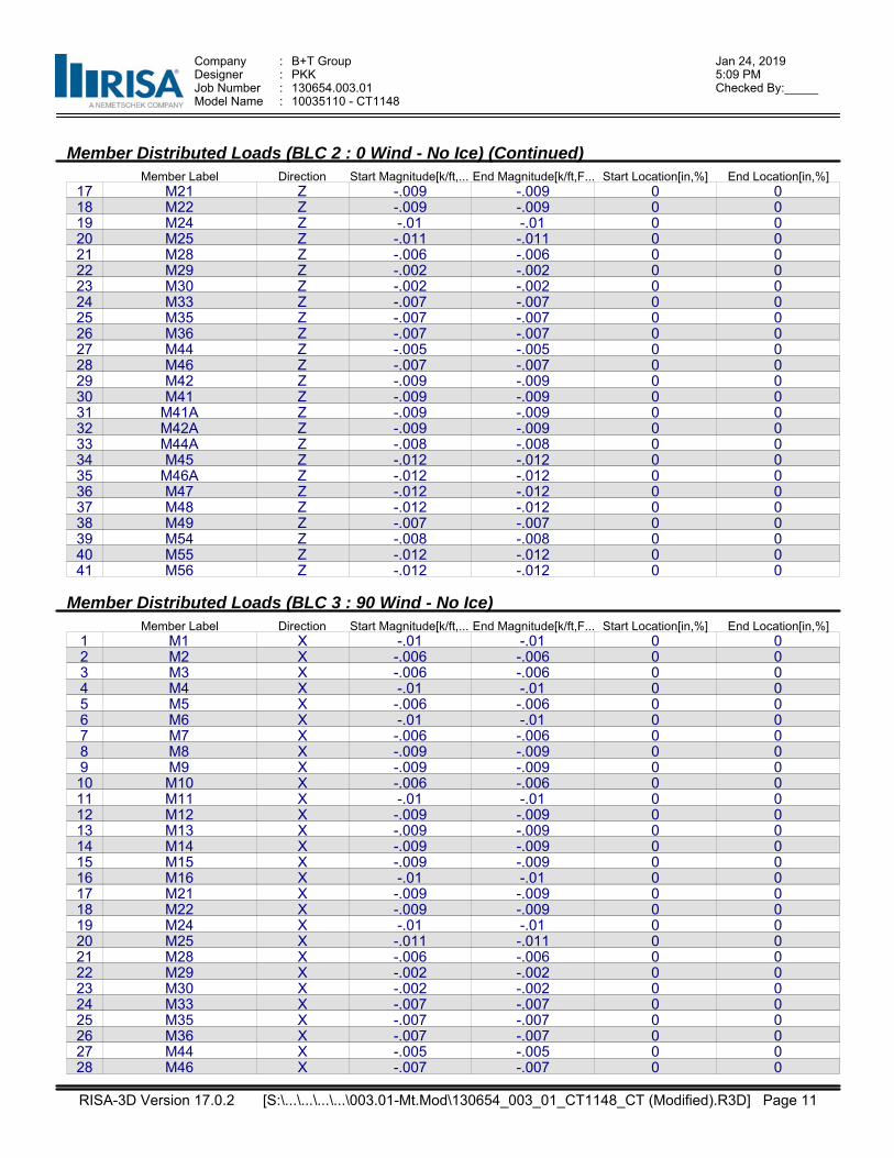
Company : B+T Group Jan 24, 20195:09 PMDesigner : PKK
Job Number : 130654.003.01 Checked By:_____Model Name : 10035110 - CT1148
Member Distributed Loads (BLC 2 : 0 Wind - No Ice) (Continued)Member Label Direction Start Magnitude[k/ft,... End Magnitude[k/ft,F... Start Location[in,%] End Location[in,%]
17 M21 Z -.009 -.009 0 018 M22 Z -.009 -.009 0 019 M24 Z -.01 -.01 0 020 M25 Z -.011 -.011 0 021 M28 Z -.006 -.006 0 022 M29 Z -.002 -.002 0 023 M30 Z -.002 -.002 0 024 M33 Z -.007 -.007 0 025 M35 Z -.007 -.007 0 026 M36 Z -.007 -.007 0 027 M44 Z -.005 -.005 0 028 M46 Z -.007 -.007 0 029 M42 Z -.009 -.009 0 030 M41 Z -.009 -.009 0 031 M41A Z -.009 -.009 0 032 M42A Z -.009 -.009 0 033 M44A Z -.008 -.008 0 034 M45 Z -.012 -.012 0 035 M46A Z -.012 -.012 0 036 M47 Z -.012 -.012 0 037 M48 Z -.012 -.012 0 038 M49 Z -.007 -.007 0 039 M54 Z -.008 -.008 0 040 M55 Z -.012 -.012 0 041 M56 Z -.012 -.012 0 0
Member Distributed Loads (BLC 3 : 90 Wind - No Ice)Member Label Direction Start Magnitude[k/ft,... End Magnitude[k/ft,F... Start Location[in,%] End Location[in,%]
1 M1 X -.01 -.01 0 02 M2 X -.006 -.006 0 03 M3 X -.006 -.006 0 04 M4 X -.01 -.01 0 05 M5 X -.006 -.006 0 06 M6 X -.01 -.01 0 07 M7 X -.006 -.006 0 08 M8 X -.009 -.009 0 09 M9 X -.009 -.009 0 010 M10 X -.006 -.006 0 011 M11 X -.01 -.01 0 012 M12 X -.009 -.009 0 013 M13 X -.009 -.009 0 014 M14 X -.009 -.009 0 015 M15 X -.009 -.009 0 016 M16 X -.01 -.01 0 017 M21 X -.009 -.009 0 018 M22 X -.009 -.009 0 019 M24 X -.01 -.01 0 020 M25 X -.011 -.011 0 021 M28 X -.006 -.006 0 022 M29 X -.002 -.002 0 023 M30 X -.002 -.002 0 024 M33 X -.007 -.007 0 025 M35 X -.007 -.007 0 026 M36 X -.007 -.007 0 027 M44 X -.005 -.005 0 028 M46 X -.007 -.007 0 0
RISA-3D Version 17.0.2 Page 11 [S:\...\...\...\...\003.01-Mt.Mod\130654_003_01_CT1148_CT (Modified).R3D]
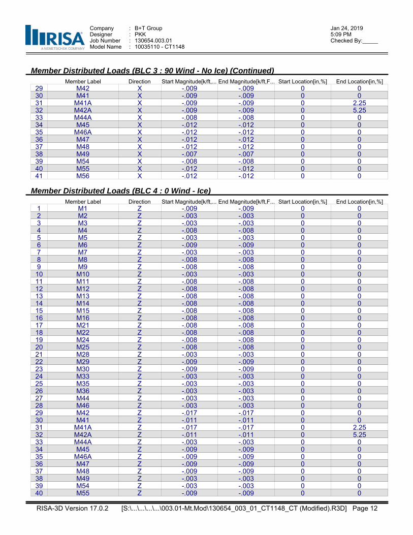
Company : B+T Group Jan 24, 20195:09 PMDesigner : PKK
Job Number : 130654.003.01 Checked By:_____Model Name : 10035110 - CT1148
Member Distributed Loads (BLC 3 : 90 Wind - No Ice) (Continued)Member Label Direction Start Magnitude[k/ft,... End Magnitude[k/ft,F... Start Location[in,%] End Location[in,%]
29 M42 X -.009 -.009 0 030 M41 X -.009 -.009 0 031 M41A X -.009 -.009 0 2.2532 M42A X -.009 -.009 0 5.2533 M44A X -.008 -.008 0 034 M45 X -.012 -.012 0 035 M46A X -.012 -.012 0 036 M47 X -.012 -.012 0 037 M48 X -.012 -.012 0 038 M49 X -.007 -.007 0 039 M54 X -.008 -.008 0 040 M55 X -.012 -.012 0 041 M56 X -.012 -.012 0 0
Member Distributed Loads (BLC 4 : 0 Wind - Ice)Member Label Direction Start Magnitude[k/ft,... End Magnitude[k/ft,F... Start Location[in,%] End Location[in,%]
1 M1 Z -.009 -.009 0 02 M2 Z -.003 -.003 0 03 M3 Z -.003 -.003 0 04 M4 Z -.008 -.008 0 05 M5 Z -.003 -.003 0 06 M6 Z -.009 -.009 0 07 M7 Z -.003 -.003 0 08 M8 Z -.008 -.008 0 09 M9 Z -.008 -.008 0 010 M10 Z -.003 -.003 0 011 M11 Z -.008 -.008 0 012 M12 Z -.008 -.008 0 013 M13 Z -.008 -.008 0 014 M14 Z -.008 -.008 0 015 M15 Z -.008 -.008 0 016 M16 Z -.008 -.008 0 017 M21 Z -.008 -.008 0 018 M22 Z -.008 -.008 0 019 M24 Z -.008 -.008 0 020 M25 Z -.008 -.008 0 021 M28 Z -.003 -.003 0 022 M29 Z -.009 -.009 0 023 M30 Z -.009 -.009 0 024 M33 Z -.003 -.003 0 025 M35 Z -.003 -.003 0 026 M36 Z -.003 -.003 0 027 M44 Z -.003 -.003 0 028 M46 Z -.003 -.003 0 029 M42 Z -.017 -.017 0 030 M41 Z -.011 -.011 0 031 M41A Z -.017 -.017 0 2.2532 M42A Z -.011 -.011 0 5.2533 M44A Z -.003 -.003 0 034 M45 Z -.009 -.009 0 035 M46A Z -.009 -.009 0 036 M47 Z -.009 -.009 0 037 M48 Z -.009 -.009 0 038 M49 Z -.003 -.003 0 039 M54 Z -.003 -.003 0 040 M55 Z -.009 -.009 0 0
RISA-3D Version 17.0.2 Page 12 [S:\...\...\...\...\003.01-Mt.Mod\130654_003_01_CT1148_CT (Modified).R3D]

Company : B+T Group Jan 24, 20195:09 PMDesigner : PKK
Job Number : 130654.003.01 Checked By:_____Model Name : 10035110 - CT1148
Member Distributed Loads (BLC 4 : 0 Wind - Ice) (Continued)Member Label Direction Start Magnitude[k/ft,... End Magnitude[k/ft,F... Start Location[in,%] End Location[in,%]
41 M56 Z -.009 -.009 0 0
Member Distributed Loads (BLC 5 : 90 Wind - Ice)Member Label Direction Start Magnitude[k/ft,... End Magnitude[k/ft,F... Start Location[in,%] End Location[in,%]
1 M1 X -.009 -.009 0 02 M2 X -.003 -.003 0 03 M3 X -.003 -.003 0 04 M4 X -.008 -.008 0 05 M5 X -.003 -.003 0 06 M6 X -.009 -.009 0 07 M7 X -.003 -.003 0 08 M8 X -.008 -.008 0 09 M9 X -.008 -.008 0 010 M10 X -.003 -.003 0 011 M11 X -.008 -.008 0 012 M12 X -.008 -.008 0 013 M13 X -.008 -.008 0 014 M14 X -.008 -.008 0 015 M15 X -.008 -.008 0 016 M16 X -.008 -.008 0 017 M21 X -.008 -.008 0 018 M22 X -.008 -.008 0 019 M24 X -.008 -.008 0 020 M25 X -.008 -.008 0 021 M28 X -.003 -.003 0 022 M29 X -.009 -.009 0 023 M30 X -.009 -.009 0 024 M33 X -.003 -.003 0 025 M35 X -.003 -.003 0 026 M36 X -.003 -.003 0 027 M44 X -.003 -.003 0 028 M46 X -.003 -.003 0 029 M42 X -.017 -.017 0 030 M41 X -.011 -.011 0 031 M41A X -.017 -.017 0 2.2532 M42A X -.011 -.011 0 5.2533 M44A X -.003 -.003 0 034 M45 X -.009 -.009 0 035 M46A X -.009 -.009 0 036 M47 X -.009 -.009 0 037 M48 X -.009 -.009 0 038 M49 X -.003 -.003 0 039 M54 X -.003 -.003 0 040 M55 X -.009 -.009 0 041 M56 X -.009 -.009 0 0
Member Distributed Loads (BLC 6 : 0 Wind - Service)Member Label Direction Start Magnitude[k/ft,... End Magnitude[k/ft,F... Start Location[in,%] End Location[in,%]
1 M1 Z -.0009 -.0009 0 02 M2 Z -.0003 -.0003 0 03 M3 Z -.0003 -.0003 0 04 M4 Z -.0009 -.0009 0 05 M5 Z -.0003 -.0003 0 06 M6 Z -.0009 -.0009 0 07 M7 Z -.0003 -.0003 0 08 M8 Z -.0009 -.0009 0 0
RISA-3D Version 17.0.2 Page 13 [S:\...\...\...\...\003.01-Mt.Mod\130654_003_01_CT1148_CT (Modified).R3D]
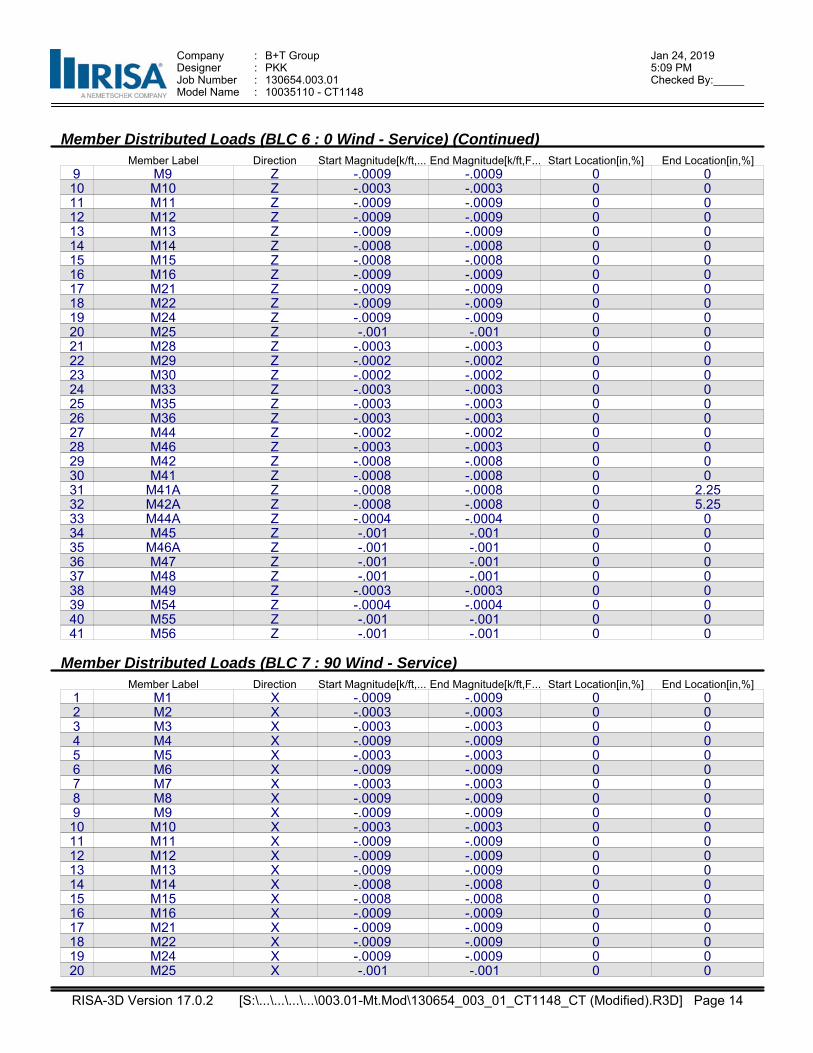
Company : B+T Group Jan 24, 20195:09 PMDesigner : PKK
Job Number : 130654.003.01 Checked By:_____Model Name : 10035110 - CT1148
Member Distributed Loads (BLC 6 : 0 Wind - Service) (Continued)Member Label Direction Start Magnitude[k/ft,... End Magnitude[k/ft,F... Start Location[in,%] End Location[in,%]
9 M9 Z -.0009 -.0009 0 010 M10 Z -.0003 -.0003 0 011 M11 Z -.0009 -.0009 0 012 M12 Z -.0009 -.0009 0 013 M13 Z -.0009 -.0009 0 014 M14 Z -.0008 -.0008 0 015 M15 Z -.0008 -.0008 0 016 M16 Z -.0009 -.0009 0 017 M21 Z -.0009 -.0009 0 018 M22 Z -.0009 -.0009 0 019 M24 Z -.0009 -.0009 0 020 M25 Z -.001 -.001 0 021 M28 Z -.0003 -.0003 0 022 M29 Z -.0002 -.0002 0 023 M30 Z -.0002 -.0002 0 024 M33 Z -.0003 -.0003 0 025 M35 Z -.0003 -.0003 0 026 M36 Z -.0003 -.0003 0 027 M44 Z -.0002 -.0002 0 028 M46 Z -.0003 -.0003 0 029 M42 Z -.0008 -.0008 0 030 M41 Z -.0008 -.0008 0 031 M41A Z -.0008 -.0008 0 2.2532 M42A Z -.0008 -.0008 0 5.2533 M44A Z -.0004 -.0004 0 034 M45 Z -.001 -.001 0 035 M46A Z -.001 -.001 0 036 M47 Z -.001 -.001 0 037 M48 Z -.001 -.001 0 038 M49 Z -.0003 -.0003 0 039 M54 Z -.0004 -.0004 0 040 M55 Z -.001 -.001 0 041 M56 Z -.001 -.001 0 0
Member Distributed Loads (BLC 7 : 90 Wind - Service)Member Label Direction Start Magnitude[k/ft,... End Magnitude[k/ft,F... Start Location[in,%] End Location[in,%]
1 M1 X -.0009 -.0009 0 02 M2 X -.0003 -.0003 0 03 M3 X -.0003 -.0003 0 04 M4 X -.0009 -.0009 0 05 M5 X -.0003 -.0003 0 06 M6 X -.0009 -.0009 0 07 M7 X -.0003 -.0003 0 08 M8 X -.0009 -.0009 0 09 M9 X -.0009 -.0009 0 010 M10 X -.0003 -.0003 0 011 M11 X -.0009 -.0009 0 012 M12 X -.0009 -.0009 0 013 M13 X -.0009 -.0009 0 014 M14 X -.0008 -.0008 0 015 M15 X -.0008 -.0008 0 016 M16 X -.0009 -.0009 0 017 M21 X -.0009 -.0009 0 018 M22 X -.0009 -.0009 0 019 M24 X -.0009 -.0009 0 020 M25 X -.001 -.001 0 0
RISA-3D Version 17.0.2 Page 14 [S:\...\...\...\...\003.01-Mt.Mod\130654_003_01_CT1148_CT (Modified).R3D]

Company : B+T Group Jan 24, 20195:09 PMDesigner : PKK
Job Number : 130654.003.01 Checked By:_____Model Name : 10035110 - CT1148
Member Distributed Loads (BLC 7 : 90 Wind - Service) (Continued)Member Label Direction Start Magnitude[k/ft,... End Magnitude[k/ft,F... Start Location[in,%] End Location[in,%]
21 M28 X -.0003 -.0003 0 022 M29 X -.0002 -.0002 0 023 M30 X -.0002 -.0002 0 024 M33 X -.0003 -.0003 0 025 M35 X -.0003 -.0003 0 026 M36 X -.0003 -.0003 0 027 M44 X -.0002 -.0002 0 028 M46 X -.0003 -.0003 0 029 M42 X -.0008 -.0008 0 030 M41 X -.0008 -.0008 0 031 M41A X -.0008 -.0008 0 2.2532 M42A X -.0008 -.0008 0 5.2533 M44A X -.0004 -.0004 0 034 M45 X -.001 -.001 0 035 M46A X -.001 -.001 0 036 M47 X -.001 -.001 0 037 M48 X -.001 -.001 0 038 M49 X -.0003 -.0003 0 039 M54 X -.0004 -.0004 0 040 M55 X -.001 -.001 0 041 M56 X -.001 -.001 0 0
Member Distributed Loads (BLC 8 : Ice)Member Label Direction Start Magnitude[k/ft,... End Magnitude[k/ft,F... Start Location[in,%] End Location[in,%]
1 M1 Y -.014 -.014 0 02 M2 Y -.013 -.013 0 03 M3 Y -.013 -.013 0 04 M4 Y -.016 -.016 0 05 M5 Y -.013 -.013 0 06 M6 Y -.014 -.014 0 07 M7 Y -.013 -.013 0 08 M8 Y -.016 -.016 0 09 M9 Y -.016 -.016 0 010 M10 Y -.013 -.013 0 011 M11 Y -.016 -.016 0 012 M12 Y -.016 -.016 0 013 M13 Y -.016 -.016 0 014 M14 Y -.014 -.014 0 015 M15 Y -.014 -.014 0 016 M16 Y -.015 -.015 0 017 M21 Y -.015 -.015 0 018 M22 Y -.015 -.015 0 019 M24 Y -.015 -.015 0 020 M25 Y -.015 -.015 0 021 M28 Y -.013 -.013 0 022 M29 Y -.023 -.023 0 023 M30 Y -.023 -.023 0 024 M33 Y -.013 -.013 0 025 M35 Y -.013 -.013 0 026 M36 Y -.013 -.013 0 027 M44 Y -.011 -.011 0 028 M46 Y -.013 -.013 0 029 M42 Y -.014 -.014 0 030 M41 Y -.014 -.014 0 031 M41A Y -.014 -.014 0 2.2532 M42A Y -.014 -.014 0 5.25
RISA-3D Version 17.0.2 Page 15 [S:\...\...\...\...\003.01-Mt.Mod\130654_003_01_CT1148_CT (Modified).R3D]
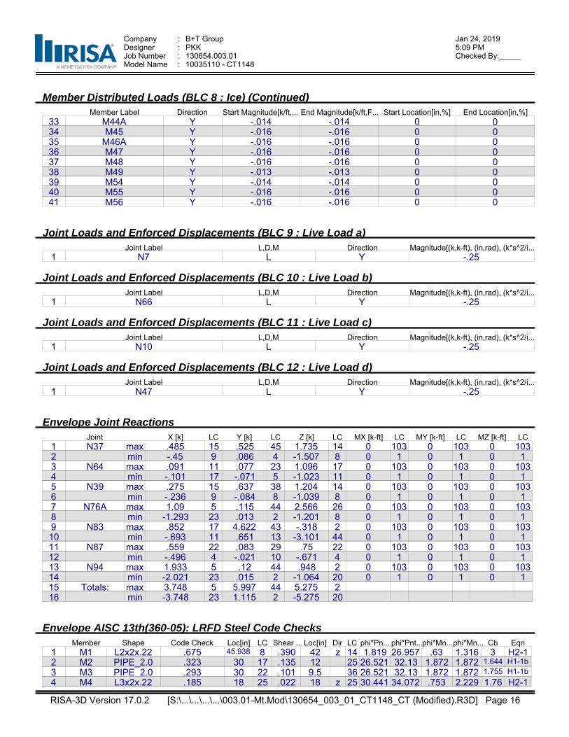
Company : B+T Group Jan 24, 20195:09 PMDesigner : PKK
Job Number : 130654.003.01 Checked By:_____Model Name : 10035110 - CT1148
Member Distributed Loads (BLC 8 : Ice) (Continued)Member Label Direction Start Magnitude[k/ft,... End Magnitude[k/ft,F... Start Location[in,%] End Location[in,%]
33 M44A Y -.014 -.014 0 034 M45 Y -.016 -.016 0 035 M46A Y -.016 -.016 0 036 M47 Y -.016 -.016 0 037 M48 Y -.016 -.016 0 038 M49 Y -.013 -.013 0 039 M54 Y -.014 -.014 0 040 M55 Y -.016 -.016 0 041 M56 Y -.016 -.016 0 0
Joint Loads and Enforced Displacements (BLC 9 : Live Load a)Joint Label L,D,M Direction Magnitude[(k,k-ft), (in,rad), (k*s^2/i...
1 N7 L Y -.25
Joint Loads and Enforced Displacements (BLC 10 : Live Load b)Joint Label L,D,M Direction Magnitude[(k,k-ft), (in,rad), (k*s^2/i...
1 N66 L Y -.25
Joint Loads and Enforced Displacements (BLC 11 : Live Load c)Joint Label L,D,M Direction Magnitude[(k,k-ft), (in,rad), (k*s^2/i...
1 N10 L Y -.25
Joint Loads and Enforced Displacements (BLC 12 : Live Load d)Joint Label L,D,M Direction Magnitude[(k,k-ft), (in,rad), (k*s^2/i...
1 N47 L Y -.25
Envelope Joint ReactionsJoint X [k] LC Y [k] LC Z [k] LC MX [k-ft] LC MY [k-ft] LC MZ [k-ft] LC
1 N37 max .485 15 .525 45 1.735 14 0 103 0 103 0 1032 min -.45 9 .086 4 -1.507 8 0 1 0 1 0 13 N64 max .091 11 .077 23 1.096 17 0 103 0 103 0 1034 min -.101 17 -.071 5 -1.023 11 0 1 0 1 0 15 N39 max .275 15 .637 38 1.204 14 0 103 0 103 0 1036 min -.236 9 -.084 8 -1.039 8 0 1 0 1 0 17 N76A max 1.09 5 .115 44 2.566 26 0 103 0 103 0 1038 min -1.293 23 .013 2 -1.201 8 0 1 0 1 0 19 N83 max .852 17 4.622 43 -.318 2 0 103 0 103 0 10310 min -.693 11 .651 13 -3.101 44 0 1 0 1 0 111 N87 max .559 22 .083 29 .75 22 0 103 0 103 0 10312 min -.496 4 -.021 10 -.671 4 0 1 0 1 0 113 N94 max 1.933 5 .12 44 .948 2 0 103 0 103 0 10314 min -2.021 23 .015 2 -1.064 20 0 1 0 1 0 115 Totals: max 3.748 5 5.997 44 5.275 216 min -3.748 23 1.115 2 -5.275 20
Envelope AISC 13th(360-05): LRFD Steel Code ChecksMember Shape Code Check Loc[in] LC Shear ... Loc[in] Dir LC phi*Pn... phi*Pnt...phi*Mn...phi*Mn... Cb Eqn
1 M1 L2x2x.22 .675 45.938 8 .390 42 z 14 1.819 26.957 .63 1.316 3 H2-12 M2 PIPE_2.0 .323 30 17 .135 12 25 26.521 32.13 1.872 1.872 1.644 H1-1b
3 M3 PIPE_2.0 .293 30 22 .101 9.5 36 26.521 32.13 1.872 1.872 1.755 H1-1b
4 M4 L3x2x.22 .185 18 25 .022 18 z 25 30.441 34.072 .753 2.229 1.76 H2-1
RISA-3D Version 17.0.2 Page 16 [S:\...\...\...\...\003.01-Mt.Mod\130654_003_01_CT1148_CT (Modified).R3D]
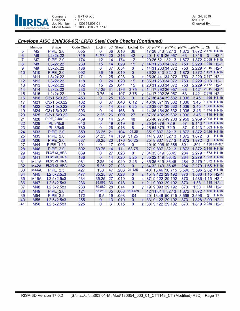
Company : B+T Group Jan 24, 20195:09 PMDesigner : PKK
Job Number : 130654.003.01 Checked By:_____Model Name : 10035110 - CT1148
Envelope AISC 13th(360-05): LRFD Steel Code Checks (Continued)Member Shape Code Check Loc[in] LC Shear ... Loc[in] Dir LC phi*Pn... phi*Pnt...phi*Mn...phi*Mn... Cb Eqn
5 M5 PIPE_2.0 .055 0 36 .016 36 17 28.843 32.13 1.872 1.872 2.175 H1-1b
6 M6 L2x2x.22 .719 45.938 20 .316 42 y 20 1.819 26.957 .63 1.316 3 H2-17 M7 PIPE_2.0 .174 12 14 .174 12 20 26.521 32.13 1.872 1.872 2.558 H1-1b
8 M8 L3x2x.22 .239 15 14 .029 15 y 14 31.263 34.072 .753 2.229 1.949 H2-19 M9 L3x2x.22 .186 0 37 .054 0 y 14 31.263 34.072 .753 2.229 2.015 H2-110 M10 PIPE_2.0 .092 36 19 .019 0 36 28.843 32.13 1.872 1.872 1.423 H1-1b
11 M11 L3x2x.22 .171 0 25 .023 0 z 25 30.441 34.072 .753 2.229 2.197 H2-112 M12 L3x2x.22 .118 0 24 .020 15 z 35 31.263 34.072 .753 2.229 2.18 H2-113 M13 L3x2x.22 .162 15 25 .041 15 z 20 31.263 34.072 .753 2.229 2.172 H2-114 M14 L2x2x.22 .233 4.125 31 .136 3.75 z 14 17.292 26.957 .63 1.421 2.015 H2-115 M15 L2x2x.22 .219 3.75 14 .197 3.75 y 14 17.292 26.957 .63 1.421 2.378 H2-116 M16 C3x1.5x0.22 .453 9 25 .136 9 z 37 36.464 39.632 1.036 3.45 1.496 H1-1b
17 M21 C3x1.5x0.22 .162 0 37 .040 6.12 y 46 38.071 39.632 1.036 3.45 1.729 H1-1b
18 M22 C3x1.5x0.22 .470 0 14 .083 6.25 z 26 38.071 39.632 1.036 3.45 1.586 H1-1b
19 M24 C3x1.5x0.22 .593 9 14 .168 9 z 14 36.464 39.632 1.036 3.45 1.474 H1-1b
20 M25 C3x1.5x0.22 .224 2.25 26 .009 27 z 37 28.402 39.632 1.036 3.45 1.849 H1-1b
21 M28 PIPE_2.48x0.... .469 40 14 .254 48 25 40.976 49.203 2.959 2.959 2.998 H1-1b
22 M29 PL 3/8x6 .643 0 49 .019 8 y 25 54.379 72.9 .57 9.113 1.663 H1-1b
23 M30 PL 3/8x6 .780 0 26 .016 8 y 25 54.379 72.9 .57 9.113 1.663 H1-1b
24 M33 PIPE_2.0 .359 36.25 21 .104 101.25 35 9.837 32.13 1.872 1.872 2.426 H1-1b
25 M35 PIPE_2.0 .456 51.25 14 .159 51.25 14 9.837 32.13 1.872 1.872 3 H1-1b
26 M36 PIPE_2.0 .637 36.25 20 .176 36.25 25 9.837 32.13 1.872 1.872 3 H1-1b
27 M44 PIPE_1.25 .101 0 17 .006 0 40 10.996 19.688 .801 .801 1.136 H1-1b*
28 M46 PIPE_2.0 .502 53.75 14 .111 53.75 27 9.837 32.13 1.872 1.872 2.349 H1-1b
29 M42 PL3/8x3_HRA .039 0 27 .023 0 y 34 35.619 36.45 .284 2.279 1.673 H1-1b
30 M41 PL3/8x3_HRA .186 0 14 .020 5.25 y 35 32.149 36.45 .284 2.279 1.653 H1-1b
31 M41A PL3/8x3_HRA .081 2.25 14 .020 2.25 y 35 35.619 36.45 .284 2.279 1.672 H1-1b
32 M42A PL3/8x3_HRA .082 5.25 27 .023 0 y 34 32.149 36.45 .284 2.279 1.65 H1-1b
33 M44A PIPE_2.5 .427 130 47 .203 21.125 48 13.46 50.715 3.596 3.596 2.82 H1-1b
34 M45 L2.5x2.5x3 .477 35.25 37 .028 0 z 15 9.122 29.192 .873 1.586 1.15 H2-135 M46A L2.5x2.5x3 .434 35.25 27 .019 0 z 37 9.122 29.192 .873 1.586 1.15 H2-136 M47 L2.5x2.5x3 .236 39.062 36 .018 0 z 21 9.093 29.192 .873 1.58 1.138 H2-137 M48 L2.5x2.5x3 .233 39.062 28 .014 0 y 19 9.093 29.192 .873 1.58 1.138 H2-138 M49 PIPE_2.0 .121 55.219 35 .008 110.439 42 11.614 32.13 1.872 1.872 1.136 H1-1b
39 M54 PIPE_2.5 .172 19.5 19 .098 104 20 13.46 50.715 3.596 3.596 3 H1-1b
40 M55 L2.5x2.5x3 .255 0 13 .019 0 z 33 9.122 29.192 .873 1.828 2.09 H2-141 M56 L2.5x2.5x3 .225 0 3 .015 0 z 38 9.122 29.192 .873 1.819 2.039 H2-1
RISA-3D Version 17.0.2 Page 17 [S:\...\...\...\...\003.01-Mt.Mod\130654_003_01_CT1148_CT (Modified).R3D]

January 24, 2019 Appurtenance Mount Structural Modification Report Site No. 10035110 Project Number 130654.003.01, CT1148 Page 7
APPENDIX B (Modification Drawings)
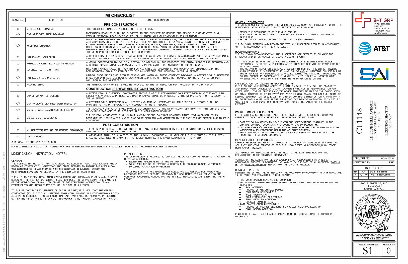
·
·
·
·
··
“ ”
·
·
·
“
” “ ”
·
·
····
····
····
···
····
MI CHECKLIST
PRE-CONSTRUCTION
CONSTRUCTION (PERFORMED BY CONTRACTOR)
POST-CONSTRUCTION
·
·
0S1REVISION:SHEET NUMBER:
130654.003.01
ISSUED FOR:
PROJECT NO:
PKKCHECKED BY:
1717 S. BOULDER
SUITE 300
TULSA, OK 74119
PH: (918) 587-4630
www.btgrp.com
CT
1148
1021 B
LU
E H
ILL
S A
VE
NU
EB
LO
OM
FIE
LD
, C
T 0
6002
HA
RT
FO
RD
EX
IST
ING
SE
CT
OR
AT
99'-00"
AutoCAD SHX Text
GENERAL CONTRACTOR THE GC IS REQUIRED TO CONTACT THE MI INSPECTOR AS SOON AS RECEIVING A PO FOR THE MODIFICATION INSTALLATION OR TURNKEY PROJECT TO, AT A MINIMUM: REVIEW THE REQUIREMENTS OF THE MI CHECKLIST WORK WITH THE MI INSPECTOR TO DEVELOP A SCHEDULE TO CONDUCT ON-SITE MI INSPECTIONS BETTER UNDERSTAND ALL INSPECTION AND TESTING REQUIREMENTS THE GC SHALL PERFORM AND RECORD THE TEST AND INSPECTION RESULTS IN ACCORDANCE WITH THE REQUIREMENTS OF THE MI CHECKLIST. RECOMMENDATIONS THE FOLLOWING RECOMMENDATIONS AND SUGGESTIONS ARE OFFERED TO ENHANCE THE EFFICIENCY AND EFFECTIVENESS OF DELIVERING A MI REPORT: IT IS SUGGESTED THAT THE GC PROVIDE A MINIMUM OF 5 BUSINESS DAYS NOTICE, PREFERABLY 10, TO THE MI INSPECTOR AS TO WHEN THE SITE WILL BE READY FOR THE MI TO BE CONDUCTED. THE GC AND MI INSPECTOR COORDINATE CLOSELY THROUGHOUT THE ENTIRE PROJECT. AND MI INSPECTOR COORDINATE CLOSELY THROUGHOUT THE ENTIRE PROJECT. MI INSPECTOR COORDINATE CLOSELY THROUGHOUT THE ENTIRE PROJECT. WHEN POSSIBLE, IT IS PREFERRED TO HAVE THE GC AND MI INSPECTOR ON-SITE DURING AND MI INSPECTOR ON-SITE DURING MI INSPECTOR ON-SITE DURING THE MI TO HAVE ANY DEFICIENCIES CORRECTED DURING THE INITIAL MI. THEREFORE, THE GC MAY CHOOSE TO COORDINATE THE MI CAREFULLY TO ENSURE ALL CONSTRUCTION FACILITIES ARE AT THEIR DISPOSAL WHEN THE MI INSPECTOR IS ON SITE. CANCELLATION OR DELAYS IN SCHEDULED MI IF THE GC AND MI INSPECTOR AGREE TO A DATE ON WHICH THE MI WILL BE CONDUCTED, AND EITHER PARTY CANCELS OR DELAYS, CARRIER SHALL NOT BE RESPONSIBLE FOR ANY CARRIER SHALL NOT BE RESPONSIBLE FOR ANY SHALL NOT BE RESPONSIBLE FOR ANY COSTS, FEES, LOSS OF DEPOSITS AND/OR OTHER PENALTIES RELATED TO THE CANCELLATION OR DELAY INCURRED BY EITHER PARTY FOR ANY TIME (E.G. TRAVEL AND LODGING, COSTS OF KEEPING EQUIPMENT ON-SITE, ETC.). IF CARRIER CONTRACTS DIRECTLY FOR A THIRD PARTY CARRIER CONTRACTS DIRECTLY FOR A THIRD PARTY CONTRACTS DIRECTLY FOR A THIRD PARTY MI, EXCEPTIONS MAY BE MADE IN THE EVENT THAT THE DELAY/CANCELLATION IS CAUSED BY WEATHER OR OTHER CONDITIONS THAT MAY COMPROMISE THE SAFETY OF THE PARTIES INVOLVED. CORRECTION OF FAILING MI'S IF THE MODIFICATION INSPECTOR FAILS THE MI (“FAILED MI”), THE GC SHALL WORK WITH FAILED MI”), THE GC SHALL WORK WITH ), THE GC SHALL WORK WITH CARRIER TO COORDINATE A REMEDIATION PLAN IN ONE OF TWO WAYS: TO COORDINATE A REMEDIATION PLAN IN ONE OF TWO WAYS: CORRECT FAILING ISSUES TO COMPLY WITH THE SPECIFICATIONS CONTAINED IN THE ORIGINAL CONTRACT DOCUMENTS AND COORDINATE A SUPPLEMENT MI. OR, WITH CARRIER'S APPROVAL, THE GC MAY WORK WITH THE EOR TO RE-ANALYZE THE CARRIER'S APPROVAL, THE GC MAY WORK WITH THE EOR TO RE-ANALYZE THE 'S APPROVAL, THE GC MAY WORK WITH THE EOR TO RE-ANALYZE THE MODIFICATION/REINFORCEMENT USING THE AS-BUILT CONDITION THE ADDITIONAL COST INCURRED IN THE SECOND SUPERVISION PROCESS WOULD BE BORNE BY THE GENERAL CONTRACTOR. MI VERIFICATION INSPECTIONS CARRIER RESERVES THE RIGHT TO CONDUCT A MI VERIFICATION INSPECTION TO VERIFY THE RESERVES THE RIGHT TO CONDUCT A MI VERIFICATION INSPECTION TO VERIFY THE ACCURACY AND COMPLETENESS OF PREVIOUSLY COMPLETED MI INSPECTION(S) ON TOWER MODIFICATION PROJECTS. ALL VERIFICATION INSPECTIONS SHALL BE HELD TO THE SAME SPECIFICATIONS AND REQUIREMENTS IN THE CONTRACT DOCUMENTS. VERIFICATION INSPECTION MAY BE CONDUCTED BY AN INDEPENDENT FIRM AFTER A MODIFICATION PROJECT IS COMPLETED, AS MARKED BY THE DATE OF AN ACCEPTED “PASSING PASSING MI” OR “PASS AS NOTED MI” REPORT FOR THE ORIGINAL PROJECT. OR “PASS AS NOTED MI” REPORT FOR THE ORIGINAL PROJECT. PASS AS NOTED MI” REPORT FOR THE ORIGINAL PROJECT. REPORT FOR THE ORIGINAL PROJECT. REQUIRED PHOTOS BETWEEN THE GC AND THE MI INSPECTOR THE FOLLOWING PHOTOGRAPHS, AT A MINIMUM, ARE TO BE TAKEN AND INCLUDED IN THE MI REPORT: PRE-CONSTRUCTION GENERAL SITE CONDITION PHOTOGRAPHS DURING THE REINFORCEMENT MODIFICATION CONSTRUCTION/ERECTION AND INSPECTION RAW MATERIALS PHOTOS OF ALL CRITICAL DETAILS FOUNDATION MODIFICATIONS WELD PREPARATION BOLT INSTALLATION AND TORQUE FINAL INSTALLED CONDITION SURFACE COATING REPAIR POST CONSTRUCTION PHOTOGRAPHS PHOTOS OF MODIFIED SECTIONS INDIVIDUALLY INDICATING ELEVATION FINAL INFIELD CONDITION PHOTOS OF ELEVATED MODIFICATIONS TAKEN FROM THE GROUND SHALL BE CONSIDERED INADEQUATE.
AutoCAD SHX Text
REQUIRED
AutoCAD SHX Text
REPORT ITEM
AutoCAD SHX Text
BRIEF DESCRIPTION
AutoCAD SHX Text
X
AutoCAD SHX Text
MI CHECKLIST DRAWING
AutoCAD SHX Text
THIS CHECKLIST SHALL BE INCLUDED IN THE MI REPORT.
AutoCAD SHX Text
N/A
AutoCAD SHX Text
EOR APPROVED SHOP DRAWINGS
AutoCAD SHX Text
FABRICATION DRAWINGS SHALL BE SUBMITTED TO THE ENGINEER OF RECORD FOR REVIEW. THE CONTRACTOR SHALL PROVIDE APPROVED SHOP DRAWINGS TO THE MI INSPECTOR FOR INCLUSION IN THE MI REPORT.
AutoCAD SHX Text
N/A
AutoCAD SHX Text
ASSEMBLY DRAWINGS
AutoCAD SHX Text
ONCE THE PRE-MODIFICATION MAPPING IS COMPLETE, PRIOR TO FABRICATION, THE CONTRACTOR SHALL PROVIDE DETAILED ASSEMBLY DRAWINGS. THESE ARE TO INCLUDE, BUT ARE NOT LIMITED TO, A VISUAL LAYOUT OF NEW REINFORCEMENT, EXISTING REINFORCEMENT CONFIGURATION, PORTHOLES, MOUNTS, STEP PEGS, SAFETY CLIMBS AND ANY OTHER MISCELLANEOUS ITEMS WHICH MAY AFFECT SUCCESSFUL INSTALLATION OF MODIFICATIONS ON THE TOWER. THESE DRAWINGS SHALL BE SUBMITTED TO THE EOR FOR APPROVAL. APPROVED ASSEMBLY DRAWINGS SHALL BE SUBMITTED TO THE MI INSPECTOR FOR INCLUSION IN THE MI REPORT.
AutoCAD SHX Text
FABRICATION INSPECTION
AutoCAD SHX Text
A LETTER FROM THE FABRICATOR, STATING THAT THE WORK WAS PERFORMED IN ACCORDANCE WITH INDUSTRY STANDARDS AND THE CONTRACT DOCUMENTS SHALL BE PROVIDED TO THE MI INSPECTOR FOR INCLUSION IN THE MI REPORT.
AutoCAD SHX Text
FABRICATOR CERTIFIED WELD INSPECTION
AutoCAD SHX Text
A VISUAL OBSERVATION BY CWI OF A PORTION OF WELDING ON THE PROPOSED STRUCTURAL MEMBERS IS REQUIRED AND A WRITTEN REPORT SHALL BE PROVIDED TO THE MI INSPECTOR FOR INCLUSION IN THE MI REPORT.
AutoCAD SHX Text
MATERIAL TEST REPORT (MTR)
AutoCAD SHX Text
MILL CERTIFICATION SHALL BE PROVIDED FOR ALL STEEL AS SPECIFIED IN THE MODIFICATION DRAWINGS AND THIS DOCUMENTATION SHALL BE PROVIDED TO THE MI INSPECTOR FOR INCLUSION IN THE MI REPORT.
AutoCAD SHX Text
N/A
AutoCAD SHX Text
FABRICATOR NDE INSPECTION
AutoCAD SHX Text
CRITICAL SHOP WELDS THAT REQUIRE TESTING ARE NOTED ON THESE CONTRACT DRAWINGS. A CERTIFIED WELD INSPECTOR SHALL PERFORM NON-DESTRUCTIVE EXAMINATION AND A REPORT SHALL BE PROVIDED TO THE MI INSPECTOR FOR INCLUSION IN THE MI REPORT.
AutoCAD SHX Text
PACKING SLIPS
AutoCAD SHX Text
THE MATERIAL SHIPPING LIST SHALL BE PROVIDED TO THE MI INSPECTOR FOR INCLUSION IN THE MI REPORT.
AutoCAD SHX Text
X
AutoCAD SHX Text
CONSTRUCTION INSPECTIONS
AutoCAD SHX Text
A LETTER FROM THE GENERAL CONTRACTOR STATING THAT THE WORKMANSHIP WAS PERFORMED IN ACCORDANCE WITH INDUSTRY STANDARDS AND THESE CONTRACT DRAWINGS SHALL BE PROVIDED TO THE MI INSPECTOR FOR INCLUSION IN THE MI REPORT.
AutoCAD SHX Text
N/A
AutoCAD SHX Text
CONTRACTOR'S CERTIFIED WELD INSPECTION
AutoCAD SHX Text
A CERTIFIED WELD INSPECTOR SHALL INSPECT AND TEST AS NECESSARY ALL FIELD WELDS. A REPORT SHALL BE PROVIDED TO THE MI INSPECTOR FOR INCLUSION IN THE MI REPORT.
AutoCAD SHX Text
N/A
AutoCAD SHX Text
ON SITE COLD GALVANIZING VERIFICATION
AutoCAD SHX Text
THE GENERAL CONTRACTOR SHALL PROVIDE DOCUMENTATION TO THE MI INSPECTOR VERIFYING THAT ANY ON-SITE COLD GALVANIZING WAS APPLIED AS SPECIFIED IN THE MODIFICATION DRAWINGS.
AutoCAD SHX Text
X
AutoCAD SHX Text
GC AS-BUILT DOCUMENTS
AutoCAD SHX Text
THE GENERAL CONTRACTOR SHALL SUBMIT A COPY OF THE CONTRACT DRAWINGS EITHER STATING "INSTALLED AS DESIGNED" OR NOTING ANY CHANGES THAT WERE REQUIRED AND APPROVED BY THE ENGINEER OF RECORD DUE TO FIELD CONDITIONS.
AutoCAD SHX Text
X
AutoCAD SHX Text
MI INSPECTOR REDLINE OR RECORD DRAWING(S)
AutoCAD SHX Text
THE MI INSPECTOR SHALL OBSERVE AND REPORT ANY DISCREPANCIES BETWEEN THE CONTRACTORS REDLINE DRAWING AND THE ACTUAL COMPLETED INSTALLATION.
AutoCAD SHX Text
X
AutoCAD SHX Text
PHOTOGRAPHS
AutoCAD SHX Text
PHOTOGRAPHS SHALL BE SUBMITTED TO THE MI WHICH DOCUMENT ALL PHASES OF THE CONSTRUCTION. THE PHOTOS SHALL BE ORGANIZED IN A MANNER THAT EASILY IDENTIFIES THE EXACT LOCATION OF THE PHOTO.
AutoCAD SHX Text
ADDITIONAL TESTING AND INSPECTIONS:
AutoCAD SHX Text
NOTE: X DENOTES A DOCUMENT NEEDED FOR THE MI REPORT AND N/A DENOTES A DOCUMENT THAT IS NOT REQUIRED FOR THE MI REPORT
AutoCAD SHX Text
X
AutoCAD SHX Text
X
AutoCAD SHX Text
X
AutoCAD SHX Text
X
AutoCAD SHX Text
MODIFICATION INSPECTION NOTES: GENERAL THE MODIFICATION INSPECTION (MI) IS A VISUAL INSPECTION OF TOWER MODIFICATIONS AND A REVIEW OF CONSTRUCTION INSPECTIONS AND OTHER REPORTS TO ENSURE THE INSTALLATION WAS CONSTRUCTED IN ACCORDANCE WITH THE CONTRACT DOCUMENTS, NAMELY THE MODIFICATION DRAWINGS, AS DESIGNED BY THE ENGINEER OF RECORD (EOR). THE MI IS TO CONFIRM INSTALLATION CONFIGURATION AND WORKMANSHIP ONLY AND IS NOT A REVIEW OF THE MODIFICATION DESIGN ITSELF, NOR DOES THE MI INSPECTOR TAKE OWNERSHIP OF THE MODIFICATION DESIGN. OWNERSHIP OF THE STRUCTURAL MODIFICATION DESIGN EFFECTIVENESS AND INTEGRITY RESIDES WITH THE EOR AT ALL TIMES. TO ENSURE THAT THE REQUIREMENTS OF THE MI ARE MET, IT IS VITAL THAT THE GENERAL CONTRACTOR (GC) AND THE MI INSPECTOR BEGIN COMMUNICATING AND COORDINATING AS SOON AS A PO IS RECEIVED. IT IS EXPECTED THAT EACH PARTY WILL BE PROACTIVE IN REACHING OUT TO THE OTHER PARTY. IF CONTACT INFORMATION IS NOT KNOWN, CONTACT B+T GROUP.
AutoCAD SHX Text
MI INSPECTOR THE MI INSPECTOR IS REQUIRED TO CONTACT THE GC AS SOON AS RECEIVING A PO FOR THE MI TO, AT A MINIMUM: REVIEW THE REQUIREMENTS OF THE MI CHECKLIST WORK WITH THE GC TO DEVELOP A SCHEDULE TO CONDUCT ONSITE INSPECTIONS, INCLUDING FOUNDATION INSPECTIONS THE MI INSPECTOR IS RESPONSIBLE FOR COLLECTING ALL GENERAL CONTRACTOR (GC) INSPECTION AND TEST REPORTS, REVIEWING THE DOCUMENTS FOR ADHERENCE TO THE CONTRACT DOCUMENTS, CONDUCTING THE IN-FIELD INSPECTIONS, AND SUBMITTING THE MI REPORT.
AutoCAD SHX Text
IT IS A VIOLATION OF LAW FOR ANY PERSON, UNLESS THEY ARE ACTING UNDER THE DIRECTION OF A LICENSED PROFESSIONAL ENGINEER, TO ALTER THIS DOCUMENT.
AutoCAD SHX Text
REV
AutoCAD SHX Text
DATE
AutoCAD SHX Text
DESCRIPTION
AutoCAD SHX Text
01/24/19
AutoCAD SHX Text
DRWN
AutoCAD SHX Text
CONSTRUCTION
AutoCAD SHX Text
0
AutoCAD SHX Text
PMS
AutoCAD SHX Text
B&T ENGINEERING, INC. PEC.0001564 Expires 2/10/20

MODIFICATIONS BASED ON THE FAILING
STRUCTURAL ANALYSIS FROM B+T GROUP
DATED 01/14/19 AND ACCOMPANIED BY
ANALYSIS FROM B+T GROUP DATED 01/24/191.1 CONTRACTOR SHALL FIELD VERIFY EXISTING CONDITIONS AND
DIMENSIONS PRIOR TO THE MOBILIZING ON THE SITE FOR INSTALLATION
OF THE MOUNT MODIFICATION AND SHALL NOTIFY THE ENGINEER OF
RECORD IF THE FIELD CONDITIONS VARY FROM WHAT IS SHOWN ON
THE DRAWINGS. IN ADDITION, THE CONTRACTOR SHALL NOTIFY THE
ENGINEER OF RECORD PRIOR TO MOBILIZING AT THE SITE IF THE
MOUNT REINFORCEMENT SHOWN WILL NEED TO BE REVISED TO
SATISFY FIELD CONDITIONS
1.2 CONTRACTOR SHALL RELOCATE NON-ANTENNA EQUIPMENT ALONG THE
EXISTING PIPE MOUNT THAT IT IS MOUNTED TO, TO ALLOW FOR
INSTALLATION OF MOUNT REINFORCEMENT. ENGINEER OF RECORD
WILL BE NOTIFIED IF NON-ANTENNA EQUIPMENT NEEDS TO BE
RELOCATED TO ANY OTHER EXISTING MEMBERS TO ALLOW FOR
INSTALLATION OF MOUNT MODIFICATION.
1.3 MODIFICATION SHALL BE COMPLETED PRIOR TO ADDING THE
PROPOSED APPURTENANCES.
1.4 ALL WORK SHALL COMPLY WITH THE TIA-222-G STANDARD, TIA-1019-A
STANDARD, AS WELL AS ANY OTHER GOVERNING BUILDING CODES.
1.5 FIELD WORK WILL BE DONE AROUND EXISTING COAXIAL CABLE AND
EQUIPMENT. ALL WORK SHALL BE DONE IN A MANNER SUCH THAT NO
DAMAGE OCCURS TO THE EXISTING EQUIPMENT OR THE STRUCTURE.
1.6 A MINIMUM OF TWO COATS OF ZINGA COLD GALVANIZING COMPOUND
(OR APPROVED EQUIVALENT) SHALL BE APPLIED TO ANY FIELD CUTS OR
FIELD DRILLED HOLES.
1.7 THE USE OF A GAS TORCH OR WELDER WILL NOT BE PERMITTED ON
THE TOWER WITHOUT THE CONSENT OF THE OWNER.
1.8 ALL FIELD CONNECTIONS SHALL BE MADE WITH A325N BOLTS, U.N.O.
1.9 IN LIEU OF TEMPORARY BRACING, CONTRACTOR MAY HAVE A STABILITY
ANALYSIS PERFORMED BY AN ENGINEER LICENSED IN THE STATE THE
TOWER IS LOCATED. THE ANALYSIS SHALL USE A MINIMUM WIND SPEED
OF 45 mph (3-SEC) PER TIA-1019.
1.10 ALL CUTTING AND WELDING ACTIVITIES SHALL BE CONDUCTED IN
ACCORDANCE WITH CCUSA POLICY "CUTTING AND WELDING PLAN" (DOC
#ENG-PLN-10015) ON AN ONGOING BASIS THROUGHOUT THE ENTIRE
LIFE OF THE PROJECT.
1.11 DIMENSIONS WITH "±" MUST BE WITHIN 3" OF THE INDICATED
DIMENSION.
FABRICATION
2.1 ALL WORK SHALL BE DONE IN ACCORDANCE WITH A.I.S.C.
"SPECIFICATIONS FOR THE DESIGN, FABRICATION AND ERECTION OF
STRUCTURAL STEEL FOR BUILDINGS."
2.2 STRUCTURAL STEEL SHALL MEET THE FOLLOWING SPECIFICATIONS:
YIELD ASTM SPECS
2.3 ALL NEW MATERIAL INCLUDING STRUCTURAL STEEL AND FASTENERS
SHALL BE HOT DIPPED GALVANIZED AFTER FABRICATION IN
ACCORDANCE WITH ASTM A123 AND A153.
2.4 WELDING SHALL MEET ANSI/AWS D1.1 STRUCTURAL WELDING CODE
(LATEST REVISION). ELECTRODES SHALL BE E80 SERIES.
2.5 CONTRACTOR SHALL PROVIDE SHOP FABRICATION DRAWINGS TO B+T
GROUP 5 DAYS PRIOR TO FABRICATION.
STEEL PIPE, U.N.O. 35ksi A53 GR.B
GENERAL NOTES
0S2REVISION:SHEET NUMBER:
130654.003.01
ISSUED FOR:
PROJECT NO:
PKKCHECKED BY:
1717 S. BOULDER
SUITE 300
TULSA, OK 74119
PH: (918) 587-4630
www.btgrp.com
CT
1148
1021 B
LU
E H
ILL
S A
VE
NU
EB
LO
OM
FIE
LD
, C
T 0
6002
HA
RT
FO
RD
EX
IST
ING
SE
CT
OR
AT
99'-00"
SCALE:
MODIFIED SECTOR FRAME (TYP. ALL SECTORS)
1
N.T.S.
NEW CLAMP AROUND
EXISTING TOWER LEG
NEW CLAMP AROUND
MOUNT PIPE
PIPE IS NOT INCLUDED IN
THE KIT
SCALE:
SITE PRO SFR-K-L SECTOR FRAME REINFORCEMENT KIT
2
N.T.S.
SCALE:
SITE PRO STK-U STIFF ARM KIT
4
N.T.S.
EXISTING FRAMING
(TYP)
NEW SITE PRO
STIFF ARM KIT
ATTACH TO
TOWER LEG
NEW CLAMP AROUND
EXISTING TOWER LEG
NEW CLAMP AROUND
MOUNT PIPE
PIPE IS NOT INCLUDED IN
THE KIT
SCALE:
SITE PRO SFS-H-L SECTOR FRAME REINFORCEMENT KIT
3
N.T.S.
EXISTING FRAMING
NEW SITE PRO
CROSSOVER
PLATE KIT
NEW STD PIPE
SCALE:
SITE PRO SCX2-K CROSSOVER PLATE KIT
5
N.T.S.
3'-0
"±
1'-3
"±
1'-8
"±
1'-3
"±
NEW SECTOR FRAME REINFORCEMENT KIT,
SITEPRO1 #SFR-K-L
ATTACHED TO NEW HORIZONTAL PIPE
AND THE TOWER LEG
RE: 2/S2
NEW SECTOR FRAME STABILIZER KIT,
SITEPRO1 #SFS-H-L
ATTACHED TO NEW HORIZONTAL
PIPE AND THE TOWER LEG
RE: 3/S2
NEW CROSSOVER PLATE KIT,
SITEPRO1 #SCX2-K
(TYP. 8 PLACES)
RE: 5/S2
NEW STIFF ARM KIT,
SITEPRO1 #STK-U
(FIELD VERIFY LENGTH)
ATTACHED TO THE INNER MOUNT PIPE AT
POSITION 1 AND THE TOWER LEG BEYOND
RE: 4/S2
REPLACE EXISTING VERTICAL PIPE
WITH 2" STD. x 10'-0" LONG
(TYP. 2 PLACES)
NEW HORIZONTAL PIPE 2-1/2" STD. x 13'-0" LONG
(TYP. 2 PLACES)
3'-4
"±
AutoCAD SHX Text
IT IS A VIOLATION OF LAW FOR ANY PERSON, UNLESS THEY ARE ACTING UNDER THE DIRECTION OF A LICENSED PROFESSIONAL ENGINEER, TO ALTER THIS DOCUMENT.
AutoCAD SHX Text
REV
AutoCAD SHX Text
DATE
AutoCAD SHX Text
DESCRIPTION
AutoCAD SHX Text
01/24/19
AutoCAD SHX Text
DRWN
AutoCAD SHX Text
CONSTRUCTION
AutoCAD SHX Text
0
AutoCAD SHX Text
PMS
AutoCAD SHX Text
B&T ENGINEERING, INC. PEC.0001564 Expires 2/10/20
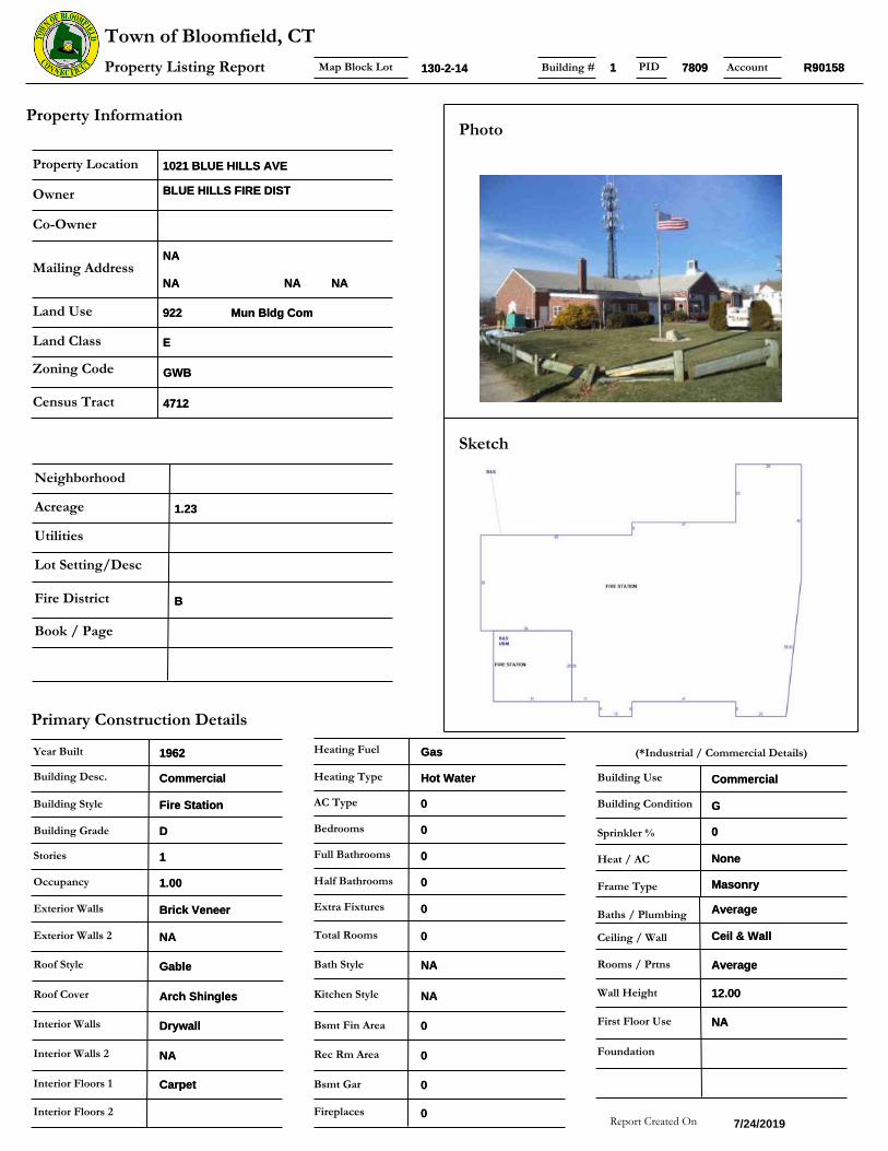
Kitchen Style
Land Use
Land Class
Mailing Address
Owner
Property Location
Zoning Code
Census Tract
Co-Owner
Neighborhood
Utilities
Acreage
Lot Setting/Desc
Photo
Building Style
Bedrooms
Half Bathrooms
Building Condition
Primary Construction Details
Property Information
Report Created On
Year Built
Roof Style
Roof Cover
Sketch
Exterior Walls
Interior Walls
Interior Floors 1
Heating Type
Heating Fuel
Map Block Lot
Building Use
Full Bathrooms
Bath Style
Stories
Property Listing Report
Town of Bloomfield, CT
Interior Floors 2
Extra Fixtures
Exterior Walls 2
Interior Walls 2
AC Type
Total Rooms
Occupancy
Building Grade
Building Desc.
Heat / AC
Frame Type
Baths / Plumbing
Ceiling / Wall
Rooms / Prtns
First Floor Use
Wall Height
(*Industrial / Commercial Details)
AccountBuilding # PID
Sprinkler %
Bsmt Fin Area
Rec Rm Area
Bsmt Gar
Fireplaces
Fire District
Book / Page
Foundation
Mun Bldg ComMun Bldg Com
EE
1021 BLUE HILLS AVE1021 BLUE HILLS AVE
GWBGWB
NANA
NANA NANA NANA
922922
47124712
BLUE HILLS FIRE DISTBLUE HILLS FIRE DIST
1.231.23
130-2-14130-2-14
Fire StationFire Station
00
00
11
NANA
7/24/2019
19621962
GableGable
Arch ShinglesArch Shingles
CarpetCarpet
Hot WaterHot Water
GasGas
CommercialCommercial
00
NANA
DrywallDrywall
Brick VeneerBrick Veneer
GG
00
NANA
NANA
00
00
1.001.00
DD
CommercialCommercial
NoneNone
MasonryMasonry
AverageAverage
Ceil & WallCeil & Wall
AverageAverage
12.0012.00
NANA
R90158R9015811 78097809
00
BB
00
00
00
00

Sales HistorySale Date Sale PriceBook/ Page
Valuation Summary
Land
Buildings
Outbuildings
Appraised Assessed
(Assessed value = 70% of Appraised Value)
Improvements
Extras
Total
Owner of Record
Report Created On
Item
Sub Areas
Subarea Type Gross Area (sq ft) Living Area (sq ft)
Total Area
Outbuilding and Extra Features
Type Description
Map Block LotProperty Listing Report
Town of Bloomfield, CTAccountBuilding # PID
0
396800 277760
459900 321930
22700 15890
0 0
879400 615580
7/24/2019
BLUE HILLS FIRE DIST
9244
0
First Floor
Basement
9244
868
0091/0376
Shed
Shed
Shed
Shed
288 S.F.
260 S.F.
200 S.F.
200 S.F.
92449244
130-2-14130-2-14
1011210112
R90158R9015811 78097809

Rockwe l l Avenue Blue Hi l l s Avenue CT R te 187
Beat r ice Avenue
Ledyard Avenue
Brookda le Avenue
Glenw ood Avenue
7686
5573
7809
1821
1454
7759
6223
1447
2564
6245
7562
2446
3876
4794
0
1355
6337
559
3215
7683
2011
77553266
6800
3262
5706
3272 1357
1356
5399
4616
2444
2744
7421
4965
6076
6884
4526
Disclaimer:This map is for informational purposes only.
All information is subject to verification by any user.The Town of Bloomfield and its mapping contractors
assume no legal responsibility for the information contained herein.
Approximate Scale: Map Produced July 20171 inch = 100 feetµ
MBL: Town of Bloomfield, Connecticut - Assessment Parcel Map
Address: 1021 BLUE HILLS AVE
Parcels labeled by Unique ID
130-2-14
P
Cut on dotted line.
Instructions
Click-N-Ship® Label Record
Electronic R
ate Approved #038555749
Thank you for shipping with the United States Postal Service!
Check the status of your shipment on the USPS Tracking® page at usps.com
SH
IPTO
:
1. Each Click-N-Ship® label is unique. Labels are to be used as printed and used only once. DO NOT PHOTO COPY OR ALTER LABEL.
2. Place your label so it does not wrap around the edge of
the package. 3. Adhere your label to the package. A self-adhesive label
is recommended. If tape or glue is used, DO NOT TAPE OVER BARCODE. Be sure all edges are secure.
4. To mail your package with PC Postage®, you may schedule a Package Pickup online, hand to your letter carrier, take to a Post Office™, or drop in a USPS collection box. 5. Mail your package on the "Ship Date" you selected when creating this label.
Priority Mail® Postage:
From:
To:
Print Date:Ship Date:
Click-N
-Ship®
Trans. #:
Expected Delivery Date:
usps.com
US PO
STAG
E
* Retail Pricing Priority Mail rates apply. There is no fee for USPS Tracking® service on Priority Mail service with use of this electronic rate shipping label. Refunds for unused postage paid labels can be requested online 30 days from the print date.
Carrier -- Leave if N
o Response
USPS TR
AC
KIN
G #
$7.35
CC
: MR
JOS
E G
INE
R, D
IR P
LAN
NIN
G &
Z
TOW
N O
F BLO
OM
FIELD
9405 5036 9930 0068 8344 86
MARK J ROBERTSQC DEVELOPMENTPO BOX 916STORRS CT 06268-0916
9405 5036 9930 0068 8344 86 0073 5000 0010 6002
PRIO
RITY M
AIL 1-D
AY™C
017
9405 5036 9930 0068 8344 86
Mailed from
06268
Total469042930
Expected D
elivery Date: 07/29/19
0024
MA
YO
R S
UZE
TTE D
EB
EA
THA
M B
RO
WN
BLO
OM
FIELD
CT 06002-2460
800 BLO
OM
FIELD
AV
E
062S0000000315
07/27/2019
USPS TRACKING # :
07/26/2019
MA
RK
J RO
BE
RTS
QC
DE
VE
LOP
ME
NT
PO
BO
X 916
STO
RR
S C
T 06268-0916
Flat Rate E
nv
07/27/2019
MAYOR SUZETTE DEBEATHAM BROWNTOWN OF BLOOMFIELD800 BLOOMFIELD AVECC: MR JOSE GINER, DIR PLANNING & ZBLOOMFIELD CT 06002-2460
$7.35$7.35
07/29/2019

P
Cut on dotted line.
Instructions Click-N-Ship® Label Record
Electronic R
ate Approved #038555749
Thank you for shipping with the United States Postal Service!
Check the status of your shipment on the USPS Tracking® page at usps.com
SH
IPTO
:
1. Each Click-N-Ship® label is unique. Labels are to beused as printed and used only once. DO NOT PHOTOCOPY OR ALTER LABEL.
2. Place your label so it does not wrap around the edge ofthe package.
3. Adhere your label to the package. A self-adhesive labelis recommended. If tape or glue is used, DO NOT TAPEOVER BARCODE. Be sure all edges are secure.
4. To mail your package with PC Postage®, youmay schedule a Package Pickup online, hand toyour letter carrier, take to a Post Office™, ordrop in a USPS collection box.
5. Mail your package on the "Ship Date" youselected when creating this label.
Priority Mail® Postage:
From:
To:
Print Date:Ship Date:
Click-N
-Ship®
Trans. #:
Expected Delivery Date:
usps.com
US PO
STAG
E
* Retail Pricing Priority Mail rates apply. There is no fee for USPS Tracking® service on Priority Mail service with use of this electronic rate shipping label. Refunds for unused postage paid labels can be requested online 30 days from the print date.
Carrier -- Leave if N
o Response
USPS TR
AC
KIN
G #
$7.35
1021 BLU
E H
ILLS A
VE
9405 5036 9930 0068 8344 93
MARK J ROBERTSQC DEVELOPMENTPO BOX 916STORRS CT 06268-0916
9405 5036 9930 0068 8344 93 0073 5000 0010 6002
PRIO
RITY M
AIL 1-D
AY™C
002
9405 5036 9930 0068 8344 93
Mailed from
06268
Total469042930
Expected D
elivery Date: 07/29/19
0024
BLO
OM
FIELD
CT 06002-3715
BLO
OM
FIELD
FIRE
DIS
TRIC
T
062S0000000312
07/27/2019
USPS TRACKING # :
07/26/2019
MA
RK
J RO
BE
RTS
QC
DE
VE
LOP
ME
NT
PO
BO
X 916
STO
RR
S C
T 06268-0916
Flat Rate E
nv
07/27/2019
BLOOMFIELD FIRE DISTRICT1021 BLUE HILLS AVEBLOOMFIELD CT 06002-3715
$7.35$7.35
07/29/2019