JULIE D. KOHLER - CT.gov
168
GOH~N WOLF ~P.C.~ ATTORNEYS AT LAW April 21, 2014 Attorney Melanie Bachman Acting Executive Director Connecticut Siting Council Ten Franklin Square New Britain, CT 06051 Re: Notice of Exempt Modification CL&P/T-Mobile co-location Site ID CT11426A 670 Chapel St., CL&P Pole 1321, Stratford, CT Dear Attorney Bachman: JULIE D. KOHLER PLEASE REPLY TO: BfIC~C~]ep01"t WRITER~s ~iREcr ~ia~: X203) 337-4157 E -Mail Address: [email protected] This office represents T -Mobile Northeast LLC ("T -Mobile") and has been retained to file exempt modification filings with the Connecticut Siting Council on its behalf. In this case, the Connecticut Light &Power Company ("CL&P") owns the existing electric transmission tower and related facility at 670 Chapel St., CL&P Pole 1321, Stratford Connecticut (latitude 41.23785 /longitude -73.12244). T -Mobile intends to replace three antennas and related equipment at this existing telecommunications facility in Stratford ("Stratford Facility"). Please accept this letter as notification, pursuant to R.C.S.A. § 16-50j-73, of construction which constitutes an exempt modification pursuant to R.C.S.A. § 16 -50j - 72(b)(2). In accordance with R.C.S.A. § 16-50j-73, a copy of this letter is being sent to the Mayor John A. Harkins and the property owner, CL&P. The existing Stratford Facility consists of a 101 foot tall transmission line lattice structure with a Powermount extending to a height of 124 feet. The facility currently supports the equipment of T -Mobile and AT&T. T -Mobile plans to replace three antennas and remove three TMAs (tower mounted amplifiers) at an elevation of 109 feet. (See the plans revised to March 10, 2014 attached hereto as Exhibit A). T -Mobile will also replace an equipment cabinet on the existing concrete pad and install new coax cable. The existing Facility is structurally capable of supporting T - Mobile' proposed modifications, as indicated in the structural analysis revised to February 25, 2014 and attached hereto as Exhibit B. (T -Mobile will implement the structural modifications set out in Section 4 of Exhibit B.) CL&P has reviewed and approved T -Mobile's proposed I I1S BROAD STREET ISS DEER HILL AVENUE 32O POST ROAD WEST 6S~ ORANGE CANTER ROAD P.O. BOX 1HZI DANBURY, CT O6H10 WESTPORT, CT O6HHO ORANGE, CT 06477 BRIDGEPORT, CI' 06601-1821 'ILL: (203) 792 2771 Ta[.: (203) 222-1034 'I~~: (203) 298-4066 Tet: (203) 368-0211 Fax: (203) 791-8149 Fax: (203) 227-1373 Fax: (203) 298-4068 Fnx: (203) 3949901
-
Upload
khangminh22 -
Category
Documents
-
view
5 -
download
0
Transcript of JULIE D. KOHLER - CT.gov

GOH~NWOLF~P.C.~ATTORNEYS AT LAW
April 21, 2014
Attorney Melanie BachmanActing Executive DirectorConnecticut Siting CouncilTen Franklin SquareNew Britain, CT 06051
Re: Notice of Exempt ModificationCL&P/T-Mobile co-locationSite ID CT11426A670 Chapel St., CL&P Pole 1321, Stratford, CT
Dear Attorney Bachman:
JULIE D. KOHLER
PLEASE REPLY TO: BfIC~C~]ep01"t
WRITER~s ~iREcr ~ia~: X203) 337-4157E-Mail Address: [email protected]
This office represents T-Mobile Northeast LLC ("T-Mobile") and has been retained tofile exempt modification filings with the Connecticut Siting Council on its behalf.
In this case, the Connecticut Light &Power Company ("CL&P") owns the existingelectric transmission tower and related facility at 670 Chapel St., CL&P Pole 1321, StratfordConnecticut (latitude 41.23785 /longitude -73.12244). T-Mobile intends to replace threeantennas and related equipment at this existing telecommunications facility in Stratford("Stratford Facility"). Please accept this letter as notification, pursuant to R.C.S.A. § 16-50j-73,of construction which constitutes an exempt modification pursuant to R.C.S.A. § 16-50j-72(b)(2). In accordance with R.C.S.A. § 16-50j-73, a copy of this letter is being sent to theMayor John A. Harkins and the property owner, CL&P.
The existing Stratford Facility consists of a 101 foot tall transmission line latticestructure with a Powermount extending to a height of 124 feet. The facility currently supportsthe equipment of T-Mobile and AT&T.
T-Mobile plans to replace three antennas and remove three TMAs (tower mountedamplifiers) at an elevation of 109 feet. (See the plans revised to March 10, 2014 attachedhereto as Exhibit A). T-Mobile will also replace an equipment cabinet on the existing concretepad and install new coax cable. The existing Facility is structurally capable of supporting T-Mobile' proposed modifications, as indicated in the structural analysis revised to February 25,2014 and attached hereto as Exhibit B. (T-Mobile will implement the structural modificationsset out in Section 4 of Exhibit B.) CL&P has reviewed and approved T-Mobile's proposed
I I1S BROAD STREET ISS DEER HILL AVENUE 32O POST ROAD WEST 6S~ ORANGE CANTER ROAD
P.O. BOX 1HZI DANBURY, CT O6H10 WESTPORT, CT O6HHO ORANGE, CT 06477BRIDGEPORT, CI' 06601-1821 'ILL: (203) 792 2771 Ta[.: (203) 222-1034 'I~~: (203) 298-4066Tet: (203) 368-0211 Fax: (203) 791-8149 Fax: (203) 227-1373 Fax: (203) 298-4068Fnx: (203) 3949901

COH,~~'NWOLF~P.C.~.arroxners ar iA~~
April 21, 2014Site ID CT11426APage 2
modifications, as evidenced by the letter dated March 18, 2014, attached hereto as Exhibit C.
The planned modifications to the Stratford Facility fall squarely within those activities explicitlyprovided for in R.C.S.A. § 16-50j-72(b)(2).
1 . The proposed modification will not increase the height of the tower. T-Mobile'sreplacement antennas will be installed at the 109 foot level. The enclosed tower drawingconfirms that the proposed antennas will merely be replacing antennas already at the 109 footelevation.
2 . The installation of the T-Mobile replacement equipment in the existingcompound, as reflected on the attached site plan, will not require an extension of the siteboundaries. T-Mobile's proposed equipment will be located entirely within the existingcompound and leased area as shown on Pages 1 and 2 of Exhibit A.
3 . The proposed modification to the Facility will not increase the noise levels at theexisting facility by six decibels or more.
4 . The operation of the replacement antennas will not increase the total radiofrequency (RF) power density, measured at the base of the tower, to a level at or above theapplicable standard. According to a Radio Frequency Emissions Analysis Report prepared byEBI dated March 12, 2014 T-Mobile's operations would add 0.803% of the FCC Standard.Therefore, the calculated "worst case" power density for the planned combined operation atthe site including all of the proposed antennas would be 23.123% of the FCC Standard ascalculated for a mixed frequency site as evidenced by the engineering exhibit attached heretoas Exhibit D.
For the foregoing reasons, T-Mobile respectfully submits that the proposed replacementantennas and equipment at the Stratford Facility constitutes an exempt modification underR.C.S.A. § 16-50j-72(b)(2).
Sincerely,
~~,J i D. Kohler, Esq.
~Jcc: Town of Stratford, Mayor John A. Harkins
Connecticut Light &Power CompanySheldon J. Freincle, Northeast Site Solutions


ALL EQUIPMENT LOCATIONS ARE APPROXIMATE AND ARESUBJECT TO APPROVAL BY LESSEE/LICENSEE'SSTRUCTURAL & RF ENGINEERS. LOCATIONS OF POWER &TELEPHONE FACILITIES ARE SUBJECT TO APPROVAL BYUTILITY COMPANIES.
SITE PLANSCALE: 1 °=80'-0"
CONFIGURATION
SUBMITTALS LEASE EXHIBIT NORTHEAST SITE SOLUTIONSLE REV A ( 10.28.13 SITE NUMBER: 54 MAIN STREET, UNIT 3LE REV 0 03.10.14 TLANTIS CT11426A STURBRIDGE, MA 01566
G ~ O ~ ~ (508) 434-5237SITE NAME:
STRATFORD/MP/JAMES FARM FOR
13x0 Centre Street T-MOBILE NORTHEAST, LLCSuite 212 SITE ADDRESS:
Newton, MA 02459 670 CHAPEL STRRET 35 GRIFFIN ROAD SOUTH
Offlce: 617-965-0789 STRATFORD, CT 06614 BLooMFIELD, CT osoo2OFFICE: (860) 692-7100
~ Fax: 617-213-5056 FAX: (860) 692-7159
DRAWN BY: EB ~ CHECKED 8Y: SM ~ PAGE 1 OF 3

~~
x x x x x x~
k
(E) 8' HIGH CHAINLWKFENCE~ k
(E) 101' HIGH CLBP `/TRANSMISSION TOWER #1321 7
(E) TOWER CONC. FOOTING ''~
k
1~.
(E) FWT POWERMOUNT WITHINTRANSMISSION TOWER
MODIFICATIONS REQUIRED. REFERTO STRUCTURAL ANALYSIS REPORT.
(P) (1) QUAD POLE APXI6DNN-16DWVS-E-A20UMTS ANTENNAS, TO REPLACE
(E)(1) DRR90-17-02DP GSM ANTENNAS(1/SECTOR, TOTAL OF 3)
(P) (6) 1-1/4" COAX CABLESTO RUN INSIDE ICEBRIDGE
(E) T-MOBILE ICEBRIDGE
(E) (6) 1-1/4" COAX CABLESTO REMAIN
(P) (1) ERICSSON RBS 6102 —CABINEf TO REPLACE(E) GSM S8000 CABINET
~+
(E) S' WIDE GATE -- ~ ~
(E) TELCO BOX ON H-FRAME -
(E) 100 AMP ELECTRICAL PANEL ON H-FRAME -
(E) EMPTY METER SOCKET -
(E) 12' WIDE GA
(E) 11'-0"x10'-0" T—MOBILECONC. PAD /LEASE AREA
(E)CINGULARSHELTER
x11 /
k\/ \ /7 C
(E)DRIVEWAY
x
CONFIGURATION
ALL EQUIPMENT LOCATIONS ARE APPROXIMATE AND ARESUBJECT TO APPROVAL BY LESSEE/LICENSEESSTRUCTURAL & RF ENGINEERS. LOCATIONS OF POWER & COMPOUND PLAN
LE-3TELEPHONE FACILITIES ARE SUBJECT TO APPROVAL BY SCALE: 1" = 10'-0°UTILITY COMPANIES.
SUBMITTALS LEASE EXHIBIT NORTHEAST SITE SOLUTIONSLE REV A ~ 10.28.13 SITE NUMBER: 54 MAIN STREET, UNIT 3LE REVD 03.10.14
TL/1NTIS CT11426A STURBRIDGE, MA 01566
GROUP (508) 434-5237
SITE NAME:
STRATFORD/MP/JAMES FARM FOR
1340 Centre Street T-MOBILE NORTHEAST, LLCSuite 212 SITE ADDRESS:
35 GRIFFIN ROAD SOUTHNewton, MA 02459 670 CHAPEL STRRET BLOOMFIELD, cT osooz
Office: 617-965-0789 STRATFORD, CT 06614 OFFICE: (860) 692-7100
Fax: 617-213-5056 FAX: (860) 692-7159
DRAWN BY: EB CHECKED BY: SM PAGE20F3
I x
11'-0'S. ~ ..Yr.~ ~~~~
I~ ~
~~ o
o
~ / ~
SECTOR q7~
x~-x x

___ /' /-.
(P) (1) QUAD POLE APXI6DNN-16DWV5ANTENNA
(E) (1) DRR90-17-02DP(1/SECTOR
~ RAD CENTER OF T—MOBILEELEV.=
(P) (6) 1-1/4~~ COAXCABLES TO RUN ON(E) WAVEGUIDE
(E) 101' HIGH CL&PTRANSMISSION TOWER #1;
(E) FWT POWERMOUNT 1TRANSMISSION TOWERMODIFICATIONS REQUIREITO STRUCTURAL ANALYS
(E) T-MOBILE ICEBRIDGE
(P) (1) ERICSSON RBSCABINET TO REPLACE(E) GSM 58000 CABINE
ALL EQUIPMENT LOCATIONS ARE APPROXIMATE ANDARE SUBJECT TO APPROVAL BY LESSEE/LICENSEESSTRUCTUR4L & RF ENGINEERS. LOCATIONS OFPOWER &TELEPHONE FACILITIES ARE SUBJECT TOAPPROVAL BY UTILITY COMPANIES.
CONFIGURATION
ELEVATION ,4 BSCALE: 1" = 16'-0"
SUBMITTALS LEASE EXHIBIT NORTHEAST SITE SOLUTIONSLE REV A 10.28.13 SITE NUMBER: 54 MAIN STREET, UNIT 3LE REV 0 ' 03.10.14 TLANTIS CT11426A- STURBRIDGE, MA 01566
G R ~ U P SITE NAME:
(508) 434-5237
STRATFORD/MP/JAMES FARM FOR
__ 1340 Centre Street T-MOBILE NORTHEAST, LLCSURE Z1 Z SITE ADDRESS:
Newton, MA 02459 670 CHAPEL STRRET 35 GRIFFIN ROAD SOUTH
Office: 617-965-0789 STRATFORD, CT 06614 B~ooMFIELD, CT osao2OFFICE: (860) 692-7100
Fax: 617-213-5056 FAX: (860) 692-7159
DRAWN BY: EB CHECKED BY: SM PAGE 30F 3


~.NT =1~~ngine~ring
Centered on Solutions"'
S t r u c t u r a l Ana / v s i s o fP o w e r m o u n t and C L& P T o w e r
T-Mobile Site Ref: CT11426A
CL&P Structure No. 7321
101' Electric Transmission Lattice Tower
670 Chapel StreetStratford, C T
CENTEK Project No. 73317.000
G ~+ ~ .~+ N n ~ i o m h o r 7 7 7 (1 7 `~
T~TT~i ~T~ I n n I I n r 1/
/~Tri~Tr'r
Rev 2: February 25, 2014
~ ~~~~~~~i ~r
,̀`4w~/~ C+ V ~ , ~/
~4 9 Ci
Prepared for:
~~ EN`~~ ~~ T-Mobile Towers
~` 4 Sylvan Way~~ '~~~ Parsippany, NJ 07054`, ~G(~l1~1- r
63-2 hJorth Branford Road, Branford, CT Ob405 2Q3.488.~580 Fax 203.4Ei8.8587 www.CentekEng.com

CENTEK ~n~/ineerin~, Inr.•.Structural Analysis — 101-ft CL&P Tower # 1321T-Mobile Antenna Upgrade — CT11426AStratford, CTRev 2 -- February 25, 2014
Table of Contents
SECTION 1 - REPORT
■ INTRODUCTION
■ PRIMARY ASSUMPTIONS USED IN THE ANALYSIS
■ ANALYSIS
■ DESIGN BASIS
■ RESULTS
■ CONCLUSION.
SECTION 2 - CONDITIONS &SOFTWARE
■ STANDARD ENGINEERING CONDITIONS
■ GENERAL DESCRIPTION OF STRUCTURAL ANALYSIS PROGRAMS
■ RISA 3-D
■ PLS TOWER
SECTION 3 - DESIGN CRITERIA
■ CRITERIA FOR DESIGN OF PCS FACILITIES ON OR EXTENDING ABOVEMETAL ELECTRIC TRANSMISSON TOWERS
■ NU DESIGN CRITERIA TABLE
• PCS SHAPE FACTOR CRITERIA
■ WIRE LOADS SHEET
SECTION 4 - DRAWINGS
■ T-1 TITLE SHEET
■ N-1 DESIGN BASIS AND GENERAL NOTES
■ N-2 STRUCTURAL STEEL NOTES
• MI-1 MODIFICATION INSPECTION REQUIREMENTS
■ S-1 TOWER ELEVATION AND FEEDLINE PLAN
■ S-2 POWERMOUNT CONNECTION DETAILS
SECTION 5 - EIA/TIA-222-F LOAD CALCULATIONS FORPOWERMOUNT ANALYSIS
■ POWERMOUNT WIND &ICE LOAD
TABLE OF CONTENTS TOC-1

CENTEK +~ngineerin~, Inc.Structural Analysis — 101-ft CL&P Tower # 7321T-Mobile Antenna Upgrade — CT11426AStratford, CTRev 2 ~ February 25, 2014
SECTION 6 - POWERMOUNT ANALYSIS PER EIA/TIA-222F
■ LOAD CASES AND COMBINATIONS (TIA/EIA LOADING)
■ RISA 3-D ANALYSIS REPORT
• POWERMOUNT CONNECTION TO CL&P TOWER
SECTION 7 - NECS/NU LOAD CALCULATIONS FOR UTILITYSTRUCTURE ANALYSIS
o EQUIPMENT WIND LOAD CALCULATION
■ COAX CABLE LOAD ON POWERMOUNT
■ COAX CABLE LOAD ON TOWER
SECTION 8 - PLS TOWER RESULTS
■ PLS REPORT
■ ANCHOR BOLT ANALYSIS
■ FOUNDATION ANALYSIS.
SECTION 9 - REFERENCE MATERIAL
■ RFDS SHEET
■ EQUIPMENT CUT SHEETS
TABLE OF CONTENTS TOC-2

CENTEK F_ngineerin~; Inc.Structural Analysis — 101-ft CL&P Tower # 1321T-Mobile Antenna Upgrade — CT11426AStratford, CTRev 2 ~ February 25, 2014
Introduction
The purpose of this report is to analyze the existing powermount and 101' CL&P tower located at 670Chapel Street in Stratford, CT for the proposed antenna and equipment upgrade by T-Mobile.
The existing and proposed loads consist of the following:
AT&T (Existing to Remain):Antennas: Six (6) Powerwave 7770 panel antennas, three (3) Powerwave P65-16-XHL-RRpanel antennas, twelve (12) Powerwave LGP214 TMA's and three (3) CCIDTMABP7819VG12A TMA's mounted on a low profile platform with a RAD center elevationof 124-ft above grade.Coax Cables: Eighteen (18) 1-1/4" ~ coax cables running on the inside of the existing FWTPowermount.
■ T-MOBILE (Existing to be Removed):Antennas: Two (2) RR90-17-02DP panel antennas and two (2) TMA's mounted on a PCSmast with a RAD center elevation of 109-ft above grade. One (1) RR90-17-02DP panelantenna and one (1) TMA's flush mounted to the FWT Powermount with a RAD centerelevation of 109-ft above grade.Mast: 4-in SCH. 40 pipe (O. D. = 4.5") and related hardware.
■ T-MOBILE (Existing to remain):Coax Cables: Six (6) 1-1/4" ~ coax cables running on the outside of the tower as indicated insection 4 of this report.
■ T-MOBILE (Proposed):Antennas: Three (3) RFS APX16DWV-16DWVS-E-A20 panel antennas mounted theexisting FWT Powermount with a RAD center elevation of 109-ft above grade.
Coax Cables: Six (6) 1-114" ~ coax cables running on the outside of the tower asindicated in section 4 of this report
Primary assumptions used in the analysis
■ Allowable steel stresses are defined by AISC-ASD 9 h̀ edition for design of the Powermountand antenna supporting elements.
■ ASCE Manual No. 10-97, "Design of Latticed Steel Transmission Structures", definesallowable steel stresses for evaluation of the CL&P utility tower.
■ All utility tower members are adequately protected to prevent corrosion of steel members.■ All proposed antenna mounts are modeled as listed above.■ All coaxial cable will be installed within the powermount unless specified otherwise.■ Powermount will be properly installed and maintained.■ No residual stresses exist due to incorrect tower erection.■ All bolts are appropriately tightened providing the necessary connection continuity.■ All welds conform to the requirements of AWS D1.1.■ Powermount and utility tower will be in plumb condition.• Utility tower was properly installed and maintained and all members were properly designed,
detailed, fabricated, and installed and have been properly maintained since erection.■ Any deviation from the analyzed loading will require a new analysis for verification of
structural adequacy.
REPORT SECTION 1-1

CENTEKFngineering Inc.Structural Analysis - 101-ft CL&P Tower # 1321T-Mobile Antenna Upgrade - CT11426AStratford, CTRev 2 -February 25, 2014
Ana 1 y s i s
Structural analysis of the existing powermount was independently completed using the current version of
RISA-3D computer program licensed to CENTEK Engineering, Inc. The RISA-3D program contains a
library of all AISC shapes and corresponding section properties are computed and applied directly within
the program. The program's Steel Code Check option was also utilized.
The existing FWT powermount consisting of a HSS18"x0.375" pipe conforming to ASTM A500 Grade B
(Fy = 42ksi) connected at six points to the existing tower was analyzed for its ability to resist loads
prescribed by the TIA/EIA standard. Section 5 of this report details these gravity and lateral wind loads.
Load cases and combinations used in RISA-3D for TIA/EIA loading are listed in report Section 6.
Structural analysis of the existing CL&P tower structure was completed using the current version of PLS-
Tower computer program licensed to CENTEK Engineering, Inc. The NESC program contains a library of
all AISC angle shapes and corresponding section properties are computed and applied directly within the
program. The program's Steel Code Check option was also utilized.
The existing 101-ft tall CL&P lattice tower was analyzed for its ability to resist loads prescribed by the
NESC standard. Maximum usage for the tower was calculated considering the additional forces from the
powermount and associated appurtenances. Section 7 of this report details these gravity and lateral wind
loads.
Design Basis
Our analysis was performed in accordance with EIA-222-F-1996, ASCE Manual No. 10-97, "Design of
Latticed Steel Transmission Structures", NESC C2-2007 and Northeast Utilities Design Criteria.
The CL&P tower structure, considering existing and future conductor and shield wire loading, with the
existing powermount was analyzed under two conditions:
■ UTILITY TOWER ANALYSIS
The purpose of this analysis is to determine the adequacy of the existing utility structure to
support the proposed antenna loads. The loading and design requirements were analyzed in
accordance with the NU Design Criteria Table, NESC C2-2007 ~ Construction Grade B, and
ASCE Manual No. 10-97, "Design of Latticed Steel Transmission Structures".
Load cases considered:
Load Case 1: NESC HeavyWind Pressure ..................................... 4.0 psfRadial Ice Thickness ............................. 0.5"Vertical Overload Capacity Factor ............. 1.50Wind Overload Capacity Factor ................ 2.50Wire Tension Overload Capacity Factor...... 1.65
Load Case 2: NESC ExtremeWind Speed ........ ............................... 110 mph ~'~Radial Ice Thickness ............................. 0"
Note 1: NESC C2-2007, Section25, Rule 250C: Extreme WindLoading, 1.25 x Gust Response Factor (wind speed: 3-second gust)
REPORT SECTION 1-2

Structural Analysis — 101-ft CL&P Tower # 1321
T-Mobile Antenna Upgrade — CT11426A
Stratford, CTRev 2 ~ February 25, 2074
■ POWERMOUNT ANALYSIS
The powermount, appurtenances and connections to the utility tower were analyzed anddesigned in accordance with the NU Design Criteria Table, TIA/EIA-222-F, and AISC-ASDstandards.
Load cases considered:
Load Case 1:Wind Speed ....................................... 85 mph ~Z~Radial Ice Thickness ............................. 0"
Load Case 2:Wind Pressure .................................... 75% of 85 mph wind pressureRadial Ice Thickness .............................. 0.5"
Note 2: Per NU Mast Design Criteria Exception 1.
Results
■ POWERMOUNT
With the proposed reinforcements detailed in Section 4 of this report the existingpowermount was determined to be structurally adequate.
Component Design Stress Ratio
ResultLimit (percentage of capacity)
HSS 18" x 0.375" Pipe Bending 69.3% PASSL2.5x2.5x3/16 Brace Bending 80.8% PASS
Connection Shear 87.4% PASS
■ UTILITY TOWER
This analysis finds that the subject utility structure is adequate to support the proposedantenna mast and related appurtenances. The tower stresses meet the requirements setforth by the ASCE Manual No. 10-97, "Design of Latticed Steel Transmission Structures", forthe applied NESC Heavy and Hi-Wind load cases. The detailed analysis results are providedin Section 8 of this report. The analysis results are summarized as follows:
A maximum usage of 94.01%occurs in the utility tower under the NESC Eutreme loadingcondition.
TOWER SECTION:
The utility structure was found to be within allowable limits.
Tower Member Stress Ratio
Result(% of capacity)
Angle g37X 94.01 °/a PASS
■ FOUNDATION AND ANCHORS
The existing foundation consists of four (4) 2-ft square tapering to 5-ft square x 5-ft-8" longreinforced concrete piers and four (4) 8-ft square x 2-ft thick reinforced concrete pads with a 33-ft-6in square x 3-ft-6-in thick concrete mat flush with the top of the piers. The base of the tower isconnected to the foundation by four (4) 1-1/4" ~ ASTM A36 anchor bolts per leg. Foundationinformation was obtained from NUSCO drawing # 01021-60001 and construction drawingsprepared by Centek engineering project no. 10021.0O3 dated 10/6/2010 marked rev 2.
REPORT SECTION 1-3

CENTEK Ens ~inef, my rrrr:Structural Analysis — 101-ff CL&P Tower # 1327T-Mobile Antenna Upgrade — CT91426AStratford, CTRev 2 -- February 25, 2094
BASE REACTIONS:
From PLS-Tower analysis of CL&P tower based on NESC/NU prescribed loads.
Load Case Shear Uplift Compression
NESC Heav Wind 10.22 ki s 31.31 ki s 53.05 ki sNESC Extreme Wind 21.27 kips 76.44 kips 93.15 kips
Note 1 —10% increase to be applied to the above tower base reactions for foundation verification per OTRM 051
ANCHOR BOLTS.
The anchor bolts were found to be within allowable limits.
Tower Component Design Limit Stress Ratio
Result(percentage of capacity)
Anchor Bolts Tension 87.2% PASS
FOUNDATION:
The foundation was found to be within allowable limits.
Foundation Design Required Proposed ResultLimit FS ~'~ Loading FS ~2~
Reinf. Conc. U lift 1.0 2.06 PASS
Pad & Pier w/ Bearing 4 ksf 1.09 ksf PASS
Mat Pressure
Note 1: F5 denotes Factor of SafetyNote 2: 10% increase fo PLS base reactions used in foundation analysis per OTRM 051.
COI~ClUS10I7
This analysis shows that the subject utility tower with the proposed reinforcements outlined belowand detailed in Section 4 of this report is adeauate to support the proposed T-Mobile equipmentinstallaiton.
• Replacement of the existing powermount connection brackets at 101-ft and 96-ft AGL.
The analysis is based, in part on the information provided to this office by Northeast Utilities and T-Mobile, ff the existing conditions are different than the information in this report, CENTEK engineering,Inc. must be contacted for resolution of any potential issues.
Please feel free to call with any questions or comments.
Respectfully Submitted by:
Principal ~ Structural Engineer
,~~~~~~~u~~r
o ~ -,
r°~ Q ~~ ~~' 9~ ~tJJ U
~x'':a~ f~'
` ~ (~~=~~, Q~ ~Lf
Prepared by:
Timothy J. Lynn, PEStructural Engineer
REPORT SECTION 1-4

CENTEK Fn~rneerin~. Inc.Structural Analysis — 101-ft CL&P Tower # 1321T-Mobile Antenna Upgrade — CT11426AStratford, CTRev 2 ~ February 25, 2014
STANDARD CONDITIONS FOR FURNISHING OF
PROFESSIONAL ENGINEERING SERVICES ON
EXISTING STRUCTURES
All engineering services are performed on the basis that the information used is current and correct. This
information may consist of, but is not necessarily limited to:
■ Information supplied by the client regarding the structure itself, its foundations, the soil conditions, the
antenna and feed line loading on the structure and its components, or other relevant information.
■ Information from the field and/or drawings in the possession of CENTEK engineering, Inc. or
generated by field inspections or measurements of the structure.
■ It is the responsibility of the client to ensure that the information provided to CENTEK engineering,
Inc. and used in the performance of our engineering services is correct and complete. In the absence
of information to the contrary, we assume that all structures were constructed in accordance with the
drawings and specifications and are in an un-corroded condition and have not deteriorated. It is
therefore assumed that its capacity has not significantly changed from the "as new" condition.
■ All services will be performed to the codes specified by the client, and we do not imply to meet any
other codes or requirements unless explicitly agreed in writing. If wind and ice loads or other relevant
parameters are to be different from the minimum values recommended by the codes, the client shall
specify the exact requirement. In the absence of information to the contrary, all work will be
performed in accordance with the latest revision of ANSI/ASCE10 &ANSI/EIA-222.
■ All services are performed, results obtained, and recommendations made in accordance with
generally accepted engineering principles and practices. CENTEK engineering, Inc. is not
responsible for the conclusions, opinions and recommendations made by others based on the
information we supply.
CONDITIONS &SOFTWARE SECTION 2-1

CENTEK 1=ngineerinc~ Inc.Structural Analysis - 101-ft CL&P Tower # 1327T-Mobile Antenna Upgrade - CT11426AStratford, CTRev 2 -February 25, 2014
GENERAL DESCRIPTION OF STRUCTURALANALYSIS PROGRAM~RISA-3D
RISA-3D Structural Analysis Program is an integrated structural analysis and design software package forbuildings, bridges, tower structures, etc.
Modeling Features:
■ Comprehensive CAD-like graphic drawing/editing capabilities that let you draw, modify andload elements as well as snap, move, rotate, copy, mirror, scale, split, merge, mesh, delete,apply, etc.
■ Versatile drawing grids (orthogonal, radial, skewed)■ Universal snaps and object snaps allow drawing without grids■ Versatile general truss generator■ Powerful graphic selecUunselect tools including box, line, polygon, invert, criteria,
spreadsheet selection, with locking■ Saved selections to quickly recall desired selections■ Modification tools that modify single items or entire selections■ Real spreadsheets with cut, paste, fill, math, sort, find, etc.■ Dynamic synchronization between spreadsheets and views so you can edit or view any data
in the plotted views or in the spreadsheets■ Simultaneous view of multiple spreadsheets■ Constant in-stream error checking and data validation■ Unlimited undo/redo capability■ Generation templates for grids, disks, cylinders, cones, arcs, trusses, tanks, hydrostatic
loads, etc.■ Support for all units systems &conversions at any time■ Automatic interaction with RISASection libraries■ Import DXF, RISA-2D, STAAD and ProSteel 3D files■ Export DXF, SDNF and ProSteel 3D files
Analysis Features:
■ Static analysis and P-Delta effects■ Multiple simultaneous dynamic and response spectra analysis using Gupta, CQC or SRSS
mode combinations■ Automatic inclusion of mass offset (5% or user defined) for dynamic analysis■ Physical member modeling that does not require members to be broken up at intermediate
joints■ State of the art 3 or 4 node plate/shell elements■ High-end automatic mesh generation — draw a polygon with any number of sides to create a
mesh of well-formed quadrilateral (NOT triangular) elements.■ Accurate analysis of tapered wide flanges -web, top and bottom flanges may all taper
independently■ Automatic rigid diaphragm modeling■ Area loads with one-way or two-way distributions■ Multiple simultaneous moving loads with standard AASHTO loads and custom moving loads
for bridges, cranes, etc.■ Torsional warping calculations for stiffness, stress and design■ Automatic Top of Member offset modeling■ Member end releases &rigid end offsets■ Joint master-slave assignments■ Joints detachable from diaphragms■ Enforced joint displacements■ 1-Way members, for tension only bracing, slipping, etc.
CONDITIONS &SOFTWARE SECTION 2-2

CENTEK ;= i,~.7i~ ~e,~;~rn~7; Ir~c.Structural Analysis — 101-ft CL&P Tower # 1321T-Mobile Antenna Upgrade — CT11426AStratford, CTRev 2 ~ February 25, 2014
■ 1-Way springs, for modeling soils and other effects■ Euler members that take compression up to their buckling load, then turn off.■ Stress calculations on any arbitrary shape■ Inactive members, plates, and diaphragms allows you to quickly remove parts of structures
from consideration■ Story drift calculations provide relative drift and ratio to height■ Automatic self-weight calculations for members and plates■ Automatic subgrade soil spring generator
Graphics Features:
■ Unlimited simultaneous model view windows■ Extraordinary "true to scale" rendering, even when drawing■ High-speed redraw algorithm for instant refreshing■ Dynamic scrolling stops right where you want■ Plot &print virtually everything with color coding &labeling■ Rotate, zoom, pan, scroll and snap views■ Saved views to quickly restore frequent or desired views■ Full render or wire-frame animations of deflected model and dynamic mode shapes with
frame and speed control■ Animation of moving loads with speed control■ High quality customizable graphics printing
Design Features:
■ Designs concrete, hot rolled steel, cold formed steel and wood■ AC! 1999/2002, BS 8110-97, CSA A23.3-94, IS456:2000,EC 2-1992 with consistent bar sizes
through adjacent spans■ Exact integration of concrete stress distributions using parabolic or rectangular stress blocks■ Concrete beam detailing (Rectangular, T and L)■ Concrete column interaction diagrams■ Steel Design Codes: AISC ASD 9th, LRFD 2nd & 3rd, HSS Specification, CAN/CSA-S16.1-
1994 & 2004, BS 5950-1-2000, IS 800-1984, Euro 3-1993 including local shape databases■ AISI 1999 cold formed steel design■ NDS 1991/1997/2001 wood design, including Structural Composite Lumber, multi-ply, full
sawn■ Automatic spectra generation for UBC 1997, IBC 2000/2003■ Generation of load combinations: ASCE, UBC, IBC, BOCA, SBC, ACI■ Unbraced lengths for physical members that recognize connecting elements and full lengths
of members■ Automatic approximation of K factors■ Tapered wide flange design with either ASD or LRFD codes■ Optimization of member sizes for all materials and all design codes, controlled by standard or
user-defined lists of available sizes and criteria such as maximum depths■ Automatic calculation of custom shape properties■ Steel Shapes: AISC, HSS, CAN, ARBED, British, Euro, Indian, Chilean■ Light Gage Shapes: AISI, SSMA, Dale / Incor, Dietrich, Marino\WARE■ Wood Shapes: Complete NDS species/grade database■ Full seamless integration with RISAFoot (Ver 2 or better) for advanced footing design and
detailing■ Plate force summation tool
CONDITIONS &SOFTWARE SECTION 2-3

CENTEK ~ ~;_;~ ~ ,~~i~_~„ ,;,~_.Structural Analysis — 101-ft CL&P Tower # 1321T-Mobile Antenna Upgrade — CT11426AStratford, CTRev 2 ~ February 25, 2014
Results Features:
■ Graphic presentation of color-coded results and plotted designs■ Color contours of plate stresses and forces with quadratic smoothing, the contours may also
be animated■ Spreadsheet results with sorting and filtering of: reactions, member &joint deflections, beam
& plate forces/stresses, optimized sizes, code designs, concrete reinforcing, materialtakeoffs, frequencies and mode shapes
■ Standard and user-defined reports■ Graphic member detail reports with force/stress/deflection diagrams and detailed design
calculations and expanded diagrams that display magnitudes at any dialed location■ Saved solutions quickly restore analysis and design results.
CONDITIONS &SOFTWARE SECTION 2-4

CENTEK l=ngineerin~. lnc.Structural Analysis — 101-ft CL&P Tower # 1321T-Mobile Antenna Upgrade — CT11426AStratford, CTRev 2 ~ February 25, 2014
GENERAL DESCRIPTION OF STRUCTURALANALYSIS PROGRAM~PLS-TOWER
PLS-TOWER is a Microsoft Windows program for the analysis and design of steel latticed towers
used in electric power lines or communication facilities. Both self-supporting and guyed towerscan be modeled. The program performs design checks of structures under user specified loads.
For electric power structures it can also calculate maximum allowable wind and weight spans andinteraction diagrams between different ratios of allowable wind and weight spans.
Modeling Features:
■ Powerful graphics module (stress usages shown in different colors)■ Graphical selection of joints and members allows graphical editing and checking■ Towers can be shown as lines, wire frames or can be rendered as 3-d polygon surfaces
■ Can extract geometry and connectivity information from a DXF CAD drawing■ CAD design drawings, title blocks, drawing borders or photos can be tied to structure model
■ XML based post processor interface■ Steel Detailing Neutral File (SDNF) export to link with detailing packages■ Can link directly to line design program PLS-CADD■ Automatic generation of structure files for PLS-CADD■ Databases of steel angles, rounds, bolts, guys, etc.■ Automatic generation of joints and members by symmetries and interpolations■ Automated mast generation (quickly builds model for towers that have regular repeating
sections) via graphical copy/paste■ Steel angles and rounds modeled either as truss, beam or tension-only elements■ Guys are easily handled (can be modeled as exact cable elements)
Analysis Features:
■ Automatic handling of tension-only members■ Automatic distribution of loads in 2-part suspension insulators (v-strings, horizontal vees, etc.)■ Automatic calculation of tower dead, ice, and wind loads as well as drag coefficients
according to:■ ASCE 74-1991■ NESC 2002■ NESC 2007■ I EC 60826:2003■ EN50341-1:2001 (CENELEC)■ EN50341-3-9:2001 (UK NNA)■ EN50341-3-17:2001 (Portugal NNA)■ ESAA C(b)1-2003 (Australia)■ TPNZ (New Zealand)■ REE (Spain)■ EIA/TIA 222-F■ ANSI/TIA 222-G■ CSA S37-01
■ Automated microwave antenna loading as per EIA/TIA 222-F and ANSI/TIA 222-G■ Minimization of problems caused by unstable joints and mechanisms■ Automatic bandwidth minimization and ability to solve large problems■ Design checks according to (other standards can be added easily):
■ ASCE Standard 10-90
CONDITIONS &SOFTWARE SECTION 2-5

CENTEK~~r~c~inPeting; Inc,.Structural Analysis - 701-ft CL&P Tower # 7327T-Mobile Antenna Upgrade - CT11426AStratford, CTRev 2 -February 25, 2014
■ AS 3995 (Australian Standard 3995)■ BS 8100 (British Standard 8100)■ EN50341-1 (CENELEC, both empirical and analytical methods are available)
■ ECCS 1985■ NGT-EGGS■ PN-90/B-03200■ EIA/TIA 222-F■ ANSI/TIA 222-G■ CSA S37-01■ EDF/RTE Resal■ IS 802 (India Standard 802)
Resu Its Features:
■ Design summaries printed for each group of members
■ Easy to interpret text, spreadsheet and graphics design summaries
■ Automatic determination of allowable wind and weight spans
■ Automatic determination of interaction diagrams between allowable wind and weight spans
■ Capability to batch run multiple tower configurations and consolidate the results
■ Automated optimum angle member size selection and bolt quantity determination
Tool for interactive angle member sizing and bolt quantity determination.
CONDITIONS &SOFTWARE SECTION 2-6

CENTEK %=nclinaerin~. IncStructural Analysis — 101-ft CL&P Tower # 1321T-Mobile Antenna Upgrade — CT11426AStratford, CTRev 2 ~ February 25, 2014
Criteria for Design of PCS Facilities On orExtending Above Metal Electric TransmissionTowers & Analysis of Transmission TowersSupporting PCS Masts ~'~
Introduction
This criteria is the result from an evaluation of the methods and loadings specified by the separatestandards, which are used in designing telecommunications towers and electric transmission towers. Thatevaluation is detailed elsewhere, but in summary; the methods and loadings are significantly different.This criteria specifies the manner in which the appropriate standard is used to design PCS facilities
including masts and brackets (hereafter referred to as "masts"), and to evaluate the electric transmissiontowers to support PCS masts. The intent is to achieve an equivalent level of safety and security under theextreme design conditions expected in Connecticut and Massachusetts.
ANSI Standard TIA/EIA-222 covering the design of telecommunications structures specifies a working
strength/allowable stress design approach. This approach applies the loads from extreme weatherloading conditions, and designs the structure so that it does not exceed some defined percentage of
failure strength (allowable stress).
ANSI Standard C2-2007 (National Electrical Safety Code) covering the design of electric transmissionmetal structures is based upon an ultimate strength/yield stress design approach. This approach appliesa multiplier (overload capacity factor) to the loads possible from extreme weather loading conditions, anddesigns the structure so that it does not exceed its ultimate strength (yield stress).
Each standard defines the details of how loads are to be calculated differently. Most of the NU effort in"unifying" both codes was to establish what level of strength each approach would provide, and thenincreasing the appropriate elements of each to achieve a similar level of security under extreme weatherloadings.
Two extreme weather conditions are considered. The first is an extreme wind condition (hurricane) basedupon a 50-year recurrence (2% annual probability). The second is a winter condition combining wind andice loadings.
The following sections describe the design criteria for any PCS mast extending above the top of anelectric transmission tower, and the analysis criteria for evaluating the loads on the transmission towerfrom such a mast from the lower portions of such a mast, and loads on the pre-existing electric lowerportions of such a mast, and loads on the pre-existing electric transmission tower and the conductors itsupports.
Note 1: Prepared from documentation provide from Northeast Utilities.
DESIGN CRITERIA SECTION 3-1

CENTEK~' ~~<<~-~iri~~~~~,~~~~~;Structural Analysis — 101-ft CL&P Tower # 1321T-Mobile Antenna Upgrade — CT11426AStratford, CTRev 2 ~ February 25, 2014
PCS Mast
The PCS facility (mast, external cable/trays, including the initial and any planned future support platforms,antennas, etc. extending the full height above the top level of the electric transmission structure) shall bedesigned in accordance with the provisions of TIA/EIA Standard 222 with two exceptions:
1. An 85 mph extreme wind speed shall be used for locations in all counties throughout the NUsystem.
2. The stress increase of TIA Section 3.1.1.1 is disallowed. The combined wind and icecondition shall consider'/" radial ice in combination with the wind load (0.75 Wi) as specifiedin TIA section 2.3.16.
ELECTRIC TRANSMISSION TOWER
The electric transmission tower shall be analyzed using yield stress theory in accordance with theattached table titled "NU Design Criteria". This specifies uniform loadings (different from the TIA loadings)on the each of the following components of the installed facility:
■ PCS mast for its total height above ground level, including the initial and planned futuresupport platforms, antennas, etc. above the top of an electric transmission structure.
■ Conductors are related devices and hardware.
■ Electric transmission structure. The loads from the PCS facility and from the electricconductors shall be applied to the structure at conductor and PCS mast attachmentpoints, where those load transfer to the tower.
The uniform loadings and factors specified for the above components in the table are based upon theNational Electrical Safety Code 2007 Edition Extreme Wind (Rule 250C) and Combined Ice and Wind(Rule 2506-Heavy) Loadings. These provide equivalent loadings compared to TIA and its loads andfactors with the exceptions noted above. (Note that the NESC does not require the projected windsurfaces of structures and equipment to be increased by the ice covering.)
In the event that the electric transmission tower is not sufficient to support the additional loadings of thePCS mast, reinforcement will be necessary to upgrade the strength of the overstressed members.
DESIGN CRITERIA SECTION 3-2

~_ I~Qrlli~asl/1~~4~M ~flil~l~~,
err
Northeast UtilitiesOverhead Transmission Standards ~ OIiIIYSfIK
pom
Attachment A
NU Design Criteria
s
~-~" N ~~ O ~j
C N ~ V)~j ~ ~ ~ UN
U N p~ y -pcp
N ~ ~ 7 O O(0Cp d 2 J LL
V (MPH) Q (PSF) Kz GhQ e on
TIA 3.1.1.1
W Arrtenna Mount TIA ~~~~~) TIA TIA disallowed for TIA
a connection~ ~ desi nO
.+_'' Tower/Pole Analysis with~ ~ antennas extending above top ---- 4 1.00 1.00 2.50
1 3 Round SurtacesO ~ ofTowedPoleV = (Yield Stress)
~ Taver/Pole Analysis with~ U(~ Antennas below by of ___ 4 1.00 1.00 2.50
1.6 Flat Surfaces
W Tower/Pole 1.3 Round Surtaces
Z (on fwofaces)
ConducA~rs: Conductor loads provided by N U
Q TIA, Section3.1.1.1
~ W Arrtenna Mount 85 TIA TIA TIA disallowed for TIA~ a connection'~G H desi nC
~ G~ Tower/Pole Analysis wim Use NESC C2-2007, Section 25, Ru1e250C: Extreme Wind LoadingU 1.6 Flat Surfaces
~ antennas extending above top 1.25 x Gust Response Factor'a ~ 1.3 Round Surtaces_ ~ ~ of Tower/Pole Height above ground level based on top of MasUAntenna
~ ~ Tower/PoleAnalysis with 1.6 Flat Surfaces~ V ~ An~nnas below top of Use NESC C2-2007, Section 25, Rule 2500: Extreme Wind Loading
~ Tower/Pole Height above ground level based on top of TavedPde 1.3 Round SurfacesWZ
Conductors: Conductor loads provided by N U
d Tower/PoleAnalysis with Use NESC C2-2007, Section 25, Rule 250D: Extreme Ice with Wind Loading
£ _ ,~ antennas extending above top 4PSF Wind Load 1.25 x Gust Response Factor 1.6 Flat Surfaces
1.3 Round Surfaces
O ofTowedPole Heightabove ground level based on top of MasVAntenna
x t
y C Ta~ver/Pole Analysis with Use NESC C2-2007, Section 25, Rule 250D: Extreme Ice with Wind Loading
V 3 p An~nnas below top cf 4PSF Wind Load 1.6 Flat Surfaces
N 1.3 Round SurfacesW ~ U Tower/Pole Heigh above ground level based on top ofTvaedPde
Z —Conductors: Conductor loads provided by N U
Only for Structures Installed after 2007
Communication Antennas on Transmission Structures (CL&P & WMECo Only)
Northeast Utilities Design OTRM 059 Rev.1Approved by: KMS (NU) NU Confidential Information page 7 of 9 03/17/2011

"~ Northeast Utilities _l~'orih~aa~1
~~~~~~ ~:~~,tie Overhead Transmission Standards —~,~ w
Shape Factor Criteria shall be per TIA Shape Factors.
2) STEP 2 -The electric transmission structure analysis and evaluation shall be performed inaccordance with NESC requirements and shall include the mast and antenna loadsdetermined from NESC applied loading conditions (not TIA/EIA Loads) on the structure andmount as specified below, and shall include the wireless communication mast and antennaloads per NESC criteria)
The structure shall be analyzed using yield stress theory in accordance with Attachment A,"NU Design Criteria." This specifies uniform loadings (different from the TIA loadings) oneach of the following components of the installed facility:
a) Wireless communication mast for its total height above ground level, including the initialand any planned future equipment (Support Platforms, Antennas, TMA's etc.) above thetop of an electric transmission structure.
b) Conductors and related devices and hardware (wire loads will be provided by NU).
c) Electric Transmission Structure
i) The loads from the wireless communication equipment components based on NESCand NU Criteria in Attachment A, and from the electric conductors shall be applied tothe structure at conductor and wireless communication mast attachment points, wherethose loads transfer to the tower.
ii) Shape Factor Multiplier:
NESC Structure Shape Cd
Polyround (for polygonal steel poles) 1.3
Flat 1.6
Open Lattice 3.2
iii) When Coaxial Cables are mounted along side the pole structure, the shape multipliershall be:
Mount Type Cable Cd Pole Cd
Coaxial Cables on outside periphery (One layer) 1.45 1.45
Coaxial Cables mounted on stand offs 1.6 1.3
d) The uniform loadings and factors specified for the above components in Attachment A,"NU Design Criteria" are based upon the National Electric Safety Code 2007 EditionExtreme Wind (Rule 250C) and Combined Ice and Wind (Rule 2506-Heavy) Loadings.These provide equivalent loadings compared to the TIA and its loads and factors with theexceptions noted above.
Note: The NESC does not require ice load be included in the supporting structure. (Ice onconductors and shield wire only, and NU will provide these loads).
e) Mast reaction loads shall be evaluated for local effects on the transmission structuremembers at the attachment points.
Communication Antennas on Transmission Structures (CL&P & WMECo Only)
Northeast Utilities Design OTRM 059 Rev.1Approved by: KMS (NU) NU Confidential Information Page 3 of 9 03/17/2011

,~—,~: Northeast~~Ii~~O Utilises System Page of
Job : Spec. Number Sheet of
Description: T-Mobile Computed by Date 7/27/10
Checked by Date
INPUT DATA TOWER ID: 1321
Structure Height (ft) : 101
Wind Zone : Central CT (green)
Tower Type : 0 Suspension
Strain
Shield Wire Properties:
Wind Speed : 90.5711047 mph
Extreme Wind Model : PCS Addition
BACK AHEAD
NAME = 3/8 CW 3/S CWDESCRIPTION = 3/8 3/8STRANDING = 7 #8 Cu Weld 7 #8 Cu WeldDIAMETER = 0.385 in 0.385 inWEIGHT = 0.324 Ib/ft 0.324 Ib/ft
Conductor Properties:
BACKNAME = TERN
Number of 795.000Conductors 1er hase 45/7 ACSR
DIAMETER = 1.063 inWEIGHT = 0.895 Ib/ft
Insulator Weight = OQibs
Horizontal Line Tensions:
R~rK
NESC HEAVY =EXTREME WIND =
LONG. WIND =250D COMBINED =NESC W/O OLF =
60 DEG F NO WIND =
Line Geometry:
LINE ANGLE (deg) _WIND SPAN (ft) _
WEIGHT SPAN (ft) _
QlDocuments and Setting5lgrayrdlDesktoplTransmission Wire Loading Worksheet (OTRM 160).xls
AHEADTERN
795.000 Number of1 Conductors per
45/7 ACSft hase1.063 in0.895 Ib/ft
Broken Wire Side = AHEAD SPAN
AHEAD
Shield Conductor Shield Conductor3,800 7,000 3,800 7,0003,038 7,356 3,061 8,027na na na nana na na nana na na na
1,280 2,733 1,073 2,736
SUMBACK: 1 AHEAD: 1 2BACK: 402 AHEAD: 402 804BACK: 489 AHEAD: 489 978
Last Modified 028/08

1\\1+~~..,:~: \~ Northeast
~1`~~~~~ Utilities Syatein
Job
Description: T-Mobile
WIRE LOADING AT ATTACHMENTS
Wind Span = 804 ftWeight Span = 978 ftTotal Angle = 2 de rees
1. NESC RULE 2508 Heavy Loading,
Shield Wre =Conductor =
TOWER ID: 1321
Broken Wire Span = AHEAD SPANType of Insulator Attachment = SUSPENSION
INTACT CONDITION BROKEN WIRE CONDITIONHorizontal Lon itudinal Vertical Horizontal Lon itudinal Vertical1,1471b Olb 1,2821b 5731b 6,2691b 6411b1,7851b Olb 2,7391b 8931b 11,5481b 1,3691b
2. NESC RULE 250C Transverse Extreme Wind Loading:
Horizontal Lon itudinal VerticalShield Wre = 705 Ib 26 Ib 364 IbConductor = 1,917 Ib 772 Ib 1,007 Ib
3. NESC RULE 250C Lonaitudinal Extreme Wind Loading:
Horizontal Longitudinal VerticalShield Wre =Conductor =
#VALUE! #VALUE! 3641b#VALUE! #VALUE! 1,0071b
4. NESC RULE 250D Extreme Ice &Wind Loading:
Horizontal Longitudinal VerticalShield Wire =Conductor =
#VALUE! #VALUE! 2,0011b#VALUE! #VALUE! 3,3841b
5. NESC RULE 2506 w/o OLF's
Hnri~nntal I nnnituriinal VPrtiral
Shield Wire =Conductor =
6. 60 Deg. F. No Wind
Shield Wire =Conductor =
7. Construction
Shield Wre =Conductor =
#VALUE! #VALUE! 8551b#VALUE! #VALUE! 1,8261b
Horizontal Longitudinal Vertical411b 2071b 3171b951b 31b 8751b
Horizontal Longitudinal Vertical621b 3101b 4751b1431b 41b 1,3131b
Page of
Spec. Number Sheet of
Computed by Date 7127110
Checked by Date
C:1Documents and Settings~grayrdlDeskfoplTransmission ~re Loading Worksheet (07RM 760).xls Lasf Modi(red 05/28/08

- 1~0,~...,=~: ~ Norkbeast
~I'~1~ Utilifies System pa e of9
Job : Spec. Number Sheet of
Description: T-Mobile Computed by Date 7/27/10
Checked by Date
INPUT DATA TOWER ID: 1321
Structure Height (ft) : 101
Wind Zone : Central CT (green)
TOwer Type : ~ Suspension
Q Strain
Shield Wire Properties:
Wind Speed : 90.5717047 mph
Extreme Wind Model : PCS Addition
BACK AHEAD
NAM E = 3/8 AW 3/8 A W
DESCRIPTION = 3/8 3!8STRANDING = 7 #8 AI Weld 7 #8 AI WeldDIAMETER = 0.385 in 0.385 inWEIGHT = 0262 Ib/ft 0.262 Ib/ft
Conductor Properties:
BACKNAME = TERN
Number of 795.000Conductors 1er hose 45/7 ACSR
DIAMETER = 1.063 inWEIGHT = 0.895 Ib/ft
Insulator Weight = OQlbs
Horizontal Line Tensions:
BACK
NESC HEAVY =EXTREME WIND =
LONG. WIND =250D COMBINED =NESC W/O OLF =
60 DEG F NO WIND =
Line Geometry:
LINE ANGLE (deg) _WIND SPAN (ft) _
WEIGHT SPAN (ft) _
AHEADTERN
795.000 Number c1 Conductors
45/7 ACSR phase1.063 in.895 Ib/~
Broken Wre Side = AHEAD SPAN
AHEADShield Conductor Shield Conductor3,600 7,000 3,600 7,0002,846 7,356 2,838 8,027na na na nana na na nana na na na
1,094 2,733 783 2,736
SUMBACK: 1 AHEAD: 1 2BACK: 402 AHEAD: 402 804BACK: 489 AHEAD: 489 978
C:IDocuments and SettingslgrayrdlDesktoplTransmission Wipe Loading Worksheet (OTRM 160).xls Last Modified OS~28/OB

~/ ~ Uf l'fi s S stem%I~~ yJob
Description: T-Mobile
WIRE LOADING AT ATTACHMENTS
Wind Span = 804 ftWeight Span = 978 ftTotal Angle = 2 de rees
1. NESC RULE 2506 Heavy Loadina:
Page of
Sheet of
Date 7127/10
Date
TOWER ID: 1321
Broken Wire Span = AHEAD SPANType of Insulator Attachment = SUSPENSION
INTACT CONDITION BROKEN W(RE CONDITIONHorizontal Lon itudinal Vertical Horizontal Lon itudinal Vertical
Shield Wire= 1,135Ib 0Ib 1,191 (b 568Ib 5,939Ib 596IbConductor= 1,7851b Olb 2,7391b 8931b 11,5481b 1,3691b
2. NESC RULE 250C Transverse Extreme Wind Loading:
Horizontal Lon itudinal VerticalShield Wire = 697 Ib 9 Ib 294 IbConductor = 1,917 Ib 772 Ib 1,007 Ib
3. NESC RULE 250C Longitudinal Extreme Wind Loading:
Horizontal Longitudinal VerticalShield Wire =Conductor =
#VALUE! #VALUE! 2941b#VALUE! #VALUE! 1,0071b
4. NESC RULE 250D Extreme ice &Wind Loading:
Horizontal Longitudinal VerticalShield Wire =Conductor =
#VALUE! #VALUE! 1,9401b#VALUE! #VALUE! 3,3841b
5. NESC RULE 2506 w/o OLF's
N~ri~ontal Longitudinal VerticalShield Wire =Conductor =
6. 60 Deg. F. No Wind
Shield Wire =Conductor =
7. Construction
Shield Wire =Conductor =
#VALUE! #VALUE! 7941b#VALUE! #VALUE! 1,8261b
Horizontal Longitudinal Vertical331b 3111b 2561b951b 31b 8751b
Horizontal Longitudinal Vertical491b 4661b 3841b1431b 41b 1,3131b
Spec. Number
Computed by
Checked by
C:IDocuments and SettingslgrayrdlDesktoplTransmission Wire Loafing Worksheet (OTRM 160).xls Last Modi(red 05i28/OB

'\~1111,~~_ PROJECT SUMMARYConnecticut//I'` Light &Power SfTE ADDRESS: 670 CHAPEL STREET
STRATPORD, CT 06674
PROJECT COORDINATES: LAT: 41'-14'-16:80"NLON: 73'-07'-20.50"W
POWERMOUNT REINFORCEMENT DESIGN E`E~:f,sz~ AMS~
CL&P STRUCT N0: 1321
CL&P CONTACT: ROBERT GRAY860.665.3175
C L& P S T R U C T. N O. 1321 T-M°B~~E S~TE RE~.: °T„426^T—MOBILE CONTACT: MARK RICHARD
670 CHAPEL STREET 860.69"43
ANTENNA CL HEIGHT: 109-0"
STRATFORD CT 06614 ENGWEER OF RECORD: CENTEK ENGINEERING, INC.
63-2 NORTH BRANFQRD ROAD~ BRANFOR~, CT 06405
CENTEK CONTACT: CARLO F. CENTORE, PE203.488.0580 ext. 122
SHEET INDEX
SHT. N0. DESCRIPTION REV.
T-1 TITLE SHEET 0
N—t DESIGN 9A515 &GENERAL NO7E5 0
N-2 STRUCTURAL STEEL NOTES 0
MI-1 I MODIFICATION INSPECTION REQUIREMENTS ~ II
5—i TOWER ELEVATION & FEE~LINE PLAN
5-2 POWERMOUNT CONNECTION DETAILS
IIII"II~~~
II'll'I'~~
IIIIIIII~~@ummoe~
Y

DESIGN BASIS
1. GOVERNING CODE: 2003 INTERNATIONAL BUILDING CODE ASMODIFlED BY THE 2005 CT STATE BUILDING CODE AND2009 AMENDMENTS.
2. TIA/EIA-222-F-1996, ASCE MANUAL N0. 72 - "DESIGNOF STEEL TRANSMISSION POLE STRUCTURES SECONDEDITION", NESC C2-2007 AND NORTHEAST UTILITIES DESIGNCRITERIA.
3. DESIGN CRITERW
WIND LOAD: (PCS MAST)BASIC WIND SPEED (V) =85 MPH (FASTEST MILE); BASEDON TIA/EIA-222F AND NU MAST DESIGN CRITERIAEXCEPTION t.
WIND LOAD: (UTILITY POLE & FOUNDATION)BASIC WIND SPEED (V) =110 MPH (3-SECOND GUST)BASED ON NESC C2-2007, SECTION 25 RULE 250C.
GENERAL NOTES
1. REFER TO STRUCTURAL ANALYSIS REPORT PREPARED BYCENTEK ENGINEERING, INC., FOR T-MOBILE, DATED 2/25/14.
2. TOWER GEOMEff2Y AND STRUCTURE MEMBER SIZES WEREOBTAINED FROM THE TOWER DESIGN DRAWINGS PREPARED BYR.D. COOMBS & CO.; DATED APRIL 12, 1957.
3. ALL CONSTRUCTION SHALL BE IN ACCORDANCE WITH THEGOVERNING BUILDING CODE.
4. DRAWINGS INDICATE THE MINIMUM STANDARDS, BUT IF ANYWORK SHOULD BE INDICATED TO BE SUBS7ANOARD TO ANYORDINANCES, LAWS, CODES, RULES, OR REGULATIONSBEARING ON THE WORK, THE CONTRACTOR SHALL INCLUDE INHIS SCOPE OF WORK AND SHALL EXECUTE THE WORKCORRECTLY IN ACCORDANCE WITH SUCH ORDINANCES, LAWS,CODES, RULES OR REGUL4TION5 WITH NO INCREASE INCOSTS.
5. BEFORE BEGINNING THE WORK, THE CONTRACTOR ISRESPONSIBLE FOR MAKING SUCH INVESTIGATIONSCONCERNING PHYSICAL CONDITIONS (SURFACE ANDSUBSURFACE) A7 OR CONTIGUOUS TD THE SITE WHICH MAYAFFECT PERFORMANCE AND COST OF THE WORK. THISINCLUDES VERIFYING ALL DIMENSIONS, ELEVATIONS, ANGLES,AND EXISTING CONDRIONS AT THE SITE, PRIOR TOFABRICATION AND/OR INSTALLATION OF ANY WORK IN THECONTRACT AREA. CONTRACTOR SHALL TAKE FIELDMEASUREMENTS NECESSARY TO ASSURE PROPER FIT OF ALLFINISHED WORK.
6. ALL WORK SHALL BE CONDUCTED BY FIELD CREWSEXPERIENCED IN THE ASSEMBLY AND ERECTION OFTRANSMISSION STRUCTURES. ALL SAFETY PROCEDURES,RIGGING AND ERECTION METHODS SHALL BE STANDARD TOTHE INDUSTRY AND IN COMPLIANCE WITH OSHA.
7. IF ANY FIELD CONDITIONS EXIST WHICH PRECLUDECOMPLIANCE WITH THE DRAWMCS, THE CONTRACTOR SHALLIMMEDIATELY NOTIFY THE ENGINEER AND SHALL PROCEEDWITH AFFECTED WORK AFTER CONFLICT IS SATISFACTORILYRESOLVED.
6. ALL DAMAGE CAUSED TO ANY EXISTING STRUCTURE SHALL BETHE SOLE RESPONSIBILIN OF THE CONTRAC70R. THECONTRACTOR WILL BE HELD LIABLE FOR ALL REPAIRSREQUIRED FOR EXISTING STRUCTURES IF DAMAGED DURINGCONSTRUCTION ACTIVITIES.
9. NO DRILLING WELDING OR TAPING IS PERMITTED ON CL&POWNED EQUIPMENT.
IIIIIIII~~~
III'I'll~~~
I'lll"I~A~~mm~000
Y ~r

STRUCTURAL STEEL
1. ALL STRUCTURAL STEEL IS DESIGNED BY ALLOWABLESTRESS DESIGN (ASD).
2. MATERIAL SPECIFlCATIONS
A. S7RUCTllRAL STEEL (W SHAPES)--AS~M A992(FY = 50 KSI)
B. STRUCTURAL STEEL (OTHER SHAPES)--ASTM A36(FY = 36 KSQ.
C. STRUCTURAL STEEL(TOWER REINF. SOLD ROUND BAR)---ASTM A572_GR50 (50 KSI)
D. STRUCTURAL HSS (RECTANGULAR SHAPES)---ASTMA500 GRADE 8, (FY = 46 KSQ
E. SiRt1CTURAL HSS (ROUND SHAPES)--ASTM A5~0GRADE 8, (FY = 42 K51)
F. PIPE--ASTM A53 GRADE B (FY = 35 KSI)
3. FASTENER SPECIFICATIONS
A. CONNECTION BOLTS---ASTM A325-N, UNLESSOTHERWISE SCHEDULED.
B U-BOLTS---ASTM A307C. ANCHOR RODS---ASTM F1554D. WELDING ELECTRODES---ASTM E70XX FOR A36 &
A572_GR50 STEELS, ASTM EBOI(X FDRA572_GR65 STEEL.E. BLIND BOLTS--A51252 PROPERTY CLASS 8.8
(FU=120 KSQ.
4. CONTRACTOR TO REVIEW ALl SHOP DRAWINGS ANDSUBMIT COPY TO ENGINEER FOR APPROVAL. DftAWINCSMUST BEAR THE CHECKER'S INITIALS BEFORESUBMITTING TO THE ENGINEER FOR REVIEW. SHOPDRAWINGS SHALL INCLUDE THE FOLLOWING: SECTIONPROFILES, SIZES, CONNECTION ATTACHMENTS,REINFORCING, ANCHORAGE, SIZE AND TYPE OFFASTENERS AND ACCESSORIES. INCLUDE ERECTIONDRAWINGS, ELEVATIONS AND DETAILS.
5, STRUCTURAL STEEL SHALL BE DETAILED, FABRICATEDAND ERECTED IN ACCORDANCE WITH THE LATESTPROVISIONS OF AISC MANUAL OF STEEL CONSTRUCTION.
6. PROVIDE ALL PLATES, CLIP ANGLES, CLOSURE PIECES,STRAP ANCHORS, MISCELLANEOUS PIECES AND HOLESREQUIRED TO COMPLETE THE STRUCTURE.
7. FIT AND SHOP ASSEMBLE FABRICATIONS IN THE LARGESTPRACTICAL SECTIONS FDR DELIVERY TO SfTE.
B. INSTALL FABRICATIONS PLUMB AND LEVEL. ACCURATELYFITTED, AND FREE FROM DISTORTIONS OR DEFECTS.
9. AFTER ERECTION OF STRUCTURES, TOUCHUP ALL WELDS,ABRASIONS AND NON-GALVANIZED SURFACES WITH A959 ORGANIC ZINC RICH PAINT IN ACCORDANCE WITHASTM 780.
10. ALL STEEL MATERIAL (EXPOSED TO WEATHER) SHALL BEGALVANIZED AFTER FABRICATION IN ACCORDANCE WITHASTM A123 "ZINC (HOT DIPPED GALVANIZED) COATINGS"ON IRONS AND STEEL PRODUCTS.
II. ALL BOLTS, ANCHORS AND MISCELLANEOUS HARDWARESHALL 8E GALVANIZED IN ACCORDANCE WITH ASTM A153'ZINC COATING (HOT-DIP) ON IRON AND STEELHARDWARE.
12. CONTRACTOR SHALL COMPLY WfTH AWS CODE FORPROCEDURES APPEARANCE AND Ql1ALIN OF WELDS, ANDWELDING PROCESSES SHALL BE QUALIFIED INACCORDANCE WITH AWS "STANDARD QUALIFlCATIONPROCEDURES". ALL WELDING SHALL BE DONE USINGTHE SCHEDULED ELECTRODES AND WELDING SHALLCONFORM TO AISC AND D1.1 WHERE FILLET WELD SIZESARE NOT SHOWN, PROVIDE THE MINIMUM SIZE PERTABLET J2.4 IN THE AISC "MANUAL OF STEELCONSTRUCTION" 9TH EDITION. AT THE COMPLETION OFWELDING, ALL DAMAGE TO GALVANIZED COATING SHALLBE REPAIRED.
13. THE ENGINEER SHALL BE NOTIFIED OF ANY INCORRECTLYFABRICATED, DAMAGED OR OTHERWISE MISFITTING ORNON CONFORMING MATERIALS OR CONDITIONS TOREMEDIAL OR CORRECTIVE AC71DN. ANY SUCH ACTIONSHALL REQUIRE ENGINEER REVIEW.
14. WNNECTION ANGLES SHALL HAVE A MINIMUM THICKNESSOF 1/4 INCHES.
15. STRUCTURAL CONNECTION BOLTS SHALL CONFORM TOASTM A325. ALL BOLTS SHALL BE 3/4" DIAMETERMINIMUM AND SHALL HAVE A MINIMUM OF TWO BOLTS,UNLESS OTHERWISE ON THE DRAWINGS.
16. ALL BOLTS SHALL BE INSTALLED PER THEREQUIREMENTS OF AISC 14TH EDf1lON & RCSC"SPECIFICATION FOR STRUCTURAL JOINTS USING HIGHSTRENGTH BOLTS".
17. ALL 60LT5 SHALL BE INSTALLED AS SNUG-TIGHTCONNECTIONS UNLESS OTHERW6E INDICATED.CONNECTIONS SPECIFIED AS PRETENSIONED ORSUP-CRITICAL SHALL BE TIGHTENED TO A BOLT TENSIONNOT LESS THAN THAT GIVEN IN TABLE J3.1 OF AISC14TH EDITION.
18. LOCK WASHER ARE NOT PERMITTED FOR A325 BOLTEDSTEEL ASSEMBLIES.
19. LOAD INDICATOR WASHERS SHALL BE UTILIZED ON AlLPRETENSIONED OR SLIP-CRITICAL CONNECTIONS.
20. SHOP CONNECTIONS SHALL BE WELDED OR HIGHSTRENGTH BOLTED.
21. MILL BEARING ENDS OF COW MNS, STIFFENERS, AND07HER GEARING SURFACES TO if2ANSFER LOAD OVERENTIRE CROSS SECTION.
22. FABRICATE BEAMS WITH MILL CAMBER UP.
23. LEVEL AND PLUMB INDIVIDUAL MEMBERS OF THESTRUCTURE TO AN ACCURACY OF 1:500, BUT NOT TOEXCEED 7/4" IN THE FULL HEIGHT OF THE COLUMN.
24. COMMENCEMENT OF STRUCTURAL STEEL WORK WITHOUTNOTIFYING THE ENGINEER OF ANY DISCREPANCIES WILL8E CONSIDERED ACCEPTANCE OF PRECEDING WORK.
I'I'llll~~~
IIIIIIII~~
1111111100
it

MODIFICATION INSPECTION REPORT REQUIREMENTS
PIiE-CONHRICTI~N DUPoNO WP81flI1CIpN PQ4FCONSIPIIC1gN
~ ~ E~ FEPOfl! ITEM 5 ~~ FB'OFi~ RQA ~~~~ PCPORf RBA
X EDR M~OIFICPTIDN INSPECTION DRAWING - FOUNDAl]ONS X M0➢]FICATI~N INSPECTOR RECORD REDLINE DRAWING
X EDR APPROVED SHOP DRAWINGS - EPRTHWORK~ BACKFILL MATERIAL &COMPACTION - PAST-INSTALLE➢ ANCHOR RO➢ PULL-OUT TEST
- FOR PPPR~VE➢ POST-MSTPLLED ANCHOR MPll - REHAR &FORMWORK GEOMETRY VERIFIGPTION X PHOTOGRAPHS
- FNHRICHTI~N INSPECT]ON - CONCRETE TESTING
- FAHRICAT~R LERTI~]E➢ WELDER INSPECTION X STEEL INSPELTI~N
% MNTERIAL LERiIFIGAT]ONS - POST 1NSTALLE➢ ANCHOR R~0 VERI FILPT7~N
- ➢ASE PLATE GR~Ui VERIFICATION
- CW'TR ICTOR'S CERTIFIE➢ WELD INSPECTION
x ou-s~TE coin ~A~vaNrziN~ vERir~cnnoN
X CONTRPCTOR AS-BUILT REDLINE URAW]NGS
N~TES~ 1. REFER TO MD➢IFIGATION INSPECTION NOTES FAR HDD7 T70NAL REpUtREMENTS2. '%' DENOTES DOCUMENT REQUIRE➢ FOR INCLUSION IN MD➢1FICPTIDN 7NSPECTIDN FINAL REPORT.3. "-' DENOTES DOCUMENT NAT REQUIRED CDR INLLl1SI~N IN MD➢iFICATIpN INSPECTION FINAL REPORT4. EAR - ENGINEER OF RECORD4. MPII - 'MANUFACTURER'S PR7NTE0 INSTPLLATION GUIDELINES'
GENERAL
1. THE MOOIFlCATION INSPECTION IS A VISUAL INSPECTIONOF STRUCTURAL MODIFICAl10 NS, TO INCLUDE A REVIEWAND COM PILAiION OF SPECIFIED SUBMITTALS ANDCONSTRUCTION INSPECTIONS, A5 AN ASSURANCE OFCOMPLIANCE WITH THE CONSTRUCTION DOCUMENTSPREPARED UNDER THE DIRECTION OF THE ENGINEER OF
RECORD (EOR).
2. THE MODIFICATION INSPECTION IS TO CONFlRMMSTALLATION CONFIGURATION AND GENERALWORKMANSHIP AND IS NOT A REVIEW OF THEMODIRCATION DESIGN. OWNERSHIP OF THE MODIFlCATIONDESIGN EFFECTIVENESS ANO INTENT RESIDES WITH THEENGINEER OF RECQRD.
3. TD ENSURE COMPLIANCE WITH THE MODIFICATIONINSPECTION RE4UIREMENTS THE GENERAL CONTRACTOR
(GC) AND THE ~NODIR CATION INSPECTOR (MI) WMMENCECOMMUNICATION UPON AUTHORIZATION TO PROCEED BYTHE CLIENT. EACH PARTY SHALL BE PROACTNE INCONTACTING THE OTHER. THE FOR SHALL BE CONTACTEDIF SPECIFIC GC/MI CONTACT WFORMATION IS NOT MADEAVAILABLE.
4. THE GC SHALL PROVIDE THE MI WITH A MINIMUM OF 5BUSINESS DAYS NOTICE OF IMPENDING INSPECTIONS.
5. WHEN POSSIBLE, THE GC AND MI SHALL BE ON SITEDURING THE MODIFICATION INSPECTION TO HAVE ANYNOTED DEFIQENCIES ADDRESSED DURING THE WffIALMODIFICATION INSPECTION.
MODIFICATION INSPECTOR (MI)
1. THE MI SHALL CONTACT THE GC UPON AUTHORIZATION BYTHE CLIENT TO:
— REVIEW THE MODIFICATION INSPECTION REPORTREQUIREMENTS.— WORK WITH THE GC IN DEVELOPMENT OF A SCHEDULEFOR ON—SITE MSPECTIONS.
— DISCl155 CRITICAL INSPECTIONS AND PROJECTCONCERNS.
2. THE MI IS RESPONSIBLE FOR COLLECTION OF ALLINSPECTION ANO TEST REPORTS, REVIEWING REPORTS FORADHERENCE TO THE CONTRACT DOCUMENTS, CONDUCTINGON—SITE INSPECTIONS AND COMPILATION & SUBMISSIONOF THE MODIFICATION INSPECTION REPORT TO THECLIENT AND THE EOR.
GENERAL CONTRACTOR (GC)
1. THE GC IS REQUIRED i0 CONTACT THE GC UPONAUTHORIZATION TO PROCEED WITH CONSTRUCTION BY THECLIENT TO:
— REVIEW THE MODIFICA710N INSPECTION REPORTREQUIREMENTS.— WORK WITH THE MI IN DEVELOPMENT OF A SCHEDULE
FOR ON—SITE WSPECT~ONS.— DISCUSS CRffICAL INSPECTIONS AND PROJECTCONCERNS.
2. THE GC IS RESPONSIBiE FOR COORDINATING ANDSCHEDl1~MG IN ADVANCE ALL REQUIRED INSPECTIONSAND TESTS WITH THE MI.
CORRECTION OF FAILING MODIFICATIONINSPECTION
1. SHOl1L0 THE S7RUCTU RAL MO~IPICATION NOT COMPLYWITH THE ftEQUIREMEMS OF THE CONSTRUCTIONDOCUMENTS, THE GC SHALL WORK WITH THEMODIFlCATION INSPECTOR IN A VIABLE REMEDIATION PLANAS FOLLOWS:
— CORRECT ALL DEFIC IENGES TO COMPLY WITH THECONTRACT DOCUMENTS AND COORDINATE WITH THEMI FOR A FOLLOW UP INSPECTION.
— WITH CLIENT Al1THORIZAT~ON, THE GC MAY WORK WITHTHE FOR TD REANALYZE THE MO~IFICATI6N USINGTHE AS—BWLT CONDITION.
REQUIRED PHOTOGRAPHS
i. THE GC AND MI SHALL AT MINIMUM PHOTO DOCUMENTTHE FOLLOWING FOR INCWSION IN THE MODIRCATIONINSPECTION REPORT:
— PRE—CONSTRUCTION: GENERAL CONDITION OF THES RE.
— DURING CONSTRUCTION: RAW MATERIALS, CRITICALDETAILS, WELD PREPARATION, BOLT INSTALLATION &TORQUE, FINAL INSTALLED CONDITION & SURFACECOATING REPAIRS.
— POST—CONSTRUCTION: FINAL CONDITION OF THE SITE
Illlllll~~~
i
III'llll~~~~mm~000
Y.

h ~ T_MOBILE ANTENNAS ___ _ _ II4~ EL f109'-0" AGL II
EXIST. PIPE MAST TO —~~BE REMOVED ~—~
REPLACE POWERMOl1NT ~CONNECTION BRACKETTYP. OF 2 LOCATIONS G(REFER TO DETAILS ONSHEEP S-2)
EXISTING 1D1' TALL CL&PSTEEL TRANSMISSIONSTRUCTURE NO. 1321
ATdcT EXISTINGEIGHTEEN (18) 7-1/4"DIA, COAX CABLESMOUNTED WITHIN FWfPOWERMOUNT
T—MOBILE PROPOSfD—
AND EXISTING SIX (6)1—t/4" DIA. COAXCABLES MOUNTED ONCOAx SUPPORT BRACKET
2 COAX CABLE PLAN5—~ SCALE: NOT TO SCALE
AT&T EXISTING EIGHTEEN (18)1 —1/4" DIA. COAX CABLESMOUNTED WITHIN FW!POWERMOUM
EXISTING 101' TALL CLdcPSTEEL TRANSMISSIONSTRUCTURE N0. 1321
T—MOBILE PROPOSED —
nNo ExisnNc six (s)1-1/4" DIA. COAXCABLES MOUNTED ONCOAX SUPPORT BRACKET
EXIST.
EXISTING SIX (6) POWERWAVE7770 PANEL AMENNAS. THREE(3) POWERWAVE P65-16—XHL—RRPANEL ANTENNAS, 1WELVE (12)POWERWAVE LGP214 7MA'S ANDTHREE (3) CCI DTMABP7819VG12ATMA'S MOUNTED ON A 10' LOWPROFlLE PLATFORM.
T—MOBILE (PROPOSE): THREE (3)RFS APXI6DNN-16DNN5—E—A20PANEL ANTENNAS FLUSH MOUNTED.T—MOBILE (EXISTING TO REMOVE):T'NO (2) EMS RR90—ll-02 DP PANELANTENNAS AND iW0 (2) TMA'sMOUNTEq ON ONE (1) PCS MAST.ONE (1) EM5 RR90-17-02DP PANELANTENNA AND ONE (1) TMA FLUSHMOUNiE~ TO THE FWT P~WERMOUNT.
1 TOWER &MAST ELEVATION$—~ SCALE: NOT TO SCALE
IIII'lll~~~{~
IIIIIIII~~F3
~~~~~~~~~~0m~m~oco
Y

~o
EE
3 ~~s-z 7
5"X3"X1-1/4" ~' W/ TWO 8" X 1/2" THICK L2-1 2"X2-1 2"X3 16"
ee~
(2) 5/8" A325 BOLTS BENT f~ ASSEMBLY ~ ~ ~ a^~(TlP. OF 4) FIELD CUT s
5 16 TO REQUIRED LENGTH "n ng
8" X 1/2" THICK 5/16 EXIST. HSS18~X0.375"
BENT (~ ASSEMBLY L2-1/2"X2-1/2"X3/16" EXISL TOWER
(NP. OF 4) FIELD CUT ~;a
TO REOUIREO LENGTH 2 _ o ff
EXIST. H5518"X0.375" 5-z3"X3"X3/4" ~' CONNECTION ~
me w/ oNe (i) 3/a^ mA325 BOLT (NP. OF 4J
2 BRACKET ELEVATION 1 BRACKET PLANS-2 scn~: i j~' - ,'-o" S-2 scn~e i/z" = i'-o" F,
5/16 ~~ ~~
5"X3"%7-1/4" ~L' W/ TWO 5/16
(2) 5/B" A325 BOLTS
8° X 1/2" THICK o 0 VS
BENT R P.SSEMBLY ~ i ~ ~ ~~t~i ~
~~~„ ~~EXIST. HSS18'X0.375'
3'X3"X3/4" R CONNECTION vTAB W/ ONE (1) 3/4" 0
o A325 BOLT (TYP. OF 4) „~„~„
POWEPMOUMCONNECTION
3 BRACKET DETAIL °~^~~s$—z SCALE: 1” = 1'-0"
.~—~

_~ Subject:~~si~iri~ann~~y~
%.er~G~.r~=~ ~sn .5~9u~ti;~~s tra~7~;~tz~,,,~ ~qm~,s~r~~~.~~~~a~;~:~ ~r2ua~b~~s~u Location:L-anfv~cl, iTeFt~1~75 F, i;,1G31 ~It~•~SFl7'
Rev. 0: 11 /20/13
Tower # 1321on CL&P
Stratford, CT
Prepared by: T.J.L. Checked by: C.F.C.Job No. 13317.000
Development of Design Heights. Emosure Coefficients,and Velocity R~sures Fir TWJEIA
wnd Speeds
Basic Wind Speed
Basic Wind Speed with Ice
Heights above ground level, z
Powermount Section 1
Powermount Section 2
Powermount Section 3
Powermount Section 4
AT& T
T-Mobile
Coax Cable
Exposure CodfiaeMs, I¢
Powertnount Section 1
Powermount Section 2
Powermount Section 3
Powermount Section 4
AT& T
V := 85 mph (User Irput per NU Mast Design Criteria Exception 1)
Vi := 74 mph (User Input per TIA/EIA-222-F Section 2.3.16)
Zpmnt1 ~ 105 ft (Userlrput)
Zpmnt2 ~- 75 ft (User Irput)
Zpmnt3 ~= 45 ft (User Irput)
Zpmnt4 ~- 15 ~ (User Irput)
Zatt :_ ~ 24 ~{ (User I rput)
Ztm := 109 ft (User Irput)
z~~:= 105 ft (Userlrput)
(per TIA/ElA-222-F Section 2.3.3)
2
7Zpmnt1
~pmnt1 ~ ( 33 = 1.392
2
7Zpm nt2
~pmnt2 ~ 33 = 1.264
2
7Zpm nt3
~pmnt3 ~- 33 = 1.093
2
7Zpm nt4
~pmnt4 := 33 = 0.798
2
7Zatt
matt ~ (33 = 1.46
2
7
T-Mobile Kztm :_ ~ 33 J = 1.4072
7
Coax Cable ICz~~ :_ ~Z 3~J = 1.392
EIA-TIA Load Calculations - Page 5.0-1

~~~~~'~~,;~in~~rin+:a Subject:
~enk~.rc}r]..:n .5-a~u~N~ai15 ~t{~;~:p~«k...~~gm
~.~.~r:au~[~,~n,~~aF,~,~ ~~~~.uai~a~.,~ynu Location:fuanfoid, {Ttlwtv5 F; (,N?31 ~~ BSfl7
Rev. 0: 11 /20/13
Load Analysis of Powermount onTower # 1321
Stratford, CT
Prepared by: T.J.L. Checked by: C.F.C.Job No. 13317.000
Velxity Pressure without ice, ~
Powermount Section 1
Powermount Section 2
Powermount Section 3
Powermount Section 4
AT& T
T-Mobile
Coax Cable
Velocity Presque with ice, gzICE
Powermount Section 1
Powertnount Section 2
Powermount Section 3
Powermount Section 4
AT& T
T-Mobile
Coax Cable
TINEIA Comrt+on Factors:
Gust Response Factor=
Gust Response Factor Multiplier =
Radiai Ice Thickness =
Radial Ice Density =
(per TIA/EIA-222-F Section 2.3.3)
4Zpmnt1 ~ 0.00256•Kzpmnt1'V2=25.745
gZpmnt2 ~- 0.00256•Kzpmnt2'V2 = 23.386
gZpmnt3 ~- 0.00256•Kzpmnt3'V2 = 20.21
gZpmnt4~ 0.00256•Kzpmnt4'V2=14.765
gZatt~- 0.00256•Kzatt•V2= 26.998
gZtm := 0.00256•Kztm•V2= 26.022
qz~~:= 0.00256•Kz~~ V2 = 25.745
(perTlA/EIA-222-F Section 2.3.3)
gzlCEpmnt1 ~= 0.00256•Kzpmnt1'V?= 19.513
gzlCEpmn~:= 0.00256~Kzpmnt2'V2= 17.725
gzlCEpmnt3~- 0.00256•Kzpmnt3'V2= 15.318
gzlCEpmnt4 ~- 0.00256•Kzpmnt4~V? = 11.191
gzlCEatt ~- 0.00256•Kzatt•V 2 = 20.463
gzlCEtm := 0.00256•Kztm•V?= 19.723
gzICE~~:= 0.00256•Kz~~V2= 19.513
GH ~ 1.69 (User Input perTlA/EIA-222-F Section 2.3.4)
m := 1.25 (User Input perTlA/EIA-222-F Section 2.3.4.4)
Ir:= 0.50 in (User Input perTlA/EIA-222f Section 2.3.1)
Id := 56.00 pcF (User Irput)
EIA-TIA Load Calculations - Page 5.0-2

Subject: Load Analysis of Powermount on CL&P~~fi' _~'_,.r~~~1iri~~_rin~y~ Tower # 1321
~enk~.rtd ~.n -5-e~~~rti~n~ •.~.,.~~,,._..~,,~~~•w,,;~n,~,~.~ti~~,ts.,,,~~,u~.~,,.i e~r,.or~a;~,c~~xu Location: Stratford, CTfSeantu~d;iT4Nl.UiS F;i;H?31JluJ~LR5A7
Prepared by: T.J.L. Checked by: C.F.C.Rev. 0: 11/20/13 Job No. 13317.000
Development of end 81ce Load on Powermonut
Powermount Data:
Powermount Shape =
Pov✓ermount Diameter=
Pawermourrt Length =
Powermount Thickness =
Vebcity Coefficient =
(per TIA/E IA-222-F-1996 Criteria)
(HSS 18x0.375)
Round (User Irput)
~pmnt~ 18 in (User input)
~pmnt ~— 124 ft (User Irput)
tpmnt~ 0.375 in (UserlrQut)
C:= KzPmnt4'V• DP2nt = 114
Powertnourrt Force Coefficient = CFPmnt- 0 59 (perTlA/EIA-222-F Table 1)
wnd Low (wi~out ice)
Powertnount Projected SurfaceArea =
Total PowermouM Section 1 Wind Force =
Total PaNermourrt Section 2 Wind Force =
Total Powermourrt Section 3 Wind Foroe =
Trial PawertnouM Section 4 Wind Force =
(per TIA/EIA-222-F-1996 Section 2.3.2)
'°̀ pmnt ~- DP 2 nt _ 1.5
sf/ft
4Zpmnt1'GH'~Fpmnf'°̀ pmnt — 39 plf BLC 5
4Zpmnt2'GH~~FpmnYApmnt— 35 plf BLC 5
4Zpmnt3'GH'~Fpmnt''°`pmnt-30 plf BLCS
gZpmnt4'GH'~Fpmnt'p`pmnt - 22 plf BLC 5
Vlfind Load (with ice)
PawermouM Projected SurfaceArea w/ Ice =
Total Powermount Section 1 Wind Force w/ Ice =
Total Powermount Section 2 Wind Force w/ Ice =
Total Powermount Section 3 Wind Face w/ Ice =
Total Powermount Section 4 Wind Force w/ Ice =
Gravity Loads (without ice)
Weight of the Pwvertnount =
Gravity Loads Qice only)
IceAr~ pa Lnear Foot =
Weight of Ice on Powermount =
(per TIA/EIA-222-F-1996 Section 2.3.2)
~~pmnt + 2•Ir)
AICEPmnt~- 12 = 1.583 sf/ft
gzICEPmnt1'GH'~FpmnTAICEPmnt = 31 plf BLC 4
gzICEPmnt2'GH'~FpmnYAICEPmnt - 28 plf BLC 4
gzICEPmnt3~GH~~Fpmnt'AICEPmnt - 24 plf BLC 4
gzICEPmnt4'GH'~Fpmnt'AICEPmnt - ~$ plf BLC 4
Self Weight (Computed inUernally by Risa3D) plf BLC 1
AiPmnt~- q[~~pmnt+ Ir•2)z— DPmnt2] = 29.1 sq in
WICEpmnt ~— ~d~ A 44nt = 11 plf BLC 3
EIA-TIA Load Calculations - Page 5.0-3

Subject: Load Analysis of Powermount on CL&P^~T`~t~r~,~in~~rin~ Tower# 1321
'~tif'I~C'•f~}~.~~Il.~OtlU~1~;7~15 ~wewrnn~y}..,~rani
b3~3liart~li+c~nfaidF,a.~cl P~r.ua~a~3~nu Location: Stratford, CTC:anfrnd,[T+FU~1~i5 F~:,Eh~l~ll~!•Ct5l17'
Prepared by: T.J.L. Checked by: C.F.C.Rev. 0: 11/20/13 Job No. 13317.000
Development of Wind 81ce Load on Ar~Eenrras
Antenna Data:
Antenna Model =
Antenna Shape =
Antenra Heigk =
Antenna Width =
Antenna Thickness =
Antenna Weight =
Number oFAntemas =
AntennaAsped Ratio =
Antenna Force Coefficient =
wnd Load (wifho~rt ioe)
Assumes Ma~dmum Possible Wind PressureApplied to all Antennas Simultaneously
Surface Area for One Arrtenna =
Antenna Projected SurfaceArea =
TotalAntema Wind Face=
wnd Lid (w~h ice)
Assumes Ma~dmum Possible end PressureApplied to all Antennas Simultaneously
SurfaceArea for Ore Antenna w/ Ice =
Antenna Projected SurfaceArea ~n/ I ae =
Total Antema Wind Face w/ Ice =
Gravity Load (without ice)
Weight of All Antennas =
Gravity Loads (ice only)
Vokun e cf Each Antenna =
Vokan e ~ Ice on Each Antenna =
Weight of Ice on Each Arrtenna =
Weight of Ice onAllAntenn~ _
(per TIA/EIA-222-F-1996 Criteria)
(T-Mobile)
RFS APX 16DWV-16DVWS-E-A20
Flat (User Irput)
pant ~ 55.9 in (User Irput)
Want- 13.0 in (User lrput)
Tang-3~~5 in (Userlrput)
WTant ~ 40.7 Its (User Irput)
Nant ~ 3 (User I rput)
pantArant ~- = 4.3
Want
Caant - 1.4 (per TIA/EIA-222-F-1996 Table 3)
(per TIA/EIA-222-F-1996 Section 2.3.2)
~anfWantSAant ~- 144 5
sf
Aant ~- SAanf Nant - 15.1 sf
Fant ~- 4Ztm'GH'~aant'Aant - 932 Its BLC 5
(per TIA/EIA-222-F-1996 Section 2.3.2)
~~ant+ ~~'~Want+ ~~ -SAICEant ~- 144 - 5'5
sf
'°̀ ICEant ~- SAICEant'Nant- 16 6 sf
Fiant~- gzlCEtm'GH'~aant~'°̀ ICEant - 774 Its BLC 4
WTanf Nant - ~ 22 Its BLC 2
Vant ~- ~anYWanYTant - 2289 cu in
Vice- ~~ant+ ~~~Want+ 1)•(Tant+ 1J - Vant- ~~» cu in
ViceWICEant ~- 1728 •Id = 33
Its
WICEanf Nant - 99 Its BLC 3
EIA-TIA Load Calculations - Page 5.0-4

~~— ht (~ Subject: Load Analysis of Powermount on CL&P
I 4~'_I~r;+,~,~<ii~~:~rin•~;~ Tower# 1321
'~.ent~:rcd...n.5U9U'ri~7ns y„~1~k..,o~ani,,i~rsa,u~~,~~,aF,~:~ e:,;~a17~~-~,y,w Location: Stratford, CT~anfa~d, CTeK~1~5 F;1,lD31 d~,N5A7'
Prepared by: T.J.L. Checked by: C.F.C.Rev. 0: 11/20/13 Job No. 13317.000
Development of VYnd 8 Ice Load on AnEenna Mourn
Mount Data:
Mourrt Type:
Mount Shape =
Pipe Mount Length =
2 inch Pipe Mourrt Linter Weight =
Pipe Mount Outside Diameter=
Number of Mounting Pipes =
Tri Sector Chain Mount Weight =
Mourrt A ffect Ratio =
Mount Fore Coefficient =
wnd Load (without icy
Assumes Mount is Shielded 6yA►►ter►na
Mount Projected Surface Area =
Total Mourrt Wind Force =
1Kmd Load (wAh ice)
Assumes Mount is Shielded byAntPnna
Mourrt Projected Surtace Area w/Ice =
Total Moum Wind Force =
Gravity Loam (withn~8 ice)
Weight Each Pipe Mount =
Weight oFAll Mounts =
Gravity Loam (ice only)
Volum e d Each Pipe =
Volum e aF Ice on Each P Qe =
Weight of Ice each mount (incl, hardware) _
Weight of Ice onAll Mounts =
(perTlA/EIA-222-F-1996 Criteria)
(f-Mobile)
Microflect Trisector ChainMount w/ 3 Pipes
Round (User Irput)
~mnt ~- 66 in (User Irput)
Wmnt ~- 3.66 plf (User Irput)
~mnt ~- 2.35 in (User Irput)
Nmnt~ 3 (Userlrput)
Wtsc mnt ~- 101 Ibs (User Irput)
~rri ntArmnt:- p -28
m nt
Camnt- 1.2
(perTlA/EIA-222-F-1996 Section 2.3.2)
'~'mnt:= 0.0
Fm nt ~= 9Ztm'GH'~am nt'Am nt = 0
(per TIA/EIA-222-F-1996 Section 2.3.2)
(perTlA/EIA-222-F Table 3)
AICEmnt ~- 0.0
Fimnt ~- gzlCEtm'GH'~amnt'AICEmnt - ~
(per TIA/EIA-222-F-1996)
~mntWTmnt ~- wmnt' 12 = 20
WTmnt'Nmnt+ Wtsc.mnt - 161
(per TIA/EIA-222-F-1996)
~ 2Vmnt~- 4'~mnt'~mnt-292
Vice- [q'[~~mnt+ ~~2]'~~mnt+ ~~] - umnt- 307
ViceWICEmnt ~ 1728 •Id = 10
WICEmnt~Nmnt + 5 = 35
sf
Ibs BLC 5
sf
Ibs BLC 4
Ibs
Ibs BLC 2
cu in
cu in
Ibs
Ibs BLC 3
EIA-TIA Load Calculations - Page 5.0-5

Subject: Load Analysis of Powermount on CL&P~.-~T'~+3r,;~.inc~rin<;~ Tower# 1321
~B~lC.(~}~.t'}I1.~O~U'fIs7C'IS v~wwn~nla~knYn~mn
~,~.~rr~u~~~~,,,~F.~.~ P~r,.l}11~1i3YkL1~N? Location: Stratford, CTC~anrq~d,cTari4Ui5 F~rxo3~alVi.BSAr
Prepared by: T.J.L. Checked by: C.F.C.Rev. 0: 11/20/13 Job No. 13317.000
Development of Wind 8 Ice Load on Cow Cables
Coax Cable Data:
Coax Type 1 =
Shape =
Coax Outside Diameter =
Coax Cable Length =
Weigtrt of Coax per foot =
Total Nun ber of Coax =
No. of Coax Projecting Outside Face of PCS Mast =
Coax aspect retio,
Coax Cable Force Factor Coefficient =
wnd Load (witl~out ice)
Coax projected surface ar~ _
Total Coax Wind Foroe =
Nfind Load (vviih ice)-
Coax projected surface area w/Ice =
Total Coax Wind Force w/ Ice =
Gravitiy Loads (wilho~d ice)
Weigh of all cables w/o ice
Gravity Loads (iae on1Y)
IceAr~ pa L'near Foot =
Ice Weight All Coax per fod =
per TIA/EIA-222-F-96 Criteria
(f-Mobile)
HELJAX 1-1/4"
Round (User Irput)
D~~~ ~ 1.55 in (User Irput)
L~~~ ;= 8 ft (User Irput)
Wt~~~ := 0.66 plf (User Irput)
Ncoax1 := 12 (Userlrput)
NPc~1 := 2 (User Irput)
~~coax1 ~ 12)Ar~~:= = 61.9
~coaxl
Ca~~ = 1.2 TIA/EIA-222-F-96 Table 3
per TIA/EIA-222-F-96 Section 2.3.2
A _ ~NPcoax1 ~coax1~ _ 0.3coax 12
F~~:= Ca~~ qz~~ GH•A~~ = 13
per TIA/EIA-222-F-96 Section 2.3.2
~NPcoax1'~coaxl + 2•Ir) -AICE~~:= 12 - 0.3
Fi~~:= Ca~~ gzICE~~ GH•AICE~~ = 14
WTcoax ~- Wtcoax1'Ncoaxl = 8
Aicoax1 ~ q [l~coaxl + 2•Ir)2 - ~coax12] = 3.2
WTicoax~-
~d'(Ncoax1.Ai1~ ~1 _ 15J
ft
plf BLC 5
ft
plf BLC 4
plf BLC 2
sq in
plf BLC 3
EIA-TIA Load Calculations - Page 5.0-6

Subject: Load Analysis of Powermount on CL&P^~~_~.~T,,~i~4~;rin~vq Tower# 1321
~er~k~•rc~~ ~̂.Il -~fJtllYr~~7C15 ~w~rrwr~mlrtn`ncam1e3-j~~,~,,,,,~,,,~~.~,,~ p:r:~~~ b,~~,,, Location: Stratford, CT
14r~nfrnd, CTcW,kay F; f,l031 d8+l.RSA7
Prepared by: T.J.L. Checked by: C.F.C.
Rev. 0: 11/20/13 Job No. 13317.000
Development of Wind 8 Ice Load on Antennas
Antenna Dale:
Arrtenna Model =
Antenna Shape =
Antenna HeigFt =
Antenna Width =
Arrtenna Thickness =
Antenna Weight =
Number ofAntemas =
AntennaAsped Ratio =
Antenna Foroe Coefficient =
VIC~nd Load (vrifhout ice)
Assumes Ma~dmum Possible end PressureApplied to all Antennas Simultaneously
Surface Area for One Arrtenna =
Antenna Projected SurfaceArea =
TotalAntema Wind Face=
Ylfind Load (with ice)
Assumes Ma~dmum Possible end PressureApplied to all A►►tennas Simultaneously
SurfaceArea for Ore Antenna w/ Ice =
Antenna Projected SurfaceA2a v✓ I oe =
Total Antema Wind Faoe w/ Ice =
Gravity Load (willtout iee)
Weight of AllAr~tennas =
Grariiy Loads (ice only)
Vokm e cf Each Antenna =
Vokan e cf Ice on Each Arrtenna =
Weight of Ice on Each Arrtenna =
Weight of Ice onAll Arrtennas =
EIA-TIA Load Calculations -
(per TIA/EIA-222-F-1996 Criteria)
(AT&T)
Powerwave 7770
Flat (User Irput)
pant ~ 55 in (User Irput)
Want- ~ ~ in (User lrput)
Tant ~- 5 in (User Input)
WTant~ 39 Ibs (UserlrQut)
Nant ~ 6 (User Input)
pantArant ~- W = 5.0
ant
Caant - ~ 4 (perTlA/EIA-222-F-1996 Table 3)
(per TIA/EIA-222-F-1996 Section 2.3.2)
pant' WantSAant := 1 ~ = 4.2 sf
Aant~- Sp`ant'Nant- 25'2 sf
Fant ~- gZatt'GH'~aant'Aant - 1610 Ibs BLC 5
(perTlA/EIA-222-F-1996 Section 2.3.2)
~~ant+ ~~'~Want+ ~~ _SAICEant ~- 144 4~7
sf
AICEant~- S~'`ICEant'Nant- 28 sf
Fiant ~- 4zICEatt'GH'~aanf'410Eant - 1356 Ibs BLC 4
WTanYNant- 2~ Ibs BLC 2
Vant ~- ~anf Want'Tant - 3025 cu in
Vice- ~~ant+ ~~~Want+ 1)•(Tant+ 1~ - vant- 1007 cu in
WICEant ~= Vice
.Id = 33 Ibs1728
W ICEanf Nant - ~ 96 Ibs BLC 3
Page 5.0-7

{~ +~~~ ii~~:trin~G~ Subject: Load Analysis of Powermount on CL&P
Iti '' ~ Tower # 1321
~entc.rc}d ~~n .fie,°uti~~+s ~~~.,~k..,~ ~a.~~,,~.~~,,,~,~~,~,aF.~.~ ~,,;:ur„~uy~u,y Location: Stratford, CT
fuanfrnd,CTtW.1u5 F; t,~d314ti~!•d5P7Prepared by: T.J.L. Checked by: C.F.C.
Rev. 0: 11/20/13 Job No. 13317.000
Develoome~t of Wind &Ice Load on Antennas
Antenna Data:
Arrtenna Model =
Antenna Shape =
Antenna Heiglt =
Antenna Width =
Arrtenna Thickness =
Antenna Weight =
Number of Antemas =
AntennaAsped Ratio =
Antenna Foroe Coefficient =
wnd Load (wiitrout ice)
Assumes Ma~dmum Possible wnd PressureApplied to all A~ennas Simultaneously
Surface Area for One Arrtenna =
Arrtenna Projected SurfaceArea =
TotalAntema Wind Faoe =
YUmd Load (wRh ice)
Assumes Ma~dmum Possible end PressureApplied to all Antennas Simultaneously
SurtaceArea for OrE Antenna w/ Ice =
Antenna Projected SurfaceAreav✓ loe=
TotalAntema Wind Face w/ Ice=
Gravity Load (wi7hout ice)
Weight ofAll Antennas =
Gravity Loads (ice only)
Vokam e cf Each Antenna =
Vokan e cf Ice on Each Arrtenna =
Weight of Ice on Each Arrtenna =
Weight of Ice on All Antenna _
EIA-TIA Load Calculations -
(per TIA/EIA-222-F-1996 Criteria)
(AT&T)
Powerwave P65-1frXLH-RR
Flat (User Irput)
pant ~- 72 in (User Input)
Want ~- ~ Z in (User f rput)
Tant ~- 6 in (User I rput)
WTant~- 64 Ibs (Userirput)
Nang- 3 (User lrput)
pantArant ~- = 6.0
Want
Caant - ~ 4 (perTlA/EIA-222-F-1996 Table 3)
(per TIA/EIA-222-F-1996 Section 2.3.2)
SA _ ~ant'Want _ 6 sf
ant' 144
E'`ant ~- SAanf Nant - ~ 8 sf
Fant ~- gZatt'GH'~aant'Aant - 1150 Ibs BLC 5
(per TIA/EIA-222-F-1996 Section 2.3.2)
~~ant+ ~~'~Want+ ~~ -SAICEant ~- 144 - 6'6 sf
AICEant~- SAICEant'Nant- 19.8 sf
Fiant ~- gzlCEatt'GH'~aanfAlCEant - 957 Ibs BLC 4
WTant'Nant - ~ 92 Ibs BLC 2
vant ~- ~anf Want'Tant - 5184 cu in
vice- ~~ant+ ~~~Want+ 1)•(Tant+ ~~ - Vant- 1459 cu in
W ICEant ~= vice
.Id = 47 Ibs1728
WICEanfNant-142 Ibs BLC3
Page 5.0-8

~-- — Subject: Load Analysis of Powermount on CL&P~~~_~;~~,~m~;~rn~cq Tower# 1321
~et1C~.[c~~ iii .~U~irtl~~+5 ~rCA~S"J'irknwncm~i1e3~~,~~,~,~,~~;~,~ p:<<d~,¢~,yn„ Location: Stratford, CTfianfouJ,CTsNt~VJ5 F;i:,lD31d8}J~BSA7
Prepared by: T.J.L. Checked by: C.F.C.Rev. 0: 11/20/13 Job No. 13317.000
DeveloomeM of wnd 8 Ice Load on TMAs
TMA Data:
TMA Model =
TMA S hape =
TMA Height =
TMAWidh=
TMA Thickness =
TMA Weight =
Number of TMAs =
TMA Aspect Ratio =
TMA Foroe Coefficient =
wnd Load (without ice)
Assumes Ma~dmum Possible end PressureApplied to ALL TMAs Simultaneously
Surface Area for One TMA =
TMA Projected Surface Area =
Total TMA Wind Force =
Yffind Load (with icra
Assumes Ma~dmum Possible end PressureApplied to ALL TMAs Simultaneously
SurfaceArea for Ore TMAw/ Ice =
TMA Projected Surface Area w/ Ice =
Total TMA Wind Face w/ Ice =
Gravity Load (without ice)
Weight ofAll TMAs =
Gravity Loads (ice only)
Volum e cf Each TMA =
Volum e cf Ice on Each TMA =
Weight of Ice on Each TMA =
Weight of Ice onAll TMAs =
EIA-TIA Load Calculations -
(perTlA/EIA-222-F-1996 Criteria)
(AT&T)
Powervvave LGP214
Flat (User Irput) ~
~-tma ~= 9~2 in (User Input)
Wtma ~- 14.4 ~n (User Irput)
Ttma ~- 2~6 in (User Irput)
WTtma ~- 14.1 Ibs (User Irput)
Ntma ~- 12 (User Irput)
~tm aArtma ~- = 0.6
Wtma
Catma - ~ 4 (per TIA/EIA-222-F-1996 Table 3)
(per TIA/EIA-222-F-1996 Section 2.3.2)
~-tma'WtmaSAtma ~_ = 0.9 sf
144
Atma ~- S'°'tma'Ntma - ~ ~ sf
Ftma ~- 4Zatt'GH~~atma'Atma -X05 Ibs BLC 5
(perTlA/EIA-222-F-1996 Section 2.3.2)
~~tma + ~~'~Wtma + 1~
SAICEtma~- 144 ~ ~ sf
AICEtma ~ SAICEtma'Ntma - 13.1 sf
Fitma ~- gzlCEatt'GH'~atma'AICEtma- 634 Ibs BLC 4
WTtma'Ntma- 169 Ibs BLC2
Vtma ~- ~tma'Wtma'Ttma - 344 cu in
Vice- ~~-tma + ~~~Wtma + 1)~(Ttma + 1) - Vtma - 221 cu in
WICEtma~ Vice ~d _ ~
Ibs1728
WICEtma Ntma - 86 Ibs BLC 3
Page 5.0-9

~-~— Subject: Load Analysis of Powermount on CL&P_~~~~r,~in~~nin•c~ Tower# 1321
~$fYGC.(k?x].4111 ~J'O~U'~I',3f1$ '~~1~'.n,.,Mtn~.ncmu
~.~~rr,~u,¢..~~~aF:~.~ e, r.u~7~,eatyxu Location: Stratford, CTt~eanfrnd,CT(Ms~lo5 F(,1U31~1d+l,RSp'I
Prepared by: T.J.L. Checked by: C.F.C.Rev. 0: 11/20/13 Job No. 13317.000
Development of wnd 8 Ice Load on TMAs
TMA Data:
TMA Model =
TMA Shape =
TMA Height =
TMAWidh=
TMAThickness =
TMA Weight =
Number of TMAs =
TMAAspect Ratio=
TMA Foroe Coefficierrt =
Wind Load (witl~outice)
Assumes Ma~dmum Possible end PressureApplied to ALL TMAs Simultaneously
Surface Area for One TMA =
TMA Projected Surface Area =
Total TMA Wind Force =
wnd Load (with icy
Assumes Ma~dmum Possible end PressureApplied [n ALL TMAs Simultaneously
SurfaceArea for Ore TMA w/ Ice =
TMA Projected Surface Area w/ Ice =
Total TMA Wind Face w/ Ice =
Gravity Load (vNithout iee)
Weight of All TMAs =
GravFty Loads (ice only)
Volum e d Each TMA =
Volum e cf Ice on Each TMA =
Weight of Ice on Each TMA =
Weight of Ice onAll TMAs =
(per TIA/EIA-222-F-1996 Criteria)
(AT&T)
CCI DTMABP7819VG12ATMA
Flat (User Irput)
~-tma ~- 14.25 in (User Irput)
Wtma ~- 11.46 in (User Irput)
Ttma ~- 4.17 in (User Irput)
WTtma ~- 20 Ibs (User Irput)
Ntma ~- 3 (User Irput)
~-tm aArtma:= w = 1.2
tma
Catma - ~ •4 (per TIA/EIA-222-F-1996 Table 3)
(perTlA/EIA-222-F-1996 Section 2.3.2)
~-tma'WtmaS'gtma:= 1~ = 1.1 sf
'4tma :- S'4tma'Ntma = 3.4 sf
Ftma ~- 4ZatYGH'~atma'Atma - 217 Ibs BLC 5
(perTlA/EIA-222-F-1996 Section 2.3.2)
~~tma + ~~'~Wtma + ~~ _SAICEtma ~ 144 1'3
sf
AICEtma ~- SAICEtma'Ntma - 4 sf
F~tma ~- 4zICEatt'GH'~atma'AICEtma- 192 Ibs BLC4
WTtma'Ntma - 60 Ibs BLC 2
Vtma ~ ~-tma'Wtma'Ttma - 681 cu in
vice ~_ ~~-tma + ~~~wtma + 1)•(Ttma + 1) - Vtma - 301 cu in
ViceWICEtma~- 1728 •Id=10
Ibs
WICEtma'Ntma - 29 Ibs BLC 3
EIA-TIA Load Calculations - Page 5.0-10

~/ Subject: Load Analysis of Powermount on CL&P~~ ~ ra~-i~ii~G~:~~n~ Tower# 1321
~enR~.r~d an So9ufi~~s ~e~,w~.~~~~~~~ Location: Stratford, CT~anr~d;c-rs~wlci~ Fi~~d3~~i~S+1.N5p7
Prepared by: T.J.L. Checked by: C.F.C.
Rev. 0: 11/20/13 Job No. 13317.000
Development of Wind 8 Ice Load on Platform
Platform Data:
Platform Model =
Platform Shape =
Platform Area =
Platform Area w/ ~e =
Platform Weight =
Platform Weight w/Ice =
Platform Force Coefficient =
wnd Load (without ice)
Total Platform Wind Force =
wnd Load (with ice)
Total Platform Wind Force w/ Ice =
Grevity Load (without ice)
Weight of Platform =
Gravity Loads (ice only)
Weight of Ice on Platform =
(perTlA/EIA-222-F-1996 Criteria)
(AT&T)
10' Low Profile PlatFam
Flat (User Irput)
AP~t := 10.58 sq ft (User Irput)
AICE.pIt~- 1338 sgft (Userlrput)
WTP~t = 2902 Ibs (User Irput)
WTICE.pit~- 3953 Ibs (Userlrput)
CaP~t := 2.0 (per TIA/EIA 222-F-1996 Table 3)
(per TIA/EIA-222-F-1996 Section 2.3.2)
Fplt ~- gZatt'GH'~aplYAplt - 965 Ibs BLC 5
(perTlA/EIA-222-F-1996 Section 2.3.2)
FiP~t = gzlCEatt'GH'~aplt'AICE.pIt - 925 Ibs BLC 4
VyTP~t - 2gp2 Ibs BLC 2
WTICE.pIt - WTplt - 1051 Ibs BLC 3
EIA-TIA Load Calculations - Page 5.0-11

Subject: Load Analysis of Powermount on CL&P~~~~~~f3a-i~~n4~rin~~~ Tower# 1321
~Erf1CC.(G~. ~^sll -~tO~JIl~IJI'15 ~dy.wr~+nhrk«.armn
~~sfr,~~t~,~,~~a~.~.~ P~r.u3ra~j~xr Location: Stratford, CT
fieanfrnd,{Ttk~lly5 F~i'~3~1~7lVl~Lk5Ai
Prepared by: T.J.L. Checked by: C.F.C.
Rev. 0: 11/20/13 Job No. 13317.000
Development of Wind 8 Ice Load on Comic Cables
Coax Cable Data:
Coax Type 1 =
Shape =
Coax Outside Diameter =
Coax Cable Length =
Weight of Coax per foot =
Total N~unberof Coax=
No. of Coax Projecting Outside Face of PCS Mast =
Coax aspect ratio,
Coax Cable Foroe Factor Coefficient =
NRnd Load (without iae)
Coax projected surface ar~ _
Total Coax Wind Force =
Wind Load (with ice)
Coex projected surface area w/Ice =
Total Coax Wind Force w/ Ice =
Gravity Loads (without ice)
Weight of all cables w/o ice
Gravity Loads (ice only)
IceArea pa L'near Foot =
Ice Weigh All Coax per fod =
per TIA/EIA-222-F-96 Criteria
(AT&T)
HELJAX 1-1/4"
Round (User Irput)
D~~~ := 1.55 in (User Irput)
L~~~ := 124 ft (User Irput)
Wt~~~ := 0.66 plf (User Input)
Ncoax1 := 18 (User Input)
Np~~~ ;= 0 (User Input) (Coaxwithin Pa~ermourrt)
~~coax1'12) -Ar~~:= - 960
~coax1
Ca~~ = 1.2 TIA/EIA-222-F-96 Table 3
per TIA/E IA-222-F-96 Section 2.3.2
A~~:= 0 ft
Fcoax ~- ~acoax'4Zcoax'GH'Acoax - ~ plf BLC 5
per TIA/EIA-222-F-96 Section 2.3.2
AICE~~:= 0 ft
Fi~~ := Ca~~ gzICE~~ GH•AICE~~ = 0 plf BLC 4
WTcoax ~- Wtcoax1'Ncoaxl = 12 plf BLC 2
Aicoax1 ~ ~ sq in
WTi~~:= Id•~N~~~• A11~ 1J = 0 plf BLC 3
EIA-TIA Load Calculations - Page 5.0-12

(~ Subject: Load Analysis of Powermount on CL&PTower # 1321
~enk~.rctl ~̂.Il ~O~LYrl:7l"iS ~nwwr~~nlrkn.acmrt
,,r7r~,ru,~~,~,~p;~ P,r.,ra~a~~suu Location: Stratford, CTfseanfgid,LTe`IiS~1i1~ F~i',EO31~N'fJ~~15A7
Prepared by: T.J.L. Checked by: C.F.C.Rev. 0: 11/20!13 Job No. 13317.000
Development of Wind 8 Ice Load on Brace Member
Member Data:
Antenna Shape =
Height =
Width =
Thickness =
Length =
Mem berAsped Ratio =
Member Force Coefficient =
Wind Load (witl~outice)
Member Projected SurfaceArea =
Total Member Wind Force =
wnd Load (with ice)
Member Projected SurfaceArea v~A I ae =
(perTlA/EIA-222-F-1996 Criteria)
L2.5~2.5~C3/16
Flat (User Irput)
Hmem ~ 2~5 in (User Irput)
Wmem ~- 2.5 in (User Input)
tmem ~- 0.1875 in (User Input)
~mem ~- 42 in (User Input)
~memArmem ~- = 16.8
Wmem
Camem - 1.73 (perTlA/EIA-222-F-1996 Table 3)
(perTlA/EIA-222-F-1996 Section 2.3.2)
HmemAmem := 12 - 0.2
Fmem ~- 4~pmnt1'GH'~amem'Amem - 16
(per TIA/EIA-222-F-1996 Section 2.3.2)
~Hmem + 2•Ir)
Total Mem ben Wind Force w/ Ice = Fimem ~- 4Z~~Epmnt1'GH'~amem'AICEmem - ~~
Gravity Load (wi~out ice)
Weight of Member = Self Weight
Gravity Loads (ice only)
IceArea pa Lnearfoot =
Aimem ~- ~~Hmem + 2•Ir> + (Wmem - tmem~~'~tmem + 2•Ir, - ~Hmem + ~Wmem + tmem~~'tmem - 6
Weight of Ice on Member = WICE.mem ~- ~d~ A144m - 2
sf/ft
pif BLC 5
sf/ft
pif BLC 4
Ibs BLC 7
sq in
plf BLC 3
EIA-TIA Load Calculations - Page 5.0-13

Subject: Load Analysis of Powermount on CL&P~~~~-,~~~~,~mer;rin•ra Tower# 1321
'~01'IkC^.tL~'~. till .7f1~Il~I~C1~ y}'~g,¢n.~l_~ i k~~ry,~~_cnl11
,,~ah~~¢~~,~,~~R.~ e:,;,,Gs,a,~~,,u„ Location: Stratford, CTQr~n(q~d,CT<NbL105 Ftf,ti~dl3N'J~LkSl1'7
Prepared by: T.J.L. Checked by: C.F.C.Rev. 0: 11/20/13 Job No. 13317.000
Development of Vlfind 8 Ice Load on Brace Nlertmber
Member Data:
Antenna Shape =
Height =
Width =
Thickness =
Length =
MemberAsped Ratio =
Member Force Coefficient =
YYnd Load (without ice)
Mem ben Projected SurfaceArea =
Total Member Wind Force =
YIGmd Lid (with ice)
Member Projected SurfaceArea v✓ I oe =
(perTlA/ElA-222-F-1996 Criteria)
L3.5X3.5x1/4
Flat (User Irput)
Hmem ~- 3.5 in (User Irput)
wmem ~- 3'S ~n (User Irput)
tmem ~- 0 25 ~n (User Input)
~mem ~- 123 in (User Input)
~memArmem ~- = 35.1
wm em
Camem - 2 (per TIA/EIA-222-F-1996 Table 3)
(per TIA/EIA-222-F-1996 Section 2.3.2)
HmemAmem ~ 1z = 0.3
Fmem ~ gZpmnt3'GH'~amem'Amem - 20
(perTlA/EIA-222-F-1996 Section 2.3.2)
~Hmem + 2•Ir)
'410Emem ~- 12 - 0.4
Total Member Wind Fore w/ Ice = Fimem ~- QzICEPmnt3'GH'~amem'AICEmem - 19
Gra~r~y Load (without ice)
Weight of Member = Self Wei~t
Crevihr Loads (ice onhi)
IceArea pa Lnearfoot =
Aimem ~- ~~Hmem + 2•Ir) + (Wmem - tmem~~'~tmem + 2•Ir) - ~Hmem + ~wmem + tmem~~'tmem - $
AimemWeight of Ice on Member = WICE.mem ~- ~d' 144 - 3
sf/ft
plf BLC 5
sf/ft
plf BLC 4
Ibs BLC 1
sq in
plf BLC 3
EIA-TIA Load Calculations - Page 5.0-14

Subject: Load Analysis of Powermount on CL&P~~_~~3r,~ri4trin~~ Tower# 1321
'~L'~fSkL'.(L?f~. i~.11 .~Op,'ll~l~Jl'1C '~urwrHn+rkws¢c~vni
ie~?hxtrtiEr,u~iaidF,aul r:+,:~ss~as~3~u Location: Stratford, CTQ~anfouJ, CTcNS~1u5 F; f,+D31 d~l*J.85A7
Prepared by: T.J.L. Checked by: C.F.C.Rev. 0: 11/20/13 Job No. 13317.000
Development of Wind &Ice Load on Brace Member
Member Data:
Antenna Shape =
Height =
Width =
Thickness =
Length =
MemberAsped Ratio=
Member Force Coefficient =
Ylfmd Load (without ice)
Member Projected SurfaceArea =
Total Member Wind Force =
wnd Load (wi7h ice)
Member Projected Surface A rea v~l I ~ _
(per TIA/E IA-222-F-1996 Criteria)
L5x5X~/8
Flat (User Irput)
Hmem ~- 5 in (User Irput)
Wmem ~- 5 in (User Irput)
tmem ~- 0.375 in (User Irput)
~mem ~ 168 in (User Irput)
~memArmem ~ = 33.6
Wmem
Camem - 2 (per TIA/EIA-222-F-1996 Table 3)
(per TIA/EIA-222-F-1996 Section 2.3.2)
Hmem'~'mem := 12 = 0.4
Fmem ~- gzpmnt4'GH'~amem'Amem - 21
(per TIA/EIA-222-F-1996 Section 2.3.2)
~Hmem + 2•Ir)
AICEmem ~ 12 - 0.5
Total Member Wind Foroew/ Ice= F~mem ~- gzICEPmnt4'GH'~amem'AICEmem - 19
Gr~rity Load (wi7hout ice)
Weight of Member = Self Weight
Gravity Loads (ice only)
IceArea pe Lnearfoot =
Aimem ~- ~~Hmem + 2•Ir) + (Wmem - tmem~~'~tmem + 2•Ir) - ~Hmem + ~Wmem + tmem~~'tmem - 11
Weight of Ice on Member = WICE.mem ~- ~d• Almem _ 4
144
sf/ft
pif BLC 5
sf/ft
pif BLC 4
Ibs BLC 1
sq in
plf BLC 3
EIA-TIA Load Calculations - Page 5.0-15

CENTEK engineering, INC. Subject: Analysis of TIA/EIA Wind and Ice Loads for Analysis of
Consulting Engineers PoWermount
63-2 North Branford Road Tabulated Load Cases
Branford, CT 06405 Location: Stratford, CT
Ph. 203-486-0580 /Fax. 203-488-8587 Date: 11/21/13 Prepared by: T.J.L. Checked by: C.F.C. Job No. 13317.000
Load Case Descri tion
1 Self Weight (Powermountt)
2 Weight of Appurtenances
3 Weight of Ice Only on PCS Structure
4 TIA/EIA Wind with Ice on PCS Structure
5 TIA/EIA Wind on PCS Structure
Footnotes:
1 PCS Structure includes: Powermount and A urtenances
Load Cases and Combinations.xls 6-0 TIA-EIA Powertnount Load Cas

CENTEK engineering, INC. Subject: Analysis of TIA/EIA Wind and Ice Loads for Analysis of Powermount Only
Consulting Engineers Load Combinations Table
632 Norih Branford Road
eranrord, cr osaos Location: Stratford, CT
Ph. 203-488-0580 /Fax. 203488-8587 Date: 11/21/13 Prepared by: T.J.L. Checked by: C.F.C. Job No. 13317.000
Envelope Wind
Load Combination Descri lion Soultion Factor P-Delta BLC Factor BLC Factor BLC Factor BLC Factor BLC Factor
1 TIA/EIA Wind +Ice on PCS Structure 1 1 1 2 1 3 1 4 1
2 TIA/EIA Wind on PCS Structure 1 1 1 2 1 5 1
Footnotes:(1) BLC =Basic Load Case2 PCS Structure includes: Powermount and A urtenances
Load Cases and Combinalions.xls 6-1 TIA-EIA Powermount Load Com

Company CENTEK Engineering, INC. Jan 23, 2014
Designer tjl, cfc 10:15 AM
Job Number 13317.000 - CT11426A CL&P Pole # 1321 - Powermount Checked By:
Global
Display Sections for Member Calcs 5Max Internal Sections for Member Calcs 97Include Shear Deformation? YesInclude War ing? YesTrans Load Btwn Intersecting Wood Wall? YesIncrease Nailing Capacity for Wind? Yes
Hot Rolled Steel Code AISC 9th: ASDRISAConnection Code AISC 14th(360-10): ASDCold Formed Steel Code AISI 1999: ASDWood Code AF&PA NDS-97: ASDWood Temperature < 100EConcrete Code ACI 318-02Mason Code ACI 530-05: ASDAluminum Code AA ADM1-05: ASD -Building
Number of Shear Regions 4Region Spacing Increment (in) 4Biaxial Column Method PCA Load ContourParme Beta FacEor PCA .65Concrete Stress Block Rectan ularUse Cracked Sections? YesBad Framing Warnings? NoUnused Force Warnin s? YesMin 1 Bar Diam. Spacin ? NoConcrete Rebar Set REBAR SET ASTMA615Min %Steel for Column 1Mau %Steel for Column 8
RISA-3D Version 10.0.1 [J:\...\...\...\...\Calcs\Rev (1)\Risa-3D\EIA-TIA - Powermount.r3d] Page 1

Company CENTEK Engineering, INC. Jan 23, 2014
Designer tjl, cfc 10:15 AM
Job Number 13317.000 - CT11426A CL&P Pole # 1321 - Powermount Checked By:
Global, Continued
Seismic Code UBC 1997Seismic Base Elevation (ft) Not EnteredAdd Base Weight? NoCt Z .035Ct X .035T Z (sec) Not EnteredT X (sec) Not EnteredR Z 8.5R X 8.5Ca .36Cv .54Nv 1Occupancy Category 4Seismic Zone 3Seismic Detailing Code ASCE 7-05mZ 1m X 1ho Z 1
Rho X 1
Hot Rolled Sfee/ Properties~I,el F flrcil !] f4ci7 Nii ThArm !\1 Ilpnci4vfk/ff^31 Vialrl~ksil Rv Fufkcil Rt
1 A36 Gr.36 29000 11154 .3 .65 .49 36 1.5 58 1.2
2 A572 Gr.50 29000 11154 .3 .65 .49 50 1.1 58 1.2
3 A992 29000 11154 .3 .65 .49 50 1.1 58 1.2
4 A500 Gr.42 29000 11154 .3 .65 .49 42 1.3 58 1.1
5 A500 Gr.46 29000 11154 .3 .65 .49 46 1.2 58 1.1
6 A53 Gr. B 29000 11154 .3 .65 .49 35 1.5 58 1.2
Hot Rolled Steel Design Parameters
~hel Ch~.,o I cnn4h I hvvfftl I h~~~H1 I rmm~ 4n I emm~ h Kw K~~ Cm_vvf:m_~~ Ch v cwav~ cwav Fiinrtinn
1 M1 Powermo.. 124 Lateral
2 M2 ~2.5~.5x...3.536 Lateral
3 M3 ~.5~¢.5x...3.536 Lateral
4 M4 ~.5~¢.5x...3.536 Lateral
5 M5 ~.5~1.5x...3.536 ~ Lateral
6 M6 ~~5~.5x...3.536 Lateral
7 M7 ~~5~.5x...3.536 Lateralg Mg ~2.5~¢.5x...3.536 Lateralg Mg ~z.5~.5x...3.536 Lateral
10 M10 ~~5~¢.5x...3.536 Lateral
11 M11 ~.5~¢.5x...3.536 Lateral
12 M12 ~~5~¢.5x...3.536 Lateral
13 M13 ~2.5~.5x...3.536 Lateral
14 M14 ~~5~.5x...3.536 Lateral
15 M15 ~~5~.5x...3.536 Lateral
16 M16 ~~5~¢.5x...3.536 Lateral
17 M17 ~~5~¢.5x...3.536 Lateral
18 M18 L3.5~C3.5x...10.253 Lateral
19 M19 L3.5X3.5x...10.253 Lateral
RISA-3D Version 10.0.1 [J:\...\...\...\...\Calcs\Rev (1)\Risa-3D\EIA-TIA - Powermount.r3d] Page 2

Company CENTEK Engineering, INC. Jan 23, 2014
Designer tjl, cfc 10:15 AM
Job Number 13317.000 - CT11426A CL&P Pole # 1321 - Powermount Checked By:
Hot Rolled Steel Design Parameters (Continued)
~hol Rhana I ann4h I hvvfftl I h»fHl I rmm~ fin I rmm~ h Kw K» Cm-vvCm-» Ch v swavz sway Function
20 M20 L3.5X3.5x...10.253 Lateral
21 M21 L3.5X3.5x...10.253 Lateral
22 M22 L5x5~3/8 14.142 Lateral
23 M23 L5x5~C3/8 ~4.~42 Lateral
24 M24 L5x5~C3/8 14.142 Lateral
25 M25 L5x5~C3i8 14.142 Lateral
Hof Rolled Steel Section Sets
1 ~hel Chino Tvno Ilocinn I ie4 M~tari~l Ilacinn R~dac D fin91 Iw ~indl b~ findl J findl
1 Powermount Hss~sxo.3... Beam Pi 2 A500 Gr.42 T ical 19.4 754 754 1510
2 L2.5x2.5x3/16 ~•5~•5~ Beam Single Angle A36 Gr.36 T ical .901 .535 .535 .011
3 L3.5x3.5x1/4 L3.5~C3.5x4 Beam Single Angle A36 Gr.36 T ical 1.7 2 2 .039
4 L5x5x3/8 L5x5x6 Beam single Mgle A36 Gr.36 T ical 3.65 8.76 8.76 .183
Member Primary Data
ahal I .Inint .I .Ininf K .Inint Rnfatp(d Sartinn/Shane Tvoe ~~ien I ist Material ~esian Rul___
1 M1 N1 N8 Powermount Beam Pi 2 A500 Gr... T ical
2 M2 N7 N32 L2.5x2.5x3/16 Beam Single Angle A36 Gr.36 T ical
3 M3 N7 N31 L2.5x2.5x3/16 Beam Single Angle A36 Gr.36 T ical
4 M4 N7 N30 L2.5x2.5x3/16 Beam Single Angle A36 Gr.36 T ical
5 M5 N7 N29 L2.5x2.5x3/16 Beam Single Angle A36 Gr.36 T ical
6 M6 N6 N28 L2.5x2.5x3/16 Beam singe An9~e 36 Gr.36 T ical
7 M7 N6 N27 L2.5x2.5x3/16 Beam Single Angle A36 Gr.36 T ical
8 M8 N6 N26 L2.5x2.5x3/16 Beam Single Mgle 36 Gr.36 T iq~
9 M9 N6 N25 L2.5x2.5x3/16 Beam Single Angle A36 Gr.36 T ical
10 M10 N5 N24 L2.5x2.5x3/16 Beam Single Angle 36 Gr.36 T ical
11 M11 N5 N23 L2.5x2.5x3/16 Beam Single Angle A36 Gr.36 T ical
12 M12 N5 N22 L2.5x2.5x3/16 Beam Single Angle A36Gr.36 T ical
13 M13 N5 N21 L2.5x2.5x3/16 Beam Single Angle A36 Gr.36 T ical
14 M14 N4 N20 L2.5x2.5x3/16 Beam Single Mgle A36 Gr.36 T ical
15 M15 N4 N19 L2.5x2.5x3/16 Beam Single Angle A36 Gr.36 T ical
16 M16 N4 N18 L2.5x2.5x3/16 Beam Single Mgle A36 Gr.36 T ical
17 M17 N4 N17 L2.5x2.5x3/16 Beam Single Angle A36 Gr.36 T ical
18 M18 N3 N16 L3.5x3.5x1/4 Beam Single Angle A36Gr.36 T ~~~
19 M19 N3 N15 L3.5x3.5x1/4 Beam Single Angle A36 Gr.36 T ical
20 M20 N3 N14 L3.5x3.5x1/4 Beam Single Angle A36Gr.36 T ical
21 M21 N3 N13 L3.5x3.5x1/4 Beam Single Angle A36 Gr.36 T ical
22 M22 N2 N12 L5x5x3/8 Beam Single Angle 36Gr.36 T ical
23 M23 N2 N11 L5x5x3/8 Beam Single Angle A36 Gr.36 T ical
24 M24 N2 N10 L5x5x3/8 Beam Single Angle A36Gr.36 T ical
25 M25 N2 N9 L5x5x3/8 Beam Single Angle A36 Gr.36 T ical
Joint Coordinates and Temperatures
Thal X fftl Y fffl 7 fRl Tamn fFl I~atarh Frnm Dian
1 N1 0 0 0 0
2 N2 0 20 0 03 N3 0 40 0 04 N4 0 74 0 0
RISA-3D Version 10.0.1 [J:\...\...\...\...\Calcs\Rev (1)\Risa-3D\EIA-TIA - Powermount.r3d] Page 3

Company CENTEK Engineering, INC. Jan 23, 2014
Designer tjl, cfc 10:15 AM
Job Number 13317.000 - CT11426A CL&P Pole # 1321 - Powermount Checked By:
Joint Coordinates and Temperatures (Continued)
i anpi x rft7 Y fftl Z fft1 Temo fFl Detach From Diaa...
5 N5 0 84 0 06 N6 0 96 0 07 N7 0 101 0 0
8 N8 0 124 0 09 N9 10 20 10 010 N10 10 20 -10 011 N11 -10 20 10 012 N 12 -10 20 -10 013 N 13 7.25 40 7.25 0
14 N 14 7.25 40 -7.25 015 N 15 -7.25 40 7.25 0
16 N 16 -7.25 40 -7.25 017 N 17 2.5 74 2.5 0
18 N 18 2.5 74 -2.5 019 N 19 -2.5 74 2.5 0
20 N20 -2.5 74 -2.5 021 N21 2.5 84 2.5 0
22 N22 2.5 84 -2.5 023 N23 -2.5 84 2.5 024 N24 -2.5 84 -2.5 0
25 N25 2.5 96 2.5 026 N26 2.5 96 -2.5 0
27 N27 -2.5 96 2.5 0
28 N28 -2.5 96 -2.5 0
29 N29 2.5 101 2.5 0
30 N30 2.5 101 -2.5 0
31 N31 -2.5 101 2.5 0
32 N32 -2.5 101 -2.5 0
Joint Boundary Conditionsi„~~+ i ~hpi x rkiini Y rk/inl Z ~k/in1 X Rot.~k-ft/radl Y Rot.fk-ft/radl Z Rot.fk-ft/radl Footing
1 N1 Reaction Reaction Reaction Reaction Reaction Reaction2 N23 N34 N45 N56 N67 N78 N89 N9 Reaction Reaction Reaction10 N10 Reaction Reaction Reaction11 N11 Reaction Reaction Reaction12 N12 Reaction Reaction Reaction13 N13 Reaction Reaction Reaction14 N14 Reaction Reaction Reaction15 N15 Reaction Reaction Reaction16 N16 Reaction Reaction Reaction17 N17 Reaction Reaction Reaction18 N18 Reaction Reaction Reaction19 N19 Reaction Reaction Reaction20 N20 Reaction Reaction Reaction
RISA-3D Version 10.0.1 [J:\...\...\...\...\Calcs\Rev (1)\Risa-3D\EIA-TIA - Powermount.r3d] Page 4

Company CENTEK Engineering, INC. Jan 23, 2014Designer tjl, cfc 10:15 AM
Job Number 13317.000 - CT11426A CL&P Pole # 1321 - Powermount Checked By:
Joint Boundary Conditions (Continued)i„~.,t i ~nol x rk~inl v fk/inl 7 ~k/inl X Rnt fk-ftlrarll Y Rnt fk-ft/radl Z R~t_fk-ft/radl Footing
21 N21 Reaction Reaction Reaction22 N22 Reaction Reaction Reaction23 N23 Reaction Reaction Reaction24 N24 Reaction Reaction Reaction25 N25 Reaction Reaction Reaction26 N26 Reaction Reaction Reaction27 N27 Reaction Reaction Reaction28 N28 Reaction Reaction Reaction29 N29 Reaction Reaction Reaction30 N30 Reaction Reaction Reaction31 N31 Reaction Reaction Reaction32 N32 Reaction Reaction Reaction
Member Point Loads (BLC 2 : Wei_ghf of Appurtenances)nno.,,tio~ i ~tioi flircr+inn 11Aannifnrlafk k_ftl I nratinnfff %1
1 M 1 Y -.122 1092 M 1 Y -.161 1093 M 1 Y -.234 123.54 M 1 Y -.192 123.55 M 1 Y -.169 123.56 M 1 Y -.06 123.57 M 1 Y -2.902 123.5
Member Point Loads (BLC 3 : Weight of Ice Only on PCS Struct)nAe...ho~ 1 ~hol flircrfinn 11A~nni4iirla~k k_ft1 I ncatinnffF %7
1 M 1 Y -.099 1092 M 1 Y -.035 109
3 M1 Y -.196 ~ 123.54 M 1 Y -.142 123.55 M 1 Y -.086 123.56 M 1 Y -.029 123.57 M1 Y -1.051 123.5
Member Point Loads (BLC 4 : TIA/EIA Wind with Ice on P)nAa..,b.o. I ~hcl fliror4inn Mannifiirlafk k_ftl I ncatinnfft ~/7
1 M 1 X .774 1092 M 1 X 1.356 123.53 M 1 X .957 123.54 M 1 X .634 123.55 M 1 X .192 123.56 M 1 X .925 123.5
Member Point Loads (BLC 5 : TIA/EIA Wind on PCS Struct)nAo..,~,or I ~hcl furor+inn ~Aannifiirla~k k_ftl I n[`atinnfff %1
1 M 1 X .932 1092 M1 X 1.61 123.53 M1 X 1.15 123.54 M 1 X .705 123.55 M1 X .217 123.56 M1 X .965 123.5
RISA-3D Version 10.0.1 [J:\...\...\...\...\Calcs\Rev (1)\Risa-3D\EIA-TIA - Powermount.r3d] Page 5

Company CENTEK Engineering, INC. Jan 23, 2014
Designer tjl, cfc 10:15 AM
Job Number 13317.000 - CT11426A CL&P Pole # 1321 - Powermount Checked By:
Joint Loads and Enforced Displacements
Joint Label L D M Direction Ma nitude k k-ft in rad k~s^2/f...
No Data to Print ...
Member Distributed Loads (BLC 2 : Weight of Appurtenances)
1 M 1 I Y -.008 -.008 101 109
2 M 1 Y -.012 -.012 0 0
Member Distributed Loads (BLC 3 : Weight of Ice Only on PCS Strucf)
Memhar I ahal fliracYinn Start Manni+nrlofk/ff F1 Fnrl Mannihviofk/ft Fl C4~rt I nr~4inn~ff o/1 Fnri I nr~tinnfH o/1
1 M 1 Y -.011 -.011 0 0
2 M 1 Y -.015 -.015 101 109
3 M2 Y -.002 -.002 0 0
4 M3 Y -.002 -.002 0 0
5 M 5 Y -.002 -.002 0 0
6 M4 Y -.002 -.002 0 0
7 M6 Y -.002 -.002 0 0
8 M7 Y -.002 -.002 0 0
9 M9 Y -.002 -.002 0 0
10 M8 Y -.002 -.002 0 0
11 M 10 Y -.002 -.002 0 0
12 M11 Y -.002 -.002 0 0
13 M13 Y -.002 -.002 0 0
14 M12 Y -.002 -.002 0 0
15 M 14 Y -.002 -.002 0 0
16 M 15 Y -.002 -.002 0 0
17 M 17 Y -.002 -.002 0 0
18 M16 Y -.002 -.002 0 0
19 M 18 Y -.003 -.003 0 0
20 M19 Y -.003 -.003 0 021 M21 Y -.003 -.003 0 0
22 M20 Y -.003 -.003 0 0
23 M22 Y -.004 -.004 0 0
24 M23 Y -.004 -.004 0 0
25 M25 Y -.004 -.004 0 0
26 M24 Y -.004 -.004 0 0
Member Distributed Loads (BLC 4 : TIA/EIA Wind with Ice on P)
Momhpr I ahal Ilirocfinn Rfiart 11Aannifivlafk/H Fl Fnrl ~A~nnifnrlc~k/ft Fl C4~h I nr~4innfH o/1 Fnrl I nr~4inn~ff o/1
1 M 1 X .031 .031 90 124
2 M1 X .028 .028 60 90
3 M 1 X .024 .024 30 60
4 M 1 X .018 .018 0 30
5 M1 X .014 .014 101 109
6 M2 X .017 .017 0 0
7 M4 X .017 .017 0 0
8 M3 X .017 .017 0 0
9 M5 X .017 .017 0 0
10 M6 X .017 .017 0 0
11 M8 X .017 .017 0 0
RISA-3D Version 10.0.1 [J:\...\...\...\...\Calcs\Rev (1)\Risa-3D\EIA-TIA - Powermount.r3d] Page 6

Company CENTEK Engineering, INC.Designer tjl, cfcJob Number 13317.000 - CT11426A CL&P Pole # 1321 - Powermount
Jan 23, 201410:15 AMChecked By:
Member Distributed Loads (BLC 4 : TIA/EIA Wind with Ice on P) (Continued)
Member Label Direction Start Maanitudefk/ft.Fl End Maanitudefk/ft,Fl Start Locationfft.%1 End Locationfft,%1
12 M7 X .017 .017 0 013 M9 X .017 .017 0 014 M10 X .017 .017 0 015 M12 X .017 .017 0 016 M11 X .017 .017 0 017 M13 X .017 .017 0 018 M14 X .017 .017 0 019 M16 X .017 .017 0 020 M 15 X .017 .017 0 021 M17 X .017 .017 0 022 M 18 X .019 .019 0 023 M20 X .019 .019 0 024 M19 X .019 .019 0 025 M21 X .019 .019 0 026 M22 X .019 .019 0 027 M24 X .019 .019 0 028 M23 X .019 .019 0 029 M25 X .019 .019 0 0
Member Distributed Loads (BLC 5 : TIA/EIA Wind on PCS Strucf)
Member Label Direction Start Maanitudefk/ft.Fl End Maanitudefk/ft.Fl Start Locationfft.%1 End Locationfft.%1
1 M 1 X .039 .039 90 1242 M 1 X .035 .035 60 903 M 1 X .03 .03 30 604 M 1 X .022 .022 0 305 M1 X .013 .013 101 1096 M2 X .016 .016 0 07 M3 X .016 .016 0 08 M4 X .016 .016 0 09 M5 X .016 .016 0 010 M6 X .016 .016 0 011 M7 X .016 .016 0 012 M8 X .016 .016 0 013 M9 X .016 .016 0 014 M10 X .016 .016 0 015 M11 X .016 .016 0 016 M12 X .016 .016 0 017 M13 X .016 .016 0 018 M14 X .016 .016 0 019 M15 X .016 .016 0 020 M 16 X .016 .016 0 021 M17 X .016 .016 0 022 M 18 X . 02 .02 0 023 M 19 X . 02 .02 0 024 M20 X .02 .02 0 025 M21 X .02 .02 0 026 M22 X .021 .021 0 027 M24 X .021 .021 0 028 M23 X .021 .021 0 029 M25 X .021 .021 0 0
RISA-3D Version 10.0.1 [J:\...\...\...\...\Calcs\Rev (1)\Risa-3D\EIA-TIA - Powermount.r3d] Page 7

Company CENTEK Engineering, INC. Jan 23, 2014
Designer tjl, cfc 10:15 AM
Job Number 13317.000 - CT11426A CL&P Pole # 1321 - Powermount Checked By:
Basic Load Cases
RI C I~acrrinTinn Catr nnry X (,ra Y (era 7 C~rav .Inint Pnin4 flic4rih Araa! Surfar
1 Self Wei ht Powermount None -12 Wei ht of A urtenances None 7 23 Weight of Ice Only on PCS Struct None 7 264 TIA/EIA Wind with Ice on P None 6 295 TIA/EIA Wind on PCS Struct None 6 29
Load Combinations
Descri tion Solve PDeRa SRSS B... Fa... B... Fa... B... Fa... B... Fa... B... Fa... B... Fa... B... Fa... B... Fa.
~ TIAIEIA Wind +Ice on PCS Str... Y@S 1 1 2 1 3 1 4 12 TIA/ElA Wind on PCS Structure Yes 1 1 2 1 5 1
3 Self Wei ht
Envelope Member Section Forces
Mwmhor Sac Ayial~kl I C v Chaar~kl I C ~ Shonr~kl I ('. Tnrnno~k_f41 I (: v_~i 11Anmwn I (: ~_v Mnmcn I C
1 M1 1 max 17.488 1 .249 2 0 1 0 1 0 1 .971 22 min 14.134 2 .204 1 0 1 0 1 0 1 .796 13 2 max 14.264 1 -.084 1 0 1 0 1 0 1 .133 24 min 11.365 2 -.105 2 0 1 0 1 0 1 .098 1
5 3 max 11.324 1 -.135 1 0 1 0 1 0 1 -1.187 16 min 8.828 2 -.167 2 0 1 0 1 0 1 -1.5 2
7 4 max 8.493 1 -1.132 1 0 1 0 1 0 1 5.982 2
8 min 6.366 2 -1.318 2 0 1 0 1 0 1 5.192 1
9 5 max 0 1 0 1 0 1 0 1 0 1 0 110 min 0 1 0 1 0 1 0 1 0 1 0 111 M2 1 max -8.949 1 .009 1 -.02 2 0 1 0 1 0 1
12 min -10.345 2 .005 2 -.021 1 0 1 0 1 0 113 2 max -8.959 1 .004 1 -.01 2 0 1 -.006 1 -.012 2
14 min -10.355 2 .003 2 -.011 1 0 1 -.007 2 -.014 115 3 max -8.97 1 0 1 0 1 0 1 -.008 1 -.016 2
16 min -10.365 2 0 1 0 1 0 1 -.009 2 -.019 117 4 max -8.981 1 -.003 2 .011 1 0 1 -.006 1 -.012 2
18 min -10.375 2 -.004 1 .01 2 0 1 -.007 2 -.014 119 5 max -8.991 1 -.005 2 .021 1 0 1 0 1 0 1
20 min -10.385 2 -.009 1 .02 2 0 1 0 1 0 1
21 M3 1 max -8.949 1 .009 1 .021 1 0 1 0 1 0 122 min -10.345 2 .005 2 .02 2 0 1 0 1 0 1
23 2 max -8.959 1 .004 1 .011 1 0 1 .014 1 .007 224 min -10.355 2 .003 2 .01 2 0 1 .012 2 .006 1
25 3 max -8.97 1 0 1 0 1 0 1 .019 1 .009 2
26 min -10.365 2 0 1 0 1 0 1 .016 2 .008 1
27 4 max -8.981 1 -.003 2 -.01 2 0 1 .014 1 .007 2
28 min -10.375 2 -.004 1 -.011 1 0 1 .012 2 .006 129 5 max -8.991 1 -.005 2 -.02 2 0 1 0 1 0 1
30 min -10.385 2 -.009 1 -.021 1 0 1 0 1 0 131 M4 1 max 10.345 2 .009 1 -.02 2 0 1 0 1 0 1
32 min 8.949 1 .005 2 -.021 1 0 1 0 1 0 1
33 2 max 10.355 2 .004 1 -.01 2 0 1 -.006 1 -.012 2
34 min 8.959 1 .003 2 -.011 1 0 1 -.007 2 -.014 1
35 3 max 10.365 2 0 1 ~ 0 1 0 1 -.008 1 -.016 2
RISA-3D Version 10.0.1 [J:\...\...\...\...\Calcs\Rev (1)\Risa-3D\EIA-TIA - Powermount.r3d] Page 8

Company CENTEK Engineering, INC.Designer tjl, cfcJob Number 13317.000 - CT11426A CL&P Pole # 1321 - Powermount
Jan 23, 201410:15 AMChecked By:
Envelope Member Section Forces (Continued)
Member Sec Axialfkl LC v Shearlkl LC z Shearfkl LC Torquefk-ftl LC v-v Momen... LC z-z Momen... LC
36 min 8.97 1 0 1 0 1 0 1 -.009 2 -.019 137 4 max 10.375 2 -.003 2 .011 1 0 1 -.006 1 -.012 238 min 8.981 1 -.004 1 .01 2 0 1 -.007 2 -.014 139 5 max 10.385 2 -.005 2 .021 1 0 1 0 1 0 140 min 8.991 1 -.009 1 .02 2 0 1 0 1 0 141 M5 1 max 10.345 2 .009 1 .021 1 0 1 0 1 0 142 min 8.949 1 .005 2 .02 2 0 1 0 1 0 143 2 max 10.355 2 .004 1 .011 1 0 1 .014 1 .007 244 min 8.959 1 .003 2 .01 2 0 1 .012 2 .006 145 3 max 10.365 2 0 1 0 1 0 1 .019 1 .009 246 min 8.97 1 0 1 0 1 0 1 .016 2 .008 147 4 max 10.375 2 -.003 2 -.01 2 0 1 .014 1 .007 248 min 8.981 1 -.004 1 -.011 1 0 1 .012 2 .006 149 5 max 10.385 2 -.005 2 -.02 2 0 1 0 1 0 150 min 8.991 1 -.009 1 -.021 1 0 1 0 1 0 151 M6 1 max 7.402 2 .009 1 -.02 2 0 1 0 1 0 152 min 6.416 1 .005 2 -.021 1 0 1 0 1 0 153 2 max 7.392 2 .004 1 -.01 2 0 1 -.006 1 -.012 254 min 6.406 1 .003 2 -.011 1 0 1 -.007 2 -.014 155 3 max 7.382 2 0 1 0 1 0 1 -.008 1 -.016 256 min 6.395 1 0 1 0 1 0 1 -.009 2 -.019 157 4 max 7.372 2 -.003 2 .011 1 0 1 -.006 1 -.012 258 min 6.384 1 -.004 1 .01 2 0 1 -.007 2 -.014 159 5 max 7.362 2 -.005 2 .021 1 0 1 0 1 0 1
60 min 6.374 1 -.009 1 .02 2 0 1 0 1 0 161 M7 1 max 7.402 2 .009 1 .021 1 0 1 0 1 0 162 min 6.416 1 .005 2 .02 2 0 1 0 1 0 163 2 max 7.392 2 .004 1 .011 1 0 1 .014 1 .007 264 min 6.406 1 .003 2 .01 2 0 1 .012 2 .006 165 3 max 7.382 2 0 1 0 1 0 1 .019 1 .009 266 min 6.395 1 0 1 0 1 0 1 .016 2 .008 167 4 max 7.372 2 -.003 2 -.01 2 0 1 .014 1 .007 268 min 6.384 1 -.004 1 -.011 1 0 1 .012 2 .006 169 5 max 7.362 2 -.005 2 -.02 2 0 1 0 1 0 170 min 6.374 1 -.009 1 -.021 1 0 1 0 1 0 171 M8 1 max x.416 1 .009 1 -.02 2 0 1 0 1 0 172 min -7.402 2 .005 2 -.021 1 0 1 0 1 0 173 2 max x.406 1 .004 1 -.01 2 0 1 -.006 1 -.012 274 min -7.392 2 .003 2 -.011 1 0 1 -.007 2 -.014 175 3 max x.395 1 0 1 0 1 0 1 -.008 1 -.016 2
76 min -7.382 2 0 1 0 1 0 1 -.009 2 -.019 177 4 max -6.384 1 -.003 2 .011 1 0 1 -.006 1 -.012 2
78 min -7.372 2 -.004 1 .01 2 0 1 -.007 2 -.014 179 5 max -6.374 1 -.005 2 .021 1 0 1 0 1 0 1
80 min -7.362 2 -.009 1 .02 2 0 1 0 1 0 181 M9 1 max x.416 1 .009 1 .021 1 0 1 0 1 0 182 min -7.402 2 .005 2 .02 2 0 1 0 1 0 183 2 max x.406 1 .004 1 .011 1 0 1 .014 1 .007 284 min -7.392 2 .003 2 .01 2 0 1 .012 2 .006 185 3 max x.395 1 0 1 0 1 0 1 .019 1 .009 286 min -7.382 2 0 1 0 1 0 1 .016 2 .008 187 ~ 4 max x.384 1 -.003 2 -.01 2 0 1 .014 1 .007 288 min -7.372 2 -.004 1 -.011 1 0 1 .012 2 .006 1
RISA-3D Version 10.0.1 [J:\...\...\...\...\Calcs\Rev (1)\Risa-3D\EIA-TIA - Powermount.r3d] Page 9

Company CENTEK Engineering, INC. Jan 23, 2014Designer tjl, cfc 10:15 AM
Job Number 13317.000 - CT11426A CL&P Pole # 1321 - Powermount Checked By:
Envelope Member Section Forces (Continued)
Member Sec Axialfkl LC v Shearfkl LC z Shear~kl LC Torquefk-ftl LC y-y Momen... LC z-z Momen... LC
89 5 max -6.374 1 -.005 2 -.02 2 0 1 0 1 0 190 min -7.362 2 -.009 1 -.021 1 0 1 0 1 0 191 M10 1 max .53 2 .009 1 -.02 2 0 1 0 1 0 192 min .458 1 .005 2 -.021 1 0 1 0 1 0 193 2 max .52 2 .004 1 -.01 2 0 1 -.006 1 -.012 294 min .447 1 .003 2 -.011 1 0 1 -.007 2 -.014 195 3 max .51 2 0 1 0 1 0 1 -.008 1 -.016 296 min .436 1 0 1 0 1 0 1 -.009 2 -.019 197 4 max .5 2 -.003 2 .011 1 0 1 -.006 1 -.012 298 min .426 1 -.004 1 .01 2 0 1 -.007 2 -.014 199 5 max .49 2 -.005 2 .021 1 0 1 0 1 0 1100 min .415 1 -.009 1 .02 2 0 1 0 1 0 1101 M11 1 max .53 2 .009 1 .021 1 0 1 0 1 0 1102 min .458 1 .005 2 .02 2 0 1 0 1 0 1103 2 max .52 2 .004 1 .011 1 0 1 .014 1 .007 2104 min .447 1 .003 2 .01 2 0 1 .012 2 .006 1105 3 max .51 2 0 1 0 1 0 1 .019 1 .009 2
106 min .436 1 0 1 0 1 0 1 .016 2 .008 1107 4 max .5 2 -.003 2 -.01 2 0 1 .014 1 .007 2108 min .426 1 -.004 1 -.011 1 0 1 .012 2 .006 1109 5 max .49 2 -.005 2 -.02 2 0 1 0 1 0 1110 min .415 1 -.009 1 -.021 1 0 1 0 1 0 1111 M12 1 max -.458 1 .009 1 -.02 2 0 1 0 1 0 1112 min -.53 2 .005 2 -.021 1 0 1 0 1 0 1
113 2 max -.447 1 .004 1 -.01 2 0 1 -.006 1 -.012 2114 min -.52 2 .003 2 -.011 1 0 1 -.007 2 -.014 1115 3 max -.436 1 0 1 0 1 0 1 -.008 1 -.016 2
116 min -.51 2 0 1 0 1 0 1 -.009 2 -.019 1117 4 max -.426 1 -.003 2 .011 1 0 1 -.006 1 -.012 2
118 min -.5 2 -.004 1 .01 2 0 1 -.007 2 -.014 1119 5 max -.415 1 -.005 2 .021 1 0 1 0 1 0 1
120 min -.49 2 -.009 1 .02 2 0 1 0 1 0 1121 M13 1 max -.458 1 .009 1 .021 1 0 1 0 1 0 1122 min -.53 2 .005 2 .02 2 0 1 0 1 0 1123 2 max -.447 1 .004 1 .011 1 0 1 .014 1 .007 2
124 min -.52 2 .003 2 .01 2 0 1 .012 2 .006 1125 3 max -.436 1 0 1 0 1 0 1 .019 1 .009 2126 min -.51 2 0 1 0 1 0 1 .016 2 .008 1127 4 max -.426 1 -.003 2 -.01 2 0 1 .014 1 .007 2128 min -. 5 2 -.004 1 -.011 1 0 1 .012 2 .006 1
129 5 max -.415 1 -.005 2 -.02 2 0 1 0 1 0 1130 min -.49 2 -.009 1 -.021 1 0 1 0 1 0 1131 M14 1 max -.458 1 .009 1 -.02 2 0 1 0 1 0 1132 min -.551 2 .005 2 -.021 1 0 1 0 1 0 1
133 2 max -.468 1 .004 1 -.01 2 0 1 -.006 1 -.012 2134 min -.561 2 .003 2 -.011 1 0 1 -.007 2 -.014 1135 3 max -.479 1 0 1 0 1 0 1 -.008 1 -.016 2136 min -.571 2 0 1 0 1 0 1 -.009 2 -.019 1
137 4 max -.489 1 -.003 2 .011 1 0 1 -.006 1 -.012 2
138 min -.581 2 -.004 1 .01 2 0 1 -.007 2 -.014 1139 5 max -.5 1 -.005 2 .021 1 0 1 0 1 0 1140 min -.591 2 -.009 1 .02 2 0 1 0 1 0 1141 M15 1 max -.458 1 .009 1 .021 1 0 1 0 1 0 1
RISA-3D Version 10.0.1 [J:\...\...\...\...\Calcs\Rev (1)\Risa-3D\EIA-TIA - Powermount.r3d] Page 10

Company CENTEK Engineering, INC. Jan 23, 2014Designer tjl, cfc 10:15 AM
Job Number 13317.000 - CT11426A CL&P Pole # 1321 - Powermount Checked By:
Envelope Member Section Forces (Continued)
MamhPr sPr: Axialfkl LC v Shearfkl LC z Shearfkl LC Torauefk-ftl LC v-v Momen... LC z-z Momen... LC
142 min -.551 2 .005 2 .02 2 0 1 0 1 0 1143 2 max -.468 1 .004 1 .011 1 0 1 .014 1 .007 2144 min -.561 2 .003 2 .01 2 0 1 .012 2 .006 1145 3 max -.479 1 0 1 0 1 0 1 .019 1 .009 2146 min -.571 2 0 1 0 1 0 1 .016 2 .008 1147 4 max -.489 1 -.003 2 -.01 2 0 1 .014 1 .007 2148 min -.581 2 -.004 1 -.011 1 0 1 .012 2 .006 1149 5 max -.5 1 -.005 2 -.02 2 0 1 0 1 0 1150 min -.591 2 -.009 1 -.021 1 0 1 0 1 0 1151 M16 1 max .551 2 .009 1 -.02 2 0 1 0 1 0 1152 min .458 1 .005 2 -.021 1 0 1 0 1 0 1153 2 max .561 2 .004 1 -.01 2 0 1 -.006 1 -.012 2154 min .468 1 .003 2 -.011 1 0 1 -.007 2 -.014 1155 3 max .571 2 0 1 0 1 0 1 -.008 1 -.016 2156 min .479 1 0 1 0 1 0 1 -.009 2 -.019 1157 4 max .581 2 -.003 2 .011 1 0 1 -.006 1 -.012 2158 min .489 1 -.004 1 .01 2 0 1 -.007 2 -.014 1159 5 max .591 2 -.005 2 .021 1 0 1 0 1 0 1160 min .5 1 -.009 1 .02 2 0 1 0 1 0 1161 M17 1 max .551 2 .009 1 .021 1 0 1 0 1 0 1162 min .458 1 .005 2 .02 2 0 1 0 1 0 1163 2 max .561 2 .004 1 .011 1 0 1 .014 1 .007 2164 min .468 1 .003 2 .01 2 0 1 .012 2 .006 1165 3 max .571 2 0 1 0 1 0 1 .019 1 .009 2166 min .479 1 0 1 0 1 0 1 .016 2 .008 1167 4 max .581 2 -.003 2 -.01 2 0 1 .014 1 .007 2168 min .489 1 -.004 1 -.011 1 0 1 .012 2 .006 1169 5 max .591 2 -.005 2 -.02 2 0 1 0 1 0 1170 min .5 1 -.009 1 -.021 1 0 1 0 1 0 1171 M18 1 max -.317 1 .045 1 -.069 1 0 1 0 1 0 1172 min -.383 2 .03 2 -.072 2 0 1 0 1 0 1173 2 max -.351 1 .023 1 -.034 1 0 1 -.032 1 -.139 2174 min -.419 2 .015 2 -.036 2 0 1 -.058 2 -.155 1175 3 max -.386 1 0 1 0 1 0 1 -.043 1 -.185 2176 min -.456 2 0 1 0 1 0 1 -.078 2 -.206 1177 4 max -.42 1 -.015 2 .036 2 0 1 -.032 1 -.139 2178 min -.492 2 -.023 1 .034 1 0 1 -.058 2 -.155 1179 5 max -.455 1 -.03 2 .073 2 0 1 0 1 0 1180 min -.528 2 -.045 1 .069 1 0 1 0 1 0 1181 M19 1 max -.317 1 .045 1 .073 2 0 1 0 1 0 1182 min -.383 2 .03 2 .069 1 0 1 0 1 0 1183 2 max -.351 1 .023 1 .036 2 0 1 .155 1 .058 2184 min -.419 2 .015 2 .034 1 0 1 .139 2 .032 1185 3 max -.386 1 0 1 0 1 0 1 .206 1 .078 2186 min -.456 2 0 1 0 1 0 1 .185 2 .043 1187 4 max -.42 1 -.015 2 -.034 1 0 1 .155 1 .058 2188 min -.492 2 -.023 1 -.036 2 0 1 .139 2 .032 1189 5 max -.455 1 -.03 2 -.069 1 0 1 0 1 0 1190 min -.528 2 -.045 1 -.073 2 0 1 0 1 0 1191 M20 1 max .383 2 .045 1 -.069 1 0 1 0 1 0 1192 min .317 1 .03 2 -.073 2 0 1 0 1 0 1193 2 max .419 2 .023 1 -.034 1 0 1 -.032 1 -.139 2194 min .351 1 .015 2 -.036 2 0 1 -.058 2 -.155 1
RISA-3D Version 10.0.1 [J:\...\...\...\...\Calcs\Rev (1)\Risa-3D\EIA-TIA - Powermount.r3d] Page 11

Company CENTEK Engineering, INC. Jan 23, 2014
Designer tjl, cfc 10:15 AM
Job Number 13317.000 - CT11426A CL&P Pole # 1321 - Powermount Checked By:
Envelope Member Section Forces (Continued)
Member Sec Axialfkl LC v Shearfkl LC z Shearfkl LC Torquefk-ftl LC v-V Momen... LC z-z Momen... LC
195 3 max .456 2 0 1 0 1 0 1 -.043 1 -.185 2196 min .386 1 0 1 0 1 0 1 -.078 2 -.206 1197 4 max .492 2 -.015 2 .036 2 0 1 -.032 1 -.139 2198 min .42 1 -.023 1 .034 1 0 1 -.058 2 -.155 1199 5 max .528 2 -.03 2 .073 2 0 1 0 1 0 1200 min .455 1 -.045 1 .069 1 0 1 0 1 0 1201 M21 1 max .383 2 .045 1 .072 2 0 1 0 1 0 1202 min .317 1 .03 2 .069 1 0 1 0 1 0 1203 2 max .419 2 .023 1 .036 2 0 1 .155 1 .058 2204 min .351 1 .015 2 .034 1 0 1 .139 2 .032 1205 3 max .456 2 0 1 0 1 0 1 .206 1 .078 2206 min .386 1 0 1 0 1 0 1 .185 2 .043 1207 4 max .492 2 -.015 2 -.034 1 0 1 .155 1 .058 2208 min .42 1 -.023 1 -.036 2 0 1 .139 2 .032 1209 5 max .528 2 -.03 2 -.069 1 0 1 0 1 0 1210 min .455 1 -.045 1 -.073 2 0 1 0 1 0 1211 M22 1 max -.193 1 .116 1 -.095 1 0 1 0 1 0 1212 min -.224 2 .088 2 -.105 2 0 1 0 1 0 1213 2 max -.24 1 .058 1 -.048 1 0 1 .039 1 -.362 2214 min -.276 2 .044 2 -.053 2 0 1 -.032 2 -.396 1215 3 max -.288 1 0 1 0 1 0 1 .053 1 -.482 2216 min -.329 2 0 1 0 1 0 1 -.043 2 -.528 1217 4 max -.335 1 -.044 2 .052 2 0 1 .039 1 -.362 2218 min -.381 2 -.058 1 .048 1 0 1 -.032 2 -.396 1219 5 max -.383 1 -.088 2 .105 2 0 1 0 1 0 1220 min -.434 2 -.116 1 .095 1 0 1 0 1 0 1221 M23 1 max -.193 1 .116 1 .105 2 0 1 0 1 0 1222 min -.224 2 .088 2 .095 1 0 1 0 1 0 1223 2 max -.24 1 .058 1 .053 2 0 1 .396 1 .032 2224 min -.276 2 .044 2 .048 1 0 1 .362 2 -.04 1225 3 max -.288 1 0 1 0 1 0 1 .528 1 .043 2226 min -.329 2 0 1 0 1 0 1 .482 2 -.053 1227 4 max -.335 1 -.044 2 -.047 1 0 1 .396 1 .032 2228 min -.381 2 -.058 1 -.052 2 0 1 .362 2 -.04 1229 5 max -.383 1 -.088 2 -.095 1 0 1 0 1 0 1
230 min -.434 2 -.116 1 -.105 2 0 1 0 1 0 1231 M24 1 max .224 2 .116 1 -.095 1 0 1 0 1 0 1232 min .193 1 .088 2 -.105 2 0 1 0 1 0 1233 2 max .276 2 .058 1 -.048 1 0 1 .039 1 -.362 2234 min .24 1 .044 2 -.053 2 0 1 -.032 2 -.396 1235 3 max .329 2 0 1 0 1 0 1 .053 1 -.482 2236 min .288 1 0 1 0 1 0 1 -.043 2 -.528 1237 4 max .381 2 -.044 2 .052 2 0 1 .039 1 -.362 2238 min .335 1 -.058 1 .047 1 0 1 -.032 2 -.396 1239 5 max .434 2 -.088 2 .105 2 0 1 0 1 0 1240 min .383 1 -.116 1 .095 1 0 1 0 1 0 1241 M25 1 max .224 2 .116 1 .105 2 0 1 0 1 0 1242 min .193 1 .088 2 .095 1 0 1 0 1 0 1243 2 max .276 2 .058 1 .053 2 0 1 .396 1 .032 2244 min .24 1 .044 2 .048 1 0 1 .362 2 -.04 1245 3 max .329 2 0 1 0 1 0 1 .528 1 .043 2246 min .288 1 0 1 0 1 0 1 .482 2 -.053 1247 4 max .381 2 -.044 2 -.047 1 0 1 .396 1 .032 2
RISA-3D Version 10.0.1 [J:\...\...\...\...\Calcs\Rev (1)\Risa-3D\EIA-TIA - Powermount.r3d] Page 12

Company CENTEK Engineering, INC. Jan 23, 2014
Designer tjl, cfc 10:15 AM
Job Number 13317.000 - CT11426A CL&P Pole # 1321 - Powermount Checked By:
Envelope Member Section Forces (Continued)
MPmhar SPr. AYialfkl I ~ v Shaarfkl I C ~ Choarfkl I r Tnrni~a~k_R7 I (: ~i_~i Mnmcn I r ~_~ 11Anmen
248 min .335 1 -.058 1 -.052 2 0 1 .362 2 -.04 1
249 5 max .434 2 -.088- 2 -.095 1 0 1 0 1 0 1
250 min .383 1 -.116 1 -.105 2 0 1 0 1 0 1
Envelope Member Section Stresses
~Aamhor cps nY~~irk~~t i c" Cha rt i t ~ Chmr~ i t v_Tnnt4cil i s "_R„+rU~~i i t >_T,,.,rU~~i i t ~_Rn4~4ei1 i t
1 M1 1 max .901 1 .026 2 0 1 -.114 1 .139 2 0 1 0 1
2 min .729 2 .021 1 0 1 -.139 2 .114 1 0 1 0 1
3 2 max .735 1 -.009 1 0 1 -.014 1 .019 2 0 1 0 1
4 min .586 2 -.011 2 0 1 -.019 2 .014 1 0 1 0 1
5 3 max .584 1 -.014 1 0 1 .215 2 -.17 1 0 1 0 1
6 min .455 2 -.017 2 0 1 .17 1 -.215 2 0 1 0 1
7 4 max .438 1 -.117 1 0 1 -.744 1 .857 2 0 1 0 1
8 min .328 2 -.136 2 0 1 -.857 2 .744 1 0 1 0 1
9 5 max 0 1 0 1 0 1 0 1 0 1 0 1 0 1
10 min 0 1 0 1 0 1 0 1 0 1 0 1 0 1
11 M2 1 max -9.932 1 .023 1 -.051 2 0 1 0 1 0 1 0 1
12 min -11.482 2 .014 2 -.054 1 0 1 0 1 0 1 0 1
13 2 max -9.944 1 .011 1 -.026 2 .336 1 -.283 2 -.285 1 .381 2
14 min -11.493 2 .007 2 -.027 1 .283 2 -.336 1 -.338 2 .321 1
15 3 max -9.956 1 0 1 0 1 .448 1 -.377 2 -.381 1 .508 2
16 min -11.504 2 0 1 0 1 .377 2 -.448 1 -.451 2 .428 1
17 4 max -9.968 1 -.007 2 .027 1 .336 1 -.283 2 -285 1 .381 2
18 min -11.515 2 -.011 1 .026 2 .283 2 -.336 1 -.338 2 .321 1
19 5 max -9.979 1 -.014 2 .054 1 0 1 0 1 0 1 0 1
20 min -11.526 2 -.023 1 .051 2 0 1 0 1 0 1 0 1
21 M3 1 max -9.932 1 .023 1 .054 1 0 1 0 1 0 1 0 1
22 min -11.482 2 .014 2 .051 2 0 1 0 1 0 1 0 1
23 2 max -9.944 1 .011 1 .027 1 -.137 1 .162 2 .701 1 -.664 2
24 min -11.493 2 .007 2 .026 2 -.162 2 .137 1 .59 2 -.789 1
25 3 max -9.956 1 0 1 0 1 -.182 1 .216 2 .934 1 -.885 2
26 min -11.504 2 0 1 0 1 -.216 2 .182 1 .786 2 -1.052 1
27 4 max -9.968 1 -.007 2 -.026 2 -.137 1 .162 2 .701 1 -.664 2
28 min -11.515 2 -.011 1 -.027 1 -.162 2 .137 1 .59 2 -.789 1
29 5 max -9.979 1 -.014 2 -.051 2 0 1 0 1 0 1 0 1
30 min -11.526 2 -.023 1 -.054 1 0 1 0 1 0 1 0 1
31 M4 1 max 11.482 2 .023 1 -.051 2 0 1 0 1 0 1 0 1
32 min 9.932 1 .014 2 -.054 1 0 1 0 1 0 1 0 1
33 2 max 11.493 2 .011 1 -.026 2 .336 1 -.283 2 -.285 1 .381 2
34 min 9.944 1 .007 2 -.027 1 .283 2 -.336 1 -.338 2 .321 1
35 3 max 11.504 2 0 1 0 1 .448 1 -.377 2 -.381 1 .508 2
36 min 9.956 1 0 1 0 1 .377 2 -.448 1 -.451 2 .428 1
37 4 max 11.515 2 -.007 2 .027 1 .336 1 -.283 2 -.285 1 .381 2
38 min 9.968 1 -.011 1 .026 2 .283 2 -.336 1 -.338 2 .321 1
39 5 max 11.526 2 -.014 2 .054 1 0 1 0 1 0 1 0 1
40 min 9.979 1 -.023 1 .051 2 0 1 0 1 0 1 0 1
41 M5 1 max 11.482 2 .023 1 .054 1 0 1 0 1 0 1 0 1
42 min 9.932 1 .014 2 .051 2 0 1 0 1 0 1 0 1
43 2 max 11.493 2 .011 1 .027 1 -.137 1 .162 2 .701 1 -.664 2
44 min 9.944 1 .007 2 .026 2 -.162 2 .137 1 .59 2 -.789 1
45 3 max 11.504 2 0 1 0 1 -.182 1 .216 2 .934 1 -.885 2
RISA-3D Version 10.0.1 [J:\...\...\...\...\Calcs\Rev (1)\Risa-3D\EIA-TIA - Powermount.r3d] Page 13

Company CENTEK Engineering, INC. Jan 23, 2014
Designer tjl, cfc 10:15 AM
Job Number 13317.000 - CT11426A CL&P Pole # 1321 - Powermount Checked By:
Envelope Member Section Stresses (Continued)
Member Sec Axialfksil LC v Shearf... LC z Shear... LC v-Toa(ksil LC v-Bot~ksil LC z-To~fksil LC z-Botfksil LC
46 min 9.956 1 0 1 0 1 -.216 2 .182 1 .786 2 -1.052 1
47 4 max 11.515 2 -.007 2 -.026 2 -.137 1 .162 2 .701 1 -.664 2
48 min 9.968 1 -.011 1 -.027 1 -.162 2 .137 1 .59 2 -.789 1
49 5 max 11.526 2 -.014 2 -.051 2 0 1 0 1 0 1 0 1
50 min 9.979 1 -.023 1 -.054 1 0 1 0 1 0 1 0 1
51 M6 1 max 8.216 2 .023 1 -.051 2 0 1 0 1 0 1 0 1
52 min 7.121 1 .014 2 -.054 1 0 1 0 1 0 1 0 1
53 2 max 8.205 2 .011 1 -.026 2 .336 1 -.283 2 -.285 1 .381 2
54 min 7.11 1 .007 2 -.027 1 .283 2 -.336 1 -.338 2 .321 1
55 3 max 8.193 2 0 1 0 1 .448 1 -.377 2 -.381 1 .508 2
56 min 7.098 1 0 1 0 1 .377 2 -.448 1 -.451 2 .428 1
57 4 max 8.182 2 -.007 2 .027 1 .336 1 -.283 2 -.285 1 .381 2
58 min 7.086 1 -.011 1 .026 2 .283 2 -.336 1 -.338 2 .321 1
59 5 max 8.171 2 -.014 2 .054 1 0 1 0 1 0 1 0 1
60 min 7.074 1 -.023 1 .051 2 0 1 0 1 0 1 0 1
61 M7 1 max 8.216 2 .023 1 .054 1 0 1 0 1 0 1 0 1
62 min 7.121 1 .014 2 .051 2 0 1 0 1 0 1 0 1
63 2 max 8.205 2 .011 1 .027 1 -.137 1 .162 2 .701 1 -.664 2
64 min 7.11 1 .007 2 .026 2 -.162 2 .137 1 .59 2 -.789 1
65 3 max 8.193 2 0 1 0 1 -.182 1 .216 2 .934 1 -.885 2
66 min 7.098 1 0 1 0 1 -.216 2 .182 1 .786 2 -1.052 1
67 4 max 8.182 2 -.007 2 -.026 2 -.137 1 .162 2 .701 1 -.664 2
68 min 7.086 1 -.011 1 -.027 1 -.162 2 .137 1 .59 2 -.789 1
69 5 max 8.171 2 -.014 2 -.051 2 0 1 0 1 0 1 0 1
70 min 7.074 1 -.023 1 -.054 1 0 1 0 1 0 1 0 1
71 M8 1 max -7.121 1 .023 1 -.051 2 0 1 0 1 0 1 0 1
72 min -8.216 2 .014 2 -.054 1 0 1 0 1 0 1 0 1
73 2 max -7.11 1 .011 1 -.026 2 .336 1 -.283 2 -.285 1 .381 2
74 min -8.205 2 .007 2 -.027 1 .283 2 -.336 1 -.338 2 .321 1
75 3 max -7.098 1 0 1 0 1 .448 1 -.377 2 -.381 1 .508 2
76 min -8.193 2 0 1 0 1 .377 2 -.448 1 -.451 2 .428 1
77 4 max -7.086 1 -.007 2 .027 1 .336 1 -.283 2 -.285 1 .381 2
78 min -8.182 2 -.011 1 .026 2 .283 2 -.336 1 -.338 2 .321 1
79 5 max -7.074 1 -.014 2 .054 1 0 1 0 1 0 1 0 1
80 min -8.171 2 -.023 1 .051 2 0 1 0 1 0 1 0 1
81 M9 1 max -7.121 1 .023 1 .054 1 0 1 0 1 0 1 0 1
82 min -8.216 2 .014 2 .051 2 0 1 0 1 0 1 0 1
83 2 max -7.11 1 .011 1 .027 1 -.137 1 .162 2 .701 1 -.664 2
84 min -8.205 2 .007 2 .026 2 -.162 2 .137 1 .59 2 -.789 1
85 3 max -7.098 1 0 1 0 1 -.182 1 .216 2 .934 1 -.885 2
86 min -8.193 2 0 1 0 1 -.216 2 .182 1 .786 2 -1.052 1
87 4 max -7.086 1 -.007 2 -.026 2 -.137 1 .162 2 .701 1 -.664 2
88 min -8.182 2 -.011 1 -.027 1 -.162 2 .137 1 .59 2 -.789 1
89 5 max -7.074 1 -.014 2 -.051 2 0 1 0 1 0 1 0 1
90 min -8.171 2 -.023 1 -.054 1 0 1 0 1 0 1 0 1
91 M10 1 max .588 2 .023 1 -.051 2 0 1 0 1 0 1 0 1
92 min .508 1 .014 2 -.054 1 0 1 0 1 0 1 0 1
93 2 max .577 2 .011 1 -.026 2 .336 1 -.283 2 -.285 1 .381 2
94 min .496 1 .007 2 -.027 1 .283 2 -.336 1 -.338 2 .321 1
95 3 max .566 2 0 1 0 1 .448 1 -.377 2 -.381 1 .508 2
96 min .484 1 0 1 0 1 .377 2 -.448 1 -.451 2 .428 1
97 4 max .555 2 -.007 2 .027 1 .336 1 -.283 2 -.285 1 .381 2
98 min .472 1 -.011 1 .026 2 .283 2 -.336 1 -.338 2 .321 1
RISA-3D Version 10.0.1 [J:\...\...\...\...\Calcs\Rev (1)\Risa-3D\EIA-TIA - Powermount.r3d] Page 14

Company CENTEK Engineering, INC. Jan 23, 2Q14Designer tjl, cfc 10:15 AM
Job Number 13317.000 - CT11426A CL&P Pole # 1321 - Powermount Checked By:
Envelope Member Section Stresses (Continued)
Member Sec Axialfksil LC v ShearL.. LC z Shear... LC v-Top(ksil LC v-Bot~ksil LC z-Top[ksi] LC z-Bot[ksi] LC
99 5 max .544 2 -.014 2 .054 1 0 1 0 1 0 1 0 1100 min .461 1 -.023 1 .051 2 0 1 0 1 0 1 0 1101 M11 1 max .588 2 .023 1 .054 1 0 1 0 1 0 1 0 1102 min .508 1 .014 2 .051 2 0 1 0 1 0 1 0 1103 2 max .577 2 .011 1 .027 1 -.137 1 .162 2 .701 1 -.664 2104 min .496 1 .007 2 .026 2 -.162 2 .137 1 .59 2 -.789 1
105 3 max .566 2 0 1 0 1 -.182 1 .216 2 .934 1 -.885 2106 min .484 1 0 1 0 1 -.216 2 .182 1 .786 2 -1.052 1107 4 max .555 2 -.007 2 -.026 2 -.137 1 .162 2 .701 1 -.664 2
108 min .472 1 -.011 1 -.027 1 -.162 2 .137 1 .59 2 -.789 1109 5 max .544 2 -.014 2 -.051 2 0 1 0 1 0 1 0 1110 min .461 1 -..023 1 -.054 1 0 1 0 1 0 1 0 1111 M12 1 max -.508 1 .023 1 -.051 2 0 1 0 1 0 1 0 1
112 min -.588 2 .014 2 -.054 1 0 1 0 1 0 1 0 1113 2 max -.496 1 .011 1 -.026 2 .336 1 -.283 2 -.285 1 .381 2114 min -.577 2 .007 2 -.027 1 .283 2 -.336 1 -.338 2 .321 1115 3 max -.484 1 0 1 0 1 .448 1 -.377 2 -.381 1 .508 2
116 min -.566 2 0 1 0 1 .377 2 -.448 1 -.451 2 .428 1117 4 max -.472 1 -.007 2 .027 1 .336 1 -.283 2 -.285 1 .381 2118 min -.555 2 -.011 1 .026 2 .283 2 -.336 1 -.338 2 .321 1119 5 max -.461 1 -.014 2 .054 1 0 1 0 1 0 1 0 1120 min -.544 2 -.023 1 .051 2 0 1 0 1 0 1 0 1121 M13 1 max -.508 1 .023 1 .054 1 0 1 0 1 0 1 0 1122 min -.588 2 .014 2 .051 2 0 1 0 1 0 1 0 1
123 2 max -.496 1 .011 1 .027 1 -.137 1 .162 2 .701 1 -.664 2124 min -.577 2 .007 2 .026 2 -.162 2 .137 1 .59 2 -.789 1125 3 max -.484 1 0 1 0 1 -.182 1 .216 2 .934 1 -.885 2
126 min -.566 2 0 1 0 1 -.216 2 .182 1 .786 2 -1.052 1127 4 max -.472 1 -.007 2 -.026 2 -.137 1 .162 2 .701 1 -.664 2
128 min -.555 2 -.011 1 -.027 1 -.162 2 .137 1 .59 2 -.789 1129 5 max -.461 1 -.014 2 -.051 2 0 1 0 1 0 1 0 1
130 min -.544 2 -.023 1 -.054 1 0 1 0 1 0 1 0 1131 M14 1 max -.508 1 .023 1 -.051 2 0 1 0 1 0 1 0 1132 min -.612 2 .014 2 -.054 1 0 1 0 1 0 1 0 1133 2 max -.52 1 .011 1 -.026 2 .336 1 -.283 2 -.285 1 .381 2
134 min -.623 2 .007 2 -.027 1 .283 2 -.336 1 -.338 2 .321 1135 3 max -.531 1 0 1 0 1 .448 1 -.377 2 -.381 1 .508 2136 min -.634 2 0 1 0 1 .377 2 -.448 1 -.451 2 .428 1137 4 max -.543 1 -.007 2 .027 1 .336 1 -.283 2 -.285 1 .381 2138 min -.645 2 -.011 1 .026 2 283 2 -.336 1 -.338 2 .321 1
139 5 max -.555 1 -.014 2 .054 1 0 1 0 1 0 1 0 1140 min -.656 2 -.023 1 .051 2 0 1 0 1 0 1 0 1
141 M15 1 max -.508 1 .023 1 .054 1 0 1 0 1 0 1 0 1142 min -.612 2 .014 2 .051 2 0 1 0 1 0 1 0 1
143 2 max -.52 1 .011 1 .027 1 -.137 1 .162 2 .701 1 -.664 2144 min -.623 2 .007 2 .026 2 -.162 2 .137 1 .59 2 -.789 1145 3 max -.531 1 0 1 0 1 -.182 1 .216 2 .934 1 -.885 2146 min -.634 2 0 1 0 1 -.216 2 .182 1 .786 2 -1.052 1147 4 max -.543 1 -.007 2 -.026 2 -.137 1 .162 2 .701 1 -.664 2
148 min -.645 2 -.011 1 -.027 1 -.162 2 .137 1 .59 2 -.789 1
149 5 max -.555 1 -.014 2 -.051 2 0 1 0 1 0 1 0 1150 min -.656 2 -.023 1 -.054 1 0 1 0 1 0 1 0 1151 M16 1 max .612 2 .023 1 -.051 2 0 1 0 1 0 1 0 1
RISA-3D Version 10.0.1 [J:\...\...\...\...\Calcs\Rev (1)\Risa-3D\EIA-TIA - Powermount.r3d] Page 15

Company CENTEK Engineering, INC. Jan 23, 2014
Designer tjl, cfc 10:15 AM
Job Number 13317.000 - CT11426A CL&P Pole # 1321 - Powermount Checked By:
Envelope Member Section Stresses (Continued)
Member Sec Axialfksil LC v Shearf... LC z Shearf... LC V-Top[ksl LC Y-Bot[ks7 LC z-Topfksil LC z-Botfksil LC
152 min .508 1 .014 2 -.054 1 0 1 0 1 0 1 0 1153 2 max .623 2 .011 1 -.026 2 .336 1 -:283 2 -.285 1 .381 2154 min .52 1 .007 2 -.027 1 .283 2 -.336 1 -.338 2 .321 1
155 3 max .634 2 0 1 0 1 .448 1 -.377 2 -.381 1 .508 2
156 min .531 1 0 1 0 1 .377 2 -.448 1 -.451 2 .428 1157 4 max .645 2 -.007 2 .027 1 .336 1 -.283 2 -.285 1 .381 2
158 min .543 1 -.011 1 .026 2 .283 2 -.336 1 -.338 2 .321 1
159 5 max .656 2 -.014 2 .054 1 0 1 0 1 0 1 0 1160 min .555 1 -.023 1 .051 2 0 1 0 1 0 1 0 1
161 M17 1 max .612 2 .023 1 .054 1 0 1 0 1 0 1 0 1162 min .508 1 .014 2 .051 2 0 1 0 1 0 1 0 1163 2 max .623 2 .011 1 .027 1 -.137 1 .162 2 .701 1 -.664 2164 min .52 1 .007 2 .026 2 -.162 2 .137 1 .59 2 -.789 1
165 3 max .634 2 0 1 0 1 -.182 1 .216 2 .934 1 -.885 2
166 min .531 1 0 1 0 1 -.216 2 .182 1 .786 2 -1.052 1167 4 max .645 2 -.007 2 -.026 2 -.137 1 .162 2 .701 1 -.664 2
168 min .543 1 -.011 1 -.027 1 -.162 2 .137 1 .59 2 -.789 1
169 5 max .656 2 -.014 2 -.051 2 0 1 0 1 0 1 0 1
170 min .555 1 -.023 1 -.054 1 0 1 0 1 0 1 0 1
171 M18 1 max -.186 1 .062 1 -.094 1 0 1 0 1 0 1 0 1
172 min -.225 2 .041 2 -.099 2 0 1 0 1 0 1 0 1173 2 max -.207 1 .031 1 -.047 1 1.388 1 -1.244 2 -.588 1 1.173 2
174 min -.247 2 .02 2 -.05 2 1.245 2 -1.387 1 -1.056 2 .653 1
175 3 max -.227 1 0 1 0 1 1.851 1 -1.659 2 -.784 1 1.564 2
176 min -.268 2 0 1 0 1 1.66 2 -1.85 1 -1.408 2 .871 1177 4 max -.247 1 -.02 2 .05 2 1.388 1 -1.244 2 -.588 1 1.173 2
178 min -.289 2 -.031 1 .047 1 1.245 2 -1.387 1 -1.056 2 .653 1179 5 max -.268 1 -.041 2 .099 2 0 1 0 1 0 1 0 1180 min -.311 2 -.062 1 .094 1 0 1 0 1 0 1 0 1
181 M19 1 max -.186 1 .062 1 .099 2 0 1 0 1 0 1 0 1182 min -.225 2 .041 2 .094 1 0 1 0 1 0 1 0 1
183 2 max -.207 1 .031 1 .05 2 -.29 1 .521 2 2.806 1 -2.794 2184 min -.247 2 .02 2 .047 1 -.522 2 .29 1 2.517 2 -3.116 1185 3 max -.227 1 0 1 0 1 -.387 1 .695 2 3.741 1 -3.726 2
186 min -.268 2 0 1 0 1 -.695 2 .386 1 3.356 2 -4.154 1
187 4 max -.247 1 -.02 2 -.047 1 -.29 1 .521 2 2.806 1 -2.794 2188 min -.289 2 -.031 1 -. 05 2 -.522 2 .29 1 2.517 2 -3.116 1
189 5 max -.268 1 -.041 2 -.094 1 0 1 0 1 0 1 0 1
190 min -.311 2 -.062 1 -.099 2 0 1 0 1 0 1 0~ - 'F191 M20 1 max .225 2 .062 1 -.094 1 0 1 0 1 0 1 0 1
192 min .186 1 .041 2 -.099 2 0 1 0 1 0 1 0 1193 2 max .247 2 .031 1 -.047 1 1.388 1 -1.244 2 -.588 1 1.173 2
194 min .207 1 .02 2 -.05 2 1.245 2 -1.387 1 -1.056 2 .653 1
195 3 max .268 2 0 1 0 1 1.851 1 -1.659 2 -.784 1 1.564 2
196 min .227 1 0 1 0 1 1.66 2 -1.85 1 -1.408 2 .871 1197 4 max .289 2 -.02 2 .05 2 1.388 1 -1.244 2 -.588 1 1.173 2
198 min .247 1 -.031 1 .047 1 1.245 2 -1.387 1 -1.056 2 .653 1199 5 max .311 2 -.041 2 .099 2 0 1 0 1 0 1 0 1
200 min .268 1 -.062 1 .094 1 0 1 0 1 0 1 0 1
201 M21 1 max .225 2 .062 1 .099 2 0 1 0 1 0 1 0 1
202 min .186 1 .041 2 .094 1 0 1 0 1 0 1 0 1
203 2 max .247 2 .031 1 .05 2 -.29 1 .521 2 2.806 1 -2.794 2
204 min .207 1 .02 2 .047 1 -.522 2 .29 1 2.517 2 -3.116 1
RISA-3D Version 10.0.1 [J:\...\...\...\...\Calcs\Rev (1)\Risa-3D\EIA-TIA - Powermount.r3d] Page 16

Company CENTEK Engineering, INC. Jan 23, 2014Designer tjl, cfc 10:15 AMJob Number 13317.000 - CT11426A CL&P Pole # 1321 - Powermount Checked By:
Envelope Member Secfion Stresses (Continued)
Mamhar Sar. Axialfkcil I C v ShParf I (; ~ Shaarf I C v-Tnnfkcil I C v-Rntfkcil I C S-Tnnfksil I C ~-Rntfksil I C
205 3 max .268 2 0 1 0 1 -.387 1 .695 2 3.741 1 -3.726 2206 min .227 1 0 1 0 1 -.695 2 .386 1 3.356 2 -4.154 1207 4 max .289 2 -.02 2 -.047 1 -.29 1 .521 2 2.806 1 -2.794 2208 min .247 1 -.031 1 -.05 2 -.522 2 .29 1 2.517 2 -3.116 1209 5 max .311 2 -.041 2 -.094 1 0 1 0 1 0 1 0 1210 min .268 1 -.062 1 -.099 2 0 1 0 1 0 1 0 1211 M22 1 max -.053 1 .074 1 -.061 1 0 1 0 1 0 1 0 1212 min -.061 2 .056 2 -.067 2 0 1 0 1 0 1 0 1213 2 max -.066 1 .037 1 -.03 1 1.157 1 -1.056 2 .231 1 .212 2214 min -.076 2 .028 2 -.034 2 1.057 2 -1.157 1 -.189 2 -.258 1215 3 max -.079 1 0 1 0 1 1.543 1 -1.409 2 .308 1 .283 2216 min -.09 2 0 1 0 1 1.409 2 -1.542 1 -.253 2 -.344 1217 4 max -.092 1 -.028 2 .034 2 1.157 1 -1.056 2 .231 1 .212 2218 min -.104 2 -.037 1 .03 1 1.057 2 -1.157 1 -.189 2 -.258 1219 5 max -.105 1 -.056 2 .067 2 0 1 0 1 0 1 0 1220 min -.119 2 -.074 1 .061 1 0 1 0 1 0 1 0 1221 M23 1 max -.053 1 .074 1 .067 2 0 1 0 1 0 1 0 1222 min -.061 2 .056 2 .061 1 0 1 0 1 0 1 0 1223 2 max -.066 1 .037 1 .034 2 .116 1 .094 2 2.318 1 -2.369 2224 min -.076 2 .028 2 .03 1 -.094 2 -.116 1 2.118 2 -2.593 1225 3 ~ max -.079 1 0 1 0 1 .155 1 .125 2 3.091 1 -3.159 2226 min -.09 2 0 1 0 1 -.125 2 -.155 1 2.824 2 -3.458 1227 4 max -.092 1 -.028 2 -.03 1 .116 1 .094 ~ 2 2.318 1 -2.369 2228 min -.104 2 -.037 1 -.034 2 -.094 2 -.116 1 2.118 2 -2.593 1229 5 max -.105 1 -.056 2 -.061 1 0 1 0 1 0 1 0 1230 min -.119 2 -.074 1 -.067 2 0 1 0 1 0 1 0 1231 M24 1 max .061 2 .074 1 -.061 1 0 1 0 1 0 1 0 1232 min .053 1 .056 2 -.067 2 0 1 0 1 0 1 0 1233 2 max .076 ~ 2 .037 1 -.03 1 1.157 1 -1.056 2 .231 1 .212 2234 min .066 1 .028 2 -.034 2 1.057 2 -1.157 1 -.189 2 -.258 1235 3 max .09 2 0 1 0 1 1.543 1 -1.409 2 .308 1 .283 2236 min .079 1 0 1 0 1 1.409 2 -1.542 1 -.253 2 -.344 1237 4 max .104 2 -.028 2 .034 2 1.157 1 -1.056 2 .231 1 .212 2238 min .092 1 -.037 1 .03 1 1.057 2 -1.157 1 -.189 2 -.258 1239 5 max .119 2 -.056 2 .067 2 0 1 0 1 0 1 0 1240 min .105 1 -.074 1 .061 1 0 1 0 1 0 1 0 1241 M25 1 max .061 2 .074 1 .067 2 0 1 0 1 0 1 0 1242 min .053 1 .056 2 .061 1 0 1 0 1 0 1 0 1243 2 max .076 2 .037 1 .034 2 .116 1 .094 2 2.318 1 -2.369 2"244 min .066 1 .028 2 .03 1 -.094 2 -.116 1 2.118 2 -2.593 1245 3 max .09 2 0 1 0 1 .155 1 .125 2 3.091 1 -3.159 2246 min .079 1 0 1 0 1 -.125 2 -.155 1 2.824 2 -3.458 1247 4 max .104 2 -.028 2 -.03 1 .116 1 .094 2 2.318 1 -2.369 2248 min .092 1 -.037 1 -.034 2 -.094 2 -.116 1 2.118 2 -2.593 1249 5 max .119 2 -.056 2 -.061 1 0 1 0 1 0 1 0 1250 min .105 1 -.074 1 -.067 2 0 1 0 1 0 1 0 1
Envelove Joint Reactions
Joint X k LC Y k LC Z k LC MX k-ft LC MY k-ft LC MZ k-ft LC
1 N1 max -.204 1 17.488 1 0 2 0 2 0 1 .971 22 min -.249 2 14.134 2 0 1 0 1 0 1 .796 1
RISA-3D Version 10.0.1 [J:\...\...\...\...\Calcs\Rev (1)\Risa-3D\EIA-TIA - Powermount.r3d] Page 17

Company CENTEK Engineering, INC. Jan 23, 2014
Designer tjl, cfc 10:15 AM
Job Number 13317.000 - CT11426A CL&P Pole # 1321 - Powermount Checked By:
Envelope Joint Reactions (Continued)
Joint X [k] LC Y [k] LC Z [k] LC MX [k-ft] LC MY [k-ft] LC MZ [k-ft1 LC
3 N9 max -.338 1 .116 1 -.203 1 0 1 0 1 0 1
4 min -.381 2 .088 2 -.232 2 0 1 0 1 0 1
5 N10 max -.338 1 .116 1 .232 2 0 1 0 1 0 1
6 min -.381 2 .088 2 .203 1 0 1 0 1 0 1
7 N11 max -.338 1 .116 1 .232 2 0 1 0 1 0 1
8 min -.381 2 .088 2 .203 1 0 1 0 1 0 1
9 N12 max -.338 1 .116 1 -.203 1 0 1 0 1 0 1
10 min -.381 2 .088 2 -.232 2 0 1 0 1 0 1
11 N13 max -.37 1 .045 1 -.273 1 0 1 0 1 0 1
12 min -.425 2 .03 2 -.322 2 0 1 0 1 0 1
13 N 14 max -.37 1 .045 1 .322 2 0 1 0 1 0 1
14 min -.425 2 .03 2 .273 1 0 1 0 1 0 1
15 N15 max -.37 1 .045 1 .322 2 0 1 0 1 0 1
16 min -.425 2 .03 2 .273 1 0 1 0 1 0 1
17 N16 max -.37 1 .045 1 -.273 1 0 1 0 1 0 1
18 min -.425 2 .03 2 -.322 2 0 1 0 1 0 1
19 N17 max -.369 1 .009 1 -.339 1 0 1 0 1 0 1
20 min -.432 2 .005 2 -.404 2 0 1 0 1 0 1
21 N18 max -.369 1 .009 1 .404 2 0 1 0 1 0 1
22 min -.432 2 .005 2 .339 1 0 1 0 1 0 1
23 N19 max -.369 1 .009 1 .404 2 0 1 0 1 0 1
24 min -.432 2 .005 2 .339 1 0 1 0 1 0 1
25 N20 max -.369 1 .009 1 -.339 1 0 1 0 1 0 1
26 min -.432 2 .005 2 -.404 2 0 1 0 1 0 1
27 N21 max .332 2 .009 1 .361 2 0 1 0 1 0 1
28 min .278 1 .005 2 .309 1 0 1 0 1 0 1
29 N22 max .332 2 .009 1 -.309 1 0 1 0 1 0 1
30 min .278 1 .005 2 -.361 2 0 1 0 1 0 1
31 N23 max .332 2 .009 1 -.309 1 0 1 0 1 0 1
32 min .278 1 .005 2 -.361 2 0 1 0 1 0 1
33 N24 max .332 2 .009 1 .361 2 0 1 0 1 0 1
34 min .278 1 .005 2 .309 1 0 1 0 1 0 1
35 N25 max 5.192 2 .009 1 5.22 2 0 1 0 1 0 1
36 min 4.492 1 .005 2 4.522 1 0 1 0 1 0 1
37 N26 max 5.192 2 .009 1 -4.522 1 0 1 0 1 0 1
38 min 4.492 1 .005 2 -5.22 2 0 1 0 1 0 1
39 N27 max 5.192 2 .009 1 -4.522 1 0 1 0 1 0 1
40 min 4.492 1 .005 2 -5.22 2 0 1 0 1 0 1
41 N28 max 5.192 2 .009 1 5.22 2 0 1 0 1 0 1
42 min 4.492 1 .005 2 4.522 1 0 1 0 1 0 1
43 N29 max -6.373 1 .009 1 -6.343 1 0 1 0 1 0 1
44 min -7.358 2 .005 2 -7.329 2 0 1 0 1 0 1
45 N30 max -6.373 1 .009 1 7.329 2 0 1 0 1 0 1
46 min -7.358 2 .005 2 6.343 1 0 1 0 1 0 1
47 N31 max -6.373 1 .009 1 7.329 2 0 1 0 1 0 1
48 min -7.358 2 .005 2 6.343 1 0 1 0 1 0 1
49 N32 max -6.373 1 .009 1 -6.343 1 0 1 0 1 0 1
50 min -7.358 2 .005 2 -7.329 2 0 1 0 1 0 1
51 Totals: max -10.92 1 18.275 1 0 152 min -12.532 2 14.691 2 0 1
RISA-3D Version 10.0.1 [J:\...\...\...\...\Calcs\Rev (1)\Risa-3D\EIA-TIA - Powermount.r3d] Page 18

Company CENTEK Engineering, INC. Jan 23, 2014Designer tjl, cfc 10:15 AMJob Number 13317.000 - CT11426A CL&P Pole # 1321 - Powermount Checked By:
Envelope Joint Displacements
Joint X in LC Yin LC Z in LC X Rotation ... LC Y Rotation ... LC Z Rotation ... LC1 N1 max 0 2 0 2 0 1 0 1 0 1 0 12 min 0 1 0 1 0 2 0 2 0 1 0 23 N2 max 0 2 -.006 2 0 2 0 2 0 1 7.085e-6 24 min 0 1 -.007 1 0 1 0 1 0 1 5.409e-6 15 N3 max .002 2 -.011 2 0 2 0 1 0 1-4.403e-5 16 min .001 1 -.013 1 0 1 0 2 0 1-5.553e-5 27 N4 max .001 2 -.017 2 0 1 0 2 0 1 3.587e-5 28 min .001 1 -.022 1 0 2 0 1 0 1 2.724e-5 19 N5 max -.001 1 -.019 2 0 2 0 1 0 1 9.96e-5 210 min -.001 2 -.024 1 0 1 0 2 0 1 8.708e-5 111 N6 max -.015 1 -.021 2 0 2 0 2 0 1-7.989e-5 112 min -.017 2 -.026 1 0 1 0 1 0 1-9.201e-5 213 N7 max .024 2 -.021 2 0 2 0 2 0 1-1.971e-3 114 min .021 1 -.027 1 0 1 0 1 0 1-2.277e-3 215 N8 max 2.263 2 -.023 2 0 2 0 2 0 1-9.331e-3 116 min 1.963 1 -.03 1 0 1 0 1 0 1-1.075e-2 217 N9 max 0 2 0 2 0 2-1.575e-3 2-2.305e-3 2 ~ 1.818e-3 118 min 0 1 0 1 0 1-1.812e-3 1-2.404e-3 1 1.582e-3 219 N10 max 0 2 0 2 0 1 6.436e-4 1 7.767e-4 2 6.49e-4 120 min 0 1 0 1 0 2 2.828e-4 2 3.838e-4 1 2.899e-4 221 N11 max 0 2 0 2 0 1-1.582e-3 2-2.305e-3 2-1.575e-3 222 min 0 1 0 1 0 2-1.818e-3 1-2.404e-3 1-1.812e-3 123 N12 max 0 2 0 2 0 2 6.49e-4 1 7.767e-4 2-2.828e-4 224 min 0 1 0 1 0 1 2.899e-4 2 3.838e-4 1-6.436e-4 125 N13 max 0 2 0 2 0 2-1.835e-3 2-3.065e-3 2 2.117e-3 126 min 0 1 0 1 0 1-2.161e-3 1-3.252e-3 1 1.78e-3 227 N 14 max 0 2 0 2 0 1 1.91 e-4 1 1.866e-3 2 1.47e-4 128 min 0 1 0 1 0 2-2.383e~ 2 1.431e-3 1-2.938e-4 229 N15 max 0 2 0 2 0 ~ 1 -1.78e-3 2-3.065e-3 2-1.835e-3 230 min 0 1 0 1 0 2-2.117e-3 1-3.252e-3 1-2.161e-3 131 N16 max 0 2 0 2 0 2 1.47e-4 1 1.866e-3 2 2.383e-4 232 min 0 1 0 1 0 1-2.938e-4 2 1.431e-3 1 -1.91e~ 133 N 17 max 0 2 0 2 0 2 -4.611 e~ 2 -3.81 e-4 2 6.14e-4 134 min 0 1 0 1 0 1-5.868e-4 1-4.298e~ 1 4.969e-4 235 N18 max 0 2 0 2 0 1 3.058e-4 1 2.797e-4 2 3.33e-4 136 min 0 1 0 1 0 2 1.966e-4 2 2.624e-4 1 2.325e-4 237 N 19 max 0 2 0 2 0 1-4.969e-4 2 -3.81 e-4 2 -4.611 e-4 238 min 0 1 0 1 0 2-6.14e-4 1-4.298e~ 1-5.868e~ 139 N20 max 0 2 0 2 ~ 0 2 3.33e-4 1 2.797e-4 2-1.966e-4 240 min 0 1 0 1 0 1 2.325e-4 2 2.624e-4 1-3.058e-4 141 N21 max 0 1 0 ~ 2 0 1-4.558e-4 2-3.396e-4 2 6.787e-4 142 min 0 2 0 1 0 2-5.916e-4 1-3.948e-4 1 5.554e-4 243 N22 max 0 1 0 2 0 2 3.106e-4 1 2.383e-4 2 3.977e-4 144 min 0 2 0 1 0 1 1.913e-4 2 2.273e-4 1 2.909e-4 245 N23 max 0 1 0 2 0 2-5.554e-4 2-3.396e-4 2-4.558e-4 246 min 0 2 0 1 0 1-6.787e-4 1-3.948e-4 1-5.916e~ 147 N24 max 0 1 0 2 0 1 3.977e-4 1 2.383e-4 2-1.913e-4 248 min 0 2 0 1 0 2 2.909e-4 2 2.273e-4 1-3.106e-4 149 N25 max 0 1 0 2 0 1-5.798e-4 2-7.664e-5 2 6.326e-4 150 min 0 2 0 1 0 2-7.124e-4 1-1.668e-4 1 4.877e-4 251 N26 max 0 1 0 2 0 2 4.315e-4 1-7.097e-7 1 3.516e-4 152 min 0 2 0 1 0 1 3.153e-4 2-2.472e-5 2 2.233e-4 2
RISA-3D Version 10.0.1 [J:\...\...\...\...\Calcs\Rev (1)\Risa-3D\EIA-TIA - Powermount.r3d] Page 19

OZ a6~d Ip£a'~unow~annod - b'll-b'1314E-~s!?~\LL) ~a2i\S~I~~\...\...\...\...\~fl ~~0~0~ uois~an QE-̀dSl~l
t-~H "0~-9'6Z ~vo' L zv6~v6 500' Z Zti~'til bZ0 9X5X5~ 5ZW 5Z~-~H "0~-9'6Z 6ti0' L zb~'til 500' Z Zb6'b6 bZ0' 9X9X5~ ~ZW bZ~-zH "0~-9'6Z6vo' L zti~'ti~ 500' Z Zbl'bl 900 9XSXS~ £ZW EZ~-ZH "off - 9' 6Z lv0' L ztil'4l 500' Z Zb~'tiL 500' 9X5X51 ZZW ZZ~-6H "off - 9' lZ s9s' Z Z E5z'o~ L00' Z £SZ'0 L L90' x5'~9~s~ ~ZW 6Z~-~H ~~o~ - 9' 4Z sss~ Z Z E5Z'0~ L00' Z £SZ'06 L90' X5'~5'E~ OZW OZl-ZH "0~-9~6Z699' Z Z £5Z'0~ L00~ Z £SZ~06 ti60~ X5~~5~E166W 6L
~-zH ~~0~-9'6Zsss~ Z z ssa~o~ L00' Z ESZ~06 b60~ Xs~FxS~s~ 8lW 8L6-6H "0~-9'6~"z'v~ L Z 9£5'£ b00' Z 9£5'£ 9b0' x5~~5~z1 LlW LLt-~H "0~-9'6~"z~b~ L z 0 b00' Z 9£S~£ 9ti0~ Xs~~s~~ 9LW 9Lt-zH "off - 9' 6Z"z'ti~ L Z 9£5'£ b00' Z 9£5'£ OEO' Xs'~S'~ 5 L W 5 L~-zH "0~-9'6Z"z'ti~ L z 9£5'E b00~ Z 9E5'£ 0£0' s~~s~~ b6W b6L-ZH "off - 9~ 6~"l'4L L Z 0 b00' Z 0 LZO' X9'~s'zl £ LW £ L~-zH ~'0~-9'6~'~z'~~ L Z 9E5'E ti00' Z 0 LZO' Xs~~s~~ ZLW Z6L-6H "off - 9' 6Z`"Z'4~ L Z 9£5'E ti00' Z 0 ~b0' X9~~9~z1 L LW L L~-~H "0~-9'6~"z'til L Z 9£5'£ b00' Z 0 6b0' S'~5'~ OlW 04~-zH "off - 9' LZ`"z'ti~ L Z 0 b00' Z 0 08£' x5'~5~~'1 6W 6L-ZH "off - 9~ ~Z"Z'4l L Z 0 b00~ Z 0 08£~ 5'~S'Zl 8W 8
~-~H "off - 9' 6~"z'b~ L Z 0 X00' Z 0 9LS' S'~5'zl LW LL-lH "off - 9~ l~"Z'4l L Z 0 X00' Z 0 9L5' S'~5'~ 9W 9L-LH "off - 9~ 6~"Z'4l L Z 9£5'£ b00' Z 9£5'£ 808' S'~5'~ 5W 5t-~H "off - 9' l~"Z'b~ L Z 9£5'£ b00' Z 9£5'£ 808' s'zx5'zl bW ti~-zH "off - 9' 6~"z'b6 L Z 9£5'£ X00' Z 9£5'£ ti£S' xg'acg'~ £W El-ZH "off - 9~ 6~"Z'4l L z 9£5'£ b00' Z 9E5~£ b£5' XS~~s'zl ZW Zl-lH 58' 9~ 6 ZL'L ZL'L Z~SZ bZ9' Z 5L'OOL 6£~~ Z 5L~006 E69' "'XB~SSH LW L5d "J :J ~ 4~ ^ 4~ 1 ~~ 1 e~ J I ~!U I+JJ~~ I J Jed4S :J I L+}J~v~ ~~ayJ apv;~ aaeyg waW
s~/~a4~ aPo~ /aa~S OSd ~Slb' a o~anu3
Z£-a86b'L- L 1~EL8'9 Z ti-a985'8- L 0 6 0 L 0 u!w ti9L£-a66£'l- Z~-a5~5'9 L tra66L'9- Z 0 Z 0 Z 0 X~w Z£N £9Z E-aE89'L- Z ~a655'L- L b-a686~Z Z 0 L 0 L 0 u!w Z9L £-aZL9'6- L b-a8bS'L- Z b-aLb6'S L 0 Z 0 Z 0 ~w L£N L9Z ~a985'8- L ira£L8'S L £-a 1.6E' 6 Z 0 L 0 I. 0 u!w 09L b-a66L'S- Z b-aS~S'9 Z£-a8lb' 6 L 0 Z 0 Z 0 ~w OEN 65Z ~-al.ti6'S- Z ~a655~L- Z£-x£89'6- L 0 L 0 L 0 u!w 85L t~-a686"Z- L ~a8bS'L- L£-aZL9~ L- Z 0 Z 0 Z 0 xew 6ZN L5L ~-aS lE~~- Z S-aZLti~Z- Z b-a££Z'Z Z 0 L 0 Z 0 uiw ggZ ti-aESl~E- L L-aL60~L- L b-a945~£ L 0 Z 0 L 0 xew 8ZN 55l ~~Z6'L- L b-a899'6- L ~9Z£'9- L 0 4 0 Z 0 uiw ~Z ~a86L'9- Z 5-ab99'L- Z ~b-aLLS~b- Z 0 Z 0 L 0 xew LZN E5:J I 1 uvµc{vz{ L "J I J u~!{G;vti A :J 11 u~i{e{vL{ X U I W!J L "J I W!J /. J I W!1 X {wu~~
panu~~uo~ s;uawa~e~ s~o .~u~o~ a o~anu3
:~(8 pa~oay~ }unow~annod - 6Z£ L # alod d'8l~ b'9Zb 6 61~ - OOO~L 6££ l ~ ~agwnN qo~
Wb'46~06 o;o'~f~ ~au6isadb60Z 'EZ Uef ~NI '~uuaaui6u3 ~i31N3~ ~ ~(uedwo~

Company CENTEK Engineering, INC. Jan 23, 2014Designer tjl, cfc 10:18 AMJob Number 13317.000 - CT11426A CL&P Pole # 1321 - Powermount Checked By:
Joint Reactions
LC Joint Label X k Y k Z k MX k-ft MY k-ft MZ k-ft
1 1 N1 -.204 17.488 0 0 0 .7962 1 N9 -.338 .116 -.203 0 0 03 1 N 10 -.338 .116 .203 0 0 04 1 N 11 -.338 .116 .203 0 0 05 1 N 12 -.338 .116 -.203 0 0 06 1 N13 -.37 .045 -.273 0 0 07 1 N 14 -. 37 .045 .273 0 0 08 1 N 15 -. 37 .045 .273 0 0 09 1 N 16 -. 37 .045 -.273 0 0 ~ 010 1 N 17 -.369 .009 -.339 0 0 011 1 N 18 -.369 .009 .339 0 0 012 1 N 19 -.369 .009 .339 0 0 013 1 N20 -.369 .009 -.339 0 0 014 1 N21 .278 .009 .309 0 0 015 1 N22 .278 .009 -.309 0 0 016 1 N23 .278 .009 -.309 0 0 017 1 N24 .278 .009 .309 0 0 018 1 N25 4.492 .009 4.522 0 0 019 1 N26 4.492 .009 -4.522 0 0 ~ 020 1 N27 4.492 .009 -4.522 0 0 021 1 N28 4.492 .009 4.522 ~ 0 0 022 1 N29 -6.373 .009 -6.343 0 0 023 1 N30 -6.373 .009 6.343 0 0 024 1 N31 -6.373 .009 6.343 0 0 025 1 N32 x.373 .009 -6.343 0 0 026 1 Totals: -10.92 18.275 027 1 COG ft : X: 0 Y: 78.388 Z: 0
RISA-3D Version 10.0.1 [J:\...\...\...\...\Calcs\Rev (1)\Risa-3D\EIA-TIA - Powermount.r3d] Page 21

Company CENTEK Engineering, INC.Designer tjl, cfcJob Number 13317.000 - CT11426A CL&P Pole # 1321 - Powermount
Jan 23, 201410:19 AMChecked By:
Joint Reactions
LC Joint Label X [k] Y [k] Z [k] MX fk-ft] MY fk-ftl MZ fk-ft11 2 N1 -.249 14.134 0 0 0 .9712 2 N9 -.381 .088 -.232 0 0 03 2 N 10 -.381 .088 .232 0 0 04 2 N11 -.381 .088 .232 0 0 05 2 N12 -.381 .088 -.232 0 0 06 2 N13 -.425 .03 -.322 0 0 07 2 N 14 -.425 ~ .03 .322 0 0 08 2 N 15 -.425 .03 .322 0 0 09 2 N 16 -.425 .03 -.322 0 0 010 2 N 17 -.432 .005 -.404 0 0 011 2 N 18 -.432 .005 .404 0 0 012 2 N 19 -.432 .005 .404 0 0 013 2 N20 -.432 .005 -.404 0 0 014 2 N21 .332 .005 .361 0 0 015 2 N22 .332 .005 -.361 0 0 016 2 N23 .332 .005 -.361 0 0 017 2 N24 .332 .005 .361 0 0 018 2 N25 5.192 .005 5.22 0 0 019 2 N26 5.192 .005 -5.22 0 0 020 2 N27 5.192 .005 -5.22 0 0 021 2 N28 5.192 .005 5.22 0 0 022 2 N29 -7.358 .005 -7.329 0 0 023 2 N30 -7.358 .005 7.329 0 0 024 2 N31 -7.358 .005 7.329 0 0 025 2 N32 -7.358 .005 -7.329 0 0 026 2 Totals: -12.532 14.691 027 2 COG ft : X: 0 Y: 75.935 Z: 0
RISA-3D Version 10.0.1 [J:\...\...\...\...\Calcs\Rev (1)\Risa-3D\EIA-TIA - Powermount.r3d] Page 22

Y Code Check
No Calc> 7.0
.so-t.o
.~s-.soZ X NB .50..75
0:.50
32
31 7 30
29
27 6 26
25
24
23 5 22
21
20
19 4 18
17
1,
143
15
13
12
I
10
2
11
9
"`N1
Solution: Envelope
CENTEK Engineering, INC.
tjl, cfc CL&P Pole # 1321 - Powermount Jan 23, 2014 at 10:16 AM
13317.000 - CT11426A Unity Check EIATIA-Powermount.r3d

-5.061k
4.064k
.01
.031
18
01
Loads: LC 1, TIA/EIA Wind +Ice on PCS Structure
CL&P Pole # 1321 - Powermount
LC #1 Loads

Code Check
No Calc> 1.0
.sai.o
.~s.saZ X 'N .5a.~5
o:.so
6.3-6.3
4-6.4
4.5 ~-6. 0 g
-4.5 Z6
0 250
0.3 ~.3
0.33 22
~ 210
~ 0.3-.3
4 -.4~ -.3'
40
-.3-.4
~ 0.3
0.3
3 -.40
-.40
- 3-.4
-, 2 03
0.0.2
0.2 -.32 0.1
-.30.1
.2-.3
0.1
8
-.2
17.5
Results for LC 1, TIA/EIA Wind +Ice on PCS StructureZ-moment Reaction units are k and k-ft
CENTEK Engineering, INC.
tjl, cfc CL&P Pole # 1321 - Powermount Jan 23, 2014 at 10:18 AM
13317.000 - CT11426A LC # 1 Reactions and Deflected Shape EIPrTIA-Powermount.r3d

Z X -3.557k
4.647k
N8
.93
8k/ft
~ 30
.01 9g 26
.039k/ 25
.015 22
21
.01 \
4 18
17
.035k/
~~-
.02 k!ft14
15 Tf 3~.',
.03k/ft 13
c-
.021 Wff 102
11
9
.0
1
Loads: LC 2, TIA/EIA Wind on PCS SVucture
CENTEK Engineering, INC.
tjl, cfc CL&P Pole # 1321 - Powermount Jan 23, 2014 at 10:17 AM
13317.000 - CT11426A LC #2 Loads EIPrTIA- Powertnourrt.r3d

Code Check
No Calc> 1.0
.so-i.oZ X ~N .~s.so
.50..750.-.50
7.3
5:-7.4
5.2
-5.2 ~ '~0 250
0.3 ~.4
0.34 22
~ 21 0
~ 0.4-.4
4 -.40 -.4•
40
-.3-.4
~ 0.3
0.3g -.4
0-.4
0
- 3-.4
-.2 04
0.0.2
0.2 -.4z 0.1
~-.40.1
.2-.4
0.1
-.2
14.1
Results for LC 2, TIA/EIA Wind on PCS StructureZ-moment Reaction units are k and k-ft
CENTEK Engineering, INC.
tjl, cfc CL&P Pole # 1321 - Powermount Jan 23, 2014 at 10:19 AM
13317.000 - CT11426A LC # 2 Reactions and Deflected Shape EIA TIA - Powermount.r3d

~~~~~,,~,~~i~4~,r~n+~ Subject:
'~~fYkS'•fL~]-X311-SfJ~~'~1i3[Yt tw~w n.~lrkwm yarn
mfWats~t3a,u~dora~RauJ Ptr~~t7~tdt3#6~tHs Location:E+an~t~icf,CT£H~P7~ Ff;tLY31~ll~~t~5N7
# 13211
Rev. 1: 01!27/14
Stratford, CT
Prepared by: T.J.L. Checked by: C.F.C.Job No. 13317.000
Powermount Connection to CLBP Tower:
Reactions:
Horz= Horz:=31•kips (Userlrput)
Pipe Collar:
Bolt Data:
Bolt Type= ASTMA325 (Userlrput)
Bdt Diameter= D:= 0.625•in (Userinput)
Number of Bolts = Nb:= 4 (User Irput)
Allowable Tensile Strength = Ft := 13.8•kips (User Irput)
Allowable Shear Strength = F~ := 8.3•kips (User Input)
Plate Data:
Plate Width = WP~t := 5•in (User Input)
Plate Thickness = tplt := 1.25•in (User Irput)
Distance from Bott to Collar = dst ;= 1.75•in (User I rput)
Allowade Ydd Strength = Fy := 36•ksi (User Input)
Weld Data:
5 (User Input)Weld Size = sw :_ •in
16 (User Input)
Weld Length = IW ~ 5•in
Number of Welds = 2 (User Input)~rir ~_
Weld Strength = FW = 70•ksi (User Input)
6.3 - Powermount Connection.xmcd.xmcd Page 6.3-1

Subject: Connection of Powermount to CL&P Tower_~ ~''~'!~'~nc~_riri+~~ # 1321
~.c~rr~.re~ ~i3 -~~~~rti~rr~ ~~r.~u Location: Stratford, CTL~7P:altiLTruifaiadF,axl Sif215SIdt3331~}iN}L'anfcnd,~=Ts~S~1[t5 F,i'k~91~i!]~,~SM7
Prepared by: T.J.L. Checked by: C.F.C.Rev. 1: 01/27/14 Job No. 13317.000
Check Pipe Collar Bolts:
Tension Force =
Bdt Tenison % of Capacity =
Check Bolt Tension =
Check Pipe Collar Plate:
Allowable Bending Strength =
Plate Section Modulus =
Plate Bending Moment =
Plate Bending Stress =
Horzft:— N — 7.8•kips
b
ftF = 56.16•%
t
fBolt_Tension := i F < 1.00,"OK","Overstressed"~
t
Bolt Tension = "OK"
Fb ~ 0.75FY = 27•ksi
Splt~— 6~WpIYtpIt2-1.302•in3
HorzM := 2 •dst = 27.125•in•kips
Mfb:= = 20.832•ksi
Splt
Plate_Bending := if(fb < Fb, "OK" , "Overstressed" )
Plate_Bending = "OK"
Check Pipe Collar Weld
Allowable Weld Strength =
Weld Section Modulus =
Weld Area =
Plate Stress =
FW ~ 0.3•FW = 21 •ksi
S,~,:= 6•.707•sw•IW2=0.921~in3
Ay,~ :_ .707•sw•IN, = 1.105•in2
HorzfW :— A n — 14.031•ksi
w w
Weld = if(fW < FW , "OK" , "Overstressed" )
Weld = "OK"
6.3 - Powermount Connection.xmcd.xmcd Page 6.3-2

fi Subject:1~
-r~r,~arl4~rn~i•c~~
~l7'IkC^.CL?~ ~I1.5'Ua~'fl'3fi.5 ~wwwn•nlrkwx~~m~u~a3~2'tartdi~l3crnl'ni+tlF.auJ F,r.ual-0lid=~l~fNy LOCatlOfl:
lYan(cnd,~TiH.~1~75 F~?ktl31~l~~BSM'~
# 1321ower
Rev. 1: 01 /27/14
Stratford, CT
Prepared by: T.J.L. Checked by: C.F.C.Job No. 13317.000
Reactions:
Angle Brace Force = Fab := 10.4•kips (User Irput)
Angle Plate:
Bolt Data:
Bolt Type = ASTMA325 (User Irput)
Bdt Diameter= D:= 0.75•in (Userlrput)
Number of Bolts = Nb:= 1 (User Irput)
Allowable Tensile Strength = Ft := 19.9•kips (User Irput)
Allowable Shear Strength = F~ := 11.9•kips (User Irput)
Plate Data:
Plate Width = WP~t := 3•in (User Irput)
Plate Thickness = tP~t := 0.75•in (User Irput)
Distance from Bolt to Collar= dst = 1.5•in (Userlrput)
Yield Strength = FY:= 36•ksi (User Irput)
Tensile Strength = F~ = 58~ksi (User Irput)
Hde Diamter= Holed:= .8125•in (User Irput)
Weld Data:
Weld Size = sw = 5 •in (User Irput)16
Weld Length = I,N := 3•in (User Input)
Number of Welds = ry,~ ;= 2 (User Irput)
Weld Strength = FN, := 70•ksi (User Irput)
6.3 - Powermount Connection.xmcd.xmcd Page 6.3-3

Subject: Connection of Powermount to CL&P Tower_~_''~~!~tl~u~rint~ # 1321
'~.~17![^•Pc*~. ~3~t. -~tC1GL'llS7f55 'A',i~"~"Elh'kn.~ raFli,~~,~~,~,~,~~„~~,~~, ~,,,~,~,~,~~y~ Location: Stratford, CTQeanC~+ul,{TSHbUiS F;?k]31~1Nb•L~5f7T
Prepared by: T.J.L. Checked by: C.F.C.Rev. 1: 01/27/14 Job No. 13317.000
CheckAngle Braoe Bolts:
Shear Force =
Bdt Sher % of Capacity =
Check Bolt Shear=
Fabf~: N — 10.4•kips
b
f~= 87.39•%
F~
f~Bolt_Shear:= i F <_ 1.00,"OK","Overstressed"~
v
Bolt Shear = "OK"
Check Anale Connection Plate:
Plate Gross Arm _
Plate NetArea =
Shear Lag Factor =
Plate Effective Net Area =
Yielding Safety Factor =
Ruptu2 Safety Factor =
Bearing Strength Safety Factor =
Clear Distance =
Tensile Yeldng =
Tensile Rupt~e =
Bearing Strength =
Ag ~- Wplt'tplt = 2.25in2
An ~— ~Wplt — Holed + .0625• in)]•tP~t = 1.594 in2
U := 1.0
Ae = A~•U = 1.594in2
Sgt := 1.67
52~:= 2.0
S2b:= 2.0
HoledI~ := dst — 2 = 1.094 in
Fy•A9
Pat ~- ~ = 48.503kipst
Fu'AeParr ~ =46.219kips
r
1.2•I~•tP~t•F~Ra:= ~ = 28.547kips
b
Pa:= min(Pat~ParRa) = 28.547kips
Plate:= ii~Fab < Pa,"OK" ,"Overstressed")
Plate = "OK"
Check Angle Connection Plate Weld:
Allowable Weld Strength =
WeldArea =
Plate Stress =
6.3 - Powermount Connection.xmcd.xmcd
FW := 0.3 • FW = 21 • ksi
AN, :_ .707•sw•ly,~ = 0.663•inz
Fabf,N :_ = 7.845~ksi
Av~,•nni
Weld := if(f,N < FW , "OK" , "Overstressed" )
Weld = "OK"
Page 6.3-4

Subject: Load Analysis of Powermount on CL&Pr~~-,~n~~rir~•~~~ Structure #1321
U4~n:a,,,~,,~b,~aF;~.~ R,r~u~,a,~,~au Location: Stratford, CT~,~nf~d,{TSHf1oy Fl f~t~31~tli'~.~Sd~''
Prepared by: T.J.L Checked by: C.F.C.Rev. 0: 11/20/13 Job No. 13317.000
Basic Comooner~
Heavy Wind Pressure =
Basic Windspeed =
Radial Ice Thickness =
Radial Ice Density =
Factors for E~dreme wnd Calculation
Elevation of Top of PCS Mast Above Grade =
Multiplier Gust Response Factor =
NESC Factor =
Importance Factor =
Velocity Pre~ure Coefficient =
E~osure Factor =
Response Term =
p:= 4.00 psf (User Irput NESC 2007 Figure 250-1 &Table 2541)
V := 110 mph (User I nput NESC 2007 Figure 250-2(e) )
Ir:= 0.50 in (Userlrput)
Id := 56.0 pcf (User I rput)
THE ;= 124 ft (User I rput)
m := 1.25 (User Input -Only for NESC EMreme wind case)
kv := 1.43 (User Irput from NESC 2007 Table 250-3 equation)
:= 1.0 (User Irput from NESC 2007 Section 250.C.2)
2
CTMEI 9.5Kz := 2.01 • 900 I = 1.324 (NESC 2007 Table 250-2)
1
7
Es := 0.346 33 = 0.303 (NESC 2007 Table 25x3)
BS ~ 1 THE — 0 826 (NESC 2007 Table 250-3)C1 + 0.375.
220 )
1
Gust Response Factor = Grf:= 1 + 2.7•Es•Bs 2 = 0.853 (NESC 2007 Table 2543)
kv2
Wind Pressure =
Shaee Factors
Shape Factor for Round Members =
Shape Factor for Flat Members =
Shape Factor fa Coax Cables Attached to Outside of P de =
Overload Factions
Overload Factors for Wind Loads:
NESC Heavy Loading =
NESC E~ctreme Loading =
Overload Factors for Vertical Loads:
NESC Heavy Loading =
NESC Eutreme Loading =
qz:= 0.00256•Kz•V2•Grf•I = 35 psf (NESC 2007 Section 250.C.2)
NUS Design Criteria Issued April 12, 2007
CdR:= 1.3 (Userlrput)
CdF ~ 1.6 (User Input)
Cd~~:= 1.45 (Userinput)
NU Design Criteria Table
2.5 (User Input) Apply in Risa-3DAnalysis
1.0 (User Input) Apply in Risa-3DAnalysis
1.5 (User Input) Apply in Risa-3D Analysis
1.0 (User Input) Apply in Risa-3D Analysis
NESC Load Calculations - Powermount.xmcd Page 7.0-1

Subject: Load Analysis of Powermount on CL&Pfi ~ r~~~~;~ ~ n ~ ~ r l n~_~ Structure #1321
'~.Cill'C%[cz~. ~sll ~fJ~1J'~I•:3f5'~ ~~q~-j,,;~hmY.,, guru,,~~~«u,~.~~,~aF;~:~ ~,,;,u~,~,,~-n~xn Location: Stratford, CTIuanfrnd,CTCH~-Ui5 F~?;tt731d3J~&5l77
Prepared by: T.J.L Checked by: C.F.C.Rev. 0: 11/20/13 Job No. 13317.000
Deueloament of end 81ce Load on Ar~ennas
Antenna Data:
Arrtenna Model =
Antenna Shape =
Antenna Heiglt =
Antenna Width =
Antenna Thickness =
Antenna Weight =
Number of Antemas =
wnd Load (NESC Extreme)
Assumes Ma~cimum Possible end PressureApplied to all Antennas Simultaneously
Surface Area for One Antenna =
Arrte~na Projected SurfaceArea =
TotalAn~ma Wind Face =
Vlfmd Load (NESC H¢evy)
Assumes Maximum Possible end PressureApplied to all Antennas Simulhaneously
SurfaceArea for Ore Antenna w/ Ice =
Antenna Projected SurfaceArea vJ I oe =
TotalAntema Wind Face w/ Ice =
Gravity Load (without ice)
Weight ofAll Antennas =
Gravity Load (ice only)
Vokan e cf Each Antenna =
Vokan e cf Ice on Each Arrtenna =
Weight of Ice on Each Arrtenna =
Weight of Ice onAll Antenna _
(T-Mct~ile)
RFS APX 16DWV-16DWVS-E-A20
Flat (User Irput)
~ant~- 55.9 in (Userlrput)
Want ~- 13.0 in (User I rout)
Tant ~- 3.15 in (User Input)
WTant ~- 40 ~ Ibs (User Input)
Nant ~- 3 (User I rput)
~ant'WantS'°̀ ant ~- 144 _ 5
sf
Aant ̀ S'4ant'Nant - 15.1 sf
Fant1 ~- gZ'~dF'AanYm = 1059 Ibs BLC 5
~~ant+ ~~'~Want+ ~~ -SAICEant ~- 144 - 5'5 sf
AICEant ~ SAICEanf Nant - 16.6 sf
Fiantl ~- P'CdF'p̀ ICEant - 106 Ibs BLC 4
Wtant1 ~- ~WTanYNant~ - 122 Ibs BLC 2
Vant ~- ~anY Want'Tant - 2289 cu in
Vice- ~~ant+ ~~~Want+ ~~'~Tant+ ~~ - Vant= 1017 cu in
WICEant ~= Vice
.Id = 33 Ibs1728
Wtice.antl ~- WICEanfNant - 99 Ibs BLC 3
NESC Load Calculations - Powermount.xmcd Page 7.0-2

~w '~ ~ Subject: Load Analysis of Powermount on CL&P~ ~ ~~'~'~~`'~~{~~ Structure #1321
~~~c~'~~~ °11' ~~`°~~"~~°`~~ ~ Location: Stratford, CTi.3:2Moi4tiI3r~,foiaPuxl P~(2i}3tdi~}1Nsl~anCrnd,tTetu~lu5 Fifzn3l~!]~,E~5N1
Prepared by: T.J.L Checked by: C.F.C.Rev. 0: 11/20/13 Job No. 13317.000
De✓elooment of Wind 81ce Load on Antenna Mounts
Mount Data:
Mourrt Type:
Mount Shape =
Pipe Mount Length =
2 inch Pipe Mount Linear Weight =
Pipe Mount Outside Diameter=
Number of Mounting Pipes =
Tri Sector Chain Mount Weight =
Wind Laed (NESC Extreme)
Assumes Mount is Shielded by Antenna
Mount Projected SurfaceAr~=
Total Moum Wind Faroe =
wnd Load (NESC Heavy)
Assumes Mount is Shielded byAntenna
Mount Projected Surface Area w/ Ice =
Total Mourrt Wind Force =
Gravity Loads (witFaut ice)
Weigh Each Pipe Mount =
Weight ofAll Mounts =
Gravity Load (ce only)
Volum e cf Each Pipe =
Volum e cf Ice on Each P pe =
Weight of Ice each mount (incl, hardware) _
Weight of Ice on All Mounts =
(f-Mobile)
Microflect Trisector ChainMount w/ 3 Pipes
Round (User I rput)
~m nt ~- 66 ~n (User I rput)
Wmnt~ 3.66 plf (Userlrput)
~mnt~ 2.375 in (Userlrput)
Nmnt ~- 3 (User Irput)
Wtsc.mnt~- X01 Ibs (Userlrput)
Amnt:= 0.0 sf
Fmnt1 ~- gZ'~dF'AmnYm = 0 Ibs BLC 5
AICEmnt ~- ~•~ sf
Fimnt1 ~- p'~dF'AICEmnt - 0 Ibs BLC 4
(per TIA/E IA-222-F-1996)
~m ntWTmnt ~- Wmnt' 12 - 20 Ibs
Wtmnt1 ~- ~WTmnt'Nmnt~ - 60 Ibs BLC 2
(per TIA/EIA-222-F-1996)
Tc 2umnt ~ 4'~mnt '~mnt - 292
cu in
Vice- [4'[~~mnt+ 1~2]•~Lmnt+ 1)J - Vmnt- 307 cu in
ViceWICEmnt ~- 1728 •Id = 10 ~~
Wtice.mnt1 ~- WICEmnt"Nmnt - 30 Ibs BLC 3
NESC Load Calculations - Powermount.xmcd Page 7.0-3

Subject: Load Analysis of Powermount on CL&P^fi' _ ,,~ ~a,~,~~in~: ~~rir~~~a Structure #1321
~~PSLG(t~r~-GI}..~?~~~It~ICJfY: is*n_vri>~Irkneg~am,,,~1rra~,~~,r~,.~F,~.~ ~„'1u3,a,~-~,~„ Location: Stratford, CTRcanfcrycl,{TtN~V~~ Rf24_i~J!l~~Sd7
Prepared by: T.J.L Checked by: C.F.C.Rev. 0: 11/20/13 Job No. 13317.000
Development of Wind 8 Ice Load on Antennas
Antenna Data:
Antenna Model =
Antenna Shape =
Antenna HeigFt =
Antenna Width =
Antenna Thickness =
Antenna Weight =
Number of Antemas =
end Load (NESC Extreme)
Assumes Maximum Possible end PressureApplied to all Antennas Simultaneously
Surface Area for One Antenna =
Antenna Projected SurfaceArea =
TotalAntema Wind Faoe =
Wind Load (NESC Heavy)
Assumes Manimum Possible end PressureApplied to all Antennas Simultaneously
SurFaceArea for Ors Antenna w/ Ice =
Antenna Projected SurfaceArea ~n/ I~ _
Total Antema Wind Face w/ Ice =
Gravity Load (witt~out ice)
Weight oFAll Antennas =
Gravity Load (ice only)
Vokmm e cF Each Antenna =
Vokdn e ~ Ice on Each Antenna =
Weight of Ice on Each Arrtenna =
Weight of Ice on AllAntenn~ _
(AT&T)
Powerwave 7770
Flat (User I rput)
pant ~- 55 in (User I rput)
Want ~- ~ ~ ~n (User I nput)
Tang-5 in (Userinput)
WTant ~- 39 Its (User I nput)
Nant ~ 6 (User I rput)
S ~ant'Want _ 4 2 sf'4ant ~ 144
Aant ~- S'°'ant'Nant - 25'2 sf
Fant2 ~- gZ'~dF'Aant'm = 1764 Its BLC 5
~~ant+ ~~'~Want+ ~~ _SAICEant ~ 144 4 ~
sf
AICEant~- SAICEanYNant-28 sf
Fiant2 ~- P'~dF'AICEant - ~ 79 Its BLC 4
Wtant2 ~- ~WTant'Nant~ - 234 Its BLC 2
Vant ~- ~anf WantTant - 3025 cu in
Vice ~- ~~ant + ~~~Want + 1)•(Tant + 1) - Vant - 1007 cu in
ViceWICEant ~- 1728 •Id = 33 Its
Wtice.ant2 ~- WICEant'Nant - 196 Its BLC 3
NESC Load Calculations - Powermount.xmcd Page 7.0-4

Subject: Load Analysis of Powermount on CL&P—i — ~~r,~~r~c~~rin•~=~ Structure #1321..
,,
'~C'~I 1kC^.CG~ C~II-r1tJ~1~'~1J[~~ tw~w.~Mlrkr ,n cnm,r~f~~,,~,~,,~,b,~~;~~ ~,rz~,~~,~„ Location: Stratford, CT[~ianl'rnd~CT~iH.~~ F~i'3~;1~111~l~L~SN7
Prepared by: T.J.L Checked by: C.F.C.Rev. 0: 11/20/13 Job No. 13317.000
Development of Wind 8 Ice Load on Antennas
Antenna Data:
Antenna Model =
Antenna Shape =
Antenre HeigFt =
Antenna Width =
Ar~enna Thickness =
Antenna Weight =
Num ber oFAntemas =
wnd Load (NESC Extreme)
Assumes Ma~cimum Possible end PressureApplied to all Antennas Simultaneously
Surface Area for One Antenna =
Arrtenna Projected SurfaceArea =
TotalAntema Wind Face =
wnd Load (NESC H~vy)
Assumes Ma~dmum Possible end PressureApplied to all Antennas Simultaneously
SurfaceArea for Ore Antenna w/ Ice =
Antenna Projected SurfaceArea v✓ I ae =
TotalAntema Wind Fcrce w/ Ice =
Gravity Load (without ice)
Weight oFAIIAntennas =
Gravity Load (ice only)
Vokun e cf Each Antenna =
Vokun e cf Ice on Each Arrtenna =
Weight of Ice on Each Antenna =
Weight of Ice on All Antennas =
(AT&T)
Powerwave P65-1FrXLH-RR
Flat (User I rput)
pant ~- 72 in (User I rput)
Want- 12 in (Userlrput)
Tant ~- 6 in (User Input)
WTant ~ 64 Ibs (User Input)
Nant ~- 3 (User I rput)
~anYWantS'c'ant ~- 144
= 6
Aant ~- S'°'ant'Nant - 18
Fant3 ~- gZ'~dF'Aant'm = 1259
~~ant+ ~~'~Want+ ~~ -SAICEant ~- 144 - 6.6
AICEant~- SAICEant'Nant- 19.8
Fiant3 ~- P'~dF'AICEant - ~Z~
Wtant3 ~ ~WTanfNant~ - 192
Vant ~- ~anf WanfTant - 5184
Vice ~~ant+ ~~~Want+ 1)•(Tant+ 1) - Vant- 1459
ViceWICEant ~- ~~28 •Id = 47
Wtice.ant3 ~- WICEant'Nant - 142
sf
sf
Ibs BLC 5
sf
sf
Ibs BLC 4
Ibs BLC 2
cu in
cu in
Ibs
Ibs BLC 3
NESC Load Calculations - Powermount.xmcd Page 7.0-5

~] Subject: Load Analysis of Powermount on CL&P,r-i~-~i~4triri•~~ Structure #1321
~er~~~~rc•~ ~:I7 -~~~I~11~7f~~ ~e~~~;E~Cz1~«.;n~4.~~,~3~ w;,,~~,~,~,~„~F;~,,~ ~,,;~,~~~,~„ Location: Stratford, CT~anfSwrl,iT4M~V75 F,~;;lU31~d~~1~5H'X
Prepared by: T.J.L Checked by: C.F.C.Rev. 0: 11/20/13 Job No. 13317.000
Develoamerrt of wnd 8 Ice Low on TMA's
TMA Data:
TMA Model =
TMA Shape =
TMA Height =
TMA Wi d h =
TMA Thickness =
TMA Weight =
Num ber of TMA's =
wnd Load (NESC F~dreme Wind)
Assumes Manimum Possible end Pressu2Applied to All TMA's Simultaneously
SurfaceArea for Ore TMA =
TMA Projected Surface Area =
Total TMA Wind Force =
wnd Load (NESC Heavy wnd)
Assumes Manimum Possible Wind PressureApplied to All TMA's Simultaneously
SurfaceArea for Ore TMAw/ Ice =
TMA Projected Surface Area w/ Ice =
Total TMA Wind Force w/ Ice =
Gravity Load (without ice)
Weight of All TMA's =
Gravity Load (ice)
Volum e cf Each TMA =
Vok~m e cf Ice on Each TMA =
Weight of Ice on Each TMA =
Weight of Ice on All TMA's =
(AT&T)
Powerwave LGP214
Flat (User Irput)
~TMA ~- 9'2 in (User Irput)
WTMA ~- 14.4 in (User Input)
TTMA ~ 2~6 in (User Irput)
wTTMA~ X4.1 Ibs (Userlrput)
NTMA ~- ~ 2 (User I rput)
~TMA' WTMASATMA ~- 144 = 0.9
'°̀ TMA ~- Sp̀ TMA'NTMA - 11
FTMA1 ~ gZ'~dF'ATMA'm = 772
~~TMA + 2•Ir)•(WTMA +SAICETMA~- ~~
AICETMA ~- SAICETMA'NTMA - 13.1
FiT~1 := P•CdF'AICETMA- 84
WtTMA1 ~- ~WTTMA'NTMA~ - 169
sf
sf
Ibs BLC 5
sf
sf
Ibs BLC 4
Ibs BLC 2
uTMA ~- ~TMA'WTMA'TTMA - 3~ cu in
Vice ~ ~~TMA + 2• Ir)~WTMA + 2• Ir)(TTMA + 2•Irl - VTMA - 221 cu ini
WICETMA~= Vice ~d _ 7
Ibs1728
Wtice.TMA1 ~- WICETMA'NTMA - 86 Ibs BLC 3
NESC Load Calculations - Powermount.xmcd Page 7.0-6

A' Subject: Load Analysis of Powermount on CL&P~1 V~_'`''~"~~~~"`'~{~`~ Structure #1321
~~re~,u~~,,r,~,uF,~.~ e,r2u~~~,~,s~,,, Location: Stratford, CTpranfrnd,{Ti1L~1d,5 FIf~'b~I~INa-65N7
Prepared by: T.J.L Checked by: C.F.C.Rev. 0: 11/20/13 Job No. 13317.000
D~eloomerrt of wnd 8 Ice Load on TMA's
TMA Data:
TMA Model =
TMA Shape =
TMA Height =
TMAWidh=
TMA Thickness =
TMA Weight =
Num ber of TMA's =
wnd Load (NESC E~reme wnd)
Assumes Ma~cimum Possible Wind P2ssureApplied to All TMA's SimuRaneously
SurfaceArea for Ore TMA =
TMA Projected Surface Area =
Total TMA Wind Foroe =
1Knd Load (NESC Heavy Vlrmd)
Assumes Maximum Possible Wind P~essweApplied to All TMA's Simultaneously
SurfaceArea for Ore TMAw/ Ice =
TMA Projected Surface Area w/ Ice =
Total TMA Wind Force w/ Ice =
Gravity Load (without ice)
Weight of All TMA's =
Gravity Load (ice)
Volum e cf Each TMA =
Volum e cf Ice on Each TMA =
Weight of Ice on Each TMA =
Weight of Ice on All TMA's =
(AT&T)
CCI DTMABP7819VG12ATMA
Flat (User Irput)
~TMA ~- 14.25 in (User Input)
WTMA ~- 1.46 in (User Irput)
TTMA~ 4.17 in (Userlrput)
WTTMA ~- 20 Ibs (User Irput)
NTMA ~- 3 (User Irput)
~TMA' WTMASATMA ~- 144 - ~~ ~
sf
'°̀ TMA ~- S'°̀ TMA'NTMA - 0.4 sf
FTC := gz•CdF'ATMA'm = 30 Ibs BLC 5
~~TMA + 2•Ir)•(WTMA + 2•Ir) -
S'°̀ ICETMA~ ~~ -0.3 sf
'°̀ ICETMA~- Sp`ICETMA'NTMA- 0.8 sf
FiTMA2 ~- P'CdF''°̀ ICETMA - 5 Ibs BLC 4
WtTMA2 ~ ~WTTMA'NTMA~ - 60 Ibs BLC 2
VTMA ~ ~TMA'WTMA'TTMA - 87 cu in
Vice ~- ~~TMA + 2•Ir)(WTMA + 2•Ir)(TTMA + 2•Ir) - VTMA - ~~~ cu in
ViceWICETMA~- 1728 •Id = 3
Ibs
Wtice.TMA2 ~- WICETMA'NTMA - ~~ Ibs BLC 3
NESC Load Calculations - Powermount.xmcd Page 7.0-7

Subject: Load Analysis of Powermount on CL&P^~ +~~~!~,in4~rin~ Structure #1321
Cantc.r~d.~i~-5~kuti~ns +~r,~k~~~~ Location: Stratford, CT~2 hnr~ ur,~ntoi:d Fa.~l r, «u7 ~t~•u5~
Rcanf~d,{TfFW1u5 F~f,~6314~.1Y5H7
Prepared by: T.J.L Checked by: C.F.C.Rev. 0: 11/20/13 Job No. 13317.000
Development of Vlfind 81ce Lnad on Platform
Platform Data: (AT&T)
Platform Ma1el = 10' Lo~n~ Profile Platform (User Irput)
Platform Shape = Flat (User Irput)
Platform Area = AP~t := 10.58 sq ft (User Irput)
Platform Area w/ Ice = AICEpIt ~— 13.38 sq ft (User I rput)
Platform Weight = WTP~t := 2902 Ibs (User I rput)
Platform Weight w/Ice = WTICEpit ~- 3953 Ibs (User Irput)
wnd Lid (NESC Extreane)
Total Platform Wind Force = Fmnt2 ~- gz'CdF•AP~t•m = 740
Wind Load (NESC Heavy)
Total Platform Wind Force w/ Ice = Fimnt2 ~- P'~dF'AICEpIt — 86
Gravity Lead (without ice)
Weight of Platform = Wtmnt2 ~- WTplt — 292
Gravity Load (ice only)
Weight of Ice on Platform = Wtice.mnt2 ~— WTICEpIt — WTplt — 1051
Ibs BLC 5
Ibs BLC 4
Ibs BLC 2
Ibs BLC 3
NESC Load Calculations - Powermount.xmcd Page 7.0-8

Subject: Load Analysis of Powermount on CL&P~~~i;~ i n ~: ~ r n~ Structure #1321
~C'~~IG4'[t?~.X311-~~~~Lr~I:J[15 ~,~~'nhk+.9.ncnn~,,~~-,~~,~,~~,~,,~~,~,~ P,,,s,~,,~~i~„ Location: Stratford, CTL~.anfrncl,CT+Hs~1~5 Fti#o~1~118•~SAT
Prepared by: T.J.L Checked by: C.F.C.Rev. 0: 11/20/13 Job No. 13317.000
Total Equipment Loads:
AT&T (a~ 124-ft AGL
NESC Heavy Wind Vertical =
~Wtant2 + Wtice.ant2 + Wtant3 + Wtice.ant3 + wtTMA1 + Wtice.TMA1 + WtTMA2 + Wtice.TMA2 + Wtmnt2+ Wtice.mnt2~'1.5 = 7563
NESC H~vy Wind Trasnsverse = ~F~ant2 + Fiant3 + FiTMA1 + FiT~ + Fimnt2~'2.5 = 1200
NESC E~dreme Wind Vertical = ~Wtant2 + Wtant3 + WtTMA1 + WtTMA2 + Wtmnt2~ - 3557
NESC E~dreme Wind Trasns~erse = ~Fant2 + Fant3 + FTMA1 + FTMA2 + Fmnt2~ = 4566
T-Mobile (a~ 109-ft AGL
NESC Heavy Wind Vertical= ~Wtant1 + Wtice.ant1 + Wtmnt1 + Wtice.mnt1~'1.5 = 467
NESC H~vy Wind Trasnsverse = ~F~ant1 + Fimnt1~'2.5 = 266
NESC E~reme Wind Vertical = ~Wtantl + Wtmntl~ — 182
NESC E~Qreme Wind Trasnsuerse = ~Fant1 + Fmnt1~ — 1059
NESC Load Calculations - Powermount.xmcd Page 7.0-9

Subject: Coax Cable on Powermount on CL&P;~,r,~~ i n ~ k r~ r~~ Tower # 1321
'~.C''~'ll'G^fc}~- GIl -~~I~I~'IIJfI'~ •~'l.~';~~i'.~: en tarn~~~~,~~,b~,~~,~,~ ~:,;21~,~,~,~,,,, Location: Stratford, CT~anCoul,tT~:Hl.V75 F~(k531J11'~~115N-7
Prepared by: T.J.L Checked by: C.F.C.Rev. 0: 11/22/13 Job No. 13317.000
Coax Cable within Powermount
11.5
14
8.5
Distance Between Coax CableAttach Points = CoaxSpan ~- 11 •ft
22
27
30
Diameter of Coax Cable = D~~ := 1.55•in
Weight of Coax Cable= W~~:=0.66•plf
Number of Coa>c Cables = N~~ := 18
Number of Projected Coax Cables Traisverse = NpT~~ := 0
Extreme Wind Pressure= qz:= 35•psf
Heavy Wind Pressure= p:= 4•psf
Radial Ice Thickness = Ir:= 0.5•in
Radial Ice Density = Id := 56•pcf
Shape Factor= Cd~~ = 1.6
Overbad Factor for NESC Heavy Wind Load = OFHW := 2.5
Overload Factor for NESC E~Qreme Wind Load = OFEW = 1.0
Overload Factor for NESC Heavy Vertical Load = OFH~ := 1.5
Overload Factor for NESC E~Qreme Vertic~ Load = OFEV ~ 1.0
Wind Area withlceTransverse= ATice~-~
W ind Area wit Fout I oe Transverse = AT := 0
IceArea pa L'ner Ft = Ai~~:= 0
Weight of Ice on All Coax Cables = Wice~- ~
(Userinput)
(User Input)
(User Input)
(Userinput) (18 Cables inside
Powertnourrt)(Userinput)
(Userinput)
(Userinput)
(User lout)
(Userinput)
(Userinput)
(Userinput)
(Userinput)
(User Input)
(User Ir~ut)
Coax Cable on Powermount.xmcd.xmcd Page 7.1-1

— ~~a-,~~ an~~;rin~;~ Subject:
~.~~rGssrtz+~ rsi~ .5~c~~~rli~,nv ~,k.~,;~~~r:~~~-T~ar~,~a,,nr~~~dF~.~ e~ra~~aa~-n~tu LoCatlon:
[anfv~d,iTCH4~1~ FI~;3b31d~!•85N7
Rev. 0: 11/22/13
Coax Cable on Powermount onTower # 1321
Stratford, CT
Prepared by: T.J.L Checked by: C.F.C.Job No. 13317.000
Heavy Vertical Lid =
HeavyVert ~- ~~Ncoaz Wcoax+ Wice~'CO~Span'~FHV~205 0
Heavy Transverse Load = 249 0
151 0
HeavyTrans ~— ~P'ATice'Cd~~ CoaxSpan'~FHW~ Heavy 196 Ib HeavyTrans - ~Vert
392 0
481 0
E~dreme ~/ertical Load =
Extreme~/ert ~- ~~Ncoax'Wcoax~'CoaxSpa~•OFEV]
137 0
E~Qreme Transverse Load = 166 0
101 0Extreme-~-rans ~— ~~gZ'p'T'~dcoax~'CO~Span~~FEW~ ExtremeVert = 131 Ib ExtremeTrans - ~
261 0
321 0
356 0
Coax Cable on Powermount.xmcd.xmcd Page 7.1-2

'~~~'IR4ft}~J. ~~Il -~*~~LI'~IJt11 ~ruY.ti~+Flr.'kA+~n canrir~rrz~u~tM.~,t~~dFk.~ ~,rl~iaa~~5~s[uanf~nd,aTs`NS~U75 F;t;tfa61~i3~l~1~5l17
Location: Stratford, CT
Prepared by: T.J.L Checked by: C.F.C.Rev. 0: 11/21/13 Job No. 13317.000
on CL&P Tower
Coax Cable on CL&P Tower
Distance Between CoaxCableAttach Points =
Coa~dal Cable Span =
Diameter of Coax Cable =
Weight of Coax Cable =
Number of Coax Cables =
Number of Projected Coax Cables Traisverse =
E~reme Wind Pressure =
Heavy Wind Pressure =
Radial Ice Thickness =
Radial Ice Density =
Shape Factor=
Overbad Factor for NESC Heavy Wind Load =
Overload Factor for NESC EMreme Wind Load =
Overload Factor for NESC Heavy Vertical Lid =
Overload Factor for NESC E~dreme Vertic~ Load =
Wind Arm wit h Ice Transverse =
WindArea wit hoot I oe Transverse =
IceArea pa L'ner Ft =
Weight of Ice on All Coax Cables =
5
8
9
CoaxSpan ~— 11 'ft Nserinput)10
11
17
30
D~~:= 1.55~in (Userlr{out)
W~~:= 0.66•plf (Userinput)
N~o~ ;- ~ 2 (User Input)
NpT~~;= 12 (Userinput)
qz:= 34.7•psf (Userinput)
p := 4• psf (User Ir~ut)
Ir:= 0.5•in (Userinpuf)
Id := 56•pcf (Userinpuf)
OFHW:=2.5 (Userinput)
OFEW:= 1.0 (Userinput)
OFHV:= 1.5 (Userinput)
OFEV:= 1.0(User Input)
ATice ~- ~NPTcoa~i D~~ + 2•Ir) = 19.6•in
AT~- ~NPTcoax'~coax~— 18.6~in
Aicoa~c:= 4'[~Dcoax+2•Ir)2— D~~2] = 0.022ft2
Wice~- Ai~~ Id•N~o~= 15.027•plf
Coax Cable on CL&P Tower.xmcd.xmcd Page 7.2-1

_'~~~~'n~n4~rin~ Subject:
~_.t''~'I~C^~~Cti~. f3~1 -SC1~,'lJ'~~'JL'1` '4Yta~`~iEl~nnen CUFlI
~~~~re~~~~,b~~aF,~~, e~r~~;~a~•~~ywr Location:C<anf~d,{T~IHS~U?5 F?,t631~#I~l~lkSd7
Rev. 0: 11/21/13
on CL&P Tower
Stratford. CT
Prepared by: T.J.L Checked by: C.F.C.Job No. 13317.000
Heavy Vertical Load =
HeavyVert ~ C~Ncoax'Wcoax+ Wice~'CoaxSPa~~OFHV] 172 131
Heavy Transverse Load = 2~5 209
310 235
HeavyTrans ~- ~P'ATice'Cd~~ CoaxSpan'~FHW~ Hea 379 Ib Hea 287 IbVert - Trans - 261344
379 287
585 444
1033 784
E~2reme Vertical Load =
Extreme~/ert~ C~Ncoa~CWcoax~'CoaxsPa~•OFEV] 40 430
E~dreme Transverse Load = 63 688
71 775
Extreme-~rans ~- ~~gz'AT•Cd~~)•CoaxSpan'~FEW~ ExtremeVert = 87 Ib ExtremeTrans - 947 Ib79 861
87 947
135 1463
Coax Cable on CL&P Tower.xmcd.xmcd Page 7.2-2

Centek Engineering Inc, Project: "cl&p tower#1321"Tvuver Version 12.50, 10:35:55 AM Tuesday, February 25, 2014Undeformed geometry displayed

Project Name 13317.000 - Stratford, CT
Project Notes: CL&P Structure # 1321/ T-Mobile CT11926A
Project File J:\Jobs\1331700.WI\Structural\Backup ➢ocumentation\Calcs\Rev (2)\PLS Tower\cl&p tower #1321.tow
Date run 10:34:32 AM Tuesday, February 25, 2019
by Tower Version 12.50
Licensed to Centek Engineering Inc
Successfully performed nonlinear analysis
Member "g8P" will not be checked for block shear since more than one gage line exists (long edge distance (g) greater than zero); however, end, edge
and spacing distances will be checked. ?.
Member "g8X•• will not be checked for block shear since more than one gage line exists (long edge distance (g) greater than zero); however, end, edge
and spacing distances will be checked. ??
Member "gBXY" will not be checked for block shear since more than one gage line exists (long edge distance (g) greater than zero); however, end, edge
and spacing distances will be checked. ?
Member "g8Y" will not 6e checked for block shear since more than one gage line exists (long edge distance (g) greater than zero); however, end, edge
and spacing distances will be checked. ?.
Member "g10P" will not be checked For block shear since more than one gage line exists (long edge distance (g) greater than zero); however, end, edge
and spacing distances will be checked. ??
Member "g10X•' will not be checked for block shear since more than one gage line exists (long edge distance (g) greater than zero); however, end, edge
and spacing distances will be checked. ?.
Member "g70XY" will not be checked for block shear since more than one gage line exists (long edge distance (g) greater than zero); however, end, edge
and spacing distances will be checked. ?.
Member "g10Y" will not be checked for block shear since more than one gage line exists (long edge distance (g) greater than zero); however, end, edge
and spacing distances will be checked. ??
Member "g12P" will not be checked for block shear since more than one gage line exists (long edge distance (g) greater than zero); however, end, edge
and spacing distances will be checked. ??
Member "912X" will not be checked For block shear since more than one gage line exists (long edge distance (g) greater than zero); however, end, edge
and spacing distances will be checked. ?.
Member "912X7" will not be checked for block shear since more than one gage line exists (long edge distance (g) gzeater than zero); however, end, edge
and spacing distances will be checked. ?.
Member •'9127" will not be checked for block shear since more than one gage line exists (long edge distance (g) greater than zero ; however, end, edge
and spacing distances will be checked. 2?
Member "g13P" will not be checked for block shear since more than one gage line exists (long edge distance (g) greater than zero); however, end, edge
and spacing distances will be checked. ??
Member "913X" will not be checked for block shear since more than one gage line exists (long edge distance (g) greater than zero); however, end, edge
and spacing distances will be checked. ?.
Member "913%Y •' will not be checked for black shear since more than one gage line exists (long edge distance (g) greater than zero); however, end, edge
and spacing distances will be checked. ?.
Member "9137" will not be checked for block shear since more than one gage line exists (long edge distance (g) greater than zero); however, end, edge
and spacing distances will be checked. ?.
Member "g1GP" will not be checked for block shear since more than one gage line exists (long edge distance (g) greater than zero); however, end, edge
and spacing distances will be checked. ??
Member "914X" will not be checked for block shear since more than one gage line exists (long edge distance (g) greater than zero); however, end, edge
and spacing distances will be checked. ?.
Member "g1CXY" will not be checked for block shear since more than one gage line exists (long edge distance (g) greater than zero); however, end, edge
and spacing distances will be checked. ?.
Member "g1GY" will not be checked for block shear since more than one gage line exists (long edge distance (g) greater than zero); however, end, edge
and spacing distances will be checked. ??
KL/R value of 224.65 exceeds maximum of 200.00 for member '•g46P" ?.
KL/R value of 224.65 exceeds maximum of 200.00 for member '•946X" ??
KL/R value of 224.65 exceeds maximum of 200.00 for member "946X7'• ??
KL/R value of 224.65 exceeds maximum of 200.00 For member "gG6Y'• ??
KL/R value of 301.66 exceeds maximum of 200.00 for member "g50P'• ?.
KI./R value of 301.66 exceeds maximum of 200.00 for member "950X" ??
KL/R value of 301.66 exceeds maximum of 200.00 for member "g50XY" ??
KL/R value of 301.66 exceeds maximum of 200.00 for member "9507'• ??
KL/R value of 233.23 exceeds maximum of 200.00 for member "g56P" ??
C entek Engineering InC - cl&p tower #1321 Page 1/6

KL/R value of 233.23 ezceeda maxisum of 200.00 for member "g56X" ??KL/R value of 233.23 exceeds maximum of 200.00 for member "g56XY" ??
HI./R value o£ 233.23 exceeds maximum of 200.00 for member "g56Y" ~
Problem calculating gross area of longitudinal face for section "3^: width is zero at elevation 101.00 (ft) which ie not the top of the section. ??
Unusual number of fixed joints found: 5. Towers normally have from between 1 and 4 filed joints. ??
The model has 34 warnings. ??
Member check option: ASCE 10Connection rupture check: ASCE 10
C=ossing diagonal check: ASCE 10 [Alternate Unsupported RLOUT = 1]
Included angle nheck: NoneClimbing load check: NoneRedundant members checked with: Actual Force
Loads from file: j:\jobs\1331700.wi\structural\backup documentation\talcs\rev (2)\pls tower\cl&p # 1321.1ca
*** Analysis Results:
Maximum element usage is 94.01% for Angle "g37X" in load case "NESC Extreme"
Maximum insulator usage is 17.09 £or Clamp "Clamp28" in load case "NESC Heavy"
Swnmary of Joint Support Reactions For All Load Cases:
Load Case Joint Long. Tran. Vert. Shear Tran. Long. Bending Vert. Found.
Label Force Force Force Force Moment Moment Moment Moment Usage
(kips) (kips) (kips) (kips) (ft-k) (ft-k) (ft-k) (ft-k) 8 ___________________________________________________________________________________
NESC Heavy 18P -7.29 -7.22 -53.05 10.22 0.29 0.11 0.2fi 0.02 0.00
NESC Heavy 23P 0.16 -1.02 -26.57 1.03 12.49 2.32 12.70 -0.69 0.00NESC Aeavy 18X 6.12 -7.79 31.31 9.91 0.32 0.09 0.33 0.01 0.00
NESC Heavy 18XY -5.86 -6.34 30.13 8.63 0.21 -0.03 0.21 -0.09 0.00NESC Heavy 18Y 6.82 -6.81 -50.03 9.69 0.18 0.10 0.21 -0.03 0.00
NESC Extreme 18P -12.95 -13.38 -93.15 18.62 0.50 0.23 0.55 0.01 0.00
NESC Extreme 23P 0.42 -1.70 -10.65 1.76 23.19 5. 89 23.92 -1.79 0.00NESC Extreme 18X Y2.63 -17.12 69.27 21.27 0.69 0.05 0,69 -0.01 0.00
NESC Ext=ems 18XY -19.77 -15.02 76.44 21.06 0.29 -0.08 0.30 -0.09 0.00
NESC Extreme 18Y 9.99 -10.71 -73.35 14.65 0.32 0.26 0.41 -0.07 0.00
Sawnary of Joint Support Reactions For All Load Cases in Direction of Leg:
Load Case Support Origin Leg Force In Residual Shear Residual Shear Residual Shear Residual Shear Total Total Total
Joint Joint Member Leg Dir. Perpendicular Horizontal Horizontal Horizontal Long. Tran. Vert.
To Leg To Leg - Re6. To Leg - Long. To Leg - Tran. FOrce Force Force
(kips) (kips) (kips) (kips) (kips) (kips) (kips) (kips)
NESC Heavy 18P 15P g14X 54.026 0.096 0.098 -0.057 -0.080 -7.24 -7.22 -53.05
NESC Heavy 16X 15X g14P -32.614 3.865 3.931 -1.817 3.985 6.12 -7.79 31.31
NESC Heavy 18XY 15XY g14Y -31.224 2.738 2.788 1.721 2.199 -5..86 -6.34 30.13
NESC Heavy 18Y 15Y g14XY 50.953 0.090 0.092 0.055 -0.073 6.82 -6.81 -50,03
NESC Extreme 18P 15P g14X 94.995 0.581 0,589 0.137 0.573 -12.95 -13.38 -93.15
NESC Extreme i8X 15X g14P -67.106 H.959 9.106 -3.791 8.280 12.63 -17.12 64.27NESC Extreme 16XY 15XY g14Y -79.053 6.089 6.198 4.256 9.506 -19.77 -15.02 76.99
NESC Extreme 18Y 15Y g19XY 74.794 0.625 0.629 0.091 0.622 9.99 -10.71 -73.35
Sections Information:
Section Top Bottom Joint Member Tran. Face Tran. Face Tran. Face Long. Face Long, Face. Long. FaceLabel Z Z Count Count Top Aidth Bot Aidth Gross Area Top Aidth Bot Width Gross Area
(ft) (f t) (ft) (f t) (ft̂ 2) (f t) (ft) (£t̂ 2)
Centek Engineering Inc - cl&p tower #1321 Page 2/6

3 124.000 74.000 42 147 0.00 5.00 192.500 0.00 20.50 629.500 Problem calculating gross area of longitudinal
face for section "3": width is zero at elevation 101.00 (f t) which ie not the top of the section. ??
2 79.000 40.000 22 61 5.00 19.46 330.830 5.00 14.96 330.830
1 40.000 0.000 15 39 19.46 25.50 799. 600 14.46 25.50 799.600
*** Overall summary for all load cases - Usage = Maximum Stress / Allowable StressPrinted capacities do not include the strength factor entered for each load case.
The Group Swmnazy reports on the member and load case that resulted in maximum usage
which may not necessarily be the same as that which produces maximum force.
Group Summary (Compression Portion):
Group Group AngleKL/R Length Curve No.Label Desc. TypeComp. No. Of
Member Holts
Comp.
(ft)
Angle Steel Max Usage Max Comp.
Size Strength Usage Cont- Use Control
rol In Member
Legl L5x5x5/16 SAE SX5X0.3125
60.36 5.000 1 10Legg L6x6x5/16 SAE 6X6X0.3125
71.33 7.133 1 10Leg3 L6x 6x3/8 SAE 6X 6X0.375
68.42 20.375 1 12Diagl L2.5x2x3/16 SAU 2.5X2X0.1875
109.55 7.071 2 2Diag2 I.2.Sx2x1/4 SAU 2.SX2X0.25103.01 fi.403 2 2Diag3 L2.Sx2.5x1/4 SAE 2.SX2.SX0.25
115.17 7.071 3 3Diag4 L2.Sx2.5x5/16 SAE 2.SX2.SX0.3125
120.09 7.614 6 2M1 L2.Sx2x1/9 SAU 2.5X2X0.25
x.00 0.000 0 0M2 L2.. Sx2.5x1/9 SAE 2.SX2.SX0.25
147.59 10.560 6 2M3 L3x2.5x1/4 SAU 3X2 ..5X0.25
116.82 5.000 3 2M4 L3x3x1/9 SAE 3X3X0.25
109.48 7.669 3 3MS L9x3x1/9 SAU 4X3X0.25
129.57 14.460 6 2M6 L9x4x1/9 SAE 4X9X0.25
164.28 20.000 6 2M7 L2.Sx2x3/16 SAU 2.SX2X0.1875
179.95 6,903 9 1M8 L2.Sx2x1/9 SAU 2.SX2X0.25
301.66 12.661 5 2DiagS I.2.Sx2x1/9 SAU 2.SX2X0.25264.71 18.876 5 2
M9 L2.5x2x3/16 SAU 2.SX2X0.1875
Comp.
(ksi) $ 8
33.0 65.89 Tens 61.72
33.0 78.32 Comp 78.32
33.0 75.60 Comp 75.60
33.0 56.35 Comp 56.35
33.0 26.60 Comp 26.60
33.0 39.77 Cross 39.77
33.0 10.05 Cross 10.05
33.0 0.00 0.00
33.0 32.23 Comp 32.23
33.0 25.77 Comp 25.77
33.0 15.45 Comp 15.95
33.0 23.29 Comp 23:29
33.0 28.31 Comp 28.31
33.0 29.59 Comp 24.59
33.0 20,91 Tens 0.00
33.0 99.01 Tens 57.62
33.0 83.05 Tens 61.16
Comp. Comp. L/R Comp. Comp. RLX RLY RLZ L/R
Force Control Capacity Connect. Connect.
Load Shear Bearing
Case Capacity Capacity
(kips) (kips) (kips) (kips)
g8X -55.236NESC Ext 89.489 1fi6.5Q0 210.937 1.000 1.000 1.000 60.36
g10X -71.598NESC Ext 91.422 166.500 210.937 1.000 1.000 1.000 71.33
g19X -99.096NESC Ext 124.967 199.800 303.750 0.333 0.333 0.333 68.42
g15P -9.852NESC Ext 17.484 33.300 25.312 0.500 0.750 0.500 106.07
g21P -6.960NESC Ext 24.281 33,300 33..750 0.500 0.750 0.500 97.39
g26Y -8.433NESC Ext 24.256 49.950 50.625 1.000 0.500 0.500 110.39
g28P -2.831NESC Ext 28.168 33.300 42,187 1.000 0.560 0.560 120.07
0.000 0.000 0.000 0.000 0:000 0.000 0.000 0.00
g 60X -5.093NESC Ext 15,646 33.300 33.750 1.000 0.500 0.500 169.79
g41P -6.760NESC Ext 26.226 33.300 33.750 1.000 1.000 1.000 113.69
g42P -9.806NESC Hea 31,104 49.950 50.625 1.000 0.500 0.500 98.95
g 62X -6.703NESC Ext 28.782 33.300 33.750 1.000 0.500 O.SOQ 135.56
g 63P -5.824NESC Ext 20.575 33,300 33.750 1.000 0.500 0.500 192.00
g45P -1.760NESC Hea 7.160 16. 650 12.656 1.000 1.000 1.000 179.95
g50Y 0.000 3..334 33.300 33.750 1.000 1.000 1.000 358.39
g33P -2.995NESC Hea 4.330 33.300 33.750 0.580 0.790 0.580 309.85
g57X -7.161NESC Ext 11.742 16.650 12.656 1.000 1.000 1.000 140.52
Centek Engineering Inc - cl&p tower #1321 Page 3/6

140.52 5.000 4 1M10 L2.Sa2.5x3/16 SAE 2.SX2.SX0.1875 33.0 85.54 Tens 80.39 g70Y -8.479NESC Ezt 20.689 16.800 10.547 1.000 1.000 1.000 85.71
102.85 3.536 3 1 A potentially damaging moment exists in the following members (make sure your system is well triangulated to minimizemomenta): g70X g70XY ..
M11 LSx5x3/8" SAE SXSX0.375 33.0 27.29 Comp 27.29 g65XY -9 ..SBSNESC Ext 35.163 16.800 21.099 1.000 1.000 1.000 171.92171.42 14.142 4 1
M12 L3.Sx3.Sx1/4 SAE 3.SX3.SX0.25 33.0 22..05 Comp 22.05 g66Y -3.lO1NESC Ext 15.475 16.800 19.062 1.000 1.000 1.000 176.80176.80 10.225 4 1
PM Powermount Pwmnt Pipe 18" Std. 50.0 2.80 Comp 2.80 g71P -25.900NESC Hea 907.332 0.000 0.000 1.000 1.000 1.000 38.9638.96 20.000 1 0
M13 I~4x3x1/4 SAU 4X3X0.25 33.0 15.61 Comp 15.61 g97P -5.310NESC Hea 39.023 66.fi00 67.500 1.000 0.500 0.500 112.62116.31 12.013 3 4
M19 Bar 2-1/2 x 1/4 Bar 2x1/4 33.0 30.31 Tens 0.00 g58Y 0.000 19.788 33.300 3.3.750 1.000 1.000 1.000 60.0060.00 5.000 1 2
Group Summary (Tension Portion):
Group Group Angle Angle Steel Max Usage Max Tension Tension Tension Net Tension Tension Tension Length No. No.HoleLabel Deac. Type Size Strength Usage Cont- Use Control Force Control Section Connect. Connect. Connect. Tens. Of Of
Diameterrol In Member Load Capacity Sbear Bearing Rupture Member Holte Holes
Tana. Case Capacity Capacity Capacity Tens.(kei) ~ 8 (kips) (kips) (kips) (kips) (kips) (£t)
(in) _____________________________________________________________________________________________________________________________________________________
Legl LSx5x5/16 SAE SXSX0.3125 33.0 65.89 Tens 65.89 g8Y 46.203NESC Ext 70.122 166.500 210.937 183.823 5.000 10 3.3100.875
Legg L6x 6x5/16 SAE 6X6X0.3125 33.0 78.32 Comp 70.59 g10Y 63.946NESC Ext 90.582 166.500 210.937 183.823 7.133 10 3.3100.875
Leg3 L6x 6x3/8 SAE 6X 6X0.375 33.0 75.60 Comp 65.32 g14Y 70.568NESC Ext 108.039 199.800 3D3,750 281.250 20.375 12 3.3100.875Diagl L2.5x2x3/16 SAU 2.SX2X0.1875 33.0 56.35 Comp 50.08 g15XY 9. 608NESC Ext 19.184 33..300 25.312 21.094 7.071 2 1.000
0.675Diag2 I.2.Sz2x1/4 SAU 2.5X2X0.25 33.0 26.fi0 Comp 25.73 g21XY 6.428NESC Ext 24.985 33.300 33.750 26.766 6.903 2 1.000
0.675Diag3 L2.5x2.5x1/4 SAE 2.5X2.SX0.25 33.0 34.77 Cross 27.31 g23X 7.878NESC Ext 28.846 49.950 50.625 42.187 7.071 3 1.000
0.875Diag9 L2.Sx2.5x5/16 SAE 2.SX2.SX0.3125 33.0 10.05 Cross 10.02 g28X 3.335NESC Ext 35.291 33.300 92.187 35.156 7.614 2 1.000
0.875M1 L2.5x2x1/4 SAU 2.SX2X0.25 33.0 0.00 0.00 0.000 0.000 0.000 0.000 0.000 0.000 0 0..000
0M2 L2.Sx2.5x1/4 SAE 2.SX2.5X0.25 33.0 32.23 Comp 4.90 g60P 1.07BNESC Ext 28.896 33.300 33.750 21.989 10.560 2 1.000
0.875M3 L3x2.5x1/4 SAU 3X2.SX0.25 33.0 25.77 Comp 19.60 g41X 5.763NESC Ext 32.410 33.300 33.750 29.412 5.000 2 1.000
0.875M4 L3x3x1/9 SAE 3X3X0.25 33.0 15.45 Comp 6.60 g90Y 3.233NESC Hea 97.520 0.000 0.000 0.000. 5.000 0 0.000
0MS L4x3x1/9 SAU 4X3X0.25 33.0 23.29 Comp 8.35 g62P 2.093NESC Ext 36.271 33.300 33.750 25.078 14.460 2 1.000
0.875M6 L4x4x1/4 SAE 4X4X0.25 33.0 28.31 Comp 11.77 g64P 3.310NESC Ext 44.624 33.300 33.750 28.125 20.000 2 2.000
0.675M7 L2.Sx2x3/16 SAU 2.SX2X0.1875 33.0 29.59 Comp 21.38 g96P 3.856NESC Kea 19.184 33.300 25.312 16.035 9.155 2 1.000
0.875M8 L2.Sx2x1/9 SAU 2.5X2X0.25 33.0 20.91 Tens 20.91 g50XY 4.597NESC Hea 29.985 33.300 33.750 21.984 12.661 2 1.000
0.875Diag5 L2..5x2x1/4 SAU 2.SX2X0.25 33.0 94.01 Tens 94.01 g37X 11.149NESC Ext 29.985 16.650 16.675 11.859 30.416 1 1.000
Centek Engineering Inc - cl&p tower #1321 Page 4/6

0.875M9 L2.Sx2x3/16 SAU 2.5X2X0.1875 33.0 83.05 Tens 83.05 g57P 7.387NESC Ext 19.184 16.650 12.656 6.895 5.000 1 1.000
0.8.75M10 L2.Sx2.5a3/16 SAE 2.SX2.SX0.1875 33.0 85.54 Tene 85.SC g70XY 9.022NESC Eat 22.961 16.800 10.597 11.719 3.536 1 1.000
0.6875 A potentially damaging moment eaieta in the following members (make sure your syet~ ie well triangulated to minimi2e momenta): g70X g70XY ??M11 L5x5x3/B SAE SXSX0.375 33.0 27.29 Comp 0.00 g65Y 0.000 99.560 16.800 21.094 23.437 14.142 1 1.000
0.6875M12 L3.5x3.5x1/4 SAE 3.SX3.SX0.25 33.0 22.05 Comp 0.00 g66Y 0,000 95.088 16.800 14.062 15.625 10.225 1 1.000
0.6875PM Powexmount Pwmnt Pipe 18" Std. 50.0 2.80 Comp 0.00 g78P 0.000 969.996 0.000 0.000 0.000 15.000 0 0.000
0M13 L4x3x1/4 SAU 4X3X0.25 33.0 15.61 Comp 1.23 g47XY 0.539NESC Ext 43.696 66.600 67.500 56.250 12.013 9 1.000
0.875M19 Sar 2-1/2 x 1/4 Bar 2x1/9 33.0 30.31 Tens 30.31 g51P 2.813NESC Hea 9.281 33.300 33.750 28.125 5.000 2 1.000
0.875
*** Maximum Stress Summary for Each Load Case
Summary of Maximum Usages by Load Case:
Load Case Ma~cimum Element ElementUsage 4 Label Type
NESC Heavy 57.62 g33P AngleNESC Extreme 99.01 g37X Angle
Summary o£ Insulator Ueagea:
Insulator Insulator Maximum Load Case AeightLabel Type Usage 8 (lbe)
________________________________________________
Clampl Clamp 3.64 NESC Heavy 0.0Clamp2 Clamp 3.44 NESC Heavy 0.0Clamp3 Clamp 6.61 NESC Heavy 0.0Clamp9 Clamp 6.73 NESC Heavy 0.0C1amp5 Clamp 6.91 NESC Heavy 0.0Clamp6 Clamp 6.85 NESC Heavy 0.0Clamp? Clamp 6.78 NESC Heany 0.0C1amp8 Clamp 6.71 NESC Heavy 0.0Clamp9 Clamp 1.92 NESC Extreme 0.0
C1amp10 Cl aznp 2.09 NESC Extreme 0.0Clampll Clamp 3.45 NESC Extreme 0.0Clampl2 Clamp 2.71 NESC Extreme 0.0Clampl3 Clamp 2.88 NESC Extreme 0.0Clampl9 Clamp 5.68 NESC Extreme 0.0Clampl5 Clamp 6.85 NESC Extreme 0.0Clampl7 Clamp 2.05 NESC Heavy 0.0C1amp18 Clamp 2.34 NESC Heavy 0.0Clampl9 Clamp 3.11 NESC Heavy 0.0C1amp20 Clamp 5.96 NESC Heavy 0.0Clamp2l Clamp 7.72 NESC Heavy 0.0Clamp22 Clamp 7.18 NESC Heavy 0.0Clamp23 Clamp 1.91 NESC Extreme 0.0Clamp29 Clamp 0.61 NESC Extreme 0.0
Centek Engineering Inc - cl&p tower #1321 Page 5/6

C1amp25 Clamp 0.61 NESC Extreme 0.0
Clamp26 Clamp 0.61 NESC Extreme 0.0
Clamp27 Clamp 4.25 NESC Heavy 0.0
C1amp28 Clamp 17.09 NESC Heavy 0.0
*** Weight of structure (lbs):
Weight of Angles*Section DLE: 23729.7
Total: 23724.7
~** End of Report
Centek Engineering Inc - cl&p tower #1321 Page 6/6

TOWER - Analysis and Design - Copyright Powe= Line Systems, Inc. 1986-2011
Project Name 13317.000 - Strat£o=d, CTProject Notes: CL&P St=ucture # 1321/ T-Mobile CT11426AProject File J:\Jobs\1331700.WI\Structural\Backup Documentation\Gales\Rev (2)\PLS Tower\cl&p tower #1321.tow
Date run 10:34:31 AM Tuesday, February 25, 2019
by Towe= Version 12.SQLicensed to Centek Engineering Inc
Successfully performed nonlinear analysis
Member "g8P" will not be checked for block shear since more than one gage line exists (long edge distance (g) greater than zero); however, end, edge
and spacing distances will be checked. ?.Member "g8X" will not be checked for block shear since more than one gage line exia is (long edge distance (g) greater than zero); however, end, edge
and spacing distances will be checked. ??Member "gBXY" will not be checked for block shear since more than one gage line exists (long edge distance (g) greater than zero); however, end, edge
and spacing distances will be checked. ?.Me~nber "g8Y" will not be checked for block shear since more than one gage line exists (long edge distance (g) greater than zero); however, end, edge
and spacing distances will be checked. ??Member "g10P•• will not be checked for block shear since more than one gage line exists (long edge distance (g) greater than zero); however, end, edge
and spacing distances will be checked. ??Member "g10X" will not be checked for block shear since more than one gage line exists (long edge distance (g) greater than zero); however, end, edge
and spacing distances will be checked. ?Member "g10XY" will not 6e checked for block shear since more than one gage line exists (long edge distance (g) greater than zero); however, end, edge
and spacing distances will be checked. ?.Member "g10Y" will not be checked for block shear since more than one gage line exists (long edge distance (g) greater than zero); however, end, edge
and spacing distances will be checked. ??Member "g12 P'• will not be checked for block shear since more than one gage line exists (long edge distance (g) greater than zero); however, end, edge
and spacing distances will be checked. ??Member "g12X•' will not be checked for block shear since more than one gage line exists (long edge distance (g) greater than zero); however, end, edge
and spacing distances will be checked. ?.Member "g12XY" will not be checked for block shear since more than one gage line exists (long edge distance (g) greater than zero); however, end, edge
and spacing distances will be checked. ??Member "g12Y" will not be checked for block shear since more than one gage line exists (long edge distance (g) greater than zero); however, end, edge
and spacing distances will be checked. ??Member "g13P" will not be checked for block shear since more than one gage line e~ci sts (long edge distance (g) greater than zero); however, end, edge
and spacing distances will be checked. ??Member "g13X" will not be checked for block shear since more than one gage line exists (long edge distance (g) greater than zero); however, end, edge
and spacing distances will be checked. ??Member "g13XY" will not be checked for block shear since more than one gage line exists (long edge distance (g) greater than zero); however, end, edge
and spaci nq distances will be checked. ?.Member "g13Y" will not be checked for block shear since more than one gage line exists (long edge distance (g) greater than zero); however, end, edge
and spacing distances will be checked. ?.Member "g14P" will not be checked for block shear since more than one gage line exists (long edge distance (g) greater than zero); however, end, edge
and spacing distances will be checked. ??Member "g14X" will not be checked for block shear since more than one gage line exists (long edge distance (g) greater than zero); however, end, edge
and spacing distances will be checked. ??Member "g14XY" will not be checked for block shear since more than one gage line exists (long edge distance (g) greater than zero); however, end, edge
and spacing distances will be checked. ?.Member "g14Y•• will not be checked for block shear since more than one gage line exists (long edge distance (g) greater than zero); however, end, edge
and spacing distances will be checked. ??KL/R value of 224.65 exceeds maximum of 200.00 for member "g46P" ??KL/R value of 224.65 exceeds maximum of 200.00 for member "g46X" ??
KL/R value of 224.65 exceeds maximum of 200.00 for member "g46XY" ?.
Centek Engineering Inc - cl&p tower #1321 Page 1/99

HI./R value of 224.65 exceeds maximum of 200.00 for member '•gG6Y" ??
KL/R value of 301.66 ezceeds maximum o£ 200.00 for member "g50p" ??
HI./R value of 301.66 eaceeda maximum of 200.00 for member `•g50X" ~.
KL/R value of 301.66 exceeds maximum of 200.00 for member '•g50XY" 3.
KL/R value o£ 301.66 exceeds maximum of 200.00 £or member "g50Y" ?.
HI./R value of 233.23 exceeds maximum of 200.00 for member "g56P" ??
HI./R value of 233.23 exceeds mazimum of 200.00 for member "g56X" ??
RI./R value o£ 233.23 exceeds maximum of 200.00 £or member "g56XY" ??
KL/R value of 233.23 exceeds maximum of 200.00 £or member "g56Y" ??
Problem calculating gross area of longitudinal face for section "3": width is zero at elevation 101.00 (f t) which is not the top of the section. ?7
Unusual number of fixed joints found: 5. Towers normally have from between 1 and 4 fixed joints. ?.
The model has 34 warnings. ??
f '~+
S
.Nonlinear convergence parameters: IIse Standard ParametersTension only member maximum compression load as a percent of compression capacity: 100;
Member check option: ASCE 10Connection rupture check: ASCE 10Crossing diagonal check: ASCE 10 [Alternate Unsupported RLOUT 1]
Included angle check: NoneClimbing load check: NoneRedundant members checked with: Actual Force
Joints Geometry:
Joint Symmetry X Coord. Y Coord. Z Coord. X Diap. Y Diep. Z Disp. X Rot. Y Rot. Z Rot.
Label Code (ft) (ft) (ft) Rest. Rest. Rest. Rest. Rest. Rest.
1P XY-Symmetry 2.5 2.5 101 Free Free Free Free Free Free
2P XY-Symmetry 2.5 2.5 96 Free Free Free Free Free Free
3P XY-Symmetry 2.5 2.5 92 Free Free Fxee Free Free Free
4P XY-Symmetry 2.5 2.5 88 Free Free Fiee Free Free Eree
5P XY-Symmetry 2.5 2.5 B4 Free Free Free Free Free Eree
6P XY-Symmetry 2.5 2.5 74 Free Free Free Free Free Eree
7P XY-Symmet=y 2.5 2.5 74 Free Free Free Free Free Free
BP XY-Symmetry 3.2 3.2 69 Free Free Free Fxee Free Free
Centek Engineering Inc - cl&p tower #1321 Page 2/99

9P XY-Symmetry 4.17 4.17 62 Free Free E=ee Free Free Free
lOP XY-Symmetry 5.28 5.28 54 Free Free Free Free Free Free
12P XY-Symmetry 7.23 7.23 40 Free Free Free Free Free Free
15P XY-Symmetry 10 10 20 Free Free Free Free Free F=ee
18P XY-Symmetry 12.75 12.75 0 Fixed Fixed Eixed Fixed Fixed Fixed
19P X-Symmetry 0 -13.75 101 Free Free Free Free Free Free
20P X-Symmetry 0 -9.75 96 Free Free Free Eree Free Free
21P X-Symmetry 0 -19.25 89 Free Free Free Free Fiee Free
22P X-Symmetry 0 -10.25 74 Free F=ee Free Free Free Free
23P None 0 0 0 Fixed Fixed Fixed Fixed Fixed Fixed
24P None 0 0 109 Free F=ee Free Free Free Free
25P None 0 0 124 Free F=ee Free Free Free Free
1X X-GenXY 2.5 -2.5 101 Free Free Free Free Free Eree
1XY XY-GenXY -2.5 -2.5 101 Free Free Fzee Free Free Free
lY Y-GenXY -2.5 2.5 101 Free Free Free Free F=ee Free
2X X-GenXY 2.5 -2.5 96 Free Free Free Free E=ee Free
2XY XY-GenXY -2.5 -2.5 96 Free Free Free Free Free Free
2Y Y-GenXY -2.5 2.5 96 Free Free Free Free Free Free
3X X-GenXY 2.5 -2.5 92 Free Free Free Free Free Free
3XY XY-GenXY -2.5 -2.5 92 Free Free Free Eree Free Free
3Y Y-GenXY -2.5 2.5 92 Free Free F=ee Free Free Free
4X X-GenXY 2.5 -2.5 88 Free Free Free Free Free Free
4XY XY-GenXY -2.5 -2.5 88 Fiee Free Free Free Free Free
4Y Y-GenXY -2.5 2.5 88 Free Free Free Free Free Free
SX X-GenXY 2.5 -2.5 89 Free Free Free Free Free Free
SXY XY-GenXY -2.5 -2.5 89 Free Free Free Free Free Free
SY Y-GenXY -2.5 2.5 89 Free Eree Free Free Free Free
6X X-GenXY 2.5 -2.5 79 Free Free Free Free Free Free
6XY XY-GenXY -2.5 -2.5 79 Eree Free Free Free Free Fxee
6Y Y-GenXY -2.5 2.5 79 Free Free Free Free Free Free
7X X-~enXY 2.5 -2.5 74 Fzee F=ee Free Free Free Free
7XY XY-GenXY -2.5 -2.5 74 Free Free Free Free Free F=ee
7Y Y-GenXY -2.5 2.5 79 Fxee Free Free Fiee Free F=ee
8X X-GenXY 3.2 -3.2 69 Free Free Free Free Free Free
BXY XY-GenXY -3.2 -3.2 69 Free Free Fiee Free Free Free
BY Y-GenXY -3.2 3.2 69 Free Free Free Eree Free Free
9X X-GenXY 4.17 -9.17 62 Free Free Free Free Free Free
9XY XY-GenXY -4.17 -4.17 - 62 Free Free Free Free Free Free
9Y Y-GenXY -4.17 9.17 62 F=ee Free Free Free Free Fxee
lOX X-GenXY 5.28 -5.28 59 Free Free Flee Free Free Free
l OXY XY-GenXY -5.28 -5.28 54 Eree Free Free Free Free Free
l0Y Y-GenXY -5.28 5.28 59 Fxee Free Free Free Free Free
12X X-GenXY 7.23 -7.23 90 Fxee Free Fxee Free Free Eree
12XY XY-GenXY -7.23 -7.23 90 Free Free Free Free Free Free
12Y Y-GenXY -7.23 7.23 40 Free Free Free Free Free Free
15X X-GenXY 10 -10 20 Free Free Free Free Free Free
15XY XY-GenXY -10 -10 20 Free Free Free Free Free Free
15Y Y-GenXY -10 10 20 Free Free Free Free Free Free
18X X-GenXY 12.75 -12.75 0 Fixed Fixed Fixed Fixed Fixed Fixed
18XY XY-GenXY -12.75 -12.75 0 Fixed Fixed Fixed Fixed Fixed Fixed
18Y Y-GenXY -12.75 12.75 0 Fixed Fixed Eixed Fixed Fixed Eixed
19X X-Gen 0 13.75 101 Free Free Fzee Free Fxee Free
20X X-Gen 0 9.75 96 Free Free Free Free Free Free
21X X-Gen 0 14.25 89 Free Free Free Free Free Free
22X X-Gen 0 10.25 79 Free Free Free Free Free Free
Secondary Joints:
Joint S]munetry Origin End Fraction Elevation X Diap. Y Diap. Z Disp. X Rot. Y Rot. Z Rot
Centek Engineering Inc - cl&p tower #1321 Page 3/49

Label Code Joint Joint Reat. Rest. Rest. Rest. Rest. Rest.
(£t)
i 0.50E205 None 15X 15Y 0.5 0 Free Free F=ee Free Free Free
i 0.50E405 None 12X 12Y 0.5 0 Free Free Fiee Free Free Free
i 0.50E745 None 7X 7Y 0.5 0 Free Free Free Free Free Free
i0,50E895 None SX SY 0.5 0 Free Free Free Free Free Freei 0.50E965 None 2XY 2P 0.5 0 Fzee Free Free Free Free Free
i0.50E1015 None 1XY 1P 0.5 0 Free Free Free Free Free Free
The model contains 63 primary and 6 secondary joints for a total of 69 joints.
Steel Material Properties:
Steel Modulus Yield Ultimate Member Member Member Member Member Member
Material o£ Stress Stress All. Stress All. Stress Rupture Rupture Hearing Hearing
Label Elasticity Fy Fu Hyp. 1 Ayp. 2 Hyp. 1 Hyp. 2 Hyp. 1 Hyp. 2
(ksi) (ksi) (kei) (kei) (kai) (ksi) (kai) (ksi) (kei)
A7 2.9e+004 33 60 0 0 0 0 0 0
A500-50 2.9e+009 50 62 0 0 0 0 0 0
Holt Properties:
Holt Holt Hole Ultimate Default Default Shear Shear
Label Diameter Diameter Shear End Holt Capacity Capacity
Capacity Distance Spaciag Hyp. 1 Hyp. 2
(in) (in) (kips) (in) (in) (kips) (kips) _______________________________________________________________________________
3/§ A394 TYPED N Q.75 0.875 16.65 1,35 1.8 0 0
5/B A325 0.625 0.6875 16.8 1.25 1.5 0 0
Nwnber Holts Used By Type:
Solt Number
Type Bolts________________________
3/4 A394 TYPED N 5505/8 A325 24
Ac~gle Properties:
Angle Angle Long Short Thick. Unit Gross w/t Radius of Radius of Radius o£ Number Rind Short Long Optimize Section
Type Size Leg Leg Weight Area Ratio Gyration Gyration Gyration of Aidth Edge Edge Coat Modulus
Rx Ry Rz Angles Dist. Dist. Factor
(in) (in) (in) (1be/£t) (in^2) (in) (in) (in) (in) (in) (in) (in 3̂)
SAE 6X 6X0.375 6 6 0.375 19.9 9.36 13.67 1.B8 1.88 1.19 1 6 3 0 1.0000 0
SAE 6X 6X0.3125 fi 6 0.3125 12.5 3.65 16.6 1.89 1.89 1.2 1 6 3 0 1.0000 0
SAE 5X5X0.375 5 5 0.375 12.3 3.61 11 1.56 1.56 0.99 1 5 2.5 0 1.0000 0
SAE SXSX0.3125 5 5 0.3125 10.3 3.03 13.4 1.57 1.57 0.994 1 5 2.5 0 1.0000 0
SAE 4X4X0.25 4 9 0.25 6.6 1,94 13.5 1.25 1.25 0.795 1 9 2 0 1.0000 0
SAE 3.SX3.SX0.25 3.5 3.5 0.25 5.8 1.69 11.5 1.09 1.09 0.694 1 3.5 I.75 0 1.0000 0
SAE 3X3X0.25 3 3 0.25 4.9 1.49 9.75 0.93 0.93 0.592 1 3 1.5 0 1.0000 0SAE 2.SX2.SX0.3125 2.5 2.5 0.3125 5 1.46 6 0,761 0.761 0.989 1 2.5 1.25 0 1.0000 0
SAE 2.5X2,SX0.25 2.5 2.5 0.25 4.1 1.19 7.75 0.769 0.769 0.991 1 2.5 1.25 0 1.0000 0
SAE 2.5X2.SX0. 1875 2.5 2.5 0.1875 3.07 0.902 10.67 0.778 0.778 0.495 1 2.5 1.25 0 1.0000 0
SAU 4X3X0.25 4 3 0.25 5.8 1.69 13.25 1.28 0.896 0.651 1 4 1.5 0 1.0000 0
SAU 3X2.SX0.25 3 2.5 0.25 4.5 1.31 9.5 0.945 0.753 0.528 1 3 1.25 0 1.0000 0
Centek Engineering Inc - cl&p tower #1321 Page 4/49

SAU 2.SX2X0.25 2.5 2 0.25 3.62 1.06 7.75 0.78.4 0.592 0.429 1 2.5 1 0 1.0000 0SAU 2.SX2X0.1875 2.5 2 0.1875 2.75 0.81 10.67 0.793 0.6 0.427 1 2.5 1 0 1.0000 0
Pwtnnt Pipe 18" Std. 18 17.25 0 70.66 19.4 1 6.24 6.24 6.24 1 18 0 0 0.0000 0Sar 2x1/4 2 0 0.25 1.7 0.5 8 1 1 1 1 2 0 0 0.0000 0
Angle Groups:
Group Group Angle Angle Material Element GroupLabel Description Type Size Type Type Type
Legl LSx5x5/16 SAE SXSX0.3125 A7 Beam LegLegg L6x6x5/16 SAE 6X 6X0.3125 A7 Beam LegLeg3 L6x 6x3/8 SAE 6X6X0.375 A7 Beam Leg
Diagl L2.Sx2x3/16 SAU 2.SX2X0.1875 A7 Truss Crossing DiagonalDi ag2 L2.5x2x1/9 SAII 2.SX2X0.25 A7 Truss Crossing DiagonalDiag3 L2.Sx2.5x1/9 SAE 2.SX2.SX0.25 A7 Truss Crossing DiagonalDiag9 L2.Sx2.5x5/16 SAE 2.SX2.SX0.3125 A7 Truss Crossing Diagonal
M1 L2.Sx2x1/9 SAU 2.SX2X0.25 A7 Beam OtherM2 L2.Sx2.5x1/4 SAE 2.SX2.SX0,25 A7 Truss OtherM3 L3x2.5x1/4 SAU 3X2.SX0.25 A7 Truss OthexM4 L3x3x1/9 SAE 3X3X0.25 A7 Beam OtherM5 L9x3x1/4 SAU 4X3X0.25 A7 Truss OtherM6 L4x4x1/4 SAE 4X9X0.25 A7 Truss OtherM7 L2.Sx2x3/16 SAU 2.5X2X0.1875 A7 Truss OtherMB L2.Sx2x1/4 SAU 2.5X2X0.25 A7 Truss Other
DiagS L2.5x2x1/4 SAU 2.SX2X0.25 A7 T-Only OtherM9 L2.Sx2x3/16 SAU 2.5X2X0.1875 A7 Truss OtherM10 L2.Sx2.5x3/16 SAE 2.SX2.5X0.1875 A7 Beam OtherM11 LSx5x3/8 SAE SX5X0.375 A7 Heam OtherM12 L3.Sx3.5x1/9 SAE 3.SX3.SX0.25 A7 Beam OtherPM Powe=mount Pwmnt Pipe 18" Std. A500-SO Beam OtherM13 L4x3x1/9 SAU 9X3Xo.25 A7 Heam OtherM14 Bar 2-1/2 x 1/9 Bar 2x1/9 A7 T=uss Other
Aggregate Angle Information:
Note: Estimate of surface area reported for painting purposes, not wind loading
Angle Angle Material Total Total Total
Type Size Type Length Surface Area Feight(£t) (ft^2) (lba)
__________________________________________________________
SAE SX5X0.3125 A7 108.00 180.00 1ll2.40SAE 6X 6X0.3125 A7 48.92 97.89 611.51SAE 6X6X0.375 A7 252,70 505.91 3765.30SAU 2.SX2X0.1875 A7 164.22 123,1E 451.60SAU 2.SX2X0.25 A7 811.00 608.25 2935.93SAE 2.SX2.5X0.25 A7 336.51 280.93 1379.70SAE 2.SX2.SX0.3125 A7 fi0.92 50.76 304.58SAE 3X3X0.25 A7 139.35 139.35 682.80SAU 3X2.SX0.25 A7 90.00 36.67 180.00SAU 4X3X0.25 A7 115.69 135.21 672.17Bar 2x1/4 A7 20.00 6.67 34.00SAE 4X4X0.25 A7 80.00 106.67 528.00SAE 5X5X0.375 A7 56.57 99.28 695.79SAE 3.SX3.SX0.25 A7 90.90 47.72 237.21
Optimize Allow. Add.Group Angle Width
For Optimize
None 0.000None 0.000None 0.000None 0,000None 0.000None 0.000None 0.000None 0.000None 0.000None 0.000None 0.000None 0.000None 0.000None 0.000None 0.000None 0.000None 0.000None 0.000None 0.000None 0.000None 0.000None 0.000None 0.000
Centek Engineering Inc - cl&p tower #1321 Page 5/49

SAE 2.5X2.SX0.1875 A7 56.57 47.14 173.67Pwmnt Pipe 18" Std. A500-50 129.00 726.50 8761.84
Sections:The adjustment factors below only apply to dead load and wind areas that are calculated for members in the model.They do not apply to equipment or to manually input dead load and drag areas.
Section Joint Dead Transverse Longitudinal Transverse Longitudinal Af Flat Ar Round Transverse Longitudinal SAPS Angle SAPS Round EorceLabel Defining Load Drag x Area Drag x Area Area Factor Area Factor Factor Factor Drag x Area Drag x Area Drag x Area Drag x Area Solid
Section Adjust. Factor Factor (CD From (CD From For Face For Face Factor Factor Factor Factor FaceBottom Factor For Face For Face Code) Code) EIA Only EIA. Only For All For All
_________________________________________________________________________________________________________________________ _______________
3 7X 1.050 3.300 3.300 1.000 1.000 0.000 0.000 0.000 0.000 0.000 0.000 None2 12X 1.000 3.200 3.200 1.000 1.000 0.000 0..000 0.000 0.000 0.000 0.000 None1 18X 1,100 3.900 3.900 1.000 1.000 0.000 0.000 0.000 0.000 0.000 0.000 None
Angle Member Connectivity:
Member Group Section Symmetry Origin End Ecc. Rest. Ratio Ratio Ratio Bolt # # Holt # Shear Connect Short LongEnd Bolt Shear Tension Reat.Label Label Label Code Joint Joint Code Code RLX RLY RLZ Type Holts Holes Planes Leg Edge Edge
Dist. Spacing Path Path Coef.
Dist. Dist.Length Length
(in) (in)(in) (in) (in) (in)
_________________________________
g3P Legl XY-Symms try 1X 2X 1 9 1 1 1 3/9 A394 TYPEO N 0 4 0 0 00 0 0 0 0
g3X Legi X-GenXY 1P 2P 1 9 1 1 1 3/4 A394 TYPED N 0 9 0 0 00 0 0 0 0
g3XY Legl XY-GenXY lY 2Y 1 9 1 1 1 3/9 A394 TYPED N 0 9 0 0 00 0 0 0 0
g3Y Legl Y-GenXY 1XY 2XY 1 4 1 1 1 3/4 A399 TYPED N 0 4 0 0 00 0 0 0 0
g9P Legl XY-Symmetry 2X 3X 1 4 1 1 1 3/9 A399 TYPED N 0 4 0 0 00 0 0 d 0
g9X Legl X-GenXY 2P 3P 1 4 1 1 1 3/9 A399 TYPED N 0 4 0 0 00 0 0 0 0
g4XY Legl XY-GenXY 2Y 3Y 1 4 1 1 1 3/9 A394 TYPED N 0 9 0 0 00 0 0 0 0
g4Y Legl Y-GenXY 2XY 3XY 1 9 1 1 1 3/4 A394 TYPED N 0 9 0 0 00 0 0 0 0
g5P Legl XY-Symmetry 3X 4X 1 9 1 1 1 3/4 A394 TYPED N 0 4 0 0 00 0 0 0 0
g5X Legl X-GenXY 3P 4P 1 4 1 1 1 3/9 A394 TYPED N 0 4 0 0 00 0 0 0 0
g5XY Legl XY-GenXY 3Y 4Y 1 4 1 1 1 3/4 A399 TYPED N 0 4 0 0 00 0 0 0 0
g5Y Legl Y-GenXY 3XY 4XY 1 4 1 1 1 3/4 A399 TYPED N 0 9 0 0 00 0 0 0 0
g6P Legl XY-Symmetry 4X SX 1 9 1 1 1 3/4 A399 TYPED N 0 9 0 0 00 0 0 0 0
g6X Legi X-GenXY 4P SP 1 4 1 1 1 3/4 A394 TYPED N 0 9 0 0 00 0 0 0 0
g 6XY Legl XY-GenXY 4Y 5Y 1 4 1 1 1 3/9 A399 TYPED N 0 4 0 0 00 0 0 0 0
g6Y Legl Y-GenXY 4XY SXY 1 4 1 1 1 3/9 A399 TYPED N 0 9 D 0 0
Centek Engineering Inc - cl&p tower #1321 Page 6/49

0 0 0 0 0g7P Legl XY-S yimnetry SX 6X 1 4 1 1 1 3/4 A394 TYPED N 0 9 0 0 0
0 0 0 0 0g7X Legl X-GenXY SP 6P 1 4 1 1 1 3/4 A394 TYPED N 0 9 0 0 0
0 0 0 0 0g7XY Legl XY-GenXY SY 6Y 1 4 1 1 1 3/4 A394 TYPED N 0 4 0 0 0
0 0 0 0 0g7Y S,egl Y-GenXY SXY 6XY 1 4 1 1 1 3/4 A399 TYPED N 0 4 0 0 0
0 0 0 0 0g8P I,egl XY-Symmetry 6X 7X 1 4 1 1 1 3/4 A394 TYPED N 10 3.31 1 Both 1 3
1.25 3 0 0 0g8X Legl X-GenXY 6P 7P 1 4 1 1 1 3/4 A394 TYPED N 10 3.31 1 Both 1 3
1.25 3 D 0 0g6XY Legl XY-Gen%Y 6Y 7Y 1 4 1 1 1 3/4. A399 TYPED N 10 3.31 1 Both 1 3
1.25 3 0 0 0g8Y I,egl Y-GenXY 6XY 7XY 1 4 1 1 1 3/4 A399 TYPED N 10 3..31 1 Both 1 3
1.25 3 0 0 0g9P Legg XY-Symmetry 7X BX 1 9 1 1 1 3/4 A394 TYPED N 0 2.36 0 0 0
0 0 0 0 0g9X Legg X-GeaXY 7P BP 1 4 1 1 1 3/4 A399 TYPED N 0 2.36 0 0 0
0 0 0 0 0g9XY Legg XY-GenXY 7Y BY 1 4 1 1 1 3/4 A394 TYPED N 0 2.36 0 0 0
0 0 0 0 0g9Y Legg Y-GenXY 7XY 8XY 1 4 1 1 1 3/4 A399 TYPED N 0 2.36 0 0 0
0 0 0 0 0g10P I,eg2 XY-S ymmet=y BX 9X 1 4 1 1 1 3/4 A394 TYPED N 10 3.31 1 Both 1 3
1.25 3 0 Q 0
g10X Legg X-GenXY 8P 9P 1 4 1 1 1 3/4 A399 TYPED N 10 3.31 1 Both 1 3
1.25 3 0 0 0g10XY Legg XY-GenXY BY 9Y 1 4 1 1 1 3/4 A399 TYPED N 10 3.31 1 Both 1 3
1.25 3 0 0 0g10Y Legg Y-GenXY BXY 9XY 1 4 1 1 1 3/4 A399 TYPED N 10 3.31 1 Soth 1 3
1.25 3 0 0 0g11P Leg3 XY-Symmetry 9X lOX 1 9 1 1 1 3/4 A399 TYPED N 0 3 0 0 0
0 0 0 0 0g11X Leg3 X-GenXY 9P lOP 1 4 1 1 1 3/4 A399 TYPED N 0 3 0 0 0
0 0 0 0 0g11XY Leg3 XY-GenXY 9Y l0Y 1 4 1 1 1 3/4 A399 TYPED N 0 3 0 0 0
0 0 0 0 0g11Y Leg3 Y-GenXY 9XY lOXY 1 4 1 1 1 3/4 A394 TYPED N 0 3 0 0 0
0 0 0 0 0g12P Leg3 XY-Symmetry lOX 12X 1 9 0.5 0.5 0.5 3/4 A399 TYPED N 12 3.31 1 Both 1.4375 3.9375
1.25 3 0 0 0g12X Leg3 X-GenXY lOP 12P 1 9 0.5 0.5 0.5 3/4 A399 TYPED N 12 3.31 1 Both 1.4375 3.9375
1.25 3 0 0 0g12XY Leg3 XY-GenXY l0Y 12Y 1 9 0.5 0.5 0.5 3/4 A399 TYPED N 12 3.31 1 Both 1.4375 3.9375
1.25 3 0 0 0g 12Y Leg3 Y-GenXY 10XY 12XY 1 4 0.5 0:5 0.5 3/4 A399 TYPED N 12 3.31 1 Both 1.9375 3.9375
1.25 3 0 0 0g13P Leg3 XY-Symmetry 12X 15X 1 4 0.333 0.333 0.333 3/4 A399 TYPED N. 12 3.31 1 Soth 1 3
1.25 3 0 0 0g13X Leg3 X-GenXY 12P 15P 1 9 0.333 0..333 0.333 3/4 A394 TYPED N 12 3.31 1 Soth 1 3
1.25 3 0 0 0g 13XY Leg3 XY-GenXY 12Y 15Y 1 9 0.333 0.333 0.333 3/4 A399 TYPED N 12 3.31 1 Both 1 3
1.25 3 0 0 0g13Y Leg3 Y-GenXY 12XY 15XY 1 9 0.333 0.333 0.333 3/9 A399 TYPED N 12 3.31 1 Both 1 3
1,25 3 0 0 0g14P Leg3 XY-Symmet=y 15X 18X 1 9 0.333 0.333 0.333 3/4 A399 TYPED N 12 3.31 1 Soth 1.4375 3.4375
1.25 3 0 0 0
Centek Enginee=ing Inc - cl&p tower #1321 Page 7/99

g14X Leg3 X-GenXY 15P 18P 1 9 0.333 0.333 0.333 3/9 A399 TYPED N 12 3.31 1 Both 1.9375 3.93751.25 3 0 0 0
g19XY Leg3 XY-GenXY 15Y 16Y 1 4 0.333 0.333 0.333 3/4 A394 TYPED N 12 3.31 1 Both 1.4375 3.93751.25 3 0 0 0
g19Y Leg3 Y-GenXY 15XY 18XY 1 9 0.333 0.333 0.333 3/9 A394 TYPED N 12 3.31 1 Both 1.4375 3.43751.25 3 0 0 0
g15P Diagl XY-Symmetry 1X 2P 2 5 0.5 0.75. 0.5 3/9 A394 TYPED N 2 1 1 Long only 1.125 01.125 2.8125 0 0 0
g15X Diagl X-GenXY lP 2X 2 5 0.5 0.75 0.5 3/9 A394 TYPED N 2 1 1 Long only 1.125 01.125 2.8125 0 0 0g 15XY Diagl XY-GenXY lY 2XY 2 5 0.5 0.75 0.5 3/4 A394 TYPED N 2 1 1 Long only 1.125 0
1.125 2.8125 0 0 0g15Y Diagl Y-GenXY 1XY 2Y 2 5 0.5 0.75 0.5 3/4 A394 TYPED N 2 1 1 Long only 1.125 0
1.125 2.8125 0 0 0g 16P Diagl XY-Symmetry 1P 2Y 2 5 0.5 0.75 0.5 3/4 A394 TYPED N 2 1 1 Long only 1.125 0
1.125 2.8125 0 0 0g16X Diagl X-GenXY 1X 2XY 2 5 0.5 0.75 0.5 3/4 A394 TYPED N 2 1 1 Long only 1.125 0
1.125 2.8125 0 0 0g16XY Diagl XY-GenXY 1XY 2X 2 5 0.5 0.75 0.5 3/4 A399 TYPED N 2 1 1 Long only 1.125 0
1.125 2.8125 0 0 0g 16Y Diagl Y-GenXY lY 2P 2 5 0.5 0.75 0.5 3/9 A399 TYPED N 2 1 1 Long only 1.125 0
1.125 2.8125 0 0 0g17P Diag2 XY-Symmetry 2X 3P 2 5 0.5 0.75 0.5 3/9 A394 TYPED N 2 1 1 Long only 1.125 0
1.125 2.5313 0 0 0g17X Diag2 X-GenXY 2P 3X 2 5 0.5 0.75 0.5 3/9 A394 TYPED N 2 1 1 Long only 1.125 0
1.125 2.5313 0 0 0g 17XY ➢iag2 XY-GenXY 2Y 3XY 2 5 0.5 0.75 0.5 3/9 A394 TYPED N 2 1 1 Long only 1.125 0
1.125 2.5313 0 0 0g17Y Diag2 Y-GenXY 2XY 3Y 2 5 0.5 0.75 0.5 3/4 A394 TYPED N 2 1 1 Long only 1.125 0
1.125 2.5313 0 0 0g18P Diag2 XY-Symmetry 2P 3Y 2 5 0.5 0.75 0.5 3/4 A399 TYPED N 2 1 1 Long only 1.125 0
1.125 2.5313 0 0 0g18X Diag2 X-GenXY 2X 3XY 2 5 0.5 0.75 0.5 3/4 A394 TYPED N 2 1 1 Long only 1.125 0
1.125 2.5313 0 0 0g 18XY Diag2 XY-GenXY 2XY 3X 2 5 0.5 0.75 0.5 3/4 A394 TYPED N 2 1 1 Long only 1.125 0
1.125 2.5313 0 0 0g18Y Diag2 Y-GenXY 2Y 3P 2 5 0.5 0.75 0.5 3/4 A394 TYPED N 2 1 1 Long only 1.125 0
1.125 2.5313 0 0 0g19P Diag2 XY-Symmetry 3X 4P 2 5 0,5 .0.75 0.5 3/9 A399 TYPED N 2 1 1 Long only 1.125 0
1.125 2.5313 0 0 0g19X Diag2 X-GenXY 3P 9X 2 5 0.5 0.75 0.5 3/9 A399 TYPED N 2 1 1 Long only 1.125 0
1.125 2.5313 0 0 0g19XY Diag2 XY-GenXY 3Y 4XY 2 5 0.5 0.75 0.5 3/4 A399 TYPED N 2 1 1 Long only 1.125 0
1.125 2.5313 0 0 0g19Y Diag2 Y-GenXY 3XY 4Y 2 5 0.5 0.75 0.5 3/4 A399 TYPED N 2 1 1 Long only 1.125 0
1.125 2.5313 0 0 0g20P Diag2 XY-Symmetry 3P 4Y 2 5 0.5 0.75 0.5 3/4 A399 TYPED N 2 1 1 Long only 1.125 0
1.125 2.5313 0 0 0g20X Diag2 X-GenXY 3X 4XY 2 5 0.5 0.75 0.5 3/4 A394 TYPED N 2 1 1 Long only 1.125 0
1.125 2.5313 0 0 0g20XY Di ag2 XY-GenXY 3XY 4X 2 5 0.5 0.75 0.5 3/4 A394 TYPED N 2 1 1 Long only 1.125 0
1.125 2.5313 0 0 0g20Y Diag2 Y-GenXY 3Y 4P 2 5 0.5 0.75 0.5 3/9 A394 TYPED N 2 1 1 Long only 1.125 0
1.125 2.5313 0 0 0g21P Diag2 XY-Symmetry 4X 5P 2 5 0.5 0.75 0.5 3/4 A394 TYPED N 2 1 1 Long only 1.125 0
1.125 2.5313 0 0 0g21X Diag2 X-GenXY 4P SX 2 5 0.5 0.75 0.5 3/4 A394 TYPED N 2 1 1 Long only 1.125 0
1.125 2.5313 0 0 0g21XY Diag2 XY-GenXY 4Y SXY 2 5 0.5 0.75 0.5 3/4 A399 TYPED N 2 1 1 Long only 1.125 0
Centek Engineering Inc - cl&p tower #1321 Page 8/49

1.125 2.5313 0 0 0g21Y Diag2 Y-GenXY 4XY SY 2 5 0.5 0.75 0.5 3/4 A399 TYPED N 2 1 1 Long only 1.125 0
1.125 2.5313 0 0 0g22P Diag2 XY-Symmetry 9P SY 2 5 0.5 0.75 0.5 3/4 A399 TYPED N 2 1 1 Long only 1.125 0
1.125 2.5313 0 0 0g22X Diag2 X-GenXY 4X SXY 2 5 0.5 0.75 0.5 3/4 A399 TYPED N 2 1 1 Long only 1.125 0
1.125 2.5313 0 0 0
g22XY Diag2 XY-GenXY 9XY SX 2 5 0.5 0.75 0.5 3/4 A399 TYPED N 2 1 1 Long only 1.125 0
1.125 2.5313 0 0 0g22Y Diag2 Y-GenXY 4Y 5P 2 5 0.5 0.75 0.5 3/4 A394 TYPED N 2 1 1 Long only 1.125 0
1.125 2.5313 0 0 0g23P Diag3 XY-Symmetry SX 6P 2 5 0..75 0.5 0.5 3/9 A399 TYPED N 3 1 1 Short only 1.125 0
1.125 2.8125 0 0 0g23X Diag3 X-GenXY SP fiX 2 5 0.75 0.5 0.5 3/9 A399 TYPED N 3 1 1 Short only 1.125 0
1.125 2.8125 0 0 0g23XY Diag3 XY-GenXY SY 6XY 2 5 0.75 0.5 0.5 3/4 A394 TYPED N 3 1 1 Short only 1.125 0
1.125 2.8125 0 0 0g23Y Diag3 Y-GenXY SXY 6Y 2 5 0.75 0.5 0.5 3/4 A394. TYPED N 3 1 1 Short only 1.125 0
1.125 2.8125 0 0 0g24P Diag3 XY-Syimnetry 5P 6Y 2 5 0.75 0.5 0.5 3/4 A399 TYPED N 3 1 1 Short only 1.125 0
i.izs z.eizs o 0 0g29X Diag3 X-GenXY 5X 6XY 2 5 0.75 0.5 0.5 3/4 A399 TYPED N 3 1 1 Short only 1.125 0
1.125 2.8125 0 0 0g24XY Diag3 XY-GenXY SXY 6X 2 5 0.75 0.5 0.5 3/4 A399 TYPED N 3 1 1 Short only 1.125 0
1.125 2.8125 0 0 0g29Y Diag3 Y-GenXY 5Y 6P 2 5 0.75 0.5 0.5 3/4 A399 TYPED N 3 1 1 Short only 1.125 0
1.125 2.8125 0 0 0
g25P Diag3 XY-Syumie try 6X 7P 2 5 0.75 0.5 0.5 3/9 A399 TYPED N 3 1 1 Short only 1.125 0
1.125 2.8125 0 0 0g25X Diag3 X-GenXY fiP 7X 2 5 0.75 0.5 0.5 3/4 A399 TYPED N 3 1 1 Sho=t only 1.125 0
1.125 2.8125 0 0 0g25XY Diag3 XY-GenXY 6Y 7XY 2 5 0.75 0.5 0.5 3/4 A399 TYPED N 3 1 1 Short only 1.125 0
1.125 2.8125 0 0 0
g25Y Diag3 Y-GenXY 6XY 7Y 2 5 0.75 0.5 0.5 3/4 A399 TYPED N 3 1 1 Sho=t only 1.125 0
1.125 2.8125 0 0 0g26P Diag3 XY-Symmetry 6P 7Y 2 5 0.75 0.5 0.5 3/4 A394 TYPED N 3 1 1 Short only 1.125 0
1.125 2.8125 0 0 0g26X Diag3 X-GenXY 6X 7XY 2 5 0.75 0.5 0.5 3/9 A394 TYPED N 3 1 1 Short only 1.125 0
1.125 2.8125 0 0 0g26XY Diag3 XY-GenXY 6XY 7X 2 5 0.75 0.5 0.5 3/4 A394 TYPED N 3 1 1 Short only 1,125 0
1.125 2.8125 0 0 0g26Y Diag3 Y-GenXY 6Y 7P 2 5 0.75 0.5 0.5 3/9 A394 TYPED N 3 1 1 Short only 1..125 0
L125 2.8125 0 0 0g27P Diag4 XY-Symmetry 7X 8P 2 5 0.78 0.56 0.56 3/4 A394 TYPED N 2 1 1 Short only 1.125 0
1.125 3.0625 0 0 0g27X Diag4 X-GenXY 7P 8X 2 5 0.78 0.56 0.56 3/4 A394 TYPED N 2 1 1 Short only 1.125 0
1.125 3.0625 0 0 0g27XY Diag4 XY-GenXY 7Y BXY 2 5 0.78 0.56 0.56 3/4 A394 TYPED N 2 1 1 Short only 1.125 0
1.125 3.0625 0 0 0g27Y Diag4 Y-GenXY 7XY 8Y 2 5 0.78 0.56 0.56 3/4 A394 TYPED N 2 1 1 Sho=t only 1.125 0
1.125 3.Ofi25 0 0 0g28P Diag4 XY-Symmetry 7P 8Y 2 5 0.7.8 0.56 0.56 3/4 A399 TYPED N 2 1 1 Short only 1.125 0
1.125 3.0625 0 0 0g28X Diag4 X-GenXY 7X BXY 2 5 0.78 0.56 0.56 3/4 A399 TYPED N 2 1 1 Short only 1.125 0
1.125 3.0625 0 0 0g28XY Diag4 XY-GenXY 7XY BX 2 S 0.78 0,56 0.56 3/4 A399 TYPED N 2 1 1 Short only 1.125 0
1.125 3.0625 0 0 0
g28Y Diag9 Y-GenXY 7Y BP 2 5 0.78 0.56 0.56 3/4 A394 TYPED N 2 1 1 Short only 1.125 0
1.125 3.0625 0 0 0
Centek Engineering Inc - c1&p tower #1321 Page 9/99

g29P Di ag3 XY-Symmetry 8X 9P 2 5 0.78 0.57 0.57 3/4 A394 TYPED N 2 1 1 Short only 1.125 0
1.125 3.3125 0 0 0g29X Diag3 X-GenXY 8P 9X 2 5 0.78 0.57 0.57 3/9 A394 TYPED N 2 1 1 Short only 1.125 0
1.125 3.3125 0 0 0g29XY Diag3 XY-GenXY 8Y 9XY 2 5 0.78 0.57 0.57 3/4 A394 TYPED N 2 1 1 Short only 1.125 0
1.125 3.3125 0 0 0g29Y Diag3 Y-GenXY BXY 9Y 2 5 0.78 0.57 0.57 3/9 A394 TYPED N 2 1 1 Shoxt only 1.125 0
1.125 3.3125 0 0 0g30P Diag3 XY-Symmetry 8P 9Y 2 5 0.78 0.57 0.57 3/4 A394 TYPED N 2 1 1 Short only 1.125 0
1.125 3.3125 0 0 0g30X Diag3 X-GenXY BX 9XY 2 5 0.78 0.57 0.57 3/4 A394 TYPED N 2 1 1 Short only 1.125 0
1.125 3.3125 0 0 0g 30XY Diag3 XY-GenXY BXY 9X 2 5 0.78 0.57 0.57 3/4 A394 TYPED N 2 1 1 Short only 1.125 0
1.125 3.3125 0 0 0g30Y Diag3 Y-GenXY BY 9P 2 5 0.78 0.57 0.57 3/4 A394 TYPED N 2 1 1 Short only 1.125 0
1.125 3.3125 0 0 0g31P Diag3 XY-Symmetry 9X lOP 2 5 0.78 0.56 0.56 3/9 A394 TYPED N 2 1 1 Short only 1.125 0
1.125 3 0 0 0
g31X Diag3 X-GenXY 9P lOX 2 5 0.78 0.56 0.56 3/4 A394 TYPED N 2 1 1 Short only 1.125 0
1.125 3 0 0 0g31XY Diag3 XY-GenXY 9Y lOXY 2 5 0.76 0,56 0.56 3/4 A394 TYPED N 2 1 1 Short only 1.125 0
1.125 3 0 0 0g31Y Diag3 Y-GenXY 9XY l0Y 2 5 0.78 0.56 0.56 3/4 A394 TYPED N 2 1 1 Short only 1.125 0
1.125 3 0 0 0g32P Diag3 XY-Symmetry 9P 10Y 2 5 0,78 0.56 0.56 3/4 A394 TYPED N 2 1 1 Short only 1.125 0
1.125 3 0 0 0g32X Diag3 X-GenXY 9X lOXY 2 5 0.78 0.56 0.56 3/9 A394 TYPED N 2 1 1 Short only 1.125 0
1.125 3 0 0 0g32XY Diag3 XY-GenXY 9XY lOX 2 5 0.76 0.56 0.56 3/4 A394 TYPED N 2 1 1 Short only 1.125 0
1.125 3 0 0 0g32Y Diag3 Y-GenXY 9Y lOP 2 5 0.78 0.56 0.56 3/4 A394 TYPED N 2 1 1 Short only 1.125 0
1.125 3 0 0 0g33P DiagS XY-Symmetry lOX 12P 2 5 0,58 0.79 0.58 3/9 A399 TYPED N 2 1 1 Long only 1.125 0
1.125 3.625 0 0 0g33X DiagS X-GenXY lOP 12X 2 5 0.58 0.79 0.58 3/4 A394 TYPED N 2 1 1 Long only 1.125 0
1.125 3.625 0 0 0g33XY DiagS XY-GenXY l0Y 12XY 2 5 0:58 0.79 0.58 3/4 A394 TYPED N 2 1 1 Long only 1.125 0
1.125 3.625 0 0 0g33Y DiagS Y-GenXY lOXY 12Y 2 5 0.58 0.79 0.58 3/4 A399 TYPED N 2 1 1 Long only 1.125 0
1.125 3.625 0 0 0g34P DiagS XY-Symmetry lOP 12Y 2 5 0.56 0.79 0.58 3/4 A394 TYPED N 2 1 1 Long only 1.125 0
1.125 3.625 0 0 0g34X DiagS X-GenXY lOX 12XY 2 5 0.56 0.79 0.58 3/4 A399 TYPED N 2 1 1 Long only 1.125 0
1.125 3.625 0 0 0g34XY DiagS XY-GenXY lOXY 12X 2 5 0.56 0.79 0.58 3/4 A399 TYPED N 2 1 1 Long only 1.125 0
1.125 3.625 0 0 0g39Y DiagS Y-GenXY l0Y 12P 2 5 0.58 0.79 0.58 3/4 A399 TYPED N 2 1 1 Long only 1.125 0
1.125 3.625 0 0 0g35P DiagS XY-Symmetry 12X i5P 2 5 0.42 0.79 0.42 3/4 A399 TYPED N 2 1 1 Long only 1.125 0
1.125 2 0 0 0g35X Diag5 X-GenXY 12P i5X 2 5 0.42 0.79 0.42 3/4 A399 TYPED N 2 1 1 Long only 1.125 0
1.125 2 0 0 0g35XY DiagS XY-GenXY 12Y iSXY 2 5 0.42 0.79 0.42 3/4 A399 TYPED N 2 1 1 Long only 1..125 0
1.125 2 0 0 0g35Y DiagS Y-GenXY 12XY i5Y 2 5 0.42 0.79 0..42 3/4 A399 TYPED N 2 1 1 Long only 1.125 0
1.125 2 0 0 0g36P DiagS XY-Symmetry 12P 15Y 2 5 0.42 0.79 0.42 3/4 A394 TYPED N 2 1 1 Long only 1.125 0
1.125 2 0 0 0g36X DiagS X-GenXY 12X 15XY 2 5 0.42 0.79 0.42 3/4 A394 TYPED N 2 1 1 Long only 1.125 0
Centek Engineezing Inc - cl&p tower #1321 Page 10/4.9

1.125 2 0 0 0g36XY DiagS XY-GenXY 12XY 15X 2 5 0.42 0.79 0.42 3/4 A394 TYPED N 2 1 1 Long only 1.125 0
1.125 2 0 0 0g36Y DiagS Y-GenXY 12Y 15P 2 5 0.92 0.79 0.42 3/4 A394 TYPED N 2 1 1 Long only 1.125 0
1.125 2 0 0 0g37P DiagS XY-Symmetry 15X 18P 2 4 0.44 0.78 0.49,3/4 A394 TYPED N 1 1 1 Long only 1.125 0
1.125 2 0 0 0g37X DiagS X-GenXY 15P 18X 2 9 0.44 0.78 0.49 3/4 A394 TYPED N 1 1 1 Long only 1.125 0
1.125 2 0 0 0g37XY DiagS XY-GenXY 15Y 18XY 2 4 0.44 0.78 0.44 3/4 A394 TYPED N 1 1 1 Long only 1.125 0
1.125 2 0 0 0g37Y DiagS Y-GenXY 15XY 18Y 2 4 0.44 0.78 0.44 3/9 A394 TYPED N 1 1 1 Long only 1.125 0
1.125 2 0 0 0g38P DiagS XY-Symmetry 15P 18Y 2 4 0.49 0.78 0.94 3/9 A394 TYPED N 1 1 1 Long only 1.125 0
1.125 2 0 0 0g38X DiagS X-GenXY 15X 18XY 2 4 0.99 0.78 0.44 3/4 A394 TYPED N 1 1 1 Long only 1.125 0
1.125 2 0 0 0g38XY DiagS XY-GenXY iSXY 18X 2 4 0.44 0.78 0.44 3/4 A394 TYPED N 1 1 1 Long only 1.125 0
1.125 2 0 0 0g38Y DiagS Y-GenXY 15Y 18P 2 4 0.99 0.78 0.94 3/4 A394 TYPED N 1 1 1 Long only 1.125 0
1.125 2 0 0 0g39P M4 XY-Symmetry 19P 1X 3 6 0.5 0.5 0.5 3/4 A399. TYPED N 2 1 1 Long only 1.5 0
1 .125 3 0 0 0g39X M4 X-GenXY 19X 1P 3 6 0.5 0.5 0.5 3/4 A399 TYPED N 2 1 1 Long only 1.5 0
1.125 3 0 0 0g39XY M4 XY-GenXY 19X lY 3 6 0.5 0.5 0.5 3/4 A394 TYPED N 2 1 1 Long only 1.5 0
1.125 3 0 0 0g39Y M9 Y-GenXY 19P 1XY 3 6 0.5 0.5 0.5 3/4 A399. TYPED N 2 1 1 Long only 1.5 0
1.125 3 0 0 0g40P M4 Y-Symmetry 1X 1P 3 6 1 1 1 0 0 0 0 0
0 0 0 D 0g40Y M4 Y-Gen 1XY lY 3 6 1 1 1 0 0 0 0 0
0 0 0 0 0g41P M3 X-Symmetry 1X 1XY 3 6 1 1 1 3/9 A394 TYPED N 2 1 1 Long only 1 0
1.5 3 0 0 0g41X M3 X-Gen iP lY 3 6 1 1 1 3/9 A394 TYPED N 2 1 1 Long only 1 0
1.5 3 0 0 0g42P M9 XY-Symmetry 20P 2X 3 6 1 0.5 0.5 3/9 A394 TYPED N 3 1 1 Long only 1.5 0
1.125 2.5 0 0 0g92X M9 X-GenXY 20X 2P 3 6 1 0.5 0.5 3/9 A394 TYPED N 3 1 1 Long only 1.5 0
1.125 2.5 0 0 0g42XY M4 XY-GenXY 20X 2Y 3 6 1 0.5 0.5 3/9 A399 TYPED N 3 1 1 Long only 1.5 0
1.125 2.5 0 0 0g42Y M9 Y-GenXY 20P 2XY 3 6 1 0.5 0.5 3/4 A399 TYPED N 3 1 1 Long only 1.5 0
1.125 2.5 0 0 0g93P M9 Y-Symmetry 2X 2P 3 6 1 1 1 3/4 A399 TYPED N 0 0 0 0 0
0 0 0 0 0g43Y M4 Y-Gen 2XY 2Y 3 6 1 1 1 3/4 A399 TYPED N 0 0 0 0 0
0 0 0 0 0g49P M3 X-Symmet=y 2X 2XY 3 6 1 1 1 3/4 A394 TYPED N 2 1 1 Long only 1 0
1.5 3 0 0 0g44X M3 X-Gen 2P 2Y 3 6 1 1 1 3/4 A394 TYPED N 2 1 1 Long only 1 0
1.5 3 0 0 0g45P M7 X-Symmetry 19P 20P 3 9 1 1 1 3/4 A394 TYPED N 1 1 1 Long only 1.125 0
1.125 0 0 0 0g45X M7 X-Gen 19X 20X 3 9 1 1 1 3/9 A394 TYPED N 1 1 1 Long only 1.125 0
1.125 0 0 0 0g46P M7 XY-Symmetry 20P 1X 3 5 1 1 1 3/4 A394 TYPED N 2 1 1 Long only 1.375 0
1.125 2 0 0 0
Centek Engineering Inc - cl&p tower #1321 Page 11/99

g96X M7 X-GenXY 20X 1P 3 5 1 1 1 3/4 A394 TYPED N 2 1 1 Long only 1.375 0
i.izs z o 0 0g46XY M7 XY-GenXY 20X lY 3 5 1 1 1 3/4 A394 TYPED N 2 1 1 Long only 1.375 0
1.125 2 0 0 0g46Y M7 Y-GenXY 20P 1XY 3 5 1 1 1 3/4 A399 TYPED N 2 1 1 Long only 1.375 0
1.125 2 0 0 0g47P M13 XY-Symmetry 21P SX 3 5 1 0.5 0.5 3/4 A394 TYPED N 9 1 1 Long only 1.5 0
1.125 2.5 0 0 0g97X M13 X-GenXY 21X SP 3 5 1 0.5 0.5 3/4 A399 TYPED N 4 1 1 Long only 1.5 0
1.125 2.5 0 0 0g47XY M13 XY-GenXY 21X SY 3 5 1 0.5 0.5 3/4 A394 TYPED N 4 1 1 Long only 1.5 0
1.125 2.5 0 0 0g97Y M13 Y-GenXY 21P SXY 3 5 1 0.5 0.5 3/4 A394 TYPED N 9 1 1 Lang only 1.5 0
1.125 2.5 0 0 0g98P M13 Y-Symmetry SX SP 3 6 1 1 1 0 0 0 0 0
0 0 0 0 0g98Y M13 Y-Gen SXY SY 3 6 1 1 1 0 0 0 0 0
0 0 0 0 0g49P M3 X-Syimnetry SX SXY 3 6 1 1 1 3/9 A399 TYPED N 2 1 1 Long only 1 0
1.5 3 0 0 0g49X M3 X-Gen SP SY 3 6 1 1 1 3/9 A399 TYPED N 2 1 1 Long only 1 0
1.5 3 0 0 0g50P MB XY-Symmetry 21P 4X 3 5 1 1 1 3/9 A394 TYPED N 2 1 1 Long only 1.125 0
1.125 2 0 0 0g50X M8 X-GenXY 21X 4P 3 5 1 1 1 3/9 A399 TYPED N 2 1 1 Long only 1.125 0
1.125 2 0 0 0g50XY MB XY-GenXY 21X 4Y 3 5 1 1 1 3/9 A399 TYPED N 2 1 1 Long only 1.125 0
1.125 2 0 0 0g50Y M8 Y-GenXY 21P 4XY 3 5 1 1 1 3/4 A399 TYPED N 2 1 1 Long only 1.125 0
1.125 2 0 0 0g51P M14 Y-Symme txy 4X 4P 1 9 1 1 1 3/4 A399 TYPED N 2 1 1 Both 1.125 0
1.125 2 0 0 0g51Y M14 Y-Gen 4XY 4Y 1 4 1 1 1 3/4 A399 TYPED N 2 1 1 Soth 1.125 0
1.125 2 0 0 0g52P M9 X-Symmetry 4X 4XY 3 9 1 1 1 3/4 A399 TYPED N 1 1 1 Long only 1.125 0
1.125 0 0 0 0g52X M9 X-Gen 4P 4Y 3 9 1 1 1 3/9 A399 TYPED N 1 1 1 Long only 1.125 0
i.izs o 0 0 0g53P M4 XY-Symmetry 22P 7X 3 5 1 0.5 0.5 3/4 A399 TYPED N 3 1 1 Long only 1.5 0
1.125 2.5 D 0 0g53X M4 X-GenXY 22X 7P 3 5 1 0.5 0.5 3/4 A399 TYPED N 3 1 1 Long only 1.5 0
1.125 2.5 0 0 0g53XY M9 XY-GenXY 22X 7Y 3 5 1 0.5 0.5 3/9 A399 TYPED N 3 1 1 Long only 1.5 0
1.125 2.5 0 0 0g53Y M4 Y-GenXY 22P 7XY 3 5 1 0.5 0.5 3/4 A399 TYPED N 3 1 1 Long only 1.5 0
1.125 2.5 0 0 0g54P M9 Y-Symmetry 7X 7P 3 6 1 1 1 0 0 0 0 0
0 0 0 0 0g54Y M4 Y-Gen 7XY 7Y 3 6 1 1 1 0 0 0 0 0
0 0 0 0 0g55P M3 X-S yimnetry 7X 7XY 3 6 1 1 1 3/9 A399 TYPED N 2 1 1 Long only 1 0
1.125 3 0 0 0g55X M3 X-Gen 7P 7Y 3 6 1 1 1 3/4 A394 TYPED N 2 1 1 Long only 1 0
1.125 3 0 0 0g56P M7 XY-Symmetry 22P 6X 3 5 1 1 1 3/9 A394 TYPED N 2 1 1 Long only 1.125 0
1.128 2 0 0 0g56X M7 X-GenXY 22X 6P 3 5 1 1 1 3/4 A394 TYPED N 2 1 1 Long only 1.125 0
1.125 2 0 0 0g56XY M7 XY-GenXY 22X 6Y 3 5 1 1 1 3/4 A399 TYPED N 2 1 1 Long only 1.125 0
Centek Engineering Inc - cl&p tower #1321 - Page 12/49

1.125 2 0 0 0g56Y M7 Y-GenXY 22P 6XY 3 5 1 1 1 3/9 A394 TYPED N 2 1 1 Long only 1.125 0
1.125 2 0 0 0g57P M9 X-Symmetry 6P 6Y 3 4. 1 1 1 3/4 A399 TYPED N 1 1 1 Long only 1.125 0
1.125 0 0 0 0g57X M9 X-Gen 6X 6XY 3 4 1 1 1 3/9 A399 TYPED N 1 1 1 Long only 1.125 0
1.125 0 0 0 0g58P M14 Y-Symmetry 6X 6P 1 4 1 1 1 3/9 A399 TYPED N 2 1 1 Both 1.25 0
1.125 2 0 0 0g58Y M14 Y-Gen 6XY 6Y 1 4 1 1 1 3/4 A399 TYPED N 2 1 1 Both 1.25 0
1.125 2 0 0 0g59P M2 Y-Symmetry lOX lOP 3 6 1 0.5 0.5 3/4 A394 TYPED N 2 1 1 Short only 1,125 0
1.125 2 0 0 0g59Y M2 Y-Gen lOXY l0Y 3 6 1 0.5 0.5 3/4 A394 TYPED N 2 1 1 Short only 1.125 0
1.125 2 0 0 0g 60P M2 X-5}m¢netry lOP l0Y 3 6 1 0.5 0.5 3/9 A394 TYPED N 2 1 1 Short only 1.125 0
1.125 2 0 D 0g 60X M2 X-Gen lOX lOXY 3 6 1 0..5 0.5 3/4 A394 TYPED N 2 1 1 Short only 1.125 0
1.125 2 0 0 0g 61P MS Y-Symmet=y 12X 12P 3 6 1 0.5 0.5 3/4 A394 TYPED N 2 1 1 Short only 1.5 0
1.125 2 0 0 0g 61Y MS Y-Gen 12XY 12Y 3 6 1 0.5 0.5 3/4 A394 TYPED N 2 1 1 Shoxt only 1.5 0
1.125 2 0 0 0g 62P MS X-Symmetry 12P 12Y 3 6 1 0.5 0.5 3/4 A394 TYPED N 2 1 1 Short only 1.5 0
1.125 2 0 0 0g 62X M5 X-Gen 12X 12XY 3 6 1 0.5 0.5 3/4 A394 TYPED N 2 1 1 Short only 1.5 0
1.125 2 0 0 0
g 63P M6 Y-Symmetry 15X 15P 3 6 1 0.5 0.5 3/4 A394 TYPED N 2 2 1 Short only 2 0
1.125 2 0 0 0g 63Y M6 Y-Gen 15XY 15Y 3 6 1 0.5 0.5 3/4 A394 TYPED N 2 2 1 Short only 2 0
1.125 2 0 0 0g69P M6 X-Symmetry 15P 15Y 3 6 1 0.5 0.5 3/4 A399 TYPED N 2 2 1 Short only 2 0
1.125 2 0 0 0g 64X M6 X-Gen 15X 15XY 3 6 1 0.5 0.5 3/4 A399 TYPED N 2 2 1 Short only 2 0
1.125 2 0 0 0g65 P M11 XY-Symmetry i0.50E205 15Y 3 9 1 1 1 5/8 A325 1 1 1 Long only 0 0
0 0 0 0 0g65X M11 X-GenXY i0.50E205 15XY 3 9 1 1 1 5/8 A325 1 1 1 Long only 0 0
0 0 0 0 0g65XY M11 XY-GenXY i0.50E205 15X 3 9 1 1 1 5/8 A325 1 1 1 Long only 0 0
0 0 0 0 0g 65Y M11 Y-GenXY i0.50E205 15P 3 9 1 1 1 5/8 A325 1 1 1 Long only 0 0
0 0 0 0 0g66P M12 XY-Symmetry i0.50E40S 12Y 3 9 1 1 1 5/8 A325 1 1 1 Long only 0 0
0 0 0 0 0g66X M12 X-GenXY i0.50E405 12XY 3 9 1 1 1 5/8 A325 1 1 1 Long only 0 0
0 0 0 0 0g 66XY M12 XY-~enXY i0.50E90S 12X 3 9 1 1 1 5/8 A325 1 1 1 Long only 0 0
0 0 0 0 0g66Y M12 Y-GenXY i0.50E405 12P 3 9 1 1 1 5/8 A325 1 1 1 Long only 0 0
0 0 0 0 0g67P M10 XY-Symmetry i0.S0E79S 7Y 3 4 1 1 1 5/B A325. 1 1 1 Long only 0 0
0 0 0 0 0g 67X M10 X-GenXY i0.50E745 7XY 3 9 1 1 1 5/8 A325 1 1 1 Long only 0 0
0 0 0 0 0g 67XY M10 XY-GenXY i0.50E745 7X 3 4 1 1 1 5/8 A325 1 1 1 Long only 0 0
0 0 0 0 0g 67Y M10 Y-GenXY i0.50E745 7P 3 9 1 1 1 5/8 A325 1 1 1 Long only 0 0
0 0 0 0 0
Centek Engineering Inc - cl&p tower fk1321 Page 13/99

g 68P M10 XY-Symmetry 10.5~E84S SY 3
0 0 d 0 0g 68X M10 X-GenXY i0.50E845 SXY 3
0 0 0 0 0g 68XY M10 XY-GenXY i0.50E845 SX 3
0 0 0 0 0g 68Y M10 Y-GenXY i0.50E845 5P 3
0 0 0 0 0g 69P M10 XY-S yn¢ne try i0.50E96S 2P 3
0 0 0 0 0g 69X M10 X-GenXY i0.50E965 2X 3
0 0 0 0 0g 69XY M10 XY-GenXY i0.50E965 2XY 3
0 0 0 0 0g69Y M10 Y-GenXY i0.50E965 2Y 3
0 0 0 0 0g70P M10 XY-Symmetry i0.50E1015 1P 3
0 0 0 0 0g70X M10 X-GenXY i0.50E1015 1X 3
0 0 0 0 0g70XY M10 XY-GenXY 10.SOE1015 1XY 3
0 0 0 0 0g70Y M10 Y-GenXY i0.50E1015 lY 3
0 0 0 0 0g71P PM None 23P i0.50E205 1
0 0 0 0 0g72P PM None 10.50E 205 i0.50E40S 1
0 0 0 0 0g73P PM None i0.50E405 i0.50E74S 1
0 0 0 0 0g79P PM None i0.50E745 i0.50E695 1
0 0 0 0 0g75P PM None i0_SOE845 i0.50E965 1
0 0 0 0 0g76P PM None i0.50E965 i0.50E1015 1
0 0 0 0 0g77P PM None i0.50E1015 24P 1
0 0 0 D 0g78P PM None 29P 25P 1
0 0 0 0 0
Meitner Capacities and Overrides:
Member Group Deaign Comp. Design Tension L/r Length
Override Werride Override Override
AarningeLabel Label Comp. Control Tension Control
Comp. Tension Tension Faceor Errors
Capacity Criterion Capacity CriterionControl Capacity Control Member
Criterion Criterion ship(kips) (kips) (ft)
(kips)
4 1 1 1 5/8 A325 1 1 1 Long only 0 0
4 1 1 1 5/8 A325 1 1 1 Long only 0 0
4 1 1 1 5/B A325 1 1 1 Long only 0 0
4 1 1 1 5/8 A325 1 1 1 Long only 0 0
4 1 1 1 5/8 A325 1 1 1 Long only 0 0
4 1 1 1 5/8 A325 1 1 1 Long only 0 0
4 1 1 1 5/8 A325 1 1 1 Long only 0 0
4 1 1 1 5/8 A325 1 1 1 Long only 0 0
4 1 1 1 5/8 A325 1 1 1 Long only 0 0
4 1 1 1 5/8 A325 1 1 1 Long only 0 0
4 1 1 1 5/8 A325 1 1 1 Long only 0 0
4 1 1 1 5/8 A325 1 1 1 Long only 0 0
4 1 1 1 0 0 0 0 0
9 1 1 1 0 0 0 0 0
4 1 1 1 0 0 0 0 0
9 1 1 1 0 0 0 0 0
4 1 1 1 0 0 0 0 0
9 1 1 1 0 0 0 0 0
9 1 1 1 0 0 0 0 0
9 1 1 1 0 0 0 0 0
L/r Connection Connection Net Rupture RTE End RTE Edge Override Override
Comp. Shear Bearing Section Tension Diat. Dist. Comp. Comp.
Capacity Capacity Capacity Tension Capacity Tension Tension Capacity Capacity
Capacity Capacity Capacity Unaup.
(kips) (kips) (kips) (kips) {kips) (kips) (kips) (kips) (kips)
g3P Leg1 89.989 L/r 63.696 Net Sect 60 5.00 89.989 0.000 0.000 63,896 0.000 0.000 0.000 0.000 0.000
Centek Engineering Inc - cl&p tower #1321 Page 19/49

0.000 Automatic
g3X Legi 89.989 L/i 63.896 Net Sect 60 5.00 89.489 0.000 0.000 63.896 0.000 0.000 0.000 0.000 0.000
0.000 Automaticg3XY Legl 89.489 L/r 63.896 Net Sect 60 5.00 89.969 0.000 0.000 63.896 0.000 0.000 0.000 0.000 0.000
0.000 Automatic
g3Y Legl 89.989 L/r 63.896 Net Sect 60 5.00 89.989 0.000 0.000 63.896 0.000 0.000 0.000 0.000 0.000
0.000 Automatic
g4P Legl 93.269 L/r 63.896 Net Sect 96 9.00 93.269 0.000 0.000 63.896 0.000 0.000 0.000 0.000 0.000
0.000 Automatic
g9X Legl 93.269 L/r 63.896 Net Sect 96 9.00 93.269 0.000 0.000 63.896 0.000 0.000 0.000 0.000 0.000
0.000 Automatic
g 9XY Legl 93.269 L/r 63.896 Net Sect 98 9.00 93.269 0.000 0.000 63.896 0.000 0.000 0.000 0.000 0.000
0.000 Automatic
g9Y Legl 93.269 L/r 63.896 Net Sect 96 9.00 93.269 0.000 0.000 63.696 0.000 0.000 0.000 0.000 0.000
0.000 Automaticg5P Legl 93.269 L/r 63.896 Net Sect 98 9.00 93.269 0.000 0.000 63.696 0.000 0.000 0.000 0.000 0.000
0.000 Automaticg5X Legl 93.269 L/r 63.896 Net Sect 98 4.00 93.269 0.000 0.000 63.896 0.000 0.000 0.000 0.000 0.000
0.000 Automaticg SXY Legl 93.269 L/r 63.896 Net Sect 48 9.00 93.269 0.000 0.000 63.696 0.000 0.000 0.000 0.000 0.000
0.000 Automatic
g5Y Legl 93.269 L/r 63.896 Net Sect 46 4.00 93.269 0.000 0.000 63.696 0.000 0.000 0.000 0.000 0.000
0.000 Automaticg6P Legl 93.269 L/r 63.896 Net Sect 98 9.00 93.269 0.000 0.000 63.896 0.000 0.000 0.000 0.000 0.000
0.000 Automaticg6X Legl 93.269 L/r 63.896 Net Sect 46 4.00 93.269 0.000 0.000 63.896 0.000 0.000 0.000 0.000 0.000
0.000 Automatic
g 6XY Legl 93.269 L/r 63.896 Net Sect 48 4.00 93.269 0.000 0.000 63.896 0.000 0.000 0.000 0.000 0.000
0.000 Automatic
g6Y Legl 93.269 L/r 63.896 Net Sect 48 9.00 93.269 0.000 0.000 63.896 0.000 0.000 0.000 0.000 0.000
0.000 Automatic
g7P Legl 89.989 L/r fi3.896 Net Sect 60 5.00 69.489 0.000 0.000 63.896 0.000 0.000 0.000 0.000 0.000
0.000 Automatic
g7X Legl 89.989 L/r 63.896 Net Sect 60 5.00 89.489 0.000 0.000 63.896 0.000 0.000 0.000 0.000 0.000
0.000 Automatic
g7XY Legl 89.989 L/r fi3.896 Net Sect 60 5.00 89.489 0.000 0.000 63.896 0.000 0.000 0.000 0.000 0.000
0.000 Automatic
g7Y Legl 89.989 L/r 63.896 Net Sect 60 5.00 89.989 0.000 0.000 63.896 0.000 0.000 0.000 0.000 0.000
0.000 Automaticg8P Legl 89.489 L/r 70.122 Not Sect 60 5.00 89.489 166.500 210.937 70.122 183.823 0.000 0.000 0.000 0.000
0.000 Automatic Member "q8P" will not be checked for block shear since more than one gage line exiete (long edge dietanco (q) greater than
zero); however, end, edge and spacing distances will be checked. ??
g8X Leql 89.489 L/r 70.122 Net Sect 60 5.00 89.489 166.500 210.937 70.122 183.823 0.000 0.000 0.000 0.000
0.000 Automatic Member "q8X" will not be checked for block shear since more than one gage line exists (long edge distance (q) greater than
zero); however, end, edge and spacing distances will be checked. ??
gBXY Legl 89.489 L/r 70.122 Nat Sect 60 5.00 89.489 166.500 210.937 70.122 183.823 0.000 0.000 0.000 0.000
0.000 Automatic Member "gBXY" will not be checked for block shear since more than one gage line ezista (long edge distance (g) greater than
zero); however, end, edge and spacing distances will be checked. ??
g8Y Legl 89.489 L/r 70.122 Net Sect 60 5.00 89.089 166.500 210.937 70.122 183.823 0.000 0.000 0.000 0.000
0.000 Automatic Member "q8Y" will not be checked for block shear since more than one gage line exists (long edge distance (g) greater than
zero); however, end, edge and spacing distances will be checked.
g9P Legg 97.966 L/r 99.155 Net Sect 51 5.10 97.966 0.000 0.000 99.155 0.000 0.000 0.000 0.000 0.000
0.000 Automatic
g9X Legg 97.966 L/r 99.155 Net Sect 51 5.10 97.966 0.000 0.000 99.155 0.000 0.000 0.000 0.000 0.000
0.000 Automatic
g 9XY Legg 97.966 L/r 99.155 Net Sect 51 5.10 97.966 0.000 0.000 99.155 0.000 0.000 0.000 0.000 0.000
0.000 Automatic
g9Y Legg 97.966 L/r 99.155 Net Sect 51 5.10 97.96fi 0.000 0.000 99.155 0.000 0.000 0.000 0.000 0.000
0.000 Automatic
Centek Engineering Inc - cl&p tower #1321 Page 15/49

g10P Legg 91.422 L/r 9D.582 Net Sect 71 7.13 91.422 166.500 210.937 90.582 183.823
0.000 Automatic Member "g10P" will not be checked for block shear since more than one gage line exists
zero); however, end, edge and spacing distances will be checked. ??
g10X Legg 91.422 L/r 90.582 Net Sect 71 7.13 91.422 166.500 210.937 90.582 183.823
0.000 Automatic Member "g10X" will not be checked for block shear since more than one gage line exists
zero); however, end, edge and spacing di stances will be checked. ??
g10XY Legg 91.422 L/r 90.582 Net Sect 71 7.13 91.422 166.500 210.937 90.582 183.823
0.000 Automatic Member "g10XY" will not be checked for block shear since more than one gage line exists
zero); however, end, edge and spacing distances will be checked. ??
g10Y Legg 91.422 L/r 90.582 Net Sect 71 7.13 91.422 166.500 210.937 90.582 183.823
0.000 Automatic Member "g10Y" will not be checked for block shear since more than one gage line exists
zero); however, end, edge and spacing distances will be checked. ??
g11P Leg3 115.850 L/r 111.395 Net Sect 82 8.15 115.850 0.000 0.000 111.395 0.000
0.000 Automatic
g11X Leg3 115.850 L/r 111.395 Net Sect 82 8.15 115.850 0.000 0.000 111.395 0.000
0.000 Automatic
g 11XY Leg3 115.850 L/r 111.395 Net Sect 82 8,15 115.850 0.000 0.000 111.395 0.000
0.000 Automatic
g11Y Leg3 115.850 L/r 111.395 Net Sect 82 8.15 115.850 0.000 0.000 111.395 0.000
0.000 Automaticg12P Leg3 122.41G L/r 108.039 Net Sect 72 14.27 122.414 199.800 303.750 108.039 281.250
0.000 Automatic Member "g12P" will not be checked for block shear since more than one gage line exists
zero); however, end, edge and spacing distances will be checked.
g12X Leg3 122.414 L/t 108.039 Net Sect 72 14.27 122.414 199.800 303.750 108.039 281.250
0.000 Automatic Member "g12X" will not be checked for block shear since more than one gage line exis to
zero); however, end, edge and spacing distances xill be checked. ~?
g12XY Leg3 122.414 L/r 108.039 Net Sect 72 14.27 122.414 199.800 303.750 108.039 281.250
0.000 Automatic Member "g12XY'• will not be checked for block shear since more than one gage line exie is
zero); however, end, edge and spacing distances will be checked. ??
g12Y Leg3 122.614 L/r 108.039 Net Sect 72 16.27 122.414 199.800 303.750 108.039 281.250
0.000 Automatic Member "g12Y" will not be checked for block shear since more than one gage line exists
zero); however, end, edge and spacing distances will be checked. ??
g13P Leg3 124.656 L/r 108.039 Net Sect 68 20.38 124.456 199.800 303.750 108.039 264.705
0.000 Automatic Member •'g13P" will not be checked for block shear since more than one gage line exists
zero); however, end, edge and spacing distances will be checked. ??
g13X Leg3 124.456 L/r 108.039 Net Sect 68 20.38 124.456 199.800 303.750 108.039 264.705
0.000 Automatic Member "g13X" will not be checked for block shear since more than one gage line exists
zero); however, end, edge and spacing distances will be checked. ~?
g13XY Leg3 124.456 L/r 108.039 Net Sect 68 20.38 124.456 199.800 303.750 108.039 264.705
0.000 Automatic M~nber "g13XY" will not be checked for block shear since more than one gage line exie is
zero); however, end, edge and spacing distances will be checked.
g13Y Leg3 124.456 L/r 108.039 Net Sect 68 20.38 124.456 199.800 303.750 108.039 264.705
0.000 Automatic Member "g13Y" will not be checked for block shear since more than one gage line exie to
zero); however, end, edge and spacing distances will be checked. ??
g1GP Leg3 124.467 L/r 108.039 Net Sect 68 20.37 124.467 199.800 303.750 108.039 281.250
0.000 Automatic Member "g14P" will not be checked £or block shear since more than one gage line esiets
zero); however, end, edge and spacing distances will be checked. ?7
g14X Leg3 124.467 L/r 108.039 Net Sect 68 20.37 124.467 199.800 303.750 108.039 281.250
0.000 Automatic Member "g14X" will not be checked for block shear since more than one gage line exia to
zero); however, end, edge and spacing distances will be checked. ??
g14XY Leg3 124.467 L/r 108.039 Net Sect 68 20.37 124.467 199.800 303.750 108.039 281.250
0.000 Automatic Member "g14XY" will not be checked for block shear since more than one gage line exie is
zero); however, end, edge and spacing distances will be checked. ??
g14Y Leg3 124.467 L/r 108.039 Net Sect 68 20.37 124.467 199.800 303.750 108.039 281.250
0.000 Automatic Member "g14Y" will not be checked for block shear since more than one gage line exis to
zero); however, end, edge and spacing distances will be checked.
g15P Diagl 17.989 L/r 19.189 Net Sect 106 7.07 17.989 33.300 25.312 19.184 21.094
0.000 Automatic
Centek Engineering Inc - cl&p tower #1321
0.000 0.000 0.000 0.000
(long edge distance (g) greater than
0.000 0.000 0.000 0.000
(long edge distance (q) greater than
0.000 0.000 0.000 0.000
(long edge distance (g) greater than
0.000 0.000 0.000 0.000
(long edge distance (g) greater than
0.000 0.000 0.000 0.000
0.000 0.000 0.000 0.000
0.000 0.000 0.000 0.000
0.000 0.000 0.000 0.000
0.000 0.000 0.000 0.000
(long edge distance (g) greater than
o.000 o.000 o.000 o.000(long edge distance (g) greater than
0.000 0.000 0.000 0.000
(long edge distance (g) greater than
0.000 0.000 0.000 0.000
(long edge distance (g) greater than
0.000 0.000 0.000 0.000
(long edge distance (g) greater than
0.000 0.000 0.000 0.000
(long edge distance (g) greater than
0.000 0.000 0.000 0.000
(long edge distance (g) greater than
0.000 0.000 0.000 0.000
(long edge distance (g) greater than
0.000 0.000 0.000 0.000
(long edge distance (q) greater than
o.000 o.000 o.000 o.000(long edge distance (g) greater than
0.000 O.D00 0.000 0.000
(long edge distance (g) greater than
0.000 0.000 0.000 0.000
(long edge distance (g) greater than
0.000 0.000 0.000 0.000
Page 16/49

g15X Diagl 17.484 L/r 19.184 Net Sect 106 7.07 17.984 33.300 25.312 19.184 21.094 0.000 0.000 0.000 0.000
0.000 Automaticg15XY Diagl 17.484 L/r 19.184 Net Sect 106 7.07 17.984 33.300 25.3.12 19.184 21.094 0.000 0.000 0.000 0.000
0.000 Automaticg15Y Diagl 17.484 L/r 19.184 Net Sect 106 7.07 17.984 33.300 25.312 19.189 21.094 0.000 0.000 0.000 0.000
0.000 Automaticg16P Diagl 17.984 L/= 19.189 Net Sect 106 7.07 17.984 33..300 25.312 19.184 21.094 0.000 0.000 0.000 0.000
0.000 Automaticg16X Diagl 17.484 L/r 19.189 Net Sect 106 7.07 17.984 33.300 25.312 19.184 21.094 0,000 0.000 0.000 0.000
0.000 Automaticg16XY Diagl 17.484 L/r 19.189 Net Sect 106 7.07 17.984 33.300 25.312 19.184 21.094 0.000 0.000 0.000 0.000
0.000 Automaticg16Y Diagl 17.484 L/r 19.184 Net Sect 106 7.07 17.984 33.300 25.312 19.184 21.094 0.000 0.000 0.000 0.000
0.000 Automaticg17P Diag2 29.281 L/r 24.985 Net Sect 97 6.40 24.281 33.300 33.750 24.985 26.766 0.000 0.000 0.000 0.000
0.000 Automaticg17X Diag2 29 .281 L/r 24.985 Net Sect 97 6.40 24.281 33.300 33.750 24.985 26.766 0.000 0.000 0.000 0.000
0.000 Automaticg17XY Diag2 29.281 L/r 24.985 Net Sect 97 6.90 24.281 33.300 33.750 29.985 26.766 0.000 0.000 0.000 0.000
0.000 Automaticg17Y Diag2 24.281 L/r 24.985 Net Sect 97 6.40 24.281 33.300 33.750 24.985 26.766 0.000 0.000 0.000 0.000
0.000 Automaticg18P Diag2 24.281 L/r 24.985 Net Sect 97 6.90 24.281 33.300 33.750 24.985 26.766 0.000 0.0.00 0.000 0.000
0.000 Automaticg 18X Diag2 29.281 L/r 24.985 Net Sect 97 6.40 24.281 33.300 33.750 29.985 26.766 0.000 0.000 0.000 0.000
0.000 Automaticg 18X7 Diag2 29.281 L/r 24.985 Net Sect 97 6.40 24.281 33.300 33.750 24.985 26.766 0..000 0.000 0.000 0.000
0.000 Automaticg18Y Diag2 29.281 L/r 29.985 Net Sect 97 6.40 24.281 33.300 33.750 29.985 26.766 0.000 0.000 0.000 0.000
0.000 Automaticg19P Diag2 29.281 L/r 24.985 Net Sect 97 6.90 29.281 33.300 33.750 24.985 26.766 0.000 0.000 0.000 0.000
0.000 Automaticg19X Diag2 29.281 L/r 24.985 Net Sect 97 6.40 29.281 33.300 33.750 29.985 26.76fi 0.000 0.000 0.000 0.000
0.000 Automaticg19XY Diag2 29.281 L/r 24.985 Net Sect 97 6.90 29.281 33.300 33.750 24.985 26.7fi6 0.000 0.000 0.000 0.000
0.000 Automaticg19Y Diag2 29.261 L/r 24.985 Net Sect 97 6.40 29.281 33.300 33.750 29.985 26.766 0.000 0.000 0.000 0.000
0.000 Automaticg20P Diag2 29.281 L/r 24.985 Net Sect 97 6.90 29.261 33.300 33.750 24.985 26.766 0.000 0.000 0.000 0.000
0.000 Automaticg20X Diag2 29.281 L/r 24.985 Net Sect 97 6.90 29.281 33.300 33.750 29.985 26.766 0.000 0.000 0.000 0.000
0.000 Automaticg20XY Diag2 24.281 L/r 29.985 Net Sect 97 6.40 24.281 33.300 33.750 29.985 26.766 0.000 0.000 0.000 0.000
0.000 Automaticg20Y Diag2 24.261 L/r 24.985 Net Sect 97 6.40 24.281 33.300 33.750 24.985 26.766 0.000 0.000 0.000 0.000
0.000 Automaticg21P Diag2 24.281 L/r 24.985 Net Sect 97 6.40 29.281 33.300 33.750 24.965 26.766 0.000 0.000 0.000 O.ODO
0.000 Automaticg21X Diag2 24.281 L/r 29.985 Net Sect 97 6.90 29.281 33.300 33.750 24.985 26.766 0.000 0.000 0.000 0.000
0.000 Automaticg21XY Diag2 29.261 L/r 24.985 Net Sect 97 6.90 29.281 33.300 33.750 24.985 26.766 0.000 0.000 0.000 0.000
0.000 Automaticg21Y Diag2 24.281 L/r 29.985 Net Sect 97 6.40 29.281 33.300 33.750 24.985 26..766 0.000 0.000 0.000 0.000
0.000 Automaticg22P Diag2 24.281 L/r 24.985 Net Sect 97 6.40 29.281 33.300 33.750 29.985 26.766 0.000 0.000 0.000 0.000
0.000 Automaticg22X Diag2 29.281 L/r 29.985 Net Sect 97 6.90 29.281 33.300 33.750 24.985 26.766 0.000 0.000 0.000 0.000
0.000 Automaticg22XY Diag2 29.281 L/r 24..985 Net Sect 97 6.90 24.281 33.300 33.750 24.985 26.766 0.000 0.000 0.000 0.000
Centek Engineering Inc - cl&p tower #1321 Page 17/49

0.000 Automaticg22Y Diag2 24.281 L/t 24.985 Net Sect 97 6.40 24.281 33.300 33.750 24.985 26.766 0.000 0.000 0.000 0.000
0.000 Automaticg23P Diag3 29.096 L/r 26.846 Net Sect 86 7.07 29.096 49.950 50.625 28.646 42.187 0.000 0.000 0.000 0.000
0.000 Automaticg23X Diag3 29.096 L/r 28.846 Net Sect 86 7..07 29.096 49.950 50.625 28.846 42.187 0.000 0..000 0.000 0.000
0.000 Automatic
g23XY Diag3 29.096 L/r 28.846 Net Sect 86 7..07 29.096 49.950 50.625 28.896 42.187 0.000 0.000 0.000 0.000
0.000 Automaticg23Y Diag3 29.096 L/r 20.846 Net Sect 86 7.07 29.096 49.950 50.625 28.896 42.1870.000 0.000 0.000 0.000
0.000 Automaticg29P Diag3 29.096 L/r 28.846 Net Sect 86 7.07 29.096 49.950 50.625 28.896 92.187 0.000 0.000 0,000 .0.000
0.000 Automaticg24X Diag3 29.096 L/r 28.846 Net Sect 86 7.07 29.096 49.950 50.625 28.896 42.187 0.000 0.000 0.000 0.000
0.000 Automaticg24XY Diag3 29.09b L/r 28.846 Net Sect 86 7.07 29.096 49.950 50. 625 28.896 42.187 0.000 0.000 0.000 0.000
0.000 Automaticg29Y Diag3 29.096 L/r 28.846 Net Sect 86 7.07 29.096 49.450 50.625 28.896 92.167 0.000 0.000 0.000 0.000
0.000 Automaticg25P Diag3 29.096 L/r 28.896 Net Sect 86 7.07 29.096 49.950 50. 625 28.896 42.187 O.D00 0.000 0.000 0.000
0.000 Automaticg25X Diag3 29.096 L/r 28.846 NetSect 86 7.07 29.096 49.950 50.625 28.896 92.187 0.000 0.000 0.000 0.000
0.000 Automaticg25XY Diag3 29.096 L/r 28.896 Net Sect 86 7.07 29.096 99.950 50.625 26.696 92.187 0.000 0.000 0.000 0.000
0.000 Automaticg25Y Diag3 29.096 L/r 28.846 Net Sect 86 7.07 29.096 49.950 50.625 28.696 92.187 0.000 0.000 0.000 0.000
0.000 Automaticg26P Diag3 29.096 L/r 28.846 Net Sect 86 7.07 29.096 49.950 50.625 28.846 92..187 0.000 0.000 0.000 0.000
0.000 Automaticg26X Diag3 29.096 L/r 28.846 Net Sect 86 7.07 29.096 99.950 50.625 28.846 42.187 0.000 0.000 0.000 0.000
0.000 Automaticg26XY Diag3 29.096 L/= 28.846 Net Sect B6 7.07 29.096 99.950 50.625 28.846 92.187 0.000 0.000 0.000 0.000
0.000 Automatic
g26Y Diag3 29.096 L/x 28.846 Net Sect 86 7.07 29.096 99.950 50:.625 28.846 42.187 0.000 0.000 0.000 0.000
0.000 Automatic
g27P Diag9 31.837 L/= 33.300 Shear 105 7.61 31.837 33.300 42.187 35.291 35.156 0.000 0.000 0.000 0.000
0.000 Automaticg27X Diag9 31.837 L/r 33,300 Shear 105 7.61 31.837 33.300 42.187 35.241 35.156 0.000 0.000 O.D00 0.000
0.000 Automaticg27XY Diag9 31.837 L/r 33.300 Shear 105 7..61 31.8:37 33..300 42.187 35.291 35.156 0.000 0.000 0.000 0.000
0.00 Automaticg27Y Diag9 31.837 L/r 33.300 Shear 105 7.61 31.837 33.300 42.187 35.291 35.156 0.000 0.000 0.000 0.000
0.000 Automaticg28P Diag4 31.937 L/i 33.300 Shear 105 7.61 31.837 33.300 42.187 35.291 35.156 0.000 0.000 0.000 0.000
0.000 Automaticg28X Diag4 31.837 L/r 33.300 Shear 105 7.61 31.837 33.300 42.187 35.241 35.156 0.000 0.000 0.000 0.000
0.000 Automaticg28XY Diag4 31.837 L/r 33.300 Shear 105 7.61 31.837 33.300 42.187 35.241 35.156 0.000 0.000 0.000 0.000
0.000 Automaticg26Y Diag4 31.837 L/i 33.300 Shear 105 7.61 31.837 33.300 42.187 35.241 35.156 0.000 0.000 0.000 0.000
0.000 Automaticg29P Diag3 18.150 L/r 28.125 Rupture 142 10.21 18.150 33.300 33.750 28.846 28.125 0.000 0.000 0.000 0.000
0.000 Automaticg29X Diag3 18.150 L/r 28.125 Rupture 142 10.21 18.156 33.300 33.750 28.846 28.125 0.000 0.000 0.000 0.000
0.000 Automaticg29XY Diag3 18.150 L/r 28.125 Rupture 142 10.21 18.150 33..300 33.750 28.846 28.125 0.000 0.000 0.000 0.000
0.000 Automatic
g29Y Diag3 18.150 L/r 28.125 Rupture 142 10.21 18.150 33.300 33.750 28.846 28.125 0.000 0.000 0.000 0.000
0.000 Automatic
Centek Engineering Inc - c1&p tower #1321 Page 16/99

g30P Diag3 18.150 L/r 28.125 Rupture 142 10.21 18.150 33.300 33.750 28.896 28.125 0.000 0.000 0.000 0.000
0.000 Automaticg30X Diag3 18.150 L/r 28.125 Rupture 192 10.21 18.150 33.300 33.750 28.846 28.125 0,000 0.000 0.000 0.000
0.000 Automaticg30XY Diag3 18.150 L/r 28.125 Rupture 142 10.21 18.150 33.300 33.750 28.696 28.125 0,000 0.000 0.000 0.000
0.000 Automaticg30Y Diag3 18.150 L/= 28.125 Rupture 142 10.21 18.150 33.300 33.750 28.696 28.125 0.000 0.000 0.00 0.000
0.000 Automaticg31P Diag3 13.fi01 L/i 28.125 Rupture 170 12.93 13.601 33.300 33:.750 28.696 28.125 0.000 0.000 0.000 0.000
0.000 Automaticg31X Diag3 13.601 L/i 28.125 Ruptu=e 170 12.43 13.601 33,300 33,750 28.896 28.125 0.000 0.000 0.000 0.000
0.000 Automaticg31XY Diag3 13.601 L/r 28.125 Rupture 170 12.93 13.601 33.300 33.750 2.$.896 28.125 0.000 0.000 0.000 0.000
0.000 Automaticg31Y Diag3 13.601 L/= 28.125 Rupture 170 12.93 13.601 33.300 33.750 28.896 28.125 0.000 0.000 0.000 0.000
0.000 Automaticg32P Diag3 13.601 L/= 28.125 Rupture 170 12.43 13.601 33.300 33,750 28.896 28.125 0.000 0.000 0.000 0.000
0.000 Automaticg32X Diag3 13. 601 L/i 26.125 Rupture 170 12.93 13.601 33.300 33.750 28.896 28.125 0.000 0.000 0.000 0.000
0.000 Automaticg32XY Diag3 13.601 L/r 28.125 Rupture 170 12.93 13.fi01 33.300 33.750 28.896 28.125 0.000 0.000 0.000 0.000
0.000 Automaticg32Y Diag3 13.601 L/= 28.125 Rupture 170 12.43 13.601 33.300 33..750 28.89fi 28.125 0.000 0.000 0.000 0.000
0.000 Automaticg33P DiagS 9.330 L/r 29.985 Net Sect 310 18.88 4.330 33.300 33.750 29.985 28.125 0.000 0.000 0.000 0.000
0.000 Automaticg33X DiagS 4.330 L/r 29.985 Net Sect 310 18.88 4.330 33.300 33,750 29.985 26.125 0.000 0.000 0.000 0.000
0.000 Automaticg33XY DiagS 9.330 L/r 29.985 Net Sect 310 18.88 4.330 33.300 33.750 24.985 26.125 0.000 0.000 0,000 0.000
0.000 Automaticg33Y DiagS 9.330 L/i 24.985 Net Sect 310 18.88 4.330 33.300 33,750 29.985 28.125 0.000 0.000 0.000 0.000
O.Ooo Automaticg34P DiagS 4.330 L/r 24.985 Net Sect 310 18.88 4.330 33.300 33.750 29.985 28.125 0.000 0.000 0.000 0.000
0.000 Automaticg34X DiagS 4.330 L/= 24.985 Net Sect 310 18.88 4.330 33.300 33.750 29..985 28.125 0.000 0.000 0.000 0.000
0.000 Automaticg34XY DiagS 4.330 L/i 29.985 Net Sect 310 18.88 4.330 33.300 33.750 29.985 28.125 0.000 0.000 0.000 0.000
0.000 Automaticg34Y DiagS 9.330 L/= 24.985 Net Sect 310 18.88 4.330 33.300 33.750 29.985 28.125 0.000 0.000 0.000 0.000
Q,000 Automaticg35P DiagS 2.992 L/r 21.989 Rupture 425 26.54 2.992 33.300 33,750 24.965 21.984 O.ODO 0.000 0.000 0.000
0.000 Automaticg35X DiagS 2.992 L/i 21.989 Rupture 425 26.59 2.942 33.300 33.750 24.985 21.984 x.000 0.000 0.000 0.000
0.000 Automaticg35XY DiagS 2.442 L/r 21.984 Rupture 425 26.54 2.942 33.300 33.750 24.985 21.984 0.000 0.000 0.000 0.000
0.000 Automaticg35Y DiagS 2.442 L/r 21.984 Rupture 425 26.54 2.442 33.300 33.750 24.985 21.984 0.000 0.000 0.000 0.000
0.000 Automaticg36P Diag5 2.992 L/r 21.989 Rupture 425 26.54 2.492 33.300 33.750 24.965 21.984 0.000 0.000 0.000 0.000
0.000 Automaticg36X DiagS 2.492 L/r 21.984 Rupture 425 26.54 2.992 33..300 33.750 24.985 21.984 0.000 0..000 0.000 0.000
0.000 Automaticg36XY DiagS 2.442 L/r 21.984 Rupture 425 26.54 2.442 33.300 33.750 24.965 21.984 0.000 0.000 0.000 0.000
0.000 Automaticg36Y DiagS 2.442 L/r 21.984 Rupture 425 26.54 2.992 33.300 33.750 24.965 21.984 0.000 0.000 0.000 0.000
0.000 Automaticg37P DiagS 1.312 L/r 11.859 Rupture 481 30.42 1.312 16.650 16.875 24.985 11.859 0.000 0.000 0.000 0.000
0.000 Automaticg37X DiagS 1.312 L/i 11.859 Rupture 481 30.42 1.312 16.650 16.875 24.985 11.859 0.000 0.000 0.000 0.000
Centek Enginee=ing Inc - cl&p tower #1321 Page 19/49

0.000 Automaticg37XY Diag5 1.312 L/r 11.859 Ruptu=e 481 30.42 1.312
0.000 Automaticg37Y DiagS 1.312 L/r 11.859 Rupture 481 30.42 1.312
0..000 Automaticg38P DiagS 1.312 L/r 11.859 Rupture 981 30.42 1.312
0.000 Automaticg38X DiagS 1.312 L/r 11.859 Rupture 461 30.92 1.312
0.000 Automaticg38XY Diag5 1.312 L/r 11,859 Rupture 481 30.42 1.312
0.000 Automaticg38Y DiagS 1.312 L/r 11.859 Rupture 981 30.42 1.312
0.000 Automaticg39P M9 28.318 L/r 28.125 Rupture 117 11.52 28.318
0.000 Automaticg39X M4 28.318 L/r 28.125 Rupture 117 11.52 28.318
0.000 Automaticg39XY M9 28.318 L/r 28.125 Rupture 117 11.52 26.318
0.000 Automaticg39Y M4 28.318 L/r 28.125 Rupture 117 11.52 28.318
0.000 Automaticg40P M4 30,742 L/r 97.520 Net Sect 101 5.00 30.742
0,000 Automaticg40Y M4 30.742 L/r 97.520 Net Sect 101 5.00 30.742
0.000 Automaticg91P M3 26.226 L/r 29.412 Rupture 114 5.00 26.226
0.000 Automaticg91X M3 26.226 L/r 29.912 Rupture 114 5.00 26.226
0.000 Automaticg42P M4 31.104 L/r 36.271 Net Sect 99 7.67 31.104
0.000 Automaticg42X M4 31.104 L/r 36.271 Net Sect 99 7.67 31.104
0.000 Automaticg42XY M4 31.104 L/r 36.271 Net Sect 99 7.67 31.104
0.000 Automaticg42Y M4 31.104 L/r 36.271 Net Sect 99 7.67 31.109
0.000 Automaticg43F M4 30.742 L/r 97.520 Net Sect 101 5.00 30.792
0.000 Automaticg93Y M4 30.742 L/r 97.520 Net Sect 101 5.00 30.742
0.000 Automaticg44P M3 26.226 L/r 29.412 Rupture 114 5.00 26.226
0.000 Automaticg94X M3 26.226 L/r 29.412 Rupture 114 5.00 26.226
0.000 Automaticg45P M7 7.160 L/r 8.895 Rupture 180 6.40 7.160
0.000 Automaticg95X M7 7.160 L/r 8.895 Rupture 180 6.40 7.160
0.000 Automaticg46P M7 4.594 L/r 18.035 Rupture 257 9.15 4.594
0.000 AutomaticKL/R value of 224.65 exceeds maximum of 200.00 £or member "g46P" ??
g46X M7 4.594 L/r 18.035 Rupture 257 9.15 4.594
0.000 AutomaticKL/R value of 224.65 eaceeda maximum of 200.00 for member "g46X" ~?
g46XY M7 4.594 L/r 18.035 Rupture 257 9.15 4.5940.000 AutomaticKL/R value of 224.65 exceeds maaimum of 200.00 for member "gG6XY" ??
g46Y M7 4.594 L/r 18.035 Rupture 257 9.15 4.594
16.650 16.875 24.985 11.859 0.000 0.000 0.000 0.000
16.650 16.875 24.985 11.859 0.000 0.000 0.000 0.000
1 fi.650 16.875 24.985 11.859 0.000 0.000 0.000 0.000
16.650 16.875 24.985 11.859 0.000 0.000 0.000 0.000
16.650 16.875 29.985 11.859 0.000 0.000 0.000 0.000
16.650 16.875 29.985 11.859 0.000 0.000 0.000 0.000
33.300 33.750 36.271 28.125 0.000 0.000 0.000 0.000
33.300 33.750 36.271 28.125 0.000 0.000 0.000 0.000
33.300 33.750 36.271 28.125 0.000 0.000 0.000 0.000
33.300 33.750 36.271 28.125 0.000 0.000 0.000 0.000
0_000 0.000 97.520 0.000 0.000 0.000 0.000 0.000
0.000 0.000 97.520 0.000 0.000 0.000 0.000 0.000
33.300 33.750 32.410 29.412 0.000 0.000 0.000 0.000
33.300 33.750 32.410 29.412 0.000 0.000 0.000 0.000
49.950 50.625 36.271 42.187 0.000 0.000 0.000 0.000
49.950 50.625 36.271 42.187 0.000 0.000 0.000 0.000
49.950 50.625 36.271 42.187 0.000 0.000 0.000 0.000
49.950 50.625 36.271 42.187 0.000 0.000 0.000 0.000
0.000 0.000 47.520 0.000 0.000 0.000 0.000 0.000
0.000 0.000 97.520 0.000 0.000 0.000 0.000 0.000
33.300 33.750 32.410 29.412 0.000 0.000 0.000 0.000
33.300 33.750 32.410 29.912 0.000 0.000 0.000 0.000
16.650 12..fiB6 19.184 8.895 0.000 0.000 0:.000 0.000
16.650 12,656 19.184 B.B95 0.000 0.000 0.000 0.000
33.300 25.312 19.184 18.035 0.000 0.000 0.000 0.000
33.300 25.312 19.184 18.035 0.000 0.000 0.000 0.000
33.300 25.312 19.184 18.035 0.000 0.000 0.000 0.000
33.300 25.312 19.184 18.035 0.000 0.000 0.000 0.000
Centek Engineering Inc - cl&p tower #1321 Page 20/99

0.000 AutomaticKL/R value of 22G.65 exceeds maximum of 200.00 for member "g46Y" ..
g47P M13 34.023 L/r 43.696 Net Sect 113 12.01 39.0230.000 Automatic
g47X M13 34.023 L/r 93.696 Net Sect 113 12.01 34.0230.000 Automatic
g47XY M13 34.023 L/r 93.696 Net Sect 113 12.01 39.0230.000 Automatic
g47Y M13 34.023 L/r 93.696 Net Sect 113 12.01 39.0230.000 Automatic
g46P M13 37.680 L/r 55.770 Net Sect 92 5.00 37.6800.000 Automatic
g48Y M13 37.680 L/r 55.770 Net Sect 92 5.00 37.6800.000 Automatic
g49P M3 26.226 L/r 29.412 Rupture 119 5.00 26.2260.000 Automatic
g49X M3 26.226 L/r 29.412 Rupture 119 5.00 26.22fi0.000 Automatic
g50P MB 3.33G L/r 21.984 Rupture 358 12.66 3.3340.000 AutomaticHI./R value of 301.66 exceeds maximum of 200.00 for member "g50P•• ??
g50X MB 3.334 L/r 21.984 Rupture 358 12.66 3.3340.000 AutomaticHI./R value of 301.66 exceeds maximum of 200.00 for member "950X" ~7g50XY M8 3.334 L/r 21.984 Rupture 358 12.66 3.334
0.000 AutomaticKL/R value of 301.66 exceeds maximum of 200.00 for member "g50XY" 77
g50Y M8 3.334 L/r 21.98G Rupture 35B 12.66 3.3340.000 AutomaticHI./R value of 301.66 exceeds maximum of 200.00 for member "g50Y" ??
g51P M19 14.786 L/x 9.281 Net Sect 60 5.00 14.7880.000 Automatic
g51Y M19 14.788 L/r 9.281 Net Sect 60 5.00 14.7860.000 Automatic
g52P M9 11.742 L/r 8.895 Rupture 141 5.00 11.7420.000 Automatic
g52X M9 11.742 L/= 6.895 Rupture 141 5,00 11.7420.000 Automatic
g53P M9. 30.173 L/r 36.271 Net Sect 105 8.19 30.1730.000 Automatic
g53X M9 30.173 L/r 36.271 Net Sect 105 8.14 30.1730.000 Automatic
g53XY M9 30.173 L/r 36.271 Net Sect 105 8.19 30.1730.000 Automatic
g53Y M4 30.173 L/r 36.271 Net Sect 105 8.14 30..1730.000 Automatic
954P M4 30.742 L/r 47.520 Net Sect 101 5.00 30.742O r~00. Automatic
g59Y M4 30,792 L/= 47.520 Net Sect 101 5.00 30.7420.000 Automatic
g55P M3 26.226 L/r 28.125 Rupture 114 5.00 26.2260.000 Automatic
g55X M3 26.226 L/r 28.125 Rupture 114 5.00 26.2260.000 Automatic
g56P M7 4.262 L/r 16.488 Rupture 269 9.56 4.2620.000 AutomaticHI./R value of 233.23 exceeds maximum of 200.00 for member "g56P" ??
g56X M7 4.262 L/r 16.488 Rupture 269 9.56 4.2620.000 Automatic
66.680 67.500 43.696 Sfi.250 0.000 0.000 0.000 0.000
66.600 67.500 43.696 56.250 0.000 0.000 0.000 0.000
66.600 67.500 43.696 56.250 0.000 0.000 0.000 0.000
66.600 67.500 43.696 56.250 0.000 0.000 0.000 0.000
o.000 o.oao ss.~~o o.00a o.000 o.000 o.000 o.000
o.000 o.00a ss.~~o o.000 o.000 o.000 o.000 o.000
33.300 33.750 32.410 29.912 0.000 0.000 0.000 0.000
33.300 33.750 32.410 29.912 0.000 0.000 0.000 0.000
33.300 33.750 24.985 21.984 0.000 0.000 0.000 0.000
33.300 33.750 24.985 21.984 0.000 D.000 0.000 0.000
33.300 33.750 24.985 21.984 0.000 0.000 0.000 0.000
33.300 33.750 24.985 21.984 0.000 0.000 0.000 0.000
33.300 33.750 9.281 28.125 0.000 0.000 0.000 0.000
33.300 33,750 9.281 28.125 0.060 0.000 0.000 0.000
16.650 12.656 19.184 6.895 0.000 0.000 0.000 0.000
16.650 12.656 19.189 6.895 0.000 0.000 0.000 0.000
49.950 50.625 36.271 92.187 0.000 0.000 0.000 0.000
99.950 50.625 36.271 42.187 0.000 0.000 0.000 0.000
99.950 50.625 36.271 42.187 0.000 0.000 0.000 0.000
99.950 50.625 36.271 42.187 0.000 0.000 0.000 0.000
0.000 0.000 47.520 0.000 0.000 0.000 0.000 0.000
o.000 o.000 a7.szo o.000 o.000 o.000 o.000 o.000
33.300 33.750 32.410 26.125 0.000 0.000 0.000 0.000
33.300 33.750 32.410 26.125 0.000 0.000 0.000 0.000
33.300 25.312 19.184 16.G8B 0.000 0.000 0.000 0.000
33.300 25.312 19.184 16.488 0.000 0.000 0.000 0.000
Centek Engineering Inc - cl&p tower #1321 Page 21/99

IQ./R value of 233.23 exceeds maximum of 200.00 for member "g56X"
g56XY M7 4.262 L/r 16.488 Rupture 269 9.56 '4.262
0.000 Automatic
KL/R value of 233.23 exceeds maximum of 200.00 for member "g56XY" ..
g56Y M7 4.262 L/r 16.488 Rupture 269 9.56 G?262
0.000 AutomaticKI./R value o£ 233.23 exceeds maximum of 200.00 for member "g56Y"
g57P M9 11.742 L/r 8.695 Rupture 191 5.00 11.792
0.000 Automaticg57X M9 11.742 L/r 8.895 Rupture 141 5.00 11.792
0.000 Automatic
g58P M19 19.788 L/r 9.281 Net Sect 60 5.00 19.788
0.000 Automatic
g58Y M19 19.788 L/r 9.281 Net Sect 60 5.00 19.788
0.000 Automatic
g59P M2 15.696 L/r 21.969 Rupture 165 10.56 15.646
0.000 Automatic
g59Y M2 15.646 L/r 21.984 Rupture 165 10.56 15.646
0.000 Automatic
g 60P M2 15.696 L/r 21.989 Rupture 165 10.56 15.646
0.000 Automatic
g60X M2 15.696 L/r 21.989 Rupture 165 10.56 15.696
0.000 Automatic
g61P MS 28.782 L/r 25.078 Rupture 136 14.96 28.782
0.000 Automatic
g 61Y MS 28.782 L/r 25.078 Rupture 136 14.96 28.782
0.000 Automatic
g 62P MS 28.782 L/r 25.078 Rupture 136 19.96 28.782
0.000 Automatic
g 62X MS 28.782 L/r 25.078 Aupture 136 19.46 28.782
0.000 Automaticg 63P M6 20.575 L/r 28.125 Rupture 192 20.00 20.575
0.000 Automatic
g63Y M6 20.575 L/r 28.125 Rupture 192 20.00 20.575
0.000 Automatic
g69P M6 20.575 L/r 26.125 Rupture 192 20.00 20.575
0.000 Automatic
g 64X M6 20.575 L/r 26.125 Rupture 192 20.00 20.575
0.000 Automatic
g 65P M11 16.600 Shear 16.800 Shear 171 19.19 35.163
0.000 Automatic
g 65X M11 16.800 Shear 16.800 Shear 171 19.19 35.163
0.000 Automatic
g 65XY M11 16.800 Shear 16.800 Shear 171 19.19 35.163
0.000 Automatic
g 65Y M11 16.800 Shear 16.800 Shear 171 19.19 35.163
0.000 Automaticg66P M12 19.062 Bearing 19.062 Bearing 177 10.22 15.975
0.000 Automatic
g66X M12 19.062 Bearing 19.062 Bearing 177 10.22 15.975
0.000 Automatic
g 66XY M12 19.062 Bearing 19.062 Bearing 177 10.22 15.975
0.000 Automatic
g66Y M12 14.062 Hearing 19.062 Bearing 177 10.22 15.475
0.000 Automatic
g 67P M10 10.597 Bearing 10.547 Searing 86 3.54 20.689
0.000 Automatic
g 67X M10 10.597 Bearing 10.597 Bearing 86 3.59 20.689
0.000 Automatic
33.300 25.312 19.184 16.488 0.000 0.000 0.000 0.000
33.300 25.312 19.184 16.488 0.000 0.000 0.000 0.000
16.650 12.656 19.184 8.895 0.000 0.000 0.000 0.000
16.650 12.656 19.184 8.895 0.000 0.000 0.000 0.000
33.300 33.750 9.281 26.125 0.000 0.000 0.000 0.000
33.300 33.750 9.281 28.125 0.000 0.000 0.000 0.000
33.300 33.750 28.846 21.989 0.000 0.000 0.000 0.000
33.300 33.750 28.846 21.989 0.000 0.000 0.000 0.000
33.300 33.750 28.846 21.989 0.000 0.000 0.000 0.000
33,300 33.750 28.846 21.989 0.000 0.000 0.000 0.000
33.300 33.750 36.271 25.078 0.000 0.000 0.000 0.000
33.300 33.750 36.271 25.078 0.000 0.000 0.000 0.000
33,300 33.750 36.271 25.078 0.000 0.000 0.000 0.000
33.300 33.750 36.271 25.078 0.000 0.000 0.000 0.000
33.300 33.750 94.624 28.125 0.000 0.000 0.000 0.000
33.300 33.750 44.624 28.125 0.000 0.000 0.000 0.000
33.300 33.750 44.624 28.125 0.000 0.000 0.000 0.000
33.300 33.750 44.629 28.125 0.000 0.000 0.000 0.000
16.800 21.099 99.560 23.937 0.000 0.000 0.000 0.000
16.800 21.099 99.560 23.437 0.000 0.000 0.000 0.000
16.800 21.099 99.560 23.937 0.000 0.000 0.000 0.000
16.800 21.099 99.560 23.937 0.000 0.000 0.000 0.000
16.800 14.062 45.088 15.625 0.000 0.000 0.000 0.000
16.800 14.062 45.088 15.625 0.000 0.000 0.000 0.000
16.800 19.062 95.088 15.625 0.000 0.000 0.000 0.000
16,800 14.062 45.088 15.625 0.000 0.000 0.000 0.000
16.800 10.547 22.961 11.719 0.000 0.000 0.000 0.000
16.800 10.547 22.961 11.719 0.000 0.000 0.000 0.000
Centek Engineering Inc - clsp tower N1321 Page 22/49

g 67XY M10 10.597 Bearing 10.597 Bearing 86 3.59 20.689 16.800
0.000 Automaticg67Y M10 10.597 Bearing 10.597 Bearing 66 3.54 20.689 16.800
0.000 Automaticg68P M10 10.597 Bearinq 10.597 Bearing 86 3.54 20.689 16.800
0.000 Automatic
g68X M10 10.597 Bearing 10.547 Bearing 66 3.59 20.689 16.800
0.000 Automaticg 68XY M10 10.597 Bearing 10.547 Bearing 86 3.54 20.689 16.800
0.000 Automaticg68Y M10 10.547 Bearing 10.547 Bearing 86 3.54 20.689 16.800
0.000 Automaticg69P M10 10.597 Bearing 10.547 Bearing 86 3.59 20.689 16.800
0.000 Automaticg 69X M10 10.547 Bea=ing 10.547 Bearing 86 3.54 20.689 16.800
0.000 Automaticg 69XY M10 10.547 Bearing 10.547 Bearing 86 3.54 20.689 16.800
0.000 Automaticg 69Y M10 10.547 Bearing 10.597 Bearing 86 3.59 20.689 16.800
0.000 Automatic
g70P M10 10.547 Bearing 10.547 Bearing 86 3.59 20.689 16.800
0.000 Automaticg70X M10 10.547 Bearing 10.597 Bearing 86 3.54 20.689 16.800
0.000 Automatic
g70XY M10 10.547 Bearing 10.597 Bearing 86 3.54 20.689 16.600
0.000 Automaticg70Y M10 10.547 Bearing 10.597 Bearing 86 3.59 20.689 16.800
0.000 Automaticg71P PM 907.332 L/r 969.998 Net Sect 38 20.00 907.332 0.000
0.000 Automaticg72P PM 907.332 L/r 969.999 Net Sect 38 20.00 907.332 0.000
0.000 Automaticg73P PM 788.892 L/r 969.998 Net Sect 65 39.00 788.892 0.000
0.000 Automaticg79P PM 954.332 L/r 969.998 Net Sect 19 10.00 959.332 0.000
0.000 Automaticg75P PM 997.938 L/r 969.998 Net Sect 23 12.00 997.938 0.000
0.000 Automaticg76P PM 966.082 L/r 969.998 Net Sect 10 5.00 966.082 0.000
0.000 Automaticg77P PM 959.972 L/r 969.998 Net Sect 15 8.00 959.972 0.000
0.000 Automaticg78P PM 934.748 L/r 969.998 Net Sect 29 15.00 939.798 0.000
0.000 Automatic
The model contains 292 angle members.
Sum of Unfactored Dead Load and Drag Areas From Equipment, Input and Calculated:
Joint Daad X-Drag Y-Drag
Label Load Area Area
(kips) (£t^2) (£t^2)
1P 0.115 5.508 4.079
2P 0.137 6.008 5.4143P 0.0876 3.834 3.834
9P 0.122 5.544 9.846SP 0.165 7.268 5.5186P 0.139 5.976 5.701
10.547 22.961 11.719 0.000 0.000 0.000 0.000
10.597 22.961 11.719 0.000 0.000 0.000 0.000
10.597 22.961 11.719 0.000 0.000 0.000 0.000
10.597 22.961 11.719 0.000 0.000 0.000 0.000
10.547 22.961 11.719 0.000 0.000 0.000 0.000
10.597 22.961 11.719 0.000 0.000 0.000 0.000
10.597 22.961 11.719 0.000 0.000 0.000 0.000
10.547 22.961 11.719 0.000 0.000 0.000 0.000
10.547 22.961 11.719 0.000 0.000 0.000 0.000
10.547 22.961 11.719 0.000 0.000 0.000 0.000
10.547 22.961 11.719 0.000 0.000 0.000 0.000
10.547 22.961 11.719 0.000 0.000 0.000 0.000
10.597 22.961 11.719 0.000 0.000 0.000 0.000
10.597 22.961 11.719 0.000 0.000 0.000 0.000
0.000 969.998 0.000 0.000 0.000 0.000 0.000
0.000 969.998 0.000 0.000 0.000 0.000 0.000
0.000 969.998 0.000 0.000 0.000 0.000 0.000
0.000 969.998 0.000 0.000 0.000 0.000 0.000
0.000 969.998 0.000 0.000 0.000 0.000 0.000
0.000 969.996 0.000 0.000 0.000 0.000 0.000
0.000 969.996 0.000 0.000 0.000 0.000 0.000
0.000 969.996 0.000 0.000 0.000 0.000 0.000
Centek Engineering Inc - cl&p tower #1321 Page 23/99

7P 0.179 6.731 6.075BP 0.156 6.190 6.1909P 0.198 7.712 7.712lOP 0.33 12.212 12.21212P 0.536 20.327 20.32715P 0.729 25.623 25.62318P 0.262 10.305 10.30519P 0.0653 3.479 1.14620P 0.0716 4.314 2.31021P 0.116 6.503 1.81622P 0.0662 3.859 1.79023P 0.707 15.000 15.00024P 0.813 17.250 17.25025P 0.53 11.250 11.2501X 0.115 5.508 9.079iXY 0.115 5.508 9.079lY 0.115 5.508 9,0792X 0.137 6.008 5.9142XY 0.137 6.008 5.9142Y 0.137 6.008 5.9143X 0.0876 3.834 3.8343XY 0.0876 3.834 3.8343Y 0.0876 3.834 3.8344X 0.122 5.594 9.6964XY 0.122 5.594 4.6964Y 0.122 5.594 9.696SX 0.165 7.268 5.518SXY 0.165 7.268 5.518SY 0.165 7.268 5.5186X 0.139 5.976 5.7016XY 0.139 5.976 5.7016Y 0.139 5.976 5.7017X 0.179 6.731 6.0757XY 0.179 6.731 6.0757Y 0.179 6.731 6.075BX 0.156 6.190 6.190
8XY 0.156 6.190 6.1908Y 0.156 6.190 6.1409X 0.198 7.712 7.7129XY 0.198 7.712 7.7129Y 0.198 7.712 7.712lOX 0.33 12.212 12.212
lOXY 0.33 12.212 12.212l0Y 0.33 12.212 12.21212X 0.536 20.327 20.32712XY 0.536 20.327 20.32712Y 0.536 20.327 20.32715X 0.729 25.623 25.62315XY 0.729 25.623 25.62315Y 0.729 25.623 25.62318X 0.262 10.305 10.30518XY 0.262 10.305 10.30518Y 0.262 10.305 10.30519X 0.0653 3.979 1.14620X 0.0716 4.319 2.31021X 0.116 6.503 1.81622X 0.0662 3.859 1.790
i 0.50E20S 1.76 38.333 38.333i0.50E40S 2.03 94.718 99.718
Centek Engineering Inc - cl&p tower #1321 Page 29/99
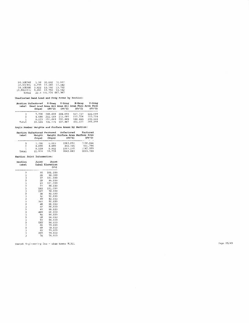
NNbW
N N N N
t
t ~ N N N~
C d~ 0101
O N
T r ~ O N
m ti
.i mr
m 01 N N N
Ifs 01 ~ V
r
c~• N
~ O O O
~n ~n ~ m .i
v~ m
.i m
r mo t~
W W W N 0
N o o W E
~n o
• N
O O O
~.I ~rl .
i o.'{
bi Nn
b U N
H b <
awW
~ ~ v
~i
bm_
N b N
A W w
x ~ ,.
Ti
ate.{..
H r~N
nl N W
~ H ••
i~
bl „'I n
O ~++
X H~
m m a
V N X
W ~ v
'JG Q
0 pN
U a
N
~o mO N ~ ~1
o ~ ~ m
N N O ~
N .-1
.i .i .i m
r a~or
m N ~o c~
r r io ,1
l~ N O N
o m m r
c.a tir
N ri N OJ
N NNto
m m m ~
inmar
ioa~or
m N N N
~O N N M
N N N l
m om~o
O O1 N NN
M N N .-I
0E
roro i~
o a, i~
i o°r'm~
V
W
I m N N t~I
1U0 U V
1 .y
ti N
w
ro i ~
°'~m
Na i
~
~'d b .-.
I N ~ u~
N N N
I N 01 M m
N N <
I wr caw
Y ~~ W
I m N t~ nt
b U v
1 oo~t o0
W b
I rl
.i m
pG HN
1
b ~V .
.
I MO NN
01 .0 N
I m m C N
H b W
I o~cm~
••
U .'t ~
I m~e mN
W
I b
c°1ibwi~~.~,~
w°Y N.+C
1 rto m N
N
N~ V
i ~
a~
d
I ~.I
~
i n
o Np
i m ev ,~ ~
C
N
I O
~.~iU f7
I E
+~
N
1 NN
q 0 ~
y~j r
W
a~
h Fl
C .i
~a
y
O O O O O O O O O O o O o 0 0 0 o O o O O O O O O
0 0 0 0 0 0 0 0 0 0 0 0 0 0 0 0 0 0 0 0 0 0 0 0 0
O O O O O O O O O O O O O O O O O O o O O o 0 o O
N lO N ~O N ~O o lO N N N N m m m m m P m m Ol Ol Ol Ot d~
O01 O01 O01
0101010101
m
l~ 1~1~ I~I~
~
ti .a
.i
~ N .-i
N N N ~C ~4 f~~l
ICI ICI ~C C ~T C ~C N N
~f~l X tX0 l0 ~ X ~
N N
M
C
u)
~O
m mmmmmmmmmmm mmmmmcn mrnm rr ~n rn rn

3 7P 74.0003 7Y 74.0003 7XY 79.0003 19P 101.0003 19X 101.0003 20P 96.0003 20X 96.0003 21P 89.0003 21X 89.0003 22P 74.0003 22X 79.0003 i0.50E745 74.0003 i0.50E845 84.0003 i0.50E965 96.0003 i0.50E1015 101.0003 29P 109.0003 25P 124.0002 7X 74.0002 8X 69.0002 7P 74.0002 BP 69.0002 7Y 79.0002 BY 69.0002 7XY 74.0002 8XY 69.0002 9X 62.0002 9P 62.0002 9Y 62.0002 9XY 62.0002 lOX 54.0002 lOP 54.0002 l0Y 54.0002 lOXY 54.0002 12X 40.0002 12P 40.0002 12Y 90.0002 12XY 90.0002 i0.50E40S 90.0002 i0.50E795 74.0001 12X 40.0001 15X 20.0001 12P 40.0001 15P 20.0001 12Y 40.0003 15Y 20.0001 12XY 90.0001 15XY 20..0001 18X 0.0001 18P 0.0001 18Y 0.0001 1BXY 0.0001 i0.50E20S 20.0001 23P 0.0001 i0.50E405 90.000
Sections Information
Section Top Hottom Joint Mesber Tran. Face Tran. Face Tran. Face Long. Face Long. Face Long. FaceLabel Z Z Count Count Top Width Bot Aidth Grose Area Top Aidth Bot Width Groas Area
Centek Engineering Inc - cl&p towel #1321 Page 26/49

(ft) (ft) (£t) (f t) (ft^2) (£t) (£t) (ft^2)
3 124.000 74.000 42 147 0.00 5.00 192.500 0.00 20.50 629.500 Problem calculating gross area of longitudinal
face for section ^3^: width ie zero at elevation 101.00 (f t) which ie not the top of the section. ??
2 79.000 90.000 22 61 5.00 14.46 330.830 5.00 14.96 330.8301 40.000 0.000 15 39 14.46 25.50 799.600 19.46 25.50 799.600
**• Insulator Data
Clamp Properties:
Lak~el Stock HoldingNumber Capacity
(lbs)______________________
C-EX1 Se+009
Clamp Insulator Connectivity:
Clamp Structure Property Min. Requiredbabel And Tip Set Vertical Load
Attach (uplift)(lba)
------------------------------------------Clampl 19P C-EX1 No LimitClamp2 19X C-EX1 No LimitC lamp3 20P C-EX1 No LimitC lamp4 20X C-EX1 No LimitClamps 21P C-EXl No LimitClamp6 21X C-EX1 No LimitClamp? 22P C-EX1 No LimitC1amp8 22X C-EX1 No LimitClamp9 3X C-EX1 No LimitC1amp10 SX C-EX1 No LimitClampll 7X C-EX1 No LimitClampl2 9X C-EX1 No LimitClampl3 lOX C-EXl No LimitC1amp14 12X C-EX1 No LimitC1amp15 15X C-EX1 No LimitClampl7 i0.50E1015 C-EX1 No LimitClampl8 i0.50E965 C-EX1 No LimitClampl9 i0.50E845 C-EX1 No LimitC1amp20 i0.50E74S C-EX1 No LimitClamp2l i0.50E90S C-EX1 No LimitClamp22 i0.50E20S C-EX1 No LimitClamp23 1X C-EX1 No LimitClamp24 1XY C-EX1 No LimitC1amp25 2X C-EX1 No LimitClamp26 2XY C-EX1 No LimitClamp27 24P C-EX1 No LimitClamp28 25P C-EX1 No Limit
Centek Engineering Inc - cl&p tower #1321 Page 27/49

*** Loads Data
Loads from £ile: j:\jobs\1331700.wi\structural\backup docwnentation\calcs\rev (2)\pls tower\cl&p # 1321.1ca
Insulator dead and wind loads are already included in the point loads printed below.
Loading Method Parameters:
Structure Height Siunmary (used for calculating wind/ice adjust with height):
Z o£ ground for wind height adjust 0.00 (ft) and structure.Z coordinate that will be put on the centerline ground p=oEile in PLS-CARD.
Ground elevation shit 0.00 (ft)
Z o£ ground with shift 0.00 (ft)
Z of structure top (highest joint) 124.00 (ft)
S tructu=e height 124.00 (£t)
S tructu=e height above ground 124.00 (ft)Tower Shape Rectangular
Load distributed evenly among joints in section for section based load cases
Vector Load Casea:
Load Caee Dead Aind SF For SF for SF for SF For Point Aind/Ice Trans. Lonqit. Ice Ice Temperature Joint
Description Load Area Steel Poles Guya Insuls. Found. Loads Model Aind Wind Thick. Density Displ.
Factor Factor Tubular Azms and Pressure Pressure
and Towers Cables (psf) (psf) (in)(lbe/£t̂ 3) (deg F) ____________________________________________________________________________________________________________________________________________
NESC Heavy 1.5000 2.5000 1.00000 1.0000 1.0000 1.0000 25 loads Wind on Face 4 0 0.000 56.000 0.0
NESC Extreme 1.0000 1.0000 1.00000 1.0000 1.0000 1.0000 25 loads NESC 2007 31 0 0.000 0.000 0.0
Point Loads for Load Case "NESC Heavy":
Joint Vertical Transverse Longitudinal Load
7.abe1 Load Load Load Comment
(lbs) (lbe) (lbs) _____________________________________________________________________
19P 1282 1147 0 Shield Wixe
19X 1191 1135 0 Shield Wire
20P 2739 1785 0 Conductor
20X 2739 1765 0 Conductor
21P 2739 1785 0 Conductor
21X 2739 1765 0 Conductor
22P 2739 1765 0 Conductor
22X 2739 1785 0 Conductor
1X 172 131 0 Coax Cables - Tower
3X 275 209 0 Coax Cables - Tower
SX 310. 235 0 Coax Cables - Tower
7X 379 287 0 Coax Cables - Tower
9X 344 261 0 Coax Cables - Tower
lOX 379 287 0 Coax Cables - Tower
12X 585 499 0 Coax Cables - Tower
15X 1033 7B4 0 Coax Cables - Tower'
29P 205 0 0 Coax Cables - Powermount
i0.50E101S 299 0 0 Coax Cables - Powe=mount
i0.50E965 151 0 0 Coax Cables - Powermount
i0.50E895 196 0 0 Coax Cables - Powermount
Centek Engineering Znc - cl&p tower #1321 Page 28/49

i 0.50E79S 392 0 0 Coa~c Cables - Powermounti 0.50E40S 981 0 0 Coax Cables - Powermounti 0.50E205 535 0 0 Coax Cables - Powe=mount
25P 7563 1200 0 AT&T Loading24P 467 266 0 T-Mobile Loading
Section Load Case Information (Standard) £or ^NESC Heavy":
Section 2 Z Ave. Res. Tran Tran Tran Long Long Long Ice Total
Label of of Elev. Adj. Adj. Drag Aind Adj. Drag Wind Aeight Feight
Top Bottom Above Aind Aind Coe£ Load Aind Coe£ LoadGround Pres. Pxes. Pres.
(ft) (f t) (ft) (pa£) (psfj (lbs) (paf) (lbe) (lbs) (lbs)
3 124.00 79.00 99.00 10.00 10.00 3.300 4026.3 0.00 3.300 0.0 0 12140
2 74.00 90.00 57.00 10.00 10.00 3.200 3607.2 0.00 3.200 0.0 0. 100351 40.00 0.00 20.00 10.00 10.00 3.900 4442.7 0.00 3.900 0.0 0 13412
Point Loads for Load Case "NESC Extreme":
Joint Vertical Tranaveree Longitudinal LoadLabel Load Load Load Comment
(lbs) (lbe) (lbs) _____________________________________________________________________
19P 364 705 26 Shield Wire19X 299 697 9 Shield Wire20P 1007 1917 772 Conductor20X 1007 1917 772 Conductor21P 1007 1917 772 Conductor21X 1007 1917 772 Conductor22P 1007 1917 772 Conductor22X 1007 1917 772 Conductor1X 40 430 0 Coax Cables - Tower3X 63 688 0 Coax Cables - TowerSX 71 775 0 Coax Cables - Tower7X 87 947 0 Coax Cables - Tower9X 79 861 0 Coax Cables - TowerlOX 87 947 0 Coax Cables - Tower12X 135 1463 0 Coax Cables - Tower15X 238 2562 0 Coax Cables - Tower24P 137 0 0 Coax Cables - Powermount
i0.50E101S 166 0 0 Coax Cables - Powexmounti0.50E96S 101 0 0 Coax Cables - Powermounti0.50E845 131 0 0 Coax Cables - Powermounti0.50E74S 261 0 0 Coax Cables - Powermounti0.50E405 321 0 0 Coax Cables - Powermounti0.50E20S 356 0 0 Coax Cables - Powexmount
25P 3557 9566 0 AT&T Loading24P 182 1059 0 T-Mobile Loading
Section Load Case Information (Code) for "NESC Extreme":
Section Z Z Ave. Rea. Tran Tran Tran Tran Tran Tran Tran Tran Long Long Long Long Long Long Long Long Ice
TotalLabel of o£ Elev. Adj. Adj. Angle Round Grosa Soli- Angle Round Wind Adj. Angle Round Groas Soli- Angle Round Wind Weight
WeightTop Bottom Above Wind Aind Face Face Area dity Drag Drag Load Wind Face Face Area dity Drag Drag Load
Ground Prea. Prea. Area Area Ratio Coef Coef Pres. Area Area Ratio Coe£ Coef
(ft) (£t) (£t) (paf) (psf) (£t^2) (£t^2) (ft^2) (lbs) (psf) (ft^2) (ft^2) (ft^2) (lba) (lbs)
Centek Engineering Inc - cl&p tower #1321 Page 29/49

(lbe)
3 129.00 79.00 99.00 32.15 32.15 54.51 67.50 192.50 0.634 3.200 2.000 9997.9 0.00 62.74 75.00 629.50 0.251 3.200 2.000 0.0 0
80932 74.00 90.00 57.00 32.15 32.15 61.72 51.00 330.83 0.391 3.200 2.000 9629.3 0.00 61.72 51.00 330.83 0.341 3.200 2.000 0.0 0
66901 40.00 0.00 20.00 32.15 32.15 70.67 60.00 799.60 0.163 3.200 2.000 11128.0 0.00 70.67 60.00 799.60 0.163 3.200 2.000 0.0 0
8942
Centek Engineering Inc - cl&p tower #1321 Page 30/49

*** Analysis Results:
Maximum element usage is 94.01 for Angle "g37X" in load case "NESC Extreme"
Maximum insulator usage is 17.09s for Clamp "Clamp28" in load case "NESC Heavy"
FVN
G
uC
Ew0arG70J
Iteration #
Angle Forces For All Load Cases:
Positive £or tension - negative for compression
Group Angle Max. Usage Max. Tens. Max. Comp. LC 1 LC 2
Label Label For All LC For All LC For All LC
$ (kips) (kips) (kips) (kips)
Legl g3P 9 37 5.986 0 000 0.752 5.986
Legl g3X 8.15 0.000 -7.296 -4.669 -7.296
Legl g3XY 8.49 0.000 -7.599 -4.617 -7.599
Legl g3Y 8.98 5.790 0.000 0.870 5.790
Centek Engineering Inc - cl&p tower #1321 Page 31/99

Legl g4P 24.82 15.859 0.000 5.812 15.859Legl g4X 19.23 0.000 -17.936 -9_509 -17.936
Legl g9XY 18.58 0.000 -17.331 -9.455 -17.331Legl g4Y 25.86 16.521 0.000 5.889 16.521
Legl g5P 34.50 22.042 0.000 8.539 22.042
Legl g5X 28.47 0.000 -26.554 -14.756 -26.554Legl gSXY 26.36 0.000 -24.585 -14.680 -24.585
Legl g5Y 37.13 23.727 0.000 8.883 23.727Legl gfiP 42.22 26.980 0.000 10.699 26.980
Legl g6X 35.87 0.000 -33.959 -19.411 -33.459
Legl g6XY 32.68 0.000 -30.977 -19.238 -30.977
Legl g6Y 45.31 28.952 0.000 10.950 28.952
Legl g7P 59.03 34.522 0.000 15.392 34.522
Legl g7X 48.28 0.000 -43.202 -23.789 -93.202Legl g7XY 40.81 0.000 -36.520 -23.872 -36.520
Legl g7Y 58.93 37.655 0.000 16.157 37.655
L egl g8P 61.06 42.618 0.000 19.469 42.816
Legl g8X 61.72 0.000 -55.236 -30.397 -55.236
Legl gBXY 48.96 0.000 -43.812 -31.135 -43.812
Legl g8Y 65.89 46.203 0.000 20.739 46.203
Legg g9P 51.38 50.945 0.000 25.019 50.995
Legg g9X 69.03 0.000 -67.626 -37.398 -67.628
Legg g9XY 54.62 0.000 -53.511 -38.292 -53.511
Legg g9Y 58.83 58.337 0.000 26.815 58.337
Legg g10P 56.51 51.189 0.000 27.098 51.189Legg g10X 78.32 0.000 -71.598 -41.108 -71.598
Legg g10XY 64.93 0.000 -58.907 -41.811 -58.907
Legg g10Y 70.59 63.946 0.000 28.420 63.94fi
Leg3 g11P 45.31 50.473 0.000 27.989 50.973
Leg3 g11X 60.85 0.000 -70.491 -41.397 -70.491Leg3 g11XY 51.79 0.000 -59.997 -41.836 -59.997Leg3 g11Y 56.97 65.695 0.000 28.701 65.695
Leg3 g12P 42.18 45.579 0..000 27.091 45.574
Leg3 g12X 62.59 0.000 -76.622 -43.955 -76.622Leg3 g12XY 52.13 0.000 -63.816 -43.461 -63.816
Leg3 g12Y 60.39 65.249 0.000 27.891 65.244
Leg3 g13P 93.62 47.122 0.000 25.851 47.122
Leg3 g13X 68.60 0.000 -85.382 -99.215 -85.392
Leg3 g13XY 56.21 0.000 -69.957 -47.922 -69.957Leg3 g13Y 60.99 65.891 0,000 26.630 65.891
Leg3 g14P 50.79 59.871 0.000 27.397 59.871
Leg3 g14X 75.60 0.000 -99.096 -53.fiO4 -99.096
Leg3 g19XY 59.59 0.000 -79.109 -50.529 -79.109
Leg3 g19Y 65.32 70.568 0,000 27.587 70.568
Diagl g15P 56.35 0.000 -9.852 -9.245 -9.852
Diagl g15X 49.36 9.469 0.000 3.922 9.469
Diagl g15XY 50.08 9.608 0.000 3.870 9.608
Diagl g15Y 54.26 0.000 -9.987 -9.168 -9.487
Diagl g16P 3.62 0.000 -0.973 -0.473 -0.933
Diagl g16X 3.Ofi 0.588 -0.025 -0.025 0.588
Diagl g16XY 0.80 0.153 -0.020 -0.020 0.153
Diagl g16Y 5.57 0.000 -0.728 -0.491 -0.728Diag2 g17P 24.85 0.000 -6.033 -4.280 -6.033
Diag2 g17X 18.93 4.730 0.000 2.007 9.730
Diag2 g17XY 19.93 9.854 0.000 2.079 4.859
Diag2 g17Y 23.62 0.000 -5.735 -4.231 -5.735
Diag2 g18P 0.97 0.117 0.000 0.117 0.039
Diag2 g18X 9.57 1.142 O.00A 0.480 1.142
Diag2 g18XY 1.73 0.433 0.000 0.433 0.052
Centek Enginee=ing Inc - cl&p tower #1321 Page 32/49

dddddddddddddddddddddddddedddddeddddddddddeddeddddeddedddbd
wwwwr~w r~wwwwwr~w wr~w r~~~wwwwwwwN~wwwr~w wwwwwwwr~wwwwwwwwr~r-wwwH~r~wr~w r
~w
w w
w w
w w
w w
w w
w w
w w
w w
w w
w w
w w
w w
w w
w w
w w
w w a w
w w
w w
w w
w w a a a a w
w a a w
w a a w a w a
wwwwawwwwwwwwwwwawwaww~nwwwawwwawwwwwaawwwawwawwa~awwwwwawaw
N N W W W W W W W W W W W W W W W W ~C ~P ~C ? ~C iC ~C J~ W W W W W W W W W W W W W W W W N N N N N N N N N N N N N N N N N
~a
~a
w
w
~
w
w
w
w
w
w
w
w
~aW W W N W lam.) tai)
N W ~W W O W W N l0 N N N W N N N J N N N m N N N N N N N~ N N N W N N N N N N N N N N N O N N w l0 w H H
7SroK K ~ r
o Kk%ro Kk x roK k ~ ro.
0 k~C rokK DCroK K ~rokK xb~C kiC b ~
C k>C ~n~ ~~C rokK DCr
o K~ X r
o ~kX roK
N VI
H F'
F+
N N
LI N N N N N N tJ N
N N N N N IJ. F+
F' N N N N N
N N N N
N J J F+ 01 N N UI lJ lD J (
J~ W ~P l0 ~P
01 N O O ~P IJ N UI ~P J Ot tJ N Ot O1 N N tp 01 N W N ~l O Ot 01 F' O F+ N W 01
N O iP iP lJ iP
1-~ Ot 1p Ja F' N a1 01 N F' N W tp O O O1 ~P pi N 01 O O ~c is N f~
l N J N~ Q1 W J ~C O ~P J W O N W (
li 01 W 1p ~ U1 J lD
In J N N O l0 J F+
O N iP F' tp O 1p 1p G! lJ O1 N UI iP J tp p1 UI tJ tD N U1 (11
N m I~ ~l O O F' N F~ H N tp J O N iP Ot N iG O~ ~C J O J W O O W O Ol UI OJ ~ J l0 F'
Ut O O O N O O H O O W O O F' O N N O O O W O O F' O O O N J O O J J O O N ~P O O N J O O F+ N O O 01 tJt 0 0 0 0 0 0 01 a1 O O
.
•
.N O O fJ J O O T lO ONO O 1-
' O W N O O m IJ O O N J O O N (n O O J J O O J m O O N m O O N l0 O O H l0 O O O N~ O N O N
J O O lD ~o
O N O N O N lJ O N N O O l0 tJ
to Ut O O O In O O W O O O W F+ O O
m 1p O O N J O
O Iv O
N O O J N O O H W O J O J m O O~ O O N to O O O m O O U1 J O O~ W O O N m. O O 01 m O O ~C O O O m N O O O W J O J 1p.0 O
1 I
I I
1 I
I I
I I
I I
I Im
11
I I
I m
Im
I I
I m
1 I
I 1
O N O O O N I-~ O O N O N O O N O O N H O O N H O O N O O N 41 O O 49 N O O N
O O
W O O N N O O O O O O ~P O O Ui O
O ~G l0 N O N N O O Ot O UI e1 O Oi O O O v O O m ~P O O Oi ~C O O 01 UI O O~ W O O m J O O m r O O l0 N O O~ W m W W tp O O J J
O l0 W W O N l0 O O O O O~ O m O O N N O O W H O l0 l0 W O O D 1p O O~ N O O Ol O O O W Ol O O J W O O Ol l0 N W W lO O O J J
O UI J .P. O J O O O N O t0 m O ~t O O 01 Ot O O I-
~ ~t O O N W O O l0 O O O W l0 O O m W O O J O O O N J O O O ~1 O Ui O O~ O O J 1p
I I
11
I I
I I
I I
I I
1O N O O O O O O O N O O O O O O N N N O O N N O O F+ Ja N N ~c
~n N N N N ~n u.+
~ ~c r o o r N t~ lJ N O O O O N ~n in N O
N •Ja •at W tU W tD ~P
is t0 O~ 01 l0 J 1p HON W 1p Ja ~P
01 N J 1p N O 01 N l0 N N m (n l0 O~ N l0 ~ m ~D N m
m l0 N W W W O W lJ N 1~
.~ l~ ~O l0 N N N m
lO N~ N N N J N O~ l0 O O N N Ui lD J O B l0 U~ l0 N J O W O 01 ~C O W W W O1 H O H iC O N 1p Q~ W W J N J tJ
i N
l0 N W v F~ (l
i CO m is Ob
i dl m m N Ol m U1 p\ 1p N J UI v N W N J v~ O N N N W O Ut N J iP tp 1p J l~l OJ Ot CO CO O O fT J N UI O N UI W H O
1 I
I I
I I
I C
I I
I 11
I I
Im
I I
I I
I I
1 I
toU1 O O O N F-` N N O N N N O N F' N F' O N O lJ N F' N O
m N ~l (n O1 ~l ~t t0 fn N ila N O1 J J
IJ I-+ N N LP 01 UI 61 O O O O .P 01 01 UI
. . . . . . . . . . . . . . . . . . . . . . . . . . . . . . . . . . . . . . . . . . . . . . . . . . . . . . . . . . .
N O l0 F' J Ui UI OT t0 Ot F' NON OI LJ N Ot J N W m F' N O N ~ N N Ot UI ~l J iP IJ J W 61 J N fi
I m F+ N l0 l9 N ✓a t0 Ja W fD N ~ 1p O N J J
W W iP 1-~ lD O N O N O N W ~P N f1i Ot N N W IU ~[a N l0 m W O UI J tp W O ~O UI W H 01 O m
m l0 J W N J O1 l0 UI O~ t.
~ 1p O W J
N O J Ja N JON tJ N J tD J m H O iP ~l 01 m N N Ln O O~ W N J l0 O ~O lJ tJ l0 N m m W 01 m J O~ O N J m N O J O W J T J 1p J l0
.

Di ag5 g33XY 7.81 1.950 -0.197 -0.197 1.950
DiagS g33Y 99.70 0.000 -1.936 -1.786 -1.936
DiagS g34P 16.67 0.000 -0.722 0.000 -0.722
DiagS g34X 26.63 6.654 0.000 2.806 6.659
DiagS g34XY 20.07 5.015 0.000 2.917 5.015
DiagS g39Y 0.17 0.041 0.000 0.041 0.000
Di agS g35P 0.00 0.000 0.000 0.000 0.000
Diag5 g35X 46.51 10.229 0.000 3.987 10.224
DiagS g35XY 22.86 5.026 0.000 2.291 5.026
DiagS g35Y 0.00 0.000 0.000 0.000 0.000
Diag5 g36P 0.00 0.000 0.000 0.000 0.000
DiagS g36X 30.76 6.762 0.000 2.859 6.762
Diag5 g36XY 29.22 6.923 0.000 3.150 6.923
DiagS g36Y 39.06 0.000 -0.832 0.000 -0.632
Di agS g37P 0.00 0.000 0.000 0.000 0.000
DiagS g37X 94.01 11.149 0.000 9.726 11.199
Di agS g37XY 96.31 5.992 0.000 2.784 5.992
Di agS g37Y 0.00 0.000 0.000 0.000 0.000
Di agS g38P 0.00 0.000 0.000 0..000 0.000
Di agS g38X 53.91 6.339 0.000 2.520 6.339
DiagS g38XY 97.93 5.625 0.000 2.662 5.625
DiagS g36Y 21.52 0.000 -0.282 0.000 -0.282
M4 g39P 1.16 0.000 -0.328 -0.051 -0.328
M4 g39X 3.99 1.109 0.000 1.109 0.653
M4 g39XY 3.95 1.112 0.000 1.112 0.700
M4 g39Y 0.69 0.000 -0.196 -0.045 -0.196
M9 g90P 6.70 3.183 0.000 3.183 0.928
M9 g40Y 6.80 3.233 0.000 3.233 1.557
M3 g41P 25.77 0.000 -6.760 -3.627 -6.760
M3 g41X 19.60 5.763 0.000 0.978 5.763
M9 g42P 15.95 0.000 -4.806 -4.806 -3.635
M9 g42X 8.82 0.000 -2.793 -2.743 -1.181
M9 g42XY 8.80 0.551 -2.739 -2.739 0.551
M9 g42Y 15.90 0.000 -4.791 -4.791 -1.769
M9 g43P 8.03 0.000 -2.968 -2.468 -1.650
M9 g93Y 8.15 0.000 -2.507 -2.507 -0.230
M3 g44P 13.69 4.085 0.000 2.781 4.085
M3 g49X 11.75 0.000 -3.092 -0.082 -3.082
M7 g45P 24.59 0.000 -1.760 -1.760 -0.700
M7 g45X 22.99 0.000 -1.693 -1.643 -0.609
M7 g46P 21.38 3.856 0.000 3.856 1.276
M7 g46X 20.86 3.763 0.000 3.763 1.119
M7 g46XY 20.85 3.761 0,000 3.761 1.889
M7 g46Y 21.33 3.897 0.000 3.897 1.886
M13 g47P 15.61 0.000 -5.310 -5.310 -9.179
M13 g47X 9.98 0.000 -3.396 -3.396 -1.821
M13 g97XY 10.10 0.539 -3.937 -3.437 0.539
M13 g47Y 15.56 0.000 -5.293 -5.293 -1.589
M13 g46P 10.85 0.000 -4.088 -4.068 -2.502
M13 g48Y 10.62 0.000 -9.003 -4.003 -1.027
M3 g49P 11.35 0.000 -2.976 -0.253 -2.976
M3 g49X 14.96 4.399 0.000 3.628 9.399
MB g50P 20.89 4.592 0.000 4.592 1.274
MB g50X 20.68 4.596 0.000 4.596 1.125
MB g50XY 20.91 4.597 0.000 4.597 2.558
M8 gSOY 20.85 4.583 0.000 9.583 2.469
M14 g51P 30.31 2.813 0.000 2.813 1.099
M19 g51Y 29.88 2.773 0.000 2.773 1.388
M9 g52P 17.01 0.000 -1.998 -1.303 -1.998
Centek Engineering Inc - cl&p tower #1321 Page 34/99

o m m m m~~ o N r~ m~ m c
m ti M
m o o m~ M N N m
w ti c
ti m mm N
m o m~ m~ m N m w~~ e~ m
m~ O m O N m r N m m N N O N r a b~~ O N~ N N C m m W~ b O O N r O M r r~ N N~~~ m C N r C~~~ N~
m S~ O N N N m N~~ N~ M N M~ O N O O C C O r m m M r m~ N O~~~~ N~ C b N C N~~~ O r C ro O C O O r N m O
.
.~ N O N~ N O O O O O N N~ r N O N O~ N~ O N~ N O m N W M C~ N N N M N ti O O N N N O N N b N W m~ m O m r~ N N
O N r~ N~ m O~ O N~~~~ O r O N S~~ a r~ C~ N N O N~ m m~ N NO N r C m N
m N N N N~~ b O m b~ r N
N N~ O N O~ O~ N N N~ O m N r~ a C N N C H m~ C O N N~ N m N N M N a N~
r~ N N~ m O N N~ O N~ N m N
~ M N a N m~ N N r b r~ O r N N~~ c N m O r h a W N r m r O N N r b N C r N C N r~ O m a m r r mm ~ V~ NN N~
OM ~ N m N N N O N N N N C m N N O O O N O O O m N O~ N N~ N N O O H
O O~ O O O~ N N~ N m m N~~~~ M~
1 1
1 1
1 1
I I
I I
I I
I 11
I I
I I
1 I
I I
I I
I I
1 1
I I N N N~ H N
O~ r N N T M O~ O O O O Oti O O M P O M W N O M~ O O m N~ N N M W m C O O~ P~~ O O~~ O N O O~ O~~~ r N
O N m O.N O~ O O O O O O O~ O O O~ O C C m O O N~ O N C m m~~ O O N O O M m
OO ~ C O M O O r0 N~ N m N
O M N C N M N O N O O O O O N O O O N O O C C O r m~ O r m~ N O~ W~~ N O O a N C N O O~ O O C O O C C~ N~ N r
O m~~ M N N O O O O O o o r o O N O O N O O
N O O N C M
N N N m N O O N O N H O O N~ O O O N~
N M N
1 I
I I
I I
I I
I I
I I
I I
I I
I I
I I
I I
I I
I I
I I
I I
I N N N~ N N
1
~ O O m O O O o N O N m~~ O O~ C O m O O O M O O O O OO O O O O OO O O ti~ O W O O~ O O O m O m N O O O O O O O
~~ N~
m O N
~ O O O~ O O O N OO O O O O O O O O r b O O O N N O O H O C N O O O O O O O
O O O O O~ h r~
m O N ti~ m O O O O O O O O M O O O O O O O OO O~ N O~ O O r S O O~ O W O O O O O O O O
N O O N O O O~ O N N N N r O N N O O~ O O O N OO O m O O O O O O O O O O~ O O~ O O O N O O N O m T O O O O O O O
m N r
m N M~ M m b M M N~ N b O N O M N~ N~ N m r C C~ m O N O r N ~~ m r~ N O M 0 m r W C C~ O N N m O N
O O N~~ N N~ N~ r N O N~ P~ m~ N C r M N M M r m~ r N M W C N O~~ m~ N~ O~ N W m N~~ N M W C m N C N
.
mO~ C a O r~ m N~~~~ m ti m
m N N a N N~ m m m a N r N M r C N O M N M m N M N m N~ b r P~ M N O N N N N N N
N ti
N
N~ N N W~ N N N
m~
N N
N N N N N N N N N N N~ ~ N N N
N N N~ r~ m m
N M M k M C C N N~~ X~ r h 0~~~ O O a N N N M M C C~ N~ N b~ k~ w r k r m m k m~~ k~ O O k O N N m C~
N N m N N N N N N N~ N N N N N N N~~~~~~~ b~~~~ N~ b~~ b~ b r~ b~ m~~~ m~ n r o r r~ r r r r
b~ b~ b~u~ b~ b~ U lT b~ lT lT N bf lT U b~ b+ [T b~ bt b1 b~ b~ b1 b~ b~ b1 b+ b~ b~ b+lO b~ b~ b~lO b+ b~ b~10 b+ b1 bl l0 b+ b~ b~~0 b~ b+ b~t~ b~ b~ C tT lT IT U
b
b
b
b
~
~
b
~
01 C ct~ C
C v c m m t~
t~ 1~ 01 01 V~ C
In I1] N
N E ~O ~D ~O N N N N N N N N O O O O O O O O O O O O O O O O f""5! S. ~ $
y' $y'
~~~~~~~~~~~~~~~~~~~~~~~~~~~~~z~~~~~~~~~~~~~~~~~~~~~~~n;~~aaa

PM g77P 1.08 0.000 -10.332 -10.332 -4.168PM g78P 0.90 0.000 -8.383 -8.383 -3.653
Centek Engineering Inc - cl&p tower #1321 Page 36/99

*** Analysis Results foi Load Case No. 1 "NESC Aeavy" - Number of iterations in SAPS 10
Equilibrium Joint Positions and Rotations £or Load Case "NESC Heavy":
Joint X-Diapl Y-Displ Z-Displ X-Rot Y-Rot Z-Rot X-Poa Y-Poe Z-Poa
Label (ft) (Ft) (ft) (deg) (deg) (deg) fft) (ft) (ft) _____________________________________________________________________________________
1P 0.002143 0.2357 -0.02079 -0.3198 0.0149 0.0366 2.502 2.736 101
2P 0.001216 0.2081 -0.0209 -0.3109 0.0071 0.0901 2.501 2.708 95.98
3P 0.0009313 0.1872 -0.01991 -0.2859 0.0093 0.0369 2.501 2.687 91.98
4P -6.396e-005 0.1676 -0.01919 -0.2857 0.0124 0.0377 2.5 2.668 87.98
5P -0.0005624 0.1476 -0.01826 -0.2739 0.0065 0.0365 2.499 2.648 83.98
6P -0.001165 0.1257 -0.01685 -0.2457 0.0137 0.0377 2.949 2.626 78.98
7P -0.002375 0.1051 -0.01508 -0.2038 0.0016 0.0390 2.998 2.605 73.98
BP -0.002311 0.09007 -0.01533 -0..1595 -0.0086 0.0383 3.198 3.29 68.98
9P -0.003965 0.0721 -0.0152 -0.1343 0.0195 0.0379 4.166 4.242 61.98
lOP -0.007819 0,05612 -0.01522 -0.1012 0.0071 0.0333 5.272 5.336 53. 98
12P -0.005259 0.03563 -0.0127 -0.0763 -0.0190 0.0201 7.225 7.266 39.99
15P -0.002757 0.01298 -0.007467 -0.0525 -0.0139 0.0051 9.997 10.01 19.99
18P 0 0 0 0.0000 0.0000 0.0000 12.75 12.75 0
19P 0.01273 0.2339 0.06039 -0.2692 0.0101 0.0367 0,01273 -13.52 101.1
20P 0.00922 0.2079 0.04028 -0.2628 0.0103 0.0367 0.00922 -9.592 96.09
21P 0.01005 0.1479 0.04954 -0.2007 0.0099 0.0366 .0.01005 -14.1 84.05
22P 0.005672 0.1096 0.03043 -0.2089 0.0079 0.0365 0.005672 -10.15 74.03
23P 0 0 0 0.0000 0.0000 0.0000 0 0 0
24P 0.005105 0.2931 -0.004212 -0.4648 0.0102 0.0235 0.005105 0.2931 109
25P 0.00772 0.4271 -0.005034 -0.5345 0.0102 0.0235 0.00772 0.4271 124
1X 0.005115 0.2354 0.004982 -0.3012 0.0100 0,0343 2.505 -2.265 101
1XY 0.005593 0.2321 0.005879 -0.3009 0.0105 0.0440 -2.994 -2.268 101
lY 0.002015 0.2324. -0.01967 -0.3199 0.0052 0.0416 -2.498 2.732 101
2X 0.004661 0.2089 0.005012 -0.2996 0.0142 0.0393 2.505 -2.292 96.01
2XY 0.004297 0.2052 0.005902 -0.3000 0.0063 0.0386 -2.496 -2.295 96.01
2Y 0.001228 0.2048 -0.01953 -0.3109 0.0129 0.0378 -2.499 2.705 95.98
3X 0.003501 0.1875 0.004803 -0.3028 0.0140 0.0384 2.504 -2.313 92
3XY 0.00405 0.1892 0.005689 -0.3027 0.0065 0.0391 -2.496 -2.316 92.01
3Y 0.0001599 0.184 -0.01904 -0.2860 0.0105 0.0386 -2.5 2.689 91.98
4X 0.00299 0.1667 0.009468 -0.2830 0.0049 0.0375 2.503 -2.333 86
4XY 0.003219 0.1634 0.005339 -0.2825 0.0152 0.0395 -2.497 -2.337 88.01
4Y -O.0001998 0.1693 -0.01833 -0.2859 0.0074 0.0393 -2.5 2.669 87.98
SX 0.002377 0.1981 0.004027 -0.2573 0.0162 0.0365 2.502 -2.352 64
5XY 0.002911 0.1948 0.004884 -0.2572 0.0039 0.0900 -2.498 -2.355 84
5Y -0.001039 x.1444. -0.0179 -0.2737 0.0126 0.0400 -2.501 2.644 83.98
6X 0.001137 0.125 0.003205 -0.2529 0.0051 0.0343 2.501 -2.375 79
6XY 0.001933 0.1217 0.004018 -0.2529 0.0147 0.0409 -2.498 -2.378 79
6Y -0.002017 0.1224 -0.01599 -0.2955 0.0047 0.0379 -2.502 2.622 78.98
7X 0.0006075 0.1055 0.002135 -0.1979 0..0188 0.0321 2.501 -2.395 74
7XY 0.0006638 0.1023 0.002876 -0.1952 -0.0019 0.0408 -2.499 -2.398 74
7Y -0.002952 0.102 -0.01418 -0.2019 0.0190 0.0347 -2.502 2.602 73.99
BX -0.0006278 0.08939 0.002981 -0.1696 0.0185 0.0310 3.199 -3.111 69
BXY 0.00161 0.0857 0.003777 -0.1656 -0.0039 0.0373 -3.198 -3.119 69
BY -0.005191 O.Q8b3 -0.01409 -0.1559 0.0291 0.0309 -3.205 3.266 68.99
9X -0.0006964 0..07191 0.003558 -0.1285 0.0022 0.0321 4.169 -4.098 62
9XY 0.001174 0.06753 0.004927 -0,1243 0.0098 0.0300 -4..169 -4.102 62
9Y -0.007359 0.06781 -0.01346 -0.1291 O.00BB 0.0263 -4.177 4.238 61.99
lOX -0.0003906 0.05593 0.004033 -0.1039 0.0051 0.0285 5.28 -5.224 54
l OXY 0.0004344 0.05113 0.004937 -0.0983 0.0050 0:0279 -5.28 -5.229 54
l0Y -0.007999 0.0513 -0.0129 -0.0972 -0.0030 0.0221 -5.288 5.331 53.99
Centek Engineering Inc - cl&p tower #1321 Page 37/99
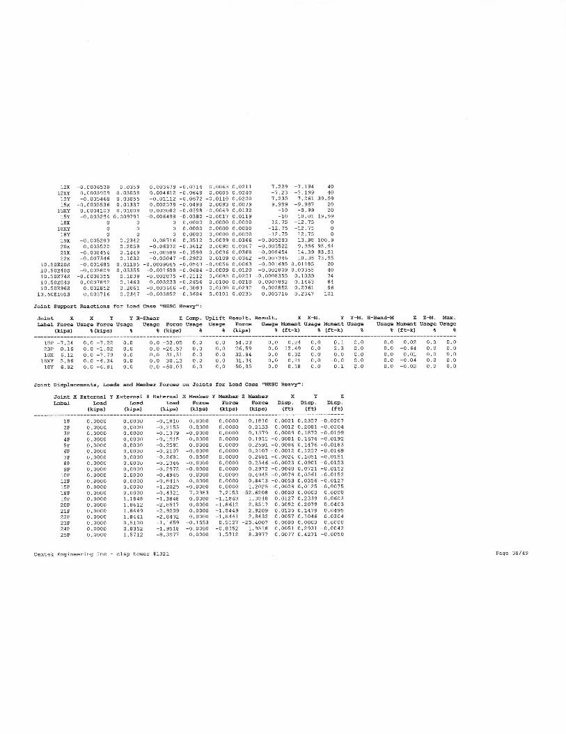
12X -0.0006538 0.0359 0.003679 -0.0719 0.0063 0.0211 7.229 -7.194 40
12XY 0.0003909 0.03056 0.009612 -0.0648 0.0005 0.0240 -7.23 -7.199 40
12Y -0.005468 0.03055 -0.01112 -0.0.672 -0.0110 0.0200 -7.235 7.261 39.9915X -0.0005536 0.01337 0.002579 -0.0498 0.0093 0.0079 9.999 -9.987 2015XY 0.0009103 0.01009 0.003082 -0.0398 -0.0049 0.0132 -10 -9.99 20
15Y -0.003294 0.009791 -0.006498 -0.0380 -0.0017 0.0119 -10 10.01 19.99
18X 0 0 0. 0.0000 0.0000 0.00-00 12.75 -12.75 0
18XY 0 0 0 0.0000 0.0000 0.0000 -12:75 -12.75 018Y 0 0 0 0.0000 0.0000 0.0000 -12.75 12.75 0
19X -0.005283 0.2392 -0.08716 -0.3512 0.0099 0.0366 -0.005283 13.98 100.9
20X -0.003522 0.2058 -0.06372 -0.3612 0.0098 0.0367 -0.003522 9.956 95.94
21X -0.008954 0.1449 -0.08589 -0.3599 0.0096 0.0368 -0.008959 19.39 83.9122X -0.007346 0.1032 -0.05097 -0.2920 0.0109 0.0362 -0.007346 10.35 73.95
i 0.50E20S -0.001685 0.01185 -0.0009065 -0.0543 -0.0056 0.0063 -0.001685 0.01185 20
i 0.50E405 -0.002809 0.03355 -0.001698 -0.0664 -0.0009 0.0120 -0.002809 0.03355 90
i 0.50E795 -0.0008355 0.1039 -0.002875 -0.2112 0.0083 0.0201 -0.0008355 0.1039 74
i0.50E895 0.0067892 0.1463 -0.003233 -0.2656 0.0100 0.0218 0.0007692 0.1463 89
i 0.50E965 0.002852 0.2061 -0.003666 -0.3083 0.0100 0.0232 0.002852 0.2061 96
i0.50E1015 0.003716 0.2397 -0.003652 -0.3604 0.0101 0.0235 0.003716 0.2397 101
Joint Support Reactions for Load Case "NESC Heavy":
Joint X X Y Y H-Shear 2 Comp. Uplift Result. Result. X X-M. Y Y-M. A-Hend-M Z Z-M. Max.
Label Force Usage Force Usage Usage Force Usage Ueage Force Ueage Moment Usage Moment Usage Ueage Moment Ueage Usage
(kips) 8(kips) 8 & (kips) ~ 6 (kips) 9 (ft-k) B (ft-k) $ 4 (£t-k) S $
18P -7.24 0.0 -7.22 0.0 0.0 -53.05 0.0 0,0 54.03 0.0 0..29 0.0 0.1 0.0
23P 0.16 0.0 -1.02 0.0 0.0 -26.57 0.0 0.0 26.59 0.0 12.49 0,0 2.3 0.0
18X 6.12 0.0 -7.79 0.0 0.0 31.31 0.0 0.0 32.84 0.0 0.32 0.0 0.0 0.0
1 BXY -5.86 0.0 -6.39 0.0 0.0 30.13 d.0 0.0 .31.34 0.0 0.21 0.0 -0.0 0.0
1BY 6.82 0.0 -6.61 0.0 0.0 -50.03 0.0 0.0 50.95 0.0 0.18 0.0 0.1 0.0
Joint Displaaementa~ Loads and Member Forces on Joints for Load Case "NESC Heavy":
Joint X External Y External Z External X Member Y Member Z Mesber X Y Z
Label Load Load Load Force Force Force Diep. Diap. Diap.
(kips) (kips) (kips) (kips) (kips) (kips) (£t) (ft) (ft)
1P 0.0000 0.0000 -0.1810 0.0000 0.0000 0.1810 0.0021 0.2357 -0.0207
2P 0.0000 0.0000 -0.2153 0.0000 0.0000 0.2153 0.0012 0.2081 -0.02043P 0.0000 0.0000 -0.1379 -0.0000 0.0000 0.1379 0.0009 0.1872 -0.0199
9P 0.0000 0.0000 -0.1915 -0.0000 0.0000 0.1915 -0.0001 0.1676 -0.0192
SP 0.0000 0.0000 -0.2591 0.0000 0.0000 0.2591 -0.0006 0.1976 -0.01836P 0.0000 0.0000 -0.2107 -0.0000 0.0000 0.2107 -0.0012 0.1257 -0.0169
7P 0.0000 0.0000 -O.Z681 0.0000 0.0000 0.2681 -0.0024 0.1051 -0.01518P 0.0000 0.0000 -0.2396 -O.D000 0.0000 0.2396 -0,0023 0.0901 -0.0153
9P 0.0000 0.0000 -0.2972 -0.0000 0.0000 0.2972 -0.0040 0.0721 -0.0152
lOP 0.0000 0.0000 -0.4945 0.0000 0.0000 0.4995 -0.0078 0.0561 -0.0152
12P 0.0000 0.0000 -0.6913 -0.0000 0.0000 0.8413 -0.0053 0.0356 -0.012715P 0.0000 0.0000 -1.2025 -O.D000 0.0000 1.2025 -0.0028 0.0125 -0.0075
18P 0.0000 0.0000 -0.4321 7.2383 7.2153 -52.6208 0.0000 0.0000 0.0000
19P 0.0000 1.1848 -1.3848 0.0000 -1.1848 1.3898 0.0127 0.2339 0.0603
20P 0.0000 1.6612 -2.8517 0.0000 -1.8612 2.8517 0.0092 0.2079 0.0403
21P 0.0000 1.6949 -2.9209 0.0000 -1.8949 2.9209 0.0100 0.1979 0.049522P 0.0000 1.8441 -2.8932 O.OD00 -1.8441 2.8932 0.0057 0,1046 0.0304
23P 0.0000 0.5100 -1.1659 -0.1553 0.5127 -25.4007 0.0000 0,0000 0.0000
24P 0.0000 0.6352 -1.9518 -0.0000 -0.8352 1.9518 0.0051 0.2931 -0.0042
25P 0.0000 1.5712 -8.3977 -0.0000 -1.5712 8.3977 0.0077 0.9271 -0.0050
0.0 0.02 0.0 0.00.0 -0.64 0.0 0.00.0 0.01 0.0 0.00.0 -0.04 0.0 0.00.0 -0.03 0.0 0.0
Centek Engineering Inc - cl&p tower #1321 Page 38/49

1X 0.0000 0.2192 -0.3530 0.0000 -0.2192 0.3530 0.0051 0.2354 0.00501XY 0.0000 0.0882 -0.1810 -0.0000 -0.0882 0.1810 0.0056 0.2321 0.0059lY 0.0000 0.0000 -0.1810 -0.0000 0.0000 0.1810 0.0020 0.2329 -0.01992X 0.0000 0.1165 -0.2153 0.0000 -D.1185 0.2153 0.0097 0.2084 0.0050
2XY 0.0000 0.1185 -0.2153 0.0000 -0.1185 0.2153 0.0093 0.2052 0.0059
2Y 0.0000 0.0000 -0.2153 0.0000 0.0000 0.2153 0.0012 0.2048 -0.01953X 0.0000 0.3080 -0.4129 -0.0000 -0.3080 0.4129 0.0035 0.1875 0.0048
3XY 0,000 0.0990 -0.1379 -0.0000 -0.0990 0.1379 0.0041 0.1842 0.00573Y 0.0000 0.0000 -0.1379 -0.0000 0.0000 0.1379 0.0002 0.1840 -0.0190
4X 0.0000 0.1329 -0.1915 -0.0000 -0.1324 0.1915 0.0029 0.1667 0.0045
4XY O,OO~Q 0.1324 -0.1915 -0.0000 -0.1324 0.1915 0.0032 0.1639 0.0053
4Y 0.0000 0.0000 -0.1915 -0.0000 0.0000 0.1915 -0.0002 0.1643 -0.0183SX 0.0000 0.3569 -0.5691 0.0000 -0.3569 0.5691 0.0024 0.1481 0.0090SXY 0.0000 0.1219 -0.2591 0.0000 -0.1219 0.2591 0.0024 0.1448 0.00495Y 0.0000 0.0000 -0.2591 0.0000 0.0000 0.2591 -0.0010 0.1499 -0.01796X 0.0000 0.1538 -0.2107 -0.0000 -0.1538 0.2107 0.0011 0.1250 0.00326XY 0.0000 0,1538 -0.2107 -0.0000 -0.1538 0.2107 0.0019 0.1217 0.00906Y 0.0000 0.0000 -0.2107 -0.0000 0.0000 0.2107 -0.0020 0.1229 -0.0160
7X 0.0000 0.4217 -0.6471 0.0000 -0.4217 0.6971 0.0008 0.1055 0.00217XY 0.0000 0.1347 -0.2681 0.0000 -0.1397 0.2681 0.0007 0.1023 0.0029
7Y 0.0000 0.0000 -0.2681 0.0000 0.0000 0.2681 -0.0025 0.1020 -0.0142
8X 0.0000 0.1561 -0.2346 -0.0000 -0.1561 0.2396 -0.0006 0.0694 0.0030
BXY 0.0000 0.1561 -0.2396 -0.0000 -0.1561 0.2396 0.0016 0.0857 0.00388Y 0.0000 0.0000 -0.2346 -0.0000 0.0000 0.2396 -0.0052 0.0863 -0.0191
9X 0.0000 0.9573 -0.6912 -0.0000 -0.4573 0.6412 -0.0007 0.0719 0.00369XY 0.0000 0.1963 -0.2972 -0.0000 -0.1963 0.2972 0.0012 0.0675 0,.00949Y 0.0000 0.0000 -0.2972 -0.0000 0.0000 0.2972 -0.0074 0.0678 -0.0135
lOX 0.0000 0.6037 -0.8735 0.0000 -0.6037 0.8735 -0.0003 0.0559 0.0040l OXY 0.0000 0.3167 -0.4945 0.0000 -0.3167 0.4995 0.0004 0.0511 0.004916Y 0.00.00 0.0000 -0.4995 -0.0000 0.0000 0.4995 -0.0079 0.0513 -0.012912X 0.0000 0.9619 -1.4263 0.0000 -0.9619 1.4263 -0.0007 0.0359 0.0037
12XY 0.0000 0.5179 -0.8413 0.0000 -0.5179 0.8413 0.0004 0.0306 0.004612Y 0.0000 0.0000 -0,8413 -0.0000 0.0000 0.8413 -0.0055 0.0306 -0.011115X 0.0000 1.9913 -2.2355 0.0000 -1.4913 2.2355 -0.0006 0.0139 0.002615XY 0.0000 0.6573 -1.2025 0.0000 -0.6573 1.2025 0.0004 0.0101 0.003115Y 0.0000 0.0000 -1.2025 -0.0000 0.0000 1.2025 -0.0033 0.0098 -0.0065
18X 0.0000 0.2789 -0.4321 -6.1225 7.5118 31.7990 0.0000 0.0000 0.000018XY 0.0000 0.2789 -0.4321 5.8636 6.0583 30.5633 0.0000 0.0000 0.000018Y 0.0000 0.0000 -0.4321 -6.8241 6.8062 -49.6019 0.0000 0.0000 0.0000
19X 0.0000 1.1350 -1.2938 -0.0000 -1.1350 1.2938 -0.0053 0.2342 -0.0872
20X 0.0000 1.7850 -2.8517 -0.0000 -1.7650 2,8517 -0.0035 0.2058 -0.063721X 0.0000 1.7850 -2.9209 -0.0000 -1.7850 2.9209 -0.0085 0.1949 -0.0859
22X 0.0000 1.7850 -2.8432 -0.0000 -1.7850 2.8932 -0.0073 0.1032 -0.0505
i D.50E20S 0.0000 1.0200 -3.4408 0.0000 -1.0200 3.4908 -0.0017 0.0118 -0.0009
i 0.50E40S 0.0000 1.3260 -3. 62fi6 -O.000D -1.3260 3.6266 -0.0028 0.0335 -0.0017i 0.50E745 0.0000 1.8635 -2.7845 0.0000 -1.0635 2.7845 -0.0008 0.1039 -0.0028
i 0.50E845 0.0000 0.5445 -1.4594 -0.0000 -0.5995 1.A544 0.0008 0.1963 -0.003210.SOE96S 0.0000 0.2970 -1.1312 0.0000 -0,2970 1,1312 0.0029 0.2061 -0.0037
10.50E 1O1S 0.0000 0.1980 -1.0066 -O.000O -0.1980 1.0066 0.0037 0.2347 -0.0039
Crossing Diagonal Check for Load Case "NESC Aeavy" (RIAUT controls):
Comp. Tens. Connect Force Force ~ ------------------Original------------------ ~ ------------Alternate----------- ~
Member Member Leg for In In I ------------------Supported----------------- I -----------Unsupported---------- ~
Label Label Comp. Comp. Tens. I L/R RLX RLY RLZ L/R IQ./R Curve I L/R RLOUT L/R KL/R Curve
Member Member Member I Cap. No. I Cap.. No.
(kips) (kips) I (kips) I (kips)
g16P g16Y Long only -d. 4.7 -0.99 17.48 0.500 0.750 0.500 106.07 109.55 2 13.07 1.000 141.42 133.17 6
Centek Engineering Inc - cl&p tower #1321 Page 39/49

ama
r!~ r N N N N N N t~ t~ t~ I~ c V' Ol O 1 O O
('1 (~1 ~~ N N N N N N N N N N N C v' ~O b
fIN
.i .iN.iN.i .i .i .-1 .-V
N NN N N
N N P~ Q~ ~ Ol ~ O1 C C T C l~ l~ Ih m
C~ C
1~
t~
T t~1
Al (~ O O M
Ol 01
. . . . . . . . . . . . . . . . . . .
,1 ~,ammmm mm0000 oommrnm
~C~ C N N~ N N Ni N N rl rl N N N N O1 01
rl rl ri N H N
.i .i N N N N N N N N
0 0 0 0 0 0 0 0 0 0 OO 0 0 0 0 0 0 0
0 0 0 0 0
0 0 0 0 0 0 0 0 0 0 0 0
0 0 0 0 0 0 0 0 0 0 0 0 0 0 0 0 0 0 0
. . . . . . . . . . . . . . . . . . .
r r ~
~~
m m m
o oommmm mmNNNN~.a (nma
M M M OJ OJ RJ ID OJ W V~ d' V' C m m
A N N
N N N N N N N N N N N N N N N ~-I
~-1 N N
N N N N N N N N N N N N N N N~ ~Il ~
~/l
IIl N N .i rl rl N .-I f
-I N .-1
r-I rl m m 01 01 C' C
N N N O O O O O O ro
¢ 1 C v~ 01 O 1 N N
01 O1 O1 M M M M M t~J
v'
O O O O O O O O O O 1 O ~ O 1 O t O O M f~ l N h
N H N N N N N N N
r-I N .-I N N H
V~ C C v~
N r I <M C C
D O O M t~1 M nl f~1 l~1
v~ C C C~~ N N N N
. . . . . . . . . . . . . . . . . . .
t~ L~ 1~ t~ t~~ f+
t O t D
v~ C N N O O
0 0 o m m m m m m m m m m o o c r r
t(l N i(1 N
111
111 N N l~l
vl
i/] N NIA V1 N lI~
to
O O O O O O O O O O O O O O O O O O O
O O O O O O O O O O O O O O O O O O O
N N N N N N N N N O O O O~~ I~
~O lO
t~ I~ I~ h t~
I~ i!1 N N In N N N In N N
O O O O O O O O O O O O O O O O O O O
O O O O O O O O O O O O O O O O O O O
00 000000 D ~+1
if11+1 N m
m6
N N IA N N N N VI N t~ r t~ r
r r r f~ h h
. . . . . . . . . . . . . . . . . . .
0 0 0 0 0 0 0 0 0 0 0 0 0 0 0 0 0 0 0
C N N N N N N N N N .i m W N rl ~O ~O
1~ t~ t~ C a V~ C v~ v Ol Ol 01 01 ~-1 N m m M M
N N H N N N N N N N N N N f7 (~1
N N H N
NN ~ O w m m ro ti o
r m m r~~~~~
O O
m M nl M d~ In N t(l N ~+] N
~
00000 00 NN N N C'C' N NOO p O
1 1
I I
I I
I I
I I
I I
I 1
NN mmmwo.im~omm.-i~~~o roe
O O
nl M t~l N C N N N N V~ N
O o 0 o 0 0 0 N N N N C V~ N N o O O o
g C q q q~ q q q q F~ q q q q C q~
0 0 0 0 O O O O O 0 O O O D 0 O O 0 0
tT b+ b+ b~ b~ b~ b~ b~ b++~ A~ A~ J~ 1~ +~ J~ L1 }l l~d C C F. ~
g b q F N N H N N N N N N u
0 o O O o 0 O o 0 0 0 0 0 0 0 0 0 0 0
.a.aNaaaaaa.~x.cx.caF.c.c.c
s. Dc w7.~ ~c' a
Na Y+w i~a S~
w N,~C >
+w
h' lD lD O ~C O O N N V' C' tO l0 m 6 ~C O N N
t0 N N N O N N N N N N N N N N O M f~f M
N b~ b~ bf N [T bt b b~ b~ b~ b+ b+ b~ b~ t+l
b~ bi bs
b
~
b
x N?•w>c ?+N araa~aNaNka~a ~.
~ X00 k0 NNam~o~ mmo ~C n
iN
.-1 l0 N N N O N N N N N N N N N
O f~1
f~lU~b+b~tT ~lT to b~b~bi b~b~b~b+b~m~tT G~
N
M
I C~ N M N t() m
N t~1. V
~ C OJ N c N I(l
aT ~-I l
O N m M O 01 01 N Ot
roi
tO C~ OJ f~ Ol m l~ I~ O f~l N N N a m o m ti m
r .a w
V~
a~ N O
0
I n I
f~ I~ b b~~~ N N N N N M N N N (~ 1
N I~ (~ O O O O ~T
~j I
ti
b OI?~
I O O O O O O O O O O o O O O O O O O O O O O O OO O O
u~.~i y,I W
i o 0 0 0 0 0 0 0 0 0 0 0 0 0 0 0 0 0 0 0 0 0 0 0 0 0 0
O'O U ~rl 100 00000 0000 O 0000000000 O p 00 O
~✓ N b X
I N N ~/1 h N It] N
ul N N u'l N N N t(] N
N N ~fl N h N N N N Vl Vl
b trl
by
W
U
11 b~ ~I .. I o 0 0 0 0 0 0 0 0 0 0 0 0 0 0 0 0 0 0 0 0 0 0 0 0 0 0
7 G i~ m
I O O O O O O O O O O O O O O O O O O O O O O O O O O O
C~ 'U •a
i o 0 0 0 0 0 0 0 0 0 0 0 0 0 0 0 0 0 0 0 0 0 0 0 0 0 0
N N b 1~
I N ifJ N N N I!I N Ifl N ~'l
In N u} N N ~(1 N N N~ N IfJ
~fJ In N N N
x° m V
U
N
.~
I N .-I N a VI I7 O1 l~ N N N (D N O O K Ol f~l .-I
N 01 ~O N ~O ~O M m
U
0
I mN ~ o ~D ~n N W ~n ~-1 r
r m to N
(V ~o in m ~o m .-I o
a a' N a'
N
(f~ I
C MCC t~l
m N ~D 1~ f~ O l~ ~ O ri N 01 m VI C N N N rl N
W. C
1 N N M Af f7 f~1
nl t~l O o O O N N N .i N rl N ~'1 M O O o O N m
(1~ rl
I .-I N (~1
C' N ~O I~ m o1 O N N (7 v~
m 01 O N N t+l '
C N ~D t~ W
N
I ~ ~ ~ ~
'~tl ~ id ~ N ~ ~ ~ ~ ~ ~ ~~+
E E E E a
~ ~ ~ ~ ~ ~
va
i.i.i.i.a.i.-i.-i .i .i ~ro~mm ~~2 rommm~mmmmro~
U U U U U U U U U U U V U U U U U U U U U V U U U U U
NmNW.~UC'iHq.HNNq.~Cr'WvNU

*** Analysis Results for Load Case No. 2 "NESC Extreme" - Number of iterations in SAPS 10
Equilibrium Joint Positions and Rotations for Load Case "NE SC Extreme^:
Joint X-Displ Y-Di spl Z-Diapl X-Rot Y-R.ot Z-Rot X-Pos Y-Pos Z-Pos
Label (ft) (f t) (ft) (deg) (deg) (deg) (ft) (ft) (£t) _________________________________________________________________________________
1P 0.04414 0.4282 -0.03299 -0.5883 0.0679 0.0738 2.544 2.928 101
2P 0.03858 0.377 -0.03231 -0.5661 0.0524 0.0843 2.539 2.877 95,97
3P 0.03548 0.339 -0.03131 -0.5295 0.0543 0.0817 2.535 2.839 91.97
4P 0.03092 0.3026 -0.02993 -0.5160 0.0653 0.0790 2.531 2.803 67.97
SP 0.02706 0.2675 -0.02825 -0.9817 0.0512 0.0765 2.527 2.767 83.97
6P 0.0227 0.2276 -0.02563 -0.9913 0.0632 0.0758 2.523 2..728 78.97
7P 0.01751 0.192 -0.02236 -0.3991 0.0275 0.0753 2.518 2.692 73.98
BP 0.0158 0.1661 -0.02283 -0.2702 0.0034 0.0769 3.216 3.366 68.98
9P 0.01122 0.1367 -0.02256 -0.2207 0.0309 0.0790 4.181 4.307 61.98
lOP 0.003983 0.1097 -0.02269 -O.1B9B 0.0993 0.0782 5.284 5.39 53.98
12P -0.01247 0.06999 -0.02158 -0.1509 0.0265 0.0653 7.218 7.3 39.98
15P -0.008032 0.02527 -0.01309 -0.1082 -0.0449 0.0212 9.992 10.03 19.99
18P 0 0 0 0.0000 0.0000 0.0000 12.75 12.75 0
19P 0.06644 0.9253 0.1282 -0.5655 0.0577 0.0798 0.06699 -13.32 101.1
20P 0.05667 0.3749 0.06855 -0.5702 0.0569 0.0899 0.05667 -9.375 96.09
21P 0.05138 0.2656 0.112 -0.9789 0.0555 0,0669 0.05138 -13.98 84.11
22P 0.03488 0.1896 0.06483 -0.9297 0.0532 0.0820 0.03468 -10.06 74.06
23P 0 0 0 0.0000 0.0000 0.0000 0 0 0
24P 0.05534 0.5491 -0.003812 -1.0090 0.0586 0.0532 0.05534 0.5491 109
25P 0.07042 0.8497 -O.00fi928 -1.2156 0.0587 0.0539 0.07042 0.8997 124
1X 0.05038 0.4263 0.01429 -0.5722 0.0565 0.0795 2.55 -2.Q72 101
1XY 0.05128 0.4212 0.01928 -0.5726 0.0596 0.0951 -2.449 -2.079 101
lY 0.09339 0.4212 -0.026 -0,5868 0.0472 0.0920 -2.957 2.921 101
2X 0.09607 0.3774 0.01421 -0.5599 0.0670 0.0870 2.546 -2.123 96.01
2XY 0.04554 0.3704 0.01922 -0.5583 0.0508 0.0829 -2.954 -2.13 96.02
2Y 0.03899 0.3701 -0.02731 -0.5671 0.0647 0.0789 -2.461 2.87 95.97
3X 0.04102 0.3393 0.01368 -0.5374 0.0649 0.0897 2.541 -2.161 92.01
3XY 0.04243 0.3324 0.01865 -0.5358 0.0536 0.0840 -2.458 -2.168 92.02
3Y 0.034 x.332 -0.02633 -0.5289 0.0629 0.0798 -2.966 2.832 91.97
4X 0.03746 0.3024 0.01285 -0.5143 0.0491 0.0826 2.537 -2.198 88.01
9XY 0.03789 0.2955 0.01779 -0.5197 0.0680 0.0899 -2.462 -2.205 88.02
4Y 0.03055 0.2958 -0.02505 -0.5125 0.0503 0.0808 -2.469 2.796 87.97
5X 0.03346 0.2679 0.01177 -0.4726 0.0697 0.0801 2.533 -2.232 89.01
SXY 0.03385 0.2611 0.01657 -0.4695 0.0462 0.0861 -2.9fi6 -2.239 84..02
SY 0.02649 0.2608 -0.02351 -0.9626 0.0627 0.0816 -2.474 2.761 83.98
6X 0.02792 0.2273 0.009972 -0.4491 0.0470 0.0781 2.528 -2.273 79.01
6XY 0.02946 0.2209 0.0146 -0.4432 0.0674 0.0834 -2.971 -2.279 79.01
6Y 0.02114 0.221 -0.02127 -0.4365 0.0484 0.0781 -2.479 2.721 78.98
7X 0.02391 0.1923 0.007659 -0.3467 0.0749 0.0757 2.524 -2.308 79.01
7XY 0.02379 0.1856 0.01209 -0.3498 0.0339 0.0810 -2.476 -2.319 79.01
7Y 0.01755 0.1855 -0.01865 -0.3608 0.0562 0.0745 -2.482 2.685 73.98
8X 0.01787 0.1659 0.008155 -0.2849 0.0758 0.0774 3.218 -3.035 69.01
BXY 0.02243 0.1565 0.01358 -0.2902 0.0280 0.0773 -3.178 -3.043 69.01
BY 0.01108 0.1562 -0.01912 -0.2909 0.0632 0.0708 -3.189 3.356 68.98
9X 0.01355 0.136 0.008179 -0.2137 0.0384 0.0835 9.184 -4.039 62.01
9XY 0.01745 0.1229 0.01961 -0.2313 0.0522 0.0706 -4.153 -4.047 62.01
9Y 0.006061 0.1226 -0.01896 -0.2325 0.0118 0.0630 -9.164 4.293 61.98
lOX 0.01031 0.1104 0.00801 -0.1768 0.0389 0.0799 5.29 -5.17 54.01
l OXY 0.01187 0.0922 0.01539 -0.1814 0.0389 0.0705 -5.268 -5.188 54.02
l0Y 0.003669 0.09211 -0.01886 -0.1802 0.0351 0.0656 -5.276 5.372 53.98
Centek Engineering Inc - cl&p tower #1321 Page 41/99

12X 0.004339 0.07135 0.007428 -0.1503 0.0332 0.0687 7.234 -7.159 90.0112XY 0.006325 0.05303 0.01417 -0.1178 0.0209 0.0727 -7.224 -7.177 90.01
12Y -0.01307 0.05284 -0.01959 -0.1239 0.0396 0.0705 -7.243 7.283 39.9915X 0.0009096 0.02735 0.005286 -0.0996 0.0275 0.0319 10 -9.973 20.0115XY 0.002449 0.01635 0.008994 -0.0655 0.0017 0.0412 -9.998 -9.989 20.01
15Y -0.009206 0.01602 -0.008704 -0.0576 -0.0227 0.0352 -10.01 10.02 19.99
18X 0 0 0 0.0000 0.0000 0.0000 12.75 -12.75 0
18XY 0 0 0 0.0000 0.0000 0.0000 -12.75 -12.75 018Y 0 0 0 0.0000 0.0000 0.0000 -12.75 12.75 0
19X 0.02793 0.4292 -0.1467 -0.5956 0.0575 0.0787 0.02793 14.17 100.9
20X 0.02918 0..3732 -0.1052 -0.6080 0.0570 0.0729 0.02918 10.12 95.69
21X 0.01232 0.2634 -0.1332 -0.5427 0.0554 0.0659 0.01232 14.51 83.6722X 0.007952 0..1885 -0.07885 -0.4637 0.0376 0.0689 0.007952 10.94 73.92
i 0.50E205 -0.004017 0.02205 -0.0003698 -0.1019 -O.OI21 0.0170 -0.004017 0.02205 20i 0.50E905 -0.003977 0.06246 -0.0007325 -0.1265 0.0171 0.0305 -0.003977 0.06296 40
i 0.50E79S 0.02062 0.1891 -0.001448 -0.3752 0.0594 0.0460 0.02062 0.1891 74
i 0.50E895 0.03019 0.2694 -0.001853 -0.4719 0.0567 0.0995 0.03019 0.2644 64
i 0.50E96S 0.09225 0.3724 -0.00247 -0.5718 0.0585 0.0522 0.04225 0.3724 96
10.50E1O1S 0.09729 0.4268 -0.002819 -0.7143 0.058.3 0.0529 0.04729 0.4268 101
Toint Support Reactions for Load Case "NESC Extreme":
Joint X X Y Y H-Shear Z Comp. Upli£t Result. Result. X X-M. Y Y-M. H-Bend-M 2 Z-M. Max.
Label Force Ueage Eorce Usage Ueage Force Usage Usage Force Usage Moment Usage Moment Usage Usage Moment Ueage Usage
(kips) ~& (kips) 8 & (kips) ~ ~ (kips) & (ft-k) 8 (£t-k) 8 $ (ft-k) 8 8
18P -12.95 0.0 -13.38 0.0 0.0 -93.15 0.0 0.0 95.00 0.0 0.50 0.0 0.2 0.0 0.0 0.01 0.0 0.0
23P 0.42 0.0 -1.70 0.0 0.0 -10.65 0.0 0.0 10.79 0.0 23.19 0.0 5.8 0.0 0.0 -1.74 0.0 0.0
18X 12.63 0.0 -17.12 0.0 0.0 fi4.27 0.0 0.0 67.70 0.0 0.69 0.0 0.0 0.0 0.0 -0.01 0.0 0.0
18XY -14.77 0.0 -15.02 0.0 0.0 76.99 0.0 0.0 79.29 0.0 0.29 0.0 -0.1 0.0 0.0 -0.09 0.0 0.0
18Y 9.99 0.0 -10.71 0.0 0.0 -73..35 0.0 0.0 74.80 0.0 0.32 0.0 0.3 0.0 0.0 -0.07 0.0 0.0
Toint Displacements, Loads and Member Forces on Joints for Load Case "NESC Extreme":
Joint X External Y External Z External R Member Y Member Z Member X Y Z
Label Load Load Load Forae Force Force Diep. Disp. Diep.
(kips) (kips) (kips) (kips) (kips) (kips) (ft) (ft) (£t)
1P 0.0000 0.23fi9 -0.1927 0.0000 -0.2369 0.1927 0.0941 0.9282 -0.0330
2P 0.0000 0.2369 -0.1927 0.0000 -0.2369 0.1927 0.0386 0.3770 -0.03233P 0.0000 0.2369 -0.1927 -0.0000 -0.2369 0.1927 0,0355 0.3390 -0.0313
4P 0.0000 0.2369 -0.1927 -0.0000 -0.2369 Q.1927 0.0309 0.3026 -0.0299
SP 0.0000 0.2369 -0.1927 0.0000 -0.2369 0.1927 0.0271 0.2675 -0.0283
6P 0.0000 0.2369 -0.1927 -0.0000 -0.2369 0.1927 0.0227 0.2276 -0.0256
7P 0.0000 0.6795 -0,4968 0,0000 -0.6795 0.4968 0.0175 0.1920 -0.0224
SP 0.0000 0.4377 -0.3091 -0.0000 -0.4377 0.3041 0.0158 0.1661 -0.0228
9P 0.0000 0.9377 -0.3041 -0.0000 -0.4377 0.3041 0.0112 0.1367 -0.0226
lOP 0.0000 0.4377 -0.3091 0.0000 -0..4377 0.3091 0.0040 0.1097 -0.0226
12P 0.0000 1.1796 -0.9002 0.0000 -1.1796 0.9002 -0.0125 0.0700 -0.0216
15P 0.0000 0.7419 -0.5961 0.0000 -0.7419 0.5961 -0.0080 0.0253 -0.0131
18P 0.0000 0,7419 -0.5961 12.9961 12.6398 -92.5586 0.0000 0.0000 0.0000
19P 0.0260 0.9419 -0.5567 -0..0260 -0.9919 0.5567 0.0669 0.9253 0.1282
20P 0..7720 2.1539 -1.1997 -0.7720 -2.1539 1.1997 0.0567 0.3749 0.0885
21P 0.7720 2.1539 -1.1997 -0.7720 -2.1539 1.1997 0.0.519 0.2656 0.1120
22P 0,7720 2.1539 -1.1997 -0.7720 -2.1539 1.1997 0.0349 0.1896 0.0648
23P 0.0000 0.7419 -0.5961 -0.4218 0.9625 -10.0493 0.0000 0.0000 0.0000
24P 0.0000 1.2959 -0.5117 -0.0000 -1.2959 0.5117 0.0553 0.5491 -0.0038
25P 0.0000 9.8029 -3.7997 -0.0000 -4.8029 3.7497 0.0709 0.8497 -0.0069
Centek Engineering Inc - cl&p tower #1321 Page 42/99

1X 0.0000 0.6669 -0.2327 0.0000 -0.6669 0.2327 0.0504 0.9283 0.0193
1XY 0.0000 0.2369 -0.1927 -0.0000 -0.2369 0.1927 0.0513 0.9212 0.0193
lY 0.0000 0.2369 -0.1927 -0.0000 -0.2369 0.1927 0.0439 0.9212 -0.0280
2X 0.0000 0.2369 -0.1927 0.0000 -0.2369 0.1927 0.0461 0.3774 0.0142
2XY 0.0000 0.2369 -0.1927 0.0000 -0.2369 0.1927 0.0455 0.3704 0.0192
2Y 0.0000 0.2369 -0.1927 0.0000 -0,2369 0.1927 0.0390 0.3701 -0.0273
3X 0.0000 0.9249 -0.2557 -0.0000 -0.9249 0.2557 0:.0410 0.3393 0.0137
3XY 0.0000 0.2369 -0.1927 -0.0000 -0.2369 0.1927 0.0429 0.3324 0.0186
3Y 0.0000 0.2369 -0.1927 -0.0000 -0,2369 0.1927 0.0340 0.3320 -0.0263
4X 0.0000 0.2369 -0.1927 -0.0000 -0.2369 0.1927 0.0375 0.3029 0.0128
9XY 0.0000 0.2369 -0.1927 -0.0000 -0.2369 0.1927 0.0379 0.2955 0.0177
4Y 0.0000 0.2369 -0.1927 -0.0000 -0.2369 0.1927 0.0306 0.2958 -0.0250
SX 0.0000 1.0119 -0.2637 0.0000 -1.0119 0.2637 0.0335 0.2679 0.0118
SXY 0.0000 0.2369 -0.1927 0.0000 -0.2369 0.1927 0.0339 0.2611 0.0166
SY 0.0000 0.2369 -0.1927 0.0000 -0.2369 0.1927 0.0265 0.2608 -0.0235
6X 0.0000 0.2369 -0.1927 -0.0000 -0.2369 0.1927 0.0279 0.2273 0.0100
6XY 0.0000 0.2369 -0.1927 -0.0000 -0.2369 0.1927 0.0295 0.2209 0.0146
fiY 0.0000 0.2369 -0.1927 -0.0000 -0.2369 0.1927 0.0211 0.2210 -0.0213
7X 0.0000 1.6215 -0.5838 0.0000 -1.6215 O.SB38 0.0239 0.1923 0.0077
7XY 0.0000 0.6745 -0.4968 0.0000 -0.6795 0.4968 0.0238 0.1856 0.0121
7Y 0.0000 0.6745 -0.4968 0.0000 -0.6745 0.4968 0.0175 0.1855 -0.0186
BX 0.0000 0.9377 -0.3091 -0.0000 -0.9377 0.3041 0.0179 0.1659 0.0082
8XY 0.0000 0.4377 -0.3091 -0.0000 -0,9377 0.3091 0.0229 0.1565 0.0136
BY 0.0000 0.4377 -0.3091 -0.0000 -0.9377 0.3091 0.0111 0.1562 -0.0191
9X 0.0000 1.2987 -0.3631 -0.0000 -1.2967 0.3631 0.0135 0.1360 0.0062
9XY 0.0000 0.4377 -0.3091 -0.0000 -0,4377 0.3091 0.0179 0.1229 0.0146
9Y 0.0000 0.9377 -0.3091 -0.0000 -0.9377 0.3091 0.0061 0.1226 -0.0190
lOX 0.0000 1.3847 -0.3911 0.0000 -1.3697 0.3911 0.0103 0.1109 0.0060
l OXY 0.0000 0.9377 -0.3091 0.0000 -0.4377 0.3091 0.0119 0.0922 0.0154
l0Y 0.0000 0.9377 -0.3091 0.0000 -0.9377 0.3091 0.0037 0.0921 -0.0189
12X 0.0000 2.6426 -1.0352 0.0000 -2.6426 1.0352 0.0093 0.0713 0.0079
12XY 0.0000 1.1796 -0.9002 0.0000 -1.1796 0.9002 0.0063 0.0530 0.0192
12Y 0.0000 1.1796 -0.9002 -0.0000 -1.1796 0.9002 -0.0131 0.0528 -0.0146
15X 0.0000 3.3239 -0.8391 0.0000 -3.3239 0.8391 0.0009 0.0279 0.0053
15XY 0.0000 0.7919 -0.5961 0.0000 -0.7919 0.5961 0.0029 0.0163 0.0090
15Y 0.0000 0.7919 -0.5961 -0.0000 -0.7919 0.5961 -0.0092 0.0160 -0.0087
18X 0.0000 0.7919 -0.5961 -12.6289 16.3753 69.8691 0.0000 0.0000 0.0000
18XY 0.0000 0.7919 -0.5961 19.7663 19.2796 77.0398 0.0000 0.0000 0.0000
16Y 0.0000 0.7919 -0.5961 -9.9997 9.9656 -72.7522 0.0000 0.0000 0.0000
19X 0.0090 0.9339 -0.4867 -0.0090 -0.9339 0.9867 0.0279 0.9292 -0.1967
20X 0.7720 2.1539 -1.1997 -0.7720 -2.1539 1.1997 0.0292 0.3732 -0.1052
21X 0.7720 2.1539 -1.1997 -0.7720 -2.1539 1.1997 0.0123 0.2639 -0.1332
22X 0.7720 2.1539 -1.1997 -0.7720 -2.1539 1.1997 0.0080 0.1885 -0.0789
i 0.50E205 0.0000 0.7919 -0.9521 0.0000 -0.7419 0.9521 -0.0090 0.0220 -0.0009
i 0.50E40S 0.0000 1.1796 -1.2212 ~ 0.0000 -1.1796 1.2212 -0.0090 0.0625 -0.0007
i 0.50E74S 0.0000 0.6745 -0.7578 0.0000 -0.6795 0.7578 0.0206 0.1891 -0.0019
i 0.50E845 0.0000 0.2369 -0.3237 -0.0000 -0.2369 0.3237 0.0302 0.2699 -0.0019
i 0.50E96S 0.0000 0.2369 -0.2937 0.0000 -0.2369 0.2937 0.0422 0.3729 -0.0025
i0.50E1015 0.0000 0.2369 -0.3587 -0.0000 -0.2369 0.3567 0.0973 0.9268 -0.0028
Crossing Diagonal Check for Load Case "NESC Extreme" (RLOUT control6):
Comp. Tene. Connect Force Force I ------------------Original------------------ I ------------~tarnate-----------
Member Member Laq for In In I ------------------Supported---------------- I -----------Unsupported----------
Label Label Comp. Comp. Tena. I L/R RLX RLY RL2 L/R RL/R Curve I L/R RLOUT L/R KL/R Curve ~
Member Member Member I Cap. No. I Cap. No.
(kips) (kips) I (kips) I (kips)
g16P g16Y Long only -0.93 -0.73 17.48 0.500 0.750 0.500 106.07 109.55 2 13.07 1.000 191.42 133.17 fi
Ceatek Engineering Inc - cl&p tower #1321 Page 93/49

a~,ba
~a NNrrrrc<n c~moo
H O O O N rl N N O O O O N N Ifl
. . . . . . . . . . . . . . .
t~1 ~O lO lO N Ifl
In ~tl O O O O C N N
M~ N N N N
N N~~ N C t0
N
N N N H N N N
N N N N
Pm mmca~~n ar r r m
m rim m0000r~ mm
. . . . . . . . . . . . . . .
ti m m m o 0 0 0 0 0 0 o rn m m
V~ N N N .-I N ~-I N N N N N N a1 O5
N H N N N N N N N N N N .-I N N
O O O O O O O O O O O O O O O
O O O O O O O O O O O O O O O
O O O O O O O O O O O O O O O
. . . . . . . . . . . . . . .
N r-I N H N N N rl N ri .i N fi rl .-I
r r r r~~~~ r ~ r m m m
0 01 01 01 N N N N fl rl .i .-I
tit c a
. . . . . . . . . . . . . . .
~f m m of d~ C d' C m
N N
N N N N N N N N N N N N N N N
N N N N N N N N N N N N N N N
N N .-1
e-V rl N .i rl W m
m Ol C
N 000¢l !D W OJC d~ d~C 01 N N
O1 M f7 M C C C C 0~ m
O O O O ~ 1 01 O 1 O t 0 0 0 O M N N
N N N N
N N e~i N N .-I N
t~ C C C N N N N C d~ C C C
O t~1 M ~+1 C C d~ C~~~~ N N N
~D t~t~t~ lO lO tO IOC C C N 00
O 01 01 01 m m m 0 0 0 O O V~ l~ f~
N
N N N .i .i H N
O O O O O O O O O O O O O O O
N00 00000 O
~O tO
IO IC
EN N N N if1
~(1 In N~ ttl
N Ifl N N I(l
d. . . . . . . . . . . . . . .
H0 0 0 0 0 0 0 0 0 0 0 0 0 0 0
%
0 0 0 0 0 0 0 0 0 0 0 0 0 0
WN N N N O O O O b ~O b l0 f~ t0
I^M1rrin Nln
Y'I NIANNNNN
VNO O O O O O O O O O O O OO O
WZ0 o O o O o 0 0 o O o 0 0 0 0
O O O O N N VI ~ m 6 W OJ OJ m m
N tll t
nNrrl~
l~r
rl~t~
W. . . . . . . . . . . . . . .
NO O O O O O O O O O O O O O O
bUm o 0 0 o d' m m m~~~
C N N N rl .-1 .-I
rl m
N l0 lO
'O
. . . . . . . . . . . . . . .
bc mmm m,l ,~mmm~nm
0N N N N N N N N M f~1
f-I N N
aN0
d
a
I m.+rrrrrrnim in timm~n ~o loom oti.i .~.itimm
W
b~
I .+~'+.i .a ~+.~.amoc rm~om m rmov~c ago ~v io i-.~
Pa ~o. r
~o r m
m m m m m m cv
b I.
O .-1 0
1 f~l
m C' l0 O N t~ OJ O Q~ IfJ
~ a
i N N Ifl N ul ~+1 N In N N f~1 N N N ~O O O O N 1~1 N N O O O N~
O O M N N N 0 J
I n O. i N N O O N
b~
1 I
I m
•d bl ~r
1 0 0 0 0 0 0 0 0 0 OO OO O O O O O O O O O O O O O O
b
d F li m
I o 0 0 0 0 0 0 0 0 0 0 0 0 0 0 0 0 0 0 0 0 0 0 0 0 0 0
~o t~tom m m~~NNo1
H .1 •
N (41
t~ m O1N W M ~O c
N 01
'O
O'O U ~ri 10000 0000000000000 0000000 000
J~ .i b k
I N N N N N N i(] I
n N N N N N t(1 N N u') N N v] h vl h N N N VJ
O O N M N N N 0~ N O N N N +-I O
~
U O W "'
.i.-I fi ~iN N.i .-I .
i N.-I .
i .i '-IH
i~
J-~ b~ ~~
I o0 00000 000000 0000 0000 00000000
g q q q C C q q q C q C q q d
~.~ 7 q a+ m
I o 0 0 0 0
o a o 0 0 0 0 0 0 0 0 0 0 0 0 0 0 0 0 0
0 0 0 0 0 0 0 0 0 0 0 0 0 0 0
v
a~.1 ~N a
ib
q'0 U•.I
i o0 00 0 00 000.0000000000000 000
T b b bf y~ {~ }J JJ JJ JJ
yJ JJ
.{J JJ .V
(7. M rl b X
I N uJ N In N~ N N N N N N N. N N N In ItJ
IA N N Ih N N t(1 N N
0 0 0 0 0 0 "o 0 0 0 0 0 0 0 0
v
ore m y
N .7 N.].0 .0 .0 .0 A.0 A.0 .0 ~4'.0
UV! [l V] Vl N VJ
fn Ul !7 f7 Ul
CeL
~ m Y~ L4 ~+ W~ W ~C W N W k~ W
IA N
I C ('1
1'1 M M M M (~i O ~D l7 C O1 W h O I~ N it1 m t~ ~D In N N f~I
NNC' V'lO ~O L~t~6]¢~O NN
ri
U
~0 I O1N W mmm m O. IOCN 111 Mf~lNm roti Ot000001T 01
N N N N N N N N N N N N f~) t~l (~l
U
N
W
1 O O ~/1 N N N N N O1 O t~ f7 d~ m d~ sM M C O~ N I~ t'1
Al l~1
f~I O
~~~~~~ a~~~ a~~~~
W
W
X
I ti N N N N N N N O N N N N N f~1 O O O N N e-I O O O O N ~O
O(1~ r~l
I N N ~l C' VI b
OJ O .-1 ~ I~l C N l~ m a1 O N N t~1 C
N b I~ m
Npi W {++W }i W NW k W W Y~IL Y~
E d
I RAW P~(1 LL W W W Wtiti
NrINNNNNNNNN
tO OJ NNv~C~l6 lOhP W
SCNN
Id i
as as
a aaaa
b+b~~~e+e~o~a+o~o~v~o~~`n,b
v'~
i ~~~~~~~~~mmmm~m~m~m~m~m ro~mmm~m~'~m~
to
~
i vv v v v v vv v.i r+~titi~~~~r+rt-a~ti~tir+~
V U U U U U U U V U U U U U U V U U
y
1
NNOUHCHri.~WxU

*** Werall summary for all load cases - Usage = Ma~cimum Stress / Allowable Stress
P=inted capacities do not include the strength factor entered for each load case.
The Group Summary reports on the member and load case that resulted in maximum usage
which may not necessarily be the same as that which produces maximum force.
Group Summary (Compression Portion):
Group Group Angle Angle Steel Max Ueage Max Comp. Comp. Comp. L/R Comp. Comp. RLX RLY RLZ L/R
IQ./R Length Curve No.Label Deac. 1~pe Size Strength Usage Cont- Uae Control Force Control Capacity Connect. Connect.
Comp. No. Ofrol In Member Load Shear Bearing
Member Holta
Comp
(ft)
Comp.
(ksi) $ B (kips)
Case Capacity Capacity
(kips) (kips) (kips)
Legl LSx5x5/16 SAE 5XSX0.3125 33.0 65.89 Tens 61.72 g8X -55.236NESC Ext 89.489 166.500 210.937 1.000 1.000 1.000 60.36
60.36 5.000 1 10Legg L6x6x5/16 SAE 6X6X0.3125 33.0 78.32 Comp 78.32 g10X -71.598NESC Ext 91.422 166.500 210.937 1.000 1.000 1.000 71.33
71.33 7.133 1 10Leg3 L6x6x3/8 SAE 6X6X0.375 33.0 75.60 Comp 75.60 g14X -99.096NESC Ext 129.467 199.800 303.750 0.333 0.333 0.333 68.92
68.92 20.375 1 12Diagl L2.5x2x3/16 SAU 2.SX2X0.1875 33.0 56.35 Comp 56.35 g15P -9.852NESC Ext 17.484 33.300 25.312 0.500 0.750 0.500 106.07
109.55 7.071 2 2Diag2 L2.Sx2x1/9 SAU 2.SX2X0.25 33.0 26.60 Comp 26.60 g21P -6.460NESC Ext 29.281 33.300 33.750 0.500 0.750 0.500 97.34
103.01 6.903 2 2Diag3 L2.5x2.5x1/4 SAE 2.SX2.SX0.25 33.0 34.77 Cross 34.77 g26Y -8.433NESC Ext 24.256 99.950 50.625 1.000 0.500 0.500 110.34
115.17 7.071 3 3Diag4 L2.5x2.5x5/16 SAE 2.SX2.5X0.3125 33.0 10.05 Cross 10.05 g28P -2.831NESC Ext 28.168 33.300 92.187 1.000 0.560 0.560 120.07
120.04 7.619 6 2M1 L2.Sx2x1/4 SAU 2.SX2X0.25 33.0 0.00 0.00 0.000 0.000 0.000 0.000 0.000 0.000 0.000 0.00
0.00 0.000 0 0M2 L2.Sx2.5x1/9 SAE 2.SX2.SX0.25 33.0 32.23 Comp 32.23 g60X -5.093NESC Ext 15.696 33.300 33.750 1.000 0.500 0.500 164.79
197.54 10.560 6 2M3 L3x2.5x1/9 SAU 3X2.SX0.25 33.0 25.77 Comp 25.77 g41P -6.760NESC Ext 26.226 33.300 33.750 1.000 1.000 1.000 113.64
116.82 5.000 3 2M4 L3x3x1/9 SAE 3X3X0.25 33.0 15.95 Comp 15.95 g42P -9.806NESC Hea 31.104 99.950 50.625 1.000 0.500 0.500 98.95
109.48 7.669 3 3MS L9x3x1/9 SAU 4X3X0.25 33.0 23.29 Comp 23.29 g62X -6.703NESC Ext 28.782 33.300 33.750 1.000 0.500 0.500 135.56
129.57 14.960 6 2M6 L9x9x1/9 SAE 9X4X0.25 33.0 28.31 Comp 28.31 g63P -5.829NESC Ext 20.575 33.300 33.750 1.000 0.500 0.500 192.00
169.28 20.000 6 2M7 L2.Sx2x3/16 SAU 2.SX2X0.1875 33.0 24.59 Comp 29.59 g45P -1.760NESC Hea 7.160 16.650 12.656 1.000 1.000 1.000 179.95
179.95 6.903 9 1MB L2.Sx2x1/9 SAU 2.SX2X0.25 33.0 20.91 Tens 0.00 g50Y 0.000 3.334 33.300 33.750 1.000 1.000 1.000 358.34
301.66 12.661 5 2DiagS I.2.Sx2x1/4 SAII 2.SX2X0.25 33.0 99.01 Tens 57.62 g33P -2.995NESC Hea 9.330 33.300 33.750 O.SBO 0.790 0.580 309.65
264.71 18.876 5 2M9 L2.Sx2x3/16 SAU 2.SX2X0,1875 33.0 83.05 Tens 61.16 g57X -7.181NESC Ext 11.742 16.650 12.656 1.000 1.000 1.000 140.52
190.52 5.000 9 1M10 L2.5:2.5a3/16 3AE 2.SX2.SX0.1875 33.0 85.54 Tens 80.39 g70Y -8.G79NESC Ext 20.689 16.800 10.547 1.000 1.000 1.000 85.71
102.85 3.536 3 1 A potentially damaging moment exists in the following members (make ours your system is well triangulated to minimize
momenta): g70X g70XY ??
Centek Engineering Inc - c16p tower #1321 Page 95/99

M11 LSx5x3/8 SAE SX5X0.375 33.0 27.29 Comp 27.29 g65XY -4.585NESC Ext 35.163 16.800 21.094 1.000 1.000 1.000 171.42
171.42 14.192 9 1M12 L3.Sx3.5x1/4 SAE 3.SX3.SX0.25 33.0 22.05 Comp 22.05 g66Y -3.lO1NE5C Ext 15.475 16.800 14.062 1.000 1.000 1.000 176.80
176.80 10.225 4 1PM Powexmount Pwmnt Pipe 18" Std. 50.0 2.80 Comp 2.80 g71P -25.400NESC Aea 907.332 0.000 0.000 1.000 1.D00 1.000 38,46
38.96 20.000 1 0M13 L4x3x1/4 SAII 4X3X0.25 33.0 15.61 Comp 15.61 g47P -5.310NESC Hea 39.023 66.600 67.500 1.000 0.500 0.500 112.62
116.31 12.013 3 9M14 Bar 2-1/2 x 1/4 Bar 2x1/4 33.0 30.31 Tens 0.00 g58Y 0.000 19.768 33.300 33.750 1.000 1.000 1.000 60.00
60.00 5.000 1 2
Group Swnmary (Tension Portion):
Group Group Angle Angle Steel Marz Usage Max Tension Tension Tension Net Tension Tension Tension Length No. No.
HoleLabel Desc. Type Size Strength Usage Cont- Use Control Force Control Section Connect. Connect. Connect. Tens. Of Of
Diameterrol In Member Load Capacity Shear Hearing Rupture Member Bolts Holes
Tens. Case Capacity Capacity Capacity Tens.
(ksi) ~ 6 (kips) (kips) (kips) (kips) (kips) (f t)
(in)
Legl LSx5x5/16 SAE 5XSX0.3125 33.0 65.89 Tens 65.89 g8Y 96.203NESC Ext 70.122 166.500 210.937 183.823 5.000 10 3.310
0.875Legg L6x6x5/16 SAE 6X6X0.3125 33.0 78.32 Comp 70.59 g10Y 63.946NESC Ext 90.582 166.500 210.937 183.823 7.133 10 3.310
0.875Leg3 L6x 6x3/8 SAE 6X 6X0.375 33.0 75.60 Comp 65.32 g14Y 70.Sfi8NESC Ext 108.039 199.800 303.750 281.250 20.375 12 3.310
0.875Diagl L2.Sx2x3/16 SAU 2.SX2X0.1875 33.0 56.35 Comp 50.08 g15XY 9. 606NESC Ext 19.184 33.300 25.312 21.094 7.071 2 1.000
0.875Diag2 L2.Sx2x1/4 SAU 2.SX2X0.25 33.0 26.60 Comp 25.73 g21XY 6. 928NESC. Ext 29.985 33.300 33.750 26.766 6.903 2 1.000
0.675Diag3 L2.Sx2.5x1/9 SAE 2.5X2.SX0.25 33.0 34.77 Cross 27.31 g23X 7.B78NESC Ext 28.846 99.950 50.625 92.167 7.071 3 1.000
0.875Diag4 L2.5x2..5x5/16 SAE 2.SX2.SX0.3125 33.0 10.05 Cross 10.02 g2BX 3. 335NESC Ext 35.241 33.300 92.187 35.156 7.619 2 1.000
0.875M1 L2. Sx2x1/9 SAU 2.SX2X0.25 33.0 0.00 0.00 0.000 0.000 0.000 0.000 0.000 0.000 0 0.000
0M2 L2.Sx2.5x1/9 SAE 2.5X2.5X0.25 33:0 32.23 Comp 9.90 g60P 1.078NESC Ext 28.846 33.300 33.750 21.984 10.5fi0 2 1.000
0.875M3 L3x2.5x1/4 SAU 3X2.SX0.25 33.0 25.77 Comp 19.60 g41X 5.763NESC Ext 32.410 33.300 33.750 29.912 5.000 2 1.000
0.875M9 L3x3x1/4 SAE 3X3X0.25 33.0 15.45 Comp 6.80 g40Y 3.233NESC Hea 47.520 0.000 0.000 0.000 5.000 0 0.000
0MS I.9 x3x1/4 SAU 9X3X0.25 33.0 23.29 Comp 8.35 g62P 2.093NESC Ext 36.271 33.300 33.750 25.078 14.960 2 1.000
0.875M6 L4x4x1/4 SAE 4X4X0 .25 33.0 28.31 Comp 11.77 g64P 3.310NESC Ext 49,624 33.300 33.750 28.125 20.000 2 2.000
0.875M7 L2.5x2x3/16 SAU 2.SX2X0.1875 33.0 24.59 Comp 21.38 g96P 3.856NESC Hea 19.184 33.300 25.312 18.035 9.155 2 1.000
0.875MB L2.Sx2x1/9 SAU 2.SX2X0.25 33.020.91 Tens 20,91 g50XY 4.597NESC Hea 29.985 33.300 33.750 21.989 12.661 2 1.000
0.875Diag5 I.2.Sx2x1/9 SAU 2.SX2X0.25 33.0 94.01 Tens 94.01 g37X 11.149NESC Ext 29.985 16.650 16.875 11.859 30.416 1 1.000
0.875M9 L2.Sx2x3/16 SAU 2.SX2X0.1875 33.0 83.05 Tens 63.05 g57P 7.387NESC Ext 19.184 16.650 12.656 8.895 5.000 1 1.000
0.875M10 L2.Sx2.5x3/16 SAE 2.5X2.5X0.1675 33.0 85.54 Tens 85.54 g70XY 9.022NESC Ext 22.961 16.800 10.547 11.719 3.536 1 1.000
Centek Engineering Inc - cl&p tower #1321 Page 46/99

0.6875 A potentially damaging moment exi ata in the following members (make sure your ayet~n is well triangulated to minimize moments): g70X g70XY ??
M11 LSx5x3/8 SAE SXSX0.375 33.0 27.29 Comp 0.00 g65Y 0.000 99.560 16.800 21.094 23.937 14.192 1 1.000
0.6875M12 L3,Sx3.5x1/4 SAE 3.SX3.SX0.25 33.0 22.05 Comp 0.00 g66Y 0.000 45.088 16.600 14.062 15.625 10.225 1 1.040
0.6875PM Powermount Pwmnt Pipe 18" Std. 50.0 2.80 Comp 0.00 g76P 0.000 969.998 0.000 0.000 0.000 15.000 0 0.000
0M13 L9x3x1/4 SAU 4X3X0.25 33.0 15.61 Comp 1.23 g47XY 0.539NESC Ext 93.696 66.600 67.500 56.250 12.013 9 1,000
0.875M14 BaY 2-1/2 x 1/4 Bar 2x1/4 33.0 30.31 Tens 30.31 g51P 2.813NESC Hea 9.281 33.300 33.750 28.125 5.000 2 1.000
0.875
*** Maximum Stress Summary for Each Load Case
Summary of Maximum Usages by Load Case:
Load Case Maximum Element ElementUsage $ Label Type
NESC Heavy 57.62 g33P Angle
NESC Extreme 94.01 g37X Angle
Summary of Insulator Usages:
Insulator Insulator Maximum Load Case Aeight
Label Type Usage 8 (lbs)
Clampl Clamp 3.64 NESC Heavy 0.0
Clamp2 Clamp 3.44 NESC Heavy 0.0
Clamp3 Clamp 6.81 NESC Heavy 0.0
Clamp4 Clamp 6.73 NESC Heavy 0.0
C1amp5 Clamp 6.91 NESC Heavy 0.0
Clamp6 Clamp 6.85 NESC Heavy 0.0
Clamp? Clamp 6.78 NESG Heavy 0.0
C1amp8 Clamp 6.71 NESC Heavy 0.0
Clamp9 Clamp 1.92 NESC Extreme 0.0
C1amp10 Clamp 2.09 NESC Extreme 0.0
Clampll Clamp 3.45 NESC Extreme 0.0
Clampl2 Clamp 2.71 NESC Extreme 0.0
Clampl3 Clamp 2.88 NESC Extreme 0.0
Clampl9 Clamp 5.68 NESC Extreme 0.0
C1amp15 Clamp 6.85 NESC Extreme 0.0
C1amp17 Clamp 2.05 NESC Heavy 0.0
Clampl8 Clamp 2.34 NESC Heavy 0.0
Clampl9 Clamp 3.11 NESC Heavy 0.0
C1amp20 Clamp 5.96 NESC Heavy 0.0
Clamp2l Clamp 7.72 NESC Heavy 0.0
Clamp22 Clamp 7.18 NESC Heavy 0.0
Clamp23 Clamp 1.91 NESC Extreme 0.0
Clamp24 Clamp 0.61 NESC Extreme 0.0
Clamp25 Clamp 0.61 NESC Extreme 0.0
Clamp26 Clamp 0.61 NESC Extreme 0.0
Clamp27 Clamp 9.25 NESC Heavy 0.0
C1amp28 Clamp 17.09 NESC Heavy 0.0
Centek Engineering Inc - c16p tower #1321 Page 47/99

Loads At Insulator Attachments For All Load Cases
Load Insulator Insulator Structure Structure Structure Structure Structure
Case Label Type Attach Attach Attach Attach Attach
Label Load X Load Y Load Z Load Res.
(kips) (kips) (kips) (kips)
NESC Heavy Clampl Clamp 19P 0.000 1.185 1.385 1.822
NESC Heavy Clamp2 Clamp 19X 0.000 1.135 1.294 1.721
NESC Heavy Clamp3 Clamp 20P 0.000 1.861 2.852 3.405
NESC Heavy Clamp4 Clamp 20X 0.000 1.785 2.852 3.364
NESC Heavy C1amp5 Clamp 21P 0.000 1.845 2.921 3.455
NESC Heavy Clamp6 Clamp 21X 0.000 1.785 2,921 3.423
NESC Heavy Clamp? Clamp 22P 0.000 1.844 2.893 3.389
NESC Heavy C1amp8 Clamp 22X 0.000 1.785 2.893 3.357
NESC Heavy Clamp9 Clamp 3X 0.000 0.308 0.413 0.515
NESC Heavy C1amp10 Clamp 5X 0.000 0.357 0.569 0.672
NESC Heavy Clampll Clamp 7X. 0.000 0.422 0.697 0.772
NESC Heavy Clampl2 Clamp 9X 0.000 0.457 0.691 0.788
NESC Heavy Clampl3 Clamp lOX 0.000 O.fiO4 0.873 1.062
NESC Heavy Clampl4 Clamp 12X 0.000 0.962 1.426 1.720
NESC Heavy C1amp15 Clamp 15X 0.000 1.941 2.236 2. 6fi0
NESC Heavy Clampl7 Clamp i0.50E1O1S 0.000 0.198 1.007 1.026
NESC Heavy C1amp18 Clamp i0.50E96S 0.000 0.297 1.131 1.169
NESC Heavy Clampl9 Clamp i0.50EB95 0..000 0.599 1.454 1.553
NESC Heavy C1amp20 Clamp i0.50E74S 0.000 1.063 2.784 2.981
NESC Heavy Clamp2l Clamp i0.50E905 0.000 1.326 3.627 3.861
NESC Heavy Clamp22 Clamp i0.50E20S 0.000 1.020 3.441 3.589
NESC Heavy Clamp23 Clamp 1X 0.000 0.219 0.353 0.916
NESC Heavy Clamp29 Clamp 1XY 0.000 0.088 0.181 0.201
NESC Heavy C1amp25 Clamp 2X 0.000 0.119 0.215 0.246
NESC Heavy Clamp26 Clamp 2XY 0.000 0,119 0.215 0.296
NESC Heavy Clamp27 Clamp 24P 0.000 0.835 1.952 2.123
NESC Heavy Clamp28 Clamp 25P 0.000 1.571 6.398 8.543
NESC Extreme -Clampl Clamp 19P 0.026 0.942 0.557 1.099
NESC Extreme Clamp2 Clamp 19X 0.009 0.934 0.987 1.053
NESC Extreme Clamp3 Clamp 20P 0.772 2.154 1.200 2.583
NESC Extreme Clamp9 Clamp 20X 0.772 2.154 1.200 2.583
NESC Extreme C1amp5 Clamp 21P 0.772 2.154 1.200 2.583
NESC Extreme Clampfi Clamp 21X 0.772 2,154 1.200 2.583
NESC Extreme Clamp? Clamp 22P 0.772 2.154 1.200 2.583
NESC Extreme ClampB Clamp 22X 0.772 2.154 1.200 2.583
NESC Extreme Clamp9 Clamp 3X 0,000 0.925 0.256 0.960
NESC Extreme C1amp10 Clamp SX 0.000 1.012 0.264 1.046
NESC Extreme Clampll Clamp 7X 0.000 1.622 0.584 1.723
NESC Extreme Clampl2 Clamp 9X. 0.000 1.299 0.383 1.359
NESC Extreme Clampl3 Clamp lOX 0.000 1.385 0.391 1,939
NESC Extreme Clampl9 Clamp 12X 0.000 2.643 1.035 2.838
NESC Extreme Clampl5 Clamp i5X 0.000 3,324 0.834 3.427
NESC Extreme Clampl7 Clamp 10.50E 1015 0.000 0.237 0.359 0.430
NESC Extreme C1amp18 Clamp i0.50E96S 0.000 0..237 0.299 0.377
NESC Extreme Clampl9 Clamp i0.50E84S 0.000 0.23.7 0.329 0.401
NESC Extreme C1amp20 Clamp i0.50E79S 0.000 0.675 0.758 1.015
NESC Extreme Clamp2l Clamp i0.50E405 0.000 1.180 1.221 1.698
NESC Ext=ems Clamp22 Clamp i0.50E205 0.000 0.742 x.952 1.207
NESC Extreme Clamp23 Clamp 1X 0.000 0,667 0.233 0.706
NESC Extreme Clamp29 Clamp 1XY 0.000 0.237 0.193 0.305
NESC Extreme C1amp25 Clamp 2X 0.000 0.237 0.193 0.305
Centek Engineering Inc - cl&p tower #1321 Page 98/49

NESC Extreme Clamp26 Clamp 2XY 0.000 0.237 0.193 0.305NESC Extreme Clamp27 Clamp 24P 0.000 1.296 0.512 1.393
NESC Extreme Clamp28 Clamp 25P 0.000 9.803 3.750 6.093
Overturning Momenta For Ueer Input Concentrated Loads:
Momenta are static equivalents based on central a~cis of 0,0 (i.e. a single pole).
Load Case Total Total Total Transverse Longitudinal Torsional
Tran. Long, Vert. Overturning Overturning MomentLoad Load Load Moment Moment
(kips) (kips) (kips) (ft-k) (Ft-k) (ft-k)
NESC Heavy 17.096 0.000 32.623 1931.527 20.835 15.809NESC Extreme 27.222 4.667 12.712 2247 .877 400.508 52.322
*** Weight of structure (lbs):Weight of Angles~5ection DLF: 23724.7Total: 23724.7
•** End of Report
Centek Engineering Inc - cl&p tower #1321 Page 49/99

~r Subject: Anchor Bolt Analysis for CL&P Tower #
~I V~_ar,~in~k~~n~:a 1321
+i`~r~ee.rer~ c~•i7 `~c~C~~li iris ~ ~~,,,n,Q31n~,~~.~ro,.wF;~.~ e~r,aus~?r~~nu Location: Startford, CTCi.anfrnd,iT[H5~Vi5 F.?ky31~1~l~85p~~
Prepared by: T.J.L. Checked by: C.F.C.Rev. 1: 1/23/14 Job No. 13317.000
Tower Anchor Bolt Analysis
Max Leq Reactions:
Uplift =
Sher=
Compression =
Anchor Bolt Data:
Use ASTM A36
Number ofAndior Bolts =
Bdt Ultimate Strength =
Bolt Yield Strength =
Diameter of Bolts =
Threads per Inch =
Coefficierrt of Friction =
Anchor Bolt Area:
Net Arm of Bdt =
Check Anchor BoltArea:
Required Area =
ProvidedArea =
Uplift:= 76.44•kips (User Irput)
Shear:=21.27•kips (Userinput)
Compression := 93.15•kips (User Input)
(Assumed Conservative Value -Actual Grade Unknown)
N = 4 (User Input)
FU ~ SSksi (User Irput)
Fy := 36ksi (User Irput)
D:= 1.25in (Userlrput)
~ ;= 7 (User I rput)
µ:= 0.55 (User Irput)
An._ 4 ~p 0.97n3•in12 _ 0.969•in2 (AISC 13th Ed. pg. 7-83)JBased on theASCE 107 Design cf Latticed
Steel Transmission S4uciures
Uplift Shear 2
ASS ~ F + 85•F — 3.4•in
Y µ~' Y
A Shear — (0.3•Compression) 0.397•in2s2 ~- ~ µ•.85•Fy
Asprovided ~- A~•N = 3.9•in2
As1Condition2:= i <_ 1.00,"OK","Overstressed"
Asprovided
Condition2 = "OK"
Condition3:= i As2 < 1.00,"OK","Overstressed"E'`sprovided
Condition3 = "OK"
Tower Anchor bolts.xmcd.xmcd Page 82-1

~' ~ ~~~-~;~anctrin~_~Subject:
~.c~r~~C.rt}e~ all 5r~~uli;~r~s -,,.n,Y~~~cnrii.~e3}~kald~li~.uif~i~tlF:,uiJ P:f,1tl31-0L~d=~i~t115 Location:RFanfq+~1,4T{Ns$[~5 Flf;~i7~1~l~~~S~i'7
Rev. 1: 1 /23/ 14
u
Stratford, CT
Prepared by: T.J.L. Checked by: C.F.C.Job No. 13317.000
Foundation Analysis
Input Data:
Max Reactions at Tamer Lep:
Shear = Shear := 21.27 1.1 •kips = 23.4•kips (User Irput)
Compression= Comp:=93.15.1.1 •kips=102.5•kips (Userlrput)
Uplift = Uplift:= 76.44.1.1 •kips = 84.1•kips (User Irput)
Tower Properties:
Tower Height = Ht := 101 •ft (User Input)
Foundation Properties:
Pier Height = PH := 5.67•ft (User Input)
Pier Width Top = P~,y~ := 2•ft (User Input)
Pier Width Botttom = P~,v2 := 5•ft (User Input)
Pier Projection Above Grade = PP := 0.5•ft (User Input)
Pad Width = pdW ;— 8.f~ (User Input)
Pad Thickness = pdt;= 2.0•ft (User Input)
Mat Width = Mat,N := 33.5~ft (User Input)
Mat Thickness = Matt := 3.5•ft (User Input)
Subarade Properties:
Concrete Und Weight = ryc = 150•pcf (User Input)
Water Unit Weight = ~yw := 62.4•pcf (User Input)
Shc Unit Weigh = ~ys := 100~pcf (User Input)
Uplift Angle= ~;=30.0•deg (Userlrput)
Sal Bearing Capacity = B~soil ~- 4000•psf (User Input)
Foundation Analysis.xmcd.xmcd Page 8.3-1

^~ - Subject:f9~,~ir~~krin~q
~t+~SkG^CG?~J. C511 -~C~,N'Lf~l~3[5{ ~~y~~•nlrka9.n cane~Pe-.n~u,,~~,~~~Fk.~ ~~r.u~~~r~«u Location:~,,rnfrnd~LT~:N.~i~75 Fit,Et731~~~1~4H'I
Rev. 1: 1 /23/ 14
on
Stratford, CT
Prepared by: T.J.L. Checked by: C.F.C.Job No. 13317.000
Calculated Data:
Volian e cf the Concrete Pad = VPad ;= pdN,2,pdt = 128•ft3
CMatW2•Matt) 3Volum e cf the Concrete Mat = Vmat ~- ,, = 982•ft
Resisting Pyramid Base 1 = B~ := Pw22 = 25ft2
/ 2
Resisting Pyramid Base 2 = g2:- ~Pw2 — P̀w2P PW~~ •(PH — Matt>J = 14.84ft2H
Volum e cf the Concrete Pier = Vpier ~- \PH 3Matt) ~g1
+ 62 + B~ •B2) = 42.75•ft3
Total Volum e of Concrete = VConc ~— upad + Vmat + Vpier — 1153•ft3
Mass of Concrete = MassConc ~- VConc'7c = 172.9~kips
Check Uplift:
Required Factor of Safety = FS ~ 1.0
MassConcActualFS :_ = 2.06
Uplift
MassConc 1Uplift Check:= i
Uplift ' FS,"OK","Overstressed"~
Uplift Check= "OK"
Crams Sectional Area of Mat =
Section Modulus of Mat =
MatW2 2Amat ~— 4 = 281 ft
Math, 3
S — ~ 2 ~ = 783•ft3mat ~— 6
Check Bearing:
Camp+MassConc Shear•(Matt)Bearing:= + = 1.09•ksf
'°̀ mat Smat
Bearing_Check ~ if(Bearing <_ BCsoil ~~~OK" , "No Good" )
Bearing_Check= "OK"
Foundation Analysis.xmcd.xmcd Page 8.3-2

Network Modernization RFDS v3.0 f'
Site ID CT11426A Latitude 4123785LongRutle -73.12244
Ske Name Stratford/MP/James Farts Site Type Structure (Non-Builtling)
Address 670 Chapel St, StralfoN, CT 06614 Site Clazs Utility Laffice Tower
Market Connecticut Landlord CL&P
Configuration
4BApprovals
Market RFMarket Development
RFDS Revision Date 10/15/2013
RFDS Final
Work Order# NOC# (888 21&fi664
Site Information
Existing Configuration Proposed ConFigura[ion
0000---
~~~
=~=
------------
o------------
Cabinet #TechnologyCabinet type
CBUDUW30DUL20DUG20DU541RBS6601dTRU/TRXRU22 B4RUS01 B2RUS01 B4
0000~---
0-~-
----
IC~~~----0---0---
Sco e of WorkRelwate cabinet Replace ebstmg 58000 GSM cabinet with 6102 cabinet. Add 2 DUW30, DUL20, DUGLO, 6 RUS01 B2 and 6 RU501 04 radios to 6102
Add cabinet ca6lnet Relocate LMU and 7705 in 6102.
X Swap cabinetRemove cahinetMake cabinM da~ic
ALPHA -Scope of Work
Add new mount Atld RRU Svap ebseng quad pole antenna at position 1. Remave/discannect obwlete PCS TMAs. Keep existing coax lines at posdion 1/left for PCS
Relocate antenna Swap eristing RRU C~SM/UMTS. Add 2 coax lines at posilinn alright forAWS UMTS~LTE. Connect PCS GSMNMTS aM AWS LTENMTS in cabinet radio
Add antenna Remove RRU units to passive antenna at position 1 via coaxlines.
X Swap antenna Consoidate coax cablesRemove a~Renna X Add coax cablesAdd TMA Add fiber cablesSwap TMA Add hybrid combiner
% Remove iMA Add filtercombiner
BETA -Scope cf Work
Add new mount Add RRU Snap ebsting quad pole antenna at posM1ion 1. Remove/disconnect obsolete PCS 7MAs. Keep existing coax lines at poslion 1/left far PCS
Relocate antenna Swap epsting RRU GSM/UMTS. Atld 2 coax lines at position 1/right for AWS UMTSILTE. Connect PCS GSM/UMTS and AWS LTENMTS in cabinet radio
Add antenna Remove RRU unRs to passive antenna at position 1 via coax Iines.
X Swap aiRenna Consofdate coax cablesRemove afRenna X Add coax cables
Add TMA Add fiber cablesSwap TMA Add hybrid combiner
X Remove TMA Add fitter combiner
GAMMA -Scope of Work V
Add new mount Add RRII Snap existing quad pole antenna at position 1. Remove/disconnect obwlete PCS TMAs. Keep existing coax Ilnes at posAian 1/left for PCS
Relocate antenna Swap epsting RRU GSMNMiS. Add 2 coax lines at position 1/right forAWS UMTSILTE. Cone[ PCS GSM/UMTS and AWS LTENMTS in cabinet radio
Add antenna Remove RRII untts to passive antenna at posNon 1 vie coax lines.
X Swap a~rtenna Consafdate coax cables
Remove antenna X Adtl coax cablesAdd TMA Add fibercables
Swap TMA Add hybrid combiner
X Remove TMA Add filtercombiner
DELTA -Scope of Work
Add new mount Add RRURelocate antenna Swap ebsting RRU
Add antenna Remove RRUSwap antenna Consolidate coax cablesRemove antenna Add coax cablesAdd TMA Add fi6ercables
Swap TMA Add hybritl combinerRemove TMA Add fiNercombiner
1/3

Network Modernization RFDS v3.0 T
Latitude 4123785Site ID CT11426A Longitude -73.12244
Si[e Name Stratford/MP/James Farm Ske Type Structure (Non-Building)
Atldress 670 Chapel Sl, Stralfortl, CT 06614 Site Class Utility Lattice Tower
Market Connecticut Landlord CL&P
Co~guration
4BApprovals
Market RFMarket Development
RFDS Revision Date 10/15/2013RFDS Final
X Mount X
GSM ~ Technology snNMrs ~ uerrsare ,
B2 ~ — — —~ Band G B2 j B4P -I ~ Active/Passive P ~ P
Ouad pole Ant. Type Quad polearsso-n-ozoP Ant. Model X16DWV-i6DWV5-
EMS ~ Ant. Vendor RFS
109 Ant Heght 10970 Azimuth 70
yes_ j_ ~ REf deployed Yes Yes__2 t ~ f_____ _ E-Till 2 j 2 j0—_ j __ -- ~ I M-Till 0 I p I
_... _I _
1 TMA#d e2 _ _ _ - _ _ _ __ _ _ _ ~
i i i i lTAA TyPe'__RRU# i_ _..._ I _. _i_._
-j -- -- RRU Type ~Z ~ ~ Used Coax# 2 2 ,
._~.1-114" j __.... _ _~._. ~ - Coax TYPe - 1-1/4°_~ 1-0/4" J—_..
~y0 Caax Length (ft) 120Fiber (CPRI) iF i
Combiner #_—~ _ _- _i _ _ _ Combiner Type _—._ __. _. _—i i
Sco e of workAdd new mount Add RRU Snap ewsting quad pole antenna at position i. Removeltlisconnect obwlete PCS TMAs. Keep existing coax Ihres at posdion tAeft for PCS
Relocate antenna Swap exisling RRU GSM/UMTS. Add 2 coaxlfnes at posRion 1/right far AWS UMTSILTE. Connect PCS GSM/L1MTS and AWS LTENMTS In cabinet radio
Add antenna Remove RRU units to passive antenna at posNon 1 via coax lines.
7( Swap aiRenna CansoGdate wazca6lesRemove arRenna X Add coat cablesAdd TMA Add fiber cablesSwap TMA Add hybrid combiner
X Remove TMA Add fifler combiner
BETA (view from behind)
Existing Confipuretion Proposed Configuration
Technology nw*s t unns~~.e
Band G 82 ~ 84Aclive/Passive P ' _ P
AnL Type Quad poleArit. Model xtsoWV-1sDWvs~Ant. Vendor RFSArt. Heghl 108Azimuth 230
RET deployed Yes YesE-Tilt 2 i 2M-Till 0 0
TMA# ~TMA Type
-- - —'—RRU # -'----
-iRRU Type
~ Used Coax# 2 _ ,. _ 2~ Coax Type 1-114" ~_1-1/4••
Combiner Type
Sco e of workAdd new mount Add RRU Swap ewsting quad pole antenna at pos[ion t. Remove/d'smnnect obsolMe PCS 7MAs. Keep epstlng coaxllnes at position 1Aeft for PCS
Relocate antenna Swap etisfi~g RRU GSMNMTS. Add 2 coax Imes at position 7/right forAWS UMTSILTE. Connect PCS GSM/UMTS and AWS LTENMTS in cabinet radio
Add antenna Rertrove RRU units to passive antenna atposi0on 1 via coaxlines.
X Swap arRenna Consolidate coax cablesRemove a~rtenna X Add coax cablesAdd TMA Atltl fiber cablesSwap TMA Add hybrid combiner
X Remove TMA Add fitter combiner
2/3

Network Modernization RFDS v3.0 T - ~'. ~ ~ ~! ~:
s~ ~o CT11426A Latitude a~.zsiesLongitutle -73.72244
She Name Stralfortl/MP/James Farts Site Type Structure (Nan-Builtling)
Address 670 Chapel St, Strafford, CT 08814 Site Class Utility Lattice Tower
Market Connecticut landlord CLBP
Configuration
4BApprovals
Market RFMarket Development
RFDS Revision Date 1 0/1 5201 3
RFDS Final
Technology rs unnsi~Band ~ 82 64
Active~Passive P PAnl. Type Quad poleArrt. Model xisoWv-isowva
Ant. Vendor RFSAnt. Height 109Azimuth 330
REf deployed Yes j YesETilt 2 2M-Till 0 I 0
TMA# ___7MA Tvoe i
RRU Type ~Ised Coax# 2 ~ 2Coa~c Type 1-1I4" ~ 1-i/4"
Combiner Type
Sco e of workAdtl new mount Add RRII Swap eMSOng quad pok aiRenna at passion 1. Remove/d"sconnec[ obsolete PCS TMAs. Keep existing coax lines at position tAeft for PCS
Relocate antenna Swap existing RRU GSM/UMTS. Add 2 coax lines at posKion 1/right forAWS UMTSiLTE. Connect PCS GSM/UMTS and AWS LTENMTS in cabinet radio
Add antenna Remove RRU un0s fo passive antenna at position 1 via coax lines.
7( Swap a~Renna Cansoidate coax cablesRemove antenna X Add coat cables
Adtl TMA Adtl fiber cablesSwap TMA Add hybrid combiner
X Remove TMA Add filter combiner
3/3

Optimizers Side-by-Side Dual Polarized Antenna, 1710-2200, 65deg, 18.4dBi, 1.4m, VET, 0-10deg RET
~•y~
A combination of two X-Polarized antennas in a single radome, this pair ofvariable tilt antennas provides exceptional suppression of all upper sidelobes atall downtilt angles. It also features a wide downtilt range. This antenna isoptimized for performance across the entire frequency band (1710-2200 MHz).The antenna comes pre-connected with two antenna control units (ACU).
•Variable electrical downtilt -provides enhanced precision in controllingintercell interference. The tilt is infield adjustable 0-10 deg.
•High Suppression of all Upper Sidelobes (Typically <-20dB).•Gain tracking -difference between AWS UL (1710-1755 MHz) and DL(2110-2155 MHz) <1dB.
•Two X-Polarised panels in a single radome.•Azimuth horizontal beamwidth difference <4deg between AWS UL (1710-1755 MHz) and DL (2110-2155 MHz).
•Low profile for low visual impact.•Dual polarization; Broadband design.•Includes (2) AISG 2.0 Compatible ACU-A20-N antenna control units.
Electrical SpecificationsMHz 1710-2200
~~6' r;'~ ;'f ,~'" ,u
~~ ,f' •~ ~1 ~ • !
"fit; .r. y;~ ~ y
i.. -
Horizontal Beamwidth, deg 65
Vertical Beamwidth, deg 5.9 to 7.7
Electrical Downtilt, deg 0-10
Gain, dBi (dBd) 18.4 (16.3)
1st Upper Sidelobe Suppression, dB > 18 (typically > 20)
Upper Sidelobe Suppression, dB > 18 all (typically > 20)
Front-To-Back Ratio, d8 >26 (typically 28)
< 1.5:1
Isolation between Ports, dB > 30
3rd Order IMP @ 2 x 43 dB~n, dBc > 150 (155 Typical)
Impedance, Ohms 50
Maximum Power Input, W 300
Lightning Protection Direct Ground
Connector Type (4) 7-16 Long Neck Female
Mechanical Specifications
Dimensions - HxWxD, mm (in) 1420 x 331 x 80 (55.9 x 13 x 3.15)
Weight w/o Mtg Hardware, kg (Ib) 18.5 (40.7)
Survival Wind Speed, km/h (mph) 200 (125)
Rated Wind Speed, km/h (mph) 160 (100)
Max Wind Loading Area, m~ (ft~) 0.47 (5.03)
Wind Load -Rear oC~ Rated Wind. N (Ibfl 408 (92)
Radome Material Fiberglass
Radome Color Light Grey RAL7035
Mounting Hardware Material Diecasted Aluminum
Shipping Weight, kg (Ib) 24.5 (53.9)
Packing Dimensions, HxWxD, mm (in) 1520 x 408 x 198 (59.8 x 16 x 7.8)
Ordering Information
Mounting Hardware APM40-2 + APM40-E2
RFS The Clear Choice O I APX16DWV-16DWVS-E-A20 ~ Rey: -- ~ Print Date: 03.12.2009 ~us on
Vertical Pattern
Horizontal Pattern


Northeast/II'~~ Utilities System
David Karpinski, General ManagerOmnipoint Communications, Inc./T-Mobile35 Griffin Road, SouthBloomfield, CT 06002
Re: Site Permitting Authorization
Dear Mr. Karpinski,:
107 Selden Si=eet, Berlin, CT 06037
Northeast Utilities Service CompanyP.O. Box 270Hartford, CT 06141-0270(860) 665-5000
March 18, 2014
Authorization is hereby given to Omnipoint Communications, Inc./T-Mobile, its employees andits duly authorized agents and independent contractors (hereinafter collectively referred to as"OmnipoindT-Mobile"), to apply for any and all local municipal, state and federal licenses,permits and approvals, including but not limited to Connecticut Siting Council, building permits,zoning variances, zoning special exceptions, site plan and subdivision approvals, driveway,wetlands and terrain alteration permits, which are or may be necessary or required forOmnipoint/T-Mobile to construct, operate and maintain a wireless communications system (PCSSystem), and/or antenna site on the following property owned by The Connecticut Light &PowerCompany (CL&P):
670 Chapel St.Sta~atford, CTPole 1321
The foregoing authorization is given subject to the following conditions:
1. This authorization shall be nonexclusive. Nothing herein shall prevent or restrict CL&Pfrom authorizing any other person or entity to apply for any similar licenses, permits orapprovals to construct, operate and maintain any other communication system or facilityof any type on the property at any time.
2. This authorization shall not obligate CL&P to pay for or reimburse any costs or expensesor to provide any assistance of any kind in connection with any applications, or bind orobligate CL&P to agree or be responsible for any on-site or off-site improvements,development restrictions, impact fees or assessments, capital improvement charges, bondsor other security, or any other fee, assessment, charge or expense imposed or required as acondition of any license, permit or approval. Omnipoint/T-Mobile shall be solely andfully responsible for all fees, charges costs and expenses of any kind in connection withany applications. CL&P agrees to reasonably cooperate with Omnipoint/T-Mobile insigning such applications or other similar documents as may be required in order forOmnipoint/T-Mobile to apply for any license, permit or approval.

This authorization shall not be deemed or construed to grant or transfer to Omnipoint/T-Mobile any interest in the property, whatsoever, and sha11 not in any respect obligate or
require CL&P to sell, lease or license the Property to Omnipoint/T-Mobile or otherwise
allow Omnipoint/T-Mobile to use or occupy the property for any purpose, regardless ofwhether any licenses, permits and approvals applied for by Omnipoint/T-Mobile for theproperty are granted. Omnipoint/T-Mobile understands and acknowledges that any andall applications filed by Omnipoint/T-Mobile for the property at Omnipoint/T-Mobilesole risk and without any enforceable expectation that the property will be made availablefor Omnipoint/T-Mobile' use.
4. Omnipoint/T-Mobile shall be required to supply to CL&P, free of charge andcontemporaneous with Omnipoint/T-Mobile filing of same, a complete copy of any andall applications, plans, reports and other public filings made by Omnipoint/T-Mobile withany local, municipal, state or federal governmental or regulatory officer, agency board,bureau, commission or other person or body for any licenses, permits or approvals for theproperty, and to keep CL&P fully informed on a regular basis of the status ofOmnipoint/T-Mobile' applications.
5. This authorization shall automatically expire six (6) months after the date of this letter,unless extended in writing by mutual agreement of CL&P and Omnipoint/T-Mobile.
Very truly yours,
~~~ ~ i
Carlos Caridad, ManagerT & D ROW &Survey Engineering
AGREED TO ON BEHALF OFOMNIPOINT COMMUNICATIONS, INC./T-MOBILE
By:ul Authorized
Date: ~' aS'd ~/
670 Chapel St.Stratford, CTPile 1321CT11426A


E61 Consulting,ir, environmental ~ engineering ~ due diligence
RADIO FREQUENCY EMISSIONS ANALYSIS REPORT
EVALUATION OF HUMAN EXPOSURE POTENTIALTO NON-IONIZING EMISSIONS
T-Mobile Existing Facility
Site ID: CT11426A
Stratford / MP /James Farm670 Chapel Street
Stratford, CT 06614
March 12, 2014
EBI Project Number: 62141454
21 B Street Burlington, MA 01803 Tel: (781) 273.2500 Fax: (781) 273.3311

EBI Consulting~ environmental ~ engineering ~ due diligence
March 12, 2014
T-Mobile USAAttn: Jason Overbey, RF Manager35 Griffin Road SouthBloomfield, CT 06002
Re: Emissions Values for Site: CT11426A -Stratford / MP /James Farm
EBI Consulting was directed to analyze the proposed T-Mobile facility located at 670 Chapel Street,
Stratford, CT, for the purpose of deternuning whether the emissions from the Proposed T-Mobile
Antenna Installation located on this property are within specified federal limits.
All information used in this report was analyzed as a percentage of current Maximum Permissible
Exposure (% MPE) as listed in the FCC OET Bulletin 65 Edition 97-Oland ANSUIEEE Std C95.1. The
FCC regulates Maximum Permissible Exposure in units of microwatts per square centimeter (µW/cm2).
The number of µW/cm2 calculated at each sample point is called the power density. The exposure limit
for power density varies depending upon the frequencies being utilized. Wireless Carriers and Paging
Services use different frequency bands each with different exposure limits, therefore it is necessary to
report results and limits in terms of percent MPE rather than power density.
All results were compared to the FCC (Federal Communications Commission) radio frequency exposure
rules, 47 CFR 1.1307(b)(1) — (b)(3), to determine compliance with the Maximum Permissible Exposure
(MPE) limits for General Population/LTncontrolled environments as defined below.
General population uncontrolled exposure limits apply to situations in which the general public maybe
exposed or in which persons who are exposed as a consequence of their employment may not be made
fully aware of the potential for exposure or cannot exercise control over their exposure. Therefore,
members of the general public would always be considered under this category when exposure is not
employment related, for example, in the case of a telecommunications tower that exposes persons in a
nearby residential area.
Public exposure to radio frequencies is regulated and enforced in units of microwatts per squaze
centimeter (µW/cm2). The general population exposure limit for the cellular band is 567 µW/cm2, and the
general population exposure limit for the PCS band is 1000 µW/cm2. Because each carrier will be using
different frequency bands, and each frequency band has different exposure limits, it is necessary to report
percent of MPE rather than power density.
21 6 Street Burlington, MA 01803 Tel: (781) 273.2500 Fax: (781) 273.3311

~~ EBI Consulting,r, environmental ~ engineering ~ due diligence
OccupationaUcontrolled exposure limits apply to situations in which persons are exposed as a
consequence of their employment and in which those persons who are exposed have been made fully
aware of the potential for exposure and can exercise control over their exposure. OccupationaUcontrolled
exposure limits also apply where exposure is of a transient nature as a result of incidental passage through
a location where exposure levels maybe above general population/uncontrolled limits (see below), as
long as the exposed person has been made fully awaze of the potential for exposure and can exercise
control over his or her exposure by leaving the area or by some other appropriate means.
Additional details can be found in FCC OET 65.
CALCULATIONS
Calculations were done for the proposed T-Mobile Wireless antenna facility located at 670 Chapel Street,
Stratford, CT, using the equipment information listed below. All calculations were performed per the
specifications under FCC OET 65. Since T-Mobile is proposing highly focused directional panel
antennas, which project most of the emitted energy out toward the horizon, the actual antenna pattern gain
value in the direction of the sample area was used. For this report the sample point is a 6 foot person
standing at the base of the tower
For all calculations, all equipment was calculated using the following assumptions:
1) 2 GSM channels (1940.000 MHz—to 1950.000 MHz) were considered for each sector of the
proposed installation.
2) 2 iJMTS channels (2110.000 MHz to 2120.000 MHz / 2140.000 MHz to 2145.000 MHz)
were considered for each sector of the proposed installation
3) 2 LTE channels (2110.000 MHz to 2120.000 MHz / 2140.000 MHz to 2145.000 MHz) were
considered for each sector of the proposed installation
4) All radios at the proposed installation were considered to be running at full power and were
uncombined in their RF transmissions paths per carrier prescribed configuration. Per FCC
OET Bulletin No. 65 -Edition 97-01 recommendations to achieve the maximum anticipated
value at each sample point, all power levels emitting from the proposed antenna installation
are increased by a factor of 2.56 to account for possible in-phase reflections from the
surrounding environment. This is rarely the case, and if so, is never continuous.
5) For the following calculations the sample point was the top of a six foot person standing at
the base of the tower. The actual gain in this direction was used per the manufactures
supplied specifications.
6) The antenna used in this modeling is the RFS APXI6DWV-16DWVS-E-A20 for LTE,
UMTS and GSM. This is based on feedback from the carrier with regards to anticipated
antenna selection. This antenna has a 16.3 dBd gain value at its main lobe. Actual antenna
gain values were used for all calculations as per the manufacturers specifications
21 B Street 'Burlington, MA 01803 Tel: (781) 273.2500 Fax: (781) 273.3311

E61 Consultingw environmental ~ engineering ~ due diligence
7) The antenna mounting height centerline of the proposed antennas is 109 feet above ground
level (AGL)
8) Emissions values for additional carriers were taken from the Connecticut Siting Council
active database. Values in this database are provided by the individual carriers themselves.
All calculation were done with respect to uncontrolled /general public threshold limits
21 B Street 6urlington, MA 01803 Tel: (781) 273.2500 Fax: (781) 273.33'11

Site ID R31426A-Stntfotd/MP/lames Farm
Ske Add~esss 670 Chapel5freet, 5t2Ho~d, CT Ofifi14
Slte Type T~ansmisslon Tower
SeRarl
Power Out Mtenna Galn
Per in direction of Power Powet
Antenna Mtenna Channel Numher of Compostte sample pa(ert Antenna anatysis G6le lncs Addl[ianal Density Density
Number Make Antenna Model Sblus Frtqumry Band Technology ~WaIK) Channels Fawer (d9d) Helgh[(R) height Uble Sim (d0) Loss ERP Value Pett2ndge
la flF5 AP%I60WV-I60WVSEA20 Ac[Ive PCS-1950 MHz GSM/AMTS 30 I 6D -3.25 109 103 7/B' 1.2 0 21.535316 0.729765 0.07298%
1B RFS APKI6~WV-S6DWV5-EF20 Active AWS-2100 MHz lIM1S/LTE 40 4 160 -3.25 109 lU3 ]/8" 1.2 0 57.42]51 1.946039 0.19460%
Sector total Power Density Value: 0.268%
xaorz
Power Out Mtenna Gain
Per In dimctlanN Power Power
Antenna Antenna Channel Numher of Compnshe sample point Antenna analysis Gble ins Additional Oenslty Ue~ity
Number Make Antenna Model SMus Frequenq Band Technology ~Wal6) Channels Vawer (dBd~ XdghT(k~ height UhIe Size (dB) Lus EI1P Value Pertxntage
la RFS AP%I6~WV-1fi0WVSEp20 ARive P6-1950 MHi GSM/UMR 30 2 60 -3.25 lU9 103 ]/8" 1.2 0 21.535316 0.7]9765 0.0]298%
10 RFS AP%16DWV-16~WV5-E-A20 ARive AWS-2100 MHz UM75/LTE 00 4 160 -3.25 109 103 1-5/8" 1.2 0 57.42751 1.906039 0.19960%
Sector fatal POWer Density Value: 0.268%
SeRar3
Power Out Mtenna Gain
Per In dlmc[lon a/ PmVer Power
Antenna Antenm Channel Number of Cnmpnslte nmple point Antenna amtysls Uhle lass Addkional De~uiry Oenflty
Number Make prM1enna Model Status Frequenry Send Technology (Wa[6) Oiannels Power (dBd) HeIgM(k) height Gble Size (dB) Loss EPP Value Pertenbge
la RFS HPX1fiDWV-160WV5-E-A20 ARive PCS-1950 MHz GSM/lIMTS 30 2 60 -3.15 109 103 7/B" 1.2 D 21535316 0.]19]65 0.07798%
18 RFS APX1fiDWV-S60WVSE-A20 ARive AWS-21~O MHx lIMTS/LTE 90 4 160 -3.Z5 109 103 1-5/8" 1.2 0 57.92751 1.996039 0.1996096
Sector total Power Density Value: 0.268%
Site Composite MPE %
Grrier MPE%
T-Mobile 0.803%
AT&T 22.330%
Total5lte MPE% 13.123%

EBI Consulting~, environmental ~ engineering ~ due diligence
Summary
All calculations performed for this analysis yielded results that were well within the allowable limits for
general public exposure to RF Emissions.
The anticipated Maximum Composite contributions from the T-Mobile facility are 0.803% (0.268°Io
from each sector) of the allowable FCC established general public limit considering all three sectors
simultaneously.
The anticipated composite MPE value for this site assuming all carriers present is 23.123% of the
allowable FCC established general public limit. This is based upon values listed in the Connecticut Siting
Council database for existing carrier emissions.
FCC guidelines state that if a site is found to be out of compliance (over allowable thresholds), that
carriers over a 5% contribution to the composite value will require measures to bring the site into
compliance. For this facility, the composite values calculated were within the allowable 100% threshold
standard per the federal government.
Scott Heffernan
RF Engineering Director
EBI Consulting
21 B Street
Burlington, MA 01803
21 B Street Burlington, MA 01803 Tel: (781) 273.2500 Fax: (781) 273.3311