ENVIRONMENTAL ASSESSMENT - CT.gov
141
ENVIRONMENTAL ASSESSMENT PROPOSED HADDAM QUARTER RD. SOLAR PROJECT JOHNSON LANE DURHAM, CONNECTICUT MIDDLESEX COUNTY Prepared for: Haddam Quarter Solar LLC 921 Thrall Avenue Suffield, CT 06078 Prepared by: All-Points Technology Corporation, P.C. 567 Vauxhall Street Extension – Suite 311 Waterford, CT 06385 June 2021
-
Upload
khangminh22 -
Category
Documents
-
view
0 -
download
0
Transcript of ENVIRONMENTAL ASSESSMENT - CT.gov

ENVIRONMENTAL ASSESSMENT
PROPOSED HADDAM QUARTER RD. SOLAR PROJECT
JOHNSON LANE
DURHAM, CONNECTICUT
MIDDLESEX COUNTY
Prepared for:
Haddam Quarter Solar LLC
921 Thrall Avenue Suffield, CT 06078
Prepared by:
All-Points Technology Corporation, P.C. 567 Vauxhall Street Extension – Suite 311
Waterford, CT 06385
June 2021
Table of Contents 1 INTRODUCTION ......................................................................................................................................... 1
2 PROPOSED PROJECT ................................................................................................................................... 3
2.1 PROJECT SETTING .............................................................................................................................................. 3 2.2 PROJECT DEVELOPMENT AND OPERATION .............................................................................................................. 5
2.2.1 Access ....................................................................................................................................................... 6 2.2.2 Public Health and Safety .......................................................................................................................... 6 2.2.3 Land Use Plans ......................................................................................................................................... 6
3 ENVIRONMENTAL CONDITIONS .................................................................................................................. 8
3.1 HABITAT AND WILDLIFE .................................................................................................................................... 10 3.1.1 Habitat Types ......................................................................................................................................... 10 3.1.2 Core Forest Determination ..................................................................................................................... 12 3.1.3 Wildlife ................................................................................................................................................... 14
3.2 RARE SPECIES ................................................................................................................................................. 14 3.2.1 Natural Diversity Data Base ................................................................................................................... 14 3.2.2 USFWS Consultation .............................................................................................................................. 15
3.3 WATER RESOURCES ......................................................................................................................................... 16 3.3.1 Wetlands and Watercourses .................................................................................................................. 16 3.3.2 Wetland Impacts .................................................................................................................................... 17 3.3.3 Floodplain Areas .................................................................................................................................... 17
3.4 WATER QUALITY ............................................................................................................................................. 18 3.4.1 Groundwater .......................................................................................................................................... 18 3.4.2 Surface Water ........................................................................................................................................ 18 3.4.3 Stormwater Management ..................................................................................................................... 19
3.5 AIR QUALITY .................................................................................................................................................. 21 3.6 SOILS AND GEOLOGY ........................................................................................................................................ 21
3.6.1 Prime Farmland Soils ............................................................................................................................. 22 3.7 HISTORIC AND ARCHAEOLOGICAL RESOURCES ....................................................................................................... 23 3.8 SCENIC AND RECREATIONAL AREAS ..................................................................................................................... 24 3.9 NOISE ........................................................................................................................................................... 26 3.10 LIGHTING ....................................................................................................................................................... 27 3.11 FAA DETERMINATION ...................................................................................................................................... 27 3.12 VISIBILITY ...................................................................................................................................................... 27
4 CONCLUSION ............................................................................................................................................ 29

Figures Figure No. Title FIGURE 1 SITE LOCATION MAP ........................................................................................................................... 2
FIGURE 2 EXISTING CONDITIONS MAP ................................................................................................................. 4
FIGURE 3 PROPOSED CONDITIONS MAP ............................................................................................................... 9
FIGURE 4 SURROUNDING FEATURES MAP ........................................................................................................... 25
Tables
TABLE 1 – HABITAT ASSESSMENT AND IMPACTS TABLE ......................................................................................... 12
TABLE 2 – WETLAND IMPACTS TABLE ................................................................................................................ 17
TABLE 3 – FARMLAND SOILS ASSESSMENT AND IMPACTS TABLE ............................................................................. 23
Appendices
APPENDIX A – PROJECT PLANS
APPENDIX B – PRODUCT INFORMATION SHEETS
APPENDIX C – USFWS AND NDDB COMPLIANCE STATEMENT
APPENDIX D – CULTURAL RESOURCES RECONNAISSANCE SURVEY REPORT
APPENDIX E – FAA DETERMINATION
APPENDIX F – VISIBILITY DOCUMENTATION

Haddam Quarter Rd Solar – Durham, CT 1 June 2021
1 Introduction
All-Points Technology Corporation, P.C. (“APT”) prepared this Environmental Assessment (“EA”) on behalf of Haddam Quarter Solar LLC (hereinafter referred to as the “Applicant”) for the proposed installation of a solar-based electric generating facility, with output of approximately 2.8 megawatts1 (“MW”) (collectively, the “Project”) located in the Town of Durham, Connecticut (“Town”). This EA has been completed to support the Applicant’s submission to the Connecticut Siting Council (“Council”) of an application for a Certificate of Environmental Compatibility and
Public Need for the construction, maintenance, and operation of the electric generating facility.
The results of this assessment demonstrate that the proposed development will comply with the Connecticut Department of Energy and Environmental Protection’s (“DEEP”) air and water quality standards and will not have an undue adverse effect on the existing environment and ecology. Further, a review of Connecticut General Statutes § 22a-20a indicates that the proposed Project is neither defined as an “affecting facility”2 nor located within an “environmental justice
community.”3
The Project will be located off of Johnson Lane in Durham on an approximately 49.00-acre parcel identified as 0 Haddam Quarter Road (“Site”) and zoned Farm Residential (FR). The Site is undeveloped and privately owned. The Site’s northern portion is largely wooded, with occasional cleared areas, a barn and a shed; the southern portion is cleared agricultural fields. An Eversource transmission line traverses the Site between the northern and western boundaries. Hersig Brook
crosses the Site south of the transmission line in a generally east-west direction.
Figure 1, Site Location Map, depicts the location of the Site and the immediate surrounding area.
1 The output referenced is Alternating Current (AC). 2 “Affecting facility” is defined, in part, as any electric generating facility with a capacity of more than ten megawatts. 3 “Environmental justice community” means (A) a United States census block group, as determined in accordance with the most recent United States census, for which thirty per cent or more of the population consists of low income persons who are not institutionalized and have an income below two hundred per cent of the federal poverty level, or (B) a distressed municipality, as defined in subsection (b) of § 32-9p.

Haddam Quarter Rd Solar – Durham, CT 2 June 2021

Haddam Quarter Rd Solar – Durham, CT 3 June 2021
2 Proposed Project
2.1 Project Setting
The Site is located between Haddam Quarter Road to the north and Johnson Lane to the south in the northeastern section of Durham. The Project will be located along the southern property
line within a cleared field (the “Project Area”).
The Site’s existing topography varies, ranging from approximately 305 feet above mean sea level (“AMSL”) to 335 feet AMSL. The eastern and western extents are gently sloping; the land rises in the center of the Site to a height of approximately 335 feet AMSL. In general, the Project Area slopes downward from south to north, toward Hersig Brook. Residential properties to the north are typically lightly wooded and those to the south are heavily wooded. Cockaponset State Forest and Millers Pond State Scenic Reserve are to the south beyond the residential properties along
Johnson Lane.
Figure 2, Existing Conditions Map, depicts current conditions on the Site.
The immediately surrounding land use is primarily residential, with agricultural and undeveloped
wooded land interspersed.

Haddam Quarter Rd Solar – Durham, CT 4 June 2021

Haddam Quarter Rd Solar – Durham, CT 5 June 2021
2.2 Project Development and Operation
Upon its completion, the solar electric energy generating facility (the “Facility”) will consist of a total of 7,434 465W photovoltaic modules (“panels”), 22 inverters, two (2) pad mounted switchgears, and two (2) 2,000 kVA transformers; and will have one (1) service interconnection line. A ground-mounted racking system will be used to secure the panel arrays. The perimeter of the solar field will be surrounded by a seven (7)-foot tall farm-style fence. The proposed electrical interconnection to the existing Eversource distribution system will extend to the western end of the solar field from the south side of Johnson Lane, transitioning to underground at the fence line. The aboveground portion of the interconnection will require the installation of approximately four (4) new utility poles. Once complete, the Facility will occupy approximately 8.9 acres of the Site with an additional ±2.0 acres of improvements beyond the fenced limits, for a total of ±10.9 acres (“Project Area”).
Proposed development drawings are provided in Appendix A, Project Plans and product
specifications are provided in Appendix B, Product Information Sheets.
The leading edge of the panels will be approximately thirty-six (36) inches above the existing ground surface, which will provide adequate room for any accumulating snow to “sheet” off. Any production degradation due to snow build-up has already been modeled into the annual system output and performance calculations. The Applicant does not envision requiring any “snow
removal” operations; rather, the snow will be allowed to melt or slide off.
Construction activities within the Project Area will include selective tree cutting within an approximately one (1) acre area along the Johnson Lane frontage; grading; installing erosion and sedimentation (“E&S”) control measures; creating a water quality volume basin and two (2) swales; installing racking and modules; electrical trenching, and installing the overhead utility
poles.
Earthwork is required to create two (2) access drives, and some regrading (cuts/fills) is necessary within other portions of the Project Area for Project development and construction of the water quality volume basin. These activities will allow the Project to comply with DEEP’s Appendix I, Stormwater Management at Solar Array Construction Projects. (“Appendix I”).
The Facility is unstaffed; after construction is complete and the Facility is operable, traffic at the Site will be minimal. It is anticipated that the Facility will require mowing and routine maintenance

Haddam Quarter Rd Solar – Durham, CT 6 June 2021
of the electrical equipment one (1) time per year. Annual maintenance will typically involve two
(2) technicians for a day. Repairs will be made on an as-needed basis.
2.2.1 Access
The Facility will be accessed from Johnson Lane at two points, one each near the west end and east end of the Project Area. At each location, a 15-foot wide gravel drive will extend from Johnson Lane to the Facility fence, and will have a vehicle turnaround and a 20-foot wide farm gate. The western drive will extend westward along the fence perimeter to the interconnect line
a distance of approximately 150 feet.
2.2.2 Public Health and Safety
The Project will meet or exceed applicable local, state, national and industry health and safety standards and requirements related to electric power generation. The Facility will not consume any raw materials, will not produce any by-products and will be unstaffed during normal operating conditions. The system will be remotely monitored and will have the ability to remotely de-
energize in the case of an emergency.
The Facility will be enclosed by a seven (7)-foot tall fence. The entrances to the Facility will be gated, limiting access to authorized personnel only. All Town emergency response personnel will be provided access via a Knox padlock. The Facility will be remotely monitored and will have the
ability to remotely de-energize in the case of an emergency.
2.2.3 Land Use Plans
The Project is consistent with state and federal policies and will support the state’s energy goals by developing a renewable energy resource while not having a substantial adverse environmental
effect.
Although local land use requirements do not apply to this Project, it has been designed to meet the intent of the Town’s land use regulations, to the extent feasible. The Site is located in the
Town’s Farm Residential (FR) zone.
The Town’s 2016 Plan of Conservation and Development (“POCD”) devotes a section to Energy and Energy Conservation. Section 9.3, “Renewable and Alternative Energies,” foresees an increase in the placement of solar panels and states that the Town “should continue its efforts to

Haddam Quarter Rd Solar – Durham, CT 7 June 2021
identify a suitable location for the installation of a large-scale solar farm,” noting the potential
financial advantage to the Town.
The Applicant believes the Project will benefit the local community by improving electrical service for existing and future development through the availability of enhanced local, renewable
generating capacity.

Haddam Quarter Rd Solar – Durham, CT 8 June 2021
3 Environmental Conditions
This section provides an overview of the current environmental conditions at the Site and an evaluation of the Project’s potential impacts on the environment. The results of this assessment demonstrate that the Project will comply with the DEEP air and water quality standards and will
not have an undue adverse effect on the existing environment and ecology.
Please refer to Figure 3, Proposed Conditions Map for a depiction of the Project and its
compatibility with the resources discussed herein.

Haddam Quarter Rd Solar – Durham, CT 9 June 2021

Haddam Quarter Rd Solar – Durham, CT 10 June 2021
3.1 Habitat and Wildlife
A variety of habitat types are located on the Site. Four (4) habitat types (vegetative communities) have been identified within the Project Area, with two (2) located within the Facility limits.4 Transitional ecotones separate these distinct habitat types, and interior wetland habitats are also located in proximity to the Project Area. Details of these habitat types were assessed during a March 20, 2021 field evaluation; habitat types identified beyond the Project Area were generally
assessed using remote sensing and publicly available datasets.
The habitats within the Project Area have the ability to support several species and are as follows.
• Cultivated Agriculture Field;
• Hayfield;
• Mixed Hardwood Forest; and • Forested Wetlands.
Wetlands introduced in this section are described in detail in Section 3.3.1 of this report.
3.1.1 Habitat Types
Cultivated Agricultural Field & Hayfield
Cultivated Agricultural Field habitat dominates much of the Site and the Project Area with a smaller component consisting of a mowed hayfield. These two distinct habitats are discussed
collectively.
The cultivated and previously harvested field was found to be fallow with some dormant weeds and significant areas of exposed soils at the time of inspection. No significant areas of soil erosion were observed although some minor rill erosion was noted in scattered areas across the field. The northeastern portion of the field within the Project Area consists of a hayfield with typical
cool season grasses and clover.
The Project development should not result in a significant alteration to the ground underlying the Facility components. Those areas disturbed during construction will be seeded with an appropriate seed mix with a focus on native grasses and forbs that is suited to the Project Area conditions.
4 For the purposes of this section, only those habitat types that are located within or in proximity to the Project Area are described.

Haddam Quarter Rd Solar – Durham, CT 11 June 2021
The existing hayfield area will be reseeded as necessary in areas where development activities result in exposed soils. Minor modifications to existing conditions will result from shading beneath the panel arrays; however, post-construction vegetation maintenance will mimic, and in many areas, improve the current management activities within this habitat (as routine plowing of the soil will cease). The installation of the Facility will result in changes in the species composition of planted crops/hayfield cool season grasses with a conversion to a permanent cover of native
grasses and forbs.
Mixed Hardwood Forest
Mixed Hardwood Forest habitat is primarily located between the Cultivated Agricultural Field/Hayfield habitats and the Forested Wetland habitat, north of the Project Area. The tree canopy is dominated by complexes of sugar maple (Acer saccharum), white ash (Fraxinus americana), red maple (Acer rubrum), red oak (Quercus rubra), black cherry (Prunus serotina), apple (Malus sp.), yellow birch (Betula alleganiensis), and musclewood (Viburnum acerifolium)
with suppressed components of American beech (Fagus grandifolia). The invasive non-native multiflora rose (Rosa multiflora), Japanese barberry (Berberis thunbergii), autumn olive (Elaeagnus umbellata), and bush honeysuckle (Lonicera spp.) dominate the shrub layer, particularly along the forest/field transitional edge. A majority of this forested interior habitat is in the stem exclusionary phase with dense stocking and closed canopy. As such, understory growth by shrubs is limited within these interior forest areas. Asiatic bittersweet (Celastrus orbiculatus) and foxgrape (Vitis labrusca) also occur throughout this habitat.
The Project will not encroach within Forested habitat north of the Facility nor will tree trimming
be necessary. As a result, the Project is not expected to have any effect on this habitat.
A narrow band of this habitat also exists between the south side of the existing field and Johnson Lane, associated with a larger area of forested habitat south of Johnson Lane. This area is dominated by sugar maple, ironwood, gray birch (Betula populifolia), Asiatic bittersweet, autumn olive, bush honeysuckle, multiflora rose and garlic mustard (Alliaria petiolata). To limit shading of the Facility, trees will be removed along with the invasive woody species within this narrow forest band along Johnson Lane and replaced with a variety of native shrubs and dwarf trees. This
activity will not have any effect on this habitat.
Please refer to Section 3.3.1. for additional discussions of this habitat type.
Haddam Quarter Rd Solar – Durham, CT 12 June 2021
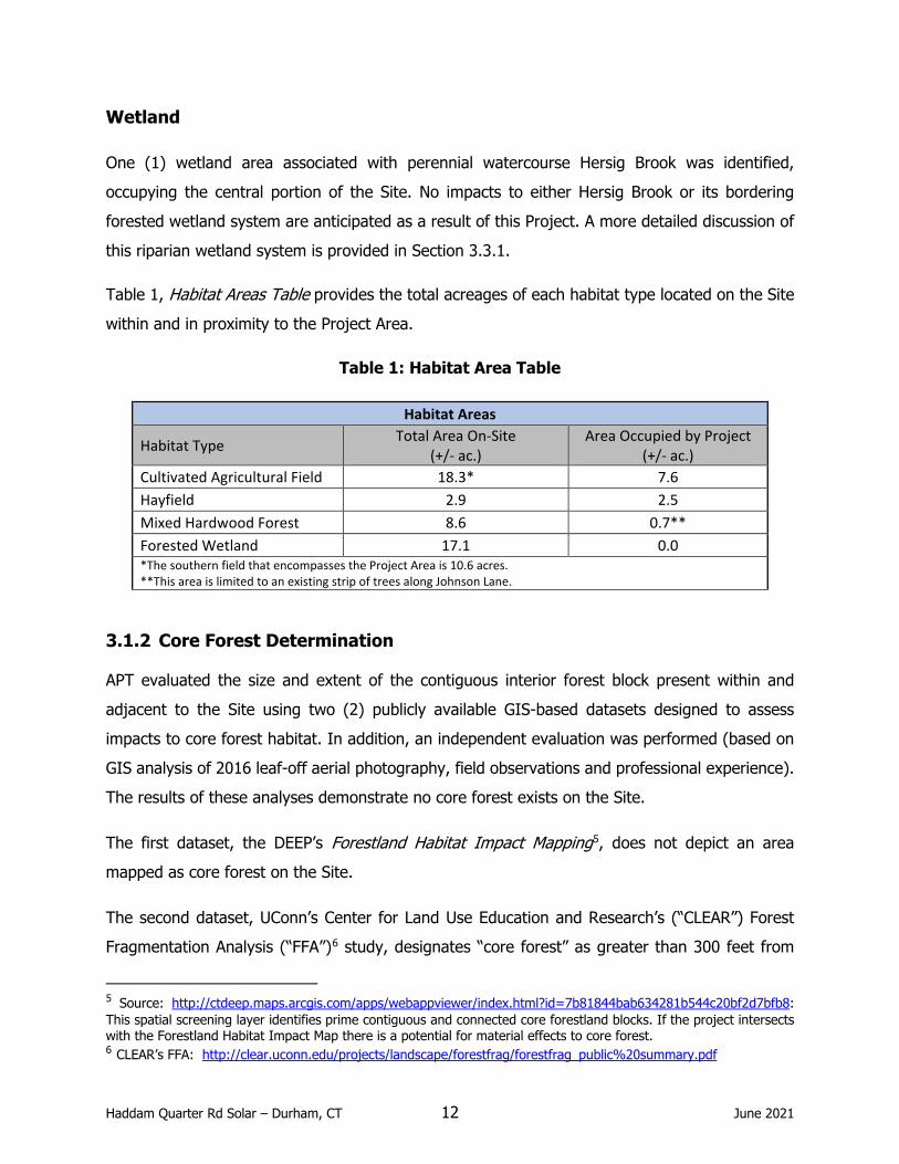
Wetland
One (1) wetland area associated with perennial watercourse Hersig Brook was identified, occupying the central portion of the Site. No impacts to either Hersig Brook or its bordering forested wetland system are anticipated as a result of this Project. A more detailed discussion of
this riparian wetland system is provided in Section 3.3.1.
Table 1, Habitat Areas Table provides the total acreages of each habitat type located on the Site
within and in proximity to the Project Area.
Table 1: Habitat Area Table
Habitat Areas
Habitat Type Total Area On-Site (+/- ac.)
Area Occupied by Project (+/- ac.)
Cultivated Agricultural Field 18.3* 7.6 Hayfield 2.9 2.5 Mixed Hardwood Forest 8.6 0.7** Forested Wetland 17.1 0.0 *The southern field that encompasses the Project Area is 10.6 acres. **This area is limited to an existing strip of trees along Johnson Lane.
3.1.2 Core Forest Determination
APT evaluated the size and extent of the contiguous interior forest block present within and adjacent to the Site using two (2) publicly available GIS-based datasets designed to assess impacts to core forest habitat. In addition, an independent evaluation was performed (based on GIS analysis of 2016 leaf-off aerial photography, field observations and professional experience). The results of these analyses demonstrate no core forest exists on the Site.
The first dataset, the DEEP’s Forestland Habitat Impact Mapping5, does not depict an area mapped as core forest on the Site.
The second dataset, UConn’s Center for Land Use Education and Research’s (“CLEAR”) Forest Fragmentation Analysis (“FFA”)6 study, designates “core forest” as greater than 300 feet from
5 Source: http://ctdeep.maps.arcgis.com/apps/webappviewer/index.html?id=7b81844bab634281b544c20bf2d7bfb8: This spatial screening layer identifies prime contiguous and connected core forestland blocks. If the project intersects with the Forestland Habitat Impact Map there is a potential for material effects to core forest. 6 CLEAR’s FFA: http://clear.uconn.edu/projects/landscape/forestfrag/forestfrag_public%20summary.pdf

Haddam Quarter Rd Solar – Durham, CT 13 June 2021
non-forested habitat. This 300-foot zone is referred to as the “edge width” and represents sub-optimal breeding habitat for forest-interior birds due to decreased forest quality, increased levels of disturbance, and increased rates of nest predation and brood parasitism within this transitional forest edge. The FFA study identifies three categories of core forest: small (< 250 acres); medium (250-500 acres); and large (>500 acres). Based on the FFA criteria, the Site only contains edge forested habitat and no core forest as a result of the southern and northern agricultural fields and the managed electrical transmission ROW traversing the Site. This is consistent with APT’s independent analysis, which indicates that no core forest is located on the Site.
The Project Area will be entirely located within an existing agricultural field and no tree clearing is proposed with the exception of selective tree removal between the field and Johnson Lane to the south. As a result, no impacts to core forested resources will occur.

Haddam Quarter Rd Solar – Durham, CT 14 June 2021
3.1.3 Wildlife
Development of the proposed Facility will alter two (2) of the four (4) habitat types located on Site, Cultivated Agricultural Field and Hayfield. Project-related activities proposed within these existing fields are not anticipated to adversely affect wildlife since these areas currently provide limited value from a wildlife utilization standpoint as a result of frequent management and
disturbances.
The edge forest habitat prevalent on the Site provides higher quality habitat for species that are more tolerant of human disturbance, habitat fragmentation and resultant “edge” effects. Generalist wildlife species, including several song birds and mammals such as raccoon (Procyon lotor), striped skunk (Mephitis mephitis), grey squirrel (Sciurus carolinensis), Virginia opossum (Didelphus virginiana), and eastern chipmunk (Tamias striatus) could be expected to use these
areas of the Site.
The Project Area will not encroach into the nearby Hersig Brook riparian corridor and bordering Mixed Hardwood Forest, so wildlife utilization is expected to continue relatively uninterrupted within these habitats. Noise and associated human activities during construction may result in limited, temporary disruption to wildlife using these nearby habitats. However, ongoing operation of the Facility will not result in a likely adverse effect in these nearby habitats as the Facility is
unoccupied.
3.2 Rare Species
APT reviewed publicly available information to determine the potential presence of state/federally
listed species and critical habitat on or proximate to the Site.
3.2.1 Natural Diversity Data Base
The DEEP Natural Diversity Data Base (“NDDB”) program performs hundreds of environmental reviews each year to determine the impact of proposed development projects on state listed species and to help landowners conserve the state’s biodiversity. In furtherance of this endeavor, the DEEP also developed maps to serve as a pre-screening tool to help applicants determine if
there is the potential for project-related impact to state-listed species.
The NDDB maps represent approximate locations of (i) endangered, threatened and special concern species and, (ii) significant natural communities in Connecticut. The locations of species

Haddam Quarter Rd Solar – Durham, CT 15 June 2021
and natural communities depicted on the maps are based on data collected over the years by DEEP staff, scientists, conservation groups, and landowners. In some cases, an occurrence represents a location derived from literature, museum records and/or specimens. These data are compiled and maintained in the NDDB. The general locations of species and communities are symbolized as shaded (or cross-hatched) polygons on the maps. Exact locations have been masked to protect sensitive species from collection and disturbance and to protect landowner’s
rights whenever species occur on private property.
APT reviewed the most recent DEEP NDDB mapping (December 2020 and June 2021), which revealed that no NDDB polygon exists partially or entirely on Site with the nearest NDDB polygon located ±0.25 mile to the southwest. Because no state-listed species or communities are
documented on the Site, consultation with NDDB is not required.
3.2.2 USFWS Consultation
The northern long-eared bat (“NLEB”; Myotis septentrionalis) is a federally-listed7 threatened species also known to occur in the vicinity of the Site. The NLEB’s range encompasses the entire State of Connecticut and suitable NLEB roost habitat includes trees (live, dying, dead, or snag)
with a diameter at breast height (“DBH”) of three (3) inches or greater.
APT reviewed the DEEP’s publicly available Northern long-eared bat areas of concern in Connecticut to assist with Federal Endangered Species Act Compliance map (February 1, 2016) to determine the locations of any known maternity roost trees or hibernaculum in the state. This map reveals that there are currently no known NLEB maternity roost trees in Connecticut. The nearest NLEB habitat resource to the Site is located in North Branford, approximately 9 miles to
the southwest.
The Project will result in the removal of a number of trees with greater than three (3) inches DBH along Johnson Lane. Since tree removal activities can potentially impact NLEB habitat, APT completed a determination of compliance with Section 7 of the Endangered Species Act of 1973 for the Project.
7 Listing under the federal Endangered Species Act

Haddam Quarter Rd Solar – Durham, CT 16 June 2021
In compliance with the US Fish and Wildlife Service (“USFWS”) criteria for assessing NLEB, the Project will not likely result in an adverse effect or incidental take8 of NLEB and does not require a permit from USFWS. A UWFWS letter dated March 23, 2021 confirmed compliance; thus, no
further consultation with USFWS is required for the proposed activity.
A full review of the Endangered Species Act (ESA) Compliance Determination and USFWS’s
Response Letter is provided in Appendix C, USFWS and NDDB Compliance Statement.
3.3 Water Resources
3.3.1 Wetlands and Watercourses
The on-Site wetland boundary was delineated by others on August 25, 2020 and documented in a technical report. An APT Professional Soil Scientist reviewed the report and performed an independent field inspection of the wetlands to verify the boundary on March 20, 2021. APT determined that the previous wetland delineation was substantially correct. One (1) wetland was identified on the Site associated with perennial watercourse Hersig Brook. The results of the wetland investigation are summarized below. The locations of these resources are depicted on Figure 2, Existing Conditions Map.
Hersig Brook and Bordering Forested Wetlands
A wetland area is located centrally on the Site, consisting of Hersig Brook and associated bordering forested wetlands. Centrally within the riparian corridor is an existing farm road hard-bottom crossing of Hersig Brook at a narrow point in the bordering wetland system. The crossing provides access from the agricultural field along Johnson Lane to a second field located south of Haddam Quarter Road. Forested wetlands that border Hersig Brook include low lying flood-prone areas and hillside seep features located along the wetland boundary that provide base flow to the brook. Dominant species within this riparian corridor consist of red maple, green ash (Fraxinus pennsylvanica), yellow birch, spicebush (Lindera benzoin), multiflora rose, highbush blueberry (Vaccinium corymbosum), greenbrier (Smilax rotundifolia), cinnamon fern (Osmunda cinnamomea), sensitive fern (Onoclea sensibilis), and skunk cabbage (Symplocarpus foetidus).
8 “Incidental take” is defined by the Endangered Species Act as take that is "incidental to, and not the purpose of, the carrying out of an otherwise lawful activity." For example, harvesting trees can kill bats that are roosting in the trees, but the purpose of the activity is not to kill bats.

Haddam Quarter Rd Solar – Durham, CT 17 June 2021
3.3.2 Wetland Impacts
No direct impacts to wetlands or watercourses are associated with developing the Facility. The Facility maintains a minimum 50-foot buffer to wetlands, with the majority of the Project’s limits of disturbance being at least 80 feet from nearest wetlands. The nearest construction activity is more than 150 feet from Hersig Brook. The nearest construction activity to bordering wetlands would occur in the eastern end of the Project Area, where proposed temporary sediment traps are approximately 35 feet at their closest point. Construction activities would not be expected to result in a likely adverse impact to the Site’s wetland resources based on the buffers being afforded and the fact that the Project will not require clearing of any mature vegetation within those buffers. Table 2, Wetland Impact Table, provides a summary of distances to wetland resources.
Table 2: Wetland Impact Table
Wetland Impacts Direct Impacts to Wetland 1 (ac.) 0 Project Proximity to Wetlands (from limit of disturbance) Distance (+/-ft.) Direction
(of wetland/water from LOD) Wetland 1 35 North Solar Installation Proximity to Wetlands (from perimeter fence) Distance (+/-ft.) Direction
(of wetland/water from perimeter fence) Wetland 1 82 Northwest
Any potential indirect impacts associated with the Project’s construction activities will be minimized by the proper installation and maintenance of proposed E&S controls, in accordance with the 2002 Connecticut Guidelines for Soil Erosion and Sediment Control.
3.3.3 Floodplain Areas
APT reviewed the United States Federal Emergency Management Agency (“FEMA”) Flood Insurance Rate Map (“FIRM”) covering the Site. A FIRM is the official map of a community on which FEMA has delineated both the special hazard areas and risk premium zones applicable to the community. The area inclusive of the Site is mapped on FIRM PANEL #09007C0207G, dated August 28, 2008. Based upon the reviewed FIRM Map, the proposed Project Area is located in an area designated as unshaded Zone X, which is defined as areas of minimal flooding, typically above the 500-year flood level.

Haddam Quarter Rd Solar – Durham, CT 18 June 2021
The Project Area is not located within a 100- and 500-year flood zone. Therefore, no special considerations or precautions relative to flooding are required for the Project.
3.4 Water Quality
As discussed in this section, the Project will comply with DEEP’s water quality standards. Once operative, the Facility will be unstaffed, and no potable water uses or sanitary discharges are planned. No liquid fuels are associated with the operation of the Facility. The panels proposed for use in the Facility do not contain GenX and PFAS chemicals, and those chemicals are not used in the manufacturing process. (See Appendix B.) Stormwater generated by the proposed development will be properly handled and treated in accordance with the 2004 Connecticut Stormwater Quality Manual and Appendix I.
3.4.1 Groundwater
Groundwater underlying the Site is classified by publicly available DEEP mapping as “GA”.9 This classification indicates groundwater within the area is presumed to be suitable for human consumption without treatment. Based upon a review of available DEEP mapping, the Site is not
located within a mapped (preliminary or final) DEEP Aquifer Protection Area.
The Project will have no adverse environmental effect on ground water quality.
3.4.2 Surface Water
The Project will have no adverse environmental effect on surface water quality. Based upon DEEP mapping, the Site is located in Major Drainage Basin 4 (Connecticut River), Regional Drainage Basin 46 (Mattabesset River), Sub Regional Drainage Basin 4605 (Allyn Brook), and Local Drainage Basin 4605-01 (Hersig Brook). Hersig Brook traverses the central portion of the Site, generally flowing in an east to west direction to the north of the Project Area. Hersig Brook is classified by DEEP as a Class A surface waterbody.10 The Project will have no effect on this surface
waterbody.
9 Designated uses in GA classified areas include existing private and potential public or private supplies of drinking water and base flow or hydraulically connected surface water bodies. 10 Designated uses for A classified waterbodies include potential drinking water supply, fish and wildlife habitat, recreational use, agricultural and industrial supply and other legitimate uses including navigation.

Haddam Quarter Rd Solar – Durham, CT 19 June 2021
Based upon the reviewed DEEP mapping, the Site is not located within a mapped Public Drinking Supply Watershed. The nearest Public Drinking Supply Watershed is located approximately one (1) mile to the south (in a watershed separate from the Site) that is associated with the Regional
Water Authority PWS CT0930011.
During construction, E&S controls will be installed and maintained in accordance with the 2002 Connecticut Guidelines for Soil Erosion and Sediment Control. Once operative, stormwater will be
managed in accordance with the 2004 Connecticut Stormwater Quality Manual.
3.4.3 Stormwater Management
In addition to the 2004 Connecticut Stormwater Quality Manual and 2002 Connecticut Guidelines for Soil Erosion and Sediment Control, the Project has been designed to meet Appendix I. Combined, these address three (3) main concerns: stormwater runoff peak attenuation, water quality volume treatment, and erosion and sediment control during construction. Technical details, mapping, and HydroCAD modeling results are provided in the Stormwater Management
Report submitted under separate cover. A summary of these results is provided below.
Stormwater Runoff Peak Attenuation
The potential for increased runoff from the Site as a result of Project construction has been evaluated and addressed. For this Site it involves not only the disturbances associated with the Project Area and Facility appurtenances, but also the sizable watershed south of Johnson Lane that flows through the property via two (2) existing culverts. Selective clearing of the vegetation along the northern side of Johnson Lane is required to avoid shading of the southern portion of the Facility. The Project will maintain existing hydrological conditions, as only limited grading is required for the installation of the access drives, swales, and water quality volume basin. Upon completion of construction, the Site will be stabilized using a mix of native flowering grasses and plants selected specifically for solar installations (Ernst Solar Farm Seed Mix), which will create a meadow condition. Appendix I requires that the hydrologic soil group be reduced by a half-drop for solar arrays. However, the Project’s change from the existing condition of tilled agricultural ground cover to proposed meadow ground cover results in a reduced curve number in the proposed condition, even accounting for the half-drop in hydrologic soil group. The reduction of the curve number in the final condition negates the need for stormwater controls, as the post-
development stormwater flows are less than the pre-development flows.

Haddam Quarter Rd Solar – Durham, CT 20 June 2021
In order to appropriately manage the off-Site drainage originating south of Johnson Lane, the Applicant proposes two (2) swales to redirect the runoff around the fenced area and any potential ground disturbance associated with construction of the Project. The primary purpose of these two swales is to direct “clean runoff” around the limits of disturbance and avoid the active construction area. The redirected runoff will still experience sheet flow across undeveloped areas of the Site,
as it does currently, prior to entering the existing wetlands and Hersig Brook.
The stormwater calculations for the Project demonstrate that the post-development peak discharges to the waters of the State of Connecticut for the 2-, 25-, 50- and 100- year storm events are less than the pre-development peak discharges. Therefore, the Project will not result
in any adverse conditions to the surrounding areas and properties.
Water Quality Volume Treatment
The Project design also provides for adequate treatment of water quality volume associated with effective impervious cover, which includes the proposed gravel access drives, concrete equipment pads, and the northeastern portion of the Project Area where solar panels will be installed on a hill with slopes exceeding 15% grade. A water quality volume basin, sized to provide the requisite treatment volumes associated with those features, is proposed on the eastern side of the Project Area. Technical details, mapping, and HydroCAD modeling results are provided in the Stormwater
Management Report submitted under separate cover.
Erosion and Sediment Control During Construction
To safeguard water resources from potential impacts during construction, the Applicant is committed to implementing protective measures in the form of a Stormwater Pollution Control Plan (“SWPCP”), to be finalized and submitted to the Council, subject to approval by DEEP Stormwater Management. The SWPCP will include monitoring of established E&S controls that are to be installed and maintained in accordance with the 2002 Connecticut Guidelines for Soil Erosion and Sediment Control. The Applicant will also apply for a General Permit for the Discharge of Stormwater and Dewatering Wastewaters from Construction Activities from DEEP.
Development of the Project requires minimal grading and ground disturbance. Nonetheless, the Applicant proposes a phased erosion control plan utilizing a series of perimeter compost filter socks to manage drainage areas less than one (1) acre, and temporary sediment traps to manage drainage areas that are greater than one (1) acre but less than five (5) acres. Taking into account

Haddam Quarter Rd Solar – Durham, CT 21 June 2021
the proximity of the wetland buffers, the temporary sediment traps will be installed on grade, utilizing stacked compost filter socks and existing topography to provide the requisite sediment treatment while minimizing ground disturbances. Additionally, the Applicant proposes to seed and establish temporary cover within the footprint of the proposed array prior to the start of construction. Upon completion of construction, the Site will be seeded with the permanent Ernst Solar Farm Seed Mix. The phased erosion control plan and details are provided in Appendix A,
Project Plans.
With the incorporation of these protective measures, stormwater runoff from Project development
will not result in an adverse impact to water quality associated with nearby surface water bodies.
3.5 Air Quality
The Site is currently undeveloped agricultural land. Due to the nature of a solar energy generating facility, no air emissions will be generated during operations and, therefore, the operation of the
Facility will have no adverse effects on air quality and no permit is required.
Temporary, potential, construction-related mobile source emissions will include those associated with construction vehicles and equipment. Any potential air quality impacts related to construction activities can be considered de minimis. Such emissions will, nonetheless, be mitigated using available measures, including, inter alia, limiting idling times of equipment; proper maintenance of all vehicles and equipment; and watering/spraying to minimize dust and particulate releases. In addition, all on-site and off-road equipment will meet the latest standards for diesel emissions,
as prescribed by the United States Environmental Protection Agency.
3.6 Soils and Geology
The construction of the water quality volume basin and grading within the Project Area will generate some excess material that will be redistributed on Site. Prior to the removal of soils, the topsoil will be stripped, stockpiled, and spread over disturbed areas being seeded. See Appendix A, Project Plans.
All exposed soils resulting from construction activities will be properly and promptly treated in
accordance with the 2002 Connecticut Guidelines for Soil Erosion and Sediment Control.

Haddam Quarter Rd Solar – Durham, CT 22 June 2021
Surficial materials on the southern portion of the Site are generally comprised of thin deposits of glacial till while northern portions of the Site are dominated by glaciofluvial (sand and gravel outwash) deposits. During field investigations, APT observed evidence of mixing of these two soil parent materials where the till hill to the south contacts with the glaciofluvial deposits that occur
along the Hersig Brook corridor.
Bedrock geology beneath the Site is mapped as Portland Arkose. Portland Arkose is described as a reddish-brown to maroon micaceous arkose and siltstone and red to black fissile silty shale. The
Applicant does not anticipate encountering bedrock during Project development.
3.6.1 Prime Farmland Soils
In accordance with the Code of Federal Regulations, CFR Title 7, part 657, farmland soils include land that is defined as prime, unique, or farmlands of statewide or local importance based on soil type. They represent the most suitable land for producing food, feed, fiber, forage, and oilseed
crops.
According to the Connecticut Environmental Conditions Online Resource Guide,11 the Project Area
contains Prime Farmland Soils, (See Figure 2, Existing Conditions Map.)
The majority of the Site has remained largely undeveloped and used for agriculture since the 1700s. Recognizing that the Project has a useful life and could be considered temporary in nature, the Applicant has proposed using minimally intrusive methods for construction of the Project. The use of a ground-mounted racking system for the installation of the solar panels and associated
equipment minimizes the need for substantial grading.
Some excavation and regrading activities are necessary within areas mapped as Prime Farmland Soils to facilitate Project development and construct the water quality volume basin. The water quality volume basin and topographic modifications allow the Project to comply with Appendix I. Topsoil removed from these areas will be segregated from underlying horizons, temporarily
stockpiled and used as top dressing for reestablishing vegetation. No topsoil will leave the Site.
After its useful life, the Facility will be decommissioned and all of the disturbed areas will be reseeded with the same (or approved equivalent) blend as established within the rest of the
11 Connecticut Environmental Conditions Online (CTECO) Resource Guide www.cteco.uconn.edu.

Haddam Quarter Rd Solar – Durham, CT 23 June 2021
Project Area. Implementation of these proposed design strategies demonstrates that the Project will not materially affect Prime Farmland Soils. In accordance with Connecticut General Statutes
§16-50k(a), the Applicant sent correspondence to the Connecticut Department of Agriculture in
April of 2021, documenting that the Project will not materially affect Prime Farmland Soils on the site.
Table 3, Farmland Soils Assessment and Impacts Table provided below details the amount of farmland soils located on the Site and the proposed impact from the Project.
Table 3: Farmland Soils Assessment and Impacts Table
Farmland Soils Assessment and Impacts Farmland Soil Classification Total Area On-Site (+/- ac.) Area within Project Limits (+/- ac.) Prime Farmland Soil Area 21.4 7.7
3.7 Historic and Archaeological Resources
At the request of APT, and on behalf of the Applicant, Heritage Consultants LLC (“Heritage Consultants”) reviewed relevant historic and archaeological information to determine whether the Site holds potential cultural resource significance. Their review of historic maps and aerial images of the Site, examination of files maintained by the Connecticut State Historic Preservation Office (“SHPO”), and a pedestrian survey of the Site revealed one (1) National Register of Historic Places (“NRHP”) property within one (1) mile of the Site. This resource is not proximate to the Project Area and due to its distance from the Site, no direct or indirect effects from the Project are
anticipated.
In terms of archaeological potential, it was determined that approximately 8.15 acres of the Project Area retains a moderate potential to contain intact archaeological deposits in the subsoil. At the request of the Applicant, Heritage performed a Phase 1B Professional Cultural Resources Assessment and Reconnaissance Survey (“Phase 1B”). The combined Phase 1A/Phase 1B report has been submitted to SHPO and is included in Appendix D, Cultural Resources Reconnaissance Survey Report. The SHPO response to the report will be provided when available.

Haddam Quarter Rd Solar – Durham, CT 24 June 2021
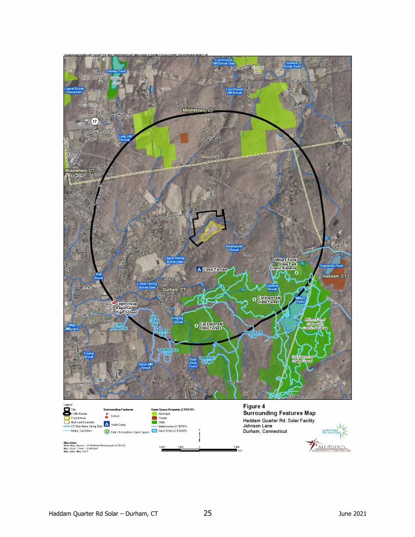
3.8 Scenic and Recreational Areas
No state or local designated scenic roads or scenic areas are located near the Site and therefore none will be physically or visually impacted by development of the Project. The nearest scenic road is a portion of State Route 17 in Durham, designated as a state scenic road, located approximate 1.5 miles southeast of the Site. Additionally, there are no CT Blue Blaze Hiking Trails
located proximate to the Site.
There are no public recreational areas located proximate to the Site; the nearest recreational area is Camp Farnam, a youth camp, located approximately 0.25 mile south of the Site. The nearest public open space is Cockaponset State Forest located approximately 0.3 mile south of the Site. Impacts to either resource, either physical or visual, are not anticipated. See Figure 4,
Surrounding Features Map, for these and other resources located within one mile of the Site.
Haddam Quarter Rd Solar – Durham, CT 25 June 2021

Haddam Quarter Rd Solar – Durham, CT 26 June 2021
3.9 Noise
The Site is primarily undeveloped and has been used historically for agriculture. With the
exception of transient farm equipment, little or no noise is currently generated on the Site.
Construction noise is exempted under both the Town of Durham noise ordinance and State of Connecticut regulations for the control of noise, RCSA 22a-69-1.8(h). During construction of the Facility, the temporary increase in noise would likely raise localized ambient sound levels immediately surrounding the Project Area. Standard types of construction equipment would be used for the Project. In general, the highest noise level from this type of equipment (e.g.,
backhoe, bulldozer, crane, trucks, etc.) is approximately 88 dBA at the source.
Once operational, noise from the Project will be minimal. The Site and all surrounding properties are located within the Farm Residential (FR) zone, and would be considered a Class A Noise Zone.12 Conservatively, the Facility would be considered a Class C (Industrial) noise emitter to Class A (Residential) receptors. As such, it is subject to noise standards of 61 dBA during the daytime and 51 dBA at night. The Facility’s only noise generating equipment are the inverters and transformers. Based on the most conservative information provided by specified equipment manufacturers, the loudest proposed equipment is the two (2) 2,000 kVA transformers that will
generate a maximum predicted sound level of approximately 61 dBA (measured at 1-foot away).
Sound reduces with distance and the inverters and transformers are inactive at night. The closest property line to either transformer is approximately 109 feet to the south, a residential property south of Johnson Lane (Parcel 19-32). APT applied the Inverse Square Law13 to evaluate the relative sound level of the transformers at the nearest property line. Based on these calculations, nearby receptors are of sufficient distances from the proposed Project-related equipment and once operational, noise levels during Facility operation will meet applicable Town and State noise
standards for a Class A Noise Zone.
Please refer to the specification sheets provided in Appendix B, Product Information Sheets.
12 RCSA 22a-69-3.5. Noise Zone Standards 13 Inverse Square Law states that the intensity of a force is inversely proportional to the square of the distance from that force. With respect to sound, this means that any a noise will have a drastic drop-off in volume as it moves away from the source and then shallows out.

Haddam Quarter Rd Solar – Durham, CT 27 June 2021
3.10 Lighting
The Site is currently unlit, except to the extent that two outbuildings in its northwestern corner
along Haddam Quarter Road (remote from the Project Area) may have occasional lighting.
No exterior lighting is planned for the Project. There will be some small, non-intrusive lighting
fixtures within the equipment to aid in maintenance.
3.11 FAA Determination
The Applicant submitted relevant Project information to the Federal Aviation Administration (“FAA”) for an aeronautical study to evaluate potential hazards to air navigation. The FAA provided a Determination of No Hazard to Air Navigation on August 11, 2020. See Appendix F, FAA Determination. Based on this determination, no marking or lighting are required, and there is no
need to conduct a glare analysis.
3.12 Visibility
The Facility will consist of 7,434 non-reflective solar panels measuring approximately 10.6 feet above grade. The proposed electrical interconnection to an existing distribution pole located on
Johnson Lane will require the installation of approximately four (4) new utility poles.
The solar modules are designed to absorb incoming solar radiation and minimize reflectivity, such that only a small percentage of incidental light will be reflected off the panels. This incidental light is significantly less reflective than common building materials, such as steel, or the surface of smooth water. The panels will be tilted up toward the southern sky at a fixed angle of 30 degrees,
thereby further reducing reflectivity.
The Site is generally a mix of agricultural fields and wooded areas, with the Facility location cleared except for a narrow strip of vegetation along Johnson Lane. APT assessed the predicted visibility of the Facility with a project-specific computer analysis of a one-mile radius around the Site. As depicted on the resulting viewshed maps, year-round visibility of the proposed Facility is limited almost entirely to the Site itself and frontage along Johnson Lane, with several narrow fingers extending farther south within driveways to residential properties. Potential seasonal views, when the leaves are off of the deciduous trees, could extend up to approximately 360 feet from the Project Area to the west, south and east. Predicted year-round visibility is estimated to

Haddam Quarter Rd Solar – Durham, CT 28 June 2021
include ±16 acres; predicted seasonal visibility of the proposed Facility is estimated to include an
additional approximately 19 acres.
The Applicant has developed a landscaping/planting plan in response to feedback from Site neighbors and members of the community. The Facility will be surrounded by a 7-foot tall farm style fence. Seven species of native trees and shrubs will be interspersed along the Facility’s southern boundary to provide visual interest and screening of select viewpoints, and to maintain the current unmanicured nature of the Property. The proposed plantings will replace non-native
invasive species and provide food and habitat for birds and small animals.
Please see Appendix F for viewshed maps, the landscaping/planting plan and photo-simulations
of the proposed Facility.

Haddam Quarter Rd Solar – Durham, CT 29 June 2021
4 Conclusion
As demonstrated in this Environmental Assessment, the Project will comply with the DEEP air and water quality standards. Further, it will not have an undue adverse effect on the existing environment and ecology; nor will it affect the scenic, historic and recreational resources in the
vicinity of the Project. Once operative, the Facility will be unstaffed and generate minimal traffic.
The Project Area is almost entirely cleared and contains no core forest. No adverse impact to any federal or state threatened, endangered or special concern species is anticipated and no State-listed species have been identified as potentially occurring within the vicinity of the Site. The Northern long-eared bat was identified as potentially occurring within the vicinity of the Site but the Project should not result in an adverse effect or an incidental take. The Applicant will implement a planting plan that replaces non-native invasive species with native species that will provide food and habitat for birds and small animals, ultimately enhancing the southern portion of the Project Area.
Portions of the Project Area are located within mapped Prime Farmland Soils. The Applicant has designed the Project to minimize disturbance to these soils by proposing minimally intrusive methods for construction and installation of Facility components and limiting excessive grading. No soil will be exported from the Site. The Applicant will seed all disturbed areas. Once the Facility has reached the end of its projected useful life, the panels and equipment can be removed and
the Project Area restored.
No wetlands or watercourses will be directly impacted by the Project. The nearest wetland boundary to construction activities associated with the Facility is approximately 82 feet away, and the nearest point of the Project limits of disturbance is 35 feet away. To aid in the protection of wetland resources, E&S controls will be installed and maintained throughout construction in accordance with the 2002 Connecticut Guidelines for Soil Erosion and Sediment Control. The distance from the main areas of disturbance within the fenced Facility to wetlands and implementation of management techniques will mitigate potential impacts to these resources
during construction.
Overall, the Project’s design minimizes the creation of impervious surfaces and generally maintains existing grades. Some minor regrading and excavations will be required for the

Haddam Quarter Rd Solar – Durham, CT 30 June 2021
development of the Facility and for the construction of the water quality volume basin. The Project has been designed to adequately handle water volume through that basin, which will be installed adjacent to the eastern fence line. In addition, two (2) swales that terminate into rip-rap plunge pools/level spreaders will be installed to redirect runoff from south of Johnson Lane around the fenced area and avoid any disturbed ground associated with construction activities. The Project has been designed in accordance with the DEEP’s General Permit for the Discharge of Stormwater and Dewatering Wastewaters from Construction Activities as well as Appendix I. The Applicant will implement a SWPCP, in accordance with the 2002 Connecticut Guidelines for Soil Erosion and Sediment Control, that will include provisions for monitoring of development activities and the
establishment of E&S controls to be installed and maintained throughout construction.
Year-round visibility of the proposed Facility beyond the Property is minimal. Seasonal views, when the leaves are off the trees, could extend up to 360’ off-Site to abutting properties to the south, east and west. The use of a farm fence and plantings of native shrub and tree species along Johnson Lane will both soften views of the Facility and create a more compatible
development with the existing neighborhood.

APPENDIX A
PROJECT PLANS

DATE:
APT FILING NUMBER:
HADDAM QUARTER SOLAR,LLC
JOHNSON LANEDURHAM, CT
SITEADDRESS:
SHEET TITLE:
DRAWN BY:
CHECKED BY:
SHEET NUMBER:
DESIGN PROFESSIONAL OF RECORD
DATENO REVISION
06/07/21
CT671100
0123456
JT
KAM
06/07/21 FOR REVIEW: KAM
CSC PERMIT SET
567 VAUXHALL STREET EXTENSION - SUITE 311WATERFORD, CT 06385 PHONE: (860)-663-1697WWW.ALLPOINTSTECH.COM FAX: (860)-663-0935
OWNER:
ADDRESS:
NEWTON FAMILY TRUST CO
1279 ARBUTUS STDURHAM, CT 06422
PROF: KEVIN A. MCCAFFERY, P.E.COMP: ALL-POINTS TECHNOLOGY
CORPORATION, P.C.ADD: 567 VAUXHALL STREET
EXTENSION - SUITE 311WATERFORD, CT 06385
LIST OF DRAWINGS SITE INFORMATION
LOUTH CALLAN RENEWABLES
"HADDAM QUARTER SOLAR, LLC"
JOHNSON LANEDURHAM, CT
USGS TOPOGRAPHIC MAP
SCALE : 1" = 2000'±
SITE
TITLE SHEET & INDEX
T-1
LONG ISLAND SOUND
15
70
MUNICIPAL LOCATION
I S L A N D
S T A T E O F R
H O
D E
STATE OF CONNECTICUT
STAT
E
OF
N
EW
YO
RK
UNION
STAFFORD
TOLLANDWILLINGTON
ENFIELD
LOCKS
WINDSOREAST
WINDSOR
WINDSOR
ELLINGTON
SOMERS
WINDSORSOUTH
MANCHESTER
WEST
HARTFORD EAST
HARTFORD
WETHERSFIELD
NEWINGTON
BRITAINNEW
HARTFORD
VERNON
GLASTONBURY
CROMWELL
PORTLAND
71BERLIN
SOUTHINGTON
ROCKY HILL
66
5
CHESHIRE
MERIDEN MIDDLETOWN
MIDDLEFIELD
PLAINVILLE
BLOOMFIELD
WOLCOTT
322
BRISTOL
EAST
GRANBY
SUFFIELD
CANTON
SIMSBURY
GRANBY
AVON
FARMINGTON
COLEBROOK
NORTHCANAAN
CANAAN
NORFOLK
WINCHESTER
TORRINGTON
CORNWALLGOSHEN
SALISBURY
SHARON
HARTFORDNEW
LITCHFIELD
HARWINTONWARREN
MORRIS
KENT
PLYMOUTHWATERTOWN
THOMASTON
WASHINGTON
WOODBURY
BETHLEHEM
MIDDLEBURY
WATERBURY
ROXBURY
BRIDGEWATER
SHERMAN
NEW
NEW
MILFORD
HARTLAND
BARKHAMSTED
PROSPECT
BURLINGTON
NAUGATUCK
OXFORD
BEACON
FALLS
SOUTHBURY
SEYMOUR
ANSONIA
BETHEL
NEWTOWN
BROOKFIELD
DANBURY
DERBYREDDING
RIDGEFIELD
FAIRFIELD
THOMPSON
KILLINGLY
PUTNAM
WOODSTOCK
ASHFORD EASTFORD
COVENTRY
MANSFIELD
POMFRET
STERLING
VOLUNTOWN
PLAINFIELD
GRISWOLD
NORTH
STONINGTON
CHAPLIN
WINDHAM
ANDOVER
SCOTLAND
SPRAGUE
COLUMBIA
LEBANON
HEBRON
MARLBOROUGH
BOLTON
LISBONNORWICH
BOZRAH
COLCHESTER
MONTVILLE
SALEMEAST HADDAM
EAST
HAMPTON
HADDAMDURHAM
FRANKLIN
LEDYARD
PRESTON
CANTERBURY
BROOKLYNHAMPTON
STONINGTON
GROTON
LONDON
NEW
LYME
OLD LYME
ESSEX
OLD
EAST LYME
SAYBROOK
CHESTER
DEEPMADISON
CLINTON
KILLINGWORTH
RIVER
GUILFORDWATERFORD
WALLINGFORD
NORTH
BETHANY
NORTHBRANFORD
EASTHAVENNEW
HAVEN
BRANFORD
WOODBRIDGE
SHELTON
MONROE
ORANGE
MILFORDSTRATFORD
EASTON
WESTON
TRUMBULL
WILTON
FAIRFIELD
WESTPORT
BRIDGEPORT
NEW
CANAAN
STAMFORD
DARIEN
GREENWICH
NORWALK
WESTHAVEN
HAMDEN
HAVEN
STATE OF MASSACHUSETTS
WESTBROOK
SOURCE: USGS 7.5 DURHAM QUADRANGLE, CT 2012
T-1
1 OF 1
GN-1
OP-1
EC-1
EC-2
EC-3
EC-4
GD-1
SP-1
DN-1
DN-2
TITLE SHEET & INDEX
EXISTING CONDITIONS PLAN PROVIDED BY DESIGNPROFESSIONALS, INC.
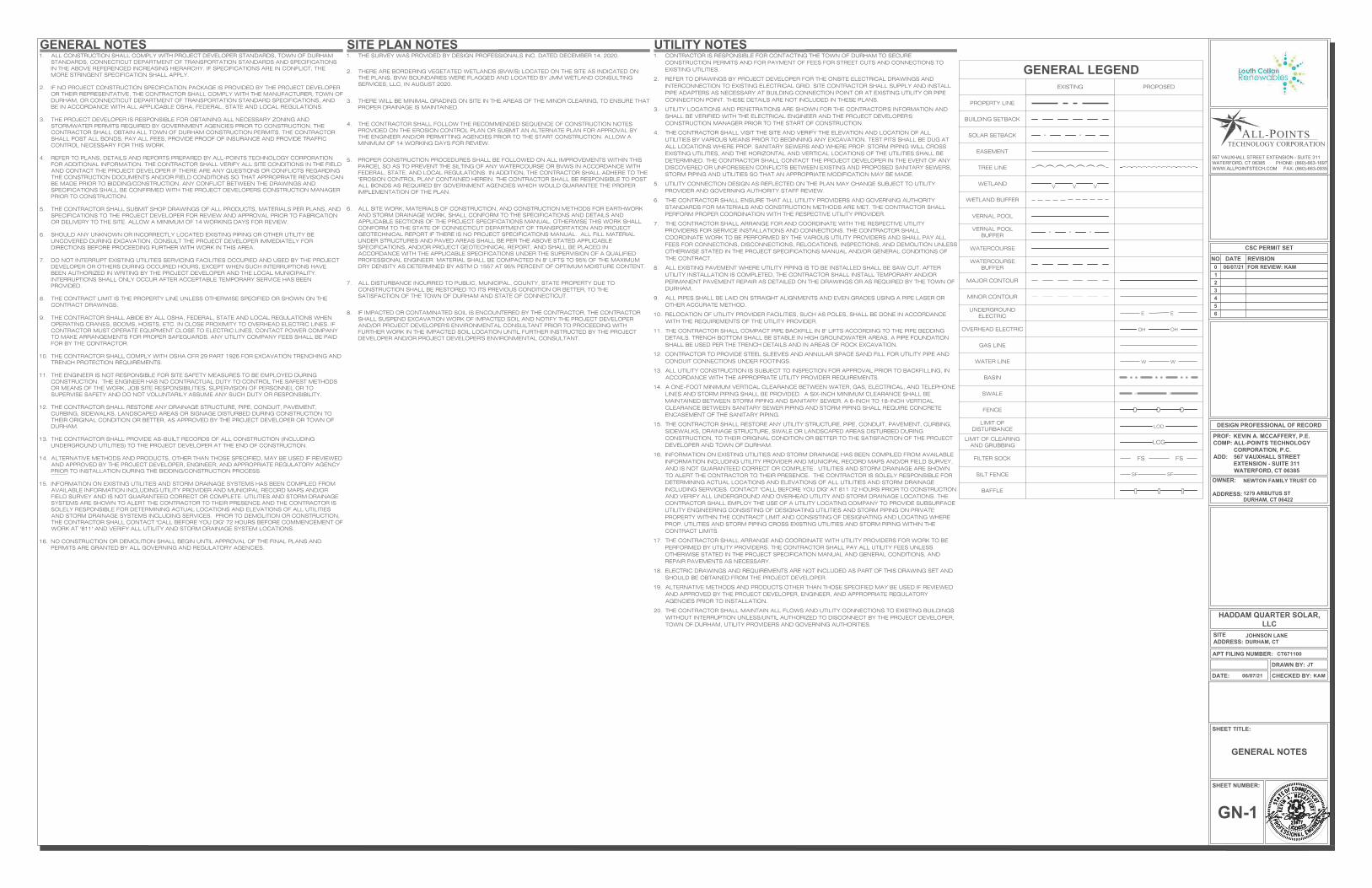
GENERAL NOTES
OVERALL LOCUS MAP
SEDIMENTATION & EROSION CONTROL NOTES
SEDIMENTATION & EROSION CONTROL DETAILS
PHASE 1 SEDIMENTATION & EROSION CONTROL PLAN
PHASE 2 SEDIMENTATION & EROSION CONTROL PLAN
FINAL GRADING & DRAINAGE PLAN
SITE & UTILITY PLAN
SITE DETAILS
SITE DETAILS
SITE NAME:
LOCATION:
SITE TYPE/DESCRIPTION:
PROPERTY OWNER:
APPLICANT:
ENGINEER CONTACT:
LATITUDE:LONGITUDE:ELEVATION:
MBLU:ZONE:
TOTAL SITE ACREAGE:TOTAL DISTURBED AREA:
SOLAR FACILITY AREA:
APPROX. VOLUME OF CUT:APPROX. VOLUME OF FILL:
APPROX. NET VOLUME:
"HADDAM QUARTER SOLAR, LLC"
JOHNSON LANE DURHAM, CT
ADD (1) GROUND MOUNTED SOLAR PANELARRAY W/ ASSOCIATED EQUIPMENT, GRAVELACCESS ROAD, AND STORMWATERMANAGEMENT.
NEWTON FAMILY TRUST CO1279 ARBUTUS STDURHAM, CT 06422
LOUTH CALLAN RENEWABLES921THRALL AVENUESUFFIELD, CT 06078
KEVIN A. MCCAFFERY, P.E.(860) 663-1697 x228
41°29'16.85" N72°39'0.04" W312'± AMSL
18-22FR
49.00± AC.10.85± AC.8.93± AC.
688± CY217± CY471± CY OF CUT
N
N

esign
rofessionals
DATE:
APT FILING NUMBER:
HADDAM QUARTER SOLAR,LLC
JOHNSON LANEDURHAM, CT
SITEADDRESS:
SHEET TITLE:
DRAWN BY:
CHECKED BY:
SHEET NUMBER:
DESIGN PROFESSIONAL OF RECORD
DATENO REVISION
06/07/21
CT671100
0123456
JT
KAM
06/07/21 FOR REVIEW: KAM
CSC PERMIT SET
567 VAUXHALL STREET EXTENSION - SUITE 311WATERFORD, CT 06385 PHONE: (860)-663-1697WWW.ALLPOINTSTECH.COM FAX: (860)-663-0935
OWNER:
ADDRESS:
NEWTON FAMILY TRUST CO
1279 ARBUTUS STDURHAM, CT 06422
PROF: KEVIN A. MCCAFFERY, P.E.COMP: ALL-POINTS TECHNOLOGY
CORPORATION, P.C.ADD: 567 VAUXHALL STREET
EXTENSION - SUITE 311WATERFORD, CT 06385
GENERAL NOTES
GN-1
1. THE SURVEY WAS PROVIDED BY DESIGN PROFESSIONALS INC. DATED DECEMBER 14, 2020.
2. THERE ARE BORDERING VEGETATED WETLANDS (BVW/S) LOCATED ON THE SITE AS INDICATED ONTHE PLANS. BVW BOUNDARIES WERE FLAGGED AND LOCATED BY JMM WETLAND CONSULTINGSERVICES, LLC, IN AUGUST 2020.
3. THERE WILL BE MINIMAL GRADING ON SITE IN THE AREAS OF THE MINOR CLEARING, TO ENSURE THATPROPER DRAINAGE IS MAINTAINED.
4. THE CONTRACTOR SHALL FOLLOW THE RECOMMENDED SEQUENCE OF CONSTRUCTION NOTESPROVIDED ON THE EROSION CONTROL PLAN OR SUBMIT AN ALTERNATE PLAN FOR APPROVAL BYTHE ENGINEER AND/OR PERMITTING AGENCIES PRIOR TO THE START CONSTRUCTION. ALLOW AMINIMUM OF 14 WORKING DAYS FOR REVIEW.
5. PROPER CONSTRUCTION PROCEDURES SHALL BE FOLLOWED ON ALL IMPROVEMENTS WITHIN THISPARCEL SO AS TO PREVENT THE SILTING OF ANY WATERCOURSE OR BVWS IN ACCORDANCE WITHFEDERAL, STATE, AND LOCAL REGULATIONS. IN ADDITION, THE CONTRACTOR SHALL ADHERE TO THE"EROSION CONTROL PLAN" CONTAINED HEREIN. THE CONTRACTOR SHALL BE RESPONSIBLE TO POSTALL BONDS AS REQUIRED BY GOVERNMENT AGENCIES WHICH WOULD GUARANTEE THE PROPERIMPLEMENTATION OF THE PLAN.
6. ALL SITE WORK, MATERIALS OF CONSTRUCTION, AND CONSTRUCTION METHODS FOR EARTHWORKAND STORM DRAINAGE WORK, SHALL CONFORM TO THE SPECIFICATIONS AND DETAILS ANDAPPLICABLE SECTIONS OF THE PROJECT SPECIFICATIONS MANUAL. OTHERWISE THIS WORK SHALLCONFORM TO THE STATE OF CONNECTICUT DEPARTMENT OF TRANSPORTATION AND PROJECTGEOTECHNICAL REPORT IF THERE IS NO PROJECT SPECIFICATIONS MANUAL. ALL FILL MATERIALUNDER STRUCTURES AND PAVED AREAS SHALL BE PER THE ABOVE STATED APPLICABLESPECIFICATIONS, AND/OR PROJECT GEOTECHNICAL REPORT, AND SHALL BE PLACED INACCORDANCE WITH THE APPLICABLE SPECIFICATIONS UNDER THE SUPERVISION OF A QUALIFIEDPROFESSIONAL ENGINEER. MATERIAL SHALL BE COMPACTED IN 8" LIFTS TO 95% OF THE MAXIMUMDRY DENSITY AS DETERMINED BY ASTM D 1557 AT 95% PERCENT OF OPTIMUM MOISTURE CONTENT.
7. ALL DISTURBANCE INCURRED TO PUBLIC, MUNICIPAL, COUNTY, STATE PROPERTY DUE TOCONSTRUCTION SHALL BE RESTORED TO ITS PREVIOUS CONDITION OR BETTER, TO THESATISFACTION OF THE TOWN OF DURHAM AND STATE OF CONNECTICUT.
8. IF IMPACTED OR CONTAMINATED SOIL IS ENCOUNTERED BY THE CONTRACTOR, THE CONTRACTORSHALL SUSPEND EXCAVATION WORK OF IMPACTED SOIL AND NOTIFY THE PROJECT DEVELOPERAND/OR PROJECT DEVELOPER'S ENVIRONMENTAL CONSULTANT PRIOR TO PROCEEDING WITHFURTHER WORK IN THE IMPACTED SOIL LOCATION UNTIL FURTHER INSTRUCTED BY THE PROJECTDEVELOPER AND/OR PROJECT DEVELOPER'S ENVIRONMENTAL CONSULTANT.
1. CONTRACTOR IS RESPONSIBLE FOR CONTACTING THE TOWN OF DURHAM TO SECURECONSTRUCTION PERMITS AND FOR PAYMENT OF FEES FOR STREET CUTS AND CONNECTIONS TOEXISTING UTILITIES.
2. REFER TO DRAWINGS BY PROJECT DEVELOPER FOR THE ONSITE ELECTRICAL DRAWINGS ANDINTERCONNECTION TO EXISTING ELECTRICAL GRID. SITE CONTRACTOR SHALL SUPPLY AND INSTALLPIPE ADAPTERS AS NECESSARY AT BUILDING CONNECTION POINT OR AT EXISTING UTILITY OR PIPECONNECTION POINT. THESE DETAILS ARE NOT INCLUDED IN THESE PLANS.
3. UTILITY LOCATIONS AND PENETRATIONS ARE SHOWN FOR THE CONTRACTOR'S INFORMATION ANDSHALL BE VERIFIED WITH THE ELECTRICAL ENGINEER AND THE PROJECT DEVELOPER'SCONSTRUCTION MANAGER PRIOR TO THE START OF CONSTRUCTION.
4. THE CONTRACTOR SHALL VISIT THE SITE AND VERIFY THE ELEVATION AND LOCATION OF ALLUTILITIES BY VARIOUS MEANS PRIOR TO BEGINNING ANY EXCAVATION. TEST PITS SHALL BE DUG ATALL LOCATIONS WHERE PROP. SANITARY SEWERS AND WHERE PROP. STORM PIPING WILL CROSSEXISTING UTILITIES, AND THE HORIZONTAL AND VERTICAL LOCATIONS OF THE UTILITIES SHALL BEDETERMINED. THE CONTRACTOR SHALL CONTACT THE PROJECT DEVELOPER IN THE EVENT OF ANYDISCOVERED OR UNFORESEEN CONFLICTS BETWEEN EXISTING AND PROPOSED SANITARY SEWERS,STORM PIPING AND UTILITIES SO THAT AN APPROPRIATE MODIFICATION MAY BE MADE.
5. UTILITY CONNECTION DESIGN AS REFLECTED ON THE PLAN MAY CHANGE SUBJECT TO UTILITYPROVIDER AND GOVERNING AUTHORITY STAFF REVIEW.
6. THE CONTRACTOR SHALL ENSURE THAT ALL UTILITY PROVIDERS AND GOVERNING AUTHORITYSTANDARDS FOR MATERIALS AND CONSTRUCTION METHODS ARE MET. THE CONTRACTOR SHALLPERFORM PROPER COORDINATION WITH THE RESPECTIVE UTILITY PROVIDER.
7. THE CONTRACTOR SHALL ARRANGE FOR AND COORDINATE WITH THE RESPECTIVE UTILITYPROVIDERS FOR SERVICE INSTALLATIONS AND CONNECTIONS. THE CONTRACTOR SHALLCOORDINATE WORK TO BE PERFORMED BY THE VARIOUS UTILITY PROVIDERS AND SHALL PAY ALLFEES FOR CONNECTIONS, DISCONNECTIONS, RELOCATIONS, INSPECTIONS, AND DEMOLITION UNLESSOTHERWISE STATED IN THE PROJECT SPECIFICATIONS MANUAL AND/OR GENERAL CONDITIONS OFTHE CONTRACT.
8. ALL EXISTING PAVEMENT WHERE UTILITY PIPING IS TO BE INSTALLED SHALL BE SAW CUT. AFTERUTILITY INSTALLATION IS COMPLETED, THE CONTRACTOR SHALL INSTALL TEMPORARY AND/ORPERMANENT PAVEMENT REPAIR AS DETAILED ON THE DRAWINGS OR AS REQUIRED BY THE TOWN OFDURHAM.
9. ALL PIPES SHALL BE LAID ON STRAIGHT ALIGNMENTS AND EVEN GRADES USING A PIPE LASER OROTHER ACCURATE METHOD.
10. RELOCATION OF UTILITY PROVIDER FACILITIES, SUCH AS POLES, SHALL BE DONE IN ACCORDANCEWITH THE REQUIREMENTS OF THE UTILITY PROVIDER.
11. THE CONTRACTOR SHALL COMPACT PIPE BACKFILL IN 8" LIFTS ACCORDING TO THE PIPE BEDDINGDETAILS. TRENCH BOTTOM SHALL BE STABLE IN HIGH GROUNDWATER AREAS. A PIPE FOUNDATIONSHALL BE USED PER THE TRENCH DETAILS AND IN AREAS OF ROCK EXCAVATION.
12. CONTRACTOR TO PROVIDE STEEL SLEEVES AND ANNULAR SPACE SAND FILL FOR UTILITY PIPE ANDCONDUIT CONNECTIONS UNDER FOOTINGS.
13. ALL UTILITY CONSTRUCTION IS SUBJECT TO INSPECTION FOR APPROVAL PRIOR TO BACKFILLING, INACCORDANCE WITH THE APPROPRIATE UTILITY PROVIDER REQUIREMENTS.
14. A ONE-FOOT MINIMUM VERTICAL CLEARANCE BETWEEN WATER, GAS, ELECTRICAL, AND TELEPHONELINES AND STORM PIPING SHALL BE PROVIDED. A SIX-INCH MINIMUM CLEARANCE SHALL BEMAINTAINED BETWEEN STORM PIPING AND SANITARY SEWER. A 6-INCH TO 18-INCH VERTICALCLEARANCE BETWEEN SANITARY SEWER PIPING AND STORM PIPING SHALL REQUIRE CONCRETEENCASEMENT OF THE SANITARY PIPING.
15. THE CONTRACTOR SHALL RESTORE ANY UTILITY STRUCTURE, PIPE, CONDUIT, PAVEMENT, CURBING,SIDEWALKS, DRAINAGE STRUCTURE, SWALE OR LANDSCAPED AREAS DISTURBED DURINGCONSTRUCTION, TO THEIR ORIGINAL CONDITION OR BETTER TO THE SATISFACTION OF THE PROJECTDEVELOPER AND TOWN OF DURHAM.
16. INFORMATION ON EXISTING UTILITIES AND STORM DRAINAGE HAS BEEN COMPILED FROM AVAILABLEINFORMATION INCLUDING UTILITY PROVIDER AND MUNICIPAL RECORD MAPS AND/OR FIELD SURVEY,AND IS NOT GUARANTEED CORRECT OR COMPLETE. UTILITIES AND STORM DRAINAGE ARE SHOWNTO ALERT THE CONTRACTOR TO THEIR PRESENCE. THE CONTRACTOR IS SOLELY RESPONSIBLE FORDETERMINING ACTUAL LOCATIONS AND ELEVATIONS OF ALL UTILITIES AND STORM DRAINAGEINCLUDING SERVICES. CONTACT "CALL BEFORE YOU DIG" AT 811 72 HOURS PRIOR TO CONSTRUCTIONAND VERIFY ALL UNDERGROUND AND OVERHEAD UTILITY AND STORM DRAINAGE LOCATIONS. THECONTRACTOR SHALL EMPLOY THE USE OF A UTILITY LOCATING COMPANY TO PROVIDE SUBSURFACEUTILITY ENGINEERING CONSISTING OF DESIGNATING UTILITIES AND STORM PIPING ON PRIVATEPROPERTY WITHIN THE CONTRACT LIMIT AND CONSISTING OF DESIGNATING AND LOCATING WHEREPROP. UTILITIES AND STORM PIPING CROSS EXISTING UTILITIES AND STORM PIPING WITHIN THECONTRACT LIMITS.
17. THE CONTRACTOR SHALL ARRANGE AND COORDINATE WITH UTILITY PROVIDERS FOR WORK TO BEPERFORMED BY UTILITY PROVIDERS. THE CONTRACTOR SHALL PAY ALL UTILITY FEES UNLESSOTHERWISE STATED IN THE PROJECT SPECIFICATION MANUAL AND GENERAL CONDITIONS, ANDREPAIR PAVEMENTS AS NECESSARY.
18. ELECTRIC DRAWINGS AND REQUIREMENTS ARE NOT INCLUDED AS PART OF THIS DRAWING SET ANDSHOULD BE OBTAINED FROM THE PROJECT DEVELOPER.
19. ALTERNATIVE METHODS AND PRODUCTS OTHER THAN THOSE SPECIFIED MAY BE USED IF REVIEWEDAND APPROVED BY THE PROJECT DEVELOPER, ENGINEER, AND APPROPRIATE REGULATORYAGENCIES PRIOR TO INSTALLATION.
20. THE CONTRACTOR SHALL MAINTAIN ALL FLOWS AND UTILITY CONNECTIONS TO EXISTING BUILDINGSWITHOUT INTERRUPTION UNLESS/UNTIL AUTHORIZED TO DISCONNECT BY THE PROJECT DEVELOPER,TOWN OF DURHAM, UTILITY PROVIDERS AND GOVERNING AUTHORITIES.
1. ALL CONSTRUCTION SHALL COMPLY WITH PROJECT DEVELOPER STANDARDS, TOWN OF DURHAMSTANDARDS, CONNECTICUT DEPARTMENT OF TRANSPORTATION STANDARDS AND SPECIFICATIONSIN THE ABOVE REFERENCED INCREASING HIERARCHY. IF SPECIFICATIONS ARE IN CONFLICT, THEMORE STRINGENT SPECIFICATION SHALL APPLY.
2. IF NO PROJECT CONSTRUCTION SPECIFICATION PACKAGE IS PROVIDED BY THE PROJECT DEVELOPEROR THEIR REPRESENTATIVE, THE CONTRACTOR SHALL COMPLY WITH THE MANUFACTURER, TOWN OFDURHAM, OR CONNECTICUT DEPARTMENT OF TRANSPORTATION STANDARD SPECIFICATIONS, ANDBE IN ACCORDANCE WITH ALL APPLICABLE OSHA, FEDERAL, STATE AND LOCAL REGULATIONS.
3. THE PROJECT DEVELOPER IS RESPONSIBLE FOR OBTAINING ALL NECESSARY ZONING ANDSTORMWATER PERMITS REQUIRED BY GOVERNMENT AGENCIES PRIOR TO CONSTRUCTION. THECONTRACTOR SHALL OBTAIN ALL TOWN OF DURHAM CONSTRUCTION PERMITS. THE CONTRACTORSHALL POST ALL BONDS, PAY ALL FEES, PROVIDE PROOF OF INSURANCE AND PROVIDE TRAFFICCONTROL NECESSARY FOR THIS WORK.
4. REFER TO PLANS, DETAILS AND REPORTS PREPARED BY ALL-POINTS TECHNOLOGY CORPORATIONFOR ADDITIONAL INFORMATION. THE CONTRACTOR SHALL VERIFY ALL SITE CONDITIONS IN THE FIELDAND CONTACT THE PROJECT DEVELOPER IF THERE ARE ANY QUESTIONS OR CONFLICTS REGARDINGTHE CONSTRUCTION DOCUMENTS AND/OR FIELD CONDITIONS SO THAT APPROPRIATE REVISIONS CANBE MADE PRIOR TO BIDDING/CONSTRUCTION. ANY CONFLICT BETWEEN THE DRAWINGS ANDSPECIFICATIONS SHALL BE CONFIRMED WITH THE PROJECT DEVELOPERS CONSTRUCTION MANAGERPRIOR TO CONSTRUCTION.
5. THE CONTRACTOR SHALL SUBMIT SHOP DRAWINGS OF ALL PRODUCTS, MATERIALS PER PLANS, ANDSPECIFICATIONS TO THE PROJECT DEVELOPER FOR REVIEW AND APPROVAL PRIOR TO FABRICATIONOR DELIVERY TO THE SITE. ALLOW A MINIMUM OF 14 WORKING DAYS FOR REVIEW.
6. SHOULD ANY UNKNOWN OR INCORRECTLY LOCATED EXISTING PIPING OR OTHER UTILITY BEUNCOVERED DURING EXCAVATION, CONSULT THE PROJECT DEVELOPER IMMEDIATELY FORDIRECTIONS BEFORE PROCEEDING FURTHER WITH WORK IN THIS AREA.
7. DO NOT INTERRUPT EXISTING UTILITIES SERVICING FACILITIES OCCUPIED AND USED BY THE PROJECTDEVELOPER OR OTHERS DURING OCCUPIED HOURS, EXCEPT WHEN SUCH INTERRUPTIONS HAVEBEEN AUTHORIZED IN WRITING BY THE PROJECT DEVELOPER AND THE LOCAL MUNICIPALITY.INTERRUPTIONS SHALL ONLY OCCUR AFTER ACCEPTABLE TEMPORARY SERVICE HAS BEENPROVIDED.
8. THE CONTRACT LIMIT IS THE PROPERTY LINE UNLESS OTHERWISE SPECIFIED OR SHOWN ON THECONTRACT DRAWINGS.
9. THE CONTRACTOR SHALL ABIDE BY ALL OSHA, FEDERAL, STATE AND LOCAL REGULATIONS WHENOPERATING CRANES, BOOMS, HOISTS, ETC. IN CLOSE PROXIMITY TO OVERHEAD ELECTRIC LINES. IFCONTRACTOR MUST OPERATE EQUIPMENT CLOSE TO ELECTRIC LINES, CONTACT POWER COMPANYTO MAKE ARRANGEMENTS FOR PROPER SAFEGUARDS. ANY UTILITY COMPANY FEES SHALL BE PAIDFOR BY THE CONTRACTOR.
10. THE CONTRACTOR SHALL COMPLY WITH OSHA CFR 29 PART 1926 FOR EXCAVATION TRENCHING ANDTRENCH PROTECTION REQUIREMENTS.
11. THE ENGINEER IS NOT RESPONSIBLE FOR SITE SAFETY MEASURES TO BE EMPLOYED DURINGCONSTRUCTION. THE ENGINEER HAS NO CONTRACTUAL DUTY TO CONTROL THE SAFEST METHODSOR MEANS OF THE WORK, JOB SITE RESPONSIBILITIES, SUPERVISION OF PERSONNEL OR TOSUPERVISE SAFETY AND DO NOT VOLUNTARILY ASSUME ANY SUCH DUTY OR RESPONSIBILITY.
12. THE CONTRACTOR SHALL RESTORE ANY DRAINAGE STRUCTURE, PIPE, CONDUIT, PAVEMENT,CURBING, SIDEWALKS, LANDSCAPED AREAS OR SIGNAGE DISTURBED DURING CONSTRUCTION TOTHEIR ORIGINAL CONDITION OR BETTER, AS APPROVED BY THE PROJECT DEVELOPER OR TOWN OFDURHAM.
13. THE CONTRACTOR SHALL PROVIDE AS-BUILT RECORDS OF ALL CONSTRUCTION (INCLUDINGUNDERGROUND UTILITIES) TO THE PROJECT DEVELOPER AT THE END OF CONSTRUCTION.
14. ALTERNATIVE METHODS AND PRODUCTS, OTHER THAN THOSE SPECIFIED, MAY BE USED IF REVIEWEDAND APPROVED BY THE PROJECT DEVELOPER, ENGINEER, AND APPROPRIATE REGULATORY AGENCYPRIOR TO INSTALLATION DURING THE BIDDING/CONSTRUCTION PROCESS.
15. INFORMATION ON EXISTING UTILITIES AND STORM DRAINAGE SYSTEMS HAS BEEN COMPILED FROMAVAILABLE INFORMATION INCLUDING UTILITY PROVIDER AND MUNICIPAL RECORD MAPS AND/ORFIELD SURVEY AND IS NOT GUARANTEED CORRECT OR COMPLETE. UTILITIES AND STORM DRAINAGESYSTEMS ARE SHOWN TO ALERT THE CONTRACTOR TO THEIR PRESENCE AND THE CONTRACTOR ISSOLELY RESPONSIBLE FOR DETERMINING ACTUAL LOCATIONS AND ELEVATIONS OF ALL UTILITIESAND STORM DRAINAGE SYSTEMS INCLUDING SERVICES. PRIOR TO DEMOLITION OR CONSTRUCTION,THE CONTRACTOR SHALL CONTACT "CALL BEFORE YOU DIG" 72 HOURS BEFORE COMMENCEMENT OFWORK AT "811" AND VERIFY ALL UTILITY AND STORM DRAINAGE SYSTEM LOCATIONS.
16. NO CONSTRUCTION OR DEMOLITION SHALL BEGIN UNTIL APPROVAL OF THE FINAL PLANS ANDPERMITS ARE GRANTED BY ALL GOVERNING AND REGULATORY AGENCIES.
GENERAL NOTES SITE PLAN NOTES UTILITY NOTES
GENERAL LEGENDEXISTING PROPOSED
PROPERTY LINE
BUILDING SETBACK
SOLAR SETBACK
EASEMENT
TREE LINE
WETLAND
WETLAND BUFFER
VERNAL POOL
VERNAL POOLBUFFER
WATERCOURSE
WATERCOURSEBUFFER
MAJOR CONTOUR
MINOR CONTOUR
UNDERGROUNDELECTRIC
OVERHEAD ELECTRIC
GAS LINE
WATER LINE
BASIN
SWALE
FENCE
LIMIT OFDISTURBANCE
LIMIT OF CLEARINGAND GRUBBING
FILTER SOCK
SILT FENCE
BAFFLE
(((((((
>>> E E
OH OH
W W
> >
000
LOD
LCG
FSFS
SF SF
[] [] []
(((((((((((((((

(((((((((((((((((((((((((((((((((((((((
((
((
((
((
((
((
((
((
((
((
((
((
((
((
((((
((
((
((
((
(
X
X
X X
X
X
X
X
X
X
X
X
X
X
X
X
X
X
X
X
X
X
X X X
X
X
X
X
X
X X
X X
X X
X
>
>
>
> >
> >
>
>
>
>
>
>
>
> >
>
>
>
>
>
>
>
> >
>
>
>
>
>
>
>
>
>
>
> > > >
> >
> >
>
>
>
>
>
>
>
>
>>
>
>
>
>
>
>
>
>
>
>>
(((((((((((((((
(
((((
((
((
((
((
((
((
((
((
(
(((((((
LOD
LOD
LOD LOD
LO
D
LO
D
LOD
LOD
LO
D
LOD
LO
D
LOD
LOD
LOD
LOD
LOD
LOD
( ( ( ( ( ((
((
((
(((
((
((
( ( ( ( ( ( ( ( ((
((
((
(
(((( ( ( ( ( ( ( ( ( ( ( ( ( ( ( ( ( ( ( ( ( (
(((
(((((((((((((((((((
((
(((((((((((
(( ( ( ( ( ( ( ( ( ( ( ( ( ( ( ( ( ( ( ( ( ( ( ( ( ( ( ( ( ( ( ( ( ( (
(
(( (
((
((
(
(
(
(
((
((
((
((
(
(
((
((
((
( ((
((
((
((
((
((
((
(((((((( (
((
((
((
((
((
((
((
((
((
((( ( (
(((((
((
((
((
((
((
((
((
((
((
((
((
((
(((((((
((((
((
(((((((
(
((
((
((((
((
((
((
((
((
(((
((
(
(
((
((
((
((
((
(
(((((((((((
((
((
(
((
((
>
OH
((
((
E
E
E
E
E
E
E
DATE:
APT FILING NUMBER:
HADDAM QUARTER SOLAR,LLC
JOHNSON LANEDURHAM, CT
SITEADDRESS:
SHEET TITLE:
DRAWN BY:
CHECKED BY:
SHEET NUMBER:
DESIGN PROFESSIONAL OF RECORD
DATENO REVISION
06/07/21
CT671100
0123456
JT
KAM
06/07/21 FOR REVIEW: KAM
CSC PERMIT SET
567 VAUXHALL STREET EXTENSION - SUITE 311WATERFORD, CT 06385 PHONE: (860)-663-1697WWW.ALLPOINTSTECH.COM FAX: (860)-663-0935
OWNER:
ADDRESS:
NEWTON FAMILY TRUST CO
1279 ARBUTUS STDURHAM, CT 06422
PROF: KEVIN A. MCCAFFERY, P.E.COMP: ALL-POINTS TECHNOLOGY
CORPORATION, P.C.ADD: 567 VAUXHALL STREET
EXTENSION - SUITE 311WATERFORD, CT 06385
OVERALL LOCUS MAP11 inch = 150 ft.( IN FEET )
N
OVERALL LOCUS MAP
SCALE : 1" = 150'-0"
OP-1
JOHNSON L
ANE
HADDAM QUARTER ROAD
AR
BU
TU
S S
TR
EE
T
MA
IDE
N L
AN
E
PROPERTY LINE (TYP.)
PROP. LIMIT OF DISTURBANCE
ZONING SETBACK LINE (TYP.)
50 ' DEEP APPENDIX I SOLAR SETBACK LIMITS (TYP.)
50.0'
25.0'
50.0'
50.0'
N/FMARK F. SHADLE
(VOL. 231 PAGE 786)
LAND OF THENEWTON FAMILY TRUST
(VOL. 223 PAGE 677)
N/FTIMOTHY P. & MAUREEN C.
MCINTYRE(VOL. 155 PAGE 626)
N/FMARCUS BETHEL
(VOL. 274 PAGE 407)
N/FROBERT E. CELATA &
PATRICIA A. REDMOND(VOL. 173 PAGE 897)
N/FOLIVE R.D. WYSOCKI(VOL. 127 PAGE 283)
N/FDIANE S. MEEKER
(VOL. 210 PAGE 802)
N/FELIZABETH C. CONROY
(VOL. 151 PAGE 175)
N/FORINDA N. &
RANDAL W. CONWAYPARCEL ID: 19-32
N/FORINDA N. CONWAY &
LAVINIA VIGUE TRUSTEESPARCEL ID: 19-27
N/FCHIKAKO T. WASYLPARCEL ID: 30-10
N/FRICHARD C. & LUCILLE S.HANLEYPARCEL ID: 29-25-7
N/FRICHARD C. & LUCILLE S.
HANLEYPARCEL ID: 29-25-6
N/FCIRO & HEATHER L.
PARENTEPARCEL ID: 29-25-5
N/FBRIAN M . DREYFUSPARCEL ID: 29-25-4
N/FLEAH BERNACKI
PARCEL ID: 29-25-1
N/FORINDA CONWAY &LAVINIA VIGUE TRUSTEESPARCEL ID: 30-9
N/FKEVIN L. & LAVINIA M.
VIGUEPARCEL ID: 19-32
N/FGEORGE M. EAMES IV
PARCEL ID: 18-18
N/FMARK A. & THERESA A.
MICHALIKPARCEL ID: 18-19
N/FERIKA L. NELSON TRUSTEEPARCEL ID: 19-12
N/FJAMES J. & CATHERINE M.
MONNESPARCEL ID: 19-13
PROP. WALKING ROUTE(OUTSIDE OF FENCED FACILITY)

DATE:
APT FILING NUMBER:
HADDAM QUARTER SOLAR,LLC
JOHNSON LANEDURHAM, CT
SITEADDRESS:
SHEET TITLE:
DRAWN BY:
CHECKED BY:
SHEET NUMBER:
DESIGN PROFESSIONAL OF RECORD
DATENO REVISION
06/07/21
CT671100
0123456
JT
KAM
06/07/21 FOR REVIEW: KAM
CSC PERMIT SET
567 VAUXHALL STREET EXTENSION - SUITE 311WATERFORD, CT 06385 PHONE: (860)-663-1697WWW.ALLPOINTSTECH.COM FAX: (860)-663-0935
OWNER:
ADDRESS:
NEWTON FAMILY TRUST CO
1279 ARBUTUS STDURHAM, CT 06422
PROF: KEVIN A. MCCAFFERY, P.E.COMP: ALL-POINTS TECHNOLOGY
CORPORATION, P.C.ADD: 567 VAUXHALL STREET
EXTENSION - SUITE 311WATERFORD, CT 06385
SEDIMENTATION &EROSION CONTROL
NOTES
EC-1
EROSION CONTROL NOTES
CONSTRUCTION OPERATION AND MAINTENANCE PLAN - BY CONTRACTOR
E&S MEASURE INSPECTION SCHEDULE MAINTENANCE REQUIRED
CONSTRUCTION ENTRANCE DAILYPLACE ADDITIONAL STONE, EXTEND THE LENGTH OR REMOVE AND REPLACETHE STONE. CLEAN PAVED SURFACES OF TRACKED SEDIMENT.
COMPOST FILTER SOCKWEEKLY & WITHIN 24 HOURS OFRAINFALL > 0.25"
REPAIR/REPLACE WHEN FAILURE OR DETERIORATION IS OBSERVED.
SILT FENCEWEEKLY & WITHIN 24 HOURS OFRAINFALL > 0.25"
REPAIR/REPLACE WHEN FAILURE OR DETERIORATION IS OBSERVED.REMOVE SILT WHEN IT REACHES 1/2 THE HEIGHT OF THE FENCE.
TOPSOIL/BORROWSTOCKPILES
DAILY REPAIR/REPLACE SEDIMENT BARRIERS AS NECESSARY.
TEMPORARY SEDIMENTTRAP
WEEKLY & WITHIN 24 HOURS OFRAINFALL > 0.5"
REMOVE SEDIMENT ONCE IT HAS ACCUMULATED TO ONE HALF OF MINIMUMREQUIRED VOLUME OF THE WET STORAGE, DEWATERING AS NEEDED.RESTORE TRAP TO ORIGINAL DIMENSIONS. REPAIR/REPLACE BAFFLESWHEN FAILURE OR DETERIORATION IS OBSERVED.
TEMPORARY SOILPROTECTION
WEEKLY & WITHIN 24 HOURS OFRAINFALL > 0.25"
REPAIR ERODED OR BARE AREAS IMMEDIATELY. RESEED AND MULCH.
SEDIMENT & EROSION CONTROL NARRATIVE
1. THE PROJECT INVOLVES THE CONSTRUCTION OF A GROUND MOUNTED SOLAR PANEL FACILITY WITH ASSOCIATED EQUIPMENT, WITH MINIMALCLEARING, GRUBBING, AND GRADING OF APPROXIMATELY 10.85± ACRES OF EXISTING LOT.
THE PROPOSED PROJECT INVOLVES THE FOLLOWING CONSTRUCTION:
A. CLEARING, GRUBBING, AND GRADING OF EXISTING LOT.B. CONSTRUCTION OF 7,434 GROUND MOUNTED SOLAR PANELS AND ASSOCIATED EQUIPMENT.B. THE STABILIZATION OF DISTURBED AREAS WITH PERMANENT VEGETATIVE TREATMENTS.
2. FOR THIS PROJECT, THERE ARE APPROXIMATELY 10.85± ACRE OF THE SITE BEING DISTURBED WITH NEGLIGIBLE INCREASE IN THE IMPERVIOUS AREAOF THE SITE, AS ALL ACCESS THOUGH THE SITE WILL BE GRAVEL. IMPERVIOUS AREAS ARE LIMITED TO THE CONCRETE PADS FOR ELECTRICALEQUIPMENT.
3. THE PROJECT SITE, AS MAPPED IN THE SOIL SURVEY OF STATE OF CONNECTICUT (NRCS, VERSION 30, JUN 9, 2020), CONTAINS TYPE 20A, 30B, 77C(HYDROLOGIC SOIL GROUP B), 40B, 69B, AND 69C (HYDROLOGIC SOIL GROUP C). A GEOTECHNICAL ENGINEERING REPORT HAS NOT BEENCOMPLETED.
4. IT IS ANTICIPATED THAT CONSTRUCTION WILL BE COMPLETED IN APPROXIMATELY 3-4 MONTHS.
5. REFER TO THE CONSTRUCTION SEQUENCING AND EROSION AND SEDIMENTATION NOTES FOR INFORMATION REGARDING SEQUENCING OF MAJOROPERATIONS IN THE ON-SITE CONSTRUCTION PHASES.
6. STORMWATER MANAGEMENT DESIGN CRITERIA UTILIZES THE APPLICABLE SECTIONS OF THE 2004 CONNECTICUT STORMWATER QUALITY MANUALAND THE TOWN OF DURHAM STANDARDS, TO THE EXTENT POSSIBLE AND PRACTICABLE FOR THIS PROJECT ON THIS SITE. EROSION ANDSEDIMENTATION MEASURES ARE BASED UPON ENGINEERING PRACTICE, JUDGEMENT AND THE APPLICABLE SECTIONS OF THE CONNECTICUTEROSION AND SEDIMENT CONTROL GUIDELINES FOR URBAN AND SUBURBAN AREAS, LATEST EDITION.
7. DETAILS FOR THE TYPICAL STORMWATER MANAGEMENT AND EROSION AND SEDIMENTATION MEASURES ARE SHOWN ON THE PLAN SHEETS ORPROVIDED AS SEPARATE SUPPORT DOCUMENTATION FOR REVIEW IN THIS PLAN.
8. CONSERVATION PRACTICES TO BE USED DURING CONSTRUCTION:A. STAGED CONSTRUCTION;B. MINIMIZE THE DISTURBED AREAS TO THE EXTENT PRACTICABLE DURING CONSTRUCTION;C. STABILIZE DISTURBED AREAS WITH TEMPORARY OR PERMANENT MEASURES AS SOON AS POSSIBLE, BUT NO LATER THAN 7-DAYS FOLLOWING
DISTURBANCE;D. MINIMIZE IMPERVIOUS AREAS;E. UTILIZE APPROPRIATE CONSTRUCTION EROSION AND SEDIMENTATION MEASURES.
9. THE FOLLOWING SEPARATE DOCUMENTS ARE TO BE CONSIDERED A PART OF THE EROSION AND SEDIMENTATION PLAN:A. STORMWATER MANAGEMENT REPORT DATED APRIL 2021.B. SWPCP DATED JUNE 2021.
SUGGESTED CONSTRUCTION SEQUENCE
THE FOLLOWING SUGGESTED SEQUENCE OF CONSTRUCTION ACTIVITIES IS PROJECTED BASED UPON ENGINEERING JUDGEMENT AND BESTMANAGEMENT PRACTICES. THE CONTRACTOR MAY ELECT TO ALTER THE SEQUENCING TO BEST MEET THE CONSTRUCTION SCHEDULE, THE EXISTINGSITE ACTIVITIES AND WEATHER CONDITIONS. SHOULD THE CONTRACTOR ALTER THE CONSTRUCTION SEQUENCE OR ANY EROSION AND SEDIMENTATIONCONTROL MEASURES THEY SHALL MODIFY THE STORMWATER POLLUTION CONTROL PLAN (“SWPCP”) AS REQUIRED BY THE GENERAL PERMIT. MAJORCHANGES IN SEQUENCING AND/OR METHODS MAY REQUIRE REGULATORY APPROVAL PRIOR TO IMPLEMENTATION.
1. THE CONTRACTOR SHALL SCHEDULE A PRE-CONSTRUCTION MEETING. PHYSICALLY FLAG THE LIMITS OF DISTURBANCE IN THE FIELD AS NECESSARYTO FACILITATE THE PRE-CONSTRUCTION MEETING.
2. CONDUCT A PRE-CONSTRUCTION MEETING TO DISCUSS THE PROPOSED WORK AND EROSION AND SEDIMENTATION CONTROL MEASURES. THEMEETING SHOULD BE ATTENDED BY THE OWNER, THE OWNER'S REPRESENTATIVE(S), THE GENERAL CONTRACTOR, DESIGNATED SUB-CONTRACTORSAND THE PERSON, OR PERSONS, RESPONSIBLE FOR THE IMPLEMENTATION, OPERATION, MONITORING AND MAINTENANCE OF THE EROSION ANDSEDIMENTATION MEASURES. THE CONSTRUCTION PROCEDURES FOR THE ENTIRE PROJECT SHALL BE REVIEWED AT THIS MEETING.
3. NOTIFY CALL BEFORE YOU DIG AT 811, AS REQUIRED, PRIOR TO THE START OF CONSTRUCTION.
PHASE 1
4. REMOVE EXISTING IMPEDIMENTS AS NECESSARY AND PROVIDE MINIMAL CLEARING AND GRUBBING TO INSTALL THE REQUIRED CONSTRUCTIONENTRANCE/S.
5. CLEAR ONLY AS NEEDED TO INSTALL THE PERIMETER EROSION AND SEDIMENTATION CONTROL MEASURES AND, IF APPLICABLE, TREE PROTECTION.ALL WETLAND AREAS SHALL BE PROTECTED BEFORE MAJOR CONSTRUCTION BEGINS.
6. INSTALL PERIMETER EROSION CONTROL.
7. INSTALL PERMANENT DIVERSION SWALES AND LEVEL SPREADERS FOR THE OFF-SITE CULVERT DRAINAGE ACROSS JOHNSON LANE.
8. INSTALL TEMPORARY COMPOST FILTER SOCK SEDIMENT TRAPS.
PHASE 2
9. UPON COMPLETION OF THE INSTALLATION OF THE PERMANENT DIVERSION SWALES AND LEVEL SPREADERS, THE REMAINING ARRAY AREA CLEARINGAND GRUBBING CAN BE COMPLETED AS REQUIRED. REMOVE CUT WOOD AND STOCKPILE FOR FUTURE USE OR REMOVE OFF-SITE. REMOVE ANDDISPOSE OF DEMOLITION DEBRIS OFF-SITE IN ACCORDANCE WITH APPLICABLE LAWS. INSTALL EROSION AND SEDIMENT CONTROL MEASURESINTERNAL TO THE SITE AS SHOWN ON EC-4.
10. TEMPORARILY SEED DISTURBED AREAS NOT UNDER CONSTRUCTION FOR THIRTY (30) DAYS OR MORE.
11. INSTALL CONCRETE EQUIPMENT PADS AND CONDUITS PROTECTED BY THESE CONTROLS.
12. INSTALL REMAINING ELECTRICAL CONDUIT.
13. INSTALL RACKING POSTS FOR GROUND MOUNTED SOLAR PANELS.
14. INSTALL GROUND MOUNTED SOLAR PANELS AND COMPLETE ELECTRICAL INSTALLATION.
15. AFTER SUBSTANTIAL COMPLETION OF THE INSTALLATION OF THE SOLAR PANELS, INSTALL PERMANENT GRASS LINED WATER QUALITY BASIN ANDCOMPLETE REMAINING SITE WORK, INCLUDING ANY REQUIRED LANDSCAPE SCREENING, AND STABILIZE ALL DISTURBED AREAS.
16. FINE GRADE, RAKE, SEED AND MULCH ALL REMAINING DISTURBED AREAS.
17. AFTER THE SITE IS STABILIZED AND WITH THE APPROVAL OF THE PERMITTEE AND TOWN OF DURHAM AGENT, REMOVE PERIMETER EROSION ANDSEDIMENTATION CONTROLS.
EROSION AND SEDIMENT CONTROL PLAN NOTES
1. THE CONTRACTOR SHALL CONSTRUCT ALL SEDIMENT AND EROSION CONTROLS IN ACCORDANCE WITH THE 2002 CONNECTICUT GUIDELINES FOR SOIL EROSIONAND SEDIMENT CONTROL, LATEST EDITION, IN ACCORDANCE WITH THE CONTRACT DOCUMENTS, AND AS DIRECTED BY THE TOWN OF DURHAM, PERMITTEE,AND/OR SWPCP MONITOR. ALL PERIMETER SEDIMENTATION AND EROSION CONTROL MEASURES SHALL BE INSTALLED PRIOR TO THE START OF CLEARING ANDGRUBBING AND DEMOLITION OPERATIONS.
2. THESE DRAWINGS ARE ONLY INTENDED TO DESCRIBE THE SEDIMENT AND EROSION CONTROL MEASURES FOR THIS SITE. SEE CONSTRUCTION SEQUENCE FORADDITIONAL INFORMATION. ALL TEMPORARY EROSION AND SEDIMENT CONTROL MEASURES SHOWN ON THE EROSION & SEDIMENT CONTROL PLAN ARE SHOWNAS REQUIRED BY THE ENGINEER. THE CONTRACTOR SHALL BE RESPONSIBLE FOR ENSURING THAT ALL EROSION CONTROL MEASURES ARE CONFIGURED ANDCONSTRUCTED IN A MANNER THAT WILL MINIMIZE EROSION OF SOILS AND PREVENT THE TRANSPORT OF SEDIMENTS AND OTHER POLLUTANTS TO STORMDRAINAGE SYSTEMS AND/OR WATERCOURSES. ACTUAL SITE CONDITIONS OR SEASONAL AND CLIMATIC CONDITIONS MAY WARRANT ADDITIONAL CONTROLS ORCONFIGURATIONS, AS REQUIRED, AND AS DIRECTED BY THE PERMITTEE AND/OR SWPCP MONITOR. REFER TO SITE PLAN FOR GENERAL INFORMATION AND OTHERCONTRACT PLANS FOR APPROPRIATE INFORMATION.
3. A BOND OR LETTER OF CREDIT MAY BE REQUIRED TO BE POSTED WITH THE GOVERNING AUTHORITY FOR THE EROSION CONTROL INSTALLATION ANDMAINTENANCE.
4. THE CONTRACTOR SHALL APPLY THE MINIMUM EROSION & SEDIMENT CONTROL MEASURES SHOWN ON THE PLAN IN CONJUNCTION WITH CONSTRUCTIONSEQUENCING, SUCH THAT ALL ACTIVE WORK ZONES ARE PROTECTED. ADDITIONAL AND/OR ALTERNATIVE SEDIMENT AND EROSION CONTROL MEASURES MAY BEINSTALLED DURING THE CONSTRUCTION PERIOD IF FOUND NECESSARY BY THE CONTRACTOR, OWNER, SITE ENGINEER, MUNICIPAL OFFICIALS, OR ANY GOVERNINGAGENCY. THE CONTRACTOR SHALL CONTACT THE OWNER AND APPROPRIATE GOVERNING AGENCIES FOR APPROVAL IF ALTERNATIVE CONTROLS OTHER THANTHOSE SHOWN ON THE PLANS ARE PROPOSED BY THE CONTRACTOR.
5. THE CONTRACTOR SHALL TAKE EXTREME CARE DURING CONSTRUCTION SO AS NOT TO DISTURB UNPROTECTED WETLAND AREAS OR INSTALLED SEDIMENTATIONAND EROSION CONTROL MEASURES. THE CONTRACTOR SHALL INSPECT ALL SEDIMENT AND EROSION CONTROLS WEEKLY AND WITHIN 24 HOURS OF A STORMWITH A RAINFALL AMOUNT OF 0.25 INCHES OR GREATER TO VERIFY THAT THE CONTROLS ARE OPERATING PROPERLY AND MAKE REPAIRS AS NECESSARY IN ATIMELY MANOR.
6. THE CONTRACTOR SHALL KEEP A SUPPLY OF EROSION CONTROL MATERIAL (SILT FENCE, COMPOST FILTER SOCK, EROSION CONTROL BLANKET, ETC.) ON-SITE FORPERIODIC MAINTENANCE AND EMERGENCY REPAIRS.
7. ALL FILL MATERIAL PLACED ADJACENT TO ANY WETLAND AREA SHALL BE GOOD QUALITY, WITH LESS THAN 5% FINES PASSING THROUGH A #200 SIEVE (BANKRUN), SHALL BE PLACED IN MAXIMUM ONE FOOT LIFTS, AND SHALL BE COMPACTED TO 95% MAX. DRY DENSITY MODIFIED PROCTOR OR AS SPECIFIED IN THECONTRACT SPECIFICATIONS.
8. PROTECT EXISTING TREES THAT ARE TO BE SAVED BY FENCING, ORANGE SAFETY FENCE, CONSTRUCTION TAPE, OR EQUIVALENT FENCING/TAPE. ANY LIMBTRIMMING SHOULD BE DONE AFTER CONSULTATION WITH AN ARBORIST AND BEFORE CONSTRUCTION BEGINS IN THAT AREA; FENCING SHALL BE MAINTAINED ANDREPAIRED DURING CONSTRUCTION.
9. CONSTRUCTION ENTRANCES (ANTI-TRACKING PADS) SHALL BE INSTALLED PRIOR TO ANY SITE EXCAVATION OR CONSTRUCTION ACTIVITY AND SHALL BEMAINTAINED THROUGHOUT THE DURATION OF ALL CONSTRUCTION IF REQUIRED. THE LOCATION OF THE TRACKING PADS MAY CHANGE AS VARIOUS PHASES OFCONSTRUCTION ARE COMPLETED. CONTRACTOR SHALL ENSURE THAT ALL VEHICLES EXITING THE SITE ARE PASSING OVER THE ANTI-TRACKING PADS PRIOR TOEXITING.
10. ALL CONSTRUCTION SHALL BE CONTAINED WITHIN THE LIMIT OF DISTURBANCE, WHICH SHALL BE MARKED WITH SILT FENCE, SAFETY FENCE, HAY BALES, RIBBONS,OR OTHER MEANS PRIOR TO CLEARING. CONSTRUCTION ACTIVITY SHALL REMAIN ON THE UPHILL SIDE OF THE SEDIMENT BARRIER UNLESS WORK IS SPECIFICALLYCALLED FOR ON THE DOWNHILL SIDE OF THE BARRIER.
11. NO CUT OR FILL SLOPES SHALL EXCEED 2:1 EXCEPT WHERE STABILIZED BY ROCK FACED EMBANKMENTS OR EROSION CONTROL BLANKETS. ALL SLOPES SHALL BESEEDED AND BANKS WILL BE STABILIZED IMMEDIATELY UPON COMPLETION OF FINAL GRADING UNTIL TURF IS ESTABLISHED.
12. DIRECT ALL DEWATERING PUMP DISCHARGE TO A SEDIMENT CONTROL DEVICE CONFORMING TO THE GUIDELINES WITHIN THE APPROVED LIMIT OF DISTURBANCE IFREQUIRED. DISCHARGE TO STORM DRAINS OR SURFACE WATERS FROM SEDIMENT CONTROLS SHALL BE CLEAR AND APPROVED BY THE PERMITTEE ORMUNICIPALITY.
13. THE CONTRACTOR SHALL MAINTAIN A CLEAN CONSTRUCTION SITE AND SHALL NOT ALLOW THE ACCUMULATION OF RUBBISH OR CONSTRUCTION DEBRIS ON THESITE. PROPER SANITARY DEVICES SHALL BE MAINTAINED ON-SITE AT ALL TIMES AND SECURED APPROPRIATELY. THE CONTRACTOR SHALL TAKE ALL NECESSARYPRECAUTIONS TO AVOID THE SPILLAGE OF FUEL OR OTHER POLLUTANTS ON THE CONSTRUCTION SITE AND SHALL ADHERE TO ALL APPLICABLE POLICIES ANDREGULATIONS RELATED TO SPILL PREVENTION AND RESPONSE/CONTAINMENT.
14. MINIMIZE LAND DISTURBANCES. SEED AND MULCH DISTURBED AREAS WITH TEMPORARY MIX AS SOON AS PRACTICABLE (2 WEEK MAXIMUM UNSTABILIZED PERIOD)USING PERENNIAL RYEGRASS AT 40 LBS PER ACRE. MULCH ALL CUT AND FILL SLOPES AND SWALES WITH LOOSE HAY AT A RATE OF 2 TONS PER ACRE. IFNECESSARY, REPLACE LOOSE HAY ON SLOPES WITH EROSION CONTROL BLANKETS OR JUTE CLOTH. MODERATELY GRADED AREAS, ISLANDS, AND TEMPORARYCONSTRUCTION STAGING AREAS MAY BE HYDROSEEDED WITH TACKIFIER.
15. SWEEP AFFECTED PORTIONS OF OFF SITE ROADS ONE OR MORE TIMES A DAY (OR LESS FREQUENTLY IF TRACKING IS NOT A PROBLEM) DURING CONSTRUCTION.FOR DUST CONTROL, PERIODICALLY MOISTEN EXPOSED SOIL SURFACES WITH WATER ON UNPAVED TRAVELWAYS TO KEEP THE TRAVELWAYS DAMP. CALCIUMCHLORIDE MAY ALSO BE APPLIED TO ACCESS ROADS. DUMP TRUCK LOADS EXITING THE SITE SHALL BE COVERED.
16. VEGETATIVE ESTABLISHMENT SHALL OCCUR ON ALL DISTURBED SOIL, UNLESS THE AREA IS UNDER ACTIVE CONSTRUCTION, IT IS COVERED IN STONE ORSCHEDULED FOR PAVING WITHIN 30 DAYS. TEMPORARY SEEDING OR NON-LIVING SOIL PROTECTION OF ALL EXPOSED SOILS AND SLOPES SHALL BE INITIATEDWITHIN THE FIRST 7 DAYS OF SUSPENDING WORK IN AREAS TO BE LEFT LONGER THAN 30 DAYS.
17. MAINTAIN ALL PERMANENT AND TEMPORARY SEDIMENT CONTROL DEVICES IN EFFECTIVE CONDITION THROUGHOUT THE CONSTRUCTION PERIOD. UPONCOMPLETION OF WORK SWEEP CONCRETE PADS, CLEAN THE STORMWATER MANAGEMENT SYSTEMS AND REMOVE ALL TEMPORARY SEDIMENT CONTROLS ONCETHE SITE IS FULLY STABILIZED AND APPROVAL HAS BEEN RECEIVED FROM PERMITTEE OR THE MUNICIPALITY.
18. SEEDING MIXTURES SHALL BE ERNST SOLAR FARM SEED MIX (SEE SITE DETAILS SHEET DN-1), OR APPROVED EQUAL BY OWNER.

DATE:
APT FILING NUMBER:
HADDAM QUARTER SOLAR,LLC
JOHNSON LANEDURHAM, CT
SITEADDRESS:
SHEET TITLE:
DRAWN BY:
CHECKED BY:
SHEET NUMBER:
DESIGN PROFESSIONAL OF RECORD
DATENO REVISION
06/07/21
CT671100
0123456
JT
KAM
06/07/21 FOR REVIEW: KAM
CSC PERMIT SET
567 VAUXHALL STREET EXTENSION - SUITE 311WATERFORD, CT 06385 PHONE: (860)-663-1697WWW.ALLPOINTSTECH.COM FAX: (860)-663-0935
OWNER:
ADDRESS:
NEWTON FAMILY TRUST CO
1279 ARBUTUS STDURHAM, CT 06422
PROF: KEVIN A. MCCAFFERY, P.E.COMP: ALL-POINTS TECHNOLOGY
CORPORATION, P.C.ADD: 567 VAUXHALL STREET
EXTENSION - SUITE 311WATERFORD, CT 06385
SEDIMENTATION &EROSION CONTROL
DETAILS
EC-2
NOTES:1. ALL EXISTING EXCAVATEDMATERIAL THAT IS NOT TO BEREUSED IN THE WORK IS TO BEIMMEDIATELY REMOVED FROM THESITE AND PROPERLY DISPOSED OF.
2. SOIL/AGGREGATE STOCKPILESITES TO BE WHERE SHOWN ONTHE DRAWINGS.
3. RESTORE STOCKPILE SITES TOPRE-EXISTING PROJECT CONDITIONAND RESEED AS REQUIRED.
4. STOCKPILE HEIGHTS MUST NOTEXCEED 35'. STOCKPILE SLOPESMUST BE 2:1 OR FLATTER.
PAVED ROADWAY
2" CRUSHED STONEUP-GRADIENT
FLOW
3
12
NOTE:SILT FENCE SHALL BE LAPPED ONLYWHEN NECESSARY PER THEMANUFACTURER RECOMMENDATIONS.
COMPOST FILTER SOCKSEDIMENTATION CONTROL BARRIER
1. BEGIN AT THE LOCATION WHERE THE SOCK IS TO BE INSTALLED BY EXCAVATING A 2-3" (5-7.5 CM) DEEP X 9"(22.9 CM) WIDE TRENCH ALONG THE CONTOUR OF THE SLOPE. EXCAVATED SOIL SHOULD BE PLACED UP SLOPEFROM THE ANCHOR TRENCH.2. PLACE THE SOCK IN THE TRENCH SO THAT IT CONTOURS TO THE SOIL SURFACE. COMPACT SOIL FROM THEEXCAVATED TRENCH AGAINST THE SOCK ON THE UPHILL SIDE. SOCKS SHALL BE INSTALLED IN 60 FTCONTINUOUS LENGTHS WITH ADJACENT SOCKS TIGHTLY ABUT. EVERY 60 FT THE SOCK ROW SHALL BESPACED 12 INCHES CLEAR, END TO END, FOR AMPHIBIAN AND REPTILE TRAVEL. THE OPEN SPACES SHALL BESTAGGERED MID LENGTH OF THE NEXT DOWN GRADIENT SOCK.3. SECURE THE SOCK WITH 18-24" (45.7-61 CM) STAKES EVERY 3-4' (0.9 -1.2 M) AND WITH A STAKE ON EACHEND. STAKES SHOULD BE DRIVEN THROUGH THE MIDDLE OF THE SOCK LEAVING AT LEAST 2-3" (5-7.5 CM) OFSTAKE EXTENDING ABOVE THE SOCK. STAKES SHOULD BE DRIVEN PERPENDICULAR TO THE SLOPE FACE.
4
STAKE ON 3'CENTER
(MIN.) 12" SMALL ANIMALCROSSING EACH
60 FT LENGTH
STAKE 60" MIN.; 6' O.C. (TYP.)
COMMERCIAL TYPE 'C'SILT FILTER FABRIC (TYP.)(W/ WIRE FENCING,WHERE REQUIRED)
COMPACTED BACKFILL
6" M
IN.
CONSTRUCTIONENTRANCE DETAILSILT FENCE DETAIL
MATERIALS STOCKPILE DETAIL
24"MIN.
DEPTH
SCALE : N.T.S.SCALE : N.T.S.
SCALE : N.T.S.
SCALE : N.T.S.
SSSS
SS
SS
SS
SS
SS
SSSSSS
SS
SS
SS
SOIL/AGGREGATE STOCKPILE OF EXISTINGSITE MATERIAL TO BE REUSED AND/OR NEWMATERIAL TO BE INSTALLED IN THE WORK
DIRECTION OF RUN-OFF FLOW (TYP.)
SINGLE ROW OF COMPOST FILTER SOCK
ASTM C-33 #2 STONEON FILTER FABRICMARAFI 140(N) ORAPPROVED EQUAL
15' MIN.
50' MIN.
4" MIN.
5SCALE : N.T.S.
TST-1
TOP OF BERM ELEVATION TABLE
302.5'
TST-2 306.0'

((((((((((((((((((((((((((((((((((((((((((((((((((((((((((((((((((((((((((((((((((((((((((((((((((((((((((((((((((((((((((((((((((((((((((((((((((((((((((((((((((((((((((((((((((((((((((((
>
>
>
>
>
> >
>
>
>
>
>
>
>
>
>
>
>
>
>
>
> > >
>
>
>
>
>
>
>
>
> > > > >
>
>
>
>
>
>
>
>
>
>
>
>
>
>
> >
>
> >
> >
>
>
>
>
>
>
>
>
>
>
>
>
>
>
>
>
>
>
> >
>
>
>
>
>
>
>
>
>
>
>
>
>
>
>
>
>
>
>
>
>
>
>
>
>
>
>
>
>
>
>
>
>
> > >
> >
>
> >
>
>
>
>
>>
>
>
>
>
>
>
>
>
>
>
>
>
>>
>
>>>
>>
>
>
>
>
>
>>>>
(((((((((((((((((((((((((((((((((((((((((((((((
((
((
( (((((((((((((((((((((((((((((((((((((((((((((((((((((((((((((((((
((
((((((((((((((((((((
LOD
LOD LOD
LO
D
LO
D
LOD
LO
D
LOD
LOD LOD
LO
D
LO
D
LO
D
LO
D
LOD
LOD
LOD
LOD
LOD
LOD
LOD LOD
LOD
LOD
LOD
LOD
LOD LOD
LOD LOD
LOD
LO
D
LOD
LOD
LOD
LOD
LOD LOD LOD
LOD
LOD LOD
LOD LOD
LOD LOD LOD
LOD LOD
LOD LOD
((((((((((((((((( ( ( ( ( ( ( ( ( ( ( ( ( ( ( ( ( ( ( ( ( (
((
((
((
((
((
( ( ( ( ( ( ( ( ( ( ((
((
((
((
((
((
((
((
((
(((((((((((((((((((((((((
((
((
((
((
((
( ( ( ( ( ( ( ( ( ( ( ( ( ( ( ( ( ( ( ( ( (((((((((((((((((((((
(
((((((((((((((((((((((((((((((((((((((((((((((((((((((((((((((((((((((((((((((((((((((((((
( ( ( ( ( ( ( ( ( ( ( ( ( ( ( ( ( ( ( ( ( ( ( ( ( ( ( ( ( ( ( ( ( ( ( ( ( ( ( ( ( ( ( ( ( ( ( ( ( ( ( ( ( ( ( ( ( ( ( ( ( ( ( ( ( ( ( ( ( ( ( ( ( ( ( ( ( ( ( ( ( ((
((
(
( ( ( ( ( ( ( ( ( ( ( ( ( ( ( ( ( ( ( ( ( ( ( ( ( ( ( ( ( ( ( ( ( ( ( ( ( ( ( ( ( ( ( ( ( ( ( ( ( ( ( ( ( ( ( ( ( ( ( ( ( ( ( ( ( ( ( ( ( ( ( ( ( ( ( ( ( ( ( ( ( ( ( ( ( ( ( ( ( ( ( ( ( ( ( ( ( ( ( ( ( ( ( ( ( ((((((((((((((((((((((((((((((((((((((((((((((((((((((((((((((((((((((((((((((((((((((((((((((((((((((((((((((
( ( ( ( ( ( ( ( ( ( ( ( ( ( ( ( ( ( (
((
((
(( ( ( ( ( ( ( ( ( ( ( ( ( ( ( ( ( ( ( ( ( ( ( ( ( ( ( ( ( ( ( ( ( ( ( ( ( ( ( ( ( ( ( ( ( ( ( ( (
((
((
((
((
((
((
((
((
((
((
((
((
((
((
((
( ( ( ( ( ( ( ( ( ( ( ((((((
((((((((((((
FS
FSFS
FS
FS
FSFS
> > >
>>
>
>
FSFS
FS
FS
FS
FS
FSFS
FS
FS
FS
FS
(((((((((((((
FS
FS
FS
FS
FS
FS
FSFS
FS
FS
FS
FS
FS
FSFS
FS
FSFS
FS
FS
FS
FS
FS
FSFS
FS
FS
FS
FS
FS
FS
FS
FS
FS
FSFS
FS
FS
FSFS
FS
320
311312313314
315
312 313 314
310
315
310
307
308
309
311
DATE:
APT FILING NUMBER:
HADDAM QUARTER SOLAR,LLC
JOHNSON LANEDURHAM, CT
SITEADDRESS:
SHEET TITLE:
DRAWN BY:
CHECKED BY:
SHEET NUMBER:
DESIGN PROFESSIONAL OF RECORD
DATENO REVISION
06/07/21
CT671100
0123456
JT
KAM
06/07/21 FOR REVIEW: KAM
CSC PERMIT SET
567 VAUXHALL STREET EXTENSION - SUITE 311WATERFORD, CT 06385 PHONE: (860)-663-1697WWW.ALLPOINTSTECH.COM FAX: (860)-663-0935
OWNER:
ADDRESS:
NEWTON FAMILY TRUST CO
1279 ARBUTUS STDURHAM, CT 06422
PROF: KEVIN A. MCCAFFERY, P.E.COMP: ALL-POINTS TECHNOLOGY
CORPORATION, P.C.ADD: 567 VAUXHALL STREET
EXTENSION - SUITE 311WATERFORD, CT 06385
PROP. CONSTRUCTION ENTRANCE(MINIMUM 50' LONG)
2
PROP. STOCK PILE AREA WITHDOUBLE ROW SILT FENCE (TYP.)(IF REQUIRED)
3
EC-3
SF
SF
SFSF
SF
PHASE 1SEDIMENTATION &
EROSION CONTROL PLAN
PROP. CONSTRUCTION ENTRANCE(MINIMUM 50' LONG)
2
PROP. 2.0' BOTTOM GRASSLINED DIVERSION SWALE W/
RIP-RAP LEVEL SPREADER
PROP. FILTREXX®SEDIMENT TRAP (TYP.)
34
5
PHASE 1 - SEDIMENTATION & EROSION CONTROL PLAN SCALE : 1" = 50'-0"
11 inch = 50 ft.( IN FEET ) NCLEARING AND GRUBBING
PHASE 1 CLEARING LEGEND
PROPERTY LINE (TYP.)
PROP. LIMIT OF DISTURBANCE
PROP. PHASE 1 LIMITS OF DISTURBANCE FOR INSTALLATION OFDIVERSION SWALES (±3.18 AC). ALL DISTURBED AREAS TO BE
LOAMED & SEEDED. (TYP.)
PROP. 2.0' BOTTOM GRASSLINED DIVERSION SWALE W/RIP-RAP LEVEL SPREADER
34
EXIST. WETLANDLIMITS (TYP.)
50' RESOURCE BUFFER
100' RESOURCE BUFFER
EXIST. WETLANDLIMITS (TYP.)
50' RESOURCE BUFFER
100' RESOURCE BUFFER
JOHNSON LANE
PROP. 12" COMPOST FILTER SOCK WING(5' LENGTH TO BE INSTALLED PERPENDICULAR
TO PERIMETER FILTER SOCK)
PROP. 18" COMPOST FILTER SOCK WING(5' LENGTH TO BE INSTALLED PERPENDICULAR
TO PERIMETER FILTER SOCK)
TST-1TOP ELEV. = 302.5'
TST-2TOP ELEV. = 306.0'
PROP. 12" COMPOST FILTER SOCK (TYP.) 4
PROP. FILTREXX®SEDIMENT TRAP (TYP.)
5

((((((((((((((((((((((((((((((((((((((((((((((((((((((((((((((((((((((((((((((((((((((((((((((((((((((((((((((((((((((((((((((((((((((((((((((((((((((((((((((((((((((((((((((((((((((((((((
>
>
>
>
>
> >
>
>
>
>
>
>
>
>
>
>
>
>
>
>
> > >
>
>
>
>
>
>
>
>
> > > > >
>
>
>
>
>
>
>
>
>
>
>
>
>
>
> >
>
> >
> >
>
>
>
>
>
>
>
>
>
>
>
>
>
>
>
>
>
>
> >
>
>
>
>
>
>
>
>
>
>
>
>
>
>
>
>
>
>
>
>
>
>
>
>
>
>
>
>
>
>
>
>
>
> > >
> >
>
> >
>
>
>
>
>>
>
>
>
>
>
>
>
>
>
>
>
>
>>
>
>>>
>>
>
>
>
>
>
>>>>
(((((((((((((((((((((((((((((((((((((((((((((((
((
((
( (((((((((((((((((((((((((((((((((((((((((((((((((((((((((((((((((
((
((((((((((((((((((((
LOD
LOD LOD
LO
D
LO
D
LOD
LO
D
LOD
LOD LOD
LO
D
LO
D
LO
D
LO
D
LOD
LOD
LOD
LOD
LOD
LOD
LOD LOD
LOD
LOD
LOD
LOD
LOD LOD
LOD LOD
LOD
LO
D
LOD
LOD
LOD
LOD
LOD LOD LOD
LOD
LOD LOD
LOD LOD
LOD LOD LOD
LOD LOD
LOD LOD
((((((((((((((((( ( ( ( ( ( ( ( ( ( ( ( ( ( ( ( ( ( ( ( ( (
((
((
((
((
((
( ( ( ( ( ( ( ( ( ( ((
((
((
((
((
((
((
((
((
(((((((((((((((((((((((((
((
((
((
((
((
( ( ( ( ( ( ( ( ( ( ( ( ( ( ( ( ( ( ( ( ( (((((((((((((((((((((
(
((((((((((((((((((((((((((((((((((((((((((((((((((((((((((((((((((((((((((((((((((((((((((
( ( ( ( ( ( ( ( ( ( ( ( ( ( ( ( ( ( ( ( ( ( ( ( ( ( ( ( ( ( ( ( ( ( ( ( ( ( ( ( ( ( ( ( ( ( ( ( ( ( ( ( ( ( ( ( ( ( ( ( ( ( ( ( ( ( ( ( ( ( ( ( ( ( ( ( ( ( ( ( ( ((
((
(
( ( ( ( ( ( ( ( ( ( ( ( ( ( ( ( ( ( ( ( ( ( ( ( ( ( ( ( ( ( ( ( ( ( ( ( ( ( ( ( ( ( ( ( ( ( ( ( ( ( ( ( ( ( ( ( ( ( ( ( ( ( ( ( ( ( ( ( ( ( ( ( ( ( ( ( ( ( ( ( ( ( ( ( ( ( ( ( ( ( ( ( ( ( ( ( ( ( ( ( ( ( ( ( ( ((((((((((((((((((((((((((((((((((((((((((((((((((((((((((((((((((((((((((((((((((((((((((((((((((((((((((((((
( ( ( ( ( ( ( ( ( ( ( ( ( ( ( ( ( ( (
((
((
(( ( ( ( ( ( ( ( ( ( ( ( ( ( ( ( ( ( ( ( ( ( ( ( ( ( ( ( ( ( ( ( ( ( ( ( ( ( ( ( ( ( ( ( ( ( ( ( (
((
((
((
((
((
((
((
((
((
((
((
((
((
((
((
( ( ( ( ( ( ( ( ( ( ( ((((((
((((((((((((
FS
FSFS
FS
FS
FSFS
> > >
>>
>
>
FSFS
FS
FS
FS
FS
FSFS
FS
FS
FS
FS
(((((((((((((
FS
FS
FS
FS
FS
FS
FSFS
FS
FS
FS
FS
FS
FSFS
FS
FSFS
FS
FS
FS
FS
FS
FSFS
FS
FS
FS
FS
FS
FS
FS
FS
FS
FSFS
FS
FS
FSFS
FS
320
311312313314
315
312 313 314
310
315
310
307
308
309
311
DATE:
APT FILING NUMBER:
HADDAM QUARTER SOLAR,LLC
JOHNSON LANEDURHAM, CT
SITEADDRESS:
SHEET TITLE:
DRAWN BY:
CHECKED BY:
SHEET NUMBER:
DESIGN PROFESSIONAL OF RECORD
DATENO REVISION
06/07/21
CT671100
0123456
JT
KAM
06/07/21 FOR REVIEW: KAM
CSC PERMIT SET
567 VAUXHALL STREET EXTENSION - SUITE 311WATERFORD, CT 06385 PHONE: (860)-663-1697WWW.ALLPOINTSTECH.COM FAX: (860)-663-0935
OWNER:
ADDRESS:
NEWTON FAMILY TRUST CO
1279 ARBUTUS STDURHAM, CT 06422
PROF: KEVIN A. MCCAFFERY, P.E.COMP: ALL-POINTS TECHNOLOGY
CORPORATION, P.C.ADD: 567 VAUXHALL STREET
EXTENSION - SUITE 311WATERFORD, CT 06385
EC-4PHASE 2 - SEDIMENTATION & EROSION CONTROL PLAN SCALE : 1" = 50'-0"
11 inch = 50 ft.( IN FEET )
PHASE 2SEDIMENTATION &
EROSION CONTROL PLAN
SF
SF
SF SF
SF
PROPERTY LINE (TYP.)
PROP. LIMIT OF DISTURBANCE
PROP. PHASE 2 LIMITS OF DISTURBANCE (±7.65 AC). ALLDISTURBED AREAS TO BE LOAMED & SEEDED. (TYP.)
TST-1 AREA±4.74 AC
PERIMETER CONTROL AREA±0.81 AC
PERIMETER CONTROL AREA±0.56 AC
PERIMETER CONTROL AREA±0.94 AC
PERIMETERCONTROL AREA
±0.27 AC
PERIMETERCONTROL AREA±0.10 AC
TST-2 AREA±2.34 AC
N
EXIST. WETLANDLIMITS (TYP.)
50' RESOURCE BUFFER
100' RESOURCE BUFFER
EXIST. WETLANDLIMITS (TYP.)
50' RESOURCE BUFFER
100' RESOURCE BUFFER
LIMITS OF WORK(NO CLEARING IS REQUIRED)
PHASE 2 LEGEND
JOHNSON LANE
TST-1TOP ELEV. = 302.5'
TST-2TOP ELEV. = 306.0'
PERIMETER CONTROL AREA±0.74 AC

((((((((((((((((((((((((((((((((((((((((((((((((((((((((((((((((((((((((((((((((((((((((((((((((((((((((((((((((((((((((((((((((((((((((((((((((((((((((((((((((((((((((((((((((((((((((((((
X
X
X
X
X
X
X
X
X
X
X
X
X
X
X
X
X
X
X
X
X
X
X
X
X
X
X
X X
X
X
X X
X
X X
X X
X X X X X
X X X
X
X
X
X
X
X
X X X X X X X X X X X
X
X
X
X
X
X
X
X
X
X
X X X X X X X X X X X X X X X X X X X X X X X X X X X X X X X X X X X X X X
>
>
>
>
>
> >
>
>
>
>
>
>
>
>
>
>
>
>
>
>
> > >
>
>
>
>
>
>
>
>
> > > > >
>
>
>
>
>
>
>
>
>
>
>
>
>
>
> >
>
> >
> >
>
>
>
>
>
>
>
>
>
>
>
>
>
>
>
>
>
>
> >
>
>
>
>
>
>
>
>
>
>
>
>
>
>
>
>
>
>
>
>
>
>
>
>
>
>
>
>
>
>
>
>
>
> > >
> >
>
> >
>
>
>
>
>>
>
>
>
>
>
>
>
>
>
>
>
>
>>
>
>>>
>>
>
>
>
>
>
>>>>
(((((((((((((((((((((((((((((((((((((((((((((((
((
((
( (((((((((((((((((((((((((((((((((((((((((((((((((((((((((((((((((
((
((((((((((((((((((((
LOD
LOD LOD
LO
D
LO
D
LOD
LO
D
LOD
LOD LOD
LO
D
LO
D
LO
D
LO
D
LOD
LOD
LOD
LOD
LOD
LOD
LOD LOD
LOD
LOD
LOD
LOD
LOD LOD
LOD LOD
LOD
LO
D
LOD
LOD
LOD
LOD
LOD LOD LOD
LOD
LOD LOD
LOD LOD
LOD LOD LOD
LOD LOD
LOD LOD
((((((((((((((((( ( ( ( ( ( ( ( ( ( ( ( ( ( ( ( ( ( ( ( ( (
((
((
((
((
((
( ( ( ( ( ( ( ( ( ( ((
((
((
((
((
((
((
((
((
(((((((((((((((((((((((((
((
((
((
((
((
( ( ( ( ( ( ( ( ( ( ( ( ( ( ( ( ( ( ( ( ( (((((((((((((((((((((
(
((((((((((((((((((((((((((((((((((((((((((((((((((((((((((((((((((((((((((((((((((((((((((
( ( ( ( ( ( ( ( ( ( ( ( ( ( ( ( ( ( ( ( ( ( ( ( ( ( ( ( ( ( ( ( ( ( ( ( ( ( ( ( ( ( ( ( ( ( ( ( ( ( ( ( ( ( ( ( ( ( ( ( ( ( ( ( ( ( ( ( ( ( ( ( ( ( ( ( ( ( ( ( ( ((
((
(
( ( ( ( ( ( ( ( ( ( ( ( ( ( ( ( ( ( ( ( ( ( ( ( ( ( ( ( ( ( ( ( ( ( ( ( ( ( ( ( ( ( ( ( ( ( ( ( ( ( ( ( ( ( ( ( ( ( ( ( ( ( ( ( ( ( ( ( ( ( ( ( ( ( ( ( ( ( ( ( ( ( ( ( ( ( ( ( ( ( ( ( ( ( ( ( ( ( ( ( ( ( ( ( ( ((((((((((((((((((((((((((((((((((((((((((((((((((((((((((((((((((((((((((((((((((((((((((((((((((((((((((((((
( ( ( ( ( ( ( ( ( ( ( ( ( ( ( ( ( ( (
((
((
(( ( ( ( ( ( ( ( ( ( ( ( ( ( ( ( ( ( ( ( ( ( ( ( ( ( ( ( ( ( ( ( ( ( ( ( ( ( ( ( ( ( ( ( ( ( ( ( (
((
((
((
((
((
((
((
((
((
((
((
((
((
((
((
( ( ( ( ( ( ( ( ( ( ( ((((((
((((((((((((
> > >
>>
>
> OH
OH
OH
OH
(((((((((((((
E E E E E E E E E E E E E E E E E E E E E E E
305
304
311312313314
315
312 313 314320320
303
305304
310
315
310
307
308
309
311
DATE:
APT FILING NUMBER:
HADDAM QUARTER SOLAR,LLC
JOHNSON LANEDURHAM, CT
SITEADDRESS:
SHEET TITLE:
DRAWN BY:
CHECKED BY:
SHEET NUMBER:
DESIGN PROFESSIONAL OF RECORD
DATENO REVISION
06/07/21
CT671100
0123456
JT
KAM
06/07/21 FOR REVIEW: KAM
CSC PERMIT SET
567 VAUXHALL STREET EXTENSION - SUITE 311WATERFORD, CT 06385 PHONE: (860)-663-1697WWW.ALLPOINTSTECH.COM FAX: (860)-663-0935
OWNER:
ADDRESS:
NEWTON FAMILY TRUST CO
1279 ARBUTUS STDURHAM, CT 06422
PROF: KEVIN A. MCCAFFERY, P.E.COMP: ALL-POINTS TECHNOLOGY
CORPORATION, P.C.ADD: 567 VAUXHALL STREET
EXTENSION - SUITE 311WATERFORD, CT 06385
GD-1FINAL GRADING & DRAINAGE PLANSCALE : 1" = 50'-0"
11 inch = 50 ft.( IN FEET )
NOTES:1. GRADE/SHAPE AREA TO MAINTAIN EXIST. DRAINAGE PATTERNS.
FINAL GRADING &DRAINAGE PLAN
CONTRACTOR SHALL SEEDWITH TACKIFIER OR HYDROSEED
ALL DISTURBED AREAS
PROP. SOLAR ARRAY SYSTEM(7,434 MODULES @ 465W,
APPROX. 3.52 MW DC (2.79 MW AC)
2
PROP. GRASS LINEDWQV BASIN (B-1)BOTTOM ELEV. = 302.50'TOP ELEV. = 305.00'
5
PROP. OVERFLOW WEIR (TYP.)SPILLWAY ELEV. = 304.00'
SPILLWAY WIDTH = 10.0'
2
SEE NOTE 1(THIS SHEET)
3:1
PROP. 15.0' WIDE GRAVEL ACCESS DRIVEWITH TURN AROUND (TYP.)
3
N
SEE N
OTE
1
(THIS
SH
EET)
SE
E N
OTE
1(T
HIS
SH
EE
T)
SEE NOTE 1(THIS SHEET)
SEE NOTE 1
(THIS SHEET)
SE
E N
OTE
1
(TH
IS S
HE
ET)
PROP. 15.0' WIDE GRAVEL ACCESS DRIVEWITH TURN AROUND (TYP.)
3PROPERTY LINE (TYP.)
PROP. LIMIT OF DISTURBANCE
PROP. TREE LINE
PROP. TREE LINE
EXIST. WETLANDLIMITS (TYP.)
50.0'100.0' 50' RESOURCE BUFFER
100' RESOURCE BUFFER
EXIST. WETLANDLIMITS (TYP.)
50' RESOURCE BUFFER
100' RESOURCE BUFFER
50.0'
100.0'
PROP. 2.0' BOTTOM WIDTHGRASS LINED DIVERSION SWALE
W/ RIP-RAP LEVEL SPREADER
34
PROP. 2.0' BOTTOM WIDTHGRASS LINED DIVERSION SWALEW/ RIP-RAP LEVEL SPREADER
34
JOHNSON LANE

((((((((((((((((((((((((((((((((((((((((((((((((((((((((((((((((((((((((((((((((((((((((((((((((((((((((((((((((((((((((((((((((((((((((((((((((((((((((((((((((((((((((((((((((((((((((((((
X
X
X
X
X
X
X
X
X
X
X
X
X
X
X
X
X
X
X
X
X
X
X
X
X
X
X
X X
X
X
X X
X
X X
X X
X X X X X
X X X
X
X
X
X
X
X
X X X X X X X X X X X
X
X
X
X
X
X
X
X
X
X
X X X X X X X X X X X X X X X X X X X X X X X X X X X X X X X X X X X X X X
>
>
>
>
>
> >
>
>
>
>
>
>
>
>
>
>
>
>
>
>
> > >
>
>
>
>
>
>
>
>
> > > > >
>
>
>
>
>
>
>
>
>
>
>
>
>
>
> >
>
> >
> >
>
>
>
>
>
>
>
>
>
>
>
>
>
>
>
>
>
>
> >
>
>
>
>
>
>
>
>
>
>
>
>
>
>
>
>
>
>
>
>
>
>
>
>
>
>
>
>
>
>
>
>
>
> > >
> >
>
> >
>
>
>
>
>>
>
>
>
>
>
>
>
>
>
>
>
>
>>
>
>>>
>>
>
>
>
>
>
>>>>
(((((((((((((((((((((((((((((((((((((((((((((((
((
((
( (((((((((((((((((((((((((((((((((((((((((((((((((((((((((((((((((
((
((((((((((((((((((((
LOD
LOD LOD
LO
D
LO
D
LOD
LO
D
LOD
LOD LOD
LO
D
LO
D
LO
D
LO
D
LOD
LOD
LOD
LOD
LOD
LOD
LOD LOD
LOD
LOD
LOD
LOD
LOD LOD
LOD LOD
LOD
LO
D
LOD
LOD
LOD
LOD
LOD LOD LOD
LOD
LOD LOD
LOD LOD
LOD LOD LOD
LOD LOD
LOD LOD
((((((((((((((((( ( ( ( ( ( ( ( ( ( ( ( ( ( ( ( ( ( ( ( ( (
((
((
((
((
((
( ( ( ( ( ( ( ( ( ( ((
((
((
((
((
((
((
((
((
(((((((((((((((((((((((((
((
((
((
((
((
( ( ( ( ( ( ( ( ( ( ( ( ( ( ( ( ( ( ( ( ( (((((((((((((((((((((
(
((((((((((((((((((((((((((((((((((((((((((((((((((((((((((((((((((((((((((((((((((((((((((
( ( ( ( ( ( ( ( ( ( ( ( ( ( ( ( ( ( ( ( ( ( ( ( ( ( ( ( ( ( ( ( ( ( ( ( ( ( ( ( ( ( ( ( ( ( ( ( ( ( ( ( ( ( ( ( ( ( ( ( ( ( ( ( ( ( ( ( ( ( ( ( ( ( ( ( ( ( ( ( ( ((
((
(
( ( ( ( ( ( ( ( ( ( ( ( ( ( ( ( ( ( ( ( ( ( ( ( ( ( ( ( ( ( ( ( ( ( ( ( ( ( ( ( ( ( ( ( ( ( ( ( ( ( ( ( ( ( ( ( ( ( ( ( ( ( ( ( ( ( ( ( ( ( ( ( ( ( ( ( ( ( ( ( ( ( ( ( ( ( ( ( ( ( ( ( ( ( ( ( ( ( ( ( ( ( ( ( ( ((((((((((((((((((((((((((((((((((((((((((((((((((((((((((((((((((((((((((((((((((((((((((((((((((((((((((((((
( ( ( ( ( ( ( ( ( ( ( ( ( ( ( ( ( ( (
((
((
(( ( ( ( ( ( ( ( ( ( ( ( ( ( ( ( ( ( ( ( ( ( ( ( ( ( ( ( ( ( ( ( ( ( ( ( ( ( ( ( ( ( ( ( ( ( ( ( (
((
((
((
((
((
((
((
((
((
((
((
((
((
((
((
( ( ( ( ( ( ( ( ( ( ( ((((((
((((((((((((
> > >
>>
>
> OH
OH
OH
OH
(((((((((((((
E E E E E E E E E E E E E E E E E E E E E E E
DATE:
APT FILING NUMBER:
HADDAM QUARTER SOLAR,LLC
JOHNSON LANEDURHAM, CT
SITEADDRESS:
SHEET TITLE:
DRAWN BY:
CHECKED BY:
SHEET NUMBER:
DESIGN PROFESSIONAL OF RECORD
DATENO REVISION
06/07/21
CT671100
0123456
JT
KAM
06/07/21 FOR REVIEW: KAM
CSC PERMIT SET
567 VAUXHALL STREET EXTENSION - SUITE 311WATERFORD, CT 06385 PHONE: (860)-663-1697WWW.ALLPOINTSTECH.COM FAX: (860)-663-0935
OWNER:
ADDRESS:
NEWTON FAMILY TRUST CO
1279 ARBUTUS STDURHAM, CT 06422
PROF: KEVIN A. MCCAFFERY, P.E.COMP: ALL-POINTS TECHNOLOGY
CORPORATION, P.C.ADD: 567 VAUXHALL STREET
EXTENSION - SUITE 311WATERFORD, CT 06385
SITE & UTILITY PLANSCALE : 1" = 50'-0"
11 inch = 50 ft.( IN FEET )
SITE & UTILITY PLAN
SP-1
PROP. 7' HIGH FARM FENCE5
PROP. 10' x 20' CONC.EQUIPMENT PAD (TYP.)
4
PROP. SOLAR ARRAY SYSTEM(7,434 MODULES @ 465W,
APPROX. 3.52 MW DC (2.79 MW AC)
2
N
PROPERTY LINE (TYP.)
PROP. LIMIT OF DISTURBANCE
EXIST. WETLANDLIMITS (TYP.)
50' RESOURCE BUFFER
100' RESOURCE BUFFER
EXIST. WETLANDLIMITS (TYP.)
50' RESOURCE BUFFER
100' RESOURCE BUFFER
PROP. OVERHEAD ELECTRIC (TYP.)(BY OTHERS)
PROP. INTERCONNECTION POINT(SEE ELECTRICAL PLANS TO CONFIRM LOCATION)
PROP. UTILITY POLE (TYP. OF 4)(BY OTHERS)
PROP. ELECTRICAL TRENCH (TYP.)(BY OTHERS)
1
PROP. 20' WIDE FARM FENCE GATE (TYP OF 2.)W/ SITE IDENTIFICATION SIGNAND KNOX PADLOCK MODEL 3770
56
PROP. 20' WIDE FARM FENCE GATE (TYP OF 2.)W/ SITE IDENTIFICATION SIGN
AND KNOX PADLOCK MODEL 3770
56
PROP. 15.0' WIDE GRAVEL ACCESS DRIVEWITH TURN AROUND (TYP.)
3
PROP. 15.0' WIDE GRAVEL ACCESS DRIVEWITH TURN AROUND (TYP.)
3
PROP. 10' x 20' CONC.EQUIPMENT PAD (TYP.)
4
PROP. GRASS LINEDIWATER QUALITY BASIN(B-1)BOTTOM ELEV. = 302.50'TOP ELEV. = 305.00'
5
15.0' (TYP.)12.0' (TYP.)
15.0' (TYP.)12.0' (TYP.)
15.0' (TYP.)12.0' (TYP.)
15.0' (MIN.)
15.0' (MIN.)
PROP. 2.0' BOTTOM GRASSLINED DIVERSION SWALE W/
RIP-RAP LEVEL SPREADER
37
PROP. 2.0' BOTTOM GRASSLINED DIVERSION SWALE W/
RIP-RAP LEVEL SPREADER
37
ZONING SETBACK LINE (TYP.)
JOHNSON LANE
82.7'
PROP. ELECTRICAL TRENCH (TYP.)(BY OTHERS)
1
100.0'
50.0'

DATE:
APT FILING NUMBER:
HADDAM QUARTER SOLAR,LLC
JOHNSON LANEDURHAM, CT
SITEADDRESS:
SHEET TITLE:
DRAWN BY:
CHECKED BY:
SHEET NUMBER:
DESIGN PROFESSIONAL OF RECORD
DATENO REVISION
06/07/21
CT671100
0123456
JT
KAM
06/07/21 FOR REVIEW: KAM
CSC PERMIT SET
567 VAUXHALL STREET EXTENSION - SUITE 311WATERFORD, CT 06385 PHONE: (860)-663-1697WWW.ALLPOINTSTECH.COM FAX: (860)-663-0935
OWNER:
ADDRESS:
NEWTON FAMILY TRUST CO
1279 ARBUTUS STDURHAM, CT 06422
PROF: KEVIN A. MCCAFFERY, P.E.COMP: ALL-POINTS TECHNOLOGY
CORPORATION, P.C.ADD: 567 VAUXHALL STREET
EXTENSION - SUITE 311WATERFORD, CT 06385
SITE DETAILS
DN-1
1 ELECTRICAL TRENCH DETAILSCALE : N.T.S.
2 TYPICAL POST MOUNTED RACKING SYSTEMSCALE : N.T.S.
3 GRAVEL ACCESS DRIVE SECTIONSCALE : N.T.S.
4 CONCRETE EQUIPMENT PADSCALE : N.T.S.
5 FARM FENCE & GATE DETAILSCALE : N.T.S.
6 NOTIFICATION SIGN DETAILSCALE : N.T.S.
STOCK PILE EXIST.GRAVEL FOR REUSE
6" WIDE PLASTIC U/G/ WARNING TAPEW/ "CAUTION BURIED UTILITY LINES"
12" SAND COVER OVER PIPE
CONDUIT, TO BE DETERMINED (TYP.)
1'-0" MIN. IN ROCK
BOTTOM OF CONDUIT TRENCH
1.0'MIN.
1'-6" MIN. (FOR ELEC.)
APPROVED COMPACTED95% MAX DRY BACKFILL (95DENSITY) COMPACTION PER
ASTM D1557 IN 8" LIFTS
4" TOPSOIL
IN EARTH IN GRAVEL
3'-0" MIN.
LENGTH AS SHOWN ON MANUFACTURER'S DETAILS
KNEE BRACE
MOUNTING POST
FINISHED GRADE
EMBEDMENT AS REQUIREDBY MANUFACTURER
TOP CHORD
PURLIN BRACKET
Z-PURLIN
NOTES:SEE MANUFACTURER'S DETAIL SHEETS FOR ADDITIONAL INFORMATION REGARDING RACKING SYSTEMREQUIREMENTS AND INSTALLATION PROCEDURES. RACKING SYSTEM TO BE INSTALLED IN ACCORDANCEWITH MANUFACTURER'S REQUIREMENTS.
GEOTEXTILE FABRIC(MIRAFI 140N OR APPROVED EQUAL)
NOTES:1. SUBBASE MAY CONSIST OF NATIVE MATERIALS IF FOUND ACCEPTABLE
BY THE ENGINEER. SUBBASE TO BE COMPACTED TO 95% MAX DRYDENSITY.
2. SUBBASE IS TO BE FREE FROM DEBRIS AND UNSUITABLE MATERIALS.
HADDAM QUARTER RDSOLAR, LLC
IN CASE OF EMERGENCYCALL T.B.D.
NOTES:EMERGENCY CALL NUMBER TO BE PROVIDED ONCE DETERMINED.
X X X X X X X X
EXIST. GRADE
#5 REBAR @12" O.C.EACH WAY
4,000 PSI CONC. SLAB
8" COMPACTED GRAVEL
2" CLR(TYP.)
SEE PLAN
4"
12"
34" CHAMFERALL AROUND
COMPACTED SUITABLE SUBBASE(STRIP LOAM & ORGANICS)
4" TOP COURSE - ROLLED BANKRUN GRAVEL CONFORMING TOCTDOT FORM 817 M.02.03 ANDM.02.03 GRADATION "C" ORCOMPACTED 11
4" PROCESSEDTRAPROCK MIX
6" BINDER COURSE - ROLLED BANK RUNGRAVEL CONFORMING TO CTDOT FORM817 M.02.03 AND M.02.06 GRADATION "A"
MATCH EXISTINGGRADE
7 ERNST SOLAR FARM SEED MIXSCALE : N.T.S.

DATE:
APT FILING NUMBER:
HADDAM QUARTER SOLAR,LLC
JOHNSON LANEDURHAM, CT
SITEADDRESS:
SHEET TITLE:
DRAWN BY:
CHECKED BY:
SHEET NUMBER:
DESIGN PROFESSIONAL OF RECORD
DATENO REVISION
06/07/21
CT671100
0123456
JT
KAM
06/07/21 FOR REVIEW: KAM
CSC PERMIT SET
567 VAUXHALL STREET EXTENSION - SUITE 311WATERFORD, CT 06385 PHONE: (860)-663-1697WWW.ALLPOINTSTECH.COM FAX: (860)-663-0935
OWNER:
ADDRESS:
NEWTON FAMILY TRUST CO
1279 ARBUTUS STDURHAM, CT 06422
PROF: KEVIN A. MCCAFFERY, P.E.COMP: ALL-POINTS TECHNOLOGY
CORPORATION, P.C.ADD: 567 VAUXHALL STREET
EXTENSION - SUITE 311WATERFORD, CT 06385
SITE DETAILS
DN-2
GRASS LINED WATER QUALITY BASIN1SCALE : N.T.S.
BOTTOM OFBASIN (TYP.)
TOP OF BERM
SPILLWAY ELEVATION
VARIES (SEE PLAN)
A'
A
EXTEND RIPRAP TOUNDISTURBEDGROUND
COMPACTEDEARTH CORE
SECTION A-A' THROUGH SPILLWAY
1:1 MAX.
SPILLWAY WIDTH
TOP OF BERM
SPILLWAY ELEVATION
4"MIN.
FILTER FABRIC UNDER STONE (MIRAFI 140N OR EQUAL)
2'±2'±
6" LOAM & SEED (TYP.)
3:1 MAX.3:1 MAX.
RIP RAP
2 OVERFLOW WEIR DETAILSCALE : N.T.S.
COMPACTEDEARTH CORE
3:1 SLOPE:LENGTH VARIES
3:1 SLOPE:LENGTH VARIES
4" TOPSOIL & SEEDEDPROPOSED EROSION CONTROL BLANKET. BioNetS75BN SHORT-TERM BIODEGRADABLESINGLE-NET STRAW BLANKET. SECURED BYBIO-STAKES, BOTH MANUFACTURED BY NORTHAMERICAN GREEN, OR APPROVED EQUAL
GRASS LINED SWALE3
UNDISTURBED NATIVE SOIL (TYP.)
3:1 SIDE SLOPE (TYP.)
EXISTING GRADE
NOTES:1. IF DEPTH VARIES FROM 1.5', SEE PLAN CALLOUTS.
SCALE : N.T.S.
IN CUT IN FILL
VARIESSEE PLAN
EXISTING GRADE
2.0' MIN
1.5' (TYP.)
4" TOPSOIL & SEEDED
PROPOSED EROSION CONTROL BLANKET. BioNetS75BN SHORT-TERM BIODEGRADABLE
SINGLE-NET STRAW BLANKET. SECURED BYBIO-STAKES, BOTH MANUFACTURED BY NORTH
AMERICAN GREEN, OR APPROVED EQUAL
UNDISTURBED NATIVE SOIL (TYP.)
ELEV=EXISTING GROUNDAT TOE OF SLOPE
3
1
OVERFLOW WEIRAPPROX.EXISTINGGRADE
TOP OF BERM
2.5'
4.0'
3
1
2

APPENDIX B
PRODUCT INFORMATION SHEETS

252 LAYOUT
Mono Multi Solutions
465-485W
20.6%
Management System
TSM-DEG15VC.20(II) 465-485W
MONOCRYSTALLINE MODULE
POWER OUTPUT RANGE
POSITIVE POWER TOLERANCE
MAXIMUM EFFICIENCY
0~+ 5W
PRODUCTS POWER RANGE
Founded in 1997, Trina Solar is the world's leading total solution provider for solar energy. With local presence around the globe, Trina Solar is able toprovide exceptional service to each customer in each market and deliver our innovative, reliable products with the backing of Trina as a strong, bankable brand. Trina Solar now distributes its PV products to over 100 countries all over the world. We are committed to building strategic, mutually beneÿcial collaborations with installers, developers, distributors and other partners in driving smart energy together.
Comprehensive Products
Under NDA
• Up to 485W front power and 20.6% module efficiency with 1/3-cut andMBB (Multi Busbar) technology enable higher BOS savings
• Lower resistance and good reflection effect of MBB ensure higher power
High power
High energy generation• Up to 25% additional power gain from back side depending on the albedo • Excellent IAM and low light performance validated by 3rd party with cell
process and module material optimization• Better anti-shading performance and lower operating temperature
Easy to install • Frame design makes module compatible with all racking and installation
methods• Easy to handle during transportation and install as normal framed module
• Improved PID resistance through cell process and module material control• Resistant to salt, acid, and ammonia• Proven to be reliable in high temperature and humidity areas• Mechanical performance: Up to 5400 Pa positive load and 2400 Pa negative
load
High reliability
EU-28 WEEECOMPLIANT
RECYCLABLEPACKAGING
THE
BIFACIAL DUAL GLASS 252 LAYOUT MODULE
Trina’s DUOMAX Warranty
85.0%90%
100%98.0%
Years 5 10 15 20 25 30
Guar
ante
ed P
ower
Trina Solar’s DUOMAX Performance Warranty
and System Certificates IEC61215/IEC61730/IEC61701/IEC62716/UL61730 ISO 9001: Quality Management SystemISO 14001: Environmental Management System ISO14064: Greenhouse Gases Emissions Verification ISO45001: Occupation Health and Safety

I-V CURVES OF PV MODULE(480W)
P-V CURVES OF PV MODULE(480W)
*Measuring tolerance: ±3%.
30 year Power Warranty
(Please refer to product warranty for details)
12 year Product Workmanship Warranty Modules per box: 31 pieces
Modules per 40’
Solar Cells
Cell Orientation
Module Dimensions
Weight
Front Glass
Back Glass
J-Box
Cables
Connector
475
20.2
Frame
Encapsulant Material
DIMENSIONS OF PV MODULE(mm)ELECTRICAL DATA (STC)
ELECTRICAL DATA (NOCT)
MECHANICAL DATA
PACKAGING CONFIGUREATION WARRANTY
container: 620 pieces
Peak Power Watts-PMAX (Wp)*
Maximum Power Voltage-VMPP (V)
Maximum Power Current-IMPP (A)
Open Circuit Voltage-VOC (V)
Short Circuit Current-ISC (A)
Module Efficiency η m (%)
STC: Irradiance 1000W/m2, Cell Temperature 25°C, Air Mass AM1.5.
NOCT: Irradiance at 800W/m2, Ambient Temperature 20°C, Wind Speed 1m/s.
Maximum Power-PMAX (Wp)
Maximum Power Voltage-VMPP (V)
Maximum Power Current-IMPP (A)
Open Circuit Voltage-VOC (V)
Short Circuit Current-ISC (A)
(Do not connect Fuse in Combiner Box with two or more strings in parallel connection)
36.0
13.19
43.2
13.80
358
33.8
10.59
40.7
11.12
470
20.0
35.9
13.09
43.1
13.68
354
33.7
10.49
40.6
11.02
465
20.0
35.8
12.99
43.0
13.58
350
33.6
10.41
40.5
10.94
480
20.4
36.1
13.29
43.3
13.92
361
33.8
10.68
40.8
11.22
485
20.6
36.2
13.39
43.4
13.97
365
34.1
10.69
40.8
11.26
Curr
ent (
A)Po
wer
(W)
Voltage(V)
Voltage(V)
2.0
4.0
6.0
8.0
10.0
12.0
14.0
0 10 20 30 40 50
1000W/m˙
800W/m˙
600W/m˙
400W/m˙
200W/m˙
50
100
150
200
250
300
350
400
450
500
0 10 20 30 40 50
200W/m˙
400W/m˙
1000W/m˙
800W/m˙
600W/m˙
Back View
Front View
1016
2315
35
35
16.0
0 ~ +5Power Tolerance-PMAX (W)
1016977
2315
1400
400
6-Grounding Hole
12-Drain Hole
4-Φ7×10Installing Hole
4-Φ9×14Installing HoleA A
BB
Electrical characteristics with di�erent rear side power gain (reference to 485 Wp front)
Maximum Power-PMAX (Wp)
Maximum Power Voltage-VMPP (V)
Maximum Power Current-IMPP (A)
Open Circuit Voltage-VOC (V)
Short Circuit Current-ISC (A)
Pmax gainPower Bifaciality: 70±5%.
509
43.4
14.67
36.2
14.06
5%
534
43.4
15.37
36.2
14.73
10%
558
43.4
16.07
36.2
15.40
15%
582
43.4
16.76
36.2
16.07
20%
606
43.4
17.46
36.2
16.74
25%
BIFACIAL DUAL GLASS 252 LAYOUT MODULE
www.trinasolar.com
CAUTION: READ SAFETY AND INSTALLATION INSTRUCTIONS BEFORE USING THE PRODUCT.
Version number: TSM_DEG15VC.20(II)_2021_A
TEMPERATURE RATINGS
43°C (±2°C)
- 0.34 %/°C
- 0.25 %/°C
MAXIMUM RATINGS
Operational Temperature
Maximum SystemVoltage
Max Series Fuse Rating
-40~+85°C
1500V DC (IEC)
1500V DC (UL)
25A
** Back-side power gain varies depending upon the specific project albedo
NOCT(Nominal Operating Cell Temperature)
Temperature Coefficient of P MAX
Temperature Coefficient of V OC
Temperature Coefficient of I SC 0.04 %/°C
A-A
11.5
35
30
35
20B-B
Laminate
Silicon Sealant
Frame
Laminate
Silicon Sealant
Frame
11.5
Monocrystalline PERC
252 cells (12 × 21)
2315 × 1016 × 35 mm (91.14 × 40 × 1.38 inches)
30.0 kg ( 66.1 lb)
2.0 mm (0.08 inches), High Transmission, AR Coated Heat Strengthened Glass
POE/EVA
2.0 mm (0.08 inches), Heat Strengthened Glass (White Grid Glass)
35 mm (1.38 inches) Anodized Aluminium Alloy
IP 68 rated
Photovoltaic Technology Cable 4.0mm2 (0.006 inches2),
Portrait: N 450 mm/P 450 mm (17.72/17.72 inches)
Landscape: N 1400/P 1400 mm (55.12/55.12 inches)
MC4 EVO2 / TS4
Under NDA


Technical Data
100/125kW, 1500Vdc String Inverters for North America
The 100 & 125kW high power CPS three phase string inverters are designed for ground mount applications. The units are high performance, advanced and reliable inverters designed specifically for the North American environment and grid. High efficiency at 99.1% peak and 98.5% CEC, wide operating voltages, broad temperature ranges and a NEMA Type 4X enclosure enable this inverter platform to operate at high performance across many applications. The CPS 100/125kW products ship with the Standard or Centralized Wire-box, each fully integrated and separable with AC and DC disconnect switches. The Standard Wire-box inlcudes touch safe fusing for up to 20 strings. The CPS Flex Gateway enables communication, controls and remote product upgrades.
NFPA 70, NEC 2014 and 2017 compliant
Touch safe DC Fuse holders adds convenience and safety
CPS Flex Gateway enables remote FW upgrades
Integrated AC & DC disconnect switches
1 MPPT with 20 fused inputs for maximum flexibility
Copper and Aluminum compatible AC connections
Key Features
Datasheet
CPS SCH100/125KTL-DO/US-600
100/125KTL Centralized Wire-box
CHINT POWER SYSTEMS AMERICA 2020/01-MKT NA Chint Power Systems America6800 Koll Center Parkway, Suite 235 Pleasanton, CA 94566
Tel: 855-584-7168 Mail: [email protected] Web: www.chintpowersystems.com
NEMA Type 4X outdoor rated, tough tested enclosure
Advanced Smart-Grid features (CA Rule 21 certified)
kVA Headroom yields 100kW @ 0.9PF and 125kW @ 0.95PF
Generous 1.87 and 1.5 DC/AC Inverter Load Ratios
Separable wire-box design for fast service
Standard 5 year warranty with extensions to 20 years
100/125KTL Standard Wire-box

Technical Data
Model Name CPS SCH100KTL-DO/US-600 CPS SCH125KTL-DO/US-600
Max. PV PowerMax. DC Input VoltageOperating DC Input Voltage RangeStart-up DC Input Voltage / PowerNumber of MPP TrackersMPPT Voltage Range1
Max. PV Input Current (Isc x1.25)
Number of DC Inputs
DC Disconnection TypeDC Surge Protection
Rated AC Output Power 100kW 125kWMax. AC Output Power2 100kVA (111KVA @ PF>0.9) 125kVA (132KVA @ PF>0.95)Rated Output VoltageOutput Voltage Range3
Grid Connection Type4
Max. AC Output Current @600Vac 96.2/106.8A 120.3/127.2ARated Output FrequencyOutput Frequency Range3
Power Factor >0.99 (±0.8 adjustable) >0.99 (±0.8 adjustable)Current THDMax. Fault Current Contribution (1-cycle RMS)Max. OCPD Rating 150A 175AAC Disconnection TypeAC Surge Protection
TopologyMax. EfficiencyCEC EfficiencyStand-by / Night Consumption
Enclosure Protection DegreeCooling MethodOperating Temperature RangeNon-Operating Temperature Range5
Operating HumidityOperating AltitudeAudible Noise
User Interface and DisplayInverter MonitoringSite Level MonitoringModbus Data MappingRemote Diagnostics / FW Upgrade Functions
Dimensions (WxHxD)
WeightMounting / Installation Angle
AC Termination
DC Termination
Fused String Inputs
Safety and EMC StandardSelectable Grid StandardSmart-Grid Features
Standard6
Extended Terms1) See user manual for further information regarding MPPT Voltage Range when operating at non-unity PF2) "Max. AC Apparent Power" rating valid within MPPT voltage range and temperature range of -30°C to +40°C (-22°F to +104°F) for 100KW PF >0.9 and 125KW PF >0.953) The "Output Voltage Range" and "Output Frequency Range" may differ according to the specific grid standard.4) Wye neutral-grounded, Delta may not be corner-grounded.5) See user manual for further requirements regarding non-operating conditions.6) 5 year warranty effective for units purchased after October 1st, 2019.
20 PV source circuits, pos. & neg. fused (Standard Wire-box)1 PV output circuit, 1-2 terminations per pole, non-fused (Centralized Wire-box)
DC Input
15 - 90 degrees from horizontal (vertical or angled)
1500V860-1450Vdc900V / 250W
1
LED Indicators, WiFi + APP
870-1300Vdc
<65dBA@1m and 25°C
CPS Flex Gateway (1 per 32 inverters)SunSpec/CPS
Standard / (with Flex Gateway)
Modbus RS485
8202ft / 2500m (no derating)0-100%
-22°F to +140°F / -30°C to +60°C (derating from +113°F / +45°C)
AC Output
System
Environment<4W
60Hz57-63Hz
Type II MOV (with indicator/remote signaling), Up=2.5kV, In=20kA (8/20uS)
600Vac528-660Vac
3Φ / PE / N (Neutral optional)
98.5%
NEMA Type 4XVariable speed cooling fans
41.47A
Load-rated DC switchType II MOV (with indicator/remote signaling), Up=2.5kV, In=20kA (8/20uS)
10, 15 and 20 years5 years
Safety
IEEE 1547a-2014, CA Rule 21, ISO-NEVolt-RideThru, Freq-RideThru, Ramp-Rate, Specified-PF, Volt-VAr, Freq-Watt, Volt-Watt
187.5kW
275A
UL1741-SA-2016, CSA-C22.2 NO.107.1-01, IEEE1547a-2014; FCC PART15
Warranty
45.28x24.25x9.84in (1150x616x250mm) with Standard Wire-box39.37x24.25x9.84in (1000x616x250mm) with Centralized Wire-box
Inverter: 121lbs / 55kg; Wire-box: 55lbs / 25kg (Standard Wire-box); 33lbs / 15kg (Centralized Wire-box)
Screw Clamp Fuse Holder (Wire range: #12 - #6AWG CU) - Standard Wire-box Busbar, M8 PEMserts (Wire range: #1AWG - 250kcmil CU/AL, Lugs not supplied) - Centralized Wire-box
15A or 20A fuses provided (Determined by product SKU)
Display and Communication
Mechanical
M10 Stud Type Terminal Block [3Φ] (Wire range: 1/0AWG - 500kcmil CU/AL, Lugs not supplied)Screw Clamp Terminal Block [N] (#12 - 1/0AWG CU/AL)
-40°F to +158°F / -40°C to +70°C maximum
<3%
Load-rated AC switch
Transformerless99.1%

Prop No: 16305729 Item: 000001 Date:06/15/2021 Catalog No:QRIY851 Design No:I21RG102308
2000 KVA Type KNAN ANSI Three Phase Padmounted Transformer 13200 GRDY / 7620 - 600GRDY/346 (2) - 2.5% Above and Below in HV 95 kv BIL 60 Hz
Dead Front, Loop feed, Six HV Bushing, In-line LV w/Radiators Bayonet Exp. Fuse + Partial Range CLF, Minimum Dims, 20 inch deep Cabinet
Dimensions are in inches and estimated. Not for construction.
* This dimension represents cabinet depth and door.
Oil Gallons: 330 Total Weight(lbs): 9938
31.2 34.7
92.3
21.4* 67.2
83.5
92.3
67.2
4.6
3.5 43.8 6.5 46.5

APPENDIX C
USFWS/NDDB COMPLIANCE STATEMENT
USFWS & NDDB COMPLIANCE
ALL-POINTS TECHNOLOGY CORPORATION, P.C.
567 VAUXHALL STREET EXTENSION ∙ SUITE 311 ∙ WATERFORD, CT 06385 ∙ PHONE 860-663-1697
April 15, 2021 Mr. Dan Band, Director of Development Louth Callan Renewables, LLC 921 Thrall Avenue Suffield, Connecticut 06078 Re: Haddam Quarter Road Solar Facility, Durham, Connecticut APT Job No: CT671100
On behalf of Louth Callan Renewables, LLC, All-Points Technology Corporation, P.C. (“APT”) performed an evaluation with respect to possible federally- and state-listed, threatened, endangered or special concern species in order to determine if the proposed referenced solar energy generation facility (“Facility”) would result in a potential adverse effect to listed species.
APT understands that Louth Callan Renewables, LLC proposes the construction of a solar energy generation facility on the northern portion of Johnson Lane and south of Haddam Quarter Road on a ±48.44-acre agricultural parcel located in Durham, Connecticut (“Subject Property”). USFWS
The federal consultation was completed in accordance with Federal Communications Commission (“FCC”) rules implementing the National Environmental Policy Act (“NEPA”) and Section 7 of the Endangered Species Act through the U.S. Fish and Wildlife Service’s (“USFWS”) Information, Planning, and Conservation System (“IPaC”). Based on the results of the IPaC review, one federally-listed1 threatened species is known to occur in the vicinity of the Subject Property documented as the northern long-eared bat (“NLEB”; Myotis septentrionalis). As a result of this preliminary finding, APT performed an evaluation to determine if the proposed referenced Facility would result in a likely adverse effect to NLEB.
The proposed Facility would be located in an open agricultural field and would require limited tree clearing along Johnson Lane; trees potentially provide NLEB habitat. Consultation with the Connecticut Department of Energy & Environmental Protection (“CTDEEP”) Wildlife Division Natural Diversity Data Base (“NDDB”) revealed that the proposed Facility is not within 150 feet of a known occupied NLEB maternity roost tree and is not within 0.25 mile of a known NLEB hibernaculum. The nearest NLEB habitat resource to the proposed Facility is located ±9.0 miles to the southwest in North Branford.
APT submitted the effects determination using the NLEB key within the IPaC system for the proposed Facility (the “Action”). This IPaC key assists users in determining whether a Federal action is consistent with the activities analyzed in the USFWS’s January 5, 2016, intra-Service Programmatic Biological Opinion (“PBO”) on the Final 4(d) Rule for the NLEB for Section 7(a)(2) compliance.
1 Listing under the federal Endangered Species Act

2 | P a g e
Based upon the IPaC submission, the Action is consistent with activities analyzed in the PBO; please refer to the enclosed March 23, 2021 USFWS letter. The Action may affect NLEB; however, any take that may occur as a result of the Action is not prohibited under the ESA Section 4(d) rule adopted for this species at 50 CFR §17.40(o). If the USFWS does not respond within 30 days from the date of the letter (April 21, 2021), one may presume that the IPaC-assisted determination was correct and that the PBO satisfies and concludes Louth Callan’s responsibilities for this Action under ESA Section 7(a)(2) with respect to NLEB. No response was received from USFWS; therefore, the Action complies with ESA Section 7(a)(2) with respect to NLEB.
In addition, Louth Callan Renewables, LLC would consider the following USFWS voluntary conservation measures, where appropriate and as the project schedule allows, to reduce the potential for impact to NLEB.
• Conduct tree removal activities outside of the NLEB pup season (June 1-July 31) and active season (April 1-October 31) to minimize impacts to pups at roosts not yet identified.
• Avoid clearing suitable spring staging and fall swarming habitat within a five-mile radius of known or assumed NLEB hibernacula during the staging and swarming seasons (April 1-May 15 and August 15-November 14, respectively). Not applicable: site is located > 5 miles from the nearest hibernacula.
• Maintain dead trees (snags) and large trees when possible. • Use herbicides and pesticides only if unavoidable. If necessary, spot treatment is preferred over
aerial application. • Minimize exterior lighting, opting for down-shielded, motion-sensor security lights instead of
constant illumination. NDDB
No known areas of state-listed species are currently depicted on the most recent CTDEEP NDDB Maps in the location of the proposed Louth Callan Facility or adjacent areas. Please refer to the enclosed NDDB Map which depicts the nearest NDDB buffer ±.25-mile southwest of the Subject Property. Since the proposed Facility and Subject Property are not located within a NDDB buffer area, consultation with DEEP is not required in accordance with their review policy2 or the Connecticut Siting Council’s review policy.
Therefore, the proposed Louth Callan Renewables, LLC facility is not anticipated to adversely impact any federal or state threatened, endangered or species of special concern. Sincerely, All-Points Technology Corporation, P.C. Dean Gustafson Senior Biologist Enclosures
2 DEEP Requests for NDDB State Listed Species Reviews. http://www.ct.gov/deep/cwp/view.asp?a=2702&q=323466&deepNav_GID=1628%20

USFWS NLEB Letter

March 23, 2021
United States Department of the InteriorFISH AND WILDLIFE SERVICE
New England Ecological Services Field Office70 Commercial Street, Suite 300
Concord, NH 03301-5094Phone: (603) 223-2541 Fax: (603) 223-0104
http://www.fws.gov/newengland
IPaC Record Locator: 982-100467214 Subject: Consistency letter for the 'Louth Callan Renewables Durham' project indicating that
any take of the northern long-eared bat that may occur as a result of the Action is not prohibited under the ESA Section 4(d) rule adopted for this species at 50 CFR §17.40(o).
Dear Deborah Gustafson:
The U.S. Fish and Wildlife Service (Service) received on March 23, 2021 your effects determination for the 'Louth Callan Renewables Durham' (the Action) using the northern long- eared bat (Myotis septentrionalis) key within the Information for Planning and Consultation (IPaC) system. You indicated that no Federal agencies are involved in funding or authorizing this Action. This IPaC key assists users in determining whether a non-Federal action may cause “take”[1] of the northern long-eared bat that is prohibited under the Endangered Species Act of 1973 (ESA) (87 Stat.884, as amended; 16 U.S.C. 1531 et seq.).
Based upon your IPaC submission, any take of the northern long-eared bat that may occur as a result of the Action is not prohibited under the ESA Section 4(d) rule adopted for this species at 50 CFR §17.40(o). Unless the Service advises you within 30 days of the date of this letter that your IPaC-assisted determination was incorrect, this letter verifies that the Action is not likely to result in unauthorized take of the northern long-eared bat.
Please report to our office any changes to the information about the Action that you entered into IPaC, the results of any bat surveys conducted in the Action area, and any dead, injured, or sick northern long-eared bats that are found during Action implementation.
If your Action proceeds as described and no additional information about the Action’s effects on species protected under the ESA becomes available, no further coordination with the Service is required with respect to the northern long-eared bat.
________________________________________________

03/23/2021 IPaC Record Locator: 982-100467214 2
[1]Take means to harass, harm, pursue, hunt, shoot, wound, kill, trap, capture, or collect, or to attempt to engage in any such conduct [ESA Section 3(19)].

03/23/2021 IPaC Record Locator: 982-100467214 3
Action DescriptionYou provided to IPaC the following name and description for the subject Action.
1. Name
Louth Callan Renewables Durham
2. Description
The following description was provided for the project 'Louth Callan Renewables Durham':
Louth Callan Renewables intends to lease a portion of the 44.48-acre Site (identified as parcel ID 18-22 in Town of Durham land records) for Project development. The proposed development consists of a ±2.3 (AC) megawatt solar photovoltaic electric generating facility.
Approximate location of the project can be viewed in Google Maps: https://www.google.com/ maps/@41.48844375,-72.65005321595743,14z
Determination Key Result
This non-Federal Action may affect the northern long-eared bat; however, any take of this species that may occur incidental to this Action is not prohibited under the final 4(d) rule at 50 CFR §17.40(o).
Determination Key Description: Northern Long-eared Bat 4(d) RuleThis key was last updated in IPaC on May 15, 2017. Keys are subject to periodic revision.
This key is intended for actions that may affect the threatened northern long-eared bat.
The purpose of the key for non-Federal actions is to assist determinations as to whether proposed actions are excepted from take prohibitions under the northern long-eared bat 4(d) rule.
If a non-Federal action may cause prohibited take of northern long-eared bats or other ESA-listed animal species, we recommend that you coordinate with the Service.

03/23/2021 IPaC Record Locator: 982-100467214 4
1.
2.
3.
4.
5.
6.
7.
8.
Determination Key ResultBased upon your IPaC submission, any take of the northern long-eared bat that may occur as a result of the Action is not prohibited under the ESA Section 4(d) rule adopted for this species at 50 CFR §17.40(o).
Qualification InterviewIs the action authorized, funded, or being carried out by a Federal agency?NoWill your activity purposefully Take northern long-eared bats?No[Semantic] Is the project action area located wholly outside the White-nose Syndrome Zone?Automatically answeredNoHave you contacted the appropriate agency to determine if your project is near a known hibernaculum or maternity roost tree? Location information for northern long-eared bat hibernacula is generally kept in state Natural Heritage Inventory databases – the availability of this data varies state-by-state. Many states provide online access to their data, either directly by providing maps or by providing the opportunity to make a data request. In some cases, to protect those resources, access to the information may be limited. A web page with links to state Natural Heritage Inventory databases and other sources of information on the locations of northern long- eared bat roost trees and hibernacula is available at www.fws.gov/midwest/endangered/ mammals/nleb/nhisites.html.YesWill the action affect a cave or mine where northern long-eared bats are known to hibernate (i.e., hibernaculum) or could it alter the entrance or the environment (physical or other alteration) of a hibernaculum?NoWill the action involve Tree Removal?YesWill the action only remove hazardous trees for the protection of human life or property?NoWill the action remove trees within 0.25 miles of a known northern long-eared bat hibernaculum at any time of year?No

03/23/2021 IPaC Record Locator: 982-100467214 5
9. Will the action remove a known occupied northern long-eared bat maternity roost tree or any trees within 150 feet of a known occupied maternity roost tree from June 1 through July 31?No
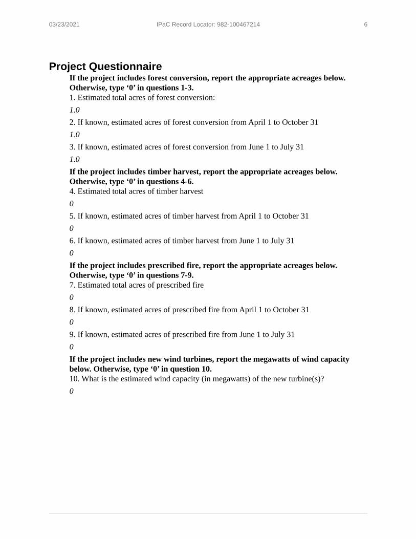
03/23/2021 IPaC Record Locator: 982-100467214 6
Project QuestionnaireIf the project includes forest conversion, report the appropriate acreages below. Otherwise, type ‘0’ in questions 1-3.1. Estimated total acres of forest conversion:1.02. If known, estimated acres of forest conversion from April 1 to October 311.03. If known, estimated acres of forest conversion from June 1 to July 311.0If the project includes timber harvest, report the appropriate acreages below. Otherwise, type ‘0’ in questions 4-6.4. Estimated total acres of timber harvest05. If known, estimated acres of timber harvest from April 1 to October 3106. If known, estimated acres of timber harvest from June 1 to July 310If the project includes prescribed fire, report the appropriate acreages below. Otherwise, type ‘0’ in questions 7-9.7. Estimated total acres of prescribed fire08. If known, estimated acres of prescribed fire from April 1 to October 3109. If known, estimated acres of prescribed fire from June 1 to July 310If the project includes new wind turbines, report the megawatts of wind capacity below. Otherwise, type ‘0’ in question 10.10. What is the estimated wind capacity (in megawatts) of the new turbine(s)?0

NDDB Map

+/- 0.2
5 mile
Middletown, CT
Middlefield, CT
Haddam, CTDurham, CT
Copyright:© 2013 National Geographic Society, i-cubed
C:\Users\mkope\Dropbox (APT GIS)\APT GIS Team Folder\Projects\Louth Callan Durham CT\Durham CT\mxd\LC Durham NDDB Attachment A.mxd
NDDB Map
Map Notes:Base Map Source: USGS 7.5 Minute TopographicQuadrangle Maps, Durham, CT (1984) and Middletown, CT (1992)Map Scale: 1:24,000Map Date: March 2021
LegendSite
Natural Diversity Database (updated Dec 2020)
Municipal Boundary Proposed Haddam Quarter Rd. Solar FacilityJohnson LaneDurham, Connecticut
1,000 0 1,000500Feet
5
Site

APPENDIX D
CULTURAL RESOURCES RECONNAISSANCE SURVEY REPORT

PREPARED FOR:
567 VAUXHALL STREET EXTENSION – SUITE 311 WATERFORD, CT 06385
PREPARED BY:
55 EAST CEDAR STREET NEWINGTON, CONNECTICUT 06111
PHASE IA/IB CULTURAL RESOURCES ASSESSMENT AND
RECONNAISSANCE SURVEYS OF THE PROPOSED LOUTH CALLAN HADDAM QUARTER ROAD SOLAR PROJECT
IN DURHAM, CONNECTICUT
JUNE 2021

i
ABSTRACT This report presents the results of a Phase IA cultural resources assessment and Phase IB reconnaissance survey for the proposed Louth Callan Haddam Quarter Road Solar Project in Durham, Connecticut. The study area associated with this facility encompasses approximately nine acres of land located to the north of Johnson Lane and to the south of Hersig Brook. During Phase IA assessment, Heritage determined that 8.15 acres of the project area retain moderate sensitivity for yielding archaeological deposits. Some portions of the open field showed signs of plowing; however, intact B-Horizon deposits were still thought to be intact. The low slopes of the project area and the fact that Hersig Brook extends past its northern border, suggests it would have been a desirable area for Native American use and/or occupation. Historical resources related to the project area’s agricultural use also may exist as well. No/low sensitivity areas for archaeological deposits, which encompass approximately 0.85 acres of land, were noted within portions of the project area containing steep slopes and signs of previous disturbance. Following this determination, Heritage completed a Phase IB cultural resources reconnaissance survey of the archaeologically sensitive 8.15 acres of the project area. During the Phase IB survey, a total of three cultural resources loci were identified. Locus 1 contained examples of quartz debitage indicating prehistoric tool manufacture. Locus 1 was recorded as the Hersig Brook Overlook Site and it was determined to lack substantial numbers of artifacts and research potential. The site was assessed as not eligible for listing to the National Register of Historic Places. Locus 2 and Locus 3 contained one piece of lithic debitage each; they too lack research potential and the qualities of significance required for listing on the National Register of Historic Places. Finally, historical period domestic artifacts from the nineteenth century were noted scattered throughout the project area. These artifacts were not associated with any known historical resources and also lack research potential. No additional examination of the project area, including the Hersig Brook Overlook Site, Locus 2, Locus 3, or the scatter of historical artifacts is recommended.

ii
TABLE OF CONTENTS CHAPTER I: INTRODUCTION ................................................................................................................................. 1
Project Description and Methods Overview .......................................................................................... 1 Project Results and Management Recommendations Overview ........................................................... 2 Project Personnel ................................................................................................................................... 2
CHAPTER II: NATURAL SETTING ............................................................................................................................ 3
Introduction ............................................................................................................................................ 3 Ecoregions of Connecticut ...................................................................................................................... 3
Southeast Hills Ecoregion ................................................................................................................ 3 Hydrology in the Vicinity of the Project Area ......................................................................................... 3 Soils Comprising the Project Area .......................................................................................................... 4
Ellington Series (Soil Code 20A): ...................................................................................................... 4 Branford Series (Soil Code 30B): ...................................................................................................... 4 Ludlow Series (Soil Code 40B): ......................................................................................................... 5 Yalesville Series (Soil Code 69B and 69C): ....................................................................................... 5
Summary................................................................................................................................................. 5 CHAPTER III: PREHISTORIC SETTING ...................................................................................................................... 6
Introduction ............................................................................................................................................ 6 Paleo-Indian Period (12,000 to 10,000 Before Present [B.P.]) ............................................................... 6 Archaic Period (10,000 to 2,700 B.P.) ..................................................................................................... 7
Early Archaic Period (10,000 to 8,000 B.P.) ..................................................................................... 7 Middle Archaic Period (8,000 to 6,000 B.P.) .................................................................................... 7 Late Archaic Period (6,000 to 3,700 B.P.) ........................................................................................ 8 Terminal Archaic Period (3,700 to 2,700 B.P.) ................................................................................. 8
Woodland Period (2,700 to 350 B.P.) ..................................................................................................... 9 Early Woodland Period (ca., 2,700 to 2,000 B.P.) .................................................................................. 9 Middle Woodland (Period (ca., 2,000 to 1,200 B.P.)………………………………………………………………………….9 Late Woodland Period (ca., 1,200 to 350 B.P.) .................................................................................... 10 Summary of Connecticut Prehistory .................................................................................................... 11
CHAPTER IV: HISTORICAL OVERVIEW .................................................................................................................. 12
Introduction .......................................................................................................................................... 12 Native American History....................................................................................................................... 12 Colonial Era (to 1790) ........................................................................................................................... 12 Early National and Industrialization Period (1790 to 1930) ................................................................. 13 Modern Period (1930 to Present) ........................................................................................................ 13 Historical Overview of the Project Area ............................................................................................... 14 Conclusions ........................................................................................................................................... 15
CHAPTER V: PREVIOUS INVESTIGATIONS .............................................................................................................. 16
Introduction .......................................................................................................................................... 16 Previously Recorded Archaeological Sites and National/State Register of Historic Places Properties/Districts in the Vicinity of the Project Area ........................................................................ 16
Site 38-7 ......................................................................................................................................... 16

iii
Conclusion ............................................................................................................................................ 16 CHAPTER VI: METHODS .................................................................................................................................... 17
Introduction .......................................................................................................................................... 17 Research Framework ............................................................................................................................ 17 Archival Research and Literature Review ............................................................................................. 17 Field Methodology and Data Synthesis ................................................................................................ 17
CHAPTER VII: RESULTS OF THE INVESTIGATION & MANAGEMENT RECOMMENDATIONS .............................................. 21
Introduction .......................................................................................................................................... 21 Results of Phase IA Survey .................................................................................................................... 21 Results of the Phase IB Fieldwork ........................................................................................................ 22
Locus 1 (Hersig Brook Overlook Site) ............................................................................................. 22 Locus 2 ........................................................................................................................................... 23 Locus 3 ........................................................................................................................................... 23 Historical Artifacts Scatter ............................................................................................................. 24
Management Recommendations ......................................................................................................... 24 BIBLIOGRAPHY ................................................................................................................................................ 26 Appendix 1: Hersig Brook Overlook Site Form……………………………………………………………………………………….47

iv
LIST OF FIGURES
Figure 1. Excerpt from a USGS 7.5’ series topographic quadrangle image showing the location of the project area in Durham, Connecticut.
Figure 2. Map of soils located in the vicinity of the project area in Durham, Connecticut. Figure 3. Excerpt from an 1859 historical map showing the location of the project area in Durham,
Connecticut. Figure 4. Excerpt from an 1874 historical map showing the location of the project area in Durham,
Connecticut. Figure 5. Excerpt from a 1934 aerial photograph showing the location of the project area in Durham,
Connecticut. Figure 6. Excerpt from a 1951 aerial photograph showing the location of the project area in Durham,
Connecticut. Figure 7. Excerpt from a 2004 aerial photograph showing the location of the project area in Durham,
Connecticut. Figure 8. Excerpt from a 2019 aerial photograph showing the location of the project area in Durham,
Connecticut. Figure 9. Digital map showing the location of previously identified archaeological sites in the vicinity
of the project area in Durham, Connecticut. Figure 10. Digital map depicting the locations of previously identified National/State Register of
Historic Places properties in the vicinity of the project area in Durham, Connecticut. Figure 11. Aerial image showing no/low and moderate archaeologically sensitive areas within the
project area in Durham, Connecticut. Figure 12. Aerial image showing the shovel test pits excavated in the moderate archaeologically
sensitive areas within the project area in Durham, Connecticut. Figure 13. Aerial image showing the locations and directions of photos taken by Heritage personnel
during survey of the project area in Durham, Connecticut.
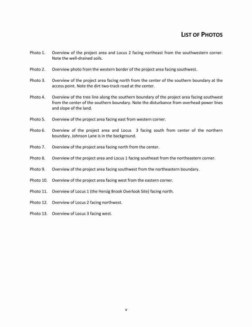
v
LIST OF PHOTOS Photo 1. Overview of the project area and Locus 2 facing northeast from the southwestern corner.
Note the well-drained soils. Photo 2. Overview photo from the western border of the project area facing southwest. Photo 3. Overview of the project area facing north from the center of the southern boundary at the
access point. Note the dirt two-track road at the center. Photo 4. Overview of the tree line along the southern boundary of the project area facing southwest
from the center of the southern boundary. Note the disturbance from overhead power lines and slope of the land.
Photo 5. Overview of the project area facing east from western corner. Photo 6. Overview of the project area and Locus 3 facing south from center of the northern
boundary. Johnson Lane is in the background.
Photo 7. Overview of the project area facing north from the center.
Photo 8. Overview of the project area and Locus 1 facing southeast from the northeastern corner. Photo 9. Overview of the project area facing southwest from the northeastern boundary. Photo 10. Overview of the project area facing west from the eastern corner. Photo 11. Overview of Locus 1 (the Hersig Brook Overlook Site) facing north. Photo 12. Overview of Locus 2 facing northwest. Photo 13. Overview of Locus 3 facing west.
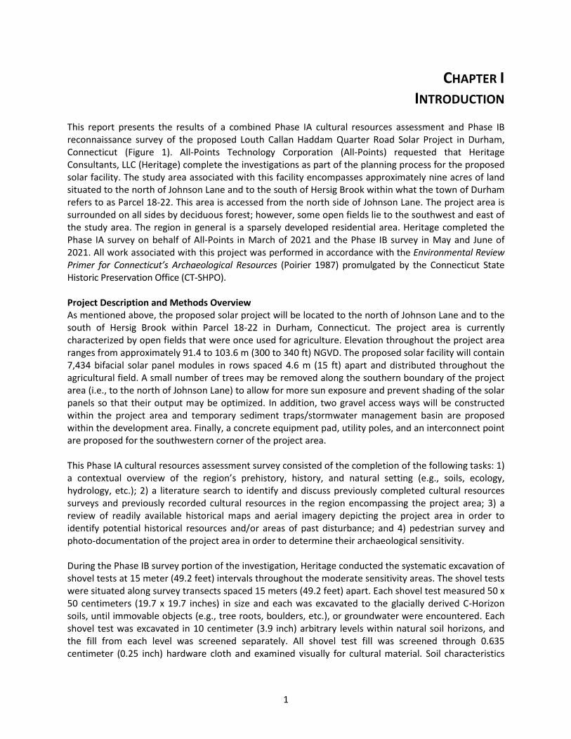
1
CHAPTER I INTRODUCTION
This report presents the results of a combined Phase IA cultural resources assessment and Phase IB reconnaissance survey of the proposed Louth Callan Haddam Quarter Road Solar Project in Durham, Connecticut (Figure 1). All-Points Technology Corporation (All-Points) requested that Heritage Consultants, LLC (Heritage) complete the investigations as part of the planning process for the proposed solar facility. The study area associated with this facility encompasses approximately nine acres of land situated to the north of Johnson Lane and to the south of Hersig Brook within what the town of Durham refers to as Parcel 18-22. This area is accessed from the north side of Johnson Lane. The project area is surrounded on all sides by deciduous forest; however, some open fields lie to the southwest and east of the study area. The region in general is a sparsely developed residential area. Heritage completed the Phase IA survey on behalf of All-Points in March of 2021 and the Phase IB survey in May and June of 2021. All work associated with this project was performed in accordance with the Environmental Review Primer for Connecticut’s Archaeological Resources (Poirier 1987) promulgated by the Connecticut State Historic Preservation Office (CT-SHPO). Project Description and Methods Overview As mentioned above, the proposed solar project will be located to the north of Johnson Lane and to the south of Hersig Brook within Parcel 18-22 in Durham, Connecticut. The project area is currently characterized by open fields that were once used for agriculture. Elevation throughout the project area ranges from approximately 91.4 to 103.6 m (300 to 340 ft) NGVD. The proposed solar facility will contain 7,434 bifacial solar panel modules in rows spaced 4.6 m (15 ft) apart and distributed throughout the agricultural field. A small number of trees may be removed along the southern boundary of the project area (i.e., to the north of Johnson Lane) to allow for more sun exposure and prevent shading of the solar panels so that their output may be optimized. In addition, two gravel access ways will be constructed within the project area and temporary sediment traps/stormwater management basin are proposed within the development area. Finally, a concrete equipment pad, utility poles, and an interconnect point are proposed for the southwestern corner of the project area. This Phase IA cultural resources assessment survey consisted of the completion of the following tasks: 1) a contextual overview of the region’s prehistory, history, and natural setting (e.g., soils, ecology, hydrology, etc.); 2) a literature search to identify and discuss previously completed cultural resources surveys and previously recorded cultural resources in the region encompassing the project area; 3) a review of readily available historical maps and aerial imagery depicting the project area in order to identify potential historical resources and/or areas of past disturbance; and 4) pedestrian survey and photo-documentation of the project area in order to determine their archaeological sensitivity. During the Phase IB survey portion of the investigation, Heritage conducted the systematic excavation of shovel tests at 15 meter (49.2 feet) intervals throughout the moderate sensitivity areas. The shovel tests were situated along survey transects spaced 15 meters (49.2 feet) apart. Each shovel test measured 50 x 50 centimeters (19.7 x 19.7 inches) in size and each was excavated to the glacially derived C-Horizon soils, until immovable objects (e.g., tree roots, boulders, etc.), or groundwater were encountered. Each shovel test was excavated in 10 centimeter (3.9 inch) arbitrary levels within natural soil horizons, and the fill from each level was screened separately. All shovel test fill was screened through 0.635 centimeter (0.25 inch) hardware cloth and examined visually for cultural material. Soil characteristics

2
were recorded using Munsell Soil Color Charts and standard soils nomenclature. Each shovel test was backfilled after it was recorded. Project Results and Management Recommendations Overview The Phase IA review of historical maps and aerial images of the project area, files maintained by the CT-SHPO, as well as pedestrian survey of the development area, resulted in the detection of a single previously identified archaeological site located within 1.6 km (1 mi) mile of the project area; it is discussed in detail in Chapter V. In addition to the cultural resources discussed above, Heritage combined data from the historical map and aerial image analysis, as well as pedestrian survey, to stratify the project area into zones of no/low and moderate archaeological sensitivity. Based on the data recovered during the Phase IA background review and subsequent pedestrian survey effort, it was the professional opinion of Heritage that approximately 8.15 acres of the project area retained a moderate sensitivity for yielding archaeological deposits. The low slopes of the project area and the fact that Hersig Brook runs past its northern border, suggests it would have been a desirable area for Native American use and/or occupation. Historical resources related to the project area’s agricultural use may exist at this location as well. Heritage recommended that a Phase IB cultural resources survey of the moderate sensitivity areas of the project area be conducted prior to the construction of the solar facility. The remaining 0.85 acres of land contain obvious signs of disturbances, steeper slopes, and/or wet soils. These areas were assessed as retaining a no/low potential for yielded intact archaeological deposits and no additional archaeological examination of them is recommended prior to construction of the proposed solar facility. During the Phase IB archaeological investigation, 179 of 179 (100 percent) planned shovel tests were excavated. This effort resulted in the identification of three prehistoric cultural resources loci (Locus 1, Locus 2, and Locus 3), as well as a field scatter of historical period artifacts. Locus 1 yielded five pieces of quartz debitage, indicating prehistoric tool manufacture. Locus 1 was recorded as the Hersig Brook Overlook Site and was determined to lack substantial numbers of artifacts and research potential. The site was assessed as not eligible for listing to the National Register of Historic Places (NRHP) applying the criteria for evaluation (36 CFR 60.4 [a-d]). Locus 2 and Locus 3 contained a single piece of lithic debitage each; they too lacked research potential and NRHP eligibility. Finally, historical domestic artifacts from the nineteenth century were noted scattered throughout the project area. These historical artifacts were not associated with any known historical resources and lack research potential. They are also not eligible for listing on the NRHP. No additional examination of the Hersig Brook Overlook Site, Locus 2, and Locus 3, the historical field scatter or the project is recommended prior to construction of the proposed solar facility. Project Personnel Key personnel for this project included Mr. David R. George, M.A., R.P.A, (Principal Investigator), Mr. Cory Atkinson, M.A., (Field Director), Mr. Sam Spitzschuh, (Field Technician), Ms. Christina Volpe, B.A., (Historian), Mr. Stephen Anderson, B.A., (GIS Specialist), and Mr. Tevin Jourdain, B.A., (Junior GIS Specialist). Ms. Elizabeth Correia, M.A., completed the laboratory analysis and compiled this report under the direction of Mr. George.

3
CHAPTER II NATURAL SETTING
Introduction This chapter provides a brief overview of the natural setting of the region containing the project area in Durham, Connecticut. Previous archaeological research has documented that specific environmental factors can be associated with both prehistoric and historical period site selection. These include general ecological conditions, as well as types of fresh water sources present, degree of slopes, and soils situated within a given project area. The remainder of this chapter provides a brief overview of the ecology, hydrological resources, and soils present within the project area and the larger region in general. Ecoregions of Connecticut Throughout the Pleistocene and Holocene Periods, Connecticut has undergone numerous environmental changes. Variations in climate, geology, and physiography have led to the “regionalization” of Connecticut’s modern environment. It is clear, for example, that the northwestern portion of the state has different natural characteristics than the coastline. Recognizing this fact, Dowhan and Craig (1976), as part of their study of the distribution of rare and endangered species in Connecticut, subdivided the state into various ecoregions. Dowhan and Craig (1976:27) defined an ecoregion as:
“an area characterized by a distinctive pattern of landscapes and regional climate as expressed by the vegetation composition and pattern, and the presence or absence of certain indicator species and species groups. Each ecoregion has a similar interrelationship between landforms, local climate, soil profiles, and plant and animal communities. Furthermore, the pattern of development of plant communities (chronosequences and toposequences) and of soil profile is similar in similar physiographic sites. Ecoregions are thus natural divisions of land, climate, and biota.”
Dowhan and Craig defined nine major ecoregions for the State of Connecticut. They are based on regional diversity in plant and animal indicator species (Dowhan and Craig 1976). Only one of the ecoregions is germane to the current investigation: Southeast Hills ecoregion. A summary of this ecoregion is presented below. It is followed by a discussion of the hydrology and soils found in and adjacent to the project area. Southeast Hills Ecoregion The Southeast Hills ecoregion consists of “coastal uplands, lying within 25 miles of Long Island Sound, characterized by low, rolling to locally rugged hills of moderate elevation, broad areas of upland, and local areas of steep and rugged topography” (Dowhan and Craig 1976). Elevations in the Southeast Hills ecoregion generally range from 75.7 to 227.2 m (250 to 750 ft) above sea level (Dowhan and Craig 1976). The bedrock of the region is composed of schists and gneisses deposited during the Paleozoic. Soils in the region have developed on top of glacial till in upland locales, and on top of stratified deposits of sand, gravel, and silt in the local valleys and upland areas (Dowhan and Craig 1976). Hydrology in the Vicinity of the Project Area The project area is situated within a region that contains several sources of freshwater, including Hersig Brook to the north of the project area boundary, Sumner Brook, Millers Pond, Ball Brook, Long Hill Brook, Dooley Pond, East Round Hill Brook, Crystal Lake, and the Coginchaug River, as well as unnamed streams, ponds, and wetlands. These freshwater sources may have served as resource extraction areas for Native

4
American and historical populations. Previously completed archaeological investigations in Connecticut have demonstrated that streams, rivers, and wetlands were focal points for prehistoric occupations because they provided access to transportation routes, sources of freshwater, and abundant faunal and floral resources. Soils Comprising the Project Area Soil formation is the direct result of the interaction of many variables, including climate, vegetation, parent material, time, and organisms present (Gerrard 1981). Once archaeological deposits are buried within the soil, they are subject to various diagenic and taphonomic processes. Different classes of artifacts may be preferentially protected, or unaffected by these processes, whereas others may deteriorate rapidly. Cyclical wetting and drying, freezing, and thawing, and compression can accelerate chemically and mechanically the decay processes for animal bones, shells, lithics, ceramics, and plant remains. Lithic and ceramic artifacts are largely unaffected by soil pH, whereas animal bones and shells decay more quickly in acidic soils. In contrast, acidic soils enhance the preservation of charred plant remains. A review of the soils within the project area is presented below. The study area is characterized by the presence of four major soil types: the Ellington series (20A), Branford series (30B), Ludlow series (40B), and Yalesville series (69B and 69C) (Figure 2). Generally speaking, the soils identified within the project area are deep to very deep, well drained sandy loams and are the types of soils that are typically correlated with prehistoric and historical use and occupation. Descriptive profiles for each soil type are presented below; they were gathered from the National Resources Conservation Service. Ellington Series (Soil Code 20A): The Ellington series consists of very deep, moderately well drained soils formed in loamy over sandy and gravelly glacial outwash. They are nearly level to strongly sloping soils on glaciofluvial landforms, typically in slight depressions and broad drainageways. Slope ranges from 0 to 15 percent. A typical profile associated with Ellington soils is as follows: Ap--0 to 8 inches; dark reddish brown (5YR 3/2) silt loam; pinkish gray (7.5YR 6/2) dry; weak medium granular structure; friable; few fine roots; 5 percent gravel; slightly acid; clear smooth boundary; Bw1--8 to 18 inches; reddish brown (5YR 4/4) silt loam; weak medium subangular blocky structure; friable; few fine roots; 5 percent gravel; moderately acid; gradual wavy boundary; Bw2--18 to 26 inches; reddish brown (5YR 4/4) very fine sandy loam; massive; friable; 10 percent gravel; common medium distinct reddish gray (5YR 5/2) iron depletions and dark red (2.5YR 3/6) masses of iron accumulation; strongly acid; abrupt smooth boundary; and 2C--26 to 65 inches; dark reddish brown (5YR 3/4) stratified sand and gravel with a few thin lenses of sandy loam; single grain; loose; 50 percent gravel; few fine distinct reddish gray (5YR 5/2) iron depletions and few fine faint yellowish red (5YR 4/6) masses of iron accumulation; strongly acid. Branford Series (Soil Code 30B): The Branford series consists of very deep, well drained soils formed in loamy over sandy and gravelly outwash. They are nearly level to strongly sloping soils on outwash plains and terraces. Slope ranges from 0 to 15 percent. A typical profile associated with Branford soils is as follows: Ap--0 to 8 inches; dark reddish brown (5YR 3/3) silt loam, light reddish brown (5YR 6/3) dry; weak medium granular structure; friable; common very fine and fine roots; 10 percent gravel; moderately acid; clear smooth boundary; Bw1--8 to 18 inches; reddish brown (5YR 4/4) loam; weak medium subangular blocky structure; friable; few fine roots; common earthworm holes and worm casts; 10 percent gravel; strongly acid; gradual wavy boundary; Bw2--18 to 24 inches; reddish brown (5YR 4/4) loam; weak coarse subangular blocky structure; very friable; few fine roots; 14 percent gravel; strongly acid; clear wavy boundary; and 2C--24

5
to 65 inches; reddish brown (5YR 4/3) stratified sand and gravel; single grain; loose; 25 percent gravel; strongly acid. Ludlow Series (Soil Code 40B): The Ludlow series consists of moderately well drained soils formed in loamy lodgment till. They are very deep to bedrock and moderately deep to a densic contact. They are nearly level to strongly sloping soils on till plains, hills, and drumlins. Slope ranges from 0 to 15 percent. A typical soil profile is as follows: Ap--0 to 8 inches; dark brown (7.5YR 3/2) silt loam, pinkish gray (7.5YR 6/2) dry; weak coarse granular structure; friable; many fine roots; 8 percent gravel; strongly acid; clear wavy boundary; Bw1--8 to 20 inches; reddish brown (5YR 4/4) silt loam; weak coarse subangular blocky structure; friable; few fine roots; 10 percent gravel; strongly acid; gradual wavy boundary; Bw2--20 to 26 inches; dark reddish brown (5YR 3/4) silt loam; weak coarse subangular blocky structure; friable; few fine roots; 12 percent gravel; common medium distinct pinkish gray (5YR 6/2) iron depletions and common medium prominent strong brown (7.5YR 5/8) masses of iron concentration; strongly acid; clear wavy boundary; and Cd--26 to 65 inches; dark reddish brown (2.5YR 3/4) gravelly loam; weak thick platy structure; very firm, brittle; thin patchy silt films and black (10YR 2/1) manganese coatings on some plates; 20 percent gravel and cobbles; few fine distinct reddish gray (5YR 5/2) iron depletions; strongly acid. Yalesville Series (Soil Code 69B and 69C): The Yalesville series consists of moderately deep, well drained soils formed in a loamy till. They are nearly level to moderately steep soils on hills and ridges. Slope ranges from 0 to 50 percent. A typical soil profile is as follows: Ap--0 to 20 cm; dark brown (7.5YR 3/2) fine sandy loam, pinkish gray (7.5YR 6/2) dry; weak medium granular structure; friable; common very fine, fine, and medium roots; 5 percent gravel; moderately acid; abrupt smooth boundary; Bw1--20 to 36 cm; reddish brown (5YR 4/4) fine sandy loam; weak medium subangular blocky structure; friable; common fine and medium roots; few very dark grayish brown earthworm casts; 5 percent gravel; moderately acid; gradual wavy boundary; Bw2--36 to 64 cm; reddish brown (5YR 4/4) loam; weak medium subangular blocky structure; friable; few fine roots; 5 percent gravel; moderately acid; gradual wavy boundary. (Combined thickness of the Bw horizons is 30 to 75 cm) C--64 to 91 cm; reddish brown (2.5YR 4/4) gravelly sandy loam; massive; firm; 12 percent gravel and 3 percent cobbles; moderately acid; abrupt wavy boundary; and 2R--91 cm; reddish brown (2.5YR 4/4) hard sandstone bedrock. Summary The natural setting of the area containing the proposed solar facility is common throughout the Southeast Hills ecoregion. The major river within this ecoregion is the Connecticut River, which has numerous smaller tributaries. Moderate slopes dominate the region, and the soils are silty and sandy loams. In general, the project region was well suited to Native American occupation throughout the prehistoric era. This portion of Durham was also used after Colonial settlement for agricultural land, as evidenced by the presence of agricultural fields throughout the region; thus, archaeological deposits dating from the prehistoric and historical era may be expected near or within the proposed project area.

6
CHAPTER III PREHISTORIC SETTING
Introduction Prior to the late 1970s and early 1980s, very few systematic archaeological surveys of large portions of the state of Connecticut had been undertaken. Rather, the prehistory of the region was studied at the site level. Sites chosen for excavation were highly visible and they were in such areas as the coastal zone, e.g., shell middens, and Connecticut River Valley. As a result, a skewed interpretation of the prehistory of Connecticut was developed. It was suggested that the upland portions of the state, i.e., the northeastern and northwestern hills ecoregions, were little used and rarely occupied by prehistoric Native Americans, while the coastal zone, i.e., the eastern and western coastal and the southeastern and southwestern hills ecoregions, were the focus of settlements and exploitation in the prehistoric era. This interpretation remained unchallenged until the 1970s and 1980s when several town-wide and regional archaeological studies were completed. These investigations led to the creation of several archaeological phases that subsequently were applied to understand the prehistory of Connecticut. The remainder of this chapter provides an overview of the prehistoric setting of the region encompassing the project area. Paleo-Indian Period (12,000 to 10,000 Before Present [B.P.]) The earliest inhabitants of the area encompassing the State of Connecticut, who have been referred to as Paleo-Indians, arrived in the area by ca., 12,000 B.P. (Gramly and Funk 1990; Snow 1980). Due to the presence of large Pleistocene mammals at that time and the ubiquity of large fluted projectile points in archaeological deposits of this age, Paleo-Indians often have been described as big-game hunters (Ritchie and Funk 1973; Snow 1980); however, as discussed below, it is more likely that they hunted a broad spectrum of animals. While there have been numerous surface finds of Paleo-Indian projectile points throughout the State of Connecticut, only two sites, the Templeton Site (6-LF-21) in Washington, Connecticut, and the Hidden Creek Site (72-163) in Ledyard, Connecticut, have been studied in detail and dated using the radiocarbon method (Jones 1997; Moeller 1980). The Templeton Site (6-LF-21) is in Washington, Connecticut and was occupied between 10,490 and 9,890 years ago (Moeller 1980). In addition to a single large and two small fluted points, the Templeton Site produced a stone tool assemblage consisting of gravers, drills, core fragments, scrapers, and channel flakes, which indicates that the full range of stone tool production and maintenance took place at the site (Moeller 1980). Moreover, the use of both local and non-local raw materials was documented in the recovered tool assemblage, suggesting that not only did the site’s occupants spend some time in the area, but they also had access to distant stone sources, the use of which likely occurred during movement from region to region. The only other Paleo-Indian site studied in detail in Connecticut is the Hidden Creek Site (72-163) (Jones 1997). The Hidden Creek Site is situated on the southeastern margin of the Great Cedar Swamp on the Mashantucket Pequot Reservation in Ledyard, Connecticut. While excavation of the Hidden Creek Site produced evidence of Terminal Archaic and Woodland Period components (see below) in the upper soil horizons, the lower levels of the site yielded artifacts dating from the Paleo-Indian era. Recovered Paleo-Indian artifacts included broken bifaces, side-scrapers, a fluted preform, gravers, and end-scrapers. Based on the types and number of tools present, Jones (1997:77) has hypothesized that the Hidden Creek Site represented a short-term occupation, and that separate stone tool reduction and rejuvenation areas were present.

7
While archaeological evidence for Paleo-Indian occupation is scarce in Connecticut, it, combined with data from the West Athens Road and King’s Road Site in the Hudson drainage and the Davis and Potts Sites in northern New York, supports the hypothesis that there was human occupation of the area not long after ca. 12,000 B.P. (Snow 1980). Further, site types currently known suggest that the Paleo-Indian settlement pattern was characterized by a high degree of mobility, with groups moving from region to region in search of seasonally abundant food resources, as well as for the procurement of high-quality raw materials from which to fashion stone tools. Archaic Period (10,000 to 2,700 B.P.) The Archaic Period, which succeeded the Paleo-Indian Period, began by ca., 10,000 B.P. (Ritchie and Funk 1973; Snow 1980), and it has been divided into three subperiods: Early Archaic (10,000 to 8,000 B.P.), Middle Archaic (8,000 to 6,000 B.P.), and Late Archaic (6,000 to 3,400 B.P.). These periods were devised to describe all non-farming, non-ceramic producing populations in the area. Regional archeologists recently have recognized a final “transitional” Archaic Period, the Terminal Archaic Period (3,400-2,700 B.P.), which was meant to describe those groups that existed just prior to the onset of the Woodland Period and the widespread adoption of ceramics into the toolkit (Snow 1980; McBride 1984; Pfeiffer 1984, 1990; Witthoft 1949, 1953). Early Archaic Period (10,000 to 8,000 B.P.) To date, very few Early Archaic sites have been identified in southern New England. As a result, researchers such as Fitting (1968) and Ritchie (1969), have suggested a lack of these sites likely is tied to cultural discontinuity between the Early Archaic and preceding Paleo-Indian Period, as well as a population decrease from earlier times. However, with continued identification of Early Archaic sites in the region, and the recognition of the problems of preservation, it is difficult to maintain the discontinuity hypothesis (Curran and Dincauze 1977; Snow 1980). Like their Paleo-Indian predecessors, Early Archaic sites tend to be very small and produce few artifacts, most of which are not temporally diagnostic. While Early Archaic sites in other portions of the United States are represented by projectile points of the Kirk series (Ritchie and Funk 1973) and by Kanawha types (Coe 1964), sites of this age in southern New England are identified on the basis of a series of ill-defined bifurcate-based projectile points. These projectile points are identified by the presence of their characteristic bifurcated base, and they generally are made from high quality raw materials. Moreover, finds of these projectile points have rarely been in stratified contexts. Rather, they occur commonly either as surface expressions or intermixed with artifacts representative of later periods. Early Archaic occupations, such as the Dill Farm Site and Sites 6LF64 and 6LF70 in Litchfield County, are represented by camps that were relocated periodically to take advantage of seasonally available resources (McBride 1984; Pfeiffer 1986). In this sense, a foraging type of settlement pattern was employed during the Early Archaic Period. Middle Archaic Period (8,000 to 6,000 B.P.) By the onset of the Middle Archaic Period, essentially modern deciduous forests had developed in the region (Davis 1969). It is at this time that increased numbers and types of sites are noted in Connecticut (McBride 1984). The most well-known Middle Archaic site in New England is the Neville Site, which is in Manchester, New Hampshire and studied by Dincauze (1976). Careful analysis of the Neville Site indicated that the Middle Archaic occupation dated from between ca., 7,700 and 6,000 years ago. In fact, Dincauze (1976) obtained several radiocarbon dates from the Middle Archaic component of the Neville Site. The dates, associated with the then-newly named Neville type projectile point, ranged from 7,740+280 and 7,015+160 B.P. (Dincauze 1976).

8
In addition to Neville points, Dincauze (1976) described two other projectile points styles that are attributed to the Middle Archaic Period: Stark and Merrimac projectile points. While no absolute dates were recovered from deposits that yielded Stark points, the Merrimac type dated from 5,910+180 B.P. Dincauze argued that both the Neville and later Merrimac and Stark occupations were established to take advantage of the excellent fishing that the falls situated adjacent to the site area would have afforded Native American groups. Thus, based on the available archaeological evidence, the Middle Archaic Period is characterized by continued increases in diversification of tool types and resources exploited, as well as by sophisticated changes in the settlement pattern to include different site types, including both base camps and task-specific sites (McBride 1984:96) Late Archaic Period (6,000 to 3,700 B.P.) The Late Archaic Period in southern New England is divided into two major cultural traditions that appear to have coexisted. They include the Laurentian and Narrow-Stemmed Traditions (Funk 1976; McBride 1984; Ritchie 1969a and b). Artifacts assigned to the Laurentian Tradition include ground stone axes, adzes, gouges, ulus (semi-lunar knives), pestles, atlatl weights, and scrapers. The diagnostic projectile point forms of this time period in southern New England include the Brewerton Eared-Notched, Brewerton Eared and Brewerton Side-Notched varieties (McBride 1984; Ritchie 1969a; Thompson 1969). In general, the stone tool assemblage of the Laurentian Tradition is characterized by flint, felsite, rhyolite, and quartzite, while quartz was largely avoided for stone tool production. In terms of settlement and subsistence patterns, archaeological evidence in southern New England suggests that Laurentian Tradition populations consisted of groups of mobile hunter-gatherers. While a few large Laurentian Tradition occupations have been studied, sites of this age generally encompass less than 500 m2 (5,383 ft2). These base camps reflect frequent movements by small groups of people in search of seasonally abundant resources. The overall settlement pattern of the Laurentian Tradition was dispersed in nature, with base camps located in a wide range of microenvironments, including riverine as well as upland zones (McBride 1978, 1984:252). Finally, subsistence strategies of Laurentian Tradition focused on hunting and gathering of wild plants and animals from multiple ecozones. The second Late Archaic tradition, known as the Narrow-Stemmed Tradition, is unlike the Laurentian Tradition, and it likely represents a different cultural adaptation. The Narrow-Stemmed tradition is recognized by the presence of quartz and quartzite narrow stemmed projectile points, triangular quartz Squibnocket projectile points, and a bipolar lithic reduction strategy (McBride 1984). Other tools found in Narrow-Stemmed Tradition artifact assemblages include choppers, adzes, pestles, antler and bone projectile points, harpoons, awls, and notched atlatl weights. Many of these tools, notably the projectile points and pestles, indicate a subsistence pattern dominated by hunting and fishing, as well the collection of a wide range of plant foods (McBride 1984; Snow 1980:228). Terminal Archaic Period (3,700 to 2,700 B.P.) The Terminal Archaic Period, which lasted from ca., 3,700 to 2,700 BP, is perhaps the most interesting, yet confusing of the Archaic Periods in southern New England prehistory. Originally termed the “Transitional Archaic” by Witthoft (1953) and recognized by the introduction of technological innovations, e.g., broadspear projectile points and soapstone bowls, the Terminal Archaic has long posed problems for regional archeologists. While the Narrow-Stemmed Tradition persisted through the Terminal Archaic and into the Early Woodland Period, the Terminal Archaic is coeval with what appears to be a different technological adaptation, the Susquehanna Tradition (McBride 1984; Ritchie 1969b). The Susquehanna Tradition is recognized in southern New England by the presence of a new stone tool industry that was based on the use of high-quality raw materials for stone tool production and a

9
settlement pattern different from the “coeval” Narrow-Stemmed Tradition. The Susquehanna Tradition is based on the classification of several Broadspear projectile point types and associated artifacts. There are several local sequences within the tradition, and they are based on projectile point type chronology. Temporally diagnostic projectile points of these sequences include the Snook Kill, Susquehanna Broadspear, Mansion Inn, and Orient Fishtail types (Lavin 1984; McBride 1984; Pfeiffer 1984). The initial portion of the Terminal Archaic Period (ca., 3,700-3,200 BP) is characterized by the presence of Snook Kill and Susquehanna Broadspear projectile points, while the latter Terminal Archaic (3,200-2,700 BP) is distinguished by the use of Orient Fishtail projectile points (McBride 1984:119; Ritchie 1971). In addition, it was during the late Terminal Archaic Period that interior cord marked, grit tempered, thick walled ceramics with conoidal (pointed) bases made their initial appearance in the Native American toolkit. These are the first ceramics in the region, and they are named Vinette I (Ritchie 1969a; Snow 1980:242); this type of ceramic vessel appears with much more frequency during the ensuing Early Woodland Period. In addition, the adoption and widespread use of soapstone bowls, as well as the implementation of subterranean storage, suggests that Terminal Archaic groups were characterized by reduced mobility and longer-term use of established occupation sites (Snow 1980:250). Finally, while settlement patterns appeared to have changed, Terminal Archaic subsistence patterns were analogous to earlier patterns. The subsistence pattern still was diffuse in nature, and it was scheduled carefully. Typical food remains recovered from sites of this period consist of fragments of white-tailed deer, beaver, turtle, fish, and various small mammals. Botanical remains recovered from the site area consisted of Chenopodium sp., hickory, butternut, and walnut (Pagoulatos 1988:81). Such diversity in food remains suggests at least minimal use of a wide range of microenvironments for subsistence purposes. Woodland Period (2,700 to 350 B.P.) Traditionally, the advent of the Woodland Period in southern New England has been associated with the introduction of pottery; however, as mentioned above, early dates associated with pottery now suggest the presence of Vinette I ceramics appeared toward the end of the preceding Terminal Archaic Period (Ritchie 1969a; McBride 1984). Like the Archaic Period, the Woodland Period has been divided into three subperiods: Early, Middle, and Late Woodland. The various subperiods are discussed below. Early Woodland Period (ca., 2,700 to 2,000 B.P.) The Early Woodland Period of the northeastern United States dates from ca., 2,700 to 2,000 B.P., and it has been thought to have been characterized by the advent of farming, the initial use of ceramic vessels, and increasingly complex burial ceremonialism (Griffin 1967; Ritchie 1969a and 1969b; Snow 1980). In the Northeast, the earliest ceramics of the Early Woodland Period are thick walled, cord marked on both the interior and exterior, and possess grit temper. Careful archaeological investigations of Early Woodland sites in southern New England have resulted in the recovery of narrow stemmed projectile points in association with ceramic sherds and subsistence remains, including specimens of white-tailed deer, soft and hard-shell clams, and oyster shells (Lavin and Salwen: 1983; McBride 1984:296-297; Pope 1952). McBride (1984) has argued that the combination of the subsistence remains and the recognition of multiple superimposed cultural features at various sites indicates that Early Woodland Period settlement patterns were characterized by multiple re-use of the same sites on a seasonal basis by small co-residential groups.

10
Middle Woodland Period (2,000 to 1,200 B.P.) The Middle Woodland Period is marked by an increase in the number of ceramic types and forms utilized (Lizee 1994a), as well as an increase in the amount of exotic lithic raw material used in stone tool manufacture (McBride 1984). The latter suggests that regional exchange networks were established, and that they were used to supply local populations with necessary raw materials (McBride 1984; Snow 1980). The Middle Woodland Period is represented archaeologically by narrow stemmed and Jack’s Reef projectile points; increased amounts of exotic raw materials in recovered lithic assemblages, including chert, argillite, jasper, and hornfels; and conoidal ceramic vessels decorated with dentate stamping. Ceramic types, indicative of the Middle Woodland Period, include Linear Dentate, Rocker Dentate, Windsor Cord Marked, Windsor Brushed, Windsor Plain, and Hollister Stamped (Lizee 1994a:200). In terms of settlement patterns, the Middle Woodland Period is characterized by the occupation of village sites by large co-residential groups that utilized native plant and animal species for food and raw materials in tool making (George 1997). These sites were the principal place of occupation, and they were positioned close to major river valleys, tidal marshes, estuaries, and the coastline, all of which would have supplied an abundance of plant and animal resources (McBride 1984:309). In addition to villages, numerous temporary and task-specific sites were utilized in the surrounding upland areas, as well as in closer ecozones such as wetlands, estuaries, and floodplains. The use of temporary and task-specific sites to support large village populations indicates that the Middle Woodland Period was characterized by a resource acquisition strategy that can best be termed as logistical collection (McBride 1984:310). Late Woodland Period (ca., 1,200 to 350 B.P.) The Late Woodland Period in southern New England dates from ca., 1,200 to 350 B.P., and it is characterized by the earliest evidence for the use of corn in the lower Connecticut River Valley (Bendremer 1993; Bendremer and Dewar 1993; Bendremer et al. 1991; George 1997; McBride 1984); an increase in the frequency of exchange of non-local lithics (Feder 1984; George and Tryon 1996; McBride 1984; Lavin 1984); increased variability in ceramic form, function, surface treatment, and decoration (Lavin 1980, 1986, 1987; Lizee 1994a, 1994b); and a continuation of a trend towards larger, more permanent settlements in riverine, estuarine, and coastal ecozones (Dincauze 1974; McBride 1984; Snow 1980). Stone tool assemblages associated with Late Woodland occupations, especially village-sized sites, are functionally variable and they reflect plant and animal resource processing and consumption on a large scale. Finished stone tools recovered from Late Woodland sites include Levanna and Madison projectile points; drills; side-, end-, and thumbnail scrapers; mortars and pestles; nutting stones; netsinkers; and celts, adzes, axes, and digging tools. These tools were used in activities ranging from hide preparation to plant processing to the manufacture of canoes, bowls, and utensils, as well as other settlement and subsistence-related items (McBride 1984; Snow 1980). Finally, ceramic assemblages recovered from Late Woodland sites are as variable as the lithic assemblages. Ceramic types identified include Windsor Fabric Impressed, Windsor Brushed, Windsor Cord Marked, Windsor Plain, Clearview Stamped, Sebonac Stamped, Selden Island, Hollister Plain, Hollister Stamped, and Shantok Cove Incised (Lavin 1980, 1988a, 1988b; Lizee 1994a; Pope 1953; Rouse 1947; Salwen and Ottesen 1972; Smith 1947). These types are more diverse stylistically than their predecessors, with incision, shell stamping, punctation, single point, linear dentate, rocker dentate stamping, and stamp and drag impressions common (Lizee 1994a:216).

11
Summary of Connecticut Prehistory In sum, the prehistory of Connecticut spans from ca., 12,000 to 350 B.P., and it is characterized by numerous changes in tool types, subsistence patterns, and land use strategies. For much of the prehistoric era, local Native American groups practiced a subsistence pattern based on a mixed economy of hunting and gathering wild plant and animal resources. It is not until the Late Woodland Period that incontrovertible evidence for the use of domesticated species is available. Further, settlement patterns throughout the prehistoric era shifted from seasonal occupations of small co-residential groups to large aggregations of people in riverine, estuarine, and coastal ecozones. In terms of the region containing the proposed project area, a variety of prehistoric site types may be expected. These range from seasonal camps utilized by Archaic populations to temporary and task-specific sites of the Woodland era.

12
CHAPTER IV HISTORICAL OVERVIEW
Introduction The proposed project area is located in the town of Durham, which is part of Middlesex County, Connecticut. Currently, the project area exists as an open parcel of land located along the southern bank of Hersig Brook. This chapter presents an overview history of the Durham area, as well as details specific to the project area location. Native American History In the 1630s, when the first colonial settlements were established in Connecticut, the area now known as Middletown, then called “Mattabesett”, was the territory of a Native American group led by a sachem named Sowheag. According to Speiss, Sowheag’s tribe included three sub-groups, the Wangunk, Mattabesec, and Machamoodus; their territory included what are known today as the towns of Wethersfield, Newington, Rocky Hill, Cromwell, Middletown, Middlefield, Durham, Haddam, East Haddam, East Hampton, and Portland, as well as parts of Glastonbury, Marlborough, and Colchester (Speiss 1930). Sowheag’s relations with the colonists were tense, as is evidenced by a 1639 incident when the General Assembly planned to send 100 men to apprehend a group of Pequots that Sowheag was harboring, though the validity of him hiding them from colonial officials them has been disputed (De Forest 1852; Crofut 1937; Cleary 1979). Native Americans who considered Durham their territory were the Mattabesetts, whose main settlements were further north in Middletown. According to the colonial records, they called the area Cocinchaug, and sold much of it to the colonists in 1672. One of the Native American signatories was a key leader named Tarramugus as well as nine others, including five women. The deed description specifically referred to four individual buyers who had the legislature’s prior permission to make the purchase of the territory (Newton 1884). Colonial Era (to 1790) In addition to the large 1672 land purchase mentioned above, many other individuals had been legislatively granted rights to acquire land in the Cocinchaug territory. It appears that not many people moved there, however, until 1699, when a group of men from Guilford petitioned the legislature to create a new town in the area. The legislature granted the petition and had a survey done to establish an official residential section. In 1703, the survey was redone in a different place, which later became the town center of Durham. The main street was laid out as eight rods in width (132 feet) and was consistent with Connecticut’s practice at the time, meaning that the town’s residents were required to build a house on their official house lot in this town plot. In 1704, the legislature gave the new settlement the name Durham. By negotiation, the adjoining town of Killingworth was convinced to give up some of its territory to the new town in 1708, and the legislature gave Durham an official land patent (Fowler 1866; Newton 1884). There were 34 proprietors named in the 1708 grant. These individuals were the official owners of the town’s territory and had the right to divide its land among themselves; a number of others were added in afterward (Newton 1884). In 1773, a tract of land in Haddam was given to the northeast part of Durham and was called “Haddam Quarter.” Haddam Quarter Road is named for this section, which today is located to the north of the proposed project area (Fowler 1866: 10). The original inhabitants of the Haddam Quarter area of Durham in 1734 were Thomas Fairchild, Stephen Smith, Abner Newton, Nathaniel Sutliff, John Smith, John Coe, and Simeon Parsons (Fowler 1866: 10).

13
Approximately a half-century later, in 1762, 830 residents were living in Durham. The number rose to 1,076 in 1774 but was still only at 1,079 as of 1790 (Keegan 2012). In addition to giving land to themselves, the original proprietors also made grants to support the Congregational ministry in general and to support the first Congregational minister, a man known as Mr. Chauncey. Money was also allocated for a burying ground on the main street and for a Congregational meeting house (Fowler 1866; Newton 1884). When it came to economics, Durham was a typical inland colonial Connecticut town in that its families focused on agricultural production mainly for their own use, but also for some small amount of trade whenever possible. These goods were mostly traded locally, but some were exported as far as Boston and the West Indies (Fowler 1866). Early National and Industrialization Period (1790 to 1930) Throughout this period, Durham’s population remained around 1,000 people, until in 1880 it fell to 990, then to 959 in 1920 before beginning to recover and climbing to 1,044 in 1930 (Keegan 2012). As of 1819, Durham’s main agricultural products were rye, corn, and flax, and a number of households engaged in making shoes that found a market in the southern states. The overall agricultural focus, however, was reflected in the presence of tanneries, grain mills, saw mills, a wool-carding machine, and a cider distillery, but no factories. The town’s small population supported three churches: Congregational, Episcopalian, and Methodist (Pease and Niles 1819). An 1837 overview of the town could only add that Durham was well-known for its cattle (Barber 1837). Despite its small population, in the 1820s the town had four turnpikes – roads maintained by private corporations in exchange for the right to charge tolls – terminating or passing through it (Newton 1884). Within a few decades these companies failed due to competition from the railroads, despite the fact that Durham did not have a railroad station. Quarrying became a prominent industry in the nineteenth century, with various sites providing stone used for foundations, buildings, and gravestones. A quarry in Haddam Quarter supplied stone that was used for projects in Cromwell and New Haven, including a building at Yale University. Other industries also took hold in Durham. In the 1850s, the Merriam Manufacturing Company was established to make tinware items and was still in operation as of 1884. In that same year there was also a factory that produced “Pond’s Extract,” which was a skin cream (Newton 1884). As noted above, however, these factories were not large enough to prevent the town’s population from declining at the end of the century. Both the 1859 and 1874 historical maps of the town depict large areas with no roads or marked structures, particularly within proximity to the proposed project area (Figures 3 and 4). This suggests that the industrializing trend of many other towns in Connecticut passed by Durham. Modern Period (1930 to Present) As of 1932, Durham’s principal industries were “agriculture and the manufacture of cash boxes, safe deposit boxes and various kinds of metal boxes” (Connecticut 1932:275). After 1940, when the automobile and the suburban residential trend began to encourage people to live in more rural areas, the town saw a substantial increase in population from 1,804 residents in 1950 to 3,096 in 1960 (The Office of Secretary of the State Denise W. Merrill 2021a). Throughout the later twentieth and early twenty-first centuries, the population continued to gradually increase, reaching an estimated 7,483 residents as of 2020 (Secretary of the State Denise W. Merrill 2021b; AdvanceCT and CT Data Collaborative 2020). While the town did experience a jump in the number of residents in the middle of the twentieth century, since then population growth has been slow and modest. This lower rate of growth can possibly be attributed to the fact that none of the state’s limited-access highways passes through Durham. This has also inhibited industrial and commercial development in the town. Today, more than 23 percent of Durham’s land area is still devoted to agriculture, and the town considers it an

14
essential part of its economy and way of life (Durham 2016). The town’s devotion to agriculture is evident in the Durham Fair, a multi-day event that has been taking place annually since 1916. The Durham Fair is the largest volunteer agricultural fair in New England and in recent years has attracted over 200,000 attendees (Durham Fair 2021). Despite the popularity of this event, the number of permanent residents in the town remains relatively low. Only moderate future population growth is anticipated in Durham, and the town’s development priority of preserving its rural and historic character will almost certainly discourage any rapid growth. Historical Overview of the Project Area A review of the 1859 map in Figure 3, revealed that there are several homesteads related to the Newton family within close proximity to the proposed project area. The Newton family, as mentioned above, was one of the founding families of the “Haddam Quarter” area of Durham in 1734. The earliest available record of the family was related to a man named Abner Newton (Fowler 1866). Abner had a son named Burwell Newton, who in turned named his son Abner Newton. Abner Newton II was born on December 27, 1764, in Durham and died there on September 9, 1852. He served as Deacon of the church in Haddam Quarter (Fowler 1866: 87). Abner Newton II is the father of Roger Watson (R.W.) Newton, who was born on July 21, 1809 in Durham. The homestead of R.W. Newton appears on the 1859 map as being closest in proximity to the proposed project area along Johnson Lane (Figure 3). At the time of the 1860 United States Census, Roger W. Newton was a 50-year-old farmer whose real estate was valued at $4,000 (United States Census 1860). He was a representative for Durham in the 1864 Connecticut Legislature and was a founding member of Durham’s Temperance Society at the age of 18 years (Fowler 1886). The 1860 census confirms that the Newton family was clustered in this area, with Samuel Newton, age 63, listed below Roger’s household. According to the Census, Samuel Newton was also a farmer possessing a real estate value of $5,000 (U. S. Census 1860). Samuel was the son of Burwell Newton, uncle to Roger W. Newton. Samuel was also Deacon of the congregation in 1827 and continued to serve the church until his death in 1864 (Fowler 1866: 88). An 1874 map indicated that the homestead of Roger Watson Newton was still closest in proximity to the proposed project area (Figure 4). According to the 1870 United States Census, Roger W. Newton was then a 60-year-old farmer with a real estate value of $6,000, signifying that his land holdings had increased sometime during the previous decade (U. S. Census 1870). Living with Roger Newton in 1870 was his wife Cynthia, age 52, and their son George W., age 24, who was also working as a farmer (U. S. Census 1870). Visible on each of the historic maps is Hersig Brook, which runs northward and adjacent to the northern limit of the proposed project area. It joins Allyn Brook, which flows westward through a rock gorge to Durham Meadows and the Coginchaug River. A 1934 aerial image depicted the Newton family farmland as being cleared for agricultural use. There is a dirt road running from the northern Haddam Quarter Road to the lower Johnson Lane abutting the southern limit of the proposed project area (Figure 5). It appears this road was used by the Newton family to connect their homesteads to the agricultural field. Some secondary regrowth is evident north of the proposed project area surrounding the route of Hersig Brook and there are residences and outbuildings off of Haddam Quarter Road (Figure 5). A 1951 aerial showed the same unpaved road running through the proposed project area. Additional reforestation occurred between the time of the 1934 photograph and the 1951 aerial image, particularly within the central path of the road leading through the project area to the north (Figure 6). The periphery of the proposed project area indicated secondary regrowth throughout the broader project region, which coincided with the overall decline of agricultural activity throughout the state during this time. A 2004 aerial photograph showed the proposed project area cleared of secondary regrowth and still being used for agriculture, and the

15
pathway is still visible through the center of the proposed project area (Figure 7). A 2019 aerial photograph depicted little change to the proposed project area since the land was still cleared (Figure 8). The unpaved path previously noted in the 2004 aerial image appeared to be no longer in-use by 2019. Additionally, several single-family dwelling units had been constructed on Haddam Quarter Road to the north of the proposed project area (Figure 8). Conclusions Based on the location of the project area and its consistent use as agricultural fields, there is the possibility of encountering remains of outbuildings, stonewalls, or other evidence of historic farming. The Newton family is the earliest family in the historical record to have occupied the project parcel, using it as early as 1734 as agricultural land. The parcel has since remained in the Newton family until the present time. The documentary record indicates that it is unlikely that significant historical resources will be affected by the proposed work within Durham.

16
CHAPTER V PREVIOUS INVESTIGATIONS
Introduction This chapter presents an overview of previous archaeological research completed within the vicinity of the project area in Durham, Connecticut. This discussion provides the comparative data necessary for assessing the results of the current Phase IA/IB cultural resources assessment and reconnaissance surveys, and it ensures that the potential impacts to all previously recorded cultural resources located within and adjacent to the project area are taken into consideration. Specifically, this chapter reviews previously identified archaeological sites and National/State Register of Historic Places properties situated in the project region (Figures 9 and 10). The discussions presented below are based on information currently on file at the Connecticut State Historic Preservation Office (CT-SHPO) in Hartford, Connecticut. In addition, the electronic site files maintained by Heritage were examined during this investigation. Both the quantity and quality of the information contained in the original cultural resources survey reports and State of Connecticut archaeological site forms are reflected below. Previously Recorded Archaeological Sites and National/State Register of Historic Places Properties/Districts in the Vicinity of the Project Area A review of data currently on file at the CT-SHPO, as well as the electronic site files maintained by Heritage, resulted in the identification of a single previously identified archaeological site (Site 38-7) within 1.6 km (1 mi) of the project area. No National or State Register of Historic Places properties were identified within the search area (Figures 9 and 10). Site 38-7 Site 38-7 was recorded as NU-13 by Michael S. Raber of Raber Associates on November 25, 2013. It is located 12.2 m (40 ft) to the west of Johnson Lane along a Connecticut Light & Power Transmission Line. Raber Associates tested the site in 2005 and returned to excavate it in 2006. As a result, quartz and quartzite Native American artifacts were recovered from 83 shovel test pits and 27 excavation units. The recovered artifacts consisted of 6 projectile points (5 of which were Narrow Stemmed types), 50 scrapers, 67 utilized flakes, 1 awl, 6 blades/knives, 1 drill, 1 gouge, and 513 pieces of lithic debitage. In addition, Raber Associates identified five cultural features that were tentatively identified as hearths and three probable post molds. Radiocarbon dating of charcoal samples taken from these features returned with dates from the Middle Woodland Period. Raber concluded that Site 38-7 was a Middle Woodland and Late Archaic Period short-term seasonal encampment for fishing, hunting, and resource processing. Site 38-7 was determined to be eligible for listing on the National Register of Historic Places under Criteria C and D as it provides insight into the overall settlement and subsistence systems locally and regionally. Site 38-7 will not be impacted by the proposed Durham solar project due to distance from the project area. Conclusion A single prehistoric archaeological resource has been previously identified within 1.6 km (1 mi) of the project area, Site 38-7. This indicates that further prehistoric resources could exist in the project area, which is further supported by the natural setting of the region discussed in Chapter II as suited to Native American occupation. Though no historical resources have been previously recorded within 1.6 km (1 mi) of the project area, Durham is known to have been used for farmsteads from settlement to the present era. The project area itself was agricultural land for its entire history, and artifacts relating to this activity may exist here, likely scattered in the plow zone.

17
CHAPTER VI METHODS
Introduction This chapter describes the research design and field methods used to complete the Phase IA cultural resources assessment and Phase IB cultural reconnaissance surveys of the proposed Louth Callan Haddam Quarter Road Solar Project in Durham, Connecticut. In addition, the location and point-of-contact for the facility at which all cultural material, drawings, maps, photographs, and field notes generated during survey will be curated is provided below. Research Framework This cultural resources investigation was designed to identify areas of no/low and moderate/high sensitivity for intact archaeological deposits during the Phase IA survey and locations of prehistoric and historical period archaeological resources located within the project area during the Phase IB survey. Fieldwork for the project was comprehensive in nature and project planning utilized the information gathered during the background research portion of the project, including previously completed cultural resources surveys, recorded cultural resources, historical maps, and historical and modern aerial imagery. The methods used to complete this investigation were designed to provide complete and thorough coverage of all portions of project area. The Phase IA survey also entailed pedestrian survey, detailed mapping, and photo-documentation of the project area, and the Phase IB survey included systematic shovel testing of perceived moderate sensitivity areas. The purpose of these investigations is to locate all surface and/or subsurface sites that occur within the project area. Archival Research and Literature Review Background research for this project included a review of a variety of historical maps depicting the proposed project area; an examination of USGS 7.5’ series topographic quadrangles; review of aerial images dating from 1934 through 2019; and a review of all archaeological sites and National and State Register of Historic Places on file with the CT-SHPO, as well as electronic cultural resources data maintained by Heritage. The intent of this review was to identify all previously recorded cultural resources situated within and immediately adjacent to the project area, and to provide a natural and cultural context for the project region. This information then was used to develop the archaeological context of the project area, and to assess its sensitivity with respect to the potential for producing intact cultural resources. Background research materials, including historical maps, aerial imagery, and information related to previous archaeological investigations, were gathered from the CT-SHPO. Finally, electronic databases and Geographic Information System files maintained by Heritage were employed during the course of this project, and they provided valuable data related to the project region, as well as data concerning previously identified archaeological sites and National/State Register of Historic Places properties within the general vicinity of the project area. Field Methodology and Data Synthesis The following sections present overview discussions of the methods used to complete the Phase IA cultural resources assessment survey of the project area and the subsequent Phase IB archaeological investigation of the proposed solar project in Durham, Connecticut.

18
Phase IA Survey Methods The Phase IA investigation was conducted to gather information concerning the environmental/physical setting of the project area, as well as its cultural context. The following tasks were completed during the investigation: 1) study of the region’s prehistory, history, and natural setting; 2) a literature search to identify and discuss previously recorded cultural resources in the project region; 3) a review of historic maps, topographic quadrangles, and aerial imagery depicting the project area in order to identify archaeologically sensitive areas, and to locate all prehistoric and historic cultural/archaeological resources that may exist within the proposed project area; and 4) pedestrian survey and photo-documentation of the project area in order to determine its archaeological sensitivity. In addition, using the historical maps and aerials with other data layers in a Project GIS, including soils, water sources, and topography, Heritage personnel stratified and mapped the project area into zones of no/low and moderate sensitivity archaeological deposit. Heritage personnel then conducted a pedestrian survey of the project area in March of 2021. While in the field, Heritage archaeologists carefully photo-documented the project area and verified its potential to yield evidence of intact Native American and/or historical period archaeological deposits. The field data associated with soils, slopes, aspect, distance to water, and previous disturbance collected during the pedestrian survey and presented above was used in conjunction with the analysis of historical maps, aerial images, and data regarding previously identified archaeological sites and National/State Register of Historic Places properties to stratify the project area into zones of no/low and/or moderate archaeological sensitivity. In general, historical period archaeological sites are relatively easy to identify on the current landscape because the features associated with them tend to be relatively permanent constructions that extend above the ground surface (i.e., stone foundations, pens, wells, privies, etc.). Archaeological sites dating from the prehistoric era, on the other hand, are less often identified during pedestrian survey because they are buried, and predicting their locations relies more on the analysis and interpretation of environmental factors that would have informed Native American site choices. With respect to the potential for identifying prehistoric archaeological sites, the project area was divided into areas of no/low and/or moderate archaeological potential by analyzing the landform types, slope, aspect, soils contained within them, and their distance to water. In general, areas located less than 300 m (1,000 ft) from a freshwater source and that contain slopes of less than 8 percent and well-drained soils possess a high potential for producing prehistoric archaeological deposits. Those areas located between 300 and 600 m (1,000 and 2,000 ft) from a freshwater source and well drained soils are considered moderate probability areas. This is in keeping with broadly based interpretations of prehistoric settlement and subsistence models that are supported by decades of previous archaeological research throughout the region. It is also expected that there may be variability of prehistoric site types found in the moderate sensitivity zones. For example, large Woodland period village sites and Archaic period seasonal camps may be expected along large river floodplains and near stream/river confluences, while smaller temporary or task specific sites may be expected on level areas with well-drained soils that are situated more than 300 m (1,000 ft) but less than 600 m (2,000 ft) from a water source. Finally, steeply sloping areas, poorly drained soils, or areas of previous disturbance are generally deemed to retain a no/low archaeological sensitivity with respect to their potential to contain prehistoric archaeological sites. In addition, the potential for a given area to yield evidence of historical period archaeological deposits is based not only on the above-defined landscape features but also on the presence or absence of previously identified historical period archaeological resources as identified during previous archaeological surveys, recorded on historical period maps, or captured in aerial images of the region

19
under study. In this case, areas situated within 100 m (328 ft) of a previously identified historical period archaeological site or a National or State Register of Historic Places district/individually listed property also may be deemed to retain a moderate archaeological sensitivity. In contrast, those areas situated over 100 m (328 ft) from any of the above-referenced properties would be considered to retain a no/low historical period archaeological sensitivity. Phase IB Survey Methods Following the completion of the Phase IA survey, a Phase IB archaeological survey, utilizing systematic shovel testing and GPS recordation, was conducted throughout the identified moderate sensitivity areas, including portion of the solar center. The field strategy was designed such that the moderate sensitivity areas were examined through a systematic subsurface testing regime during which shovel tests were excavated at 15 meter (49.2 foot) intervals along 13 parallel survey transects spaced 15 meters (49.2 feet) apart. A total of 179 of 179 (100 percent) planned shovel tests were excavated during the fieldwork effort (Figure 13). During survey, each shovel test measured 50 x 50 centimeters (19.7 x 19.7 inches) in size and each was excavated until the glacially derived C-Horizon was encountered or until large buried objects (e.g., boulders) prevented further excavation. Each shovel test was excavated in 10 centimeter (3.9 inch) arbitrary levels within natural strata, and the fill from each level was screened separately. All shovel test fill was screened through 0.635 centimeter (0.25 inch) hardware cloth and examined visually for cultural material. Soil characteristics were recorded in the field using Munsell Soil Color Charts and standard soils nomenclature. Each shovel test was backfilled after it was recorded. Laboratory Analysis Laboratory analysis of recovered cultural material followed established archaeological protocols. To begin the laboratory analysis process, field specimen bag proveniences first were crosschecked against the field notes and the specimen inventories for accuracy and completeness. Following this quality-control process, all recovered material was washed by hand, air-dried, and sorted into basic material categories. The nature and structure of the laboratory analysis was determined by the goals of the project. The artifact analysis consisted of making and recording a series of observations for each recovered specimen. The observations were chosen to provide the most significant information about each specimen. Separate databases, designed specifically for the analysis of the recovered historic and prehistoric artifacts, were employed to store, organize, and manipulate data gathered during the analytical process. A detailed discussion of the recovered artifacts is discussed in detail in the following chapter. Historic Cultural Material Analysis The analysis of the historic cultural material recovered during the current Phase I cultural resources reconnaissance survey was organized by class, functional group, type, and subtype. The first level, class, represented the material category, e.g., ceramic, glass, metal. The second level, functional group, e.g., architecture, kitchen, or personal, was based on standard classifications. The third and fourth levels, type, and subtype, described the temporally and/or functionally diagnostic artifact attributes. The identification of artifacts was aided by consulting standard reference works. Prehistoric Lithic Analysis The lithic analysis protocol used in this project was a “technological” or “functional” one designed to identify prehistoric reduction trajectories, lithic industries, and tool functions. The protocol focused on recording technological characteristics of the recovered lithic artifacts. The lithic artifact database was

20
organized by lithic material group, type, and subtype. The first level describes the raw material type of the artifact. Lithic materials were identified utilizing recognized geological descriptions and terminology, and with the use of type specimens of known source. Lithic raw materials were divided into distinct categories based on three factors: texture, color, and translucence. The second analysis level, type, was used to define the general class, e.g., unmodified flake, core, or preform, of lithic artifact, while the last level, subtype, was employed to specify morphological attributes, e.g., primary cortex, extensively reduced, or corner-notched. Typological identifications for temporally and regionally diagnostic tools were included in the analysis. Such identifications were made by reference to established lithic artifact typologies. Curation Following the completion and acceptance of the Final Report of Investigations, all cultural material, drawings, maps, photographs, and field notes will be curated with:
Dr. Sarah Sportman Office of Connecticut State Archaeology, Box U-1023
University of Connecticut, Storrs, Connecticut 06269

21
CHAPTER VII RESULTS OF THE INVESTIGATION &
MANAGEMENT RECOMMENDATIONS Introduction This chapter presents the results of the Phase IA cultural resources assessment survey and Phase IB reconnaissance survey of the project area in Durham, Connecticut. As stated in the introductory section of this report, the goals of the investigation included completion of the following tasks: 1) a contextual overview of the region’s prehistory, history, and natural setting (e.g., soils, ecology, hydrology, etc.); 2) a literature search to identify and discuss previously completed cultural resources surveys and previously recorded cultural resources in the project region; 3) a review of readily available historical maps and aerial imagery depicting the project area in order to identify potential historical resources and/or areas of past disturbance; 4) pedestrian survey and photo-documentation of the project items in order to determine their archaeological sensitivity; and 5) subsurface examination of the moderate archaeologically sensitive areas identified during the Phase IA survey portion of the investigation. Results of Phase IA Survey At the time of survey, the project area was characterized by mowed, open fields with a dirt two-track road extending north to south through the center (Figure 13 and Photos 1 through 3). The open fields contained well-drained soils (Photo 1). There were signs of vehicle use along the borders of the property as well, evidenced by tire marks (Photo 3). The terrain is generally level until it rises to a short hill in the northeastern section (Photos 5 through 10). In addition, there is a small portion of steep slope along the entire Johnson Lane border; this area showed some signs of previous disturbance (Photo 4). The project area is surrounded by deciduous forest on all sides and Johnson Lane runs along its southern boundary, separated by a line of trees. Access to the property was from the north side of Johnson Lane, where there is a cut in the tree line at the center of the southern boundary of the project area. The combined review of historical maps, aerial images, land deeds, and pedestrian survey indicates that much of the project area contains low slopes and well drained soils within an open field that is situated in close proximity to a freshwater source. Some portions of the field showed signs of past plowing; however, it was determined that intact B-Horizon deposits may still have existed in the project area. The low slopes of the project area and the fact that Hersig Brook extends past its northern border, suggests it would have been a desirable area for Native American use. Historical resources related to the project area’s agricultural use also may exist in the area as well. Based on the data collected during this investigation, it was the professional opinion of Heritage that 8.15 acres of the project area retain a moderate sensitivity for yielding archaeological deposits (Figure 11 and Photos 1, 3, 6, and 9). In contrast, it was determined that 0.85 acres of the project area retained a no/low sensitivity because of steep slopes, signs of substantial previous disturbance, and what appeared to be wet soils. For example, the area along the southern boundary of the project area, north of Johnson Lane, contained steep slopes leading up to Johnson Lane, as well as disturbance from overhead power line construction and field clearing (Photo 4). In the northeastern section of the project area, no/low sensitivity areas are encompassed by steep slopes (Photos 7 and 8). Heritage recommended that a Phase IB cultural resources survey of the moderate sensitivity areas of the project area be conducted prior to the construction of the solar facility. No additional archaeological examination of the no/low sensitivity areas was recommended. The remainder of the project parcel was subjected to Phase IB survey, the results of which are presented below.

22
Results of the Phase IB Fieldwork Based on the results of the Phase IA survey, the Phase IB fieldwork was completed through the systematic excavation of shovel tests at 15 meter (49.2 foot) intervals along 13 survey transects spaced 15 meters (49.2 ft) apart. In addition, in those areas where artifact clusters were identified, delineation shovel testing at 7.5 meter (24.6 foot) intervals was undertaken in the cardinal directions around positive shovel tests. A total of 179 of 179 (100 percent) planned shovel tests were excavated during the Phase IB survey (Figure 12). The shovel testing effort resulted in the identification of three areas of prehistoric artifacts across the project parcel. They were designated as Locus 1, Locus 2, and Locus 3. The survey effort also resulted in the collection of a scatter of historical period artifacts from the project area. The various finds are discussed in turn below. Locus 1 (Hersig Brook Overlook Site) Locus 1, which was given the name Hersig Brook Overlook Site, was identified on a raised landform within the northeastern portion of the project area at an approximate elevation of 104 meters (340 feet) NGVD (Figure 12 and Photo 11). It is an irregularly area shaped with maximum dimensions of 22.9 x 15.2 meters (75 x 50 feet). At the time of the survey, vegetation in this area consisted of grasses and weeds associated with a fallow agricultural field. Locus 1 was first identified within Shovel Tests 2 and 3 along Survey Transect 11. A total of 17 delineation shovel test pits were excavated surrounding these two positive shovel test pits. A typical shovel test excavated within the Locus 1 area exhibited two soil horizons before meeting a rock impasse at 58 centimeters below surface (22.8 inches below surface). The uppermost plow zone (Ap-Horizon) extended from 0 to 33 centimeters below surface (0 to 13 inches below surface) and was described as a deposit of brown (10YR 4/3) coarse sand with gravel. It was underlain by a layer of subsoil (B-Horizon) that ranged in depth from 33 to 58 centimeters below surface (13 to 22.8 inches below surface) and was described as a strong brown (7.5YR 4/3) very coarse sand mixed with degrading rock. The Phase IB archaeological investigation of Locus 1 resulted in the recovery of 1 quartz secondary thinning flake and 2 pieces of quartz secondary shatter from the Ap-Horizon (plow zone) between 10 and 30 centimeters below surface (3.9 and 11.8 inches below surface), as well as a single quartz secondary thinning flake and 1 piece of quartz primary shatter from the B-Horizon between 10 and 20 centimeters below surface (3.9 and 7.9 inches below surface) (Table 1). These artifacts were recorded as the Hersig Brook Overlook Site. Despite careful excavation and adequate survey coverage, no cultural features or soil anomalies were identified within the site area. The recovered archaeological data indicates that the Hersig Brook Overlook Site lacks substantial numbers of artifacts, evidence of cultural features, and research potential. This short term occupation was assessed as not eligible for listing to the NRHP applying the criteria for evaluation (36 CFR 60.4 [a-d]). No additional archaeological examination of Hersig Brook Overlook Site is recommended prior to the construction of the proposed solar facility. A Connecticut archaeological site form for the Hersig Brook Overlook Site is attached in Appendix I. Table 1. Artifacts recovered from Locus 1, or the Hersig Brook Overlook Site.
Transect Shovel Test Horizon Depth Material Type Subtype Count
11
2 Ap 10-20 cmbs lithic quartz secondary thinning flake 1
3 Ap 20-30 cmbs lithic quartz secondary shatter 1
D10 Ap 10-20 cmbs lithic quartz secondary shatter 1
D6 B 10-20 cmbs lithic quartz primary shatter 1
secondary thinning flake 1
Total 5

23
Locus 2 Locus 2, which measured approximately 50 square meters (538.2 square feet) in size, was identified at an approximate elevation of 94.5 meters (310 feet) NGVD on a level area in the western end of the project area (Figure 12 and Photo 12). This area also consisted of a fallow agricultural field. Locus 2 was identified within Shovel Test 15 along Survey Transect 11, around which four delineation shovel tests were excavated. Of the delineation shovel tests, two were positive for historical material only; these finds were not considered part of this prehistoric cultural resource locus. A typical shovel test within the Locus 2 area exhibited three soil horizons in profile and extended to a depth of 83 centimeters below surface (32.7 inches below surface). The uppermost soil horizon (Ap-Horizon; plow zone) extended from 0 to 38 centimeters below surface (0 to 15 inches below surface) and was described as a deposit of dark brown (10YR 3/4) silty coarse sandy loam mixed with minor amounts of gravel. It was underlain by a layer of subsoil (B-Horizon) that ranged in depth from 38 to 73 centimeters below surface (15 to 28.7 inches below surface); it was described as a layer of yellowish brown (10YR 5/6) silty coarse sand with gravel. Finally, the glacially derived C-Horizon extended to approximately 83 centimeters below surface (32.7 inches below surface) and was described as a layer of light brown (7.5YR 5/6) coarse sand with gravel. Phase IB survey of the Locus 2 area resulted in the collection of only a single prehistoric artifact. Laboratory analysis revealed that it was chert secondary thinning flake. This flake was recovered from the Ap-Horizon at depth between 10 and 20 centimeters below surface (3.9 and 7.9 inches below surface). The artifact cannot be assigned to a particular prehistoric date of occupation or cultural affiliation. No cultural features or soil anomalies were identified within the Locus 2 area during the survey effort. As a result, it is the professional opinion of Heritage that Locus 2, which is an isolated find, lacks substantial numbers of artifacts, intact archaeological deposits, and research potential. It was assessed as not eligible for listing to the NRHP applying the criteria for evaluation (36 CFR 60.4 [a-d]). No additional archaeological examination of this non-site cultural resources locus is recommended prior to the construction of the proposed solar facility. Locus 3 Locus 3 was identified on a level portion of the project area at an approximate elevation of 94.5 meters (310 feet) NGVD; it measured approximately 50 square meters (538.2 square feet) in size. The Locus 3 area is located near the center of the northern boundary of the project area (Figure 12 and Photo 13). At the time of the survey, vegetation in this area consisted of weeds and tall grasses associated with a fallow agricultural field. The shovel tests excavated in the Locus 3 area exhibited three soil horizons in profile and extended to a depth of 83 centimeters below surface (32.7 inches below surface). The Ap-Horizon (plow zone) extended from 0 to 38 centimeters below surface (0 to 15 inches below surface) and was described as a deposit of dark brown (10YR 3/4) silty coarse sandy loam mixed with gravel. It was underlain by the B-Horizon (subsoil) that ranged in depth from 38 to 73 centimeters below surface (15 to 28.7 inches below surface); it was described as a deposit of yellowish brown (10YR 5/6) silty coarse sand with gravel. Finally, the glacially derived C-Horizon, which extended to 83 centimeters below surface (32.7 inches below surface), was described as a layer of strong brown (7.5YR 5/6) coarse sand with gravel. Phase IB survey of the Locus 3 area resulted in the recovery of a single artifact that was identified as quartzite secondary thinning flake. It was collected from the B-Horizon of Shovel Test 3 along Transect 12. After its identification, four delineation shovel test pits were excavated around this findspot in the cardinal directions around this find, but no additional artifacts were recovered. In addition, no cultural features or soil anomalies were identified within the Locus 3 area. It is the professional opinion of

24
Heritage that Locus 3 lacks substantial numbers of artifacts, evidence for cultural features, and research potential. It too was assessed as not eligible for listing to the NRHP applying the criteria for evaluation (36 CFR 60.4 [a-d]). No additional archaeological examination of this non-site cultural resources locus is recommended prior to the construction of the proposed solar facility. Historical Artifacts Scatter Finally, 16 historical artifacts were recorded throughout the project area during the Phase IB survey. They consisted of 3 machine-cut nails (1790s to 1900s), 2 wire nails (ca. 1890 to present), 3 clear glazed redware body sherds, 1 clear glazed pearlware body sherd (ca. 1780 to 1830), 1 blue transfer printed pearlware body sherd (ca. 1780 to 1830) 1 green painted pearlware rim sherd (ca. 1780 to 1830), 3 clear glazed whiteware body sherds (ca. 1820 to present), 1 clear glazed whiteware base sherd (ca. 1820 to present), and 1 clam shell fragment. The historical materials were all recovered from the Ap-Horizon (plow zone) between 0 and 50 centimeters below surface (0 and 19.7 inches below surface) (Table 2). The historical period artifacts within the project area are domestic in nature. The Phase IB survey of the project area failed to identify any surficial or buried architectural feature (e.g., foundations, wells, privies, etc.) that could be associated with the historical artifacts. Therefore, these artifacts are interpreted as a scatter of materials that lacks historical association, research potential, and the qualities of significance as defined by the National Register of Historic Places (NRHP) criteria for evaluation (36 CFR 60.4 [a-d]). No additional examination of historical artifact scatter is recommended. Table 1. Historical artifacts recovered throughout the project area.
Transect Shovel Test Horizon Depth Material Type Subtype Count
5 5 Ap 0-10 cmbs metal iron machine-cut nail 1
7 Ap 0-10 cmbs ceramic redware clear glazed body 2
8
18 Ap 20-30 cmbs metal iron machine-cut nail 1
3 Ap 10-20 cmbs shell clam fragment 1
4 Ap 0-10 cmbs ceramic redware clear glazed body 1
7 Ap 20-30 cmbs ceramic pearlware clear glazed body 1
metal iron machine-cut nail 1
9 5 Ap 10-20 cmbs ceramic pearlware green painted rim 1
10 19 Ap 20-30 cmbs ceramic pearlware blue transfer printed body 1
11
16 Ap 20-30 cmbs ceramic whiteware clear glazed body 1
metal steel wire nail 1
5 Ap 40-50 cmbs metal steel wire nail 1
D3 Ap 0-10 cmbs ceramic whiteware clear glazed base 1
D4 Ap 20-30 cmbs ceramic whiteware clear glazed body 1
13 3 Ap 0-10 cmbs ceramic whiteware clear glazed body 1
Total 16
Management Recommendations Phase IA survey revealed that 8.15 acres of the project area retain a moderate sensitivity for yielding archaeological deposits. During the Phase IB archaeological investigation of this moderate sensitivity area, a total of three prehistoric cultural resources loci and a scatter of historical period artifacts were identified (Figure 12). Locus 1 contained five pieces of quartz debitage, indicating prehistoric tool manufacture and short term us of the area. Locus 1 was recorded as the Hersig Brook Overlook Site, but it was determined to lack substantial numbers of artifacts and research potential. The site was assessed as not eligible for listing to the NRHP applying the criteria for evaluation (36 CFR 60.4 [a-d]). Locus 2 and Locus 3 each contained one piece of lithic debitage. They too lacked research potential and NRHP eligibility applying the criteria for evaluation (36 CFR 60.4 [a-d]). Finally, historical domestic artifacts

25
were noted scattered throughout the project area. These historical objects were not associated with any known historical resources and lacked research potential. They also lacked research potential and were determined to be not eligible for listing on the NRHP applying the criteria for evaluation (36 CFR 60.4 [a-d]). No additional examination of the Hersig Brook Overlook Site, Locus 2, Locus 3, or the historical artifact scatter is recommended. The construction project will have no adverse effect on archaeological or historical resources.

26
BIBLIOGRAPHY AdvanceCT and CTData Collaborative 2020 Durham, Connecticut, CERC Town Profile 2019. Electronic document, https://s3-us-west- 2.amazonaws.com/cerc-pdfs/2019/durham-2019.pdf, accessed June 9, 2021. Asch, D.L., and N. B. Asch
1985 Prehistoric Plant Cultivation in West-Central Illinois. In Prehistoric Food Production in North America, edited by R.I. Ford, pp. 149-203. Museum of Anthropology Anthropological Papers No. 75. University of Michigan, Ann Arbor.
Banks, R.C., R.W. McDiarmid, A.L. Gardner
1987 Checklist of vertebrates of the Unites States: The U.S. Territories and Canada. U.S. Department of the Interior, Fish and Wildlife Service, Washington, D.C.
Barber, John Warner
1836 Connecticut Historical Collections, Containing a General Collection of Interesting Facts, Traditions, Biographical Sketches, Anecdotes, &c. History and Antiquities of Every Town in Connecticut, with Geographical Descriptions. New Haven, CT: B.I. Hamlen.
Bell, Michael
1985 The Face of Connecticut: People, Geology, and the Land. State Geological Natural History Survey of Connecticut Department of Environmental Protection.
Bendremer, J.
1993 Late Woodland Settlement and Subsistence in Eastern Connecticut. Ph.D. Dissertation, Department of Anthropology, University of Connecticut, Storrs, Connecticut.
Bendremer, J. and R. Dewar
1993 The Advent of Maize Horticulture in New England. In Corn and Culture in the Prehistoric New World. Ed. by S. Johannessen and C. Hastorf. Westview Press, Boulder.
Bendremer, J., E. Kellogg and T. Largy
1991 A Grass-Lined Storage Pit and Early Maize Horticulture in Central Connecticut. North American Archaeologist 12(4):325-349.
Braun, E.L.
1950 Deciduous Forests of Eastern North America. The Free Press. Brown, Clair A.
1965 Louisiana Trees and Shrubs. Louisiana Forestry Commission Bulletin No. 1. Claitor’s Publishing Division, Baton Rouge, Louisiana.
Chapman, J., and A.B. Shea
1981 The Archaeobotanical Record: Early Archaic Period to Contact in the Lower Little Tennessee River Valley. Tennessee Anthropologist 6(1):61-84.

27
Coe, Joffre Lanning 1964 The Formative Cultures of the Carolina Piedmont. Transactions of the American
Philosophical Society, Vol. 54, Part 5. Philadelphia, Pennsylvania.
Connecticut, Colony of 1762 “A List of the Number of Inhabitants in each Town in the Colony of Connecticut taken in the
Year 1762.” RG 001. Hartford, Connecticut: Connecticut State Archives. Connecticut Environmental Conditions Online (CT ECO)
2019 Connecticut 2019 Orthophotography. Storrs, Connecticut: University of Connecticut, Connecticut Environmental Conditions Online. http://www.cteco.uconn.edu/data/flight2019/index.htm.
Cleary, Barbara Ann, et al. 1979 Middletown, Connecticut: A Survey of Historical and Architectural Resources. 3 vols.
Middletown, CT: The Greater Middletown Preservation Trust; reprinted by Historic Preservation and Museum Division, Commission on Culture & Tourism, 2005.
Connecticut Department of Public Works (CT DPW) 1932 Town Overview Data Collaborative. Collections of the Connecticut State Library, Hartford,
CT. Connecticut, State of 1932 State Register and Manual. State of Connecticut, Hartford, Connecticut. Crofut, Florence
1937 Guide to the History and Historic Sites of Connecticut, vol.1. New Haven, CT: Yale University Press.
Curran, M.L., and D.F. Dincauze
1977 Paleo-Indians and Paleo-Lakes: New Data from the Connecticut Drainage. In Amerinds and their Paleoenvironments in Northeastern North America. Annals of the New York Academy of Sciences 288:333-348.
Davis, M.
1969 Climatic changes in southern Connecticut recorded by Pollen deposition at Rogers Lake. Ecology 50: 409-422.
De Forest, J. W.
1852 History of the Indians of Connecticut from the Earliest Known Period to 1850. Wm. Jas. Hamersley, Hartford, Connecticut.
Dincauze, Dena F.
1974 An Introduction to Archaeology in the Greater Boston Area. Archaeology of Eastern North America 2(1):39-67.
1976 The Neville Site: 8000 Years at Amoskeag. Peabody Museum Monograph No. 4. Cambridge,
Massachusetts.
28
Durham Fair 2021 History of the Durham Fair. https://www.durhamfair.com/info/history, accessed June 9, 2021.
Durham, Town of
2016 Plan of Conservation and Development. Accessed January 2, 2018. http://www.townofdurhamct.org/filestorage/28562/27548/28085/16272/PoCD_Approved_-_Effective_Date_8-1-2016.pdf.
Dowhan, J.J. and R.J. Craig
1976 Rare and endangered species of Connecticut and Their Habitats. State Geological Natural History Survey of Connecticut Department of Environmental Protection, Report of Investigations No. 6.
Fairchild Aerial Surveys
1934 Connecticut Statewide Aerial Photograph Series. Hartford, Connecticut: Connecticut State Archives.
Feder, Kenneth
1984 Pots, Plants, and People: The Late Woodland Period of Connecticut. Bulletin of the Archaeological Society of Connecticut 47:99-112.
Fitting, J.E.
1968 The Spring Creek Site. In Contributions to Michigan Archaeology, pp. 1-78. Anthropological Papers No. 32. Museum of Anthropology, University of Michigan, Ann Arbor.
Ford, R.I.
1985 Patterns of Prehistoric Food Production in North America. In Prehistoric Food Production in North America, edited by R.I. Ford, pp. 341-364. Museum of Anthropology Anthropological Papers No. 75. University of Michigan, Ann Arbor.
Fowler, William Chauncey 1866 History of Durham, Connecticut, from the First Grant of Land in 1662 to 1866. Hartford: Wiley,
Waterman & Eaton. Fritz, Gayle J.
1990 Multiple Pathways to Farming in Pre-Contact Eastern North America. Journal of World Prehistory 4(4):387-435.
Funk, R.E.
1976 Recent Contributions to Hudson Valley Prehistory. New York State Museum Memoir 22. Albany.
George, D.
1997 A Long Row to Hoe: The Cultivation of Archaeobotany in Southern New England. Archaeology of Eastern North America 25:175 - 190.

29
George, D. and C. Tryon 1996 Lithic and Raw Material Procurement and Use at the Late Woodland Period Cooper Site, Lyme,
Connecticut. Paper presented at the joint meeting of the Archaeological Society of Connecticut and the Massachusetts Archaeological Society, Storrs Connecticut
George, D.R., and R. Dewar
1999 Prehistoric Chenopodium in Connecticut: Wild, Weedy, Cultivated, or Domesticated? Current Northeast Paleoethnobotany, edited by J. Hart, New York State Museum, Albany, New York.
Gerrard, A.J.
1981 Soils and Landforms, An Integration of Geomorphology and Pedology. George Allen & Unwin: London.
Gramly, R. Michael, and Robert E. Funk
1990 What is Known and Not Known About the Human Occupation of the Northeastern United States Until 10,000 B. P. Archaeology of Eastern North America 18: 5-32.
Griffin, J.B.
1967 Eastern North America Archaeology: A Summary. Science 156(3772):175-191. Hitchcock, Charlotte
2012 “Historic Resources Inventory – Building and Structures: Treat Farm.” State of Connecticut Department of Economic and Community Development. https://connecticutbarns.org/upload/state_reg/SR-barn_Orange_OldTavernRoad_361_No.4919.pdf.
Hughes, A. S. and M. S. Allen 1976 Connecticut Place Names. Hartford, CT: The Connecticut Historical Society. Johannessen, Sissel
1984 Paleoethnobotany. In American Bottom Archaeology: A Summary of the FAI-270 Project Contribution to the Culture History of the Mississippi River Valley, edited by Charles J. Bareis and James W. Porter, pp. 197-214. University of Illinois Press, Urbana.
Jones, B.
1997 The Late Paleo-Indian Hidden Creek Site in Southeastern Connecticut. Archaeology of Eastern North America 25:45-80.
Keegan, Kristen Noble, comp.
2012 Historical Population Data of Connecticut. Unpublished Excel spreadsheet. Lavin, L.
1980 Analysis of Ceramic Vessels from the Ben Hollister Site, Glastonbury, Connecticut. Bulletin of the Archaeological Society of Connecticut 43:3-46.
1984 Connecticut Prehistory: A Synthesis of Current Archaeological Investigations. Archaeological
Society of Connecticut Bulletin 47:5-40.
30
1986 Pottery Classification and Cultural Models in Southern New England Prehistory. North American Archaeologist 7(1):1-12.
1987 The Windsor Ceramic Tradition in Southern New England. North American Archaeologist
8(1):23-40. 1988a Coastal Adaptations in Southern New England and Southern New York. Archaeology of
Eastern North America, Vol.16:101-120. 1988b The Morgan Site, Rocky Hill, Connecticut: A Late Woodland Farming Community in the
Connecticut River Valley. Bulletin of the Archaeological Society of Connecticut 51:7-20. Lizee, J.
1994a Prehistoric Ceramic Sequences and Patterning in southern New England: The Windsor Tradition. Unpublished Ph.D. dissertation, Department of Anthropology, University of Connecticut, Storrs.
1994b Cross-Mending Northeastern Ceramic Typologies. Paper presented at the 1994 Annual
Meeting of the Northeastern Anthropological Association, Geneseo, New York.
McBride, K. 1978 Archaic Subsistence in the Lower Connecticut River Valley: Evidence from Woodchuck Knoll.
Man in the Northeast 15 & 16:124-131. 1983 Prehistory of the Lower Connecticut River Valley. Ph.D. Dissertation, Department of
Anthropology, University of Connecticut, Storrs, Connecticut.
Moeller, R. 1980 6-LF-21: A Paleo-Indian Site in Western Connecticut. American Indian Archaeological
Institute, Occasional Papers No. 2. Newton, H. G. 1884 “Town of Durham.” In J. H. Beers & Co., The History of Middlesex County 1635-1885, pp.
263-281. NY: J. H. Beers & Co. Niering, W.A., and N.C. Olmstead
1995 National Audubon Society Field Guide to North American Wildflowers: Eastern Region. Chanticleer Press, New York.
Pagoulatos, P.
1988 Terminal Archaic Settlement and Subsistence in the Connecticut River Valley. Man in the Northeast 35:71-93.
Pease, John C. and John M. Niles 1819 A Gazetteer of the States of Connecticut and Rhode-Island. Hartford, CT: William S. Marsh.

31
Peterson, T. R., and M. McKenny 1968 Wildflowers of Northeastern and North-Central America. Houghton Mifflin Company,
Boston, Massachusetts. Pfeiffer, J.
1984 The Late and Terminal Archaic Periods in Connecticut Prehistory. Bulletin of the Bulletin of the Archaeological Society of Connecticut 47:73-88.
1986 Dill Farm Locus I: Early and Middle Archaic Components in Southern Connecticut. Bulletin of
the Archaeological Society of Connecticut 49:19-36. 1990 The Late and Terminal Archaic Periods in Connecticut Prehistory: A Model of Continuity. In
Experiments and Observations on the Archaic of the Middle Atlantic Region. R. Moeller, ed.
Poirier, D. 1987 Environmental Review Primer for Connecticut’s Archaeological Resources. Connecticut
Historical Commission, State Historic Preservation Office, Hartford, Connecticut.
Pope, G. 1952 Excavation at the Charles Tyler Site. Bulletin of the Archaeological Society of Connecticut
26:3-29. 1953 The Pottery Types of Connecticut. Bulletin of the Archaeological Society of New Haven 27:3-
10.
Ritchie, W.A. 1969a The Archaeology of New York State. Garden City: Natural History Press. 1969b The Archaeology of Martha’s Vineyard: A Framework for the Prehistory of Southern New
England; A study in Coastal Ecology and Adaptation. Garden City: Natural History Press 1971 A Typology and Nomenclature for New York State Projectile Points. New York State Museum
Bulletin Number 384, State Education Department. University of the State of New York, Albany, New York.
Ritchie, W.A., and R.E. Funk
1973 Aboriginal Settlement Patterns in the Northeast. New York State Museum Memoir 20. The State Education Department, Albany.
Robinson, P., and Hall, L. M.
1980 Tectonic synthesis of southern New England. In International Geological Correlation Project, Proceedings, Project 27: The Caledonides in the U.S.A.: Blacksburg, Virginia, Virginia Polytechnic Institute and State University Department of Geological Sciences Memoir 2, edited by Wones, D.R.
Rouse, I.
1947 Ceramic Traditions and sequences in Connecticut. Bulletin of the Archaeological Society of Connecticut 21:10-25.

32
Salwen, B., and A. Ottesen 1972 Radiocarbon Dates for a Windsor Occupation at the Shantok Cove Site. Man in the
Northeast 3:8-19.
Secretary of the State Denise W. Merrill, The Office of 2021a Population of Connecticut Towns 1900-1960. https://portal.ct.gov/SOTS/Register-
Manual/Section-VII/Population-1900-1960, accessed June 9, 2021. 2021b Population of Connecticut Towns 1970-2010. https://portal.ct.gov/SOTS/Register- Manual/Section-VII/Population-1970-2010, accessed June 9, 2021. Shelford, V.E.
1963 The Ecology of North America. University of Illinois Press.
Smith, B.D. 1992 Rivers of Change: Essays on Early Agriculture in Eastern North America. Smithsonian
Institution Press, Washington and London. Smith, C.
1947 An Outline of the Archaeology of Coastal New York. Bulletin of the Archaeological Society of Connecticut 21:2-9.
Spiess, Mathias
1930 Connecticut Circa 1625: Its Indian Trails Villages and Sachemdoms. [N.p.]: The Connecticut Society of the Colonial Dames of America, Inc.
Trumbull, J. Hammond, ed.
1859 The Public Records of the Colony of Connecticut, May 1678 - June, 1689; with Notes and an Appendix. Volume 3. Hartford, Connecticut: Press of Case, Lockwood & Co.
Turner, G. M. and M. W. Jacobus 1989 Connecticut Railroads: An Illustrated History. Hartford, CT: Connecticut Historical Soc. U.S. Census
1860 Eighth Census of the United States, Schedule 1. HeritageQuest Online. Ann Arbor, MI: ProQuest LLC.
1870 Ninth Census of the United States, Schedule 1. HeritageQuest Online. Ann Arbor, MI:
ProQuest LLC.
United States Coastal Survey (USCS) 1837 “West Haven to Black Rock Connecticut.” Sheet T-22. C. M. Eakin, surveyor. Washington, DC:
United States Coastal Survey.
United States Department of Agriculture (USDA) 1951 Agricultural Stabilization and Conservation Service Aerial Photography for Connecticut.
Washington, DC: Collections of the National Archives and Records Administration.

33
Warren, M. and Gillett, G. 1813 Connecticut From Actual Survey Made in 1811. Hartford, Connecticut: Hudson & Goodwin.
Wood, Frederic J.
1919 The Turnpikes of New England and Evolution of the Same Through England, Virginia, and Maryland. Boston: Marshall Jones Company.

34
Figure 1. Excerpt from a USGS 7.5’ series topographic quadrangle image showing the location of the project area in Durham, Connecticut.

35
Figure 2. Map of soils located in the vicinity of the project area in Durham, Connecticut.

36
Figure 3. Excerpt from an 1859 historical map showing the location of the project area in Durham, Connecticut.

37
Figure 4. Excerpt from an 1874 historical map showing the location of the project area in Durham, Connecticut.

38
Figure 5. Excerpt from a 1934 aerial photograph showing the location of the project area in Durham, Connecticut.

39
Figure 6. Excerpt from a 1951 aerial photograph showing the location of the project area in Durham, Connecticut.

40
Figure 7. Excerpt from a 2004 aerial photograph showing the location of the project area in Durham, Connecticut.

41
Figure 8. Excerpt from a 2019 aerial photograph showing the location of the project area in Durham, Connecticut.

42
Figure 9. Digital map showing the location of previously identified archaeological sites in the vicinity of the project area in Durham, Connecticut.

43
Figure 10. Digital map depicting the locations of previously identified National/State Register of Historic Places properties in the vicinity of the project area in Durham, Connecticut.

44
Figure 11. Aerial image showing no/low and moderate archaeologically sensitive areas within the project area in Durham, Connecticut.

45
Figure 12. Aerial image showing the shovel test pits excavated in the moderate archaeologically sensitive areas within the project area in
Durham, Connecticut.

46
Figure 13. Aerial image showing the locations and directions of photos taken by Heritage personnel during survey of the project area in
Durham, Connecticut.

47
Photo 1. Overview of the project area and Locus 2 facing northeast from the southwestern corner. Note the well-drained soils.
Photo 2. Overview photo from the western border of the project area facing southwest.

48
Photo 3. Overview of the project area facing north from the center of the southern boundary at the access point. Note the dirt two-track road at the center.
Photo 4. Overview of the tree line along the southern boundary of the project area facing southwest from the center of the southern boundary. Note the disturbance from overhead power lines and slope of the land.

49
Photo 5. Overview of the project area facing east from western corner.
Photo 6. Overview of the project area and Locus 3 facing south from center of the northern boundary. Johnson Lane is in the background.

50
Photo 7. Overview of the project area facing north from the center.
Photo 8. Overview of the project area and Locus 1 facing southeast from the northeastern corner.

51
Photo 9. Overview of the project area facing southwest from the northeastern boundary.
Photo 10. Overview of the project area facing west from the eastern corner.

52
Photo 11. Overview of Locus 1 (the Hersig Brook Overlook Site) facing north.
Photo 12. Overview of Locus 2 facing northwest.

53
Photo 13. Overview of Locus 3 facing west.

APPENDIX E
FAA DETERMINATION

Mail Processing CenterFederal Aviation AdministrationSouthwest Regional OfficeObstruction Evaluation Group10101 Hillwood ParkwayFort Worth, TX 76177
Aeronautical Study No.2020-ANE-4470-OE
Page 1 of 4
Issued Date: 08/11/2020
Daniel BandLouth Callan RenewablesPO Box 1923Wallingford, CT 06492
** DETERMINATION OF NO HAZARD TO AIR NAVIGATION **
The Federal Aviation Administration has conducted an aeronautical study under the provisions of 49 U.S.C.,Section 44718 and if applicable Title 14 of the Code of Federal Regulations, part 77, concerning:
Structure: Solar Panel Ground Mounted Solar ArrayLocation: Durham, CTLatitude: 41-29-28.00N NAD 83Longitude: 72-38-50.00WHeights: 313 feet site elevation (SE)
12 feet above ground level (AGL)325 feet above mean sea level (AMSL)
This aeronautical study revealed that the structure does not exceed obstruction standards and would not be ahazard to air navigation provided the following condition(s), if any, is(are) met:
Based on this evaluation, marking and lighting are not necessary for aviation safety. However, if marking/lighting are accomplished on a voluntary basis, we recommend it be installed in accordance with FAA Advisorycircular 70/7460-1 L Change 2.
This determination expires on 02/11/2022 unless:
(a) the construction is started (not necessarily completed) and FAA Form 7460-2, Notice of ActualConstruction or Alteration, is received by this office.
(b) extended, revised, or terminated by the issuing office.(c) the construction is subject to the licensing authority of the Federal Communications Commission
(FCC) and an application for a construction permit has been filed, as required by the FCC, within6 months of the date of this determination. In such case, the determination expires on the dateprescribed by the FCC for completion of construction, or the date the FCC denies the application.
NOTE: REQUEST FOR EXTENSION OF THE EFFECTIVE PERIOD OF THIS DETERMINATION MUSTBE E-FILED AT LEAST 15 DAYS PRIOR TO THE EXPIRATION DATE. AFTER RE-EVALUATIONOF CURRENT OPERATIONS IN THE AREA OF THE STRUCTURE TO DETERMINE THAT NOSIGNIFICANT AERONAUTICAL CHANGES HAVE OCCURRED, YOUR DETERMINATION MAY BEELIGIBLE FOR ONE EXTENSION OF THE EFFECTIVE PERIOD.

Page 2 of 4
This determination is based, in part, on the foregoing description which includes specific coordinates, heights,frequency(ies) and power. Any changes in coordinates, heights, and frequencies or use of greater power, exceptthose frequencies specified in the Colo Void Clause Coalition; Antenna System Co-Location; Voluntary BestPractices, effective 21 Nov 2007, will void this determination. Any future construction or alteration, includingincrease to heights, power, or the addition of other transmitters, requires separate notice to the FAA.Thisdetermination includes all previously filed frequencies and power for this structure.
If construction or alteration is dismantled or destroyed, you must submit notice to the FAA within 5 days afterthe construction or alteration is dismantled or destroyed.
This determination does include temporary construction equipment such as cranes, derricks, etc., which may beused during actual construction of the structure. However, this equipment shall not exceed the overall heights asindicated above. Equipment which has a height greater than the studied structure requires separate notice to theFAA.
This determination concerns the effect of this structure on the safe and efficient use of navigable airspaceby aircraft and does not relieve the sponsor of compliance responsibilities relating to any law, ordinance, orregulation of any Federal, State, or local government body.
If we can be of further assistance, please contact our office at (404) 305-6531, or [email protected]. On anyfuture correspondence concerning this matter, please refer to Aeronautical Study Number 2020-ANE-4470-OE.
Signature Control No: 446543289-448075949 ( DNE )Darin ClipperSpecialist
Attachment(s)Case DescriptionMap(s)

Page 3 of 4
Case Description for ASN 2020-ANE-4470-OE
Construction of a ground mounted photovoltaic solar facility with an battery storage component on up to 44 acres of the site

Page 4 of 4
Verified Map for ASN 2020-ANE-4470-OE

APPENDIX F
VISIBILITY DOCUMENTATION

[
[
[[
[
[
[
[
[
[
[
[
[[
[
[
[[
[[
[
[
[
[
[
[[
[
[
[[
[[
[
[
[
E
E
!y
!y
!y
!y
!y
!y
!y
!y
!y
!y
!y
!y
!y
!y
!y
!y
!y
!y
!y
!y
!y
!y
!y
!y
!y
!y
!y
!y
!y
!y
!y
!y
!y
!y
!y
!y
!y
!y!y
!y
!y
!y
!y
!y
!y
!y
!y
!y
!y
!y
!y
!y
!y
!y
!y
!y
!y
!y
!y
!y
!y
!y
!y
!y
!y
!y
!y
!y
!y
!y
!y
!y
!y
!y
!y
!y
!y
!y
!y
!y
!y
!y
!y
!y
!y
!y
!y
!y
!y
!y
!y
!y
!y
!y
!y
!y
!y
!y
!y
!y
!y
!y
!y!y
!y
!y
!y
!y
!y
!y
!y
!y
!y
!y
!y
!y
!y
!y
BEAR ROCK ROAD
STAT
E HWY 1
7
FA R N U M R O A D
BLA
CKW
ALN
UTDR
IVE
S U MNE
RW
OO
D SRO
AD
WIL
C OX
DRIV
E
AUSTIN ROAD
CARRIAGE DRIVE
ARBU
TUS S
TREE
T
M A ID E N L A N E
WIES E
AL BER T
RO AD
S Y C A M O REDR IV
E
IRO N W
OO
DLA
NE
PA R T R ID G E L A N E
WHE
ELER
HILL
DRIV
E
GU I RE
ROA
D
A C O R N D R IV E
PICKETT LANE
HOLLY LANE
DA IS YLA NE
WOODS LANE
T R IG O D R IV E
H A M LE T
ROYA LO AK
DR IVE
MA
INS T
REE T
BRICK LANE
OXB
OWRI
DGE
ROA D
GUIRE
JOHNS ON L A N E
TA L C O T T R IDGEROA D
FO O TH IL L S
RO A D
CE SCALA NE
E DW A RD S RD
COLEM
AN
R O A D
ROUND HILL ROAD
HADDAM QUARTER ROAD
¬«17
AllynMillpond
UpperHersig
Brook DamStepanski
Pond
Lower HersigBrook Dam
Millers Pond
Round Hill534.64' AMSL
Strawberry Hill285.36' AMSL Blue/Red
Trail
ValleyView Trail
FieldForestTrail
MattabesettTrail
mattabesetttrail
CockaponsetForest Trail
millers pondpark trail
OldMattebesset
Trail
Millers PondPark Trail
Town TennisCourts
Haddam LandTrust, Inc.
(Foot Hills Road)
CockaponsetState Forest
Dooley Pond
Millers PondState Park
Scenic Reserve
Middletown
Middlefield
Haddam
Durham
Viewshed Analysis Map
LegendSiteU tility Po le
[ [[ [ Perim eter Fen c eSo la r M o dulesStudy Area (1-M ile Ra dius)Predic ted Yea r-Ro un d V isib ility (16 Acres)Areas o f Po ten tia l Seaso n a l V isib ility (19 Acres)M un ic ipa l Bo un da ry
Tra ilSc en ic Highwa y
!y DEEP Bo a t Laun c hesM un ic ipa l a n d Priva te Open Spa c e Pro pertyState Fo rest/Pa rk
Protected Open Space PropertyFedera lLa n d TrustM un ic ipa lPriva teSta teDEEP_ Pro perty
Durham
C:\U sers\m ko pe\Dro pb o x (APT GIS)\APT GIS Tea m Fo lder\Pro jec ts\Lo uth Ca lla n Durha m CT\Durha m CT\m xd\LC Durha m V iewshed Aeria l.m xd
0.25 0 0.250.125M ilesE
Statewide and Regional Overview Map
Pro po sed Ha dda m Quarter Rd. So la r Fa c ilityJo hn so n La n e
Durha m , Co n n ec tic ut
[
[
[
[[
[
[
[
[
[
[
[
[[
[[[
[
[
[[
[
[[
[[
[
[
[
[
[
[
[
[
[
[[
[
[[
[
[
[
[
JOHNSON LANE
HADDAM QUARTER ROAD
Detail Area Inset Map
1,000-Foot Radius
Pro po sed so la r pa n els to b e m o un ted o n a ppro xim ate 10' AGL suppo rt structures.Pro po sed in terc o n n ec t utility po les to b e a ppro xim a tely 40' AGL. Fo rest c a n o py height a n d to po gra phic c o n to urs are derived fro m LiDAR data .Study a rea en c o m pa sses a 1-m ile ra dius a n d in c ludes 2,822 a c res.In fo rm a tio n pro vided o n this m ap has n o t b een field verified.Base M ap So urc e: 2019 Aeria l Pho to graph (CTECO)M a p Date: M arc h 2021
This map depicts areas where the proposed Facility may potentially be visible to the human eyewithout the aid of magnification based on a viewer eye-height of 5 feet above the ground and interveningtopography, tree canopy and structures. This analysis may not account for all visible locations, as it isbased on the combination of computer modeling, incorporating the DSM and 2019 digital aerial photographs only. No in-fieldverification has been completed. This analysis does not claim to depict the only areas, or all locations, where visibility may occur;it is intended to provide a representation of those areas where the Facility is likely to be seen.
Limitations
Physical Geography / Background DataA digita l surfa c e m o del (DSM ) was crea ted fro m the State o f Co n n ec ticut 2016 LiDAR LAS data po in ts. The first return LiDAR LAS va lues, asso c ia ted with the highest fea ture in the la n dsc a pe (suc h as a treeto p o r to p o f b uildin g), were used to c a pture the n a tura l a n d b uilt fea tures o n the Earth’s surfa c e b eyo n d the appro xim a te lim its o f c lea rin g asso c ia ted with the pro po sed so la r fa c ility. The “b a re-ea rth” return va lues were utilized to reflec t pro po sed c o n ditio n s where vegetative c lea rin g a sso c ia ted with the pro po sed so la r fa c ility wo uld o c c ur. M un ic ipa l Open Spa c e, State Recrea tio n Area s, Tra ils, Co un ty Rec rea tio n Area s, a n d To wn Bo un da ry da ta o b ta in ed fro m CT DEEP.Sc en ic Ro a ds: CTDOT State Sc en ic Highwa ys (2015); M un ic ipa l Sc en ic Ro a ds (c o m piled b y APT)Dedicated Open Space & Recreation AreasCo n n ec ticut Departm en t o f En ergy a n d En viro n m en ta l Pro tec tio n (DEEP): DEEP Pro perty (M a y 2007; Federa l Open Spa c e (1997); M un ic ipa l a n d Priva te Open Spa c e (1997); DEEP Bo a t Laun c hes (1994) Co n n ec ticut Fo rest & Parks Asso c ia tio n , Co n n ec ticut W a lk Bo o ks East & W est
OtherCTDOT Sc en ic Strips (b a sed o n Departm en t o f Tra n spo rtatio n da ta )
**Not all the sources listed above appear on the Viewshed Maps. Only those features within the scale of the graphic are shown.
Notes
Data Sources:

[
[
[[
[
[
[
[
[
[
[
[
[[
[
[
[[
[[
[
[
[
[
[
[[
[
[
[[
[[
[
[
[
!y
!y
!y
!y
!y
!y
!y
!y
!y
!y
!y
!y
!y
!y
!y
!y
!y
!y
!y
!y
!y
!y
!y
!y
!y
!y
!y
!y
!y
!y
!y
!y
!y
!y
!y
!y
!y
!y!y
!y
!y
!y
!y
!y
!y
!y
!y
!y
!y
!y
!y
!y
!y
!y
!y
!y
!y
!y
!y
!y
!y
!y
!y
!y
!y
!y
!y
!y
!y
!y
!y
!y
!y
!y
!y
!y
!y
!y
!y
!y
!y
!y
!y
!y
!y
!y
!y
!y
!y
!y
!y
!y
!y
!y
!y
!y
!y
!y
!y
!y
!y
!y
!y!y
!y
!y
!y
!y
!y
!y
!y
!y
!y
!y
!y
!y
!y
!y
Blue/RedTrail
ValleyView Trail
FieldForestTrail
MattabesettTrail
mattabesetttrail
CockaponsetForest Trail
millers pondpark trail
OldMattebesset
Trail
Millers PondPark Trail
Town TennisCourts
Haddam LandTrust, Inc.
(Foot Hills Road)
CockaponsetState Forest
Dooley Pond
Millers PondState Park
Scenic Reserve
Middletown
Middlefield
Haddam
Durham
Copyright:© 2013 Na tiona l Geogra phic S ociety, i-cubed
Viewshed Analysis Map
LegendS iteU tility Pole
[ [[ [ Perim eter FenceS ola r ModulesS tudy Area (1-Mile Ra dius)Predicted Y ea r-Round Visibility (16Area s of Potentia l S ea sona l Visibility (19 Acres)Municipa l Bounda ry
T ra ilS cenic Highwa y
!y DEEP Boa t L a unchesMunicipa l a nd Priva te Open S pa ce PropertyS ta te Forest/Pa rk
Protected Open Space PropertyFedera lL a nd T rustMunicipa lPriva teS ta teDEEP_ Property
Durham
C:\U sers\m kope\Dropbox (APT GIS )\APT GIS T ea m Folder\Projects\L outh Ca lla n Durha m CT \Durha m CT \m xd\L C Durha m Viewshed U S GS .m xd
0.25 0 0.250.125MilesE
Statewide and Regional Overview Map
Proposed Ha dda m Qua rter Rd. S ola r Fa cilityJohnson L a ne
Durha m , Connecticut
[
[
[
[[
[
[
[
[
[
[
[
[[
[[[
[
[
[[
[
[[
[[
[
[
[
[
[
[
[
[
[
[[
[
[[
[
[
[
[
JOHNSON LANE
HADDAM QUARTER ROAD
Detail Area Inset MapBase Map: 2019 Aerial Photograph (CTECO)
1,000-Foot Radius
Proposed sola r pa nels to be m ounted on a pproxim a te 10' AGL support structures. Proposed interconnect utility poles to be a pproxim a tely 40' AGL . Forest ca nopy height a nd topogra phic contours a re derived from L iDAR da ta .S tudy a rea encom pa sses a 1-m ile ra dius a nd includes 2,822 a cres.Inform a tion provided on this m a p ha s not been field verified.Ba se Ma p S ource: U S GS 7.5 Minute Topogra phic Qua dra ngle Ma ps, Durha m , CT (1984), Ha dda m , CT (1971), Middle Ha dda m , CT (1984), a nd Middletown, CT (1992)Ma p Da te: Ma rch 2021
This map depicts areas where the proposed Facility may potentially be visible to the human eyewithout the aid of magnification based on a viewer eye-height of 5 feet above the ground and interveningtopography, tree canopy and structures. This analysis may not account for all visible locations, as it isbased on the combination of computer modeling, incorporating the DSM and 2019 digital aerial photographs only. No in-fieldverification has been completed. This analysis does not claim to depict the only areas, or all locations, where visibility may occur;it is intended to provide a representation of those areas where the Facility is likely to be seen.
Limitations
Physical Geography / Background DataA digita l surfa ce m odel (DS M) wa s crea ted from the S ta te of Connecticut 2016 L iDAR L AS da ta points. T he first return L iDAR L AS va lues, a ssocia ted with the highest fea ture in the la ndsca pe (such a s a treetop or top of building), were used to ca pture the na tura l a nd built fea tures on the Ea rth’s surfa ce beyond the a pproxim a te lim its of clea ring a ssocia ted with the proposed sola r fa cility. T he “ba re-ea rth” return va lues were utilized to reflect proposed conditions where vegeta tive clea ring a ssocia ted with the proposed sola r fa cility would occur. Municipa l Open S pa ce, S ta te Recrea tion Area s, T ra ils, County Recrea tion Area s, a nd Town Bounda ry da ta obta ined from CT DEEP.S cenic Roa ds: CT DOT S ta te S cenic Highwa ys (2015); Municipa l S cenic Roa ds (com piled by APT )Dedicated Open Space & Recreation AreasConnecticut Depa rtm ent of Energy a nd Environm enta l Protection (DEEP): DEEP Property (Ma y 2007; Federa l Open S pa ce (1997); Municipa l a nd Priva te Open S pa ce (1997); DEEP Boa t L a unches (1994) Connecticut Forest & Pa rks Associa tion, Connecticut Wa lk Books Ea st & West
OtherCT DOT S cenic S trips (ba sed on Depa rtm ent of T ra nsporta tion da ta )
**Not all the sources listed above appear on the Viewshed Maps. Only those features within the scale of the graphic are shown.
Notes
Data Sources:


Dwarf River Birch Nannyberry Common Juniper
Dwarf Arborvitae Staghorn SumacBlack Chokeberry Dwarf Serviceberry
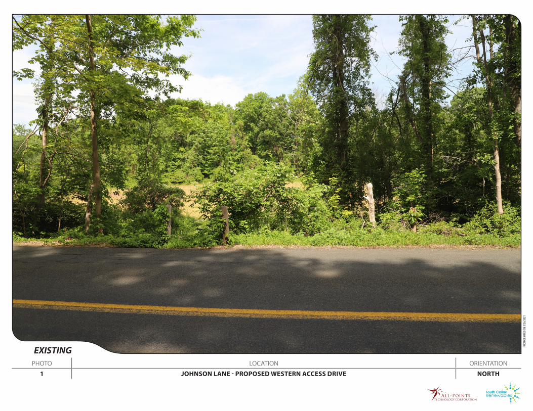
EXISTINGPHOTO LOCATION ORIENTATION
1 JOHNSON LANE - PROPOSED WESTERN ACCESS DRIVE NORTH
PHOT
OGRA
PHED
ON
5/26
/202
1

PROPOSEDPHOTO LOCATION ORIENTATION
1 JOHNSON LANE - PROPOSED WESTERN ACCESS DRIVE NORTH

EXISTINGPHOTO LOCATION ORIENTATION
2 JOHNSON LANE - EAST OF EXISTING FARM ROAD NORTHWEST
PHOT
OGRA
PHED
ON
5/26
/202
1

PROPOSEDPHOTO LOCATION ORIENTATION
2 JOHNSON LANE - EAST OF EXISTING FARM ROAD NORTHWEST

EXISTINGPHOTO LOCATION ORIENTATION
3 JOHNSON LANE - EAST OF PROPOSED EASTERN ACCESS DRIVE NORTHWEST
PHOT
OGRA
PHED
ON
5/26
/202
1

PROPOSEDPHOTO LOCATION ORIENTATION
3 JOHNSON LANE - EAST OF PROPOSED EASTERN ACCESS DRIVE NORTHWEST