Environmental Impact Assessment - Commissionerate of ...
146
The Environmental People Client: Tamil Nadu Water Supply and Drainage Board, Southern Region, Madurai. Environmental Impact Assessment and Environmental Management Plan for Design, Construction, Operation and Maintenance of 12.05MLD Sewage Treatment Plant at Theni-Allinagaram Municipality Contractor: Eco Protection Engineers Pvt. Ltd, Chennai.
-
Upload
khangminh22 -
Category
Documents
-
view
2 -
download
0
Transcript of Environmental Impact Assessment - Commissionerate of ...

The Environmental People
Client:
Tamil Nadu Water Supply and Drainage Board, Southern Region, Madurai.
Environmental Impact Assessment and
Environmental Management Plan for
Design, Construction, Operation and Maintenance of 12.05MLD Sewage Treatment Plant at
Theni-Allinagaram Municipality
Contractor:
Eco Protection Engineers Pvt. Ltd, Chennai.

CONTENTS Chapter Title Page No. EXECUTIVE SUMMARY i – viii
I INTRODUCTION
1.1 General 09 – 10
1.2 Sewage Treatment Plant – The Project 10 – 12
1.3 Environmental Status 12
1.4 Environmental Impact Assessment 12
1.5 Environmental Management Plan 13
1.6 Legal, Policy & Institution Frame Work 13
1.6.1 Water Act, 1974 13
1.6.2 Air Act, 1981 14
1.6.3 Environment Protection Act 1986, & Notifications 15
1.6.4 Environmental and Social Framework (ESF) and TNUDF 15
1.6.5 Operation Policy and Directorate of the World Bank 15
1.6.6 Tamil Nadu Pollution Control Board (TNPCB) 15
1.6.7 Noise Pollution Rules 2000 16
1.6.8 National Archaeological Sites prevention Acts 16
1.7 Clearances Required from Competent Authority 17
II PROJECT DESCRIPTION
2.1 General 18
2.2 STP- Location 19
2.3 Downstream Of STP Site 19
2.4 Project Cost 25
2.4.1 Construction Cost 25
2.4.2 Operation & Maintenance 26
2.5 Sewage Treatment Plant 26 - 33
2.5.1 Treatment Processes and Unit Operations 27 - 33
2.6 Power Details 33
2.7 Man Power 33
2.8 Sewage Disposal-Current Status 35
2.9 Disposal /Reuse 35

2.10 Sludge Handling and Disposal 35
III BASELINE ENVIRONMENTAL STATUS 3.1 Methodology 37
3.2 Air Environment 38 - 49
3.2.1 Climate and Meteorology
3.2.2 Wind
3.2.3 Ambient Air Quality
3.3 Noise Environment 49 - 53
3.4 Water Environment 53 - 57
3.5 Soil Environment 57 - 67
3.5.1 Geomorphology
3.5.2 Geology
3.5.3 Soil
3.5.4 Land Utilization
3.5.5 Land use / land cover
3.5.6 Observations
3.6 Biological Environment 67 - 68
3.6.1 Development of Green Belts
3.7 Socioeconomic Environment 69 - 70
IV PREDICTION AND EVALUATION OF IMPACTS
4.1. General 71
4.2. Prediction of impacts 71 – 74
4.2. a. Air Environment
4.2. b. Water Environment
4.2. c. Soil Environment
4.2. d. Noise Environment
4.2. e. Flora and Fauna
4.2. f. Socio Economic
4.3. Evaluation of impacts 74
V PUBLIC CONSULTATION
5.1 General 76

VI ENVIRONMENTAL MANAGEMENT PLAN
6.1 General 77
6.2 Environmental Management Plan – Pre Construction Phase 78–80
6.2.1 Sitting Phase
6.2.2 Planning Phase
6.2.3 Designing Phase
6.3 Construction Phase 80 - 81
6.4 Operation and Maintenance Phase 81 - 82
6.5 Personal Safety Systems 83
6.6 Safety Measures 83 - 84
6.7 Environmental Monitoring Plan
6.7.1 General 84
6.7.2 Monitoring Plan 84 - 86
6.7.2. a. Air Environment
6.7.2. b. Water Environment
6.7.2. c. Soil Environment
6.7.2. d. Noise Environment
6.7.2. e. Socio Economic
6.7.3 Off Site Monitoring 86
6.8 Environmental Cell 87
6.9 Budgetary Estimate (Annual) 87
6.10 Compliance Reporting 87
VII SAFETY WORK PRACTICES FOR SEWAGE TREATMENT PLANT 101
VIII ENVIRONMENTAL ENHANCEMENT MEASURES
8.1 Greenbelt Development 106
IX PROCESS DESIGN CALCULATION 113
ANNEXURES
I Compliance Statement for Consent to Establish Order
II NOC & Consent to establish from TNPCB
III Public Consultation
IV Sampling Location
V Water Analysis Report

List of Tables Table No. List of Table Page No.
1.1 Clearances Required from Competent Authority 17 2.1 Characteristics of the Raw Sewage 27 2.2 Characteristics of Treated Water 28 2.3 Man Power 33 2.4 Process and Unit Operations Design Specifications 34 3.1 Environmental Attributes 28 3.2 Climatalogical Summary 30 3.3 Ambient Air Quality Monitoring Locations 32 3.4 Techniques used for Ambient Air Quality Monitoring 34 3.5 Ambient Air Quality Results 35 3.6 Noise Monitoring Locations 41 3.7 Noise Level Standards 42 3.8 Ambient Noise Levels Results 42 3.9 Water Quality Sampling Locations 44 3.10 Characteristics of Ground water quality 45 3.11 Characteristics of Surface water quality 46 3.12 Soil sampling locations 52 3.13 Standard Soil Classification 53 3.14 Soil Characteristics 54 3.15 List of Flora in the study area 58 3.16 List of Fauna in the study area 58 3.17 Suggested plants for Green belt development 60 3.18 Theni Population Details 61 3.19 Literacy Rate in Theni 61 3.20 Theni district workforce engagement in different sectors 62 3.21 Table 3.21 Workforce engagement in different sectors in Theni 62 4.1 EIA Matrixes 67 4.2 Environmental Management Plan for Pre-Construction Phase 82 6.2 Environmental Management Plan for Construction Phase 83 - 86 6.3 Environmental Enhancement and Special Issues 87 6.4 Trouble Shooting/ Remedial measures and responsibility 88 – 98 6.5 Operation & Maintenance Check List 99 - 102 6.6 Environmental Monitoring plan 103 - 105 6.7 Cost Estimate for Environmental Monitoring Plan 106 6.8 Cost Estimation for Greenbelt Development 107 6.9 Operation & Maintenance Log Sheet 108 8.1 Suggested Plant Species for Greenbelt development 115

List of Figures
Fig. No. List of Figures Page No.
1.1 Theni District Map 11 2.1 Location of STP Site 15 2.2 Project Site Layout 16 2.3 Treatment Scheme for Sewage Treatment Plant 19 3.1 Wind rose Diagram for December 31 3.2 3.2 Ambient Air Quality for PM10 36 3.3 Ambient Air Quality for PM2.5 37 3.4 Ambient Air Quality for SO2 38 3.5 Ambient Air Quality for NOx 39 3.6 Noise Level Results 43 3.7 Drainage Overlay on Geology 48 3.8 Soil Map of India 50 3.9 Soil Map of India 51 3.10 Land Use & Land cover 52 3.11 Particle Size Classification of Soil 54 3.12 Figure 3.12 Nutrient Content in Soil 55 3.13 Figure 3.13 Exchangeable Cations in Soil 55 3.14 Figure 3.14 Organic Matter (%) in Soil 56 6.1 Green Belt Development 98

i
EXECUTIVE SUMMARY
1.0 WASTEWATER TREATMENT PLANT – Theni – Allinagaram Municipality
Theni Municipality has proposed to establish a 12.05 MLD capacity Sewage Treatment Plant
(STP) with Activated Sludge Process (ASP) at Theni Allinagaram, Theni District, Tamilnadu
as part of the underground sewerage scheme to cater to the infrastructural needs of the
Municipality.
Theni Allinagaram is a first grade Municipality in Theni District situated 75 km West of
Madurai in NH 49 extension (Madurai to Cochin). The Population of this Municipality is
85424 as per 2001 Census. The average annual rain fall of this town is 770 m. The mean
temperature of the project area is 34oC. The main occupation of the public is business and
agriculture. The contour of the town ranges from 278 m to 323 m. The total of the town is
22.23 sq.km. The length of road is 78 km. The ground water table during summer is reported
to be approximately 15 to 18 m below ground level.
ABC Environ Solutions PVT. Ltd., has been approached by M/s. Eco Protection
Engineers PVT. Ltd., to conduct Baseline Environmental Studies at their STP Site in Theni
Allinagaram Municipality.
Theni-Allinagaram municipality is in the forefront in completing the underground drainage
systems and that Sewage Treatment Plant for a processing capacity of 12.05 MLD is
proposed for immediate implementation. The Sewage Treatment Plant (STP) is envisaged as
state-of-the-art plant, on the basis of an Advanced Biological Treatment Process followed
by disinfection.
The Extended Aeration process is incorporated as the core treatment process of the STP, as
it can offer the BOD removal efficiency at 95-99% which should ensure the treated sewage
for BOD at less than 20mg/l and TSS at less than 30mg/l.

ii
The STP gets operated to its design parameters and ensures the quality of the treated sewage
as per the standards of Water Act of MoEF and guidelines of Tamil Nadu Pollution
Control Board.
Theni-Allinagram Municipality has already obtained “Consent to Establishment” from
Tamil Nadu Pollution Control Board for the Sewage Treatment Plant in the proposed
location.
2.0 TREATMENT PROCESSES AND UNIT OPERATIONS: The municipal sewage drawn through the under ground sewerage system will be treated in
four stages of treatment viz.,
Primary Treatment
- Screening, Degritting
Secondary Treatment
- Aeration Tank (Modified (ASP), Secondary clarifier and
Sludge Dewatering Unit (Centrifuge).
Disinfection:
- Chlorine Treatment
The sewage is screened, degritted in the preliminary treatment with mechanical screens, grit
chamber. The pre-treated effluent will then be taken to an Aerobic Tank, designed on the
basis of Extended Aeration (a modified ASP) with a secondary clarifier. The sludge will be
fully recycled to have MLVSS at 3000-4000 mg/l and for F/m ratio of 0.03 to 0.5 Kg
BOD/Kg MLSS. Day so that BOD5 and TSS removal efficiencies will be 95-99% and 80-
90% respectively.
The clarified effluent will be dosed with hypochlorite solution so as to ensure complete
killing of pathogenic micro organisms. The treated sewage will be collected in treated water
collection tank at STP Site and it will be pumped to the Thamaraikulam. The treated sewage
which is envisaged to confirm to standards for use of treated sewage for Agriculture, will be
taken to the existing irrigation systems of channels.

iii
The proposed STP will have flow and quality monitoring facilities, so as to ensure the
operation of STP as per the standards and guidelines of TamilNadu Pollution Control Board.
3.0 ENVIRONMENTAL STATUS:
The location of the proposed STP has been choosing on the basis of the environmental
standards, geological conditions and facilities for the disposal/reuse of treated sewage.
Theni is generally found to have a sub-tropical meteorological conditions with moderate wind
conditions, poor rainfall with moderate atmospheric temperatures and humidity. The location
of STP is adjoining to the grave yard (Electrical crematorium) and relatively away from
residential locations.
AIR ENVIRONMENT:
The parameters chosen for assessment of air quality were Particulate Matter (PM 10 and 2.5
µ), Sulphur Dioxide (SO2) and Oxides of Nitrogen (NOx) in the four different AAQ
Locations. In the study area, PM10, PM 2.5, SO2 and NOx concentration observations are
found to be within the specified standards of CPCB at all locations.
NOISE ENVIRONMENT:
The Noise monitoring was carried out in four different locations in day and night time. The
daytime Leq varied from 42.1 to 48.9 dB (A) and the night time Leq from 40.3 to 43.5 dB
(A) within the study area. All the Noise Level results are found to be within the specified
standards of CPCB at all locations.
WATER ENVIRONMENT:
Water sampling has been conducted to establish baseline water quality in the area. Four
Ground Water and Two Surface Water samples are collected and water analysis was carried
out for physical and chemical parameters as per the methods prescribed in IS and “Standard
Methods for the Examination of Water and Wastewater. The physicochemical characteristics
of ground water and surface are compared with the standards (IS 10500: Indian

iv
Standards/Specifications for Drinking Water) reference values. in the study area were
moderate to very hard in nature.
The chloride content in the studied area ranged from 24-187 mg/L. The sulphate content in
the ground water is found to be from 28 to 78 mg/L. All the chloride, sulphate, lead and iron
values are within the IS standards in all the area. The lead and oil & grease values are below
detectable limit in both the Vaigai River and Thamaraikulam.
The baseline water environment in and around 2 km radius of the proposed Project Site were
established in line with the ISO 19001 Standards. The Mullai Periyar River flows in the
Eastern side of the STP site at a distance of 0.3 km. The flow direction and flow
accumulation of the study area clearly indicates the control of the structural features on the
river system. From the STP site the surface water flows towards East.
LAND ENVIRONMENT
Red loam soil is the predominant Soil type in this district accounting for 37.48% followed by
red sandy soil of 14.53%. The other types of soils are lateritic soil, black soil, and sandy soil.
According to the land utilization pattern only 40 % of it is under agriculture. Excluding the
forest area which is 34%, the remaining 26% of land may be brought under waste land
development programme.
Soil samples are collected from four different locations. The analyzed results are compared
with soil classification, from the observations it was found that the soil in the study area
shows moderate fertility.
BIOLOGICAL ENVIRONMENT
The biological environment includes mainly terrestrial ecosystem and aquatic ecosystem. No
endangered Species found in and around the project site. The list of plant and animal species
recorded in the study areas are discussed in the report.

v
SOCIOECONOMIC ENVIRONMENT
Theni district socioeconomic environment and the anticipated impacts of the proposed project
is discussed in the report. The areas of discussion in this chapter are demographic structure,
economic activity, education, literacy profile, land use and infrastructure resources.
The results of the ambient air quality, Noise level monitoring, Water Quality Analysis and
Soil Sampling results at different locations in Theni Allinagaram, noted that all
emissions/results are within the limits of existing regulations of the CPCB/TNPCB/IS
standards. For further improvement and maintenance of the existing compliance to
environmental laws, it is recommended that Environmental Management Plan and
Environmental Monitoring Plan has to be strictly implemented, complying with the
TNPCB/CPCB regulations.
4.0 IMPACT ASSESSMENT:
The Installation of STP will stop the discharge of untreated sewage which is at present used
for irrigation and land disposal. The proposed STP will improve the present status of land and
water in the Theni-Allinagaram area.
The STP will render the treated wastewater to adhere the standards of BOD5 and TSS so that
it will be fully reused. Hence, the installation of STP will improve the environmental quality
of Theni-Allinagaram.
The impact matrix was drawn for the Sewage Treatment Plant and it is found that the
installation of STP will have more positive and proactive impact on the environmental quality
of Theni-Allinagaram.
5. STATUTORY APPROVALS /PERMITS:
The environmental permit for this kind of project is consent from State Pollution Control
Board. Theni-Allinagaram Municipality has already got consent for establishment from
TamilNadu Pollution control Board, for starting the construction activities.
vi
A copy of the “NOC & Consent to Establishment” from Tamil Nadu Pollution Control
Board for establishing the Sewage Treatment Plant for Theni Allinagaram, in the said
location, is presented in ANNEXURE-I.
Consent to Operate:
Anyhow, consent is required for operating the plant. On completion of all works and before
one month of time, Theni-Allinagaram municipality needs to apply for consent for operating
the plant.
Consent renewal:
The consent for operation can be taken only on annual basis from TNPCB and its validity
only upto end of March of the every Year. Every year, application must be filed during
February-March along with requisite consent fee to state PCB for renewing the consent or
permit to operate the STP for the next one year period.
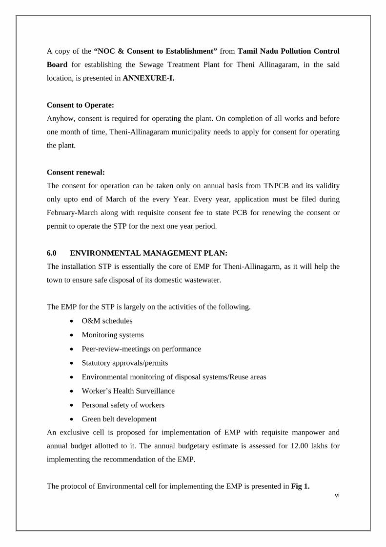
6.0 ENVIRONMENTAL MANAGEMENT PLAN:
The installation STP is essentially the core of EMP for Theni-Allinagarm, as it will help the
town to ensure safe disposal of its domestic wastewater.
The EMP for the STP is largely on the activities of the following.
• O&M schedules
• Monitoring systems
• Peer-review-meetings on performance
• Statutory approvals/permits
• Environmental monitoring of disposal systems/Reuse areas
• Worker’s Health Surveillance
• Personal safety of workers
• Green belt development
An exclusive cell is proposed for implementation of EMP with requisite manpower and
annual budget allotted to it. The annual budgetary estimate is assessed for 12.00 lakhs for
implementing the recommendation of the EMP.
The protocol of Environmental cell for implementing the EMP is presented in Fig 1.

vii
FIG. 1a ENVIRONMENTAL CELL
Chairman (Municipal Commission)
Theni-Allinagaram
Project Incharge
(Theni-Allinagaram Municipal Executive Engineers)
Operation Head (O& M –Engineer AE grade)
(All statuty approvals/ Public grievances)
Chemist. a. Lab Assistant
- Analysis of samples - Maintenance of operating
parameters b. Personal Safety Systems
Plumber
a. Field Assistants (2 Nos) - Maintenance of pipelines,
leaks - Pumps/Blowers
Electrical
a. Field Assistants (2 Nos) - Maintenance of all electrical
installation - Maintenance of Fire Fighting
Systems
Electrical
a. Field Assistants (2 Nos) - Maintenance of all electrical
installation - Maintenance of Fire Fighting
Systems

viii
FIG. 1b ENVIRONMENTAL CELL
Executive Engineer (TWAD Board)
Assistant Executive Engineers
(TWAD Board)
Assistant Engineers (TWAD Board)
Operation Head (O&M – In-charge)
Lab Chemist. (01No.) a. Lab Assistant (01 Nos.)
- Analysis of samples - Maintenance of operating
parameters b. Personal Safety Systems
Plumber (01Nos.)
a. Field Assistants (1 Nos) - Maintenance of pipelines,
leaks - Pumps/Blowers
Plant Operator (01Nos.)
a. Field Assistants - Maintenance of all electrical
installation - Maintenance of Fire Fighting
Systems
Electrical
a. Field Assistants (1 Nos) - Maintenance of all electrical
installation - Maintenance of Fire Fighting
Systems

Page 9 of 119
CHAPTER – I
INTRODUCTION
1.1 GENERAL:
Theni Allinagaram is a first grade Municipality in Theni District situated 75 km West of
Madurai in NH 49 extension (Madurai to Cochin). The Population of Theni
Municipality is 85424 as per 2001 Census. The average annual rain fall of this town is
770 m. The mean temperature of the project area is 34oC. The main occupation of the
public is business and agriculture.
Theni Allinagaram Municipality is the headquarters of Theni District. The town is
situated at 300 m above Mean Sea Level, between 100o37” N Latitude and 77o20”E
Longitude. Theni is linked to Periyakulam, Bodinayakkanur and Cumbum towns by
major district roads. A Master Gauge (MG) railway line links this town with Madurai
Corporation. Theni Allinagaram was constituted as Grade III Municipality in 1964 and
later upgraded to a Grade II Municipality in 1972. Population of the town at that time
was 24,606. Pursuant to 1983, Theni Allinagaram was classified as a First Grade
Municipality.
The contour of the town ranges from 278 m to 323 m. The total of the town is 22.23
sq.km. The length of road is 78 km. The ground water table during summer is reported
to be approximately 15 to 18 m below ground level.
Theni district is in the Southern part of Tamil Nadu. This district is surrounded by the
Western Ghats, with it green stretches of cultivated lands and tea gardens. Silk cotton,
soft towels, coffee seeds, cardamom, mango, are the main produce of the district. Theni
district is the main route for the tourist bound from Madurai to Kochi via
Bodinayakanur and Munnar and Madurai to Thekkadi wildlife sanctuary.
Theni Municipality has proposed to establish a 12.05 MLD capacity Sewage Treatment
Plant (STP) with Activated Sludge Process (ASP) at Theni Allinagaram, Theni District,
Tamilnadu as part of the underground sewerage scheme to cater the infrastructural
needs of the Municipality.

Page 10 of 119
The location map for the project site is shown in Figure 1. The Project is implemented
under third Tamil Nadu Urban Programme financed by international development
Agency.
The quantity of municipal sewage is assessed for 12.05 million litres per day, on the
basis of population and water use pattern presently, the sewage is not properly treated
and hence a full fledged Sewage Treatment Plant is envisaged in the project, to serve
Theni-Allinagaram Municipality.
The proposed STP, for processing 12.05 MLD, of sewage should be planned, designed,
constructed, operated and maintained, in harmony with the existing environmental
conditions and ambience.
The installation of STP should enhance the present environmental status of the project
location and Theni as whole. The operation of STP should ensure prevention of water
pollution and provide qualitatively, standardized water for irrigation and ground water
recharge by the reclaimed water from the municipal wastewater.
1.2 SEWAGE TREATMENT PLANT – THE PROJECT
The sewage from the domestic areas of Theni-Allinagaram is envisaged for full fledged
treatment and treated water is planned for use in the farming activities and ground water
recharge through rain water harvesting structures.
The sewage treatment plant is designed to process 12.05MLD of sewage. The proposed
STP is based on the Modified Form of Activated Sludge Process which will ensure
contaminant-free water after the treatment.
The installation of STP is planned for execution on DBOT (Design-Build-Operate-
Transfer) basis, leaving the performance of the STP to the responsibility of the
contractors.
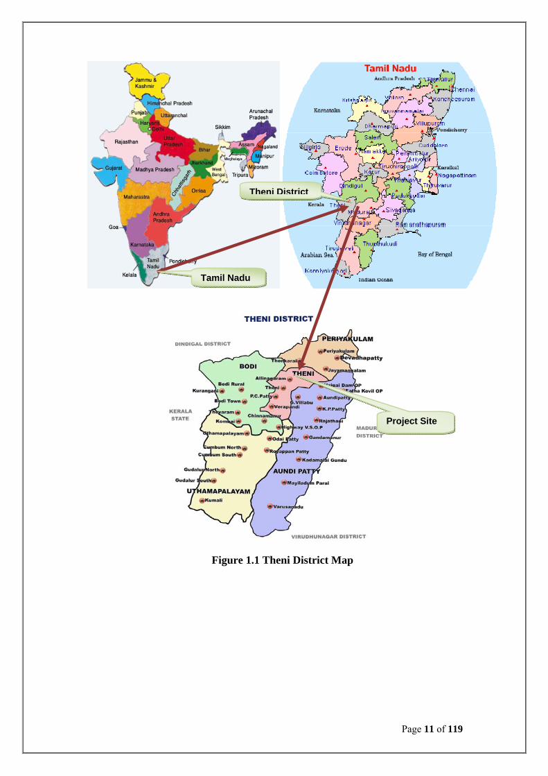
Page 11 of 119
Figure 1.1 Theni District Map
Tamil Nadu
Theni District
Project Site

Page 12 of 119
M/s. Eco Protection Engineers Pvt. Ltd, Chennai, a turn-key status environmental
engineering firm is preparing the detailed process and plant design for the STP.
M/s. ABC Environ Solutions Pvt. Ltd, Chennai, has been appointed as EIA
consultant for conducting requisite Environmental Surveys, for Environmental Impact
Assessment and preparing Environmental Management Plan.
1.3 ENVIRONMENTAL STATUS: There also no sensitive or environmentally or socially important places, nearby. The
proposed project location is surveyed for all the environmental attributes like
Microbiology Air, Water, Soil, Noise and Human using Standard Protocols and as
per the guidelines of MoEF, New Delhi.
The existing environmental dimension of the project location shall be surveyed for a
comprehensive data to develop strategies for monitoring the environmental components
in the post project scenario.
A snap survey on all the components of the surrounding environment in the 5Km radius
of the project location was carried out and environmental setting of the project location
was assessed.
1.4 ENVIRONMENTAL IMPACT ASSESSMENT: The environmental base line data of the project location is interpreted with the resultant
and residues of the proposed STP activities.
The activities that concern the collection, transfer, treatment and disposal of wastewater
through Theni town has been interpreted to identify the impacts of such activities on the
surrounding environmental attributes of the project location.
EIA matrix is drawn for the STP and it is found that the installation of STP will impart
significant positive impacts on the project environment.

Page 13 of 119
1.5 ENVIRONMENTAL MANAGEMENT PLAN:
A detailed EMP is devised as per the guidance documents of MoEF.
The EMP is detailed exclusively for three different phase of the Project viz.,
• Design Phase
• Construction Phase
• Operation And Maintenance Phase
Off site monitoring of water and soil in 5 Km radius of the project site, especially in the
areas of treated water disposal are recommended. The sampling and analysis of water
and soil samples be carried out as per standard procedures and as per the guidelines of
EIA notifications of MoEF.
The EMP will be adhered in principle during the period of the execution of project and
also after with an exclusive “Environmental Cell” for operating and maintaining the
STP.
1.6 LEGAL, POLICY & INSTITUTION FRAME WORK
This section reviews the policies, regulations and administrative framework within
which the project is to be implemented. The review includes the Environmental and
social framework of TNUIFSL, operational policies / directions of the World Bank and
sector-specific environmental policies and regulations of the Govt. of India and Govt. of
Tamilnadu.
1.6.1 Water Act, 1974 These laws seek to control pollution of water and enhance the quality of water. Under
this law, it is mandatory to obtain Consent to Establishment of STP and the effluent to
be treated to meet the discharge standards of inland surface water and discharged as per
the standards stipulated by TNPCB before discharge into the river or on land for
irrigation and pay consent fees as stipulated for local bodies viz., Town Panchayat,
Municipality, Corporation which are causing water pollution.

Page 14 of 119
1.6.2 Air Act, 1981 This Act provides prevention, control and abatement of air pollution. With a framework
similar to the Water Act, the Air Act gave the central and State Board’s authority to
issue consents to industries operating within the designated air pollution control areas.
The State also prescribes emission standards for stationary and mobile sources.
1.6.3 Environment Protection Act 1986, & Notifications: In order to create national environmental legislation, the EPA articulates a policy for
environmental protection covering air, water and land and provide a framework for
Central Government to coordinate between Central and State Authorities established
under various laws, including the Water Act and Air Act. Under this umbrella Act, the
Central Government must set National Ambient and Emissions Standards, establish
procedures for managing hazardous substances, regulate industrial sites, investigate and
research pollution issues and establish laboratories and collect and disseminate
information.
Among other relevant legislation, the Public Liability Insurance Act (PLIA) of 1991
mandates that business owners operating with hazardous substances take out insurance
policies covering potential liability from an accident and establish Environmental Relief
Funds to deal with accidents involving hazardous substances. The National
Environmental Appellate Authority Act of 1997 requires the Central Government to
establish an authority to hear appeals on area restrictions where operations will not be
carried out or will be carried out with certain safeguard measures.
In 2005, Parliament enacted the Right to Information Act designed to promote greater
transparency and accountability of the government and public participation in decision-
making.
1.6.4 Environmental and Social Framework (ESF) and TNUDF TNUIFSL has categorized urban infrastructure projects into three categories viz. E-1, E-
2 and E-3. As per ESF, the Theni-Allinanagam STP project comes under E1 category.
The E1 projects require EA and approval of World Bank prior to implementation. The
projects comply with the environmental resettlement and social standards set forth in
the TNUDF’s Environmental and Social Framework.
Page 15 of 119
1.6.5 Operation Policy and Directorate of the World Bank Operational Policy 4.01 (OP 4.01) is one of the ten safeguard policies of the World
bank, which provides the Environmental Impact Assessment (EIA) guidance for the
lending operations.
The OP 4.01 requires the borrower to screen projects upstream in the project cycle for
potential impacts. Thereafter, an appropriate Environmental Assessment (EA) approach
to assess, minimize / enhance and mitigate potentially adverse impacts is selected
depending on nature and scale of project. The EA needs to be integrated in the project
development process such that timely measures can be applied to address the identified
impacts. The policy requires consultation with affected groups and NGOs to recognize
community concerns and the need to address the same as part of EA.
1.6.6 Tamil Nadu Pollution Control Board (TNPCB) The TNPCB has the mandate for environmental management at the state level, with
emphasis on air and water quality.
The board is responsible for:
• Planning and executing state-level air and water initiatives,
• Advising state government on air, water and industry issues,
• Establishing standards based on National Minimum Standards,
• Enforcing and monitoring of all activities within the State under the Air Act, the
Water act and the Cess Act, etc.
• Conducting and organizing public hearings for projects as defined by the various
Acts and as stipulated by the Amendment (April 1997) to the EIA Act; and,
Issuing No-objection Certificates (NOC) for development projects defined in
such a way as to include road projects.
• The NOC from the Tamil Nadu Pollution Control Board TNPCB in pursuant to
the Water (Prevention and Control of Pollution) Act of 1974, the Cess Act of
1977 and the Air (Prevention and Control of Pollution) Act of 1981.
• The State Pollution Control Board issues a No-objection Certificate (NOC) after
accepting the application for the project.

Page 16 of 119
1.6.7 Noise Pollution Rules 2000 In order to curb the growing problems of noise pollution, the government of India has
enacted the noise pollution rules 2000 that includes the following main provisions:
• The state government may categorize the areas as industrial or commercial or
residential.
• The Ambient air quality Standards in respect of Noise for different areas has
been specified.
• The State government shall take measures for abatement of noise including
noise emanating from vehicular movement and ensure that the existing noise
Levels do not exceed the ambient air quality standards specified under these
rules.
• Areas not less than 100 m around Hospitals, Educational institutions and Court
is declared as silence area under these rules.
• A loud speaker or a public address system shall not be used except after
obtaining written permission from the authority and the same shall not be used
at night, between 10 pm to 6 am.
• A person found violating the provisions as to the maximum noise permissible in
any particular area shall be liable to be punished for it, under the provision of
these rules and any other law in force.
1.6.8 National Archaeological Sites prevention Acts: 1.6.8.1 The Ancient Monuments and Archaeological Sites and Remains Act, 1958 In order to bring out the legislation on par with constitutional provisions and provide
better and effective preservation to the archaeological wealth of the country. The
Ancient Monuments and Archaeological Sites and Remains Act 1958 (No 24 of 1958)
was enacted on 28th August 1958.
This Act provides preservation of ancient and historical monuments and archaeological
sites and remains of national importance for the regulation of archaeological
excavations and for the protection of sculptures, carvings and other similar objects.
Subsequently, the Ancient Monuments and Archaeological Sites and Remains Rules
1959 were framed. The Act along with Rules came into force with effect from 15
October 1959. This Act repealed The Ancient and Historical Monuments and
Archaeological Sites and Remains (Declaration of National Importance) Act, 1951

Page 17 of 119
1.6.8.2 The Antiquities and Art Treasures Act, 1972
The Antiquities and Art Treasures Act 1972 (No. 52 of 1972) is the latest Act enacted
on 9th September 1972 for effective control over the moveable cultural property
consisting of antiquities and art treasures. The Act regulates export trade in antiquities
and art treasures, provides prevention of smuggling and fraudulent dealings, authorizes
compulsory acquisition of antiquities and art treasures for preservation in public places
and provides certain other matters connected therewith or incidental or ancillary thereto.
This Act was supplemented with The Antiquities and Art Treasures Rules 1973. The
Act and Rules have been in force with effect from 5th April 1976. This legislation
revealed the Antiquities Export Control Act, 1947 (Act No. XXXI of 1947)
1.6.8.3 The Treasure Trove Act, 1878 The Indian Treasure Trove Act, 1878 (Act No. VI of 1878) was promulgated to protect
and preserve any treasure found accidentally but having archaeological and historical
value. This Actwas enacted to protect and preserve such treasures and their lawful
disposal. In a landmark development in 1886, James Burgess, the then Director General
succeeded in prevailing upon the Government for issuing directions forbidding any
person or agency to undertake excavation without prior consent of the Archaeological
Survey and debarring officers from disposing of antiquities found or acquired without
the permission of the Government.
1.7 Clearances Required from Competent Authority:
1.1 Table
S. No. Activity Clearance
Required. Statutory Authority Status
1.0
Establishment of Proposed Sewage Treatment Plant
Consent To Establishment under Air and Water Act, 1981
Tamil Nadu Pollution Control Board.
The Consent for Establishment has been obtained from TNPCB vides Proceedings No: DEE /DGL/F.No.DGL-125/W/2009, Dated: 31.12.2009, Consent Order No: 62/OL/2009/31/12/2009 for the proposed STP. The photocopy of the Same is enclosed as Annexure – II.
2.0
Commissioning of Sewage Treatment Plant
Consent To Operate under Air and Water Act.
Tamil Nadu Pollution Control Board.
Consent To Operate will be obtained from TNPCB once it is ready for commissioning.

Page 18 of 119
CHAPTER – II
PROJECT DESCRIPTION
2.1. GENERAL:
Theni-Allinagaram is a first grade municipality in Theni District. Tototal area of the
town is 22.23 Sq.km. There is no sewerage system existing in Theni Allinagaram.
Sewage disposal is primarily through septic tanks. In general, it is discharged in to the
open street drains. Some soak pits of shallow depth and inadequate size are also in
existence. These soak pits do not function properly and thereby allowing the sullage
overflows. The street drains carrying sullage and sewage, are ultimately discharged in to
water courses.
The sewerage system will comprise of construction of 12.05 MLD Sewage Treatment
Plant of Activated Sludge Process, laying of main sewer line diameter of 150 mm and
600 mm for a length of 4.50 km and secondary/laterals for a length of 56.80km in
diameter ranging from 200 mm to 600 mm. In the system two lifting Station has also
been proposed , one lifting station to pump about 0.25 MLD of sewage to be transported
to a gravity sewer through a pumping main of diameter 200mm and a length of 120
metres and other one lifting station to pump about 0.75MLD of sewage to be
transported to STP site a pumping main of diameter 150 mm and a length of 1.50kms.
One Main pumping station has also proposed to pump about 11.30MLD of sewage to
sewage treatment plant through a pumping main of diameter 600mm and length of
3.0kms.
For house service connection it has been proposed 110 mm & 160 mm diameter ODU
PVC pipes (4 to 6 per manholes). The house service connection is provided normally to
the manholes, where 2 or 3 House Service Connections (HSC) will be to Road Side
Chamber (RSC) and RSCs will in turn be connected with manholes. Also provision has
been made in the cost estimate for dismantling cum refilling the septic tank / soak pit
utilities for those who do not find space for effecting a separate connection.
The collection system is designed for the volume of waste water to be generated for the
projected population of 2024. Per capita wastewater generation is considered as 80% of
the net water supply. Peak factor has been considered to design the sewer lines.

Page 19 of 119
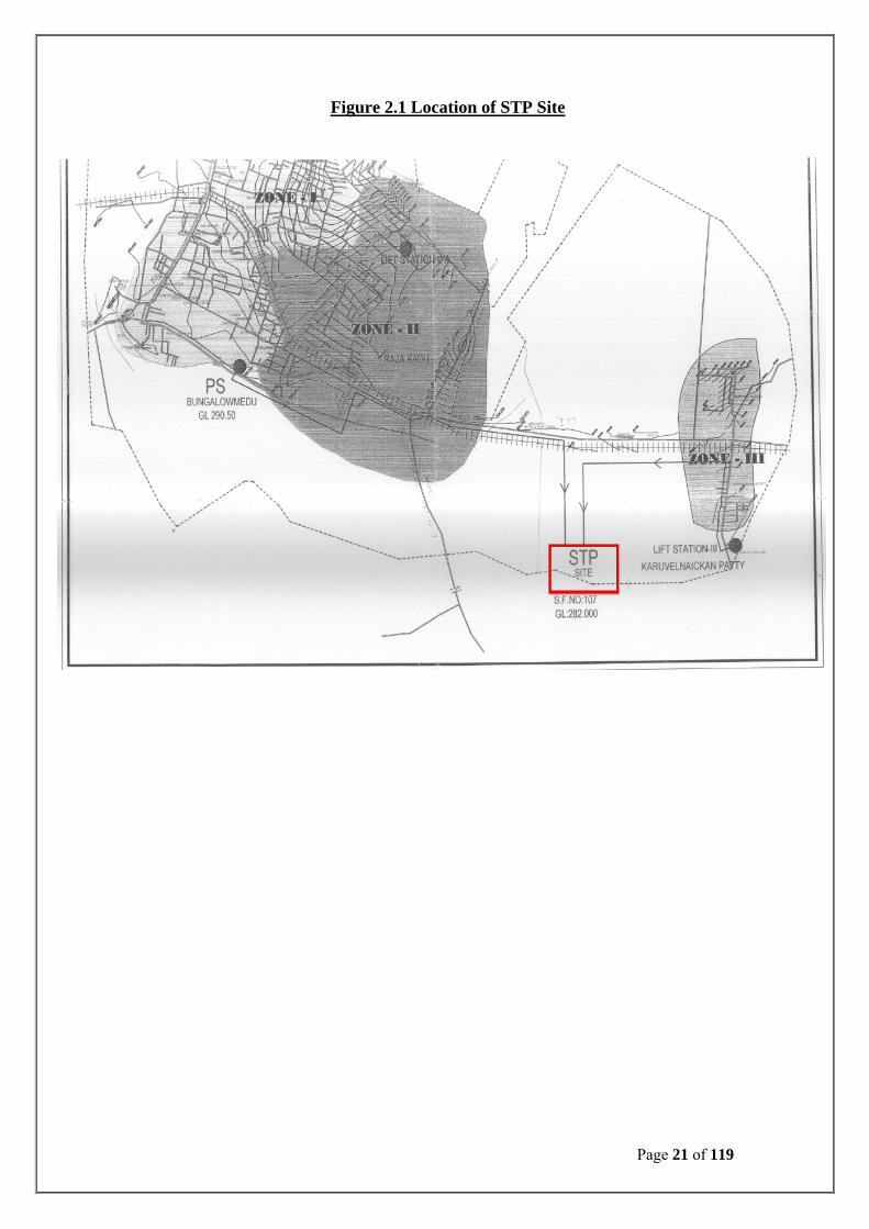
2.2 STP- LOCATION:
Location : Karuvelnaickanpatty Village Area Available : 3.81acres STP Area Requirement : 1.04 acres Area for future expansion : 0.64 acres Ownership : Theni- Allinagaram Municipality
The site for the proposed STP is 3.81Acre, in SF. No. 107 / Village,karuvelnaickan
Patty and Theni district.
The geological position of the STP site is,
Latitude: 100°36’’N
Longitude: 770 20’’ E
The location is fully owned by Theni-Allinagaram municipality, which was assigned to
TWAD Board for establishing the said Sewage Treatment Plant.
The location of the STP site is presented in Fig. 2.1.
2.3 DOWNSTREAM OF STP SITE:
The following sources are available in the river vaigai from downstream of STP
location of Theni-Allinagaram UGSS.
S. No. Name of Scheme No. of
Infiltration well Qty in MLD Distance in KM Method of Treatment
1 Palacombai CWSS Condemned
3 Nos. 2 Nos.
1.96 3.10 Adding of Bleaching powder
2 Vallalnathi CWSS 3 Nos. 1.75 3.25 -do-
3 Collectorate WSS 2 Nos. 0.50 3.30 -do-
4 Kunnur WSS 1 No. 0.25 3.40 -do-
5 Theni Municipality WSS 3 Nos. 2.50 3.50 -do-
6 Unjampatty WSS 3 Nos. 0.50 3.90 -do-
7 Saruthupatty WSS 1 No. 0.25 5.60 -do-
8 Medical College WSS 1 No. 0.25 5.70 -do-
9 Arappadithevanpatty CWSS 2 Nos. 1.15 5.80 -do-
10 Andipatty WSS 5 Nos. 2.20 6.10 -do-
11 Theni Municipality WSS 8 Nos. 6.00 6.60 -do-

Page 20 of 119
The following parameters were tested periodically.
Physical Parameters:
Appearance
Colour
Odour
Turbidity
TDS
Electrical conductivity
Chemical Parameters:
PH
Total Alkalinity
Total Hardness
Calcium
Magnesium
Iron
Mangenis
Ammonia
Nitrite
Nitrate
Chloride
Fluride
Sulphate
Pospate
Permananganet test
Bacteriological Parameters:
Total coliform
Fecal coliform
Strepto pocci
Page 21 of 119
Figure 2.1 Location of STP Site

Page 22 of 119

Page 23 of 119
Page 24 of 119
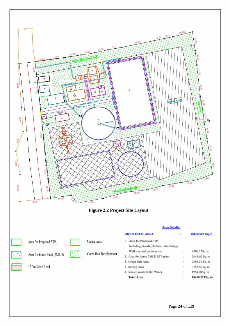
Figure 2.2 Project Site Layout

Page 25 of 119
2.4 PROJECT COST
The total project cost is estimated to be Rs.7.78 Crores (Detailed breakup is given in
Table) and the total operation and maintance (O&M) cost is estimated to be
0.606Crores (Detailed break-up is given Table 2.3.1 & 2.3.2).
2.4.1 CONSTRICTION COST:
Project Cost
S. No. Description Amount in Rs
I Capital cost:
a. Submission and acceptance of detailed designs, drawings and estimates. 5,94,000.00
b. Hydraulic process design and layout of the plant. 4,95,000.00
c. Structural design and construction drawing for primary units. 6,43,500.00
d. Structural design and construction drawing for secondary units. 7,42,500.00
e. Structural design and construction drawing for sludge handling, treatment arrangements unit and auxillary units.
3,96,000.00
II Submission and acceptance of detailed Environmental Assessment Report.
1,98,000.00
III Construction of the following components of the plant
1 Receiving Chamber 7,42,500.00
2 Screening units 26,73,000.00
3 De-gritting units 42,57,000.00
4 Distribution box & Bye-pass arrangement 9,90,000.00
5 Primary and Secondary Units 3,86,10,000.00
7 Chlorination Tank 41,08,500.00
8 Sludge Sum p and Pump house 31,68,000.00
9 Centrifuge House 76,72,500.00
10 Administrative Building including Furniture and Laboratory Equipments 30,69,000.00
11 Internal Roads, Pathways, Pavements, Storm water drainage 6,43,500.00
12 Misc. Civil works 6,43,500.00
13 Site Clearance, Disposal/ Plot Development – Landscaping etc. 2,47,500.00
14 Electrical Works including (Bidder to specify various units) 79,20,000.00
Total 7,78,14,000.00

Page 26 of 119
2.4.2 OPERATION MAINTANCE COST:
S. No Description Amount in Rs.
1.0 Trail Run 8,00,000.00
2.0 O&M Cost for 5 Years
a.
Fixed cost (Man power, maintenance of all Civil
Structures and entire plant House Keeping, all repairs
including spares & Replacement, Oil & Grease cost)
36,00,000.00
b. Variable cost (except TNEB power charges, Diesel cost, Chlorine Dosage costs) other chemical consumable cost and safe disposal grit / sludge transportation to site
15,42,524.00
c. Environmental Monitoring Plan during Operation Phase
a. Green Belt b. Safety Training c. Personal Protective Equipments, etc.
1,20,600.00
Total 60,63,124.00
2.5 SEWAGE TREATMENT PLANT:
The STP is planned for installation at SF. No. 107 / Village, karuvelnaickan, Theni. As
the location is away from any significant habitation and at the tail end of the drainage
systems, the STP operation will be at ease and will not invite any apprehension from the
public.
The STP layout is presented in Fig. 2.2.
The STP is envisaged for 12.05 MLD Capacity to serve the entire community under
Theni Municipality. The STP is planned and designed on the basis of Modified
Activated Sludge Process.
The typical characteristic of the sewage is presented in Table. 2.1. The schematics of the Sewage Treatment Plant is presented in the Fig.2.3.

Page 27 of 119
2.5.1 TREATMENT PROCESSES AND UNIT OPERATIONS:
The proposed Sewage treatment plant is designed to have a high rate aerobic biological
treatment process, namely, Extended Aeration process followed by Disinfection to
ensure pathogens-free treated effluent, which can be readily used for irrigation.
Unit operations are designed to achieve stage or step wise removal of Solids and
organics.
Receiving Chamber
Fine Screen channel
Detritor Tank
Flow Measurement
Aeration Tank & Secondary Clarifier
Chlorine House & Chlorine contact tank
Sludge Sump
Centrifuge
Disposal line • Table: 2.1 – Characteristics of the Raw Sewage:
S. No Parameters Units Values
1 pH - 6.22 Biochemical Oxygen Demand (BOD5) mg/l 236 3 Chemical Oxygen Demand mg/l 4524 Total Suspended Solids mg/l 220 5 Total Kjeldahl Nitrogen mg/l 616 Ammonia Nitrogen mg/l 50 7 Total Phosphorus mg/l 58 Sulfates mg/l 54 9 Faecal Coliform/100ml MPN 106
10 Total Coliform /100ml MPN 107
11 Chloride mg/l 20012 Oil & Grease mg/l < 1

Page 28 of 119
• Table : 2.2 – Characteristics of Treated Water:
S. No. Parameters Units Values 1. pH - 5.5 -92. Biochemical Oxygen Demand (BOD5) mg/l ≤ 20 3. Chemical Oxygen Demand mg/l ≤ 2504. Total Suspended Solids mg/l ≤ 30 5. Ammonia Nitrogen mg/l ≤ 506. Nitare Nitrogen mg/l ≤ 5 7. Total Phosphorus mg/l ≤ 58. Total Coliform /100ml MPN ≤ 1000 no. 9. Oil & Grease mg/l < 5

Page 29 of 119
• Fig: 2.3 – Treatment Scheme for Sewage Treatment Plant:

Page 30 of 119
The inlet chamber will receive the raw sewage to pass it further to screen channel and
subsequently to the grit chamber. In screen channel floating matters are trapped and
removed. In grit chamber, grit is being removed. The sewage having been treated for
screening and grit removal is then treated biologically. The treated wastewater is
disinfected in chlorine contact tank to meet the fecal coliform limit.
A portion of the settled biological sludge is recycled to aeration tank to maintain the
active biomass content in aeration tank. Excess sludge will be collected in Sludge sump,
from where it is fed to the centrifuge for dewatering before its disposal or its use as
manure. The filtrate from the centrifuge shall be returned to the receiving chamber.
Primary Treatment Process: a. Receiving Chamber: An inlet chamber is provided ahead of screen channel to receive the sewage from the pumping station. b. Fine Screen Channel: Mechanical fine screen is provided with manual standby facility for the 100% percent
of the flow is provided for the screening operation. The manual screening process is
undertaken by screen consisting of 50 mm x 3mm thick flats with 6 mm clear openings
to trap the floating materials.
The mechanically operated screen will be equipped with a mechanism, which will
automatically rake at a pre-set sensor control. The screenings will be collected in a
hopper located above the water level such that the screenings can be easily collected in
a collection cart.
Each of the standby screen channels will have manually cleaned bars screens with bar
clearance of 10 mm. Aluminum gates are provided with RCC platforms and access
staircase. Hand railing is provided on all platforms.

Page 31 of 119
b. Detritor Tank: The grit removal consists of two essential elements grit collecting mechanism and grit
washing mechanism. Each operates separately but in hydraulic communication with one
another.
The removal of grit is essential to,
• Protect moving mechanical equipment from abrasion and accompanying
abnormal wear.
• Reduce formation of heavy deposits in pipeline, channels, and conduits. Mechanism:
• The detritor is a continuous flow tank in which the grit settles due
to gravity and the water overflows through the outlet weir on the
opposite side.
• The settled grit is scrapped by means of a scraper mechanism towards
the openings on the classifier sidewall at the bottom.
• The collection chamber works on velocity principle and is so designed
that only grit settles down and organic matter overflows.
• The classifier mechanism consists of a reciprocating rake driven by a
gear drive fitted with a motor.
• The grit collected is given a thorough washing and is delivered from the top of the classifier through a chute for further disposal.
The Organic Return Pump / Mixer return the washed organic liquor lying in the
classifier back to the detritor collection chamber.
d. Flow Measurement: After screening and grit removal, the sewage enters into the flow measurement channel
(Parshll Flume), where Ultra Sonic Flow Meter will be installed to measure the flow of
incoming sewage.

Page 32 of 119
e. Aeration Tank: (Biological Treatment) A process in which wastewater continuously flows into an aerated tank in which a culture of suspended microorganisms biologically flocculate and metabolize colloidal and soluble organic material (BOD).
Primary organisms – bacteria, consume soluble and colloidal organics.
Secondary organisms - Protozoa consume suspended organics and dispersed
bacteria.
Aeration provides:
Mixing - Necessary to keep micro-organisms in contact With the organics.
Oxygen - For metabolism.
f. Chlorine Contact Tank: Outflow of the secondary clarifier water will be carried to chlorine contact tank by RCC
channel/pipe. Chlorine diffuser arrangement shall be made at the inlet of chlorine
contact tank for the mixing of chlorine to the incoming flow. In chlorine contact tank,
chlorine gas will come in contact with treated sewage and will remove the faecal
coliform by chemical reaction (Disinfection). RCC Baffle walls shall be provided in the
tank to prevent the short circuting. g. Sludge Sump: The sludge withdrawn from the secondary clarifier is collected in the sludge sump.
Sludge pumps will be provided in the pump house with necessary valves and piping.
The pump house will have rising main from pumping station to centrifuge. The sludge
will be pumped to the centrifuge for dewatering. h. Centrifuge: The dewatering of the sludge will be carried out in centrifuge. The centrifuges shall be
housed in an elevated platform such that the dewatered sludge falls directly on to the
cart to be taken for disposal. A polyelectrolyte dosing system comprising of tanks,
agitators and pumps is provided to dose dewatering polyelectrolyte at the centrifuge
inlet to aid sludge dewatering. The filtrate is disposed off to the receiving chamber.

Page 33 of 119
Sludge Quantity:
• Sludge Produced (Before Dewatering) : 86.76m3/day
• Sludge produced (After Dewatering) : 4.82m3/day
i. Proposed Disposal Line:
The treated sewage from chlorine contact chamber will be collected in final treated
water tank and then it will be pumped to Thamaraikulam through pipe line. The final
treated water tank, pumping and piping arrangement are all arranged by TWAD Board /
Municipality. Which is being used for Agricultural Purposes. The pipe line is of closed
conduits with inspection chambers at an interval.
j. Supernatant Collection Tank:
The sewage to be generated from the Administrative block and centrate from centrifuge
will be sent to Supernatant Collection Sump and then pumped into receiving chamber
for further treatment.
k. Bypass Arrangement:
Bypass Arrangement shall be provided from the PTU Outlet Chamber to Chlorination
tank inlet for the purpose of ensuring the sewage should be treated atleast by
chlorination method during the maintenance period. During that period, chlorination
will be done excess for ensuring the outlet parameter as per the design standard. This
will be monitored and recorded by regular analysis of the sewage and treated water
samples.
2.6. POWER DETAILS:
The power supply required will be provided by TNEB. Generator will be installed as
power back up. D.G. set capacity of 200 KVA (1 No), will be used for power
requirement during emergency conditions in operation phase.
2.7. MAN POWER:
S. No. Description Nos. 1. Plant Operator 2 2. Lab Chemist 1 3. Lab Assistant 1 4. Watchman / helper 2 5. Gardener / Farm Assistant. 2 Total Man Power 8
Table: 2.3

Page 34 of 119
• Table : 2.4 – Process and Unit Operations Design Specifications:
S. No Name of the Unit Design parameter
1. Receiving Chamber Average Flow- 12.05 mld. Peak Factor-2.25 Detention Time-60 secs.
2. Fine Screen Average flow –12.05 mld. . No. of units-2 Nos.(Mechanical-1 No, Manual-1 No) Approach velocity at Avg flow –0.3m/sec Velocity through screen at average flow- 0.6m/sec Velocity through screen at Peak flow- 1.2 m/sec
3. De gritting Average flow – 12.05 mld. No. of units-2 Nos.(Working-1 No, Stand by-1 No) Surface overflow rate – 960m^3/m^2/day Velocity –0.15m to 0.30m/sec Detention time-60sec.
4. Aeration (for ASP)
Average flow – 12. 05 mld Peak factor –2.25 MLSS-3000-4000 mg/lit MLVSS/MLSS –0.80 F/M=0.3-0.5 kg BOD 5day/ Kg MLSS/day HRT- 4-5 Hours. Kg of O2 required/Kg of BOD removed-0.8 to 1.0 Return Sludge-25-50%
5.
Secondary Clarifier ( if required) ( for ASP)
Average flow – 12 .05 mld Peak factor –2.25 Overflowrate– 15- 25m^3*/m^2/day(Avg flow) 40-50 m^3/m^2/day (Peak Flow)
6. Chlorine contact Tank Dosage-10ppm Contact time- 30 minutes Average flow-5.58 mld

Page 35 of 119
2.8 SEWAGE DISPOSAL-CURRENT STATUS:
At presently, Theni-Allinagarm does not have an Existing Underground sewage
scheme. Most households in this town have water seal latrines with septic tank
arrangement. Sullage is let into soak pits. But, in many areas of city, sullage and
domestic sewage is discharged into storm water drains resulting in unsanitary
conditions. Overall sanitation situation in the town is not satisfactory and hence needs
improvement.
2.9 DISPOSAL /REUSE:
The treated sewage, as it is envisaged to adhere the standards of characteristics
(Importantly BOD5 at less than 20 mg/l and TSS at less than 30mg/l), can be safely
disposal into the disposal into Thamaraikulam through pipeline. The pipe line is of
closed conduits with inspection chambers at an interval. which is being used for
Agricultural Purposes.
The characteristics of the treated effluent are listed in Table 2.3.
Method of Disposal:
Disposal body : Thamaraikulam
Distance from the STP : 0.75m
Mode of Disposal : Closed Conduit
2.10 SLUDGE HANDLING AND DISPOSAL:
The sludge generation will be very less and the proposed extended Aeration process of
Treatment will produce highly “Stabilized Sludge”, which will be recycled in the
aeration tank for MLSS built up of 3000-4000 mg/l. The excess sludge, will seldom
taken to Dewatering Unit for Sludge Centrifuge. The dried sludge will be used as
manure in the green belt activities of STP location.
The sludge generation will be very minimum as the MLSS requirement is very high at
4000 mg/l. The re-circulation of the sludge will result is complete mineralization of the
sludge.

Page 36 of 119
The sludge generation for such extended aeration plant is very little as the sludge
recirculation is almost 100%. The sludge wasting in SDB is only Occasional and
seldom.
Hence, it can be reused for green belt (as stated in page 2.9) or if excess at times, can
also used to farming activities as manure (as stated in (7.2C).
The excess sludge (after usage of sludge recircling and green belt) will be dumped at
5km from the STP site on the municipality solid waste yard.
Treated Sewage Disposal Pipe Line

Page 37 of 119
CHAPTER – III
BASELINE ENVIRONMENTAL STATUS
The following section describes the existing environmental settings in the study area. In
order to identify any potential impact and changes to the natural and socioeconomic
environments, it is essential to have a thorough understanding of the nature of those
existing environments prior to commencement of the proposed activities. This translates
as a need to characterize the existing baseline environmental and socio economic
conditions including establishing the prevailing conditions for a range of media through
primary monitoring, undertaking focused surveys, and the collection of secondary
information from various published sources. This includes the physical environment
comprising air, water, land components, biological environment, and socio-economic
environment. The major purposes of describing the environmental settings of the study
area are:
• To understand the environmental characteristics of the area
• To assess the existing environmental quality
• To identify environmentally significant factors
3.1 METHODOLOGY:
Attributes of the physical environment like air, water, soil, and noise quality in the
surrounding area were assessed primarily through field studies and by undertaking
monitoring and analysis of samples collected from field. Information about geology,
hydrology, prevailing natural hazards like earthquakes, etc have been collected from
literature reviews and authenticated information made available by government
departments. Socioeconomic data has been obtained from the census and various
government departments. All the samples are collected in the month of 11th January 2011.
The Environmental attributes monitored are presented in the Table 3.1. Sampling
Locations map is enclosed as Annexure I.

Page 38 of 119
Table: 3.1 Environmental Attributes
S. No.
Attribute
Parameter
Source of Data
1 Water Quality
Physical and Chemical parameters
Four ground water and two surface water samples are collected at study areas during this period.
2 Ambient Air Quality
PM 10, PM 2.5, SO2 and NOx
Ambient air quality monitoring at four locations
3 Noise levels Noise levels in dBA
Noise level monitoring at four locations
4 Soil
Soil types and samples analyzed for physical and chemical parameters.
Data collected from secondary data pertaining to soil type and analysis of soil samples at four locations
5 Ecology
Existing terrestrial flora and fauna within the study area
Field survey and secondary data
6 Geology Geological history Secondary data
7 Land Use
Trend of land use change for different categories
Secondary data
8 Socio-economic aspects
Socio economic characteristics of the study area
Based on field survey and data collected from secondary data
3.2 AIR ENVIRONMENT:
The existing quality of the air environment serves as an index for assessing the pollution
load and the assimilative capacity of any region and forms an important tool for planning
project activity in the area. Primary ambient air quality data was collected to understand
the air quality in the region and to assess the impacts on air environment.
3.2.1 Climate and Meteorology:
Climate and meteorology of a place can play an important role in the implementation of
any developmental project. Meteorology is also the key to understand local air quality as
there is an essential relationship between meteorology and atmospheric dispersion
involving wind in the broadest sense of the term.

Page 39 of 119
A. Climate:
In the plains, the temperatures range from a minimum of 13 °C to a maximum of 39.5°C.
In the hills, however, the temperatures can range from as low as 4-5°C to 25°C. The
district is known for its salubrious climate, hills and lakes. Cumbum, Uthamapalayam
and Theni are charming towns in the district. Resounding cascades, silver-lined clouds
resting a top billiard green hill tops, sheer rock faces and temples of antiquity are the stuff
that distinguishes these places from others. These unique places warm the soul and
provide the much-needed balm to the mind.
The district receives rainfall under the influence of both southwest and northeast
monsoon. The rainfall data from 3 stations viz. Periyakulam, Bodinaikanur and
Uthamapalayam for the period 99 years (1901-1999) have been considered for the
analysis.
Normal annual rainfall is of the order of 791.2 mm out of which 47% (375.5) received
during NE Monsoon and 22% (172.7) is received during SW monsoon. The mean daily
minimum temperature varies from 20.9°C (January) to 26.3°C (May) and mean daily
maximum temperature varies from 29.7°C (December) to 37.5°C (May). The evaporation
values vary from 80 mm to 325 mm. The climatalogical data have been furnished by
department of economics and statistics, government of Tamil Nadu.
B. Meteorology:
Meteorological information is important for devising baseline ambient air quality
monitoring plans and for the prediction of impacts from air quality modeling. Secondary
data has been collected from various sources including data from Indian Meteorological
Department (IMD). The climatalogical summary for Theni is provided in Table 3.2.

Page 40 of 119
Table 3.2 Climatalogical Summary
EXTREME WEATHER EVENTS IN THE MONTH OF JANUARY
Year Temperature(oC) Rainfall (mm)
Highest Maximum(Date) Lowest Minimum(Date)
24 Hours Highest (Date) Monthly Total
2010 20.0 (01) 5.8 (25) 11.8 (10) 23.7 2009 33.0 (30,31) 18.2 (01) 2.7 (27) 2.8 2008 34.0 (29,30,31) 18.0 (20) 0.9 (05) 1.6 2007 33.8 (23) 19.0 (2,4,5) 11.6 (28) 12.8 2006 33.6 (25) 17.4 (20) 7.2 (16) 9.9 2005 33.5 (25) 18.0 (11) 0.3 (01) 0.3 2004 35.0 (27) 18.2 (12) 2.3 (27) 2.3 2003 33.2 (25) 18.6 (15) 0.1 (10) 0.1 2002 34.8 (26) 17.4 (14) Trace (06) Trace 2001 32.1 (26) 18.4 (21) 3.1 (31) 3.1
ALL TIME RECORD
35.0 (27,2004) 15.0 (14,1990) 122.6 (08,1990) 301.0 (1943)
Source: IMD, Chennai
Month
Mean Temperature(oC)
Mean Total
Rainfall (mm)
Mean Number of
Rainy Days
Mean Number of days
Daily Minimum
Daily Maximum HAIL Thunder FOG SQUALL
Jan’10 19.9 30.4 10.4 0.9 0.0 0.0 0.0 0.0 Feb’10 20.7 32.6 5.3 0.6 0.0 0.7 0.1 0.0 Mar’10 22.5 35.2 13.3 1.0 0.0 2.0 0.0 0.0 Apr’10 24.9 36.6 44.3 2.6 0.0 7.4 0.1 0.1 May’10 25.9 37.3 55.1 3.8 0.0 10.8 0.0 0.1 Jun’10 25.8 36.4 48.5 2.6 0.0 5.5 0.0 0.0 Jul’10 25.5 35.4 57.6 2.8 0.0 5.0 0.0 0.0
Aug’10 25.1 35.3 85.5 4.5 0.0 7.5 0.0 0.0 Sep’10 24.3 34.6 108.8 6.2 0.0 10.5 0.0 0.0 Oct’10 23.4 32.4 189.9 9.2 0.0 10.4 0.0 0.0 Nov’10 22.4 30.2 153.1 7.1 0.0 4.6 0.0 0.0 Dec’10 21.0 29.4 63.5 3.9 0.0 1.0 0.0 0.0 Annual 23.5 33.8 837.9 45.2 0.0 65.4 0.2 0.2

Page 41 of 119
3.2.2 Wind: Wind speed and wind direction plays a major role in dispersion of pollutants. The
predominant wind direction was found to be EAST (E). Winds are generally light to
moderate with some strengthening in monsoon season. The catchment is influenced by
winds from south – west and north – west during June to September and from north –
east and southeast during October to April. The average wind speed in the catchment
varies from 4.9 to 9.6 km/hr.
Figure3.1 Windrose Diagram for December

Page 42 of 119
3.2.3 Ambient Air Quality:
The ambient air quality monitoring was carried out at the selected locations within the
study areas. The purpose of the estimation of background pollutant concentration was to
assess the impact of the proposed STP on the ambient air quality. The parameters chosen
for assessment of air quality were Particulate Matter (PM10 and PM2.5), Sulphur Dioxide
(SO2) and Oxides of Nitrogen (NOx).
A. Selection of Sampling Locations
The baseline status of the ambient air quality has been established through field
monitoring data on Particulate Matter (PM10 and PM2.5), Sulphur Dioxide (SO2) and
Oxides of Nitrogen (NOx) at specified locations within the study area. The locations for
air quality monitoring were scientifically selected based on the following considerations
using climatalogical data.
• Meteorological conditions
• Topography of the study area
• Representativeness of the region for establishing baseline status
• Representativeness with respect to likely impact areas.
The ambient air quality monitoring locations for theni municipality STP are given in the
Table 3.3.
Table 3.3 Ambient Air Quality Monitoring Locations
S.
No Code Location Geographical Location Direction
Distance
(km)
Environmental
Setting
1 AAQ1 Project Site
Karuvelanayakanpatti
N 09º59’54.66”
E 77 º 30’05.96”
- - Barren Land
2 AAQ2 Forest Road, Theni N 10º00’29.44”
E 77 º 29’10.46”
NW 2.01 Residential
3 AAQ3 Amatchiyapuram N 09º59’18.35”
E 77 º 30’38.62”
SSE 1.87 Residential
4 AAQ4 Vedapuri N 09º59’51.15”
E 77 º 28’43.15”
WSW 2.52 Residential

Page 43 of 119
B. Parameters for Sampling
Respirable Particulate Matter (PM 10 and PM 2.5), Sulphur dioxide (SO2) and Oxides of
Nitrogen (NOx) were the major pollutants associated with proposed project. Carbon
Monoxide (CO) and Hydrocarbons (HC) were minor pollutants, which are usually
ignored because of their low emission quantities as well as their extremely low
concentrations in the study areas.
C. Instruments used for Sampling:
Respirable Dust Samplers APM 460 BL of Envirotech were used for monitoring
particulate matter (PM10), gaseous pollutants like SO2 and NOx. Fine Particulate
Samplers APM 550 of Envirotech was used for monitoring PM 2.5.
D. Sampling and Analytical Techniques:
PM 10 and PM 2.5 have been estimated by gravimetric method. In RDS, ambient air is
sucked through a cyclone. Coarse and non Respirable dust is separated from the air
stream by centrifugal forces acting on the solid particles and these particles fall through
the cyclone's conical hopper and get collected in the sampling cap placed at the bottom.
The fine dust (<10 microns) forming the respirable particulate matter (PM10) passes the
cyclone and is retained on the filter paper. A tapping is provided on the suction side of
the blower to provide suction for sampling air through a set of impingers which contains
absorbing solutions for SO2 and NOx. Samples of gases are drawn at a flow rate of 0.2
lpm.
PM2.5 was determined by fine particulate sampler. The air inlet has a circular symmetry
so that air entry is unaffected by wind direction and is designed to keep out rain, insects
and very large particles. The inlet section immediately leads to an impactor stage
designed to trap particles with an aerodynamic diameter larger than 10 microns. Thus the
air stream in the down tube consists of only medium and fine particulates. The
streamlined air flow of the down tube is accelerated through the nozzle of the well shaped
impactor designed to trap medium size particulates with an aerodynamic diameter
between 2.5 and 10 microns. To avoid sampling errors due to the tendency of small

Page 44 of 119
particles to bounce off the impaction surface a 37mm diameter GF/A paper immersed in
silicone oil is used as an impaction surface.
The air stream leaving the WINS impactor consists of microns. These fine particles are
collected on a special teflon membrane filter of 47 mm diameter.
Modified West and Gaeke method (IS-5182 part-II, 1969) has been adopted for
estimation of SO2 and Jacobs Hochheiser method (IS-5182 part-IV, 1975) has been
adopted for the estimation of NOx. The techniques for sampling and analysis of
parameters are presented in the Table 3.4.
Table 3.4 Techniques used for Ambient Air Quality Monitoring
S. No Parameter Technique
1 Particulate Matter (PM10) Respirable Dust Sampler (Gravimetric method)
2 Particulate Matter (PM 2.5) Fine Particulate Sampler (Gravimetric method)
3 Sulphur Dioxide West and Gaeke
4 Nitrogen Oxide Jacob & Hochheiser
E. Results:
Various parameters like maximum, minimum and average have been computed from the
monitored data for all the locations and the results of ambient air quality monitoring for
Theni Municipality STP are presented in the Table 3.5.

Page 45 of 119
Table 3.5 Ambient Air Quality Results
Note: All values are expressed in µg/m3
Code
Location PM10 PM2.5 SO2 NOx
Min Max Avg 98 per
Min Max Avg 98 per
Min Max Avg
98 per
Min Max Avg 98 per
AAQ1 Project Site 36 44 41 42.9 16 21 18 20.3 5.0 5.6 5.2 5.4 8.9 9.8 9.3 9.5 AAQ2 Forest Road 63 78 69 76.3 24 33 29 30.2 5.3 6.6 5.9 6.1 10.3 14.4 12.6 14.1
AAQ3 Amatchiyapuram 32 39 36 37.8 15 19 17 18.6 5.0 5.4 5.2 5.3 7.6 10.3 9.4 10.1 AAQ4 Vedapuri 42 56 48 54.2 22 27 24 26.3 5.2 6.2 5.8 6.0 9.9 11.6 10.4 11.3
CPCB STANDARDS
Industrial/ Residential / other area 100 60 80 80

Page 46 of 119
F. Observations:
1. PM10
A maximum value of 78 µg/m3 was observed at Forest Road, Theni (AAQ2) attributing
to the vehicle movement observed on the road close to this Area. Next higher value of 56
µg/m3 was observed at Vedapuri (AAQ4). A lower value of 39 µg/m3 was observed at
Amatchiyapuram (AAQ3) and the project site (AAQ1) PM10 concentration was 44 µg/m3
which is lower than the 24 hours applicable limit of 100 µg/m3. The Figure 3.2 shows the
graphical representation of ambient air quality for PM10 in the monitored locations. In the
study area, PM10 level observations are found to be within the specified standards of
CPCB at all locations.
Figure 3.2 Ambient Air Quality for PM10

Page 47 of 119
2. PM2.5
In the study area, PM 2.5 level observations are found to be within the specified standards
of CPCB at all locations. The maximum value of 33.0 µg /m3 was observed at Forest
Road, Theni (AAQ2). The next higher value of 27.0 µg/m3 was observed at Vedapuri
(AAQ4). The lower value of 19.0 µg/m3 was observed at Amatchiyapuram (AAQ3) and
the project site (AAQ1) PM2.5 concentration was 21 µg/m3 which is lower than the 24
hours applicable limit is 60 µg/m3. The Figure 3.3 shows the graphical representation of
ambient air quality for PM2.5 in the monitored locations.
Figure3.3 Ambient Air Quality for PM2.5

Page 48 of 119
3. Sulphur Dioxide:
In the study area, SO2 level observations are well within the specified standards of CPCB
at all the monitored locations. The higher values of SO2 were observed to be 6.6 µg/ m3 at
Forest Road, Theni (AAQ2) and 6.2 µg/m3 at Vedapuri (AAQ4). The lower value of 5.4
µg/m3 was observed at Amatchiyapuram (AAQ3) and 5.6 µg/m3 was observed at the
project site (AAQ1) which is lower than the 24 hours applicable limit is 80 µg/ m3. The
Figure 3.4 shows the ambient air quality results for SO2 in the monitored locations.
Figure3.4 Ambient Air Quality for SO2

Page 49 of 119
4. Oxides of Nitrogen:
The higher values of NOx were observed to be 14.4 µg/m3 at Forest Road, Theni
(AAQ2) and 11.6 µg/m3 at Vedapuri (AAQ4). The lower value of 10.3 µg/m3 was
observed at Amatchiyapuram (AAQ3) and 9.8 µg/m3 was observed at the project site
(AAQ1) which is lower than the 24 hours applicable limit is 80 µg/m3. The Figure 3.5
shows the ambient air quality results for NOx in the monitored locations.
Figure3.5 Ambient Air Quality for NOx
3.3 NOISE ENVIRONMENT:
Unwanted noise and unpleasant sounds are generally classified as noise pollution. It is
measured in decibels. Normally a person begins to identify sounds when a level of 10 to
15 dB(A) is reached. The other end of the scale is known as the threshold of pain 140
dB(A), or the point at which the average person experiences pain. The most common and
universally accepted scale is the ‘A’ weighted scale which is measured as dB(A).

Page 50 of 119
The environmental assessment of noise from the industrial activity, construction activity
and vehicular traffic can be undertaken by taking into consideration various factors like
potential damage to hearing, physiological responses, and annoyance and general
community responses.
The main objective of monitoring of ambient noise levels was to establish the baseline
noise levels in different zones. i.e. Residential, Industrial, Commercial and Silence zones,
in the surrounding areas and to assess the total noise level in the environment of the study
area.
A. Identification of Sampling Locations
A preliminary reconnaissance survey was undertaken to identify the major noise sources
in the area. The sampling location in the area was identified considering location of
industry, commercial shopping complex activities, residential areas with various traffic
activity and sensitive areas like hospital, court, temple and schools. The noise monitoring
locations are presented in Table 6.
B. Instrument used for Sampling
Noise levels were measured using a sound level meter. The sound level meter measures
the Sound Pressure Level (SPL), the Maximum Sound Pressure Level (max) and the
equivalent continuous noise level (Leq) by switching on the corresponding function
mode.

Page 51 of 119
Table3.6 Noise Monitoring Locations
S. No Location Code Location Geographic Location
1 N1 Project Site N 09º59’54.66”
E 77 º 30’05.96”
2 N2 Forest Road, Theni N 10º00’29.44”
E 77 º 29’10.46”
3 N3 Amatchiyapuram N 09º59’18.35”
E 77 º 30’38.62”
4 N4 Aranmanaipudur N 09º59’51.15”
E 77 º 28’43.15”
C. Method of Monitoring:
Sound Pressure Level (SPL) measurements were taken at all locations, with an interval of
1 minute over a period of one hour for 24 hours. The day noise levels have been
monitored during 6 am to 10 pm and night noise levels during 10 pm to 6 am at all the
locations covered in the study area. Noise levels were recorded every one minute in the
following manner. To obtain noise levels at 8 AM, noise readings, with setting at ‘A’
response slow mode, were recorded continuously for 60 minutes. All the readings were
obtained for 24 hours. These readings were later tabulated and the frequency distribution
table was prepared.

Page 52 of 119
Table 3.7 Noise Level Standards
Category of Area / Zone
Limits in dB (A)
Day Time Night Time
Industrial Area 75 70
Commercial Area 65 55
Residential Area 55 45
Silence Zone 50 40
Source: CPCB
Note: Daytime shall mean from 6.00 a.m. to 10.00 p.m.
Night time shall mean from 10.00 p.m. to 6.00 a.m.
D. Results:
The summary of computed ambient noise level parameters like Lday, Lnight for the study
area presented in Table 8 compared to the standards specified by CPCB mentioned below
in Table 3.7.
Table 3.8 Ambient Noise Levels Results
S. No Location
Code Sampling Location
Leq day
dB(A)
Leq night
dB(A)
1 N1 Project Site 43.8 41.4
2 N2 Forest Road, Theni 48.9 43.5
3 N3 Amatchiyapuram 42.1 40.3
4 N4 Aranmanaipudur 44.2 42.1

Page 53 of 119
Figure3.6 Noise Level Results
E. Observations
The daytime Leq varied from 42.1 to 48.9 dB (A) and the night time Leq from
40.3 to 43.5 dB (A) within the study area. All the values are within the CPCB
standards.
3.4 WATER ENVIRONMENT:
Water sampling has been conducted to establish baseline water quality in the area. Water
analysis was carried out for physical and chemical parameters as per the methods
prescribed in IS and “Standard Methods for the Examination of Water and Wastewater
(American Public Health Association)”.
A. Sampling Locations
The details of the water sampling stations are presented in the Table 3.9.

Page 54 of 119
Table 3.9 Water Quality Sampling Locations
B. Results
The physicochemical characteristics of ground water and surface are presented in the
Table 3.10 and Table 11 and it’s compared with the standards (IS 10500: Indian
Standards/Specifications for Drinking Water) reference values.
Location Code Location Geographical
Location Direction Type of Water
Distance from
Project Site Km
W1 Project Site
N 09º59’54.66” E 77 º 30’05.96” - Ground
Water -
W2 Forest Road N 10º00’29.44” E 77 º 29’10.46” NW Ground
Water 2.01
W3 Amatchiyapuram N 09º59’41.75” E 77 º 30’41.95” ESE Ground
Water 1.20
W4 Aranmanaipudur N 09º59’41.06” E 77 º 29’27.81” SW Ground
Water 1.31
W5 Vaigai River (Amatchiyapuram)
N 09º59’54.09” E 77 º 30’21.19” SE Surface
Water 0.31
W6 Tamaraikulam (Karuvelanayakanpatti)
N 10º00’12.44” E 77 º 29’55.78” NNE Surface
Water 0.64

Page 55 of 119
Table 3.10 Characteristics of Ground water quality
S. NO
PARAMETERS
UNIT
LIMIT AS PER
IS 10500 : 1991
W1
W2
W3
W4
1 pH at 25°C - 6.5-8.5 7.65 7.41 7.67 7.40
2 Total Dissolved Solids mg/l 500 888 1087 456 630
3 Total Hardness as CaCO3 mg/l 300 560 570 304 410
4 Chloride as Cl mg/l 250 163 187 24 64
5 Sulphate as SO4 mg/l 200 70 78 28 38
6 Fluoride as F mg/l 1.0 0.66 0.54 2.36 1.14
7 Lead as Pb mg/l 0.05 BDL(<0.03) BDL(<0.03) BDL(<0.03) BDL(<0.03)
8 Iron as Fe mg/l 0.3 BDL(<0.05) BDL(<0.05) BDL(<0.05) 0.19
Page 56 of 119
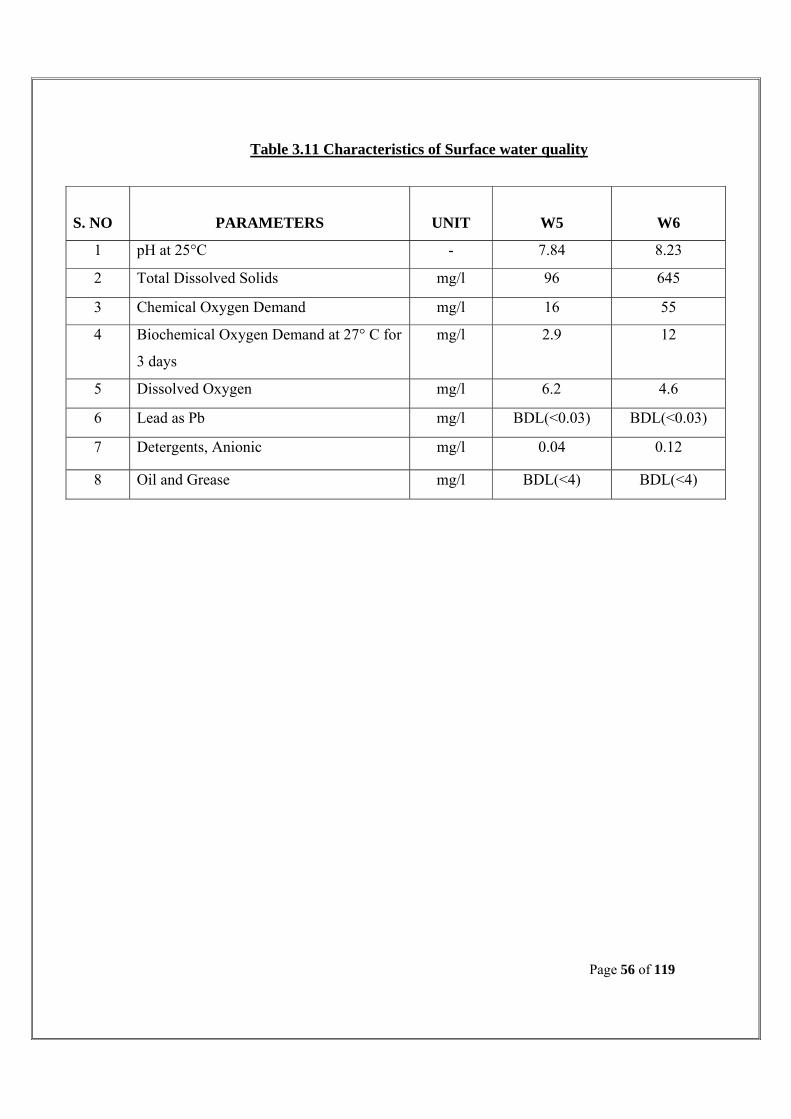
Table 3.11 Characteristics of Surface water quality
S. NO
PARAMETERS
UNIT
W5
W6
1 pH at 25°C - 7.84 8.23
2 Total Dissolved Solids mg/l 96 645
3 Chemical Oxygen Demand mg/l 16 55
4 Biochemical Oxygen Demand at 27° C for
3 days
mg/l 2.9 12
5 Dissolved Oxygen mg/l 6.2 4.6
6 Lead as Pb mg/l BDL(<0.03) BDL(<0.03)
7 Detergents, Anionic mg/l 0.04 0.12
8 Oil and Grease mg/l BDL(<4) BDL(<4)

Page 57 of 119
C. OBSERVATIONS:
Ground Water:
The pH of ground water in the study area varies between 7.40 - 7.67.
TDS values were found to be from 456 to 1087 mg/L and Total Hardness varied
from 304 – 570 mg/L. This indicates that water in the study area were moderate to
very hard in nature.
The chloride content in the studied area ranged from 24-187 mg/L. The sulphate
content in the ground water is found to be from 28 to 78 mg/L.
The lead values for all the locations are below detectable limit and the Iron values
also below detectable limit expt. Aranmanaipudur (0.19 mg/L). All the chloride,
sulphate, lead and iron values are within the IS standards in all the area.
Surface Water:
The pH of the surface water was found to be 7.84 at Vaigai River and 9.31 in
Tamaraikulam.
TDS values were found to be 96.0 at Vaigai River and 645 in Tamaraikulam.
The COD and BOD value in the Vaigai River was found to be 16 mg/L & 2.9
mg/L and Tamaraikulam was found to be 55 mg/L & 12 mg/L respectively.
The Dissolved Oxygen and Detergents values are 6.2 mg/L, 0.04 mg/L and 4.6
mg/L, 0.12 mg/L in Vaigai River and Tamaraikulam respectively.
The lead and oil & grease values are below detectable limit in both the Vaigai
River and Tamaraikulam.

Page 58 of 119
3.5 SOIL ENVIRONMENT:
3.5.1 Geomorphology:
Theni District is characterized predominantly by structural and denudational land forms
viz., structural hills, residual hills, linear ridges and pediment. Bazada zone is found well
developed at the foot hills on the western and northern part of the district. The valleys are
characterized by colluvio fluvial sediments. The hilly terrain act as catchment area and
runoff zones while the bazada zone bordering the hills form a good recharge zones.
3.5.2 Geology:
The prominent geological formation in the study area is basaltic sediment rocks
composed by AC-Charnockite in north and northwest part and quartzite in south and
south central area. In the south west region along the Suruli river basin quartzite
abundant. AMP-Garnet Biotite Gneiss has been distributed. AMH-Hornblende Biotite
Gneissover laid on the igneous rocks in north and North west of the Valkaradu hills in the
study area. Lineaments have been founded in north towards south west between AMH
Hornblende Biotite Gneiss around Valkaradu RF and AMP-Garnet Biotite Gneiss in
south west near Suruli river.
Fig:3.7 Drainage Overlay on Geology

Page 59 of 119
3.5.3. Soil:
Red loam soil is the predominant soil type in this district accounting for 37.48% followed
by red sandy soil of 14.53%. The other types of soils are lateritic soil, black soil, and
sandy soil. The district is characterized by red, black and brown soils. The major part of
the area is characterized by red soil, which can be either transported or lateritic (insitu).
These are medium to heavy textured soils with moderate to higher permeability. The
black soils are limited to less than 1% of the area. They are fine textured with low
permeability. The brown soils are limited to less than 1% of the area and they
characterized by low permeability.
The Soil map of India is shown in the Figure 9. For studying soil quality of the region,
sampling locations were selected to assess the existing soil conditions in and around the
project area representing various land use conditions. The physical and chemical
concentrations were determined. The samples were collected from these different depths
viz., 30cm, 60cm and 100cm.
The present study of the soil quality establishes the baseline characteristics and this will
help in future in identifying the incremental concentrations if any, due to the operation of
the proposed project. The sampling locations have been identified with the following
objectives;
• To determine the baseline soil characteristics of the study area and
• To determine the impact of proposed project on soil characteristics
Four locations within the study areas were selected for soil sampling. At each location,
soil samples were collected from three different depths viz., 30cm, 60cm, and 100cm
below the surface. The samples were analyzed for physical and chemical characteristics.
Details of the soil sampling location are shown in Table 3.12 and the results are
presented in the Table 3.14 respectively.

Page 60 of 119
Figure 3.8 Soil Map of India

Page 61 of 119
3.5.4 Land Utilization: According to the land utilization pattern only 40 % of it is under agriculture. Excluding
the forest area which is 34%, the remaining 26% of land may be brought under waste
land development programme in order to augment the revenue and to make use of the
agricultural laborers throughout the year.
Figure 3.9 Soil Map of India
3.5.5 Land use / land cover:
The whole study area mainly covered with agro based land uses. The area except
Western Ghats in West and North west and Valkaradu RF in South east covered with
cultivable lands, plantation, fallow, current fallow, barren, vacant and waste lands.etc,
along the Suruli river bed and west part to the settlement around the water tanks, the rich
agricultural lands distributed toward north to south and west to east. North and North east
part compass with dry lands and barren lands. The middle region of the study area
occupied with cluster settlements in core and isolated settlements in peripheral.
Valkaradu RF and its slope covered with natural vegetation and open scrubs at the upland
area and surround with dry barren lands.

Page 62 of 119
Figure 3.10
Table 3.12 Soil sampling locations
S. No Location
Code Place Geographic location Direction
Distance
Km
Environmental
Setting
1 S1 Project Site N 09º59’54.66”
E 77 º 30’05.96” - -
Barren Land
2 S2 Forest Road N 10º00’29.44”
E 77 º 29’10.46” NW 1.94
Residential
3 S3 Amatchiyapuram N 09º59’41.75”
E 77 º 30’41.95” SE 1.66
Residential
4 S4 Aranmanaipudur N 09º59’41.06”
E 77 º 29’27.81” SW 1.43
Residential

Page 63 of 119
Table 3.13 Standard Soil Classification
Chemical Parameters
Ranking Very Low Low Moderate High Very High
pH <4, very Strongly Acidic
4-5, Strongly Acidic
5-8, Ideal for Plant
Growth
8-9 Strongly Basic
>9 Very Strongly Basic
Electrical conductivity
(μS/cm)
<2000, Non saline
2000-4000 Saline
4000-8000 Moderately
Saline
8000-16000 Highly Saline
>16000 Extremely
Saline Total Nitrogen (%) <0.05
Very Low 0.05-0.15
Low 0.15-0.25 Moderate
0.25-0.5 High >0.5 Very High
Total Phosphorous
(mg/kg) <5
Very Low 5-10 Low
10-30 Moderate
30-60 High >60 Very High
Sodium (mg/kg)
- <200 Non Sodic
200-500 Moderate
>500 Sodic
Potassium (mg/kg)
- <150 Low 150-250 Moderate
250-800 High >800 Very High
Calcium (mg/kg)
- <1000 Low
1000-2000 Moderate
>2000 High -
Magnesium (mg/kg)
<40 Very Low 40-100 Low
100-300 Moderate
>300 High -
% Organic Matter 0.5-1.0 Very Low
1.0-2.0 Low
2.0-3.0 Moderate
3.0-5.0 High >5 Very High

Page 64 of 119
Table 3.14 Soil Characteristics
S. No TEST PARAMETERS S1 S2 S3 S4
1 pH 8.65 8.52 8.41 8.36 2 Electrical conductivity, mS/cm 0.129 0.172 0.456 0.239
3 Available Nitrogen, mg/kg 27 36 21 49 4 Available Phosphorous, mg/kg 18.3 21.5 14.7 28.2
5 Available Potassium, mg/kg 88 152 324 212
6 Exchangeable Calcium as Ca, m.eq/100g 2.14 1.77 2.54 1.22
7 Exchangeable Magnesium as Mg, m.eq/100g
1.02 1.24 1.81 1.54
8 Exchangeable Sodium as Na, m.eq/100g 0.92 0.83 1.58 1.31
9 Organic matter (%) 0.85 0.42 0.31 0.57
10 Texture Classification Sandy Clay Loam
Sandy Clay Loam
Sandy Loam
Sandy Clay Loam
11 Sand (%) 63.1 58.0 64.2 68.5
12 Clay (%) 29.8 25.3 10.0 21.1
13 Silt (%) 7.1 16.7 25.8 10.4
Figure 3.11 Particle Size Classification of Soil

Page 65 of 119
Figure 3.12 Nutrient Content in Soil
Figure 3.13 Exchangeable Cations in Soil
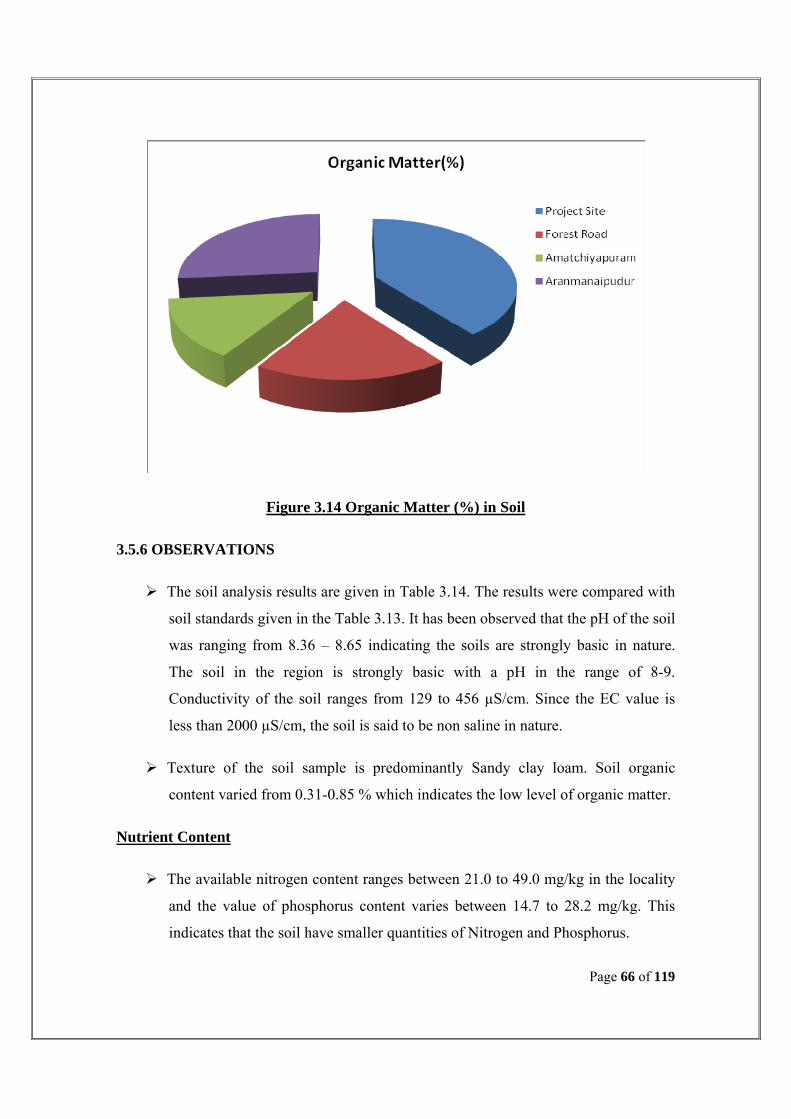
Page 66 of 119
Figure 3.14 Organic Matter (%) in Soil
3.5.6 OBSERVATIONS
The soil analysis results are given in Table 3.14. The results were compared with
soil standards given in the Table 3.13. It has been observed that the pH of the soil
was ranging from 8.36 – 8.65 indicating the soils are strongly basic in nature.
The soil in the region is strongly basic with a pH in the range of 8-9.
Conductivity of the soil ranges from 129 to 456 µS/cm. Since the EC value is
less than 2000 µS/cm, the soil is said to be non saline in nature.
Texture of the soil sample is predominantly Sandy clay loam. Soil organic
content varied from 0.31-0.85 % which indicates the low level of organic matter.
Nutrient Content
The available nitrogen content ranges between 21.0 to 49.0 mg/kg in the locality
and the value of phosphorus content varies between 14.7 to 28.2 mg/kg. This
indicates that the soil have smaller quantities of Nitrogen and Phosphorus.
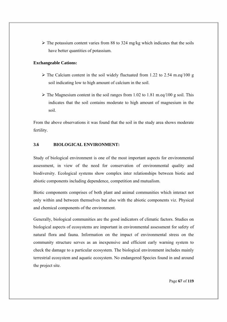
Page 67 of 119
The potassium content varies from 88 to 324 mg/kg which indicates that the soils
have better quantities of potassium.
Exchangeable Cations:
The Calcium content in the soil widely fluctuated from 1.22 to 2.54 m.eq/100 g
soil indicating low to high amount of calcium in the soil.
The Magnesium content in the soil ranges from 1.02 to 1.81 m.eq/100 g soil. This
indicates that the soil contains moderate to high amount of magnesium in the
soil.
From the above observations it was found that the soil in the study area shows moderate
fertility.
3.6 BIOLOGICAL ENVIRONMENT: Study of biological environment is one of the most important aspects for environmental
assessment, in view of the need for conservation of environmental quality and
biodiversity. Ecological systems show complex inter relationships between biotic and
abiotic components including dependence, competition and mutualism.
Biotic components comprises of both plant and animal communities which interact not
only within and between themselves but also with the abiotic components viz. Physical
and chemical components of the environment.
Generally, biological communities are the good indicators of climatic factors. Studies on
biological aspects of ecosystems are important in environmental assessment for safety of
natural flora and fauna. Information on the impact of environmental stress on the
community structure serves as an inexpensive and efficient early warning system to
check the damage to a particular ecosystem. The biological environment includes mainly
terrestrial ecosystem and aquatic ecosystem. No endangered Species found in and around
the project site.

Page 68 of 119
The list of plant species recorded in the study areas are given in the Table 3.15 and the
commonly found animals in the study areas are given in the Table 3.16.
Table 3.15 List of Flora in the study area
S. No. Botanical name Local name
1 Saraca indica Asogam
2 Azadirachta indica Veppam
3 Sesbania grandiflora Agathi
4 Musa paradisiaca Banana tree
5 Cocos nucifera Thennai
6 Derris Indica Pungai
7 Psidium guajava Guava
8 Hibiscus rosa sinensis Chebbaruthi
9 Ficus religiosa Arasu
10 Moringa tinctoria Murungai
11 Mangifera indica Mamaram
Table 3.16 List of Fauna in the study area
Salvinia Oscillatoria
Duckweed Spirogyra
Water snake Oedogonium
Frog (Amphibian) Hydra
Gerrius Streptocephalus
Lymnea Egg cases of lymnea and planorbis
Back swimmer Nostoc
Mosquito Larvae And Pupae Insect Larvae

Page 69 of 119
3.7 SOCIOECONOMIC ENVIRONMENT:
The following section discusses the baseline scenario of the socio-economic environment
in the theni district and the anticipated impacts of the proposed project on the socio-
economic environment. The areas of discussion in this chapter are demographic structure,
economic activity, education, literacy profile, land use and infrastructure resources.
A. Demography
The population details in the theni areas according to 2001 census are shown in Tables
3.18.
Table 3.18 Theni Population Details
Parameter Total Male Female Sex ratio
Population 1093950 552986 540964 978
Population
(0-6) 126127 66705 59422 891
Scheduled castes 211800 107109 104691 977
Scheduled tribes 1686 855 831 972
B. Education and literacy profile
Literacy is an important indicator to assess the Human Development Index of the area.
Literacy rate in the theni area is tabulated in Table 19. Literacy rate of Theni is
71.58 % as per census 2001.
Table 3.19 Literacy Rate in Theni
Parameter Total Male Female Percentage
Literates 692797 398150 294647 71.58
Illiterates 401153 154836 246317 28.42

Page 70 of 119
C. Economic Activity
Table 3.20 shows the Theni district workforce engagement in different sectors.
Table 3.21 Statistics of working and non-working people in Theni
Parameter Total Male Female Percentage
Cultivators Main workers 50436 33390 17046 10.65
Marginal workers 2229 873 1356 4.79
Agricultural laborers
Main workers 245989 129061 116928 51.93
Marginal workers 31716 12058 19658 68.1
Household workers
Main workers 10959 5581 5378 2.31
Marginal workers 1363 312 1051 2.93
Other workers
Main workers 166324 130028 36296 35.11
Marginal workers 573670 234704 338966 52.44
Table 3.21 Workforce engagement in different sectors in Theni
Industries in Theni:
The cotton ginning, extraction of oil from various oil seeds, cotton and chilly trading are
the main business in this district. Many textile industries are located in and around theni
as the climate are suitable for Textile Industries and it provides employment opportunity
for the local people. Vermiculate used for manufacturing cement and paints are available
in cumbum valley area. Once famous for its agricultural products, it retains its
agricultural tint of economy and remains a backward industrial area. Industrial estates
have come up with orientation for small scale and cottage industries.
Parameter Total Male Female Percentage
Population 1093950 552986 540964 100
Workers 520280 318282 201998 47.56
Non workers 573670 234704 338966 52.44

Page 71 of 119
CHAPTER-IV
PREDICTION AND EVALUATION OF IMPACTS
4.1. GENERAL:
Sewage Treatment Plant is an important pollution control system for any Environmental
Management Plan for a community, so also it is for Theni. Anyhow, failure in the proper
and scheduled implementation, Planning and designing of the processes and treatment
operations and most importantly operation and maintenance of Sewage Treatment Plants,
will ultimately impart health and environmental pollution in the project location.
The sewage collection and transfer are not part of this project. Anyhow, its failure also
Should be taken into account, as that will influence the operation of STP.
The impacts due to the proposed installation of STP are evaluated for all environmental
attributes of the project location.
4.2. PREDICTION OF IMPACTS:
Any stagnant sewage is unsightly, odorous and offers a potential spot for the breeding
and propagation of mosquitoes and other files.
Improper management of Sewerage system will adversely affect the performance of the
STP, Whatever be the efforts taken for better operation of STP. Hence, the municipal
Engineer needs to ensure proper collection of sewage into sewers and transfer it for the
design parameters to the sewage Treatment plant.
4.2.a. Air Environment:
Stagnant sewage and on ageing, it starts smell, giving out odorous gases due to partial
facultative degradation of organics present in the sewage.

Page 72 of 119
The fowl gases that comprises largely H2S, contains CO2 and Sulphur Oxides. The gas is
the product of partial biodegradation of the organics, by the anaerobic micro organisms.
The gases are unhealthy and on its concentration, the “Sawer Gas” has examples for
having killed sewer workers. Hence, ageing and stagnation of sewage should be
prevented by flooring the sewage is sewerage in the designed rate and should be favoured
for immediate treatment in the STP.
The STP may also result in non halogenated VOCs and semi VOCs that can concentrated
to impart health impacts in the long run, if not properly managed for complete
biodegradation of the sewage in the STP.
4.2. b. Water Environment:
The treated sewage is desired for irrigation in the present proposal of STP. Hence, the
requisite degree of treatment efficiency is most important to remove the pollutants like
TDS @ < 30 mg/l, BOD5 - @ <20mg/l and O&G @ < 10 mg/l.
The quantity and characteristics of the treated sewage in the outfall sewer line from the
STP shall be monitored and implemented as deciding factors in the reuse/recycle
strategies of treated sewage.
It must be noted that surface water pollution should be avoided as the treated sewage is
envisaged through existing natural nulla, irrigation tank and finding its destination for
irrigation.
4.2.c. Soil Environment:
The project location is surround by extensive activities of cultivation and, some parts of
the area is under intensive agriculture.
Through the treated sewage from the proposed STP will be boon for meeting the water
requirements for irrigation, any untreated sewage may severely damage the soil structure
by the deposition of solids.

Page 73 of 119
The untreated sewage may cause organic and inorganic carbon deposits in the soil strata
which in turn, can covert it as non fertile and will weaken the water bearing capacity of
the soil structure.
The disposal of untreated or even treated sewage @ more than 35 KL per Hecare of
cultivable land per day, will sicken the soil, known as “Soil Sickness”.
The sickened soil, on time, will become arid and will loose the ingredients of fertility and
capacity to retain water in the matrix.
4.2.d. Noise Environment:
The quicent Calm conditions of the project location will receive significant disturbance
due to continual operation of the pumps, motor, blower and compressions and DG set in
the STP.
Hence, such noise making equipments be put our centimerus performance monitoring for
its efficiency and structural strength.
4.2. e. Flora and Fauna:
STP operation will ensure the immediate environmental attribute of the project location
as clean and free from pollutants. Hence, flora and fauna will recure possible impacts due
tot eh propound project.
4.2.f. Socio Economic:
The population of Theni will get pollution free water courses with the implementation of
the proposed STP.
The avoidance of stagnant sewage will enhance the hygienist of the Theni which will in
turn will help the peoples from water borne diseases.
As the proposed location for STP is owned by Theni-Allinagaram municipality, no land
acquisition is involved.

Page 74 of 119
The land is vacant and unoccupied and has no human settlement or activity. Hence, there
is no requirement of resettlement and Rehabilitation.
4.3. EVALUATION OF IMPACTS: The impacts on different components of environment and other related issues are fully
assessed and classified. The impacts are considered on four different accounts as follows:
Impact I : Mitigated by environment management plans and systems
Impact II : Not yet fully, qualitatively assessed
Impact III : Not yet fully, quantitatively assessed
Impact IV : Positive impacts on the environment
The widely adopted Matrix method for evaluating the impacts of the STP on its environs,
is used in this study for evaluating the impacts of the proposed STP project of Theni.
Data generated from Existing Environmental Status (EES) studies formed the basis for
the Matrix method.
The impacts in the post project scenario of the plant are studied on classified
environmental components viz.,
Physico-chemical environment, biological environment and human environment, as
listed in the matrix.
The EIA matrix, with evaluated parameters, is presented in the Table 4.1.

Page 75 of 119
INDEX PROPOSED SEWAGE TREATMENT PLANT P. Significant pollution but control measures were Incorporated Z. Significant benefit out of the STP S. Significant pollutant but short term and information available are insufficient. R. Significant pollution and long term and Permanent.
Tre
atm
ent
Equ
ipm
ents
Dis
posa
l –
Reu
se L
and
APC
Mea
sure
s
Noi
se L
evel
Was
te
Solid
Ene
rgy
Pipe
line
&
Pum
ps
Lab
our
fors
e
Am
mon
isat
ion
Gro
wth
Gre
en B
elt
EN
VIR
ON
ME
NTA
L C
OM
PON
EN
TS Ph
ysio
-Che
mic
al
Water
Water Table Z Z Quantity Z Z Quality P Flow Rate Z Water Balance Z Z Z Z Recharge Z Z Z Z Z
Air Meteorology Air Quality P P p Emission Rate P P
Land
Use-Pattern Z p Z Soil Characteristics P Water Resources Z P Mineral Resources Coastal
Noise Intensity P P Duration P P Frequency P P
Bio
logi
cal Flora
Species Z Population Z Habitat Z
Fauna Species Population Habitat
Hum
an
Health Community Disease
Occupational health hazards p p Personal Hygiene p p Z
Socio-Economic
Population Z Z Z Employment Z Z Z Education Z Z Use-holds Z Z Z Z Intra Structural Facilities Z Z Z Z Z Amenities Z Z Z Z Commerce Z Z Z Z
Aesthetic& culture
Landscape Z Man Made Objects Monuments
TABLE 4.1 EIA MATRIXES

Page 76 of 119
CHAPTER –V
PUBLIC CONSULTATION 5.1GENERAL An advertisement in Dinathanthi dated 04.08.2010 was issued declaring to convene stake
holders meeting on 12.08.2010.
Accordingly Stake a holder meeting was convened at Theni-Allinagaram municipality on
12.08.2010 by the commissioner, Theni-Allinagaram municipality and the meeting was
attended by public, ounselors of local body, & EE/sewage –Division/Theni.
During the meeting the pros &cons of installing STP within the municipal graveyard
were analyzed, no opposition received/raised and it was decided to locate the STP site
within the municipal graveyard.
During public consultation related papers is presented in ANNEXURE –II.

Page 77 of 119
CHAPTER –VI
ENVIRONMENTAL MANAGEMENT PLAN
6.1 GENERAL: Sewage Treatment Plants, in general, form the core for any Environmental Management
plan for a local body to ensure proper management of Wastewater from its Community.
Anyhow, the wastewater management plan requires specified designs, strategies for its
collection from source points, transfer through public/Private areas, treatment and
ultimate disposal of treated Wastewater or recycle/reuse. They pose environmental
concerns for the environment around and more particularly the community that
surrounds.
Environmental Management Plan needs to be designed to prevent and mitigate the
possible pollution indexes due to the activities involved in wastewater collection, transfer,
treatment and disposal of municipal wastewater treatment plants.
The 12.05MLD Capacity of STP, rather the wastewater Treatment Plant (WWTP), to
serve the population of Theni-Allinagaram will require significantly larger operations
through habitations, commercial areas and finally end up to continue in a receiving water
body.
A specifically designed EMP is framed for incorporation and implementation during all
stages of WWTP (STP) Viz., Planning, Construction and Operation.
The implementation of EMP is important as that of implementing the proposed STP
(WWTP) itself.

Page 78 of 119
6.2 ENVIRONMENTAL MANAGEMENT PLAN – PRE CONSTRUCTION
PHASE:
The sitting, planning and designing of Sewage Treatment Plant shall adopt the most
Suitable technical option from the available options towards the one that is environment
friendly with less foot print and conservative on energy front.
6.2.1 Sitting Phase:
The STP be sited in a location which has the natural gradient which shall predominantly
reduce the requirement of Sewage pumping in the sewerage system. Hence, a detailed
sewerage plan be scrutinized with options of STP locations.
The STP location also is preferably keeping a distance of minimum 1.0 to 2.0Km from
the classified residential Zones. The planning and building approval authorities be either
consulted or and later informed on the location of STP. The finalization of the STP
location be confirmed on taking he preferred location put up on the Master Plan of the
Theni.
6.2.2 Planning Phase:
There are several options of treatment processes for treating municipal Wastewater (here
referred sewage) like Activated Sludge Process, Extended Aeration processes, UASB
followed by ASP, Conventional Anaerobic Digester followed by ASP, Contact
Stabilization Process, etc.,
The sewage be analysed for its characteristics from different locations, on different time
and duration and even for different seasons.
The Composite, representative sewage be analysed through random and regulated
samples drawn and analysed using protocols as per Standard Procedures.

Page 79 of 119
The parameters of study be for pH, Solids (TSS, TDS, TS), BOD5, COD, Total Nitrogen,
Total phosphorous and O&G. Anyhow, the parameters need not be restricted only for
the above.
The commercial activities be examined for certain activities like electroplating, where in
cyanide be analysed as added parameter.
The quantification of the sewage and source projects of the generation are the major
concern. The sewage plan shall be checked for its veracity of the demography.
The demography Theni was studied for a population of 85424 in the year 2001. The life
expectancy period of STP at 25-30 years be interpreted to arrive the design capacity of
STP.
The design capacity of the STP has been arrived for 12.05 MLD for the life expectancy
period of 30 years.
6.2.3 Designing Phase:
The hydraulic and structural designs of STP are ensured after the requisite planning tools
on Sewage quantity and characteristics.
The process design with the choice of a particular process, here in, Activated Sludge
Process, was made on the findings that the sewage confirms largely a conventional Indian
Sewage with TSS at 220 mg/l and BOD5 at 236mg/l.
The Topography and contour map of the STP location, project impact map (5 KM) and
the service area/sewerage of Theni be interpreted for designing the hydraulics of the
sewage flow through the sewage treatment plants.
The objective of hydraulic design will get the sewer size, gradient and the specification of
the sewer appurtenances. The proposed STP location and sewage plan has been

Page 80 of 119
securitized for hydraulic profile and the design was made by M/s. Eco Protection
Engineers private limited, Chennai.
The structural design has no many options except to use standard practices for design that
confirm to IS standards. The structural components of STP are confirmed for M 30;
Standard of Reinforced cement concrete as per IS 456 and material of construction used
for the standard specification as per IS 3370.
The design packages were used to optimise the material requirement and also to give the
requisite strength for structures against tensile, compression and shear. The design of STP
structural components was made by M/s. Eco Protection Engineers Private Limited,
Chennai using the latest software systems for RCC design.
The following measures are implemented with the responsible government bodies;
• Site clearance, including permission for nay trees. Anyhow, this is not credible in
the present case, as the site is almost barren and vacant.
• Baseline data on Environmental attributes in the project location
• Temporary traffic arrangements be planned.
• Consent – to – establishment from TamilNadu Pollution Control Board, by filling
applications in Form-I & II along with this document on REIA/EMP.
• Temporary labour/worker’s camp with bank amenities be planned.
6.3 CONSTRUCTION PHASE:
The construction, Erection, Commissioning, start up and performance run of the sewage
treatment plant is envisaged for a time frame of Two year.
PERT chart was devised for the entire program of the contract execution for proving STP
with the defined scope of work.
During this period of construction, the concerns of public for dust, unusual traffic,esthetic
and also for Odour problems during start up periods be addressed properly.

Page 81 of 119
The following measures also be incorporated in the schedule of work during the
construction Phase of the Project”
• Green belt development in the open spaces, leaving spaces for internal roads.
• The Top soil be preserved and shall be compacted on the top surface on
completion of the project.
• The disposal of construction debris be made in consultation with the Theni
Municipality.
• Oil/lubricants use be properly managed and prevented for its spillage/wastage.
• Ground water Contamination be prevented from the disposal of construction
Waste and leak/spills of sewage.
• Sign Boards, explaining the activities be put up for necessary guidance and
alertness for the common people.
• Electrical installations be made with requisite approvals from TNEB.
• Personal safety systems be provided for all workers /Laborers.
• Necessary Insurance coverage be made for the worker’s involved in the
Project.
• First Aid facilities be always available in the construction site. A doctor on-
call be arranged for emergency purposes.
6.4 OPERATION AND MAINTENANCE PHASE:
The operation of STP to treat and dispose the treated sewage to confirm the Disposal
standards of MoEF and TNPCB is the most important and keep its performance
sustainable is the important task.
It is important to note that the operation of STP is continual, round the clock and in no
circumstances, the plant will be non-functional and untreated sewage is disposed off.
The following measures are important to implement as part of EMP;

Page 82 of 119
a) Trained peoples of sufficient account at least one plumber; one electrician;
two field assistants, all in two shifts.
One operation Head with a chemist are important to undertake the
necessary sample analysis and fix the operating parameters of MLVSS
(@ 3000-4000 mg/l); DO (@ 1-2 mg/l) and SVI (@ 100-120 mg/l) for
better performance of the proposed STP.
b) Electromagnetic flow meters be installed and auto logging for influent
and effluent quantities be recorded on hourly basis, and daily average
flow be monitored, for fixing the operating parameters, of the STP.
c) A DG set is almost –important to support the operation of Aeration system
during the periods of Power failure and Keep them in operation, round the
clock.
d) Documentation and data logging be made in standard formats and stored
in soft and hard copies.
e) The operation head be always receptive for any complaints from
agriculturists landowners and from the common peoples.
f) A well drawn green belt be developed around the STP area and be kept
clean and with more esthetic value.
g) The maintenance of pumps, motors, blowers, etc., be carried out on daily,
weekly and monthly basis, as per the recommendations of the system
suppliers. Especially, the stand by units shall always be kept in good
operating conditions.
h) In Chlorine gas exposed to eyes, shivering your eyes with plain water for
10 to 15 minutes. If you wear contacts, remove them before rinsing your
eyes, and place them in the bags with the contaminated clothing. Do not
put the contacts back in your eyes.

Page 83 of 119
A format of daily log sheet is recommended for daily accounting of operation and
maintenance of the STP. The Environmental Management Plan presented in Table 6.1.
The Trouble Shooting/Remedial Measures and Responsibility is presented in Table 6.2.
6.5 PERSONAL SAFETY SYSTEMS:
The skilled operators are provided with shoes, goggles, gloves and cloth mask during
their working hours in the plant.
They should be trained in all aspects of the operation and maintenance schedules of all
equipments viz., motor, pump, compressor, DG set, Aerators, etc.
First Air Box be provided in all strategic location of the STP at least on a locations viz.,
office, laboratory, clarifier/Aerator, so that in case of any accidents the affected person(s)
can be given first aid treatment at the site.
A log of information on general Hospital, public health centre and medical shop shall be
maintained in the administration office of STP.
Fire fighting guns are provided in three location of the STP viz., Electrical power home,
administrate office and laboratory.
6.6 SAFETY MEASURES:
1. The station site will be enclosed with 2.5m Compound wall, lockable gates,
designed to discourage entry by unauthorized persons and animals.
2. Provide safety, unauthorized entry and TWAD address signage.
3. Necessary arrangement made for free accessing to all tanks and buildings like Walkway, Staircase, Handrails and pathways.

Page 84 of 119
4. All the employees who work in STP site will be given safety training and they will be allowed to operate STP.
5. Gas detection and monitoring equipment where required. Where gas alarms are provided, install an indicator light outside the building so that the operator can check gas levels before entering the building.
6. Portable ventilation and blower equipment, intrinsically safe, with sufficient hose,
where required.
7. Portable lighting equipment intrinsically safe, where required.
8. A good practice of safety is maintained by way of a safety week once in six
months and awareness programmes will be conducted once in six months.
6.7 ENVIRONEMNTAL MONITORING PLAN:
6.7.1 General:
The location of STP for at least 5km radius, considering it as the probable Impact Area,
should be put under continuous environmental surveillance.
The 5km radius is conventional for water and land polluting activities. It could be seen
that 5km is the limit from any identified water course for establishing any not industrial
activity.
The attributes of the location viz., Air, Water, Soil, Noise, Flora & Fauna and Human
(social status) need to be continually monitored for any possible impact due to the
activities of STP.
The installation STP is expected to bring high standards for living for Theni Town and
will prevent water and soil pollution.
6.7.2 Monitoring Plan:
The environmental monitoring plan is exclusively drawn for all the components of
environment. The treatment plant on one points will upheld the living standards of
Theni and other may harm the hygienist –or hazzle free environment.
The monitory plan is also planed for 5km radius of area from the project site.

Page 85 of 119
6.7.2.a. Air Environment:
There will not be any emission stack from the STP activity. The release of VOC and
SVOC from the STP activity is appreciated.
The wind profile of the project location warranted the monitoring plan for the 5km
radius from the impact location.
A snap Ambient Air Quality Survey shall be organized once in a month by either the
TNPCB or any approved laboratory. SPM, RPM, SO2, NOX, Co, Pb and Odour be the
parameters for the AAQ survey. At least 5 AAQ station are recommend for the survey.
6.7.2.b. Water Environment:
The water resource of the project location has been geo-surveyed for its features and
characteristics. The probable impact due to sewage, treated or untreated, should be
monitored.
The Raw Sewage and treated wastewater be continuously shall be checked continuously
with the quantity of the treated wastewater.
6.7.2.c. Soil Environment:
The disposal of untreated sewage, even the treated sewage if not properly disposed it
will lead to “Sickness” of the soil on its disposal on it.
The characteristics of the soil in the project location should be maintained by taking
sample on every month. The sludge disposal on to open land should not be practiced. The
dewatered sludge be used a manure and given to local farming activities.

Page 86 of 119
6.7.2.d. Noise Environment:
DG set, Air compressor/Air Blowers, motor and pumps etc., are certain sources for Noise
generation and propagation.
Since the area in away from the population and noise cannot be a major pollution index
for the proposed plant.
Anyhow, all these rotating equipments, as listen above, be monitored by O&M contract
by all the respective suppliers for specific parameters.
6.7.2.e. Socio Economic:
The project of STP will ensure clean, more hygienic ambience to all the peoples of Theni.
Anyhow, if not properly managed the stagnation of sewage or ageing will make the area
unhygienic. Any such stagnation as pool of sewage will make the area more assumable
and favorite for plays or insects.
The health impact due to the operation of STP shall be monitored.
The ground water will be prevented from any possible commercial and industrial
activities.
The land for the project is owned by Municipality and hence no acquisition of land in
involved. The living conditions of peoples of Theni will essentially improve, on
commissioning of the STP.
6.7.3 OFF SITE MONITORING:
The project impact area is assessed for 5 Km radius around the project site. Requisite
samples on water, air and soil be taken and monitored periodically as per the guidelines
of CPCB. The schedule for offsite Environmental monitoring is presented in Table 6.3.
The frame work of offsite monitoring as listed in Table 6.2 be enacted for the listed time
frame.

Page 87 of 119
6.8 ENVIRONMENTAL CELL:
An exclusive wing shall be made responsible for continual operation of the STP with
best of its performance of treatment to ensure the treated sewage @ TSS < 30 mg/l and
BOD5 @ < 20 mg/l. The cell shall be evaluated annually for its performants and
Constituent members, and be allotted annual funds. The operation head be authorized
to spend the funds with approval from LB of Theni.
The protocol of the proposed Environmental cell is presented in Fig. 6.2.
6.9 BUDGETARY ESTIMATE (ANNUAL)
The EMP objectives better operation and maintenance of the STP and also monitoring the
quantity and quality of the raw and treated sewage. The plant operation for exclusive
parameters of operation Viz., TSS, BOD5, MLVSS, SVI etc., be continuously monitored.
As the treated sewage is planned for disposal into the existing natural irrigation systems,
necessary monitoring schedules for water, air and soil quality be implemented. A
Budgetary estimate for the effective implementation of EMP is present in Table 6.4.
and 6.5.
6.10 COMPLIANCE REPORTING:
The implementation of all the management measures above would be reported to
TNUIFSL through regular compliance reporting. A sample format proposed to be used
for O&M is provided in Table 6.6.

Page 88 of 119
S.NO POTENTIAL IMPACTS MITIGATION MEASURES TIME FRAME RESPONSIBLE
AGENCIES 1. Clearances All clearance required for Environmental aspects during construction
will be ensured and made available before start of work. Before construction Eco Protection Engineers
Pvt. Ltd., 2. Tree cutting The STP site identified is barren land and hence does not involve tree
cutting. For laying line of treated effluent disposal, adequate care would be taken to avoid tree cutting. In case of any need arising for tree cutting, compensatory plantation would be done in the vacant land available in the STP site in addition to the greenbelt plan. Compensatory plantation will be done by way of re-plantation of twice the number of trees cut will be carried out in the project area.
Pre-construction & construction phase
Eco Protection Engineers Pvt. Ltd.,
3. Baseline parameters Baseline parameters have been recorded during the baseline study and monitoring would be carried out as per monitoring plan provided.
Construction & Operation phase
Eco Protection Engineers Pvt. Ltd.,
4. Disposal of treated wastewater i) The construction and operation activities for STP will be initiated only after obtaining necessary consents from the TNPCB. ii) The quality of treated water will comply with the discharge standards for disposal into water body. iii) Performance standards will always be maintained, ensuring efficient working condition of treatment plant.
Pre-construction & post- construction phase
Eco Protection Engineers Pvt. Ltd.,
5. Storage of materials Pipes and other construction materials would be stored in the vacant portion available in the STP site.
During construction Eco Protection Engineers Pvt. Ltd.,
6. Construction of labor camps i) All relevant provisions of the Factories Act, 1948 and the Building and the other Construction Workers (Regulation of Employment and Conditions of Service) Act, 1996 iv) All temporary accommodation will be constructed and maintained in such a fashion that uncontaminated water is available for drinking, cooking and washing. The sewage system for the camp will be planned and adequate health care will be provided for the work force.
During construction Eco Protection Engineers Pvt. Ltd.,
Table 6.1 Environmental Management Plan for Pre-Construction Phase

Page 89 of 119
S.NO POTENTIAL
IMPACTS MITIGATION MEASURES TIME FRAME
RESPONSIBLE
AGENCIES
1 Compensatory plantation of
trees
There is no tree cutting involved, however as three rows of trees are
planned along the periphery of the STP site.
In case any tree cutting arises compensatory plantation of twice the
number of trees felled will be done in the vacant land available in the
STP site.
Pre-construction and
construction
Eco Protection Engineers
Pvt. Ltd.,
2 Protection of top soil and
Environmental enhancing
The top soil will be protected and compacted after completion of work.
Top soil from the STP area will be stored in stock piles and used for
gardening purposes.
During construction Eco Protection Engineers Pvt. Ltd.
3 Disposal of construction debris
and excavated materials.
A suitable site will be identified for safe disposal, in relatively low
lying areas, away from the water bodies, residential and agricultural
fields etc., and got approved by the Engineer. Care will be taken that
the dumped material does not affect natural drainage system.
During construction Eco Protection Engineers Pvt. Ltd.
4 Pollution from Fuel and
Lubricants
i) All location and lay-out plans of such sites will be submitted prior to
the establishment and will be approved by the Engineer.
ii) We ensure that all vehicle / machinery and equipment operation,
maintenance and refueling will be carried out in such a fashion that
spillage of fuels and lubricants does not contaminate the ground.
iii) All spills and collected petroleum products will be disposed off in
accordance with MoEF and state PCB guidelines.
During construction and
operation
Eco Protection Engineers Pvt. Ltd.
5 Contamination of ground water (i) Contamination of ground water quality is not envisaged as the
treated water quality will comply with the standards laid down by PCB
for disposal onto water bodies.
During operation Eco Protection Engineers
Pvt. Ltd.
Table 6.2 Environmental Management Plan for Construction Phase

Page 90 of 119
S.NO POTENTIAL
IMPACTS MITIGATION MEASURES TIME FRAME
RESPONSIBLE
AGENCIES
ii) The sludge arising from the treatment plant would be dried and
disposed off by the municipality periodically.
ii) Regular monitoring of the treated sewage quality and ground water
quality in the nearby areas will be done and ensure compliance with
PCB standards.
6 Informatory signs and hoardings Erection and maintenance of informatory, safety signs, hoardings
written in English and local language wherever required will be
provided.
During construction Eco Protection Engineers
Pvt. Ltd.
7 Risk from Electrical
Equipment(s)
All required precautions will be taken to prevent danger from electrical
equipment and ensure that
i) No material will be stacked or placed as to cause danger or
inconvenience to any person or the public.
ii) All necessary fencing and lights will be provided to protect the
public in construction zones. All machines to be used in the
construction will conform to the relevant Indian Standards (IS) codes,
will be free from patent defect, will be kept in good working order, will
be regularly inspected and properly maintained as per IS provision.
During construction Eco Protection Engineers
Pvt. Ltd.
8 Disposal of treated waste water i) The treated water quality will be complied with the standards of
TNPCB before let out into the stream.
ii) Efficient working condition of treatment plant will be maintained.
iii) Stream water and other water bodies receiving STP discharge will
During Operation Eco Protection Engineers
Pvt. Ltd.
Table 6.2 Environmental Management Plan for Construction Phase

Page 91 of 119
S.NO POTENTIAL
IMPACTS MITIGATION MEASURES TIME FRAME
RESPONSIBLE
AGENCIES
not be polluted.
9 Disposal of sludge The dewatered sludge from STP will be use as manure/will be sent to
municipal solid waste facility.
During Operation Eco Protection Engineers
Pvt. Ltd.
10 Labour camp and facilities i) Uncontaminated water will be supplied to labours for drinking
cooking and washing purposes.
ii) Sufficient quantity of potable water (as per IS) will be supplied in
every work place / labour camp site at suitable and easily accessible
places and regular maintenance of such facilities.
Pre-Construction, and
operation
Eco Protection Engineers
Pvt. Ltd.
11 Safety aspects i) Adequate precautions will be taken to prevent the accidents and from
the machineries. All machines used will confirm to the relevant Indian
Standards code and will be regularly inspected by the PIA.
ii) Where loose soil is met with, shoring and strutting will be provided
to avoid collapse of soil.
iii) Protective footwear and goggles will be provided to all the workers
employed on mixing of materials like cement, concrete etc.
iv) Welders protective eye shields will be provided to workers who are
engaged in welding works.
v) Earplugs will be provided to workers exposed to loud noise, and
workers working in crushing, compaction, or concrete mixing
operation.
vi) All necessary safety appliances such as safety goggles, helmets,
safety belts, ear plugs, masks etc., to workers and staffs will be
During Construction Eco Protection Engineers
Pvt. Ltd.,
Table 6.2 Environmental Management Plan for Construction Phase

Page 92 of 119
S.NO POTENTIAL
IMPACTS MITIGATION MEASURES TIME FRAME
RESPONSIBLE
AGENCIES
provided. We will comply with all the precautions as required for
ensuring the safety of the workmen as per the International Labor
Organization (ILO) Convention No.62 as far as those are applicable to
this contract.
vii) Do not employ any person below the age of 14 years for any work
and no women will be employed on the work of painting with products
containing lead in any form.
12 First Aid The following arrangements will be made for the workers:
i) A readily available first aid unit including an adequate supply of
sterilized dressing materials and appliances as per the factories Rules in
every work zone.
ii) Availability of suitable transport at all times to take injured or sick
persons to the nearest hospital.
During Construction Eco Protection Engineers
Pvt. Ltd.,
13 Odour Nuisance Greenbelt will be developed around the STP site for control of odour
nuisance to the surrounding areas.
During construction Eco Protection Engineers Pvt. Ltd.
14 Implementing TNPCB
conditions
The conditions stipulated by the TNPCB while issuing Consent to
Establish for the proposed STP will be implemented.
During construction Eco Protection Engineers Pvt. Ltd.
Table 6.2 Environmental Management Plan for Construction Phase

Page 93 of 119
S.NO ENVIRONMENTAL ENHANCEMENT AND
SPECIAL ISSUES LOCATION IMPLEMENTING AGENCY
1 Flora and Chance found Fauna We ensure that reasonable precaution will be taken to prevent workmen or any other persons from removing and damaging any flora (plant/vegetation) and fauna (animal) including fishing in any water body and hunting of any animal. If any wild animal is found near the construction site at any point of time, it will be immediately reported to the nearby forest officer and appropriate steps / measures will be taken in consultation with the forest officials.
Project area Eco Protection Engineers Pvt. Ltd.,
2 Chance Found Archaeological Property
i) STP site does not fall under the sensitive area. ii) All fossils, coins, articles of value of antiquity, structures and other remains or things of geological or archaeological interest discovered will be dealt with as per provisions of the relevant legislation. Care will be taken to prevent the workmen from removing and damaging any such article or thing.
Project area Eco Protection Engineers Pvt. Ltd.
3 Monitoring of environment parameters
i) Seasonal monitoring of Air, Water, Noise and Soil quality will be done. ii) The parameter will be monitored according to Environmental Monitoring Plan.
Project area Eco Protection Engineers Pvt. Ltd.
4 Sensitive Areas i) The dust and noise impacts due to vehicle movement during construction and their effectiveness will be checked and minimized with precautionary measures.
Project area Eco Protection Engineers Pvt. Ltd.
5 Clearing of construction of camps and restoration
Site restoration plans will be prepared for approval by the engineer. On completion of the works, all temporary structures will be cleared away, all rubbish cleared, excreta or other disposal pits or trenches filled in and effectively sealed off and the site will be left clean and tidy.
During construction period Eco Protection Engineers Pvt. Ltd.
Table 6.3 Environmental Enhancement and Special Issues

Page 94 of 119
S.NO. UNIT OPERATIONS TROUBLE SHOOTING / REMEDIAL MEASURES RESPONSIBILITY
1.0 INLET CHAMBER a) Over flow Regular-/Controlled operation of pumps Operation and Maintenance Contractor
2.0 FINE SCREEN CHAMBER a) Clogging of debris
Periodical / regular cleaning of clogs-rubbish/rugs screenings Operation and Maintenance Contractor
b) Head loss Periodical / regular cleaning of clogs-rubbish/rugs screenings
Operation and Maintenance Contractor
c) Odor Cleaning of clogs Operation and Maintenance Contractor d) Mechanical damage of
screens/racks/platform/ Handrails/ ladder Repair/Replacement Up to Contract period – Contractor After Contract
period – Theni Municipality
3.0 DETRITOR a) Clogging of debris
Periodical / regular cleaning of clogs-rubbish/rugs screenings
Operation and Maintenance Contractor
b) Head loss Periodical / regular cleaning of clogs-rubbish/rugs screenings
Operation and Maintenance Contractor
c) Odor Cleaning of clogs Operation and Maintenance Contractor d) Mechanical damage of screens/racks/platform/ Handrails/ ladder
Repair/Replacement Up to Contract period – Contractor After Contract period – Theni Municipality
4.0 SCUM TRAP a) Odor
Removal of clogging Regular/ Periodical removal of scum Operation and Maintenance Contractor
b) Mechanical failure Proper maintenance Operation and Maintenance Contractor 5.0 PARSHALL FLUME CHANNEL
a) Settling of Grit Periodical removal of grit Operation and Maintenance Contractor
TABLET 6.4 TROUBLE SHOOTING/ REMEDIAL MEASURES AND RESPONSIBILITY
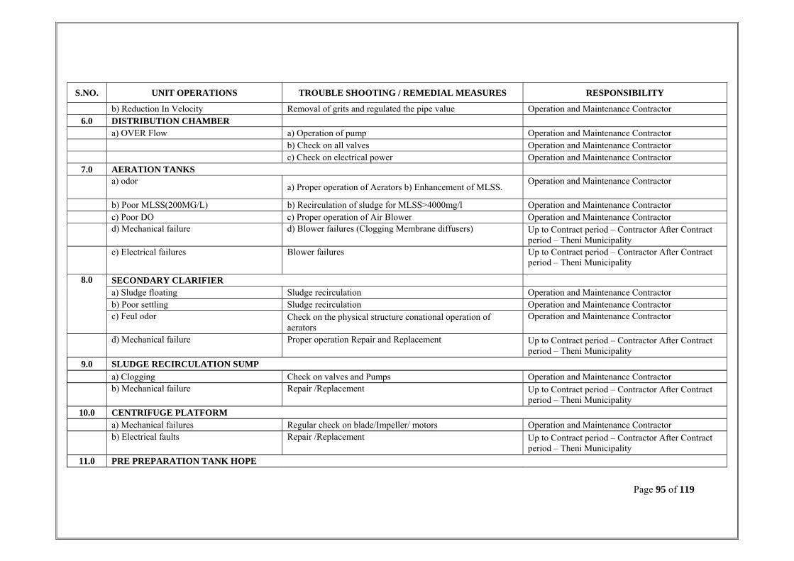
Page 95 of 119
S.NO. UNIT OPERATIONS TROUBLE SHOOTING / REMEDIAL MEASURES RESPONSIBILITY
b) Reduction In Velocity Removal of grits and regulated the pipe value Operation and Maintenance Contractor 6.0 DISTRIBUTION CHAMBER
a) OVER Flow a) Operation of pump Operation and Maintenance Contractor b) Check on all valves Operation and Maintenance Contractor c) Check on electrical power Operation and Maintenance Contractor
7.0 AERATION TANKS a) odor
a) Proper operation of Aerators b) Enhancement of MLSS. Operation and Maintenance Contractor
b) Poor MLSS(200MG/L) b) Recirculation of sludge for MLSS>4000mg/l Operation and Maintenance Contractor c) Poor DO c) Proper operation of Air Blower Operation and Maintenance Contractor d) Mechanical failure d) Blower failures (Clogging Membrane diffusers) Up to Contract period – Contractor After Contract
period – Theni Municipality e) Electrical failures Blower failures Up to Contract period – Contractor After Contract
period – Theni Municipality
8.0 SECONDARY CLARIFIER a) Sludge floating Sludge recirculation Operation and Maintenance Contractor b) Poor settling Sludge recirculation Operation and Maintenance Contractor c) Feul odor Check on the physical structure conational operation of
aerators Operation and Maintenance Contractor
d) Mechanical failure Proper operation Repair and Replacement Up to Contract period – Contractor After Contract period – Theni Municipality
9.0 SLUDGE RECIRCULATION SUMP a) Clogging Check on valves and Pumps Operation and Maintenance Contractor b) Mechanical failure Repair /Replacement Up to Contract period – Contractor After Contract
period – Theni Municipality 10.0 CENTRIFUGE PLATFORM
a) Mechanical failures Regular check on blade/Impeller/ motors Operation and Maintenance Contractor b) Electrical faults Repair /Replacement Up to Contract period – Contractor After Contract
period – Theni Municipality 11.0 PRE PREPARATION TANK HOPE
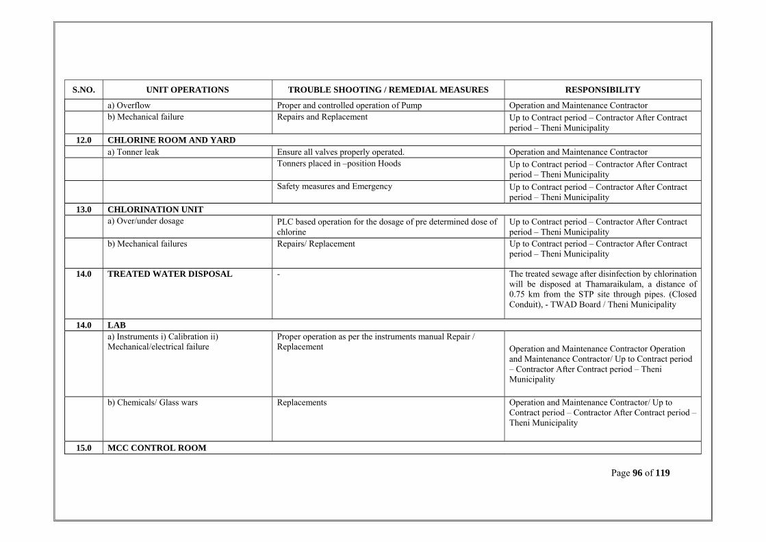
Page 96 of 119
S.NO. UNIT OPERATIONS TROUBLE SHOOTING / REMEDIAL MEASURES RESPONSIBILITY
a) Overflow Proper and controlled operation of Pump Operation and Maintenance Contractor b) Mechanical failure Repairs and Replacement Up to Contract period – Contractor After Contract
period – Theni Municipality 12.0 CHLORINE ROOM AND YARD
a) Tonner leak Ensure all valves properly operated. Operation and Maintenance Contractor Tonners placed in –position Hoods Up to Contract period – Contractor After Contract
period – Theni Municipality Safety measures and Emergency Up to Contract period – Contractor After Contract
period – Theni Municipality 13.0 CHLORINATION UNIT
a) Over/under dosage PLC based operation for the dosage of pre determined dose of chlorine
Up to Contract period – Contractor After Contract period – Theni Municipality
b) Mechanical failures Repairs/ Replacement Up to Contract period – Contractor After Contract period – Theni Municipality
14.0 TREATED WATER DISPOSAL - The treated sewage after disinfection by chlorination will be disposed at Thamaraikulam, a distance of 0.75 km from the STP site through pipes. (Closed Conduit), - TWAD Board / Theni Municipality
14.0 LAB a) Instruments i) Calibration ii)
Mechanical/electrical failure Proper operation as per the instruments manual Repair / Replacement Operation and Maintenance Contractor Operation
and Maintenance Contractor/ Up to Contract period – Contractor After Contract period – Theni Municipality
b) Chemicals/ Glass wars Replacements Operation and Maintenance Contractor/ Up to Contract period – Contractor After Contract period – Theni Municipality
15.0 MCC CONTROL ROOM

Page 97 of 119
S.NO. UNIT OPERATIONS TROUBLE SHOOTING / REMEDIAL MEASURES RESPONSIBILITY
a) Instrumentaion facult Calibration and proper maintenance of instruments Operation and Maintenance Contractor/ Up to Contract period – Contractor After Contract period – Theni Municipality
b) Wiring fault Proper maintenance Replacement Operation and Maintenance Contractor/ Up to Contract period – Contractor After Contract period – Theni Municipality
16.0 GENERATOR ROOM a) Requirement of fuel Stock of fuel for atleast 24 hours requirement Operation and Maintenance Contractor/ Up to
Contract period – Contractor After Contract period – Theni Municipality
b) Noise Repair /Replacement of parts Up to Contract period – Contractor After Contract period – Theni Municipality
17.0 BLOWER YARD a) Noise Proper maintenance of blower/motors Operation and Maintenance Contractor Up to
Contract period – Contractor After Contract period – Theni Municipality
b) Mechanical failures Repair /Replacement Up to Contract period – Contractor After Contract period – Theni Municipality
c) Electrical fault Repair /Replacement Up to Contract period – Contractor After Contract period – Theni Municipality
18.0 PUMP ROOM-I a) Noise Proper maintenances of impellers/casing Operation and Maintenance Contractor
b) Leakage Proper maintenance of Pumps, glands/joints Operation and Maintenance Contractor c) Mechanical failures Repair /Replacement Operation and Maintenance Contractor Up to
Contract period – Contractor After Contract period – Theni Municipality

Page 98 of 119
S.NO. UNIT OPERATIONS TROUBLE SHOOTING / REMEDIAL MEASURES RESPONSIBILITY
d) Electrical fault Repair /Replacement Operation and Maintenance Contractor Up to Contract period – Contractor After Contract period – Theni Municipality
19.0 WORKERS TOILET a) Odor Daily cleaning Operation and Maintenance Contractor
b) Water Supply Proper maintenance Operation and Maintenance Contractor c) Washing Accessories Providing buckets, mobs, soap etc, Operation and Maintenance Contractor d) Physical damage of sewer appurtenances Repair /Replacement Operation and Maintenance Contractor Up to
Contract period – Contractor After Contract period – Theni Municipality

Page 99 of 119
6.5 Operation & Maintenance Check List for STP ASP Method
S. NO
DESCRIPTION OF UNIT
QTY (Nos)
PROCESS ISSUE
REMEDIAL MEASURES
MECHANICAL ISSUES
REMEDIAL MEASURES REMARKS
PERSONAL PROTECTIVE EQUIPMENTS
1 Manual Screens 2 Clogging of Screen
Periodical cleaning shall be done.
Manual screens will be used when either of mechanical coarse or fine screen break down or conveyor Breakdown
Highvis jacket or vest, waterproof overalls, standard overalls, hard hat, safety boots, gloves dust mask, ear protectors, safety glasses
2 Mechanical Screen 2 Clogging of
Screen Periodical cleaning shall be done.
Low oil level due to oil leakage
Tighten the connections And /or change the hoses. Exchange the seals of cylinder Manual screens will
be used when the mechanical screens under maintenance.
High-vis jacket or vest, Water proof overalls, standard overalls, hard hat, safety boots, gloves dust mask, ear protectors, safety glasses
Gear unit for any damage, Loose connection or if any circuit breaker has tripped.
Repair/replace gear unit, Correct the connections/reset the circuit breaker.
3 Grit Separator
2 (1W+1
S)
Carryover of grit
Remove grit more frequently
Mechanical failure takes place in Gear box
Regular preventive maintenance such as lubrication, topping of oil and alignment check to be done.
Standby unit will be used during maintenance
Highvis jacket or vest, waterproof overalls, standard overalls, hard hat, safety boots, gloves dust mask, ear protectors, safety glasses

Page 100 of 119
S. NO
DESCRIPTION OF UNIT
QTY (Nos)
PROCESS ISSUE
REMEDIAL MEASURES
MECHANICAL ISSUES
REMEDIAL MEASURES REMARKS
PERSONAL PROTECTIVE EQUIPMENTS
Gear unit for any damage, Loose connection or if any circuit breaker has tripped.
Repair/replace gear unit, Correct the connections/reset the circuit breaker.
4 Aeration Tank 01 Excessive / less MLSS Concentration.
The MLSS concentration in the aeration tank can be regulated by controlling the rate of sludge return based on SVI determined experimentally.
- _ -
High-vis jacket or vest, waterproof overalls, standard overalls, hard hat, safety boots, gloves dust mask, ear protectors, safety glasses
5 Secondary Clarifier 2 Floating of
Sludge Regulating the Return Sludge
Mechanical failure takes place in Gear box
Regular preventive maintenance such as lubrication, topping of oil and alignment check to be done.
Keep in stock essential spares and take one unit out of service in the event of break down
Highvis jacket or vest, waterproof overalls, standard overalls, hard hat, safety boots, gloves dust mask, ear protectors, safety glasses
6 Centrifuge 2
(1W+1 S)
Pump Failure due to wear and tear of impeller, bearing, shaft and pump choaking. Fluctuation in power.
Routine maintenance such as glad packing, impeller & shaft alignment with adequate spare at site.
Standby unit will be used during maintenance
Highvis jacket or vest, waterproof overalls, standard overalls, hard hat, safety boots, gloves dust mask, ear protectors, safety glasses

Page 101 of 119
S. NO
DESCRIPTION OF UNIT
QTY (Nos)
PROCESS ISSUE
REMEDIAL MEASURES
MECHANICAL ISSUES
REMEDIAL MEASURES REMARKS
PERSONAL PROTECTIVE EQUIPMENTS
7 Return/Excess Sludge Transfer Pumps
2 (1W+1
S)
Pump Failure due to wear and tear of impeller, bearing, shaft and pump choking. Fluctuation in power
Routine maintenance such as glad packing, impeller & shaft alignment with adequate spare at site.
Standby unit will be used during maintenance
Highvis jacket or vest, waterproof overalls, standard overalls, hard hat, safety boots, gloves dust mask, ear protectors, safety glasses
8 Centrifuge feed pumps
2 (1W+1S)
Pump Failure due to wear and tear of impeller, bearing, shaft and pump choaking. Fluctuation in power
Routine maintenance such as glad packing, impeller & shaft alignment with adequate spare at site.
Standby unit will be used during maintenance
Highvis jacket or vest, waterproof overalls, standard overalls, hard hat, safety boots, gloves dust mask, ear protectors, safety glasses
9 Blower for Aeration Tank
3 (2W+1
S)
Mechanical failure takes place in Motor & Blower
Regular preventive maintenance such as lubrication, topping of oil and alignment check to be done.
Standby unit will be used during maintenance
Highvis jacket or vest, standard overalls, hard hat, safety boots, gloves dust mask, ear protectors and safety glasses.
10 Blower for Sludge mixing
2 (1W+1
S)
Mechanical failure takes place in Motor & Blower
Regular preventive maintenance such as lubrication, topping of oil and alignment check to be done.
Standby unit will be used during maintenance
Highvis jacket or vest, standard overalls, hard hat, safety boots, gloves dust mask, ear protectors and safety glasses.

Page 102 of 119
S. NO
DESCRIPTION OF UNIT
QTY (Nos)
PROCESS ISSUE
REMEDIAL MEASURES
MECHANICAL ISSUES
REMEDIAL MEASURES REMARKS
PERSONAL PROTECTIVE EQUIPMENTS
11 Chlorinator 02 (1W+1 S)
Excessive / Less dosing of Chlorine
The operator should be careful in administering calculated doses accurately.
Leakage of Chlorine gas from cylinder.
Regular Preventive maintenance such as 1. Daily inspection of all chlorine Cylinder. 2. Ammonia should be kept handy for checking for leaks. 3. Chlorine cylinders storage building should be well ventilated.
Standby unit will be used during maintenance
Highvis jacket or vest, waterproof overalls, standard overalls, hard hat, safety boots, gloves dust mask, ear protectors, safety glasses
12 Power interruption / failure
Power failure
DG set will be operated during power failure. Preventive Maintenance are as follows: 1. Inspected daily to maintain safe and reliable operation. 2. Daily check the engine
Highvis jacket or vest, waterproof overalls, standard overalls, hard hat, safety boots, gloves dust mask, ear protectors, and safety glasses.

Page 103 of 119
6.6. ENVIRONMENTAL MONITORING PLAN
AIR QUALITY MONITORING
Project stage Pre construction, construction & operation period
Parameter SPM, RPM, SO2, NOx, CO, H2S and Pb
Sampling method Use method specified by CPCB for analysis
Standards Air (Prevention and Control of Pollution ) Rules, CPCB, 1994
Frequency Once before start of work & once every season of the year during construction & operation period and at two locations.
Duration Continuous 24 hours / or for 1 full working day
Location Two stations – 1. STP boundary in the downwind direction
2. Nearest residential area
Measures Wherever air pollution parameters increase above specified standards, additional measures as decided by the engineer will be adopted
Implementation Contractor through approved monitoring agencies
Supervision Implementing agency
WATER QUALITY MONITORING
Project stage Pre construction, Construction & Operation period
Parameter • pH, BOD, COD, DO, TDS, Pb, Oil & Grease and Detergents for Surface water. • pH, TDS, Total hardness, Sulphate, Fluorides, Chloride, Fe, Pb for groundwater.
Sampling method Grab sample collected from source and analysis as per Standard methods for examination of water and wastewater
Standards Indian standards for Inland Surface Water (IS: 1226, 1982) and for Drinking water (IS: 10500, 191)
Frequency Once during construction and Monthly at two locations (surface water) and at one location four times per year during operation period.
Duration Grab sampling

Page 104 of 119
Location Surface water
i) Outlet from the STP
ii) At 500 m away from the downstream of the outfall of STP site
Ground water
• Nearest bore well
Measures At locations of increase in water pollution, all inflow channels will be checked for pollution loads and channel delivering higher pollution
loads will be terminated from disposal into the water source and other methods of disposal will be adopted.
Implementation Contractor through approved monitoring agencies
Supervision Implementing agency
NOISE LEVEL MONITORING
Project stage Pre-Construction and Operational phase
Parameter Noise level on dB (A) scale noise levels on dB (A) scale
Special Guidance • Free field at 1m from the equipments whose noise levels are being determined
• Equivalent noise levels using an integrated noise level meter kept at a distance of 15m from edge of pavement
Standards MoEF Noise Rules, 2000
Frequency Once every season (except monsoon) during construction period and at two locations, 4 times per year during operation period.
Duration Readings will be taken at 15 seconds interval for 15 minutes every hour and then averaged.
Location At one location, near the equipment yard, or at sensitive locations such as residences, schools, hospitals etc.
Measures Increase of noise levels causing disturbance to the sensitive receptors, management measures as suggested in the EMP will be carried out.
Implementation Contractor through approved monitoring agencies.
Supervision Implementing agency.
SOIL QUALITY MONITORING
Project stage Pre - Construction and Construction
Parameter Monitoring of Pb, SAR and Oil & Grease

Page 105 of 119
Sampling method Sample of soil collected to be acidified and analyzed using absorption spectrometer.
Standards Threshold for each contaminated set by IRIS database of USEPA until national standards are promulgated.
Frequency During the pre monsoon and post monsoon seasons for the construction and operation period.
Duration Grab sampling
Location At one location in the point of sludge disposal or where the dried sludge is used as manure.
Measures At location of increase in pollution level, source will be identified and will be diverted from future disposal.
Implementation Contractor through approved monitoring agencies.
Supervision Implementing agency.
GREEN BELT MAINTANCE
Project stage Pre - Construction and Post Construction
Duration Growth and survival of trees planted will be monitored at least for period of 3 years.
Implementation Contractor through approved monitoring agencies.
Supervision Implementing agency.
Apart from the above mentioned monitoring requirements, any major accidents/spillage during bulk transport of hazardous materials.
Depending on the type of spillages/accidents the parameters to be monitored will be decided by the engineer and will be carried out
through approved monitoring agencies and supervised by the implementing agency.

Page 106 of 119
Table 6.7 Cost Estimate for Environmental Monitoring Plan
S. No Description Monitoring locations Frequency of monitoring Cost / sample (Rs.) Total Amount (Rs.)
Cost estimation of Environmental monitoring during Construction Phase
1 Air Quality Monitoring 2 1 4500 9,000
2 Water Quality Monitoring 3 1 3800 11,400
3 Noise Level Monitoring 4 1 500 2,000
4 Soil Quality Monitoring 1 2 2500 5,000
5 Mobilization charges 20,000
Total (Rupees Forty Seven Thousand and Four Hundred only) 47,400.00
Cost estimation of Environmental Monitoring during Operation Phase (per year)
1 Air Quality Monitoring 2 4 1850 14,800
2 Water Quality Monitoring Surface water Ground water Out fall STP
1 1 1
4 2
12
1650 1650 1650
6600 3300 19800
3 Soil Quality Monitoring 2 1 2350 4700
4 Noise Level Monitoring 2 4 500 4000
5 Mobilization charges 30,400
Total (Rupees One Lakh and Nine Thousand and Six Hundred only) 83,600.00

Page 107 of 119
Table 6.8 Cost Estimation for Greenbelt Development
S. No. Description Cost per tree in RS. Total Amount in RS. 1.0 290 Trees plantation 75.00 21,750.00
2.0 Maintenance 15,250.00
Total 37,000.00
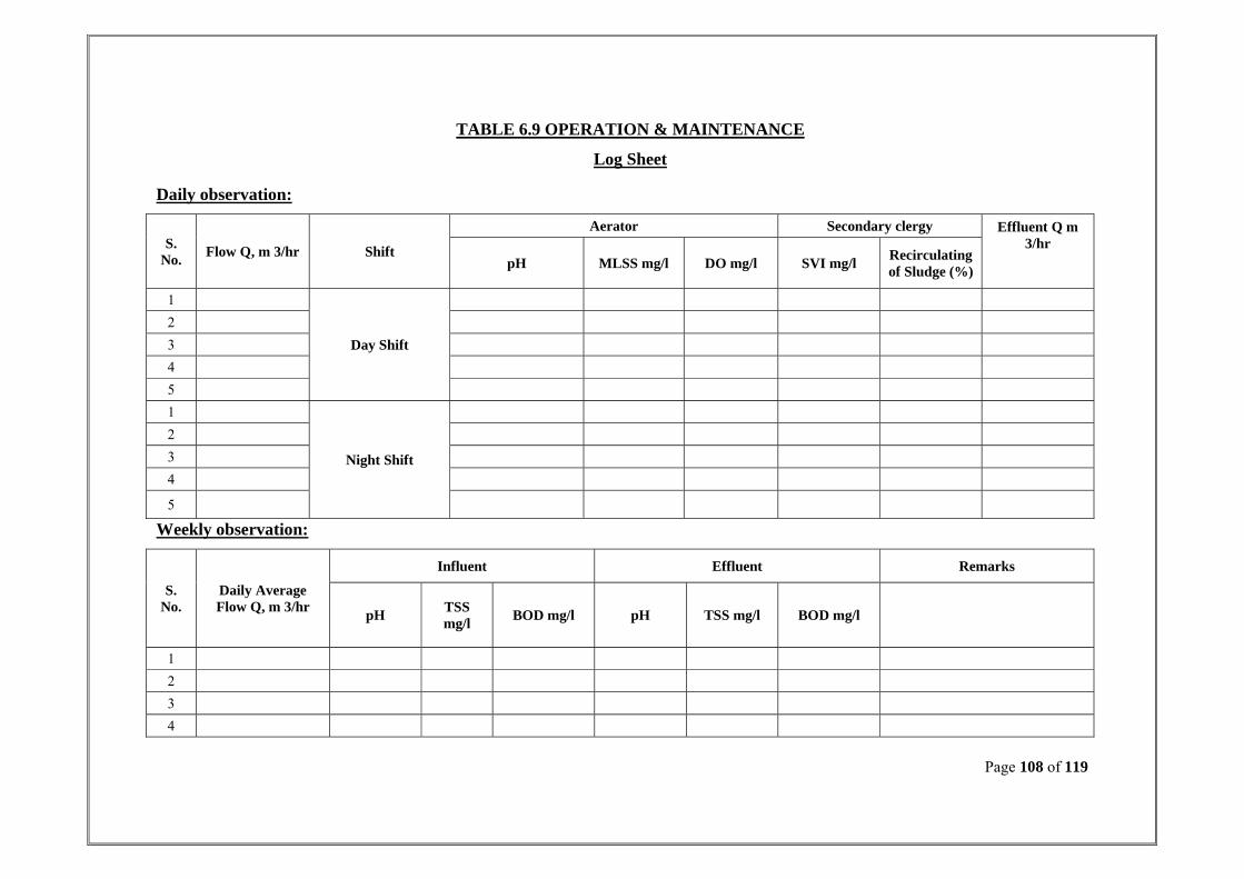
Page 108 of 119
Daily observation:
S. No. Flow Q, m 3/hr Shift
Aerator Secondary clergy Effluent Q m 3/hr
pH MLSS mg/l DO mg/l SVI mg/l Recirculating of Sludge (%)
1
Day Shift
2
3
4
5
1
Night Shift
2
3
4
5
Weekly observation:
S. No.
Daily Average Flow Q, m 3/hr
Influent Effluent Remarks
pH TSS mg/l BOD mg/l pH TSS mg/l BOD mg/l
1
2
3
4
TABLE 6.9 OPERATION & MAINTENANCE
Log Sheet

Page 109 of 119
CHAPTER –VII
SAFETY WORK PRACTICES FOR SEWAGE TREATMENT PLANT (DOS AND DON’TS)
S. No. DOs DON’Ts
1.0 Post "NO SMOKING" signs at all entrances to Aeration Tank facilities and at other conspicuous places.
Do not smoke, light open flames, or produce sparks in the immediate vicinity of tanks and buildings, or other conspicuous areas
2.0 Practice good personal hygiene and safety to guard against occupationally related diseases.
Do not eat, drink, or smoke while handling grit, screenings or sludge
3.0 Wear clothing that protects the arms and legs. Keep shirts tucked into pants
Avoid loose-fitting clothing that could get caught in moving Equipment
4.0 Wear the appropriate protective gloves whenever working in contact with wastewater, biosolids. Wash hands with a disinfectant soap after handling Wastewater, biosolids, or chemicals.
Never allow wastewater, biosolids, or chemicals to come into contact with cuts or broken skin. Do not place fingers into mouth, nose, ears, or eyes while handling wastewater, biosolids, or chemicals.
5.0 When working with classifiers or grit equipment, beware of rotating equipment.
Do not sacrifice safety for speed
6.0 Wear safety harness or life jacket when leaning on or hanging over aeration tank guard rails or safety chains.
Do not sit on aeration tank guard rails or safety chains
7.0 Use care and caution when using hand tools, power tools, and portable power equipment.
Do not use tools and equipment unless trained and experienced in the proper use and operation.
8.0 Use care and caution when lifting heavy tools and equipment. Do not use defective tools or equipments for handling tough jobs
9.0 Use care and caution when working in the laboratory. Store chemicals in a safe place where they are not hazardous to personnel or property. Wash hands with a disinfectant soap after handling chemicals. Wash off chemical spills on skin immediately with running water.
Do not place fingers into mouth, nose, ears, or eyes while handling chemicals. Do not have personal contact with chemicals

Page 110 of 119
S. No. DOs DON’Ts 10.0 Keep all work places including service rooms, storage rooms,
passageways and exits clean and orderly. Keep all walk areas free of sludge, slime, caustic, polymer, rags, grit, grease, oil, or other materials that could cause slipping.
Do not walk on sludge. Do not walk on bare foot or in slippery footwear.
11.0 Have at least two persons present before entering a launder or weir trough: one person to enter the sedimentation effluent troughs or weir trough, the other in the clear to observe in the event of an emergency
Never enter a sedimentation tank effluent trough or weir through alone and unattended
12.0 Plant personnel must be trained and instructed on the use and handling of chlorine, chlorine equipment, chlorine emergency repair kits, and other chlorine emergency procedures. Use extreme care and caution when handling chlorine. Lift chlorine cylinders only with an approved and load-tested device. Secure chlorine cylinders into position immediately Store chlorine l-ton cylinders on their sides only (horizontally) Always keep valve protection hoods in place until the chlorine cylinders are ready for connection Use only the specified wrench to operate chlorine cylinder valves. Open chlorine cylinder valves slowly; no more than one full turn Have at least two personnel present before entering a chlorine atmosphere: One person to enter the chlorine atmosphere, the other to observe in the event of an emergency
Never leave a cylinder suspended. Avoid dropping chlorine cylinders. Avoid banging chlorine cylinders into other objects. Never apply direct flame to a chlorine cylinder. Except to repair a leak, do not tamper with the fusible plugs on chlorine cylinders. Do not hammer, bang, or force chlorine cylinder valves under any circumstances Never enter a chlorine atmosphere unattended Never store other materials in chlorine cylinder storage areas; substances like acetylene and propane are not compatible with chlorine.
13.0 Use care and caution when working around all electrical equipment Observe "DANGER" and "HIGH VOLTAGE" signs. Consider all electrical conductors and equipment to be "live" until positively proven to be deenergized. Use only wooden or fiberglass ladders when working around electrical lines and equipment. Have frayed or broken electrical cords repaired Immediately
Do not bypass electrical safety devices. Do not use open-face drop lights. Never tape frayed or damaged electrical cords. Never use an empty electrical control panel as a storage locker Never use electrical tools in or near water without ground fault interrupter circuit. Never stand in water when using an electrical tool or equipment

Page 111 of 119
CHAPTER –VIII
ENVIRONMENTAL ENHANCEMENT MEASURES The following Enhancement Measure is encountered to overcome the environmental
impact so far studied in the previous chapters.
Greenbelt development
8.1 GREENBELT DEVELOPMENT A green belt for 2962.00 Sq.m is planned for the development of green belt. The green belt
development plan is presented in Fig. 6.1.
The budgetary estimate for the development of envisaged green belt in the project
location is presented in Table 2.3.2.
Theni Municipality has handed over 3.81acres for the installation of STP components to
treat 12.05.00 mld at percent.
AREA DETAILS:
Total area of the site : 15418.523 Sq.m
I. Present Scenario:
1. Area for Proposed STP,
Including, Roads, platform, steel bridge,
Walkway and pathway etc. : 4706.17Sq. m
2. Area for future 7MLD STP plant : 2641.60 Sq. m
3. Green Belt Area : 2961.21 Sq. m
3. Saving Area : 3155.46 sq. m
4. formed road (12.0m Wide) : 1954.08Sq. m
Total Area : 18418.523Sq. M

Page 112 of 119
Survival Monitoring:
Atleast once in a week, the responsible officer for green belt development as per the
Environmental Cell, shall monitor the plants and shrubs in the green belt for their status
and survival rate.
The contractor is recommended to hire the services of a horticulturist to monitor the
green belt, periodically to suggest necessary measure for watering, application of manure,
pesticides, etc.
Impact Area:
The Extent of 1km, 5km, 10km and 20km radius are the guidelines from Ministry of
Environmental and Forests and TamilNadu Pollution Control Board.
Reuse of treated Sewage:
Anyhow, the local peoples are surveyed for reuse of the treated sewage for farming
activities.
The total land allotted for Theni-Allinagaram STP is 3.81acres in which 1.04 acres will
be used for sewage treatment plant and the vacant land will be developed with green belt.
Around the STP 4 rows of tree will be planted and the distance between the plants will be
5 meters, the predominant wind direction recorded during study period was SE and SW,
and predominant wind speed was in the range of 4 - 10 Kmph hence the thick plantation
will be in southern direction of proposed project site.
GREEN BELT DESIGN
Distance between rows : 2.5 m
Distance between trees : 5 m
Rows of plants provided : 4 rows in North, South and East,
2 rows in West direction
Total green belt area : 2961.21Sq.m
Total number of plants : 290Nos.

Page 113 of 119
• A comprehensive greenbelt plan shall be implemented to improve the ecological condition.
• The trees in subsequent rows will be interspaced and the trees of subsequent rows
be selected in such a way that the canopy is sloping.
The total trees after the implementation of this plant will be around 290 trees. This will be
more than compensate for the loss of green cover and will serve the important
environmental objectives of the dust and fumes capture, noise attenuation and wind
barrier while also improving the aesthetics.
• The proposed green belt will be integrated with the existing plantation and locally
available and sustainable species shall only be chosen for plantation
• Green belt development will be taken up along with the consumption work so that
plantation will grow to adequate height by the time of plant commissioning. Thus
greenbelt will be effective in containing the pollutants due to the plant operations.
• The trees selected for greenbelt development will be such a fashion that the
canopy is sloping.
The main purpose of green belt development is to contribute to the following factors.
1. To attenuate noise level generated from the plant;
2. To improve the aesthetics of the plant area;
3. To trap the vehicular and fugitive dust emissions;
4. To act as a pollution sink for gaseous emissions;
5. To maintain ecological balances;
6. To prevent soil erosion and to protect the natural vegetation;
7. To utilize the treated effluents.

Page 114 of 119
A) Planned Species for Green Belt:
While selecting the plant species for the proposed green belt, the following points have
been taken in to consideration:
1. Should be a fast growing type;
2. Should have a thick canopy cover;
3. Should be perennially green;
4. Should be preferably of native origin; and
5. Should have large leaf area index.
B) Recommended Species for Plantation
Based on climate and soil characteristics of the study areas, some species are
recommended for plantation. The climate of the region is tropical, where there is medium
rainfall as well as extreme heat and soil temperature is very high in summer. Hence in
order to have a ground cover, some fast growing species, which do not require watering,
have been recommended for mass plantation. The below mentioned species not only
resist water stress but also covers the ground quickly and also have wider soil
adaptability. For protecting the environment from dust, temperature, chemicals, emissions
the following species have been recommended.

Page 115 of 119
Table 8.1 Suggested Plant Species for Greenbelt development
The above given suitable trees will be planted in consultation with the local body at the
time of implementing greenbelt operation.
GREENBELT IMPLEMENTATION
S.NO SCIENTIFIC NAME COMMON NAME LOCAL NAME
1. Eucalyptus Gum Tree Tailamaram
2. Polyalthia longifolia Ashoka tree Ashokamaram
3. Aegle marmelos Bel Vilvam
4. Azadirachta indica Neem Vepa
5. Pongamia pinnata Pungam Pungam maram
The above given suitable trees will be planted in consultation with the local body at the
time of implementing greenbelt operation.
GREENBELT IMPLEMENTATION PLAN
The greenbelt will be developed in an area of 2961.21 square meters by planting 4 rows
of trees with an interspace distance of 5 meters in the predominant wind direction. The
plantation of tree saplings will be done during monsoon season in a phased manner. The
Phase I has been commenced by initially planting 70 tree saplings and the photographs
are shown in Figure 7.1.
The second, third and fourth phase of tree plantation will be done with regular intervals.
During the second phase of tree plantation programme another 70 tree saplings will be
planted. In the third phase, 75 numbers will be planted and in the last phase, 75 tree
saplings will be planted. The first and second phase of tree plantation will be completed
within December 2012 and third and fourth phase will be completed within April 2013.

Page 116 of 119
Figure 8.1

Page 117 of 119
Annexure - I
COMPLIANCE STATEMENT FOR CONSENT TO ESTABLISH ORDER NO.
62/OL/2009, PROCEEDINGS NO: DEE/DGL/F.NO.DGL-1251/W/2009, DATED:
31/12/2009 UNDER WATER & AIR ACT
S.No. Special & Gareral Conditions Status
1.0 The above consent to establish cannot be construed as comsent to operate unit shall not commence the operation without obtaining the consent to operate.
We ensure that the Sewage Treatment Plant will not be commissioned without obtaining Consent to Operate from the Board under the Water & Air Acts.
2.0 The industry shall make a request for grant of consent to opetaet at least thirty days before the commissoning of trail production.
The Municipality will apply to TNPCB prior to 30 days for Consent to Operate.
3.0 The init shall construct compound wall around the boundery of the unit.
We provided the compound wall around the boundary of the unit.
4.0 Samles of water from the wells or any other nearby water sources have to taken by the unit and get them analyzed by the board laboratory to develp base line data to assess the existing water quality.
We adhere to the conditions stipulated by the Board.
5.0 The unit shall provide an alternate power source along with separate energy meter for the effluent treatment plant to ensure contiuouse operation of the effluent tratment plant.
To ensure continuous operation of STP, the Contractor will install 250 KVA DG set as alternate source of power during power failure scenario.
6.0 This consent does not authorise or approve the construction of any physical structures or facilities or the undertaking of any work in any natural water course.
We adhere to the conditions stipulated by the Board in the Consent Order.
7.0 Any change in the details furnished in the conditions has to be bouought to the notice of the board and got approved by the board, before obtaining consent to operate under the said Act.
Any change / quantity of flow in the Sewage Treatment Plant will be intimated to the Board for approval.
8.0 The unit has to comply with the provisions of Public Liability Insurance Act, 1991 to provide immediate relief in the event of any hazard to human beings, other living creatures / plants and properties while handling and storage of hazardous substances. (if applicable)
We confirm that, there won’t be any storage of hazardous material in the STP site during the operational phase. For disinfection, chlorine is used which is stored in 1 ton capacity toner. All the safety norms will be strictly followed at the time of operational phase.

Page 118 of 119
S.No. Special & Gareral Conditions Status
9.0 Consent to operate will not be issued unless the unit complies with the conditions of consent to establish.
Consent to Operate will be applied on completion of the construction works and comply with condition as per the CTE of TNPCB.
10. In case there is any change in the management, the unit shall inform the change with relevant documents immediately.
The Municipality authorities will inform if there is any change in the management to TNPCB along with relevant document.
11.0 The unit shall provide adequate watersprnklers for the control of dust emission during the loading and unloading of construction material. So as to minimize the dust emmission.
The theni-allinagaram municipality alredly provided the 10ft bitmun road from NH to STP site.
12.0 The units dhall develop green belet of adequate width around the premises.
For the development of green belt, various species identified are listed in Table – 8.1

Page 119 of 119
ANNEXURE II
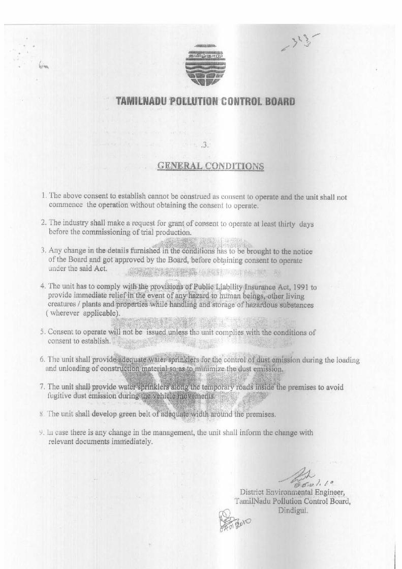
Page 120 of 119

Page 121 of 119

Page 122 of 119

Page 123 of 119
ANNEXURE –III

Page 124 of 119

Page 125 of 119

Page 126 of 119

Page 127 of 119
Annexure – IV
Sampling Locations

Chapter - IX
CLIENT:
CONTRACTOR:
TITLE: PROCESS DESIGN CALCULATIONS
DOC NO: 10-TWAD-STP-12MLD-BE-01 No. of Sheets 11
G.M K.R C.C
Initial Sign Initial Sign Initial Sign 2 02/08/2012
Prepared by Checked By Approved by Rev. no Date
Process Design Calculations
for
12.05 MLD Capacity Sewage Treatment Plant with
Activated Sludge Process (Extended Aeration)
at
Theni- Allinagaram
TAMILNADU WATER SUPPLY AND DRAINAGE BOARD, Southern Region, Madurai.
ECO PROTECTION ENGINEERS PVT LIMITED, Plot no: 943, 54th street, Anna Nagar West Extension, Chennai-600101, Tamilnadu, India.
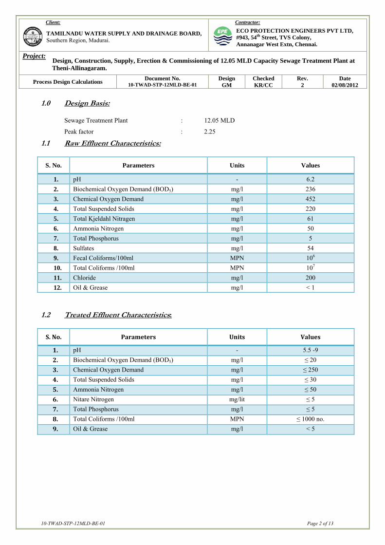
Design, Construction, Supply, Erection & Commissioning of 12.05 MLD Capacity Sewage Treatment Plant at Theni-Allinagaram.
10-TWAD-STP-12MLD-BE-01 Page 2 of 13
Client:
Contractor:
Project:
Process Design Calculations Document No. 10-TWAD-STP-12MLD-BE-01
Design GM
Checked KR/CC
Rev. 2
Date 02/08/2012
TAMILNADU WATER SUPPLY AND DRAINAGE BOARD, Southern Region, Madurai.
ECO PROTECTION ENGINEERS PVT LTD, #943, 54th Street, TVS Colony, Annanagar West Extn, Chennai.
1.0 Design Basis:
Sewage Treatment Plant : 12.05 MLD
Peak factor : 2.25
1.1 Raw Effluent Characteristics:
S. No. Parameters Units Values
1. pH - 6.2 2. Biochemical Oxygen Demand (BOD5) mg/l 236 3. Chemical Oxygen Demand mg/l 452 4. Total Suspended Solids mg/l 220 5. Total Kjeldahl Nitragen mg/l 61 6. Ammonia Nitrogen mg/l 50 7. Total Phosphorus mg/l 5 8. Sulfates mg/l 54 9. Fecal Coliforms/100ml MPN 106 10. Total Coliforms /100ml MPN 107 11. Chloride mg/l 200 12. Oil & Grease mg/l < 1
1.2 Treated Effluent Characteristics: S.No. Parameters Units Values
1. pH - 5.5 -9 2. Biochemical Oxygen Demand (BOD5) mg/l ≤ 20 3. Chemical Oxygen Demand mg/l ≤ 250 4. Total Suspended Solids mg/l ≤ 30 5. Ammonia Nitrogen mg/l ≤ 50 6. Nitare Nitrogen mg/lit ≤ 5 7. Total Phosphorus mg/l ≤ 5 8. Total Coliforms /100ml MPN ≤ 1000 no. 9. Oil & Grease mg/l < 5

Design, Construction, Supply, Erection & Commissioning of 12.05 MLD Capacity Sewage Treatment Plant at Theni-Allinagaram.
10-TWAD-STP-12MLD-BE-01 Page 3 of 13
Client:
Contractor:
Project:
Process Design Calculations Document No. 10-TWAD-STP-12MLD-BE-01
Design GM
Checked KR/CC
Rev. 2
Date 02/08/2012
TAMILNADU WATER SUPPLY AND DRAINAGE BOARD, Southern Region, Madurai.
ECO PROTECTION ENGINEERS PVT LTD, #943, 54th Street, TVS Colony, Annanagar West Extn, Chennai.
2.0 UNITS SIZING CLACULATION: 2.1. Receiving Chamber:
Average Design flow : 12050 m3 /day Peak factor : 2.25 Peak Flow : 27113m3/day = 1129.7m3/hr No. of Receiving Chamber : 01No. Hydraulic detention time during Peak flow : 60 Seconds Required volume of the receiving 1129.7x 60
Chamber : --------------- m3 3600 : 18.8 m3
Provided Liquid depth : 2.0m Area of the Chamber : 9.4m2 Consider length of chamber : 3.1m Required width of Chamber : 3.032m Say : 3.10m Provide, Size of Receiving Chamber : 3.1m x 3.1m x 2.0m LD+0.5m FB
2.2 Coarse Screen Chamber:
Average Design flow : 12050 m3 /day Peak factor : 2.25 Peak Flow : 27113m3/day = 1129.7m3/hr
Number of Screen Chamber : 2 Nos.
(01No. Mechanical Working+01No. Manual St. By) For each 100% of peak flow
Velocity through screen during Peak flow : 1.2 m / sec
(As per CPHEEO Manual)

Design, Construction, Supply, Erection & Commissioning of 12.05 MLD Capacity Sewage Treatment Plant at Theni-Allinagaram.
10-TWAD-STP-12MLD-BE-01 Page 4 of 13
Client:
Contractor:
Project:
Process Design Calculations Document No. 10-TWAD-STP-12MLD-BE-01
Design GM
Checked KR/CC
Rev. 2
Date 02/08/2012
TAMILNADU WATER SUPPLY AND DRAINAGE BOARD, Southern Region, Madurai.
ECO PROTECTION ENGINEERS PVT LTD, #943, 54th Street, TVS Colony, Annanagar West Extn, Chennai.
Mechanical Course Screen:
Design Flow : 1129.7m3/hr : 0.314m3/sec Provide 50mm x 10mm SS 304 bars Clear opening between bars : 20 mm
As per manufacturer specification, the size of screen chamber as follows,
Size of Mech. Coarse screen channel : 4.0 m x 1.2 m x 0.50 m + 0.50 m FB
Manual Coarse Screen:
Provide 50mm x 10mm SS 304 bars Clear opening between bars : 25 mm Area of flow considering for peak Flow : 0.314 x 35
1.2 25 : 0.4m2
Provide width of screen : 1.0m Consider liquid rise in channel : 0.40m Say : 0.50m Velocity during peak flow : 0.314
1.0 x 0.5 : 0.628m/s
Number of bars : Width of screen (Clear opening + thickness of bar) : 1000 25 + 10 Number of bars, n : 29Nos.
Size of Screen Chamber : 4.0 m x 1.0m x 0.50m LD + 0.5m FB

Design, Construction, Supply, Erection & Commissioning of 12.05 MLD Capacity Sewage Treatment Plant at Theni-Allinagaram.
10-TWAD-STP-12MLD-BE-01 Page 5 of 13
Client:
Contractor:
Project:
Process Design Calculations Document No. 10-TWAD-STP-12MLD-BE-01
Design GM
Checked KR/CC
Rev. 2
Date 02/08/2012
TAMILNADU WATER SUPPLY AND DRAINAGE BOARD, Southern Region, Madurai.
ECO PROTECTION ENGINEERS PVT LTD, #943, 54th Street, TVS Colony, Annanagar West Extn, Chennai.
2.3. Fine Screen Chamber:
Average flow : 12050m3 /day
Peak factor : 2.25 Peak flow : 1129.7m3/hr : 0.314m3/sec Number of Screen Chamber : 2 Nos.
(01N0. Mechanical Working+01No. Manual St. By) For each 100% of peak flow
Velocity through screen during Peak flow : 1.2 m / sec
(As per CPHEEO Manual)
Mechanical Fine Screen As per manufacturer specification, the size of screen chamber as follows,
�
Size of Mech. fine screen channel : 4.0 m x 1.2 m x 0.50 m + 0.50 m FB Manual Fine Screen:
Provide 50 mm x 6mm SS 304 bars Clear opening between bars : 6mm Area of flow considering for peak Flow : 0.314 x 12
1.2 6 : 0.523m2
Provide width of screen : 1.0m Consider liquid rise in channel : 0.523m
Say : 0.5m
Velocity during peak flow : 0.314
1.0 x 0.5 : 0.628m/s
Number of bars : Width of screen (Clear opening + thickness of bar) : 1000 6 + 6 Number of bars, n : 83Nos. Provide,
Size of Screen Chamber : 4.0 m x 1.2 m x 0.5m LD + 0.50 FB

Design, Construction, Supply, Erection & Commissioning of 12.05 MLD Capacity Sewage Treatment Plant at Theni-Allinagaram.
10-TWAD-STP-12MLD-BE-01 Page 6 of 13
Client:
Contractor:
Project:
Process Design Calculations Document No. 10-TWAD-STP-12MLD-BE-01
Design GM
Checked KR/CC
Rev. 2
Date 02/08/2012
TAMILNADU WATER SUPPLY AND DRAINAGE BOARD, Southern Region, Madurai.
ECO PROTECTION ENGINEERS PVT LTD, #943, 54th Street, TVS Colony, Annanagar West Extn, Chennai.
2.4. Detritor Tank:
Number of Tanks : 2 Nos. (1W+1S) Average flow : 12050m3/day
Surface over flow rate : 960m3/m2/day Area of Detritus tank : 12050
-------------- m2 960
: 12.55m2 Provide Length of detritus tank : 3.6m Reqd. Width of detritus tank : 3.486m Say : 3.6m Side water depth of tank : 0.6 m Provide, Size of Detritus Tank : 3.6m x 3.6m x 0.6m SWD x 0.5 m FB
2.5. Parshall Flume: Average flow : 12050m3/day Peak flow : 27112.5m3/day : 1129.6m3/hr Velocity thru’ channel at peak flow : 1.2 m/sec Area of channel : 1129.6/3600 1.2
: 0.2614m2
Provide liquid depth in the channel : 0.50 m Required width of the channel : 0.523m
Say : 0.60m As per the enclosed parshall flume tabulation,
Throat width L : 0.30 m
Dimension B : 1.34 m
Dimension F : 0.60 m
Dimension G : 0.90 m
Length of flume : 2.84m Considering upstream and downstream in the flume,

Design, Construction, Supply, Erection & Commissioning of 12.05 MLD Capacity Sewage Treatment Plant at Theni-Allinagaram.
10-TWAD-STP-12MLD-BE-01 Page 7 of 13
Client:
Contractor:
Project:
Process Design Calculations Document No. 10-TWAD-STP-12MLD-BE-01
Design GM
Checked KR/CC
Rev. 2
Date 02/08/2012
TAMILNADU WATER SUPPLY AND DRAINAGE BOARD, Southern Region, Madurai.
ECO PROTECTION ENGINEERS PVT LTD, #943, 54th Street, TVS Colony, Annanagar West Extn, Chennai.
Total Length of flume : 5.50m Width of flume : 1.20m Provide, Size of the parshall flume : 5.50m x 1.2 m x 0.50 m LD + 0.50 m FB
2.6. Aeration Tank:
Design flow of Aeration tank : 12050m3/day BOD concentration in raw sewage : 236 mg/l
Based on exhaustive literature review, we carried out lab trials and conducted detailed studies at the site to arrive at the design parameters for the Aeration tank. Volume of Aeration Tank : Q in m3/day x Inlet BOD ------------------------------- MLVSS X F/M : 12050 x 236 ----------------- 2800 x 0.16 Volume of Aeration Tank : 6348m3 No. of Aeration tanks : 1No. Detention time provided : 6348 ---------- x 24 12050 : 12.6 hrs Providing 5.0 m ELD Plan 6348 area of the Aeration tank : ------------- m2 required 5.0
: 1270m2
Provided Length of Aeration Tank : 50m
Width of the Aeration tank : 25.4m Say : 25.0m Provide, Size of aeration tank : 50.0 m x 25.0m x 5.0 m LD + 0.5 m FB

Design, Construction, Supply, Erection & Commissioning of 12.05 MLD Capacity Sewage Treatment Plant at Theni-Allinagaram.
10-TWAD-STP-12MLD-BE-01 Page 8 of 13
Client:
Contractor:
Project:
Process Design Calculations Document No. 10-TWAD-STP-12MLD-BE-01
Design GM
Checked KR/CC
Rev. 2
Date 02/08/2012
TAMILNADU WATER SUPPLY AND DRAINAGE BOARD, Southern Region, Madurai.
ECO PROTECTION ENGINEERS PVT LTD, #943, 54th Street, TVS Colony, Annanagar West Extn, Chennai.
Diffused Aeration System: Oxygen Required at BOD Load: 12050 x 236 Total BOD load : -------------- kg/d.
1000 : 2843.8kg/d.
12050 x (236 – 20) x 1.28 O2 Required : ----------------------------- 1000 : 3331.6kg of O2/day
Air required : 3331.6kg/of O2/ day ---------------------------------------- 0.65 x 0.95 x 1.29 x 0.21 x 0.225x 24 : 3688m3/hr Capacity of Blower : 1845m3/hr @ 6000mmWG Nos. Of Blower : 2W + 1S Diffuser Size : 93 mm x 1000mm L Air Flow Rate per Diffuser : 15m3/hr Total Nos. of Diffuser : 246Nos.
2.7. Secondary Clarifier: No. of clarifier : 01Nos. Design flow of clarifier : 12050m3/d : 502m3/h
Consider, Surface loading rate for Average flow : 20m3/m2/d Area of Clarifier (A) : 12050 -------------- 20 : 602.50m2 Diameter of Clarifier (D) : √ (A x 4) / ∏ : √ (602.5 x 4) / ∏
: 27.697m

Design, Construction, Supply, Erection & Commissioning of 12.05 MLD Capacity Sewage Treatment Plant at Theni-Allinagaram.
10-TWAD-STP-12MLD-BE-01 Page 9 of 13
Client:
Contractor:
Project:
Process Design Calculations Document No. 10-TWAD-STP-12MLD-BE-01
Design GM
Checked KR/CC
Rev. 2
Date 02/08/2012
TAMILNADU WATER SUPPLY AND DRAINAGE BOARD, Southern Region, Madurai.
ECO PROTECTION ENGINEERS PVT LTD, #943, 54th Street, TVS Colony, Annanagar West Extn, Chennai.
Check the Surface Loading Rate at peak flow, Surface Loading Rate : 12050 x 2.25 ----------------- 602.5 : 45m3/m2/day
(OK, as its range from 40-50m3/m2/day)
Consider, Side Water Depth of Clarifier : 3.5m Provide,
Size of Clarifier : 28.0mDia x 3.5m SWD + 0.50 m FB Recirculation Rate: X Recirculation Ratio : --------------- Xw – X X – MLSS Concentration in the aeration zone Xw – MLSS Concentration in settling zone X : 4000mg/lit Xw : 10000mg/lit 4000 : ------------- 10000-4000 Recirculation Ratio : 0.66 Recirculation flow : 502 x 0.66 : 331.32m3/hr Recirculation Pump: No. of Pumps : 02Nos. (1No. Working+1No. St.By) Capacity of Pump : 332m3/hr @ 10m Head Excess Sludge Generation: 12050 x {236-20}
BOD Removed : --------------------- 1000 : 2602.8kg/day
As per CPHEEO Manual Page no. 234, the Excess Sludge will be 0.25 to 0.35kg/kg of BOD removed For the Extended Aeration System having on primary clarifier.

Design, Construction, Supply, Erection & Commissioning of 12.05 MLD Capacity Sewage Treatment Plant at Theni-Allinagaram.
10-TWAD-STP-12MLD-BE-01 Page 10 of 13
Client:
Contractor:
Project:
Process Design Calculations Document No. 10-TWAD-STP-12MLD-BE-01
Design GM
Checked KR/CC
Rev. 2
Date 02/08/2012
TAMILNADU WATER SUPPLY AND DRAINAGE BOARD, Southern Region, Madurai.
ECO PROTECTION ENGINEERS PVT LTD, #943, 54th Street, TVS Colony, Annanagar West Extn, Chennai.
Consider, Excess Sludge generated : 0.35 kg / kg of BOD removed : 2602.8 x 0.35
Total Excess Sludge : 910.98kg/day The sludge produced will be readily settable and as also observed during our studies the expected
Dry solids concentration in the settled sludge would 1.0%. Density of Excess Sludge : 1050kg/m3 The Volume of the excess 910.98 Sludge produced : --------------- m3/d
{0.01 x 1050}
Volume of sludge produced per day : 86.76m3/day 2.8. Sludge Sump: Nos. of Tanks : 1 No. Volume of Sludge Produced per day : 86.76m3/day : 3.615m3/hr
Retention Time : 4hr Volume of Sump : 14.46m3 Provided Liquid Depth : 2.0 m Area of Tank : 7.23m2 Provided with of sump : 1.8m Required length of Sump : 4.016m Say : 4.0m Provide, Size of Sludge Sump : 4.0m x 1.8m x 2.0 m LD + 0.5 m F.B
2.9. Sludge Sump Pump House:
Area of Sludge Pump house : 20m2 Provide, Size of Sludge Pump House : 5.0 m x 4.0 m x 3.5 m Height 2.10. Sludge Centrifuge:
Volume of Sludge produced per day : 86.76m3/day Hours of operation of centrifuge : 16 hrs/day Capacity of centrifuge : 86.76/16 : 5.422m3/hr

Design, Construction, Supply, Erection & Commissioning of 12.05 MLD Capacity Sewage Treatment Plant at Theni-Allinagaram.
10-TWAD-STP-12MLD-BE-01 Page 11 of 13
Client:
Contractor:
Project:
Process Design Calculations Document No. 10-TWAD-STP-12MLD-BE-01
Design GM
Checked KR/CC
Rev. 2
Date 02/08/2012
TAMILNADU WATER SUPPLY AND DRAINAGE BOARD, Southern Region, Madurai.
ECO PROTECTION ENGINEERS PVT LTD, #943, 54th Street, TVS Colony, Annanagar West Extn, Chennai.
Provide, Capacity of Sludge Centrifuge : 5.5m3/hr Nos. of Centrifuge : 02 Nos. (1W+1S)
2.11. Centrifuge House: Area of Centrifuge House : 36 m2
Provide,
Size of Centrifuge House : 6.0 m x 6.0 m x 8.0 m Height
2.12. Sludge Centrifuge Feed Pump: Capacity of Pump : 6m3/hr Head : 30MWC
Nos. of Pump : 02 Nos. (1W+1S) 2.13. Poly Electrolyte Dosing System:
Dosing Tank: Volume of dry sludge : 910.98kg/day Dosage of ploy electrolyte : 0.8kg/ton of dried solids Required quantity of poly electrolyte : 0.73kg/day Considering 0.1% Concentration of solution Nos. of tanks : 01Nos. (1W) Detention Time of dosing tank : 12 hrs Required volume of the tank : 0.73 x 100 x 12
0.1 x 24 : 365liters
Provided, Volume of Tank : 500Lit MOC of the Dosing Tank : HDPE
Dosing Pump:
Capacity of pump : 0-35LPH Head : 0.3kg/cm2 No. of Pumps : 02Nos. (1W+1S)

Design, Construction, Supply, Erection & Commissioning of 12.05 MLD Capacity Sewage Treatment Plant at Theni-Allinagaram.
10-TWAD-STP-12MLD-BE-01 Page 12 of 13
Client:
Contractor:
Project:
Process Design Calculations Document No. 10-TWAD-STP-12MLD-BE-01
Design GM
Checked KR/CC
Rev. 2
Date 02/08/2012
TAMILNADU WATER SUPPLY AND DRAINAGE BOARD, Southern Region, Madurai.
ECO PROTECTION ENGINEERS PVT LTD, #943, 54th Street, TVS Colony, Annanagar West Extn, Chennai.
2.14. Chlorine Contact Tank: Design Flow : 502m3/hr Provided detention period : 30 minutes Volume of the chlorine contact 502 x 30 Tank required : --------------- m3 60 : 251m3
No. of Tank : 1 No. Provided Liquid Depth : 3.5 m Area of Tank : 71.71m2 Considered Length of Tank : 12.0m Width of the tank : 5.976m Say : 6.0m Provide,
Size of Chlorine Contact Tank : 12.0 m x 7.0m x 3.0 m LD + 0.50 m FB 2.15. Chlorination cum Tonner Room: Area of Chlorination Shed : 35 m2
Provide, Size of chlorination Shed : 7.0 m x 5.0 m x 3.5 m Height
2.16. Blower cum MCC Room:
Area of Room : 91 m2
Provide, Size of Room : 13.0 m x 7.0 m x 5.0 m Height
2.17. Administration, Store House, Laboratory Building:
Area of Administration, Store House, Laboratory Building, etc. : 50 m2 + 50 m2 (G+1) Provide, Size of Room : 10.0 m x 5.0 m x 4.0m Height (G+1)

Design, Construction, Supply, Erection & Commissioning of 12.05 MLD Capacity Sewage Treatment Plant at Theni-Allinagaram.
10-TWAD-STP-12MLD-BE-01 Page 13 of 13
Client:
Contractor:
Project:
Process Design Calculations Document No. 10-TWAD-STP-12MLD-BE-01
Design GM
Checked KR/CC
Rev. 2
Date 02/08/2012
TAMILNADU WATER SUPPLY AND DRAINAGE BOARD, Southern Region, Madurai.
ECO PROTECTION ENGINEERS PVT LTD, #943, 54th Street, TVS Colony, Annanagar West Extn, Chennai.
2.18. Transformer Yard& Sub Station:
Provide, Size of yard : 8.0m x 4.0m
2.19. Security Room:
Provide, Size of Room : 3.0m x 3.0mx 3.5mHT