![KW[from 1994]wac_c.pdf](https://static.fdokumen.com/doc/165x107/6314afe3c72bc2f2dd0476e0/kwfrom-1994waccpdf.jpg)
4000 kW Industrial Generator Set Voltage Regulators - Kohler
10
15- 4000 kW Industrial Generator Set Voltage Regulators Industrial Generator Set Accessories Voltage Regulators The following information provides general features, specifications, and functions of available voltage regulators. This information generally applies to a single generator set and multiple generator sets with paralleling applications. Refer to the respective generator set specification sheet and see your authorized distributor for information regarding specific voltage regulator applications and availability. Integral Voltage Regulator with Kohlerr APM402, Decision-Makerr 3000, and Decision-Makerr 3500 Controllers and Menu-Driven Selections (15- 1000 kW Generator Set Models) The voltage regulator is integral to the controller and uses patented hybrid voltage regulator design providing 0.5% no-load to full-load regulation using root-mean-square (RMS) voltage sensing. The voltage regulator features three-phase sensing and is available for 12- or 24-volt engine electrical systems. Integral Voltage Regulator with Kohlerr APM603 Controllers and Menu-Driven Selections (80- 4000 kW Generator Set Models) The voltage regulator is integral to the controller and uses patented high-speed digital voltage regulator design providing 0.25% no-load to full-load regulation using true root-mean-square (RMS) voltage sensing. The voltage regulator features three-phase sensing and is available for 12- or 24-volt engine electrical systems. Integral Voltage Regulator with Kohlerr Decision-Makerr 550 and Decision-Makerr 6000 Controllers and Menu-Driven Selections (20- 3250 kW Generator Set Models) The voltage regulator is integral to the controller and uses microprocessor logic providing 0.25% no-load to full-load regulation using root-mean-square (RMS) voltage sensing. The voltage regulator features three-phase sensing and is available for 12- or 24-volt engine electrical systems. (continued on page 2) Decision-Makerr 3500 Controller with Integral Voltage Regulator APM603 Controller with Integral Voltage Regulator Decision-Makerr 6000 Controller with Menu-Driven Integral Voltage Regulator APM402 and Decision-Makerr 3000 Controller with Integral Voltage Regulator Decision-Makerr 550 Controller with Menu-Driven Integral Voltage Regulator G6-58 3/21o Page 1
-
Upload
khangminh22 -
Category
Documents
-
view
0 -
download
0
Transcript of 4000 kW Industrial Generator Set Voltage Regulators - Kohler
15- 4000 kW Industrial GeneratorSet Voltage Regulators
Industrial Generator Set Accessories
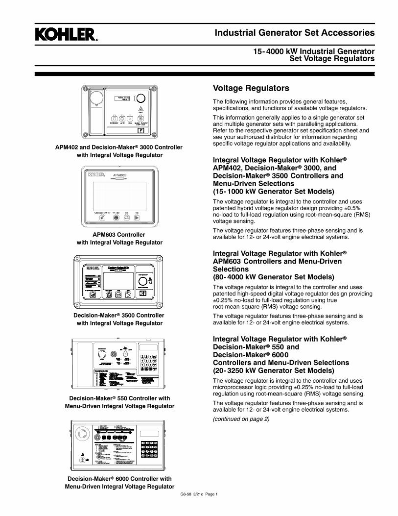
Voltage RegulatorsThe following information provides general features,specifications, and functions of available voltage regulators.
This information generally applies to a single generator setand multiple generator sets with paralleling applications.Refer to the respective generator set specification sheet andsee your authorized distributor for information regardingspecific voltage regulator applications and availability.
Integral Voltage Regulator with KohlerrAPM402, Decision-Makerr 3000, andDecision-Makerr 3500 Controllers andMenu-Driven Selections(15- 1000 kW Generator Set Models)The voltage regulator is integral to the controller and usespatented hybrid voltage regulator design providing 0.5%no-load to full-load regulation using root-mean-square (RMS)voltage sensing.
The voltage regulator features three-phase sensing and isavailable for 12- or 24-volt engine electrical systems.
Integral Voltage Regulator with KohlerrAPM603 Controllers and Menu-DrivenSelections(80- 4000 kW Generator Set Models)The voltage regulator is integral to the controller and usespatented high-speed digital voltage regulator design providing0.25% no-load to full-load regulation using trueroot-mean-square (RMS) voltage sensing.
The voltage regulator features three-phase sensing and isavailable for 12- or 24-volt engine electrical systems.
Integral Voltage Regulator with KohlerrDecision-Makerr 550 andDecision-Makerr 6000Controllers and Menu-Driven Selections(20- 3250 kW Generator Set Models)The voltage regulator is integral to the controller and usesmicroprocessor logic providing 0.25% no-load to full-loadregulation using root-mean-square (RMS) voltage sensing.
The voltage regulator features three-phase sensing and isavailable for 12- or 24-volt engine electrical systems.
(continued on page 2)
Decision-Makerr 3500 Controllerwith Integral Voltage Regulator
APM603 Controllerwith Integral Voltage Regulator
Decision-Makerr 6000 Controller withMenu-Driven Integral Voltage Regulator
APM402 and Decision-Makerr 3000 Controllerwith Integral Voltage Regulator
Decision-Makerr 550 Controller withMenu-Driven Integral Voltage Regulator
G6-58 3/21o Page 1

G6-58 3/21o Page 2
Fast-Responset II PMG with RMS Voltage Sensing
Digital DVRr 2000E Voltage Regulator
Voltage Regulators (continued)
Digital DVRr 2000E Voltage Regulator(250- 2250 kW Generator Set Models)The digital voltage regulator has 0.25% no-load to full-loadregulation using RMS voltage sensing.
The voltage regulator features three-phase sensing and isavailable for 12- or 24-volt engine electrical systems.
Digital DVRr 2000EC+ Voltage Regulator(400- 1300 kW Generator Set Models)The digital voltage regulator has 0.25% no-load to full-loadregulation using true RMS voltage sensing.
The voltage regulator features three-phase sensing and isavailable for 12- or 24-volt engine electrical systems.
Reactive power regulation (VAR) and power factor regulation(PF) modes enable paralleling with utility power.
Fast ResponsetII PMG with Average VoltageSensing Voltage Regulator(20- 300 kW Generator Set Models)The solid-state voltage regulator has 2% no-load to full-loadregulation using average voltage sensing.
The voltage regulator features single- or three-phase sensingoptions and is available for 12- or 24-volt engine electricalsystems.
Available with optional 1% no-load to full-load regulationusing average single-phase voltage sensing.
Fast ResponsetII PMG with RMS VoltageSensing Voltage Regulator (20- 300 kWGenerator Set Models)The solid-state voltage regulator has 0.5% no-load tofull-load regulation using RMS voltage sensing.
The voltage regulator features single- or three-phase sensingoptions and is available for 12- or 24-volt engine electricalsystems.
Not available on all models.
DER2 Voltage Regulator(KD800- 1750 Generator Set Models only)The digital voltage regulator has 0.25% no-load to full-loadregulation using single-phase sensing in RMS mode.
The voltage regulator features single- or three-phase sensingwith automatic recognition and is available for 12- or 24-voltengine electrical systems.
D510C Voltage Regulator(KD1250- 4000 Generator Set Models only)The digital voltage regulator has 0.25% no-load to full-loadregulation using RMS voltage sensing.
The voltage regulator features single- or three-phase sensingoptions and is available for 12- or 24-volt engine electricalsystems.
DVRr is a registered trademark of Marathon Electric Mfg. Corp.
Digital DVRr 2000EC+ Voltage Regulator
DER2 Voltage Regulator
D510C Voltage Regulator
Fast-Responset II PMG with Average Voltage Sensing
G6-58 3/21o Page 3
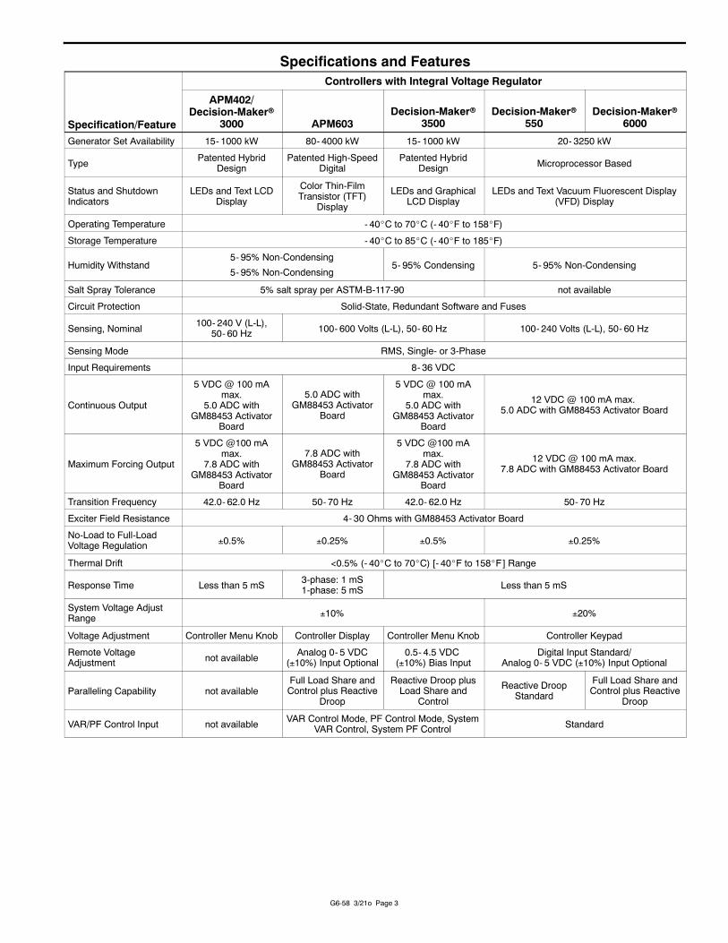
Specifications and Features
Specification/Feature
Controllers with Integral Voltage Regulator
APM402/Decision-Makerr
3000 APM603Decision-Makerr
3500Decision-Makerr
550Decision-Makerr
6000
Generator Set Availability 15- 1000 kW 80- 4000 kW 15- 1000 kW 20- 3250 kW
Type Patented HybridDesign
Patented High-SpeedDigital
Patented HybridDesign Microprocessor Based
Status and ShutdownIndicators
LEDs and Text LCDDisplay
Color Thin-FilmTransistor (TFT)
Display
LEDs and GraphicalLCD Display
LEDs and Text Vacuum Fluorescent Display(VFD) Display
Operating Temperature - 40_C to 70_C (- 40_F to 158_F)
Storage Temperature - 40_C to 85_C (- 40_F to 185_F)
Humidity Withstand5- 95% Non-Condensing
5- 95% Non-Condensing5- 95% Condensing 5- 95% Non-Condensing
Salt Spray Tolerance 5% salt spray per ASTM-B-117-90 not available
Circuit Protection Solid-State, Redundant Software and Fuses
Sensing, Nominal 100- 240 V (L-L),50- 60 Hz 100- 600 Volts (L-L), 50- 60 Hz 100- 240 Volts (L-L), 50- 60 Hz
Sensing Mode RMS, Single- or 3-Phase
Input Requirements 8- 36 VDC
Continuous Output
5 VDC @ 100 mAmax.
5.0 ADC withGM88453 Activator
Board
5.0 ADC withGM88453 Activator
Board
5 VDC @ 100 mAmax.
5.0 ADC withGM88453 Activator
Board
12 VDC @ 100 mA max.5.0 ADC with GM88453 Activator Board
Maximum Forcing Output
5 VDC @100 mAmax.
7.8 ADC withGM88453 Activator
Board
7.8 ADC withGM88453 Activator
Board
5 VDC @100 mAmax.
7.8 ADC withGM88453 Activator
Board
12 VDC @ 100 mA max.7.8 ADC with GM88453 Activator Board
Transition Frequency 42.0- 62.0 Hz 50- 70 Hz 42.0- 62.0 Hz 50- 70 Hz
Exciter Field Resistance 4- 30 Ohms with GM88453 Activator Board
No-Load to Full-LoadVoltage Regulation 0.5% 0.25% 0.5% 0.25%
Thermal Drift <0.5% (- 40_C to 70_C) [- 40_F to 158_F] Range
Response Time Less than 5 mS 3-phase: 1 mS1-phase: 5 mS Less than 5 mS
System Voltage AdjustRange 10% 20%
Voltage Adjustment Controller Menu Knob Controller Display Controller Menu Knob Controller Keypad
Remote VoltageAdjustment not available Analog 0- 5 VDC
(10%) Input Optional0.5- 4.5 VDC
(10%) Bias InputDigital Input Standard/
Analog 0- 5 VDC (10%) Input Optional
Paralleling Capability not availableFull Load Share andControl plus Reactive
Droop
Reactive Droop plusLoad Share and
Control
Reactive DroopStandard
Full Load Share andControl plus Reactive
Droop
VAR/PF Control Input not available VAR Control Mode, PF Control Mode, SystemVAR Control, System PF Control Standard
G6-58 5/20n Page 4
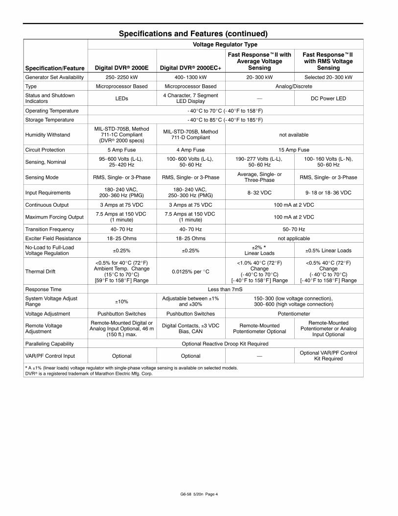
Specifications and Features (continued)
Specification/Feature
Voltage Regulator Type
Digital DVRr 2000E Digital DVRr 2000EC+
Fast ResponsetII withAverage Voltage
Sensing
Fast ResponsetIIwith RMS Voltage
Sensing
Generator Set Availability 250- 2250 kW 400- 1300 kW 20- 300 kW Selected 20- 300 kW
Type Microprocessor Based Microprocessor Based Analog/Discrete
Status and ShutdownIndicators LEDs 4 Character, 7 Segment
LED Display — DC Power LED
Operating Temperature - 40_C to 70_C (- 40_F to 158_F)
Storage Temperature - 40_C to 85_C (- 40_F to 185_F)
Humidity WithstandMIL-STD-705B, Method
711-1C Compliant(DVRr 2000 specs)
MIL-STD-705B, Method711-D Compliant not available
Circuit Protection 5 Amp Fuse 4 Amp Fuse 15 Amp Fuse
Sensing, Nominal 95- 600 Volts (L-L),25- 420 Hz
100- 600 Volts (L-L),50- 60 Hz
190- 277 Volts (L-L),50- 60 Hz
100- 160 Volts (L- N),50- 60 Hz
Sensing Mode RMS, Single- or 3-Phase RMS, Single- or 3-Phase Average, Single- orThree-Phase RMS, Single- or 3-Phase
Input Requirements 180- 240 VAC,200- 360 Hz (PMG)
180- 240 VAC,250- 300 Hz (PMG) 8- 32 VDC 9- 18 or 18- 36 VDC
Continuous Output 3 Amps at 75 VDC 3 Amps at 75 VDC 100 mA at 2 VDC
Maximum Forcing Output 7.5 Amps at 150 VDC(1 minute)
7.5 Amps at 150 VDC(1 minute) 100 mA at 2 VDC
Transition Frequency 40- 70 Hz 40- 70 Hz 50- 70 Hz
Exciter Field Resistance 18- 25 Ohms 18- 25 Ohms not applicable
No-Load to Full-LoadVoltage Regulation 0.25% 0.25% 2% *
Linear Loads 0.5% Linear Loads
Thermal Drift
<0.5% for 40_C (72_F)Ambient Temp. Change
(15_C to 70_C)[59_F to 158_F] Range
0.0125% per _C
<1.0% 40_C (72_F)Change
(- 40_C to 70_C)[- 40_F to 158_F] Range
<0.5% 40_C (72_F)Change
(- 40_C to 70_C)[- 40_F to 158_F] Range
Response Time Less than 7mS
System Voltage AdjustRange 10% Adjustable between 1%
and 30%150- 300 (low voltage connection),300- 600 (high voltage connection)
Voltage Adjustment Pushbutton Switches Pushbutton Switches Potentiometer
Remote VoltageAdjustment
Remote-Mounted Digital orAnalog Input Optional, 46 m
(150 ft.) max.
Digital Contacts, 3 VDCBias, CAN
Remote-MountedPotentiometer Optional
Remote-MountedPotentiometer or Analog
Input Optional
Paralleling Capability Optional Reactive Droop Kit Required
VAR/PF Control Input Optional Optional — Optional VAR/PF ControlKit Required
* A 1% (linear loads) voltage regulator with single-phase voltage sensing is available on selected models.DVRr is a registered trademark of Marathon Electric Mfg. Corp.

G6-58 3/21o Page 5
Specifications and Features (continued)
Specification/Feature
Voltage Regulator Type
DER2 D510C
Generator Set Availability KD800- 1750 KD1250- 4000
Type Digital Controlled based onDigital Signal Processor (DSP) Digital Controlled based on Dedicated Software
Status and ShutdownIndicators — Power, Voltage, Frequency, Faults, Excitation
Operating Temperature - 25_C to 70_C (- 13_F to 158_F) - 40_C to 65_C (- 40_F to 149_F)
Storage Temperature - 25_C to 70_C (- 13_F to 158_F) - 55_C to 85_C (- 67_F to 185_F)
Circuit Protection 5 Amp Fuse (Fast Acting) Electronic Short-Circuit, Current Limited
Sensing, Nominal 75- 300 Volts (L-L), 12- 72 Hz 90- 530 Volts (L-L)
Sensing Mode RMS, Single-Phase RMS, Single- or 3-Phase
Input Power Requirements 40- 270 VAC 11-32 VDC
Continuous Output 5 Amps 6 Amps
Maximum Forcing Output 12 Amps 15 Amps/10 s
Transition Frequency — 37-100 Hz
No-Load to Full-LoadVoltage Regulation 0.25% 0.25%
Response Time Less than 300 mS Depending on Proportional Integral Derivative (PID)Settings
System Voltage AdjustRange 10% 10%
Voltage Adjustment Programmable via Software Potentiometer, External Input
Remote Voltage Adjustment Analog, 10 VDC Analog, 10 VDC, 0-10 Volts, 4-20 mA
Paralleling Capability Optional Optional
VAR/PF Control Input — Optional (available as an ES only)
DER2 Voltage RegulatorD Digital controlled voltage regulator based on Digital SignalProcessing (DSP) programming.
D Single-phase and three-phase average voltage sensing withautomatic recognition.
D Voltage regulation of 0.25% from no load to nominal load instatic condition with single-phase sensing in RMS mode.
D Programmable soft start.
D USB communications port.
AdjustmentsAll parameters are programmable via software.
D StabilityD VoltageD AmpsD 50 or 60 Hz
D510C Voltage RegulatorD Digital controlled voltage regulator based on dedicatedsoftware.
D Single-phase and three-phase RMS voltage sensing.
D Voltage regulation of 0.25% from no load to nominal load instatic condition.
D Meets the requirements of IEC standard 60034-1, UL 708,and CSA certifications.
D Soft start 0- 100 s.
D USB communications port.
ProtectionsD Short-circuitD Loss of voltage referenceD OvervoltageD Over excitationD High temperatureD Speed dropD Diode faultD Stator current unbalanceD Current limitation
G6-58 5/20n Page 6
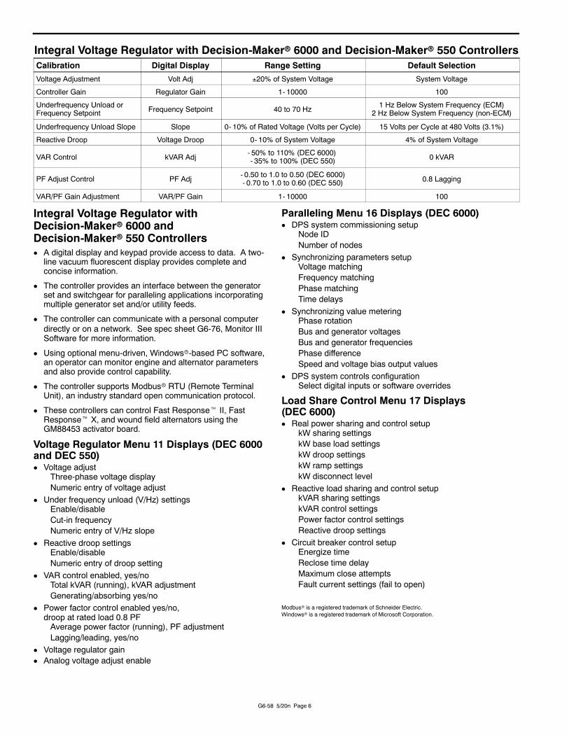
Integral Voltage Regulator with Decision-Makerr 6000 and Decision-Makerr 550 ControllersCalibration Digital Display Range Setting Default Selection
Voltage Adjustment Volt Adj 20% of System Voltage System Voltage
Controller Gain Regulator Gain 1- 10000 100
Underfrequency Unload orFrequency Setpoint Frequency Setpoint 40 to 70 Hz 1 Hz Below System Frequency (ECM)
2 Hz Below System Frequency (non-ECM)
Underfrequency Unload Slope Slope 0- 10% of Rated Voltage (Volts per Cycle) 15 Volts per Cycle at 480 Volts (3.1%)
Reactive Droop Voltage Droop 0- 10% of System Voltage 4% of System Voltage
VAR Control kVAR Adj - 50% to 110% (DEC 6000)- 35% to 100% (DEC 550) 0 kVAR
PF Adjust Control PF Adj - 0.50 to 1.0 to 0.50 (DEC 6000)- 0.70 to 1.0 to 0.60 (DEC 550) 0.8 Lagging
VAR/PF Gain Adjustment VAR/PF Gain 1- 10000 100
Integral Voltage Regulator withDecision-Makerr 6000 andDecision-Makerr 550 ControllersD A digital display and keypad provide access to data. A two-
line vacuum fluorescent display provides complete andconcise information.
D The controller provides an interface between the generatorset and switchgear for paralleling applications incorporatingmultiple generator set and/or utility feeds.
D The controller can communicate with a personal computerdirectly or on a network. See spec sheet G6-76, Monitor IIISoftware for more information.
D Using optional menu-driven, Windowsr-based PC software,an operator can monitor engine and alternator parametersand also provide control capability.
D The controller supports Modbusr RTU (Remote TerminalUnit), an industry standard open communication protocol.
D These controllers can control Fast Responset II, FastResponset X, and wound field alternators using theGM88453 activator board.
Voltage Regulator Menu 11 Displays (DEC 6000and DEC 550)D Voltage adjust
Three-phase voltage displayNumeric entry of voltage adjust
D Under frequency unload (V/Hz) settingsEnable/disableCut-in frequencyNumeric entry of V/Hz slope
D Reactive droop settingsEnable/disableNumeric entry of droop setting
D VAR control enabled, yes/noTotal kVAR (running), kVAR adjustmentGenerating/absorbing yes/no
D Power factor control enabled yes/no,droop at rated load 0.8 PFAverage power factor (running), PF adjustmentLagging/leading, yes/no
D Voltage regulator gainD Analog voltage adjust enable
Paralleling Menu 16 Displays (DEC 6000)D DPS system commissioning setup
Node IDNumber of nodes
D Synchronizing parameters setupVoltage matchingFrequency matchingPhase matchingTime delays
D Synchronizing value meteringPhase rotationBus and generator voltagesBus and generator frequenciesPhase differenceSpeed and voltage bias output values
D DPS system controls configurationSelect digital inputs or software overrides
Load Share Control Menu 17 Displays(DEC 6000)D Real power sharing and control setup
kW sharing settingskW base load settingskW droop settingskW ramp settingskW disconnect level
D Reactive load sharing and control setupkVAR sharing settingskVAR control settingsPower factor control settingsReactive droop settings
D Circuit breaker control setupEnergize timeReclose time delayMaximum close attemptsFault current settings (fail to open)
Modbusr is a registered trademark of Schneider Electric.Windowsr is a registered trademark of Microsoft Corporation.
G6-58 3/21o Page 7
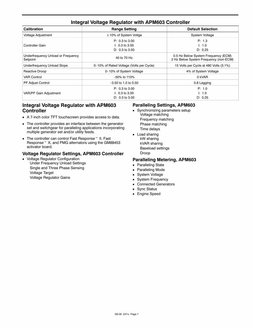
Integral Voltage Regulator with APM603 ControllerCalibration Range Setting Default Selection
Voltage Adjustment ±10% of System Voltge System Voltage
Controller GainP: 0.3 to 3.00I: 0.3 to 3.00D: 0.3 to 3.00
P: 1.3I: 1.0D: 0.25
Underfrequency Unload or FrequencySetpoint 40 to 70 Hz 0.5 Hz Below System Frequency (ECM)
2 Hz Below System Frequency (non-ECM)
Underfrequency Unload Slope 0- 10% of Rated Voltage (Volts per Cycle) 15 Volts per Cycle at 480 Volts (3.1%)
Reactive Droop 0- 10% of System Voltage 4% of System Voltage
VAR Control - 50% to 110% 0 kVAR
PF Adjust Control - 0.50 to 1.0 to 0.50 0.8 Lagging
VAR/PF Gain AdjustmentP: 0.3 to 3.00I: 0.3 to 3.00D: 0.3 to 3.00
P: 1.0I: 1.0D: 0.25
Integral Voltage Regulator with APM603ControllerD A 7-inch color TFT touchscreen provides access to data.
D The controller provides an interface between the generatorset and switchgear for paralleling applications incorporatingmultiple generator set and/or utility feeds.
D The controller can control Fast Responset II, FastResponset X, and PMG alternators using the GM88453activator board.
Voltage Regulator Settings, APM603 ControllerD Voltage Regulator Configuration
Under Frequency Unload SettingsSingle and Three Phase SensingVoltage TargetVoltage Regulator Gains
Paralleling Settings, APM603D Synchronizing parameters setup
Voltage matchingFrequency matchingPhase matchingTime delays
D Load sharingkW sharingkVAR sharingBaseload settingsDroop
Paralleling Metering, APM603D Paralleling StateD Paralleling ModeD System VoltageD System FrequencyD Connected GeneratorsD Sync StatusD Engine Speed
G6-58 5/20n Page 8
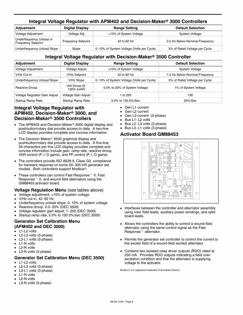
Integral Voltage Regulator with APM402 and Decision-Makerr 3000 ControllersAdjustment Digital Display Range Setting Default Selection
Voltage Adjustment Voltage Adj 10% of System Voltage System Voltage
Underfrequency Unload orFrequency Setpoint Frequency Setpoint 42 to 62 Hz 2.5 Hz Below Nominal Frequency
Underfrequency Unload Slope Slope 0- 10% of System Voltage (Volts per Cycle) 5% of Rated Voltage per Cycle
Integral Voltage Regulator with Decision-Makerr 3500 ControllerAdjustment Digital Display Range Setting Default Selection
Voltage Adjustment Voltage Adjust 10% of System Voltage System Voltage
V/Hz Cut-in V/Hz Setpoint 42 to 62 Hz 1.0 Hz Below Nominal Frequency
Underfrequency Unload Slope V/Hz Slope 0- 10% of System Voltage (Volts per Cycle) 5% of Rated Voltage per Cycle
Reactive Droop Volt Droop @100% kVAR 0.0% to 20% of System Voltage 1% of System Voltage
Voltage Regulator Gain Adjust Voltage Gain Adjust 1 to 255 128
Startup Ramp Rate Startup Ramp Rate 5.0% to 100.0%/Sec 25%/Sec
Integral Voltage Regulator withAPM402, Decision-Makerr 3000, andDecision-Makerr 3500 ControllersD The APM402 and Decision-Makerr 3000 digital display and
pushbutton/rotary dial provide access to data. A two-lineLCD display provides complete and concise information.
D The Decision-Makerr 3500 graphical display andpushbutton/rotary dial provide access to data. A five-line,35-characters per line LCD display provides complete andconcise information include gain, ramp rate, reactive droop,VAR control (P, I, D gains), and PF control (P, I, D gains).
D The controllers provide ISO 8528-5, Class G3, compliancefor transient response on some 20- 300 kW generator setmodels. Both controllers support Modbusr.
D These controllers can control Fast Responset II, FastResponset X, and wound field alternators using theGM88453 activator board.
Voltage Regulation Menu (see tables above)D Voltage adjustment, 10% of system voltageD V/Hz cut-in, 42- 62 HzD Underfrequency unload slope, 0- 10% of system voltageD Reactive droop, 0.0- 20% (DEC 3500)D Voltage regulator gain adjust, 1- 255 (DEC 3500)D Startup ramp rate, 5.0% to 100.0%/sec (DEC 3500)
Generator Set Calibration Menu(APM402 and DEC 3000)D L1-L2 voltsD L2-L3 volts (3-phase)D L3-L1 volts (3-phase)D L1-N voltsD L2-N voltsD L3-N volts (3-phase)
Generator Set Calibration Menu (DEC 3500)D L1-L2 voltsD L2-L3 volts (3-phase)D L3-L1 volts (3-phase)D L1-N voltsD L2-N voltsD L3-N volts (3-phase)
D Gen L1 currentD Gen L2 currentD Gen L3 current (3-phase)D Bus L1- L2 voltsD Bus L2- L3 volts (3-phase)D Bus L3- L1 volts (3-phase)
Activator Board GM88453
D Interfaces between the controller and alternator assemblyusing rotor field leads, auxiliary power windings, and opticboard leads.
D Allows the controllers the ability to control a wound-fieldalternator using the same control signal as the FastResponset alternator.
D Permits the generator set controller to control the current tothe exciter field of a wound-field excited alternator.
D Contains two isolated relay driver outputs (RDO) rated at250 mA. Provides RDO outputs indicating a field over-excitation condition and that the alternator is supplyingvoltage to the activator.
Modbusr is a registered trademark of Schneider Electric.

G6-58 3/21o Page 9
Digital DVRr 2000E Voltage RegulatorD The sealed electronic, solid-state microprocessor-baseddigital voltage regulator controls the generator set output byregulating the current flow into the exciter field.
D The digital voltage regulator is equipped with single- and/orthree-phase sensing. Single-phase sensing is achieved byconnecting terminals E2 and E3 to the same generator setterminal.
D Provisions are included in the regulator to allow theparalleling of two or more generator sets using either reactivedroop or reactive differential (cross current) compensationwith the addition of an external 5-amp 5VA currenttransformer (paralleling capability with optional DVRr2000EC model only).
D The underfrequency function allows the generator set tooperate with a constant volts-per-hertz characteristic.
D The over-excitation function monitors the voltage regulatoroutput voltage and causes the voltage regulator to shut downwhen the output voltage exceeds the preset trip level of80 volts for 15 seconds.
D The overvoltage function monitors the voltage regulatorsensed voltage and causes the voltage regulator to shutdown when the sensed voltage exceeds the preset trip levelsof 120% for 0.75 seconds.
D The voltage regulator is equipped with a sensor that monitorsthe ambient temperature and will turn itself off when thetemperature exceeds 70_C (158_F).
D The loss of the sensing function causes the voltage regulatorto shut down if an open circuit occurs in one or more of thesensing leads.
D The field current limit function monitors voltage regulatoroutput current and limits current should a heavy load or shortcircuit occur across the field output terminals.
D The manual mode of field current controls aid in setup andtroubleshooting.
D The alarm output contacts provide remote indication of faultcondition.
Status and Mode Adjustments
Status and Shutdown IndicatorsD Field amp limitD Loss of sensingD Manual modeD Over excitationD Over temperatureD Over voltageD Under frequencyD VAR/PF active
AdjustmentsD Coarse voltage adjustmentD DroopD Fine voltage adjustmentD GainD Manual mode adjustmentD Manual mode on/offD Phase sensing, 1- 3D Stability rangeD Under frequencyD VAR/PF adjustmentD VAR/PF select
Digital DVRr 2000EC+ Voltage RegulatorD Preset stability settings based on generator frame size
D Adjustable soft start in ARV1 or ARV3 regulation modes
D Under frequency (Volts/Hertz) regulation
D True RMS three-phase or single-phase generator voltagesensing
D Field current sensing
D Field voltage monitoring
D Contact inputs for system interface capability
D Contact output for fault indication
D Generator paralleling with reactive droop compensation andreactive differential compensation
D Front-panel human-machine interface (HIM) for status andconfiguration
D Modbusr protocol via RS232 for external communication
D DVR PortaltWindowsr-based software for configurationand monitoring
D CAN interface with CAN 2.0B J1939 protocol for meteringand control
D Power on LED indicator
D Configurable auxiliary input for metering and control
D Simulated reactive power for droop set-up
D Generator power limiting mode
ProtectionsD Field over excitation shutdownD Field under excitation shutdownD Generator over voltage shutdownD Generator under voltage shutdownD Generator voltage imbalance shutdownD Loss of generator sensing shutdownD Instantaneous field over current shutdownD Regulation over temperature shutdownD Generator reverse power shutdownD Generator start up fault shutdownD Field current limiting alarmD Generator under frequency alarmD Generator power limit alarmD Loss of CAN communication alarm
Modbusr is a registered trademark of Schneider Electric.Windowsr is a registered trademark of Microsoft Corporation.DVRr is a registered trademark of Marathon Electric Mfg. Corp.
2009 Kohler Co., All rights reserved.
DISTRIBUTED BY:
G6-58 5/20n Page 10
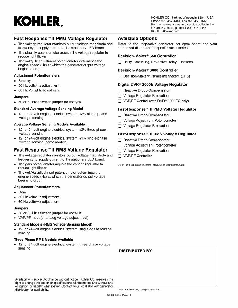
Fast ResponsetII PMG Voltage RegulatorD The voltage regulator monitors output voltage magnitude and
frequency to supply current to the stationary LED board.D The stability potentiometer adjusts the voltage regulator to
reduce light flicker.D The volts/Hz adjustment potentiometer determines the
engine speed (Hz) at which the generator output voltagebegins to drop.
Adjustment PotentiometersD StabilityD 50 Hz volts/Hz adjustmentD 60 Hz Volts/Hz adjustment
JumpersD 50 or 60 Hz selection jumper for volts/Hz
Standard Average Voltage Sensing ModelD 12- or 24-volt engine electrical system, 2% single-phase
voltage sensing
Average Voltage Sensing Models AvailableD 12- or 24-volt engine electrical system, 2% three-phase
voltage sensingD 12- or 24-volt engine electrical system, 1% single-phase
voltage sensing (some models)
Fast ResponsetII RMS Voltage RegulatorD The voltage regulator monitors output voltage magnitude and
frequency to supply current to the stationary LED board.D The gain potentiometer adjusts the voltage regulator to
reduce light flicker.D The volt/Hz adjustment potentiometer determines the
engine speed (Hz) at which the generator output voltagebegins to drop.
Adjustment PotentiometersD GainD 50 Hz volts/Hz adjustmentD 60 Hz volts/Hz adjustment
JumpersD 50 or 60 Hz selection jumper for volts/HzD VAR/PF input (or analog voltage adjust input)
Standard Models (RMS Voltage Sensing Model)D 12- or 24-volt engine electrical system, single-phase voltage
sensing
Three-Phase RMS Models AvailableD 12- or 24-volt engine electrical system, three-phase voltage
sensing
Available OptionsRefer to the respective generator set spec sheet and yourauthorized distributor for specific accessories.
Decision-Makerr 550 Controller- Utility Paralleling, Protective Relay Functions
Decision-Makerr 6000 Controller- Decision-Makerr Paralleling System (DPS)
Digital DVRr 2000E Voltage Regulator- Reactive Droop Compensator
- Voltage Regulator Relocation
- VAR/PF Control (with DVRr 2000EC only)
Fast-Responset II PMG Voltage Regulator- Reactive Droop Compensator
- Voltage Adjustment Potentiometer
- Voltage Regulator Relocation
Fast-Responset II RMS Voltage Regulator- Reactive Droop Compensator
- Voltage Adjustment Potentiometer
- Voltage Regulator Relocation- VAR/PF Controller
DVRr is a registered trademark of Marathon Electric Mfg. Corp.
Availability is subject to change without notice. Kohler Co. reserves theright to change the design or specificationswithout notice andwithout anyobligation or liability whatsoever. Contact your local Kohlerr generatordistributor for availability.
KOHLER CO., Kohler, Wisconsin 53044 USAPhone 920-457-4441, Fax 920-459-1646For the nearest sales and service outlet in theUS and Canada, phone 1-800-544-2444KOHLERPower.com