apollo 4000 - World Precision Instruments
74
APOLLO 4000 World’s first fully-integrated Free Radical Analyzer INSTRUCTION MANUAL Serial No._____________________ 061506 World Precision Instruments www.wpiinc.com APOLLO 4000 WARNING This instrument must not be connected to a local network nor to the Internet. Do not attach any peripheral device other than a USB printer. Any change to the proprietary hard disk registry in this device — whether by virus or by normally benign hardware or software installations — may render the drive or the Apollo software inoperable, requiring the instrument’s return to the factory for reformatting. File corruption or damage to applications or operating system caused by such use will not be covered by the Warranty.
-
Upload
khangminh22 -
Category
Documents
-
view
2 -
download
0
Transcript of apollo 4000 - World Precision Instruments
APOLLO 4000World’s first fully-integrated Free Radical Analyzer
INSTRUCTION MANUAL
Serial No._____________________
061506
World Precision Instruments
ww
w.w
pii
nc
.co
m
APOLLO 4000WARNING
This instrument must not be connected to a local network nor to the Internet. Do not attach any
peripheral device other than a USB printer. Any change to the proprietary hard disk registry in this device — whether by virus or by normally benign
hardware or software installations — may render the drive or the Apollo software inoperable, requiring the
instrument’s return to the factory for reformatting. File corruption or damage to applications or
operating system caused by such use will not be covered by the Warranty.

APOLLO 4000
WORLD PRECISION INSTRUMENTS 3
Cop
yrig
ht ©
200
3 b
y W
orld
Pre
cisi
on In
stru
men
ts, I
nc. A
ll rig
hts
rese
rved
. No
par
t of t
his
pub
licat
ion
may
be
rep
rod
uced
or
tran
slat
ed in
toan
y la
ngua
ge,
in a
ny fo
rm, w
ithou
t prio
r w
ritte
n p
erm
issi
on o
f Wor
ld P
reci
sion
Inst
rum
ents
, Inc
.
ContentsINTRODUCTION ...............................................................................A-1
Design Architecture ........................................................................................ A-2Plug-and-Play Design ..................................................................................... A-2Free Radical Sensor Technology .................................................................... A-2Instrument Description ................................................................................... A-3Unpacking ...................................................................................................... A-5
OPERATING INSTRUCTIONS ...........................................................B-1Setting up the APOLLO 4000 ......................................................................... B-1APOLLO.EXE Operating Software .................................................................. B-4Example of a real signal application ............................................................ B-12
USING THE APOLLO 4000 TO DETECT NITRIC OXIDE ...................C-1Initial Set-up .................................................................................................... C-1Calibration of the NO Sensor .......................................................................... C-1The Calibration Kit .......................................................................................... C-1Calibration by the chemical generation of NO ............................................... C-2Calibration of NO sensor by decomposition of SNAP .................................... C-7Calibration of NO sensor using aqueous standards prepared with NO Gas C-15Measurement of NO ..................................................................................... C-18Maintenance of NO Sensors ........................................................................ C-20
USING THE APOLLO 4000 TO DETECT OXYGEN............................D-1Initial Set-up .................................................................................................... D-1Calibration and Use of Oxygen Sensors ........................................................ D-1Calibration ...................................................................................................... D-2Probe Structure and Assembly ....................................................................... D-8
USING THE APOLLO 4000 TO DETECT HYDROGEN PEROXIDE..... E-1Initial Set-up .....................................................................................................E-1The structure of the HPO sensor .....................................................................E-1Calibration of the HPO Sensor ........................................................................E-2Calibration Procedure ......................................................................................E-2Interference .....................................................................................................E-4Maintenance of HPO Sensors .........................................................................E-4
TROUBLESHOOTING FOR APOLLO 4000 ........................................ F-1
APPENDIX: BASIC GROUNDING & SHIELDING PRINCIPLES ........ G-1

APOLLO 4000
INTRODUCTION
WORLD PRECISION INSTRUMENTS A-1
INTRODUCTION
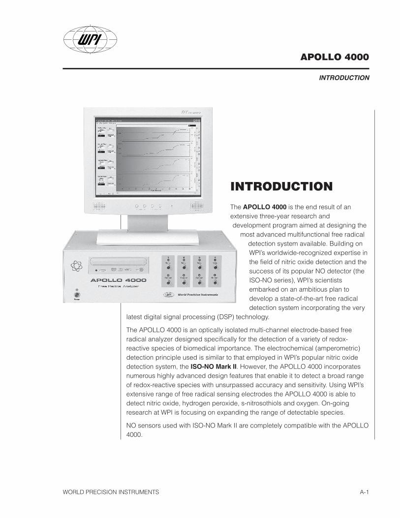
The APOLLO 4000 is the end result of anextensive three-year research anddevelopment program aimed at designing the
most advanced multifunctional free radicaldetection system available. Building onWPI’s worldwide-recognized expertise inthe field of nitric oxide detection and thesuccess of its popular NO detector (theISO-NO series), WPI’s scientistsembarked on an ambitious plan todevelop a state-of-the-art free radicaldetection system incorporating the very
latest digital signal processing (DSP) technology.
The APOLLO 4000 is an optically isolated multi-channel electrode-based freeradical analyzer designed specifically for the detection of a variety of redox-reactive species of biomedical importance. The electrochemical (amperometric)detection principle used is similar to that employed in WPI’s popular nitric oxidedetection system, the ISO-NO Mark II. However, the APOLLO 4000 incorporatesnumerous highly advanced design features that enable it to detect a broad rangeof redox-reactive species with unsurpassed accuracy and sensitivity. Using WPI’sextensive range of free radical sensing electrodes the APOLLO 4000 is able todetect nitric oxide, hydrogen peroxide, s-nitrosothiols and oxygen. On-goingresearch at WPI is focusing on expanding the range of detectable species.
NO sensors used with ISO-NO Mark II are completely compatible with the APOLLO4000.
APOLLO 4000
INTRODUCTION
WORLD PRECISION INSTRUMENTSA-2
Design ArchitectureThe APOLLO 4000 is based on an optically isolated 4-channel configuration (a 2-channel version is also available). This design enables simultaneous real-timemeasurement of NO (or other free radicals) to be performed using up to 4 differentelectrodes. In addition, each free radical sensing channel also contains anindependent channel for temperature measurement.
APOLLO 4000 incorporates a powerful single board computer and proprietarysoftware (apollo.exe) that enables real-time display and data-acquisition ofindividual channels or any combination of channels. An extensive graphical userinterface (GUI) based on a full color LCD monitor allows complete control andprogramming of all detection and data-acquisition parameters to be made usingthe standard keyboard and mouse included with the system.
The APOLLO 4000 consists of two functionally independent modules: Front EndConverter (FEC) and User Interface (UI). The FEC is an 8-channel data-acquisitionmodule based on a 24-bit A-to-D and 16-bit D-to-A conversion driven by a DigitalSignal Processor (DSP). The User Interface is built on a standard PC platform withWindows 2000® operating system. A standard serial port (RS232) provides thecommunication between the FEC and UI. The system is fully compatible with astandard keyboard and mouse and can be readily interfaced with PC’s, computernetworks, printers, and any device that uses Ethernet Tbase-10/100, USB, SerialPort or Parallel Port communications.
Plug-and-Play DesignThe APOLLO 4000 is designed for use with WPI’s range of free radical sensors.The user simply plugs the required sensor into any one of the input channelslocated on the instruments main front panel and then selects the detection andacquisition parameters using the integrated software control. Each channel is alsoprovided with an independent temperature input port that allows real-timemonitoring of temperature using WPI’s appropriate temperature sensors.
Free Radical Sensor TechnologyThe APOLLO 4000 and its associated free radical sensors can provide fast,accurate, and stable measurements over a wide range of concentrations in bothaqueous solutions and in gas mixtures. Its features include a rapid response time,
APOLLO 4000
INTRODUCTION
WORLD PRECISION INSTRUMENTS A-3
high sensitivity and selectivity, ease of use, and versatility unmatched by any othersimilar instrument.
The detection principles are based on the electrochemical (amperometric)response produced by the various compatible free radical sensors. In summary,the free radical of interest diffuses through a selective membrane covering thesensor and is oxidized at the working electrode, resulting in an electrical (redox)current. The amount of redox current produced is proportional to the free radicalconcentration in the sample. All of WPI’s free radical sensors are “combinationelectrodes” in which the sensing and reference electrodes have been combinedwithin a high performance Faraday shield designed to minimize susceptibility toenvironmental noise. The Apollo software can be programmed to display eitherredox current (e.g., pA) or concentration (e.g., nM). Output from the APOLLO 4000can also be collected via BNC connectors on the rear panel of the instrument.
APOLLO 4000 is fully compatible with WPI’s extensive range of free radicalsensors. Currently this range of sensors includes electrodes for monitoring; nitricoxide, oxygen and hydrogen peroxide. However, new sensors are currently indevelopment. For details on the complete list of compatible sensors please see thelatest WPI product catalog, or visit WPI’s website (www.wpiinc.com).
Instrument DescriptionParts List
The package should contain the following items:
Part No. Description
APOLLO4000 Free Radical Analyzer800408 Standard Keyboard800407 Standard Mouse800406 17” LCD monitor35209 Program CD
— Power cables— Instruction Manual
APOLLO 4000
INTRODUCTION
WORLD PRECISION INSTRUMENTSA-4
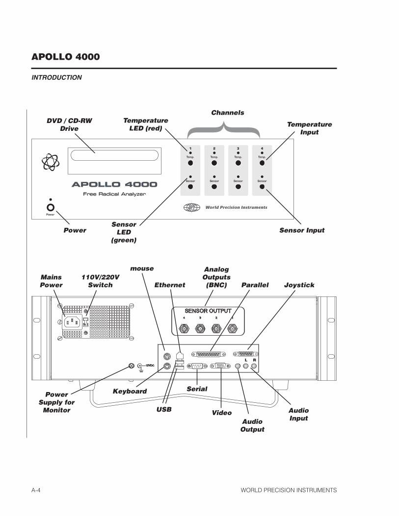
}ChannelsTemperature
LED (red)
SensorLED
(green)Power
TemperatureInput
Sensor Input
DVD / CD-RWDrive
MainsPower
110V/220VSwitch
mouse
PowerSupply for
Monitor
Keyboard
AnalogOutputs(BNC)
USB
Ethernet
Serial
VideoAudioOutput
AudioInput
L R
Parallel Joystick
APOLLO 4000
INTRODUCTION
WORLD PRECISION INSTRUMENTS A-5
UnpackingUpon receipt of this product, make a thorough inspection of the contents and checkfor possible damage. Missing cartons or obvious damage to cartons should be notedon the delivery receipt before signing. Concealed loss or damage should be re-ported at once to the carrier and an inspection requested. Please read the sectionentitled “Claims and Returns” on the Warranty page of this manual.
Returns: Do not return any goods to WPI without obtaining prior approval (RMA #required) and instructions from our Returns Department. Goods returned (unautho-rized) by collect freight may be refused. If a return shipment is necessary, use theoriginal container. If the original container is not available, use a suitable substitutethat is rigid and of adequate size. Wrap the instrument in paper or plastic surroundedwith at least 100 mm (four inches) of shock absorbing material. Please read the sec-tion entitled “Claims and Returns” on the Warranty page of this manual.
APOLLO 4000
INTRODUCTION
WORLD PRECISION INSTRUMENTSA-6
APOLLO 4000
OPERATING INSTRUCTIONS
WORLD PRECISION INSTRUMENTS B-1
OPERATING INSTRUCTIONS
To exploit the APOLLO 4000’s capabilities fully, it is very important that the user beaware of the general methods for operating the maintaining the instrument. This willalso ensure that the user is able to understand and interpret the readings.
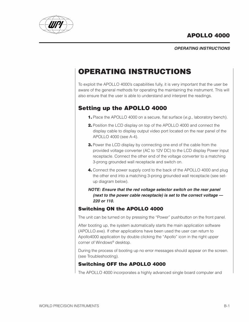
Setting up the APOLLO 40001. Place the APOLLO 4000 on a secure, flat surface (e.g., laboratory bench).
2. Position the LCD display on top of the APOLLO 4000 and connect thedisplay cable to display output video port located on the rear panel of theAPOLLO 4000 (see A-4).
3. Power the LCD display by connecting one end of the cable from theprovided voltage converter (AC to 12V DC) to the LCD display Power inputreceptacle. Connect the other end of the voltage converter to a matching3-prong grounded wall receptacle and switch on.
4. Connect the power supply cord to the back of the APOLLO 4000 and plugthe other end into a matching 3-prong grounded wall receptacle (see set-up diagram below).
NOTE: Ensure that the red voltage selector switch on the rear panel(next to the power cable receptacle) is set to the correct voltage —220 or 110.
Switching ON the APOLLO 4000
The unit can be turned on by pressing the “Power” pushbutton on the front panel.
After booting up, the system automatically starts the main application software(APOLLO.exe). If other applications have been used the user can return toApollo4000 application by double clicking the “Apollo” icon in the right uppercorner of Windows® desktop.
During the process of booting up no error messages should appear on the screen.(see Troubleshooting).
Switching OFF the APOLLO 4000
The APOLLO 4000 incorporates a highly advanced single board computer and
APOLLO 4000
OPERATING INSTRUCTIONS
WORLD PRECISION INSTRUMENTSB-2
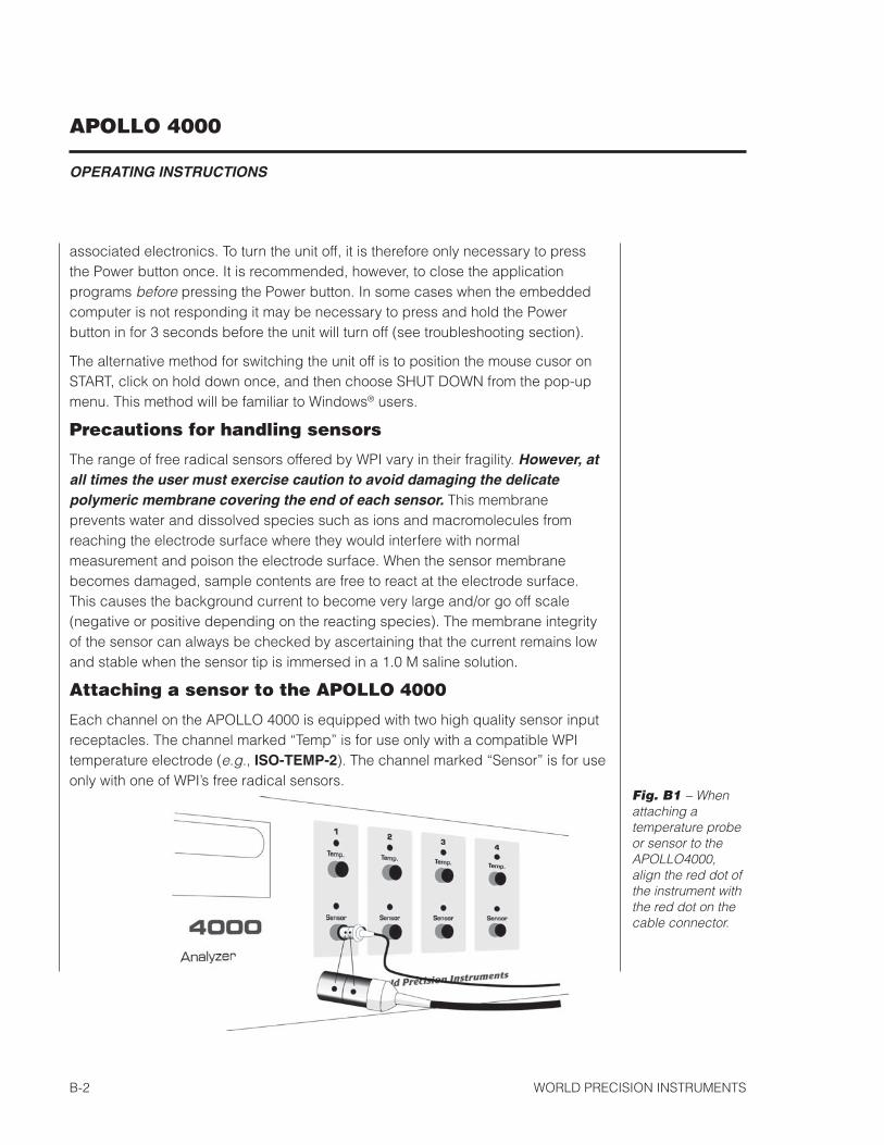
Fig. B1 – Whenattaching atemperature probeor sensor to theAPOLLO4000,align the red dot ofthe instrument withthe red dot on thecable connector.
associated electronics. To turn the unit off, it is therefore only necessary to pressthe Power button once. It is recommended, however, to close the applicationprograms before pressing the Power button. In some cases when the embeddedcomputer is not responding it may be necessary to press and hold the Powerbutton in for 3 seconds before the unit will turn off (see troubleshooting section).
The alternative method for switching the unit off is to position the mouse cusor onSTART, click on hold down once, and then choose SHUT DOWN from the pop-upmenu. This method will be familiar to Windows® users.
Precautions for handling sensors
The range of free radical sensors offered by WPI vary in their fragility. However, atall times the user must exercise caution to avoid damaging the delicatepolymeric membrane covering the end of each sensor. This membraneprevents water and dissolved species such as ions and macromolecules fromreaching the electrode surface where they would interfere with normalmeasurement and poison the electrode surface. When the sensor membranebecomes damaged, sample contents are free to react at the electrode surface.This causes the background current to become very large and/or go off scale(negative or positive depending on the reacting species). The membrane integrityof the sensor can always be checked by ascertaining that the current remains lowand stable when the sensor tip is immersed in a 1.0 M saline solution.
Attaching a sensor to the APOLLO 4000
Each channel on the APOLLO 4000 is equipped with two high quality sensor inputreceptacles. The channel marked “Temp” is for use only with a compatible WPItemperature electrode (e.g., ISO-TEMP-2). The channel marked “Sensor” is for useonly with one of WPI’s free radical sensors.
APOLLO 4000
OPERATING INSTRUCTIONS
WORLD PRECISION INSTRUMENTS B-3
NOTE: The Temp and Sensor inputs are not interchangeable but no damageto the APOLLO 4000 will occur if a sensor/electrode is accidentally insertedinto the wrong input receptacle.
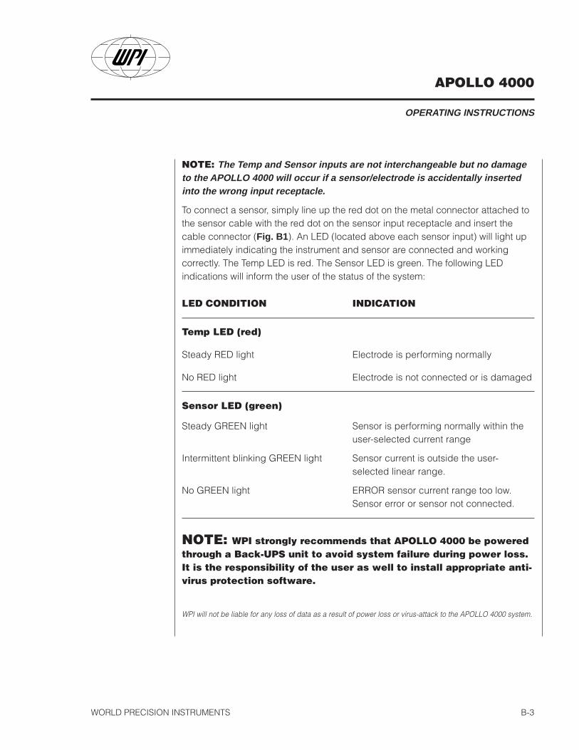
To connect a sensor, simply line up the red dot on the metal connector attached tothe sensor cable with the red dot on the sensor input receptacle and insert thecable connector (Fig. B1). An LED (located above each sensor input) will light upimmediately indicating the instrument and sensor are connected and workingcorrectly. The Temp LED is red. The Sensor LED is green. The following LEDindications will inform the user of the status of the system:
LED CONDITION INDICATION
Temp LED (red)
Steady RED light Electrode is performing normally
No RED light Electrode is not connected or is damaged
Sensor LED (green)
Steady GREEN light Sensor is performing normally within theuser-selected current range
Intermittent blinking GREEN light Sensor current is outside the user-selected linear range.
No GREEN light ERROR sensor current range too low.Sensor error or sensor not connected.
NOTE: WPI strongly recommends that APOLLO 4000 be poweredthrough a Back-UPS unit to avoid system failure during power loss.It is the responsibility of the user as well to install appropriate anti-virus protection software.
WPI will not be liable for any loss of data as a result of power loss or virus-attack to the APOLLO 4000 system.
APOLLO 4000
OPERATING INSTRUCTIONS
WORLD PRECISION INSTRUMENTSB-4
Fig. B2
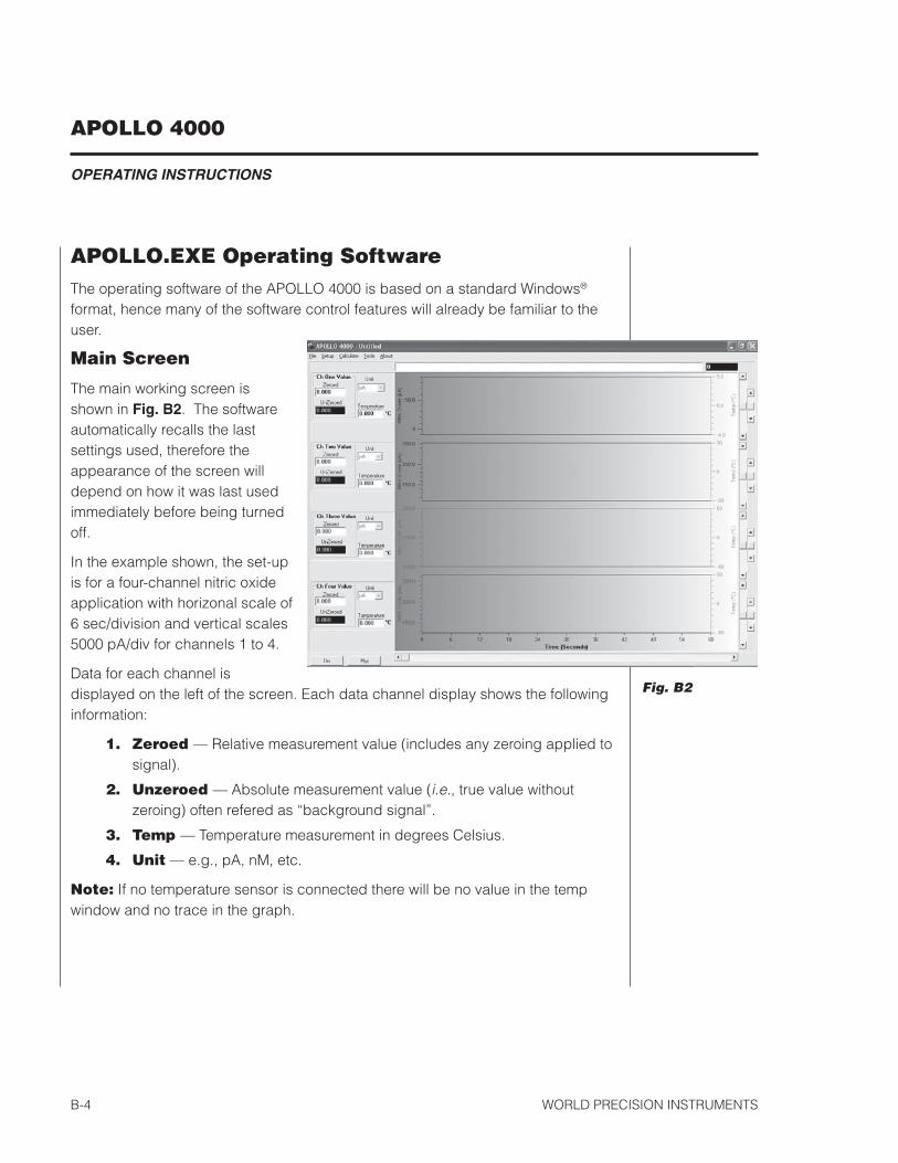
APOLLO.EXE Operating SoftwareThe operating software of the APOLLO 4000 is based on a standard Windows®
format, hence many of the software control features will already be familiar to theuser.
Main Screen
The main working screen isshown in Fig. B2. The softwareautomatically recalls the lastsettings used, therefore theappearance of the screen willdepend on how it was last usedimmediately before being turnedoff.
In the example shown, the set-upis for a four-channel nitric oxideapplication with horizonal scale of6 sec/division and vertical scales5000 pA/div for channels 1 to 4.
Data for each channel isdisplayed on the left of the screen. Each data channel display shows the followinginformation:
1. Zeroed — Relative measurement value (includes any zeroing applied tosignal).
2. Unzeroed — Absolute measurement value (i.e., true value withoutzeroing) often refered as “background signal”.
3. Temp — Temperature measurement in degrees Celsius.
4. Unit — e.g., pA, nM, etc.
Note: If no temperature sensor is connected there will be no value in the tempwindow and no trace in the graph.
APOLLO 4000
OPERATING INSTRUCTIONS
WORLD PRECISION INSTRUMENTS B-5
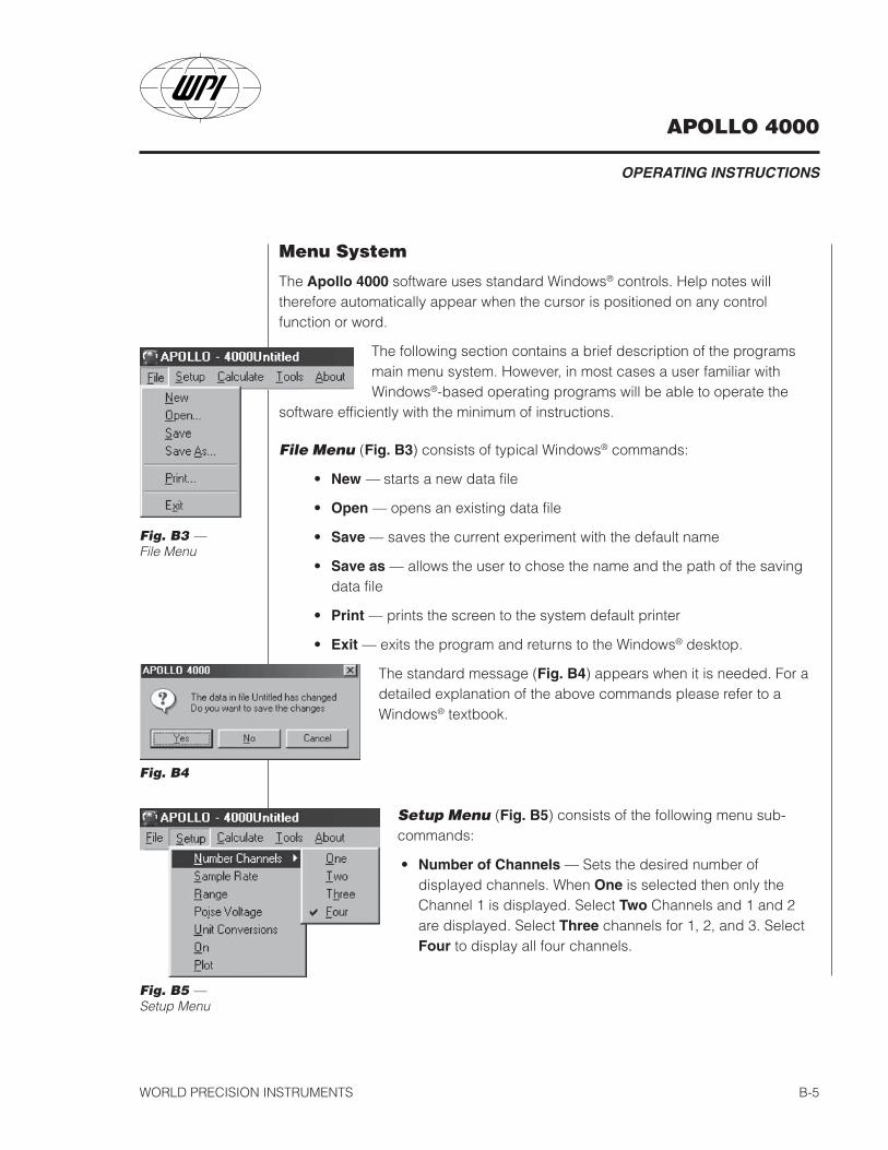
Menu System
The Apollo 4000 software uses standard Windows® controls. Help notes willtherefore automatically appear when the cursor is positioned on any controlfunction or word.
The following section contains a brief description of the programsmain menu system. However, in most cases a user familiar withWindows®-based operating programs will be able to operate the
software efficiently with the minimum of instructions.
File Menu (Fig. B3) consists of typical Windows® commands:
• New — starts a new data file
• Open — opens an existing data file
• Save — saves the current experiment with the default name
• Save as — allows the user to chose the name and the path of the savingdata file
• Print — prints the screen to the system default printer
• Exit — exits the program and returns to the Windows® desktop.
The standard message (Fig. B4) appears when it is needed. For adetailed explanation of the above commands please refer to aWindows® textbook.
Fig. B5 —Setup Menu
Fig. B3 —File Menu
Fig. B4
Setup Menu (Fig. B5) consists of the following menu sub-commands:
• Number of Channels — Sets the desired number ofdisplayed channels. When One is selected then only theChannel 1 is displayed. Select Two Channels and 1 and 2are displayed. Select Three channels for 1, 2, and 3. SelectFour to display all four channels.
APOLLO 4000
OPERATING INSTRUCTIONS
WORLD PRECISION INSTRUMENTSB-6
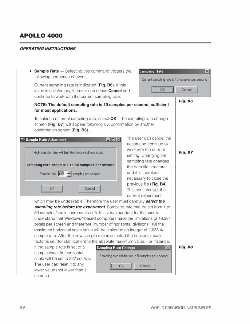
• Sample Rate — Selecting this command triggers thefollowing sequence of events:
Current sampling rate is indicated (Fig. B6). If thisvalue is satisfactory, the user can chose Cancel andcontinue to work with the current sampling rate.
NOTE: The default sampling rate is 10 samples per second, sufficientfor most applications.
To select a different sampling rate, select OK. The sampling rate changescreen (Fig. B7) will appear following OK confirmation by anotherconfirmation screen (Fig. B8).
The user can cancel theaction and continue towork with the currentsetting. Changing thesampling rate changesthe data file structureand it is thereforenecessary to close theprevious file (Fig. B4).This can interrupt thecurrent experiment
which may be undesirable. Therefore the user must carefully select thesampling rate before the experiment. Sampling rate can be set from 1 to50 samples/sec in increments of 5. It is very important for the user tounderstand that Windows®-based computers have the limitations of 16,384pixels per screen and therefore (number of horizontal divisions=10) themaximum horizontal scale value will be limited to an integer of 1,638.4/sample rate. After the new sample rate is selected the horizontal scalefactor is set (for clarification) to the absolute maximum value. For instance,if the sample rate is set to 5samples/sec the horizontalscale will be set to 327 sec/div.The user can reset it to anylower value (not lower than 1sec/div).
Fig. B8
Fig. B6
Fig. B7
APOLLO 4000
OPERATING INSTRUCTIONS
WORLD PRECISION INSTRUMENTS B-7
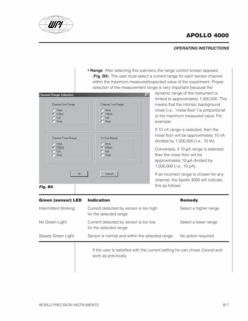
• Range. After selecting this submenu the range control screen appears(Fig. B9). The user must select a current range for each sensor channelwithin the maximum measured/expected value of the experiment. Properselection of the measurement range is very important because the
dynamic range of the instrument islimited to approximately 1,000,000. Thismeans that the intrinsic backgroundnoise (i.e., “noise floor”) is proportionalto the maximum measured value. Forexample:
If 10 nA range is selected, then thenoise floor will be approximately 10 nAdivided by 1,000,000 (i.e., 10 fA).
Conversely, if 10 µA range is selectedthen the noise floor will beapproximately 10 µA divided by1,000,000 (i.e., 10 pA).
If an incorrect range is chosen for anychannel, the Apollo 4000 will indicatethis as follows:Fig. B9
Green (sensor) LED Indication Remedy
Intermittent blinking Current detected by sensor is too high Select a higher rangefor the selected range
No Green Light Current detected by sensor is too low Select a lower rangefor the selected range
Steady Green Light Sensor is normal and within the selected range No action required
If the user is satisfied with the current setting he can chose Cancel andwork as previously.
APOLLO 4000
OPERATING INSTRUCTIONS
WORLD PRECISION INSTRUMENTSB-8
Fig. B11
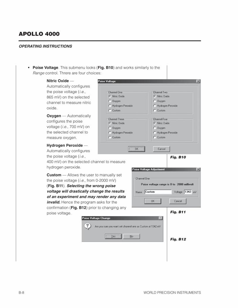
• Poise Voltage. This submenu looks (Fig. B10) and works similarly to theRange control. Threre are four choices:
Nitric Oxide —Automatically configuresthe poise voltage (i.e.,865 mV) on the selectedchannel to measure nitricoxide.
Oxygen — Automaticallyconfigures the poisevoltage (i.e., 700 mV) onthe selected channel tomeasure oxygen.
Hydrogen Peroxide —Automatically configuresthe poise voltage (i.e.,400 mV) on the selected channel to measurehydrogen peroxide.
Custom — Allows the user to manually setthe poise voltage (i.e., from 0-2000 mV)(Fig. B11). Selecting the wrong poisevoltage will drastically change the resultsof an experiment and may render any datainvalid. Hence the program asks for theconfirmation (Fig. B12) prior to changing anypoise voltage.
Fig. B10
Fig. B12
APOLLO 4000
OPERATING INSTRUCTIONS
WORLD PRECISION INSTRUMENTS B-9
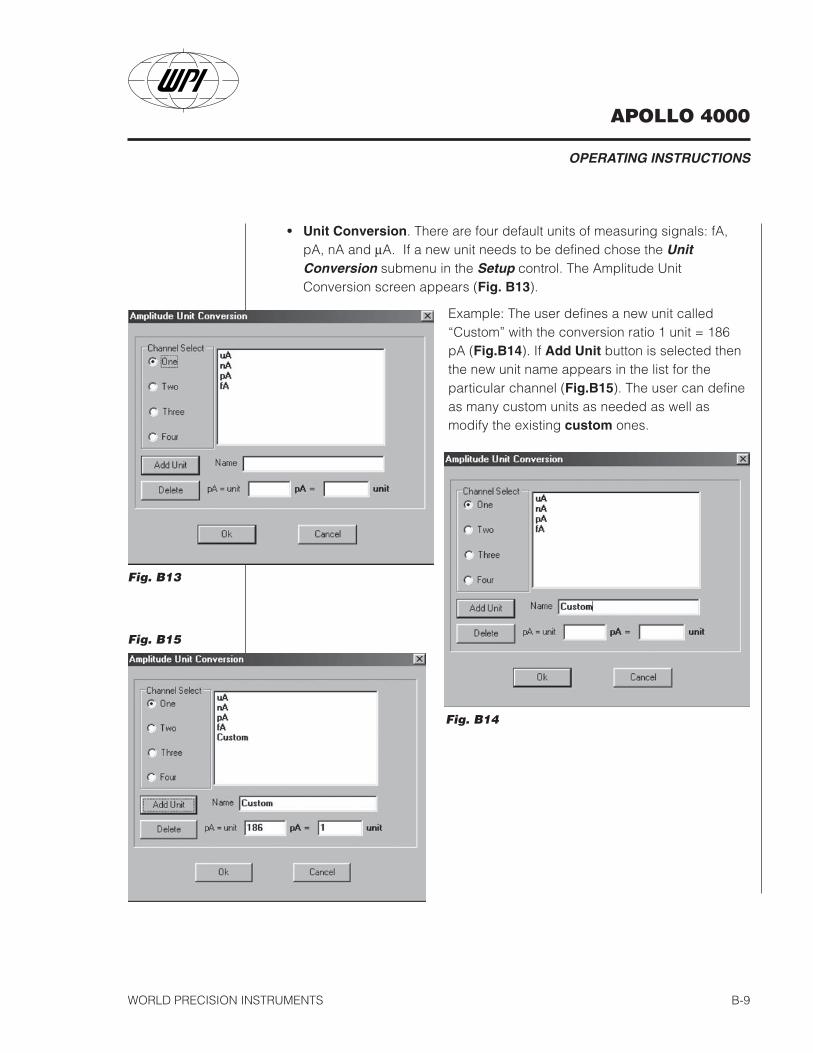
• Unit Conversion. There are four default units of measuring signals: fA,pA, nA and µA. If a new unit needs to be defined chose the UnitConversion submenu in the Setup control. The Amplitude UnitConversion screen appears (Fig. B13).
Example: The user defines a new unit called“Custom” with the conversion ratio 1 unit = 186pA (Fig.B14). If Add Unit button is selected thenthe new unit name appears in the list for theparticular channel (Fig.B15). The user can defineas many custom units as needed as well asmodify the existing custom ones.
Fig. B15
Fig. B13
Fig. B14

APOLLO 4000
OPERATING INSTRUCTIONS
WORLD PRECISION INSTRUMENTSB-10
• On / Off toggle control (also the push button in theleft bottom corner of the screen). This menu startsand stops the acquisition of data, including writing toa data file. Before the acquisition starts, the programnotifies the user about the sampling rate andmaximum horizontal scale factor (Fig. B16).
• Plot / Analyze toggle control (also the push button in the left bottom cornerof the screen) commands the program to start and stop plotting of theincoming data to the screen. In the Analyze mode there is a possibility tomeasure different parameters of the acquired data defined by Calculatemenu with the cursors. The cursors appear when the pointer device(mouse) is moved to a certain position and its left button pushed. There area total of two cursors. The second cursor appears after the first one whenthe pointer device left button is released.
Calculate Menu includes five different self explanatory parameters that theprogram can recalculate from the recorded data stream (Fig.B17):
• Value and Delta — The value as well as time parameter ofplotted data is indicated in the appropriate windows (seeFig. B2) when the pointer device moves. Clicking of the pointerdevice left button fixes the first cursor. While the left button isdepressed the first cursor position data is subtracted from thedata of the current cursor position. When the left button isreleased the second cursor is fixed and the difference (delta)between second and first cursors is measured in the approriate amplitudeand time windows.
• Samples, Average, Min, Max modes enable the appropriate figuremeasured between the cursors. It is either number of samples, average,minimum or maximum value accordingly.
Fig. B16
Fig. B17
APOLLO 4000
OPERATING INSTRUCTIONS
WORLD PRECISION INSTRUMENTS B-11
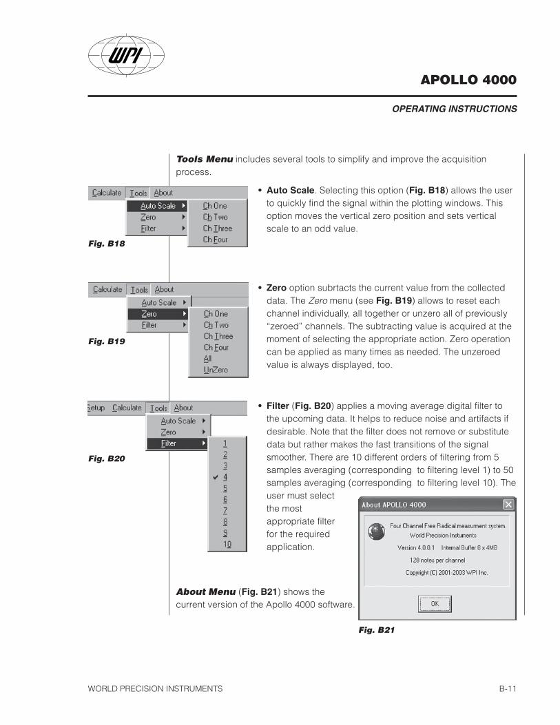
Tools Menu includes several tools to simplify and improve the acquisitionprocess.
• Auto Scale. Selecting this option (Fig. B18) allows the userto quickly find the signal within the plotting windows. Thisoption moves the vertical zero position and sets verticalscale to an odd value.
Fig. B21
Fig. B18
Fig. B19
Fig. B20
About Menu (Fig. B21) shows thecurrent version of the Apollo 4000 software.
• Zero option subrtacts the current value from the collecteddata. The Zero menu (see Fig. B19) allows to reset eachchannel individually, all together or unzero all of previously“zeroed” channels. The subtracting value is acquired at themoment of selecting the appropriate action. Zero operationcan be applied as many times as needed. The unzeroedvalue is always displayed, too.
• Filter (Fig. B20) applies a moving average digital filter tothe upcoming data. It helps to reduce noise and artifacts ifdesirable. Note that the filter does not remove or substitutedata but rather makes the fast transitions of the signalsmoother. There are 10 different orders of filtering from 5samples averaging (corresponding to filtering level 1) to 50samples averaging (corresponding to filtering level 10). Theuser must selectthe mostappropriate filterfor the requiredapplication.
APOLLO 4000
OPERATING INSTRUCTIONS
WORLD PRECISION INSTRUMENTSB-12
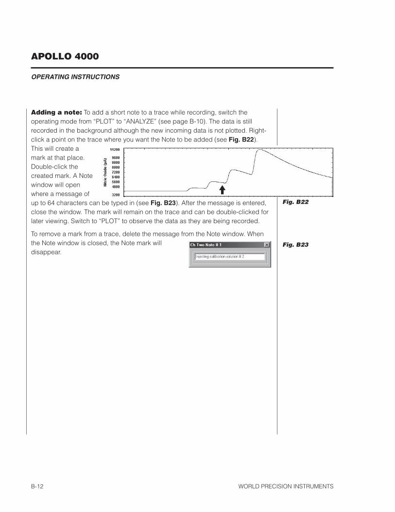
Adding a note: To add a short note to a trace while recording, switch theoperating mode from “PLOT” to “ANALYZE” (see page B-10). The data is stillrecorded in the background although the new incoming data is not plotted. Right-click a point on the trace where you want the Note to be added (see Fig. B22).This will create amark at that place.Double-click thecreated mark. A Notewindow will openwhere a message ofup to 64 characters can be typed in (see Fig. B23). After the message is entered,close the window. The mark will remain on the trace and can be double-clicked forlater viewing. Switch to “PLOT” to observe the data as they are being recorded.
To remove a mark from a trace, delete the message from the Note window. Whenthe Note window is closed, the Note mark willdisappear.
Fig. B22
Fig. B23
APOLLO 4000
OPERATING INSTRUCTIONS
WORLD PRECISION INSTRUMENTS B-13
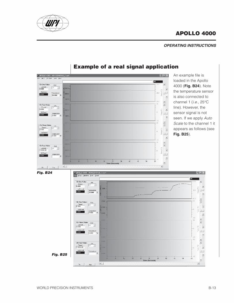
Example of a real signal applicationAn example file isloaded in the Apollo4000 (Fig. B24). Notethe temperature sensoris also connected tochannel 1 (i.e., 25°Cline). However, thesensor signal is notseen. If we apply AutoScale to the channel 1 itappears as follows (seeFig. B25).
Fig. B24
Fig. B25
APOLLO 4000
OPERATING INSTRUCTIONS
WORLD PRECISION INSTRUMENTSB-14
Fig. B26
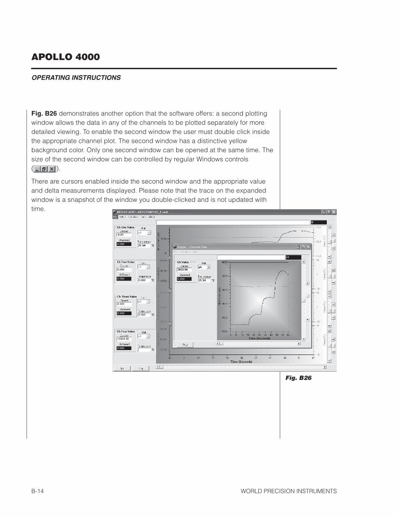
Fig. B26 demonstrates another option that the software offers: a second plottingwindow allows the data in any of the channels to be plotted separately for moredetailed viewing. To enable the second window the user must double click insidethe appropriate channel plot. The second window has a distinctive yellowbackground color. Only one second window can be opened at the same time. Thesize of the second window can be controlled by regular Windows controls( ).
There are cursors enabled inside the second window and the appropriate valueand delta measurements displayed. Please note that the trace on the expandedwindow is a snapshot of the window you double-clicked and is not updated withtime.

APOLLO 4000
NITRIC OXIDE DETECTION
WORLD PRECISION INSTRUMENTS C-1
USING THE APOLLO 4000 TODETECT NITRIC OXIDE
Initial Set-upAttach the nitric oxide sensor to the required sensor input channel on the APOLLO4000. From the main Setup menu of the software, select the correct poise voltage“Nitric Oxide” and appropriate Range for the selected channel. The electrode mustnow be calibrated.
Calibration of the NO SensorAccurate measurements of NO require an accurate calibration. Three calibrationmethods are described in this section. The first and most convenient method is basedon a simple chemical reaction which generates known amounts of NO (from NO-
2).This method can only be used with the 2.0 mm sensor (ISO-NOP).
The second method is based on the decomposition of the S-nitrosothiol NO-donor,SNAP using either Cu(I) as described in Method I or Cu(II) as outlined in Method II,as a catalyst. The NO liberated from SNAP is used to calibrate the sensor.
The third method involves preparing aqueous solutions of NO standards from saturatedNO solutions.
The Calibration KitPerform the calibration using the NO calibration kit (WPI catalog #5435) which consistsof the following items:
Plastic stand with two holes; two glass vials; two silicon septums without holes;two silicon septums with holes and radial slit; one short needle; one long needle.
The chemicals required for the calibration are not provided.
NOTE: The NO chamber (WPI #NOCHM) can be used as an alternative to the useof the calibration kit. Designed specifically for use with 2.0 mm electrodes, thechamber can be adapted to other probes. Calibration temperatures from 4 - 40°Ccan be controlled using an external circulating bath.
APOLLO 4000
NITRIC OXIDE DETECTION
WORLD PRECISION INSTRUMENTSC-2
Calibration by the chemical generation of NO(Type of NO sensor that can be calibrated with this method: ISONOP)
This method is recommended for use with the 2.0 mm sensor (ISO-NOP). However,because it requires the use of strong acid it cannot be used with other NO sensors.
The first step is to prepare the following two solutions:
Solution #1: 0.1 M H2SO4 + 0.1 M KI
To make 500 mL of solution requires:
4.9 g of H2SO4 (2.7 mL of concentrated H2SO4 {18.4 M})8.3 g of KI
Slowly add the sulfuric acid to about 400 mL of distilled water while stirring. Thenadd the KI and mix; finally add distilled water to a final volume of 500 mL.
Solution #2: 50 µM KNO2 (or NaNO2)
The recommended method for preparing this solution is to purchase an ionchromatography liquid nitrite standard (NaNO2 or KNO2) which may be diluted asappropriate. Standard Nitrite is available from WPI, catalog #7357.
Alternatively, crystalline reagent KNO2 may be used, but the user should note thatKNO2 is extremely hygroscopic and degrades once exposed to atmosphericmoisture. It is therefore recommended that if the crystalline reagent is to be usedthat the reagent packaged under argon be purchased (available from EastmanKodak Chem #105 7462), and that it be stored in a desiccator. While this willextend the life of the reagent, it will need to be replaced more frequently than willthe liquid standard. The standard nitrite solution prepared from this compoundshould be stored in a gas-tight bottle and refrigerated.
This method of calibration is based on the following reaction:
2KNO2 + 2KI + 2H2SO4 → 2NO + I2 + 2H2O + 2K2SO4 (1)
where a known amount of KNO2 is added to produce a known amount of NO. Thequantity (and so the concentration) of NO generated can be calculated directlyfrom the stoichiometry if the concentrations of the reactants are known. Since KIand H2SO4 are present in great excess the limiting reagent is KNO2. Experiments
APOLLO 4000
NITRIC OXIDE DETECTION
WORLD PRECISION INSTRUMENTS C-3
have demonstrated that the nitric oxide generated from this reaction will persistsufficiently long to calibrate the NO sensor easily and accurately.
Since the reaction goes to completion, the equation above states that the ratiobetween KNO2 and NO is 1:1. Therefore the amount of NO generated in the solu-tion will be equal to the amount of KNO2 added. The final concentration of NO willbe equal to the diluted concentration of KNO2 in the solution.
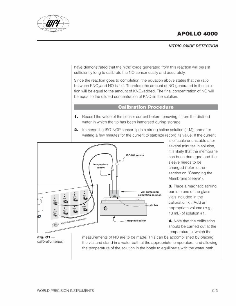
Calibration Procedure
1. Record the value of the sensor current before removing it from the distilledwater in which the tip has been immersed during storage.
2. Immerse the ISO-NOP sensor tip in a strong saline solution (1 M), and afterwaiting a few minutes for the current to stabilize record its value. If the current
is offscale or unstable afterseveral minutes in solution,it is likely that the membranehas been damaged and thesleeve needs to bechanged (refer to thesection on “Changing theMembrane Sleeve”).
3. Place a magnetic stirringbar into one of the glassvials included in thecalibration kit. Add anappropriate volume (e.g.,10 mL) of solution #1.
4. Note that the calibrationshould be carried out at thetemperature at which the
measurements of NO are to be made. This can be accomplished by placingthe vial and stand in a water bath at the appropriate temperature, and allowingthe temperature of the solution in the bottle to equilibrate with the water bath.
Figure 4 —calibrationsetup
Fig. C1 —calibration setup
APOLLO 4000
NITRIC OXIDE DETECTION
WORLD PRECISION INSTRUMENTSC-4
5. Place the stand (and water bath if appropriate) on the magnetic stirrer, andturn on the stirrer so that the bar is stirring at a moderate rate.
6. Secure the ISO-NO sensor in an electrode holder or micromanipulator (or useone of the septums included with the start-up kit). Do not push the sensortip through the hole — slide the elctrode through the sliced sideof the septum. Carefully lower the sensor into the vial sealing the openingwith the septum. The sensor tip should be immersed about 2-3 mm into thesolution, and should not be in contact with stir bar. Be very careful wheninserting the sensor not to make contact between the cap and/or bottom of the jar with the tip of the sensor. This coulddamage the membrane of the sensor.
7. Wait until the current on the display becomes stable again before continuing.This may take several minutes if the sensor has undergone a large temperaturechange.
8. If you feel it is necessary to degas solution #1 prior to calibration, this can bedone by inserting one of the long stainless steel needles included with thecalibration kit through the septum so that the tip is in the solution. Attach theneedle through appropriate tubing to a source of pure argon gas (nitrogenmay also be used). Insert one of the short needles included with the kitthrough the septum such that the needle tip is clearly exposed (not in thesolution) inside the vial. The small needle allows gas to escape, therebyavoiding a buildup of pressure. Purge the solution at low pressure (5 psi orless) for 15 minutes.
9. Once purging is complete and the gas source is turned off, remove the purgingand pressure relief needles.
10. One should allow a few minutes for the temperature to equilibrate with the waterbath again since purging with the gas may have changed the temperature.
11. Once the current has achieved a stable value, record this value.
12. Generally, it is not necessarry to pre-purge the calibration solution, since the NOdecays only very slowly in this solution.
APOLLO 4000
NITRIC OXIDE DETECTION
WORLD PRECISION INSTRUMENTS C-5
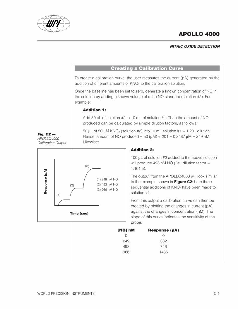
Creating a Calibration Curve
To create a calibration curve, the user measures the current (pA) generated by theaddition of different amounts of KNO2 to the calibration solution.
Once the baseline has been set to zero, generate a known concentration of NO inthe solution by adding a known volume of a the NO standard (solution #2). Forexample:
Addition 1:
Add 50 µL of solution #2 to 10 mL of solution #1. Then the amount of NOproduced can be calculated by simple dilution factors, as follows:
50 µL of 50 µM KNO2 (solution #2) into 10 mL solution #1 = 1:201 dilution.Hence, amount of NO produced = 50 (µM) ÷ 201 = 0.2487 µM = 249 nM.Likewise:
Addition 2:
100 µL of solution #2 added to the above solutionwill produce 493 nM NO (i.e., dilution factor =1:101.5).
The output from the APOLLO4000 will look similarto the example shown in Figure C2: here threesequential additions of KNO2 have been made tosolution #1.
From this output a calibration curve can then becreated by plotting the changes in current (pA)against the changes in concentration (nM). Theslope of this curve indicates the sensitivity of theprobe.
[NO] nM Response (pA)0 0
249 332493 746966 1486
Fig. C2 —APOLLO4000Calibration Output

APOLLO 4000
NITRIC OXIDE DETECTION
WORLD PRECISION INSTRUMENTSC-6
Once the sensitivity of theprobe has been ascertained(in the above example thesensitivity was 1.557 pA / nM)the sensor is ready to useexperimentally.
NO2 and NO3 Determination
We have recently developed a new reagent-less nitrate-reductor, called theNITRALYZER™. The Nitralyzer is a very useful tool for researchers currently usingenzymatic conversion of NO3 to NO2. Researchers who use the Greiss method forNO2 determination will also be very interested to learn that using the ISO-NOP (andthe titration method for calibration described above) a detection limit for NO2 as lowof 1 nM is routinely possible. This compares to a detection limit using Greissreagent of approximately 1 µM. Hence, the ISO-NOP is several orders ofmagnitude more sensitive than the Greiss method. Information on the Nitralyzer isaavailable from WPI.
Figure C3 —APOLLO4000Calibration Curve
ISO-NO Calibration Curve Based on Tabulated Data
0
400
800
1200
1600
0 200 400 600 800 1000
Concentration of NO (nM)

APOLLO 4000
NITRIC OXIDE DETECTION
WORLD PRECISION INSTRUMENTS C-7
Calibration of NO sensor by decompositionof SNAPThis method can be used to calibrated all NO sensors (see Ref. 1: Zhang, et al.,“Novel Calibration Method for Nitric Oxide Microsensors by StoichiometricalGeneration of Nitric Oxide from SNAP” Electroanalysis, 2000, 12: 6).
S-nitroso-N-acetyl –D,L-penicillamine (SNAP) is a stable NO containing compoundthat can be used for quantitative generation of NO in solution. SNAP decomposesto NO and a disulfide by product when dissolved in water. However, the rate ofdecomposition of the SNAP is very slow. The kinetics controlling the decompositionof SNAP depends on several parameters including, pH, presence of catalyst,temperature and light.
In the procedure described here, SNAP is used in combination with a catalyst,cuprous chloride, to generate known amounts NO in solution, which can then beused to accurately calibrate various NO-sensors. The protocol does not investigateall parameters involved in SNAP decomposition neither is it intended to propose amodel by which SNAP is decomposed.
Two methods are described here for the calibration of NO sensors based ondecomposition of SNAP. The first method relies on the use of Cu(I) as a catalyst forthe 100% conversion of SNAP into NO. This method is extremely accurate buttechnically more demanding than the second method, which relies on the use ofCu(II) for the partial but quantifiable conversion of SNAP to NO.
Method 1: Calibration by decomposition of a S-nitrosothiol compound using Cu(I) as a catalyst
This method of calibration results in the 100% conversion of SNAP to NO. Theamount of NO produced, therefore, is based on the final concentration of SNAP.
CAUTION: The described calibration procedure requires the use of cuprous (I)chloride, CuCl, where Cu (I) is the active catalyst for the conversion of SNAP toNO. The calibration curve assumes only the presence of Cu (I) and hence a 100%conversion efficiency of SNAP to NO (see “A novel method to calibrate nitric oxidemicrosensors by stoichiometrical generation of nitric oxide from SNAP”, X. Zhang,L. Cardosa, M. Broderick, H. Fein, I. R. Davis, Electroanalysis, 2000, 12(6),425-
APOLLO 4000
NITRIC OXIDE DETECTION
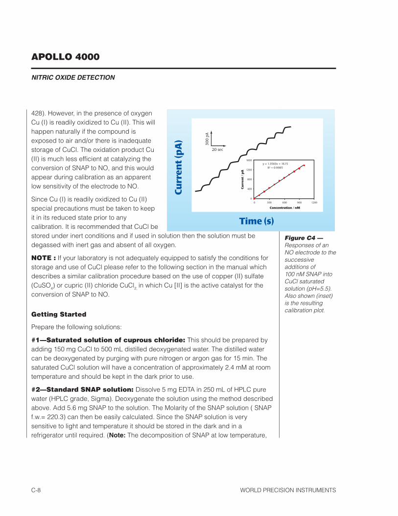
WORLD PRECISION INSTRUMENTSC-8
428). However, in the presence of oxygenCu (I) is readily oxidized to Cu (II). This willhappen naturally if the compound isexposed to air and/or there is inadequatestorage of CuCl. The oxidation product Cu(II) is much less efficient at catalyzing theconversion of SNAP to NO, and this wouldappear during calibration as an apparentlow sensitivity of the electrode to NO.
Since Cu (I) is readily oxidized to Cu (II)special precautions must be taken to keepit in its reduced state prior to anycalibration. It is recommended that CuCl bestored under inert conditions and if used in solution then the solution must bedegassed with inert gas and absent of all oxygen.
NOTE : If your laboratory is not adequately equipped to satisfy the conditions forstorage and use of CuCl please refer to the following section in the manual whichdescribes a similar calibration procedure based on the use of copper (II) sulfate(CuSO4) or cupric (II) chloride CuCl2, in which Cu [II] is the active catalyst for theconversion of SNAP to NO.
Getting Started
Prepare the following solutions:
#1—Saturated solution of cuprous chloride: This should be prepared byadding 150 mg CuCl to 500 mL distilled deoxygenated water. The distilled watercan be deoxygenated by purging with pure nitrogen or argon gas for 15 min. Thesaturated CuCl solution will have a concentration of approximately 2.4 mM at roomtemperature and should be kept in the dark prior to use.
#2—Standard SNAP solution: Dissolve 5 mg EDTA in 250 mL of HPLC purewater (HPLC grade, Sigma). Deoxygenate the solution using the method describedabove. Add 5.6 mg SNAP to the solution. The Molarity of the SNAP solution ( SNAPf.w.= 220.3) can then be easily calculated. Since the SNAP solution is verysensitive to light and temperature it should be stored in the dark and in arefrigerator until required. (Note: The decomposition of SNAP at low temperature,
Figure C4 —Responses of anNO electrode to thesuccessiveadditions of100 nM SNAP intoCuCl saturatedsolution (pH=5.5).Also shown (inset)is the resultingcalibration plot.
APOLLO 4000
NITRIC OXIDE DETECTION
WORLD PRECISION INSTRUMENTS C-9
in dark and in absence of trace metal ions proceeds very slowly due to thepresence of chelating reagent, EDTA). The standard SNAP solution can then beused for many calibrations of NO probes throughout the day. However, since SNAPwill slowly decompose even if stored correctly as described, it is recommendedthat a fresh standard stock solution of SNAP is prepared at the beginning ofeveryday. This will ensure an accurate calibration of the NO sensor.
The concentration of SNAP (and hence NO produced) in the stock solution iscalculated as follows:
[C] = [A•W/(M•V)]1000
Where C is the concentration of SNAP in micromolars, A is the purity of SNAP, W isweight of SNAP in milligrams and V is the volume of the solution in liters. If SNAPpurity is 98.5%, hence in the above example the concentration of SNAP is:
[C] = [98.5% x 5.6 / (220.3 x 0.25)] x 1000 = 100.1 µM
Note: The purity of SNAP used is extremely important to ensure an accuratecalibration. We recommend the use of high grade SNAP with minimal purity of 98%or better. SNAP can be purchased from WPI in various amounts.
Calibration Procedure
Within a nitrogen or argon environment, place 10.0 mL of solution #1 (CuCl) in a20 mL vial (supplied in the calibration kit). Drop a small stirring bar into thesolution, and place the vial on the top of a magnetic stirring plate. Immerse a NOprobe into this solution, and while stirring, allow the background current to decayand stabilize for 3-5 min. As soon as the background current becomes stable startrecording the data on the APOLLO4000.
Next inject 3 aliquots containing 5 µL, 10 µL and 20 µL sequentially of the SNAPstock solution (solution #2) into the vial containing cuprous chloride solution.Depending on the required calibration range (i.e., the final amount of NOproduced) desired, the volumes of SNAP stock solution could be increased toproduce a greater concentration of NO. It is recommended that calibration rangebe kept close to the anticipated experimental concentration of NO.
Immediately following the first addition of SNAP into Solution#1 the current (pA) outputfrom the ISO-NO will be seen to increase rapidly. Within a few seconds the response

APOLLO 4000
NITRIC OXIDE DETECTION
WORLD PRECISION INSTRUMENTSC-10
will reach a plateau and the second aliquot of SNAP can then be added. Successiveadditions of the remaining aliquots of SNAP can be made in a similar way.
A calibration curve can be constructed by plotting the signal output (pA) vsconcentration (nM) of SNAP. Each addition of SNAP corresponds to equivalent NOconcentration. The response should be very linear from 10 to 1000 nM.
The sensitivity of the NO probe can be established from the gradient of the responsecurve. The sensitivity of the ISO-NOP sensor is about 1 pA/nM. Once the slope of theprobe has been determined the value can be entered into the APOLLO4000software program (see previous section) if the user wishes the observe data inconcentration mode (i.e., nM, µM).
Note: Remember that most NO probes are sensitive to temperature changes. It istherefore recommended that the calibration of a NO sensor is performed at theexperimental temperature.
Method 2: Calibration by decomposition of SNAP usingCu(II) as a catalyst
This method of calibration relies on the use of Cu(II) for the partial but quantifiableconversion of SNAP to NO. This procedure can be used as an alternative to theprevious method in which Cu (I) is the active catalyst for the conversion of SNAP toNO. In this procedure Cu(II) is substituted as a catalyst for ease-of-handling.
NOTE: Experimentally it has been shown that Cu(II) is less efficient as a catalyst inthe conversion of SNAP to NO (e.g., conversion ratio is reduced to approximately60%). The accuracy of the calibration may also be reduced (see discussion).
S-Nitriso-N-acetyl-D,L-penicillamine (SNAP) is a stable NO containing compoundthat can be used for quantitative generation of NO in solution. SNAP decomposesto NO and a disulfide byproduct when dissolved in water. However, the rate ofdecomposition is very slow. The kinetics of decomposition for this reagent is afunction of several parameters including pH, presence of a catalyst, temperatureand light.
In the procedure described here, SNAP is used in combination with a catalyst,copper (II) sulfate (CuSO4) or cupric (II) chloride (CuCl2), to generate a knownquantity of NO in solution. Note that this protocol does not investigate the effects of

APOLLO 4000
NITRIC OXIDE DETECTION
WORLD PRECISION INSTRUMENTS C-11
all parameters involved in SNAP decomposition nor does it propose a model bywhich NO is decomposed. The presented procedure provides an empiricalestimation of the amount of generated NO based on the molarity of a standardstock solution of SNAP under a controlled set of parameters.
Getting Started
Prepare the following solutions:
Solution #1: Dissolve 5 mg EDTA in 250 mL of water (HPLC grade).
Solution #2: Prepare 250 mL 0.1 M copper (II) sulfate (or cupric (II) chloride) indistilled water.
Preparing standard SNAP solution:
To prepare the stock solution of SNAP, weigh approximately 5.0 mg +/- 2.0 mg ofSNAP and add it to solution #1. Calculate the Molarity of SNAP solution (SNAP f.w.= 220.3). Decomposition of SNAP in the stock solution proceeds very slowly due tothe presence of chelating reagent, EDTA. Thus the rate of decomposition isnegligible and the stock solution of SNAP remains relatively stable for at least 5hours if kept in refrigerator.
Note: The purity of standard reagent, SNAP, is very important for the reported data.Use high grade SNAP with minimal purity of 95% or better. SNAP can bepurchased from WPI (catalog # SNAP50, SNAP100, SNAP500).
Calibration Procedure
Place 10.0 mL of solution #2 in a 20 mL vial (supplied in the calibration kit). Drop asmall stirring bar into the solution, and place the vial on the top of a magneticstirring plate. Immerse a NO probe into this solution, and while stirring, allow thebackground current to stabilize for about 3-5 minutes. As soon as the backgroundcurrent becomes stable start the recording.
Next, sequentially inject three aliquots of SNAP solution, 5 µL, 10 µL, and 20 µL,into the vial containing copper sulfate solution. The current output will rapidlyincrease upon addition of first aliquot and will reach a plateau within a fewseconds. Inject the second aliquot, 10 µL, as soon as the first signal reaches aplateau. Finally add the third aliquot as the second signal reaches its plateau. Ifaliquots are not added promptly when reaching the previous plateau, the signal will
APOLLO 4000
NITRIC OXIDE DETECTION
WORLD PRECISION INSTRUMENTSC-12
slowly decline because generated NO is quickly oxidized to nitrite and nitratewhich will not be detected by the probe.
Note: You can change the volume of injected aliquots according to theconcentration of SNAP stock solution. Decrease the volume of aliquot if theelectrode is very sensitive or increase the volume of aliquot if the electrode is lesssensitive.
Because NO sensors can be calibrated in a linear fashion, the magnitude of everysignal should almost double as the volume of SNAP solution added is doubled inthe course of the calibration. Use the recorded data to construct a calibrationcurve. The calibration curve can be simply constructed by plotting the signaloutput (e.g., in pA) vs. the concentration of SNAP added at that time. Note thatevery addition of SNAP solution corresponds to a particular NO concentration. Thiswill be discussed below. After the sensitivity of the NO probe is established, theAPOLLO4000 software can be programmed to display data in either concentrationmode (i.e., nM, mM) or redox current (i.e., pA, nA).
The standard SNAP solution can be used for the calibration of NO probesthroughout the day. Store the solution in the dark and refrigerate when not in use.Prepare a fresh stock solution of SNAP in the beginning of every day to ensureminimal decomposition of SNAP in the stock solution. Concentration of SNAPdecreases to 5-10% of its nominal value after approximately 4-5 hours.
NOTE: Remember that most NO probes are sensitive to changes in temperature.It is therefore recommended that the calibration of your sensor is performed atexperimental temperature.

APOLLO 4000
NITRIC OXIDE DETECTION
WORLD PRECISION INSTRUMENTS C-13
Predicting the level of detectable NO according to themolar ratio of SNAP in the presence of catalyst(Method II)
Experiments have shown that SNAP is decomposed instantaneously under thefollowing set of experimental conditions:
Temperature 25°C
Catalyst solution 0.1M copper sulfate
SNAP WPI, 98% purity. Fresh stock solution with5 mg/250 mL solution EDTA added.
Copper sulfate is at equilibrium with ambient air (aerobic conditions).
SNAP (RSNO) decomposes to NO and a disulfide byproduct according to thefollowing equation:
2RSNO → 2NO + RS-SR
Theoretically, the concentration of generated NO should be equal to the finalconcentration of SNAP in the copper sulfate solution in the calibration vial if thedecomposition goes to completion and if the generated NO is detected quicklybefore it is oxidized to nitrite and nitrate.
However, it is expected that the level of detectable NO will be below the theoreticalvalue because the copper sulfate solution was at equilibrium with ambient air, andconsequently a portion of the generated NO would have been immediately oxidizedto nitrite and nitrate before it was measured by the NO sensor. In addition, it ispossible that decomposition of SNAP does not go to completion even in thepresence of a catalyst. Results on the kinetics of SNAP decomposition in thepresence of a catalyst in an anaerobic environment are published elsewhere (Zhanget al., “Novel Calibration Method for Nitric Oxide Microsensors by StoichiometricalGeneration of Nitric Oxide from SNAP”, Electroanalysis, 2000, 12: 6).
Our experimental data indicates a conversion efficiency of SNAP to NO ofapproximately 0.6 (i.e., 60%). This result is only applicable for calibration of a NOsensor in a solution, which is at equilibrium with ambient air and at theexperimental conditions described above. Hence for each mole of SNAP, 0.6 moleof NO is liberated under the proposed set of parameters. It is assumed the other40% of SNAP is either not decomposed or a proportion that is decomposed to NO

APOLLO 4000
NITRIC OXIDE DETECTION
WORLD PRECISION INSTRUMENTSC-14
is subsequently oxidized immediately before it is detected by the NO sensor.
Example for creating a calibration curve and related computations
1. SNAP weight = 6.4 mg.
2. SNAP was dissolved in 250 mL solution #1 to obtain the standard stock solution.
3. 20 µL, 40 µL, and 80 µL of SNAP stock were added sequentially into 10 mL ofsolution # 2.
4. The current was continuously recorded during the course of the calibration.
5. A standard calibration curve was constructed according to the recorded date.
[SNAP] [NO] = 0.6 X [SNAP] Output Current232.4 nM 139.4 nM 230 pA462.0 nM 277.2 nM 488 pA916.8 nM 550.1 nM 1001 pA
Y = -32.038 + 1.88X
The data from calibration curve indicates that this procedure allows an excellentlinear calibration of NO probes (R2= 1). The accuracy of calibration isapproximately +/- 10% from mean. The source of error arises most probably fromgravimetric measurement of the standard reagent, SNAP. In addition, purity ofSNAP as well as partial oxidation of generated NO in the calibration solution couldcontribute to this error. Such a deviation may not be so important when NO isquantified in biological systems because most often the ability to measure changesin the basal concentration of NO is more significant than measurement of theabsolute level of NO.
APOLLO 4000
NITRIC OXIDE DETECTION
WORLD PRECISION INSTRUMENTS C-15
WARNING: Nitric oxide must be handled only in a well-ventilatedarea, usually a laboratory fume hood with forced ventilation. TheU.S. Occupational Safety and Health Administration has set a time-weightedaverage maximum NO value as 25 ppm. That is to say that 25 ppm is cited as themaximum concentration to which workers may be continually exposed. Briefinhalation of concentrations as low as 200 ppm could produce delayed pulmonaryedema which may be fatal after an asymptomatic period of up to 48 hours afterthe initial exposure. It is therefore critical that the personnel handlingthe gas be thoroughly familiar with the Material Safety Data Sheet(MSDS) and proper handling procedures. The precautions recommendedby the gas manufacturer must be followed.
Calibration of NO sensor using aqueousstandards prepared with NO GasThe following method can be used with all NO sensors.
Preparing an NO Standard
This method has the advantage of allowing the user to calibrate NO sensors in thesame environment in which the experimental measurements will be made.However, it has the disadvantages of added cost, inconvenience, and greaterhazard to the user. All of these factors must be taken into consideration. The setupfor preparing a saturated NO aqueous solution is illustrated in Fig. C5.
1. Be certain the fume hood is functioning. See Fig. C5.
2. Make sure that all fittings and connections are secure. The tubing to be usedshould not be permeable to NO. We recommend Tygon® tubing if a polymertubing is to be used; this is permeable to NO but has the best performancecompared to other polymer tubing of which we are currently aware. Ideallyglass tubing should be used. If Tygon® tubing is used, note that prolongedexposure to NO affects its properties; therefore it is recommended that thetubing be inspected frequently and that it be replaced when it appears to be

APOLLO 4000
NITRIC OXIDE DETECTION
WORLD PRECISION INSTRUMENTSC-16
brittle. The pressure regulator and tee purge adaptor should be stainlesssteel. This is because nitric oxide is a corrosive gas.
3. Prepare 100 mL of a 10 % (by weight) KOH solution and place it in thesidearm flask as illustrated above. The flask should be sealed with a stopperthrough which the tubing passes by means of a Luer fitting to a syringe needlewhich extends almost to the bottom of the flask. Tubing is used to connect theside arm of the flask to the vial containing the water to be equilibrated withNO. The KOH solution is used to remove other nitrogen oxides from the NOgas.
4. Place 20 mL of distilled (preferably deionized) water in a small glass vial. Sealthe vial with a stopper and insert through the stopper a long syringe needlewhich extends almost to the base of the vial. Connect this syringe needle tothe tubing from the KOH flask as illustrated. Insert an additional shortersyringe needle which should not extend into the solution. This acts asa pressure relief during purging.
Figure C5 —Setup for preparinga saturated NOaqueous solutionmust be in a fumehood with forcedventilation. Nitricoxide is highly toxicand, as illustrated,escapes into theatmosphere duringpreparation of thestandards.
*Lecture bottleof NO (14.2liters, 98.5%)obtained fromAldrich, catalog#29.556-6;telephone 800-558-9160
APOLLO 4000
NITRIC OXIDE DETECTION
WORLD PRECISION INSTRUMENTS C-17
5. Place the distilled water vial in an ice-water bath. Reducing the temperatureincreases the solubility of NO in solution. Thus when the solution is used atroom temperature you will be assured of a saturated NO solution.
6. Purge the system with argon (or nitrogen) gas for a period of 30 minutes at amoderate flow rate such that the pressure is maintained at a safe level (1-2psi). When purging it should be observed that gas is indeed bubbling throughthe KOH solution as well as the distilled water. After 30 minutes turn off theargon source, and switch the tee purge valve to the correct position forpurging with NO from the lecture bottle.
7. Purge the system with NO for 5-10 minutes if using a pure source (longer if theNO source is not pure). Again make sure that gas is bubbling through bothsolutions. Warning: NO is now escaping from the pressure reliefneedle in the stopper of the distilled water vial. It is imperativethat the fume hood be running at maximum capacity with thefront panel closed (in the down position).
8. After the time in step 7 has elapsed turn off the NO source.
9. Immediately remove the two needles from the distilled water vial.
10. Set the tee purge valve for purging with argon (or nitrogen) gas, and turn onthe argon source. Purge the system for 5-10 minutes at a moderate flow rate.Gas should be bubbling through the KOH and then escaping from the flaskinto the atmosphere. Again be sure that the fume hood is ventilating well.
11. Turn off the argon (or nitrogen) source, and allow the fume hood to continue toventilate for 10-15 minutes so as to ensure that all traces of NO gas areremoved from the atmosphere.
12. The solution of distilled water should now be saturated with NO. Theconcentration of NO produced by this saturation is dependent upon thetemperature. At 0° C, the concentration is approximately 3.3 mM, and at 20°Cthe concentration is approximately 1.91 mM.
13. Dilutions of known concentration can be prepared from this saturated solutionIn preparing a dilution, be careful not to unseal the vial, for thisexposes the solution to atmospheric oxygen.
Once the dilutions are prepared, it is a simple matter to calibrate the instrument.
APOLLO 4000
NITRIC OXIDE DETECTION
WORLD PRECISION INSTRUMENTSC-18
Measurement of NOIt is impossible to outline in detail how to use NO sensors to measure NO in everyexperimental set up the user may encounter. There are, however, some guidingprinciples of which the user should be aware to exploit fully the capabilities of thetechnology. These are outlined below.
NO Delivery
For any measurement of NO to be made, the NO must reach the sensor surface soit can react on the surface of the electrode. This point is of particular concernbecause in many experiments the lifetime of NO is quite short. This is especially soin biological systems where compounds such as hemoglobin can reduce the half-life of NO to less than a second. It is therefore very important that the experimentalset up is designed so as to maximize delivery of NO to the sensor. In particular, thetip of the sensor should be placed as close as possible to the site of release of NO.
Durability and Handling
The user must excercise caution when handling any NO sensor to avoid actionswhich could damage the sensor tip. The sensor membrane and membrane coat-ings are extremely delicate and improper handling will lead to damage.
Environmental Influences
There are two environmental parameters to which NO sensors are quite sensitive:temperature and electrical interference, both of which are discussed in greaterdetail below.
Temperature
Note that the sensitivity of the NO sensor is temperature-dependent. This is due tothe effects of temperature on the partial pressure of NO in either liquid or gassamples, on the permeability of the membrane or coatings, and on theconductivities of various circuit components. It is therefore recommended that anycalibration is performed at the same temperature as the experiment.
Electrical Interference
Although nitric oxide monitoring using the Apollo 4000 involves the measurementof extremely small currents (e.g., less than 1 pA), the intrinsic noise level of the
APOLLO 4000
NITRIC OXIDE DETECTION
WORLD PRECISION INSTRUMENTS C-19
Apollo 4000 and NO sensors is sufficiently low so as to provide accuratemeasurements of nitric oxide. However various external electrical sources maycouple to the system and produce large extraneous signals in the output record.The magnitude of this external noise depends on the environment of the laboratory.If the interference introduced by the electrical signals in the environment is large,the first step towards eliminating it is to ground and shield the system properly. Seethe section on Grounding and Shielding Procedure for the Apollo 4000.
APOLLO 4000
NITRIC OXIDE DETECTION
WORLD PRECISION INSTRUMENTSC-20
Maintenance of NO SensorsThe various NO sensors, if well cared for, will require very little maintenance.
Maintenance of the ISO-NOP
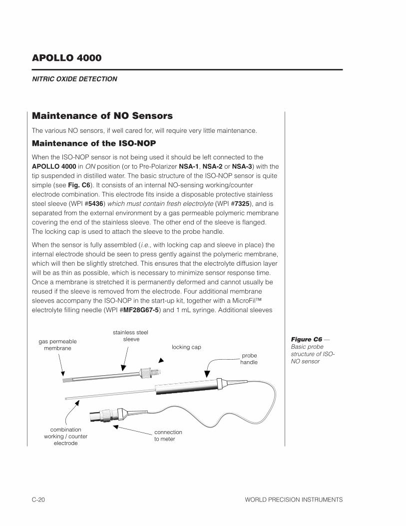
When the ISO-NOP sensor is not being used it should be left connected to theAPOLLO 4000 in ON position (or to Pre-Polarizer NSA-1, NSA-2 or NSA-3) with thetip suspended in distilled water. The basic structure of the ISO-NOP sensor is quitesimple (see Fig. C6). It consists of an internal NO-sensing working/counterelectrode combination. This electrode fits inside a disposable protective stainlesssteel sleeve (WPI #5436) which must contain fresh electrolyte (WPI #7325), and isseparated from the external environment by a gas permeable polymeric membranecovering the end of the stainless sleeve. The other end of the sleeve is flanged.The locking cap is used to attach the sleeve to the probe handle.
When the sensor is fully assembled (i.e., with locking cap and sleeve in place) theinternal electrode should be seen to press gently against the polymeric membrane,which will then be slightly stretched. This ensures that the electrolyte diffusion layerwill be as thin as possible, which is necessary to minimize sensor response time.Once a membrane is stretched it is permanently deformed and cannot usually bereused if the sleeve is removed from the electrode. Four additional membranesleeves accompany the ISO-NOP in the start-up kit, together with a MicroFil™electrolyte filling needle (WPI #MF28G67-5) and 1 mL syringe. Additional sleeves
combinationworking / counter
electrode
probe handle
stainless steel sleevegas permeable
membrane
connection to meter
locking capFigure C6 —Basic probestructure of ISO-NO sensor
APOLLO 4000
NITRIC OXIDE DETECTION
WORLD PRECISION INSTRUMENTS C-21
can also be purchased separately (WPI #5436). With proper care and by followingthe instructions below a membrane sleeve should last more than one month.
Cleaning the Membrane
The membrane sleeve itself requires very little maintenance. The primary concernis to avoid damage to the membrane and to keep it as clean as possible. Aftereach use the membrane should be cleaned by suspending the tip in distilled waterfor 20-30 minutes to dissolve salts and remove particles, which may haveaccumulated on the membrane. If the probe was used in a protein rich solution thetip should first be soaked in a protease solution for several minutes to removeprotein build-up, and then in distilled water. Enzymatic detergent (e.g., Enzol, WPI#7363) can also be used. The membrane sleeves can also be sterilized chemicallyusing an appropriate disinfectant (e.g., Cidex, WPI #7364). Accumulated organicmatter can be removed by briefly immersing the tip in an acid or base solution (attimes both may be necessary) for 10 seconds. A good indication of a dirtymembrane sleeve is a sluggish response or an unusually low sensitivity. If theseproblems are not rectified by the above cleaning procedures then the membranesleeve should be replaced. The probe cannot be used in organicsolvents.
Replacing a Membrane Sleeve
All membrane sleeves will eventually have to be replaced by the user. Theprocedure for doing so is simple and straightforward.
1. Unscrew the locking cap from the handle.
2. Hold the stainless steel sleeve and remove it with the locking cap from theinternal electrode assembly, being careful not to bend the electrode assemblywhen doing so.
3. Rinse the internal electrode with distilled water (particularly the tip) and let itsoak for at least 15 minutes. Be careful not to let water get into the handle. Thecurrent on the ISO-NO meter should go offscale when the electrode is beingrinsed.
4. Gently dry the electrode with a soft tissue (Kimwipes). Be sure to drythoroughly the flat surface at the tip of the electrode. After drying the currentshould stabilize fairly quickly to a low value (e.g., 0 - 20 pA). If this occurs thenthe electrode is in good working order.
APOLLO 4000
NITRIC OXIDE DETECTION
WORLD PRECISION INSTRUMENTSC-22
5. If the electrode is not clean, repeat steps 3 and 4. If necessary the ISO-NOPRejuvenator (WPI #JUV) can be used restore sensitivity of an old electrode(contact WPI for assistance).
6. Remove the locking cap from the old used sleeve, and gently slide it onto thenew replacement sleeve.
7. Dip the internal electrode 1-2 cm into the electrolyte provided in the ISO-NOstart-up kit, the current should go offscale during this. Using the MicroFil™nonmetallic syringe needle and 1 mL plastic syringe, supplied, injectapproximately 100 microliters of electrolyte directly into the new sleeve. TheMicroFil supplied should be less than the length of the sleeve, so that it will notpuncture the delicate membrane at the tip of the sleeve during injection. If theMicroFil is longer than the sleeve it can be cut to the correct length.
8. Slowly and smoothly insert the electrode into the sleeve, and screw the lockingcap into the handle. The electrode should be observed to press gently againstthe membrane.
9. The current displayed on the meter at this time will be high or offscale.
10.Suspend the tip of the new assembled probe in distilled water.
11.After 10-15 minutes the current should no longer be offscale and will graduallydecrease with time. It may take several hours for the sensor current to reach alow stable value, at which time it will be ready for use.
12.The integrity of the new membrane can be determined by immersing the probetip into a strong saline solution (1 M). If the current observed, after a fewminutes in the saline solution, increases dramatically or is offscale then themembrane integrity is not good and a new membrane will have to be fitted.
13.When the ISO-NOP is not being used it should be stored with the tipsuspended in distilled water.
Additional membrane kits (WPI #5436) may be purchased separately.
Maintenance of Nitric Oxide Microsensors
WPI’s Nitric Oxide microsensors are maintenance-free consumable sensors thatare warranted against defect for 30 days from the date of purchase. The followinginformation should increase the lifetime of the sensor:
APOLLO 4000
NITRIC OXIDE DETECTION
WORLD PRECISION INSTRUMENTS C-23
Tip care
The surface of the sensor tip is very sensitive and is covered with a unique layer ofpropriety selective membranes. The tip of the sensor should never be handled asthis will damage the membranes and compromise the electrode’s selectivity forNO. During use the electrode should be held securely, preferably using a microma-nipulator or other similar device that permits accurate positioning.
The electrode should be cleaned periodically in distilled water and dried using softtissue paper. Organic contamination can be removed using a mild enzymaticdetergent such as ENZOL (WPI part # 7363)
Sterilization
The following methods can be used to sterilize the sensor:• Ethylene oxide• Cidex solution (WPI part # 7364)
Storage
NO microsensors should be stored dry in a cool place away from direct sunlight.They can also be left attached to an ISO-NO Activator (WPI part # NSA-1, NSA-2,NSA-3). The Activator maintains the sensor in a polarized state, ready for immedi-ate use when required.

APOLLO 4000
NITRIC OXIDE DETECTION
WORLD PRECISION INSTRUMENTSC-24
APOLLO 4000
OXYGEN DETECTION
World Precision instruments d-�
USING THE APOLLO 4000 TO DETECT OXYGEN
Initial Set-upAttach the oxygen sensor to the required sensor input channel on the APollo 4000. From the main setup menu of the software select the correct poise voltage “oxygen” and appropriate range for the selected channel. the electrode must now be calibrated.
Calibration and Use of Oxygen Sensorsthe ISO-OXY-2 sensor provides accurate, stable and electrically isolated oxygen measurements. With a probe tip diameter of just 2 mm and low oxygen consumption, iso-oXY-2 is ideal for making measurements in small sample volumes. other features include a fast response time and a sturdy stainless steel probe body.
the iso-oXY-2 in combination with APollo 4000 amperometrically measures the concentration of oxygen in aqueous solutions and gas mixtures. iso-oXY-2 is not suited for long-term continuous gas measurements, as it needs to be calibrated on a daily basis. measurements can be displayed either as a percentage of atmospheric pressure, parts per million (ppm), or as a redox current in nanoamperes (nA). the iso-oXY-2 houses a platinum working electrode and a silver counter \ reference electrode inside a stainless steel sleeve. A gas permeable polymer membrane fits over the end of the sleeve which allows oxygen to pass while blocking liquids, ions and particulate matter. oxygen diffuses through the membrane and is reduced at the platinum cathode which is held at -0.7 V when the instrument is on. this results in an electrical current being generated, the magnitude of which is determined by the rate of diffusion to the electrode which is proportional to the partial pressure of oxygen outside the membrane. thus the current serves as a measure of the partial pressure of oxygen.
iso-oXY-2 comes ready to use. All the user must do is attach the sensor to the APollo 4000, turn the power on and wait for the current to decay to a stable value. this usually takes several hours. the current can be monitored directly on the APollo 4000. once the current stabilizes the user may then calibrate the instrument.
NOTE: Before using the ISO‑OXY‑2 dissolved oxygen sensor for the first time, connect the sensor to the APOLLO 4000 (power ON) overnight.
APOLLO 4000
OXYGEN DETECTION
World Precision instrumentsd-2
CalibrationFor accurate results the sensor probe should be calibrated as closely as is possible to the temperature at which the measurement is to be made.
Polarization
the user must select the correct poise voltage potential for oxygen applied to the electrode (Fig. B10). After initially connecting the oxygen sensor to the Apollo 4000 in on position, the probe current will be high — approximately �0,000 pA. the current will decrease and settle to a stable value after a period of time — usually six to eight hours. the iso-oXY-2 should always remain connected to the APollo 4000. When the APollo 4000 is turned off it no longer applies a polarizing voltage to the electrode Hence, it may then take several hours for the background current of the electrode to become stable once the APollo 4000 is switched back on again.
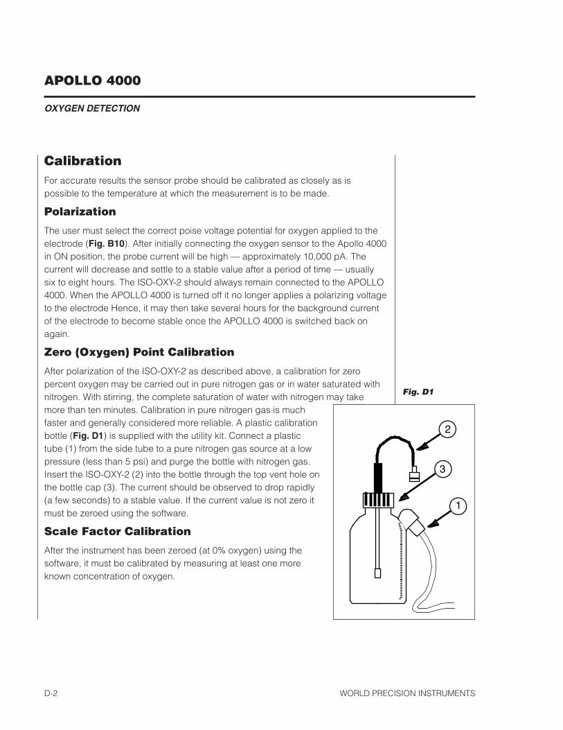
Zero (Oxygen) Point Calibration
After polarization of the iso-oXY-2 as described above, a calibration for zero percent oxygen may be carried out in pure nitrogen gas or in water saturated with nitrogen. With stirring, the complete saturation of water with nitrogen may take more than ten minutes. calibration in pure nitrogen gas is much faster and generally considered more reliable. A plastic calibration bottle (Fig. D1) is supplied with the utility kit. connect a plastic tube (�) from the side tube to a pure nitrogen gas source at a low pressure (less than 5 psi) and purge the bottle with nitrogen gas. insert the iso-oXY-2 (2) into the bottle through the top vent hole on the bottle cap (3). the current should be observed to drop rapidly (a few seconds) to a stable value. if the current value is not zero it must be zeroed using the software.
Scale Factor Calibration
After the instrument has been zeroed (at 0% oxygen) using the software, it must be calibrated by measuring at least one more known concentration of oxygen.
2
3
1
Fig. D1
APOLLO 4000
OXYGEN DETECTION
World Precision instruments d-3
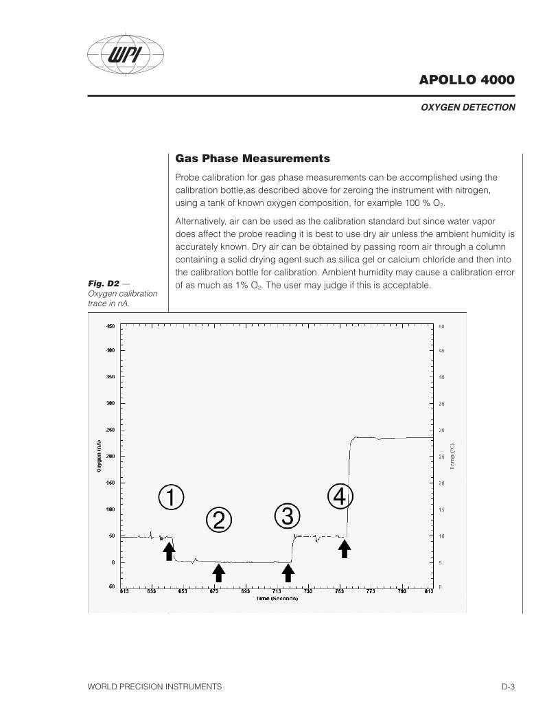
Gas Phase Measurements
Probe calibration for gas phase measurements can be accomplished using the calibration bottle,as described above for zeroing the instrument with nitrogen, using a tank of known oxygen composition, for example �00 % o2.
Alternatively, air can be used as the calibration standard but since water vapor does affect the probe reading it is best to use dry air unless the ambient humidity is accurately known. dry air can be obtained by passing room air through a column containing a solid drying agent such as silica gel or calcium chloride and then into the calibration bottle for calibration. Ambient humidity may cause a calibration error of as much as �% o2. the user may judge if this is acceptable.Fig. D2 —
Oxygen calibration trace in nA.
APOLLO 4000
OXYGEN DETECTION
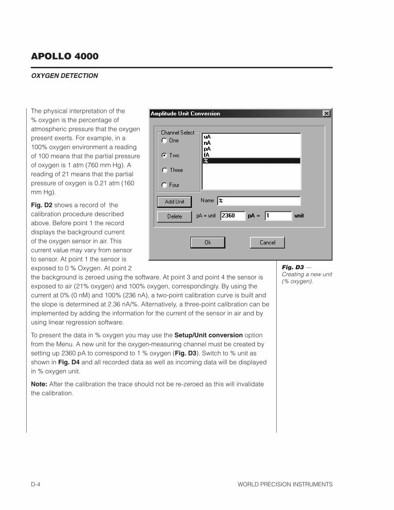
World Precision instrumentsd-4
the physical interpretation of the % oxygen is the percentage of atmospheric pressure that the oxygen present exerts. For example, in a �00% oxygen environment a reading of �00 means that the partial pressure of oxygen is � atm (760 mm Hg). A reading of 2� means that the partial pressure of oxygen is 0.2� atm (�60 mm Hg).
Fig. D2 shows a record of the calibration procedure described above. Before point � the record displays the background current of the oxygen sensor in air. this current value may vary from sensor to sensor. At point � the sensor is exposed to 0 % oxygen. At point 2 the background is zeroed using the software. At point 3 and point 4 the sensor is exposed to air (2�% oxygen) and �00% oxygen, correspondingly. By using the current at 0% (0 nm) and �00% (236 nA), a two-point calibration curve is built and the slope is determined at 2.36 nA/%. Alternatively, a three-point calibration can be implemented by adding the information for the current of the sensor in air and by using linear regression software.
to present the data in % oxygen you may use the Setup/Unit conversion option from the menu. A new unit for the oxygen-measuring channel must be created by setting up 2360 pA to correspond to � % oxygen (Fig. D3). switch to % unit as shown in Fig. D4 and all recorded data as well as incoming data will be displayed in % oxygen unit.
Note: After the calibration the trace should not be re-zeroed as this will invalidate the calibration.
Fig. D3 — Creating a new unit (% oxygen).

APOLLO 4000
OXYGEN DETECTION
World Precision instruments d-5
Aqueous measurements
For aqueous calibration, fill the calibration bottle with distilled water to approximately two thirds of its full volume. immerse the probe tip into the water via the top hole. Aerate, for a few minutes, by bubbling air through the side arm of the bottle at a low pressure using a simple aquarium aeration pump. the scale reading should be allowed to settle to a stable reading. dissolved oxygen calibration is corrected for the effect of water vapor by the following equations :
(1) pO2 = 21% × (1 - pH2O) or
(2) pO2 = 21% × (1 -p'H2O/760)
Fig. D4 — Oxygen calibration trace in % oxygen.
APOLLO 4000
OXYGEN DETECTION
World Precision instrumentsd-6
where pH2o and p'H2o are the partial pressure of water vapor at standard atmospheric pressure in atmospheres and in mm Hg, respectively (see Table 3).
For example, the pH2o in water- saturated air at 24 deg is 22 mm Hg (see Table 3). therefore the po2 = 2�% x (� - 22/760) = 20.4 %. note that for purposes of oxygen measurements liquid water is considered to be “water-saturated air”. the values of water vapor pressures at different temperatures can be found in Table 3.
You may obtain zero % oxygen concentration by adding to your solution of several mg na2s2o3 per 20 ml of solution.
to present dissolved oxygen concentration in parts per million (ppm), refer to Table 1a. this table gives the solubility of oxygen in water at different temperatures at an ambient pressure of � atm. if the solution temperature is 25°c, for example, the oxygen concentration when the probe is in water is 8.4 ppm. You do not need to correct for the water-vapor effect for a ppm calibration since the values in table �a are obtained in “water-saturated air” at an atmospheric pressure of 760 mm Hg.
the unit ppm is equivalent to mg/l. this is illustrated as follows. the solubility of oxygen in water at 0 deg according to the merck index is 4.889 ml per �00 ml. using the ideal gas law we can calculate the number of moles of oxygen present in �00 ml :
PV = nrtn = P*V/r*t
n = (0.2�)*(4.889x�0-3) / (0.08206)*(273)n = 45.8 x �0-6 moles
Where P is the partial pressure of oxygen, V is the volume of oxygen, n is the number of moles of oxygen, r is the universal gas constant, and t is the absolute temperature. From the number of moles of oxygen we can calculate the number of grams of oxygen :
45.8 x �0-6 mol * 32 g / mol�.46 x �0-3 g
therefore there will be (�.46 x �0-3 g / 0.� l) �4.6 mg of oxygen per liter. since � l of water has a mass of �000 g, and there are � million mg in �000 g, the concentration in ppm shall be:
(�4.6 x �0-3 g/l) / (�000 g/l) = �4.6 ppm

APOLLO 4000
OXYGEN DETECTION
World Precision instruments d-7
note that this value corresponds to that given in table �a.
For accurate results the temperature of the water sample and the fluid being tested should be identical. they should be continuously stirred using a magnetic stirrer.
When measuring fluid samples for dissolved oxygen, periodically rinse the exterior of the probe with distilled water, blot the membrane dry and recheck the electrode’s calibration as described above.
Creating a Calibration Curve
to create a calibration curve, the user measures the current (nA) of the sensor at various concentrations of oxygen. the calibration could be either a two-point or three-point calibration, including measurements at 0% oxygen, �00% oxygen or air (2�% oxygen) with the corresponding correction for water vapor in case of aqueous measurements (see Table 3).
Note: For absolute measurements in % and ppm units, zeroing function should not be used after the initial zeroing.
After calibration the user can select to show the oxygen concentration in % or ppm units. the conversion factor %-to-nA or ppm-to-nA (sensitivity of the probe) is determined from the slope of the calibration curve and must be typed into the corresponding field (see Fig. B15). only after selecting ppm or % unit will oxygen concentration be displayed.
Calibration Method for O2 Measurements in Living Tissue or Blood
the APollo 4000 and iso-oXY-2 probe may be used extensively in applications involving o2 measurements in vitro or in vivo in living tissue or fluids such as blood. You may still use the calibration procedure in this manual for these measurements since a membrane-covered amperometric oxygen electrode will always measure oxygen activity, not concentration. Although it is normal to think in terms of dissolved oxygen concentration, it is actually more appropriate to define oxygen in solution in terms of activity, since this is the “effective concentration”. For example, in distilled water the activity coefficient, γc, is close to unity; but in solutions with high salt concentration the activity coefficient is different from unity and concentration and activity of dissolved oxygen are no longer equal: the oxygen concentration falling with salt concentration increase, while activity remains constant. For a membrane-covered oxygen electrode this is an important effect
APOLLO 4000
OXYGEN DETECTION
World Precision instrumentsd-8
since an oxygen detector only responds to the difference in activity across the membrane rather than the concentration difference. so in samples containing an electrolyte, while the oxygen concentration falls with increasing salt concentration the probe current remains constant.
thus, if it is necessary to have a measure of dissolved oxygen in terms of concentration, then the calibration is somewhat more complicated since the relationship between activity and concentration may change with the change of salt concentration in the samples. the activity coefficient, a ratio of the activity to the concentration, generally cannot be predicted and one must rely on empirical determinations since the compositions of living fluids such as blood are extremly complicated. one may directly use the fluid to be tested as a “solvent” to prepare a calibration stantard. Alternatively, one may use the Bunsen absorption coefficient, α, to calculate oxygen concentration in blood in terms of the results with the oxygen electrode. the equation is:
where K is a conversion factor depending on the unit of pressure chosen (� for atm), pt and pH2o are the total pressure of gas and the partial pressures of water, respectively. po2 is the partial pressure of oxygen in blood obtained from the measurements with the oxygen electrode. Bunsen coefficients for solubility of oxygen in plasma and blood can be found in Table 4. However, it is very important to calibrate at the same temperature as that of the measurement site.
Probe Structure and AssemblyFig. D5 shows the principal components of an iso-oXY-2. A gas permeable membrane (3) is cemented to the tip of the outer stainless steel sleeve (1). the interior of the probe is a slender wand containing the platinum cathode and silver counter / reference electrode inside the sleeve. the wand is permanently mounted in the probe’s plastic handle (2). After electrolyte has been deposited inside the sleeve (see below), the wand is slowly inserted into the sleeve and secured by screwing the sleeve cap (4) gently into the probe handle. if the membrane on the stainless steel sleeve becomes damaged, the entire sleeve must be replaced. two spare sleeves are provided with the iso2 kit, and the user may purchase more. should the user wish to sterilize the probe this should be done with alchohol or some other chemical for an assembled probe. the membrane sleeves can be
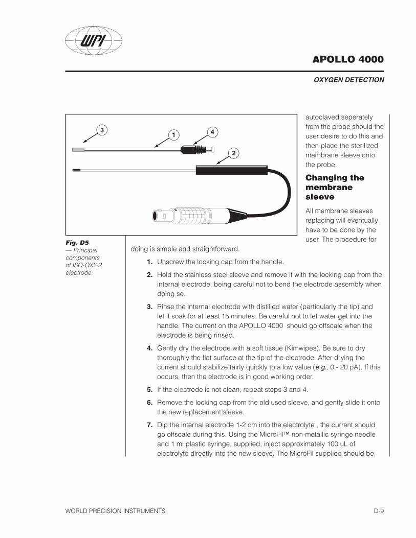
APOLLO 4000
OXYGEN DETECTION
World Precision instruments d-9
autoclaved seperately from the probe should the user desire to do this and then place the sterilized membrane sleeve onto the probe.
Changing the membrane sleeve
All membrane sleeves replacing will eventually have to be done by the user. the procedure for
doing is simple and straightforward.
1. unscrew the locking cap from the handle.
2. Hold the stainless steel sleeve and remove it with the locking cap from the internal electrode, being careful not to bend the electrode assembly when doing so.
3. rinse the internal electrode with distilled water (particularly the tip) and let it soak for at least �5 minutes. Be careful not to let water get into the handle. the current on the APollo 4000 should go offscale when the electrode is being rinsed.
4. Gently dry the electrode with a soft tissue (Kimwipes). Be sure to dry thoroughly the flat surface at the tip of the electrode. After drying the current should stabilize fairly quickly to a low value (e.g., 0 - 20 pA). if this occurs, then the electrode is in good working order.
5. if the electrode is not clean, repeat steps 3 and 4.
6. remove the locking cap from the old used sleeve, and gently slide it onto the new replacement sleeve.
7. dip the internal electrode �-2 cm into the electrolyte , the current should go offscale during this. using the microFil™ non-metallic syringe needle and � ml plastic syringe, supplied, inject approximately �00 ul of electrolyte directly into the new sleeve. the microFil supplied should be
Fig. D5 — Principal components of ISO-OXY-2 electrode.
1
2
3 4

APOLLO 4000
OXYGEN DETECTION
World Precision instrumentsd-�0
less than the length of the sleeve, so that it will not puncture the delicate membrane at the tip of the sleeve during injection. if the microFil is longer than the sleeve it can be cut to the correct length.
8. slowly and smoothly insert the electrode into the sleeve, and screw the locking cap into the handle. the electrode should be observed to press gently against the membrane.
9. the current at this time will be high or offscale.
10. suspend the tip of the new assembled probe in PBs buffer solution.
11. After �0-�5 minutes the current should no longer be offscale and will gradually decrease with time. it may take several hours for the sensor current to reach a low stable value, at which time it will be ready for use.
12. if the current observed, after a few minutes in the saline solution, increases dramatically or is offscale, then the membrane integrity is not good and a new membrane will have to be fitted.
13. When the iso-oXY-2 is not being used it should be stored with the tip suspended in distilled water.
Clean the Membrane
the membrane sleeve itself requires very little maintenance. the primary concern is to avoid to damage the membrane and to keep it as clean as possible. After each use, the membrane should be cleaned by suspending the tip in distilled water for 20-30 minutes to dissolve salts and remove particles ,which may have accumulated on the membrane. if the probe was used in a protein rich solution the tip should first be soaked in a protease solution for several minutes to remove protein build-up, and then in distilled water. enzymatic detergent (e.g., enzol, WPi #7363) can also be used. the membrane sleeves can also be sterilized chemically using an appropriate disinfectant (e.g., cidex, WPi #7364). Accumulated organic matter can be removed by briefly immersing the tip in an acid or base solution (at times both may be necessary) for �0 seconds. A good indication of a dirty membrane sleeve is a sluggish response or an unusually low sensitivity. if these problems are not rectified by the above cleaning procedures then the membrane sleeve should be replaced. the probe cannot be used in organic solvents.
APOLLO 4000
OXYGEN DETECTION
World Precision instruments d-��
Care of the Electrode
the reduction of oxygen and other trace impurities causes a decrease in the surface activity of the working electrode. this phenomenon is referred to as “poisoning”, and over time has the effect of gradually reducing the electrode’s capability to generate a sufficient redox current. As such, it is recommended to use the following guidelines to maximize the life of the electrode:
if the oxygen electrode is being used on a daily basis, it’s recommended that the instrument be left on with the electrode connected to maintain polarization (see “Polarization” on page d-2). However; if the electrode is not to be used for a period of more than 2-3 days, it’s recommended that the electrode be disconnected from the instrument, and stored with the tip immersed in distilled water. this practice will reduce the possibility of a gradual reduction of electrode surface activity (as discussed above) under long term polarization. if the electrode will not be used for a long period of time (several months), refer to the section titled “storage” below.
Handling Precaution
When passing the o2 probe through small holes, gaskets or o-rings, allow sufficient clearance so that the probe tip is not damaged by abrasion. the probe tip should slide through openings easily before sealing the probe shaft to assure an air-tight fit.
Storage
For long term storage (several months) unscrew and remove the sleeve from the probe handle, rinse the electrode tip and the sleeve with distilled water. When both are dry, replace sleeve to protect probe wand but do not screw the sleeve completely onto the handle.
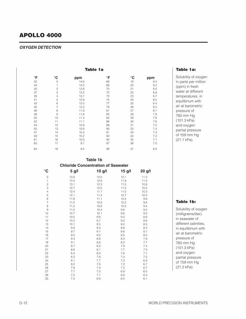
APOLLO 4000
OXYGEN DETECTION
World Precision instrumentsd-�2
Table 1a
°F °C ppm °F °C ppm32 0 �4.6 66 �9 9.434 � �4.2 68 20 9.235 2 �3.8 70 2� 9.037 3 �3.5 72 22 8.839 4 �3.� 73 23 8.74� 5 �2.8 75 24 8.543 6 �2.5 77 25 8.445 7 �2.2 79 26 8.246 8 ��.9 8� 27 8.�48 9 ��.6 82 28 7.950 �0 ��.3 84 29 7.852 �� ��.� 86 30 7.654 �2 �0.8 88 3� 7.555 �3 �0.6 90 32 7.457 �4 �0.4 9� 33 7.359 �5 �0.2 93 34 7.26� �6 �0.0 95 35 7.�63 �7 9.7 97 36 7.0
64 �8 9.5 99 37 6.9
Table 1bChloride Concentration of Seawater
°C 5 g/l 10 g/l 15 g/l 20 g/l 0 �3.8 �3.0 �2.� ��.3 � �3.4 �2.6 ��.8 ��.0 2 �3.� �2.3 ��.5 �0.8 3 �2.7 �2.0 ��.2 �0.5 4 �2.4 ��.7 ��.0 �0.3 5 �2.� ��.4 �0.7 �0.0 6 ��.8 ��.� �0.5 9.8 7 ��.5 �0.9 �0.2 9.6 8 ��.2 �0.6 �0.0 9.4 9 ��.0 �0.4 9.8 9.2 �0 �0.7 �0.� 9.6 9.0 �� �0.5 9.9 9.4 8.8 �2 �0.3 9.7 9.2 8.6 �3 �0.� 9.5 9.0 8.5 �4 9.9 9.3 8.8 8.3 �5 9.7 9.� 8.6 8.� �6 9.5 9.0 8.5 8.0 �7 9.3 8.8 8.3 7.8 �8 9.� 8.6 8.2 7.7 20 8.7 8.3 7.9 7.4 2� 8.6 8.� 7.7 7.3 22 8.4 8.0 7.6 7.� 23 8.3 7.9 7.4 7.0 24 8.� 7.7 7.3 6.9 25 8.0 7.6 7.2 6.7 26 7.8 7.4 7.2 6.7 27 7.7 7.3 6.9 6.5 28 7.5 7.� 6.8 6.4 30 7.3 6.9 6.5 6.�
Table 1a:
solubility of oxygen in parts per million (ppm) in fresh water at different temperatures, in equilibrium with air at barometric pressure of 760 mm Hg (�0�.3 kPa) and oxygen partial pressure of �59 mm Hg (2�.� kPa).
Table 1b:
solubility of oxygen (milligrams/liter) in seawater of different salinities, in equilibrium with air at barometric pressure of 760 mm Hg (�0�.3 kPa) and oxygen partial pressure of �59 mm Hg (2�.2 kPa).
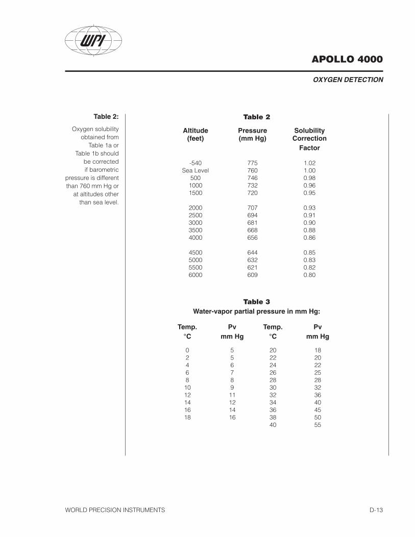
APOLLO 4000
OXYGEN DETECTION
World Precision instruments d-�3
Table 2
Altitude Pressure Solubility (feet) (mm Hg) Correction Factor
-540 775 �.02 sea level 760 �.00 500 746 0.98 �000 732 0.96 �500 720 0.95
2000 707 0.93 2500 694 0.9� 3000 68� 0.90 3500 668 0.88 4000 656 0.86
4500 644 0.85 5000 632 0.83 5500 62� 0.82 6000 609 0.80
Table 3Water-vapor partial pressure in mm Hg:
Temp. Pv Temp. Pv °C mm Hg °C mm Hg
0 5 20 �8 2 5 22 20 4 6 24 22 6 7 26 25 8 8 28 28 �0 9 30 32 �2 �� 32 36 �4 �2 34 40 �6 �4 36 45 �8 �6 38 50 40 55
Table 2:
oxygen solubility obtained from
table �a or table �b should
be corrected if barometric
pressure is different than 760 mm Hg or
at altitudes other than sea level.
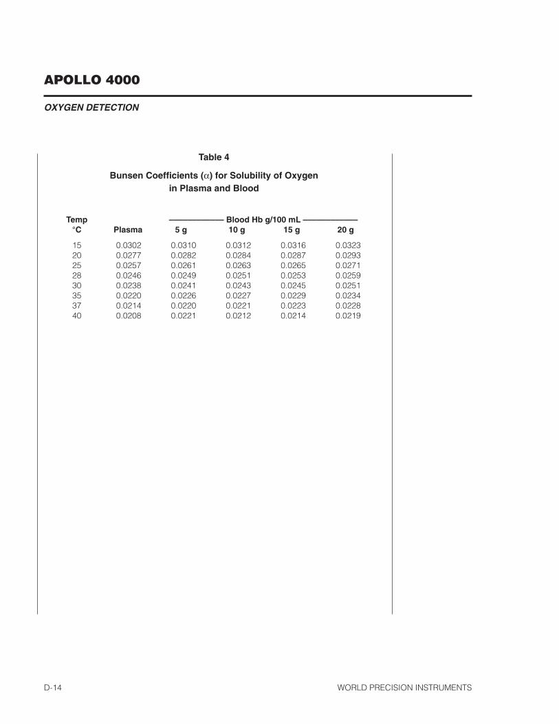
APOLLO 4000
OXYGEN DETECTION
World Precision instrumentsd-�4
Table 4
Bunsen Coefficients (α) for Solubility of Oxygenin Plasma and Blood
Temp –––––––––––– Blood Hb g/100 mL –––––––––––– °C Plasma 5 g 10 g 15 g 20 g
�5 0.0302 0.03�0 0.03�2 0.03�6 0.0323 20 0.0277 0.0282 0.0284 0.0287 0.0293 25 0.0257 0.026� 0.0263 0.0265 0.027� 28 0.0246 0.0249 0.025� 0.0253 0.0259 30 0.0238 0.024� 0.0243 0.0245 0.025� 35 0.0220 0.0226 0.0227 0.0229 0.0234 37 0.02�4 0.0220 0.022� 0.0223 0.0228 40 0.0208 0.022� 0.02�2 0.02�4 0.02�9
APOLLO 4000
HYDROGEN PEROXIDE DETECTION
World Precision instruments e-�
USING THE APOLLO 4000 TO DETECT HyDrOGEN PErOxIDE
Initial Set-upAttach the HPo sensor to the required input channel of the APollo 4000. From the main setup menu of the software select the correct poise voltage “Hydrogen Peroxide” and appropriate range for the selected channel. the electrode must now be calibrated.
The structure of the HPO sensor the basic structure of the ISO-HPO-2 sensor is identical to that of the iso-noP nitric oxide sensor (see Fig. C6), although there are significant differences in the actual type of materials used.
it consists of an internal working/counter electrode combination. this electrode fits inside a disposable stainless steel sleeve (WPi#600012) which must contain fresh refillable electrolyte (WPi#100042), and is separated from the external environment by membrane covering the end of the stainless sleeve. the other end of the sleeve is flanged. the locking cap is used to attach the sleeve to the probe handle. When the sensor is fully assembled ,the internal electrode should be press gently against the membrane, which will then be slightly stretched. this ensures that the electrolyte diffusion layer will be as thin as possible, which is necessary to minimize sensor response time.
once a membrane is stretched, it is permanently deformed and cannot usually be reused if the sleeve is removed from the electrode. Four additional membrane sleeves (WPi#600012), a MicroFil™ electrolyte filling needle (WPi#MF28G67-5) and � ml syringe are provided in the iso-HPo startup-kit (WPi#600011).
With proper care and by following the instructions below, a membrane sleeve should last more than one month.
APOLLO 4000
HYDROGEN PEROXIDE DETECTION
World Precision instrumentse-�
Calibration of the HPO SensorHydrogen Peroxide (H�o�) is a very important product in the biological system. the determination of H�o� requires an accurate method of calibration. Amperometeric (electrochemical) determination using the Apollo is a very reliable method to measure H�o�. the Apollo measures the amount of H�o� oxidized on the surface of the sensor using a poise voltage of +400 mV. the oxidation of H�o� at the sensor surface produces a small current (pA), which is detected by the Apollo. the amount of current produced is linearly proportional to amount of H�o� in the experiment.
Items required
• Plastic stand with two holes• one glass vial• �.0mm H�o� standard solution (available from WPi)• 0.0�m PBs buffer solution (PBs buffer tablets available from WPi)
note: the multi-port measurement chambers (WPi#NOCHM or #NOCHM-4) can be used as an alternative calibration kit, specifically for use at different temperature condition. calibration temperatures from 4 - 40°c can be controlled using an external circulating bath (contact WPi for information).
Calibration Procedure1. turn on the instrument Apollo 4000, set all the parameters that are needed
in experiment. select the poise voltage for hydrogen peroxide in the software.
2. Add an appropriate volume (e.g.,�0 ml) of PBs buffer solution (0.0�m) in glass vial. turn on the stirrer so that the bar is stirring in moderate rate.
3. remove the sensor from the electrolyte solution in which the tip has been immersed during storage. immerse the iso-HPo-� sensor tip in PBs buffer solution (0.0�m), the sensor tip should be immersed about 0.3-0.5mm into the solution, and should not be touched by stir bar.
4. record the current value. if the current is offscale or unstable after a half hour in solution, it is likely that the membrane has been damaged and the sleeve needs to be changed (refer to the section on“changing the sleeve”).

APOLLO 4000
HYDROGEN PEROXIDE DETECTION
World Precision instruments e-3
note: the calibration should be carried out at the temperature at which the samples of H�o� are to be measured. this can be accomplished by placing the vial and stand in a water bath at the appropriate temperature, and allowing the temperature of the solution in the bottle to equilibrate with the water bath.
5. once the current has achieved a stable value. it is ready for calibration.
Creating a calibration curve
to create a calibration curve, the user measures the current (pA) generated by the addition of different amounts of H�o� to the calibration solution.
1. After the current is stable, zero the baseline.
2. Add a known volume of the H�o� standard solution to the PBs buffer solution.
For example, add 0, 5, �0, �0, 40, 80ml H�o� standard solution (�.0mm) into �0ml PBs buffer solution.
the output from the H�o� will like similar to the example shown in Fig. E1.
From this output, a calibration curve (Fig. E2) can be created by plotting the changes in current (pA) against the changes in concentration (mm). the slope of this curve indicates sensitivity of the probe.
-100
100
300
500
700
900
1100
1300
-30 20 70 120 170
time (sec)
curr
ent
(pA
)
0.5 µM1 µM
2 µM
4 µM
8 µM
Figure E1 — H2O2 calibration output.
y = 73.296x + 6.4857R2 = 0.9988
0
100
200
300400
500
600
700
0 2 4 6 8 10
Concentration of H2O2 (µM)
Cu
rren
t (p
A)
Figure E2 — ISO-HPO-2 calibration curve based on Figure 1
APOLLO 4000
HYDROGEN PEROXIDE DETECTION
World Precision instrumentse-4
InterferenceTemperature
the background current of the sensor will usually increase with increasing temperature of the experiment. Although, the sensitivity of the sensor does not change significantly within the range �0-37°c. it is therefore recommended that any calibration should be performed at the same temperature as the experiment.
pH
Between pH 3-�0, changing the pH of the solution does not affect the sensitivity of the HPo sensor. However if the pH is below 3.0, the noise of the sensor will increase. At pH �0.0 and higher, the response of the sensor will diminish significantly.
Maintenance of HPO SensorsWhen the iso-HPo-� sensor is not being used (and for short-term storage) it should be connected to the APollo 4000 with power on and with the tip suspended in distilled water. tthis will keep the sensor polarized and ready for immediate use.
Clean the Membrane
the membrane sleeve itself requires very little maintenance. the primary concern is to avoid to damage the membrane and to keep it as clean as possible. After each use, the membrane should be cleaned by suspending the tip in distilled water for �0-30 minutes to dissolve salts and remove particles ,which may have accumulated on the membrane. if the probe was used in a protein rich solution the tip should first be soaked in a protease solution for several minutes to remove protein build-up, and then in distilled water. enzymatic detergent (e.g., enzol, WPi#7363) can also be used. the membrane sleeves can also be sterilized chemically using an appropriate disinfectant (e.g., cidex, WPi#7364). Accumulated organic matter can be removed by briefly immersing the tip in an acid or base solution (at times both may be necessary) for �0 seconds. A good indication of a dirty membrane sleeve is a sluggish response or an unusually low sensitivity. if these problems are not rectified by the above cleaning procedures then the membrane sleeve should be replaced. the probe cannot be used in organic solvents.

APOLLO 4000
HYDROGEN PEROXIDE DETECTION
World Precision instruments e-5
Changing the Membrane Sleeve
All membrane sleeves replacing will eventually have to be done by the user. the procedure for doing is simple and straightforward.
1. unscrew the locking cap from the handle.
2. Hold the stainless steel sleeve and remove it with the locking cap from the internal electrode, being careful not to bend the electrode assembly when doing so.
3. rinse the internal electrode with distilled water (particularly the tip) and let it soak for at least �5 minutes. Be careful not to let water get into the handle. the current on the Apollo – 4000 should go offscale when the electrode is being rinsed.
4. Gently dry the electrode with a soft tissue (Kimwipes). Be sure to dry thoroughly the flat surface at the tip of the electrode. After drying the current should stabilize fairly quickly to a low value ( e.g., 0 - �0 pA). if this occurs, then the electrode is in good working order.
5. if the electrode is not clean, repeat steps 3 and 4. if necessary the iso-noP rejuvenator (WPi #JuV) can be used to restore sensitivity of an old electrode (contact WPi for assistance).
6. remove the locking cap from the old used sleeve, and gently slide it onto the new replacement sleeve.
7. dip the internal electrode �-� cm into the electrolyte , the current should go offscale during this. using the microFil™ non-metallic syringe needle and � ml plastic syringe, supplied, inject approximately �00 ul of electrolyte directly into the new sleeve. the microFil supplied should be less than the length of the sleeve, so that it will not puncture the delicate membrane at the tip of the sleeve during injection. if the microFil is longer than the sleeve it can be cut to the correct length.
8. slowly and smoothly insert the electrode into the sleeve, and screw the locking cap into the handle. the electrode should be observed to press gently against the membrane.
9. the current at this time will be high or offscale.

APOLLO 4000
HYDROGEN PEROXIDE DETECTION
World Precision instrumentse-�
10. suspend the tip of the new assembled probe in PBs buffer solution.
11. After �0-�5 minutes the current should no longer be offscale and will gradually decrease with time. it may take several hours for the sensor current to reach a low stable value, at which time it will be ready for use.
12. if the current observed, after a few minutes in the saline solution, increases dramatically or is offscale, then the membrane integrity is not good and a new membrane will have to be fitted.
Storage
store the electrode with its tip immersed in electrolyte solution in the sealed vial provided with the electrode.
.
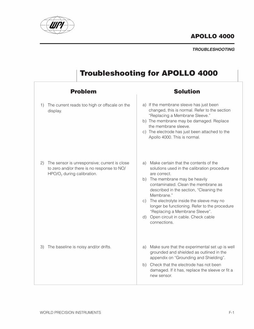
APOLLO 4000
TROUBLESHOOTING
WORLD PRECISION INSTRUMENTS F-1
Problem Solution
a) If the membrane sleeve has just beenchanged, this is normal. Refer to the section“Replacing a Membrane Sleeve.”
b) The membrane may be damaged. Replacethe membrane sleeve.
c) The electrode has just been attached to theApollo 4000. This is normal.
1) The current reads too high or offscale on thedisplay.
Troubleshooting for APOLLO 4000
a) Make certain that the contents of thesolutions used in the calibration procedureare correct.
b) The membrane may be heavilycontaminated. Clean the membrane asdescribed in the section, “Cleaning theMembrane.”
c) The electrolyte inside the sleeve may nolonger be functioning. Refer to the procedure“Replacing a Membrane Sleeve”.
d) Open circuit in cable. Check cableconnections.
2) The sensor is unresponsive; current is closeto zero and/or there is no response to NO/HPO/O2 during calibration.
a) Make sure that the experimental set up is wellgrounded and shielded as outlined in theappendix on “Grounding and Shielding”.
b) Check that the electrode has not beendamaged. If it has, replace the sleeve or fit anew sensor.
3) The baseline is noisy and/or drifts.
APOLLO 4000
TROUBLESHOOTING
WORLD PRECISION INSTRUMENTSF-2
APOLLO 4000
BASIC GROUNDING & SHIELDING PRINCIPLES
WORLD PRECISION INSTRUMENTS G-1
APPENDIX: BASIC GROUNDING &SHIELDING PRINCIPLES
While the current model of the Apollo 4000 is protected against EMI it may still benecessary under very noisy conditions to provide additional shielding. Enclosingthe system in a iron shield (Faraday cage) is the best way to shield against strayelectric fields. The best Faraday cage is constructed of solid sheet metal, but inNO measurements it is usually necessary to see the measurement system. Thealternative is to use copper screening but it must be soldered completely alongany joining seams. Place all the instruments and the sample into a groundedFaraday cage.
It may not always be possible to put the whole measurement system in a Faradaycage for shielding, as for example with a flow-through system when the probe isimmersed into the effluent of a perfusion system or placed directly into the vein ofthe heart of an animal. In this case grounding the external bathing fluid, vein, ortissue with a stainless steel needle or Ag/AgCl reference electrode will often helpsignificantly. If pumps or other electrical instruments are to be used in a flow-through system, the associated equipment or instruments should be grounded aswell. Use a common ground for all equipment in the experiment.
After careful grounding and shielding of the electronic equipment and the probesystem, sometimes it is found that movement of people in the immediate vicinitycauses current fluctuations. These are due to variations in the resulting straycapacitance. There are several ways to minimize these effects. When themeasurements are made in vivo, it is good practice to ground the animals. Inaddition, the operator may need to be grounded because large static charges canbe generated by the operator’s body. Wrist straps connected to ground theoperator may be helpful.
.
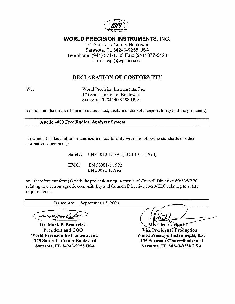
APOLLO 4000
WORLD PRECISION INSTRUMENTS 5
WarrantyWPI (World Precision Instruments, Inc.) warrants to the original purchaser that this equipment, including itscomponents and parts, shall be free from defects in material and workmanship for a period of one year* fromthe date of receipt. WPI’s obligation under this warranty shall be limited to repair or replacement, at WPI’soption, of the equipment or defective components or parts upon receipt thereof f.o.b. WPI, Sarasota, FloridaU.S.A. Return of a repaired instrument shall be f.o.b. Sarasota.
The above warranty is contingent upon normal usage and does not cover products which have been modifiedwithout WPI’s approval or which have been subjected to unusual physical or electrical stress or on which theoriginal identification marks have been removed or altered. The above warranty will not apply if adjustment,repair or parts replacement is required because of accident, neglect, misuse, failure of electric power, airconditioning, humidity control, or causes other than normal and ordinary usage.
To the extent that any of its equipment is furnished by a manufacturer other than WPI, the foregoing warrantyshall be applicable only to the extent of the warranty furnished by such other manufacturer. This warranty willnot apply to appearance terms, such as knobs, handles, dials or the like.
WPI makes no warranty of any kind, express or implied or statutory, including without limitation any warrantiesof merchantability and/or fitness for a particular purpose. WPI shall not be liable for any damages, whetherdirect, indirect, special or consequential arising from a failure of this product to operate in the manner desiredby the user. WPI shall not be liable for any damage to data or property that may be caused directly orindirectly by use of this product.
Claims and Returns• Inspect all shipments upon receipt. Missing cartons or obvious damage to cartons should be noted on thedelivery receipt before signing. Concealed loss or damage should be reported at once to the carrier and aninspection requested. All claims for shortage or damage must be made within 10 days after receipt ofshipment. Claims for lost shipments must be made within 30 days of invoice or other notification ofshipment. Please save damaged or pilfered cartons until claim settles. In some instances, photographicdocumentation may be required. Some items are time sensitive; WPI assumes no extended warranty or anyliability for use beyond the date specified on the container.
• WPI cannot be held responsible for items damaged in shipment en route to us. Please enclosemerchandise in its original shipping container to avoid damage from handling. We recommend that youinsure merchandise when shipping. The customer is responsible for paying shipping expenses includingadequate insurance on all items returned.
• Do not return any goods to WPI without obtaining prior approval and instructions (RMA#) from our returnsdepartment. Goods returned unauthorized or by collect freight may be refused. The RMA# must be clearlydisplayed on the outside of the box, or the package will not be accepted. Please contact the RMAdepartment for a request form.
• Goods returned for repair must be reasonably clean and free of hazardous materials.
• A handling fee is charged for goods returned for exchange or credit. This fee may add up to 25% of thesale price depending on the condition of the item. Goods ordered in error are also subject to the handlingfee.
• Equipment which was built as a special order cannot be returned.
• Always refer to the RMA# when contacting WPI to obtain a status of your returned item.
• For any other issues regarding a claim or return, please contact the RMA department.
Warning: This equipment is not designed or intended for use on humans.
* Electrodes, batteriesand otherconsumable parts arewarranted for 30 daysonly from the date onwhich the customerreceives these items.
World Precision Instruments, Inc.International Trade Center, 175 Sarasota Center Blvd., Sarasota FL 34240-9258
Tel: 941-371-1003 • Fax: 941-377-5428 • E-mail: [email protected]: Astonbury Farm Business Centre • Aston, Stevenage, Hertfordshire SG2 7EG • Tel: 01438-880025 • Fax: 01438-880026 • E-mail: [email protected]
Germany: Liegnitzer Str. 15, D-10999 Berlin • Tel: 030-6188845 • Fax: 030-6188670 • E-mail: [email protected]