4000 Series Operation Manual - Transmille
186
Version 1.00 : September 2015 All product names are trademarks of their respective companies 4000 Series Precision Multi Product Calibrator Operation Manual
-
Upload
khangminh22 -
Category
Documents
-
view
3 -
download
0
Transcript of 4000 Series Operation Manual - Transmille

Version 1.00 : September 2015
All product names are trademarks of their respective companies
4000 Series
Precision Multi Product Calibrator
Operation Manual

4000 SERIES OPERATION MANUAL
TRANSMILLE LTD. Page 2
IMPORTANT NOTICE
THIS CALIBRATOR WILL
REQUIRE AN UNLOCK CODE
AFTER THE EVALUATION PERIOD HAS EXPIRED.
(60 Days after invoice date) AFTER THE EVALUATION PERIOD HAS EXPIRED THE
OPERATION OF THE CALIBRATOR IS LOCKED AND THE DISPLAY SHOWS A NUMBER WHICH MUST BE QUOTED TO TRANSMILLE
TO RECEIVE THE UNLOCK CODE
THE UNLOCK CODE IS AVAILALBLE
FROM TRANSMILLE ONLY AFTER PAYMENT HAS BEEN RECEIVED. This code only needs to be entered once
in the life of the instrument.
Please contact Transmille or use the form in the back of the manual to obtain the unlock code.
Transmille Ltd.
Staplehurst, Kent. Tel: 44 (0)1580 890700 Fax: 44(0)1580 890711
Email: [email protected]

4000 SERIES OPERATION MANUAL
TRANSMILLE LTD. Page 3
DECLARATION OF CONFORMITY
Manufacturer’s Name: Transmille Ltd. Manufacturer’s Address: Unit 4, Select Business Centre Lodge Road Staplehurst TN12 0QW Declares, that the product Product Name: Advanced Multi-Product Calibrator Model Number: 4000 Series Product Options: This declaration covers all options of the above product(s) Conforms with the following European Directives: The product herewith complies with the requirements of the Low Voltage Directive 73/73EEC and the EMC Directive 89/336/EEC (including 93/68/EEC) and carries the CE Marking accordingly Conforms with the following product standards: EMC EN 61326-1:1997+A1:1998 • EN55011:1991 (Group 1: Class A) Standard Limit IEC 61000-4-2:1995+A1:1998 / EN 61000-4-2:1995 4kV CD, 8kV AD IEC 61000-4-3:1995 / EN 61000-4-3:1995 3 V/m, 80-1000 MHz IEC 61000-4-4:1995 / EN 61000-4-4:1995 0.5kV signal lines, 1kV power lines IEC 61000-4-5:1995 / EN 61000-4-5:1995 0.5kV line-line, 1kV line-ground IEC 61000-4-6:1996 / EN 61000-4-6:1996 3V, 0.15-80 MHz / cycle, 100% IEC 61000-4-11:1994 / EN 61000-4-11:1994 Dips: 30% 10ms; 60% 100ms Interrupt > 95%@5000ms
SAFETY IEC 61010-1:1990+A1:1992+A2:1995 / EN 61010-1:1993+A2:1995 16/01/2015 Revision No: 1.0 Managing Director Date: 16/01/2015

4000 SERIES OPERATION MANUAL
TRANSMILLE LTD. Page 4
TABLE OF CONTENTS
1 INTRODUCTION ......................................................................................................................... 12
MAIN FEATURES ........................................................................................................................... 12
ACCURACY AND FUNCTIONALITY .................................................................................................... 13
TRUE MULTIPRODUCT CALIBRATION .............................................................................................. 13
RETRO FIT OPTIONS ..................................................................................................................... 14
USB INTERFACE ........................................................................................................................... 14
OUTPUT CONNECTIONS ................................................................................................................. 14
2 PREPARING THE CALIBRATOR FOR USE. ............................................................................ 15
INITIAL INSPECTION ....................................................................................................................... 15
LIFTING AND CARRYING THE CALIBRATOR ...................................................................................... 15
POSITIONING THE CALIBRATOR ...................................................................................................... 16
REAR PANEL CONNECTIONS AND CONTROLS ................................................................................. 17
SETTING AND CHECKING THE LINE VOLTAGE................................................................................... 18
POWER LINE INLET FUSE AND RATING ............................................................................................ 18
INTERFACE TYPES ........................................................................................................................ 19
USB INTERFACE ........................................................................................................................... 19
CONNECTING TO A COMPUTER ....................................................................................................... 19
POWERING UP THE CALIBRATOR .................................................................................................. 21
OUTPUT CONNECTIONS ............................................................................................................... 22
WARNING AND OUTPUT OVERLOAD INDICATIONS. ......................................................................... 24
HIGH VOLTAGE TIMEOUT. ............................................................................................................ 25
30 AMP TEMPERATURE CUT-OUT ................................................................................................ 25
3 OPERATION ................................................................................................................................ 26
SAFETY WARNINGS ....................................................................................................................... 26
INTRODUCTION TO OPERATION ...................................................................................................... 26
FRONT PANEL CONTROLS ............................................................................................................. 27
Numerical Keypad ........................................................................................................................ 29
Multiplier Keys .............................................................................................................................. 29
Function Keys .............................................................................................................................. 29
Range Up / Range Down Keys .................................................................................................... 29
Left / Right / Up / Down Arrow Keys ............................................................................................ 29
Output On / Standby keys ............................................................................................................ 30
DIGITAL CONTROL......................................................................................................................... 30
FRONT PANEL USB CONNECTOR .................................................................................................. 31
TOUCHSCREEN INTERFACE FUNCTIONALITY ................................................................................... 31

4000 SERIES OPERATION MANUAL
TRANSMILLE LTD. Page 5
CONNECTION HELP PROMPTS ....................................................................................................... 33
MAIN MENU .................................................................................................................................. 34
CONFIGURATION MENU ................................................................................................................. 36
VIEW HARDWARE CONFIGURATION .............................................................................................. 38
SET PASSCODE .......................................................................................................................... 39
CONFIGURING TEST REPORT NUMBER ......................................................................................... 40
CONFIGURING REFERENCE MULTIMETER ..................................................................................... 43
UPDATING FIRMWARE VIA USB .................................................................................................... 45
SPECIAL FUNCTIONS AVAILABLE USING THE ‘SOFT’ KEYS ............................................................. 48
CONNECTING OUTPUT NEGATIVE TO LINE EARTH (GROUND) ........................................................ 48
SELECTING FRONT PANEL CONTROL ............................................................................................. 48
TERMINAL STATUS LED’S ........................................................................................................... 50
Voltage Output Terminal Pair (Black & Red) ............................................................................... 52
Current Output Terminals (Black & Red) ..................................................................................... 52
30 Amps Output Terminals (Blue and Yellow) ............................................................................. 52
Earth Terminal (Green) ................................................................................................................ 52
Scope & Frequency BNC Connector Outputs ............................................................................. 52
High Bandwidth Connector Output .............................................................................................. 52
9 PIN ADAPTER INTERFACE CONNECTOR ..................................................................................... 53
4 CONNECTION DIAGRAMS ........................................................................................................ 54
AC/DC VOLTAGE .......................................................................................................................... 54
AC/DC CURRENT UP TO 2A .......................................................................................................... 54
AC/DC CURRENT ABOVE 2A ......................................................................................................... 55
2 WIRE RESISTANCE / VARIABLE RESISTANCE / VARIABLE PRT ...................................................... 56
4 WIRE RESISTANCE / PASSIVE PRT ............................................................................................. 56
PASSIVE CAPACITANCE / VARIABLE CAPACITANCE .......................................................................... 57
INDUCTANCE (OPTIONAL) .............................................................................................................. 57
FREQUENCY ................................................................................................................................. 58
PULSE WIDTH MODULATION (PWM) / DUTY CYCLE ........................................................................ 58
THERMOCOUPLE SOURCE USING EA001A ................................................................................... 59
CURRENT SIMULATION UP TO 1500A USING EA002 COIL ADAPTER ............................................... 59
RPM SIMULATION USING EA003 ................................................................................................. 60
OSCILLOSCOPE AMPLITUDE / TIMEBASE / RISE TIME ..................................................................... 60
OSCILLOSCOPE HIGH BANDWIDTH ............................................................................................... 61
POWER CALIBRATION .................................................................................................................. 61
5 SETTING OUTPUTS ................................................................................................................... 62
ADJUSTING THE SET OUTPUT USING THE DIGITAL CONTROL ........................................................... 63
AUTOMATIC DISPLAY OF % OR PPM ERROR AND REFERENCE KEY ................................................... 63
RANGE HOLD ................................................................................................................................ 63
4000 SERIES OPERATION MANUAL
TRANSMILLE LTD. Page 6
LOW IMPEDANCE LOADS................................................................................................................ 64
SETTING A DC VOLTAGE OUTPUT .................................................................................................. 65
SETTING A DC CURRENT OUTPUT ................................................................................................. 66
SETTING A AC VOLTAGE OUTPUT .................................................................................................. 67
SETTING A AC CURRENT OUTPUT ................................................................................................. 68
SETTING 2 WIRE PASSIVE RESISTANCE OUTPUT. ........................................................................... 69
SETTING 2-WIRE SIMULATED RESISTANCE (OPTION) .................................................................... 71
SETTING 4-WIRE RESISTANCE OUTPUT ....................................................................................... 74
USING CURRENT COILS (OPTION) ................................................................................................ 76
SETTING CAPACITANCE (PASSIVE) OUTPUT ................................................................................. 77
SETTING CAPACITANCE (SIMULATED) OUTPUT ............................................................................. 79
SETTING INDUCTANCE OUTPUT (OPTION)..................................................................................... 81
THERMOCOUPLE SIMULATION (OPTION) ....................................................................................... 83
SETTING FREQUENCY OUTPUT .................................................................................................... 86
SETTING RPM OUTPUT WITH EA003 ADAPTOR (OPTION) ............................................................ 88
SETTING PULSE WIDTH MODULATION (PWM, MARK SPACE RATIO) .............................................. 90
SELECTING PRT (PT100) RESISTANCE OUTPUT (OPTION) ........................................................... 91
SELECTING SIMULATED PRT OUTPUT (OPTION) ........................................................................... 92
SELECTING AC POWER CALIBRATION OUTPUT (OPTION) .............................................................. 94
SELECTING DC POWER CALIBRATION OUTPUT (OPTION) .............................................................. 97
DDS POWER (OPTION) ............................................................................................................... 99
OSCILLOSCOPE CALIBRATION OUTPUT (OPTION) ........................................................................ 101
6 PROCEDURE MODE ................................................................................................................ 105
CREATING PROCEDURES ............................................................................................................. 105
IMPORTING PROCEDURES ........................................................................................................... 105
7 VERIFICATION MODE .............................................................................................................. 106
EQUIPMENT REQUIRED ............................................................................................................... 107
CONFIGURING FOR MEASUREMENTS ............................................................................................ 108
PERFORMING VERIFICATION ........................................................................................................ 108
8 REMOTE PROGRAMMING ...................................................................................................... 115
RESPONSE / ERROR CODES ........................................................................................................ 116
LEGACY COMMANDS ................................................................................................................... 117
PROGRAMMING COMMANDS OVERVIEW ....................................................................................... 117
COMPOUND COMMANDS ............................................................................................................. 117
OUTPUT STATE ........................................................................................................................... 119
DC VOLTAGE COMMANDS ........................................................................................................... 119
AC VOLTAGE COMMANDS ........................................................................................................... 121
8.7.1 Additional examples: ..................................................................................................... 122

4000 SERIES OPERATION MANUAL
TRANSMILLE LTD. Page 7
DC CURRENT COMMANDS........................................................................................................... 123
AC CURRENT COMMANDS ........................................................................................................... 125
PASSIVE RESISTANCE COMMANDS............................................................................................. 127
PASSIVE CAPACITANCE COMMANDS .......................................................................................... 129
SIMULATED RESISTANCE COMMANDS (OPTION) ......................................................................... 130
VARIABLE CAPACITANCE COMMANDS (OPTION) .......................................................................... 132
FREQUENCY COMMANDS (OPTION) ............................................................................................ 134
PULSE WIDTH MODULATION COMMANDS (OPTION) ..................................................................... 136
INDUCTANCE COMMANDS (OPTION) ........................................................................................... 139
PASSIVE PRT COMMANDS (OPTION) ......................................................................................... 141
VARIABLE PRT COMMANDS (OPTION) ........................................................................................ 143
THERMOCOUPLE SIMULATION COMMANDS (OPTION) .................................................................. 145
OSCILLOSCOPE CALIBRATION COMMANDS (OPTION) .................................................................. 148
8.20.1 Amplitude .................................................................................................................. 148
8.20.2 Timebase .................................................................................................................. 151
8.20.3 Bandwidth (Levelled) Sweep – SCP350/SCP600 .................................................... 154
8.20.4 Bandwidth (Levelled) Sweep – SCP6400 ................................................................ 156
8.20.5 Bandwidth 50kHz Reference .................................................................................... 158
AC POWER CALIBRATION COMMANDS (OPTION) ........................................................................ 159
MISCELLANEOUS COMMANDS .................................................................................................... 162
8.22.1 Earth Relay (Floating or Grounded negative terminals) ........................................... 162
8.22.2 Reset Calibrator ........................................................................................................ 162
8.22.3 System ID ................................................................................................................. 162
8.22.4 Calibration Mode Enable / Disable ........................................................................... 163
8.22.5 Transmit Displayed Reading .................................................................................... 163
9 TECHNICAL DESCRIPTION ..................................................................................................... 164
GENERAL ................................................................................................................................... 164
CONSTRUCTION .......................................................................................................................... 164
INTERNAL FUSES ........................................................................................................................ 165
OPENING THE CASE .................................................................................................................... 166
ACCESS TO INTERNAL FUSES – TOP BOARD ................................................................................. 168
ACCESS TO INTERNAL FUSES – FRONT PANEL PCB ..................................................................... 169
POWER SUPPLY AND OUTPUT SWITCHING BOARD .......................................................................... 170
PROCESSOR BOARD ................................................................................................................... 170
MAIN ANALOGUE AMPLIFIER AND FEEDBACK BOARD ...................................................................... 170
HIGH VOLTAGE AMPLIFIER AND OUTPUT .................................................................................... 171
CURRENT TRANS CONDUCTANCE AMPLIFIER .............................................................................. 171
OUTPUT CURRENTS SENSING & SHUNTS ................................................................................... 172
10 CALIBRATION TUTORIAL ....................................................................................................... 173
4000 SERIES OPERATION MANUAL
TRANSMILLE LTD. Page 8
GETTING THE BEST OUT OF THE CALIBRATOR. ............................................................................. 173
MAKING GOOD MEASUREMENTS ................................................................................................ 173
THERMALLY GENERATED EMF VOLTAGE ERRORS. ...................................................................... 173
LEAD/CONNECTION RESISTANCE ............................................................................................... 174
POWER LINE AND LOW FREQUENCY PICK UP AND NOISE .............................................................. 175
11 CALIBRATION AND MAINTENANCE ...................................................................................... 176
GENERAL ................................................................................................................................. 176
ELECTRICAL SAFETY TESTS ...................................................................................................... 176
CLEANING OF THE FAN DUCT ..................................................................................................... 177
CLEANING THE EXTERNAL CASE ................................................................................................. 177
CALIBRATION ............................................................................................................................ 178
12 GUARANTEE AND SERVICE................................................................................................... 179
APPENDIX A ...................................................................................................................................... 181
INSTALLING THE USB INTERFACE DRIVER (WINDOWS XP) .................................................................. 181
INSTALLING THE USB INTERFACE DRIVER (WINDOWS VISTA / 7) ......................................................... 183
CHECKING THE COM PORT SETTING FOR THE USB INTERFACE .......................................................... 185

4000 SERIES OPERATION MANUAL
TRANSMILLE LTD. Page 9
LIST OF FIGURES
Figure 1 - The 4010 Advanced Multiproduct Calibrator ............................................ 12 Figure 2 - Minimum Clearance Required ................................................................. 16 Figure 3 - Rear Panel Connections and Controls..................................................... 17 Figure 4 - Power Line Fuse ...................................................................................... 18 Figure 5 - USB Cable Connection from PC to Instrument ........................................ 19
Figure 6 - Supplied USB driver ................................................................................ 20 Figure 7 - 4000 Series Front Panel .......................................................................... 27 Figure 8 - Front Panel Digital Control ....................................................................... 30 Figure 9 – USB Device Port ..................................................................................... 31 Figure 10 – 7 Inch High Resolution LCD Touchscreen ............................................ 32
Figure 11 – Connection Help Screen ....................................................................... 33 Figure 12 - Main Menu Screen................................................................................. 34
Figure 13 - Configuration Screen ............................................................................. 36 Figure 14 – Configuration Menu ............................................................................... 38 Figure 15 – Unit Configuration prompt ..................................................................... 38 Figure 16 – Set Passcode Selected ......................................................................... 39
Figure 17 – Enter New Passcode Prompt ................................................................ 39 Figure 18 – Confirmation of change to Passcode .................................................... 40
Figure 19 – Set Test Report Number selected ......................................................... 41 Figure 20 – Enter New Test Report Number Prompt ............................................... 41 Figure 21 – Confirmation of change to Test Report number .................................... 42
Figure 22 – Reference Meter Selection ................................................................... 43 Figure 23 – Reference Meter Configuration Menu ................................................... 44
Figure 24 – Reference Meter GPIB Address Entry .................................................. 44 Figure 25 – Update Firmware via USB Selected...................................................... 45
Figure 26 - Firmware Update Progress Indication .................................................... 46 Figure 27 – Firmware Update Successful ................................................................ 46 Figure 28 – Firmware Update Error Message 1 ....................................................... 47
Figure 29 – Firmware Update Error Message 2 ....................................................... 47
Figure 30 - Negative to Line Earth Indication ........................................................... 48 Figure 31 – Local Key .............................................................................................. 49 Figure 32 – Active Terminal LED’s ........................................................................... 50 Figure 33 - Adapter Interface 9 Way ‘D’ Type Connector (Female) ......................... 53 Figure 34 – AC / DC Voltage Connection ................................................................ 54
Figure 35 – AC / DC Current up to 2A ..................................................................... 55 Figure 36 – AC / DC Current above 2A .................................................................... 55 Figure 37 – 2 Wire Resistance / Variable Resistance / Variable PRT ...................... 56 Figure 38 – 4 Wire Resistance / Passive PRT ......................................................... 56
Figure 39 – Passive Capacitance / Variable Capacitance ....................................... 57 Figure 40 - Inductance ............................................................................................. 57 Figure 41 - Frequency .............................................................................................. 58
Figure 42 – Pulse Width Modulation (PWM) / Duty Cycle ........................................ 58 Figure 43 - Thermocouple Source Using EA001A ................................................... 59 Figure 44 – Current simulation up to 1500A using Ea002 Coil Adapter ................... 59 Figure 45 - RPM Simulation Using EA003 ............................................................... 60 Figure 46 – Oscilloscope Amplitude / Timebase / Rise Time ................................... 60 Figure 47 – Oscilloscope High Bandwidth ............................................................... 61

4000 SERIES OPERATION MANUAL
TRANSMILLE LTD. Page 10
Figure 48 – Power Calibration.................................................................................. 61
Figure 49 – Position of % or PPM error from Reference Value ................................ 63 Figure 50 – Range Hold Key .................................................................................... 64
Figure 51 – Direct resistance selection keys ............................................................ 70 Figure 52 - Resistance (Passive) Selection Using the Function Menu ..................... 70 Figure 53 - Soft Key and Direct Touch Selection of 2-Wire Mode ............................ 71 Figure 54 – Soft Key and Direct Touch Selection of Simulated Resistance ............. 72 Figure 55 - Resistance (Passive) Selection Using the Function Menu ..................... 73
Figure 56 - Direct Resistance Selection Keys .......................................................... 74 Figure 57 – Resistance (Passive) Selection Using the function Menu ..................... 75 Figure 58 - Soft Key and Direct Touch Selection of 4-Wire Mode ............................ 75 Figure 59 – Direct Capacitance Selection Keys ....................................................... 77 Figure 60 - Capacitance (Passive) Selection Using Function Menu ........................ 78
Figure 61 – Capacitance (Simulated) Using Function Menu .................................... 80
Figure 62 – Direct Inductance Selection Keys ......................................................... 81 Figure 63 – Inductance Selection Using Function Menu .......................................... 82
Figure 64 – Thermocouple Simulation Menu ........................................................... 83 Figure 65 – Direct Frequency Selection Keys .......................................................... 87 Figure 66 – Frequency Selection Using Function Menu .......................................... 87 Figure 67 – Soft Key and Direct Touch Selection of RPM Values............................ 89
Figure 68 – Soft Key and Direct Touch Selection of Simulated Ohms ..................... 92 Figure 69 - AC Power Menu Screen ........................................................................ 95
Figure 70 – Soft Key and Direct Touch Selection of AC Power Options .................. 96 Figure 71 – Phase Correction Indicator ................................................................... 96 Figure 72 – DC Power Menu Screen ....................................................................... 97
Figure 73 – Voltage Waveform Selection Screen .................................................. 100 Figure 74 – Soft Key and Direct Touch Selection for Oscilloscope Options ........... 101
Figure 75 - Amplitude Mode Screen ...................................................................... 102 Figure 76 - Timebase Mode Screen ....................................................................... 102
Figure 77 - Bandwidth Mode Screen ...................................................................... 103 Figure 78 - 4000 Main Screen................................................................................ 109
Figure 79 – Selecting Verification Procedure ......................................................... 109 Figure 80 – Pre-Test prompt display toggle ........................................................... 110
Figure 81 – Enable adjustment toggle ................................................................... 110 Figure 82 - Procedure Mode Screen ...................................................................... 110 Figure 83 – Procedure Mode Pre-Test Prompt ...................................................... 111
Figure 84 – Verification Mode Measurement Screen ............................................. 112 Figure 85 – Verification Mode Summary View ....................................................... 114
Figure 86 – Compound Command Schema ........................................................... 118 Figure 87 – Underside of 4000 Series Calibrator ................................................... 166 Figure 88 – Top Board With Cover ........................................................................ 168
Figure 89 - Fuse Location on Top Board With Cover Removed............................ 169 Figure 90 – Fuse Location on Front Panel PCB .................................................... 169

4000 SERIES OPERATION MANUAL
TRANSMILLE LTD. Page 11
LIST OF TABLES
Table 1 - Keyboard Functions .................................................................................. 28 Table 2 - Main Menu Options ................................................................................... 34 Table 3 - Configuration Options ............................................................................... 36 Table 4 - Terminal Descriptions ............................................................................... 51 Table 5 - Thermocouple Functions .......................................................................... 84
Table 6 - Scope Options ........................................................................................ 103 Table 7 – Supported Reference Multimeters ......................................................... 107 Table 8 – Verification Screen Components ............................................................ 112 Table 9 – 4000 Series Response / Error Code Description ................................... 116

4000 SERIES OPERATION MANUAL
TRANSMILLE LTD. Page 12
1 Introduction
The 4000 series calibrator offers the most advanced and up to date means of
calibration of a wide variety of electrical measuring instruments. The 4000 series
advanced multi product calibrator provides a fully functional, precision
programmable calibration source.
Main Features
AC/DC Volts to 1025 V
AC/DC Current to 30 Amps
AC/DC Current to 1500 Amps with EA002 50 Turn Clamp Coil Adapter
2 and 4 Wire Resistance to 1 G (passive and simulated modes)
Capacitance to 100 mF (passive and simulated modes)
Inductance to 10 H
Frequency to 10 MHz
Pulse Width Modulation / Duty Cycle
PT100 resistance Simulation (Option)
RTD Simulation active (Option)
Thermocouple Simulation (C & F)
Figure 1 - The 4010 Advanced Multiproduct Calibrator

4000 SERIES OPERATION MANUAL
TRANSMILLE LTD. Page 13
DDS Power / Power Harmonics Generation (Internal Option)
350/620 MHz Oscilloscope Calibration (Internal Option)
6400MHz High Bandwidth Oscilloscope Output
USB Interface
GPIB (IEEE488) Interface Option
Extendable via Range of Adaptors utilising the Adapter Interface
Accuracy and Functionality
The 4000 series integrates powerful calibration capabilities using built-in software.
This system provides total functionality including procedure management, calibration
record keeping and built-in PCL printer connectivity for direct printout of reports.
The 4010 advanced multi product calibrator has a basic DC accuracy of 8ppm.
True Multiproduct Calibration
From one instrument
Designed to provide an accurate cost effective instrument for the calibration of
multimeters, clamp meters, frequency meters, temperature meters, and capacitance
meters. Internal options allow the calibration of power meters, oscilloscopes up to
6.4GHz, inductance and LCR meters.
Designed for use in the laboratory or portable onsite calibration, the 4000 series
calibrator is suitable for use in a standards laboratory. The 4000 series boasts a fast
warm up time combined with direct connection to a PC/laptop (via a USB interface)
allowing for a fast return on investment and premium accuracy.
4000 SERIES OPERATION MANUAL
TRANSMILLE LTD. Page 14
Retro Fit Options
Allows additional functions to be added.
Several internal retrofit options including oscilloscope, power, inductance and PRT
allow the user to select the most cost effective solution for the calibration work with
the ability to add extra functions at a later date. External options for the calibration of
clamp meters, high accuracy thermocouple simulation with auto CJC (cold junction
compensation) built into the TC (thermocouple) connector, optical tachometers,
torque drivers etc. are also available via the front panel adapter interface.
USB Interface
Fitted as standard.
All functions and outputs of the 4000 series calibrator are fully programmable over
the USB interface. The use of the USB interface saves the cost of fitting GPIB cards
to the PC, and also allows easy connection to portable PC’s, reducing the set up
time for on-site calibration.
Output Connections
The output terminal configuration is designed to match the majority of multimeter
input connections, e.g. volts/ohms, low current and high current eliminating the need
for lead changing during calibration. All outputs are isolated when not in use and an
L.E.D. indicator shows the active output(s).

4000 SERIES OPERATION MANUAL
TRANSMILLE LTD. Page 15
2 Preparing The Calibrator for Use.
Initial inspection
After shipment the calibrator should be inspected for any signs of external damage.
Should external damage be found contact the carrier immediately. Do not connect a
damaged instrument to the line power as this may result in internal damage. Please
retain the original packaging; this should be used when returning the calibrator for
service and recalibration.
Lifting and Carrying the Calibrator
Note:
Observe all normal practices for health and safety when carrying heavy items.
The calibrator weighs 23kg with most of the weight at the right rear corner. The
calibrator can be carried by one person supporting the underneath. The front
handles, fitted as standard, can be used to move the calibrator short distances or to
reposition. A custom carry case with shoulder strap is available if the calibrator is to
be regularly transported - see options list. The calibrator should always be placed
down on a firm flat surface on its base feet. Avoid knocking or banging the calibrator
and always place down smoothly.
Warning: DO NOT DROP THE CALIBRATOR
This may cause internal damage.

4000 SERIES OPERATION MANUAL
TRANSMILLE LTD. Page 16
Positioning the Calibrator
The calibrator can be used free standing on a bench or mounted in a standard rack
enclosure. The calibrator can be operated at any angle; the two front feet have tilt
legs for bench operation. For all installations care must be taken not to cover the
ventilation slots underneath or block the fan. A 2” (5cm) space behind the instrument
is also required for line and interface connections.
Minimum 2” (5cm)
Figure 2 - Minimum Clearance Required

4000 SERIES OPERATION MANUAL
TRANSMILLE LTD. Page 17
Rear Panel Connections and Controls
Connections on the rear panel are for Line Power via a 3 Pin IEC connector
incorporating the Line Fuse, Voltage Selection and on-off switch. Note the mains
inlet is filtered.
A USB Type B socket is provided for connection to computers for remote control of
the calibrator through software.
In addition, an optional GPIB Interface can be installed to allow remote control of the
4000 Series via GPIB.
An additional GPIB interface for connection of a reference Multimeter that does not
offer USB or Serial connectivity can also be specified.
A third connector for the 10kV External HV amplifier (EA3024) is also provided if the
option is specified.
Figure 3 - Rear Panel Connections and Controls
Mains / Line Inlet (IEC) Connector
Cooling Fan Vent (Keep Clear)
Power Switch KV Amplifier Interface (Option) GPIB Interface (Option)
Fuse Holder / Line Voltage Selector USB Interface Connector
Reference Meter GPIB Port (Option)

4000 SERIES OPERATION MANUAL
TRANSMILLE LTD. Page 18
Setting and checking the Line Voltage
Warning: The line power cord must have an earth conductor to
avoid risk of shock.
This instrument must be correctly earthed.
The calibrator has been designed to work from either 100-120 Volt line supply or
200 - 240 Volt line supply. Check that the voltage selector is set at the correct
voltage before connecting the power to the instrument. Connecting the calibrator to
the wrong supply will cause internal damage to the instrument. To change the line
voltage, remove the fuse / voltage selector housing, rotate through 180and replace
with the required voltage setting at the bottom of the housing indicated by the arrow,
ensure that the correct fuse is fitted. The calibrator is set for 110V operation in the
USA, 230V operation in the UK and Europe.
Options for 100V operation in Japan are available (option must be ordered).
Power Line Inlet Fuse and rating
The power line inlet fuse is located directly below the power inlet within the voltage
selector housing. The correct fuse rating is 3.15A anti-surge for 230V operation and
5A anti-surge for 110V operation.
Figure 4 - Power Line Fuse

4000 SERIES OPERATION MANUAL
TRANSMILLE LTD. Page 19
Interface Types
Connection to the 4000 Series calibrators is achieved by the following interfaces:
USB
Using supplied USB cable. If a longer / replacement cable is required, the 4000
Series requires a USB 2.0 Type A to Type B cable.
GPIB (option)
Requires GPIB cable for connection to PC.
USB Interface
The 4000 series calibrator can be fully controlled and calibrated via USB interface.
The interface is optically isolated from the calibrator circuitry. The calibrator can
send information with reference to the output status, calibration factors and value of
internal standards together with other information. The internal processor decodes
the commands and returns control codes to verify the correct operation of that
command.
The calibrator can be sent individual commands directly from a Windows HYPER
TERMINAL program, any basic or high level program, or from the ProCal Calibration
System.
Connecting to a computer
A USB cable (supplied) can be used to connect the calibrator to a computer via a
USB Port.
Figure 5 - USB Cable Connection from PC to Instrument

4000 SERIES OPERATION MANUAL
TRANSMILLE LTD. Page 20
Also supplied is a USB driver on CD:
Figure 6 - Supplied USB driver
For details on installing the USB driver, see appendix A.

4000 SERIES OPERATION MANUAL
TRANSMILLE LTD. Page 21
Powering up the calibrator
After connecting line power, the calibrator can be switched on with the line power
switch above the mains inlet socket on the rear panel.
The fan will start and the front panel display will illuminate indicating power. The
display will show the Transmille logo and state that it is initialising.
After a short delay, during which time the processor performs a self-test of the
instrument, the display will show an output of 000.00000mV DC.
Allow the calibrator to warm up for 30 minutes to obtain full accuracy; the fast start
feature of the calibrator will give approx. 90% of full specifications within 10 minutes.
The calibrator has been designed to be powered up continuously.
If the calibrator is being used using a remote interface, the control program can be
run once the calibrator has fully initialised.

4000 SERIES OPERATION MANUAL
TRANSMILLE LTD. Page 22
Output Connections
Warning: Risk of shock.
High voltages may be present on the output binding posts.
Ensure calibrator is in the STANDBY condition
before changing leads or connections.
For voltages greater than 30V AC RMS, 42V AC Peak or 60V DC,
the binding posts must be in the closed position.
ONLY 4mm banana connections should be used for
outputs above these voltages.
Do not touch exposed metal on banana plugs, spade connections
or bare wires. These outputs may have
lethal voltages present
Warning: Under no circumstances should any voltage
be connected to the calibrator outputs.
Although the output terminals are protected against voltage/current
being applied, repeated application of voltage/current may affect the
performance and reliability of the protection circuitry.
Output binding posts are all low thermal tellurium copper 4mm binding posts. The
binding posts accept 4mm style connectors, as well as spade and bare wire
connections when the binding post is in the open position.
Additional Outputs (Oscilloscope, Frequency) are either BNC or Type N
connections.

4000 SERIES OPERATION MANUAL
TRANSMILLE LTD. Page 23
The 4000 series calibrator’s outputs have been designed to allow most multimeters
to be calibrated without changing connections. There are 7 separate ‘sets’ of binding
posts that will be used for outputs
1) AC / DC Voltage, 2 Wire Resistance, Capacitance & Inductance
2) AC / DC Current up to 2A and 4 Wire Resistance
3) AC / DC Current above 2A.
4) Scope Output Terminal
5) Frequency Output Terminal
6) High Bandwidth Output Terminal
7) Earth Terminal
When an output terminal pair is not active they are completely open circuit (except
High Bandwidth and Earth Terminal) and isolated from the other outputs. As only
one pair is active at a time (except 4 wire Ohms and Passive PRT Output) they may
be combined together if required to match the meters input arrangement.
The Earth Terminal is always connected to earth via the earth pin on the IEC
connector on the rear. The earth terminal can be used to connect a floating
instrument under test to a common ground.
Note:
To avoid ground loops, do not connect the front panel Earth Terminal to ground. The
Earth Terminal is always connected to earth via the rear panel IEC terminal
One example is the configuration of multimeter inputs with a single common low and
inputs with voltage, low and high current. To match this to the calibrator, simply
connect the 3 low outputs of the calibrator together and connect the voltage, low &
high current outputs to the appropriate meter’s inputs. Note that when outputting
resistance, the calibrator will use the voltage output terminals.
A second example is where the meter has separate voltage and current inputs, often
using four wire ohms on both pairs. In this case simply connect the voltage and

4000 SERIES OPERATION MANUAL
TRANSMILLE LTD. Page 24
current outputs to the meter’s inputs, the calibrator will use both the voltage and
current pair on 4 wire ohms.
It is recommended that the voltage and low current leads be of high quality screened
cable with gold plated 4mm plugs fitted. The cable must be able to withstand 1025
volts AC and have an insulation resistance greater than 1T to avoid introducing
any shunting effect on the high resistance ranges.
Poor quality test leads will introduce noise, thermal E.M.F. and leakage errors on
low voltage & current ranges and also unstable readings on resistance and
capacitance outputs. Special test leads are available from Transmille.
The low output can be connected to line earth or allowed to float as selected - see
operation section of this manual. It is recommended that the low is earthed which
will help to reduce noise on high ohms and low current. If allowed to float with
respect to line earth the low must remain within 50 volts of line earth. Outputs are
optically isolated from the USB and GPIB interfaces
Warning and output Overload indications.
The self-test function of the 4000 series calibrator continuously monitors the output
of the calibrator for overload or fault conditions.
In the event of the calibrator not being able to drive the load, it will automatically trip
into standby and the display will show . The required drive current
being too high on a voltage range, or the required compliance voltage being too high
on a current range causes the ‘standby’ condition. Pressing the key after the
load has been corrected can restore the output.
STANDBY

4000 SERIES OPERATION MANUAL
TRANSMILLE LTD. Page 25
High Voltage Timeout.
As an additional safety feature, the calibrator will automatically return to standby if
left on the 200V or 1kV ranges after a set time period. This is 20 minutes for DC and
AC frequencies of less than 5 kHz or 3 minutes for frequencies of 5 kHz and greater.
This feature is ENABLED as a default setting when instruments are shipped from
Transmille, however can be disabled by the user.
30 Amp Temperature Cut-out
The 4000 series calibrator is capable of supplying high currents for sustained
periods of up to 30A. Above this value the calibrator will enter a standby / cool-down
period until the instruments temperature has reduced. The output amplifier operating
temperature is monitored by the micro controller, which will shut down the output if
required. The time before shut down occurs will vary depending on the set output
current and the load - see extended specifications. During this shutdown period, the
calibrator will be set to standby with a warning message shown on the display
indicating the temperature limit has been reached. It is safe to reselect the output at
any time as the microprocessor will automatically protect the output amplifier from
damage.

4000 SERIES OPERATION MANUAL
TRANSMILLE LTD. Page 26
3 Operation
Safety Warnings
WARNING: The information in this section is intended only
for qualified personnel. The user must at all times be
adequately protected from electric shock. Qualified
personnel must ensure that operators of the equipment are
adequately insulated from connection points.
WARNING: This instrument is capable of generating both
DC and AC high voltages.
Soft carry-cases and hard transit cases are available for
regular transportation of the calibrator.
Introduction to Operation
All functions of the 4000 Series Calibrator can be controlled from the front panel soft
keys, touch screen interface or controlled remotely by a computer. During remote
control the front panel is ‘locked out’, but local control may be resumed by pressing
the ‘local’ button - it must be remembered that this action may disrupt the computer
program.

4000 SERIES OPERATION MANUAL
TRANSMILLE LTD. Page 27
Front Panel Controls
The front panel of the 4000 Series Calibrator utilises a high quality custom rubber
keyboard with tactile feel buttons and integrated touchscreen interface. The front
panel is therefore sealed against the ingress of moisture and dirt enabling the
calibrator to be used in most working environments without risk of early failure of the
operating buttons. The front panel can easily be wiped clean with a soft cloth. Care
should be taken not scratch the touchscreen interface. All graphics are ‘under
printed’ making them rugged and durable.
Note:
The front panel key buttons are for use with fingers only - do not press the key with
hard or sharp objects e.g. Ball-point pens, pencils, screwdrivers etc. Repeated
actions like this will almost certainly cause the keyboard to fail. (This will not be
covered under warranty). Care should also be taken when transporting the
instrument, do not place test leads or other objects on top of the panel which may
come into contact with the display area and cause damage.
Figure 7 - 4000 Series Front Panel

4000 SERIES OPERATION MANUAL
TRANSMILLE LTD. Page 28
Note:
The touchscreen offers a capacitive touch capability. This means that a stylus is not
required to operate the screen. Hard or sharp objects e.g. Ball-point pens, pencils,
screwdrivers etc. should not be used to enter parameters on the screen. The screen
will not operate if a glove is worn over the operating hand, in cases where this is
unavoidable the physical soft keys can be used to select functions as opposed to
utilising the touchscreen. Please note that the warranty DOES NOT cover damage
caused to the touchscreen by using objects other than fingers to use the
touchscreen interface.
The keyboard is divided into sections to allow easy operation. These sections are
displayed below:
Table 1 - Keyboard Functions

4000 SERIES OPERATION MANUAL
TRANSMILLE LTD. Page 29
Numerical Keypad
Allows numeric values to be entered.
Multiplier Keys
Mega (M), kilo (k), milli (m), micro(u) or nano (n).
Function Keys
Volts (V), Amps(A), Ohms (2 & 4 Wire), Farads(F), Celsius(C), & Frequency(Hz).
Range Up / Range Down Keys
Allow the output to be multiplied / divided by 10.
Left / Right / Up / Down Arrow
Keys
To select the digit to be controlled by the rotary control.

4000 SERIES OPERATION MANUAL
TRANSMILLE LTD. Page 30
Digital Control
A digital potentiometer allows the ‘highlighted digit’ on the display to be incremented
(turning clockwise) or decremented (turning anti-clockwise). As an output is changed
the deviation from the original value entered on the keyboard is shown in either % or
ppm, depending upon the magnitude of deviation from the previous set point.
Output On / Standby keys
Allow the calibrators output to be disconnected from the terminals. LED
indicators are incorporated in these switches to clearly show the output status.
Clockwise Rotation
(Increment Digit)
Anti-Clockwise Rotation
(Decrement Digit)
Cursor Keys can be used to move the position of the digit marker, and increment / decrement the digit.
Figure 8 - Front Panel Digital Control
4000 SERIES OPERATION MANUAL
TRANSMILLE LTD. Page 31
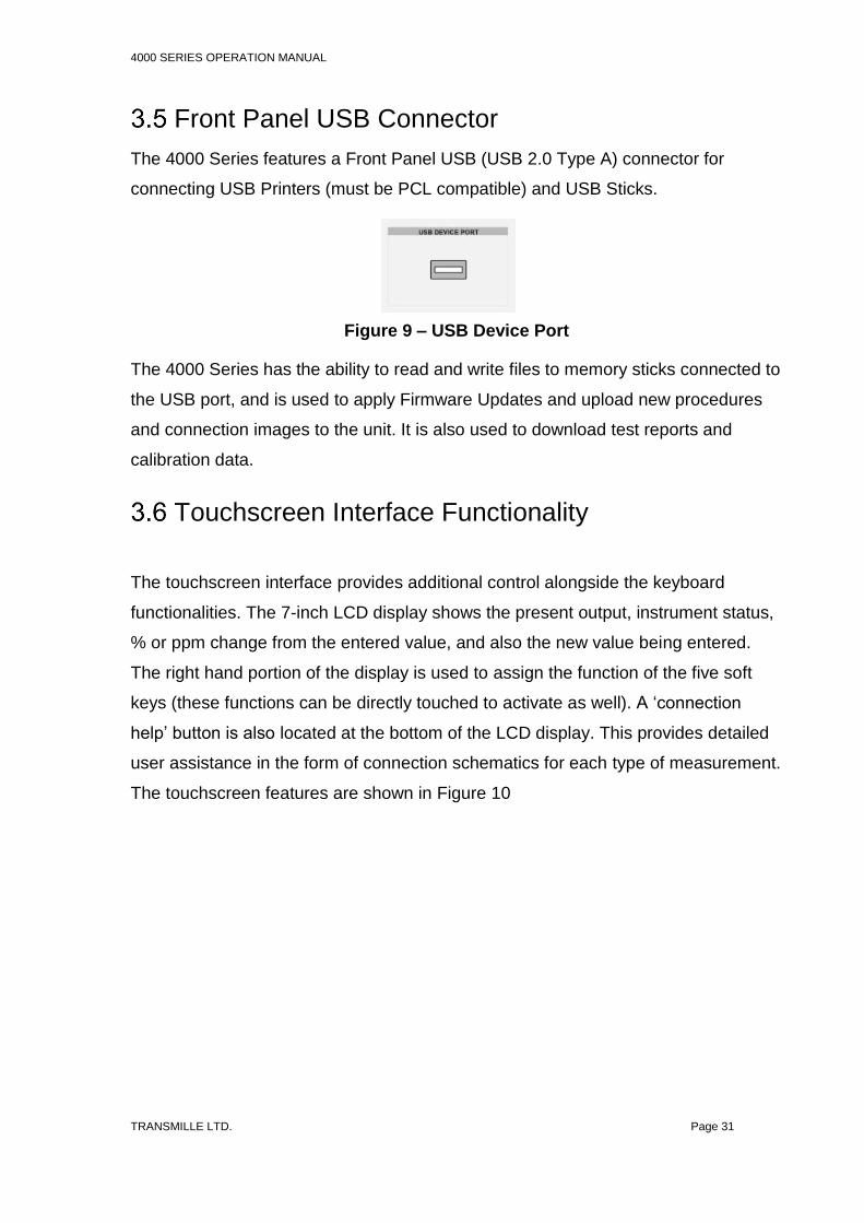
Front Panel USB Connector
The 4000 Series features a Front Panel USB (USB 2.0 Type A) connector for
connecting USB Printers (must be PCL compatible) and USB Sticks.
The 4000 Series has the ability to read and write files to memory sticks connected to
the USB port, and is used to apply Firmware Updates and upload new procedures
and connection images to the unit. It is also used to download test reports and
calibration data.
Touchscreen Interface Functionality
The touchscreen interface provides additional control alongside the keyboard
functionalities. The 7-inch LCD display shows the present output, instrument status,
% or ppm change from the entered value, and also the new value being entered.
The right hand portion of the display is used to assign the function of the five soft
keys (these functions can be directly touched to activate as well). A ‘connection
help’ button is also located at the bottom of the LCD display. This provides detailed
user assistance in the form of connection schematics for each type of measurement.
The touchscreen features are shown in Figure 10
Figure 9 – USB Device Port

4000 SERIES OPERATION MANUAL
TRANSMILLE LTD. Page 32
1. Output range and function
2. Output value
3. Dynamic soft key and direct touch menu
4. Instrument status indicator
5. Negative to Ground indicator
6. Function specific configuration display
7. Error Message Indicator
8. Connection Help
Figure 10 – 7 Inch High Resolution LCD Touchscreen
M
k
DC
m
mOUTPUT OFF
POWER
SCOPE
PROCEDURES
METER
UTILITIES
200mV DC Range [1] NEG TO GND
POLARITY
000.00000mVDC
Status
STANDBYCONNECTION HELP
RANGE HOLD
NEG TO GND
FUNCTIONS
MENU
1 2
3
4
5
6
7

4000 SERIES OPERATION MANUAL
TRANSMILLE LTD. Page 33
Connection Help Prompts
To ensure ease of use, the 4000 Series Calibrator features inbuilt connection help
prompts which can be displayed on the screen. These prompts are designed to
assist with making connections to typical test equipment.
Connection prompts are function specific, and the correct prompt is displayed
automatically for the function selected (i.e. a connection prompt suitable for DC
Voltage will be displayed when in the DC Voltage function).
To view the connection prompt, press the ‘CONNECTION HELP’ key in the lower
right of the main output screen (highlighted in Figure 10 on Page 32). A full screen
colour image of an example connection will appear on the screen
Connection prompts can be updated via the USB connection while performing a
Firmware Update to custom images for specific applications.
To leave the connection help screen, press the ‘CLOSE’ button in the lower right of
the screen.
Note:
The output of the calibrator will remain active during display of a connection prompt.
Figure 11 – Connection Help Screen
4000 SERIES OPERATION MANUAL
TRANSMILLE LTD. Page 34
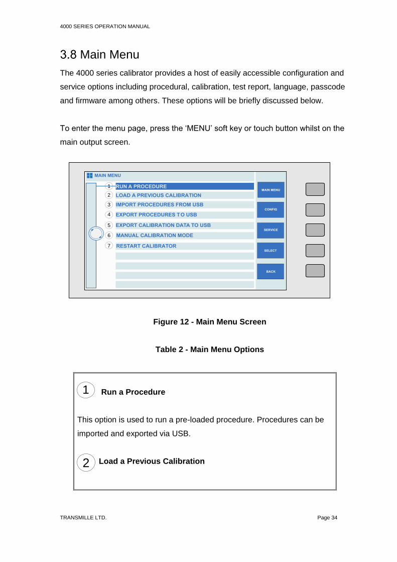
Main Menu
The 4000 series calibrator provides a host of easily accessible configuration and
service options including procedural, calibration, test report, language, passcode
and firmware among others. These options will be briefly discussed below.
To enter the menu page, press the ‘MENU’ soft key or touch button whilst on the
main output screen.
Figure 12 - Main Menu Screen
Table 2 - Main Menu Options
Run a Procedure
This option is used to run a pre-loaded procedure. Procedures can be
imported and exported via USB.
Load a Previous Calibration
M
k
DC
m
mOUTPUT OFF
POWER
SCOPE
PROCEDURES
METER
UTILITIES
MAIN MENU
MAIN MENU
CONFIG
SELECT
BACK
RUN A PROCEDURE
LOAD A PREVIOUS CALIBRATION
IMPORT PROCEDURES FROM USB
EXPORT PROCEDURES TO USB
EXPORT CALIBRATION DATA TO USB
MANUAL CALIBRATION MODE
RESTART CALIBRATOR
SERVICE
1
2
3
4
5
6
7
1
2

4000 SERIES OPERATION MANUAL
TRANSMILLE LTD. Page 35
This option allows the user to view a test report of a previous
calibration. Within this function you can print the report, save data or
select a test to view or resume testing (via the menu key).
Import Procedures from USB
Use this option to import procedures to the calibrator from a USB
storage device.
Export Procedures to USB
Use this option to export procedures from the calibrator to a USB
storage device.
Export Calibration Data to USB
This option allows the export of calibration data to a USB storage
device.
Manual Calibration Mode
This option allows the user to manually calibrate the calibrator via the
touchscreen. This option is password protected and the user will be
prompted to enter the password upon selecting this mode. Please refer
to the 4000 Series Calibration Manual for further details of this function.
Restart Calibrator
If, for unexpected reasons, the calibrator requires restarting, this
function can be used. Upon restarting the calibrator, the default DC
volts screen is displayed.
3
4
5
6
7

4000 SERIES OPERATION MANUAL
TRANSMILLE LTD. Page 36
Configuration Menu
To enter the Configuration Menu, follow the instructions in Section 3.8 to access the
Main Menu. Whilst on the Main Menu, press the ‘CONFIG’ soft key or touch button
to enter the configuration menu.
Figure 13 - Configuration Screen
Table 3 - Configuration Options
View Configuration
Select this option to view your current configuration settings.
Set Passcode
Select this option to set a passcode, using the numerical keys to lock
calibration functions.
Set Test Report Number
M
k
DC
m
mOUTPUT OFF
POWER
SCOPE
PROCEDURES
METER
UTILITIES
CONFIGURATION MENU
MAIN MENU
CONFIG
SELECT
BACK
VIEW CONFIGURATION
SET PASSCODE
SET TEST REPORT NUMBER
SET LANGUAGE
BACKUP CALIBRATION DATA
RESTORE CALIBRATION DATA
SELECT METER [METER=8081]
UPDATE FIRMWARE VIA USB
SERVICE
1
2
3
4
5
6
7
8
1
2
3

4000 SERIES OPERATION MANUAL
TRANSMILLE LTD. Page 37
Using this function to select the current test report number
Set Language
Use this option to change the language displayed on the calibrator.
Backup Calibration Data
This option allows calibration data to be backed up.
Restore Calibration Data
This option allows the user to restore calibration data.
Select Meter
Enables selection of the reference Multimeter to be used for self-
verification / adjustment tests
Update Firmware Via USB
Select this option to update firmware (when available) via USB.
4
5
7
6
8

4000 SERIES OPERATION MANUAL
TRANSMILLE LTD. Page 38
View Hardware Configuration
The ‘View Configuration’ menu option allows users to view the hardware and
software configuration of the 4000 series calibrator, as well as the serial number of
the unit.
To view the configuration of the unit, select the ‘VIEW CONFIGRATION’ menu item.
Figure 14 – Configuration Menu
Upon selecting the menu item and pressing ‘SELECT’ or ‘ENTER’, a prompt will
appear displaying the configuration of the unit.
Figure 15 – Unit Configuration prompt
M
k
DC
m
mOUTPUT OFF
POWER
SCOPE
PROCEDURES
METER
UTILITIES
CONFIGURATION MENU
MAIN MENU
CONFIG
SELECT
BACK
VIEW CONFIGURATION
SET PASSCODE
SET TEST REPORT NUMBER
SET LANGUAGE
BACKUP CALIBRATION DATA
RESTORE CALIBRATION DATA
SELECT METER [METER=8081]
UPDATE FIRMWARE VIA USB
SERVICE
M
k
DC
m
mOUTPUT OFF
POWER
SCOPE
PROCEDURES
METER
UTILITIES
CONFIGURATION MENU
MAIN MENU
CONFIG
SELECT
BACK
VIEW CONFIGURATION
SET PASSCODE
SET TEST REPORT NUMBER
SET LANGUAGE
BACKUP CALIBRATION DATA
RESTORE CALIBRATION DATA
SELECT METER [METER=8081]
UPDATE FIRMWARE VIA USB
SERVICE
OK
UI Version 1.7.1 : 03-09-15Firmware Version 13.0.22 Serial 1234568OS Serial Number = xxxxxxxLock Status = UnlockedOptions:PWRDDS, SCP6400, SIMULATED RESISTANCE, PRT, CAPACITANCE, INDUCTANCE
i

4000 SERIES OPERATION MANUAL
TRANSMILLE LTD. Page 39
Set Passcode
The 4000 Series calibrator has the ability to lock configuration options to prevent
unauthorised changes to settings or configurations.
To modify the Passcode, first select ‘SET PA SSCODE’ from the Configuration
Menu.
Pressing the ‘SELECT’ key, or pressing ‘ENTER’ will display a prompt enabling
entry of a new passcode.
Figure 16 – Set Passcode Selected
Figure 17 – Enter New Passcode Prompt
M
k
DC
m
mOUTPUT OFF
POWER
SCOPE
PROCEDURES
METER
UTILITIES
CONFIGURATION MENU
MAIN MENU
CONFIG
SELECT
BACK
VIEW CONFIGURATION
SET PASSCODE
SET TEST REPORT NUMBER
SET LANGUAGE
BACKUP CALIBRATION DATA
RESTORE CALIBRATION DATA
SELECT METER [METER=8081]
UPDATE FIRMWARE VIA USB
SERVICE
M
k
DC
m
mOUTPUT OFF
POWER
SCOPE
PROCEDURES
METER
UTILITIES
CONFIGURATION MENU
MAIN MENU
CONFIG
SELECT
BACK
VIEW CONFIGURATION
SET PASSCODE
SET TEST REPORT NUMBER
SET LANGUAGE
BACKUP CALIBRATION DATA
RESTORE CALIBRATION DATA
SELECT METER [METER=8081]
UPDATE FIRMWARE VIA USB
SERVICE
ENTER NEW PASSCODE
NEW PASSCODE
ENTER SETTING (NUMERIC ONLY) USING KEYPAD THEN PRESS ENTER
1234

4000 SERIES OPERATION MANUAL
TRANSMILLE LTD. Page 40
Using the Numerical Keys (Section 3.3), enter the desired code. Pressing the
‘ENTER’ key will confirm your entry, which will be confirmed by the calibrator.
Configuring Test Report Number
To adjust the test report number that the 4000 series assigns to test procedures, the
Configuration Menu can be used to set a new starting number. This will then be
automatically incremented each time a new test procedure is saved.
To modify the Test Report number, first select ‘SET TEST REPORT NUMBER’ from
the Configuration Menu.
Figure 18 – Confirmation of change to Passcode
M
k
DC
m
mOUTPUT OFF
POWER
SCOPE
PROCEDURES
METER
UTILITIES
CONFIGURATION MENU
MAIN MENU
CONFIG
SELECT
BACK
VIEW CONFIGURATION
SET PASSCODE
SET TEST REPORT NUMBER
SET LANGUAGE
BACKUP CALIBRATION DATA
RESTORE CALIBRATION DATA
SELECT METER [METER=8081]
UPDATE FIRMWARE VIA USB
SERVICE
ENTER NEW PASSCODE
NEW PASSCODE
ENTER SETTING (NUMERIC ONLY) USING KEYPAD THEN PRESS ENTER
1234Passcode changed to 1234i

4000 SERIES OPERATION MANUAL
TRANSMILLE LTD. Page 41
Pressing the ‘SELECT’ key, or pressing ‘ENTER’ will display a prompt enabling
entry of the new Test Report Number
Using the Numerical Keys (Section 3.3), enter the desired code. Pressing the
‘ENTER’ key will confirm your entry, which will be confirmed by the calibrator
Figure 19 – Set Test Report Number selected
Figure 20 – Enter New Test Report Number Prompt
M
k
DC
m
mOUTPUT OFF
POWER
SCOPE
PROCEDURES
METER
UTILITIES
CONFIGURATION MENU
MAIN MENU
CONFIG
SELECT
BACK
VIEW CONFIGURATION
SET PASSCODE
SET TEST REPORT NUMBER
SET LANGUAGE
BACKUP CALIBRATION DATA
RESTORE CALIBRATION DATA
SELECT METER [METER=8081]
UPDATE FIRMWARE VIA USB
SERVICE
ENTER NEW TEST REPORT NUMBER
START FROM
ENTER SETTING (NUMERIC ONLY) USING KEYPAD THEN PRESS ENTER
1

4000 SERIES OPERATION MANUAL
TRANSMILLE LTD. Page 42
Figure 21 – Confirmation of change to Test Report number
M
k
DC
m
mOUTPUT OFF
POWER
SCOPE
PROCEDURES
METER
UTILITIES
CONFIGURATION MENU
MAIN MENU
CONFIG
SELECT
BACK
VIEW CONFIGURATION
SET PASSCODE
SET TEST REPORT NUMBER
SET LANGUAGE
BACKUP CALIBRATION DATA
RESTORE CALIBRATION DATA
SELECT METER [METER=8081]
UPDATE FIRMWARE VIA USB
SERVICE
ENTER NEW TEST REPORT NUMBER
START FROM
ENTER SETTING (NUMERIC ONLY) USING KEYPAD THEN PRESS ENTER
1Test number set to start from 1i

4000 SERIES OPERATION MANUAL
TRANSMILLE LTD. Page 43
Configuring Reference Multimeter
The 4000 series has the ability to self-verify using an external reference multimeter
for full traceability.
To configure communication with an external multimeter, the model and address
(GPIB only) must be configured.
The default condition is to connect to a Transmille 8081 via the front panel USB port,
however an option is available to add an additional GPIB port to the rear panel for
connection to multimeter that offer only GPIB interfaces.
Note: To avoid address conflicts on the GPIB bus, the GPIB controlled reference
meter MUST be connected to the correct GPIB connector.
To select the model and address of reference meter, highlight the ‘SELECT METER’
menu option in the configuration menu
Press the ‘SELECT’ soft key or the ‘ENTER’ key to access the meter configuration
menu. Using the Digital Control or the arrow keys, select the required multimeter by
highlighting the selection and then pressing ‘SELECT’ or using the ‘ENTER’ key
Figure 22 – Reference Meter Selection

4000 SERIES OPERATION MANUAL
TRANSMILLE LTD. Page 44
In the case of the Reference Meter GPIB option being installed, and a meter that
offers only GPIB connectivity has been selected an additional menu will appear
prompting the user to enter the GPIB address of the reference multimeter.
Note: The 4000 series supports GPIB addresses between 1 and 30
Note: The Reference meter port acts as a GPIB HOST rather than GPIB DEVICE.
The Reference meter port should not be used to control the 4000 series over GPIB
bus.
Figure 23 – Reference Meter Configuration Menu
Figure 24 – Reference Meter GPIB Address Entry

4000 SERIES OPERATION MANUAL
TRANSMILLE LTD. Page 45
Updating Firmware via USB
The 4000 Series provides the facility to improve functionality via Firmware updates
that can be applied by the end user via USB.
Note :
Updating firmware is at the users risk. Although security checks are performed while
applying updates, incorrectly applying firmware updates (corrupted memory stick,
invalid updates, removing memory stick during the update process, power failures)
run the risk of loss of data / functionality.
To update firmware of the 4000 Series via USB, a blank memory stick formatted as
FAT32 is required.
Transmille will provide an update package to be copied across to the memory stick
using a computer. After copying the contents of the update package to the memory
stick, the memory stick should be connected to the Front Panel USB Connector (see
Figure 9 on Page 31).
After waiting approximately 5 seconds for the USB stick to be recognised (if using a
Transmille memory stick the active LED will light), select ‘UPDATE FIRMWARE VIA
USB’ from the Configuration Menu.
Figure 25 – Update Firmware via USB Selected
M
k
DC
m
mOUTPUT OFF
POWER
SCOPE
PROCEDURES
METER
UTILITIES
CONFIGURATION MENU
MAIN MENU
CONFIG
SELECT
BACK
VIEW CONFIGURATION
SET PASSCODE
SET TEST REPORT NUMBER
SET LANGUAGE
BACKUP CALIBRATION DATA
RESTORE CALIBRATION DATA
SELECT METER [METER=8081]
UPDATE FIRMWARE VIA USB
SERVICE

4000 SERIES OPERATION MANUAL
TRANSMILLE LTD. Page 46
Pressing the ‘SELECT’ key, or pressing ‘ENTER’ will display a prompt showing progress of the firmware update.
After the progress bar has filled, updated connection images, language databases
and procedures will also be copied (if present) from the memory stick. If the update
has been successful, a message will be displayed prompting removal of the USB
stick and a message that the calibrator will restart.
After pressing ‘OK’, the calibrator screen will go blank while the calibrator restarts.
The calibrator will restart to the 200mV DC range, with an output of 0mV set.
Figure 26 - Firmware Update Progress Indication
Figure 27 – Firmware Update Successful
M
k
DC
m
mOUTPUT OFF
POWER
SCOPE
PROCEDURES
METER
UTILITIES
CONFIGURATION MENU
MAIN MENU
CONFIG
SELECT
BACK
VIEW CONFIGURATION
SET PASSCODE
SET TEST REPORT NUMBER
SET LANGUAGE
BACKUP CALIBRATION DATA
RESTORE CALIBRATION DATA
SELECT METER [METER=8081]
UPDATE FIRMWARE VIA USB
SERVICE
SYSTEM UPDATING...
Updating Firmware from\USBDisk...OKVerifying Firmware...
M
k
DC
m
mOUTPUT OFF
POWER
SCOPE
PROCEDURES
METER
UTILITIES
CONFIGURATION MENU
MAIN MENU
CONFIG
SELECT
BACK
VIEW CONFIGURATION
SET PASSCODE
SET TEST REPORT NUMBER
SET LANGUAGE
BACKUP CALIBRATION DATA
RESTORE CALIBRATION DATA
SELECT METER [METER=8081]
UPDATE FIRMWARE VIA USB
SERVICE
SYSTEM UPDATING...
Updating Firmware from\USBDisk...OKVerifying Firmware...Updating Connection Images... OKUpdating Language Files... OKUpdate Complete
OK
Remove USB Drive, then click OK to restarti

4000 SERIES OPERATION MANUAL
TRANSMILLE LTD. Page 47
In the unlikely event of the firmware update being unsuccessful, unless the fault is
due to a failure in the mains supply, an error message will be displayed on the
screen indicating that the firmware update was unsuccessful.
During a firmware update, system files are not overwritten until the update has been
successfully validated, so no damage occurs to the system.
A second error message is then displayed to indicate that the update process has
been exited.
Causes for a failed update can include:
Figure 28 – Firmware Update Error Message 1
Figure 29 – Firmware Update Error Message 2
M
k
DC
m
mOUTPUT OFF
POWER
SCOPE
PROCEDURES
METER
UTILITIES
CONFIGURATION MENU
MAIN MENU
CONFIG
SELECT
BACK
VIEW CONFIGURATION
SET PASSCODE
SET TEST REPORT NUMBER
SET LANGUAGE
BACKUP CALIBRATION DATA
RESTORE CALIBRATION DATA
SELECT METER [METER=8081]
UPDATE FIRMWARE VIA USB
SERVICE
OK
Error transferring file from USBi

4000 SERIES OPERATION MANUAL
TRANSMILLE LTD. Page 48
1. Faulty Memory Stick
2. Insufficient time being allowed for Memory Stick to initialise since insertion
3. Corrupt or Missing firmware update files.
In the case of a failed firmware update, Transmille or the local representative should
be contacted before retrying to walk through diagnosis steps.
Special Functions Available Using the ‘Soft’ Keys
The ‘soft’ keys are positioned to the right hand side of the touchscreen display. The
function of these keys will change depending on the parameter of the calibrator.
Connecting Output Negative to Line Earth
(Ground)
The soft key and touch button ‘NEG TO GND’ switches the output negative terminal
from floating to ground (line earth). The ‘on’ condition is shown at the top left of the
display and also by the front panel LED.
We recommend that the default condition of output connected to ground is used as
this reduces noise and pick up and decreases the risk of damage to the calibrator by
incorrect connection.
Selecting front panel control
M
k
DC
m
mOUTPUT OFF
POWER
SCOPE
PROCEDURES
METER
UTILITIES
200mV DC Range [1] NEG TO GND
POLARITY
1.0010000mVDC
Status
STANDBYCONNECTION HELP
RANGE HOLD
NEG TO GND
FUNCTIONS
MENU
REFERENCE
DEVIATION
1.000V
0.10 %
Figure 30 - Negative to Line Earth Indication

4000 SERIES OPERATION MANUAL
TRANSMILLE LTD. Page 49
When the calibrator has been controlled from the interface, the front panel controls
are disabled. To regain front panel control, use the ‘LOCAL’ soft key
M
k
DC
m
mOUTPUT OFF
POWER
SCOPE
PROCEDURES
METER
UTILITIES
200mV DC Range [1] NEG TO GND
1.0010000mVDC
Status
STANDBYCONNECTION HELP
LOCAL
Figure 31 – Local Key

4000 SERIES OPERATION MANUAL
TRANSMILLE LTD. Page 50
Terminal Status LED’s
LED’s above the terminals indicate which pair is active. When terminals are not
active they are electrically isolated from each other, this enables terminals to be
linked together if required.
The terminals on the 4000 series and their status indication LED’s can be seen in
Figure 32. Each terminal is described in Table 2.
Active terminals indicated by illuminated LED
Figure 32 – Active Terminal LED’s

4000 SERIES OPERATION MANUAL
TRANSMILLE LTD. Page 51
Table 4 - Terminal Descriptions

4000 SERIES OPERATION MANUAL
TRANSMILLE LTD. Page 52
Voltage Output Terminal Pair (Black & Red)
Low thermal 4mm safety terminals used for all voltage outputs up to 1025V, for 2 wire/4 wire resistance, capacitance and inductance (optional). Note: the low ‘black’ terminal can be internally switched to line earth by a soft key function. When floating, the maximum voltage on this terminal with respect to ground should not exceed 50 Volts peak.
Current Output Terminals (Black & Red)
4mm safety terminals for all current outputs up to 2 Amps, TTL frequency and for sense connection for 4 wire resistance. Note: the low ‘black’ terminal can be internally switched to line earth by a soft key function. When floating, the maximum voltage on this terminal with respect to ground should not exceed 50 Volts peak.
30 Amps Output Terminals (Blue and Yellow)
4mm Safety terminals used for all currents above 2 Amps.
Earth Terminal (Green)
Isolated BNC sockets for frequency and oscilloscope function outputs. They incorporate a green LED indicator to show when the terminal is active.
Scope & Frequency BNC Connector Outputs
Isolated BNC sockets for frequency and oscilloscope function outputs. They incorporate a green LED indicator to show when the terminal is active.
High Bandwidth Connector Output Type N connector for high bandwidth oscilloscope calibration module (internal option).

4000 SERIES OPERATION MANUAL
TRANSMILLE LTD. Page 53
WARNING:
Dangerous voltage or current may be present on these terminals.
9 Pin Adapter Interface Connector
Used for connection to external pods used for extending calibration capability, e.g.
Thermocouple simulation etc.
Figure 33 - Adapter Interface 9 Way ‘D’ Type Connector (Female)
This connector output incorporates a green LED to indicate when the adapter
interface is active.
The pins connections are as follows:
Pin 1 – +15V
Pin 2 – Digital ground
Pin 3 – Strobe
Pin 4 – Data
Pin 5 – Select
Pin 6 – -15V
Pin 7 – Analogue ground
Pin 8 – Output
Pin 9 – Input
ADAPTER INTERFACE

4000 SERIES OPERATION MANUAL
TRANSMILLE LTD. Page 54
4 Connection Diagrams
Provided in this section are example connection diagrams for typical pieces of test
equipment, indicating the terminals to use for each type of output.
AC/DC Voltage
Figure 34 – AC / DC Voltage Connection
AC/DC Current Up to 2A
- +
- + !!
- !
4010 ADVANCED MULTI PRODUCT CALI
- +
- + !!
- !
4010 ADVANCED MULTI PRODUCT CALI

4000 SERIES OPERATION MANUAL
TRANSMILLE LTD. Page 55
Figure 35 – AC / DC Current up to 2A
AC/DC Current above 2A
Figure 36 – AC / DC Current above 2A
- +
- + !!
- !
4010 ADVANCED MULTI PRODUCT CALI

4000 SERIES OPERATION MANUAL
TRANSMILLE LTD. Page 56
2 Wire Resistance / Variable Resistance / Variable
PRT
Figure 37 – 2 Wire Resistance / Variable Resistance / Variable PRT
4 Wire Resistance / Passive PRT
Figure 38 – 4 Wire Resistance / Passive PRT
- +
- + !!
- !
4010 ADVANCED MULTI PRODUCT CALI
- +
- + !!
- !
4010 ADVANCED MULTI PRODUCT CALI

4000 SERIES OPERATION MANUAL
TRANSMILLE LTD. Page 57
Passive Capacitance / Variable Capacitance
Figure 39 – Passive Capacitance / Variable Capacitance
Inductance (Optional)
Figure 40 - Inductance
- +
- + !!
- !
4010 ADVANCED MULTI PRODUCT CALI
- +
- + !!
- !
4010 ADVANCED MULTI PRODUCT CALI

4000 SERIES OPERATION MANUAL
TRANSMILLE LTD. Page 58
Frequency
Figure 41 - Frequency
Pulse Width Modulation (PWM) / Duty Cycle
Figure 42 – Pulse Width Modulation (PWM) / Duty Cycle
- +
- + !!
- !
4010 ADVANCED MULTI PRODUCT CALI

4000 SERIES OPERATION MANUAL
TRANSMILLE LTD. Page 59
Thermocouple Source using EA001A
Figure 43 - Thermocouple Source Using EA001A
Current Simulation up to 1500A using EA002 coil
adapter
Figure 44 – Current simulation up to 1500A using Ea002 Coil Adapter
OUTPUT SELECT
USB DEVICE PORT ADAPTER INTERFACE
M
ENTER
k
DC
µ
m
VOLTS
AMPS
Ω 4WIRE
F
TEMP °C
M
k
m
u
DC
M
k
DC
µ
m
k
µ
m
k
DC
µ
m
M 9
6
3
±
AC
8
5
2
0
BACKSPACE
7
4
1
.
C
SHIFT ENTER DCMODE
Hz
OHMS

4000 SERIES OPERATION MANUAL
TRANSMILLE LTD. Page 60
RPM Simulation using EA003
Figure 45 - RPM Simulation Using EA003
Oscilloscope Amplitude / Timebase / Rise Time
Figure 46 – Oscilloscope Amplitude / Timebase / Rise Time
- +
- + !!
- !
4010 ADVANCED MULTI PRODUCT CALI
OUTPUT SELECT
USB DEVICE PORT ADAPTER INTERFACE
M
ENTER
k
DC
µ
m
VOLTS
AMPS
Ω 4WIRE
F
TEMP °C
M
k
m
u
DC
M
k
DC
µ
m
k
µ
m
k
DC
µ
m
M 9
6
3
±
AC
8
5
2
0
BACKSPACE
7
4
1
.
C
SHIFT ENTER DCMODE
Hz
OHMS
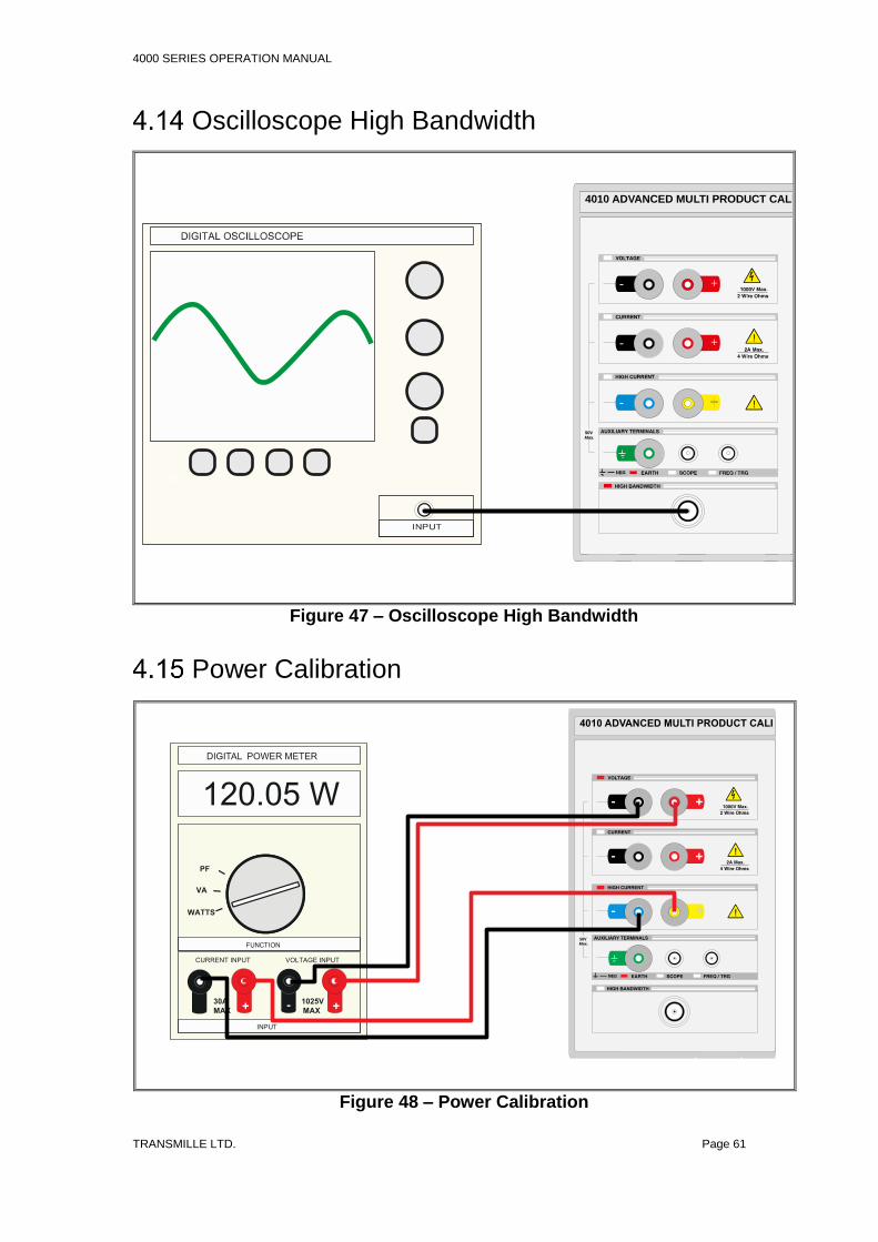
4000 SERIES OPERATION MANUAL
TRANSMILLE LTD. Page 61
Oscilloscope High Bandwidth
Figure 47 – Oscilloscope High Bandwidth
Power Calibration
Figure 48 – Power Calibration
- +
- + !!
- !
4010 ADVANCED MULTI PRODUCT CALI
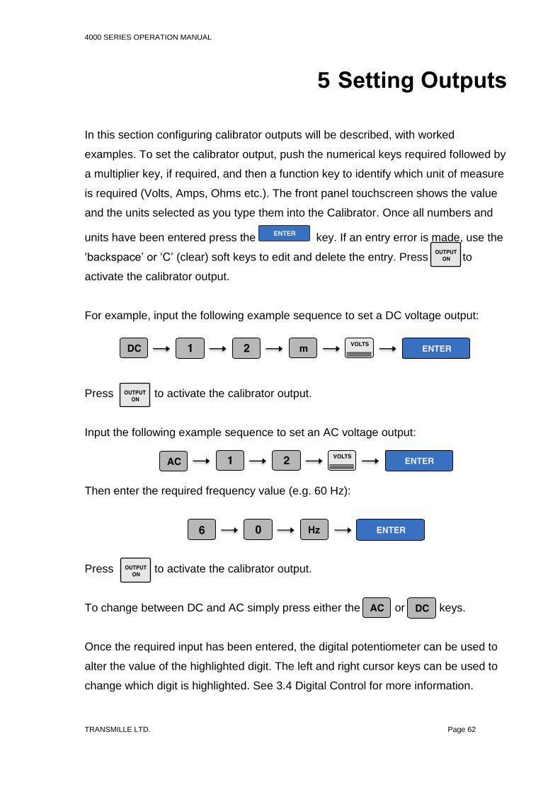
4000 SERIES OPERATION MANUAL
TRANSMILLE LTD. Page 62
5 Setting Outputs
In this section configuring calibrator outputs will be described, with worked
examples. To set the calibrator output, push the numerical keys required followed by
a multiplier key, if required, and then a function key to identify which unit of measure
is required (Volts, Amps, Ohms etc.). The front panel touchscreen shows the value
and the units selected as you type them into the Calibrator. Once all numbers and
units have been entered press the key. If an entry error is made, use the
‘backspace’ or ‘C’ (clear) soft keys to edit and delete the entry. Press to
activate the calibrator output.
For example, input the following example sequence to set a DC voltage output:
Press to activate the calibrator output.
Input the following example sequence to set an AC voltage output:
Then enter the required frequency value (e.g. 60 Hz):
Press to activate the calibrator output.
To change between DC and AC simply press either the or keys.
Once the required input has been entered, the digital potentiometer can be used to
alter the value of the highlighted digit. The left and right cursor keys can be used to
change which digit is highlighted. See 3.4 Digital Control for more information.

4000 SERIES OPERATION MANUAL
TRANSMILLE LTD. Page 63
Adjusting the Set Output Using the Digital Control
After the output has been set, any digit of the output display can be incremented or
decremented using either the digital control or the up and down arrow keys. The
digit selected is indicated by the cursor and can be changed by using the left and
right arrow keys. See section 3.4 Digital Control for more information.
Automatic Display of % or ppm Error and Reference
Key
When the output value is changed by the methods above, the display will show the
change in ppm or % from the original reference value entered from the keyboard. If
needed, the reference value can be reset to the present value on the display by the
REF key.
Figure 49 – Position of % or PPM error from Reference Value
This feature is ideal for displaying the error in a meter under test by adjusting the
output from the calibrator to make the meter read the nominal value.
Range Hold
A soft key and direct touch button is available to toggle between manual and locked
ranges. This function is primarily made to prevent small perturbation in the output
through range changes, typically encountered when making linearity measurements.
M
k
DC
m
mOUTPUT OFF
POWER
SCOPE
PROCEDURES
METER
UTILITIES
200mV DC Range [1] NEG TO GND
POLARITY
1.0010000mVDC
Status
STANDBYCONNECTION HELP
RANGE HOLD
NEG TO GND
FUNCTIONS
MENU
REFERENCE
DEVIATION
1.000V
0.10 %
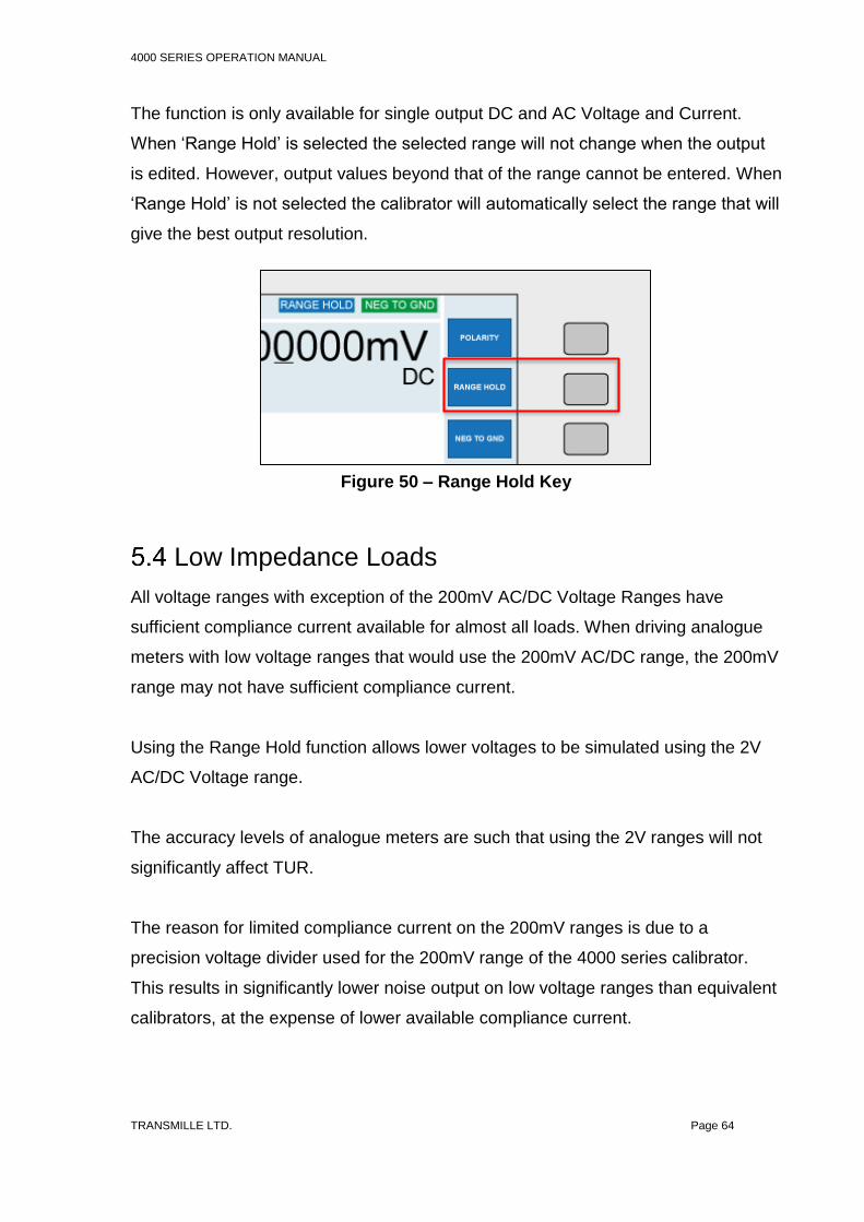
4000 SERIES OPERATION MANUAL
TRANSMILLE LTD. Page 64
The function is only available for single output DC and AC Voltage and Current.
When ‘Range Hold’ is selected the selected range will not change when the output
is edited. However, output values beyond that of the range cannot be entered. When
‘Range Hold’ is not selected the calibrator will automatically select the range that will
give the best output resolution.
Low Impedance Loads
All voltage ranges with exception of the 200mV AC/DC Voltage Ranges have
sufficient compliance current available for almost all loads. When driving analogue
meters with low voltage ranges that would use the 200mV AC/DC range, the 200mV
range may not have sufficient compliance current.
Using the Range Hold function allows lower voltages to be simulated using the 2V
AC/DC Voltage range.
The accuracy levels of analogue meters are such that using the 2V ranges will not
significantly affect TUR.
The reason for limited compliance current on the 200mV ranges is due to a
precision voltage divider used for the 200mV range of the 4000 series calibrator.
This results in significantly lower noise output on low voltage ranges than equivalent
calibrators, at the expense of lower available compliance current.
Figure 50 – Range Hold Key

4000 SERIES OPERATION MANUAL
TRANSMILLE LTD. Page 65
For modern meters with high input impedances and higher resolutions, this
significantly improved noise performance improves noise floor specifications and
performance rather than using direct outputs.
Setting a DC Voltage Output
Complete the following procedure to set a DC voltage output. If an entry error is
made, use the ‘backspace’ or ‘C’ (clear) soft keys to edit and delete the entry.
1) Connect the unit under test to the 4000 series calibrator as required (see section
4.1 AC/DC Voltage for connection information).
2) Ensure the instrument to be calibrated has been set to measure the correct
output on the desired range.
3) On the 4000 series, input the following example sequence to set a DC voltage
output:
4) Press to activate the calibrator output.
The calibrator will now produce 12 mV DC at the appropriate terminals.
Once on a range, any new output within that range can be set without the calibrator
returning to standby. When a high voltage or high current values are entered the
calibrator will automatically go into standby mode. To output this voltage or current,
press the key. This safety feature stops the accidental selection of high
voltage or current.

4000 SERIES OPERATION MANUAL
TRANSMILLE LTD. Page 66
Setting a DC Current Output
Complete the following procedure to set a DC current output. If an entry error is
made, use the ‘backspace’ or ‘C’ (clear) soft keys to edit and delete the entry.
1) Connect the unit under test to the 4000 series calibrator as required (see section
4.2 and 4.3 for connection information).
2) Ensure the instrument to be calibrated has been set to measure the correct
output on the desired range.
3) On the 4000 series, input the following example sequence to set a DC current
output:
4) Press to activate the calibrator output.
The calibrator will now produce 12 mA DC at the appropriate terminals.
Once on a range, any new output within that range can be set without the calibrator
returning to standby. When a high voltage or high current values are entered the
calibrator will automatically go into standby mode. To output this voltage or current,
press the key. This safety feature stops the accidental selection of high
voltage or current.
Note:
Ensure the correct output terminals are used when setting an output above 2A. See
Table 4 and 4.3 for more information.

4000 SERIES OPERATION MANUAL
TRANSMILLE LTD. Page 67
Setting a AC Voltage Output
Complete the following procedure to set an AC voltage output. If an entry error is
made, use the ‘backspace’ or ‘C’ (clear) soft keys to edit and delete the entry.
1) Connect the unit under test to the 4000 series calibrator as required (see section
4.1 AC/DC Voltage for connection information).
2) Ensure the instrument to be calibrated has been set to measure the correct
output on the desired range.
3) On the 4000 series, input the following example sequence to set an AC voltage
output:
4) Then enter the required frequency value (e.g. 60 Hz):
5) Press to activate the calibrator output.
The calibrator will now produce 12 V, 60 Hz AC at the appropriate terminals.
Once on a range, any new output within that range can be set without the calibrator
returning to standby. When a high voltage or high current values are entered the
calibrator will automatically go into standby mode. To output this voltage or current,
press the key. This safety feature stops the accidental selection of high
voltage or current.

4000 SERIES OPERATION MANUAL
TRANSMILLE LTD. Page 68
Setting a AC Current Output
Complete the following procedure to set an AC current output. If an entry error is
made, use the ‘backspace’ or ‘C’ (clear) soft keys to edit and delete the entry.
1) Connect the unit under test to the 4000 series calibrator as required (see section
4.2 and 4.3 for connection information).
2) Ensure the instrument to be calibrated has been set to measure the correct
output on the desired range.
3) On the 4000 series, input the following example sequence to set an AC current
output:
4) Then enter the required frequency value (e.g. 60 Hz):
5) Press to activate the calibrator output.
The calibrator will now produce 12 mA, 60 Hz AC at the appropriate terminals.
Once on a range, any new output within that range can be set without the calibrator
returning to standby. When a high voltage or high current values are entered the
calibrator will automatically go into standby mode. To output this voltage or current,
press the key. This safety feature stops the accidental selection of high
voltage or current.
Note:
Ensure the correct output terminals are used when setting an output above 2A. See
Table 4 and 4.3 for more information.

4000 SERIES OPERATION MANUAL
TRANSMILLE LTD. Page 69
Setting 2 Wire Passive Resistance Output.
Complete the following procedure to select 100k in 2-wire mode. If an entry error is
made, use the ‘BACKSPACE’ or ‘C’ (clear) soft keys to edit and delete the entry.
Note:
The calibrator uses standard resistors of fixed decade values. The nearest available
resistance to the entered value will be automatically selected.
1) Connect the meter under test to the 4000 series calibrator as required (see
section 4.4 2 Wire Resistance / Variable Resistance / Variable PRT for
connection information).
2) Ensure the instrument to be calibrated has been set to measure the correct
output on the desired range.
3) On the 4000 series, input the following example sequence to set a 2-wire
resistance value:
4) Press to activate the calibrator output.
2-Wire resistance ranges can be selected directly from the touchscreen as seen in
Figure 51 or by using the ‘Range up’ and ‘Range down’ keys.
The resistance displayed will be the calibrated value held in the non-volatile
calibration memory for that standard. Note the values are different for 2 and 4-wire
ohms.

4000 SERIES OPERATION MANUAL
TRANSMILLE LTD. Page 70
Alternatively, the 2-wire resistance mode can be selected using the functions menu,
as illustrated below:
On the main DC voltage screen, using the soft keys or touchscreen, press the
‘Functions’ key. The following screen displays a list of available functions. Using the
digital control or touchscreen directly, select the required function (in this case
passive resistance). Once ‘Resistance (Passive)’ has been selected, 2-Wire mode is
activated by default. The soft keys or direct touch buttons can be used to select 2-
Wire mode, as seen in Figure 53.
M
k
DC
m
mOUTPUT OFF
POWER
SCOPE
PROCEDURES
METER
UTILITIES
FUNCTION MENU
FUNCTIONS
ADAPTERS
SELECT
BACK
RESISTANCE (PASSIVE)
RESISTANCE (SIMULATED)
CAPACITANCE (PASSIVE)
CAPACITANCE (SIMULATED)
FREQUENCY
PWM
INDUCTANCE
OSCILLOSCOPE CALIBRATION
POWER CALIBRATION
RTD / PRT (PASSIVE)
RTD / PRT (SIMULATED)
M
k
DC
m
mOUTPUT OFF
SCOPE
PROCEDURES
METER
UTILITIES
NEG TO GND
0100.00°C
Status
STANDBYCONNECTION HELP
4-WIRE
SIMULATED
BACK
2-WIRE
0Ω 0.1Ω 1Ω 10Ω 100Ω 1kΩ 10kΩ
100kΩ 1MΩ 10MΩ 100MΩ 1GΩ
Figure 51 – Direct resistance selection keys
Figure 52 - Resistance (Passive) Selection Using the
Function Menu

4000 SERIES OPERATION MANUAL
TRANSMILLE LTD. Page 71
Figure 53 - Soft Key and Direct Touch Selection of 2-Wire Mode
Setting 2-Wire Simulated Resistance (Option)
The calibrator can simulate (Active) 2-wire resistance values in the range of
0to 10M
Complete the following procedure to select 100k in 2-wire simulated mode. If an
entry error is made, use the ‘backspace’ or ‘C’ (clear) soft keys to edit and delete the
entry.
1. From the resistance screen press the simulated soft key.
M
k
DC
m
mOUTPUT OFF
POWER
SCOPE
PROCEDURES
METER
UTILITIES
200mV DC Range [1] NEG TO GND
2-WIRE
10.000490kΩ
Status
STANDBYCONNECTION HELP
4-WIRE
SIMULATED
NEG TO GND
BACK
2-WIRE
2-Wire mode can be selected via the soft key or touchscreen button

4000 SERIES OPERATION MANUAL
TRANSMILLE LTD. Page 72
Figure 54 – Soft Key and Direct Touch Selection of Simulated Resistance
2. Connect the meter under test to the 4000 series calibrator as required (see
section 2 Wire Resistance / Variable Resistance / Variable PRT on page 56
for connection information).
3. Ensure the instrument to be calibrated has been set to measure the correct
output on the desired range.
4. On the 4000 series, input the following example sequence to set the
resistance value:
5. Press to activate the calibrator output.
Alternatively, the 2-wire simulated resistance mode can be selected using the
functions menu, as illustrated below:
M
k
DC
m
mOUTPUT OFF
POWER
SCOPE
PROCEDURES
METER
UTILITIES
200mV DC Range [1] NEG TO GND
2-WIRE
10.000490kΩ
Status
STANDBYCONNECTION HELP
4-WIRE
SIMULATED
NEG TO GND
BACK
2-WIRE
Simulated Ω can be selected via the soft key or touchscreen button

4000 SERIES OPERATION MANUAL
TRANSMILLE LTD. Page 73
On the main DC voltage screen, using the soft keys or touchscreen, press the
‘Functions’ key. The following screen displays a list of available functions. Using the
digital control or touchscreen directly, select the required function (in this case
simulated resistance). 4-wire mode can then be selected from the soft key menu.
M
k
DC
m
mOUTPUT OFF
POWER
SCOPE
PROCEDURES
METER
UTILITIES
FUNCTION MENU
FUNCTIONS
ADAPTERS
SELECT
BACK
RESISTANCE (PASSIVE)
RESISTANCE (SIMULATED)
CAPACITANCE (PASSIVE)
CAPACITANCE (SIMULATED)
FREQUENCY
PWM
INDUCTANCE
OSCILLOSCOPE CALIBRATION
POWER CALIBRATION
RTD / PRT (PASSIVE)
RTD / PRT (SIMULATED)
Figure 55 - Resistance (Passive) Selection Using the
Function Menu

4000 SERIES OPERATION MANUAL
TRANSMILLE LTD. Page 74
Setting 4-Wire Resistance Output
Complete the following procedure to select 100m in 4-wire mode. If an entry error
is made, use the ‘backspace’ or ‘C’ (clear) soft keys to edit and delete the entry.
Note:
The calibrator uses standard resistors of fixed decade values. The nearest available
resistance to the entered value will be automatically selected.
1) Connect the meter under test to the 4000 series calibrator as required (see
section 4.5 4 Wire Resistance / Passive PRT for connection information).
2) Ensure the instrument to be calibrated has been set to measure the correct
output on the desired range.
3) On the 4000 series, input the following example sequence to set a 4-wire
resistance value:
4) Press to activate the calibrator output.
Other 4-wire ranges can be selected directly from the touchscreen when 4-wire
mode is activated, as seen in Figure 56.
Figure 56 - Direct Resistance Selection Keys
The resistance displayed will be the calibrated value held in the non-volatile
calibration memory for that standard. Note the values are different for 2 and 4 wire
Ohms. 4-wire Ohms is indicated on the terminal LED’s by both the voltage and
current terminal LEDs illuminating.
M
k
DC
m
mOUTPUT OFF
POWER
SCOPE
PROCEDURES
METER
UTILITIES
Thermocouple Range [98] Min=-200 Max=1370 NEG TO GND
NEG TO GND
0100.00°C
Status
STANDBYCONNECTION HELP
4-WIRE
SIMULATED
BACK
4-WIRE
0Ω 0.1Ω 1Ω 10Ω 100Ω 1kΩ 10kΩ
100kΩ

4000 SERIES OPERATION MANUAL
TRANSMILLE LTD. Page 75
Alternatively, the 4-wire resistance mode can be selected using the functions menu,
as illustrated below:
Figure 57 – Resistance (Passive) Selection Using the function Menu
On the main DC voltage screen, using the soft keys or touchscreen, press the
‘Functions’ key. The following screen displays a list of available functions. Using the
digital control or touchscreen directly, select the required function (in this case
passive resistance). Once ‘Resistance (Passive)’ has been selected, 2-Wire mode is
activated by default. The soft keys or direct touch buttons can be used to select 4-
Wire mode, as seen in
Figure 58 - Soft Key and Direct Touch Selection of 4-Wire Mode
M
k
DC
m
mOUTPUT OFF
POWER
SCOPE
PROCEDURES
METER
UTILITIES
FUNCTION MENU
FUNCTIONS
ADAPTERS
SELECT
BACK
RESISTANCE (PASSIVE)
RESISTANCE (SIMULATED)
CAPACITANCE (PASSIVE)
CAPACITANCE (SIMULATED)
FREQUENCY
PWM
INDUCTANCE
OSCILLOSCOPE CALIBRATION
POWER CALIBRATION
RTD / PRT (PASSIVE)
RTD / PRT (SIMULATED)
M
k
DC
m
mOUTPUT OFF
POWER
SCOPE
PROCEDURES
METER
UTILITIES
200mV DC Range [1] NEG TO GND
2-WIRE
10.000490kΩ
Status
STANDBYCONNECTION HELP
4-WIRE
SIMULATED
NEG TO GND
BACK
2-WIRE
4-Wire can be selected via the soft key or touchscreen button

4000 SERIES OPERATION MANUAL
TRANSMILLE LTD. Page 76
Using Current Coils (Option)
The 4000 series calibrator can be used with the optional current coil EA002 (2, 10
and 50 turn coil) or any other current coil that does not exceed the burden voltage
limits.
This enables currents both DC and AC of up to 1500A to be produced for the
calibration of current clamp meters.
The current from the calibrator is connected the appropriate coil connections. The
current output from the calibrator is then multiplied by the number of turns in that coil
producing a higher current for the clamp to measure.
Complete the following procedure to select 500A DC using the 50 turn coil. If an
entry error is made, use the ‘backspace’ or ‘C’ (clear) soft keys to edit and delete the
entry.
1) First press the ‘Functions’ soft key or touch button to enter the functions menu.
2) Press the ‘Adapters’ soft key or touch button to enter the adapters menu.
3) Using the digital control, select ‘EA002 clamp coil adapter’ (touchscreen
functionality can also be used here).
4) Select either 2, 10 or 50 turn coil type as required using the soft keys or touch
button.
5) Input the following example sequence to set 500A DC 50 turn coil.
6) Press to activate the calibrator output.
Note:
30A range output is selected automatically as current output required >2A
50 TURNS

4000 SERIES OPERATION MANUAL
TRANSMILLE LTD. Page 77
Setting Capacitance (Passive) Output
Note:
The calibrator uses standard capacitors of fixed values. The nearest available
capacitance to the entered value will be automatically selected.
Complete the following procedure to select 100nF in Capacitance mode. If an entry
error is made, use the ‘backspace’ or ‘C’ (clear) soft keys to edit and delete the
entry.
1) Connect the meter under test to the 4000 series calibrator as required (see
section 4.6 Passive Capacitance / Variable Capacitance for connection
information).
2) Ensure the instrument to be calibrated has been set to measure the correct
output on the desired range.
3) On the 4000 series, input the following example sequence to enter and set a
Capacitance value:
4) Press to activate the calibrator output.
Different Capacitance ranges can be selected directly from the touchscreen when
Capacitance mode is activated, as shown in Figure 59.
Figure 59 – Direct Capacitance Selection Keys
M
k
DC
m
mOUTPUT OFF
POWER
SCOPE
PROCEDURES
METER
UTILITIES
Thermocouple Range [98] Min=-200 Max=1370 NEG TO GND
0100.00°C
Status
STANDBYCONNECTION HELP
BACK
PASSIVE
1nF 2nF 5nF 10nF 100nF 1uF 10uF

4000 SERIES OPERATION MANUAL
TRANSMILLE LTD. Page 78
Capacitance is available at the voltage terminals as indicated by the LED.
The capacitance displayed will be the calibrated value held in the non-volatile
calibration memory for that standard. Note this is the value measured with a 1 kHz
sine wave on a LCR bridge. When measuring capacitance, Cp (parallel) should be
selected for values up to and including 1uF and Cs (series) for values above.
Alternatively, the passive Capacitance mode can be selected using the functions
menu, as illustrated below:
Figure 60 - Capacitance (Passive) Selection Using Function Menu
On the main DC voltage screen, using the soft keys or touchscreen, press the
‘Functions’ key. The following screen displays a list of available functions. Using the
digital control or touchscreen directly, select the required function (in this case
passive Capacitance).
M
k
DC
m
mOUTPUT OFF
POWER
SCOPE
PROCEDURES
METER
UTILITIES
FUNCTION MENU
FUNCTIONS
ADAPTERS
SELECT
BACK
RESISTANCE (PASSIVE)
RESISTANCE (SIMULATED)
CAPACITANCE (PASSIVE)
CAPACITANCE (SIMULATED)
FREQUENCY
PWM
INDUCTANCE
OSCILLOSCOPE CALIBRATION
POWER CALIBRATION
RTD / PRT (PASSIVE)
RTD / PRT (SIMULATED)

4000 SERIES OPERATION MANUAL
TRANSMILLE LTD. Page 79
Setting Capacitance (Simulated) Output
The calibrator can simulate a range of variable capacitance values (see extended
specifications for available outputs).
Complete the following procedure to select and output in simulated capacitance
mode. If an entry error is made, use the ‘backspace’ or ‘C’ (clear) soft keys to edit
and delete the entry.
1) Connect the meter under test to the 4000 series calibrator as required (see
section 4.6 Passive Capacitance / Variable Capacitance for connection
information).
2) Ensure the instrument to be calibrated has been set to measure the correct
output on the desired range.
3) Select ‘Functions’ using the soft key or touchscreen button.
4) Using the digital potentiometer, or by directly touching the required option, select
‘Capacitance (Simulated)’.
5) Press the ‘ENTER’ or ‘SELECT’ key, the calibrator will enter the Simulated
Capacitance Range
6) On the 4000 series, input the following example sequence to set a Capacitance
output of 12uF
7) The calibrator will change automatically to the most appropriate range and the
entered
8) Press to activate the calibrator output.
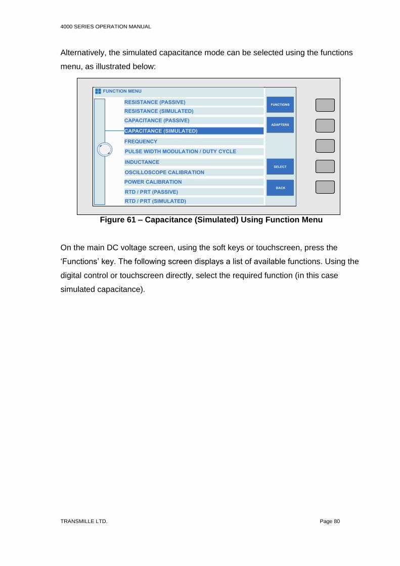
4000 SERIES OPERATION MANUAL
TRANSMILLE LTD. Page 80
Alternatively, the simulated capacitance mode can be selected using the functions
menu, as illustrated below:
Figure 61 – Capacitance (Simulated) Using Function Menu
On the main DC voltage screen, using the soft keys or touchscreen, press the
‘Functions’ key. The following screen displays a list of available functions. Using the
digital control or touchscreen directly, select the required function (in this case
simulated capacitance).
M
k
DC
m
mOUTPUT OFF
POWER
SCOPE
PROCEDURES
METER
UTILITIES
FUNCTION MENU
FUNCTIONS
ADAPTERS
SELECT
BACK
RESISTANCE (PASSIVE)
RESISTANCE (SIMULATED)
CAPACITANCE (PASSIVE)
CAPACITANCE (SIMULATED)
PULSE WIDTH MODULATION / DUTY CYCLE
INDUCTANCE
OSCILLOSCOPE CALIBRATION
POWER CALIBRATION
RTD / PRT (PASSIVE)
RTD / PRT (SIMULATED)
CAPACITANCE (SIMULATED)
FREQUENCY

4000 SERIES OPERATION MANUAL
TRANSMILLE LTD. Page 81
Setting Inductance Output (Option)
Note:
The calibrator uses standard inductors of fixed values. The nearest available
inductance to the entered value will be automatically selected.
Complete the following procedure to select 10mH in Inductance mode. If an entry
error is made, use the ‘backspace’ or ‘C’ (clear) soft keys to edit and delete the
entry.
1) Connect the meter under test to the 4000 series calibrator as required (see
section 4.7 Inductance (Optional) for connection information).
2) Ensure the instrument to be calibrated has been set to measure the correct
output on the desired range.
3) On the 4000 series, input the following example sequence to enter and set an
Inductance value:
4) Press to activate the calibrator output.
Inductance is available at the voltage terminals as indicated by the LED. The
inductance displayed will be the calibrated value held in the non-volatile calibration
memory for that standard.
Different Inductance ranges can be selected directly from the touchscreen when
Inductance mode is activated.
Figure 62 – Direct Inductance Selection Keys
M
k
DC
m
mOUTPUT OFF
POWER
SCOPE
PROCEDURES
METER
UTILITIES
Thermocouple Range [98] Min=-200 Max=1370 NEG TO GND
0100.00°C
Status
STANDBYCONNECTION HELP
BACK
1mH 10mH 20mH 30mH 50mH 1000mH 1H
10H

4000 SERIES OPERATION MANUAL
TRANSMILLE LTD. Page 82
Alternatively, Inductance can be selected using the functions menu, as illustrated
below:
Figure 63 – Inductance Selection Using Function Menu
On the main DC voltage screen, using the soft keys or touchscreen, press the
‘Functions’ key. The following screen displays a list of available functions. Using the
digital control or touchscreen directly, select the required function (in this case
Inductance).
M
k
DC
m
mOUTPUT OFF
POWER
SCOPE
PROCEDURES
METER
UTILITIES
FUNCTION MENU
FUNCTIONS
ADAPTERS
SELECT
BACK
RESISTANCE (PASSIVE)
RESISTANCE (SIMULATED)
CAPACITANCE (PASSIVE)
CAPACITANCE (SIMULATED)
FREQUENCY
PWM
INDUCTANCE
OSCILLOSCOPE CALIBRATION
POWER CALIBRATION
RTD / PRT (PASSIVE)
RTD / PRT (SIMULATED)

4000 SERIES OPERATION MANUAL
TRANSMILLE LTD. Page 83
Thermocouple Simulation (Option)
The thermocouple simulation option allows the user to enter a temperature in °C and
set the calibrator to the specific voltage output which corresponds to the
thermocouple type selected.
On entering thermocouple simulation mode, type K will be the default function. The
display (Figure 64) will indicate the current selected range and output status:
Figure 64 – Thermocouple Simulation Menu
The different Thermocouple types can be directly selected using the touchscreen.
Once in thermocouple mode, the menus available on the right hand of the screen
reflect the thermocouple mode options - the available functions are:
M
k
DC
m
mOUTPUT OFF
POWER
SCOPE
PROCEDURES
METER
UTILITIES
Thermocouple Range [98] Min=-200 Max=1370 NEG TO GND
TYPE
0100.00°C
Status
STANDBYCONNECTION HELP
AUTO CJ
MANUAL CJ
BACK
Type K. Auto CJ = 30.5°C
J K T NBSR
ULE C

4000 SERIES OPERATION MANUAL
TRANSMILLE LTD. Page 84
Table 5 - Thermocouple Functions
Complete
the following procedure to select K type simulation equivalent to 450°C. If an entry
error is made, use the ‘backspace’ or ‘C’ (clear) soft keys to edit and delete the
entry.
1) First press the ‘Functions’ soft key or touch button to enter the functions menu.
2) Press the ‘Adapters’ soft key or touch button to enter the adapters menu.
3) Using the digital control, select ‘EA001A Thermocouple adapter’ (touchscreen
functionality can also be used here).
4) Connect the thermocouple adapter to the adapter interface connection on the
front panel of the 4000 series calibrator (See section 4.10 Thermocouple Source
using EA001A for connection information).
5) Connect the unit under test to the thermocouple. Ensure the correct range has
been selected.
6) Select the thermocouple type to be simulated as described above in this case K
type.
7) Select the cold junction compensation options using the soft keys or touchscreen
(see Table 5).
Selects the manual cold junction (CJ)
compensation mode.
Press the key and input the required CJ
temperature value via the numeric
keypad on the touchscreen.
Selects the automatic cold junction
compensation mode. This allows the
calibrator to use the built in temperature
sensor within the adapter’s thermocouple
plug to compensate for the cold junction
measured between the adapter plug and
the UUT socket.
AUTO CJ
MANUAL CJ

4000 SERIES OPERATION MANUAL
TRANSMILLE LTD. Page 85
8) For Manual CJ only: Input the following example sequence, using the numerical
keypad, to enter 0°C:
9) Press to activate the calibrator output.
To change the temperature output from the nominal value, use the deviation
function. This is controlled by using the left and right arrow keys to select the digit to
be incremented. To increase or decrease the highlighted digit, use the up and down
of the cursor keys or use the digital potentiometer (see section 3.4 Digital Control).
MANUAL CJ

4000 SERIES OPERATION MANUAL
TRANSMILLE LTD. Page 86
Setting Frequency Output
Note:
The calibrator uses a precision Temperature Compensated Crystal Oscillator
(TCXO). Frequencies from 1Hz to 1MHz in steps of 1 Hz are available together with
the reference frequency of 10MHz.
Complete the following procedure to select 10kHz in Frequency mode. If an entry
error is made, use the ‘backspace’ or ‘C’ (clear) soft keys to edit and delete the
entry.
1) Connect the meter under test to the 4000 series calibrator as required (see
section 4.8 Frequency for connection information).
2) Ensure the instrument to be calibrated has been set to measure the correct
output on the desired range.
3) On the 4000 series, input the following example sequence to enter and set the
Frequency value:
4) Press to activate the calibrator output.
To change the Frequency output from the nominal value, use the deviation function.
This is controlled by using the left and right arrow keys to select the digit to be
incremented. To increase or decrease the highlighted digit, use the up and down of
the cursor keys or use the digital potentiometer (see section 3.4 Digital Control).
Furthermore, pressing the ‘decades’ button on the touchscreen allows decade
values to be directly selected. This is illustrated in Figure 65.

4000 SERIES OPERATION MANUAL
TRANSMILLE LTD. Page 87
Figure 65 –
Direct Frequency Selection Keys
Alternatively, Frequency can be selected using the functions menu, as illustrated
below:
Figure 66 – Frequency Selection Using Function Menu
On the main DC voltage screen, using the soft keys or touchscreen, press the
‘Functions’ key. The following screen displays a list of available functions. Using the
digital control or touchscreen directly, select the required function (in this case
Frequency).
M
k
DC
m
mOUTPUT OFF
POWER
SCOPE
PROCEDURES
METER
UTILITIES
FREQUENCY Range [96]
0100.00°C
Status
STANDBYCONNECTION HELP
BACK
10Hz 100Hz 1kHz 10kHz 100kHz 1MHz 10MHz
100MHz
VARIABLE
10MHz REF
DECADES
M
k
DC
m
mOUTPUT OFF
POWER
SCOPE
PROCEDURES
METER
UTILITIES
FUNCTION MENU
FUNCTIONS
ADAPTERS
SELECT
BACK
RESISTANCE (PASSIVE)
RESISTANCE (SIMULATED)
CAPACITANCE (PASSIVE)
CAPACITANCE (SIMULATED)
FREQUENCY
PWM
INDUCTANCE
OSCILLOSCOPE CALIBRATION
POWER CALIBRATION
RTD / PRT (PASSIVE)
RTD / PRT (SIMULATED)
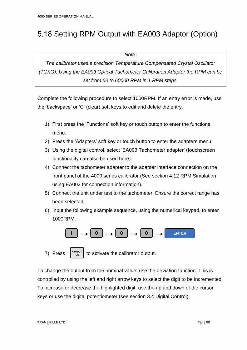
4000 SERIES OPERATION MANUAL
TRANSMILLE LTD. Page 88
Setting RPM Output with EA003 Adaptor (Option)
Note:
The calibrator uses a precision Temperature Compensated Crystal Oscillator
(TCXO). Using the EA003 Optical Tachometer Calibration Adaptor the RPM can be
set from 60 to 60000 RPM in 1 RPM steps.
Complete the following procedure to select 1000RPM. If an entry error is made, use
the ‘backspace’ or ‘C’ (clear) soft keys to edit and delete the entry.
1) First press the ‘Functions’ soft key or touch button to enter the functions
menu.
2) Press the ‘Adapters’ soft key or touch button to enter the adapters menu.
3) Using the digital control, select ‘EA003 Tachometer adapter’ (touchscreen
functionality can also be used here).
4) Connect the tachometer adapter to the adapter interface connection on the
front panel of the 4000 series calibrator (See section 4.12 RPM Simulation
using EA003 for connection information).
5) Connect the unit under test to the tachometer. Ensure the correct range has
been selected.
6) Input the following example sequence, using the numerical keypad, to enter
1000RPM:
7) Press to activate the calibrator output.
To change the output from the nominal value, use the deviation function. This is
controlled by using the left and right arrow keys to select the digit to be incremented.
To increase or decrease the highlighted digit, use the up and down of the cursor
keys or use the digital potentiometer (see section 3.4 Digital Control).

4000 SERIES OPERATION MANUAL
TRANSMILLE LTD. Page 89
Alternatively set RPM values can be directly selected using the soft keys or
touchscreen buttons, as seen in Figure 67.
Figure 67 – Soft Key and Direct Touch Selection of RPM Values
M
k
DC
m
mOUTPUT OFF
POWER
SCOPE
PROCEDURES
METER
UTILITIES
RPM Range [99]
01002RPM
Status
STANDBYCONNECTION HELP
BACK
100 RPM
1000 RPM
10000 RPM
60000 RPM
RPM can be selected via the soft key or touchscreen buttons

4000 SERIES OPERATION MANUAL
TRANSMILLE LTD. Page 90
Setting Pulse Width Modulation (PWM, Mark
Space Ratio)
The calibrator can produce an accurate mark space ratio output within the frequency
range 100Hz to 10kHz. The width of the pulse can be adjusted from 1% to 99% in
1% steps.
Complete the following procedure to set a PWM. If an entry error is made, use the
‘backspace’ or ‘C’ (clear) soft keys to edit and delete the entry.
1. Connect the meter under test to the 4000 series calibrator as required (see
section 4.9 Pulse Width Modulation (PWM) / Duty Cycle for connection
information).
2. Ensure the instrument to be calibrated has been set to measure the correct
output on the desired range.
3. Select ‘Functions’ using the soft key or touchscreen button.
4. Using the digital potentiometer, or by directly touching the required option,
select ‘Pulse width modulation / duty cycle’.
5. On the 4000 series, input the following example sequence to enter and set
the required Frequency value (e.g. 1kHz):
6. Press to activate the calibrator output.
To change the required percentage from the nominal value, use the deviation
function. This is controlled by using the left and right arrow keys to select the digit to
be incremented. To increase or decrease the highlighted digit, use the up and down
of the cursor keys or use the digital potentiometer (see section 3.4 Digital Control).

4000 SERIES OPERATION MANUAL
TRANSMILLE LTD. Page 91
Selecting PRT (PT100) Resistance Output (Option)
The calibrator uses fixed value standard resistors. These resistors represent the
following temperatures: -100C, 0C, 30C, 60C, 100C, 200C, 300C and 800C.
The nearest available temperature to the entered value will be selected.
Complete the following procedure to select passive PRT. If an entry error is made,
use the ‘backspace’ or ‘C’ (clear) soft keys to edit and delete the entry.
1) Connect the meter under test to the 4000 series calibrator as required (see
section 4.5 4 Wire Resistance / Passive PRT for connection information).
2) Ensure the instrument to be calibrated has been set to measure the correct
output on the desired range.
3) Select ‘Functions’ using the soft key or touchscreen button.
4) Using the digital potentiometer, or by directly touching the required option, select
‘RTD / PRT (Passive)’.
5) On the 4000 series, input the following example sequence to enter and set the
required temperature value (e.g. 100C):
6) Press to activate the calibrator output.
To change the required temperature, range from the nominal value, use the up and
down of the cursor keys or use the digital potentiometer.

4000 SERIES OPERATION MANUAL
TRANSMILLE LTD. Page 92
Selecting Simulated PRT Output (Option)
The calibrator can simulate PRT temperature values for RTD types 25100,
250500 and 1000in the range -200C to 800C.
Complete the following procedure to select 100C in simulated PRT mode. If an
entry error is made, use the ‘backspace’ or ‘C’ (clear) soft keys to edit and delete the
entry.
1) From the passive PRT screen press the simulated soft key.
Figure 68 – Soft Key and Direct Touch Selection of Simulated Ohms
2) Connect the meter under test to the 4000 series calibrator as required (see
section 4.42 Wire Resistance / Variable Resistance / Variable PRT for
connection information).
3) Ensure the instrument to be calibrated has been set to measure the correct
output on the desired range.
4) On the 4000 series, input the following example sequence to set the
temperature value:
5) Press to activate the calibrator output.
Simulated Ω can be selected via the soft key or touchscreen button
M
k
DC
m
mOUTPUT OFF
POWER
SCOPE
PROCEDURES
METER
UTILITIES
Thermocouple Range [98] Min=-200 Max=1370 NEG TO GND
100.000°C
Status
STANDBYCONNECTION HELP
4-WIRE
SIMULATED
BACK
SIMULATED

4000 SERIES OPERATION MANUAL
TRANSMILLE LTD. Page 93
To change the required temperature from the nominal value, use the deviation
function. This is controlled by using the left and right arrow keys to select the digit to
be incremented. To increase or decrease the highlighted digit, use the up and down
of the cursor keys or use the digital potentiometer (see section 3.4 Digital Control).

4000 SERIES OPERATION MANUAL
TRANSMILLE LTD. Page 94
Selecting AC Power Calibration Output (Option)
The 4000 series calibrator can simulate power by simultaneously supplying AC
voltage and AC current with a phase relationship.
Complete the procedure below to set a AC power output. If an entry error is made,
use the ‘backspace’ or ‘C’ (clear) soft keys to edit and delete the entry.
1) Connect the meter under test to the 4000 series calibrator as required (see
section 4.15 Power Calibration for connection information).
2) Ensure the instrument to be calibrated has been set to measure the correct
output on the desired range.
3) Select ‘Functions’ using the soft key or touchscreen button.
4) Using the digital potentiometer, or by directly touching the required option, select
‘Power Calibration’. The following screen will appear:
M
k
DC
m
mOUTPUT OFF
POWER
SCOPE
PROCEDURES
METER
UTILITIES
PWRDDS : 200mV AC (21) : 100µA AC Power (126)
000.0000mV
Status
STANDBYCONNECTION HELP
BACK
VOLTAGE
CURRENT
FREQUENCY
000.00µA60Hz
PHASE
0.000W
Φ 1.000
0.000VA
VOLTAGE (TOUCH TO CHANGE)
CURRENT (TOUCH TO CHANGE)
0.0°LOCKED
SINE WAVE
SINE WAVE
1 2 3
8
4 5
5
6
7

4000 SERIES OPERATION MANUAL
TRANSMILLE LTD. Page 95
Figure 69 - AC Power Menu Screen
1) Power Factor 5. Waveform Type (touch to change)
2) Calculated VA Output 6. Current Output
3) Watts 7. Voltage Output
4) Frequency 8. Phase Angle
5) Using the numeric keypad, enter the required voltage value (e.g. 10 V).
6) Then, using the numeric keypad, enter the required current value (e.g. 10 A).
7) Finally, using the numeric keypad, enter the required frequency value (e.g. 60
Hz).
Note:
Current output in power mode follows the same convention as normal current
operation. Up to 2A is output from the low current terminals. 2.02 – 30A output
from the high current terminals. See Section 4.3 on Page 55 for more information.
Alternatively, to select and change the required output from the nominal value, the
deviation function can be used. This is controlled by using the left and right arrow
keys to select the digit to be incremented. To increase or decrease the highlighted
digit, use the up and down of the cursor keys or use the digital potentiometer (see
section Digital Control).
The required output can also be selected directly by using the soft keys or
touchscreen buttons. This is illustrated in Figure 70.

4000 SERIES OPERATION MANUAL
TRANSMILLE LTD. Page 96
Figure 70 – Soft Key and Direct Touch Selection of AC Power Options
8) To change phase, select the phase soft key or touchscreen button and input the
required value.
9) Press to activate the calibrator output.
Note:
When the ‘locking’ message is shown on the calibrator display, phase correction is
in progress. Phase specifications do not apply until the icon is updated to display
‘LOCKED’. See Figure 71.
Figure 71 – Phase Correction Indicator
PHASE
0.0°LOCKING
M
k
DC
m
mOUTPUT OFF
POWER
SCOPE
PROCEDURES
METER
UTILITIES
PWRDDS : 200mV AC (21) : 100µA AC Power (126)
000.0000mV
Status
STANDBYCONNECTION HELP
BACK
VOLTAGE
CURRENT
FREQUENCY
000.00µA60Hz
PHASE
0.000W
Φ 1.000
0.000VA
VOLTAGE (TOUCH TO CHANGE)
CURRENT (TOUCH TO CHANGE)
0.0°LOCKED
SINE WAVE
SINE WAVE
AC Power options can be selected via the soft keys or touchscreen buttons.

4000 SERIES OPERATION MANUAL
TRANSMILLE LTD. Page 97
Selecting DC Power Calibration Output (Option)
The 4000 series calibrator can simulate DC power by simultaneously outputting DC
voltage and DC current.
Complete the procedure below to set a DC power output. If an entry error is made,
use the ‘backspace’ or ‘C’ (clear) soft keys to edit and delete the entry.
1) Connect the meter under test to the 4000 series calibrator as required (see
section 4.15 Power Calibration for connection information).
2) Ensure the instrument to be calibrated has been set to measure the correct
output on the desired range.
3) Select ‘Functions’ using the soft key or touchscreen button.
4) Using the digital potentiometer, or by directly touching the required option, select
‘Power Calibration’. The following screen will appear (Figure 72).
Figure 72 – DC Power Menu Screen
5) Using the numeric keypad, enter the required voltage value (e.g. 10 V).
6) Then, using the numeric keypad, enter the required current value (e.g. 10 A).
M
k
DC
m
mOUTPUT OFF
POWER
SCOPE
PROCEDURES
METER
UTILITIES
PWRDDS : 200mV AC (21) : 100µA AC Power (126)
000.00000mV
Status
STANDBYCONNECTION HELP
BACK
VOLTAGE
CURRENT
FREQUENCY
2.0000ADC
PHASE
0.000W
DC
0.000VA
VOLTAGE
CURRENT
DC
DC
DC

4000 SERIES OPERATION MANUAL
TRANSMILLE LTD. Page 98
7) Press to activate the calibrator output.

4000 SERIES OPERATION MANUAL
TRANSMILLE LTD. Page 99
DDS Power (Option)
The DDS power option is used to simulate harmonics, sags, swells and transients
during power output to verify the waveform analysis functions of modern power
analysers in addition to Voltage, Current and Phase.
The DDS power option outputs two independent digitally generated waveforms with
a high degree of accuracy.
Voltage and current waveform types can be selected directly on the touchscreen
(see Figure 73). There are 7 different waveforms available, these are: sine wave, 3rd
harmonic 5%, 3rd harmonic 10%, 5th harmonic 5%, 5th harmonic 10%, 12th harmonic
10% and transient.
M
k
DC
m
mOUTPUT OFF
POWER
SCOPE
PROCEDURES
METER
UTILITIES
PWRDDS : 200mV AC (21) : 100µA AC Power (126)
Status
STANDBYCONNECTION HELP
CANCEL
0.000W
Φ 1.000
0.000VA
VOLTAGE (TOUCH TO CHANGE)
SINE WAVE
SINE WAVE
SELECT VOLTAGE WAVEFORM (TOUCH TO SELECT)
CURRENT (TOUCH TO CHANGE)
SINE WAVE 3rd HARMONIC 5% 3rd HARMONIC 10%
5th HARMONIC 5% 5th HARMONIC 10% 12th HARMONIC 10%
TRANSIENT CUSTOM

4000 SERIES OPERATION MANUAL
TRANSMILLE LTD. Page 100
Figure 73 – Voltage Waveform Selection Screen
The custom waveform item is user programmable using the ProWave software
supplied with the calibrator. See the ProWave documentation for more details on
setting the custom waveform.
To configure the DDS power output, please see the AC Power instructions in
Section 5.22 for configuring Voltage, Current, Frequency and phase parameters,
and then press either the ‘Voltage’ or ‘Current’ waveforms to select the required
waveform.
DDS Power will default to Sine wave generation when the function is first entered.

4000 SERIES OPERATION MANUAL
TRANSMILLE LTD. Page 101
Oscilloscope Calibration Output (Option)
The calibrator provides Amplitude, Timebase and Bandwidth outputs for the
calibration of oscilloscopes.
Complete the procedure below to configure oscilloscope calibration mode. If an
entry error is made, use the ‘backspace’ or ‘C’ (clear) soft keys to edit and delete the
entry.
1) Connect the meter under test to the 4000 series calibrator as required (see
section 4.13 & 4.14 for connection information).
2) Ensure the instrument to be calibrated has been set to measure the correct
output on the desired range.
3) Select ‘Functions’ using the soft key or touchscreen button.
4) Using the digital potentiometer, or by directly touching the required option, select
‘Oscilloscope Calibration’. The following should be the oscilloscope functional
screen.
5) The required output can be selected using the soft keys or touchscreen buttons;
this is illustrated in Figure 74. By default, amplitude is selected.
Figure 74 – Soft Key and Direct Touch Selection for Oscilloscope Options
M
k
DC
m
m
POWER
SCOPE
PROCEDURES
METER
UTILITIES
SCP6400MHz : 2mV/Div NEG TO GND
AMPLITUDE
12.0000mV
Status
STANDBYCONNECTION HELP
BANDWIDTH
TIMEBASE
FAST RISE
BACK
AMPLITUDEMODE
2mV/Div 5mV/Div 10mV/Div 20mV/Div
500mV/Div 1V/Div 2V/Div 5V/Div
50mV/Div
10V/Div
100mV/Div 200mV/Div
20V/Div 50V/Div
Oscilloscope options can be selected via the soft keys or touchscreen buttons.

4000 SERIES OPERATION MANUAL
TRANSMILLE LTD. Page 102
6) Amplitude ranges can be selected directly from the touchscreen as seen in Figure
75 or by using the ‘Range up’ and ‘Range down’ keys.
Figure 75 - Amplitude Mode Screen
7) To select timebase mode press the ‘TIMEBASE’ soft key or touch button. See
Figure 74.
8) Timebase ranges can be selected directly from the touchscreen as seen in Figure
76 or by using the ‘Range up’ and ‘Range down’ keys.
Figure 76 - Timebase Mode Screen
Fig __. DC power functions screen.
M
k
DC
m
m
POWER
SCOPE
PROCEDURES
METER
UTILITIES
SCP6400MHz : 2mV/Div
AMPLITUDE
12.0000mV
Status
STANDBYCONNECTION HELP
BANDWIDTH
TIMEBASE
FAST RISE
BACK
AMPLITUDEMODE
2mV/Div 5mV/Div 10mV/Div 20mV/Div
500mV/Div 1V/Div 2V/Div 5V/Div
50mV/Div
10V/Div
100mV/Div 200mV/Div
20V/Div 50V/Div
M
k
DC
m
m
POWER
SCOPE
PROCEDURES
METER
UTILITIES
SCP6400MHz : 5s/Div
AMPLITUDE
00.00%
Status
STANDBYCONNECTION HELP
BANDWIDTH
TIMEBASE
FAST RISE
BACK
TIMEBASE MODE
20mV/Div
-50% +50%
5s/Div 2s/Div 1s/Div 500ms/Div 200ms/Div 100ms/Div 50ms/Div 20ms/Div
10ms/Div 5ms/Div 2ms/Div 1ms/Div 500µs/Div 200µs/Div 100µs/Div 50µs/Div
20µs/Div 10µs/Div 5µs/Div 2µs/Div 1µs/Div 500ns/Div 200ns/Div 100ns/Div
50ns/Div 20ns/Div 10ns/Div 5ns/Div 2ns/Div
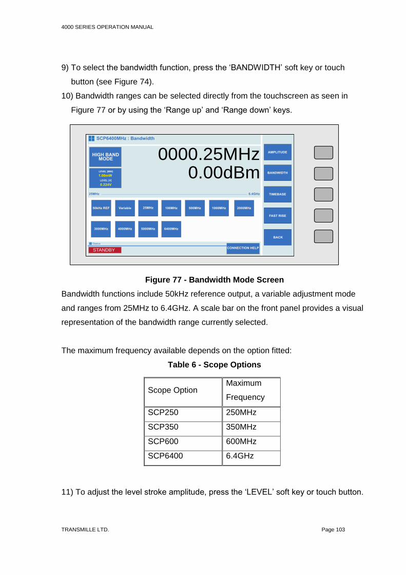
4000 SERIES OPERATION MANUAL
TRANSMILLE LTD. Page 103
9) To select the bandwidth function, press the ‘BANDWIDTH’ soft key or touch
button (see Figure 74).
10) Bandwidth ranges can be selected directly from the touchscreen as seen in
Figure 77 or by using the ‘Range up’ and ‘Range down’ keys.
Figure 77 - Bandwidth Mode Screen
Bandwidth functions include 50kHz reference output, a variable adjustment mode
and ranges from 25MHz to 6.4GHz. A scale bar on the front panel provides a visual
representation of the bandwidth range currently selected.
The maximum frequency available depends on the option fitted:
Table 6 - Scope Options
11) To adjust the level stroke amplitude, press the ‘LEVEL’ soft key or touch button.
Scope Option Maximum
Frequency
SCP250 250MHz
SCP350 350MHz
SCP600 600MHz
SCP6400 6.4GHz
M
k
DC
m
m
POWER
SCOPE
PROCEDURES
METER
UTILITIES
SCP6400MHz : Bandwidth
AMPLITUDE0000.25MHz
Status
STANDBYCONNECTION HELP
BANDWIDTH
TIMEBASE
FAST RISE
BACK
HIGH BAND MODE
2000MHz
0.00dBm25MHz 6.4GHz
1000MHz500MHz100MHz25MHzVariable50kHz REF
3000MHz 4000MHz 5000MHz 6400MHz
LEVEL [MW]
LEVEL [V]
1.00mW
0.224V

4000 SERIES OPERATION MANUAL
TRANSMILLE LTD. Page 104
12) To select the fast rise function, press the ‘FAST RISE’ soft key or touch button
(see Figure 74).
13) Once all required functions and ranges are set, press to activate the
calibrator output.
For all oscilloscope functions: To change the required output from the nominal
value, the deviation function can be used. This is controlled by using the left and
right arrow keys to select the digit to be incremented. To increase or decrease the
highlighted digit, use the up and down of the cursor keys or use the digital
potentiometer (see section 3.4).
4000 SERIES OPERATION MANUAL
TRANSMILLE LTD. Page 105
6 Procedure Mode
NOTE: Procedure Mode as of UI version 1.8.5 is under active development. Further
features will be added in UI updates enabling additional functionality.
The 4000 procedure mode enables automated procedures to be run on the 4000
series without the need for control from a computer.
This function is ideal for production lines or environments where IT systems restrict
the use of computers.
Creating Procedures
Procedures are created using Transmilles ProEdit software. Using ProEdit a
procedure can be written in a matter of minutes using the powerful Wizard.
For further information on ProEdit, please refer to the Transmille website at
www.transmille.com
Importing Procedures
Procedures are uploaded to the 4000 Series using the front mounted USB port.

4000 SERIES OPERATION MANUAL
TRANSMILLE LTD. Page 106
7 Verification Mode
Verification mode is intended for competent
laboratories to be able to accelerate the verification and
adjustment process of the 4000 Series calibrator. Running
adjustment tests will affect the calibration of the instrument, and relies
upon the reference multimeter being within specification.
Transmille hold no responsibility for incorrect adjustments made using
Verification Mode, it is the users responsibility to ensure that reference
equipment used is of a suitable standard and accuracy for use with the
4000 series.
Verification mode can generate high voltages of up to 1020V AC/DC, as
well as currents of up to 30A. Care should be taken at all times and due
caution applied.
Only qualified operators should initiate verification mode and be aware
of the functions and tests that the calibrator will perform.
Note : As of UI version 1.8.5 main features of the 4000 Series can be
verified/calibrated via the front panel verification mode. Additional features such as
Oscilloscope Flatness, Timebase etc. are not possible.
Verification mode performs a fully traceable verification and/or calibration of the
4000 Series. Rather than the artefact calibration used by other
calibrators/references, the method used by the 4000 Series provides traceability
though the reference meter and standard used rather than ‘black box’ methods.

4000 SERIES OPERATION MANUAL
TRANSMILLE LTD. Page 107
A range of verification procedures are available, many of which can be customised
by the operator to verify specific points that may be of particular interest (for
example, 7.5V may be required on a production line, so an additional verification
test can be added to verify the error at this pint rather than the factory defaults)
Equipment Required
Self-verification requires a supported reference multimeter. As of UI version xxx the
following meters are supported:
Table 7 – Supported Reference Multimeters
Manufacturer Model
Transmille 8081
Fluke 8508A
For meters that offer only GPIB Interface (i.e. Fluke 8508A) the optional Reference
Meter interface must be specified. Multimeters with Serial or USB interfaces can be
connected directly to the 4000 series front panel USB port (Serial meters will require
a USB to Serial Convertor that uses an FTDI chip. These adapters are available
from Transmille)
In addition, to verify LCR (Inductance parameters, an LCR meter will be required.
Some multimeters do not offer current measurements up to 30A. In this case
external current shunts will be required. Users are free to use their own shunts if
they fall within the accuracies required for calibration. Alternatively, Transmille
provide a series of AC/DC current shunts with accuracies suitable for performing
calibration of the 4000 series. For further information please visit
www.transmille.com
For verification of Frequency outputs, an external frequency reference is required for
confirming errors within the measurement device.

4000 SERIES OPERATION MANUAL
TRANSMILLE LTD. Page 108
Configuring for Measurements
In section 3.13 on Page 43 the process for configuring the Reference Multimeter is
explained in detail.
Best practice should be applied for choice of test leads, environmental conditions as
well as warm up time of all required equipment.
Only skilled technicians capable of performing the measurements manually should
use the Verification Mode, as considerations such as thermals on leads and errors
due to test lead resistance cannot be compensated for. Excessive errors due to
connection issues will affect the performance of verification mode and cause the
4000 series to be incorrectly adjusted.
Performing Verification
After the 4000 Series has been turned on for at least 4 hours (to achieve best
specifications) and all other required test equipment has warmed up to specification
verification can be performed.
Ensure that the correct reference multimeter has been configured and connected to
the appropriate interface. Instructions for configuring the reference multimeter can
be found in Section 3.13 on Page 43
From the Main screen, press ‘Menu’ to bring up the Main Menu

4000 SERIES OPERATION MANUAL
TRANSMILLE LTD. Page 109
Select ‘Enter Procedure Mode’
From the procedure list, select the verification / adjustment procedure required using
the digital control, arrow keys or touchscreen. A verification of just one function (i.e.
verify only DC Voltage outputs) or a full verification can be run depending upon the
what is required.
Pressing the ‘SELECT’ soft key, or the ‘ENTER’ button will then enter procedure
mode and prepare the reference multimeter for measurements.
Figure 79 – Selecting Verification Procedure
Figure 78 - 4000 Main Screen

4000 SERIES OPERATION MANUAL
TRANSMILLE LTD. Page 110
Verification/Calibration procedures can be configured with prompts to alter the user
to changes in connections/outputs, i.e. a prompt may require the user to short the
voltage leads from the reference multimeter to perform a voltage zero. These
prompts can be turned on and off by selecting (highlighted with a tick). If the box is
not ticked, prompts will not show.
The Verification/Calibration procedure can be run with or without adjustments by
highlighting the checkbox. If the checkbox is selected (highlighted with a tick)
adjustment tests in the procedure will run, performing adjustments to the calibration
of the 4000 Series.
Selecting ‘START TESTING’ will begin the measurement sequence.
Figure 80 – Pre-Test prompt display toggle
Figure 81 – Enable adjustment toggle
Figure 82 - Procedure Mode Screen

4000 SERIES OPERATION MANUAL
TRANSMILLE LTD. Page 111
If Before-Test prompts have been configured in the verification procedure, prior to
measurements starting a pop up screen will appear informing the user of a task to
perform (changing lead configuration for example)
Prompts can appear on the screen if configured within the procedure that is being
run. These prompts will require acknowledgement by pressing the ‘OK’ key that
appears in the centre of the screen below the text prompt.
After pressing ‘OK’ the calibrator will continue with the verification procedure.
The screen will display the measurement mode parameters, with the calibrator
output at the top of the screen.
Figure 83 – Procedure Mode Pre-Test Prompt

4000 SERIES OPERATION MANUAL
TRANSMILLE LTD. Page 112
Table 8 – Verification Screen Components
Label Number Function
1 Test Title / Description – Provides operator with a description
of the test. This is also the title of the test when printed as a
certificate / data is exported.
2 Test number – Provides operator with the position in a
sequence of tests as well as approximate progress.
3 Measurement Status – This status displays the current
measurement state. This status varies upon the current
measurement state of measurement.
4 Summary – provides an overview of tests in the procedure,
including results for tests that have been completed
5 Calibrator Output – displays the calibrators current output
6 Measurement Bar – Provides the operator with a visual
reference of the error in calibrator output. When the arrow
indicates that the current result is ‘Green’, the measurement
is within specification. If the measurement arrow indicates
‘Amber’, the measurement is ‘Marginal’, when the
measurement arrow is in the ‘Red’, this indicates that the
measurement is outside of specification
Figure 84 – Verification Mode Measurement Screen
1 2
3 4
5
6
7
9 8
10 11
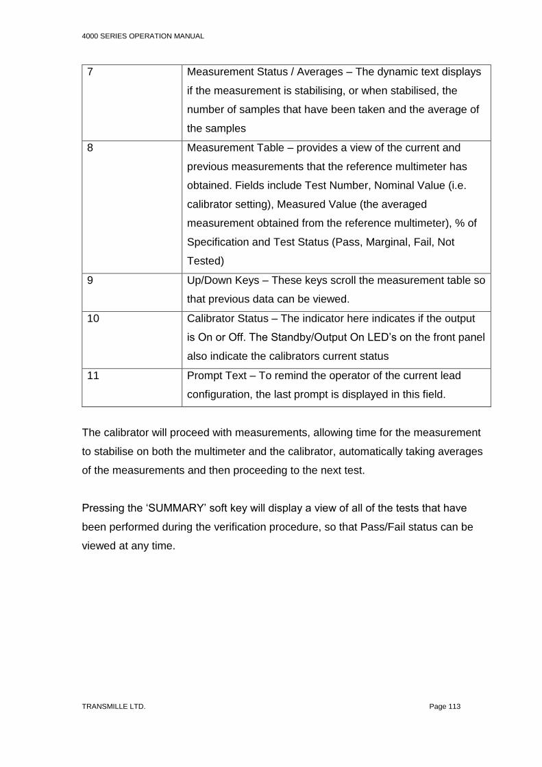
4000 SERIES OPERATION MANUAL
TRANSMILLE LTD. Page 113
7 Measurement Status / Averages – The dynamic text displays
if the measurement is stabilising, or when stabilised, the
number of samples that have been taken and the average of
the samples
8 Measurement Table – provides a view of the current and
previous measurements that the reference multimeter has
obtained. Fields include Test Number, Nominal Value (i.e.
calibrator setting), Measured Value (the averaged
measurement obtained from the reference multimeter), % of
Specification and Test Status (Pass, Marginal, Fail, Not
Tested)
9 Up/Down Keys – These keys scroll the measurement table so
that previous data can be viewed.
10 Calibrator Status – The indicator here indicates if the output
is On or Off. The Standby/Output On LED’s on the front panel
also indicate the calibrators current status
11 Prompt Text – To remind the operator of the current lead
configuration, the last prompt is displayed in this field.
The calibrator will proceed with measurements, allowing time for the measurement
to stabilise on both the multimeter and the calibrator, automatically taking averages
of the measurements and then proceeding to the next test.
Pressing the ‘SUMMARY’ soft key will display a view of all of the tests that have
been performed during the verification procedure, so that Pass/Fail status can be
viewed at any time.

4000 SERIES OPERATION MANUAL
TRANSMILLE LTD. Page 114
From this view all test points in the procedure can be viewed by scrolling up and down using the Digital Control. When the test is highlighted (as in Figure 85), pressing the ‘SELECT TEST’ key will re-run the verification tests from the selected test. Pressing ‘PRINT’ will print out a test report via a PCL compatible printer that has been connected via the Front Panel USB connector. Pressing the ‘SAVE DATA’ key will save the current verification procedure as a new test report. The Test Report is saved under an automatically generated number. This number can be changed by following the procedure in Section 3.12 on Page 40. Pressing ‘MENU’ will return the 4000 Series to the Procedure Mode home screen, and pressing ‘EXIT’ will return the 4000 Series to the main screen, exiting Procedure Mode. If the test report has not been saved, a prompt will appear on the screen prompting if the user wishes to save the test report or to discard results.
Figure 85 – Verification Mode Summary View

4000 SERIES OPERATION MANUAL
TRANSMILLE LTD. Page 115
8 Remote Programming
WARNING
The 4000 Series Calibrator can produce high voltages up
to 1025V and must be programmed with due caution
to prevent dangerous voltages from being present at
the output terminals without warning to the operator.
Any programs should be extensively tested to maintain safe operation
and include safeguard’s such as error catchments and handling to
ensure that any commands sent to the calibrator perform as expected
and any that do not are safely handled to ensure user safety.
Within the 4000 series command language, response codes are
included to determine the operational state of the calibrator. These
response codes can also be used to determine whether a command
was received correctly and thus ensuring safe operation of the
calibrator.
Due to continual improvement, commands are subject to change, with
features either added or removed. Although all efforts will be made to
retain backwards compatibility with previous commands, this cannot be
guaranteed. All commands are correct as of firmware version 13.0.25

4000 SERIES OPERATION MANUAL
TRANSMILLE LTD. Page 116
Response / Error Codes
The 4000 Series calibrators will respond to any command with a fixed code
beginning with a star (*) - the codes are listed below
Table 9 – 4000 Series Response / Error Code Description
Response Code Description *0 Command Successful
*1 Unrecognised Command
*2 Invalid Range
*3 Invalid Frequency
*4 Invalid Output Value
*5 Invalid Calibration Factor
*6 Unauthorised Command
*7 Correct command, incorrect data
*8 High Voltage Timeout
*9 Output Error
*10 I-Guard Voltage Detected
*11 High Current Over Temperature
*12 High Current Timeout
*13 Current Over Compliance
*14 Output Overload
*15 Simulated Resistance – Terminal voltage in excess of
specification
*16 Simulated Resistance – Input Current in excess of
specification
*17 Simulated Resistance – Offset compensation failed
All status/error responses are followed by <CR><LF>, and are send over the
interface even when in Local front panel control.

4000 SERIES OPERATION MANUAL
TRANSMILLE LTD. Page 117
Legacy Commands
To maintain compatibility with 3000A Series Calibrators, the 4000 Series command
language features both new commands for 4000 Series Functions, as well as
backwards compatible commands for use in existing programs.
If the 4000 Series is used with ProCal, the built in drivers automatically support new
functions of the 4000 Series Calibrator.
Programming Commands Overview
The 4000 Series calibrators are controlled by a set of simple high level commands
which can be used either individually or as part of a command sequence.
The required terminator for the commands to be detected by the calibrator is a
carriage return (ASCII character 13) and should be the last character sent on a
command line.
For Example:
{Command}{Data}<CR>
Where the command is represented as {Command}, the required value as {Data}
and the carriage return (ASCII character 13) is represented by <CR>
Compound Commands
To simplify remote commands, multiple commands can be sent in a single line of
instructions. This can reduce the number of lines required in a program to configure
the output of the calibrator.

4000 SERIES OPERATION MANUAL
TRANSMILLE LTD. Page 118
The separator ‘/’ (backslash) should be used between each command/data pair, as
in Figure 86.
An example of the use of this would be setting Range 1 (r1) for 200mV DC Voltage,
with an output of 100mV (O100), followed by turning the output on (S0)
r1/O100/S0<CR>
These commands do not need additional delays between and can simplify the
setting of outputs.
{Command} {Data} {Terminator}
/
Figure 86 – Compound Command Schema

4000 SERIES OPERATION MANUAL
TRANSMILLE LTD. Page 119
Output State
The output status of the 4000 Series Calibrator can be configured with the following
commands:
Standby Mode
Standby ON S1
Standby OFF S0
To turn output ON, set standby to OFF e.g. r1/O100/S0<CR>
DC Voltage Commands
Function Range Command Legacy Command
DC Voltage 200mV r1 R1
2V r2 R2
20V r3 R3
200V r4 R4
1000V r5 R5
10kV (EA3024) r5 R5
Standby Mode
Standby ON S1
Standby OFF S0
Output
Set Output O (not zero)
The DC voltage section consists of a set of range commands which are used in
conjunction with the standby and output command. To enable a DC Voltage to be
set and an output assigned, the following command sequence should be used:
{RANGE}/{OUTPUT}/{STANDBY CONDITION}<CR>

4000 SERIES OPERATION MANUAL
TRANSMILLE LTD. Page 120
For example, to assign 2V D.C. with the output switched on, the command is:
r2/O2/S0<CR>
r2 = 2V Range (as detailed in the table above)
O2 = 2V Output
S0 = Standby OFF (i.e. output switched ON)
<CR> = Carriage Return (ASCII character 13)
Additional examples:
150mV DC r1/O150/S0<CR> (sets 150mV output on the 200mV range)
22V DC r3/O22/S0<CR> (sets 22V output on the 200V range)
If a command includes a value which cannot be set due to, for example, the value
being higher than the range maximum, the calibrator will reject the command and
stay set as it is (the calibrator will also beep to signify a rejected command)
The calibrator will respond to the commands sent with the response codes as
detailed at the beginning of this section. These codes can be used to ensure that
hazardous output conditions are clearly indicated to the operator and to maintain
control of these outputs. This allows the calibrator to be returned to a safe state
once the testing required has been completed (e.g. setting the calibrator back to
standby once a test is complete and ensuring this has been successfully achieved
and no hazardous outputs remain on the terminals).
This functionality is employed within the ProCal calibration software from Transmille
to allow safe operation of the calibrator and to ensure the calibrator is returned to a
safe state in between test points and at the completion of a test sequence.

4000 SERIES OPERATION MANUAL
TRANSMILLE LTD. Page 121
AC Voltage Commands
Function Range Command Legacy Command
AC Voltage 200mV r21 R12
2V r22 R13
20V r23 R14
200V r24 R15
1000V r25 R16
10kV (EA3024) r26
Standby Mode
Standby ON S1
Standby OFF S0
Output
Set Output O (not zero)
AC Frequency
Fxxxxx E.G. 10kHz = F10000
The AC voltage section consists of a set of range commands which are used in
conjunction with the standby and output command. To enable an AC Voltage to be
set and an output assigned, the following command sequence should be used:
<RANGE>/<OUTPUT>/<FREQUENCY>/<STANDBY CONDITION><CR>
For example, to get 2V @ 200Hz AC with the output switched on, the command is:
r2/O2/F200/S0<CR>
r13 = 2V AC Range (as detailed in the table above)
O2 = 2V Output

4000 SERIES OPERATION MANUAL
TRANSMILLE LTD. Page 122
F200 = 200Hz Frequency
S0 = Standby OFF (i.e. output switched ON)
<CR> = Carriage Return (ASCII character 13)
8.7.1 Additional examples:
135mV @ 10kHz AC
r12/O135/F10000/S0<CR>
(sets 135mV @ 10kHz output on the 200mV range)
255V @ 15kHz AC
r16/O255/F15000/S0<CR>
(sets 255V @ 15kHz output on the 1000V range)
If a command includes a value which cannot be set due to, for example, the value
being higher than the range maximum, the calibrator will reject the command and
stay set as it is (the calibrator will also beep to signify a rejected command)
The calibrator will respond to the commands sent with the response codes as
detailed at the beginning of this section. These codes can be used to ensure that
hazardous output conditions are clearly indicated to the operator and to maintain
control of these outputs. This allows the calibrator to be returned to a safe state
once the testing required has been completed (e.g. Setting the calibrator back to
standby once a test is complete and ensuring this has been successfully achieved
and no hazardous outputs remain on the terminals).
This functionality is employed within the ProCal calibration software from Transmille
to allow safe operation of the calibrator and to ensure the calibrator is returned to a
safe state in between test points and at the completion of a test sequence.
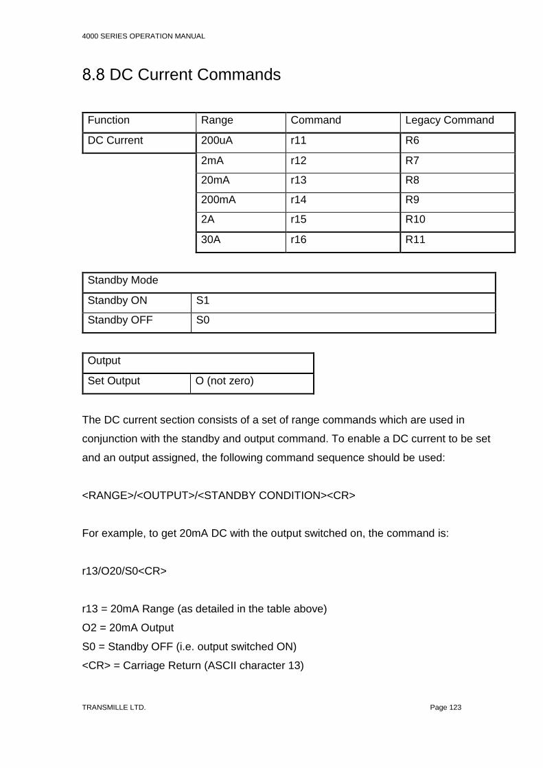
4000 SERIES OPERATION MANUAL
TRANSMILLE LTD. Page 123
DC Current Commands
Function Range Command Legacy Command
DC Current 200uA r11 R6
2mA r12 R7
20mA r13 R8
200mA r14 R9
2A r15 R10
30A r16 R11
Standby Mode
Standby ON S1
Standby OFF S0
Output
Set Output O (not zero)
The DC current section consists of a set of range commands which are used in
conjunction with the standby and output command. To enable a DC current to be set
and an output assigned, the following command sequence should be used:
<RANGE>/<OUTPUT>/<STANDBY CONDITION><CR>
For example, to get 20mA DC with the output switched on, the command is:
r13/O20/S0<CR>
r13 = 20mA Range (as detailed in the table above)
O2 = 20mA Output
S0 = Standby OFF (i.e. output switched ON)
<CR> = Carriage Return (ASCII character 13)

4000 SERIES OPERATION MANUAL
TRANSMILLE LTD. Page 124
Additional examples:
25mA DC r14/O25/S0<CR> (sets 25mA output on the 200mA range)
12A DC r16/O12/S0<CR> (sets 12A output on the 30A range)
If a command includes a value which cannot be set due to, for example, the value
being higher than the range maximum, the calibrator will reject the command and
stay set as it is (the calibrator will also beep to signify a rejected command)
The calibrator will respond to the commands sent with the response codes as
detailed at the beginning of this section. These codes can be used to ensure that
hazardous output conditions are clearly indicated to the operator and to maintain
control of these outputs. This allows the calibrator to be returned to a safe state
once the testing required has been completed (e.g. Setting the calibrator back to
standby once a test is complete and ensuring this has been successfully achieved
and no hazardous outputs remain on the terminals).
This functionality is employed within the ProCal calibration software from Transmille
to allow safe operation of the calibrator and to ensure the calibrator is returned to a
safe state in between test points and at the completion of a test sequence.

4000 SERIES OPERATION MANUAL
TRANSMILLE LTD. Page 125
AC Current Commands
Function Range Command Legacy Command
AC Current 200uA r31 R17
2mA r32 R18
20mA r33 R19
200mA r34 R20
2A r35 R21
30A r36 R22
Standby Mode
Standby ON S1
Standby OFF S0
Output
Set Output O (not zero)
AC Frequency
Fxxxxx E.G. 10kHz = F10000
The AC current section consists of a set of range commands which are used in
conjunction with the standby and output command. To enable a AC current to be set
and an output assigned, the following command sequence should be
used:
<RANGE>/<OUTPUT>/<FREQUENCY>/<STANDBY CONDITION><CR>
For example, to get 20mA @ 1 kHz AC with the output switched on, the command
is:
r33/O20/F1000/S0<CR>
r33 = 20mA Range (as detailed in the table above)
4000 SERIES OPERATION MANUAL
TRANSMILLE LTD. Page 126
O2 = 20mA Output
F1000 = 1 kHz Frequency
S0 = Standby OFF (i.e. output switched ON)
<CR> = Carriage Return (ASCII character 13)
Additional examples:
25mA @ 1.5 kHz AC
r34/O25/F1500/S0<CR>
(sets 25mA @ 1.5kHz output on the 200mA range)
12A AC @ 300 Hz
r36/O12/F300/S0<CR>
(Sets 12A @ 300Hz output on the 20A range)
If a command includes a value which cannot be set due to, for example, the value
being higher than the range maximum, the calibrator will reject the command and
stay set as it is (the calibrator will also beep to signify a rejected command)
The calibrator will respond to the commands sent with the response codes as
detailed at the beginning of this section. These codes can be used to ensure that
hazardous output conditions are clearly indicated to the operator and to maintain
control of these outputs. This allows the calibrator to be returned to a safe state
once the testing required has been completed (e.g. Setting the calibrator back to
standby once a test is complete and ensuring this has been successfully achieved
and no hazardous outputs remain on the terminals).
This functionality is employed within the ProCal calibration software from Transmille
to allow safe operation of the calibrator and to ensure the calibrator is returned to a
safe state in between test points and at the completion of a test sequence.

4000 SERIES OPERATION MANUAL
TRANSMILLE LTD. Page 127
Passive Resistance Commands
Function Range Command Legacy Command
Resistance 0 Ohms r41 R23
0.1 Ohms r42 R24
1 Ohms r43 R25
10 Ohms r44 R26
100 Ohms r45 R27
1 kOhm r46 R28
10 kOhms r47 R29
100 kOhms r48 R30
1 MOhms r49 R31
10 MOhms r50 R32
100 MOhms r51 R33
1G Ohms r52 R65
Standby Mode
Standby ON S1
Standby OFF S0
2 / 4 Wire Resistance
2 Wire I0
4 Wire I1
The resistance section consists of a set of range commands which are used in
conjunction with the 2 or 4 Wire mode and standby commands. To enable a DC
resistance to be set, the following command sequence should be used:
<RANGE>/<2 OR 4 WIRE MODE>/<STANDBY CONDITION><CR>
The use of the output (O) command is not necessary as the resistance ranges are
fixed ranges at decade points.

4000 SERIES OPERATION MANUAL
TRANSMILLE LTD. Page 128
For example, to set the 1kOhm range 2-Wire output with the output switched on, the
command is:
r46/I0/S0<CR>
r46 = 1KOhm Range (as detailed in the table above)
I0 = 2 Wire mode
S0 = Standby OFF (i.e. output switched ON)
<CR> = Carriage Return (ASCII character 13)
Additional examples:
1 kOhm 4-Wire
r46/I1/S0<CR>
10 MOhm 2-Wire
r49/I0/S0<CR>
The calibrator will respond to the commands sent with the response codes as
detailed at the beginning of this section. These codes can be used to ensure that
hazardous output conditions are clearly indicated to the operator and to maintain
control of these outputs. This allows the calibrator to be returned to a safe state
once the testing required has been completed (e.g. setting the calibrator back to
standby once a test is complete and ensuring this has been successfully achieved
and no hazardous outputs remain on the terminals).
This functionality is employed within the ProCal calibration software from Transmille
to allow safe operation of the calibrator and to ensure the calibrator is returned to a
safe state in between test points and at the completion of a test sequence.

4000 SERIES OPERATION MANUAL
TRANSMILLE LTD. Page 129
Passive Capacitance Commands
Function Range Command Legacy Command
Capacitance 1nF r61 R34
2nF r62 R35
5nF r63 R36
10nF r64 R37
100nF r65 R38
1uF r66 R39
10uF r67 R40
Standby Mode
Standby ON S1
Standby OFF S0
The capacitance section consists of a set of range commands which are used in
conjunction with the standby command. To enable a capacitance to be set, the
following command sequence should be used:
<RANGE>/<STANDBY CONDITION><CR>
The use of the output (O) command is not necessary as the capacitance ranges are
fixed ranges at decade points.
For example, to set the 10nF output with the output switched on, the command is:
r64/S0<CR>
r64 = 10nF Range (as detailed in the table above)
S0 = Standby OFF (i.e. output switched ON)
<CR> = Carriage Return (ASCII character 13)

4000 SERIES OPERATION MANUAL
TRANSMILLE LTD. Page 130
Simulated Resistance Commands (Option)
Function Range Command Legacy Command
Resistance 100 Ohms r164 I2/R27
330 Ohms r165 N/A
1 kOhm r166 I2/R28
3.3 kOhms r167 N/A
10 kOhms r168 I2/R29
33 kOhms r169 N/A
100 kOhms r170 I2/R30
330 kOhms r171 N/A
1 MOhms r172 I2/R31
3.3 MOhms r173 N/A
10 MOhms r174 I2/R32
33 MOhms r175 N/A
100 MOhms r176 N/A
330 MOhms r177 N/A
1G Ohms r178 N/A
Standby Mode
Standby ON S1
Standby OFF S0
Output
Set Output O (not zero)
The resistance section consists of a set of range commands which are used in
conjunction with the standby command. To enable a capacitance to be set, the
following command sequence should be used:
<RANGE>/<OUTPUT>/<STANDBY CONDITION><CR>

4000 SERIES OPERATION MANUAL
TRANSMILLE LTD. Page 131
Examples:
8 kOhms 450 MOhms 60 Ohms
r168/O8/S0<CR> r178/O0.45/S0<CR> r164/O60/S0<CR>
r168 = 3.3 kOhm – 10
kOhm Range
O8 = 8 kOhms Output
S0 = Standby OFF (i.e.
output ON)
<CR> = Carriage Return
(ASCII 13)
r178 = 330MOhms – 1
GOhms Range
O450 = 0.45 GOhms
Output
S0 = Standby OFF (i.e.
output ON)
<CR> = Carriage Return
(ASCII 13)
r164 = 0 Ohms – 100
Ohms Range
O60 = 60 Ohms Output
S0 = Standby OFF (i.e.
output ON)
<CR> = Carriage Return
(ASCII 13)

4000 SERIES OPERATION MANUAL
TRANSMILLE LTD. Page 132
Variable Capacitance Commands (Option)
Function Range Command Legacy Command
Capacitance 0.95uF - 9.5uF r193 N/A
9.5 – 95uF r195 N/A
95uf – 950uF r197 N/A
0.95mF – 9.5mF r199 N/A
9.5mF – 100mF r201 N/A
Standby Mode
Standby ON S1
Standby OFF S0
Output
Set Output O (not zero)
The capacitance section consists of a set of range commands which are used in
conjunction with the standby command. To enable a capacitance to be set, the
following command sequence should be used:
<RANGE>/<OUTPUT>/<STANDBY CONDITION><CR>
For example, to set an output of 1.2 mF with the output switched on, the command
is:
r199/O1.2/S0<CR>
r199 = 0.95mF to 9.5mF Range (as detailed in the table above)
O1.2 = Output of 1.2mF
S0 = Standby OFF (i.e. output switched ON)
<CR> = Carriage Return (ASCII character 13)

4000 SERIES OPERATION MANUAL
TRANSMILLE LTD. Page 133
10 uF 40mF
r195/O10/S0<CR> r201/O40/S0<CR>
r195 = 9.5uF – 95uF
Range
O10 = 10 uF Output
S0 = Standby OFF (i.e.
output ON)
<CR> = Carriage Return
(ASCII 13)
r201 = 9.5mF – 100mF
Range
O450 = 40 mF Output
S0 = Standby OFF (i.e.
output ON)
<CR> = Carriage Return
(ASCII 13)

4000 SERIES OPERATION MANUAL
TRANSMILLE LTD. Page 134
Frequency Commands (Option)
Function Mode Activation Command
Frequency R58
Preset Values Command
1Hz H0
10Hz H1
100Hz H2
1kHz H3
10kHz H4
20kHz H5
50kHz H6
100kHz H7
1MHz H8
10MHz H9
Standby Mode
Standby ON S1
Standby OFF S0
The frequency section consists of a mode activation command followed by a set of
range commands which are used in conjunction with the standby command. To
enable a frequency to be set, the following command sequence should be used:
<MODE>/<PRESET OR (O) FREQUENCY>/<STANDBY CONDITION><CR>
The use of the output (O) command enables the frequency to be set from
1Hz to 1MHz in 1Hz steps.
For example, to set the 10 kHz output with the output switched on, the command
would be:

4000 SERIES OPERATION MANUAL
TRANSMILLE LTD. Page 135
R58/H4/S0<CR>
R58 = Frequency Mode Activation (as detailed in the table above)
H4 = 10 kHz output (as detailed in the table above)
S0 = Standby OFF (i.e. output switched ON)
<CR> = Carriage Return (ASCII character 13)
To set a frequency other than a preset the following command line would be used,
for example 15 kHz output with the output switched on:
R58/O15000/SO<CR>
R58 = Frequency Mode Activation (as detailed in the table above)
O15000 = 15 kHz output
S0 = Standby OFF (i.e. output switched ON)
<CR> = Carriage Return (ASCII character 13)
Additional examples:
1 Hz R58/H0/S0<CR>
100 kHz R58/H7/S0<CR>
The calibrator will respond to the commands sent with the response codes as
detailed at the beginning of this section. These codes can be used to ensure that
hazardous output conditions are clearly indicated to the operator and to maintain
control of these outputs. This allows the calibrator to be returned to a safe state
once the testing required has been completed (e.g. Setting the calibrator back to
standby once a test is complete and ensuring this has been successfully achieved
and no hazardous outputs remain on the terminals).
This functionality is employed within the ProCal calibration software from Transmille
to allow safe operation of the calibrator and to ensure the calibrator is returned to a
safe state in between test points and at the completion of a test sequence.

4000 SERIES OPERATION MANUAL
TRANSMILLE LTD. Page 136
Pulse Width Modulation Commands (Option)
Function Mode Activation Command
Pulse Width Modulation R59
Preset Values Command
10% H0
20% H1
30% H2
40% H3
50% H4
60% H5
70% H6
80% H7
90% H8
Frequency
Fxxxxx e.g. 1kHz = F1000
Standby Mode
Standby ON S1
Standby OFF S0
The pulse width modulation section consists of a mode activation command followed
by a set of range commands which are used in conjunction with the standby
command. To enable a pulse width modulation to be set, the following command
sequence should be used:
<MODE>/<FREQUENCY>/<PRESET OR (O) PERCENTAGE>/<STANDBY
CONDITION><CR>

4000 SERIES OPERATION MANUAL
TRANSMILLE LTD. Page 137
The frequency can be set from 100 Hz to 10 kHz in 1Hz steps. The use of the output
(O) command enables the pulse width modulation to be set from 1% to 99% in 1%
steps or the preset values can be used e.g. H0 = 10%
For example, to set the 10% output with the output switched on, the command is:
R59/F1000/H0/S0<CR>
R59 = Pulse width modulation Mode Activation (as detailed in the table above)
F1000 = Frequency 1 kHz (1000 Hz)
H0 = 10% output (as detailed in the table above)
S0 = Standby OFF (i.e. output switched ON)
<CR> = Carriage Return (ASCII character 13)
To set a pulse width other than a preset the following command line would be used,
for example 47% output at 7 kHz with the output switched on:
R59/F7000/O47/S0<CR>
R59 = Pulse width modulation Mode Activation (as detailed in the table above)
F7000 = Frequency 7 kHz (7000 Hz)
O47 = 47% output
S0 = Standby OFF (i.e. output switched ON)
<CR> = Carriage Return (ASCII character 13)
Additional example
100 Hz @ 40% R59/F100/H3/S0<CR>
The calibrator will respond to the commands sent with the response codes as
detailed at the beginning of this section. These codes can be used to ensure that
hazardous output conditions are clearly indicated to the operator and to maintain
control of these outputs. This allows the calibrator to be returned to a safe state
once the testing required has been completed (e.g. setting the calibrator back to

4000 SERIES OPERATION MANUAL
TRANSMILLE LTD. Page 138
standby once a test is complete and ensuring this has been successfully achieved
and no hazardous outputs remain on the terminals).
This functionality is employed within the ProCal calibration software from Transmille
to allow safe operation of the calibrator and to ensure the calibrator is returned to a
safe state in between test points and at the completion of a test sequence.

4000 SERIES OPERATION MANUAL
TRANSMILLE LTD. Page 139
Inductance Commands (Option)
Function Range Command Legacy Command
Inductance 1mH r76 R42
10mH r77 R43
19mH r78 R44
29mH r79 R45
50mH r80 R46
100mH r81 R47
1H r82 R48
10H r83 R49
Standby Mode
Standby ON S1
Standby OFF S0
The inductance section consists of a set of range commands which are used in
conjunction with the standby command. To enable an inductance to be set, the
following command sequence should be used:
<RANGE>/<STANDBY CONDITION><CR>
The use of the output (O) command is not necessary as the inductance ranges are
fixed ranges at decade points.
For example, to set the 29mH output with the output switched on, the command is :
r79/S0<CR>
r79 = 29mH Range (as detailed in the table above)
S0 = Standby OFF (i.e. output switched ON)
<CR> = Carriage Return (ASCII character 13)

4000 SERIES OPERATION MANUAL
TRANSMILLE LTD. Page 140
Additional examples:
10mH r77/S0<CR>
1H r82/S0<CR>
The calibrator will respond to the commands sent with the response codes as
detailed at the beginning of this section. These codes can be used to ensure that
hazardous output conditions are clearly indicated to the operator and to maintain
control of these outputs. This allows the calibrator to be returned to a safe state
once the testing required has been completed (e.g. Setting the calibrator back to
standby once a test is complete and ensuring this has been successfully achieved
and no hazardous outputs remain on the terminals).
This functionality is employed within the ProCal calibration software from Transmille
to allow safe operation of the calibrator and to ensure the calibrator is returned to a
safe state in between test points and at the completion of a test sequence.

4000 SERIES OPERATION MANUAL
TRANSMILLE LTD. Page 141
Passive PRT Commands (Option)
Function Range Command Legacy Command
PRT Value -100C r86 R50
0C r87 R51
30C r88 R52
60C r89 R53
100C r90 R54
200C r91 R55
300C r92 R56
400C r93 R57
Standby Mode
Standby ON S1
Standby OFF S0
The PRT section consists of a set of range commands which are used in
conjunction with the standby command. To enable a PRT value to be set, the
following command sequence should be used:
<RANGE>/<STANDBY CONDITION><CR>
The use of the output (O) command is not necessary as the PRT ranges are fixed
output ranges.

4000 SERIES OPERATION MANUAL
TRANSMILLE LTD. Page 142
For example, to set the 60°C output with the output switched on, the command is:
r89/S0<CR>
r89 = 60°C Range (as detailed in the table above)
S0 = Standby OFF (i.e. output switched ON)
<CR> = Carriage Return (ASCII character 13)
Additional examples:
200°C r91/S0<CR>
400°C r93/S0<CR>
The calibrator will respond to the commands sent with the response codes as
detailed at the beginning of this section. These codes can be used to ensure that
hazardous output conditions are clearly indicated to the operator and to maintain
control of these outputs. This allows the calibrator to be returned to a safe state
once the testing required has been completed (e.g. Setting the calibrator back to
standby once a test is complete and ensuring this has been successfully achieved
and no hazardous outputs remain on the terminals).
This functionality is employed within the ProCal calibration software from Transmille
to allow safe operation of the calibrator and to ensure the calibrator is returned to a
safe state in between test points and at the completion of a test sequence.

4000 SERIES OPERATION MANUAL
TRANSMILLE LTD. Page 143
Variable PRT Commands (Option)
Function Range Command Legacy Command
Variable PRT <auto> r95 N/A
Standby Mode
Standby ON S1
Standby OFF S0
R0
Set R0 Value (25 Ohm, 100 Ohm (default),
500 Ohms, 1kOhm
PRTZERO
The variable PRT output consists of a range command, the R0 value, and the output
value which are used in conjunction with the standby command. To enable an
output to be set, the following command sequence should be used:
<RANGE>/<R0>/<OUTPUT>/<STANDBY CONDITION><CR>
For example, to set the 100°C with an R0 of 100 Ohms with the output switched on,
the command is:
r95/PRTZERO100/O100/S0<CR>
r95 = Variable PRT Function
PRTZERO100 = Set the R0 reference to 100 Ohms
O100 = set the output to 100°C
S0 = Standby OFF (i.e. output switched ON)
<CR> = Carriage Return (ASCII character 13)
Output
Set Output O (not zero)

4000 SERIES OPERATION MANUAL
TRANSMILLE LTD. Page 144
Additional examples:
317.5°C with an R0 of 250 Ohms
r95/PRTZERO250/O317.5/S0<CR>
The calibrator will respond to the commands sent with the response codes as
detailed at the beginning of this section. These codes can be used to ensure that
hazardous output conditions are clearly indicated to the operator and to maintain
control of these outputs. This allows the calibrator to be returned to a safe state
once the testing required has been completed (e.g. setting the calibrator back to
standby once a test is complete and ensuring this has been successfully achieved
and no hazardous outputs remain on the terminals).
This functionality is employed within the ProCal calibration software from Transmille
to allow safe operation of the calibrator and to ensure the calibrator is returned to a
safe state in between test points and at the completion of a test sequence.

4000 SERIES OPERATION MANUAL
TRANSMILLE LTD. Page 145
Thermocouple Simulation Commands (Option)
This function requires the use of the optional EA001A Thermocouple simulation
adapter. This is used in conjunction with the adapter interface connection on the
4000 Series to provide the thermocouple simulation.
Function Command Legacy Command
Thermocouple Simulation r98 R60
Range Command Legacy Command
Type K LK L1
Type J LJ L2
Type T LT L3
Type R LR L4
Type S LS L5
Type E LE L6
Type N LN L7
Type B LB L8
Type U LU N/A
Type C LC N/A
Linear (1mV / °C) Lm N/A
Cold Junction
Manual Cold Junction (0C) K0
Auto Cold Junction K1
Manual Cold Junction settable KT<value>
Output
Set Output O (not zero)
Standby Mode

4000 SERIES OPERATION MANUAL
TRANSMILLE LTD. Page 146
Standby ON S1
Standby OFF S0
The thermocouple simulation function consists of the following commands:
1) Thermocouple simulation mode activation
2) Thermocouple cold junction type
3) Thermocouple type command
4) Thermocouple output value
5) Standby mode command
To enable thermocouple simulation to be set up, the following command sequence
should be used:
<MODE>/<CJC TYPE>/<THERMO TYPE>/<TEMP VALUE>/
<STANDBY CONDITION><CR>
For example, to set the following configuration:
1) AUTOMATIC COLD JUNCTION COMPENSATION
2) TYPE R
3) 250°C
4) Output ON
Send the following command sequence:
r95/K1/LR/O250/S0<CR>
r95 = Thermocouple simulation mode activation
K1 = Automatic cold junction compensation (as detailed in the table above)
LR = Type R thermocouple
O250 = 250°C output
S0 = Standby OFF (i.e. output switched ON)

4000 SERIES OPERATION MANUAL
TRANSMILLE LTD. Page 147
<CR> = Carriage Return (ASCII character 13)
Additional examples:
Type K: Auto CJC: 500°C = r95/K1/LK/O500/S0<CR>
Type K: Auto CJC: 1500°C = r95/K1/LK/O1500/S0<CR>
Type E: Manual CJC (0°C): 400°C = r95/K0/LE/O400/S0<CR>
Type N: Auto CJC: -100°C = r95/K1/LN/O-100/S0<CR>
Type K: Manual CJC (24.5°C): 200°C = r95/KT24.5/LK/O200/S0<CR>
If a command includes a value which cannot be set due to, for example, the value
being higher than the range maximum, the calibrator will reject the command and
stay set as it is (the calibrator will also beep to signify a rejected command)
The calibrator will respond to the commands sent with the response codes as
detailed at the beginning of this section. These codes can be used to ensure that
hazardous output conditions are clearly indicated to the operator and to maintain
control of these outputs. This allows the calibrator to be returned to a safe state
once the testing required has been completed (e.g. setting the calibrator back to
standby once a test is complete and ensuring this has been successfully achieved
and no hazardous outputs remain on the terminals).
This functionality is employed within the ProCal calibration software from Transmille
to allow safe operation of the calibrator and to ensure the calibrator is returned to a
safe state in between test points and at the completion of a test sequence.

4000 SERIES OPERATION MANUAL
TRANSMILLE LTD. Page 148
Oscilloscope Calibration Commands (Option)
This function requires the oscilloscope calibration option to be installed in the 3000A
Series calibrator - the output via the BNC connector indicated by the green LED.
8.20.1 Amplitude
Function Mode Activation Command
Amplitude Mode A1 Amplitude Mode ON
A0 Amplitude Mode OFF
(returns to DCV mode)
Range Command
5mV/DIV H1
10mV/DIV H2
20mV/DIV H3
50mV/DIV H4
100mV/DIV H5
200mV/DIV H6
500mV/DIV H7
1V/DIV H8
2V/DIV H9
5V/DIV H10
10V/DIV H11
20V/DIV H12
50V/DIV H13
Amplitude Waveform
Square Wave G0
DC a. G
1
The Amplitude function consists of the following commands:

4000 SERIES OPERATION MANUAL
TRANSMILLE LTD. Page 149
1) Amplitude mode activation
2) Amplitude range
3) Amplitude waveform
4) Standby mode command
To enable an amplitude range to be set up, the following command sequence
should be used:
<MODE>/<RANGE>/<WAVEFORM>/<STANDBY CONDITION><CR>
For example, to set the following configuration:
5) 1V/Division
6) Square Wave
7) Output ON
Send the following command sequence:
A1/H8/G0/S0<CR>
A1 = Oscilloscope amplitude mode activation
H8 = 1V/Division amplitude range
G0 = Square wave
S0 = Standby OFF (i.e. output switched ON)
<CR> = Carriage Return (ASCII character 13)

4000 SERIES OPERATION MANUAL
TRANSMILLE LTD. Page 150
Additional examples:
100mV/Division: Square Wave = A1/H5/G0/S0<CR>
10V/Division: DC = A1/H11/G1/S0<CR>
The calibrator will respond to the commands sent with the response codes as
detailed at the beginning of this section. These codes can be used to ensure that
hazardous output conditions are clearly indicated to the operator and to maintain
control of these outputs. This allows the calibrator to be returned to a safe state
once the testing required has been completed (e.g. setting the calibrator back to
standby once a test is complete and ensuring this has been successfully achieved
and no hazardous outputs remain on the terminals).
This functionality is employed within the ProCal calibration software from Transmille
to allow safe operation of the calibrator and to ensure the calibrator is returned to a
safe state in between test points and at the completion of a test sequence.

4000 SERIES OPERATION MANUAL
TRANSMILLE LTD. Page 151
8.20.2 Timebase
Function Mode Activation Command
Timebase Mode R61
Range Command
5s/DIV H0
2s/DIV H1
1s/DIV H2
500ms/DIV H3
200ms/DIV H4
100ms/DIV H5
50ms/DIV H6
20ms/DIV H7
10ms/DIV H8
5ms/DIV H9
2ms/DIV H10
1ms/DIV H11
500us/DIV H12
200us/DIV H13
100us/DIV H14
50us/DIV H15
20us/DIV H16
10us/DIV H17
5us/DIV H18
2us/DIV H19
1us/DIV H20
500ns/DIV H21
200ns/DIV H22
100ns/DIV H23
50ns/DIV H24
20ns/DIV H25

4000 SERIES OPERATION MANUAL
TRANSMILLE LTD. Page 152
The Timebase function consists of the following commands:
1) Timebase mode activation
2) Timebase range
3) Standby mode command
To enable a timebase range to be set up, the following command sequence should
be used:
<MODE>/<RANGE>/<STANDBY CONDITION><CR>
For example, to set the following configuration:
4) 1ms/Division
5) Output ON
Send the following command sequence:
R61/H11/S0<CR>
R61 = Oscilloscope timebase mode activation
H11 = 1ms/Division timebase range
S0 = Standby OFF (i.e. output switched ON)
<CR> = Carriage Return (ASCII character 13)

4000 SERIES OPERATION MANUAL
TRANSMILLE LTD. Page 153
Additional examples:
1us/Division = A1/H20/S0<CR>
50ns/Division = A1/H24/S0<CR>
The calibrator will respond to the commands sent with the response codes as
detailed at the beginning of this section. These codes can be used to ensure that
hazardous output conditions are clearly indicated to the operator and to maintain
control of these outputs. This allows the calibrator to be returned to a safe state
once the testing required has been completed (e.g. Setting the calibrator back to
standby once a test is complete and ensuring this has been successfully achieved
and no hazardous outputs remain on the terminals).
This functionality is employed within the ProCal calibration software from Transmille
to allow safe operation of the calibrator and to ensure the calibrator is returned to a
safe state in between test points and at the completion of a test sequence.

4000 SERIES OPERATION MANUAL
TRANSMILLE LTD. Page 154
8.20.3 Bandwidth (Levelled) Sweep – SCP350/SCP600
Function Mode Activation Command
BW Sweep Mode R62
Output
Set Output O (not zero)
The bandwidth function consists of the following commands:
1) Bandwidth mode activation
2) Output value (MHz)
3) Standby mode command
To enable a bandwidth to be set up, the following command sequence should be
used:
<MODE>/<OUTPUT VALUE>/<STANDBY CONDITION><CR>
For example, to set 400MHz output with the output switched on, the command is:
R62/O400/S0<CR>
R62 = Oscilloscope Bandwidth mode activation
O400 = 400MHZ output
S0 = Standby OFF (i.e. output switched ON)
<CR> = Carriage Return (ASCII character 13)

4000 SERIES OPERATION MANUAL
TRANSMILLE LTD. Page 155
Additional examples:
50MHz = R62/O50/S0<CR>
600MHz = R62/O600/S0<CR>
If a command includes a value which cannot be set due to, for example, the value
being higher than the range maximum, the calibrator will reject the command and
stay set as it is (the calibrator will also beep to signify a rejected command)
The calibrator will respond to the commands sent with the response codes as
detailed at the beginning of this section. These codes can be used to ensure that
hazardous output conditions are clearly indicated to the operator and to maintain
control of these outputs. This allows the calibrator to be returned to a safe state
once the testing required has been completed (e.g. Setting the calibrator back to
standby once a test is complete and ensuring this has been successfully achieved
and no hazardous outputs remain on the terminals).
This functionality is employed within the ProCal calibration software from Transmille
to allow safe operation of the calibrator and to ensure the calibrator is returned to a
safe state in between test points and at the completion of a test sequence.

4000 SERIES OPERATION MANUAL
TRANSMILLE LTD. Page 156
8.20.4 Bandwidth (Levelled) Sweep – SCP6400
Function Mode Activation Command
BW Sweep Mode r119
Frequency
Set Frequency F<frequency kHz>
Output Power
Set Power O<power>
Output
Set Output O (not zero)
The bandwidth function consists of the following commands:
1) SCP6400 Range Selection
2) Output Frequency (kHz)
3) Output Power (dBm)
4) Standby mode command
To enable a bandwidth to be set up, the following command sequence should be
used:
<RANGE>/<OUTPUT FREQUENCY>/<OUTPUT POWER>/<STANDBY MODE>
For example, to set 400MHz output, at 0dBm with the output switched on, the
command is:
r119/F400000/O0/S0<CR>

4000 SERIES OPERATION MANUAL
TRANSMILLE LTD. Page 157
r119 = SCP6400
F400000 = 400MHZ Output (400,000kHz)
O0 = 0dBm output
S0 = Standby OFF (i.e. output switched ON)
<CR> = Carriage Return (ASCII character 13)
Additional examples:
400MHz @ -3 dBm = r119/F400000/O-3/S0<CR>
1.2GHz @ -10 dBm = r119/F1200000/O-10/S0<CR>
If a command includes a value which cannot be set due to, for example, the value
being higher than the range maximum, the calibrator will reject the command and
stay set as it is (the calibrator will also beep to signify a rejected command)
The calibrator will respond to the commands sent with the response codes as
detailed at the beginning of this section. These codes can be used to ensure that
hazardous output conditions are clearly indicated to the operator and to maintain
control of these outputs. This allows the calibrator to be returned to a safe state
once the testing required has been completed (e.g. Setting the calibrator back to
standby once a test is complete and ensuring this has been successfully achieved
and no hazardous outputs remain on the terminals).
This functionality is employed within the ProCal calibration software from Transmille
to allow safe operation of the calibrator and to ensure the calibrator is returned to a
safe state in between test points and at the completion of a test sequence.

4000 SERIES OPERATION MANUAL
TRANSMILLE LTD. Page 158
8.20.5 Bandwidth 50kHz Reference
Function Mode Activation Command
BW Ref (50kHz) R63
The bandwidth 50 kHz reference function consists of the following commands:
5) Bandwidth 50 kHz mode activation
6) Standby mode command
To select the 50 kHz reference to be selected, the following command sequence
should be used:
<MODE>/<STANDBY CONDITION><CR>
R63/S0<CR>
R63 = Oscilloscope Bandwidth 50 kHz reference mode activation
S0 = Standby OFF (i.e. output switched ON)
<CR> = Carriage Return (ASCII character 13)
The calibrator will respond to the commands sent with the response codes as
detailed at the beginning of this section. These codes can be used to ensure that
hazardous output conditions are clearly indicated to the operator and to maintain
control of these outputs. This allows the calibrator to be returned to a safe state
once the testing required has been completed (e.g. setting the calibrator back to
standby once a test is complete and ensuring this has been successfully achieved
and no hazardous outputs remain on the terminals).
This functionality is employed within the ProCal calibration software from Transmille
to allow safe operation of the calibrator and to ensure the calibrator is returned to a
safe state in between test points and at the completion of a test sequence.

4000 SERIES OPERATION MANUAL
TRANSMILLE LTD. Page 159
AC Power Calibration Commands (Option)
This function requires the power calibration option to be installed in the 4000 series
calibrator - the output will appear on the voltage terminals and either the low or high
current terminals depending on the setting and be indicated by the combined
illumination of the voltage and current terminal LEDs.
UNDERSTANDING POWER
The equations below explain the relationship between Watts, Current,
Voltage & Phase Angle.
Active Power: Watts = Voltage x Current x Cosine
Apparent Power: VA = Volts x Current
Power Factor: PF = Active Power / Apparent Power
Phase Angle: = Angle of AC Current shift from Voltage
Function Mode Activation Command
Power Mode B1 AC Power Mode ON
B0 Power Mode OFF
(returns to DCV mode)
Voltage Setup
Voltage output (volts) O (not zero)
Current Setup
Current output (amps) C
Phase Setup
Phase setting (degrees) M

4000 SERIES OPERATION MANUAL
TRANSMILLE LTD. Page 160
The power function consists of the following commands:
7) Power mode activation
8) Voltage output setting
9) Current output setting
10)Phase relationship in degrees
11)Standby mode command
To enable a power output to be set up, the following command sequence
should be used:
<MODE>/<VOLTAGE>/<CURRENT>/<PHASE>/<STANDBY CONDITION><CR>
For example, to set the following configuration:
12)200V
13)2A
14)90° Phase
15)Output ON
Send the following command sequence:
B1/O200/C2/M90/S0<CR>
B1 = Power mode activation
O200 = 200V voltage output
C2 = 2A current output
M90 = 90° phase relationship
S0 = Standby OFF (i.e. output switched ON)
<CR> = Carriage Return (ASCII character 13)

4000 SERIES OPERATION MANUAL
TRANSMILLE LTD. Page 161
Additional example:
B1/O500/C10/M180/S0<CR>
B1 = Power mode activation
O500 = 500V voltage output
C10 = 10A current output
M180 = 90° phase relationship
S0 = Standby OFF (i.e. output switched ON)
<CR> = Carriage Return (ASCII character 13)
If a command includes a value which cannot be set due to, for example, the value
being higher than the range maximum, the calibrator will reject the command and
stay set as it is (the calibrator will also beep to signify a rejected command)
The calibrator will respond to the commands sent with the response codes as
detailed at the beginning of this section. These codes can be used to ensure that
hazardous output conditions are clearly indicated to the operator and to maintain
control of these outputs. This allows the calibrator to be returned to a safe state
once the testing required has been completed (e.g. setting the calibrator back to
standby once a test is complete and ensuring this has been successfully achieved
and no hazardous outputs remain on the terminals).
This functionality is employed within the ProCal calibration software from Transmille
to allow safe operation of the calibrator and to ensure the calibrator is returned to a
safe state in between test points and at the completion of a test sequence.
Using the optional virtual front panel software from Transmille, additional
functionality can be achieved from the power function including energy tests in kWh.

4000 SERIES OPERATION MANUAL
TRANSMILLE LTD. Page 162
Miscellaneous Commands
8.22.1 Earth Relay (Floating or Grounded negative terminals)
Earth Relay
J0 Earth Relay On
J1 Earth Relay Off
The earth relay command allows the negative terminals to either floating or
grounded, depending on the command set. This is also indicated in the display of
the calibrator by the -VE symbol (top left).
To set the negative terminals to floating, the command is:
J1<CR>
To set the negative terminals to grounded, the command is:
J0<CR>
<CR> = Carriage Return (ASCII character 13)
8.22.2 Reset Calibrator
*RST<CR> will reset the calibrator to default start up conditions (200mV DC Range, Output Off, Range Hold Off)
8.22.3 System ID
*IDN?<CR> will return a string in the following format:
<MANUFACTURER>,<MODEL>,<SERIAL NUMBER>,<FIRMWARE VERSION>
For the 4010, an example response will be:
TRANSMILLE,4010,12345678,13.0.16

4000 SERIES OPERATION MANUAL
TRANSMILLE LTD. Page 163
8.22.4 Calibration Mode Enable / Disable
Calibration Mode
a1 Enable Calibration Mode (Shift Light Illuminates)
a2 Store Calibration (Shift Light turns off), new calibration
factors stored
a0 Abort Calibration (Shift Light turns off), any changes to
calibration discarded
8.22.5 Transmit Displayed Reading
When the 4010 is used with an adapter that provides read back functionality (such as the TPM series of pressure sensors, the EA008 pA/High Resistance measurement adapter etc.) the 4000 series offers the ability to provide measurements in addition to outputs. To receive the current reading over the interface, the following command should be used:
READ? The calibrator will respond with the current reading, followed by <CR>

4000 SERIES OPERATION MANUAL
TRANSMILLE LTD. Page 164
9 Technical Description
General
The 4000 Series calibrators use the latest in reference, resistor and processor
technology designed to minimise cost and size yet maximise performance. The
microprocessor controls and monitors all functions of the calibrator. Calibration
constants are held in a non-volatile memory allowing the calibration to be performed
without removing the covers. There are no internal adjustments required in normal
service.
Warning risk of shock.
The line power cord must be disconnected before
removing the covers of the instrument
Construction
The calibrator is constructed in a 4U case with fan cooling used for the high voltage
and high current amplifiers. The calibrator construction is modular to allow ease of
servicing. The rear panel assembly comprises of the mains inlet and transformer, 30
Amp power output amplifier and fan assembly.
The main analogue PCB slides into slots in the case from the rear of the instrument.
This plugs into the mother board which is mounted just behind the front panel. The
precision reference and D/A converter plugs into the analogue PCB.
The Power supply and switching PCB plugs in to the mother board just above the
analogue PCB. The Processor board plugs into this PCB.

4000 SERIES OPERATION MANUAL
TRANSMILLE LTD. Page 165
Internal Fuses
In normal operation these fuses should never need to be replaced. Only under fault
conditions will they require changing.
Note:
To access these fuses it is necessary to dismantle the case, which should only be
carried out by a qualified person. See removing top cover.
Warning risk of shock.
The line power cord must be disconnected before
removing the covers of the instrument
Internal fuses include:
F1: 15V Supply A/S 5Amp 20mm
F2: 15V Supply A/S 5Amp 20mm
F3: 35V Supply A/S 1Amp 20mm
F4: 35V Supply A/S 1Amp 20mm

4000 SERIES OPERATION MANUAL
TRANSMILLE LTD. Page 166
Opening The Case
Warning risk of shock.
The line power cord must be disconnected before
removing the covers of the instrument
To gain access to the inside of the calibrator, first remove the top cover by removing
6 screws located on the underneath of the calibrator. Carefully draw the rear panel
straight back away from the instrument. Note the back panel assemble is heavy with
the weight of the mains transformer etc. There are cable assemblies running from
the rear panel sub assemble to PCB inside, these cables can be unplugged if
required.
Figure 87 – Underside of 4000 Series Calibrator
1
2
3

4000 SERIES OPERATION MANUAL
TRANSMILLE LTD. Page 167
Note:
To allow the top cover to be slid back the two side screws must be removed (note
the front panel has 3 fixings at the bottom of the panel – these only need to be
removed if the front panel needs to be dropped down or removed).
Remove all six cover fixing screws to enable cover to be
removed.
Front Panel side screws require removal to slide cover off
enclosure
Front panel bottom screws only require removal if front panel is
to be removed.
1
2
3

4000 SERIES OPERATION MANUAL
TRANSMILLE LTD. Page 168
Access to Internal Fuses – Top Board
After removing the top cover (see above) the metal screening cover of the top PCB
must be removed – remove all nylon fixing screws, plus 1 metal screw from far end
of PCB cover. The fuses will then be clearly visible (see below):
Figure 88 – Top Board With Cover
Fuses F1, F2, F3, F4 located here

4000 SERIES OPERATION MANUAL
TRANSMILLE LTD. Page 169
Figure 89 - Fuse Location on Top Board With Cover Removed
Access to Internal Fuses – Front Panel PCB
Output protection fuses are located on the front panel PCB. To gain access to these,
it is necessary to drop the front panel down – before proceeding, ensure the bottom
3 screws attaching the front panel to the main case are removed (see previous
instructions for removing the top cover)
Figure 90 – Fuse Location on Front Panel PCB
To allow the front panel to be dropped down for access to the front panel fuses,
remove the screws from both sides of the front panel assembly, shown above. The
fuses are located in PCB mounted fuse holders as shown above. Replace these
fuses with the same type and rating – 2A Ultra Rapid
Fuses F1, F2 located here

4000 SERIES OPERATION MANUAL
TRANSMILLE LTD. Page 170
Power supply and output switching board
On this board is the power supply for the calibrator which is a linear design having
the inherent advantage of being low in noise. Supply voltages are 5 Volts, 15
Volts, 35 Volts and unregulated 9 Volts at 30Amps.
The resistance, capacitance and inductance standard also on this PCB which are
selected by high performance relays. The resistance outputs can be selected as 4
wire from the program if selected.
Processor Board
Plugs into the Power supply and output switching board and controls all functions
within the calibrator with the exception of the high voltage safety cut-out. The
processor board is a complete working board containing RAM, PROM, Clock, Cal
Ram, I/O and RS232. The processor also applies all calibration factors held in RAM.
Cal Factors are stored twice to prevent errors. The processor runs a self-test to
detect malfunction and overloads.
Main analogue amplifier and feedback board
This board generates AC and DC voltages and currents which are derived from the
D/A boards 0 to 10Volt reference. This reference voltage is compared against the
output after it is scaled from either a precision resistive divider of switchable gain for
voltage ranges or from a set of precision current shunts for the current ranges. The
error signal is amplified to produce the output. To maximise stability there are no
adjustment components in the attenuator circuits, all calibration uses correction
calibration factors stored in the non-volatile memory of the processor.
AC outputs are produced using digital signal processing to produce an accurate
stable low distortion sine wave. The amplitude of this waveform is controlled by the

4000 SERIES OPERATION MANUAL
TRANSMILLE LTD. Page 171
difference signal from the DC Reference from the D/A and the DC output from a
high performance true RMS converter.
High Voltage Amplifier and Output
All outputs above 20 volts use this amplifier. A high power 150W IC amplifier
running from 25 volt supplies with thermal and output overload protection output is
switched into either a high frequency ferrite transformers or a LF iron laminate
transformer depending on the frequency to produce all high voltage outputs. For DC
outputs the signal is first chopped to provide an AC square wave at approx. 10 kHz
before being fed to the Power amp. The output from these transformers is rectified
to produce a DC output or used directly for AC. A safety cut out circuit in the
secondary windings of the transformers will disconnect the input to the amplifier in
the event of excessive output current. This cut out is independent of processor
control and once tripped will remain in an off state until reset by the processor. All
high voltage switching is performed by relays. To maximise contact life relays are
only operated when the amplifier is in standby.
Current Trans conductance Amplifier
A low voltage high current amplifier is used for current outputs powered from the
unregulated 9 volt 30 amp supply. A pair of high power transistors on the heat sink
before the fan are the final output stage of this amplifier. The output from this stage
is switched to either the low current output terminals or the 30 amp output terminals.

4000 SERIES OPERATION MANUAL
TRANSMILLE LTD. Page 172
Output Currents Sensing & Shunts
Six high stability current shunts with low temperature coefficients from 4kOhms to
0.01ohm provide feedback for the current ranges. The lower values are switched
using a four wire method for optimum accuracy, there is no provision for the
adjustment of the value of the shunts and calibration is performed by the calibration
factors. The 30Amp range shunt is mounted on the heat sink assembly on the rear
panel.
Output from the shunts is fed to a low drift differential amplifier which is used to
reference the current shunts output to system ground. Analogue switches set the
trans conductance amplifier to standby when range changing and when on voltage
ranges. This prevents high current spikes being produced during range changing.

4000 SERIES OPERATION MANUAL
TRANSMILLE LTD. Page 173
10 Calibration Tutorial
Getting the best out of the calibrator.
The 4000 Series are very accurate calibrators producing a very wide range of output
signals. To make the best possible use of the range of outputs and to eliminate
errors this section details some common sources of errors and offers some
techniques to reduce them.
Making Good Measurements
Transmille provide free of charge online training via our website
(www.transmille.com) as well as our YouTube channel
(www.youtube.com/Transmille).
In these videos we demonstrate common errors in measurement technique in a
visual format showing both the effects, as well as how to best mitigate these effects.
Thermally generated EMF voltage errors.
At every connection in a measuring system different metals come into contact with
each other, each junction forms a thermocouple. The voltages generated at these
junctions are called thermoelectric voltages and are dependent on the type of metals
in contact and the difference in temperature.
This effect, of course, is used to measure temperature with thermocouples, however
this effect will cause large errors in low voltage measurements, as thermocouple
voltages for some metals can be in the millivolt region. Copper is best but many
standard test plugs are made from nickel plated brass and should not be used.

4000 SERIES OPERATION MANUAL
TRANSMILLE LTD. Page 174
Gold plated copper plugs are available for low level work. If the test lead has been in
use on a high current range this will have made the plug warm, which will also
increase the error.
Lead/Connection Resistance
When measuring resistance, it is important to ensure that the correct lead type and
connections are used, as there are noticeable effects at both low and high values of
resistance.
At low values of resistance, 4 wire connections should be used where possible, as
well as ensuring that all connections are clean and free of contaminants. Leads and
their connections can have up to 100mOhms of resistance, which can cause large
errors in relation to the specification of both the calibrator as well as the UUT.
Leads should be nulled out by the user to ensure that the resistance of the leads
used are not added to the indicated measurement by the UUT.
For high value resistance measurement, it is important to ensure that the insulation
resistance of the leads used (the resistance between the conductor and the
insulator) is suitably high. If the insulation resistance is not suitable high, the effect is
equivalent to placing a resistor in parallel with the sourced resistor, reducing the
resistance seen by the UUT.
An example of this is a set of leads with an insulation resistance of 10GOhm. The
calibrator is used to source an output of 1GOhm. An error of 10% will be seen by the
UUT, this is due to the resistance of the leads.
When High Resistance is being sourced low cost ‘ultra flex’ leads should not be
used, although these leads are very resilient to wear and tear in daily use, these
leads are not suitable for precision measurements of high value resistance. Coaxial

4000 SERIES OPERATION MANUAL
TRANSMILLE LTD. Page 175
leads with high insulation resistance should be used, with insulation such as PTFE,
and with screening to prevent power line and noise pickup.
Power line and low frequency Pick up and noise
These effects are most noticeable when using high resistance (100kohms and
above) and low current. All constant current sources have a very high output
impedance which will pick up noise just like the high value resistance. To reduce
pickup, use screened leads and try earthling the low side of the calibrator output.
For high value resistance it is essential that the cables insulation resistance will not
affect the accuracy. Most PVC cables will only have insulation resistance of around
10G; this will give an error of 1% on the 100mohm output.
Low AC Current is particularly difficult as the capacitance of screened leads will
shunt some of the current away.

4000 SERIES OPERATION MANUAL
TRANSMILLE LTD. Page 176
11 Calibration and Maintenance
WARNING
The information in this section is intended only for qualified personnel.
The user must at all times be adequately protected from electric shock.
General
The 4000 Series calibrators maintenance requirements are listed below. Please
note that the calibrator does not require any regular internal servicing or adjustment.
Electrical Safety Checks on Line power lead and case
Cleaning of the Fan
Cleaning the external case
Calibration and operation verifications
Electrical Safety Tests
These can be carried out as frequently as required. Earth bond and insulation can
be tested as a class 1 standard. Flash testing is not recommended due to the
possibility of damage to internal components.

4000 SERIES OPERATION MANUAL
TRANSMILLE LTD. Page 177
Cleaning of the Fan Duct
WARNING : Risk of Shock
Ensure calibrator is disconnected from line power
before proceeding.
Fan ducts may be cleaned with brush and vacuum cleaner
Cleaning the external case
Use a damp cloth with a mild water based cleaner for the outside case and front
panel. Do not use alcohol based cleaners or solvents and do not spill or allow liquid
to enter the case.

4000 SERIES OPERATION MANUAL
TRANSMILLE LTD. Page 178
Calibration
To adjust the 4000 Series calibrator, the calibrator can either be connected to a
computer via the USB interface. Calibration constants stored within the calibrator
can then be adjusted using the Virtual Front Panel software. To prevent
unauthorised use of this software, a password is required before access is granted.
Adjustment can be completed without disassembly of the calibrator.
The 4000 Series calibrator also includes the facility to adjust outputs using the front
panel controls. Calibration constants stored within the calibrator can then be
adjusted.
REFER TO THE CALIBRATION MANUAL FOR CALIBRATION
PROCEDURE.
THE CALIBRATION OF THE INSTRUMENT SHOULD ONLY BE
CARRIED OUT
BY QUALIFIED PERSONNAL

4000 SERIES OPERATION MANUAL
TRANSMILLE LTD. Page 179
12 Guarantee and service
Transmille Ltd. guarantees this instrument to be free from defects under normal use and service for a period of 3 years from purchase. This guarantee applies only to the original purchaser and does not cover fuses, or any instrument which, in Transmille’ s opinion, has been modified, misused or subjected to abnormal handling or operating conditions. Transmille’ s obligation under this guarantee is limited to replacement or repair of an instrument which is returned to Transmille within the warranty period. If Transmille determines that the fault has been caused by the purchaser, Transmille will contact the purchaser before proceeding with any repair. To obtain repair under this guarantee the purchaser must return the instrument in its original packaging (carriage prepaid) and a description of the fault to Transmille at the address shown below. The instrument will be repaired at the factory and returned to the purchaser, carriage prepaid. Note: TRANSMILLE ASSUMES NO RESPONSIBILITY FOR DAMAGE IN TRANSIT THIS GUARANTEE IS THE PURCHASER’S SOLE AND EXCLUSIVE GUARANTEE AND IS IN LEIU OF ANY OTHER GUARANTEE, EXPRESSED OR IMPLIED. TRANSMILLE SHALL NOT BE LIABLE FOR ANY INCIDENTAL, INDIRECT, SPECIAL OR CONSEQUENTIAL DAMAGES OR LOSS.
Transmille Ltd. Unit 4, Select Business Centre Lodge Road Staplehurst Kent TN12 0QW United Kingdom Tel: +44 0 1580 890700 Fax: +44 0 1580 890711 Email: [email protected] Web: www.transmille.com

4000 SERIES OPERATION MANUAL
TRANSMILLE LTD. Page 180
4000 Series Fax Back Form
Your 4000 Series Multi-Product Calibrator is fitted with a security system which requires a security code to be entered to allow continued operation of the unit beyond the 65 Day evaluation period. Please complete the following details: Company Name: __________________________________________ Contact Name: __________________________________________ Address: __________________________________________ __________________________________________
__________________________________________
__________________________________________
Country: __________________________________________
Tel: ____________________________
Fax: ____________________________
Instrument Model: 4000 Series Multi-Product Calibrator
Serial Number: ____________________________
Please Fax This Form To : +44 (0) 1580 890711
On receipt of this fax Transmille will, on receipt of payment for the calibrator, send details of the security code with details on how to enter this code.
Transmille Ltd. Unit 4, Select Business Centre Lodge Road Staplehurst Kent. TN12 0QW United Kingdom. Tel : +44 0 1580 890700 Fax : +44 0 1580 890711 Email : [email protected] Web : www.transmille.com

4000 SERIES OPERATION MANUAL
TRANSMILLE LTD. Page 181
Appendix A
Installing the USB Interface Driver (Windows XP)
Insert the supplied USB lead driver CD into the computer CD drive
Click on menu to install driver –
follow on screen prompts.
Connect the USB lead to the INSTRUMENT and connect to the computer
Windows will detect a new device is
connected - Select No, not this time
when asked if a Windows update search
should be run
Select Install the software automatically
to begin driver installation

4000 SERIES OPERATION MANUAL
TRANSMILLE LTD. Page 182
Once located Windows will install the
driver and complete the installation.
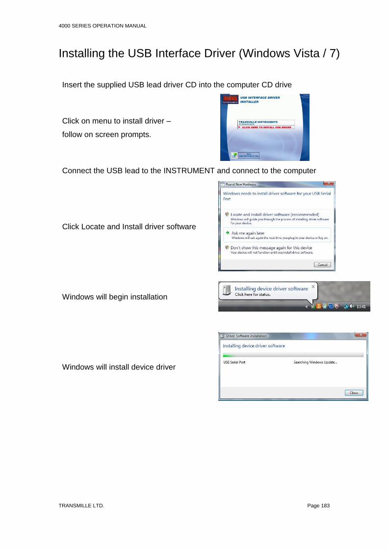
4000 SERIES OPERATION MANUAL
TRANSMILLE LTD. Page 183
Installing the USB Interface Driver (Windows Vista / 7)
Insert the supplied USB lead driver CD into the computer CD drive
Click on menu to install driver –
follow on screen prompts.
Connect the USB lead to the INSTRUMENT and connect to the computer
Click Locate and Install driver software
Windows will begin installation
Windows will install device driver

4000 SERIES OPERATION MANUAL
TRANSMILLE LTD. Page 184
Once installed, Windows will display the
allocated COM Port in brackets as shown:
Note : The COM port number can be
checked at any time by using Windows
Control Panel.
[see instructions on next page].

4000 SERIES OPERATION MANUAL
TRANSMILLE LTD. Page 185
Checking the COM Port setting for the USB Interface
Once the USB interface driver is installed, it will have assigned a ‘virtual’ COM port
number which is needed for setting up the instrument for computer control (via
optional ProCal Calibration software). To determine the COM port number, follow
the steps below:
Open Windows Control Panel
Select the SYSTEM icon
Select the Hardware tab, then click the
Device Manager button

4000 SERIES OPERATION MANUAL
TRANSMILLE LTD. Page 186
Select Ports (COM & LPT) - the virtual
COM Port number assigned is shown in
brackets