AX-3 Series Operation Manual - Delta EMEA
380
AX-3 Series Operation Manual www.deltaww.com AX - 3 Series Operation Manual Industrial Automation Headquarters Delta Electronics, Inc. Taoyuan Technology Center No.18, Xinglong Rd., Taoyuan District, Taoyuan City 33068, Taiwan TEL: 886-3-362-6301 / FAX: 886-3-371-6301 Asia Delta Electronics (Shanghai) Co., Ltd. No.182 Minyu Rd., Pudong Shanghai, P.R.C. Post code : 201209 TEL: 86-21-6872-3988 / FAX: 86-21-6872-3996 Customer Service: 400-820-9595 Delta Electronics (Japan), Inc. Tokyo Office Industrial Automation Sales Department 2-1-14 Shibadaimon, Minato-ku Tokyo, Japan 105-0012 TEL: 81-3-5733-1155 / FAX: 81-3-5733-1255 Delta Electronics (Korea), Inc. Seoul Office 1511, 219, Gasan Digital 1-Ro., Geumcheon-gu, Seoul, 08501 South Korea TEL: 82-2-515-5305 / FAX: 82-2-515-5302 Delta Energy Systems (Singapore) Pte Ltd. 4 Kaki Bukit Avenue 1, #05-04, Singapore 417939 TEL: 65-6747-5155 / FAX: 65-6744-9228 Delta Electronics (India) Pvt. Ltd. Plot No.43, Sector 35, HSIIDC Gurgaon, PIN 122001, Haryana, India TEL: 91-124-4874900 / FAX : 91-124-4874945 Delta Electronics (Thailand) PCL. 909 Soi 9, Moo 4, Bangpoo Industrial Estate (E.P.Z), Pattana 1 Rd., T.Phraksa, A.Muang, Samutprakarn 10280, Thailand TEL: 66-2709-2800 / FAX : 662-709-2827 Delta Electronics (Australia) Pty Ltd. Unit 20-21/45 Normanby Rd., Notting Hill Vic 3168, Australia TEL: 61-3-9543-3720 Americas Delta Electronics (Americas) Ltd. Raleigh Office P.O. Box 12173, 5101 Davis Drive, Research Triangle Park, NC 27709, U.S.A. TEL: 1-919-767-3813 / FAX: 1-919-767-3969 Delta Electronics Brazil São Paulo Sales Office Rua Itapeva, 26 - 3°, andar Edificio Itapeva, One - Bela Vista 01332-000 - São Paulo - SP - Brazil TEL: 55-12-3932-2300 / FAX: 55-12-3932-237 Delta Electronics International Mexico S.A. de C.V. Mexico Office Gustavo Baz No. 309 Edificio E PB 103 Colonia La Loma, CP 54060 Tlalnepantla, Estado de México TEL: 52-55-3603-9200 *We reserve the right to change the information in this catalogue without prior notice. EMEA Headquarters: Delta Electronics (Netherlands) B.V. Sales: [email protected] Marketing: [email protected] Technical Support: [email protected] Customer Support: [email protected] Service: [email protected] TEL: +31(0)40 800 3900 BENELUX: Delta Electronics (Netherlands) B.V. De Witbogt 20, 5652 AG Eindhoven, The Netherlands Mail: [email protected] TEL: +31(0)40 800 3900 DACH: Delta Electronics (Netherlands) B.V. Coesterweg 45, D-59494 Soest, Germany Mail: [email protected] TEL: +49(0)2921 987 0 France: Delta Electronics (France) S.A. ZI du bois Challand 2, 15 rue des Pyrénées, Lisses, 91090 Evry Cedex, France Mail: [email protected] TEL: +33(0)1 69 77 82 60 Iberia: Delta Electronics Solutions (Spain) S.L.U Ctra. De Villaverde a Vallecas, 265 1º Dcha Ed. Hormigueras – P.I. de Vallecas 28031 Madrid TEL: +34(0)91 223 74 20 Carrer Llacuna 166, 08018 Barcelona, Spain Mail: [email protected] Italy: Delta Electronics (Italy) S.r.l. Via Meda 2–22060 Novedrate(CO) Piazza Grazioli 18 00186 Roma Italy Mail: [email protected] TEL: +39 039 8900365 Russia: Delta Energy System LLC Vereyskaya Plaza II, office 112 Vereyskaya str. 17 121357 Moscow Russia Mail: [email protected] TEL: +7 495 644 3240 Turkey: Delta Greentech Elektronik San. Ltd. Sti. (Turkey) Şerifali Mah. Hendem Cad. Kule Sok. No:16-A 34775 Ümraniye – İstanbul Mail: [email protected] TEL: + 90 216 499 9910 GCC: Delta Energy Systems AG (Dubai BR) P.O. Box 185668, Gate 7, 3rd Floor, Hamarain Centre Dubai, United Arab Emirates Mail: [email protected] TEL: +971(0)4 2690148 Egypt + North Africa: Delta Electronics Unit 318, 3rd Floor, Trivium Business Complex, North 90 street, New Cairo, Cairo, Egypt Mail: [email protected] AX-3-0339420-02 2021/04/ 26
-
Upload
khangminh22 -
Category
Documents
-
view
7 -
download
0
Transcript of AX-3 Series Operation Manual - Delta EMEA

AX-3 Series Operation Manual
www.deltaww.com
AX
-3 Se
ries Op
eration M
anual
Industrial Automation HeadquartersDelta Electronics, Inc. Taoyuan Technology CenterNo.18, Xinglong Rd., Taoyuan District, Taoyuan City 33068, TaiwanTEL: 886-3-362-6301 / FAX: 886-3-371-6301
AsiaDelta Electronics (Shanghai) Co., Ltd.No.182 Minyu Rd., Pudong Shanghai, P.R.C.Post code : 201209 TEL: 86-21-6872-3988 / FAX: 86-21-6872-3996Customer Service: 400-820-9595
Delta Electronics (Japan), Inc.Tokyo Office Industrial Automation Sales Department 2-1-14 Shibadaimon, Minato-kuTokyo, Japan 105-0012TEL: 81-3-5733-1155 / FAX: 81-3-5733-1255
Delta Electronics (Korea), Inc.Seoul Office1511, 219, Gasan Digital 1-Ro., Geumcheon-gu, Seoul, 08501 South KoreaTEL: 82-2-515-5305 / FAX: 82-2-515-5302
Delta Energy Systems (Singapore) Pte Ltd.4 Kaki Bukit Avenue 1, #05-04, Singapore 417939TEL: 65-6747-5155 / FAX: 65-6744-9228
Delta Electronics (India) Pvt. Ltd.Plot No.43, Sector 35, HSIIDC Gurgaon, PIN 122001, Haryana, IndiaTEL: 91-124-4874900 / FAX : 91-124-4874945
Delta Electronics (Thailand) PCL. 909 Soi 9, Moo 4, Bangpoo Industrial Estate (E.P.Z), Pattana 1 Rd., T.Phraksa, A.Muang, Samutprakarn 10280, ThailandTEL: 66-2709-2800 / FAX : 662-709-2827
Delta Electronics (Australia) Pty Ltd.Unit 20-21/45 Normanby Rd., Notting Hill Vic 3168, AustraliaTEL: 61-3-9543-3720
AmericasDelta Electronics (Americas) Ltd.Raleigh OfficeP.O. Box 12173, 5101 Davis Drive, Research Triangle Park, NC 27709, U.S.A.TEL: 1-919-767-3813 / FAX: 1-919-767-3969
Delta Electronics Brazil São Paulo Sales Office Rua Itapeva, 26 - 3°, andar Edificio Itapeva, One - Bela Vista 01332-000 - São Paulo - SP - Brazil TEL: 55-12-3932-2300 / FAX: 55-12-3932-237
Delta Electronics International Mexico S.A. de C.V.Mexico OfficeGustavo Baz No. 309 Edificio E PB 103Colonia La Loma, CP 54060Tlalnepantla, Estado de MéxicoTEL: 52-55-3603-9200
*We reserve the right to change the information in this catalogue without prior notice.
EMEAHeadquarters: Delta Electronics (Netherlands) B.V. Sales: [email protected] Marketing: [email protected] Technical Support: [email protected] Customer Support: [email protected] Service: [email protected]: +31(0)40 800 3900
BENELUX: Delta Electronics (Netherlands) B.V.De Witbogt 20, 5652 AG Eindhoven, The Netherlands Mail: [email protected]: +31(0)40 800 3900
DACH: Delta Electronics (Netherlands) B.V.Coesterweg 45, D-59494 Soest, GermanyMail: [email protected]: +49(0)2921 987 0
France: Delta Electronics (France) S.A.ZI du bois Challand 2, 15 rue des Pyrénées, Lisses, 91090 Evry Cedex, France Mail: [email protected]: +33(0)1 69 77 82 60
Iberia: Delta Electronics Solutions (Spain) S.L.UCtra. De Villaverde a Vallecas, 265 1º Dcha Ed. Hormigueras – P.I. de Vallecas 28031 Madrid TEL: +34(0)91 223 74 20
Carrer Llacuna 166, 08018 Barcelona, SpainMail: [email protected]
Italy: Delta Electronics (Italy) S.r.l.Via Meda 2–22060 Novedrate(CO) Piazza Grazioli 18 00186 Roma ItalyMail: [email protected]: +39 039 8900365
Russia: Delta Energy System LLC Vereyskaya Plaza II, office 112 Vereyskaya str. 17 121357 Moscow Russia Mail: [email protected]: +7 495 644 3240
Turkey: Delta Greentech Elektronik San. Ltd. Sti. (Turkey) Şerifali Mah. Hendem Cad. Kule Sok. No:16-A 34775 Ümraniye – İstanbulMail: [email protected]: + 90 216 499 9910
GCC: Delta Energy Systems AG (Dubai BR)P.O. Box 185668, Gate 7, 3rd Floor, Hamarain Centre Dubai, United Arab Emirates Mail: [email protected]: +971(0)4 2690148
Egypt + North Africa: Delta ElectronicsUnit 318, 3rd Floor, Trivium Business Complex, North 90 street, New Cairo, Cairo, Egypt Mail: [email protected]
AX-3-0339420-02 2021/04/26

AX-3 Series Operation Manual
Revision History Vers ion Revis ion Date
1 s t The f i rs t ve rs ion was pub l i shed . 2020 /10 /30
2 n d
1 . Chapte r 1 & 2 : added in fo rmat ion fo r new produc ts , AX-300NA0PA1, AX-324NA0PA1P and AX-308EA0MA1P.
2 . Chapte r 4 : Updated images o f new vers ion DIADes igner -AX so f tware . Added desc r ip t ions for new se t t ing page Sys tem Set t ing in sec t ion 4 .2 .1 .11 . Added Added Loca l l IO Fresh Task De lay Time tab le in sec t ion 4 .2 .2 . Added Tim ing fo r the Var iab le to be C leared to Zero in sec t ion 4 .3 .2 .5 . Added th ree new mot ion con t ro l func t ion b locks in the l is t o f Synchron iza t ion axes in sec t ion 4 .4 .1 .4 .
3 . Chapte r 7 : Added ve loc i ty axis desc r ip t ion in sec t ion 7 .4 .2 . Added in fo rmat ion o f Servo Gear Rat io Se t t ing in sec t ion 7 .4 .2 .1 . Updated s tep in fo rmat ion and cor rec ted the word ing Trapezo id in sec t ion 7 .4 .3 . Added new var iab les fo r axis g roup in sec t ion 7 .5 .2 .
4 . Chapte r 8 : Updated sof tware images in sec t ion 8 .2 . De le ted in fo rmat ion abou t Mat r i kon ® FLEX™ OPC UA. Added Set t ing up an Encryp ted Connec t ion wi th the “ UaExper t ” .
5 . Chapte r 9 : Added in fo rmat ion abou t Sta r tup Check ing and Timeouts in sec t ion 9 .1 .3 . Added no tes in sec t ion 9 .3 .1 .2 .
2021 /04 /26

i
AX-3 Series Operation Manual
Table of Contents
Chapter 1 Product Introduction
1.1 Overview ........................................................................................... 1-2 1.1.1 Related Manuals ............................................................................ 1-2
1.1.2 Models Descriptions ........................................................................ 1-3
1.2 DIADesigner-AX Software Overview .................................................. 1-9 1.2.1 Features ....................................................................................... 1-9
Chapter 2 Specifications and System Configurations
2.1 General Specifications ....................................................................... 2-2
2.2 CPU Module Specifications ................................................................. 2-4 2.2.1 Functional specifications ................................................................. 2-4
2.2.2 Electrical specifications ................................................................. 2-10
2.2.3 CPU Module Profiles ...................................................................... 2-12
2.2.4 CPU Module Input/Output Terminals ............................................... 2-16
2.3 Power Supply Module Specifications ................................................ 2-17 2.3.1 General Specifications .................................................................. 2-17
2.3.2 Power Supply Module Profiles ........................................................ 2-17
2.3.3 Power Supply Module Terminals ..................................................... 2-18
2.4 Extension Modules ........................................................................... 2-19
Chapter 3 Installing Hardware and Getting Started
3.1 Installing Hardware ........................................................................... 3-2 3.1.1 Installing and Removing a Memory Card ........................................... 3-2
3.1.2 Installing and Replacing a Button Cell Battery .................................... 3-3
3.1.3 Installing the AX-3 Series PLC in the Control Cabinet .......................... 3-5
3.2 Installing and Uninstalling DIADesigner-AX ...................................... 3-7 3.2.1 Installing DIADesign-AX .................................................................. 3-8
3.2.2 Uninstalling DIADesigner-AX ......................................................... 3-14

i i
3.3 Getting Started and Setting up Communication ............................... 3-15 3.3.1 Getting Started ............................................................................. 3-15
3.3.2 Setting up Communication ............................................................. 3-16
Chapter 4 Basic Operation
4.1 Introduction on DIADesigner-AX ........................................................... 4-2 4.1.1 Creating a New Project ................................................................... 4-2
4.2 Setting Items on the Device Page .......................................................... 4-4 4.2.1 CPU Parameter Settings .................................................................. 4-4
4.2.2 Extension Module Parameter Settings .............................................. 4-29
4.3 Data Type and Variables ...................................................................... 4-30 4.3.1 Data Type .................................................................................... 4-30
4.3.2 Variables ..................................................................................... 4-31
4.4 Task ..................................................................................................... 4-40 4.4.1 Task Configuration ........................................................................ 4-40
Chapter 5 Hardware Configuration
5.1 Environment of Hardware Configuration ........................................... 5-2
5.2. Add a Module ..................................................................................... 5-5
5.3 Remove a Module .............................................................................. 5-7
5.4 Copy and Paste a Module ................................................................... 5-9 5.4.1 Copy a Module ............................................................................... 5-9
5.4.2 Paste a Module ............................................................................. 5-10
5.5 Cut and Paste a Module ................................................................... 5-11 5.5.1 Cut a Module ................................................................................ 5-11
5.5.2 Paste a Module ............................................................................. 5-12
Chapter 6 Network Configuration
6.1 Network Configuration ...................................................................... 6-2 6.1.1 Introduction .................................................................................. 6-2
6.1.2 Basic Knowledge ............................................................................ 6-3
6.1.3 Creating a Network Topology .......................................................... 6-5

i i i
Chapter 7 Motion Control Basic Settings and Operation
7.1 Introduction on Motion Control Instructions ..................................... 7-5 7.1.1 Motion Control Instructions ............................................................. 7-5
7.1.2 Application Notes on Motion Control Instructions ................................ 7-5
7.1.3 Categories of Motion Control Instructions .......................................... 7-6
7.2 Creating Motion Control Project ......................................................... 7-7 7.2.1 Process Flowchart .......................................................................... 7-7
7.2.2 Process for Creating a Project .......................................................... 7-8
7.3 Commissioning ................................................................................ 7-14 7.3.1 Procedure for Commissioning ........................................................ 7-14
7.3.2 Example of Axis Parameter Settings ............................................... 7-14
7.3.3 Perform Axes Commissioning ........................................................ 7-16
7.4 Motion Control Device ...................................................................... 7-19 7.4.1 Overview .................................................................................... 7-19
7.4.2 Introduction to Axis ...................................................................... 7-19
7.4.3 Procedure for Single-axis Configuration .......................................... 7-28
7.4.4 Axis Group Settings ...................................................................... 7-35
7.4.5 Procedure for Axis Group Configuration........................................... 7-38
7.5 Motion Axis Variables ...................................................................... 7-43 7.5.1 Variables for Single Axis ............................................................... 7-43
7.5.2 Variables for Axis Group ............................................................... 7-46
7.6 Motion Control Programming ........................................................... 7-49 7.6.1 Motion Control Program ................................................................ 7-49
7.6.2 Axis State Transitions ................................................................... 7-53
7.6.3 Execution and Status Indication for Motion Control Instructions ......... 7-56
7.6.4 Position ........................................................................................ 7-66
7.6.5 CAM Tables and Framework .............................................................. 7-66
7.7 Motion Control Functions ................................................................. 7-71 7.7.1 System Structure ......................................................................... 7-71
7.7.2 Single-axis Control ....................................................................... 7-71
7.7.3 Velocity Control ........................................................................... 7-89
7.7.4 Torque control ............................................................................... 7-91
7.7.5 Common Functions for Single-axis Control.......................................... 7-92
7.7.6 Axis Group Control ....................................................................... 7-99
7.7.7 High-speed IO ............................................................................ 7-103

i v
7.7.8 Other Features ........................................................................... 7-132
7.8 Programming Example .................................................................. 7-136 7.8.1 Device Framework ...................................................................... 7-136
7.8.2 Examples ................................................................................... 7-136
Chapter 8 OPC UA Server
8.1 OPC UA Server ................................................................................... 8-2 8.1.1 Creating a Project for OPC UA Access .................................................... 8-2
8.2 Setting up a Connection with the “UaExpert” Client .......................... 8-4
8.3 Setting up an Encrypted Connection .................................................. 8-8 8.3.1 Setting up User Account and Password .................................................. 8-8
8.3.2 CODESYS Security Agent ..................................................................... 8-9
8.3.3 Setting up an Encrypted Connection with the “Prosys OPC UA Client” ....... 8-12
8.3.4 Setting up an Encrypted Connection with the “UaExpert” ........................ 8-15
Chapter 9 Communication
9.1 Introduction to EtherCAT Communication ............................................. 9-2 9.1.1 Features of EtherCAT Fieldbux .............................................................. 9-2
9.1.2 Settings up EtherCAT Master ................................................................ 9-3
9.1.3 Setting up the EtherCAT Slave .............................................................. 9-5
9.2 Introduction to Modbus Serial Communication ...................................... 9-8 9.2.1 Modbus Serial Port .............................................................................. 9-8
9.2.2 Modbus Serial Master ......................................................................... 9-11
9.2.3 Modbus Serial Slave ........................................................................... 9-21
9.3 Introduction to Ethernet Communication ............................................ 9-24 9.3.1 Ethernet Port ..................................................................................... 9-24
9.3.2 Modbus TCP Master (Client) ................................................................ 9-28
9.3.3 Modbus TCP Slave (Server) ................................................................. 9-38
Appendix A Troubleshooting
A.1 Troubleshotting ................................................................................. A-2 A.1.1 Basic Troubleshooting Steps ............................................................ A-2
A.1.2 Clear the Error States ..................................................................... A-2
A.1.3 Troubleshooting SOP ...................................................................... A-3
A.1.4 Viewing Log .................................................................................. A-3

v
A.2 Troubleshooting of CPU Modules .......................................................A-6 A.2.1 ERROR LED Indicators Blinking Every 0.5 Seconds ............................. A-6
A.2.2 ERROR LED Indicators Blinking Rapidly Every 0.2 Seconds .................. A-8
A.2.3 ERROR LED Indicators Slow Blinking Every 3 Seconds and Lighting up
for 1 Second .................................................................................. A-8
A.2.4 BAT. LOW LED Indicators Are ON ..................................................... A-8
A.2.5 BAT. LOW LED Indicators Blinking Every 0.5 Seconds ......................... A-8
A.2.6 Others .......................................................................................... A-9
A.3 Troubleshooting of the Funciton Blocks ........................................... A-10 A.3.1 DL_BuiltInIO_AX3 ........................................................................ A-10
A.3.2 DL_MotionControl_AX3 ................................................................. A-13
A.4 Troubleshooting of I/O Modules ...................................................... A-14 A.4.1 Troubleshooting of Analog Modules (AD/DA/XA) and Temperature Modules
(RTD/TC) .................................................................................... A-14
A.5 Error Codes and LED Indicators for CPU Modules............................. A-16 A.5.1 Error Codes and LED Indicators for CPU Modules .............................. A-17
A.5.2 Error Codes and LED Indicators for Analog and Temperature Module .. A-19


1-1
Chapter 1 Product Introduction Table of Contents
1.1 Overview ........................................................................................... 1-2 1.1.1 Related Manuals ............................................................................ 1-2 1.1.2 Models Descriptions........................................................................ 1-3
1.2 DIADesigner-AX Software Overview .................................................. 1-9 1.2.1 Features ....................................................................................... 1-9
1

AX-3 Ser ies Operat ion Manual
1-2
_1 1.1 Overview
This manual introduces the AX-3 Series CPU functions, devices, module tables, troubleshooting, and so forth.
1.1.1 Related Manuals
The related manuals for AX-3 Series programmable logic controllers are listed below. AX-3 Series Operation Manual
This manual introduces CPU functions, devices, module tables, electrical specifications, appearances and dimension, basic concept of motion control, basic configurations, troubleshooting, and so forth.
AX-3 Series Quick Start This quick start helps you create and use the system in a short time. Besides presenting you with basic system framework, this quick start uses example to demonstrate how to design, write programs, use variables as well as function blocks (FB) and download the PLC program to the PLC. Refer to Appendix A Troubleshooting of AX-3 Series Operation Manual, if any error occurs.
AX Series Motion Controller Manual This introduces single-axis and multi-axes instructions for programming the AX Series Motion Controllers.
AX Series Standard Instructions Manual This introduces standard instructions for programming the AX Series Controllers.
AS Series Hardware and Operation Manual This manual introduces electrical specifications, wirings of CPU modules and modules, appearances, dimensions, and so forth.
AS Series Module Manual This manual introduces special I/O modules such as network modules, analog I/O modules, temperature measurement modules, and so forth.
DIADesigner-AX User Manual This manual introduces the use of the software, programming languages, including Ladder Diagram (LD),
Sequential Function Chart (SFC), Structured Text (ST), and Function Block Diagram (FBD), as well as Program Organization Unit (POU), tasks and editing techniques for motion control programs.

Chapter 1 Product In t roduct ion
1-3
1_ 1.1.2 Models Descriptions
Classification Model Name Description
Power Supply
Module
AS-PS02 Input: 100-240 VAC, 50/60 Hz
Output: 24VDC/2A, 48W (for PLC internal use)
AS-PS02A
Input: 100-240 VAC, 50/60 Hz
Output: 24VDC/1.5A, 36W (for PLC internal use)
Output: 24VDC/0.5A, 12W (for external use)
AX-3 Logic
Controller CPU
Module
AX-300NA0PA1
CPU module, NPN output, built-in with 2x Ethernet port
switches, 1x RS-485, 1x RS-232, 1 USB, Micro SD interface.
Program capacity: 32 MB; Data capacity: 32 MB, removable
terminal blocks
AX-324NA0PA1P
CPU module, PNP output, built-in with 16DI (200KHz), 8 DO
(200KHz NPN), 2x Ethernet port switches, 1x RS-485, 1x RS-
232, 1 USB, Micro SD interface. Program capacity: 32 MB;
Data capacity: 32 MB, removable terminal blocks
AX-3 Motion
Controller CPU
Module
AX-308EA0MA1T
8-axis motion controller CPU module, NPN output, 2x built-in
Relative Encoders, 1x SSI, 16 DI (200KHz), 8 DO (200KHz
NPN), 2x Ethernet port switches, 1x EtherCAT, 1x RS-485,
1x RS-232, 1 USB, Micro SD interface. Program capacity: 32
MB; Data capacity: 32 MB, removable terminal blocks
AX-308EA0MA1P
8-axis motion controller CPU module, PNP output, 2x built-in
Relative Encoders, 1x SSI, 16 DI (200KHz), 8 DO (200KHz
NPN), 2x Ethernet port switches, 1x EtherCAT, 1x RS-485,
1x RS-232, 1 USB, Micro SD interface. Program capacity: 32
MB; Data capacity: 32 MB, removable terminal blocks
AX-364ELA0MA1T
64-axis motion controller CPU module, PNP output, 2x built-in
Relative Encoders, 1x SSI, 16 DI (200KHz), 8 DO (200KHz
NPN), 2x Ethernet port switches, 1x EtherCAT, 1x RS-485,
1x RS-232, 1 USB, Micro SD interface. Program capacity: 32
MB; Data capacity: 32 MB, removable terminal blocks
Digital
input/output
module
AS08AM10N-A
24VDC
5mA
8 inputs
Spring-clamp terminal block
AS08AN01P-A
5 - 30VDC
0.5A/output, 4A/COM
8 outputs

AX-3 Ser ies Operat ion Manual
1-4
_1 Classification Model Name Description
Sourcing output
Spring-clamp terminal block
AS08AN01R-A
240VAC/24VDC
2A/output, 8A/COM
8 outputs
Relay
Spring-clamp terminal block
AS08AN01T-A
5 - 30VDC
0.5A/output, 4A/COM
8 outputs
Sinking output
Spring-clamp terminal block
AS16AM10N-A
24VDC
5mA
16 inputs
Spring-clamp terminal block
AS16AN01P-A
5 - 30VDC
0.5A/output, 4A/COM
16 outputs
Sourcing output
Spring-clamp terminal block
AS16AN01R-A
240VAC/24VDC
2A/output, 8A/COM
16 outputs
Relay
Spring-clamp terminal block
AS16AN01T-A
5 - 30VDC
0.5A/output, 4A/COM
16 outputs
Sinking output
Spring-clamp terminal block
AS16AP11P-A
24VDC
5mA
8 inputs
5 - 30VDC

Chapter 1 Product In t roduct ion
1-5
1_ Classification Model Name Description
0.5A/output, 4A/COM
8 outputs
Sourcing output
Spring-clamp terminal block
AS16AP11R-A
24VDC
5mA
8 inputs
240VAC/24VDC
2A/output, 8A/COM
8 outputs
Relay
Spring-clamp terminal block
AS16AP11T-A
24VDC
5mA
8 inputs
5 - 30VDC
0.5A/output, 4A/COM
8 outputs
Sinking output
Spring-clamp terminal block
AS32AM10N-A
24VDC
3.2mA
32 inputs
MIL connector
AS32AN02T-A
5 - 30VDC
0.1A/output, 3.2A/COM
32 outputs
Sinking output
MIL connector
AS64AM10N-A
24VDC
3.2mA
64 inputs
MIL connector
AS64AN02T-A 5 - 30VDC
0.1A/output, 3.2A/COM

AX-3 Ser ies Operat ion Manual
1-6
_1 Classification Model Name Description
64 outputs
Sinking output
MIL connector
Analog
input/output
module
AS04AD-A
4-channel analog input module
Hardware resolution: 16 bits
0–10V, 0/1–5V, -5 to +5V, -10 to +10V, 0/4–20mA, -20–+20mA
Conversion time: 2 ms/channel
AS08AD-B
8-channel analog input module
Hardware resolution: 16 bits
0 to +10V, 0/1–5V, -5V to +5V, -10V to +10V
Conversion time: 2 ms/channel
AS08AD-C
8-channel analog input module
Hardware resolution: 16 bits
0/4–20mA, -20mA–+20mA
Conversion time: 2 ms/channel
AS04DA-A
4-channel analog output module
Hardware resolution: 12 bits
-10 to +10V, 0–20mA, 4–20mA
Conversion time: 2 ms/channel
AS06XA-A
4-channel analog input
Hardware resolution: 16 bits
0–10V, 0/1–5V, -5 to +5V, -10 to +10V, 0/4–20mA, -20 to
+20mA
Conversion time: 2 ms/channel
2-channel analog output
Hardware resolution: 12 bits
-10 to +10V, 0–20mA, 4–20mA
Conversion time: 2 ms/channel
Temperature
measurement
module
AS04RTD-A
4-channe, 2-wire/3-wire RTD
Sensor type: Pt100 / Ni100 / Pt1000 / Ni1000 / JPt100 / LG-
Ni1000 / Cu50 / Cu100 / 0-300Ω / 0-3000Ω input impedance
Resolution: 0.1°C/0.1°F (16 bits)
Conversion time: 200ms/channel
AS06RTD-A 6-channe, 2-wire/3-wire RTD
Sensor type: Pt100 / Ni100 / Pt1000 / Ni1000 / JPt100 / LG-

Chapter 1 Product In t roduct ion
1-7
1_ Classification Model Name Description
Ni1000 / Cu50 / Cu100 / 0-300Ω / 0-3000Ω input impedance,
Resolution: 0.1°C/0.1°F (16 bits)
Conversion time: 200ms/channel
AS04TC-A
4-channel thermocouple
Sensor type: J, K, R, S, T, E, N, B and -100 to +100 mV
Resolution: 0.1°C/0.1°F (24 bits)
Conversion time: 200ms/channel
AS08TC-A
8-channel thermocouple
Sensor type: J, K, R, S, T, E, N, B and -100 to +100 mV
Resolution: 0.1°C/0.1°F (24 bits)
Conversion time: 200ms/channel
Load cell
module AS02LC-A
2-channel, 4-wire/6-wire load cell sensor
Eigenvalue applicable to a load cell: 1, 2, 4, 6, 20, 40, 80 mV/V
Highest accuracy: 0.04% of full-scale
ADC Resolution : 24 bits
Conversion time: 2.5–400 ms (nine options to choose from)
Programming
cable
UC-PRG015-01A
(1.5M)
Used for the connection between a PLC and a PC via a mini
USB port, use for AS Series CPU modules
UC-PRG030-01A
(3M)
Use for the connection between a PLC and a PC with a mini
USB port, use for AS Series CPU modules
UC-PRG030-20A
(3M)
Use for the connection between a PLC and a PC with a RJ45
port, use for AS Series CPU modules and AS-FEN02 function
card
I/O extension
cable
UC-ET010-24B (1M)
UC-ET020-24B (2M)
UC-ET030-24B (3M)
MIL connector, 40Pin ↔ 40Pin, shielded, use for
AS32AM10N-A, AS32AN02T-A, AS64AM10N-A and
AS64AN02T-A
UC-ET010-24D (1M)
UC-ET020-24D (2M)
UC-ET030-24D (3M)
MIL connector, 40Pin↔ 2x 20Pin, shielded, use for AS332T-A,
AS332P-A, AS324MT-A, AS32AM10N-A, AS32AN02T-A,
AS64AM10N-A, and AS64AN02T-A
External
terminal
module
UB-10-ID16A
16 inputs/outputs, 20-Pin MIL connector, use for AS332T-A,
AS332P-A, AS324MT-A, AS32AM10N-A, AS32AN02T-A,
AS64AM10N-A and AS64AN02T-A
UB-10-ID32A 32 inputs, 40-Pin MIL connector, use for AS32AM10N-A and
AS64AM10N-A
UB-10-IO32D Terminal block (spring clamp/MIL connector), MIL connector to
40-Pin spring clamp terminal block, use for AS332T-A,

AX-3 Ser ies Operat ion Manual
1-8
_1 Classification Model Name Description
AS332P-A, AS324MT-A, AS32AM10N-A, AS32AN02T-A
UB-10-OR16A 16 relay outputs, 20-Pin MIL connector, NPN, use for AS332T-
A, AS32AN02T-A and AS64AN02T-A
UB-10-OR16B 16 relay outputs, 20-Pin MIL connector, PNP, use for AS332P-
A
UB-10-OT32A 32 transistor outputs, 40-Pin MIL connector, NPN, use for
AS32AN02T-A and AS64AN02T-A
ECAT cables
for motion
controller
UC-EMC003-02A Ethernet communication cable, 0.3M
UC-EMC005-02A Ethernet communication cable, 0.5M
UC-EMC010-02A Ethernet communication cable, 1M
UC-EMC020-02A Ethernet communication cable, 2M
UC-EMC050-02A Ethernet communication cable, 5M
UC-EMC100-02A Ethernet communication cable, 10M
UC-EMC200-02A Ethernet communication cable, 20M
UC-EMC003-02B Ethernet communication cable, 0.3M
UC-EMC005-02B Ethernet communication cable, 0.5M
UC-EMC010-02B Ethernet communication cable, 1M
UC-EMC020-02B Ethernet communication cable, 2M
UC-EMC030-02B Ethernet communication cable, 3M
UC-EMC050-02B Ethernet communication cable, 5M
UC-EMC100-02B Ethernet communication cable, 10M

Chapter 1 Product In t roduct ion
1-9
1_ 1.2 DIADesigner-AX Software Overview
Conformed to IEC61131-3, DIADesigner-AX is a new programming tool for a new generation Delta PLC. With
the abundant applied instructions and an adequate motion function library, DIADesigner-AX provides a friendly
and multilingual programming interface for a more convenient and efficient development environment.
1.2.1 Features
DIADesigner-AX is applicable to AX-8 and AX-3 series.
Support all the programming languages that IEC 61131-3 defines, including LD, SFC, ST, and FBD, as
well as POU, tasks and other programming language standard.
Powerful and proven function library for various applications.
Input assistance for the input and configuration.
User-friendly programming with mouse and keyboard in IEC 61131-3 supported programming
languages.
Extensive debugging and online features for the fast optimization of the application code and to speed
up testing and commissioning.
Numerous security features for the protection of the source code and for safeguarding the operation of
the controller.
Programmable devices from different manufacturers.
The user interface is extendible and adaptable without leaving the framework.
Transparent internal structures of the development tool and the available components.
Many seamlessly integrated tools for different kinds of automation tasks.
Two built-in configuration tools:
HWCONFIG: for the hardware configurations and parameter managements for the system.
NWCONFIG: for the network configurations and data exchange management for the system.
Providing various solutions for motion control including PLCopen, MC function block, G-code editor, E-CAM
editor, positioning planning chart tool and many more.
Support PLCopen POUs for single and multi-axis motions
Support PLCopen POUs for add-on functions, including diagnostics, stop, and CAM controller
Additional POUs for different tasks including monitoring dynamic data, following error, operating CAMs
and CAM controllers
Integrated graphical CAM editor with loads of configuration options
Virtual and logical axes are supported.
Integrated drivers for numerous Modbus and EtherCAT protocols
Configuration of the drives as standard field devices.

AX-3 Ser ies Operat ion Manual
1-10
_1 MEMO

Chapter 2 Specifications and System Configurations
Table of Contents
2.1 General Specifications ....................................................................... 2-2
2.2 CPU Module Specifications ................................................................. 2-4 2.2.1 Functional specifications ................................................................. 2-4 2.2.2 Electrical specifications ................................................................. 2-10 2.2.3 CPU Module Profiles ...................................................................... 2-12 2.2.4 CPU Module Input/Output Terminals ............................................... 2-16
2.3 Power Supply Module Specifications ................................................ 2-17 2.3.1 General Specifications .................................................................. 2-17 2.3.2 Power Supply Module Profiles ........................................................ 2-17 2.3.3 Power Supply Module Terminals ..................................................... 2-18
2.4 Extension Modules ........................................................................... 2-19
2 2

AX-3 Ser ies Operat ion Manual
2-2
_2
2.1 General Specifications Item Specifications
Operating temperature -20 to 55°C*1 Storage temperature -40 to 80°C
Operating humidity 5–95% No condensation
Storage humidity 5–95% No condensation
Work environment No corrosive gas exists. Installation location In a control box Pollution degree 2 Ingress protection (IP ratings)
IP20
EMC Standard (electromagnetic compatibility)
Refer to tables of EMI, EMS and conducted immunity test below.
Vibration resistance
Tested with: 5 Hz ≦ f ≦ 8.4 Hz, constant amplitude 3.5 mm;
8.4 Hz ≦ f ≦ 150 Hz, constant acceleration 1g
Duration of oscillation: 10 sweep cycles per axis on each direction of the three mutually perpendicular axes International Standard IEC 61131-2 & IEC 60068-2-6 (TEST Fc)
Shock resistance
Tested with: Half-sine wave: Strength of shock 15 g peak value, 11 ms duration; Shock direction: The shocks in each in direction per axis, on three mutually perpendicular axes (total of 18 shocks) International Standard IEC 61131-2 & IEC 60068-2-27 (TEST Ea)
Safety Conforms to IEC 61131-2, UL508 Ambient air temperature-barometric pressure-altitude
Operating: 1080 ~ 795hPa (-1000 ~ 2000 m) Storage:1080 ~ 660hPa (-1000 ~ 3500 m)
*1: Leave the AX-3 Series PLC in an environment within the operating temperature for at least one hour to ensure the AX-3 Series PLC temperature is within the operating temperature. • EMI
Port Frequency range Level (Normative) Reference standard Enclosure port
(radiated) (measured at a distance of
10 meters)
30-230 MHz 40 dB (μV/m) quasi-peak IEC 61000-6-4
230-1000 MHz 47 dB (μV/m) quasi-peak
AC power port (conducted)
0.15-0.5 MHz 79 dB (μV) quasi-peak
IEC 61000-6-4 66 dB (μV) average
0.5-30 MHz 73 dB (μV) quasi-peak 60 dB (μV) average

Chapter 2 Spec i f ica t ions and System Conf igurat ions
2-3
2_
• EMS
Environmental phenomenon
Reference standard Test Test level
Electrostatic discharge IEC 61000-4-2
Contact ± 4 kV Air ± 8 kV
Radio frequency electromagnetic field Amplitude modulated
IEC 61000-4-3 80% AM, 1 kHz sinusoidal
2.0-2.7 GHz 1 V/m 1.4-2.0 GHz 3 V/m 80-1000 MHz 10 V/m
Power frequency magnetic field IEC 61000-4-8
60 Hz 30 A/m 50 Hz 30 A/m
• Conducted immunity test
Environmental phenomenon Fast transient burst High energy surge Radio frequency
interference Reference standard IEC 61000-4-4 IEC 61000-4-5 IEC 61000-4-6
Interface/Port Specific interface/port Test level Test level Test level
Data communication
Shielded cable 1 kV 1 kV CM 10 V
Unshielded cable 1 kV 1 kV CM 10 V
Digital and analog I/O
AC I/O (unshielded)
2 kV 2 kV CM
1 kV DM 10 V
Analog or DC I/O(unshielded)
1 kV 1 kV CM 10 V
All shielded lines (to the earth)
1 kV 1 kV CM 10 V
Equipment power AC power 2 kV
2 kV CM 1 kV DM
10 V
DC power 2 kV 0.5 kV CM
0.5 kV DM 10 V
I/O power and auxiliary power
output
AC I/O and AC auxiliary power
2 kV 2 kV CM
1 kV DM 10 V
DC I/O and DC auxiliary power
2 kV 0.5 kV CM
0.5 kV DM 10 V

AX-3 Ser ies Operat ion Manual
2-4
_2
2.2 CPU Module Specifications 2.2.1 Functional specifications Logic Controller CPU Module
Type AX-308EA0MA1T AX-308EA0MA1P
AX-364ELA0MA1T
Process time Execution time
LD instruction 5 nanoseconds (ns)
Arithmetic instructions (LREAL data type) 36 nanoseconds (ns)
Program
Program capacity Capacity 8 MB
Variable memory
Retaintive Retain
768 KB (device memory (%M) is counted in)
Persist 128 KB
Non-retaintive
16 MB
Device memory (%M) Size 512 KB
USB port Number of ports 1
Type Mini USB
RS232 port
Number of ports 1
Baud rate 9,600, 19,200, 38,400, 57,600, 76,800, 115,200 bps
Serial commumication format Stop bit: 1, 2; Parity bit: None, Odd, Even; Data bit: 7, 8
Commumication protocol Modbus ASCII/RTU
RS485 port
Number of ports 1
Baud rate 9,600, 19,200, 38,400, 57,600, 76,800, 115,200 bps
Serial commumication format Stop bit: 1, 2; Parity bit: None, Odd, Even; Data bit: 7, 8
Commumication protocol Modbus ASCII/RTU
TCP
Modbus TCP Maximum number of the connections
32 (Server + Client)
SOCKET Maximum number of the TCP connections
Modbus TCP Maximum data length per connection 100 words
SOCKET Maximum data length per instruction 8 KB

Chapter 2 Spec i f ica t ions and System Conf igurat ions
2-5
2_
EtherNet/IP
CIP IO Connection
Maximum number of the Scanner connections 12
Maximum number of the Adapter connections 1
Requested Packet Interval (RPI) 20~1,000 ms (unit: 1 ms)
Maximum Transmission Speed 2,200 pps
Maximum data length per connection 510 bytes (default: 100 bytes)
CIP Explicit Message
Class 3 / UCMM
Get_Attribute_Single (FB) Get_Attributes_All (FB)
Set_Attribute_Single (FB) Set_Attributes_All (FB)
CIP objects supported Identity, Message Router, Assembly, Connection, Manager, Port, TCP/IP
interface, Ethernet link, Vendor specific
OPC UA server
Supported profiles and models PLCopen and OPC Foundation: OPC UA Information Model for IEC 61131-3
Endpoints and connecting ports TCP: 4840 (Reconfigurable via configuration file)
Maximum number of sessions (Client) 5
Maximum number ofmonitored items per server 1000
Sampling rate of the monitored items (ms) 100, 300, 500, 1000, 2500, 5000
Maximum number of subscriptions per server 100
Maximum number of variables that can be published
10,000
Maximum number of value attributes that can be published
10,000
Maximum number of structure definitions that can be published
100
Conditions that can not be published for each network-
published variable
More than three dimensional arrays Array of Array The OPC UA Stack will limit messages to about 300 kB. This is the maximum for values too. Pointer variables, Interface variables Structures containing pointers and interfaces
Security mode and policy None Sign - Basic256Sha256 SignAndEncrypt - Basic256Sha2566

AX-3 Ser ies Operat ion Manual
2-6
_2
Application authentication
Authentication X.509
Number of certificates that can be stored
Trusted applications: 32 Issuer certificiates: 32
Rejected applications: 32
User authentication
Method of user authentication User name / password / Anonymous
IO configuration
Number of IO entension modules supported 32
I/O capacity IN: 8,192byte
OUT: 8,192byte
Built-in IO High speed counter - 6 (200KHz)
Memory card SD card type Micro SD
(SDHC, 32GB max.)
Real-time clock
Year, Month, Date, Hour, Minute, Second, Week One CR1620 battery is required.
Motion Controller CPU Module
Type AX-308EA0MA1T AX-308EA0MA1P
AX-364ELA0MA1T
Process time Execution time
LD instruction 5 nanoseconds (ns)
Arithmetic instructions (LREAL data type) 36 nanoseconds (ns)
Program
Program capacity Capacity 8 MB
Variable memory
Retaintive Retain
768 KB (device memory (%M) is counted in)
Persist 128 KB
Non-retaintive
16 MB
Device memory (%M) Size 512 KB
Motion control
Number of controlled
axes
Maximum number of controlled axes 16 axes 128 axes
EtherCAT axes 8 axes 64 axes
Pulse Out axes 4 axes 4 axes
Maximum number of axes for linear interpolation axis
control 6 axes 6 axes
Maximum number of axes for circular interpolation
axis control 2 axes 2 axes
Maximum number of axes groups 8 groups 8 groups

Chapter 2 Spec i f ica t ions and System Conf igurat ions
2-7
2_
Motion control period The same control period as that is used
for the process data communications cycle for EtherCAT.
CAM
Number of CAM data
points
Maximum points per CAM table
256 points
Maximum points for all CAM tables
20,480 points
Maximum number of CAM tables 80
Ethernet port
Number of ports 2
Physical media types 10BASE-T/100BASE-TX/1000BASE-T Switch
Topology Star, linear
Transmission speed 10/100/1000 Mbps
Cable Category 5e or later, 100 meters (Max.)
Protocols ARP, IP, TCP, UDP, Modbus TCP, EtherNet/IP
USB port Number of ports 1
Type Mini USB
RS232 port
Number of ports 1
Baud rate 9,600, 19,200, 38,400, 57,600, 76,800, 115,200 bps
Serial commumication format Stop bit: 1, 2; Parity bit: None, Odd, Even; Data bit: 7, 8
Commumication protocol Modbus ASCII/RTU
RS485 port
Number of ports 1
Baud rate 9,600, 19,200, 38,400, 57,600, 76,800, 115,200 bps
Serial commumication format Stop bit: 1, 2; Parity bit: None, Odd, Even; Data bit: 7, 8
Commumication protocol Modbus ASCII/RTU
EtherCAT port
EtherCAT Master Class B
Physical media types 100BASE-TX
Transmission speed 100 Mbps
Topology Line, daisy chain, and branching
Cable Category 5e or later, 100 meters (Max.)
Maximum number of Slaves 64 96

AX-3 Ser ies Operat ion Manual
2-8
_2
Transmission cycle 2,000μs~32,000μs
(unit can be set to 250μs)
TCP
Modbus TCP Maximum number of the connections
32 (Server + Client)
SOCKET Maximum number of the TCP connections
Modbus TCP Maximum data length per connection 100 words
SOCKET Maximum data length per instruction 8 KB
EtherNet/IP
CIP IO Connection
Number of adapter to be connected 8
Maximum number of the CIP connections (Input
T->O) 64
Maximum number of the CIP connections (Output
O->T) 64
Requested Packet Interval (RPI) 20~1,000ms (unit: 1 ms)
Maximum Transmission Speed 3,000 pps
Maximum data length per connection 500 bytes
CIP Explicit Message
Class 3 / UCMM
Get_Attribute_Single (FB) Get_Attributes_All (FB)
Set_Attribute_Single (FB) Set_Attributes_All (FB)
CIP objects supported Identity, Message Router, Assembly, Connection, Manager, Port, TCP/IP
interface, Ethernet link, Vendor specific
OPC UA server
Supported profiles and models PLCopen and OPC Foundation: OPC UA Information Model for IEC 61131-3
Endpoints and connecting ports TCP: 4840 (Reconfigurable via configuration file)
Maximum number of sessions (Client) 5
Maximum number ofmonitored items per server 1000
Sampling rate of the monitored items (ms) 100, 300, 500, 1000, 2500, 5000
Maximum number of subscriptions per server 100
Maximum number of variables that can be published
10,000

Chapter 2 Spec i f ica t ions and System Conf igurat ions
2-9
2_
Maximum number of value attributes that can be published
10,000
Maximum number of structure definitions that can be published
100
Conditions that can not be published for each network-
published variable
More than three dimensional arrays Array of Array The OPC UA Stack will limit messages to about 300 kB. This is the maximum for values too. Pointer variables, Interface variables Structures containing pointers and interfaces
Security mode and policy None Sign - Basic256Sha256 SignAndEncrypt - Basic256Sha2566
Application authentication
Authentication X.509
Number of certificates that can be stored
Trusted applications: 32 Issuer certificiates: 32
Rejected applications: 32
User authentication
Method of user authentication User name / password / Anonymous
IO configuration
Number of IO entension modules supported 32
I/O capacity IN:8,192byte
OUT:8,192byte
Built-in IO
Encoder 2
SSI 1
High speed counter 5 (200KHz)
Pulse out 4 (200KHz)
Memory card SD card type Micro SD
(SDHC, 32GB max.)
Real-time clock
Year, Month, Date, Hour, Minute, Second, Week One CR1620 battery is required.
EtherCAT axes include positioning axes and synchronization axes. The maximum number of the axes are listed below.
Model Item
Maximum number of positioning axes
Maximum number of synchronization axes
Maximum number of positioning and
synchronization axes AX-308EA0MA1T AX-308EA0MA1P 8 8 8
AX-364ELA0MA1T 64 8 64

AX-3 Ser ies Operat ion Manual
2-10
_2
2.2.2 Electrical specifications
Model
Item
AX-308EA0MA1T AX-308EA0MA1P AX-364ELA0MA1T
AX-300NA0PA1 AX-324NA0PA1P
Supply voltage 24 VDC (20.4 VDC~28.8 VDC) (-15%~+20%)
Power consumption (W) 11W 4W 5W
Weight (g) 380g 240g 300g
Electrical specifications for the inputs on digital input/output module. The signals passing through
the inputs are 24 VDC signals.
Model Item
AX-308EA0MA1T / AX-308EA0MA1P AX-364ELA0MA1T / AX-324NA0PA1P
Number of inputs 16
Connector type Removable terminal blocks Input type Digital input Input form Direct current (sinking or sourcing) Input voltage/ current 24 VDC, 5 mA
Action level
OFF→ON >15 VDC
ON→OFF <5 VDC
Response time
OFF→ON 2.5 μs
ON→OFF 5 μs
Maximum input frequency 200KHz
Input impedance 5.6 kΩ
Input signal Voltage input Sinking: The inputs are NPN transistors whose collectors are open collectors. Sourcing: The inputs are PNP transistors whose collectors are open collectors.
Input electrical isolation optocoupler Input display When the optocoupler is driven, the input LED indicator is ON.

Chapter 2 Spec i f ica t ions and System Conf igurat ions
2-11
2_
Electrical specifications for the outputs on digital input/output module. The signals passing through the inputs are 24 VDC signals.
Model Item
AX-308EA0MA1T AX-364ELA0MA1T
AX-308EA0MA1P AX-324NA0PA1P
Number of outputs 8 Connector type Removable terminal blocks Output form NPN (Sinking) PNP (Sourcing) Voltage 24 VDC (-15% ~+20%)
Maximum load
Resistance 0.1A/output Inductance -
Bulb -
Maximum output frequency*1 200 KHz
Maximum Response time
OFF→ON 2.5 μs

AX-3 Ser ies Operat ion Manual
2-12
_2
2.2.3 CPU Module Profiles • AX-308EA0MA1T/ AX-308EA0MA1P/ AX-364ELA0MA1T
O UTIN
3
6
7
4
5
1
2
0
3
6
7
4
5
1
2
0
AX -308EER RO R
BAT. LOW
RU N
PO WER
9
8
10
11
12
15
13
14
STO P
RU N
M icr o SD
+EtherC AT
Ethernet
6
C 0
3
OU T
2
1
0
7
2
5
4
3
1
0
I N
C0
7
6
5
4
OU T
S/S 1
IN
9
8
10
14
15
12
13
11
S/S0
RS -232
RS -485
8
110
100
12 3
10 11 12
4
5
9
13
56
8898.3
7
6
1814 15 16 17
110
SSI
Encoder
Unit: mm

Chapter 2 Spec i f ica t ions and System Conf igurat ions
2-13
2_
• AX-300NA0PA1
A X-300NERR OR
BAT. LO W
RS- 232
RS- 485
RU N
PO WER
STOP
RUN
Mic ro S D
+
Ethernet
67
21
3
4
5
67
100
8898.3
8
7
6
10 11
14 16

AX-3 Ser ies Operat ion Manual
2-14
_2
• AX-324NA0PA1P
8
85
100
21
3
10 11
9
13
568898
.3
7
6
1814 16
85
6
C0
3
O UT
2
1
0
7
2
5
4
3
1
0
IN
C0
7
6
5
4
S/S1
IN
9
8
10
14
15
12
13
11
S/S0
OUTIN
3
6
7
4
5
1
2
0
3
6
7
4
5
1
2
0
AX -324NERR OR
BAT. LO W
RS-232
RS-485
RUN
POWE R
9
8
10
11
12
15
13
14
STO P
RUN
Mic ro SD
+
Ethernet
4
5
Number Name Description
1 Battery holder A case for holding a battary (not enclosed) for the real-time clock fuction
2 Power supply For power supply 3 Label Nameplate 4 External module port Connects the modules 5 Grounding clip For grounding
6
Power LED indicator Indicates the power status of the CPU module
Run LED indicator
Operating status of the CPU module ON: the module is running. OFF: the module is stopped. Blinking: the module is detecting an error.
Error LED indicator
Error status of the module ON: a serious error occurs in the module. OFF: the module is normal. Blinking: a minor error occurs in the module.

Chapter 2 Spec i f ica t ions and System Conf igurat ions
2-15
2_
Number Name Description BAT.LOW LED indicator
Indicates the battery status of the CPU module.
COM1 LED COM2 LED
Indicates the communication status of the COM port. OFF: no communication over the COM port Blinking: communication over the COM port
7 Run/Stop RUN: execute the programs STOP: stop the programs
8 COM Port Provides an interface for RS-485 and RS-232 communication
9 Input/Output LED indicator
If there is an input signal, the input LED indicator is ON. If there is an output signal, the output LED indicator is ON.
10 Model name Shows the model name of the CPU module. 11 USB Port Mini USB communication port 12 SSI Port SSI Encoder communication port
13 Input Terminals For input wiring
14 Ethernet Port
Ethernet Switch communication port LINK indicator (Green): LED ON: The network connection is established. LED OFF: The network connection is NOT established.
ACT indicator (Orange): LED blinking: Data transmission (sending/receiving) LED OFF: No data transmission
15 EtherCAT Port
EtherCAT communication port LINK indicator (Green): LED ON: The network connection is established. LED OFF: The network connection is NOT established.
ACT indicator (Orange): LED blinking: Data transmission (sending/receiving) LED OFF: No data transmission
16 SD Card Slot Provides an interface for an SD card 17 Encoder Port Incremental encoder communication port 18 Output Terminals For output wiring

AX-3 Ser ies Operat ion Manual
2-16
_2
2.2.4 CPU Module Input/Output Terminals
AX-308EA0MA1T / AX-308EA0MA1P / AX-364ELA0MA1T
OU TIN
3
6
7
4
5
1
2
0
3
6
7
4
5
1
2
0
ERROR
BAT. LO W
RUN
POWER
9
8
10
11
12
15
13
14
STO P
RUN
Mi cro SD
+EtherCAT
Eth ernet
6
C0
3
OUT
2
1
0
7
2
5
4
3
1
0
IN
C0
7
6
5
4
OUT
S/S1
IN
9
8
10
14
15
12
13
11
S /S0
RS-232
RS-485
SSI
Encoder
SSI ENCNDOR IN
1 DATA+ 1 A1+ X0.0 X0.8 2 DATA- 2 A1- X0.1 X0.9 6 CLK+ 10 B1+ X0.2 X0.10
14 CLK- 11 B1- X0.3 X0.11 8 GND 4 Z1+ X0.4 X0.12
15 5V 5 Z1- X0.5 X0.13 15 +5V1 X0.6 X0.14 3 A2+ X0.7 X0.15 9 A2- S/S0 S/S1 6 B2+ OUT
12 B2- Y0.0 Y0.4 13 Z2+ Y0.1 Y0.5 14 Z2- Y0.2 Y0.6 7 +5V2 Y0.3 Y0.7 8 0V C0 C0
AX-324NA0PA1P
IN
0 8 1 9 2 10 3 11 4 12 5 13 6 14 7 15
S/S0 S/S1 OUT
0 4 1 5 2 6 3 7
C0 C0

Chapter 2 Spec i f ica t ions and System Conf igurat ions
2-17
2_
2.3 Power Supply Module Specifications 2.3.1 General Specifications
AS-PS02/AS-PS02A
Item Specifications
Supply voltage 100–240 VAC (-15% to +10%) 50/60 Hz±5%
Action specifications
If the input power supply is larger than 85 VAC, the power supply module can function normally.
Allowable instantaneous power failure time
If the instantaneous power failure time is less than ten milliseconds, the power supply module keeps running.
Fuse 2.5A/250 VAC
Inrush current <70A@115 VAC
24 VDC output AS-PS02: 2 A for internal use: the CPU and the modules. AS-PS02A: 1.5 A for internal use: the CPU and the modules; 0.5 A for external use.
Power protection The 24 VDC output is equipped with the short circuit protection and the overcurrent protection.
Electrical isolaiton 1,500 VAC (Primary-secondary), 1,500 VAC (Primary-PE), 500 VAC (Secondary-PE)
Insulation voltage Above 5 MΩ The voltage between all inputs/outputs and the ground is 500 VDC.
Ground The diameter of the ground should not be less than the diameters of the cables connected to the terminals L and N.
Weight AS-PS02 270 g AS-PS02A 310 g
2.3.2 Power Supply Module Profiles AS-PS02
70
8898.3
1
4
2
3
IN PUT
Wai t 5 seconds a f ter removing
L G WARNING
Ri sk o f e lect rical shock.
power before servi ci ng.
N
L
PS02
POWER
74.277.9
7591.5
4
AX-3 Ser ies Operat ion Manual
2-18
_2
AS-PS02A
70
8898.3
1
4
2
3
74.277.9
7591.5
O UTP UT
IN PU T
PS02A
POWER
LG WA RN IN GRis k o f e le c tr ic al s h oc k.Wa it 5 s e co nd s a f te r r e m o vi ngpo w er b ef o re s er v icin g .
NL
24G+24V
O UTP UT
IN PU T
+24V24G
Ris k o f e le c tr ic al s h oc k.
LG
LN
WA RN IN G
POWER
PS02A
po w er b ef o re s er v icin g .
4
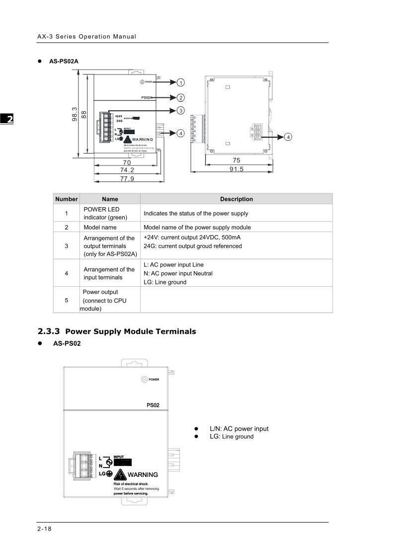
Number Name Description
1 POWER LED indicator (green)
Indicates the status of the power supply
2 Model name Model name of the power supply module
3 Arrangement of the output terminals (only for AS-PS02A)
+24V: current output 24VDC, 500mA 24G: current output groud referenced
4 Arrangement of the input terminals
L: AC power input Line N: AC power input Neutral LG: Line ground
5 Power output (connect to CPU
module)
2.3.3 Power Supply Module Terminals AS-PS02
POWER
PS02
INPUT
WARNING
INPUT
power before servicing.Wait 5 seconds after removingRisk of electrical shock.
LNLGLG WARNING
Risk of electrical shock.
power before servicing.
NL
PS02
POWER
L/N: AC power input LG: Line ground

Chapter 2 Spec i f ica t ions and System Conf igurat ions
2-19
2_
AS-PS02A
OUTPUT
INPUT
PS02A
POWER
LG WARNINGRisk of electrical shock.Wait 5 seconds after removingpower before servicing.
NL
24G+24V
OUTPUT
INPUT
+24V24G
Risk of electrical shock.
LG
LN
WARNING
POWER
PS02A
power before servicing.
+24V: connecting external 24VDC + 24G: connecting external 24G L/N: AC power input LG: Line ground
2.4 Extension Modules You can connect the AS Series modules to AX-3 Series CPU. Refer to AS Series Module Manual for more information.

AX-3 Ser ies Operat ion Manual
2-20
_2
MEMO

3-1
Chapter 3 Installing Hardware and Getting Started
Table of Contents
3.1 Installing Hardware ........................................................................... 3-2 3.1.1 Installing and Removing a Memory Card ........................................... 3-2 3.1.2 Installing and Replacing a Button Cell Battery.................................... 3-3 3.1.3 Installing the AX-3 Series PLC in the Control Cabinet .......................... 3-5
3.2 Installing and Uninstalling DIADesigner-AX ...................................... 3-7 3.2.1 Installing DIADesign-AX .................................................................. 3-8 3.2.2 Uninstalling DIADesigner-AX ......................................................... 3-14
3.3 Getting Started and Setting up Communication ............................... 3-15 3.3.1 Getting Started ............................................................................ 3-15 3.3.2 Setting up Communication ............................................................ 3-16
3

AX-3 Ser ies Operat ion Manual
3-2
_3
3.1 Installing Hardware
3.1.1 Installing and Removing a Memory Card
Memory Card Slot of the CPU Module The memory card slot is on the front side of the AX Series PLC.
OUTIN
3
67
4
5
12
0
3
67
4
5
12
0
ERROR
BAT. LOW
RUN
POWER
9
8
10
1112
15
13
14
STOP
RUN
Micro SD
+Eth erCAT
Ether net
6
C0
3
OUT
2
1
0
7
2
5
4
3
1
0
I N
C0
7
6
5
4
OUT
S/S1
I N
9
8
10
14
15
12
13
11
S/S0
RS-232
RS-485
SSI
Encod er
AX-308 E
Me mory Ca rd Slot
Installing a Memory Card
Insert a memory card into the CPU module memory card slot and push it to the end of the slot until it clicks. Be sure
the memory card is fixed firmly in the slot; if the memory card is loose, it is not installed correctly. With a fool-proofing
design, the memory card can only be inserted in one direction. Do not force to push the memory card into the slot or
you may damage the CPU module. See the instructions in the figures below for reference.
O U TI N
3
6
7
4
5
1
2
0
3
6
7
4
5
1
2
0
ER R OR
BAT. LO W
RU N
PO WE R
9
8
10
11
12
15
13
14
S TO P
R U N
M ic ro S D
+
E therC AT
Ethernet
6
C0
3
O U T
2
1
0
7
2
5
4
3
1
0
IN
C 0
7
6
5
4
O U T
S/S 1
IN
9
8
10
14
15
12
13
11
S /S0
RS -232
RS -485
SS I
Enc oder
A X - 308E
O U TIN
3
6
7
4
5
1
2
0
3
6
7
4
5
1
2
0
E R RO R
B AT. LO W
R U N
P O WE R
9
8
10
11
12
15
13
14
S TO P
R U N
M ic ro S D
+
Et herC AT
E thernet
6
C0
3
O UT
2
1
0
7
2
5
4
3
1
0
IN
C 0
7
6
5
4
O U T
S/S 1
IN
9
8
10
14
15
12
13
11
S /S0
R S -232
R S -485
SS I
E nc oder
A X -308E
O U TIN
3
6
7
4
5
1
2
0
3
6
7
4
5
1
2
0
ER R O R
BA T. L OW
R UN
PO W ER
9
8
10
11
12
15
13
14
STO P
RU N
M icr o S D
+E therC AT
Ether net
6
C 0
3
O U T
2
1
0
7
2
5
4
3
1
0
IN
C 0
7
6
5
4
OU T
S/S 1
I N
9
8
10
14
15
12
13
11
S /S0
R S-232
R S-485
S SI
Enc oder
AX - 308E
Removing a Memory Card
You can remove a memory card by pushing it further into the slot. And then the card springs from the slot.
O UTIN
3
6
7
4
5
1
2
0
3
6
7
4
5
1
2
0
E R RO R
B AT. LO W
R U N
P O WE R
9
8
10
11
12
15
13
14
S TO P
R U N
M ic ro S D
+Ethe rC AT
E thernet
6
C 0
3
O UT
2
1
0
7
2
5
4
3
1
0
IN
C0
7
6
5
4
O U T
S /S1
IN
9
8
10
14
15
12
13
11
S/ S0
R S -232
R S -485
SS I
E nc oder
A X -308E
O U TIN
3
6
7
4
5
1
2
0
3
6
7
4
5
1
2
0
E R RO R
B AT. LO W
R U N
P O WE R
9
8
10
11
12
15
13
14
S TO P
R U N
M ic ro S D
+Et herC AT
E thernet
6
C0
3
O UT
2
1
0
7
2
5
4
3
1
0
IN
C 0
7
6
5
4
O U T
S/S 1
IN
9
8
10
14
15
12
13
11
S /S0
R S -232
R S -485
SS I
E nc oder
A X -308E
O UTIN
3
6
7
4
5
1
2
0
3
6
7
4
5
1
2
0
E R RO R
B AT. LO W
R U N
P O WE R
9
8
10
11
12
15
13
14
S TO P
R U N
M ic ro S D
+Ethe rC AT
E thernet
6
C 0
3
O UT
2
1
0
7
2
5
4
3
1
0
IN
C0
7
6
5
4
O U T
S /S1
IN
9
8
10
14
15
12
13
11
S/ S0
R S -232
R S -485
SS I
E nc oder
A X -308E

Chapter 3 Ins ta l l ing Hardware and Get t ing Star ted
3-3
3_
3.1.2 Installing and Replacing a Button Cell Battery
Installation
The real-time clock (RTC) cannot work unless the battery power is properly supplied. The AX-3 Series PLC does NOT include the battery when it leaves the factory. You need to purchase and install the CR1620 3V battery beforehand. And before installing the battery, you must get rid of the static electricity in the body by touching the grounded metal or you can wear antistatic gloves to avoid the static electricity.
The first-time battery installation can be done whether the AX-3 Series PLC is powered on or off. After installation, you can set the RTC through DIADesigner-AX. Follow the steps below for installing a battery. 1. Pull out the battery holder from the AX-3 Series PLC with the tip of a screwdriver at the concave part of the
battery compartment as shown below.
2. Put the CR1620 3V battery in the battery holder in the direction indicated by the arrow below.
3. After putting the battery in the battery holder, push the battery holder back into the AX-3 Series PLC as shown
below.

AX-3 Ser ies Operat ion Manual
3-4
_3
Replacement
When the BAT LOW indicator of the AX-3 Series PLC is red, it indicates there is no battery installed or the battery voltage is low and you need to install or replace the battery of the AX-3 Series PLC. It is suggested to replace the battery while the AX-3 Series PLC is powered on. If you replace the batter while the PLC is powered off, the real-time clock data will be lost. Before replacing the battery, you must get rid of the static electricity in the body by touching the grounded metal or you can wear antistatic gloves to avoid the static electricity.
Follow the steps below for replacing a battery. 1. Pull out the battery holder from the AX-3 Series PLC with the tip of a screwdriver at the concave part of the
battery compartment as shown below.
2. Take the CR1620 3V battery out of the battery holder in the direction indicated by the arrow below.
3. After the battery is removed, put in a new one and push the battery holder back into the AX-3 Series PLC as
shown below.

Chapter 3 Ins ta l l ing Hardware and Get t ing Star ted
3-5
3_
3.1.3 Installing the AX-3 Series PLC in the Control Cabinet
Environmental Temperature Requirement for the Control Cabinet
The ambient temperature of the control cabinet should be -20 ~ 55°C and the humidity 5 ~ 95%. DO NOT install the control cabinet near flammable material or high-temperature equipment. Keep enough space for air ventilation. Install fans or air conditioning system if the environment temperature exceeds 55°C. The equipment is for indoor use only. Install the control cabinet around 1.0m~2.0m in height for easier installation and operation. Keep the installation away from the high-voltage equipment or power equipment. Cut off the power supply of the control cabinet before installation.
Actions for Anti-interference
Do not install the AX-3 Series PLC in the control cabinet with high-voltage equipment. Keep at least 200mm away from the power wire. The control cabinet should be grounded. Use the AX-3 Series PLC according to the instructions on the manual. If operating the AX-3 Series PLC in a
manner not specified by the manufacturer, it may weaken the protection provided.
Dimension Requirement for the Control Cabinet
The AX-3 Series PLC has to be installed in an enclosure. In order to ensure that the AX-3 Series PLC radiates heat normally, the space between the AX-3 Series PLC and the enclosure should be larger than 50 millimeters. (D > 50mm)
D D
D
D
Motion Controller

AX-3 Ser ies Operat ion Manual
3-6
_3
Installing the AX-3 Series PLC on DIN rail Pull out the fixing clips at the rear of the AX-3 Series PLC. Then edge in the horizontal slots which are at the rear of the AX-3 Series PLC on the DIN rail. And then push and lock the fixing clips to have the AX-3 Series PLC securely installed in the control cabinet. (The image below is for illustration purposes only; refer to AS500E Series Motion Controller Operation Manual for more information.)
OUTOU T
The installation inside the control cabinet (The image below is for illustration purposes only; refer to AS500E Series Motion Controller Operation Manual for more information.)

Chapter 3 Ins ta l l ing Hardware and Get t ing Star ted
3-7
3_
3.2 Installing and Uninstalling DIADesigner-AX
System requirements
Project System Requirement
Runtime System DIADesigner-AX V1.00 or later
Operating System Windows 7 / 8.1 / 10 (32/64 bits)
CPU Intel Celeron 540 1.8 GHz (min.), Intel Core i5 M520 2.4 GHz (min.)
Memory 2GB or above (recommend to use 4GB or more)
Hard Disk Drive 10GB or more
Monitor Resolution 1920 x 1080 Pixels recommend
Keyboard/Mouse General Keyboard Mouse or Windows compatible device
PC interface Ethernet, USB, Serial port (depends on product interface)
Software Need to install .Net Framework 4.6.2

AX-3 Ser ies Operat ion Manual
3-8
_3
3.2.1 Installing DIADesign-AX
Before installation begins, make sure the computer used for installing DIADesigner-AX meets the minimum system
requirements listed in section 3.2.
The DIAInstaller is a software installer which assists you to download and install DIAStudio software applications.
You can download, install, and update products such as DIASelector, DIADesigner, DIAScreen, and COMMGR. Go
to https://diastudio.deltaww.com/home/downloads to download the DIAStudio for DIAInstaller.
Before entering the download page, you need to sign in or sign up.
After logging-in, click DIAStudio download button to download DIAInstaller as the image shown below.

Chapter 3 Ins ta l l ing Hardware and Get t ing Star ted
3-9
3_
Follow the steps below for installing DIADesigner-AX.
1. Double-click DIAInstaller icon to see the latest version of DIADesigner-AX.
2. Click Download.
3. After that, you can see DIADesigner-AX is downloaded and grayed out. Click Install.

AX-3 Ser ies Operat ion Manual
3-10
_3
4. An InstallShied Wizard shows up and starts installing. Click Next.
5. The window of License Agreement shows up. Select “I accept the terms in the license agreement” and then click
Next.

Chapter 3 Ins ta l l ing Hardware and Get t ing Star ted
3-11
3_
6. Click Change… to change the download path. Or leave the default path unchanged. Click Next.

AX-3 Ser ies Operat ion Manual
3-12
_3
7. The window of Setup Type shows up as the image shown below. Select the one you need and then click Next.
8. The window of Ready to Install the Program appears as below and then click Install.

Chapter 3 Ins ta l l ing Hardware and Get t ing Star ted
3-13
3_
It may take some time to install.
9. After installation, the window of InstallShield Wizard Completed appears. Click Finish to complete the
installation.

AX-3 Ser ies Operat ion Manual
3-14
_3
3.2.2 Uninstalling DIADesigner-AX
Follow the steps below for uninstalling DIADesigner-AX.
1. Double-click DIAInstaller icon to open and then click Uninstall.
2. The system will remove DIADesigner-AX from your computer in the background.

Chapter 3 Ins ta l l ing Hardware and Get t ing Star ted
3-15
3_
3.3 Getting Started and Setting up Communication
3.3.1 Getting Started
After DIADesigner-AX is successfully installed, click Start , you can find it under the folder of Delta Industrial
Automation and you can also find its short cut on the desktop. Double-click either one to start the software. You can
open more than one DIADesigner-AX software to achieve multitasking.
After the loading is done, you can see the start page as below. Refer to Chapter 4 for more details on operation.

AX-3 Ser ies Operat ion Manual
3-16
_3
3.3.2 Setting up Communication
After DIADesigner-AX is successfully installed, the system creates the execution file CODESYS Gateway V3 under
the folder of Delta Industrial Automation and GatewaySysTray.exe in the Program Files folder. Double-click either one
to start the Gateway. After that, the system starts Gateway automatically whenever you turn your computer on. And its
icon will appear on the taskbar. If not, go to the execution file CODESYS Gateway V3 under the folder of Delta
Industrial Automation or GatewaySysTray.exe in the Program Files folder to start the Gateway manually.
You can click the Gateway icon on the taskbar to see the Gateway status.
OR

Chapter 3 Ins ta l l ing Hardware and Get t ing Star ted
3-17
3_
Click Stop Gateway if you need to stop gateway working.
If you need to discontinue the execution of GatewaySysTray completely, you can click Exit Gateway Control and the
icon will disappear on the taskbar.
Open the software DIADesigner-AX and open/create your project to see the project-setting page. Double-click Device (Product Name) to open the device-setting page. You can find the Gateway status under the Communication Settings tab. If the Gateway is started, its light is green. If the Gateway is stopped, its light is red.

AX-3 Ser ies Operat ion Manual
3-18
_3
You can configure the Local Gateway. Click Gateway and click the option Configure the Local Gateway to open the setting page.

Chapter 3 Ins ta l l ing Hardware and Get t ing Star ted
3-19
3_
You can find two interfaces under Local Gateway, including UDP interface and TCP interface. You can also create a different port. Click Add and select Add top level interface and then use the drop-down list to select the port you needed to add. Here we use adding COM Port as an example.
After adding COM Port, you can set up the COM port name, its corresponding port and the baudrate. Once the setting is done, click OK. You need to Stop/Start GatewaySysTray again to ensure the following action, such as Scan Network to work properly. Refer to the previous steps to run GatewaySysTray again.

AX-3 Ser ies Operat ion Manual
3-20
_3
You can add configuration settings under COM Port. Right-click the COM Port icon , select Add configuration setting….. to add the setting items. After that you can further define the setting values. Once the setting is done, click OK.
After the configurations of Local Gateway are set, you can select the Scan Network tab to bring out network scanned results on the Select Device setting page. Select AX-308EA0MA1T and then click OK.

Chapter 3 Ins ta l l ing Hardware and Get t ing Star ted
3-21
3_
If the connection is established successfully, you can find that the status light is green and the detailed device information under the device image.

AX-3 Ser ies Operat ion Manual
3-22
_3
MEMO

Chapter 4 Basic Operation Table of Contents
4.1 Introduction on DIADesigner-AX .................................................................... 4-2 Creating a New Project .............................................................................. 4-2
4.2 Setting Items on the Device Page .................................................................. 4-4 CPU Parameter Settings ............................................................................ 4-4 Extension Module Parameter Settings ....................................................... 4-29
4.3 Data Type and Variables ............................................................................... 4-30 Data Type .............................................................................................. 4-30 Variables ............................................................................................... 4-31
4.4 Task ............................................................................................................. 4-40 Task Configuration .................................................................................. 4-40
4 4

AX-3 Ser ies Operat ion Manual
4-2
_4
4.1 Introduction on DIADesigner-AX DIADesigner-AX is an open platform for PLC development system and industrial automation. The adaptable DIADesigner-AX provides an easy way to create professional engineering of IEC 61131-3 automation projects. Based on the IEC 61131-3 data structure and the high-level language programming, DIADesigner-AX is strong in functionality, easy to develop, reliable, extendable and open for development. Integrated with components such as visualization and Safety solution, DIADesigner-AX offers a variety of user-friendly engineering functions for your professional applications in controller development system sectors including PLC and motion control. In DIADesigner-AX, you can customize the user interface by arranging the window layout and the appearance of menus, toolbars and commands according to your requirements.
Creating a New Project
Double-click the DIADesigner-AX icon to open DIADesigner-AX. Click New Project on the Start Page or select File > New Project (Ctrl+N) to create a new project.
Next you will see a window with two sections, Categories and Templates. Click Projects in the Categories section and click Standard project in the Templates section. After that create a Name and specify a location for the project and then click OK.

Chapter 4 Bas ic Operat ion
4-3
_4
And a Standard Project dialog appears. You can select the device and the programming language from the drop-down list. Click OK, the system generates a cyclic task with a default PLC_PRG.
DIADesigner-AX Version V1.0.0 DIADesigner-AX Version V1.1.0 or later
After a new project is successfully created, you can see a project management area in the left side of the window. All the options are listed in nodes. Click View -> Devices (Alt+0) on the tool bar, if nothing appears in the project management area.

AX-3 Ser ies Operat ion Manual
4-4
_4
4.2 Setting Items on the Device Page This section introduces all the setting items on the Device Page.
CPU Parameter Settings 4.2.1.1 Communication Settings On the Communication Settings page, you can define the communication method for DIADesigner-AX and controller. Use the drop-down list of the Gateway tab to add new gateways or manage existing gateways or configure local gateways. You can simply specify an IP address or DNS address for the gateway while adding new gateways. This is useful if you want to connect to a remote gateway running on another PC or device. If you use DNS the address must begin with “dns”. For the setting of PLC, you can enter its IP address (e.g. 192.168.1.5) or its device name (e.g. AX-308EA0MA1T) in the field under the controller image. After that DIADesigner-AX scans to search for the PLC in the network of the gateway.

Chapter 4 Bas ic Operat ion
4-5
_4
Status of the Connection
The dots under the images of gateway and controller indicate the connection status. Red: Not be able to establish a connection Green: A connection is established. Black: Unknown connection status
Tab Description
Scan Network Click Scan Network to open the Select Device page. This page lists all configured gateways with the associated devices. You can select one target device from this list.
Gateway
This menu includes the following setting items: Add New Gateway: You can add and define a new gateway channel here. Manage Gateways: This page is with an overview of all gateways. You can add or
delete entries here or change their order. Configure the Local Gateway: Select this setting item to open the Gateway
Configuration page. You can configure the block drivers for the local gateway.
Device
This menu includes the following setting items: Options:
• Add Current Device to Favorites: Adds the currently set device to the list of favorite devices.
• Manage Favorite Devices: Click this option to open a list of all preferred devices. You can add or delete entries or change their order. The top device is the default.
• :Filter Network Scans by Target ID:
The display is limited on the devices that have the same target ID as the current device configured in the project.
• :Confirm Online Mode:
DIADesigner-AX requires you to confirm the followings when calling the following online commands (for safety purposes): Force values, Write values, Multiple loading, Remove force list, Single cycle, Start, and Stop.
• Store Communication Settings in Project: :DIADesigner-AX saves the communication settings in the project for
reuse on the same computer. Note: If you use the project on another computer, you need to reset the active path. : DIADesigner-AX saves the communication settings in the options of the local installation for reuse on the same computer. Note: When using DIADesigner-AX SVN, the option should be cleared in order to prevent blocking the device object. Rename Active Device: Click this setting item to open the Change Device Name page.

AX-3 Ser ies Operat ion Manual
4-6
_4
Tab Description Wink Current Device: Devices that support this function illuminate a flashing signal. Send Echo Service: DIADesigner-AX sends five echo services to the PLC. These are used to test the network connection, similar to the ping function. The services are sent first without data packets and then with data packets. The scope of the data packets depends on the communication buffer of the PLC. A message box opens with information about the average echo service delay and the scope of the sent data packets. Encrypted Communication:
: The communication to this controller is encrypted. A certificate of the controller is required in order to log in to the controller. If the certificate is not available, then an error message shows up prompting whether or not the certificate should be displayed and installed.
If the Enforce Encrypted Communication option is selected as Security level in the Security Screen view, then the Encrypted Communication is disabled here.
Change Communication Policy: Click this setting item to open the Change Communication Policy page for changing the device setting for the encryption of communication. If a new communication policy is selected in this dialog, then the configuration on the controller is changed.
Communication
Current policy The currently selected policy for the encryption of communication
New policy
Drop-down list for the new policy for encryption • No encryption: The controller does not support encrypted
communication.• Optional encryption: The controller supports encrypted and
unencrypted communication.• Enforced encryption: The controller supports encrypted
communication only.
Device User Management
Current policy The currently selected policy for user management
New policy
Drop-down list for the new policy for user management • Optional user management: It is the responsibility of the
user to enable user management on the device or leavethe device unprotected.
• Enforced user management: The user management on thedevice is enabled and cannot be disabled by the user.

Chapter 4 Bas ic Operat ion
4-7
_4
4.2.1.2 Applications Here you can check and manage the applications on the PLC.
Button Description
Remove / Remove All Remove: Deletes the application selected in the list. Remove All: Deletes all listed applications on the PLC.
Details… Click Details button to see information defined for the application on the Information tab of the dialog box Properties.
Content…
Requirement: Go to Application > Proprieties > Application Generation Options to activate the Download the application info option. This causes information about the contents of the application to be additionally loaded to the PLC. Click Content button to see additional information about the differences between the latest generated code and the application code that exists on the controller. The different modules are displayed in a comparison view.
Refresh List Click Refresh List button to have the controller scanned for applications and the list is refreshed accordingly.

AX-3 Ser ies Operat ion Manual
4-8
_4
4.2.1.3 Backup and Restore You can backup and restore the application-specific file on the PLC by saving and reading a zip archive.
Tab Description
Backup
Click Backup tab to see the followings Read Backup Information from Device: Use this function to search for application-
specific files from the $PlcLogic$ directory of the PLC and lists them on the Backup tab page.
Create Backup File and Save to Disk: Use this function to compress the files in into a backup zip file. The file extension is tbf (=”Target Backup File”).
Save Backup File to Device: Use this function to save the backup file to the TBF directory of the PLC.
Restore
Load Backup File from Disk: After clicking this button, the system generates a list of all backup files found on the disk. Select one of these files to view its contents.
Load Backup File from Device: After clicking this button, the system generates a list of all backup files found on the PLC. Select one of these files to view its contents.
Restore on Device: This function is available if at least one component of the backup file that is currently loaded in the tabbed page is set to active. It prompts for restoring the application status on the device.
Target Information
ID ID of the PLC
Type Device type
Version Device version
Backup Information
File name Storage path of the backup file.
Size of active files Total size of the files set as active in the table
Mode Defines the scope of the backup: Application. The application-related files are added to the archive.
Comment Optional entry for comments to be saved in the meta.info file of the backup and reading when the files are restored.

Chapter 4 Bas ic Operat ion
4-9
_4
4.2.1.4 Files You can transfer files between the computer and the PLC on this page through DIADesigner-AX. .
Item Description
Location Path in the file system of the computer. Subdirectories and files are shown in the lower part of the view with name, size, and change date.
Click this button to create a new file folder
Deletes the selected files or folders
Updates the list of files and folders for the set path (location)
Write File to the PLC
Write File from the PLC
4.2.1.5 Log You can view the PLC log here. It lists the events that were recorded on the target system, including
• Events during the startup and shutdown of the system (components loaded, with version) • Application download and loading of the boot application • Custom entries • Log entries from I/O drivers • Log entries from data sources

AX-3 Ser ies Operat ion Manual
4-10
_4
Item Description
Offline logging : Default settings : The PLC also records actions that are not related to the connection with the controller.
However, this is currently available only for the safety version of CODESYS.
UTC time : Standard setting; the time stamp is converted to the local time on the computer as
indicated by the time zone of the operating system. : The time stamp of the runtime system is displayed.
Severity
Four categories for the severity of the event: • :Message
• :Warning
• :Error
• :Debugging
You can show or hide each category by clicking corresponding buttons in the bar. Each button shows the number of log entries of the category concerned.
Time stamp Date and time (example: 08-01-2020 09:48)
Description Description of the event
Component Name of the runtime system component concerned, e.g. CmpApp Drop-down list with component names
The log list displays only events that concern the selected component
Logger
Drop-down list with all available logs. The standard setting is the <Default Logger> specified by the target system; now it is identical to ‘StdLogger for DIADesigner-AX runtime system.
Refreshes the log list
Exports the list contents to an xml file.
Imports a log list from an xml file.
Deletes the displayed log list. All entries are deleted.

Chapter 4 Bas ic Operat ion
4-11
_4
4.2.1.6 PLC Settings You can make the basic settings for the configuration of the PLC here, for example the handling of inputs and outputs and the bus cycle task.
➀ Application for I/O handling Item Description
Application for I/O handling Application that is for the I/O handling.
➁ PLC Settings
Item Description
Update IO while in stop
: DIADesigner-AX does not refresh the values of the input and output channels when the PLC is in the stop state.
: DIADesigner-AX refreshes the values of the input and output channels even if the PLC is in the stop state. If the watchdog detects a malfunction, the outputs are set to the predefined default values.
Behavior of the outputs in stop
Handling of the output channels when the controller enters the stop state: • Keep current values: The current values are retained. • Set all outputs to default: The default values resulting from the I/O mapping
are assigned. • Execute program: You can control the handling of the output values via a
program contained in the project, which DIADesigner-AX executes at “STOP”. Enter the name of the program in the field on the right.
Always update variables
Global setting that defines whether or not DIADesigner-AX updates the I/O variables in the bus cycle task. This setting is effective for I/O variables of the slaves and modules only if ‘disabled’ is defined in their update settings. • Disabled (update only if used in a task): DIADesigner-AX updates the I/O
variables only if they are used in a task. • Enabled 1 (use bus cycle task if not used in another task): DIADesigner-AX
updates the I/O variables in the bus cycle task if they are not used in any other task.
• Enabled 2 (always in bus cycle task): DIADesigner-AX updates all variables in each cycle of the bus cycle task, regardless of whether they are used and whether they are mapped to an input or output channel.

AX-3 Ser ies Operat ion Manual
4-12
_4
➂ Bus Cycle Options Item Description
Bus cycle task *1 Task that controls the bus cycle. By default the task defined by the device description is entered.
Note 1: Before you select the <unspecified> setting for the bus cycle task, you should be aware that “<unspecified>” means that the default setting given in the device description goes into effects. You should therefore check this description. Use of the task with the shortest cycle time may be defined as the default there, but use of the task with the longest cycle time could equally well be defined! ➃ Additional Settings
Item Description Generate Force variables for I/O mapping
The device does not support this function.
Enable Diagnostics for devices
: DIADesigner-AX automatically integrates the library CAA Device Diagnosis in the project and creates an implicit function block for each device. If there is already a function block for the device, then either an extended FB is used (for example with EtherCAT) or a further FB instance is added. This then contains a general implementation of the device diagnostics.
Show I/O warnings as errors Warnings concerning the I/O configuration are displayed as errors. 4.2.1.7 PLC Shell You can use this text-based control monitor for querying specific information from the controller. You can specify device-dependent commands for this and receive the response from the controller in a result window.

Chapter 4 Bas ic Operat ion
4-13
_4
4.2.1.8 Users and Groups You can edit the device user management of the controller. You can define user accounts and user groups. In combination with the configuration on the Access Rights tab, you thus control access to control objects and files at runtime. For the first time use, use default settings “Administrator” as the user name and password. After logging-in, for security reasons, change the defaults of the username and password.

AX-3 Ser ies Operat ion Manual
4-14
_4
Toolbar of the tab Item Description
Synchronization
1. Switches on and off the synchronization between the editor and the user management on the device. 2. If the button is not pressed, then the editor is blank or it contains a configuration that you loaded from the hard disk. 3. If the button is pressed, then DIADesigner-AX synchronizes the display in the editor continuously with the current user management on the connected device. 4. If you activate the synchronization while the editor contains a user configuration that is not synchronized with the device yet, then you are prompted what should happen to the editor contents. Options: • Upload from the device and overwrite the editor content: The configuration on
the device is loaded into the editor, overwriting the current contents. • Download the editor content to the device and overwrite the user management
there: The configuration in the editor is transferred to the device and applied there.
Import from disk Click this button and then to select and import a user management configuration from the file.
Export to disk Click this button and then to save the user management configuration as an XML file.
Device user User name of the user currently logged in on the device
Users Item Description
Add Click this button to create a new user account.*1
Import Click this button to select the desired entries to import users into the device user management.*2
Edit Click this button to change the settings of the selected user account. Delete Click this button to delete the account of the selected user.
Groups
Item Description Add Click this button to create a new user group.*3
Import Click this button to select the desired entries to import groups into the device user management.*4
Edit Click this button to change the settings of the selected group. Delete Click this button to delete the selected group.

Chapter 4 Bas ic Operat ion
4-15
_4
Note 1: The Add User setting page
Item Description ➀ Name User name ➁ Default group Use the drop-down list to select the default group ➂ Password Password ➃ Confirm password Confirm password ➄ Password strength Levels from Very weak to Very good ➅ Hide password : The password is shown only with asterisks “*” when it is typed in. ➆ Password can be changed by user : Password can be changed by the user ➇ Password must be changed at first login : Password must be changed at first login
Note 2: The Import User setting page After selected the user from the list, click OK to import.

AX-3 Ser ies Operat ion Manual
4-16
_4
Note 3: The Add Group setting page Type in the new group name and select the to-be-added group members for this new group and then click OK.
Note 4: The Import Group setting page After selected the group from the list, click OK to import.

Chapter 4 Bas ic Operat ion
4-17
_4
4.2.1.9 Access Rights Here you can define the device access rights of device users to objects on AX-3 Series PLC. As in the project user management, users must be members of at least one user group and only user groups can be granted certain access rights. Requirements for the Access Rights tab to be displayed: • In the DIADesigner-AX options, in the Device editor category, the Show access rights page option must be selected. Note that this DIADesigner-AX option can be overwritten by the device description. Requirements for the access rights to be granted to user groups • A component for the user management has to be available on AX-3 Series PLC. That is the primary requirement. • Users and user groups have to be configured on the Users and Groups tab.

AX-3 Ser ies Operat ion Manual
4-18
_4
Toolbar of the tab Item Description
Synchronization
1. Switches on and off the synchronization between the editor and the user management on the device. 2. If the button is not pressed, then the editor is blank or it contains a configuration that you loaded from the hard disk. 3. If the button is pressed, then DIADesigner-AX synchronizes the display in the editor continuously with the current user management on the connected device. 4. If you activate the synchronization while the editor contains a user configuration that is not synchronized with the device yet, then you are prompted what should happen to the editor contents. Options: • Upload from the device and overwrite the editor content: The configuration on
the device is loaded into the editor, overwriting the current contents. • Download the editor content to the device and overwrite the user management
there: The configuration in the editor is transferred to the device and applied there.
Import from disk Click this button and then to select and import a user management configuration from the file.
Export to disk Click this button and then to save the user management configuration as an XML file.
Device user User name of the user currently logged in on the device
Objects Description
In the tree structure, the objects are listed to which actions can be executed at runtime. The objects are each assigned by their object source and partially sorted in object groups. In the Rights view, you can configure the access options for a user group to a selected object.
Object source (root node) • File system objects ‣ Device: In these objects, the rights can be granted to folders of the current execution
directory of the AX-3 Series PLC. • Runtime objects ‣ /: In these objects, all objects are managed that have online access in the AX-3 Series PLC
and therefore have to control the access rights. A description of the objects is located in the table. Overview of the objects
Object groups and objects (indented) Example: Device with child nodes Logger, PlcLogic, Settings, UserManagement.

Chapter 4 Bas ic Operat ion
4-19
_4
Rights Description
In general, the access rights are inherited from the root object (also Device or /) to the sub-objects. This means that if a permission of a user group is denied or explicitly granted to a parent object, then this first affects all child objects. The table applies for the object that is currently selected in the tree. For every user group, it shows the rights currently configured for the possible actions on this object.
Possible actions on the object: • Add/Remove • Modify • View • Execute When an object is clicked, a table on the right side shows the access rights of the available user groups for the selected object. This allows you to quickly see: • Which access rights are evaluated by an object • Which user group has which effective rights to which object Meanings of the symbols • : Access right granted explicitly • : Access right denied explicitly • : Access right granted through inheritance • : Access right denied through inheritance • : The access right was not granted or denied explicitly and also not inherited by the parent object. Access is
not possible. • No symbol: Multiple objects are selected that have different access rights. Change the permission by clicking the symbol.

AX-3 Ser ies Operat ion Manual
4-20
_4
Overview Runtime objects > Device
Device > Logger
The Logger object on the Access Rights tab was created by the “Logger” component and controls its access rights. The possible access rights for this object can be granted only for the View action.
Device > PlcLogic
All IEC applications are inserted here automatically as child objects during download. When an application is deleted, it is removed automatically. This allows specific control of online access to the application. Access rights can be assigned centrally over all applications in the PlcLogic. The Administrator and Developer user groups have full access to the IEC applications. The Service and Watch user groups only have read access (for example for read-only monitoring of values).
PlcLogic > Application
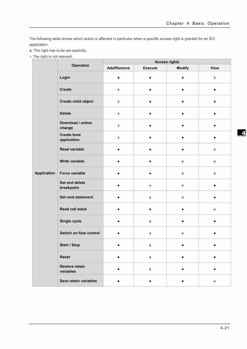
Chapter 4 Bas ic Operat ion
4-21
_4
The following table shows which action is affected in particular when a specific access right is granted for an IEC application. x: The right has to be set explicitly. -: The right is not relevant.
Application
Operation Access rights
Add/Remove Execute Modify View
Login ● ● ● x
Create x ● ● ●
Create child object x ● ● ●
Delete x ● ● ●
Download / online change x ● ● ●
Create boot application x ● ● ●
Read variable ● ● ● x
Write variable ● ● x x
Force variable ● ● x x
Set and delete breakpoint ● x x ●
Set next statement ● x x ●
Read call stack ● ● ● x
Single cycle ● x ● ●
Switch on flow control ● x x ●
Start / Stop ● x ● ●
Reset ● x ● ●
Restore retain variables ● x ● ●
Save retain variables ● ● ● x

AX-3 Ser ies Operat ion Manual
4-22
_4
PlcShell
Only the Modify permission is evaluated at this time. This means that only when the Modify permission has been granted to a user group can PLC shell commands also be evaluated.
RemoteConnections
Additional external connections to the AX-3 Series PLC can be configured below this node. Currently, access to the OPC UA server can be configured here.
Settings
This is the online access to the configuration settings of the AX-3 Series PLC. By default, access to Modify is granted only to the administrator.
UserManagement This is the online access to the user management of AX-3 Series PLC. By default, read/write access is granted only to the administrator.
X509 This controls the online access to the X.509 certificates. Two types of access are distinguished here: Read (View) Write (Modify) Every operation is assigned to one of these two access rights. Each operation is inserted as a child object below X509. Therefore, access per operation can now be fine-tuned even more.

Chapter 4 Bas ic Operat ion
4-23
_4
File system objects > /
All folders from the execution path of the AX-3 Series PLC are inserted below the “/” file system object. This allows you to grant specific rights to each folder of the file system.
4.2.1.10 Symbol Rights Here you can define the access rights of different user groups to the individual symbol sets available on the AX-3 Series PLC. Requirement: User management must be set up on the AX-3 Series PLC. An application was downloaded to AX-3 Series PLC for which symbol sets were defined in DIADesigner-AX project. They have access data for logging in to the AX-3 Series PLC.

AX-3 Ser ies Operat ion Manual
4-24
_4
In the Symbol Sets view, all symbol sets are listed below the Application node whose definition was downloaded with the application to the AX-3 Series PLC.
In the Rights view, the user groups defined in the user management of the controller are listed in a table. When a symbol set is selected, you see the access rights of the corresponding user group to the symbols of this set.
: Access granted; : Access not granted. You can change the access rights by double-clicking the symbol.
Click the button to save the current access configuration to an XML file. The file type is Device symbol management files (*.dsm). Click the button to read a file like this from the computer.

Chapter 4 Bas ic Operat ion
4-25
_4
4.2.1.11 System Setting Here you can set up the system settings for the AX-3 Series PLC. Before setting up, make sure that DIADesigner-AX is successfully connected to AX-3 Series PLC. Refer to section 4.2.1.1 for establishing the connection between DIADesigner-AX and AX-3 Series PLC. Note: the name of this setting page was “Runtime Clock Configuration” in DIADesigner-AX V1.0.0. Now in DIADesigner-AX V1.1.0, this page is named “System Settings”, given that Network Settings are included here.
Runtime Clock ➀ PLC Time: Use the button Read PLC Time to read the PLC current date and time and the result will be updated here. ➁ Date: Use the button Write PLC Time to write the date on DIADesigner-AX (PC) into PLC and the result will be updated here. ➂ Time: Use the button Sync with Local Time to write the time on DIADesigner-AX (PC) into PLC and the result will be updated here. Time Zone ➃ PLC Timezone: Use the button Read Timezone to read the PLC current timezone and the result will be updated here. ➄ Timezone: Use the button Write Timezone to write the timezone on DIADesigner-AX (PC) into PLC and the result will be updated here. Network (available for DIADesigner-AX V1.1.0 or later) ⑥ IP Address Mode: Static.
⑦ IP address: You can input your own IP address, Subnet mask and Default gateway.
⑧ DNS settings: You can obtain DNS server address automatically or define your own DNS server addresses.

AX-3 Ser ies Operat ion Manual
4-26
_4
4.2.1.12 System Parameters Here you can set up the various parameters for the AX-3 Series PLC. Note that settings on this page do NOT support on-line editing.
I/O module CONFIG by Manual/Max when Power On
You can set the number of I/O modules here. Manual (default): The actual module placement should be based on the configuration set in HWCONFIG. If the settings are matched, the PLC can run normally. Max: Sets a maximum number for the module placement. An alarm shows if your actual I/O module placement is larger than the maximum setting.
CPU module Stop when I/O Module No Response The parameter sets whether the CPU and other normal modules can operate constantly when there is an extension module, which does not response during offline period. Stop (default): The CPU module stops running and then shows errors. Keep Run: The CPU module and other normal modules keep running.
CPU module Stop when I/O Module Occurred Error
The parameter sets the method to deal with a minor error in the extension modules. Stop: The CPU stops running and sends an error. Keep Run (default): The CPU keeps running but records the warning message.
Select Action When 24Vdc Input Unstable What to do when the 24Vdc power is unstable Continue Running when power stable (default): The CPU stops and waits till the power is stable and then the CPU begins to run. Into Error Status: The CPU stops and ERROR LED blinks; even after the power is stable again, the CPU still stays stop. Show Battery Low Voltage Error The parameter sets whether the alarm is shown when the lithium battery for the real-time clock is of low voltage or is not installed. Disable: The function is closed. Enable (default): An alarm shows when the lithium battery is of low voltage or not installed.

Chapter 4 Bas ic Operat ion
4-27
_4
4.2.1.13 Task Deployment Here displays a table of inputs and outputs and their assignments to the defined tasks and bus cycle task. You can search for the relevant information here. The information is refreshed after the project is compiled and downloaded to the CPU. If the search result is not as expected, you can use the information to troubleshoot.
The task defined as a Bus cycle task in the PLC Settings of the device
For inputs and outputs that are written or read by a task.

AX-3 Ser ies Operat ion Manual
4-28
_4
4.2.1.14 Status Here you can find the device status information, for example ‘Running’ or ‘Stopped’, and specific diagnostic messages from the respective device, also information about the card used and the internal bus system.
4.2.1.15 Information Here you can find general information that originates from the device description file: name, vendor, categories, version, order number, description, and other relevant information.

Chapter 4 Bas ic Operat ion
4-29
_4
Extension Module Parameter Settings You can set up the extension settings, including IO update task time, command task priority and task delay time in this setting page. LocalIO Fresh Task Priority:
It is the priority of the data exchange tasks between the CPU module and the extension modules. Set the priority level from 0 to 31.*1 LocalIO Cmd Task Priority:
It is the priority of the extension module tasks, including module Run/Stop, module parameter read/write, module instruction From/To and so forth. Set the priority level from 0 to 31.*1 LocalIO Fresh Task Delay Time:
This is used for editing the importing/exporting cycle time of the extension modules. You can set the task delay time according to the module types. Below is the data exchange time table for the AS Series modules. Refer to section 4.4.1.2 for more information on Bus Cycle Task.
Module Time (ms) Module Time (ms)
AS02HC *2 AS08AM 0.6
AS02PU 1.5 AS08AN 0.6
AS04PU 2.1 AS06RTD 0.9
AS02LC 0.6 AS16AP11R 1.2
AS02ADH 0.6 AS16AN01T 0.6
AS04AD 0.9 AS16AM10N 0.6
AS04DA 0.9 AS06XA 1.5
AS08AD 1.2 AS32AM 0.6
AS04RTD 0.9 AS32AN 0.6
AS04TC 0.9 AS64AM 0.9
AS08TC 1.2 AS64AN 0.9
Note 1: It is suggested not to change the task priority or it might affect the communication of module or EtheCAT functions. Note 2: The duration for the module to perform data exchange varies according to the instructions used in the program.

AX-3 Ser ies Operat ion Manual
4-30
_4
4.3 Data Type and Variables Data Type
Data Type Minimum Value Maximum Value Data Width
BOOL FALSE TRUE 1 bit
BYTE 0 255 8 bit
WORD 0 65535 16 bit
DWORD 0 4294967295 32 bit
LWORD 0 264-1 64 bit
SINT -128 127 8bit
USINT 0 255 8 bit
INT -32768 32767 16 bit
UINT 0 65565 16 bit
DINT -2147483648 2147483647 32 bit
UDINT 0 4294967295 32 bit
LINT -263 263-1 64 bit
ULINT 0 264-1 64 bit
REAL -3.402823E+38 3.402823E+38 32 bit
LREAL -1.7976931348623157E+308 1.7976931348623157E+308 64 bit
TIME T#0ms T#49d17h2m47s295ms 32 bit
LTIME LTIME#0ns LTIME#213503d23h34n33s
709ms551us615ns 64 bit
TIME_OF_DAY ( TOD )
TOD#00:00:00.000 TOD#23:59:59.999 32 bit
DATE D#1970-1-1 ( 01/01/70 )
DATE#2106-2-7 (February 07, 2106)
32 bit
DATE_AND_TIME DT#1979-1-1-00:00:00 (01/01/1970 00:00:00)
DT#2106-2-7-6:28:15 (February 07, 2106 6:28:15)
32 bit
STRING ASCII format (8 bit): up to 255 characters
WSTRING Unicode format (16 bit): no limit on the length

Chapter 4 Bas ic Operat ion
4-31
_4
Variables Rules for identifiers of variables:
No spaces or special characters
Not case sensitive (For example, Var0 and VAR0 are seen as the same variable)
No multiple consecutive underscores (For example, b__Var0 is not permitted)
Rules for multiple use of identifiers
Local variable cannot be declared more than one time.
If a local variable and a global variable share the same name, the local variable has priority within the POU.
Variables with the same name can be declared in different global variables list.
(For example, globe_list1.bvar and globe_list2.bvar can co-exist in two different global variables lists.)
Comments
Single comment: the symbol // indicates a single comment, for example: // Variable Define
Multiple comments: the symbol (* XX : XX *) indicates multiples comments from XX to XX, for example (* Variable Define : Variable Define*)
4.3.2.1 Declaration of Variables In DIADesigner-AX projects you can declare variables in the following methods. Syntax: <Variable Name> : <Data Type> := <Initialization> ; Example:
Array Syntax: <Variable Name>:ARRAY[0..N] OF <Data Type> Example:

AX-3 Ser ies Operat ion Manual
4-32
_4
4.3.2.2 Address Assignments In AX-3 Series, there are three ranges in the memory area, including I (input memory range), Q (output memory range) and M (flag memory range). You can use specific character strings to express memory position and size. For the M flag memory range in AX-3 Series PLC, you cannot manually use the bit operation when in online mode.
Syntax: %<Memory Area Prefix><Size Prefix><Memory Position>
Memory Area Description Range
I Input Memory Range 8 KB
Q Output Memory Range 8 KB
M Flag Memory Range 512 KB
Size Prefix Data Type Data Width
X -- 1 bit
B Byte 8 bit
W Word 16 bit
D DWord 32 bit
L LWord 64 bit
• Memory Area The numbering that you use for addressing the memory position depends on the target system. Before specifying the address value in the memory area, you need to know the mapping corresponding relationship of devices to prevent the overlapping memory ranges. See the table below for reference.
Memory Area
X0.63~X0.56 X0.55~X0.48 X0.47~X0.40 X0.39~X0.32 X0.31~X0.17 X0.23~X0.16 X0.15~X0.8 X0.7~X0.0
X7.7~X7.0 X6.7~X6.0 X5.7~X5.0 X4.7~X4.0 X3.7~X3.0 X2.7~X2.0 X1.7~X1.0 X0.7~X0.0
B7 B6 B5 B4 B3 B2 B1 B0
W3 W2 W1 W0
D1 D0
L0

Chapter 4 Bas ic Operat ion
4-33
_4
• Example
4.3.2.3 Variables • Global Variables If a variable that is declared in the POU, it is a local variable and it can only be used in the same POU. If a variable that is declared in the global variable list, it is a global variable and it can used in any POU.
Address Description
%QX7.5 Single bit address of the output bit 7.5
%IW215 Word address of the input word 215
%QB7 Byte address of the output byte 7
%MD48 Address of a double word at memory position 48 in flag memory
VAR wVar0 AT %IW0 : WORD; END_VAR
Variable declaration with address information of an input word
VAR bVar0 AT IX7.5 : BOOL; END_VAR
Boolean variable declaration with address information of an input bit X7.5.

AX-3 Ser ies Operat ion Manual
4-34
_4
• Constant Variables You can declare a variable as a constant variable. Constant variables can be accessed as read-only and without assigning an initialization value.
Declaration of Constant Variables

Chapter 4 Bas ic Operat ion
4-35
_4
• Retain Variables You can declare a variable as retentive or use retain / persistent variable directly. Refer to the table below for differences among variable, retain variable and persistent variable.
Initialize
Reboot PLC Reset warm Reset cold Download Reset Origin
Variable O O O O O
Retain Variable X X O O O
Persistent Variable X X X X O
Declaration of Retain Variables
You can declare the Persistent Variable / Retain Persistent Variable / Persistent Retain Variable in the Persistent Variable Object and the results are the same.
Persistent Variable List:

AX-3 Ser ies Operat ion Manual
4-36
_4
If you need to declare a local variable as persistent, you need to add the variable instance path in the persistent variable list.

Chapter 4 Bas ic Operat ion
4-37
_4
4.3.2.4 User-defined Data Types You can create your own data type, DUT (Data Type Unit) or UDT (User-defined Data Type), by clicking ADD Object and selecting DUT. Four data types can be created, including Structure, Enumeration, Alias and Union.
DUT:
Structure: A structure is a compound data type used for grouping simple data types or other compound data types. Syntax:
TYPE <Structure Name>:
STRUCT
<Variable Declaration 1>
...
<Variable Declaration n>
END_STRUCT
END_TYPE

AX-3 Ser ies Operat ion Manual
4-38
_4
Example:
Applications:
• Enumeration: An enumeration is used to map a set of names to numeric values. Enumerated data types help make the code more self-documenting and make program listing more readable. Syntax:
TYPE <Enumeration Name> :
(
<First Component Declaration>:= Component Declaration,
… ,
< Last Component Declaration >:= Component Declaration
) <Basic Data Type> := Default Variable Initialization;
END_TYPE
Example:

Chapter 4 Bas ic Operat ion
4-39
_4
• Alias: Alias is a scalar data type for a variable that can save a single value and self-define the data type.
Example:
TYPE <Alias Name> : STRING(20); END_TYPE
• Union:
Union is a data structure that contains different data types. All components have the same amount of memory. Syntax:
TYPE <Union Name>:
UNION
<Variable Declaration 1>
...
<Variable Declaration n>
END_UNION
END_TYPE
Example:
4.3.2.5 Timing for the Variable to be Cleared to Zero For different types of variables, the timing to clear the variables to zero is various. Find the various timings below for the variables to be cleared to zero under different occasions.
Action VAR VAR Retain VAR Retain Persistent
Reset Warm ○ ● ●
Reset Cold ○ ○ ●
Reset Origin ○ ○ ○
Download ○ ○ ●
Online Change ● ● ●
● = Value retained
○ = Clear to zero

AX-3 Ser ies Operat ion Manual
4-40
_4
4.4 Task
Task Configuration You define one or more tasks for controlling and executing the program blocks (POUs) in the PLC. You define a task with a name, a priority, and a type, which determines which condition triggers the start of the task. You can define this condition either by time (cyclic-interval, freewheeling) or by the occurrence of an internal or external event to process the task.
A task calls one or more program blocks (POUs). With the combination of priority and condition, you define the order in which the tasks are processed. You can configure a watchdog for each task.
Rules for the processing order of the defined tasks:
• If the task condition is satisfied, then the system processes the task.
• If several tasks satisfy the condition for processing at the same time, then the system processes the tasks with the highest priority first.
• If several tasks with the same priority level satisfy the condition for processing at the same time, then the system processes the longest waiting task first.
• The program calls are processed in the order they appear in the configuration dialog of the task.
• If a called program has the same name in the device tree of the application and in a library or project-global in the POU window, then the application program is used.
Note: Set the priority level from 0 to 31. If the set number is closer to 0, it has higher priority.
4.4.1.1 Task Types There are five types of task types: Cyclic Task:
The system processes the task in cycles. The cycle time of the task is defined in the input field Interval.
Event Task: The system starts processing the Event Task as soon as the global variable defined in the input field Event contains a rising edge.
Freewheeling Task: The system starts processing the Freewheeling Task again automatically in a continuous loop at program start and at the end of a complete pass.
Status Task: The system starts Status Task processing as soon as the variable defined in the Event input field yields the Boolean value TRUE.

Chapter 4 Bas ic Operat ion
4-41
_4
4.4.1.2 Bus Cycle Task If the task condition is satisfied, then the system processes the task. Set the priority level from 0 to 31. If the set number is closer to 0, it has higher priority. The system processes the task in the order of Task Group in Task Configuration. Behavior of the bus cycle
Output buffer
Input buffer
IO input
IO output
Task1 Task1
Task2
Task3 Task3
Task2
0ms 1ms 2ms
Pause
Pause
❶
❷
❸
❹
❺
❻
① ①
① ①
① Bus cycle Task 1: Priority=1, Bus cycle Task, Cyclic Task
Task 2: Priority=3, Event Task
Task 3: Priority=5, Freewheeling Task
❶ The condition for starting Task 1 is met; Task 1 starts. ❷ Task 1 completes and the I/O data from buffer is exchanged with the I/O channel (physical hardware.) Task 3 starts. ❸ The condition for starting Task 2 is met and Task 2 has higher priority than Task 3 does. Thus Task 2 starts and Task 3 halts. ❹ The condition for starting Task 1 is met and Task 1 has higher priority than Task 2 does. Thus Task 3 starts and Task 4 halts. ❺ Task 1 completes and the I/O data from buffer is exchanged with the I/O channel (physical hardware.) Task 2 starts again. ❻ Task 2 completes and the Task 3 starts again.
Note ➀: The messages are normally sent on the bus in this task. Other tasks copy only the I/O data from an internal buffer that is exchanged only with the physical hardware in the bus cycle task.

AX-3 Ser ies Operat ion Manual
4-42
_4
4.4.1.3 Watchdog If the task exceeds the time set for the watchdog, then the task is halted with an error status.
• Several consecutive timeouts:
Sensitivity: 0, watchdog timeout = time *1
Sensitivity: n, watchdog timeout = time *n
*1

Chapter 4 Bas ic Operat ion
4-43
4.4.1.4 Motion Instructions for Types of Tasks Here is the table of motion instructions for different task types. “V” means the motion instruction can be executed for the task type. Synchronization axes
Classification Instruction Name Task Type
Cyclic Freewheeling Bus Cycle EtherCAT
Motion Control
Function Blocks
MC_Home V
MC_Stop V
MC_Halt V
MC_MoveAbsolute V
MC_MoveRelative V
MC_MoveAdditive V
MC_MoveSuperImposed V
MC_CamIn V
MC_CamOut V
MC_MoveVelocity V
MC_PositionProfile V
MC_VelocityProfile V
MC_AccelerationProfile V
MC_Jog V
MC_GearIn V
MC_GearOut V
MC_GearInPos V
MC_Phasing V
DMC_TorqueControl V
DMC_VelocityControl V
DMC_MoveLinearAbsolute V
DMC_MoveLinearRelative V
DMC_MoveCircularAbsolute V
DMC_MoveCircularRelative V
DMC_GroupStop V
DMC_GroupHalt V
DMC_Home_P V DMC_GroupInterrupt V DMC_GroupContinue V DMC_ImmediateStop_P V
Instructions for
Management
MC_Power V V V
MC_SetPosition V V V
MC_ReadParameter V V V
MC_WriteParameter V V V
MC_ReadBoolParameter V V V
MC_WriteBoolParameter V V V
MC_ReadActualPosition V V V
MC_ReadActualVelocity V V V
MC_ReadActualTorque V V V

AX-3 Ser ies Operat ion Manual
4-44
_4
Classification Instruction Name Task Type
Cyclic Freewheeling Bus Cycle EtherCAT MC_Reset V V V
MC_ReadStatus V V V
MC_ReadAxisError V V V
MC_CamTableSelect V V V
MC_TouchProbe V V V
MC_AbortTrigger V V V
MC_DigitalCamSwitch V V V
DMC_GroupEnable V V V
DMC_GroupDisable V V V
DMC_GroupReadStatus V V V
DMC_GroupReadError V V V
DMC_GroupReset V V V
DMC_CamReadTappetStatus V V V
DMC_CamReadTappetValue V V V
DMC_CamWriteTappetValue V V V
DMC_CamAddTappet V V V
DMC_CamDeleteTappet V V V
DMC_CamReadPoint V V V
DMC_CamWritePoint V V V
DMC_ChangeMechanismGearRation V V V
DMC_ReadMotionState V V V DMC_GroupReadParameter V V V DMC_GroupWriteParameter V V V
Note: it is suggested a motion function block should be created within a bus cycle EtherCAT to avoid inconsistent movement. Positioning axes
Classification Instruction Name Task Type
Cyclic Freewheeling Bus Cycle EtherCAT
Motion Control
Function Blocks
MC_Halt_DML V V V
MC_Home_DML V V V
MC_MoveAbsolute_DML V V V
MC_MoveRelative_DML V V V
MC_MoveVelocity_DML V V V
MC_Stop_DML V V V
Instructions for
Management
MC_Power_DML V V V MC_ReadBoolParameter_DML V V V MC_ReadParameter_DML V V V MC_ReadStatus_DML V V V MC_Reset_DML V V V MC_WriteBoolParameter_DML V V V MC_WriteBoolParameter_DML V V V MC_ChangeAxisConfig_DML V V V MC_ReinitDrive_DML V V V MC_SetOpmode_DML V V V MC_StartupDrive_DML V V V

Chapter 5 Hardware Configuration
Table of Contents
5.1 Environment of Hardware Configuration ................................................ 5-2
5.2. Add a Module ........................................................................................ 5-5
5.3 Remove a Module................................................................................... 5-7
5.4 Copy and Paste a Module ....................................................................... 5-9 5.4.1 Copy a Module .................................................................................... 5-9
5.4.2 Paste a Module ................................................................................. 5-10
5.5 Cut and Paste a Module ....................................................................... 5-11 5.5.1 Cut a Module .................................................................................... 5-11
5.5.2 Paste a Module ................................................................................. 5-12
5 5

AX-3 Ser ies Operat ion Manual
5-2
_5
Hardware Configuration is the tools in DIADesign-AX for hardware configuration. Its functions include setting parameters for CPU and modules. This chapter will introduce the abovementioned funcitons.
5.1 Environment of Hardware Configuration
Double-click on the Device section to open the Hardware Configurate (Device) window as the image shown below.
Hardware Configuration (Device): This is the main work area for system configuration and settings.
Product List Editor: Here listed out all supported modules for the selected CPU. Click to see all the supported modules on the right window (Product List Editor).
Click to unfold the list. Click the module name to see a short module description.

Chapter 5 Hardware Conf igurat ion
5-3
5__
Click on the upper-left corner to see the current configurations. For example, the width of the total
connected module, the current consumption and power current output.
Use on the upper-right corner to rearrange the device image for better viewing
experience and easier operation.

AX-3 Ser ies Operat ion Manual
5-4
_5
Enter a key word in the Search Toolbox on the right-side window and press “Enter” button on your keyboard to search for the matched modules.

Chapter 5 Hardware Conf igurat ion
5-5
5__
5.2. Add a Module
Method 1
With AX-3 Series PLC backplaneless design, the extension module can install on the right-side of AX-3 Series
PLC directly. Double-click or drag and drop the extension module that you’d like to add from the Product List.
Newly added extension modules will apper on the right-side of the AX-3 Series PLC. And the device names
will also show up on the left-side under Delta_LocalBus_Master.

AX-3 Ser ies Operat ion Manual
5-6
_5
Method 2
If the AX-3 Series PLC and its connected extension module are powered on and the gateway is correctly set,
you can use the icon to scan and add the modules in. Newly added extension modules will apper on
the right-side of the AX-3 Series PLC. And the device names will also show up on the left-side under
Delta_LocalBus_Master.

Chapter 5 Hardware Conf igurat ion
5-7
5__
5.3 Remove a Module
You cannot remove a CPU. You can only delete extension modules.
Method 1
Right-click the module image that you’d like to remove to open the context menu and click the option Delete or
use the Delete Button on your keyboard to remove the module.
After you click Delete, a confirmation shows up. Click Yes to delete the module.
And the device names will also be removed from the left-side under Delta_LocalBus_Master.

AX-3 Ser ies Operat ion Manual
5-8
_5
Method 2
Right-click the device name under Delta_LocalBus_Master that you’d like to remove to open the context menu
and click the option Delete or use the Delete Button on your keyboard to remove the module. After that the
device image will also be removed from the editing area.

Chapter 5 Hardware Conf igurat ion
5-9
5__
5.4 Copy and Paste a Module
You cannot use copy and paste on a CPU. You can only use copy and paste on extension modules.
5.4.1 Copy a Module
Method 1
Right-click the module image that you’d like to copy to open the context menu and click the option Copy to
duplicate the module.
Method 2
Right-click the device name under Delta_LocalBus_Master that you’d like to copy to open the context menu
and click the option Copy to copy the module.

AX-3 Ser ies Operat ion Manual
5-10
_5
5.4.2 Paste a Module
Method 1
You can place the module between modules. Right-click where you’d like to paste the module to open the
context menu and click the option Paste to place the module on the left of the module you had clicked. Or you
can place the module at the end by right-clicking the + to paste the copied module there.
And the device names will also be updated on the left-side under Delta_LocalBus_Master.
Method 2
You can place the module between modules. Right-click where you’d like to paste the module under
Delta_LocalBus_Master to open the context menu and click the option Paste to place the module above the
module you had clicked. Or you can place the module at the end by right-clicking Delta_LocalBus_Master to
paste the copied module.
And the module image will also be updated on the editing area.

Chapter 5 Hardware Conf igurat ion
5-11
5__
5.5 Cut and Paste a Module
You cannot use cut and paste on a CPU. You can only use cut and paste on extension modules.
5.5.1 Cut a Module
Method 1
Right-click the module image that you’d like to cut to open the context menu and click the option Cut to take
out the module.
Method 2
Right-click the device name under Delta_LocalBus_Master that you’d like to cut to open the context menu and
click the option Cut to take out the module.

AX-3 Ser ies Operat ion Manual
5-12
_5
5.5.2 Paste a Module
Method 1
You can place the module between modules. Right-click where you’d like to paste the module to open the
context menu and click the option Paste to place the module on the left of the module you had clicked. Or you
can place the module at the end by right-clicking the + to paste the copied module there.
And the device names will also be updated on the left-side under Delta_LocalBus_Master.
Method 2
You can place the module between modules. Right-click where you’d like to paste the module under
Delta_LocalBus_Master to open the context menu and click the option Paste to place the module above the
module you had clicked. Or you can place the module at the end by right-clicking Delta_LocalBus_Master to
paste the copied module.
And the module image will also be updated on the editing area.

6-1
Chapter 6 Network Configuration
Table of Contents
6.1 Network Configuration ...................................................................... 6-2 6.1.1 Introduction .................................................................................. 6-2 6.1.2 Basic Knowledge ............................................................................ 6-3 6.1.3 Creating a Network Topology........................................................... 6-5
6 6

AX-3 Ser ies Operat ion Manual
6-2
_6
6.1 Network Configuration DIADesigner-AX provides a Network Configuration tool for users to configure the network in a project. Detailed network setting information will be covered in the following sections.
6.1.1 Introduction
You can use Network Configuration to:
(a) create networks such as EtherCAT, Modbus, Ethernet, CANOpen in a project and set up file sending paths
(b) set up EtherCAT Master
(c) set up Modbus COM port
(d) set up Ethernet IP settings
Network Configuration is under the Device tree. You can double-click to open its setting page and start planning a network framework for the project.
Device: Here shows all the configured devices in a tree view.
Working area: Here is the main working area for you to create a network framework.
Device list: Here lists all the available devices in a tree view.
Message display area: Here displays operational messages.

Chapter 6 Network Conf igurat ion
6-3
6_
6.1.2 Basic Knowledge Before creating networks, you need to have some basic knowledge. Here we provide some basic knowledge in the following sections for you.
Device and Network A device is the most basic element in a network. It can be a PLC, a servo, a drive or any device that you defined. Here a network is a collection of devices which are interconnected. Every communication port should be assigned with a network type, such as Modbus, Ethernet, EtherCAT or CANOpen. A physical interface that a device uses to connect to a network is a communication port of the device. If there are more than two ports on a device, the device can connect to different networks.
Device Name A device name is the identity of the device. You can identify a device in the Device Tree by its name. However it bears little significance on operation.
Device name
Communication port
Network number & network type

AX-3 Ser ies Operat ion Manual
6-4
_6
Network Type and Communication Port
EtherCAT
The orange yellow line indicates the EtherCAT communication. Double-click the Master station node to open the EtherCAT setting page of the Master. The number of Master Station is 0 and that cannot be changed. Double-click the connection of Slave to open the EtherCAT setting page of the Slave. The last digit appeared in the EtherCAT address 1001 is used as an indicator of this connection on the Network Configuration Editor page.
Modbus TCP/EtherNETIP
The blue line indicates the Modbus TCP/EtherNetIP communication. Double-click this line to open its setting page to edit IP addresses. The last digit appeared in the last section of the IP address is used as an indicator of this connection on the Network Configuration Editor page.
Modbus
The blue line indicates the Modbus communication (RS-232 / RS-485). Double-click this line to open the Modbus communication port setting page.

Chapter 6 Network Conf igurat ion
6-5
6_
6.1.3 Creating a Network Topology 6.1.3.1 Station Nodes When you open the Network Configuration for the first time, the system creates a graphical representation automatically.
You can use the following methods to add devices including PLCs, servo motors, and drives in the network topology. Method 1
Double-click the device that you want to add from the Product List on the right. After that you can see the added device is updated in the graphical representation and also on the Device Tree.
Updated here
Updated here

AX-3 Ser ies Operat ion Manual
6-6
_6
Method 2 Right-click the project name on the Device Tree to bring out the context menu. Double-click Add Device on the context menu to open a setting page for adding devices. Double-click the device you’d like to add or click Add Device to add the device in.
Method 3
Right-click the device to bring out the context menu and click Network Scan or click the icon for Network Scan to automatically scan and then add the connected configured devices and network in the project.

Chapter 6 Network Conf igurat ion
6-7
6_
6.1.3.2 Creating a Connection After creating the station nodes, you can start to crate connections. The network types include Modbus, Ethernet, EtherCAT and CANOpen. Refer to 6.1.2 for more information. You can use the following methods to add created network connections. Method 1 Drag and drop the communication port to the corresponding network type shown in line to create a connection between devices.
Method 2 Hold the communication port and drag it to the unused dotted line to create a network connection that is the same as the selected network communication type and then a new gray unused dotted line will also be created.

AX-3 Ser ies Operat ion Manual
6-8
_6
MEMO

7-1
Chapter 7 Motion Control Setup & Operation
Table of Contents 7.1 Introduction on Motion Control Instructions ...................................... 7-5
7.1.1 Motion Control Instructions ................................................................. 7-5
7.1.2 Application Notes on Motion Control Instructions .................................... 7-5
7.1.3 Categories of Motion Control Instructions .............................................. 7-6
7.2 Creating Motion Control Project ......................................................... 7-7
7.2.1 Process Flowchart .............................................................................. 7-7
7.2.2 Process for Creating a Project .............................................................. 7-8
7.3 Commissioning ................................................................................. 7-14
7.3.1 Procedure for Commissioning ............................................................ 7-14
7.3.2 Example of Axis Parameter Settings ................................................... 7-14
7.3.3 Perform Axes Commissioning ............................................................. 7-16
7.4 Motion Control Device ...................................................................... 7-19
7.4.1 Overview ........................................................................................ 7-19
7.4.2 Introduction to Axis .......................................................................... 7-19
7.4.2.1 About Axis Parameters ................................................................7-20
7.4.2.2 Axis Application in Program .........................................................7-27
7.4.3 Procedure for Single-axis Configuration .............................................. 7-28
7.4.4 Axis Group Settings .......................................................................... 7-35
7.4.4.1 Prameters for Axis Group ............................................................7-35
7.4.4.2 Using Axis Groups in Program ......................................................7-37
7.4.5 Procedure for Axis Group Configuration ............................................... 7-38
7.5 Motion Axis Variables ....................................................................... 7-43
7.5.1 Variables for Single Axis .................................................................... 7-43
7.5.2 Variables for Axis Group .................................................................... 7-46
7.6 Motion Control Programming ........................................................... 7-49
7.6.1 Motion Control Program .................................................................... 7-49
7.6.1.1 Program Architecture and Types in DIADesigner-AX ........................7-49
12 7

AX-3 Ser ies Operat ion Manual
7-2
_7
7.6.1.2 POU in DIADesigner-AX ............................................................... 7-50
7.6.1.3 Adding POU in DIADesigner-AX .................................................... 7-50
7.6.1.4 PDO Mapping ............................................................................. 7-52
7.6.2 Axis State Transitions ....................................................................... 7-53
7.6.2.1 Axis State ................................................................................. 7-53
7.6.2.2 Axis Group State ........................................................................ 7-55
7.6.3 Execution and Status Indication for Motion Control Instructions ............. 7-56
7.6.3.1 Basic Rules of Executing Instructions ............................................ 7-57
7.6.3.2 Timing Diagram for Input/Outputs ................................................ 7-59
7.6.3.3 Repeated Execution Behavior of Single Axis Motion Instructions ....... 7-59
7.6.3.4 Multi-execution of Motion Control Instructions ............................... 7-60
7.6.3.5 Synchronous Execution Eehavior of Motion Instructions .................. 7-60
7.6.4 Position ............................................................................................ 7-66
7.6.4.1 Types of Positions ......................................................................... 7-66
7.6.5 CAM Tables and Framework .................................................................. 7-66
7.6.5.1 E-CAM Framework .......................................................................... 7-66
7.6.5.2 Creating E-CAM ............................................................................ 7-67
7.7 Motion Control Functions ................................................................. 7-71
7.7.1 System Structure ............................................................................. 7-71
7.7.2 Single-axis Control ........................................................................... 7-71
7.7.2.1 Cyclic Synchronous Position Mode ................................................ 7-71
Profile Position Mode ......................................................................... 7-72
7.7.2.2 ...................................................................................................... 7-72
7.7.2.3 Positioning ................................................................................ 7-72
7.7.2.4 Stop Method .............................................................................. 7-73
7.7.2.5 MC_GearIn ................................................................................ 7-76
7.7.2.6 MC_GearInPos ........................................................................... 7-78
7.7.2.7 MC_CamIn ................................................................................ 7-79
7.7.3 Velocity Control ............................................................................... 7-89
7.7.3.1 CSP Mode .................................................................................. 7-89
7.7.3.2 CSV Mode ................................................................................. 7-90
7.7.3.3 Profile Velocity Mode ................................................................... 7-90
7.7.4 Torque control ................................................................................... 7-91
7.7.5 Common Functions for Single-axis Control ............................................. 7-92

Chapter 7 Mot ion Contro l Bas ic Se t t ings & Operat ion
7-3
7_
7.7.5.1 Command Position ........................................................................7-92
7.7.5.2 Velocity Command ........................................................................7-94
7.7.5.3 Acceleration and Deceleration Command ...........................................7-95
7.7.5.4 Jerk Command .............................................................................7-96
7.7.5.5 Axis Direction ...............................................................................7-97
7.7.6 Axis Group Control ........................................................................... 7-99
7.7.6.1 Linear Interpolation ....................................................................7-99
7.7.6.2 Circular Interpolation ................................................................ 7-100
7.7.6.3 Group Stop Command ............................................................... 7-102
7.7.7 High-speed IO ................................................................................ 7-103
7.7.7.1 IO Configuration ......................................................................... 7-103
7.7.7.2 DIO Setting ................................................................................ 7-104
7.7.7.3 SSI Encoder Setting .................................................................... 7-107
7.7.7.4 Pulse Encoder Setting .................................................................. 7-113
7.7.7.5 Capture/Compare Function Setting .......................................... 7-120
7.7.7.6 Pulse Output Function Setting .................................................... 7-126
7.7.7.7 Confirm High-Speed IO Errors .................................................... 7-131
7.7.8 Other Features ............................................................................... 7-132
7.7.8.1 Change Current Position ............................................................ 7-132
7.7.8.2 Software Limit ......................................................................... 7-132
7.7.8.3 Position Lag Setting .................................................................. 7-133
7.7.8.4 Cam Switch Function ................................................................ 7-134
7.7.8.5 Position Capture ....................................................................... 7-134
7.8 Programming Example ................................................................... 7-136
7.8.1 Device Framework .......................................................................... 7-136
7.8.1.1 Utilization ................................................................................ 7-136
7.8.1.2 Configuration ........................................................................... 7-136
7.8.2 Examples ....................................................................................... 7-136
7.8.2.1 Servo On ................................................................................. 7-138
7.8.2.2 Reset and Control Single-axis Error ............................................ 7-139
7.8.2.3 Control on Instruction Errors...................................................... 7-142
7.8.2.4 Quick Stop for Single Axes ........................................................ 7-144
7.8.2.5 Home Positioning ..................................................................... 7-146
7.8.2.6 Absolute Positioning .................................................................. 7-149

AX-3 Ser ies Operat ion Manual
7-4
_7
7.8.2.7 Switch CAM Table during CAM Operation ..................................... 7-150
7.8.2.8 Perform Master PhaseOffset for CAM ........................................... 7-159
7.8.2.9 Change Current Position in Movement ......................................... 7-166
7.8.2.10 Perform Superimposed during Gear Engagment ........................ 7-171

Chapter 7 Mot ion Contro l Bas ic Se t t ings & Operat ion
7-5
7_
7.1 Introduction on Motion Control Instructions 7.1.1 Motion Control Instructions
This manual introduces the elements for motion control programming including devices, symbols and motion control instructions.
Motion control instructions are defined as function blocks (FB) and are used in the program for performing a variety of motion control purposes. The motion control (MC) instructions are developed based on the specifications of PLCopen* motion control function blocks.
This section gives an overview of the motion control instructions for both PLCopen-based function blocks and Delta-defined function blocks. PLCopen defines the program and function block interfaces so as to achieve a standardized motion control programming environment for the languages specified in IEC61131-3. Using PLCopen-based instructions together with Delta-defined instructions reduces the costs for training and support.
Before using the instructions, please be sure that you understand the devices, symbols and the function of instructions sufficiently.
You can also refer to the Appendices for a quick reference of the motion control instruction list and error codes.
*Note:PLCopen is an organization promoting industrial control based on IEC61131-3, which is an international standardwidely adopted for PLC programming. For more information regarding PLCopen, check the official website at:http://www.plcopen.org/
7.1.2 Application Notes on Motion Control Instructions This section explains important specifications and limitations when applying motion control instructions. For detailed information of each instruction in this manual, refer to section 7.6.3 Motion Control Programming.
Programming languages for motion control instructions
You can use all programming languages provided by DIADesigner-AX to create, edit, or maintain the program. The supported languages include Ladder Diagram (LD), Sequential Function Chart (SFC), Continuous Function Chart (CFC), Structured Text (ST) and Function Block Diagram (FBD).
For detailed information about the programming languages, refer to DIADesigner-AX Software Manual.
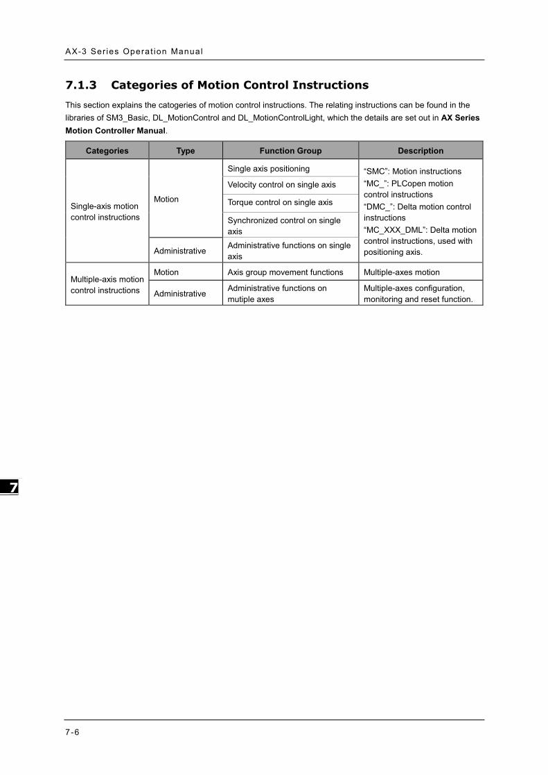
AX-3 Ser ies Operat ion Manual
7-6
_7
7.1.3 Categories of Motion Control Instructions This section explains the catogeries of motion control instructions. The relating instructions can be found in the libraries of SM3_Basic, DL_MotionControl and DL_MotionControlLight, which the details are set out in AX Series Motion Controller Manual.
Categories Type Function Group Description
Single-axis motion control instructions
Motion
Single axis positioning “SMC”: Motion instructions “MC_”: PLCopen motion control instructions “DMC_”: Delta motion control instructions “MC_XXX_DML”: Delta motion control instructions, used with positioning axis.
Velocity control on single axis
Torque control on single axis
Synchronized control on single axis
Administrative Administrative functions on single axis
Multiple-axis motion control instructions
Motion Axis group movement functions Multiple-axes motion
Administrative Administrative functions on mutiple axes
Multiple-axes configuration, monitoring and reset function.

Chapter 7 Mot ion Contro l Bas ic Se t t ings & Operat ion
7-7
7_
7.2 Creating Motion Control Project
7.2.1 Process Flowchart
The following flowchart shows the process of creating motion control project and positioning axis.

AX-3 Ser ies Operat ion Manual
7-8
_7
7.2.2 Process for Creating a Project ● Create a new project
Double ckick on the DIADesign-AX icon to open the software.
Click File.
Choose New Project
Type in the fields of Name and Location in the New Project window, select the desired project and then click OK. Model AX-308E is taken as an example to illustrate the process, which the project name is shown as “Project AX-308EA0MA1T”.

Chapter 7 Mot ion Contro l Bas ic Se t t ings & Operat ion
7-9
7_
Double-click on “Network Configuration” to continue with EtherCAT settings.
“Network Configuration Editor” window will pop up after double-click. Find the target slave devices from “Product List Editor” on the right.

AX-3 Ser ies Operat ion Manual
7-10
_7
Choose “Servo Device” “ASD-A2” “ASD-A2-E” from the product list. Then, the device will be automatically added to “Network Configuration Editor” after a double-click
Click and hold the left mouse button on the yellow box of slave device and drag it towards the EtherCAT main line to complete the configuration of master-slave connection.

Chapter 7 Mot ion Contro l Bas ic Se t t ings & Operat ion
7-11
7_
Double-click on the yellow box of master device to continue on parameter settings for EtherCAT master device.
EtherCAT distributed clock can be configured within master device settings.

AX-3 Ser ies Operat ion Manual
7-12
_7
Double-click on the slave device to continue on EtherCAT slave device settings.
Tabs relating to slave device configuration will be displayed after double-clicking, such as Station address setting, “Process Data” and “Startup Parameters”.

Chapter 7 Mot ion Contro l Bas ic Se t t ings & Operat ion
7-13
7_
Afterwards, you can start writing programs with motion function blocks in POUs, which should be placed under “EtherCAT+Task”, to ensure normal operation of function blocks.

AX-3 Ser ies Operat ion Manual
7-14
_7
7.3 Commissioning 7.3.1 Procedure for Commissioning The chart below shows the steps to build a commissioning process:
7.3.2 Example of Axis Parameter Settings Before using software to perform commissioning, axis parameters must be set first. The figure below illustrates the setting method.

Chapter 7 Mot ion Contro l Bas ic Se t t ings & Operat ion
7-15
7_
Axis configuration screen
Parameters setting
Name Setting
Axis Type Linear Axis
Command pulse per motor rotation 10,000
Pitch [Unit] 1*1
Gear ratio denominator 128*2
Gear ratio numerator 1*2
Software limit_Posotive 10,000
Software limit_Negative -10,000
*Note:
1. In case of the Unit [mm], the input parameter should be 0.001 for moving 1um.
2. It’s a must to set P1-44 and P1-45 of the servo drive.

AX-3 Ser ies Operat ion Manual
7-16
_7
7.3.3 Perform Axes Commissioning Select “EtherCAT_Master_SoftMotion” and double-click on it.
Left click on the “Online Config Mode” icon.
After entering online commissioning, double-click on “SM_Drive_ETC_Delta_ASDA_A2”

Chapter 7 Mot ion Contro l Bas ic Se t t ings & Operat ion
7-17
7_
Open “Commissioning” tab after entering the setting screen of axis parameters.
Introduction of commissioning screen
Information of axis commands
Name Function
Position[u] Command position and actual position
Velocity[u/s] Command value and actual value of velocity
Acceleration[u/s2] Command value and actual value of acceleration
Torque[Nm] Command value and actual value of torque

AX-3 Ser ies Operat ion Manual
7-18
_7
Axis status and communication status
Name Function
Status Axis status
Communication Communication status
Axis power: Set power ON/ OFF.
Error reset: Clear error messages of servo axis.
Homing: Make the axis back to the start position.
Inch
Name Function
Distance Moving distance
Velocity Moving velocity
Acceleration Acceleration rate
Deceleration Deceleration rate
Jerk Command value of jerk
Read&Write: Read-write parameters of upper axes. If need be, you can read and modify Object Dictionary by inputting as follows. - Read and write the parameter 0x6098 in object dictionary
1 = fixed number
6098 =the parameter to be read and written
00 = sub of the parameter
1. Convert 0x1609800 to demical number as 23,107,584 2. Change 23,107,584 to -23,107,584 3. Enter -23,107,584 in the “Parameter” field to read the parameter “0x6098”.

Chapter 7 Mot ion Contro l Bas ic Se t t ings & Operat ion
7-19
7_
7.4 Motion Control Device
7.4.1 Overview
Motion control devices are mainly used for configuring parameters for motion axis. In most applications, you can set up axis parameters in DIADesigner-AX software, a convenient environment for you, where axis parameters required for configuring motion control on axis are defined as Structure. A Structure is a data type applicable to group the data elements together.
7.4.2 Introduction to Axis
The axis is used to perform motion control in the system and includes real servo drives, encoders and virtual servo drives. The following table shows the axis types:
Type Description
Positioning axis*1 Achieve basic positioning control via EtherCAT, such as functions of absolute positioning, relative positioning, and etc.
Velocity axis*1 Achieve velocity control and torque control. (as seen in CIA 402 Velocity Mode)
Synchronous axis*2 Achieve servo motor control and basic positioning control via EtherCAT, as well as synchronous motion control like electronic cam function.
Pulse-type axis Achieve real servo motor control with pulses. Virtual axis Execute motion control commands without using real servo motor. Encoder axis Use real encoder (SSI or incremental encoder) as feedback signals.
Virtual encoder axis Can only be used in the program without encoders.
*Note 1:
Positioning and velocity axes must match the function library of DL_MotionControlLight.
When AX-364EL uses Ethercat with the number of axes exceeding 64 and the Soft Motion version is below V4.7.0.0, the parameters of MAX_MAILBOX_CHANNELS and MAX_SDO_Channels in the Library (IODrvEtherCat ETC_Parameter) must be changed to 128.
*Note 2: Synchronous axes must match DL_MotionControl and the function library of SM3_Basic.

AX-3 Ser ies Operat ion Manual
7-20
_7
7.4.2.1 About Axis Parameters
After creating a servo axis, the corresponding axis parameters will be generated as well. The following table details the relating description.
Synchronous Axis
Axis Type and Limits
Name Function
Virtual Activate virtual axes.
Linear Axis/Rotary Axis Set to be linear axis or rotary axis.
Linear Axis Software Limits
Name Function
Activated Activate software limits (only supports Linear axis)
Negative[u] Reverse software limit.
Positive[u] Forward software limit.
Rotary Axis Modulo Setting
Name Function
Modulo Value[u] Set the area of rotation for a turn. (only supports rotary axes)

Chapter 7 Mot ion Contro l Bas ic Se t t ings & Operat ion
7-21
7_
Error Reaction
Name Function
Quick Stop Emergency stop for axes
Deceleration[u/s2] Deceleration stop for axes (effective when Quick Stop is inactive)
Velocity Ramp Type
Name Function
Trapezoid/Sin2/Quadratic/ Quadratic(Smooth)
Motion curves setting for axes
Position Lag Supervision
Name Function
Positon Lag Reaction Set the reaction for position lag.
Lag Limit [u] Set the value of lag limit.
Positive/Negative Command
Name Function
Reverse OFF/On Enable or disable reverse function for positive/negative command setting.
Transmission Mechanism Servo Gear Ratio Setting
Name Function
Unit Numerator Numerator factor of the electronic gear unit
Unit Denominator Denominator factor of the electronic gear unit
Descriptions of different machanism types are as follows:
Ball Screw

AX-3 Ser ies Operat ion Manual
7-22
_7
Name Function
(1) Command Pulse per motor rotation The command pulse value for per motor rotation
(4) Pitch The distance between screw threads
(2) Gear ratio numerator Numerator of gear ratio
(3) Gear ratio denominator Denominator of gear ratio
Round Table
Name Function
(1) Command Pulse per motor rotation The command pulse value for per motor rotation
(4) Movement distance per motor rotation Movement distance for one full motor retation
(2) Gear ratio numerator Numerator of gear ratio
(3) Gear ratio denominator Denominator of gear ratio
Belt Pully
Name Function
(1) Command Pulse per motor rotation The command pulse value for per motor rotation
(4) Diameter (Movement distance per motor rotation: Diameter *n)
Diameter (Movement distance per motor rotation: Diameter *n)
(2) Gear ratio numerator Numerator of gear ratio
(3) Gear ratio denominator Denominator of gear ratio

Chapter 7 Mot ion Contro l Bas ic Se t t ings & Operat ion
7-23
7_
Homing Setting
Name Function
Homing Mode Configure homing mode setting.
Homing Speed during search for switch Set the homing speed during search for switch.
Homing Speed during search for z phase pulse Set the homing speed during search for Z phase pulse.
Homing Acceleration Set the homing acceleration rate.
Positioning Axis

AX-3 Ser ies Operat ion Manual
7-24
_7
Axis Type and Limits
Name Function
Linear Axis/Rotary Axis Set to be linear axis or rotary axis.
Linear Axis Software Limits
Name Function
Activated Activate software limits (only supports Linear axis)
Negative[u] Reverse software limit.
Positive[u] Forward software limit.
Rotary Axis Modulo Setting
Name Function
Modulo Value[u] Set the area of rotation for a turn. (only supports rotary axes)
Velocity Ramp Type
Name Function
Trapezoid/Sin2 Motion curves setting for axes Positive/Negative Command
Name Function
Reverse OFF/On Enable or disable reverse function for positive/negative command setting.
Transmission Mechanism Servo Gear Ratio Setting
Name Function
Unit Numerator Numerator factor of the electronic gear unit
Unit Denominator Denominator factor of the electronic gear unit

Chapter 7 Mot ion Contro l Bas ic Se t t ings & Operat ion
7-25
7_
Descriptions of different machanism types are as follows:
Ball Screw
Name Function
(4) Command Pulse per motor rotation The command pulse value for per motor rotation
(4) Pitch The distance between screw threads
(5) Gear ratio numerator Numerator of gear ratio
(6) Gear ratio denominator Denominator of gear ratio
Round Table
Name Function
(4) Command Pulse per motor rotation The command pulse value for per motor rotation
(4) Movement distance per motor rotation Movement distance for one full motor retation
(5) Gear ratio numerator Numerator of gear ratio
(6) Gear ratio denominator Denominator of gear ratio

AX-3 Ser ies Operat ion Manual
7-26
_7
Belt Pully
Name Function
(4) Command Pulse per motor rotation The command pulse value for per motor rotation
(4) Diameter (Movement distance motor rotation:Diameter *n)
Diameter (Movement distance per motor rotation: Diameter *n)
(5) Gear ratio numerator Numerator of gear ratio
(6) Gear ratio denominator Denominator of gear ratio
Homing Setting
Name Function
Homing Mode Configure homing mode setting.
Homing Speed during search for switch Set the homing speed during search for switch.
Homing Speed during search for z phase pulse
Set the homing speed during search for Z phase pulse.
Homing Acceleration Set the homing acceleration rate.

Chapter 7 Mot ion Contro l Bas ic Se t t ings & Operat ion
7-27
7_
7.4.2.2 Axis Application in Program
After a servo axis is newly added in the project, the name of servo axis will be generated automatically (you are allowed to change the name) and input to the function block.
Synchronous Axis
Positioning Axis

AX-3 Ser ies Operat ion Manual
7-28
_7
7.4.3 Procedure for Single-axis Configuration
The procedure for axis settings is shown as follows. For more details of creating new projects, please find section 7.2.
Configure EtherCAT settings after opening the project. First, click “Network Configuration”.

Chapter 7 Mot ion Contro l Bas ic Se t t ings & Operat ion
7-29
7_
Click “Delta ASDA-A2-E EtherCAT(CoE) Drive Rev4_SM” *1 after entering Network Configuration page and connect to the line above.
Note 1: *1 Delta ASDA-A2-E EtherCAT(CoE) Drive Rev4_SM is a synchronous axis. If a positioning axis is what you need, select Delta ASDA-A2-E EtherCAT(CoE) Drive Rev4_DML instead. After that, the operational procedures are the same for the synchronous axis and positioning axis.
Double-click on the slave device after finishing the connection.

AX-3 Ser ies Operat ion Manual
7-30
_7
Switch to “Procesas Data” page to configure mapping groups of PDO. The default setting for ASDA-A2 is second group, which can operate normally with most function blocks. If additional groups or parameters of PDO need to be selected and added, please refer to content concerning fuction blocks description in AX Series Motion Controller Manual.
Initialize EtherCAT communication
After initialization is completed, you need to input fixed values for the required Object Dictionary which can be configured on “Startup Parameters” page.

Chapter 7 Mot ion Contro l Bas ic Se t t ings & Operat ion
7-31
7_
After finishing the settings of axis communication, double-click on “SM_Drive_ETC_Delta_ASDA_A2”.
Axis settings page
Options of axis type: “Rotary Axis” and “Linear Axis”
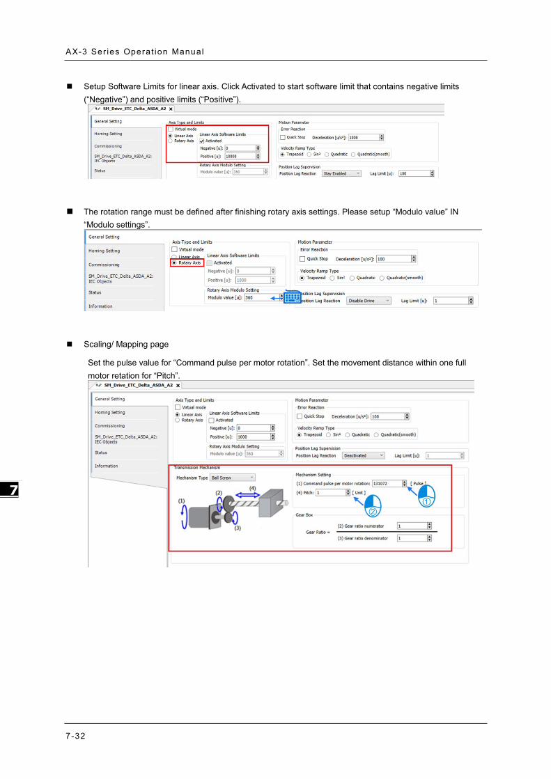
AX-3 Ser ies Operat ion Manual
7-32
_7
Setup Software Limits for linear axis. Click Activated to start software limit that contains negative limits (“Negative”) and positive limits (“Positive”).
The rotation range must be defined after finishing rotary axis settings. Please setup “Modulo value” IN “Modulo settings”.
Scaling/ Mapping page
Set the pulse value for “Command pulse per motor rotation”. Set the movement distance within one full motor retation for “Pitch”.

Chapter 7 Mot ion Contro l Bas ic Se t t ings & Operat ion
7-33
7_
To configure the communication cycle time of Ethernet, click “EtherCAT_Master_SoftMotion”, then set the value of “Cycle time” as 2000 and “Sync offset” as 50.
Scan PLC controller
Add the newly scanned PLC controller and click “OK”.

AX-3 Ser ies Operat ion Manual
7-34
_7
A green light icon will be shown if the connection is successful, then click “Login”.
A prompt box will pop out to remind you if you want to perform a download, click “Yes” to continue.

Chapter 7 Mot ion Contro l Bas ic Se t t ings & Operat ion
7-35
7_
7.4.4 Axis Group Settings
Axis group movement will be functioned when executes linear interpolation and circular interpolation with multiple axes. DIADesigner-AX is required for grouping axes.
Maximum controll axes Linear interpolation 6 axes
Circular interpolation 6 axes (3 follower axes)
7.4.4.1 Prameters for Axis Group
The parameters used for axis group movement are as follows.

AX-3 Ser ies Operat ion Manual
7-36
_7
Kinematic
Name Function
Axis X*1 X axis in axis group
Axis Y*1 Y axis in axis group
Axis Z*1 Z axis in axis group
Axis A*1 A axis in axis group
Axis B*1 B axis in axis group
Axis C*1 C axis in axis group
Motion Parameter
Name Function
Ramp Type*2 Velocity ramp type
Max Velocity Limit*3 The max velocity of axis group
Max Acceleration Limit*3 The max acceleration of axis group
Max Deceleration Limit*3 The max deceleration of axis group
Max Jerk Limit(Reserved)*3 The max jerk rate of axis group (Reserved)
Tasks
Name Function
Bus Task Configure the updating task for axis groups.
Note 1: Axis X ~ Axis C: Enter the names of axes individually.
Note 2: There are two Ramp Type: Trapezoid and S-curve type, which are shown in the following figures.
Trapezoid
T
V

Chapter 7 Mot ion Contro l Bas ic Se t t ings & Operat ion
7-37
7_
S Curve
Note 3: Max Velocity Limit:An error occurs when the velocity exceeds the setting value.
Max Acceleration Limit:An error occurs when the acceleration exceeds the setting value.
Max Deceleration Limit:An error occurs when the deceleration exceeds the setting value.
7.4.4.2 Using Axis Groups in Program
To follow the procedure, you must add the node of axis group to the project tree and names the required axis in the group individually before using the AxisGroup function block. After finishes the settings, please connect the node of axis group to AxisGroup input of each function block.
V
T

AX-3 Ser ies Operat ion Manual
7-38
_7
7.4.5 Procedure for Axis Group Configuration To use the axis group movement function, you must name the axis group and set the corresponding
individual axes with DIADesigner-AX. The process flowchart of creating axis groups is shown below.
Procedure of creating axis groups in program
(1) Add single axes. The following example starts from creating two virtual axes.

Chapter 7 Mot ion Contro l Bas ic Se t t ings & Operat ion
7-39
7_
(2) After finish creating axes, select “Application” and right click “Add Object” “Delta Axis Group”
(3) Set the name for axis group on the “Add Delta Axis Group” page, then click “Add”

AX-3 Ser ies Operat ion Manual
7-40
_7
(4) Afterwards, “DMC_Axis_Group” will be shown on the Project tree.
(5) Click “DeltaAxisGroup”, then enter the names of two virtual axes into the fields of “Axis X” and “Axis Y”.

Chapter 7 Mot ion Contro l Bas ic Se t t ings & Operat ion
7-41
7_
(6) Click “Bus Task” to enter “Input Assistant”, then choose “EtherCAT_Task” on the screen and click “OK” with “EtherCAT_Task” shown in the Tasks field afterwards.
(7) Add “DMC_GroupEnable” function block below PLC_PRG and connect the name of axis group to the AxisGroup input.

AX-3 Ser ies Operat ion Manual
7-42
_7
(8) After the program writing is completed, click the Compile button to confirm the validity.
(9) After compilation, click Online Monitoring button to download the program.

Chapter 7 Mot ion Contro l Bas ic Se t t ings & Operat ion
7-43
7_
7.5 Motion Axis Variables
7.5.1 Variables for Single Axis
After creating axes in the Project tree with DIADesigner_AX, the corresponding axis parameters (read-only) will be generated automatically. Axes are categorized into two types: synchronous axis (Axis_REF_SM3) and positioning axis (Axis_REF_DML), which are set out in the following table
Synchronous axis (Axis_REF_SM3)
Numbering Name Data type Default value
Description
1000 nAxisState SMC_AXIS_ STATE(INT)
Standstill
(3)
Operating state of the current axis according to MC_ReadStatus
1012 bCommunication BOOL FALSE When communication is normal (refer as True), if disconnected (refer as False)
1014 uiDriveInterfaceError UINT 0 When Driver Interface detects an error, Error Handling occurs
1021 wDriveId WORD Driver The number in driver nodes on the Field bus
1025 fTaskCycle LREAL Driver EtherCAT cycle time of task
1035 fbeFBError
ARRAY
[0..g_SMC_NUMBER_FB_ERRORS
]
OF SMC_FBER
ROR
0 Axis-related error table
1040 bVirtual BOOL FALSE True: virtual axis ; false: real axis
1051 iRatioTechUnitsNum DINT 1 Change gear ratio in axis setting (denominator)
1052 dwRatioTechUnits Denom
DWORD 1 Change gear ratio in axis setting (numerator)
1060 iMovementType INT 1 0 = Modulo
1 = Finite
1061 fPositionPeriod LREAL 1000 Max movement distance of rotary axis
1062 eRampType SMC_RAMP
TYPE Trapez
Velocity ramp type:
Trapezoid sin^2 Quadtatic

AX-3 Ser ies Operat ion Manual
7-44
_7
Numbering Name Data type Default value
Description
Quadtatic(smooth)
1100/1 fSetPosition LREAL 0 Commanded position (User-defined unit)
1101 fActPosition LREAL 0 Feedback position (User-defined unit)
1110,11 fSetVelocity LREAL 0 Commanded velocity (User-defined unit /s)
1111,10 fActVelocity LREAL 0 Feedback velocity (User-defined unit /s)
1115 bConstantVelocity BOOL FALSE True: the axis is driving with constant velocity
1120 fSetAcceleration LREAL 0 Commanded acceleration (Unit: User-defined unit /s^2)
1125 bAccelerating BOOL FALSE True when Axis is accelerating
1135 bDecelerating BOOL FALSE True when Axis is decelerating
1140 fSetJerk LREAL 0 Commanded jerk value
1160 fSetTorque LREAL 0 Commanded torque (Nm)
1161 fActTorque LREAL 0 Actual torque (Nm)
1200,2 fSWLimitPositive LREAL 0 Setting the range of positive software limit
1201,3 fSWLimitNegative LREAL 0 Setting the range of positive software limit
1204 bSWEndSwitchActive BOOL FALSE True when software limit switch activated State machine changes to ErrorStop
1205 bSWLimitEnable BOOL FALSE Software limit end switches: True (Enable) /False(Disable)
- strDriveInterfaceError STRING ‘’ Axis error

Chapter 7 Mot ion Contro l Bas ic Se t t ings & Operat ion
7-45
7_
Positioning Axis (Axis_REF_DML)
Numbering Name Data Type Default value Descripyion
1000 nAxisState SML_AXIS_STATE SML_AS_PowerO
ff(0)
Operating state of the current axis according to MC_ReadStatus
1012 bCommunication
BOOL FALSE When communication is normal (refer as True), if disconnected (refer as False)
1014 uiDriveInterfaceError
UINT 0 When Driver Interface detects an error, Error Handling occurs
1051 iRatioTechUnitsNum
DINT 1 Change gear ratio in axis setting (denominator)
1052 dwRatioTechUnits Denom
DWORD 1 Change gear ratio in axis setting (numerator)
1060 iMovementType
SML_MovementType
SML_MT_MODULO
Axis types
SML_MT_MODULO = Rotary axis
SML_MT_FINITE = Linear axis
1062 eRampType*1
SMC_RAMPTYPE Trapez Setting Ramp type:
Trapezoid sin^2
1101 fActPosition LREAL 0 Feedback position (User-defined unit)
- strDriveInterfaceError
STRING ‘’ Axis error
*Note 1: Only support Trapezoid and sin^2

AX-3 Ser ies Operat ion Manual
7-46
_7
7.5.2 Variables for Axis Group
After creating axis groups in project tree with DIADesigner-AX, the corresponding axis variables will be generated automatically, which are set out in the following table.
Name Data Type Setting Value
(Default Value) Function
GroupState DMC_
GROUP_ STATE
GroupDisabled / GroupStandby / GroupMoving / GroupHoming / GroupStopping / GroupErrorstop (GroupDisabled)
Commands for axis group status.
bError BOOL TRUE / FALSE
(FALSE) TRUE when an error occurs in the axis group
dwErrorId DMC_
ERROR
DMC_ERROR (DMC_GM_NO_
ERROR) Detailed error description
lrVelocity LREAL 0 ~ 1.798E+308 (0) Current velocity of axis group
lrAcceleration LREAL Positive number,
negative number or zero (0)
Current acceleration of axis group
lrJerk LREAL Positive number,
negative number or zero (0)
Current jerk of axis group
bAccelerating BOOL TRUE / FALSE
(FALSE) TRUE when accelerating
bDecelerating BOOL TRUE / FALSE
(FALSE) TRUE when decelerating
bConstantVelocity BOOL TRUE / FALSE
(FALSE) TRUE when moving at a constant velocity (including zero velocity)
bInPosition BOOL TRUE / FALSE
(FALSE) TRUE when positioning is done.
bContinueDataWriten BOOL TRUE / FALSE
(FALSE)
TRUE when axis group is forced to stop and the relevant data can be used by DMC_GroupContinue.
ContinuePos ARRAY
[0..5] OF LREAL [0,0,0,0,0,0]
When the execution of DMC_GroupInterrupt is done, the position of the current axis group is recorded.
AxisX_Name* String Display the Axis_X name for current axis group
AxisY_Name* String Display the Axis_Y name for current axis group
AxisZ_Name* String Display the Axis_Z name for current axis group
AxisA_Name* String Display the Axis_A name for current axis group
AxisB_Name* String Display the Axis_B name for current

Chapter 7 Mot ion Contro l Bas ic Se t t ings & Operat ion
7-47
7_
Name Data Type Setting Value
(Default Value) Function
axis group
AxisC_Name* String Display the Axis_C name for current axis group
RampType DMC_GROUP_RAMP_TYPE
Trapezoid / S Curve (S Curve)
Ramp type of current S-curve
lrMaxVelocityLimit LREAL Positive number or zero
(1000000) The max velocity of axis group
lrMaxAcceleration Limit
LREAL Positive number or zero
(2000000) The max acceleration of axis group
lrMaxDecelerationLimit LREAL Positive number or zero
(2000000) The max deceleration of axis group
lrMaxJerkLimit (Reserved)
LREAL Positive number or zero
(0) The max jerk of axis group (Reserved)
lrVelocityWarning Percentage
LREAL 0 ~ 1 (0)
Set the persontage of the maximum velocity of axis group for the warning to start. Once the set persontage is reached, the warning starts. Set the value to 0 to stop the warning.
lrAccelerationWarning Percentage
LREAL 0 ~ 1 (0)
Set the persontage of the maximum acceleration of axis group for the warning to start. Once the set persontage is reached, the warning starts. Set the value to 0 to stop the warning.
lrDecelerationWarning Percentage
LREAL 0 ~ 1 (0)
Set the persontage of the maximum deceleration of axis group for the warning to start. Once the set persontage is reached, the warning starts. Set the value to 0 to stop the warning.
lrJerkWarning Percentage (Reserved)
LREAL 0 ~ 1 (0)
Set the persontage of the maximum jerk of axis group for the warning to start. Once the set persontage is reached, the warning starts. Set the value to 0 to stop the warning.
Radius Correction LREAL 0 ~ 100
(0, 1)
This is to set the tolerance for setting the radius when circular interpolation is seclected in the function block of DMC_MoveCircularRelative.AuxPoint. Tolerance % = the distance between the center point and the bisection of the starting and ending points to be divided by the radius.
bVelocityWarning BOOL TRUE / FALSE
(FALSE)
TRUE when the velocity of axis group exceeds the value set in the lrVelocityWarning Percentage.
bAccelerationWarning BOOL TRUE / FALSE
(FALSE)
TRUE when the acceleration of axis group exceeds the value set in the lrAccelerationWarningPercentage.
bDecelerationWarning BOOL TRUE / FALSE
(FALSE)
TRUE when the deceleration of axis group exceeds the value set in the lrDecelerationWarningPercentage.

AX-3 Ser ies Operat ion Manual
7-48
_7
Name Data Type Setting Value
(Default Value) Function
bJerkWarning (Reserved)
BOOL TRUE / FALSE
(FALSE)
TRUE when the jerk of axis group exceeds the value set in the lrDecelerationWarningPercentage.
StopMethod Enum of BYTE
Immediate Stop / MaxGroupDecStop /
MaxAxisDecStop (Immediate Stop)
Set the stop method for the axis group when errors occur or when it is time to stop the movement.
Note: When the rotary type of axis is selected, the range of motion can NOT exceed the value set in modulo, otherwise, an error “Axis limit violated” will occur. ”

Chapter 7 Mot ion Contro l Bas ic Se t t ings & Operat ion
7-49
7_
7.6 Motion Control Programming 7.6.1 Motion Control Program Before programming in DIADesigner-AX, please take the following descriptions as reference.
7.6.1.1 Program Architecture and Types in DIADesigner-AX
In the classic architecture, a source code for a PLC is composed of procedures including subroutines. When the size of a program becomes larger, maintenance and debugging also becomes a huge burden. Under the IEC 61131-3 architecture, a program is divided into several units according to the functions or characteristics which makes developing and maintaining much easier. Since POU are modularized, different POU can be developed by different designers to enhance distribution of professional manpower and project execution
There are three types of POUs: program (PROG), function block (FB) and function (FC).
▓ Program (PROG):
The program type plays a major process role in a PLC program. The execution is assigned by Task which includes specific scan cycle or interrupt subroutines and provides scan order arrangement for programs in the Task list. Besides, a POU of the program type can call a function block (FB).
▓ Function block (FB):
A static symbol can be declared in a function block (FB). As a result, the value of the symbol after an operation can be retained. Owing to the fact that the operation is performed on the value memorized in the function block and an input value, the output values may be different even if the input values are the same.
Besides, a function block can call another function block.The function block (FB) type is similar to subroutines. The FB process requires suitable parameters and can only execute once called by a program.
▓ Function (FC):
Function (FC) is used to return back operation results. Contrary to FBs, it have no memory and can only return a single value. Since an FC does not have any memory of its own, it cannot call a function block but a function.
Tasks
Each program POU needs to assign a Task that determines the order for program execution or start.
The programming structure characteristic of IEC 61131-3 is that a program can be divided into several independent POUs. When POUs are compiled, they are rearranged and combined into an execution code for scanning. The new combination order of POUs are based on the assigned Tasks.
Below are types of tasks:
▓ Cyclic: Assigned POU sets interval time for per scan.
▓ Event: When Bool variable is set from False to True, a scan execution is performed.
▓ External: When external triggers to send a signal, a corresponding POU is executed.
▓ Freewheeling: Assigned POU performs scan automatically in a continuous loop when the previous scan has been completed.
▓ Status: When Bool variable is set from False to True, a scan cycle is executed.
Please refer to section 4.4.1 for the details of task operating process.

AX-3 Ser ies Operat ion Manual
7-50
_7
7.6.1.2 POU in DIADesigner-AX
All POUs created by you are listed in the project management area with programs and function blocks been managed separately. In addition, the icon of POU may vary based on different program and function block programming languages which also includes information beside the POU name.
Double-click the POU in the project management area for editing. The POU editing section is composed of two parts. The upper part of the editing section is the symbol table of local variables, while the lower part is the main part of the program. Also, the editing environment at the lower part of the editing section is different when using different programming languages. For more information on symbol tables and programming, please refer to the following sections.
7.6.1.3 Adding POU in DIADesigner-AX
Open the existed projects in DIADesigner-AX and right-click “Appliction” to select “Add Object”, then choose “POU”.

Chapter 7 Mot ion Contro l Bas ic Se t t ings & Operat ion
7-51
7_
Type in POU name. For Implementation language, select a programming language then click “Add”
The POU appears in the left column. Double-click on “EtherCAT_Task” and choose “Add Call”.
Select the created POU and click “OK”.

AX-3 Ser ies Operat ion Manual
7-52
_7
Choose POU in EtherCAT_Task item to compile a program .
7.6.1.4 PDO Mapping
Before using motion control instructions, the communication of PDO (Process Data Objects) Mapping between the software DIADesigner-AX and AX motion CPU must be setup first.
Setting values for PDO Mapping
RxPDO(1600 hex) Control Word(6040 hex),TargetPosition(607A hex)
TxPDO(1A00 hex) Status Word(6041 hex),ActualPosition(6064 hex)
The table above is the pre-determined PDO Mapping parameters for ASDA-A2-E.
Please refer to AX Series Motion Controller Manual for the PDO parameters required by the related motion function blocks.

Chapter 7 Mot ion Contro l Bas ic Se t t ings & Operat ion
7-53
7_
7.6.2 Axis State Transitions
This section introduces single axis state transitions and multi-axis state transitions in axis groups for multiple function block use. The transition rules fulfills PLCopen motion control standard.
7.6.2.1 Axis State
Synchronous Axis
Note 1: Regardless of the state. An error in the axis has occured.
Note 2: Regardless of the state. MC_Power.Enable = FALSE. There is no error in the axis.
Note 3: MC_Reset and MC_Power.Status = FALSE
Note 4: MC_Reset and MC_Power.Status = TRUE and MC_Power.Enable = TRUE
Note 5: MC_Power.Enable = TRUE and MC_Power.Status = TRUE
Note 6: MC_Stop.Done = TRUE and MC_Stop.Execute = FALSE

AX-3 Ser ies Operat ion Manual
7-54
_7
State Meaning
Disabled Axis during servo OFF, standstill, ready to execute
Standstill Axis during servo ON, standstill
Discrete Motion The state would be Discrete Motion while executing single-axis motion instructions.
Continuous Motion The state would be Continuous Motion while executing continuous motion instructions of single-axis.
Synchronized Achieves state of synchronized motion via instructions for synchronized control.
Includes synchronous waiting state.
Stopping When Execute is True via MC_Stop instructions
Cannot execute axis instructions during this state
When CommandAborted is TRUE, the instruction is executed
ErrorStop Axis during servo ON or axis errors
Cannot execute axis motion instructions under this state and all instructions are in CommandAborted = 1 state.
Homing The state would be Homing while executing MC_Home or MC_HomeWithParameter instructions for single axis.
Positioning Axis

Chapter 7 Mot ion Contro l Bas ic Se t t ings & Operat ion
7-55
7_
State Meaning Disabled Axis during servo OFF, standstill, ready to execute Standstill Axis during servo ON, standstill Discrete Motion The state would be Discrete Motion while executing single-axis motion instructions.
Continuous Motion The state would be Continuous Motion while executing continuous motion instructions of single-axis.
Stopping When Execute is True via MC_Stop instructions Cannot execute axis instructions during this state
ErrorStop When an error occurs in the single axis. Cannot execute axis motion instructions for single axis under this state.
Homing The state would be Homing while executing MC_Home or MC_HomeWithParameter instructions for single axis.
7.6.2.2 Axis Group State
Note 1: Applicable to all function blocks of group moving, non-administrative.
Note 2: All motion function blocks are able to be executed when the state is GroupErrorStop or GroupStopping
Note 3: When DMC_GroupStop is Done or MC_GroupStop is not Execute.
Note 4: The state of GroupDisabled can only be changed under GroupStandby state , or an error will occur.
Status Definition GroupDisabled Execute MC_GroupDisable and switch axis to GroupDisabled. GroupStandby No motion instructions has been executed and the state of axis group is GroupStandby.
GroupMoving A group positioning instruction is being executed, the state of axis group is GroupMoving.Moving。
GroupStopping When Active of MC_GroupSto is True, the state of axis group is GroupStopping. No motion instructions can be executed under this state.
GroupErrorStop The axis group will enter GroupErrorStop state, once an error occurs.

AX-3 Ser ies Operat ion Manual
7-56
_7
Interaction between single-axis state and axis group state
(1) If one of the axes in the group is in ErrorStop and the axis group is not in GroupDisabled, the group would be in GroupErrorStop status.
(2) When state GroupMoving/GroupStopping/GroupHoming disconnect the power of an axis, the axis group would be in GroupErrorStop state.
(3) If all axes are in Standstill, the axis group can be in state GroupStandby, GroupDisabled or GroupErrorStop.
(4) If the motion of a single-axis interrupts the motion of axis group, the other axes in the group should be stopped and enter state Stopping, while the state of the axis group entering state GroupStandby.
(5) In case that the axis group is in GroupStandby, there’s no need for all the single axes being in state SynchronizedMotion.
(6) For axis group motion instructions (including MC_GroupStop), all single axes in the axis group should be in state SynchronizedMotion.
(7) When an error occurs during the movement of axis group, all axis in the group should stop immediately till the axis group entering state GroupErrorStop. Those single axes with no errors will enter state Standstill.
(8) When the state of axis group is GroupErrorStop, the state of single axes will not be affected.
7.6.3 Execution and Status Indication for Motion Control Instructions
The motion function blocks are grouped under two main categories with AX series motion controllers:
Category Description
MC_ PLCopen motion control function blocks
DMC_ Delta self-defined function blocks*
*Note: Delta self-defined function blocks (DMC) include motion control type and other administrative/ non-administrative type applicable for AX series motion CPU. Please find AX
General pins for motion control function blocks include input, output and in-out. The section explains the meanings and behaviors of these pins. For more details concerning motion function blocks, please refer to AX Series Motion Controller Manual.

Chapter 7 Mot ion Contro l Bas ic Se t t ings & Operat ion
7-57
7_
7.6.3.1 Basic Rules of Executing Instructions
● Defining input and output pins
Common inputs and outputs in motion control function blocks are listed below. Usually, a function block consists of at least one or a part of the input/output pins listed below. For example, a function block contains either Execute or Enable input pin based on the properties of the motion control function block.
Inputs
Name Description Date Type Setting value
(Default)
En Receiving the logic status in front of the instruction BOOL True/False (False)
Enable Enabling motion control function block BOOL True/False (False)
Execute Executing motion control function block BOOL True/False (False)
Outputs
Name Description Date Type Setting value(Default)
Eno Transfering the input logic state of the En to the next serial instruction
BOOL True/False (False)
Done The execution of the function block is completed BOOL True/False (False)
Valid The output pin value is valid BOOL True/False (False)
Busy The motion control function block is listed for execution
BOOL True/False (False)
Active Axes are been controlled by function blocks BOOL True/False (False)
CommandAborted(Aborted)
Aborts execution for motion control function blocks BOOL True/False (False)
Error Error occurs in function blocks BOOL True/False (False)
A motion control function block usually consists of Execute or Enable input pin and is used to either execute or enable a motion control function block. In addition, a motion control function block has Busy and Done output pins. The Busy and Done outputs refer to the status of motion control function blocks. When execution of motion control function blocks can be aborted by another motion control function block, the CommandAborted/Aborted output pin appears in the function block. Nevertheless, when Error output pin is True, this indicates error during function block execution.
A motion control function block not only has Execute/Enable input, but also include the input value/state. The characteristics are described below.
- Use input value
▓ When a function block contains Execute input, each input value is used once Execute input signal
changes from False to True. However, when Execute is re-triggered, input values are not updated as a result.
▓ When a function block contains Enable input, each input value is used once Enable input signal changes
from False to True. Compare to Execute input, function blocks of Enable input usually have more input values which need to be continuously updated. (Refer to each function block for more detail).

AX-3 Ser ies Operat ion Manual
7-58
_7
- Input value exceeds range
When a motion control function block is enabled, the system restricts you to input values that exceeds the permitted range. Nevertheless, error occurs during execution of motion control function blocks and results in motion axes errors. You should avoid input incorrect values in programs.
- Output pins are mutually exclusive.
▓ When a function block contains Execute input, Busy output, Done output, CommandAborted output or
Error output, only one state is set to True during the same time. When Execute input is set True, one output (Busy, Done, CommandAborted or Error) must set True.
▓ When a function block contains Enable input, while Valid output and Error output are mutually exclusive,
this indicates only one output is set True.
- Valid time for output data/status value
▓ When a function block contains Execute input and the input signal changes from True to False, the current
Done output, Error output, CommandAborted output of current True and output pin data are reset or cleared. However, when a function block is Busy, despite that the Execute input signal changes from True to False, execution of the function block will not stop. The expected output state (Done output, Error output, CommandAborted output) will generate to True and retain for one week.
▓ When a function block contains Enable input and input signal changes from True to False, Valid output,
Busy output and Error output are reset. (For input and output description not mentioned, please refer to MC_Power instruction for more details.)
- Characteristic of Done output
When execution of a motion control function block is completed, Done output is set to True.
- Characteristic of Busy output
▓ When a function block contains Execute input and uses Buy output to indicate incomplete execution, new
output state (value) is to be generated. When Execute input signal changes from False to True, then Busy output is set to True. When Done output, CommandAborted output or Error output is set to True, then Busy output is reset.
▓ When a function block contains Enable input and uses Buy output to indicate incomplete execution, new
output state (value) is to be generated. When Enable input signal changes from False to True and as long as Busy output is set True, changes in input state (value) can be expected.
- Characteristic of CommandAborted/Aborted output
When execution of a motion control function block is aborted, CommandAborted/Aborted output is set True.
- Relation between Enable input and Valid output
A function block contains Enable input and uses Valid output to indicate validity of output data/status. Only when Enable input is set True and output data/status is valid, then Valid output is set True; when errors occur in function blocks, then output data/status is invalid and Valid output is set to False; when errors are cleared in motion control function blocks and output data/status changes to valid, then Valid output is set to True.

Chapter 7 Mot ion Contro l Bas ic Se t t ings & Operat ion
7-59
7_
7.6.3.2 Timing Diagram for Input/Outputs
Situation 1: The execution of motion control function block is aborted.
Situation 2: Errors occur in motion control function blocks.
Situation 3: The execution of motion control function block is completed.
Situation 1: The execution of motion control function block is normal.
Situation 2: An error occurs in a motion control function block.
7.6.3.3 Repeated Execution Behavior of Single Axis Motion Instructions
When single axis motion function blocks are executing (Busy state), variables for input pins can be modified and function block pins can be re-triggered on the rising. Meanwhile, the state of function block output pins remain the same (remain Busy), while the system is executing which means it is aborting the previous rising edge-trigger instruction under buffer mode. For similar mode of behavior, refer to section 7.6.3.5 Single Axis Buffer Mode (Aborting) for more details.

AX-3 Ser ies Operat ion Manual
7-60
_7
7.6.3.4 Multi-execution of Motion Control Instructions
This section describes executing multiple motion control instructions for the same axis or axis group within the same scan period.
In the following programming, instruction instances Move1 and Move2 start in the same task period when contact A turns ON.
According to the ladder logic, instructions in a program are executed from the top. Therefore Motion1 starts first, and then Motion 2 will be executed once Motion 1 is finished.
This is considered multi-execution of motion control instructions. Since the motion combination is dertermined by input variables of BufferMode, BufferMode setting in Motion 2 is used to execute Motion 2 in relation to Motion 1.
Contact A Motion 1
Motion 2
BufferMode
Abort
Ax is 1
Ax is 1
7.6.3.5 Synchronous Execution Eehavior of Motion Instructions
▓ Single Axis Buffer Mode
You can execute another motion control instruction while an axis is moving. A total of six types of BufferMode can be chosen to proceed multi-execution of two instructions, which you can set the BufferMode input variables to the later motion control instruction to select one of the six Buffer Modes.
The meanings of terms relating to BufferMode shown as follows:
1. Current instruction: The motion control instruction that was in operation just before executing the multi-execution instruction.
2. Buffered instruction: A motion control instruction that was executed during an axis motion and is waiting to be executed
3. Transit velocity: The velocity to use by the current instruction to trasfer to the buffered instruction. 4. Target Velocity: The Velocity parameters of the instruction. 5. Target position: the Positon or Distance parameters of relating move instructions.
BufferMode Description of Operation
0:mcAborting (Aborting)
The current instruction is aborted and the multi-executed instruction is executed.
1:mcBuffered (Buffered)
The buffered instruction is executed after the operation for the current instruction is normally finished.
2:mcBlendingLow (Low velocity)
The buffered instruction is executed after the target position of the current instruction is reached. The transit velocity is set to the target velocity of the current instruction or the buffered instruction, whichever is lowest.
3:mcBlendingPrevious (Previous velocity)
The buffered instruction is executed after the target position of the current instruction is reached.The target velocity of the current instruction is used as the transit velocity
4:mcBlendingNext (Next velocity)
The buffered instruction is executed after the target position of the current instruction is reached. The target velocity of the buffered instruction is used as the transit velocity.

Chapter 7 Mot ion Contro l Bas ic Se t t ings & Operat ion
7-61
7_
BufferMode Description of Operation
5:mcBlendingHigh (High velocity)
The buffered instruction is executed after the target position of the current instruction is reached. The transit velocity is set to the target velocity of the current instructionor the buffered instruction, whichever is highest.
Example: Brefly explain with two MoveRelative instructons
The max velocity and the displacement of the first and second instruction are respectively V1, S1 and V2, S2.
Different types of BufferModes set for the second instruction result in various transitting situation shown as follows.
Buffermode=mcAborting
1. Present instruction aborted during acceleration. 2. Present instruction aborted at constant speed.
3. Present instruction aborted during decelerating. 4. The instruction transferred and the present instruction are in opposite direction.
t
Curr entins truct ionis s tarted
The buffer ed ins tr uct ion is s tar ted and then starts to contr ol the
ax is im mediately.
Buffered i ns truct ion
V
C urrenti nstruc tion
V2
t
The buffered i nstruct ion is s tarted and then starts to control the
ax is i mmediately.
Buffer ed ins truct ion
V
Currentins tr uct ionis s tar ted
Curr entins truct ion
V2
V1
t
Curr entins truct ionis s tarted
The buffered ins truct ion is s tarted and then starts to contr ol the
ax is i mmediately.
Buffered ins truct ion
V
Currentins tr uct ion
V2
V1
t
The buffer ed ins tru ct i on i s s tar te d a nd the n s ta rts t o contro l the
ax is i m me dia tely.
Buffered i nstruc ti on
V
Currentins tr uct ionis s tar ted
C urrentinstruc ti on
V1
V2

AX-3 Ser ies Operat ion Manual
7-62
_7
Buffermode=mcBuffered
1. The instruction transferred and the present instruction are in same direction.
2. The instruction transferred and the present instruction are in opposite direction.
Buffermode=mcBlendingLow
1. The velocity of current instruction is slower 2. The velocity of current instruction is greater
3. The instruction transferred and the present instruction are in opposite direction.
t
Cur rentins truct ionis s tarted
When current i ns truc t ion execut ion is completed, the buffered i nstruc tion
starts to control the axis .
Buffered instruc ti on
V
Curr entins truct ion
The bufferedi nstruct ion is s tarted
V2
V1
S1S2
t
When cur rent ins truct ion execut ion is compl eted, t he buffer ed i nstruct io
starts to control the ax is .
Buffer ed ins truct ion
V
Currentins truc t ioni s s tarted
Currentins tr uct ion
The buffer edinstruc tion is s tarted
V1
V2
S1
S2
tBuffered ins truc t ion
V
Currentins truc t ionis s tarted
Cur renti ns truct ion
The bufferedi nstruct ion is s tarted
The buffered i nstruct ion starts to controlthe ax is when current ins truct ion executi on
is completed and the axis veloc ity is the low erof the tw o i nstruct ion vel ocit ies .
V2
V1
S1
S2
tBuffered instruction
V
Curr entins truct ionis s tarted
Curr entins truct ion
The bufferedi nstruct ion is s tarted The buffered i nstruc tion s tar ts to control the axi s
when cur rent ins truc t ion execut ion is completed and the axis veloc ity is the low er of the
tw o ins truct ion veloc it ies .V1
V2
S1S2
t
Buffer ed ins truct ion
V
C urrentinstruc ti oni s started
Currentins truc t ion
The buffer edi nstruct ion is s tarted
The moti on di rect ions of current instruc ti onand buffered ins tr uct ion ar e oppos ite.
The buffered ins truc t ion s tarts to control the ax is w hen current ins truct ion
decelerates t ill the veloc ity is 0.
V1
V2
S1
S2

Chapter 7 Mot ion Contro l Bas ic Se t t ings & Operat ion
7-63
7_
Buffermode=mcBlendingPrevious
1. The velocity of current instruction is slower 2. The velocity of current instruction is greater
3. The instruction transferred and the present instruction are in opposite direction.
tBuffered ins truc t ion
V
Currentins truc t ionis s tarted
Cur renti ns truct ion
T he bufferedi nstruct ion is s tarted
The buffer ed ins truct ion starts to contr ol the axiswhen curr ent ins truc t ion execut ion is completed and
the axis veloc ity is that of the prev ious ins truct ion.
V2
V1
S1
S2
tBuffered instruct ion
V
Currentins truc t ionis s tarted
C urrenti nstruct ion
The bufferedins tr uct ion is s tar ted
T he buffered i nstruct ion starts to control the axi swhen cur rent ins tr uct ion executi on is completed and
the axi s vel ocity i s that of the pr evious i nstruct ion.
V1
V2
S1S2
t
Buffered instruc ti on
V
C urrentinstruc ti oni s started
Currentins truc t ion
The buffer edi nstruct ion is s tarted
The motion direc t ions of current ins truct ionand buffered i nstruc tion are opposite.
The buffered ins truc t ion s tarts to controlthe axis w hen current instruc ti ondeceler ates t il l the veloci ty i s 0.
V1
V2
S1
S2

AX-3 Ser ies Operat ion Manual
7-64
_7
Buffermode=mcBlendingNext
1. The velocity of current instruction is slower 2. The velocity of current instruction is greater
3. The instruction transferred and the present instruction are in opposite direction.
tBuffered i nstruct ion
V
Cur rentins truct ionis s tarted
Currenti ns truc ti on
The buffer edinstruc ti on i s started C ur rent ins tr uct ion execution is completed
and the buffered ins truct ion starts to control th axis w hen the ax is veloc ity is dec reased to the
veloci ty o f the nex t ins truct ion.V1
V2
S1S2
t
Buffered ins tr uc t ion
V
Currentins truc t ionis s tarted
Currentinstruct ion
The bufferedi nstruct ion is s tarted
The buffer ed instruct ion s tarts to control th ax is w hen the moti on dir ect ions of buffere
instruc ti on and curr ent instruc t ion are opposite and the veloc ity of cur rent
ins tr uc t ion i s decreased to 0.
V1
V2
S1
S2
tBuffered ins truc ti on
V
C urrenti nstruct ionis s tarted
Currentins tr uct ion
The bufferedins truct ion is s tarted
Cur rent ins tr uc t ion execut ion is completedand the buffered ins tr uct ion starts to control t
axi s when the ax is accel erates to the veloc it of the next i ns truc t ion.
V2
V1
S1
S2

Chapter 7 Mot ion Contro l Bas ic Se t t ings & Operat ion
7-65
7_
Buffermode=mcBlendingHigh
1. The velocity of current instruction is slower 2. The velocity of current instruction is greater
3. The instruction transferred and the present instruction are in opposite direction.
*Note: Single-axis motion instructions MC support only Buffermode=mcAborting while motion instructions for axis group support all of the above BufferMode.
tBuffer ed ins truct ion
V
Currentinstruc ti oni s started
Currentinstruc ti on
The bufferedi nstruct ion is s tarted
The buffer ed ins truct ion starts to control the axwhen current instruc ti on execut ion is com plete
and the axi s vel ocity r eaches the higher ofthe two ins tr uct ion veloc it ies .
V2
V1
S1S2
t
tBuffered i nstruc tion
V
Currentins tr uc t ionis s tar ted
Cur renti nstruct ion
The bufferedi nstruct ion is s tarted
The buffered ins truct ion starts to control th ax is w hen current i ns truct ion executi on is
completed and the ax is veloc ity is thehigher of the tw o i nstruct ion vel ocit ies .
V1
V2
S1S2
t
Buffered instruc ti on
V
C urrentinstruc ti oni s started
Curr entins truct ion
The bufferedins tr uct ion is s tar ted The buffered instruc ti on star ts to control the
when the motion di rect ions of bufferedins truc t ion and cur rent ins tr uct ion ar e opposi te and the veloc ity of current
ins truct ion is decr eased to 0.
V1
V2
S1
S2

AX-3 Ser ies Operat ion Manual
7-66
_7
7.6.4 Position This section describes the position processes of motion control programming.
7.6.4.1 Types of Positions
MC function blocks are formed by the following two types of positions.
● Command position: MC function block provides command position.
● Actual position: The actual feedback position from servo drives.
The following figure indicates the relationship between the command position and the actual position.
The following item of command position and actual position is the same.
Position Type Description
Command position This is the position that motion controller outputs to servo drive
Actual (feedback) position This is the position feedback from servo drive or encoder
*Note: For axes configured as Virtual, the actual position is equal to the command.
7.6.5 CAM Tables and Framework This section introduces electronic cam (E-CAM) operation and using DIADesigner-AX to generate CAM table settings as well as E-CAM applications. For details regarding insturctions, please refer to AX Series Motion Controller Manual.
7.6.5.1 E-CAM Framework
Adopt CAM Editor function from software DIADesigner-AX for planning CAM curves and download to PLC via communication protocols so that MC function blocks can be used to control CAM.

Chapter 7 Mot ion Contro l Bas ic Se t t ings & Operat ion
7-67
7_
7.6.5.2 Creating E-CAM
The data that defines the relationship between master/slave (CAM axis) is called E-CAM data.
When using CAM Editor of DIADesigner-AX , it is crucial to know the relationship between master and slave axis position through the two methods described below:
Method 1: Obtains the relationship between master and slave axis position based on E-CAM data setting.
Method 2: Measures the corresponding relationship between master and slave axis position through real task.
When the CAM master and slave relationship is confirmed, the slave position can be obtained based on the master axis position.
● Create DIADesigner-AX CAM tables
(1) Right-click “Application”, choose “Add Object” and then select “CAM Table”.

AX-3 Ser ies Operat ion Manual
7-68
_7
(2) Type the name of the CAM table.
(3) After clicking “Add”, CAM icon is shown on the left item box.

Chapter 7 Mot ion Contro l Bas ic Se t t ings & Operat ion
7-69
7_
(4) Click “Cam Table” on the CAM page.
(5) Add or delete CAM data on the CAM Table screen
- Click to add new CAM data
- Click to delete CAM data
- X: Position data of master axis
- Y: Position data of slave axis
- A: Acceleration of slave axis
- J: Jerk of slave axis
- Segment Type: Curve type
(6) You can configur multiple tappets on “Tappets” page and several tappets can be set for each tappet ID. After finishing setting “Tappet table”, a diagram which illustrates the relation between tappets and master axes would be shown on “Tappets “ page. While moving the points on Tappets page, the setting parameters on Tappet table page would be changed simultaneously.

AX-3 Ser ies Operat ion Manual
7-70
_7
(7) You can configure tappets on “Tappet table” page and read the status of tappets with SMC_GetTappetValue, which can also be modified according to the settings in “Tappet table” and the direction when CAM master passing the tappets.
- Click to add new Track ID.
- Click to delete TrackID.
- Track ID: Tappet ID
- X: Master position
- Positive pass: Axis passes tappets in positive direction, which the setting is as below:
None: No action
Switch to ON: TRUE
Switch to OFF: FALSE
Invert: Opposite direction
- Negative pass: Axis passes tappets in negative direction, which the setting is as below:
None: No action
Switch to ON: TRUE
Switch to OFF: FALSE
Invert: Opposite direction

Chapter 7 Mot ion Contro l Bas ic Se t t ings & Operat ion
7-71
7_
7.7 Motion Control Functions 7.7.1 System Structure The single axis motion instructions of MC function blocks can generate specified motion path for axis based on user-defined parameters under three control modes including position control, velocity control, and torque control.
The CANopen over EtherCAT (CoE) protocol is based on standard CiA402 which includes Cyclic Synchronous Position Mode, Cyclic Synchronous Velocity Mode and Cyclic Synchronous Torque Mode (explained in the following sections).
7.7.2 Single-axis Control
7.7.2.1 Cyclic Synchronous Position Mode
The synchrinization between AX series controllers and servo drives is implemented via sync signal transmission sent by controllers. These incoming data would not be valid until the Distributed Clocks (DC)* in each servo drives
are synchronized. In the following figure, four servo drives receive control data at different timing (t1, t2, t3, t4)
within a synchronous cyclic time (T). However, the data is valid after all servo drives are synchronized with the SYNC event of the distributed clock system.
*Note: Cyclic synchronous position mode is used only for synchronous axes.
Position
t
SYNC SYNC SYNC
t
t
t
Slave 1
Slave 2
Slave 3
Slave 4
TTTt1 t2 t3 t4
P1
P2
P3
P4

AX-3 Ser ies Operat ion Manual
7-72
_7
7.7.2.2 Profile Position Mode
After the servo drive receives position demands from the master device, the drive controls the motor to reach the target position. Under profile position mode*, at first the master device only inform the drive about configuration relating to target position, velocity command, acceleration, and deceleration.All motion plannings are executed by the trajectory generator inside servo drive, from triggering demand to reaching target position.
PositionLimit Function
Velocity Limit
Function
Position Trajectory Generator
Servo
M
AccelerationLimit
Function
Position_Demand_value( 60FCh)
Target_Position(607Ah)
Profile_Velocity(6081h)
Profile_Acceleration(6083h)
Profile_Deceleration(6084h)
* Profile position mode is only used for positioning axes.
7.7.2.3 Positioning
● Absolute positioning
The curves for motion planning allows axis to move to the absolute coordinates of the target position in relation to home. In addition, the absolute positioning range for modulo axis is limited to the range of its cyclic rotation. Please refer to MC_MoveAbsolute function block for more information.
The following figure shows the motion trajectory for absolute positioning.

Chapter 7 Mot ion Contro l Bas ic Se t t ings & Operat ion
7-73
7_
Rotary axes setting
- After choosing “Rotary Axis” for axis type, set the angle of rotation for rotary axis in “Modulo value” area.
● Relative positioning
The curves for motion planning allos axis to move to the relative coordinates of the target position in relation to the actual position. Please refer to MC_MoveRelative function block for more information.
The following figure shows the motion trajectory for relative positioning.
7.7.2.4 Stop Method
The stopping state includes using motion instructions or enabled limit input as well as error stop input to stop axis operation. The stop behavior regarding clear error and limit input differs depending on the servo drives.
▓ Using motion instructions to stop
To stop single-axis movement, use MC_Stop or MC_Halt instruction.
▓ MC_Stop
- MC_Stop stops an axis in motion based on specified method and changes the state to “Stopping”.
- The instruction aborts any instructions in execution. When the axis state is “Stopping”, no instructions can be executed.

AX-3 Ser ies Operat ion Manual
7-74
_7
- The state of “Stopping” continues until velocity reaches 0 or Execute becomes False. When velocity is 0, Done changes to True.
- When Done becomes True and Execute is False, the axis changes to “Standstill” state.
The following diagram shows MC_Stop motion trajectory.
Velocity is determined by specified deceleration (DT).
▓ MC_Halt
- MC_Halt temporarily stops an axis in motion and changes axis state to “DsicreteMotion” until axis velocity reaches 0. When the axis stops, the axis state changes to “Standstill”.
- During axis deceleration, other motion instructions can be executed to immediately abort MC_Halt operation.
▓ Limit input stop
Software limit: You can activate/ inactivate software limit and configure its parameter settings on axis parameter setting page. When the axis is close to software limit during the movement, it will start the deceleration stop based on the axis parameters and stop under the software limit.
The example is shown as below:
- The positive and negative limit are respectively set as 10000 and 0 with “Activated” being selected. Then set 1000 for Deceleration.

Chapter 7 Mot ion Contro l Bas ic Se t t ings & Operat ion
7-75
7_
- Use function block MC_MoveRelative and activate the function block when the position reaches 11,000. After the axis moving to about 8,000, Busy of the function block will shift from TRUE to FALSE, while CommandAborted shifts from FALSE to TRUE. The axis then starts to decelerate and stop at the position inside software limit
Hardware limit: Since the EtherCAT servo wires carry the hardware limit signals, the stop method for hardware limit may be different between companies and brands. The following description takes Delta ASDA-A2-E servo drive as example:
- Use MC_Jog function block to perform axis rotating in positive direction. Once the hardware limit is reached during the rotation, ASDA-A2-E servo drive will be stopped and report error messages via communication.
After using MC_Reset to clear errors for reaching software/ hardware limit, the system synchronizes the command positon with the values of return position automatically and move away from the direction of limit so as to operate properly.
Position
Velocity
Execute
MC_MoveRelative
Busy
CommandAborted
100000
9992
Position
Velocity
JogForward
MC_Jog
Busy
CommandAborted
Hardware limits

AX-3 Ser ies Operat ion Manual
7-76
_7
7.7.2.5 MC_GearIn
Use MC_GearIn instruction to control gear movement and cancel synchronization via MC_Gear Out instruction
In MC_GearIn, the master and slave axes, gear ratio numerator and gear ratio denominator, acceleration, deceleration as well as jerk are specified.
▓ The following diagram shows the execution steps of instructions for electronic gears:
● When executing MC_GearIn, the slave axis enters the state of synchronized motion, while for MC_GearOut execution, the slave axis shifts awaya from sync state and maintains instant velocity to continue the movement and enters the state of continuous motion.
● During synchronized motion, when executing MC_Stop on the slave axis, MC_GearIn is aborted while master axis maintains the state of continuous motion and the slave axis enters to stopping state that will return to standstill once MC_Stop is Done.
● When slave axis is in synchronized motion state, its velocity may alter according to the master axis velocity and gear ratio.
● When both master and slave axes enters state of synchronization, use MC_SetPosition to prevent motors from generating accidents due to high speed operation.

Chapter 7 Mot ion Contro l Bas ic Se t t ings & Operat ion
7-77
7_
▓ Using RatioNumerator, RatioDenominator in MC_GearIn to setup the gear ratio between master and slave
axes.
- When gear ratio is positive, the master and slave axes are moving in the same direction.
- When gear ratio is negative, the master and slave axes are moving in the opposite direction.
- Synchronization of master and slave axes is completed once slave velocity reaches the setting in the instruction.
1. When MC_GearIn is enabled, the slave starts to engage with the master axis and the slave velocity is twice the speed of the master velocity (RatioNumerator : RatioDenominator = 2:1).
2. When InGear is True, synchronization of master and slave axes are completed and slave axis is in synchronized motion state.
3. When MC_Stop is enabled, the master axis starts decelerating and the slave axis in sync also decelerates based on the gear ratio.
4. When MC_Stop is operating, MC_GearOut is enabled, the sync between master and slave axes is aborted but maintains that velocity and is in continous motion state.
Velocity
Ratio Numerator: Ratio Denominator = 2:1
Master
Slave
1000
2000
0

AX-3 Ser ies Operat ion Manual
7-78
_7
7.7.2.6 MC_GearInPos
You can adopt MC_GearInPos to assign the synchronous starting positions of master and slave axis.
▓ MC_GearInPos sequence
The assigned master and slave, gear ratio numerator and denominator, synchronous starting positions of master and slave axis in MC_GearInPos executes the master start distance in sync as well as whether or not to permit reversal. The function block engages both master and slave axis in the assigned position based on the curve of the slave axis.
The master axis starts to execute sync position as MasterSyncPosition(180) – MasterStartDistance(50); When the axis reaches to that position, StartSync is True.
The slave axis generates a motion curve based on other parameters; When the master reaches MasterSyncPosition(180) and the slave axis also reaches SlaveSyncPosition(90), the StartSync is False and InSync is True.
When MasterStartDistance ≦ 0, the function block executes and synchronization is completed;
Meanwhile, the slave axis position will move up and down to the assigned sync position.
When slave reversal is not permitted, you need to set AvoidReversal to True.

Chapter 7 Mot ion Contro l Bas ic Se t t ings & Operat ion
7-79
7_
7.7.2.7 MC_CamIn
The slave axis follows the master axis for synchronized motion based on CAM table. The master and slave axes are assigned via the pre-assigned CAM table (MC_CamTableSelect). Use MC_CamIn for CAM engagement, and MC_CamOut to remove gear engagement.
After the engagement, synchronization between master and slave axis is completed successfully and the state of slave axis is Synchronized Motion. The following is the information about creating E-CAM:
Initial setting
- Create E-CAM data
The following two methods can create E-CAM curve data:
Method 1: Master and slave positions are determined base on standard functions.
Method 2: The corresponding relationship between master and slave base on actual measurement.
E-CAM master and slave setting and operation
By using MC_CamIn and MC_CamTableSelect, E-CAM slave and master as well as basic operation setups can be completed.
- Master and slave source setting
In MC_CamTableSelect and MC_CamIn function blocks, the master input pins determines the master source while slave input pin determines the slave source.

AX-3 Ser ies Operat ion Manual
7-80
_7
*Note: For more details of pins definition, please refer to AX Series Motion Controller Manual.
- Master as external pulse counter
The sources of E-CAM master include actual and virtual axes as well as the counter. When using the external counter as master’s source, use DMC_HCnt function block.
System structure and DMC_HCnt
- Relationship between master and slave positions
By using the software to pre-plane the relationship between CAM master and slave positions, the positions in the CAM table rather than actual axis positions define the phase of the master and slave axes. When the pre-planned CAM mechanism defined as CAM function, the input is the CAM master phase and the output is the CAM slave phase. For example:
x: CAM master phase ; y: CAM slave phase
y = CAM(x)

Chapter 7 Mot ion Contro l Bas ic Se t t ings & Operat ion
7-81
7_
The CAM phase derives from the axis position and conversion may take place. The conversion between axis position and CAM phase is related to parameters including MasterAbsolute, SlaveAbsolute, MasterOffset, SlaveOffset, MasterScaling and SlaveScaling. The slave follows the master axis to perform synchronized motion under MC_CamIn instruction. The relationship between master and slave positions should be based on the pre-planned CAM relationship (relation curve or CAM table). The process of calculating slave position from the master position is shown below:
The above diagram resulted in the following calculation method:
Position_Slave = SlaveScaling×CAM (MasterScaling×MasterPosition + MasterOffset) + SlaveOffset When master is in absolute mode, the current master position is the arithmetic result of the rotating axis; when in relative mode, the master position is the starting point (usually 0) in corresponse to CAM.
- Relationship between Startmode and MasterAbsolute, SlaveAbsolute in CamTableSelect
• Absolute mode (StartMode=0): When E-CAM synchronization starts, the CAM calculation and current slave position is irrelevant. When current slave position is different from the starting position that is calculated, then Jump is generated.
• Relative mode (StartMode=1): CAM changes based on current slave positions; the slave positions are added from its current position. When the engaging position of the slave is different from the starting position plus the current position that is calculated, then Jump is generated.
• Ramp mode (StartMode = 2, 3, 4): Add a curve of motion compensation based on VelocityDiff, Acceleration, Deceleration, Jerk to prevent the Jump during CAM engagement.
MC_CamTableSelect.MasterAbsolute Master mode
absolute Absolute mode
relative Relative mode
MC_CamIn.StartMode MC_CamTableSelect.SlaveAbsolute Slave mode
absolute True Absolute mode
absolute False Relative mode
relative True Relative mode
relative False Relative mode
ramp_in True Ramp in absolute mode
ramp_in False Ramp in relative mode
ramp_in_pos True Positive ramp in absolute mode
ramp_in_pos False Positive ramp in relative mode
ramp_in_neg True Negative ramp in absolute mode
ramp_in_neg False Negative ramp in relative mode

AX-3 Ser ies Operat ion Manual
7-82
_7
- Offset and scaling (MasterOffset/MasterScaling/SlaveOffset/Slavescaling)
Since the CAM mechanism between master and slave are pre-planned, when executing CAM, you can adopt Offset and Scaling parameters to pre-plane position offset or scaling. For example, the processing product has different dimensions, but only one CAM mechanism is required for programming, therefore, by changing offset and scaling parameters, the switching of processing products amongst different dimensions can be adjusted. You can input specific scaling values for master scaling of CAM and slave offset. The master and slave can setup offset and scaling values accordingly.
The master and slave offset and scaling both determine the actual CAM in relation to the effect that is described in the following example. The diagram below demonstrates pre-planned CAM mechanism:
When master and slave are both in absolute mode and executes engagement, both master and slave positions are 0; when not using offset and scaling (default value), the following diagram shows the actual corresponding relationship between master and slave during the process of executing CAM:

Chapter 7 Mot ion Contro l Bas ic Se t t ings & Operat ion
7-83
7_
When position offset or scaling is not in default value, the following diagrams show the effects of the corresponding relationship between master and slave actual positions during CAM execution:
For master and slave offset as 0, the effects from scaling of master and slave for actual CAM execution
Situations:
Situation 1: When scaling ratio for master and slave is 1, offset is 0, the actual CAM mechanism is the same as pre-planned.
Situation 2: When master scaling ratio is 1, slave scaling ratio is 2 and offset for both axes is 0, the slave position that corresponds to the master position is twice the amount of pre-planned measurement.
Situation 3: When master scaling ratio is 1, slave scaling ratio is 0.5 and offset for both axes is 0, the slave position that corresponds to the master position is half the amount of pre-planned measurement.
Situation 4: When master scaling ratio is 2, slave scaling ratio is 1 and offset for both axes is 0, the master position that corresponds to the slave position is twice the amount of pre-planned measurement. From CAM phase perspective, the Master CAM is twice the amount of pre-planned measurement, meaning the Master CAM changes from 360 to 180, while Slave CAM phase remains the same.

AX-3 Ser ies Operat ion Manual
7-84
_7
Situation 5: When master scaling ratio is 0.5, slave scaling ratio is 1 and offset for both axes is 0, the master position that corresponds to the slave position is half the amount of pre-planned measurement. From CAM phase perspective, the Master CAM is half the amount of pre-planned measurement, meaning the Master CAM changes from 360 to 720, while Slave CAM phase remains the same.
The scaling ratio for master and slave is 1 and the CAM effect when executing actual master and slave offset. The master offset means that the position curve of actual axis position moves horizontally during CAM execution; the slave offset means that the position curve moves vertically during CAM execution.
Situations:
Master axis position Master axis position
Situation 1: When the scaling ratio of master and slave is 1, the master offset is 0 and the slave offset is 60, the slave position that corresponds to the master position need to add 60 based on the pre-planned measurement. For instance, the master position is 180 and corresponds to the slave position that is 180 in CAM mechanism, but the slave position is 240 (240=180+60) during actual execution.
Situation 2: When the scaling ratio of master and slave is 1, the master offset is 90 and the slave offset is 0, the master position that corresponds to the slave position offsets by 90 (adding offset value) based on the pre-planned measurement. For instance, the master position is 180 and corresponds to the slave position that is 180 in CAM mechanism. However, during actual execution, the master position is 90 and corresponds to the slave position of 180, meaning the slave position corresponds to the master position that is 180 (180=90+90) in pre-planned CAM mechanism.
CAM table
By selecting CAM in DIADesigner-AX project tree, you can edit the CAM curve that determines the operating characteristics of CAM.

Chapter 7 Mot ion Contro l Bas ic Se t t ings & Operat ion
7-85
7_
- Features of CAM table
Direct observation on the changes of CAM curves in corresponds to the slave motion range, velocity, acceleration, and jerk at any time.
The master starting coordinate by default begins from 0 and ends at 360. You can make modifications based on real physical range
- Editing method for CAM curves
Graph editing on DIADesigner-AX
You adopt graphs to edit CAM table, horizontal coordinates as master position and master axis length to determine CAM operating range. The four kinds of curves shown in the page (see below) represents position, speed, acceleration and jerk. When designing CAM, postion and speed curve can be used to make motion range adjustment, while adjusting acceleration curve allows stabilization in movement.
CAM table editing on DIADesigner-AX
Besides using graphs for editing, the CAM table is also used to modify any increase or decrease on critical points and positions directly on the CAM table page

AX-3 Ser ies Operat ion Manual
7-86
_7
Programming editing
You can also adopt programming to make modifications regarding critical points on the CAM table. To modify a program (see below), the starting position (master, slave) of CAM table moves from (0,0) to (0, 30), but image displayed in the software will not be changed.
For using DMC_CamWritePoint function block to modify CAM table in programming, descriptions are as follows:
Assigned CAM table
Execute function blocks
Choose the CAM point number to read
Position of the CAM master axis
Position of the CAM slave axis
Velocity of the CAM slave axis
Acceleration of the CAM slave axis
*Note: For more details of function blocks, please refer to AX Series Motion Controller Manual.
CAM table properties: In Properties window, you can adjust the properties regarding CAM table. For example, the starting and ending position of master and slave, periodic parameters setups, required curve continuation and editing formats.

Chapter 7 Mot ion Contro l Bas ic Se t t ings & Operat ion
7-87
7_
Steps on using E-CAM:
1. CAM table configuration: setup master range, slave range, create starting point, ending point and other critical points as well as curve type adjustments.
2. Use instruction MC_CamTableSelect to connect configured CAM table with the actual one and receive CAM ID to be used for later instructions.
3. After receiving CAM ID, use instruction MC_CamIn to execute engagement for assigned master and slave.
4. Use instruction MC_Camout for the master and slave relationship disengagement. For synchronous movement, use instruction MC_Stop and MC_Halt on slave axis for disengaging synchronous relation between master and slave.
Switching of CAM tables: When CAM table is operating, please refer to MC_CAM_REF for switching the CAM table of MC_CamTableSelect.
Declaring variables
Switching of CAM tables
In the programming examples shown above, use the switching of CamTableID to change MC_CAM_REF to achieve switching of multiple CAM tables. Below are the two CAM tables:
The first Cam table
The second Cam table (Cam_1)

AX-3 Ser ies Operat ion Manual
7-88
_7
Timing diagram for switching of Cam table
When switching Cam tables, the slave moves along the motion path based on the first CAM table until the master position reaches to the next critical point and then start to follow th motion path based on the second.

Chapter 7 Mot ion Contro l Bas ic Se t t ings & Operat ion
7-89
7_
7.7.3 Velocity Control
There are three kinds of motion control modes, the Cyclic Synchronous Position (CSP), the Cyclic Synchronous Velocity mode (CSV), and Profile Velocity mode (PV).
7.7.3.1 CSP Mode
The CSP mode is described as cyclic synchronous position in section 7.7.2.1. Under this mode, the controller can calculate the position of a command per cycle based on assigned velocity (including acceleration, deceleration and jerk) then send this command to the servo for execution.
In CSP mode, when external interference causes the current servo position to lag behind the position command of the controller, vibrations may appear as a result to compensate these position errors.
The use of motion instruction MC_MoveVelocity can execute velocity and motion control in CSP mode. When executing, the axis state enters continuous_motion state. The assigned acceleration, deceleration and jerk can be set during velocity adjustment (before reaching assigned velocity or during buffering). MC_Stop and MC_Halt or
other motion instructions can be used to stop the control mode when needed.
The following diagram uses MC_MoveVelocity to proceed velocity and motion control, as well as MC_Halt for discontinue in the timing diagram:
Assign velocity to 0, though the current movement is static but the system will be in continuous_motion status.
In AX series, use instruction MC_MoveVelocity to execute velocity control for single axis in CSP mode. Please refer to AX Series Motion Controller Manual for more function block details.

AX-3 Ser ies Operat ion Manual
7-90
_7
7.7.3.2 CSV Mode
The CSV mode is the cyclic synchronous velocity mode (CSV). Under this mode, the controller can calculate the velocity for per cycle based on the assigned velocity (including acceleration, deceleration and jerk) then send this command to the servo for execution.
Despite external interference, cyclic velocity commands in CSV mode are send to servos that are unlikely to cause vibrations due to compensating positions found in CSP mode.
In AX series, use instruction MC_ VelocityControl to execute velocity control for single axis in CSV mode. Please refer to AX Series Motion Controller Manual for more function block details.
7.7.3.3 Profile Velocity Mode
Under this mode, velocity trajectory generator performs motion path planning based on conditions assigned by master devices, such as velocity command and acceleration as well as deceleration.
Target_Velocity( 60FFh)
Max_Profile_Velocity( 607Fh)Profile VelocityLimit Function
Velocity Trajectory Generator
Profile_Acceleration( 6083h)
Profile_Deceleration( 6084h) Acceleration Limit Function
Quick_Stop_Deceleration (6085h)
Velocity_Demand_value( 606Bh)
Servo
M
*Note: Profile Velocity mode is used for positioning axes.

Chapter 7 Mot ion Contro l Bas ic Se t t ings & Operat ion
7-91
7_
7.7.4 Torque control Torque control can be categorized into Cyclic Synchronous Torque mode (CST) and Profile Torque mode (PT).
Profile Torque mode* (PT)
- Use DMC_TorqueControl to generate assigned torque output continuously through single axes.
- Notification
• When using DMC_TorqueControl, switch the control mode to cyclic synchronous torque mode.
• When using MC_TorqueControl, the control mode switches to torque mode and cannot use function
blocks regarding shifts or velocity. Use MC_TorqueControl Enable instead of MC_Stop to stop motors.
• Do not set Torque to 0, when setting is 0, MC_TorqueControl is reported as error.
• Use the velocity of DMC_TorqueControl to set the maximum velocity limit for servo motors which avoids high speed rotation as motor load declines in torque mode.
• Adopt TorqueRamp to achieve the target torque value.
• When Torque is bigger than 0 (Torque > 0), the motor operates in positive direction.
• When Torque is smaller than 0 (Torque < 0), the motor operates in negative direction.
Note: *1: ASDA-A3-E Series V1.1165 or later supports Profile Torque Mode. *2: ASDA-B3-E Series V1.0665 or later supports Profile Torque Mode.

AX-3 Ser ies Operat ion Manual
7-92
_7
7.7.5 Common Functions for Single-axis Control The common functions for single-axis control are described in the following section.
7.7.5.1 Command Position
Types of positions
The axis motion function modules adopt the following two types of positions.
Type of position Meaning
Command position The position that MC function modules outputs to control an axis.
Actual position The position as feedback from the servo drive*
*Note: For virtual axis, there is no position feedback from the servo drive, so the command position will replaces the actual position.
The following figure shows the relationship between the command position and actual position:
A comparison between the command position and actual position:
Item Command position Actual position
Count mode Linear axis / rotary axis The same count mode setting as in command
position
Command unit Length unit (m, mm, inch…) / angle
unit (degree) / … The same unit setting as in command position
Software limits Set the range limit for MC function
modules The same range limit setting as in command
positoin
Positioning Change to any desire position within
the range limit The same position setting as in command
position, but position lag may appear*
*Note: Due to the settings of servomechanism, the so-called position lag may be generated between command and actual positions. As motion velocity increases, position lag also increases slightly. When limiting the lag, you can adjust axis setting to monitor the position lag and set operation for position lag being too large. For virtual axis, actual position equals to command position and position lag does not exist.

Chapter 7 Mot ion Contro l Bas ic Se t t ings & Operat ion
7-93
7_
Descriptions for the relevant parameters are as follows:
Position unit
The unit refers to “command unit”.
Position lag
Setting Value Meaning
Position lag supervision
Deactivated Position lag not checked
Disable drive When position lag exceeds the limit, the axis is in servo off.
Do quick stop When position lag exceeds the limit, the axis is in quick stop.
Stay enabled When position lag exceeds the limit, the axis maintains servo on.
Lag limit [u] LREAL Allowable lag limit
Besides deactivated setting value, when other settings exceeds lag limits, the axis reports error as in SMC_ERROR.SMC_DI_POSITIONLAGERROR.
Software limits
Setting Value Meaning
Software limits
Activated Checked / Unchecked Whether or not software limits is activated.
Negative [u] LREAL Negative software limit
Positive [u] LREAL Positive software limit
Description of positions in MC function modules
Please take note of the following input variables with two different interpretations that are related to positions in MC function modules:
Item Meaning
Position Target position (absolute position)
Distance Moving distance (relative position)
Monitoring positions
To observe change in position, you can focus on the following two axis variables (AXIS_REF_SM3 type) for monitoring:
Variable name Position type Data type
.fSetPosition Command position LREAL
.fActPosition Actual position LREAL

AX-3 Ser ies Operat ion Manual
7-94
_7
7.7.5.2 Velocity Command
Types of velocity
The following two types of velocity are used in MC function modules.
Position type Meaning
Command velocity
The velocity in which MC function module ouputs for axis control
Actual velocity The velocity based on the actual feedback position of servo drives at each point in time*
*Note: For virtual axis, there is no position feedback from the servo drive, so the command position will replaces the actual position.
Velocity unit
The velocity unit is “command unit/s”.
Velocity ramp type
Setting Value Meaning
Velocity ramp type
Trapezoid A trapezoidal velocity ramp (Each section is constant acceleration)
Sin2 The velocity ramp equals to sin2 function (acceleration ramp is fixed)
Quadratic Acceleration ramp with trapezoidal profile (jerk limited)
Quadratic (smooth) Adopts the same meaning as in Quadratic, but with continuous S-curve velocity (jerk limited).
Description of velocity in MC function modules
The following input variable that is related to velocity in MC function modules:
Item Meaning
Velocity Target velocity*
*Note: Due to inadequate trajectory length, small acceleration and jerk as well as other factors, it is not possible to obtain the target velocity.
Monitoring velocity
To observe change in velocity, you can focus on the following two axis variables (AXIS_REF_SM3 type) for monitoring:
Variable name Position type Data type
.fSetVelocity Command velocity LREAL
.fActVelocity Actual velocity LREAL

Chapter 7 Mot ion Contro l Bas ic Se t t ings & Operat ion
7-95
7_
7.7.5.3 Acceleration and Deceleration Command
Types of acceleration
The following two types of acceleration are used in the MC function modules.
Position type Meaning
Acceleration command
The outputs of MC function modules to control axis acceleration
Actual acceleration
The acceleration calculated based on actual velocity
Acceleration unit
The acceleration rates are in “command units/ s2 “.
Axis settings related to acceleration
(1) Types of acceleration waveform Please refer to “7.7.5.2 Velocity Command- Velocity ramp type” for more information.
Description of acceleration in MC function modules
The following input variables that are related to acceleration/deceleration in MC function modules:
Item Meaning
Acceleration Target acceleration*
Deceleration Target deceleration*
*Note: Due to inadequate trajectory length, small jerk and other factors, it is not possible to obtain target acceleration or target deceleration. According to standard acceleration and deceleration rates, if demand for absolute value of current velocity decreases, deceleration rate is performed; if the demand for absolute value of current velocity increases, acceleration rate is performed. For instance, when the current axis velocity is 500, the motion control instructions during execution is in reverse direction (Velocity = 1000, Acceleration = 1200, Deceleration = 600). The following diagram shows the velocity and acceleration waveform:
Monitoring acceleration
To observe change in acceleration, you can focus on the following two axis variables (AXIS_REF_SM3 type) for monitoring:
Variable name Position type Data type
.fSetAcceleration Command
acceleration LREAL
.fActAcceleration Actual acceleration LREAL

AX-3 Ser ies Operat ion Manual
7-96
_7
7.7.5.4 Jerk Command
The jerk assigns the changes in acceleration or deceleration rate. When the jerk is specified, the velocity waveform is in S-curve (the ramp of acceleration increases or decreases, no jerk) can reduce the shock on machines.
Types of jerk The following two types of jerk are used in the MC function modules.
Position type Meaning
Command jerk The outputs of MC function modules to control axis
Actual jerk The jerk that is calculated based on actual acceleration
Jerk unit The jerk is in “command units/s3”.
Axis settings related to jerk (1) Types of jerk waveform Please refer to “7.7.5.2 Velocity Command- Velocity ramp type” for more information.
Description of jerk in MC function modules The following input variable that is related to jerk in MC function modules:
Item Meaning
Jerk Target jerk*
*Note: When velocity ramp type is trapezoid or in Sin2, the setting values of jerk are not applied in the movement; when velocity ramp type is quadratic or quadratic (smooth), the jerk does affect the velocity ramp.
Monitoring jerk
To observe change in jerk, you can focus on the following two axis variables (AXIS_REF_SM3 type) for monitoring:
Variable name Position type Data type
.fSetJerk Command jerk LREAL
.fActJerk Actual jerk LREAL

Chapter 7 Mot ion Contro l Bas ic Se t t ings & Operat ion
7-97
7_
7.7.5.5 Axis Direction
The following situation requires specified operation directions:
When input value of absolute during contant velocity, specified direction is required.
When setting rotation axis, movement towards either postivie or negative direction can reach the target position, therefore, operation direction is required.
Description of directions in MC function modules
The following input variable that is related to direction in MC function modules: Item Setting Meaning
Direction
negative Motion operates in a negative direction
shortest Motion operates the shortest way (Only for rotation axis)*
positive Motion operates in a positive direction
current Motion operates based on the current direction (Only for rotation axis)
fastest Motion operates in the fastest way (Only for rotation axis)*
*Note: The concept of shortest (moving distance) and fastest (moving time) are similar but not completely the same, please refer to the following example:
Setup:
Set axis as rotation axis, range 360。
Set velocity ramp type of axis as Trapezoid.
Procedure:
Use MC_MoveVelocity to execute constant velocity motion. (Velocity=1000)
When motor reaches 350 and velocity reaches 1000, execute MC_MoveAbsolute with 2 different direction settings
(1) Execute MC_MoveAbsolute (Position=180, Velocity = Acceleration = Deceleration = 1000, Direction = fatest)
When MC_MoveAbsolute.Execute triggers, the system determines the shortest way to reach position 180 is to move in positive direction and decrease velocity to 0. The process takes about 1 sec.

AX-3 Ser ies Operat ion Manual
7-98
_7
(2) Execute MC_MoveAbsolute (Position = 180, Velocity = Acceleration = Deceleration = 1000, Direction = shortest)
When MC_MoveAbsolute.Execute triggers, the system determines the shortest way to reach position 180 is to move in negative direction (350 – 180 = 170). However, since the process requires velocity to be in reverse, therefore, more turns are included. The process takes about 2.5 sec.

Chapter 7 Mot ion Contro l Bas ic Se t t ings & Operat ion
7-99
7_
7.7.6 Axis Group Control An axis group must consists of at least one axis configured via DIADesigner-AX. Up to six axes can be supported for linear axes, while three axes are supported by rotary type with three extra axes as the follow axes.
7.7.6.1 Linear Interpolation
TransitionMode: The resulting noises and vibration of machines may occur if the trajectory of interpolation changes while in motion. By using the input variable "TransitionMode”, the chances of the above situation will be minimized.
Available transition modes
Mode Description
None No effects (default)
Overlap Continue by combinig the deceleration of the previous motion and the acceleration of the
current motion.
Supported buffer modes
Mode Aborting Buffered Blending
Low Blending Previous
Blending Next
Blending High
None A A N N N N
Overlap A A D D D D
A = Supported
N = Not supported
D = Continue with Blending mode
TransitionMode: For the below situation, set the mode to be None or Overlap, then choose buffered.

AX-3 Ser ies Operat ion Manual
7-100
_7
TransitionMode: For the below situation, set the mode to be Overlap, then choose Blending. Plan with reference to acceleration and deceleration given to the motion function block of each axis group.
7.7.6.2 Circular Interpolation
Circular movements can be run in the three main planes of the spatial coordinate system, only using X, Y, Z axis and three additional follower axes.
Concept of follower axes:
Follower axes A, B, C move in a propotional and synchronized motion as axes X, Y, Z moving.
The axis group moves to position (30, 40, 0) with the start point of 0, which the combined moving distance is 50, while follower axes moving to position (100, 200, 300). The synchronized movement between aixs group and follower axes is shown as following figures.

Chapter 7 Mot ion Contro l Bas ic Se t t ings & Operat ion
7-101
7_
Follower A
Follower B
Follower C
*Note: When the axis group is not in motion, the input velocity given to axis group function block is used for the follower axis whichever the distance is the longest. At the same time, other follower axes move in synchronized motion based on the proportion of distances.
A Position
Axis Group Position50
100
25
50
0
B Position
Axis Group Position50
200
25
100
0
C Position
Axis Group Position50
300
25
150
0

AX-3 Ser ies Operat ion Manual
7-102
_7
7.7.6.3 Group Stop Command
There’re two different ways to stop axis group motion:
Programming stop
Use DMC_GroupStop in the programming to decelerate the moving axis group to a stop. Then the group state switches to GroupStopping, which no motion instruction can be executed under this status.
The velocity for a deceleration stop must be set to the lrDeceleration pin.
Error stop
As soon as an error occurs in group motion, the axis group stops operating.
For example, Hardware Limit is reached while the axis group is moving. The velocity drops to zero as a result of the output CommandAborted.
Hardware Limit
Velocity
3000
CommandAborte

Chapter 7 Mot ion Contro l Bas ic Se t t ings & Operat ion
7-103
7_
7.7.7 High-speed IO The chapter contains information regarding CPU with IOs for configuration and parameter settings.
7.7.7.1 IO Configuration
DIO: Set functions including interrupt, filter and polarity. Refer to section 7.7.7.2 for more information.
SSI Encoder: Set functions such as SSI coding type, clock frequency and SSI data length. Refer to section 7.7.7.3 for more information.
Pulse Encoder: Set functions including high speed counter variables, count modes, enable or disable Z phase signal as well as declare high speed timer variables. Refer to section 7.7.7.4 for more information.
Capture/ Compare: Declares variables regarding high speed capture and compare. Refer to section 7.7.7.5 for more information.
Pulse Output: Set functions including pulse output, direction and homing mode. Refer to section 7.7.7.6 for more information.

AX-3 Ser ies Operat ion Manual
7-104
_7
7.7.7.2 DIO Setting
The section describes setting funcitons including interrupt, filter and polarity of IOs in DIO device.
Double-click on “DIO” to enter the configuration page.
Configuration
Function Description
External Interrupt Setting
Default value
Activate external interrupt
When external interrupt is activated, set input signals as rising edge.
When external interrupt is activated, set input signals as falling edge.
When external interrupt is activated, set input signals as rising and falling edge.
Port Port number
Filter Set filter time (us), setting range is from 0 to 100000000. The
default is 100us.
Polarity Set input polarity. The default is contact A .
Set input polarity, The default is contact B.

Chapter 7 Mot ion Contro l Bas ic Se t t ings & Operat ion
7-105
7_
IO interrupt mode setting
After activate the interrupt function on DIO setting page, click on “Task” tp proceed.
Enter Task configuration page and choose “External” from the drop down list for Type.

AX-3 Ser ies Operat ion Manual
7-106
_7
Then choose the corresponding interrupt contact from the drop down list of External event.
The setting value for hardware filter time is smaller than IN input duty on time as shown below:
The input range for hardawre filter is from 0 to 50,000,000, unit as 0.01μs
The relation between filter frequency and filter time:
Filter frequency*1 (Hz): Filter frequency= 1 / (2*t); t is the filter time setting value (unit: 0.01μs). When input frequency is higher than the filter frequency range, signals are filtered.
The function focuses on the X input point used in DFB_Capture, DFB_Hcnt, DFB_HTmr, DFB_Compare and IO interrupt.

Chapter 7 Mot ion Contro l Bas ic Se t t ings & Operat ion
7-107
7_
7.7.7.3 SSI Encoder Setting
The IO end of AS508ECT supports one set of SSI encoder function. Through connecting D-SUB port and PLC, the port provides 5V encoder power output. You can click and enable SSI encoder function to setup the required parameters as well as receive data via hardware configuration channels.
SSI encoder structure
Enable SSI encoder
Click SSI Encoder and choose SSI Encoder Configuration on BuiltIn_IO page.

AX-3 Ser ies Operat ion Manual
7-108
_7
The SSI related configuration can be set on the SSI Encoder Configuration page. Refer to below descriptions for settings respectively.
General
Item Function Setting value
(Default value)
EncoderType Set SSI encoder type Gray code / Binary code
(Gray code)
Clock Frequency Set SSI clock frequencies
(Need SSI encoder datasheet as reference) (500)
MultiTurnsSetup Set SSI encoder multiturn setup
(Need SSI encoder datasheet as reference) (12)
SingleTurnsSetup Set SSI encoder singleturn setup
(Need SSI encoder datasheet as reference) (13)

Chapter 7 Mot ion Contro l Bas ic Se t t ings & Operat ion
7-109
7_
Item Function Setting value
(Default value)
Clock Pause Time After the last falling edge of clock, the data line keeps at a low level for a while before the line rises. (Need SSI encoder datasheet as reference)
(80)
Axis Standard
Item Function Setting value
(Default value)
Encoder Type Display encoder type -
Axis Type
Item Function Setting value
(Default value)
Linear Axis/Rotary Axis Set the axis type to be Linear Axis or Rotary Axis.
Linear Axis Rotary Axis (Linear Axis)
Modulo Choose the axis type to be rotary axis first and set the value for the rotation area for a turn.
(360)
Positive/Negative Command
Item Function
Reverse OFF/ON Decide on the rotation direction for positive and negative commands.
Transmission Mechanism
Different structures are presenred in the following descriptions:
Ball Screw

AX-3 Ser ies Operat ion Manual
7-110
_7
Item Description
(1) Command Pulse per motor rotation Amount of pulses that the encoder counts per revolution of the motor
(4) Pitch Pitch of screw
(2) Gear ratio numerator The numerator of gear ratio
(3) Gear ratio denominator The denominator of gear ratio
Round Table
Item Description
(1) Command Pulse per motor rotation Amount of pulses that the encoder counts per revolution of the motor
(4) Movement distance per motor rotation Distance of movement per revolution of the motor.
(2) Gear ratio numerator The numerator of gear ratio
(3) Gear ratio denominator The denominator of gear ratio
Belt Pully

Chapter 7 Mot ion Contro l Bas ic Se t t ings & Operat ion
7-111
7_
Item Description
(1) Command Pulse per motor rotation Amount of pulses that the encoder counts per revolution of the motor
(4) Diameter (Movement distance motor rotation:Diameter *n)
Distance of movement per revolution of the motor. (Movement distance per rotation:Diameter *n)
(2) Gear ratio numerator The numerator of gear ratio
(3) Gear ratio denominator The denominator of gear ratio
SSI Encoder mapping variable setting
The actual position and ErrorID can be read by SSI Encoder via the following parameters.
Parameter Description
EncoderPosition Actual position of SSI Encoder
ErrorID
Status of SSI Encoder Communication.
0 : No Error
1 : Error Communication
2 : Wrong Parameter Setting
*Note:
ErrorID:
1. When SSI encoder is not connected or SSI encoder and CPU is disconnected, then ErrorID=1.
2. When MultiTurns + SingleTurns is bigger than 32, then ErrorID=2.
The error situations mentioned above allows BusCycle to stop updating EncoderPosition and the EncoderPosition will keep the last value, the purpose is to avoid jump from other slave axis when main axis encoder is in synchronized motion.
ErrorID Clear:
1. When SSI encoder is not connected or SSI encoder and CPU is disconnected, then Status Data=1, the BusCycle stops to update and the EncoderPosition keeps the last value, the purpose is to avoid jump from other slave axis when main axis encoder is in synchronized motion.
Ans: Check the connection between SSI encoder and CPU. The modified firmware will make sure the communication channel is properly connected to restore EncoderPosition updates of BusCycle. There are many reasons for cause of errors, for example: SSI encoder not properly connected, broken SSI encoder and abnormal drive board.
2. When MultiTurns + SingleTurns is bigger than 32, then Status Data =2:
Ans: When the parameter setting value of MultiTurns + SingleTurns does not exceed 32, then download again.

AX-3 Ser ies Operat ion Manual
7-112
_7
Use SSI Encoder in program
The SSI encoder device contains variables of axis encoder that can be used for MC function blocks in POU. (Ex. MC_CamIn).
Click “IEC Objects” on BuiltIn_IO page.
Example of variable reading
The actual position and ErrorID can be accessed via the variable with red border, such as “SSI_Encoder. EncoderPosition” and “SSI_Encoder.ErrorID”.
The column marked on the IEC Objects tab is the configuration function for each variable. For the axis used in POU, the axis name should be set as Encoder_Axis.

Chapter 7 Mot ion Contro l Bas ic Se t t ings & Operat ion
7-113
7_
For MC_Camln function block in POU, SSI can be used for master source, while the input name of Master axis is Encoder_Axis.
7.7.7.4 Pulse Encoder Setting
The connecting method for AX series and pulse-type encoders supports interface regarding differential input (2 sets) and open collector for pulse input (6 sets). Through connecting D-SUB15 port and PLC, the differential interface has 2 sets of high-speed counter to count the amount of encoder’s pulse value or frequency; the open collector for pulse input regarding the external encoder requires connecting input points on the IO boards, the section contains 6 sets of high seepd counter to count the amount of encoder’s pulse value or frequency. You need to click and enable pulse-type encoder function for required parameter settings, then receive encoder’s data via hardware configuration channels.
The section describes the pulse-type encoder function modules of the IO (see below), the maximum amount concerning AS308E support for high speed counter and the total of high speed timers are 8 sets.
High speed counter (Cnt)
When selecting Cnt function in Hardware IO Configuration, you can also setup the high speed counter and encoder sections.

AX-3 Ser ies Operat ion Manual
7-114
_7
Enable hign speed IO function
A number of 8 counters are displayed on BuiltIn_IO page. Select Counter 0, then click “Counter Configuration” tag.
On Counter Configuration page, choose Counter 0, which has been selected on the previous page.

Chapter 7 Mot ion Contro l Bas ic Se t t ings & Operat ion
7-115
7_
Configure Counter-related settings on Counter Configuration page. Descriptions are as follows.
Counter Mode
Pulse Counter Mode Description
UD Forward rotation pulse train and reverse rotation pulse train
PD Pulse and direction
AB A-phase and B-phase pulse
4AB A-phase and B-phase pulse (4x)
External Trigger Activate Z-phase signals Refer to section 7.7.7.3 SSI Encoder Setting for on configuration page.

AX-3 Ser ies Operat ion Manual
7-116
_7
Use Counter in program
The high speed counter contains variables of axis encoder that can be used for MC function blocks in POU.
Click on “IEC Objects” tab on BuiltIn_IO page.
The column marked on the IEC Objects tab is the configuration function of each variable. To enable counter function, the variavle Counter_0 needs to be input to the Counter pin of DFB_HCnt.
For MC_Camln function block in POU, the input variable corresponding to Master should be Encoder_Axis while using variable Counter_0 SSI as the source of the master axis.

Chapter 7 Mot ion Contro l Bas ic Se t t ings & Operat ion
7-117
7_
High speed timer (Tmr)
Enable high speed timer function
When selecting Tmr function in Hardware IO Configuration, the high speed timer in AX series is set as 0.1μs. To enable timer function, select Timer 0 between 8 sets of Timer on BuiltIn_IO page to activate with no configuration page required.

AX-3 Ser ies Operat ion Manual
7-118
_7
Timer mapping variable setting
Right click “BuiltIn_IO” and choose Edit IO Mapping.
Click to add new variables on Edit IO Mapping page.

Chapter 7 Mot ion Contro l Bas ic Se t t ings & Operat ion
7-119
7_
Use Timer in program
The Timer variables can be used for MC function blocks in POU.
Click “IEC Objects” on BuiltIn_IO page.
The column marked on the IEC Objects tab is the configuration function of each variable. For the axis used in POU, the axis name should be set as Timer_0.

AX-3 Ser ies Operat ion Manual
7-120
_7
To enable Timer function, DFB_HTmr_0 is required to use. For DFB_HTmr_0 function block in POU, enter Timer_0 as the axis name.
7.7.7.5 Capture/Compare Function Setting
This section introduces the Capture and Compare function modules with built-in high-speed counters. A maximum of 8 groups of high-speed captures and compares can be supported by AX series motion controllers.
Capture

Chapter 7 Mot ion Contro l Bas ic Se t t ings & Operat ion
7-121
7_
Enable Capture function
Select one of the 8 Capture groups to activate on the BuiltIn_IO page.
Then choose the external trigger input from the drop-down list after activating Capture.

AX-3 Ser ies Operat ion Manual
7-122
_7
Use Capture in program
The Capture variables can be used for MC function blocks in POU.
Click “IEC Objects” on BuiltIn_IO page.
The column marked on the IEC Objects tab is the configuration function of each variable. For the axis used in POU, the axis name should be set as Capture _0.
For DFB_Capture function block in POU, enter Capture _0 as the axis name.

Chapter 7 Mot ion Contro l Bas ic Se t t ings & Operat ion
7-123
7_
Compare
Enable Compare function
Select one of the 8 Compare groups to activate on the BuiltIn_IO page.

AX-3 Ser ies Operat ion Manual
7-124
_7
Then choose the external trigger output from the drop-down list after activating Compare.
Use Compare in program
The Compare variables can be used for MC function blocks in POU.
Click “IEC Objects” on BuiltIn_IO page.

Chapter 7 Mot ion Contro l Bas ic Se t t ings & Operat ion
7-125
7_
The column marked on the IEC Objects tab is the configuration function of each variable. For the axis used in POU, the axis name should be set as Compare _0.
For DFB_Compare function block in POU, enter Compare _0 as the axis name.

AX-3 Ser ies Operat ion Manual
7-126
_7
7.7.7.6 Pulse Output Function Setting
This section introduces pulse output function modules with built in IO shown as follows. A maximum of 4 groups pulse-output unit can be chosen to use with AX-308E series motion controllers.
Activate axis function
Choose one of the four pulse output axes to activate on BuiltIn_IO page.
Click “PoAxis Configuration” after activating Axis.

Chapter 7 Mot ion Contro l Bas ic Se t t ings & Operat ion
7-127
7_
Click to enter Axis 0 tab on PoAxis Configuration page.

AX-3 Ser ies Operat ion Manual
7-128
_7
Axis-related settings can be configured on Pulse Output Setting page, which is described in the following information.
① Mode setting
Item Funtion Setting Value (Default)
Mode Set the type of pulse output. CW/CCW
Pulse and Direction (A/B)
Reverse ONn/ Reverse OFF
Set the pulse axis to rotate in positive or negative direction. Reverse ONn Reverse OFF
(Reverse OFF)

Chapter 7 Mot ion Contro l Bas ic Se t t ings & Operat ion
7-129
7_
② Axis Type and Limits
Item Funtion Setting Value (Default)
Virtual Activate virtual axes. TRUE
FALSE (FALSE)
Linear Axis/Rotary Axis Set the axis type to be linear axis or rotary axis. Linear Axis
Rotary Axis
(Linear Axis)
③ Linear Axis Software Limits
Item Funtion Setting Value (Default)
Activated Activate software limit (only supports linear axis)
TRUE/FALSE (FALSE)
Negative[u] Set the negative software limit. (0)
Positive[u] Set the positive software limit. (10000)
④ Rotary Axis Modulo Setting
Item Funtion Setting Value (Default)
Modulo Value[u] Set the area of rotation for a turn. (only supports rotary axes)
(360)
⑤ Error Reaction
Item Funtion Setting Value (Default)
Quick Stop Stop the axis immediately. (360)
Deceleration[u/s2] The axis will perform a deceleration stop. (functional only when Quick Stop is not
activated) (10000)
⑥ Velocity Ramp Type
Item Funtion Setting Value (Default)
Trapezoid/Sin2/Quadratic/ Quadratic (Smooth)
Set the ramp type for axis motion. (Trapezoid)
⑦ Software Configuration Page: Please refer to 7.7.7.3 SSI Encoder Setting

AX-3 Ser ies Operat ion Manual
7-130
_7
⑧ Homing Setting
Item Funtion Setting Value (Default)
Homing Mode Set the homing mode. (Mode 351)
Homing speed during search for switch
Set the homing speed during search for switch. (1000)
Homing speed during search for z phase pulse
Set the homing speed during search for z phase pulse.
(50)
Homing Acceleration Set the homing acceleration. (10000)
Use Pulse Axis in program
To use Pulse Axis in POU, Pulse Output Axis variables are required for MC function blocks in POU.
Click “IEC Objects” on BuiltIn_IO page.
The column marked on the IEC Objects tab is the configuration function of each variable. For the axis used in POU, the axis name should be set as Pulse_Output_Axis_0.

Chapter 7 Mot ion Contro l Bas ic Se t t ings & Operat ion
7-131
7_
For MC_Power function block in POU, enter Pulse_Output_Axis_0 as the axis name.
7.7.7.7 Confirm High-Speed IO Errors
Errors in Pulse Output Axis are displayed on Status tab under BuiltIn_IO page with messages notifying you of which pulse axis has error.
You can continue to check and monitor the error information on PoAxis Configuration tab page.

AX-3 Ser ies Operat ion Manual
7-132
_7
7.7.8 Other Features 7.7.8.1 Change Current Position
MC_SetPosition
This function block is to change the current position by shifting the coordinate system of an axis.
The changing of the coordinate system is made by modifying both the current position of the instruction (command position) and the actual position from the feedback signals with the same value.
The following error between command position and actual position remains the same value.
The function block is used to change the coordinate system and does not lead to servo drive and motor movement. And the current position of the encoder axis can be edited by this function block.
Timing diagram
7.7.8.2 Software Limit
In addition to hardware limit, the range of axis motion can also be limited by software limit.
Values for forward and reverse limit range need to be set before activating software limit. Software limit is set to be not activated as defult so as to prevent any damage to the device when an operator error occurs.
Note: Refer to section 7.7.2.4 for example on Stop Method.
Execute
Done
Busy
Error

Chapter 7 Mot ion Contro l Bas ic Se t t ings & Operat ion
7-133
7_
Software display
Can be configured via DIADesigner-AX software.
The positive and negative position are able to be resized on the configuration page:
Item Data Type Default Setting Negative LREAL 0.0 Position LREAL 10000.0
7.7.8.3 Position Lag Setting
The command position as well as feedback position are located at zero while the axis is in motion. If there’s a greart difference between command position and feedback position, an error will be reported.
The position lag reaction is set to be “Stay Enabled” as default.
Setting mode Function Deactivated Not activated. Disable drive When position lag exceeds limit setting, axis will shift to servo off. Do quickstop When position lag exceeds limit setting, axis will shift to quick stop. Stay enabled When position lag exceeds limit setting, axis will remain as servo on.

AX-3 Ser ies Operat ion Manual
7-134
_7
7.7.8.4 Cam Switch Function
MC_DigitalCamSwitch
Specify the tappet position. True when the moving axis reaches the specified position, then turn to False when passing it. The following example regards to configuration settings.
Example: Use two switches in the same track with MC_DigitalCamSwitch instruction.
Parameter setting
Parameter Type Switch1 Switch2
TrackNumber INT 1 1
FirstOnPosition [u] REAL 200 400
LastOnPosition [u] REAL 300 -
AxisDirection INT 0=Both 0=Both
CamSwitchMode INT 0=Position 1=TIME
Duration TIME - 2500ms
Trigger and timing
- Switch 1 on Track 1 is ON when the position reaches 200 and turns to OFF once the axis position reaches 300.
- When the position reaches 400, Switch 1 turns to ON again for 2500ms and then shifts to OFF.
7.7.8.5 Position Capture
MC_TorchProbe captures and records an axis position when a trigger event occurs.
A total of two trigger signals can be configures for each axis. MC_AbortTrigger is used to abort capture function.
Function description:
- The touch probe operation activates for only one time for recording the very first trigger signal after Execute is set as True. When a valid position is captured and recorded, the following trigger signals will be ignored.
- One function block instance should relate to only one MC_TouchProbe instruction.
- If there were multiple function block instances on the same capture and axis, the members of MC_TRIGGER_REF should be added with TouchProbeID, which identifies different TouchProbe actions. The definition of TouchProbeID can be associated to MC_AbortTrigger.
- The operation of MC_TouhcProbe with window mask function is demonstrated as below:
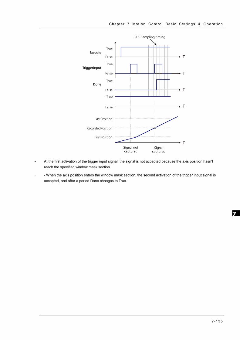
Chapter 7 Mot ion Contro l Bas ic Se t t ings & Operat ion
7-135
7_
- At the first activation of the trigger input signal, the signal is not accepted because the axis position hasn’t reach the specified window mask section.
- - When the axis position enters the window mask section, the second activation of the trigger input signal is accepted, and after a period Done chnages to True.

AX-3 Ser ies Operat ion Manual
7-136
_7
7.8 Programming Example The following section explains on the basis of the programming example.
7.8.1 Device Framework
The following devices are used in the example.
Device Model Name CPU AX-308E
Power DVP-PS02 Servo driver Delta ASDA-A2-E Servo motor Delta ECMA-C
7.8.1.1 Utilization
Please refer to the following manuals for information regarding device configuration and wiring.
Device Reference CPU and Power Chapter 2 in this manual
Servo driver Related configuration description in
Delta servo drive user manuals
Wiring for EtherCAT slave device Delat ASDA A2-E EtherCAT
Interface Servo Drive User Manual
7.8.1.2 Configuration
The following configuration is applied in the example in the next section.
Device Configuration setting Controller Chapter 2 in this manual
Motion control settings Chapter 7 in this manual
Servo parameters Use the default settings of ASDA-A2-E slave,
gear ratio=10000:10000
7.8.2 Examples
The following example uses the same POU in EtherCAT task to explain. Also, the required variables will be declared and used in this POU Task. (The POU naming in LD and ST languages will be different for illustration purpose.)

Chapter 7 Mot ion Contro l Bas ic Se t t ings & Operat ion
7-137
7_
The Interval time for ECAT synchronization is set to be 4 ms.
Set the gear ratio as 10000:10000 for mechanism setting.

AX-3 Ser ies Operat ion Manual
7-138
_7
7.8.2.1 Servo On
Execute MC_Power (Servo on) instruction to activate the servo driver after the EtherCAT communication is built in the following example with LD and ST programming languages supported.
Main variables used in programming
Variable Data Type Default Note SM_Drive_Virtual AXIS_REF_SM3 - Virtual axis variable
Start BOOL FALSE Shift to True when start the server and enable
Servo On
LD language
Check for the successful EtherCAT communication when Start is True so as to enable MC_Power via ServoOn output, which the status should be True.
ST language
Check for the successful EtherCAT communication when Start is True so as to enable MC_Power via ServoOn output, which the status should be True.
Monitoring window can also be used to observe the variable output status with no need for naming the output variables.
IF Start THEN ServoOn :=TRUE; ELSE ServoOn :=FALSE; END_IF //MC_Power MC_Power_0( Axis:= SM_Drive_Virtual, Enable:= ServoOn, bRegulatorOn:= TRUE, bDriveStart:= TRUE, Status=> , bRegulatorRealState=> , bDriveStartRealState=> , Busy=> , Error=> , ErrorID=> );

Chapter 7 Mot ion Contro l Bas ic Se t t ings & Operat ion
7-139
7_
7.8.2.2 Reset and Control Single-axis Error
You can view the error information of variable status through Watch table. Take MC_MoveVelocity input as example, when acceleration value is set as 0 and Execute is True, an error will occur in the fuction block and the ErrorID displays Row Data 301. You can find the complete error message in the Watch table, which is SMC_MV_INVALID_ACCDEC_VALUES. After troubleshooting with manual’s help, MC_MoveVelocity can function normally by shifting the Execute status from False to True. As for MC_Reset, it is used for clearing servo errors.
The following example supports with LD and ST programming languages.
Main variables used in programming
Variable Data Type Default Note SM_Drive_Virtual AXIS_REF_SM3 - Virtual axis variables ServoOn BOOL FALSE To enable MC_Power MC_MoveVelocity0_Execute BOOL FALSE Execute input of velocity instruction
MC_MoveVelocity0_Acceleration LREAL 0 Acceleration input of velocity instruction, for setting acceleration.
MC_DIRECTION.positive MC_Direction - Assigned moving direction-positive
FBErrorOccured MC_ReadStatus FALSE True when an error occurs in the function block
ClearErr BOOL FALSE When FBErrorOccured is True, FB errors can beclear by triggering SMC_ClearFBError
Timing Diagram
MC_MoveVelocity
Execute
Servo On
Clear Err
ErrorOccured
Acceleration
MC_MoveVeloity
MC_ReadStatus

AX-3 Ser ies Operat ion Manual
7-140
_7
LD Language
Via function SMC_ClearFBError that error can be deleted and output FBErrorOccured of MC_ReadStatus would shift to Fulse, once an error occurs in the function block. In addition, since input of SMC_ClearFBError need to be tranferred via pointers, ADR(input) must be fed and use bool to clear FB error flag.
Disable Execute input of MC_MoveVelocity to update the status of Error output.

Chapter 7 Mot ion Contro l Bas ic Se t t ings & Operat ion
7-141
7_
Set acceleration of MC_MoveVelocity to be 10000 and restart (Execute is True). The output of MC_MoveVelocity would be Busy with values of fSetVelocity and fSetPosition shown on the Watch table under normal operation.
ST Language
MC_MoveVelocity_0( Axis:= SM_Drive_Virtual, Execute:= MC_MoveVelocity0_Execute, Velocity:= 10000, Acceleration:= MC_MoveVelocity0_Acceleration, Deceleration:= 10000, Jerk:= 10000, Direction:= MC_DIRECTION.positive, InVelocity=> , Busy=> , CommandAborted=> , Error=> , ErrorID=>);
MC_ReadStatus_0( Axis:= SM_Drive_Virtual,
Enable:= TRUE);
Set acceleration of MC_MoveVelocity to be 10000 and restart (Execute is True). The output of MC_MoveVelocity would be Busy with values of fSetVelocity and fSetPosition shown on the Watch table under normal operation.
MC_MoveVelocity_0(
Axis:= SM_Drive_Virtual, Execute:= MC_MoveVelocity0_Execute, Velocity:= 10000, Acceleration:= MC_MoveVelocity0_Acceleration := 10000, Deceleration:= 10000, Jerk:= 10000, Direction:= MC_DIRECTION.positive,

AX-3 Ser ies Operat ion Manual
7-142
_7
InVelocity=> , Busy=> , CommandAborted=> , Error=> , ErrorID=> ); MC_ReadStatus_0( Axis:= SM_Drive_Virtual, Enable:= TRUE );
7.8.2.3 Control on Instruction Errors
If an error occurs while executing instruction MC_Power (Servo On), no further action will be taken, while ProgNext indicates whether execution can be moved on. The following example supports with LD and ST programming languages.
Main variables used in programming
Variable Data Type Default Note
SM_Drive_Virtual AXIS_REF_SM3 - Virtual axis variables
ServoOn BOOL FALSE To enable MC_Power
ProgNext BOOL FALSE ProgNext indicator shows whether to take further action
MC_Power_0.Status BOOL FALSE Axis is ready to move when the status is True.
MC_Power_0.Busy BOOL FALSE Execution of FB has not been completed when the status is True.
Timing Diagram
Servo On
Start
Status
Busy
ProgNext
MC_Power
MC_Power

Chapter 7 Mot ion Contro l Bas ic Se t t ings & Operat ion
7-143
7_
LD Language
Check if any errors have occurred in MC_Power before moving onto the next step.
ST Language
IF Start THEN ServoOn :=TRUE; ELSE ServoOn :=FALSE; END_IF IF (MC_Power_0.Status=TRUE) OR (MC_Power_0.Busy=TRUE) THEN ProgNext :=TRUE; ELSE ProgNext :=FALSE; END_IF //MC_Power MC_Power_0( Axis:= SM_Drive_Virtual, Enable:= ServoOn, bRegulatorOn:= TRUE, bDriveStart:= TRUE, Status=> , bRegulatorRealState=> , bDriveStartRealState=> , Busy=> , Error=> , ErrorID=> );

AX-3 Ser ies Operat ion Manual
7-144
_7
7.8.2.4 Quick Stop for Single Axes
MC_Stop can be used to stop the moving axis when an error occurs during execution of MC_MoveAbsolute instruction. The following example supports with LD and ST programming languages.
Main variables used in programming
Variable Data Type Default Note SM_Drive_Virtual AXIS_REF_SM3 - Virtual axis variables ServoOn BOOL FALSE To enable MC_Power MC_MoveAbsolute0_Execute BOOL FALSE Execute input of MC_MoveAbsolute
MC_DIRECTION.positive MC_Direction - Assigned moving direction-positive (valid for rotary axes)
StopOn BOOL FALSE Activate MC_Stop when the status is True
MC_Stop_0.Done BOOL FALSE Execution of MC_Stop is done when the status is True
Timing Diagram
Busy
Execute
Error
Done
MC_MoveAbsolute
MC_MoveAbsolute
MC_MoveAbsolute
MC_MoveAbsolute
MC_Stop
MC_Stop
Execute
Done
SetVelocity
SavePosition
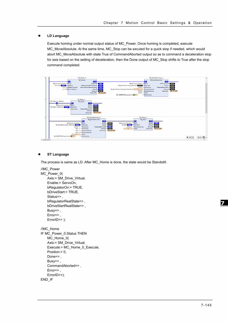
Chapter 7 Mot ion Contro l Bas ic Se t t ings & Operat ion
7-145
7_
LD Language
Execute homing under normal output status of MC_Power. Once homing is completed, execute MC_MoveAbsolute. At the same time, MC_Stop can be excuted for a quick stop if needed, which would abort MC_MoveAbsolute with state True of CommandAborted output so as to command a deceleration stop for axis based on the setting of deceleration, then the Done output of MC_Stop shifts to True after the stop command completed.
ST Language
The process is same as LD. After MC_Home is done, the state would be Standstill.
//MC_Power MC_Power_0( Axis:= SM_Drive_Virtual, Enable:= ServoOn, bRegulatorOn:= TRUE, bDriveStart:= TRUE, Status=> , bRegulatorRealState=> , bDriveStartRealState=> , Busy=> , Error=> , ErrorID=> ); //MC_Home IF MC_Power_0.Status THEN MC_Home_0( Axis:= SM_Drive_Virtual, Execute:= MC_Home_0_Execute, Position:= 0, Done=> , Busy=> , CommandAborted=> , Error=> , ErrorID=>); END_IF

AX-3 Ser ies Operat ion Manual
7-146
_7
If a quick stop is performed by MC_Stop during execution of MC_MoveAbsolute, MC_MoveAbsolute would be aborted and be in Stopping state.
//MC_MoveAbsolute & MC_Stop MC_MoveAbsolute_0( Axis:= SM_Drive_Virtual, Execute:= MC_MoveAbsolute0_Execute, Position:= 10000.0, Velocity:= 500.0, Acceleration:= 500.0, Deceleration:= 500.0, Jerk:= , Direction:= MC_DIRECTION.positive, Done=> , Busy=> , CommandAborted=> , Error=> , ErrorID=>); MC_Stop_0( Axis:= SM_Drive_Virtual, Execute:= StopOn, Deceleration:= 5000.0, Jerk:= , Done=> , Busy=> , Error=> , ErrorID=>); 7.8.2.5 Home Positioning
Use homing instruction in the the following example to let you understand how to perform the homing operation. Currently, a total of 36 homing modes (0~35) are supported and the OD is 6098(Homing method) /6099sub1(Speed during search for switch) /6099sub2(Speed during search for zero). For more details, please refer to Delta High Resolution AC Servo Drive ASDA-A2 Series User Manual.
For the following example, specify the parameters of OD as mentioned above after adding A2-E sevo in EtherCAT Slave.
Choose mode 33 for Homing Method (Perform homing operation once meet the first Z pulse.)
Speed during search for switch =1000 (Unit: 0.1rpm) (Search for limit switch at the speed of 100rmp.)
Speed during search for zero =100 (Unit: 0.1rpm) (Search for zero at the speed of 10rmp.)
After settings are completed, the homing method for executing MC_Home with LD/ ST language would be corresponding to the one specified as above.

Chapter 7 Mot ion Contro l Bas ic Se t t ings & Operat ion
7-147
7_
Main variables used in programming
Variable Data Type Default Note Axis_1 AXIS_REF_SM3 - Real axis variables
ServoOn BOOL FALSE To enable MC_Power
Timing diagram
Disabled
Execute
StandStill
Done
MC_Home
MC_ReadStatus
Homing
MC_Home
MC_ReadStatus
MC_ReadStatus

AX-3 Ser ies Operat ion Manual
7-148
_7
LD language
The state would be Standstill when the outputs of MC_Power are under normal status. Shift to state Homing when execute MC_Home, then back toStandstill after home positioning is completed.
ST language
Process is same as LD. The state is Standstill after execution of MC_Home is completed, which the output status can be checked via variables and Watch tables.
MC_Home_0( Axis:= Axis_1, Execute:= , Position:= 0, Done=> , Busy=> , CommandAborted=> , Error=> , ErrorID=> ); MC_ReadStatus_0( Axis:= Axis_1, Enable:= TRUE, Valid=> , Busy=> , Error=> , ErrorID=> , Disabled=> , Errorstop=> , Stopping=> , StandStill=> , DiscreteMotion=> , ContinuousMotion=> , SynchronizedMotion=> , Homing=> , ConstantVelocity=> , Accelerating=> , Decelerating=> , FBErrorOccured=>);

Chapter 7 Mot ion Contro l Bas ic Se t t ings & Operat ion
7-149
7_
7.8.2.6 Absolute Positioning
Via MC_MoveAbsolute instruction used in the following example that you are able to understand how to perform displacement at one speed. The following example supports with LD and ST programming languages.
Main variables used in programming
Variable Data Type Default Note Axis_1 AXIS_REF_SM3 - Real axis variables ServoOn BOOL FALSE To enable MC_Power
MC_MoveAbsolute0_Execute BOOL FALSE Execute input of MC_MoveAbsolute
MC_DIRECTION.positive MC_Direction - Assigned moving direction-positive (valid for rotary axes)
Timing diagram
LD language
Check if the outputs of MC_Power is under normal status, then execute MC_MoveAbsolute to move from the start position 0 to the assigned position 50000.
Busy
Execute
Error
Done
MC_MoveAbsolute
SetVelocity
MC_MoveAbsolute
MC_MoveAbsolute
MC_MoveAbsolute
SavePosition
Servo On

AX-3 Ser ies Operat ion Manual
7-150
_7
ST language
MC_Home_0( Axis:= Axis_1, Execute:= , Position:= 0, Done=> , Busy=> , CommandAborted=> , Error=> , ErrorID=> ); MC_MoveAbsolute_0( Axis:= Axis_1, Execute:= MC_MoveAbsolute0_Execute, Position:= 50000, Velocity:= 10000, Acceleration:= 100000, Deceleration:= 100000, Jerk:= 100000, Direction:= SM3_Basic.MC_DIRECTION.positive, Done=> , Busy=> , CommandAborted=> , Error=> , ErrorID=> );
7.8.2.7 Switch CAM Table during CAM Operation
The following example illustrates that CAM table can be switched while executing MC_CamIn.
Perform switching between two CAM tables configured with different output parameters by adding master and slave axes as well as using two MC_CamIn instructions. Use CamTable 1 when the instruction position of master axis is below 3000. Once the position is over 3000, it will switch to CamTable 2.
Main variables used in programming
Variable Data Type Default Note
Axis_Master AXIS_REF_VIRTUAL_SM3 - Master-related axis variables
Axis_Slave AXIS_REF_VIRTUAL_SM3 - Slave-related axis variables
CamTable1 MC_CAM_REF - Relating variables for Cam table1
CamTable2 MC_CAM_REF - Relating variables for Cam table2
StartFlag BOOL FALSE
If this variable is TRUE and the communication with axes is normal, Servo ON will be activated and continue on further actions.
MC_Power0_Status BOOL FALSE Status output variables of MC_Power for master, TRUE when Servo On
MC_Power1_Status BOOL FALSE Status output variables of MC_Power for slave, TRUE when Servo On

Chapter 7 Mot ion Contro l Bas ic Se t t ings & Operat ion
7-151
7_
Variable Data Type Default Note
MC_Home0_Done BOOL FALSE Output Done variables of MC_Home for master, TRUE when homing completed.
MC_Home1_Done BOOL FALSE Output Done variables of MC_Home for slave, TRUE when homing completed.
MC_MoveAbs_Busy BOOL FALSE Output Bust variables of MC_MoveAbsolute for master, TRUE when the FB is executed.
CamTableSelect MC_CAM_REF - Specify the corresponding Cam table.
CamTable1_En BOOL FALSE TRUE when CamTable1 is chosen to be used.
CamTable2_En BOOL FALSE TRUE when CamTable2 is chosen to be used.
CamTableID MC_CAM_ID -
The internal data structure of the selectedCam table, which is from MC_CamTableSelect and used as input of MC_CamIn.
MC_CamIn1_InSync BOOL FALSE Output InSync variables of CamTable1, TRUE when master and slave axis are synchronized with cam.
MC_CamIn2_InSync BOOL FALSE Output InSync variables of CamTable2, TRUE when master and slave axis are synchronized with cam.
CamTable1:
CamTable2:

AX-3 Ser ies Operat ion Manual
7-152
_7
Timing diagram
LD language
Set StartFlag to be TRUE, then the normal operation of communications for both master and slave axis would be checked respectively

Chapter 7 Mot ion Contro l Bas ic Se t t ings & Operat ion
7-153
7_
Under normal condition, Servo ON state will be set to master and slave axis.
Under Servo On state and unsure of the start position, home positioning will be operated first.
After the homing operation of master axis is completed, execute MC_MoveAbsolute instruction.

AX-3 Ser ies Operat ion Manual
7-154
_7
When the instruction position of master axis is below 3000, use CamTable1 (CamTable1_En=True, CamTable2_En=False). Conversely, when position is over 3000, use CamTable2 (CamTable1_En=False, CamTable2_En=True). Under both conditions, set the corresponding Cam table with MC_CamTableSelect instruction.
When absolute positioning is operated for master axis and CamTable1_En is True, execute with CamTable1.
When absolute positioning is operated for master axis and CamTable2_En is True, execute with CamTable2.

Chapter 7 Mot ion Contro l Bas ic Se t t ings & Operat ion
7-155
7_
ST language
// Set StartFlag to be TRUE, then the normal operation of communications for both master and slave axis would be //checked respectively
IF StartFlag = TRUE THEN IF Axis_Master.bCommunication = TRUE THEN MC_Power0_Enable := TRUE; MC_Power0_RegulatorOn := TRUE; MC_Power0_DriveStart := TRUE; END_IF IF Axis_Slave.bCommunication = TRUE THEN MC_Power1_Enable := TRUE; MC_Power1_RegulatorOn := TRUE; MC_Power1_DriveStart := TRUE; END_IF END_IF //Under normal condition, Servo ON state will be set to master and slave axis.
MC_Power_0( Axis:= Axis_Master, Enable:= MC_Power0_Enable, bRegulatorOn:= MC_Power0_RegulatorOn, bDriveStart:= MC_Power0_DriveStart, Status=> MC_Power0_Status, bRegulatorRealState=> , bDriveStartRealState=> , Busy=> , Error=> , ErrorID=> ); MC_Power_1( Axis:= Axis_Slave, Enable:= MC_Power1_Enable, bRegulatorOn:= MC_Power1_RegulatorOn, bDriveStart:= MC_Power1_DriveStart, Status=> MC_Power1_Status, bRegulatorRealState=> , bDriveStartRealState=> , Busy=> , Error=> , ErrorID=> );
// Under Servo On state and unsure of the start position, home positioning will be operated first.
IF MC_Power0_Status = TRUE THEN MC_Home0_Execute := TRUE; END_IF IF MC_Power1_Status = TRUE THEN MC_Home1_Execute := TRUE; END_IF MC_Home_0( Axis:= Axis_Master,

AX-3 Ser ies Operat ion Manual
7-156
_7
Execute:= MC_Home0_Execute, Position:= 0, Done=> MC_Home0_Done, Busy=> , CommandAborted=> , Error=> , ErrorID=>); MC_Home_1( Axis:= Axis_Slave, Execute:= MC_Home1_Execute, Position:= 0, Done=> MC_Home1_Done, Busy=> , CommandAborted=> , Error=> , ErrorID=> );
// After the homing operation of master axis is completed, execute MC_MoveAbsolute instruction.
//MC_MoveAbsolute(
Axis:= Axis_Master, Execute:= MC_Home1_Done, Position:= 6000, Velocity:= 500, Acceleration:= 1000, Deceleration:= 1000, Jerk:= , Direction:= positive, Done=> MC_MoveAbs_Done, Busy=> MC_MoveAbs_Busy, CommandAborted=> , Error=> , ErrorID=> );
// When the instruction position of master axis is below 3000, use CamTable1 (CamTable1_En=True, //CamTable2_En=False).
//When position is over 3000, use CamTable2 (CamTable1_En=False, CamTable2_En=True).
//Under both conditions, set the corresponding Cam table with MC_CamTableSelect instruction.
IF Axis_Master.fSetPosition > 3000 THEN CamTableSelect := CamTable2; CamTable1_En := FALSE; CamTable2_En := TRUE; ELSE CamTableSelect := CamTable1; CamTable1_En := TRUE; CamTable2_En := FALSE; END_IF IF (CamTable1_En = TRUE) OR (CamTable2_En = TRUE) THEN CamTable_En := TRUE; END_IF

Chapter 7 Mot ion Contro l Bas ic Se t t ings & Operat ion
7-157
7_
MC_CamTableSelect( Master:= Axis_Master, Slave:= Axis_Slave, CamTable:= CamTableSelect, Execute:= CamTable_En, Periodic:= TRUE, MasterAbsolute:= FALSE, SlaveAbsolute:= FALSE, Done=> MC_CamTableSelect_Done, Busy=> , Error=> , ErrorID=> , CamTableID=> CamTableID);
// When absolute positioning is operated for master axis and CamTable1_En is True, execute with //CamTable1.
IF (MC_MoveAbs_Busy = TRUE) AND (CamTable1_En = TRUE) THEN MC_CamIn_1( Master:= Axis_Master, Slave:= Axis_Slave, Execute:= TRUE, MasterOffset:= 0, SlaveOffset:= 0, MasterScaling:= 1, SlaveScaling:= 1, StartMode:= relative, CamTableID:= CamTableID, VelocityDiff:= 1000, Acceleration:= 1000, Deceleration:= 1000, Jerk:= , TappetHysteresis:= , InSync=> MC_CamIn1_Insync, Busy=> , CommandAborted=> , Error=> , ErrorID=> , EndOfProfile=> , Tappets=> ); END_IF
// When absolute positioning is operated for master axis and CamTable2_En is True, execute with //CamTable2
IF (MC_MoveAbs_Busy = TRUE) AND (CamTable2_En = TRUE) THEN MC_CamIn_2( Master:= Axis_Master, Slave:= Axis_Slave, Execute:= TRUE, MasterOffset:= 0, SlaveOffset:= 0, MasterScaling:= 1, SlaveScaling:= 1, StartMode:= relative, CamTableID:= CamTableID, VelocityDiff:= 1000, Acceleration:= 1000,

AX-3 Ser ies Operat ion Manual
7-158
_7
Deceleration:= 1000, Jerk:= , TappetHysteresis:= , InSync=> MC_CamIn2_Insync, Busy=> , CommandAborted=> , Error=> , ErrorID=> , EndOfProfile=> , Tappets=> ); END_IF
Based on the above settings to perform switching Cam tables. Switch the table when the position of master axis is over 3000.

Chapter 7 Mot ion Contro l Bas ic Se t t ings & Operat ion
7-159
7_
7.8.2.8 Perform Master PhaseOffset for CAM
After the motion of slave axis being aborted during original CAM operation, it starts to sychronize with the controlled master axis. Phase offset of the master axis is operated by executing MC_Phasing when PhasingActive is TRUE.and the slave axis synchronizes with the phase after offset completed. The following example supports with LD and ST programming languages.
Main variables used in programming
Variable Data Type Default Note
Axis_Master AXIS_REF_
VIRTUAL_SM3 - Master-related axis variables.
Axis_Slave AXIS_REF_
VIRTUAL_SM3 - Slave-related axis variables.
CamTable MC_CAM_REF - Variables relating to Cam table.
StartFlag BOOL FALSE If this variable is TRUE and the communication with axes is normal, Servo ON will be activated and continue on further actions.
MC_Power0_Status BOOL FALSE Status output variables of MC_Power for master, TRUE when Servo On.
MC_Power1_Status BOOL FALSE Status output variables of MC_Power for slave, TRUE when Servo On.
MC_Home0_Done BOOL FALSE Output Done variables of MC_Home for master, TRUE when homing completed.
MC_Home1_Done BOOL FALSE Output Done variables of MC_Home for slave, TRUE when homing completed.
MC_MoveVelocity_ Velocity
LREAL 500 The target velocity for master axis to move in constant velocity motion.
MC_MoveVelocity_ InVelocity
BOOL FALSE The InVelocity output variables of MC_MoveVelocity, TRUE when the target velocity is reached.
CamTableID MC_CAM_ID - The internal data structure of the selectedCam table, which is from MC_CamTableSelect and used as input of MC_CamIn.
MC_CamIn1_InSync BOOL FALSE Output InSync variables of CamTable1, TRUE when master and slave axis are synchronized with cam.
PhasingActive BOOL FALSE If the variable is TRUE and Cam is InSync, MC_Phasing will starts to be executed.
MC_Phasing_PhaseShift LREAL 500 Specify the phaseshift values for the master and slave axis.
MC_Phasing_Velocity LREAL 300 Specify the relative velocity for phasing operating between the master and slave axis.
MC_Phasing_Done BOOL FALSE The Done output variables of MC_Phasing. TRUE when phase offset is completed.
CamTable:

AX-3 Ser ies Operat ion Manual
7-160
_7
Timing diagram
LD language
Set StartFlag to be TRUE, then the normal operation of communications for both master and slave axis would be checked respectively.

Chapter 7 Mot ion Contro l Bas ic Se t t ings & Operat ion
7-161
7_
Under normal condition, Servo ON state will be set to master and slave axis.
Under Servo On state and unsure of the start position, home positioning will be operated first.
After the homing operation of master axis is completed, execute MC_MoveVelocity.

AX-3 Ser ies Operat ion Manual
7-162
_7
After the master axis reaches the target velocity, execute MC_CamIn with the Cam table specified by MC_CamTableSelect.
If PhasingActive is TRUE and the slave axis is in synchronized with the master axis based on the setting of MC_Phasing, master and slave axis start performing phase offset, which breaks the original master-slave relationship in Cam.

Chapter 7 Mot ion Contro l Bas ic Se t t ings & Operat ion
7-163
7_
According to above setting to perform phase offset of the master axis, the slave axis synchronizes with the phase after offset completed and the PhaseShift would be fixed, which the PhaseShift between master and slave would be 500, taking the cursor timing 3500-3000 as example, and the velocity of slave axis would be 200 while performing phase offset (velocity of master axis 500 minus velocity 300).
ST language
//Set StartFlag to be TRUE, then the normal operation of communication for both master and slave axis //would be checked respectively.
IF StartFlag = TRUE THEN IF Axis_Master.bCommunication = TRUE THEN MC_Power0_Enable := TRUE; MC_Power0_RegulatorOn := TRUE; MC_Power0_DriveStart := TRUE; END_IF IF Axis_Slave.bCommunication = TRUE THEN MC_Power1_Enable := TRUE; MC_Power1_RegulatorOn := TRUE; MC_Power1_DriveStart := TRUE; END_IF END_IF
//Under normal condition, Servo ON state will be set to master and slave axis.
MC_Power_0( Axis:= Axis_Master, Enable:= MC_Power0_Enable, bRegulatorOn:= MC_Power0_RegulatorOn, bDriveStart:= MC_Power0_DriveStart, Status=> MC_Power0_Status, bRegulatorRealState=> ,
Slave Velocity = 200

AX-3 Ser ies Operat ion Manual
7-164
_7
bDriveStartRealState=> , Busy=> , Error=> , ErrorID=> ); MC_Power_1( Axis:= Axis_Slave, Enable:= MC_Power1_Enable, bRegulatorOn:= MC_Power1_RegulatorOn, bDriveStart:= MC_Power1_DriveStart, Status=> MC_Power1_Status, bRegulatorRealState=> , bDriveStartRealState=> , Busy=> , Error=> , ErrorID=> ); //Under Servo On state and unsure of the start position, home positioning will be operated first IF MC_Power0_Status = TRUE THEN MC_Home0_Execute := TRUE; END_IF IF MC_Power1_Status = TRUE THEN MC_Home1_Execute := TRUE; END_IF MC_Home_0( Axis:= Axis_Master, Execute:= MC_Home0_Execute, Position:= 0, Done=> MC_Home0_Done, Busy=> , CommandAborted=> , Error=> , ErrorID=> ); MC_Home_1( Axis:= Axis_Slave, Execute:= MC_Home1_Execute, Position:= 0, Done=> MC_Home1_Done, Busy=> , CommandAborted=> , Error=> , ErrorID=> );
//After the homing operation of master axis is completed, execute MC_MoveVelocity.
MC_MoveVelocity( Axis:= Axis_Master, Execute:= MC_Home0_Done, Velocity:= MC_MoveVelocity_Velocity, Acceleration:= MC_MoveVelocity_Acc, Deceleration:= MC_MoveVelocity_Dec, Jerk:= , Direction:= current,

Chapter 7 Mot ion Contro l Bas ic Se t t ings & Operat ion
7-165
7_
InVelocity=> MC_MoveVelocity_InVelocity, Busy=> , CommandAborted=> , Error=> , ErrorID=> );
// After the master axis reaches the target velocity, execute MC_CamIn with the Cam table specified by //MC_CamTableSelect.
MC_CamTableSelect( Master:= Axis_Master, Slave:= Axis_Slave, CamTable:= CamTable, Execute:= TRUE, Periodic:= TRUE, MasterAbsolute:= FALSE, SlaveAbsolute:= FALSE, Done=> MC_CamTableSelect_Done, Busy=> , Error=> , ErrorID=> , CamTableID=> CamTableID); IF MC_MoveVelocity_InVelocity = TRUE THEN MC_CamIn_1( Master:= Axis_Master, Slave:= Axis_Slave, Execute:= TRUE, MasterOffset:= 0, SlaveOffset:= 0, MasterScaling:= 1, SlaveScaling:= 1, StartMode:= relative, CamTableID:= CamTableID, VelocityDiff:= 1000, Acceleration:= 1000, Deceleration:= 1000, Jerk:= , TappetHysteresis:= , InSync=> MC_CamIn1_Insync, Busy=> , CommandAborted=> , Error=> , ErrorID=> , EndOfProfile=> , Tappets=> ); END_IF
//If PhasingActive is TRUE and the slave axis is in synchronized with the master axis based on the setting of //MC_Phasing, master and slave axis start performing phase offset, which breaks the original master-slave //relationship in Cam.
IF (PhasingActive = TRUE) AND (MC_CamIn1_Insync = TRUE) THEN MC_Phasing_Execute := TRUE; END_IF

AX-3 Ser ies Operat ion Manual
7-166
_7
MC_Phasing( Master:= Axis_Master, Slave:= Axis_Slave, Execute:= MC_Phasing_Execute, PhaseShift:= MC_Phasing_PhaseShift, Velocity:= MC_Phasing_Velocity, Acceleration:= MC_Phasing_Acc, Deceleration:= MC_Phasing_Dec, Jerk:= , Done=> MC_Phasing_Done, Busy=> , CommandAborted=> , Error=> , ErrorID=> );
7.8.2.9 Change Current Position in Movement
Change the current position of axis to the target position in the coordinate system with the feedback of the current position. The interacting effects between MC_MoveRelative and MC_SetPosition are explained in the below example. The following example supports with LD and ST programming languages.
Main variables used in programming
Variable Data Type Default Note
Axis_Virtual AXIS_REF_VIRTUAL_
SM3 - Associate variables of axis.
StartFlag BOOL FALSE If this variable is TRUE and the communication with axes is normal, Servo ON will be activated and continue on further actions.
MC_Power0_Status BOOL FALSE Status output variables of MC_Power for master, TRUE when Servo On.
MC_Home0_Done BOOL FALSE Output Done variables of MC_Home for master, TRUE when homing completed.
MC_MoveRel_Distance LREAL 8000 The target relative positions of MC_MoveRelative.
MC_MoveRel_Done BOOL FALSE The output Done variables of MC_MoveRelative. TRUE when the relative positioning is completed.
MC_MoveRel_Busy BOOL FALSE The output Busy variables of MC_MoveRelative TRUE when the instruction is triggered and executed.
MC_SetPosition_Execute BOOL FALSE If TRUE, MC_SetPosition starts to be executed.
MC_SetPosition_Position LREAL 3000 The absolute position and relative distance changed by MC_SetPosition.
MC_SetPosition_Mode BOOL TRUE MC_SetPosition is to set the axis position to be
absolute position or relative position.
MC_SetPosition_Done BOOL FALSE The output Done variables of MC_SetPosition TRUE when the position is changed.

Chapter 7 Mot ion Contro l Bas ic Se t t ings & Operat ion
7-167
7_
Timing diagram
LD language
Set StartFlag to be TRUE, then the normal operation of communication for axis would be checked.
Under normal condition, set the axis to be in state Servo On.
Under Servo On state and unsure of the start position, home positioning operation will be required.

AX-3 Ser ies Operat ion Manual
7-168
_7
After the homing operation of axis is completed, execute MC_MoveRelative.
The target position of relative displacement = 8000
When the current position of axis passes 4000, execute MC_SetPosition (Mode = Relative,Distance = 3000) so
as to change the current position to be the assigned target position.
Start a relative positioning procedure based on the current set position in coordinate system according to the above settings, which the position would finally reach 11000 (11000 = 4000 + 3000 + (8000 – 4000)) without influencing the displacement of motion body controlled by MC_MoveRelative. The displacement is 8000 (8000 =(4000 – 0)+(11000 – 7000)) same as the original setting.

Chapter 7 Mot ion Contro l Bas ic Se t t ings & Operat ion
7-169
7_
The difference between the above and the picture below is that the mode of MC_SetPoition is changed to Absolute (Position = 3000). The actual position is set to the parameterized absolute target Position value, and the position would finally reach 7000 (7000 = 3000+(8000 – 4000)) without influencing the displacement of motion body controlled by MC_MoveRelative. The displacement would be 8000 (8000=(4000 – 0)+(7000 – 3000))same as the original setting.
ST language
Set StartFlag to be TRUE, then the normal operation of communication for axis would be checked.
IF StartFlag = TRUE THEN IF Axis_Virtual.bCommunication = TRUE THEN MC_Power0_Enable := TRUE; MC_Power0_RegulatorOn := TRUE; MC_Power0_DriveStart := TRUE; END_IF END_IF
// Under normal condition, set the axis to be in state Servo On.
MC_Power_0( Axis:= Axis_Virtual, Enable:= MC_Power0_Enable, bRegulatorOn:= MC_Power0_RegulatorOn, bDriveStart:= MC_Power0_DriveStart, Status=> MC_Power0_Status, bRegulatorRealState=> , bDriveStartRealState=> , Busy=> , Error=> , ErrorID=> );

AX-3 Ser ies Operat ion Manual
7-170
_7
//Under Servo On state and unsure of the start position, home positioning operation will be required.
IF MC_Power0_Status = TRUE THEN MC_Home0_Execute := TRUE; END_IF MC_Home_0( Axis:= Axis_Virtual, Execute:= MC_Home0_Execute, Position:= 0, Done=> MC_Home0_Done, Busy=> , CommandAborted=> , Error=> , ErrorID=> );
//After the homing operation of axis is completed, execute MC_MoveRelative.
//The target position of relative displacement = 8000
MC_MoveRelative( Axis:= Axis_Virtual, Execute:= MC_Home0_Done, Distance:= MC_MoveRel_Distance, Velocity:= MC_MoveRel_Velocity, Acceleration:= MC_MoveRel_Acc, Deceleration:= MC_MoveRel_Dec, Jerk:= , Done=> MC_MoveRel_Done, Busy=> MC_MoveRel_Busy, CommandAborted=> , Error=> , ErrorID=> );
//When the current position of axis passes 4000, execute MC_SetPosition (Mode = Relative,Distance = 3000) so as
to //change the current position to be the assigned target position.
IF (MC_MoveRel_Busy = TRUE) AND (Axis_Virtual.fSetPosition >= 4000) THEN MC_SetPosition_Execute := TRUE; END_IF MC_SetPosition( Axis:= Axis_Virtual, Execute:= MC_SetPosition_Execute, Position:= MC_SetPosition_Position, Mode:= MC_SetPosition_Mode, Done=> MC_SetPosition_Done, Busy=> , Error=> , ErrorID=> );

Chapter 7 Mot ion Contro l Bas ic Se t t ings & Operat ion
7-171
7_
7.8.2.10 Perform Superimposed during Gear Engagment
Perform MC_MoveSuperImposed on the particular slave axis while the gear has been engaged in the following example. The final position of slave axis would be the displacement of gear ratio relative to master axis and plus the specific distance superimposed in motion. The following example supports with LD and ST programming languages.
Main variables used in programming
Variable Data Type Default Note
Axis_Master AXIS_REF_
VIRTUAL_SM3 - Master-related axis variables.
Axis_Slave AXIS_REF_
VIRTUAL_SM3 - Slave-related axis variables.
StartFlag BOOL FALSE
If this variable is TRUE and the communication with axes is normal, Servo ON will be activated and continue on further actions.
MC_Power0_Status BOOL FALSE Status output variables of MC_Power for master, TRUE when Servo On.
MC_Power1_Status BOOL FALSE Status output variables of MC_Power for slave, TRUE when Servo On.
MC_Home0_Done BOOL FALSE Output Done variables of MC_Home for master, TRUE when homing operation completed.
MC_Home1_Done BOOL FALSE Output Done variables of MC_Home for slave, TRUE when homing operation completed.
MC_GearIn_InGear BOOL FALSE Output InGear variables of MC_GearIn. TRUE when the engage operation is completed.
MC_GearIn_RatioNumerator
DINT 2 Numerator of the gear ratio between master and slave axis.
MC_GearIn_RatioDenominator
UDINT 1 Denominator of the gear ratio between master and slave axis.
MC_MoveAbs_Execute BOOL FALSE When the variable is TRUE, MC_MoveAbsolute is executed.
MC_MoveAbs_Position LREAL 3000 Absolute target position of assigned master axis.
MC_MoveAbs_Velocity LREAL 1000 Target velocity of assigned master axis.
MC_MoveAbs_Done BOOL FALSE Output Done variables of MC_MoveAbsolute for master, TRUE when absolute positioning completed.
MC_MoveAbs_Busy BOOL FALSE Output Busy variables of MC_MoveAbsolute for master axis. TRUE when the instruction is executed.
MC_MoveSuperImposed_Execute
BOOL FALSE When the variable is TRUE, MC_MoveSuperImposed is executed.

AX-3 Ser ies Operat ion Manual
7-172
_7
Variable Data Type Default Note
MC_MoveSuperImposed_Done
BOOL FALSE
Output Done variables of MC_Move- SuperImposed for slave axis. TRUE when the superimposed movement is completed.
MC_MoveSuperImposed_Distance
LREAL 1000 Superimposed displacement of the assigned slave axis.
MC_MoveSuperImposed_ VelocityDiff
LREAL 1500 Specify the relative velocity to the master axis while the superimposed movement operating on the slave axis.
Timing diagram

Chapter 7 Mot ion Contro l Bas ic Se t t ings & Operat ion
7-173
7_
LD language
Set StartFlag to be TRUE, then the normal operation of communications for both master and slave axis would be checked respectively.
Under normal condition, Servo ON state will be set to master and slave axis.
When the master and slave axis are in Servo On state and unsure of the start position, home positioning operation will be required.

AX-3 Ser ies Operat ion Manual
7-174
_7
After the homing operation is completed, execute MC_GearIn to activate a master-slave coupling (gear coupling).
Right after the engage action completed with output InGear, execute MC_MoveAbsolute to the master axis.
At the same time, when the slave axis moves to the preset triggering position=2000 based on the coupling relationship, MC_MoveSuperImposed would be executed which the slave axis would move a superimposed distance of specific displacement on the original preset target position.
According to the above settings, slave axis would move a displacement according to the gear ratio relative to the master axis and also the specific distance superimposed while in motion to reach the final target position.
The moving distance of master axis is 3000 and the original target position of slave axis would be 6000 calculated with the gear ratio 1:2. Therefore, the final target position of slave axis will changes to be 7000 (6000+1000) with an extra superimposed distance=1000. While coupling, the velocities of master and slave axis are respectively 1000 and 2000. Yet the velocity of slave axis changes to 3500 while superimposing (the original velocity 2000+ VelocityDiff 1500).

Chapter 7 Mot ion Contro l Bas ic Se t t ings & Operat ion
7-175
7_
ST language
Set StartFlag to be TRUE, then the normal operation of communications for both master and slave axis would be checked respectively.
IF StartFlag = TRUE THEN IF Axis_Master.bCommunication = TRUE THEN MC_Power0_Enable := TRUE; MC_Power0_RegulatorOn := TRUE; MC_Power0_DriveStart := TRUE; END_IF IF Axis_Slave.bCommunication = TRUE THEN MC_Power1_Enable := TRUE; MC_Power1_RegulatorOn := TRUE; MC_Power1_DriveStart := TRUE; END_IF END_IF Under normal condition, Servo ON state will be set to master and slave axis.
MC_Power_0( Axis:= Axis_Master, Enable:= MC_Power0_Enable, bRegulatorOn:= MC_Power0_RegulatorOn, bDriveStart:= MC_Power0_DriveStart, Status=> MC_Power0_Status, bRegulatorRealState=> , bDriveStartRealState=> , Busy=> , Error=> , ErrorID=> );

AX-3 Ser ies Operat ion Manual
7-176
_7
MC_Power_1( Axis:= Axis_Slave, Enable:= MC_Power1_Enable, bRegulatorOn:= MC_Power1_RegulatorOn, bDriveStart:= MC_Power1_DriveStart, Status=> MC_Power1_Status, bRegulatorRealState=> , bDriveStartRealState=> , Busy=> , Error=> , ErrorID=> );
When the master and slave axis are in Servo On state and unsure of the start position, home positioning operation will be required.
IF MC_Power0_Status = TRUE THEN MC_Home0_Execute := TRUE; END_IF IF MC_Power1_Status = TRUE THEN MC_Home1_Execute := TRUE; END_IF MC_Home_0( Axis:= Axis_Master, Execute:= MC_Home0_Execute, Position:= 0, Done=> MC_Home0_Done, Busy=> , CommandAborted=> , Error=> , ErrorID=> ); MC_Home_1( Axis:= Axis_Slave, Execute:= MC_Home1_Execute, Position:= 0, Done=> MC_Home1_Done, Busy=> , CommandAborted=> , Error=> , ErrorID=> );
After the homing operation is completed, execute MC_GearIn to activate a master-slave coupling (gear coupling).
MC_GearIn( Master:= Axis_Master, Slave:= Axis_Slave, Execute:= MC_Home0_Done,

Chapter 7 Mot ion Contro l Bas ic Se t t ings & Operat ion
7-177
7_
RatioNumerator:= MC_GearIn_RatioNumerator, RatioDenominator:= MC_GearIn_RatioDenominator, Acceleration:= MC_GearIn_Acc, Deceleration:= MC_GearIn_Dec, Jerk:= , InGear=> MC_GearIn_InGear, Busy=> , CommandAborted=> , Error=> , ErrorID=> ); IF MC_GearIn_InGear = TRUE THEN MC_MoveAbs_Execute := TRUE; END_IF Right after the engage action completed with output InGear, execute MC_MoveAbsolute to the master axis.
MC_MoveAbsolute( Axis:= Axis_Master, Execute:= MC_MoveAbs_Execute, Position:= MC_MoveAbs_Position, Velocity:= MC_MoveAbs_Velocity, Acceleration:= MC_MoveAbs_Acc, Deceleration:= MC_MoveAbs_Dec, Jerk:= , Direction:= Positive, Done=> MC_MoveAbs_Done, Busy=> MC_MoveAbs_Busy, CommandAborted=> , Error=> , ErrorID=> ); At the same time, when the slave axis moves to the preset triggering position=2000 based on the coupling relationship, MC_MoveSuperImposed would be executed which the slave axis would move a superimposed distance of specific displacement on the original preset target position.
IF MC_MoveAbs_Busy = TRUE THEN IF Axis_Slave.fSetPosition >= 2000 THEN MC_MoveSuperImposed_Execute := TRUE; END_IF END_IF MC_MoveSuperImposed( Axis:= Axis_Slave, Execute:= MC_MoveSuperImposed_Execute, Distance:= MC_MoveSuperImposed_Distance, VelocityDiff:= MC_MoveSuperImposed_VelocityDiff, Acceleration:= MC_MoveSuperImposed_Acc, Deceleration:= MC_MoveSuperImposed_Dec, Jerk:= ,

AX-3 Ser ies Operat ion Manual
7-178
_7
Done=> MC_MoveSuperImposed_Done, Busy=> , CommandAborted=> , Error=> , ErrorID=> );

Chapter 8 OPC UA Server Table of Contents
8.1 OPC UA Server ........................................................................................ 8-2 8.1.1 Creating a Project for OPC UA Access ............................................................. 8-2
8.2 Setting up a Connection with the “UaExpert” Client................................ 8-4 8.3 Setting up an Encrypted Connection ....................................................... 8-8
8.3.1 Setting up User Account and Password ........................................................... 8-8 8.3.2 CODESYS Security Agent .............................................................................. 8-9 8.3.3 Setting up an Encrypted Connection with the “Prosys OPC UA Client” ............... 8-12 8.3.4 Setting up an Encrypted Connection with the “UaExpert” ................................ 8-15
8 8

AX-3 Ser ies Operat ion Manual
8-2
8_
8.1 OPC UA Server The standard installation of DIADesigner-AX includes an OPC UA server. You can use it to access the variable interface of the controller via a client. The OPC UA server communicates with connected OPC UA clients over a separate TCP connection. Therefore, these connections have to be examined again separately with regard to security. The OPC UA server can now be safeguarded by using encrypted communication to the client and OPC UA user management. See the following sections for these settings. Browsing of data types and variables Standard read/write services Notification for value changes: subscription and monitored item services Encrypted communication according to “OPC UA standard (profile: Basic256SHA256)”
8.1.1 Creating a Project for OPC UA Access You need to create a project for OPC UA access before using OPC UA Server. Follow the steps below. 1. Create a new DIADesigner-AX project. 2. Declare some variables of different types in the PLC_PRG program.
3. Go to Application -> Add Object -> Symbol Configuration to add a Symbol Configuration object.

Chapter 8 OPC UA Server
8-3
8_
4. Select Support OPC UA feature and click Add on the setting page of Add Symbol Configuration. After that Symbol Configuration setting page shows up automatically.
5. Click Build on the Symbol Configuration setting page. The variables are shown in a tree structure.
6. Select the variables that you want to change with an OPC UA client. Specify the access rights. After setting, click Build again.
7. Download the project to the AX-3 Series PLC.

AX-3 Ser ies Operat ion Manual
8-4
8_
8.2 Setting up a Connection with the “UaExpert” Client The OPC UA client “UaExpert” is freely accessible software. You can download the software here: https://www.unified-automation.com/downloads/opc-ua-clients.html Using this client, you can connect to the OPC UA server. The following description refers to this program. Other OPC UA clients work in a similar way. After download UAExpert, follow the following steps to set up a connection.
(1) Double-click the UaExpert to start the UaExpert.
(2) Right-click Server and then click Add to open Add Server window.
(3) Go to Custom Discovery -> Double click to Add Server...> and then type in “opc.tcp://192.168.1.5” in the Enter URL dialog.

Chapter 8 OPC UA Server
8-5
8_
(4) After that you can find AX308E under the opc.tcp://192.168.1.5. Select OPCUAServer@AX-308EA0MA1T and click OK to close the window. If the connection type is NOT an encrypted one, the node None-None appears under the added server.
(5) If you need to edit the server properties, go back to the starting window. Expand the option Servers under Project and then right-click AX308 to open a context menu. Click Properties to open the Server Settings page.

AX-3 Ser ies Operat ion Manual
8-6
8_
(6) Change the Endpoint Url from OPCUAServer@AX-308EA0MA1T:4840 to opc.tcp://192.168.1.5:4840 and click OK to close the window.
(7) Right-click AX308 to open a context menu. Click Connect to AX308E.

Chapter 8 OPC UA Server
8-7
8_
(8) After establishing the connection, you can change the variables in AX308E through the OPC UA client UaExpert. Select and drag the variables you’d like to modify from the left view “Address Space” to the right view “Default DA View” and then double-click the item to be modified to edit.

AX-3 Ser ies Operat ion Manual
8-8
8_
8.3 Setting up an Encrypted Connection To have a successful encrypted connection, you need to follow the sections below to create certificates for OPC UA server and OPC UA client.
8.3.1 Setting up User Account and Password
Setting up an account and password for OPC UA Server is the same as setting up the account for AX-3 Series PLC. Refer to section 4.2.1.8 of AX-3 Series Operation Manual for more information. Below is an example for setting up a new account as guest. The default account is Administrator. And here you can see two accounts on the example image.

Chapter 8 OPC UA Server
8-9
8_
8.3.2 CODESYS Security Agent In order to encrypt data and exchange it with the client safely, the server needs a certificate that the client must classify as trusted when a connection is established for the first time. You will need CODESYS Security Agent for creating a certificate for the DIADesigner-AX. Go to CoDeSys Store to download the software: https://store.codesys.com/matrikon-flex-opc-ua-editor.html?___SID=U (1) Install the add-on CODESYS Security Agent. After installing, you need to restart DIADesigner-AX.
(2) Open DIADesigner-AX to create a project. Click View on the toolbar and then click the option Security Screen to
open the setting page.

AX-3 Ser ies Operat ion Manual
8-10
8_
(3) Select the Devices tab.
(4) Click to refresh and all services of the controller that require a certificate are displayed in the right view.,
(5) Select the service OPC UA Server and then click to open the Certificate Settings page for the creation of
a new certificate for the device. After setting up the certificate parameters, click OK. And the certificate is created on the controller.

Chapter 8 OPC UA Server
8-11
8_
(6) Again select the service Encrypted Application and then click to open the Certificate Settings page for
the creation of a new certificate for the device. After setting up the certificate parameters, click OK. And the certificate is created on the controller.
(7) And you have created two certificates OPC UA Server and Encrypted Application on the controller.*
* Note: You need to power-on and then power-off the PLC to have the two certificates become effective.

AX-3 Ser ies Operat ion Manual
8-12
8_
8.3.3 Setting up an Encrypted Connection with the “Prosys OPC UA Client” The OPC UA client “Prosys OPC UA Client” is freely accessible software. You can download the software here: https://downloads.prosysopc.com/opc-ua-client-downloads.php Using this client, you can connect to the OPC UA server. The following description uses Prosys OPC UA Client V3.2.0 as an example. Other OPC UA clients work in a similar way. After download Prosys OPC UA Client, follow the following steps to set up a connection.
(1) Double-click the Prosys OPC UA Client to start the Prosys OPC UA Client.
(2) Type in the OPC UA Server IP address “opc.tcp://192.168.1.5:4840” in the field of Disconnected as shown in ①.
(3) Click as shown in ③ to open the Security Settings window. Only the connection type Basic256SHA256 is
supported. Select “Show only modes that are supported by the server”. Click OK.
(4) Click as shown in ④ to open the User Authentication setting window. Set up the username and password
and click Apply to apply the settings.
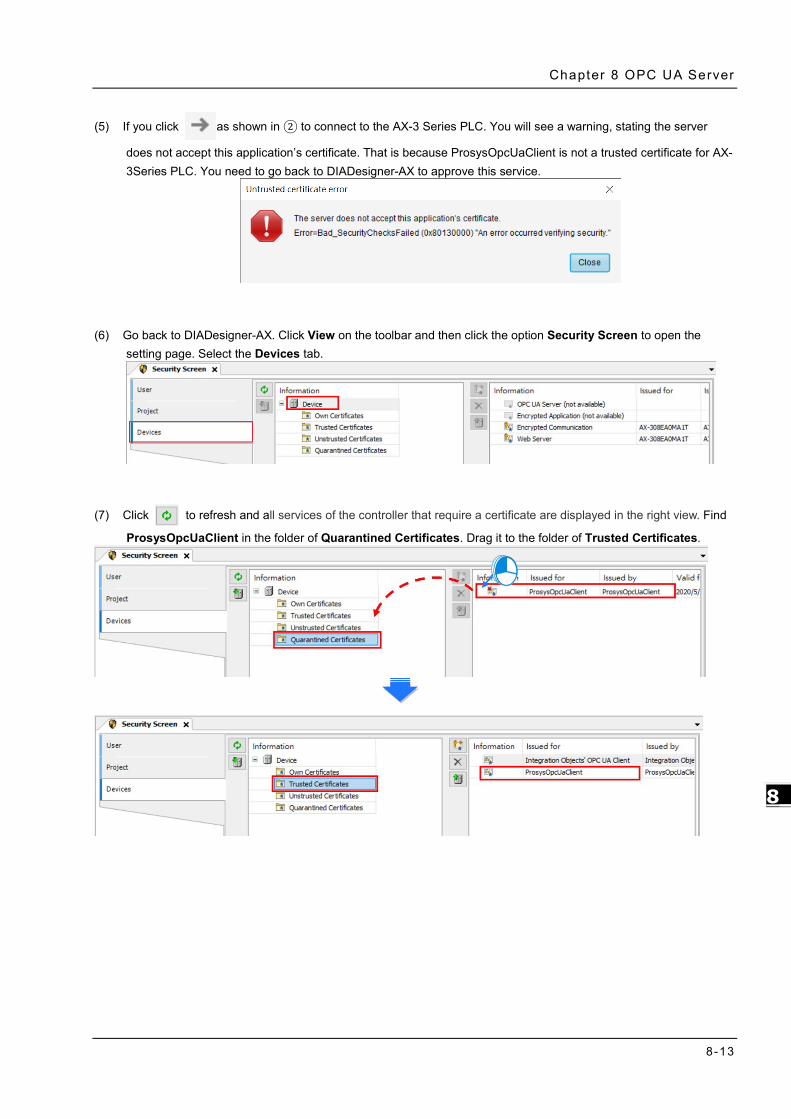
Chapter 8 OPC UA Server
8-13
8_
(5) If you click as shown in ② to connect to the AX-3 Series PLC. You will see a warning, stating the server
does not accept this application’s certificate. That is because ProsysOpcUaClient is not a trusted certificate for AX-3Series PLC. You need to go back to DIADesigner-AX to approve this service.
(6) Go back to DIADesigner-AX. Click View on the toolbar and then click the option Security Screen to open the
setting page. Select the Devices tab.
(7) Click to refresh and all services of the controller that require a certificate are displayed in the right view. Find
ProsysOpcUaClient in the folder of Quarantined Certificates. Drag it to the folder of Trusted Certificates.

AX-3 Ser ies Operat ion Manual
8-14
8_
(8) Go back to ProsysOpcUaClient. Click as shown in ② to connect to the AX-3 Series PLC as an Administrator.
After establishing the connection, you can edit the settings in AX308E through ProsysOpcUaClient.
If you connect to the AX-3 Series PLC as a guest. You do not have permission to make any change on the settings.

Chapter 8 OPC UA Server
8-15
8_
8.3.4 Setting up an Encrypted Connection with the “UaExpert” The OPC UA client “UaExpert” is freely accessible software. You can download the software here: https://www.unified-automation.com/downloads/opc-ua-clients.html Using this client, you can connect to the OPC UA server. The following description uses UaExpert V1.5 as an example. Other OPC UA clients work in a similar way. After download UAExpert, follow the following steps to set up a connection.
(1) Double-click the UaExpert to start the UaExpert.
(2) Right-click Server and then click Add to open Add Server window.
(3) Go to Custom Discovery -> Double click to Add Server...> and then type in “opc.tcp://192.168.1.5” in the Enter URL dialog.

AX-3 Ser ies Operat ion Manual
8-16
8_
(4) After that you can find opc.tcp://192.168.1.5 under Custom Discovery. Select Basic256SHA256 under the OPCUAServer@AX-308EA0MA1T (opc.tcp) and click OK after inputting the Username and Password in the Authentication Settings to create an encrypted connection.
(5) If you need to edit the server properties, go back to the starting window. Expand the option Servers under Project and then right-click AX308 to open a context menu. Click Properties to open the Server Settings page.

Chapter 8 OPC UA Server
8-17
8_
(6) Change the Endpoint Url from OPCUAServer@AX-308EA0MA1T:4840 to opc.tcp://192.168.1.5:4840 and click OK to close the window.
(7) Right-click AX308 to open a context menu. Click Connect to AX308E.

AX-3 Ser ies Operat ion Manual
8-18
8_
(8) After clicking Connect, you will see an error. That is because UaExpert is not a trusted certificate for AX-3Series PLC. You need to go back to DIADesigner-AX to approve this service.
(9) Go back to DIADesigner-AX. Click View on the toolbar and then click the option Security Screen to open the
setting page. Select the Devices tab. Click to refresh and all services of the controller that require a
certificate are displayed in the right view. Find UaExpert in the folder of Quarantined Certificates. Drag it to the folder of Trusted Certificates.
(10) Repeat step 7 to connect to OPC UA Server again. After the connection is established, you can see the tree node
on the left side and you can edit the settings in AX308E through UaExpert.

9-1
9 Chapter 9 Communication
Table of Contents
9.1 Introduction to EtherCAT Communication ............................................. 9-2 9.1.1 Features of EtherCAT Fieldbux .............................................................. 9-2 9.1.2 Settings up EtherCAT Master ................................................................ 9-3 9.1.3 Setting up the EtherCAT Slave .............................................................. 9-5
9.2 Introduction to Modbus Serial Communication ...................................... 9-8 9.2.1 Modbus Serial Port .............................................................................. 9-8 9.2.2 Modbus Serial Master ......................................................................... 9-11 9.2.3 Modbus Serial Slave ........................................................................... 9-21
9.3 Introduction to Ethernet Communication ............................................ 9-24 9.3.1 Ethernet Port ..................................................................................... 9-24 9.3.2 Modbus TCP Master (Client) ................................................................ 9-28 9.3.3 Modbus TCP Slave (Server) ................................................................. 9-38

AX-3 Ser ies Operat ion Manual
9-2
_9
9.1 Introduction to EtherCAT Communication
9.1.1 Features of EtherCAT Fieldbux
The EtherCAT bus is the Ethernet-based fieldbus. The communication rate of the EtherCAT network is 100Mbps and the distance between two adjacent nodes is within 50 metres. The EtherCAT network is noticeably very different from the general Ethernet network. One EtherCAT network has just one EtherCAT master and EtherCAT slaves contain ESC chips (EtherCAT Slave Controller) specially used for processing EtherCAT communication data and inserting the data which slaves need to transmit to the master into the EtherCAT frame. The last EtherCAT slave in the network will return the data which have been handled to the master in chronological order. See the illustration of data transmission shown below. Thanks to the ESC chips in slaves, the master can make a communication with all slaves in an EtherCAT data frame and thus the communication efficiency is enhanced.
EtherCAT Communication between the Controller and Slaves
Since the EtherCAT bus is the EtherNet-based fieldbus, the EtherCAT data frame still adopts the UDP/IP Ethernet data frame structure. EtherCAT data field includes 2 bytes of EtherCAT data header and 44~1498 bytes of EtherCAT data. EtherCAT Data field consists of one or more EtherCAT datagrams. EtherCAT Data can be defined and analyzed in a protocol as long as the master and slaves comply with the protocol. Currently the mostly used two protocols are COE (CANopen Over EtherCAT) and SOE (Sercos Over EtherCAT). EtherCAT data frame structure is as displayed below.

Chapter 9 Communicat ion
9-3
9_
9.1.2 Settings up EtherCAT Master
This section introduces functions in the tab of AX_308_Series_EtherCAT_Master_SoftMotion. Refer to Chapter 6 for Network Configuration and how to create an EtherCAT connection.
①②
③ ④
General
➀ Autoconfig Master/Slaves: Enable this option to have basic configurations done. Suggested to use this option.
➁ EtherCAT NIC Setting
Destination address (MAC): MAC address of the device in the EtherCAT network that is to receive the telegrams.
Source address (MAC): MAC address of the controller (Select CPSW1 when you use Broswe… to find Slave)
Network Name: Name or MAC of the network, depending on which of the following options is activated: Select Network by MAC: The network is specified by the MAC ID. (default: CPSW*1) Select network by Name: Network is identified by the network name and the project is device-
independent. ➂ Distributed Clock
Cycle time: Master sends out corresponding data to the Slaves in a cycle time specified here. Sync offset: Parameter for setting the delay time between the Distributed Clock time base of the
EtherCAT slave and the cycle start of the PLC. With the default value of 20%, the PLC cycle starts 20% of the bus cycle time after the sync interrupt of the slave. For the controller program, 80% of the cycle is always available. Here the Sync offset determines only when the EtherCAT data of the master is exchanged to and from the slaves relative to the time base of the EtherCAT slave.
Sync window monitoring: Enabled to monitor the synchronization of the slaves. Sync window: Time for Sync window monitoring.
➃ Options
Use LRW instead of LWR/LRD: Use combined read/write commands/PDO (LRW) instead of separating read (LRD) and write commands (LWR).
Enabled messages per task: Read and write commands, i.e. the handling of the input and output messages, can be controlled with various tasks.
Automatic restart slaves: In the case of a communication breakdown, the master immediately attempts to restart the slaves.

AX-3 Ser ies Operat ion Manual
9-4
_9
Log Here you can view the PLC log. It lists the events that wer recorded on the target system. Refer to section 4.2.1.5 Log for more information.
EtherCAT I/O Mappting
Here you can select the bus cycle task for EtherCAT communication. The bus cycle task selected will be synchronized with the specified EtherCAT_Master cycle time. Bus cycle task: Select a bus cycle task to synchronize with the EtherCAT communication time. When the
option “Use parent bus cycle setting is selected”, the system use the shortest cycle time as the EtherCAT cycle time.

Chapter 9 Communicat ion
9-5
9_
9.1.3 Setting up the EtherCAT Slave
This section introduces functions in the tab of Slaves. You can either scan the network to add the slaves in or add slaves from the Product list. Refer to section 6.1.3 for more information.
General
Address ➀ EtherCAT address: Final address of the slaves, assigned by the master during bootup. The address is
independent of the position of the slave in the network. Distributed Clocks
➁ Select DC: Cycle time for the data exchange. ➂ Startup Checking
Function Description Check vendor ID Once the system starts, it checks if the vendor ID and product ID are the same
as the configured. If not, the system stops without any further operation. Check product ID
Check revision number Once the system starts, it checks if the revision number is the same as the drop-down list showed.
➃ Timeouts
Function Description SDO access Once the system starts, the SDO also starts transmitting. Unit: ms
I -> P Switching form Init mode to Pre operational mode. Unit: ms
P -> S/S -> O Switching from Pre operational mode to Safe Operational mode. Or switching from Safe-Op mode to Operational modd. Unit: ms

AX-3 Ser ies Operat ion Manual
9-6
_9
Process Data The data mapping of the EtherCAT network is a cyclic data exchange between the master and slave through the CoE-based PDO mapping. The data that a slave sends to the master are packed in TxPDO and the data that the slave reads from the master are packed in RxPDO. The inputs and outputs on the pages of Select the Outputs and Select the Inputs contain the lists of PDOs which are available for data exchange and can be edited. For ESI file of a device, the PDOs and PDO contents for option have been defined and some PDO contents are allowed to be edited by users themselves as defined in ESI.
If outputs of the device are activated here (for writing), these outputs can be assigned to project variables in the EtherCAT I/O Mapping window. And if inputs of the device are activated here (for reading), these inputs can be assigned to project variables in the EtherCAT I/O Mapping window. It takes more PLC system resources, if you use more PDOs.
Startup Parameters
The table shows the commands which have been defined by default in ESI file when the master will read and write values to the slave in the specific status of EtherCAT network operation. Users can add or reduce or modify commands in the table. Funciton Button Description
Add By specifying new index/subindex entries, a new object can be added to the SDO that is not yet described in the EDS file. This is useful if only an incomplete object directory or none at all is present.
Edit In this window you can change the parameters of the SDO before the SDO is added to the configuration.
Move Up Moves the selected line upwards by one line Move Down Moves the selected line downwards by one line

Chapter 9 Communicat ion
9-7
9_
Click Add button to open the Select Item Object Directory window. And select the parameter that you’d like to add and then click OK to add the item in.

AX-3 Ser ies Operat ion Manual
9-8
_9
9.2 Introduction to Modbus Serial Communication
9.2.1 Modbus Serial Port
DIADesigner-AX supports the following Modbus network types, including one RS-232 and one RS-485. Each Modbus Serial Port allows one master. A maximum of 32 slaves can be attached to a master. But since RS-232 has no multipoint capability, only point-to-point connection is possible. And only the FIRST slave can communicate with the master. Since RS-485 has multipoint capability, RS-485 does NOT have such limitations. Follow the below section to set up the basic settings for communication via the serival port for the Modbus serial port.
9.2.1.1 Adding Delta Modbus COM 1. Right-click the PLC in the tree view to open up a conext menu. And click Add Device…to open the Add
Device setting window.
2. Find Delta Modbus COM (Fieldbuses -> Modbus -> Modbus Serial Port -> Delta Modbus COM) and then
double-click it or click Add Device to add this port in.

Chapter 9 Communicat ion
9-9
9_
3. Find the added port Delta_Modbus_COM (Delta Modbus COM) in the tree view and double-click it to open the setting window to set up.
9.2.1.2 Setting up Delta Modbus COM General
Here you can configure Serial Port Parameters. Settings include COM Port (RS-232 /RS-485), Baudrate, Parity, Data Bits, Stop Bits and Transmission Mode can be set here.
Item Description
COM Port Communication interface: RS-232/RS-485
Baudrate The communications speed in bits per second (bps): 9600/19200/38400/57600/115200
Parity None/Odd/Event
Data Bits 7/8 (when the transmission mode is RTU, you need to set the data bits to 8)
Stop Bits 1 bit/2bits
Transmission Mode RTU/ASCII

AX-3 Ser ies Operat ion Manual
9-10
_9
Status Here you can find the device status information, for example ‘Running’ or ‘Stopped’, and specific diagnostic messages from the respective device, also information about the card used and the internal bus system.
Item Description
Modbus Serial The status of Modbus Serial Communication
Information Here you can find general information that originates from the device description file: name, vendor, categories, version, order number, description, and other relevant information.

Chapter 9 Communicat ion
9-11
9_
9.2.2 Modbus Serial Master
AX-3 Series PLC can act as a Modbus Serial Master, after you have created Modbus Master COM port and Modbus Slave COM port. Follow the below section to set up the Modbus Serial Master.
9.2.2.1 Adding Delta Modbus Master/Slave COM
1. Right-click the created Delta_Modbus_COM (Delta Modbus COM) in the tree view to open up a conext menu. And click Add Device…to open the Add Device setting window.

AX-3 Ser ies Operat ion Manual
9-12
_9
2. Find and double-click Delta Modbus Master COM Port (Fieldbuses -> Modbus -> Modbus Serial Master -> Delta Modbus Master COM Port) or click Add Device to add this port in. You can only add one Master COM Port. After you added one master, the other added devices are slave ports: Delta_Modbus_Master_COM_Port, the Delta_Modbus_Slave_COM_Port.
3. Find the added port Delta_Modbus_Master_COM_Port (Delta Modbus Master COM Port) in the tree view and double-click it to open the setting window to set up.

Chapter 9 Communicat ion
9-13
9_
9.2.2.2 Setting up Delta Modbus Master COM General
Here you can configure the basic settings for Modbus Serial Master.
Item Description
Retry Count Set up the number of times for the COM port to reconnect if the connection is lost.
Auto-Reconnect Enable this option to have this port to reconnect automatically if an error occurs or commection timeout occurs.
Delta Modbus Serial Master I/O Mapping
Bus cycle task: Select a bus cycle task to synchronize with the Modbus communication time. When the option “Use parent bus cycle setting is selected”, the system use the shortest cycle time as the bus cycle time. Refer to section 4.2.1.6 PLC Settings for more information.

AX-3 Ser ies Operat ion Manual
9-14
_9
Delta Modbus Serial Master IEC Objects Here is the correspondings of the DFB_ModbusCOMMaster function block. You can check the status of Modbus Serial Master under this tab.
Expression Description
bStop Stop sending the Slave any new request bResetComPort Reset the COM port uiNumberOfCommunicatingSlaves The number of the Slaves that are in communication bAllSlavesOk The communication status of the Slave
Status
Here you can find the device status information, for example ‘Running’ or ‘Stopped’, and specific diagnostic messages from the respective device, also information about the card used and the internal bus system.
Information Here you can find general information that originates from the device description file: name, vendor, categories, version, order number, description, and other relevant information.

Chapter 9 Communicat ion
9-15
9_
9.2.2.3 Setting up Delta Modbus Slave COM In the tree view, find the added port Delta_Modbus_Slave_COM_Port (Delta Modbus Slave COM Port). Double-click it to open the setting window to set up.
General Here you can configure the basic settings for Modbus Serial Slave, such as Slave Address, Response Timeout and Device Type.
Item Description
Slave Addres Address of a serial Modbus device (value between 1 and 247)
Response Timeout Time interval for the master to wait for the response from the slave. This is especially configured for this slave node and overwrites the general response timeout setting of the respective master.
Device Type
You can select standard Modbus devices or Delta devices. If you select Delta devices, the system converts the protocol used into Modbus protocol automatically so that you do NOT need to refer to the register map for the conversion.

AX-3 Ser ies Operat ion Manual
9-16
_9
Modbus Slave Channel Here you can define slave channels. Each channel represents a single Modbus request. You can create up to 10 channels for each slave. AX-3 Series PLC will send out Modbus request packets in chronological order. All channels share the same Modbus connection.
Click Add Channel, you can edit the channel before adding it in. The Device Address shows the Modbus protocol address whether the device type you selected is Standard Modbus Device or Delta Devices under the General tap. Since the system converts the protocol used into Modbus protocol automatically, you do NOT need to refer to the register map for the conversion.
Device Type:Standard Modbus Device Device Type:Delta AH Series

Chapter 9 Communicat ion
9-17
9_
Item Description
Device Type Standard Modbus Device Delta Series Device
Enable Activates this channel
Name Defines this channel name
Access Type
Modbus function code Read coils (0x01) Read discrete inputs (0x02) Read holding registers (0x03) Read input registers (0x04) Read single coil (0x05) Write single register (0x06) Write multiple coils (0x0F) Write multiple registers (0x10) Read/Write multiple registers (0x17)
Read/Write Registers Read coils Read registers Write coils Write registers Note: PLC uses the corresponding Modbus function code according to the read/write register of the device type.
Trigger
Cyclic: The request occurs periodically. Rising edge: The request occurs as a
reaction to a rising edge of the Boolean trigger variables. The trigger variable is defined in the tab I/O Mapping.
Application: The Modbus request is triggered by DFB_ModbusComChannel
Cyclic: The request occurs periodically. Rising edge: The request occurs as a
reaction to a rising edge of the Boolean trigger variables. The trigger variable is defined in the tab I/O Mapping.
Application: The Modbus request is triggered by DFB_ModbusComChannel
Comment Description of the channel
Device Address Modbus protocol address
Delta register address (will be converted into Modbus protocl in the background)
Length Number of the register to be read/written to. (up to 100 coils and 100 registers)
Number of the register to be read/written to. (up to 256 coils and 100 registers)
Error Handling
What to do with the data in case of a communication error: Set To ZERO Keep last value

AX-3 Ser ies Operat ion Manual
9-18
_9
Modbus Slave Init After the Modbus connection between AX-3 Series PLC and the slaves is established, you can use Add Channel button to edit the Initialization Value of the Coil/Register.
Click Add Channel, you can edit the Access Type, Device Address, Length, Initialization Value and Comment.
Click OK to confirm the settings.
Modbus Generic Serial Slave I/O Mapping
After you have added channels under the tab of Modbus Slave Channel, you can find the variables and the set access types under this tab. Here you can define the variables for mapping. The descriptions here reflect what you have set for the Access Type in Modbus Slave Channel tab. When the Trigger type is set to Rising edge in Modbus Slave Channel, the description here adds one more condition, Trigger variable.

Chapter 9 Communicat ion
9-19
9_
Delta Modbus Serial Slave IEC Objects Here is the correspondings of the DFB_ModbusCOMMaster function block. You can check the status of Modbus Serial Slave under this tab.
Expression Description
bTrigger Trigger all Modbus channels at one time.
bReset Re-establish the connection and reset bError and ModbusRrror when the connection status shows error. And this function is only available when the option “Auto-Reconnect” is NOT enabled.
bAcknowledge Re-establish the connection and the Modbus channel that showed error previously continues to execute the data transmission. And this function is only available when the option “Auto-Reconnect” is NOT enabled.
bDoInit Initialized the Slave bInitDone The initialization of the Slave is complete. bBusy This channel is in data transmission. bDone The data transmission via this channle is complete. bError Error occurs when this channels is in data transmission. ModbusError Record of the Modbus error iChannelIndex The number of the channel that is in execution.
Status
Here you can find the Modbus Slave COM Port status information, for example ‘Running’ or ‘Stopped’, and specific diagnostic messages from the respective device, also information about the card used and the internal bus system.

AX-3 Ser ies Operat ion Manual
9-20
_9
Information Here you can find general information that originates from the device description file: name, vendor, categories, version, order number, description, and other relevant information.

Chapter 9 Communicat ion
9-21
9_
9.2.3 Modbus Serial Slave
AX-3 Series PLC can act as a Modbus Serial Slave, after you add Modbus Serial Device in and set up the allowable areas for Coils/Register. If Modbus Serial Master uses Delta device communication protocol, there is no access restrictions. Follow the below section to set up the Modbus Serial Slave.
9.2.3.1 Adding a Modbus Serial Device
1. Right-click the created Delta_Modbus_COM (Delta Modbus COM) in the tree view to open up a conext menu. And click Add Device…to open the Add Device setting window.
2. Find and double-click Delta Modbus Serial Devie (Fieldbuses -> Modbus -> Modbus Serial Master -> Delta
Modbus Serial Device) or click Add Device to add this port in.

AX-3 Ser ies Operat ion Manual
9-22
_9
3. Find the added port Delta_Modbus_Serial_Device (Delta Modbus Serial Device) in the tree view and double-click it to open the setting window to set up.
9.2.3.2 Setting up the Modbus Serial Device General
Here you can configure the basic settings for Modbus Serial Device. Set up the allowable areas for Coils/Register. If Modbus Serial Master uses Delta device communication protocol, there is no access restrictions.

Chapter 9 Communicat ion
9-23
9_
Delta Modbus Serial SlaveI/O Mapping Bus cycle task: Select a bus cycle task to synchronize with the Modbus communication time. When the option “Use parent bus cycle setting is selected”, the system use the shortest cycle time as the bus cycle time. Refer to section 4.2.1.6 PLC Settings for more information.
Status Here you can find the Modbus Serial Slave Device status information, for example ‘Running’ or ‘Stopped’, and specific diagnostic messages from the respective device, also information about the card used and the internal bus system.
Information Here you can find general information that originates from the device description file: name, vendor, categories, version, order number, description, and other relevant information.

AX-3 Ser ies Operat ion Manual
9-24
_9
9.3 Introduction to Ethernet Communication
9.3.1 Ethernet Port
DIADesigner-AX supports the following Modbus network types, including Modbus TCP and EtherNet/IP. Follow the below section to set up the basic settings for communication via the Ethernet Adapter.
9.3.1.1 Adding an Ethernet Adapter Device 1. Right-click the PLC in the tree view to open up a conext menu. And click Add Device…to open the Add
Device setting window.
2. Find and double-click Ethernet (Fieldbuses -> Ethernet Adapter -> Ethernet) or click Add Device to add this
port in.

Chapter 9 Communicat ion
9-25
9_
3. Find the added Ethernet (Ethernet) in the tree view and double-click it to open the setting window to set up.
9.3.1.2 Setting up the Ethernet General
Here you can configure Ethernet Parameters. Settings include Interface, IP address, Subnet mask, Default gateway and Adjust operating system settings can be set here.
Item Description
Interface Current communication interface
IP address
Settings of the selected network interface Subnet mask
Default gateway
Adjust operating system settings* The settings on the target system will be overwritten by the values above.
Note: For FW V1.0.1.0 or later, you can find the DDF of AX-3 Series PLC on the setting page. Go to Device -> System Setting. Refer to section 4.2.1.11 for more information.

AX-3 Ser ies Operat ion Manual
9-26
_9
Status Here you can find the device status information, for example ‘Running’ or ‘Stopped’, and specific diagnostic messages from the respective device.
Item Description
Ethenet Device The status of Ethenet Communication
Last Diagnostic Message Network diagnosis
Ethernet Device I/O Mapping Bus cycle task: Select a bus cycle task to synchronize with the communication time. When the option “Use parent bus cycle setting is selected”, the system use the shortest cycle time as the bus cycle time. Refer to section 4.2.1.6 PLC Settings for more information

Chapter 9 Communicat ion
9-27
9_
Ethernet Device IEC Objects Here you can find the objects defined by Ethernet Adapter Device. “Objects” are listed that allow for access to the device from the IEC application. In online mode, you can use the table of IEC objects as a monitoring view.
Information Here you can find general information that originates from the device description file: name, vendor, categories, version, order number, description, and other relevant information.

AX-3 Ser ies Operat ion Manual
9-28
_9
9.3.2 Modbus TCP Master (Client)
AX-3 Series PLC can act as a Modbus TCP Master, after you have created Modbus TCP Master and Modbus TCP Slave. Follow the below section to set up the Modbus TCP Master.
9.3.2.1 Adding a Modbus TCP Master/Slave 1. Right-click the Ethernet (Ethernet) node in the tree view to open up a conext menu. And click Add
Device…to open the Add Device setting window.
2. Find and double-click Delta Modbus TCP Master (Fieldbuses -> Modbus -> Modbus TCP Master -> Delta
Modbus TCP Master) or click Add Device to add this port in. After that you can find Delta_Modbus_TCP_Master under the Ethernet node in the tree view.

Chapter 9 Communicat ion
9-29
9_
3. Right-click Delta_Modbus_TCP_Master under the Ethernet node in the tree view to open up a conext menu. And click Add Device…to open the Add Device setting window.
4. Find and double-click Delta Modbus TCP Slave (Fieldbuses -> Modbus -> Modbus TCP Slave -> Delta Modbus TCP Slave) or click Add Device to add this port in.

AX-3 Ser ies Operat ion Manual
9-30
_9
After that you can find Delta_Modbus_TCP_Slave under the Delta_Modbus_TCP_Master node in the tree view.
5. Find the added port Delta_Modbus_TCP_Master (Delta Modbus TCP Master) in the tree view and double-click it to open the setting window to set up.
9.3.2.2 Setting up the Modbus TCP Master Delta Modbus TCP Master I/O Mapping
Bus cycle task: Select a bus cycle task to synchronize with the Modbus communication time. When the option “Use parent bus cycle setting is selected”, the system use the shortest cycle time as the bus cycle time. Refer to 4.2.1.6 section PLC Settings for more information.

Chapter 9 Communicat ion
9-31
9_
Delta Modbus TCP Master IEC Objects You can check the status of Modbus TCP Master under this tab.
bStop: TRUE => Stop sending Modbus TCP packets. bSlaveError: TRUE => connection/communication with the Slave is abnormal uiConnectedSlaves: the number of the connected Slaves
EX: (ST programming language): Delta Modbus TCP Master.bStop:= TRUE;
Status Here you can find the device status information, for example ‘Running’ or ‘Stopped’, and specific diagnostic messages from the respective device, also information about the card used and the internal bus system.
Information Here you can find general information that originates from the device description file: name, vendor, categories, version, order number, description, and other relevant information.

AX-3 Ser ies Operat ion Manual
9-32
_9
9.3.2.3 Setting up the Modbus TCP Slave 1. In the tree view, find the Delta_Modbus_TCP_Slave (Delta Modbus TCP Slave) and double-click it to open
the setting window to set up.
General
Here you can configure the basic settings for Modbus TCP Slave, such as Slave Address, Response Timeout and Device Type.
Item Description
Slave Addres Address of a serial Modbus device
Response Timeout Time interval for the master to wait for the response from the slave. This is especially configured for this slave node and overwrites the general response timeout setting of the respective master.
Port Port number
Device Type
You can select standard Modbus devices or Delta devices. If you select Delta devices, the system converts the protocol used into Modbus protocol automatically so that you do NOT need to refer to the register map for the conversion.
IP Address Slave IP address
Auto-Reconnect Enable this option to have this port to reconnect automatically if an error occurs or commection timeout occurs.

Chapter 9 Communicat ion
9-33
9_
Modbus Slave Channel Here you can define slave channels. Each channel represents a single Modbus request. You can create up to 10 channels for each slave. AX-3 Series PLC will send out Modbus request packets in chronological order. All channels share the same Modbus TCP connection.
Click Add Channel, you can edit the channel before adding it in. The Device Address shows the Modbus protocol address whether the device type you selected is Standard Modbus Device or Delta Devices under the General tap. Since the system converts the protocol used into Modbus protocol automatically, you do NOT need to refer to the register map for the conversion.
Device Type:Standard Modbus Device Device Type:Delta AH Series

AX-3 Ser ies Operat ion Manual
9-34
_9
Item Description
Device Type Standard Modbus Device Delta Series Device
Enable Activates this channel
Name Defines this channel name
Access Type
Modbus function code Read coils (0x01) Read discrete inputs (0x02) Read holding registers (0x03) Read input registers (0x04) Read single coil (0x05) Write single register (0x06) Write multiple coils (0x0F) Write multiple registers (0x10) Read/Write multiple registers (0x17)
Read/Write Registers Read coils Read registers Write coils Write registers Note: PLC uses the corresponding Modbus function code according to the read/write register of the device type.
Trigger
Cyclic: The request occurs periodically. Rising edge: The request occurs as a
reaction to a rising edge of the Boolean trigger variables. The trigger variable is defined in the tab I/O Mapping.
Application: The Modbus request is triggered by DFB_ModbusTCPChannel
Cyclic: The request occurs periodically. Rising edge: The request occurs as a
reaction to a rising edge of the Boolean trigger variables. The trigger variable is defined in the tab I/O Mapping.
Application: The Modbus request is triggered by DFB_ModbusTCPChannel
Comment Description of the channel
Device Address Modbus protocol address
Delta register address (will be converted into Modbus protocl in the background)
Length Number of the register to be read/written to. Number of the register to be read/written to. (up to 256 coils and 100 registers)
Error Handling
What to do with the data in case of a communication error: Set To ZERO Keep last value

Chapter 9 Communicat ion
9-35
9_
Modbus Slave Init After the Modbus connection between AX-3 Series PLC and the slaves is established, you can use Add Channel button to edit the Initialization Value of the Coil/Register.
Click Add Channel, you can edit the Access Type, Device Address, Length, Initialization Value and Comment.
Click OK to confirm the settings.

AX-3 Ser ies Operat ion Manual
9-36
_9
Modbus Generic Serial Slave I/O Mapping After you have added channels under the tab of Modbus Slave Channel, you can find the variables and the set access types under this tab. Here you can define the variables for mapping. The descriptions here reflect what you have set for the Access Type in Modbus Slave Channel tab. When the Trigger type is set to Rising edge in Modbus Slave Channel, the description here adds one more condition, Trigger variable.
Delta Modbus TCP Slave IEC Objects
You can check the status of Modbus TCP Slave under this tab.
Expression Description
bConfirmError If the option “Auto-Reconnect” is NOT enabled, during the data transmission, any channel that showed error stops. After the bConfirmError shows “TRUE”, the channel that showed error previously continues to execute.
bDoInit Initialized the Slave bInitDone The initialization of the Slave is complete. bBusy This channel is in data transmission. bDone The data transmission via this channle is complete. bError Error occurs when this channels is in data transmission. ModbusError Record of the Modbus error iChannelIndex The number of the channel that is in execution.

Chapter 9 Communicat ion
9-37
9_
Status Here you can find the Modbus TCP Slave status information, for example ‘Running’ or ‘Stopped’, and specific diagnostic messages from the respective device, also information about the card used and the internal bus system.
Information Here you can find general information that originates from the device description file: name, vendor, categories, version, order number, description, and other relevant information.

AX-3 Ser ies Operat ion Manual
9-38
_9
9.3.3 Modbus TCP Slave (Server)
AX-3 Series PLC can act as a Modbus TCP Slave, after you add Modbus TCP Slave Device in and set up the allowable areas for Coils/Register. If Modbus TCP Master uses Delta device communication protocol, there is no access restrictions. Follow the below section to set up the Modbus TCP Slave.
9.3.3.1 Adding a Modbus TCP Slave Device 1. Right-click the Ethernet (Ethernet) node in the tree view to open up a conext menu. And click Add
Device…to open the Add Device setting window.
2. Find and double-click Delta Modbus TCP Slave Devie (Fieldbuses -> Modbus -> Modbus TCP Slave Device
-> Delta Modbus TCP Slave Device) or click Add Device to add this port in.
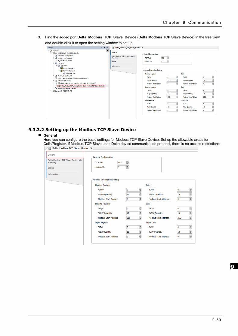
Chapter 9 Communicat ion
9-39
9_
3. Find the added port Delta_Modbus_TCP_Slave_Device (Delta Modbus TCP Slave Device) in the tree view and double-click it to open the setting window to set up.
9.3.3.2 Setting up the Modbus TCP Slave Device General
Here you can configure the basic settings for Modbus TCP Slave Device. Set up the allowable areas for Coils/Register. If Modbus TCP Slave uses Delta device communication protocol, there is no access restrictions.

AX-3 Ser ies Operat ion Manual
9-40
_9
Delta Modbus TCP Slave Device I/O Mapping Bus cycle task: Select a bus cycle task to synchronize with the Modbus communication time. When the option “Use parent bus cycle setting is selected”, the system use the shortest cycle time as the bus cycle time. Refer to section 4.2.1.6 PLC Settings for more information.
Status Here you can find the Modbus TCP Slave Device status information, for example ‘Running’ or ‘Stopped’, and specific diagnostic messages from the respective device, also information about the card used and the internal bus system.
Information Here you can find general information that originates from the device description file: name, vendor, categories, version, order number, description, and other relevant information.

Appendix A Troubleshooting Table of Contents
A.1 Troubleshotting ................................................................................. A-2 A.1.1 Basic Troubleshooting Steps ............................................................ A-2 A.1.2 Clear the Error States ..................................................................... A-2 A.1.3 Troubleshooting SOP ...................................................................... A-3 A.1.4 Viewing Log .................................................................................. A-3
A.2 Troubleshooting of CPU Modules ....................................................... A-6 A.2.1 ERROR LED Indicators Blinking Every 0.5 Seconds ............................. A-6 A.2.2 ERROR LED Indicators Blinking Rapidly Every 0.2 Seconds .................. A-8 A.2.3 ERROR LED Indicators Slow Blinking Every 3 Seconds and Lighting up
for 1 Second ................................................................................. A-8 A.2.4 BAT. LOW LED Indicators Are ON ..................................................... A-8 A.2.5 BAT. LOW LED Indicators Blinking Every 0.5 Seconds ......................... A-8 A.2.6 Others .......................................................................................... A-9
A.3 Troubleshooting of the Funciton Blocks ........................................... A-10 A.3.1 DL_BuiltInIO_AX3 ........................................................................ A-10 A.3.2 Motion Control Related Instructions ................................................ A-13
A.4 Troubleshooting of I/O Modules ...................................................... A-14 A.4.1 Troubleshooting of Analog Modules (AD/DA/XA) and Temperature Modules
(RTD/TC) .................................................................................... A-14 A.4.2 Troubleshooting of Loadcell Modules AS02LC ................................... A-16
A.5 Error Codes and LED Indicators for CPU Modules ............................ A-17 A.5.1 Error Codes and LED Indicators for CPU Modules ............................. A-18 A.5.2 Error Codes and LED Indicators for Analog and Temperature Module .. A-20
12 A

AX-3 Ser ies Operat ion Manual
A-2
_A _A
A.1 Troubleshotting A.1.1 Basic Troubleshooting Steps This chapter includes the possible errors the can occur during operation, their causes, and corrective actions.
(1) Check the following:
The PLC should be operated in a safe environment (consider environmental, electronic, and vibration safeties).
Connect power supply correctly to the PLC.
Secure the module, terminal, and cable installations.
All LED indicators show correctly.
Set all switches correctly.
(2) Check the following operational functions:
Switch the RUN/STOP state
Check the settings for the AX-3 Series to RUN/STOP
Check and eliminate errors from external devices
Use the System Log function in DIADesigner-AX to check system operation and logs
(3) Identify possible causes:
AX-3 Series or external device
CPU or extension modules
Parameters or program settings
A.1.2 Clear the Error States
Use the following methods to clear the error states. If the error source is not corrected, the system continues to show errors.
(1) Switch the CPU model state to STOP and then to RUN.
(2) Turn off the CPU and turn it on again.
(3) Use DIADesigner-AX to perform Reset Warn to clear the error logs.
(4) Use DIADesigner-AX to perform Reset Origin to reset the CPU to default settings and then redownload the program to start again.

Appendix A Troubleshoot ing
A-3
_A
A.1.3 Troubleshooting SOP
An error occured
Basic troubleshooting
done
CPU or module error
Error LED ON
Error LED Blinking
BAT LED ON
BAT LED Blinking
The problem persists after restarting the
power.
Refer to section A.1.1 Refer to section A.2.Contact the local
authorized distributors.
1. Refer to section A.1.4 2. Refer to section A.4 Refer to section A.2.
Refer to section A.2. Refer to section A.2.
No
Module
Yes
Yes
Yes
Yes
Yes
Yes
CPU
No
Yes
No Yes
A.1.4 Viewing Log
When an error occurs, the system generates corresponding error codes and stores the error messages in the PLC. You can find events during the startup and shutdown of the system, application download and loading of the boot application, custom entries, log entries from I/O drivers, and log entries from data sources on the Log tab of the Device setting page. Refer to section 4.2.1.5 for more information on Log.
1. Log Tab
Double-click the Device in the tree view to open the Device setting page and then you can find Log tab on the left section.

AX-3 Ser ies Operat ion Manual
A-4
_A _A
2. Files
The system generates log files (.csv) when the PLC is power-off or the log exceeds 64 KB. You can read the log file from the Files tab of the Device setting page.
_A

Appendix A Troubleshoot ing
A-5
_A

AX-3 Ser ies Operat ion Manual
A-6
_A _A
A.2 Troubleshooting of CPU Modules Check the LED indicators and the error codes from the CPU module and refer to the following table for troubleshooting.
A.2.1 ERROR LED Indicators Blinking Every 0.5 Seconds CPU ERROR
Error Code (16#)
Description Solution
140E More than eight remote modules on the right side of the CPU module.
Check the total number of remote modules on the right side of the CPU module (maximum is 8).
1600 The extension module ID exceeds the range.
1. Make sure the module is properly connected to the CPU module and turn the modules on again.
2. If the problem persists, contact the local authorized distributors.
1601 The extension module ID cannot be set.
1. Make sure the module is properly connected to the CPU module and turn the modules on again.
2. If the problem persists, contact the local authorized distributors.
1602 The extension module ID is duplicated.
1. Make sure the module is properly connected to the CPU module and turn the modules on again.
2. If the problem persists, contact the local authorized distributors.
1603 The extension module cannot be operated.
1. Make sure the module is properly connected to the CPU module and turn the modules on again.
2. If the problem persists, contact the local authorized distributors.
1604 Extension module communication timeout
1. Make sure the module is properly connected to the CPU module and turn the modules on again.
2. If the problem persists, contact the local authorized distributors. 2000 CPU memory access is denied. If the problem persists, contact the local authorized distributors.
2001 CPU external memory access is denied.
If the problem persists, contact the local authorized distributors.
2100 The number of MODBUS TCP connections exceeds the range.
Check if the number of Modbus TCP connection (Server+Client) exceeds the maximum number 32.
2200 The arrangement of the I/O modules is not consistent with the settings.
Check whether the settings in Hardware Configuration are consistent with the arrangement of the I/O modules.
2201 The number of connected communication modules exceed the maximum number 4.
Check the total number of communication modules.
2202 The number of connected positioning modules exceed the maximum number 8.
Check the total number of positioning modules.
2203 The number of connected extension modules exceed the maximum number 32.
Check the total number of extension modules.

Appendix A Troubleshoot ing
A-7
_A
EtherCAT ERROR
Error Code (16#)
Description Solution
1 EtherCAT communication lost Make sure the terminal and cable are properly connected to the CPU module. Execute the function block, DFB_ResetECATMaster, to reset the EtherCAT Master.
2 EtherCAT data mapping failed Make sure the terminal and cable are properly connected to the CPU module. Execute the function block, DFB_ResetECATMaster, to reset the EtherCAT Master.
4 Incorrect EtherCAT network name Make sure the Network Name/address is correctly set on the setting page of the EtherCAT Master.
5 EtherCAT Slave failed to initialize Make sure the actual placement is the same as the settings in the Network Configuration.
6 Vendor ID of the Slave does NOT match.
Make sure the actual placement is the same as the settings in the Network Configuration.
Make sure the ESI file of the Slave is matched. Disable the Startup Checking item to canel checking Vendor ID
on the EtherCAT Master setting page.
7 Product ID of the Slave does NOT mathc.
Make sure the actual placement is the same as the settings in the Network Configuration.
Make sure the ESI file of the Slave is matched. Disable the Startup Checking item to canel checking Product
ID on the EtherCAT Master setting page.
Note: EtherCAT error LED is defined by the Library IODrvEtherCAT.
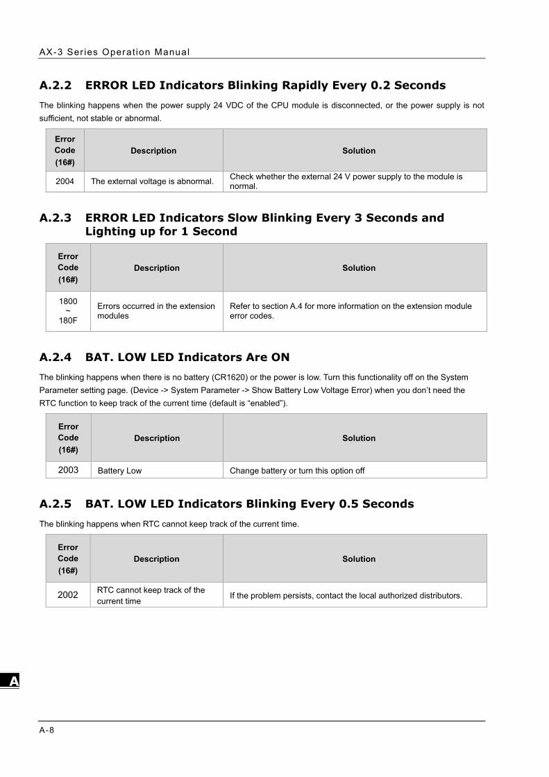
AX-3 Ser ies Operat ion Manual
A-8
_A _A
A.2.2 ERROR LED Indicators Blinking Rapidly Every 0.2 Seconds The blinking happens when the power supply 24 VDC of the CPU module is disconnected, or the power supply is not sufficient, not stable or abnormal.
Error Code (16#)
Description Solution
2004 The external voltage is abnormal. Check whether the external 24 V power supply to the module is normal.
A.2.3 ERROR LED Indicators Slow Blinking Every 3 Seconds and Lighting up for 1 Second
Error Code (16#)
Description Solution
1800 ~
180F
Errors occurred in the extension modules
Refer to section A.4 for more information on the extension module error codes.
A.2.4 BAT. LOW LED Indicators Are ON The blinking happens when there is no battery (CR1620) or the power is low. Turn this functionality off on the System Parameter setting page. (Device -> System Parameter -> Show Battery Low Voltage Error) when you don’t need the RTC function to keep track of the current time (default is “enabled”).
Error Code (16#)
Description Solution
2003 Battery Low Change battery or turn this option off
A.2.5 BAT. LOW LED Indicators Blinking Every 0.5 Seconds
The blinking happens when RTC cannot keep track of the current time.
Error Code (16#)
Description Solution
2002 RTC cannot keep track of the current time
If the problem persists, contact the local authorized distributors.

Appendix A Troubleshoot ing
A-9
_A
A.2.6 Others
Error Code (16#)
Description Solution
2500 The firmware version of the PLC is not in accordance with what stated on the DDF (Device Description File).
Check the firmware version o fthe PLC and the requirement on the DDF.
2501 SSI encoder is NOT connected to PLC. Check the connection between SSI concoder and PLC.
2502 The setting value of the single turn and multiturn SSI encoders exceed the setting limit. (up to 32 bits).
The setting value of the single turn and multiturn SSI encoder should not exceed the maximum of 32 bits.
2503 An error occurs when the pulse outputs. Check the log of the corresponding pluse on the ON-LINE monitioing page.

AX-3 Ser ies Operat ion Manual
A-10
_A _A
A.3 Troubleshooting of the Funciton Blocks A.3.1 DL_BuiltInIO_AX3 The following errors are specified as warnings; however no error indicators will appear and the AX-3 Series CPU can still run.
Error Code (16#)
Item Name Description Solution
0 DFB_HSIO_NO_ERR No error on the high speed IO function block
-
186A0 DMC_HP_INVALID_ HOME_SPEED
The speed set in the homing motion on the pulse axis is invalid.
The setting value in the fields of Search for Switch and Search for Z Phase Pulse on the setting page of Pulse Axis cannot not be set to 0. Set a non-zero value.
186A1 DMC_HP_INVALID_ HOME_ACC_DEC
The acceleration set or the deceleration set in the homing motion is invalid.
The setting value in the fields of acceleration and deceleration in the homing motion on the setting page of Pulse Axis cannot not be set to 0. Set a non-zero value.
186A2 DMC_HP_INVALID_ HOME_POSITION
The position set in the homing motion is invalid.
Set the function block pin, lrPosiotion, in the range of [0 ~ PulseAxis.Modulo Value ].
186A3 DMC_HP_AXIS_NOT_PULSEAXIS
The variable of the function block pin is NOT a PulseAxis_REF type.
Make sure to select Pulse Axis on the IO Configuration setting page and import IEC Object to the pin “Axis” of the function block DMC_Home_P.
186A4 DMC_HP_HOMING_METHOD_RESERVED
This version does NOT support this type of homing mode.
Check if this type of homing mode is supported in this version. Refer to the specification and then change the mode accordingly.
186A5 DMC_HP_HOMING_MOVEMENT_HW_LIMIT
If the positive/negative limit is activated, the axis cannot move in this homing mode.
Make sure the hardware limit used is supported by this homing mode. Refer to the specification and then change the mode or the setting accordingly.
186A6 DMC_HP_HOMING_ AXIS_STATE_NOT_ STANDSTILL
The state of the pulse axis is not at standstill.
Make sure the function block DMC_Home_P is executed when the axis state is at standstill.
186AC DFB_CAP_INVALID_CAPTURE_REF
The variable of the function block pin is NOT a Capture_REF type.
Make sure to select Capture on the IO Configuration setting page and import IEC Object to the pin “Capture” of the function block DMC_Capture.
186AD DFB_CAP_INVALID_COUNTER_REF
The variable of the function block pin is NOT a Counter_REF type.
Make sure to select Counter on the IO Configuration setting page and import IEC Object to the pin “Counter” of the function block DMC_Capture.
186AE DFB_CAP_INVALID_ VALUE_SETTING
The mask setting value (uiMaskValue) in DFB_Capture exceeds the range of rotary axis.
Set the pin "uiMaskValue" of the function block DFB_Capture in the range of [0 ~ EncoderAxis.Modulo Value ].
186AF DFB_CAP_INVALID_DELTARANGE
When the encoder of high-speed counter is a rotary axis and the pin of "diDeltaMax" or "diDeltaMin" exceeds the range of rotary axis.
Set the pin "diDeltaMax" or "diDeltaMin" of the function block DFB_Capture in the range of [0 ~ EncoderAxis.Modulo Value ].
186B0 DFB_CAP_CAPTURE_ALREADY_ENABLE
The device for high-speed capture is already enabled.
Check if the device for high-speed capture is already enabled by other DFB_Capture.

Appendix A Troubleshoot ing
A-11
_A
Error Code (16#)
Item Name Description Solution
186B6 DFB_CMP_INVALID_COMPARE_REF
The variable of the function block pin is NOT a Compare_REF type.
Make sure to select Compare on the IO Configuration setting page and import IEC Object to the pin “Counter” of the function block DMC_Compare.
186B7 DFB_CMP_INVALID_COUNTER_REF
The variable of the function block pin is NOT a Counter_REF type.
Make sure to select Counter on the IO Configuration setting page and import IEC Object to the pin “Counter” of the function block DMC_Compare.
186B8 DFB_CMP_INVALID_CMPVALUE
When the encoder of high-speed counter is a rotary axis and the pin of "diCompareValue" exceeds the range.
Set the pin "diCompareValue" of the function block DFB_Compare in the range of [0 ~ EncoderAxis.Modulo Value ].
186B9 DFB_CMP_INVALID_REFRESHCYCLE
The setting value of input pin "wRefreshCycle" exceeds the range of [0-30000], unit 0.1us.
Set the pin "wRefreshCycle" of the function block DFB_Compare in the range of [0 ~ 30000].
186BA DFB_CMP_ COMPARE_ALREADY_ENABLE
The device for high-speed compare is already enabled.
Check if the device for high-speed compare is already enabled by other DFB_Compare.
186C0 DFB_HC_INVALID_ COUNTER_REF
The variable of the function block pin is NOT a Counter_REF type.
Make sure to select Counter on the IO Configuration setting page and import IEC Object to the pin “Counter” of the function block DMC_HCnt.
186C1 DFB_HC_COUNTER_ALREADY_ENABLE
The device for high-speed counter is already enabled.
Check if the device for high-speed counter is already enabled by other DFB_HCnt.
186C2
DFB_HC_COUNTER_REF_CHANGED_ DURING_ OPERATION
The input pin "Counter" has been changed during the execution of the function block.
Check if the variable of the pin “Counter” has been changed after the execution of the DFB_HCnt.
186C8 DFB_HT_INVALID_ TIMER_REF
The variable of the function block pin is NOT a Timer_REF type.
Make sure to select Timer on the IO Configuration setting page and import IEC Object to the pin “Timerr” of the function block DFB_HTmr.
186C9 DFB_HT_TIMER_ ALREADY_ENABLE
The device for high-speed timer is already enabled.
Check if the device for high-speed timer is already enabled by other DFB_HTmr.
186CA DFB_HT_TIMER_REF_CHANGED_DURING_OPERATION
The input pin "Timer" has been changed during the execution of the function block.
Check if the variable of the pin “Timer” has been changed after the execution of the DFB_HTmr.
186D0 DFB_PV_INVALID_ COUNTER_REF
The variable of the function block pin is NOT a Counter_REF type.
Make sure to select Counter on the IO Configuration setting page and import IEC Object to the pin “Counter” of the function block DFB_PresetValue.
186D1 DFB_PV_NOT_ ENABLE_EXTERNAL_TRIGGER
The counter is not set as triggered externally but the mode of DFB_PresetValue is set to "EXTERNAL_TRIGGER".
Make sure to select External Trigger on the Counter Configuration page.
186D2 DFB_PV_PREVIOUS_PRESET_NOT_DONE
The preset counting function of the counter has been enabled by other function block
Execute this function block after the execution of DFB_PresetValue of this counter completes.

AX-3 Ser ies Operat ion Manual
A-12
_A _A
Error Code (16#)
Item Name Description Solution
DMC_PresetValue and is not done yet.
186D3 DFB_PV_CANNOT_ PRESET_WHEN_SAMPLING
The counter is executing DFB_Sample.
Disable the sample function of this counter. Disable DFB_Sample of this counter.
186D4 DFB_PV_SETRING_ NOT_DONE
The counter is executing DFB_SetRing and is not done yet.
Execute this function block after the execution of DFB_SetRing of this counter completes.
186D5 DFB_PV_INVALID_ PRESET_VALUE
When the encoder of high-speed counter is a rotary axis and the pin of "diPresetValue" exceeds the range.
Set the pin "diPresetValue" of the function block in the range of [0 ~ EncoderAxis.Modulo Value ].
186D6
DFB_PV_COUNTER_REF_CHANGED_ DURING_ OPERATION
The input pin "Counter" has been changed during the execution of the function block.
Check if the variable of the pin “Counter” has been changed after the execution of the DFB_PresetValue.
186DC DFB_SP_INVALID_ COUNTER_REF
The variable of the function block pin is NOT a Counter_REF type.
Make sure to select Counter on the IO Configuration setting page and import IEC Object to the pin “Counter” of the function block DMC_Sample.
186DD DFB_SP_COUNTER_NOT_ENABLE
The function block DFB_Counter is not enabled yet.
Execute DFB_Sample after making sure this counter is enabled by DFB_HCnt.
186DE DFB_SP_ALREADY_SAMPLING
The counter is executing DFB_Sample.
Check if this counter is enabled by other DFB_Sample.
186DF DFB_SP_PRESET_ NOT_DONE
The counter is executing DFB_PresetValue and is not done yet.
Execute this function block after the execution of DFB_PresetValue of this counter completes.
186E0 DFB_SP_INVALID_ SAMPLE_TIME
The setting value of input pin “wSampleTime” of the function block DFB_Sample exceeds the range of [10-65535].
Set the pin “wSampleTime” of the function block DFB_Sample in the range of of [10-65535].
186E1
DFB_SP_COUNTER_REF_CHANGED_ DURING_ OPERATION
The input pin "Counter" has been changed during the execution of the function block.
Check if the variable of the pin “Counter” has been changed after the execution of the DFB_Sample.
186E7 DFB_SR_INVALID_ COUNTER_REF
The variable of the function block pin is NOT a Counter_REF type.
Make sure to select Counter on the IO Configuration setting page and import IEC Object to the pin “Counter” of the function block DFB_SetRing.
186E8 DFB_SR_COUNTER_HAS_NO_CHILD_ ENCODER_AXIS
No child node of the high-speed counter is connected to the encoder.
Insert EncoderAxis into the counter and set the encoder type to rotary axis and reexecute the function block.
186E9 DFB_SR_COUNTER_NOT_RING
The encoder of the high-speed counter is not a rotary axis type.
Select the encoder type to rotary axis on the Counter Configuration page.
186EA DFB_SR_PREVIOUS_SETRING_NOT_ DONE
The preset counting function of the counter has been enabled by other function block DMC_SetRing and is not done yet.
Execute this function block after the execution of DFB_SetRing of this counter completes.

Appendix A Troubleshoot ing
A-13
_A
Error Code (16#)
Item Name Description Solution
186EB DFB_SR_PRESET_ NOT_DONE
The counter is executing DFB_PresetValue and is not done yet.
Execute this function block after the execution of DFB_PresetValue of this counter completes.
186EC DFB_SR_INVALID_ RING_RANGE
When the encoder of high-speed counter is a rotary axis and the pin of "diPositionPeriod" is less than 0 and bigger than the setting value of bSetDown.
Set the pin "diPositionPeriod" of the function block bigger than 0 and less than the setting value of bSetDown.
186ED
DFB_SR_COUNTER_REF_CHANGED_ DURING_ OPERATION
The input pin "Counter" has been changed during the execution of the function block.
Check if the variable of the pin “Counter” has been changed after the execution of the DFB_SetRing.
A.3.2 Motion Control Related Instructions The errors occured in DL_MotionControl or DL_MotionControlLight are specified as warnings; however no error indicators will appear and the AX-3 Series CPU can still run. Refer to AX Series Motion Controller Manual for the troubleshooting of DL_MotionControl.

AX-3 Ser ies Operat ion Manual
A-14
_A _A
A.4 Troubleshooting of I/O Modules Introduction to troubleshotting modules
The following AS series modules can be installed in an AX-3 Series system. There are 2 types of error codes; error and warning. The CPU module and its modules stop operating when errors occur. The CPU modules and its modules do not stop operating when warnings are triggered.
A.4.1 Troubleshooting of Analog Modules (AD/DA/XA) and Temperature Modules (RTD/TC)
A.4.1.1 ERROR ERROR LED Indicators Are ON You can set up the option to be True in Module Alarm Setting to have the following errors appear as warnings when they occur. Otherwise, when an error occurs, only an error message appears.
Error Code (16#)
Description Solution
16#1605 Hardware failure If the problem persists, contact the local authorized distributors.
16#1607 The external voltage is abnormal. Check the power supply.
16#1608 The factory calibration or the CJC is abnormal.
If the problem persists, contact the local authorized distributors.
A.4.1.2 ERROR LED Indicators Blinking Every 0.2 Seconds The following errors are specified as warnings to ensure that the AX-3 Series CPU can still run even when the warnings are triggered by its AIO modules. If you need the CPU STOP running immediately when the first 4 errors occur, you need to set the them as errors.
Error Code (16#)
Description Solution
16#1801 The external voltage is abnormal. Check the power supply.
16#1802 Hardware failure If the problem persists, contact the local authorized distributors.
16#1804 The factory calibration is abnormal. If the problem persists, contact the local authorized distributors.
16#1807 The CJC is abnormal. If the problem persists, contact the local authorized distributors.
16#1808 The signal received by channel 1 exceeds the range of analog inputs (temperature).
Check the signal received by channel 1
16#1809 The signal received by channel 2 exceeds the range of analog inputs (temperature).
Check the signal received by channel 2
16#180A The signal received by channel 3 exceeds the range of analog inputs (temperature).
Check the signal received by channel 3
16#180B The signal received by channel 4 exceeds the range of analog inputs (temperature).
Check the signal received by channel 4

Appendix A Troubleshoot ing
A-15
_A
Error Code (16#)
Description Solution
16#180C The signal received by channel 5 exceeds the range of analog inputs (temperature).
Check the signal received by channel 5
16#180D The signal received by channel 6 exceeds the range of analog inputs (temperature).
Check the signal received by channel 6
16#180E The signal received by channel 7 exceeds the range of analog inputs (temperature).
Check the signal received by channel 7
16#180F The signal received by channel 8 exceeds the range of analog inputs (temperature).
Check the signal received by channel 8
- When power-on, the module is not detected by CPU module.
Check if the connection between module and CPU module is working. If not, connect again.

AX-3 Ser ies Operat ion Manual
A-16
_A _A
A.4.2 Troubleshooting of Loadcell Modules AS02LC A.4.2.1 ERROR ERROR LED Indicators Are ON You can set up the option to be True in Module Alarm Setting to have the following errors appear as warnings when they occur. Otherwise, when an error occurs, only an error message appears.
Error Code (16#)
Description Solution
16#1605 Hardware failure If the problem persists, contact the local authorized distributors.
16#1607 The external voltage is abnormal. Check the power supply. A.4.2.2 ERROR LED Indicators Blinking Every 0.2 Seconds The following errors are specified as warnings to ensure that the AX-3 Series CPU can still run even when the warnings are triggered by its LC modules. If you need the CPU STOP running immediately when the first 4 errors occur, you need to set the them as errors.
Error Code (16#)
Description Solution
16#1801 The external voltage is abnormal. Check the power supply.
16#1802 Hardware failure If the problem persists, contact the local authorized distributors.
16#1807 The CJC is abnormal. If the problem persists, contact the local authorized distributors.
16#1808 The signal received by channel 1 exceeds the range of analog inputs (temperature).
Check the signal received by channel 1
16#1809 The signal received by channel 2 exceeds the range of analog inputs (temperature).
Check the signal received by channel 2
16#180A The signal received by channel 3 exceeds the range of analog inputs (temperature).
Check the signal received by channel 3
16#180B The signal received by channel 4 exceeds the range of analog inputs (temperature).
Check the signal received by channel 4
16#180C The signal received by channel 5 exceeds the range of analog inputs (temperature).
Check the signal received by channel 5
16#180D The signal received by channel 6 exceeds the range of analog inputs (temperature).
Check the signal received by channel 6
- When power-on, the module is not detected by CPU module.
Check if the connection between module and CPU module is working. If not, connect again.

Appendix A Troubleshoot ing
A-17
_A
A.5 Error Codes and LED Indicators for CPU Modules A. Columns
a. Error code: If an error occurs in the system, an error code is generated.
b. Description: The description of the error
c. CPU status: If the error occurs, the CPU stops running, keeps running, or shows the status you defined for the error.
Stop: The CPU stops running when the error occurs.
Continue: The CPU keeps running when the error occurs.
d. LED indicator status: If the error occurs, the LED indicator is ON, OFF, or blinks.
ERROR: System error
Descriptions
Module Type LED indicator Descriptions
CPU Error LED
There are five types of indicators for of the CPU module errors, including LED indicator ON, OFF, blinking fast, blinking normally, and blinking slowly. When the LED indicator is ON, blinking fast/normally, clear the problems first for the CPU module to keep on running. When the LED indicator is blinking slowly, indicating a warning type of error codes, it does not require immediate action. Clear the problems when the module is powered off. Error type:
ON: A serious error occurs in the module. Blinking fast (every 0.2 seconds): unstable power supply or hardware Failure. Blinking normally (every 0.5 second): system program errors or system cannot run.
Warning type: Blinking slowly (every 1 second and off for 3 seconds): a warning is triggered, but the system can still run. OFF: a warning is triggered, but the system can still run. You can modify the
rules and use DIADesigner-AX to show the warnings, instead of using indicators to show the errors.

AX-3 Ser ies Operat ion Manual
A-18
_A _A
A.5.1 Error Codes and LED Indicators for CPU Modules Refer to Section A.2 for the status descriptions of the Error LED indicators.
CPU ERROR
Error Code (16#)
Description CPU status
ERROR LED indicator
ON Blinking fast
Blinking normally
Blinking slowly OFF
140E Number of remote modules exceeds the limit of eight on the right side of the CPU module.
Stop V
1500 Connection lost in the remote modules Continue V 1600 The ID of the extension module exceeds the range. Stop V 1601 The ID of the extension module cannot be set. Stop V 1602 The ID of the extension module is duplicated. Stop V 1603 The extension module cannot be operated. Stop V 1604 Extension module communication timeout Stop V 2000 CPU memory access is denied. Stop V
2001 CPU external memory access is denied. Stop V
2002 RTC cannot keep track of the current time
(the battery LED is blinking.) Continue V
2003 Battery low (the battery LED is ON.) Continue V
2004 24VDC power supply is not sufficient and then is
recovered from low-voltage for less than 10 ms. Continue V
2100 The number of MODBUS TCP connections exceeds the range.
Continue V
2200 The arrangement of the I/O modules is not consistent with the settings.
Stop V
2201 The number of connected communication modules exceed the maximum number 4.
Stop V
2202 The number of connected positioning modules exceed the maximum number 8. Stop
V
2203 The number of connected extension modules exceed the maximum number 32.
Stop V
2500 The firmware version of the PLC is not in accordance with what stated on the DDF (Device Description File).
Continue
V
2501 SSI encoder is NOT connected to PLC. Continue V
2502 The setting value of the single turn and multiturn SSI encoders exceed the setting limit. (up to 32 bits).
Continue
V
2503 An error occurs when the pulse outputs. Continue V

Appendix A Troubleshoot ing
A-19
_A
EtherCAT ERROR
Error Code (16#)
Description CPU status
ERROR LED indicator
ON Blinking fast
Blinking normally
Blinking slowly OFF
1 EtherCAT communication lost Continue V
2 EtherCAT data mapping failed Continue V 4 Incorrect EtherCAT network name Continue V 5 EtherCAT Slave failed to initialize Continue V 6 Vendor ID of the Slave does NOT match. Continue V 7 Product ID of the Slave does NOT mathc. Continue V

AX-3 Ser ies Operat ion Manual
A-20
_A _A
A.5.2 Error Codes and LED Indicators for Analog and Temperature Module
Error Code (16#) Description
ERROR LED indicator
A D / D A / A ↔ D
ERROR
16#1605 Hardware failure (the diver board included) OFF ON 16#1607 The external voltage is abnormal. OFF ON 16#1608 The factory calibration or the CJC is abnormal. OFF ON
16#1801*1 The external voltage is abnormal. OFF Blinking 16#1802*1 Hardware failure OFF Blinking
16#1804*1 The factory calibration is abnormal. RUN: Blinking STOP: OFF
Blinking
16#1807*1 The CJC is abnormal. OFF Blinking
16#1808 The signal received by channel 1 exceeds the range of analog inputs (temperature).
RUN: Blinking STOP: OFF
Blinking
16#1809 The signal received by channel 2 exceeds the range of analog inputs (temperature).
16#180A The signal received by channel 3 exceeds the range of analog inputs (temperature).
16#180B The signal received by channel 4 exceeds the range of analog inputs (temperature).
16#180C The signal received by channel 5 exceeds the range of analog inputs (temperature).
16#180D The signal received by channel 6 exceeds the range of analog inputs (temperature).
16#180E The signal received by channel 7 exceeds the range of analog inputs (temperature).
16#180F The signal received by channel 8 exceeds the range of analog inputs (temperature).
*1 : The errors are specified as warnings to ensure that the AX-3 Series CPU can still run even when the warnings are triggered by its AIO modules. If you need the CPU STOP running immediately when the first 4 errors occur, you need to set the them as errors.