
Delta Elevator Drive VFD-ED Series User Manual - Delta EMEA
365
www.deltaww.com Industrial Automation Headquarters Delta Electronics, Inc. Taoyuan Technology Center No.18, Xinglong Rd., Taoyuan District, Taoyuan City 33068, Taiwan TEL: 886-3-362-6301 / FAX: 886-3-371-6301 Asia Delta Electronics (Shanghai) Co., Ltd. No.182 Minyu Rd., Pudong Shanghai, P.R.C. Post code : 201209 TEL: 86-21-6872-3988 / FAX: 86-21-6872-3996 Customer Service: 400-820-9595 Delta Electronics (Japan), Inc. Tokyo Office Industrial Automation Sales Department 2-1-14 Shibadaimon, Minato-ku Tokyo, Japan 105-0012 TEL: 81-3-5733-1155 / FAX: 81-3-5733-1255 Delta Electronics (Korea), Inc. Seoul Office 1511, 219, Gasan Digital 1-Ro., Geumcheon-gu, Seoul, 08501 South Korea TEL: 82-2-515-5305 / FAX: 82-2-515-5302 Delta Energy Systems (Singapore) Pte Ltd. 4 Kaki Bukit Avenue 1, #05-04, Singapore 417939 TEL: 65-6747-5155 / FAX: 65-6744-9228 Delta Electronics (India) Pvt. Ltd. Plot No.43, Sector 35, HSIIDC Gurgaon, PIN 122001, Haryana, India TEL: 91-124-4874900 / FAX : 91-124-4874945 Delta Electronics (Thailand) PCL. 909 Soi 9, Moo 4, Bangpoo Industrial Estate (E.P.Z), Pattana 1 Rd., T.Phraksa, A.Muang, Samutprakarn 10280, Thailand TEL: 66-2709-2800 / FAX : 662-709-2827 Delta Energy Systems (Australia) Pty Ltd. Unit 20-21/45 Normanby Rd., Notting Hill Vic 3168, Australia TEL: 61-3-9543-3720 Americas Delta Electronics (Americas) Ltd. Raleigh Office P.O. Box 12173, 5101 Davis Drive, Research Triangle Park, NC 27709, U.S.A. TEL: 1-919-767-3813 / FAX: 1-919-767-3969 Delta Greentech (Brasil) S/A São Paulo Office Rua Itapeva, 26 – 3˚ Andar - Bela Vista CEP: 01332-000 – São Paulo – SP - Brasil TEL: 55-11-3530-8642 / 55-11-3530-8640 Delta Electronics International Mexico S.A. de C.V. Mexico Office Vía Dr. Gustavo Baz No. 2160, Colonia La Loma, 54060 Tlalnepantla Estado de Mexico TEL: 52-55-2628-3015 #3050/3052 *We reserve the right to change the information in this manual without prior notice. DELTA_IA-MDS_VFD-ED_UM_EN_20190424 EMEA Headquarters: Delta Electronics (Netherlands) B.V. Sales: [email protected] Marketing: [email protected] Technical Support: [email protected] Customer Support: [email protected] Service: [email protected] TEL: +31(0)40 800 3800 BENELUX: Delta Electronics (Netherlands) B.V. De Witbogt 20, 5652 AG Eindhoven, The Netherlands Mail: [email protected] TEL: +31(0)40 800 3800 DACH: Delta Electronics (Netherlands) B.V. Coesterweg 45, D-59494 Soest, Germany Mail: [email protected] TEL: +49(0)2921 987 0 France: Delta Electronics (France) S.A. ZI du bois Challand 2, 15 rue des Pyrénées, Lisses, 91090 Evry Cedex, France Mail: [email protected] TEL: +33(0)1 69 77 82 60 Iberia: Delta Electronics Solutions (Spain) S.L.U Ctra. De Villaverde a Vallecas, 265 1º Dcha Ed. Hormigueras – P.I. de Vallecas 28031 Madrid TEL: +34(0)91 223 74 20 C/Llull, 321-329 (Edifici CINC) | 22@Barcelona, 08019 Barcelona Mail: [email protected] TEL: +34 93 303 00 60 Italy: Delta Electronics (Italy) S.r.l. Ufficio di Milano Via Senigallia 18/2 20161 Milano (MI) Piazza Grazioli 18 00186 Roma Italy Mail: [email protected] TEL: +39 02 64672538 Russia: Delta Energy System LLC Vereyskaya Plaza II, office 112 Vereyskaya str. 17 121357 Moscow Russia Mail: [email protected] TEL: +7 495 644 3240 Turkey: Delta Greentech Elektronik San. Ltd. Sti. (Turkey) Şerifali Mah. Hendem Cad. Kule Sok. No:16-A 34775 Ümraniye – İstanbul Mail: [email protected] TEL: + 90 216 499 9910 GCC: Delta Energy Systems AG (Dubai BR) P.O. Box 185668, Gate 7, 3rd Floor, Hamarain Centre Dubai, United Arab Emirates Mail: [email protected] TEL: +971(0)4 2690148 Egypt + North Africa: Delta Electronics 511 Cairo Business Plaza, North 90 street, New Cairo, Cairo, Egypt Mail: [email protected] Delta Elevator Drive VFD-ED Series User Manual Delta Elevator Drive VFD-ED Series User Manual
-
Upload
khangminh22 -
Category
Documents
-
view
2 -
download
0
Transcript of Delta Elevator Drive VFD-ED Series User Manual - Delta EMEA

www.deltaww.com
Industrial Automation HeadquartersDelta Electronics, Inc. Taoyuan Technology CenterNo.18, Xinglong Rd., Taoyuan District, Taoyuan City 33068, TaiwanTEL: 886-3-362-6301 / FAX: 886-3-371-6301
AsiaDelta Electronics (Shanghai) Co., Ltd.No.182 Minyu Rd., Pudong Shanghai, P.R.C.Post code : 201209 TEL: 86-21-6872-3988 / FAX: 86-21-6872-3996Customer Service: 400-820-9595
Delta Electronics (Japan), Inc.Tokyo Office Industrial Automation Sales Department 2-1-14 Shibadaimon, Minato-kuTokyo, Japan 105-0012TEL: 81-3-5733-1155 / FAX: 81-3-5733-1255
Delta Electronics (Korea), Inc.Seoul Office1511, 219, Gasan Digital 1-Ro., Geumcheon-gu, Seoul, 08501 South KoreaTEL: 82-2-515-5305 / FAX: 82-2-515-5302
Delta Energy Systems (Singapore) Pte Ltd.4 Kaki Bukit Avenue 1, #05-04, Singapore 417939TEL: 65-6747-5155 / FAX: 65-6744-9228
Delta Electronics (India) Pvt. Ltd.Plot No.43, Sector 35, HSIIDC Gurgaon, PIN 122001, Haryana, IndiaTEL: 91-124-4874900 / FAX : 91-124-4874945
Delta Electronics (Thailand) PCL. 909 Soi 9, Moo 4, Bangpoo Industrial Estate (E.P.Z), Pattana 1 Rd., T.Phraksa, A.Muang, Samutprakarn 10280, ThailandTEL: 66-2709-2800 / FAX : 662-709-2827
Delta Energy Systems (Australia) Pty Ltd.Unit 20-21/45 Normanby Rd., Notting Hill Vic 3168, AustraliaTEL: 61-3-9543-3720
AmericasDelta Electronics (Americas) Ltd.Raleigh OfficeP.O. Box 12173, 5101 Davis Drive, Research Triangle Park, NC 27709, U.S.A.TEL: 1-919-767-3813 / FAX: 1-919-767-3969
Delta Greentech (Brasil) S/ASão Paulo OfficeRua Itapeva, 26 – 3˚ Andar - Bela VistaCEP: 01332-000 – São Paulo – SP - BrasilTEL: 55-11-3530-8642 / 55-11-3530-8640
Delta Electronics International Mexico S.A. de C.V.Mexico OfficeVía Dr. Gustavo Baz No. 2160, Colonia La Loma, 54060 Tlalnepantla Estado de MexicoTEL: 52-55-2628-3015 #3050/3052
*We reserve the right to change the information in this manual without prior notice. DELTA_IA-MDS_VFD-ED_UM_EN_20190424
EMEAHeadquarters: Delta Electronics (Netherlands) B.V. Sales: [email protected] Marketing: [email protected] Technical Support: [email protected] Customer Support: [email protected] Service: [email protected]: +31(0)40 800 3800
BENELUX: Delta Electronics (Netherlands) B.V.De Witbogt 20, 5652 AG Eindhoven, The Netherlands Mail: [email protected]: +31(0)40 800 3800
DACH: Delta Electronics (Netherlands) B.V.Coesterweg 45, D-59494 Soest, GermanyMail: [email protected]: +49(0)2921 987 0
France: Delta Electronics (France) S.A.ZI du bois Challand 2, 15 rue des Pyrénées, Lisses, 91090 Evry Cedex, France Mail: [email protected]: +33(0)1 69 77 82 60
Iberia: Delta Electronics Solutions (Spain) S.L.UCtra. De Villaverde a Vallecas, 265 1º Dcha Ed. Hormigueras – P.I. de Vallecas 28031 Madrid TEL: +34(0)91 223 74 20
C/Llull, 321-329 (Edifici CINC) | 22@Barcelona, 08019 Barcelona Mail: [email protected]: +34 93 303 00 60
Italy: Delta Electronics (Italy) S.r.l.Ufficio di Milano Via Senigallia 18/2 20161 Milano (MI) Piazza Grazioli 18 00186 Roma Italy Mail: [email protected]: +39 02 64672538
Russia: Delta Energy System LLC Vereyskaya Plaza II, office 112 Vereyskaya str. 17 121357 Moscow Russia Mail: [email protected]: +7 495 644 3240
Turkey: Delta Greentech Elektronik San. Ltd. Sti. (Turkey) Şerifali Mah. Hendem Cad. Kule Sok. No:16-A 34775 Ümraniye – İstanbulMail: [email protected]: + 90 216 499 9910
GCC: Delta Energy Systems AG (Dubai BR)P.O. Box 185668, Gate 7, 3rd Floor, Hamarain Centre Dubai, United Arab Emirates Mail: [email protected]: +971(0)4 2690148
Egypt + North Africa: Delta Electronics511 Cairo Business Plaza, North 90 street, New Cairo, Cairo, Egypt Mail: [email protected]
Delta Elevator DriveVFD-ED Series User Manual
Delta E
levator Drive V
FD-E
D S
eries User M
anual

Copyright Notice ©Delta Electronics, Inc. All rights reserved. All information contained in this user manual is the exclusive property of Delta Electronics Inc. (hereinafter referred to as "Delta ") and is protected by copyright law and all other laws. Delta retains the exclusive rights of this user manual in accordance with the copyright law and all other laws. No parts in this manual may be reproduced, transmitted, transcribed, translated or used in any other ways without the prior consent of Delta.
Limitation of Liability The contents of this user manual are only for the use of the AC motor drives manufactured by Delta. Except as defined in special mandatory laws, Delta provides this user manual “as is” and does not offer any kind of warranty through this user manual for using the product, either express or implied, including but not limited to the following: (i) this product will meet your needs or expectations; (ii) the information contained in the product is current and correct; (iii) the product does not infringe any rights of any other person. You shall bear your own risk to use this product.
In no event shall Delta, its subsidiaries, affiliates, managers, employees, agents, partners and licensors be liable for any direct, indirect, incidental, special, derivative or consequential damages ( including but not limited to the damages for loss of profits, goodwill, use or other intangible losses) unless the laws contains special mandatory provisions to the contrary.
Delta reserves the right to make changes to the user manual and the products described in the user manual without prior notice and afterwards.


I
PLEASE READ PRIOR TO INSTALLATION FOR SAFETY.
Disconnect AC input power before connecting any wiring to the AC motor drive. Even if the power has been turned off, a charge may still remain in the DC-link
capacitors with hazardous voltages before the POWER LED is OFF. Do NOT touch theinternal circuits and components.
There are highly sensitive MOS components on the printed circuit boards. Thesecomponents are especially sensitive to static electricity. Take anti-static measure beforetouching these components or the circuit boards.
Never modify the internal components or wiring. Ground the AC motor drive by using the ground terminal. The grounding method must
comply with the laws of the country where the AC motor drive is to be installed. Do NOT install the AC motor drive in a location with high temperature, direct sunlight or
inflammable materials or gases. Never connect the AC motor drive output terminals U/T1, V/T2 and W/T3 directly to the
AC mains circuit power supply. After finishing the wiring of the AC motor drive, check if U/T1, V/T2, and W/T3 are
short-circuited to ground with a multimeter. Do NOT power the drive if short circuitsoccur. Eliminate the short circuits before the drive is powered.
The rated voltage for AC motor drive must be 240V for 230V series (480V for 460Vseries) and the mains supply current capacity must be 5000A RMS ( 10000A RMSfor the 40 HP (30 kW) models).
Only qualified persons are allowed to install, wire and maintain the AC motor drives. Even if the three-phase AC motor is stopped, a charge with hazardous voltages may
still remain in the main circuit terminals of the AC motor drive. The performance of electrolytic capacitor will degrade if it is not charged for a long time.
It is recommended to charge the drive which is stored in no charge condition every 2years for 3–4 hours to restore the performance of electrolytic capacitor in the motordrive. Note: When power up the motor drive, use adjustable AC power source (e.g. ACautotransformer) to charge the drive at 70%–80% of rated voltage for 30 minutes (donot run the motor drive). Then charge the drive at 100% of rated voltage for an hour (donot run the motor drive). By doing these, restore the performance of electrolyticcapacitor before starting to run the motor drive. Do NOT run the motor drive at 100%rated voltage right away.
Pay attention to the following precautions when transporting and installing this package(including wooden crate and wood stave)1. If you need to deworm the wooden crate, do NOT use fumigation or you will damage
the drive. Any damage to the drive caused by using fumigation voids the warranty.2. Use other methods, such as heat treatment or any other non-fumigation treatment, to
deworm the wood packaging material.3. If you use heat treatment to deworm, leave the packaging materials in an
environment of over 56°C for a minimum of thirty minutes. Connect the drive to a three-phase three-wire or three-phase four-wire Wye system to
comply with UL standards. If the motor drive generates leakage current over AC 3.5 mA or over DC 10 mA on a
grounding conductor, compliance with local grounding regulations or IEC61800-5-1standard is the minimum requirement for grounding.
NOTE
The content of this manual may be revised without prior notice. Please consult our distributors or download the latest version at http://www.deltaww.com/iadownload_acmotordrive

II
Table of Contents CHAPTER 1 INTRODUCTION .................................................................................................................. 1-1
1-1 Nameplate Information…..................................................................................................1-2 1-2 Model Name………….......................................................................................................1-3 1-3 Serial Number.................................................................................................................1-3 1-4 Apply After Service by Mobile Device………………………………………………...…….1-4 1-5 RFI Switch…..................................................................................................................1-7 1-6 Dimensions.....................................................................................................................1-10
CHAPTER 2 INSTALLATION .................................................................................................................. 2-1
2-1 Mounting Clearance..........................................................................................................2-2 2-2 Airflow and Power Dissipation.........................................................................................2-3
CHAPTER 3 WIRING ................................................................................................................................ 3-1
3-1 Wiring..........................................................................................................................................3-3 3-2 System Wiring Diagram.............................................................................................................3-8
CHAPTER 4 MAIN CIRCUIT TERMINALS ............................................................................................. 4-1
4-1 Main Circuit Diagram...................................................................................................................4-3 4-2 Main Circuit Terminal Specifications............................................................................................4-5
CHPATER 5 CONTROL TERMINALS ...................................................................................................... 5-1
5-1 Remove the Cover before Wiring………………..…………………………………………………5-2 5-2 Control Terminal Specifications........................................................................................5-4 5-3 Control Circuit Terminals………..............................................................................................5-5
CHAPTER 6 OPTIONAL ACCESSORIES ................................................................................................ 6-1
6-1 Brake Resistors and Brake Units Used in AC Motor Drives................................................ 6-2 6-2 Non-fuse Circuit Breaker.................................................................................................... 6-6 6-3 Fuse Specification Chart .................................................................................................... 6-6 6-4 AC/DC Reactor.............................................................................................................. 6-7 6-5 Zero Phase Reactor......................................................................................................... 6-32 6-6 EMC Filter....................................................................................................................... 6-36 6-7 Digital Keypad................................................................................................................. 6-48 6-8 USB/RS-485 Communication Interface IFD6530…......................................................... 6-50
CHAPTER 7 OPTION CARDS .................................................................................................................. 7-1
7-1 EMED-PGABD-1......................................................................................................7-4 7-2 EMED-PGHSD-1.....................................................................................................7-8 7-3 EMED-PGHSD-2.....................................................................................................7-12
CHAPTER 8 SPECIFICATIONS ............................................................................................................... 8-1
8-1 230V Series…………………………………...........................................................................8-2 8-2 460V Series…………………………………...........................................................................8-2

III
8-3 Operation, Storage and Transportation Environments…..……………………….....................8-4
CHAPTER 9 DIGITAL KEYPAD ............................................................................................................... 9-1
9-1 Descriptions of Keyboard Panel …………………………….............................................9-2 9-2 Keypad Operation Process...............................................................................................9-3 9-3 Description of the Digital Keypad KPC-CC01 .......................................................................9-4 9-4 Digital Keypad KPC-CC01 Functions..........................................................................9-6 9-5 Digital Keypad KPC-CC01 Fault Codes and Descriptions………………….……………9-17 9-6 TPEditor Installation .................................................................................................9-21
CHAPTER 10 AUTO-TUNING PROCESS .............................................................................................. 10-1
10-1 Auto-tuning Flow Chart……………………………………………...............................................10-2 10-2 Explanations for the Auto-tuning Steps...................................................................................10-4 10-3 Elevator Performance Fine-tuning…......................................................................................10-17
CHAPTER 11 SUMMARY OF PARAMETER SETTINGS ....................................................................... 11-1
CHAPTER 12 DESCRIPTIONS OF PARAMETER SETTINGS .............................................................. 12-1
00 Drive Parameters…………………………………………………………………………………...12-1 01 Basic Parameters……………………………………………..……………………………….….12-8 02 Digital Input / Output Parameters…………………………..…………………………………….12-18 03 Analog Input / Output Parameters…………………………..……………………………………12-33 04 Multi-step Speed Parameters………………………………..……………………………..…..12-38 05 IM Parameters……………..………………………………………..…………………………….….12-40 06 Protection Parameters…………………………………………..………………………………..12-44 07 Special Parameters…………………………………………….………………………………..12-64 08 PM Parameters…………………..………………………………..……………………………….12-70 09 Communication Parameters……………………………………..………………………….……12-73 10 Feedback Control Parameters…………………………………..………………………………12-83 11 Advanced Parameters…………………………………………..…………………………….…12-90 12 User-defined Parameters…………..…….……………………..……………………………….12-94 13 View User-defined Parameters….........……………………..…....…………………………….12-98
CHAPTER 13 WARNING CODES .......................................................................................................... 13-1
CHAPTER 14 FAULT CODES ................................................................................................................ 14-1
CHAPTER 15 SUGGESTIONS AND ERROR CORRECTIONS FOR STANDARD AC MOTOR DRIVES
................................................................................................................................................................. 15-1
15-1 Maintenance and Inspections…………...……...................................................................15-3 15-2 Greasy Dirt Problems…………….........................................................................................15-7 15-3 Fiber Dust Problems.…………………….…………………….…............................................15-8 15-4 Corrosion Problems ……..................................................................................................15-9 15-5 Industrial Dust Problems ………………………..................................................................15-10 15-6 Installation and Wiring Problems…………...........................................................................15-11

IV
15-7 Multi-function Input / Output Terminal Application Problems...............................................15-12
CHAPTER 16 SAFE TORQUE OFF FUNCTION………….………………………………………………….16-1
16-1 Failure Rate of the Drive’s Safety Function…….…………………………………………………16-2 16-2 Description of STO’s Functions….……………………………………………….………………...16-3 16-3 Wiring Diagram……………………………………………………………………………………….16-4 16-4 Related Parameters……………….…………………………………………………………………16-6 16-5 Timing Diagram Description………….……………………………………………...………………16-7 16-6 Fault Codes Related to STO……………..……….……………………………………..………..16-9
APPENDIX A. EMC Standard Installation Guide…………………………………..………………………..A-1
APPENDIX B. Revision History……..………………………………………………..………………………..B-1
Issued Edition: 01 Firmware Version: V1.07
(Refer to Parameter 00-06 on the product to get the firmware version.) Issued Date: April, 2019

Ch01 Introduction | VFD-ED
1-1
Chapter 1 Introduction
1-1 Nameplate Information
1-2 Model Name
1-3 Serial Number
1-4 Apply After Service by Mobile Device
1-5 RFI Switch
1-6 Dimensions

Ch01 Introduction | VFD-ED
1-2
After you receive the AC motor drive, check the following:
1. Inspect the unit after unpacking to ensure that it was not damaged during shipment. Make sure that the part number printed on the package corresponds with the part number indicated on the nameplate.
2. Make sure that the voltage for the wiring is in the range indicated on the nameplate. Install the AC motor drive according to this manual.
3. Before applying the power, make sure that all the devices, including power, motor, control board and digital keypad are connected correctly.
4. When wiring the AC motor drive, make sure that the wiring for input terminals “R/L1, S/L2, T/L3” and output terminals “U/T1, V/T2, W/T3” is correct to prevent drive damage.
5. When power is applied, select the language and set parameter groups with the digital operation panel (KPED-LE01). When executing a trial run, begin with a low speed and then gradually increase the speed until reaching the desired speed.
1-1 Nameplate Information This example uses the 15 HP/11 kW 230 V, 3-phase motor drive.

Ch01 Introduction | VFD-ED
1-3
1-2 Model Name
1-3 Serial Number

Ch01 Introduction | VFD-ED
1-4
1-4 Apply After Service by Mobile Device
1-4-1 Location of Service Link Label
Frame B The image below shows the service link label (service label) that is located on the side of the case.
ServiceLabel
Frame C Remove the front cover of the case to find the service link label (service label) located on the upper left corner as shown in the following image.

Ch01 Introduction | VFD-ED
1-5
Frame D Remove the front cover of the case to find the service link label (service label) located on the upper left corner as shown in the following image.
Service Label
Frame E Remove the front cover of the case to find the service link label (service label) located on the upper left corner as shown in the following image.
Service Label

Ch01 Introduction | VFD-ED
1-6
1-4-2 Service Link Label
QR code
Serial number Web address of after sales service-
http://service.deltaww.com/ia/repair?sn=serial number
Scan QR Code to request service
1. Find the QR code sticker (as shown above).
2. Run the QR code reader App on your smartphone.
3. Point your camera at the QR Code. Hold your camera steady until the QR code comes into focus.
4. Access the Delta After-Sales Service website.
5. Fill in the information in the columns marked with an orange star.
6. Enter the CAPTCHA and click Submit to complete the request.
Cannot find the QR Code?
1. Open a web browser on your computer or smartphone.
2. Enter https://service.deltaww.com/ia/repair in the browser address bar and press the Enter key.
3. Fill in the information in the columns marked with an orange star.
4. Enter the CAPTCHA and click Submit to complete the request.

Ch01 Introduction | VFD-ED
1-7
1-5 RFI Switch
The AC motor drive may emit electrical noise. You can use the RFI (Radio Frequency Interference) switch to suppress interference on the power line. The RFI switches on Frames B, C, D, E are at similar locations. Open the drive’s top cover to remove the RFI switch as shown in the following image.
NOTE: The RFI switches on Frames B/C/D/E are at similar locations.

Ch01 Introduction | VFD-ED
1-8
Isolating main power from ground When the power distribution system for the motor drive is a floating ground system (IT) or an asymmetric ground system (TN), you must remove the RFI switch. Removing the switch also cuts off the internal RFI capacitor (filter capacitor) between the system's frame and the central circuits to avoid damaging the central circuits and reduces the ground leakage current.
Important points regarding ground connection
To ensure the safety of personnel, ensure proper operation, and reduce electromagnetic radiation, you must properly ground the motor and drive during installation.
The diameter of the grounding cables must meet the size specified by safety regulations. You must connect the shielded cable to the motor drive’s ground to meet safety regulations. Only use the shielded cable as the ground for equipment when the above points are met. When installing multiple sets of motor drives, do not connect the motor drives’ grounds in series. See
the following image.
Pay particular attention to the following points
Do not remove the RFI switch while the power is ON. Make sure the main power is OFF before removing the RFI switch. Removing the RFI switch also cuts the capacitor conductivity. Gap discharge may occur once the
transient voltage exceeds 1000 V.
If you remove the RFI switch, you remove the reliable electrical isolation. In other words, all controlled inputs and outputs become low-voltage terminals with basic electrical isolation. Also, when you remove the internal RFI switch, the motor drive is no longer electromagnetic compatible (EMC). Do not remove the RFI switch if the main power is a grounded power system. You must remove the RFI switch when conducting high voltage tests. When conducting a high voltage
test for the entire facility, disconnect the main power and the motor if the leakage current is too high.
Floating Ground System (IT Systems)
A floating ground system is also called an IT system, ungrounded system, or high impedance/resistance (greater than 30 Ω) grounding system. Disconnect the ground cable from the internal EMC filter. In situations where EMC is required, check for excess electromagnetic radiation affecting nearby
low-voltage circuits. In some situations, the adapter and cable naturally provide enough suppression. If in doubt, install an extra electrostatic shielded cable on the power supply side between the main circuit and the control terminals to increase shielding.
Do not install an external RFI/EMC filter. The external EMC filter passes through a filter capacitor and connects power input to the ground. This is very dangerous and damages the motor drive.
Ch01 Introduction | VFD-ED
1-9
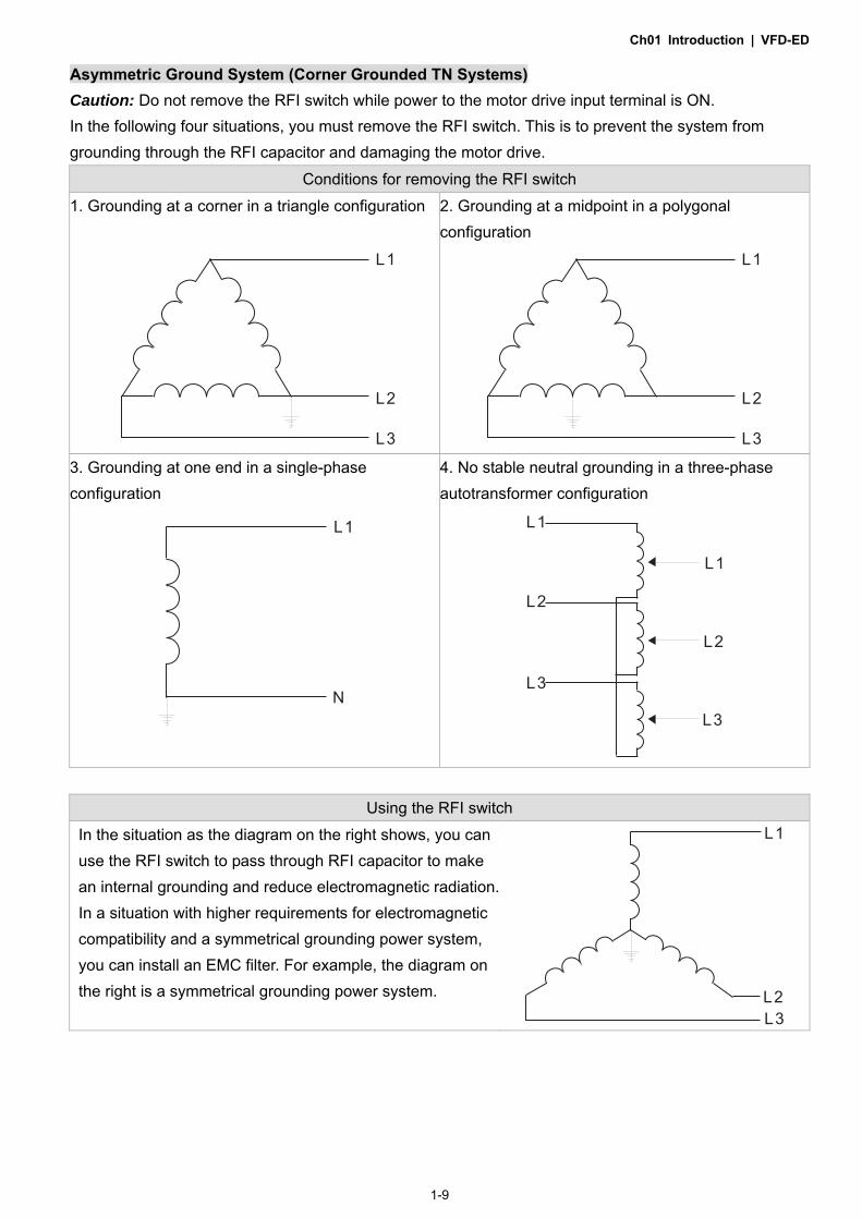
Asymmetric Ground System (Corner Grounded TN Systems)
Caution: Do not remove the RFI switch while power to the motor drive input terminal is ON. In the following four situations, you must remove the RFI switch. This is to prevent the system from grounding through the RFI capacitor and damaging the motor drive.
Conditions for removing the RFI switch
1. Grounding at a corner in a triangle configuration
L2
L3
L1
2. Grounding at a midpoint in a polygonal configuration
L2
L3
L1
3. Grounding at one end in a single-phase configuration
L1
N
4. No stable neutral grounding in a three-phase autotransformer configuration
L1
L2
L3
L1
L2
L3
Using the RFI switch
In the situation as the diagram on the right shows, you can use the RFI switch to pass through RFI capacitor to make an internal grounding and reduce electromagnetic radiation. In a situation with higher requirements for electromagnetic compatibility and a symmetrical grounding power system, you can install an EMC filter. For example, the diagram on the right is a symmetrical grounding power system. L2
L3
L1

Ch01 Introduction | VFD-ED
1-10
1-6 Dimensions Frame B VFD022ED21S, VFD037ED21S, VFD040ED23S/43S
Unit: mm [inch]
Frame W W1 H H1 H2 D D1* S1 A B C
B 193.5 [7.60]
162.5 [6.39]
260.0 [10.22]
247.0 [9.71]
230.0 [9.04]
133.5 [5.25]
58.0 [2.28]
6.5 [0.26]
138.6 [5.46]
67.2 [2.66]
17.6 [0.69]
*D1: This dimension is for flange mounting application reference.

Ch01 Introduction | VFD-ED
1-11
Frame C VFD055ED23S/43S, VFD075ED23S/43S, VFD110ED23S/43S, VFD150ED43S, VFD185ED43S
Unit: mm [inch]
Frame W W1 W2 H H1 H2 D D1* S1 S2 S3 ∅1 ∅2
C 235.0 [9.25]
204.0 [8.03]
176.0 [6.93]
350.0 [13.78]
337.0 [13.27]
320.0 [15.60]
146.0 [5.75]
70.0 [2.76]
6.5 [0.26]
9.0 [0.35]
7.0 [0.28]
19.7 [0.78]
28.3 [1.11]
Note: A1–A4 and B1–B4 can be used for screwdriver installation; B1–B4 can also be used for sleeve installation *D1: This dimension is for flange mounting application reference.

Ch01 Introduction | VFD-ED
1-12
Frame D VFD150ED23S, VFD185ED23S, VFD220ED23S/43S, VFD300ED43S
Unit: mm [inch]
Frame W W1 H H1 H2 D D1* S1 ∅1 ∅2 ∅3
D 255.0 [10.04]
226.0 [8.90]
403.8 [15.90]
384.0 [15.12]
360.0 [14.17]
178.0 [7.01]
94.0 [3.70]
8.5 [0.33]
17.5 [0.69]
32.0 [1.26]
26.0 [1.02]
*D1: This dimension is for flange mounting application reference.

Ch01 Introduction | VFD-ED
1-13
Frame E VFD300ED23S, VFD370ED23S/43S, VFD450ED43S, VFD550ED43S, VFD750ED43S
S1S1
DETAIL A (MOUNTING HOLE)
DETAIL B (MOUNTING HOLE)
WW1
HH1
SEE DETAIL B
D
H2
D1
S2
D2SEE DETAIL A
Unit: mm [inch]
Frame W W1 H H1 H2 D D1* D2 S1 S2
E 330.0 [12.99]
285.0 [11.22]
550.0 [21.65]
525.0 [20.67]
492.0 [19.37]
273.4 [10.76]
107.2 [4.22]
16.0 [0.63]
11.0 [0.43]
18.0 [0.71]
*D1: This dimension is for flange mounting application reference.

Ch01 Introduction | VFD-ED
1-14
Built-In Keyboard Panel KPED-LE01 Unit: mm [inch]

Ch02 Installation | VFD-ED
2-1
Chapter 2 Installation
2-1 Mounting Clearance
2-2 Airflow and Power Dissipation

Ch02 Installation | VFD-ED
2-2
2-1 Mounting Clearance Do not allow material such as fiber particles, scraps of paper, shredded wood, sawdust, and metal
particles to adhere to the heat sink. Install the AC motor drive in a metal cabinet. When installing one drive below another one, use a
metal separator between the AC motor drives to prevent mutual heating and to prevent the risk of fire.
Install the AC motor drive in Pollution Degree 2 (IEC 60664-1) environments only: under normal circumstances only nonconductive pollution occurs and temporary conductivity caused by condensation is expected.
The motor drives’ figures shown below are for reference only. The actual motor drives may look different.
Air Flow
W W
H
H
Minimum Mounting Clearance
Frame Capacity Model No. W (Width) mm [inch]
H (Height) mm [inch]
B 3.0–5.0 HP (2.2–4 kW) VFD022ED21S, VFD037ED21S, VFD040ED23S/43S 50 [2] 150 [6]
C 7.5–15 HP
(5.5–11 kW) VFD055ED23S/43S,VFD075ED23S/43S, VFD110ED23S/43S, VFD150ED43S, VFD185ED43S
75 [3] 175 [7]
D 20–40 HP
(15–30 kW) VFD150ED23S, VFD185ED23S, VFD220ED23S/43S, VFD300ED43S
75 [3] 200 [8]
E 40–100 HP (30–75 kW)
VFD300ED23S, VFD370ED23S/43S, VFD450ED43S, VFD550ED43S, VFD750ED43S 75 [3] 200 [8]
NOTE The minimum mounting clearances stated in the table above apply to AC motor drives frame B, C, D and E. Failure to follow the minimum mounting clearances may cause the motor drive fan to malfunction and cause heat dissipation problems.

Ch02 Installation | VFD-ED
2-3
2-2 Airflow and Power Dissipation
Model No.
Airflow Rate for Cooling Power Dissipation for
AC Motor Drive
Flow Rate [cfm] Flow Rate [m3/hr] Power Dissipation [W]
External Internal Total External Internal Total Loss External
(Heat Sink) Internal Total
VFD022ED21S 13.7 - 13.7 23.3 - 23.3 60 36 96
VFD037ED21S 23.9 - 23.9 40.7 - 40.7 84 46 130
VFD040ED23S 23.9 - 23.9 40.7 - 40.7 133 49 182
VFD055ED23S 48.5 - 48.5 82.4 - 82.4 212 67 279
VFD075ED23S 48.5 - 48.5 82.4 - 82.4 292 86 379
VFD110ED23S 47.9 - 47.9 81.4 - 81.4 355 121 476
VFD150ED23S 64.6 - 64.6 109.8 - 109.8 490 161 651
VFD185ED23S 102.3 - 102.3 173.8 - 173.8 638 184 822
VFD220ED23S 102.8 - 102.8 174.7 - 174.7 723 217 939
VFD300ED23S 179 30 209 304 51 355 932 186 1118
VFD370ED23S 179 30 209 304 51 355 1112 222 1334
VFD040ED43S 13.7 - 13.7 23.3 - 23.3 123 42 165
VFD055ED43S 48.5 - 48.5 82.4 - 82.4 185 55 240
VFD075ED43S 48.5 - 48.5 82.4 - 82.4 249 71 320
VFD110ED43S 47.9 - 47.9 81.4 - 81.4 337 94 431
VFD150ED43S 46.1 - 46.1 78.4 - 78.4 302 123 425
VFD185ED43S 46.1 - 46.1 78.4 - 78.4 391 139 529
VFD220ED43S 102.8 - 102.8 174.7 - 174.7 642 141 783
VFD300ED43S 83.7 - 83.7 142.2 - 142.2 839 180 1019
VFD370ED43S 179 30 209 304 51 355 803 252 1055
VFD450ED43S 179 30 209 304 51 355 1014 270 1284
VFD550ED43S 179 30 209 304 51 355 1244 275 1519
VFD750ED43S 186 30 216 316 51 367 1541 338 1878

Ch02 Installation | VFD-ED
2-4
Carrier Frequency Derating Capacity (Fc)
Frame B C D E E
Fc (kHz) 2.2–4 kW 5.5–11 kW 15–22 kW 30–45 kW 55–75kW
0 100% 100% 100% 100% 100%
1 100% 100% 100% 100% 100%
2 100% 100% 100% 100% 100%
3 100% 100% 100% 100% 100%
4 100% 100% 100% 100% 100%
5 100% 100% 100% 100% 100%
6 100% 100% 100% 100% 100%
7 100% 100% 100% 90.73% -
8 100% 100% 100% 82.20% -
9 94.24% 100% 92.32% 74.31% -
10 88.92% 100% 85.21% - -
11 82.54% 95.35% 78.63% - -
12 78.08% 91.02% 72.53% - -
13 73.95% 86.98% 66.87% - -
14 70.14% 84.14% 61.62% - -
15 66.61% 80.67% 56.74% - -
Carrier Frequency Derating Curve (Fc)

Ch02 Installation | VFD-ED
2-5
Ambient Temperature Derating Curve
Altitude Derating Curve

Ch02 Installation | VFD-ED
2-6
[The page intentionally left blank]

Ch03 Wiring | VFD-ED
3-1
Chapter 3 Wiring
3-1 Wiring
3-2 System Wiring Diagram
Ch03 Wiring | VFD-ED
3-2
After removing the front cover, verify that the power and control terminals are clear. Be sure to observe the following precautions when wiring. Make sure that power is only applied to the R/L1, S/L2, and T/L3 terminals. Failure to comply may
result in damage to the equipment. The voltage and current should be within the range indicated on
the AC motor drive nameplate (see Section 1-1 Nameplate Information).
All the units must be grounded directly to a common ground terminal to prevent damage from a
lightning strike or electric shock.
Make sure you correctly tighten the main circuit terminal screws to prevent sparks from screws that
have been loosened due to vibration.
Turn off the AC motor drive power before installing any wiring. A hazardous charge may still remain in the DC BUS capacitors after the power has been turned off. Measure the remaining voltage before wiring. For your safety, do not perform any wiring before the voltage drops to a safe level < 25 VDC. Performing a wiring installation while voltage remains may cause sparks and short circuits.
Only qualified personnel familiar with AC motor drives are allowed to perform installation, wiring and commissioning. Make sure the power is turned off before wiring to prevent electric shock.
When wiring, choose wires that comply with local regulations for your safety. Check the following items after finishing the wiring:
1. Are all connections correct? 2. Are there any loose wires? 3. Are there any short circuits between the terminals or to ground?
Ch03 Wiring | VFD-ED
3-3
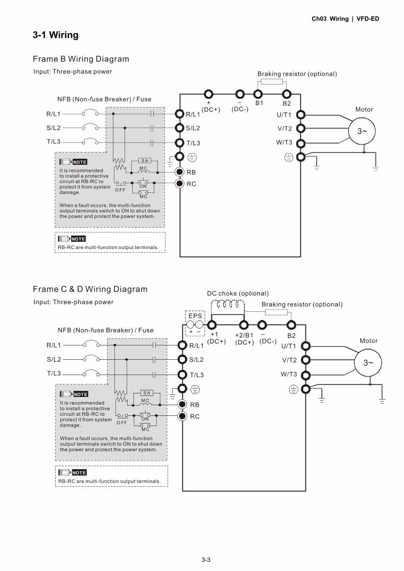
3-1 Wiring

Ch03 Wiring | VFD-ED
3-4
*See Figure 2 on page 3-6 for the Emergency Power Supply (EPS) system wiring diagrams.
*1 See Section 6-1 Brake Resistors & Brake Units Used in AC Motor Drives for details.

Ch03 Wiring | VFD-ED
3-5

Ch03 Wiring | VFD-ED
3-6
Figure 1
Switching between two modes: SINK (NPN) /SOURCE (PNP)
Figure 2
Emergency Power Supply (EPS) system wiring diagrams
Frames B, C, D & E 1. One-phase UPS or battery can only be used on the main power supply

Ch03 Wiring | VFD-ED
3-7
Frames C & D 2. When the voltage of the main power supply is lower than 140 VDC (230V series) / 280 VDC (460V
series), connect the control power to one-phase UPS or battery.
Notes on the emergency power supply (EPS) Be aware of the following conditions when the emergency power is ON (MI=43): 1. The fan does not run in order to prevent voltage drop during EPS. 2. The motor drive does not save parameter settings. When the power is turned off and then back on,
the parameter settings are lost. 3. The motor drive operates at the speed set in Pr.06-44. 4. Low voltage and phase loss protections are NOT available. 5. You can display the DC BUS voltage with Pr.06-29.

Ch03 Wiring | VFD-ED
3-8
3-2 System Wiring Diagram
Power input terminal
Supply power according to the rated power specifications indicated in the manual (refer to Chapter 08 Specifications).
NFB or fuse There may be a large inrush current during power on. Refer to Section 6-2 NFB to select a suitable NFB or fuse.
Electromagnetic contactor
Switching the power ON/OFF on the primary side of the electromagnetic contactor can turn the integrated elevator device ON/OFF, but frequent switching can cause machine failure. Do not switch ON/OFF more than once an hour. Do not use the electromagnetic contactor as the power switch for the integrated elevator drive; doing so shortens the life of the integrated elevator drive.
AC reactor (input terminal)
When the main power supply capacity is greater than 1000 kVA, or when it switches into the phase capacitor, the instantaneous peak voltage and current generated may destroy the internal circuit of the integrated elevator drive. It is recommended that you install an input side AC reactor in the integrated elevator drive. This also improves the power factor and reduces power harmonics.The wiring distance should be within 10 m. Refer to Chapter 06 Optional Accessoires for details.
Zero phase reactor
Use to reduce radiated interference, especially in environments with audio devices, and reduce input and output side interference. The effective range is AM band to 10 MHz. Refer to Chapter 06 Optional Accessoires for details.
EMC filter Can use to reduce electromagnetic interference.
Brake module &
Brake resistor (BR)
Use to shorten the deceleration time of the motor. Refer to Chapter 06 Optional Accessoires for details.
AC reactor (output
terminal)
The motor cable length affects the size of the reflected wave on the motor end. It is recommended that you install an AC output reactor when the motor wiring length exceeds 20 meters. Refer to Chapter 06 Optional Accessoires for details.

Ch04 Main Circuit Terminals | VFD-ED
4-1
Chapter 4 Main Circuit Terminals
4-1 Main Circuit Diagram
4-2 Main Circuit Terminal Specifications

Ch04 Main Circuit Terminals | VFD-ED
4-2
Main input power terminals Do not connect a three-phase model to one-phase power. R/L1, S/L2 and
T/L3 have no phase-sequence requirement and can be connected in any sequence.
You must install a NFB between the three-phase power input terminals and the main circuit terminals (R/L1, S/L2, T/L3). Add a magnetic contactor (MC) to the power input wiring to cut off power quickly and reduce malfunctions when the AC motor drive protection function activates. Both ends of the MC should have an R-C surge absorber.
Tighten the screws in the main circuit terminal to prevent sparks caused by screws loosened due to vibration.
Use voltage and current within the specifications in Chapter 08. When using a general ELB (Earth Leakage Breaker), select a current sensor
with sensitivity of 200 mA or above and not less than 0.1 second operation time to avoid nuisance tripping. When choosing an ELB designed for the AC motor drive, choose a current sensor with sensitivity of 30 mA or above.
Use shielded wire or conduit for the power wiring and ground the two ends of the shielding or conduit.
Do NOT run and stop the AC motor drives by turning the power ON and OFF. Run and stop the AC motor drives by sending the RUN and STOP commands through the control terminals or the keypad. If you still need to run and stop the AC motor drives by turning the power ON and OFF, do so no more often than ONCE per hour.
Output terminals of the main circuit
When it is necessary to install a filter at the output side of the AC motor drive terminals U/T1, V/T2, W/T3, use an inductance filter. Do not use phase-compensation capacitors or L-C (Inductance-Capacitance) or R-C (Resistance-Capacitance) capacitors.
DO NOT connect phase-compensation capacitors or surge absorbers at the output terminals of AC motor drives.
Use well-insulated motors to prevent any electric leakage from the motors. Use terminals [+1, +2] for connecting a DC reactor. Use terminals [+1, +2/B1] for connecting a DC BUS. Use these terminals to connect a DC reactor to improve the power factor
and reduce harmonics. A jumper is connected to these terminals at the factory. Remove that jumper before connecting to a DC reactor.
+1
JumperDC reactor
Models above 22 kW do not have a built-in brake resistor. To improve resistance braking, connect an optional external brake resistor.
When not in use, leave terminals +2/B1, (-) open. Short-circuiting [B2] or [-] to [+2/B1] damages the motor drive. Do NOT
short-circuit those terminals.

Ch04 Main Circuit Terminals | VFD-ED
4-3
4-1 Main Circuit Diagram
Frame B
Frames C & D
Frame E

Ch04 Main Circuit Terminals | VFD-ED
4-4
Terminal Symbol Description
EPS (+, -) Backup power/ Emergency power connection terminal. Note: EPS (Emergency Power Supply) input terminal supports only frames C & D.
R/L1, S/L2, T/L3 Commercial power input terminal.
U/T1, V/T2, W/T3 AC motor drive output terminals for connecting a three-phase induction motor.
+1, +2/B1 Connections for DC reactor to improve the power factor. Remove the jumper before installing a DC reactor. Frame E has a built-in DC reactor.
+2/B1, B2 Connections for brake resistor (optional).
Ground connection; comply with local regulations.

Ch04 Main Circuit Terminals | VFD-ED
4-5
4-2 Main Circuit Terminal Specifications
Frame B
Frame B
Model
Main circuit terminals: R/L1, S/L2, T/L3, U/T1, V/T2, W/T3, +(DC+), -(DC-), B1, B2,
NOTE Use Figure 1 to choose terminal wire size. As shown in Figure 2, use insulated heat
shrink tubing that is resistant to at least 600 V to comply with UL and CSA regulations (600 V, YDPU2).
Maximum Wire
Gauge
Minimum Wire
Gauge
Screw Size Tightening
Torque (±10%)
VFD022ED21S
5.3 mm² [10 AWG]
2.1 mm² [14 AWG] M4
18 kg-cm (15.6 lb-in.) (1.7 N-m)
VFD040ED43S
VFD037ED21S 3.3 mm² [12 AWG] VFD040ED23S
For UL installation compliance, select copper wires with voltage rating of 600 V and temperature resistance of 75°C.

Ch04 Main Circuit Terminals | VFD-ED
4-6
Frame C
Frame C
Model
Main circuit terminals: R/L1, S/L2, T/L3, U/T1, V/T2, W/T3, +1, +2/B1, -, B2,
NOTE Use Figure 1 to choose terminal wire size. As shown in Figure 2, use insulated heat shrink
tubing that is resistant to at least 600 V to comply with UL and CSA regulations (600 V, YDPU2).
Maximum Wire
Gauge
Minimum Wire
Gauge
Screw Size Tightening
Torque (±10%)
VFD055ED23S
13.3 mm² [6 AWG]
3.3 mm² [10 AWG]
M5 30 kg-cm (26 lb-in.) (2.9 N-m)
VFD110ED43S VFD055ED43S 3.3 mm²
[12 AWG] VFD075ED43S VFD075ED23S 8.4 mm²
[8 AWG] VFD150ED43S VFD185ED43S
VFD110ED23S 13.3 mm² [6 AWG]
For UL installation compliance, select copper wires with voltage rating of 600 V and temperature resistance of 75°C.
Ch04 Main Circuit Terminals | VFD-ED
4-7
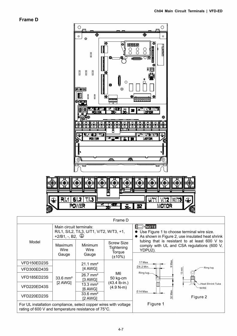
Frame D
Frame D
Model
Main circuit terminals: R/L1, S/L2, T/L3, U/T1, V/T2, W/T3, +1, +2/B1, -, B2,
NOTE Use Figure 1 to choose terminal wire size. As shown in Figure 2, use insulated heat shrink
tubing that is resistant to at least 600 V to comply with UL and CSA regulations (600 V, YDPU2).
Maximum Wire
Gauge
Minimum Wire
Gauge
Screw Size Tightening
Torque (±10%)
VFD150ED23S
33.6 mm² [2 AWG]
21.1 mm² [4 AWG]
M6 50 kg-cm
(43.4 lb-in.) (4.9 N-m)
VFD300ED43S
VFD185ED23S 26.7 mm² [3 AWG]
VFD220ED43S 13.3 mm² [6 AWG]
VFD220ED23S 33.6 mm² [2 AWG]
For UL installation compliance, select copper wires with voltage rating of 600 V and temperature resistance of 75°C.

Ch04 Main Circuit Terminals | VFD-ED
4-8
Frame E
Frame E
Model
Main circuit terminals: R/L1, S/L2, T/L3, U/T1, V/T2, W/T3, +1(DC+), -(DC-),
NOTE Use Figure 1 to choose terminal wire size. As shown in Figure 2, use insulated heat
shrink tubing that is resistant to at least 600 V to comply with UL and CSA regulations (600 V, YDPU2).
Maximum Wire
Gauge
Minimum Wire
Gauge
Screw Size Tightening
Torque (±10%)
VFD370ED43S
152 mm² [300 MCM]
53.5 mm² [1/0 AWG]
M8 200 kg-cm (173 lb-in.) (19.6 N-m)
VFD450ED43S 67.4 mm² [2/0 AWG]
VFD300ED23S 107 mm² [4/0 AWG] VFD550ED43S
VFD370ED23S 152 mm² [300 MCM] VFD750ED43S
For UL installation compliance, select copper wires with voltage rating of 600 V and temperature resistance of 75°C.

Ch05 Control Terminals | VFD-ED
5-1
Chapter 5 Control Terminals
5-1 Remove the Cover before Wiring
5-2 Control Terminal Specifications
5-3 Control Circuit Terminals

Ch05 Control Terminals | VFD-ED
5-2
5-1 Remove the Cover before Wiring
Remove the top cover before wiring the multi-function input and output terminals NOTE The motor drives’ figures shown below are for reference only. The actual motor drives may
look different.
Frames B, C & D Step 1 Step 2
Step 3

Ch05 Control Terminals | VFD-ED
5-3
Frame E Step 1 Step 2
Step 3

Ch05 Control Terminals | VFD-ED
5-4
5-2 Control Terminal Specifications

Ch05 Control Terminals | VFD-ED
5-5
5-3 Control Circuit Terminals
Terminal sockets A, B, C
Torque: 2 kg-cm [1.7 lb-in.] (0.20 Nm)
Wire gauge: 0.08–2.07 mm² [28–14 AWG]
Terminal socket D
Torque: 2 kg-cm [1.7 lb-in.] (0.20 Nm)
Terminal socket E
Torque: 5.2 kg-cm [4.5 lb-in.] (0.51 Nm)
Wire gauge: 0.08–3.33 mm² [28–12 AWG]
To comply with UL standards, use copper wires in the installation that are able to withstand 600 V, 75ºC environments.
Control Board Switch NRM = Normal
Terminals Terminal Function Default (NPN mode) +24 V / E24 V
Digital control signal common terminal (Source)
+24 V±5% 200 mA
COM Digital control signal common terminal (Sink)
Common terminal for multi-function input terminals
FWD Forward-Stop command FWD-DCM: ON = run in forward OFF = decelerate to stop
REV Reverse-Stop command REV-DCM: ON = run in reverse OFF = decelerate to stop
MI1 –
MI8 Multi-function input 1–8
Refer to parameters Pr.02-01–Pr.02-08 to program the multi-function inputs MI1–MI8. Source mode: ON: the activation current is 6.5 mA ≥ 11 VDC OFF: allowable leakage current 10 μA ≤ 11 VDC
DCM Digital frequency signal common terminal
SCM1 The default is short-circuited (E24V/STO1/STO2). The default is short-circuited (SCM1/SCM2/DCM). Power cutoff safety function for EN954-1 and IEC/EN61508. When STO1–SCM1 and STO2–SCM2 are ON, the activation current is 3.3 mA ≥ 11 VDC.
SCM2
STO1
STO2
+10 V Potentiometer power supply Power supply for analog frequency setting: +10 VDC 20 mA
-10 V Potentiometer power supply Power supply for analog frequency setting: -10 VDC 20 mA

Ch05 Control Terminals | VFD-ED
5-6
AUI1
Analog voltage frequency command
Impedance: 20 kΩ Range: -10–10 VDC = 0–Maximum Output Frequency (Pr.01-00)
AUI2
ACM Analog signal common terminal control
Analog signal common terminal
RA Multi-function relay output A (N.O.)
1. User-defined function 2. Resistive Load
3 A (N.O.) / 3 A (N.C.) 250 VAC 5 A (N.O.) /3 A (N.C.) 30 VDC (minimum 5 VDC, 10 mA)
To output different kinds of monitoring signals such as motor drive in operation, frequency reached, and overload indication.
RB Multi-function relay output A (N.C.)
RC Multi-function relay output B (Default: error indication)
MRA Multi-function output terminal (N.O.)
MRB Multi-function output terminal (N.C.)
MRC Multi-function output terminal (Default: operating Indication)
R1A Multi-function output terminal A (N.O.)
R2A Multi-function output terminal A (N.O.)
R12C Multi-function output terminal (Default: no function)
SG1+ Modbus RS-485 SG1+ switch: terminator 120 ohm (default) / open
SG1- Modbus RS-485
CAN_L CAN Bus
DIP switch: terminator 120 ohm (default) / open CAN_H CAN Bus
MO1 Multi-function output terminal 1 (photo coupler)
The AC motor drive outputs various monitoring signals, such as drive in operation, frequency reached, and overload indication through a transistor

Ch05 Control Terminals | VFD-ED
5-7
MO2 Multi-function output terminal 2 (photo coupler)
(open collector).
MCM
Multi-function output common terminal (photo coupler)
Maximum 48 VDC 50 mA
AFM1
0-10 V, max. output current: 2 mA, max. load: 5 kΩ -10–10 V, max. output current: 2 mA, max. load: 5 kΩ Maximum output current: 2 mA Resolution: 0–10 V, corresponds to the maximum operating frequency. Range: 0–10 V→ -10–10 V
AFM2
RJ45 PINS 1, 2, 6, 7: Reserved PIN 3: SGND PIN 4: SG- PIN 5: SG+ PIN 8: EV
SW2 Switching USB port DIP switch: NRM (default) / PRG (use this side of the switch to update firmware). Updating firmware should be done by qualified motor drive service personnel only. Do NOT try to update the firmware by yourself.

Ch05 Control Terminals | VFD-ED
5-8
[The page intentionally left blank]

06 Optional Accessories | VFD-ED
6-1
Chapter 6 Optional Accessories
6-1 Brake Resistors and Brake Units Used in AC Motor Drives
6-2 Non-fuse Circuit Breaker
6-3 Fuse Specification Chart
6-4 AC / DC Reactor
6-5 Zero Phase Reactor
6-6 EMC Filter
6-7 Digital Keypad
6-8 USB / RS-485 Communication Interface IFD6530

06 Optional Accessories | VFD-ED
6-2
The optional accessories listed in this chapter are available upon request. Installing additional accessories to your drive can substantially improve the drive’s performance. Select accessories according to your needs or contact your local distributor for suggestions.
6-1 Brake Resistors and Brake Units Used in AC Motor Drives
Vo
lta
ge
Applicable Motor 125% Braking Torque/10% ED *1 Max. Braking Torque*2
HP Model Braking Torque*3
(kg-m)
Brake Unit Delta’s Part No.*4 Min.
Braking Power*6
(kW)
Braking Current
(A)*7 VFDB*5 Amt. Part No. Amt. Working Method
Min. Resistor
Value (Ω)
Max. Total
Braking Current
(A)
Peak Power (kW)
230V
3 VFD022ED21S 1.5 BR300W070 1 0.22 5.4 38.0 10 3.8
5 VFD037ED21S 2.5 BR400W040 1 0.37 9.5 19.0 20 7.6
5 VFD040ED23S 2.5 BR500W030 1 0.4 9.5 19.0 20 7.6
7.5 VFD055ED23S 3.7 BR1K0W020 1 0.55 19.0 15.6 24.4 9.3
10 VFD075ED23S 5.1 BR1K0W016 1 0.75 19.0 11.5 33 12.5
15 VFD110ED23S 7.5 BR1K5W013 1 1.1 29.2 9.5 40 15.2
20 VFD150ED23S 10.2 BR1K0W4P3 2 2 parallel 1.5 44.2 8.3 46 17.5
25 VFD185ED23S 12.2 BR1K0W016 2 2 serial 1.85 44.2 5.8 66 25.1
30 VFD220ED23S 14.9 BR1K5W3P3 2 2 parallel 2.2 57.6 5.8 66 25.1
40 VFD300ED23S 20.3 2015 2 BR1K0W5P1 4 2 serial
2 parallel 3 74.5 4.8 80 30.4
50 VFD370ED23S 25.1 2022 2 BR1K2W3P9 4 2 serial
2 parallel 3.7 97.4 3.2 120 45.6
460V
5 VFD040ED43S 2.7 BR1K0W075 1 0.4 10.1 54.3 14 10.6
7.5 VFD055ED43S 3.7 BR1K0W075 1 0.55 10.1 48.4 15.7 11.9
10 VFD075ED43S 5.1 BR1K0W075 1 0.75 10.1 48.4 15.7 11.9
15 VFD110ED43S 7.5 BR1K5W043 1 1.1 17.7 30.8 24.7 18.8
20 VFD150ED43S 10.1 BR1K0W016 2 2 parallel 1.5 23.8 25.0 30.4 23.1
25 VFD185ED43S 12.5 BR1K0W016 2 2 parallel 1.85 23.8 20.8 36.5 27.7
30 VFD220ED43S 14.9 BR1K5W013 2 2 parallel 2.2 29.2 19.0 40 30.4
40 VFD300ED43S 20.3 BR1K0W016 4 2 serial
2 parallel 3 47.5 14.1 54 41.0
50 VFD370ED43S 25.0 4045 1 BR1K2W015 4 2 serial
2 parallel 3.7 50.7 12.7 60 45.6
60 VFD450ED43S 30.4 4045 1 BR1K5W013 4 2 serial
2 parallel 4.5 58.5 12.7 60 45.6
75 VFD550ED43S 37.2 4030 2 BR1K0W5P1 4 2 serial
4 parallel 5.5 74.5 9.5 80 60.8
100 VFD750ED43S 50.7 4045 2 BR1K2W015 8 4 serial
2 parallel 7.5 101.3 6.3 120 91.2
*1 Calculation of 125% braking torque: (kW)*125%*0.8; where 0.8 is the motor efficiency. Since there is a resistor power consumption limit, the longest operation time for 10% ED is 10 seconds (ON: 10 seconds / OFF: 90 seconds). 10% ED applies for IM motor elevator system.
*2 Refer to the Brake Performance Curve for “Operation Duration & ED (%)” versus “Braking Current”. *3 The calculation of the braking torque is based on a four-pole motor (1800 rpm). *4 To dissipate heat, fix a resistor of 400 W or lower to the frame to maintain the surface temperature below 250°C
(482°F). Fix a resistor of 1000 W or higher to a surface to maintain the surface temperature below 600°C (1112°F). If the surface temperature is higher than the temperature limit, install more heat dissipating systems or increase the size of the resistor.
*5 Refer to VFDB series Braking Module Instruction for more details on the braking resistor. *6 The braking resistor should be able to endure 10 times the overload capacity. *7 The calculation of the braking current is based on Delta’s braking resistor and default braking voltage (220V:
380V; 440V: 760V).
06 Optional Accessories | VFD-ED
6-3
Vo
lta
ge
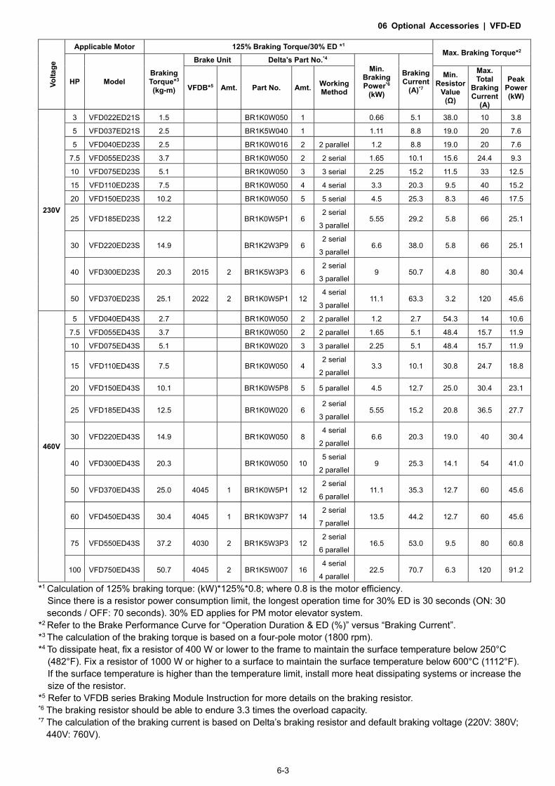
Applicable Motor 125% Braking Torque/30% ED *1
Max. Braking Torque*2
HP Model Braking Torque*3
(kg-m)
Brake Unit Delta’s Part No.*4 Min.
Braking Power*6
(kW)
Braking Current
(A)*7 VFDB*5 Amt. Part No. Amt. Working Method
Min. Resistor
Value (Ω)
Max. Total
Braking Current
(A)
Peak Power (kW)
230V
3 VFD022ED21S 1.5 BR1K0W050 1 0.66 5.1 38.0 10 3.8
5 VFD037ED21S 2.5 BR1K5W040 1 1.11 8.8 19.0 20 7.6
5 VFD040ED23S 2.5 BR1K0W016 2 2 parallel 1.2 8.8 19.0 20 7.6
7.5 VFD055ED23S 3.7 BR1K0W050 2 2 serial 1.65 10.1 15.6 24.4 9.3
10 VFD075ED23S 5.1 BR1K0W050 3 3 serial 2.25 15.2 11.5 33 12.5
15 VFD110ED23S 7.5 BR1K0W050 4 4 serial 3.3 20.3 9.5 40 15.2
20 VFD150ED23S 10.2 BR1K0W050 5 5 serial 4.5 25.3 8.3 46 17.5
25 VFD185ED23S 12.2 BR1K0W5P1 6 2 serial
3 parallel 5.55 29.2 5.8 66 25.1
30 VFD220ED23S 14.9 BR1K2W3P9 6 2 serial
3 parallel 6.6 38.0 5.8 66 25.1
40 VFD300ED23S 20.3 2015 2 BR1K5W3P3 6 2 serial
3 parallel 9 50.7 4.8 80 30.4
50 VFD370ED23S 25.1 2022 2 BR1K0W5P1 12 4 serial
3 parallel 11.1 63.3 3.2 120 45.6
460V
5 VFD040ED43S 2.7 BR1K0W050 2 2 parallel 1.2 2.7 54.3 14 10.6
7.5 VFD055ED43S 3.7 BR1K0W050 2 2 parallel 1.65 5.1 48.4 15.7 11.9
10 VFD075ED43S 5.1 BR1K0W020 3 3 parallel 2.25 5.1 48.4 15.7 11.9
15 VFD110ED43S 7.5 BR1K0W050 4 2 serial
2 parallel 3.3 10.1 30.8 24.7 18.8
20 VFD150ED43S 10.1 BR1K0W5P8 5 5 parallel 4.5 12.7 25.0 30.4 23.1
25 VFD185ED43S 12.5 BR1K0W020 6 2 serial
3 parallel 5.55 15.2 20.8 36.5 27.7
30 VFD220ED43S 14.9 BR1K0W050 8 4 serial
2 parallel 6.6 20.3 19.0 40 30.4
40 VFD300ED43S 20.3 BR1K0W050 10 5 serial
2 parallel 9 25.3 14.1 54 41.0
50 VFD370ED43S 25.0 4045 1 BR1K0W5P1 12 2 serial
6 parallel 11.1 35.3 12.7 60 45.6
60 VFD450ED43S 30.4 4045 1 BR1K0W3P7 14 2 serial
7 parallel 13.5 44.2 12.7 60 45.6
75 VFD550ED43S 37.2 4030 2 BR1K5W3P3 12 2 serial
6 parallel 16.5 53.0 9.5 80 60.8
100 VFD750ED43S 50.7 4045 2 BR1K5W007 16 4 serial
4 parallel 22.5 70.7 6.3 120 91.2
*1 Calculation of 125% braking torque: (kW)*125%*0.8; where 0.8 is the motor efficiency. Since there is a resistor power consumption limit, the longest operation time for 30% ED is 30 seconds (ON: 30 seconds / OFF: 70 seconds). 30% ED applies for PM motor elevator system.
*2 Refer to the Brake Performance Curve for “Operation Duration & ED (%)” versus “Braking Current”. *3 The calculation of the braking torque is based on a four-pole motor (1800 rpm). *4 To dissipate heat, fix a resistor of 400 W or lower to the frame to maintain the surface temperature below 250°C
(482°F). Fix a resistor of 1000 W or higher to a surface to maintain the surface temperature below 600°C (1112°F). If the surface temperature is higher than the temperature limit, install more heat dissipating systems or increase the size of the resistor.
*5 Refer to VFDB series Braking Module Instruction for more details on the braking resistor. *6 The braking resistor should be able to endure 3.3 times the overload capacity. *7 The calculation of the braking current is based on Delta’s braking resistor and default braking voltage (220V: 380V;
440V: 760V).

06 Optional Accessories | VFD-ED
6-4
NOTE
1. Select the resistance value, power and brake usage (ED %) according to Delta rules. Definition for Brake Usage ED%
For safety, install a thermal overload relay between the brake unit and the brake resistor in conjunction with the magnetic contactor (MC) before the drive for additional protection. The thermal overload relay protects the brake resistor from damage due to frequent or continuous braking. Under such circumstances, turn off the power to prevent damage to the brake resistor.
2. Any damage to the drive or other equipment caused by using brake resistors and brake modules that are not provided by Delta voids the warranty.
3. Consider environmental safety factors when installing the brake resistors. If you use the minimum resistance value, consult your local dealers for the power calculation.
4. When using more than two brake units, the equivalent resistor value of parallel brake unit cannot be less than
the value in the column “Minimum Resistor Value (Ω)”. Read the wiring information in the brake unit user manual thoroughly prior to operation.
5. This chart is for normal use. If the AC motor drive requires frequent braking, increase the Watts by two to three
times. 6. Use the following graph to select the thermal relay.

06 Optional Accessories | VFD-ED
6-5
Thermal Relay: Thermal relay selection is based on its
overload capacity. A standard braking capacity
of ED is 10% ED (Tripping time = 10 sec.). The
figure on the left is an example of a 460V, 110
kW AC motor drive. It requires the thermal
relay to take 260% overload capacity for 10
sec. (hot starting) and the braking current is
126 A. In this case, select a thermal relay rated
at 50 A. The property of each thermal relay
may vary among different manufacturers.
Carefully read the thermal relay user guide
before using it.

06 Optional Accessories | VFD-ED
6-6
6-2 Non-fuse Circuit Breaker
Comply with the UL standard: Per UL 508, paragraph 45.8.4, part a. The rated current of a breaker shall be two to four times the maximum rated input current of the AC motor drive.
One-phase/Three-phase Three-phase
Model Recommended non-fuse breaker (A)
Model Recommended non-fuse breaker (A)
VFD022ED21S* 50 VFD040ED43S 30 VFD037ED21S* 75 VFD055ED43S 35 VFD040ED23S 40 VFD075ED43S 40 VFD055ED23S 50 VFD110ED43S 50 VFD075ED23S 60 VFD150ED43S 60 VFD110ED23S 100 VFD185ED43S 75 VFD150ED23S 125 VFD220ED43S 100 VFD185ED23S 150 VFD300ED43S 125 VFD220ED23S 175 VFD370ED43S 150 VFD300ED23S 250 VFD450ED43S 200 VFD370ED23S 300 VFD550ED43S 250
VFD750ED43S 350
* VFD022ED21S and VFD037ED21S are one-phase models.
6-3 Fuse Specification Chart
Fuse specifications lower than the table below are allowed.
Model Input Current (A) Line Fuse
I (A) Bussmann P/N VFD022ED21S 26 60 JJN-60 VFD037ED21S 37 90 JJN-90 VFD040ED23S 20 50 JJN-50 VFD055ED23S 23 60 JJN-60 VFD075ED23S 30 80 JJN-80 VFD110ED23S 47 125 JJN-125 VFD150ED23S 56 150 JJN-150 VFD185ED23S 73 175 JJN-175 VFD220ED23S 90 225 JJN-225 VFD300ED23S 132 300 JJN-300 VFD370ED23S 161 400 JJN-400
VFD040ED43S 11.5 35 JJS-35 VFD055ED43S 14 40 JJS-40 VFD075ED43S 17 45 JJS-45 VFD110ED43S 24 60 JJS-60 VFD150ED43S 30 80 JJS-80 VFD185ED43S 37 90 JJS-90 VFD220ED43S 47 110 JJS-110 VFD300ED43S 58 150 JJS-150 VFD370ED43S 80 200 JJS-200 VFD450ED43S 100 250 JJS-250 VFD550ED43S 128 300 JJS-300 VFD750ED43S 165 400 JJS-400

06 Optional Accessories | VFD-ED
6-7
6-4 AC / DC Reactor
AC Input Reactor
Installing an AC reactor on the input side of an AC motor drive can increase line impedance, improve the power factor, reduce input current, increase system capacity, and reduce interference generated from the motor drive. It also reduces momentary voltage surges or abnormal current spikes. For example, when the main power capacity is higher than 500 kVA, or when using a switching capacitor bank, momentary peak voltage and current spikes may damage the AC motor drive’s internal circuit. An AC reactor on the input side of the AC motor drive protects it by suppressing surges.
Installation Install an AC input reactor in series between the main power and the three input phases R S T, as shown in the figure below:
Connecting an AC Input Reactor
DC Reactor
A DC reactor can also increase line impedance, improve the power factor, reduce input current, increase system power, and reduce interference generated from the motor drive. A DC reactor stabilizes the DC BUS voltage. Compared with an AC input reactor, a DC reactor is in smaller size, lower price, and lower voltage drop (lower power dissipation).
Installation Install a DC reactor between terminals +1(DC+) and +2/B1(DC+). Remove the DC reactor jumper, as shown in the figure below, before installing a DC reactor.

06 Optional Accessories | VFD-ED
6-8
Installing a DC reactor THD (Total Harmonic Distortion) The table below shows the THDi specification when using Delta's drives (three-phase power models) to work with AC/DC reactors.
Motor Drive
Spec. Models without
AC/DC Reactors
Models without
Built-in DC Reactors
Models with
Built-in DC Reactors
Reactors in
Series Spec.
3% Input
AC Reactor
5% Input
AC Reactor
4%
DC Reactor
3% Input
AC Reactor
5% Input
AC Reactor
5th 73.3% 38.5% 30.8% 25.5% 27.01% 25.5%
7th 52.74% 15.3% 9.4% 18.6% 9.54% 8.75%
11th 7.28% 7.1% 6.13% 7.14% 4.5% 4.2%
13th 0.4% 3.75% 3.15% 0.48% 0.22% 0.17%
THDi 91% 43.6% 34.33% 38.2% 30.5% 28.4%
Note THDi may vary due to different installation conditions and environment (wires, motors).
THDi Specification
Note: For three-phase power models, Delta provides 4% DC reactors and 3% AC reactors. Refer to the following sections to select your applicable reactors.

06 Optional Accessories | VFD-ED
6-9
AC Output Reactor
When using drives in long wiring output application, ground fault (GFF), over-current (OC) and motor over-voltage (OV) often occur. GFF and OC cause errors due to the drive's self-protective mechanism; over-voltage damages motor insulation.
The excessive length of the output wires makes the grounded stray capacitance too large, increase the three-phase output common mode current, and the reflected wave of the long wires makes the motor dv / dt and the motor terminal voltage too high. Thus, installing a reactor on the drive’s output side can increases the high-frequency impedance to reduce the dv / dt and terminal voltage to protect the motor.
Installation Install an AC output reactor in series between the three output phases U V W and the motor, as shown in the figure below:
Connecting an AC output reactor
Applicable Reactors 200V–230V/ 50–60Hz (One-phase power)
Model Rated
Current (Arms)
Saturation Current (Arms)
AC Input Reactors
(mH)
AC Input Reactors Delta part#
AC Output Reactors
(mH)
AC Output Reactors Delta Part #
VFD022ED21S 12 24 1.172 DR025D0117 2.02 DR012L0202
VFD037ED21S 17 34 0.574 DR049DP574 1.17 DR018L0117
200V–230V/ 50–60Hz (Three-phase power)
Model Rated
Current (Arms)
Saturation Current (Arms)
AC Input / Output Reactors
(mH)
AC Input / Output Reactors
Delta part #
DC Reactors
(mH)
DC Reactors Delta Part #
VFD040ED23 20 40 0.507 DR025AP507 DR025LP507 NA* NA*
VFD055ED23 24 48 0.507 DR025AP507 DR025LP507 1.17 DR025D0117
VFD075ED23 30 60 0.32 DR033AP320 DR033LP320 0.851 DR033DP851
VFD110ED23 45 90 0.215 DR049AP215 DR049LP215 0.574 DR049DP574
VFD150ED23 58 116 0.162 DR065AP162 DR065LP162 0.432 DR065DP432

06 Optional Accessories | VFD-ED
6-10
Model Rated
Current (Arms)
Saturation Current (Arms)
AC Input / Output Reactors
(mH)
AC Input / Output Reactors
Delta part #
DC Reactors
(mH)
DC Reactors Delta Part #
VFD185ED23 77 154 0.141 DR090AP141 DR090LP141 0.325 DR090DP325
VFD220ED23 87 174 0.141 DR090AP141 DR090LP141 0.325 DR090DP325
VFD300ED23 132 264 0.087 DR146AP087 DR146LP087 NA** NA**
VFD370ED23 161 322 0.07 DR180AP070 DR180LP070 NA** NA**
Note: NA* stands for not being able to install this accessory; NA** stands for built-in accessory.
380V–460V/ 50–60Hz (Three-phase power)
Model Rated
Current (Arms)
Saturation Current (Arms)
AC Input / Output Reactors
(mH)
AC Input / Output Reactors
Delta part #
DC Reactors
(mH)
DC Reactors Delta Part #
VFD040ED43S 11.5 23 2.31 DR010A0231 DR010L0231 NA* NA*
VFD055ED43S 13 26 2.02 DR012A0202 DR012L0202 4.67 DR012D0467
VFD075ED43S 17 34 1.17 DR018A0117 DR018L0117 3.11 DR018D0311
VFD110ED43S 23 46 0.881 DR024AP881 DR024LP881 2.33 DR024D0233
VFD150ED43S 30 60 0.66 DR032AP660 DR032LP660 1.75 DR032D0175
VFD185ED43S 38 76 0.639 DR038AP639 DR038LP639 1.47 DR038D0147
VFD220ED43S 45 90 0.541 DR045AP541 DR045LP541 1.24 DR045D0124
VFD300ED43S 58 116 0.405 DR060AP405 DR060LP405 0.935 DR060DP935
VFD370ED43S 80 160 0.267 DR091AP267 DR091LP267 NA** NA**
VFD450ED43S 100 200 0.221 DR110AP221 DR110LP221 NA** NA**
VFD550ED43S 128 256 0.162 DR150AP162 DR150LP162 NA** NA**
VFD750ED43S 165 330 0.135 DR180AP135 DR180LP135 NA** NA**
Note: NA* stands for not being able to install this accessory; NA** stands for built-in accessory.

06 Optional Accessories | VFD-ED
6-11
Reactor Dimensions
AC input reactor dimension and specifications:
Unit: mm
Input Reactors Delta Part # A B C D1*D2 E G1 G2 PE D
DR005A0254 100 115 65 6*9 45 60 40 M4
DR008A0159 100 115 65 6*9 45 60 40 M4
DR011A0115 130 135 95 6*12 60 80.5 60 M4
DR017AP746 130 135 100 6*12 65 80.5 60 M4
Tightening torque:0.6–0.8 Nm PE MD
Tightening torque: F Nm

06 Optional Accessories | VFD-ED
6-12
Unit: mm
Input Reactors Delta Part # A B C D1*D2 H G1 G2 PE D
DR025AP215 130 195 100 6*12 65 80.5 60 M4
DR033AP163 130 195 100 6*12 65 80.5 60 M4
DR049AP163 160 200 125 6*12 90 107 75 M4
Tightening torque: F Nm
Installing screw: M5
PE MD
06 Optional Accessories | VFD-ED
6-13
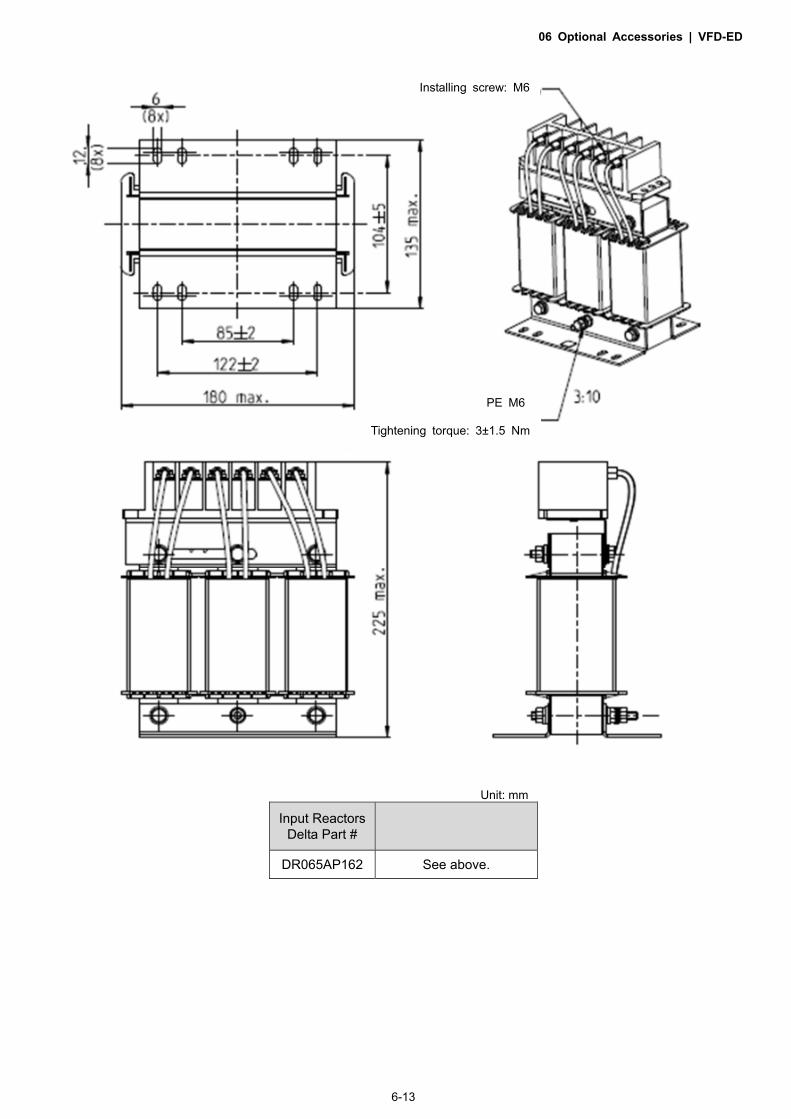
Unit: mm
Input Reactors Delta Part #
DR065AP162 See above.
Installing screw: M6
Tightening torque: 3±1.5 Nm
PE M6

06 Optional Accessories | VFD-ED
6-14
Unit: mm
Input Reactors Delta Part #
DR075AP170 See above.
PE M8 x 23 Tightening torque: 6±0.3 Nm
Terminal gauge: 4 mm2 Tightening torque: 0.8–1.0 Nm

06 Optional Accessories | VFD-ED
6-15
Unit: mm
Input Reactors Delta Part #
DR090AP141 See above.
Terminal gauge: 4 mm2 Tightening torque: 0.8–1.0 Nm
PE M8 x 23 Tightening torque: 6±0.3Nm

06 Optional Accessories | VFD-ED
6-16
Unit: mm
Input Reactors Delta Part #
DR105AP106 See above.
Terminal gauge: 4 mm2 Tightening torque: 0.8–1.0 Nm
PE M8 x 23 Tightening torque: 6±0.3 Nm

06 Optional Accessories | VFD-ED
6-17
Unit: mm
Input Reactors Delta Part #
DR146AP087 See above.
Terminal gauge: 4 mm2 Tightening torque: 0.6–0.8 Nm
PE M8 x 23 Tightening torque: 6±0.3 Nm

06 Optional Accessories | VFD-ED
6-18
Unit: mm
Input Reactors Delta Part #
DR180AP070 See above.
Terminal gauge: 4 mm2 Tightening torque: 0.6–0.8 Nm
PE M8 x 23 Tightening torque: 6±0.3 Nm

06 Optional Accessories | VFD-ED
6-19
Unit: mm
Input Reactors Delta Part # A B C D1*D2 H G1 G2 PE D
DR003A0810 100 125 65 6*9 43 60 40 M4
DR004A0607 100 125 65 6*9 43 60 40 M4
DR006A0405 130 15 95 6*12 60 80.5 60 M4
DR009A0270 160 160 105 6*12 75 107 75 M4
DR010A0231 160 160 115 6*12 90 107 75 M4
DR012A0202 160 160 115 6*12 90 107 75 M4
DR018A0117 160 160 115 6*12 90 107 75 M4
Tightening torque: F Nm
PE MD
Tightening torque: 0.6–0.8 Nm

06 Optional Accessories | VFD-ED
6-20
Unit: mm
Input Reactors Delta Part # A B C D1*D2 H G1 G2 PE D
DR024AP881 160 175 115 6*12 90 107 75 M4
DR032AP660 195 200 145 6*12 115 122 85 M6
DR038AP639 190 200 145 6*12 115 122 85 M6
DR045AP541 190 200 145 6*12 115 122 85 M6
Installing screw: M5
PE MD
Tightening torque: F Nm

06 Optional Accessories | VFD-ED
6-21
Unit: mm
Input Reactors Delta Part #
DR060AP405 See above.
Installing screw: M6
PE M6
Tightening torque: 3±1.5 Nm

06 Optional Accessories | VFD-ED
6-22
Unit: mm
Input Reactors Delta Part # A A1 B B1 B2 C D D1*D2 E C1 G1 G2 H
DR073AP334 228 240 215 40 170 133 8.5 7*13 152 75 176 200 97
DR091AP267 228 240 245 40 195 133 8.8 7*13 152 90 176 200 97
DR110AP221 228 240 245 40 195 138 8.5 7*13 152 75 176 200 102
1:5 Terminal gauge: 4 mm2 Tightening torque: 0.8–1.0 Nm
PE M8 x 23 Tightening torque: 6±0.3 Nm

06 Optional Accessories | VFD-ED
6-23
Unit: mm
Input Reactors Delta Part # A A1 B B1 B2 C C1 D D1*D2 F G1 G2 H M*T
DR150AP162 240 250 245 40 200 151 105 9 11*18 160 190 220 125 20*3
DR180AP135 240 250 245 40 200 151 105 9 11*18 160 190 220 125 20*3
DR220AP110 264 270 275 50 230 151 105 9 10*18 176 200 230 106 30*3
DR260AP098 264 270 285 50 240 151 105 9 10*18 176 200 230 106 30*3
DR310AP078 300 300 345 55 295 153 105 9 10*18 200 224 260 113 30*3
DR370AP066 300 300 345 55 295 158 120 9 10*18 200 224 260 118 50*4
PE M8 x 23 Tightening torque: 6±0.3 Nm
1:5 Terminal gauge: 4 mm2 Tightening torque: 0.8–1.0 Nm

06 Optional Accessories | VFD-ED
6-24
DC reactor dimension and specifications:
C
A
D
E
B
R
Unit: mm DC Reactors Delta Part # A B C D E R
DR005D0585 79 78 112 64±2 56±2 9.5*5.5 DR008D0366 79 78 112 64±2 56±2 9.5*5.5 DR011D0266 79 92 112 64±2 69.5±2 9.5*5.5 DR017D0172 79 112 112 64±2 89.5±2 9.5*5.5 DR025D0117 99 105 128 79±2 82.5±2 9.5*5.5 DR033DP851 117 110 156 95±2 87±2 10*6.5 DR049DP574 117 120 157 95±2 97±2 10*6.5 DR065DP432 117 140 157 95±2 116.5±2 10*6.5 DR075DP391 136 135 178 111±2 112±2 10*6.5 DR090DP325 136 135 179 111±2 112±2 10*6.5 DR003D1870 79 78 112 64±2 56±2 9.5*5.5 DR004D1403 79 92 112 64±2 69.5±2 9.5*5.5 DR006D0935 79 92 112 64±2 69.5±2 9.5*5.5 DR009D0623 79 112 112 64±2 89.5±2 9.5*5.5 DR010D0534 99 93 128 79±2 70±2 9.5*5.5 DR012D0467 99 105 128 79±2 82.5±2 9.5*5.5 DR018D0311 117 110 144 95±2 87±2 10*6.5 DR024D0233 117 120 144 95±2 97±2 10*6.5 DR032D0175 117 140 157 95±2 116.5±2 10*6.5 DR038D0147 136 135 172 111±2 112±2 10*6.5 DR045D0124 136 135 173 111±2 112±2 10*6.5 DR060DP935 136 150 173 111±2 127±2 10*6.5

06 Optional Accessories | VFD-ED
6-25
AC output reactor dimension and specifications:
Unit: mm
Output Reactors
Delta Part # A B C D1*D2 E G1 G2 PE D
DR005L0254 96 110 70 6*9 42 60 40 M4
DR008L0159 120 135 96 6*12 60 80.5 60 M4
DR011L0115 120 135 96 6*12 60 80.5 60 M4
DR017LP746 120 135 105 6*12 65 80.5 60 M4
DR025LP507 150 160 120 6*12 88 107 75 M4
DR033LP320 150 160 120 6*12 88 107 75 M4
Tightening torque: 0.6–0.8 Nm Tightening torque: 1.0–1.2 Nm
Screw length must
not interfere with the
mounting holes.

06 Optional Accessories | VFD-ED
6-26
Unit: mm
Output Reactors
Delta Part # A B C D1*D2 H G G1 Q M PE D
DR049LP215 180 205 175 6*12 115 85 122 16 1.2-1.4 M4
DR065LP162 180 215 185 6*12 115 85 122 35 2.5-3.0 M4
Screw length must
not interfere with the
mounting holes.
Terminal gauge: 16 mm2 Tightening torque: 1.2–1.4 Nm

06 Optional Accessories | VFD-ED
6-27
Unit: mm
Output Reactors
Delta Part # A A1 B B1 B2 C C1 D1*D2 E G1 H M*T
DR075LP170 240 228 215 44 170 151 100 7*13 152 176 85 20*3
DR090LP141 240 228 215 44 170 151 100 7*13 152 176 85 20*3
DR105LP106 240 228 215 44 170 165 110 7*13 152 176 97 20*3
DR146LP087 240 228 240 45 202 165 110 7*13 152 176 97 30*3
DR180LP070 250 240 250 46 205 175 110 11*18 160 190 124 30*5

06 Optional Accessories | VFD-ED
6-28
Unit: mm
Output Reactors
Delta Part # A B C D1*D2 H G1 G2 PE D
DR003L0810 96 115 65 6*9 42 60 40 M4
DR004L0607 120 135 95 6*12 60 80.5 60 M4
DR006L0405 120 135 95 6*12 60 80.5 60 M4
DR009L0270 150 160 100 6*12 74 107 75 M4
DR010L0231 150 160 115 6*12 88 107 75 M4
DR012L0202 150 160 115 6*12 88 107 75 M4
DR018L0117 150 160 115 6*12 88 107 75 M4
DR024LP881 150 160 115 6*12 88 107 75 M4
DR032LP660 180 190 145 6*12 114 122 85 M6
Tightening torque: 0.6–0.8 Nm Tightening torque: 1.0–1.2 Nm
Screw length must
not interfere with
the mounting holes.

06 Optional Accessories | VFD-ED
6-29
Unit: mm
Output Reactors
Delta Part # A B C D1*D2 H G1 G2 PE D
DR038LP639 180 205 170 6*12 115 85 122 M4
DR045LP541 235 245 155 7*13 85 / 176 M6
Screw length must
not interfere with the
mounting holes.
Terminal gauge: 16 mm2 Tightening torque: 1.2–1.4 Nm

06 Optional Accessories | VFD-ED
6-30
Unit: mm
Output Reactors
Delta Part # A A1 B B1 B2 C C1 D1*D2 E G1 H M*T
DR060LP405 240 228 215 44 170 163 110 7*13 152 176 97 20*3
DR073LP334 250 235 235 44 186 174 115 11*18 160 190 124 20*3
DR091LP267 250 240 235 44 186 174 115 11*18 160 190 124 20*3
DR110LP221 270 260 245 50 192 175 115 10*18 176 200 106 20*3

06 Optional Accessories | VFD-ED
6-31
Unit: mm
Output Reactors
Delta Part # A A1 B B1 B2 C C1 D1*D2 E G1 G2 H M*T
DR150LP162 270 264 265 51 208 192 125 10*18 176 200 / 118 30*3
DR180LP135 300 295 310 55 246 195 125 11*22 200 230 190 142 30*3

06 Optional Accessories | VFD-ED
6-32
6-5 Zero Phase Reactor
You can also suppress interference by installing a zero phase reactor at the main input or the motor output of the drive, depending on the location of the interference. Due to the large current passed through the main input/motor output side, pay attention to core saturation issue. Delta provides two types of zero phase reactors to solve interference problems.
A. Casing with mechanical fixed part
The ideal material for withstanding large current loaded for the zero phase reactor at the main input/motor output is composite core. Core has strong saturation, and its strong resistance are many times of simple metal magnetic materials. Thus it can be used for high frequencies and you can get higher impedance by increasing the number of turns.
AD
CB
E
G
F
Unit: mm [inch]
Model A B C D E F G(Ø) Torque
RF008X00A 98 [3.858]
73 [2.874]
36.5 [1.437]
29 [1.142]
56.5 [2.224]
86 [3.386]
5.5 [0.217] 8–10 kgf/cm
RF004X00A 110 [4.331]
87.5 [3.445]
43.5 [1.713]
36 [1.417]
53 [2.087]
96 [3.780]
5.5 [0.217] 8–10 kgf/cm
D
BC
E
F
HG
Unit: mm [inch]
Model A B C D E F G(Ø) H Torque
RF002X00A 200 [7.874]
172.5 [6.791]
90 [3.543]
78 [3.071]
55.5 [2.185]
184 [7.244]
5.5 [0.217]
22 [0.866] 40–45 kgf/cm

06 Optional Accessories | VFD-ED
6-33
Unit: mm [inch]
Model A B C D E F G(Ø) H I
RF300X00A 241 [9.488]
217 [8.543]
114 [4.488]
155 [6.102]
42 [1.654]
220 [8.661]
6.5 [0.256]
7.0 [0.276]
20 [0.787]
Torque: 40–45 kgf/cm
B. Casing without mechanical fixed part
Adopts nanocrystalline core developed by VACR , and has high initial magnetic permeability, high saturation induction density, low iron loss and perfect temperature characteristic. If the zero phase reactor does not need to be fixed mechanically, use this solution.
Unit: mm
Model A B C Function
T60006L2040W453 22.5 43.1 18.5 Motor wire
T60006L2050W565 36.3 53.5 23.4 Motor wire
T60006L2160V066 166.9 123.9 30.5 Motor wire
T60004L2016W620 10.7 17.8 8.0 Signal line
T60004L2025W622 17.5 27.3 12.3 Signal line

06 Optional Accessories | VFD-ED
6-34
Reactor Model
(See Note) Recommended Wire Size Wiring
Method Qty Applicable Motor Drives
RF008X00A T60006L2040W453
≤ 8 AWG ≤ 8.37 mm2 Diagram A Diagram B
1 VFD022ED21S VFD037ED21S VFD040ED23S VFD040ED43S
RF004X00A T60006L2050W565
≤ 4 AWG ≤ 21.15 mm2 Diagram A Diagram B
1
VFD055ED23S VFD075ED23S VFD110ED23S VFD055ED43S VFD075ED43S VFD110ED43S VFD150ED43S VFD185ED43S
RF002X00A T60006L2160V066
≤ 2 AWG ≤ 33.62 mm2 Diagram A Diagram B
1 VFD150ED23S VFD185ED23S VFD220ED23S VFD220ED43S VFD300ED43S
RF300X00A T60006L2160V066
≤ 300 MCM ≤ 152 mm2 Diagram A Diagram B
1 VFD300ED23S VFD370ED23S VFD370ED43S VFD450ED43S VFD550ED43S VFD750ED43S
Note: 600 V insulated cable wire
Installation
During installation, pass the cable through at least one zero phase reactor. Use a suitable cable type (insulation class and wire section) so that the cable passes easily through the zero phase reactor. Do not pass the grounding cable through the zero phase reactor; only pass the motor wire through the zero phase reactor. With longer motor cables the zero-phase reactor can effectively reduce interference at the motor output. Install the zero-phase reactor as close to the output of the drive as possible. Diagram A shows the installation diagram for a single turn zero phase reactor. If the wire diameter allows several turns, Diagram B shows the installation of a multi-turn zero phase reactor. The more turns, the better the noise suppression effect.
Diagram A. Single turn wiring diagram for shielding wire with a zero phase reactor
Diagram B. Multi-turn zero phase reactor

06 Optional Accessories | VFD-ED
6-35
Installation Precaution
Install the zero phase reactor at the drive’s output terminal (U/T1, V/T2, W/T3). After the zero phase reactor is installed, it reduces the electromagnetic radiation and load stress emitted by the wiring of the frequency converter. The number of zero phase reactors required for the drive depends on the wiring length and the drive voltage.
The normal operating temperature of the zero phase reactor should be lower than 85°C (176°F). However, when the zero phase reactor is saturated, its temperature may exceed 85°C (176°F). In this case, increase the number of zero phase reactors to avoid saturation. The following are reasons that might cause saturation of the zero phase reactors: the drive wiring is too long; the drive has several sets of loads; the wiring is in parallel; or the drive uses high capacitance wiring. If the temperature of the zero phase reactor exceeds 85°C (176°F) during the operation of the drive, increase the number of zero phase reactors.
Recommended maximum wiring gauge when installing zero phase reactor:
Zero Phase Reactor
Model No.
Max. Wire Gauge or
LUG width
Max. Wire Gauge AWG (1 C*3) Max. Wire Gauge AWG (4 C*1)
75 C 90 C 75 C 90 C
RF008X00A 13 MM 3 AWG 1 AWG 3 AWG 1 AWG
RF004X00A 16 MM 1 AWG 2/0 AWG 1 AWG 1/0 AWG
RF002X00A 36 MM 600 MCM 600 MCM 1 AWG 1/0 AWG
RF300X00A 73 MM 650 MCM 650 MCM 300 MCM 300 MCM
T60006L2040W453 11 MM 9 AWG 4 AWG 6 AWG 6 AWG
T60006L2050W565 16 MM 1 AWG 2/0 AWG 1 AWG 1/0 AWG
T60006L2160V066 57 MM 600 MCM 600 MCM 300 MCM 300 MCM

06 Optional Accessories | VFD-ED
6-36
6-6 EMC Filter
The table below shows external EMC filter models for each ED-S series motor drive. Choose corresponding zero phase reactors and applicable shielding cables according to the required noise emission and electromagnetic interference rating for the best configuration and anti-interference performance. If radiation emission (RE) is not a concern on site and you only need conducted emission (CE) to reach EN55011 Class A, you do not need to install a zero phase reactor on the input side to reach the EMC standard.
220V Models
VFD-ED
EMC Filter Model #
Zero Phase Reactor
Carrier Frequency
EN12015
Frame Motor Drive
Model #
Rated Input
Current (A)
Input Side (R/S/T)
Conducted Emission
Radiation Emission
Length of Output Shielded Cable
50 m
B
VFD022ED21S 24 B84142A0042R122 RF008X00A or T60006L2040W453
Carrier frequency by
default
CLASS A CLASS A
VFD037ED21S 34 B84142A0042R122 RF008X00A or T60006L2040W453 CLASSA CLASSA
VFD040ED23S 20 EMF035A23A RF008X00A or T60006L2040W453 CLASS A CLASS A
C
VFD055ED23S 23 EMF056A23A RF004X00A or T60006L2050W565 CLASS A CLASS A
VFD075ED23S 30 EMF056A23A RF004X00A or T60006L2050W565 CLASS A CLASS A
VFD110ED23S 47 EMF056A23A RF004X00A or T60006L2050W565 CLASS A CLASS A
D
VFD150ED23S 56 B84143D0150R127 RF002X00A or T60006L2160V066 CLASS A CLASS A
VFD185ED23S 73 B84143D0150R127 RF002X00A or T60006L2160V066 CLASS A CLASS A
VFD220ED23S 90 B84143D0150R127 RF002X00A or T60006L2160V066 CLASS A CLASS A
E VFD300ED23S 132 B84143D0150R127 RF002X00A or
T60006L2160V066 CLASS A CLASS A
VFD370ED23S 161 B84143D0200R127 RF300X00A or T60006L2160V066 CLASS A CLASS A
460V Models
VFD-ED
EMC Filter Model #
Zero Phase Reactor
Carrier Frequency
EN12015
Frame Motor Drive
Model #
Rated Input
Current (A)
Input Side (R/S/T)
Conducted Emission
Radiation Emission
Length of Output Shielded Cable
50 m
B VFD040ED43S 11.5 EMF018A43A RF008X00A or T60006L2040W453
Carrier frequency by
default
CLASS A CLASS A
C
VFD055ED43S 14 EMF033A43A RF004X00A or T60006L2050W565 CLASSA CLASS A
VFD075ED43S 17 EMF033A43A RF004X00A or T60006L2050W565 CLASS A CLASS A
VFD110ED43S 24 EMF033A43A RF004X00A or T60006L2050W565 CLASS A CLASS A
VFD150ED43S 30 B84143D0075R127 RF004X00A or
T60006L2050W565 CLASS A CLASS A
VFD185ED43S 37 B84143D0075R127 RF004X00A or
T60006L2050W565 CLASS A CLASS A
D VFD220ED43S 47 B84143D0090R127 RF002X00A or
T60006L2160V066 CLASS A CLASS A

06 Optional Accessories | VFD-ED
6-37
VFD300ED43S 58 B84143D0090R127 RF002X00A or
T60006L2160V066 CLASS A CLASS A
E
VFD370ED43S 80 B84143D0200R127 RF300X00A or T60006L2160V066 CLASS A CLASS A
VFD450ED43S 100 B84143D0200R127 RF300X00A or T60006L2160V066 CLASS A CLASS A
VFD550ED43S 128 B84143D0200R127 RF300X00A or T60006L2160V066 CLASS A CLASS A
VFD750ED43S 165 B84143D0200R127 RF300X00A or T60006L2160V066 CLASS A CLASS A

06 Optional Accessories | VFD-ED
6-38
EMC Filter Dimension
EMC Filter Model #: EMF018A43A Unit: mm [inch]
5.5 [0.22]
5.5 [0.22]
109.0 [4.29]
275.
0 [1
0.83
]
263.
0 [1
0.35
]
5.5 [0.22]
76.0 [2.99]
76.0 [2.99]
5.5 [0.22]37.0 [1.46]
70.0 [2.76]
263.
0 [1
0.35
]
28.0 [1.10]25.0 [0.98]

06 Optional Accessories | VFD-ED
6-39
EMC Filter Model #: EMF035A23A, EMF033A43A Unit: mm [inch]
5.5 [0.22]
5.5 [0.22]
80.0 [3.15]
33.0 [1.30] 28.0 [1.10]
33.0 [1.30] 28.0 [1.10]
298.
0 [1
1.73
]
5.5 [0.22]90.0 [3.54]
5.5 [0.22]
130.0 [5.12]
90.0 [3.54]
310.
0 [1
2.20
]
298.
0 [1
1.73
]

06 Optional Accessories | VFD-ED
6-40
EMC Filter Model #: EMF056A23A Unit: mm [inch]
155.0 [6.10]110.0 [4.33]
390.
0 [1
5.35
]
5.5 [0.22]
375.
0 [1
4.76
]
110.0 [4.33]
5.5 [0.22]
5.5 [0.22]
5.5 [0.22]
375.
0 [1
4.76
]
28.0 [1.10]33.0 [1.30]
28.0 [1.10]33.0 [1.30]
80.0 [3.15]

06 Optional Accessories | VFD-ED
6-41
EMC Filter Model #: B84143D0075R127, B84143D0090R127 Unit: mm [inch]

06 Optional Accessories | VFD-ED
6-42
EMC Filter Model #: B84143D0150R127 Unit: mm [inch]

06 Optional Accessories | VFD-ED
6-43
EMC Filter Model #: B84143D0200R127 Unit: mm [inch]

06 Optional Accessories | VFD-ED
6-44
EMC Filter Model #: B84142A0042R122 Unit: mm [inch]

06 Optional Accessories | VFD-ED
6-45
EMC Filter Installation
All electrical equipment in operation, including AC motor drives, generates high-frequency and low-frequency noise that interfere with peripheral equipment by radiation or conduction. By correctly installing an EMC filter, you can eliminate much of the interference. Use DELTA EMC filters for the best interference elimination. The following standards are met when the AC motor drive and EMC filter are installed and wired according to the user manual:
1. EN61000-6-4 2. EN61800-3: 1996 3. EN55011: (1991) Class A Group 1 (1st Environment, restricted distribution) 4. European Standards: EN12015 & EN12016

06 Optional Accessories | VFD-ED
6-46
General precaution
To ensure the best anti-interference performance for EMC filter, observe the following precautions in addition to the installation and wiring in the user manual: Install the EMC filter and AC motor drive on the same metal plate. Install the AC motor drive on the
EMC filter footprint or install the EMC filter as close as possible to the AC motor drive. Use the shortest wire possible. Ground the metal plate. Fix the EMC filter cover and AC motor drive
or grounding to the metal plate and make the contact area as large as possible. Choose suitable motor cable and precautions
Improper installation and choice of motor cable affect the performance of EMC filters. Be sure to observe the following precautions when selecting motor cable. Use shielded cable (double shielding is best). Ground the shielding on both ends of the motor cable
with the minimum length and maximum contact area. Remove any paint on the metal saddle for good ground contact with the plate and shielding (see
Figure 1). The connections between the motor’s shielded cable and metal plate must be correct. Use a
U-shape metal saddle to fix both ends of the motor cable. See Figure 2 for correct connections.
Remove any paint on metal saddle for good ground contact with the plate and shielding.
saddle the plate with grounding
Figure 1
Figure 2

06 Optional Accessories | VFD-ED
6-47
The motor cable length 1. Required cable length when the motor drive is at full load.
a. Non-shielded cable: For 5.5 kW (7.5 HP) and below models, the maximum cable length is 100 m
(328 ft). For 7.5 kW (10 HP) and above models, the maximum cable length is 200 m (656 ft) b. Shielded cable: For 5.5 kW (7.5 HP) and below models, the maximum cable length is 50 m (165 ft).
For 7.5 kW (10 HP) models, the maximum cable length is 100 m (328 ft). c. To be compatible with the European Standards EN12015 & EN12016, follow one of the following
in addition to the precautions on page 6-44: Use shielded cables The motor cable must be shorter than 2 m (6 ft).
If the cable length is longer than the recommended lengths above, install an output reactor.
NOTE
If the cable length is too long, the stray capacitance between cables increases and may cause leakage current. In this case, It activates the over-current protection, increases leakage current, or may affect the current display. The worst case is that it may damage the AC motor drive.
If more than one motor is connected to the AC motor drive, the total wiring length is the sum of the wiring length from AC motor drive to each motor.
For the 460V series AC motor drive, when you install an overload thermal relay between the drive and the motor to protect the motor from overheating, the connecting cable must be shorter than 50 m; however, an overload thermal relay malfunction may still occur. To prevent the malfunction, install an output reactor (optional) to the drive or lower the carrier frequency setting (Pr.00-12).
2. Consequence of the surge voltages on the motor
When a motor is driven by a PWM-type AC motor drive, the motor terminals experience surge voltages due to component conversion of AC motor drive and cable capacitance. When the motor cable is very long (especially for the 460V series), surge voltages may damage the insulation. To prevent this, follow these rules:
a. Use a motor with enhanced insulation (refer to the tables below).
b. Reduce the cable length between the AC motor drive and motor to suggested values.
c. Connect an output reactor (optional) to the output terminals of the AC motor drive.
For 7.5 kW (10 HP) and higher models:
Insulation level of motor 1000 V 1300 V 1600 V 460 VAC input voltage 20 m (66 ft) 100 m (328 ft) 400 m (1312 ft) 230 VAC input voltage 400 m (1312 ft) 400 m (1312 ft) 400 m (1312 ft)
For 5.5 kW (7.5 HP) and lower models:
Insulation level of motor 1000 V 1300 V 1600 V 460 VAC input voltage 20 m (66 ft) 50 m (165 ft) 50 m (165 ft) 230 VAC input voltage 100 m (328 ft) 100 m (328 ft) 100 m (328 ft)

06 Optional Accessories | VFD-ED
6-48
6-7 Digital Keypad
KPC-CC01
F: Frequency CommandH: Output FrequencyU: User Defined Uni tsERR: CAN Error Ind icatorRUN: CAN Run Indicator
: Status Indicator
A: LED Disp lay D isplay frequency, current, vo ltage and error etc.
C: Function (Refer to the chart follows for deta il description)
Keypad Functions
Key Description ESC ESC Key
Press the ESC key to return to the previous page, or return to the last category in the sub-menu. MENU Menu Key
Press the MENU key to the main menu. Menu items: 1. Parameter Setup 2. Copy Parameter 3. Keypad Locked 4. PLC Function
5. Copy PLC 6. Fault Record 7. Quick Start 8. Display Setup
9. Time Setup 10. Language Setup 11. Start-up 12. Main Page
13. PLC Link
VFD-ED does not support menu item 4 and 5 (PLC functions) and menu item 7 (Quick Start).
ENTER ENTER Key Press the ENTER key to go to the next menu level. If you are at the last level, then press ENTER to execute the command.
HAND No function AUTO No function
FWD/REV Operation Direction Key The FWD/REV key controls the operation direction but does NOT activate the drive. FWD:
forward, REV: reverse. The drive operates in the direction as shown by the LED.
RUN Start Key This button is functional only when the keypad is the source of the command. This button causes the motor drive to run according to its settings. See “Description of LED
Functions” for LED status. Pressing the RUN button repeatedly is allowed while the motor drive is stopping. If HAND mode is ON, the RUN key is valid only when the HAND mode operation source is digital
keypad for parameter settings. STOP Stop Key
The STOP key has the highest priority in command. Press the STOP key to stop the drive under any conditions. Press the RESET key to reset the drive when faults occur. If the RESET key does not respond, go
to MENU Fault Records to check the most recent fault.

06 Optional Accessories | VFD-ED
6-49
LED Function Description
LED Description
Steady ON: AC motor drive operation indicator, including DC brake, zero speed, standby,
restart after fault and speed tracking.
Blinking: motor drive is decelerating to stop or in Base Block status.
Steady OFF: motor drive does not execute the operation command.
Steady ON: AC motor drive stop indicator.
Blinking: motor drive is in standby status.
Steady OFF: motor drive does not execute the STOP command.
Operation Direction LED
1. Green light is on, the drive is running forward.
2. Red light is on, the drive is running in reverse.
3. Blinking light: the drive is changing direction.
Dimension Unit: mm [inch]
RJ45 Extension Cables for the Digital Keypad
Part # Description
CBC-K3FT 3 feet RJ45 extension lead (approximately 0.9 m)
CBC-K5FT 5 feet RJ45 extension lead (approximately 1.5 m)
CBC-K7FT 7 feet RJ45 extension lead (approximately 2.1 m)
CBC-K10FT 10 feet RJ45 extension lead (approximately 3 m)
CBC-K16FT 16 feet RJ45 extension lead (approximately 4.9 m)

06 Optional Accessories | VFD-ED
6-50
6-8 USB/RS-485 Communication Interface IFD6530
Warning Read this section thoroughly before installing and using the interface.
This section and the driver file may be revised without prior notice. Consult our distributors or download
the most updated instruction/driver version at
http://www.delta.com.tw/product/em/control/cm/control_cm_main.asp.
Introduction IFD6530 is a convenient RS-485-to-USB converter that does not require an external power supply and a complex setting process. It supports baud rates from 75 to 115.2 kbps and auto-switching of the data transmission direction. In addition, it adopts the RJ45 in RS-485 connector for convenient wiring. Its small size, use of plug-and-play and hot-swappable provide more conveniences for connecting all DELTA IABG products to your PC.
Applicable Models: All DELTA IABG products.
Application & Dimension:
Specifications
Power supply No external power is needed.
Power consumption 1.5 W
Isolated voltage 2,500 VDC
Baud rate 75, 150, 300, 600, 1200, 2400, 4800, 9600, 19200, 38400, 57600, 115200 bps
RS-485 connector RJ45
USB connector A type (plug)
Compatibility Full compliance with USB V2.0 specification
Maximum cable length RS-485 communication port: 100 m
Supports RS-485 half-duplex transmission

06 Optional Accessories | VFD-ED
6-51
RJ45
PIN Description PIN Description 1 Reserved 5 SG+ 2 Reserved 6 GND 3 GND 7 Reserved 4 SG- 8 +9V
Preparation before Installing Driver Extract the driver file (IFD6530_Drivers.exe) by following steps. Download the driver file (IFD6530_Drivers.exe) at www.deltaww.com/iadownload_acmotordrive/IFD6530_Drivers.
Note: DO NOT connect the IFD6530 to your PC before extracting the driver file.
STEP 1 STEP 2
STEP 3 STEP 4
STEP 5
At the end of this process, you should have a folder named SiLabs under drive c:\ SiLabs.

06 Optional Accessories | VFD-ED
6-52
Installing the Driver
After connecting the IFD6530 to your PC, install the driver using the following steps.

06 Optional Accessories | VFD-ED
6-53
LED Display 1. Steady green LED ON: power is ON. 2. Blinking orange LED: data is transmitting.

06 Optional Accessories | VFD-ED
6-54
[The page intentionally left blank]

Ch07 Option Cards | VFD-ED
7-1
Chapter 7 Option Cards
7-1 EMED-PGABD-1
7-2 EMED-PGHSD-1
7-3 EMED-PGHSD-2

Ch07 Option Cards | VFD-ED
7-2
Select the applicable option cards for your drive or contact your local distributor for suggestions. To prevent damage to the motor drive during installation, remove the digital keypad and the cover before wiring. Refer to the following instructions. Removing the Top Cover
Frames B, C & D Screw Torque: kg-cm [lb-in.] Step 1 Step 2
Step 3

Ch07 Option Cards | VFD-ED
7-3
Frame E Screw Torque: kg-cm [lb-in.] Step 1 Step 2
Step 3
Vertical View of the Motor Drive & Screw Specifications

Ch07 Option Cards | VFD-ED
7-4
7-1 EMED-PGABD-1 Applicable encoder: A/B/Z & U/V/W Absolute Encoders
unit: mm [inch]
15.5 [0.61]<2X>
47.0 [1.85]<2X>
53.0 [2.09]
19.0
[0.7
5]
30.0
[1.1
8]
105.
0[4
.13]
<2X>
109.
0[4
.29]
21.9
[0.8
6]
Ø4.0
[Ø0.16]<3X>
Ø3.5 [Ø0.14]
Dimension Diagram
Wire Gauge Torque
30–16 AWG 1.6 kg-cm [1.4 Ib-in.]
The following table lists the terminal specifications.
Terminals Descriptions
TB2
Vin
Voltage input, to adjust the amplitude of output voltage at terminal A/O and
terminal B/O. It also provides a 5 V voltage to support line driver’s signal.
Vin voltage range: 8–24 V, Max: 24 V.
A/O, B/O
Output signal for the push-pull voltage frequency division.
Default: Output amplitude is about +24 V. Use SW3 to disable the internal
default power. Required input power through Vin-GND port (i.e. output voltage’s
amplitude)
Vin voltage range: 8–24 V, Max: 24 V.
Push-Pull Voltage Output
Max. output frequency: 100 kHz
Supports frequency division output, the frequency division range: 1–31.
GND Common ground terminal connecting to the host controller and the motor drive.
AO, /AO, BO, /BO
Output signal for the line driver frequency division. Line Driver RS422 Max. output frequency: 150 kHz Supports frequency division output, the frequency division range: 1–31.

Ch07 Option Cards | VFD-ED
7-5
TB1
VP
Power output for encoder
Note: Use SW1 to set output voltage amplitude
Voltage: +5 ± 0.5 V or +12 ± 1 V Current: 200 mA max.
0 V Common power terminal for encoder
A, A , B,
B , Z, Z
Incremental-type encoder signal input terminal
Types of input signal: line driver, voltage, push-pull, open-collector
Note: Different input signals need different wiring methods. See the user manual
for wiring diagrams.
Max. input frequency: 150 kHz
U, U , V
V , W, W
Absolute-type encoder signal input terminal
Types of input signal: line driver, voltage, push-pull, open-collector
Note: Different input signals need different wiring methods. See the user manual
for wiring diagrams.
Max. input frequency: 150 kHz
JP1
Ground Terminal
Connect the motor drive power supply to ground. Supports PG shielding.
SW1 Switch between power for the encoder (5 V / 12 V).
SW2
Offline Detection Switch. Switch to the Line-D side to enable offline detection for
the Line-D input signal. Switch to OPEN-C side to disable offline detection
function for the OPEN-C input signal.
SW3
Power supply switch for frequency division. Switch to INP side to provide 24 V
power for internal use. Switch to EXP side to provide 24 V power for external
use (client).
Applicable encoders: Different Types of Encoder Output
Push-pull Voltage Output Open Collector Line Driver
NOTE Verify that the SW1 is set to the correct output voltage before powering ON. Keep the motor drive wiring away from any high voltage lines to avoid interference.

Ch07 Option Cards | VFD-ED
7-6
Wiring Diagram
Providing3-phase power
Non‐Fuse Breaker
DC choke(optional)
JumperBrake resistor(optional)
Motor
Encoder
Phase difference 90 ?
Phase difference 90 ?
Set up the Frequency Division Signal ① After the encoder inputs a PULSE signal, there is an output signal by the division factor “n” Set the value in
Pr.10-29 (PG card’s frequency division output). ② Set Pr.10-29 (PG card’s frequency division output):
The decimal frequency division output setting; range of the division factor “n”: 1–31. ③ Pr.10-30 (PG card’s frequency division output mode)
Bit3 Bit2 Bit1 Bit0 X X OUT/M IN/M
OUT/M: Pulse output mode for frequency division; IN/M: Pulse input mode for frequency division; “X” is for backup while “0” is a value to write.
The following table lists the Input Mode (IN/M) & Output Mode (OUT/M) setting and description:
OUT/M IN/M Division Factor
A is ahead of B B is ahead of A
0 0
A-/A
B-/B
A/O-/A/O
B/O-/B/O
AO-AO
BO-BO
A-/A
B-/B
A/O-/A/O
B/O-/B/O
A/O-/A/O
B/O-/B/O
AO-AO
BO-BO

Ch07 Option Cards | VFD-ED
7-7
1 0
A-/A
B-/B
A/O-/A/O
B/O-/B/O
A/O-/A/O
B/O-/B/O
AO -AO
BO -BO
A-/A
B-/B
A/O-/A/O
B/O-/B/O
A/O-/A/O
B/O-/B/O
AO-AO
BO-BO
X 1
A-/A
B-/B
A/O-/A/O
B/O-/B/O
A/O-/A/O
B/O-/B/O
AO-AO
BO-BO
A-/A
B-/B A/O-/A/O
B/O-/B/O
A/O-/A/O
B/O-/B/O
AO-AO
BO-BO
NOTE In the waveform, A-/A, B-/B are the PG card input signals; AO- AO , BO- BO are the differential
output frequency division signals. Use a differential probe to measure.
Division factor “n”: Set 15 to divide the input signal by 15.
When OUT/M, IN/M set to 0 and 0, the PG card input signal A-/A, B-/B are square waves while
AO- AO , BO- BO are frequency division output.
When OUT/M, IN/M are set to 1 and 0, the PG card input signal A-/A, B-/B are square waves while
the BO- BO is the A and B phase indicator (for example, when BO- BO is LOW, it means A is ahead
of B: when BO- BO is HIGH, it means B is ahead of A). AO- AO is frequency division output.
When OUT/M, IN/M are set to X and 1, B-/B phase has to be the direction indication input signal
(for example, when B-/B is LOW, it means A is ahead of B; when B-/B is HIGH, it means B is
ahead of A). A-/A is a square wave input, BO- BO and B-/B phase are input into synchronous
action; AO- AO is frequency division output.
Take Pr.10-29 and Pr.10-30 as examples: When the frequency division value is 15, OUT/M =1,
IN/M = 0. Set Pr.10-29 = 15 and Pr.10-30 = 0002h.
Set Pr.10-29 =15
Set Pr.10-30 =0002h
Bit3 Bit2 Bit1 Bit0
X X 1 0

Ch07 Option Cards | VFD-ED
7-8
7-2 EMED-PGHSD-1
Applicable encoder: SIN/COS: Heidenhain ERN1387 EnDat2.1/01: Heidenhain ECN413, ECN1313 SICK HIPERFACE: SRS50/60
VinA /O
TB1
B/OGND
AOAOBOBO
J3
SW1
SW2
Dimension Unit: mm [inch]
30.0
[1.1
8] 19.0
[0.7
5]
105.
0 [4
.13]
<2X>
14.5 [0.57]<2X>46.0 [1.81]<2X>
50.0 [1.97]
109.
0 [4
.29]
Wire Gauge Torque
30–16 AWG 1.6 kg-cm [1.4 Ib-in.]
※ Supports Heidenhain ERN1387, EnDat2.1, HIPERFACE. Terminals Descriptions
TB1
Vin Voltage input: (to adjust the output voltage amplitude of the push-pull pulse) Max. input voltage: 24 VDC Max. input current: 30 mA
A/O, B/O Push-pull pulse output signal Max. output frequency: 50 kHz
GND Common power input/signal output terminal
AO, /AO, BO, /BO Line driver RS422 Max. input frequency: 100 kHz
J3 (D-SUB female connector) Encoder signal input terminal
SW1 Frequency division output power terminal selection INP: Power supplied by PG card EXP: Power from an external source
SW2
Encoder’s voltage output terminal (Up) Note: Modify the terminal output voltage by switching the direction of the SW2 DIP switch on the PG card. 5 V: 5 VDC 8 V: 8 VDC

Ch07 Option Cards | VFD-ED
7-9
EMED-PGHSD-1 (Terminal J3) pin definitions depend on the encoder type
5 4 3 2 110 9 8 7 615 14 13 12 11
Terminal# Heidenhain ERN1387 Heidenhain ECN1313 HIPERFACE®
1 B- B- REFSIN 2 - - - 3 R+ DATA DATA+ 4 R- /DATA DATA- 5 A+ A+ +COS 6 A- A- REFCOS 7 0V 0V GND 8 B+ B+ +SIN 9 Up Up Up
10 C- - - 11 C+ - - 12 D+ - - 13 D- - - 14 - /CLOCK - 15 - CLOCK -
The following table lists the terminal functions. Terminals Descriptions Specifications
J3
Up (VP)
The output voltage for the encoder. Use the SW2 DIP switch to change the output voltage to +5 V or +8 V.
Voltage: +5.1 VDC ± 0.3 V; +8.4 VDC ± 1.5 V Current: 200 mA max.
0 V Encoder common power terminal
Reference level for the encoder’s power.
A+, A-, B+, B-, R+, R-
Encoder sine wave differential signal input (incremental signal)
Input frequency: 40 kHz max.
R
+SIN, +COS, REFSIN, REFCOS
Encoder sine wave differential signal input (incremental signal)
Input frequency: 20 kHz max.
SINCOS
0.9...1.1V
REFSIN/REFCOS
C+, C-, D+, D- Encoder sine wave differential signal input (absolute signal)
0
0
360 mech.0
90 mech.0
C+
D+
0.8....1.2Vss(~~1Vss; Z =1k )0
DATA+(DATA), DATA-(/DATA)
RS-485 communication interface
Terminal resistance is about 130 Ω
CLOCK+, CLOCK- CLOCK differential output
for ENDAT.
Line Driver RS422 level output

Ch07 Option Cards | VFD-ED
7-10
NOTE . Verify that the SW2 switch is set to the correct output voltage before powering on.
Keep the motor drive wiring away from any high voltage lines to avoid interference.
Wiring Diagram
Set the Frequency Division Signal
① After the encoder inputs a PULSE signal, there is an output signal by the division factor “n.” Set the value
in Pr.10-29 (PG card’s frequency division output).
② Set Pr.10-29 (PG card’s frequency division output):
The decimal frequency division output setting; range of the division factor “n”: 1–31. ③ Pr.10-30 (PG card’s frequency division output mode)
Bit3 Bit2 Bit1 Bit0 X X OUT/M IN/M
OUT/M: Pulse output mode for frequency division; IN/M: Pulse input mode for frequency division; “X” is for backup while “0” is a value to write.

Ch07 Option Cards | VFD-ED
7-11
The following table lists the Input Mode (IN/M) & Output Mode (OUT/M) setting and description:
OUT/M IN/M Division Factor
A is ahead of B B is ahead of A
0 0
A-/A
B-/B
A/O-/A/O
B/O-/B/O
AO-AO
BO-BO
A-/A
B-/B
A/O-/A/O
B/O-/B/O
A/O-/A/O
B/O-/B/O
AO-AO
BO-BO
1 0
A-/A
B-/B
A/O-/A/O
B/O-/B/O
A/O-/A/O
B/O-/B/O
AO -AO
BO -BO
A-/A
B-/B
A/O-/A/O
B/O-/B/O
A/O-/A/O
B/O-/B/O
AO-AO
BO-BO
X 1
A-/A
B-/B
A/O-/A/O
B/O-/B/O
A/O-/A/O
B/O-/B/O
AO-AO
BO-BO
A-/A
B-/B A/O-/A/O
B/O-/B/O
A/O-/A/O
B/O-/B/O
AO-AO
BO-BO
NOTE In the waveform, A-/A, B-/B are the PG card input signals; AO- AO , BO- BO are the differential
output frequency division signals. Use a differential probe to measure.
Division factor “n”: Set 15 to divide the input signal by 15.
When OUT/M, IN/M set to 0 and 0, the PG card input signal A-/A, B-/B are square waves while
AO- AO , BO- BO are frequency division output.
When OUT/M, IN/M are set to 1 and 0, the PG card input signal A-/A, B-/B are square waves while
the BO- BO is the A and B phase indicator (for example, when BO- BO is LOW, it means A is ahead
of B: when BO- BO is HIGH, it means B is ahead of A). AO- AO is frequency division output.
When OUT/M, IN/M are set to X and 1, B-/B phase has to be the direction indication input signal
(for example, when B-/B is LOW, it means A is ahead of B; when B-/B is HIGH, it means B is
ahead of A). A-/A is a square wave input, BO- BO and B-/B phase are input into synchronous
action; AO- AO is frequency division output.
Take Pr.10-29 and Pr.10-30 as examples: When the frequency division value is 15, OUT/M =1,
IN/M = 0. Set Pr.10-29 = 15 and Pr.10-30 = 0002h.
Set Pr.10-29 =15
Set Pr.10-30 =0002h
Bit3 Bit2 Bit1 Bit0
X X 1 0

Ch07 Option Cards | VFD-ED
7-12
7-3 EMED-PGHSD-2
Applicable encoder: SIN/COS: Heidenhain ERN1387 EnDat2.1/01: Heidenhain ECN413, ECN1313 SICK HIPERFACE: SRS50/60
Dimension Unit: mm [inch]
30.0
[1.1
8] 19.0
[0.7
5]
105.
0 [4
.13]
<2X>
14.5 [0.57]<2X>46.0 [1.81]<2X>
50.0 [1.97]
109.
0 [4
.29]
Ø4.0 [Ø0.16]<3X>
Ø3.5 [Ø0.14]
19.7
[0.7
8]
Wire Gauge Torque
30–16 AWG 1.6 kg-cm [1.4 Ib-in.]
※ Supports Heidenhain ERN1387, EnDat2.1, HIPERFACE. Terminals Descriptions
TB1
Vin Voltage input: (to adjust the output voltage amplitude of the push-pull pulse) Max. input voltage: 24 VDC Max. input current: 30 mA
A/O, B/O Push-pull pulse output signal Max. output frequency: 50 kHz
GND Common power input/signal output terminal
AO, /AO, BO, /BO Line driver RS422 Max. input frequency: 100 kHz
TB2 Encoder signal input terminal
JP3
Ground Terminal Connect the motor drive power supply to ground. Supports PG shielding.
SW1 Frequency division output power terminal selection INP: Power supplied by PG card EXP: Power from an external source
SW2
Encoder’s voltage output terminal (Up) Note: Modify the terminal output voltage by switching the direction of the SW2 DIP switch on the PG card. 5 V: 5 VDC 8 V: 8 VDC

Ch07 Option Cards | VFD-ED
7-13
EMED-PGHSD-2 (Terminal TB2) pin definitions depend on the encoder type
Terminals Heidenhain ERN1387 Heidenhain ECN1313 HIPERFACE® A+ A+ A+ +COS A- A- A- REFCOS C+ C+ Must set
Pr.10-31=1 - -
C- C- - - R+/DATA+ R+ DATA DATA+ R-/DATA- R- /DATA DATA-
VP Up Up Up B+ B+ B+ +SIN B- B- B- REFSIN D+ D+ - - D- D- - -
CLK+ - CLOCK - CLK- - /CLOCK - 0V 0V 0V GND
The following table lists the terminal functions. Terminals Descriptions Specifications
TB2
Up (VP)
The output voltage for the encoder. Use the SW2 DIP switch to change the output voltage to +5 V or +8 V.
Voltage: +5.1 VDC ± 0.3 V; +8.4 VDC ± 1.5 V Current: 200 mA max.
0 V Encoder common power terminal
Reference level for the encoder’s power.
A+, A-, B+, B-, R+, R-
Encoder sine wave differential signal input (incremental signal)
Input frequency: 40 kHz max.
R
+SIN, +COS, REFSIN, REFCOS
Encoder sine wave differential signal input (incremental signal)
Input frequency: 20 kHz max.
SINCOS
0.9...1.1V
REFSIN/REFCOS
C+, C-, D+, D- Encoder sine wave differential signal input (absolute signal)
0
0
360 mech.0
90 mech.0
C+
D+
0.8....1.2Vss(~~1Vss; Z =1k )0

Ch07 Option Cards | VFD-ED
7-14
DATA+(DATA), DATA-(/DATA)
RS-485 communication
interface
Terminal resistance is about 130 Ω.
CLOCK+, CLOCK- CLOCK differential output
for ENDAT
Line driver RS422 level output
NOTE . Verify that the SW2 switch is set to the correct output voltage before powering on.
Keep the motor drive wiring away from any high voltage lines to avoid interference.
Wiring Diagram
Set the Frequency Division Signal ① After the encoder inputs a PULSE signal, there is an output signal by the division factor “n.” Set the value
in Pr.10-29 (PG card’s frequency division output). ② Set Pr.10-29 (PG card’s frequency division output):
The decimal frequency division output setting; range of the division factor “n”: 1–31. ③ Pr.10-30 (PG card’s frequency division output mode)
Bit3 Bit2 Bit1 Bit0 X X OUT/M IN/M
OUT/M: Pulse output mode for frequency division; IN/M: Pulse input mode for frequency division; “X” is for backup while “0” is a value to write.
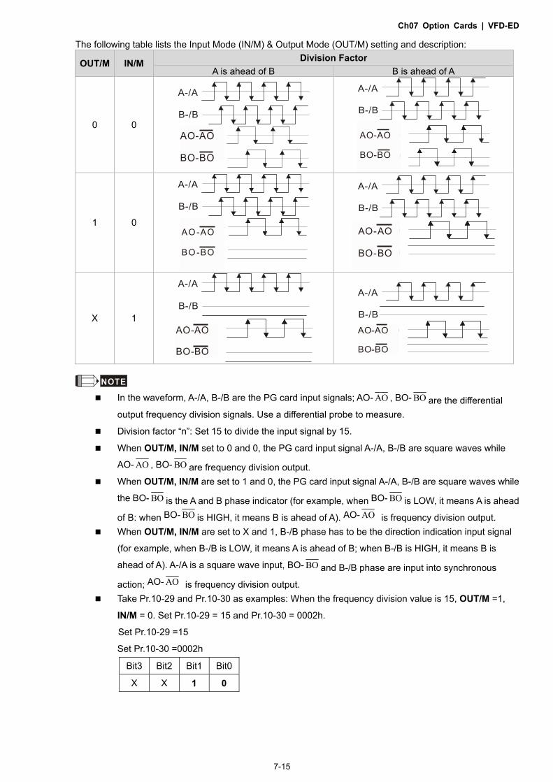
Ch07 Option Cards | VFD-ED
7-15
The following table lists the Input Mode (IN/M) & Output Mode (OUT/M) setting and description:
OUT/M IN/M Division Factor
A is ahead of B B is ahead of A
0 0
A-/A
B-/B
A/O-/A/O
B/O-/B/O
AO-AO
BO-BO
A-/A
B-/B
A/O-/A/O
B/O-/B/O
A/O-/A/O
B/O-/B/O
AO-AO
BO-BO
1 0
A-/A
B-/B
A/O-/A/O
B/O-/B/O
A/O-/A/O
B/O-/B/O
AO -AO
BO -BO
A-/A
B-/B
A/O-/A/O
B/O-/B/O
A/O-/A/O
B/O-/B/O
AO-AO
BO-BO
X 1
A-/A
B-/B
A/O-/A/O
B/O-/B/O
A/O-/A/O
B/O-/B/O
AO-AO
BO-BO
A-/A
B-/B A/O-/A/O
B/O-/B/O
A/O-/A/O
B/O-/B/O
AO-AO
BO-BO
NOTE In the waveform, A-/A, B-/B are the PG card input signals; AO- AO , BO- BO are the differential
output frequency division signals. Use a differential probe to measure.
Division factor “n”: Set 15 to divide the input signal by 15.
When OUT/M, IN/M set to 0 and 0, the PG card input signal A-/A, B-/B are square waves while
AO- AO , BO- BO are frequency division output.
When OUT/M, IN/M are set to 1 and 0, the PG card input signal A-/A, B-/B are square waves while
the BO- BO is the A and B phase indicator (for example, when BO- BO is LOW, it means A is ahead
of B: when BO- BO is HIGH, it means B is ahead of A). AO- AO is frequency division output.
When OUT/M, IN/M are set to X and 1, B-/B phase has to be the direction indication input signal
(for example, when B-/B is LOW, it means A is ahead of B; when B-/B is HIGH, it means B is
ahead of A). A-/A is a square wave input, BO- BO and B-/B phase are input into synchronous
action; AO- AO is frequency division output.
Take Pr.10-29 and Pr.10-30 as examples: When the frequency division value is 15, OUT/M =1,
IN/M = 0. Set Pr.10-29 = 15 and Pr.10-30 = 0002h.
Set Pr.10-29 =15
Set Pr.10-30 =0002h
Bit3 Bit2 Bit1 Bit0
X X 1 0

Ch07 Option Cards | VFD-ED
7-16
[The page intentionally left blank]

Ch08 Specifications | VFD-ED
8-1
Chapter 8 Specifications
8-1 230V Series
8-2 460V Series
8-3 Operation, Storage and Transportation Environments

Ch08 Specifications | VFD-ED
8-2
8-1 230V Series Frame Size B C D E
Model VFD-_ _ _ED23/21S 022* 037* 040 055 075 110 150 185 220 300 370
Applicable Motor Output (kW) 2.2 3.7 4.0 5.5 7.5 11 15 18.5 22 30 37
Applicable Motor Output (HP) 3 5 5 7.5 10 15 20 25 30 40 50
Out
put R
atin
g
Rated Output Capacity (kVA) 4.8 6.8 7.9 9.5 12.5 19 25 29 34 46 55
Rated Output Current (A) 12.0 17 20.0 24.0 30.0 45.0 58.0 77.0 87.0 132.0 161.0
Maximum Output Voltage (V) Three-phase proportional to input voltage
Output Frequency Range 0.00–400 Hz
Carrier Frequency Range 2–15 kHz 2–9 kHz
Rated Output Maximum
Carrier Frequency 8 kHz 10 kHz 8 kHz 6 kHz
Inpu
t Rat
ing
Input Current (A) 24 34 20 23 30 47 56 73 90 132 161
Rated Voltage / Frequency One-phase Three-phase
200–240 V, 50/60 Hz
Voltage Tolerance ±10% (180–264 V)
Frequency Tolerance ±5% (47–63 Hz)
Cooling Method Fan cooling
Weight (kg) 6 6 6 8 10 10 13 13 13 36 36 *VFD022ED21S & VFD037ED21S are one-phase input models.
8-2 460V Series Frame Size B C D E
Model VFD-_ _ _ED43S 040 055 075 110 150 185 220 300 370 450 550 750
Applicable Motor Output (kW) 4.0 5.5 7.5 11 15 18.5 22 30 37 45 55 75
Applicable Motor Output (HP) 5 7.5 10 15 20 25 30 40 50 60 75 100
Out
put R
atin
g
Rated Output Capacity (kVA) 9.2 10.4 13.5 18.3 24 30.3 36 46.2 63.7 80 96.4 116.3
Rated Output Current (A) 11.5 13 17 23 30 38 45 58 80 100 128 165
Maximum Output Voltage (V) Three-phase proportional to input voltage
Output Frequency Range 0.00–400 Hz
Carrier Frequency Range 2–15 kHz 2–9 kHz 2–6 kHz
Rated Output Maximum
Carrier Frequency 8 kHz 10 kHz 8 kHz 6 kHz
Inpu
t Rat
ing Input Current (A) 11.5 14 17 24 30 37 47 58 80 100 128 165
Rated Voltage / Frequency Three-phase 380–480 V, 50/60 Hz
Voltage Tolerance ±10% (342–528 V)
Frequency Tolerance ±5% (47–63 Hz)
Cooling Method Fan cooling
Weight (kg) 6 8 10 10 10 10 13 14.5 36 36 50 50
*Assumes operation at the rated output current. Input current rating varies depending on the input reactor,
transformer, wiring connections and power supply impedance.

Ch08 Specifications | VFD-ED
8-3
General Specifications C
ontro
l Cha
ract
eris
tics
Control Method 1: V/F, 2: VF+PG, 3: SVC, 4: FOC+PG, 5: TQC+PG, 6: FOC+PM
Starting Torque In V/F mode: 150% at 0.5 Hz.
In FOC+PG or FOC+PM mode: 150% at 0 Hz.
Speed Control Range 1:100 (up to 1:1000 when using PG card)
Speed Control Accuracy 0.5% (up to 0.02% when using PG card)
Speed Response Ability 5 Hz (Up to 30 Hz for vector control)
Max. Output Frequency 0.00–400.00 Hz
Output Frequency
Accuracy Digital command 0.005%; analog command 0.5%.
Frequency Setting
Resolution
Digital command: 0.01 Hz; analog command: 1/4096 (12 bit) of the maximum output
frequency.
Torque Limit Max. is 200% of the torque current
Torque Accuracy 5%
Accel. / Decel. Time 0.00–600.00 seconds
V/F Curve Adjustable V/F curve using four independent points.
Frequency Setting Signal 10 V
Brake Torque About 20% (while using optional braking resistor, about 125%, 30% ED)
Prot
ectio
n C
hara
cter
istic
s
Motor Protection Electronic thermal relay protection
Over-current Protection The current is limited by 190% of the drive’s rated current and the limit for
over-current protection is 250% of the drive’s rated current.
Ground Leakage Current
Protection More than 50% of the drive’s rated current
Overload Ability Constant torque: 150% for 60 seconds; variable torque: 180% for 10 seconds.
Voltage Protection Over-voltage level: VDC > 400/800 V; low-voltage level: VDC < 200/400 V
Over-voltage Protection
for the Input Power Varistor (MOV)
Overheating Protection Built-in temperature sensor
Certifications EN81-1+A3, EN81-20: 2014

Ch08 Specifications | VFD-ED
8-4
8-3 Operation, Storage and Transportation Environments
DO NOT expose the AC motor drive to a poor environment, such as one with dust, direct sunlight, corrosive or inflammable gasses, humidity, liquids or excessive vibration. The salt in the air must be less than 0.01 mg/cm2 every year.
Environment
Installation Location IEC60364-1/IEC60664-1 pollution degree 2. Indoor use only.
Surrounding Temperature
Operation
Between -10–40°C, up to 50°C with derating for the operation temperature.
Between 40–50°C
with Derating
2.2–4 kW: for every 1°C increase in temperature, decrease the drive’s rated current by 2.2% 5.5–30 kW: for every 1°C increase in temperature, decrease the drive’s rated current by 2.5% 37–75 kW: for every 1°C increase in temperature, decrease the drive’s rated current by 2.0%
Storage/ Transportation -20–60oC
Non-condensing, non-freezing.
Rated Humidity
Operation Max. 90% Storage/ Transportation Max. 90%
No water condensation
Altitude Operation
If the AC motor drive is installed at an altitude of 0–1000 m, follow normal operation restrictions. For altitudes of 1000–3000 m, decrease the drive’s rated current by 1% or lower the temperature by 0.5°C for every 100 m increase in altitude. The maximum altitude for corner grounding is 3000 m. If installing at an altitude higher than 3000 m is required, contact Delta for more information.
Power System
TN system*1*2
Package Drop
Storage ISTA procedure 1A (according to weight) IEC60068-2-31 Transportation
Vibration
1.0 mm, peak to peak value range from 2–13.2 Hz; 0.7–1.0 G range from 13.2–55 Hz; 1.0 G range from 55–512 Hz. Compliance with IEC 60068-2-27.
Impact Compliance with IEC/EN 60068-2-27 Protection
Level NEMA 1/IP20
EMC Level IEC 61800-3 and IEC 61000-4 *1: TN system: The neutral point of the power system connects directly to the ground. The exposed metal
components connect to the ground through the protective grounding conductor. *2: One-phase models use a one-phase three-wire power system.

Ch09 Digital Keypad | VFD-ED
9-1
Chapter 9 Digital Keypad
9-1 Description of Keyboard Panel
9-2 Keypad Operation Process
9-3 Description of the Digital Keypad KPC-CC01
9-4 Digital Keypad KPC-CC01 Functions
9-5 Digital Keypad KPC-CC01 Fault Codes and Descriptions
9-6 TPEditor Installation

Ch09 Digital Keypad | VFD-ED
9-2
9-1 Description of Keyboard Panel Keyboard Panel KPED-LE01
Keypad Functions Keys Description
Shift key Moves the cursor so you can adjust the selected value.
Reset key Resets the motor drive after a fault.
Mode key Changes among the different display modes.
ENTER key Allows you to read or modify the current parameter settings.
Up and Down keys These buttons have two functions: 1. Press the Up or Down button to increase or decrease the selected value. 2. Press the Up or Down button to select items in a menu and languages.
LED Function Description LED Description
Status Display UP: Moving up. DN: Moving down D1: MI1 status D2: MI2 status D3: MI3 status D4: MI4 status
Main Display Area Displays frequency, current, voltage, rotation direction, user-defined units, errors and warnings.

Ch09 Digital Keypad | VFD-ED
9-3
Description of the Displayed Functions
Displayed Function Description
Displays the VFD-ED frequency setting.
Displays the actual frequency output from the VFD-ED to the motor.
Displays the user-defined value in Pr.00-04.
Displays the current (amperes).
Displays the selected parameter.
Displays the value in a parameter.
Displays the external fault.
Displays “End” for approximately one second (as shown in the left figure) if the data has been accepted and automatically stored in the register.
Displays if the setting data is not accepted or data value exceeds the allowed range.
9-2 Keypad Operation Process

Ch09 Digital Keypad | VFD-ED
9-4
9-3 Description of the Digital Keypad KPC-CC01
KPC-CC01
Communication Interface RJ45 (socket), RS-485 interface Installation methods Place the keypad flat on the surface of the control box.
The front cover is water proof. Use a model MKC-KPPK for wall mounting or
embedded mounting. Its protection level is IP66. The maximum RJ45 extension cable is 5 m (16 ft). This keypad can also be used on Delta’s motor drives
C2000, CH2000 and CP2000.
Keypad Functions Key Description
Start Key This button is functional only when the keypad is the source of the command. This button causes the motor drive to run according to its settings. See “LED Function
Description” for LED status. Pressing the RUN button repeatedly is allowed while the motor drive is stopping.
Stop Key The STOP key has the highest priority in command. Press the STOP key to stop the drive under any conditions. Press the RESET key to reset the drive when faults occur. If the RESET key does not
respond, go to MENU “Fault Records” to check the most recent fault.
Operation Direction Key The FWD/REV key controls the operation direction but does NOT activate the drive.
FWD: forward, REV: reverse. The drive operates in the direction as shown by the LED.
ENTER Key Press the ENTER key to go to the next menu level. If you are at the last level, then press ENTER to execute the command.
ESC Key Press the ESC key to return to the previous page, or return to the last category in the sub-menu.
MENU Key Press the MENU key to return to the main menu. Menu items: 1. Parameter Setup 2. Copy Parameter 3. Keypad Locked 4. PLC Function
5. Copy PLC 6. Fault Record 7. Quick Start 8. Display Setup
9. Time Setup 10. Language Setup 11. Start-up 12. Main Page
13. PLC Link
VFD-ED does not support menu item 4 and 5 (PLC functions) and menu item 7 (Quick Start).
Direction: Left/Right/Up/Down cursor keys In the numeric value setting mode, press Left and Right to move the cursor; press Up
and Down to change the selected value. In the menu/text selection mode, use the cursor keys to select an item.

Ch09 Digital Keypad | VFD-ED
9-5
LED Function Descriptions LED Description
Steady ON: AC motor drive operation indicator, including DC brake, zero speed, standby,restart after fault and speed tracking. Blinking: motor drive is decelerating to stop or in Base Block status. Steady OFF: motor drive does not execute the operation command.
Steady ON: AC motor drive stop indicator. Blinking: motor drive is in standby status. Steady OFF: motor drive does not execute the STOP command.
Operation Direction LED 1. Green light is on, the drive is running forward. 2. Red light is on, the drive is running in reverse. 3. Blinking light: the drive is changing direction.

Ch09 Digital Keypad | VFD-ED
9-6
9-4 Digital Keypad KPC-CC01 Functions
NOTE 1. Start-up page can only display pictures, no flash. 2. When power is ON, it displays the start-up page and then the main page. The main page displays Delta’s default
setting F/H/A/U. Set the displayed order with Pr.00-03 (Start-up Display). When the selected item is U page, use left key and right key to switch between the items. Set the displayed order of U page with Pr.00-04 (Content of Multi-function Display).
3. VFD-ED does not support menu item 4 and 5 (PLC functions) and menu item 7 (Quick Start).

Ch09 Digital Keypad | VFD-ED
9-7
Display Icon
Display Item
1. Parameter Setup
For example: Set the master frequency command source.
Display the Group 00 Motor Drive Parameter. Use Up and Down to select parameter 20: Auto Frequency Command.
Press ENTER to display the parameter’s setting menu.
Use Up and Down to choose a setting. For example, choose 2 Analogue Input, and then press ENTER.
After you press ENTER, the screen displays “END”, indicating that the new parameter value is set.

Ch09 Digital Keypad | VFD-ED
9-8
2. Copy Parameter
Press ENTER to go to 001–004: content storage
Four groups of parameters are available to copy. The steps are shown in the example below. Example: Save parameters in the motor drive.
1. Go to Copy Parameter. 2. Select the parameter group to copy, and
then press ENTER.
1. Select 1: keypad->VFD. 2. Press ENTER to go to the “Save in the
motor drive” screen.
Copy parameters until it is done.
Once copying parameters is done, thekeypad automatically returns to this screen.
Example: Save parameters in the keypad.
1. Go to Copy Parameter. 2. Select the parameter group to copy, and
then press ENTER.
1. Select 2: VFD->Keypad. 2. Press ENTER to go to the “Save in the
keypad drive” screen.
Press Up or Down to select a symbol. Press Left or Right to move the cursor toselect a filename.
String & Symbol Table: !"#$%&'()*+,-./0123456789:;<=
>?@ABCDEFGHIJKLMNOPQRSTUVWXYZ
[\]^_`abcdfghijklmnopqrstuvwx
yz{|}~
After you confirm the filename, press ENTER.
Copy parameters until it is done.
After copying parameters, the keypad automatically returns to this screen.
Press Right to see the date the parameterswere copied.

Ch09 Digital Keypad | VFD-ED
9-9
Press Right again to see the time the parameters were copied.
3. Keypad Locked
Lock the Keypad
Use this function to lock the keypad. The main screen does not display “keypad locked” when the keypad is locked; however it displays the message “Press ESC 3 sec to unlock key” when any key is pressed.
When the keypad is locked, the main screen does not display the locked status.
Press any key on the keypad; a message displays as shown on the left.
If you do not press ESC, the keypad automatically returns to this screen.
The keypad is still locked. When you press any key, the screen shows the message on the left.
Press ESC for 3 seconds to unlock the keypad and the keypad returns to this screen. All keys on the keypad are functional.
Once the keypad is unlocked, turning the power off and then back on doesnot lock the keypad.
4. 4.
4. Fault Record
ENTERPress
to select.
KPC-CE01 does not support this function.
Able to store 6 error codes (Keypad V1.02 and previous versions) Able to store 20 error codes (Keypad V1.03 and later versions) The most recent error record shows as the first record. Choose an error record to see details such as date, time, frequency, current, voltage, and DC BUS voltage.
Press Up or Down to select a fault record. After selecting a fault code, press ENTER to see that fault record’s details.
Press Up or Down to see the fault record’s details such as date, time, frequency, current, voltage, and DC BUS voltage. Press ESC to return to the Fault Record screen.

Ch09 Digital Keypad | VFD-ED
9-10
Press Up or Down to select the next fault record. After selecting a fault record, press ENTER to see that fault record’s details.
Press Up or Down to see the fault record’s detailssuch as date, time, frequency, current, voltage, and DC BUS voltage.
NOTE
The AC motor drive fault actions are recorded and saved to the KPC-CC01. When you remove the KPC-CC01 and connect it to another AC motor drive, the previous fault records are not deleted. The new fault records of the new AC motor drive continue to be added to the KPC-CC01.
5. Display Setup
Press ENTER to display the
Display Setup screen.
1. Contrast
Press Up or Down to adjust the setting value.
For example, increase the contrast to +10.
After you set the value, press ENTER to see the screen display after increasing the contrast.
Then press ENTER and decrease the contrast to -10.
Press ENTER to see the screen display after adjusting the contrast to -10.
2. Back-Light
Press ENTER to go to Back-Light time setting screen.
Press Up or Down to adjust the setting value.
When the setting value is 0 Min, the backlight stays on.

Ch09 Digital Keypad | VFD-ED
9-11
When the setting value is 10 Min, the backlight turns off in 10 minutes.
3. Text Color
Press ENTER to go to the Text Color setting screen.
The default value is White Text.
Press Up or Down to adjust the setting value, and then press ENTER.
1 :2 :3 :
The setting value changes to Blue Text.
6. Time Setup
Time setup
2009/01/01_ _ : _ _ :_ _
Press Left or Right to select
Year, Month, Day, Hour, Minute
or Second to change.
Press Up or Down to set the Year.
Press Up or Down to set the Month.
Press Up or Down to set the Day.
Press Up or Down to set the Hour.
Press Up or Down to set the Minute.
Press Up or Down to set the Seconds.

Ch09 Digital Keypad | VFD-ED
9-12
Press ENTER to confirm the new date and time setting.
NOTE Limitation: The charging process for the keypad super capacitor finishes in
about 6 minutes. When you remove the digital keypad from the motor drive,
the drive stores the time setting for seven days. After seven days, you must
reset the time.
7. Language Setup
Press Up or Down to select the
language, and then press
ENTER.
The Language setting option is displayed in the language of your choice. Language setting options:
1. English
2. 繁體中文
3. 简体中文
NOTE: VFD-ED only supports these three languages currently.
8. Start-up
1. Default 1 DELTA LOGO
2. Default 2 DELTA Text
3. User-defined: an optional accessory is required (TPEditor & USB/RS-485
Communication Interface-IFD6530) to design your own start-up page.
If the editor accessory is not installed, the User Define option displays a
blank screen.
USB/RS-485 Communication Interface-IFD6530 Refer to Chapter 06 Optional Accessories for more details. TPEditor Go to Delta’s website to download the TPEditor V1.30.6 or later versions.
http://www.delta.com.tw/ch/product/em/download/download_main.asp?act
=3&pid=1&cid=1&tpid=3
Refer to Section 9-6 TPEditor Installation for operation description.

Ch09 Digital Keypad | VFD-ED
9-13
9. Main Page
You can choose the Default picture or the User-defined picture.
ENTERPress
to select.
1. Default page
F H u
60.00Hz
540.0Vdc 0.00Hz
F 600.00 Hz >>> H >>> A >>> U (options rotate) 2. User-defined: an optional accessory is required (TPEditor & USB/RS-485
Communication Interface-IFD6530) to design your own start-up page. If the editor accessory is not installed, the User Define option displays a blank screen.
USB/RS-485 Communication Interface-IFD6530 Refer to Chapter 06 Optional Accessories for more details. TPEditor Go to Delta’s website to download the TPEditor V1.30.6 or later versions.
http://www.delta.com.tw/ch/product/em/download/download_main.asp?act=3&pid=1&cid=1&tpid=3
Refer to Section 9-6 TPEditor Installation for operation description.
10. PC Link
1. TPEditor: This function allows you to connect the keypad to a computer,
and then download and edit user-defined pages.
Press ENTER to go to the PC Link Waiting to connect to PC screen.
In TPEditor, from the Communication menu, choose Write to TP.

Ch09 Digital Keypad | VFD-ED
9-14
In the Confirm message box, click YES.
The software starts downloading screens to the KPC-CC01.
Download completed.
2. VFDSoft: This function links to the software VFDSoft, and then you can
upload data that you copied one or more parameter (1–4) from the drive
to the KPC-CC01.
Connect KPC-CCO1 to your computer.
Choose 2. VFDSoft
Press Up or Down to select a parameter group to upload to VFDSoft.
Press ENTER to display the PC Link Waiting to connect to PC screen.

Ch09 Digital Keypad | VFD-ED
9-15
On your computer, open VFDSoft, and click Parameter on the toolbar.
In the Parameter Management, from the Table menu, click Read from
KPC-CC01.
Choose the correct communication port, and then click OK.
Start to upload parameters to VFDSoft.

Ch09 Digital Keypad | VFD-ED
9-16
Uploading parameter is completed.
Before using the user-defined Start-up screen and user-defined Main screen,
you must preset the Start-up screen and the Main screen as user-defined.
If you do not download the user-defined screens to the KPC-CC01, the
Start-up screen and the Main screen are blank.
Other Displays
When a fault or warning occurs, the menu displays the following screens.
ocAOc at accel
Fault
CE01Comm. Error 1
Warning
1. Press ENTER to RESET. If there is no response, contact your local distributor for instructions to return the
equipment to the factory. To view the DC BUS fault voltage value, output current and output voltage, press MENU and then choose Fault Record for details (refer to the descriptions in the above #4 Fault Record).
2. Press ENTER again. If the screen returns to Main page, the fault is cleared. When a fault or warning message appears, the screen backlight blinks until the fault or warning is cleared.
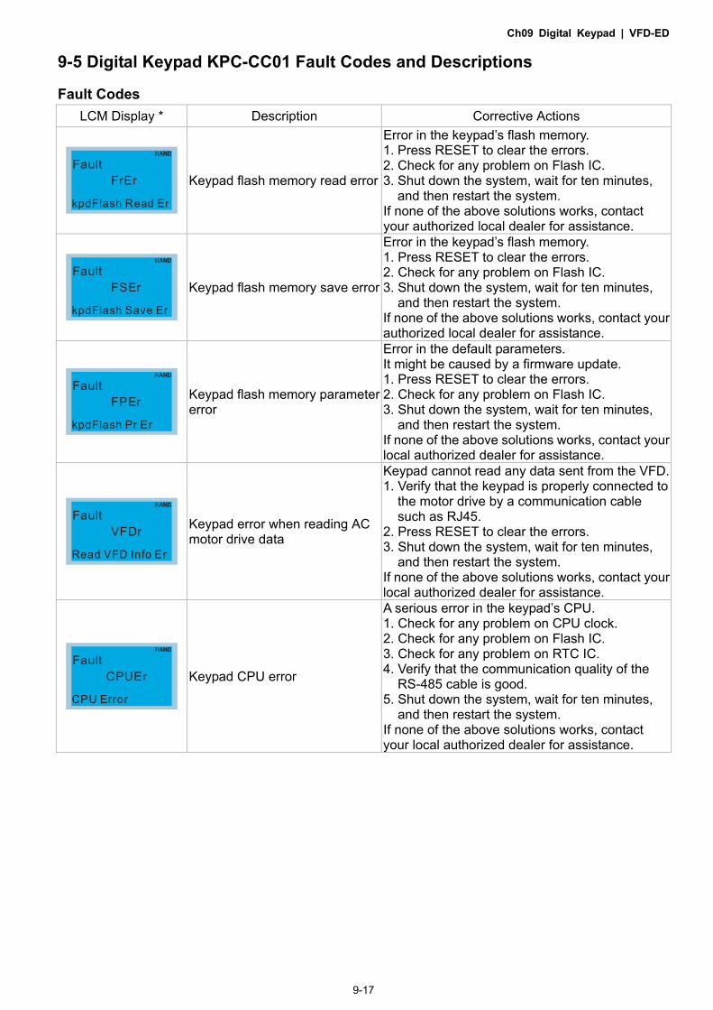
Ch09 Digital Keypad | VFD-ED
9-17
9-5 Digital Keypad KPC-CC01 Fault Codes and Descriptions
Fault Codes
LCM Display * Description Corrective Actions
FrEr
kpdFlash Read Er
Fault
Keypad flash memory read error
Error in the keypad’s flash memory. 1. Press RESET to clear the errors. 2. Check for any problem on Flash IC. 3. Shut down the system, wait for ten minutes,
and then restart the system. If none of the above solutions works, contact your authorized local dealer for assistance.
FSEr
kpdFlash Save Er
Fault
Keypad flash memory save error
Error in the keypad’s flash memory. 1. Press RESET to clear the errors. 2. Check for any problem on Flash IC. 3. Shut down the system, wait for ten minutes,
and then restart the system. If none of the above solutions works, contact your authorized local dealer for assistance.
FPEr
kpdFlash Pr Er
Fault
Keypad flash memory parameter error
Error in the default parameters. It might be caused by a firmware update. 1. Press RESET to clear the errors. 2. Check for any problem on Flash IC. 3. Shut down the system, wait for ten minutes,
and then restart the system. If none of the above solutions works, contact your local authorized dealer for assistance.
VFDr
Read VFD Info Er
Fault
Keypad error when reading AC motor drive data
Keypad cannot read any data sent from the VFD. 1. Verify that the keypad is properly connected to
the motor drive by a communication cable such as RJ45.
2. Press RESET to clear the errors. 3. Shut down the system, wait for ten minutes,
and then restart the system. If none of the above solutions works, contact your local authorized dealer for assistance.
CPUEr
CPU Error
Fault
Keypad CPU error
A serious error in the keypad’s CPU. 1. Check for any problem on CPU clock. 2. Check for any problem on Flash IC. 3. Check for any problem on RTC IC. 4. Verify that the communication quality of the
RS-485 cable is good. 5. Shut down the system, wait for ten minutes,
and then restart the system. If none of the above solutions works, contact your local authorized dealer for assistance.

Ch09 Digital Keypad | VFD-ED
9-18
Warning Codes LCM Display * Description Corrective Actions
CE01Comm Command Er
Warning
Modbus function code error
Motor drive does not accept the communication command sent from the keypad. 1. Verify that the keypad is properly connected to
the motor drive by a communication cable such as RJ45.
2. Press RESET to clear the errors. If none of the above solutions works, contact your local authorized dealer for assistance.
CE02Comm Address Er
Warning
Modbus data address error
Motor drive does not accept the keypad’s communication address. 1. Verify that the keypad is properly connected to
the motor drive by a communication cable such as RJ45.
2. Press RESET to clear the errors. If none of the above solutions works, contact your local authorized dealer for assistance.
CE03Comm Data Error
Warning
Modbus data value error
Motor drive does not accept the communication data sent from the keypad. 1. Verify that the keypad is properly connected to
the motor drive by a communication cable such as RJ45.
2. Press RESET to clear the errors. If none of the above solution works, contact your local authorized dealer for assistance.
CE04Comm Slave Error
Warning
Modbus slave drive error
Motor drive cannot process the communication command sent from the keypad. 1. Verify that the keypad is properly connected to
the motor drive by a communication cable such as RJ45.
2. Press RESET to clear the errors. 3. Shut down the system, wait for ten minutes,
and then restart the system. If none of the above solutions works, contact your local authorized dealer for assistance.
CE10KpdComm Time Out
Warning
Modbus transmission time-out
Motor drive does not respond to the communication command sent from the keypad. 1. Verify that the keypad is properly connected to
the motor drive by a communication cable such as RJ45.
2. Press RESET to clear the errors. 3. Shut down the system, wait for ten minutes,
and then restart the system. If none of the above solutions works, contact your local authorized dealer for assistance.
TPNOTP No Object
Warning
Object not supported by TPEditor
Keypad’s TPEditor uses an unsupported object. 1. Verify that the TPEditor is not using an
unsupported object or setting. Delete unsupported objects and unsupported settings.
2. Re-edit the object in the TPEditor, and then download it to the keypad.
If none of the above solutions works, contact your local authorized dealer for assistance.

Ch09 Digital Keypad | VFD-ED
9-19
File Copy Setting Fault Description LCM Display * Description Corrective Actions
Err 1
Read Only
File 1
Parameter and file are read-only
The parameter/file is read-only and cannot be written to. 1. Verify the specification in the user manual. If this solution does not work, contact your local authorized dealer for assistance.
Err
Write Fail
File 1
Fail to write parameter and file
An error occurred while writing to a parameter/file. 1. Check for any problem on Flash IC. 2. Shut down the system, wait for ten minutes,
and then restart the system. If this solution does not work, contact your local authorized dealer for assistance.
Err
VFD Running
File 1
AC motor drive is in operating status
A setting cannot be changed while the motor drive is in operation. 1. Verify that the drive is not in operation. If this solution does not work, contact your local authorized dealer for assistance.
Err
Pr Lock
File 1
AC motor drive parameter is locked
A setting cannot be changed because a parameter is locked. 1. Check if the parameter is locked. If it is locked,
unlock it and try to set the parameter again. If this solution does not work, contact your local authorized dealer for assistance.
Err
Pr Changing
File 1
AC motor drive parameter is changing
A setting cannot be changed because a parameter is being modified. 1. Check if the parameter is being modified. If it is
not being modified, try to change that parameter again.
If this solution does not work, contact your local authorized dealer for assistance.
Err
Fault Code
File 1
Fault code is not cleared
A setting cannot be changed because an error has occurred in the motor drive. 1. Check if an error occurred in the motor dive. If
there is no error, try to change the setting again.
If this solution does not work, contact your local authorized dealer for assistance.
Err
Warning Code
File 1
Warning code is not cleared
A setting cannot be changed because of a warning message given to the motor drive. 1. Check if there is a warning message given to
the motor drive. If this solution does not work, contact your local authorized dealer for assistance.
Err
Type Dismatch
File 1
File type mismatch
Data to be copied are not the correct type, so the setting cannot be changed. 1. Check if the products’ serial numbers to be
copied are in the same category. If they are in the same category, try to copy the setting again.
If this solution does not work, contact your authorized dealer for assistance.

Ch09 Digital Keypad | VFD-ED
9-20
LCM Display * Description Corrective Actions
Err
Password Lock
File 1
File is locked with password
A setting cannot be changed because some data are locked. 1. Check if the data are unlocked or able to be
unlocked. If the data are unlocked, try to change the setting again.
2. Shut down the system, wait for ten minutes, and then restart the system.
If none of the above solutions works, contact your authorized dealer for assistance.
Err 10
Password Fail
File 1
File password mismatch
A setting cannot be changed because the password is incorrect. 1. Check if the password is correct. If the
password is correct, try to change the setting again.
2. Shut down the system, wait for ten minutes, and then restart the system.
If none of the above solutions works, contact your authorized dealer for assistance.
Err
Version Fail
File 1
File version mismatch
A setting cannot be changed because the version of the data is incorrect. 1. Check if the version of the data matches the
motor drive. If it matches, try to change the setting again.
If this solution does not work, contact your authorized dealer for assistance.
Err
VFD Time Out
File 1
AC motor drive copy function time-out
A setting cannot be changed because the data copying time-out expired. 1. Try copying the data again. 2. Check if copying data is authorized. If it is
authorized, try to copy the data again. 3. Shut down the system, wait for ten minutes,
and then restart the system. If none of the above solutions works, contact your authorized dealer for assistance.
Err
Keypad Issue
File 1
Other keypad error This setting cannot be changed due to other keypad issues (Reserved functions). Contact your authorized dealer for assistance.
Err
VFD Issue
File 1
Other AC motor drive error This setting cannot be changed due to other motor drive issues (Reserved functions). Contact your authorized dealer for assistance.
※ The content in this section only applies to the KPC-CC01 keypad V1.01 and later versions.

Ch09 Digital Keypad | VFD-ED
9-21
9-6 TPEditor Installation The TPEditor can edit up to 256 HMI (Human-Machine Interface) pages with a total storage capacity of 256 KB.
Each page can include 50 normal objects and 10 communication objects.
1) TPEditor: Setup & Basic Functions
1. Run TPEditor (version 1.60 or later) by double-clicking the program icon.
2. On the File menu, click New. In the New Project window, for Set Device Type, select DELTA VFD-C
Inverter. For TP Type, select VFD-C KeyPad. For File Name, enter TPE0 and then click OK.
3. The editor displays the Design window. On the Edit menu, click Add a New Page. You can also right-click on the TP page in the upper right corner of the Design window and click Add to add one more pages to edit.
4. Edit the Start-up screen.

Ch09 Digital Keypad | VFD-ED
9-22
5. Add static text. Open a blank page (step 3), then on the toolbar click . Double-click the blank page to display the Static Text Setting dialog box, and then enter the static text.
6. Add a static bitmap. Open a blank page (step 3), then on the toolbar, click . Double-click the blank page to display the Static Bitmap Setting dialog box where you can choose the bitmap.
Inquiry (I):
Recent Documents
Desktop
My Documents
My Computer
My Network Places
Filename ( ):N
File Type ( ):T
Open ( ):O
Cancel
You can only use images in the BMP format. Click the image and then click Open to show the image in the page.
7. Add a geometric bitmap. There are 11 kinds of geometric bitmaps to choose. Open a new blank page (step
3), then on the toolbar click the geometric bitmap icon that you need
. In the page, drag the geometric bitmap and enlarge it to the size that you need.
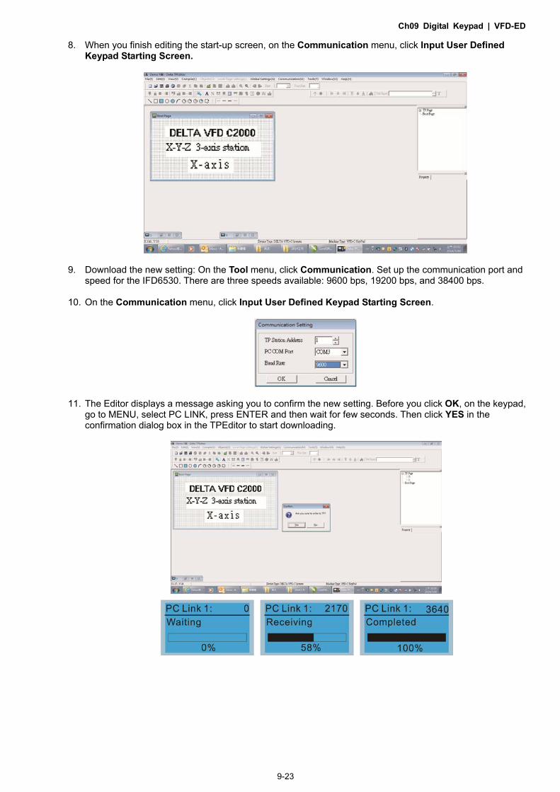
Ch09 Digital Keypad | VFD-ED
9-23
8. When you finish editing the start-up screen, on the Communication menu, click Input User Defined Keypad Starting Screen.
9. Download the new setting: On the Tool menu, click Communication. Set up the communication port and speed for the IFD6530. There are three speeds available: 9600 bps, 19200 bps, and 38400 bps.
10. On the Communication menu, click Input User Defined Keypad Starting Screen.
11. The Editor displays a message asking you to confirm the new setting. Before you click OK, on the keypad, go to MENU, select PC LINK, press ENTER and then wait for few seconds. Then click YES in the confirmation dialog box in the TPEditor to start downloading.

Ch09 Digital Keypad | VFD-ED
9-24
2) Edit Main Page and Download to the Keypad
1. In the Editor, add a page to edit. On the Edit menu, click Add a New Page. You can also right-click on the TP page in the upper right corner of the Design window and click Add to add one more pages to edit. This keypad currently support up to 256 pages.
2. In the bottom right-hand corner of the Editor, click the page number to edit, or on the View menu, click HMI Page to start editing the main page. As shown in the picture above, the following objects are available. From left to right they are: Static Text, ASCII Display, Static Bitmap, Scale, Bar Graph, Button, Clock Display, Multi-state bit map, Units, Numeric Input, the 11 geometric bitmaps, and lines of different widths. Use the same steps to add Static Text, Static Bitmap, and geometric bitmaps as for the start-up page.
3. Add a numeric/ASCII display. On the toolbar, click the Numeric/ASCII button. In the page, double-click
the object to specify the Refer Device, Frame Setting, Font Setting and Alignment.
Click […]. In the Refer Device dialog box, choose the VFD communication port that you need. If you want to read the output frequency (H), set the Absolute Addr. to 2202. For other values, refer to the ACMD Modbus Comm Address List in Pr.09-04 in Chapter 12.

Ch09 Digital Keypad | VFD-ED
9-25
4. Scale Setting : On the toolbar, double-click to add a scale. You can also edit the Scale Setting in the Property Window on the right-hand side of your computer screen.
a. Scale Position: specifies where to place the scale. b. Scale Side: specifies whether the scale is numbered from smaller numbers to larger numbers or
from larger to smaller. c. Font Setting: specifies the font. d. Value Length: specifies 16 bits or 32 bits. e. Main Scale & Sub-scale: divides the whole scale into equal parts; enter the numbers for the main
scale and sub-scale. f. Max Value & Min Value: specifies the numbers on the two ends of the scale. They can be negative
numbers, but the maximum and minimum values are limited by the Value Length setting. For example, when Value Length is hexadecimal (16 bits), the maximum and the minimum value cannot be entered as -400000. Clicking OK creates a scale as in the picture below.
5. Bar Graph setting. On the toolbar, click to add a bar graph.
a. Refer Device: specifies the VFD communication port. b. Direction Setting: specifies the direction: From Bottom to Top, From Top to Bottom, From Left
to Right or From Right to Left. c. Value Length: determines the range of the maximum value and minimum value. d. Max Value and Min Value: specifies the maximum value and minimum value. A value smaller than
or equal to the minimum value causes the bar graph to be blank (0). A value is bigger or equal to the maximum value causes the bar graph is full (100%). A value between the minimum and maximum values causes the bar graph to be filled proportionally.

Ch09 Digital Keypad | VFD-ED
9-26
6. Button setting. On the toolbar, click . Currently this function only allows the keypad to switch pages; other functions are not yet available (including text input and insert image). In the blank page, double-click to open the Button Setting window.
Button Type: specifies the button’s functions. Page Jump and Constant Setting are the only functions currently supported. a. Page Jump Setting
1) Page Jump Setting: in the Button Type drop-down list, choose Page Jump to show the Page Jump Setting.
2) Function Key: specifies the functions for the following keys on the KPC-CC01 keypad: F1, F2, F3, F4, Up, Down, Left and Right. Note that the Up and Down keys are locked by TPEditor. You cannot program these two keys. If you want to program Up and Down keys, on the Tool menu, click Function Key Settings, and then click Re-Define Up/Down Key.
3) Button Text: specifies the text that appears on a button. For example, when you enter Next Page for the button text, that text appears on the button.
b. Constant Setting
This function specifies the memory address’ values for the VFD or PLC. When you press the Function
key, it writes a value to the memory address specified by the value for Constant Setting. You can use
this function to initialize a variable.

Ch09 Digital Keypad | VFD-ED
9-27
7. Clock Display Setting: on the toolbar, click . You can display the time, day, or date on the keypad. Open a new page and click once in that window to add a clock display. Choose to display Time, Day, or Date on the keypad. To adjust time, go to Time Setup on the keypad’s menu. You can also specify the Frame Setting, Font Setting, and Alignment.
8. Multi-state bitmap: on the toolbar, click . Open a new page and click once in that window to add a Multi-state bitmap. This object reads a bit’s property value from the PLC. It defines the image or text that appears when this bit is 0 or 1. Set the initial status (Current State) to be 0 or 1 to define the displayed image or text.
9. Unit Measurement: on the toolbar, click . Open a new blank page, and double-click on that window to display the Units Setting dialog box.
Choose the Metrology Type and the Unit Name. For Metrology, the choices are Length, Square Measure, Volume/Solid Measure, Weight, Speed, Time, and Temperature. The unit name changes automatically when you change metrology type.

Ch09 Digital Keypad | VFD-ED
9-28
10. Numeric Input Setting: on the toolbar, click . This object allows you to provide parameters or communication ports and to input numbers. Open a new file and double-click on that window to display the Numeric Input Setting dialog box.
a. Refer Device: specifies the Write and the Read values. Enter the numbers to display and the corresponding parameter and communication port numbers. For example, enter 012C to Read and Write Parameter Pr.01-44.
b. OutLine Setting: specifies the Frame Setting, Font Setting, Hori. Alignment, and Vert. Alignment for the outline.
c. Function Key: specifies the function key to program on the keypad in the Function Key box. The corresponding key on the keypad starts to blink. Press ENTER to confirm the setting.
d. Value Type and Value Length: specify the range of the Min Value and Max Value for the Limit Setting. Note that the corresponding supporting values for VFD-ED must be 16 bits. 32 bit values are not supported.
e. Value Setting: automatically set by the keypad itself. f. Limit Setting: specifies the range for the numeric input here.
For example, if you set Function Key to F1, Min Value to 0 and Max Value to 4, when you press F1 on the keypad, then you can press Up/Down on the keypad to increase or decrease the value. Press ENTER on the keypad to confirm your setting. You can also view the parameter table for Pr.01-44 to verify if you correctly entered the value.
11. Download the TP Page
Press Up or Down on the keypad to select “PC Link” in the Menu. Then press ENTER on the keypad. The screen displays “Waiting”. In TPEditor, choose a page that you have created, and then on the Communication menu click Write to TP to start downloading the page to the keypad. Then, the keypad displays “Receiving”. When you see “Completed” on the keypad screen, the download is finished. You can then press ESC on the keypad to go back to the menu screen.

Ch10 Auto-tuning Process | VFD-ED
10-1
Chapter 10 Auto-tuning Process
10-1 Auto-tuning Flow Chart
10-2 Explanations for the Auto-tuning Steps
10-3 Elevator Performance Fine-tuning

Ch10 Auto-tuning Process | VFD-ED
10-2
10-1 Auto-tuning Flow Chart

Ch10 Auto-tuning Process | VFD-ED
10-3

Ch10 Auto-tuning Process | VFD-ED
10-4
10-2 Explanations for the Auto-tuning Steps Step 1
Basic Parameter Settings
Make sure that Pr.00-00 (AC motor drive identity code) matches with the nameplate on the AC motor drive.
Reset all parameters to default (set Pr.00-02 to 9 or 10).
Pr.00-02 Parameter Reset
0: No function 1: Read only 5: Direct docking mode only, contact Delta for more information. 8: Keypad locked 9: Reset all parameters to defaults (base frequency = 50 Hz) 10: Reset all parameters to defaults (base frequency = 60 Hz)
Master Frequency Command Source: User-defined. (Pr.00-14)
Pr.00-14 Master Frequency Command Source
1: RS-485 serial communication or digital keypad (KPC-CC01) 2: External analog input (Pr.03-00) 3: Digital terminal inputs (Pr.04-00–Pr.04-15) 4: Direct docking mode only, contact Delta for more information.
Operation Command Source: User-defined. (Pr.00-15)
Pr.00-15 Operation Command Source
1: External terminals 2: RS-485 serial communication or digital keypad (KPC-CC01)
MI/MO External Terminal Settings
Refer to Pr.02-01–Pr.02-08 for the external input terminals MI1–MI8 settings. NOTE: The default for Pr.02-08 is 40 (Enable drive function). Disable this function if you do not need to use it. Pr.02-01– Pr.02-08 Settings
0: No function 1: Multi-step speed command 1 2: Multi-step speed command 2 3: Multi-step speed command 3 4: Multi-step speed command 4 5: Reset 6: JOG command 7: Acceleration/deceleration speed inhibit 8: First and second acceleration/deceleration time 9: Third and fourth acceleration/deceleration time 10: EF input (Pr.07-28) 11: Reserved 12: Stop output 13–14: Reserved 15: AUI1 operation speed command 16: Reserved 17: AUI2 operation speed command 18: Emergency stop (Pr.07-28) 19–23: Reserved 24: FWD JOG command 25: REV JOG command 26: Reserved 27: ASR1/ASR2 selection 28: Emergency stop (EF1) (Motor coasts to stop) 29–30: Reserved

Ch10 Auto-tuning Process | VFD-ED
10-5
31: High torque bias (according to Pr.07-21) 32: Middle torque bias (according to Pr.07-22) 33: Low torque bias (according to Pr.07-23) 34–37: Reserved 38: Disable writing to EEPROM function 39: Torque command direction 40: Enable drive function 41: Magnetic contactor detection 42: Mechanical brake 1 43: EPS function (Emergency Power System) 44: Mechanical brake 2 45–51: Direct docking mode only, contact Delta for more information.
53: Terminal signal for direct docking 54: Power failure signal 55: Manual emergency deceleration 56: Automatic emergency deceleration
Refer to Pr.02-15 and Pr.02-16 for the settings for MO1–MO2 Pr.02-15– Pr.02-16 Settings
0: No function 1: Operation indication 2: Operation speed reached 3: Desired frequency 1 reached (Pr.02-25, Pr.02-26) 4: Desired frequency 2 reached (Pr.02-27, Pr.02-28) 5: Zero speed (Frequency command) 6: Zero speed with stop (Frequency command) 7: Over-torque (OT1) (Pr.06-05–06-07) 8: Over-torque (OT2) (Pr.06-08–06-10) 9: Drive ready 10: User-defined low-voltage detection (LV) 11: Malfunction indication 12: Mechanical brake release (Pr.02-29, Pr.02-30, Pr.02-37) 13: Overheat (Pr.06-14) 14: Brake chopper signal 15: Motor-controlled magnetic contactor output 16: Slip error (oSL) 17: Malfunction indication 1 18: Reserved 19: Brake chopper output error 20: Warning output 21: Over-voltage warning 22: Over-current stall prevention warning 23: Over-voltage stall prevention warning 24: Operation mode indication (Pr.00-15=1) 25: Forward command 26: Reverse command 27: Output when current ≥ Pr.02-33 28: Output when current < Pr.02-33 29: Output when frequency ≥ Pr.02-34 30: Output when frequency < Pr.02-34 31: Power generation direction and status verification 32: Power generation direction 33: Zero speed (actual output frequency) 34: Zero speed with Stop (actual output frequency) 35: Fault output selection 1 (Pr.06-22) 36: Fault output selection 2 (Pr.06-23) 37: Fault output selection 3 (Pr.06-24) 38: Fault output selection 4 (Pr.06-25) 39: Reserved 40: Speed reached (including zero speed)

Ch10 Auto-tuning Process | VFD-ED
10-6
41: Reserved 42: STO output error 43–44: Direct docking mode only
45: Reserved 46: Retrying after a fault has occurred indication 47: Direct docking mode only
48: Control output of star-delta contactor 49: Emergency power mode action

Ch10 Auto-tuning Process | VFD-ED
10-7
Step 2 Encoder Settings
Speed feedback card selections
Refer to CH07 Speed Feedback Card Selection. Delta provides three kinds of PG cards including EMED-PGABD-1, EMED-PGHSD-1, EMED-PGHSD-2.
Pr.10-00 Selection of Encoder
0: Disable 1: ABZ 2: ABZ+Hall 3: SIN/COS + Sinusoidal 4: SIN/COS + Endat 5: SIN/COS 6: SIN/COS + Hiperface
Encoder input type settings: Pr.10-01–Pr.10-02
Detection of the motor magnetic pole position The detection method is different according to the setting for Pr.10-00 (Selection of Encoder). The detection methods: (refer to detailed parameter descriptions for Pr.10-00) (1) 1 or 5: The AC motor drive outputs a short circuit to detect the position of the magnetic pole.
At this moment, the motor generates a little noise. (2) 2: The AC motor drive detects the position of the magnetic pole with the UVW encoder
signal. (3) 3: The AC motor drive detects the position of the magnetic pole with the sine encoder
signal. (4) 4 or 6: The AC motor drive detects the position of the magnetic pole with the
communication encoder signal.
Encoder defines the number of pulses per revolution. Pr.10-01 Encoder Pulse
1–25000
Encoder Input Type Setting. This parameter is normally set to 1. If the motor does not run with the parameter set to 1, change it to 2. Pr.10-02 Encoder Input Type Setting
0: Disable 1: Phase A leads in a forward run command and phase B leads in a reverse run command 2: Phase B leads in a forward run command and phase A leads in a reverse run command 3: Phase A is a pulse input and phase B is a direction input (low input = reverse direction, high input = forward direction). 4: Phase A is a pulse input and phase B is a direction input (low input = forward direction, high input = reverse direction). 5: Single-phase input

Ch10 Auto-tuning Process | VFD-ED
10-8
Step 3 Motor Tuning
Set the parameters according to the motor type (PM or IM).
1. Motor auto-tuning: Set the Operation Command source to the digital keypad (Pr.00-15 = 2, refer
to step 1 above)
Control method selections: Set Pr.00-09 to 8 when using PM motors. Pr.00-09 Control Method
0: V/F control (V/F) 1: V/F control + Encoder (VFPG) 2: Sensorless Vector Control (SVC) 3: FOC vector control + Encoder (FOCPG) 8: FOC Permanent Motor control (FOCPM)
NOTE: Set the parameter according to the motor type (PM or IM).
2. Enter the motor nameplate information into Pr.01-00–Pr.01-02 Pr.01-00 Maximum Output Frequency
10.00–400.00 Hz
Pr.01-01 First Output Frequency Setting (base frequency/ motor’s rated frequency)
0.00–400.00 Hz
Pr.01-02 First Output Voltage Setting (base voltage/ motor’s rated voltage)
230V series: 0.1–255.0 V 460V series: 0.1–510.0 V
【IM (Induction Motor)】
3. Motor auto-tuning: If the Operation Command source is set to the digital keypad (Pr.00-15 = 2, refer to step 1 above), set Pr.05-00 = 2. Pr.05-00 Motor Auto-tuning
0: No function 1: Dynamic test (Rs, Rr, Lm, Lx, no-load current) (Motor runs) 2: Static test (Motor does not run)
NOTE 1: You do not need to release the brake in this auto-tuning operation. Make sure that the electromagnetic valve is ON when it is installed between the AC motor drive and the motor. When Pr.05-00 is set to 2, you must enter the motor no-load current in Pr.05-05. The digital keypad displays the warning message “Auto tuning” during auto-tuning until it is finished. Finally, it saves the measured results in Pr.05-06–Pr.05-09.
NOTE 2: Dynamic test can also apply for IM auto-tuning.
Pr.05-01 Motor Full-load Current
(40–120%)*Pr.00-01 Amps

Ch10 Auto-tuning Process | VFD-ED
10-9
Pr.05-02 Motor Rated Power
0.00–655.35 kW
Pr.05-03 Motor Rated Speed (rpm)
0–65535
Pr.05-04 Number of Motor Poles
2–48
【PM (Permanent Magnet Motor)】
4. Motor Auto-tuning: If the Operation Command source is set to the digital keypad (Pr.00-15 = 2, refer to step 1 above), set Pr.08-00 = 2. Pr.08-00 Motor Auto-tuning
0: No function 1: Only for an unloaded motor, auto-measures the angle between magnetic pole and PG origin (Pr.08-09) 2: For PM parameters (suggested to lock the brake) 3: Auto-measures the angle between the magnetic pole and the PG origin (Pr.08-09)
NOTE 1: You do not need to release the brake in this auto-tuning operation. Make sure that the electromagnetic valve is ON when it is installed between the AC motor drive and the motor. The digital keypad displays the warning message “Auto tuning” during auto-tuning until it is finished. Finally, it saves the measured results in Pr.08-05, Pr.08-07 and Pr.08-08. Pr.08-05 is Motor Rs, Pr.08-07 is Motor Lq and Pr.08-08 is Back Electromotive Force. NOTE 2: It is recommended that you set Pr.08-00 to 1 (unloaded motor) for the most accurate calculation. If you must run auto-tuning with a loaded motor, balance the carriage before execution. When Pr.08-00 = 1, note the following: When executing auto-measurement of the angle between the magnetic pole and the PG
origin, stop the carriage at the middle level. Make sure that the electromagnetic valve and mechanical brake are OFF before executing
this function. When Pr.08-00 = 1, execute this function with the motor unloaded for the most accurate
result. If you must run auto-tuning with a loaded motor, balance the carriage before execution.
Ensure the balance by releasing the brake manually before running. This balance affects the accuracy that influences the power efficiency in driving the motor.
NOTE 3: If you are unable to balance the carriage in the measuring environment, set Pr.08-00 to 3 when you execute this function. This setting does not require an unloaded motor. However, it has a difference of 15–30o for the different encoder types. When you set Pr.08-00 to 3, the motor drive executes the function according to the
Pr.10-00 setting. The difference between Pr.08-00 = 3 and Pr.08-00 = 1 is that it does not need to balance the carriage when Pr.08-00 = 3. In addition, the motor operation status is shown in the above table (When Pr.10-00=1, 2, 3 and 5, the motor runs. When Pr.10-00=4 and 6, the motor does not run).

Ch10 Auto-tuning Process | VFD-ED
10-10
When Pr.08-00=3, make sure that Pr.10-02 Encoder Input Type is set correctly. The incorrect setting results in the wrong magnetic pole position and makes the wrong angle between magnetic pole and PG origin (Pr.08-09).
NOTE 4: The digital keypad displays the warning message “Auto tuning” during auto-tuning until it is finished. Finally, it saves the measured result in Pr.08-09.
NOTE 5: If the digital keypad displays the warning message “Auto Tuning Err” during auto-tuning due to an abnormal drive or human error, check if the wiring is correct. When the digital keypad displays the warning message “PG Fbk Error”, change the setting in Pr.10-02 (for example: if it was set to 1, change it to 2). When the digital keypad displays the warning message “PG Fbk Loss”, check if the Z-phase pulse feedback is normal.
Pr.08-01 Motor Full-load Current
(40–120%) * Pr.00-01 Amps
Pr.08-02 Motor Rated Power
0.00–655.35 kW
Pr.08-03 Motor Rated Speed (rpm)
0–65535 rpm
Pr.08-04 Number of Motor Poles
2–96
Measure the angle between the magnetic pole and the PG origin
To execute “RUN” from the digital keypad or external terminals: 1. Using the digital keypad:
Set Pr.08-00 = 1 and press RUN key to execute “auto-measure the angle between magnetic pole and PG origin”. Note that you must manually release the electromagnetic valve and brake if they are not controlled by the AC motor drive.
2. Using external terminals: Set Pr.00-14 = 3 (Frequency command source) Set Pr.00-15 = 1 (Operation command source) Use the “Inspection” function to execute “auto-measure the angle between magnetic pole and PG origin”.
An IM motor does not need the position of the magnetic pole so you do not need to execute this function (auto-measure the angle between the magnetic pole and the PG origin).
Measure the angle between the magnetic pole and the PG origin: Pr.08-00 = 1 or 3
Pr.08-00 Motor Auto-tuning
0: No function 1: Only for an unloaded motor, auto-measures the angle between the magnetic pole and the PG origin (Pr.08-09) 2: For PM parameters (suggested to lock the brake) 3: Auto-measures the angle between the magnetic pole and the PG origin (Pr.08-09)
NOTE 1: You must finish motor auto-tuning before you can execute the “auto-measure the angle between the magnetic pole and the PG origin” function. NOTE 2: Measure twice, and the angle tolerance between two times must be ± 5º.

Ch10 Auto-tuning Process | VFD-ED
10-11
Step 4
Multi-step Speed Setting or Analog Setting (Do not wire the two settings at the same time)
A. Multi-step speed settings
Confirm the total number of speed steps (high speed, middle speed, low speed, creep, inspection and level auto-learning)
Make sure that the step speed settings and the corresponding terminal actions for the multi-function input commands (MI1–MI4) are correct.
Set the multi-step speeds in Pr.04-00–Pr.04-15
Pr.04-00–Pr.04-15 settings
Zero Step Speed Frequency 0.00–400.00 Hz 1st Step Speed Frequency 0.00–400.00 Hz 2nd Step Speed Frequency 0.00–400.00 Hz 3rd Step Speed Frequency 0.00–400.00 Hz 4th Step Speed Frequency 0.00–400.00 Hz 5th Step Speed Frequency 0.00–400.00 Hz 6th Step Speed Frequency 0.00–400.00 Hz 7th Step Speed Frequency 0.00–400.00 Hz 8th Step Speed Frequency 0.00–400.00 Hz 9th Step Speed Frequency 0.00–400.00 Hz 10th Step Speed Frequency 0.00–400.00 Hz 11th Step Speed Frequency 0.00–400.00 Hz 12th Step Speed Frequency 0.00–400.00 Hz 13th Step Speed Frequency 0.00–400.00 Hz 14th Step Speed Frequency 0.00–400.00 Hz 15th Step Speed Frequency 0.00–400.00 Hz
NOTE: It is recommended that you set the high speed frequency to the half of the maximum operating frequency before confirming each step speed setting and the corresponding terminal actions for the multi-function input commands.
Ensure the speed steps, and use with Pr.01-23 and the multi-function input commands (Pr.02-01–Pr.02-08) setting #8 (first and second acceleration/deceleration time) and setting #9 (third and fourth acceleration/deceleration time).
Set the acceleration/deceleration time: Pr.01-12–Pr.01-19. Pr.01-12–Pr.01-19 settings
Acceleration Time 1 0.00–600.00 sec. Deceleration Time 1 0.00–600.00 sec. Acceleration Time 2 0.00–600.00 sec. Deceleration Time 2 0.00–600.00 sec. Acceleration Time 3 0.00–600.00 sec. Deceleration Time 3 0.00–600.00 sec. Acceleration Time 4 0.00–600.00 sec. Deceleration Time 4 0.00–600.00 sec.
NOTE: It is recommended that you set Pr.01-31 (Deceleration Time when Operating without RUN Command) to the smallest value for the trial run to ensure that all the actions are correct, and then increase it for the ride comfort test.

Ch10 Auto-tuning Process | VFD-ED
10-12
S-curve setting: Pr.01-24–Pr.01-30
NOTE: It is recommended that you set the S-curve time to 0 for the trial run to ensure that all the actions are correct, and then increase it for the ride comfort test.
B. Analog setting
1. Set Pr.00-14 = 2, (Frequency command set by external analog signal). 2. Set Pr.00-15 = 1, (Operation command set by external terminals). 3. To work with the control terminals, set AUI1 (Pr.03-23) and AUI2 (Pr.03-24) to match the
controller output mode. 4. Set AUI1 (Pr.03-03, Pr.03-06, Pr.03-09) and AUI2 (Pr.03-05, Pr.03-08, Pr.03-11) to work
with the connecting port. Set F to display 0 Hz when the motor drive is going to stop.
Step 5
Inertia
For a synchronous motor, set Pr.11-05 = 40%; for an asynchronous motor, set Pr.11-05 = 80%. Pr.11-05 Inertial Ratio
1–300%
Inertia reference value (%)
Load/Motor IM PM
No-load 40 10
With load 80–120 40
Step 6 Trial Run Use the trial run after you complete Step 1 to Step 5 above to check if the motor runs normally after executing the inspection with a loaded motor. At the same time, check if the multi-function output terminal operations are correct (such as whether the action of the brake release and electromagnetic valve match the host controller).
Also check the speed, current value, and check for noise in the carriage and other noise sources when switching between each step.
Pr.01-24–Pr.01-30 settings
S-curve for Acceleration Begin Time S1 0.00–25.00 sec. S-curve for Acceleration Arrival Time S2 0.00–25.00 sec. S-curve for Deceleration Begin Time S3 0.00–25.00 sec. S-curve for Deceleration Arrival Time S4 0.00–25.00 sec.
Mode Selection when Frequency < Fmin
0: Output waiting 1: Zero-speed operation 2: Fmin (fourth output
frequency setting) Switch Frequency for S3/S4 Changes to S5 0.00–400.00 Hz S-curve for Deceleration Arrival Time S5 0.00–25.00 sec.

Ch10 Auto-tuning Process | VFD-ED
10-13
Step 7 Elevator Tuning (1) Enable slip compensation (VF, SVC)
0: Disable; > 0: Enable. Set Pr.05-13, Pr.05-23, Pr.05-24
Pr.05-13 Slip Compensation Gain
0.00–10.00
Pr.05-23 Slip Compensation Gain % (Power Generation Mode)
0.0–100.0%
Pr.05-24 Slip Compensation Gain % (Electricity Mode)
0.0–100.0%
NOTE 1: In V/F mode, you do not need to set Pr.05-13. Set Pr.05-23 and Pr.05-24 directly according to the compensation requirements for power generation mode and electricity mode. NOTE 2: In SVC mode, you must set Pr.05-13 first, and then set Pr.05-23 and Pr.05-24 according to the compensation requirements for power generation mode and electricity mode.
(2) Comfort adjustment for normal operation (FOCPG, FOCPM) PDFF enabled Set Pr.11-00, Pr.11-06, Pr.11-07, Pr.11-08 Pr.11-00 System Control
Bit 0 = 0: No function Bit 0 = 1: ASR auto-tuning, enable PDFF Bit 7 = 0: No function Bit 7 = 1: Zero speed position control is enabled Bit 9 = 0: Dynamic PG origin auto-tuning with load (support by PGHSD-1) Bit 9 = 1: Static PG origin auto-tuning with load by enabling PGHSD-1 Bit 15 = 0: Detect the position of magnetic pole again when power is
applied Bit 15 = 1: Start from the magnetic pole position of the previous power
failure when power is applied
Fine-tune Pr.11-06, Pr.11-07, and Pr.11-08 to make a comfortable ride (jerk free and smooth) Pr.11-06– Pr.11-08 Settings
Zero speed Bandwidth Low speed Bandwidth High speed Bandwidth
1–40 Hz 1–40 Hz 1–40 Hz
(3) Start-up adjustment (FOCPM) Control by the zero speed position
Set Pr.11-00, Pr.10-19, Pr.10-22, Pr.10-23, Pr.02-29 and Pr.10-24 Pr.11-00 System control
Bit 0 = 0: No function Bit 0 = 1: ASR auto-tuning, enable PDFF. Bit 7 = 0: No function Bit 7 = 1: Zero speed position control is enabled Bit 9 = 0: Dynamic PG origin auto-tuning with load (support by
PGHSD-1) Bit 9 = 1: Static PG origin auto-tuning with load by enabling PGHSD-1 Bit 15 = 0: Detect the position of magnetic pole again when power is
applied

Ch10 Auto-tuning Process | VFD-ED
10-14
Bit 15 = 1: Start from the magnetic pole position of the previous power failure when power is applied
Pr.10-19 Zero Speed Position Control Gain (P)
0.00–655.00%
NOTE: Refer to detailed parameter descriptions for Pr.02-32.
Pr.10-22 Zero Speed Position Control Holding Time
0.001–65.535 sec.
Pr.10-23 Zero Speed Position Control Low Pass Filter Time
0.001–65.535 sec.
Pr.10-24 Zero Speed Position Control Activation Mode Selection
0: After the brake release set in Pr.02-29 1: After the brake signal input (Pr.02-01–Pr.02-08 is set to 42)
Pr.02-29 Brake Release Delay Time when Elevator Starts
0.000–65.000 sec.
NOTE: When Pr.10-24 = 0, you must use the zero speed position control with Pr.02-29 (refer to detailed parameter descriptions for Pr.02-32),
Preload input function (This function is not for normal usage. Refer to the following settings if
needed.) Connect the preload signal to the AC motor drive external terminal (AUI1). Set Pr.03-00 = 3, Pr.07-19 = 1, Pr.03-03, Pr.03-06 and Pr.03-09. Pr.03-00 Analog Input 1 (AUI1)
0: No function 1: Frequency command (speed limit under torque control mode) 2: Torque command (torque limit under speed mode) 3: Preload input 4–5: Reserved 6: P.T.C. thermistor input value 7: Positive torque limit 8: Negative torque limit 9: Regenerative torque limit 10: Positive/negative torque limit

Ch10 Auto-tuning Process | VFD-ED
10-15
Pr.07-19 Torque Offset Source
0: Disable 1: Analog input (Pr.03-00) 2: Torque offset setting (Pr.07-20) 3: Control through external terminals (by Pr.07-21–Pr.07-23)
Pr.03-03 Analog Input Bias 1 (AUI1)
-100.0–100.0%
Pr.03-06 Positive/negative Bias Mode (AUI1)
0: Zero bias 1: Lower than or equal to bias 2: Higher than or equal to bias 3: Using bias as the base to get the absolute value of bias
voltage (unipolar) 4: Using bias as the base (unipolar)
Pr.03-09 Analog Input Gain 1 (AUI1)
0.0–500.0%
NOTE: Use Pr.03-03, Pr.03-06 and Pr.03-09 to adjust the analog input signal.

Ch10 Auto-tuning Process | VFD-ED
10-16
(4) DC brake adjustment Set Pr.07-02, Pr.07-03, Pr.07-04, Pr.07-30
Pr.07-02 DC Brake Current Level at Start-up (VF, VFPG, SVC)
0–100% (motor drive rated current)
Pr.07-03 DC Brake Activation Time
0.0–60.00 sec.
Pr.07-30 DC Brake Current Level at Stop (VF, VFPG, SVC)
0–100% (motor drive rated current)
Pr.07-04 DC Brake Stopping Time
0.0–60.00 sec.
(5) Set drive stop Set Pr.01-29, Pr.01-30, Pr.01-31 and Pr.11-19 Pr.01-29 Switch Frequency for S3/S4 Changes to S5
0.00–400.00 Hz
Pr.01-30 S-curve for Deceleration Arrival Time S5
0.00–25.00 sec.
Pr.11-19 Zero Speed Parking Bandwidth
1–40 Hz
Pr.01-31 Deceleration Time when Operating without RUN Command
0.00–600.00 sec.

Ch10 Auto-tuning Process | VFD-ED
10-17
10-3 Elevator Performance Fine-tuning
Stage Function Pr. Explanation Settings Default
Starting
Delay Time
02-31
Magnetic Contactor
Contracting Delay Time
between Drive and Motor
0.010–65.000 sec. 0.200
02-29 Brake Release Delay Time
when Elevator Starts 0.000–65.000 sec. 0.250
Start-up
Adjustment
01-04 Second Output Voltage
Setting (VF)
230V series: 0.1–255.0 V
460V series: 0.1–510.0 V
5.0
10.0
01-06 Third Output Voltage Setting
(VF)
230V series: 0.1–255.0 V
460V series: 0.1–510.0 V
5.0
10.0
01-08 Fourth Output Voltage
Setting (VF, SVC)
230V series: 0.1–255.0 V
460V series: 0.1–510.0 V
5.0
10.0
11-00 System Control (FOCPM) Bit 7 = 1: Zero speed
position control is enabled 0000h
10-19 Zero Speed Position Control
Gain (P) (FOCPM)
0.00–655.00% 80.00
10-22 Zero Speed Position Control
Holding Time (FOCPM) 0.001–65.535 sec. 0.250
10-23
Zero Speed Position Control
Low Pass Filter Time
(FOCPM)
0.001–65.535 sec. 0.004
10-24
Zero Speed Position Control
Activation Mode Selection
(FOCPM)
0: After the brake release
set in Pr.02-29
1: After the brake signal
input (Pr.02-01–Pr.02-08 is
set to 42)
0
Torque
Check 02-33
External Terminal Output
Current Level
0–100%
(motor drive rated current) 0

Ch10 Auto-tuning Process | VFD-ED
10-18
Stage Function Pr. Explanation Settings Default
02-37 Torque Check 0: Disable 1: Enable 0
DC Brake 07-02
DC Brake Current Level at
Start-up
0–100%
(motor drive rated current) 0
07-03 DC Brake Activation Time 0.0–60.0 sec. 0.7
Accelerating Multi-step
Speed
01-12 Accel. Time 1 0.00–600.00 sec. 3.00
01-24 S-curve for Acceleration
Begin Time S1 0.00–25.00 sec. 1.00
01-25 S-curve for Acceleration
Arrival Time S2 0.00–25.00 sec. 1.00
Decelerating Multi-step
Speed
01-13 Decel. Time 1 0.00–600.00 sec. 2.00
01-26 S-curve for Deceleration
Begin Time S3 0.00–25.00 sec. 1.00
01-27 S-curve for Deceleration
Arrival Time S4 0.00–25.00 sec. 1.00
Leveling Elevator
Parking
01-29 Switch Frequency for S3/S4
Changes to S5 0.00–400.00Hz 0.00
01-30 S-curve for Deceleration
Arrival Time S5 0.00–25.00 sec. 1.00
11-19
Zero Speed Parking
Bandwidth
(FOCPG, FOCPM)
1–40Hz 10
01-31
Deceleration Time when
Operating without RUN
Command
0.00–600.00 sec. 2.00
Stopping
Delay Time
02-30 Brake Engage Delay Time
when Elevator Stops 0.000–65.000 sec. 0.250
02-32
Magnetic Contactor
Release Delay Time
between Drive and Motor
0.010–65.000 sec. 0.200
Torque
Check
02-33 External Terminal Output
Current Level
0–100%
(motor drive rated current)
0
02-37 Torque Check 0: Disable 1: Enable
0
DC Brake 07-30
DC Brake Current Level at
Stop
0–100%
(motor drive rated current) 0
07-04 DC Brake Stopping Time 0.0–60.0 sec. 0.7

Ch11 Summary of Parameter Settings | VFD-ED
11-1
Chapter 11 Summary of Parameter Settings
This chapter provides a summary of parameter settings including the ranges, defaults, and sets parameters. You can set, change, and reset the parameters with the digital keypad.
NOTE 1) : Indicates a parameter that you can set during operation. 2) For more details on parameters, refer to Chapter 12 Descriptions of Parameter Settings. 3) indicates that the parameters or the setting values only apply on the Direct Docking Mode. The actual
functions of each elevator controller vary from one to another. For more information, contact Delta. 4) The parameters described in this user manual are designed for multi-speed mode. The defaults for direct
docking mode are different from the defaults described in this user manual. If you need to use the direct docking mode, contact Delta for more information.
00 Drive Parameters : You can set this parameter during operation.
NOTE IM: Induction Motor; PM: Permanent Magnet Motor
Pr. Explanation Setting Range Default
VF
VFPG
SV
C
FOC
PG
TQC
PG
FOC
PM
00-00 AC Motor Drive Identity Code
108: 220 V, 3 HP (single-phase)
110: 220 V, 5 HP (single-phase)
8: 230V, 3 HP
10: 230V, 5 HP
11: 460V, 5 HP (4.0 kW)
12: 230V, 7.5 HP
13: 460V, 7.5 HP
14: 230V, 10 HP
15: 460V, 10 HP
16: 230V, 15 HP
17: 460V, 15 HP
18: 230V, 20 HP
19: 460V, 20 HP
20: 230V, 25 HP
21: 460V, 25 HP
22: 230V, 30 HP
23: 460V, 30 HP
24: 230V, 40 HP
25: 460V, 40 HP
26: 230V, 50 HP
27: 460V, 50 HP
29: 460V, 60 HP
31: 460V, 75 HP
33: 460V, 100 HP
Read Only
00-01 AC Motor Drive Rated Current Display
Display by model Read only

Ch11 Summary of Parameter Settings | VFD-ED
11-2
00-02 Parameter Reset 0: No function 1: Read only 5: Direct docking mode only 8: Keypad locked 9: Reset all parameters to defaults (base
frequency is 50 Hz) 10: Reset all parameters to defaults
(base frequency is 60 Hz)
0
00-03 Start-up Display 0: Frequency command value 1: The actual output frequency 2: DC BUS voltage 3: Output current 4: Output voltage 5: User-defined (Pr.00-04)
0
00-04 Content of Multi-function Display
0: Display output current (A) (Unit: Amps)
1: Reserved
2: Display the actual output frequency
(H.) (Unit: Hz)
3: Display DC BUS voltage (v) (Unit: VDC)
4: Display output voltage (E) (Unit: VAC)
5: Display output power angle (n) (Unit:
degree)
6: Display output power in kW (P) (Unit:
kW)
7: Display the actual motor speed in rpm
(r) (Unit: rpm)
8: Display estimated output torque in %
(t) (Unit: %)
9: Display the PG feedback (G) (see
Pr.10-00, Pr.10-01) (Unit: PLS)
10: Display the electrical angle of drive
output (b) (Unit: %)
11: Display AUI1 in % (1.) (Unit: %)
12: Reserved
13: Display AUI2 in % (2.) (Unit: %)
14: Display the heat sink temperature
in °C (c.) (Unit: °C). 15: Display the IGBT temperature
in °C (c.) (Unit: °C). 16: Display digital input status (ON/OFF)
(i)
17: Display digital output status
(ON/OFF) (o)
18: Display multi-step speed (S)
19: The corresponding CPU digital input
pin status (i.)
0

Ch11 Summary of Parameter Settings | VFD-ED
11-3
20: The corresponding CPU digital output pin status (o.)
21–23: Reserved
24: Output AC voltage when malfunction
occurred
25: Output DC voltage when malfunction
occurred
26: Motor frequency when malfunction
occurred
27: Output current when malfunction
occurred
28: Output frequency when malfunction
occurred 29: Frequency command when
malfunction occurred 30: Output power when malfunction
occurred
31: Output torque when malfunction
occurred 32: Input terminal status when
malfunction occurred 33: Output terminal status when
malfunction occurred 34: Drive status when malfunction
occurred 35: Display MI and MO status on digital
keypad 36: CAN communication interference
index 37: Multi-function display selection
00-05 User-Defined Coefficient K
Digit 4: number of decimal points (0–3) Digit 3–0: 40–9999
0
00-06 Software Version READ ONLY #.# 00-07 Password Input 1–9998, 10000–65535
0–2: number of wrong password attempts 0
00-08 Password Set 1–9998, 10000–65535 0: No password set or successful input in
Pr.00-07 1: Password has been set
0
00-09 Control Method 0: V/F control (V/F) 1: V/F control + Encoder (VFPG) 2: Sensorless Vector Control (SVC) 3: FOC vector control + Encoder
(FOCPG) 8: FOC Permanent Motor control
(FOCPM)
0
00-10 Speed Unit 0: Hz 1: m/s 2: ft/s 3: Direct docking mode only
0
00-11 Output Direction Selection
0: FWD: counterclockwise, REV: clockwise 1: FWD: clockwise, REV: counterclockwise
0
00-12 Carrier Frequency 2–15 kHz 12 00-13 Automatic Voltage 0: Enable AVR 0

Ch11 Summary of Parameter Settings | VFD-ED
11-4
Regulation (AVR) Function
1: Disable AVR 2: Disable AVR when deceleration stop
00-14 Master Frequency Command Source
1: RS-485 serial communication or digital keypad (KPC-CC01) 2: External analog input (Pr.03-00) 3: Digital terminal inputs (Pr.04-00–Pr.04-15) 4: Direct docking mode only
1
00-15 Operation Command Source
1: External terminals 2: RS-485 serial communication or digital
keypad (KPC-CC01)
1

Ch11 Summary of Parameter Settings | VFD-ED
11-5
01 Basic Parameters : You can set this parameter during operation.
Pr. Explanation Setting Range Default
VF
VFPG
SV
C
FOC
PG
TQC
PG
FOC
PM
01-00
Maximum Output Frequency
10.00–400.00 Hz 60.00/ 50.00
01-01 First Output Frequency Setting (base frequency / motor’s rated frequency)
0.00–400.00 Hz 60.00/ 50.00
01-02 First Output Voltage Setting (base voltage/ motor’s rated voltage)
230V series: 0.1–255.0 V 460V series: 0.1–510.0 V
220.0 440.0
01-03 Second Output Frequency Setting
0.00–400.00 Hz 0.50
01-04 Second Output Voltage Setting
230V series: 0.1–255.0 V 460V series: 0.1–510.0 V
5.0 10.0
01-05 Third Output Frequency Setting
0.00–400.00 Hz 0.50
01-06 Third Output Voltage Setting
230V series: 0.1–255.0 V 460V series: 0.1–510.0 V
5.0 10.0
01-07 Fourth Output Frequency Setting
0.00–400.00 Hz 0.00
01-08 Fourth Output Voltage Setting
230V series: 0.1–255.0 V 460V series: 0.1–510.0 V
5.0 10.0
01-09 Starting Frequency 0.00–400.00 Hz 0.50 01-10 Output Frequency
Upper Limit 0.00–400.00 Hz 120.00
01-11 Output Frequency Lower Limit
0.00–400.00 Hz 0.00
01-12 Accel. Time 1 0.00–600.00 sec. 3.00 01-13 Decel. Time 1 0.00–600.00 sec. 2.00 01-14 Accel. Time 2 0.00–600.00 sec. 3.00 01-15 Decel. Time 2 0.00–600.00 sec. 2.00 01-16 Accel. Time 3 0.00–600.00 sec. 3.00 01-17 Decel. Time 3 0.00–600.00 sec. 2.00 01-18 Accel. Time 4 0.00–600.00 sec. 3.00 01-19 Decel. Time 4 0.00–600.00 sec. 2.00 01-20 JOG Acceleration Time 0.00–600.00 sec. 1.00 01-21 JOG Deceleration Time 0.00–600.00 sec. 1.00 01-22 JOG Frequency 0.00–400.00 Hz 6.00 01-23 Switch Frequency
between First and Fourth Accel./ Decel.
0.00–400.00 Hz 0.00
01-24 S-curve for Acceleration Begin Time S1
0.00–25.00 sec. 1.00
01-25 S-curve for Acceleration Arrival Time S2
0.00–25.00 sec. 1.00
01-26 S-curve for Deceleration Begin Time S3
0.00–25.00 sec. 1.00
01-27 S-curve for Deceleration Arrival Time S4
0.00–25.00 sec. 1.00
01-28 Mode Selection when Frequency < Fmin
0: Output waiting 1: Zero-speed operation 2: Fmin (fourth output frequency setting)
1
01-29 Switch Frequency for S3/S4 Changes to S5
0.00–400.00 Hz 0.00
01-30 S-curve for Deceleration Arrival Time S5
0.00–25.00 sec. 1.00

Ch11 Summary of Parameter Settings | VFD-ED
11-6
01-31 Deceleration Time when Operating without RUN Command
0.00–600.00 sec. 2.00
01-32 Direct docking mode only
01-33 High Speed Time for Short Floor 0.00–60.00 sec. 3.00
01-34 Leveling Time for Short
Floor 0.00–60.00 sec. 3.00
01-35 Limit for Direct Docking
Terminal 0.00–10.00 2.00
01-36 Deceleration Distance for
Direct Docking Terminal 0.00–100.00 cm 30.00
01-37 Deceleration Distance
Reference for Short Floor 0.00–655.35 m Read only
01-38 Short Floor/Direct Docking Terminal Enabled
0000h: Disabled 0001h: Short floor enabled 0002h: Direct docking terminal enabled 0003h: Short floor + direct docking terminal enabled
0000h
01-39 Automatic Emergency
Deceleration Level 5.00–400.00 Hz 60.00
01-40 Deceleration Time for
Emergency Deceleration 0.00–600.00 sec. 2.00

Ch11 Summary of Parameter Settings | VFD-ED
11-7
02 Digital Input / Output Parameters
: You can set this parameter during operation.
Pr. Explanation Setting Range Default
VF
VFPG
SV
C
FOC
PG
TQC
PG
FOC
PM
02-00 Two-wire/three-wire Operation Control
0: FWD/STOP, REV/STOP 1: FWD/STOP, REV/STOP (Line Start Lockout) 2: RUN/STOP, REV/FWD 3: RUN/STOP, REV/FWD
(Line Start Lockout) 4: Three-wire 5: Three-wire (Line Start Lockout)
0
02-01 Multi-Function Input Command 1 (MI1) 0: no function
1
(The Stop terminal for three-wire operation) 1: multi-step speed command 1
02-02 Multi-Function Input Command 2 (MI2) 2: multi-step speed command 2 2
02-03 Multi-Function Input Command 3 (MI3) 3: multi-step speed command 3 3
02-04 Multi-Function Input Command 4 (MI4) 4: multi-step speed command 4 4
02-05 Multi-Function Input Command 5 (MI5) 5: Reset 0
02-06 Multi-Function Input Command 6 (MI6) 6: JOG command 0
02-07 Multi-Function Input Command 7 (MI7)
7: Acceleration/ deceleration speed inhibit
0
02-08 Multi-Function Input
Command 8 (MI8)
(Enable Drive terminal)
8: First, second
acceleration/deceleration time 40
9: Third, fourth acceleration/deceleration time
10: EF input (Pr.07-28) 11: Reserved 12: Stop output 13–14: Reserved 15: AUI1 operation speed command 16: Reserved
17: AUI2 operation speed command 18: Emergency Stop (Pr.07-28) 19–23: Reserved 24: FWD JOG command 25: REV JOG command 26: Reserved 27: ASR1/ASR2 selection 28: Emergency stop (EF1)
(Motor coasts to stop)
29–30: Reserved 31: High torque bias (according to
Pr.07-21)
32: Middle torque bias (according to Pr.07-22)
33: Low torque bias (according to Pr.07-23)
34–37: Reserved 38: Disable writing to EEPROM function 39: Torque command direction 40: Enable drive function

Ch11 Summary of Parameter Settings | VFD-ED
11-8
41: Magnetic contactor detection 42: Mechanical brake 1 43: EPS function (Emergency Power
System)
44: Mechanical brake 2 45–51: Direct docking mode only 53: Terminal leveling signal for direct
docking
54: Power failure signal 55: Manual emergency deceleration 56: Automatic emergency deceleration 02-09 Digital Input Response
Time 0.001–30.000 sec. 0.005
02-10 Digital Input Operation Direction
0–65535 0
02-11 Multi-function Output 1: RA, RB, RC (Relay1)
0: No function 11 1: Operation indication 02-12 Multi-function Output 2:
MRA, MRB, MRC (Relay2)
2: Operation speed reached 1 3: Desired frequency reached 1
(Pr.02-25, Pr.02-26)
02-13 Multi-function Output 3: R1A, R12C (Relay3)
4: Desired frequency reached 2 (Pr.02-27, Pr.02-28)
0
02-14 Multi-function Output 4: R2A, R12C (Relay4)
5: Zero speed (Frequency command) 0
02-15 Multi-function Output 5: (MO1)
6: Zero speed with stop (Frequency command)
0
02-16 Multi-function Output 6: (MO2)
7: Over-torque (OT1) (Pr.06-05–06-07) 0 8: Over-torque (OT2) (Pr.06-08–06-10) 0 9: Drive ready 0 10: User-defined low-voltage detection
(LV) 0
11: Malfunction indication 0 12: Mechanical brake release
(Pr.02-29, Pr.02-30, Pr.02-37) 0
13: Overheat (Pr.06-14) 0
14: Brake chopper signal 15: Motor-controlled magnetic contactor
output
16: Slip error (oSL) 17: Malfunction indication 1 18: Reserved 19: Brake chopper output error 20: Warning output 21: Over-voltage warning 22: Over-current stall prevention
warning
23: Over-voltage stall prevention warning
24: Operation mode indication (Pr.00-15=1)
25: Forward command 26: Reverse command 27: Output when current ≥ Pr.02-33 28: Output when current < Pr.02-33 29: Output when frequency ≥ Pr.02-34 30: Output when frequency < Pr.02-34 31: Power generation direction and
status verification
32: Power generation direction 33: Zero speed (actual output
frequency)
34: Zero speed with Stop (actual output frequency)

Ch11 Summary of Parameter Settings | VFD-ED
11-9
35: Fault output option 1 (Pr.06-22) 36: Fault output option 2 (Pr.06-23) 37: Fault output option 3 (Pr.06-24) 38: Fault output option 4 (Pr.06-25) 39: Reserved 40: Speed reached (including zero
speed)
41: Reserved 42: STO output error 43–44: Direct docking mode only 45: Reserved 46: Retrying after a fault has occurred
indication
47: Direct docking mode only 48: Control output of star-delta contactor 49: Emergency power mode action . 02-17–02-22 Reserved 02-23 Multi-output Direction 0–65535 0
02-24 Serial Start Signal Selection
0: According to FWD/REV signal 1: According to Enable drive function signal
0
02-25 Desired Frequency Reached 1 0.00–400.00 Hz 60.00/
50.00
02-26 Desired Frequency Reached Width 1 0.00–400.00 Hz 2.00
02-27 Desired Frequency Reached 2 0.00–400.00 Hz 60.00/
50.00
02-28 Desired Frequency Reached Width 2 0.00–400.00 Hz 2.00
02-29 Brake Release Delay Time when Elevator Starts
0.000–65.000 sec. 0.250
02-30 Brake Engage Delay Time when Elevator Stops
0.000–65.000 sec. 0.250
02-31 Magnetic Contactor Contracting Delay Time between Drive and Motor
0.010–65.000 sec.
0.200
02-32 Magnetic Contactor Release Delay Time between Drive and Motor
0.010–65.000 sec.
0.200
02-33 External Terminal Output Current Level 0–100% (motor drive rated current) 0
02-34 External Terminal Output Speed Limit
0.00–400.00 Hz (this is motor speed when using with PG)
0.00
02-35 Mechanical Brake Detection Time 0.00–10.00 sec. 0.00
02-36 Magnetic Contactor Detection Time 0.00–10.00 sec. 0.00
02-37 Torque Check 0: Disable 1: Enable
0
02-38 Star-delta Contactor Release Delay Time between Drive and Motor
0.0010~65.000 sec. 0.200
02-39 Star-delta Contactor Contracting Delay Time between Drive and Motor
0.0010~65.000 sec. 0.200

Ch11 Summary of Parameter Settings | VFD-ED
11-10
03 Analog Input / Output Parameters
: You can set this parameter during operation.
Pr. Explanation Setting Range Default
VF
VFPG
SV
C
FOC
PG
TQC
PG
FOC
PM
03-00 Analog Input 1 (AUI1) 0: No function 1 03-01 Reserved 1: Frequency command (speed limit
under torque control mode)
03-02 Analog Input 2 (AUI2) 2: Torque command (torque limit under speed mode)
0
3: Preload Input 4–5: Reserved 6: P.T.C. thermistor input value 7: Positive torque limit 8: Negative torque limit 9: Regenerative torque limit 10: Positive/negative torque limit 03-03 Analog Input Bias 1
(AUI1) -100.0–100.0% 0.0
03-04 Reserved 03-05 Analog Input Bias 1
(AUI2) -100.0–100.0% 0.0
03-06 AUI1 Positive/negative Bias Mode
0: Zero bias 1: Lower than or equal to bias 2: Higher than or equal to bias 3: Using bias as the base to get the
absolute value of bias voltage (unipolar)
4: Using bias as the base (unipolar)
0
03-07 Reserved 03-08 AUI2 Positive/negative
Bias Mode 0
03-09 Analog Input Gain 1 (AUI1) 0.0–500.0% 100.0
03-10 Reserved 03-11 Analog Input Gain 1
(AUI2) 0.0–500.0% 100.0
03-12 Analog Input Filter Time (AUI1) 0.00–2.00 sec. 0.01
03-13 Reserved 03-14 Analog Input Filter Time
(AUI2) 0.00–2.00 sec. 0.01
03-15 Reserved 03-16 Reserved 03-17 Analog Output Selection
1 0: Output frequency (Hz) 0
1: Frequency command (Hz) 2: Motor speed (RPM) 3: Output current (rms) 4: Output voltage 5: DC BUS voltage 6: Power factor angle 7: Power factor 8: Output torque 9: AUI1 10: Reserved 11: AUI2 12: q-axis current 13: q-axis feedback value 14: d-axis current 15: d-axis feedback value 16: q-axis voltage 17: d-axis voltage 18: Torque command

Ch11 Summary of Parameter Settings | VFD-ED
11-11
19–20: Reserved 21: Power Output 03-18 Analog Output Gain 1 0–200.0% 100.0 03-19 Analog Output Value in
REV Direction 1 0: Absolute value in output voltage 1: Output 0 V in REV direction 2: Enable output voltage in REV direction
0
03-20 Analog Output Selection 2
0: Output frequency (Hz) 0 1: Frequency command (Hz) 2: Motor speed (RPM) 3: Output current (rms) 4: Output voltage 5: DC BUS voltage 6: Power factor angle 7: Power factor 8: Output torque 9: AUI1 10: Reserved 11: AUI2 12: q-axis current 13: q-axis feedback value 14: d-axis current 15: d-axis feedback value 16: q-axis voltage 17: d-axis voltage 18: Torque command 19–20: Reserved 21: Power Output 03-21 Analog Output Gain 2 0–200.0% 100.0 03-22 Analog Output Value in
REV Direction 2 0: Absolute value in output voltage 1: Output 0 V in REV direction 2: Enable output voltage in REV direction
0
03-23 Analog Input Type (AUI1)
0: Bipolar (10 V) 1: Unipolar (0–10 V)
0
03-24 Analog Input Type (AUI2)
0: Bipolar (10 V) 1: Unipolar (0–10 V)
0

Ch11 Summary of Parameter Settings | VFD-ED
11-12
04 Multi-step Speed Parameters : You can set this parameter during operation.
Pr. Explanation Setting Range Default
VF
VFPG
SV
C
FOC
PG
TQC
PG
FOC
PM
04-00 Zero Step Speed Frequency 0.00–400.00 Hz 0.00 04-01 1st Step Speed Frequency 0.00–400.00 Hz 0.00 04-02 2nd Step Speed Frequency 0.00–400.00 Hz 0.00 04-03 3rd Step Speed Frequency 0.00–400.00 Hz 0.00 04-04 4th Step Speed Frequency 0.00–400.00 Hz 0.00 04-05 5th Step Speed Frequency 0.00–400.00 Hz 0.00 04-06 6th Step Speed Frequency 0.00–400.00 Hz 0.00 04-07 7th Step Speed Frequency 0.00–400.00 Hz 0.00 04-08 8th Step Speed Frequency 0.00–400.00 Hz 0.00 04-09 9th Step Speed Frequency 0.00–400.00 Hz 0.00 04-10 10th Step Speed Frequency 0.00–400.00 Hz 0.00 04-11 11th Step Speed Frequency 0.00–400.00 Hz 0.00 04-12 12th Step Speed Frequency 0.00–400.00 Hz 0.00 04-13 13th Step Speed Frequency 0.00–400.00 Hz 0.00 04-14 14th Step Speed Frequency 0.00–400.00 Hz 0.00 04-15 15th Step Speed Frequency 0.00–400.00 Hz 0.00
04-16 –
04-99 Direct docking mode only

Ch11 Summary of Parameter Settings | VFD-ED
11-13
05 IM Parameters : You can set this parameter during operation.
Pr. Explanation Setting Range Default
VF
VFPG
SV
C
FOC
PG
TQC
PG
FOC
PM
05-00 Motor Auto-tuning 0: No function 1: Dynamic test (Rs, Rr, Lm, Lx, no-load current) (Motor runs) 2: Static test (Motor does not run)
0
05-01 Motor Full-load Current (40–120%) * Pr.00-01 Amps #.## 05-02 Motor Rated Power 0.00–655.35 kW #.## 05-03 Motor Rated Speed
(rpm) 0–65535 1710
05-04 Number of Motor Poles 2–48 4 05-05 Motor No-load Current 0–Pr.05-01 <default> #.## 05-06 Motor Rs 0.000–65.535 0.000 05-07 Motor Rr 0.000–65.535 0.000 05-08 Motor Lm 0.0–6553.5 mH 0.0 05-09 Motor Lx 0.0–6553.5 mH 0.0 05-10 Torque Compensation
Time Constant 0.001–10.000 sec. 0.020
05-11 Slip Compensation Time Constant
0.001–10.000 sec. 0.100
05-12 Torque Compensation Gain
0–10 0
05-13 Slip Compensation Gain 0.00–10.00 1.00 05-14 Slip Deviation Level 0–1000% (0: disable) 0 05-15 Slip Deviation Detection
Time 0.0–10.0 sec. 1.0
05-16 Over-slip Action
0: Warn and keep operation 1: Fault and ramp to stop 2: Fault and coast to stop
0
05-17 Hunting Gain 0–10000 (0: disable) 2000 05-18 Accumulated Motor
Operation Time (Min.) 0–1439 0
05-19 Accumulated Motor Operation Time (day)
0–65535 0
05-20 Core Loss Compensation
0–250% 10
05-21 Accumulated Motor Power-on Time (Min.)
0–1439 0
05-22 Accumulated Motor Power-on Time (day)
0–65535 0
05-23 Slip Compensation Gain % (Power Generation Mode)
0.0–100.0% 0.0
05-24 Slip Compensation Gain % (Electricity Mode)
0.0–100.0% 0.0

Ch11 Summary of Parameter Settings | VFD-ED
11-14
06 Protection Parameters : You can set this parameter during operation.
Pr. Explanation Setting Range Default
VF
VFPG
SV
C
FOC
PG
TQC
PG
FOC
PM
06-00 Low Voltage Level 230V series: 160.0–220.0 V 460V series: 320.0–440.0 V
180.0 360.0
06-01 Phase-loss Protection 0: Warn and keep operation 1: Fault and ramp to stop 2: Fault and coast to stop
2
06-02 Over-current Stall Prevention during Acceleration
0: Disable 0–250% (rated current of the motor drive)
0
06-03 Over-current Stall Prevention during Operation
0: Disable 0–250% (rated current of the motor drive)
0
06-04 Acceleration/Deceleration Time for Stall Prevention at Constant Speed
0: Use the current acceleration/deceleration time 1: Use the first acceleration/deceleration time 2: Use the second acceleration/deceleration time 3: Use the third acceleration/deceleration time 4: Use the fourth acceleration/deceleration time 5: Use the auto-acceleration/ auto-deceleration time
0
06-05 Over-torque Detection (OT1)
0: Disable 1: Over-torque detection during constant
speed operation, continue to operate after detection
2: Over-torque detection during constant speed operation, stop operating after detection
3: Over-torque detection during operation, continue to operate after detection
4: Over-torque detection during operation, stop operating after detection
0
06-06 Over-torque Detection Level (OT1)
10–250% (rated current of the motor drive)
150
06-07 Over-torque Detection Time (OT1)
0.1–60.0 sec. 0.1
06-08 Over-torque Detection (OT2)
0: Disable 1: Over-torque detection during constant
speed operation, continue to operate after detection
2: Over-torque detection during constant speed operation, stop operating after detection
3: Over-torque detection during operation, continue to operate after detection
4: Over-torque detection during operation, stop operating after detection
0
06-09 Over-torque Detection Level (OT2)
10–250% (rated current of the motor drive)
150
06-10 Over-torque Detection Time (OT2)
0.1–60.0 sec. 0.1

Ch11 Summary of Parameter Settings | VFD-ED
11-15
06-11 Current Limit 0–250% (rated current of the motor drive) 200 06-12 Electronic Thermal
Relay 0: Standard motor 1: Inverter motor 2: Disabled
2
06-13 Electronic Thermal Characteristic
30.0–600.0 sec. 60.0
06-14 Heat Sink Overheat (OH) Warning
0.0–110.0°C 90.0
06-15 Stall Prevention Limit Level
0–100% (refer to Pr.06-02, Pr.06-03) 50
06-16 Present Fault Record 0: No fault 0 06-17 Second Most Recent
Fault Record 1: Over-current during acceleration (ocA) 0
06-18 Third Most Recent Fault Record
2: Over-current during deceleration (ocd)
0
06-19 Fourth Most Recent Fault Record
3: Over-current during constant speed (ocn)
0
06-20 Fifth Most Recent Fault Record
4: Ground fault (GFF) 0
06-21 Sixth Most Recent Fault Record
5: IGBT short-circuit (occ) 6: Over-current at stop (ocS) 7: Over-voltage during acceleration (ovA) 8: Over-voltage during deceleration (ovd) 9: Over-voltage during constant speed (ovn) 10: Over-voltage at stop (ovS) 11: Low voltage during acceleration (LvA) 12: Low voltage during deceleration (Lvd) 13: Low voltage during constant speed (Lvn) 14: Low voltage at stop (LvS) 15: Input phase loss (PHL) 16: IGBT overheat (oH1) 17: Bulk capacitors overheat (oH2) 18: Abnormal IGBT temperature detected
(tH1o) 19: Abnormal bulk capacitor temperature
detected (tH2o) 20:Unusal cooling fan operation (FAn) 21: Overload (oL) (150%; 1 minute, motor drive overloaded) 22: Motor overloaded (EoL1) 23: Reserved 24: Motor PTC overheat (oH3) 25: Reserved 26: Over-torque 1 (ot1) 27: Over-torque 2 (ot2) 28: Reserved 29: Reserved 30: Memory writing error (cF1) 31: Memory reading error (cF2) 32: Isum current detection error (cd0) 33: U-phase current detection error (cd1) 34: V-phase current detection error (cd2) 35: W-phase current detection error (cd3) 36: CC current clamp hardware error (Hd0) 37: OC (over-current) hardware error (Hd1) 38: ov (over-voltage hardware error (Hd2) 39: GFF(ground fault) hardware error (Hd3) 40: Auto-tuning error on motor’s
parameter (AUE) 41: Reserved
0

Ch11 Summary of Parameter Settings | VFD-ED
11-16
42: PG feedback error (PGF1) 43: PG feedback loss (PGF2) 44: PG feedback stall (PGF3) 45: PG slip error (PGF4) 46: Reserved 47: Reserved 48: Reserved 49: External fault input (EF) 50: Emergency stop from external
terminals (EF1) 51: Reserved 52: Password error after three attempts
(Pcod) 53: Reserved 54: Illegal communication command
(cE01) 55: Illegal communication address (cE02) 56: Communication data length error (cE03) 57: Communication attempts to write to a
read-only address (cE04) 58: Modbus transmission time-out (cE10) 59: Keypad transmission time-out (cP10) 60: Brake chopper error (BF) 61–63: Reserved 64: Mechanical brake feedback error (MBF) 65: PGF5 hardware error 66: Magnetic contactor error (MCF) 67: Output phase loss (MPHL) 68: CAN BUS disconnected 69–71: Reserved 72: Safe torque loss (STL1) 73: PGcd hardware error 74: PG absolute signal error (PGHL) 75: PG Z phase signal loss (PGAF)
76: Safe torque output stops (STO)
77: Safe torque loss 2 (STL2)
78: Safe torque loss 3 (STL3) *The definition of codes #69–#71 has been modified in v1.04. See Chapter 14 for more information.
06-22 Fault Output Option 1 0–65535 (refer to bit table for fault code) 0 06-23 Fault Output Option 2 0–65535 (refer to bit table for fault code) 0 06-24 Fault Output Option 3 0–65535 (refer to bit table for fault code) 0 06-25 Fault Output Option 4 0–65535 (refer to bit table for fault code) 0 06-26 PTC (Positive
Temperature Coefficient) Detection Action
0: Warn and keep operation 1: Fault and ramp to stop
0
06-27 PTC Level 0.0–100.0% 50.0 06-28 PTC Detection Filter
Time 0.00–10.00 sec. 0.20
06-29 Voltage of Emergency Power
24.0–375.0 VDC 48.0–750.0 VDC
24.0 48.0
06-30 Fault Output Setting Method
0: According to Pr.06-22–Pr.06-25 1: According to the binary setting
0
06-31 Phase Loss Detection of Drive Output at Start-up (MPHL)
0: Disable 1: Enable
0
06-32 Accumulated Drive Power-on Time at the
0–65535 Read only

Ch11 Summary of Parameter Settings | VFD-ED
11-17
First Fault (min.) 06-33 Accumulated Drive
Power-on Time at the First Fault (day)
0–65535 Read only
06-34 Accumulated Drive Power-on Time at the Second Fault (min.)
0–65535 Read only
06-35 Accumulated Drive Power-on Time at the Second Fault (day)
0–65535 Read only
06-36 Accumulated Drive Power-on Time at the Third Fault (min.)
0–65535 Read only
06-37 Accumulated Drive Power-on Time at the Third Fault (day)
0–65535 Read only
06-38 Accumulated Drive Power-on Time at the Fourth Fault (min.)
0–65535 Read only
06-39 Accumulated Drive Power-on Time at the Fourth Fault (day)
0–65535 Read only
06-40 Accumulated Drive Power-on Time at the Fifth Fault (min.)
0–65535 Read only
06-41 Accumulated Drive Power-on Time at the Fifth Fault (day)
0–65535 Read only
06-42 Accumulated Drive Power-on Time at the Sixth Fault (min.)
0–65535 Read only
06-43 Accumulated Drive Power-on Time at the Sixth Fault (day)
0–65535 Read only
06-44 (EPS) Emergency Power Mode Operation Speed
0.00–400.00 Hz 0.00
06-45
Fault and Warning Actions
Bit0 = 0: Display Lv fault and coast to stop Bit0 = 1: Display Lv warn and coast to stop Bit1 = 0: Fan lock, fault and coast to stop Bit1 = 1: Fan lock, warn and coast to stop Bit2 = 0: software GFF protection enabled Bit2 = 1: software GFF protection disabled
0
06-46
(EPS) Emergency Power ON Operation Direction
0: Run according to the current command 1: Run according to the operation
direction of power generation mode,
and execute the power generation
direction detection when in power
generation mode.
2: After determining the power generation
direction, the host controller sends a
running direction command. (When at
STOP, the direction of power
generation mode (MO = 32) confirms
0

Ch11 Summary of Parameter Settings | VFD-ED
11-18
and the direction of power generation
mode does not remain.) Execute the
power generation direction detection
every time.
3. After determining the power generation
direction, the host controller sends a
running direction command. (When at
STOP, the direction of power
generation mode (MO =32) confirms
and the direction of power generation
mode remains.) Execute the power
generation direction detection one
time.
4. Run according to the operation
direction of power generation mode,
and execute the power generation
direction detection when in normal
mode. 06-47 Power Generation
Direction Search Time 0.0–5.0 sec. 1.0
06-48 Power Capacity of Emergency Power (EPS)
0.0–100.0 kVA 0.0
06-49 STO Latch Selection 0: STO alarm latch 1: STO alarm no latch 2: STO latch (warn and record running
commands when stop) 3: STO no latch (warn and record running
commands when stop)
0
06-50 MO’s Action when Retrying after Fault
0: Output
1: No output
0
06-51 Number of Times to Retry after Fault
0–10 0
06-52 Time Interval between Retries
0.5–600.0 sec. 10.0
06-53 Frequency Command when the Most Recent Fault Occurred
0.00–655.35 Hz Read only
06-54 Output Frequency when the Most Recent Fault Occurred
0.00–655.35 Hz Read only
06-55 Output Current when the Most Recent Fault Occurred
0.00–655.35 Amps Read only
06-56 Motor Frequency when the Most Recent Fault Occurred
0.00–655.35 Hz Read only
06-57 Output Voltage when the Most Recent Fault Occurred
0.0–6553.5 V Read only
06-58 DC BUS Voltage when the Most Recent Fault Occurred
0.0–6553.5 V Read only
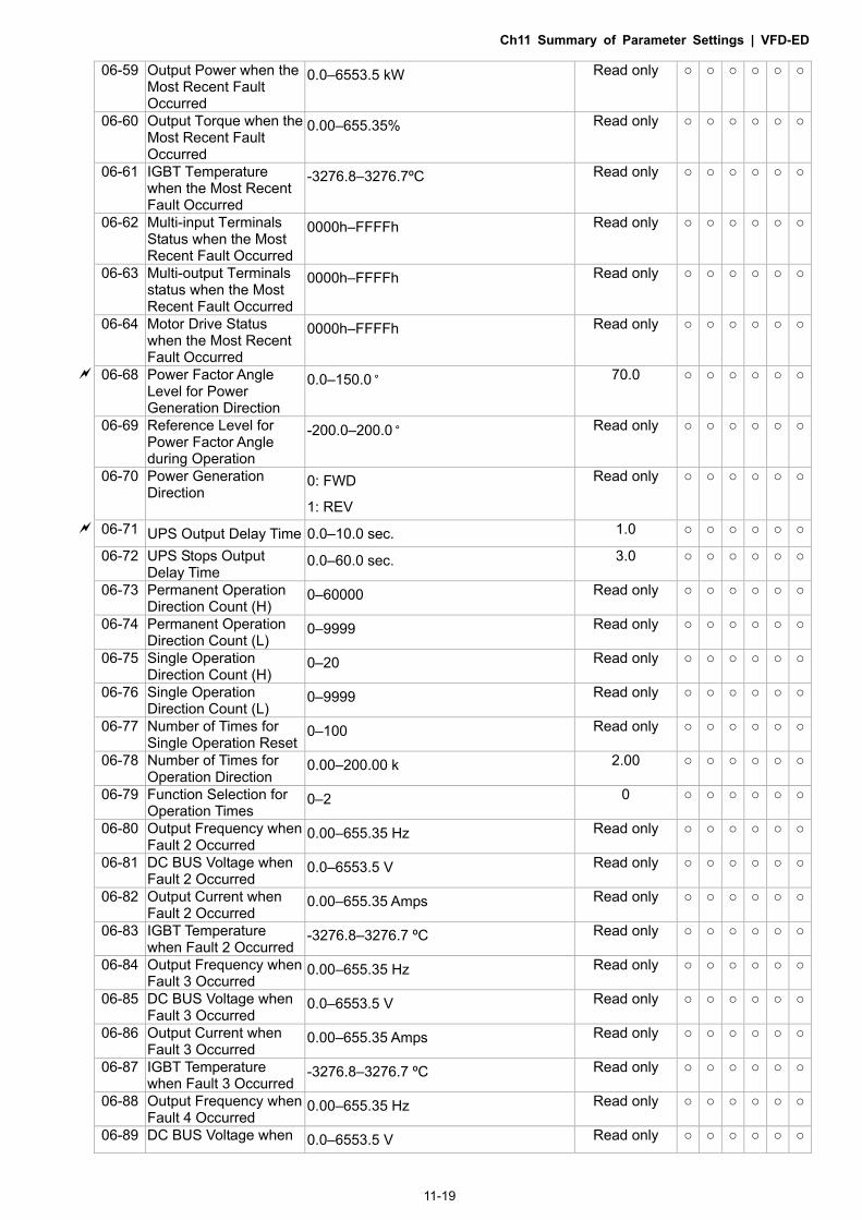
Ch11 Summary of Parameter Settings | VFD-ED
11-19
06-59 Output Power when the Most Recent Fault Occurred
0.0–6553.5 kW Read only
06-60 Output Torque when the Most Recent Fault Occurred
0.00–655.35% Read only
06-61 IGBT Temperature when the Most Recent Fault Occurred
-3276.8–3276.7ºC Read only
06-62 Multi-input Terminals Status when the Most Recent Fault Occurred
0000h–FFFFh Read only
06-63 Multi-output Terminals status when the Most Recent Fault Occurred
0000h–FFFFh Read only
06-64 Motor Drive Status when the Most Recent Fault Occurred
0000h–FFFFh Read only
06-68 Power Factor Angle Level for Power Generation Direction
0.0–150.0 70.0
06-69 Reference Level for Power Factor Angle during Operation
-200.0–200.0 Read only
06-70 Power Generation Direction
0: FWD
1: REV
Read only
06-71 UPS Output Delay Time 0.0–10.0 sec. 1.0
06-72 UPS Stops Output Delay Time
0.0–60.0 sec. 3.0
06-73 Permanent Operation Direction Count (H)
0–60000 Read only
06-74 Permanent Operation Direction Count (L)
0–9999 Read only
06-75 Single Operation Direction Count (H)
0–20 Read only
06-76 Single Operation Direction Count (L)
0–9999 Read only
06-77 Number of Times for Single Operation Reset
0–100 Read only
06-78 Number of Times for Operation Direction
0.00–200.00 k 2.00
06-79 Function Selection for Operation Times
0–2 0
06-80 Output Frequency when Fault 2 Occurred
0.00–655.35 Hz Read only
06-81 DC BUS Voltage when Fault 2 Occurred
0.0–6553.5 V Read only
06-82 Output Current when Fault 2 Occurred
0.00–655.35 Amps Read only
06-83 IGBT Temperature when Fault 2 Occurred
-3276.8–3276.7 ºC Read only
06-84 Output Frequency when Fault 3 Occurred
0.00–655.35 Hz Read only
06-85 DC BUS Voltage when Fault 3 Occurred
0.0–6553.5 V Read only
06-86 Output Current when Fault 3 Occurred
0.00–655.35 Amps Read only
06-87 IGBT Temperature when Fault 3 Occurred
-3276.8–3276.7 ºC Read only
06-88 Output Frequency when Fault 4 Occurred
0.00–655.35 Hz Read only
06-89 DC BUS Voltage when 0.0–6553.5 V Read only

Ch11 Summary of Parameter Settings | VFD-ED
11-20
Fault 4 Occurred 06-90 Output Current when
Fault 4 Occurred 0.00–655.35 Amps Read only
06-91 IGBT Temperature when Fault 4 Occurred
-3276.8–3276.7 ºC Read only
06-92 Output Frequency when Fault 5 Occurred
0.00–655.35 Hz Read only
06-93 DC BUS Voltage when Fault 5 Occurred
0.0–6553.5 V Read only
06-94 Output Current when Fault 5 Occurred
0.00–655.35 Amps Read only
06-95 IGBT Temperature when Fault 5 Occurred
-3276.8–3276.7 ºC Read only
06-96 Output Frequency when Fault 6 Occurred
0.00–655.35 Hz Read only
06-97 DC BUS Voltage when Fault 6 Occurred
0.0–6553.5 V Read only
06-98 Output Current when Fault 6 Occurred
0.00–655.35 Amps Read only
06-99 IGBT Temperature when Fault 6 Occurred
-3276.8–3276.7 ºC Read only

Ch11 Summary of Parameter Settings | VFD-ED
11-21
07 Special Parameters : You can set this parameter during operation.
Pr. Explanation Setting Range Default
VF
VFPG
SV
C
FOC
PG
TQC
PG
FOC
PM
07-00 Brake Chopper Level 230V series: 350.0–450.0 VDC 460V series: 700.0–900.0 VDC
380.0 760.0
07-01 Reserved 07-02 DC Brake Current Level
at Start-up
0–100% (motor drive rated current) 0
07-03 DC Brake Activation
Time
0.0–60.0 sec. 0.7
07-04 DC Brake Stopping
Time
0.0–60.0 sec. 0.7
07-05 Start-point for DC Brake 0.00–400.00 Hz 0.00
07-06 DC Brake Proportional
Gain
1–500 50
07-07 Dwell Time at
Acceleration
0.00–600.00 sec. 0.00
07-08 Dwell Frequency at
Acceleration.
0.00–400.00 Hz 0.00
07-09 Dwell Time at
Deceleration.
0.00–600.00 sec. 0.00
07-10 Dwell Frequency at
Deceleration.
0.00–400.00 Hz 0.00
07-11 Cooling Fan Control 0: Cooling fan always ON. 1: One minute after AC motor drive stops, cooling fan is OFF. 2: AC motor drive runs and cooling fan is ON; AC motor drive stops and cooling fan is OFF. 3: Cooling fan is ON to run when preliminary IGBT temperature () reached. 4: Cooling fan is always OFF.
2
07-12 Torque command -150.0–150.0% (Pr.07-14 setting = 100%)
0.0
07-13 Torque Command Source
0: Digital keypad (KPC-CC01) 1: RS-485 serial communication 2: Analog signal (Pr.03-00)
2
07-14 Maximum Torque Command
0–300% (motor drive rated torque) 100
07-15 Torque Command Filter Time
0.000–1.000 sec. 0.000
07-16 Speed Limit 0: Settings in Pr.07-17 and Pr.07-18 1: Frequency command source (Pr.00-14)
0
07-17 Torque Mode +Speed Limit
0–120% 10
07-18 Torque Mode-Speed Limit
0–120% 10

Ch11 Summary of Parameter Settings | VFD-ED
11-22
07-19 Torque Offset Source 0: Disable 1: Analog input (Pr.03-00) 2: Torque offset setting (Pr.07-20) 3: Control through external terminals (by Pr.07-21–Pr.07-23)
0
07-20 Torque Offset Setting 0.0–100.0% (motor drive rated torque) 0.0 07-21 High Torque Offset 0.0–100.0% (motor drive rated torque) 30.0 07-22 Middle Torque Offset 0.0–100.0% (motor drive rated torque) 20.0 07-23 Low Torque Offset 0.0–100.0% (motor drive rated torque) 10.0 07-24 Forward Motor Torque
Limit 0–300% (motor drive rated torque) 200
07-25 Forward Regenerative Torque Limit
0–300% (motor drive rated torque) 200
07-26 Reverse Motor Torque Limit
0–300% (motor drive rated torque) 200
07-27 Reverse Regenerative Torque Limit
0–300% (motor drive rated torque) 200
07-28 Emergency Stop (EF) & Forced Stop
0: Coast to stop 1: According to deceleration time 1 2: According to deceleration time 2 3: According to deceleration time 3 4: According to deceleration time 4 5: According to Pr.01-31
0
07-29 Time for Decreasing Torque at Stop
0.000–5.000 sec. 0.000
07-30 DC Brake Current Level at Stop
0–100% (motor drive rated current) 0

Ch11 Summary of Parameter Settings | VFD-ED
11-23
08 PM Parameters : You can set this parameter during operation.
Pr. Explanation Setting Range Default
VF
VFPG
SV
C
FOC
PG
TQC
PG
FOC
PM
08-00 Motor Auto-tuning 0: No function 1: Only for an unloaded motor,
auto-measures the angle between magnetic pole and PG origin (Pr.08-09)
2: For PM parameters (suggested to lock the brake)
3: Auto-measures the angle between magnetic pole and PG origin (Pr.08-09)
0
08-01 Motor Full-load Current (40–120%) * Pr.00-01 Amps #.## 08-02 Motor Rated Power 0.00–655.35 kW #.## 08-03 Motor Rated Speed
(rpm) 0–65535 rpm 1710
08-04 Number of Motor Poles 2–96 4 08-05 Motor Rs 0.000–65.535 0.000 08-06 Motor Ld 0.0–6553.5 mH 0.0 08-07 Motor Lq 0.0–6553.5 mH 0.0 08-08 Back Electromotive
Force 0.0–6553.5 V rms 0.0
08-09 Angle between Magnetic Pole and PG Origin
0.0–360.0° 360.0
08-10 Magnetic Pole Reorientation
0: Disable 1: Enable
0

Ch11 Summary of Parameter Settings | VFD-ED
11-24
09 Communication Parameters
: You can set this parameter during operation.
Pr. Explanation Setting Range Default
VF
VFPG
SV
C
FOC
PG
TQC
PG
FOC
PM
09-00 Communication Address 1–254 1 09-01 Transmission Speed 4.8–115.2 kbps 19.2 09-02 Transmission Fault
Treatment 0: Warn and keep operation 1: Warn and ramp to stop 2: Reserved 3: No action and no display
3
09-03 Time-out Detection 0.0–100.0 sec. 0.0: Disable
0.0
09-04 Communication Protocol 0: 7N1 (ASCII) 1: 7N2 (ASCII) 2: 7E1 (ASCII) 3: 7O1 (ASCII) 4: 7E2 (ASCII) 5: 7O2 (ASCII) 6: 8N1 (ASCII) 7: 8N2 (ASCII) 8: 8E1 (ASCII) 9: 8O1 (ASCII) 10: 8E2 (ASCII) 11: 8O2 (ASCII) 12: 8N1 (RTU) 13: 8N2 (RTU) 14: 8E1 (RTU) 15: 8O1 (RTU) 16: 8E2 (RTU) 17: 8O2 (RTU)
13
09-05 Response Delay Time 0.0–200.0 ms 2.0
09-06 –
09-13 Direct docking mode only -
09-14 PDO Transmission Interval 0–65535 ms 0
ExternalTerminal

Ch11 Summary of Parameter Settings | VFD-ED
11-25
10 Feedback Control Parameters : You can set this parameter during operation.
Pr. Explanation Setting Range Default
VF
VFPG
SV
C
FOC
PG
TQC
PG
FOC
PM
10-00 Selection of Encoder 0: Disable 1: ABZ 2: ABZ+Hall 3: SIN/COS+Sinusoidal 4: SIN/COS+Endat 5: SIN/COS 6: SIN/COS+Hiperface
0
10-01 Encoder Pulse 1–25000 2048 10-02 Encoder Input Type
Setting 0: Disable 1: Phase A leads in a forward run
command and phase B leads in a reverse run command
2: Phase B leads in a forward run command and phase A leads in a reverse run command
3: Phase A is a pulse input and phase B is a direction input (low input = reverse direction, high input = forward direction)
4: Phase A is a pulse input and phase B is a direction input (low input = forward direction, high input = reverse direction)
5: Single-phase input
0
10-03 Encoder Feedback Signal Fault Action (PGF1, PGF2)
0: Warn and keep operation 1: Fault and ramp to stop 2: Fault and stop operation
2
10-04 Encoder Feedback Signal Fault Detection Time
0.0–10.0 sec. 1.0
10-05 Encoder Stall Level (PGF3)
0–120% (0: Disable) 115
10-06 Encoder Stall Detection Time
0.0–2.0 sec. 0.1
10-07 Encoder Slip Range (PGF4)
0–50% (0: Disable) 50
10-08 Encoder Slip Detection Time
0.0–10.0 sec. 0.5
10-09 Encoder Stall and Slip Error Action
0: Warn and keep operation 1: Fault and ramp to stop 2: Fault and stop operation
2
10-10 Mode Selection for UVW Input
0: Z signal is at the falling edge of U-phase 1: Z signal is at the rising edge of U-phase
0
10-11 ASR (Auto Speed Regulation) Control (P) of Zero Speed
0.0–1000.0% 100.0
10-12 ASR (Auto Speed Regulation) Control (I) of Zero Speed
0.000–10.000 sec. 0.100
10-13 ASR (Auto Speed Regulation) Control (P) 1
0.0–1000.0% 100.0
10-14 ASR (Auto Speed Regulation) Control (I) 1
0.000–10.000 sec. 0.100
10-15 ASR (Auto Speed 0.0–1000.0% 100.0

Ch11 Summary of Parameter Settings | VFD-ED
11-26
Regulation) Control (P) 2
10-16 ASR (Auto Speed Regulation) Control (I) 2
0.000–10.000 sec. 0.100
10-17 ASR 1/ ASR2 Switch Frequency
0.00–400.00 Hz (0: Disable) 7.00
10-18 ASR Primary Low Pass Filter Gain
0.001–0.350 sec. 0.008
10-19 Zero Speed Position Control Gain (P)
0.00–655.00% 80.00
10-20 Low Speed ASR Width Adjustment
0.00–400.00 Hz 5.00
10-21 High Speed ASR Width Adjustment
0.00–400.00 Hz 5.00
10-22 Zero Speed Position Control Holding Time
0.001–65.535 sec. 0.250
10-23 Zero Speed Position Control Low Pass Filter Time
0.001–65.535 sec. 0.004
10-24 Zero Speed Position Control Activation Mode Selection
0: After the brake release set in Pr.02-29 1: After the brake signal input
(Pr.02-01–Pr.02-08 is set to 42)
0
10-25 Elevator Leveling (Zero Speed Gain P)
0.0–1000.0% 100.0
10-26 Elevator Leveling (Zero Speed Integral I)
0.000–10.000 sec. 0.100
10-27 Elevator Starting (Zero Speed Gain P)
0.0–1000.0% 100.0
10-28 Elevator Starting (Zero Speed Integral I)
0.000–10.000 sec. 0.100
10-29 PG Card Frequency Division Output
0–31 0
10-30 PG Card Frequency Division Output Type
0000h–0008h 0000h
10-31 PG Card C+/C- 0000h–0001h 0000h 10-32 Over-acceleration Level 0.0–20.0 m/s² 0.0
10-33 Over-acceleration Detection Time
0.01–5.00 sec. 0.05
10-34 Over-acceleration Detection Selection
0: Always detect 1: Detect during operation
0

Ch11 Summary of Parameter Settings | VFD-ED
11-27
11 Advanced Parameters : You can set this parameter during operation.
Pr. Explanation Setting Range Default
VF
VFPG
SV
C
FOC
PG
TQC
PG
FOC
PM
11-00
System Control Bit 0 = 0: No function Bit 0 = 1: ASR auto-tuning, enable PDFF Bit 7 = 0: No function Bit 7 = 1: Zero speed position control is enabled Bit 9 = 0: Dynamic PG origin auto-tuning
with load (support by PGHSD-1) Bit 9 = 1: Static PG origin auto-tuning
with load by enabling PGHSD-1 Bit 15 = 0: Detect the position of
magnetic pole again when power is applied
Bit 15 = 1: Start from the magnetic pole position of the previous power failure when power is applied
0
11-01 Elevator Speed 0.10–4.00 m/s 1.00 11-02 Sheave Diameter 100–2000 mm 400 11-03 Mechanical Gear Ratio 1.00–100.00 1.00
11-04
Suspension Ratio 0 = 1:1 1 = 2:1 2 = 4:1 3 = 8:1
1
11-05 Inertial Ratio 1–300% 40 11-06 Zero speed Bandwidth 1–40 Hz 10 11-07 Low speed Bandwidth 1–40 Hz 10 11-08 High speed Bandwidth 1–40 Hz 10 11-09 PDFF Gain Value 0–200% 30
11-10 Speed Feed Forward Gain
0–500 0
11-11 Notch Filter Depth 0–20 db 0 11-12 Notch Filter Frequency 0.00–200.00 Hz 0.00
11-13 Keypad Display for Low Pass Filter Time
0.001–65.535 sec. 0.500
11-14 Motor Current at Acceleration
50–200% 150
11-15 Carriage Acceleration 0.20–2.00 m/s2 0.75 11-16 Reserved 11-17 Reserved 11-18 Reserved
11-19 Zero Speed Parking Bandwidth
1–40 Hz 10
11-20 PWM Mode 0: DPWM mode (Digital Pulse-Width Modulation Mode) 1: SVPWM mode (Space-Vector Pulse Width Modulation Mode)
0

Ch11 Summary of Parameter Settings | VFD-ED
11-28
12 User-defined Parameters : You can set this parameter during operation.
User-defined Parameters include parameters from Group 00–11.
Pr. Explanation Setting Range Default
VF
VFPG
SV
C
FOC
PG
TQC
PG
FOC
PM
12-00 User-defined Parameter 1 0–9999 0616 12-01 User-defined Parameter 2 0–9999 0632 12-02 User-defined Parameter 3 0–9999 0633 12-03 User-defined Parameter 4 0–9999 0653 12-04 User-defined Parameter 5 0–9999 0654 12-05 User-defined Parameter 6 0–9999 0655 12-06 User-defined Parameter 7 0–9999 0656 12-07 User-defined Parameter 8 0–9999 0657 12-08 User-defined Parameter 9 0–9999 0658 12-09 User-defined Parameter 10 0–9999 0659 12-10 User-defined Parameter 11 0–9999 0660 12-11 User-defined Parameter 12 0–9999 0661 12-12 User-defined Parameter 13 0–9999 0662 12-13 User-defined Parameter 14 0–9999 0663 12-14 User-defined Parameter 15 0–9999 0664 12-15 User-defined Parameter 16 0–9999 0617 12-16 User-defined Parameter 17 0–9999 0634 12-17 User-defined Parameter 18 0–9999 0635 12-18 User-defined Parameter 19 0–9999 0618 12-19 User-defined Parameter 20 0–9999 0636 12-20 User-defined Parameter 21 0–9999 0637 12-21 User-defined Parameter 22 0–9999 0619 12-22 User-defined Parameter 23 0–9999 0638 12-23 User-defined Parameter 24 0–9999 0639 12-24 User-defined Parameter 25 0–9999 0620 12-25 User-defined Parameter 26 0–9999 0640 12-26 User-defined Parameter 27 0–9999 0641 12-27 User-defined Parameter 28 0–9999 0621 12-28 User-defined Parameter 29 0–9999 0642 12-29 User-defined Parameter 30 0–9999 0643 12-30 User-defined Parameter 31 0–9999 0 12-31 User-defined Parameter 32 0–9999 0

Ch11 Summary of Parameter Settings | VFD-ED
11-29
13 View User-defined Parameters
: You can set this parameter during operation.
Pr. Explanation Parameter Group 12 Setting Values
Display Address Pr.00-00–Pr.11-20
Default
VF
VFPG
SV
C
FOC
PG
TQC
PG
FOC
PM
13-00 Present Fault Record 0616 - 13-01 Motor Operation at Present Fault Time (min.) 0632 - 13-02 Motor Operation at Present Fault Time (day) 0633 - 13-03 Frequency Command at Present Fault 0653 - 13-04 Output Frequency at Preset Fault 0654 - 13-05 Output Current at Present Fault 0655 - 13-06 Motor Frequency at Present Fault 0656 - 13-07 Output Voltage at Present Fault 0657 - 13-08 DC BUS Voltage at Present Fault 0658 - 13-09 Output Power at Present Fault 0659 - 13-10 Output Torque at Present Fault 0660 - 13-11 Power Module IGBT Temperature at Present
Fault 0661 -
13-12 Multi-function Terminal Input Status at Present Fault 0662 -
13-13 Multi-function Terminal Output Status at Present Fault 0663 -
13-14 Drive Status at Present Fault 0664 - 13-15 Second Most Recent Fault Record 0617 - 13-16 Motor Operation at Second Most Recent
Fault Time (min.) 0634 -
13-17 Motor Operation at Second Most Recent Fault Time (day) 0635 -
13-18 Third Most Recent Fault Record 0618 - 13-19 Motor Operation at Third Most Recent Fault
Time (min.) 0636 -
13-20 Motor Operation at Third Most Recent Fault Time (day) 0637 -
13-21 Fourth Most Recent Fault Record 0619 - 13-22 Motor Operation at Fourth Most Recent Fault
Time (min.) 0638 -
13-23 Motor Operation at Fourth Most Recent Fault Time (day) 0639 -
13-24 Fifth Most Recent Fault Record 0620 - 13-25 Motor Operation at Fifth Most Recent Fault
Time (min.) 0640 -
13-26 Motor Operation at Fifth Most Recent Fault Time (day) 0641 -
13-27 Sixth Most Recent Fault Record 0621 - 13-28 Motor Operation at Sixth Most Recent Fault
Time (min.) 0642 -
13-29 Motor Operation at Sixth Most Recent Fault Time (day) 0643 -
13-30 No default 13-31 No default

Ch11 Summary of Parameter Settings | VFD-ED
11-30
[The page intentionally left blank]

Ch12 Descriptions of Parameter Settings | VFD-ED
12-1
Chapter 12 Descriptions of Parameter Settings
00 Drive Parameters : You can set this parameter during operation.
AC Motor Drive Identity Code Control Mode VF VFPG SVC FOCPG TQCPG FOCPM Default: ##
Settings Read Only
AC Motor Drive Rated Current Display Control Mode VF VFPG SVC FOCPG TQCPG FOCPM Default: ##
Settings Read Only (Display by model)
Pr.00-00 displays the AC motor drive identity code. The capacity, rated current, rated voltage and the maximum carrier frequency relate to the identity code. Use the following table to check how the AC motor drive rated current, rated voltage, and maximum carrier frequency correspond to the identity code.
Pr.00-01 displays the AC motor drive rated current. By reading this parameter, you can check if the AC motor drive is correct.
230V series
Power (kW) 2.2* 3.7* 4.0 5.5 7.5 11 15 18.5 22 30 37 Horsepower (HP) 3 5 5 7.5 10 15 20 25 30 40 50
Motor Drive ID Code (Pr.00-00)
108 110 10 12 14 16 18 20 22 24 26
Rated Output Current for
General Purposes (A)
12.0 17.0 20 24 30 45 58 77 87 132 161
Range of the Carrier Frequency
2–15 kHz 2–9 kHz
Rated Max. Output Carrier Frequency
8 kHz 10 kHz 8 kHz 6 kHz
*VFD022ED21S and VFD037ED21S are single-phase models.
460V series
Power (kW) 4.0 5.5 7.5 11 15 18.5 22 30 37 45 55 75 Horsepower (HP) 5 7.5 10 15 20 25 30 40 50 60 75 100
Motor Drive ID Code (Pr.00-00)
11 13 15 17 19 21 23 25 27 29 31 33
Rated Output Current for
General Purposes (A)
11.5 13 17 23 30 38 45 58 80 100 128 165
Range of the Carrier Frequency
2–15 kHz 2–9 kHz 2–6 kHz
Rated Max. Output Carrier Frequency
8 kHz 10 kHz 8 kHz 6 kHz

Ch12 Descriptions of Parameter Settings | VFD-ED
12-2
Parameter Reset Control Mode VF VFPG SVC FOCPG TQCPG FOCPM Default: 0
Settings 0: No Function
1: Read Only 5: Direct docking mode only, contact Delta for more information.
8: Keypad Locked
9: Reset all parameters to defaults (50 Hz )
10: Reset all parameters to defaults (60 Hz)
1: Set all parameters to read-only except Pr.00-00–Pr.00-07, and you can use this setting with the password setting for password protection.
9 or 10: Reset all parameters to the default. If the keypad is locked by a password, enter the password to reset to the default. The password is also erased.
8: Lock the keypad and only Pr.00-02 and Pr.00-07 can be changed.
Start-up Display
Control Mode VF VFPG SVC FOCPG TQCPG FOCPM Default: 0
Settings 0: Display the Frequency command value (LED F)
1: Display the actual output frequency (LED H)
2: DC BUS voltage (V)
3: Display the output current (A)
4: Output voltage (E)
5: User-defined (see Pr.00-04)
Determines the start-up display page after power is applied to the drive. Content of Multi-Function Display
Control Mode VF VFPG SVC FOCPG TQCPG FOCPM Default: 0
Settings 0: Display the output current in A supplied to the motor 1: Reserved 2: Display the actual output frequency (H) 3: Display the actual DC BUS voltage for the AC motor drive in
VDC
4: Display the terminals U, V, and W output voltage to the motor in VAC
5: Display the terminals U, V, W power factor angle to the motor
in º
6: Display the terminals U, V, and W output power to the motor
in kW
7: Display the actual motor speed in rpm (enabled when using with a PG card)
8: Display the estimated torque in % as it relates to current.
9: Display the PG feedback
10: Display the electrical angle of drive output
11: Display the AUI1 analog input terminal signal in %. Range -10–10 V corresponds to 0–100%. (1.)
12: Reserved 13: Display the AUI2 analog input terminal signal in %.
Range -10–10 V corresponds to 0–100%. (2.)

Ch12 Descriptions of Parameter Settings | VFD-ED
12-3
14: Display the heat sink temperature (°C)
15: Display the IGBT temperature in °C.
16: Display digital input status ON/OFF (i)
17: Display digital output status ON/OFF (o)
18: Display multi-step speed
19: The corresponding CPU digital input pin status (i.)
20: The corresponding CPU digital output pin status (o.)
21–23: Reserved
24: Output AC voltage when malfunction occurred (8)
25: Output DC voltage when malfunction occurred (8.)
26: Motor frequency when malfunction occurred (h)
27: Output current when malfunction occurred (4)
28: Output frequency when malfunction occurred (h.)
29: Frequency command when malfunction occurred
30: Output power when malfunction occurred
31: Output torque when malfunction occurred
32: Input terminal status when malfunction occurred
33: Output terminal status when malfunction occurred
34: Drive status when malfunction occurred
35: Display MI and MO status on digital keypad
36: CAN communication interference index
37: Multi-function display selection
This parameter displays the content on the digital keypad KPC-CC01 on page U. Use this parameter to get the AC motor drive’s status.
Example 01
Terminal MI8 MI7 MI6 MI5 MI4 MI3 MI2 MI1 REV FWD Status 0 0 1 0 0 0 0 1 1 0
0: OFF, 1: ON
MI1: Set Pr.02-01 to 1 (multi-step speed command 1). MI8: Set Pr.02-08 to 8 (the 1st, 2nd acceleration/deceleration time selection). If REV, MI1 and MI8 are ON, the value is 0000 0000 1000 01102 in binary and 0086H in HEX. Meanwhile, if you set Pr.00-04 to 16 or 19, the keypad KPC-CC01 displays “0086” and LED U is ON. Pr.00-04=16 is the status of the digital input and Pr.00-04=19 is the corresponding CPU digital input pin status. Set the parameter to 16 to monitor the digital input status and then set to 19 to check if the wire is normal. Example 02
Terminal MO8 MO7 MO6 MO5 MO4 MO3 MO2 MO1 R2A R1A MRA RA Status 0 0 0 0 1 0 0 0 0 1 1 0
RA: Set Pr.02-11 to 9 (Drive ready)
After applying the power to the AC motor drive, if there is no other error, the contact is ON. If you set Pr.00-04 to 17 or 20, the keypad displays 0001 and LED U is ON. Pr.00-04=17 is the status of digital output and Pr.00-04=20 is the corresponding CPU digital output pin status. Set the parameter to 17 to monitor the digital output status and then set to 20 to check if the wire is normal.

Ch12 Descriptions of Parameter Settings | VFD-ED
12-4
User-defined Coefficient K Control Mode VF VFPG SVC FOCPG TQCPG FOCPM Default: 0
Settings Digit 4: number of decimal points (0–3)
Digit 0–3: 40–9999
Digital setting method Digital 4: number of decimal points (0: no decimal points, 1: one decimal point and so on.)
Digit 0–3: 40–9999 (the corresponding value for the maximum frequency).
Meaning of numerical order 00000
Decimal Point Number
Corresponding Value
For example, if you use rpm to display the motor speed, and the corresponding value for the four-pole motor, 60 Hz is 1800. You can set this parameter to 1800 to indicate that the corresponding value for 60 Hz is 1800 rpm. If the unit is rps, set to 10300 to indicate that the corresponding value for 60 Hz is 30.0 (one decimal point).
The frequency setting only displays as the rpm value. For example, 60 Hz is displayed as 1800 rpm. After you set Pr.00-05, the keypad does not display the frequency unit “Hz” after returning to the Main
menu.
Software Version Control Mode VF VFPG SVC FOCPG TQCPG FOCPM Default: #.##
Settings Read Only
Password Input Control Mode VF VFPG SVC FOCPG TQCPG FOCPM Default: 0
Settings 1–9998, 10000–65535
Display 0–2 (number of wrong password attempts)
Inputs the password that is set in Pr.00-08. Enter the correct password here to enable changing parameters. You are limited to a maximum of three attempts. After three consecutive failed attempts, “Password Error” is displayed, and you must restart the AC motor drive before you can try again to enter the correct password.
If you forget the password, you can decode by setting this parameter to 9999 and press the PROG/DATA button ( PROG
DATA ) twice. Note that this resets the settings to the default.
Password Set Control Mode VF VFPG SVC FOCPG TQCPG FOCPM Default: 0
Settings 1–9998, 10000–65535
Display 0: No password set or successful input in Pr. 00-07
1: Password has been set
Sets a password to protect your parameter settings. If the display shows 0, no password is set or the password in Pr.00-07 is not correct. When the display shows 0, you can change all parameters, including Pr.00-08. The first time you can set a password directly. After you successfully set the password, the display shows 1. Be sure to record the password for later use.

Ch12 Descriptions of Parameter Settings | VFD-ED
12-5
To cancel the parameter lock, set this parameter to 0 after setting correct password in Pr.00-07. The password consists of 2–5 digits.
How to make the password valid again after decoding by Pr.00-07: Method 1: Re-enter the original password into Pr.00-08 (or you can enter a new password if you want to use a changed or new one). Method 2: After rebooting, the password function is restored. Method 3: Entering a non-password value into Pr.00-07.
Password Decode Flow Chart
Password Sett ing Decoding F low Chart Forgett ing Passwrod00-08
Displays 01 whenentering correctpassword into Pr.00-08.
Displays 00 whenentering correctpassword into Pr.00-07.
00-08
After entering 9999, press twice to decode. The parametersetti ng wil l be set to fac tory sett ing.
00-07
PROGDATA
3 chances to enter the correct password. 1st time displays "01" if password is incorrect.2nd time displays "02", if password is incorrect.3rd time displays "P code"(blinking)
If the password was entered incorrectly after three tries, the keypad will be locked.Turn the power OFF/ON to re-enter the password.
Incorrect PasswordEND
Displays 00 whenentering correctpassword into Pr.00-07.
Correct PasswordEND
00-07
00-0800-08 00-07
Control Mode Control Mode VF VFPG SVC FOCPG TQCPG FOCPM Default: 0
Settings 0: V/F control (V/F)
1: V/F control + Encoder (VFPG)
2: Sensorless Vector Control (SVC)
3: FOC vector control + Encoder (FOCPG)
8: FOC Permanent Motor control (FOCPM)
Mode selection:
Settings Control Mode
Applicable Motor Type
Speed Feedback
Energy- savings
Tuning Difficulty
Ride Comfort
Speed Control Range
Motor Parameter Learning
Basic Control
Speed Control
0 V/F IM X Low Low Normal 1:50 X V/F control
Voltage control
1 VFPG IM O Medium Medium Normal 1:50 O Frequency control
Frequency control
2 SVC IM X Medium Medium Normal 1:50 O Voltage control
Voltage control
3 FOCPG IM O High High Good 1:1000 O Vector control
Frequency control
8 FOCPM PM O High High Good 1:1000 O Vector control
Frequency control

Ch12 Descriptions of Parameter Settings | VFD-ED
12-6
Determines the AC motor drive control method. Setting 0: You can set the V/F ratio as required and control multiple motors simultaneously. Setting 1: You can use a PG card with an Encoder for close-loop speed control. Setting 2: Use auto-tuning for optimal settings of the control parameters. Setting 3: To increase torque and the accuracy of the speed control (1:1000). Setting 8: To increase torque and the accuracy of the speed control (1:1000). This setting is for use only
with permanent magnet motors. The other settings are for use with induction motors.
Speed Unit Control Mode VF VFPG SVC FOCPG TQCPG FOCPM Default: 0
Settings 0: Hz
1: m/s
2: ft/s
3: Direct docking mode only, contact Delta for more information.
Output Direction Selection Control Mode VF VFPG SVC FOCPG TQCPG FOCPM Default: 0
Settings 0: FWD: counterclockwise, REV: clockwise
1: FWD: clockwise, REV: counterclockwise Carrier Frequency
Control Mode VF VFPG SVC FOCPG TQCPG FOCPM Default:12
Settings 2–15 kHz
Determines the PWM carrier frequency for the AC motor drive.
Models 3–5 HP 7.5–15 HP 20–30 HP 40–60 HP 75–100 HP
Settings 2–15 kHz 2–15 kHz 2–15 kHz 2–9 kHz 2–6 kHz
Default 8 kHz 10 kHz 8 kHz 6 kHz 6 kHz
2kHz
8kHz
15kHz
CarrierFrequency
AcousticNoise
ElectromagneticNoise or Leakage
Current
HeatDissipation
CurrentWave
Significant
Minimal
Minimal Minimal
Significant Significant From the table, you see that the PWM carrier frequency has a significant influence on the
electromagnetic noise, the AC motor drive heat dissipation, and the motor acoustic noise. If you set the carrier frequency higher than the defaults in the table above, the motor drive derates the
capacity. See Carrier Frequency Derating Capacity (Fc) in Chapter 02. Automatic Voltage Regulation (AVR) Function
Control Mode VF VFPG SVC FOCPG TQCPG FOCPM Default: 0
Settings 0: Enable AVR
1: Disable AVR
2: Disable AVR when decelerating to stop

Ch12 Descriptions of Parameter Settings | VFD-ED
12-7
Selects the AVR mode. AVR regulates the output voltage to the motor. For example, if you set the V/F curve to 200 VAC / 50 Hz and the input voltage is from 200 to 264 VAC, the output voltage does not exceed 200 VAC / 50 Hz. If the input voltage is from 180 to 200 VAC, the output voltage to the motor and the input voltage is in direct proportion to the input voltage.
When you set this parameter to 1 during ramp to stop using the auto-acceleration / auto-deceleration function, the deceleration is smoother and faster.
Master Frequency Command Source
Control Mode VF VFPG SVC FOCPG FOCPM Default:1
Settings 1: RS-485 serial communication or digital keypad (KPC-CC01)
2: External analog input (Pr.03-00)
3: Digital terminal inputs (Pr.04-00–04-15)
4: Direct docking mode only, contact Delta for more information.
Determines the drive’s master frequency source.
Operation Command Source Control Mode VF VFPG SVC FOCPG TQCPG FOCPM Default:1
Settings 1: External terminals
2: RS-485 serial communication or digital keypad (KPC-CC01)
The ED series motor drives are shipped without a digital keypad, but you can use the external terminals or RS-485 to control the operation command.
When the LED PU is ON, you can control the operation command with the optional digital keypad. (Refer to
Chapter 09 for more information about the digital keypad KPC-CC01).

Ch12 Descriptions of Parameter Settings | VFD-ED
12-8
01 Basic Parameters : You can set this parameter during operation.
Maximum Output Frequency Control Mode VF VFPG SVC FOCPG TQCPG FOCPM Default: 60.00/50.00
Settings 10.00–400.00 Hz
Determines the AC motor drive’s Maximum Output Frequency. All the AC motor drive frequency command sources (analog inputs -10–10 V) are scaled to correspond to the output frequency range.
1st Output Frequency Setting (base frequency/ motor’s rated frequency) Control Mode VF VFPG SVC FOCPG TQCPG FOCPM Default: 60.00/50.00
Settings 0.00–400.00 Hz
Set this parameter according to the rated frequency on the motor nameplate. If the motor is 60 Hz, set this parameter to 60. If the motor is 50 Hz, set it to 50.
1st Output Voltage Setting (base voltage/ motor’s rated voltage) Control Mode VF VFPG SVC FOCPG TQCPG FOCPM Default: 220.0/440.0
Settings 230V series 0.1–255.0 V
460V series 0.1–510.0 V
Set this parameter according to the rated voltage on the motor nameplate. If the motor is 220 V, set this parameter to 220.0. If the motor is 200 V, set this parameter to 200.0.
There are many motor types in the market and the power system for each country is also different. The economical and convenient solution is to install an AC motor drive. Then there is no problem using the motor with different voltage and frequency inputs, and the motor drive can improve the original motor characteristics and useful life.
Second Output Frequency Setting Control Mode VF VFPG Default: 0.50
Settings 0.00–400.00 Hz
Second Output Voltage Setting Control Mode VF VFPG Default: 5.0/10.0
Settings 230V series 0.1–255.0 V
460V series 0.1–510.0 V
Third Output Frequency Setting Control Mode VF VFPG Default: 0.50
Settings 0.00–400.00 Hz
Third Output Voltage Setting Control Mode VF VFPG Default: 5.0/10.0
Settings 230V series 0.1–255.0 V
460V series 0.1–510.0 V
Fourth Output Frequency Setting Control Mode VF VFPG SVC FOCPG TQCPG Default: 0.00
Settings 0.00–400.00 Hz
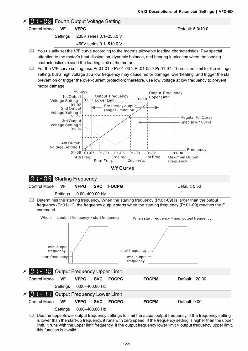
Ch12 Descriptions of Parameter Settings | VFD-ED
12-9
Fourth Output Voltage Setting Control Mode VF VFPG Default: 5.0/10.0
Settings 230V series 0.1–255.0 V
460V series 0.1–510.0 V
You usually set the V/F curve according to the motor’s allowable loading characteristics. Pay special attention to the motor’s heat dissipation, dynamic balance, and bearing lubrication when the loading characteristics exceed the loading limit of the motor.
For the V/F curve setting, use Pr.01-01 Pr.01-03 Pr.01-05 Pr.01-07. There is no limit for the voltage setting, but a high voltage at a low frequency may cause motor damage, overheating, and trigger the stall prevention or trigger the over-current protection; therefore, use low voltage at low frequency to prevent motor damage.
01-05 01-03 01-01
01-06
01-04
01-02
01-0001-0701-08 01-09
01-11 01-101st OutputVoltage Setting 1
Output FrequencyLower Limit
Frequency output ranges limitation
Regular V/f CurveSpecial V/f Curve
Voltage
4th Freq.Start Freq.
3rd Freq.2nd Freq.
1st Freq. Maximum OutputFrequency
V/f Curve
2nd OutputVoltage Sett ing 1
3rd OutputVoltage Sett ing 1
4th OutputVoltage Setting 1
Output FrequencyUpper Limit
Frequency
Starting Frequency Control Mode VF VFPG SVC FOCPG Default: 0.50
Settings 0.00–400.00 Hz Determines the starting frequency. When the starting frequency (Pr.01-09) is larger than the output
frequency (Pr.01-11), the frequency output starts when the starting frequency (Pr.01-09) reaches the F command.
When min. output frequency > start frequency When start frequency > min. output frequency
min. output frequency
start frequency
start frequency
min. output frequency
Output Frequency Upper Limit Control Mode VF VFPG SVC FOCPG FOCPM Default: 120.00
Settings 0.00–400.00 Hz
Output Frequency Lower Limit Control Mode VF VFPG SVC FOCPG FOCPM Default: 0.00
Settings 0.00–400.00 Hz Use the upper/lower output frequency settings to limit the actual output frequency. If the frequency setting
is lower than the start-up frequency, it runs with zero speed. If the frequency setting is higher than the upper limit, it runs with the upper limit frequency. If the output frequency lower limit > output frequency upper limit, this function is invalid.

Ch12 Descriptions of Parameter Settings | VFD-ED
12-10
Accel. Time 1
Control Mode VF VFPG SVC FOCPG FOCPM Default: 3.00
Settings 0.00–600.00 sec.
Decel. Time 1
Control Mode VF VFPG SVC FOCPG FOCPM Default: 2.00
Settings 0.00–600.00 sec.
Accel. Time 2
Control Mode VF VFPG SVC FOCPG FOCPM Default: 3.00
Settings 0.00–600.00 sec.
Decel. Time 2
Control Mode VF VFPG SVC FOCPG FOCPM Default:2.00
Settings 0.00–600.00 sec.
Accel. Time 3
Control Mode VF VFPG SVC FOCPG FOCPM Default:3.00
Settings 0.00–600.00 sec.
Decel. Time 3
Control Mode VF VFPG SVC FOCPG FOCPM Default:2.00
Settings 0.00–600.00 sec.
Accel. Time 4
Control Mode VF VFPG SVC FOCPG FOCPM Default:3.00
Settings 0.00–600.00 sec.
Decel. Time 4
Control Mode VF VFPG SVC FOCPG FOCPM Default:2.00
Settings 0.00–600.00 sec.
The Acceleration Time determines the time required for the AC motor drive to ramp from 0 Hz to the Maximum Output Frequency (Pr.01-00). The Deceleration Time determines the time required for the AC motor drive to decelerate from the Maximum Output Frequency (Pr.01-00) down to 0 Hz.
Select the Acceleration/Deceleration Time 1, 2, 3, 4 with the multi-function input terminal settings. The defaults are Acceleration Time 1 and Deceleration Time 1.
When there is a large opposing torque and inertial torque for the load, and the acceleration and deceleration time settings are less than the necessary value, then they enable the torque limit and stall prevention functions. When this happens, the actual acceleration and deceleration time are longer than the settings.

Ch12 Descriptions of Parameter Settings | VFD-ED
12-11
01-00
01-13,15,17,19 01-12,14,16,18
Frequency
Time
Max. OutputFrequencyFrequency
Setting
accel. time decel. time
Accel./Decel. Time
JOG Acceleration Time
JOG Deceleration Time Control Mode VF VFPG SVC FOCPG FOCPM Default: 1.00
Settings 0.00–600.00 sec.
You can use both the external terminal JOG and the JOG key on the keypad. When the JOG command is ON, the AC motor drive accelerates from the fourth output voltage setting (Pr.01-07) to the JOG frequency (Pr.01-22). When the JOG command is OFF, the AC motor drive decelerates from the JOG frequency to zero. The Acceleration and Deceleration time are set by these parameters (Pr.01-20, Pr.01-21).
You cannot execute the JOG command when the AC motor drive is running. When the JOG command is running, other operation commands are invalid except the Forward and Reverse commands.
Frequency
Time
01-22JOG frequency
01-074th outputfrequencysett ing
01-20 01-21JOG acceleration t ime JOG decel eration t ime
JOG accel./decel . t ime
JOG Frequency
Control Mode VF VFPG SVC FOCPG TQCPG FOCPM Default: 6.00
Settings 0.00–400.00 Hz
You can use both the external terminal JOG and the JOG key on PU. When the JOG terminal is disabled, the AC motor drive accelerates from 0 Hz to the JOG frequency (Pr.01-22). When the JOG terminal is enabled, the AC motor drive decelerates from the JOG frequency to zero. The Acceleration and Deceleration time are set by these parameters (Pr.01-20, Pr.01-21). You cannot execute the JOG command when the AC motor drive is running. When the JOG command is running, other operation commands are invalid except the Forward and Reverse commands and the STOP key on the digital keypad.

Ch12 Descriptions of Parameter Settings | VFD-ED
12-12
Switch Frequency between First and Fourth Accel./Decel. Control Mode VF VFPG SVC FOCPG FOCPM Default: 0.00
Settings 0.00–400.00 Hz
Determines the frequency for the transition from acceleration and deceleration time 1 to acceleration and deceleration time 4. You can also enable the transition from acceleration or deceleration time 1 to acceleration and deceleration time 4 with the external terminals (Pr.02-01–Pr.02-08). The external terminal has priority over Pr.01-23.
Frequency
1st/4th Acceleration/Deceleration Switching
01-23
4th Acceleration Time4th Deceleration Time
1st AccelerationTime 1st Deceleration
Time
1st/4th Acceleration/DecelerationFreq.
S-curve for Acceleration Begin Time S1
S-curve for Acceleration Arrival Time S2
S-curve for Deceleration Begin Time S3
S-curve for Deceleration Arrival Time S4
S-curve for Deceleration Arrival Time S5 Control Mode VF VFPG SVC FOCPG FOCPM Default: 1.00
Settings 0.00–25.00 sec.
Switch Frequency for S3/S4 Changes to S5
Control Mode VF VFPG SVC FOCPG FOCPM Default: 0.00
Settings 0.00–400.00 Hz
Using an S-curve gives the smoothest transition between speed changes. The acceleration and deceleration curve adjusts the acceleration and deceleration S-curve. When enabled, the motor drive produces a different acceleration and deceleration curve according to the acceleration and deceleration time.
The Actual Acceleration Time = selected acceleration Time + (Pr.01-24 + Pr.01-25) / 2. The Actual Deceleration Time = selected deceleration Time + (Pr.01-26 + Pr.01-27 + Pr.01-30 * 2) / 2.
Use Pr.01-29 to set the switch frequency between S4 and S5 for smooth stopping. Set this parameter to the leveling speed of the elevator.
Frequency
01-12accel. t ime
01-13decel. t ime
Time
01-25=S2 01-26=S3
01-24=S1
01-27=S4
01-30=S5
01-29Switch frequencyfor S3/S 4 changes to S5

Ch12 Descriptions of Parameter Settings | VFD-ED
12-13
Mode Selection when Frequency < Fmin Control Mode VF VFPG SVC Default: 1
Settings 0: Output Waiting
1: Zero-speed operation
2: Fmin (Fourth output frequency setting)
The AC motor drive uses this parameter when it is at 0 Hz. 1 or 2: The voltage outputs according to the output voltage command corresponding to Fmin (Pr.01-08).
Deceleration Time when Operating without RUN Command Control Mode VF VFPG SVC FOCPG FOCPM Default: 2.00
Settings 0.00–600.00 sec.
The AC motor drive stops according to this parameter when cancelling the RUN command. Refer to the figure in the description for Pr.01-29 for details.
Direct docking mode only Control Mode Default: -
Settings Contact Delta for more information
High Speed Time for Short Floor Control Mode VF VFPG SVC FOCPG TQCPG FOCPM Default: 3.00
Settings 0.00–60.00 sec.
Sets the high speed duration during short floor operation.
Leveling Speed Time for Short Floor Control Mode VF VFPG SVC FOCPG TQCPG FOCPM Default: 3.00
Settings 0.00–60.00 sec.
Sets the leveling speed duration during short floor operation.
Limit for Direct Docking Terminal Control Mode VF VFPG SVC FOCPG TQCPG FOCPM Default: 2.00
Settings 0.00–10.00
Sets the limit for changing from leveling speed to acceleration when using terminals for direct docking.
Deceleration Distance for Direct Docking Terminal Control Mode VF VFPG SVC FOCPG TQCPG FOCPM Default: 30.00
Settings 0.00–10.00 cm
Sets the distance between deceleration points.
Deceleration Distance Reference for Short Floor Control Mode VF VFPG SVC FOCPG TQCPG FOCPM Default: Read only
Settings 0.00–655.35 m
Sets the distance between deceleration points according to short floors (write inhibit).

Ch12 Descriptions of Parameter Settings | VFD-ED
12-14
Short Floor/Direct Docking Terminal Enabled Control Mode VF VFPG SVC FOCPG TQCPG FOCPM Default: 0000h
Settings 0000h: Disabled
0001h: Short floor enabled
0002h: Direct docking terminal enabled 0003h: Short floor + direct docking terminal enabled
Related parameters: Pr.02-01–02-08 multi-function input terminal (53: terminal leveling signal for direct docking).
Direct docking terminal function: When the elevator runs to the leveling area, controller sends a leveling signal to the drive to make the drive stop within effective distance (Pr.01-36), as shown in the figure below. If deceleration distance is too short, the drive adjusts the speed according to the limit for acceleration change (Pr.01-35). There are two methods for sending leveling signals: 1. Using multi-function input terminals 2. Do not use the low speed multi-step speed When using the first method, set MI setting value to 53.
Direct docking terminal function (using MI terminal to input leveling signals)

Ch12 Descriptions of Parameter Settings | VFD-ED
12-15
Direct docking terminal function (using multi-step speed change)
Definitions of deceleration distance for short floors:
When the motor runs with the highest speed, the deceleration distance for short floors is calculated according to the first deceleration time (S3 curve time, equivalent deceleration time, S4 curve time) and leveling speed duration, as Pr.01-37 in Case 1_Short floor function diagram illustrated.
The following cases are illustrated by diagrams: Case 1. Deceleration point (instead of high speed) is given before allowed speed Case 2. Deceleration point (instead of high speed) is given before allowed speed and high speed time is not zero. Case 3. Deceleration point (instead of high speed) is given before allowed speed and high speed time is zero.
Case 1. Deceleration point (instead of high speed) is given before allowed speed Regardless of the corresponding speed when the drive gives the deceleration points, the drive issues the speed allowance command to replace leveling speed, executes the corresponded S2 curve before allowed speed, maintains the high speed time set, and gives the leveling speed after high speed duration. Refer to Pr.01-12, 01-24, 01-25 for information on acceleration curves.

Ch12 Descriptions of Parameter Settings | VFD-ED
12-16
Short floor function diagram
Case 2. Deceleration point (instead of high speed) is given before allowed speed and high speed time is not zero. When high speed is higher than allowed speed, the drive automatically determines the remaining distances and reduces the high speed duration accordingly to increase the running speed. Note that if the high speed duration is reduced to zero or below zero, the system executes the equivalent speed command according to the current speed instead of executing S2, and increases the high speed duration to reduce the leveling time.

Ch12 Descriptions of Parameter Settings | VFD-ED
12-17
Case 3. Deceleration point (instead of high speed) is given before allowed speed and high speed time is zero When high speed is higher than allowed speed, because there is no duration, the drive levels the speed instead of executing S2, adds high speed duration accordingly to reduce the leveling time, which is the same as Case 2 when the high speed duration is reduced to zero or below zero.
Automatic Emergency Deceleration Level Control Mode VFPG FOCPG FOCPM Default: 60.00
Settings 5.00–400.00 Hz
When MI is set to 56, the system monitors the current speed. If the speed is higher than Pr.01-39, the drive decelerates to Pr.01-29 speed according to Pr.01-40 deceleration time.
Deceleration Time for Emergency Deceleration Control Mode VFPG FOCPG FOCPM Default: 2.00
Settings 0.00–600.00 sec.
When MI=55 function is triggered, the drive decelerates to Pr.01-29 speed according to Pr.01-40 deceleration time, as shown in the figure below.

Ch12 Descriptions of Parameter Settings | VFD-ED
12-18
02 Digital Input / Output Parameters
: You can set this parameter during operation. Two-wire//three-wire Operation Control Control Mode VF VFPG SVC FOCPG TQCPG FOCPM Default: 0
Settings 0: FWD/STOP, REV/STOP
1: FWD/STOP, REV/STOP (Line Start Lockout)
2: RUN/STOP, REV/FWD
3: RUN/STOP, REV/FWD (Line Start Lockout)
4: Three-wire
5: Three-wire (Line Start Lockout)
Three of the six modes include a “Line Start Lockout” feature. When line start lockout is enabled, the motor drive does not run when you apply power. The Line Start Lockout feature does not guarantee that the motor never starts under this condition. It is possible the motor may be set in motion by a malfunctioning switch.
This parameter controls operation from external terminals. There are three different control modes. Pr.02-00 External Terminal Control Circuits
0, 1 Two-wire operation control (1)
FWD/STOP REV/STOP
FWD:("OPEN":STOP) ("CLOSE":FWD)
REV:("OPEN": STOP) ("CLOSE": REV)
VFD-EDDCM
FWD/STOP
REV/STOP
2, 3 Two-wire operation control (2)
RUN/STOP REV/FWD
FWD:("OPEN":STOP) ("CLOSE":RUN)REV:("OPEN": FWD) ("CLOSE": REV)
VFD-EDLDCM
RUN/STOP
FWD/REV
4, 5 Three-wire operation control
FWD "CLOSE":RUN
MI1 "OPEN":STOP
REV/FWD "OPEN": FWD "CLOSE": REV
VFD-EDDCM
STOP
REV/FWD
RUN
Multi-Function Input Command 1 (MI1) (It is the Stop terminal for three-wire operation)
Default:1
Multi-Function Input Command 2 (MI2) Default:2
Multi-Function Input Command 3 (MI3) Default:3
Multi-Function Input Command 4 (MI4) Default:4
Multi-Function Input Command 5 (MI5) Default: 0
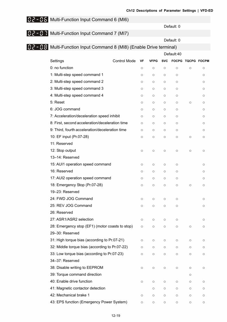
Ch12 Descriptions of Parameter Settings | VFD-ED
12-19
Multi-Function Input Command 6 (MI6) Default: 0
Multi-Function Input Command 7 (MI7) Default: 0
Multi-Function Input Command 8 (MI8) (Enable Drive terminal) Default:40
Settings Control Mode VF VFPG SVC FOCPG TQCPG FOCPM
0: no function
1: Multi-step speed command 1 2: Multi-step speed command 2 3: Multi-step speed command 3 4: Multi-step speed command 4 5: Reset 6: JOG command 7: Acceleration/deceleration speed inhibit 8: First, second acceleration/deceleration time 9: Third, fourth acceleration/deceleration time 10: EF input (Pr.07-28) 11: Reserved
12: Stop output 13–14: Reserved
15: AUI1 operation speed command 16: Reserved 17: AUI2 operation speed command 18: Emergency Stop (Pr.07-28) 19–23: Reserved
24: FWD JOG Command 25: REV JOG Command 26: Reserved
27: ASR1/ASR2 selection 28: Emergency stop (EF1) (motor coasts to stop) 29–30: Reserved
31: High torque bias (according to Pr.07-21) 32: Middle torque bias (according to Pr.07-22) 33: Low torque bias (according to Pr.07-23) 34–37: Reserved
38: Disable writing to EEPROM 39: Torque command direction 40: Enable drive function 41: Magnetic contactor detection
42: Mechanical brake 1 43: EPS function (Emergency Power System)

Ch12 Descriptions of Parameter Settings | VFD-ED
12-20
44: Mechanical brake 2
45–51: Direct docking mode only
53: Terminal leveling signal for direct docking
54: Power failure signal
55: Manual emergency deceleration
56: Automatic emergency deceleration
Selects the functions for each multi-function terminal. If you set Pr.02-00 to three-wire operation control, terminal MI1 is for STOP terminal, and MI1 is not
available for any other operation.
Settings Functions Descriptions
0 No Function
1 Multi-step speed command 1 15-step speeds controlled through the four terminals, and 17 in
total including the master speed and JOG (refer to Pr.
04-00–Pr.04-14).
When using communication to control the multi-step speed,
settings 1–4 are invalid.
2 Multi-step speed command 2
3 Multi-step speed command 3
4 Multi-step speed command 4
5 Reset After you eliminate the drive error, use this terminal to reset the
drive.
6 JOG Command JOG operation
7 Acceleration/deceleration Speed Inhibit
When enabled, acceleration and deceleration are stopped and the AC motor drive starts to accelerate and decelerate from the inhibit point.
8 The first, second acceleration or deceleration time
You can select the motor drive’s acceleration and deceleration time through the terminals; there are four acceleration and deceleration speeds in total.
Bit 0 Bit 1 Descriptions 0 0 First accel./decel. time
When output frequency is less than Pr.01-23 (Switch Frequency between first/fourth Accel./decel.), it outputs the fourth accel./decel. time.
0 1 Second accel./decel. time 1 0 Third accel./decel. time 1 1 Fourth accel./decel. time
If the drive receives STOP command, it decelerates to stop with
Pr.01-31.
9 The third, fourth acceleration or
deceleration time
10 EF Input External fault input terminal, and decelerates according to
Pr.07-28 (records EF fault).
11: Reserved
12 Stop output
When enabled, the motor drive output stops immediately and
the motor coasts. When disabled, the motor drive accelerates to
the frequency setting.
13–14: Reserved
15 AUI1 operation speed
command
When the operation speed command source is AUI1 and AUI2,
and two or more terminals are ON, the priority is AUI1 > AUI2.
When enabled, the frequency source is AUI1.

Ch12 Descriptions of Parameter Settings | VFD-ED
12-21
16: Reserved
17 AUI2 operation speed command When enabled, it forces the frequency source to AUI2.
18 Emergency Stop When enabled, the motor drive ramps to stop according to
Pr.07-28.
19–23: Reserved
24 FWD JOG command When enabled, the motor drive executes the forward Jog
command.
25 REV JOG command When enabled, the motor drive executes the reverse Jog
command.
26: Reserved
27 ASR1/ASR2 selection ON: Speed is adjusted according to ASR 2. OFF: Speed is adjusted according to ASR 1.
28 Emergency stop (EF1) (Motor coasts to stop)
ON: The motor drive executes emergency stop and records the
fault code.
29–30: Reserved
31 High torque bias When Pr.07-19 is set to 3:
Set the high torque bias in Pr.07-21.
Set the middle torque bias in Pr.07-22.
Set the low torque bias in Pr.07-23.
31 32 33 Torque Bias OFF OFF OFF N/A OFF OFF ON Pr.07-23 OFF ON OFF Pr.07-22 OFF ON ON Pr.07-23+ Pr.07-22 ON OFF OFF Pr.07-21 ON OFF ON Pr.07-21+ Pr.07-23 ON ON OFF Pr.07-21+ Pr.07-22
ON ON ON Pr.07-21+ Pr.07-22+ Pr.07-23
32 Middle torque bias
33 Low torque bias
34–37: Reserved
38 Disable writing to EEPROM When enabled, you cannot write to EEPROM.
39 Torque command direction When the torque command is AUI, set this function to change the torque command direction. To work with Pr.07-13 = 2, set Pr.03-01 to 2.
40 Enable drive function
When enabled, it executes the motor drive function. This
function can be used with multi-function output (setting
Pr.02-11–Pr.02-14 to 15) and (Pr.02-31 and Pr.02-32).

Ch12 Descriptions of Parameter Settings | VFD-ED
12-22
41 Magnetic contactor detection
This terminal is for the magnetic contactor feedback signal
ON/OFF.
When the motor drive receives a RUN command, it enables the
corresponding output terminal (setting 15) after Pr.02-31 time. It
checks if this function is enabled in the detection time
(Pr.02-36). If NOT, the magnetic contactor error occurs and
error code “MCF” displays.
42 Mechanical brake 1
When the motor drive receives a RUN command, it enables the
corresponding output terminal (setting 12) after Pr.02-29 time. It
checks if this function is enabled in the detection time
(Pr.02-35). If NOT, the mechanical brake error occurs and error
code “MBF” displays.
43 EPS function (Emergency
Power System)
If power is cut during running, the drive stops when the DC BUS
voltage is less than the low voltage level. After power is cut, the
drive runs according to the EPS frequency when EPS is applied
and this function is ON.
44 Mechanical brake 2
When the motor drive receives a RUN command, it enables the
corresponding output terminal (setting 12) after Pr.02-29 time. It
checks if this function is enabled in the detection time
(Pr.02-35). If NOT, the mechanical brake error occurs and error
code “MBF” displays.
45–51 Direct docking mode only Contact Delta for more information.
53 Terminal leveling signal for
direct docking
When the elevator runs to the leveling area, controller sends a
signal to the drive to make the drive stop within effective
distance (Pr.01-36).
54 Power failure signal
When power failure occurs, the host controller inputs this signal
to inform the drive. When the motor drive receives this signal,
MO = 49 is disabled after Pr.06-71 time
55 Manual emergency
deceleration
When the motor drive receives this signal, it decelerates to
Pr.01-29 speed according to Pr.01-40 deceleration time.
56 Automatic emergency
deceleration
After setting this MI function, the system monitors the current
speed. If the speed is higher than Pr.01-39, the drive
decelerates to Pr.01-29 speed according to Pr.01-40
deceleration time.

Ch12 Descriptions of Parameter Settings | VFD-ED
12-23
FrequencyOutput
Multi-functionInput Terminal D=41
Frequency
T1<02-36
07-03 07-04
02-31 02-32
T2<02-35
OperationCommand(FWD/REV)
Time
Multi-functionOutput Terminal D=15
Zero speed
Outputfrequency
Operationcommand
Magnetic contactor
Multi -functioninput termina lMI41
Multi -functioninput termina lMI41
Multi -functioninput termina lMI41
Detection time for contactor (02-36)
Status 1
Status 2
Status 3
Digital Input Response Time Control Mode VF VFPG SVC FOCPG TQCPG FOCPM Default:0.005
Settings 0.001–30.000 sec.
Defines the digital input terminal signal delay and confirmation. The delay time prevents interference that can cause errors (except for the counter input) in the digital terminal input (FWD, REV and MI1–8). Increasing the setting for this parameter can reduce the errors, but it delays the response time.
Digital Input Operation Direction Control Mode VF VFPG SVC FOCPG TQCPG FOCPM Default: 0
Settings 0–65535
Sets the input signal level and it is not affected by the SINK/SOURCE status. Bit 0 is for FWD terminal, bit 1 is for REV terminal and bits 2–9 are for MI1 to MI8. You can change the terminal status through communications.
For example, set MI1=1 (multi-step speed command 1) and MI2=2 (multi-step speed command 2). Then the forward + second step speed command = 1001 (binary) = 9 (Decimal). You only need to set Pr.02-10=9 through communications and it can move forward at the second step speed. In this case, you do not need to wire any multi-function terminals.
bit9 bit8 bit7 bit6 bit5 bit4 bit3 bit2 bit1 bit0
MI8 MI7 MI6 MI5 MI4 MI3 MI2 MI1 REV FWD

Ch12 Descriptions of Parameter Settings | VFD-ED
12-24
Multi-function Output 1: RA, RB, RC (Relay 1) Default: 11
Multi-function Output 2: MRA, MRB, MRC (Relay 2) Default: 1
Multi-function Output 3: R1A, R12C (Relay 3) Multi-function Output 4: R2A, R12C (Relay 4) Multi-function Output 5: MO1 Multi-function Output 6: MO2
Reserved Reserved Reserved Reserved Reserved Reserved Default: 0 Settings Control Mode VF VFPG SVC FOCPG TQCPG FOCPM
0: No function 1: Operation indication 2: Operation speed reached 3: Desired frequency 1 reached (Pr.02-25,
Pr.02-26)
4: Desired frequency 2 reached (Pr.02-27,
Pr.02-28)
5: Zero Speed (Frequency command) 6: Zero speed with stop (Frequency command) 7: Over-torque (OT1) (Pr.06-05–06-07) 8: Over-torque (OT2) (Pr.06-08–06-10) 9: Drive ready 10: User-defined low-voltage detection (LV) 11: Malfunction indication 12: Mechanical brake release (Pr.02-29, Pr.02-30,
Pr.02-37)
13: Overheat (Pr.06-14) 14: Brake chopper signal 15: Motor-controlled magnetic contactor output
16: Slip error (oSL) 17: Malfunction indication 1 18: Reserved
19: Brake chopper output error
20: Warning output 21: Over-voltage warning 22: Over-current stall prevention warning
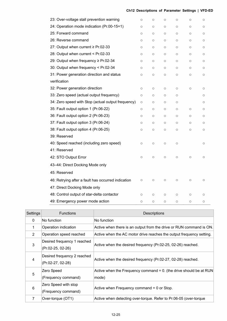
Ch12 Descriptions of Parameter Settings | VFD-ED
12-25
23: Over-voltage stall prevention warning 24: Operation mode indication (Pr.00-15=1) 25: Forward command 26: Reverse command 27: Output when current ≥ Pr.02-33 28: Output when current < Pr.02-33 29: Output when frequency ≥ Pr.02-34 30: Output when frequency < Pr.02-34 31: Power generation direction and status
verification
32: Power generation direction
33: Zero speed (actual output frequency) 34: Zero speed with Stop (actual output frequency) 35: Fault output option 1 (Pr.06-22) 36: Fault output option 2 (Pr.06-23) 37: Fault output option 3 (Pr.06-24) 38: Fault output option 4 (Pr.06-25) 39: Reserved
40: Speed reached (including zero speed) 41: Reserved 42: STO Output Error
43–44: Direct Docking Mode only
45: Reserved
46: Retrying after a fault has occurred indication
47: Direct Docking Mode only 48: Control output of star-delta contactor 49: Emergency power mode action Settings Functions Descriptions
0 No function No function
1 Operation indication Active when there is an output from the drive or RUN command is ON.
2 Operation speed reached Active when the AC motor drive reaches the output frequency setting.
3 Desired frequency 1 reached
(Pr.02-25, 02-26) Active when the desired frequency (Pr.02-25, 02-26) reached.
4 Desired frequency 2 reached
(Pr.02-27, 02-28) Active when the desired frequency (Pr.02-27, 02-28) reached.
5 Zero Speed
(Frequency command)
Active when the Frequency command = 0. (the drive should be at RUN
mode)
6 Zero Speed with stop
(Frequency command) Active when Frequency command = 0 or Stop.
7 Over-torque (OT1) Active when detecting over-torque. Refer to Pr.06-05 (over-torque
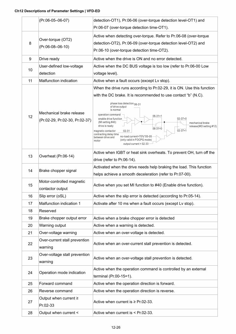
Ch12 Descriptions of Parameter Settings | VFD-ED
12-26
(Pr.06-05–06-07) detection-OT1), Pr.06-06 (over-torque detection level-OT1) and
Pr.06-07 (over-torque detection time-OT1).
8 Over-torque (OT2)
(Pr.06-08–06-10)
Active when detecting over-torque. Refer to Pr.06-08 (over-torque
detection-OT2), Pr.06-09 (over-torque detection level-OT2) and
Pr.06-10 (over-torque detection time-OT2).
9 Drive ready Active when the drive is ON and no error detected.
10 User-defined low-voltage
detection
Active when the DC BUS voltage is too low (refer to Pr.06-00 Low
voltage level).
11 Malfunction indication Active when a fault occurs (except Lv stop).
12 Mechanical brake release
(Pr.02-29, Pr.02-30, Pr.02-37)
When the drive runs according to Pr.02-29, it is ON. Use this function
with the DC brake. It is recommended to use contact “b” (N.C).
13 Overheat (Pr.06-14) Active when IGBT or heat sink overheats. To prevent OH, turn off the
drive (refer to Pr.06-14).
14 Brake chopper signal Activated when the drive needs help braking the load. This function
helps achieve a smooth deceleration (refer to Pr.07-00).
15 Motor-controlled magnetic
contactor output Active when you set MI function to #40 (Enable drive function).
16 Slip error (oSL) Active when the slip error is detected (according to Pr.05-14).
17 Malfunction indication 1 Activate after 10 ms when a fault occurs (except Lv stop).
18 Reserved
19 Brake chopper output error Active when a brake chopper error is detected
20 Warning output Active when a warning is detected.
21 Over-voltage warning Active when an over-voltage is detected.
22 Over-current stall prevention
warning Active when an over-current stall prevention is detected.
23 Over-voltage stall prevention
warning Active when an over-voltage stall prevention is detected.
24 Operation mode indication Active when the operation command is controlled by an external
terminal (Pr.00-15=1).
25 Forward command Active when the operation direction is forward.
26 Reverse command Active when the operation direction is reverse.
27 Output when current ≥
Pr.02-33 Active when current is ≥ Pr.02-33.
28 Output when current < Active when current is < Pr.02-33.

Ch12 Descriptions of Parameter Settings | VFD-ED
12-27
Pr.02-33
29 Output when frequency ≥
Pr.02-34 Active when frequency is ≥ Pr.02-34.
30 Output when frequency <
Pr.02-34 Active when frequency is < Pr.02-34.
31 Power generation direction
and status verification Activate when the power generation direction is verified.
32 Power generation direction Activate when the power generation direction runs forward.
33 Zero speed (actual output
frequency)
Active when the actual output frequency is 0. The drive should be in
RUN mode.
34 Zero speed with stop (actual
output frequency)
Active when the actual output frequency is 0 or Stop. The drive should
be in RUN mode.
35 Fault output option 1
(Pr.06-22) Active when Pr.06-22 is ON.
36 Fault output option 2
(Pr.06-23) Active when Pr.06-23 is ON.
37 Fault output option 3
(Pr.06-24) Active when Pr.06-24 is ON.
38 Fault output option 4
(Pr.06-25) Active when Pr.06-25 is ON.
39 Reserved
40 Speed reached (including
zero speed) Active when the output frequency reaches the frequency setting.
41 Reserved
42 STO Output Error
Status of drive Status of safety output
Status A (MO=42)
Normal Broken circuit (open)
STO Short circuit (closed) *Setting of logic output
STL1–STL3 Short circuit (closed) B is on page 16-6.
43–44 Direct Docking Mode only Contact Delta for more information
45 Reserved
46 Retrying after a fault has
occurred indication
Retry multiple outputs after an error has occurred. When the retry
period has finished, MO stops.
47 Direct Docking Mode only Contact Delta for more information
48 Control output of star-delta
contactor Active when the drive receives a STOP command.
49 Emergency power mode
action
Active when the drive receives a signal from the host controller
(Pr.02-01–02-08=54) after Pr.06-71 time.

Ch12 Descriptions of Parameter Settings | VFD-ED
12-28
Multi-output Direction Control Mode VF VFPG SVC FOCPG TQCPG FOCPM Default: 0
Settings 0–65535
This parameter uses bit setting. If the bit is 1, the multi-function output terminal acts in the opposite direction. For example, if you set Pr.02-11 to 1 and the forward bit is 0, Relay 1 is ON when the drive is running and OFF when the drive is stopped. Bit 11 Bit 10 Bit 9 Bit 8 Bit 7 Bit 6 Bit 5 Bit 4 Bit 3 Bit 2 Bit 1 Bit 0
- - - - - - MO2 MO1 R2A R1A MRA RA
Serial Start Signal Selection Control Mode VF VFPG SVC FOCPG FOCPM Default: 0
Settings 0: According to FWD/REV signal
1: According to Enable drive function signal
Selects the electromagnetic valve serial start method. 0: According to FWD/REV signal, the motor starts to run after the Enable signal MI = 40 is ON.
1: According to Enable signal, the electromagnetic valve, mechanical brake and DC brake all follow
parameters’ setting to run after FWD/REV and Enable are ON.
Pr.02-24=0 Enable Drive 0 1
Multi-function output
MO= 15
0 False False
1 True True
No matter if the Enable Drive function signal outputs or not,
the drive starts to count Pr.02-31 after MO15 .outputs.

Ch12 Descriptions of Parameter Settings | VFD-ED
12-29
Pr.02-24=1 Enable Drive 0 1
Multi-function output
MO= 15
0 False False
1 False True
After both Enable Drive function signal and MO15 output, the drive starts to count Pr.02-31.
Desired Frequency Reached 1 Control Mode VF VFPG SVC FOCPG FOCPM Default: 60.00/50.00
Settings 0.00–400.00 Hz
Desired Frequency Reached Width 1 Control Mode VF VFPG SVC FOCPG FOCPM Default: 2.00
Settings 0.00–400.00 Hz
Desired Frequency Reached 2 Control Mode VF VFPG SVC FOCPG FOCPM Default: 60.00/50.00
Settings 0.00–400.00 Hz
Desired Frequency Reached Width 2 Control Mode VF VFPG SVC FOCPG FOCPM Default: 2.00
Settings 0.00–400.00 Hz
Once the output frequency reaches the desired frequency and the corresponding multi-function output terminal is set to 3 or 4 (Pr.02-11–Pr.02-22), this multi-function output terminal is ON.
Brake Release Delay Time when Elevator Starts Control Mode VF VFPG SVC FOCPG TQCPG FOCPM Default: 0.250
Settings 0.000–65.000 sec.
Brake Engage Delay Time when Elevator Stops Control Mode VF VFPG SVC FOCPG TQCPG FOCPM Default: 0.250
Settings 0.000–65.000 sec.
When the AC motor drive runs and after the delay time in Pr.02-29, the corresponding multi-function
output terminal (12: mechanical brake release) is ON. When the AC motor drive stops and after the delay time in Pr.02-30, the corresponding multi-function
output terminal (12: mechanical brake release) is OFF. Use this function with the DC brake function.

Ch12 Descriptions of Parameter Settings | VFD-ED
12-30
Motor speed/Output frequenc y
07- 03DC brake time duringstart-up
07- 04DC braketime duringstopping
Mul ti -function output(m echanica l br ak e r eleas e)Pr.02- 11 to 02-22=12
Mechanica l brake
bounce time of mechanical brake
RUN/STOP
02-29 Brake release delay time when elevator starts
RUN STOP
02-30 Brake engage delay time whenelevator stops
DC brake DC brake
Mechanical brake release brake engage
brake engage
Magnetic Contactor Contracting Delay Time between Drive and Motor Magnetic Contactor Release Delay Time between Drive and Motor
Control Mode VF VFPG SVC FOCPG TQCPG FOCPM Default: 0.200
Settings 0.010–65.000 sec.
After running, use these parameters with multifunction input terminal setting 40 (Enable drive function), and multifunction output terminal setting 15 (motor-controlled magnetic contactor output). When the multifunction output terminals are ON, the drive starts outputting after the delay time in Pr.02-31. When the drive stops outputting, multifunction output terminals release after the delay time in Pr.02-32.
Star-delta Contactor Release Delay Time between Drive and Motor
Control Mode VF VFPG SVC FOCPG TQCPG FOCPM Default: 0.200
Settings 0.0010~65.000 sec.
Star-delta Contactor Contracting Delay Time between Drive and Motor
Control Mode VF VFPG SVC FOCPG TQCPG FOCPM Default: 0.200
Settings 0.0010~65.000 sec.

Ch12 Descriptions of Parameter Settings | VFD-ED
12-31
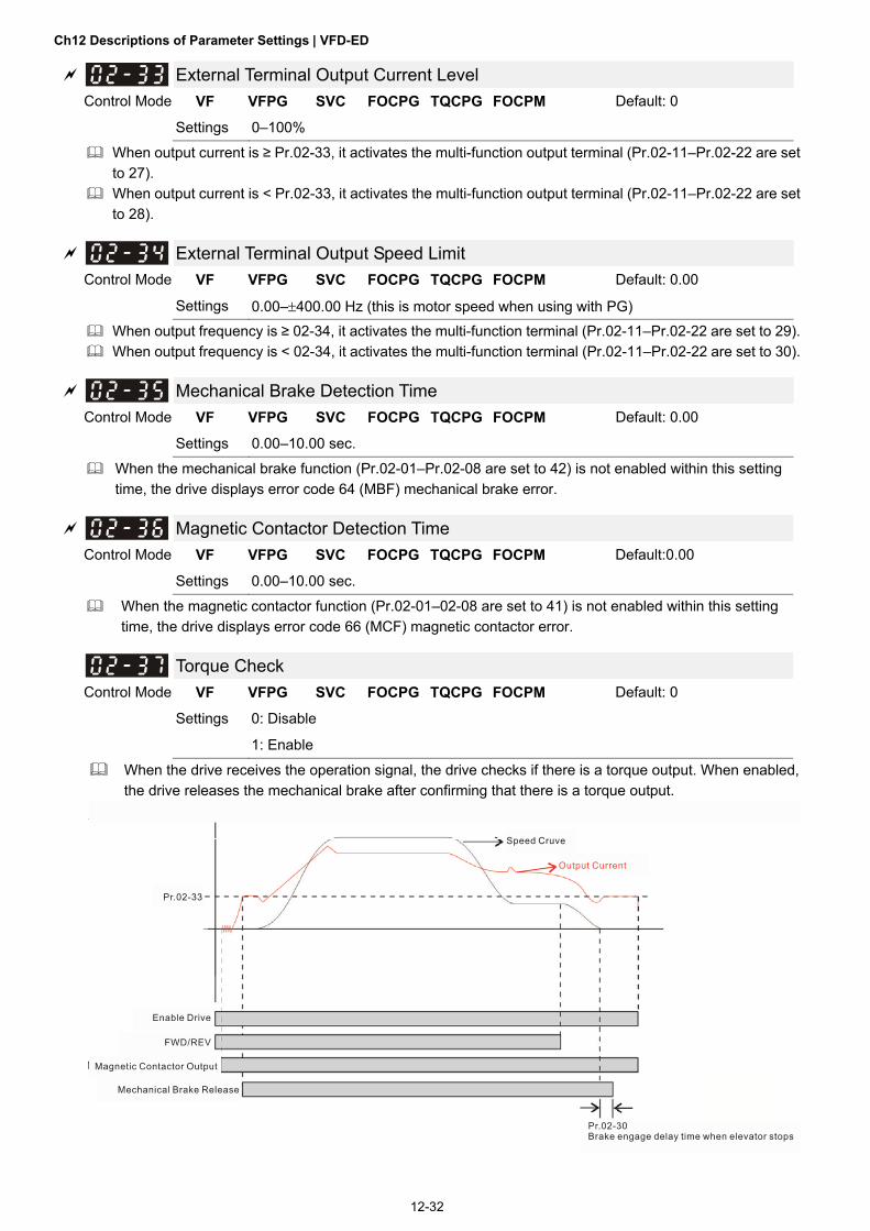
Ch12 Descriptions of Parameter Settings | VFD-ED
12-32
External Terminal Output Current Level Control Mode VF VFPG SVC FOCPG TQCPG FOCPM Default: 0
Settings 0–100%
When output current is ≥ Pr.02-33, it activates the multi-function output terminal (Pr.02-11–Pr.02-22 are set to 27).
When output current is < Pr.02-33, it activates the multi-function output terminal (Pr.02-11–Pr.02-22 are set to 28).
External Terminal Output Speed Limit Control Mode VF VFPG SVC FOCPG TQCPG FOCPM Default: 0.00
Settings 0.00–400.00 Hz (this is motor speed when using with PG) When output frequency is ≥ 02-34, it activates the multi-function terminal (Pr.02-11–Pr.02-22 are set to 29). When output frequency is < 02-34, it activates the multi-function terminal (Pr.02-11–Pr.02-22 are set to 30).
Mechanical Brake Detection Time
Control Mode VF VFPG SVC FOCPG TQCPG FOCPM Default: 0.00
Settings 0.00–10.00 sec.
When the mechanical brake function (Pr.02-01–Pr.02-08 are set to 42) is not enabled within this setting time, the drive displays error code 64 (MBF) mechanical brake error.
Magnetic Contactor Detection Time Control Mode VF VFPG SVC FOCPG TQCPG FOCPM Default:0.00
Settings 0.00–10.00 sec.
When the magnetic contactor function (Pr.02-01–02-08 are set to 41) is not enabled within this setting time, the drive displays error code 66 (MCF) magnetic contactor error.
Torque Check Control Mode VF VFPG SVC FOCPG TQCPG FOCPM Default: 0
Settings 0: Disable
1: Enable
When the drive receives the operation signal, the drive checks if there is a torque output. When enabled, the drive releases the mechanical brake after confirming that there is a torque output.

Ch12 Descriptions of Parameter Settings | VFD-ED
12-33
03 Analog Input / Output Parameters
: You can set this parameter during operation. Analog Input 1 (AUI1)
Default:1
Reserved Analog Input 2 (AUI2)
Default: 0
Settings Control Mode VF VFPG SVC FOCPG TQCPG FOCPM
0: No function
1: Frequency command (speed limit under torque
control mode)
2: Torque command (torque limit under speed
mode)
3: Preload input
4–5: Reserved
6: P.T.C. thermistor input value
7: Positive torque limit
8: Negative torque limit
9: Regenerative torque limit
10: Positive/negative torque limit When using the Frequency command or speed limit under torque control mode, the corresponding value
for 0 to ±10 V or 4–20 mA is 0–maximum output frequency (Pr.01-00). When using the Torque command or torque limit, the corresponding value for 0 to ±10 V or 4–20 mA is
0–maximum output torque (Pr.07-14). When using torque compensation, the corresponding value for 0 to ±10 V or 4–20 mA is 0–moto’s rated
torque.
Positive to rque
Reverse
03-00~0 2=7Positive to rque limit
03-00~0 2=8Neg ative to rque limit
03-00~0 2=9Reg enerative torque limit
03-00~0 2=10Positive/negat ive torque limit
Neg ative Torq ue
Forward
03-00~0 2=10Positive/negat ive torque limit 03-00~0 2=9
Reg enerative torque limit

Ch12 Descriptions of Parameter Settings | VFD-ED
12-34
07-19: Source of torque offset03-00~02: Analog i nput sel ec tions (AUI1/A CI/AUI2)03-03~05: Analog i nput bias (AUI1/A CI/AUI2)03-06~08: AUI1/A CI/AUI2 bias mode
07-19=1 Analog input03-00~02=3
Bias mode 03-06~08
B ias 03-03~05
+
+/-
Analog input gain03-09~11
Torque for preload
Analog Input Bias 1 (AUI1) Control Mode VF VFPG SVC FOCPG TQCPG FOCPM Default:0.0
Settings -100.0–100.0%
Sets the corresponding AUI1 voltage for the external analog input 0.
Reserved Analog Input Bias 1 (AUI2)
Control Mode VF VFPG SVC FOCPG TQCPG FOCPM Default:0.0
Settings -100.0–100.0%
Sets the corresponding AUI2 voltage for the external analog input 0. The relation between external input voltage/current and setting frequency is equal to -10–10 V (4–20 mA)
corresponding to 0-60 Hz.
Reserved
AUI1 Positive/negative Bias Mode Control Mode VF VFPG SVC FOCPG TQCPG FOCPM Default: 0
AUI2 Positive/negative Bias Mode Control Mode VF VFPG SVC FOCPG TQCPG FOCPM Default: 0
Settings 0: Zero bias
1: Lower than or equal to bias
2: Higher than or equal to bias
3: Use bias as the base to get the absolute value of bias voltage (unipolar)
4: Using bias as the base (unipolar)
In a noisy environment, you can use a negative bias to provide a noise margin. It is recommended that you NOT use less than 1 V to set the operating frequency.

Ch12 Descriptions of Parameter Settings | VFD-ED
12-35
10V51 2 3 4-1-2-3-4-5-10V 6 7 8 9
03-00 to
03-02
-6-7-8-9
0
1
2
3
44
2
2
4
2
03-09~03-11 gain is posit ive
4
Zero bias
Serv e bias as the center, lower than bias = bias
Serve bias as the center, greater than bias=biasThe absolute value of the bias voltagewhile s erving as the c enter (unipolar)Serve bias as the center (unipolar)
bias
biasPositive bias
Negativ e bias
Analog Input Gain 1 (AUI1) Control Mode VF VFPG SVC FOCPG TQCPG FOCPM Default:100.0
Settings 0.0–500.0%
Reserved Analog Input Gain 1 (AUI2)
Control Mode VF VFPG SVC FOCPG TQCPG FOCPM Default: 100.0
Settings 0.0–500.0%
Pr.03-03–03-11 are used when the Frequency command source is the analog voltage/current signal.
Analog Input Filter Time (AUI1) Control Mode VF VFPG SVC FOCPG TQCPG FOCPM Default: 0.01
Settings 0.00–2.00 sec.
Reserved Analog Input Filter Time (AUI2)
Control Mode VF VFPG SVC FOCPG TQCPG FOCPM Default: 0.01
Settings 0.00–2.00 sec.
Analog signals, such as those entering AUI1 and AUI2, are commonly affected by interference that affects the stability of the analog control. Use the Input Noise Filter to create a more stable system.
If Pr.03-14 is large, the control is more stable, but the response to the input is slower. If Pr.03-14 is small, the control may be unstable, but the response to the input is faster.
Reserved Reserved

Ch12 Descriptions of Parameter Settings | VFD-ED
12-36
Analog Output Selection 1 Analog Output Selection 2
Control Mode VF VFPG SVC FOCPG TQCPG FOCPM Default: 0
Settings 0: Output frequency (Hz)
1: Frequency command (Hz)
2: Motor speed (RPM)
3: Output current (rms)
4: Output voltage
5: DC BUS Voltage
6: Power factor angle
7: Power factor
8: Output torque
9: AUI1
10: Reserved
11: AUI2
12: q-axis current
13: q-axis feedback value
14: d-axis current
15: d-axis feedback value
16: q-axis voltage
17: d-axis voltage
18: Torque command
19–20: Reserved
21: Power output
When setting to 0, it is output frequency, not ASR output frequency.
Analog Output Gain 1
Analog Output Gain 2 Control Mode VF VFPG SVC FOCPG TQCPG FOCPM Default:100.0
Settings 0–200.0%
Sets the corresponding voltage for the analog output 0.
Analog Output Value in REV Direction 1
Analog Output Value in REV Direction 2
Control Mode VF VFPG SVC FOCPG TQCPG FOCPM Default: 0
Settings 0: Absolute value in output voltage
1: Output 0 V in REV direction
2: Enable output voltage in REV direction

Ch12 Descriptions of Parameter Settings | VFD-ED
12-37
10V
frequency
Selection for the analog output direction
0V
03-19=0
10V
frequency
0V
03-19=1
10V
frequency
0V
03-19=2
Analog Input Type (AUI1) Analog Input Type (AUI2) Control Mode VF VFPG SVC FOCPG TQCPG FOCPM Default: 0
Settings 0: Bipolar (±10 V)
1: Unipolar (0–10 V)
When this parameter is set to 0 (bipolar), the input function direction is determined by the input signal. 0: And Pr.03-00=1 or 2, AUI decides the operation direction. 1: And Pr.03-00=1, the FWD/REV terminal decides the operation direction. 1: And Pr.03-00=2, setting Pr.02-01–Pr.02-08 to 39 decides the operation direction.

Ch12 Descriptions of Parameter Settings | VFD-ED
12-38
04 Multi-step Speed Parameters : You can set this parameter during operation.
Zero Step Speed Frequency
1st Step Speed Frequency
2nd Step Speed Frequency
3rd Step Speed Frequency
4th Step Speed Frequency
5th Step Speed Frequency
6th Step Speed Frequency
7th Step Speed Frequency
8th Step Speed Frequency
9th Step Speed Frequency
10th Step Speed Frequency
11th Step Speed Frequency
12th Step Speed Frequency
13th Step Speed Frequency
14th Step Speed Frequency
15th Step Speed Frequency Control Mode VF VFPG SVC FOCPG FOCPM Default: 0.00
Settings 0.00–400.00 Hz
The multi-function input terminals (refer to Pr.02-01–Pr.02-08) select one of the AC motor drive multi-step speeds (including the master frequency, in total 16 speeds). Pr.04-00–Pr.04-15 determine the speeds (frequencies) as shown above.
When Pr.00-14 = 1, the master frequency is Pr.01-00. When Pr.00-14 = 3, the master frequency is Pr.04-00.

Ch12 Descriptions of Parameter Settings | VFD-ED
12-39
–
Direct docking mode only
Control Mode VF VFPG SVC FOCPG FOCPM Default: -
Settings Contact Delta for more information

Ch12 Descriptions of Parameter Settings | VFD-ED
12-40
05 IM Parameters : You can set this parameter during operation.
Motor Auto-tuning Control Mode VF Default: 0
Settings 0: No function
1: Dynamic test (Rs, Rr, Lm, Lx, no-load current) [motor runs]
2: Static Test [motor does not run]
Start auto-tuning by pressing the RUN key on the keypad. It writes the measured value into Pr.05-05–Pr.05-09 (Rs, Rr, Lm, Lx, no-load current).
The steps for auto-tuning are: (when you set this parameter to 1: dynamic test) 1. Make sure that all the parameters are set to defaults and the motor wiring is correct. 2. Make sure the motor is not loaded before auto-tuning, and that the shaft is not connected to any belt
or gear motor. Set this parameter to 2 if you cannot separate the motor from the load. 3. Enter the correct values for Pr.01-02, Pr.01-01, Pr.05-01, Pr.05-02, Pr.05-03 and Pr.05-04. Refer to
motor capacity to set the acceleration/deceleration time. 4. When you set Pr.05-00 to 1, the AC motor drive executes auto-tuning immediately after receiving a
RUN command (NOTE: the motor will run!). 5. After executing auto-tuning, check if Pr.05-05–Pr.05-09 all have values. 6. Equivalent circuit diagram:
VS
I Rs
Rr
Lx
Lm
Pr.05-06 Pr.05-09
Pr.05-08 Pr.05-07
Equivalent circuit for VFD-VL ser ies ※ If Pr.05-00 is set to <2: Static Test>, the value in Pr.05-05 is required.
NOTE 1. In torque/vector control mode, do not run motors in parallel. 2. Do not use torque/vector control mode if the motor rated power exceeds the rated power for the AC
motor drive. 3. The no-load current is usually 20–50% of the rated current. 4. The rated speed cannot be larger or equal to 120 f/p (f: output frequency Pr.01-01, p: Number of
Motor Poles Pr.05-04). 5. After the auto-tuning, activate the drive again to make it operate when the auto-tuning command
source is the external terminal.
Motor Full-load Current Control Mode VF VFPG SVC FOCPG TQCPG Unit: Amp
Default: #.##
Settings (40–120%)* Pr.00-01 Amps
Set this value according to the rated motor frequency from the motor nameplate. Example: Suppose the rated current for 7.5 HP (5.5 kW) models is 25 A and the default is 22.5 A. In this way, the current range is from 10 A (25 * 40%) to 30 A (25 * 120%).
As shown in the table below, the defaults vary according to the different motor drive outputs in HP and in kW.
Equivalent circuit for VFD-ED Series

Ch12 Descriptions of Parameter Settings | VFD-ED
12-41
Motor drive’s output (HP) 3* 5* 5 7.5 10 15 20 25 30 40 50 60 75 100
Motor drive’s output (kW) 2.2 3.7 4 5.5 7.5 11 15 18.5 22 30 37 45 55 75
230V
Motor Full Load Current
(A) Default
9.82 13.91 16.36 19.64 24.54 36.82 47.46 63 71.18 108 131.72
460V
Motor Full Load Current
(A) Default
9.41 10.64 13.91 18.82 24.54 31.1 36.82 47.46 65.46 81.82 104.72 135
*: single-phase models.
Motor Rated Power Control Mode SVC FOCPG TQCPG Default: #.##
Settings 0.00–655.35 kW
Sets the rated power of the motor. The default is the power of the drive.
Motor Rated Speed (rpm) Control Mode VFPG SVC FOCPG TQCPG Default: 1710
Settings 0–65535
Sets the motor rated speed from the value on the motor nameplate.
Number of Motor Poles Control Mode VF VFPG SVC FOCPG TQCPG Default: 4
Settings 2–48
Sets the number of motor poles (must be an even number).
Motor No-load Current Control Mode VFPG SVC FOCPG TQCPG Unit: Amp
Default: #.##
Settings 0–Pr.05-01 default
As shown in the table below, the defaults vary according to the different motor drive output in HP and in kW.
Motor drive’s output (HP) 3* 5* 5 7.5 10 15 20 25 30 40 50 60 75 100
Motor drive’s output (kW) 2.2 3.7 4 5.5 7.5 11 15 18.5 22 30 37 45 55 75
230V Motor Current w/o load (A)
Default 3.44 4.87 5.73 6.85 8.5 12.56 15.97 20.78 23.22 33.51 39.52
460V Motor Current w/o load (A)
Default
3.29 3.71 4.81 6.43 8.26 10.28 11.99 15 19.64 24.55 31.42 40.5
*: single-phase models.
Rs of Motor Rr of Motor Control Mode SVC FOCPG TQCPG Default: 0.000
Settings 0.000–65.535 Ω

Ch12 Descriptions of Parameter Settings | VFD-ED
12-42
Lm of Motor Lx of Motor Control Mode SVC FOCPG TQCPG Default: 0.0
Settings 0.0–6553.5 mH
Torque Compensation Time Constant
Control Mode SVC Default: 0.020
Settings 0.001–10.000 sec.
Slip Compensation Time Constant
Control Mode SVC Default: 0.100
Settings 0.001–10.000 sec.
Setting Pr.05-10 and Pr.05-11 changes the response time for the compensation. When you set Pr.05-10 and Pr.05-11 to 10 seconds, it maximizes the response time for the compensation.
If the settings are too low, the system may become unstable.
Torque Compensation Gain
Control Mode VF VFPG Default: 0
Settings 0–10
You can set this parameter so that the AC motor drive increases its voltage output for a higher torque.
Slip Compensation Gain
Control Mode VF VFPG SVC Default: 1.00
Settings 0.00–10.00
When the motor drive controls an asynchronous motor, the load and slip increase. Use this parameter to correct the frequency and lower the slip to make the motor run near the synchronous speed under the rated current. When the output current is larger than the motor no-load current, the drive compensates the frequency according to the Pr.05-13 setting. If the actual speed is slower than the expected speed, increase the setting and vice versa.
This is only valid in SVC mode.
Slip Deviation Level
Control Mode VFPG SVC FOCPG Default: 0
Settings 0–1000%
0: Disable
Slip Deviation Detection Time
Control Mode VFPG SVC FOCPG Default:1.0
Settings 0.0–10.0 sec.
Over-slip Action
Control Mode VFPG SVC FOCPG Default: 0
Settings 0: Warn and keep operation
1: Fault and ramp to stop
2: Fault and coast to stop
Pr.05-14–Pr.05-16 set the allowable slip level and time and over-slip action when the drive is running.

Ch12 Descriptions of Parameter Settings | VFD-ED
12-43
Hunting Gain
Control Mode VF VFPG SVC Default: 2000
Settings 0–10000
0: Disable
The motor has current wave motion under some specific conditions. You can improve this situation by setting this parameter. You can set it to 0 for current wave motion in the high frequency range or when running with PG. When the current wave motion happens in the low frequency range, increase Pr.05-17.
Accumulated Motor Operation Time (Min.) Control Mode VF VFPG SVC FOCPG TQCPG FOCPM Default: 0
Settings 0–1439 minutes
Accumulated Motor Operation Time (Day) Control Mode VF VFPG SVC FOCPG TQCPG FOCPM Default: 0
Settings 0–65535 days
Pr.05-18 and Pr.05-19 record the motor operation time. You can clear the records by setting the values to 0. Operating time that is less than 60 seconds is not recorded.
Core Loss Compensation
Control Mode SVC Default: 10
Settings 0–250%
Accumulated Motor Power-on Time (Min.) Control Mode VF VFPG SVC FOCPG TQCPG FOCPM Default: 0
Settings 0–1439 minutes
Accumulated Motor Power-on Time (day) Control Mode VF VFPG SVC FOCPG TQCPG FOCPM Default: 0
Settings 0–65535 days
Slip Compensation Gain % (power generation mode)
Control Mode VF SVC Default: 0.0
Settings 0.0–100.0%
Slip Compensation Gain % (electricity mode)
Control Mode VF SVC Default: 0.0
Settings 0.0–100.0%
When in VF mode, you do NOT have to set Pr.05-13. To satisfy the demand for different compensation
gains in power generation mode and electricity mode, set Pr.05-23 and Pr.05-24.
When in SVC mode, set Pr.05-13 first. To satisfy the demand for different compensation gains in power
generation mode and electricity mode, set Pr.05-23 and Pr.05-24.

Ch12 Descriptions of Parameter Settings | VFD-ED
12-44
06 Protection Parameters : You can set this parameter during operation.
Low Voltage Level
Control Mode VF VFPG SVC FOCPG TQCPG FOCPM Default: 180.0/360.0
Settings 230V series: 160.0–220.0 V
460V series: 320.0–440.0 V
Sets the Lv level.
LV
Pr. 06-00
30V(60V)
input voltage
Phase-loss Protection
Control Mode VF VFPG SVC FOCPG TQCPG FOCPM Default: 2
Settings 0: Warn and keep operation
1: Fault and ramp to stop
2: Fault and coast to stop
Sets the phase-loss action. The phase-loss affects the drive’s control characteristics and life.
Over-current Stall Prevention during Acceleration Control Mode VF VFPG SVC Default: 0
Settings 0: Disable
0–250% (rated current of the motor drive)
During acceleration, the AC motor drive output current may increase abruptly and exceed the value specified in Pr.06-02 due to rapid acceleration or excessive load on the motor. When you enable this function, the AC motor drive stops accelerating and keeps the output frequency constant until the current drops below the maximum value.
06-02Over-CurrentDetectionLevel
Output FrequencyOver-Current Stall
prevention duringAcceleration,frequency held
time
actual acceleration time when over-current stall prevention is enabled
current

Ch12 Descriptions of Parameter Settings | VFD-ED
12-45
Over-current Stall Prevention during Operation
Control Mode VF VFPG SVC Default: 0
Settings 0: Disable
0–250% (rated current of the motor drive)
If the output current exceeds the setting specified in Pr.06-03 when the drive is operating, the drive decreases its output frequency according to the Pr.06-04 setting to prevent motor stall. If the output current is lower than the setting in Pr.06-03, the drive accelerates (according to Pr.06-04) again to catch up with the Frequency command value.
Over-Current Detection Level06-03 Output Current
Output Frequency
Over-Current StallPrevention duringOperation, outputfrequency decrease
over-current stall prevention during operation
Time
Acceleration/Deceleration Time for Stall Prevention at Constant Speed Control Mode VF VFPG SVC Default: 0
Settings 0: Use the current acceleration/deceleration time
1: Use the 1st acceleration/deceleration time
2: Use the 2nd acceleration/deceleration time
3: Use the 3rd acceleration/deceleration time
4: Use the 4th acceleration/deceleration time
5: Use the auto-acceleration/auto-deceleration time
Sets the acceleration/deceleration time when stall prevention occurs at constant speed.
Over-torque Detection (OT1)
Control Mode VF VFPG SVC FOCPG TQCPG FOCPM Default: 0
Settings 0: Over-torque detection disabled
1: Over-torque detection during constant speed operation, continue to operate after
detection
2: Over-torque detection during constant speed operation, stop operating after
detection
3: Over-torque detection during operation, continue to operate after detection
4: Over-torque detection during operation, stop operating after detection
Over-torque Detection Level (OT1)
Control Mode VF VFPG SVC FOCPG TQCPG FOCPM Default:150
Settings 10–250% (rated current of the motor drive)

Ch12 Descriptions of Parameter Settings | VFD-ED
12-46
Over-torque Detection Time (OT1)
Control Mode VF VFPG SVC FOCPG TQCPG FOCPM Default: 0.1
Settings 0.1–60.0 sec.
Over-torque Detection (OT2) Control Mode VF VFPG SVC FOCPG TQCPG FOCPM Default: 0
Settings 0: Over-torque detection disabled
1: Over-torque detection during constant speed operation, continue to operate after
detection
2: Over-torque detection during constant speed operation, stop operating after
detection
3: Over-torque detection during operation, continue to operate after detection
4: Over-torque detection during operation, stop operating after detection
Over-torque Detection Level (OT2) Control Mode VF VFPG SVC FOCPG TQCPG FOCPM Default: 150
Settings 10–250% (rated current of the motor drive)
Over-torque Detection Time (OT2) Control Mode VF VFPG SVC FOCPG TQCPG FOCPM Default: 0.1
Settings 0.1–60.0 sec.
Pr.06-05 and Pr.06-08 determine the drive’s operating mode after over-torque is detected. Over-torque is detected according to the following method: if the output current exceeds the over-torque
detection level (Pr.06-06, default is 150%) and also exceeds the over-torque detection time (Pr.06-07, default is 0.1 second), the keypad displays the fault code “OT1/OT2”. If using a multi-function output terminal for over-torque detection, the output is ON. Refer to Pr.02-11–02-22 for details.
5% Pr.06-06,Pr.06-09
Pr.06-07, 06-10
current
Current Limit
Control Mode FOCPG TQCPG FOCPM Default: 200
Settings 0–250% (rated current of the motor drive)
Sets the drive’s current limit.
Electronic Thermal Relay Control Mode VF VFPG SVC FOCPG TQCPG FOCPM Default: 2
Settings 0: Standard motor
1: Inverter motor
2: Disabled

Ch12 Descriptions of Parameter Settings | VFD-ED
12-47
Prevents self-cooled motor from overheating at low speeds. You can use an electrical thermal relay to limit the drive’s output power.
Electronic Thermal Characteristic
Control Mode VF VFPG SVC FOCPG TQCPG FOCPM Default: 60.0
Settings 30.0–600.0 sec.
The parameter is set by the drive’s output frequency, current and operation time for activating the I2t electronic thermal protection function. The function is activated for 150% of the setting current in Pr.06-13.
1
2
3
4
5
60Hz
0 50 100 150 200
Operat iont ime(min)
Loadfac tor (% )
Heat Sink Overheat (OH) Warning
Control Mode VF VFPG SVC FOCPG TQCPG FOCPM Default: 90.0
Settings 0.0–110.0°C Stall Prevention Limit Level
Control Mode VF VFPG SVC Default: 50
Settings 0–100% (Refer to Pr.06-02, Pr.06-03)
When the operating frequency is larger than Pr.01-01, Pr.06-02 = 150%, Pr.06-03 = 100% and Pr.06-15 = 80%: Stall Prevention Level during acceleration = Pr.06-02 x Pr.06-15 = 150% x 80% = 120%. Stall Prevention Level at constant speed = Pr.06-03 x Pr.06-15 = 100% x 80% = 80%.
06-02
06-15
01-01
01-01x06-02
Stal l Prevention Level
output frequency
frequency
Present Fault Record Second Most Recent Fault Record Third Most Recent Fault Record Fourth Recent Fault Record Fifth Most Recent Fault Record Sixth Most Recent Fault Record

Ch12 Descriptions of Parameter Settings | VFD-ED
12-48
Control mode
VF VFPG SVC FOCPG TQCPG FOCPM Default: 0
Settings 0: No fault 1: Over-current during acceleration (ocA) 2: Over-current during deceleration (ocd) 3: Over-current during constant speed (ocn) 4: Ground fault (GFF) 5: IGBT short-circuit (occ) 6: Over-current at stop (ocS) 7: Over-voltage during acceleration (ovA) 8: Over-voltage during deceleration (ovd) 9: Over-voltage during constant speed (ovn) 10: Over-voltage at stop (ovS) 11: Low voltage during acceleration (LvA) 12: Low voltage during deceleration (Lvd) 13: Low voltage during constant speed (Lvn) 14: Low voltage at stop (LvS) 15: Input phase loss (PHL) 16: IGBT overheat (oH1) 17: Bulk capacitor overheat (oH2) 18: Abnormal IGBT temperature detected (tH1o) 19: Abnormal bulk capacitor temperature detected (tH2o) 20: Unusual cooling fan operation (FAn) 21: Overload (oL) (150%; 1 minute, motor drive overloaded) 22: Motor overload (EoL1) 23: Reserved 24: Motor PTC overheat (oH3) 25: Reserved 26: Over-torque 1 (ot1) 27: Over-torque 2 (ot2) 28: Reserved 29: Reserved 30: Memory writing error (cF1) 31: Memory reading error (cF2) 32: Isum current detection error (cd0) 33: U-phase current detection error (cd1) 34: V-phase current detection error (cd2) 35: W-phase current detection error (cd3) 36: cc current clamp hardware error (Hd0) 37: oc (over-current) hardware error (Hd1)
38: ov (over-voltage) hardware error (Hd2)
39: GFF (ground fault) hardware error (Hd3)
40: Auto-tuning error on motor’s parameter (AuE)
41: Reserved
42: PG feedback error (PGF1)
43: PG feedback loss (PGF2)

Ch12 Descriptions of Parameter Settings | VFD-ED
12-49
44: PG feedback stall (PGF3)
45: PG slip error (PGF4)
46: Reserved
47: Reserved
48: Reserved
49: External fault input (EF)
50: Emergency stop from external terminals (EF1)
51: Reserved
52: Password error after three attempts (Pcod)
53: Reserved
54: Illegal communication command (cE01)
55: Illegal communication address (cE02)
56: Communication data length error (cE03)
57: Communication attempts to write to a read-only address (cE04) 58: Modbus transmission time-out (cE10) 59: Keypad transmission time-out (cP10) 60: Brake chopper error (BF) 61–63: Reserved 64: Mechanical brake feedback error (MBF) 65: PGF5 hardware error 66: Magnetic contactor error (MCF) 67: Output phase loss (MPHL) 68: CAN BUS disconnected 69–71: Reserved 72: Safe torque loss (STL1) 73: PGcd hardware error 74: PG absolute signal error (PGHL) 75: PG Z phase signal loss (PGAF) 76: Safe torque output stops (STO) 77: Safe torque loss 2 (STL2) 78: Safe torque loss 3 (STL3) The parameters record when the fault occurs and forces a stop. For the Lv, it records when it is operating, or it
warns without recording.
Fault Output Setting Method Control Mode VF VFPG SVC FOCPG TQCPG FOCPM Default: 0
Settings 0: According to settings in Pr.06-22–06-25
1: According to the binary setting
This parameter is used with the settings 35–38 in Pr.02-11–Pr.02-22 (multi-function output). The fault output selections 1–4 correspond to Bit 0–3.
This parameter provides two setting methods for the fault output. 0: Set according to the settings in Pr.06-22–Pr.06-25. 1: Set according to the binary setting. Refer to the following example for details. Example: Assume that:

Ch12 Descriptions of Parameter Settings | VFD-ED
12-50
Pr.02-13 (Multi-function output 3 R1A (Relay 3)) is set to 35 Fault output option 1 (Pr.06-22). Pr.02-14 (Multi-function output 4 R2A (Realy4)) is set to 36 Fault output option 2 (Pr.06-23). Pr.02-15 (Multi-function output 5 (MO1)) is set to 37 Fault output option 3 (Pr.06-24). Pr.02-16 (Multi-function output 6 (MO2)) is set to 38 Fault output option 4 (Pr.06-25). Also assume that external fault outputs with the following signal: R1A = 1, R2A = 1, MO1 = 0 and MO2 = 1. The corresponding Bit 3–0 is 1011.
Bit 3 Bit 2 Bit 1 Bit 0 Fault code
- - - - 0: No fault
0 0 0 1
1: Over-current during acceleration (ocA) 2: Over-current during deceleration (ocd) 3: Over-current during constant speed (ocn) 4: Ground fault (GFF) 5: IGBT short-circuit (occ) 6: Over-current at stop (ocS)
0 0 1 0
7: Over-voltage during acceleration (ovA) 8: Over-voltage during deceleration (ovd) 9: Over-voltage during constant speed (ovn) 10: Over-voltage at stop (ovS)
0 0 1 1
11: Low voltage during acceleration (LvA) 12: Low voltage during deceleration (Lvd) 13: Low voltage during constant speed (Lvn) 14: Low voltage at stop (LvS) 15: Input phase loss (PHL)
0 1 0 0
16: IGBT overheat (oH1) 17: Bulk capacitor overheat (oH2) 18: Abnormal IGBT temperature detected (tH1o) 19: Abnormal bulk capacitor temperature detected (tH2o)
1 0 0 0 20: Unusual cooling fan operation (FAn) 0 1 0 1 21: Overload (oL) (150%; 1 minute, motor drive overloaded)
0 1 1 0 22: Motor overload (EoL1) 24: Motor PTC overheat (oH3)
0 1 1 1 26: Over-torque 1 (ot1) 27: Over-torque 2 (ot2)
1 0 0 0
30: Memory writing error (cF1) 31: Memory reading error (cF2) 32: Isum current detection error (cd0) 33: U-phase current detection error (cd1) 34: V-phase current detection error (cd2) 35: W-phase current detection error (cd3) 36: cc (current clamp) hardware error (Hd0) 37: oc (over-current) hardware error (Hd1) 38: ov (over-voltage) hardware error (Hd2) 39: GFF (ground fault) hardware error (Hd3)
1 0 0 1 40: Auto-tuning error on motor’s parameter (AUE)
1 0 1 0 41: Reserved 42: PG feedback error (PGF1) 43: PG feedback loss (PGF2)
0 1 1 1 44: PG feedback stall (PGF3)
1 0 1 0
45: PG slip error (PGF4) 46: Reserved 47: Reserved 48: Reserved
1 0 1 1 49: External fault input (EF) 50: Emergency stop from external terminals (EF1)
1 0 0 1 52: Password error after three attempts (Pcod)
1 1 0 0
54: Illegal communication command (cE01) 55: Illegal communication address (cE02) 56: Communication data length error (cE03) 57: Communication attempts to write to a read-only address (cE04)

Ch12 Descriptions of Parameter Settings | VFD-ED
12-51
Bit 3 Bit 2 Bit 1 Bit 0 Fault code
58: Modbus transmission time-out (cE10) 59: Keypad transmission time-out (cP10)
1 0 0 0 60: Brake chopper error (BF)
1 0 1 1 61–63: Reserved 64: Mechanical brake feedback error (MBF)
1 0 0 0 65: PGF5 hardware error 1 0 1 1 66: Magnetic contactor error (MCF) 1 0 1 1 67: Output phase loss (MPHL) 1 1 0 1 68: CAN BUS disconnected 1 1 1 0 72: Safe torque loss (STL1) 1 0 0 0 73: PGcd hardware error 1 0 0 0 74: PG absolute signal error (PGHL) 1 0 0 0 75: PG Z phase signal loss (PGAF) 1 1 1 0 76: Safe torque output stops (STO) 1 1 1 0 77: Safe torque loss 2 (STL2) 1 1 1 0 78: Safe torque loss 3 (STL3)
Fault Output Option 1 Fault Output Option 2 Fault Output Option 3 Fault Output Option 4
Control Mode VF VFPG SVC FOCPG TQCPG FOCPM Default: 0
Settings 0–65535 sec. (refer to bit table for fault code)
You can use these parameters with multi-function output (set Pr.02-11–Pr.02-22 to 35–38) for the specific requirement. When a fault occurs, the corresponding terminals are activated. You must convert binary value to decimal value when setting Pr.06-22–Pr.06-25.
Fault code Bit0 Bit1 Bit2 Bit3 Bit4 Bit5 Bit6
current Volt. OL SYS FBK EXI CE
0: No fault
1: Over-current during acceleration (ocA)
2: Over-current during deceleration (ocd)
3: Over-current during constant speed (ocn)
4: Ground fault (GFF)
5: IGBT short-circuit (occ)
6: Over-current at stop (ocS)
7: Over-voltage during acceleration (ovA)
8: Over-voltage during deceleration (ovd)
9: Over-voltage during constant speed (ovn)
10: Over-voltage at stop (ovS)
11: Low voltage during acceleration (LvA)
12: Low voltage during deceleration (Lvd)
13: Low voltage during constant speed (Lvn)
14: Low voltage at stop (LvS)
15: Input phase loss (PHL)
16: IGBT overheat (oH1)
17: Bulk capacitor overheat (oH2)

Ch12 Descriptions of Parameter Settings | VFD-ED
12-52
Fault code Bit0 Bit1 Bit2 Bit3 Bit4 Bit5 Bit6
current Volt. OL SYS FBK EXI CE
18: Abnormal IGBT temperature detected
(tH1o)
19: Abnormal bulk capacitor temperature
detected (tH2o)
20: Unusual cooling fan operation (FAn)
21: Overload (oL) (150%; 1 minute, motor
drive overloaded)
22: Motor overload (EoL1)
23: Reserved
24: Motor PTC overheat (oH3)
25: Reserved
26: Over-torque 1 (ot1)
27: Over-torque 2 (ot2)
28: Reserved
29: Reserved
30: Memory writing error (cF1)
31: Memory reading error (cF2)
32: Isum current detection error (cd0)
33: U-phase current detection error (cd1)
34: V-phase current detection error (cd2)
35: W-phase current detection error (cd3)
36: cc (current clamp) hardware error (Hd0)
37: oc (over-current) hardware error (Hd1)
38: ov (over-voltage) hardware error (Hd2)
39: GFF (ground fault) hardware error (Hd3)
40: Auto-tuning error on motor’s parameter
(AUE)
41: Reserved
42: PG feedback error (PGF1)
43: PG feedback loss (PGF2)
44: PG feedback stall (PGF3)
45: PG slip error (PGF4)
46: Reserved
47: Reserved
48: Reserved
49: External fault input (EF)
50: Emergency stop from external terminals
(EF1)

Ch12 Descriptions of Parameter Settings | VFD-ED
12-53
Fault code Bit0 Bit1 Bit2 Bit3 Bit4 Bit5 Bit6
current Volt. OL SYS FBK EXI CE
51: Reserved
52: Password error after three attempts
(Pcod)
53: Reserved
54: Illegal communication command (cE01)
55: Illegal communication address (cE02)
56: Communication data length error (cE03)
57: Communication attempts to write to a
read-only address (cE04)
58: Modbus transmission time-out (cE10)
59: Keypad transmission time-out (cP10)
60: Brake chopper error (BF)
61–62: Reserved
63: Reserved
64: Mechanical brake feedback error (MBF)
65: PGF5 hardware error
66: Magnetic contactor error (MCF)
67: Output phase loss (MPHL)
68: CAN BUS disconnected (CANF)
72: Safe torque loss (STL1)
73: PGcd hardware error
74: PG absolute signal error (PGHL)
75: PG Z phase signal loss (PGAF)
76: Safe torque output stops (STO)
77: Safe torque loss 2 (STL2)
78: Safe torque loss 3 (STL3)
PTC (Positive Temperature Coefficient) Detection Action
Control Mode VF VFPG SVC FOCPG TQCPG FOCPM Default: 0
Settings 0: Warn and keep operation
1: Fault and ramp to stop
Sets the action after detecting PTC.
PTC Level Control Mode VF VFPG SVC FOCPG TQCPG FOCPM Default: 50.0
Settings 0.0–100.0%
Sets the PTC level. 100% PTC level corresponds to the maximum analog input value.

Ch12 Descriptions of Parameter Settings | VFD-ED
12-54
PTC Detection Filter Time Control Mode VF VFPG SVC FOCPG TQCPG FOCPM Default: 0.20
Settings 0.00–10.00 sec.
See Parameter Group 03 Analog Input/ Output Parameters for details.
Phase Loss Detection of Drive Output at Start-up (MPHL) Control Mode VF VFPG SVC FOCPG TQCPG FOCPM Default: 0
Settings 0: Disable
1: Enable 1: Auto-detect whether the connection between the drive and motor is normal whenever the drive runs. If
an error occurs to the connection between the drive and the motor (broken or loose wiring) or there is no output for the drive’s any or all of the three phases, the drive displays fault code “67” to indicate motor output phase loss.
Accumulated Drive Power-on Time at the First Fault (min.) Accumulated Drive Power-on Time at the Second Fault (min.) Accumulated Drive Power-on Time at the Third Fault (min.) Accumulated Drive Power-on Time at the Fourth Fault (min.) Accumulated Drive Power-on Time at the Fifth Fault (min.) Accumulated Drive Power-on Time at the Sixth Fault (min.) Control Mode VF VFPG SVC FOCPG TQCPG Default: Read only
Settings 0–65535 min.
Accumulated Drive Power-on Time at the First Fault (day) Accumulated Drive Power-on Time at the Second Fault (day) Accumulated Drive Power-on Time at the Third Fault (day) Accumulated Drive Power-on Time at the Fourth Fault (day) Accumulated Drive Power-on Time at the Fifth Fault (day) Accumulated Drive Power-on Time at the Sixth Fault (day) Control Mode VF VFPG SVC FOCPG TQCPG Default: Read only
Settings 0–65535 day
Fault and Warning Action Control Mode VF VFPG SVC FOCPG TQCPG FOCPM Default: 0
Settings Bit 0 = 0: Display Lv fault and coast to stop
Bit 0 = 1: Display Lv warn and coast to stop
Bit 1= 0 : Fan lock, fault and coast to stop
Bit 1 = 1: Fan lock, warn and coast to stop
Bit 2 = 0: Software GFF protection enabled
Bit 2 = 1: Software GFF protection disabled
Voltage of Emergency Power Control Mode VF VFPG SVC FOCPG TQCPG FOCPM Default: 24.0/48.0
Settings 24.0–375.0 VDC
48.0–750.0 VDC

Ch12 Descriptions of Parameter Settings | VFD-ED
12-55
This parameter works with setting 43 (EPS function) for Pr.02-01–Pr.02-08 (multi-function input commands).
Emergency Power (EPS) Mode Operation Speed Control Mode VF VFPG SVC FOCPG TQCPG FOCPM Default: 0.00
Settings 0.00–400.00 Hz Emergency Power (EPS) ON Operation Direction
Control Mode VF VFPG SVC FOCPG TQCPG FOCPM Default: 0
Settings 0: Run according to current command
1: Run according to the operation direction of power generation mode, and execute
the power generation direction detection when in power generation mode. 2: After determining the power generation direction, the host controller sends a running direction command. (When at STOP, the direction of power generation
mode (MO = 32) confirms and the direction of power generation mode does not
remain.) Execute the power generation direction detection every time.
3: After determining the power generation direction, the host controller sends a
running direction command. (When at STOP, the direction of power generation
mode (MO =32) confirms and the direction of power generation mode remains.)
Execute the power generation direction detection one time.
4: Run according to the operation direction of power generation mode, and execute
the power generation direction detection when in normal mode. Pr.06-46 is enabled when the external terminal detects the emergency power signal EPS (MI=43). When you set Pr.06-46 to 1 and a forward/reverse run command is given, the drive checks for the
elevator loading and operates in the power regeneration direction (the motor is in power generating status). The drive uses and operates in the direction that was detected as its power regeneration direction. For safety, the drive does not operate in user command direction to prevent emergency power voltage drop (EPS).
When you set Pr.06-46 to 4 (motor with gear box): 1. When the normal mode runs to the largest power factor angel, the results are saved in Pr.06-69. 2. Compare the power factor angle detected by the power generation direction with Pr.06-86 setting
value, if the value is larger than Pr.06-68, the current direction is saved in Pr.06-70. 3. When in emergency power mode, the drive runs according to the Pr.06-70 operation direction.
VF and SVC control modes: In the time setting in Pr.06-47, the drive detects the elevator loading status by performing forward/reverse run. Then the elevator operates in the power regeneration direction (the motor is in power generating status). Refer to the diagram below for the Auto-Detection Timing Graph.

Ch12 Descriptions of Parameter Settings | VFD-ED
12-56
Drive's DC volt age
Output Frequ ency
Operation comma ndFWD/REV
Emergency power det ect ion MI=43
ON
ON
DC brake t ime
Power generationdirection searchtime
06-44 Operation spe ed of enege ncy power
Drive is readyMO=9
ON
ON
ONMO=31
Low voltage levelEmergency DC voltage
07-03
06-47
MO=32
Power generation direction searchingPower generation direction
Ref er to auto-det ection time graph f or more d etail
Output Frequency
Motor's Elec tro-
DC Brak ing
Mechani cal Brake
Up/Down Command
A BC
EF
GDC F C F
B ED B E
magnet ic Valve
A Pr.02-31: Magnetic Contactor Contracting Delay Time between Drive and Motor
B Pr.02-29: Brake Release Delay Time when Elevator Starts
C Pr.07-03: DC Brake Activation Time D Pr.06-47: Power Generation Direction Search Time
E Pr.02-30: Brake Engage Delay Time when Elevator Stops
F Pr.07-04: DC Brake Stopping Time G Pr.02-32: Magnetic Contactor Release
Delay Time between Drive and Motor
Auto-detection Timing Diagram
FOCPG/PM Control Mode: In the time setting in Pr.06-47, the drive remains at zero-speed and it is able
to determine the elevator loading without performing forward/reverse run. Then the elevator operates in the power regeneration direction (the motor is in power generating status). Refer to the diagram below for the Auto-Detection Timing Graph.

Ch12 Descriptions of Parameter Settings | VFD-ED
12-57
ON
ON
Power Generatio n Dire ction Searching Time
06 -4 4
ON
ON
ON
07 -0 3
06 -4 7
Drive's DC vo lt age
Output Frequ ency
Operation comma ndFWD/REV
Emergency power det ect ion MI=43
DC brake t imeOperation spe ed of enege ncy power
Drive is readyMO=9
Low voltage level
Emergency DC voltage
MO=31Power generation direction searching
MO=32Power generation direction
Power Generation Direction Search Time
Control Mode VF VFPG SVC FOCPG TQCPG FOCPM Default: 1.0
Settings 0.0–5.0 sec.
Power Capacity of Emergency Power (EPS) Control Mode VF VFPG SVC FOCPG TQCPG FOCPM Default: 0.0
Settings 0.0–100.0 kVA
When using emergency power (EPS), you must set the parameter to the required power capacity for the emergency power, and then the AC motor drive calculates the acceptable elevator speed (Pr.06-44) with the following equation.
0105_ ratedmotorI (Induction Motor)/ 0108 (PM Motor)
ratedmotor
epsI
V_
max_3
5.04806
5.001010201
max_lim_
eps
iteps
Vf
When the Frequency command > fEPS, the operation speed of emergency power (EPS) is fEPS. When the Frequency command ≤ fEPS, the operation speed of emergency power (EPS) is set according to the current Frequency command.
Power Factor Angle Level for Power Generation Direction Control Mode VF VFPG SVC FOCPG TQCPG FOCPM Default: 70.0
Settings 0.0–150.0 During operation, if the largest power factor angle is larger than Pr.06-68 setting value, the power
generation direction is the current operation direction.
Reference Level for Power Factor Angle during Operation Control Mode VF VFPG SVC FOCPG TQCPG FOCPM Default: Read only
Settings -200.0–200.0
The largest power factor angle during operation.

Ch12 Descriptions of Parameter Settings | VFD-ED
12-58
Power Generation Direction Control Mode VF VFPG SVC FOCPG TQCPG FOCPM Default: Read only
Settings 0: FWD
1: REV UPS Output Delay Time
Control Mode VF VFPG SVC FOCPG TQCPG FOCPM Default: 1.0
Settings 0.0–10.0 sec.
UPS Stops Output Delay Time Control Mode VF VFPG SVC FOCPG TQCPG FOCPM Default: 3.0
Settings 0.0–60.0 sec. Pr.06-71: At power failure, the electromagnetic valve sends a MI signal to inform the drive to activate UPS.
Then, the drive sends a MO signal to activate the UPS electromagnetic valve after Pr.06-71 delay time.
Pr.06-72: After the controller deactivates the emergency power mode, it stops sending a MO signal to deactivate the UPS power after Pr.06-72 delay time.
Related parameters: multi-function input commands Pr.02-01–Pr.02-08 function setting 54 (Power failure signal) and multi-function output terminals Pr.02-11–Pr.02-16 function setting 49 (Emergency power mode action).
EPS Flow Chart
STO Latch Selection
Control Mode VF VFPG SVC FOCPG TQCPG FOCPM Default: 0
Settings 0: STO alarm latch 1: STO alarm no latch 2: STO latch (Warn and record running commands when stop) 3: STO no latch (Warn and record running commands when stop)
When Pr.06-49 = 0, the STO alarm is latched, which means that once the cause of the alarm is cleared,
you must use a Reset command to clear the STO alarm.

Ch12 Descriptions of Parameter Settings | VFD-ED
12-59
When Pr.06-49 = 1, STO alarm is NOT latched, which means that once the cause of the alarm is cleared,
the STO alarm clears automatically.
When Pr.06-49 = 2, the STO alarm is latched, which means once the cause of the alarm is cleared, you
must use a Reset command to clear the STO alarm. If the STO alarm is latched and the drive receives a
running command when it is at stop, the drive runs according to this running command after the STO
reset.
When Pr.06-49 = 3, the STO alarm is NOT latched, which means that once the cause of the alarm is
cleared, the STO alarm clears automatically. If the STO alarm is latched and the drive receives a running
command when it is at stop, the drive runs according to this running command after the STO automatically
clears.
When in STL1–STL3 mode, the STO alarm is latched and you cannot set Pr.06-49.
MO’s Action when Retrying after Fault Control Mode VF VFPG SVC FOCPG TQCPG FOCPM Default: 0
Settings 0: Output
1: No output
Determines whether to display the fault indication when the following faults occur: 7: Over-voltage during acceleration (ovA) 8: Over-voltage during deceleration (ovd) 9: Over-voltage during constant speed (ovn) 10: Over-voltage at stop (ovS) 11: Low voltage during acceleration (LvA) 12: Low voltage during deceleration (Lvd) 13: Low voltage during constant speed (Lvn) 14: Low voltage at stop (LvS) 15: Input Phase loss (PHL)
Two MO terminals are affected by this parameter and should be set up as: MO = 10: Low voltage waning (LV) MO = 11: Fault Indication
Number of Times to Retry after Fault
Control Mode VF VFPG SVC FOCPG TQCPG FOCPM Default: 0
Settings 0–10 times
To determine the number of times to retry when the following faults occur: 7: Over-voltage during acceleration (ovA) 8: Over-voltage during deceleration (ovd) 9: Over-voltage during constant speed (ovn) 10: Over-voltage at stop (ovS) 11: Low voltage during acceleration (LvA) 12: Low voltage during deceleration (Lvd) 13: Low voltage during constant speed (Lvn) 14: Low voltage at stop (LvS) 15: Input Phase loss (PHL)
After every retry attempt, the number of times to retry is automatically reduced by one as displayed on the keypad.
The principles for the number of times to reset: 1. Reset the fault manually. 2. After running normally for 10 minutes, the motor drive returns to the prior setting. 3. The motor drive is powered on and powered off again.

Ch12 Descriptions of Parameter Settings | VFD-ED
12-60
Time Interval between Retries Control Mode VF VFPG SVC FOCPG TQCPG FOCPM Default: 10.0
Settings 0.5–600.0 sec.
Determines the time interval between retries when the following faults occur: 7: Over-voltage during acceleration (ovA) 8: Over-voltage during deceleration (ovd) 9: Over-voltage during constant speed (ovn) 10: Over-voltage at stop (ovS) 11: Low voltage during acceleration (LvA) 12: Low voltage during deceleration (Lvd) 13: Low voltage during constant speed (Lvn) 14: Low voltage at stop (LvS) 15: Input Phase loss (PHL)
DC Breaking
Malfunction
Pr06-52 Time interval of ttempting to econnect while malfunctiona r
Pr02-11~Pr02-16: MO#46: Malfunction Indication
RUN command (forward/reversly)
MI1 =40: Enable the motor drive
MO#12: Release the mechnical brake
MO #46: Attempting to reconnect while malfunctionAuto Reset-
DC Breaking
Frequency Command when the Most Recent Fault Occurred Control Mode VF VFPG SVC FOCPG TQCPG FOCPM Default: Read only
Settings 0.00–655.35 Hz
Output Frequency when the Most Recent Fault Occurred
Control Mode VF VFPG SVC FOCPG TQCPG FOCPM Default: Read only
Settings 0.00–655.35 Hz
Output Current when the Most Recent Fault Occurred
Control Mode VF VFPG SVC FOCPG TQCPG FOCPM Default : Read only
Settings 0.00–655.35 Amps
Motor Frequency when the Most Recent Fault Occurred
Control Mode VF VFPG SVC FOCPG TQCPG FOCPM Default : Read only
Settings 0.00–655.35 Hz
Output Voltage when the Most Recent Fault Occurred
Control Mode VF VFPG SVC FOCPG TQCPG FOCPM Default: Read only
Settings 0.0–6553.5 V
DC BUS Voltage when the Most Recent Fault Occurred
Control Mode VF VFPG SVC FOCPG TQCPG FOCPM Default : Read only
Settings 0.0–6553.5 V

Ch12 Descriptions of Parameter Settings | VFD-ED
12-61
Output Power when the Most Recent Fault Occurred
Control Mode VF VFPG SVC FOCPG TQCPG FOCPM Default : Read only
Settings 0.0–6553.5 kW
Output Torque when the Most Recent Fault Occurred
Control Mode VF VFPG SVC FOCPG TQCPG FOCPM Default: Read only
Settings 0.00–655.35%
IGBT Temperature when the Most Recent Fault Occurred
Control Mode VF VFPG SVC FOCPG TQCPG FOCPM Default: Read only
Settings -3276.8–3276.7
Multi-input Terminals Status when the Most Recent Fault Occurred
Control Mode VF VFPG SVC FOCPG TQCPG FOCPM Default: Read only
Settings 0000h–FFFFh
Multi-output Terminals Status when the Most Recent Fault Occurred
Control Mode VF VFPG SVC FOCPG TQCPG FOCPM Default: Read only
Settings 0000h–FFFFh
Motor Drive Status when the Most Recent Fault Occurred Control Mode VF VFPG SVC FOCPG TQCPG FOCPM Default: Read only Settings 0000h–FFFFh
Permanent Operation Direction Count (H)
Control Mode VF VFPG SVC FOCPG TQCPG FOCPM Default: Read only Settings 0–60000
Permanent Operation Direction Count (L)
Control Mode VF VFPG SVC FOCPG TQCPG FOCPM Default: Read only Settings 0–9999
Single Operation Direction Count (H) Control Mode VF VFPG SVC FOCPG TQCPG FOCPM Default: Read only Settings 0–20
Single Operation Direction Count (L)
Control Mode VF VFPG SVC FOCPG TQCPG FOCPM Default: Read only Settings 0–9999
Number of Times for Single Operation Reset Control Mode VF VFPG SVC FOCPG TQCPG FOCPM Default: Read only Settings 0–100
Number of Times for Operation Direction Control Mode VF VFPG SVC FOCPG TQCPG FOCPM Default: 2.00 Settings 0.00–200.00 k

Ch12 Descriptions of Parameter Settings | VFD-ED
12-62
Function Selection for Operation Times
Control Mode VF VFPG SVC FOCPG TQCPG FOCPM Default: 0 Settings 0–2 When you set Pr.06-79 to 0:
Disable the operation direction count function and clear parameters (Pr.06-75, 06-76, and 06-78), and add one time to the number of time for single operation reset (pr.06-77).
When you set Pr.06-79 to 1: Enable the operation direction count function and add one time to the permanent operation direction count and single operation direction count whenever the operation direction changes. If the single operation direction count is larger than Pr.06-78, it displays a ERV warning and continues operation.
When you set Pr.06-79 to 2: Enable the operation direction count function and add one time to the permanent operation direction count and single operation direction count whenever the operation direction changes. If the single operation direction count is larger than Pr.06-78, it displays a SERV warning and decelerates to stop.
Output Frequency when Fault 2 Occurred
Control Mode VF VFPG SVC FOCPG TQCPG FOCPM Default: Read only Settings 0.00–655.35 Hz
DC BUS Voltage when Fault 2 Occurred
Control Mode VF VFPG SVC FOCPG TQCPG FOCPM Default: Read only Settings 0.0–6553.5 V
Output Current when Fault 2 Occurred
Control Mode VF VFPG SVC FOCPG TQCPG FOCPM Default: Read only Settings 0.00–655.35 Amps
IGBT Temperature when Fault 2 Occurred Control Mode VF VFPG SVC FOCPG TQCPG FOCPM Default: Read only Settings -3276.8–3276.7 ºC
Output Frequency when Fault 3 Occurred Control Mode VF VFPG SVC FOCPG TQCPG FOCPM Default: Read only Settings 0.00–655.35 Hz
DC BUS Voltage when Fault 3 Occurred Control Mode VF VFPG SVC FOCPG TQCPG FOCPM Default: Read only Settings 0.0–6553.5 V
Output Current when Fault 3 Occurred Control Mode VF VFPG SVC FOCPG TQCPG FOCPM Default: Read only Settings 0.00–655.35 Amps
IGBT Temperature when Fault 3 Occurred
Control Mode VF VFPG SVC FOCPG TQCPG FOCPM Default: Read only Settings -3276.8–3276.7 ºC
Output Frequency when Fault 4 Occurred Control Mode VF VFPG SVC FOCPG TQCPG FOCPM Default: Read only Settings 0.00–655.35 Hz
DC BUS Voltage when Fault 4 Occurred
Control Mode VF VFPG SVC FOCPG TQCPG FOCPM Default: Read only Settings 0.0–6553.5 V

Ch12 Descriptions of Parameter Settings | VFD-ED
12-63
Output Current when Fault 4 Occurred
Control Mode VF VFPG SVC FOCPG TQCPG FOCPM Default: Read only Settings 0.00–655.35 Amps
IGBT Temperature when Fault 4 Occurred Control Mode VF VFPG SVC FOCPG TQCPG FOCPM Default: Read only Settings -3276.8–3276.7 ºC
Output Frequency when Fault 5 Occurred Control Mode VF VFPG SVC FOCPG TQCPG FOCPM Default: Read only Settings 0.00–655.35 Hz
DC BUS Voltage when Fault 5 Occurred
Control Mode VF VFPG SVC FOCPG TQCPG FOCPM Default: Read only Settings 0.0–6553.5 V
Output Current when Fault 5 Occurred Control Mode VF VFPG SVC FOCPG TQCPG FOCPM Default: Read only Settings 0.00–655.35 Amps
IGBT Temperature when Fault 5 Occurred Control Mode VF VFPG SVC FOCPG TQCPG FOCPM Default: Read only Settings -3276.8–3276.7 ºC
Output Frequency when Fault 6 Occurred Control Mode VF VFPG SVC FOCPG TQCPG FOCPM Default: Read only Settings 0.00–655.35 Hz
DC BUS Voltage when Fault 6 Occurred Control Mode VF VFPG SVC FOCPG TQCPG FOCPM Default: Read only Settings 0.0–6553.5 V
Output Current when Fault 6 Occurred Control Mode VF VFPG SVC FOCPG TQCPG FOCPM Default: Read only Settings 0.00–655.35 Amps
IGBT Temperature when Fault 6 Occurred Control Mode VF VFPG SVC FOCPG TQCPG FOCPM Default: Read only Settings -3276.8–3276.7 ºC

Ch12 Descriptions of Parameter Settings | VFD-ED
12-64
07 Special Parameters : You can set this parameter during operation.
Brake Chopper Level
Control Mode VF VFPG SVC FOCPG TQCPG FOCPM Default: 380.0/760.0
Settings 230V series: 350.0–450.0 VDC
460V series: 700.0–900.0 VDC
Sets the DC BUS voltage at which the brake chopper is activated.
Reserved
DC Brake Current Level at Start-up Control Mode VF VFPG SVC Default: 0
Settings 0–100% of the rated current of the motor drive
Sets the level of the DC brake current output to the motor at start-up. When setting the DC brake current, the rated current (Pr.00-01) is 100%. It is recommended that you start with a low DC brake current level and then increase until you reach the proper holding torque. However, the DC brake current cannot exceed the motor’s rated current to prevent the motor from burnout. Therefore, DO NOT use the DC brake for mechanical retention, otherwise injury or accident may occur.
When in FOCPG/TQCPG/FOCPM mode, you can enable the DC brake function without setting up this parameter.
DC Brake Activation Time
Control Mode VF VFPG SVC FOCPG FOCPM Default: 0.7
Settings 0.0–60.0 sec.
Sets the length of time that the DC brake current is supplied to motor when activating the drive.
DC Brake Stopping Time Control Mode VF VFPG SVC FOCPG FOCPM Default: 0.7
Settings 0.0–60.0 sec.
Sets the length of time that the DC brake current is supplied to motor when stopping the drive.
Start-point for DC Brake
Control Mode VF VFPG SVC FOCPG Default: 0.00
Settings 0.00–400.00 Hz
Determines the frequency at which the DC brake begins during deceleration. When the setting is less than the start frequency (Pr.01-09), the start-point for the DC brake begins at the minimum frequency.
ONOFF
01-09 07-05
Output freque ncy
Run /Stop Time
DC Brake Time
DC Brake ActivationTime Start
frequen cy
Start-point forDC braketime duringstopping07-0 3 07-0 4
DC Brake Stopp in gTime

Ch12 Descriptions of Parameter Settings | VFD-ED
12-65
DC Brake Proportional Gain
Control Mode VF VFPG SVC Default: 50
Settings 1–500
Sets the output voltage gain when DC braking.
Dwell Time at Acceleration
Control Mode VF VFPG SVC FOCPG FOCPM Default: 0.00
Settings 0.00–600.00 sec.
Dwell Time at Deceleration Control Mode VF VFPG SVC FOCPG FOCPM Default: 0.00
Settings 0.00–600.00 sec.
Dwell Frequency at Acceleration Control Mode VF VFPG SVC FOCPG FOCPM Default: 0.00
Settings 0.00–400.00 Hz
Dwell Frequency at Deceleration Control Mode VF VFPG SVC FOCPG FOCPM Default: 0.00
Settings 0.00–400.00 Hz
In a heavy load situation, dwelling can temporarily stabilize the output frequency.
Use Pr.07-07–Pr.07-10 with heavy load to prevent over-voltage or over-current.
Frequency
TimeDwell at accel./decel.
07-08Dwell Frequency at Accel. 07-07
Dwell Time at Accel.
07-09Dwell Time at Decel.
07-10Dwell Frequencyat Decel.
Cooling Fan Control
Control Mode VF VFPG SVC FOCPG TQCPG FOCPM Default: 2
Settings 0: Cooling fan is always ON.
1: One minute after AC motor drive stops, cooling fan is OFF.
2: AC motor drive runs and cooling fan is ON; AC motor drive stops and cooling fan
is OFF.
3: Cooling fan is ON to run when preliminary IGBT temperature () reached.
4: Cooling fan is always OFF. Use this parameter for the fan control. When set to 3, the fan starts to run until the heat sink temperature is less than 40°C if temperature exceeds
40°C.

Ch12 Descriptions of Parameter Settings | VFD-ED
12-66
Torque Command
Control Mode TQCPG Default: 0.0
Settings -150.0–150.0% (Pr.07-14 setting = 100%)
This parameter sets the Torque command. When Pr.07-14 is 250% and Pr.07-12 is 100%, the actual Torque command = 250x100% =250% of the motor rated torque.
Torque Command Source
Control Mode TQCPG Default: 2
Settings 0: Use the KPC-CC01 digital keypad
1: Use the RS-485 serial communication
2: Use the analog signal (Pr.03-00)
Specifies the Torque command source (Torque command is in Pr.07-12).
Maximum Torque Command
Control Mode VF VFPG SVC FOCPG TQCPG FOCPM Default: 100
Settings 0–300% of the rated motor drive torque
Sets the maximum Torque command value (the motor rated torque is 100%).
Torque Command Filter Time Control Mode TQCPG Default: 0.000
Settings 0.000–1.000 sec.
When the setting is too long, the control is stable but the control response is delayed. When the setting is too short, the response is quick but the control may be unstable. Adjust the setting according to your control and response situation.
Speed Limit Control Mode TQCPG Default: 0
Settings 0: Use the settings in Pr.07-17 and Pr.07-18
1: Use the Frequency command source (Pr.00-14)
07-18 00-14 07-1700-1407-18 07-1707-16=1 07-16=1
torque torque torque
frequency frequency frequency
Pr.07-16=0Running/opposite running direction arelimited by Pr.07-17and Pr.07-18.
When it is forward running,running direction is limited by Pr.00-14opposite running direction is limited by Pr.07-18.
When it is reverse running,running direction is limitedby Pr.07-17opposite running directionis limited by Pr.00-14.
Torque Mode + Speed Limit
Control Mode TQCPG Default: 10
Settings 0–120%

Ch12 Descriptions of Parameter Settings | VFD-ED
12-67
Torque Mode - Speed Limit
Control Mode TQCPG Default: 10
Settings 0–120%
Limits the speed for forward and reverse running in torque mode (Pr.01-00 Maximum Output Frequency = 100%).
Torque Offset Source Control Mode SVC FOCPG TQCPG FOCPM Default: 0
Settings 0: Disable
1: Use the analog input (Pr.03-00)
2: Use the torque offset setting (Pr.07-20)
3: Use the external terminals (by Pr.07-21–Pr.07-23)
Specifies the torque offset source. When set to 3, the torque offset sources are Pr.07-21, Pr.07-22 and Pr.07-23 according to the
multi-function input terminal settings (31, 32 or 33).
Pr.02-01–Pr.02-08
is set to 31
Pr.02-01–Pr.02-08
is set to 32
Pr.02-01–Pr.02-08
is set to 33 Torque offset
OFF OFF OFF N/A OFF OFF ON 07-23 OFF ON OFF 07-22 OFF ON ON 07-23+07-22 ON OFF OFF 07-21 ON OFF ON 07-21+07-23 ON ON OFF 07-21+07-22 ON ON ON 07-21+07-22+07-23
Torque Offset Setting Control Mode SVC FOCPG TQCPG FOCPM Default: 0.0
Settings 0.0–100.0% (motor drive rated torque)
Sets the torque offset. The motor rated torque is 100%.
High Torque Offset
Control Mode SVC FOCPG TQCPG FOCPM Default: 30.0
Settings 0.0–100.0% (motor drive rated torque)
Middle Torque Offset Control Mode SVC FOCPG TQCPG FOCPM Default: 20.0
Settings 0.0–100.0% (motor drive rated torque)
Low Torque Offset Control Mode SVC FOCPG TQCPG FOCPM Default: 10.0
Settings 0.0–100.0% (motor drive rated torque)
When set to 3, the torque offset sources are Pr.07-21, Pr.07-22 and Pr.07-23 according to the multi-function input terminal settings (31, 32 or 33). The motor rated torque is 100%.
Forward Motor Torque Limit Forward Regenerative Torque Limit

Ch12 Descriptions of Parameter Settings | VFD-ED
12-68
Reverse Motor Torque Limit Reverse Regenerative Torque Limit
Control Mode FOCPG TQCPG FOCPM Default: 200
Settings 0–300% (rated torque of the motor drive)
The motor rated torque is 100%. The settings for Pr.07-24–Pr.07-27 compare with Pr.03-00=5, 6, 7, 8. The minimum of the comparison result is torque limit. The diagram below illustrates the torque limit.
Po sitive to rque
Nega tive to rque
speed
06-1 1 current limit 06-1 1 current limit
06-1 1 current limit 06-1 1 current limitReverse motor mod e Forward re genera tive mode
Forward mo tor modeReverse rege nerat ive mo de
The level o f torque limit will b e th e min. va lu e of fo llowing thre e values1. torq ue limit o f P r.07-2 4 to Pr.07-262. Torque limit of externa l analog termina ls 3. Pr.06-11 curre nt limit
Exte rnal ana lo g terminalsPr.03-00~027: positive to rque limit
10: positive/n egat ive torqu e l imit9: regen erative torque limit
Exte rnal an alog terminalsP r.03-00 ~02
7: positive torque limit10: positive /neg ative torque limit
Exte rnal ana lo g terminalsPr.03-00~03-0 28: nega tive to rque limit10: positive/n egat ive torqu e limit
Exte rnal an alog terminalsPr.0 3-00~03-02
8: neg ative torque limit9: Regen erative torque limit
10: positive /neg ative torque limit
Pr.07-27Reverse rege nerat iveto rque limit
Pr.07-24Forwa rd moto r
torque l imit
Pr.07-25Forward reg enera tive
torque l imit
Pr.07-26Reverse motorto rque limit
Quadrant IQuadrant IIQuadrant III Quadrant IV
speed
Emergency Stop (EF) & Forced Stop Control Mode VF VFPG SVC FOCPG TQCPG FOCPM Default: 0
Settings 0: Coast to stop
1: According to deceleration Time 1
2: According to deceleration Time 2
3: According to deceleration Time 3
4: According to deceleration Time 4
5: According to Pr.01-31
When the multi-function input terminal is set to 10 or 18 and is ON, the AC motor drive is controlled according to the setting in Pr.07-28.
Time for Decreasing Torque at Stop
Control Mode FOCPG TQCPG FOCPM Default: 0.000
Settings 0.000–5.000 sec.
When the elevator is stopped and the mechanical brake is engaged, the drive stops output. At the same time, it produces noise from the reacting force between the motor and the mechanical brake. Use this parameter to decrease this reacting force and lower the noise.
Sets the time when torque decreases from 300% to 0%.

Ch12 Descriptions of Parameter Settings | VFD-ED
12-69
RUN/STOP
0%i
t
i00-01 x 100%
300% x(07-29)=t
DC Brake Current Level at Stop
Control Mode VF VFPG SVC Default: 0
Settings 0–100% of the rated current of the motor drive
Sets the level of the DC brake current output to the motor at stop. When setting the DC brake current, the
rated current (Pr.00-01) is 100%. It is recommended that you start with a low DC brake current level and
then increase until you reach the proper holding torque. However, the DC brake current cannot exceed the
motor’s rated current to prevent the motor from burnout. Therefore, DO NOT use the DC brake for
mechanical retention, otherwise injury or accident may occur.
When in FOCPG/TQCPG/FOCPM control mode, you can enable the DC brake without setting up Pr.07-30.

Ch12 Descriptions of Parameter Settings | VFD-ED
12-70
08 PM Parameters : You can set this parameter during operation.
Motor Auto-tuning Control Mode FOCPM Default: 0
Settings 0: No function
1:Only for an unloaded motor; auto-measures the angle between magnetic pole and
PG origin (Pr.08-09)
2: For PM parameters (suggested to lock the brake)
3: Auto-measures the angle between magnetic pole and PG origin (Pr.08-09)
1: Auto-measures the angle between the magnetic pole and the PG origin. Follow the steps below when measuring:
1. Unload before auto-tuning. 2. If the drive controls the brake, the drive can auto-tune after you complete the wiring and set the
brake control parameters. 3. If the host controller controls the brake, make sure that the brake is in release state before
auto-tuning. 3: Auto-measures the angle between the magnetic pole and the PG origin. Follow the steps below when
measuring: 1. The motor can be loaded or unloaded before auto-tuning. 2. If the drive controls the brake, the drive can auto-tune after you complete the wiring and set the
brake control parameters. 3. If the host controller controls the brake, make sure that the brake is in release state before
auto-tuning. 4. Make sure the setting for Pr.10-02 is correct. Incorrectly setting Pr.10-02 causes incorrect
positioning of the magnetic pole and results in the wrong angle between the magnetic pole and PG origin.
2: Starts auto-tuning by pressing RUN on the keypad. The drives write the measured values into Pr.08-05, Pr.08-07 (Rs, Lq) and Pr.08-08 (Back EMF). The steps for auto-tuning for static measurement are:
1. Make sure that all the parameters are set to defaults and the motor wiring is correct. 2. Motor: Set Pr.08-01, Pr.08-02, Pr.08-03 and Pr.08-04 with correct values. Refer to the motor
capacity to set the acceleration and deceleration time. 3. When you set Pr.08-00 to 2, the AC motor drive executes auto-tuning immediately after receiving a
RUN command. (NOTE: the motor will run! The shaft needs to be locked by an external force). 4. After executing, check that all values are filled in Pr.08-05 and Pr.08-07.
NOTE The rated speed cannot be larger than or equal to 120 f/p. Note that if the electromagnetic valve and brake are not controlled by the AC motor drive, release it
manually. Set Pr.08-00 to 1 (unloaded motor) for accurate calculation. If you need to execute this function with
a loaded motor, balance the carriage before execution. If you do not balance the carriage in a measured environment, you can execute this function with a
loaded motor by setting Pr.08-00 = 3. It will have a difference of 15–30o for the different encoder types. Refer to the reference table for auto-tuning for Pr.10-00 (PG Signal Type).
The warning message “Auto tuning” displays on the digital keypad during measuring until it finishes measuring. Then it saves the result in Pr.08-09.
“Auto Tuning Err” displays on the keypad when stopping due to an AC motor drive fault or human error, which means the detection fails. Check the wiring connections of the AC motor drive If “PG Fbk Error” displays on the digital keypad, change the setting of Pr.10-02 (if set to 1, change it to 2). If “PG Fbk Loss” displays on the digital keypad, check the feedback of Z-phase pulse.

Ch12 Descriptions of Parameter Settings | VFD-ED
12-71
Motor Full-load Current Control Mode FOCPM Unit: Amp
Default: #.##
Settings (40–120%) * Pr.00-01 Amps
Sets according to the motor rated frequency as indicated on the motor nameplate. The default is 90% of the rated current. Example: Suppose the rated current for 7.5 HP (5.5 kW) models is 25 A and the default is 22.5 A. In this case, the current range is from 10 A (25 * 40%) to 30 A (25 * 120%).
Motor Rated Power
Control Mode FOCPM Default: #.##
Settings 0.00–655.35 kW
Sets the motor rated power. The default is the power of the drive.
Motor Rated Speed (rpm)
Control Mode FOCPM Default: 1710
Settings 0–65535 rpm
Sets the motor rated speed according to the motor nameplate.
Number of Motor Poles Control Mode FOCPM Default: 4
Settings 2–96
Sets the number of motor poles (must be an even number).
Motor Rs Control Mode FOCPM Default: 0.000
Settings 0.000–65.535 Ω
Motor Ld Motor Lq Control Mode FOCPM Default: 0.0
Settings 0.0–6553.5 mH
Back Electromotive Force Control Mode FOCPM Default: 0.0
Settings 0.0–6553.5 Vrms
Sets the back electromotive force (phase-phase RMS value) when the motor is operated at the rated speed.
You can get the RMS value by setting Pr.08-00 = 2 (Motor Auto-tuning).
Angle between Magnetic Pole and PG Origin Control Mode FOCPM Default: 360.0
Settings 0.0–360.0°
The angle between magnetic pole and PG origin (measured by auto-tuning).

Ch12 Descriptions of Parameter Settings | VFD-ED
12-72
Magnetic Pole Re-orientation Control Mode FOCPM Default: 0
Settings 0: Disable
1: Enable
Use with Pr.11-00 bit15 = 1. Use this function to search for the magnetic pole position only for permanent magnet motors. When there is no origin-adjustment for encoder (Pr.08-09 is 360.0), it only ensures that the motor operation
efficiency can be up to 86% of the best efficiency. In this situation, when the operation efficiency needs to be improved, you can restart or set Pr.08-10 to 1 to get the magnetic pole orientation.

Ch12 Descriptions of Parameter Settings | VFD-ED
12-73
09 Communication Parameters : You can set this parameter during operation.
When using the communication interface, the
diagram on the right shows the communication
port pin definitions. We recommend that you
connect the AC motor drive to your PC
by using Delta IFD6530 or IFD6500 as a
communication converter.
Communication Address
Default: 1
Settings 1–254
Sets the communication address for the drive if the AC motor drive is controlled through RS-485 serial communication. The communication address for each AC motor drive must be unique.
Transmission Speed
Control Mode VF VFPG SVC FOCPG TQCPG FOCPM Default: 19.2
Settings 4.8–115.2 kbps
Sets the transmission speed between the RS-485 master (PLC, PC, etc.) and the AC motor drive.
Transmission Fault Treatment
Control Mode VF VFPG SVC FOCPG TQCPG FOCPM Default: 3
Settings 0: Warn and keep operation
1: Warn and ramp to stop
2: Reserved
3: No action and no display
Determines the treatment if a transmission time-out error (such as disconnection) occurs during
communication.
Time-out Detection
Control Mode VF VFPG SVC FOCPG TQCPG FOCPM Default: 0.0
Settings 0.0–100.0 sec.
0.0: Disable
Sets the communication time-out value.
Communication Protocol
Control Mode VF VFPG SVC FOCPG TQCPG FOCPM Default:13
Settings 0: 7, N, 1 for ASCII
1: 7, N, 2 for ASCII
2: 7, E, 1 for ASCII
3: 7, O, 1 for ASCII
4: 7, E, 2 for ASCII
5: 7, O, 2 for ASCII

Ch12 Descriptions of Parameter Settings | VFD-ED
12-74
6: 8, N, 1 for ASCII
7: 8, N, 2 for ASCII
8: 8, E, 1 for ASCII
9: 8, O, 1 for ASCII
10: 8, E, 2 for ASCII
11: 8, O, 2 for ASCII
12: 8, N, 1 for RTU
13: 8, N, 2 for RTU
14: 8, E, 1 for RTU
15: 8, O, 1 for RTU
16: 8, E, 2 for RTU
17: 8, O, 2 for RTU
Control by PC or PLC (Computer Link):
Selects the desired mode along with the RS-485 serial port communication protocol in Pr.09-00.
Modbus ASCII (American Standard Code for Information Interchange): Each data byte is the combination
of two ASCII characters; for example, a 1-byte data: 64 Hex, is shown as ‘64’ in ASCII, and consists of ‘6’
(36 Hex) and ‘4’ (34 Hex).
1. Code Description
The communication protocol is in hexadecimal, ASCII: “0”, “9”, “A”, “F”, every 16 hexadecimal represents
an ASCII code. For example:
Character ‘0’ ‘1’ ‘2’ ‘3’ ‘4’ ‘5’ ‘6’ ‘7’
ASCII code 30H 31H 32H 33H 34H 35H 36H 37H
Character ‘8’ ‘9’ ‘A’ ‘B’ ‘C’ ‘D’ ‘E’ ‘F’
ASCII code 38H 39H 41H 42H 43H 44H 45H 46H
2. Data Format
10-bit character frame (For ASCII):
(Format: 7, N, 2)
Start bit 0 1 2 3 4 5 6 Stop
bit
7-data bits10-bits character frame
Stopbit
(Format: 7, E, 1)
Evenparity
Start bit 0 1 2 3 4 5 6 Stop
bit
7-data bits10-bits character frame

Ch12 Descriptions of Parameter Settings | VFD-ED
12-75
(Format: 7, O, 1)
Oddparity
Start bit 0 1 2 3 4 5 6 Stop
bit
7-data bits
10-bits character frame
11-bit character frame (For RTU)
(Format: 8, N, 2)
Start bit 0 1 2 3 4 5 6 Stop
bit
8-data bits11-bits character frame
Stopbit7
(Format: 8, E, 1)
Start bit 0 1 2 3 4 5 6 Stop
bit
8-data bits11-bits character frame
7 Evenparity
(Format 8, O, 1)
Start bit 0 1 2 3 4 5 6 Stop
bit
8-data bits11-bits character frame
7 Oddparity
3. Communication Protocol
3.1 Communication Data Frame
ASCII mode:
STX Start character ‘:’ (3AH) Address Hi Communication address:
8-bit address consists of 2 ASCII codes Address Lo Function Hi Command code:
8-bit command code consists of 2 ASCII codes Function Lo DATA (n-1)
to DATA 0
Contents of data: Nx8-bit data consists of 2n ASCII codes n<=16, maximum of 32 ASCII codes (20 sets of data)
LRC CHK Hi LRC checksum: 8-bit checksum consists of 2 ASCII codes LRC CHK Lo
END Hi End characters: END1= CR (0DH), END0 = LF(0AH) END Lo

Ch12 Descriptions of Parameter Settings | VFD-ED
12-76
RTU mode: START A silent interval of larger than/equal to 10 ms Address Communication address: 8-bit binary address Function Command code: 8-bit binary command
DATA (n-1) to
DATA 0
Contents of data: n×8-bit data, n<=16
CRC CHK Low CRC checksum: 16-bit CRC checksum consists of 2 8-bit binary characters CRC CHK High
END A silent interval of larger than/equal to 10 ms
3.2 Address (Communication Address)
00H: Broadcast to all AC motor drives
01H: AC motor drive of address 01
0FH: AC motor drive of address 15
10H: AC motor drive of address 16
:
FEH: AC motor drive of address 254
3.3 Function (Function code) and DATA (data characters)
(1) 03H: Read data from register
Example: reading continuous 2-data from register address 2102H, AMD address is 01H.
ASCII mode: Command Message Response Message
STX ‘:’ STX ‘:’ Address ‘0’ Address ‘0’
‘1’ ‘1’ Function ‘0’ Function ‘0’
‘3’ ‘3’
Starting address
‘2’ Number of data (count by byte)
‘0’ ‘1’ ‘4’ ‘0’
Content of starting address 2102H
‘1’ ‘2’ ‘7’
Number of data (count by word)
‘0’ ‘7’ ‘0’ ‘0’ ‘0’
Content of address 2103H ‘0’
‘2’ ‘0’ LRC Check ‘D’ ‘0’
‘7’ ‘0’ END CR LRC Check ‘7’
LF ‘1’ END CR LF
RTU mode:
Command Message Response Message Address 01H Address 01H Function 03H Function 03H
Starting data address 21H Number of data (count by byte) 04H 02H
Number of data (count by world)
00H Content of data address 2102H
17H 02H 70H
CRC CHK Low 6FH Content of data address 2103H
00H CRC CHK High F7H 00H
CRC CHK Low FEH
CRC CHK High 5CH

Ch12 Descriptions of Parameter Settings | VFD-ED
12-77
(2) 06H: Single write, write single data to register
06H: Single write, write single data to register (can write at most 20 sets of data simultaneously).
Example: writing data 6000 (1770H) to register 0100H. AMD address is 01H. ASCII mode:
Command Message Response Message STX ‘:’ STX ‘:’
Address ‘0’ Address ‘0’ ‘1’ ‘1’
Function ‘0’ Function ‘0’ ‘6’ ‘6’
Data address
‘0’
Data address
‘0’ ‘1’ ‘1’ ‘0’ ‘0’ ‘0’ ‘0’
Data content
‘1’
Data content
‘1’ ‘7’ ‘7’ ‘7’ ‘7’ ‘0’ ‘0’
LRC Check ‘7’ LRC Check ‘7’ ‘1’ ‘1’
END CR END CR LF LF
RTU mode:
Command Message Response Message Address 01H Address 01H Function 06H Function 06H
Data address 01H Data address 01H 00H 00H
Data content 17H Data content 17H 70H 70H
CRC CHK Low CRC CHK High
86H CRC CHK Low CRC CHK High
86H 22H 22H
(3) 10H: Write multiple registers (write multiple data to registers)
Example: Set the multi-step speed,
Pr.04-00 = 50.00 (1388H), Pr.04-01 = 40.00 (0FA0H). AC motor drive address is 01H.
ASCII mode:
Command Message Response Message STX ‘:’ STX ‘:’
ADR 1 ADR 0
‘0’ ADR 1 ADR 0
‘0’ ‘1’ ‘1’
CMD 1 ‘1’ CMD 1 ‘1’ CMD 0 ‘0’ CMD 0 ‘0’
Target Register
‘0’
Target Register
‘0’ ‘5’ ‘5’ ‘0’ ‘0’ ‘0’ ‘0’
Number of Register (Count by word)
‘0’ Number of Register
(Count by word)
‘0’ ‘0’ ‘0’ ‘0’ ‘0’ ‘2’ ‘2’
Number of Register (Count by byte)
‘0’ LRC Check ‘E’ ‘4’ ‘8’
The first data content ‘1’ END CR ‘3’ LF ‘8’

Ch12 Descriptions of Parameter Settings | VFD-ED
12-78
‘8’
The second data content
‘0’ ‘F’ ‘A’ ‘0’
LRC Check ‘9’ ‘A’
END CR LF
RTU mode:
Command Message Response ADR 01H ADR 01H
CMD 10H CMD 1 10H Target 05H Target 05H
Register 00H Register 00H Number of Register 00H Number of Register 00H
(Count by word) 02H (Count by word) 02H Number of Register(Byte) 04 CRC Check Low 41H
The first 13H CRC Check High 04H Data content 88H The second 0FH Data content A0H
CRC Check Low ‘9’ CRC Check High ‘A’
3.4 Checksum
ASCII mode (LRC Check)
LRC (Longitudinal Redundancy Check) is calculated by summing up the values of the bytes from ADR1 to the
last data character then calculating the hexadecimal representation of the 2’s-complement negation of the
sum.
For example, as shown in the above Section 3.3.1,
01H + 03H + 21H + 02H + 00H + 02H = 29H, the 2’s-complement negation of 29H is D7H.
RTU mode (CRC check)
CRC (Cyclical Redundancy Check) is calculated with the following steps: Step 1: Load a 16-bit register (called CRC register) with FFFFH.
Step 2: Exclusive OR the first 8-bit byte of the command message with the low order byte of the 16-bit CRC
register, putting the result in the CRC register.
Step 3: Examine the LSB of CRC register.
Step 4: If the LSB of CRC register is 0, shift the CRC register one bit to the right with MSB zero filling, then
repeat step 3. If the LSB of CRC register is 1, shift the CRC register one bit to the right with MSB zero filling,
Exclusive OR the CRC register with the polynomial value A001H, then repeat step 3.
Step 5: Repeat step 3 and 4 until eight shifts have been performed. When this is done, a complete 8-bit byte
will have been processed.
Step 6: Repeat step 2 to 5 for the next 8-bit byte of the command message. Continue doing this until all bytes
have been processed. The final contents of the CRC register are the CRC value. When transmitting the CRC
value in the message, the upper and lower bytes of the CRC value must be swapped, i.e. the lower order
byte is transmitted first.
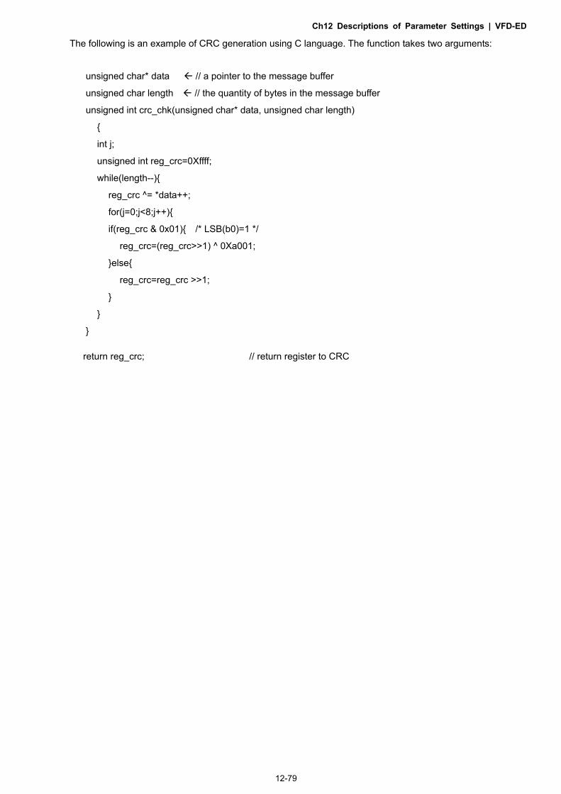
Ch12 Descriptions of Parameter Settings | VFD-ED
12-79
The following is an example of CRC generation using C language. The function takes two arguments:
unsigned char* data // a pointer to the message buffer
unsigned char length // the quantity of bytes in the message buffer
unsigned int crc_chk(unsigned char* data, unsigned char length)
int j;
unsigned int reg_crc=0Xffff;
while(length--)
reg_crc ^= *data++;
for(j=0;j<8;j++)
if(reg_crc & 0x01) /* LSB(b0)=1 */
reg_crc=(reg_crc>>1) ^ 0Xa001;
else
reg_crc=reg_crc >>1;
return reg_crc; // return register to CRC

Ch12 Descriptions of Parameter Settings | VFD-ED
12-80
4. ACMD Modbus Communication Address List
The following table shows the contents of available addresses. Content Address Function
AC motor drive Parameters GGnnH GG means parameter group, nn means parameter number, for example, the
address of Pr.04-01 is 0401H.
Command Write only 2000H
Bit 0–3
0: No function 1: Stop 2: Run 3: Jog + Run
Bit 4–5
00B: No function 01B: FWD 10B: REV 11B: Change direction
Bit 6–7
00B: First acceleration/deceleration 01B: Second acceleration/deceleration 10B: Third acceleration/deceleration 11B: Fourth acceleration/deceleration
Bit 8–11
0000B: master speed 0001B: 1st step speed 0010B: 2nd step speed 0011B: 3rd step speed 0100B: 4th step speed 0101B: 5th step speed 0110B: 6th step speed 0111B: 7th step speed 1000B: 8th step speed 1001B: 9th step speed 1010B: 10th step speed
Status monitor
Read only
1011B: 11th step speed 1100B: 12th step speed 1101B: 13th step speed 1110B: 14th step speed 1111B: 15th step speed
Bit 12 1: Enable bit 06–11
Bit 13–14
00B: No function 01B: Operated by digital keypad 10B: Operated by Pr.00-15 setting 11B: Change operation source
Bit 15 Reserved 2001H Frequency command
2002H
Bit 0 1: EF (external fault) ON Bit 1 1: Reset Bit 2 1: B.B. ON
Bit 3–15 Reserved 2100H Fault code: refer to Pr.06-16–Pr.06-21
2119H
Bit 0–1
00: Stop 01: Deceleration 10: Ready for operation 11: Operation
Bit 2 1: JOG command
Bit 3–4
00: FWD command, FWD output 01: FWD command, REV output 10: REV command, FWD output 11: Reserved
Bit 5–7 Reserved Bit 8 1: Master frequency controlled by communication interface
Bit 9 1: Master frequency controlled by analog/external terminal signals (EXT)
Bit 10 1: Operation command controlled by communication interface (PU)
Bit 11 1: Parameters locked

Ch12 Descriptions of Parameter Settings | VFD-ED
12-81
Content Address Function Bit 12 1: Enable copy parameter from keypad
Bit 13–15 Reserved 2102H Frequency command (F) 2103H Output frequency (H) 2104H Output current (AXXX.X) 2105H DC BUS Voltage (UXXX.X) 2106H Output voltage (EXXX.X) 2107H Current step number of multi-step speed operation 2116H Multi-function displays (Pr.00-04) 2201H Pr.00-05 user-defined setting 2203H AUI1 analog input (XXX.XX %) 2204H AUI2 analog input (XXX.XX %) 2205H Reserved 2206H Display temperature of IGBT (oC) 2207H Display temperature of heat sink (oC) (only for model 40 HP and above) 2208H Digital input state 2209H Digital output state
5. Exception Response
The AC motor drive is expected to return a normal response after receiving command messages from the master device. The following describes the conditions when no normal response is sent to the master device. The AC motor drive does not receive the messages due to a communication error; thus, the AC motor drive gives no response. The master device eventually processes a time-out condition. The AC motor drive receives the messages without a communication error, but cannot handle them. It returns an exception response to the master device and displays an error message “CExx” on the AC motor drive keypad. The xx of “CExx” is a decimal code equal to the exception code (described below). In the exception response, the most significant bit (bit7) of the original command code is set to 1 (function code and 80H), and it returns an exception code that explains the condition that caused the exception.
Example: ASCII mode RTU mode
STX ‘:’ Address 01H
Address ‘0’ Function 86H ‘1’ Exception code 02H
Function ‘8’ CRC CHK Low C3H ‘6’ CRC CHK High A1H
Exception code ‘0’ ‘2’
LRC CHK ‘7’ ‘7’
END CR LF
The following table describes the exception codes.
Exception Code Description
1 Incorrect data contents: the contents of data are too large, and not recognized by the motor drive.
2 Incorrect parameter address: The parameter addresses are not recognized by the motor drive.
3 Password locked: parameters cannot be changed.
4 Parameters cannot be changed during operation. 10 Transmission time-out

Ch12 Descriptions of Parameter Settings | VFD-ED
12-82
Response Delay Time
Control Mode VF VFPG SVC FOCPG TQCPG FOCPM Default: 2.0
Settings 0.0–200.0 ms
If the host computer does not finish the transmitting/receiving process, you can use this parameter to set the response delay time after the AC motor drive receives communication command as shown in the following picture.
PC or PLC commandHandling time of the AC drive
Response Delay Time
Response Message of the AC Drive
RS-485 BUS
–
Direct docking mode only
Control Mode VF VFPG SVC FOCPG FOCPM Default: -
Settings Contact Delta for more information
PDO Transmission Interval Control Mode VF VFPG SVC FOCPG TQCPG FOCPM Default: 0
Settings 0–65535 ms

Ch12 Descriptions of Parameter Settings | VFD-ED
12-83
10 Feedback Control Parameters
: You can set this parameter during operation. In this parameter group, ASR is the abbreviation for Adjust Speed Regulator and PG is the abbreviation for
Pulse Generator.
Selection of Encoder Control Mode VFPG FOCPG TQCPG FOCPM Default: 0
Settings 0: Disable
1: ABZ
2: ABZ+Hall
3: SIN/COS + Sinusoidal
4: SIN/COS + Endat
5: SIN/COS
6: SIN/COS + Hiperface
When you set Pr.10-02 to 3, 4 or 5, you can set Pr.10-00 only to 0, 1 or 2, and you cannot use 3, 4, 5 and 6.
When you set Pr.10-00 to 3, the encoder has one sine and one cosine signal for each revolution. The signal must be: 0.75–1.2 Vpp for the amplitude with phase angle 90°±5 elec. (EX: ERN 1185 ERN 1387)
When you set Pr.10-00 to 4 or 6, wait for two seconds after applying the power before executing the RUN command.
When you set Pr.10-00 to 5, you must set Pr.08-09 to 360. Detection of the magnetic pole:
(1) 1 or 5: The AC motor drive outputs a short circuit to detect the position of the magnetic pole. At this moment, the motor generates a little noise. (2) 2: The AC motor drive detects the position of the magnetic pole with the UVW encoder signal. (3) 3: The AC motor drive detects the position of the magnetic pole with the sine encoder signal. (4) 4 or 6: The AC motor drive detects the position of the magnetic pole with the communication encoder signal.
The following table is the reference auto-tuning PG Signal Type
Setting PG Signal Type Applicable PG Card Pr.08-00=1 Pr.08-00=3
Pr.10-00=1 A, B, Z EMED-PGAB/ABD-1 N/A N/A Pr.10-00=2 A, B, Z+U, V, W EMED-PGABD-1 Rolling test*1 Rolling test*1
Pr.10-00=3 SIN/COS+ Sinusoidal EMED-PGHSD-1 Rolling test*1 Rolling test*1
Pr.10-00=4 SIN/COS+Endat EMED-PGSD-1 Dynamic test*1 Static test*1 Pr.10-00=5 SIN/COS EMED-PGHSD-1 N/A N/A Pr.10-00=6 SIN/COS + Hiperface EMED-PGHSD-1 Dynamic test*1 Static test*1
*1 Static: Brake engaged, no motor running. Dynamic: Brake released, motor rotates less than one revolution.
Rolling: Brake released, motor rotates more than one revolution.
Encoder Pulse Control Mode VFPG FOCPG TQCPG FOCPM Default: 2048
Settings 1–25000
A Pulse Generator (PG) or encoder provides a motor speed feedback signal. This parameter defines the number of pulses for each cycle of the PG control.

Ch12 Descriptions of Parameter Settings | VFD-ED
12-84
Encoder Input Type Setting
Control Mode VFPG FOCPG TQCPG FOCPM Default: 0 Settings 0: Disable 1: Phase A leads in a forward run command and phase B leads in a reverse run
command
Forwardrunning
A
B
FWD REV
2: Phase B leads in a forward run command and phase A leads in a reverse run
command
Forwardrunning
A
B
FWD REV
3: Phase A is a pulse input and phase B is a direction input. (low input=reverse
direction, high input=forward direction)
Forwardrunning
A
B
FWD REV
4: Phase A is a pulse input and phase B is a direction input. (low input=forward
direction, high input=reverse direction)
Forwardrunning
A
B
FWD REV
5: Single-phase input
Forwardrunning A
When you set Pr.10-00 to 3, 4, 5 or 6, you can set Pr.10-02 only to 0, 1 or 2, and you cannot use 3, 4 and 5.
You must enter the correct pulse type for stable control.
Encoder Feedback Signal Fault Action (PGF1, PGF2) Control Mode VFPG FOCPG TQCPG FOCPM Default: 2
Settings 0: Warn and keep operation
1: Fault and ramp to stop
2: Fault and stop operation
Encoder Feedback Signal Fault Detection Time Control Mode VFPG FOCPG TQCPG FOCPM Default: 1.0
Settings 0.0–10.0 sec.
When there is PG loss, encoder signal error, pulse signal setting error or signal error, if time exceeds the setting for this parameter, the PG signal error occurs. Refer to the Pr.10-03 for the encoder feedback signal fault action.

Ch12 Descriptions of Parameter Settings | VFD-ED
12-85
Encoder Stall Level (PGF3)
Control Mode VFPG SVC FOCPG FOCPM Default: 115
Settings 0–120%
0: Disable
Determines the maximum encoder feedback signal allowed before a fault occurs; the maximum output frequency Pr.01-00 = 100%.
Encoder Stall Detection Time (maximum output frequency Pr.01-00 = 100%)
Control Mode VFPG SVC FOCPG FOCPM Default: 0.1
Settings 0.0–2.0 sec.
Encoder Slip Range (PGF4) (maximum output frequency Pr.01-00 = 100%) Control Mode VFPG SVC FOCPG FOCPM Default: 50
Settings 0–50%
0: Disable
Encoder Slip Detection Time (maximum output frequency Pr.01-00=100%) Control Mode VFPG SVC FOCPG FOCPM Default: 0.5
Settings 0.0–10.0 sec.
Encoder Stall and Slip Error Action (maximum output frequency Pr.01-00 = 100%)
Control Mode VFPG SVC FOCPG FOCPM Default: 2
Settings 0: Warn and keep operation
1: Fault and ramp to stop
2: Fault and stop operation When the difference of (rotation speed-motor frequency) exceeds the Pr.10-07 setting, and the detection
time exceeds Pr.10-08 or the motor frequency exceeds Pr.10-05 setting, the drive starts to count time. If the detection time exceeds Pr.10-06, the encoder feedback signal error occurs. Refer to Pr.10-09 encoder stall and slip error action.
Mode Selection for UVW Input Control Mode VFPG FOCPG TQCPG FOCPM Default: 0
Settings 0: Z signal is at the falling edge of U-phase
1: Z signal is at the rising edge of U-phase
0: The operation is U->V->W, Z signal is at the falling edge of U-phase. 1: The operation is U->V->W, Z signal is at the rising edge of U-phase.
U
V
Pr.10-10=1
Pr.10-10=0
Z Signal
Z Signal

Ch12 Descriptions of Parameter Settings | VFD-ED
12-86
ASR (Auto Speed Regulation) Control (P) of Zero Speed
Control Mode VF VFPG SVC FOCPG FOCPM Default: 100.0
Settings 0.0–1000.0%
ASR (Auto Speed Regulation) Control (I) of Zero Speed Control Mode VF VFPG SVC FOCPG FOCPM Default: 0.100
Settings 0.000–10.000 sec.
ASR (Auto Speed Regulation) Control (P) 1 Control Mode VF VFPG SVC FOCPG FOCPM Default: 100.0
Settings 0.0–1000.0%
ASR (Auto Speed Regulation) Control (I) 1 Control Mode VF VFPG SVC FOCPG FOCPM Default: 0.100
Settings 0.000–10.000 sec.
ASR (Auto Speed Regulation) Control (P) 2 Control Mode VF VFPG SVC FOCPG FOCPM Default: 100.0
Settings 0.0–1000.0%
ASR (Auto Speed Regulation) Control (I) 2 Control Mode VF VFPG SVC FOCPG FOCPM Default: 0.100
Settings 0.000–10.000 sec.
ASR 1/ASR2 Switch Frequency Control Mode VF VFPG SVC FOCPG FOCPM Default: 7.00
Settings 0.00–400.00 Hz
0: Disable
ASR P determines the proportional control and associated gain (P). ASR I determines the integral control and associated gain (I).
When you set the integral time to 0, it is disabled. Pr.10-17 defines the switch frequency for the ASR1 (Pr.10-13, Pr.10-14) and ASR2 (Pr.10-15, Pr.10-16).
10-17
10-1310-14
10-1510-16
Hz
PI
10-1110-12
0Hz
10-20 10-21

Ch12 Descriptions of Parameter Settings | VFD-ED
12-87
When using multi-function input terminals to switch ASR1/ASR2, the following diagram shows the operation.
ONOFF
ASR 1
0.1 sec
OFF
0.1 sec
ASR 1ASR 2
Setting multi-function input terminal to 17 (ASR1/ASR2 switch)
ASR Primary Low Pass Filter Gain
Control Mode VF VFPG SVC FOCPG FOCPM Default: 0.008
Settings 0.001–0.350 sec.
Defines the ASR command filter time. When Pr.11-00 is set to 1 ASR auto-tuning, Pr.10-18 is invalid.
Zero Speed Position Control Gain (P) Control Mode FOCPM Default: 80.00
Settings 0.00–655.00%
When Pr.11-00 is set to bit 7=1, Pr.10-19 is valid
Low Speed/ASR Width Adjustment Control Mode VFPG FOCPG FOCPM Default: 5.00
Settings 0.00–400.00 Hz
High Speed ASR Width Adjustment Control Mode VFPG FOCPG FOCPM Default: 5.00
Settings 0.00–400.00 Hz
These two parameters set the width of the slope of the ASR command during zero speed to low speed or Pr.10-17 to high speed.
10-17
10-1310-14
10-1510-16
Hz
PI
10-1110-12
0Hz
10-20 10-21
Zero Speed Position Control Holding Time
Control Mode FOCPM Default: 0.250
Settings 0.001–65.535 sec.
When Pr.11-00 is set to bit 7=1, Pr.10-22 is valid.
Sets this parameter when elevator jerk at start-up or carriage inversion occurs. In principle, the holding time
cannot exceed the time when frequency starts output.

Ch12 Descriptions of Parameter Settings | VFD-ED
12-88
Zero Speed Position Control Low Pass Filter Time
Control Mode FOCPM Default: 0.004
Settings 0.001–65.535 sec.
Zero Speed Position Control Activation Mode Selection Control Mode FOCPM Default: 0
Settings 0: After the brake release set in Pr.02-29
1: After the brake signal input (Pr.02-01–02-08 is set to 42)
When Pr.10-24 = 0, use the zero speed control with Pr.02-29 (refer to the explanations in Pr.02-32).
Elevator Leveling (Zero Speed Gain P)
Control Mode VF VFPG SVC FOCPG FOCPM Default: 100.0
Settings 0.0–1000.0%
Elevator Leveling (Zero Speed Integral I)
Control Mode VF VFPG SVC FOCPG FOCPM Default: 0.100
Settings 0.000–10.000 sec.
Elevator Starting (Zero Speed Gain P)
Control Mode VF VFPG SVC FOCPG FOCPM Default: 100.0
Settings 0.0–1000.0% Elevator Starting (Zero Speed Integral I)
Control Mode VF VFPG SVC FOCPG FOCPM Default: 0.100
Settings 0.000–10.000 sec.
01-24=S1
01-25=S2 01-26=S3
01-27=S4
01-30=S5
01-29 S5 Switch Frequency
01-12Accel. Time 1
Pr01-13 Decel. Time 1
01-31 Decel. Time w/o RUN command
MO = 12Release the Mechanical Brake
Output Frequency
DC Brake07-03 DC Brake Activation Time 07-04
02-3002-29 Brake Release DelayTime when Elevator Starts
10-22Zero speed Position Holding Time
10-25/ 10-26Elevator Leveling PI
11-00 bit 7=110-27/28Elevator Starts Zero Speed PI
10-11/ 10-12Auto Speed Regulation Control of Zero Speed PI
DC Brake Stopping Time
Zero-Speed Position Control

Ch12 Descriptions of Parameter Settings | VFD-ED
12-89
PG Card Frequency Division Output
Control Mode VFPG FOCPG FOCPM Default: 0
Settings 0–31
Setting to 0 is the same as setting to 1:
0: No frequency division
1: Frequency division by 1 (remains the same as the original frequency)
PG Card Frequency Division Output Type
Control Mode VFPG FOCPG FOCPM Default: 0000h
Settings 0000h–0008h
See Chapter 7 for more information about PG cards.
PG Card C+/C-
Control Mode VFPG FOCPG FOCPM Default: 0000h
Settings 0000h–0001h
When using a Heidenhain ERN1387 encoder, use Pr.10-31 to adjust the definition of the Delta PG card
EMED-PGHSD-1’s terminal 10 and terminal 11 (see the table below). Refer to p.7-8 for detailed terminal
descriptions.
Delta PG card: EMED-PGHSD-1 (D-sub Terminal #)
5 4 3 2 110 9 8 7 615 14 13 12 11
Heidenhain ERN1387 Terminal # Pr.10-31=0000h Pr.10-31=0001h
10 C- C+ 11 C+ C-
After connecting Delta PG card EMED-PGHSD-2 according to the descriptions in Section 7-3, you must
set Pr.10-31=0001h.
Over-acceleration Level Control Mode VF VFPG SVC FOCPG FOCPM Default: 0.0
Settings 0.0–20.0 m/s²
Over-acceleration Detection Time
Control Mode VF VFPG SVC FOCPG FOCPM Default: 0.05
Settings 0.0–5.00 sec.
Over-acceleration Detection Selection
Control Mode VF VFPG SVC FOCPG FOCPM Default: 0
Settings 0: Always detect
1: Detect during operation

Ch12 Descriptions of Parameter Settings | VFD-ED
12-90
11 Advanced Parameters : You can set this parameter during operation.
System Control Control Mode FOCPG FOCPM Default: 0000h
Settings Bit 0 = 0: No function
Bit 0 = 1: ASR auto-tuning, enable PDFF
Bit 7 = 0: No function
Bit 7 = 1: Zero speed position control is enabled
Bit 9 = 0: Dynamic PG origin auto-tuning with load (support by PGHSD-1)
Bit 9 = 1: Static PG origin auto-tuning with load by enabling PGHSD-1
Bit 15 = 0: When power is applied, detect the position of the magnetic pole again
Bit 15 = 1: When power is applied, start from the magnetic pole position of the
previous power failure
Bit 0 = 1: Enable the PDFF function and the system generates an ASR setting. At this time, Pr.10-11–Pr.10-16 are invalid and Pr.11-09–Pr.11-10 are valid.
YES
NO
Setting auto gain adjustmentPr.11-00=1
Adjust Pr.11-06, 11-07 and 11-08separately by speed response
Adjust by requirementPr.11-09, Pr. 11-10 (PDFF function)
Adjust by requirement Pr.10-17 (A SR1/ASR2 swi tch frequency)Pr.10-20: Zero speed/ASR1 width adjustmentPr.10-21: ASR1/ASR2 width adjustment Adjust by requirement Pr.07-25~28 (torque li mit)
Adjust gain value by manualPr.11-00=0 ( fac tory sett ing)
Adjust Pr.10-11, 10-12, 10-13,10-14, 10-15 and 10-16 separately by speed response
Adjust by requirementPr.10-18 (for general, no need to adjus t)
When Pr.11-00 is set B it 0=1
Bit 0= 0 Bit 0= 1PI
Hz
10-1510-16
10-1310-14
10-1110-12
0Hz 10-17
10-20 10-21
PI
Hz
11-06
11-07
0Hz 10-17
PI adjus tment-manual gain PI adjus tment-auto gain
Pr.11-08use to adjust the strength of zero-servo lock 10-20 10-21

Ch12 Descriptions of Parameter Settings | VFD-ED
12-91
When Bit 7 = 1, zero speed position control is enabled (refer to p.12-25 timing diagram). Pr.10-22 is valid
only when bit 7 is set to 1, and this function only supports PM motors.
When Bit 9 = 1, valid only when Pr.10-00 is set to 3, and the mechanical brake must be in engaged state.
Elevator Speed Control Mode FOCPG FOCPM Default: 1.00
Settings 0.10–4.00 m/s
Sheave Diameter Control Mode FOCPG FOCPM Default: 400
Settings 100–2000 mm
Mechanical Gear Ratio
Control Mode FOCPG FOCPM Default: 1.00
Settings 1.00–100.00
Suspension Ratio Control Mode FOCPG FOCPM Default: 1
Settings 0 = 1: 1
1 = 2: 1
2 = 4:1
3 = 8:1
suspension ratio 1 :1 suspension rat io 2 :1
reelreel
11 -02sheave diameter
car riage carriage
pully
pullypully
pully
load w eightload w eight
Inertial Ratio
Control Mode FOCPG FOCPM Default: 40
Settings 1–300%
You can calculate the load inertia according to the settings of motor parameters, Pr.11-02 Sheave Diameter, Pr.11-14 Motor Current at Acceleration and Pr.11-15 Carriage Acceleration. You can use this parameter to adjust the load inertia ratio.
Inertia reference value (%): Load/Motor IM PM
No-load 40 10 With load 80–120 40

Ch12 Descriptions of Parameter Settings | VFD-ED
12-92
Zero speed Bandwidth
Control Mode FOCPG FOCPM Default: 10
Settings 1–40 Hz
Low speed Bandwidth Control Mode FOCPG FOCPM Default: 10
Settings 1–40 Hz
High speed Bandwidth Control Mode FOCPG FOCPM Default: 10
Settings 1–40 Hz
After estimating the inertia and setting Pr.11-00 =1 (auto-tuning), you can adjust parameters Pr.11-06, Pr.11-07 and Pr.11-08 separately by speed response. The larger the value, the faster the response. Pr.10-17 is the switch frequency between the low speed and high speed bandwidth.
PDFF Gain Value
Control Mode FOCPG FOCPM Default: 30
Settings 0–200%
After you estimate and set Pr.11-00=1 (auto-tuning), use Pr.11-09/11-10 to reduce overshoot. Adjust the PDFF gain value according to the actual situation.
In addition to traditional PI control, it also provides the PDFF function to reduce overshoot for speed control. 1. Get system inertia 2. Set Pr.11-00 to 1 3. Adjust Pr.11-09 and Pr.11-10 (a larger value suppresses overshoot better). Adjust according to the actual condition.
PIPDFF
It is recommended to disable this function (Pr.11-09=0) forY/ connection switch andASR1/ASR2 switch application.
Speed Feed Forward Gain
Control Mode FOCPG FOCPM Default: 0
Settings 0–500
Pr.11-09 and Pr.11-10 are enabled when Pr.11-00 is set to Bit 0 = 1.
Notch Filter Depth
Control Mode FOCPG FOCPM Default: 0
Settings 0–20 db
Notch Filter Frequency Control Mode FOCPG FOCPM Default: 0.00
Settings 0.00–200.00 Hz

Ch12 Descriptions of Parameter Settings | VFD-ED
12-93
Sets the resonance frequency of the mechanical system. Adjust it to a smaller value to suppress the mechanical system resonance.
A larger value improves resonance suppression function. The notch filter frequency is the mechanical frequency resonance.
Keypad Display for Low Pass Filter Time Control Mode VF VFPG SVC FOCPG TQCPG FOCPM Default: 0.500
Settings 0.001–65.535 sec.
Lowers the blinking frequency of the LCD display.
Motor Current at Acceleration
Control Mode FOCPM Default: 150
Settings 50–200%
Carriage Acceleration Control Mode FOCPM Default: 0.75
Settings 0.20–2.00 m/s2
Reserved Reserved Reserved
Zero Speed Parking Bandwidth Control Mode FOCPG FOCPM Default: 10
Settings 1–40 Hz
PWM Mode (Pulse-Width Modulation Mode) Control Mode Default: 0
Settings 0: DPWM Mode (Digital Pulse-Width Modulation Mode)
1: SVPWM mode (Space-Vector Pulse Width Modulation Mode)

Ch12 Descriptions of Parameter Settings | VFD-ED
12-94
12 User-defined Parameters : You can set this parameter during operation.
User-defined Parameter 1
Control Mode VF VFPG SVC FOCPG TQCPG FOCPM Default: 0616
Settings 0–9999
User-defined Parameter 2
Control Mode VF VFPG SVC FOCPG TQCPG FOCPM Default: 0632
Settings 0–9999
User-defined Parameter 3
Control Mode VF VFPG SVC FOCPG TQCPG FOCPM Default: 0633
Settings 0–9999
User-defined Parameter 4
Control Mode VF VFPG SVC FOCPG TQCPG FOCPM Default: 0653
Settings 0–9999
User-defined Parameter 5
Control Mode VF VFPG SVC FOCPG TQCPG FOCPM Default: 0654
Settings 0–9999 User-defined Parameter 6
Control Mode VF VFPG SVC FOCPG TQCPG FOCPM Default: 0655
Settings 0–9999
User-defined Parameter 7
Control Mode VF VFPG SVC FOCPG TQCPG FOCPM Default: 0656
Settings 0–9999
User-defined Parameter 8
Control Mode VF VFPG SVC FOCPG TQCPG FOCPM Default: 0657
Settings 0–9999
User-defined Parameter 9
Control Mode VF VFPG SVC FOCPG TQCPG FOCPM Default: 0658
Settings 0–9999
User-defined Parameter 10
Control Mode VF VFPG SVC FOCPG TQCPG FOCPM Default: 0659
Settings 0–9999
User-defined Parameter 11
Control Mode VF VFPG SVC FOCPG TQCPG FOCPM Default: 0660
Settings 0–9999

Ch12 Descriptions of Parameter Settings | VFD-ED
12-95
User-defined Parameter 12
Control Mode VF VFPG SVC FOCPG TQCPG FOCPM Default: 0661
Settings 0–9999
User-defined Parameter 13
Control Mode VF VFPG SVC FOCPG TQCPG FOCPM Default: 0662
Settings 0–9999
User-defined Parameter 14
Control Mode VF VFPG SVC FOCPG TQCPG FOCPM Default: 0663
Settings 0–9999
User-defined Parameter 15
Control Mode VF VFPG SVC FOCPG TQCPG FOCPM Default: 0664
Settings 0–9999
User-defined Parameter 16
Control Mode VF VFPG SVC FOCPG TQCPG FOCPM Default: 0617
Settings 0–9999
User-defined Parameter 17
Control Mode VF VFPG SVC FOCPG TQCPG FOCPM Default: 0634
Settings 0–9999
User-defined Parameter 18
Control Mode VF VFPG SVC FOCPG TQCPG FOCPM Default: 0635
Settings 0–9999
User-defined Parameter 19
Control Mode VF VFPG SVC FOCPG TQCPG FOCPM Default: 0618
Settings 0–9999
User-defined Parameter 20
Control Mode VF VFPG SVC FOCPG TQCPG FOCPM Default: 0636
Settings 0–9999
User-defined Parameter 21
Control Mode VF VFPG SVC FOCPG TQCPG FOCPM Default: 0637
Settings 0–9999
User-defined Parameter 22
Control Mode VF VFPG SVC FOCPG TQCPG FOCPM Default: 0619
Settings 0–9999

Ch12 Descriptions of Parameter Settings | VFD-ED
12-96
User-defined Parameter 23
Control Mode VF VFPG SVC FOCPG TQCPG FOCPM Default: 0638
Settings 0–9999
User-defined Parameter 24
Control Mode VF VFPG SVC FOCPG TQCPG FOCPM Default: 0639
Settings 0–9999
User-defined Parameter 25
Control Mode VF VFPG SVC FOCPG TQCPG FOCPM Default: 0620
Settings 0–9999
User-defined Parameter 26
Control Mode VF VFPG SVC FOCPG TQCPG FOCPM Default: 0640
Settings 0–9999
User-defined Parameter 27
Control Mode VF VFPG SVC FOCPG TQCPG FOCPM Default: 0641
Settings 0–9999
User-defined Parameter 28
Control Mode VF VFPG SVC FOCPG TQCPG FOCPM Default: 0621
Settings 0–9999
User-defined Parameter 29
Control Mode VF VFPG SVC FOCPG TQCPG FOCPM Default: 0642
Settings 0–9999
User-defined Parameter 30
Control Mode VF VFPG SVC FOCPG TQCPG FOCPM Default: 0643
Settings 0–9999
User-defined Parameter 31
Control Mode VF VFPG SVC FOCPG TQCPG FOCPM Default: 0
Settings 0–9999
User-defined Parameter 32
Control Mode VF VFPG SVC FOCPG TQCPG FOCPM Default: 0
Settings 0–9999
You can define commonly used parameters in parameter group 12. You can enter the parameters from group 00 to group 11 into group 12 (it can save up to 32 parameters). The saved values can also be the parameter addresses (but you must convert the hexadecimal value to a
decimal value). Examples of user-defined parameters
Example 1:

Ch12 Descriptions of Parameter Settings | VFD-ED
12-97
If you want to enter Pr.08-03 into Pr.12-00, enter 0803 into Pr.12-00. Then, the keypad displays the setting for Pr.08-03 in Pr.13-00. Example 2: If you need to enter parameter addresses 2102H and 211BH with the digital keypad, convert 211BH to a decimal value before entering (see below for details).
The setting method for 211BH:
Convert 211BH (hexadecimal) to a decimal value: 2 1 1 B
1 11x16 + x16 =16+11=1 0 27 input 2127

Ch12 Descriptions of Parameter Settings | VFD-ED
12-98
13 View User-defined Parameters
: You can set this parameter during operation.
– View User-defined Parameters
Control Mode VF VFPG SVC FOCPG TQCPG FOCPM Default: -
Settings Pr.00-00–Pr.11-20
Present Fault Record
Control Mode VF VFPG SVC FOCPG TQCPG FOCPM Default: -
Display
Address
0616 (Same as Pr.06-16)
Motor Operation at Present Fault Time (min.)
Control Mode VF VFPG SVC FOCPG TQCPG FOCPM Default: -
Display
Address
0632 (Same as Pr.06-32)
Motor Operation at Present Fault Time (day) Control Mode VF VFPG SVC FOCPG TQCPG FOCPM Default: -
Display
Address
0633 (Same as Pr.06-33)
Frequency Command at Present Fault Control Mode VF VFPG SVC FOCPG TQCPG FOCPM Default: -
Display
Address
0653 (Same as Pr.06-53)
Output Frequency at Preset Fault Control Mode VF VFPG SVC FOCPG TQCPG FOCPM Default: -
Display
Address
0654 (Same as Pr.06-54)
Output Current at Present Fault Control Mode VF VFPG SVC FOCPG TQCPG FOCPM Default: -
Display
Address
0655 (Same as Pr.06-55)
Motor Frequency at Present Fault Control Mode VF VFPG SVC FOCPG TQCPG FOCPM Default: -
Display
Address
0656 (Same as Pr.06-56)

Ch12 Descriptions of Parameter Settings | VFD-ED
12-99
Output Voltage at Present Fault Control Mode VF VFPG SVC FOCPG TQCPG FOCPM Default: -
Display
Address
0657 (Same as Pr.06-57)
DC BUS Voltage at Present Fault
Control Mode VF VFPG SVC FOCPG TQCPG FOCPM Default: -
Display
Address
0658 (Same as Pr.06-58)
Output Power at Present Fault Control Mode VF VFPG SVC FOCPG TQCPG FOCPM Default: -
Display
Address
0659 (Same as Pr.06-59)
Output Torque at Present Fault
Control Mode VF VFPG SVC FOCPG TQCPG FOCPM Default: -
Display
Address
0660 (Same as Pr.06-60)
Power Module IGBT Temperature at Present Fault
Control Mode VF VFPG SVC FOCPG TQCPG FOCPM Default: -
Display
Address
0661 (Same as Pr.06-61)
Multi-function Terminal Input Status at Present Fault
Control Mode VF VFPG SVC FOCPG TQCPG FOCPM Default: -
Display
Address
0662 (Same as Pr.06-62)
Multi-function Terminal Output Status at Present Fault Control Mode VF VFPG SVC FOCPG TQCPG FOCPM Default: -
Display
Address
0663 (Same as Pr.06-63)
Drive Status at Present Fault Control Mode VF VFPG SVC FOCPG TQCPG FOCPM Default: -
Display
Address
0664 (Same as Pr.06-64)
Second Most Recent Fault Record
Control Mode VF VFPG SVC FOCPG TQCPG FOCPM Default: -
Display
Address
0617 (Same as Pr.06-17)

Ch12 Descriptions of Parameter Settings | VFD-ED
12-100
Motor Operation at Second Most Recent Fault Time (min.)
Control Mode VF VFPG SVC FOCPG TQCPG FOCPM Default: -
Display
Address
0634 (Same as Pr.06-34)
Motor Operation at Second Most Recent Fault Time (day) Control Mode VF VFPG SVC FOCPG TQCPG FOCPM Default: -
Display
Address
0635 (Same as Pr.06-35)
Third Most Recent Fault Record Control Mode VF VFPG SVC FOCPG TQCPG FOCPM Default: -
Display
Address
0618 (Same as Pr.06-18)
Motor Operation at Third Most Recent Fault Time (min.)
Control Mode VF VFPG SVC FOCPG TQCPG FOCPM Default: -
Display
Address
0636 (Same as Pr.06-36)
Motor Operation at Third Most Recent Fault Time (day) Control Mode VF VFPG SVC FOCPG TQCPG FOCPM Default: -
Display
Address
0637 (Same as Pr.06-37)
Fourth Most Recent Fault Record Control Mode VF VFPG SVC FOCPG TQCPG FOCPM Default: -
Display
Address
0619 (Same as Pr.06-19)
Motor Operation at Fourth Most Recent Fault Time (min.) Control Mode VF VFPG SVC FOCPG TQCPG FOCPM Default: -
Display
Address
0638 (Same as Pr.06-38)
Motor Operation at Fourth Most Recent Fault Time (day) Control Mode VF VFPG SVC FOCPG TQCPG FOCPM Default: -
Display
Address
0639 (Same as Pr.06-39)
Fifth Most Recent Fault Record
Control Mode VF VFPG SVC FOCPG TQCPG FOCPM Default: -
Display
Address
0620 (Same as Pr.06-20)

Ch12 Descriptions of Parameter Settings | VFD-ED
12-101
Motor Operation at Fifth Most Recent Fault Time (min.)
Control Mode VF VFPG SVC FOCPG TQCPG FOCPM Default: -
Display
Address
0640 (Same as Pr.06-40)
Motor Operation at Fifth Most Recent Fault Time (day) Control Mode VF VFPG SVC FOCPG TQCPG FOCPM Default: -
Display
Address
0641 (Same as Pr.06-41)
Sixth Most Recent Fault Record Control Mode VF VFPG SVC FOCPG TQCPG FOCPM Default: -
Display
Address
0621 (Same as Pr.06-21)
Motor Operation at Sixth Most Recent Fault Time (min.) Control Mode VF VFPG SVC FOCPG TQCPG FOCPM Default: -
Display
Address
0642 (Same as Pr.06-42)
Motor Operation at Sixth Most Recent Fault Time (day) Control Mode VF VFPG SVC FOCPG TQCPG FOCPM Default: -
Display
Address
0643 (Same as Pr.06-43)
No default
No default

Ch12 Descriptions of Parameter Settings | VFD-ED
12-102
[The page intentionally left blank]

Ch13 Warning Codes | VFD-ED
13-1
Chapter 13 Warning Codes
ID No. Display on
KPED-LE01 Display on LCM
Keypad Descriptions
1
CE01
CE01Comm. Cmd. Err
Warning
Illegal communication command Cause Communication command error
2
CE02
CE02Data Adrr. Err
Warning
Illegal data address Cause Data address error
3
CE03
CE03Data Length Err
Warning
Communication data length error Cause Communication data length exceeds 1–20 characters
4
CE04
CE04Wrong Writing
Warning
Attempt to write to a read-only address. Cause Communication error occurred when attempting to write values into 0x21xx, 0x22xx read-only address.
5
CE10
CE10Comm. Time Out
Warning
Modbus transmission time-out Cause Communication cable error
6
CP10
CP10Keypad time out
Warning
Digital keypad KPC-CC01 transmission time-out Cause Communication cable or digital keypad error
7
SE1
SE1Keypad Copy Err
Warning
Keypad copy parameter error Cause Keypad copy errors, including communication delays, communication error (keypad received error FF86) and parameter value error.

Ch13 Warning Codes | VFD-ED
13-2
ID No. Display on
KPED-LE01 Display on LCM
Keypad Descriptions
8
SE2
SE2Keypad Copy Fail
Warning
Keypad copy parameter failure Cause Keypad copy done but parameter writing error
9
oH1
oH1IGBT Over Heat
Warning
IGBT overheat warning Cause IGBT temperature is over the default 90˚C (Pr.06-14).
10
oH2
oH2Capacitance oH
Warning
Capacitor overheat warning Cause The temperature of the capacitor is over 65˚C.
15
PGF1
PGF1
Warning
PG feedback error Cause When Pr.10-03 = 0 (default = 2), a warning message displays instead of a fault message when an error occurs.
16
PGF2
PGF2
Warning
PG feedback loss warning Cause Pr.10-03 = 0 (default = 2), a warning message displays instead of a fault message when an error occurs.
17
PGF3
PGF3
Warning
PG feedback stall warning Cause Pr.10-09 = 0 (default = 2), a warning message displays instead of a fault message when an error occurs.
18
PGF4
PGF4
Warning
PG slip error warning Cause Pr.10-09 = 0 (default = 2), a warning message displays instead of a fault message when an error occurs.
19
PHL
PHLPhase Loss
Warning
Phase loss Cause When Pr.06-01 =0 (default = 2), a warning message displays instead of a fault message when a phase loss occurs.
20
ot1
ot1Over Torque 1
Warning
Over-torque 1 Cause When Pr.06-05 =1 or 3 (default = 0), a warning message displays instead of a fault message when there is an over-torque detection.

Ch13 Warning Codes | VFD-ED
13-3
ID No. Display on
KPED-LE01 Display on LCM
Keypad Descriptions
21
ot2
ot2Over Torque 2
Warning
Over-torque 2 Cause When Pr.06-05 =1 or 3 (default = 0), a warning message displays instead of a fault message when there is an over-torque detection.
22
oH3
oH3Motor Over Heat (PTC)
Warning
Motor overheat (PTC) Cause When Pr.06-26 = 0 (default = 0), a warning message displays when there is a PTC detection.
24
oSL
oSLOver Slip Warn
Warning
Over-slip error Cause When Pr.05-16 = 0 (default = 0), a warning message displays when the slip deviation level is over the setting in Pr.05-14 and the slip deviation detection time is longer than the setting in Pr.05-15.
25
tUn
tUnAuto tuning
Warning
Auto-tuning in process
26
FAn
FanFan Off
Warning
Fan error warning Cause When Pr.06-45 bit 1 = 1, a warning message displays when the cooling fan is locked (when bit1 = 1, there is an output error).
27
dCAn
CAN OFFCAN bus Off
Warning
CAN Bus off Cause CAN Bus disconnection or PDO communication time-out
28
STOA
STOASTO Warning
Warning
Safe Torque Off alarm Cause Safe torque output function is off and Pr.06-49 = 1 or 3.

Ch13 Warning Codes | VFD-ED
13-4
[The page intentionally left blank]

Ch14 Fault Codes | VFD-ED
14-1
Chapter 14 Fault Codes
*In accordance with the settings of Pr.06-16 to Pr.06-21.
ID* Display on
KPED-LE01 LCM Panel Display Descriptions
1
ocAoc at Accel
Fault
Over-current during acceleration (output current exceeds three times the drive’s rated current during acceleration). corrective action 1. Short-circuit at motor output: Check for possible poor
insulation at the output. 2. Acceleration Time is too short: Increase the Acceleration
Time. 3. AC motor drive output power is too small: Replace the AC
motor drive with a higher power model.
2
ocdoc at Decel
Fault
Over-current during deceleration (output current exceeds three times the drive’s rated current during deceleration). corrective action 1. Short-circuit at motor output: Check for possible poor
insulation at the output. 2. Deceleration Time is too short: Increase the Deceleration
Time. 3. AC motor drive output power is too small: Replace the AC
motor drive with a higher power model.
3
ocnoc at Normal SPD
Fault
Over-current during steady operation (output current exceeds three times the drive’s rated current during constant speed). corrective action 1. Short-circuit at motor output: Check for possible poor
insulation at the output. 2. Sudden increase in motor load: Check for possible motor stall. 3. AC motor drive output power is too small: Replace the AC
motor drive with a higher power model.
4
GFFGround Fault
Fault
Ground fault When one or more of the output terminals is (are) grounded, and the short circuit current is more than 60% of the AC motor drive rated current, the AC motor drive power module may be damaged. NOTE: The short circuit protection is to protect the AC motor drive, not to protect you.
corrective action 1. Check the wiring connections between the AC motor drive and
motor for possible short circuits, also check connection to ground.
2. Check whether the IGBT power module is damaged. 3. Check for possible poor insulation at the output.

Ch14 Fault Codes | VFD-ED
14-2
5 occShort Circuit
Fault
Short circuit is detected between the IGBT module upper bridge and lower bridge. corrective action Contact the dealer or manufacturer to return the motor drive to the factory for repair.
6
ocSoc at Stop
Fault
Over-current at stop Hardware failure in over-current detection corrective action Contact the dealer or manufacturer to return the motor drive to the factory for repair.
7
ovAov at Accel
Fault
DC BUS over-voltage during acceleration
230V: 405 VDC; 460V: 810 VDC
corrective action 1. Check if the input voltage falls in the rated AC motor drive
input voltage range. 2. Check for possible voltage transients. 3. If DC BUS over-voltage is due to regenerative voltage,
increase the Acceleration Time or add an optional brake resistor.
8
ovdov at Decel
Fault
DC BUS over-voltage during deceleration
230V: 405 VDC; 460V: 810 VDC corrective action 1. Check if the input voltage falls in the rated AC motor drive
input voltage range. 2. Check for possible voltage transients. 3. If DC BUS over-voltage due to regenerative voltage, increase
the Deceleration Time or add an optional brake resistor.
9
ovnov at Normal SPD
Fault
DC BUS over-voltage at constant speed
230V: 405 VDC; 460V: 810 VDC corrective action 1. Check if the input voltage falls in the rated AC motor drive
input voltage range. 2. Check for possible voltage transients. 3. If DC BUS over-voltage due to regenerative voltage, increase
the Deceleration Time or add an optional brake resistor.
10
ovSov at Stop
Fault
Over-voltage at stop
Hardware failure in voltage detection. corrective action 1. Check if the input voltage falls in the rated AC motor drive
input voltage range. 2. Check for possible voltage transients.
11
LvALv at Accel
Fault
DC BUS voltage during acceleration is less than the setting in
Pr.06-00. corrective action 1. Check if the input voltage is normal. 2. Check for possible sudden load change.

Ch14 Fault Codes | VFD-ED
14-3
12
LvdLv at Decel
Fault
DC BUS voltage during deceleration is less than the setting in
Pr.06-00. corrective action
1. Check if the input voltage is normal.
2. Check for possible sudden load change.
13
LvnLv at Normal SPD
Fault
DC BUS voltage at constant speed is less than the setting in
Pr.06-00 corrective action
1. Check if the input voltage is normal.
2. Check for possible sudden load change.
14
LvSLv at Stop
Fault
Low voltage at stop corrective action
1. Check if the input voltage is normal.
2. Check for possible sudden load change.
15
PHLPhase Loss
Fault
Phase Loss corrective action
Check power source input to make sure all three input phases are
connected correctly.
16
oH1IGBT Over Heat
Fault
IGBT overheating
IGBT temperature exceeds protection level
3–5 HP, 50–60 HP: 105ºC
7.5–30 HP: 95ºC
40–100 HP: 110ºC corrective action 1. Ensure that the ambient temperature falls in the specified
temperature range. 2. Make sure heat sink is not obstructed. Check if the fan is
operating 3. Check if there is enough ventilation clearance for the AC
motor drive.
17
oH2Capacitance oH
Fault
Capacitor overheating
Capacitor’s temperature exceeds the protection level.
3–100 HP: 65ºC
corrective action 1. Ensure that the ambient temperature falls in the specified
temperature range. 2. Make sure heat sink is not obstructed. Check if the fan is
operating 3. Check if there is enough ventilation clearance for the AC
motor drive.

Ch14 Fault Codes | VFD-ED
14-4
18
tH1oThermo 1 Open
Fault
IGBT overheating protection fault corrective action
Contact the dealer or manufacturer to return the motor drive to the
factory for repair.
19
tH2oThermo 2 Open
Fault
Capacitor module overheating fault corrective action
Contact the dealer or manufacturer to return the motor drive to the
factory for repair.
20
FAnFan Locked
Fault
Cooling fan does not run properly. corrective action
Check if the cooling fan is covered by dust and needs to be cleaned.
Contact the dealer or manufacturer to return the motor drive to the
factory for repair if necessary.
21
oLOver Load
Fault
The output current causes the motor drive to be overload. If the
output current is 150% higher than the drive’s rated current, the
motor drive can sustain the output for a maximum of 60 seconds. corrective action
1. Check if the motor is overloaded.
2. Increase the output capacity of the motor drive.
22
EoL1Thermal Relay 1
Fault
The output current causes the motor to be overload. If the output
current is 150% higher than the drive’s rated current, the motor can
sustain the output for a maximum of 60 seconds. corrective action
1. Check the setting for motor full-load current (Pr.05-01).
2. Check if motor is overloaded and change to a higher power
motor.
24
oH3Motor Over Heat
Fault
Motor overheating
The AC motor drive internal temperature exceeds the setting in
Pr.06-27 (PTC level). corrective action
1. Make sure that the motor is not obstructed.
2. Ensure that the ambient temperature falls in the specified
temperature range.
3. Change to a higher power motor.

Ch14 Fault Codes | VFD-ED
14-5
26
ot1Over Torque 1
Fault
The ot1 and ot2 fault codes appear when the following conditions occur:
- The output current exceeds the setting in Pr.06-06 (Over-torque Detection Level (OT1)> and Pr.06-09 (Over-torque Protection Level (OT2).
- The output current lasts longer than the time setting in Pr.06-07 and Pr.06-10.
- You set Pr.06-05 or Pr.06-08 to 2 or 4. corrective action 1. Check if the motor is overloaded. 2. Check if the setting in Pr.05-01 IM (Motor Full-load Current)
and Pr.08-01 PM (Motor Full-load Current) are appropriate. 3. If necessary, increase the motor output capacity.
27
ot2Over Torque 2
Fault
30
cF1EEPROM Write Err
Fault
Cannot program internal EEPROM. corrective action
1. Press RESET key to reset to the default.
2. Contact the dealer or manufacturer to return the motor drive to
the factory for repair.
31
cF2EEPROM Read Err
Fault
Cannot read internal EEPROM. corrective action
1. Press RESET key to reset to the default.
2. Contact the dealer or manufacturer to return the motor drive to
the factory for repair.
32
cd0Isum Sensor Err
Fault
Hardware failure in current detection corrective action
Reboot the motor drive. If fault code continues to display on the
keypad, contact the dealer or manufacturer to return the motor drive
to the factory for repair.
33
cd1Ias Sensor Err
Fault
U-phase current detection error corrective action
Reboot the motor drive. If fault code continues to display on the
keypad, contact the dealer or manufacturer to return the motor drive
to the factory for repair.
34
cd2Ibs Sensor Err
Fault
V-phase current detection error corrective action
Reboot the motor drive. If fault code continues to display on the
keypad, contact the dealer or manufacturer to return the motor drive
to the factory for repair.

Ch14 Fault Codes | VFD-ED
14-6
35
cd3Ics Sensor Err
Fault
W-phase current detection error corrective action
Reboot the motor drive. If fault code continues to display on the
keypad, contact the dealer or manufacturer to return the motor drive
to the factory for repair.
36
Hd0cc HW Error
Fault
CC (current clamp) hardware error corrective action
Reboot the motor drive. If fault code continues to display on the
keypad, contact the dealer or manufacturer to return the motor drive
to the factory for repair.
37
Hd1oc HW Error
Fault
OC hardware error corrective action
Reboot the motor drive. If fault code continues to display on the
keypad, contact the dealer or manufacturer to return the motor drive
to the factory for repair.
38
Hd2ov HW Error
Fault
OV hardware error corrective action
Reboot the motor drive. If fault code continues to display on the
keypad, contact the dealer or manufacturer to return the motor drive
to the factory for repair.
39
Hd3GFF HW Error
Fault
GFF hardware error corrective action
Reboot the motor drive. If fault code continues to display on the
keypad, contact the dealer or manufacturer to return the motor drive
to the factory for repair.
40
AUEAuto Tuning Err
Fault
Auto-tuning error corrective action
1. Check the cabling between drive and motor.
2. Check if the motor capacity and the parameter settings are
appropriate and try again.
42
PGF1PG Fbk Error
Fault
PG feedback error (command direction is different from the feedback
direction) corrective action
When PG feedback control is enabled, check if Pr.10-01 (Encoder
Pulse) is set to 0.

Ch14 Fault Codes | VFD-ED
14-7
43
PGF2PG Fbk Loss
Fault
PG feedback loss corrective action
Check the PG feedback wiring.
44
PGF3PG Fbk Over SPD
Fault
PG feedback stall corrective action 1. Check the PG feedback wiring. 2. Check if the settings for PI gain and acceleration/deceleration
are appropriate (Pr.10-05, Pr.10-06). 3. Contact the dealer or manufacturer to return the motor drive to
the factory for repair.
45
PGF4PG Fbk Deviate
Fault
PG slip error corrective action 1. Check the PG feedback wiring. 2. Check if the settings for PI gain and acceleration/deceleration
are appropriate (Pr.10-07, Pr.10-08). 3. Contact the dealer or manufacturer to return the motor drive to
the factory for repair.
49
EFExternal Fault
Fault
External Fault
When you set the Multi-Function Input command (MI1–MI8) to #10
EF input (Pr.07-28) and when multi-function input terminals are
triggered to close, the motor drive stops running. corrective action
Press RESET after you clear the fault.
50
EF1Emergency Stop
Fault
Emergency Stop
When you set the Multi-Function Input command (MI1–MI8) to #28
Emergency stop (EF1) (Motor coasts to stop), the motor drive stops
running. corrective action Press RESET after you clear the fault.
52
PcodPassword Error
Fault
Password error
After entering the wrong password three consecutive times, the
keypad is locked. corrective action
Refer to Pr.00-07 and Pr.00-08 settings for more information. Cycle
the power for the motor drive to clear the lock and enter the correct
password.
54
cE01Comm Cmd Err
Fault
Illegal function code corrective action
Check if the function code is correct (function code must be 03, 06,
10, 63).

Ch14 Fault Codes | VFD-ED
14-8
55
cE02Data Addr Err
Fault
Illegal data address (00H to 254H)
The data address for 0X2XX is between 0X2000–0X2005. Any
address out of this range is a fault. corrective action
Check if the communication data address is correct.
56
cE03Data length Err
Fault
Illegal data length
The data length must be between 1 to 20 digits. Any length out of this
range is a fault. corrective action
Check if the data length is smaller than the minimum value or larger
than the maximum value.
57
cE04Wrong Writing
Fault
Attempt to write value to read-only communication address
Communication addresses such as 0X21XX, 0X22XX are read-only.
Any command sent to these addresses causes a fault. corrective action
Check if the communication address is correct.
58
cE10Comm Time Out
Fault
Modbus communication time-out (Pr.09-02–Pr.09-03) corrective action
Check if the communication wiring is correct.
59
cP10Keypad Time Out
Fault
Keypad KPC-CC01 transmission time-out corrective action
1. Check if the communication wiring is correct
2. Check if there is anything wrong with the keypad
60
BFBraking Fault
Fault
Brake resistor fault corrective action
If the fault code continues to display on the keypad after you press
RESET key, contact the dealer or manufacturer to return the motor
drive to the factory for repair.
64
MBFMech. Brake Fail
Fault
Mechanical brake failure
The feedback signal and the release signal are not consistent. corrective action
1. Check if the mechanical brake signal is correct.
2. Check if the mechanical brake detection time setting (Pr.02-35)
is correct.

Ch14 Fault Codes | VFD-ED
14-9
65 PGF5PG HW Error
Fault
PG card hardware error corrective action
1. Check if the PG feedback wiring is correct.
2. If fault code continues to display on the keypad, contact the
dealer or manufacturer to return the motor drive to the factory
for repair.
66
MCFContactor Fail
Fault
Magnetic contactor error
The feedback signal and the release signal are not consistent. corrective action
1. Check if the magnetic contactor signal is correct.
2. Check if the magnetic contactor detection time setting
(Pr.02-36) is correct.
67
MPHLMotor Phase Loss
Fault
Motor phase loss. corrective action
1. Check the cabling between drive and motor.
2. Check if there is any output from the motor drive.
3. Contact the dealer or manufacturer to return the motor drive to
the factory for repair.
68
CANFCAN Bus Off
Fault
CAN Bus off corrective action
1. Check that the CAN Bus is wired correctly.
2. Verify that there is no PDO communication time-out.
69 Reserved
70 Reserved
71 Reserved
72
STL1STO L oss 1
F aul t
STO1–SCM1 internal hardware error. corrective action 1. Check the STO1/SCM1 wiring. 2. Reset the emergency switch (ON) and reboot the motor drive. 3. Check the voltage at least > 11 V. 4. Check the wiring between STO1 and E24V, and the wiring
between SCM1 and DCM. 5. After checking all the wiring, reboot the motor drive. If STL1 still
appears, contact the local dealer or manufacturer.

Ch14 Fault Codes | VFD-ED
14-10
73
PGcdPG cd Wrong Wire
Fault
PG card wiring error corrective action
Incorrect wiring for pin C+, C-, D+, D-. Verify if the wiring matches the
descriptions in Section 7-2 (EMED-PGHSD-1) and Section 7-3
(EMED-PGHSD-2).
74
PGHL PG Hall loss Err
Fault
PG absolute signal error corrective action
1. Check if the encoder absolute positions (C+/C- and D+/D-) and
PG card are properly wired.
2. If the cables are properly wired but the fault code still displays
on the keypad, contact the dealer or manufacturer to return the
motor drive to the factory for repair.
75
PGAF Z Sig. loss Err
Fault
PG Z-phase signal loss corrective action
1. Check if the encoder’s Z-phase signal and PG card are properly
wired.
2. If the cables are properly wired but the fault code still displays
on the keypad, contact the dealer or manufacturer to return the
motor drive to the factory for repair.
76
STOSafe Torque Off
Fault
Safe Torque Off function is enabled. corrective action 1. Check the wiring for STO1/SCM1 and STO2/SCM2. 2. Reset the emergency switch (ON) and reboot the motor drive. 3. Check the voltage at least > 11 V. 4. Check the wiring between STO1/STO2 and E24V, and the
wiring between SCM1/SCM2 and DCM. 5. After checking all the wiring, reboot the motor drive. If STO still
appears, contact the local dealer or manufacturer.
77
STL2STO L oss 2
F aul t
STO2–SCM2 internal hardware error. corrective action 1. Check the STO2/SCM2 wiring. 2. Reset the emergency switch (ON) and reboot the motor drive. 3. Check the voltage at least > 11 V. 4. Check the wiring between STO2 and E24V, and the wiring
between SCM2 and DCM. 5. After checking all the wiring, reboot the motor drive. If STL2 still
appears, contact the local dealer or manufacturer.

Ch14 Fault Codes | VFD-ED
14-11
78
STL3STO L oss 3
F aul t
Internal hardware error.
corrective action
After checking all the wiring, reboot the motor drive. If STL3 still
appears, contact the local dealer or manufacturer.

Ch14 Fault Codes | VFD-ED
14-12
[The page intentionally left blank]

Ch15 Suggestions and Error Corrections for Standard AC Motor Drives | VFD-ED
15-1
Chapter 15 Suggestions and Error
Corrections for Standard AC Motor Drives
15-1 Maintenance and Inspections
15-2 Greasy Dirt Problems
15-3 Fiber Dust Problems
15-4 Corrosion Problems
15-5 Industrial Dust Problems
15-6 Installation and Wiring Problems
15-7 Multi-function Input / Output Terminal Application Problems

Ch15 Suggestions and Error Corrections for Standard AC Motor Drives | VFD-ED
15-2
The AC motor drive has various warnings and protections against errors such as over-voltage, low voltage, or over-current. Once an error occurs, the protections activate, the AC motor drive stops output, activates the error contacts, and the motor coasts to stop. Please refer to the error display from the AC motor drive and look up the corresponding causes and solutions. The fault record is stored in the AC motor drive internal memory and can store the six most recent error messages. You can read it from the digital keypad or through the communications by accessing the parameters.
The AC motor drive includes a large number of electronic components, including ICs, resistors, capacitors, transistors, cooling fans and relays. These components do not last forever. Even under normal circumstances, they will eventually become error-prone if used past their lifespans. Therefore, you must perform periodic preventive maintenance to identify defective and worn out parts, and eliminate the causes of malfunctions in the AC motor drive at an early stage. At the same time, parts that have exceeded their product life should be replaced whenever possible to ensure safe operation. Visual checks should be done regularly to monitor the AC motor drive's operation, and to make sure nothing unusual happens. Check the situations listed in the following table.
Wait five seconds after a fault has been cleared before pressing RESET with the input terminal keypad.
The Hybrid Servo Controller must first be switched off for at least five minutes for ≤ 22 kW models, and 10 minutes for ≥ 30kW models until the charging indicator turns off, and the voltage between terminals – must be lower than 25 VDC before it is safe to open the cover to begin maintenance operations.
Only qualified personnel can work on maintenance or replace parts. (Remove metal items such as watch, rings, and other metal items before operation, and use only insulated tools.)
Never modify internal components or wiring. The performance and the surrounding environment should meet the standard
specifications. There should be no abnormal noise, vibration, or odor.

Ch15 Suggestions and Error Corrections for Standard AC Motor Drives | VFD-ED
15-3
15-1 Maintenance and Inspections
For regular maintenance, first stop operation, then turn off the power, and then take off the outer cover. Even after turning off the power supply, charging voltages remaining in the filter capacitor require some time to discharge. To avoid danger, operation must not start until the charging indicator goes off, and you confirm the voltage with a voltmeter to be below the safety value (≤ 25 VDC).
Ambient environment
Items to Check Methods and Criterion
Maintenance Period
Daily Half Year
One Year
Check the ambient temperature, humidity, and vibration and check for any dust, gas, oil or water drops.
Visual inspection and measurement with equipment with standard specification
Check for any dangerous objects Visual inspection
Voltage
Items to Check Methods and Criterion
Maintenance Period
Daily Half Year
One Year
Check that the voltage of main circuit and control circuit are correct.
Measure with multimeter with standard specifications.
Digital keypad display
Items to Check Methods and Criterion
Maintenance Period
Daily Half Year
One Year
Check that the display is clear for reading Visual inspection
Check for any missing characters Visual inspection
Mechanical parts
Items to Check Methods and Criterion
Maintenance Period
Daily Half Year
One Year
Check for any abnormal sound or vibration Visual and audible inspection
Check for any loose bolts Securely tighten
Check for any deformed or damaged parts Visual inspection
Check for any color change caused by overheating
Visual inspection
Check for any dust or dirt Visual inspection

Ch15 Suggestions and Error Corrections for Standard AC Motor Drives | VFD-ED
15-4
Main circuit
Items to Check Methods and Criterion
Maintenance Period
Daily Half Year
One Year
Check for any loose or missing bolts Securely tighten
Check for machine or insulator deformation, crack, damage or color change due to overheating or ageing
Visual inspection
Check for any dust or dirt Visual inspection
Main circuit terminals and wiring
Items to Check Methods and Criterion
Maintenance Period
Daily Half Year
One Year
Check the terminal and copper plate for color change or deformation due to overheating
Visual inspection
Check for damage to the wiring insulation or color change
Visual inspection
Main circuit terminal block
Items to Check Methods and Criterion
Maintenance Period
Daily Half Year
One Year
Check for any damage Visual inspection
Main circuit filter capacitor
Items to Check Methods and Criterion
Maintenance Period
Daily Half Year
One Year
Check for any liquid leaks, color change, crack or buckling of the exterior cover
Visual inspection
Check if the safety valve is not removed or if the valve is obviously expanded
Visual inspection
Measure static capacity when required
Main circuit resistor
Items to Check Methods and Criterion
Maintenance Period
Daily Half Year
One Year
Check for any odors or insulation cracks due to overheating Visual inspection, smell
Check for any disconnections Visual inspection
Check for damaged connections Measure with multimeter with standard specifications

Ch15 Suggestions and Error Corrections for Standard AC Motor Drives | VFD-ED
15-5
Main circuit transformer and reactor
Items to Check Methods and Criterion
Maintenance Period
Daily Half Year
One Year
Check for any abnormal vibration or odors Visual, audible inspection and smell
Main circuit electromagnetic contactor and relay
Items to Check Methods and Criterion
Maintenance Period
Daily Half Year
One Year
Check for any sound of vibration while running Audible inspection
Check that the contact works correctly Visual inspection
Main circuit printed circuit board and connector
Items to Check Methods and Criterion
Maintenance Period
Daily Half Year
One Year
Check for any loose screws and connectors Tighten the screws and press the connectors firmly in place.
Check for any odors and color change Visual and smell inspection
Check for any crack, damage, deformation or corrosion
Visual inspection
Check for any liquid leaks or deformation in capacity
Visual inspection
Cooling system cooling fan
Items to Check Methods and Criterion
Maintenance Period
Daily Half Year
One Year
Check for any abnormal sound or vibration
Visual, audible inspection, and turn the fan by hand (turn off the power before operation) to see if it rotates smoothly.
Check for any loose bolts Securely tighten
Check for any color change due to overheating
Visual inspection

Ch15 Suggestions and Error Corrections for Standard AC Motor Drives | VFD-ED
15-6
Cooling system ventilation channel
Items to Check Methods and Criterion
Maintenance Period
Daily Half Year
One Year
Check for any obstruction in the heat sink, air intake or air outlet
Visual inspection
NOTE Use a chemically neutral cloth to clean and use a dust cleaner to remove dust when necessary.

Ch15 Suggestions and Error Corrections for Standard AC Motor Drives | VFD-ED
15-7
15-2 Greasy Dirt Problems
Serious greasy dirt problems generally occur in processing industries such as machine tools, punching machines and so on. Please be aware of the possible damages that greasy oil may cause to your drive. 1. Electronic components that silt up with greasy oil may cause the drive to burn out or even
explode. 2. Most greasy dirt contains corrosive substances that may damage the drive. Solution
Install the AC motor drive in a standard cabinet to keep it away from greasy dirt. Clean and remove greasy dirt regularly to prevent damage to the drive.
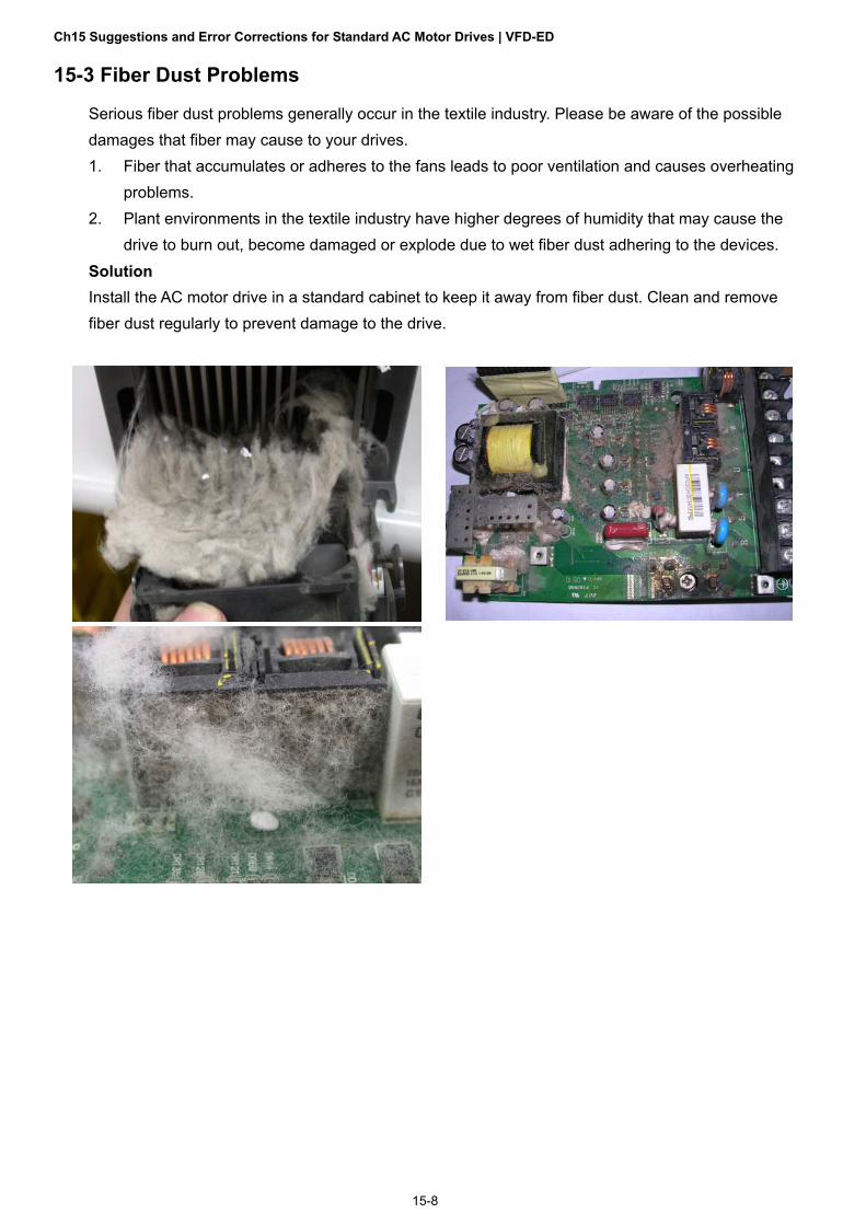
Ch15 Suggestions and Error Corrections for Standard AC Motor Drives | VFD-ED
15-8
15-3 Fiber Dust Problems
Serious fiber dust problems generally occur in the textile industry. Please be aware of the possible damages that fiber may cause to your drives. 1. Fiber that accumulates or adheres to the fans leads to poor ventilation and causes overheating
problems. 2. Plant environments in the textile industry have higher degrees of humidity that may cause the
drive to burn out, become damaged or explode due to wet fiber dust adhering to the devices. Solution
Install the AC motor drive in a standard cabinet to keep it away from fiber dust. Clean and remove fiber dust regularly to prevent damage to the drive.

Ch15 Suggestions and Error Corrections for Standard AC Motor Drives | VFD-ED
15-9
15-4 Corrosion Problems
Corrosion problems may occur if any fluids flow into the drives. Please be aware of the possible damages that corrosion may cause to your drive. 1. Corrosion of internal components may cause the drive to malfunction and possibility to explode. Solution
Install the AC motor drive in a standard cabinet to keep it away from fluids. Clean the drive regularly to prevent corrosion.

Ch15 Suggestions and Error Corrections for Standard AC Motor Drives | VFD-ED
15-10
15-5 Industrial Dust Problems
Serious industrial dust pollution frequently occur in environments such as stone processing plants, flour mills, cement plants, and so on. Please be aware of the possible damages that industrial dust may cause to your drives. 1. Dust accumulating on electronic components may cause overheating problem and shorten the
service life of the drive. 2. Conductive dust may damage the circuit board and may even cause the drive to explode. Solution
Install the AC motor drive in a standard cabinet and cover the drive with a dust cover. Clean the cabinet and ventilation holes regularly for good ventilation.

Ch15 Suggestions and Error Corrections for Standard AC Motor Drives | VFD-ED
15-11
15-6 Installation and Wiring Problems
When wiring the drive, the most common problem is incorrect wire installation or poor wiring. Please be aware of the possible damages that poor wiring may cause to your drives. 1. If screws are not fully tightened, then sparking may occur as impedance increases. 2. If you have opened the drive and modified the internal circuit board, the internal components
may have been damaged. Solution
Ensure that all screws are tightened when installing the AC motor drive. If the AC motor drive functions abnormally, send it back to Delta for repair. DO NOT try to modify or repair the internal components or wiring.

Ch15 Suggestions and Error Corrections for Standard AC Motor Drives | VFD-ED
15-12
15-7 Multi-function Input / Output Terminal Application Problems
Multi-function input/output terminal errors are generally caused by over-usage of the terminals and not following the specifications. Please be aware of the possible damages that multi-function input/output terminal errors may cause to your drives. 1. Input/output circuit may burn out when the terminal usage exceeds the specified limit. Solution
Refer to the user manual for multi-function input output terminals usage and follow the specified voltage and current. DO NOT exceed the specification limits.

Ch16 Safe Torque Off Function | VFD-ED
16-1
Chapter 16 Safe Torque Off Function
16-1 Failure Rate of the Drive’s Safety Function
16-2 Description of STO’s Functions
16-3 Wiring Diagram
16-4 Related Parameters
16-5 Timing Diagram Description
16-6 Fault Codes Related to STO

Ch16 Safe Torque Off Function | VFD-ED
16-2
16-1 Failure Rate of the Drive’s Safety Function
Item Definition Standard Performance
SFF Safe Failure Fraction IEC61508 Channel 1: 80.08% Channel 2: 68.91%
HFT (Type A subsystem)
Hardware Fault Tolerance IEC61508 1
SIL Safety Integrity Level IEC61508 SIL 2 IEC62061 SILCL 2
PFH Average frequency of dangerous failure [h-1]
IEC61508 9.56×10⁻¹⁰
PFDav Probability of Dangerous Failure on Demand
IEC61508 4.18×10⁻⁶
Category Category ISO13849-1 Category 3 PL Performance level ISO13849-1 d
MTTFd Mean time to dangerous failure ISO13849-1 High DC Diagnostic coverage ISO13849-1 Low

Ch16 Safe Torque Off Function | VFD-ED
16-3
16-2 Description of STO’s Functions The STO (Safe Torque Off) function is to cut off the motor’s power supply to prevent the motor from producing torque force. The STO function is run by two independent hardware circuits to control the drive signals emitted by the motor’s current, and then to cut off motor drive’s power module output in order to safely stop the motor drive.
The following table describes the terminal functions. Table 1: Terminal Function Descriptions
Signal Channel Status of Photo Coupler
STO Signal
STO1–SCM1 ON (High) ON (High) OFF (Low) OFF (Low)
STO2–SCM2 ON (High) OFF (Low) ON (High) OFF (Low)
Drive Output Status Ready STL2 mode (Torque output off)
STL1 mode (Torque output off)
STO mode (Torque output Off)
STO is Safe Torque Off
STL1–STL3 means an STO internal hardware error.
STL3 means STO1–SCM1 and STO2–SCM2 has an internal circuit error.
STO1–SCM1 ON (High): means STO1–SCM1 has connection to a +24 VDC power supply.
STO2–SCM2 ON (High): means STO2–SCM2 has connection to a +24 VDC power supply.
STO1–SCM1 OFF (Low): means STO1–SCM1 has no connection to a +24 VDC power supply.
STO2–SCM2 OFF (Low): means STO2–SCM2 has no connection to a +24 VDC power supply.

Ch16 Safe Torque Off Function | VFD-ED
16-4
16-3 Wiring Diagram 16-3-1 Internal Safety Circuit
The following diagram shows the drive’s Internal Safety Circuit.
+24V
STO1
SCM1
STO2
SCM2
COM
V+
C2000
CPU Linedrive
Ga ted rive M
VFD-ED
DCM
16-3-2 Internal Safety Circuit Terminals
The part D in the diagram below shows the default for terminals +24V-STO1-STO2 and terminals SCM1-SCM2-DCM in the drive’s Internal Safety Circuit, which are short-circuited when they are delivered from the factory.
+24V
STO1
SCM1
STO2
SCM2
COM
V+
C2000
CPU Linedr ive
Ga ted rive M
S
S
VFD-ED
DCM

Ch16 Safe Torque Off Function | VFD-ED
16-5
16-3-3 Drive’s Control Circuit Wiring Diagram
1. Remove the E24V-STO1-STO2 short circuit. 2. The following diagram shows the wiring. The contract for safety interlock circuit must be closed
during the normal situation so that the motor drive can run. 3. In STO mode, if you switch on the safety interlock circuit, the motor drive stops outputting and
the keypad displays STO. 4. If the restart permission signal is OFF before the elevator controller issues the command to start
the elevator, it means that the STO function is currently malfunctioned or M1 magnetic contactor error has occurred, and then the elevator is unable to start (R1 cannot be ON).
Note: “R” in R1/R2 stands for Relay; “M” in M1 stands for MC (Magnetic Contactor)

Ch16 Safe Torque Off Function | VFD-ED
16-6
16-4 Related Parameters STO Latch Selection
Default: 0 Settings 0: STO alarm latch
1: STO alarm no latch
0: The STO alarm is latched, which means that once the cause of the alarm is cleared, you must use a Reset command to clear the STO alarm.
1: The STO alarm is NOT latched which, means that once the cause of the alarm is cleared, the STO alarm clears automatically.
When in STL1–STL3 mode, STO alarm is latched and you cannot set Pr.06-49.
Multi-function Output 1: RA, RB, RC (Relay 1)
Default: 11
Multi-function Output 2: MRA, MRB, MRC (Relay 2)
Default: 1
Multi-function Output 3: R1A, R12C (Relay 3)
Multi-function Output 4: R2A, R12C (Relay 4)
Multi-function Output 5: MO1
Multi-function Output 6: MO2
Default: 0 Settings 0: No function 1: Operation indication 11: Malfunction indication 42: STO Output Error
Multi-output Direction Default: 0
This parameter uses bit setting. If the bit is 1, the multi-function output terminal acts in the opposite direction.
Bit 11 Bit 10 Bit 9 Bit 8 Bit 7 Bit 6 Bit 5 Bit 4 Bit 3 Bit 2 Bit 1 Bit 0
- - - - - - MO2 MO1 R2A R1A MRA RA
STO output default: Pr.02-15 (MO1 =42 Logic Output A). You can also set Pr.02-23 (Multi-output direction) to choose Logic Output B.
Motor Drive Status
Output Safety Status
Logic Output A (Pr.02-15 = 42)
Logic Output B (Pr.02-15 = 42) (Pr.02-23 = 16)
Normal Broken circuit (Open) Short circuit (Closed)
STO Short circuit (Closed) Broken circuit (Open)
STL1–STL3 Short circuit (Closed) Broken circuit (Open)

Ch16 Safe Torque Off Function | VFD-ED
16-7
16-5 Timing Diagram Description
16-5-1 Normal Operation Status
As shown in Figure 1, when the STO1–SCM1 and STO2–SCM2 are ON (safety function is not required), the motor drive executes “Operating” or “Output Stop” according to the RUN/STOP command.
Figure 1
16-5-2 Pr.06-49 = 0, STO alarm latch
As shown in Figure 2, when both STO1–SCM1 and STO2–SCM2 channels are OFF during operation (safety function is required), the STO function is enabled and the motor drive stops outputting regardless of the command type.
Figure 2
16-5-3 Pr.06-49 = 1, STO alarm no latch
Figure 3

Ch16 Safe Torque Off Function | VFD-ED
16-8
16-5-4 STL1
Figure 4
16-5-5 STL2
Figure 5

Ch16 Safe Torque Off Function | VFD-ED
16-9
16-6 Fault Codes Related to STO
Present Fault Record
Second Most Recent Fault Record
Third Most Recent Fault Record
Fourth Recent Fault Record
Fifth Most Recent Fault Record
Sixth Most Recent Fault Record Settings
72: Safe torque loss (STL1) 76: Safe torque output stops (STO)
77: Safe torque loss 2 (STL2)
78: Safe torque loss 3 (STL3)
Error Code Reading Description
72
(STL1) Safe torque loss (STL1) STO1–SCM1 internal circuit error.
76
(STO) Safe torque output stops (STO)
Safe Torque Off function is enabled while
Pr.06-49 is set to 0 or 2.
77
(STL2) Safe torque loss 2 (STL2) STO2–SCM2 internal circuit error.
78
(STL3) Safe torque loss 3 (STL3)
STO1–SCM1 and STO2–SCM2 internal circuit
error.

Ch16 Safe Torque Off Function | VFD-ED
16-10
[The page intentionally left blank]

Appendix A. EMC Standard Installation Guide | VFD-ED
A-1
Appendix A.
AC Motor Drives EMC Standard Installation Guide
EMC Compliance Practice

Appendix A. EMC Standard Installation Guide | VFD-ED
A-2
Preface
When an AC motor drive is installed in a noisy environment, radiated and/or conducted noise via signal and power cables can interfere with the correct functioning, cause errors or even damage to the drive. To prevent this, some AC motor drives have an enhanced noise resistance but the results are limited and it is not economical. Therefore, an effective method would be finding the cause of the noise and use the right solution to achieve “no emission, no transmission and no reception of noise”. All three solutions should be applied.
Finding the Noise Ascertain whether the error is caused by noise. Find the source of the noise and its transmission path. Confirm the signal and the source of noise
Solutions Grounding Shielding Filtering

Appendix A. EMC Standard Installation Guide | VFD-ED
A-3
Table of Contents
1. Introduction 1.1 What is EMC 1.2 EMC for AC Motor Drive 2. How to prevent EMI 2.1 Types of EMI: common-mode and differential mode noise 2.2 How does EMI transmit? (Noise transmission) 3. Solution to EMI: Grounding 3.1 Protective Grounding & Functional Grounding 3.2 Ground Loops 3.3 Earthing Systems 4. Solution to EMI: Shielding 4.1 What is Shielding? 4.2 How to Reduce EMI by Shielding? 5. Solution to EMI: Filter 5.1 Filter 5.2 Harmonic Interference

Appendix A. EMC Standard Installation Guide | VFD-ED
A-4
Introduction
1.1 What is EMC? Electromagnetic Compatibility (EMC) is the ability of an electrical device to function properly in
electromagnetic environments. It does not emit electromagnetic noise to surrounding equipment and is immune to interference from surrounding equipment. The goal is to achieve high immunity and low emission; these two properties define the quality of EMC. In general, electrical devices react to high and low frequency phenomena. High frequency phenomena are electrostatic discharge (ESD); pulse interference; radiated electromagnetic field; and conducted high frequency electrical surge. Low frequency phenomena refer to mains power harmonics and imbalance.
The standard emission and immunity levels for compliance depend on the installation location of the drive. A Power Drive System (PDS) is installed in an industrial or domestic environment. A PDS in a domestic environment must have lower emission levels and is allowed to have lower immunity levels. A PDS in an industrial environment is allowed to have higher emission levels but must have more severe immunity levels.
1.2 EMC for AC Motor Drive When an AC motor drive is put into operation, harmonic signal will occur at the AC drive’s power input and
output side. It creates a certain level of electromagnetic interference to the surrounding electrical devices and the mains power network. An AC motor dive is usually applied in industrial environments with a strong electromagnetic interference. Under such conditions, an AC drive could disturb or be disturbed.
Delta’s AC motor drives are designed for EMC and comply with EMC standard EN61800-3 2004. Installing the AC motor drive accurately will decrease EMI influences and ensure long-term stability of the electricity system. It is strongly suggested to follow Delta’s user manual for wiring and grounding. If any difficulties or problems arise, please follow the instructions and measures as indicated in this EMC Standard Installation Guide.

Appendix A. EMC Standard Installation Guide | VFD-ED
A-5
How to prevent EMI
2.1 Types of EMI: Common-mode and differential-mode noise The electromagnetic noise of an AC motor drive can be distinguished into common-mode and differential-
mode noise. Differential-mode noise is caused by the stray capacitance between the conducting wires and common-mode noise is caused by the common-mode coupling current path created by the stray capacitance between the conducting wires and ground.
Basically, differential-mode noise has a greater impact to the AC motor drive and common-mode noise has a greater impact to high-sensitivity electronic devices. An excessive amount of differential-mode noise may trigger the circuit protection system of the AC motor drive. Common-mode noise affects peripheral electronic devices via the common ground connection. EMC problems can be more serious when the following conditions apply: When a large horsepower AC motor drive is connected to a large horsepower motor. The AC motor drive’s operation voltage increases. Fast switching of the IGBTs. When a long cable is used to connect the motor to the AC motor drive.
2.2 How does EMI transmit? (Noise transmission path) Noise disturbs peripheral high-sensitivity electrical devices/systems via conduction and radiation, their
transmission paths are shown hereafter: 1. Noise current in the unshielded power cable is conducted to ground via stray capacitances into a common-
mode voltage. Whether or not other modules are capable to resist this common-mode noise depends on their Common-Mode Rejection Ratio (CMRR), as shown in the following figure.
Noise Unshielded cable
Ground
Cstray
Send
Load
Receive
2. Common-mode noise in the power cable is transmitted through the stray capacitance and coupled into the
adjacent signal cable, as shown in Figure 2. Several methods can be applied to reduce the effect of this common-mode noise; for example, shield the power cable and/or the signal cables, separate the power and signal cables, take the input and output side of the signal cable and twist them together to balance out the stray capacitance, let power cables and signal cables cross at 90°, etc.

Appendix A. EMC Standard Installation Guide | VFD-ED
A-6
Noise
Unshielded cable
Ground
Cstray
Powersupply SystemCable
3. Common-mode noise is coupled via the power cable to other power systems then the cable of such a power
system is coupled to the transmission system, as shown in Figure 3.
Noise
Unshielded cable
Ground
Cstray
Send
Load
Receive
4. The common-mode noise of an unshielded power cable is transmitted to the ground via the stray capacitance.
Since both shielded wire and unshielded wire are connected to a common ground, other systems can be interfered with by the common-mode noise that is transmitted from the ground back to the system via the shield. See Figure 4.
Noise Unshielded cable
Ground
Send Receive
Load
Cstray
Cstray
5. When excessive pulse modulated currents pass through an un-grounded AC drive cable, it acts as an antenna
and creates radiated interference.
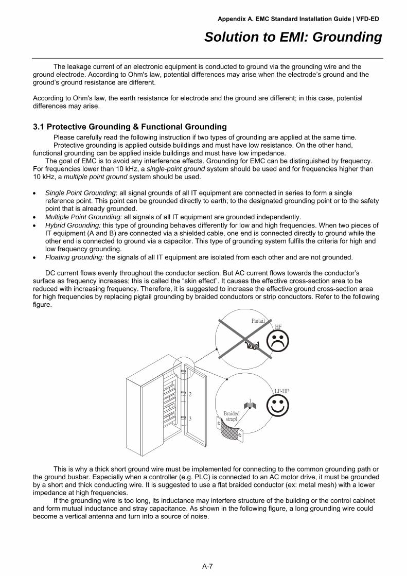
Appendix A. EMC Standard Installation Guide | VFD-ED
A-7
Solution to EMI: Grounding
The leakage current of an electronic equipment is conducted to ground via the grounding wire and the ground electrode. According to Ohm's law, potential differences may arise when the electrode’s ground and the ground’s ground resistance are different. According to Ohm's law, the earth resistance for electrode and the ground are different; in this case, potential differences may arise.
3.1 Protective Grounding & Functional Grounding Please carefully read the following instruction if two types of grounding are applied at the same time. Protective grounding is applied outside buildings and must have low resistance. On the other hand,
functional grounding can be applied inside buildings and must have low impedance. The goal of EMC is to avoid any interference effects. Grounding for EMC can be distinguished by frequency.
For frequencies lower than 10 kHz, a single-point ground system should be used and for frequencies higher than 10 kHz, a multiple point ground system should be used. Single Point Grounding: all signal grounds of all IT equipment are connected in series to form a single
reference point. This point can be grounded directly to earth; to the designated grounding point or to the safety point that is already grounded.
Multiple Point Grounding: all signals of all IT equipment are grounded independently. Hybrid Grounding: this type of grounding behaves differently for low and high frequencies. When two pieces of
IT equipment (A and B) are connected via a shielded cable, one end is connected directly to ground while the other end is connected to ground via a capacitor. This type of grounding system fulfils the criteria for high and low frequency grounding.
Floating grounding: the signals of all IT equipment are isolated from each other and are not grounded.
DC current flows evenly throughout the conductor section. But AC current flows towards the conductor’s surface as frequency increases; this is called the “skin effect”. It causes the effective cross-section area to be reduced with increasing frequency. Therefore, it is suggested to increase the effective ground cross-section area for high frequencies by replacing pigtail grounding by braided conductors or strip conductors. Refer to the following figure.
1
2
3
PigtailHF
LF-HF
Braidedstrapl
1
This is why a thick short ground wire must be implemented for connecting to the common grounding path or the ground busbar. Especially when a controller (e.g. PLC) is connected to an AC motor drive, it must be grounded by a short and thick conducting wire. It is suggested to use a flat braided conductor (ex: metal mesh) with a lower impedance at high frequencies.
If the grounding wire is too long, its inductance may interfere structure of the building or the control cabinet and form mutual inductance and stray capacitance. As shown in the following figure, a long grounding wire could become a vertical antenna and turn into a source of noise.

Appendix A. EMC Standard Installation Guide | VFD-ED
A-8
Lon
g PE
Paintedsheet metal
HF
3.2 Ground Loops A ground loop occurs when the pieces of equipment are connected to more than one grounding path. In this
case, the ground current may return to the grounding electrode via more than one path. There are three methods to prevent ground loops 1. Use a common power circuit 2. Single point grounding 3. Isolate signals, e.g. by photocouplers
Equipment
Cable
Equipment
A B
Earth plane
Equipment
Cable
Equipment
A B
Earth plane
Cable
Very good
Good
Accompanying cable
In order to avoid “Common Mode Noise”, please use parallel wires or twisted pair wiring. Follow this rule and
also avoid long wires, it is suggested to place the two wires as close to each other as possible.
3.3 Earthing Systems The international standard IEC60364 distinguishes three different earthing system categories, using the two-letter codes TN, TT, IT. The first letter indicates the type of earthing for the power supply equipment (generator or transformer).
T: One or more points of the power supply equipment are connected directly to the same earthing point. I: Either no point is connected to earth (isolated) or it is connected to earth via high impedance.
The second letter indicates the connection between earth and the power supply equipment. T: Connected directly to earth (This earthing point is separate from other earthing points in the power supply system.) N: Connected to earth via the conductor that is provided by the power supply system
The third and forth letter indicate the location of the earth conductor. S: Neutral and earth conductors are separate C: Neutral and earth are combined into a single conductor

Appendix A. EMC Standard Installation Guide | VFD-ED
A-9
TN system TN: The neutral point of the low voltage transformer or generator is earthed, usually the star point in a three-phase system. The body of the electrical device is connected to earth via this earth connection at the transformer. Protective earth (PE): The conductor that connects the exposed metallic parts of the consumer. Neutral (N): The conductor that connects to the start point in a three-phase system or that carries the return current in a single phase system.
L1L2
L3N
PE
TN-S system TN-S: PE and N are two separate conductors that are combined together only near the power source (transformer or generator). It is the same as a three-phase five-wire system.

Appendix A. EMC Standard Installation Guide | VFD-ED
A-10
TN-C system TN-C: PE and N are two separate conductors in an electrical installation similar to a three-phase five-wire system, but near the power side, PE and N are combined into a PEN conductor similar to a three-phase four-wire system.
L1
L2
L3
PEN
ConsumerEarth
Generator or t ransformer
TN-C-S system TN-C-S: A combined earth and neutral system (PEN conductor) is used in certain systems but eventually split up into two separate conductors PE and N. A typical application of combined PEN conductor is from the substation to the building but within the building PEN is separated into the PE and N conductors. Direct connection of PE and N conductors to many earthing points at different locations in the field will reduce the risk of broken neutrals. Therefore, this application is also known as protective multiple earthing (PME) in the UK or as multiple earthed neutral (MEN) in Australia
L1
L2
L3
N
ConsumerEarth
Generator or t ransformer
PE

Appendix A. EMC Standard Installation Guide | VFD-ED
A-11
TT system TT: The neutral point (N) of the low voltage transformer and the equipment frames (PE) are connected to a separate earthing point. The Neutral (N) of the transformer and electrical equipment are connected.
IT system IT: The neutral point of the transformer and electrical equipment are not earthed, only the equipment frames PE are earthed. In the IT network, the power distribution system Neutral is either not connected to earth or is earthed via high impedance. In such a system, an insulated monitoring device is used for impedance monitoring. A built-in filter should be disconnected by the RFI-jumper and an external filter should not be installed when the AC motor drive or the AC servo motor drive is connected to an IT system.

Appendix A. EMC Standard Installation Guide | VFD-ED
A-12
Criteria for Earthing System and EMC
TN-S TN-C TT IT Safety of Personnel
Good Continuity of the PE conductor must be ensured throughout the installation
Good Continuity of the PE conductor must be ensured throughout the installation
Good RCD is mandatory
Good Continuity of the PE conductor must be ensured throughout the installation
Safety of Property
Poor High fault current (around 1kA)
Poor High fault current (around 1kA)
Good Medium fault current (< a few dozen amperes)
Good Low current at the first fault (< a few dozen mA) but high current at the second fault
Availability of Energy
Good Good Good Excellent
EMC Behavior
Excellent Few equipotential Problems: - Need to handle the high leaking currents problem of the device
- High fault current (transient disturbances)
Poor (prohibited)
- Neutral and PE are the same
- Circulation of disturbance currents in exposed conductive parts (high magnetic-field radiation)
- High fault currents (transient disturbances)
Good - Over-voltage risk
- Equipotential Problems: - Need to handle the high leaking currents problem of the device
- RCD (Residual- current device)
Poor (should be avoided)
- Over-voltage risk - Common–mode filters and surge arrestors must handle the phase-to-phase voltage.
- RCDs subject to nuisance tripping when common-mode capacitors are present
- Equivalent to TN system for second fault

Appendix A. EMC Standard Installation Guide | VFD-ED
A-13
Solution to EMI: Shielding
4.1 What is Shielding? Electrostatic shielding is used to isolate equipment so that it will not create electromagnetic field interference
or be influenced by an external electromagnetic field. A conductive material is used for electrostatic shielding to achieve this isolation.
A Faraday cage can be made from a mesh of metal or a conductive material. One characteristic of metal is that it is highly conductive and not electrostatic, which offers shielding and prevents interference by external electrical fields. Metal with its high conductivity protects the internal devices from high voltages—no voltage will enter the cage even when the cage is experiencing a high current. In addition, electromagnetic fields can also pass through the Faraday cage without causing any disturbance.
Electromagnetic shielding is applied to some electrical devices and measurement equipment for the purpose of blocking interference. Examples of shielding include: earth high-voltage indoor equipment using a metal frame or a high-density metal mesh shielding a power transformer is achieved by wrapping a metal sheet between the primary and secondary
windings or by adding an enamel wire to the winding wire which is then earthed. a shielding coating, which is made of metal mesh or conductive fibers to provide effective protection for the
workers who work in a high-voltage environment.
In the picture below, the radio appears to be not fully covered by metal but if the conductivity of the metal is high, radio waves are completely blocked and the radio will not receive any signal.
Mobile phone connections are also established through the transmission of radio waves. This is why the mobile phone reception is often cut off when we walk into an elevator. The metal walls of the elevator create the same shielding effect just as if we had entered a metal cage. Another example is a microwave oven. The microwave door may seem transparent in visible light, but the density of the metal mesh in the microwave door blocks the electromagnetic waves. A higher density of the metal mesh offers better shielding.

Appendix A. EMC Standard Installation Guide | VFD-ED
A-14
Electromagnetic fields
Wall of shieldedenclosure Greater leakage
form bigger apertures
g(gap)
d(depth)
"Waveguide below cut-off" doesn't leak very much
(does not have to be a tube)G=gap
(aper tu re d imension)d=depth
(distance that f ieldshave to travel)
0
20
40
60
80
0.05 0.1 0.2 10.5 2 5
GHz
Shield ing ef fectiveness (SE)in dB
d=18"g=6"
d=12"g=6"
d=6"g=6"
d=6"g=2"
d=4"g=2"
d=2"g=2"
F<0.5Fcutoff SE is approximately 27d/g
4.2 How to reduce EMI by Shielding? Iron and other metals are high conductivity materials that provide effective shielding at extremely low
frequencies. But conductivity will decrease as: 1. High frequency signals are applied to the conductor. 2. Equipment is located in a strong magnetic field 3. The shielding frame is forced into a specific form by machines. It is difficult to select a suitable high-conductivity material for shielding without the help from a shielding material supplier or a related EMI institution.
Metallic Shielding Effectiveness Shielding Effectiveness (SE) is used to assess the applicability of the shielding shell. The formula is:
SEdB=A+R+B (Measures in dB) where A= Absorption loss (dB)
R= Reflection loss (dB) B= Correction factor (dB) (for multiple reflections in thin shields)
The absorption loss refers to the amount of energy loss as the electromagnetic wave travels through the
shield. The formula is: AdB=1.314(fσμ) 1/2t where f= frequency (MHz)
μ= permeability relative to copper σ= conductivity relative to copper t= thickness of the shield in centimeters
The reflection loss depends on the source of the electromagnetic wave and the distance from that source.
For a rod or straight wire antenna, the wave impedance increases as it moves closer to the source and decreases as it moves away from the source until it reaches the plane wave impedance (377) and shows no change. If the wave source is a small wire loop, the magnetic field is dominant and the wave impedance decreases as it moves closer to the source and increases as it moves away from the source; but it levels out at 377 when the distance exceeds one-sixth of the wavelength.

Appendix A. EMC Standard Installation Guide | VFD-ED
A-15
Electrical Cabinet Design In a high frequency electric field, shielding can be achieved by painting a thin layer of conductive metal on the
enclosure or on the internal lining material. However, the coating must be thorough and all parts should be properly covered without any seams or gaps (just like a Faraday cage). That is only the ideal. Making a seamless shielding shell is practically impossible since the cage is composed of metal parts. In some conditions, it is necessary to drill holes in the shielding enclosure for installation of accessories (like optional cards and other devices). 1. If the metallic components are properly welded using sophisticated welding technology to form an electrical
cabinet, deformation during usage is unlikely to occur. But if the electrical cabinet is assembled with screws, the protective insulating layer under the screw must be properly removed before assembly to achieve the greatest conductivity and best shielding.
2. Drilling holes for the installation of wires in the electrical cabinet lowers the shielding effectiveness and increases the chance of electric waves leaking through the openings and emitting interference. We recommend that the drilled holes are as narrow as possible. When the wiring holes are not used, properly cover the holes with metal plates or metal covers. The paint or the coating of the metal plate and metal cover should be thoroughly removed to ensure a metal-to-metal contact or a conductive gasket should be installed.
3. Install industrial conductive gaskets to completely seal the electrical cabinet and the cabinet door without gaps. If conductive gaskets are too costly, please screw the cabinet door to the electrical cabinet with a short distance between the screws.
4. Reserve a grounding terminal on the electrical cabinet door. This grounding terminal shall not be painted. If the paint already exists, please remove the paint before grounding.
Electrical wires and cables Shielded Twisted Pair (STP) is a type of cable where two insulated copper wires are twisted together with a
metal mesh surrounding the twisted pair that forms the electromagnetic shielding and can also be used for grounding.
The individual electrical wires and complete cable are surrounded by (synthetic) rubber that provides insulation and also protects against damage.
There are two types of electrical cables: high voltage and low voltage. The high voltage cable differs from the low voltage cable in that it has an additional insulation layer called the dielectric insulator within the plastic sleeve. The dielectric insulator is the most important component in insulation. The low voltage cable is usually only filled with a soft polymer material for keeping the internal copper wire in place. The shield has two functions. 1. To shield the electrical wire and cable.
A. Electric currents increase as power flows through the power cable and generate an electrical field. Such interference can be suppressed inside the cable by shielding the power cables or the electrical wires. B. To form a protective earthing. When the cable core is damaged, the leakage current will flow via the shield to ground
2. To protect the cable. A power cable used for the computer control purpose generates only relatively low amount of current inside the cable. Such power cable will not become the source of interferences but has great possibility to be interfered by the surrounding electrical devices.
Metallic shield
Centre core
Plast ic jacket
Dielectric insulator

Appendix A. EMC Standard Installation Guide | VFD-ED
A-16
Solution to EMI: Filter
5.1 Filter Electromagnetic interference is transmitted in two ways, by radiation and by conduction. The most effective
and economical method of reducing radiated interference is to use shielding and of reducing conducted interference is to use an electromagnetic filter.
Noise interference can be divided into two categories: high frequency (150 kHz–300 MHz) and low frequency (100–3000 Hz). High-frequency noise fades more over distance and has a shorter wave-length, while low-frequency noise fades less over distance and has a longer wave-length. Both types of interference are transmitted through power cables and power leads, affecting the power supply side.
High-frequency interference at the power side can be eliminated or attenuated by mounting a filter. The filter consists of coils and capacitors. Some drives do not have a built-in filter, in which case the installation of an external option filter is required. The drawing below shows a standard filter diagram:
A filter is composed of a Differential Mode section (to eliminate noise below 150 kHz) and a Common Mode
section (to eliminate noise above 150 kHz). For high-frequency noise, the inductor acts as a high impedance to form an open circuit and the capacitor acts as a low impedance to form a short circuit. Proper design and dimensioning of inductors and capacitors give a resonant circuit to absorb harmonic currents. Capacitor Cy is earthed to lead the harmonic currents to the ground.
External Filter The filter and the AC drive should be installed in the control cabinet or on the mounting plate that is earthed
to ground. The motor cable must be shielded and as short as possible. Please use the filters recommended by Delta to ensure compliance with EMC standards.
EMI FilterL1 L1'L2 L2'L3 L3'
R/L1
S/L2T/L3
U/T1
V/T2
W/T3
Chassis Grounding
Connect to the steel structure of the building
Shielded Motor Cable
Metal Conduits
The Shielded Chassis
IP20/NEMA 1/UL Type 1Option Kit

Appendix A. EMC Standard Installation Guide | VFD-ED
A-17
AC Motor Drives with Built-in Filter 1. Since interferences are suppressed by installing an earthed capacitor in the filter, the amount of current to
ground (leakage current) could result in electric shocks to personnel or the power system. Please be aware of this problem.
2. Since the leakage current to ground can be high, it is crucial to implement protective earthing to prevent electrical shocks.
Filter Installation (With and Without)
Zero Phase Reactor (Choke) Interferences can also be suppressed by installing a zero phase reactor at the power supply side and/or the
AC Motor Drive’s output, depending on where the interference is. Since currents are large at the power input and the AC Motor Drive’s output, please carefully select the magnetic core with suitable current handling capability. An ideal magnetic material for large currents is compound magnetic powder. It has a higher current handling capability and higher impedance compared to pure metallic magnetic cores. It is therefore suitable to implement in a high frequency environment. The impedance can also be enhanced by increasing the turn ratio.
Zero Phase Reactor Installation There are two installation methods, depending on the size of the zero phase reactor and the motor cable length.
1. Wind the motor cable through the middle of a zero-phase reactor four times. Place the reactor and the AC
Motor Drive as close to each other as possible.
PowerSupply
Zero Phase Reactor
MOTORU/T1
V/T2
W/T3
R/L1
S/L2
T/L3
2. Place all wires through the middle of four zero-phase reactors without winding.
U/T1V/T2W/T3
R/L1S/L2T/L3
PowerSupply
Zero Phase Reactor
MOTOR

Appendix A. EMC Standard Installation Guide | VFD-ED
A-18
Analog Input Signals If the analog input signals are affected by noise from the AC motor drive, please connect a capacitor and a
ferrite core as indicated in the following diagram. Wind the wires around the core in same direction for 3 times or more.
CAVI/ACI/AUI
ACM
Ferrite core
5.2 Harmonic Interference The AC motor drive’s input current is non-linear, the input rectifier generates harmonics. Harmonics must be
limited to within a certain range to avoid impact the mains power and to avoid current distortion to ensure surrounding devices are not influenced. An AC Motor Drive with built-in DC reactor suppresses harmonic currents (Total Harmonic Current Distortion THID) effectively and therefore reduces the harmonic voltage peaks (Total Harmonic Voltage Distortion).
Harmonic Current at the Power Supply Side
(A) Fundamental Sine Wave (60Hz)
(B) Harmonic (180Hz)
3 rd
(C) Harmonica lly Distorted Wave
(B) Harmonic (300Hz)
5 th
(C) Harmonica lly Distorted Wave
(A) Fundamental Sine Wave (60Hz)
Suppression of Harmonic Currents When a large portion of lower order harmonic currents (5th, 7th, 11th ,etc.) occur at the power input,
surrounding devices will be disturbed and the power factor will be low as a result of reactive power. Installing a reactor at the AC Motor Drive’s input effectively suppresses lower order harmonic currents.
AC Reactor Installed in series with the power supply and is effective in reducing low order current harmonics.
Features of an AC reactor include: 1. Reduces the harmonic currents to the AC Motor Drive and increases the impedance of the power supply. 2. Absorbs interferences generated by surrounding devices (such as surge voltages, currents, and mains surge
voltages) and reduce their effect on the AC Motor Drive. 3. Increases the power factor.
DC Reactor A DC-Reactor is installed between the rectifier and the DC-bus capacitor to suppress harmonic currents and
to achieve a higher power factor.

Appendix A. EMC Standard Installation Guide | VFD-ED
A-19
Current Wave Diagrams Without Reactor With Reactor
0 50 100 150 200 250 300 350 400 450 500-150
-100
-50
0
50
100
150
0 50 100 150 200 250 300 350 400 450 500-150
-100
-50
0
50
100
150

Appendix A. EMC Standard Installation Guide | VFD-ED
A-20
[The page intentionally left blank]

Appendix B. Revision HistoryVFD-ED
B-1
Appendix B. Revision History
Newly Added
Description Chapter
Copyright notice and limitation of liability added Preface EC 60664-1 for pollution degree 2 added Chapter 2 ”HP” and “Min. Braking Power” columns are added for 6-1 Brake Resistors
and Brake Units Used in AC Motor Drives, and notes for 6 and 7 under the tables are also added.
One-phase models for Section 6-2 non-fuse circuit breaker added Installation precaution for Section 6-5 Zero Phase Reactor added Recommended maximum wiring gauge reference table for Section 6-5
added
Chapter 6
Notes for terminal function table and descriptions for the third item (and hereinafter) for setting the frequency division signal for EMED-PGHSD-1 added
Descriptions for the third item (and hereinafter) for setting the frequency division signal for EMED-PGHSD-2 added
Chapter 7
Operation, Storage and Transportation Environments\EMC level added Chapter 8 The descriptions for text color under menu item “5. Display Setup” for
Section 9-4 Digital Keypad KPC-CC01 Functions added Chapter 9
The curve and descriptions for elevator performance fine-tuning added Explanations for the auto-tuning steps added:
Step 5: Inertia reference value (%) Step 7: (1) Enable slip compensation (VF, SVC), (2) Comfort adjustment for normal operation (FOCPG, FOCPM), and (4) DC brake adjustment.
Chapter 10
Parameter settings and detailed descriptions added: Parameter Group 01: 01-33–01-40 Parameter Group 02: 02-11–02-22 function setting #49 Parameter Group 04: 04-15 Parameter Group 06: 06-68–06-72, 06-73–06-99
Chapter 11 Chapter 12

Appendix B. Revision HistoryVFD-ED
B-2
Major Changes
Description Chapter
Vdc is corrected to VDC;Vac is corrected to VAC. All sections “Before Using” updated Preface For Section 1-5 RFI Switch, all “cut off RFI short circuit cable” is corrected to
“remove RFI switch”, "according to IEC 61800-3" is deleted, one “RFI capacitor” is corrected to “RFI switch” for particular attention under Isolating Main Power from Ground.
Figure, dimension, and notes for Frame C are updated in Section 1-6 Dimensions.
Chapter 1
Models’ information about horsepower and capacity are combined into one table for Section 2-2 Minimum Mounting Clearance.
Chapter 2
Frame E wring diagram (braking resistor added) updated Chapter 3 Main circuit diagram for frame E updated (braking resistor added) Chapter 4 Figures for control board switch are respectively placed into the Default (NPN
mode) column for SG1+ and SG1- terminals and SW2 terminal. The figure for AUI and AUI2 analog voltage frequency updated Descriptions for AFM1 and AFM2 Default (NPN mode) are combined into one
column.
Chapter 5
Table for brake resistors and brake units used in AC motor drives updated: table is changed from one to two (10% ED and 30% ED), “Braking Resistor Value Spec. for Each AC Motor Drive” column is deleted, “Braking Resistor Value Spec. for Each AC Motor Drive” column is corrected to “Delta’s Part No.”, values in the tables are all updated, note 1 under the tables are updated.
Section 6-4 AC/DC Reactor all updated Zero phase reactors are changed into two types: casing with mechanical fixed
part and casing without mechanical fixed part Diagrams for installing zero phase reactors are changed into two methods: single
turn and multi-turn. Zero phase reactor models for input side (R/S/T) of 220V and 460V models
updated. Zero phase reactor models for output side (U/V/W) of 220V and 460V models deleted.
Figures for EMC filters updated Menu items under MENU key for KPC-CC01 keypad functions are corrected to
13 items and unsupported item 4, 5 and 7 are noted. HAND and AUTO keys for KPC-CC01 keypad functions are corrected to “no
function” LED function descriptions updated The method for downloading the driver file (IFD6530_Drivers.exe) is changed
from CD to URL address.
Chapter 6

Appendix B. Revision HistoryVFD-ED
B-3
Major Changes
Description Chapter
The table for screw specification for optional card terminal is deleted and screw specifications are respectively placed into the right bottom corner for each PG card figure.
The number of PG cards for Vertical View of the Motor Drive & Screw Specifications are corrected from two to three: EMED-PGABD-1, EMED-PGHSD-1 and EMED-PGHSD-2.
Applicable encoders for EMED-PGHSD-1 and EMED-PGHSD-2 updated EMED-PGABD-1\Terminal TB2\Terminals A/O and B/O\
SW2 is corrected to SW3 in Descriptions column EMED-PGHSD-2 (Terminal TB2) pin definitions depend on the encoder type
\Terminals\ Change terminal order in the terminal table to match that in the terminal figure, and information of the second row is deleted. “Must set Pr.10-31=1” to terminals C+ and C- for Heidenhain ERN1387 is added.
Terminal UP is corrected into Up. Terminal Vp is corrected into VP. Terminal DVin is corrected into Vin.
Chapter 7
General Specifications\brake torque updated General Specifications\certifications updated Operation temperature updated
Chapter 8
Menu items under MENU key for KPC-CC01 keypad functions are corrected to 13 items and unsupported item 4, 5 and 7 are noted.
Unsupported menu items under Section 9-4 Digital Keypad KPC-CC01 Functions are corrected from two items (4 and 5) to three items (4, 5 and 7).
Language selections for Language Setup are corrected to three languages: English, Traditional Chinese and Simplified Chinese and that only these three languages are currently supported are noted.
Subsection 3) Edit Main Page is deleted because the contents are the same as those in subsection 2) Edit Main Page & Example of Download under Section 9-6 TPEditor Installation.
Chapter 9
Flow chart for the auto-tuning process updated Explanations for the auto-tuning steps updated:
Step 1: Pr.00-02, Pr.00-14, Pr.00-15, Pr.02-01–02-08, Pr.02-15–02-16 settings Step 2: Encoder Settings Step 3: Pr.00-09 and Pr.01-02 settings,【PM Motor】\Motor Auto-tuning\ Pr.08-00 NOTE1 descriptions, and Pr.08-00 NOTE2 descriptions under Measure the Angle between the Magnetic Pole and the PG Origin. Step 4: Pr.01-12–01-19 NOTE description, and analog setting Step 7: Pr.11-00, Pr.11-06–11-08 settings, (3) Start-up adjustment (FOCPM),
Chapter 10

Appendix B. Revision HistoryVFD-ED
B-4
Major Changes
Description Chapter
Pr.11-00, Pr.10-19, Pr.10-22, Pr.03-00, Pr.07-19, Pr.03-06, Pr.03-09 settings, and (5) Set drive stop.
Parameter settings and detailed descriptions updated: Parameter Group 00: 00-01, 00-02, 00-09, 00-11, 00-14, 00-15 Parameter Group 01: 01-21, 01-29 Parameter Group 02: 02-01–02-08, 02-10, 02-11–02-22, 02-34, 02-37, 02-38,
02-39, 02-44 Parameter Group 03: 03-00–03-02, 03-17 & 03-20, 03-23 & 03-24 Parameter Group 05: 05-01, 05-05, 05-18, 05-19, 05-21, 05-22 Parameter Group 06: 06-02, 06-03, 06-10, 06-11, 06-16–06-21, 06-28,
06-32–06-43, 06-46, 06-49–06-64 Parameter Group 07: 07-03, 07-11, 07-23, 07-28, 07-29 Parameter Group 08: 08-00 Parameter Group 09: 09-02, 09-04 Parameter Group 10: 10-00, 10-06–10-09, 10-19, 10-24, 10-29, 10-30, 10-31 Parameter Group 11: 11-03, 11-04, 11-05, 11-16–11-18, 11-20 Parameter Group 12: 12-00–12-31 Parameter Group 13: 13-00–13-31
Chapter 11 Chapter 12
Descriptions for warning codes CE01, CE02, CE03, CE04, CE10, CP10, PGF1, PGF4, ot1, ot2, oH3, oSL, FAn, dCAn updated
Chapter 13
Descriptions for fault codes ocA, ocd, ocn, GFF, occ, ocS, ovS, LvA, Lvd, Lvn, LvS, PHL, oH1, tH1o, tH2o, FAn, oL, EoL1, oH3, ot1&ot2, cF1, cF2, cd0, cd1, cd2, cd3, Hd0, Hd1, Hd2, Hd3, PGF1, PGF3, PGF4, EF, EF1, Pcod, cE02, BF, MBF, PGF5, MCF, MPHL, CANF, STL1, PGcd, PGHL, PGAF, PGcd, STO, STL2, STL3 updated
Chapter 14
Descriptions for Suggestions and Error Corrections for Standard AC Motor Drives updated
Chapter 15
The descriptions and contents for Table 1 Terminal Function Descriptions updated: The status of photo coupler between channel STO2–SCM2 and STL1 mode (Torque output off) is corrected from ON(Low) to ON(High)
Descriptions and the figure for Section 16-3-3 Control Circuit Wiring Diagram updated (change from ESTOP to Safety Interlock Circuit)
Descriptions for Fault Codes related to STO updated
Chapter 16


![Elevator Catalog [1.3 MB] - Wirerope Works](https://static.fdokumen.com/doc/165x107/6327034c6d480576770d1104/elevator-catalog-13-mb-wirerope-works.jpg)