HFE1600-D1U-Rack-User-Manual.pdf - TDK-Lambda EMEA
32
General Safety Instructions: READ SAFETY INSTRUCTIONS Servicing: These products are not customer serviceable. TDK-Lambda and their authorised agents only are permitted to carry out repairs. Critical Components: These products are not authorised for use as critical components in nuclear control systems, life support systems or equipment for use in hazardous environments without the express written approval of the Managing Director of TDK-Lambda EMEA. Product Usage: These products are designed for use within a host equipment which restricts access to authorised competent personnel. This product is a component power supply and is only to be installed by qualified persons within other equipment and must not be operated as a stand-alone product. This product is for sale to business to business customers and can be obtained via distribution channels. It is not intended for sale to end users. This product is a component power supply and complies with the EMC directive. The EMC performance of a component power supply will be affected by the final installation, compliance to the stated EMC standards and conformance to the EMC Directive must be confirmed after installation by the final equipment manufacturer. For guidance with respect to test conditions please visit our website at https://emea.tdk-lambda.com/EMC_guidance or contact your local TDK-Lambda sales office. Environmental: These products are IPX0, and therefore chemicals/solvents, cleaning agents and other liquids must not be used. Environment: This power supply is a switch mode power supply for use in applications within a Pollution Degree 2, overvoltage category II environment. Material Group IIIb PCB’s are used within it. Output Loading: The output power taken from the power supply must not exceed the rating stated on the power supply label, except as stated in the product limitations in this handbook. Input Parameters: This product must be operated within the input parameters stated in the product limitations in this handbook. End of Life Disposal: The unit contains components that require special disposal. Make sure that the unit is properly disposed of at the end of its service life and in accordance with local regulations. RISK OF ELECTRIC SHOCK High Voltage Warning: Dangerous voltages are present within the power supply. The professional installer must protect service personnel from inadvertent contact with these dangerous voltages in the end equipment. WARNING: When installed in a Class I end equipment, this product must be reliably earthed and professionally installed. The (+) or (-) output(s) can be earthed or left floating. The unit cover(s)/chassis must not be made user accessible. The mains input connector is not acceptable for use as field wiring terminals. Do not use mounting screws, which penetrate the unit more than 3mm (FPS/RFE1000), 6mm (HFE/RFE1600/2500 & racks). Special earthing screws are used on these products which connect the cover to the chassis. They must not be removed. If they are removed by mistake, they must be replaced with new ones and the product tested for earth bonding. This unit must be securely mounted and its earth terminal/baseplate properly boned to the main protective earth 1
-
Upload
khangminh22 -
Category
Documents
-
view
0 -
download
0
Transcript of HFE1600-D1U-Rack-User-Manual.pdf - TDK-Lambda EMEA

General Safety Instructions:
READ SAFETY INSTRUCTIONSServicing:These products are not customer serviceable. TDK-Lambda and their authorised agents only are permitted to carry out repairs.
Critical Components:These products are not authorised for use as critical components in nuclear control systems, life support systems or equipment for use in hazardous environments without the express written approval of the Managing Director of TDK-Lambda EMEA.
Product Usage:These products are designed for use within a host equipment which restricts access to authorised competent personnel.
This product is a component power supply and is only to be installed by qualified persons within other equipment and must not be operated as a stand-alone product.
This product is for sale to business to business customers and can be obtained via distribution channels. It is not intended for sale to end users.
This product is a component power supply and complies with the EMC directive. The EMC performance of a component power supply will be affected by the final installation, compliance to the stated EMC standards and conformance to the EMC Directive must be confirmed after installation by the final equipment manufacturer.
For guidance with respect to test conditions please visit our website at https://emea.tdk-lambda.com/EMC_guidance or contact your local TDK-Lambda sales office.
Environmental:These products are IPX0, and therefore chemicals/solvents, cleaning agents and other liquids must not be used.
Environment:This power supply is a switch mode power supply for use in applications within a Pollution Degree 2, overvoltage category II environment. Material Group IIIb PCB’s are used within it.
Output Loading:The output power taken from the power supply must not exceed the rating stated on the power supply label, except as stated in the product limitations in this handbook.
Input Parameters:This product must be operated within the input parameters stated in the product limitations in this handbook.
End of Life Disposal:The unit contains components that require special disposal. Make sure that the unit is properly disposed of at the end of its service life and in accordance with local regulations.
RISK OF ELECTRIC SHOCK
High Voltage Warning:Dangerous voltages are present within the power supply. The professional installer must protect service personnel from inadvertent contact with these dangerous voltages in the end equipment.
WARNING: When installed in a Class I end equipment, this product must be reliably earthed and professionally installed.
The (+) or (-) output(s) can be earthed or left floating. The unit cover(s)/chassis must not be made user accessible. The mains input connector is not acceptable for use as field wiring terminals. Do not use mounting screws, which penetrate the unit more than 3mm (FPS/RFE1000), 6mm (HFE/RFE1600/2500 & racks). Special earthing screws are used on these products which connect the cover to the chassis. They must not be removed. If they are removed by mistake, they must be replaced with new ones and the product tested for earth bonding.
This unit must be securely mounted and its earth terminal/baseplate properly boned to the main protective earth
1
before any connection to the MAINS supply is made. An internal fuse protects the unit and must not be replaced by the user. In case of internal defect, the unit must be returned to TDK-Lambda or one of their authorised agents. A suitable mechanical, electrical and fire enclosure must be provided by the end use equipment for mechanical, electric shock and fire hazard protection.
Energy Hazards:Certain modules are capable of providing hazardous energy (240VA) according to output voltage setting. Final equipment manufacturers must provide protection to service personnel against inadvertent contact with these module output terminals. If set such, that hazardous energy can occur, then the module terminals or connections must not be user accessible.
Disconnect device: An appropriate disconnect device shall be incorporated in the building installation wiring. Refer to the user manual of the specific model for more details.
Rack mounting safety instructions:A) Elevated Operating Ambient - If installed in a closed or multi-unit rack assembly, the operating ambient temperature of the rack environment may be greater than room ambient. Therefore, consideration should be given to installing the equipment in an environment compatible with the maximum ambient temperature (Tma) specified by the manufacturer.
B) Reduced Air Flow - Installation of the equipment in a rack should be such that the amount of air flow required for safe operation of the equipment is not compromised.
C) Mechanical Loading - Mounting of the equipment in the rack should be such that a hazardous condition is not achieved due to uneven mechanical loading.
D) Circuit Overloading - Consideration should be given to the connection of the equipment to the supply circuit and the effect that overloading of the circuits might have on overcurrent protection and supply wiring. Appropriate consideration of equipment nameplate ratings should be used when addressing this concern.
E) Reliable Earthing - Reliable earthing of rack-mounted equipment should be maintained. Particular attention should be given to supply connections other than direct connections to the branch circuit (e.g. use of power strips).
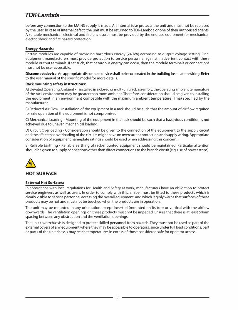
HOT SURFACE
External Hot Surfaces:In accordance with local regulations for Health and Safety at work, manufacturers have an obligation to protect service engineers as well as users. In order to comply with this, a label must be fitted to these products which is clearly visible to service personnel accessing the overall equipment, and which legibly warns that surfaces of these products may be hot and must not be touched when the products are in operation.
The unit may be mounted in any orientation except inverted (mounted on its top) or vertical with the airflow downwards. The ventilation openings on these products must not be impeded. Ensure that there is at least 50mm spacing between any obstruction and the ventilation openings.
The unit cover/chassis is designed to protect skilled personnel from hazards. They must not be used as part of the external covers of any equipment where they may be accessible to operators, since under full load conditions, part or parts of the unit chassis may reach temperatures in excess of those considered safe for operator access.
2

DEUTSCH
Allgemeine Sicherheitsvorschriften:
LESEN SIE DIE SICHERHEITSVORSCHRIFTENWartung:Diese Produkte können nicht durch den Kunden gewartet werden. Nur TDK-Lambda und deren zugelassene Vertriebshändler sind zur Durchführung von Reparaturen berechtigt.
Kritische Komponenten:Diese Produkte sind nicht für die Verwendung als kritische Komponenten in nuklearen Kontrollsystemen, Lebenserhaltungssystemen oder Geräten in gefährlichen Umgebungen geeignet, sofern dies nicht ausdrücklich und in Schriftform durch den Geschäftsführer von TDK-Lambda EMEA genehmigt wurde.
Produktverwendung:Diese Produkte sind zur Verwendung innerhalb von Host-Anlagen gedacht, die einen auf das Fachpersonal beschränkten Zugang haben.
Dieses Produkt ist eine Stromversorgungs-Komponente und sie darf nur von qualifiziertem Personal in andere Geräte eingebaut werden und sie darf NICHT als eigenständiges (“Stand-Alone”) Gerät betrieben werden.
Dieses Produkt ist für den Verkauf an Geschäftskunden entwickelt worden und es kann über Distributionskanäle bezogen werden.
Es ist NICHT für den Verkauf an Endkunden gedacht und konzipiert.
Dieses Produkt ist ein Komponenten-Netzteil und entspricht der EMV-Richtlinie. Das EMV-Verhalten eines Einbaunetzteiles wird von der Einbausituation im Endgerät maßgeblich beeinflusst. Die Übereinstimmung mit den angegebenen EMV-Normen und die Erfüllung der EMV-Richtlinie muss nach dem Einbau vom Endgerätehersteller nachgewiesen werden.
Für Anwendungshinweise besuchen Sie bitte unsere Website auf https://emea.tdk-lambda.com/ EMC_guidance oder kontaktieren Sie Ihr lokales TDK-Lambda Vertriebsbüro.
Umwelt:Diese Produkte sind IPX0, aus diesem Grund dürfen keine Chemikalien/Lösungsmittel, Reinigungsmittel und andere Flüssigkeiten verwendet werden.
Umgebung:Dieses Netzteil ist ein Schaltnetzteil zur Verwendung in einer Umgebung mit einem Verschmutzungsgrad 2, Überspannungskategorie II. Materialgruppe IIIb mit darin verwendeten PCBs.
Ausgangsstrom:Der Ausgangsstrom des Netzteiles darf die Leistung, die auf dem Label des Netzteiles vermerkt ist, nur dann überschreiten, wenn dies in den Produktgrenzen dieses Handbuches ausgezeichnet ist.
Eingangsparameter:Dieses Produkt muss innerhalb der Eingangsparameter, die in den Produktgrenzen dieses Handbuches angegeben sind, betrieben werden.
Entsorgung am Ende der Betriebszeit:Das Gerät enthält Komponenten die unter Sondermüll fallen. Das Gerät muss am Ende der Betriebszeit ordnungsgemäß und in Übereinstimmung mit den regionalen Bestimmungen entsorgt werden.
GEFAHR DURCH ELEKTRISCHEN SCHLAGHochspannungswarnung:Innerhalb des Netzteiles gibt es gefährliche Spannungen. Der Elektroinstallateur muss das Wartungspersonal vor versehentlichem Kontakt mit den gefährlichen Spannungen im Endgerät schützen.
WARNUNG! Falls Sie unser Netzgerät in eine Anwendung mit Schutzklasse 1 eingebaut haben, stellen Sie sicher, dass es fachgerecht installiert und zuverlässig geerdet ist.
3

Die (+) oder (-) Ausgänge können geerdet werden oder unangeschlossen bleiben.
Die Abdeckung des Gerätes/das Gehäuse darf für den Benutzer nicht zugänglich sein. Der Haupteingangsanschluss ist nicht für die Verwendung als Feldverdrahtungsanschluss geeignet. Verwenden Sie keine Befestigungsschrauben, die mehr als 3mm (FPS/RFE 1000), 6mm (HFE/RFE 1600/2500, racks) in das Gerät eindringen. Zur Befestigung der Abdeckung am Gehäuse werden für diese Produkte spezielle Erdungsschrauben verwendet. Diese dürfen nicht entfernt werden. Sollten sie versehentlich entfernt werden, müssen sie durch neue ersetzt und das Produkt auf Erdschluss geprüft werden. Vor dem Anschließen an die AC-Hauptstromversorgung muss das Gerät sicher montiert und die Grundplatte korrekt an die Schutzerde angeschlossen sein. Eine interne Sicherung schützt das Gerät und darf durch den Benutzer nicht ausgetauscht werden. Im Fall von internen Defekten muss das Gerät an TDK-Lambda oder einen der autorisierten Vertriebshändler zurückgeschickt werden. Ein geeignetes mechanisches, elektrisches und brandgeschütztes Gehäuse muss als Schutz vor der Gefahr von mechanischen Risiken, Stromschlägen und Brandschutz in dem Endgerät vorgesehen werden.
Gefahren durch elektrische Energie:Von bestimmten Modulen kann je nach Einstellung der Ausgangsspannung gefährliche elektrische Energie ausgehen (240 VA). Die Endgerätehersteller müssen einen Schutz für Servicepersonal vor unbeabsichtigtem Kontakt mit den Ausgangsanschlüssen dieser Module vorsehen. Kann aufgrund der Einstellung gefährliche elektrische Energie auftreten, dürfen die Modulanschlüsse für den Benutzer nicht zugänglich sein.
Trennvorrichtung: Eine geeignete Trennvorrichtung muss in die Verkabelung der Gebäudeinstallation integriert werden. Weitere Einzelheiten finden Sie im Benutzerhandbuch des jeweiligen Modells.
Sicherheitshinweise für die Gestellmontage:A) Erhöhte Betriebsumgebung - Wenn das Gerät in einem geschlossenen oder mehrteiligen Gestell installiert wird, kann die Betriebsumgebungstemperatur der Gestellumgebung höher sein als die Raumtemperatur. Daher sollte die Installation des Geräts in einer Umgebung in Betracht gezogen werden, die mit der vom Hersteller angegebenen maximalen Umgebungstemperatur (Tma) kompatibel ist.
B) Reduzierter Luftstrom - Die Installation der Geräte in einem Gestell sollte so erfolgen, dass der für den sicheren Betrieb der Geräte erforderliche Luftstrom nicht beeinträchtigt wird.
C) Mechanische Belastung - Die Montage des Geräts im Gestell sollte so erfolgen, dass durch ungleichmäßige mechanische Belastung kein gefährlicher Zustand entsteht.
D) Überlastung des Stromkreises - Der Anschluss des Geräts an den Versorgungsstromkreis und die Auswirkungen, die eine Überlastung der Stromkreise auf den Überspannungsschutz und die Versorgungskabel haben könnte, sollten berücksichtigt werden. Berücksichtigen Sie dabei die Angaben auf dem Typenschild des Geräts.
E) Zuverlässige Erdung - Die zuverlässige Erdung von Geräten im Gestell sollte beibehalten werden. Besondere Aufmerksamkeit sollte anderen Versorgungsanschlüssen als dem direkten Anschluss an den Zweigstromkreis (z. B. Verwendung von Steckdosenleisten) gewidmet werden.
HEISSE OBERFLÄCHEN
Äußere heiße Oberflächen:In Übereinstimmung mit den regionalen Bestimmungen für Gesundheit und Sicherheit bei der Arbeit ist der Hersteller für den Schutz von Wartungspersonal und Benutzern verantwortlich. Um diesen Bestimmungen gerecht zu werden, muss auf den Produkten ein Label angebracht werden, das deutlich sichtbar für das Wartungspersonal mit Zugriff auf die gesamte Anlage ist, und das gut lesbar auf die eventuell heiße Oberfläche des Gerätes hinweist und das Berühren des Produktes in Betrieb untersagt.
Das Gerät darf in jeder Position befestigt werden, mit Ausnahme über Kopf (umgekehrt) oder vertikal mit dem Luftstrom abwärts.
Die Belüftungsöffnungen an diesem Produkt dürfen nicht blockiert werden. Achten Sie darauf, dass mindestens 50 mm Abstand zwischen Hindernissen und den Belüftungsöffnungen bleibt.
Die Geräteabdeckung/das Gehäuse ist so entworfen, dass das Fachpersonal vor Gefahren geschützt wird. Sie dürfen nicht als Teil der externen Abdeckung für Geräte verwendet werden, die für den Betreiber zugänglich sein müssen, da Teile oder das gesamte Gerätegehäuse unter voller Auslastung übermäßige Temperaturen erreichen kann, die für den Zugang des Betreibers nicht mehr als sicher betrachtet werden.
4
FRANÇAIS
Consignes générales de sécurité:
LIRE LES CONSIGNES DE SECURITEEntretien:
Ces produits ne peuvent pas être réparés par l’utilisateur. Seuls, TDK-Lambda et ses agents agréés sont autorisés à effectuer des réparations.
Composants critiques:Ces produits ne doivent pas être utilisés en tant que composants critiques dans des systèmes de commande nucléaire, dans des systèmes de sauvetage ou dans des équipements utilisés dans des environnements dangereux, sans l’autorisation écrite expresse du directeur général de TDK-Lambda EMEA.
Utilisation du produit:Ces produits sont conçus pour être utilisés dans un équipement hôte dont l’accès n’est autorisé qu’aux personnes compétentes. Ce produit est une alimentation considérée comme un composant devant être installé par des personnes qualifiées, dans un autre équipement. Il ne doit pas être utilisé en tant que produit fini.
Ce produit est destiné à la vente entre entreprises et peut être obtenu via des canaux de distribution. Il n’est pas prévu à la vente pour les particuliers.
Ce produit est un composant d’alimentation électrique et est conforme à la directive EMC. La performance CEM d’une alimentation considérée comme un composant d’un équipement sera affectée par l’équipement final, la conformité aux normes CEM énoncée et la conformité à la directive CEM doivent être confirmées après installation de l’alimentation par le fabricant de l’équipement final.
Pour obtenir des conseils concernant nos conditions d’essai, veuillez consulter notre site Web à l’adresse https://emea.tdk-lambda.com/EMC_guidance ou contacter votre bureau de vente local TDK-Lambda.
Environnement:Ces produits sont IPX0, et donc on ne doit pas utiliser des produits chimiques/solvants, des produits de nettoyage et d’autres liquides.
Environnement fonctionnel:Cette alimentation fonctionne en mode commutation pour utilisation dans des applications fonctionnant dans un environnement avec Degré de Pollution 2 et catégorie de surtension II. Elle utilise des cartes des circuits imprimés (PCB) de Groupe IIIb.
Intensité soutirée:L’intensité soutirée de l’alimentation ne doit pas dépasser l’intensité nominale marquée sur la plaque signalétique, sauf indications contraires dans les limitations du produit décrit dans ce manuel.”
Paramètres d’entrée:Ce produit doit être utilisé à l’intérieur des paramètres d’entrée indiqués dans les limitations du produit dans ce manuel.
Elimination en fin de vie:L’alimentation contient des composants nécessitant des dispositions spéciales pour leur élimination. Vérifiez que cette alimentation est mise au rebut correctement en fin de vie utile et conformément aux réglementations locales en vigueur.”
RISQUE DE CHOC ELECTRIQUE
Attention-Danger haute tension:Des tensions dangereuses sont présentes dans l’alimentation. L’installateur doit protéger le personnel d’entretien contre un contact involontaire avec ces tensions dangereuses dans l’équipement final.
AVERTISSEMENT: Si ce produit est installé dans un équipement final de classe I, il doit être mis à la terre de manière fiable et installé par un professionnel averti.
5

Les sorties (+) ou (-) peuvent être raccordées à la terre ou laissées flottantes. Le couvercle/châssis de l’alimentation ne doit pas être accessible àl’utilisateur.
Le connecteur d’entrée d’alimentation principale ne doit pas être utilisé comme borne de raccordement. N’utilisez pas de vis pénétrant dans le module sur une profondeur supérieure à 3mm (FPS/RFE 1000), 6mm (HFE/RFE 1600/2500, racks). Des vis de terre spéciales sont utilisées sur ces produits pour raccorder le couvercle au châssis. Elles ne doivent pas être enlevées. Si elles sont enlevées par erreur, elles doivent être remplacées et le produit doit être testé pour vérifier que le raccordement à la terre est correct.
Ce module doit être solidement installé et sa plaque de base doit être raccordée à la terre de protection principale avant d’être raccordée à l’alimentation principale AC. Un fusible interne protège le module et ne doit pas être remplacé par l’utilisateur. En cas de défaut interne, le module doit être renvoyé à TDK-Lambda ou l’un de ses agents agréés. Une enceinte appropriée doit être prévue par l’utilisateur final pour assurer la protection contre les chocs mécaniques, les chocs électriques et l’incendie.
Energies dangereuses:Certains modules peuvent générer une énergie dangereuse (240 VA) selon le réglage de tension de sortie. Le fabricant de l’équipement final doit assurer la protection des techniciens d’entretien contre un contact involontaire avec les bornes de sortie de ces modules. Si une telle tension dangereuse risque de se produire, les bornes ou les connexions du module ne doivent pas être accessibles par l’utilisateur.
Dispositif de déconnexion : Un dispositif de déconnexion approprié sera intégré au câblage de l’installation du bâtiment. Consultez le manuel d’utilisation du modèle spécifique pour plus de détails.
Consignes de sécurité pour le montage en rack : A) Température ambiante de fonctionnement élevée : Si l’équipement est installé dans un rack fermé ou à plusieurs unités, la température ambiante de fonctionnement de l’environnement du rack peut être supérieure à la température ambiante de la pièce. Par conséquent, il convient de privilégier lors de l’installation de l’équipement un environnement compatible avec la température ambiante maximale (Tma) recommandée par le fabricant.
B) Débit d’air réduit : L’installation de l’équipement en rack doit permettre que la quantité de débit d’air nécessaire pour un fonctionnement sûr de l’équipement ne soit pas compromise.
C) Chargement mécanique : Le montage de l’équipement en rack doit être exempt de tout risque dû à une charge mécanique inégale.
D) Surcharge des circuits : Une attention particulière doit être apportée lors du raccord de l’équipement au circuit d’alimentation électrique, et à l’effet que la surcharge des circuits pourrait avoir sur la protection contre les surintensités et le câblage d’alimentation. Il est recommandé à cet effet de tenir compte des valeurs nominales sur la plaque signalétique de l’équipement.
E) Mise à la terre fiable : Une mise à la terre fiable de l’équipement monté en rack doit être maintenue. Une attention particulière doit être accordée aux raccords d’alimentation autres que les raccords directs au circuit de dérivation (par exemple, l’utilisation de multiprises).
SURFACE CHAUDE
Surfaces chaudes extérieures:Conformément aux réglementations locales concernant la santé et la sécurité sur les lieux de travail, les fabricants doivent protéger les techniciens d’entretien et les utilisateurs. Pour cela, une plaque signalétique doit être installée sur ces produits, et cette plaque doit être bien visible pour les techniciens d’entretien intervenant sur l’équipement, et elle doit indiquer de manière bien visible par les surfaces de ces produits peuvent être chaudes et qu’elles ne doivent pas être touchées lorsque les produits fonctionnent.
Le module peut être monté suivant une orientation quelconque, sauf en position inversée (monté sur son sommet) ou en position verticale avec écoulement d’air descendant.
Les orifices de ventilation sur ces produits ne doivent pas être obstrués. Vérifiez qu’il y a un espace libre d’au moins 50 mm entre une obstruction et les orifices de ventilation.
Le couvercle et le châssis du module sont conçus pour protéger des personnels expérimentés. Ils ne doivent pas être utilisés comme couvercles extérieurs d’un équipement, accessible aux opérateurs car en condition de puissance maximum, des parties du châssis peuvent atteindre des températures considérées comme dangereuses pour l’opérateur.
6

ITALIANO
Norme generali di sicurezza:
SI PREGA DI LEGGERE LE NORME DI SICUREZZAManutenzione:Il cliente non può eseguire alcuna manutenzione su questi prodotti. L’esecuzione delle eventuali riparazioni è consentita solo a TDK-Lambda e ai suoi agenti autorizzati.
Componenti critici:Non si autorizza l’uso di questi prodotti come componenti critici all’interno di sistemi di controllo nucleari, sistemi necessari alla sopravvivenza o apparecchiature destinate all’impiego in ambienti pericolosi, senza l’esplicita approvazione scritta dell’Amministratore Delegato di TDK-Lambda EMEA.
Uso dei prodotti:Questi prodotti sono progettati per l’uso all’interno di un’apparecchiatura ospite che limiti l’accesso al solo personale competente e autorizzato. Questo prodotto è da considerarsi come un alimentatore professionale componente e come tale deve essere installato da personale qualificato all’interno di altre apparecchiature e non può essere utilizzato come prodotto indipendente.
Questo prodotto non è inteso per la vendita al dettaglio o agli utilizzatori finali.
Questo prodotto è un alimentatore componenti ed è conforme alla direttiva EMC. Le prestazioni EMC di un alimentatore utilizzato come componente di un’apparecchiatura saranno influenzate dal montaggio finale, la conformità alle norme EMC indicate e la conformità alla direttiva EMC dovranno essere confermata dopo l’installazione dell’alimentatore da parte del produttore dell’apparecchiatura finale.
Per indicazioni riguardanti le condizioni di test si prega di visitare il nostro sito web all’indirizzo https:// emea.tdk-lambda.com/EMC_guidance o contattare l’ufficio vendite TDK-Lambda locale.
Condizioni ambientali:Questi prodotti sono classificati come IPX0, dunque non devono essere utilizzati sostanze chimiche/solventi, prodotti per la pulizia o liquidi di altra natura.
Ambiente:Questo prodotto è un alimentatore a commutazione, destinato all’uso in applicazioni rientranti in ambienti con le seguenti caratteristiche: Livello inquinamento 2, Categoria sovratensione II. Questo prodotto contiene schede di circuiti stampati in materiali di Gruppo IIIb.
Carico in uscita:La potenza in uscita ottenuta dall’alimentatore non deve superare la potenza nominale indicata sulla targhetta dell’alimentatore, fatto salvo dove indicato nei limiti per i prodotto specificati in questo manuale.
Parametri di alimentazione:Questo prodotto deve essere utilizzato entro i parametri di alimentazione indicati nei limiti per il prodotto, specificati in questo manuale.”
Smaltimento:L’unità contiene componenti che richiedono procedure speciali di smaltimento. Accertarsi che l’unità venga smaltita in modo corretto al termine della vita utile e nel rispetto delle normative locali.
RISCHIO DI SCOSSA ELETTRICA
Avvertimento di alta tensione:All’interno dell’alimentatore sono presenti tensioni pericolose. Gli installatori professionali devono proteggere il personale di manutenzione dal rischio di contatto accidentale con queste tensioni pericolose all’interno dell’apparecchiatura finale.
ATTENZIONE: Se installato in un’attrezzatura di classe I, questo prodotto deve essere collegato a terra in modo
7

affidabile ed installato in modo professionale.
Le uscite (+) o (-) possono essere messa a terra o lasciate isolate.
I coperchi/il telaio dell’unità non devono essere accessibili da parte dell’utente.
Il connettore dell’alimentazione principale non può essere utilizzato come terminale di collegamento di campo. Non utilizzare viti che penetrano nell’unità per più di 3mm (FPS/RFE 1000), 6mm (HFE/RFE 1600/2500, racks). Per questi prodotti vengono usate viti speciali di messa a terra, che collegano il coperchio al telaio. Tali viti non devono essere rimosse. Se le viti vengono tolte per errore, vanno sostituite con nuove viti ed occorre testare il prodotto per verificarne il collegamento a massa. Questa unità deve essere fissata in modo saldo e la sua piastra di base deve aderire correttamente alla messa a terra protettiva di rete prima di procedere a qualsiasi collegamento all’alimentazione di rete a CA.
Un fusibile interno protegge l’unità e non deve essere sostituito dall’utente. Nell’eventualità di un difetto interno, restituire l’unità a TDK-Lambda o a uno dei suoi agenti autorizzati. L’apparecchiatura finale deve includere una recinzione meccanica, elettrica e antincendio per proteggere dai pericoli di natura meccanica, dalle scosse elettriche e dai pericoli di incendio.
Pericoli energetici:Alcuni moduli sono in grado di erogare energia pericolosa (240 VA) a seconda della tensione in uscita impostata. I produttori delle apparecchiature finali sono tenuti a proteggere il personale di manutenzione dal rischio di contatto accidentale con questi terminali dei moduli di uscita. Se impostati su livelli che non escludono l’erogazione di energia pericolosa, questi terminali o collegamenti non devono risultare accessibili
Dispositivo di disattivazione: un dispositivo di disattivazione appropriato sarà incorporato nell’impianto elettrico dell’edificio. Vedere il manuale utente del modello specifico per ulteriori informazioni.
Istruzioni di sicurezza del montaggio in rack:A) Ambiente di esercizio elevato - Se l’unità viene installata in un gruppo chiuso o in un rack con più unità, la temperatura ambiente di esercizio dell’ambiente rack potrebbe essere maggiore rispetto a quella della stanza. Di conseguenza, occorre prendere in considerazione l’installazione dell’apparecchiatura in un ambiente compatibile con la temperatura ambiente massima (Tma) specificata dal produttore.
B) Flusso d’aria ridotto - L’installazione dell’apparecchiatura in un rack deve essere tale da non compromettere la quantità di flusso d’aria necessaria per un funzionamento sicuro dell’apparecchiatura.
C) Carico meccanico - Il montaggio dell’apparecchiatura nel rack deve essere tale da non creare una condizione di pericolo a causa di un carico meccanico non omogeneo.
D) Sovraccarico del circuito - È necessario valutare il collegamento dell’apparecchiatura al circuito di alimentazione e l’effetto che il sovraccarico dei circuiti potrebbe avere sulla protezione da sovracorrente e il cablaggio di alimentazione. È necessario prendere in appropriata considerazione i valori nominali di targa dell’apparecchiatura quando si affronta questo problema.
E) Messa a terra sicura - Deve essere mantenuta una messa a terra sicura dell’apparecchiatura montata su rack. Deve essere prestata particolare attenzione alle connessioni di alimentazione diverse dalle connessioni dirette al circuito di derivazione (per esempio uso di prese multiple).
da parte dell’utente.
SUPERFICIE CALDA
Superfici esterne calde:Coerentemente con le norme locali in materia di salute & sicurezza professionali, i produttori sono tenuti a salvaguardare i tecnici di manutenzione, e inoltre gli utenti. Per far fronte a tali obblighi, i prodotti devono presentare una targhetta, chiaramente visibile al personale di manutenzione che accede all’apparecchiatura nel complesso e che risulti inoltre leggibile e avverta gli addetti del rischio che le superfici di questi prodotti possono scottare e non vanno toccate con i prodotti in funzione.
L’unità può essere installata in qualunque orientamento, ma non in posizione capovolta o in posizione verticale con il flusso dell’aria rivolto verso il basso. Le griglie di ventilazione su questi prodotti non devono essere ostruite. Verificare che vi sia una distanza minima di 50 mm fra le griglie di ventilazione e qualsiasi eventuale ostruzione.
Il coperchio/telaio dell’unità è realizzato per proteggere il personale esperto dai pericoli. Non deve essere usato come parte degli involucri esterni di qualsiasi apparecchiatura, se risulta accessibile da parte degli addetti, poiché è possibile che in condizioni di pieno carico una o più parti del telaio dell’unità giunga/giungano a temperature superiori ai limiti considerati sicuri per l’accesso da parte degli addetti.
8

ESPAÑOL
Instrucciones generales de seguridad:
LEA LAS INSTRUCCIONES DE SEGURIDADServicio:Estos productos no pueden ser reparados por los clientes. TDK-Lambda y sus agentes autorizados son los únicos que pueden llevar a cabo las reparaciones.
Componentes fundamentales:Estos productos no pueden ser utilizados como componentes fundamentales en sistemas de control nuclear, sistemas de soporte vital o equipos a utilizar en entornos peligrosos sin el consentimiento expreso por escrito del Director General de TDK-Lambda EMEA.
Uso de los productos:Estos productos han sido diseñados para ser utilizados en un equipo central que restrinja el acceso al personal cualificado autorizado.
Este producto es una fuente de alimentación y sólo puede ser instalado por personal cualificado dentro de otros equipos y no debe ser tratado como un producto independiente. Este producto debe ser vendido entre empresas profesionales y solo puede obtenerse a través de los canales de distribución .No está destinado para la venta a usuarios finales
Este producto es una fuente de alimentación de componentes y cumple con la directiva EMC. El rendimiento de CEM del suministro eléctrico de un componente se verá afectado por la instalación final; el fabricante del equipo final debe confirmar el cumplimiento de las normas CEM establecidas y la conformidad con la Directiva CEM después de la instalación. Si desea orientación sobre las condiciones de prueba, visite nuestro sitio web en https://emea.tdk-lambda.com/EMC_guidance o póngase en contacto con la oficina de ventas local de TDK-Lambda
Medioambiental:Estos productos son IPX0 y, por tanto, no pueden utilizarse sustancias químicas/disolventes, agentes de limpieza ni otros líquidos.
Medio ambiente:Esta fuente de alimentación es una fuente de alimentación de modo conmutado a utilizar en aplicaciones dentro de un entorno con un Grado de contaminación 2 y una Categoría de sobretensión II. En él se utilizan policloruros de bifenilo del Grupo de materiales IIIb.
Carga de salida:La potencia de salida tomada de la fuente de alimentación no puede sobrepasar el valor nominal indicado en la etiqueta de la fuente de alimentación, excepto en los casos indicados en las limitaciones del producto en este manual.
Parámetros de entrada:Este producto debe ser utilizado dentro de los parámetros de entrada indicados en las limitaciones del producto en este manual.
Desecho de la unidad:La unidad contiene componentes que deben ser desechados de una manera especial. Asegúrese de desechar correctamente la unidad al final de su vida útil y conforme a las normas locales vigentes.
PELIGRO DE DESCARGAS ELÉCTRICASAdvertencia de alta tensión:En esta fuente de alimentación hay tensiones peligrosas. El instalador profesional debe proteger al personal de servicio contra cualquier contacto accidental con estas tensiones peligrosas en el equipo final.
ADVERTENCIA: La instalación de este producto en un equipo de clase I la deben llevar a cabo profesionales y el producto debe estar conectado a tierra.
La salida o salidas (+) o (-) pueden conectarse a tierra o se las puede dejar flotando.
9

Debe impedirse el acceso de los usuarios a la cubierta o cubiertas y al chasis de la unidad.
El conector de entrada de la red no es apto para ser utilizado a modo de bornes de cableado de campo. No utilice tornillos de montaje susceptibles de penetrar en la unidad más de 3mm (FPS/RFE 1000), 6mm (HFE/ RFE 1600/2500, racks). Con estos productos se utilizan unos tornillos de puesta a tierra especiales que conectan la cubierta al chasis. No se deben quitar en ningún caso. En caso de quitarlos por error, hay que reemplazarlos por unos nuevos y comprobar la conexión a tierra del producto.
Esta unidad se debe montar de forma que quede firmemente aseguradas y su placa base quede bien conectada a la toma de tierra de protección principal antes de establecer cualquier conexión a la fuente de alimentación de CA de la red. Un fusible interno protege la unidad y este no debe ser nunca reemplazado por el usuario. En caso de existir algún defecto interno, la unidad debe ser enviada a TDK-Lambda o a uno de sus agentes autorizados. El equipo de uso final debe constituir un recinto de protección mecánica, eléctrica y contra incendios de protección mecánica, contra descargas eléctricas y contra el peligro de incendios.
Peligros de energía:Algunos módulos pueden generar energía peligrosa (240VA) dependiendo de la configuración de la tensión de salida. Los fabricantes de equipos finales deben proteger al personal de servicio contra un contacto accidental con estos bornes de salida de los módulos. Si se configura de modo que pueda generarse energía peligrosa, hay que evitar que el usuario pueda acceder a los bornes o conexiones del módulo.
Dispositivo de desconexión: Se debe incorporar un dispositivo de desconexión apropiado en el cableado de instalación del edificio. Consulte el manual de usuario del modelo específico para obtener más detalles.
Instrucciones de seguridad para el montaje en bastidor:A) Temperatura Ambiente de Funcionamiento Elevada - si se instala en un conjunto de bastidor cerrado o de unidades múltiples, la temperatura ambiente de funcionamiento del entorno del bastidor puede ser mayor que la temperatura ambiente de la habitación. Por lo tanto, se debe considerar instalar el equipo en un entorno compatible con la temperatura ambiente máxima (Tma) especificada por el fabricante.
B) Flujo de Aire Reducido - la instalación del equipo en un bastidor debe ser tal que la cantidad de flujo de aire requerida para el funcionamiento seguro del equipo no se vea comprometida.
C) Carga Mecánica - el montaje del equipo en el bastidor debe prevenir que se produzca una condición peligrosa debido a una carga mecánica desigual.
D) Sobrecarga del Circuito - se debe considerar la conexión del equipo al circuito de alimentación y el efecto que la sobrecarga de los circuitos podría tener sobre la protección contra sobrecorriente y sobre el cableado de alimentación. Al abordar este asunto, debe tenerse muy en cuenta los valores de consumo definidos en la placa de identificación del equipo.
E) Conexión a Tierra Confiable - se debe mantener una conexión a tierra confiable del equipo montado en bastidor. Se debe prestar especial atención a las conexiones de alimentación que no sean conexiones directas al circuito derivado (por ejemplo, uso de regletas de enchufes).
SUPERFICIE CALIENTE
Superficies externas calientes:Según las normas locales relativas a la Salud y Seguridad en el trabajo, los fabricantes están obligados a proteger a los ingenieros de servicio además de a los usuarios. Para que esto se cumpla, debe colocarse una etiqueta en estos productos que pueda ser vista claramente por el personal de servicio que accede al equipo general, y con advertencias legibles de que las superficies de estos productos pueden estar calientes y no deben tocarse cuando los productos se encuentran en funcionamiento.
La unidad se puede montar en cualquier orientación excepto invertida (montada sobre su parte de arriba) o vertical con los orificios para el flujo de aire mirando hacia abajo. Las aberturas de ventilación de estos productos no deben obstruirse jamás. Asegúrese de que quede una separación de 50 mm por lo menos entre cualquier obstrucción y las aberturas de ventilación.
La cubierta/chasis de la unidad ha sido diseñada para que proteja a las personas cualificadas de los peligros. No deben ser utilizadas como parte de las cubiertas externas de cualquier equipo al que pueden acceder los operarios, ya que bajo unas condiciones de carga completa, la pieza o piezas del chasis de la unidad pueden alcanzar temperaturas superiores a las consideradas seguras para el acceso de los operarios.
10

PORTUGUÊS
Instruções gerais de segurança:
LEIA AS INSTRUÇÕES DE SEGURANÇAManutenção:Estes produtos não são podem ser submetidos a manutenção por parte do cliente. Apenas a TDK-Lambda e os seus agentes autorizados têm permissão para realizar reparações.
Componentes essenciais:Não é autorizada a utilização destes produtos como componentes essenciais de sistemas de controlo nuclear, sistemas de suporte de vida ou equipamento para utilização em ambientes perigosos sem a expressa autorização por escrito do Director-Geral da TDK-Lambda EMEA.
Utilização do produto:Estes produtos foram concebidos para utilização dentro de um equipamento de alojamento que apenas permita o acesso a pessoal qualificado autorizado.
Este produto é uma alimentaçao considerado com um componente para ser instalado por pessoas qualificadas, em outros equipamentos. Não deve ser usado como um produto acabado.
Este produto é destinado para venda entre as empresas e pode ser obtido através de canais de distribuição. Não se destina à venda aos particulares
Este produto é uma fonte de alimentação componente e está em conformidade com a directiva EMC.
O desempenho EMC da fonte de alimentação de um componente será afetado pela instalação final. Após a instalação, o fabricante do equipamento final tem de confirmar a conformidade com as normas EMC indicadas e a conformidade com a Diretiva EMC. Para obter orientação relativamente às condições de teste, visite o nosso website, em https://emea.tdk-lambda.com/EMC_guidance, ou contacte o seu escritório de vendas local da TDK-Lambda.
Ambiental:Estes produtos são IPX0 e, como tal, não se devem utilizar químicos/solventes, agentes de limpeza e outros líquidos.
Ambiente:Esta fonte de alimentação é uma fonte de alimentação do modo de comutação para utilização em aplicações com um Nível de Poluição 2 e ambientes da categoria de sobretensão II. São utilizadas placas de circuitos impressos do grupo de materiais IIIb.
Carga de saída:A potência de saída extraída da fonte de alimentação não deve exceder a classificação assinalada na etiqueta da fonte de alimentação, excepto quando indicado nas limitações do produto neste guia.
Parâmetros de entrada:Este produto deve ser utilizado dentro dos parâmetros de entrada indicados nas limitações do produto neste guia.
Eliminação no fim de vida:A unidade contém componentes que necessitam de procedimentos especiais de eliminação. Certifique-se de que a unidade é devidamente eliminada no fim da sua vida útil e que tal é feito em conformidade com os regulamentos locais.
RISCO DE CHOQUE ELÉCTRICO
Aviso de alta tensão:Estão presentes tensões perigosas dentro da fonte de alimentação. O profissional que realizar a instalação deve proteger o pessoal de assistência contra contactos inadvertidos com estas tensões perigosas do equipamento final.
AVISO: Quando instalado num equipamento de Classe I, este produto deve ser ligado à terra de forma fiável e instalado por um profissional.
As saídas (+) e (-) podem ser ligadas à terra ou deixadas soltas.11

O chassis/cobertura(s) da unidade não deve estar acessível ao utilizador.
O conector de entrada de alimentação não deve ser utilizado como terminal de cablagens no local. Não utilize parafusos de montagem, uma vez que estes penetrarão na unidade em mais do que 3mm (FPS/RFE 1000), 6mm (HFE/RFE 1600/2500, racks). Nestes produtos utilizam-se parafusos especiais de ligação à terra, que ligam a cobertura ao chassis. Não devem ser removidos. Se forem removidos por engano, deverão ser substituídos por parafusos novos, devendo-se testar a ligação à terra do produto.
A unidade deve ser instalada de forma segura e o seu suporte devidamente ligado à principal terra de protecção antes de se realizar qualquer ligação à fonte de alimentação de corrente alternada. Existe um fusível interno que protege a unidade e que não deve ser substituído pelo utilizador. Em caso de defeito interno, a unidade deve ser devolvida à TDK-Lambda ou a um dos seus agentes autorizados. O equipamento de utilização final deve fornecer um bastidor com protecção mecânica, eléctrica e contra incêndios adequada.
Perigos de energia:Alguns módulos tem a capacidade de fornecer energia perigosa (240 VA), de acordo com a configuração da tensão de saída. O equipamento final do fabricante deve garantir que o pessoal de assistência está protegido contra contactos inadvertidos com estes terminais de saída do módulo. Se essa energia perigosa for produzida, as ligações e os terminais do módulo não devem ser acessíveis pelos utilizadores.
Desligar o dispositivo: Na instalação da cablagem do edifício será incorporado um dispositivo para desligar. Consulte o manual do utilizador do modelo específico para obter mais detalhes.Instruções de segurança para a montagem do bastidor:
A) Ambiente de Operação Elevado – se o bastidor for instalado num local fechado ou com várias unidades, a temperatura ambiente de operação do bastidor deverá ser superior à temperatura ambiente do local. Por tal motivo, importa ter em conta que o bastidor deverá ser instalado num ambiente compatível com a temperatura ambiente máxima (Tma) especificada pelo fabricante.
B) Fluxo de Ar reduzido – A instalação do equipamento num bastidor deverá ser de forma a não comprometer a quantidade de ar necessária para o funcionamento seguro do mesmo.
C) Carga Mecânica – A montagem do equipamento no bastidor deverá ser de forma a evitar desequilíbrios de cargas mecânicas.
D) Sobrecarga do Circuito – Deverá ser tida em consideração a conexão do equipamento ao circuito de alimentação e o efeito que a sobrecarga dos circuitos possa ter na proteção de sobretensão e cablagem de alimentação. Deve ter-se em atenção as informações constantes na placa sinalética do equipamento, quando se abordar esta questão.
E) Ligação de Terra Fiável – Deve ser mantida uma ligação de terra fiável para o equipamento montado no bastidor. Deverá ser dada atenção particular às ligações de alimentação e não só às ligações diretas ao circuito derivado (por exemplo utilização de réguas de extensão).
SUPERFÍCIE QUENTE
Superfícies quentes externas:Segundo com os regulamentos locais sobre saúde e segurança no local de trabalho, os fabricantes têm a obrigação de proteger os técnicos de manutenção, bem como os utilizadores. De forma a respeitar este regulamento, estes produtos deverão ter uma etiqueta que seja facilmente visível ao pessoal de assistência que aceda ao equipamento em geral, e que alerte, de forma legível, para o facto de as superfícies destes produtos poderem estar quentes, não devendo ser tocadas quando os produtos estão em funcionamento.
A unidade pode ser instalada em qualquer posição, excepto invertida (montada sobre a parte superior), ou na posição vertical, com o fluxo de ar dirigindo-se para baixo. As aberturas de ventilação destes produtos não devem ser obstruídas. Certifique-se de que existe um espaçamento de pelo menos 50 mm entre qualquer obstrução e as aberturas de ventilação.
O chassis/cobertura da unidade está concebido de forma a proteger o pessoal especializado de perigos. Não devem ser utilizados como parte das coberturas externas de qualquer equipamento em que possam estar acessíveis aos operadores, uma vez que em condições de carga máxima, algumas peças do chassis da unidade podem atingir temperaturas superiores às consideradas seguras para o acesso do operador.
12

Notes:*1 For cases where conformance to various safety standards (UL, EN etc.) is required, to be described as 100-240Vac (50/60Hz).*2 Maximum voltage drop on load wires: HFE1600-12: 0.25V/wire, HFE1600-24: 0.5V/wire, HFE1600-32: 0.75V/wire, 1600-48: 1V/wire.*3 Mixing of units with PMBus option (“HFE1600-xx/S”) and standard units (“HFE1600-xx”) is not allowed.*4 From 85 ~132Vac or 170 ~ 265Vac, constant load.*5 From No-load to Rated load, constant input voltage. Measured at the sensing point in Remote sense.*6 Use UL approved Insulated terminal lugs.
HFE1600-D1U SERIES RACK SPECIFICATIONS
1 Number of power supply modules to be inserted (*3) --- Dual Output / Each Output :Maximum 2 units HFE1600 of the
same output voltage rating (*3).2 Maximum output power W Refer to HFE1600 specifications
3 Maximum output current A 266A per output
4 Input voltage / frequency range (*1) --- 85~265Vac continuous, 47~63Hz, Single phase, separate input for each PS module.
5 Maximum input current (at 100/200Vac) A 14.2/8.1 for each HFE1600 power supply module
6 Maximum line regulation (*4) % Less than 0.25% of rated output voltage
7 Maximum load regulation (*5) % Less than 0.8% of rated output voltage
8 AC input connector (*6) ---Separate for each power supply.HFE1600-D1U: IEC inlet IEC320-C16. HFE1600-D1U-TB: Terminal Block.
9 Output terminals --- Dual Output; bus-bar output for each output terminal. Refer to outline drawing.
10 Remote sensing (*2) V Possible. Refer to Instruction Manual.
11 Parallel operation --- Possible. Refer to Instruction Manual.
12 Series operation --- Possible. Refer to Instruction Manual.
13 Remote On/Off control (INHIBIT) --- Separate control for each PS unit, by electrical signal or dry contact. OFF: 0~0.6V or short. ON: 2~15V or open.
14 Remote On/Off control (ENABLE) --- Common for each output, by electrical signal or dry contact. On: 0~0.6V or short. OFF: 2~15V or open.
15 DC OK signal ---Separate signal for each PS unit, Open collector signal. Maximum sink current: 10mA. Tracking output setting, “LOW” when Vout>90+/-5% from output voltage setting.
16 AC fail signal ---Separate signal for each PS unit. Open collector signal-Maximum sink current: 10mA. “Low” when input voltage is 85Vac<Vin<270Vac.
17 Over Temperature alarm signal --- Separate signal for each PS unit, Open collector signal. Maximum sink current: 10mA. Refer to Instruction Manual.
18 Output voltage trimming --- Separate for each Output, by built-in potentiometer. Refer to Instruction Manual.
19 Output voltage programming --- Separate for each Output, by 0~5V signal. Refer to Instruction Manual.
20 Output voltage programming via PMBus interface --- Separate for each Output I2C bus. Refer to Instruction Manual.
21 Auxiliary power supply --- Separate for each Output. 11.2~12.5VDC. Maximum output current: 0.5A
22 Operating temperature --- -10~50°C: 100% load. +50°C to 60°C - Derate 2%/°C. +60°C to 70°C - Derate 2.5%/°C.
23 Storage temperature --- -30~85°C.
24 Operating humidity --- 10~90% RH, no condensation.
25 Storage humidity --- 10~95% RH, no condensation.
26 Vibration --- Built to meet IEC60068-2-64 (Basic Transportation)
27 Shock --- Built to meet IEC60068-2-27 (Basic Transportation)
28 Applicable safety standards --- IEC 62368-1 UL62368-1 CSA22.2 No.62368-1 EN62368-1.
29 Withstand voltage ---Input-Output: 3000Vrms, 1min. Input-Ground: 2000Vrms, 1min. Output-Ground: 12V,24V,32V models - 500Vrms, 1min. Output-Ground: 48V model - 2250Vdc, 1min.
30 Isolation resistance --- More than 100Mohm at 25°C and 70% RH. Output-Ground: 500Vdc
31 Weight (Typ) (with accessories) kg 5.0
32 Size (W*H*D) --- 445x43.6x365mm. Refear to Outline drawing.
HFE1600-D1U RACK INSTRUCTION MANUAL
13

SAFETY APPROVALSUL62368-1 and CSA22.2 No.62368-1 - UL Recognized. C-UL for CanadaIEC 62368-1 - CB Test Report and Certificate.EN 62368-1 - TUV Mark, CE Mark.Marking of the CE symbol indicates compliance to the EMC Directive, and the Low Voltage Directive and RoHS Directive of the European Union.
A “Declaration of Conformity” in accordance with the preceding directives and standards has been made and is on file at our EU
representative: TDK-Lambda Germany GmbH, Karl-Bold-Str. 40, D-77855 Achern.
A “Declaration of Conformity” may be accessed via company website www.emea.tdk-lambda.com/manual
All models of HFE and RFE series are professional equipment and are not intended for sale to the general public.
14

SAFETY INSTRUCTIONSCAUTION: The following safety precaution must be observed during all phases of operation, service and repair of this equipment. Failure to comply with the safety precautions or warnings in this document violates safety standards of design, manufacture and intended use of this equipment and may impair the built-in protections within. TDK Lambda shall not be liable for user’s failure to comply with these requirements.
CAUTION: HFE1600-D1U rack is not authorized for use as critical component in nuclear control systems, life support systems or equipment for use in hazardous environments without the express written approval of the managing director of TDK-Lambda.
INSTALLATION (OVERVOLTAGE) CATEGORY& ENVIRONMENTAL CONDITIONSThe HFE1600-D1U has been evaluated to Overvoltage category II. The HFE1600-D1U intended for use in the following operation conditions:* Indoor use * Pollution degree 2 * Max. operational altitude: 3000m above sea level*Ambient temperature: -10°C-50°C at 100% load, up to 70°C with output de-rating applied (refer to Specification above).
GROUNDINGHFE1600-D1U rack is Class I product. To minimize shock hazard, the HFE1600-S1U rack must be connected to an electrical ground. The instruments must be connected to the AC power supply mains through a three conductor power cable, with the ground wire firmly connected to an electrical ground (safety ground) at the power outlet. For instruments designed to be hard-wired to the supply mains, the protective earth terminal must be connected to the safety electrical ground before any other connection is made. Any interruption of the protective ground conductor or disconnection of the protective earth terminal will cause a potential shock hazard that might cause personal injury.
LIVE CIRCUITSOperating personnel must not remove the HFE1600-D1U rack cover. No internal adjustment or component replacement is allowed by non-TDK Lambda qualified service personnel. Never replace components with power cable connected. To avoid injuries, always disconnect power, discharge circuits and remove external voltage sources before touching components. Restricted Access Area: HFE1600-D1U rack should only be installed in a Restricted Access Area. Access should be available to service personnel only.
PARTS SUBSTITUTIONS & MODIFICATIONS Parts substitutions and modifications are allowed by authorized TDK Lambda service personnel only. For repairs or modifications, the instrument must be returned to TDK Lambda service facility.
AC INPUT, AC INPUT RATING, AC POWER CABLES
CAUTION
Risk of electrical shock and energy hazard. Disconnecting one power supply line disconnects only one power supply module. To isolate the unit completely, disconnect all power supply lines. Terminal blocks should only be used by professional workers to connect AC cables.
ATTENTION
Risque de choc et de danger e’lectriques. Le de’branchement d’une seule alimenttation stabilise’e ne de’branche uniquement qu’un module “Alimentation Stabilise’e”. Pour isoler completement le module en cause, il faut de’brancher toutes les alimentations stabilise’es.
Do not connect HFE1600-D1U to mains supply exceeding the input voltage and frequency rating of HFE1600-D1U. The input voltage and frequency rating is: 100-240V~, 50/60Hz. For safety reasons, the mains supply voltage fluctuations should not exceed +/-10% of nominal voltage.
AC Cables are not provided with unit. Refer to table below for recommended AC cables.
HEAT HAZARDWARNING: Top, bottom and side surfaces may become hot when operating the unit continuously. To reduce the risk of injury from a hot surface, allow the surface to cool before touching.
ENERGY HAZARDThe main output of HFE1600-D1U is capable of providing hazardous energy. Due to hazardous energy level the output bus bars and connections therefore must not be user accessible. Manufacturer’s final equipment must provide protection to service personnel against inadvertent contact with output bus bars.
HFE1600- D1U HFE1600- D1U/TB
Standard high temprature power cable with type C15 appliance plug rated: EU - 10A/250V; US/C - 15A/250V
Min. - 14AWG (1.5 mm2), rated Min. 300Vac,105ºC for supply and ground connection.
Terminal Lug - Use UL approved Insulated terminal lugs.
15

FUSESThere are no fuses in the HFE1600-D1U rack.
Multiple power source: Caution Shock hazard - all power sources shall be disconnected before servicing to avoid shock hazard
OVERCURRENT PROTECTION:A readily accessible branch circuit over current protective device rated 30A max. per each input must be incorporated in the building wiring.The protective device must disconnect both supply line simultaneously.
SYMBOLS
CAUTION Risk of Electrical Shock.
Instruction manual symbol. The instrument will be marked with this symbol when it is necessary for the user to refer to the instruction manual.
Indicates hazardous voltage.
This symbol indicates the presence of a hot surface or component. Touching this surface could result in bodily injury.
Indicates ground terminal.
Protective earth; protective ground. Indicates the terminal which is intended for connection to an external conductor for protection against electric shock in case of a fault.
All power sources shall be disconnected before servicing to avoid shock hazard.
L1 Indicates first Line supply terminal
L2/N Indicates second Line or Neutral supply terminal
Denotes hazard. An attention to a procedure is called. Not following the procedure correctly could result in personal injury. A WARNING sign should not be skipped and all indicated conditions must be fully understood and met.
Denotes hazard. An attention to a procedure is called. Not following the procedure correctly could result in damage to the equipment.
16

1.1. J1 Connector for Control and Monitoring Mating for J1-A/B Control Plug or custom made plug / cable should be inserted to J1-A/B for proper HFE1600-D1U rack operation. Refer to Chapter 3 for connection diagrams.
J1 - A/B Pin Allocation Chart see Table 1.1.a/1.1.b
J1- Connector description: P/N 2-1734285-3 (AMP) Mating Plug description: P/N DB-25 (Male)
1. REAR PANEL CONNECTIONS AND CONTROLS
Fig 1.1 Rear view of HFE1600-D1U series
HFE 1600-D1U
HFE 1600-D1U-TB
AC Line Inputs
J1-A
J1-A
J1-B
Output Bus Bars
+
+
-
-
J2-BAdjustment trimmerOutput B
J1-B J2-A
Address SelectionA&B
Address SelectionA&B
Adjustment trimmerOutput A
AC Line Inputs
Output Bus Bars 1
+
+
-
-
17
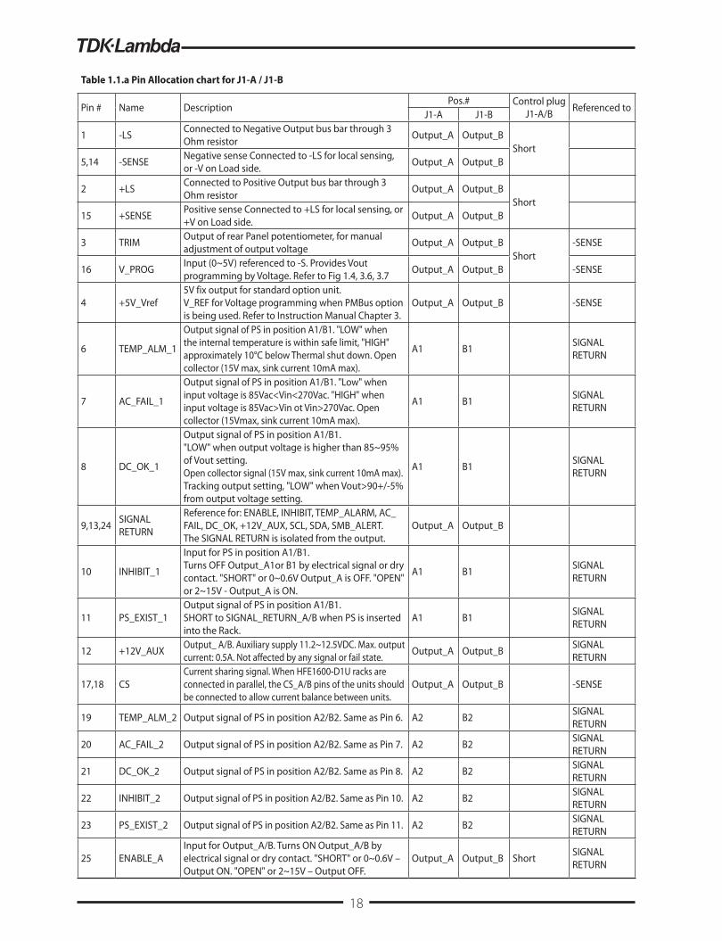
Table 1.1.a Pin Allocation chart for J1-A / J1-B
Pin # Name DescriptionPos.# Control plug
J1-A/B Referenced toJ1-A J1-B
1 -LS Connected to Negative Output bus bar through 3 Ohm resistor Output_A Output_B
Short5,14 -SENSE Negative sense Connected to -LS for local sensing,
or -V on Load side. Output_A Output_B
2 +LS Connected to Positive Output bus bar through 3 Ohm resistor Output_A Output_B
Short15 +SENSE Positive sense Connected to +LS for local sensing, or
+V on Load side. Output_A Output_B
3 TRIM Output of rear Panel potentiometer, for manual adjustment of output voltage Output_A Output_B
Short-SENSE
16 V_PROG Input (0~5V) referenced to -S. Provides Vout programming by Voltage. Refer to Fig 1.4, 3.6, 3.7 Output_A Output_B -SENSE
4 +5V_Vref5V fix output for standard option unit. V_REF for Voltage programming when PMBus option is being used. Refer to Instruction Manual Chapter 3.
Output_A Output_B -SENSE
6 TEMP_ALM_1
Output signal of PS in position A1/B1. "LOW" when the internal temperature is within safe limit, "HIGH" approximately 10°C below Thermal shut down. Open collector (15V max, sink current 10mA max).
A1 B1 SIGNAL RETURN
7 AC_FAIL_1
Output signal of PS in position A1/B1. "Low" when input voltage is 85Vac<Vin<270Vac. "HIGH" when input voltage is 85Vac>Vin ot Vin>270Vac. Open collector (15Vmax, sink current 10mA max).
A1 B1 SIGNAL RETURN
8 DC_OK_1
Output signal of PS in position A1/B1. "LOW" when output voltage is higher than 85~95% of Vout setting. Open collector signal (15V max, sink current 10mA max). Tracking output setting, "LOW" when Vout>90+/-5% from output voltage setting.
A1 B1 SIGNAL RETURN
9,13,24 SIGNAL RETURN
Reference for: ENABLE, INHIBIT, TEMP_ALARM, AC_FAIL, DC_OK, +12V_AUX, SCL, SDA, SMB_ALERT. The SIGNAL RETURN is isolated from the output.
Output_A Output_B
10 INHIBIT_1
Input for PS in position A1/B1. Turns OFF Output_A1or B1 by electrical signal or dry contact. "SHORT" or 0~0.6V Output_A is OFF. "OPEN" or 2~15V - Output_A is ON.
A1 B1 SIGNAL RETURN
11 PS_EXIST_1Output signal of PS in position A1/B1. SHORT to SIGNAL_RETURN_A/B when PS is inserted into the Rack.
A1 B1 SIGNAL RETURN
12 +12V_AUX Output_ A/B. Auxiliary supply 11.2~12.5VDC. Max. output current: 0.5A. Not affected by any signal or fail state. Output_A Output_B SIGNAL
RETURN
17,18 CSCurrent sharing signal. When HFE1600-D1U racks are connected in parallel, the CS_A/B pins of the units should be connected to allow current balance between units.
Output_A Output_B -SENSE
19 TEMP_ALM_2 Output signal of PS in position A2/B2. Same as Pin 6. A2 B2 SIGNAL RETURN
20 AC_FAIL_2 Output signal of PS in position A2/B2. Same as Pin 7. A2 B2 SIGNAL RETURN
21 DC_OK_2 Output signal of PS in position A2/B2. Same as Pin 8. A2 B2 SIGNAL RETURN
22 INHIBIT_2 Output signal of PS in position A2/B2. Same as Pin 10. A2 B2 SIGNAL RETURN
23 PS_EXIST_2 Output signal of PS in position A2/B2. Same as Pin 11. A2 B2 SIGNAL RETURN
25 ENABLE_AInput for Output_A/B. Turns ON Output_A/B by electrical signal or dry contact. "SHORT" or 0~0.6V – Output ON. "OPEN" or 2~15V – Output OFF.
Output_A Output_B Short SIGNAL RETURN
18

1.2. J2 Pin Allocation Chart J2 connector (RJ45 type) is used for parallel connection of two Racks. Table 1.2 .a: J2-A Table 1.2.b: J2-B
1.3. Output Bus Bar ConnectionsThe HFE1600-D1U has two identical Output Bus Bar connections on both sides of Rear Panel. each Bas-bar connected different output.
ATTENTION: Maximum allowable current for each pair of Output Bus Bars – 266A.
Model HFE1600-12 HFE1600-24 HFE1600-32 HFE1600-48
Output voltage range (V) 9.6~13.2 19.2~29.0 25.6~38.6 38.4~58
Fig 1.3b Installation of Output Bus-Bars Protection Cover.
Protection Cover
Canoe Clip
1.4. Output Voltage adjustment Trimmer Output Voltage may be adjusted by the Rear Panel Trimmer.
Fig 1.3a Output Bus-Bars.MAXIMUM 266AMPMAXIMUM 266AMP
Output B Output A+ -+ -
Pin 1
Pin 1
IN
OUT
J2-A/B
Pin 1
IN Out
Pin # Name Pin # Name
1 Not connected 1 Not connected
2 Not connected 2 Not connected
3 Not connected 3 Not connected
4 -SENSE_A 4 -SENSE_A
5 SCL_A (PMBus) 5 SCL_A (PMBus)
6 SIGNAL_RETURN_A 6 SIGNAL_RETURN_A
7 SDA_A (PMBus) 7 SDA_A (PMBus)
8 SMB_ALERT_A 8 SMB_ALERT_A
IN Out
Pin # Name Pin # Name
1 Not connected 1 Not connected
2 Not connected 2 Not connected
3 Not connected 3 Not connected
4 -SENSE_B 4 -SENSE_B
5 SCL_B (PMBus) 5 SCL_B (PMBus)
6 SIGNAL_RETURN_B 6 SIGNAL_RETURN_B
7 SDA_B (PMBus) 7 SDA_B (PMBus)
8 SMB_BLERT_B 8 SMB_BLERT_B
19

1.5. PMBus address Each slot in the Rack (see fig-2.2) has its own address for PMBus communication Valid only if /S option power supply is being used. In case parallel connection of two racks is used, SW1 located at the rear panel is used to differentiate between addresses for the same slots.
see Table 1.5.A Table 1.5.B
2. Rack mechanical features2.1. Insertion and extraction of the PS
2.2. Definition of Power Supplies Position
Fig 2.2 Power supply positions
Position In Rack SW1-4 SW1-5 Address (Bin)A1
ON ON0000
A2 0001A1
ON OFF0010
A2 0011A1
OFF ON0100
A2 0101A1
OFF OFF0110
A2 0111
Position In Rack SW1-1 SW1-2 Address (Bin)B1
ON ON1000
B2 1001B1
ON OFF1010
B2 1011B1
OFF ON1100
B2 1101B1
OFF OFF1110
B2 1111
SW1
To insert the power supply push unit into the rack with extraction handle closed.
To extract power supply, elevate the release knob and pull the extraction handle simultaneously.
Position A1 Position A2 Blank panel Position B1 Position B2
Release KnobFig 2.1
CAUTIONWhen inserting a power supply into the rack, do not use unnecessary force;
slamming the power supply into the rack can damage the connectors on the rear of the supply and inside the rack.
20
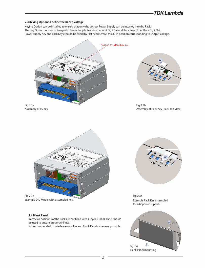
2.3 Keying Option to define the Rack’s VoltageKeying Option can be installed to ensure that only the correct Power Supply can be inserted into the Rack.The Key Option consists of two parts: Power Supply Key (one per unit Fig 2.3a) and Rack Keys (5 per Rack Fig 2.3b).Power Supply Key and Rack Keys should be fixed (by Flat head screws M3x6) in position corresponding to Output Voltage.
Fig 2.3aAssembly of PS Key
Fig 2.3cExample 24V Model with assembled Key.
Fig 2.3d
Example Rack Key assembled for 24V power supplies
Fig 2.3bAssembly of Rack Key (Rack Top View)
2.4 Blank PanelIn case all positions of the Rack are not filled with supplies, Blank Panel should be used to ensure proper Air Flow.It is recommended to interleave supplies and Blank Panels wherever possible.
Fig 2.4Blank Panel mounting
21

2.5 Rack’s mounting optionsRack can be mounted into 19” Rack Cabinet which suits both USA and European Standards:
Fig 2.5 Mounting options, brackets and screws are included.
22

3. Typical applications3.1 Basic connection (Position A shown)For basic connection the supplied Control Plug should be inserted to J1-A.
Fig 3.1 Basic connection diagram.
3.2 Remote sensing (Position A shown)ATTENTION: 1. Maximum voltage drop on load wires: HFE1600-12: 0.25V/wire, HFE1600-24: 0.5V/wire, HFE1600-32: 0.75V/wire, HFE1600-48: 1V/wire.2. Twisted wires should be used for Remote Sensing connection.3. If Remote Sensing is used do not break Main Output connection.
Fig 3.2 Remote Sensing connection diagram
3.3 On/Off control for the entire Rack (Position A shown)Switch closed: Output ONSwitch open: Output OFF
Fig 3.3 Entire rack On/Off control diagram.
Voltage drop onload connection}3.2 Remote sensing
HFE1600-D1U LOAD
SIG
NA
L R
ET
UR
N_
A
+1
2V
_A
UX
_A
PS
_E
XIS
T_
A_
1
INH
IBIT
_A
_1
SIG
NA
L R
ET
UR
N_
A
DC
OK
_A
_1
AC
_F
AIL
_A
_1
TE
MP
_A
LA
RM
_A
_1
-SE
NS
E_
A
+5
V_
VR
EF
_A
TR
IM_
A
+L
S_
A
-LS
_A
13 12 11 10 9 8 7 6 5 4 3 2 1
25 24 23 22 21 20 19 18 17 16 15 14
EN
AB
LE
_A
SIG
NA
L R
ET
UR
N_
A
PS
_E
XIS
T_
A_
2
INH
IBIT
_A
_2
DC
OK
_A
_2
AC
_F
AIL
_A
_2
TE
MP
_A
LA
RM
_A
_2
CS
_A
CS
_A
V_
PR
OG
_A
+S
EN
SE
_A
-SE
NS
E_
A
Fig 3.2 Remote Sensing connection diagram
Note: This Connection Diagram is for J1-A. The same connection procedure can be followed for J1-B also.
+V
-V
+V
-V
J1-A CONTROLPLUG
3.1 Basic application
HFE1600-D1U LOAD
SIG
NA
L R
ET
UR
N_
A
+1
2V
_A
UX
_A
PS
_E
XIS
T_
A_
1
INH
IBIT
_A
_1
SIG
NA
L R
ET
UR
N_
A
DC
OK
_A
_1
AC
_F
AIL
_A
_1
TE
MP
_A
LA
RM
_A
_1
-SE
NS
E_
A
+5
V_
VR
EF
_A
TR
IM_
A
+L
S_
A
-LS
_A
13 12 11 10 9 8 7 6 5 4 3 2 1
25 24 23 22 21 20 19 18 17 16 15 14
EN
AB
LE
_A
SIG
NA
L R
ET
UR
N_
A
PS
_E
XIS
T_
A_
2
INH
IBIT
_A
_2
DC
OK
_A
_2
AC
_F
AIL
_A
_2
TE
MP
_A
LA
RM
_A
_2
CS
_A
CS
_A
V_
PR
OG
_A
+S
EN
SE
_A
-SE
NS
E_
A
Fig 3.1 Basic connection diagram
Note: This Connection Diagram is for J1-A. The same connection procedure can be followed for J1-B also.
+V
-V
+V
-V
J1-A CONTROLPLUG
3.3 On/Off control for Output A
HFE1600-D1U LOAD
SIG
NA
L R
ET
UR
N_
A
+1
2V
_A
UX
_A
PS
_E
XIS
T_
A_
1
INH
IBIT
_A
_1
SIG
NA
L R
ET
UR
N_
A
DC
OK
_A
_1
AC
_F
AIL
_A
_1
TE
MP
_A
LA
RM
_A
_1
-SE
NS
E_
A
+5
V_
VR
EF
_A
TR
IM_
A
+L
S_
A
-LS
_A
13 12 11 10 9 8 7 6 5 4 3 2 1
25 24 23 22 21 20 19 18 17 16 15 14
EN
AB
LE
_A
SIG
NA
L R
ET
UR
N_
A
PS
_E
XIS
T_
A_
2
INH
IBIT
_A
_2
DC
OK
_A
_2
AC
_F
AIL
_A
_2
TE
MP
_A
LA
RM
_A
_2
CS
_A
CS
_A
V_
PR
OG
_A
+S
EN
SE
_A
-SE
NS
E_
A
Fig 3.3 Output A On/Off control diagram
Note: This Connection Diagram is for J1-A. The same connection procedure can be followed for J1-B also.
+V
-V
+V
-V
J1-A CONTROLPLUG
23

3.4 Individual On/Off control for each PS (Position A shown)Switch closed: Output OFFSwitch open: Output ON
Fig 3.4 individual units On/Off diagram.
3.5 Supervisory signals (Position A shown)Following signals are accessible from each power supply at J1:DC OKAC FAILPS EXISTTEMP ALARMThese signals are Open Collector type (max 15V, max 10mA), isolated from Output and referenced to SIGNAL RETURN.
Fig 3.5 presents example of the typical connection for DC OK signal of power supply in position A2. Instead of 12V AUX, external Supply of 15V max. can be used with recommended Pull-up resistors for 5mA max.
Fig 3.5 “DC OK” signal connection diagram for Power Supply in Position A2 .
3.6 Output Voltage programming by External Voltage (Position A shown)
Fig 3.6 Output Voltage programming by External Voltage.
Voltage Programming
0
10
20
30
40
50
60
0 1 2 3 4 5
V PROG (V)
V OUT (V)
38.4
25.6
19.2
9.6
58
29
38.6
13.2
48V Model
32V Model
24V Model12V Model
3.5 Supervisory signals
HFE1600-D1U LOAD
SIG
NA
L R
ET
UR
N_
A
+1
2V
_A
UX
_A
PS
_E
XIS
T_
A_
1
INH
IBIT
_A
_1
SIG
NA
L R
ET
UR
N_
A
DC
OK
_A
_1
AC
_F
AIL
_A
_1
TE
MP
_A
LA
RM
_A
_1
-SE
NS
E_
A
+5
V_
VR
EF
_A
TR
IM_
A
+L
S_
A
-LS
_A
13 12 11 10 9 8 7 6 5 4 3 2 1
25 24 23 22 21 20 19 18 17 16 15 14
EN
AB
LE
_A
SIG
NA
L R
ET
UR
N_
A
PS
_E
XIS
T_
A_
2
INH
IBIT
_A
_2
DC
OK
_A
_2
AC
_F
AIL
_A
_2
TE
MP
_A
LA
RM
_A
_2
CS
_A
CS
_A
V_
PR
OG
_A
+S
EN
SE
_A
-SE
NS
E_
A
Fig 3.5 "DC OK" signal connection diagram for power supply in Position A2.
Note: This Connection Diagram is for J1-A. The same connection procedure can be followed for J1-B also.
+V
-V
+V
-V
J1-A CONTROLPLUG
10kOhmDC OK
RETURN
3.4 Individual On/Off control for each PS
HFE1600-D1U LOAD
SIG
NA
L R
ET
UR
N_
A
+1
2V
_A
UX
_A
PS
_E
XIS
T_
A_
1
INH
IBIT
_A
_1
SIG
NA
L R
ET
UR
N_
A
DC
OK
_A
_1
AC
_F
AIL
_A
_1
TE
MP
_A
LA
RM
_A
_1
-SE
NS
E_
A
+5
V_
VR
EF
_A
TR
IM_
A
+L
S_
A
-LS
_A
13 12 11 10 9 8 7 6 5 4 3 2 1
25 24 23 22 21 20 19 18 17 16 15 14
EN
AB
LE
_A
SIG
NA
L R
ET
UR
N_
A
PS
_E
XIS
T_
A_
2
INH
IBIT
_A
_2
DC
OK
_A
_2
AC
_F
AIL
_A
_2
TE
MP
_A
LA
RM
_A
_2
CS
_A
CS
_A
V_
PR
OG
_A
+S
EN
SE
_A
-SE
NS
E_
A
Fig 3.4 Individual On/Off control for each PS
Note: This Connection Diagram is for J1-A. The same connection procedure can be followed for J1-B also.
Individual On/Off control for each PS
+V
-V
+V
-V
J1-A CONTROLPLUG
3.6 Output voltage programming by External Voltage.
HFE1600-D1U LOAD
SIG
NA
L R
ET
UR
N_
A
+1
2V
_A
UX
_A
PS
_E
XIS
T_
A_
1
INH
IBIT
_A
_1
SIG
NA
L R
ET
UR
N_
A
DC
OK
_A
_1
AC
_F
AIL
_A
_1
TE
MP
_A
LA
RM
_A
_1
-SE
NS
E_
A
+5
V_
VR
EF
_A
TR
IM_
A
+L
S_
A
-LS
_A
13 12 11 10 9 8 7 6 5 4 3 2 1
25 24 23 22 21 20 19 18 17 16 15 14
EN
AB
LE
_A
SIG
NA
L R
ET
UR
N_
A
PS
_E
XIS
T_
A_
2
INH
IBIT
_A
_2
DC
OK
_A
_2
AC
_F
AIL
_A
_2
TE
MP
_A
LA
RM
_A
_2
CS
_A
CS
_A
V_
PR
OG
_A
+S
EN
SE
_A
-SE
NS
E_
A
Fig 3.6 Output voltage programming by External Voltage.
Note: This Connection Diagram is for J1-A. The same connection procedure can be followed for J1-B also.
+V
-V
+V
-V
J1-A CONTROLPLUG
+
24

3.7 Output Voltage programming by PMBus (Position A shown)
Fig 3.7 Output Voltage programming by PMBus
3.8 PMBus Host connectionTo connect the rack to the Host computer connect communication cable (refer to table 3.8 for cable connection) between J2-A/J2-B and computer:
Table 3.8 PMBus Cable.
RJ45 Shielded Male Connector should be used.
Cable must be shielded; only connector shield is connected to cable shield.
Signal Name Pin J2-A/J2-B Wire (AWG) To Host Note
SCL 5 22~24 -Twisted pair
SIGNAL_RETURN 6 22~24 -
SDA 7 22~24 -Twisted pair
SMB_ALERT 8 22~24 -
3.7 Output Voltage programming by PMBus.
HFE1600-D1U LOAD
SIG
NA
L R
ETU
RN
_A
+12V
_AU
X_A
PS_E
XIST
_A_1
INH
IBIT
_A_1
SIG
NA
L R
ETU
RN
_A
DC
OK
_A_1
AC
_FA
IL_A
_1
TEM
P_A
LAR
M_A
_1
-SEN
SE_A
+5V_
VREF
_A
TRIM
_A
+LS_
A
-LS_
A
13 12 11 10 9 8 7 6 5 4 3 2 1
25 24 23 22 21 20 19 18 17 16 15 14
ENA
BLE
_A
SIG
NA
L R
ETU
RN
_A
PS_E
XIST
_A_2
INH
IBIT
_A_2
DC
OK
_A_2
AC
_FA
IL_A
_2
TEM
P_A
LAR
M_A
_2
CS_
A
CS_
A
V_PR
OG
_A
+SEN
SE_A
-SEN
SE_A
Fig 3.7 Output Voltage programming by PMBus.
Note: This Connection Diagram is for J1-A. The same connection procedure can be followed for J1-B also.
+V
-‐V
+V
-‐V
J1-‐A CONTROLPLUG
25

3.9 Parallel connection of two Racks (Position A shown)To connect two Racks in parallel for higher Output Current:• Connect Main Outputs (Bus-Bars) in parallel. Make the connections as short as possible and with equal length.• Connect Senses (twisted pairs) to Load point.• Connect J2-A connectors of both Racks by Cable (cable construction see Table 3.9).• Slave - Disconnect connection between VPROG and TRIM (J1.3 and J1.16).• Slave - Switch SW1 to “OFF” position (applicable for HFE1600-xx /S PMBus option). For addressing refer to Table 1.5.A/B• Output Voltage could be adjusted by the trimmer on Master Rack.
Table 3.9 Rack Interconnection Cable.
RJ45 Shielded Male Connectors should be used.Cable must be shielded; only connector shields are connected to cable shield.
Fig 3.9 Racks parallel connection diagram.
Signal Name From pin Wire (AWG) To Pin Note
-SENSE 4 22~24 4 Twisted pair
SCL 5 22~24 5Twisted pair
SIGNAL_RETURN 6 22~24 6
SDA 7 22~24 7Twisted pair
SMB_ALERT 8 22~24 8
Voltage drop onload connection}
NOTEFor PMBus OPTION in the master rack1. Disconnect Pin 3&162. Connect Pin 4&16
26

3.10 Series Rack connectionUp to 2 racks with the same number of power supplies and rating (voltage and current) can be used to increase the output voltage.To connect two Racks in series:• Connect Main Outputs (bus bars) in series;• Connect Senses (twisted) to Load point (as shown in fig-3.10), or Local Sensing using supplied Control Plugs.• In case PMBus is used Connect J2 connectors of both Racks by Interconnect Cable for Serial connection (cable construction see Table 3.10);
CAUTIONDo not use Cable as of Table 3.9.• On one Rack Switch SW1 up to OFF position (only for HFE1600-xx /S PMBus option), Addressing see Table 1.5;• Output Voltage can be adjusted by potentiometers on both Racks.
RJ45 Shielded Male Connectors should be used. Cable must be shielded; only connector shields are connected to cable shield. Diodes should be connected in parallel with each unit output to prevent reverse voltage. Each diode should be rated to at least the power supply rated output voltage and output current.
WARNINGDo not connect -SENSE and any signals referenced to -SENSE between two Racks. Only signals referenced to SIGNAL RETURN can be connected between Racks.
Table 3.10 Rack Interconnection Cable for Serial connection.
Fig 3.10 Serial connection diagram (remote sense).
Signal Name From pin Wire (AWG) To Pin Note
-SENSE 4 Open 4 Do not connect!
SCL 5 22~24 5Twisted pair
SIGNAL_RETURN 6 22~24 6
SDA 7 22~24 7Twisted pair
SMB_ALERT 8 22~24 8
(*)
(*)
(*) Diods are user supplied.
27

HFE 1600 - D1U Outline Drawing
28

HFE 1600 - D1U-TB Outline Drawing
29

30

31

IA79
3-04
-01D
32