RACK CONVEYOR DISHWASHER Installation and Operation ...
136
RACK CONVEYOR DISHWASHER ELECTRICALLY HEATED STEAM HEATED TYPE: 151E Accessories FS40 Installation and Operation Manual From S/N: Rev.: 2.2
-
Upload
khangminh22 -
Category
Documents
-
view
1 -
download
0
Transcript of RACK CONVEYOR DISHWASHER Installation and Operation ...

RACK CONVEYOR DISHWASHER
ELECTRICALLY HEATEDSTEAM HEATED
TYPE: 151E
AccessoriesFS40
Installation and Operation Manual
From S/N: Rev.: 2.2


4.12.2000 Rev. 2.2
Dear Customer,
Congratulations on deciding to choose a Metos equipment for your kitchen activities. Youmade an excellent choice. We will do our best to make also you a satisfied Metos custom-er like thousands and thousands of others all over the world.
Please read this manual carefully. You will learn many right, safe and efficient workingmethods in order to get the best possible benefit from the equipment. The instructions andhints in this manual will give you a quick and easy start in using this equipment. You willnote very quickly how nice it is to use the Metos equipment.
All rights are reserved for technical changes.
You will find all the main technical data on the rating plate fixed to the equipment. Whenyou need service or technical help, please let us know the serial number of the equipment.This will make it easier to provide you with the correct service. Please write the contactinformation of your local Metos service in advance on the lines below.
METOS TEAM
Metos service phone number:...............................................................................................
Contact person:....................................................................................................................
3

4.12.2000 Rev. 2.2
4
4.12.2000 Rev.
1. General .......................................................................................................... 71.1 Symbols used in the manual .......................................................................................... 71.2 Symbols used on the appliance ...................................................................................... 71.3 Checking the relation of the appliance and the manual ................................................. 71.4 Rating plate information ................................................................................................ 81.5 Staff training .................................................................................................................. 8
2. Safety .............................................................................................................. 92.1 Safe use of the appliance ............................................................................................... 92.2 Safety instructions in case of malfunction ..................................................................... 92.3 Disposal of the appliance ............................................................................................... 92.4 Other prohibitions .......................................................................................................... 9
3. Functional description ................................................................................ 103.1 Application of the appliance ........................................................................................ 10
3.1.1 Use for other purposes ......................................................................................... 103.2 Construction ................................................................................................................ 103.3 Control panel .............................................................................................................. 12
4. Operation instructions ............................................................................... 144.1 Before use .................................................................................................................... 14
4.1.1 Preparing the operation ........................................................................................ 144.2 Operation ..................................................................................................................... 14
4.2.1 Start of dishwashing ............................................................................................ 144.2.2 Dishwashing ........................................................................................................ 14
4.3 After use ...................................................................................................................... 154.3.1 Cleaning .............................................................................................................. 15
5. Installation ................................................................................................... 175.1 General ........................................................................................................................ 175.2 Operating conditions ................................................................................................... 17
5.2.1 Lighting ................................................................................................................ 175.2.2 Ventilation ........................................................................................................... 17
5.3 Electrical connection ................................................................................................... 185.4 Water connections ....................................................................................................... 185.5 Drain connection ......................................................................................................... 185.6 Steam connection ......................................................................................................... 185.7 Measures after installation ........................................................................................... 18
5

4.12.2000 Rev.
5.8 First start, test run ........................................................................................................ 19
6. Adjustments ................................................................................................ 206.1 Setting the DIP switches .............................................................................................. 20
6.1.1 Setting the machine model .................................................................................. 206.1.2 Setting the machine type ..................................................................................... 206.1.3 Setting the accessories ....................................................................................... 206.1.4 Setting the language to the machine with text panel .......................................... 20
6.2 Adjusting the final rinse ............................................................................................. 216.3 Adjusting the reference values ................................................................................... 216.4 Controlling the infeed conveyor ................................................................................. 236.5 Controlling the dryer .................................................................................................. 236.6 Setting the filling memory to zero .............................................................................. 23
7. Troubleshooting .......................................................................................... 24
8. Spare parts .................................................................................................. 278.1 Voltage codes .............................................................................................................. 298.2 Product codes ............................................................................................................... 29
9. Technical specifications ............................................................................ 101
6

4.12.2000 Rev. 2.2General
1. General
Carefully read the instructions in this manual as they contain important information re-garding proper, efficient and safe installation, use and maintenance of the appliance.
Keep this manual in a safe place for eventual use by other operators of the appliance.
The installation of this appliance must be carried out in accordance with the manufactur-er’s instructions and following local regulations. The connection of the appliance to theelectric and water supply must be carried out by qualified persons only.
Persons using this appliance should be specifically trained in its operation.
Switch off the appliance in case of failure or malfunction. The periodical function checksrequested in the manual must be carried out according to the instructions. Have the appli-ance serviced by a technically qualified person authorized by the manufacturer and usingoriginal spare parts.
Not complying with the above may put the safety of the appliance in danger.
1.1 Symbols used in the manual
This symbol informs about a situation where a safety risk might be at hand. Given instruc-tions are mandatory in order to prevent injury.
This symbol informs about the right way to perform in order to prevent bad results, appli-ance damages or hazardous situations.
This symbol informs about recommendations and hints that help to get the best perform-ance out of the appliance.
1.2 Symbols used on the appliance
This symbol on a part informs about electrical terminals behind the part. The removal ofthe part must be carried out by qualified persons only.
1.3 Checking the relation of the appliance and the manual
The rating plate of the appliance indicates the serial number of the appliance. If the man-uals are missing, it is possible to order new ones from the manufacturer or the local rep-resentative. When ordering new manuals it is essential to quote the serial number shownon the rating plate.
7

4.12.2000 Rev. 2.2General
1.4 Rating plate information
The rating plate of the appliance is located in the lower section of the machine, at eitherloading or unloading end. The technical data provided by the rating plate are also shownin the machine’s circuit diagrams. The field contents are as follows:
1. Machine type2. Manufacturing number3. Manufacturing year4. Sealing class5. Voltage6. Number of phases, nollajohdin7. Frequency8. Main fuse9. Motor power10. Electrical heating power11. Maximum power
1.5 Staff training
Before taking the machine into use, make sure that the staff receive the requisite informa-tion for handling and maintenance!
8

4.12.2000 Rev. 2.2Safety
2. Safety
2.1 Safe use of the appliance
Do not touch the interior parts of the washing space while the machine is running. Do noteither operate the machine when the cover plates have been detached.
Pinch risk: The reciprocating movement of the conveyor may cause a risk of squeezingin the immediate vicinity of the loading and unloading openings, the angle feeder or themechanical curves.
2.2 Safety instructions in case of malfunction
In case of electricity breakdown, switch the power off with the main switch.
Check the following:
• Has the appliance been used according to instructions?• Are all possibly removable parts refitted?• Is the main switch in the ON position?• Are the circuit breakers (fuses) of the appliance in the main fuse box in working
order? Ask an authorized person to check the circuit breakers.• If this does not help, contact an authorized service person.
2.3 Disposal of the appliance
The disposal of the appliance when its economical lifetime has been reached must be car-ried out in accordance with local rules and regulations. Contact professional personnelspecializing in recycling.
2.4 Other prohibitions
Only use detergents intended for machine dishwashing. Follow the instructions providedby the detergent supplier.
Use protective gloves or goggles when handling the detergent. Observe the warnings onthe detergent container.
9

4.12.2000 Rev. 2.2Functional description
3. Functional description
3.1 Application of the appliance
The appliance is designed for washing dishes used in food serving, food preparation andfood storing. A detergent intended for machine dishwashing must be used.
3.1.1 Use for other purposes
Always consult the manufacturer, if you intend to use the appliance for other purposesthan mentioned above.
3.2 Construction
1. Curtains2. Wash arms3. Rinse nozzles4. Door catch5. Door6. Tank drain lever
1 2 35
6
3
789
13
12 9 12 11 10
2 3 4
14
10

4.12.2000 Rev. 2.2Functional description
7. Final pump rinse filter8. Final rinse filter9. Drain plug10. Rubber gasket11. Overflow pipe and drain plug lift shaft12. Strainer plates13. Overflow pipe14. Start switch
11

4.12.2000 Rev. 2.2Functional description
3.3 Control panel
1. Temperature display pre wash (WD-211E, 241E, 331E)2. Signal light for low water level in corresponding tank3. Temperature display power wash4. Push button for wash with automatic stop5. Door open signal light6. Signal light for selected wash method7. Signal light; machine’s overload or stop emergency activated8. Push button for wash without automatic stop9. Signal light; infeed / outload conveyor overload or unload table switch activated
15 16 17 18 19
20
12

4.12.2000 Rev. 2.2Functional description
10. Signal light for overloads of pumps and condensor fan11. Control switch12. Signal light; final rinse filter (8) blocked13. Emergency stop push button14. Temperature display final rinse 15. Circuit board16. Diagnosis button17. Push buttons for adjustment of reference values18. Potentiometer (vacant)19. DIP switches20. Potentiometer for infeed conveyor
13

4.12.2000 Rev. 2.2Operation instructions
4. Operation instructions
4.1 Before use
4.1.1 Preparing the operation
• Make sure that the machine has been cleaned and that the water supply valves arein the OPEN position.
• Put the overflow pipe and the drain plugs in place. Make sure that they are properlyfastened to the lift shaft (11).
• Check the condition of rubber gaskets (10). • Put the strainers and curtains in place. • Check the amount of detergent and rinse aid. • Close the doors.
4.2 Operation
4.2.1 Start of dishwashing
Turn the machine’s control switch (11) to position 1 and wait until the tanks fill and thewater heates up. The filling time is approx. 6-13 minutes. In dishwashers connected tocold water supply, the filling time is 30 minutes at the maximum. When the temperaturesare clearly visible on the displays (1, 3, 14) the machine is ready for dishwashing.
Push the button AUT. The machine starts and runs for a moment for mixing the detergent.
4.2.2 Dishwashing
Remove loose food residues and rack the dishes.Rack the trays longitudinally to machine.If GN containers are washed in the machine, they must be placed in a special rack and fedinto the machine longitudinally.
Choose the wash method AUT or MAN.
• AUT = Wash with an automatic stop. The dishwasher starts when a rack is fed in.The rack remains within the wash zone until the next rack pushes it on. The dish-washer stops automatically if no new rack is fed in.
• MAN = Wash without an automatic stop. The dishwasher starts immediately. TheMAN position is preferable for heavily soiled wash items. If only one rack is fed,
14

4.12.2000 Rev. 2.2Operation instructions
it stops and is processed in the wash zone for a duration that can be decided by theoperator. The rack will be pushed out of the dishwasher when a new rack is fed in.
We recommend to feed in racks at the following intervals:
approx. 50cm
Increase the distance if the wash items are heavily soiled.
4.3 After use
4.3.1 Cleaning
The temperature of the rinsing water is approx. 85ºC. Do not open the machine doors untilthe washing process is completed.
Cleaning: The temperature of wash water in the power wash tank is approx. 60ºC and itis mixed with detergent. Be careful when emptying and cleaning the tanks. Use protectivegloves.
Use of a pressure washer for cleaning the machine is forbidden.
Do not use steel wool for cleaning the machine. Use of steel wool may cause rust spots onthe machine surfaces. Do not either use detergents that, if not thorougly rinsed from sur-faces, form foam during the wash process, thus impairing the wash result. Consult yourdetergent supplier for the correct type of detergent.
It is not allowed to clean the outside of the machine with a jet of water.
For cleaning the outer surfaces, wiping with a damp cloth will often suffice.
When washing floors, water can splash up from the floor, thus damaging electric compo-nents, which are not designed to withstand rinsing with water. Special protective coversshould be used to protect the machine from water splashes, if the floor is washed with apressure washer.
Daily cleaning
• Turn the control switch (11) to position 0. • Empty the tanks by pulling the tank drain level (6).• Clean the tank strainers (12), tanks, curtains and wash nozzles. Clean the final
rinse filter (8). Dry the rubber lists of the doors. The rubber lists are located on therear side of the door, in the door’s upper section. Leave the doors open.
• Clean the outer surfaces of the machine with a damp cloth. Do not use steel woolfor cleaning. Use of steel wool may cause rust spots on the machine surfaces.
15

4.12.2000 Rev. 2.2Operation instructions
Basic cleaning of a returning unit equipped with a conveyor
• Stop the conveyor with the stop switch• Spray the system with non-foaming general cleaning liquid or desinfecting deter-
gent. Your detergent supplier can recommend you the best product for this pur-pose. The conveyor materials stand up to all normal detergents that are used inkitchen.
• Let the detergent act for 10-15 minutes or a length of time recommended by thedetergent supplier.
• Clean more dirty places e.g. with a brush.• Rinse the system thoroughly, don’t rinse electric parts like control boxes and elec-
tric motors.
Follow the dosing and safety instructions given by the detergent supplier.
Weekly cleaning and maintenance when needed
• Wash arms (2): Detach the wash arms and clean them inside. Clean the wash armnozzles.
• Rinse nozzles (3): Clean.• Final pump rinse filter (7): Clean the filter 2-3 times a week or more often depend-
ing on the use of the machine. The filter is located in the final rinse zone, behindthe door in the lower section of the machine. The final rinse tank must be emptywhen cleaning the filter. Detach the filter cover by turning it counterclockwise.Clean the filter and put it carefully back into place.
• Doors (5): The doors can be detached for cleaning. Lift the door to the upper posi-tion and press the door catch (4) backwards. The door can be completeley liftedout for cleaning. When the door is put back into place, make sure that the list, onwhich the door is placed, is fitted in the groove of the catch (4).
16

4.12.2000 Rev. 2.2Installation
5. Installation
See the technical specifications and the installation drawing.
5.1 General
Electrical, water and steam connections have to be done by an authorized installationcompany.
Make sure that the main voltage is the same as indicated in the rating plate of the machine.
Check the tightness of the connections before starting the machine. See also the installa-tion instructions.
5.2 Operating conditions
5.2.1 Lighting
To get the best possible working conditions, the machine should be placed in a room withadequate general lighting.
5.2.2 Ventilation
A satisfactory working environment requires adequate ventilation in the dishwashingroom.
17

4.12.2000 Rev. 2.2Installation
5.3 Electrical connection
For details, see the installation drawing and the connection drawing in chapter “TechnicalSpecifications”.
There is an electrical wiring diagram inside the electric box door (3). Keep this in the elec-tric box also after installation.
The main switch (2) has been constructed inside the machine. Connect the cable to the ter-minal board (1). NOTE. In special cases the electrical feed can be drawn from the floor.In this case, the cable is drawn under the cover plates (13).
Check the correct rotating direction of the pumps in use when the tanks have filled withwater. The rotating direction has to be the same as indicated by the arrow on the pump. Ifthe rotation direction is wrong, stop the machine and change two phases of the cable inthe terminal board.
5.4 Water connections
The pipe connection pieces are packed inside the machine.
Adjust the machine horizontally with the feet. Connect the cold and warm water feed (4,5). There are filters inside the pipe connections.The water connections have to beequipped with stop cocks. In machines where the water connectios are taken from thefloor, warm and cold water connection points are (8, 9).
5.5 Drain connection
The drain connection (10) can be led either to the right or to the left. Connect the drainpipe to (A) and draw it to the floor gulley so that the pipe ends above the water level. Re-move the hole cover from the appropriate side of the cover plate (B) and take the drainpipe trough it.
5.6 Steam connection
If the machine is steam heated, connect pipes for steam and condensation water to the con-nection point (11).
5.7 Measures after installation
When the tanks have been filled with water, check once more that the machine is standinghorizontally. Close the doors and check that the doors are in straight line.If necessary, ad-just with the feet.
18

4.12.2000 Rev. 2.2Installation
5.8 First start, test run
Place the overflow pipe, the drain plugs, the strainer plates and the curtains. Close thedoors.
Make sure that the automatic fuse FU/M in the electric box is on. Turn the control switchto position ’1’, the tank filling starts.
NOTE! To avoid the burning of boiler heating elements, there is so called filling memoryin the machine which allows you to check if the boilers of the machine are filled or empty.When the machine is delivered from the factory, the boilers are emptied and the fillingmemory is set to zero. When the control switch of the machine is turned to position ’1’,the tanks and the boilers fill with water. The boilers are filled via the solenoid valve Y02.When the valve Y02 is open, a red light on the card is lit. If the relay light is not on, theboilers do not fill and the heating elements may burn. IMMEDIATELY SWITCH OFFTHE MACHINE and set the filling memory to zero. See chapter “Adjusting referencevalues” to set the filling memory to zero.
The filling time in the warm water connected machine is appr. 6-13 minutes. The fillingtime in the cold water connected machine is 30 minutes at the maximum.
Test the machine with racks, check the temperatures of the tanks and the final rinse. Checkthat the machine does not leak from water and detergent connections.
The CE mark is only valid for the machine of original design.
19
4.12.2000 Rev. 2.2Adjustments
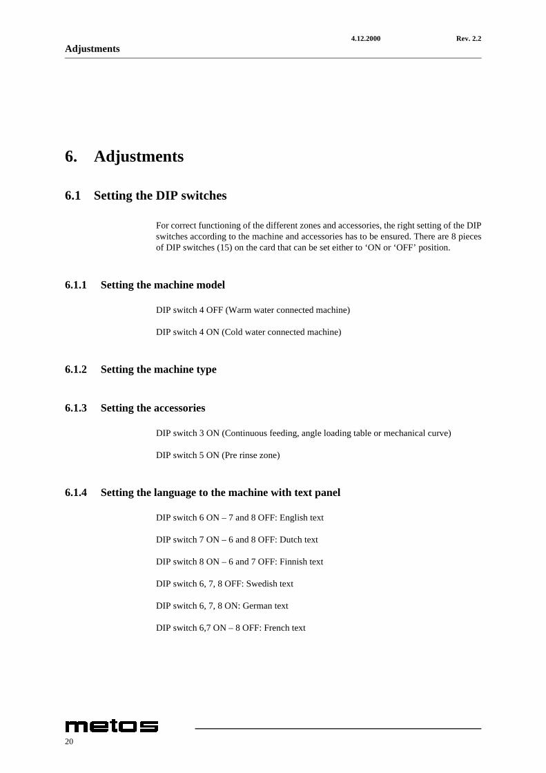
6. Adjustments
6.1 Setting the DIP switches
For correct functioning of the different zones and accessories, the right setting of the DIPswitches according to the machine and accessories has to be ensured. There are 8 piecesof DIP switches (15) on the card that can be set either to ‘ON or ‘OFF’ position.
6.1.1 Setting the machine model
DIP switch 4 OFF (Warm water connected machine)
DIP switch 4 ON (Cold water connected machine)
6.1.2 Setting the machine type
6.1.3 Setting the accessories
DIP switch 3 ON (Continuous feeding, angle loading table or mechanical curve)
DIP switch 5 ON (Pre rinse zone)
6.1.4 Setting the language to the machine with text panel
DIP switch 6 ON – 7 and 8 OFF: English text
DIP switch 7 ON – 6 and 8 OFF: Dutch text
DIP switch 8 ON – 6 and 7 OFF: Finnish text
DIP switch 6, 7, 8 OFF: Swedish text
DIP switch 6, 7, 8 ON: German text
DIP switch 6,7 ON – 8 OFF: French text
20
4.12.2000 Rev. 2.2Adjustments
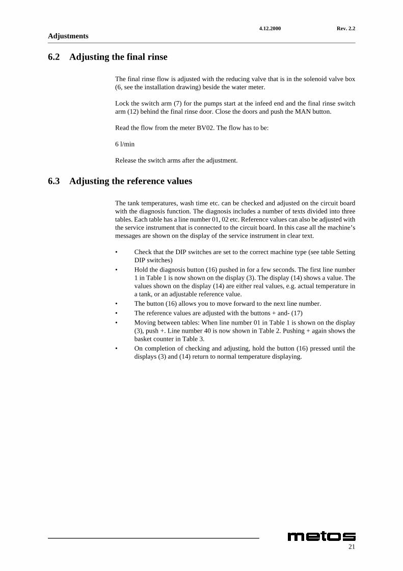
6.2 Adjusting the final rinse
The final rinse flow is adjusted with the reducing valve that is in the solenoid valve box(6, see the installation drawing) beside the water meter.
Lock the switch arm (7) for the pumps start at the infeed end and the final rinse switcharm (12) behind the final rinse door. Close the doors and push the MAN button.
Read the flow from the meter BV02. The flow has to be:
6 l/min
Release the switch arms after the adjustment.
6.3 Adjusting the reference values
The tank temperatures, wash time etc. can be checked and adjusted on the circuit boardwith the diagnosis function. The diagnosis includes a number of texts divided into threetables. Each table has a line number 01, 02 etc. Reference values can also be adjusted withthe service instrument that is connected to the circuit board. In this case all the machine’smessages are shown on the display of the service instrument in clear text.
• Check that the DIP switches are set to the correct machine type (see table SettingDIP switches)
• Hold the diagnosis button (16) pushed in for a few seconds. The first line number1 in Table 1 is now shown on the display (3). The display (14) shows a value. Thevalues shown on the display (14) are either real values, e.g. actual temperature ina tank, or an adjustable reference value.
• The button (16) allows you to move forward to the next line number.• The reference values are adjusted with the buttons + and- (17)• Moving between tables: When line number 01 in Table 1 is shown on the display
(3), push +. Line number 40 is now shown in Table 2. Pushing + again shows thebasket counter in Table 3.
• On completion of checking and adjusting, hold the button (16) pressed until thedisplays (3) and (14) return to normal temperature displaying.
21

4.12.2000 Rev. 2.2Adjustments
Table 1: Adjusting the reference values
Table 2
* 0 = unactivated, 1 = activated
** if the flow falls below 4l/min, the symbol (12) flashes.
Table 3: Rack counting
Display (3)Line No
Refers to Display (14)Ref. value
Settingarea
Remarks
03 Temp. power wash 1 - -
04 Ref. value power wash 1 60°C 40-95°C
05 Temp. boiler 3 - -
06 Ref. value boiler 3 80°C 70-95°C
07 Temp. boiler 1 - -
08 Ref. value boiler 1 80°C 60-95°C
09 Temp. boiler 2 (final rinse) - -
10 Ref. value boiler 2 (final rinse) 85°C 70-95°C
11 Temp. condensing battery - -
12 Ref. value condensing battery temp. 30°C 10-60°C
13 Timer condensing fan 5 sek 1-90 sek
14 Wash time (50 Hz frequency) 60 sek 40-180 sek
15 Off delay conveyor infeed 2 sek 0-10 sek
Display (3)Line No.
Refers to Display (14)
40 Filled boilers 0 or 1*
41 Final rinse flow l/min** -
42 Extended delay time interval for feed. Applies to machine with drying zone and conveyor curve on outfeed
0 or 1*
43 Motorized infeed conveyor 0 or 1*
Both displays (3) and (14) together show the number of racks up to 9999. By pushing the button (16), the number of racks will be shown in tens of thousands.
22

4.12.2000 Rev. 2.2Adjustments
6.4 Controlling the infeed conveyor
The infeed conveyor runs generally together with the feeding of the machine. To get thecorrect distance between the racks fed in, the conveyor can temporarily be stopped. Withthe aid of the potentiometer P1 (20) on the printed circuit card, a stop time for the rack canbe decided. (Table 4)
Table 4
6.5 Controlling the dryer
The possible dryer in the machine is controlled in parallel with the machine infeed. Thewash time (table 1, line No. 14) is increased by 60 seconds compared to the machine with-out the dryer.
6.6 Setting the filling memory to zero
When emptying the boilers you have to set the filling memory to zero (adjusting the rf.values line 40 = 0) or to disconnect the connector J9 on the circuit board.
Machinetype
Stop time infeed conveyor Potentiometer P1 setting area
151E 15 sec 0-30 sec
23

4.12.2000 Rev. 2.2Troubleshooting
7. Troubleshooting
PROBLEM POSSIBLE CAUSE MEASURES
Tank fills slowly Mud separator blocked Clean mud separator
Solenoid valve defective Call the service
Pressure switch defective Call the service
Tank fills not to the right level Overflow pipe leaks or ismissing Check and put in place
Pressure switch defective Call the service
Solenoid valve defective Call the service
Tank temperature is not correct Heating element defective Call the service
Fuse blown out Call the service
Pressure switch defective Call the service
Thermoelement defective Call the service
Final rinse temperature is not correct Fuse blown out Call the service
Machine doesn’t start Roller table switch activated Remove rack from the end of roller table
Door is not properly closed Close the door
Conveyor overload protection activated Remove obstacles from conveyor
Steam exhausts from the machine’s end
Condensor’s outblow opening covered Check and remove obstacles
Condensor fan defective Call the service
Amount of incoming water too low Call the service
Curtains are not in their places Check and put in place
Poor wash result Too short washing time Feed racks with longer distance
Dishes placed incorrectly in the rack Correct placing
Dirt dried on dishes Soak dishes before feeding into machine
Wash or rinse nozzles blocked Check and clean
Tank strainers incorrectly placed Check and put in place correctly
Curtains are not on their places Check and put in place
Detergent or rinse aid dosing wrong Call the detergent supplier
Temperatures wrong Call the service
24

4.12.2000 Rev. 2.2Troubleshooting
Always call the service if you have to open cover plates.
Alarm
Malfunctions in the machine’s operation are indicated on the control panel. The signallights (5, 7, 9, 12, 13) are blinking indicating different malfunctions. The displays (3) and(14) indicate different errors (’Err01’, etc.). Malfunctions in the circuits that are measur-ing temperatures are indicated on the corresponding temperature display with numbers 0or 99. Number 0 = circuit brokeni, number 99 = short cut in circuit. The temperature con-trol circuit doesn’t work in either of the cases.
The alarm for low water level in a tank (symbol 2) is given after two minutes. If the mal-function doesn’t go off within three minutes from giving the alarm, the pumps will stop.
The machine user can correct the following malfunctions. In other cases one have to callthe service.
• Symbol (5): A door is open. Close the door and push the button AUT or MAN.• Symbol (7): check if any object has stopped the conveyor. Remove possible ob-
jects and push either AUT or MAN button. See emergency stop• Symbol (9): if the machine is connected to a roller conveyor fitted with a limit
switch, this may have been activated by a rack. Remove the rack.• Symbol (12): the final rinse filter is blocked. Clean the filter and push either AUT-
or MAN-button (2)• Emergency stop (13): if the machine has been stopped by the emergency stop de-
vice, reset the emergency stop by turning in the direction of an arrow. Then pushAUT or MAN button.
Fault codes
Pump defective Call the service
Dishes don’t dry Rinse nozzles blocked Check and clean
Rinse aid dosing wrong Call the detergent supplier
Final rinse temperature too low Call the service
Dishes tip over in racks Dishes incorrectly placed Correct placing
Nozzle pressure too higa Call the service
Err01Procedure
Time for filling of tanks has overrun.Reset the alarm by turning the control switch (11) to position ’0’ and back to position on
Err04Procedure
Defective temperature sensor. In display 0 or 99.Call the service and have the sensor replaced
Err06Procedure
Too low final rinse flowThe alarm is reset automatically when the reason for the reduced flow is rec-tified
Err07Procedure
Defective Eprom or circuit boardCall the service and have the Eprom or circuit board replaced. The service in-strument shows the defective component
25

4.12.2000 Rev. 2.2Troubleshooting
26

4.12.2000 Rev. 2.2Spare parts
8. Spare parts
Water connections ................................30
Condensing battery, fan.......................34
Electric cubicle......................................36
Doors, curtains......................................40
Transporter...........................................44
Pre-wash................................................ 50
Chemical wash ......................................56
Final rinse, emptying............................ 62
Booster heater.......................................68
Sets of spare parts / Complete booster heater72
Couplings, pipe details .........................74
Electric components [151E].................78
Electric components [151E].................80
Electric components [151E nor]..........86
Electric components [151E nor]..........88
Electric components [151E steam]......94
27

4.12.2000 Rev. 2.2Spare parts
Electric components [151E steam]......96
28

4.12.2000 Rev. 2.2Spare parts
8.1 Voltage codes
8.2 Product codes
! applies only to codes not listed
Voltage code VoltageA 3/N/PE∼400/230V 50HzB ∼250V 16A 50HzC 3/N/PE∼380/220V 50HzD 3/PE∼200V 50-60HzF 2/PE 220−240V 50HzG 3/N/PE∼415/240V 50HzH 3/PE∼230V 50HzI 3/PE∼220V 60HzJ 3/PE∼380 50HzK 3/PE∼400V 50HzL 3/PE∼415V 50HzM 3/PE∼440V 60HzN 3/PE∼460V 60HzO 3/PE∼480V 60HzP 1/N/PE~220-240V 50HzR 2/PE~220-230V 60Hz
Product code Full nameModel codesE ELECTRICALLY HEATEDS STEAM HEATEDType codes151 151EAccessory codesFS40 FS40
29

4.12.2000 Rev. 2.2Spare parts
10
20
30
40
50
60
70
75
80
90
100
110
120
130
140
30

4.12.2000 Rev. 2.2Spare parts
ID Code Model Type Accessory Voltage DescriptionMODULE:Water connections10 5320206 Cold water connection20 5320205 Hot water connection30 5320002 Vacuum valve40 5320225 Non return valve 1/2"50 5320224 Filter 1/2"60 5320220 Reducing valve70 5320180 Coupling device 3/4"" x 1/2" for reducing valve75 5315611 Water meter80 5320248 Solenoid valve 24V90 5320249 Coil 24V100 5315612 Water meter with impulse generator BV1110 5320179 Connecting pipe d=15,m 3/4" x 3/4", L=60mm120 43744.01 Angle connection 3/4" x 1/2"130 5320129 Valve hood140 5315593 Ball valve 1/2"
31

4.12.2000 Rev. 2.2Spare parts
150
160
170
180
190
200
32

4.12.2000 Rev. 2.2Spare parts
ID Code Model Type Accessory Voltage Description150 5320186 Pipe d=15mm. A=130mm B=35mm160 5320185 Copper pipe d=15mm. A=90mm B=35mm170 61701519 Conduit entry 15mm180 719.1219 Conduit entry 15mm190 51458029 Rubber sleeve TET 14-20200 718.1050 Plastic plug d=62mm
33

4.12.2000 Rev. 2.2Spare parts
320
330
340
350
360
370
375
380
390
400
410
420
430
440
34

4.12.2000 Rev. 2.2Spare parts
ID Code Model Type Accessory Voltage DescriptionMODULE:Condensing battery, fan320 5320121 Cover for condensing battery box330 5320123 Cover for condensing battery340 5320122 Cover for condensing fan350 5320140 Lifting device360 917.015010 Copper pipe d=15mm (State length when ordering)370 5320255 Condensing battery375 5320141 A,H,M Condensing fan, complete380 5315599 Safety valve390 61701519 Conduit entry 15mm400 5320241 Rubber moulding 15 x 8mm (State length when ordering)410 5320242 Rubber moulding A=22mm (State length when ordering)420 5320243 Rubber moulding A=15mm (State length when ordering)430 5320188 Packing for condensing fan440 5320187 Condensing battery gasket
35

4.12.2000 Rev. 2.2Spare parts
520
530
540
550
560
570
580
590
600
610
620
630
640
36

4.12.2000 Rev. 2.2Spare parts
ID Code Model Type Accessory Voltage DescriptionMODULE:Electric cubicle520 5320328 Emergency stop530 5320048 Knob540 5315711 Thermometer550 722.0104 Thermometer attachment560 719.1031 O-ring 31,2 x 3,0570 5315511 Pilot lamp complete, green580 5315512 Lamp lens, green590 5320196 Distance tube d=8mm L=7mm600 5320250 Lock, complete610 5320253 Locking knob620 5320228 Gas spring 200N630 5320238 Nut cover d=17mm640 43743.32 Holder
37

4.12.2000 Rev. 2.2Spare parts
650
660
670
680
690
38

4.12.2000 Rev. 2.2Spare parts
ID Code Model Type Accessory Voltage Description650 5320259 Cable screw cap 37mm (400V)660 5320260 Cable screw cap 47mm (230V)670 51465052 Lock nut 37mm (400V)680 51465054 Lock nut 47mm (230V)690 5320243 Rubber moulding A=15mm (State length when
ordering)
39

4.12.2000 Rev. 2.2Spare parts
700
710
720
730
740
750
760
765
770
780
790
795
800
810
820
830
840
850
40

4.12.2000 Rev. 2.2Spare parts
ID Code Model Type Accessory Voltage DescriptionMODULE:Doors, curtains700 5320091 Door, complete Width 400mm710 5320092 Door, complete Width 600mm720 5320093 Door, complete Width 900mm730 5320237 Handle740 5320157 Sliding border L=618mm (plastic)750 5320169 Fastening border for door (400mm)760 5320165 Fastening border for door (600mm)765 5320166 Fastening border for door (900mm)770 5320167 Spring bracket780 5320168 Washer790 5320229 Spring 30N795 5315515 Spring 47N800 5320329 Roller for door spring d=40mm (plastic)810 700.0144 Screw M8 x 70820 700.1405 Locking nut M8830 5320127 Holder840 5320184 Plate spring 45 x 60850 5320189 Stop lug
41

4.12.2000 Rev. 2.2Spare parts
860
870
880
890
900
910
930
940
950
42

4.12.2000 Rev. 2.2Spare parts
ID Code Model Type Accessory Voltage Description860 5320244 Rubber moulding (State length when ordering)870 5315353 Magnet 6 x 50880 5320115 Lower final rinse door (complete)890 5320251 Sliding lock900 5320252 Locating clip910 5315224 Curtain (short)930 5315226 Curtain (long)940 5315286 Curtain rod950 5320330 Curtain suspension
43

4.12.2000 Rev. 2.2Spare parts
960
970
980
990
1000
1010
1020
1030
1040
1050
1060
1070
1080
1090
44

4.12.2000 Rev. 2.2Spare parts
ID Code Model Type Accessory Voltage DescriptionMODULE:Transporter960 5320043 A,H,M Feeding motor960 806.1910 A,H,M Feeding motor970 5320051 Limit position980 5320132 Attachment for overload breaker990 36028.31 Attachment1000 5320272 Draining pipe d=10mm1010 5315693 Distance rubber d=10 x 251020 5315685 V-ring V50S1030 5315121 Packing d=25 x 401040 5315167 Protection washer d=25 x 651050 5315111 Feed roller d=20 x 451060 5315571 Grommet d=8 x 16 (plastic)1070 5315207 Feed crank1080 5320153 Slide block1090 5320107 Slide block
45

4.12.2000 Rev. 2.2Spare parts
1100
1110
1120
1130
1140
1150
1160
1170
1180
1190
1200
1210
1220
1230
1240
1250
1260
1270
46

4.12.2000 Rev. 2.2Spare parts
ID Code Model Type Accessory Voltage Description1100 5320156 Distance block1110 5320177 Washer1120 5320176 Washer 76 x 411130 5320154 End plug1140 5320156 Clutch1150 5320158 Clutch1160 5320331 Axle for clucth d=8mm, L=32mm1170 5320195 Locking ring SGA 81180 5320159 Clutch, complete1190 5320152 Bushing d=6 x 81200 5320094 Feeding cradle1240 5320119 Feeding bar
47

4.12.2000 Rev. 2.2Spare parts
1280
129013001310132013301340
1350
1380
1390
1360
1370
48

4.12.2000 Rev. 2.2Spare parts
ID Code Model Type Accessory Voltage Description1280 36483.01 Connector pipe1290 5320136 Guide pipe L=908mm1330 43357.35 T-60 Guide pipe L=605mm1340 43357.36 T-90 Guide pipe L=905mm1350 5320332 Connecting plug for guide pipe d=15mm, L=46mm, plastic1360 5320175 Distance sleeve d=161370 700.0120 Screw M6 x 401380 700.1205 Washer d=6,4 x 18mm1390 700.1404 Locking nut M6
49

4.12.2000 Rev. 2.2Spare parts
1400
1410
1420
1430
1440
1450
1460
1470
1480
1490
1500
1510
1520
1530
50

4.12.2000 Rev. 2.2Spare parts
ID Code Model Type Accessory Voltage DescriptionMODULE:Pre-wash1400 5320294 A,H,M Pump FIR 12261410 5320134 Pump connection1420 5320026 Hose clamp 40-601430 5320016 Hose clamp 50-701440 5320246 Rubber foot 30 x 30 x31450 5320235 Radiator hose d=50mm (State length when ordering)1460 5320100 Rinse arm, complete1470 5320333 Eccentric lock1480 36374.31 Packing for rinse arm1510 5320174 Adjusting plate1520 5320233 Hose clamp 50/651530 5320090 Main pipe
51

4.12.2000 Rev. 2.2Spare parts
1540
1550
1560
1570
1580
1590
1600
1610
1620
1630
1640
1650
1660
1670
52

4.12.2000 Rev. 2.2Spare parts
ID Code Model Type Accessory Voltage Description1540 5320133 Strainer1580 5320181 Holder for magnet and field break switch1590 5315033 Pump strainer1600 5320112 Level pipe1610 5315699 Level pipe seal1620 5315802 Screw cap for thermostat1630 5315687 PVC-hose d=5 x 8 (State length when ordering)1640 43743.31 Attachment for temperature sensor1650 5320143 Foot L=245mm1660 5315677 Plastic foot1670 5320164 Main pipe for intermediate rinse d=15mm,
L=550mm
53

4.12.2000 Rev. 2.2Spare parts
1680
1690
17001705
1710
1720
1730
1740
54

4.12.2000 Rev. 2.2Spare parts
ID Code Model Type Accessory Voltage Description1680 5320171 Rinse pipe for intermediate rinse, complete1690 5315643 Nozzle 1/161700 5315363 Photocell, receiver B621705 5315365 Photocell, transmitter B611710 5320334 Cable screw cap 18,6mm1720 5320335 Lock nut 18,6mm1730 5320336 Packing d=19 x 27mm1740 5320337 Washer d=11 x 16mm
55

4.12.2000 Rev. 2.2Spare parts
1750
1760
1770
1780
1790
1800
1810
1820
1830
1840
1850
1860
1870
1880
1890
56

4.12.2000 Rev. 2.2Spare parts
ID Code Model Type Accessory Voltage DescriptionMODULE:Chemical wash1750 5320294 A,H,M Pump FIR 12261760 5320134 Pump connection1770 5320026 Hose clamp 40-601780 5320016 Hose clamp 50-701790 5320246 Rubber foot 30 x 30 x31800 5320235 Radiator hose d=50mm (State length when ordering)1810 5320100 Rinse arm, complete1820 5320333 Eccentric lock1830 36374.31 Gasket for wash arm1840 5320111 Lower rinsing ramp1850 5320174 Adjusting plate1860 5320233 Hose clamp 50/651870 5320090 Main pipe1880 5320133 Strainer1890 5320332 Plug for detergent connection d=15mm, L=46mm, plastic
57

4.12.2000 Rev. 2.2Spare parts
1900
1910
1920
1930
1940
1950
1960
1970
1980
1990
2000
2010
2020
2030
2040
58
4.12.2000 Rev. 2.2Spare parts
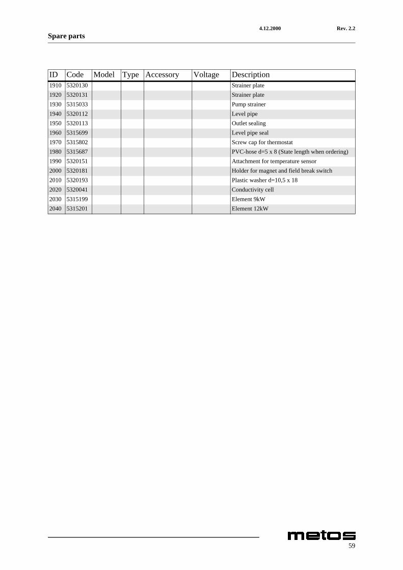
ID Code Model Type Accessory Voltage Description1910 5320130 Strainer plate1920 5320131 Strainer plate1930 5315033 Pump strainer1940 5320112 Level pipe1950 5320113 Outlet sealing1960 5315699 Level pipe seal1970 5315802 Screw cap for thermostat1980 5315687 PVC-hose d=5 x 8 (State length when ordering)1990 5320151 Attachment for temperature sensor2000 5320181 Holder for magnet and field break switch2010 5320193 Plastic washer d=10,5 x 182020 5320041 Conductivity cell2030 5315199 Element 9kW2040 5315201 Element 12kW
59

4.12.2000 Rev. 2.2Spare parts
2050
2060
2070
2080
2090
2100
2110
2120
2130
2140
2150
2160
60

4.12.2000 Rev. 2.2Spare parts
ID Code Model Type Accessory Voltage Description2050 5320274 Electric mantle 400V2060 5320273 Electric mantle 230V2070 5320144 Electric mantle cover2080 5315689 O-ring d=90 x 4,02090 5320275 Distance nut2100 5320276 Copper clamp2110 5320257 A,M Cable screw cap 18,6mm (400V) plastic2120 5320262 A,M Lock nut 18,6mm (plastic)2130 5320258 H Cable screw cap 22,5mm (230V)2140 5320261 H Lock nut 22,5mm2150 5320269 Thermostat attachment2160 734.0303 Thermostat knob
61

4.12.2000 Rev. 2.2Spare parts
2170
2180
2190
2200
2210
2220
2230
2240
2250
2260
2270
2280
2290
2300
62

4.12.2000 Rev. 2.2Spare parts
ID Code Model Type Accessory Voltage DescriptionMODULE:Final rinse, emptying2170 5320042 A,H,M Pump FIR M02472180 5320246 Rubber foot 30 x 30 x32190 5315697 Rubber bend 60 x 120 x 252200 5320020 Hose clamp 20-322210 5315606 Filter, complete2220 5315610 Filter strainer2230 5315609 O-ring to filter2240 5320150 Muff d=25 L=34mm (plastic)2250 5315687 PVC-hose d=5 x 8 (State length when ordering)2260 5320181 Holder for magnet and field break switch2270 5315208 Strainer2280 5315204 Outlet sealing2290 5315699 Level pipe seal2300 5320120 Final rinse breaker
63

4.12.2000 Rev. 2.2Spare parts
2310
2320
2330
2340
2350
2360
2370
2380
2390
2400
2410
2420
2430
2440
2450
2460
64

4.12.2000 Rev. 2.2Spare parts
ID Code Model Type Accessory Voltage Description2310 5320182 Axle to final rinse breaker d=8mm L=64mm2320 5315353 Magnet 6 x 502330 5320195 Locking ring SGA 82340 5320183 Main pipe, final rinse d=15mm L=579mm2350 5320149 Main pipe, re-circulating final rinse d=15mm2360 5320173 Filler pipe d=15mm2370 5320171 Rinse pipe, re-circulating final rinse (complete)2380 5315643 Nozzle2390 5320172 Rinse pipe, final rinse (complete)2400 5315650 Nozzle2410 5320126 Emptying bar2420 5320160 Support for emptying bar2430 5320125 Knob for emptying2440 5320162 Bearing for lifting shaft2450 5320338 Plastic plug for lifting shaft d=15mm 2460 5320192 Washer d=17 x 30
65

4.12.2000 Rev. 2.2Spare parts
2480249025002510
2470
66

4.12.2000 Rev. 2.2Spare parts
ID Code Model Type Accessory Voltage Description2470 5320191 Washer d=13 x 242480 5320108 Lifting axle for level pipe and outlet sealings
67

4.12.2000 Rev. 2.2Spare parts
2520
2530
2540
2550
2560
2570
2580
2590
2600
2610
2620
2630
2640
2650
2660
2670
2680
2690
2700
68

4.12.2000 Rev. 2.2Spare parts
ID Code Model Type Accessory Voltage DescriptionMODULE:Booster heater2520 5320117 Booster heater holder2530 5320128 Emptying plate2540 5315015 Container, standard version2550 5320267 Container, electronic version2560 5320101 A,H Element 9 kW with fusible cut-out2570 5315199 A,H Element 9 kW without fusible cut-out2580 5315201 A,H Element 12 kW without fusible cut-out2590 5320274 A,H Electric mantle 400V2600 5320273 H Electric mantle 230V2610 5320144 Electric mantle cover2620 5315689 O-ring d=90 x 4,02630 5320275 Distance nut2640 5320276 Copper clamp2650 5320194 Packing 8 x 14 x 1,52660 5315465 Temperature sensor, complete2670 5320146 Screw2680 5320145 Spring2690 5320257 Cable screw cap 18,6mm (400V), plastic2700 5320262 A,M Lock nut 18,6mm (plastic)
69

4.12.2000 Rev. 2.2Spare parts
2710
2720
2730
2740
2750
70

4.12.2000 Rev. 2.2Spare parts
ID Code Model Type Accessory Voltage Description2710 5320258 A,M Cable screw cap 22,5mm (230V)2720 5320261 Lock nut 22,5mm2730 5315105 Thermostat attachment, d=15 L=21mm (brass)2740 5315162 Connection coupling for detergent and drying agent2750 5320271 Plug 1/8"
71

4.12.2000 Rev. 2.2Spare parts
2755
72

4.12.2000 Rev. 2.2Spare parts
ID Code Model Type Accessory Voltage DescriptionMODULE:Sets of spare parts / Complete booster heater2755 01163.21 A,H 9 kW standard version2755 01163.14 A,H 9 kW electronic version2755 01163.03 A,H 12 kW standard version2755 011613.16 A,H 12 kW electronic version
73

4.12.2000 Rev. 2.2Spare parts
2760
2770
2780
2790
2800
2810
2820
2830
2840
2850
2860
2870
74

4.12.2000 Rev. 2.2Spare parts
ID Code Model Type Accessory Voltage DescriptionMODULE:Couplings, pipe details2760 5315581 Coupling COMISA 1/2" x 15mm2770 5320209 Coupling COMISA 15 x 15mm2780 5320000 Coupling COMISA 15 X 15 x 15mm2790 5315585 Coupling COMISA, 15mm x 1/2"2800 5315581 Coupling COMISA, 15mm x 1/2" chromium-plated2810 5315583 Coupling COMISA 1/2" x 15mm chromium-plated2820 5320212 Coupling COMISA 15 X 15 x 15mm chromium-plated2830 5320213 Coupling COMISA 15 x 1/2" x 15mm chromium-plated2840 5320214 Coupling COMISA 15 x 1/2" x 15mm chromium-plated2850 705.0315 Nut COMISA 15mm2860 705.0420 Clamping sleeve COMISA 15mm2870 705.0316 Nut COMISA, 15mm chromium-plated
75
4.12.2000 Rev. 2.2Spare parts
2880
2890
2900
2910
2920
2930
2940
2950
2960
76

4.12.2000 Rev. 2.2Spare parts
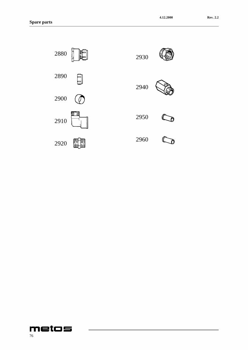
ID Code Model Type Accessory Voltage Description2880 5320207 Coupling LK 303 15mm x 3/4"2890 5320198 Nut LK 63 15mm2900 5320200 Clamping sleeve LK 65 15mm2910 5320217 Coupling 1/2" x 1/2"2920 5320216 Nipple 1/2"2930 5320215 Bushing 3/4" x 1/2"2940 5315593 Ball valve 1/2"2950 705.0104 Support sleeve FPL 720 12 x 1,0mm2960 705.0102 Support sleeve FPL 720 15 x 1,0mm
77

4.12.2000 Rev. 2.2Spare parts
e53876e.cgm
78

4.12.2000 Rev. 2.2Spare parts
ID Code Model Type Accessory Voltage DescriptionMODULE:Electric components [151E]A1 5315258 E A Circuit board
61007950 E A Eprom symb61007960 E A Eprom text61007970 E A Eprom symb61008000 E A Eprom text
A2:1 5320283 E A Cable5320080 E A Panel card symb
A2:2 5320054 E A Panel card textA3 5315250 E A Relay cardA4 5320078 E A Frequency exch.
5320061 E A EpromA5 5320081 E A Interface boardC1 5315409 E A RC-unitC2 5315409 E A RC-unitFU/DM 5320075 E A Automatic fuseFU/M 5320077 E A Automatic fuseFU0 5320076 E A Automatic fuseFU16 5320076 E A Automatic fuseFU22 5315549 E A Automatic fuseFU41 5315549 E A Automatic fuseFU42 5315549 E A Automatic fuseFU43 64800325 E A Automatic fuseFV1 5320065 E A VaristorH20 55500242 E A Signal lightK02 5315527 E A ContactorK1 5315527 E A ContactorK15 5315527 E A ContactorK16 5315527 E A ContactorK17 5315527 E A ContactorK172 5315527 E A ContactorK18 5315527 E A ContactorK19 5315527 E A ContactorK2 5315527 E A Contactor
5320287 E A Help cont. blockK22 5315527 E A ContactorK41 5315527 E A ContactorK42 5315527 E A ContactorK43 5315527 E A Contactor
79

4.12.2000 Rev. 2.2Spare parts
e53876e.cgm
80

4.12.2000 Rev. 2.2Spare parts
ID Code Model Type Accessory Voltage DescriptionMODULE:Electric components [151E]KA02 5315244 E A Relay
5320046 E A Relay baseKA05 5315244 E A Relay
5320046 E A Relay baseKA2 5315244 E A Relay
5320046 E A Relay baseKA20 5315244 E A Relay
5320046 E A Relay baseQ1 5320047 E A Linebreaker
5320048 E A Knob5320049 E A Axel5320083 E A Extra conn. block
QM02 5320070 E A Thermal relay5320073 E A Extra conn. block
QM15 5320069 E A Thermal relay5320073 E A Extra conn. block
QM16 5320070 E A Thermal relayQM16 63113025 E A Thermal relay
5320073 E A Extra conn. blockQM2 63113027 E A Thermal relay
5320073 E A Extra conn. blockS1 5320328 E A Emergency stopS10 5315246 E A SwitchS30 5315331 E A SwitchT1 5320086 E A TransformerV1 ACS121805 E A DiodZ1 61075646 E A Ferrit coreSP02 5315791 E A Pressure switchSP2 5315791 E A Pressure switchFU31 5315554 E A Automatic fuseK11 63723113 E A ContactorK31 63723113 E A ContactorQM10 63113027 E A Thermal relay
5320073 E A Extra conn. blockQM11 5320071 E A Thermal relay
63704900 E A Extra conn. blockQM17 5320070 E A Thermal relay
5320073 E A Extra conn. blockQM172 5320070 E A Thermal relay
5320073 E A Extra conn. blockQM18 5320070 E A Thermal relay
5320073 E A Extra conn. blockQM19 5320070 E A Thermal relay
5320073 E A Extra conn. block
81

4.12.2000 Rev. 2.2Spare parts
S20 5315331 E A SwitchST31 5315797 E A Thermostat
ID Code Model Type Accessory Voltage Description
82

4.12.2000 Rev. 2.2Spare parts
83

4.12.2000 Rev. 2.2Spare parts
84
4.12.2000 Rev. 2.2Spare parts
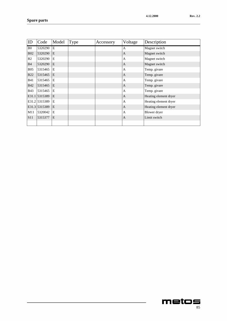
ID Code Model Type Accessory Voltage DescriptionB0 5320290 E A Magnet switchB02 5320290 E A Magnet switchB2 5320290 E A Magnet switchB4 5320290 E A Magnet switchB05 5315465 E A Temp. givareB22 5315465 E A Temp. givareB41 5315465 E A Temp. givareB42 5315465 E A Temp. givareB43 5315465 E A Temp. givareE31.1 5315389 E A Heating element dryerE31.2 5315389 E A Heating element dryerE31.3 5315389 E A Heating element dryerM11 5320042 E A Blower dryerS11 5315377 E A Limit switch
85
4.12.2000 Rev. 2.2Spare parts
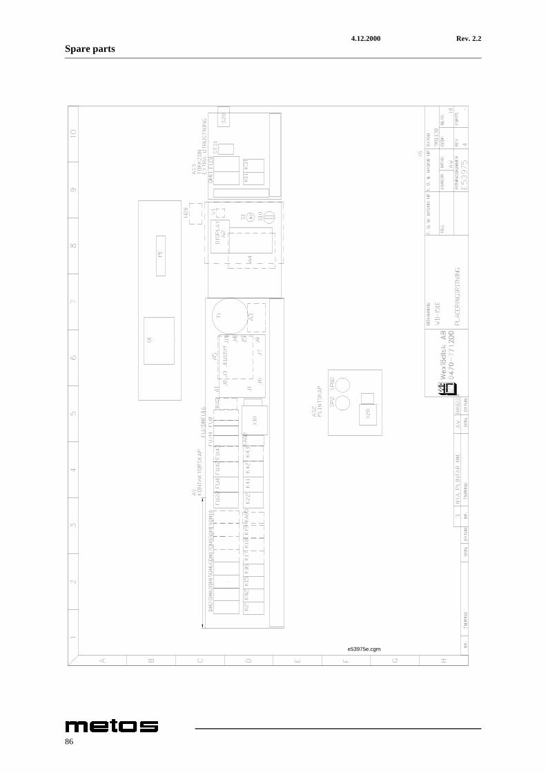
e53975e.cgm
86

4.12.2000 Rev. 2.2Spare parts
ID Code Model Type Accessory Voltage DescriptionMODULE:Electric components [151E nor]A1 5315258 E H Circuit board
61007950 E H Eprom symb61007960 E H Eprom text61007970 E H Eprom symb61008000 E H Eprom text
A2:1 5320283 E H Cable5320080 E H Panel card symb
A2:2 5320054 E H Panel card textA3 5315250 E H Relay cardA4 5320078 E H Frequency exch.
5320061 E H EpromA5 5320081 E H Interface boardC1 5315409 E H RC-unitC2 5315409 E H RC-unitFU/DM 5320077 E H Automatic fuseFU/M 5320077 E H Automatic fuseFU0 64800110 E H Automatic fuseFU16 5320077 E H Automatic fuseFU22 64800340 E H Automatic fuseFU41 64800340 E H Automatic fuseFU42 64800340 E H Automatic fuseFU43 64800340 E H Automatic fuseFV1 5320065 E H VaristorH20 55500242 E H Signal lightK02 5315527 E H ContactorK15 5315527 E H ContactorK16 5315527 E H ContactorK2 5315527 E H Contactor
5320287 E H Help cont. blockK22 5315527 E H ContactorK41 5315527 E H ContactorK42 5315527 E H ContactorK43 5315527 E H Contactor
87

4.12.2000 Rev. 2.2Spare parts
e53975e.cgm
88

4.12.2000 Rev. 2.2Spare parts
ID Code Model Type Accessory Voltage DescriptionMODULE:Electric components [151E nor]KA02 5315244 E H Relay
5320046 E H Relay baseKA2 5315244 E H Relay
5320046 E H Relay baseKA20 5315244 E H Relay
5320046 E H Relay baseQ1 60110050 E H Linebreaker
60105053 E H Knob60104008 E H Protection
QM02 5320070 E H Thermal relay5320073 E H Extra conn. block
QM15 5320069 E H Thermal relay5320073 E H Extra conn. block
QM16 5320069 E H Thermal relay5320073 E H Extra conn. block
QM2 5320288 E H Thermal relay5320073 E H Extra conn. block
S1 5320328 E H Emergency stopS10 5315246 E H SwitchS30 5315331 E H SwitchT1 5320086 E H TransformerV1 ACS12180
5E H Diod
Z1 61075646 E H Ferrit coreSP02 5315791 E H Pressure switchSP2 5315791 E H Pressure switchFU31 64800325 E H Automatic fuseK11 63723113 E H ContactorK31 63723113 E H ContactorQM11 63113027 E H Thermal relay
5320073 E H Extra conn. blockS20 5315331 E H SwitchST31 5315797 E H Thermostat
89

4.12.2000 Rev. 2.2Spare parts
90

4.12.2000 Rev. 2.2Spare parts
ID Code Model Type Accessory Voltage DescriptionB0 5320290 E H Magnet switchB02 5320290 E H Magnet switchB2 5320290 E H Magnet switchB4 5320290 E H Magnet switchB05 5315465 E H Temp. givareB22 5315465 E H Temp. givareB41 5315465 E H Temp. givareB42 5315465 E H Temp. givareB43 5315465 E H Temp. givareE31.1 5315389 E H Heating element dryerE31.2 5315389 E H Heating element dryerE31.3 5315389 E H Heating element dryerM11 5320042 E H Blower dryerS11 5315377 E H Limit switchST43 734.0302 E H Thermostat
91

4.12.2000 Rev. 2.2Spare parts
92

4.12.2000 Rev. 2.2Spare parts
ID Code Model Type Accessory Voltage DescriptionST43:2 734.0201 E H Overheat protection
93

4.12.2000 Rev. 2.2Spare parts
e54871e.cgm
94

4.12.2000 Rev. 2.2Spare parts
ID Code Model Type Accessory Voltage DescriptionMODULE:Electric components [151E steam]A1 5315258 S L Circuit board
61008030 S L Eprom symb61008010 S L Eprom text61008020 S L Eprom text fra61007950 S L Eprom symb61007960 S L Eprom text61007970 S L Eprom symb61008000 S L Eprom text
A2:1 5320283 S L Cable5320080 S L Panel card symb
A2:2 5320054 S L Panel card textA3 5315250 S L Relay cardA4 5320078 S L Frequency exch.
5320061 S L EpromA5 5320081 S L Interface boardC1 5315409 S L RC-unitC2 5315409 S L RC-unitFU/DM 5320077 S L Automatic fuseFU/M 5320077 S L Automatic fuseFU0 5320076 S L Automatic fuseFU16 5320076 S L Automatic fuseFV1 5320065 S L VaristorH20 55500242 S L Signal lightK02 5315527 S L ContactorK15 5315527 S L ContactorK16 5315527 S L ContactorK2 5315527 S L Contactor
5320287 S L Help cont. block
95

4.12.2000 Rev. 2.2Spare parts
e54871e.cgm
96

4.12.2000 Rev. 2.2Spare parts
ID Code Model Type Accessory Voltage DescriptionMODULE:Electric components [151E steam]KA02 5315244 S L Relay
5320046 S L Relay baseKA2 5315244 S L Relay
5320046 S L Relay baseKA20 5315244 S L Relay
5320046 S L Relay baseQ1 5320047 S L Linebreaker
5320048 S L Knob5320049 S L Axel5320083 S L Extra conn. block
QM02 5320070 S L Thermal relay5320073 S L Extra conn. block
QM2 63113027 S L Thermal relay63713042 S L Extra conn. block5320084 S L Connec. bloc63713085 S L Conn. bar
QM15 5320069 S L Thermal relay5320073 S L Extra conn. block
QM16 5320070 S L Thermal relay5320073 S L Extra conn. block
S1 5320328 S L Emergency stopS10 5315246 S L SwitchS30 5315331 S L SwitchT1 60681064 S L TransformerV1 ACS12180
5S L Diod
Z1 61075646 S L Ferrit coreSP02 5315791 S L Pressure switchSP1 5315791 S L Pressure switchSP2 5315791 S L Pressure switchFU31 5315554 S L Automatic fuseK11 63723113 S L ContactorK31 63723113 S L ContactorQM11 5320071 S L Thermal relay
63704900 S L Extra conn. blockS20 5315331 S L SwitchST31 5315797 S L Thermostat
97

4.12.2000 Rev. 2.2Spare parts
98

4.12.2000 Rev. 2.2Spare parts
ID Code Model Type Accessory Voltage DescriptionB0 5320290 S L Magnet switchB02 5320290 S L Magnet switchB2 5320290 S L Magnet switchB4 5320290 S L Magnet switchB05 5315465 S L Temp. givareB22 5315465 S L Temp. givareB41 5315465 S L Temp. givareB42 5315465 S L Temp. givareB43 5315465 S L Temp. givareE31.1 5315389 S L Heating element dryerE31.2 5315389 S L Heating element dryerE31.3 5315389 S L Heating element dryerM11 5320042 S L Blower dryerS11 5315377 S L Limit switch
99

4.12.2000 Rev. 2.2Spare parts
100

4.12.2000 Rev. 2.2Technical specifications
9. Technical specifications
Flow chart 36629
Flow chart 36633
Flow chart E53867
Main circuit E53868
Control circuit E53869
Control circuit E53870
Control circuit E53871
Control circuit E53872
Control circuit E53873
Control circuit E53874
Control circuit E53875
Main circuit E53966
Main circuit E53967
Control circuit E53968
Control circuit E53969
Control circuit E53970
101

4.12.2000 Rev. 2.2Technical specifications
Control circuit E53971
Control circuit E53972
Control circuit E53973
Control circuit E53974
Main circuit E54716
Main circuit E54717
Control circuit E54718
Control circuit E54719
Control circuit E54720
Control circuit E54721
Control circuit E54722
Control circuit E54723
Control circuit E54724
Conveyor control circuit
Rinse equipment control circuit
Installation drawing
102

Flow chart 36629
IS T
O BE
EXL
UDED
IN C
ASE
OF C
OLDW
ATER
CON
NECT
ION/
EI K
ÄYTÖ
SSÄ
JOS
VAIN
KYL
MÄVE
SILI
ITÄN
TÄ/
UTGÅ
R VI
D KA
LLV.
ANSL
. CHEM
ICAL
WAS
H/KE
MIAL
LINE
N PE
SU/
KEMD
ISK
DOUB
LE F
INAL
RIN
SE/
KAKS
OISL
OPPU
HUUH
TELU
/DU
BBEL
SLU
TSKÖ
LJNI
NG
1. FI
LTER
/MUD
ANER
OITI
N 1/2
"2.
NONR
ETUR
N VA
LVE/
TAK
AISK
UVEN
TTIIL
I/ B
ACKV
ENTI
L3.
RESU
CTIO
N PR
OTEC
TION
/ T
AKAI
SINI
MUSU
OJA/
ÅTE
RSUG
NING
SSKY
DD4.
OUTP
UT D
ETER
GENT
DOS
ING/
LIIT
ÄNTÄ
PES
UAIN
EANN
OST.
/ U
TTAG
FÖR
DIS
KM.D
OS.
5. SO
LENO
IDVA
LVE
DANF
OSS
EVSI
/ M
AGNE
ETTI
VENT
TIIL
I/ M
AGNE
TV. D
ANFO
SS E
VSI
6. TH
ROTT
LE V
ALVE
/ S
ÄÄTÖ
VENT
TIIL
I ESI
HUUH
T./
STR
YPVE
NTIL
7. FI
NAL
RINS
E PU
MP/
LOP
PUHU
UHTE
LUPU
MPPU
/ S
LUTS
KÖLJ
NING
PUMP
8. CH
EMIC
AL W
ASH
PUMP
/ P
ESUP
UMPP
U KE
M.PE
SU/
KEM
DISK
PUMP
9. OU
TPUT
DRY
ING
AGEN
T/ L
IITÄN
TÄ H
UUHT
.AIN
EANN
OST.
/ U
TTAG
FÖR
TOR
KM.D
OS10
. BOO
STER
HEA
TER/
BO
ILER
I/
GENO
MSTR
ÖMMA
RE11
. WAT
ERME
TER/
VE
DENK
ULUT
US M
ITTA
RI/
VA
TTEN
MÄTA
RE12
. RED
UCIN
G VA
LVE/
PA
INEE
NALE
NNUS
VENT
TIIL
I/
REDU
CERI
NGSV
ENTI
L13
. CON
DENS
ING
BATT
ERY/
LA
UHDU
TINP
ATTE
RI/
KO
NDEN
SBAT
TERI
14. C
ONDE
NSIN
G FA
N/
LAUH
DUTI
NPUH
ALLI
N/
KOND
ENSF
LÄKT
15. B
OOST
ER P
UMP
(EXT
RA)/
PA
INEE
NKOR
OTUS
PUMP
PU (O
PTIO
)/
TRYC
KSTE
GRIN
GSPU
MP (E
XTRA
)16
. FIL
TER/
SU
ODAT
IN L
OPPU
HUUH
T.17
. THE
RMOM
ETER
(ONL
Y RE
LAY
MACH
INE)
/
LÄMP
ÖMIT
TARI
(AIN
OAST
AAN
RELE
VERS
IOT)
/
TERM
OMET
ER (E
NDAS
T RE
LÄUT
FÖRA
NDE)
18. S
AFET
Y VA
LVE
/
TUR
VAVE
NTTI
ILI /
S
ÄKER
HETS
VENT
IL
STAN
DARD
DES
IGN/
STAN
DARD
I VER
SIO/
VID
STAN
DARD
UTFÖ
RAND
ECO
LD W
ATER
CON
NECT
ION/
KYLM
ÄVES
ILIIT
. KON
E/VI
D KA
LLVA
TTEN
ANSL
UTNI
NGBO
OSTE
R PU
MP/K
ONE
PAIN
EENK
OROT
USPU
MPUL
LA/M
ED T
RYCK
STEG
RING
SPUM
PTE
XT P
ANEL
/TEK
STI P
ANEE
LI V
ERSI
O/VI
D TE
XTPA
NEL
UTFÖ
RAND
EEX
TRA
BOOS
TER
HEAT
ER F
INAL
RIN
SE/Y
LIMÄ
ÄRÄI
SELL
Ä BO
ILER
ILLA
/VID
EXT
RA G
ENOM
STRÖ
MMAR
E RE
C.
SP=L
EVEL
REL
AY/P
AINE
KYTK
IN/P
RESS
OSTA
TB0
5-B4
3=TE
MPER
ATUR
SEN
SOR
ELEC
TRON
IC V
ERSI
ON/L
ÄMPÖ
TILA
-ANT
URIT
ELE
KTR.
VER
SIO
/TEM
PERA
TURG
IVAR
E EL
EKTR
ONIS
K VE
RSIO
NST
05-S
T43=
THER
MOST
ATS
RELA
Y VE
RSIO
N/TE
RMOS
TAAT
IN R
ELEV
ERSI
O/T
ERMO
STAT
S RE
LÄVE
RSIO
NSY
MBOL
S RE
LAY
VERS
ION
IN B
RACK
ETS
/ SYM
BOLE
ISSA
REL
E VE
RSIO
SUL
UISS
A/S
YMBO
LER
RELÄ
VERS
ION
INOM
PAR
ENTE
S
WAT
ER S
UPPL
YVI
RTAU
SKAA
VIO
FLÖD
ESSC
HEMA

Flow chart 36633
STAN
DARD
DES
IGN/
STAN
DARD
I VER
SIO/
VID
STAN
DARD
UTFÖ
RAND
ECO
LD W
ATER
CON
NECT
ION/
KYLM
ÄVES
ILIIT
. KON
E/VI
D KA
LLVA
TTEN
ANSL
UTNI
NGBO
OSTE
R PU
MP/K
ONE
PAIN
EENK
OROT
USPU
MPUL
LA/M
ED T
RYCK
STEG
RING
SPUM
PTE
XT P
ANEL
/TEK
STI P
ANEE
LI V
ERSI
O/VI
D TE
XTPA
NEL
UTFÖ
RAND
EEX
TRA
BOOS
TER
HEAT
ER F
INAL
RIN
SE/Y
LIMÄ
ÄRÄI
SELL
Ä BO
ILER
ILLA
/VID
EXT
RA G
ENOM
STRÖ
MMAR
E RE
C.
WAT
ER S
UPPL
YVI
RTAU
SKAA
VIO
FLÖD
ESSC
HEMA
DOUB
LE F
INAL
RIN
SE/
KAKS
OISL
OPPU
HUUH
TELU
/DU
BBEL
SLU
TSKÖ
LJNI
NG
CHEM
ICAL
WAS
H/KE
MIAL
LINE
N PE
SU/
KEMD
ISK
IS T
O BE
EXL
UDED
IN C
ASE
OF C
OLDW
ATER
CON
NECT
ION/
EI K
ÄYTÖ
SSÄ
JOS
VAIN
KYL
MÄVE
SILI
ITÄN
TÄ/
UTGÅ
R VI
D KA
LLV.
ANSL
.
PRE
RINS
E ZO
NE/
ESIH
UUHT
ELUL
OHKO
/FÖ
RSPO
LNIN
GZON
FS-4
0
SP=L
EVEL
REL
AY/P
AINE
KYTK
IN/P
RESS
OSTA
TB0
5-B4
3=TE
MPER
ATUR
SEN
SOR
ELEC
TRON
IC V
ERSI
ON/L
ÄMPÖ
TILA
-ANT
URIT
ELE
KTR.
VER
SIO
/TEM
PERA
TURG
IVAR
E EL
EKTR
ONIS
K VE
RSIO
NST
05-S
T43=
THER
MOST
ATS
RELA
Y VE
RSIO
N/TE
RMOS
TAAT
IN R
ELEV
ERSI
O/T
ERMO
STAT
S RE
LÄVE
RSIO
NSY
MBOL
S RE
LAY
VERS
ION
IN B
RACK
ETS
/ SYM
BOLE
ISSA
REL
E VE
RSIO
SUL
UISS
A/S
YMBO
LER
RELÄ
VERS
ION
INOM
PAR
ENTE
S
1. FI
LTER
/MUD
ANER
OITI
N 1/2
"2.
NONR
ETUR
N VA
LVE/
TAK
AISK
UVEN
TTIIL
I/ B
ACKV
ENTI
L3.
RESU
CTIO
N PR
OTEC
TION
/ T
AKAI
SINI
MUSU
OJA/
ÅTE
RSUG
NING
SSKY
DD4.
OUTP
UT D
ETER
GENT
DOS
ING/
LIIT
ÄNTÄ
PES
UAIN
EANN
OST.
/ U
TTAG
FÖR
DIS
KM.D
OS.
5. SO
LENO
IDVA
LVE
DANF
OSS
EVSI
/ M
AGNE
ETTI
VENT
TIIL
I/ M
AGNE
TV. D
ANFO
SS E
VSI
6. TH
ROTT
LE V
ALVE
(NEE
DLE
VALV
E)/
SÄÄ
TÖVE
NTTI
ILI E
SIHU
UHT.
(NEU
LAVE
NTTI
ILI)/
STR
YPVE
NTIL
(NÅL
VENT
IL)
7. FI
NAL
RINS
E PU
MP/
LOP
PUHU
UHTE
LUPU
MPPU
/ S
LUTS
KÖLJ
NING
PUMP
8. CH
EMIC
AL W
ASH
PUMP
/ P
ESUP
UMPP
U KE
M.PE
SU/
KEM
DISK
PUMP
9. OU
TPUT
DRY
ING
AGEN
T/ L
IITÄN
TÄ H
UUHT
.AIN
EANN
OST.
/ U
TTAG
FÖR
TOR
KM.D
OS10
. BOO
STER
HEA
TER/
BO
ILER
I/
GENO
MSTR
ÖMMA
RE11
. WAT
ERME
TER/
VE
DENK
ULUT
US M
ITTA
RI/
VA
TTEN
MÄTA
RE12
. RED
UCIN
G VA
LVE/
PA
INEE
NALE
NNUS
VENT
TIIL
I/
REDU
CERI
NGSV
ENTI
L13
. CON
DENS
ING
BATT
ERY/
LA
UHDU
TINP
ATTE
RI/
KO
NDEN
SBAT
TERI
14. C
ONDE
NSIN
G FA
N/
LAUH
DUTI
NPUH
ALLI
N/
KOND
ENSF
LÄKT
15. B
OOST
ER P
UMP
(EXT
RA)/
PA
INEE
NKOR
OTUS
PUMP
PU (O
PTIO
)/
TRYC
KSTE
GRIN
GSPU
MP (E
XTRA
)16
. FIL
TER/
SU
ODAT
IN L
OPPU
HUUH
T.17
. THE
RMOM
ETER
(ONL
Y RE
LAY
MACH
INE)
/
LÄMP
ÖMIT
TARI
(AIN
OAST
AAN
RELE
VERS
IOT)
/
TERM
OMET
ER (E
NDAS
T RE
LÄUT
FÖRA
NDE)
18. S
AFET
Y VA
LVE/
T
URVA
VENT
TIIL
I/
SÄK
ERHE
TSVE
NTIL
19. T
HROT
TLE
VALV
E (B
ALL
VALV
E)/
SÄÄ
TÖVE
NTTI
ILI E
SIHU
UHT.
(KUU
LAVE
NTTI
ILI)/
STR
YPVE
NTIL
(KUL
VENT
IL)
WD-
151
FS40

Flow chart E53867
PÄÄV
IRTA
KAAV
IO
MAIN
CIR
CUIT
DIA
GRAM
EL. A
NSLU
TNIN
GEL
. CON
NECT
ION
KABE
LCA
BLE
63A
WIT
H DR
YING
ZON
E80
A W
ITH
BOILE
R 3
80A
WIT
H DR
YING
ZON
E, B
OILE
R 3
63A
MED
TOR
KZON
80A
MED
GEN
OMST
RÖMM
ARE
380
A M
ED T
ORKZ
ON, G
EN.S
TR. 3
PUHA
LLIN
, KUI
VAAJ
AFA
N, D
RYIN
G ZO
NEFL
ÄKT,
TOR
KZON
PUMP
PU A
LLAS
2PU
MP T
ANK
2PU
MPPU
ALL
AS 02
PUMP
TAN
K 02
LAUH
DUTI
NPUH
ALLIN
COND
ENSI
NG F
ANKO
NDEN
SFLÄ
KT
KULJ
ETIN
MOOT
TORI
FEED
MOT
ORMA
TNIN
GSMO
TOR

Main circuit E53868
LÄMM
ITYS
ALL
AS 2
VÄRM
E TA
NK 2
HEAT
TAN
K 2
LÄMM
ITYS
BOI
LERI
1VÄ
RME
GEN.
STR.
1HE
ATIN
G BO
ILER
1
LÄMM
ITYS
KUI
VAAJ
AVÄ
RME
TORK
ZON
HEAT
DRY
ING
ZONE
MANÖ
VER
CONT
ROL
DISK
MEDE
LS U
TRUS
TNIN
GDE
TERG
ENT
EQUI
PMEN
T
LIITÄ
NTÄ
LÄMM
ITYS
BOI
LERI
2VÄ
RME
GEN.
STR.
2HE
ATIN
G BO
ILER
2
LÄMM
ITYS
BOI
LERI
3VÄ
RME
GEN.
STR.
3HE
ATIN
G BO
ILER
3
PÄÄV
IRTA
KAAV
IOMA
IN C
IRCU
IT D
IAGR
AMHU
VUDK
RETS
SCHE
MA
MATN
INGS
MOTO
RFE
ED M
OTOR
13,1
13,1

Control circuit E53869
PUMP
TAN
K 2
PUMP
TAN
K 02
KOND
ENSF
LÄKT
COND
ENSI
NG F
AN
MATN
INGS
MOTO
RFE
ED M
OTOR
KALL
VATT
ENCO
LD W
ATER
FYLL
NING
TAN
KAR
FILL
ING
TANK
S
KALL
VATT
ENCO
LD W
ATER
OHJA
USVI
RTAK
AAVI
OCO
NTRO
L CIR
CUIT
DIA
GRAM
MANÖ
VERK
RETS
SCHE
MA
/ KAB
EL / C
ABLE
/ RÖD
/ RED
/ VIT
/ WHI
TE
STAR
T DI
SKNI
NGST
ART
WAS
HKU
ORI//C
ORE
TRAN
SMIT
TER
RECE
IVER
FREK
VENS
OMVA
NDLA
REFR
EQUE
NCY
CONV
.
KATS
O KA
AVIO
SE S
CHEM
ALO
OK A
T DR
AWIN
GRU
SKEA
/BRU
N/BR
OWN
VIHR
EÄ/G
RÖN/
GREE
N
ULOS
OTTO
/ UT
TAG
/ OU
TTAK
E
NÄYT
TÖKO
RTTI
/ PAN
EL K
ORT
/ PAN
EL C
ARD
PIIR
IKOR
TTI /
DATO
R KO
RT / C
IRCU
IT B
OARD
MUST
A/SV
ART/
BLAC
K
PUNA
INEN
/RÖD
/RED
KELT
AINE
N/GU
L/YEL
LOW

Control circuit E53870
LÄMM
ITYS
ALL
AS 2
VÄRM
E TA
NK 2
HEAT
ING
TANK
2
LÄMM
ITYS
BOI
LERI
1VÄ
RME
GENO
MSTR
. 1HE
ATIN
G BO
ILER
1
LÄMM
ITYS
BOI
LERI
2VÄ
RME
GEN.
STR
2HE
ATIN
G BO
ILER
2
KUIV
AUSA
INEA
NNOS
T.TO
RKME
DELS
DOSE
RING
DRYI
NG A
GENT
DOS
AGE
SLUT
SKÖL
JNIN
GFI
NAL R
INSE
PIIR
IKOR
TTI /
DATO
R KO
RT / C
IRCU
IT B
OARD
OHJA
USVI
RTAK
AAVI
OMA
NÖVE
RKRE
TSSC
HEMA
CONT
ROL C
IRCU
IT D
IAGR
AM

Control circuit E53871
FLÄK
T TO
RKZO
NFA
N DR
YING
ZON
E
LÄMM
ITYS
KUI
VAAJ
AVÄ
RME
TORK
ZON
HEAT
ING
DRIN
G ZO
NE
LARM
ALAR
M
LÄMM
ITYS
BOI
LERI
3VÄ
RME
GEN.
STR.
3HE
ATIN
G BO
ILER
3
RELE
KORT
TIRE
LÄ K
ORT
RELA
Y BO
ARD
OHJA
USKO
RTTI
/DA
TOR
KORT
/CO
MPUT
ER B
OARD
KYTK
INKA
APIS
SAPL
INTS
KÅP
PLIN
TH C
UBIC
LE
PESU
AINE
ANNO
ST. K
YTKE
TÄÄN
LIIT
TIMI
INDI
SKME
DELS
UTR
USTN
ING
INKO
PPLA
S ME
LLAN
PLIN
TDE
TERG
ENT
EQ. C
ONNE
CTS
BETW
EEN
PLIN
T
HUUH
T.AI
NEAN
NOST
. KYT
KETÄ
ÄN LI
ITTI
MIIN
TORK
MEDE
LSDO
SERI
NG IN
KOPP
LAS
MELL
AN P
LINT
DRYI
NG A
GENT
DOS
AGE
CONN
ECTS
BET
WEE
N PL
INT
HUOM
! HUU
HT.A
INEA
NNOS
T. 23
0V Y
HDIS
TÄ LI
ITTI
MET
104-
105.
ANNO
STEL
IJA K
YTKE
TÄÄN
LIIT
TIMI
IN 10
2-10
3/OB
S! A
NVÄN
DES
230V
FÖR
TOR
KMED
ELSD
OSER
ING
FÖRB
INDS
PLIN
T 10
4-10
5OC
H KO
PPLA
IN T
ORKM
EDEL
SDOS
. MEL
LAN
PLIN
T 10
2-10
3/OB
S! IF
230V
IS U
SED
FOR
THE
DRYI
NG A
GENT
DOS
AGE
BRID
GE C
ONNE
CT P
LINTH
104-
105 A
ND C
ONNE
CT T
HE D
ISPE
NSER
BET
WEE
N PL
INTH
102-
103.
/ MÄT
CELL
/ DET
ERGE
NT S
ENSO
R OHJA
USVI
RTAK
AAVI
OMA
NÖVE
RKRE
TSSC
HEMA
CONT
ROL C
IRCU
IT D
IAGR
AM
PESUAINE/DISKM./DETERG.
PESUAINE/DISKM./DETERG.

Control circuit E53872
/ DAT
OR K
ORT
/ COM
PUTE
R BO
ARD
LUCK
A TA
NK 2
APER
TURE
TAN
K 2
LUCK
A FÖ
RSPO
LNIN
GAP
ERTU
RE P
RE-R
INSE
LUCK
A TA
NK 02
APER
TURE
TAN
K 02
LOPP
URAJ
AKYT
KIN
ENDL
IMIT
STAR
T RE
C. S
LUTS
KÖLJ
NING
/ST
ART
REC.
FIN
AL R
INSE
YLIK
UORM
AKYT
KIN
OVER
LOAD
NIVÅ
TAN
K 02
LEVE
L TAN
K 02
SLUT
SKÖL
JNIN
GFI
NAL R
INSE
NIVÅ
TAN
K 2
LEVE
L TAN
K 2
OHJA
USVI
RTAK
AAVI
O
CONT
ROL C
IRCU
IT D
IAGR
AM

Control circuit E53873
/ DAT
OR K
ORT
/ COM
PUTE
R BO
ARD
OHJA
USVI
RTAK
AAVI
O
CONT
ROL C
IRCU
IT D
IAGR
AM
STOP
P MA
TNIN
GST
OP F
EED
MATN
INGS
MOTO
RFE
ED M
OTOR
KULJ
ETTI
MET
TRAN
SPOR
TÖRE
RCO
NVEY
ORS
PUMP
TAN
K 2
PUMP
TAN
K 02
KOND
ENSF
LÄKT
COND
ENSI
NG F
AN
TORK
ZON
DRYI
NG Z
ONE
LÄMM
IN V
ESI (
TEKS
TIPA
NEEL
I)VA
RMVA
TTEN
(TEX
T PA
NEL)
WAR
M W
ATER
(TEX
T PA
NEL)
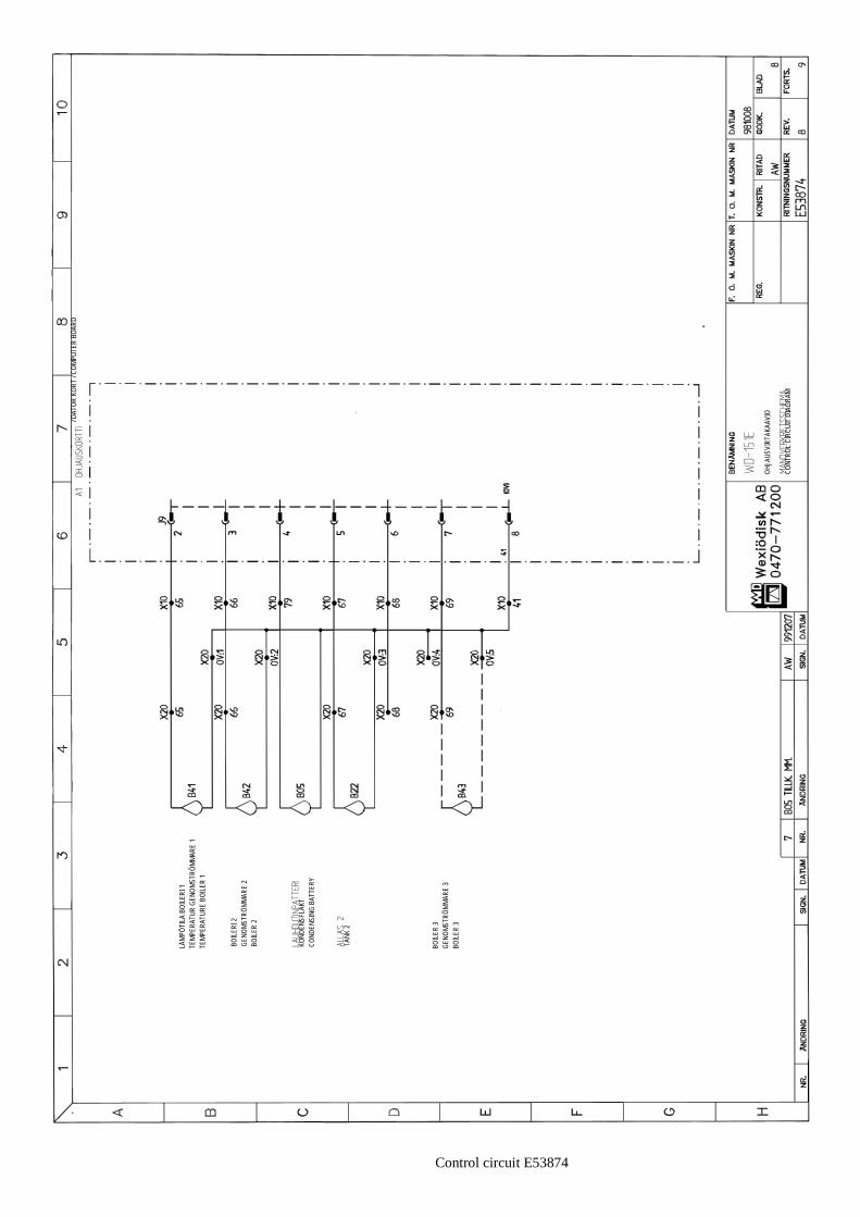
Control circuit E53874
/ DAT
OR K
ORT
/ COM
PUTE
R BO
ARD
LÄMP
ÖTILA
BOI
LERI
1TE
MPER
ATUR
GEN
OMST
RÖMM
ARE
1TE
MPER
ATUR
E BO
ILER
1
BOILE
RI 2
GENO
MSTR
ÖMMA
RE 2
BOILE
R 2
KOND
ENSF
LÄKT
COND
ENSI
NG B
ATTE
RY
TANK
2
BOILE
R 3
GENO
MSTR
ÖMMA
RE 3
BOILE
R 3
OHJA
USVI
RTAK
AAVI
O
CONT
ROL C
IRCU
IT D
IAGR
AM

Control circuit E53875
OHJA
USVI
RTAK
AAVI
O
CONT
ROL C
IRCU
IT D
IAGR
AM

PUHALLIN, KUIVAAJAFAN, DRYING ZONEFLÄKT, TORKZON
4
Main circuit E53966
PUMPPU ALLAS 2PUMP TANK 2
PUMPPU ALLAS 02PUMP TANK 02
LAUHDUTINPUHALLINCONDENSING FANKONDENSFLÄKT
KULJETINMOOTTORIFEED MOTORMATNINGSMOTOR
MAIN CIRCUIT DIAGRAMPÄÄVIRTAKAAVIOHUVUDKRETSSCHEMA
EL.CONNECTIONEL. ANSLUTNING
CABLE
125A WITH DRYING ZONE125A WITH BOILER 3160A WITH DRYING ZONE, BOILER 3
125A MED TORKZON125A MED GENOMSTRÖMMARE 3125A MED TORKZON, GEN.STR. 3
1,22

NÖVERNTROL
DISKMEDELS UTRUSTNINGDETERGENT EQUIPMENT
LIITÄNTÄ
MATNINGSMOTORFEED MOTOR
4
1,22
Main circuit E53967
LÄMMITYS ALLAS 2VÄRME TANK 2HEAT TANK 2
LÄMMITYS BOILERI 1VÄRME GEN.STR. 1HEATING BOILER 1
LÄMMITYS KUIVAAJAVÄRME TORKZONHEAT DRYING ZONE
LÄMMITYS BOILERI 2VÄRME GEN.STR. 2HEATING BOILER 2
LÄMMITYS BOILERI 3VÄRME GEN.STR. 3HEATING BOILER 3 MA
CO
PÄÄVIRTAKAAVIOMAIN CIRCUIT DIAGRAMHUVUDKRETSSCHEMA
4 NY M16,QM16 AW/KOK 001002

PUMP TANK 2
PUMP TANK 02
KONDENSFLÄKTCONDENSING FAN
MATNINGSMOTORFEED MOTOR
KALLVATTENCOLD WATER
FYLLNING TANKARFILLING TANKS
KALLVATTENCOLD WATER
GRAMMA 4
Control circuit E53968
OHJAUSVIRTAKAAVIOCONTROL CIRCUIT DIAMANÖVERKRETSSCHE
/ KABEL / CABLE
/ RÖD / RED/ VIT / WHITE
START DISKNINGSTART WASH
PUNAINEN/RÖD/RED
MUSTA/SVART/BLACK
KUORI//CORE
KELTAINEN/GUL/YELLOW
TRANSMITTER
RECEIVER
FREKVENSOMVANDLAREFREQUENCY CONV.
KATSO KAAVIOSE SCHEMALOOK AT DRAWING
RUSKEA/BRUN/BROWN
VIHREÄ/GRÖN/GREEN
ULOSOTTO / UTTAG / OUTTAKE
NÄYTTÖKORTTI / PANEL KORT / PANEL CARD
PIIRIKORTTI / DATOR KORT / CIRCUIT BOARD

LÄMMITYS ALLAS 2VÄRME TANK 2HEATING TANK 2
LÄMMITYS BOILERI 1VÄRME GENOMSTR. 1HEATING BOILER 1
LÄMMITYS BOILERI 2VÄRME GEN.STR 2HEATING BOILER 2
KUIVAUSAINEANNOST.TORKMEDELSDOSERINGDRYING AGENT DOSAGE
SLUTSKÖLJNINGFINAL RINSE
ARAM 4
Control circuit E53969
PIIRIKORTTI / DATOR KORT / CIRCUIT BOARD
OHJAUSVIRTAKAAVIOMANÖVERKRETSSCHEMCONTROL CIRCUIT DIAG
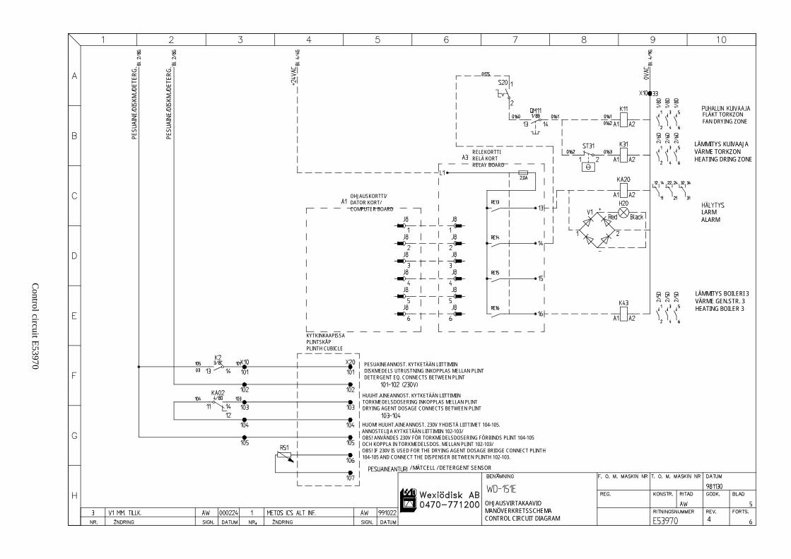
FLÄKT TORKZONFAN DRYING ZONE
LÄMMITYS KUIVAAJAVÄRME TORKZONHEATING DRING ZONE
LARMALARM
LÄMMITYS BOILERI 3VÄRME GEN.STR. 3HEATING BOILER 3
H
MAGRAM 4
Control circuit E53970
RELEKORTTIRELÄ KORTRELAY BOARD
OHJAUSKORTTI/DATOR KORT/COMPUTER BOARD
KYTKINKAAPISSAPLINTSKÅPPLINTH CUBICLE
PESUAINEANNOST. KYTKETÄÄN LIITTIMIINDISKMEDELS UTRUSTNING INKOPPLAS MELLAN PLINTDETERGENT EQ. CONNECTS BETWEEN PLINT
HUUHT.AINEANNOST. KYTKETÄÄN LIITTIMIINTORKMEDELSDOSERING INKOPPLAS MELLAN PLINTDRYING AGENT DOSAGE CONNECTS BETWEEN PLINT
HUOM! HUUHT.AINEANNOST. 230V YHDISTÄ LIITTIMET 104-105.ANNOSTELIJA KYTKETÄÄN LIITTIMIIN 102-103/OBS! ANVÄNDES 230V FÖR TORKMEDELSDOSERING FÖRBINDS PLINT 104-105OCH KOPPLA IN TORKMEDELSDOS. MELLAN PLINT 102-103/OBS! IF 230V IS USED FOR THE DRYING AGENT DOSAGE BRIDGE CONNECT PLINT104-105 AND CONNECT THE DISPENSER BETWEEN PLINTH 102-103.
/ MÄTCELL / DETERGENT SENSOR
OHJAUSVIRTAKAAVIOMANÖVERKRETSSCHECONTROL CIRCUIT DIA
PESU
AINE
/DIS
KM./D
ETER
G.
PESU
AINE
/DIS
KM./D
ETER
G.

KORT / COMPUTER BOARD
GRAM 4
Control circuit E53971
/ DATOR
LUCKA TANK 2APERTURE TANK 2
LUCKA FÖRSPOLNINGAPERTURE PRE-RINSE
LUCKA TANK 02APERTURE TANK 02
LOPPURAJAKYTKIN
ENDLIMIT
START REC. SLUTSKÖLJNING/START REC. FINAL RINSE
YLIKUORMAKYTKIN
OVERLOAD
NIVÅ TANK 02LEVEL TANK 02
SLUTSKÖLJNINGFINAL RINSE
NIVÅ TANK 2LEVEL TANK 2
OHJAUSVIRTAKAAVIO
CONTROL CIRCUIT DIA

KORT / COMPUTER BOARD
GRAM 4
Control circuit E53972
/ DATOR
OHJAUSVIRTAKAAVIO
CONTROL CIRCUIT DIA
STOPP MATNINGSTOP FEED
MATNINGSMOTORFEED MOTOR
KULJETTIMETTRANSPORTÖRERCONVEYORS
PUMP TANK 2
PUMP TANK 02
KONDENSFLÄKTCONDENSING FAN
TORKZONDRYING ZONE
LÄMMIN VESI (TEKSTIPANEELI)VARMVATTEN (TEXT PANEL)WARM WATER (TEXT PANEL)

RT / COMPUTER BOARD
GRAM 4
Control circuit E53973
/ DATOR KO
LÄMPÖTILA BOILERI 1TEMPERATUR GENOMSTRÖMMARE 1TEMPERATURE BOILER 1
BOILERI 2GENOMSTRÖMMARE 2BOILER 2
KONDENSFLÄKTCONDENSING BATTERY
TANK 2
TANK 1
BOILER 3GENOMSTRÖMMARE 3BOILER 3
OHJAUSVIRTAKAAVIO
CONTROL CIRCUIT DIA

GRAM 4
Control circuit E53974
OHJAUSVIRTAKAAVIO
CONTROL CIRCUIT DIA

Main circuit E54716
EL. A
NSLU
TNIN
GEL
.CON
NECT
ION
MAX
ANSL
UTNI
NGCA
BLE
MAX
20 A
W
ITH
DRYI
NG Z
ONE
20A
MED
TOR
KZON
PUHA
LLIN
, KUI
VAAJ
AFA
N, D
RYIN
G ZO
NEFL
ÄKT,
TOR
KZON
MAIN
CIR
CUIT
DIA
GRAM
PÄÄV
IRTA
KAAV
IOHU
VUDK
RETS
SCHE
MA
PUMP
PU A
LLAS
2PU
MP T
ANK
2
PUMP
PU A
LLAS
02PU
MP T
ANK
02
LAUH
DUTI
NPUH
ALLIN
COND
ENSI
NG F
ANKO
NDEN
SFLÄ
KT
KULJ
ETIN
MOOT
TORI
FEED
MOT
ORMA
TNIN
GSMO
TOR
16/2
0A
)
2
7
151E
STE
AM M
AR
INE
VER
S.H
ÖYR
Y M
ARIN
E VE
RS
.ÅN
GA
MA
RIN
T U
TF.

Main circuit E54717
PÄÄV
IRTA
KAAV
IOMA
IN C
IRCU
IT D
IAGR
AMHU
VUDK
RETS
SCHE
MA
MANÖ
VER
CONT
ROL
DISK
MEDE
LS U
TRUS
TNIN
GDE
TERG
ENT
EQUI
PMEN
T
MATN
INGS
MOTO
RFE
ED M
OTOR
LIITÄ
NTÄ
LÄMM
ITYS
KUI
VAAJ
AVÄ
RME
TORK
ZON
HEAT
DRY
ING
ZONE
151E
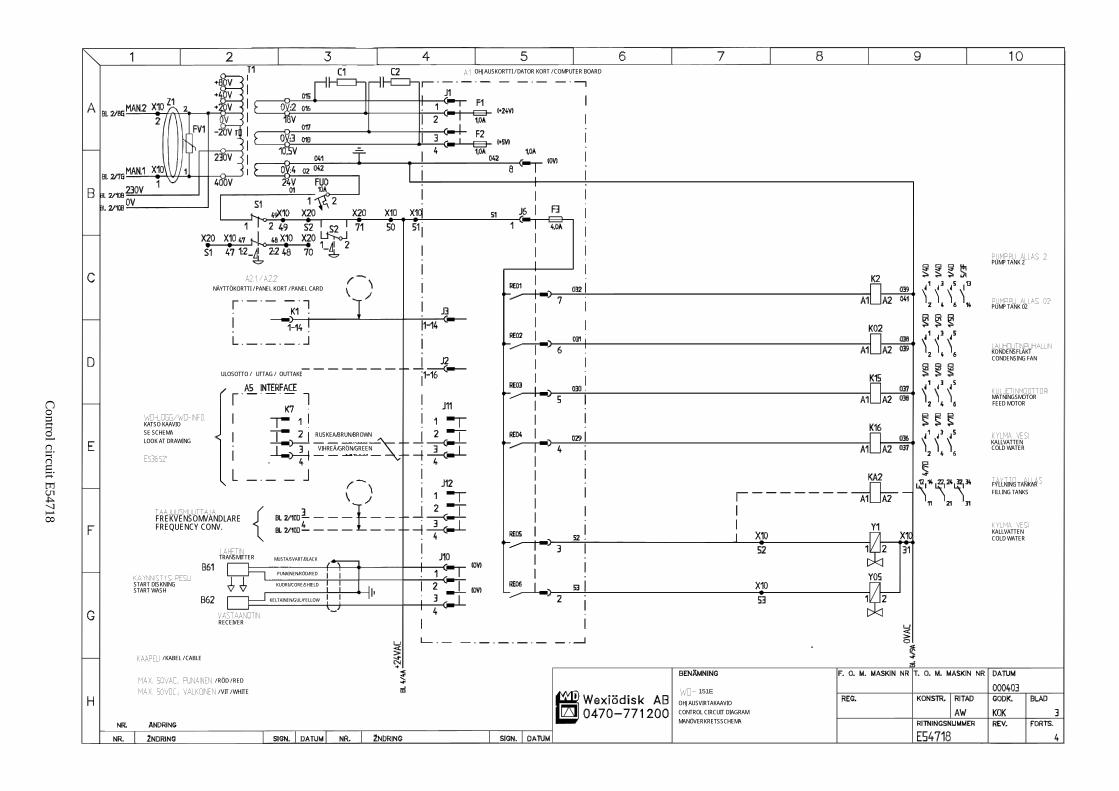
PUMP TANK 2
PUMP TANK 02
KONDENSFLÄKTCONDENSING FAN
MATNINGSMOTORFEED MOTOR
KALLVATTENCOLD WATER
FYLLNING TANKARFILLING TANKS
KALLVATTENCOLD WATER
Control circuit E54718
OHJAUSVIRTAKAAVIOCONTROL CIRCUIT DIAGRAMMANÖVERKRETSSCHEMA
/ KABEL / CABLE
/ RÖD / RED
/ VIT / WHITE
START DISKNINGSTART WASH
KATSO KAAVIOSE SCHEMALOOK AT DRAWING
FREKVENSOMVANDLAREFREQUENCY CONV.
TRANSMITTER
RECEIVER
NÄYTTÖKORTTI / PANEL KORT / PANEL CARD
ULOSOTTO / UTTAG / OUTTAKE
OHJAUSKORTTI / DATOR KORT / COMPUTER BOARD
RUSKEA/BRUN/BROWN
VIHREÄ/GRÖN/GREEN
MUSTA/SVART/BLACK
PUNAINEN/RÖD/RED
KELTAINEN/GUL/YELLOW
KUORI//CORE/SHIELD
151E

Control circuit E54719
A1 O
HJAU
SKOR
TTI /
DATO
R KO
RT / C
OMPU
TER
BOAR
D
LÄMM
ITYS
ALL
AS 2
VÄRM
E TA
NK 2
HEAT
ING
TANK
2
LÄMM
ITYS
BOI
LERI
1VÄ
RME
GENO
MSTR
. 1HE
ATIN
G BO
ILER
1
LÄMM
ITYS
BOI
LERI
2VÄ
RME
GEN.
STR
2HE
ATIN
G BO
ILER
2
KUIV
AUSA
INEA
NNOS
T.TO
RKME
DELS
DOSE
RING
DRYI
NG A
GENT
DOS
AGE
SLUT
SKÖL
JNIN
GFI
NAL R
INSE
OHJA
USVI
RTAK
AAVI
OMA
NÖVE
RKRE
TSSC
HEMA
CONT
ROL C
IRCU
IT D
IAGR
AM
151E

Control circuit E54720
OHJA
USKO
RTTI
/DA
TOR
KORT
/CO
MPUT
ER B
OARD
RELÄ
KOR
TRE
LAY
BOAR
D
KYTK
INKA
APIS
SAPL
INTS
KÅP
PLIN
TH C
UBIC
LE
PESU
AINE
ANNO
ST. K
YTKE
TÄÄN
LIIT
TIMI
INDI
SKME
DELS
UTR
USTN
ING
INKO
PPLA
S ME
LLAN
PLIN
TDE
TERG
ENT
EQ. C
ONNE
CTS
BETW
EEN
PLIN
T
HUUH
T.AI
NEAN
NOST
. KYT
KETÄ
ÄN LI
ITTI
MIIN
TORK
MEDE
LSDO
SERI
NG IN
KOPP
LAS
MELL
AN P
LINT
DRYI
NG A
GENT
DOS
AGE
CONN
ECTS
BET
WEE
N PL
INT
HUOM
! HUU
HT.A
INEA
NNOS
T. 23
0V Y
HDIS
TÄ LI
ITTI
MET
104-
105.
ANNO
STEL
IJA K
YTKE
TÄÄN
LIIT
TIMI
IN 10
2-10
3/OB
S! A
NVÄN
DES
230V
FÖR
TOR
KMED
ELSD
OSER
ING
FÖRB
INDS
PLIN
T 10
4-10
5OC
H KO
PPLA
IN T
ORKM
EDEL
SDOS
. MEL
LAN
PLIN
T 10
2-10
3/OB
S! IF
230V
IS U
SED
FOR
THE
DRYI
NG A
GENT
DOS
AGE
BRID
GE C
ONNE
CT P
LINTH
104-
105 A
ND C
ONNE
CT T
HE D
ISPE
NSER
BET
WEE
N PL
INTH
102-
103.
/ MÄT
CELL
/ DET
ERGE
NT S
ENSO
R
OHJA
USVI
RTAK
AAVI
OMA
NÖVE
RKRE
TSSC
HEMA
CONT
ROL C
IRCU
IT D
IAGR
AM
FLÄK
T TO
RKZO
NFA
N DR
YING
ZON
E
LÄMM
ITYS
KUI
VAAJ
AVÄ
RME
TORK
ZON
HEAT
ING
DRIN
G ZO
NE
LARM
ALAR
M
LÄMM
ITYS
BOI
LERI
3VÄ
RME
GEN.
STR.
3HE
ATIN
G BO
ILER
3
LÄMM
ITYS
KUI
VAAJ
AVÄ
RME
TORK
ZON
HEAT
ING
DRIN
G ZO
NE
RED
RÖ
DP
UN
AIN
EN
BLAC
KSV
AR
TM
UST
A
151E
REL
EKO
RTT
I

Control circuit E54721
OHJA
USVI
RTAK
AAVI
O
CONT
ROL
CIRC
UIT
DIAG
RAM
LUCK
A TA
NK 2
APER
TURE
TAN
K 2
LUCK
A FÖ
RSPO
LNIN
GAP
ERTU
RE P
RE-R
INSE
LUCK
A TA
NK 0
2AP
ERTU
RE T
ANK
02
LOPP
URAJ
AKYT
KIN
ENDL
IMIT
STAR
T RE
C. S
LUTS
KÖLJ
NING
/ST
ART
REC.
FIN
AL R
INSE
YLIK
UORM
AKYT
KIN
OVER
LOAD
NIVÅ
TAN
K 02
LEVE
L TA
NK 0
2
SLUT
SKÖL
JNIN
GFI
NAL
RINS
E
NIVÅ
TAN
K 2
LEVE
L TAN
K 2
/DAT
OR
KO
RT/
CO
MP
UTE
R B
OA
RD
151E

Control circuit E54722
OHJA
USVI
RTAK
AAVI
O
CONT
ROL C
IRCU
IT D
IAGR
AM
/ DAT
OR K
ORT
/ COM
PUTE
R BO
ARD
STOP
P MA
TNIN
GST
OP F
EED
MATN
INGS
MOTO
RFE
ED M
OTOR
KULJ
ETTI
MET
TRAN
SPOR
TÖRE
RCO
NVEY
ORS
PUMP
TAN
K 2
PUMP
TAN
K 02
KOND
ENSF
LÄKT
COND
ENSI
NG F
AN
TORK
ZON
DRYI
NG Z
ONE
LÄMM
IN V
ESI (
TEKS
TIPA
NEEL
I)VA
RMVA
TTEN
(TEX
T PA
NEL)
WAR
M W
ATER
(TEX
T PA
NEL)
151E

Control circuit E54723
OHJA
USVI
RTAK
AAVI
O
CONT
ROL C
IRCU
IT D
IAGR
AM
/ DAT
OR K
ORT
/ COM
PUTE
R BO
ARD
LÄM
PÖTI
LA B
OILE
RI 1
TEMP
ERAT
UR G
ENOM
STRÖ
MMAR
E 1
TEMP
ERAT
URE
BOIL
ER 1
BOILE
RI 2
GENO
MST
RÖM
MARE
2BO
ILER
2
KOND
ENSF
LÄKT
COND
ENSI
NG B
ATTE
RY
TANK
2
BOIL
ER 3
GENO
MST
RÖM
MARE
3BO
ILER
3
151E

Control circuit E54724
OHJA
USVI
RTAK
AAVI
O
CONT
ROL
CIRC
UIT
DIAG
RAM
151E

Conveyor control circuit

POLNINGALTAAN HUUHTELU
KEDJESPOLNINGKETJUHUUHTELU
TRANSPORTÖRKULJETIN
PLINTSKÅPLIITINRASIA
KONTAKTORSKÅPKONTAKTORIKOTELO
TRYCKSTEGRINGSPUMPPAINEENKOROTUSPUMPPU
INMATNINGSTRANSPORTÖR SE SCHEMA E53905SYÖTTÖKULJETIN KATSO KUVA E53905
TEET
Rinse equipm
ent control circuit
DISKMASKINASTIANPESUKONE
TRYCKSTEGRINGSPUMPPAINEENKOROTUSPUMPPU
NÖDSTOPPHÄTÄSEIS
KORGGIVAREKORINTUNNISTIN
FÖRSPOLNING ESIHUUHTELU
TRÅGSLIOTUS
DATORKORTPIIRIKORTTI
METOS RINSE EQUIPMENT
METOS HUUHTELUVARUS
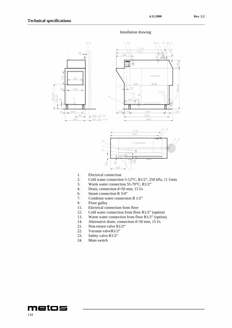
4.12.2000 Rev. 2.2Technical specifications
Installation drawing
1. Electrical connection2. Cold water connection 5-12°C, R1/2”, 250 kPa, 11 l/min3. Warm water connection 55-70°C, R1/2”4. Drain, connection d=50 mm, 15 l/s6. Steam connection R 3/4”7. Condense water connection R 1/2”9. Floor gulley11. Electrical connection from floor12. Cold water connection from floor R1/2” (option)13. Warm water connection from floor R1/2” (option)14. Alternative drain, connection d=50 mm, 15 l/s21. Non-return valve R1/2”22. Vacuum valveR1/2”23. Safety valve R1/2”24. Main switch
134

4.12.2000 Rev. 2.2Technical specifications
Item Model Type Voltage SpecificationGeneral data, capacityMax. surface temperature at room temperature +20oC 35°CNoise level 68 dBVentilation recommendation 1000 m3/hCapacity 120 racks/hourRack size 500mm x 500mmWeight of machine 370 kgWeight of package 30 kgTank volume, chemical wash 100 litresTank volume, final rinse 6 litresTotal tank volume 106 litresCold water consumption, final rinse 1,8 litres/rackSteam consumption 50 kg/hChemical wash pump 1,5 kWFinal rinse pump 0,11 kWFeed motor 0,12 kWCondensation fan 0,12 kWTank heating element 12 kWBoiler element 2x9 kWTotal connected power 31,9 kWMain fuse A 50 AMax. connection area A 35 mm2Main fuse H 100 AMax. connection area H 70 mm2Electrical connection, electrically heated machine with drying zone T-60, T-90Total connected power 38,6 kWMain fuse A 63 AMain fuse H 125 AElectrical connection, electrically heated machine with drying zone T-180Total connected power 45,4 kWMain fuse A 63 AMain fuse H 125 AElectrical connection, steam heated machineTotal connected power 1,85 kWMain fuse A 16 AMax. connection area A 35 mm2Main fuse H 20 AMax. connection area H 35 mm2
135