installation operating & maintenance manual - LENNOX EMEA
142
INSTALLATION OPERATING & MAINTENANCE MANUAL ROOFTOP FLEXY™ English August 2003
-
Upload
khangminh22 -
Category
Documents
-
view
2 -
download
0
Transcript of installation operating & maintenance manual - LENNOX EMEA

INSTALLATIONOPERATING &MAINTENANCE MANUAL
ROOFTOPFLEXY™
EnglishAugust 2003


IOM / ROOF-TOP FLEXY™ Series - Page 1
CONTENTS
The present manual applies to the following ROOFTOP versions :FCA 60 - FCA 70 - FCA 85 - FCA 100 - FCA 120 - FCA 140 - FCA 160 - FCA 190FCK 60 - FCK 70 - FCK 85 - FCK 100 - FCK 120 - FCK 140 - FCK 160 - FCK 190FHA 60 - FHA 70 - FHA 85 - FHA 100 - FHA 120 - FHA 140 - FHA 160 - FHA 190FHK 60 - FHK 70 - FHK 85 - FHK 100 - FHK 120 - FHK 140 - FHK 160 - FHK 190FDA 60 - FDA 70 - FDA 85 - FDA 100 - FDA 120 - FDA 140 - FDA 160 - FDA 190FDK 60 - FDK 70 - FDK 85 - FDK 100 - FDK 120 - FDK 140 - FDK 160 - FDK 190FGA 60 - FGA 70 - FGA 85 - FGA 100 - FGA 120 - FGA 140 - FGA 160 - FGA 190FGK 60 - FGK 70 - FGK 85 - FGK 100 - FGK 120 - FGK 140 - FGK 160 - FGK 190
FXA 25 - FXA 30 - FXA 35 - FXA 40 - FXA 55 - FXA 70 - FXA 85 - FXA 100 - FXA 110 - FXA 140 - FXA 170FXK 25 - FXK 30 - FXK 35 - FXK 40 - FXK 55 - FXK 70 - FXK 85 - FXK 100 - FXK 110 - FXK 140 - FXK 170
The technical information and specifications contained in this manual are for reference only. The manufacturer reserves the right to modify these withoutwarning and without obligation to modify equipment already sold.
Ref. FLEXY_IOM/0803-E
NOTES FOR UNIT FITTED WITH GAS BURNER :
THE UNIT MUST BE INSTALLED IN ACCORDANCE WITH LOCALSAFETY CODES AND REGULATIONS AND CAN ONLY BE USED INWELL VENTILLATED AREA.
PLEASE READ CAREFULLY THE MANUFACTURER'S INSTRUCTIONSBEFORE STARTING THIS UNIT.
THIS MANUAL IS ONLY VALID FOR UNITS DISPLAYING THEFOLLOWING CODES: GB IR GR DA NO FI IS
In case these symbols are not displayed on the unit, please refer to thetechnical documentation which will eventually detail any modificationsrequired to the installation of the unit in a particular country.
INSTALLATIONOPERATIONMAINTENANCE MANUAL

Page 2 - IOM / ROOF-TOP FLEXY™ Series
CONTENTS
IMPORTANT NOTICE......................................................................................... 3
INSTALLATIONTRANSPORT - HANDLING .............................................................................................. 4INSTALLATION ............................................................................................................... 12INSTALLATION ON A ROOF MOUNTING FRAME ........................................................... 13INSTALLATION ON POSTS ............................................................................................ 15COMMISSIONING ........................................................................................................... 16
OPERATIONVENTILATION ................................................................................................................. 21AIR FLOW BALANCING .................................................................................................. 23FILTERS ......................................................................................................................... 39FANSTART OPERATION ................................................................................................. 40FX AIR FLOW BALANCING ............................................................................................. 41HOT WATER COILS ....................................................................................................... 44GAS BURNERS .............................................................................................................. 45
CONTROL FUNCTIONSUSING THE KP 17 COMFORT DISPLAY........................................................................ 57USING THE KP02 MAINTENANCE DISPLAY ................................................................. 58USING THE KP07 REMOTE GRAPHICAL DISPLAY ...................................................... 72BMS CONTACTS KIT ...................................................................................................... 81CLIMATIC™ PARAMETERS ............................................................................................ 82CONTROL INTERFACE CLIMALINK/CLIMALOOK......................................................... 88
WIRING DIAGRAMSELECTRICAL WIRING DIAGRAMS LIST OF ITEMS ....................................................... 96ELECTRICAL WIRING DIAGRAMS .............................................................................. 100
TROUBLESHOOTINGSAFETY AND ERROR CODES..................................................................................... 117MAINTENANCE DIAGNOSTIC ..................................................................................... 123MAINTENANCE PLAN .................................................................................................. 126WARRANTY .................................................................................................................. 129
CERTIFICATESISO 9001 CERTIFICATION ........................................................................................... 130PED CERTIFICATION OF CONFORMITY ..................................................................... 131GLAS WOOL FIRE CLASS ........................................................................................... 13233 KW GAS BURNER CE CERTIFICATION OF CONFORMITY ................................... 13360 KW GAS BURNER CE CERTIFICATION OF CONFORMITY ................................... 134120 KW GAS BURNER CE CERTIFICATION OF CONFORMITY ................................. 135180 kW GAS BURNER CE CERTIFICATION OF CONFORMITY ................................. 136INSULATION FIRE CLASS ........................................................................................... 137
CONTENTS

IOM / ROOF-TOP FLEXY™ Series - Page 3
IMPORTANT NOTICE
IMPORTANT NOTICE
All work on the unit must be carried out by a qualified and authorised employee.
Non-compliance with the following instructions may result in injury or serious accidents.
Work on the unit:• The unit shall be isolated from the electrical supply by disconnection and locking using the
main isolating switch.• Workers shall wear the appropriate personal protective equipment (helmet, gloves,
glasses, etc.).
Work on the electrical system:• Work on electric components shall be performed with the power off (see below) by
employees having valid electrical qualification and authorisation.
Work on the refrigerating circuit(s):• Monitoring of the pressures, draining and filling of the system under pressure shall be
carried out using connections provided for this purpose and suitable equipment.• To prevent the risk of explosion due to spraying of coolant and oil, the relevant circuit shall
be drained and at zero pressure before any disassembly or unbrazing of the refrigeratingparts takes place.
• There is a residual risk of pressure build-up by degassing the oil or by heating theexchangers after the circuit has been drained. Zero pressure shall be maintained byventing the drain connection to the atmosphere on the low pressure side.
• The brazing shall be carried out by a qualified brazier. The brazing shall comply with stan-dard NF EN1044 (minimum 30% silver).
Replacing components:• In order to maintain CE marking compliance, replacement of components shall be carried
out using spare parts, or using parts approved by Lennox.• Only the coolant shown on the manufacturer's nameplate shall be used, to the exclusion of
all other products (mix of coolants, hydrocarbons, etc.).
CAUTION:In the event of fire, refrigerating circuits can cause an explosion and spray coolant gas and oil.

Page 4 - IOM / ROOF-TOP FLEXY™ Series
TRANSPORT - HANDLING
Figure 1
DELIVERY CHECKSOn receipt of a new equipment please check the followingpoints. It is the customer's responsibility to ensure that theproducts are in good working order:- The exterior has not been damaged in any way.- The lifting and handling equipment are suitable for theequipment and comply with the specifications of the handlinginstructions enclosed here-in.- Accessories ordered for on site installation have beendelivered and are in good working order.- The equipment supplied corresponds to the order andmatches the delivery note.
If the product is damaged, exact details must be confirmedin writing by registered post to the shipping company within48 hours of delivery (working days). A copy of the letter mustbe addressed to Lennox and the supplier or distributor forinformation purposes. Failure to comply will invalidate anyclaim against the shipping company.
RATING PLATE
The rating plate provides a complete reference for the modeland ensures that the unit corresponds to the model ordered.It states the electrical power consumption of the unit on start-up, its rated power and its supply voltage. The supply voltagemust not deviate beyond +10/-15 %. The start-up power isthe maximum value likely to be achieved for the specifiedoperational voltage. The customer must have a suitableelectrical supply. It is therefore important to check whetherthe supply voltage stated on the unit's rating plate iscompatible with that of the mains electrical supply. The ratingplate also states the year of manufacture as well as the typeof refrigerant used and the required charge for eachcompressor circuit.
STORAGE
When units are delivered on site they are not always requiredimmediately and are sometimes put into storage. In the eventof medium to long-term storage, we recommend the followingprocedures :- Ensure that there is no water in the hydraulic systems.- Keep the heat exchanger covers in position (AQUILUX cover).- Keep protective plastic film in position.- Ensure the electrical panels are closed.- Keep all items and options supplied in a dry and cleanplace for future assembly before using the equipment.
MAINTENANCE KEY
On delivery we recommend that you keep the key which isattached to an eyebolt in a safe and accessible place. Thisallows you to open the panels for maintenance andinstallation work.The locks are ¼ turn +then tighter (figure 2).
CONDENSATE DRAINS
The condensate drains are not assembled when deliveredand are storedin the electrical panel with their clamping collars.To assemble them, insert themon the condensate tray outletsand use a screwdriver totighten the collars (figure 3).
Figure 3
Figure 2

IOM / ROOF-TOP FLEXY™ Series - Page 5
TRANSPORT - HANDLING
DIMENSIONS AND WEIGHTS
Condensation Airflow configuration
WEIGHT (kg) SLING
std std highStandard Centrifugal 1 2 3 4 5 6 7 8 gas gas 1 2 3
FC/FH 060 - Cooling only and heat pumpX - X - - - - - - X 2825 2255 1470 630 1060 - - 2210 - -X - - - - X - - X - 2825 2255 1470 630 1090 - - 2210 - -X - - X X - X X - - 2825 2285 1470 630 1090 - - 2210 - -- X X - - - - - - X 2875 2255 2070 630 1230 - - 2590 1855 -- X - - - X - - X - 2875 2255 2070 630 1260 - - 2590 1855 -- X - X X - X X - - 2875 2285 2070 630 1260 - - 2590 1855 -
FG 060 - GASX - X - - - - - - X 2825 2255 1470 630 - 1210 1280 2210 - -- X X - - - - - - X 2875 2255 2070 630 - 1380 1450 2590 1855 -
FC/FH 070 - Cooling only and heat pumpX - X - - - - - - X 2825 2255 1470 630 1075 - - 2210 - -X - - - - X - - X - 2825 2255 1470 630 1100 - - 2210 - -X - - X X - X X - - 2825 2285 1470 630 1100 - - 2210 - -- X X - - - - - - X 2875 2255 2070 630 1245 - - 2590 1855 -- X - - - X - - X - 2875 2255 2070 630 1270 - - 2590 1855 -- X - X X - X X - - 2875 2285 2070 630 1270 - - 2590 1855 -
FC/FH 070 - GASX - X - - - - - - X 2825 2255 1470 630 - 1230 1300 2210 - -- X X - - - - - - X 2875 2255 2070 630 - 1400 1470 2590 1855 -
FC/FH 085 - Cooling only and heat pumpX - X - - - - - - X 3785 2255 1495 630 1220 - - 2830 2330 -X - - - - X - - X - 3785 2255 1495 630 1270 - - 2830 2330 -X - - X X - X X - - 3785 2285 1495 630 1275 - - 2830 2330 -- X X - - - - - - X 3835 2255 2080 630 1435 - - 3230 2430 1870- X - - - X - - X - 3835 2255 2080 630 1485 - - 3230 2430 1870- X - X X - X X - - 3835 2285 2080 630 1490 - - 3230 2430 1870
FC/FH 085 - GASX - X - - - - - - X 3785 2255 1495 630 - 1320 1390 2830 2330 -- X X - - - - - - X 3835 2255 2080 630 - 1535 1605 3230 2430 1870
FC/FH 100 - Cooling only and heat pumpX - X - - - - - - X 3785 2255 1495 630 1280 - - 2830 2330 -X - - - - X - - X - 3785 2255 1495 630 1320 - - 2830 2330 -X - - X X - X X - - 3785 2285 1495 630 1320 - - 2830 2330 -- X X - - - - - - X 3835 2255 2080 630 1495 - - 3230 2430 1870- X - - - X - - X - 3835 2255 2080 630 1545 - - 3230 2430 1870- X - X X - X X - - 3835 2285 2080 630 1545 - - 3230 2430 1870
FC/FH 100 - GASX - X - - - - - - X 3785 2255 1495 630 - 1380 1450 2830 2330 -- X X - - - - - - X 3835 2255 2080 630 - 1595 1665 3230 2430 1870
HEI
GH
T (m
m)
HO
OD
(mm
)
WID
TH (m
m)
LEN
GTH
(mm
)

Page 6 - IOM / ROOF-TOP FLEXY™ Series
TRANSPORT - HANDLING
DIMENSIONS AND WEIGHTS
WEIGHT (kg) SLING
std std highStandard Centrifugal 1 2 3 4 5 6 7 8 gas gas 1 2 3
FC/FH 120 - Cooling only and heat pumpX - X - - - - - - X 3585 2255 1470 630 1530 - - 2700 - 2080X - - - - X - - X - 3585 2255 1470 630 1580 - - 2700 - 2080X - - X X - X X - - 3585 2285 1470 630 1600 - - 2700 - 2080- X X - - - - - - X 3635 2255 1930 630 1805 - - 3000 2410 1880- X - - - X - - X - 3635 2255 1930 630 1855 - - 3000 2410 1880- X - X X - X X - - 3635 2285 1930 630 1875 - - 3000 2410 1880
FG 120 - GASX - X - - - - - - X 4035 2255 1470 630 - 1840 1890 3000 - 2310- X X - - - - - - X 4085 2255 1930 630 - 2115 2165 3300 2700 2080
FC/FH 140 - Cooling only and heat pumpX - X - - - - - - X 3585 2255 1470 630 1630 - - 2700 - 2080X - - - - X - - X - 3585 2255 1470 630 1680 - - 2700 - 2080X - - X X - X X - - 3585 2285 1470 630 1700 - - 2700 - 2080- X X - - - - - - X 3635 2255 1930 630 1905 - - 3000 2410 1880- X - - - X - - X - 3635 2255 1930 630 1955 - - 3000 2410 1880- X - X X - X X - - 3635 2285 1930 630 1975 - - 3000 2410 1880
FG 140 - GASX - X - - - - - - X 4035 2255 1470 630 - 1920 1970 3000 - 2310- X X - - - - - - X 4085 2255 1930 630 - 2000 2050 3300 2700 2080
FC/FH 160 - Cooling only and heat pumpX - X - - - - - - X 3595 2255 2070 900 2050 - - 2700 - 2090X - - - - X - - X - 3595 2255 2070 900 2120 - - 2700 - 2090X - - X X - X X - - 3595 2285 2070 900 2140 - - 2700 - 2090- X X - - - - - - X 3645 2255 2070 900 2275 - - 2700 - 2090- X - - - X - - X - 3645 2255 2070 900 2345 - - 2700 - 2090- X - X X - X X - - 3645 2285 2070 900 2365 - - 2700 - 2090
FG 160 - GASX - X - - - - - - X 4045 2255 2070 900 - 2410 2460 3000 - 2320- X X - - - - - - X 4095 2255 2070 900 - 2635 2685 3000 - 2320
FC/FH 190 - Cooling only and heat pumpX - X - - - - - - X 3595 2255 2070 900 2175 - - 2700 - 2090X - - - - X - - X - 3595 2255 2070 900 2245 - - 2700 - 2090X - - X X - X X - - 3595 2285 2070 900 2265 - - 2700 - 2090- X X - - - - - - X 3645 2255 2070 900 2400 - - 2700 - 2090- X - - - X - - X - 3645 2255 2070 900 2470 - - 2700 - 2090- X - X X - X X - - 3645 2285 2070 900 2490 - - 2700 - 2090
FG 190 - GASX - X - - - - - - X 4045 2255 2070 900 - 2540 2600 3000 - 2320- X X - - - - - - X 4095 2255 2070 900 - 2765 2825 3000 - 2320
HEI
GH
T (m
m)
CA
SQU
ETTE
(mm
)
Condensation Airflow configuration
WID
TH (m
m)
LEN
GTH
(mm
)

IOM / ROOF-TOP FLEXY™ Series - Page 7
TRANSPORT - HANDLING
HANDLINGThe equipment can be moved using the lifting holes on thetop of the unit.The "sling" length is the value that we recommend for safehandling of the equipment.
Some units can only be supported by four slings at right-angles. Others require different lengths (see figures 4).It is essential that all lifting holes are used and that the slingsare all of the same size to avoid damaging the equipment.
Sling length = 2210 mmfor angle = 45°C
FC.../FH.../FD.../FG... 060 & 070
LENGTH HEIGHT WIDTH AUVENT WEIGHT (kg)
lateral ventil standardMODELS mm mm mm mm mm kgFX 025 4070 1635 1055 490 600 950FX 030 4070 1635 1055 490 600 980FX 035 4750 2255 1290 490 600 1400FX 040 4750 2255 1290 490 600 1450FX 055 4750 2255 1290 490 600 1600FX 070 5050 2255 1725 890 600 1800FX 085 5050 2255 1725 890 600 1900FX 100 5050 2255 1725 890 600 2000FX 110 5650 2255 2000 860 - 2620FX 140 5650 2255 2000 860 - 2620FX 170 5650 2255 2000 860 - 2650
DIMENSIONS AND WEIGHTS
Figure 4 for all handlingdrawings - pages 7 to11

Page 8 - IOM / ROOF-TOP FLEXY™ Series
TRANSPORT - HANDLING
FC.../FH.../FD.../FG... 060 & 070 with centrifugal fans
Sling length = 2590 mmfor angle = 45°C
Sling length = 2330 mmfor angle = 64,5°C
FC.../FH.../FD.../FG... 085 & 100
Sling length = 2430 mmfor angle = 45°C
FC.../FH.../FD.../FG... 085 & 100 with centrifugal fans
Sling length = 3230 mmfor angle = 45°C
Sling length = 2830 mmfor angle = 45°C
Sling length = 1870mm
for angle = 45°C
Figure 3 for all handling drawings - pages 7 to11

IOM / ROOF-TOP FLEXY™ Series - Page 9
TRANSPORT - HANDLING
Sling length = 2080 mmfor angle = 45°C
FC.../FH.../FD... 120 & 140
Sling length = 2700 mmfor angle = 45°C
Sling length = 2410 mmfor angle = 45°C
FC.../FH.../FD... 120 & 140 with centrifugal fans
Sling length = 2080 mmfor angle = 45°C
FG... 120 & 140 with gas burner
Sling length = 2700 mmfor angle = 45°C
Sling length = 3000 mmfor angle = 45°C
Sling length = 1880 mmfor angle = 45°C
Figure 3 for all handling drawings - pages 7 to11

Page 10 - IOM / ROOF-TOP FLEXY™ Series
TRANSPORT - HANDLING
Sling length = 2700 mmfor angle = 45°C
FG... 120 & 140 with gas burner and centrifugal fans
Sling length = 3300 mmfor angle = 45°C
Sling length = 2080 mmfor angle = 45°C
Sling length = 2090 mmfor angle = 45°C
FC.../FH.../FD... 160 & 190FC.../FH.../FD... 160 & 190 with centrifugal fans
Sling length = 2700 mmfor angle = 45°C
Sling length = 2320 mmfor angle = 45°C
FG... 160 & 190FG... 160 & 190 with centrifugal fans
Sling length = 3000 mmfor angle = 45°C
Figure 3 for all handling drawings - pages 7 to11

IOM / ROOF-TOP FLEXY™ Series - Page 11
1
1
2
TRANSPORT - HANDLING
FX 25 & 30
Sling length 1 = 3000 mmSling length 2 = 2350 mm
1
1
2
FX 35 - 40 - 55
Sling length 1 = 3700 mmSling length 2 = 2850 mm
1
1
2Sling length 1 = 3900 mmSling length 2 = 3000 mm
FX 70 - 85 - 100
1
1
2Sling length 1 = 4300 mmSling length 2 = 3250 mm
FX 110 - 140 - 170

Page 12 - IOM / ROOF-TOP FLEXY™ Series
PRELIMINARY CHECKBefore installing the equipment, the following items MUST bechecked :
- Is there sufficient space for the equipment?- Is the surface on which the equipment is to be installed
sufficiently solid to withstand its weight ? A detailedstudy of the frame must be made beforehand.
- Do the supply and return ductwork openings excessivelyweaken the structure?
- Are there any obstructing items which could hinder theoperation of the equipment?
- Does the electrical power available correspond to theequipment's electrical specifications?
- Is drainage provided for the condensate?- Is there sufficient access for maintenance?- Installation of the equipment could require different
lifting methods which may vary with each installation(helicopter or crane). Have these been evaluated ?
- Ensure that the unit is installed in accordance with theinstallation instructions and applicable codes.
- Check to ensure that the refrigerant lines do not rubagainst the cabinet or against other refrigerant lines.
In general, make sure no obstacles (walls, trees or roof ledges)are obstructing the duct connections or hindering assemblyand maintenance access.
INSTALLATION
Figure 5
INSTALLATION REQUIREMENTSThe surface on which the equipment is to be installed mustbe clean and free of any obstacles which could hinder theflow of air to the condensers:
- Avoid uneven surfaces- Avoid installing two units side by side or close to each
other as this may restrict the airflow to the condensers.
Before installing a packaged rooftop unit it is important tounderstand :
- The direction of prevailing winds.- The direction and position of air flows.- The external dimensions of the unit and the dimensions
of the supply and return air connections.- The arrangement of the doors and the space required to
open them to access the various components.
Figure 5 shows the required clearances and dimensions.
CONNECTIONS
- Ensure that all the pipework crossing walls or roofs aresecured and insulated.
- To avoid condensation problems, be sure all pipes areinsulated according to temperatures of fluids and type ofrooms.
NOTE : The AQUILUX protection sheets fitted to the finnedsurfaces must be removed prior to start up.
MODELS A B C D
FC/FH/FG/FD60 !!!!! 140 1400 2000 1400 2300160 & 190 2000 2000 2000 2300
FX25 & 30 * 1100 * 170035 !!!!! 55 * 1300 * 230070 !!!!! 100 * 1700 * 2300110 !!!!! 170 * 2000 * 2300* : according to connection

IOM / ROOF-TOP FLEXY™ Series - Page 13
2
INSTALLATION ON A ROOFMOUNTING FRAME
As levels are adjustable, observe the followingrecommendations for correct installation of the equipment.
Above all, ensure that all the adjustable returns arefacing outward (1 - figure 6).They are usually turned inside-out for transport.
Place the roof mounting frame on the trimmer beam byfirst lining up the inlet and then the outlet. (2 - figure 7).
After levelling the frame, fix the surface flaps onto thetrimmer.
1
Figure 6
Figure 7
Figure 8

Page 14 - IOM / ROOF-TOP FLEXY™ Series
INSTALLATION ON A ROOFMOUNTING FRAME
When the frame is correctly positioned, it isessential to secure the assembly with weldingseam (20 to 30 mm for every 200 mm) alongthe outside, or by using an alternative method(1 - figure 9).
Assembly joint (1 - figure 10)
Insulate the frame before installation. We recommend the minimumapplication of 25 mm thick insulation.Check that the covering is continuous and watertight (2 - figure 10).
CAUTION : To be effective, it must finsh behind the lip (3 - figure 10)
Before installing the equipment, make sure that the assembly seal is not damaged.Once in position, the bottom of the equipment must be horizontal and against the roofcurb as shown on figure 11.
The installer must comply to local authority standards and specifications.
1
23
Figure 10
Figure 11
1Figure 9

IOM / ROOF-TOP FLEXY™ Series - Page 15
INSTALLATION ON POSTS
The unit can be fitted on corner posts using the frame provided. The minimum height of the posts should be 400mm.
Figure 12

Page 16 - IOM / ROOF-TOP FLEXY™ Series
THIS WORK MUST ONLY BE CARRIED OUTBY TRAINED REFRIGERATION ENGINEERS
Before connecting the power :- Ensure that the power supply between the building and
the unit meets local authority standards and that thecable specification satisfies the start-up and operatingconditions.
- Ensure that the electrical connections in the controlpanel and on the motors are secure.
- Ensure that all drive motors are secure.- Ensure that the adjustable pulley blocks are secure and
that the belt is tensioned with the transmission correctlyaligned.
- Using the electrical wiring diagram, check the conformityof the electrical safety devices (circuit breaker settings,presence and rating of fuses).
At this point attach the manometers to the refrigerant circuit
Powering up the system with the unit isolatingswitch
- Close the blower circuit breaker and the 24V control.- Power up the unit by closing the isolator switch. At this
point the blower should start unless the CLIMATIC™does not energise the contactor. In this particular casethe blower can be forced by bridging the COM and NOwires on the connector J1 on the CLIMATIC controller.Once the fan is running check the rotation direction.Refer to the rotation arrow on the fan.
- The fan and other components direction of rotation ischecked during an end of line test. They shouldtherefore all turn in the same direction.
- If they run in the opposite direction, disconnect thepower supply to the machine at the building's mainsswitch, reverse two phases of the incoming supply to themachine and try again.
Using CLIMATIC™- Check the voltages recorded against the rated values, in
particular on the system supply fans.- If the readings on the fans are outside the limits, this
indicates excessive air flow which will affect thethermodynamic performance. Refer to the "Air flowbalancing" section.
COMMISSIONING
1. Check the configuration
- You will need a KP02 maintenance controller orCLIMALOOK with KP 14 interface.
1 Liquid crystal display2 Raise/lower keys3 "FILTER" Led (flashing red)4 "ADDRESS" key5 "MODE" key6 "VALUE" key7 "UNIT RUNNING" led8 "MODE" led9 "GENERAL ALARM" led.
- The jumpers arefactory set and theconfiguration switchesare adjusteddepending on theoption selection andthe type of unit.
- Close the 24V control circuit breakers- The CLIMATIC™ is starting. Wait for 30 seconds.
1.1 Check and adjust the factory configuration
- Reset the DAD smoke detector (if fitted)
Figure 14
Figure 13
Figure 16
Figure 15

IOM / ROOF-TOP FLEXY™ Series - Page 17
Check the setpoints on CLIMATIC™ (LF 20).
COMMISSIONING
C0 Password technician Level 63
C98 Type of Unit Refer to configuration table LF20
C99 Type of Unit [off] Flexy [on] Linea On or OFF
C103 Humidity and enthalpy management Option [off] LINEA [on] only Flexy with Advanced Pack
C77 (Linea) Authorisation of defrost. Threshold of temperature of refrigerant fluid ( in°C)
1.0°C for R407c -3.0°C for R22
C79 Defrost cycle end value indicating the nr of Start-ups of the condenser fan to signify the end of defrost
Linea set to1 Flexy set to 3
C101 Activation of all seasons control option [ON] / [OFF] if fitted
C73 All seasons control option on FLEXY - Otherwise – unloading 50% of the compressors in cooling mode
Set to 20.0°C for Linea Set to 12°C for Flexy
C74 If option all seasons control – shut down condenser fans - Otherwise - 100% unloading of compressors in cooling mode -
Set to 12.0°C for Linea Set to 5.0°C for Flexy
C49 Threshold of activation of the power exhaust fan according to the position of the economiser damper (in %) Set to 50%
C46 Number of minutes of anticipation per degrees. This allows an anticipated start-up in the morning mode depending on the outside temperature.
Set to 0
C83 Maximum usable power for electric heat (in %)
C90 Choice of operating mode for KP17 [ON] = KP17 in ON / OFF mode
C91 Identification number for the J-Bus connections
C93 Identification number for the connections link between boards
C94 Number of boards linked on the bus
C95 Selection of the operating mode for KP017
C96 Selection of exchange mode for room temperature and humidity-
C97 Selection of exchange mode for outdoor temperature and humidity
C100 Activation of the dual-speed option for fan supply (Flexy)
C101 Activation of the all seasons control option
C102 Activation of the optimised defrost option
C05 Fault reset Set to ON
C06 Remote control, On / Off Unit Set to ON ( the unit should start)

Page 18 - IOM / ROOF-TOP FLEXY™ Series
Configuration table LF20
COMMISSIONING
F.A050 11F.A060 12F.A070 13F.A085 14F.A100 15F.A120 16F.A140 17F.A160 18F.A190 19
FXA025 20FXA030 21FXA035 22FXA040 23FXA055 24FXA070 25FXA085 26FXA100 27FXA110 28FXA140 29FXA170 30
F.K050 111F.K060 112F.K070 113F.K085 114F.K100 115F.K120 116F.K140 117F.K160 118F.K190 119
FXK025 120FXK030 121FXK035 122FXK040 123FXK055 124FXK070 125FXK085 126FXK100 127FXK110 128FXK140 129FXK170 130
Switches on KP01
1 = on ....................... Option : pressure pick-up on air 500 pa (on FLEXY™ off = sensor 1000 pa)2 = on | 3 = off ................... Option : hot water coil2 = off | 3 = on ................... Option : electrical heater2 = on | 3 = on ................... Option : gas burner4 = on ....................... Option : cycle reversing valve, compressors (heat pump)5 = on ....................... Option : heating of great power / or / pump (except freezing of the hot water coil)6 = on ....................... Option : fresh air, economiser7 = on ....................... Option : fresh air, all fresh air8 = on ....................... Option : KP02 / KP17
POWERING THE UNIT
- Power up the unit by closing the isolator switch (if fitted).- Close all circuit breakers and power up the unit, remove
the bridge on connector J14 if fitted.- If now only one of the components rotates in the wrong
direction, disconnect the power supply at the machine'sisolator switch (if fitted) and reverse two of thecomponent's phases on the terminal within the electricalpanel.
- Check the current drawn against the rated values, inparticular on the supply fan.
- If the readings on the fan are outside the specified limits,this usually indicates excessive air flow which will affectthe life expectancy and the thermodynamic performan-ces of the unit. This will also increase the risks of wateringress into the unit. Refer to the "air flow balancing"section to correct the problem.
At this point attach the manometers to the refrigerant circuit.
RUN TEST
Start unit in cooling modeThermodynamic readings using manometers and prevailingenvironmental conditions.No rated values are given here. These depend on theenvironmental conditions both outside and inside the buildingduring operation. However, an experienced refrigerationengineer will be able to detect any abnormal machineoperation.
Safety test- "Dirty filter" detection test : vary the set-point value in
respect to the air pressure value. Observe the responseof the CLIMATIC™.
- Same procedure for detecting "Missing filter" or "Air flowdetection".
- Check the smoke detection function (if fitted).- Check the Firestat by pressing the test button(if fitted).- Disconnect the circuit breakers of the outdoor fans and
check the high pressure cut-out points on differentrefrigerant circuits.
Reverse cycle testThis test is designed to check the good operation of the 4-way reversing valves on heat pump reversible systems. Startthe reverse cycle by adjusting the cold or hot temperaturethreshold data according to the indoor and outdoor conditionsat the time of test.

IOM / ROOF-TOP FLEXY™ Series - Page 19
COMMISSIONING report
(4) SUPPLY BLOWER SECTION / VENTILATION TRAITEMENT Type / Type: Power displayed on plate / Puissance affichée sur la plaque: Voltage displayed on plate / Tension affichée sur la plaque: Current displayed on plate / Intensité affichée sur la plaque:
KW V A
N°1 …………………… …………………… ……………………
N°2 …………………… …………………… ……………………
Fan Type / Type de Ventilateur: Forward / Action Backward / Réaction
Forward / Action Backward / Réaction
Displayed Belt Length / Longueur Courroie affichée: mm …………………… …………………… Tension Checked/ Tension Vérifiée: Yes/Oui No/ Non Yes/Oui No/ Non Alignment Checked / Alignement Vérifié: Yes/Oui No/ Non Yes/Oui No/ Non Motor Pulley Dia/ Poulie Moteur Dia: DM mm …………………… …………………… Fan Pulley Dia/ Poulie Ventilateur Dia: DP mm …………………… ……………………
Fan Speed / Vitesse rotation Ventilateur = Motor rpm x DM / DP Averaged Measured Amps / Intensité Mesurée moyenne:
rpm A
…………………… ……………………
…………………… ……………………
Shaft Mechanical Power (Refer to airflow balancing) Puissance Mécanique à l’Arbre (Voir section réglage débit) W …………………… ……………………
Operating point checked / Vérif. Point de fonctionnement: Yes/Oui No/ Non Yes/Oui No/ Non Estimated Airflow / Estimation Débit d’Air m3/h …………………… ……………………
(5) AIRFLOW PRESS. SENSOR CHECK / VERIF. DES SECURITES PRESSOSTATS D’AIR
Measured pressure drop / Pertes de charge au pressostat …………………………… mbar
Set Points Adjusted / Changement des consignes: Yes/Oui No/ Non If Yes enter new values/ Si oui noter les nouvelles consignes: 3410: ………… 3411: ………… 3412: …………
(6) EXTERNAL SENSOR CHECKS / VERIFICATION DES CAPTEURS EXTERNES Check and record temp. in menu 2110 / Vérifier et mesurer les températures. Dans menu 2110: Yes/Oui No/ Non Check electrical connections / Vérification des
connections électriques: Yes/Oui No/ Non 100% Fresh Air / 100% Air neuf 100% return Air / 100% Air repris
Supply Temperature / Température Soufflage ………………………..°C ………………………..°C Return Temperature / Température reprise ………………………..°C ………………………..°C Outdoor Temperature / Température extérieure ………………………..°C ………………………..°C
(7) MIXING AIR DAMPERS CHECKS / VERIFICATIONS VOLETS DE MELANGE Dampers open & close freely/
Volets s’ouvrent et se ferment OK % Minimum FA:
%minimum Air Neuf: Power exhaust checked/
Ventilateur extraction Enthalpy sensor(s) checked/
Control enthalpie installé Yes/Oui No/ Non ……………..% Yes/Oui No/ Non Yes/Oui No/ Non
Site details / Informations site Site / Site Unit Ref/ N° Affaire Installer/ Installateur
……………………………………… …………………………………….... ………………………………………
Controller/ Contrôleur Model/Modele Serial No/ No Série Refrigerant / Réfrigérant
…………………………………. ……………….………………… ………………………………… …………………………………
(1) ROOF INSTALLATION / INSTALLATION SUR LE TOIT Sufficient Access OK / Accès Suffisants Yes/Oui No/ Non
Condensate drain fitted / Drainage condensats Installé Yes/Oui No/ Non
Roofcurb / Costière OK Not OK/PasOK
(2) CONNECTIONS CHECK / VERIFICATIONS DE RACCORDEMENTS Phase check/ Vérification des Phases Yes / Oui No / Non
Voltage between Phases Tension entre Phases
1 / 2 ……………….
2 / 3 ……………….
1 / 3 ……………….
(3) CLIMATIC CONFIGURATION CHECK / VERIFIER LA CONFIGURATION CLIMATIC CLIMATIC 50 Configured according to the Options and Specifications / CLIMATIC 50 configuré en fonction des options et des spécifications: Yes/Oui No/ Non

Page 20 - IOM / ROOF-TOP FLEXY™ Series
COMMISSIONING report
(8) REFRIGERATION SECTION / SECTION REFRIGERATION Outdoor Fan Motor Current / Intensité Moteurs Batterie externe: Check Rotation
Motor 1 / Moteur 1 L1 ……..A L2 ……..A L3 ……A Yes/Oui No/ Non Motor 2 / Moteur 2 L1 ……..A L2 ……..A L3 ……A Yes/Oui No/ Non
Compressor Voltage/ Tension
Compresseur. Motor 3 / Moteur 3 L1 ……..A L2 ……..A L3 ……A Yes/Oui No/ Non Comp1: …….. V Motor 4 / Moteur 4 L1 ……..A L2 ……..A L3 ……A Yes/Oui No/ Non Comp2: …….. V Motor 5 / Moteur 5 L1 ……..A L2 ……..A L3 ……A Yes/Oui No/ Non Comp3: …….. V Motor 6 / Moteur 6 L1 ……..A L2 ……..A L3 ……A Yes/Oui No/ Non Comp4: …….. V
Compressor Amps COOLING / Intensité Compresseur MODE FROID Pressures & Temperatures / Pressions & températures
Temperatures / Temperatures Pressures / Pressions Phase 1 Phase 2 Phase 3 Suction/ Asp Disch / refoul LP/ BP HP / HP
Comp 1 …..… A …..… A …..… A ……… °C ……… °C ……… Bar ……… Bar Comp 2 …..… A …..… A …..… A ……… °C ……… °C ……… Bar ……… Bar Comp 3 …..… A …..… A …..… A ……… °C ……… °C ……… Bar ……… Bar Comp 4 …..… A …..… A …..… A ……… °C ……… °C ……… Bar ……… Bar Check Reversing valves./ Vérifier vannes d’inversion:
Valve1/Vanne1: Yes/Oui No/ Non Valve2/Vanne2: Yes/Oui No/ Non
Valve3/Vanne3: Yes/Oui No/ Non Valve4/Vanne4: Yes/Oui No/ Non
Compressor Amps HEATING / Intensité Compresseur en Pompe à Chaleur Pressures & Temperatures / Pressions & températures
Temperatures / Temperatures Pressures / Pressions Phase 1 Phase 2 Phase 3 Suction/ Asp Disch / refoul LP/ BP HP / HP
Comp 1 …..… A …..… A …..… A ……… °C ……… °C ……… Bar ……… Bar Comp 2 …..… A …..… A …..… A ……… °C ……… °C ……… Bar ……… Bar Comp 3 …..… A …..… A …..… A ……… °C ……… °C ……… Bar ……… Bar Comp 4 …..… A …..… A …..… A ……… °C ……… °C ……… Bar ……… Bar
HP cut out / Coupure HP ……Bar LP cut out / Coupure sécurité BP ………..…... Bar Refrigerant charge / Charge réfrigérant C1 : ………..kg C2 : ………..kg C3 : ………..kg C4 : ………..kg
(9) ELECTRIC HEATER SECTION / SECTION RECHAUFFEUR ELECTRIQUE Type / Type: …………………………………………………. Serial No/ No Série.:………………………..
AMPS 1st stage (Baltic) / Intensité 1er étage (Baltic) AMPS 2nd stage (Baltic) / Intensité 2e étage (Baltic) 1 ………………. 2 ………………. 3 ………………. 1 ………………. 2 ………………. 3 ……………….
(10) HOT WATER COIL SECTION / SECTION BATTERIE EAU CHAUDE Check Three Way Valve Movement / Vérification Mouvement Vanne trois voies: Yes/Oui No/ Non
(11) GAS HEATING SECTION / RAMPE GAZ Gas Burner N°1 / Brûleur gaz N°1 Gas Burner N°2 / Brûleur gaz N°2
Size / Taille: ……………………….
Valve type / Type vanne: …………………….
Size / Taille: ……………………….
Valve type / Type vanne: …………………….
Pipe size/ tuyauterie: Gas type / Type gas : G……. Pipe size/ tuyauterie Gas type / Type gas : G……. Line press./ press. ligne :
……………………… Drop test / test pression Yes/Oui No/ Non
line press./ press. ligne : ………………………
Drop test / test pression Yes/Oui No/ Non
Check manifold pressure/ Pression injection: High fire/Grande allure…….…Low fire/Petite allure………..
Check manifold pressure/ Pression injection: High fire/Grande allure…….…... Low fire/Petite allure………..
Pressure cut out airflow press switch / Pression coupure pressostat débit d’air : ……………………mbar /Pa
Pressure cut out airflow press switch / Pression coupure pressostat débit d’air : ……………………mbar /Pa
Motor amps I moteur: ……….A
Flue temp / temp fumées
……… °C
CO2 %:
………%
CO ppm:
………%
Motor Amps I Moteur: ……….A
Flue temp / temp fumées ………. °C
CO2 %:
………%
CO ppm:
………%
(12) REMOTE CONTROL BMS CHECK / VERIFICATIONS BMS CONTROL A DISTANCE Type / Type:
………………………. Sensor type / Type Capteur:
………………………….. KP07 KP/17 checked/ vérifiées:
Yes/Oui No/ Non Interconnect wiring checked:
Yes/Oui No/ Non
Comments...................................................................................................................................................................................................................................................................................................................................................................................................................................................................................................................................................................................................

IOM / ROOF-TOP FLEXY™ Series - Page 21
VENTILATION
BELT TENSIONOn delivery, the drive belts are new and correctly tensioned. After the first 50 operatinghours check and adjust the tension. 80% of the total elongation of belts is generallyproduced during the first 15 hours of operation.
Before adjusting the tension, make sure that the pulleys are correctly aligned.To tension the belt, set the height of motor support plate by moving the plateadjustment screws.
This recommended deflection is 16 mm per metre from centre to centre.
Check that according to the diagram below (figure 18), the following ratio remainsthe same.
A (m)= 20
P (mm)
The belts should always be replaced when :- the disk is set to maximum,- the belt rubber is worn or the wire is visible.
Replacement belts must have the same rated size as the ones they are replacing.If a transmission system has several belts, they must all be from the samemanufacturing batch (compare serial numbers).
NOTE :An under-tensioned belt will slip, heat and wear prematurely. On the other hand, ifa belt is over-tensioned, the pressure on the bearings will cause them to over-heatand wear prematurely. Incorrect alignment will also cause the belts to wearprematurely.
A P
Figure 18
Figure 17

Page 22 - IOM / ROOF-TOP FLEXY™ Series
VENTILaTION : PULLEYS
MOUNTING AND ADJUSTING PULLEYS
Fan pulley removalRemove the 2 screws and put one of them in the extractionthreaded screw.
Screw in fully. The hub and the pulley will separate from eachother.
Remove the hub and the pulley by hand without damagingthe machine.
Fan pulley installationClean and de-grease the shaft, hub and conical bore of thepulley. Lubricate the screws and install the hub and pulley.Position the screws without turning them.
Place the assembly on the shaft and screw in the screwsalternatively and evenly. Using a mallet or a hammer with awooden wedge, tap on the face of the hub to keep theassembly in place. Torque the screws to 30 Nm.
Take the pulley in both hands and shake it vigorously to makesure everything is in place.Fill the holes with grease for protection.
NOTE : During installation, the key should never protrude outof its groove.After 50 operating hours, check that the screws are still inplace.
Motor pulley installation and removalThe pulley is held in position by the key and a screw locatedin the groove. After unlocking, removing this screw by pullingagainst the shaft spindle (if necessary, use a mallet and tapuniformly on the hub to remove it).To assemble, proceed in the reverse order after havingcleaned and de-greased the motor shaft and the pulley bore.
Pulleys alignmentAfter adjusting one or both of the pulleys, check thetransmission alignment using a ruler placed on the inner faceof the two pulleys.
NOTE : The warranty may be affected if any major modificationis made to the transmission without obtaining our agreementbeforehand.
Figure 19
Figure 20
Figure 21

IOM / ROOF-TOP FLEXY™ Series - Page 23
The actual resistance of ductwork systems is not always identical to the calculated theoretical values. To rectify this, it may benecessary to modify the pulley and belt setting. To this effect, the motors are fitted with variable pulleys.
Measure the absorbed ampsIf the absorbed amps are greater than the rated values, the ventilation system has a lower pressure drop than anticipated.Reduce the flow by reducing the rpm. If the system resistance is significantly lower than design, there is a risk that the motorwill overheat resulting in an emergency cut out.
If the absorbed amps are lower than the rated values, your system has a higher pressure drop than anticipated. Increase theflow by increasing the rpm. At the same time you will increase the absorbed power which may result in having to increase themotor size.
To carry out the adjustment and to avoid a time-consuming re-start, stop the machine and if necessary lock the main switch.First unscrew the 4 Allen screw(s) on the pulley (see figure 23).
0,5 1 1,5 2 2,5 3 3,5 4 4,5 5,0 5,58450 /
12095 116 5 113,9 111,8 109,7 107,6 105,5 103,4 101,3 99,2 97,1 95,0 -
D8450 20,2 28,0 5 21,0 21,8 22,5 23,3 24,1 24,9 25,7 26,4 27,2 28,0 -8550 /
136110 131 5 128,9 126,8 124,7 122,6 120,5 118,4 116,3 114,2 112,1 110,0
D8550 20,6 31,2 5 21,6 22,7 23,8 24,8 25,9 26,9 28,0 29,1 30,1 31,2 -8670
171145 166 5 163,9 161,8 159,7 157,6 155,5 153,4 151,3 149,2 147,1 145,0 -
D8670 20,5 31,1 5 21,5 22,7 23,8 24,8 25,7 26,9 27,9 29,0 30,0 31,1 -
The easiest way to determine the fan rotation speed is touse a tachometer. If not available the fan rpm can beestimated using the following two methods.
1st Method with the pulley secured in place :
L
Measure the distance between the two outside faces of thepulley.Using table 1 the motor pulley actual diameter can beestimated
ALLEN WRENCH 4
AIRFLOW BALANCING
Pulleytype
Pulleyexternal
Ø
Min Ø/
Min dist.
Max Ø/
Max dist.
nr ofturns
from fullyclosed to
fullyopen
Actual Ø (DM) or distance between faces for a givennumber of turns from fully closed with SPA belt in (mm)
Figure 22
Figure 23

Page 24 - IOM / ROOF-TOP FLEXY™ Series
AIRFLOW BALANCING
2nd method when adjusting the pulley :- Close the pulley fully and count the number of turns
from fully closed position. Using table 1 determine themotor pulley actual diameter.
- Record the fix fan pulley diameter.(DF)- Determine the fan speed using the following formula:
rpm FAN = rpm MOTOR x DM / DF
Where :rpm MOTOR : ....... from the motor plate or table 2DM : ...................... from table 1DF: ........................ from machine
Once the pulleys are adjusted and the belt checked andtensioned, start the fan motor and record the Amps andVoltage between the phases :Using the measured data and table 2
- Theoretical mechanical power at the fan shaft :
Pmeca fan= P meca Motor x η Transmission
Pmeca fan= Pelec x η meca motor x η Transmission
Pmeca fan= V x I x √3 x cosϕ x η meca motor x η Transmission
This formula can be approximated in this way
Pmeca fan = V x I x 1.73 x 0.85 x 0.76 x 0.9
With the fan "rpm" and the mechanical power at the fan shaftan operating point and the supplied airflow can be estimatedusing the fan curves.
CHECKING AIRFLOW AND ESP
Using the fan curves on page 25, 26, 27, the airflow, the totalpressure available (PTOT) and the corresponding dynamicpressure (Pd) can now be estimated, for a specific operatingpoint;
The next step consist in estimating the pressure losses acrossthe unit.This can be achieved using the "dirty filter pressure sensor"and the accessories pressure drop table:Also the pressure drop due to the duct inlet into the roof-topunit can be taken as 20 to 30 Pa.
∆PINT = ∆P filter + coil + P Inlet + ∆P Options
using the results from above, the external static pressure (ESP)can then be estimated:
ESP = PTOT - Pd - ∆PINT
Table 2
Motor Size Nom, Speed Cos meca motor0,75 kW 1400 rpm 0,77 0,701,1 kW 1425 rpm 0,82 0,771,5 kW 1430 rpm 0,81 0,752,2 kW 1430 rpm 0,81 0,763,0 kW 1425 rpm 0,78 0,774 kW 1425 rpm 0,79 0,805,5 kW 1430 rpm 0,82 0,82
Economiser EU7 Hot water coil Electric heater Roofcurb Horizontal Gaz100% open Filter S H S H Base frame Roofcurb H
SIZE Air flow (m3/h) (Pa) (Pa) (Pa) (Pa) (Pa) (Pa) (Pa) (Pa) (Pa)Min. 10 000 4 67 12 14 5 8 10 41 22
60 Nom. 12 000 6 93 16 19 8 8 11 59 26Max. 15 000 9 135 24 28 8 10 13 92 31Min. 12 000 6 56 6 12 5 5 13 59 29
70 Nom. 14 000 8 73 8 16 5 5 16 80 34Max. 18 000 12 113 13 25 8 8 22 132 47Min. 14 000 8 73 8 16 5 8 18 44 7
85 Nom. 16 000 10 113 13 25 8 8 26 57 10Max. 22 000 16 159 18 36 8 10 32 109 12Min. 16 000 10 93 10 20 8 10 26 57 10
100 Nom. 20 000 14 135 15 30 10 13 32 90 12Max. 22 000 16 159 18 36 13 15 38 109 15Min. 18 000 12 113 13 25 10 13 32 33 29
120 Nom. 22 000 16 159 18 36 13 15 38 49 35Max. 24 000 18 184 21 41 15 18 44 58 40Min. 20 000 14 135 15 30 10 15 35 40 31
140 Nom. 24 000 18 184 21 41 15 18 46 58 40Max. 25 000 19 197 22 44 15 20 50 63 43Min. 22 000 16 87 9 18 8 8 24 49 45
160 Nom. 28 000 22 132 13 27 8 10 30 79 56Max. 32 000 26 165 17 34 13 13 34 103 64Min. 24 000 18 101 10 20 10 10 34 58 64
190 Nom. 33 000 27 174 18 36 13 13 41 109 77Max. 36 000 30 201 21 41 13 15 48 130 89
Table 5.52

IOM / ROOF-TOP FLEXY™ Series - Page 25
AIRFLOW BALANCING
EXAMPLEThe unit used for this example is a FHK 060N with standard supply and return airflow configuration. It is also fitted with aneconomiser and an electric heater type H.It is fitted with a AT 18-18 fan which curve is shown on page xxx and a 2.2 kW motor.
- Motor rpm : 1430 rpm- cos ϕ = 0.81- Voltage = 400 V- Current = 4,68A
Pmech fan = V x I x √√√√√ 3 x cosϕ ϕ ϕ ϕ ϕ x ηηηηηmech motor x ηηηηηTransmission
= 400 x 4.68 x √√√√√ 3 x 0.81 x 0.76 x 0.9 = 1,79 kWThe unit is also fitted with a transmission kit 1
- Fixed Fan pulley : 250 mm- Motor adjustable pulley type "8450" opened 1 turn from fully closed or measured distance between pulley end plates is
21,8 mm: from table xxx it can be determined that the motor pulley has a diameter of 111,8 mmrpm FAN = rpm MOTOR x DM / DF = 1430 x 118,2 / 250 = 640 rpm
Using the fan curve below the operating point can be located.It can be determined that the fan is providing approximately 12 000 m3/h with a total pressure PTOT = 420 Pa
640
420
12
10
1.79
Hd (mmH2O)
AT 18-18
The pressure losses in the unit are thesum of all pressure drops across thedifferent parts of a unit :
- Coil and filter (measured) = 105 Pa
- Options = 6 Pa for economiser and8 Pa for electric heater H
∆P = 105 + 6 + 8 = 119 Pa
The dynamic pressure at 1200m3/h isgiven at the bottom of the fan curve
Pd = 100 Pa
The external static pressure available istherefore
ESP = PTOT - Pd - ∆PINT
= 420 - 100 - 119 = 201 Pa
Figure 24

Page 26 - IOM / ROOF-TOP FLEXY™ Series
AIRFLOW BALANCING
KIT FAN TYPE CURVENR PICTURE
SINGLE TWIN ON PAGE
FC/FH/FD... 060 - StandardK1 AT 18-18 S - 34K2 AT 18-18 S - 34K3 AT 18-18 S - 34K4 AT 18-18 S - 34K5 AT 18-18 S - 34K6 AT 18-18 S - 34K7 AT 18-18 S - 34K8 AT 18-18 S - 34K9 AT 18-18 S - 34K10 AT 18-18 S - 34K11 AT 18-18 S - 34K12 AT 18-18 S - 34K13 AT 18-18 S - 34
FC/FH/FD... 070 - StandardK1 AT 18-18 S - 34K2 AT 18-18 S - 34K3 AT 18-18 S - 34K4 AT 18-18 S - 34K5 AT 18-18 S - 34K6 AT 18-18 S - 34K7 AT 18-18 S - 34K8 AT 18-18 S - 34K9 AT 18-18 S - 34K10 AT 18-18 S - 34
FC/FH/FD... 085 - StandardK1 AT 15-15 G2L - 32K2 AT 15-15 G2L - 32K3 AT 15-15 G2L - 32K4 AT 15-15 G2L - 32K5 AT 15-15 G2L - 32K6 AT 15-15 G2L - 32K7 AT 15-15 G2L - 32K8 AT 15-15 G2L - 32K9 - AT 15-15 S 32K10 AT 15-15 G2L - 32K11 - AT 15-15 S 32K12 AT 15-15 G2L - 32K13 - AT 15-15 S 32
FC/FH/FD... 100 - StandardK1 AT 15-15 G2L - 32K2 AT 15-15 G2L - 32K3 AT 15-15 G2L - 32K4 AT 15-15 G2L - 32K5 AT 15-15 G2L - 32K6 - AT 15-15 S 32K7 AT 15-15 G2L - 32K8 - AT 15-15 S 32K9 AT 15-15 G2L - 32
KIT FAN TYPE CURVENR PICTURE
SINGLE TWIN ON PAGE
FC/FH/FD... 120 - StandardK1 - AT 18-18 S 34K2 - AT 18-18 S 34K3 - AT 18-18 S 34K4 - AT 18-18 S 34K5 - AT 18-18 S 34K6 - AT 18-18 S 34K7 - AT 18-18 S 34K8 - AT 18-18 S 34K9 - AT 18-18 S 34
FC/FH/FD... 140 - StandardK1 - AT 18-18 S 34K2 - AT 18-18 S 34K3 - AT 18-18 S 34K4 - AT 18-18 S 34K5 - AT 18-18 S 34K6 - AT 18-18 S 34K7 - AT 18-18 S 34K8 - AT 18-18 S 34K9 - AT 18-18 S 34
FC/FH/FD... 160 - StandardK1 - AT 18-18 S 34K2 - AT 18-18 S 34K3 - AT 18-18 S 34K4 - AT 18-18 S 34K5 - AT 18-18 S 34K6 - AT 18-18 S 34K7 - AT 18-18 S 34K8 - AT 18-18 S 34K9 - AT 18-18 S 34K10 - AT 18-18 S 34
FC/FH/FD... 190 - StandardK1 - AT 18-18 S 34K2 - AT 18-18 S 34K3 - AT 18-18 S 34K4 - AT 18-18 S 34K5 - AT 18-18 S 34K6 - AT 18-18 S 34K7 - AT 18-18 S 34K8 - AT 18-18 S 34K9 - AT 18-18 S 34K10 - AT 18-18 S 34
IOM / ROOF-TOP FLEXY™ Series - Page 27
AIRFLOW BALANCING
KIT FAN TYPE CURVENR PICTURE
SINGLE TWIN ON PAGE
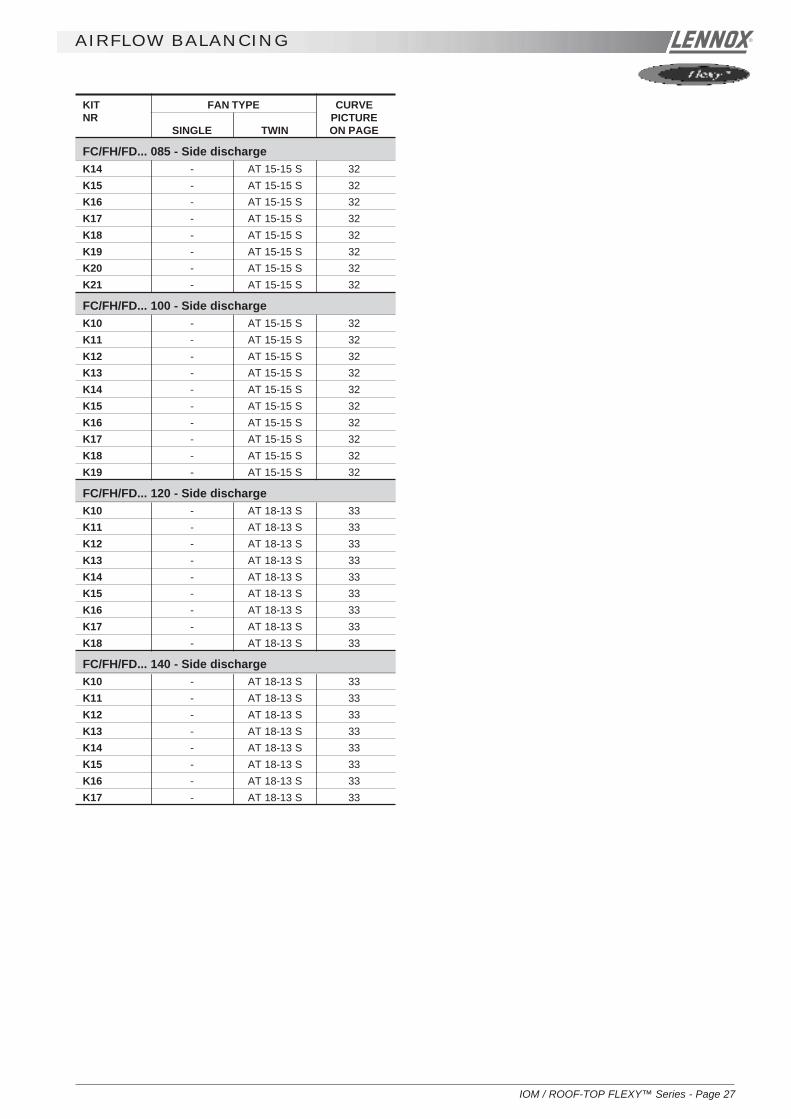
FC/FH/FD... 085 - Side dischargeK14 - AT 15-15 S 32K15 - AT 15-15 S 32K16 - AT 15-15 S 32K17 - AT 15-15 S 32K18 - AT 15-15 S 32K19 - AT 15-15 S 32K20 - AT 15-15 S 32K21 - AT 15-15 S 32
FC/FH/FD... 100 - Side dischargeK10 - AT 15-15 S 32K11 - AT 15-15 S 32K12 - AT 15-15 S 32K13 - AT 15-15 S 32K14 - AT 15-15 S 32K15 - AT 15-15 S 32K16 - AT 15-15 S 32K17 - AT 15-15 S 32K18 - AT 15-15 S 32K19 - AT 15-15 S 32
FC/FH/FD... 120 - Side dischargeK10 - AT 18-13 S 33K11 - AT 18-13 S 33K12 - AT 18-13 S 33K13 - AT 18-13 S 33K14 - AT 18-13 S 33K15 - AT 18-13 S 33K16 - AT 18-13 S 33K17 - AT 18-13 S 33K18 - AT 18-13 S 33
FC/FH/FD... 140 - Side dischargeK10 - AT 18-13 S 33K11 - AT 18-13 S 33K12 - AT 18-13 S 33K13 - AT 18-13 S 33K14 - AT 18-13 S 33K15 - AT 18-13 S 33K16 - AT 18-13 S 33K17 - AT 18-13 S 33

Page 28 - IOM / ROOF-TOP FLEXY™ Series
AIRFLOW BALANCING
KIT FAN TYPE CURVENR PICTURE
SINGLE TWIN ON PAGE
FG... 060 - GasK1 - AT 15-15 S 32K2 - AT 15-15 S 32K3 - AT 15-15 S 32K4 - AT 15-15 S 32K5 - AT 15-15 S 32K6 - AT 15-15 S 32K7 - AT 15-15 S 32K8 - AT 15-15 S 32K9 - AT 15-15 S 32K10 - AT 15-15 S 32
FG... 070 - GasK1 - AT 15-15 S 32K2 - AT 15-15 S 32K3 - AT 15-15 S 32K4 - AT 15-15 S 32K5 - AT 15-15 S 32K6 - AT 15-15 S 32K7 - AT 15-15 S 32K8 - AT 15-15 S 32K9 - AT 15-15 S 32K10 - AT 15-15 S 32K11 - AT 15-15 S 32
FG... 085 - GasK1 - AT 15-15 S 32K2 - AT 15-15 S 32K3 - AT 15-15 S 32K4 - AT 15-15 S 32K5 - ADN 325L 36K6 - AT 15-15 S 32K7 - ADN 325L 36K8 - AT 15-15 S 32K9 - AT 15-15 S 32K10 - ADN 325L 36K11 - ADN 325L 36
FG... 100 - GasK1 - AT 15-15 S 32K2 - AT 15-15 S 32K3 - AT 15-15 S 32K4 - AT 15-15 S 32K5 - ADN 325L 36K6 - AT 15-15 S 32K7 - AT 15-15 S 32K8 - ADN 325L 36K9 - AT 15-15 S 32K10 - ADN 325L 36
KIT FAN TYPE CURVENR PICTURE
SINGLE TWIN ON PAGE
FG... 120 - GasK1 - ADN 370L 37K2 - ADN 370L 37K3 - ADN 370L 37K4 - ADN 370L 37K5 - ADN 370L 37K6 - ADN 370L 37K7 - ADN 370L 37K8 - ADN 370L 37
FG... 137 - GasK1 - ADN 370 L 37K2 - ADN 370 L 37K3 - ADN 370 L 37K4 - ADN 370 L 37K5 - ADN 370 L 37
FG... 160 - GasK1 - ADN 450 L 38K2 - ADN 450 L 38K3 - ADN 450 L 38K4 - ADN 450 L 38K5 - ADN 450 L 38K6 - ADN 450 L 38K7 - ADN 450 L 38K8 - ADN 450 L 38K9 - ADN 450 L 38K10 - ADN 450 L 38
FG... 190 - GasK1 - ADN 450 L 38K2 - ADN 450 L 38K3 - ADN 450 L 38K4 - ADN 450 L 38K5 - ADN 450 L 38K6 - ADN 450 L 38K7 - ADN 450 L 38K8 - ADN 450 L 38K9 - ADN 450 L 38K10 - RDN 450 K 35

IOM / ROOF-TOP FLEXY™ Series - Page 29
AIR FLOW BALANCING
KIT FAN TYPE CURVENR PICTURE
SINGLE TWIN ON PAGE
FX... 025 IndoorK1 AT 12-12 S - 31K2 AT 12-12 S - 31K3 AT 12-12 S - 31K4 AT 12-12 S - 31K5 AT 12-12 S - 31K6 AT 12-12 S - 31K7 AT 12-12 S - 31K8 AT 12-12 S - 31K9 AT 12-12 S - 31K10 AT 12-12 S - 31
FX.. 030 IndoorK1 AT 12-12 S - 31K2 AT 12-12 S - 31K3 AT 12-12 S - 31K4 AT 12-12 S - 31K5 AT 12-12 S - 31K6 AT 12-12 S - 31K7 AT 12-12 S - 31K8 AT 12-12 S - 31K9 AT 12-12 S - 31K10 AT 12-12 S - 31
FX... 035 IndoorK1 AT 15-15 S - 32K2 AT 15-15 S - 32K3 AT 15-15 S - 32K4 AT 15-15 S - 32K5 AT 15-15 S - 32K6 AT 15-15 S - 32K7 AT 15-15 S - 32K8 AT 15-15 S - 32
FX... 040 IndoorK1 AT 15-15 S - 32K2 AT 15-15 S - 32K3 AT 15-15 S - 32K4 AT 15-15 S - 32K5 AT 15-15 S - 32K6 AT 15-15 S - 32K7 AT 15-15 S - 32K8 AT 15-15 S - 32K9 AT 15-15 S - 32K10 AT 15-15 S - 32
FX... 055 IndoorK1 AT 15-15 S - 32K2 AT 15-15 S - 32K3 AT 15-15 S - 32K4 AT 15-15 S - 32K5 AT 15-15 S - 32K6 AT 15-15 S - 32K7 AT 15-15 S - 32K8 AT 15-15 S - 32K9 AT 15-15 S - 32K10 AT 15-15 S - 32
KIT FAN TYPE CURVENR PICTURE
SINGLE TWIN ON PAGE
FX... 070 IndoorK1 AT 18-18 S - 34K2 AT 18-18 S - 34K3 AT 18-18 S - 34K4 AT 18-18 S - 34K5 AT 18-18 S - 34K6 AT 18-18 S - 34K7 AT 18-18 S - 34K8 AT 18-18 S - 34K9 AT 18-18 S - 34K10 AT 18-18 S - 34K11 AT 18-18 S - 34
FX... 085 IndoorK1 AT 18-18 S - 34K2 AT 18-18 S - 34K3 AT 18-18 S - 34K4 AT 18-18 S - 34K5 AT 18-18 S - 34K6 AT 18-18 S - 34K7 AT 18-18 S - 34K8 AT 18-18 S - 34K9 AT 18-18 S - 34
FX... 0100 IndoorK1 AT 18-18 S - 34K2 AT 18-18 S - 34K3 AT 18-18 S - 34K4 AT 18-18 S - 34K5 AT 18-18 S - 34K6 AT 18-18 S - 34K7 AT 18-18 S - 34
FX... 110 IndoorK1 - AT 18-18 S 34K2 - AT 18-18 S 34K3 - AT 18-18 S 34K4 - AT 18-18 S 34K5 - AT 18-18 S 34K6 - AT 18-18 S 34K7 - AT 18-18 S 34
FX... 140 IndoorK1 - AT 18-18 S 34K2 - AT 18-18 S 34K3 - AT 18-18 S 34K4 - AT 18-18 S 34K5 - AT 18-18 S 34K6 - AT 18-18 S 34K7 - AT 18-18 S 34K8 - AT 18-18 S 32
FX... 170 IndoorK1 - AT 18-18 S 32K2 - AT 18-18 S 32K3 - AT 18-18 S 32K4 - AT 18-18 S 32K5 - AT 18-18 S 32K6 - AT 18-18 S 32K7 - AT 18-18 S 32

Page 30 - IOM / ROOF-TOP FLEXY™ Series
AIR FLOW BALANCING
KIT FAN TYPE CURVENR PICTURE
SINGLE TWIN ON PAGE
FX... 085 OutdoorK1 AT 18-18 S - 37K2 AT 18-18 S - 37K3 AT 18-18 S - 37K4 AT 18-18 S - 37K5 AT 18-18 S - 37
FX... 100 OutdoorK1 - AT 15-15 S 35K2 - AT 15-15 S 35K3 - AT 15-15 S 35K4 - AT 15-15 S 35K5 - AT 15-15 S 35
FX... 110 OutdoorK1 AT 18-18 S - 37K2 AT 18-18 S - 37K3 AT 18-18 S - 37K4 AT 18-18 S - 37K5 AT 18-18 S - 37K6 AT 18-18 S - 37
FX... 140 OutdoorK1 AT 18-18 S - 37K2 AT 18-18 S - 37K3 AT 18-18 S - 37K4 AT 18-18 S - 37K5 AT 18-18 S - 37
FX... 170 OutdoorK1 AT 18-18 S - 37K2 AT 18-18 S - 37K3 AT 18-18 S - 37K4 AT 18-18 S - 37K5 AT 18-18 S - 37
KIT FAN TYPE CURVENR PICTURE
SINGLE TWIN ON PAGE
FX... 025 OutdoorK1 AT 12-12 S - 31K2 AT 12-12 S - 31K3 AT 12-12 S - 31K4 AT 12-12 S - 31K5 AT 12-12 S - 31K6 AT 12-12 S - 31
FX... 030 OutdoorK1 AT 12-12 S - 31K2 AT 12-12 S - 31K3 AT 12-12 S - 31K4 AT 12-12 S - 31K5 AT 12-12 S - 31
FX... 035 OutdoorK1 AT 15-15 S - 32K2 AT 15-15 S - 32K3 AT 15-15 S - 32K4 AT 15-15 S - 32K5 AT 15-15 S - 32K6 AT 15-15 S - 32K7 AT 15-15 S - 32
FX... 040 OutdoorK1 AT 15-15 S - 32K2 AT 15-15 S - 32K3 AT 15-15 S - 32K4 AT 15-15 S - 32K5 AT 15-15 S - 32K6 AT 15-15 S - 32K7 AT 15-15 S - 32
FX... 055 OutdoorK1 AT 15-15 S - 32K2 AT 15-15 S - 32K3 AT 15-15 S - 32K4 AT 15-15 S - 32K5 AT 15-15 S - 32
FX... 070 OutdoorK1 AT 18-18 S - 34K2 AT 18-18 S - 34K3 AT 18-18 S - 34K4 AT 18-18 S - 34K5 AT 18-18 S - 34K6 AT 18-18 S - 34

IOM / ROOF-TOP FLEXY™ Series - Page 31
AIR FLOW BALANCING
AT 12-12 FAN

Page 32 - IOM / ROOF-TOP FLEXY™ Series
AIR FLOW BALANCING
AT 15-15 FAN

IOM / ROOF-TOP FLEXY™ Series - Page 33
AIR FLOW BALANCING
AT 18-13

Page 34 - IOM / ROOF-TOP FLEXY™ Series
AIR FLOW BALANCING
AT 18-18 FAN

IOM / ROOF-TOP FLEXY™ Series - Page 35
AIR FLOW BALANCING
RDN 450 FAN

Page 36 - IOM / ROOF-TOP FLEXY™ Series
AIR FLOW BALANCING
ADN 355 FAN
IOM / ROOF-TOP FLEXY™ Series - Page 37
AIR FLOW BALANCING
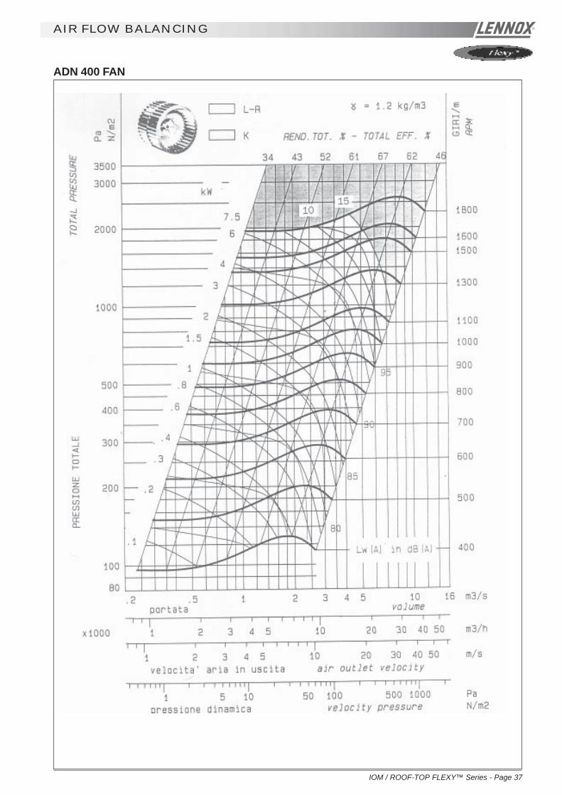
ADN 400 FAN

Page 38 - IOM / ROOF-TOP FLEXY™ Series
AIR FLOW BALANCING
ADN 450 FAN

IOM / ROOF-TOP FLEXY™ Series - Page 39
filters
The CLIMATIC™ controls the filters. Two types of problemsmay occur :
1 - 004 error code (lit LED “filter”) or the following icon (for a
graphics screen - KP07) :
Item 8 on KP 17 indicates that the filters must be changed.The unit has not stopped but the airflow is likely to be reduceddue to increased pressure drop acros the filters.
2 - 005 error code or the following icon
(for a graphics screen - KP07) :
Item 9 on KP17 indicates that the filters are out of position :either they have been damaged or not been replaced duringmaintenance. In the latter case, the unit has not stopped butthe increased flowrate may result in the motor overheating. Itis important to check the filter immediately.
FILTER REPLACEMENT :After opening the filter access panel, unscrew the butterflynuts maintaining the filter support and remove it (figure 33).
Remove the cells that are slide-mounted (figure 34).Use the rod in the lower filter section to remove the cells atthe botton of the sliders.
Install new filters inside the sliders.
Figure 32
Figure 33 Figure 34
KP 17 DISPLAY

Page 40 - IOM / ROOF-TOP FLEXY™ Series
VENTILaTION : FANSTART OPERATION
Current protection of the ThyristorThe FANSTART will display a fault (red LED) if the currentexceeds the thyristor current limits
125A during 0.4 s87.4A during 2 s75A during 6 s.62.5A during 20 s.
Start up sequence too longA fault (red LED) will appear if after 1min20s the FANSTARTControl is not bypassed and the motor running from the mains.
Phase rotation checkIf the phase rotation is incorrect the FANSTART Control willdisplay a fault ( Red LED). Two of the phases must then beinverted and the start up cycle resumed.
AIR SOCK CONTROLThe use of air socks for space conditioning allows high airvolumes to be distributed at low velocity and is becoming acommon feature in many applications. To accommodate thistrend, Air-sock control is offered which allows the air socks tobe progressively filled with air on start up. FLEXY™ has beenenhanced with an electronic device to soft start the fan. Ittakes up to 1 minute to go from 0% of air to full air flow.This time can be divided in several stages :
- The aim of this first voltage input is to overcome theresistance of the transmission (Pulleys and belts) : 0.5sand up to 1000 rpm
- The second stage is to inflate the air sock : 5 to 30 s.and 600 to 900 rpm
Finally the air sock is gradually pressurised during the last 5to 30 second. The motor reaches nominal speed and thecontroller is bypassed.
The motor speed control is achieve through a variation of thesupply voltage of each phase at constant frequency.
The thermal overload limit on the motor imposes a currentlimitation during the acceleration stage. Hence if the selectedslope is to steep, a predefined current limit can be reached(potentiometer adjustment) and the controller will automaticallyreduce the voltage set-point accordingly. Then once the currentis back under the high current limit it carries on with the startup cycle.
Safety
Excessive "slow down" limitThe FANSTART will display a fault (red LED) and stop themotor, if the motor slows down excessively (voltage couldreach 0V) because of the current limitation during theacceleration stage.
Missing phase safetyThe FANSTART will display a fault (red LED) if the current inthe third phase is too low or reaches 0 Amps (Three phasesupply or motor problem)
FAN STARTOFF MOTOR OFF
Green LED = 0Red LED = 0
MOTOR OFFGreen LED = 1Red LED = 1
Power + Control ONGreen LED = 1Red LED = 0
Control ONPower OFF
PHASEROTATION
CHECK
T°C FaultThyristor
OK
INFLATIONGreen LED = 1Red LED = 0
ACCELERATIONGreen LED = 1Red LED = 0
(If current control ON)
CONTROL OFFmotor connected
to mains
NOT OK
I > I maxSpeed = 0
T > 1 min20sI < Imin
I > I maxSpeed = 0
T > 1 min20sI < Imin
Current
1st voltage Input to Overcometransmission performance
Over-current limit
Air sockInflation5 to 30s Acceleration 15 to 30s FANSTART off
Figure 35
Figure 37

IOM / ROOF-TOP FLEXY™ Series - Page 41
FX AIR FLOW BALANCING
1. Operation of the grids
- Balancing grids are installed on fresh air side in order to compensate for the higher pressure drop on the ducted returnair side.
- The aim is to avoid the pressure variations in the area to air conditioned (risk of doors opening in cinemas for example)but also to avoid a current surge on the motor when running 100% fresh air.
- The objective is to maintain constant airflow/pressure operating conditions with the supply air, regardless of thepercentage of fresh air.
- Once adjusted the air treatment fans should not see the difference between the ducted return air and the fresh air.
2. Airside adjustment procedure for the FX with 4 dampers
- Adjust the machine with the 0% fresh air configuration, the grids are open to the maximum.- Measure the Amps and Speed of the "treatment" fan motor. Determine the airflow and pressure using the Fan Curves.- If the absorbed Amps are higher than the value on the motor plate, the supply and return ducts pressure drop is lower
than the requested value at the time of order. Reduce the rpm, change the Pulleys if necessary.- Once the airflow and pressure have been checked and confirmed, measure the static pressure at the 5 following points :
1a : "Treatment " fan inlet (ex : -230 Pa)2a : "Treatment" expansion box (ex : -210 Pa)3a : Return air box (ex : -190 Pa)4a : Extraction expansion box (ex : -70 Pa)5a : Extraction fan inlet (ex : -120 Pa)
- Adjust the extraction grid to reach a pressure in 4 equal to the pressure in 2 (ex : reach -210 Pa when closing).- Check the Amps absorbed by the extraction fan motor; It must be lower than the value on the plate otherwise reduce the
fan speed.- Reverse the fresh air percentage: 100 % fresh air at the treatment.- Measure the Static pressure at the same 5 points
1b : "Treatment " Fan Inlet (ex : -80 Pa)2b : "Treatment" expansion box (ex : -50 Pa)3b : Return air box (ex : -200 Pa)4b : Extraction expansion box (ex : -220 Pa)5b : Extraction fan inlet (ex : -250 Pa)
- Adjust the grid on the "treatment" side only to reach a pressure at point 2b identical to the pressure at 2a (reach -210 Pawhen closing)
- Check that the pressure measured in the extraction expansion box 5b has not changed too much compared with theprevious measurement 5a. Adjust the bypass grid to compensate any possible difference.
1 2 43 5
Figure 25

Page 42 - IOM / ROOF-TOP FLEXY™ Series
"Treatment" side damper Extraction side damper+ fresh air bypass (25% damper).
FX AIR FLOW BALANCING
Figure 27 Figure 28
Example of pressure tapping point available oneach box :
Figure 26

IOM / ROOF-TOP FLEXY™ Series - Page 43
FX AIR FLOW BALANCING
PRINCIPLE SKETCHES
10 000 m3/h 10 000 m3/h
10 000 m3/h
12 500 m3/h2 500 m3/h
Fresh air hood
SUPPLYair duct
RETURNair duct
Treatmentfan
Extraction fanEXTRACTION
air duct
Grid on damper
10 000 m3/h
10 000 m3/h
2 500 m3/h
12 500 m3/h2 500 m3/h
10 000 m3/h
10 000 m3/h
2 500 m3/h
12 500 m3/h
0% FRESH AIR TREATMENT
100% FRESH AIR TREATMENT
CONSTANT 25% BYPASS TO EXTRACTION
Fresh air hood
Fresh air hood
RETURNair duct
RETURNair duct
SUPPLYair duct
EXTRACTIONair duct
SUPPLYair duct EXTRACTION
air duct
Treatmentfan
Treatmentfan
Extractionfan
Extractionfan
Grid on damper
By pass grid
Figure 29
Figure 30
Figure 31
By pass grid
By pass grid

Page 44 - IOM / ROOF-TOP FLEXY™ Series
HOT WATER COILS
HYDRAULIC CONNECTIONSThe heating coil is connected to the isolating valves. Twokeys must be used to tighten the connections, one of thekeys maintains the valve body. Failure to use two keys maydamage the pipes and invalidates the warranty.
Proceed as follows :- Open the stop valves and set the 3-way valve to the
intermediate position (manual position and turn thethumbwheel to a mid position).
- Fill the hydraulic system and bleed the battery usingthe air vent (figure 37).
- Check the connections for possible leaks.- Reset the 3-way
valve toautomatic.
PROTECTION AGAINST FREEZING1) Use glycol water
GLYCOL IS THE ONLYEFFECTIVE PROTECTION AGAINST FREEZING
The antifreeze must protect the unit and avoid icing underwinter conditions.Warning : monoethylene glycol-based antifreeze mayproduce corrosive agents when mixed with air.
2) Drain the installation
You must ensure that the manual or automatic air vents havebeen installed on all high points in the system. In order todrain the system check that all the drain cocks have beeninstalled on all low points of the system.To drain, open all the valves and remember to place theunit in air.
A HEATING COIL FROZEN DUE TO LOWAMBIENT CONDITIONS IS NOT COVERED BYTHE WARRANTY.
ELECTROLYTIC CORROSIONAttention is drawn to the corrosion problems resulting fromelectrolytic reaction created from unbalanced earthconnections.
ANY COIL DAMAGED BY ELECTRONICREACTION IS NOT COVERED BY THE
WARRANTY.
Figure 37
Figure 38

IOM / ROOF-TOP FLEXY™ Series - Page 45
GAS BURNER
1. PRELIMINARY CHECKS AND VERIFI-CATIONS BEFORE START-UP
NOTE :ANY WORK ON THE GAS SYSTEM MUST BECARRIED OUT BY QUALIFIED PERSONNEL.THIS UNIT MUST BE INSTALLED INACCORDANCE WITH LOCAL SAFETY CODESAND REGULATIONS AND CAN ONLY BE USED INWELL VENTILLATED AREA.PLEASE READ CAREFULLY THEMANUFACTURER'S INSTRUCTIONS BEFORESTARTING A UNIT.BEFORE COMMISSIONING A UNIT WITH GAZBURNER, IT IS MANDATORY TO ENSURE THATTHE GAZ DISTRIBUTION SYSTEM (type of gas,available pressure…) IS COMPATIBLE WITH THEADJUSTMENT AND SETTINGS OF THE UNIT.
1.1 Check access and clearances around theunit :
- Make sure one can move freely around the unit- A one-meter clearance must be left in front of the burnt
gas exhaust chimney(s)- Combustion air inlet and burnt gas exhaust(s) must not
be obstructed in any way.
1.2 Supply network pipe sizing
- The gas supply to arooftop gas unit mustbe according to SoundEngineering Practice.
- The pipe-workconnected to eachrooftop must not besmaller than thediameter of theconnection on therooftop unit.
1.3 Shut-off valve in front of each rooftop
- Make sure that a shut off isolation valve has beeninstalled before EACH rooftop.
- Check that the internal shut off valves in the rooftop unitis open.
1.4 Pipe-work purging and gas static pressurechecks
- Purge the pipe-worknear the connection onthe HONEYWELL valvefor a few seconds
Standard GN 20 mbar :Check the pressure at theinlet of the HONEYWELLvalve.
GN 300 mbar option with pressure regulator :Check the pressure at the regulator inlet.
Propane 37 mbar option :Check the pressure at the inlet of the HONEYWELL valve.
Propane 148 mbar option with pressure regulation(yellow spring) :Check the pressure at the regulator inlet. A 10% tolerancearound the nominal pressure is acceptable.
1.5 Probes and electrodes position check
Visually check that the ionisation probe is centred in the middleof the flame.
Check that the end of the ignition electrode is aligned with theside of the inshot burner.
Figure 40
Figure 41
INCORRECT
CORRECT
Figure 42
Figure 43

Page 46 - IOM / ROOF-TOP FLEXY™ Series
Time in secondsOperationsControl operation sequence
Extraction fan
Smoke extraction fan "ON"
30 to 45 seconds pre-Ventilation
Fire-up spark electrode 4s
Opening of the gas valve "High Heat"Flame propagation towardsthe ionisation probeIf Ionisation within 5sec :Normal runningOtherwise fault on gas ignition control blockAfter 5 minutes, fault reportedon the climatic controller
GAS BURNER
2. GAS BURNER RESET
- Press the "reset" button" on the gas control block to reset the unit after a fault
3. START UP AND SET UP OF THE GAS UNIT
3.1 General operation check of the system
- Check that the centrifugal fan blower in the unit is running.
3.2 Set up
- Set the setpoint 59 and 60 to "ON". This will priorities the gas burner.- Increase the set temperature "1" (room set point temperature) to a temperature higher than the room temperature.
3.3 Burner start up check
RESETbutton
Figure 44
1 2 3 4 5 6 7 8 9 1 1 2 3 3 3 3 3 3 3 3 3 3 4 4 4 4 4 4 4 3 3 4 40 1 9 0 1 2 3 4 5 6 7 8 9 0 1 2 3 4 5 6 9 9 0 0
8 9 0 1
If incorrect sequence refer to the fault analysis table to identify the problem.

IOM / ROOF-TOP FLEXY™ Series - Page 47
GAS BURNER
Connector x14
Figure 45
Figure 46
- Standard start-up chronology- If incorrect sequence, refer to the fault table to identify the problem.
3.4 Pressure regulator adjustment (in case of 300 mbar)
- The burner must be run in high heat mode for this check.- Fit the tube of the "accurate" manometer on the IN pressure port of
the HONEYWELL Block after having loosened the screw by twoturns
- Check and adjust if necessary the IN pressure to 20,0 mbar (G20) or37,0 mbar for propane (G31).
3.5 High heat injection pressure checks
- Fit the tube of the "accurate"Manometer to the OUT port on theHONEYWELL valve after havingloosened the screw.
- Check and adjust if necessary theOUT pressure to 8,4 mbar (G20) or31,4 mbar for propane (G31).
3.6 Low heat injection pressure checks
- Carefully disconnect the wire numbered 116 for the bottom gasburner and the wire numbered 126 for the tops gas burner.
- Check and adjust if necessary the OUT pressure to 3,5 mbar (G20)or 14 mbar for propane (G31).
3.7 Reconnect the wires 116-126
Figure 47Figure 48
Figure 49
Figure 50 Figure 51

Page 48 - IOM / ROOF-TOP FLEXY™ Series
GAS BURNERGAS BURNERGAS BURNERGAS BURNERGAS BURNER
Type of Gas Category Supply pressure Low heat injection High heat injectionadjustment pressure pressureHoneywell Valve adjustment adjustment
Natural GAZ G20 20.0 mbar 3.5 mbar 8.4 mbar
Natural GAZ G25 (Groningue) 25.0 mbar 5.0 mbar 12.3 mbar
Propane G31 (GPL) 37.0 mbar 14.0 mbar 31.4 mbar
4. Burner safety checks
4.1 Smoke extractor pressure switch test
- With the gas burner running, disconnect the flexible tube fitted to the pressuretaping on the smoke box (figure 53).
- The Flame must disappear and the fan must carry on running.- However, NO fault will be displayed (HONEYWELL control block or
CLIMATIC™).- After reconnecting of the tube, the burner will restart after 30 seconds of pre-
ventilation.
4.2 Gas pressure switch test
- With the gas burner running, close the internal shut off valve in the rooftop.- The burner stops completely.- However, No fault light will be displayed on the Honeywell Control box.- After 6 Minutes, the CLIMATIC 2 will display fault 14 or 15.- Reset the CLIMATIC™ 2.
4.3 Ionisation probe test
- With the gas burner running, disconnect the RAJAH terminal plug.- The flame disappears- The fan is still running and attempting to restart the burner (restart cycle 45
seconds).- At the end of the restart cycle the burner stops completely.- The fault light on the HONEYWELL Block is ON.- Manually reset the HONEYWELL controller to eliminate the fault. (Refer to
§2).
Figure 52
Figure 53
Figure 54
Then re-tighten all pressure adjustment screws.
3.8 Rating table for type of gas and corresponding adjusmtent pressure

IOM / ROOF-TOP FLEXY™ Series - Page 49
GAS BURNER
5. DISASSEMBLING THE GAS BURNER FOR MAINTE-NANCE PURPOSE
5.1 Preliminary safety recommendations
- Isolate the unit using the main isolator- Close off the isolating gas valve located before the unit
5.2 Disconnect the pipework. Do not discard the seals
5.3 Disassembling the gas "rail"
- Disconnect the electrical connector on the electric board EF45 or 46.- Remove the two screws which hold the gas bar in place- Carefully remove the gas "rail"
avoiding any damaged to theelectrodes.
5.4 Disassembling the chimneys
- Electrically disconnect the fan and remove the screws holding it in place.- Take care not to loose any cage nuts in the smoke bos.- Attention : check the correct position of the pressure tube used by the
extraction pressure switch.
Figure 56 Figure 57
Figure 58
Figure 59
Figure 55

Page 50 - IOM / ROOF-TOP FLEXY™ Series
HEATING : gas burner
GAS BURNER FIRE-UP SEQUENCE
Gaz low pressure switch?
Operation from controlThermostat GAS = Closed
Supply thermostat timit ? (Auto reset)
Gaz ignition control block signal
Extraction Fan ON
Air pressure switch ONBackfire thermostat ON ?
Pre-ventilation 30 to 45 seconds
Fire-up Electrode 4s
Gas valve open
Ionisation 1 second afterthe end of sparking ?
Gas valve remains open
Normal operation
Air press switch ONor Backfire thermostat ?
Signal from ionisationprobe still ON?
Gas controlValve closes
BURNERSTOPS
Gas controlValve closes
BURNER STOPSFault on Gascontrol block
6 minutes delay
FAULT ON CLIMATIC
YES
NO
NO
YES
YES
NO
YES
NO
NO
YES
NO
YES

IOM / ROOF-TOP FLEXY™ Series - Page 51
6.1 Fault codes 14 and 15
- Reset the CLIMATIC™ 2- Check voltage 230V after circuit breaker QF3- Check gas isolation shut-off valves are open- Check gas pressure at the inlet of the gas valve. It must be > 20 mbar when the burners shut down- Adjust the setpoints 59 and 60 to ON to priorities the burner. Increase the value of th setpoint "1" (room setpoint
temperature) to a temperature higher than room (variable 1).- Follow the diagnostic table (see following pages).
GAS BURNERS
Check output voltageafter the control box Check solenoid coils
on the Honeywell valve
Figure 60
Figure 61

Page 52 - IOM / ROOF-TOP FLEXY™ Series
GAS BURNERS
DIAGNOSTIC TABLE GAS BURNER
STAGES NORMAL OPERATION FAULT ACTIONS SOLUTIONS
Heating requested
Contactors KM21-22 engaged
Contactors do not engage
• Check safety thermostats B29-30 in the air duct before the gas heat exchanger
• Replace component
Contactors KM21-22 are engaged
Extraction fans are running
Nothing happens
• Check the free movement of the fan wheel
• Check the supply temperature limitation thermostats B45-46
• Check GAS low pressure switches B17-18
• Check electrical connection on the Honeywell control block and on EF45-46 connection boards
• Check the fan supply voltage
• Replace thermostat • Open GAS Supply • Replace EF 45-46 if
necessary
Extraction fan ON
After 30 seconds: the fire-up electrode must create sparks
Continuous ventilation without sparks by electrode
• Check position of the fire-up electrode (refer to preliminary checks and verifications §1)
• Check the pressure drop at the pressure switch : It must be higher than 200 Pa
• Check the good operation of the pressure switch using an Ohmmeter and by sucking through the tube to create a depression.
• Check the operation the Backfire thermostat B32-B33
• Re-position the
pressure taping tube.(§5.d)
• Change the pressure switch
• Reset or replace the
Thermostat
Continuous ventilation with sparks created by electrode
After 2 seconds the gas burner fires-up
After 4 second the GAS Burner still not running and Safety shutdown by the Honeywell Block.
• Check injection pressure during start-up (value for high heat)
• Check the supply voltage to the control box (continuous voltage). Refer to figure 61.
• Remove the control box from the gas block. Check using an ohmmeter the solenoid coil of the GAS block (4 kOhm). Refer to figure 62
• Remove the air from the pipe-work
• Adjust the injection pressure to high heat value
• Change the control box if the GAS valve is OK.
• Change the gas valve control

IOM / ROOF-TOP FLEXY™ Series - Page 53
GAS BURNERS
7. REQUIRE EQUIPMENT LIST
6.1 Adjustment ansstart-up
- An accurate manometerfrom 0 to 3500 Pa (0 to350 mbar) : 0.1% fullscale.Example Ref :DRUCK DPI 70519, rue Maurice Pellerin92600 Asnières.Tel +33 1 41 32 34 64.Fax: +33 1 47 93 00 48
- A multimeter with ohmmeter and micro-amps scale(ionisation)
- Adjustable spanner· Tube spanner Set : 8, 9, 10, and 13.- 1 Flat screwdriver diameter 3,4, Fillips n°1
6.2 Maintenance
- Vacuum cleaner- Paint brush / nylon brush diameter 50
8. CHANGING GAS TYPE
8.1 Modification of the gas burner to run propaneinstead of natural gas
- Disconnect electrically the GAS burner- Disconnect GAS supply- Remove the gas rail with the injectors- Replace GAS Injectors (natural GAS = 2,3 mm by
Propane = 1,37 mm)- Replace the pilot high/how (natural GAS reference
V4336A 2204 1) by the propane version (yellowreference V4336A 2212 1).
- BE CAREFULL : DO NOT REPLACE THE PILOT SEAL,keep the seal from the natural gas installation.
8.2 Modification of the pressure regulator (ifoption 148 mbar)
- Replace the pressure regulator of neutral colour with aYELLOW spring
- Start again all pressure adjustments (§4)
9. REGULAR MAINTENANCE
9.1 Preliminary safety recommendations
- Isolate the unit electrically- Isolate the gas burner using the appropriate shut-off
valves
9.2 Cleaning the components
- Disconnect the gas burner electrically- Disassemble the gas pipe-work.- Disassemble the gas burner and remove dust using a
paintbrush and a vacuum cleaner.
9.3 Sweeping
- Disassemble the gas burner (refer to previousparagraph)
- Disassemble the exhaust extraction fan.- Disassemble the exhaust box- Sweep the inside of the box using a paintbrush and a
vacuum cleaner.- Remove the dust inside the heat exchanger tube using a
nylon brush diameter 50 and vacuum the dust away.Figure 62

Page 54 - IOM / ROOF-TOP FLEXY™ Series
GAS BURNERS
60 KW BURNER FOR FGX 60 AND 70 MODELS
1
2
Figure 63

IOM / ROOF-TOP FLEXY™ Series - Page 55
GAS BURNER
120 KW BURNER FOR FGX 60, 70 AND 100 MODELS
1
2
3
Figure 64

Page 56 - IOM / ROOF-TOP FLEXY™ Series
180 KW BURNER FOR FGX 120 AND 140 MODELS
GAS BURNER
1
23
Figure 65

IOM / ROOF-TOP FLEXY™ Series - Page 57
KP17 COMFORT CONTROL DISPLAYWIRING
Failure to install the Comfort control display with therecommended cable may cause the display to malfunction.The KP17 remote must be connected to the CLIMATIC™using a 4 x 0.5 mm2 braid-screened cable.This connection is provided through a remote interface cardwhich is located within the Control panel section.Refer to the wiring section of this manual.
The CLIMATIC™ 'Comfort' control Display allows an untrainedperson to easily operate a Lennox Roof-Top.This display connects to a single Rooftop and, through theuse of the control keys, LED's and display the user can seehow the connected Rooftop is operating, wether there are anyfaults, modify the comfort setpoint and override the Rooftopoperation.If installed correctly the CLIMATIC™ "Comfort" control displaycan be installed up to 1000 m away from the Rooftop unit.
DISPLAY (1 - figure 66)In 'Automatic' operation the comfort setpoint is displayed inthe event of a fault detected on the unit an error code isautomatically displayed.
The + / - keys (2) are used to change the heating/cooling/operating setpoints.
The LED (3) indicates the current operating mode :- In 'Automatic' mode, i.e. in the programmed time
schedules, the LED flashes,- In forced occupied mode, the LED is permanently on- In forced unoccupied mode, the LED is off.
Forced Occupied Key (4)Pressing this key will override the Automatic control and forcethe unit to run in its "Occupied" mode.Whilst in this mode the LED (3) will remain permanently on.To return to "Automatic" mode press button (6) when the LED(3) will flash again.
Forced Unoccupied Key (5)If, to save energy, the installations are not used within a periodprogrammed for automatic use, it is possible, by pressing thiskey, to force the unit into its to "unoccupied" mode. The LED(3), which was previously flashing or lit, will now go out.
Automatic Operation Key (6)If the system was previously set to forced occupied mode (LED(3) lit) or forced unoccupied mode (LED (3) off), this key allowsyou to return to the automatic programmed mode. The LEDwill flash.
NOTE : 'Forced' modes will automatically be re-set at 00:00h
LED (7) Indicates whether the unit is operating or not.
LED (8) Indicates that the filters are dirty.
LED (9) Indicates a general fault has been detected by theCLIMATIC™. Refer to the "Fault codes" section of this manual.
USING THE KP 17 COMFORT CONTROL DISPLAY
Figure 66

Page 58 - IOM / ROOF-TOP FLEXY™ Series
USING THE KP02 MAINTENANCE CONTROL DISPLAY
CALLOUT :1 LIQUID CRYSTAL DISPLAY2 RAISE/LOWER KEYS3 "FILTER" LED (flashing red)4 "ADDRESS" KEY5 "MODE" KEY6 "VALUE" KEY7 "UNIT RUNNING" LED8 "MODE" LED9 "GENERAL ALARM" LED.
1 - DISPLAY FORMATS
Hour
Default display. If the display unit has been inactive for 5 minutes, this screen will automatically be displayed.
<--> 12 hours and 59 minutes
Date
<--> 8 April 1999
Variable or setpoint address
Figure 67
This display unit allows you to read and modify all the valuesof the variables or setpoints of the rooftop to which it isconnected.
NOTE : If your ROOFTOP already has a KP17 Comfort displayconnected (see previous section) simply disconnect it andconnect this panel to the same location, once completed re-connect the KP17. It is not necessary to switch off the powerto the CLIMATIC™ whilst the KP02/KP17 is being changed.
The dialogue with the controller is initiated by the CLIMATIC™.If, after 3 attempts, no communication is established, amessage will be displayed signalling the problem. The unitwill then try to re-connect at regular intervals.

IOM / ROOF-TOP FLEXY™ Series - Page 59
Variable or setpoint value
Digital Values
1 <--> ON 0 <--> OFF
TemperaturesTemperatures are displayed in °C, to an accuracy of 0.1 °C
<--> -21.6 °C <--> + 105.8 °C
PressuresPressure is given in bars, to an accuracy of 0.1 bar.
<--> 18.3 bars
Other analog values
Valeurs displayed Values nondisplayed
Specific Displays
Software VersionWhen the unit is powered up, the KP02 software version number is displayed.
<--> version 1.0 (for example)
Display TestThe display can only be tested for correct operation when the unit is powered up and by pressing on the 3 keys "A", "M"and "-" simultaneously. If the display is working correctly, the following will be displayed :
All digits are properly displayed.
Communication ErrorIf there is no communication between the KP02 display unit and the CPU card, the following message is displayed :
<--> "Communication problem"
USING THE KP02 MAINTENANCE CONTROL DISPLAY

Page 60 - IOM / ROOF-TOP FLEXY™ Series
USING THE KP02 MAINTENANCE CONTROL DISPLAY
2 - OPERATING MODESThe maintenance display allows for 4 modes of operation.Key [M] allows you to move successively and in a loop fromone mode to the next.The current mode is indicated by the status of LEDs [V] and[C] :
Status of LEDs associatedwith current mode : [V] [C]
A. The variable mode allows you toread the values of variables lit not lit
B. The setpoint mode allows you tochange the settings not lit lit
C. The read date mode allows you toview the time and the date not lit not lit
D. The date setting mode allows you tochange the time and the date lit lit
A : VARIABLES MODE
Pressing key [A] displays the address of the variable beingread.To go to a higher address, press [A] while simultaneouslypressing on [+].The address will increase slowly by pressing [+] intermittentlyor more quickly by keeping your finger on the key.To go to a lower address, proceed as above but with the [-]key.
When the required address appears, press [V] to display thevariable value. If you do not press any key, the display willautomatically return after a minute. The variables are updatedevery second.
B : SETPOINTS MODE
The setpoint address can be chosen in the same way as forthe variable address (see above).When the address of the required setpoint appears, pressing[V] will likewise display the current value.To increase the setpoint press [V] while holding down the [+]key at the same time.The address will increase slowly by pressing [+] intermittentlyor more quickly by keeping your finger on the key.To go to a lower setpoint, proceed as above but with the [-]key as well as the [V] key.
The new value is applied when [V] is released.
PASSWORDAccess to all the setpoints is password-protected. Enter thepassword before making changes.To do so, following the above procedure : go to address settingn° 0 and enter the number corresponding to your password.
If the password code is correct, the following message willappear when key [V] is released :
If the keypad has been inactive for 5 minutes, the password isreactivated. You must therefore enter it again to continuemaking changes to the setpoint values.
C : DATE READING MODE
One of the following modes
- Hour
- or date
can be chosen by pressing [A] and briefly pressing on [+] or[-].Pressing [V] will display the value of the data selected,otherwise it will automatically be displayed after a minute.
D : DATE SETTING MODE
This mode allows the 6 date modes to be set :
• Hours and minutes <-->
• Day of the month <-->
• Day of the week <-->
• Month <-->
• Year <-->
In the same way as for the setpoints, the value can beincreased by simultaneously pressing on keys [V] and [+] andthey can be decreased by simultaneously pressing on [V]and [-].

IOM / ROOF-TOP FLEXY™ Series - Page 61
USING THE KP02 MAINTENANCE CONTROL DISPLAY
Item Minimum value Maximum value
Hours and minutes 00-00H 23-59 H
Day of the month 1 31
Day of the week 1 7
Month 1 12
Year 0 99
For different types of data, the setting ranges are as follows :
Changes are only incorporated when key [A] is pressed.
NOTE : The compatibility of the value for the day of the monthis not checked when it is entered. You might therefore enterFebruary 31st but when you try to validate, it will be ignoredand the preceding value stored.
3 - POWER SUPPLY (LED 7 - figure 40)
When lit, the LED indicates that the machine is powered up.
4 - MODE (LED 8 - figure 40)
This LED indicates the current operating mode.In normal mode, i.e. within the programmed schedules, theLED flashes.In forced day mode, the LED is permanently on and in forcednight mode, the LED is off.
5 - FILTER DIRTY (LED 3 - figure 40)
This LED indicates that the CLIMATIC™ has detected thatthe filter is blocked.
6 - GENERAL FAULT (LED 9 - figure 40)
This LED indicates a general fault has been detected.Refer to the "Fault codes" section of this manual.

Page 62 - IOM / ROOF-TOP FLEXY™ Series
USING THE KP02 MAINTENANCE CONTROL DISPLAY
LIST OF SETPOINTS (LF 20 - APRIL 2002)
1st Level Mini. Factory Maxi.
C 000 [Kp02] Password, technician level 0 # 255
C 001 [Kp17] [Mode] Required room temperature (in °c). This value corresponds to the middle of the dead zone - (active for Day mode only)
C 051 21.0°C C 050
C 002 [Kp17] Forced occupied mode (Day) – This action deactivates automatically when the clock first pass midnight - Yellow led lit
Off Off On
C 003 [Kp17] Cancels the override of day or night modes- Yellow led flashing Off Off On
C 004 [Kp17] Forced unoccupied mode (Night) – This action automatically deactivates when the clock pass midnight for the second time – Yellow led off
Off Off On
C 005 [Reset] Fault reset Off Off On
C 006 [On / Off] Remote control, On / Off unit Off Off On
C 007 [Kp02] Selection of the memory number for the defaults to be visualized 1 # 5
C 008
[Kp02] [Mode] Mode selection for the visualization and the adjustment of the settings 0 = Day, 1 = Week-End, 2 = Night, 3 = not used, 4 = Morning, 5 = Midday, 6 = Evening 7 = BMS
0 # 7
C 009 [Mode] Day of the week, Start of mode - (active for the Week-End mode) 1 # 7
C 010 [Mode] Hour, Start of mode - (active for the modes Week-End, Night, Morning, Midday, Evening) 0 h # h 22 h
C 011 [Mode] Minute, Start of mode - (active for the modes Week-end, Night, Morning, Midday, Evening) 0 m # m 59 m
C 012 [Mode] Day of the week, End of mode - (active for the Week-End mode) 1 # 7
C 013 [Mode] Hour, End of mode - (active for the modes Week-End, Morning, Midday, Evening) 0 h # h 23 h
C 014 [Mode] Minute, End of mode - (active for the modes Week-End, Morning, Midday, Evening) 0 m # m 59 m
C 015 [Mode] Required maximum room temperature (in °c) - Cooling set point 8.0 c # c 35.0 c
C 016 [Mode] Required minimum room temperature (in °c) - Heating set point 8.0 c # c 35.0 c
C 017 [Mode] Selection of humidity control mode [Off] The relative humidity set points are taken into account (in %) [On] The absolute humidity set points are taken into account - (in g/kg)
Off Off On
C 018 [Mode] Required maximum room relative humidity (in %) – Dehumidification set point 0 % # % 100 %
C 019 [Mode] Required maximum room absolute humidity (in g/kg) – Dehumidification set point 0.0 g/kg # g/kg 30.0 g/kg
C 020 [Mode] Required minimum room relative humidity (in %) – Humidification set point 0 % # % 100 %

IOM / ROOF-TOP FLEXY™ Series - Page 63
USING THE KP02 MAINTENANCE CONTROL DISPLAY
LIST OF SETPOINTS (LF 20 - APRIL 2002) - cont'd
1st Level
Mini. Factory Maxi.
C 021 [Mode] Required minimum room absolute humidity (in g/kg) – Humidification set point 0.0 g/kg # g/kg 30.0 g/kg
C 022 [Mode] Required minimum percentage for fresh air 0 % # % 100 %
C 023 [Mode] Stopping and running of the fan blower supply [Off] The blower is stopped [On] The blower is running.
Off # On
C 024 [Mode] Stopping and running of the fan blower supply in the regulation dead zone [Off] The blower is stopped [On] The blower is running
Off # On
C 025 [Mode] Management of the low speed on the fan supply in the cooling regulation zone [Off] The fan is on high speed [On] The fan is on low speed
Off # On
C 026 [Mode] Management of the low speed on the fan supply in the regulation dead zone [Off] The fan is on high speed [On] The fan is on low speed
Off # On
C 027 [Mode] Management of the low speed on the fan supply in the heating regulation zone [Off] The fan is on high speed [On] The fan is on low speed
Off # On
C 028 [Mode] Force the noise reduction mode [On] 50% of the compressors are unloaded Off # On
C 029 [Mode] Force the operation mode Off # On
C 030 [Command] Force the low speed on fan blower supply Off Off On
C 031 [Command] Force the fresh air damper in the closed position - (0% fresh air) Off Off On
C 032 [Command] Force the fresh air damper to its defined minimum set point position. Off Off On
C 033 [Command] Force fresh air damper in the fully open position - (100% fresh air) Off Off On
C 034 [Command] Force an unloading of the compressors Off Off On
C 035 [Command] Force an unloading of the electric heat Off Off On
C 036 [Command] Forced unloading of : (FLEXY™) - 50% of the compressors - 100% of electrical heat Off Off On
C 037 [Command] Force an unloading of all refrigeration parts Off Off On
C 038 [Command] Force an unloading of all heating parts Off Off On
C 039 [Safety limits] Room temperature low limit (in °c) - Threshold of activation of the safety cut-out 5.0 c 10.0 c 20.0 c
C 040 [Safety limits] Room temperature high limit (in °c) - Threshold of activation of the safety cut-out 20.0 c 40.0 c 40.0 c

Page 64 - IOM / ROOF-TOP FLEXY™ Series
USING THE KP02 MAINTENANCE CONTROL DISPLAY
LIST OF SETPOINTS (LF 20 - APRIL 2002) - cont'd
1st Level
Mini. Factory Maxi.
C 041 [Safety limits] Room relative humidity low limit (in %) - Threshold of activation of the safety cut-out 0 % 0 % 50 %
C 042 [Limit safety] Room absolute humidity low limit (in g/kg) - Threshold of activation of the safety cut-out 0.0 g/kg 0.0 g/kg 30.0 g/kg
C 043 [Safety limits] Room relative humidity high limit (in %) - Threshold of activation of the safety cut-out 50 % 100 % 100 %
C 044 [Limit safety] Room absolute humidity high limit (in g/kg) - Threshold of activation of the safety cut-out 0.0 g/kg 30.0 g/kg 30.0 g/kg
C 045 [Anticipation function] Bottom of slope (in °c) - Limit of activation of the function - This allows an anticipated start-up in the morning mode depending on the outside temperature.
0.0 c 10.0 c 20.0 c
C 046 [Anticipation function] Slope - Number of minutes of anticipation per degrees. This allows an anticipated start-up in the morning mode depending on the outside temperature.
0 0 100
C 047 [Co²] Fresh air dampers opening threshold (in ppm) 0 ppm 1000 ppm 2000 ppm
C 048 [Co²] Fresh air dampers maximum opening limit (in ppm) 0 ppm 1500 ppm 2000 ppm
C 049 [Extraction] Threshold of activation of the power exhaust fan according to the position of the economiser damper (in %) 0 % 10% 100 %
2nd Level Mini. Factory Maxi.
C 050 [kp17] [Mode] Maximum limit for room temperature, Day mode (in °c) - (active for the mode Day) 21.0 c 27.0 c 35.0 c
C 051 [kp17] [Mode] Minimum limit for room temperature, Day mode (in °c) - (active for the mode Day) 8.0 c 17.0 c 21.0 c
C 052 [Room control] Minimum operation time for a stage (in seconds) 25 s 180 s 1800 s
C 053 [Room control] Temperature difference between the beginning and the end of a stage of control in cooling. (in °c) 0.0 c 1.0 c 10.0 c
C 054 [Room regulation] Temperature difference between two stages of control in cooling. (in °c) 0.1 c 1.0 c 10.0 c
C 055 [Room control] Temperature difference between the beginning and the end of a stage of control in heating. (in °c) 0.0 c 0.5 c 10.0 c
C 056 [Room control] Temperature difference between two stages of control in heating. (in °c) 0.1 c 0.5 c 10.0 c
C 057 [Room control] Choice of the priority for the control in heating. [On] Hot water coil or electrical heater or gas then compressors [Off]. Compressors then hot water coil or electrical heater or gas
Off Off On
C 058 [Supply control] Activation of the control. – The control of the supply applies when the room temperature is in the dead zone. - This function allows to maintain comfort with the supply air
Off Off On
C 059 [Supply control] Sampling time (in seconds) 1 s 10 s 120 s
C 060 [Supply control] Choice of the priority for the control in heating [On] Hot water coil or electrical heater or gas then compressors [Off] Compressors then hot water coil or electrical heater or gas
Off Off On

IOM / ROOF-TOP FLEXY™ Series - Page 65
USING THE KP02 MAINTENANCE CONTROL DISPLAY
LIST OF SETPOINTS (LF 20 - APRIL 2002) - cont'd
2nd Level
Mini. Factory Maxi.
C 061 [Humidity control] Relative humidity difference between the beginning and the end of a stage of control in dehumidification (in %) 1 % 3 % 50 %
C 062 [Humidity control] Relative humidity difference between two stages of control in dehumidification (in %) 1 % 3 % 50 %
C 063 [Humidity control] Sampling time of the control in humidification (in seconds) 1 s 10 s 120 s
C 064 [Humidity control] Proportional band for the control in humidification (in %) 1 % 5 % 50 %
C 065 [Safety limit] Supply temperature low limit (in °c) - Threshold of activation of the 1st level of safety.
C 066 + 2.0 c 8.0c / 10.0 c 19.0 c
C 066 [Safety limit] Supply temperature low limit (in °c) - Threshold of activation of the 2nd level of safety.
C 067 + 2.0 c 6.0c / 8.0 c 17.0 c
C 067 [Safety limit] Supply temperature low limit (in °c) - Threshold of activation of the 3rd level of safety. - Alarm threshold 5.0 c / 1.0 c 2.0c / 6.0 c 15.0 c
C 068 [Safety limit] Supply temperature high limit (in °c) - Threshold of activation of the 1st level of safety 20.0 c 40.0 c 70.0 c
C 069 [Safety limit] Supply temperature high limit (in °c) - Threshold of activation of the 2nd level of safety. - Alarm threshold C 068 60.0 c 70.0 c
C 070 [Control limit] Fresh air damper - Maximum outdoor temperature limit (in °c). - If the outdoor temperature is higher than this limit the control in free-cooling is not authorized. - The fresh air damper is then positioned on the minimum setting.
0.0 c 26.0 c 60.0 c
C 071 [Control limit] Fresh air damper – Minimum outdoor temperature limit (in °c). - If the outdoor temperature is lower than this limit the control in free-cooling is not authorized. - The fresh air damper is then positioned on the minimum setting.
0.0 c 5.0 c 30.0 c
C 072 [Fresh air damper] Maximum allowable opening for the fresh air damper (in %) 0 % 100 % 100 %
C 073
[Control limit] * 1° (FLEXY) If option all seasons control - Reduction of speed of the condenser fans - Threshold of outdoor temperature (in °c). - If the outside temperature is lower than this threshold the condenser fans run low speed * 2° Otherwise – Unloading 50% of the compressors in cooling mode - Threshold of outdoor temperature (in °c). - If the outdoor temperature is lower than this threshold 50% of the compressors are unloaded by the control.
-10.0 c / 10.0 c
12.0 c / 20.0 c 30.0 c
C 074
[Control limit] * 1° If option all seasons control – Shut down condenser fans - Threshold of outdoor temperature (in °c). - If the outdoor temperature is lower than this threshold the condenser fans are stopped * 2° Otherwise - Unloading 100% of compressors in cooling mode - Threshold of outdoor temperature (in °c). - If the outdoor temperature is lower than this threshold the compressors are stopped by the control
-10.0 c / 10.0 c 5.0 c / 12.0 c 30.0 c
C 075 [Control limit] Unloading 100% of compressors in heating mode - Threshold of outdoor temperature (in °c). - If the outdoor temperature is lower than this threshold the compressors are not used by the regulation
-50.0 c -20.0 c 20.0 c

Page 66 - IOM / ROOF-TOP FLEXY™ Series
USING THE KP02 MAINTENANCE CONTROL DISPLAY
LIST OF SETPOINTS (LF 20 - APRIL 2002) - cont'd
2nd Level
Mini. Factory Maxi.
C 076 [Defrost function] Authorization of defrost - Threshold of outdoor temperature (in °c) 8.0 c 10.0 c /
20.0 c 20.0 c
C 077 [Defrost function] Authorization of defrost - Threshold of temperature of refrigerant fluid (in °c) -10.0 c 2.0 c /
-2.0 c 6.0 c
C 078 [Defrost function] Coil icing time (in minute) - The defrost cycle starts if the operating time of a compressor in heat pump mode reached this value
30 m 30 m / 45 m 90 m
C 079 [Defrost function] Defrost cycle end - Value indicating the number of start-up of the condenser fan by the pressure switch to signify the end of the defrost cycle
1 1 / 3 5
C 080 [Safety limit] Water heat exchanger output temperature low limit (in °c) - Threshold of activation of the safety 4.0 c 5.0 c 20.0 c
C 081 [Safety limit] Water heat exchanger output temperature high limit (in °c) - Threshold of activation of the safety 20.0 c 45.0 c 46.0 c
C 082 [Control limit] Unloading 100% of electrical heat - Threshold of outdoor temperature (in °c). If the outdoor temperature is higher than this threshold electrical heat are switched off by the control
-20.0 c 10.0 c 30.0 c
C 083 [Electric heat] Maximum usable power for electric heat (in %) 0 % 100 % 100 %
C 084 [Electric heat] (FLEXY FX) All season control - Threshold of mixed air temperature (in °c) - If the mixed air temperature is lower than this threshold electric heat is activated
0.0 c 5.0 c 10.0 c
C 085 [Safety limit] Air flow detection - Threshold of pressure difference for the loss of pressure detection (in pa) - If the pressure difference across the filters is lower than this threshold the safety is activated.
0 pa 20 pa 1000 pa
C 086 [Safety limit] Clogged filter detection– Threshold of pressure difference for the detection of clogging (in pa) - If the pressure difference across the filters is higher than this threshold the safety is activated
0 pa 250 pa 1000 pa
C 087 [Safety limit] Missing filter detection - Threshold of pressure difference for the detection of missing filters (in pa) - If the pressure difference across the filter is lower than this threshold the safety is activated
0 pa 50 pa 1000 pa
C 088 [kp12-2] Time delay for the closing of contact n°3 (in seconds) 4 s 60 s 65535 s
C 089 [kp12-2] Time delay for the opening of the contact n°2 (in seconds) 2 s 300 s 65535 s
C 090 [kp17] Choice of operating mode – [Off] Left button = Forcing day mode / Medium button = Cancel forcing / Right button = Forcing night mode – [On] Left button = Start the unit / Right button = Stop the unit
Off # On
C 091 [Configuration] Identification number for the j-bus connections 1 # 255
C 092 [BMS] Activation of the control by a computer or an automat - Mode BMS is activated if this value is different from zero, this value is decreased every second
0 0 65535
C 093 [Configuration] [Link] Identification number for the connections link between boards 0 # 7
C 094 [Configuration] [Link] Number of boards linked on the bus 0 # 8

IOM / ROOF-TOP FLEXY™ Series - Page 67
USING THE KP02 MAINTENANCE CONTROL DISPLAY
LIST OF SETPOINTS (LF 20 - APRIL 2002) - cont'd
2nd Level
Mini. Factory Maxi.
C 095
[Configuration] [Link] Selection of the operating mode – [0] Inactive [1] One kp17 for several units - All information on the kp17 connected
to the master unit is communicated to the slave units [2] One unit in standby mode - The unit with the highest address
connected to the bus is stopped. If a fault is detected on another unit, the faulty unit is stopped and the standby unit is started automatically
[3] Same as choice 2 but the standby unit is changed every Tuesday at 8 o’clock
0 # 3
C 096
[Configuration] [Link] Selection of exchange mode for room temperature and humidity [0] Inactive [1] The room temperature and humidity of the master unit are
communicated to the slave units [2] The room temperature and humidity are taken as the average of
the active probes.
0 # 2
C 097
[Configuration] [Link] Selection of exchange mode for outdoor temperature and humidity [0] Inactive [1] The outdoor temperature and humidity of the master unit are
communicated to the slave units [2] The outdoor temperature and humidity are taken as the average
of the active probes.
0 # 2
C 098 [Configuration] Type of unit 0 # 65535
C 099 [Configuration] Type of unit [Off] FLEXY Off # On
C 100 [Configuration] Activation of the dual-speed option for fan supply Off # On
C 101 [Configuration] Activation of the all seasons control option Off # On
C 102 [Configuration] Activation of the optimised defrost option Off # On
C 103 [Configuration] Activation of the humidity and the enthalpy management option Off # On
C 104 [Various] Override all set points to factory settings Off Off On
C 105 [Various] reserved Lennox 0 0 65535

Page 68 - IOM / ROOF-TOP FLEXY™ Series
USING THE KP02 MAINTENANCE CONTROL DISPLAY
VARIABLE LIST (LF 20 - April 2002)
1st Level
V 000 [Defects] error codesV 001 [Value] Temperature (in °c), Room, Reference valueV 002 [Value] Relative humidity (in %), Room, Reference valueV 003 [Value] Absolute humidity (in g/kg), Room, Reference valueV 004 [Value] Temperature (in °c), Outdoor, Reference valueV 005 [Value] Relative humidity (in %), Outdoor, Reference valueV 006 [Value] Absolute humidity (in g/kg), Outdoor, Reference valueV 007 [Input] Temperature (in °c), SupplyV 008 [Input] Temperature (in °c), MixingV 009 [Input] Temperature (in °c), FreeV 010 [Input] Temperature (in °c), Chilled waterV 011 [Input] Temperature (in °c), Compressor, n°1V 012 [Input] Temperature (in °c), Compressor, n°2V 013 [Input] Temperature (in °c), Compressor, n°3V 014 [Input] Temperature (in °c), Compressor, n°4V 015 [Input] Temperature (in °c), Condenser, n°1V 016 [Input] Temperature (in °c), Condenser, n°2V 017 [Input] Temperature (in °c), Condenser, n°3V 018 [Input] Temperature (in °c), Condenser, n°4V 019 [Input] Temperature (in °c), Water condenser, Output exchangerV 020 [Input] Signal, Shift of the set pointV 021 [Input] Pressure (in pa), Air flow, Supply fanV 022 [Input] Signal (in ppm), Air quality sensor, Co²V 023 [Input] Pressure (in b), Compressor, n°1V 024 [Input] Pressure (in b), Compressor, n°2V 025 [Input] Pressure (in b), Compressor, n°3V 026 [Input] Pressure (in b), Compressor, n°4V 027 [Output] Supply fanV 028 [Output] Supply fan, Command low speedV 029 [Output] Extraction fanV 030 [Output] Compressor, n°1V 031 [Output] Compressor, n°2V 032 [Output] Compressor, n°3V 033 [Output] Compressor, n°4V 034 [Output] Compressor, Cycle reversing valve, Heat pump, n°1V 035 [Output] Compressor, Cycle reversing valve, Heat pump, n°2V 036 [Output] Compressor, Cycle reversing valve, Heat pump, n°3V 037 [Output] Compressor, Cycle reversing valve, Heat pump, n°4V 038 [Output] Compressor, Hot gas injection valveV 039 [Output] Condenser fan, Command low speedV 040 [Output] Condenser fan, n°1V 041 [Output] Condenser fan, n°2V 042 [Output] Condenser fan, n°3V 043 [Output] Condenser fan, n°4V 044 [Output] PumpV 045 [Output] Electrical heater, n°1, 1st levelV 046 [Output] Electrical heater, n°1, 2nd levelV 047 [Output] Electrical heater, n°2V 048 [Output] Gas grade, n°1, 1st levelV 049 [Output] Gas grade, n°1, 2nd levelV 050 [Output] Gas grade, n°2

IOM / ROOF-TOP FLEXY™ Series - Page 69
V 051 [Output] Gas grade, ResetV 052 [Output] Economiser, Proportional action (0-255)V 053 [Output] Chilled water coil, Proportional action (0-255)V 054 [Output] Hot water coil, Proportional action (0-255)V 055 [Output] Electrical heater, Static relays, Proportional action (0-255)V 056 [Output] Humidifier, Proportionnel action (0-255)V 057 [Statute] supply fan
1 = ok 2 = option air flow3 = option low speed 4 = option air flow + low speed6 = activation of a defect 7 = activation of a defect filters8 = ventilation nonready
V 058 [Statute] Economiser0 = option any air recycled 1 = all fresh air2 = option economiser 3 = option enthalpy4 = option co² 5 = option enthalpy + co²6 = function enthalpy activates 7 = remote command active8 = ventilation no ready
V 059 [Statute] Chilled water coil0 = not configured 1 = ok8 = ventilation no ready
V 060 [Statute] Hot water coil0 = not configured 1 = ok8 = ventilation no ready
V 061 [Statute] Compressor, n°10 = not configured 1 = option cooling only2 = option heat pump 3 = defrost in progress5 = limit outside temperature or remote command active6 = activation of a defect 7 = activation of a defect condenser8 = ventilation no ready
V 062 [Statute] Compressor, n°20 = not configured 1 = option cooling only2 = option heat pump 3 = defrost in progress5 = limit outside temperature or remote command active6 = activation of a defect 7 = activation of a defect condenser8 = ventilation no ready
V 063 [Statute] Compressor, n°30 = not configured 1 = option cooling only2 = option heat pump 3 = defrost in progress5 = limit outside temperature or remote command active6 = activation of a defect 7 = activation of a defect condenser8 = ventilation no ready
V 064 [Statute] Compressor, n°40 = not configured 1 = option cooling only2 = option heat pump 3 = defrost in progress5 = limit outside temperature or remote command active6 = activation of a defect 7 = activation of a defect condenser8 = ventilation no ready
V 065 [Statute] Condenser0 = not configured 1 = option air condenser2 = option water condenser 6 = activation of a defect8 = ventilation no ready
V 066 [Statute] Pump0 = not configured 1 = ok6 = activation of a defect 8 = ventilation no ready
V 067 [Statute] Electrical heater0 = not configured 1, 2 or 3 = number of stages4 = static relays5 = limit outside temperature or remote command active6 = activation of a defect 8 = ventilation no ready
USING THE KP02 MAINTENANCE CONTROL DISPLAY

Page 70 - IOM / ROOF-TOP FLEXY™ Series
V 068 [Statute] Gas grade0 = not configured 1, 2 or 3 = number of stages6 = activation of a defect 8 = ventilation no ready
V 069 [Statute] Humidifier0 = not configured 1 = ok6 = activation of a defect 8 = ventilation no ready
V 070 [Regulation] Real set point, Cooling, RoomV 071 [Regulation] Real set point, Heating, RoomV 072 [Regulation] Power-factor, Cooling, RoomV 073 [Regulation] Power-factor, Heating, RoomV 074 [Regulation] Real set point, SupplyV 075 [Regulation] Power-factor, Cooling, SupplyV 076 [Regulation] Power-factor, Heating, SupplyV 077 [Regulation] Real set point, Dehumidification, RoomV 078 [Regulation] Real set point, Humidification, RoomV 079 [Regulation] Power-factor, Dehumidification, RoomV 080 [Regulation] Power-factor, Humidification, RoomV 081 [Mode] Number of the active modeV 082 [Function] Number of the unit in standbyV 083 [Defects] Memory, CodeV 084 [Defects] Memory, HourV 085 [Defects] Memory, MinuteV 086 [Defects] Memory, DayV 087 [Defects] Memory, MonthV 088 [Information] Non-standard programV 089 [Information] Number of version of the program
USING THE KP02 MAINTENANCE CONTROL DISPLAY
CONFIGURATIONThis information is taken into account by the program after having switched off/on the CLIMATIC, and a second time for C091and C093 setpoints.
Set point ‘Eeprom’
(KP02 C.083) Maximum percentage of power of electrical heater 1(KP02 C.090) On = KP17 in ON/OFF mode 1(KP02 C.091) J.Bus - Number of slave (KP06, KP07, CLIMALINK, CLIMALOOK) 2(KP02 C.093) Link - Identification number 2(KP02 C.094) Link - Number of connected cards 1(KP02 C.095) Link - Functions 1(KP02 C.096) Link - Room Temperature and Humidity 1(KP02 C.097) Link - Outside Temperature and Humidity 1(KP02 C.098) See tables below 1(KP02 C.100) On = Option Bi-Speed of the blower 1(KP02 C.101) On = Option Regulation all seasons 1(KP02 C.102) On = Option optimised defrost 1(KP02 C.103) On = Option Enthalpy and management of the humidity 1

IOM / ROOF-TOP FLEXY™ Series - Page 71
Configuration table LF20
USING THE KP02 MAINTENANCE CONTROL DISPLAY
Switches on KP01
1 = on ....................... Option : pressure pick-up on air 500 pa (on FLEXY™ off = sensor 1000 pa)
2 = on | 3 = off ................... Option : hot water coil
2 = off | 3 = on ................... Option : electrical heater
2 = on | 3 = on ................... Option : gas burner
4 = on ....................... Option : cycle reversing valve, compressors (heat pump)
5 = on ....................... Option : heating of great power / or / pump (except freezing of the hot water coil)
6 = on ....................... Option : fresh air, economiser
7 = on ....................... Option : fresh air, all fresh air
8 = on ....................... Option : KP02 / KP17
F.A050 11F.A060 12F.A070 13F.A085 14F.A100 15F.A120 16F.A140 17F.A160 18F.A190 19
FXA025 20FXA030 21FXA035 22FXA040 23FXA055 24FXA070 25FXA085 26FXA100 27FXA110 28FXA140 29FXA170 30
F.K050 111F.K060 112F.K070 113F.K085 114F.K100 115F.K120 116F.K140 117F.K160 118F.K190 119
FXK025 120FXK030 121FXK035 122FXK040 123FXK055 124FXK070 125FXK085 126FXK100 127FXK110 128FXK140 129FXK170 130

Page 72 - IOM / ROOF-TOP FLEXY™ Series
USING THE KP07 GRAPHIC CONTROL DISPLAY
This display unit allows you to operate 1 to 8 machines. Theicon and schematic display provides a vivid and user-friendlyinterface.It uses a liquid crystal monochrome display, withbackground lighting, consisting of 240 x 128 pixels. It has 2LEDs and 12 keys.The remote console must be connected to the unit using a 4 x0.5 mm² braid-screened cable (maxi length is 1000 m ).Plan the console electric supply in 230V/50Hz (500 mA)On the unit, connection to the KP01 card J18 input will bedone with connection items (screws...) delivered with theconsole.
ITEMS :1 LCD SCREEN, 240x128 PIXELS, MONOCHROME,
BACKGROUND LIGHTING2 5 KEYS FOR FIXED FUNCTIONS3 7 "SCREEN" KEYS FOR VARIOUS FUNCTIONS4 "ON" LED5 "GENERAL ALARM" LED.
The main display unit functions are as follows :- Control of a range of interactive screens allowing access
to all information and control data.- Continual resetting of all dynamic parameters displayed
in the various screens.- Recording of successive status of pre-defined variables
to create analog and event histories.
A KP07 unit can be attached to more than 8 LENNOXRooftops, providing they have the same software.
The link between the controllers and the display is serial anduses the JBUS protocol. After being connected, the unit triesto establish communication with the specified machines. If,after 3 attempts, the unit cannot communicate with theRooftop(s), the latter will be "disconnected". The connectionfailure is displayed on the screen and recorded in the eventhistory. The display unit will then try to re-connect at regularintervals.
NOTE : To adjust the screen contrast, please consult the endof this part.
1 - SCREEN KEYS WITH VARIABLEFUNCTIONS (figure 68)
There are 7 keys located around the LCD screen :
The function of these keys may vary from one screen toanother and is defined on the active screen by an icon. In thecase of keys [1], [2], [3] and [4], the icon is displayed abovethe key. For the 3 other keys [A], [B] and [C], the icon appearsto their left.
Each key allows you to :- Proceed to another screen, or- Write a value in a given variable.
Figure 68

IOM / ROOF-TOP FLEXY™ Series - Page 73
USING THE KP07 GRAPHIC CONTROL DISPLAY
2 - FIXED KEYS (FIGURE 69)The functions of these 5 keys are fixed :
PAGE DOWN :
Moves to the next page of the same screen type.
PAGE UP :
Returns to the previous page of the same screen type.
STRUCTURE :
Returns to the first screen (showing the structure).
PREVIOUS SCREEN :
Returns to the screen previously displayed
MODIFICATION :
Pressing on this key activates the "modification" mode(see below).
3 - ON (LED 4 - figure 69)
When lit, it indicates that the machine is powered up.
4 - GENERAL FAULT (voyant 5 - figure 69)
This LED indicates a general fault has been detected.
5 - "MODIFICATION" MODEThis mode allows you to change the values of all the variablesdisplayed on the active screen. It uses the 4 keys "1", "2", "3"and "4" by attributing preset functions to them :
KEY / ASSOCIATED ICON
Selects the variable to be changed
Selects the number to be changed
(By pressing successively on the key the cursor will movefrom digit to digit, from right to left, then the cursor remains onthe last digit of the value to be changed.)
Increases the number from 0 to 9
Confirms the current change.
Through "MODIFICATION" mode, the user is able to :- choose the number of the controller he wishes to see
the variables of (if several LENNOX Rooftops areattached to the same KP07 display unit),
- control the setpoints.
To exit "MODIFICATION" mode and return to the active screen,press the "MODIFICATION" key.
Note :- During modification, the screen is no longer updated.- If a change is not confirmed, the variable will retain its
previous value.
CONTRAST SETTINGThe display contrast can be set in "MODIFICATION" mode :
- Pressing successively on key [A] increases the contrast.- Pressing successively on key [B] decreases the
contrast.- Key [C] allows you to find the default contrast.

Page 74 - IOM / ROOF-TOP FLEXY™ Series
USING THE KP07 GRAPHIC CONTROL DISPLAY
GENERAL SCREEN LAYOUT
Summary
Measurements :Humidity
Operational status :Ventilation
Chart :Ambient temperature
Chart :Ambient humidity
History :Safety & Errors
Hourmeters :Ventilation, customer...
Operational status :Frost
History :Safety & Errors
Operational status :Compressor n° 1
Operational status :Compressor n° 2
Operational status :Compressor n° 3
Operational status :Compressor n° 4
Operational status :Heaters
History :Safety & Errors
Hourmeters :Electrical resistance
History :Safety & Errors
Hourmeters :Humidifier
History :Sécurité & défauts
Hourmeters :Compressors
Hourmeters :Fan. Capacitors
Measurements :Temperatures
perational status :Humidification

IOM / ROOF-TOP FLEXY™ Series - Page 75
USING THE KP07 GRAPHIC CONTROL DISPLAY
Settings :Time
Settings :On/Off
Settings :On ; Ventilation
Settings :Condition ; Day
Password :Level 1
Settings :Condition ; Weekend
Settings :On ; Ventilation
Settings :Condition ; Night
Settings :On ; Ventilation
Settings:Time
Settings :Condition ; Morning
Settings :On ; Ventilation
Settings :Time
Settings :Anticipation
Settings :Condition ; Noon
Settings :On ; Ventilation
Settings:Time
Settings :Condition ; Evening
Settings :On ; Ventilation
Settings :Time

Page 76 - IOM / ROOF-TOP FLEXY™ Series
USING THE KP07 GRAPHIC CONTROL DISPLAY
Settings :On ; Ventilation
Settings :Condition ; BMS
Settings :Control ; Cold
Settings :Control ; Hot
Settings :Control. ; Dehumidification
Settings :Control ; Humidification
Settings :Control ; Misc.
Settings :Limits ; Ambient
Settings :Remote controls
Settings :Remote controls
Settings :Remote controls
Password :Level 2
Settings :Limits ; Outside
Settings :Limits ; Blowing
Settings :Air flow ; Filters
Settings :Std. order ; Ambient
Settings :Std. order ; Blowing

IOM / ROOF-TOP FLEXY™ Series - Page 77
USING THE KP07 GRAPHIC CONTROL DISPLAY
INDEX OF ICONS
Keys
Select variable to change
Select digit to change.
Increase value
Enter current change.
Go to temperature and humidity values and charts.
Go to the machine component status.
Go to various notices.
Go to room temperature chart.
Go to room humidity chart (Flexy only)
Reset errors and error meters.
Go to error history.
Go to operation hourmeters.
Go to frosting component status.
Go to compressor and condenser operational status.
Go to heating devices operational status.
Go to humidifier operational status (Flexy only)
Enter password.
Go to operational condition settings.
Go to control settings.
Go to safety settings.
Go to On/Off and Discharge settings.
Go to fan On/Off settings.
Go to anticipation settings.
Logging on
Log on password to go to settings.
Log on date and time.

Page 78 - IOM / ROOF-TOP FLEXY™ Series
USING THE KP07 GRAPHIC CONTROL DISPLAY
Sensors
Temperature sensor
Humidity sensor
Pressure sensor
Return or room data
Supply data
Outside data
Operating conditions
Operating condition: Day
Operating condition: Weekend
Operating condition: Night
Operating condition: Morning
Operating condition: Noon
Operating condition: Evening
Operating condition: BMS
Operating status
Cooling mode setting operation.
Heating mode setting operation.
Device in manual mode (prohibited under control)
/ (On / Off) Customer option
/ (On / Off) blower fan
/ (High / Low) Ventilation speed (Flexy only)
Filters
/ (On / Off) Fresh air damper.
/ (On / Off) Cold proportional valve, cold water battery
/ (On / Off) Compressor

IOM / ROOF-TOP FLEXY™ Series - Page 79
Compressor defrosting.
Compressor stopped in anti-short cycle.
/ (On / Off) Condenser
/ (On / Off) Gas grade.
Half flow gas.
/ (On / Off) Hot proportional valve, hot water valve.
/ (On / Off) Electrical heaters.
/ (On / Off) Humidifier
/ (On / Off) Dehumidification
/ (On / Off) Pump
Errors
General alarm
/ (Start / End)
Communication interrupted between unit KP07 and a CPU board.
/ (Start / End) [081][083][085][086][087][113] [123] [133] [143]
Faulty temperature sensors.
/ (Start / End) [082][084]Faulty humidity sensors (Flexy only)
/ (Start / End) [112] [122] [132] [142]Faulty pressure transmitters (Flexy only)
/ (Start / End) [013][022][096]
Low temperature limit.
/ (Start / End) [012][023][097]
High temperature limit.
/ (Start / End) [032]Low humidity limit (Flexy only)
/ (Start / End) [033]
High humidity limit. (Flexy only)
/ (Start / End) [094]
Error : only applicable to customer.
USING THE KP07 GRAPHIC CONTROL DISPLAY

Page 80 - IOM / ROOF-TOP FLEXY™ Series
/ (Start / End) [091]
Faulty processing fan.
/ (Start / End) [001]
Wrong air flow.
/ (Start / End) [099]
Error smoke.
/ (Start / End) [004]
Dirty filters.
/ (Start / End) [005]
Missing filters.
/ (Start / End) [115][125][135][145]
Faulty high pressure or faulty electrical compressor.
/ (Start / End) [117][127][137][147]
Faulty low pressure compressor.
/ (Start / End) [092][093]
Faulty condensers.
/ (Start / End) [098]
Faulty water flow. (Flexy only)
/ (Start / End) [041]
Faulty pump. (Flexy only)
/ (Start / End) [011]
Faulty electrical batteries.
/ (Start / End) [014][015]
Faulty gas burner.
/ (Start / End) [031]
Faulty humidifier. (Flexy only)
USING THE KP07 GRAPHIC CONTROL DISPLAY

IOM / ROOF-TOP FLEXY™ Series - Page 81
This option is used for making a connection to the BMS only,by a set of hard contacts.It requires the addition of a KP05 card, if this is not already inplace, and a KP12 card.Input connection must be by screened cable only.
Limits of relays :• 10A – 250V with resistive load• 4A – 250V with inductive load.
BMS VOLT FREE CONTACTS KIT
DRY CONTACT KIT FOR BMS / REMOTE SET POINT
STO
P C
ON
TR
OL
NIG
HT
CO
NT
RO
L
DAY
CO
NT
RO
L
50%
LO
AD
SH
ED
DIN
G
HE
AT
LOA
D S
HE
DD
ING
CO
LD L
OA
D S
HE
DD
ING
FAU
LT R
ES
ET
TIN
G
FIL
TE
R F
AU
LT
TR
EA
TM
EN
T FA
N F
AU
LT
CO
MP
RE
SS
OR
FA
ULT
GA
S B
UR
NE
R F
AU
LTE
LEC
TR
ICA
L R
ES
ISTA
NC
E F
AU
LT
TOP
LIM
IT T
EM
PE
RAT
UR
E F
AU
LT
BO
TTO
M L
IMIT
TE
MP
ER
ATU
RE
FA
ULT
HU
MID
IFIE
R F
AU
LT

Page 82 - IOM / ROOF-TOP FLEXY™ Series
CLIMATIC™ PARAMETERS
ON - OFFThe unit is declared On if setpoint 6 (C06) is ON.The unit can be stopped by a remote control command byhard contact.On KP12 extension card - see chapter on BMS contact kit.
DEFINITION OF TIME SLOT PARAMETERSThe CLIMATIC™ allows you to programme 5 operating zonesper day, in addition to an idle zone for the weekend.Slot activation is :
- automatically controlled by the CLIMATIC™, if you havedefined these time parameters for each slot
- forced manually by action on the controller (instructions02/03 and 04 for KP02).
- forced by the BMS contacts kit ( see this chapter).- forced by the computer connection.
The five available time slots are :
WEEK-END
NIGHT
MORNING
NOON
EVENING
If none of the time slots listed above is active, the active slotis :
DAY
A particular time slot :
BMS is activated if the unit is connected to a
computer network.
0 1 2 3 4 5 6 7 8 9 10 11 12 13 14 15 16 17 18 19 20 21 22 23 24
With the KP07 :- Go directly to the screen concerning the time slot to be
modified, enter the parameters described below on thescreen (see organisation of screens in KP07chapter).
With the KP02 :- The slot to be set up must first be defined by the 08
instruction. Enter the information below then return tothe 08 instruction to go to the next slot.
Friday 22h. Monday 8h.

IOM / ROOF-TOP FLEXY™ Series - Page 83
DESCRIPTION OF PARAMETERSParameters are defined for the time slot. Select by instruction 08 setting.0 = DAY / 1 = WEEKEND / 2 = NIGHT / 3 = unused / 4 = MORNING / 5 =MIDDAY / 6 = EVENING / 7 = BMS.
Instruction Description09 Day of the week of start of setting . From 1 to 7, 1 = Sunday.10 Hour of start of setting11 Minutes for start of setting12 Day of the end of setting13 Hour of end of setting14 Minutes of end of setting15 Setpoint in heating16 Setpoint in air conditioning17 Defined if the hygrometry values below are taken as absolute (ON) or relative (OFF).18 Minimum relative humidity of ambient air (%)19 Maximum relative humidity of ambient air (%)20 Minimum absolute humidity of ambient air (g/kg of dry air)21 Maximum absolute humidity of ambient air (g/kg of dry air)22 Relative value of minimum flow of new air (%)23 Fan operation in regulation zone *. ON OFF24 Fan operation in neutral zone*. ON OFF25 ON, forces low speed fan operation in the cooling zone26 ON, forces low speed fan operation in the neutral zone*.27 ON, forces automatic low speed operation in heating zone28 Low noise29 Instruction used to force operation in the current setting
CLIMATIC™ PARAMETERS
* The regulation zone is defined for a temperature less thanthe heating instruction or greater than the air-conditioninginstruction. The neutral zone is between these 2 values.
NOTE : The end of the night slot night is defined by the startof the morning slot : this is why there is no need to define theend of the night slot in the table below
Setpointvalue DAY WEEK-END NIGHT MORNING MIDDAY EVENING BMS
for KP02 = 0 = 1 = 2 = 4 = 5 = 6 = 79 - 7 - - - - -10 - 22 22 6 12 19 -11 - 0 0 0 0 0 -12 - 2 - - - - -13 - 6 - 6 12 19 -14 - 0 - 0 0 0 -15 23.0 30.0 30.0 23.0 23.0 23.0 23.016 19.0 10.0 10.0 19.0 19.0 19.0 19.017 Off Off Off Off Off Off Off18 0 0 0 0 0 0 019 100 100 100 100 100 100 10020 0.0 0.0 0.0 0.0 0.0 0.0 0.021 30.0 30.0 30.0 30.0 30.0 30.0 30.022 20 0 0 0 20 20 2023 On On On On On On On24 Off Off Off Off Off Off Off25 Off Off Off Off Off Off Off26 Off Off Off Off Off Off Off27 Off Off Off Off Off Off Off28 Off Off Off Off Off Off Off29 Off Off Off Off Off Off Off
Page 84 - IOM / ROOF-TOP FLEXY™ Series
ADVANCE ACTIVATION OF THE MORNINGSLOTDepending on the thermal inertia of the building or theinstallation and external climatic conditions, it is possible toadvance the switch from the NIGHT slot to the MORNINGslot.
The time advanced, in minutes, is calculated using thefollowing formula :Time advanced = (gradient start temperature) x inertiacoefficient
For example :- Outside temperature 0 °C- Gradient start temperature set to + 10 °C (i.e. below
10°C outside, you want to advance start-up)- Inertia coefficient set to 12- Start of Morning slot set to 8h30
In these conditions the switch to the morning slot will beadvanced by: (10 - 0) x 12 i.e. 120 min.The installation will therefore start up at 6h30 instead of 8h30.
REGULATION OF AMBIENT AIRTwo power factors, one for cooling (variable 72), the other forheating (variable 73), are calculated according to the differencein temperature between the Setpoint and the referencetemperature.The progression of these cooling or heating power factors islimited by the temperature hysteresis and the activationdifferentials between 2 stages.If the hysteresis value is 0, the power factor concerned is nolonger limited.See below for setting hysteresis and activation differentials.
The power factors are periodically recalculated by theCLIMATIC™. The integration time (setpoint 52) is adjustable.This parameter should depend on the air agitation ratio of theunit and temperature variations in the sector to be airconditioned.
CLIMATIC™ PARAMETERS
ORDER OF COMPONENTS INREGULATION
Heating operationSetpoint 57 = ON
Water coil or electric coil or gas ! Compressors
Setpoint 57 = OFFCompressors ! Water coil or electric coil or gas

IOM
/ RO
OF-TO
P FLE
XY
™ S
eries - Page 85
CL
IMA
TIC
™ P
AR
AM
ET
ER
S
100%
75%
50%
25%
0%
Cp1
Cp2
Cp3
Cp4
Cp1
Cp2
Cp3
Cp4
Figure 79
Inversion bysetpoint 57
Differential in heating
setpoint 56
Inversion bysetpoint 57
Hysteresis in heating
setpoint 56
!
"
#
$
! : Gas 2 + Gas 1
" : Gas 2 + 1/2 Gas 1
# : Gas 1
$ : 1/2 Gas 1Cp1...Cp4 : Compressor no. 1...4
Hysteresis in air cond.
setpoint 53
Differential in air cond.
setpoint 54
Inertia
zone
Min. freshair
Heatingsetpoint 16
Air conditioningsetpoint 15
Damper
3-way valve orwater coil

Page 86 - IOM / ROOF-TOP FLEXY™ Series
REGULATION OF SUPPLY AIRSupplying air regulation should be activated by setting setpoint58 to ON.
The main aim of supplying air regulation is to maintain thetemperature of supplied air at a value close to the average ofthe neutral zone, if ambient air regulation is not active.
Two power factors, one for cooling (variable 75), and the otherfor heating (variable 76), are calculated according to thedifference in temperature between the setpoint and thereference temperature.
The power factors are periodically recalculated by theCLIMATIC™. The integration time (setpoint 59) is adjustable
ORDER OF COMPONENTS INREGULATION
Heating operationSetpoint 60 = ON
Water coil or electric coil or gas ! Compressors
Setpoint 60 = OFFCompressors ! Water coil or electric coil or gas
CLIMATIC™ PARAMETERS
BLOWING REGULATION BY AIR DAMPER
The aim of air supplying regulation by the air damper is toeven out the temperature of supplied air to a value close tothe average of the neutral zone.This function is not taken into account if blowing regulation isactive.
A power factor is calculated according to difference intemperature between the setpoint and the ambient and outsidetemperatures.The progression of the power factor is limited by the maximumpercentage of fresh air (setpoint 72) if the outside temperatureis less than the minimum outside air temperature (setpoint71).
REGULATION IN HUMIDITYTwo power factors, one for dehumidifying (variable 79), theother for humidifying (variable 80), are calculated accordingto the difference in relative hygrometry between the setpointand the reference relative hygrometry.
The power factors are recalculated periodically by theCLIMATIC™. The integration time is adjustable (setpoint 63).
REGULATION IN DEHUMIDIFYING
Dehumidification
Hysteresis(setpoint 69)
Hysteresis(setpoint 69)
Activation differential(setpoint 70)
Activation differential(setpoint 70)
Hysteresis(setpoint 69)
1st stage
2nd stage
3rd stage

IOM / ROOF-TOP FLEXY™ Series - Page 87
REGULATION IN HUMIDIFYING
100%
0%
SETTING THE FRESH AIR MINIMUMThe minimum value for opening the damper to outside air canbe set by instruction (see configuration of operating zones).This value is expressed directly as a percentage.
CO² SENSORWhere a CO² sensor is connected to the unit, the value of thefresh air minimum is calculated according to the CO² ratio.The value measured by the sensor can be read in variable17.
2000 ppmCO2
0 ppm
100%
Setpoint 47 defines the number of ppm up to which the freshair minimum is still achieved.Setpoint 48 defines the number of ppm from which 100% freshair is used.
ENTHALPY FUNCTIONThis function is used to control the use of the economiserregister according to air enthalpy. If the outside hygrometry isgreater than the inside hygrometry, the respective enthalpyvalues are then calculated. According to the result obtained,input of new air is optimised.
CLIMATIC™ PARAMETERS
COMPRESSOR-RELATED FUNCTIONS
Anti-short cycle
The CLIMATIC™ provides protection of the compressorsagainst frequent restarts. This is why the compressors cannotbe started, even if requested to do so by regulation, unlessthe time since they were last put into operation is greater thansix minutes.
Equalisation of compressor operating times (Fseries)
The CLIMATIC™ program is organised to equalisecompressor operating times
Defrost function
For heat pump units and air condensation units, cycle inversionphases are programmed for defrosting the outside coil.
Defrosting is activated depending on :- outside temperature (limit set by setpoint 76),- coil temperature (limit set by setpoint 77),- with overall weighting by an icing constant (setpoint 78).
Humidity band %setpoint 65
Setpoint 47 Setpoint 48

Page 88 - IOM / ROOF-TOP FLEXY™ Series
control interface CLIMALINK / CLIMALOOK
It is possible to connect up to 12 CLIMATIC50 withClimalook2 or 8 rooftops equipped with CLIMATIC2 and 12with CLIMATIC 50 when Climalook 3 or Climalink isinstalled.
CLIMALINK 2This product consist in a central unit and a communicationinterface.This unit is designed to be connected to a maximum of 12rooftops fitted with CLIMATIC 50 controllers via a RS485interface. A connection diagram is provided in the box.The central unit must be installed in a dry, secured location.Once the unit is connected and powered up, it is entirelyautomatic and does not require a screen akeyboard or a mouse. After a power failure, the central unitmust be restarted using the ON/OFF button.To avoid this Lennox recommend to connect the central unitto a pulsating current power outlet or "UPS". Lennox cannotbe held responsible in the event this recommendation is notacted upon.
CLIMALOOK 2This product is identical to the CLIMALINK 2 but it is equippedwith a 15inch TFT flat screen, a mouse and a numeric keypad
to have a local display of the installation. It can be connectedto up to 12 CL50 controller via a RS485 interface.
CLIMALOOK 3Climalook 3 provides the same features as Climalook 2 as itcan be connected to 12 rooftops equipped with CLIMATIC 50controller but it can also be connected to 8 rooftops fitted withCLIMATIC2 controller and KP01 board (Flexy and Lineaalready on site).
NOTE: In order to connect a unit fitted with CLIMATIC2 youmust ensure that the program version is at least LF20.Otherwise it must be upgraded to LF20 before connection toClimalook 3
Climalook uses the internet explorer interface for localoperation. The local operating mode is completely automaticand does not require any configuration. Like Climalink,Climalook can receive remote queries thanks to its internalmodem and an analogue telephone line.Climalook and Climalink do not work with ISDN telephone lines.
NOTE : To function correctly each RTU requires an addressto be set using a KP02 (setpoint 91).To register in the climatic the power to the climatic must beswitched off twice after entering the value.
Whenever the power is switched on it is necessary towait 5 minutes after the welcome page is displayed toallow the software to fully update.
CONNECTION TO CLIMATIC2 AND KP01BOARDThe connections between the units and the Climalink/Climalook must be done using a double shielded pair of wire(not supplied by Lennox) This cable must have external metalbraiding, and its cross-section must be at least 0.5mm2 witha maximum of 1mm2
Each cable will be connected to the COM B port on the KP01Board, and particular attention must be taken to the order ofconnections. The cable coming out of the KP14 with a BD9plug at the end will be connected to the SERIAL Port at theback of the central unit.
Details of theconnection
KP 01 board
Led flashing during dialogue with the PC
KP 14 interface
The cable coming out of the KP14 with aBD9 plug at the end will be connected tothe SERIAL Port at the back of the centralunit.

IOM / ROOF-TOP FLEXY™ Series - Page 89
control interface CLIMALINK / CLIMALOOK
After the starting procedure of the Climalook 3 central unit,the LED next to the B PORT on the CLIMATIC KP01 boardwill start to flash. The CPU connects to the boards one afterthe other , and so it is normal for the LED to stop flashingoccasionally.
When all the connections are established, press the on/offbutton. The programs are launched automatically, and the LEDlocated to the right of the Com B on the CLIMATIC KP01 boardshould flash.Note the site telephone number in order to make the remotequery.
Plug for telephone linkRJ11. Cable supplied withthe unit.
CONNECTION TO CLIMATICTM 50 USINGINTERFACE 435/232
It is possible to connect up to 12 rooftops fitted with CLIMATIC50 when using a Climalook 3.The connections between the units and the Climalink/Climalook must be done using a double shielded pair of wire(not supplied by Lennox) This cable must have external metalbraiding, and its cross-section must be at least 0.5mm2 witha maximum of 1mm2
The wires will be connected to each CLIMATIC50 485 portsYou must ensure the connection order is correct :
+ on +,- on -and gnd on gnd.
Note the site telephone number in order to make the remotequery
Plug for telephone linkRJ11. Cable supplied withthe unit.
The cable terminated by aDB9 plug, coming out of the485/232 interface will beconnected to the SERIALport on the Climalookcentral unit
After the starting upprocedure is completed theLED on the INTERFACE willstart flashing.
RS 485 daughter-board

Page 90 - IOM / ROOF-TOP FLEXY™ Series
control interface CLIMALINK / CLIMALOOK
SETTINGS FOR THE CONNECTIONSDepending on the version of Windows you are running,access the « Make new connection» function.
Click on next
Click on nextClick
ClickEnter the telephone number to whichyour ClimaLook’s modem is con-nected.
Click

IOM / ROOF-TOP FLEXY™ Series - Page 91
Enter the site name
Type “Administrateur”
The modem dials the number, and then the two modemshook up.In the task bar next to the time display you should see thesymbol indicating connection with the remote computer.
Type “http:// Lennox” in the Address field
On some versions of Windows, a dialogue box may ask youto enter the password again. In this case :
- for User enter Administrateur- for password enter VISION- leave the workgroup field empty.
You can now start Internet Explorer.
Click on Finish
The first time you log in, Windows asks you to confirmyour login identifiers:
- for User enterAdministrateur
- for password enterVISION
- leave the workgroup field empty.
After this formality, you gain access to:
THE WELCOME PAGEFirst of all you must lower the virtual keyboard window,before choosing the language.NOTE : To operate the program it is necessary to minimisethe virtual keyboard.Then click on the flag corresponding to the language you wantto use.
Enter your access code and confirm. The access code 999serves as a temporary code until you have configured yourown security code.If your code is valid you will access the next menu. Otherwiseyou remain on the same page.
There are three access levels :1st level : use of the User, Schedule, Macro and
History pages.2nd level : ditto, plus the Service page.3rd level : ditto, plus the Access page.
If the local application is not functioning, it is possible youmay remain on the same page, even if your access code isvalid. In this case, it is necessary to first restart the localcentral unit before continuing.
Click Type “VISION”
control interface CLIMALINK / CLIMALOOK

Page 92 - IOM / ROOF-TOP FLEXY™ Series
control interface CLIMALINK / CLIMALOOK
This page gives you the basic information about how yourinstallation functions. The roof-top unit’s number correspondsto its EPROM number.
Unit’s day and timeTHE MAIN PAGE
Position the mouse on one of the units to obtain informationindicating this unit’s status.If the unit does not exist, is not powered up, or if communicationwith it is impossible, its icon disappears from the screen. Theprogram attemps to communicate with absent units every tenminutes.To access a unit’s operating details, just click on it once.20 seconds automatic refresh on this screen.
THE USER PAGEThis is the page used most frequently. It enables you to displayand modify a number of settings on your unit.
Use the refresh function to update the values read.
Some settings are read-only, others can be modified.
Read-only setting :
Modifiable setting :
The bottom of the page displays the unit currently beingqueried, and can also be used to change the unit by clicking.This takes you to the user page for the new machine.If the unit does not exist, is not powered up, or if communicationwith it is impossible, its icon disappears from the screen. Theprogram attemps to communicate with absent units every tenminutes.
It is possible modify several settings atthe same time.The settings will only be modified if the«submit» function is confirmed.
If your unit has - or had - a fault, it is outlined in red on themain page. You can use the fault module to trouble-shoot:
If the fault is still present, it is displayed here :
The fault reset function isused to clear the unit’serrors if this is possible. Ifthe error persists, the faultreturns.
The clear default function isused to reset the softwarememory of defaults. It does noterase the unit’s faults.
The colour outline around the roof-top unit and the operatingtemperatures indicate the unit’s status:Green : Operating mode,White : Stop mode,Orange : Night mode,Red: Fault mode,
Dischargetemperature
Ambienttemperature

IOM / ROOF-TOP FLEXY™ Series - Page 93
The empty fields correspond to occasions when the CLIMALOOK/ CLIMALINK unit has stopped
The menus :
THE SERVICE PAGEThe Service page is for technical users who know exactlyhow to adjust air-conditioning units. It is protected by a secondlevel password.
The units are presented in groups, and it is possible to displayand modify several settings, as in the User page.The settings will only be modified if the «submit» function isconfirmed.
- To access the Service page for another unit, simply clickon this unit.
- To return to the User page, click on the User menu.- To access the Schedule page, click on the Schedule
menu.
THE SCHEDULE PAGEThis page is used to display and modify all the configurationsettings for each zone of a unit’s operating schedule.Use the refresh function to update the values read.
In addition it is possible to copy all the displayed settings andthen paste them in another unit you have chosen.
The settings will only be modified if the «submit» function isconfirmed.
For some settings, a small icon isdisplayed at the end of the lineClick on it to get a history of this setting.
+ Supply temperature / Room temperature / Outdoor airtemperature + Faults (last 10 days)
control interface CLIMALINK / CLIMALOOK
Schedule page which shows all theset points for the different modes.
Service page or experienced userTo refresh the values
Access codes page
General History page
Macro page
Main page
Welcome page
Use the refresh function to update the values read

Page 94 - IOM / ROOF-TOP FLEXY™ Series
THE MACRO PAGEThis page enables you to modify all the units on your site inone action.You can choose to perform one or more actions.Modify the value or values you want to submit.
The standard Macros are :- Adjust the Comfort thermostat- Set to Night mode- Set fresh air to the minimum- Set the time on the Climatic boards.
THE HISTORY PAGEThis page is provided in addition to the individual history you’vealready seen in the User page. It tells you when localcommunication starts and stops, and gives you the users’access codes.
This is a read-only page. The history is automatically clearedto ensure refreshment doesn’t take too long.This page will also show units faults.
To create a new user : Click on name
Click on “Submit” Select “Entire site”
control interface CLIMALINK / CLIMALOOK
THE ACCESS PAGE
This page enables users who have a third level access codeto attribute access codes to other users.The acccess code 999 is your first access code. Rememberto delete it once you have created your own access codes.
Use the virtual keyboard on the task bar
Use the keyboard to enter the name, password (maximum of4 digits) and the access level.
1 = use of the User, Schedule, Macro and History pages.2 = same level, plus the Service page.3 = same level, plus the Access page.

IOM / ROOF-TOP FLEXY™ Series - Page 95
Confirm by clicking on «Submit»
PROBLEM SOLVING
Impossible to enter your access code, you remainon the welcome page.
Local communication has been interrupted. You must restartthe local unit.After restarting, you must wait for 5 to 10 minutes until the unitis ready to be queried once more.
The values read do not seem to move.
The values are not in fact refreshed automatically, and for allthe pages you must use the Refresh function to be sure youare reading the latest values.
The keyboard has disappeared from the task bar.Click on Start / Programs / StartUp
The local unit is not answering the phone.The local unit is - or was - powered down, and you must pressthe On/off button.See recommendations at the beginning of the document.The unit is not connected to a direct analogue phone line.
How to check the ClimaLink is functioning correctly afterinstallation :Connect up the unit and the KP14Connect the cables to the J18 inputs on the Climatic boards.After a few minutes, the central unit should start its dialogue.The LED on the Climatic board to the right of the J18 inputshould flash.
If this does not happen, check the wiring.The only way to examine the problem in more detail is to obtaina monitor and a mouse and contact the Lennox services.
After installing a ClimaLook or ClimaLink central unit, it is vitalto perform the telephone communication tests.
Take a test telephone set and make sure you have aconnection.Note the telephone number to which the central unit isconnected.
Connect the central unit and ask a person on the remote siteto test communication.
Obviously the central unit must be the only device installedon the phone line. It cannot share the line with a fax or anothermodem.
Reposition the keyboard in the task bar by clicking on theminus sign in the top right-hand part of the keyboard.
control interface CLIMALINK / CLIMALOOK

Page 96 - IOM / ROOF-TOP FLEXY™ Series
ELECTRICAL DATA
The power cable should be connected to the main isolatingswitch and is fed from the underside of the unit into theelectrical panel.Refer to the general arrangement drawings in thedocumentation to locate the exact entry position.
The power cable sizes must be calculated with reference tothe electrical characteristics of your machine.We are unable to state the cross sectional area of the cable
as it is directly related to the type of cable you are using, thedistance separating the equipment from the source but alsovarious factors relating to the cable fitting.
In the following pages you will find references to electricaldiagrams which will allow you to select the wiring for yourequipment.As the diagrams are valid for the entire range, they will referto items not included in your scope of supply.
FUNCTIONSFCA / FCK = Cooling only unit
0102
0304
.105
0607
0809
10FC
1112
1314
1516
1718
1920
2122
2324
2526
Electric heater TRIAC
Hot water coil
-
-
Economiser
Extraction fan
All fresh air
Firestat
Smoke detector
Advanced control pack (FC : cooling - FH : heat pump)
Digital console KP02
Consoles KP07 or KP17
Hygiene probe
Air sock control
Dry contact kit (KP12.2)
RS232 KP14
CL06
KP07
Pump
Low ambient kit
-
-
Remote set point (KP05)
KP12.3 (TCB)
KP12.4 (Adaptvision)
Climalink/Climalook
FDA / FDK = Cooling only unit
0102
0304
.204
.304
.405
0607
0809
10FC
1112
1314
1516
1718
2526
2024
23
-
-
-
Gas burner 33/60 kW
Gas burner 120 kW
Gas burner 180 kW
Economiser
Extraction fan
All fresh air
Firestat
Smoke detector
Advanced control pack (FC : cooling- FH : heat pump)
Digital console KP02
Consoles KP07 or KP17
Hygiene probe
Air sock control
Dry contact kit (KP12.2)
RS232 KP14
CL06
KP07
Low ambient kit
Remote set point (KP05)
KP12.3 (TCB)
KP12.4 (Adaptvision)
Climalink/Climalook

IOM / ROOF-TOP FLEXY™ Series - Page 97
ELECTRICAL DATA
FHA / FHK = Heat pump rooftop
Electric heater TRIAC
Hot water coil
Heat pump
-
Economiser
Extraction fan
All fresh air
Firestat
Smoke detector
Advanced control pack (FC : cooling- FH : heat pump)
Digital console KP02
Consoles KP07 or KP17
Hygiene probe
Air sock control
Dry contact kit (KP12.2)
RS232 KP14
CL06
KP07
Pump
Low ambient kit
Remote set point (KP05)
Climalink/Climalook
KP12.3 (TCB)
KP12.4 (Adaptvision)
0102
0304
.105
0607
0809
10FH
1112
1314
1516
1718
1920
2122
2324
2526
Intelligent defrost
-
FDA / FDK = Cooling only unit
-
-
Heat pump
Gas burner 33/60 kW
Gas burner 120 kW
Gas burner 180 kW
Economiser
Extraction fan
All fresh air
Firestat
Smoke detector
Advanced control pack (FC : cooling- FH : heat pump)
Digital console KP02
Consoles KP07 or KP17
Hygiene probe
Air sock control
Dry contact kit (KP12.2)
RS232 KP14
CL06
KP07
Intelligent defrost
KP12.3 (TCB)
-
Remote set point (KP05)
0102
0304
.204
.304
.405
0607
0809
10FH
1112
1314
1516
1718
2526
2124
2320
-
Low ambient kit
Climalink/Climalook
KP12.4 (Adaptvision)

Page 98 - IOM / ROOF-TOP FLEXY™ Series
ELECTRICAL DATA
FXA / FXK = Heat pump rooftop
Electric heater TRIAC
Hot water coil
Heat pump
-
Economiser
-
-
Firestat
Smoke detector
Advanced control pack (FC : cooling- FH : heat pump)
Digital console KP02
Consoles KP17
Hygiene probe
Air sock control
Dry contact kit (KP12.2)
RS232 KP14
CL06
KP07
-
-
Remote set point (KP05)
Climalink/Climalook
KP12.3 (TCB)
KP12.4 (Adaptvision)
0102
0304
.105
0607
0809
10FH
1112
1314
1516
1718
1920
2122
2324
2526
-
All fresh air
DIAGRAM REFERENCE LEGEND
+A0 Climatic controller+A1+A2 Condensation group 1 / Condensation group 2+A3+A4 Condenser 1 /Condenser 2
-A1-B1 External air thermostat-B2 Smoke detection head-B3 RC circuit-B4-B5 Gas manifold ionisation probe-B6-B7 Gas manifold ignition electrode-B11 Water flow rate controller
-B13 Clogged air filter pressure switch / air flow rate-B14 Hot water battery antifreeze thermostat-B15 Hot water battery antifreeze thermostat-B16 Fire thermostat-B17-B18 Gas manifold smoke minimum gas pressure switch-B19-B20 Blower fan motor -MS1-MS2 stoptherme-B21-B22 Gas manifold extraction air pressure switch-B23-B24 Extraction fan motor -ME1-ME2 stoptherme-B25-B26 Electric battery -E1-E2 safety klixon-B27 Electric battery -E3 safety klixon-B29-B30 Gas manifold air flow rate safety klixon-B32-B33 Gas manifold flashback safety klixon-B41-B42 Compressor -MG1-MG2 high pressure safety switch-B43-B44 Compressor -MG3-MG4 high pressure switch-B45-B46 Gas manifold 1 / gas manifold 2 regulation klixon-B51-B52 Compressor -MG1-MG2 low pressure safety switch-B53-B54 Compressor-MG3-MG4 low pressure safety switch-B61-B62 Compressor -MG1-MG2 high pressure control switch-B63-B64 Compressor -MG3-MG4 high pressure control switch-B71-B72 Condenser -MC1-MC2 fan motor stoptherme-B73-B74 Condenser -MC3-MC4 fan motor stoptherme-B81-B82 Scroll compressor -MG1-MG2 protection module-B83-B84 Scroll compressor -MG3-MG4 protection module-B91-B92 Pressure switch 4 / 20ma compressor -MG1-MG2-B93-B94 Pressure switch 4 / 20ma compressor -MG3-MG4
BCD Condense batteryBEC Hot water batteryBEG Chilled water batteryBEV Evaporator battery
-BG10 Hygiene probe-BH10 Regulation hygrometry probe-BH11 External hygrometry probe
-BT10 Regulation temperature probe-BT11 External temperature probe-BT12 Blower temperature probe-BT13 Cold water temperature probe-BT14 Condenser 1 speed regulation temperature probe-BT15 Condenser 2 speed regulation temperature probe-BT16 Heat exchanger water outlet antifreeze probe-BT17 Mixture probe-BT21-BT22 Compressor 1-2 antifrost temperature probe-BT23-BT24 Compressor 3-4 antifrost temperature probe-BT25 Free temperature-BT91-BT92 Defrost temperature sensor compressor 1-2-BT93-BT94 Defrost temperature sensor compressor 3-4-BTP1-2 Compressor -MG1-MG2 accumulator-BTP3-4 Compressor -MG3-MG4 accumulatorCL06.2 JBUSDT Thermostatic holder-EEH Horizontal water heat exchangerEEV Vertical water heat exchanger
-E1-E2 Heater -E1-E2-E3 Heater -E3-E4 Vapour humidifier -E4-E7-E8 Antifreeze heater cords hot water battery-E9-E10 Antifreeze heater cords-E11 Smoke detector printed circuit-E12 Humidifier -E4 level solenoid valve-E13 Water leak electrode-E14 Burner control box-E15 Vapour humidifier -E4 printed circuit

IOM / ROOF-TOP FLEXY™ Series - Page 99
-E16 Printed circuit 0/10V vapour humidifier -E4-E20 CPU card KP01-E21 ON-OFF input card KP03-E22 ON-OFF input card KP08,1-E23 Analog output card KP04,1-E24 Analog output card KP04,2-E25 Analog output card KP04,3-E26 Analog output card KP04,4-E27 ON-OFF input card KP08,2-E28 Input card 4 /20 mA KP05,1-E29.1.2 Input output card KP12-E30 Digital console KP02 ou KP17-E31 Graphic console KP07-E32 Interface-E51-E52 Compressor -MG1-MG2 housing resistance-E53-E54 Compressor -MG3-MG4 housing resistance
FCO Water circuit humidifierFD Dehumidifier filterFDB Bottle dehumidifier filterFDW Double flow dehumidifier filter
-F1 Secondary circuit -T1 128VA / 24V protection fuse-F2 Secondary circuit -T1 30VA / 12V protection fuse-F3 Secondary circuit -T1 6VA / 12V protection fuse-F4 Secondary circuit -T1 36VA / 24V protection fuse
-KA31-KA32 Gas burner fault relay-KA41-KA42 Gas burner fault relay-KA1-KA2 Relay-KA3 Smoke fault relay-KA4 PV/GV relay-KA9 External temperature relay +5°-KE1-KE2 Heater -E1-E2 contactor-KE3 Heater -E3 contactor-KE4 Vapour humidifier -E4 contactor-KM1-KM2 Blower fan motor -MS1-MS2 contactor-KM3 Blower fn motor low speed contactor-KM4 Star coupling contactor-KM5-KM6 Extraction fan motor -ME1-ME2 contactor-KM7 Extraction fan motor low speed contactor-KM8 Star coupling contactor+E40-KM9-KM10 Condenser 1 / condenser 2 fan motor contactor-KM11-KM12 Compressor -MG1-MG2 contactor-KM13-KM14 Compressor -MG3-MG4 contactor-KM15 Condenser 2 fan motor contactor-KM20 Circulation pump -MP1 contactor-KM21-KM22 Gas manifold 1 - gas manifold 2 contactor
-KM91-KM101 Low ambient contactor-KT1.2 Timing relay-MC1,2 Condenser -MC1-MC2 fan motor-MC3,4 Condenser -MC3-MC4 fan motor-ME1-ME2 Extraction fan motor -ME1-ME2 contactor-ME3-ME4 Extraction fan motor -ME3-ME4-MG1-MG2 Compressor -MG1-MG2 contactor-MG3-MG4 Compressor -MG3-MG4 contactor-MP1 Circulation pump motor-MR1 Economiser damper motor-MR2 Blower damper motor-MR3 Fresh air damper motor-MR4 Extraction damper motor-MR5 Recycler air damper motor
-MS1-MS2 Blower fan motor -MS1-MS2
-Q1-Q2 Blower fan motor -MS1-MS2 protection-Q5-Q6 Extraction fan motor -ME1-ME2 protection-Q9 Condenser -MC1-MC2 fan motor protection-Q10 Condenser -MC3-MC4 fan motor protection-Q11-Q12 Compressor -MG1-MG2 protection-Q13-Q14 Compressor -MG3-MG4 protection-Q15 Condenser -MC2 fan motor protection-Q20 Circulation pump -MP1 protection-Q25 Housing resistance protection-QF1 Primary circuit protection -T1-QF2 Primary circuit protection -T3-QF3 Secondary circuit protection -T3-QF4 Primary circuit protection -T4
-QG Main switch-QG1-QG2 Condenser 1 / condenser 2 main switch
-QE1-QE2 Heater -E1-E2 protection-QE3 Heater -E3 protection-RL Liquid reservoir-SAT Check valve-SA1 Humidifier -E4 on/off switch-SA2 Humidifier -E4 drain switch-SB1 Emergency stop
-T1 Control circuit transformer 400v / 24v-T2 Power supply transformer 400v / 12v / 12v / 24v-T3 Burner power supply transformer 400 / 230v-T4 Power supply transformer -dad4485 400 / 230v
-TCB control thermostat
-TI4 Humidifier -E4 current transformerUF Cooling unitUT Air treatment unitU1 InterfaceVAM Manual check valveVL Liquid indicatorVRM Manual control valve
-V1 Electric battery static contactor-V2 Electric battery static contactor
V2VP Pressure switched 2-way valveV3VP Pressure switched 3-way valve
-Y1 Gas manifold N1 reset electromagnet-Y2 Gas manofold N2 reset electromagnet-YR Humidifier -E4 filling solenoid valve-YV Humidifier -E4 drain solenoid valve-YV1 Chilled water 3-way valve-YV2 Hot water 3-way valve-YV11-YV12 Compressor -MG1-MG2 cycle reversal valve-YV13-YV14 Compressor -MG3-MG4 cycle reversal valve-YV31-YV32 Burner gas solenoid valve-YV41-YV42 Gas manifold safety solenoid valve-YV51-YV52 Gas manifold main solenoid valve-YV61 Compressor -MG1 hot gas injection solenoid valve-YV71-YV72 Compressor -MG1-MG2 liquid solenoid valve
-Z* Capacity resistance circuit
ELECTRICAL DATA

Page 100 - IOM / ROOF-TOP FLEXY™ Series
-E51 -E53 -E54
L13L12L11
FCA / FCK = Cooling only unit FHA / FHK = Heat pump rooftopFXA/FXK = Heat recovery unit
MAIN CURRENT DIAGRAM
HelicoidHelicoid
HelicoidHelicoid
HelicoidHelicoid
CentrifugalCentrifugal
CentrifugalCentrifugal
CentrifugalCentrifugal
CentrifugalCentrifugal
ELECTRICAL DATA
L3L2
1112
12V.H12V.G
12V.E12V.F
5.5 kW
02
02
HelicoidHelicoidHelicoidHelicoid
HelicoidHelicoid

IOM / ROOF-TOP FLEXY™ Series - Page 101
ELECTRICAL WIRING DIAGRAMS
FGA / FGK = Cooling only unit with gas firesd heatingFDA / FDK = Heat pump rooftopwith gas firesd heating
MAIN CURRENT DIAGRAM
Helicoid
Centrifugal
HelicoidHelicoidHelicoid
HelicoidHelicoid
HelicoidHelicoidHelicoidHelicoid
HelicoidHelicoid Centrifugal
CentrifugalCentrifugal
CentrifugalCentrifugal

Page 102 - IOM / ROOF-TOP FLEXY™ Series
ELECTRICAL WIRING DIAGRAMS
MAIN CURRENT DIAGRAM

IOM / ROOF-TOP FLEXY™ Series - Page 103
ELECTRICAL WIRING DIAGRAMS
MAIN CURRENT DIAGRAM
Helicoid
CentrifugalCentrifugal
Helicoid Helicoid Helicoid

Page 104 - IOM / ROOF-TOP FLEXY™ Series
ELECTRICAL WIRING DIAGRAMS
CLIMATIC CONTROLLER
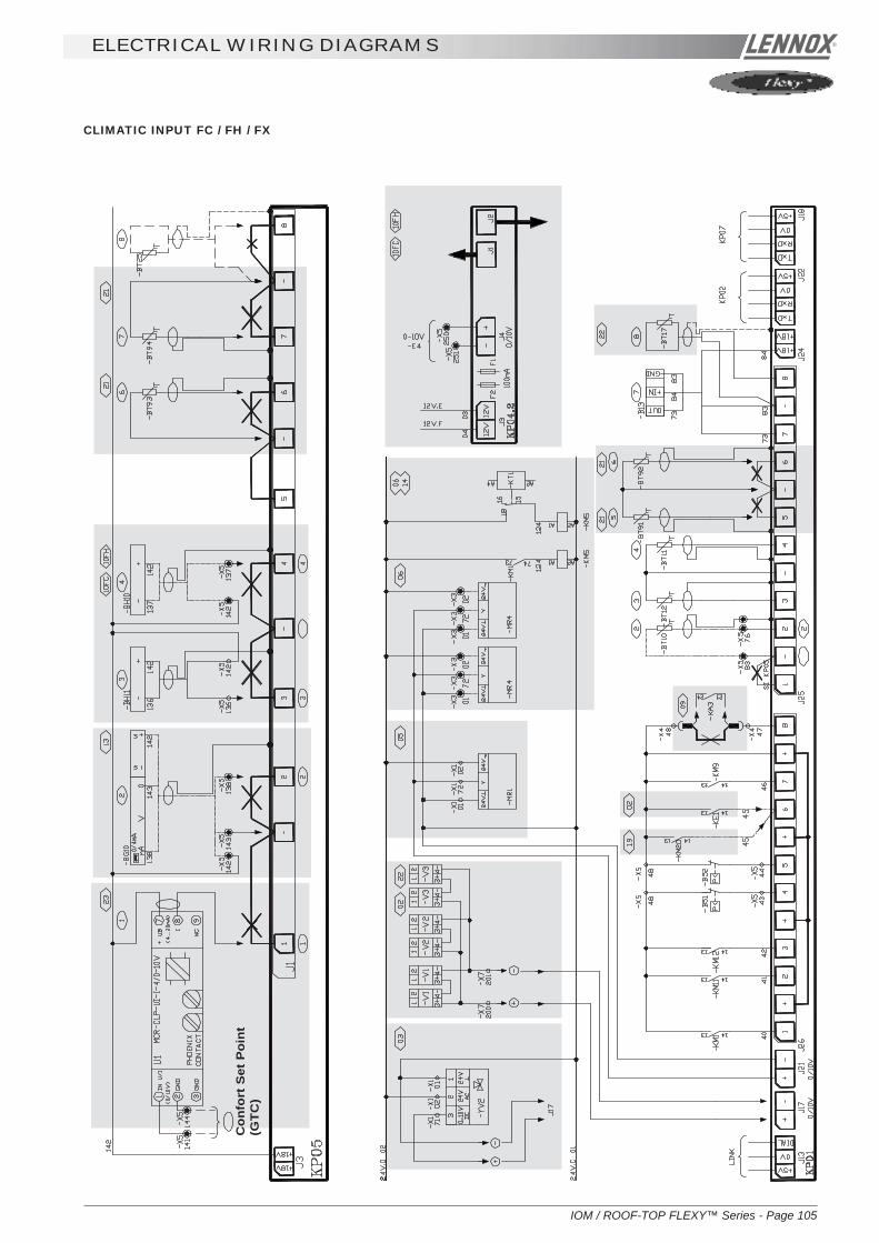
IOM / ROOF-TOP FLEXY™ Series - Page 105
ELECTRICAL WIRING DIAGRAMS
CLIMATIC INPUT FC / FH / FX
Con
fort
Set
Poi
nt(G
TC)

Page 106 - IOM / ROOF-TOP FLEXY™ Series
ELECTRICAL WIRING DIAGRAMS
CLIMATIC INPUT FG / FD

IOM / ROOF-TOP FLEXY™ Series - Page 107
ELECTRICAL WIRING DIAGRAMS
CLIMATIC OUTPUT FC / FH / FX
FAILUREHU
ALA
RM
ON
TR
AN
SF
ER
STAR
TER
PRO
GR
ESSI
VE

Page 108 - IOM / ROOF-TOP FLEXY™ Series
ELECTRICAL WIRING DIAGRAMS
ON
TR
AN
SF
ER
STAR
TER
PRO
GR
ESSI
VE
CLIMATIC OUTPUT FG / FD
ALA
RM
FAILUREHU S
TAR
TER

IOM / ROOF-TOP FLEXY™ Series - Page 109
ELECTRICAL WIRING DIAGRAMS
WIRING DIAGRAM GAS BURNER 33 / 60 / 120 Kw

Page 110 - IOM / ROOF-TOP FLEXY™ Series
ELECTRICAL WIRING DIAGRAMS
GAS BURNER 180 Kw

IOM / ROOF-TOP FLEXY™ Series - Page 111
ELECTRICAL WIRING DIAGRAMS
DAD SMOKE DETECTOR / KP7 GRAPHIC DISPLAY
RESISTANCE
FEMELLE
UNITES2,3,4,5,6,7,8
CUSTOMERELECTRICAL
TRANSFO
GRAPHIC CONTROLDISPLAY
UNITE 1

Page 112 - IOM / ROOF-TOP FLEXY™ Series
ELECTRICAL WIRING DIAGRAMS
DRY CONTACT KIT FOR BMS / REMOTE SET POINT
TCB THERMOSTAT CONTROL BOARD
STO
P C
ON
TRO
L
NIG
HT
CO
NTR
OL
DA
Y C
ON
TRO
L
50%
LO
AD
SH
ED
DIN
G
HE
AT
LOA
D S
HE
DD
ING
CO
LD L
OA
D S
HE
DD
ING
FAU
LT R
ES
ETT
ING
FILT
ER
FA
ULT
TRE
ATM
EN
T FA
N F
AU
LT
CO
MP
RE
SS
OR
FA
ULT
GA
S B
UR
NE
R F
AU
LTE
LEC
TRIC
AL
RE
SIS
TAN
CE
FAU
LT
TOP
LIM
IT T
EM
PE
RA
TUR
EFA
ULT
BO
TTO
M L
IMIT
TEM
PE
RA
TUR
E F
AU
LT
HU
MID
IFIE
R F
AU
LT
FIL
TE
R F
AU
LT
TR
EAT
ME
NT
FAN
FA
ULT
CO
MP
RE
SS
OR
FA
ULT
GA
S B
UR
NE
R F
AU
LTE
LEC
TR
ICA
L R
ES
ISTA
NC
E F
AU
LT

IOM / ROOF-TOP FLEXY™ Series - Page 113
ELECTRICAL WIRING DIAGRAMS
KP 06 (J-BUS INTERFACE)
Relais SPST
Hard ContactsLiaison
Liaison
F1 Fuse 1AJ2 Unit size 8k (position 1-2) 32k (position 2-3)J3 SUBD 9-point connector RS232 linkJ4 15. SUBD 9-point connector RS485 linkJ7 PHENIX 3-point connector supply 230 VJ14 CLIMATIC link 4-point connectorJ15 ADN Inputs 12-point connectorJ16 ADN Outputs 12-point connectorLD1 Monitoring LED power 6V linkLD2 Dialogue monitoring LEDLD3 Power Fell monitoring LEDLD4 Monitoring LED power 5V linkSW1 Speed configuration (9600, 4800 ,2400 or 1200 baud)SW2 Speed configuration (9600, 4800 ,2400 or 1200 baud)SW3 TXD signal configuration RS232 (position 2-3) / RS485
(position 1-2)SW4 RXD signal configuration RS232 (position 2-3) / RS485
(position 1-2)SW5 +10V Converter (Position 1-2)U7 Programmable EPROM CL06U9 Configurable EPROM
Serial link RS232The link is used for short distancesOnly a master control can be connected to this linkSerial link RS485This link is used for long distances (maximum 100 metres)Up to 31 controls can be connected (including 1 master)

Page 114 - IOM / ROOF-TOP FLEXY™ Series
ELECTRICAL WIRING DIAGRAMS
REPARTITEURDE PHASES
REPARTITEURDE PHASES
REPARTITEURDE PHASES
LAYOUT ELECTRICAL PANEL

IOM / ROOF-TOP FLEXY™ Series - Page 115
ELECTRICAL WIRING DIAGRAMS
LAYOUT ELECTRICAL PANEL
FGA / FDA 60 at 190FGK / FDK 60 at 190

Page 116 - IOM / ROOF-TOP FLEXY™ Series
SITE ELECTRICAL CONNECTIONS
KP02 KP18
-E30
-E32KP18
-E31
REGULATION TEMPERATURE PROBE
HYGIENE PROBE REGULATION HYGROMETRY PROBE

IOM / ROOF-TOP FLEXY™ Series - Page 117
SAFETY AND ERROR CODES
000 No fault
001 Failure air flow004 Dirty filters005 Missing filters011 Faulty electrical heater012 Supply air overtemperature013 Temperature room too low014 Faulty gas burner no. 1015 Faulty gas burner no. 2022 Supply temperature too low023 Room overtemperature031 Faulty humidifier032 Room humidity too low033 Room over humidity041 Faulty pump081 Faulty return air or room temperature sensor082 Faulty return air or room relative humidity sensor083 Faulty outside temperature sensor084 Faulty outside relative humidity sensor085 Faulty supply air temperature sensor086 Faulty cold water loop temperature sensor087 Faulty water condenser outlet temperature sensor088 Faulty mixing air temperature sensor091 Faulty blower fan092 Faulty condenser : system 1093 Faulty condenser : system 2094 Faulty condenser : system 3095 Faulty condenser : system 4096 Condenser water temperature too low097 Condenser water overtemperature098 Faulty condenser water flow099 Error : smoke111 Faulty condenser temperature sensor, compressor no. 1112 Faulty pressure transmitter, compressor no. 1115 Faulty high pressure or faulty electrical power, compressor no. 1117 Faulty low pressure compressor no. 1121 Faulty condenser temperature sensor, compressor no. 2122 Faulty pressure transmitter, compressor no. 2125 Faulty high pressure or faulty electrical power compressor no. 2127 Faulty low pressure compressor no. 2131 Faulty condenser temperature sensor, compressor no. 3132 Faulty pressure transmitter, compressor no. 3135 Faulty high pressure or faulty electrical power compressor no. 3137 Faulty low pressure compressor no. 3141 Faulty condenser temperature sensor, compressor no. 4142 Faulty pressure transmitter, compressor no. 4145 Faulty high pressure or faulty electrical power compressor no. 4147 Faulty low pressure compressor no. 4

Page 118 - IOM / ROOF-TOP FLEXY™ Series
The following text includes references such as [C11] and [V25]. They relate to the setpoint or variable numbers used with theKP02 unit.
Wrong Air Flow
If the pressure differential obtained by the analog sensor [V21] is less than the setpoint value[C88] for more than 20 seconds, and if the blower fan has operated for more than 1 minute 30seconds, the air flow safety system is activated and stops the ventilation.The air flow safety system automatically stops after 1 minute 30 seconds and is automaticallylocked out after 3 cut-outs in the same day. In this case a manual reset is obligatory. The cut-out counter is reset to zero every evening at 20:00 if the value does not exceed 3 failures.
Dirty Filters
If the pressure differential obtained by the analog sensor [V21] is greater than the setpointvalue [C86] for more than one minute, the CLIMATIC™ indicates that the filters are dirty. Theunit is not stopped.
Missing Filters
If the pressure differential obtained by the analog sensor [V21] is less than the setpoint value[C87] for more than one minute, the CLIMATIC™ indicates that the filters are missing. The unitis not stopped.
SUPPLY AIR TEMPERATURE SAFETY SYSTEM
Supply Air Overtemperature Limit
1st Safety LevelIf the supply air temperature is greater than or equal to the setpoint [C68], the heat controlsystem starts to reduce progressively. The control cycle will recommence normal operation fora temperature lower than 3°C below this setpoint.
2nd Safety LevelIf the supply air temperature is greater than or equal to the setpoint [C69], the safety system isactivated. The safety system automatically stops at a temperature lower than 3°C below thissetpoint.
Supply Air Temperature Too Low
1st Safety LevelIf the supply air temperature is greater than or equal to the setpoint [C65], the cold controlsystem starts to reduce progressively. The control cycle will recommence normal operation fora temperature in excess of 3°C above this setpoint.
2nd Safety LevelIf the supply air temperature is less than or equal to the setpoint [C66], the unit automaticallypositions its fresh air damper to the all air recycled position and cuts out cold production. Thissafety level automatically stops at a temperature in excess of 3°C above this setpoint.
3rd Safety LevelIf the supply air temperature is less than or equal to the setpoint [C67] for more than 15minutes and for 15 minutes after the fan has started, the "supply air temperature too low" safetysystem is activated. The unit shuts down completely.This safety system cuts out if the supply air temperature is greater than 3°C above this setpoint.It is automatically maintained after 3 cut-outs in the same day, and in this case a manual resetis obligatory. The cut-out counter is reset to zero every evening at 20:00 if the value does notexceed 3 failures.
NOTE : If a unit has a hot water battery, the temperature setpoint value is fixed at +6°C and the
SAFETY AND ERROR CODES
001
004
005
012
022

IOM / ROOF-TOP FLEXY™ Series - Page 119
041
register time set to 5 seconds. In addition, if the antifreeze thermostat is opened, the 3rd safetylevel is immediately automatically maintained. In this case, manual resetting of the thermostatfollowed by the CLIMATIC™ is obligatory
Room Overtemperature Safety System
Upper Room Air LimitIf the room temperature is greater than or equal to the setpoint [C40], the safety system isactivated. It automatically cuts out at a temperature lower than 3°C below this setpoint.
Lower Room Air LimitIf the room temperature is less than or equal to the setpoint [C39], the safety system is activate
Faulty Electrical Heater BatteriesThe electrical heater battery safety thermostats act directly on the heater stage contactors.This information is fed to the CLIMATIC™ via auxiliary contacts.If the CLIMATIC™ gives the order to the heater to operate and if 5 seconds later the auxiliarycontact is still open, the heat safety system is activated and stops the electrical heater assembly.This safety system is automatically locked-out. In this case a manual reset is obligatory.Note: This fault is also displayed in the event of a contact "shunt".
Faulty Gas BurnersIf there is a fault with the gas control boxes the heat safety system is activated and stops therespective burner.This safety system automatically cuts out on the CLIMATIC™ and the control unit must bemanually reset.
Faulty Humidifier (Flexy Only)If there is a fault with the gas control unit for more than a minute, the safety system is activatedand stops the humidifier.This safety system is automatically locked-out. In this case a manual reset is obligatory.
Room Humidity Safety System
Lower Room LimitIf the room humidity is less than or equal to the setpoint [C41] or [C42], the safety system isactivated. It automatically cuts out at a humidity of 3% above this setpoint.
Upper Room LimitIf the room humidity is greater than or equal to the setpoint [C43] or [C44], the safety system isactivated. It automatically cuts out at a humidity of 3% below this setpoint.
Faulty PumpThe internal protection of the water pump motor acts directly on the pump contactor. This information istransmitted to the CLIMATIC™ via an auxiliary contact of the contactor.If the CLIMATIC™ gives the pump the order to operate and if 5 seconds later the auxiliary contactremains open, the safety system is activated and stops the pump.The safety system is immediately automatically locked out. In this case, manual resetting is obligatory.Note: This error is also displayed in the event of a "shunt" of the auxiliary contact of the contactor.
SAFETY AND ERROR CODES
023
013
011
031
014
015
032
033

Page 120 - IOM / ROOF-TOP FLEXY™ Series
Sensor Status
Room temperature sensor missing or faulty.
Room relative humidity sensor missing or faulty
Outside air temperature sensor faulty
Outside relative humidity sensor faulty
Supply Air temperature sensor faulty
Temperature sensor on cold water loop faulty
Temperature sensor on condenser water outlet faulty.
NOTE :Missing or faulty room, supply air or outside air temperature sensors can affect the overallcontrol system. A safety device will be activated and all equipment except for the ventilation willcut out. Failure of the other sensors will only stop the equipment involved.
Faulty inter card linkThe inter card link is faulty or missing.
Faulty blower fanThe fan contactor is not connected although the CLIMATIC™ requests it.
- The thermostat fire safety mechanism, or the fire insertion, is open.- The internal protection of the blower fan motor is open.
The fire detector and the fan motor internal protection act directly on the fan motor contactor.This information is transmitted to the CLIMATIC™ via an auxiliary contact of the contactor. Ifthe CLIMATIC™ gives the order to operate to the fan and if the auxiliary contact is still open 5seconds later, the fan safety system is activated and stops the unit.The safety system is immediately automatically locked out. In this case, manual resetting isobligatory.If a unit is fitted with an all-or-nothing servomotor-powered damper, the detection time extendsto 2 minutes (Flexy™ only).Note : This error is also displayed in the event of a "shunt" of the auxiliary contact of thecontactor.
Faulty ventilation, condenser circuit 1 or 2The fan contactor is not connected although the CLIMATIC™ requests it.The fan motor internal protection acts directly on the fan motor contactor. This information istransmitted to the CLIMATIC™ via an auxiliary contact of the contactor.If the CLIMATIC™ gives the order to operate to the fan and if the auxiliary contact is still open5 seconds later, the fan safety system is activated and stops the condenser fan and thecompressors concerned.The safety system is immediately automatically locked out. In this case, manual resetting isobligatory.
Faulty ventilation, condenser circuit 3 or 4The fan contactor is not connected although the CLIMATIC™ requests it.The fan motor internal protection acts directly on the fan motor contactor. This information istransmitted to the CLIMATIC™ via an auxiliary contact of the contactor.If the CLIMATIC™ gives the order to operate to the fan and if the auxiliary contact is still open5 seconds later, the fan safety system is activated and stops the condenser fan and thecompressors concerned.The safety system is immediately automatically setpoint. In this case, manual resetting isobligatory.
089
SAFETY AND ERROR CODES
081
082
083
084
085
086
087
091
092
093

IOM / ROOF-TOP FLEXY™ Series - Page 121
Customer errorA fault has been detected, external to the unit.
Water leakIf the contact of the water leak detection card is closed for more than 30 seconds, the safetysystem is activated.
WATER HEAT EXCHANGER OUTLET TEMPERATURE SAFETY SYSTEM.
Condenser Water Temperature Too Low
If the temperature of the water loop is less than or equal to the preset setpoint [C80] during theoperation of one of the compressors, the condenser safety mechanism is applied. Thecompressors are stopped.This safety mechanism automatically cuts out if the loop temperature exceeds 4°C from thissetpoint.It is also automatically locked out after 3 failures within a day. In this case, manual resetting isobligatory. The counter is reset to zero every evening at 20:00 if its value does not exceed 3failures.
Condenser Water Temperature Too High
The temperature of the water loop is greater than or equal to the preset setpoint [C81] duringthe operation of one of the compressors, the condenser safety mechanism is applied. Thecompressors are stopped.This safety mechanism automatically cuts out if the loop temperature is less than 4°C from thissetpoint.It is also automatically locked out after 3 failures within a day. In this case, manual resetting isobligatory. The counter is reset to zero every evening at 20:00 if its value does not exceed 3failures.
Faulty Water Flow
If the contact of the water flow controller is open for more than 20 seconds, the condensersafety mechanism is applied. The compressors are stopped.This safety mechanism automatically cuts out if the loop temperature is less than 4°C from thissetpoint.It is also automatically locked out after 3 failures within a day. In this case, manual resetting isobligatory. The meter is reset to zero every evening at 20:00 if its value does not exceed 3failures.
Error : Smoke
If the contact closes due to the smoke detector card, the smoke safety mechanism is activated.The unit is completely shut down and the fresh air louver is set to the fresh air position.This safety mechanism is automaticallylocked out. In this case, manual resetting is obligatory.
SAFETY AND ERROR CODES
094
095
096
096
098
099

Page 122 - IOM / ROOF-TOP FLEXY™ Series
Refrigeration system faults
Faulty condenser temperature sensor
Faulty pressure transmitter sensor, refrigeration system
Faulty refrigeration system, frost temperature sensor
High pressure switch safety or compressor electrical safety
The compressor contactor is not connected although the CLIMATIC™ requests it.- The high pressure pressostat is open.- The internal protection of the compressor motor is open.
The high pressure pressostat and the compressor motor thermal protection act directly on thecompressor contactor. This information is transmitted to the CLIMATIC™ via an auxiliary contactof the contactor.If the CLIMATIC™ gives the order to operate to the compressor and if the auxiliary contact isstill open 5 seconds later, the fan safety system is activated and stops the compressor.Thesafety system automatically cuts out after 4 minutes.It is also automatically locked out after 3 failures within a day. In this case, manual resetting isobligatory. The counter is reset to zero every evening at 20:00 if its value does not exceed 3failures.
Faulty low pressure compressor
If the low pressure pressostat is open and the compressor has been operating for more than 2minutes, the low pressure safety system is activated and stops the compressor. This safetysystem is not taken into account during the defrost cycle for the heat pump units.The compressor is engaged when the pressostat contact closes.It is also automatically locked out after 3 failures within a day. In this case, manual resetting isobligatory. The counter is reset to zero every evening at 20:00 if its value does not exceed 3failures.
SAFETY AND ERROR CODES
111
121
131
141
112
122
132
142
113
123
133
143
115
125
135
145
117
127
137
147

IOM / ROOF-TOP FLEXY™ Series - Page 123
FAULT
LP PROBLEMSandLP CUT OUTS
HP PROBLEMSAND HP CUTOUTS
maintenance diagnostic
REFRIGERATION
POSSIBLE CAUSE AND SYMPTOMS
Refrigerant charge too low
In Heat Pump Mode the temperature differencebetween T outdoor and Tevap. (Dew) is toohigh5°C < Delta T < 10°C excellent10°C < Delta T < 15°C acceptable15°C < Delta T < 25°C too high
Refrigeration circuit blocked in distribution
Liquid line drier blocked. High temperaturedifference between inlet and outlet of the drier
Contaminant in the expansion valve
Expansion valve not adjusted properly
Ice plug in the expansion valve.
Incorrect insulation of the thermostatic bulb ofthe expansion valve
Low Pressure Switch cut out point too high
LP cut out due to not enough defrost on heatpumps
Incorrect Airflow rates
Moisture or contaminants in the system
SOLUTION
Measure the superheat and sub-cooling:Good if 5°C<SC<10°C and 5°C<SH<10°CBad if SC>10°C and SH too LowCheck superheat adjustment and charge unit (aleak check must be carried out)
If too high check the coils are clean or checkcoil internal pressure drop between the liquidline and the suction lineGood if < 3barToo high if > 3bar (coil blocked)
Stop the fan and create icing of the coil.Check all circuits freeze evenly across thewhole surface of the coilIf some parts of the coil do not freeze this couldindicate a problem with the distribution
Change filter drier
Attempt to free the valve adjusting element byfreezing the valve and then heating thethermostatic element. Replace the valve ifnecessary
Adjust the expansion valve
Heat the main body of the valve. If the LPincreases and then decreases gradually, emptythe circuit and replace the drier.
Superheat too low: adjust superheatMove the thermostatic element along the pipeInsulate the Thermostatic element of the valve
Check the cut out pressure of the Low Pressureswitch: It must be 0.7+/- 0.2bar and mustcloses at 2.24 +/- 0.2 bar
Adjust the CLIMATIC settings to extend thedefrost cycles or shorten the time betweendefrosts
Heat pump mode :Check the filter before the indoor coilmeasure and estimate the airflow rateincrease the speed of the fanCooling mode :Check the condenser fan (Amps)
Summer operationSeveral hours after the unit has stopped, checkthe correspondance between the measuredpressure and the outdoor temperature
Table 15

Page 124 - IOM / ROOF-TOP FLEXY™ Series
maintenance diagnostic
FAULT
HP PROBLEMSAND HP CUTOUTS
Strong variationsof pressure ( 2 to 3bar) ThermostaticExpansion Valve"hunting"
Very highdischargetemperature,High ampsmeasured atcompressor
POSSIBLE CAUSE AND SYMPTOMS
Moisture or contaminants in the system
Condenser coil is obstructed
Recycled Hot Air
Incorrect adjustment of the expansion valve
Low refrigerant charge
Filter drier obstructed with gas bubbles at theexpansion valve inletMoisture in the system
Very high superheat, very hot compressor
Four Way reversing valve possibly blocked,abnormal noise from the valve, low LP andincreasing HP
SOLUTION
If the circuit pressure is higher (<1bar) than thesaturated pressure corresponding to themeasured outdoor temperature, there ispossibility that some contaminants are presentin the system.Reclaim the refrigerant, and vacuum the circuit(Ensure very low and slow vacuum for R407c)Recharge the unit
Check the condenser coil and clean isnecessary
Check clearance around the condenser
Refer to LP problems and LP cut out section
Open the superheat adjustment on the expan-sion valve.Check the pressure drop on the filter drier inthe suction line
Check operation of the valve by going throughcycle inversions. Change if necessary.Refer to LP problems
INDOOR FAN BLOWER
REFRIGERATION
FAULT
High amps onaction Fan motor
High amps onreaction Fanmotor
Unstable runningand high vibration
POSSIBLE CAUSE AND SYMPTOMS
Pressure drop in the ducting installation toolow.
Pressure drop in the ducting installation toohigh.
Fan jumping from one operating point tothe other.
SOLUTION
Reduce the rotation speed of the fanMeasure and estimate the airflow and pressureand compare with the specification fromcustomer.
Reduce the rotation speed of the fanMeasure and estimate the airflow and pressureand compare with the specification fromcustomer.
Change rotation speed of the fan.

IOM / ROOF-TOP FLEXY™ Series - Page 125
maintenance diagnostic
FAULT
Heat Pump mode: Circuit breakeropen
POSSIBLE CAUSE AND SYMPTOMS
High Amps due to a low voltage from the mainsupply
High amps due to freezing of the coil
Flexy : Water ingress in the motor connectionbox.
SOLUTION
Check the voltage drop when all componentsare running.Change the circuit breaker for one with a higherrating.
Check the adjustable amps on the motorstarter.Adjust the defrost cycle set points.
Change the component
OUTDOOR AXIAL FAN
FAULT
High Temperaturetrip out onelectric heater
POSSIBLE CAUSE AND SYMPTOMS
Low airflow rate
Incorrect position of the Klixon
SOLUTION
Measure and estimate the airflow and pressureand compare with the specification fromcustomer.
Check that the Klixon, is positioned in theairflow, relocate Klixon if necessaryCheck that there is no heat transfer from theKlixon support.
ELECTRIC HEATER
FAULT
Water found inthe ventilationsection
Water ingress inthe filtercompartment
POSSIBLE CAUSE AND SYMPTOMS
Cooling mode:Water carried away from the coil because ofexcessive airflow and speed on the coil.
Low air pressure in the compartment due to ahigh airflow rate or a high pressure drop beforethe fan
Check seals around the ventilation section.
Water ingress through a leaking fresh air hoodor when running 100% fresh air
SOLUTION
Estimate the airflow rate and check the speedis lower than 2.8 m/s
Check filterReduce airflow rate
Check the door sealCheck for the presence of silicone seals in thecorners of the door and at the bottom of therefrigeration section bulkhead.
Check the seals and flanges in the fresh airhoodReduce the airflow rate if necessary
ELECTRIC HEATER

Page 126 - IOM / ROOF-TOP FLEXY™ Series
Rooftops are generally placed on the roof but can also be installed in technical rooms. These units are very robust but aminimum regular maintenance is required. Some moving parts in the units can suffer from wear and tear and must bechecked regularly (belts). Other parts can get clogged by dirt carried in the air (filters) and must be cleaned or replaced.
These units are designed to produce cooled or heated air through the use of a refrigeration vapour compression system, it istherefore imperative to monitor the refrigeration circuit operating pressures and check the pipe-work for leaks.
The table below, details a possible maintenance plan, including the operations to be carried out and the periodicity at whichthey must be accomplished. It is recommended to follow such a plan to keep a rooftop unit in good working order. Regularmaintenance of your rooftop will extend its operating life and reduce operating faults
Symbols and Legend :
0 Operation which can be carried out by on-site maintenance technicians.
∆∆∆∆∆ Operation which must be carried out by qualified personnel, trained to operate on this type of equipment.
NOTE :
- Times are given for information purpose only and may vary depending on the unit size and type of installation.
- Coil cleaning must be carried out by qualified personnel using appropriate methods that won't damage the fins or thetubes.
- It is recommended to keep a minimum stock of common replacement parts in order to be able to carry out regularmaintenance operations (i.e. filters). You can contact your local Lennox representative which can assist you inestablishing a parts list for each type of equipment.
- The access ports to the refrigeration circuits MUST be leak checked every time gauges are connected to the serviceports.
MAINTENANCE PLAN

IOM
/ RO
OF-TO
P FLE
XY
™ S
eries - Page 127
MA
INT
EN
AN
CE
PL
AN
TASK
Clean or replace filters: Disposable, or metalframe.
Visual check of the oil level
Position check of the compressor crankcaseheater.
Belt tension check.
Centrifugal fan bearings check
Check absorbed Amps
Check Smoke detector
Check Climatic control, set-points and varia-bles
Check clock settings
Check the position and tightness ofrefrigeration components
Check Airflow rate safety switch (if fitted).
Check freeze protection on HWC
Check three way valve on HWC
Check economiser actuator operation
Check refrigeration 4way valve
Check tightness of all electrical connections
OPERATING MODE
Replace filters with new ones if disposable. Vacuum clean or blowthe dirt. Wash and dry carefully. +Replace media if necessaryBlocked filter will reduced the performance of the unit.THE UNIT MUST NOT OPERATE WITHOUT FILTERS
Visually check the oil level through the sight glass on the side ofthe compressor casing
Check the heating resistance is fitted properly and tight around thecompressor body.
Check belt tension (Info in IOM) Replace belt if necessary.
Isolate unit from the main power supply; Push the fan wheelmanually and check for abnormal noises. Bearings are lubricatedfor life but may need replacement after 10000 hours
Check absorbed Amps on all three phases; compare with thenominal value given in the electrical wiring diagram.
Start the unit. Trigger the smoke detector by moving a magnetaround the detector head. Reset unit and control.
Refer to the commissioning sheet; Check all set points are setaccording to this document.
Check the time and date of the control
Check systematically all connections and fixings on therefrigeration circuit. Check for oil traces, eventually a leak testshould be conducted. Check operating pressures correspond tothe ones indicated on the commissioning sheet
Shut down supply fan. The fault must be detected within 5seconds.
Increase room set-point 10°C above the actual room temperature.Check operation of the piston. It must move away from the valvehead. Reset the control.
Check all fixings and transmission. Stop the unit using the control.The fresh air damper must closes. Start the unit the fresh airdamper should open
With the unit running in cooling mode increase the room set-pointtemperature by 10°C. The unit should switch to heat pump mode.Reset the control.
Power down the unit and check and tighten all screws, terminaland electric connections, taking a particular attention to the powerlines and low voltage control wires
6 YEARLY ESTIMATEDMONTHLY QUARTERLY MONTHLY B4 TIME
WINTER (mn)
0 20
0 2
0 2
0 10
0 10
∆ 15
∆ 5
∆ 15
0 5
∆ 30
0
∆ 5
∆ 5
∆ 5
∆ 5
∆ 30
Table 16

Page 128 - IO
M / R
OO
F-TOP FLE
XY
™ S
eries
MA
INT
EN
AN
CE
PL
AN
TASK
Check HP / LP safety switches
Check outdoor fans and fan guards
Check position of all sensors
Check and clean if necessary all fresh airgrilles
Check indoor and outdoor coils, clean ifnecessary
Check electric heater element for excessivecorrosion
Check anti-vibration mountings, for wear andtear.
Check refrigeration circuit for traces of acidin the oil
Check Glycol concentration in the HWCcircuit
Check defrost cycle with 4-way valve inver-sion.
Gas burner module check for corrosion
Sweeping and cleaning the gas burner
Gas supply pressures / connectionschecks
Gas regulation valve settings
Check gas burner safety switches
OPERATING MODE
Install manifold gauges on the circuit to be checked. Shut downthe axial fans and wait for the HP switch to shut down thecompressor: 29bar (+1 / -0) auto-reset 22bar (+ - 0.7)Reconnect fans. Switch off the centrifugal supply fan and waitfor the LP switch to cut out: 0.5bar (+ - 0.5) reset 1.5bar (+-0.5).
Check the fan blades conditions and all fan guards and protec-tions
Check the good positioning and operation of all sensors of allsensors. Check the values given in the control system. Replacesensor if necessary
Check the fresh air grilles (if fitted). If dirty or damaged, removethem from unit and clean with high pressure water cleaner. Refiton unit once clean and dry.
Visually check the coils for dirt. If not too dirty, cleaning with alight brush may be enough (WARNING: Fins and copper tubesare very fragile! Any damage WILL reduce the performances ofthe unit). If very dirty, deep industrial cleaning is required usingde-greasing agents.(External contractors must be called).
Isolate the unit; Pull the electric heater out of the heater modulebox and check the resistances fo traces of corrosion; Replaceresistance as required;
Visually check anti-vibration mountings on compressors andcentrifugal fan. Replace if damaged.
Take a sample of oil from the refrigeration circuit.
Check the glycol concentration in the pressurised water circuit.( a concentration of 30% gives a protection down to aprox. -15°C) check the circuit pressure
Switch the unit to heat pump mode. Change the set point toobtain the standard defrost mode and reduce the cycle time tothe min value. Check the operation of the defrost cycle.
Pull out the burner to access the tubes (refer to Gas burnersection in the IOM)
Clean the in-shot burners and the blower wheel lightly with abrush. Sweep the flue and flue box. Wipe-off the dust from thehousing of the motor. Clean combustion air inlet louvers Pull-outbaffles from the tubes, sweep the tubesCHECK FLUE BOX GASKET
refer to Gas burner section in the IOM for details
refer to Gas burner section in the IOM for details
refer to Gas burner section in the IOM for details
6 YEARLY ESTIMATEDMONTHLY QUARTERLY MONTHLY B4 TIME
WINTER (mn)
∆ 15
0 5
0 5
0 5
0 / ∆ 1h if cleaning
0 1h ifreplacement
0 1h ifreplacement
∆
∆ 30
∆ 30
∆ 30
∆ 30
∆ 15
∆ 30
∆ 30

IOM / ROOF-TOP FLEXY™ Series - Page 129
warranty
TERMS AND CONDITIONSIn the absence of any other written agreement, the guaranteeshall only apply to design faults which occur within a 12 monthperiod (warranty period).
The warranty period starts on the date of commissioning andat the latest six months after the delivery of the Rooftop.
ANTI-CORROSION WARRANTY
10 year warranty terms and conditions for corro-sion to the Rooftop casing :
Lennox shall guarantee the casing of its Rooftop unitsmanufactured since May 1991 against corrosion for 10 yearscommencing from the date of delivery of the material.
The warranty shall not apply in the following cases :1. If the corrosion of the casing is caused by external
damage to the protective layer such as scratches,projections, abrasion, impacts etc...
2. If the casing is not kept continually clean in the courseof maintenance work or by a specialist company,
3. If the casing is not cleaned and maintained inaccordance with regulations,
4. If the Rooftop units are installed on a site or in anenvironment which is known to be corrosive, unless aspecial protective coating has been applied by theowner for these applications, which has beenrecommended by a competent body not linked to theowner and after carrying out a study of the site.
Note : With the exception of the casing, the rest of the machineis covered by the warranty of our general terms of sale.
DO NOT CONFUSE THE WARRANTYWITH MAINTENANCEThe warranty will only apply if a maintenance contract hasbeen signed, starting from the date of commissioning, and ifthe maintenance contract has actually been performed.
The maintenance contract must be made with a specialist,
competent company.
The sole effect of any repair, modification or replacement ofan item during the warranty period must be to extend thematerial's warranty period.
Maintenance must be carried out in accordance withregulations.
If a spare part is supplied after the expiry of the warranty period,it shall be guaranteed for a period equal to the initial warrantyperiod and will be subject to the same conditions.
We recommend for a contract four inspections per year (everythree months), before the start of each season, in order tocheck the operation of the equipment in the various operatingmodes.

Page 130 - IOM / ROOF-TOP FLEXY™ Series
ISO 9001 CERTIFICATION

IOM / ROOF-TOP FLEXY™ Series - Page 131
PED CERTIFICATION OF CONFORMITY

Page 132 - IOM / ROOF-TOP FLEXY™ Series
GLASS WOOL FIRE CLASS

IOM / ROOF-TOP FLEXY™ Series - Page 133
33 kW GAS BURNER CE CERTIFICATION OF CONFORMITY

Page 134 - IOM / ROOF-TOP FLEXY™ Series
60 kW GAS BURNER CE CERTIFICATION OF CONFORMITY

IOM / ROOF-TOP FLEXY™ Series - Page 135
120 kW GAS BURNER CE CERTIFICATION OF CONFORMITY

Page 136 - IOM / ROOF-TOP FLEXY™ Series
180 kW GAS BURNER CE CERTIFICATION OF CONFORMITY

IOM / ROOF-TOP FLEXY™ Series - Page 137
INSULATION FIRE CLASS

Page 138 - IOM / ROOF-TOP FLEXY™ Series
INSULATION FIRE CLASS


www.lennoxeurope.com
FLEXY_IOM/0803-EDue to Lennox's ongoing commitment to quality, Specifications, Ratings and Dimensions subject to change without notice and without incurring liability.Improper installation, adjustment, alteration, service or maintenance can cause property damage or personal injury.Installation and service must be performed by a qualified installer and servicing agency.
LENNOX BENELUX N.V./S.A.tel. : + 32 3 633 30 45fax : + 32 3 633 00 89e-mail : [email protected]
JANKA LENNOX a.s.tel. : + 420 2 510 88 111fax : + 420 2 579 10 393e-mail : [email protected]
LENNOX FRANCEtel. : + 33 1 64 76 23 23fax : + 33 1 64 76 35 75e-mail : [email protected]
LENNOX DEUTSCHLAND GmbHtel. : + 49 69 42 09790fax : + 49 69 42 09 79 40e-mail :[email protected]
LENNOX BENELUX B.V.tel. : + 31 33 2471 800fax : + 31 33 2459 220e-mail : [email protected]
LENNOX POLSKA Sp. z o.o.tel. : + 48 22 832 26 61fax : + 48 22 832 26 62e-mail : [email protected]
LENNOX PORTUGAL LDA.tel. : +351 22 998 33 70fax : +351 22 998 33 79e-mail : [email protected]
LENNOX DISTRIBUTION MOSCOWtel. : + 7 095 246 07 46fax : + 7 502 933 29 55e-mail : [email protected]
LENNOX SLOVENSKO s.r.o.tel. : + 421 2 44 87 19 27fax : + 421 2 44 88 64 72e-mail : [email protected]
LENNOX REFAC S.A.tel. : + 34 915 40 18 10fax : + 34 915 42 84 04e-mail : [email protected]
LENNOX DISTRIBUTION KIEVtel. : + 380 44 213 14 21fax : + 380 44 213 14 21e-mail : [email protected]
LENNOX INDUSTRIES LTDtél. : + 44 1604 599400fax : + 44 1604 594200e-mail : [email protected]
LENNOX DISTRIBUTIONtel. : + 33 4 72 23 20 14fax : + 33 4 72 23 20 28e-mail : [email protected]
BELGIUM,LUXEMBOURG :
CZECH REPUBLIC :
FRANCE :
GERMANY :
NETHERLANDS :
POLAND :
PORTUGAL :
RUSSIA :
SLOVAKIA :
SPAIN :
UKRAINE :
UNITED KINGDOM,IRELAND :
OTHER EUROPEAN COUNTRIES,AFRICA,
MIDDLE-EAST :