Service Manual | Lennox Global
161
Thank you for selecting LENNOX air conditioners. Service Manual LIUH018180P431-C LIUH024180P431-C LIUH036180P431-C LIUH048180P431-C LIUH060180P431-C LICH4018180P431-C LICH4024180P431-C LICH4036180P431-C LICH4048180P431-C LICH4012180P431-C LIFHC018180P431-C LIFHC024180P431-C LIFHC036180P431-C LIFHC048180P431-C LIFHC060180P431-C LIFHC012180P431-C LISH012000P431-C LISH024000P431-C LISH036000P431-C LISH048000P431-C LISH060000P431-C LISH018000P431-C
-
Upload
khangminh22 -
Category
Documents
-
view
2 -
download
0
Transcript of Service Manual | Lennox Global

Thank you for selecting LENNOX air conditioners.
Service ManualLIUH018180P431-CLIUH024180P431-CLIUH036180P431-CLIUH048180P431-CLIUH060180P431-C
LICH4018180P431-CLICH4024180P431-CLICH4036180P431-CLICH4048180P431-C
LICH4012180P431-C
LIFHC018180P431-CLIFHC024180P431-CLIFHC036180P431-CLIFHC048180P431-CLIFHC060180P431-C
LIFHC012180P431-C
LISH012000P431-C
LISH024000P431-CLISH036000P431-CLISH048000P431-CLISH060000P431-C
LISH018000P431-C

CONTENTS
1. Precaution............................................................................................................................................... 1
1.1 Safety Precaution .......................................................................................................................... 4
1.2 Warning.......................................................................................................................................... 4
2. Part Names and Features ....................................................................................................................... 7
2.1 Model Names of Indoor/Outdoor units .......................................................................................... 7
2.2 Part names of Indoor/Outdoor units .............................................................................................. 8
2.3 Features....................................................................................................................................... 13
3. Dimension ............................................................................................................................................. 16
3.1 Indoor Unit ................................................................................................................................... 16
3.2 Outdoor Unit ................................................................................................................................ 21
4. Service Space ....................................................................................................................................... 23
4.1 Indoor Unit ................................................................................................................................... 23
4.2 Outdoor Unit ................................................................................................................................ 23
5. Refrigerant Cycle Diagram ................................................................................................................... 26
6. Wiring Diagram ..................................................................................................................................... 27
6.1 Indoor Unit ................................................................................................................................... 27
6.2 Outdoor Unit ................................................................................................................................ 35
7. Fan Curves............................................................................................................................................ 40
8 Electric Characteristics ......................................................................................................................... 47
9 Sound Level ........................................................................................................................................... 48
9.1 Indoor unit .................................................................................................................................... 48
9.2 Outdoor unit ................................................................................................................................. 51
10 Accessories ......................................................................................................................................... 52
11. The Specification of Power ................................................................................................................ 54
13.Installation Details
...............................................................................................................................
57
13.1Location selection
.......................................................................................................................
57
13.2 Indoor unit installation
...............................................................................................................
57
13.3 Outdoor unit installation.............................................................................................................
67
13.4 Refrigerant pipe installation
.......................................................................................................
68
13.5 Drainage pipe installation
..........................................................................................................
72
13.6 Vacuum Drying and Leakage Checking
....................................................................................
75
13.7 Additional refrigerant charge
.....................................................................................................
76
13.8 Engineering of insulation
...........................................................................................................
77
13.9 Engineering of electrical wiring..................................................................................................
78
13.10 Test operation
..........................................................................................................................
78
14. Operation Characteristics
................................................................................................................
80
15. Electronic Function
..........................................................................................................................
81
15.1 Abbreviation
.............................................................................................................................
81
15.2 Display function
.......................................................................................................................
81
15.3 Main Protection........................................................................................................................
81
12. Field Wiring ................................................................................................................ 55................................
15.4 Operation Modes and Functions ............................................................................................. 83
16. Troubleshooting ............................................................................................................................... 89
16.1 Indoor Unit Error Display ......................................................................................................... 90
16.2 Error Display on Two Way Communication Wired Controller ................................................. 91
16.3 Outdoor unit error display ........................................................................................................ 92
16.4 Diagnosis and Solution ............................................................................................................ 96
16.5 Main parts check ..................................................................................................................... 122
17. Disassembly Instructions................................................................................................................. 129
17.1 Indoor unit ................................................................................................................................ 129
17.2 Outdoor unit ............................................................................................................................. 139
4
1. Precaution
1.1 Safety Precaution
To prevent injury to the user or other
people and property damage, the following
instructions must be followed.
Incorrect operation due to ignoring
instruction will cause harm or damage.
Before service the unit, be sure to
read this service manual at first.
1.2 Warning
Installation
Do not use a defective or underrated
circuit breaker. Use this appliance on a
dedicated circuit.
There is risk of fire or electric shock.
For electrical work, contact the dealer,
seller, a qualified electrician, or an
authorized service center.
Do not disassemble or repair the product,
there is risk of fire or electric shock.
Always ground the product.
There is risk of fire or electric shock.
Install the panel and the cover of
control box securely.
There is risk of fire of electric shock.
Always install a dedicated circuit and
breaker.
Improper wiring or installation may cause
electric shock.
Use the correctly rated breaker of
fuse.
There is risk of fire or electric shock.
Do not modify or extend the power
cable.
There is risk of fire or electric shock.
Do not install, remove, or reinstall the
unit by yourself (customer).
There is risk of fire, electric shock, explosion,
or injury.
Be caution when unpacking and
installing the product.
Sharp edges could cause injury, be especially
careful of the case edges and the fins on the
condenser and evaporator.
For installation, always contact the
dealer or an authorized service center.
Do not install the product on a
defective installation stand.
Be sure the installation area does not
deteriorate with age.
If the base collapses, the air conditioner could
fall with it, causing property damage, product
failure, and personal injury.
Do not let the air conditioner run for a
long time when the humidity is very high
and a door or a window is left open.
Take care to ensure that power cable
could not be pulled out or damaged during
operation.
There is risk of fire or electric shock.
Do not place anything on the power
cable.
There is risk of fire or electric shock.
Do not plug or unplug the power
supply plug during operation.
There is risk of fire or electric shock.
Do not touch (operation) the product
with wet hands.
Do not place a heater or other
appliance near the power cable.
There is risk of fire and electric shock.
Do not allow water to run into
electrical parts.
It may cause fire, failure of the product, or
electric shock.
Do not store or use flammable gas or
combustible near the product.
There is risk of fire or failure of product.
Do not use the product in a tightly
closed space for a long time.
Oxygen deficiency could occur.
When flammable gas leaks, turn off
the gas and open a window for ventilation
before turn the product on.
5
If strange sounds or smoke comes
from product, turn the breaker off or
disconnect the power supply cable.
There is risk of electric shock or fire.
Stop operation and close the window
in storm or hurricane. If possible, remove
the product from the window before the
hurricane arrives.
There is risk of property damage, failure of
product, or electric shock.
Do not open the inlet grill of the
product during operation. (Do not touch the
electrostatic filter, if the unit is so equipped.)
There is risk of physical injury, electric shock,
or product failure.
When the product is soaked, contact
an authorized service center.
There is risk of fire or electric shock.
Be caution that water could not enter
the product.
There is risk of fire, electric shock, or product
damage.
Ventilate the product from time to
time when operating it together with a stove
etc.
There is risk of fire or electric shock.
Turn the main power off when
cleaning or maintaining the product.
There is risk of electric shock.
When the product is not be used for a
long time, disconnect the power supply plug
or turn off the breaker.
There is risk of product damage or failure, or
unintended operation.
Take care to ensure that nobody
could step on or fall onto the outdoor unit.
This could result in personal injury and
product damage.
CAUTION
Always check for gas (refrigerant)
leakage after installation or repair of
product.
Low refrigerant levels may cause failure of
product.
Install the drain hose to ensure that
water is drained away properly.
A bad connection may cause water leakage.
Keep level even when installing the
product.
It can avoid vibration of water leakage.
Do not install the product where the
noise or hot air from the outdoor unit could
damage the neighborhoods.
It may cause a problem for your neighbors.
Use two or more people to lift and
transport the product.
Do not install the product where it will
be exposed to sea wind (salt spray) directly.
It may cause corrosion on the product.
Corrosion, particularly on the condenser and
evaporator fins, could cause product
malfunction or inefficient operation.
Operational
Do not expose the skin directly to
cool air for long time. (Do not sit in the
draft).
Do not use the product for special
purposes, such as preserving foods, works
of art etc. It is a consumer air conditioner,
not a precision refrigerant system.
There is risk of damage or loss of property.
Do not block the inlet or outlet of air
flow.
Use a soft cloth to clean. Do not use
harsh detergents, solvents, etc.
There is risk of fire, electric shock, or damage
to the plastic parts of the product.
Do not touch the metal parts of the
product when removing the air filter. They
are very sharp.
Do not step on or put anything on the
product. (outdoor units)
Always insert the filter securely.
Clean the filter every two weeks or more
often if necessary.
A dirty filter reduces the efficiency of the air
conditioner and could cause product
malfunction or damage.

6
Do not insert hands or other objects
through air inlet or outlet while the product
is operated.
Do not drink the water drained from
the product.
Use a firm stool or ladder when
cleaning or maintaining the product.
Be careful and avoid personal injury.
Replace the all batteries in the remote
control with new ones of the same type. Do
not mix old and new batteries or different
types of batteries.
There is risk of fire or explosion.
Do not recharge or disassemble the
batteries. Do not dispose of batteries in a
fire.
They may burn of explode.
If the liquid from the batteries gets
onto your skin or clothes, wash it well with
clean water. Do not use the remote of the
batteries have leaked.
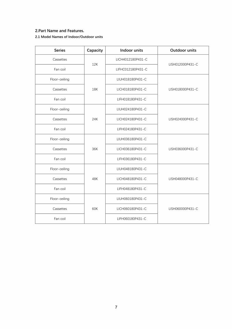
2.Part Name and Features.
2.1 Model Names of Indoor/Outdoor units
Series Capacity Indoor units Outdoor units
Cassettes
12K
LICH4012180P431-C
LISH012000P431-C
Fan coil LIFHC012180P431-C
Floor-ceiling
18K
LIUH018180P431-C
LISH018000P431-C Cassettes LICH018180P431-C
Fan coil LIFH018180P431-C
Floor-ceiling
24K
LIUH024180P431-C
LISH024000P431-C Cassettes LICH024180P431-C
Fan coil LIFH024180P431-C
Floor-ceiling
36K
LIUH036180P431-C
LISH036000P431-C Cassettes LICH036180P431-C
Fan coil LIFH036180P431-C
Floor-ceiling
48K
LIUH048180P431-C
LISH048000P431-C Cassettes LICH048180P431-C
Fan coil LIFH048180P431-C
Floor-ceiling
60K
LIUH060180P431-C
LISH060000P431-C Cassettes LICH060180P431-C
Fan coil LIFH060180P431-C
7

8
2.2 Part names of Indoor/Outdoor units
Cassette Units

9
A6 Duct Units

10
Ceiling-floor Units

11
2.3.2 Cassette Units
2.3.2.1 Lower Noise
Optimize air channel system design to ensure the maximum quietness and comfort.
Noise max down 6dB.
2.3.2.2 Turbo Mode (Optional)
Turbo function can boost cooling or heating speed in a short period, and makes the room cool
down or heat up rapidly.
2.3.2.3 Fire-proof Controller Box
Electrical control box adopts new design, which can meet higher fire safety requirements.
2.3.2.4 Fresh Air
Fresh air intake function bring you fresh and comfortable air feeling.
2.3.2.5 Wired Controller (Optional)
Compared with infrared remote controller, wired controller can be fixed on the wall and avoid
mislaying. It's mainly used for commercial zone and makes air conditioner control more
convenient.
Old New
Turbo Mode (After 30 min)
Cold Hot
Common vs. Turbo
Old New

12
2.3.4 Ceiling-floor Units
2.3.4.1 Two-way Installation
The rounded design of the ceiling and floor type air conditioner allows either ceiling or floor-level
installation. Ceiling installation saves room space, while floor installation helps prevent the loss of
warm air.
2.3.4.2 Brief Design
Brief design that is suitable for any interior will not only give you cooling and heating performance
but also upgrade your lifestyle.
2.3.4.3 3D Airflow
Vertical air flow and horizontal airflow can be adjusted by remote controller, the cooperation of the two
airflow ways help to spread air comfortably throughout even a large room. With these functions, the
whole room can be evenly air-conditioned for both floor-level and ceiling installation.
2.3.4.4 Optional Drainage Pipe Connection
Both right side and left side drainage holes are available to avoid the space limitation for drainage
pipe installation. Make you more convenient during installation.
2.3.4.5 Convenience Operating and Easy Maintenance
Remote controller as standard, wired controller for optional.
The filter without screw fixed, can be took out easily.
2.3.4.6 Easy Installation, Save Working Time
The pipes can be connected from bottom, back and right side, makes the installation more easily.
The wiring works can be finished before installation.

13
2.3.4.7 Outside Water Pump for Optional When Ceiling Installation.

14
2.3.5 A6 Duct Units
2.3.5.1. Higher Static Pressure
As a ducted air conditioner with medium static pressure, it has the widest static pressure range.
The maximum static pressure reaches 160Pa
2.3.5.2. Slim Design
The industry Lowest height is designed to be fitted into tight roof spaces.
*18K unit - 210mm,24K/36K unit - 249mm,48K unit -300mm
2.3.5.3. Constant air volume control For ordinary duct, when the static pressure exceeds the expected range, it is fairly difficult even for
an experienced installer to calculate and adjust the air volume precisely. With constant air volume control technology, the duct will automatically adjusts to perfect static
pressure and keep constant air volume.
2.3.5.4.Flexible Air Intake Way (Bottom side or Rear side)
The frame size of air inlet in rear and bottom is the same. It’s very easy to switch to match different
application.

15
2.3.5.5. Communication wire connection
A6 duct uses two wires without polarity connection way, which almost has no mistake during the
installation.
2.3.5.6.Easy Clean
With a larger window design, once the motor and the blower wheels have been detached, heat
exchanger and water receiver tray in behind can be seen very clearly. Dust can be easily removed
from the inside by vacuum
2.3.5.7.Fresh air intake function(Optional)
Install one duct from the reserved fresh-air intake to outdoor.
Continually inhale the fresh air to improve the quality of the indoor air, fulfills air quality more
healthy and comfortable.
Air intake from rear (Standard)
Air intake from bottom (Optional)

16
Cassette Units(9K, 12K, 18K)
Panel
Gas sideLiquid side
4-install hanger
Body
Drain pipe25
Fresh air intake65
647
647
50
Drain hole
( for Service )
545
570260
68
42
157
126
44
Wiring connection port
75
E-parts box
4-Screw hole(for install panel)
523
570
Wiring connection port
3. Dimension
17
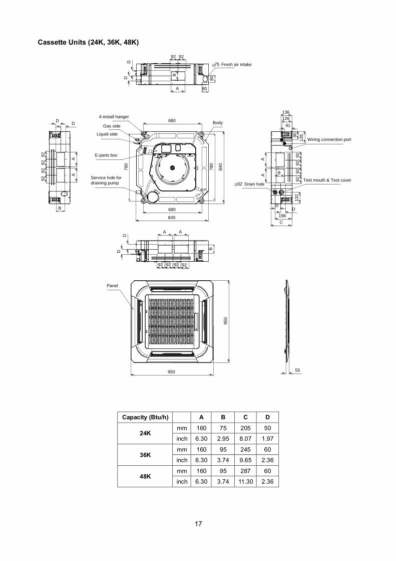
Cassette Units (24K, 36K, 48K)
840840
950
950
C
Test mouth & Test coverDrain hole32
Wiring connection port
680
780
780
680
136
126
91
196
132
AA
B
A A
B
AA
B
A
BService hole for
draining pump
Fresh air intake75
55
80
80
4-install hanger
Gas side
Liquid side
E-parts box
13590
Panel
Body
92
92
92
92
DD
92 92
DD
DD
92
92
92
92
92 92 92 92
D
D
Capacity (Btu/h) A B C D
24K mm 160 75 205 50
inch 6.30 2.95 8.07 1.97
36K mm 160 95 245 60
inch 6.30 3.74 9.65 2.36
48K mm 160 95 287 60
inch 6.30 3.74 11.30 2.36
18
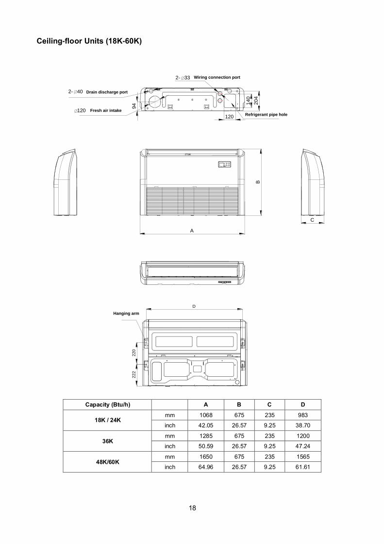
Ceiling-floor Units (18K-60K)
A
B
220
222
C
120
2- 40
120
14
0
2- 33 Wiring connection port
20
4
94
Fresh air intake
Drain discharge port
Refrigerant pipe hole
Hanging arm
D
Capacity (Btu/h) A B C D
18K / 24K mm 1068 675 235 983
inch 42.05 26.57 9.25 38.70
36K mm 1285 675 235 1200
inch 50.59 26.57 9.25 47.24
48K/60K mm 1650 675 235 1565
inch 64.96 26.57 9.25 61.61
19
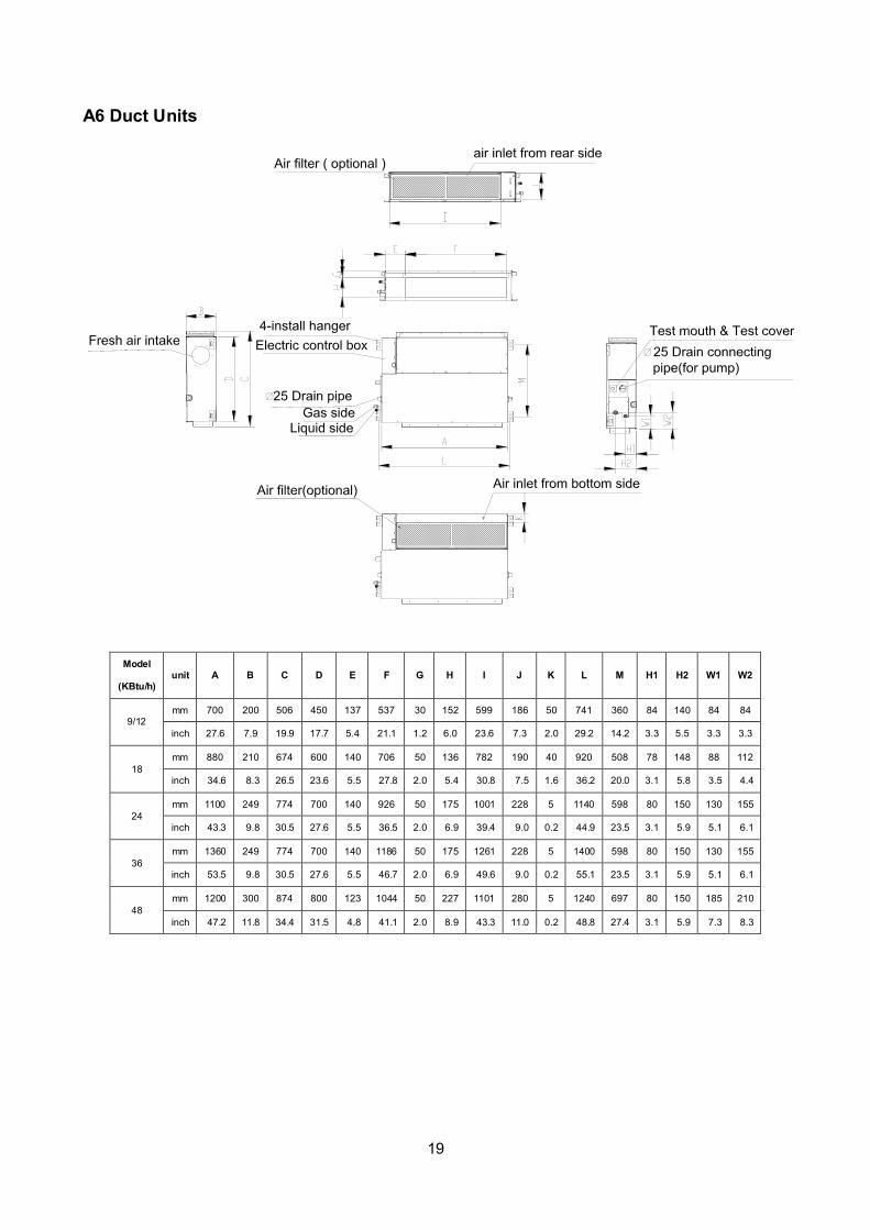
A6 Duct Units
Model
(KBtu/h) unit A B C D E F G H I J K L M H1 H2 W1 W2
9/12 mm 700 200 506 450 137 537 30 152 599 186 50 741 360 84 140 84 84
inch 27.6 7.9 19.9 17.7 5.4 21.1 1.2 6.0 23.6 7.3 2.0 29.2 14.2 3.3 5.5 3.3 3.3
18
mm 880 210 674 600 140 706 50 136 782 190 40 920 508 78 148 88 112
inch 34.6 8.3 26.5 23.6 5.5 27.8 2.0 5.4 30.8 7.5 1.6 36.2 20.0 3.1 5.8 3.5 4.4
24
mm 1100 249 774 700 140 926 50 175 1001 228 5 1140 598 80 150 130 155
inch 43.3 9.8 30.5 27.6 5.5 36.5 2.0 6.9 39.4 9.0 0.2 44.9 23.5 3.1 5.9 5.1 6.1
36
mm 1360 249 774 700 140 1186 50 175 1261 228 5 1400 598 80 150 130 155
inch 53.5 9.8 30.5 27.6 5.5 46.7 2.0 6.9 49.6 9.0 0.2 55.1 23.5 3.1 5.9 5.1 6.1
48
mm 1200 300 874 800 123 1044 50 227 1101 280 5 1240 697 80 150 185 210
inch 47.2 11.8 34.4 31.5 4.8 41.1 2.0 8.9 43.3 11.0 0.2 48.8 27.4 3.1 5.9 7.3 8.3
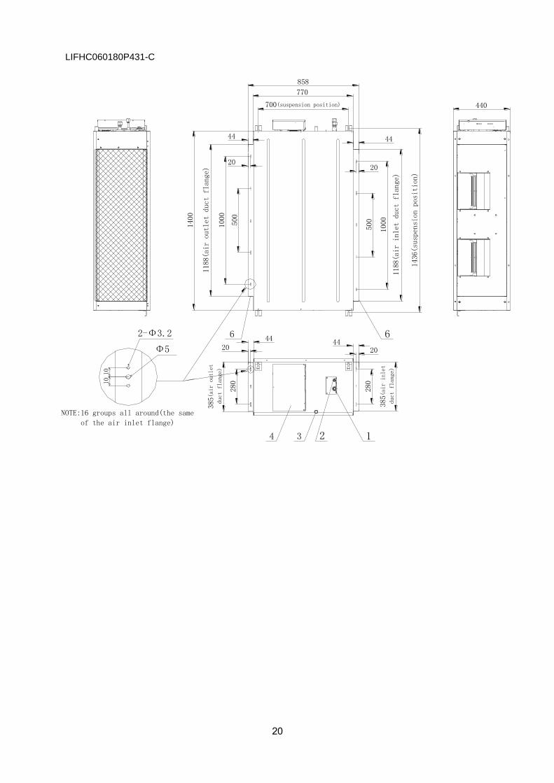
20
NOTE:16 groups all around(the same
of the air inlet flange)
10
Φ5
2-Φ3.2
10
280
280
1000
500
1000
500
385(a
ir inlet
duct
flange)
385(air outlet
duct
flange)
1188(air outlet duct flange)
1188(air inlet duct flange)
1436(suspension position)
700(suspension position)
770
1400
440
4420
44
858
LIFHC060180P431-C

21
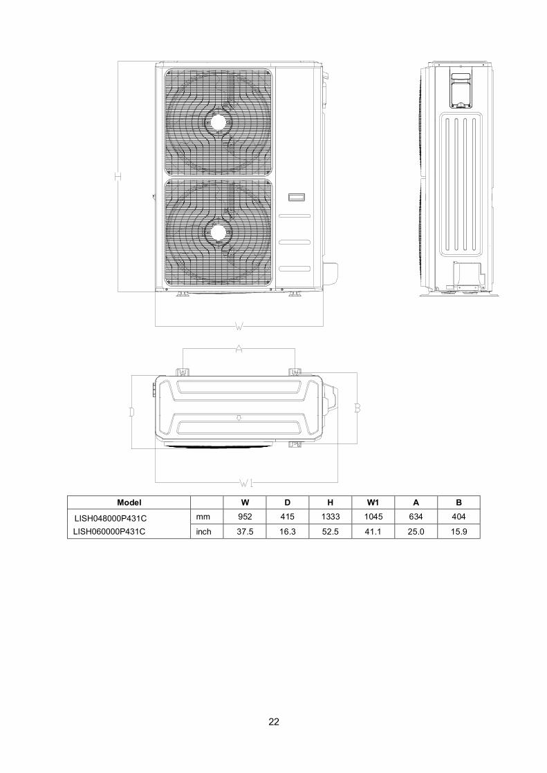
3.2 Outdoor Unit
Note: The above drawing is only for reference. The appearance of your units may be different.
Model
unit
W
D
H
W1
A
B
mm
770
300
555
840
487
298
inch
30.3
11.8
21.9
33.1
19.2
11.7
mm
800
333
554
870
514
340
inch
31.5
13.1
21.8
34.3
20.2
13.4
mm
845
363
702
914
540
350
inch
33.3
14.3
27.6
36.0
21.3
13.8
mm
946
410
810
1030
673
403
inch
37.2
16.1
31.9
40.6
26.5
15.9
A
BD
LISH009000P431-C
LISH012000P431-C
LISH018000P431-C
LISH024000P431-CLISH036000P431-C
22
Model W D H W1 A B
mm 952 415 1333 1045 634 404
inch 37.5 16.3 52.5 41.1 25.0 15.9
LISH060000P431C
LISH048000P431C

23
4. Service Space
4.1 Indoor Unit
A6 Duct Units
Ensure enough space required for installation and maintenance.
200mm(7.87in) or more 300mm(11.81in) or more
600mmx600mm/23.62inx23.62in
Check orifice
All the indoor units reserve the hole to connect the fresh air pipe. The hole size as following
Cassette Units
Unit: mm

24
Ceiling-floor Units
25
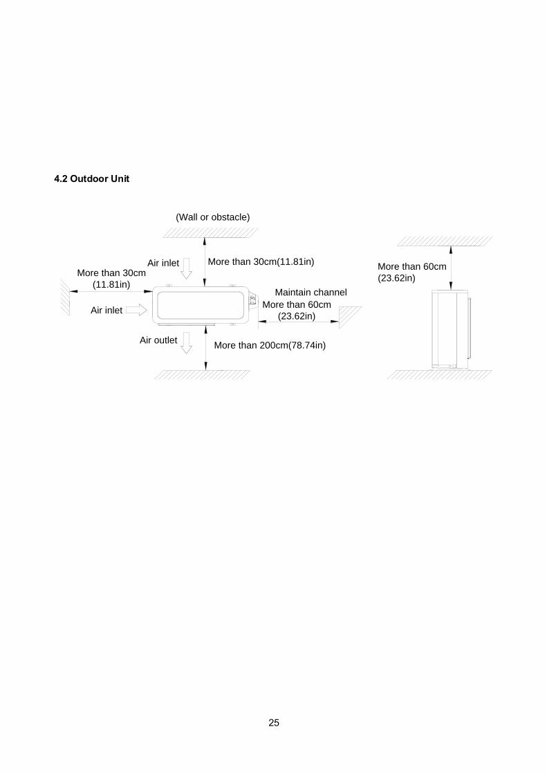
4.2 Outdoor Unit
More than 30cm
(11.81in)
More than 60cm
(23.62in)
More than 200cm(78.74in)
Air inlet
Air inlet More than 30cm(11.81in)
Air outlet
(Wall or obstacle)
Maintain channel
More than 60cm
(23.62in)
26
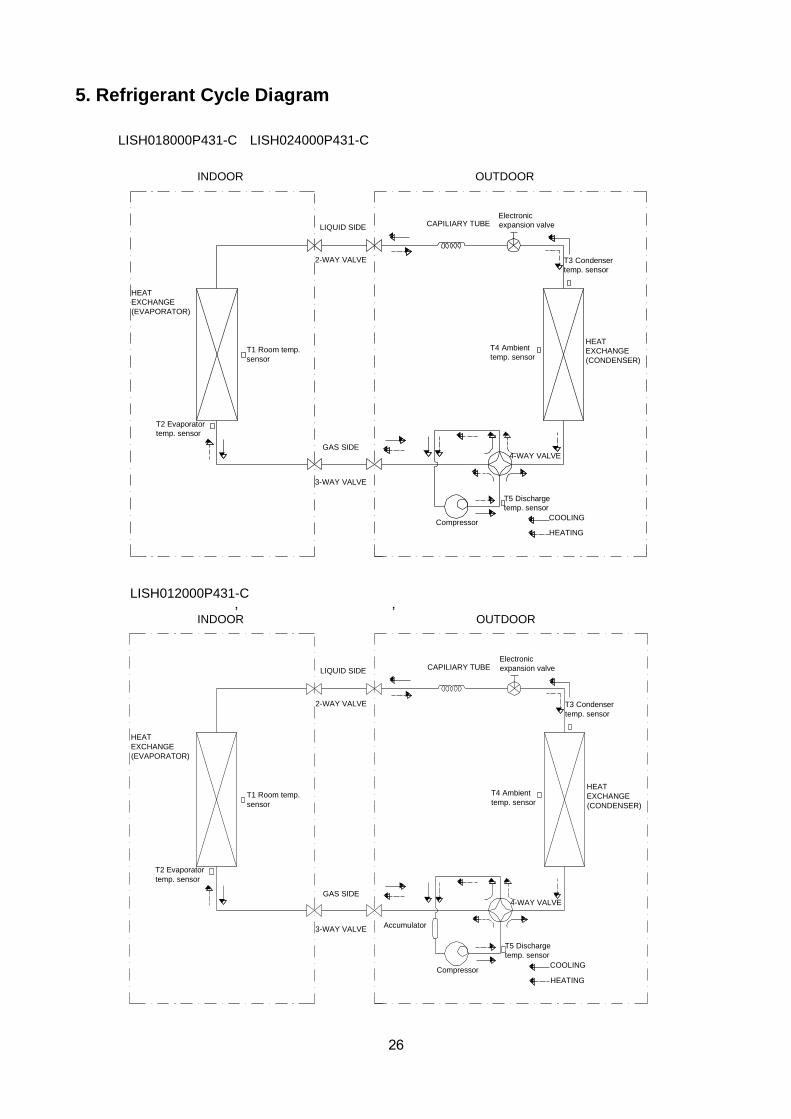
5. Refrigerant Cycle Diagram
LIQUID SIDE
GAS SIDE
HEAT
EXCHANGE
(EVAPORATOR)
HEAT
EXCHANGE
(CONDENSER)
Compressor
2-WAY VALVE
3-WAY VALVE
4-WAY VALVE
COOLING
HEATING
T1 Room temp.
sensor
T3 Condenser
temp. sensor
T5 Discharge
temp. sensor
T4 Ambient
temp. sensor
INDOOR OUTDOOR
T2 Evaporator
temp. sensor
Electronic
expansion valveCAPILIARY TUBE
, ,
LIQUID SIDE
GAS SIDE
HEAT
EXCHANGE
(EVAPORATOR)
HEAT
EXCHANGE
(CONDENSER)
Compressor
2-WAY VALVE
3-WAY VALVE
4-WAY VALVE
COOLING
HEATING
T2 Evaporator
temp. sensor
T1 Room temp.
sensor
T3 Condenser
temp. sensor
T5 Discharge
temp. sensor
T4 Ambient
temp. sensor
INDOOR OUTDOOR
Accumulator
Electronic
expansion valveCAPILIARY TUBE
LISH018000P431-C LISH024000P431-C
LISH012000P431-C
27
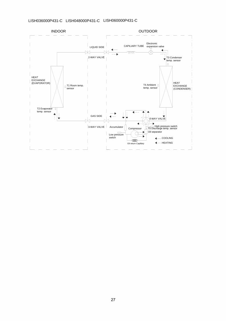
LIQUID SIDE
GAS SIDE
HEAT
EXCHANGE
(EVAPORATOR) HEAT
EXCHANGE
(CONDENSER)
Compressor
2-WAY VALVE
3-WAY VALVE
4-WAY VALVE
COOLING
HEATING
T2 Evaporator
temp. sensor
T1 Room temp.
sensor
T3 Condenser
temp. sensor
AccumulatorT5 Discharge temp. sensor
High pressure switch
T4 Ambient
temp. sensor
Low pressure
switch
INDOOR OUTDOOR
Oil return Capillary
Oil separator
Electronic
expansion valveCAPILIARY TUBE
LISH036000P431-C LISH048000P431-C LISH060000P431-C

28
6. Wiring Diagram
6.1 Indoor Unit
LICH4012180P431-C LICH4018180P431-C LICH4024180P431-C

29
LICH4036180P431-C LICH4048180P431-C

30
LIUH018180P431-C LIUH024180P431-C
LIUH036180P431-C

31
LIUH048180P431-C
LIUH060180P431-C

32
LIUH036180P431-C LIUH048180P431-C
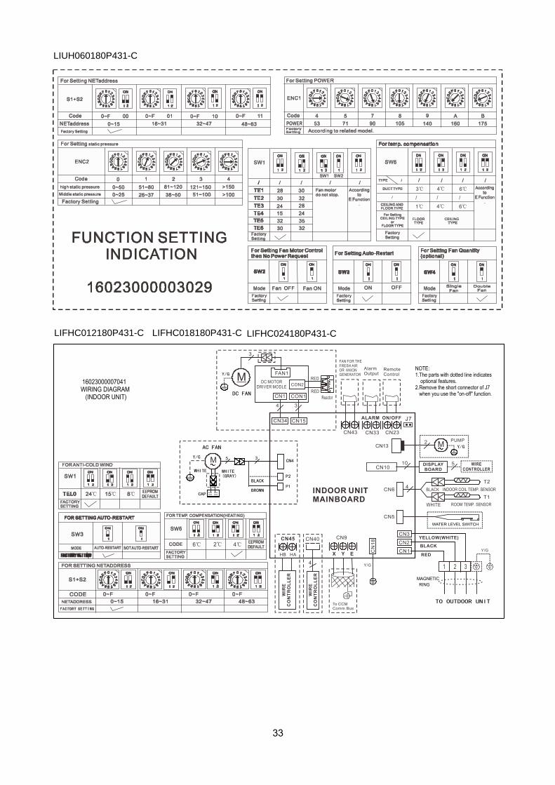
33
LIUH060180P431-C
LIFHC012180P431-C LIFHC018180P431-C LIFHC024180P431-C

44
Note: If the short connector “J7” or “JR6” is losed, when you don’t use the on-off function, the LED
displays error code “CP”.
LIFHC036180P431-C LIFHC048180P431-C LIFHC060180P431-C

35
6.2 Outdoor Unit
LISH018000P431-C

36
LISH012000P431-C

37
LISH024000P431-C

38
LISH036000P431-C

3839
40
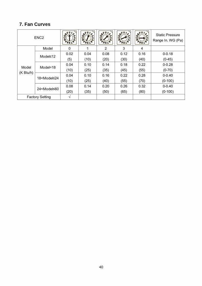
7. Fan Curves
ENC2
Static Pressure
Range In. WG (Pa)
Model
(K Btu/h)
Model 0 1 2 3 4
Model≤12 0.02
(5)
0.04
(10)
0.08
(20)
0.12
(30)
0.16
(40)
0-0.18
(0-45)
Model=18 0.04
(10)
0.10
(25)
0.14
(35)
0.18
(45)
0.22
(55)
0-0.28
(0-70)
18<Model≤24 0.04
(10)
0.10
(25)
0.16
(40)
0.22
(55)
0.28
(70)
0-0.40
(0-100)
24<Model≤60 0.08
(20)
0.14
(35)
0.20
(50)
0.26
(65)
0.32
(80)
0-0.40
(0-100)
Factory Setting √

41
H
M
L
H
M
L
H
M
L
H
M
L
Rated point
Limit
Rated point
Limit
Rated point
Limit
Rated point
Limit
External static pressure pa (in.w.c)
10 20 25 30 40 50(0.10) (0.12) (0.16) (0.20)(0.08)(0.04)
0
External static pressure pa (in.w.c)
10 20 25 30 40 50(0.10) (0.12) (0.16) (0.20)(0.08)(0.04)
0
External static pressure pa (in.w.c)
10 20 25 30 40 50(0.10) (0.12) (0.16) (0.20)(0.08)(0.04)
0
External static pressure pa (in.w.c)
10 20 25 30 40 50(0.10) (0.12) (0.16) (0.20)(0.08)(0.04)
0
1200(706)
1100(647)
1000(588)
900(529)
800(471)
700(412)
600(353)
500(294)
400(235)
300(176)
200(118)
100(59)
Air volume m3/h(CFM)
1200(706)
1100(647)
1000(588)
900(529)
800(471)
700(412)
600(353)
500(294)
400(235)
300(176)
200(118)
100(59)
Air volume m3/h(CFM)
1200(706)
1100(647)
1000(588)
900(529)
800(471)
700(412)
600(353)
500(294)
400(235)
300(176)
200(118)
100(59)
Air volume m3/h(CFM)
1200(706)
1100(647)
1000(588)
900(529)
800(471)
700(412)
600(353)
500(294)
400(235)
300(176)
200(118)
100(59)
Air volume m3/h(CFM)
SP1SP2
LIFHC012180P431-C

42
High
SP1 SP2
Middle
Low
Rated Point
Limit
High
Middle
Low
Rated Point
Limit
10
External static pressure pa(in.w.c)
Air volume m3/h(CFM)
1800(1059)
SP3SP4
High
MiddleLow
Rated Point
Limit
High
MiddleLow
Rated Point
Limit
1700(1000)
1600(941)
1500(882)
1400(823)
1300(765)
1200(706)
1100(647)
1000(588)
900(529)
800(471)
700(412)
600(353)
500(294)
400(235)
300(176)
200(118)
100(59)
0
20 25 30 60 70 80 90 100 120130140 15016040 50 110(0.10)(0.12) (0.16)(0.20)(0.24) (0.28)(0.32)(0.36) (0.40) (0.44) (0.48) (0.52) (0.56) (0.60) (0.64)
10
External static pressure pa(in.w.c)
20 25 30 60 70 80 90 100 120130140 15016040 50 110(0.10)(0.12) (0.16)(0.20)(0.24) (0.28)(0.32)(0.36) (0.40) (0.44) (0.48) (0.52) (0.56) (0.60) (0.64)
10
External static pressure pa(in.w.c)
20 25 30 60 70 80 90 100 120130140 15016040 50 110(0.10)(0.12) (0.16)(0.20)(0.24) (0.28)(0.32)(0.36) (0.40) (0.44) (0.48) (0.52) (0.56) (0.60) (0.64)
10
External static pressure pa(in.w.c)
20 25 30 60 70 80 90 100 120130140 15016040 50 110(0.10)(0.12) (0.16)(0.20)(0.24) (0.28)(0.32)(0.36) (0.40) (0.44) (0.48) (0.52) (0.56) (0.60) (0.64)
(0.08)(0.04) (0.08)(0.04)
(0.08)(0.04)
(0.08)(0.04)
Air volume m3/h(CFM)
1800(1059)
1700(1000)
1600(941)
1500(882)
1400(823)
1300(765)
1200(706)
1100(647)
1000(588)
900(529)
800(471)
700(412)
600(353)
500(294)
400(235)
300(176)
200(118)
100(59)
0
Air volume m3/h(CFM)
1800(1059)
1700(1000)
1600(941)
1500(882)
1400(823)
1300(765)
1200(706)
1100(647)
1000(588)
900(529)
800(471)
700(412)
600(353)
500(294)
400(235)
300(176)
200(118)
100(59)
0
Air volume m3/h(CFM)
1800(1059)
1700(1000)
1600(941)
1500(882)
1400(823)
1300(765)
1200(706)
1100(647)
1000(588)
900(529)
800(471)
700(412)
600(353)
500(294)
400(235)
300(176)
200(118)
100(59)
0
LIFHC018180P431-C

43
High
SP1 SP2
SP3 SP4
MiddleLow
Rated Point Limit
High
MiddleLow
Rated Point Limit
High
MiddleLow
Rated PointLimit
High
MiddleLow
Rated Point
Limit
1800(1059)
1600(941)
1400(823)
1200(706)
1000(588)
800(471)
600(353)
400(235)
200(118)
0
2000(1176)
2200(1294)
2400(1412)
2600(1529)
Air volume m3/h(CFM)
10
External static pressure pa(in.w.c)
20 25 30 60 70 80 90 100 120130140 15016040 50 110(0.10)(0.12) (0.16)(0.20)(0.24) (0.28)(0.32)(0.36) (0.40) (0.44) (0.48) (0.52) (0.56) (0.60) (0.64)(0.08)(0.04)
10
External static pressure pa(in.w.c)
20 25 30 60 70 80 90 100 120130140 15016040 50 110(0.10)(0.12) (0.16)(0.20)(0.24)(0.28)(0.32)(0.36) (0.40) (0.44) (0.48) (0.52) (0.56) (0.60) (0.64)(0.08)(0.04)
10
External static pressure pa(in.w.c)
20 25 30 60 70 80 90 100 120130140 15016040 50 110(0.10)(0.12) (0.16)(0.20)(0.24) (0.28)(0.32)(0.36) (0.40) (0.44) (0.48) (0.52) (0.56) (0.60) (0.64)(0.08)(0.04)
10
External static pressure pa(in.w.c)
20 25 30 60 70 80 90 100 120130140 15016040 50 110(0.10)(0.12) (0.16)(0.20)(0.24) (0.28)(0.32)(0.36) (0.40) (0.44) (0.48) (0.52) (0.56) (0.60) (0.64)(0.08)(0.04)
1800(1059)
1600(941)
1400(823)
1200(706)
1000(588)
800(471)
600(353)
400(235)
200(118)
0
2000(1176)
2200(1294)
2400(1412)
2600(1529)
Air volume m3/h(CFM)
1800(1059)
1600(941)
1400(823)
1200(706)
1000(588)
800(471)
600(353)
400(235)
200(118)
0
2000(1176)
2200(1294)
2400(1412)
2600(1529)
Air volume m3/h(CFM)
1800(1059)
1600(941)
1400(823)
1200(706)
1000(588)
800(471)
600(353)
400(235)
200(118)
0
2000(1176)
2200(1294)
2400(1412)
2600(1529)
Air volume m3/h(CFM)
LIFHC024180P431-C

44
High
SP1
MiddleLow
Rated Point
Limit
High
SP2
MiddleLow
Rated Point
Limit
High
SP3
MiddleLow
Rated Point
Limit
High
SP4
Middle
Low
Rated
Point
Limit
1800(1059)
1600(941)
1400(823)
1200(706)
1000(588)
800(471)
600(353)
400(235)
200(118)
0
2000(1176)
2200(1294)
2400(1412)
2600(1529)
Air volume m3/h(CFM)
2800(1647)
3000(1765)
3200(1882)
3400(2000)
3600(2118)
2500(1471)
10
External static pressure pa(in.w.c)
20 25 30 60 70 80 90 100 120130140 15016040 50 110(0.10)(0.12)(0.16)(0.20) (0.24)(0.28)(0.32)(0.36) (0.40) (0.44) (0.48) (0.52) (0.56) (0.60) (0.64)(0.08)(0.04)
1800(1059)
1600(941)
1400(823)
1200(706)
1000(588)
800(471)
600(353)
400(235)
200(118)
0
2000(1176)
2200(1294)
2400(1412)
2600(1529)
Air volume m3/h(CFM)
2800(1647)
3000(1765)
3200(1882)
3400(2000)
3600(2118)
2500(1471)
1800(1059)
1600(941)
1400(823)
1200(706)
1000(588)
800(471)
600(353)
400(235)
200(118)
0
2000(1176)
2200(1294)
2400(1412)
2600(1529)
Air volume m3/h(CFM)
2800(1647)
3000(1765)
3200(1882)
3400(2000)
3600(2118)
2500(1471)
1800(1059)
1600(941)
1400(823)
1200(706)
1000(588)
800(471)
600(353)
400(235)
200(118)
0
2000(1176)
2200(1294)
2400(1412)
2600(1529)
Air volume m3/h(CFM)
2800(1647)
3000(1765)
3200(1882)
3400(2000)
3600(2118)
2500(1471)
10
External static pressure pa(in.w.c)
20 25 30 60 70 80 90 100 120130 140 15016040 50 110(0.10)(0.12)(0.16)(0.20) (0.24)(0.28)(0.32)(0.36) (0.40) (0.44) (0.48) (0.52) (0.56) (0.60) (0.64)(0.08)(0.04)
10
External static pressure pa(in.w.c)
20 25 30 60 70 80 90 100 120130140 15016040 50 110(0.10)(0.12)(0.16)(0.20) (0.24)(0.28)(0.32)(0.36) (0.40) (0.44) (0.48) (0.52) (0.56) (0.60) (0.64)(0.08)(0.04)
10
External static pressure pa(in.w.c)
20 25 30 60 70 80 90 100 120130140 15016040 50 110(0.10)(0.12)(0.16)(0.20) (0.24)(0.28)(0.32)(0.36) (0.40) (0.44) (0.48) (0.52) (0.56) (0.60) (0.64)(0.08)(0.04)
LIFHC036180P431-C

45
High
SP1
MiddleLow
Rated Point
LimitHigh
SP2
MiddleLow
Rated PointLimit
High
SP3
MiddleLow
Rated Point
Limit
High
SP4
MiddleLow
Rated Point
Limit
Air volume m3/h(CFM)
1800(1059)
1600(941)
1400(823)
1200(706)
1000(588)
800(471)
600(353)
400(235)
200(118)
0
2000(1176)
2200(1294)
2400(1412)
2600(1529)
2800(1647)
3000(1765)
3200(1882)
3400(2000)
3600(2118)
10
External static pressure pa(in.w.c)
20 25 30 60 70 80 90 100 120130140 15016040 50 110(0.10)(0.12)(0.16)(0.20) (0.24)(0.28)(0.32)(0.36) (0.40) (0.44) (0.48) (0.52) (0.56) (0.60) (0.64)(0.08)(0.04)
170(0.68)
180(0.72)
190(0.76)
200(0.80)
3800(2235)
4000(2353)
4200(2471)
3100(1824)
10
External static pressure pa(in.w.c)
20 25 30 60 70 80 90 100 120130 140 15016040 50 110(0.10)(0.12)(0.16)(0.20) (0.24)(0.28)(0.32)(0.36) (0.40) (0.44) (0.48) (0.52) (0.56) (0.60) (0.64)(0.08)(0.04)
170(0.68)
180(0.72)
190(0.76)
200(0.80)
10
External static pressure pa(in.w.c)
20 25 30 60 70 80 90 100 120130140 15016040 50 110(0.10)(0.12)(0.16)(0.20) (0.24)(0.28)(0.32)(0.36) (0.40) (0.44) (0.48) (0.52) (0.56) (0.60) (0.64)(0.08)(0.04)
170(0.68)
180(0.72)
190(0.76)
200(0.80)
10
External static pressure pa(in.w.c)
20 25 30 60 70 80 90 100 120130140 15016040 50 110(0.10)(0.12)(0.16)(0.20) (0.24)(0.28)(0.32)(0.36) (0.40) (0.44) (0.48) (0.52) (0.56) (0.60) (0.64)(0.08)(0.04)
170(0.68)
180(0.72)
190(0.76)
200(0.80)
Air volume m3/h(CFM)
1800(1059)
1600(941)
1400(823)
1200(706)
1000(588)
800(471)
600(353)
400(235)
200(118)
0
2000(1176)
2200(1294)
2400(1412)
2600(1529)
2800(1647)
3000(1765)
3200(1882)
3400(2000)
3600(2118)
3800(2235)
4000(2353)
4200(2471)
3100(1824)
Air volume m3/h(CFM)
1800(1059)
1600(941)
1400(823)
1200(706)
1000(588)
800(471)
600(353)
400(235)
200(118)
0
2000(1176)
2200(1294)
2400(1412)
2600(1529)
2800(1647)
3000(1765)
3200(1882)
3400(2000)
3600(2118)
3800(2235)
4000(2353)
4200(2471)
3100(1824)
Air volume m3/h(CFM)
1800(1059)
1600(941)
1400(823)
1200(706)
1000(588)
800(471)
600(353)
400(235)
200(118)
0
2000(1176)
2200(1294)
2400(1412)
2600(1529)
2800(1647)
3000(1765)
3200(1882)
3400(2000)
3600(2118)
3800(2235)
4000(2353)
4200(2471)
3100(1824)
LIFHC048180P431-C

46
0
20
40
60
80
100
120
140
160
180
200
1800 2300 2800 3300 3800
Exte
rnal
sta
tic
pre
ssu
re (
Pa)
Air volume(m3/h)
High Speed
Minimum rpm(switch 0)
Maximum rpm(switch 4)
0
20
40
60
80
100
120
140
160
180
1800 2300 2800 3300 3800
Exte
rnal
sta
tic
pre
ssu
re (
Pa)
Air volume(m3/h)
Low Speed
Minimum rpm(switch 0)
Maximum rpm(switch 4)
LIFHC060180P431-C

8 Electric Characteristics
Model Indoor unit
Hz Voltage Min. Max.
LIUH018180P431-C 60 208-230V 187V 253V
LIUH024180P431-C 60 208-230V 187V 253V
LIUH036180P431-C 60 208-230V 187V 253V
LIUH048180P431-C 60 208-230V 187V 253V
LIUH060180P431-C 60 208-230V 187V 253V
LICH4012180P431-C 60 208-230V 187V 253V
LICH4018180P431-C 60 208-230V 187V 253V
LICH4018180P431-C 60 208-230V 187V 253V
LICH4018180P431-C 60 208-230V 187V 253V
LICH4018180P431-C 60 208-230V 187V 253V
LICH4018180P431-C 60 208-230V 187V 253V
LICH4018180P431-C 60 208-230V 187V 253V
LIFHC012180P431-C 60 208-230V 187V 253V
LIFHC018180P431-C 60 208-230V 187V 253V
LIFHC024180P431-C 60 208-230V 187V 253V
LIFHC036180P431-C 60 208-230V 187V 253V
LIFHC048180P431-C 60 208-230V 187V 253V
LIFHC060180P431-C 60 208-230V 187V 253V
LISH012000P431-C 60 208-230V 187V 253V
LISH018000P431-C 60 208-230V 187V 253V
LISH024000P431-C 60 208-230V 187V 253V
LISH036000P431-C 60 208-230V 187V 253V
LISH048000P431-C 60 208-230V 187V 253V
LISH060000P431-C 60 208-230V 187V 253V
47
48
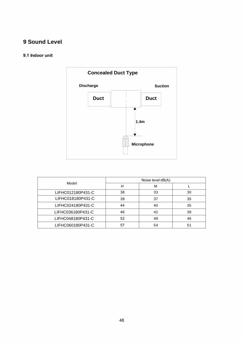
9 Sound Level
9.1 Indoor unit
SuctionDischarge
Microphone
1.4m
Concealed Duct Type
DuctDuct
Model Noise level dB(A)
H M L
38
33
30
39
37
35
44
40
35
46
42
39
52
49
46
57
54
51
LIFHC012180P431-C
LIFHC018180P431-C
LIFHC024180P431-C
LIFHC036180P431-C
LIFHC048180P431-C
LIFHC060180P431-C

49
1.4m
Microphone
Model Noise level dB(A)
H M L
41
38
35
46
43
41
51
47
43
52
47
44
53
49
45
LICH4012180P431-C
LICH4018180P431-C
LICH4036180P431-C
LICH4024180P431-C
LICH4060180P431-C

50
Microphone
1m
1mAir outlet side
1.5m
1mMicrophone
Model
Noise level dB(A)
H
M
L
47
44
38
53
49
45
55
48
41
57
54
52
55
49
46
LIUH018180P431-C
LIUH024180P431-CLIUH036180P431-C
LIUH048180P431-C
LIUH060180P431-C

51
9.2 Outdoor unit
Note: H= 0.5 × height of outdoor unit
Model Noise Level dB(A)
57
59
61
65
63
64
H
1.0m
Outdoor Unit
Microphone
LISH012000P431-C
LISH024000P431-C
LISH036000P431-C
LISH048000P431-C
LISH060000P431-C
LISH018000P431-C

52
10 Accessories
Duct Units
Name Shape Quantity
Tubing & Fittings
Soundproof / insulation sheath
2
Binding tape
1
Seal sponge
1
Drainpipe Fittings
(for cooling & heating)
Drain joint
1
Seal ring
1
Wired controller & Its Frame Wired controller 1
Others
Owner's manual 1
Installation manual 1
EMS & It’s fitting Magnetic ring (twist the electric wires L
and N around it to five circles)
1
Cassette Units
Name Shape Quantity
Installation Fittings Installation paper board
1
Tubing & Fittings Soundproof / insulation sheath
1
Drainpipe Fittings
Out-let pipe sheath
1
Out-let pipe clasp
1
Drain joint
1
Seal ring
1
Remote controller & Its
Frame(The product you
have might not be
provided the following
accessories)
Remote controller & Its Frame
1
Remote controller holder
1

53
Mounting screw(ST2.9×10-C-H)
2
Remote controller manual
1
Alkaline dry batteries (AM4)
2
Others
Owner's manual
1
Installation manual
1
Installation accessory
(The product you have
might not be provided the
following accessories
Expansible hook
4
Installation hook 4
Orifice 1
Console Units
Name Shape Quantity
Installation fittings Hook
2
Remote controller & Its Frame
Remote controller
1
Frame
1
Mounting screw(ST2.9×10-C-H)
2
Alkaline dry batteries (AM4)
2
Others Installation manual / 1
Owner's manual / 1
Ceiling-floor Units
Name Shape Quantity
Remote controller & Its
holder
1. Remote controller
1
2. Remote controller holder
1
3. Mounting screw (ST2.9×10-C-H)
2
4. Alkaline dry batteries (AM4)
2
Others
5. Owner's manual 1
6. Installation manual 1
7. Remote controller manual 1

54
11. The Specification of Power
Type 9K-18K 24K
Power Phase 1-phase 1-phase
Frequency and Voltage 208-230V, 60Hz 208-230V, 60Hz
Circuit Breaker/ Fuse (A) 25/20 25/20
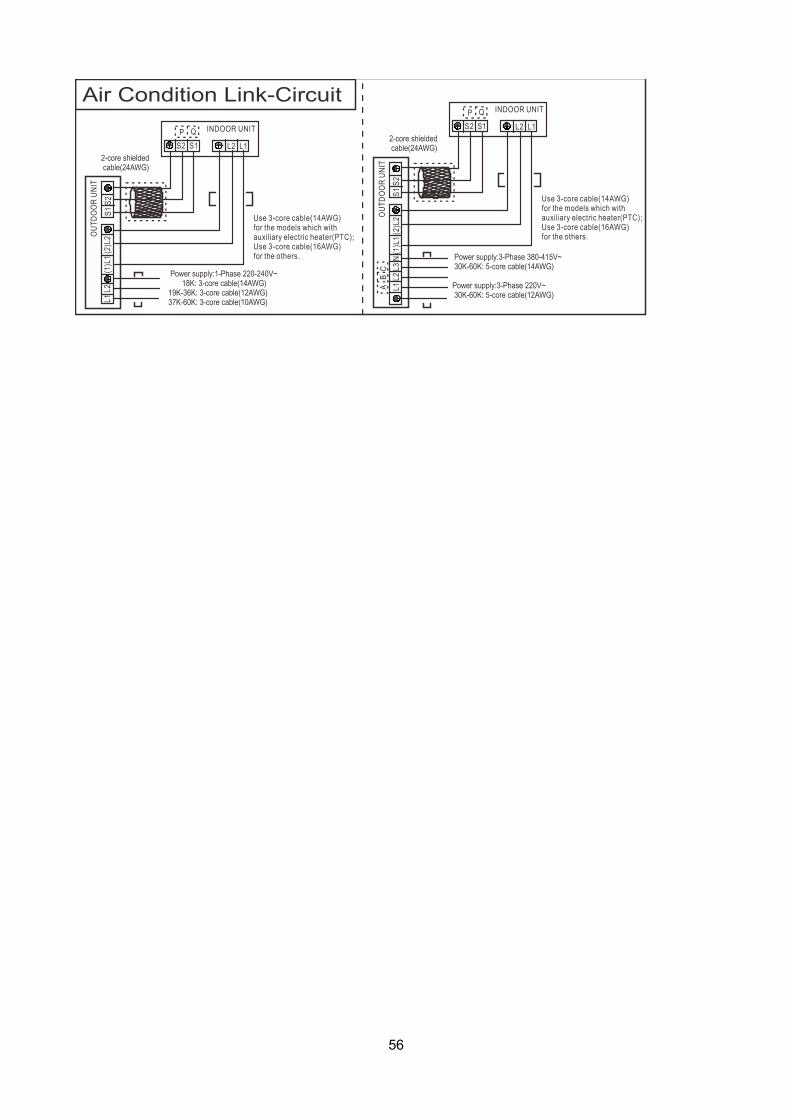
Indoor Unit Power Wiring
Indoor/Outdoor Connecting Wiring
Outdoor Unit Power Wiring 3-core cable
(14AWG)
3-core cable
(14AWG)
Strong Electric Signal
4-core cable
(16AWG)
4-core cable
(16AWG)
4-core cable
(14AWG)(with
auxiliary electric
heater)
4-core cable
(14AWG)(with
auxiliary electric
heater)
Weak Electric Signal
Model 36K 48K/60k
Power Phase 1-phase 1-phase
Frequency and Voltage 208-230V, 60Hz 208-230V, 60Hz
Circuit Breaker/ Fuse (A) 40/30 50/40
Indoor Unit Power Wiring
Indoor/Outdoor
Connecting Wiring
Outdoor Unit Power Wiring 3-core cable 12AWG 3-core cable 10AWG
Strong Electric Signal
3-core cable 16AWG 3-core cable 16AWG
4-core cable (14AWG)(with
auxiliary electric heater)
4-core cable (14AWG)(with
auxiliary electric heater)
Weak Electric Signal 2-core shielded cable 24AWG 2-core shielded cable 24AWG
55
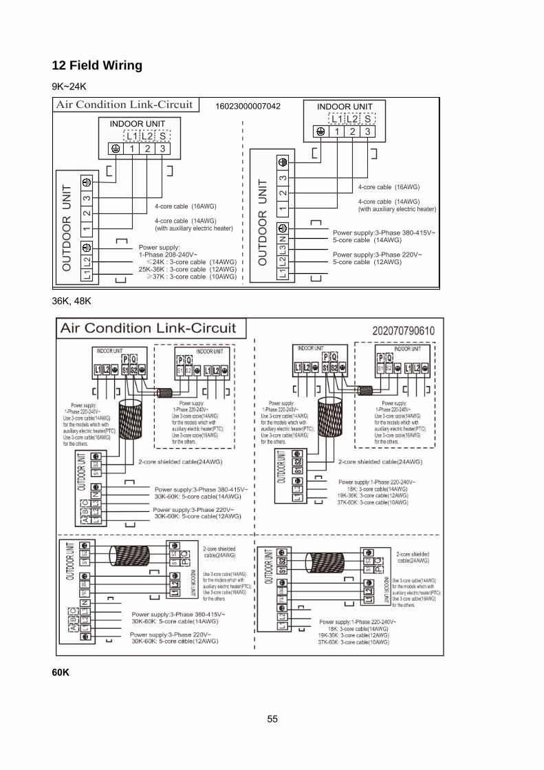
12 Field Wiring
9K~24K
36K, 48K
60K
56
57
13 Installation Details
13.1Location selection
13.1.1 Indoor unit location selection
The place shall easily support the indoor
unit’s weight.
The place can ensure the indoor unit
installation and inspection.
The place can ensure the indoor unit
horizontally installed.
The place shall allow easy water drainage.
The place shall easily connect with the
outdoor unit.
The place where air circulation in the room
should be good.
There should not be any heat source or
steam near the unit.
There should not be any oil gas near the unit
There should not be any corrosive gas near
the unit
There should not be any salty air neat the
unit
There should not be strong electromagnetic
wave near the unit
There should not be inflammable materials
or gas near the unit
There should not be strong voltage vibration.
13.1.2 Outdoor unit location selection
The place shall easily support the outdoor
unit’s weight.
Locate the outdoor unit as close to indoor
unit as possible
The piping length and height drop cannot
exceed the allowable value.
The place where the noise, vibration and
outlet air do not disturb the neighbors.
There is enough room for installation and
maintenance.
The air outlet and the air inlet are not
impeded, and not face the strong wind.
It is easy to install the connecting pipes and
cables.
There is no danger of fire due to leakage of
inflammable gas.
It should be a dry and well ventilation place
The support should be flat and horizontal
Do not install the outdoor unit in a dirty or
severely polluted place, so as to avoid
blockage of the heat exchanger in the
outdoor unit.
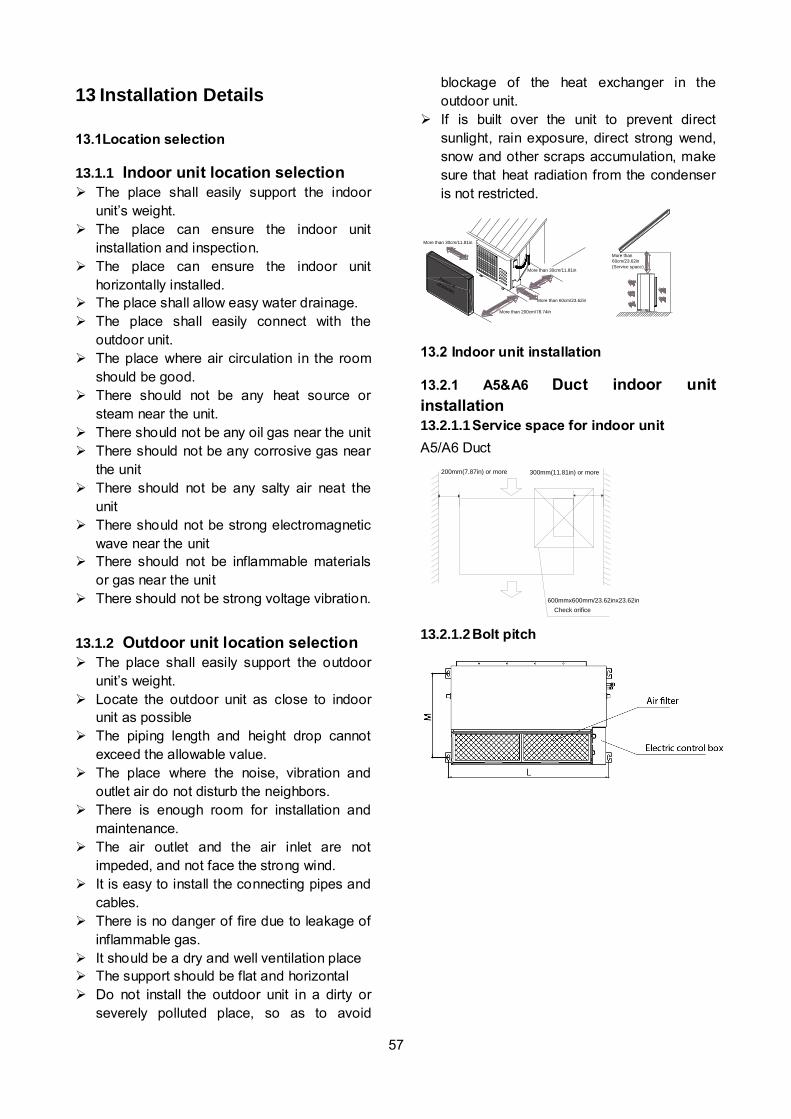
If is built over the unit to prevent direct
sunlight, rain exposure, direct strong wend,
snow and other scraps accumulation, make
sure that heat radiation from the condenser
is not restricted.
More than 30cm/11.81in
More than 60cm/23.62in
More than 200cm/78.74in
More than 30cm/11.81in
More than
60cm/23.62in
(Service space)
Fence orobstacles
13.2 Indoor unit installation
13.2.1 A5&A6 Duct indoor unit
installation
13.2.1.1 Service space for indoor unit
A5/A6 Duct
200mm(7.87in) or more 300mm(11.81in) or more
600mmx600mm/23.62inx23.62in
Check orifice
13.2.1.2 Bolt pitch

58
13.2.1.3
Hang indoor unit
1. Please refer to the upper data to locate the
four positioning screw bolt hole on the ceiling.
Be sure to mark the areas where ceiling hook
holes will be drilled.
2. Install and fit pipes and wires after you have
finished installing the main body. When
choosing where to start, determine the
direction of the pipes to be drawn out.
Especially in cases where there is a ceiling
involved, align the refrigerant pipes, drain
pipes, and indoor and outdoor lines with their
connection points before mounting the unit.
3. Install hanging screw bolts.
•
Cut off the roof beam.
•
Strengthen the place that has been cut
off, and consolidate the roof beam.
4. After you select an installation location, align
the refrigerant pipes, drain pipes, as well as
indoor and outdoor wires with their connection
points before mounting the unit.
5. Drill 4 holes 10cm (4”) deep at the ceiling
hook positions in the internal ceiling. Be sure to
hold the drill at a 90° angle to the ceiling.
6. Secure the bolt using the washers and nuts
provided.
7. Install the four suspension bolts.
8. Mount the indoor unit with at least two
people to lift and secure it. Insert suspension
bolts into the unit’s hanging holes. Fasten
them using the washers and nuts provided.
9. Mount the indoor unit onto the hanging
screw bolts with a block. Position the
indoor unit flat using a level indicator to
prevent leaks.
Note: Confirm the minimum drain tilt is 1/100 or
more.
13.2.1.4 Duct and accessories installation
1. Install the filter (optional) according to the
size of the air inlet.
2. Install the canvas tie-in between the body
and the duct.
3. Air inlet and air outlet duct should be apart far
enough to avoid air passage short-circuit.
4. Connect the duct according to the following
diagram.

59
5.Please refer to the following static pressure to
install.
Model Static Pressure(Pa)
0-100
0-160
0-160
0-160
Change the fan motor static pressure
corresponding to external duct static pressure.
NOTE: 1.Do not put the connecting duct weight
on the indoor unit.
2.When connecting duct, use inflammable
canvas tie-in to prevent vibrating.
3. Insulation foam must be wrapped outside the
duct to avoid condensate. An internal duct
underlayer can be added to reduce noise,
if the end-user requires.
13.2.1.5 Control (only for inverter A5 Duct
units)
The capacity of the system and the
network address of the air-conditioner can
be set by the switches on the indoor Main
Control Board.
Before setting, turn off the power. After
setting, restart the unit.
Setting is not allowed when the unit is
power on.
1. Horsepower code setting
The capacity of the indoor unit has been set
in the factory according to the below table.
ENC1 Toggle switch Code
Capacity(kw)
Note: The capacity has
been set in the factory, anyone can’t adjust it
except the qualified person
4 5.3 5.6
5 7.1
7 9.0 8 10.5
9 14
16
2. Network address set
Every air-conditioner in network has only one
network address to distinguish each other.
Address code of air-conditioner in LAN is set by
code switches S1 & S2 on the Main Control
Board of the indoor unit, and the set range is
0-63.
13.2.1.6 Adjust the air inlet direction (From
rear side to under-side)
For A5 Duct units
① Take off ventilation panel and flange, cut
off the staples at side rail
2. Stick the attached seal sponge as per the
indicating place in the following fig, and then
change the mounting positions of air return
panel and air return flange.
LIFHC018180P431-CLIFHC024180P431-CLIFHC036180P431-CLIFHC048180P431-C

60
3. When installing the filter mesh, fit it into the
flange inclined from air return opening, and
then push up.
4. The installation has finish, upon filter mesh
which fixing blocks have been insert to the
flange positional holes.
For A6 Duct units
1.Take off ventilation panel and flange, cut off
the staples at side rail
2.Change the mounting positions of ventilation
panel and air return flange .
3. When installing the filter mesh, fit it into the
flange as illustrated in the following figure.
NOTE: All the figures in this manual are for
demonstration purposes only. The air
conditioner you have purchased may be slightly
different in design, though similar in shape.
13.2.1.7 Fresh air duct installation
Dimension :
13.2.2 Compact cassette indoor unit
installation
13.2.2.1 Service space for indoor unit

61
13.2.2.2 Bolt pitch
13.2.2.3 Install the pendant bolt
Select the position of installation hooks
according to the hook holes positions showed
in upper picture.
Drill four holes of Ø12mm, 45~50mm deep at
the selected positions on the ceiling. Then
embed the expansible hooks (fittings).
Face the concave side of the installation hooks
toward the expansible hooks. Determine the
length of the installation hooks from the height
of ceiling, then cut off the unnecessary part.
If the ceiling is extremely high, please
determine the length of the installation hook
depending on the real situation.
13.2.2.4 Install the main body
Make the 4 suspender through the 4 hanger of
the main body to suspend it. Adjust the
hexangular nuts on the four installation hooks
evenly, to ensure the balance of the body. Use
a leveling instrument to make sure the
levelness of the main body is within ±1°.
Adjust the position to ensure the gaps between
the body and the four sides of ceiling are even.
The body's lower part should sink into the
ceiling for 10~12 mm. In general, L is half of the
screw length of the installation hook.

62
Locate the air conditioner firmly by wrenching
the nuts after having adjusted the body's
position well.
13.2.2.5 Install the panel
Remove the grille
Hang the panel to the hooks on the mainbody.
Tighten the screws under the panel hooks till
the panel closely stick on the ceiling to avoid
condensate water.
Hang the air-in grill to the panel, then connect
the lead terminator of the swing motor and that
of the control box with corresponding
terminators on the body respectively.
Note: The panel shall be installed after the
wiring connected.
13.2.3 Console indoor unit installation
13.2.3.1 Service space for indoor unit

63
13.2.3.2 Install the main body
Fix the hook with tapping screw onto the
wall
Hang the indoor unit on the hook.
(The bottom of body can touch with floor or
suspended, but the body must install vertically.)
13.2.4 Ceiling-floor unit installation
13.2.4.1 Service space for indoor unit
13.2.4.2 Bolt pitch
① Ceiling installation
Capacity (Btu/h) D E
18K / 24K mm 983 220
inch 38.70 8.66
36K mm 1200 220
inch 47.24 8.66
48K/60K mm 1565 220
inch 61.61 8.66
② Wall-mounted installation
13.2.4.3 Install the pendant bolt
① Ceiling installation
Select the position of installation hooks
according to the hook holes positions showed
in upper picture.
Drill four holes of Ø12mm, 45~50mm deep at
the selected positions on the ceiling. Then
embed the expansible hooks (fittings).
② Wall-mounted installation
Install the tapping screws onto the wall.(Refer
to picture below)

64
13.2.4.4 Install the main body
① Ceiling installation (The only installation
method for the unit with drain pump)
Remove the side board and the grille.
Locate the hanging arm on the hanging screw
bolt. Prepare the mounting bolts on the unit.
Put the side panels and grilles back.
② Wall-mounted installation
Hang the indoor unit by insert the tapping
screws into the hanging arms on the main unit.
(The bottom of body can touch with floor or
suspended, but the body must install vertically.)
13.2.5 Slim cassette indoor unit
installation
13.2.5.1 Service space for indoor unit
Capacity (Btu/h) A H
24K mm 205 >235
inch 8.07 >9.25

65
36K mm 245 >275
inch 9.65 >10.83
48K mm 287 >317
inch 11.30 >12.48
13.2.5.2 Bolt pitch
13.2.5.3 Install the pendant bolt
Select the position of installation hooks
according to the hook holes positions showed
in upper picture.
Drill four holes of Ø12mm, 45~50mm deep at
the selected positions on the ceiling. Then
embed the expansible hooks (fittings).
13.2.5.4 Install the main body
Make the 4 suspender through the 4 hanger of
the main body to suspend it. Adjust the
hexangular nuts on the four installation hooks
evenly, to ensure the balance of the body. Use
a leveling instrument to make sure the
levelness of the main body is within ±1°.
Adjust the position to ensure the gaps between
the body and the four sides of ceiling are even.
The body's lower part should sink into the
ceiling for 10~12 mm. In general, L is half of the
screw length of the installation hook.
Locate the air conditioner firmly by wrenching
the nuts after having adjusted the body's
position well.
13.2.5.5 Install the panel
Remove the grille
Remove the 4 corner covers.

66
Hang the panel to the hooks on the mainbody. If
the panel is with auto-lift grille, please watch the
ropes lifing the grille, DO NOT make the ropes
enwinded or blocked.
Tighten the screws under the panel hooks till
the panel closely stick on the ceiling to avoid
condensate water.
Hang the air-in grill to the panel, then connect
the lead terminator of the swing motor and that
of the control box with corresponding
terminators on the body respectively.
Install the 4 corner covers back.
Note: The panel shall be installed after the
wiring connected.
13.2.6 HESP duct indoor unit installation
13.2.6.1 Service space for indoor unit
13.2.6.2 Bolt pitch
Capacity
(KBtu)
Size of mounted lug
D E
60 700 1436
13.2.6.3 Install the pendant bolt
Select the position of installation hooks
according to the hook holes positions showed
in upper picture.
Drill four holes of Ø12mm, 45~50mm deep at
the selected positions on the ceiling. Then
embed the expansible hooks (fittings).
500mm or more 600mm or more
Indoor unit
600mmx600mm
Maintenance and repair space

67
13.2.6.4 Install the main body
Make the 4 suspender through the 4 hanger of
the main body to suspend it. Adjust the
hexangular nuts on the four installation hooks
evenly, to ensure the balance of the body. Use
a leveling instrument to make sure the
levelness of the main body is within ±1°.
13.2.6.5 Install the air duct
Please design the air duct as below
recommended picture
13.3 Outdoor unit installation
13.3.1 Service space for outdoor unit
More than 30cm
(11.81in)
More than 60cm
(23.62in)
More than 200cm(78.74in)
Air inlet
Air inlet More than 30cm(11.81in)
Air outlet
(Wall or obstacle)
Maintain channel
More than 60cm
(23.62in)
13.3.2 Bolt pitch
For the value of A,B and D, please refer to
the dimension part.
13.3.3 Install the Unit
Since the gravity center of the unit is not at its
physical center, so please be careful when
lifting it with a sling.
Never hold the inlet of the outdoor unit to
prevent it from deforming.
Do not touch the fan with hands or other
objects.
W
H
W1
A
BD

68
Do not lean it more than 45, and do not lay it
sidelong.
Make concrete foundation according to the
specifications of the outdoor units.
Fasten the feet of this unit with bolts firmly to
prevent it from collapsing in case of earthquake
or strong wind.
13.4 Refrigerant pipe installation
13.4.1 Maximum pipe length and height
drop
Considering the allowable pipe length and
height drop to decide the installation position.
Make sure the distance and height drop
between indoor and outdoor unit not exceeded
the date in the following table.
Model Max. Length Max. Elevation
m Ft. m Ft.
9,000Btu/h 25 82.2 10 32.9
12,000Btu/h 25 82.2 10 32.9
18,000Btu/h 30 98.7 20 65.8
24,000Btu/h 50 164.5 25 82.2
36,000Btu/h 65 213.8 30 98.7
48,000Btu/h 65 213.8 30 98.7
13.4.2 The procedure of connecting pipes
1. Choose the pipe size according to the
specification table.
2. Confirm the cross way of the pipes.
3. Measure the necessary pipe length.
4. Cut the selected pipe with pipe cutter
Make the section flat and smooth.
90 Lean Crude Burr
o
5. Insulate the copper pipe
Before test operation, the joint parts should
not be heat insulated.
6. Flare the pipe
Insert a flare nut into the pipe before flaring
the pipe
According to the following table to flare the
pipe
Pipe
diameter
Flare
dimension A
(mm) Flare shape
Min Max
1/4"
(6.35) 8.3 8.7
R0.4~0.8
A
45°
90°4-+
3/8"
(9.52) 12.0 12.4
1/2"
(12.7) 15.4 15.8
5/8"
(15.9) 18.6 19.1
3/4" (19) 22.9 23.3
After flared the pipe, the opening part must
be seal by end cover or adhesive tape to
avoid duct or exogenous impurity come into
the pipe.
7. Drill holes if the pipes need to pass the
wall.
8. According to the field condition to bend the
pipes so that it can pass the wall smoothly.
9. Bind and wrap the wire together with the
insulated pipe if necessary.
10. Set the wall conduit
11. Set the supporter for the pipe.
12. Locate the pipe and fix it by supporter
69
For horizontal refrigerant pipe, the distance
between supporters should not be exceed
1m.
For vertical refrigerant pipe, the distance
between supporters should not be exceed
1.5m.
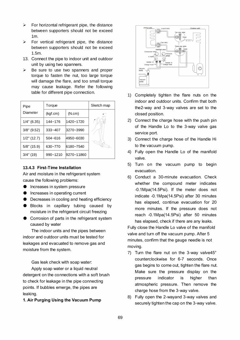
13. Connect the pipe to indoor unit and outdoor
unit by using two spanners.
Be sure to use two spanners and proper
torque to fasten the nut, too large torque
will damage the flare, and too small torque
may cause leakage. Refer the following
table for different pipe connection.
Pipe
Diameter
Torque Sketch map
(kgf.cm) (N.cm)
1/4" (6.35) 144~176 1420~1720
3/8" (9.52) 333~407 3270~3990
1/2" (12.7) 504~616 4950~6030
5/8" (15.9) 630~770 6180~7540
3/4" (19) 990~1210 9270~11860
13.4.3 First-Time Installation
Air and moisture in the refrigerant system
cause the following problems:
Increases in system pressure
Increases in operating current
Decreases in cooling and heating efficiency
Blocks in capillary tubing caused by
moisture in the refrigerant circuit freezing
Corrosion of parts in the refrigerant system
caused by water
The indoor units and the pipes between
indoor and outdoor units must be tested for
leakages and evacuated to remove gas and
moisture from the system.
Gas leak check with soap water:
Apply soap water or a liquid neutral
detergent on the connections with a soft brush
to check for leakage in the pipe connecting
points. If bubbles emerge, the pipes are
leaking.
1. Air Purging Using the Vacuum Pump
1) Completely tighten the flare nuts on the
indoor and outdoor units. Confirm that both
the2-way and 3-way valves are set to the
closed position.
2) Connect the charge hose with the push pin
of the Handle Lo to the 3-way valve gas
service port.
3) Connect the charge hose of the Handle Hi
to the vacuum pump.
4) Fully open the Handle Lo of the manifold
valve.
5) Turn on the vacuum pump to begin
evacuation.
6) Conduct a 30-minute evacuation. Check
whether the compound meter indicates
-0.1Mpa(14.5Psi). If the meter does not
indicate -0.1Mpa(14.5Psi) after 30 minutes
has elapsed, continue evacuation for 20
more minutes. If the pressure does not
reach -0.1Mpa(14.5Psi) after 50 minutes
has elapsed, check if there are any leaks.
Fully close the Handle Lo valve of the manifold
valve and turn off the vacuum pump. After 5
minutes, confirm that the gauge needle is not
moving.
7) Turn the flare nut on the 3-way valve45°
counterclockwise for 6-7 seconds. Once
gas begins to come out, tighten the flare nut.
Make sure the pressure display on the
pressure indicator is higher than
atmospheric pressure. Then remove the
charge hose from the 3-way valve.
8) Fully open the 2-wayand 3-way valves and
securely tighten the cap on the 3-way valve.
70
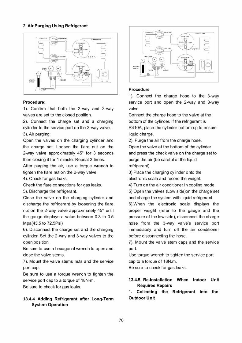
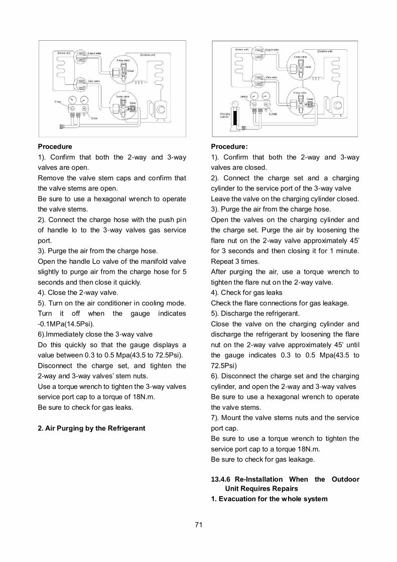
2. Air Purging Using Refrigerant
Procedure:
1). Confirm that both the 2-way and 3-way
valves are set to the closed position.
2). Connect the charge set and a charging
cylinder to the service port on the 3-way valve.
3). Air purging:
Open the valves on the charging cylinder and
the charge set. Loosen the flare nut on the
2-way valve approximately 45° for 3 seconds
then closing it for 1 minute. Repeat 3 times.
After purging the air, use a torque wrench to
tighten the flare nut on the 2-way valve.
4). Check for gas leaks.
Check the flare connections for gas leaks.
5). Discharge the refrigerant.
Close the valve on the charging cylinder and
discharge the refrigerant by loosening the flare
nut on the 2-way valve approximately 45° until
the gauge displays a value between 0.3 to 0.5
Mpa(43.5 to 72.5Psi)
6). Disconnect the charge set and the charging
cylinder. Set the 2-way and 3-way valves to the
open position.
Be sure to use a hexagonal wrench to open and
close the valve stems.
7). Mount the valve stems nuts and the service
port cap.
Be sure to use a torque wrench to tighten the
service port cap to a torque of 18N·m.
Be sure to check for gas leaks.
13.4.4 Adding Refrigerant after Long-Term
System Operation
Procedure
1). Connect the charge hose to the 3-way
service port and open the 2-way and 3-way
valve.
Connect the charge hose to the valve at the
bottom of the cylinder. If the refrigerant is
R410A, place the cylinder bottom-up to ensure
liquid charge.
2). Purge the air from the charge hose.
Open the valve at the bottom of the cylinder
and press the check valve on the charge set to
purge the air (be careful of the liquid
refrigerant).
3) Place the charging cylinder onto the
electronic scale and record the weight.
4) Turn on the air conditioner in cooling mode.
5) Open the valves (Low side)on the charge set
and charge the system with liquid refrigerant.
6).When the electronic scale displays the
proper weight (refer to the gauge and the
pressure of the low side), disconnect the charge
hose from the 3-way valve’s service port
immediately and turn off the air conditioner
before disconnecting the hose.
7). Mount the valve stem caps and the service
port.
Use torque wrench to tighten the service port
cap to a torque of 18N.m.
Be sure to check for gas leaks.
13.4.5 Re-installation When Indoor Unit
Requires Repairs
1. Collecting the Refrigerant into the
Outdoor Unit
71
Procedure
1). Confirm that both the 2-way and 3-way
valves are open.
Remove the valve stem caps and confirm that
the valve stems are open.
Be sure to use a hexagonal wrench to operate
the valve stems.
2). Connect the charge hose with the push pin
of handle lo to the 3-way valves gas service
port.
3). Purge the air from the charge hose.
Open the handle Lo valve of the manifold valve
slightly to purge air from the charge hose for 5
seconds and then close it quickly.
4). Close the 2-way valve.
5). Turn on the air conditioner in cooling mode.
Turn it off when the gauge indicates
-0.1MPa(14.5Psi).
6).Immediately close the 3-way valve
Do this quickly so that the gauge displays a
value between 0.3 to 0.5 Mpa(43.5 to 72.5Psi).
Disconnect the charge set, and tighten the
2-way and 3-way valves’ stem nuts.
Use a torque wrench to tighten the 3-way valves
service port cap to a torque of 18N.m.
Be sure to check for gas leaks.
2. Air Purging by the Refrigerant
Procedure:
1). Confirm that both the 2-way and 3-way
valves are closed.
2). Connect the charge set and a charging
cylinder to the service port of the 3-way valve
Leave the valve on the charging cylinder closed.
3). Purge the air from the charge hose.
Open the valves on the charging cylinder and
the charge set. Purge the air by loosening the
flare nut on the 2-way valve approximately 45’
for 3 seconds and then closing it for 1 minute.
Repeat 3 times.
After purging the air, use a torque wrench to
tighten the flare nut on the 2-way valve.
4). Check for gas leaks
Check the flare connections for gas leakage.
5). Discharge the refrigerant.
Close the valve on the charging cylinder and
discharge the refrigerant by loosening the flare
nut on the 2-way valve approximately 45’ until
the gauge indicates 0.3 to 0.5 Mpa(43.5 to
72.5Psi)
6). Disconnect the charge set and the charging
cylinder, and open the 2-way and 3-way valves
Be sure to use a hexagonal wrench to operate
the valve stems.
7). Mount the valve stems nuts and the service
port cap.
Be sure to use a torque wrench to tighten the
service port cap to a torque 18N.m.
Be sure to check for gas leakage.
13.4.6 Re-Installation When the Outdoor
Unit Requires Repairs
1. Evacuation for the whole system

72
Procedure:
1).Confirm that both the 2-way and 3-way
valves are open.
2). Connect the vacuum pump to 3-way valve’s
service port.
3). Conduct an evacuation for approximately
one hour. Confirm that the compound meter
displays a value of -0.1Mpa(14.5Psi).
4). Close the valve (Low side) on the charge set,
turn off the vacuum pump. After 5 minutes,
confirm that the gauge needle is not moving.
5). Disconnect the charge hose from the
vacuum pump.
2. Refrigerant charging
Procedure:
1). Connect the charge hose to the charging
cylinder. Open the 2-way 3-way valve.
With the charge hose you disconnected from
the vacuum pump, connect it to the valve at the
bottom of the cylinder. If the refrigerant is
R410A, place the cylinder bottom-up to ensure
liquid charge.
2). To purge the air from the charge hose, open
the valve at the bottom of the cylinder and press
the check valve on the charge set (be careful of
the liquid refrigerant).
3) Place the charging cylinder onto the
electronic scale and record the weight.
4). Open the valves (Low side) on the charge
set and charge the system with liquid refrigerant
If the system cannot be charged with the
specified amount of refrigerant, or can be
charged with a only a small amount at a time
(approximately 150g each time),turn the unit on
in cooling mode; however, one time is not
sufficient, wait approximately 1 minute and then
repeat the procedure.
5).If the electronic scale displays the proper
weight, disconnect the charge hose from the
3-way valve’s service port immediately.
If the system has been charged with liquid
refrigerant while the air conditioner is on, turn
off the air conditioner before disconnecting the
hose.
6). Mount the valve stem caps and the service
port.
Use a torque wrench to tighten the service port
cap to a torque of 18N.m.
Be sure to check for gas leakage.
13.5 Drainage pipe installation
Install the drainage pipe as shown below and
take measures against condensation.
Improperly installation could lead to leakage
and eventually wet furniture and belongings.
13.5.1 Installation principle
Ensure at least 1/100 slope of the drainage
pipe
Adopt suitable pipe diameter
Adopt nearby condensate water discharge
13.5.2 Key points of drainage water pipe
installation
1. Considering the pipeline route and
elevation
Before installing condensate water pipeline,
determine its route and elevation to avoid

73
intersection with other pipelines and ensure
slope is straight.
2. Drainage pipe selection
The drainage pipe diameter shall not small
than the drain hose of indoor unit
According to the water flowrate and
drainage pipe slope to choose the suitable
pipe, the water flowrate is decided by the
capacity of indoor unit.
Relationship between water flowrate and
capacity of indoor unit
Capacity (x1000Btu) Water flowrate (l/h)
12 2.4
18 4
24 6
30 7
36 8
42 10
48 12
60 14
According to the above table to calculate the
total water flowrate for the confluence pipe
selection.
For horizontal drainage pipe (The following
table is for reference)
PVC pipe
Reference value of inner diameter of pipe (mm)
Allowable maximum water flowrate (l/h)
Remark
Slope 1/50
Slope 1/100
PVC25 20 39 27 For branch pipe PVC32 25 70 50
PVC40 31 125 88 Could be used for confluence pipe
PVC50 40 247 175
PVC63 51 473 334
Attention: Adopt PVC40 or bigger pipe to be the
main pipe.
For Vertical drainage pipe (The following
table is for reference)
PVC pipe
Reference value of inner diameter of pipe (mm)
Allowable maximum water flowrate (l/h)
Remark
PVC25 20 220 For branch pipe PVC32 25 410
PVC40 31 730 Could be used
PVC50 40 1440 for confluence pipe
PVC63 51 2760
PVC75 67 5710
PVC90 77 8280
Attention: Adopt PVC40 or bigger pipe to be the
main pipe.
3. Individual design of drainage pipe
system
The drainage pipe of air conditioner shall
be installed separately with other sewage
pipe, rainwater pipe and drainage pipe in
building.
The drainage pipe of the indoor unit with
water pump should be apart from the one
without water pump.
4. Supporter gap of drainage pipe
In general, the supporter gap of the
drainage pipe horizontal pipe and vertical
pipe is respectively 1m~1.5m (3.28~4.92ft)
and 1.5m~2.0m(4.95~6.56ft).
Each vertical pipe shall be equipped with
not less than two hangers.
Overlarge hanger gap for horizontal pipe
shall create bending, thus leading to air
block.
Too long distance
Gas bag
5. The horizontal pipe layout should avoid
converse flow or bad flow
Drainage pipe
Water flow
Drainage pipe Drainage pipe
Drain teeDrain tee
Water flow Water flow Water flow Water flow Water flow
Water flow
Water flowWater flow
Drain tee
Branch pipe
Water flow
Water flow
Keep a certain degree
Branch pipe
GasGas
Main pipeMain pipe
The correct installation will not cause
converse water flow and the slope of the
branch pipes can be adjusted freely
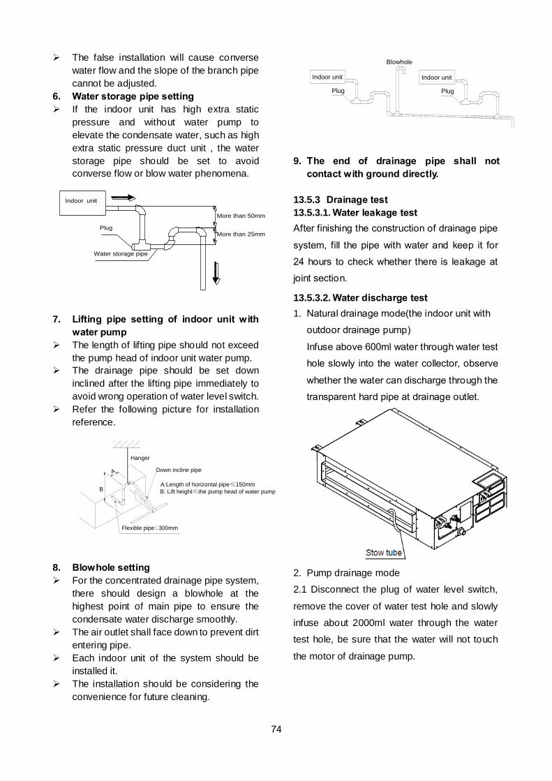
74
The false installation will cause converse
water flow and the slope of the branch pipe
cannot be adjusted.
6. Water storage pipe setting
If the indoor unit has high extra static
pressure and without water pump to
elevate the condensate water, such as high
extra static pressure duct unit , the water
storage pipe should be set to avoid
converse flow or blow water phenomena.
Indoor unit
More than 50mm
More than 25mmPlug
Water storage pipe
7. Lifting pipe setting of indoor unit with
water pump
The length of lifting pipe should not exceed
the pump head of indoor unit water pump.
The drainage pipe should be set down
inclined after the lifting pipe immediately to
avoid wrong operation of water level switch.
Refer the following picture for installation
reference.
Flexible pipe 300mm
Hanger
A
A:Length of horizontal pipe≤150mm
B: Lift height≤the pump head of water pump
Down incline pipe
B
8. Blowhole setting
For the concentrated drainage pipe system,
there should design a blowhole at the
highest point of main pipe to ensure the
condensate water discharge smoothly.
The air outlet shall face down to prevent dirt
entering pipe.
Each indoor unit of the system should be
installed it.
The installation should be considering the
convenience for future cleaning.
Blowhole
Plug
Indoor unit
Plug
Indoor unit
9. The end of drainage pipe shall not
contact with ground directly.
13.5.3 Drainage test
13.5.3.1. Water leakage test
After finishing the construction of drainage pipe
system, fill the pipe with water and keep it for
24 hours to check whether there is leakage at
joint section.
13.5.3.2. Water discharge test
1. Natural drainage mode(the indoor unit with
outdoor drainage pump)
Infuse above 600ml water through water test
hole slowly into the water collector, observe
whether the water can discharge through the
transparent hard pipe at drainage outlet.
2. Pump drainage mode
2.1 Disconnect the plug of water level switch,
remove the cover of water test hole and slowly
infuse about 2000ml water through the water
test hole, be sure that the water will not touch
the motor of drainage pump.
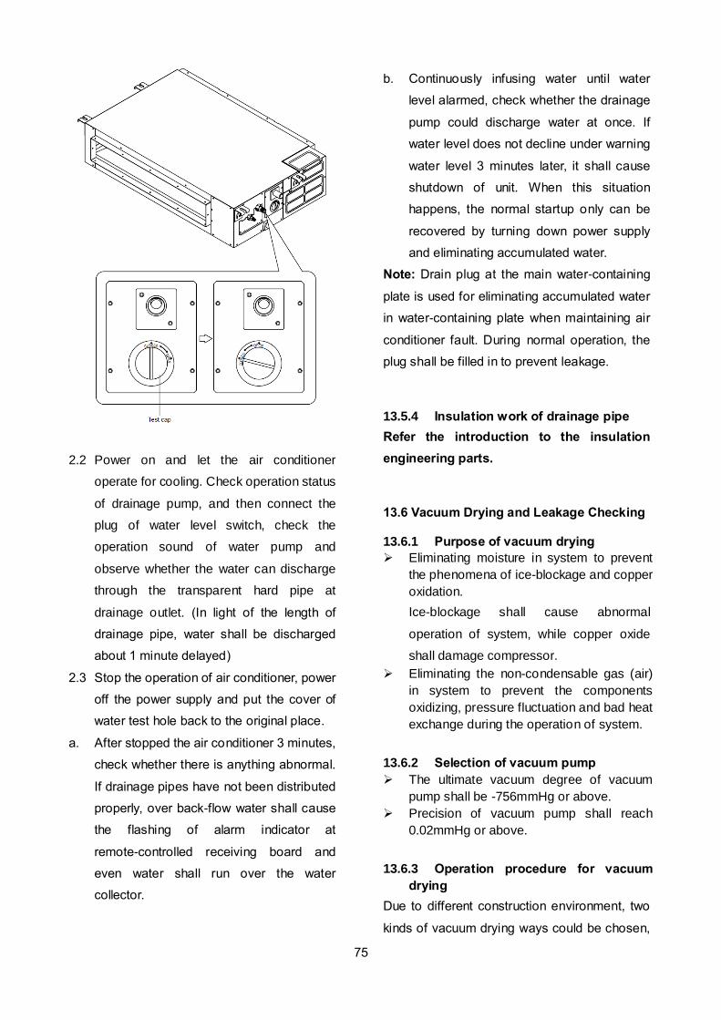
75
2.2 Power on and let the air conditioner
operate for cooling. Check operation status
of drainage pump, and then connect the
plug of water level switch, check the
operation sound of water pump and
observe whether the water can discharge
through the transparent hard pipe at
drainage outlet. (In light of the length of
drainage pipe, water shall be discharged
about 1 minute delayed)
2.3 Stop the operation of air conditioner, power
off the power supply and put the cover of
water test hole back to the original place.
a. After stopped the air conditioner 3 minutes,
check whether there is anything abnormal.
If drainage pipes have not been distributed
properly, over back-flow water shall cause
the flashing of alarm indicator at
remote-controlled receiving board and
even water shall run over the water
collector.
b. Continuously infusing water until water
level alarmed, check whether the drainage
pump could discharge water at once. If
water level does not decline under warning
water level 3 minutes later, it shall cause
shutdown of unit. When this situation
happens, the normal startup only can be
recovered by turning down power supply
and eliminating accumulated water.
Note: Drain plug at the main water-containing
plate is used for eliminating accumulated water
in water-containing plate when maintaining air
conditioner fault. During normal operation, the
plug shall be filled in to prevent leakage.
13.5.4 Insulation work of drainage pipe
Refer the introduction to the insulation
engineering parts.
13.6 Vacuum Drying and Leakage Checking
13.6.1 Purpose of vacuum drying
Eliminating moisture in system to prevent
the phenomena of ice-blockage and copper
oxidation.
Ice-blockage shall cause abnormal
operation of system, while copper oxide
shall damage compressor.
Eliminating the non-condensable gas (air)
in system to prevent the components
oxidizing, pressure fluctuation and bad heat
exchange during the operation of system.
13.6.2 Selection of vacuum pump
The ultimate vacuum degree of vacuum
pump shall be -756mmHg or above.
Precision of vacuum pump shall reach
0.02mmHg or above.
13.6.3 Operation procedure for vacuum
drying
Due to different construction environment, two
kinds of vacuum drying ways could be chosen,
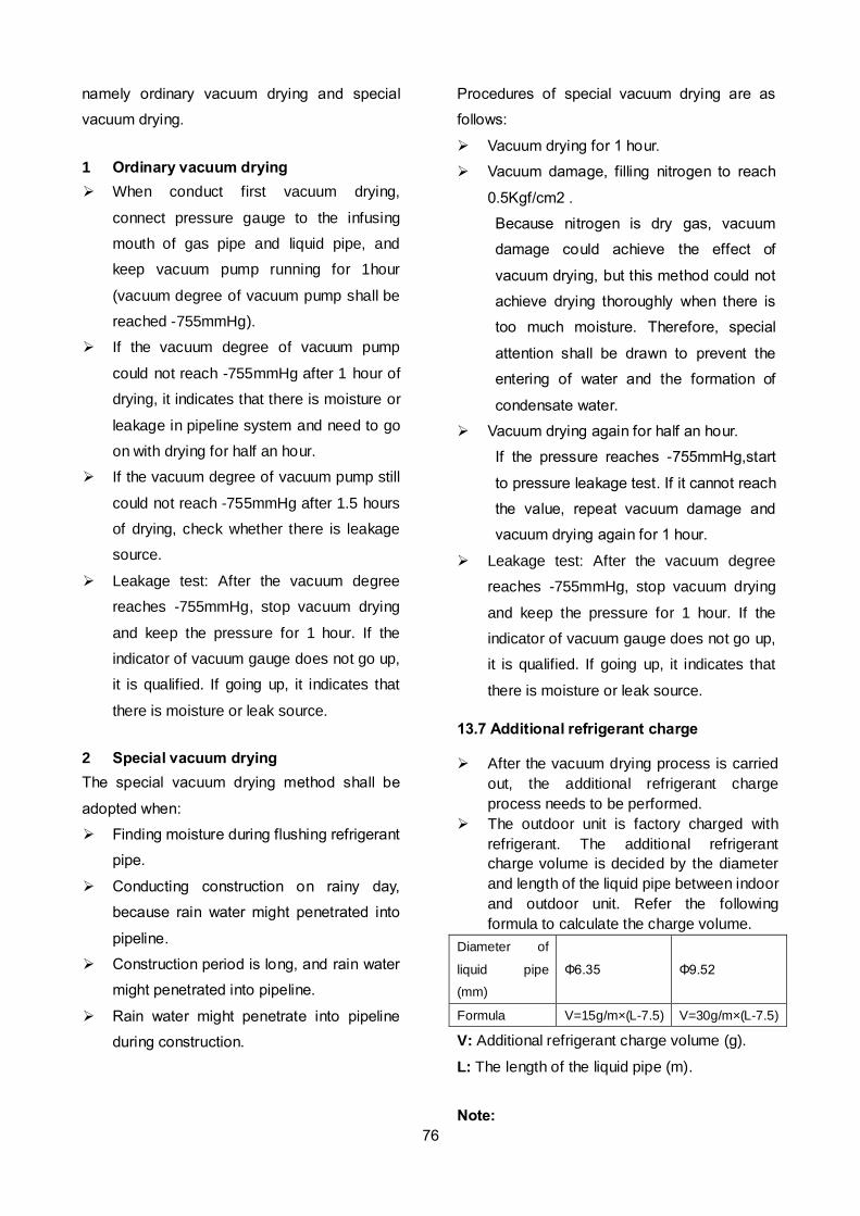
76
namely ordinary vacuum drying and special
vacuum drying.
1 Ordinary vacuum drying
When conduct first vacuum drying,
connect pressure gauge to the infusing
mouth of gas pipe and liquid pipe, and
keep vacuum pump running for 1hour
(vacuum degree of vacuum pump shall be
reached -755mmHg).
If the vacuum degree of vacuum pump
could not reach -755mmHg after 1 hour of
drying, it indicates that there is moisture or
leakage in pipeline system and need to go
on with drying for half an hour.
If the vacuum degree of vacuum pump still
could not reach -755mmHg after 1.5 hours
of drying, check whether there is leakage
source.
Leakage test: After the vacuum degree
reaches -755mmHg, stop vacuum drying
and keep the pressure for 1 hour. If the
indicator of vacuum gauge does not go up,
it is qualified. If going up, it indicates that
there is moisture or leak source.
2 Special vacuum drying
The special vacuum drying method shall be
adopted when:
Finding moisture during flushing refrigerant
pipe.
Conducting construction on rainy day,
because rain water might penetrated into
pipeline.
Construction period is long, and rain water
might penetrated into pipeline.
Rain water might penetrate into pipeline
during construction.
Procedures of special vacuum drying are as
follows:
Vacuum drying for 1 hour.
Vacuum damage, filling nitrogen to reach
0.5Kgf/cm2 .
Because nitrogen is dry gas, vacuum
damage could achieve the effect of
vacuum drying, but this method could not
achieve drying thoroughly when there is
too much moisture. Therefore, special
attention shall be drawn to prevent the
entering of water and the formation of
condensate water.
Vacuum drying again for half an hour.
If the pressure reaches -755mmHg,start
to pressure leakage test. If it cannot reach
the value, repeat vacuum damage and
vacuum drying again for 1 hour.
Leakage test: After the vacuum degree
reaches -755mmHg, stop vacuum drying
and keep the pressure for 1 hour. If the
indicator of vacuum gauge does not go up,
it is qualified. If going up, it indicates that
there is moisture or leak source.
13.7 Additional refrigerant charge
After the vacuum drying process is carried
out, the additional refrigerant charge
process needs to be performed.
The outdoor unit is factory charged with
refrigerant. The additional refrigerant
charge volume is decided by the diameter
and length of the liquid pipe between indoor
and outdoor unit. Refer the following
formula to calculate the charge volume.
Diameter of
liquid pipe
(mm)
Φ6.35 Φ9.52
Formula V=15g/m×(L-7.5) V=30g/m×(L-7.5)
V: Additional refrigerant charge volume (g).
L: The length of the liquid pipe (m).
Note:
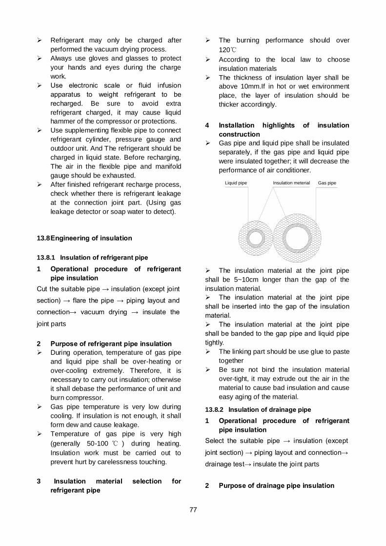
77
Refrigerant may only be charged after
performed the vacuum drying process.
Always use gloves and glasses to protect
your hands and eyes during the charge
work.
Use electronic scale or fluid infusion
apparatus to weight refrigerant to be
recharged. Be sure to avoid extra
refrigerant charged, it may cause liquid
hammer of the compressor or protections.
Use supplementing flexible pipe to connect
refrigerant cylinder, pressure gauge and
outdoor unit. And The refrigerant should be
charged in liquid state. Before recharging,
The air in the flexible pipe and manifold
gauge should be exhausted.
After finished refrigerant recharge process,
check whether there is refrigerant leakage
at the connection joint part. (Using gas
leakage detector or soap water to detect).
13.8 Engineering of insulation
13.8.1 Insulation of refrigerant pipe
1 Operational procedure of refrigerant
pipe insulation
Cut the suitable pipe → insulation (except joint
section) → flare the pipe → piping layout and
connection→ vacuum drying → insulate the
joint parts
2 Purpose of refrigerant pipe insulation
During operation, temperature of gas pipe
and liquid pipe shall be over-heating or
over-cooling extremely. Therefore, it is
necessary to carry out insulation; otherwise
it shall debase the performance of unit and
burn compressor.
Gas pipe temperature is very low during
cooling. If insulation is not enough, it shall
form dew and cause leakage.
Temperature of gas pipe is very high
(generally 50-100 ) during heating.
Insulation work must be carried out to
prevent hurt by carelessness touching.
3 Insulation material selection for
refrigerant pipe
The burning performance should over
120
According to the local law to choose
insulation materials
The thickness of insulation layer shall be
above 10mm.If in hot or wet environment
place, the layer of insulation should be
thicker accordingly.
4 Installation highlights of insulation
construction
Gas pipe and liquid pipe shall be insulated
separately, if the gas pipe and liquid pipe
were insulated together; it will decrease the
performance of air conditioner.
Liquid pipe Insulation meterial Gas pipe
The insulation material at the joint pipe
shall be 5~10cm longer than the gap of the
insulation material.
The insulation material at the joint pipe
shall be inserted into the gap of the insulation
material.
The insulation material at the joint pipe
shall be banded to the gap pipe and liquid pipe
tightly.
The linking part should be use glue to paste
together
Be sure not bind the insulation material
over-tight, it may extrude out the air in the
material to cause bad insulation and cause
easy aging of the material.
13.8.2 Insulation of drainage pipe
1 Operational procedure of refrigerant
pipe insulation
Select the suitable pipe → insulation (except
joint section) → piping layout and connection→
drainage test→ insulate the joint parts
2 Purpose of drainage pipe insulation
78
The temperature of condensate drainage water
is very low. If insulation is not enough, it shall
form dew and cause leakage to damage the
house decoration.
3 Insulation material selection for
drainage pipe
The insulation material should be flame
retardant material, the flame retardancy of
the material should be selected according
to the local law.
Thickness of insulation layer is usually
above 10mm.
Use specific glue to paste the seam of
insulation material, and then bind with
adhesive tape. The width of tape shall not
be less than 5cm. Make sure it is firm and
avoid dew.
4 Installation and highlights of insulation
construction
The single pipe should be insulated before
connecting to another pipe, the joint part
should be insulated after the drainage test.
There should be no insulation gap between
the insulation material.
13.9 Engineering of electrical wiring
1 Highlights of electrical wiring
installation
All field wiring construction should be
finished by qualified electrician.
Air conditioning equipment should be
grounded according to the local electrical
regulations.
Current leakage protection switch should
be installed.
Do not connect the power wire to the
terminal of signal wire.
When power wire is parallel with signal wire,
put wires to their own wire tube and remain
at least 300mm gap.
According to table in indoor part named
“the specification of the power” to choose
the wiring, make sure the selected wiring
not small than the date showing in the
table.
Select different colors for different wire
according to relevant regulations.
Do not use metal wire tube at the place with
acid or alkali corrosion, adopt plastic wire
tube to replace it.
There must be not wire connect joint in the
wire tube If joint is a must, set a connection
box at the place.
The wiring with different voltage should not
be in one wire tube.
Ensure that the color of the wires of outdoor
and the terminal No. are same as those of
indoor unit respectively.
13.10 Test operation
1 The test operation must be carried out
after the entire installation has been
completed.
2 Please confirm the following points
before the test operation.
The indoor unit and outdoor unit are
installed properly.
Tubing and wiring are correctly completed.
The refrigerant pipe system is
leakage-checked.
The drainage is unimpeded.
The ground wiring is connected correctly.
The length of the tubing and the added
stow capacity of the refrigerant have been
recorded.
The power voltage fits the rated voltage of
the air conditioner.
There is no obstacle at the outlet and inlet
of the outdoor and indoor units.
The gas-side and liquid-side stop values
are both opened.
The air conditioner is pre-heated by turning
on the power.
3 Test operation
Set the air conditioner under the mode of
"COOLING" by remote controller, and check
the following points.
Indoor unit
Whether the switch on the remote controller
works well.
Whether the buttons on the remote
controller works well.
Whether the air flow louver moves
normally.
Whether the room temperature is adjusted
well.
Whether the indicator lights normally.
Whether the temporary buttons works well.

79
Whether the drainage is normal.
Whether there is vibration or abnormal
noise during operation.
Outdoor unit
Whether there is vibration or abnormal
noise during operation.
Whether the generated wind, noise, or
condensed of by the air conditioner have
influenced your neighborhood.
Whether any of the refrigerant is leaked.
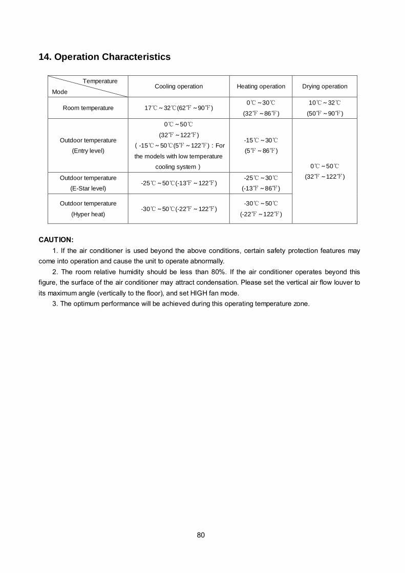
80
14. Operation Characteristics
Temperature
Mode Cooling operation Heating operation Drying operation
Room temperature 17~32(62~90) 0~30
(32~86)
10~32
(50~90)
Outdoor temperature
(Entry level)
0~50
(32~122)
(-15~50(5~122):For
the models with low temperature
cooling system)
-15~30
(5~86)
0~50
(32~122) Outdoor temperature
(E-Star level) -25~50(-13~122)
-25~30
(-13~86)
Outdoor temperature
(Hyper heat) -30~50(-22~122)
-30~50
(-22~122)
CAUTION:
1. If the air conditioner is used beyond the above conditions, certain safety protection features may
come into operation and cause the unit to operate abnormally.
2. The room relative humidity should be less than 80%. If the air conditioner operates beyond this
figure, the surface of the air conditioner may attract condensation. Please set the vertical air flow louver to
its maximum angle (vertically to the floor), and set HIGH fan mode.
3. The optimum performance will be achieved during this operating temperature zone.

81
15. Electronic Function
15.1 Abbreviation
T1: Indoor room temperature
T2: Coil temperature of indoor heat exchanger
T3: Coil temperature of condenser
T4: Outdoor ambient temperature
T5: Compressor discharge temperature
Td: Target temperature
15.2 Display function
15.2.1 Icon explanation on indoor display board
(Duct)
15.2.2 Icon explanation on indoor display board
(Compact cassette).
15.2.3 Icon explanation on indoor display board
(slim Cassette).
15.2.4 Icon explanation on indoor display board
(Console).
15.2.5 Icon explanation on indoor display board
(Ceiling Floor)
15.3 Main Protection
15.3.1 Three minutes delay at restart for
compressor
1 minute delay for the 1st time stand-up and 3
minutes delay for others.
15.3.2 Temperature protection of
compressor top
The unit will stop working when the compressor
top temp. protector cut off, and will restart after
the compressor top temp. protector restart.
15.3.3 Temperature protection of
compressor discharge
When the compressor discharge temp. is
getting higher, the running frequency will be
limited as below rules:
---Compressor discharge temp. T5>115
(239°F) for 5s, compressor stops and restarts
up till T5<90(194°F)
---110<T5<115(239°F), decrease the
frequency to the lower level every 2 minutes.
---105(221°F)<T5<110(230°F), keep running
at the current frequency.
----T5<105(221°F), no limit for frequency.
15.3.4 Fan speed malfunction
When indoor fan speed keeps too low (lower
than 300RPM) for 50s, the indoor fan will shut
OPERATION TIMER DEF./FAN ALARM
Temporary button
Operation lamp
Timer indicator
Infrared signal receiver
Alarm indicator
PRE-DEF indicator(cooling and heating type)
or fan only indicator(cooling only type)
MANUAL
Display digital tube
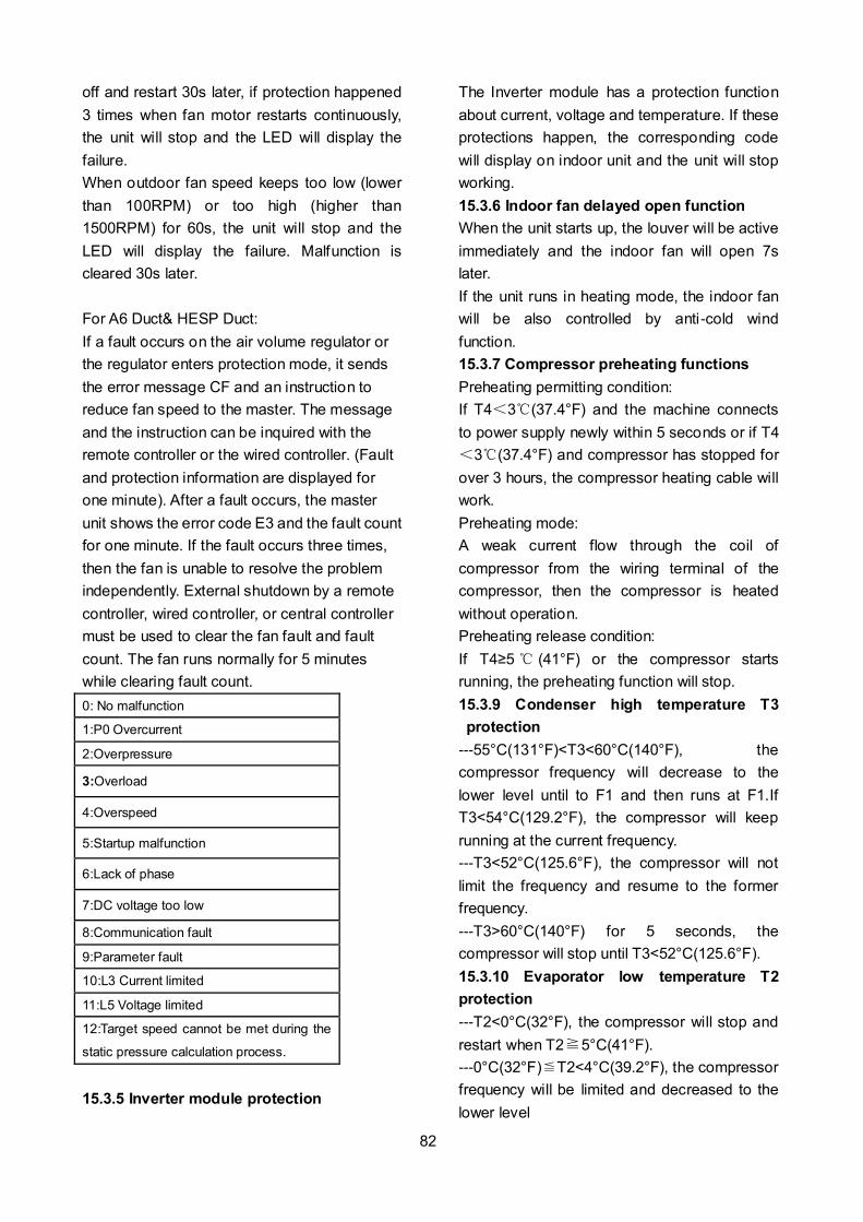
82
off and restart 30s later, if protection happened
3 times when fan motor restarts continuously,
the unit will stop and the LED will display the
failure.
When outdoor fan speed keeps too low (lower
than 100RPM) or too high (higher than
1500RPM) for 60s, the unit will stop and the
LED will display the failure. Malfunction is
cleared 30s later.
For A6 Duct& HESP Duct:
If a fault occurs on the air volume regulator or
the regulator enters protection mode, it sends
the error message CF and an instruction to
reduce fan speed to the master. The message
and the instruction can be inquired with the
remote controller or the wired controller. (Fault
and protection information are displayed for
one minute). After a fault occurs, the master
unit shows the error code E3 and the fault count
for one minute. If the fault occurs three times,
then the fan is unable to resolve the problem
independently. External shutdown by a remote
controller, wired controller, or central controller
must be used to clear the fan fault and fault
count. The fan runs normally for 5 minutes
while clearing fault count.
0: No malfunction
1:P0 Overcurrent
2:Overpressure
3:Overload
4:Overspeed
5:Startup malfunction
6:Lack of phase
7:DC voltage too low
8:Communication fault
9:Parameter fault
10:L3 Current limited
11:L5 Voltage limited
12:Target speed cannot be met during the
static pressure calculation process.
15.3.5 Inverter module protection
The Inverter module has a protection function
about current, voltage and temperature. If these
protections happen, the corresponding code
will display on indoor unit and the unit will stop
working.
15.3.6 Indoor fan delayed open function
When the unit starts up, the louver will be active
immediately and the indoor fan will open 7s
later.
If the unit runs in heating mode, the indoor fan
will be also controlled by anti-cold wind
function.
15.3.7 Compressor preheating functions
Preheating permitting condition:
If T4<3(37.4°F) and the machine connects
to power supply newly within 5 seconds or if T4
<3(37.4°F) and compressor has stopped for
over 3 hours, the compressor heating cable will
work.
Preheating mode:
A weak current flow through the coil of
compressor from the wiring terminal of the
compressor, then the compressor is heated
without operation.
Preheating release condition:
If T4≥5 (41°F) or the compressor starts
running, the preheating function will stop.
15.3.9 Condenser high temperature T3
protection
---55°C(131°F)<T3<60°C(140°F), the
compressor frequency will decrease to the
lower level until to F1 and then runs at F1.If
T3<54°C(129.2°F), the compressor will keep
running at the current frequency.
---T3<52°C(125.6°F), the compressor will not
limit the frequency and resume to the former
frequency.
---T3>60°C(140°F) for 5 seconds, the
compressor will stop until T3<52°C(125.6°F).
15.3.10 Evaporator low temperature T2
protection
---T2<0°C(32°F), the compressor will stop and
restart when T2≧5°C(41°F).
---0°C(32°F)≦T2<4°C(39.2°F), the compressor
frequency will be limited and decreased to the
lower level
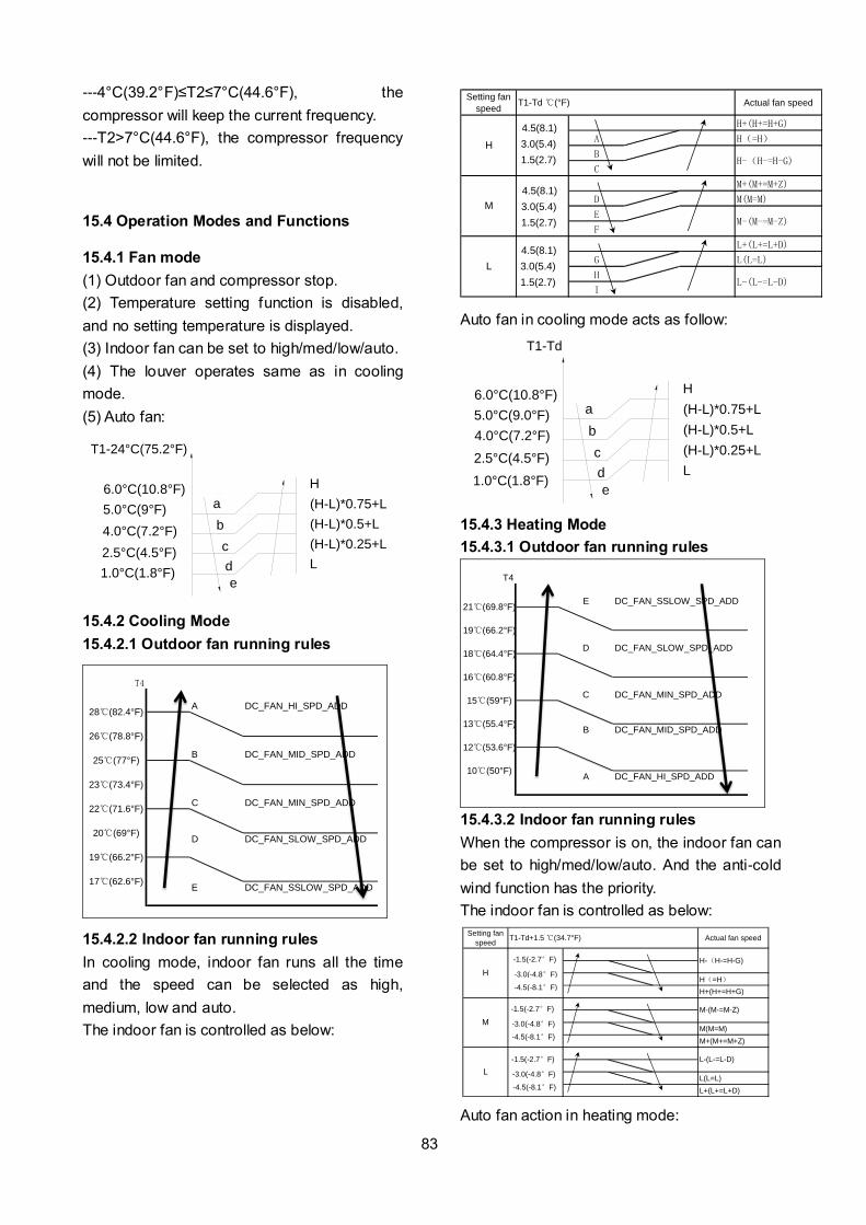
83
---4°C(39.2°F)≤T2≤7°C(44.6°F), the
compressor will keep the current frequency.
---T2>7°C(44.6°F), the compressor frequency
will not be limited.
15.4 Operation Modes and Functions
15.4.1 Fan mode
(1) Outdoor fan and compressor stop.
(2) Temperature setting function is disabled,
and no setting temperature is displayed.
(3) Indoor fan can be set to high/med/low/auto.
(4) The louver operates same as in cooling
mode.
(5) Auto fan:
a
b
c
d
6.0°C(10.8°F)
T1-24°C(75.2°F)
e
H
(H-L)*0.75+L
(H-L)*0.5+L
(H-L)*0.25+L
L
5.0°C(9°F)
4.0°C(7.2°F)
2.5°C(4.5°F)
1.0°C(1.8°F)
15.4.2 Cooling Mode
15.4.2.1 Outdoor fan running rules
T4
A DC_FAN_HI_SPD_ADD
B DC_FAN_MID_SPD_ADD
C DC_FAN_MIN_SPD_ADD
D DC_FAN_SLOW_SPD_ADD
E DC_FAN_SSLOW_SPD_ADD
28(82.4°F)
19(66.2°F)
17(62.6°F)
26(78.8°F)
25(77°F)
23(73.4°F)
22(71.6°F)
20(69°F)
15.4.2.2 Indoor fan running rules
In cooling mode, indoor fan runs all the time
and the speed can be selected as high,
medium, low and auto.
The indoor fan is controlled as below:
Setting fan
speedActual fan speed
H+(H+=H+G)
A H(=H)
B
C
M+(M+=M+Z)
D M(M=M)
E
F
L+(L+=L+D)
G L(L=L)
H
I
T1-Td (°F)
L
L-(L-=L-D)
H
H-(H-=H-G)
M
M-(M-=M-Z)
4.5(8.1)
3.0(5.4)
1.5(2.7)
4.5(8.1)
3.0(5.4)
1.5(2.7)
4.5(8.1)
3.0(5.4)
1.5(2.7)
Auto fan in cooling mode acts as follow:
a
b
c
d
6.0°C(10.8°F)
T1-Td
e
H
(H-L)*0.75+L
(H-L)*0.5+L
(H-L)*0.25+L
L
5.0°C(9.0°F)
4.0°C(7.2°F)
2.5°C(4.5°F)
1.0°C(1.8°F)
15.4.3 Heating Mode
15.4.3.1 Outdoor fan running rules
T4
E DC_FAN_SSLOW_SPD_ADD
D DC_FAN_SLOW_SPD_ADD
C DC_FAN_MIN_SPD_ADD
B DC_FAN_MID_SPD_ADD
A DC_FAN_HI_SPD_ADD
15(59°F)
13(55.4°F)
12(53.6°F)
10(50°F)
21(69.8°F)
19(66.2°F)
18(64.4°F)
16(60.8°F)
15.4.3.2 Indoor fan running rules
When the compressor is on, the indoor fan can
be set to high/med/low/auto. And the anti-cold
wind function has the priority.
The indoor fan is controlled as below:
Setting fan
speedActual fan speed
H(=H)
H+(H+=H+G)
M(M=M)
M+(M+=M+Z)
L(L=L)
L+(L+=L+D)
H-(H-=H-G)
M-(M-=M-Z)
L-(L-=L-D)
T1-Td+1.5 (34.7°F)
L
H
M
-1.5(-2.7°F)
-3.0(-4.8°F)
-4.5(-8.1°F)
-
-1.5(-2.7°F)
-3.0(-4.8°F)
-4.5(-8.1°F)
-1.5(-2.7°F)
-3.0(-4.8°F)
-4.5(-8.1°F)
Auto fan action in heating mode:
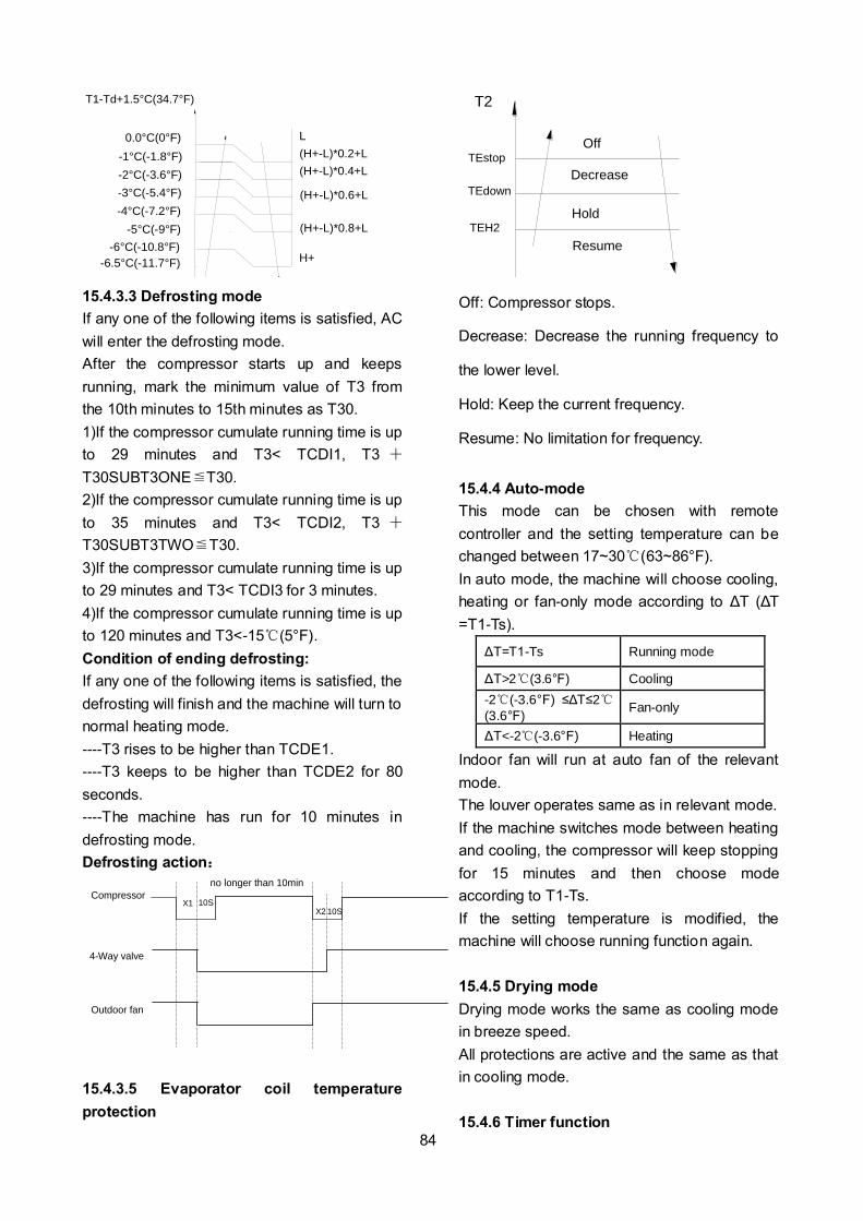
84
0.0°C(0°F)
T1-Td+1.5°C(34.7°F)
L
(H+-L)*0.2+L
(H+-L)*0.4+L
(H+-L)*0.6+L
H+
(H+-L)*0.8+L
-1°C(-1.8°F)
-2°C(-3.6°F)
-3°C(-5.4°F)
-4°C(-7.2°F)
-5°C(-9°F)
-6°C(-10.8°F)
-6.5°C(-11.7°F)
15.4.3.3 Defrosting mode
If any one of the following items is satisfied, AC
will enter the defrosting mode.
After the compressor starts up and keeps
running, mark the minimum value of T3 from
the 10th minutes to 15th minutes as T30.
1)If the compressor cumulate running time is up
to 29 minutes and T3< TCDI1, T3 +
T30SUBT3ONE≦T30.
2)If the compressor cumulate running time is up
to 35 minutes and T3< TCDI2, T3 +
T30SUBT3TWO≦T30.
3)If the compressor cumulate running time is up
to 29 minutes and T3< TCDI3 for 3 minutes.
4)If the compressor cumulate running time is up
to 120 minutes and T3<-15(5°F).
Condition of ending defrosting:
If any one of the following items is satisfied, the
defrosting will finish and the machine will turn to
normal heating mode.
----T3 rises to be higher than TCDE1.
----T3 keeps to be higher than TCDE2 for 80
seconds.
----The machine has run for 10 minutes in
defrosting mode.
Defrosting action:
Compressor
Outdoor fan
4-Way valve
X1 10S 10S
no longer than 10min
X2
15.4.3.5 Evaporator coil temperature
protection
TEstop
T2
Resume
Off
DecreaseTEdown
TEH2Hold
Off: Compressor stops.
Decrease: Decrease the running frequency to
the lower level.
Hold: Keep the current frequency.
Resume: No limitation for frequency.
15.4.4 Auto-mode
This mode can be chosen with remote
controller and the setting temperature can be
changed between 17~30(63~86°F).
In auto mode, the machine will choose cooling,
heating or fan-only mode according to ΔT (ΔT
=T1-Ts).
ΔT=T1-Ts Running mode
ΔT>2(3.6°F) Cooling
-2(-3.6°F) ≤ΔT≤2(3.6°F)
Fan-only
ΔT<-2(-3.6°F) Heating
Indoor fan will run at auto fan of the relevant
mode.
The louver operates same as in relevant mode.
If the machine switches mode between heating
and cooling, the compressor will keep stopping
for 15 minutes and then choose mode
according to T1-Ts.
If the setting temperature is modified, the
machine will choose running function again.
15.4.5 Drying mode
Drying mode works the same as cooling mode
in breeze speed.
All protections are active and the same as that
in cooling mode.
15.4.6 Timer function

85
15.4.6.1 Timing range is 24 hours.
15.4.6.2 Timer on. The machine will turn on
automatically when reaching the setting time.
15.4.6.3 Timer off. The machine will turn off
automatically when reaching the setting time.
15.4.6.4 Timer on/off. The machine will turn on
automatically when reaching the setting “on”
time, and then turn off automatically when
reaching the setting “off” time.
15.4.6.5 Timer off/on. The machine will turn off
automatically when reaching the setting “off”
time, and then turn on automatically when
reaching the setting “on” time.
15.4.6.6 The timer function will not change the
AC current operation mode. Suppose AC is off
now, it will not start up firstly after setting the
“timer off” function. And when reaching the
setting time, the timer LED will be off and the
AC running mode has not been changed.
15.4.6.7 The setting time is relative time.
15.4.7 Sleep function mode
15.4.7.1 The sleep function is available in
cooling, heating or auto mode.
15.4.7.2. Operation process in sleep mode is as
follow:
When cooling, the setting temperature rises 1
(1.8°F) (be lower than 30(86°F)) every one
hour, 2 hours later the setting temperature
stops rising and the indoor fan is fixed at low
speed.
When heating, the setting temperature
decreases 1 (1.8°F) (be higher than 17
(62.6°F)) every one hour, 2 hours later the
setting temperature stops rising and indoor fan
is fixed at low speed. (Anti-cold wind function
has the priority).
15.4.7.3 Operation time in sleep mode is 7
hours. After 7 hours the AC quits this mode and
turns off
15.4.7.4 Timer setting is available.
15.4.8 Auto-Restart function
The indoor unit is equipped with auto-restart
function, which is carried out through an
auto-restart module. In case of a sudden power
failure, the module memorizes the setting
conditions before the power failure. The unit will
resume the previous operation setting (not
including sleep function) automatically after 3
minutes when power returns.
15.4.9 Follow me
1) If the indoor PCB receives the signal which
results from pressing the FOLLOW ME button
on remote controller or wired remote controller,
the buzzer will emit a sound and this indicates
the follow me function is initiated. But when the
indoor PCB receives signal which sent from
remote controller every 3 minutes, the buzzer
will not respond. When the unit is running with
follow me function, the PCB will control the unit
according to the temperature from follow me
signal, and the temperature collection function
of room temperature sensor will be shielded.
2) When the follow me function is available,
the PCB will control the unit according to the
room temperature from the remote controller
and the setting temperature.
3) The PCB will take action to the mode
change information from remote controller
signal, but it will not affected by the setting
temperature.
4) When the unit is running with follow me
function, if the PCB doesn’t receive any signal
from remote controller for 7 minutes or pressing
FOLLOW ME button again, the follow me
function will be turned off automatically, and the
temperature will control the unit according to
the room temperature detected from its own
room temperature sensor and setting
temperature.
15.4.10 8 Heating(optional)
In heating operation, the preset temperature of
the air conditioner can be as lower as 8
(46.4°F), which keeps the room temperature
steady at 8(46.4°F) and prevents household
things freezing when the house is unoccupied
for a long time in severe cold weather.

86
15.4.11 Drain pump control
Adopt the water-level switch to control the
action of drain pump.
Main action under different condition :( every 5
seconds the system will check the water level
one time)
1. When the A/C operates with cooling
(including auto cooling), dehumidifying, and
forced cooling mode, the pump will start
running immediately and continuously, till stop
cooling.
2. Once the water level increase and up to the
control point, LED will alarm and the drain
pump open and continue checking the water
level. If the water level fall down and LED
disalarmed (drain pump delay close 1 minute)
and operate with the last mode. Otherwise the
entire system stop operating (including the
pump) and LED remain alarming after 3
minutes,
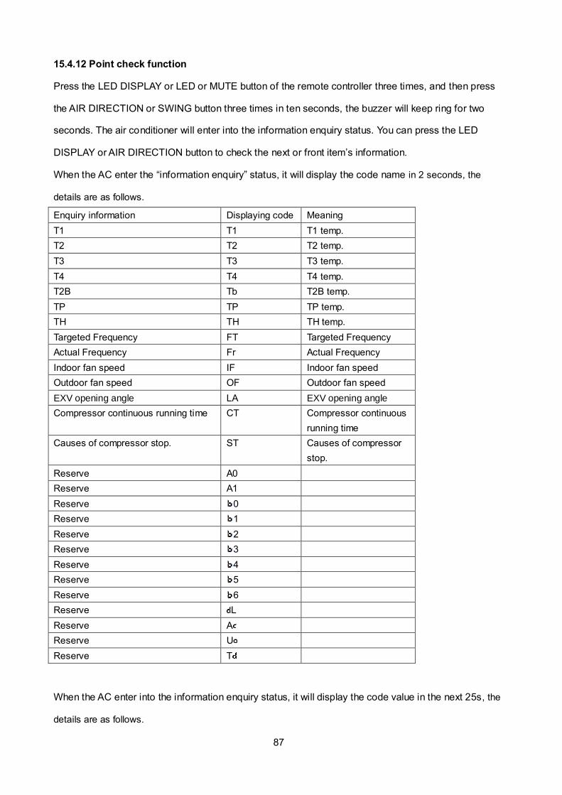
87
15.4.12 Point check function
Press the LED DISPLAY or LED or MUTE button of the remote controller three times, and then press
the AIR DIRECTION or SWING button three times in ten seconds, the buzzer will keep ring for two
seconds. The air conditioner will enter into the information enquiry status. You can press the LED
DISPLAY or AIR DIRECTION button to check the next or front item’s information.
When the AC enter the “information enquiry” status, it will display the code name in 2 seconds, the
details are as follows.
Enquiry information Displaying code Meaning
T1 T1 T1 temp.
T2 T2 T2 temp.
T3 T3 T3 temp.
T4 T4 T4 temp.
T2B Tb T2B temp.
TP TP TP temp.
TH TH TH temp.
Targeted Frequency FT Targeted Frequency
Actual Frequency Fr Actual Frequency
Indoor fan speed IF Indoor fan speed
Outdoor fan speed OF Outdoor fan speed
EXV opening angle LA EXV opening angle
Compressor continuous running time CT Compressor continuous
running time
Causes of compressor stop. ST Causes of compressor
stop.
Reserve A0
Reserve A1
Reserve 0
Reserve 1
Reserve 2
Reserve 3
Reserve 4
Reserve 5
Reserve 6
Reserve L
Reserve A
Reserve U
Reserve T
When the AC enter into the information enquiry status, it will display the code value in the next 25s, the
details are as follows.
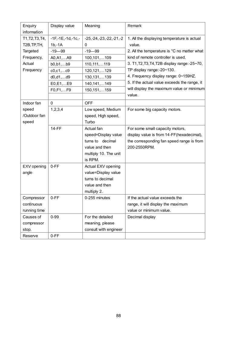
88
Enquiry
information
Display value Meaning Remark
T1,T2,T3,T4,
T2B,TP,TH,
Targeted
Frequency,
Actual
Frequency
-1F,-1E,-1d,-1c,-
1b,-1A
-25,-24,-23,-22,-21,-2
0
1. All the displaying temperature is actual
value.
2. All the temperature is °C no matter what
kind of remote controller is used.
3. T1,T2,T3,T4,T2B display range:-25~70,
TP display range:-20~130.
4. Frequency display range: 0~159HZ.
5. If the actual value exceeds the range, it
will display the maximum value or minimum
value.
-19—99 -19—99
A0,A1,…A9 100,101,…109
b0,b1,…b9 110,111,…119
c0,c1,…c9 120,121,…129
d0,d1,…d9 130,131,…139
E0,E1,…E9 140,141,…149
F0,F1,…F9 150,151,…159
Indoor fan
speed
/Outdoor fan
speed
0 OFF
1,2,3,4 Low speed, Medium
speed, High speed,
Turbo
For some big capacity motors.
14-FF Actual fan
speed=Display value
turns to decimal
value and then
multiply 10. The unit
is RPM.
For some small capacity motors,
display value is from 14-FF(hexadecimal),
the corresponding fan speed range is from
200-2550RPM.
EXV opening
angle
0-FF Actual EXV opening
value=Display value
turns to decimal
value and then
multiply 2.
Compressor
continuous
running time
0-FF 0-255 minutes If the actual value exceeds the
range, it will display the maximum
value or minimum value.
Causes of
compressor
stop.
0-99 For the detailed
meaning, please
consult with engineer
Decimal display
Reserve 0-FF
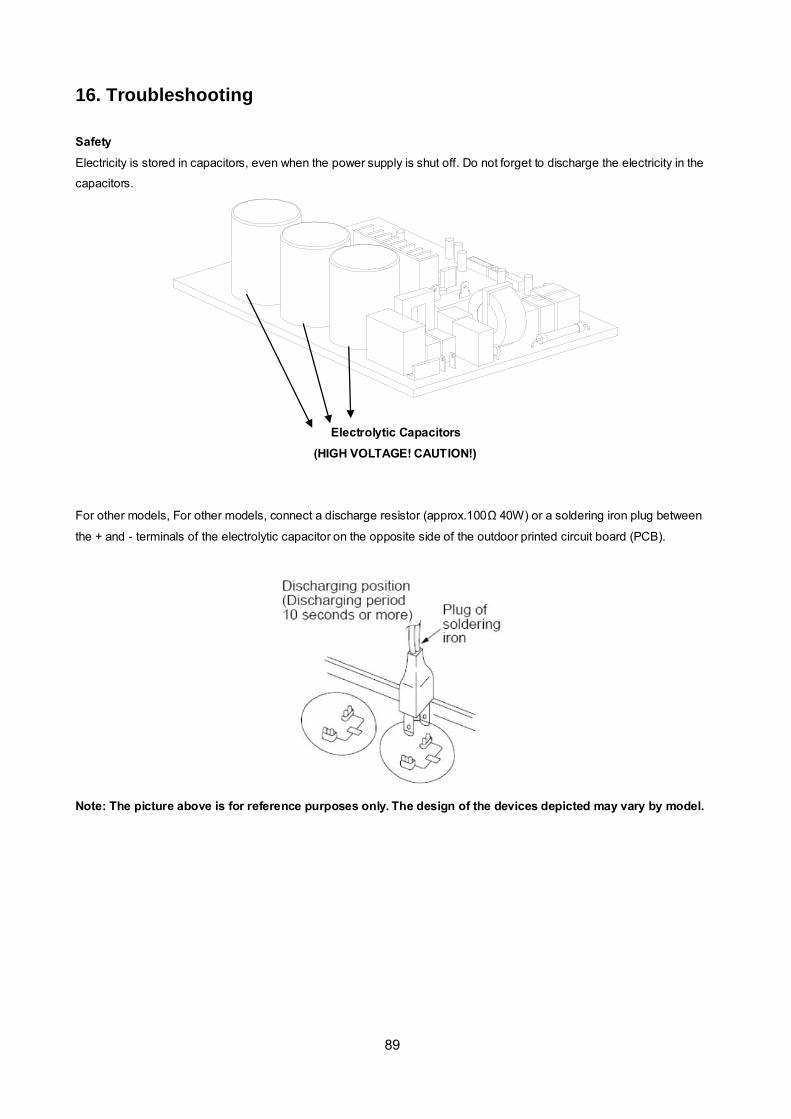
89
16. Troubleshooting
Safety
Electricity is stored in capacitors, even when the power supply is shut off. Do not forget to discharge the electricity in the
capacitors.
Electrolytic Capacitors
(HIGH VOLTAGE! CAUTION!)
For other models, For other models, connect a discharge resistor (approx.100Ω 40W) or a soldering iron plug between
the + and - terminals of the electrolytic capacitor on the opposite side of the outdoor printed circuit board (PCB).
Note: The picture above is for reference purposes only. The design of the devices depicted may vary by model.
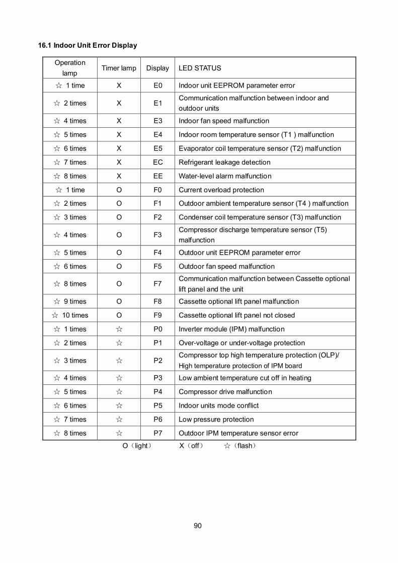
90
16.1 Indoor Unit Error Display
Operation
lamp Timer lamp Display LED STATUS
1 time X E0 Indoor unit EEPROM parameter error
2 times X E1 Communication malfunction between indoor and
outdoor units
4 times X E3 Indoor fan speed malfunction
5 times X E4 Indoor room temperature sensor (T1 ) malfunction
6 times X E5 Evaporator coil temperature sensor (T2) malfunction
7 times X EC Refrigerant leakage detection
8 times X EE Water-level alarm malfunction
1 time O F0 Current overload protection
2 times O F1 Outdoor ambient temperature sensor (T4 ) malfunction
3 times O F2 Condenser coil temperature sensor (T3) malfunction
4 times O F3 Compressor discharge temperature sensor (T5)
malfunction
5 times O F4 Outdoor unit EEPROM parameter error
6 times O F5 Outdoor fan speed malfunction
8 times O F7 Communication malfunction between Cassette optional
lift panel and the unit
9 times O F8 Cassette optional lift panel malfunction
10 times O F9 Cassette optional lift panel not closed
1 times P0 Inverter module (IPM) malfunction
2 times P1 Over-voltage or under-voltage protection
3 times P2 Compressor top high temperature protection (OLP)/
High temperature protection of IPM board
4 times P3 Low ambient temperature cut off in heating
5 times P4 Compressor drive malfunction
6 times P5 Indoor units mode conflict
7 times P6 Low pressure protection
8 times P7 Outdoor IPM temperature sensor error
O(light) X(off) (flash)

91
16.2 Error Display on Two Way Communication Wired Controller
Display LED STATUS
F0 Communication error between wired controller and indoor unit
F1 The cassette faceplate is abnormal
E7 Indoor unit EEPROM parameter error
E1 Communication malfunction between indoor and outdoor units
E8 Indoor fan speed malfunction
E2 Indoor room temperature sensor (T1 ) malfunction
E3 Evaporator coil temperature sensor (T2) malfunction
EF Refrigerant leakage detection
EE Water-level alarm malfunction
E5 Outdoor ambient temperature sensor (T4 ) malfunction
E5 Condenser coil temperature sensor (T3) malfunction
E5 Compressor discharge temperature sensor (T5) malfunction
ED Outdoor unit EEPROM parameter error
ED Outdoor fan speed malfunction
EB Inverter module (IPM) malfunction
EF Other malfunction
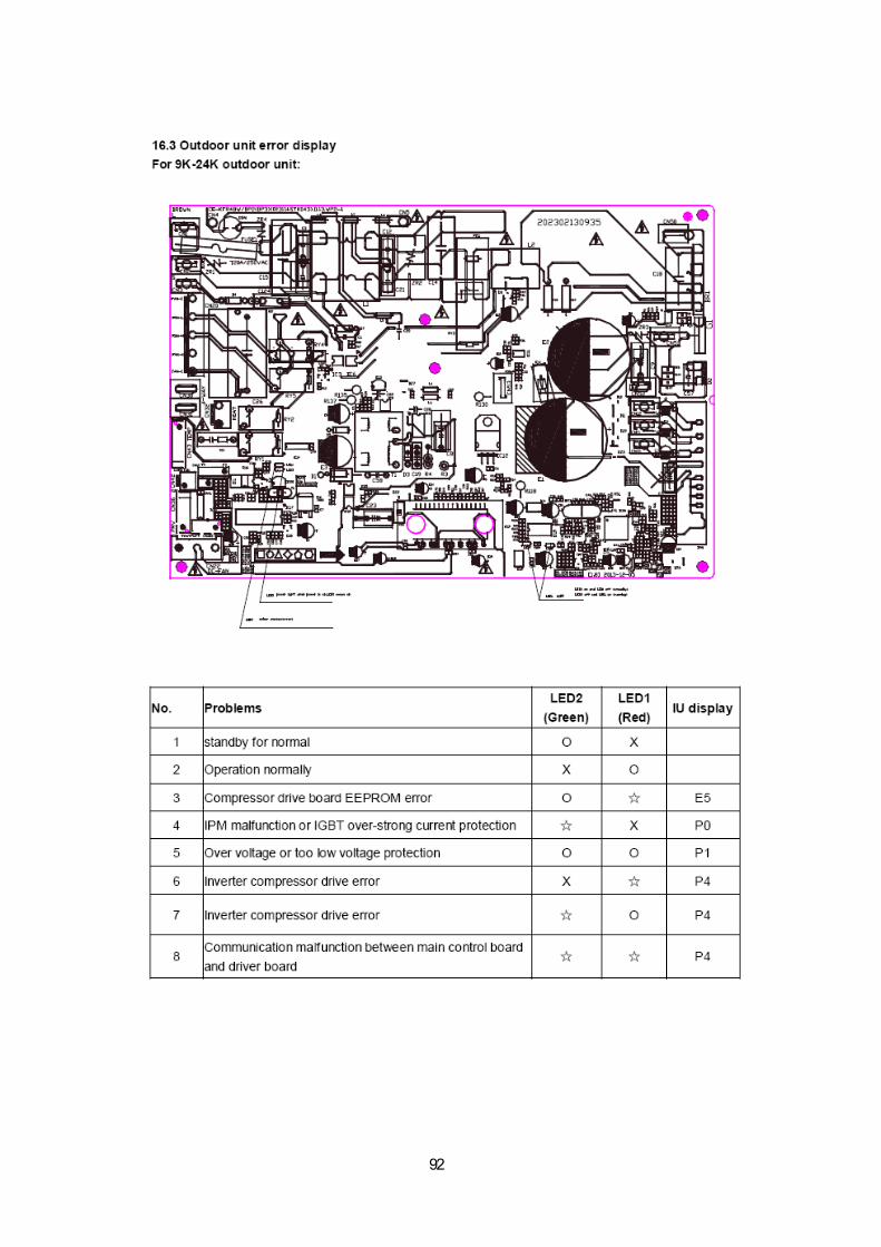
92
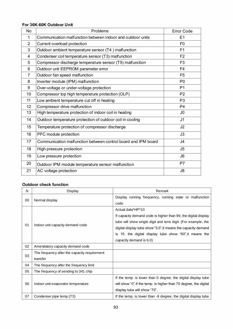
93
For 36K-60K Outdoor Unit
No Problems Error Code
1 Communication malfunction between indoor and outdoor units E1
2 Current overload protection F0
3 Outdoor ambient temperature sensor (T4 ) malfunction F1
4 Condenser coil temperature sensor (T3) malfunction F2
5 Compressor discharge temperature sensor (T5) malfunction F3
6 Outdoor unit EEPROM parameter error F4
7 Outdoor fan speed malfunction F5
8 Inverter module (IPM) malfunction P0
9 Over-voltage or under-voltage protection P1
10 Compressor top high temperature protection (OLP) P2
11 Low ambient temperature cut off in heating P3
12 Compressor drive malfunction P4
13 High temperature protection of indoor coil in heating J0
14 Outdoor temperature protection of outdoor coil in cooling J1
15 Temperature protection of compressor discharge J2
16 PFC module protection J3
17 Communication malfunction between control board and IPM board J4
18 High pressure protection J5
19 Low pressure protection J6
20 Outdoor IPM module temperature sensor malfunction P7
21 AC voltage protection J8
Outdoor check function
N Display Remark
00 Normal display Display running frequency, running state or malfunction
code
01 Indoor unit capacity demand code
Actual data*HP*10
If capacity demand code is higher than 99, the digital display
tube will show single digit and tens digit. (For example, the
digital display tube show “5.0”,it means the capacity demand
is 15. the digital display tube show “60”,it means the
capacity demand is 6.0)
02 Amendatory capacity demand code
03 The frequency after the capacity requirement
transfer
04 The frequency after the frequency limit
05 The frequency of sending to 341 chip
06 Indoor unit evaporator temperature
If the temp. is lower than 0 degree, the digital display tube
will show “0”.If the temp. is higher than 70 degree, the digital
display tube will show “70”.
07 Condenser pipe temp.(T3) If the temp. is lower than -9 degree, the digital display tube

114
08 Outdoor ambient temp.(T4)
will show “-9”.If the temp. is higher than 70 degree, the
digital display tube will show “70”. If the indoor unit is not
connected, the digital display tube will show: “――”
09 Compressor discharge temp.(T5)
The display value is between 13~129 degree. If the temp. is
lower than 13 degree, the digital display tube will show
“13”.If the temp. is higher than 99 degree, the digital display
tube will show single digit and tens digit. (For example, the
digital display tube show “0.5”,it means the compressor
discharge temp. is 105 degree. the digital display tube show
“1.6”,it means the compressor discharge temp. is 116
degree)
10 AD value of current The display value is hex number.
11 AD value of voltage
12 Indoor unit running mode code Off:0, Fan only 1,Cooling:2, Heating:3
13 Outdoor unit running mode code Off:0, Fan only 1,Cooling:2, Heating:3, Forced cooling:4
14 EXV open angle
Actual data/4.
If the value is higher than 99, the digital display tube will
show single digit and tens digit.
For example, the digital display tube show “2.0”,it means the
EXV open angle is 120×4=480p.)
15 Frequency limit symbol
Bit7 Frequency limit caused by
IGBT radiator The display value is
hex number. For
example, the digital
display tube show
2A, then Bit5=1,
Bit3=1, Bit1=1.
It means frequency
limit caused by T4,
T3 and current.
Bit6 Frequency limit caused by
PFC
Bit5 Frequency limit caused by T4.
Bit4 Frequency limit caused by T2.
Bit3 Frequency limit caused by T3.
Bit2 Frequency limit caused by T5.
Bit1 Frequency limit caused by
current
Bit0 Frequency limit caused by
voltage
16 DC fan motor speed
17 IGBT radiator temp.
The display value is between 30~120 degree. If the temp. is
lower than 30 degree, the digital display tube will show
“30”.If the temp. is higher than 99 degree, the digital display
tube will show single digit and tens digit. (For example, the
digital display tube show “0.5”,it means the IGBT radiator
temp. is 105 degree. the digital display tube show “1.6”,it
means the IGBT radiator temp. is 116 degree)
18 Indoor unit number The indoor unit can communicate with outdoor unit well.
General:1, Twins:2
19 Evaporator pipe temp. T2 of 1# indoor unit If the temp. is lower than 0 degree, the digital display tube
will show “0”.If the temp. is higher than 70 degree, the digital
display tube will show “70”. If the indoor unit is not 20 Evaporator pipe temp. T2 of 2# indoor unit
21 Evaporator pipe temp. T2 of 3# indoor unit

115
connected, the digital display tube will show: “――”
22 1# Indoor unit capacity demand code Actual data*HP*10
If capacity demand code is higher than 99, the digital display
tube will show single digit and tens digit. (For example, the
digital display tube show “5.0”,it means the capacity demand
is 15. the digital display tube show “60”,it means the
capacity demand is 6.0). If the indoor unit is not connected,
the digital display tube will show: “――”
23 2# Indoor unit capacity demand code
24 3# Indoor unit capacity demand code
25 Room temp. T1 of 1# indoor unit If the temp. is lower than 0 degree, the digital display tube
will show “0”.If the temp. is higher than 70 degree, the digital
display tube will show “70”. If the indoor unit is not
connected, the digital display tube will show: “――”
26 Room temp. T1 of 2# indoor unit
27 Average room temp. T1
28 Reason of stop
29 Evaporator pipe temp. T2B of 1# indoor unit If the temp. is lower than 0 degree, the digital display tube
will show “0”.If the temp. is higher than 70 degree, the digital
display tube will show “70”. If the indoor unit is not
connected, the digital display tube will show: “――” 30 Evaporator pipe temp. T2B of 2# indoor unit
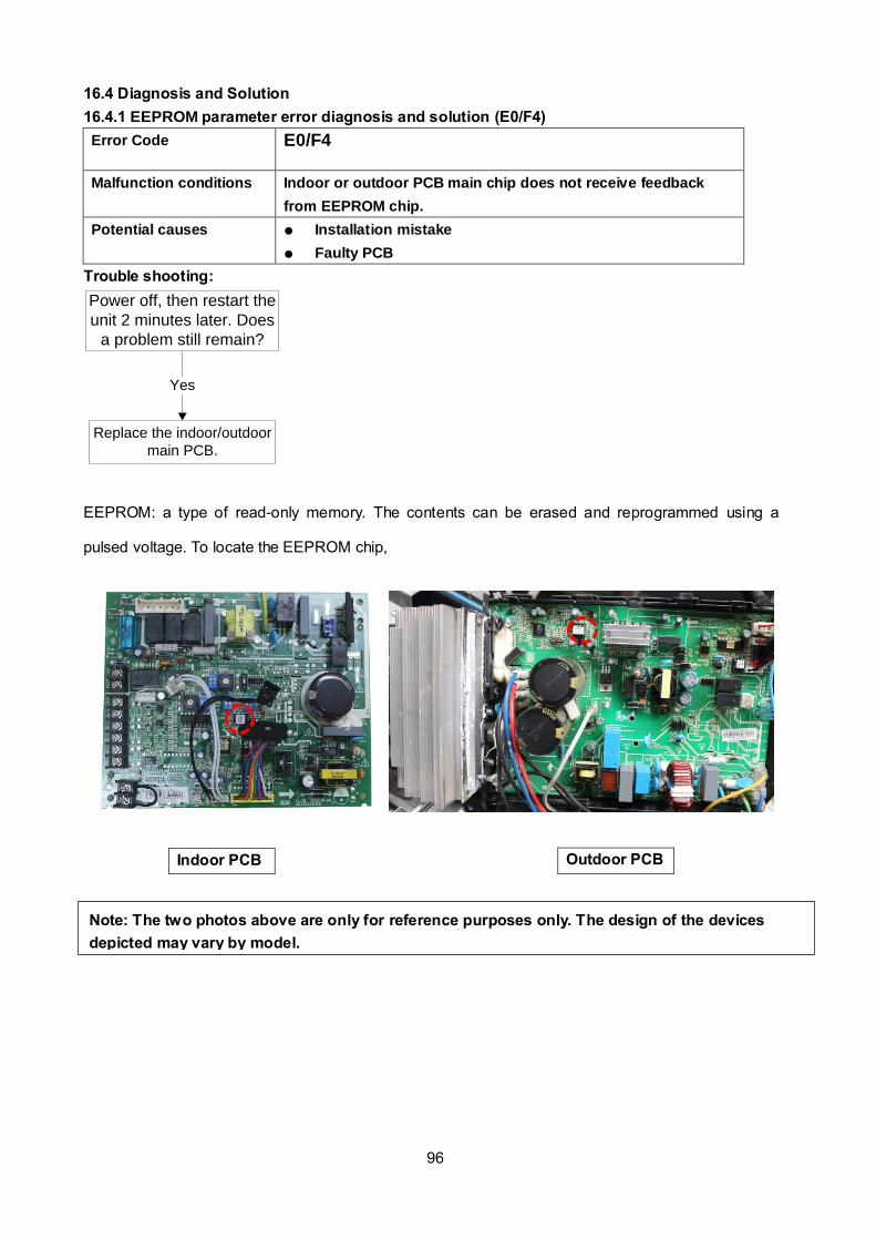
96
16.4 Diagnosis and Solution
16.4.1 EEPROM parameter error diagnosis and solution (E0/F4)
Error Code E0/F4
Malfunction conditions Indoor or outdoor PCB main chip does not receive feedback
from EEPROM chip.
Potential causes Installation mistake
Faulty PCB
Trouble shooting:
Yes
Replace the indoor/outdoor
main PCB.
Power off, then restart the
unit 2 minutes later. Does
a problem still remain?
EEPROM: a type of read-only memory. The contents can be erased and reprogrammed using a
pulsed voltage. To locate the EEPROM chip,
Indoor PCB Outdoor PCB
Note: The two photos above are only for reference purposes only. The design of the devices
depicted may vary by model.
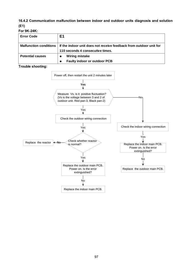
97
16.4.2 Communication malfunction between indoor and outdoor units diagnosis and solution
(E1)
For 9K-24K:
Error Code E1
Malfunction conditions If the indoor unit does not receive feedback from outdoor unit for
110 seconds 4 consecutive times.
Potential causes Wiring mistake
Faulty indoor or outdoor PCB
Trouble shooting:
Measure Vs, is it positive fluctuation?
(Vs is the voltage between 3 and 2 of
outdoor unit. Red pan-3, Black pan-2)
Measure Vs, is it positive fluctuation?
(Vs is the voltage between 3 and 2 of
outdoor unit. Red pan-3, Black pan-2)
Yes
Power off, then restart the unit 2 minutes laterPower off, then restart the unit 2 minutes later
No
Replace the outdoor main PCB.
Power on. Is the error
extinguished?
Replace the outdoor main PCB.
Power on. Is the error
extinguished?
Check the outdoor wiring connection Check the outdoor wiring connection
Replace the indoor main PCB.
Power on. Is the error
extinguished?
Replace the indoor main PCB.
Power on. Is the error
extinguished?
Yes
Replace the outdoor main PCB.Replace the outdoor main PCB.
No
Replace the indoor main PCB.Replace the indoor main PCB.
No
Check the indoor wiring connection Check the indoor wiring connectionYes
Yes
Check whether reactor
is normal?
Check whether reactor
is normal?
Yes
Replace the reactorReplace the reactor No

118
Remark:
Use a multimeter to test the DC
voltage between 2 port and 3 port of
outdoor unit. The red pin of
multimeter connects with 2 port while
the black pin is for 3 port.
When AC is normal running, the
voltage will move alternately between
-50V to 50V.
If the outdoor unit has malfunction,
the voltage will move alternately with
positive value.
While if the indoor unit has
malfunction, the voltage will be a
certain value.
Remark,
The old label is L1,L2,S, L1,L2
The new label is 1, 2, 3, L1,L2
Remark:
Use a multimeter to test the
resistance of the reactor which does
not connect with capacitor.
The normal value should be around
zero ohm. Otherwise, the reactor
must have malfunction and need to
be replaced.
98

99
For 36K-48K:
Malfunction
conditions
Indoor unit does not receive feedback from outdoor unit for 60
seconds OR outdoor unit does not receive feedback from indoor unit
for 120 seconds.
Possible causes Wiring mistakes
Faulty indoor or outdoor PCB
Communication malfunction between indoor
and outdoor units
Communication malfunction between indoor
and outdoor units
E1 displayedE1 displayed
No
Power off, then restart the unit 2
minutes later. Does a problem still
exist?
Power off, then restart the unit 2
minutes later. Does a problem still
exist?
Adopt shield cable/shield
cable earthing
Adopt shield cable/shield
cable earthingNo
Yes
Yes
Remove interference or
add magnet ring on power
wire
Remove interference or
add magnet ring on power
wire
Yes
Replace the signal wireReplace the signal wireYes
Pull out and insert backPull out and insert backNo
No
Replace the indoor main PCB, is the
error resolved?
Replace the indoor main PCB, is the
error resolved?
Yes
Replace the outdoor Main PCB.Replace the outdoor Main PCB.
No
Is there any interference such
as too many lamps, power
transformers? Or is the signal
wire too long?
Is there any interference such
as too many lamps, power
transformers? Or is the signal
wire too long?
Is the signal wire a shield cable
and is the shield cable a
earthing?
Is the signal wire a shield cable
and is the shield cable a
earthing?
Is the signal wire is broken?Is the signal wire is broken?
Are the signal wires properly
inserted on PCB?
Are the signal wires properly
inserted on PCB?

100
16.4.3 Fan speed malfunction diagnosis and solution (E3)
Error Code E3
Malfunction conditions When indoor fan speed is too low (300RPM) for a certain period
of time, the unit ceases operation and the LED displays a failure
code.
Potential Causes Wiring mistake
Faulty fan assembly
Faulty fan motor
Faulty PCB
Trouble shooting:
Power off, then restart the
unit after 2 minutes. Does
a problem remain?
Shut off the power supply,
Rotate the fan by hand.
Does it turn easily?
The unit is operating normally
Find the cause of the
problem and resolve it
Check the wiring of fan
motor. Is it improperly
wired?
No
Yes
No
Correct the connections.No
NoReplace the fan motor
Yes
Yes
Measure the voltage for the
fan motor from the main
PCB. Is it within normal
parameters?
Yes
Replace the main PCBNo

101
Index 1:
1. Indoor DC fan motor (Control Chip is in Fan Motor)
Turn power on and while the unit is on standby, measure the voltage between pin1 and pin3 as well as
between pin4 and pin3 in fan motor connector. If the value of the voltage is not within the range shown
in the following table, the PCB may be experiencing problems and need to be replaced.
DC motor voltage input and output
NO. Color Signal Voltage
1 Red Vs/Vm 200~380V
2 --- --- ---
3 Black GND 0V
4 White Vcc 13.5~16.5V
5 Yellow Vsp 0~6.5V
6 Blue FG 13.5~16.5V
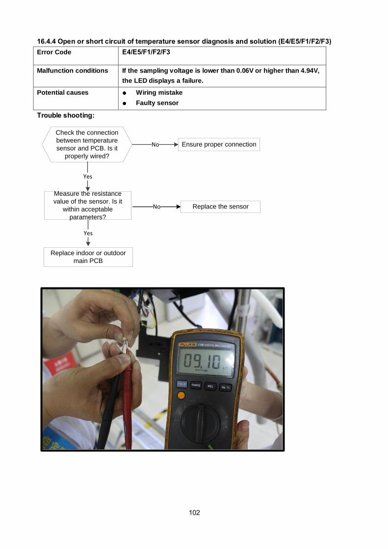
102
16.4.4 Open or short circuit of temperature sensor diagnosis and solution (E4/E5/F1/F2/F3)
Error Code E4/E5/F1/F2/F3
Malfunction conditions If the sampling voltage is lower than 0.06V or higher than 4.94V,
the LED displays a failure.
Potential causes Wiring mistake
Faulty sensor
Faulty PCB Trouble shooting:
Check the connection
between temperature
sensor and PCB. Is it
properly wired?
Ensure proper connectionNo
Yes
Replace indoor or outdoor
main PCB
Measure the resistance
value of the sensor. Is it
within acceptable
parameters?
Replace the sensorNo
Yes

103
16.4.5 Refrigerant Leakage Detection diagnosis and solution (EC)
Error Code EC
Malfunction conditions Define the evaporator coil temperature T2 of the compressor
starts running as Tcool.
If the following occurs 3 times, the display shows "EC" and the
unit switches off:
In the first 8 minutes after the compressor starts up, if T2 <
Tcool-2 is not maintained for 4 seconds and compressor
running frequency is not higher than 50Hz for 3 minutes Potential Causes Faulty T2 sensor
Faulty indoor PCB
System problems, such as leakage or blockages
Trouble shooting:
Is there cool air blowing
out from indoor air outlet?
Yes
Yes
Check the T2
sensor. Is it
securely attached?
No
Check system for leakages.
Are any leakages present?
No
Power off, then restart the
unit 2 minutes later. Does a
problem still remain?
Replace the indoor
PCB
Yes
Repair the leakage and
recharge the refrigerant
Yes
Check System for blockages
and clear blockages if present

104
16.4.6 Water-level alarm malfunction diagnosis and solution
Error Code EE
Malfunction conditions If the sampling voltage is not 5V, the LED will display the failure code.
Possible causes Wiring mistakes
Faulty water-level switch
Faulty water pump
Faulty indoor PCB
If the water-level switch
is inserted well?
If the water-level switch
is inserted well?No Insert the water-level switch wellInsert the water-level switch well
If the water-level switch
is broken?
If the water-level switch
is broken?Yes Replace the water-level switchReplace the water-level switch
Replace the water pump, If
malfunction is still not
solved
Replace the water pump, If
malfunction is still not
solved
Yes
No
Yes
Replace the indoor main PCBReplace the indoor main PCB
Power off, then restart the unit 3 minutes
later. Is it still displaying the error code?
Power off, then restart the unit 3 minutes
later. Is it still displaying the error code?
Yes
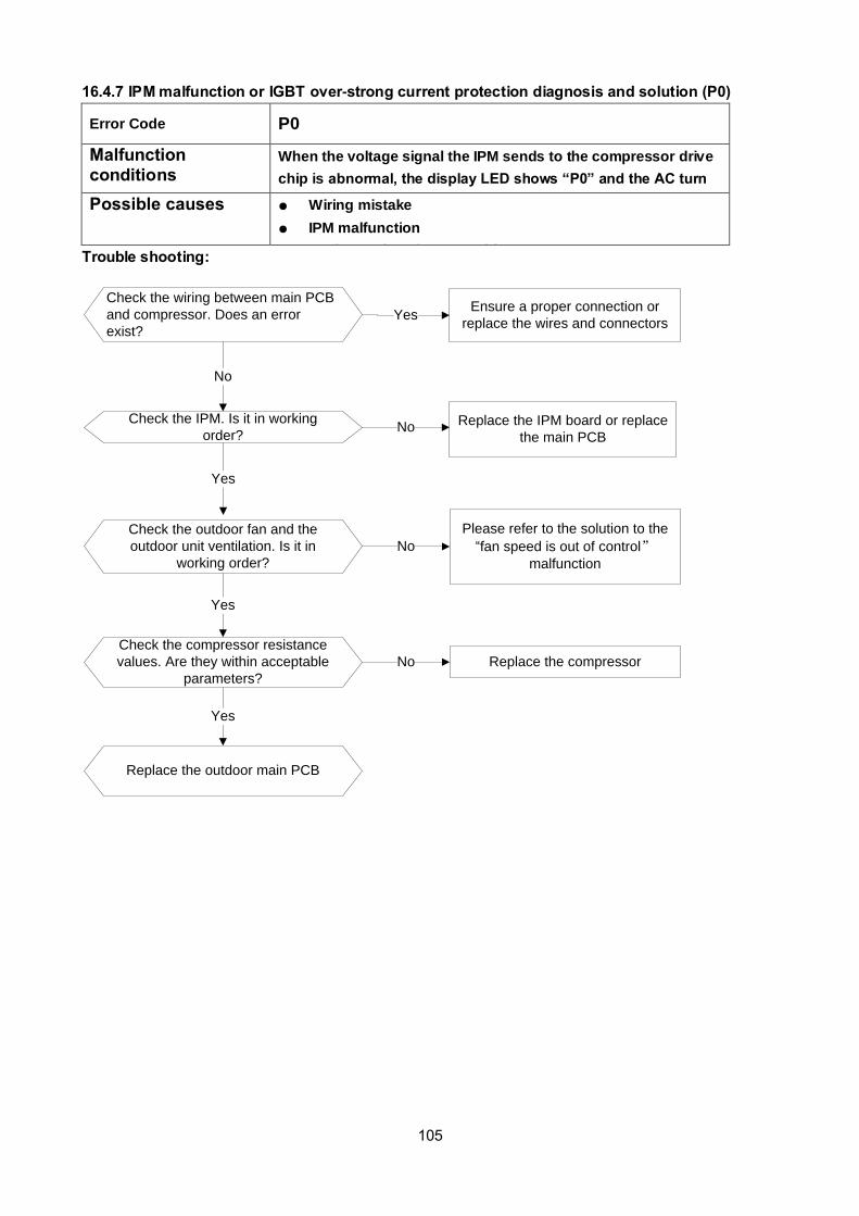
105
16.4.7 IPM malfunction or IGBT over-strong current protection diagnosis and solution (P0)
Error Code P0
Malfunction conditions
When the voltage signal the IPM sends to the compressor drive
chip is abnormal, the display LED shows “P0” and the AC turn
off. Possible causes Wiring mistake
IPM malfunction
Faulty outdoor fan assembly
Compressor malfunction
Faulty outdoor PCB
Trouble shooting:
Check the wiring between main PCB
and compressor. Does an error
exist?
Ensure a proper connection or
replace the wires and connectorsYes
No
Check the IPM. Is it in working
order?No
Yes
Replace the IPM board or replace
the main PCB
Check the outdoor fan and the
outdoor unit ventilation. Is it in
working order?
No
Please refer to the solution to the
“fan speed is out of control”
malfunction
Yes
Check the compressor resistance
values. Are they within acceptable
parameters?
No Replace the compressor
Yes
Replace the outdoor main PCB
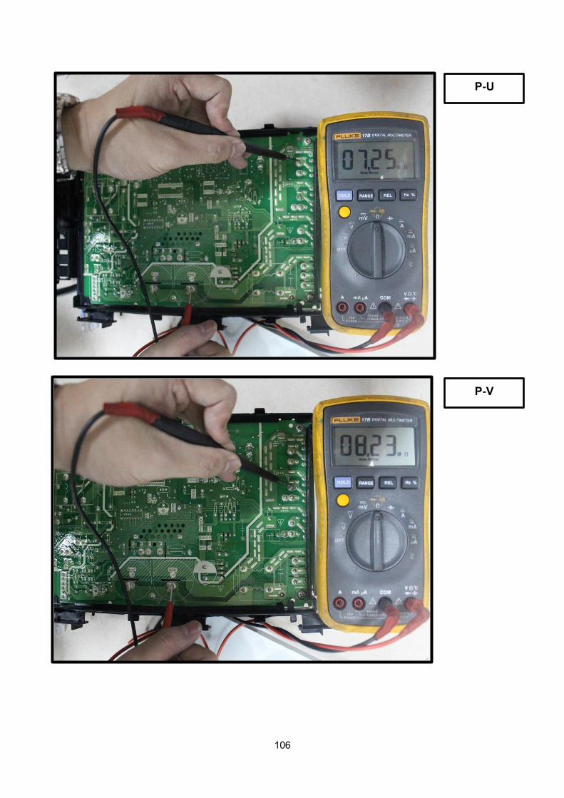
106
P-U
P-V
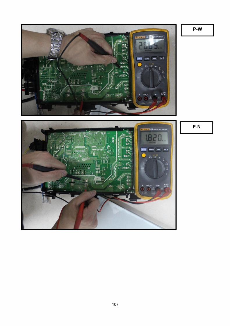
107
P-W
P-N
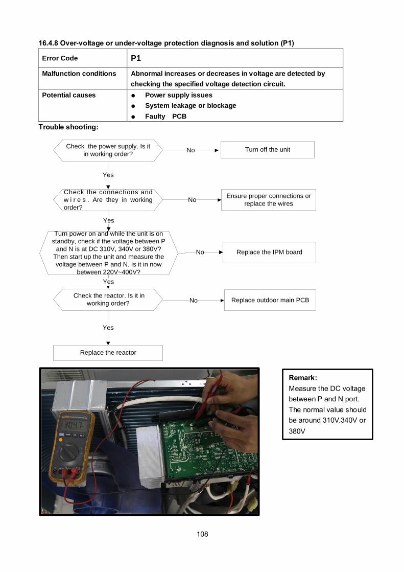
108
16.4.8 Over-voltage or under-voltage protection diagnosis and solution (P1)
Error Code P1
Malfunction conditions Abnormal increases or decreases in voltage are detected by
checking the specified voltage detection circuit.
Potential causes Power supply issues
System leakage or blockage
Faulty PCB
Trouble shooting:
Check the power supply. Is it
in working order?
Check the connections and
w i r e s . Are they in working
order?
Turn off the unitNo
Yes
NoEnsure proper connections or
replace the wires
Yes
Replace the reactor
Yes
No Replace the IPM board
Turn power on and while the unit is on
standby, check if the voltage between P
and N is at DC 310V, 340V or 380V?
Then start up the unit and measure the
voltage between P and N. Is it in now
between 220V~400V?
Check the reactor. Is it in
working order?
Yes
No Replace outdoor main PCB
Remark:
Measure the DC voltage
between P and N port.
The normal value should
be around 310V.340V or
380V

109
16.4.9 High temperature protection of compressor top diagnosis and solution (P2)
Error Code P2
Malfunction decision
conditions If the sampling voltage is not 5V, the LED will display the failure.
Supposed causes
Power supply problems.
System leakage or block
PCB faulty
Trouble shooting:
Check the air flow system
of indoor and outdoor units.
Does a problem exist?
Clear up the air inlet and outlet or the heat
exchanger of the indoor and outdoor units.Yes
No
Yes
Yes
Power off and then restart the unit
10 minutes afterwards
Check compressor
temperature. Is it within
acceptable parameters?
No
Check the refrigerant
system. Is it functioning
properly?
Yes
Check the overload
protector. Is it properly
wired?
Ensure a proper
connectionNo
Measure the resistance
between the two ports of
the OLP. Is it zero?
Yes
Replace the OLPNo
Replace the outdoor control PCB
Yes
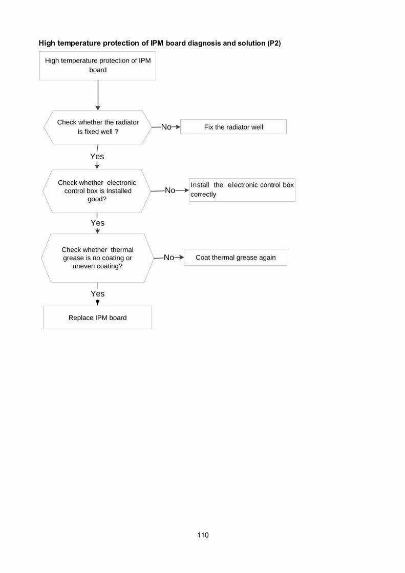
110
High temperature protection of IPM board diagnosis and solution (P2)
High temperature protection of IPM
board
High temperature protection of IPM
board
Check whether the radiator
is fixed well ?
Check whether the radiator
is fixed well ?
Check whether electronic
control box is Installed
good?
Check whether electronic
control box is Installed
good?
Check whether thermal
grease is no coating or
uneven coating?
Check whether thermal
grease is no coating or
uneven coating?
Yes
Yes
NoInstall the electronic control box
correctly
Install the electronic control box
correctly
Fix the radiator wellFix the radiator well
Coat thermal grease againCoat thermal grease againNo
Replace IPM boardReplace IPM board
No
Yes
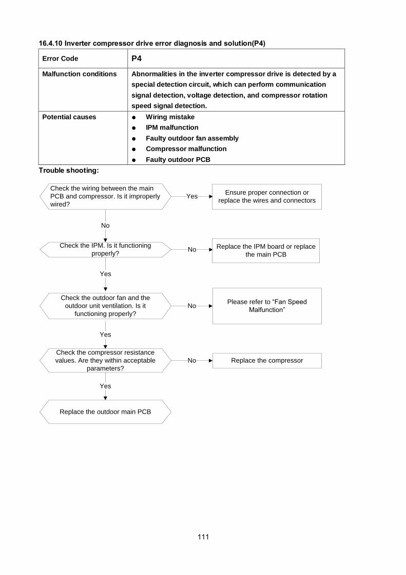
111
16.4.10 Inverter compressor drive error diagnosis and solution(P4)
Error Code P4
Malfunction conditions Abnormalities in the inverter compressor drive is detected by a
special detection circuit, which can perform communication
signal detection, voltage detection, and compressor rotation
speed signal detection.
Potential causes Wiring mistake
IPM malfunction
Faulty outdoor fan assembly
Compressor malfunction
Faulty outdoor PCB
Trouble shooting:
Check the wiring between the main
PCB and compressor. Is it improperly
wired?
Ensure proper connection or
replace the wires and connectorsYes
No
Check the IPM. Is it functioning
properly?No
Yes
Replace the IPM board or replace
the main PCB
Check the outdoor fan and the
outdoor unit ventilation. Is it
functioning properly?
NoPlease refer to “Fan Speed
Malfunction”
Yes
Check the compressor resistance
values. Are they within acceptable
parameters?
No Replace the compressor
Yes
Replace the outdoor main PCB
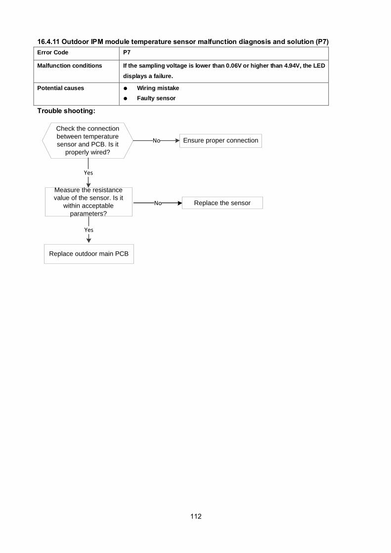
112
16.4.11 Outdoor IPM module temperature sensor malfunction diagnosis and solution (P7)
Error Code P7
Malfunction conditions If the sampling voltage is lower than 0.06V or higher than 4.94V, the LED
displays a failure.
Potential causes Wiring mistake
Faulty sensor
Faulty PCB Trouble shooting:
Check the connection
between temperature
sensor and PCB. Is it
properly wired?
Ensure proper connectionNo
Yes
Replace outdoor main PCB
Measure the resistance
value of the sensor. Is it
within acceptable
parameters?
Replace the sensorNo
Yes

113
16.4.12. J0 Malfunction Malfunction conditions When evaporator coil temperature is more than 60°C, the unit stops. It starts again
only when the evaporator coil temperature is less than 54°C
Possible causes • Faulty evaporator coil temperature sensor
• Dirty heat exchanger
• Faulty fan
• Faulty PCB
J0 displayedJ0 displayed
Evaporator high temperature protection Evaporator high temperature protection
Is the compressor operating?Is the compressor operating?
Yes
Is the outdoor ambient
temperature is higher than 30?
Is the outdoor ambient
temperature is higher than 30?
No
Correct the connectionCorrect the connectionNo
Is the connection between T2 and The
PCB is in working order?Have T2 and T2B been
reversed?
Is the connection between T2 and The
PCB is in working order?Have T2 and T2B been
reversed?
Is the resistance of T2 normal according to
Appendix 1?
Is the resistance of T2 normal according to
Appendix 1?Replace the temperature sensorReplace the temperature sensorNo
Yes
Yes
Stop the unit Stop the unit Yes
Is the air-outlet blocked?Is the air-outlet blocked?
Are the heat exchanger and
filter dirty?
Are the heat exchanger and
filter dirty?
Is the indoor fan running normally?
Is the indoor fan running normally?
No
Yes
Clean the air-outletClean the air-outlet
Replace the indoor main PCB
Replace the indoor main PCB
Clean the heat exchanger and filterClean the heat exchanger and filterYes
No
Yes
Refer to the solution for the malfunction of the fan speed being out of control . Find the cause and resolve
the problem
Refer to the solution for the malfunction of the fan speed being out of control . Find the cause and resolve
the problem
No
No
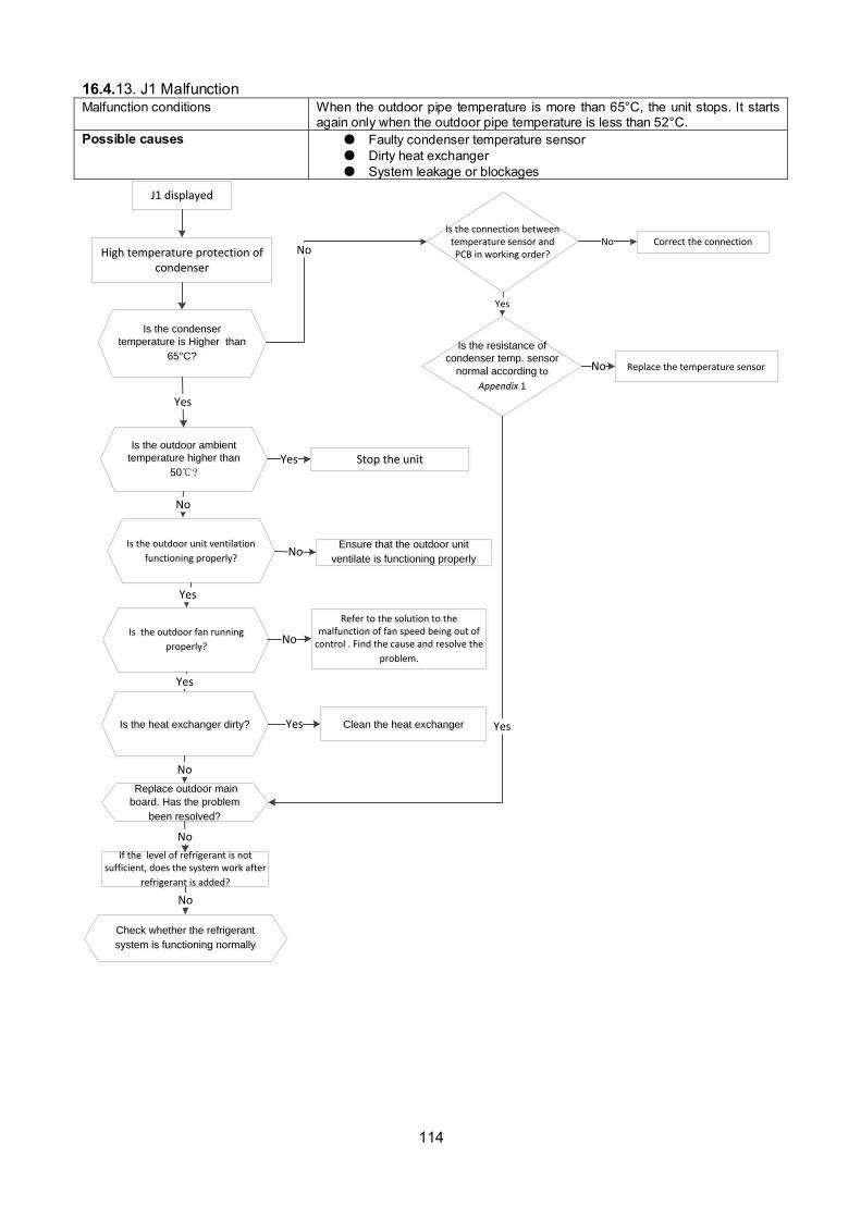
114
16.4.13. J1 Malfunction Malfunction conditions When the outdoor pipe temperature is more than 65°C, the unit stops. It starts
again only when the outdoor pipe temperature is less than 52°C.
Possible causes Faulty condenser temperature sensor
Dirty heat exchanger
System leakage or blockages
J1 displayedJ1 displayed
High temperature protection of condenser
High temperature protection of condenser
Is the condenser
temperature is Higher than
65°C?
Is the condenser
temperature is Higher than
65°C?
Yes
Is the resistance of
condenser temp. sensor
normal according to
Appendix 1
Is the resistance of
condenser temp. sensor
normal according to
Appendix 1
Replace the temperature sensorReplace the temperature sensor
No
No
Is the outdoor ambient
temperature higher than
50?
Is the outdoor ambient
temperature higher than
50?
No
Stop the unit Stop the unit Yes
Is the outdoor unit ventilation
functioning properly?
Is the outdoor unit ventilation
functioning properly?
Yes
Ensure that the outdoor unit
ventilate is functioning properly
Ensure that the outdoor unit
ventilate is functioning properly
Is the heat exchanger dirty?Is the heat exchanger dirty?
No
Clean the heat exchangerClean the heat exchangerYes
Check whether the refrigerant
system is functioning normally
Check whether the refrigerant
system is functioning normally
Replace outdoor main
board. Has the problem
been resolved?
Replace outdoor main
board. Has the problem
been resolved?
No
If the level of refrigerant is not sufficient, does the system work after
refrigerant is added?
If the level of refrigerant is not sufficient, does the system work after
refrigerant is added?
No
Is the outdoor fan running
properly?
Is the outdoor fan running
properly?
Refer to the solution to the malfunction of fan speed being out of
control . Find the cause and resolve the
problem.
Refer to the solution to the malfunction of fan speed being out of
control . Find the cause and resolve the
problem.
No
Yes
No
Correct the connectionCorrect the connectionNo
Yes
Is the connection between temperature sensor and PCB in working order?
Is the connection between temperature sensor and PCB in working order?
Yes

115
16.4.14. J2 Malfunction
Malfunction conditions When the compressor discharge temperature (T5) is more
than 115 for 10 seconds, the compressor will stop and not
restart until T5 is less than 90.
Possible causes Refrigerant leakage
Wiring mistake
Faulty discharge temperature sensor
Faulty outdoor PCB
J2 displayedJ2 displayed
Temperature protection of compressor discharge
Temperature protection of compressor discharge
Is the compressor discharge temperature more than 115°C
?
Is the compressor discharge temperature more than 115°C
?
Are the compressor
discharge temperature
sensor and PCB connected
properly according to the
wiring diagrams?
Are the compressor
discharge temperature
sensor and PCB connected
properly according to the
wiring diagrams?
Measure the resistance value
of compressor discharge
temp. sensor. If the value is
not normal, refer to the Appendix 2. Does a problem stil
exist?
Measure the resistance value
of compressor discharge
temp. sensor. If the value is
not normal, refer to the Appendix 2. Does a problem stil
exist?
No
Yes
Yes
No Correct the wiring connectionCorrect the wiring connection
Stop the leak and add refrigerantStop the leak and add refrigerant
Replace the compressor discharge temp. sensorReplace the compressor discharge temp. sensorNo
Yes
Replace high pressure valve assyReplace high pressure valve assy
Yes
No
Replace outdoor main PCB.
Does a problem still exist?
Replace outdoor main PCB.
Does a problem still exist?
No
Is refrigerant leaking?Is refrigerant leaking?

116
16.4.15. J3 Malfunction Malfunction decision conditions When the voltage signal that IPM send to compressor drive chip is abnormal, the
display LED will show “J3” and AC will turn off.
Supposed causes Wiring mistake
Faulty IPM board
Faulty outdoor fan ass’y
Compressor malfunction
Faulty outdoor PCB
At first test the resistance between every two ports of U, V, W of IPM and P, N. If any result of them is 0
or close to 0, the IPM is defective. Otherwise, please follow the procedure below:
J3 displayJ3 display
PFC module protectionPFC module protection
Check whether the
connecting line between
main board and the PFC
module is connected tightly
Check whether the
connecting line between
main board and the PFC
module is connected tightly
Yes
Measure whether the voltage
between P and N is normal
refer to the Appendix 3?
Measure whether the voltage
between P and N is normal
refer to the Appendix 3?
No
Check whether the
inductance of PFC module
is good? If the inductance is
good, the resistance of the
two ports is 0
Check whether the
inductance of PFC module
is good? If the inductance is
good, the resistance of the
two ports is 0
Yes
Replace the inductanceReplace the inductanceNo
Connect it tightly, check
normal or not
Connect it tightly, check
normal or not
Replace the outdoor main boardReplace the outdoor main boardYes
Yes
No
No
Replace the PFC moduleReplace the PFC module Trouble is solvedTrouble is solved

117
16.4.16. J4 Malfunction
Communication error between outdoor main
chip and compressor driven chip
Communication error between outdoor main
chip and compressor driven chip
Is there at least one LED in the compressor driven chip light?
Is there at least one LED in the compressor driven chip light?
Check the signal wire between the Compressor driven chip and the
main board, is it connected properly?
Check the signal wire between the Compressor driven chip and the
main board, is it connected properly?
Reconnect and retry. Is the error still displayed?
Reconnect and retry. Is the error still displayed?
Replace Compressor driven Chip. Is the system running
normally?
Replace Compressor driven Chip. Is the system running
normally?
Replace the electric control boxReplace the electric control box
No
No
No
No
Yes
Problem is resolvedProblem is resolved
No
Yes
Replace outdoor main board. Is the system running
normally?
Replace outdoor main board. Is the system running
normally?
No
Yes
Yes
J4 displayedJ4 displayed
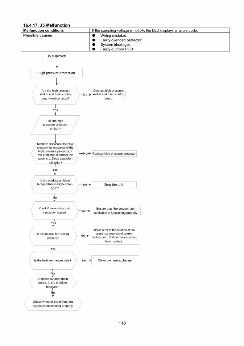
118
16.4.17. J5 Malfunction Malfunction conditions If the sampling voltage is not 5V, the LED displays a failure code.
Possible causes Wiring mistakes
Faulty overload protector
System blockages
Faulty outdoor PCB
Are the high pressure
switch and main control
boar wired correctly?
Are the high pressure
switch and main control
boar wired correctly?
Method: Disconnect the plug.
Measure the resistance of the
high pressure protector, if
the protector is normal the
value is o, Does a problem
still exist?
Method: Disconnect the plug.
Measure the resistance of the
high pressure protector, if
the protector is normal the
value is o, Does a problem
still exist?
Yes
Yes
Connect high pressure
switch and mian control
board
Connect high pressure
switch and mian control
board
No
Replace high pressure protectorReplace high pressure protectorNo
Is the high
pressure protector
broken?
Is the high
pressure protector
broken?
Is the outdoor ambient
temperature is higher than
50?
Is the outdoor ambient
temperature is higher than
50?
No
Stop the unit Stop the unit Yes
Check if the outdoor unit
ventilation is good
Check if the outdoor unit
ventilation is good
Yes
Ensure that the outdoor unit
ventilation is functioning properly
Ensure that the outdoor unit
ventilation is functioning properly
Is the heat exchanger dirty?Is the heat exchanger dirty?
No
Clean the heat exchangerClean the heat exchangerYes
Check whether the refrigerant
system is functioning properly
Check whether the refrigerant
system is functioning properly
Replace outdoor main
board. Is the problem
resolved?
Replace outdoor main
board. Is the problem
resolved?
No
J5 displayedJ5 displayed
High pressure protection High pressure protection
Is the outdoor fan running
properly?
Is the outdoor fan running
properly?
please refer to the solution of fan speed has been out of control
malfunction . Find out the cause and
have it solved.
please refer to the solution of fan speed has been out of control
malfunction . Find out the cause and
have it solved.
No
Yes
NO
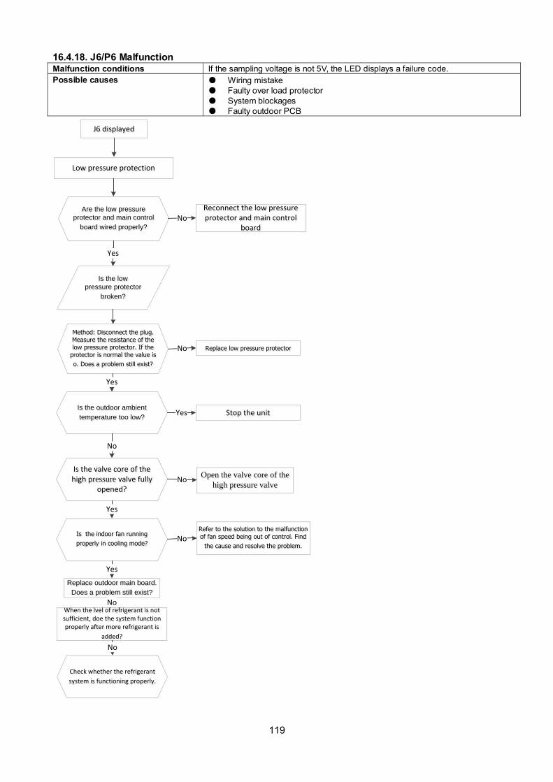
119
16.4.18. J6/P6 Malfunction Malfunction conditions If the sampling voltage is not 5V, the LED displays a failure code.
Possible causes Wiring mistake
Faulty over load protector
System blockages
Faulty outdoor PCB
J6 displayedJ6 displayed
Low pressure protection Low pressure protection
Are the low pressure
protector and main control
board wired properly?
Are the low pressure
protector and main control
board wired properly?
Method: Disconnect the plug. Measure the resistance of the low pressure protector. If the
protector is normal the value is
o. Does a problem still exist?
Method: Disconnect the plug. Measure the resistance of the low pressure protector. If the
protector is normal the value is
o. Does a problem still exist?
Yes
Yes
Reconnect the low pressure protector and main control
board
Reconnect the low pressure protector and main control
board
Replace outdoor main board.
Does a problem still exist?
Replace outdoor main board.
Does a problem still exist?
No
Replace low pressure protectorReplace low pressure protectorNo
Is the low
pressure protector
broken?
Is the low
pressure protector
broken?
Is the outdoor ambient
temperature too low?
Is the outdoor ambient
temperature too low?
No
Stop the unit Stop the unit Yes
Open the valve core of the
high pressure valve
Open the valve core of the
high pressure valveNo
Is the valve core of the high pressure valve fully
opened?
Is the valve core of the high pressure valve fully
opened?
Is the indoor fan running
properly in cooling mode?
Is the indoor fan running
properly in cooling mode?
Refer to the solution to the malfunction of fan speed being out of control. Find
the cause and resolve the problem.
Refer to the solution to the malfunction of fan speed being out of control. Find
the cause and resolve the problem.No
Yes
Yes
No
Check whether the refrigerant
system is functioning properly.
Check whether the refrigerant
system is functioning properly.
When the lvel of refrigerant is not sufficient, doe the system function properly after more refrigerant is
added?
When the lvel of refrigerant is not sufficient, doe the system function properly after more refrigerant is
added?
No

120
16.4.19. J8 malfunction Malfunction decision conditions
An abnormal voltage rise or drop is detected by checking the specified voltage detection circuit.
Supposed causes Abnormal power supply Wiring mistake Faulty bridge rectifier Faulty IPM board
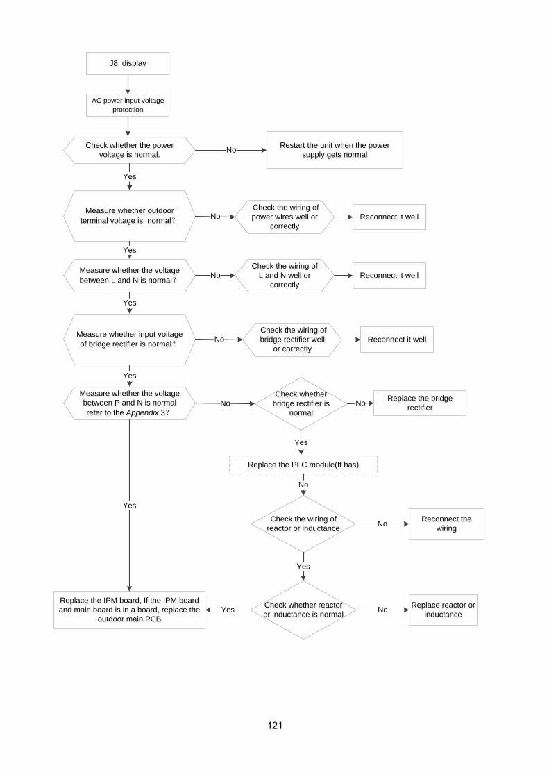
121
AC power input voltage
protection
AC power input voltage
protection
J8 displayJ8 display
Check whether the power
voltage is normal.
Check whether the power
voltage is normal.
Measure whether outdoor
terminal voltage is normal?
Measure whether outdoor
terminal voltage is normal?
Restart the unit when the power
supply gets normal
Restart the unit when the power
supply gets normalNo
Yes
No Reconnect it wellReconnect it well
Yes
Yes
No
Replace the IPM board, If the IPM board
and main board is in a board, replace the
outdoor main PCB
Replace the IPM board, If the IPM board
and main board is in a board, replace the
outdoor main PCB
Yes
Replace the PFC module(If has)Replace the PFC module(If has)
No
Yes
Measure whether the voltage
between L and N is normal?
Measure whether the voltage
between L and N is normal?
Yes
Measure whether input voltage
of bridge rectifier is normal?
Measure whether input voltage
of bridge rectifier is normal?
Yes
No
No
Measure whether the voltage
between P and N is normal
refer to the Appendix 3?
Measure whether the voltage
between P and N is normal
refer to the Appendix 3?
Replace the bridge
rectifier
Replace the bridge
rectifierNo
Check whether
bridge rectifier is
normal
Check whether
bridge rectifier is
normal
Check the wiring of
reactor or inductance
Check the wiring of
reactor or inductanceReconnect the
wiring
Reconnect the
wiring No
Check whether reactor
or inductance is normal
Check whether reactor
or inductance is normal
Yes
Replace reactor or
inductance
Replace reactor or
inductanceNo
Check the wiring of
power wires well or
correctly
Check the wiring of
power wires well or
correctly
Reconnect it wellReconnect it wellCheck the wiring of
L and N well or
correctly
Check the wiring of
L and N well or
correctly
Reconnect it wellReconnect it well Check the wiring of
bridge rectifier well
or correctly
Check the wiring of
bridge rectifier well
or correctly
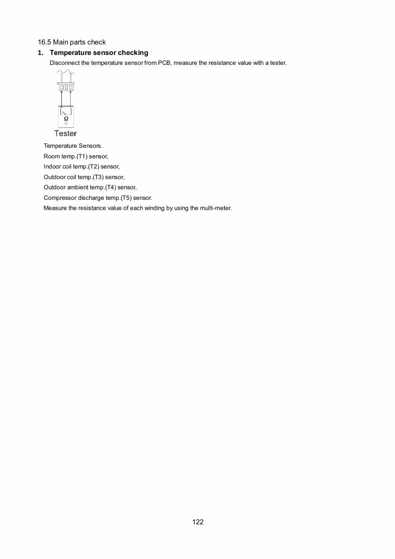
122
16.5 Main parts check
1. Temperature sensor checking
Disconnect the temperature sensor from PCB, measure the resistance value with a tester.
Temperature Sensors.
Room temp.(T1) sensor,
Indoor coil temp.(T2) sensor,
Outdoor coil temp.(T3) sensor,
Outdoor ambient temp.(T4) sensor,
Compressor discharge temp.(T5) sensor.
Measure the resistance value of each winding by using the multi-meter.

123
Appendix 1 Temperature Sensor Resistance Value Table for T1,T2,T3,T4 (--K)
K Ohm K Ohm K Ohm K Ohm
-20 -4 115.266 20 68 12.6431 60 140 2.35774 100 212 0.62973
-19 -2 108.146 21 70 12.0561 61 142 2.27249 101 214 0.61148
-18 0 101.517 22 72 11.5 62 144 2.19073 102 216 0.59386
-17 1 96.3423 23 73 10.9731 63 145 2.11241 103 217 0.57683
-16 3 89.5865 24 75 10.4736 64 147 2.03732 104 219 0.56038
-15 5 84.219 25 77 10 65 149 1.96532 105 221 0.54448
-14 7 79.311 26 79 9.55074 66 151 1.89627 106 223 0.52912
-13 9 74.536 27 81 9.12445 67 153 1.83003 107 225 0.51426
-12 10 70.1698 28 82 8.71983 68 154 1.76647 108 226 0.49989
-11 12 66.0898 29 84 8.33566 69 156 1.70547 109 228 0.486
-10 14 62.2756 30 86 7.97078 70 158 1.64691 110 230 0.47256
-9 16 58.7079 31 88 7.62411 71 160 1.59068 111 232 0.45957
-8 18 56.3694 32 90 7.29464 72 162 1.53668 112 234 0.44699
-7 19 52.2438 33 91 6.98142 73 163 1.48481 113 235 0.43482
-6 21 49.3161 34 93 6.68355 74 165 1.43498 114 237 0.42304
-5 23 46.5725 35 95 6.40021 75 167 1.38703 115 239 0.41164
-4 25 44 36 97 6.13059 76 169 1.34105 116 241 0.4006
-3 27 41.5878 37 99 5.87359 77 171 1.29078 117 243 0.38991
-2 28 39.8239 38 100 5.62961 78 172 1.25423 118 244 0.37956
-1 30 37.1988 39 102 5.39689 79 174 1.2133 119 246 0.36954
0 32 35.2024 40 104 5.17519 80 176 1.17393 120 248 0.35982
1 34 33.3269 41 106 4.96392 81 178 1.13604 121 250 0.35042
2 36 31.5635 42 108 4.76253 82 180 1.09958 122 252 0.3413
3 37 29.9058 43 109 4.5705 83 181 1.06448 123 253 0.33246
4 39 28.3459 44 111 4.38736 84 183 1.03069 124 255 0.3239
5 41 26.8778 45 113 4.21263 85 185 0.99815 125 257 0.31559
6 43 25.4954 46 115 4.04589 86 187 0.96681 126 259 0.30754
7 45 24.1932 47 117 3.88673 87 189 0.93662 127 261 0.29974
8 46 22.5662 48 118 3.73476 88 190 0.90753 128 262 0.29216
9 48 21.8094 49 120 3.58962 89 192 0.8795 129 264 0.28482
10 50 20.7184 50 122 3.45097 90 194 0.85248 130 266 0.2777
11 52 19.6891 51 124 3.31847 91 196 0.82643 131 268 0.27078
12 54 18.7177 52 126 3.19183 92 198 0.80132 132 270 0.26408
13 55 17.8005 53 127 3.07075 93 199 0.77709 133 271 0.25757
14 57 16.9341 54 129 2.95896 94 201 0.75373 134 273 0.25125
15 59 16.1156 55 131 2.84421 95 203 0.73119 135 275 0.24512
16 61 15.3418 56 133 2.73823 96 205 0.70944 136 277 0.23916
17 63 14.6181 57 135 2.63682 97 207 0.68844 137 279 0.23338
18 64 13.918 58 136 2.53973 98 208 0.66818 138 280 0.22776
19 66 13.2631 59 138 2.44677 99 210 0.64862 139 282 0.22231

124
Appendix 2 Temperature Sensor Resistance Value Table for T5,TH (--K)
K Ohm K Ohm K Ohm K Ohm
-20 -4 542.7 20 68 68.66 60 140 13.59 100 212 3.702
-19 -2 511.9 21 70 65.62 61 142 13.11 101 214 3.595
-18 0 483 22 72 62.73 62 144 12.65 102 216 3.492
-17 1 455.9 23 73 59.98 63 145 12.21 103 217 3.392
-16 3 430.5 24 75 57.37 64 147 11.79 104 219 3.296
-15 5 406.7 25 77 54.89 65 149 11.38 105 221 3.203
-14 7 384.3 26 79 52.53 66 151 10.99 106 223 3.113
-13 9 363.3 27 81 50.28 67 153 10.61 107 225 3.025
-12 10 343.6 28 82 48.14 68 154 10.25 108 226 2.941
-11 12 325.1 29 84 46.11 69 156 9.902 109 228 2.86
-10 14 307.7 30 86 44.17 70 158 9.569 110 230 2.781
-9 16 291.3 31 88 42.33 71 160 9.248 111 232 2.704
-8 18 275.9 32 90 40.57 72 162 8.94 112 234 2.63
-7 19 261.4 33 91 38.89 73 163 8.643 113 235 2.559
-6 21 247.8 34 93 37.3 74 165 8.358 114 237 2.489
-5 23 234.9 35 95 35.78 75 167 8.084 115 239 2.422
-4 25 222.8 36 97 34.32 76 169 7.82 116 241 2.357
-3 27 211.4 37 99 32.94 77 171 7.566 117 243 2.294
-2 28 200.7 38 100 31.62 78 172 7.321 118 244 2.233
-1 30 190.5 39 102 30.36 79 174 7.086 119 246 2.174
0 32 180.9 40 104 29.15 80 176 6.859 120 248 2.117
1 34 171.9 41 106 28 81 178 6.641 121 250 2.061
2 36 163.3 42 108 26.9 82 180 6.43 122 252 2.007
3 37 155.2 43 109 25.86 83 181 6.228 123 253 1.955
4 39 147.6 44 111 24.85 84 183 6.033 124 255 1.905
5 41 140.4 45 113 23.89 85 185 5.844 125 257 1.856
6 43 133.5 46 115 22.89 86 187 5.663 126 259 1.808
7 45 127.1 47 117 22.1 87 189 5.488 127 261 1.762
8 46 121 48 118 21.26 88 190 5.32 128 262 1.717
9 48 115.2 49 120 20.46 89 192 5.157 129 264 1.674
10 50 109.8 50 122 19.69 90 194 5 130 266 1.632
11 52 104.6 51 124 18.96 91 196 4.849
12 54 99.69 52 126 18.26 92 198 4.703
13 55 95.05 53 127 17.58 93 199 4.562
14 57 90.66 54 129 16.94 94 201 4.426
15 59 86.49 55 131 16.32 95 203 4.294
16 61 82.54 56 133 15.73 96 205 4.167
17 63 78.79 57 135 15.16 97 207 4.045
18 64 75.24 58 136 14.62 98 208 3.927
19 66 71.86 59 138 14.09 99 210 3.812
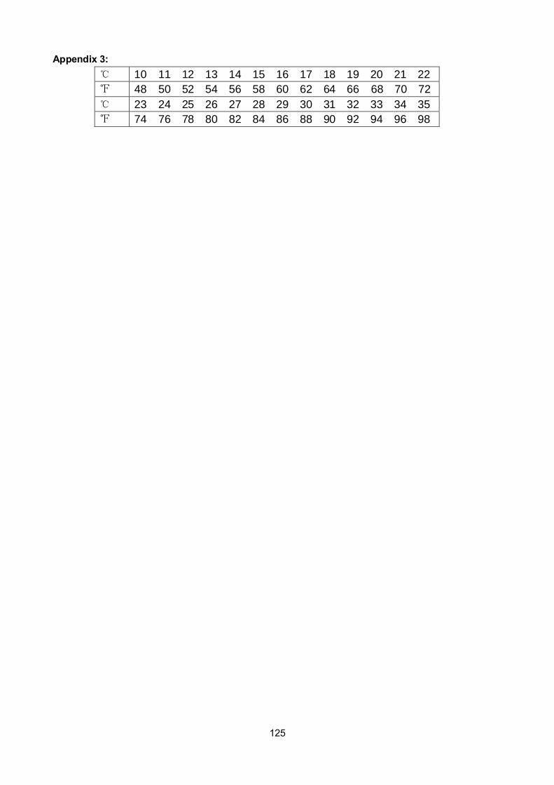
125
Appendix 3:
10 11 12 13 14 15 16 17 18 19 20 21 22
48 50 52 54 56 58 60 62 64 66 68 70 72
23 24 25 26 27 28 29 30 31 32 33 34 35
74 76 78 80 82 84 86 88 90 92 94 96 98

126
2. Compressor checking
Measure the resistance value of each winding by using the tester.
Position Resistance Value
ASN98D22UFZ ASM135D23UFZ ATF235D22UMT ATF250D22UMT ATF310D43UMT ATQ420D1UMU ATM115D43UFZ2
Blue -
Red
1.57Ω 1.75 Ω 0.75 Ω 0.75 Ω 0.65 Ω 0.38Ω 1.87Ω Blue -
Black
Red -
Blue
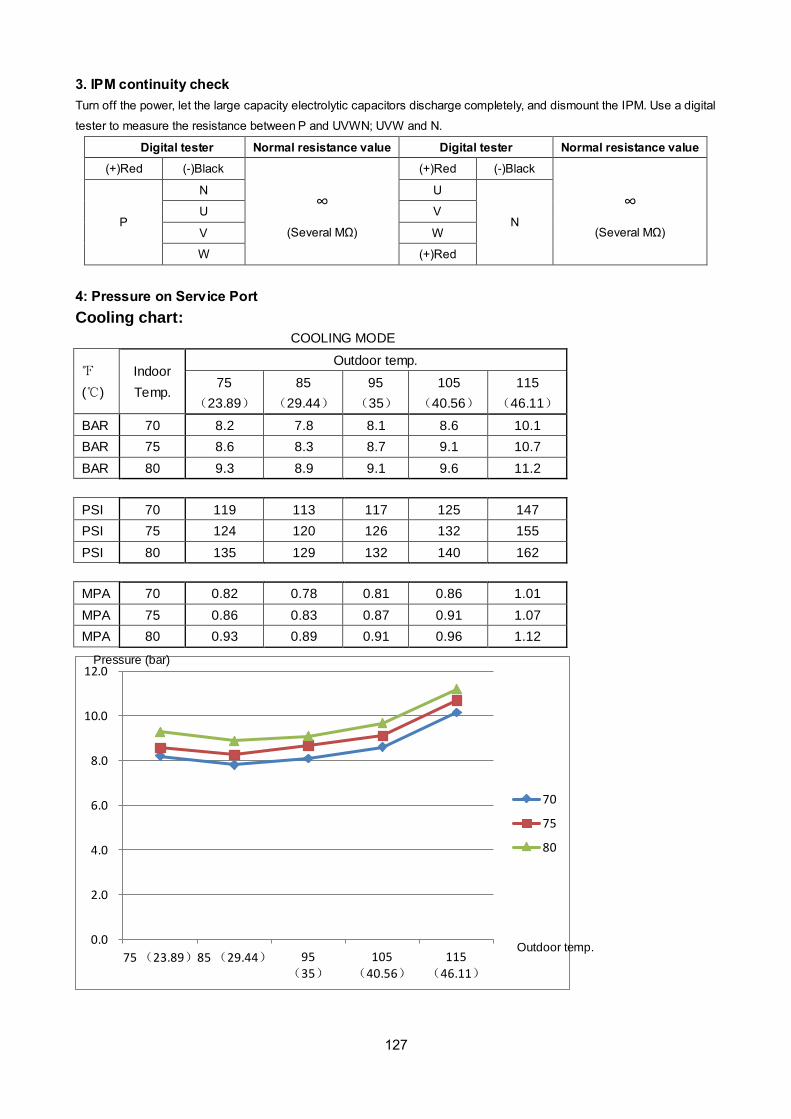
127
3. IPM continuity check
Turn off the power, let the large capacity electrolytic capacitors discharge completely, and dismount the IPM. Use a digital
tester to measure the resistance between P and UVWN; UVW and N.
Digital tester Normal resistance value Digital tester Normal resistance value
(+)Red (-)Black
∞
(Several MΩ)
(+)Red (-)Black
∞
(Several MΩ) P
N U
N U V
V W
W (+)Red
4: Pressure on Service Port
Cooling chart:
COOLING MODE
()
Indoor
Temp.
Outdoor temp.
75
(23.89)
85
(29.44)
95
(35)
105
(40.56)
115
(46.11)
BAR 70 8.2 7.8 8.1 8.6 10.1
BAR 75 8.6 8.3 8.7 9.1 10.7
BAR 80 9.3 8.9 9.1 9.6 11.2
PSI 70 119 113 117 125 147
PSI 75 124 120 126 132 155
PSI 80 135 129 132 140 162
MPA 70 0.82 0.78 0.81 0.86 1.01
MPA 75 0.86 0.83 0.87 0.91 1.07
MPA 80 0.93 0.89 0.91 0.96 1.12
0.0
2.0
4.0
6.0
8.0
10.0
12.0
75 (23.89)85 (29.44) 95 (35)
105 (40.56)
115 (46.11)
70
75
80
Pressure (bar)
Outdoor temp.

128
Heating Chart:
HEATING MODE
()
Indoor
Temp.
Outdoor temp.
57 (13.89) 47 (8.33) 37 (2.78)
27
(-2.78)
17
(-8.33)
BAR 55 30.3 28.5 25.3 22.8 20.8
BAR 65 32.5 30.0 26.6 25.4 23.3
BAR 75 33.8 31.5 27.8 26.3 24.9
PSI 55 439 413 367 330 302
PSI 65 471 435 386 368 339
PSI 75 489 457 403 381 362
MPA 55 3.03 2.85 2.53 2.28 2.08
MPA 65 3.25 3.00 2.66 2.54 2.33
MPA 75 3.38 3.15 2.78 2.63 2.49
0.0
5.0
10.0
15.0
20.0
25.0
30.0
35.0
40.0
57 (13.89) 47 (8.33) 37 (2.78) 27 (-2.78)
17 (-8.33)
55
65
75
Pressure (bar)
Outdoor temp.
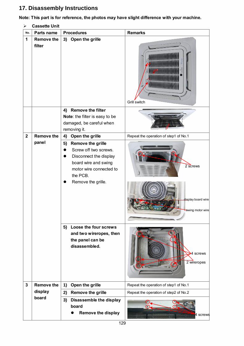
129
Cassette Unit
No. Parts name Procedures Remarks
1 Remove the
filter
3) Open the grille
4) Remove the filter
Note: the filter is easy to be
damaged, be careful when
removing it.
2 Remove the
panel
4) Open the grille Repeat the operation of step1 of No.1
5) Remove the grille
Screw off two screws.
Disconnect the display
board wire and swing
motor wire connected to
the PCB.
Remove the grille.
5) Loose the four screws
and two wireropes, then
the panel can be
disassembled.
3 Remove the
display
board
1) Open the grille Repeat the operation of step1 of No.1
2) Remove the grille Repeat the operation of step2 of No.2
3) Disassemble the display
board
Remove the display
Grill switch
2 screws
4 screws
4 screws
2 wireropes
display board wire
swing motor wire
17. Disassembly Instructions
Note: This part is for reference, the photos may have slight difference with your machine.
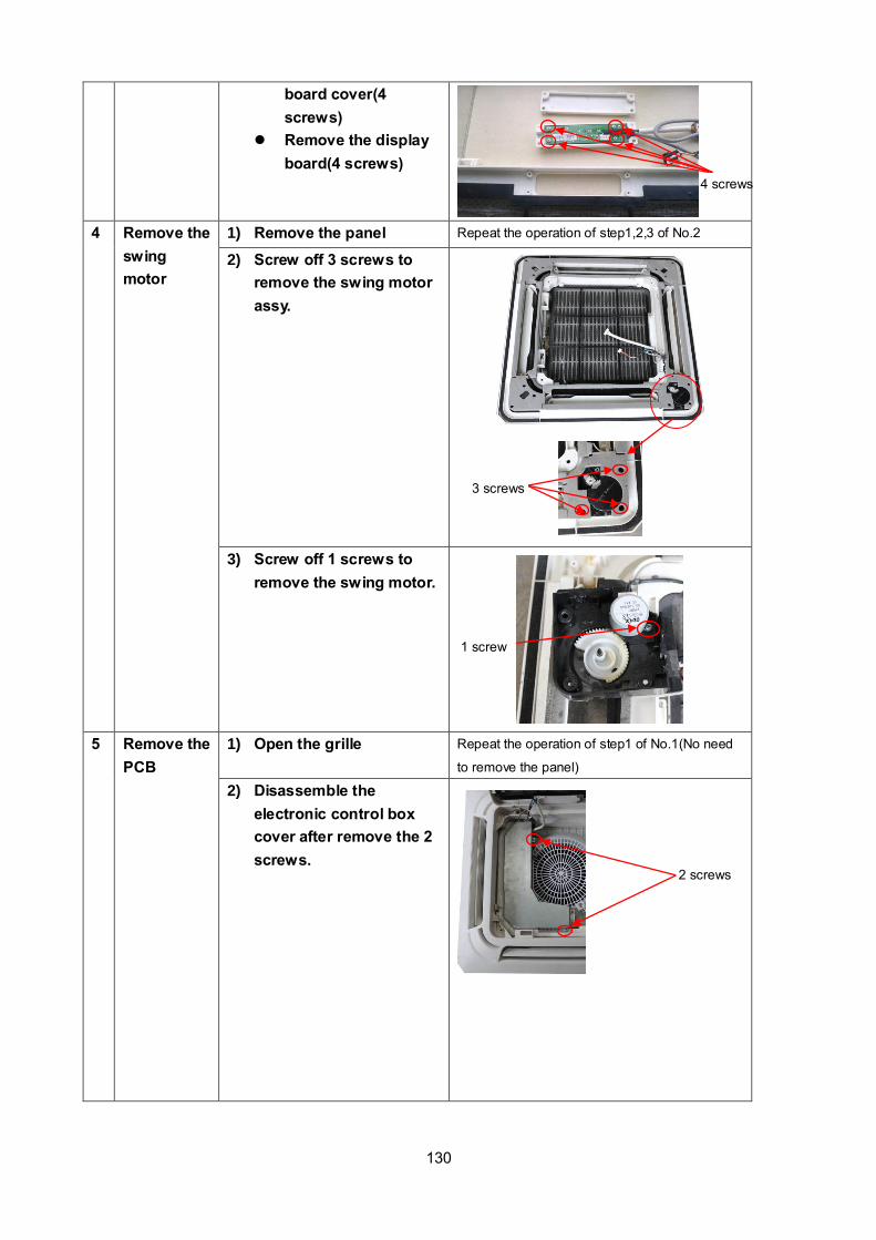
130
board cover(4
screws)
Remove the display
board(4 screws)
4 Remove the
swing
motor
1) Remove the panel Repeat the operation of step1,2,3 of No.2
2) Screw off 3 screws to
remove the swing motor
assy.
3) Screw off 1 screws to
remove the swing motor.
5 Remove the
PCB
1) Open the grille Repeat the operation of step1 of No.1(No need
to remove the panel)
2) Disassemble the
electronic control box
cover after remove the 2
screws.
2 screws
4 screws
3 screws
1 screw
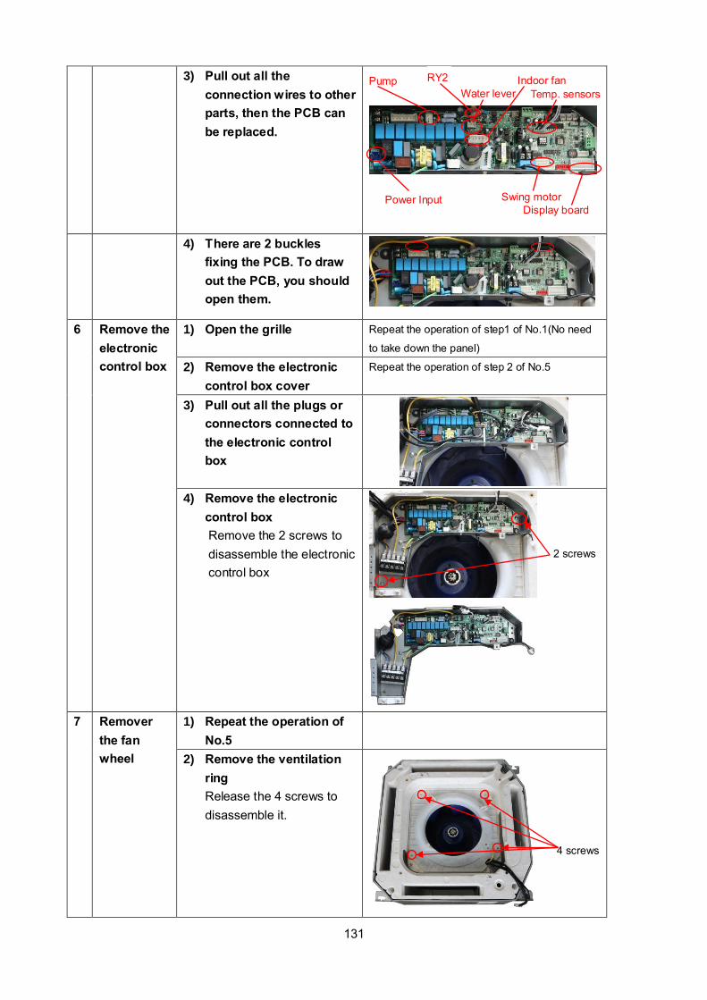
131
3) Pull out all the
connection wires to other
parts, then the PCB can
be replaced.
4) There are 2 buckles
fixing the PCB. To draw
out the PCB, you should
open them.
6 Remove the
electronic
control box
1) Open the grille Repeat the operation of step1 of No.1(No need
to take down the panel)
2) Remove the electronic
control box cover
Repeat the operation of step 2 of No.5
3) Pull out all the plugs or
connectors connected to
the electronic control
box
4) Remove the electronic
control box
Remove the 2 screws to
disassemble the electronic
control box
7 Remover
the fan
wheel
1) Repeat the operation of
No.5
2) Remove the ventilation
ring
Release the 4 screws to
disassemble it.
2 screws
Pump RY2
Temp. sensors
Display board
Swing motor
Water lever
Power Input
4 screws
Indoor fan

132
3) Remove the fixing nut to
disassemble the fan
wheel
4) Pull out the fan wheel
8 Remove the
fan motor
1) Repeat the operation of
No.6
2) Remove the fixing board
of fan motor wire
3) Remove the 5 screws to
disassemble the fan
motor
9 Remove the
water
collecting
6) Remove the panel Repeat the operation of No.2
7) Remove the electronic
control box
Repeat the operation of No.6
3 nuts
5 screws

133
assembly 8) Screw off the 4 screws
inside 4 holes (1 is under
a protection cover) to
remove the water
collecting assembly.
9) Take out the water
collecting assembly
10 Remove the
draining
pump
1) Remove the panel Repeat the operation of No.2
2) Remove the electronic
control box
Repeat the operation of No.6
3) Remove the water
collecting assembly
Repeat the operation of No.9
4) Disconnect the drain
pipe.
5) Release 2 screws to
remove the pump
supporter. Be careful of
the connection wires.
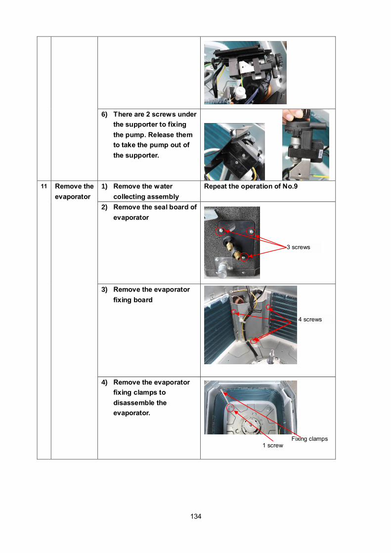
134
6) There are 2 screws under
the supporter to fixing
the pump. Release them
to take the pump out of
the supporter.
11 Remove the
evaporator
1) Remove the water
collecting assembly
Repeat the operation of No.9
2) Remove the seal board of
evaporator
3) Remove the evaporator
fixing board
4) Remove the evaporator
fixing clamps to
disassemble the
evaporator.
3 screws
Fixing clamps 1 screw
4 screws

135
A6 Duct Unit
No. Parts name Procedures Remarks
1 Remove the
electronic
control box
6) Screw off the screws to
remove the cover of
electronic control box
7) Disconnect the fan motor
wire, room temperature
sensor wire and
evaporator temperature
sensor wire
8) Screw off the screws to
remove electronic
control box
2 Remove the
PCB
9) Remove the cover of
electronic control box
Repeat the operation of step1 of No1
2) Pull out all the plugs
or connectors connected
to the PCB and remove
the ground wire after
remove the screw.
Five screws
Plug of room temperate sensor and evaporator temperature sensor
Fan motor wire
2 screws

136
10) Remove the PCB from
the electronic control
box
3** Remove the
reactance
6) Remove the cover of
electronic control box
Repeat the operation of step1 of No1
7) Disconnect the reactance
wire
8) Screw off the screw to
remover it
4** Remove the
drain pump
1) Remove the cover of
electronic control box
Repeat the operation of step1 of No1
2) Disconnect the drain
pump wire
3) Screw off the screws to
remover it
Press the two fixing holders to remove the PCB
1 screw
Reactance wire
4 screws
Drain pump wire
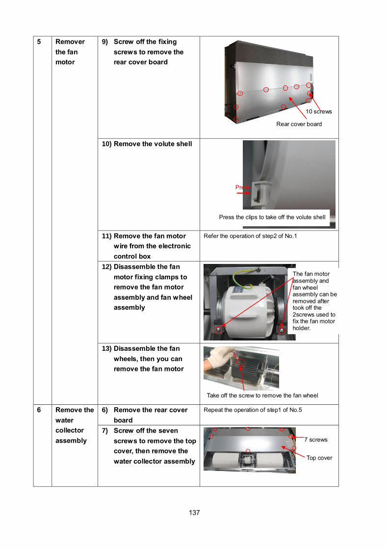
137
5 Remover
the fan
motor
9) Screw off the fixing
screws to remove the
rear cover board
10) Remove the volute shell
11) Remove the fan motor
wire from the electronic
control box
Refer the operation of step2 of No.1
12) Disassemble the fan
motor fixing clamps to
remove the fan motor
assembly and fan wheel
assembly
13) Disassemble the fan
wheels, then you can
remove the fan motor
6 Remove the
water
collector
assembly
6) Remove the rear cover
board
Repeat the operation of step1 of No.5
7) Screw off the seven
screws to remove the top
cover, then remove the
water collector assembly
7 screws
Press the clips to take off the volute shell
Press
10 screws
Rear cover board
The fan motor assembly and fan wheel assembly can be removed after took off the 2screws used to fix the fan motor holder.
Take off the screw to remove the fan wheel
Top cover

138
7 Remove the
evaporator
10) Remove the water
collector
Repeat the operation of No.6
11) Remove the evaporator
sensor
12) Remove the pipe clamp
board
13) Remove the evaporator
support board
14) Screw off the fixing
screws to remove the
evaporator
** means there is no this part in some models.
Evaporator sensor
2 screws
4 screws
1 screw
Water collector assembly

139
No. Part name Procedures Remarks
Panel plate How to remove the panel
plate.
1) Stop operation of
the air conditioner and
turn “OFF” the power
breaker.
1) Remove the big
handle first, and then
remove the top panel(3
screws).
3) Remove the screws of
front panel(6 screws)
(4) Remove the screws of
the right side panel(8
screws)
2
4
3
2 Fan ass’y How to remove the fan
Screws of top panel (3 screws, 1 screw is under the big handler)
3 screws
of the big
handler
6 screws of front panel
17.2 Outdoor unit
LISH012000P431-C

140
ass’y.
1) After remove the
panel plate following
procedure 1, remove
the hex nut fixing the
fan and then remove
the fan.
2) Unfix the hooks and
then open the electronic
control box cover.
1
2
compressor T3,T4,T5 sensor
Motor Electronic expansion valve
4 way valve

141
3) Disconnect the
connector for fan motor
from the electronic control
board.
4) Remove the four
fixing screws of the
fan motor. Then remove
the fan motor.
3 Electrical
parts How to remove the
electrical parts.
1) After finish work of
item 1 and item 2, remove
the connectors for the
compressor.
2) Pull out the two blue
wires connected with the
four way valve.
1
3
4
2

142
3) Pull out connectors of
the condenser coil temp.
sensor(T3),outdoor
ambient temp. sensor(T4)
and discharge temp.
sensor(T5).
4) disconnect the
electronic expansion
valve wire
5) Remove the
grounding screw.
6) Remove the
Wires (1,2,3). Then
remove the electronic
control box.
3
4
5 6
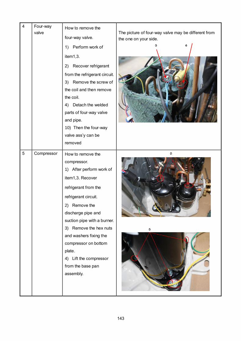
143
4 Four-way
valve How to remove the
four-way valve.
1) Perform work of
item1,3.
2) Recover refrigerant
from the refrigerant circuit.
3) Remove the screw of
the coil and then remove
the coil.
4) Detach the welded
parts of four-way valve
and pipe.
10) Then the four-way
valve ass’y can be
removed
The picture of four-way valve may be different from
the one on your side.
3 4
5 Compressor How to remove the
compressor.
1) After perform work of
item1,3. Recover
refrigerant from the
refrigerant circuit.
2) Remove the
discharge pipe and
suction pipe with a burner.
3) Remove the hex nuts
and washers fixing the
compressor on bottom
plate.
4) Lift the compressor
from the base pan
assembly.
2
3

144
No. Part name Procedures Remarks
Panel plate How to remove the panel
plate.
1) Stop operation of
the air conditioner and turn
“OFF” the power breaker.
2) Remove the top panel(3
screws).
3) Remove the screws of
front panel(9 screws)
4) Remove the screws of
the right side panel(8
screws)
2
4
3
2 Fan ass’y How to remove the fan
ass’y.
1
3 screws of top panel
9 screws of front panel
3 screws of
big handle
LISH018000P431-C

145
1) After remove the panel
plate following procedure
1, remove the hex nut
fixing the fan and then
remove the fan.
2) After remove the top
cover . Unfix the hooks
and then open the
electronic control box
cover.
3) Disconnect the
connector for fan motor
from the electronic control
2
T3,T4,T5 sensor wire
Motor wire Electronic expansion valve
Compressor wire
4 way valve wire Electric pipe heater and Crankcase electric heater
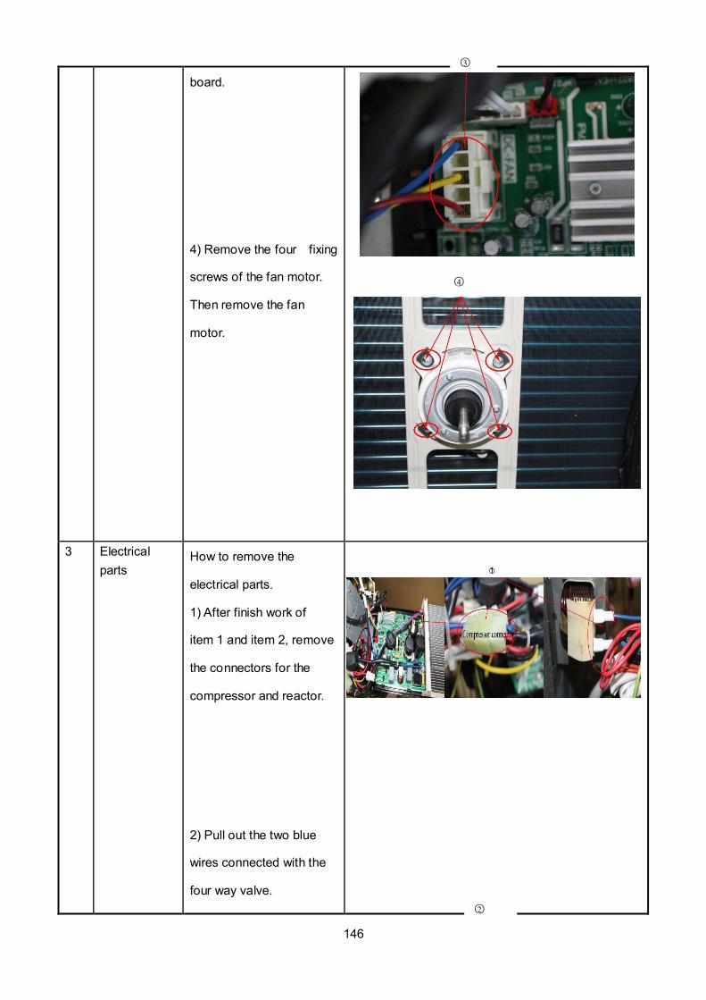
146
board.
4) Remove the four fixing
screws of the fan motor.
Then remove the fan
motor.
3 Electrical
parts How to remove the
electrical parts.
1) After finish work of
item 1 and item 2, remove
the connectors for the
compressor and reactor.
2) Pull out the two blue
wires connected with the
four way valve.
1
3
4
2

147
3) Pull out connectors of
the condenser coil temp.
sensor(T3),outdoor
ambient temp. sensor(T4)
and discharge temp.
sensor(T5).
4) disconnect the
electronic expansion valve
wire
6) remove the electric
heaters.
3
3
4
5

148
6) Remove the
grounding screw.
7) Remove the
Wires (1,2,3 or
L1,L2,S).Then remove the
electronic control box.
7
⑥

149
4 Four-way
valve How to remove the
four-way valve.
1) Perform work of
item1,3.
2) Recover refrigerant
from the refrigerant circuit.
3) Remove the screw of
the coil and then remove
the coil.
4) Detach the welded
parts of four-way valve
and pipe.
11) Then the four-way
valve ass’y can be
removed
The picture of four-way valve may be different from
the one on your side.
3
5 Compressor How to remove the
compressor.
1) After perform work of
item1,3. Recover
refrigerant from the
refrigerant circuit
2) Remove the
discharge pipe and suction
pipe with a burner.
3) Remove the hex nuts
and washers fixing the
compressor on bottom
plate.
4) Lift the compressor
from the base pan
assembly.
2
3
④

150
Screws of big
handle
(3 screws)
No. Part name Procedures Remarks
1 Panel plate How to remove the panel
plate.
1) Stop operation of the
air conditioner and turn
“OFF” the power breaker.
2) Remove the big handle
first,then remove the top
cover (7 screws)
3)Remove the screws of
front panel(11 screws)
(4) Remove the screws of
the right side panel(13
screws)
\
2
4
3
2 Fan ass’y How to remove the fan
Screws of front panel(11 screws)
Screws of top panel(3screws,1screws is under the big handle)
4 screws of big handle
LISH036000P431-CLISH024000P431-C

151
ass’y.
1) After remove the panel
plate following procedure 1
2) Remove the nut fixing
the fan,and remove the
fan.
3) Unfix the hooks and
remove the screws, then
open the electronic control
box cover.
2
3
fan Electronic control box
compressor

152
4) Disconnect the
connector for fan motor
from the electronic control
board.
5) Remove the four fixing
screws of the fan motor,
then remove the motor.
5
4
T3,T4,T5,sensor Pressure switch Compressor
wire
Electronic expansion 4 way valve Motor wire
5
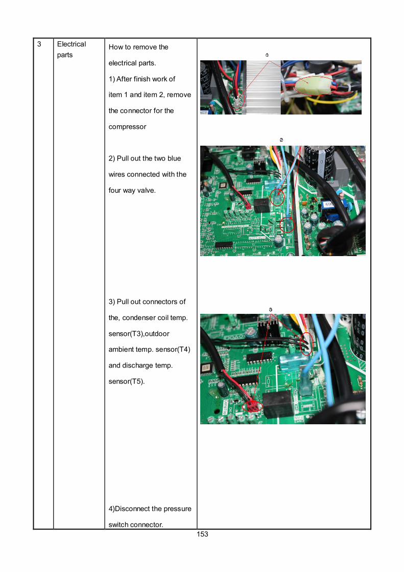
153
3 Electrical
parts How to remove the
electrical parts.
1) After finish work of
item 1 and item 2, remove
the connector for the
compressor
2) Pull out the two blue
wires connected with the
four way valve.
3) Pull out connectors of
the, condenser coil temp.
sensor(T3),outdoor
ambient temp. sensor(T4)
and discharge temp.
sensor(T5).
4)Disconnect the pressure
switch connector.
1
2
3
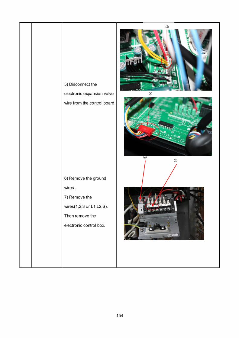
154
5) Disconnect the
electronic expansion valve
wire from the control board
6) Remove the ground
wires .
7) Remove the
wires(1,2,3 or L1,L2,S).
Then remove the
electronic control box.
6 7
5
4

155
4 Four-way
valve
How to remove the
four-way valve.
1) Perform work of item
1,3.
2) Recover refrigerant
from the refrigerant circuit.
3) Remove the screw of
the coil and then remove
the coil.
4) Detach the welded parts
of four-way valve and pipe.
5) Then the four-way valve
ass’y can be removed
The picture of four-way valve may be different from
the one on your side.
5 Compressor How to remove the
compressor.
1) After perform work of
item1,3. Recover
refrigerant from the
refrigerant circuit.
2) Remove the
discharge pipe and suction
pipe with a burner.
3) Remove the hex nuts
and washers fixing the
compressor on bottom
plate.
4) Lift the compressor
from the base pan
assembly.
2
③
3 4

156
,
No. Part name Procedures Remarks
1 Fan ass’y How to remove the fan ass’y.
1) Stop operation of
the air conditioner and turn
“OFF” the power breaker.
2) Remove the screws of air
outlet grille(8 screws)
3) Remove the hex nut fixing
the fan.
4) Remove the fan.
5) Remove the screws of top
cover, and remove the top
cover. (4 screws)
6) Remove the screws of right
front side panel, and remove
the right front side panel (1
③
Screws of top cover
LISH048000P431-C LISH060000P431-C

157
screw)
7) Disconnect the fan motor
connectors FAN1(3p,white) and
FAN2(3p,white) from DC motor
driver board.
8) Remove the fan motor after
unfastening fixing screws.
2 Panel plate How to remove the panel plate.
1) Remove big handle.(2
screws) and water
collector(2 screws)
2) Remove two screws of
terminal board and seven
screws of right-rear panel,
and remove the right-rear
panel.
Screws of Water collector
Screws of big handle
⑧
⑦
Screws of right-rear panel
⑥
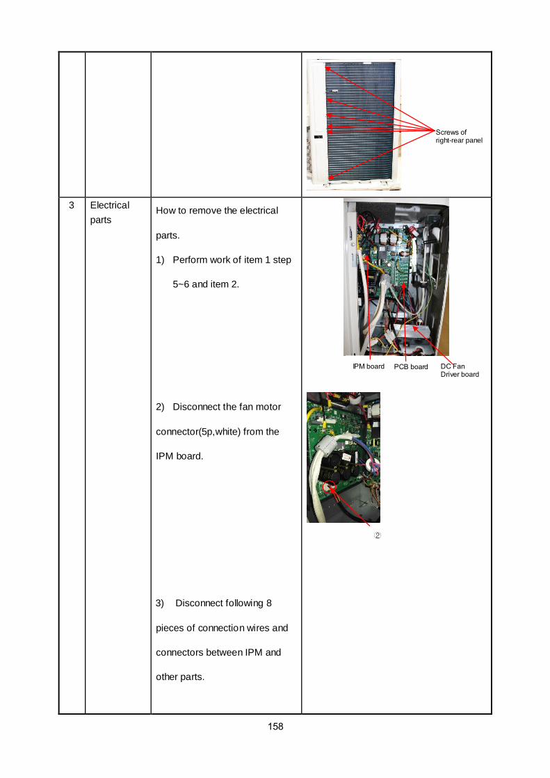
158
3 Electrical
parts How to remove the electrical
parts.
1) Perform work of item 1 step
5~6 and item 2.
2) Disconnect the fan motor
connector(5p,white) from the
IPM board.
3) Disconnect following 8
pieces of connection wires and
connectors between IPM and
other parts.
IPM board
PCB board
DC Fan Driver board
Screws of right-rear panel
②

159
CN2(yellow)
CN1(red)
CN6(black)
CN3(yellow)
U、V、W(black)
CN9(10p,white)
4) Remove the screws
fixing the IPM board and remove
the IPM board.
5) Disconnect the connectors
and wires connected from PCB
and other parts.
Connectors:
CN8: Discharge temperature sensor
(2p,white)
CN12:Heatsink temperature
sensor(2p,red)
CN9:T3/T4 temperature sensor
(2p/2p,white)
CN15: Electronic expansion valve
(6p,red)
CN10: High and low pressure switch
(2p/2p, white)
Wires:
CN17/CN18: 4-way valve (blue-blue)
CN19/CN20: connected to crankcase
heating cable. (black-red)
CN24/CN25: Electric heater of
chassis (orange-orange)
CN1:L-IN (red or white)
CN3:N-IN (black)
6) Disconnect the grounding
CN1/CN3
CN17/CN18
CN19/CN20
CN24/CN25
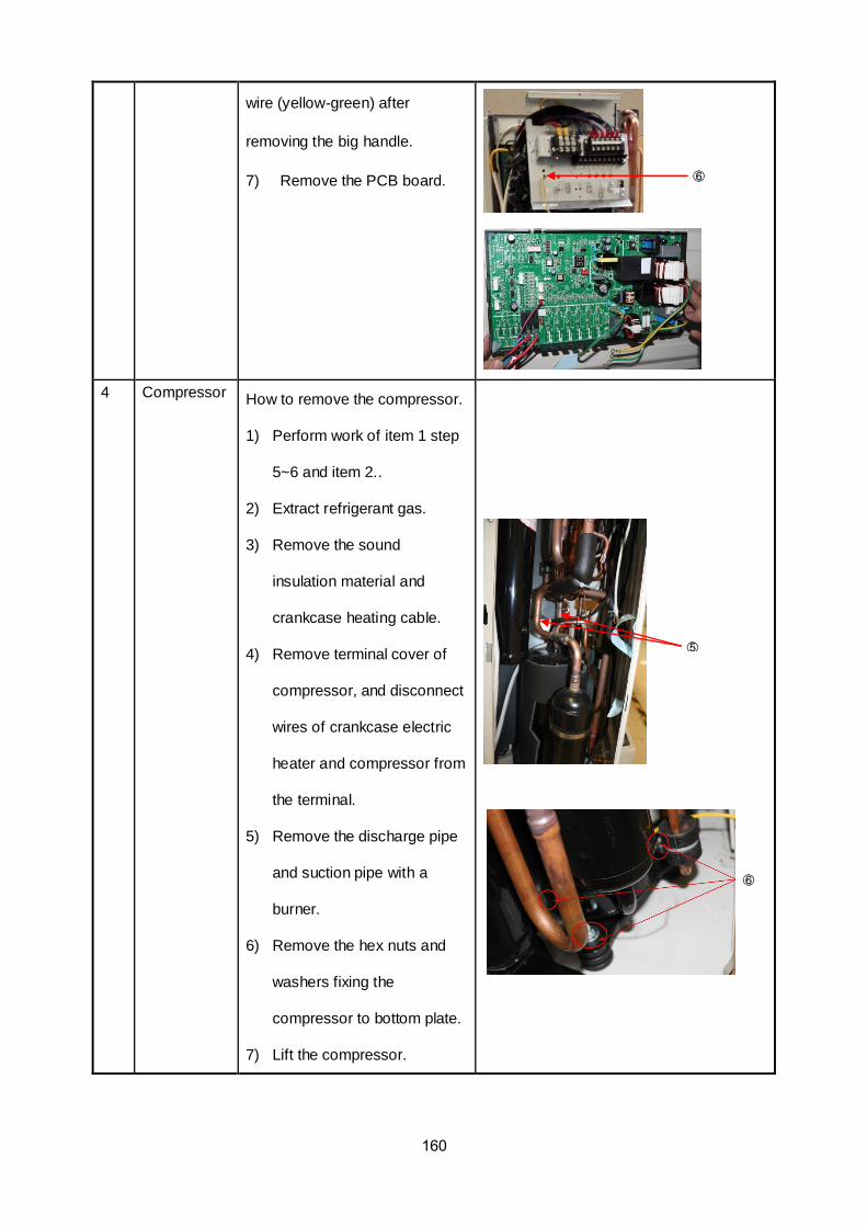
160
wire (yellow-green) after
removing the big handle.
7) Remove the PCB board.
4 Compressor How to remove the compressor.
1) Perform work of item 1 step
5~6 and item 2..
2) Extract refrigerant gas.
3) Remove the sound
insulation material and
crankcase heating cable.
4) Remove terminal cover of
compressor, and disconnect
wires of crankcase electric
heater and compressor from
the terminal.
5) Remove the discharge pipe
and suction pipe with a
burner.
6) Remove the hex nuts and
washers fixing the
compressor to bottom plate.
7) Lift the compressor.
⑥
⑥
⑤
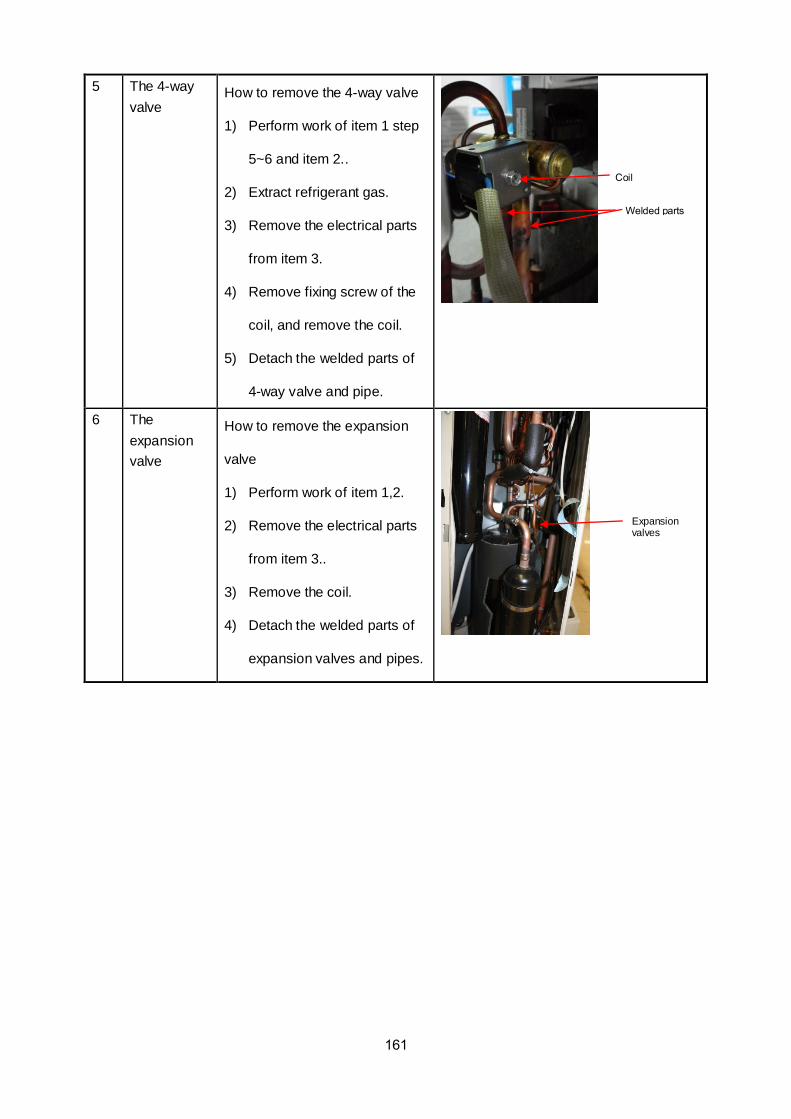
161
5 The 4-way
valve How to remove the 4-way valve
1) Perform work of item 1 step
5~6 and item 2..
2) Extract refrigerant gas.
3) Remove the electrical parts
from item 3.
4) Remove fixing screw of the
coil, and remove the coil.
5) Detach the welded parts of
4-way valve and pipe.
6 The
expansion
valve
How to remove the expansion
valve
1) Perform work of item 1,2.
2) Remove the electrical parts
from item 3..
3) Remove the coil.
4) Detach the welded parts of
expansion valves and pipes.
Coil
Welded parts
Expansion valves