L SERIES® ROOFTOP UNITS - Lennox International -
60
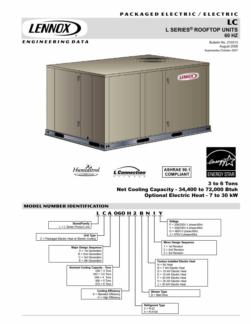
E N G I N E E R I N G D A T A LC L SERIES ® ROOFTOP UNITS 60 HZ P A C K A G E D E L E C T R I C / E L E C T R I C 3 to 6 Tons Net Cooling Capacity - 34,400 to 72,000 Btuh Optional Electric Heat - 7 to 30 kW Bulletin No. 210313 August 2008 Supersedes October 2007 ASHRAE 90.1 COMPLIANT MODEL NUMBER IDENTIFICATION LCA Y 1 060 H N 2 B Major Design Sequence A = 1st Generation B = 2nd Generation C = 3rd Generation E = 4th Generation Brand/Family L = L Series Product Line Unit Type C = Packaged Electric Heat w/ Electric Cooling Nominal Cooling Capacity − Tons 036 = 3 Tons 042 = 3.5 Tons 048 = 4 Tons 060 = 5 Tons 072 = 6 Tons Cooling Efficiency S = Standard Efficiency H = High Efficiency Minor Design Sequence 1 = 1st Revision 2 = 2nd Revision 3 = 3rd Revision Voltage P = 208/230V−1 phase−60hz Y = 208/230V-3 phase-60hz G = 460V-3 phase-60hz J = 575V-3 phase-60hz Refrigerant Type 2 = R−22 4 = R−410A Blower Type B = Belt Drive Factory Installed Electric Heat N = No Heat B = 7 kW Electric Heat D = 10 kW Electric Heat E = 15 kW Electric Heat F = 20 kW Electric Heat H = 25 kW Electric Heat J = 30 kW Electric Heat
-
Upload
khangminh22 -
Category
Documents
-
view
2 -
download
0
Transcript of L SERIES® ROOFTOP UNITS - Lennox International -
E N G I N E E R I N G D A T A
LCL SERIES® ROOFTOP UNITS
60 HZ
P A C K A G E D E L E C T R I C / E L E C T R I C
3 to 6 Tons
Net Cooling Capacity − 34,400 to 72,000 Btuh
Optional Electric Heat − 7 to 30 kW
Bulletin No. 210313August 2008
Supersedes October 2007
ASHRAE 90.1COMPLIANT
MODEL NUMBER IDENTIFICATION
L C A Y1060 H N2 B
Major Design SequenceA = 1st Generation
B = 2nd GenerationC = 3rd GenerationE = 4th Generation
Brand/FamilyL = L Series Product Line
Unit TypeC = Packaged Electric Heat w/ Electric Cooling
Nominal Cooling Capacity − Tons036 = 3 Tons
042 = 3.5 Tons048 = 4 Tons060 = 5 Tons072 = 6 Tons
Cooling EfficiencyS = Standard Efficiency
H = High Efficiency
Minor Design Sequence
1 = 1st Revision2 = 2nd Revision3 = 3rd Revision
VoltageP = 208/230V−1 phase−60hzY = 208/230V-3 phase-60hzG = 460V-3 phase-60hzJ = 575V-3 phase-60hz
Refrigerant Type2 = R−224 = R−410A
Blower TypeB = Belt Drive
Factory Installed Electric HeatN = No HeatB = 7 kW Electric HeatD = 10 kW Electric HeatE = 15 kW Electric HeatF = 20 kW Electric HeatH = 25 kW Electric HeatJ = 30 kW Electric Heat

L Series Packaged Electric / Electric 3 to 6 Ton / Page 2
CONTENTS
Accessory Air Resistance Page 21. . . . . . . . . . . . . . . . . . . . . . . . . . . . . . . . .
Application Guide Pages 54−56. . . . . . . . . . . . . . . . . . . . . . . . . . . . . . . . . . . .
Blower Performance Pages 20−21. . . . . . . . . . . . . . . . . . . . . . . . . . . . . . . . . .
Cooling Ratings Pages 15−17. . . . . . . . . . . . . . . . . . . . . . . . . . . . . . . . . . . . . .
Dimensions Pages 41−45. . . . . . . . . . . . . . . . . . . . . . . . . . . . . . . . . . . . . . . . .
Electrical / Electric Heat Data Pages 22−32. . . . . . . . . . . . . . . . . . . . . . . . . .
Features and Benefits Pages 2−5. . . . . . . . . . . . . . . . . . . . . . . . . . . . . . . . . .
Guide Specifications Pages 46−53. . . . . . . . . . . . . . . . . . . . . . . . . . . . . . . . . .
Humiditrol® Dehumidification System Page 7. . . . . . . . . . . . . . . . . . . . . . . .
Humiditrol® Dehumidification System ratings Pages 17−19. . . . . . . . . . . . .
Model Number Identification Page 1. . . . . . . . . . . . . . . . . . . . . . . . . . . . . . . .
Options / Accessories Pages 6−10. . . . . . . . . . . . . . . . . . . . . . . . . . . . . . . . .
Specifications Pages 12−14. . . . . . . . . . . . . . . . . . . . . . . . . . . . . . . . . . . . . . .
Sound Data Page 14. . . . . . . . . . . . . . . . . . . . . . . . . . . . . . . . . . . . . . . . . . . . .
System Controller / Unit Controllers Pages 12−39. . . . . . . . . . . . . . . . . . . . .
Unit Clearances Page 33. . . . . . . . . . . . . . . . . . . . . . . . . . . . . . . . . . . . . . . . . .
Weights Page 40. . . . . . . . . . . . . . . . . . . . . . . . . . . . . . . . . . . . . . . . . . . . . . . . .
FEATURES AND BENEFITS
APPROVALS
ETL and CSA listed.Efficiency ratings verified by CSA.Components bonded for grounding tomeet safety standards for servicingrequired by UL, ULC and National andCanadianElectrical Codes.3 thru 5 ton models are certified inaccordance with the USE certificationprogram, which is based on ARI Standard210/240-94.6 ton models are certified in accordancewith the ULE certification program, whichis based on ARI Standard 340/360−2004.ENERGY STAR® certified units aredesigned to use less energy, help savemoney on utility bills, and help protect theenvironment.The ENERGY STAR® Partner of the YearAward signifies that Lennox has madeoutstanding contributions to designenergy efficient units that will lowerenergy bills, while meeting industrystandards for comfort and indoor airquality. Lennox was the first HVACmanufacturer to win this award and hasbeen a four time recipient since 2003.ISO 9001 Registered ManufacturingQuality System.
Dealer Design AwardLennox has received the Dealer DesignAward from an independent panel ofdealer−contractors selected by AirConditioning, Heating & RefrigerationNews ("The News") magazine. Theirdecision is based on "best in categories"of installation, maintenance and serviceas well as quality and performance.
WARRANTY
Limited five years on compressors.Limited three years on IntegratedModular Control.Limited one year all other coveredcomponents.
CABINET
ConstructionHeavy−gauge steel panels and fullperimeter heavy−gauge galvanized steelbase rail provides structural integrity fortransportation, handling, and installation.Base rails have rigging holes. Threesides of the base rail have fork slots.Raised edges around duct and powerentry openings in the bottom of the unitprovide additional protection againstwater entering the building.
Air−Flow ChoiceUnits are shipped in down−flow (vertical)configuration, can be field converted tohorizontal air flow configuration.
Duct FlangesProvided for horizontal duct attachment.
Power EntryElectrical lines can be brought throughthe unit base or through horizontalaccess knock−outs.
Exterior PanelsConstructed of heavy−gauge, galvanizedsteel with a two−layer enamel paint finish.
InsulationAll panels adjacent to conditioned air arefully insulated with non−hygroscopicfiberglass insulation.Unit base is fully insulated. The insulationalso serves as an air seal to the roof curb,eliminating the need to add a seal duringinstallation.
Access PanelsHinged access panels are provided forthe economizer/filter section, andcompressor/controls section.All hinged panels have seals andquarter−turn latching handles to provide atight air and water seal.
REQUIRED SELECTIONS
Air Flow ConfigurationSpecify horizontal or down−flow.
OPTIONS/ACCESSORIES
Factory Installed
Corrosion ProtectionPolymeric epoxy coating that isdeposited by electrical transport(electrophoresis), using a processknown as electrocoat (e−coat). Availablefor enhanced coil corrosion protection.Factory installed on the condenser coil,evaporator coil, or both.
Field Installed
Coil GuardsPainted, galvanized steel wire guards toprotect outdoor coil. Not used with HailGuards.
Hail GuardsConstructed of heavy gauge steel,painted to match cabinet, helps protectoutdoor coils from hail damage. Not usedwith Coil Guards.
COOLING SYSTEMDesigned to maximize sensible andlatent cooling performance at designconditions.System can operate from 0°F to 125°Fwithout any additional controls.
CompressorResiliently mounted on rubber grommetsfor quiet operation.Scroll compressors on all models forhigh performance, reliability and quietoperation.
Compressor Crankcase HeaterProtects against refrigerant migration thatcan occur during low ambient operation.
Thermal Expansion ValveAssures optimal performance throughoutthe application range.Removable element head.
Filter/DrierHigh capacity filter/drier protects thesystem from dirt and moisture.
High Pressure SwitchProtects the compressor from overloadconditions such as dirty condenser coils,blocked refrigerant flow, or loss ofoutdoor fan operation.
B
C
D
E
F
G
H
I
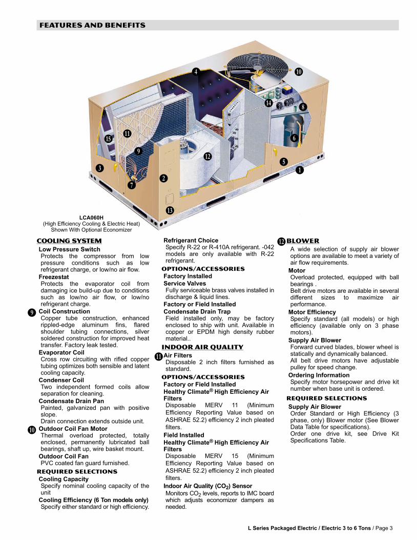
L Series Packaged Electric / Electric 3 to 6 Tons / Page 3
FEATURES AND BENEFITS
BC
D
E
F
G
H
J
I
K
L
M
N
O
P
LCA060H(High Efficiency Cooling & Electric Heat)
Shown With Optional Economizer
COOLING SYSTEM
Low Pressure SwitchProtects the compressor from lowpressure conditions such as lowrefrigerant charge, or low/no air flow.
FreezestatProtects the evaporator coil fromdamaging ice build−up due to conditionssuch as low/no air flow, or low/norefrigerant charge.
Coil ConstructionCopper tube construction, enhancedrippled−edge aluminum fins, flaredshoulder tubing connections, silversoldered construction for improved heattransfer. Factory leak tested.
Evaporator CoilCross row circuiting with rifled coppertubing optimizes both sensible and latentcooling capacity.
Condenser CoilTwo independent formed coils allowseparation for cleaning.
Condensate Drain PanPainted, galvanized pan with positiveslope.Drain connection extends outside unit.
Outdoor Coil Fan MotorThermal overload protected, totallyenclosed, permanently lubricated ballbearings, shaft up, wire basket mount.
Outdoor Coil FanPVC coated fan guard furnished.
REQUIRED SELECTIONS
Cooling CapacitySpecify nominal cooling capacity of theunit
Cooling Efficiency (6 Ton models only)Specify either standard or high efficiency.
Refrigerant ChoiceSpecify R−22 or R−410A refrigerant. −042models are only available with R−22refrigerant.
OPTIONS/ACCESSORIES
Factory Installed
Service ValvesFully serviceable brass valves installed indischarge & liquid lines.
Factory or Field Installed
Condensate Drain TrapField installed only, may be factoryenclosed to ship with unit. Available incopper or EPDM high density rubbermaterial..
Indoor Air Quality
Air FiltersDisposable 2 inch filters furnished asstandard.
OPTIONS/ACCESSORIES
Factory or Field Installed
Healthy Climate® High Efficiency AirFiltersDisposable MERV 11 (MinimumEfficiency Reporting Value based onASHRAE 52.2) efficiency 2 inch pleatedfilters.
Field Installed
Healthy Climate® High Efficiency AirFiltersDisposable MERV 15 (MinimumEfficiency Reporting Value based onASHRAE 52.2) efficiency 2 inch pleatedfilters.
Indoor Air Quality (CO2) Sensor
Monitors CO2 levels, reports to IMC boardwhich adjusts economizer dampers asneeded.
BLOWER
A wide selection of supply air bloweroptions are available to meet a variety ofair flow requirements.
MotorOverload protected, equipped with ballbearings .Belt drive motors are available in severaldifferent sizes to maximize airperformance.
Motor EfficiencySpecify standard (all models) or highefficiency (available only on 3 phasemotors).
Supply Air BlowerForward curved blades, blower wheel isstatically and dynamically balanced.All belt drive motors have adjustablepulley for speed change.
Ordering InformationSpecify motor horsepower and drive kitnumber when base unit is ordered.
REQUIRED SELECTIONS
Supply Air BlowerOrder Standard or High Efficiency (3phase, only) Blower motor (See BlowerData Table for specifications).Order one drive kit, see Drive KitSpecifications Table.
J
K
L
M

L Series Packaged Electric / Electric 3 to 6 Ton / Page 4
FEATURES AND BENEFITS
ELECTRICAL
REQUIRED SELECTIONS
Voltage ChoiceSpecify when ordering base unit.
OPTIONS/ACCESSORIES
Factory Installed
Phase Monitor (3 Phase Models Only)Protects unit against prematureequipment failure caused by phase loss,phase reversal, phase unbalance, undervoltage and over voltage.
Field Installed
Circuit Breakers up to 175 AmpHACR circuit breaker without powerdistribution lugs. Accessible from outsideof unit, spring−loaded weatherproof coverfurnished. Main power to the unit is fieldconnected to the circuit breaker whichallows all power to be shutoff for service.Circuit breaker is sized to the unitmaximum overcurrent protection(MOCP) size.
Factory or Field Installed
Electric HeatHelix wound nichrome elements, timedelay for element staging, individualelement limit controls, wiring harness,may be two-stage controlled. Whenelectric heat is factory installed, allrequired components are included. AUnit Fuse Block must be ordered extrawhen field installed electric heat is used.See Electrical/Electric Heat tables forordering information, Pages 22−32.
Disconnect Switch up to 250 AmpAccessible from outside of unit, springloaded weatherproof cover furnished.Main power to the unit is field connectedto the disconnect which allows all powerto be shut off for service. SeeElectrical/Electric Heat tables forordering information, Pages 22−32.GFI Service Outlets (2) − 115v groundfault circuit interrupter (GFCI) type, fieldwired.
SERVICEABILITYDesigned to streamline generalmaintenance and decreasetroubleshooting time.
DiagnosticsIMC diagnostic codes pinpoint problems,minimizing troubleshooting time.
Marked & Color−Coded WiringAll electrical wiring is color−coded andmarked to identify which components it isconnecting.
Electrical PlugsPositive connection electrical plugs areused to connect common accessories ormaintenance parts for easy removal orinstallation.
Toolless, Hinged Access PanelsLarge access panels are hinged andhave quarter−turn, latching handles forquick and easy access to maintenanceareas (economizer / filter, compressor /controls).
Blower AccessSupply air blower parts are located nearthe access door for easy servicing andadjustment.
Thermal Expansion ValvesThermal expansion valves are locatednear the perimeter of the unit for easieraccess.Removable element head allows changeout of element and bulb without removingthe TXV.
Coil CleaningIndependently formed condenser coilsallow separation for easier cleaning.
Standard ComponentsA large number of common maintenanceparts are standard throughout the entirerange of sizes (3−30 tons), reducing theneed to carry a lot of different parts to thejob or maintain in inventory.
Compressor CompartmentCompressors are located near theperimeter of the unit for easier access.Compressors are isolated from thecondenser air flow allowing systemoperation checks to be done withoutchanging the air flow across the outdoorcoils.
Service Valves (optional)Optional factory installed liquid anddischarge service valves allowrefrigerant to be isolated to the high sidefor service work on the low side of therefrigeration system.
Electric Heaters (optional)Optional electric heaters are accessedthrough the heating access panel.Heaters can be removed if necessary.
CONTROLS
Intelligent Unit Controller
The Integrated Modular Control (IMC) isa solid−state microprocessor−basedcontrol board that provides flexiblecontrol of all unit functions.All control voltage is provided via a 24V(secondary) transformer with built−incircuit breaker protection.Built-in functions include:Blower On/Off Delay − Adjustable timedelay between blower on and off.Built-in Control Parameter Defaults −No programming required.Compressor Time−Off Delay −Adjustable time delay betweencompressor shutoff and start up.DDC Compatible − Various third partyDDC controllers can be factory or fieldinstalled. Refer to the Unit Controllerssection for details.Dirty Filter Switch Input − When a DirtyFilter Switch is installed, the IMC willsignal when the indoor blower staticpressure increases, indicating a dirtyfilter condition. Switch is optional and canbe factory or field installed.Discharge Air Temperature Control −The IMC will cycle up to 4 stages ofheating or cooling to maintain thedischarge air setpoints for heating orcooling. Optional sensor is shipped withthe unit for remote field installation in thesupply duct. (single zone or bypasszoning control).Display/Sensor Readout − Displayscontrol parameters, diagnostic codes,and sensor readings. The IMC unitcontroller displays temperature readingsfrom return air, supply air, and outdoor airsensors that are furnished as standardon all L Series units. IMC will also displayreadings from optional sensors such aszone sensors, CO2 sensors or relativehumidity sensors.Economizer Control Choice − Theeconomizer is controlled by an add−onboard to the IMC. The economizercontrol board has several choices forcontrolling the economizer. SeeEconomizer / Outdoor Air / ExhaustOptions.
N
O

L Series Packaged Electric / Electric 3 to 6 Tons / Page 5
FEATURES AND BENEFITS
CONTROLS − CONTINUED
Intelligent Unit ControllerExtensive Unit Diagnostics − The IMCmonitors all sensors and functionsrelated to unit operation to provide criticalinformation. The IMC will display detaileddiagnostic information with over 90diagnostic codes to pinpoint anyproblems and reduce troubleshootingtime. All diagnostic codes are listedinside control access panel for easyreference.Exhaust Fan Control Modes − Fanscontrolled by fresh air damper position orbuilding static differential pressuretransducer.Permanent Diagnostic Code Storage −Maintains diagnostic codes through apower failure.Field Changeable Control Parameters− Over 200 different control parametersallow customization of the unit operationby changing delays, cooling stages,deadbands, and setpoints.Indoor Air Quality Input − The IMC isDemand Control Ventilation ready fromthe factory (optional field installed CO2sensor required). Two modes ofoperation are available: setpoint andproportional.
1 − Setpoint − Opens the economizerdampers to full position when CO2setpoint level is reached.2 − Proportional − Opens the dampersat the first set point and graduallyincreases it as the CO2 level increasesuntil the second setpoint is reached.
Low Ambient Controls − Allows unitcooling operation down to 0°F.Minimum Compressor Run Time −Ensures proper oil return to thecompressor.Network Capable − The IMC can bedaisy chained to other L Series units or LConnection® Network controllers usingtwisted pair wire.Night Setback Mode − Adjusts setpoints,closes outdoor air dampers and operatesthe blower on demand, may becustomized for special requirements.Return Air Temperature Limit Control− Allows the user to override thedemands based upon the return airtemperature during either heating orcooling operation. Helps protect againstabnormal operating conditions in theevent of a room sensor or thermostatfailure.Safety Switch Input − Normally−closeddigital input allows the IMC to respond toa external safety switch trip (phaseprotector, low voltage, etc.) shuttingdown unit operation.Service Relay Output − Digital outputcan indicate a critical error has occurredto an external control device. Can also beconfigured to energize based on relativehumidity, indoor air quality, outdoor airtemperature or unit operation.
Smoke Alarm Mode − Control board hasfour choices for responding to a smokealarm.
1 − Unit Off − unit will turn off.2 − Positive Pressure − blower isenergized, exhaust fan is de−energized,and the outdoor air dampers areopened.3 − Negative Pressure − blower isenergized, exhaust fan is energized,and the outdoor air dampers are closed.4 − Purge − blower is energized, exhaustfan is energized, and the outdoor airdampers are opened.
Staging − 2 heat/2 cool. Capable of up to4 heat/4 cool with zone sensor or thirdparty DDC control system.
�Strike Three" Protection − Endscooling or heating operation when any ofthe following occurs three times(adjustable) within a thermostat cycle:low pressure trip, high pressure trip, heatlimit trip, or freeze−stat trip.
On−Demand Dehumidification −Monitors and controls condenser hot gasbypass operation with Humiditrol option.Prioritizes heat and cool demand withdehumidification demand. Reheatdemand can be enabled by digital input ora field installed relative humidity sensorcan be used. CAV models only.
Thermostat Bounce Delay − Protectscompressor from short cycling whenmechanical thermostat is used.
Warm-up Mode Delay − Adjustable timethat the economizer dampers are kept inthe closed position during morningwarm−up.
On−Board User Interface − Push−button,DIP switches used with three−digit displayreadout for field adjustment of controlparameters. LED indicators for LConnection Network (transmit andreceive) and for each thermostat input.
PC Interface − PC with optional UnitController software may be used to fieldor remotely adjust parameters, readalarms, or display unit status.
Zone Sensor Operation − Controls zonetemperature with up to 4 stages ofheating or cooling with optional zonesensor.
OPTIONS / ACCESSORIESFactory or Field Installed
Blower Proving Switch
Monitors blower operation, shuts downunit if blower fails. Factory installed.
Dirty Filter Switch
Senses static pressure increaseindicating dirty filter condition.
Fresh Air TemperingUsed in applications with high outside airrequirements. The IMC (IntegrateControl Module) energizes the first stageheat as needed to maintain a minimumsupply air temperature for comfort,regardless of the thermostat demand.When ordered as a factory option, thesensor ships with the unit but must befield installed.
Smoke Detector
Photoelectric type, installed in supply airsection or return air section or bothsections
Interoperability via BACnet® orLonTalk® ProtocolsCommunication compatible withthird−party automation systems thatsupport the BACnet Application SpecificController device profile, LonMark®Space Comfort Controller functionalprofile, or LonMark Discharge AirController functional profile. See Page 35.
Commercial Control Systems
L Connection® NetworkComplete building automation controlsystem for single or multi−zoneapplications. Options include localinterface, software for local or remotecommunication, and hardware fornetworking other control functions. See LConnection Network EngineeringHandbook Bulletin for details.
Aftermarket DDC
Novar® Unit Controller and options.See Page 34.
Thermostats
Control system and thermostat options.Aftermarket unit controller options. SeeSee Page 39.
Field Installed
Humidity Sensor Kit, Remote MountedHumidity sensor required with factoryinstalled Humiditrol® Option orSupermarket reheat field selectableoption.

L Series Packaged Electric / Electric 3 to 6 Ton / Page 6
OPTIONS / ACCESSORIES
ECONOMIZER/OUTDOOR AIR/EXHAUST OPTIONS
Factory or Field Installed
Economizer
Parallel gear driven action return air andoutdoor air dampers, plug-in connectionsto unit, nylon bearings, neoprene seals,24 volt fully modulating spring returnmotor, adjustable minimum damperposition, damper assembly slides in unit,outdoor air hood must be orderedseparately, optional down-flow barometricrelief dampers available, choice ofeconomizer controls. The IMC add−onboard for economizer control is includedwith the economizer. Control board hasfour choices for controlling theeconomizer (DIP switch selections).
1 − Differential Sensible Control −Factory setting. Uses the outdoor airand return air sensors that arefurnished with the unit. The IMCcompares the outdoor air and return airand using setpoints, enables theeconomizer when the outdoor airtemperature is below the configuredsetpoint and cooler than return air.NOTE − Differential Sensible Controlcan be configured in the field to provideOffset Differential Sensible Control orSingle Sensible Control.In Offset Differential Sensible Controlmode, the economizer is enabled if thetemperature differential (offset)between outdoor air and return airreaches the configured setpoint.In Single Sensible Control mode, theeconomizer is enabled when outdoorair temperature falls below theconfigured setpoint.2 − Global Control − The IMCcommunicates with a DDC system withone global sensor (enthalpy or sensible)to determine whether outside air issuitable for free cooling on all unitsconnected to the control system. Sensormust be field provided.3 − Single Enthalpy Control − Outdoorair enthalpy sensor enableseconomizer if the outdoor enthalpy isless than the setpoint of the board.Factory installed.4 − Differential Enthalpy Control − Twosolid-state enthalpy sensors allow theeconomizer control board to selectbetween outdoor air or return air,whichever has lower enthalpy. Factoryinstalled.
Barometric Relief Dampers, Down−FlowAllows relief of excess air, aluminumblade dampers prevent blow back andoutdoor air infiltration during off cycle,bird screen furnished. Requires fieldinstalled Damper Hood. See FieldInstalled section. Not used with PowerExhaust Fan.
Outdoor Air Damper − Down−Flow orHorizontalLinked mechanical dampers, 0 to 25%(fixed) outdoor air adjustable, installs inunit, outdoor air hood must be orderedseparately. Automatic model featuresfully modulating spring return dampermotor with plug−in connection. Manualmodel features a slide damper. Maximummixed air temperature in cooling mode:100°F.
Outdoor Air HoodRequired with LAREMD Economizer,LAOAD and LAOADM Outdoor AirDamper Sections, one cleanablealuminum mesh fresh air filter furnished.
Field Installed
Barometric Relief Damper Hood,Down−FlowRequired with Down−Flow BarometricRelief Dampers.
Barometric Relief Dampers, HorizontalAllows relief of excess air, aluminumblade dampers prevent blow back andoutdoor air infiltration during off cycle,field installed in return air duct, birdscreen and hood furnished, two dampersper order number.
Power Exhaust FanInstalls external to unit for down-flowapplications only with economizer option,provides exhaust air pressure relief,includes integrated barometric reliefdamper that prevents blow−back andoutdoor air infiltration during off cycle,interlocked to run when supply air bloweris operating, fan runs when outdoor airdampers are 50% open (adjustable),motor is overload protected, bird screenand hood are furnished, steel cabinet andhood are painted to match unit. Fan is 14in. in diameter with 4 fan blades. Total airvolume is 1900 cfm at 0 in. w.g., 1/2 hpmotor. 385 Watts total input.
CEILING DIFFUSERS
Ceiling DiffusersAluminum grilles, large center grille,insulated diffuser box with flanges,hanging rings furnished, interiortransition (even air flow), internallysealed (prevents recirculation), adapts toT-bar ceiling grids or plaster ceilings.
Transitions (Supply and Return)Used with diffusers, installs in roof curb,galvanized steel construction, flangesfurnished for duct connection to diffusers,fully insulated.
ROOF CURBS
Roof Curb, Down−FlowNailer strip furnished, mates to unit, USNational Roofing Contractors Approved,shipped knocked down. Available in 8,14, 18, and 24 inch heights.Cliplock curbs use interlocking tabs tofasten together. No tools required.Standard roof curb corners fastentogether with furnished hardware.
P

L Series Packaged Electric / Electric 3 to 6 Tons / Page 7
OPTIONS / ACCESSORIES
Humiditrol® DEHUMIDIFICATION SYSTEM
Factory installed option designed tocontrol humidity. Providesdehumidification on demand usingASHRAE 90.1 recommended method forcomfort conditioning humidity control.Available for LCA036H, LCA048H,LCA060H and LCC072S only.Unit comes equipped with 1 row reheatcoil, solenoid valve and humiditycontroller.Provides dehumidification on demandusing ASHRAE 90.1 recommendedmethod for reheat with comfortconditioning humidity control.In addition to a thermostat or room sensorused for conventional operation, ahumidity sensor is required and must belocated in the occupied space. RemoteMounted Humidity Sensor Kit is requiredfor field installation.The humidity sensor provides input to theIntegrated Modular Control which is usedto control activation of thedehumidificationoperation.Reheat controls are located in thecompressor control section of the unit foreasy access.
BenefitsImproves indoor air quality.Helps prevents damage due to highhumidity levels.Improves comfort levels by reducingspace humidity levels.
OPERATION
No Dehumidification DemandThe unit will operate conventionallywhenever there is a demand for coolingor heating and no dehumidificationdemand.Free cooling is only permitted when thereis no demand for dehumidification.
Dehumidification Demand OnlyThe IMC is factory set at 60% relativehumidity setpoint and can be adjusted atthe IMC or with optional Unit ControllerSoftware.For L Connection® Network ControlPanel (NCP) applications, the humiditysetpoint can be adjusted at the NCP.The unit will operate in thedehumidification mode until the relativehumidity of the conditioned space is 3%below the setpoint.Reheat operation will initiate on adehumidification demand and does notrequire a cooling demand.The reheat coil is sized to provide 68°F to75°F supply air during reheat operation.This reduces sensible cooling capacityand extends compressor run time tocontrol humidity when the cooling load islow.
A solenoid valve diverts hot gas from thecompressor to the reheat coil.The cooled and dehumidified air from theevaporator is reheated as it passesthrough the reheat coil.The de−superheated and partiallycondensed refrigerant continues to theoutdoor condenser coil wherecondensing is completed. The unit willcontinue to operate in this mode until thedehumidification demand is satisfied. A heating demand or cooling demand willterminate reheat operation.
Dehumidification and CoolingDemand (Thermostat/Room SensorApplication)If both a dehumidification and a coolingdemand occur, the system will operate incooling until the cooling demand issatisfied. Then the system will energizethe dehumidification mode.
ACCESSORIES
Humidity Sensor Kit, Remote MountedHumidity sensor required with factoryinstalled Humiditrol® Option orSupermarket reheat field selectableoption.
HUMIDITROL DEHUMIDIFICATION SCHEMATIC
REHEATCOIL
EVAPORATORCOIL
SOLENOID VALVE
RETURNAIR
CONDENSERCOIL
OUTDOORAIR
COMPRESSORSUPPLY
AIR
CHECK VALVE
EXPANSIONVALVE

L Series Packaged Electric / Electric 3 to 6 Ton / Page 8
OPTIONs / ACCESSORIES
Item CatalogNo.
036 042 048 060 072
COOLING SYSTEM
Condensate Drain Trap Copper − LTACDKC03/07 45K67 � � � � �
EPDM − C1TRAP30121 43W45 � � � � �
Corrosion Protection Factory � � � � �
Efficiency Standard Factory �
High Factory � � � � �
Refrigerant Type R−22 Factory � � � � �
R−410A Factory � � � �
Service Valves Factory � � � � �
Stainless Steel Condensate Drain Pan Factory � � � � �
Blower − SUPPLY AIR
1.5 hp Standard or High Efficiency Factory � � � � �
2 hp Standard or High Efficiency Factory � � � � �
3 hp Standard Efficiency Factory � � � � �
CABINET
Coil Guards 28L52 x x x x x
Hail Guards 28L53 x x x x x
CONTROLS
Blower Proving Switch C0SWCH01AE1− 30K49 � � � � �
Commercial Controls L Connection® Building Automation System − − − � � � � �
IMC BACnet® Module − C0CTRL50AE1L 11W29 � � � � �
IMC LonTalk® Module − C0CTRL51AE1L 11W28 � � � � �
Novar® ETM−2051 Unit Controller 69K67 � � � � �
Dirty Filter Switch C0SWCH00AE1− 30K48 � � � � �
Fresh Air Tempering C0SNDC03AE−1 45L78 � � � � �
Smoke Detector − Supply LTSASDK03/07 41L85 � � � � �
Smoke Detector − Return LTARSDK03/07 41L86 � � � � �
ELECTRICAL
Voltage60 hz
208/230V − 1 phase Factory � � � �
208/230V − 3 phase Factory � � � � �
460V − 3 phase Factory � � � � �
575V − 3 phase Factory � � � � �
HACR Circuit Breakers � � � � �
Disconnect Switch − See Electrical/ElectricHeat Data Tables for selection
80 Amp 67M16 � � � � �
150 Amp 67M17 � � � � �
GFI Service Outlets LTAGFIK10/15 31M77 � � � � �
Phase Monitor − 3 Phase Models Only � � � � �
NOTE − The catalog and model numbers that appear here are for ordering field installed accessories only.
⊗ − Field Installed or Configure to Order (factory installed)
� − Configure to Order (Factory Installed)X − Field Installed.

L Series Packaged Electric / Electric 3 to 6 Tons / Page 9
OPTIONs / ACCESSORIES
Item CatalogNo.
036 042 048 060 072
ELECTRIC HEAT
7 kW 208/240V−1ph − EHA060−7 23L62 � � � �
208/240V−3ph − EHA060−7 23L67 � � � �
460V−3ph − EHA060−7 23L73 � � � �
575V−3ph − EHA060−7 23L79 � � � �
10 kW 208/240V−1ph − EHA072−10 23L63 � � � � �
208/240V−3ph − EHA072−10 23L68 � � � � �
460V−3ph − EHA072−10 23L74 � � � � �
575V−3ph − EHA072−10 23L80 � � � � �
15 kW 208/240V−1ph − EHA072−15 23L64 � � � � �
208/240V−3ph − EHA072−15 23L69 � � � � �
460V−3ph − EHA072−15 23L75 � � � � �
575V−3ph − EHA072−15 23L81 � � � � �
20 kW 208/240V−1ph − EHA072−20 23L65 � � � � �
208/240V−3ph − EHA072−20 23L70 � � � � �
460V−3ph − EHA072−20 23L76 � � � � �
575V−3ph − EHA072−20 23L82 � � � � �
25 kW 208/240V−1ph − EHA072−25 23L66 � �
208/240V−3ph − EHA072−25 23L71 � �
460V−3ph − EHA072−25 23L77 � �
575V−3ph − EHA072−25 23L83 � �
30 kW 208/240V−3ph − EHA072−30 23L72 �
460V−3ph − EHA072−30 23L78 �
575V−3ph − EHA072−30 23L84 �
ELECTRIC HEAT ACCESSORIES/OPTIONS
Unit Fuse Block See Electrical/Electric Heat Data Tables for selection � � � � �
ELECTRIC HEAT SUB−FUSE BLOCK − Required with all Electric Heaters. See Electrical/Electric Heat Data Tables for selection
For 7 kWElectric Heat
208/240V−1ph − EHAFB−7 27L01 � � � �
208/240V−3ph − EHAFB−7 27L06 � � � �
460V/575V−3ph − EHAFB−7 27L12 � � � �
For 10 kWElectric Heat
208/240V−1ph − EHAFB−10 27L02 � � � � �
208/240V−3ph − EHAFB−10 27L07 � � � � �
460V−3ph − EHAFB−10 27L13 � � � � �
575V−3ph − EHAFB−10 27L18 � � � � �
For 15 kWElectric Heat
208/240V−1ph − EHAFB−15 27L03 � � � � �
208/240V−3ph − EHAFB−15 27L08 � � � � �
460V−3ph − EHAFB−15−G/20−J 27L14 � � � � �
575V−3ph − EHAFB−15 27L19 � � � � �
For 20 kWElectric Heat
208/240V−1ph − EHAFB−20 27L04 � � � � �
208/240V−3ph − EHAFB−20 27L09 � � � � �
460V−3ph − EHAFB−20−G/25−J 27L15 � � � � �
575V−3ph − EHAFB−15−G/20−J 27L14 � � � � �
For 25 kWElectric Heat
208/240V−1ph − EHAFB−25 27L05 � �
208/240V−3ph − EHAFB−25 27L10 � �
460V−3ph − EHAFB−25−G/30−J 27L16 � �
575V−3ph − EHAFB−20−G/25−J 27L15 � �
For 30 kWElectric Heat
208/240V−3ph − EHAFB−30 27L11 �
460V−3ph − EHAFB−30 27L17 �
575V−3ph − EHAFB−25−G/30−J 27L16 �
NOTE − The catalog and model numbers that appear here are for ordering field installed accessories only.
⊗ − Field Installed or Configure to Order (factory installed)

L Series Packaged Electric / Electric 3 to 6 Ton / Page 10
OPTIONs / ACCESSORIES
Item CatalogNo.
036 042 048 060 072
HUMIDITROL® DEHUMIDIFICATION SYSTEM
Humiditrol � � � �
Humidity Sensor Kit, Remote Mounted (required) C0SNSR31AE−1 17M50 x x x x
Remote Sensor Wall Seal Plate COMISC18AE−1 58L33 x x x x
Indoor Air Quality
Air Filters
Healthy Climate® High Efficiency Air Filters16 x 25 x 2 − Order 2 per unit
MERV 11 − C1FILT20EA1− 97L84 � � � � �
MERV 15 − C1FLTR50EA1− 28W02 x x x x x
Indoor Air Quality (Co2) Sensors
Sensor − white case CO2 display C0SNSR50AE1L 77N39 x x x x x
Sensor − white case no display C0SNSR52AE1L 87N53 x x x x x
Sensor − black case CO2 display C0SNSR51AE1L 87N52 x x x x x
Sensor − duct mount, black case, no display C0SNSR53AE1L 87N54 x x x x x
CO2 Sensor Duct Mounting Kit C0MISC19AE1− 85L43 x x x x x
Aspiration Box for duct mounting C0MISC16AE1− 90N43 x x x x x
Handheld CO2 Monitor LTAIAQSHM03/36 70N93 x x x x x
ECONOMIZER
Economizer
Economizer (Sensible Control) − Order Hood Separately LAREMD03/07 62K67 � � � � �
Outdoor Air Hood for Economizer LAOAH03/07 62K70 � � � � �
Economizer Controls
Differential (Dual) Enthalpy C1SNSR07AE1− 86M33 � � � � �
Single Enthalpy C1SNSR06AE1− 86M32 � � � � �
Global, Enthalpy Sensor Field Provided Factory � � � � �
Differential Sensible Furnished Factory � � � � �
Barometric Relief
Down−Flow Barometric Relief Dampers − Order Hood Separately LAGED03/07 62K61 � � � � �
Damper Hood for Down−Flow Barometric Relief Dampers LAGEH03/07 28L51 � � � � �
Horizontal Barometric Relief Dampers − Hood Furnished LAGEDH03/15 53K04 x x x x x
OUTDOOR AIR
Outdoor Air Dampers (down−flow or horizontal)
Damper Section, Motorized Operation − Order Hood Separately LAOADM03/07 62K69 � � � � �
Damper Section, Manual Operation − Order Hood Separately LAOAD03/07 62K68 � � � � �
Outdoor Air Hood for Outdoor Air Dampers (required) Number and size of Filters (1) 16 x 25 x 1 in.
LAOAH03/07 62K70 � � � � �
Power Exhaust (Down−Flow Only)
Standard Static (Includes Barometric Relief Dampers andHood)
208/230V − LAPEF03/06 62K63 x x x x x
460V − LAPEF03/06 62K64 x x x x x
575V − LAPEF03/07 62K65 x x x x x
NOTE − The catalog and model numbers that appear here are for ordering field installed accessories only.
⊗ − Field Installed or Configure to Order (factory installed)
� − Configure to Order (Factory Installed)X − Field Installed.

L Series Packaged Electric / Electric 3 to 6 Tons / Page 11
OPTIONs / ACCESSORIES
Item CatalogNo.
036 042 048 060 072
ROOF CURBS − CLIPLOCK 1000
Down−Flow
8 in. height L1CURB23A−1 26W35 x x x x x
14 in. height LARMF03/07S−14 59J47 x x x x x
18 in. height LARMF03/07S−18 25K03 x x x x x
24 in. height LARMF03/07S−24 12K69 x x x x x
ROOF CURBS − STANDARD
Down−Flow
14 in. height LARMF03/07−14 45J19 x x x x x
24 in. height LARMF03/07−24 29L66 x x x x x
CEILING DIFFUSERS
Step−Down − Order one RTD9−65−R 27G87 x x x x
RTD11−95 29G04 x
(Canada Only) RTD11−95S 13K61 x
Flush − Order one FD9−65−R 27G86 x x x x
FD11−95 29G08 x
(Canada Only) FD11−95S 13K56 x
Transitions (Supply and Return) − Order one LASRT03/06 28L50 x x x x
(Canada Only) LASRT03/072 38L01 x x x x
LASRT07 48J27 x
NOTE − The catalog and model numbers that appear here are for ordering field installed accessories only.X − Field Installed.

L Series Packaged Electric / Electric 3 to 6 Ton / Page 12
SPECIFICATIONS − BELT DRIVE BLOWER 3−3.5 ton
GeneralData
Nominal Tonnage 3 Ton 3.5 Ton
Model No. LCA036H2B LCA036H4B LCA042H2B
Efficiency Type High High High
CoolingPerformance
Gross Cooling Capacity − Btuh (kW) 37,600 (11.0) 36,200 (10.6) 44,800 (13.1)
2 Net Cooling Capacity − Btuh (kW) 36,400 (10.7) 35,000 (10.2) 43,500 (12.7)
ARI Rated Air Flow − cfm (L/s) 1200 (565) 1300 (615) 1370 (650)
3 Sound Rating Number (dB) 82 82 82
Total Unit Power (kW) 3.3 3.0 3.9
2 SEER (Btuh/Watt) 13.00 13.40 13.00
2 EER (Btuh/Watt) 11.20 11.4 11.30
Refrigerant Type R−22 R−410 R−22
Refrigerant Charge Furnished 7 lbs. 0 oz.(3.18 kg)
8 lbs. 12 oz.(3.97 kg)
8 lbs. 8 oz.(3.86 kg)
Refrigerant Charge Furnishedwith Humiditrol® Option
7 lbs. 14 oz.(3.57 kg)
8 lbs. 12 oz.(3.97 kg)
NotAvailable
Compressor Type Scroll Scroll Scroll
Electric Heat Available − See Page 33 7, 10, 15, or 20 kW
OutdoorCoil
Net face area − sq. ft. (m2) 14.6 (1.35) 14.6 (1.35) 14.6 (1.35)
Tube diameter − in. (mm) 3/8 (9.5) 3/8 (9.5) 3/8 (9.5)
Number of rows 2 2 1.3
Fins per inch (m) 20 (787) 20 (787) 20 (787)
OutdoorCoilFan
Motor horsepower (W) 1/3 (224) 1/3 (224) 1/3 (224)
Motor rpm 1075 1075 1075
Total Motor watts 360 360 360
Diameter − in. (mm) 24 (610) 24 (610) 24 (610)
Number of blades 3 3 3
Total Air volume − cfm (L/s) 4200 (1980) 4200 (1980) 4200 (1980)
IndoorCoil
Net face area − sq. ft. (m2) 6.25 (0.58) 6.25 (0.58) 6.25 (0.58)
Tube diameter − in. (mm) 3/8 (9.5) 3/8 (9.5) 3/8 (9.5)
Number of rows 2 2 3
Fins per inch (m) 15 (591) 15 (591) 15 (591)
Drain connect − no. & size − in. (mm) fpt (1) 3/4 (19) (1) 3/4 (19) (1) 3/4 (19)
Expansion device type Balanced Port Thermostatic Expansion Valve, replaceable thermostatic element
4 IndoorBlowerand DriveSelection
Nominal motor output − voltage 1.5 hp (1.1 kW) − 208/230V 1ph, 208/230V, 460V or 575V 3ph2 hp (1.5 kW) − 208/230V, 460V or 575V − 3ph3 hp (2.2 kW) − 208/230V, 460V or 575V − 3ph
Maximum usable motor output 1.72 hp (1.3 kW), 2.3 hp (1.7 kW) or 3.45 hp (2.6 kW)
Motor − Drive kit 1.5 hpkit #1 − 615 − 920 rpmkit #2 − 800 − 1105 rpm
2 hpkit #3 − 920 − 1230 rpm
3 hpkit #4 − 1070 − 1325 rpm
Wheel�nominal�diameter�x�width − in. (mm) 11−1/2 x 9 (292 x 229)
Filters Type of filter Disposable
Number and size − in. (mm) (2) 16 x 25 x 2 (406 x 635 x 51)
Electrical characteristics − 60 Hz 208/230V − 1 phase208/230V, 460V or 575V − 3 phase
NOTE − Net capacity includes evaporator blower motor heat deduction. Gross capacity does not include evaporator blower motor heat deduction.1 All models less than 13 SEER are not available in Ontario.2 Certified in accordance with the USE certification program, which is based on ARI Standard 210/240; 95�F (35�C) outdoor air temperature and 80�F (27�C) db/67�F (19�C)wb entering evaporator air; minimum external duct static pressure.3 Sound Rating Number rated in accordance with test conditions included in ARI Standard 270.4 Using total air volume and system static pressure requirements determine from blower performance tables rpm and motor output required. Maximum usable output of motorsfurnished are shown. In Canada, nominal motor output is also maximum usable motor output. If motors of comparable output are used, be sure to keep within the service factorlimitations outlined on the motor nameplate.

L Series Packaged Electric / Electric 3 to 6 Tons / Page 13
SPECIFICATIONS − BELT DRIVE BLOWER 4−5 TON
GeneralData
Nominal Tonnage 4 Ton 5 Ton
Model No. LCA048H2B LCA048H4B LCA060H2B LCA060H4B
Efficiency Type High High High High
CoolingPerfor-mance
Gross Cooling Capacity − Btuh (kW) 50,500 (14.8) 51,000 (17.6) 63,000 (18.5) 62,500 (18.3)
2 Net Cooling Capacity − Btuh (kW) 49,000 (14.4) 49,500 (14.5) 61,000 (17.9) 60,000 (17.6)
ARI Rated Air Flow − cfm (L/s) 1450 (685) 1600 (755) 2000 (945) 2000 (945)
3 Sound Rating Number (dB) 82 82 82 82
Total Unit Power (kW) 4.3 4.3 5.5 5.8
2 SEER (Btuh/Watt) 13.25 13.50 13.00 13.00
2 EER (Btuh/Watt) 11.30 11.5 11.00 10.90
Refrigerant Type R−22 R−410 R−22 R−410A
Refrigerant Charge Furnished 9 lbs. 8 oz.(4.31 kg)
10 lbs. 12 oz.(4.88 kg)
10 lbs. 0 oz.(4.54 kg)
10 lbs. 9 oz.(4.79 kg)
Refrigerant Charge Furnishedwith Humiditrol® Option
11 lbs. 0 oz.(4.99 kg)
10 lbs. 12 oz.(4.88 kg)
11 lbs. 13 oz.(5.36 kg)
12 lbs. 6 oz.(5.61 kg)
Compressor Type Scroll Scroll Scroll Scroll
Electric Heat Available − See Page 33 7, 10, 15, or 20 kW 7, 10, 15, 20, 25, or 30 kW
OutdoorCoil
Net face area − sq. ft. (m2) 14.6 (1.35) 14.6 (1.35) 14.6 (1.35) 14.6 (1.35)
Tube diameter − in. (mm) 3/8 (9.5) 3/8 (9.5) 3/8 (9.5) 3/8 (9.5)
Number of rows 2 2 2 2
Fins per inch (m) 20 (787) 20 (787) 20 (788) 20 (788)
OutdoorCoilFan
Motor horsepower (W) 1/3 (224) 1/3 (224) 1/3 (248) 1/3 (248)
Motor rpm 1075 1075 1075 1075
Total Motor watts 360 360 360 360
Diameter − in. (mm) 24 (610) 24 (610) 24 (610) 24 (610)
Number of blades 3 3 3 3
Total Air volume − cfm (L/s) 4200 (1980) 4200 (1980) 4200 (1980) 4200 (1980)
IndoorCoil
Net face area − sq. ft. (m2) 6.25 (0.58) 6.25 (0.58) 6.25 (0.58) 6.25 (0.58)
Tube diameter − in. (mm) 3/8 (9.5) 3/8 (9.5) 3/8 (9.5) 3/8 (9.5)
Number of rows 3 3 3 3
Fins per inch (m) 15 (591) 15 (591) 15 (591) 15 (591)
Drain connect − no. & size − in. (mm) fpt (1) 3/4 (19) (1) 3/4 (19) (1) 3/4 (19) (1) 3/4 (19)
Expansion device type Balanced Port Thermostatic Expansion Valve, replaceable thermostatic element
4 IndoorBlowerand DriveSelection
Nominal motor output − voltage 1.5 hp (1.1 kW) − 208/230V 1ph, 208/230V, 460V or 575V 3ph2 hp (1.5 kW) − 208/230V, 460V or 575V − 3ph3 hp (2.2 kW) − 208/230V, 460V or 575V − 3ph
Maximum usable motor output 1.72 hp (1.3 kW), 2.3 hp (1.7 kW) or 3.45 hp (2.6 kW)
Motor − Drive kit 1.5 hpkit #1 − 615 − 920 rpmkit #2 − 800 − 1105 rpm
2 hpkit #3 − 920 − 1230 rpm
3 hpkit #4 − 1070 − 1325 rpm
Wheel�nominal�diameter�x�width − in. (mm) 11−1/2 x 9 (292 x 229)
Filters Type of filter Disposable
Number and size − in. (mm) (2) 16 x 25 x 2 (406 x 635 x 51)
Electrical characteristics − 60 Hz 208/230V − 1 phase208/230V, 460V or 575V − 3 phase
NOTE − Net capacity includes evaporator blower motor heat deduction. Gross capacity does not include evaporator blower motor heat deduction.1 All models less than 13 SEER are not available in Ontario.2 Certified in accordance with the USE certification program, which is based on ARI Standard 210/240; 95�F (35�C) outdoor air temperature and 80�F (27�C) db/67�F (19�C)wb entering evaporator air; minimum external duct static pressure.3 Sound Rating Number rated in accordance with test conditions included in ARI Standard 270.4 Using total air volume and system static pressure requirements determine from blower performance tables rpm and motor output required. Maximum usable output of motorsfurnished are shown. In Canada, nominal motor output is also maximum usable motor output. If motors of comparable output are used, be sure to keep within the service factorlimitations outlined on the motor nameplate.

L Series Packaged Electric / Electric 3 to 6 Ton / Page 14
SPECIFICATIONS − BELT DRIVE BLOWER 6 TON
GeneralData
Nominal Tonnage 6 Ton 6 Ton 6 Ton 6 Ton
Model No. LCC072S2B LCC072S4B LCA072H2B LCA072H4B
Efficiency Type Standard Standard High High
CoolingPerformance
Gross Cooling Capacity − Btuh (kW) 76,000 (22.3) 75,000 (22.0) 74,000 (21.7) 75,000 (22.0)1 Net Cooling Capacity − Btuh (kW) 72,000 (21.1) 72,000 (21.1) 71,000 (20.8) 72,000 (21.1)
ARI Rated Air Flow − cfm (L/s) 2100 (990) 2250 (1060) 2100 (990) 2250 (1060)2 Sound Rating Number (dB) 82 82 82 82
Total Unit Power (kW) 7.2 7.2 6.8 7.01 EER (Btuh/Watt) 10.3 10.1 10.5 10.4
Refrigerant Type R−22 R−410A R−22 R−410
Refrigerant Charge Furnished 9 lbs. 5 oz.(4.22 kg)
10 lbs. 14 oz.(4.93 kg)
9 lbs. 13 oz.(4.45 kg)
11 lbs. 8 oz.(5.22 kg)
Refrigerant Charge Furnishedwith Humiditrol® Option
9 lbs. 8 oz.(4.31 kg)
10 lbs. 14 oz.(4.93 kg)
NotAvailable
NotAvailable
Electric Heat Available − See page 33 10, 15, 20, 25, or 30 kW 10, 15, 20, 25, or 30 kW
Compressor Type Scroll Scroll Scroll Scroll
CondenserCoil
Net face area − sq. ft. (m2) 14.6 (1.35) 14.6 (1.35) 14.6 (1.35) 14.6 (1.35)
Tube diameter − in. (mm) 3/8 (9.5) 3/8 (9.5) 3/8 (9.5) 3/8 (9.5)
Number of rows 2 2 2 2
Fins per inch (m) 20 (788) 20 (788) 20 (788) 20 (788)
OutdoorCoilFan
Motor horsepower (W) 1/3 (248) 1/3 (248) 1/3 (248) 1/3 (248)
Motor rpm 1075 1075 1075 1075
Total Motor watts 360 360 360 360
Diameter − in. (mm) 24 (610) 24 (610) 24 (610) 24 (610)
Number of blades 3 3 3 3
Total Air volume − cfm (L/s) 4200 (1980) 4200 (1980) 4200 (1980) 4200 (1980)
IndoorCoil
Net face area − sq. ft. (m2) 6.25 (0.58) 6.25 (0.58) 6.25 (0.58) 6.25 (0.58)
Tube diameter − in. (mm) 3/8 (9.5) 3/8 (9.5) 3/8 (9.5) 3/8 (9.5)
Number of rows 3 3 4 4
Fins per inch (m) 15 (591) 15 (591) 15 (591) 15 (591)
Drain connection − no. & size − in. (mm) fpt (1) 3/4 (19) (1) 3/4 (19) (1) 3/4 (19) (1) 3/4 (19)
Expansion device type Balanced Port Thermostatic Expansion Valve, replaceable thermostatic element
3 IndoorBlowerand DriveSelection
Nominal motor output − voltage 1.5 hp (1.1kW) 2 hp (1.5 kW) 3 hp (2.2 kW)
Maximum usable motor output 1.72 hp (1.3 kW), 2.3 hp (1.7 kW) or 3.45 hp (2.6 kW)
Motor − Drive kit 1.5 hpkit #1 − 615 − 920 rpmkit #2 − 800 − 1105 rpm
2 hpkit #3 − 920 − 1230 rpm
3 hpkit #4 − 1070 − 1325 rpm
Wheel�nominal�diameter�x�width − in. (mm) 11−1/2 x 9 (292 x 229)
Filters Type of filter Disposable
Number and size − in. (mm) (2) 16 x 25 x 2 (406 x 635 x 51)
Electrical characteristics − 60 Hz 208/230V, 460V or 575V − 3 phaseNOTE − Net capacity includes evaporator blower motor heat deduction. Gross capacity does not include evaporator blower motor heat deduction.1 Certified in accordance with the USE certification program, which is based on ARI Standard 210/240; 95�F (35�C) outdoor air temperature and 80�F (27�C) db/67�F (19�C)wb entering evaporator air; minimum external duct static pressure.2 Sound Rating Number rated in accordance with test conditions included in ARI Standard 270.3 Using total air volume and system static pressure requirements determine from blower performance tables rpm and motor output required. Maximum usable output of motorsfurnished are shown. In Canada, nominal motor output is also maximum usable motor output. If motors of comparable output are used, be sure to keep within the service factorlimitations outlined on the motor nameplate.
OUTDOOR SOUND DATA
UnitModel No.
Octave Band Sound Power Levels dBA, re 10−12 Watts − Center Frequency − HZ 1 Sound RatingNumber (dB)125 250 500 1000 2000 4000 8000
036 70 73 77 76 73 68 60 82
042 70 73 76 77 73 68 59 82
048 69 72 77 76 72 66 58 82
060 72 73 78 78 73 68 61 82
072 68 71 76 77 74 69 61 82
NOTE − The octave sound power data shown does not include tonal correction.1 Sound Rating Number according to ARI Standard 270−95.

L Series Packaged Electric / Electric 3 to 6 Tons / Page 15
COOLING RATINGS NOTE − For Temperatures and Capacities not shown in tables, see bulletin − Cooling Unit Rating Table Correction Factor Data in Miscellaneous Engineering Data section.
3 TON HIGH EFFICIENCY (R−22) LCA036H2
EnteringWet BulbTempera-
ture
TotalAir
Volume
Outdoor Air Temperature Entering Outdoor Coil
85�F (29�C) 95�F (35�C) 105�F (41�C) 115�F (46�C)
TotalCoolingCapacity
CompMotor
kWInput
Sensible To TotalRatio (S/T)Dry Bulb
TotalCoolingCapacity
CompMotor
kWInput
Sensible To TotalRatio (S/T)Dry Bulb
TotalCoolingCapacity
CompMotor
kWInput
Sensible To TotalRatio (S/T)Dry Bulb
TotalCoolingCapacity
CompMotor
kWInput
Sensible To TotalRatio (S/T)Dry Bulb
cfm L/s kBtuh kW75�F24�C
80�F27�C
85�F29�C
kBtuh kW75�F24�C
80�F27�C
85�F29�C
kBtuh kW75�F24�C
80�F27�C
85�F29�C
kBtuh kW75�F24�C
80�F27�C
85�F29�C
63�F(17�C)
960 455 35.3 10.3 2.26 .69 .82 .95 34.1 10.0 2.55 .70 .84 .97 32.8 9.6 2.88 .71 .85 .98 31.5 9.2 3.26 .72 .87 1.00
1200 565 36.8 10.8 2.25 .73 .89 1.00 35.5 10.4 2.54 .75 .91 1.00 34.2 10.0 2.87 .76 .93 1.00 32.8 9.6 3.25 .78 .95 1.00
1440 680 38.0 11.1 2.25 .78 .95 1.00 36.7 10.8 2.54 .80 .97 1.00 35.3 10.3 2.86 .82 .99 1.00 34.0 10.0 3.24 .84 1.00 1.00
67�F(19�C)
960 455 37.8 11.1 2.25 .54 .66 .78 36.5 10.7 2.54 .55 .67 .80 35.1 10.3 2.87 .55 .68 .82 33.6 9.8 3.25 .56 .69 .84
1200 565 39.1 11.5 2.24 .57 .71 .86 37.7 11.0 2.53 .57 .72 .87 36.3 10.6 2.86 .58 .74 .89 34.7 10.2 3.24 .59 .76 .92
1440 680 40.1 11.8 2.24 .59 .76 .92 38.6 11.3 2.53 .60 .78 .94 37.1 10.9 2.86 .61 .79 .96 35.5 10.4 3.24 .62 .82 .98
71�F(22�C)
960 455 40.5 11.9 2.24 .41 .52 .63 39.1 11.5 2.52 .41 .53 .64 37.6 11.0 2.85 .41 .53 .66 36.1 10.6 3.23 .41 .54 .67
1200 565 41.9 12.3 2.23 .42 .55 .68 40.4 11.8 2.52 .42 .56 .70 38.8 11.4 2.85 .42 .57 .71 37.2 10.9 3.23 .43 .58 .72
1440 680 42.8 12.5 2.23 .43 .58 .73 41.3 12.1 2.52 .43 .59 .75 39.6 11.6 2.84 .44 .60 .77 38.0 11.1 3.22 .44 .61 .79
3 TON HIGH EFFICIENCY (R−410A) LCA036H4
EnteringWet BulbTemperat
ure
TotalAir
Volume
Outdoor Air Temperature Entering Outdoor Coil
85�F (29�C) 95�F (35�C) 105�F (41�C) 115�F (46�C)
TotalCoolingCapacity
CompMotor
kWInput
Sensible To TotalRatio (S/T)Dry Bulb
TotalCoolingCapacity
CompMotor
kWInput
Sensible To TotalRatio (S/T)Dry Bulb
TotalCoolingCapacity
CompMotor
kWInput
Sensible To TotalRatio (S/T)Dry Bulb
TotalCoolingCapacity
CompMotor
kWInput
Sensible To TotalRatio (S/T)Dry Bulb
cfm L/s kBtuh kW75�F24�C
80�F27�C
85�F29�C
kBtuh kW75�F24�C
80�F27�C
85�F29�C
kBtuh kW75�F24�C
80�F27�C
85�F29�C
kBtuh kW75�F24�C
80�F27�C
85�F29�C
63�F(17�C)
960 455 34.1 10.0 1.96 .68 .83 .97 32.6 9.6 2.28 .70 .85 .99 31.0 9.1 2.62 .71 .87 1.00 29.2 8.6 3.02 .73 .90 1.00
1200 565 35.5 10.4 1.97 .74 .90 1.00 33.9 9.9 2.28 .75 .93 1.00 32.2 9.4 2.63 .78 .96 1.00 30.4 8.9 3.03 .80 .98 1.00
1440 680 36.6 10.7 1.97 .79 .97 1.00 35.0 10.3 2.28 .81 .99 1.00 33.4 9.8 2.63 .84 1.00 1.00 31.7 9.3 3.02 .87 1.00 1.00
67�F(19�C)
960 455 36.4 10.7 1.97 .54 .66 .79 34.7 10.2 2.28 .54 .67 .81 33.0 9.7 2.63 .55 .69 .83 31.1 9.1 3.03 .56 .71 .86
1200 565 37.6 11.0 1.97 .57 .71 .87 35.9 10.5 2.28 .58 .73 .89 34.0 10.0 2.63 .59 .75 .92 32.0 9.4 3.03 .60 .78 .95
1440 680 38.5 11.3 1.97 .60 .77 .94 36.7 10.8 2.28 .61 .79 .96 34.7 10.2 2.64 .62 .82 .99 32.6 9.6 3.03 .64 .85 1.00
71�F(22�C)
960 455 38.9 11.4 1.98 .40 .52 .64 37.1 10.9 2.29 .41 .53 .65 35.3 10.3 2.63 .41 .54 .67 33.2 9.7 3.03 .41 .55 .68
1200 565 40.1 11.8 1.98 .41 .55 .69 38.2 11.2 2.29 .42 .56 .70 36.3 10.6 2.64 .42 .57 .72 34.1 10.0 3.03 .43 .59 .75
1440 680 40.9 12.0 1.98 .43 .58 .74 39.0 11.4 2.29 .43 .60 .76 36.9 10.8 2.64 .44 .61 .79 34.7 10.2 3.03 .44 .63 .82
3.5 TON HIGH EFFICIENCY (R−22) LCA042H2
EnteringWet BulbTempera-
ture
TotalAir
Volume
Outdoor Air Temperature Entering Outdoor Coil
85�F (29�C) 95�F (35�C) 105�F (41�C) 115�F (46�C)
TotalCoolingCapacity
CompMotor
kWInput
Sensible To TotalRatio (S/T)Dry Bulb
TotalCoolingCapacity
CompMotor
kWInput
Sensible To TotalRatio (S/T)Dry Bulb
TotalCoolingCapacity
CompMotor
kWInput
Sensible To TotalRatio (S/T)Dry Bulb
TotalCoolingCapacity
CompMotor
kWInput
Sensible To TotalRatio (S/T)Dry Bulb
cfm L/s kBtuh kW75�F24�C
80�F27�C
85�F29�C
kBtuh kW75�F24�C
80�F27�C
85�F29�C
kBtuh kW75�F24�C
80�F27�C
85�F29�C
kBtuh kW75�F24�C
80�F27�C
85�F29�C
63�F(17�C)
1120 530 41.2 12.1 2.69 .70 .83 .96 39.7 11.6 3.04 .71 .85 .97 38.2 11.2 3.45 .72 .86 .99 36.6 10.7 3.90 .73 .88 1.00
1400 660 42.9 12.6 2.68 .75 .90 1.00 41.4 12.1 3.04 .76 .92 1.00 39.8 11.7 3.44 .78 .94 1.00 38.2 11.2 3.89 .79 .96 1.00
1680 795 44.4 13.0 2.68 .80 .96 1.00 42.8 12.5 3.03 .82 .98 1.00 41.3 12.1 3.43 .83 .99 1.00 39.7 11.6 3.88 .86 1.00 1.00
67�F(19�C)
1120 530 44.0 12.9 2.68 .55 .67 .80 42.5 12.5 3.03 .55 .68 .81 40.8 12.0 3.43 .56 .69 .83 39.1 11.5 3.89 .57 .70 .84
1400 660 45.6 13.4 2.67 .58 .72 .87 44.0 12.9 3.02 .58 .74 .89 42.3 12.4 3.42 .59 .75 .90 40.5 11.9 3.88 .60 .77 .92
1680 795 46.8 13.7 2.67 .61 .78 .93 45.1 13.2 3.02 .62 .79 .95 43.3 12.7 3.42 .63 .81 .97 41.4 12.1 3.87 .64 .83 .99
71�F(22�C)
1120 530 47.2 13.8 2.67 .42 .53 .64 45.5 13.3 3.02 .42 .54 .66 43.8 12.8 3.42 .42 .54 .66 42.0 12.3 3.87 .42 .55 .68
1400 660 48.8 14.3 2.66 .43 .56 .70 47.0 13.8 3.01 .43 .57 .71 45.2 13.2 3.41 .43 .58 .72 43.3 12.7 3.86 .43 .59 .74
1680 795 49.9 14.6 2.66 .44 .60 .75 48.1 14.1 3.00 .44 .61 .77 46.2 13.5 3.40 .45 .62 .78 44.2 13.0 3.85 .45 .63 .80
4 TON HIGH EFFICIENCY (R−22) LCA048H2
EnteringWet BulbTempera-
ture
TotalAir
Volume
Outdoor Air Temperature Entering Outdoor Coil
85�F (29�C) 95�F (35�C) 105�F (41�C) 115�F (46�C)
TotalCoolingCapacity
CompMotor
kWInput
Sensible To TotalRatio (S/T)Dry Bulb
TotalCoolingCapacity
CompMotor
kWInput
Sensible To TotalRatio (S/T)Dry Bulb
TotalCoolingCapacity
CompMotor
kWInput
Sensible To TotalRatio (S/T)Dry Bulb
TotalCoolingCapacity
CompMotor
kWInput
Sensible To TotalRatio (S/T)Dry Bulb
cfm L/s kBtuh kW75�F24�C
80�F27�C
85�F29�C
kBtuh kW75�F24�C
80�F27�C
85�F29�C
kBtuh kW75�F24�C
80�F27�C
85�F29�C
kBtuh kW75�F24�C
80�F27�C
85�F29�C
63�F(17�C)
1280 605 47.3 13.9 3.11 .69 .82 .95 45.6 13.4 3.51 .70 .84 .97 43.8 12.8 3.96 .71 .85 .98 41.9 12.3 4.47 .72 .88 1.00
1600 755 49.2 14.4 3.13 .74 .90 1.00 47.4 13.9 3.53 .75 .92 1.00 45.5 13.3 3.99 .77 .93 1.00 43.6 12.8 4.50 .79 .96 1.00
1920 905 50.8 14.9 3.15 .79 .96 1.00 48.9 14.3 3.55 .81 .98 1.00 47.1 13.8 4.01 .83 .99 1.00 45.3 13.3 4.52 .85 1.00 1.00
67�F(19�C)
1280 605 50.3 14.7 3.15 .54 .66 .79 48.5 14.2 3.55 .55 .67 .80 46.6 13.7 4.00 .55 .69 .82 44.6 13.1 4.51 .56 .70 .84
1600 755 52.1 15.3 3.17 .57 .71 .86 50.2 14.7 3.57 .58 .73 .88 48.1 14.1 4.03 .59 .74 .90 46.0 13.5 4.54 .60 .76 .92
1920 905 53.3 15.6 3.19 .60 .77 .93 51.3 15.0 3.59 .61 .78 .95 49.2 14.4 4.05 .62 .80 .97 47.1 13.8 4.56 .63 .82 .99
71�F(22�C)
1280 605 53.7 15.7 3.19 .41 .53 .64 51.8 15.2 3.60 .41 .53 .65 49.8 14.6 4.05 .42 .54 .66 47.7 14.0 4.56 .42 .55 .67
1600 755 55.5 16.3 3.21 .42 .56 .69 53.4 15.6 3.62 .42 .56 .70 51.3 15.0 4.08 .43 .57 .72 49.0 14.4 4.60 .43 .58 .74
1920 905 56.6 16.6 3.23 .43 .59 .74 54.5 16.0 3.64 .43 .60 .76 52.2 15.3 4.10 .44 .61 .78 50.0 14.7 4.61 .44 .62 .80

L Series Packaged Electric / Electric 3 to 6 Ton / Page 16
COOLING RATINGSNOTE − For Temperatures and Capacities not shown in tables, see bulletin − Cooling Unit Rating Table Correction Factor Data in Miscellaneous Engineering Data section.
4 TON HIGH EFFICIENCY (R−410A) LCA048H4
EnteringWet BulbTempera-
ture
TotalAir
Volume
Outdoor Air Temperature Entering Outdoor Coil
85�F (29�C) 95�F (35�C) 105�F (41�C) 115�F (46�C)
TotalCoolingCapacity
CompMotor
kWInput
Sensible To TotalRatio (S/T)Dry Bulb
TotalCoolingCapacity
CompMotor
kWInput
Sensible To TotalRatio (S/T)Dry Bulb
TotalCoolingCapacity
CompMotor
kWInput
Sensible To TotalRatio (S/T)Dry Bulb
TotalCoolingCapacity
CompMotor
kWInput
Sensible To TotalRatio (S/T)Dry Bulb
cfm L/s kBtuh kW75�F24�C
80�F27�C
85�F29�C
kBtuh kW75�F24�C
80�F27�C
85�F29�C
kBtuh kW75�F24�C
80�F27�C
85�F29�C
kBtuh kW75�F24�C
80�F27�C
85�F29�C
63�F(17�C)
1280 605 49.2 14.4 2.97 .69 .83 .97 46.9 13.7 3.38 .70 .86 .99 44.4 13.0 3.85 .72 .88 1.00 41.8 12.3 4.40 .74 .91 1.00
1600 755 51.2 15.0 2.99 .74 .91 1.00 48.8 14.3 3.39 .76 .94 1.00 46.3 13.6 3.86 .78 .97 1.00 43.7 12.8 4.41 .81 .99 1.00
1920 905 52.8 15.5 3.00 .80 .98 1.00 50.5 14.8 3.40 .82 1.00 1.00 48.2 14.1 3.87 .85 1.00 1.00 45.6 13.4 4.42 .89 1.00 1.00
67�F(19�C)
1280 605 52.3 15.3 3.00 .54 .66 .79 49.9 14.6 3.40 .54 .68 .82 47.3 13.9 3.87 .55 .69 .84 44.4 13.0 4.42 .57 .71 .87
1600 755 54.1 15.9 3.01 .57 .72 .88 51.5 15.1 3.42 .58 .73 .91 48.8 14.3 3.88 .59 .76 .93 45.8 13.4 4.42 .60 .79 .97
1920 905 55.4 16.2 3.02 .60 .77 .95 52.7 15.4 3.42 .61 .80 .98 49.8 14.6 3.89 .63 .83 1.00 46.9 13.7 4.43 .65 .86 1.00
71�F(22�C)
1280 605 55.9 16.4 3.02 .40 .52 .64 53.3 15.6 3.42 .41 .53 .65 50.6 14.8 3.89 .41 .54 .67 47.6 14.0 4.44 .41 .55 .69
1600 755 57.7 16.9 3.03 .41 .55 .69 54.9 16.1 3.44 .42 .57 .71 52.0 15.2 3.90 .42 .58 .73 48.9 14.3 4.45 .43 .59 .76
1920 905 58.8 17.2 3.04 .43 .59 .75 56.0 16.4 3.45 .43 .60 .77 53.0 15.5 3.91 .44 .62 .80 49.8 14.6 4.45 .45 .64 .83
5 TON HIGH EFFICIENCY (R−22) LCA060H2
EnteringWet BulbTempera-
ture
TotalAir
Volume
Outdoor Air Temperature Entering Outdoor Coil
85�F (29�C) 95�F (35�C) 105�F (41�C) 115�F (46�C)
TotalCoolingCapacity
CompMotor
kWInput
Sensible To TotalRatio (S/T)Dry Bulb
TotalCoolingCapacity
CompMotor
kWInput
Sensible To TotalRatio (S/T)Dry Bulb
TotalCoolingCapacity
CompMotor
kWInput
Sensible To TotalRatio (S/T)Dry Bulb
TotalCoolingCapacity
CompMotor
kWInput
Sensible To TotalRatio (S/T)Dry Bulb
cfm L/s kBtuh kW75�F24�C
80�F27�C
85�F29�C
kBtuh kW75�F24�C
80�F27�C
85�F29�C
kBtuh kW75�F24�C
80�F27�C
85�F29�C
kBtuh kW75�F24�C
80�F27�C
85�F29�C
63�F(17�C)
1600 755 60.5 17.7 3.92 .70 .84 .96 58.5 17.1 4.43 .70 .85 .98 56.4 16.5 5.00 .72 .87 .99 54.1 15.9 5.63 .73 .89 1.00
2000 945 62.8 18.4 3.95 .75 .91 1.00 60.7 17.8 4.45 .76 .93 1.00 58.5 17.1 5.02 .78 .95 1.00 56.2 16.5 5.66 .80 .97 1.00
2400 1135 64.8 19.0 3.97 .80 .97 1.00 62.7 18.4 4.47 .82 .99 1.00 60.5 17.7 5.05 .84 1.00 1.00 58.3 17.1 5.68 .86 1.00 1.00
67�F(19�C)
1600 755 64.2 18.8 3.96 .55 .67 .80 62.0 18.2 4.47 .55 .68 .81 59.7 17.5 5.04 .56 .69 .83 57.3 16.8 5.67 .56 .71 .85
2000 945 66.2 19.4 3.98 .58 .72 .88 63.9 18.7 4.49 .58 .74 .89 61.5 18.0 5.06 .59 .75 .92 59.0 17.3 5.70 .60 .77 .94
2400 1135 67.7 19.8 4.00 .61 .78 .95 65.3 19.1 4.51 .62 .80 .96 62.8 18.4 5.08 .63 .82 .98 60.2 17.6 5.72 .64 .84 .99
71�F(22�C)
1600 755 68.4 20.0 4.00 .41 .53 .65 66.0 19.3 4.51 .41 .54 .66 63.6 18.6 5.09 .41 .54 .67 61.1 17.9 5.71 .42 .55 .68
2000 945 70.3 20.6 4.03 .42 .56 .70 67.9 19.9 4.53 .42 .57 .71 65.3 19.1 5.10 .43 .58 .73 62.6 18.3 5.74 .43 .59 .75
2400 1135 71.7 21.0 4.04 .43 .60 .76 69.1 20.3 4.54 .44 .61 .77 66.5 19.5 5.12 .44 .62 .79 63.7 18.7 5.76 .45 .63 .81
5 TON HIGH EFFICIENCY (R−410A) LCA060H4
EnteringWet BulbTempera-
ture
TotalAir
Volume
Outdoor Air Temperature Entering Outdoor Coil
85�F (29�C) 95�F (35�C) 105�F (41�C) 115�F (46�C)
TotalCoolingCapacity
CompMotor
kWInput
Sensible To TotalRatio (S/T)Dry Bulb
TotalCoolingCapacity
CompMotor
kWInput
Sensible To TotalRatio (S/T)Dry Bulb
TotalCoolingCapacity
CompMotor
kWInput
Sensible To TotalRatio (S/T)Dry Bulb
TotalCoolingCapacity
CompMotor
kWInput
Sensible To TotalRatio (S/T)Dry Bulb
cfm L/s kBtuh kW75�F24�C
80�F27�C
85�F29�C
kBtuh kW75�F24�C
80�F27�C
85�F29�C
kBtuh kW75�F24�C
80�F27�C
85�F29�C
kBtuh kW75�F24�C
80�F27�C
85�F29�C
63�F(17�C)
1600 755 59.8 17.5 3.82 .67 .82 .97 57.1 16.7 4.32 .68 .84 .99 54.3 15.9 4.89 .70 .87 1.00 51.2 15.0 5.57 .72 .90 1.00
2000 945 62.1 18.2 3.84 .72 .91 1.00 59.3 17.4 4.35 .74 .93 1.00 56.4 16.5 4.93 .76 .96 1.00 53.3 15.6 5.60 .80 .99 1.00
2400 1135 64.1 18.8 3.87 .78 .98 1.00 61.4 18.0 4.37 .81 .99 1.00 58.5 17.1 4.96 .84 1.00 1.00 55.6 16.3 5.64 .87 1.00 1.00
67�F(19�C)
1600 755 63.5 18.6 3.86 .52 .65 .78 60.6 17.8 4.37 .53 .66 .80 57.5 16.9 4.94 .54 .68 .83 54.3 15.9 5.62 .55 .69 .86
2000 945 65.6 19.2 3.88 .55 .70 .87 62.5 18.3 4.39 .56 .71 .90 59.3 17.4 4.98 .57 .74 .93 55.8 16.4 5.65 .59 .77 .96
2400 1135 67.0 19.6 3.90 .58 .76 .95 63.9 18.7 4.41 .60 .78 .97 60.5 17.7 5.00 .61 .81 .99 57.0 16.7 5.67 .63 .85 1.00
71�F(22�C)
1600 755 67.8 19.9 3.91 .39 .51 .62 64.7 19.0 4.42 .39 .52 .64 61.4 18.0 5.00 .40 .53 .65 58.0 17.0 5.69 .40 .54 .67
2000 945 69.7 20.4 3.94 .40 .54 .68 66.5 19.5 4.45 .41 .55 .69 63.0 18.5 5.04 .41 .56 .71 59.4 17.4 5.72 .42 .58 .74
2400 1135 71.1 20.8 3.95 .42 .57 .73 67.7 19.8 4.47 .42 .59 .76 64.2 18.8 5.05 .43 .60 .79 60.4 17.7 5.74 .43 .62 .82
6 TON STANDARD EFFICIENCY (R−22) LCC072S2
EnteringWet BulbTempera-
ture
TotalAir
Volume
Outdoor Air Temperature Entering Outdoor Coil
85�F (29�C) 95�F (35�C) 105�F (41�C) 115�F (46�C)
TotalCoolingCapacity
CompMotor
kWInput
Sensible To TotalRatio (S/T)Dry Bulb
TotalCoolingCapacity
CompMotor
kWInput
Sensible To TotalRatio (S/T)Dry Bulb
TotalCoolingCapacity
CompMotor
kWInput
Sensible To TotalRatio (S/T)Dry Bulb
TotalCoolingCapacity
CompMotor
kWInput
Sensible To TotalRatio (S/T)Dry Bulb
cfm L/s kBtuh kW75�F24�C
80�F27�C
85�F29�C
kBtuh kW75�F24�C
80�F27�C
85�F29�C
kBtuh kW75�F24�C
80�F27�C
85�F29�C
kBtuh kW75�F24�C
80�F27�C
85�F29�C
63�F(17�C)
1920 905 72.4 21.2 5.31 .66 .81 .96 70.0 20.5 5.96 .67 .83 .97 67.5 19.8 6.71 .68 .85 .99 64.8 19.0 7.54 .69 .87 1.00
2400 1135 74.9 22.0 5.37 .71 .90 1.00 72.5 21.2 6.03 .73 .92 1.00 69.9 20.5 6.78 .74 .94 1.00 67.2 19.7 7.62 .76 .95 1.00
2880 1360 77.0 22.6 5.43 .77 .97 1.00 74.6 21.9 6.08 .79 .98 1.00 72.0 21.1 6.84 .81 .99 1.00 69.4 20.3 7.67 .83 1.00 1.00
67�F(19�C)
1920 905 76.3 22.4 5.40 .52 .64 .77 73.8 21.6 6.06 .52 .65 .79 71.1 20.8 6.80 .53 .66 .81 68.2 20.0 7.64 .54 .67 .83
2400 1135 78.4 23.0 5.46 .55 .69 .86 75.8 22.2 6.11 .55 .70 .88 73.0 21.4 6.86 .56 .72 .90 70.1 20.5 7.70 .57 .74 .92
2880 1360 79.9 23.4 5.50 .58 .75 .94 77.3 22.7 6.16 .59 .77 .95 74.5 21.8 6.90 .59 .79 .97 71.4 20.9 7.75 .61 .81 .99
71�F(22�C)
1920 905 80.8 23.7 5.52 .39 .50 .62 78.2 22.9 6.18 .39 .51 .63 75.4 22.1 6.92 .39 .51 .64 72.4 21.2 7.76 .39 .52 .65
2400 1135 82.8 24.3 5.57 .40 .54 .67 80.1 23.5 6.23 .40 .54 .68 77.1 22.6 6.98 .40 .55 .69 74.0 21.7 7.82 .41 .56 .71
2880 1360 84.2 24.7 5.61 .41 .57 .73 81.3 23.8 6.27 .41 .58 .75 78.3 22.9 7.02 .42 .59 .77 75.1 22.0 7.86 .42 .60 .79

L Series Packaged Electric / Electric 3 to 6 Tons / Page 17
COOLING RATINGS NOTE − For Temperatures and Capacities not shown in tables, see bulletin − Cooling Unit Rating Table Correction Factor Data in Miscellaneous Engineering Data section.
6 TON STANDARD EFFICIENCY (R−410A) LCC072S4
EnteringWet BulbTempera-
ture
TotalAir
Volume
Outdoor Air Temperature Entering Outdoor Coil
85�F (29�C) 95�F (35�C) 105�F (41�C) 115�F (46�C)
TotalCoolingCapacity
CompMotor
kWInput
Sensible To TotalRatio (S/T)Dry Bulb
TotalCoolingCapacity
CompMotor
kWInput
Sensible To TotalRatio (S/T)Dry Bulb
TotalCoolingCapacity
CompMotor
kWInput
Sensible To TotalRatio (S/T)Dry Bulb
TotalCoolingCapacity
CompMotor
kWInput
Sensible To TotalRatio (S/T)Dry Bulb
cfm L/s kBtuh kW75�F24�C
80�F27�C
85�F29�C
kBtuh kW75�F24�C
80�F27�C
85�F29�C
kBtuh kW75�F24�C
80�F27�C
85�F29�C
kBtuh kW75�F24�C
80�F27�C
85�F29�C
63�F(17�C)
1920 905 73.6 21.6 5.46 .70 .84 .97 70.5 20.7 6.16 .72 .87 .99 67.3 19.7 6.98 .73 .89 1.00 63.9 18.7 7.91 .75 .91 1.00
2400 1135 76.2 22.3 5.52 .76 .92 1.00 73.1 21.4 6.22 .77 .94 1.00 69.9 20.5 7.01 .79 .96 1.00 66.6 19.5 7.92 .82 .98 1.00
2880 1360 78.4 23.0 5.57 .81 .98 1.00 75.4 22.1 6.27 .83 .99 1.00 72.2 21.2 7.06 .86 1.00 1.00 68.9 20.2 8.00 .88 1.00 1.00
67�F(19�C)
1920 905 77.6 22.7 5.55 .55 .68 .81 74.4 21.8 6.24 .56 .69 .83 71.0 20.8 7.03 .57 .71 .85 67.4 19.8 7.95 .58 .72 .88
2400 1135 79.8 23.4 5.60 .58 .73 .89 76.4 22.4 6.29 .59 .75 .91 72.9 21.4 7.09 .60 .77 .94 69.2 20.3 8.02 .62 .79 .96
2880 1360 81.3 23.8 5.64 .61 .79 .95 77.9 22.8 6.34 .63 .81 .97 74.3 21.8 7.14 .64 .84 .99 70.6 20.7 8.06 .66 .86 1.00
71�F(22�C)
1920 905 82.3 24.1 5.66 .41 .53 .66 78.9 23.1 6.36 .41 .54 .67 75.3 22.1 7.16 .42 .55 .68 71.6 21.0 8.09 .42 .56 .70
2400 1135 84.3 24.7 5.72 .42 .57 .72 80.8 23.7 6.41 .43 .58 .73 77.1 22.6 7.21 .43 .59 .75 73.2 21.5 8.13 .44 .61 .77
2880 1360 85.7 25.1 5.75 .44 .61 .77 82.1 24.1 6.45 .44 .62 .79 78.2 22.9 7.25 .45 .63 .82 74.2 21.7 8.18 .45 .65 .84
6 TON HIGH EFFICIENCY (R−22) LCA072H2
EnteringWet BulbTempera-
ture
TotalAir
Volume
Outdoor Air Temperature Entering Outdoor Coil
85�F (29�C) 95�F (35�C) 105�F (41�C) 115�F (46�C)
TotalCoolingCapacity
CompMotor
kWInput
Sensible To TotalRatio (S/T)Dry Bulb
TotalCoolingCapacity
CompMotor
kWInput
Sensible To TotalRatio (S/T)Dry Bulb
TotalCoolingCapacity
CompMotor
kWInput
Sensible To TotalRatio (S/T)Dry Bulb
TotalCoolingCapacity
CompMotor
kWInput
Sensible To TotalRatio (S/T)Dry Bulb
cfm L/s kBtuh kW75�F24�C
80�F27�C
85�F29�C
kBtuh kW75�F24�C
80�F27�C
85�F29�C
kBtuh kW75�F24�C
80�F27�C
85�F29�C
kBtuh kW75�F24�C
80�F27�C
85�F29�C
63�F(17�C)
1920 905 72.0 21.1 5.02 .69 .83 .96 69.6 20.4 5.62 .70 .85 .98 67.0 19.6 6.31 .71 .86 .99 64.1 18.8 7.12 .72 .89 1.00
2400 1135 74.6 21.9 5.09 .74 .91 1.00 72.2 21.2 5.69 .76 .93 1.00 69.5 20.4 6.39 .77 .95 1.00 66.5 19.5 7.21 .79 .97 1.00
2880 1360 76.9 22.5 5.15 .80 .97 1.00 74.4 21.8 5.76 .81 .99 1.00 71.7 21.0 6.46 .83 1.00 1.00 68.9 20.2 7.29 .86 1.00 1.00
67�F(19�C)
1920 905 76.3 22.4 5.14 .54 .67 .80 73.7 21.6 5.74 .55 .68 .81 70.9 20.8 6.43 .55 .69 .83 67.8 19.9 7.25 .56 .70 .85
2400 1135 78.6 23.0 5.20 .57 .72 .88 75.9 22.2 5.80 .58 .73 .89 73.0 21.4 6.52 .59 .75 .91 69.7 20.4 7.34 .60 .77 .94
2880 1360 80.3 23.5 5.26 .60 .78 .95 77.5 22.7 5.86 .61 .79 .96 74.4 21.8 6.57 .62 .81 .98 71.1 20.8 7.38 .64 .83 1.00
71�F(22�C)
1920 905 81.1 23.8 5.28 .41 .53 .64 78.3 22.9 5.89 .41 .53 .65 75.4 22.1 6.60 .41 .54 .66 72.1 21.1 7.42 .41 .55 .68
2400 1135 83.3 24.4 5.35 .42 .56 .70 80.4 23.6 5.96 .42 .57 .71 77.3 22.7 6.67 .42 .58 .73 73.8 21.6 7.49 .43 .59 .74
2880 1360 84.8 24.9 5.41 .43 .59 .75 81.8 24.0 6.01 .43 .60 .77 78.6 23.0 6.72 .44 .61 .79 75.0 22.0 7.54 .44 .63 .82
6 TON HIGH EFFICIENCY (R−410A) LCA072H4
EnteringWet BulbTempera-
ture
TotalAir
Volume
Outdoor Air Temperature Entering Outdoor Coil
85�F (29�C) 95�F (35�C) 105�F (41�C) 115�F (46�C)
TotalCoolingCapacity
CompMotor
kWInput
Sensible To TotalRatio (S/T)Dry Bulb
TotalCoolingCapacity
CompMotor
kWInput
Sensible To TotalRatio (S/T)Dry Bulb
TotalCoolingCapacity
CompMotor
kWInput
Sensible To TotalRatio (S/T)Dry Bulb
TotalCoolingCapacity
CompMotor
kWInput
Sensible To TotalRatio (S/T)Dry Bulb
cfm L/s kBtuh kW75�F24�C
80�F27�C
85�F29�C
kBtuh kW75�F24�C
80�F27�C
85�F29�C
kBtuh kW75�F24�C
80�F27�C
85�F29�C
kBtuh kW75�F24�C
80�F27�C
85�F29�C
63�F(17�C)
1920 905 73.5 21.5 5.12 .70 .84 .97 70.1 20.5 5.73 .72 .86 .99 66.4 19.5 6.44 .73 .89 1.00 62.4 18.3 7.26 .75 .92 1.00
2400 1135 76.2 22.3 5.19 .75 .92 1.00 72.7 21.3 5.81 .77 .94 1.00 68.9 20.2 6.52 .80 .97 1.00 65.0 19.0 7.33 .83 .99 1.00
2880 1360 78.5 23.0 5.24 .81 .98 1.00 75.0 22.0 5.87 .83 1.00 1.00 71.4 20.9 6.59 .86 1.00 1.00 67.5 19.8 7.42 .89 1.00 1.00
67�F(19�C)
1920 905 77.9 22.8 5.23 .55 .68 .81 74.2 21.7 5.86 .56 .69 .83 70.3 20.6 6.56 .57 .71 .85 65.9 19.3 7.38 .58 .73 .89
2400 1135 80.2 23.5 5.30 .58 .73 .89 76.4 22.4 5.92 .59 .75 .91 72.2 21.2 6.62 .60 .77 .94 67.8 19.9 7.44 .62 .80 .97
2880 1360 81.9 24.0 5.35 .61 .79 .96 77.9 22.8 5.96 .63 .81 .98 73.7 21.6 6.67 .64 .84 1.00 69.1 20.3 7.49 .66 .87 1.00
71�F(22�C)
1920 905 82.7 24.2 5.37 .41 .53 .65 78.9 23.1 5.99 .42 .54 .67 74.7 21.9 6.70 .42 .55 .69 70.1 20.5 7.53 .42 .57 .71
2400 1135 85.0 24.9 5.44 .42 .57 .71 80.9 23.7 6.06 .43 .58 .73 76.5 22.4 6.77 .43 .59 .75 71.8 21.0 7.58 .44 .61 .78
2880 1360 86.5 25.4 5.49 .44 .60 .77 82.3 24.1 6.10 .44 .62 .79 77.8 22.8 6.81 .45 .63 .82 72.9 21.4 7.63 .46 .66 .85
HUMIDITROL® DEHUMIDIFICATION SYSTEM RATINGS
3 TON HIGH EFFICIENCY (R−22) COOLING CAPACITY WITH HUMIDITROL ON LCA036H2
EnteringWet BulbTempera-
ture
TotalAir
Volume
Outdoor Air Temperature Entering Outdoor Coil
65�F (18�C) 75�F (24�C) 85�F (29�C) 95�F (35�C)
TotalCoolingCapacity
CompMotor
kWInput
Sensible To TotalRatio (S/T)
TotalCoolingCapacity
CompMotor
kWInput
Sensible To TotalRatio (S/T)
TotalCoolingCapacity
CompMotor
kWInput
Sensible To TotalRatio (S/T)
TotalCoolingCapacity
CompMotor
kWInput
Sensible To TotalRatio (S/T)
Dry Bulb Dry Bulb Dry Bulb Dry Bulb
cfm L/s kBtuh kW75�F24�C
80�F27�C
85�F29�C
kBtuh kW75�F24�C
80�F27�C
85�F29�C
kBtuh kW75�F24�C
80�F27�C
85�F29�C
kBtuh kW75�F24�C
80�F27�C
85�F29�C
63° F(17° C)
960 455 20.5 6.0 1.78 .40 .63 .85 19.5 5.7 2.00 0.40 0.64 0.89 18.3 5.4 2.26 0.40 0.65 0.90 17.1 5.0 2.53 0.40 0.68 0.94
1200 565 22.1 6.5 1.77 .49 .77 .98 21.0 6.2 2.00 0.51 0.78 0.98 19.8 5.8 2.25 0.52 0.80 1.00 18.5 5.4 2.52 0.52 0.83 1.00
1440 680 23.4 6.9 1.77 .59 .88 1.00 22.2 6.5 2.00 0.59 0.89 1.00 21.0 6.2 2.25 0.62 0.91 1.00 19.7 5.8 2.52 0.63 0.94 1.00
67° F(19° C)
960 455 25.2 7.4 1.77 .25 .44 .63 24.0 7.0 2.00 0.25 0.43 0.64 22.8 6.7 2.25 0.24 0.44 0.65 21.5 6.3 2.52 0.24 0.44 0.66
1200 565 26.6 7.8 1.77 .30 .52 .73 25.4 7.4 1.99 0.30 0.52 0.75 24.1 7.1 2.24 0.30 0.53 0.77 22.7 6.7 2.51 0.29 0.53 0.78
1440 680 27.7 8.1 1.76 .35 .61 .83 26.4 7.7 1.99 0.36 0.61 0.86 25.1 7.4 2.24 0.34 0.62 0.87 23.6 6.9 2.51 0.35 0.64 0.90
71° F(22° C)
960 455 29.0 8.5 1.76 .13 .27 .44 27.8 8.1 1.99 0.11 0.28 0.44 26.5 7.8 2.24 0.10 0.27 0.43 25.1 7.4 2.50 0.08 0.27 0.44
1200 565 30.5 8.9 1.76 .14 .33 .50 29.2 8.6 1.98 0.14 0.33 0.51 27.9 8.2 2.23 0.13 0.32 0.52 26.4 7.7 2.50 0.11 0.33 0.54
1440 680 31.6 9.3 1.76 .16 .38 .58 30.2 8.9 1.98 0.17 0.37 0.59 28.8 8.4 2.23 0.15 0.38 0.61 27.3 8.0 2.50 0.14 0.38 0.62

L Series Packaged Electric / Electric 3 to 6 Ton / Page 18
HUMIDITROL® DEHUMIDIFICATION SYSTEM RATINGS
3 TON HIGH EFFICIENCY (R−410A) COOLING CAPACITY WITH HUMIDITROL ON LCA036H4
EnteringWet BulbTempera-
ture
TotalAir
Volume
Outdoor Air Temperature Entering Outdoor Coil
65�F (18�C) 75�F (24�C) 85�F (29�C) 95�F (35�C)
TotalCoolingCapacity
CompMotor
kWInput
Sensible To TotalRatio (S/T)
TotalCoolingCapacity
CompMotor
kWInput
Sensible To TotalRatio (S/T)
TotalCoolingCapacity
CompMotor
kWInput
Sensible To TotalRatio (S/T)
TotalCoolingCapacity
CompMotor
kWInput
Sensible To TotalRatio (S/T)
Dry Bulb Dry Bulb Dry Bulb Dry Bulb
cfm L/s kBtuh kW75�F24�C
80�F27�C
85�F29�C
kBtuh kW75�F24�C
80�F27�C
85�F29�C
kBtuh kW75�F24�C
80�F27�C
85�F29�C
kBtuh kW75�F24�C
80�F27�C
85�F29�C
63° F(17° C)
960 450 24.7 7.2 2.0 0.50 0.70 0.89 20.6 6.0 2.2 0.44 0.68 0.91 16.4 4.8 2.3 0.35 0.66 0.92 15.2 4.4 2.5 0.35 0.70 0.96
1200 570 25.6 7.5 2.0 0.56 0.80 0.98 21.4 6.3 2.2 0.53 0.81 1.00 17.2 5.1 2.4 0.46 0.81 1.00 16.0 4.7 2.5 0.49 0.85 1.00
1440 680 26.4 7.7 1.9 0.63 0.89 1.00 22.0 6.5 2.1 0.61 0.91 1.00 17.6 5.2 2.3 0.58 0.94 1.00 16.3 4.8 2.5 0.61 0.98 1.00
67° F(19° C)
960 450 40.0 11.7 2.0 0.32 0.49 0.65 23.6 6.9 2.1 0.25 0.45 0.64 20.6 6.0 2.3 0.18 0.41 0.64 19.5 5.7 2.6 0.19 0.42 0.68
1200 570 29.0 8.5 2.0 0.37 0.56 0.76 24.6 7.2 2.1 0.29 0.52 0.76 20.9 6.1 2.3 0.22 0.49 0.76 19.1 5.6 2.6 0.20 0.50 0.79
1440 680 30.4 8.9 2.0 0.42 0.64 0.86 25.7 7.5 2.1 0.35 0.60 0.87 21.6 6.3 2.3 0.28 0.59 0.89 19.6 5.7 2.5 0.26 0.60 0.92
71° F(22° C)
960 450 31.0 9.1 2.0 0.13 0.28 0.44 25.1 7.4 2.2 0.04 0.22 0.40 23.9 7.0 2.4 0.03 0.23 0.41 22.9 6.7 2.6 0.03 0.23 0.43
1200 570 44.2 13.0 2.0 0.20 0.37 0.54 27.8 8.2 2.2 0.10 0.31 0.51 25.6 7.5 2.4 0.08 0.29 0.51 23.7 6.9 2.6 0.05 0.30 0.53
1440 680 31.4 9.2 1.9 0.23 0.41 0.61 28.7 8.4 2.1 0.14 0.37 0.59 26.0 7.6 2.3 0.09 0.35 0.60 23.5 6.9 2.5 0.04 0.33 0.61
4 TON HIGH EFFICIENCY (R−22) COOLING CAPACITY WITH HUMIDITROL ON LCA048H2
EnteringWet BulbTempera-
ture
TotalAir
Volume
Outdoor Air Temperature Entering Outdoor Coil
65�F (18�C) 75�F (24�C) 85�F (29�C) 95�F (35�C)
TotalCoolingCapacity
CompMotor
kWInput
Sensible To TotalRatio (S/T)
TotalCoolingCapacity
CompMotor
kWInput
Sensible To TotalRatio (S/T)
TotalCoolingCapacity
CompMotor
kWInput
Sensible To TotalRatio (S/T)
TotalCoolingCapacity
CompMotor
kWInput
Sensible To TotalRatio (S/T)
Dry Bulb Dry Bulb Dry Bulb Dry Bulb
cfm L/s kBtuh kW75�F24�C
80�F27�C
85�F29�C
kBtuh kW75�F24�C
80�F27�C
85�F29�C
kBtuh kW75�F24�C
80�F27�C
85�F29�C
kBtuh kW75�F24�C
80�F27�C
85�F29�C
63° F(17° C)
1280 605 29.8 8.7 2.47 .44 .66 .88 28.4 8.3 2.77 .45 .67 .90 26.9 7.9 3.11 .45 .70 .91 25.2 7.4 3.51 .46 .71 .95
1600 755 31.9 9.3 2.49 .54 .79 .98 30.5 8.9 2.79 .55 .80 1.00 28.8 8.4 3.13 .56 .83 1.00 27.0 7.9 3.53 .56 .86 1.00
2880 1360 33.5 9.8 2.50 .63 .89 1.00 32.0 9.4 2.80 .62 .92 1.00 30.4 8.9 3.15 .65 .93 1.00 28.5 8.3 3.55 .67 .97 1.00
67° F(19° C)
1280 605 35.1 10.3 2.49 .30 .47 .65 33.6 9.8 2.80 .29 .47 .66 31.9 9.3 3.15 .27 .46 .67 30.1 8.8 3.55 .27 .47 .68
1600 755 37.0 10.8 2.51 .34 .55 .76 35.5 10.4 2.82 .33 .54 .77 33.7 9.9 3.17 .34 .55 .78 31.8 9.3 3.57 .34 .59 .81
2880 1360 38.4 11.3 2.52 .39 .63 .85 36.8 10.8 2.83 .39 .64 .87 34.9 10.2 3.19 .39 .65 .89 32.9 9.6 3.59 .39 .67 .92
71° F(22° C)
1280 605 40.0 11.7 2.52 .16 .31 .46 38.4 11.3 2.83 .15 .31 .47 36.6 10.7 3.19 .13 .31 .47 34.7 10.2 3.60 .12 .28 .48
1600 755 41.9 12.3 2.54 .18 .35 .54 40.3 11.8 2.86 .17 .36 .54 38.4 11.3 3.21 .16 .36 .55 36.3 10.6 3.62 .15 .35 .56
2880 1360 43.3 12.7 2.55 .20 .40 .61 41.5 12.2 2.87 .19 .41 .62 39.5 11.6 3.23 .18 .41 .64 37.4 11.0 3.64 .17 .42 .65
4 TON HIGH EFFICIENCY (R−410A) COOLING CAPACITY WITH HUMIDITROL ON LCA048H4
EnteringWet BulbTempera-
ture
TotalAir
Volume
Outdoor Air Temperature Entering Outdoor Coil
65�F (18�C) 75�F (24�C) 85�F (29�C) 95�F (35�C)
TotalCoolingCapacity
CompMotor
kWInput
Sensible To TotalRatio (S/T)
TotalCoolingCapacity
CompMotor
kWInput
Sensible To TotalRatio (S/T)
TotalCoolingCapacity
CompMotor
kWInput
Sensible To TotalRatio (S/T)
TotalCoolingCapacity
CompMotor
kWInput
Sensible To TotalRatio (S/T)
Dry Bulb Dry Bulb Dry Bulb Dry Bulb
cfm L/s kBtuh kW75�F24�C
80�F27�C
85�F29�C
kBtuh kW75�F24�C
80�F27�C
85�F29�C
kBtuh kW75�F24�C
80�F27�C
85�F29�C
kBtuh kW75�F24�C
80�F27�C
85�F29�C
63° F(17° C)
1280 600 34.5 10.1 2.7 0.49 0.69 0.89 31.9 9.3 3.0 0.48 0.71 0.92 27.6 8.1 3.3 0.45 0.70 0.95 26.2 7.7 3.6 0.46 0.75 0.98
1600 760 35.6 10.4 2.6 0.55 0.81 1.00 33.4 9.8 2.9 0.57 0.82 1.00 29.0 8.5 3.2 0.54 0.84 1.00 27.5 8.1 3.5 0.57 0.89 1.00
1920 910 36.9 10.8 2.7 0.64 0.91 1.00 34.5 10.1 2.9 0.65 0.94 1.00 29.9 8.8 3.2 0.65 0.96 1.00 28.4 8.3 3.5 0.70 1.00 1.00
67° F(19° C)
1280 600 38.8 11.4 2.6 0.30 0.47 0.65 35.8 10.5 2.9 0.28 0.47 0.66 31.6 9.3 3.2 0.24 0.44 0.67 30.3 8.9 3.5 0.24 0.47 0.70
1600 760 40.4 11.8 2.6 0.34 0.55 0.77 37.4 11.0 2.9 0.34 0.55 0.79 32.5 9.5 3.2 0.28 0.53 0.80 30.3 8.9 3.5 0.29 0.56 0.85
1920 910 41.7 12.2 2.7 0.40 0.63 0.87 38.9 11.4 3.0 0.39 0.64 0.90 33.6 9.9 3.2 0.34 0.64 0.92 31.2 9.1 3.5 0.34 0.66 0.97
71° F(22° C)
1280 600 42.3 12.4 2.6 0.18 0.33 0.48 40.4 11.8 2.9 0.13 0.31 0.47 38.0 11.1 3.2 0.12 0.29 0.47 35.3 10.4 3.5 0.11 0.29 0.47
1600 760 46.0 13.5 2.7 0.24 0.41 0.57 43.6 12.8 3.0 0.19 0.38 0.56 40.3 11.8 3.3 0.15 0.36 0.56 36.6 10.7 3.6 0.13 0.35 0.56
1920 910 47.7 14.0 2.7 0.26 0.45 0.64 44.9 13.1 3.0 0.20 0.42 0.63 40.9 12.0 3.3 0.18 0.41 0.64 36.8 10.8 3.6 0.13 0.39 0.66
5 TON HIGH EFFICIENCY (R−22) COOLING CAPACITY WITH HUMIDITROL ON LCA060H2
EnteringWet BulbTempera-
ture
TotalAir
Volume
Outdoor Air Temperature Entering Outdoor Coil
65�F (18�C) 75�F (24�C) 85�F (29�C) 95�F (35�C)
TotalCoolingCapacity
CompMotor
kWInput
Sensible To TotalRatio (S/T)
TotalCoolingCapacity
CompMotor
kWInput
Sensible To TotalRatio (S/T)
TotalCoolingCapacity
CompMotor
kWInput
Sensible To TotalRatio (S/T)
TotalCoolingCapacity
CompMotor
kWInput
Sensible To TotalRatio (S/T)
Dry Bulb Dry Bulb Dry Bulb Dry Bulb
cfm L/s kBtuh kW75�F24�C
80�F27�C
85�F29�C
kBtuh kW75�F24�C
80�F27�C
85�F29�C
kBtuh kW75�F24�C
80�F27�C
85�F29�C
kBtuh kW75�F24�C
80�F27�C
85�F29�C
63° F(17° C)
1600 755 37.2 10.9 3.12 .45 .67 .90 35.4 10.4 3.49 0.45 0.70 0.91 33.5 9.8 3.92 0.46 0.71 0.95 31.5 9.2 4.43 0.44 0.72 0.96
2000 945 39.7 11.6 3.15 .55 .80 1.00 37.9 11.1 3.58 0.55 0.83 1.00 35.8 10.5 3.95 0.56 0.84 1.00 33.7 9.9 4.45 0.57 0.87 1.00
2400 1135 41.8 12.3 3.16 .64 .92 1.00 39.8 11.7 3.53 0.65 0.93 1.00 37.5 11.0 3.97 0.66 0.95 1.00 35.7 10.5 4.47 0.68 0.98 1.00
67° F(19° C)
1600 755 44.2 13.0 3.15 .29 .48 .66 42.3 12.4 3.52 0.28 0.47 0.67 40.2 11.8 3.96 0.28 0.47 0.68 38 11.1 4.47 0.27 0.48 0.71
2000 945 46.5 13.6 3.18 .33 .56 .77 44.4 13.0 3.55 0.34 0.55 0.78 42.2 12.4 3.98 0.34 0.58 0.81 39.9 11.7 4.49 0.33 0.58 0.84
2400 1135 48.1 14.1 3.19 .39 .64 .88 45.9 13.5 3.56 0.39 0.65 0.89 43.7 12.8 4.00 0.40 0.66 0.92 41.3 12.1 4.51 0.40 0.68 0.94
71° F(22° C)
1600 755 50.7 14.9 3.19 .15 .31 .48 48.6 14.2 3.56 0.14 0.30 0.48 46.4 13.6 4.00 0.13 0.31 0.48 44 12.9 4.51 0.10 0.31 0.49
2000 945 52.9 15.5 3.21 .18 .36 .55 50.7 14.9 3.58 0.17 0.37 0.56 48.3 14.2 4.03 0.16 0.36 0.56 45.9 13.5 4.53 0.13 0.36 0.57
2400 1135 54.4 15.9 3.23 .20 .41 .62 52.1 15.3 3.60 0.19 0.42 0.64 49.7 14.6 4.04 0.18 0.42 0.67 47.1 13.8 4.54 0.18 0.43 0.68

L Series Packaged Electric / Electric 3 to 6 Tons / Page 19
HUMIDITROL® DEHUMIDIFICATION SYSTEM RATINGS
5 TON HIGH EFFICIENCY (R−410A) COOLING CAPACITY WITH HUMIDITROL ON LCA060H4
EnteringWet BulbTempera-
ture
TotalAir
Volume
Outdoor Air Temperature Entering Outdoor Coil
65�F (18�C) 75�F (24�C) 85�F (29�C) 95�F (35�C)
TotalCoolingCapacity
CompMotor
kWInput
Sensible To TotalRatio (S/T)
TotalCoolingCapacity
CompMotor
kWInput
Sensible To TotalRatio (S/T)
TotalCoolingCapacity
CompMotor
kWInput
Sensible To TotalRatio (S/T)
TotalCoolingCapacity
CompMotor
kWInput
Sensible To TotalRatio (S/T)
Dry Bulb Dry Bulb Dry Bulb Dry Bulb
cfm L/s kBtuh kW75�F24�C
80�F27�C
85�F29�C
kBtuh kW75�F24�C
80�F27�C
85�F29�C
kBtuh kW75�F24�C
80�F27�C
85�F29�C
kBtuh kW75�F24�C
80�F27�C
85�F29�C
63�F(17�C)
1600 755 38.7 11.4 2.9 0.42 0.65 0.88 36.3 10.7 3.4 0.42 0.67 0.91 33.8 9.9 3.8 0.42 0.70 0.95 31.2 9.2 4.3 0.42 0.73 0.98
2000 945 41.2 12.1 3.0 0.51 0.79 1.00 38.8 11.4 3.4 0.52 0.82 1.00 36.1 10.6 3.8 0.54 0.85 1.00 33.3 9.8 4.4 0.56 0.89 1.00
2400 1135 43.3 12.7 3.0 0.60 0.90 1.00 40.8 12.0 3.4 0.62 0.93 1.00 37.9 11.1 3.9 0.64 0.97 1.00 35.5 10.4 4.4 0.67 0.98 1.00
67�F(19�C)
1600 765 45.6 13.4 3.0 0.26 0.44 0.62 43.1 12.6 3.4 0.26 0.45 0.65 40.4 11.8 3.8 0.25 0.45 0.65 37.5 11.0 4.4 0.24 0.45 0.69
2000 945 47.9 14.0 3.0 0.32 0.51 0.75 45.2 13.2 3.4 0.32 0.52 0.77 42.4 12.4 3.9 0.30 0.54 0.80 39.4 11.5 4.4 0.30 0.56 0.84
2400 1135 49.6 14.5 3.0 0.37 0.60 0.85 46.8 13.7 3.4 0.36 0.61 0.88 43.9 12.9 3.9 0.36 0.63 0.92 40.8 12.0 4.4 0.37 0.67 0.95
71�F(22�C)
1600 765 52.1 15.3 3.0 0.14 0.30 0.44 49.5 14.5 3.4 0.13 0.29 0.44 46.6 13.7 3.9 0.11 0.29 0.45 43.4 12.7 4.4 0.09 0.28 0.46
2000 945 54.4 15.9 3.0 0.16 0.33 0.51 51.5 15.1 3.5 0.15 0.34 0.52 48.4 14.2 3.9 0.14 0.34 0.54 45.3 13.3 4.4 0.13 0.34 0.54
2400 1135 55.9 16.4 3.1 0.18 0.38 0.59 53.0 15.5 3.5 0.17 0.38 0.61 49.8 14.6 3.9 0.17 0.39 0.63 46.4 13.6 4.5 0.15 0.40 0.65
6 TON STANDARD EFFICIENCY (R−22) COOLING CAPACITY WITH HUMIDITROL ON LCC072S2
EnteringWet BulbTempera-
ture
TotalAir
Volume
Outdoor Air Temperature Entering Outdoor Coil
65�F (18�C) 75�F (24�C) 85�F (29�C) 95�F (35�C)
TotalCoolingCapacity
CompMotor
kWInput
Sensible To TotalRatio (S/T)
TotalCoolingCapacity
CompMotor
kWInput
Sensible To TotalRatio (S/T)
TotalCoolingCapacity
CompMotor
kWInput
Sensible To TotalRatio (S/T)
TotalCoolingCapacity
CompMotor
kWInput
Sensible To TotalRatio (S/T)
Dry Bulb Dry Bulb Dry Bulb Dry Bulb
cfm L/s kBtuh kW75�F24�C
80�F27�C
85�F29�C
kBtuh kW75�F24�C
80�F27�C
85�F29�C
kBtuh kW75�F24�C
80�F27�C
85�F29�C
kBtuh kW75�F24�C
80�F27�C
85�F29�C
63° F(17° C)
1920 905 45.4 13.3 4.24 .46 .70 .90 43.4 12.7 4.75 0.47 0.71 0.91 41.2 12.1 5.26 0.47 0.72 0.93 38.9 11.4 5.73 0.46 0.73 0.96
2400 1135 48.1 14.1 4.30 .56 .82 1.00 46.0 13.5 4.81 0.56 0.83 1.00 43.8 12.8 5.32 0.57 0.85 1.00 41.4 12.1 5.79 0.58 0.88 1.00
2880 1360 50.3 14.7 4.35 .64 .92 1.00 48.1 14.1 4.86 0.67 0.93 1.00 45.9 13.5 5.37 0.68 0.95 1.00 43.4 12.7 5.84 0.69 0.97 1.00
67° F(19° C)
1920 905 52.6 15.4 4.33 .30 .48 .66 50.4 14.8 4.84 0.28 0.47 0.67 48.1 14.1 5.34 0.29 0.48 0.68 45.6 13.4 5.82 0.27 0.48 0.71
2400 1135 54.9 16.1 4.39 .35 .56 .77 52.7 15.4 4.89 0.34 0.57 0.80 50.2 14.7 5.40 0.35 0.58 0.81 47.7 14.0 5.87 0.33 0.59 0.84
2880 1360 56.6 16.6 4.43 .39 .64 .88 54.3 15.9 4.93 0.39 0.65 0.89 51.8 15.2 5.45 0.40 0.68 0.92 49.1 14.4 5.91 0.40 0.69 0.94
71° F(22° C)
1920 905 59.4 17.4 4.44 .15 .31 .48 57.1 16.7 4.95 0.14 0.30 0.48 54.7 16.0 5.46 0.13 0.31 0.48 52.1 15.3 5.93 0.10 0.31 0.49
2400 1135 61.6 18.1 4.50 .18 .36 .56 59.2 17.4 5.01 0.17 0.37 0.57 56.7 16.6 5.52 0.15 0.36 0.58 53.9 15.8 5.99 0.13 0.36 0.58
2880 1360 63.2 18.5 4.53 .20 .41 .63 60.7 17.8 5.04 0.19 0.41 0.64 58.0 17.0 5.56 0.17 0.42 0.67 55.2 16.2 6.03 0.18 0.43 0.68
6 TON STANDARD EFFICIENCY (R−410) COOLING CAPACITY WITH HUMIDITROL ON LGC072S4
EnteringWet BulbTempera-
ture
TotalAir
Volume
Outdoor Air Temperature Entering Outdoor Coil
65�F (18�C) 75�F (24�C) 85�F (29�C) 95�F (35�C)
TotalCoolingCapacity
CompMotor
kWInput
Sensible To TotalRatio (S/T)
TotalCoolingCapacity
CompMotor
kWInput
Sensible To TotalRatio (S/T)
TotalCoolingCapacity
CompMotor
kWInput
Sensible To TotalRatio (S/T)
TotalCoolingCapacity
CompMotor
kWInput
Sensible To TotalRatio (S/T)
Dry Bulb Dry Bulb Dry Bulb Dry Bulb
cfm L/s kBtuh kW75�F24�C
80�F27�C
85�F29�C
kBtuh kW75�F24�C
80�F27�C
85�F29�C
kBtuh kW75�F24�C
80�F27�C
85�F29�C
kBtuh kW75�F24�C
80�F27�C
85�F29�C
63�F(17�C)
1920 905 47.6 13.9 4.3 0.47 0.70 0.90 45.1 13.2 4.9 0.47 0.71 0.93 42.2 12.4 5.4 0.48 0.74 0.95 39.2 11.5 5.9 0.50 0.77 0.98
2400 1135 50.4 14.8 4.4 0.56 0.82 1.00 47.8 14.0 4.9 0.59 0.83 1.00 44.9 13.1 5.5 0.59 0.86 1.00 41.8 12.2 6.0 0.61 0.89 1.00
2880 1360 52.6 15.4 4.4 0.65 0.92 1.00 49.9 14.6 5.0 0.67 0.93 1.00 47.1 13.8 5.5 0.70 0.97 1.00 44.0 12.9 6.0 0.73 0.98 1.00
67�F(19�C)
1920 905 55.0 16.1 4.4 0.30 0.48 0.67 52.2 15.3 5.0 0.29 0.49 0.69 49.2 14.4 5.5 0.29 0.50 0.70 46.0 13.5 6.0 0.29 0.50 0.72
2400 1135 57.3 16.8 4.5 0.36 0.57 0.79 54.5 16.0 5.0 0.35 0.57 0.80 51.4 15.1 5.5 0.35 0.60 0.83 48.1 14.1 6.1 0.35 0.60 0.86
2880 1360 59.0 17.3 4.5 0.41 0.64 0.88 56.2 16.5 5.0 0.41 0.67 0.91 53.0 15.5 5.6 0.40 0.69 0.94 49.5 14.5 6.1 0.42 0.72 0.95
71�F(22�C)
1920 905 62.0 18.2 4.5 0.16 0.32 0.49 59.0 17.3 5.1 0.15 0.32 0.49 56.0 16.4 5.6 0.13 0.31 0.50 52.6 15.4 6.1 0.11 0.31 0.50
2400 1135 64.2 18.8 4.6 0.18 0.36 0.56 61.2 17.9 5.1 0.17 0.37 0.57 58.0 17.0 5.7 0.16 0.37 0.59 54.4 15.9 6.2 0.15 0.38 0.60
2880 1360 65.9 19.3 4.6 0.20 0.43 0.64 62.7 18.4 5.2 0.19 0.43 0.66 59.3 17.4 5.7 0.19 0.44 0.68 55.8 16.4 6.2 0.18 0.44 0.71

L Series Packaged Electric / Electric 3 to 6 Tons / Page 20
BLOWER DATA 3 − 5 TON
3 THRU 6 TON − BELT DRIVE BLOWER − BASE UNIT
BLOWER TABLE INCLUDES RESISTANCE FOR BASE UNIT ONLY WITH DRY INDOOR COIL AND AIR FILTERS IN PLACE.ADD: 1 − Wet indoor coil air resistance of selected unit.
2 − Any factory installed options air resistance (economizer, etc.)3 − Any field installed accessories air resistance (duct resistance, diffuser, etc.)
Then determine from blower table blower motor output and drive required.See above for blower motors and drives and Page 21 for wet coil and options/accessory air resistance data.NOTE − UNITS ARE NOT APPROVED FOR OPERATION ABOVE 1325 RPM.
BOLD INDICATE FIELD FURNISHED DRIVE.
AirVolume
cfm(L/s)
Total Static Pressure � Inches Water Gauge (Pa)
.00 (00) .20 (50) .40 (100) .60 (150) .80 (200) 1.00 (250) 1.20 (300) 1.40 (350) 1.60 (400) 1.80 (450)
RPM BHP(kW)
RPM BHP(kW)
RPM BHP(kW)
RPM BHP(kW)
RPM BHP(kW)
RPM BHP(kW)
RPM BHP(kW)
RPM BHP(kW)
RPM BHP(kW)
RPM BHP(kW)
1000(470)
375 0.10(0.07)
515 0.15(0.11)
645 0.20(0.15)
760 0.30(0.22)
860 0.45(0.34)
955 0.60(0.45)
1040 0.75(0.56)
1120 1.00(0.75)
1195 1.20(0.90)
1270 1.45(1.08)
1200(565)
430 0.15(0.11)
560 0.20(0.15)
680 0.25(0.19)
785 0.35(0.26)
885 0.50(0.37)
970 0.65(0.48)
1055 0.80(0.60)
1130 1.00(0.75)
1205 1.20(0.90)
1275 1.45(1.08)
1400(660)
490 0.20(0.15)
615 0.30(0.22)
725 0.35(0.26)
820 0.45(0.34)
910 0.55(0.41)
995 0.70(0.52)
1075 0.85(0.63)
1150 1.05(0.78)
1220 1.25(0.93)
1285 1.45(1.08)
1600(755)
560 0.35(0.26)
670 0.40(0.30)
770 0.50(0.37)
860 0.60(0.45)
945 0.70(0.52)
1025 0.80(0.60)
1100 0.95(0.71)
1170 1.15(0.86)
1240 1.30(0.97)
1305 1.50(1.12)
1800(850)
630 0.50(0.37)
730 0.55(0.41)
820 0.65(0.48)
905 0.75(0.56)
985 0.85(0.63)
1060 1.00(0.75)
1130 1.10(0.82)
1200 1.30(0.97)
1265 1.45(1.08)
1325 1.65(1.23)
2000(945)
700 0.65(0.48)
790 0.75(0.56)
875 0.85(0.63)
955 0.95(0.71)
1030 1.05(0.78)
1100 1.20(0.90)
1165 1.30(0.97)
1230 1.45(1.08)
1295 1.65(1.23) − − −
2200(1040)
770 0.85(0.63)
855 0.95(0.71)
930 1.05(0.78)
1005 1.15(0.86)
1075 1.30(0.97)
1140 1.40(1.04)
1205 1.55(1.16)
1265 1.70(1.27)
1325 1.85(1.38) − − −
2400(1135)
840 1.15(0.86)
920 1.25(0.93)
990 1.35(1.01)
1060 1.45(1.08)
1125 1.55(1.16)
1190 1.70(1.27)
1250 1.85(1.38)
1305 2.00(1.49) − − − − − −
2600(1225)
910 1.45(1.08)
980 1.55(1.16)
1050 1.65(1.23)
1115 1.75(1.31)
1175 1.90(1.42)
1235 2.05(1.53)
1295 2.20(1.64) − − − − − − − − −
2800(1320)
980 1.80(1.34)
1050 1.90(1.42)
1110 2.05(1.53)
1170 2.15(1.60)
1230 2.30(1.72)
1285 2.40(1.79) − − − − − − − − − − − −
3000(1415)
1050 2.20(1.64)
1115 2.35(1.75)
1175 2.45(1.83)
1230 2.60(1.94)
1285 2.70(2.01) − − − − − − − − − − − − − − −
FACTORY INSTALLED BELT DRIVE KIT SPECIFICATIONS
Motor Outputs RPM Range
Nominal hp Maximum hp Nominal kW Maximum kW Drive 1 Drive 2 Drive 3 Drive 4
1.5 hpStandard or High Efficiency 1.72 1.1 1.3 615 − 920 800 − 1105 − − − − − −
2 hpStandard or High Efficiency 2.3 1.5 1.7 − − − − − − 920 − 1230 − − −
3 hpStandard Efficiency Only 3.45 2.2 2.6 − − − − − − − − − 1070 − 1325
*Using total air volume and system static pressure requirements determine from blower performance tables rpm and motor output required. Maximum usable output of motorsfurnished by Lennox are shown. In Canada, nominal motor output is also maximum usable motor output. If motors of comparable output are used, be sure to keep within the servicefactor limitations outlined on the motor nameplate.

L Series Packaged Electric / Electric 3 to 6 Ton / Page 21
BLOWER DATA
FACTORY INSTALLED OPTIONS/FIELD INSTALLED ACCESSORY AIR RESISTANCE
Air Volume
Wet Indoor Coil
EconomizerHumiditrol
DehumidificationCoil
Filters
036H/042H(2 row)
048H/060H072S
(3 row)
072H(4 row) MERV 11 MERV 15
cfm L/s in. w.g. Pain.
w.g.Pa
in.w.g.
Pain.
w.g.Pa in. w.g. Pa
in.w.g.
Pain.
w.g.Pa
1000 470 0.02 4 0.05 12 0.07 18 0.04 10 0.01 3 0.01 3 0.04 10
1200 565 0.03 8 0.06 16 0.09 24 0.04 10 0.02 4 0.01 3 0.05 12
1400 660 0.04 10 0.08 21 0.12 31 0.04 10 0.02 5 0.02 4 0.06 15
1600 755 0.05 13 0.10 26 0.15 38 0.04 10 0.02 6 0.03 7 0.07 18
1800 850 0.06 16 0.12 31 0.18 46 0.05 12 0.03 7 0.03 7 0.08 21
2000 945 0.07 18 0.14 36 0.21 53 0.05 12 0.03 7 0.04 10 0.10 26
2200 1040 0.09 21 0.17 42 0.25 62 0.05 12 0.04 10 0.05 11 0.11 27
2400 1135 0.11 27 0.19 48 0.28 70 0.05 12 0.05 11 0.06 15 0.12 31
2600 1225 0.13 32 0.22 54 0.31 77 0.06 15 0.05 13 0.07 16 0.14 36
2800 1320 0.16 40 0.25 63 0.36 88 0.06 15 0.06 15 0.08 21 0.15 38
3000 1415 0.20 50 0.29 71 0.41 101 0.06 15 0.07 16 0.09 24 0.17 42
NOTE − Electric heat has no appreciable air resistance.
AIR RESISTANCE − CEILING DIFFUSERS
Air Volume RTD9 Step-Down DiffuserFD9 FlushDiffuser
RTD11 Step-Down Diffuser FD11Flush
Diffusercfm L/s
2 EndsOpen
1 Side2 Ends Open
All Ends &Sides Open
2 EndsOpen
1 Side2 Ends Open
All Ends &Sides Open
in. w.g. Pa in. w.g. Pa in. w.g. Pa in. w.g. Pa in. w.g. Pa in. w.g. Pa in. w.g. Pa in. w.g. Pa
1000 470 0.19 47 0.16 40 0.14 35 0.14 35 − − − − − − − − − − − − − − − − − − − − − − − −
1200 565 0.25 62 0.20 50 0.17 42 0.17 42 − − − − − − − − − − − − − − − − − − − − − − − −
1400 660 0.33 82 0.26 65 0.20 50 0.20 50 − − − − − − − − − − − − − − − − − − − − − − − −
1600 755 0.43 107 0.32 80 0.20 50 0.24 60 − − − − − − − − − − − − − − − − − − − − − − − −
1800 850 0.56 139 0.40 100 0.30 75 0.30 75 0.13 32 0.11 27 0.09 22 0.09 22
2000 945 0.73 182 0.50 125 0.36 90 0.36 90 0.15 37 0.13 32 0.11 27 0.10 25
2200 1040 0.95 237 0.63 157 0.44 110 0.44 110 0.18 45 0.15 37 0.12 30 0.12 30
2400 1135 − − − − − − − − − − − − − − − − − − − − − − − − − 0.21 52 0.18 45 0.15 37 0.14 35
2600 1225 − − − − − − − − − − − − − − − − − − − − − − − − − 0.24 60 0.21 52 0.18 45 0.17 42
2800 1320 − − − − − − − − − − − − − − − − − − − − − − − − − 0.27 67 0.24 60 0.21 52 0.20 50
3000 1415 − − − − − − − − − − − − − − − − − − − − − − − − − 0.32 80 0.29 72 0.25 62 0.25 62
CEILING DIFFUSER AIR THROW DATA
Air Volume 1 Effective Throw
Model No. RTD9−65 FD9−65
cfm L/s ft. m ft. m
1000 470 10 − 17 3 − 5 15 − 20 5 − 6
1200 565 11 − 18 3 − 5 16 − 22 5 − 7
1400 660 12 − 19 4 − 6 17 − 24 5 − 7
1600 755 12 − 20 4 − 6 18 − 25 5 − 7
1800 850 13 − 21 4 − 6 20 − 28 6 − 9
2000 945 14 − 23 4 − 7 21 − 29 6 − 9
2200 1040 16 − 25 5 − 8 22 − 30 7 − 9
Model No. RTD11−95 FD11−95
2600 1225 24 − 29 7 − 9 19 − 24 6 − 7
2800 1320 25 − 30 8 − 9 20 − 28 6 − 9
3000 1415 27 − 33 8 − 10 21 − 29 6 − 91 Effective throw based on terminal velocities of 75 ft. (22.9 m) per minute.
POWER EXHAUST FANS PERFORMANCE
Return Air System
Static PressureAir Volume Exhausted
in. w.g. Pa cfm L/s
0 0 1900 895
0.05 12 1745 825
0.10 25 1570 740
0.15 37 1400 660
0.20 50 1230 580
0.25 62 1060 500
0.30 75 970 460
0.35 87 800 380

L Series Packaged Electric / Electric 3 to 6 Tons / Page 22
ELECTRICAL/ELECTRIC HEAT DATA
HIGH EFFICIENCY (R−22) LCA036H2
ELECTRICAL DATA1 Voltage − 60hz 208/230V
− 1 Ph208/230V − 3 Ph 460V − 3 Ph 575V − 3 Ph
Compressor Rated Load Amps 16 10.3 5.8 4.2
Locked Rotor Amps 88 77 39 30.6
Outdoor Fan Motor − Full Load Amps 2.4 2.4 1.3 1
Power Exhaust (1) 0.5 HP − Full Load Amps 4.4 4.4 1.7 1.7
Service Outlet 115V GFI (Amps) 15 15 15 15
Indoor BlowerMotor
Horsepower 1.5 1.5 2 3 1.5 2 3 1.5 2 3
Full Load Amps 11.5 5.7 7.5 10.6 2.8 3.4 4.8 2.4 2.7 3.92 MaximumOvercurrentProtection
Unit Only 45 30 30 35 15 15 15 15 15 15
With Power Exhaust 50 35 35 40 15 15 20 15 15 15
3 MinimumCircuitAmpacity
Unit Only 34 21 23 26 12 12 14 9 9 11
With Power Exhaust 39 26 28 31 14 14 16 11 11 12
ELECTRIC HEAT DATA
Electric Heat Voltage 208V 240V 208V 240V 208V 240V 208V 240V 480V 480V 480V 600V 600V 600V2 MaximumOvercurrentProtection
Unit+Electric Heat
7 kW 4 50 60 30 30 4 30 35 35 35 15 15 20 15 15 15
10 kW 4 60 70 4 35 40 40 40 4 40 45 20 20 25 20 20 20
15 kW 4 90 100 4 50 60 4 50 60 60 60 30 30 30 25 25 25
20 kW 4 110 125 4 60 70 70 70 4 70 80 35 35 40 30 30 303 MinimumCircuitAmpacity
Unit+Electric Heat
7 kW 46 51 26 29 28 31 32 35 15 15 17 12 12 14
10 kW 60 67 34 38 36 40 40 44 19 20 22 16 16 17
15 kW 83 93 47 53 49 55 53 59 27 27 29 22 22 23
20 kW 105 119 60 68 62 70 66 74 34 35 37 28 28 292 MaximumOvercurrentProtection
Unit+Electric Heat
and (1) 0.5 HPPower Exhaust
7 kW 60 60 35 35 4 35 40 40 40 20 20 20 15 15 20
10 kW 4 70 80 4 40 45 45 45 4 45 50 25 25 25 20 20 20
15 kW 4 90 100 60 60 60 60 4 60 70 30 30 35 25 25 30
20 kW 125 125 4 70 80 4 70 80 80 80 40 40 40 30 30 353 MinimumCircuitAmpacity
Unit+Electric Heat
and (1) 0.5 HPPower Exhaust
7 kW 52 57 31 34 34 36 37 40 17 17 19 14 14 16
10 kW 66 72 39 43 41 45 45 49 21 22 24 18 18 20
15 kW 88 98 52 58 54 60 58 64 29 29 31 24 24 26
20 kW 111 125 65 73 67 76 71 79 36 37 39 30 30 32
ELECTRICAL ACCESSORIES
Unit FuseBlock
Unit Only 26L39 26L35 26L35 26L36 26L43 26L43
with power exhaust 26L41 26L36 26L36 26L37 26L43 26L44 26L43
Disconnect 0−10 kW 67M16 67M16 67M16 67M16 67M16 67M16
15−20 kW 67M17 67M16 67M16 67M16 67M16 67M16
Heater OnlySub−FuseBlock
7 kW 27L01 27L06 27L06 27L06 27L12 27L12
10 kW 27L02 27L07 27L07 27L07 27L13 27L18
15 kW 27L03 27L08 27L08 27L08 27L14 27L19
20 kW 27L04 27L09 27L09 27L09 27L15 27L141 Extremes�of�operating�range�are�plus�and�minus�10%�of�line�voltage.2 HACR type breaker or fuse.3 Refer�to�National or Canadian�Electrical�Code�manual�to�determine�wire,�fuse�and�disconnect�size�requirements.4 Factory installed circuit breaker not available.

L Series Packaged Electric / Electric 3 to 6 Ton / Page 23
ELECTRICAL/ELECTRIC HEAT DATA 3 TON
HIGH EFFICIENCY (R−410A) LCA036H4
ELECTRICAL DATA1 Voltage − 60hz 208/230V
− 1 Ph208/230V − 3 Ph 460V − 3 Ph 575V − 3 Ph
Compressor Rated Load Amps 15.4 11.5 5.1 4.3
Locked Rotor Amps 83 77 35 31
Outdoor Fan Motor − Full Load Amps 2.4 2.4 1.3 1
Power Exhaust (1) 0.5 HP − Full Load Amps 4.4 4.4 1.7 1.7
Service Outlet 115V GFI (Amps) 15 15 15 15
Indoor BlowerMotor
Horsepower 1.5 1.5 2 3 1.5 2 3 1.5 2 3
Full Load Amps 11.5 5.7 7.5 10.6 2.8 3.4 4.8 2.4 2.7 3.92 MaximumOvercurrentProtection
Unit Only 45 30 35 35 15 15 15 15 15 15
With (1) 0.5 HPPower Exhaust
50 35 40 40 15 15 15 15 15 15
3 MinimumCircuitAmpacity
Unit Only 34 23 25 28 11 12 13 9 10 11
With (1) 0.5 HPPower Exhaust
38 27 29 32 13 13 15 11 11 12
ELECTRIC HEAT DATA
Electric Heat Voltage 208V 240V 208V 240V 208V 240V 208V 240V 480V 480V 480V 600V 600V 600V
2 MaximumOvercurrentProtection
Unit+Electric Heat
7 kW 4 50 60 30 30 35 35 35 35 15 15 20 15 15 15
10 kW 4 60 70 4 35 40 40 40 4 40 45 20 20 25 20 20 20
15 kW 4 90 100 4 50 60 4 50 60 60 60 30 30 30 25 25 25
20 kW 4 110 125 4 60 70 70 70 4 70 80 35 35 40 30 30 303 MinimumCircuitAmpacity
Unit+Electric Heat
7 kW 46 51 26 29 28 31 32 35 15 15 17 12 12 14
10 kW 60 67 34 38 36 40 40 44 19 20 22 16 16 17
15 kW 83 93 47 53 49 55 53 59 27 27 29 22 22 23
20 kW 105 119 60 68 62 70 66 74 34 35 37 28 28 292 MaximumOvercurrentProtection
Unit+Electric Heat
and (1) 0.5 HPPower Exhaust
7 kW 60 60 35 35 40 40 40 40 20 20 20 15 15 20
10 kW 4 70 80 4 40 45 45 45 4 45 50 25 25 25 20 20 20
15 kW 4 90 100 60 60 60 60 4 60 70 30 30 35 25 25 30
20 kW 125 125 4 70 80 4 70 80 80 80 40 40 40 30 30 353 MinimumCircuitAmpacity
Unit+Electric Heat
and (1) 0.5 HPPower Exhaust
7 kW 52 57 31 34 34 36 37 40 17 17 19 14 14 16
10 kW 66 72 39 43 41 45 45 49 21 22 24 18 18 20
15 kW 88 98 52 58 54 60 58 64 29 29 31 24 24 26
20 kW 111 125 65 73 67 76 71 79 36 37 39 30 30 32
ELECTRICAL ACCESSORIES
Unit FuseBlock
Unit Only 26L39 26L35 26L36 26L36 26L43 26L43
with power exhaust 26L41 26L36 26L37 26L37 26L43 26L43
Disconnect 67M16 67M16 67M16 67M16 67M16 67M16
Heater OnlySub−FuseBlock
7 kW 27L01 27L06 27L06 27L06 27L12 27L12
10 kW 27L02 27L07 27L07 27L07 27L13 27L18
15 kW 27L03 27L08 27L08 27L08 27L14 27L19
20 kW 27L04 27L09 27L09 27L09 27L15 27L141 Extremes�of�operating�range�are�plus�and�minus�10%�of�line�voltage.2 HACR type breaker or fuse.3 Refer�to�National or Canadian�Electrical�Code�manual�to�determine�wire,�fuse�and�disconnect�size�requirements.4 Factory installed circuit breaker not available.

L Series Packaged Electric / Electric 3 to 6 Tons / Page 24
ELECTRICAL/ELECTRIC HEAT DATA 3.5 TON
HIGH EFFICIENCY (R−22) LCA042H2
ELECTRICAL DATA1 Voltage − 60hz 208/230V
1ph208/230V−3ph 460V−3ph 575V−3ph
Compressor Rated Load Amps 17.9 12.4 5.8 4.8
Locked Rotor Amps 103 88 44 34
Outdoor Fan Motor − Full Load Amps 2.4 2.4 1.3 1
Power Exhaust (1) 0.5 HP − Full Load Amps 4.4 4.4 1.7 1.7
Service Outlet 115V GFI (Amps) 15 15 15 15
Indoor BlowerMotor
Horsepower 1.5 1.5 2 3 1.5 2 3 1.5 2 3
Full Load Amps 11.5 5.7 7.5 10.6 2.8 3.4 4.8 2.4 2.7 3.9
2 MaximumOvercurrentProtection
Unit Only 50 35 35 40 15 15 15 15 15 15
With (1) 0.5 HPPower Exhaust
50 40 40 45 15 15 20 15 15 15
3 MinimumCircuitAmpacity
Unit Only 37 24 26 29 12 12 14 10 10 11
With (1) 0.5 HPPower Exhaust
41 28 30 33 14 14 16 12 12 13
ELECTRIC HEAT DATA
Electric Heat Voltage 208V 240V 208V 240V 208V 240V 208V 240V 480V 480V 480V 600V 600V 600V
2 MaximumOvercurrentProtection
Unit+Electric Heat
7 kW 4 50 60 35 35 35 35 40 40 15 15 20 15 15 15
10 kW 4 60 70 4 35 40 40 40 4 40 45 20 20 25 20 20 20
15 kW 4 90 100 4 50 60 4 50 60 60 60 30 30 30 25 25 25
20 kW 4 110 125 4 60 70 70 70 4 70 80 35 35 40 30 30 30
3 MinimumCircuitAmpacity
Unit+Electric Heat
7 kW 46 51 26 29 28 31 32 35 15 15 17 12 12 14
10 kW 60 67 34 38 36 40 40 44 19 20 22 16 16 17
15 kW 83 93 47 53 49 55 53 59 27 27 29 22 22 23
20 kW 105 119 60 68 62 70 66 74 34 35 37 28 28 29
2 MaximumOvercurrentProtection
Unit+Electric Heat
and (1) 0.5 HPPower Exhaust
7 kW 60 60 40 40 40 40 45 45 20 20 20 15 15 20
10 kW 4 70 80 4 40 45 45 45 4 45 50 25 25 25 20 20 20
15 kW 4 90 100 60 60 60 60 4 60 70 30 30 35 25 25 30
20 kW 125 125 4 70 80 4 70 80 80 80 40 40 40 30 30 35
3 MinimumCircuitAmpacity
Unit+Electric Heat
and (1) 0.5 HPPower Exhaust
7 kW 52 57 31 34 34 36 37 40 17 17 19 14 14 16
10 kW 66 72 39 43 41 45 45 49 21 22 24 18 18 20
15 kW 88 98 52 58 54 60 58 64 29 29 31 24 24 26
20 kW 111 125 65 73 67 76 71 79 36 37 39 30 30 32
ELECTRICAL ACCESSORIES
Unit FuseBlock
Unit Only 26L31 26L36 26L36 26L37 26L43 26L43
with power exhaust 26L31 26L37 26L37 26L39 26L43 26L44 26L43
Disconnect 0−10 kW 67M16 67M16 67M16 67M16 67M16 67M16
15−20 kW 67M17 67M16 67M16 67M16 67M16 67M16
Heater OnlySub−FuseBlock
Heater OnlySub−FuseBlock
7 kW 27L01 27L06 27L06 27L06 27L12 27L12
10 kW 27L02 27L07 27L07 27L07 27L13 27L18
15 kW 27L03 27L08 27L08 27L08 27L14 27L19
20 kW 27L04 27L09 27L09 27L09 27L15 27L141 Extremes�of�operating�range�are�plus�and�minus�10%�of�line�voltage.2 HACR type breaker or fuse.3 Refer�to�National or Canadian�Electrical�Code�manual�to�determine�wire,�fuse�and�disconnect�size�requirements.4 Factory installed circuit breaker not available.

L Series Packaged Electric / Electric 3 to 6 Ton / Page 25
ELECTRICAL/ELECTRIC HEAT DATA 4 TON
HIGH EFFICIENCY (R−22) LCA048H2
ELECTRICAL DATA1 Voltage − 60hz 208/230V−1ph 208/230V−3ph 460V−3ph 575V−3ph
Compressor Rated Load Amps 19.2 14.7 7.1 5.1
Locked Rotor Amps 137 91 50 37
Outdoor Fan Motor − Full Load Amps 2.4 2.4 1.3 1
Power Exhaust (1) 0.5 HP − Full Load Amps 4.4 4.4 1.7 1.7
Service Outlet 115V GFI (Amps) 15 15 15 15
Indoor BlowerMotor
Horsepower 1.5 1.5 2 3 1.5 2 3 1.5 2 3
Full Load Amps 11.5 5.7 7.5 10.6 2.8 3.4 4.8 2.4 2.7 3.9
2 MaximumOvercurrentProtection
Unit Only 50 40 40 45 20 20 20 15 15 15
With (1) 0.5 HPPower Exhaust
60 45 45 50 20 20 20 15 15 15
3 MinimumCircuitAmpacity
Unit Only 38 27 29 32 13 14 15 10 11 12
With (1) 0.5 HPPower Exhaust
43 31 33 36 15 16 17 12 12 13
ELECTRIC HEAT DATA
Electric Heat Voltage 208V 240V 208V 240V 208V 240V 208V 240V 480V 480V 480V 600V 600V 600V
2 MaximumOvercurrentProtection
Unit+Electric Heat
7 kW 4 50 60 40 40 40 40 45 45 20 20 20 15 15 15
10 kW 4 60 70 40 40 40 40 45 45 20 20 25 20 20 20
15 kW 4 90 100 4 50 60 4 50 60 60 60 30 30 30 25 25 25
20 kW 4 110 125 4 60 70 70 70 4 70 80 35 35 40 30 30 30
3 MinimumCircuitAmpacity
Unit+Electric Heat
7 kW 46 51 27 29 29 31 32 35 15 15 17 12 12 14
10 kW 60 67 34 38 36 40 40 44 19 20 22 16 16 17
15 kW 83 93 47 53 49 55 53 59 27 27 29 22 22 23
20 kW 105 119 60 68 62 70 66 74 34 35 37 28 28 29
2 MaximumOvercurrentProtection
Unit+Electric Heat
and (1) 0.5 HPPower Exhaust
7 kW 60 60 45 45 45 45 50 50 20 20 20 15 15 20
10 kW 4 70 80 45 45 45 45 50 50 25 25 25 20 20 20
15 kW 4 90 100 60 60 60 60 4 60 70 30 30 35 25 25 30
20 kW 125 125 4 70 80 4 70 80 80 80 40 40 40 30 30 35
3 MinimumCircuitAmpacity
Unit+Electric Heat
and (1) 0.5 HPPower Exhaust
7 kW 52 57 31 34 34 36 37 40 17 17 19 14 14 16
10 kW 66 72 39 43 41 45 45 49 21 22 24 18 18 20
15 kW 88 98 52 58 54 60 58 64 29 29 31 24 24 26
20 kW 111 125 65 73 67 76 71 79 36 37 39 30 30 32
ELECTRICAL ACCESSORIES
Unit FuseBlock
Unit Only 26L31 26L37 26L37 26L39 26L44 26L44 26L43
with power exhaust 26L32 26L39 26L39 26L41 26L44 26L43
Disconnect 0−10 kW 67M16 67M16 67M16 67M16 67M16 67M16
15−20 kW 67M17 67M16 67M16 67M16 67M16 67M16
Heater OnlySub−FuseBlock
7 kW 27L01 27L06 27L06 27L06 27L12 27L12
10 kW 27L02 27L07 27L07 27L07 27L13 27L18
15 kW 27L03 27L08 27L08 27L08 27L14 27L19
20 kW 27L04 27L09 27L09 27L09 27L15 27L141 Extremes�of�operating�range�are�plus�and�minus�10%�of�line�voltage.2 HACR type breaker or fuse.3 Refer�to�National or Canadian�Electrical�Code�manual�to�determine�wire,�fuse�and�disconnect�size�requirements.4 Factory installed circuit breaker not available.

L Series Packaged Electric / Electric 3 to 6 Tons / Page 26
ELECTRICAL/ELECTRIC HEAT DATA 4 TON
HIGH EFFICIENCY (R−410A) LCA048H4
ELECTRICAL DATA1 Voltage − 60hz 208/230V−1ph 208/230V−3ph 460V−3ph 575V−3ph
Compressor Rated Load Amps 25.7 17.9 7.9 6.2
Locked Rotor Amps 134 91 46 37
Outdoor Fan Motor − Full Load Amps 2.4 2.4 1.3 1
Power Exhaust (1) 0.5 HP − Full Load Amps 4.4 4.4 1.7 1.7
Service Outlet 115V GFI (Amps) 15 15 15 15
Indoor BlowerMotor
Horsepower 1.5 1.5 2 3 1.5 2 3 1.5 2 3
Full Load Amps 11.5 5.7 7.5 10.6 2.8 3.4 4.8 2.4 2.7 3.9
2 MaximumOvercurrentProtection
Unit Only 70 45 50 50 20 20 20 15 15 15
With (1) 0.5 HPPower Exhaust
70 50 50 50 20 20 25 15 15 20
3 MinimumCircuitAmpacity
Unit Only 47 31 33 36 14 15 16 12 12 13
With (1) 0.5 HPPower Exhaust
51 35 37 40 16 17 18 13 14 15
ELECTRIC HEAT DATA
Electric Heat Voltage 208V 240V 208V 240V 208V 240V 208V 240V 480V 480V 480V 600V 600V 600V
2 MaximumOvercurrentProtection
Unit+Electric Heat
7 kW 70 70 45 45 50 50 50 50 20 20 20 15 15 15
10 kW 70 70 45 45 50 50 50 50 20 20 25 20 20 20
15 kW 4 90 100 4 50 60 4 50 60 60 60 30 30 30 25 25 25
20 kW 4 110 125 4 60 70 70 70 4 70 80 35 35 40 30 30 30
3 MinimumCircuitAmpacity
Unit+Electric Heat
7 kW 47 51 31 31 33 33 36 36 15 15 17 12 12 14
10 kW 60 67 34 38 36 40 40 44 19 20 22 16 16 17
15 kW 83 93 47 53 49 55 53 59 27 27 29 22 22 23
20 kW 105 119 60 68 62 70 66 74 34 35 37 28 28 29
2 MaximumOvercurrentProtection
Unit+Electric Heat
and (1) 0.5 HPPower Exhaust
7 kW 70 70 50 50 50 50 50 50 20 20 25 15 15 20
10 kW 4 70 80 50 50 50 50 50 50 25 25 25 20 20 20
15 kW 4 90 100 60 60 60 60 4 60 70 30 30 35 25 25 30
20 kW 125 125 4 70 80 4 70 80 80 80 40 40 40 30 30 35
3 MinimumCircuitAmpacity
Unit+Electric Heat
and (1) 0.5 HPPower Exhaust
7 kW 52 57 35 35 37 37 40 40 17 17 19 14 14 16
10 kW 66 72 39 43 41 45 45 49 21 22 24 18 18 20
15 kW 88 98 52 58 54 60 58 64 29 29 31 24 24 26
20 kW 111 125 65 73 67 76 71 79 36 37 39 30 30 32
ELECTRICAL ACCESSORIES
Unit FuseBlock
Unit Only 26L34 26L39 26L41 26L41 26L44 26L43
with power exhaust 26L34 26L41 26L41 26L41 26L44 26L45 26L43 26L44
Disconnect 67M16 67M16 67M16 67M16 67M16 67M16
Heater OnlySub−FuseBlock
7 kW 27L01 27L06 27L06 27L06 27L12 27L12
10 kW 27L02 27L07 27L07 27L07 27L13 27L18
15 kW 27L03 27L08 27L08 27L08 27L14 27L19
20 kW 27L04 27L09 27L09 27L09 27L15 27L141 Extremes�of�operating�range�are�plus�and�minus�10%�of�line�voltage.2 HACR type breaker or fuse.3 Refer�to�National or Canadian�Electrical�Code�manual�to�determine�wire,�fuse�and�disconnect�size�requirements.4 Factory installed circuit breaker not available.

L Series Packaged Electric / Electric 3 to 6 Ton / Page 27
ELECTRICAL/ELECTRIC HEAT DATA 4 TON
HIGH EFFICIENCY (R−22) LCA060H2
ELECTRICAL DATA1 Voltage − 60hz 208/230V−1ph 208/230V−3ph 460V−3ph 575V−3ph
Compressor Rated Load Amps 28.8 17.3 9 7.1
Locked Rotor Amps 169 123 62 50
Outdoor Fan Motor − Full Load Amps 2.4 2.4 1.3 1
Power Exhaust (1) 0.5 HP − Full Load Amps 4.4 4.4 1.7 1.7
Service Outlet 115V GFI (Amps) 15 15 15 15
Indoor BlowerMotor
Horsepower 1.5 1.5 2 3 1.5 2 3 1.5 2 3
Full Load Amps 11.5 5.7 7.5 10.6 2.8 3.4 4.8 2.4 2.7 3.9
2 MaximumOvercurrentProtection
Unit Only 70 45 45 50 20 20 25 15 15 20
With (1) 0.5 HPPower Exhaust
80 50 50 50 25 25 25 20 20 20
3 MinimumCircuitAmpacity
Unit Only 50 30 32 35 16 16 18 13 13 14
With (1) 0.5 HPPower Exhaust
55 35 36 40 18 18 20 14 15 16
ELECTRIC HEAT DATA
Electric Heat Voltage 208V 240V 208V 240V 208V 240V 208V 240V 480V 480V 480V 600V 600V 600V
2 MaximumOvercurrentProtection
Unit+Electric Heat
7 kW 70 70 45 45 45 45 50 50 20 20 25 15 15 20
10 kW 70 70 45 45 45 45 50 50 20 20 25 20 20 20
15 kW 4 90 100 4 50 60 4 50 60 60 60 30 30 30 25 25 25
20 kW 4 110 125 4 60 70 70 70 4 70 80 35 35 40 30 30 30
25 kW 150 150 4 80 90 4 80 90 4 80 90 45 45 45 35 35 35
3 MinimumCircuitAmpacity
Unit+Electric Heat
7 kW 50 51 30 30 32 32 35 35 16 16 18 13 13 14
10 kW 60 67 34 38 36 40 40 44 19 20 22 16 16 17
15 kW 83 93 47 53 49 55 53 59 27 27 29 22 22 23
20 kW 105 119 60 68 62 70 66 74 34 35 37 28 28 29
25 kW 128 145 73 83 75 85 79 89 42 42 44 34 34 35
2 MaximumOvercurrentProtection
Unit+Electric Heat
and (1) 0.5 HPPower Exhaust
7 kW 80 80 50 50 50 50 50 50 25 25 25 20 20 20
10 kW 80 80 50 50 50 50 50 50 25 25 25 20 20 20
15 kW 4 90 100 60 60 60 60 4 60 70 30 30 35 25 25 30
20 kW 125 125 4 70 80 4 70 80 80 80 40 40 40 30 30 35
25 kW 4 150 175 4 80 90 4 90 100 4 90 100 45 45 50 40 40 40
3 MinimumCircuitAmpacity
Unit+Electric Heat
and (1) 0.5 HPPower Exhaust
7 kW 55 57 35 35 36 36 40 40 18 18 20 14 15 16
10 kW 66 72 39 43 41 45 45 49 21 22 24 18 18 20
15 kW 88 98 52 58 54 60 58 64 29 29 31 24 24 26
20 kW 111 125 65 73 67 76 71 79 36 37 39 30 30 32
25 kW 133 151 78 88 81 91 84 94 44 44 46 36 36 38
ELECTRICAL ACCESSORIES
Unit FuseBlock
Unit Only 26L34 26L39 26L39 26L41 26L44 26L45 26L43 26L44
with power exhaust 65M85 26L41 26L41 26L41 26L45 26L44
Disconnect 0−10 kW 67M16 67M16 67M16 67M16 67M16 67M16
15−20 kW 67M17 67M16 67M16 67M16 67M16 67M16
25 kW 67M17 67M17 67M17 67M17 67M16 67M16
Heater OnlySub−FuseBlock
7 kW 27L01 27L06 27L06 27L06 27L12 27L12
10 kW 27L02 27L07 27L07 27L07 27L13 27L18
15 kW 27L03 27L08 27L08 27L08 27L14 27L19
20 kW 27L04 27L09 27L09 27L09 27L15 27L14
25 kW 27L05 27L10 27L10 27L10 27L16 27L151 Extremes�of�operating�range�are�plus�and�minus�10%�of�line�voltage.2 HACR type breaker or fuse.3 Refer�to�National or Canadian�Electrical�Code�manual�to�determine�wire,�fuse�and�disconnect�size�requirements.4 Factory installed circuit breaker not available.

L Series Packaged Electric / Electric 3 to 6 Tons / Page 28
ELECTRICAL/ELECTRIC HEAT DATA 5 TON
HIGH EFFICIENCY (R−410A) LCA060H4
ELECTRICAL DATA1 Voltage − 60hz 208/230V−1ph 208/230V−3ph 460V−3ph 575V−3ph
Compressor Rated Load Amps 30.1 18.1 9 6.8
Locked Rotor Amps 158 137 62 50
Outdoor Fan Motor − Full Load Amps 2.4 2.4 1.3 1
Power Exhaust (1) 0.5 HP − Full Load Amps 4.4 4.4 1.7 1.7
Service Outlet 115V GFI (Amps) 15 15 15 15
Indoor BlowerMotor
Horsepower 1.5 1.5 2 3 1.5 2 3 1.5 2 3
Full Load Amps 11.5 5.7 7.5 10.6 2.8 3.4 4.8 2.4 2.7 3.92 MaximumOvercurrentProtection
Unit Only 80 45 50 50 20 20 25 15 15 20
With (1) 0.5 HPPower Exhaust
80 50 50 50 25 25 25 20 20 20
3 MinimumCircuitAmpacity
Unit Only 52 31 33 36 16 16 18 12 13 14
With (1) 0.5 HPPower Exhaust
56 36 37 41 18 18 20 14 14 16
ELECTRIC HEAT DATA
Electric Heat Voltage 208V 240V 208V 240V 208V 240V 208V 240V 480V 480V 480V 600V 600V 600V2 MaximumOvercurrentProtection
Unit+Electric Heat
7 kW 80 80 45 45 50 50 50 50 20 20 25 15 15 20
10 kW 80 80 45 45 50 50 50 50 20 20 25 20 20 20
15 kW 4 90 100 4 50 60 4 50 60 60 60 30 30 30 25 25 25
20 kW 4 110 125 4 60 70 70 70 4 70 80 35 35 40 30 30 30
25 kW 150 150 4 80 90 4 80 90 4 80 90 45 45 45 35 35 353 MinimumCircuitAmpacity
Unit+Electric Heat
7 kW 52 52 31 31 33 33 36 36 16 16 18 12 13 14
10 kW 60 67 34 38 36 40 40 44 19 20 22 16 16 17
15 kW 83 93 47 53 49 55 53 59 27 27 29 22 22 23
20 kW 105 119 60 68 62 70 66 74 34 35 37 28 28 29
25 kW 128 145 73 83 75 85 79 89 42 42 44 34 34 352 MaximumOvercurrentProtection
Unit+Electric Heat
and (1) 0.5 HPPower Exhaust
7 kW 80 80 50 50 50 50 50 50 25 25 25 20 20 20
10 kW 80 80 50 50 50 50 50 50 25 25 25 20 20 20
15 kW 4 90 100 60 60 60 60 4 60 70 30 30 35 25 25 30
20 kW 125 125 4 70 80 4 70 80 80 80 40 40 40 30 30 35
25 kW 4 150 175 4 80 90 4 90 100 4 90 100 45 45 50 40 40 403 MinimumCircuitAmpacity
Unit+Electric Heat
and (1) 0.5 HPPower Exhaust
7 kW 56 57 36 36 37 37 41 41 18 18 20 14 14 16
10 kW 66 72 39 43 41 45 45 49 21 22 24 18 18 20
15 kW 88 98 52 58 54 60 58 64 29 29 31 24 24 26
20 kW 111 125 65 73 67 76 71 79 36 37 39 30 30 32
25 kW 133 151 78 88 81 91 84 94 44 44 46 36 36 38
ELECTRICAL ACCESSORIES
Unit FuseBlock
Unit Only 26L34 26L39 26L41 26L41 26L44 26L45 26L43 26L44
with power exhaust 65M85 26L41 26L41 26L41 26L45 26L44
Disconnect 0−10 kW 67M16 67M16 67M16 67M16 67M16 67M16
15−20 kW 67M17 67M16 67M16 67M16 67M16 67M16
25 kW 67M17 67M17 67M17 67M17 67M16 67M16
Heater OnlySub−FuseBlock
7 kW 27L01 27L06 27L06 27L06 27L12 27L12
10 kW 27L02 27L07 27L07 27L07 27L13 27L18
15 kW 27L03 27L08 27L08 27L08 27L14 27L19
20 kW 27L04 27L09 27L09 27L09 27L15 27L14
25 kW 27L05 27L10 27L10 27L10 27L16 27L151 Extremes�of�operating�range�are�plus�and�minus�10%�of�line�voltage.2 HACR type breaker or fuse.3 Refer�to�National or Canadian�Electrical�Code�manual�to�determine�wire,�fuse�and�disconnect�size�requirements.4 Factory installed circuit breaker not available.

L Series Packaged Electric / Electric 3 to 6 Ton / Page 29
ELECTRICAL/ELECTRIC HEAT DATA 6 TON
STANDARD EFFICIENCY (R−22) LCC072S2
ELECTRICAL DATA1 Voltage − 60hz 208/230V−3ph 460V−3ph 575V−3ph
Compressor Rated Load Amps 20.7 10.3 7.4
Locked Rotor Amps 156 75 54
Outdoor Fan Motor − Full Load Amps 2.4 1.3 1
Power Exhaust (1) 0.5 HP − Full Load Amps 4.4 1.7 1.7
Service Outlet 115V GFI (Amps) 15 Amps 15 Amps 15 Amps
Indoor BlowerMotor
Horsepower 1.5 2 3 1.5 2 3 1.5 2 3
Full Load Amps 5.7 7.5 10.6 2.8 3.4 4.8 2.4 2.7 3.9
2 MaximumOvercurrentProtection
Unit Only 50 50 50 25 25 25 20 20 20
With (1) 0.5 HPPower Exhaust
50 60 60 25 25 30 20 20 20
3 MinimumCircuitAmpacity
Unit Only 34 36 39 17 18 19 13 13 15
With (1) 0.5 HPPower Exhaust
39 41 44 19 20 21 15 15 16
ELECTRIC HEAT DATA
Electric Heat Voltage 208V 240V 208V 240V 208V 240V 480V 480V 480V 600V 600V 600V
2 MaximumOvercurrentProtection
Unit+Electric Heat
10 kW 50 50 50 50 50 50 25 25 25 20 20 20
15 kW 4 50 60 4 50 60 60 60 30 30 30 25 25 25
20 kW 4 60 70 70 70 4 70 80 35 35 40 30 30 30
25 kW 4 80 90 4 80 90 4 80 90 45 45 45 35 35 35
30 kW 4 90 100 4 90 100 4 100 110 50 50 60 40 40 45
3 MinimumCircuitAmpacity
Unit+Electric Heat
10 kW 34 38 36 40 40 44 19 20 22 16 16 17
15 kW 47 53 49 55 53 59 27 27 29 22 22 23
20 kW 60 68 62 70 66 74 34 35 37 28 28 29
25 kW 73 83 75 85 79 89 42 42 44 34 34 35
30 kW 86 98 88 100 92 104 49 50 52 40 40 41
2 MaximumOvercurrentProtection
Unit+Electric Heat
and (1) 0.5 HPPower Exhaust
10 kW 50 50 60 60 60 60 25 25 30 20 20 20
15 kW 60 60 60 60 4 60 70 30 30 35 25 25 30
20 kW 4 70 80 4 70 80 80 80 40 40 40 30 30 35
25 kW 4 80 90 4 90 100 4 90 100 45 45 50 40 40 40
30 kW 4 100 110 4 100 110 4 100 110 60 60 60 45 45 45
3 MinimumCircuitAmpacity
Unit+Electric Heat
and (1) 0.5 HPPower Exhaust
10 kW 39 43 41 45 45 49 21 22 24 18 18 20
15 kW 52 58 54 60 58 64 29 29 31 24 24 26
20 kW 65 73 67 76 71 79 36 37 39 30 30 32
25 kW 78 88 81 91 84 94 44 44 46 36 36 38
30 kW 91 103 94 106 97 109 51 52 54 42 42 44
ELECTRICAL ACCESSORIES
Unit FuseBlock
Unit Only 26L41 26L41 26L41 26L44 26L45 26L43 26L44
with power exhaust 26L41 26L42 26L42 26L45 26L44
Disconnect 0−10 kW 67M16 67M16 67M16 67M16 67M16
15−20 kW 67M17 67M17 67M17 67M16 67M16
Heater OnlySub−FuseBlock
10 kW 27L07 27L07 27L07 27L13 27L18
15 kW 27L08 27L08 27L08 27L14 27L19
20 kW 27L09 27L09 27L09 27L15 27L14
25 kW 27L10 27L10 27L10 27L16 27L15
30 kW 27L11 27L11 27L11 27L17 27L161 Extremes�of�operating�range�are�plus�and�minus�10%�of�line�voltage.2 HACR type breaker or fuse.3 Refer�to�National or Canadian�Electrical�Code�manual�to�determine�wire,�fuse�and�disconnect�size�requirements.4 Factory installed circuit breaker not available.

L Series Packaged Electric / Electric 3 to 6 Tons / Page 30
ELECTRICAL/ELECTRIC HEAT DATA 6 TON
STANDARD EFFICIENCY (R−410A) LCC072S4
ELECTRICAL DATA1 Voltage − 60hz 208/230V−3ph 460V−3ph 575V−3ph
Compressor Rated Load Amps 22.4 10.6 7.7
Locked Rotor Amps 149 75 54
Outdoor Fan Motor − Full Load Amps 2.4 1.3 1
Power Exhaust (1) 0.5 HP − Full Load Amps 4.4 1.7 1.7
Service Outlet 115V GFI (Amps) 15 15 15
Indoor BlowerMotor
Horsepower 1.5 2 3 1.5 2 3 1.5 2 3
Full Load Amps 5.7 7.5 10.6 2.8 3.4 4.8 2.4 2.7 3.9
2 MaximumOvercurrentProtection
Unit Only 50 60 60 25 25 25 20 20 20
With (1) 0.5 HPPower Exhaust
60 60 60 25 30 30 20 20 20
3 MinimumCircuitAmpacity
Unit Only 37 38 41 18 18 20 14 14 15
With (1) 0.5 HPPower Exhaust
41 43 46 20 20 22 15 16 17
ELECTRIC HEAT DATA
Electric Heat Voltage 208V 240V 208V 240V 208V 240V 480V 480V 480V 600V 600V 600V
2 MaximumOvercurrentProtection
Unit+Electric Heat
10 kW 50 50 60 60 60 60 25 25 25 20 20 20
15 kW 4 50 60 60 60 60 60 30 30 30 25 25 25
20 kW 4 60 70 70 70 4 70 80 35 35 40 30 30 30
25 kW 4 80 90 4 80 90 4 80 90 45 45 45 35 35 35
30 kW 4 90 100 4 90 100 4 100 110 50 50 60 40 40 45
3 MinimumCircuitAmpacity
Unit+Electric Heat
10 kW 37 38 38 40 41 44 19 20 22 16 16 17
15 kW 47 53 49 55 53 59 27 27 29 22 22 23
20 kW 60 68 62 70 66 74 34 35 37 28 28 29
25 kW 73 83 75 85 79 89 42 42 44 34 34 35
30 kW 86 98 88 100 92 104 49 50 52 40 40 41
2 MaximumOvercurrentProtection
Unit+Electric Heat
and (1) 0.5 HPPower Exhaust
10 kW 60 60 60 60 60 60 25 30 30 20 20 20
15 kW 60 60 60 60 4 60 70 30 30 35 25 25 30
20 kW 4 70 80 4 70 80 80 80 40 40 40 30 30 35
25 kW 4 80 90 4 90 100 4 90 100 45 45 50 40 40 40
30 kW 4 100 110 4 100 110 4 100 110 60 60 60 45 45 45
3 MinimumCircuitAmpacity
Unit+Electric Heat
and (1) 0.5 HPPower Exhaust
10 kW 41 43 43 45 46 49 21 22 24 18 18 20
15 kW 52 58 54 60 58 64 29 29 31 24 24 26
20 kW 65 73 67 76 71 79 36 37 39 30 30 32
25 kW 78 88 81 91 84 94 44 44 46 36 36 38
30 kW 91 103 94 106 97 109 51 52 54 42 42 44
ELECTRICAL ACCESSORIES
Unit FuseBlock
Unit Only 26L41 26L42 26L42 26L45 26L44
with power exhaust 26L42 26L42 26L42 26L45 26L35 26L44
Disconnect 0−20 kW 67M16 67M16 67M16 67M16 67M16
25−30 kW 67M17 67M17 67M17 67M16 67M16
Heater OnlySub−FuseBlock
10 kW 27L07 27L07 27L07 27L13 27L18
15 kW 27L08 27L08 27L08 27L14 27L19
20 kW 27L09 27L09 27L09 27L15 27L14
25 kW 27L10 27L10 27L10 27L16 27L15
30 kW 27L11 27L11 27L11 27L17 27L161 Extremes�of�operating�range�are�plus�and�minus�10%�of�line�voltage.2 HACR type breaker or fuse.3 Refer�to�National or Canadian�Electrical�Code�manual�to�determine�wire,�fuse�and�disconnect�size�requirements.4 Factory installed circuit breaker not available.

L Series Packaged Electric / Electric 3 to 6 Ton / Page 31
ELECTRICAL/ELECTRIC HEAT DATA 6 TON
HIGH EFFICIENCY (R−22) LCA072H2
ELECTRICAL DATA1 Voltage − 60hz 208/230V−3ph 460V−3ph 575V−3ph
Compressor Rated Load Amps 19.9 9 7.4
Locked Rotor Amps 156 70 54
Outdoor Fan Motor − Full Load Amps 2.4 1.3 1
Power Exhaust (1) 0.5 HP − Full Load Amps 4.4 1.7 1.7
Service Outlet 115V GFI (Amps) 15 15 15
Indoor BlowerMotor
Horsepower 1.5 2 3 1.5 2 3 1.5 2 3
Full Load Amps 5.7 7.5 10.6 2.8 3.4 4.8 2.4 2.7 3.9
2 MaximumOvercurrentProtection
Unit Only 50 50 50 20 20 25 20 20 20
With (1) 0.5 HPPower Exhaust
50 50 60 25 25 25 20 20 20
3 MinimumCircuitAmpacity
Unit Only 33 35 38 16 16 18 13 13 15
With (1) 0.5 HPPower Exhaust
38 40 43 18 18 20 15 15 16
ELECTRIC HEAT DATA
Electric Heat Voltage 208V 240V 208V 240V 208V 240V 480V 480V 480V 600V 600V 600V
2 MaximumOvercurrentProtection
Unit+Electric Heat
10 kW 50 50 50 50 50 50 20 20 25 20 20 20
15 kW 4 50 60 4 50 60 60 60 30 30 30 25 25 25
20 kW 4 60 70 70 70 4 70 80 35 35 40 30 30 30
25 kW 4 80 90 4 80 90 4 80 90 45 45 45 35 35 35
30 kW 4 90 100 4 90 100 4 100 110 50 50 60 40 40 45
3 MinimumCircuitAmpacity
Unit+Electric Heat
10 kW 34 38 36 40 40 44 19 20 22 16 16 17
15 kW 47 53 49 55 53 59 27 27 29 22 22 23
20 kW 60 68 62 70 66 74 34 35 37 28 28 29
25 kW 73 83 75 85 79 89 42 42 44 34 34 35
30 kW 86 98 88 100 92 104 49 50 52 40 40 41
2 MaximumOvercurrentProtection
Unit+Electric Heat
and (1) 0.5 HPPower Exhaust
10 kW 50 50 50 50 60 60 25 25 25 20 20 20
15 kW 60 60 60 60 4 60 70 30 30 35 25 25 30
20 kW 4 70 80 4 70 80 80 80 40 40 40 30 30 35
25 kW 4 80 90 4 90 100 4 90 100 45 45 50 40 40 40
30 kW 4 100 110 4 100 110 4 100 110 60 60 60 45 45 45
3 MinimumCircuitAmpacity
Unit+Electric Heat
and (1) 0.5 HPPower Exhaust
10 kW 39 43 41 45 45 49 21 22 24 18 18 20
15 kW 52 58 54 60 58 64 29 29 31 24 24 26
20 kW 65 73 67 76 71 79 36 37 39 30 30 32
25 kW 78 88 81 91 84 94 44 44 46 36 36 38
30 kW 91 103 94 106 97 109 51 52 54 42 42 44
ELECTRICAL ACCESSORIES
Unit FuseBlock
Unit Only 26L41 26L41 26L41 26L44 26L45 26L43 26L44
with power exhaust 26L41 26L41 26L42 26L45 26L44
Disconnect 0−20 kW 67M16 67M16 67M16 67M16 67M16
25−30 kW 67M17 67M17 67M17 67M16 67M16
Heater OnlySub−FuseBlock
10 kW 27L07 27L07 27L07 27L13 27L18
15 kW 27L08 27L08 27L08 27L14 27L19
20 kW 27L09 27L09 27L09 27L15 27L14
25 kW 27L10 27L10 27L10 27L16 27L15
30 kW 27L11 27L11 27L11 27L17 27L161 Extremes�of�operating�range�are�plus�and�minus�10%�of�line�voltage.2 HACR type breaker or fuse.3 Refer�to�National or Canadian�Electrical�Code�manual�to�determine�wire,�fuse�and�disconnect�size�requirements.4 Factory installed circuit breaker not available.

L Series Packaged Electric / Electric 3 to 6 Tons / Page 32
ELECTRICAL/ELECTRIC HEAT DATA 6 TON
HIGH EFFICIENCY (R−410A) LCA072H4
ELECTRICAL DATA1 Voltage − 60hz 208/230V−3ph 460V−3ph 575V−3ph
Compressor Rated Load Amps 22.4 10.6 7.7
Locked Rotor Amps 149 75 54
Outdoor Fan Motor − Full Load Amps 2.4 1.3 1
Power Exhaust (1) 0.5 HP − Full Load Amps 4.4 1.7 1.7
Service Outlet 115V GFI (Amps) 15 15 15
Indoor BlowerMotor
Horsepower 1.5 2 3 1.5 2 3 1.5 2 3
Full Load Amps 5.7 7.5 10.6 2.8 3.4 4.8 2.4 2.7 3.9
2 MaximumOvercurrentProtection
Unit Only 50 60 60 25 25 25 20 20 20
With (1) 0.5 HPPower Exhaust
60 60 60 25 30 30 20 20 20
3 MinimumCircuitAmpacity
Unit Only 37 38 41 18 18 20 14 14 15
With (1) 0.5 HPPower Exhaust
41 43 46 20 20 22 15 16 17
ELECTRIC HEAT DATA
Electric Heat Voltage 208V 240V 208V 240V 208V 240V 480V 480V 480V 600V 600V 600V
2 MaximumOvercurrentProtection
Unit+Electric Heat
10 kW 50 50 60 60 60 60 25 25 25 20 20 20
15 kW 4 50 60 60 60 60 60 30 30 30 25 25 25
20 kW 4 60 70 70 70 4 70 80 35 35 40 30 30 30
25 kW 4 80 90 4 80 90 4 80 90 45 45 45 35 35 35
30 kW 4 90 100 4 90 100 4 100 110 50 50 60 40 40 45
3 MinimumCircuitAmpacity
Unit+Electric Heat
10 kW 37 38 38 40 41 44 19 20 22 16 16 17
15 kW 47 53 49 55 53 59 27 27 29 22 22 23
20 kW 60 68 62 70 66 74 34 35 37 28 28 29
25 kW 73 83 75 85 79 89 42 42 44 34 34 35
30 kW 86 98 88 100 92 104 49 50 52 40 40 41
2 MaximumOvercurrentProtection
Unit+Electric Heat
and (1) 0.5 HPPower Exhaust
10 kW 60 60 60 60 60 60 25 30 30 20 20 20
15 kW 60 60 60 60 4 60 70 30 30 35 25 25 30
20 kW 4 70 80 4 70 80 80 80 40 40 40 30 30 35
25 kW 4 80 90 4 90 100 4 90 100 45 45 50 40 40 40
30 kW 4 100 110 4 100 110 4 100 110 60 60 60 45 45 45
3 MinimumCircuitAmpacity
Unit+Electric Heat
and (1) 0.5 HPPower Exhaust
10 kW 41 43 43 45 46 49 21 22 24 18 18 20
15 kW 52 58 54 60 58 64 29 29 31 24 24 26
20 kW 65 73 67 76 71 79 36 37 39 30 30 32
25 kW 78 88 81 91 84 94 44 44 46 36 36 38
30 kW 91 103 94 106 97 109 51 52 54 42 42 44
ELECTRICAL ACCESSORIES
Unit FuseBlock
Unit Only 26L41 26L42 26L42 26L45 26L44
with power exhaust 26L42 26L42 26L42 26L45 26L35 26L44
Disconnect 0−20 kW 67M16 67M16 67M16 67M16 67M16
25−30 kW 67M17 67M17 67M17 67M16 67M16
Heater OnlySub−FuseBlock
10 kW 27L07 27L07 27L07 27L13 27L18
15 kW 27L08 27L08 27L08 27L14 27L19
20 kW 27L09 27L09 27L09 27L15 27L14
25 kW 27L10 27L10 27L10 27L16 27L15
30 kW 27L11 27L11 27L11 27L17 27L161 Extremes�of�operating�range�are�plus�and�minus�10%�of�line�voltage.2 HACR type breaker or fuse.3 Refer�to�National or Canadian�Electrical�Code�manual�to�determine�wire,�fuse�and�disconnect�size�requirements.4 Factory installed circuit breaker not available.

L Series Packaged Electric / Electric 3 to 6 Ton / Page 33
ELECTRIC HEAT CAPACITIES
VoltsInput
7 kW 10 kW 15 kW 20 kW 25 kW 30 kW
kWInput
BtuhOutput
No.of
Steps
kWInput
BtuhOutput
No.of
Steps
kWInput
BtuhOutput
No.of
Steps
kWInput
BtuhOutput
No.of
Steps
kWInput
BtuhOutput
No.of
Steps
kWInput
BtuhOutput
No.of
Steps
208 5.3 18,100 1 7.5 25,600 1 11.3 38,600 1 15.0 51,200 1 18.8 64,200 2 22.5 76,800 1
220 5.9 20,100 1 8.4 28,700 1 12.6 43,000 1 16.8 57,400 1 21.0 71,700 2 25.2 86,000 1
230 6.4 21,900 1 9.2 31,400 1 13.8 47,100 1 18.4 62,800 1 23.0 78,500 2 27.5 93,900 1
240 7.0 23,900 1 10.0 34,200 1 15.0 51,200 1 20.0 68,300 1 25.0 85,400 2 30.0 102,400 1
440 5.9 20,100 1 8.4 28,700 1 12.6 43,000 1 16.8 57,400 1 21.0 71,700 1 25.2 86,000 1
460 6.4 21,900 1 9.2 31,400 1 13.8 47,100 1 18.4 62,800 1 23.0 78,500 1 27.5 93,900 1
480 7.0 23,900 1 10.0 34,200 1 15.0 51,200 1 20.0 68,300 1 25.0 85,400 1 30.0 102,400 1
550 5.9 20,100 1 8.4 28,700 1 12.6 43,000 1 16.8 57,400 1 21.0 71,700 1 25.2 86,000 1
575 6.4 21,900 1 9.2 31,400 1 13.8 47,100 1 18.4 62,800 1 23.0 78,500 1 27.5 93,900 1
600 7.0 23,900 1 10.0 34,200 1 15.0 51,200 1 20.0 68,300 1 25.0 85,400 1 30.0 102,400 1
UNIT CLEARANCES − INCHES (MM)
BD
C
A
OUTDOOR AIRHOOD
1 Unit ClearanceA B C D
TopClearancein. mm in. mm in. mm in. mm
Service Clearance 36 914 36 914 36 914 36 914
UnobstructedMinimumOperationClearance
36 914 36 914 36 914 36 914
NOTE − Entire perimeter of unit base requires support when elevated above the mounting surface.1 Service Clearance − Required for removal of serviceable parts.
Minimum Operation Clearance − Required clearance for proper unit operation.

L Series Packaged Electric / Electric 3 to 6 Tons / Page 34
OPTIONAL UNIT CONTROLLERS AND SYSTEMS INTEGRATION
FACTORY OR FIELD INSTALLED
NOVAR ETM−2051
Electronic Thermostat Module (ETM)/Blower Proving Switch/Return Air Sensor/Discharge Air Sensor/Wiring Harness −
Module monitors unit operation from different sensors installed in unit and monitors unit diagnostic codes of the IMC. The ETMhas outputs for 2 stage heat/2 stage cool, 7 relay outputs: fan Cool 1, Cool 2. Heat 1, Heat 2, Economizer, Night Mode, automatic
or continuous blower operation, economizer damper operation and night setback, features: day/occupied mode with low enthalpy
(outdoor air damper open), high enthalpy (outdoor air damper closed) or night/unoccupied mode (outdoor air damper closed), net-
work communication (RS−485, shielded pair twisted wire), local override (1 to 255 minutes), watchdog function, fail−safe operation,
ETM allows units to be �daisy chained" together (up to 31 units) to be operated from one central location with an �executive" type
control processor (on−site or off−site), built-in time delays, built-in unit operating defaults, diagnostic LED’s indicate various operat-ing functions, surge suppression protects ETM against lightning or voltage spikes, Blower Proving Switch monitors blower opera-
tion and locks out unit in case of blower failure, Return Air Sensor provides input to ETM module to determine heating or cooling
operation and number of stages required, Discharge Air Sensor monitors leaving air temperature during unit operation.
C0CTRL35EA1L
FIELD INSTALLED
Room Temperature Sensor with Adjustable Temperature Setpoint and Built−in Night Setback Override Button − Provides
input to ETM module to determine heating or cooling operation and number of stages required. Temperature setpoint adjustment.Override button allows momentary override of night setback during unoccupied mode. Status LED.
C0SNZN75AE1−
Room Temperature Sensor − Provides input to ETM module to determine heating or cooling operation and number of stages re-
quired.
C0SNZN74AE1−
Room Temperature Sensor with Switchover − Used to sense indoor space temperatures in commercial and industrial environ-
ments. In programmable "fall−back" configuration, provides capability to switch over control to a secondary sensor if the signal
is lost from this sensor.
C0SNZN76AE1−
Averaging Sensor − Used for temperature averaging in a large room. . . . . . . . . . . . . . . . . . . . . . . . . . . . . . . . . . . . . . . . . . . . . . . . . . C0SNZN74AE1−
Override Switch − After Hours Remote Override Button − Wall Plate furnished. . . . . . . . . . . . . . . . . . . . . . . . . . . . . . . . . . . . . . . . . . . C0SWCH20AE1−
Dirty Filter Switch − Senses static pressure increase indicating a dirty filter condition. . . . . . . . . . . . . . . . . . . . . . . . . . . . . . . . . . . . . C0SWCH00AE1−
ROOM AIRSENSOR
W/ REMOTESWITCHOVER
1 C0CTRL35EA1L
ROOM AIRSENSOR
WITHOVERRIDE
OVERRIDESWITCH
NO
STOP
START
AVERAGINGSENSOR
NO
ROOM AIRSENSOR
OVERRIDESWITCH
AVERAGINGSENSOR
NO NO
1 Includes Blower Proving Switch, Discharge Air Sensor,Return Air Sensor andWiring Harness
DIRTYFILTERSWITCH
NO

L Series Packaged Electric / Electric 3 to 6 Ton / Page 35
OPTIONAL UNIT CONTROLLERS AND SYSTEMS INTEGRATION
FACTORY OR FIELD INSTALLED
IMC LONTALK® MODULEThe IMC LonTalk module allows communication between the Lennox IMC (M1−7, v5.10+) controller and a LonWorks® network.
The module translates input and output variables between the Lennox protocol and the LonTalk protocol. The IMC LonTalk Module
has been developed to communicate with building automation systems that support the LonMark® Space Comfort Controller
(SCC) or Discharge Air Controller (DAC) functional profiles. A Lennox zone sensor, a LonTalk network zone sensor, or a LonTalkthermostat or DDC controller may be used to send the zone temperature or thermostat demands to the IMC.
The IMC LonTalk Module utilizes an FTT−10A free topology transceiver communicating at 78.8 kbps. It is compatible with Echelon®
qualified twisted pair cable such as Lennox model no. C0MISC03AE1−, Belden 8471 or NEMA Level 4 cables. The Module can
communicate up to 1640 ft. (500m) with no repeater and up to 3200 ft. (1000m) with one repeater. The LonWorks limit of 64 nodes
per segment applies to this device. One termination module, Lennox model no. C0MISC90AE1− is required for free topology seg-ments and two are required for doubly terminated bus topology segments. Termination modules must be field provided.
NOTE: A qualified systems integrator with adequate training and experience is required to integrate and commission the IMC Lon-
Talk Module into a third−party LonTalk building automation system. A LonWorks network configuration software tool such as Lon-
Maker® (or equivalent) is required to commission the LonWorks network. An external interface file (XIF) will be made available
upon request.
C0CTRL51AE1L
LONWORKS NETWORK VARIABLES − INPUTS
LonMark Name Variable Type Description
nviApplicMode
SNVT_hvac_mode
Unit application mode
0−Auto Auto (unit−defined operation)
1−Heat Demand for full heating
3−Cool Demand for full cooling
6−Off Unit off (IMC standby)
9−Fan only Main fan (blower) on
254−Reset Force controller reset
255−Null Same as auto.
nviOAMinPos SNVT_lev_percent Min economizer damper position
nviOccManCmd SNVT_occupancy Zone occupied status
nviOccSchedule SNVT_tod_eventOccupancy scheduler input used to put controller unit into differentoccupancy modes
nviOccSensor SNVT_occupancy Occupancy sensor input. Used to indicate the presence of occu-pants
nviSpaceDehumSP SNVT_lev_percent Zone relative humidity set point
nviSetpoint SNVT_temp_p Zone temperature setpoint
nviSetptOffset SNVT_temp_p Zone temp setpoint offset
nviSpaceTemp SNVT_temp_p Remote zone temp.
nviEmergOverride SNVT_hvac_emerg Emergency smoke override
nviComprEnable SNVT_switch Compressor enable
nviPriHeatEnable SNVT_switch Primary heat enable
nviAuxHeatEnable SNVT_switch Auxiliary heat enable

L Series Packaged Electric / Electric 3 to 6 Tons / Page 36
OPTIONAL UNIT CONTROLLERS AND SYSTEMS INTEGRATION
IMC LONTALK® MODULE (Continued)
LONWORKS NETWORK VARIABLES − OUTPUTS
LonMark Name Variable Type Description
snvoIMCVersion Manufacturer defined IMC firmware version. D0−D3 (ASCII)
snvoUnitID Manufacturer definedUnit ID. $3x−Gas/Elect
$4x−Elect/Elect$5x−Heat Pump
nvoUnitStatus:
SNVT_hvac_status Unit operation mode (i.e. cool, heat, etc)
1 − HVAC heat
2 − HVAC morning warmup
3 − HVAC cool
5 − HVAC pre−cool
6 − HVAC off
7 − HVAC test
8 − HVAC emergency heat
9 − HVAC fan only
12 − HVAC max heat
14 − HVAC dehumidification
129 − HVAC fresh air heating
131 − HVAC fresh air cooling
145 − HVAC defrost 1
161 − HVAC defrost 2
177 − HVAC defrost 1 2
nvoSpaceTemp SNVT_temp_p Zone Temperature, effective
nvoDischAirTemp SNVT_temp_p Supply air temperature
nvoEffectOccup SNVT_occupancy Zone occupied status
nvoLocalOATemp SNVT_temp_p Outdoor air temperature
nvoLocalSpaceTemp SNVT_temp_p Zone Temperature, local
nvoOADamper SNVT_lev_percent Economizer damper position
nvoHeatPrimary SNVT_lev_percent Primary heating status
nvoHeatSecondary SNVT_lev_percent Heat pump electric strip heating status
nvoCoolPrimary SNVT_lev_percent Cooling compressor 1−4 status (on/off)
nvoEconEnabled SNVT_switch Economizer outdoor air suitable
nvoSupFanStatus SNVT_switch Supply fan status
nvoEffectSetpt SNVT_temp_p Zone temperature set points
snvoCurrentError Manufacturer defined Currently displayed error code
snvoCommStatus Manufacturer defined IMC Communicating
snvoErrorPointer Manufacturer defined
Error pointer. This value points to the next available alarm codelocation. It runs from 0 to 83 and then returns to 0. Tracking thisvalue and using the ten most recent IMC error codes (next vari-able) allows an application to 1) determine when new errors arelogged by the IMC, 2) what those errors are, and 3) if any errorshave been missed due to network delays or other reasons.
snvoMostRecErr1−10 Manufacturer defined Alarm codes listed in the IMC manual
nvoSpaceCO2 SNVT_ppm Zone CO2 level (PPM), local
nvoSpaceRHEff SNVT_lev_percent Zone relative humidity, effective
nvoSpaceRH SNVT_lev_percent Zone relative humidity, local
nvoEffSpaceDHSP SNVT_lev_percent Zone relative humidity set point
nvoDehumidifier SNVT_switch Dehumidification status
nvoRATemp SNVT_temp_p Return air temperature
nvoBldgStatPress SNVT_press_p Analog Input 2 (GP1 − VAV Bldg Static)
nvoDuctStatPress SNVT_press_p Analog Input 1 (GP1 − VAV Supply Static)
nvoExhFanStatus SNVT_switch Exhaust fan status

L Series Packaged Electric / Electric 3 to 6 Ton / Page 37
OPTIONAL UNIT CONTROLLERS AND SYSTEMS INTEGRATION
FACTORY OR FIELD INSTALLED
IMC BACNET® MODULEThe IMC BACnet module allows communication between the Lennox IMC (M1−7, v5.10+) controller and a BACnet MSTP network.
The module translates input and output variables between the Lennox protocol and the BACnet protocol. The IMC BACnet Module
has been developed to communicate with building automation systems that support the BACnet Application Specific Controller
(B−ASC) device profile. A Lennox zone sensor, a BACnet network zone sensor, or a BACnet thermostat or DDC controller maybe used to send the zone temperature or thermostat demands to the IMC.
The IMC BACnet Module is compatible with MSTP EIA−485 daisy−chain networks communicating at 38.4 kbps. It is compatible
with twisted pair, shielded cable such as Lennox model nos. C0MISC00AE1−, C0MISC04AE1− or C0MISC01AE1− or Belden 8761,
88761. A maximum of 31 IMC BACnet Modules can be included per network. The BACnet MSTP maximum total bus length (without
repeater) of 850 ft. (260m) applies to this device. A 120 ohm resistor must be added to the last module in the daisy chain (includedin field kit).
NOTE: A qualified systems integrator with adequate training and experience is required to integrate and commission the IMC BAC-
net Module into a third−party BACnet building automation system. A BACnet network configuration software tool is required to com-
mission the BACnet network.
C0CTRL50AE1L
INPUTS TO IMC
BACnet Object Name Object Type: ID: Units Description
Application Mode Control AO: 101:95 (No_ Units) Unit application
0 − Auto Auto (unit−defined operation)
1 − Heat Demand for full Heating
3 − Cool Demand for full Cooling
6 − Off Unit Off (IMC stand by)
9 − Fan only Main fan (blower ) on
228 − Cool 1 Thermostat input Y1
232 − Cool 2 Thermostat input Y2
236 − Cool 3 Thermostat input Y1 & Y2
225 − Heat 1 Thermostat input W1
226 − Heat 2 (heat pump only)Thermostat input W2 (heat pump emer-gency heat)
227 − Heat 3 Thermostat input W1 & W2
229 − Supermarket Reheat Lo Thermostat input Y1 & W1
230 − Supermarket Reheat Hi Thermostat input Y1 & W2
254 − Reset Force controller reset
255 − Null Same as auto.
Outdoor Air Min Pos Control AO: 102 : 98 (Percent) Min economizer damper position
Occupancy Override Control AO: 103: 95 (No_Units) Zone occupied status
Occupancy Scheduler Control AO: 104: 95 (No_Units)Occupancy scheduler input used to putcontroller unit into different occupancymodes.
Occupancy Sensor Input AO: 107: 95 (No_Units)Occupancy sensor input. Used to indicatethe presence of occupants
Space Dehumidification Setpt AO: 108: 98 (Percent) Zone relative humidity set point
Temperature Setpoint (abs) AO: 109: 64 (Degrees − Fahrenheit) Zone temperature setpoint
Temperature Setpoint Offset AO: 110: 64 (Degrees − Fahrenheit) Zone temp setpoint offset
Space Temperature Input AO: 113: 64 (Degrees − Fahrenheit) Remote zone temp.
Emergency Override Control AO: 114: 95 (No_Units) Emergency smoke override
Compressor Enable Control AO: 115: 98 (Percent) Compressor enable
Primary Heat Enable Control AO: 117: 98 (Percent) Primary heat enable
Auxiliary Heat Enable Control AO: 119: 98 (Percent) Auxiliary heat enable

L Series Packaged Electric / Electric 3 to 6 Tons / Page 38
OPTIONAL UNIT CONTROLLERS AND SYSTEMS INTEGRATION
IMC BACNET® MODULE (Continued)
OUTPUTS FROM IMC
OUTPUTS FROM IMC
IMC Version [00].....[07] AI: 200−207 : 95 (No_Units) IMC firmware version. (null terminated ASCII)
Unit ID AI: 231 : 95 (No_Units) Unit ID $3x−Gas/Elect.$4x−Elect/Elect.$5x−Heat Pump
Unit Status AI :232 : 95 (No_Units)
Unit operation mode (i.e. cool, heat, etc.)
1 − HVAC heat
2 − HVAC morning warm−up
3 − HVAC cool
5 − HVAC pre−cool
6 − HVAC off
7 − HVAC test
8 − HVAC emergency heat
9 − HVAC fan only
12 − HVAC max heat
14 − HVAC dehumidification
129 − HVAC fresh air heating
131 − HVAC fresh air cooling
145 − HVAC defrost 1
161 − HVAC defrost 2
177 − HVAC defrost 1, 2
Space Temperature AI: 239 : 64 : 95 (Degrees − Fahrenheit))
Discharge Air Temperature AI: 240 : 64 (Degrees − Fahrenheit) Supply air temperature
Effective Occupancy AI : 241 : 95 (No_ Unit) Zone occupied status
Local Outside Air Temperature AI 242 : 64 (Degrees − Fahrenheit) Outdoor air temperature
Local Space Temperature AI: 243 :64 (Degrees Fahrenheit) Zone Temperature, local
Outside Air Damper AI: 244 : 98 (Percent) Economizer damper position
Heat Primary AI: 245 :98 (Percent) Primary heating status
Heat Secondary AI: 246 : 98 (Percent) Heat pump electric strip heating status
Cool Primary AI: 247 : 98 (Percent) Cooling compressor 1−4 status (on/off)
Economizer Enabled AI: 248 : 95 (Percent) Economizer outdoor air suitable
Supply Fan Status AI: 250 : 98 (Percent) Supply fan status
Space Temperature Set Point(Eff)
AI: 252 :64 (Degrees Fahrenheit) Zone temperature set points
Current Error AI: 253 : 95 (No_Units) Currently displayed error code
Error Pointer AI: 254 : 95 (No_Units) Error pointer. This value points to the next availablealarm code location. It runs from 0 to 83 and thenrolls−over to 0. Tracking this value and using theten most recent error codes (below) allows an ap-plication to determine when new errors are loggedby the IMC, what those errors are, and if any errorshave been missed due to network delays or for anyother reason.
Most recent Error 1..10 AI: 255−264 : 95 (No _Units) IMC alarm codes as listed in the IMC manual.
Space CO2 Sensor (Local) AI : 274 :96 (Parts per million) Zone CO2 level (PPM), local
Space Humidity (Local) AI: 276 : 98 (Percent) Zone relative humidity, local
Dehumidification Set Point (Eff) AI: 278 : 98 (Percent) Zone relative humidity set point
Dehumidification Status AI: 279 : 95 (No_Units) Dehumidification status
Return Air Temperature AI: 281 :64 (Degrees Fahrenheit)) Return air temperature
Building Static Pressure AI: 282 : 64 (Inches of water) Analog Input 2 (GP1 − VAV Bldg Static)
Duct Static Pressure AI: 282 : 64 (Inches of water) Analog Input 1 (GP1 − VAV Supply Static)
Exhaust Fan Status AI: 285 :98 (Percent) Exhaust fan status
Controller Online B1:100 :95 (No_Units) IMC Communicating

L Series Packaged Electric / Electric 3 to 6 Ton / Page 39
OPTIONAL CONVENTIONAL TEMPERATURE CONTROL SYSTEMS − FIElD INSTALLED
COMMERCIAL TOUCHSCREEN THERMOSTAT
Intuitive Touchscreen Interface − Two Stage Heating / Two Stage Cooling Conventional orHeat Pump − Seven Day Programmable − Four Time Periods/Day − Economizer Output − Title 24Compliant − ENERGY STAR® Qualified − Backlit Display − Automatic Changeover
C0STAT02AE1L
Sensors For Touchscreen Thermostat
1 Remote non−adjustable wall mount 20k temperature sensor . . . . . . . . . . . . . . . . . . . . . . . . . . . . . . . C0SNZN01AE1−
1 Remote non−adjustable wall mount 10k averaging temperature sensor . . . . . . . . . . . . . . . . . . . . . C0SNZN73AE1−
1 Remote non−adjustable duct mount temperature sensor . . . . . . . . . . . . . . . . . . . . . . . . . . . . . . . . . . C0SNDC00AE1−
Outdoor temperature sensor . . . . . . . . . . . . . . . . . . . . . . . . . . . . . . . . . . . . . . . . . . . . . . . . . . . . . . . . . . . C0SNSR03AE1−
Accessories For Touchscreen Thermostat
Locking cover (clear) . . . . . . . . . . . . . . . . . . . . . . . . . . . . . . . . . . . . . . . . . . . . . . . . . . . . . . . . . . . . . . . . . . C0MISC15AE1−
1 Remote sensors for C0STAT02AE1L can be applied in the following combinations: (1) C0SNZN01AE1−, (2) C0SNZN73AE1−, (2) C0SNZN01AE1− and (1) C0SNZN73AE1−, (4) C0SNZN01AE1−, (3) C0SNZN01AE1− and (2) C0SNZN73AE1.
DIGITAL NON−PROGRAMMABLE THERMOSTATS
Intuitive Interface − Automatic Changeover − Simple Up and Down Temperature Control
Two−stage heating / cooling conventional systems . . . . . . . . . . . . . . . . . . . . . . . . . . . . . . . . . . . . . . . C0STAT10AE1L
Sensor For Digital Non−Programmable Thermostats Above
Remote wall mounted temperature sensor . . . . . . . . . . . . . . . . . . . . . . . . . . . . . . . . . . . . . . . . . . . . . . . C0SNZN00AE1−
Intuitive Interface − Automatic Changeover − Backlit Display − Simple Up and Down TemperatureControl
One−stage heating / cooling conventional systems . . . . . . . . . . . . . . . . . . . . . . . . . . . . . . . . . . . . . . . C0STAT12AE1L
Sensor For Digital Non−Programmable Thermostats Above
Outdoor temperature sensor . . . . . . . . . . . . . . . . . . . . . . . . . . . . . . . . . . . . . . . . . . . . . . . . . . . . . . . . . . . C0SNSR04AE1−
Accessories For Digital Non−Programmable Thermostats Above
Optional wall mounting plate . . . . . . . . . . . . . . . . . . . . . . . . . . . . . . . . . . . . . . . . . . . . . . . . . . . . . . . . . . . C0MISC17AE1−

L Series Packaged Electric / Electric 3 to 6 Tons / Page 40
WEIGHT DATA
Model NumberNet Shipping
lbs. kg lbs. kg
036, 042 645 292 775 351
048 675 306 805 365
060 685 301 815 370
072S 676 307 806 366
072H 686 311 816 370
OPTIONS / ACCESSORIESWeight
lbs. kg.
CEILING DIFFUSERS
Step−Down RTD9−65 67 30
RTD11−95 88 40
Flush FD9−65 37 17
FD11−95 75 34
Transitions LARST03/06 28 13
LARST07 28 13
ECONOMIZER / OUTDOOR AIR / EXHAUST
Economizer LAREMD03/07 34 17
Barometric Relief
Down−Flow Barometric Relief Dampers LAGED03/07 8 4
Down−Flow Barometric Relief Damper Hood 15 7
Horizontal Barometric Relief Dampers LAGEDH03/07 8 4
Outdoor Air Dampers
Damper Section (down−flow) − Automatic LAOADM03/07 24 11
Damper Section (down−flow) − Manual LAOAD03/07 46 11
Outdoor Air Hood (down−flow) LAOAH03/07 18 8
Power Exhaust LAPEF03/07 69 31
ELECTRIC HEAT
7−25 kW 9 4
30 kW 12 6
Sub Fuse Block EHAFB (all) 10 5
PACKAGING
LTL Packaging (less than truck load) 8 4
ROOF CURBS − CLIPLOCK
Down−Flow
8 in. (203 mm) height L1CURB23AN1 85 39
14 in. (356 mm) height LARMF03/07S−14 100 45
18 in. (457 mm) height LARMF03/07S−18 112 51
24 in. (610 mm) height LARMF03/07S−24 131 59
ROOF CURBS − STANDARD
Down−Flow
14 in. (356 mm) height LARMF03/07−14 100 45
24 in. (610 mm) height LARMF03/07−24 172 78
HUMIDITROL® DEHUMIDIFICATION SYSTEM
Humiditrol 15 7

L Series Packaged Electric / Electric 3 to 6 Ton / Page 41
DIMENSIONS − INCHES (MM)
ModelNo.
CORNER WEIGHTS CENTER OF GRAVITY
AA BB CC DD EE FF
lbs. kg lbs. kg lbs. kg lbs. kg in. mm in. mm
036/042 126 57 143 65 200 91 176 80 19−1/4 489 41 1041
048 133 60 154 70 209 95 180 82 19−5/8 498 40−1/2 1029
060 131 59 154 70 216 98 184 83 19−1/4 489 40−1/2 1029
072 132 60 150 68 215 98 189 86 19 483 41 1041
14(356)
*ELECTRICAL INLET(High Voltage)
6-1/8(156)
28(711)
14(356)
CONDENSATEDRAIN
45 (1143)
5-1/8 (130)24-3/4(629)
TOP VIEW
SIDE VIEW
SIDE VIEW(Horizontal Openings)
BOTTOMPOWER ENTRY5 X 8 (127 X 203)
36-1/2(927)
HORIZONTALRETURN AIR OPENING
3-1/4(83)
33-1/4(845)
LIFTING HOLES(For Rigging)
FORKLIFT SLOTS(Both Sides & Blower End)
HORIZONTALSUPPLY AIR OPENING
87-1/2 (2223)BASE
4-1/2(114)
28(711)
14 (356)
86 (2184)
*When Factory InstalledDisconnect is Not Used.
14(356)
AA BB
CCDD
EE
FF
46-1/2(1181)BASE
CENTER OFGRAVITY
*ELECTRICALINLET
(Low Voltage)
4−1/2(114)
5−7/8(149)
5-1/4(133)
5-1/8(130)
SU
PP
LY
END VIEW
RETURN
28(711)
4-1/2(114)
4-1/2(114)
4-1/2(114)
4-1/2(114)
28(711)
OPTIONAL GFI115 VOLT OUTLET
(Factory orField Installed)
OPTIONAL DISCONNECTOR CIRCUIT BREAKER
(Factory Installed)

L Series Packaged Electric / Electric 3 to 6 Tons / Page 42
ACCESSORY DIMENSIONS − INCHES (MM)
15(381)
*13(330)
OPTIONAL POWEREXHAUST FAN(Field Installed)
(Down−flow Applications Only)
15(381)
OPTIONAL OUTDOORAIR HOOD
(Factory or Field Installed)(Required with Economizer
or Outdoor Air Damper)
OPTIONAL BAROMETRICRELIEF HOOD(Field Installed)
31-1/2(800)
OPTIONAL OUTDOOR AIR HOOD DETAILWITH BAROMETRIC RELIEF DAMPERS (Down−Flow)
OPTIONAL OUTDOORAIR HOOD
(Factory or Field Installed)(Required with Economizer
or Outdoor Air Damper)
OPTIONAL OUTDOOR AIR HOOD DETAILWITH POWER EXHAUST FANS (Down−Flow)
HORIZONTAL BAROMETRIC RELIEF DAMPERS(Field installed in horizontal return air duct adjacent to unit)
FRONT VIEW SIDE VIEW
31−5/8 (803)
14−1/2(368)
6−1/2(165)*29−1/2 (749)
*NOTE − Opening size required in return air duct.
15(381)
OPTIONAL HORIZONTALBAROMETRIC DAMPERS
(Field Installed − Economizer Only)
OPTIONAL OUTDOOR AIR HOOD DETAILWITH HORIZONTAL BAROMETRIC RELIEF DAMPERS (Horizontal)
HORIZONTALRETURN AIR
DUCT
OPTIONAL OUTDOORAIR HOOD
(Factory or Field Installed)(Required with Economizer
or Outdoor Air Damper)

L Series Packaged Electric / Electric 3 to 6 Ton / Page 43
ACCESSORY DIMENSIONS − INCHES (MM)
CLIPLOCK 1000 ROOF CURBS − DOUBLE DUCT OPENING
TYPICAL FLASHING DETAIL FOR ROOF CURB
ROOF CURB(Extends around entire
perimeter of unit)
FIBERGLASSINSULATION
(Furnished)COUNTER FLASHING(Field Supplied)
BASE BOTTOM
RIGID INSULATION(Field Supplied)
ROOFINGMATERIAL
CANT STRIP(Field Supplied)
PACKAGEDUNIT
NAILERSTRIP
(Furnished)
14 (356)18 (457)24 (610)
SUPPLY AIROPENING
RETURN AIROPENING
DETAIL ROOF CURB
14 (356)18 (457)24 (610)
FACTORY INSTALLEDPERIMETER WOODNAILER STRIP
1−13/16(46)
15−1/2(394)
41−1/8(1045)
29−1/2(749)
15−1/2(394)
4−5/8(117)
29−1/2(749)
1−13/16(46)
78−1/2(1994) 37−1/2
(952)
1−13/16(46)
82−1/8(2086)
1 (25)TYPICAL
1−13/16(46)
1/2 (13)
NOTE � Roof deck may be omitted within confines of curb.

L Series Packaged Electric / Electric 3 to 6 Tons / Page 44
ACCESSORY DIMENSIONS − INCHES (MM)
STANDARD ROOF CURBS − DOUBLE DUCT OPENING
TYPICAL FLASHING DETAIL FOR ROOF CURB
ROOF CURB(Extends around entire
perimeter of unit)
FIBERGLASSINSULATION
(Furnished)COUNTER FLASHING(Field Supplied)
BASE BOTTOM
RIGID INSULATION(Field Supplied)
ROOFINGMATERIAL
CANT STRIP(Field Supplied)
PACKAGEDUNIT
NAILERSTRIP
(Furnished)
15−1/2(394)
1−13/16(46)
DETAIL ROOF CURB
14 (356)
1 (25)
FACTORY INSTALLEDPERIMETER WOODNAILER STRIP
2 (51)
82−1/8(2086)
41−1/8(1045)
29−1/2(749)
15−1/2(394)4−5/8
(117)
29−1/2(749)
RETURN AIROPENING
14 (356) OR24 (610)
1 (25)TYPICAL
1−13/16(46)
78−1/2(1994)
37−1/2(952)
1−13/16(46)
SUPPLY AIROPENING
NOTE � Roof deck may be omitted within confines of curb.
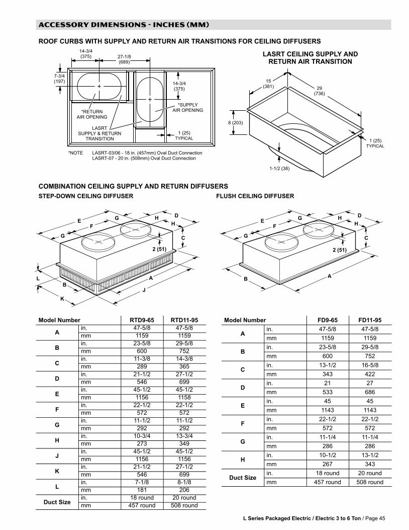
L Series Packaged Electric / Electric 3 to 6 Ton / Page 45
ACCESSORY DIMENSIONS − INCHES (MM)
ROOF CURBS WITH SUPPLY AND RETURN AIR TRANSITIONS FOR CEILING DIFFUSERS
1 (25)TYPICAL
LASRTSUPPLY & RETURN
TRANSITION
*SUPPLYAIR OPENING*RETURN
AIR OPENING
7-3/4(197) 14-3/4
(375)
27-1/8(689)
14-3/4(375)
*NOTE LASRT−03/06 − 18 in. (457mm) Oval Duct ConnectionLASRT−07 − 20 in. (508mm) Oval Duct Connection
29(736)
15(381)
8 (203)
LASRT CEILING SUPPLY ANDRETURN AIR TRANSITION
1-1/2 (38)
1 (25)TYPICAL
COMBINATION CEILING SUPPLY AND RETURN DIFFUSERS
STEP-DOWN CEILING DIFFUSER FLUSH CEILING DIFFUSER
L A
J
C
HH
DG
G
FE
B
K
2 (51)
A
C
HH
DG
G
FE
B
2 (51)
Model Number RTD9−65 RTD11−95
Ain. 47−5/8 47−5/8
mm 1159 1159
Bin. 23−5/8 29−5/8
mm 600 752
Cin. 11−3/8 14−3/8
mm 289 365
Din. 21−1/2 27−1/2
mm 546 699
Ein. 45−1/2 45−1/2
mm 1156 1158
Fin. 22−1/2 22−1/2
mm 572 572
Gin. 11−1/2 11−1/2
mm 292 292
Hin. 10−3/4 13−3/4
mm 273 349
Jin. 45−1/2 45−1/2
mm 1156 1156
Kin. 21−1/2 27−1/2
mm 546 699
Lin. 7−1/8 8−1/8
mm 181 206
Duct Sizein. 18 round 20 round
mm 457 round 508 round
Model Number FD9−65 FD11−95
Ain. 47−5/8 47−5/8
mm 1159 1159
Bin. 23−5/8 29−5/8
mm 600 752
Cin. 13−1/2 16−5/8
mm 343 422
Din. 21 27
mm 533 686
Ein. 45 45
mm 1143 1143
Fin. 22−1/2 22−1/2
mm 572 572
Gin. 11−1/4 11−1/4
mm 286 286
Hin. 10−1/2 13−1/2
mm 267 343
Duct Sizein. 18 round 20 round
mm 457 round 508 round

GUIDE SPECIFICATIONS
L Series Packaged Electric / Electric 3 to 6 Ton / Page 46
This specification is for [Lennox Industries L Series®] rooftop units. Revise specification section number andtitle below to suit project requirements, specification practices and section content. Refer to CSI MasterFormat�for other section numbers and titles.
Optional text and text that requires a decision are indicated by bold brackets [ ] and proprietary information isindicated by bold italic brackets[ ]; delete text that is not needed in final copy of specification. Specifier Notestypically precede specification text; delete notes in final copy of specification. Trade/brand names with appropriatesymbols typically are used in Specifier Notes; symbols are not used in specification text. Metric conversion, whereused, is soft metric conversion.
Specifying Engineer Please Note − These Guide Specifications cover all L Series units (3 thru 30 tons).Please edit to accurately identify the options selected for the job.
SECTION 23 74 33 UNITARY AIR CONDITIONING EQUIPMENT
PART 1 GENERAL
PART 1.01 SUMMARY
A. Section Includes: Packaged rooftop units and commercial packaged, gas/electric and electric/electric heat pumps.
Specifier Note: Revise paragraph below to suit project requirements. Add section numbers and titles per CSI MasterFormatand specifier’s practice.
B. Related Sections:
Specifier Note: Article below may be omitted when specifying manufacturer’s proprietary products and recommendedinstallation. Retain Reference Article when specifying products and installation by an industry reference standard. Ifretained, list standard(s) referenced in this section. Indicate issuing authority name, acronym, standard designation andtitle. Establish policy for indicating edition date of standard referenced. Conditions of the Contract or Division 1 ReferencesSection may establish the edition date of standards. This article does not require compliance with standard, but is merely alisting of references used. Article below should list only those industry standards referenced in this section. Retain onlythose reference standards to be used within the text of this Section. Add and delete as required for specific project.
PART 1.02 REFERENCES
A. American National Standards Institute (ANSI):
1. ANSI/ASHRAE 15 Safety Standard for Refrigeration Systems.
2. ANSI/ASHRAE/IESNA 90.1 Energy Efficient Design of New Buildings Except Low−Rise Residential Buildings.
3. ANSI Z21.47 Gas−Fired Central Furnaces.
B. Air−Conditioning and Refrigeration Institute (ARI):
1. ARI 210/240 Unitary Air−Conditioning and Air−Source Heat Pump Equipment.
2. ARI 270 Sound Rating of Outdoor Unitary Equipment.
3. ARI 340/360 Commercial and Industrial Unitary Air−Conditioning and Heat Pump Equipment.
4. ARI 370 Sound Rating of Large Outdoor Refrigerating and Air Conditioning Equipment.
C. American Society of Heating, Refrigerating, and Air−Conditioning Engineers, Inc. (ASHRAE):
1. ASHRAE 52.2 Method of Testing General Ventilation Air−Cleaning Devices for Removal Efficiency by Particle Size(ANSI approved).
2. ASHRAE 62.1 Ventilation for Acceptable Indoor Air Quality.
D. U.S. Energy Policy Act of 1992 (EPACT).
E. U.S. National Appliance Energy Conservation Act (NAECA):
1. NAECA 1988.
F. National Fire Protection Association (NFPA):
1. NFPA 90A Installation of Air Conditioning and Ventilation Systems.
G. Underwriters Laboratories, Inc. (UL):
1. UL 1995 Standard for Safety for Heating and Cooling Equipment.

GUIDE SPECIFICATIONS
L Series Packaged Electric / Electric 3 to 6 Ton / Page 47
Specifier Note: Article below should be restricted to statements describing design or performance requirements andfunctional (not dimensional) tolerances of a complete system. Limit descriptions to composite and operational propertiesrequired to link components of a system together and to interface with other systems.
PART 1.03 SYSTEM DESCRIPTION
A. Design Requirements: Provide products and systems that have been manufactured, fabricated and installed to followingcriteria:
1. ANSI/ASHRAE/IESNA 90.1.
2. ANSI Z21.47.
3. UL 1995.
B. Performance Requirements:
1. Packaged Gas Electric:
a. Natural Gas Supply Pressure: 7 in. w.c. (1.7 kPa).
Specifier Note: For belt drive blowers from models LGC036S, LGA036H, LGC042S, LGA042H, LGC048S, LGA048H,LGC060S, LGA060H, LGC072S, LGA072H, LGC090S, LGA090H, LGC102S, LGA102H, LGC120S, LGA120H, LGC150S,LGC156H, LGC180S, LGC180H, LGC210S, LGC210H, LGC240S, LGA240H, LGA248H, LGC300S, LGC300H and LGC360Hsingle phase is not an option.
b. LPG/Propane Supply Pressure: 11 in. w.c. (2.7 kPa).
Specifier Note: Specify 208/230V or 460V or 575V, 3−phase for L Series units from 6 − 30 ton (21.1 − 105.6 kW). Specify208/230V, 1−phase, 208/230V, 460V or 575V, 3−phase for L Series units from 3 − 5 ton (10.6 − 17.6 kW).
2. Packaged Cooling:
Specifier Note: For belt drive blowers from models LCC036S, LCA036H, LCC042S, LCA042H, LCC048S, LCA048H, LCC060S,LCA060H, LCC072S, LCA072H, LCC090S, LCA090H, LCC102S, LCA102H, LCC120S, LCA120H, LCC150S, LCC156H,LCC180S, LCC180H, LCC210S, LCC210H, LCC240S, LCA240H, LCA248H, LCC300S, LCC300H and LCC360H single phase isnot an option.
b. Electrical Requirements for Belt Drive Blowers: 60 hz, [208/230 V, 3−phase] [460 V, 3−phase] [575 V,3−phase].
Specifier Note: Available Heat Pump units include LHA090, LHA102, LHA120, LHA150, LHA180 and LHA240 only.
3. Packaged Heat Pumps:
a. Electrical Requirements: 60 hz, [208/230 V, 3−phase] [460 V, 3−phase] [575 V, 3−phase].
4. ARI Rated Net Cooling Efficiency: To meet or exceed ASHRAE Standard 90.1 at rated airflow not less than 350cfm/ton.
Specifier Note: Article below includes submittal of relevant data to be furnished by Contractor before, during or afterconstruction. Coordinate this article with Architect’s and Contractor’s duties and responsibilities in Conditions of theContract and Division 1 Submittal Procedures Section.
PART 1.04 SUBMITTALS
A. General: Submit listed submittals in accordance with Conditions of the Contract and Division 1 Submittal Procedures.
B. Product Data: Submit product data for specified products.
C. Shop Drawings:
1. Submit shop drawings in accordance with Section 01 33 23 − Submittal Procedures.
2. Indicate:
a. Equipment, piping and connections, together with valves, strainers, control assemblies, thermostatic controls,auxiliaries and hardware, and recommended ancillaries which are mounted, wired and piped ready for finalconnection to building system, its size and recommended bypass connections.
b. Piping, valves and fittings shipped loose showing final location in assembly.
c. Control equipment shipped loose, showing final location in assembly.
d. Dimensions, internal and external construction details, recommended method of installation with proposedstructural steel support, mounting curb details, sizes and location of mounting bolt holes; include massdistribution drawings showing point loads.
e. Detailed composite wiring diagrams for control systems showing factory installed wiring and equipment onpackaged equipment or required for controlling devices or ancillaries, accessories and controllers.

GUIDE SPECIFICATIONS
L Series Packaged Electric / Electric 3 to 6 Ton / Page 48
f. Details of vibration isolation.
g. Estimate of sound levels to be expected across individual octave bands in dB.
h. Type of refrigerant used.
D. Quality Assurance:
1. Test Reports: Certified test reports showing compliance with specified performance characteristics and physicalproperties.
2. Certificates: Product certificates signed by manufacturer certifying materials comply with specified performancecharacteristics and criteria and physical requirements.
3. Manufacturer’s Instructions: Manufacturer’s installation instructions.
Specifier Note: Coordinate paragraph below with Part 3 Field Quality Requirements Article herein. Retain or delete asapplicable.
E. Manufacturer’s Field Reports: Manufacturer’s field reports specified.
F. Closeout Submittals: Submit the following:
1. Warranty: Warranty documents specified.
2. Operation and Maintenance Data: Operation and maintenance data for installed products in accordance withDivision 1 Closeout Submittals (Maintenance Data and Operation Data) Section. Include methods for maintaininginstalled products and precautions against cleaning materials and methods detrimental to finishes and performance.Include names and addresses of spare part suppliers.
3. Provide brief description of unit, with details of function, operation, control and component service.
4. Commissioning Report: Submit commissioning reports, report forms and schematics in accordance withSection 01 91 00 − Commissioning.
PART 1.05 QUALITY ASSURANCE
A. Qualifications:
1. Installer experienced in performing work of this section who has specialized in installation of work similar to thatrequired for this project.
2. Manufacturer Qualifications: Manufacturer capable of providing field service representation during construction andapproving application method.
Specifier Note: Paragraph below should list obligations for compliance with specific code requirements particular to thissection. General statements to comply with a particular code are typically addressed in Conditions of the Contract andDivision 1 Regulatory Requirements Section. Repetitive statements should be avoided. Current data on building coderequirements and product compliance may be obtained from filter manufacturer technical support specialists.
B. Regulatory Requirements: Provide [Packaged gas electric] [Packaged cooling] [Packaged heat pump] that complieswith the following requirements:
1. ARI 210/240.
2. ARI 270.
3. ARI 340/360.
4. ASHRAE 52.2.
5. NFPA 90A.
C. Preinstallation Meetings: Conduct preinstallation meeting to verify project requirements, manufacturer’s installationinstructions and manufacturer’s warranty requirements. Comply with Division 1 Project Management and Coordination(Project Meetings).
PART 1.06 DELIVERY, STORAGE & HANDLING
A. General: Comply with Division 1 Product Requirements.
B. Ordering: Comply with manufacturer’s ordering instructions and lead time requirements to avoid construction delays.
C. Packing, Shipping, Handling and Delivery:
1. Deliver materials in manufacturer’s original, unopened, undamaged containers with identification labels intact.
2. Ship, handle and unload units according to manufacturer’s instructions.
D. Storage and Protection:
1. Store materials protected from exposure to harmful weather conditions.
2. Factory shipping covers to remain in place until installation.
PART 1.07 PROJECT CONDITIONS

GUIDE SPECIFICATIONS
L Series Packaged Electric / Electric 3 to 6 Ton / Page 49
A. Installation Location: [Confirm design conditions and temperature.].
Specifier Note: Coordinate article below with Conditions of the Contract and with Division 1 Closeout Submittals (Warranty).
PART 1.08 WARRANTY
A. Project Warranty: Refer to Conditions of the Contract for project warranty provisions.
B. Manufacturer’s Warranty: Submit, for Owner’s acceptance, manufacturer’s standard warranty document executed byauthorized company official. Manufacturer’s warranty is in addition to, and not a limitation of, other rights Owner may haveunder Contract Documents.
Specifier Note: Coordinate paragraph below with manufacturer’s warranty requirements.
C. Warranty: Commencing on Date of Installation.
1. Compressors: 5 years (limited).
2. Integrated Modular Control: 3 years (limited).
3. Other System Components: 1 year (limited).
4. Aluminized Heat Exchangers: 10 years (limited).
5. Stainless Steel Heat Exchangers: 15 years (limited).
PART 2 PRODUCTS
Specifier Note: Retain article below for proprietary method specification. Add product attributes, performancecharacteristics, material standards and descriptions as applicable. Use of such phrases as �or equal" or �or approvedequal" or similar phrases may cause ambiguity in specifications. Such phrases require verification (procedural, legal andregulatory) and assignment of responsibility for determining �or equal" products.
PART 2.01 ROOFTOP UNITS
A. Manufacturer: Lennox Industries Inc.
1. Contact: 2100 Lake Park Blvd., Richardson, TX 75080; Telephone: (800) 453−6669; website: www.lennox.com.
B. Proprietary Products/Systems: Lennox L Series Unitary Air Conditioning Equipment, including the following equipment:
1. Cabinet: Weatherproofing tested and certified to AGA [Rain test standards] and soundproofing tested to ARI 270,[_____] dbA at [______] m (______) ft. free field.
a. Heavy gauge steel panels and full perimeter heavy gauge galvanized steel base rails.
b. Raised edges around duct and power entry openings in bottom of unit.
c. Airflow Configuration: [Down−flow (vertical) return air] [Horizontal return airflow with Horizontal RoofMounting Frame] [And Horizontal Return Air Panel Kit (required when converting down−flowconfigured unit to horizontal airflow)].
d. Power Entry: Electrical [And gas] lines brought through unit base or through horizontal access knockouts.
e. Exterior Panels: Constructed of heavy gauge, galvanized steel with 2−layer enamel paint finish.
f. Insulation: All panels adjacent to conditioned air fully insulated with non−hygroscopic fiberglass insulation. Unitbase fully insulated.
g. Base Rail: Full perimeter base rail with rigging holes; 3 sides with fork slots.
h. Access Panels: Hinged for compressor/controls/heating areas, blower access and air filter/economizer access;and, sealed with quarter−turn latching handles and tight air and water seal.
2. Compressor:
a. Copeland scroll type, hermetically sealed.
3. Fans, General: Centrifugal, forward curved impellers, statically and dynamically balanced. [Multi] V−belt drive withadjustable variable pitch motor pulley.
a. Condenser Fan: Low sound operating, PVC coated fan guard, direct drive propeller type fans to dischargevertically.
b. Condenser Fan Motor: Permanently lubricated, permanent split capacitor; totally enclosed from weather, dustand corrosion; permanently lubricated ball bearings; resiliently mounted; overload protected.
4. Evaporator Coils: Pressure and leak tested to 500 psi (3445 kPa), nonferrous coils with enhanced aluminum finsmechanically bonded to durable copper tubes.
5. Condenser Coils:
a. Pressure and leak tested to 500 psi (3445 kPa), nonferrous coils with enhanced aluminum fins mechanicallybonded to durable copper tubes.

GUIDE SPECIFICATIONS
L Series Packaged Electric / Electric 3 to 6 Ton / Page 50
Specifier Note: Specify slab construction for L Series over 6 tons (21.1 kW), excluding heat pumps.
b. [Formed construction] [Slab construction].
6. Air Distribution:
a. Equipment capable of down−flow (vertical) or side (horizontal) handling of conditioned air.
b. Optional Equipment:
Specifier Note: The following kit is required for horizontal air handling for L Series 3 − 12 ton (10.6 − 42.2 kW) models.
1) Horizontal conversion kit for horizontal air handling.
Specifier Note: The following kit is required for horizontal air handling for L Series, 13 − 30 ton (45.8 − 105.6 kW) models.
2) Horizontal return air panel kit and horizontal roof mounting frame for horizontal air handling.
7. Filters: To meet NFPA 90A, air filter requirements [Type Class 1] [Type Class 2]; [______]% efficiency, metalframed, [Replaceable media] [Throwaway] [Standard to unit manufacturer].
a. Disposable 2 inch (51 mm).
b. Disposable 2 inch (51 mm) pleated MERV 11 rated.
c. Disposable 2 inch (51 mm) pleated MERV 15 rated.
8. Heat Exchanger: Removable for servicing; stainless steel optional for applications where mixed air temperaturebelow 45 degrees F (7 degrees C); E.T.L./C.S.A. design certified for outdoor installation.
9. Gas Heating System:
a. Tubular heat exchanger and inshot type gas burners constructed of aluminized steel.
b. Direct spark ignition; electronic flame sensor controls; flame rollout switch; limit controls and automaticredundant dual gas valve with staging control and combustion air proving switch on combustion air inducer.
Specifier Note: When LPG/propane is required, specify optional kit.
c. Able to use LPG/propane [With optional kit].
d. Complete service access provided for controls and wiring.
10. Electric Heating System:
a. Available for factory or field installation.
b. Heating elements of Nichrome bare wire exposed directly to airstream.
11. Refrigeration System:
a. Self−sealing, discharge, suction and liquid line service gauge ports, freeze−stats, expansion valves and fullrefrigerant charge.
Specifier Note: R−22 is available on all models with 3 − 30 ton (10.6 − 105.6 kW) capacities. R−410 is available on all highefficiency units and on the 6, 12.5 and 25 ton (21.1, 44 and 87.9 kW) standard efficiency models. Variable air volume withR−410a is available on 21, 25 and 30 ton (74, 88 and 105.6 kW) units.
b. [R22] [R−410a] [Variable air volume] [Variable air volume with R−410a].
c. Copper tubing not to touch sharp metal surfaces.
d. Compressor Circuits: Automatic reset, high pressure switch; automatic reset, low pressure switch; liquid linefilter−drier.
e. Capable of operating down to 0 degrees F (−17 degrees C) without installation of additional controls.
12. Supply Air Blower:
a. [Constant air volume with adjustable pulleys] [Variable air volume with fixed pulleys and variablefrequency drive] [Variable air volume with fixed pulleys and variable frequency drive with bypass] withmotor/drive combinations and optional drive kits.
b. Centrifugal supply air blower with [Permanently lubricated ball bearings and adjustable belt drive] [Sleevebearings and multi−speed direct drive motor].
c. Blower assembly [Slides out of unit] [Is accessible] for servicing.
Specifier Note: 3 to 6 ton ( 10.6 − 21.1 kW ) blower is fixed.
d. Blower wheel statically and dynamically balanced.

GUIDE SPECIFICATIONS
L Series Packaged Electric / Electric 3 to 6 Ton / Page 51
13. Integrated Modular Control (IMC):
a. Solid state control board to operate unit.
b. Built−in functions include: Blower on/off delay; built−in control parameter defaults; service relay output; dirty filterswitch input; dehumidistat input, economizer control; [Gas valve delay between stages]; [ETM compatible];[DDC compatible]; unit diagnosis; diagnostics code storage; indoor air quality input; low ambient controls;minimum run time; night setback mode; smoke alarm mode; low pressure control; thermostat bounce delay;3−digit display; degrees F or degrees C display, 2−stage heat/4−stage cool thermostat compatible and warm−upmode; [Electric heat staging with optional 4−stage board].
14. Gas Heating Controls:
a. Remote thermostat[s] as indicated.
b. Built−in [Un] fused disconnect switch.
c. [Four] stages of heating control from [Thermostat with optional four stage board] [DDC with roomsensor].
d. Supply fan to turn on [40] seconds after heating demand is received with 8 − 60 second adjustable time delay.
e. Supply fan to turn off [120] seconds after heating demand has ended with 80 − 300 second adjustable timedelay.
f. Adjustable delay time of [30] [Value between 30 − 160] seconds between low and high fire of 2−stage gasvalve system.
g. Heat off delay of [100] [Value between 30 − 300] seconds after thermostat heating demand has ended.
h. To turn off heat and keep supply air fan running if overheat limit occurs.
i. Adjustable maximum overheat limit trip count during heating cycle of [3] [Value between 1 − 15], with digitaloutput, limit indicator.
j. To report error with each occurrence of overheat limit trip and to identify limit that tripped. Error code stored innonvolatile memory.
k. To shut off gas heat if flame rollout occurs and to report error identifying rollout switch.
l. Maximum flame rollout switch trip count of [3] during heating cycle, with digital output, limit indicator. Maximumcount limit adjustable from 1 − 6 counts.
m. To turn off heat if induced airflow is too low and to report error identifying pressure switch.
n. Maximum induced airflow pressure switch trip count of [3] during heating cycle, with digital output, limitindicator. Maximum count limit adjustable from 1 − 6 counts.
o. Error reported if gas valve not energized 2 minutes after heating demand; gas valve identified.
p. Maximum ignition failure count of [3] with digital output, limit indicator. Maximum count limit adjustable from 1 −6 counts.
q. To shut off gas valve if flame not sensed. Error reported and stored in nonvolatile memory.
r. Delay between stages on gas valve.
s. To shut off unit if gas valve is energized with no demand for heat. Error reported and stored in nonvolatilememory.
15. Electric Heating Controls:
a. Panel board with [______] stage controller.
b. Remote thermostat[s] as indicated.
c. Built−in [Un] fused disconnect switch.
d. Supply Fan: Start before electric elements are energized and continue operating until bonnet temperaturereaches minimum setting. Include switch for continuous fan operation.
e. Two stages of heating control from [Thermostat] [DDC].
f. Supply fan to turn off [20] seconds after heating demand has ended. Time delay adjustable from 0 − 300seconds.
g. With delay time of [12] seconds between low and high heat stages. Time delay adjustable from 12 − 60seconds.
h. To turn off heat and keep supply air fan running if overheat limit occurs.
i. Adjustable maximum overheat limit trip count of [3] during heating cycle with digital output, limit indicator.Maximum count limit adjustable from 1 − 15 counts.
j. Error reported and identified if overheat limit tripped. Error code stored in nonvolatile memory.
16. Cooling Controls:
a. Provide [Smoke detectors in return] [Smoke detectors in supply].
GUIDE SPECIFICATIONS
L Series Packaged Electric / Electric 3 to 6 Ton / Page 52
Specifier Note: Specify b, c or d below.
b. [Manual] [Automatic] outside [And return] air dampers for fixed outside air quantity.
c. Remote controlled outside [And return] air dampers with damper operator and means for adjusting outside airquantity.
d. Motorized outside, return and [Automatic] [Power exhaust] [Gravity] relief dampers with spring returndamper operator and control package to automatically vary outside air quantity. Outside air and exhaust airdampers, normally closed.
e. Tight−fitting parallel blade dampers with neoprene or suitable gaskets, synthetic bushings and 1% maximumleakage.
f. Damper Operation: 24 V, spring return motor with gear train sealed in oil.
g. Mixed Air Controls: [Maintain 55 degrees F (13 degrees C)] [Indicated] mixed air temperature (adjustable).
h. Up to 2 stages of cooling from [Thermostat] [External DDC controller] without need for additional controls.
i. Up to 3 stages of cooling when used with relay and [3−stage thermostat] [DDC controller].
j. Up to 4 stages of cooling standard with room sensor.
Specifier Note: Specify article �j" when used with Lennox L Connection Network Building Automation System.
k. Up to 4 stages of cooling.
l. To allow blower on delay of up to 60 seconds after cooling demand is received. Default value of zero.
m. To allow blower off delay of up to 240 seconds after cooling demand has ended. Default value of zero.
n. Minimum compressor on time of [240] seconds on 3−phase units, adjustable between 60 − 510 seconds.
o. Minimum compressor off time of [300] seconds on single−phase units, adjustable from 60 − 510 seconds.
p. Default maximum high pressure switch trip occurrence during cooling or dehumidification cycle of [3]. Tripoccurrence limit adjustable from 1 − 8 occurrences. If maximum limit reached, compressor locked out anddigital output for service activated.
q. Default maximum low pressure switch trip occurrence during cooling or dehumidification cycle of [3]. Tripoccurrence limit adjustable from 1 − 8 occurrences. If maximum limit reached, compressor locked out anddigital output for service activated.
r. Low pressure trip read delay of [5] minutes if compressor off time has been less than 4 hours and outdoortemperature is less than 70 degrees F (21 degrees C). Delay adjustable from 0 − 34 minutes. Temperature setpoint adjustable from 10 degrees F (−12 degrees C) to 100 degrees F (38 degrees C). Compressor off timeadjustable from 1 − 6 hours.
s. Low pressure trip read delay of [15] minutes if compressor off time has been 4 hours or greater and outdoortemperature is less than 70 degrees F (21 degrees C). Delay adjustable from 0 − 34 minutes. Temperature setpoint adjustable from 10 degrees F (−12 degrees C) to 100 degrees F (38 degrees C). Compressor off timeadjustable from 1 − 6 hours.
t. Low pressure trip read delay of [2] minutes if compressor off time has been less than 4 hours and outdoortemperature is 70 degrees F (21 degrees C) or greater. Delay adjustable from 0 − 34 minutes.
u. Temperature set point adjustable from 10 degrees F (−12 degrees C) to 100 degrees F (38 degrees C).Compressor off time adjustable from 1 − 6 hours.
v. Low pressure trip read delay of [8] minutes if compressor off time has been 4 hours or greater and outdoortemperature is 70 degrees F (21 degrees C) or greater. Delay adjustable from 0 − 34 minutes.
w. Temperature set point adjustable from 10 degrees F (−12 degrees C) to 100 degrees F (38 degrees C).Compressor off time adjustable from 1 − 6 hours.
x. Each pressure switch trip occurrence (either high or low) to record error in nonvolatile memory and identifycompressor circuit.
y. Low outdoor air temperature compressor lockout set point of 0 degrees F (−18 degrees C) for each compressorcircuit. Low outdoor temperature limit set point individually adjustable for each compressor circuit from 80degrees F (27 degrees C) to −30 degrees F (−34 degrees C).
z. Maximum allowable evaporator freeze−stat trip occurrence of [3] during cooling demand with limit adjustablefrom 1 − 4 occurrences. Control to shut off compressor each time freeze−stat trip occurs and record error codein nonvolatile memory. If maximum limit reached, compressor locked out and digital output for serviceactivated.
aa. Condenser Fan Control:
1) On units with multiple condenser fans, [6] second time delay between condenser fan shutoff and restartto prevent reverse rotation of fan. Time delay adjustable between 0 − 16 seconds.
2) On units with 4 condenser fans, first stage low outdoor temperature set point of 55 degrees F (13 degreesC) that reduces airflow through condenser by turning off some fans. Set point adjustable between 60degrees F (16 degrees C) and 10 degrees F (−12 degrees C).

GUIDE SPECIFICATIONS
L Series Packaged Electric / Electric 3 to 6 Ton / Page 53
3) On units with 6 condenser fans, second stage low outdoor temperature set point of 40 degrees F (4degrees C) to reduce airflow through condenser by turning off all fans. Set point adjustable between 60degrees F (16 degrees C) and 10 degrees F (−12 degrees C).
4) On units with 6 condenser fans, condenser fan on delay of [2] seconds. Adjustable between 0 − 240seconds.
Specifier Note: Edit article below to suit project requirements. If substitutions are permitted, edit text below. Add text torefer to Division 1 Project Requirements (Product Substitutions Procedures) Section.
PART 2.02 PRODUCT SUBSTITUTIONS
A. Substitutions: No substitutions permitted.
PART 3 EXECUTION
PART 3.01 MANUFACTURER’S INSTRUCTIONS
Specifier Note: Article below is an addition to the CSI SectionFormat and a supplement to MANU−SPEC. Revise article belowto suit project requirements and specifier’s practice.
A. Compliance: Comply with manufacturer’s written data, including product technical bulletins, product catalog installationinstructions, and product carton installation instructions.
PART 3.02 EXAMINATION
A. Site Verification of Conditions: Verify substrate conditions, which have been previously installed under other sections, areacceptable for product installation in accordance with manufacturer’s instructions.
PART 3.03 INSTALLATION
A. Install [Packaged rooftop units] [And] [Commercial packaged, gas/electric and electric/electric heat pumps] inaccordance with manufacturer’s instructions, on roof curbs [Provided by manufacturer] [As indicated].
B. Run drain line from cooling coil condensation drain pan to discharge [Over roof drain].
PART 3.04 COMPLETION AND CLEANUP
A. Upon completion and verification of performance of installation, remove surplus materials, excess materials, rubbish, toolsand equipment.
END OF SECTION

L Series Packaged Electric / Electric 3 to 6 Tons / Page 54
APPLICATION GUIDE CONTROLS IMC
AFTERMARKET ZONING SYSTEM INTERFACE
Introduction
Lennox’ premium rooftop unit (RTU) controller, the Integrated Modular Controller (IMC), along with a variable frequency drive(VFD) option on certain RTUs, increases the ability of premium Lennox RTUs to be applied to a variety of zoning systems.The type of zoning system to be used dictates the type of RTU and the requirements for the zoning control system. Thefollowing explains each basic system and how the IMC must interface with an aftermarket zoning control system to meet therequirements of each application.
Lennox units in single zone and constant volume bypass applications may utilize an aftermarket unit controller assupervisory controller for the RTU. The IMC runs in thermostat mode and is primarily useful for diagnostic purposes, allowingthe aftermarket controller to directly monitor and control heat/cool staging, the bypass damper, zone dampers, etc. When theIMC is used in thermostat mode, a maximum of two stage heating and three stage cooling are available.
Supervisory control must be provided by the Lennox IMC to minimize complication and standardize control on LennoxVFD−controlled variable air volume (VAV) RTUs. In this configuration, the IMC controls the VFD based on static pressure inthe supply duct. It controls the economizer, and stages compressors based on discharge air temperature. The aftermarketcontroller simply sends calls for cooling or heating based on setpoint and schedule conditions. The IMC also has manyoptions for controlling single−stage, 50% power exhaust fans; two−stage, 100% power exhaust fans; or modulating powerexhaust fans.
NOTE − Please refer to the IMC Manual for additional details.
Interface Definition
With an aftermarket control system interface, the IMC requires four digital inputs to control the rooftop unit: G (blower enable),OCP (occupied), Y1 (enables discharge cooling), W1 (enables discharge heating) and Y2 (second stage call for cooling) andW2 (second stage call for heating) should be added in constant volume applications.
These configurations minimize the controls expertise required to create a viable interface. Further, they create a consistent,standardized approach conducive to support and trouble−shooting on a broad basis without the need for substantialknowledge of the IMC, VFD, bypass, or aftermarket controllers or systems.

L Series Packaged Electric / Electric 3 to 6 Ton / Page 55
APPLICATION GUIDE CONTROLS IMC
AFTERMARKET ZONING SYSTEM INTERFACE
Constant Volume Bypass RTU Wiring Summary for units equipped with M1−6 or higher (Aftermarket SupervisoryControl)
Heating Demand
Cooling Demand
Occupied Demand
Ventilation Demand
Common
TB1
24VAC
Cooling Demand
Heating Demand
1 − Global (Econ)2 − W13 − G456 − 24VAC7 − Common8 − 24 VAC9 − OCP10 − CO2 Sensor (−)1112 − Y213 − W21415 − CO2 Sensor (+)16 −Zone Sensor17 − Zone Sensor18 − Y119 − Service Output20 − RH Sensor21 − Remote Smoke Alarm2223 − Remote A4224 − Humiditrol (EMS digital option)25
1 Supply StaticPressure Sensor
1 Optional Building StaticPressure Switch or Sensor
1 Bypass Damper
AftermarketRTU Controller
1 See Aftermarket Controller InstallationInstructions for wiring information.
Variable Air Volume RTU Wiring Summary − for units equipped with M1−7 or higher (IMC Supervisory Control)
Heating Demand
Cooling Demand
Occupied Demand
Ventilation Demand
Common
TB1
24VAC
1 − Global (Econ)2 − W13 − G456 − 24VAC7 − Common8 − 24 VAC9 − OCP10 − CO2 Sensor (−)1112 − Y213 − W21415 − CO2 Sensor (+)16 −Zone Sensor17 − Zone Sensor18 − Y119 − Service Output20 − RH Sensor21 − Remote Smoke Alarm2223 − Remote A4224 − Humiditrol (EMS digital option)25
2 Optional Building StaticPressure Switch or Sensor
TB18
1 − S37 Bldg. Press Switch (stg. 1)2 − S39 Bldg. Press Switch (stg. 2)3 − Common4 − RLY−H (24VAC)5 − RLY−NO output to K2016 − A30 Supply Press. Sensor Input7 − A34 Bldg. Pres. Sensor Input8 − Optional AI9 − Optional AI10 − Analog ground11 − Analog output to Supply VFD (A96) or Bypass Damper (B9)12 − Analog output to Exhaust VFD (A137)
2 Supply StaticPressure Sensor
Variable Frequency Drive0−10V, 10V Full Speed
(or Bypass Damper 2−10V, 2Vfull open)
AftermarketRTU Controller
2 Requires 24VAC connection
FactoryWired

L Series Packaged Electric / Electric 3 to 6 Tons / Page 56
APPLICATION GUIDE CONTROLS IMC
AFTERMARKET ZONING SYSTEM INTERFACE
Sequence of OperationIMC Supervisory Control
Operation when IMC blower (G) input is energized
When a G signal is present, the IMC controls the VFD or bypass damper to hold a constant supply duct staticpressure based on the input from the IMC pressure sensor, using a PID control loop. For increased flexibility,the IMC has separate, adjustable static pressure setpoints for ventilation, cooling, heating and smokealarms. These set points reside in the memory of the IMC, have factory default settings, and may beadjusted in the field prior to start−up.
Operation when IMC occupied (OCP) input is energized
When an OCP signal is present, the IMC adjusts the fresh air damper to either a fixed minimum position orallows it to modulate based on a CO2 sensor. The CO2 sensor can be wired directly to the IMC, to anothercontroller that can monitor the sensor and pass a signal to the IMC for damper control, or to both the IMC andanother device for monitoring through the desired man−machine interface while the IMC maintains dampercontrol. During morning warm−up/cool−down the IMC keeps the fresh air damper closed based on the IMCconfiguration settings selected. The set points for minimum and maximum damper position setting and CO2
control reside in the memory of the IMC, have factory default settings, and may be adjusted at start up. Theycannot be adjusted using the aftermarket controls system.
Operation when IMC first stage cooling (Y1) input is energized
When a Y1 signal is present the IMC controls up to 4 stages of cooling (depending on RTU configuration) tomaintain a cooling discharge air temperature setpoint. These stages include mechanical cooling, or outdoorair for cooling with an economizer. The discharge air temperature setpoint resides in the IMC, has a factorydefault setting, and may be adjusted at start up. It cannot be adjusted using the aftermarket controls system.The IMC has advanced discharge−air cooling reset options selected at start up based on return airtemperature and/or outside air temperature. Outside air reset saves energy by gradually increasing thedischarge air set point as outside air temperature decreases. Return air reset reduces potential forovercooling if the zoning system is misapplied, has an abnormal condition, or a dominant zone. The resetgradually increases discharge air temperature as return air temperature decreases.NOTE − Y2 signal is recommended for constant volume applications.
Operation when IMC first stage heating (W1) input is energized
When a W1 signal is present, the IMC controls up to 4 stages of heating (depending on RTU configuration) tomaintain a heating discharge air temperature. The heating discharge air temperature set point resides in theIMC, has a factory default setting, and may be adjusted at start up. It cannot be adjusted using theaftermarket controls system. The IMC has advanced discharge air heating reset options based on return airtemperature and/or outside air temperature. Outside air reset saves energy by gradually decreasing thedischarge air set point as outside air temperature increases. Return air reset reduces the potential foroverheating if the zoning system is misapplied, has an abnormal condition, or a dominant zone. The resetgradually decreases discharge air temperature as return air temperature increases. NOTE − W2 signal is recommended for constant volume applications.
Power Exhaust Fan Operation
The IMC has many power exhaust fan control options that include single−stage, two−stage and modulatingcontrol, depending on how the unit is equipped. Stage control options can be triggered based on fresh airdamper positions, pressure switches, or a analog pressure sensor. Modulating control for units with VFDpowered exhaust fans are typically modulated to maintain return or building static pressure, but can bestaged. Set−points and operation settings for controlling power exhaust fans reside in the IMC, have factorydefault settings, and may be adjusted at start up. They cannot be adjusted using the aftermarket controlssystem.


REVISIONS
Sections Description of Change
All Removed all 2−5 ton Standard and High efficiency models with SEER less than 13. This eliminates alldirect drive models.
Options/Accessories Removed SectraAdd horizontal configuration to Outdoor Air DampersRemoved Manual Horizontal Outdoor Air Dampers (OAD3)
Sound Data New sound data
Electrical/Electric HeatData
All new data
Accessory Dimensions Added horizontal configuration for Outdoor Air DampersRemoved Manual Horizontal Outdoor Air Dampers (OAD3)New drawings for diffusers
Application Guide Updated section to reflect usage with M1−6 and higher versions

Visit us at www.lennox.com
For the latest technical information, www.lennoxcommercial.com
Contact us at 1−800−4−LENNOX
NOTE − Due to Lennox’ ongoing committment to quality, Specifications, Ratings and Dimensions subject to change without notice and without incurring liability.Improper installation, adjustment, alteration, service or maintenance can cause property damage or personal injury.Installation and service must be performed by a qualified installer and servicing agency. ©2008 Lennox Industries Inc.