Lightning and surge protection for rooftop photovoltaic systems
Upload
khangminh22Category
view
1download
0
P A C K A G E D G A S E L E C T R I C
LGHE-Series™ Rooftop Units
60 HZBulletin No. LGH-156-300 (10/2015)
13 to 25 TonsNet Cooling Capacity - 152,000 to 270,000 Btuh
Gas Input Heat Capacity - 169,000 to 480,000 BtuhMODEL NUMBER IDENTIFICATION
L G H 240 H 4 B S 1 YBrand/Family
L = E-Series™®
Unit Type G = Packaged Gas Heat w/ Electric Cooling
Major Design Sequence H = 1st Generation
Nominal Cooling Capacity - Tons 156 = 13 Tons 180= 15 Tons
210 = 17.5 Tons 240 = 20 Tons 300 = 25 Tons
Cooling Efficiency H = High Efficiency
S = Standard EfficiencyRefrigerant Type 4 = R-410A
Heating Type L = Low Gas Heat, 1 Stage S = Standard Gas Heat, 2 Stage M = Medium Gas Heat, 2 Stage H = High Gas Heat, 2 Stage
Minor Design Sequence 1 = 1st Revision 2 = 2nd Revision 3 = 3rd Revision
Voltage Y = 208/230V-3 phase-60hz G = 460V-3 phase-60hz J = 575V-3 phase-60hz
Blower Type B = Belt Drive, Constant Air Volume (CAV) M = Single Zone VAV Supply Fan
P R O D U C T S P E C I F I C AT I O N S
ASHRAE 90.1COMPLIANT

E-Series™ Packaged Gas / Electric 13 to 25 Ton / Page 2
FEATURES AND BENEFITS
E-Series™ rooftop units feature:
• Hinged Access Panels - Provide quick access to components and protect panels and roof from damage during servicing.
• Isolated Compressor Compartment - Allows performance check during normal compressor operation without disrupting airflow.
• Corrosion-Resistant Removable Drain Pan - End or bottom drain connection capability. Provides application flexibility, durability and improved serviceability.
• Thermostatic Expansion Valves - Provide peak cooling performance across the entire application range.• Scroll Compressors - Standard on all units for reliable, long-term operation.• Eco-last™ Coil System - Smaller, lighter condenser coil.• Dehumidification System - Patented system allows for independent control of temperature and humidity, providing
enhanced comfort control.• Constant Air Volume (CAV) Single Zone VAV Supply Fan Supply Air Blower Option - Allows constant or multi-
staged air delivery.• Auto-Tensioner for Blower Belt - Factory option ensures blower is delivering the proper airflow for comfort, while
maximizing efficiency and belt life.• MERV 13 Filters - Available as factory or field option, provide an enhanced level of indoor air quality, and can help
the building qualify for additional LEED credits.• Foil-Faced Insulation - Insulation on all internal surfaces that have contact with airflow helps minimize airborne
fibers and improve IAQ.• Common Components - Many maintenance items are standard throughout the entire product line, reducing the
need to carry different parts to the job or maintain in inventory.
Intelli-guide™ Control System Standard on every E-Series™ rooftop unit, the new Intelli-guide™ unit controller is the heart of the Allied controls offering. The intuitive user interface makes setup, troubleshooting and service easier than ever. Each unit tracks the runtime of every major component and records the date and time when service or maintenance is performed.
WireRight™ SystemThe WireRight™ system simplifies field sensor or thermostat installation through advanced connectors that are keyed and color-coded to help prevent miswiring. Not only is the wire coloring scheme standardized across all models, each connection is intuitively labeled to make troubleshooting and servicing quick and easy.
APPROVALSAHRI Certified to AHRI Standard 340/360-2007.ETL listed.Efficiency ratings are certified by CSA.Components are bonded for grounding to meet safety standards for servicing required by UL, ULC and National and Canadian Electrical Codes.All models are ASHRAE 90.1 compliant.Single Zone VAV models meet California Code of Regulations, Title 24 requirements for staged airflow.ISO 9001 Registered Manufacturing Quality System.
A
E-Series™ packaged rooftop unit product line was created to save energy with intelligence by offering some of the highest energy efficiency ratings available with a powerful, easy to use unit controller. This makes E-Series™ rooftop units perfect for business owners looking for an HVAC product with the lowest total cost of ownership. B
C
D
EF
G
H
I
K
J
N
O
PQ
L
M

E-Series™ Packaged Gas / Electric 13 to 25 Ton / Page 3
FEATURES AND BENEFITS
APPROVALSAHRI Certified to AHRI Standard 340/360-2007.ETL listed.Efficiency ratings are certified by CSA.Components are bonded for grounding to meet safety standards for servicing required by UL, ULC and National and Canadian Electrical Codes.All models are ASHRAE 90.1 compliant.Single Zone VAV models meet California Code of Regulations, Title 24 requirements for staged airflow.ISO 9001 Registered Manufacturing Quality System.
A
EnErgy Star® certified units are designed to use less energy, help save money on utility bills, and help protect the environment.The EnErgy Star® Partner of the Year Award signifies that Allied has made outstanding contributions to design energy efficient units that will lower energy bills, while meeting industry standards for comfort and indoor air quality.
WARRANTYLimited ten years aluminized heat exchanger, limited fifteen years optional stainless steel heat exchanger.Limited five years on compressors.Limited three years on the Eco-last™ Coil System.Limited three years on Intelli-guide™ Unit Controller.Limited five years Optional High Performance Economizers.Limited one year all other covered components.
HEATING SYSTEMAluminized steel inshot burners, direct spark ignition, electronic flame sensor, combustion air inducer, redundant automatic dual stage gas valve with manual shut-off.
Heat ExchangerTubular construction, aluminized steel, life cycle tested.Optional Stainless Steel Heat Exchanger is required if mixed air temperature is below 45°F.
Electronic Pilot IgnitionElectronic spark igniter provides positive direct ignition of burners on each operating cycle. The system permits main gas valve to stay open only when the burners are proven to be lit. Should a loss of flame occur, the gas valve closes, shutting off the gas to the burners. Ignition module has LED to indicate status and aid in troubleshooting.Ignition control is factory installed in the controls section.
Limit ControlsFactory installed, redundant limit controls with fixed temperature setting. Heat limit controls protect heat exchanger and other components from overheating.
Safety SwitchesFlame roll-out switch, flame sensor and combustion air inducer proving switch protect system operation.
Required Selections
Gas Input Choice - Order one:• Low Gas Heat, 1 Stage
(169,000 Btuh)• Standard Gas Heat, 2 Stage
(169,000/260,000 Btuh)• Medium Gas Heat, 2 Stage
(234,000/360,000 Btuh)• High Gas Heat, 2 Stage
(312,000/480,000 Btuh)
BCONTENTSBlower Data . . . . . . . . . . . . . . . . . . . . . . . . . . . . . . . . .32Dehumidification System Ratings . . . . . . . . . . . . . . . . . . . . . .29Dimensions - Accessories. . . . . . . . . . . . . . . . . . . . . . . . . .44Dimensions - Unit . . . . . . . . . . . . . . . . . . . . . . . . . . . . . .41Electrical Accessories. . . . . . . . . . . . . . . . . . . . . . . . . . . .37Electrical Data. . . . . . . . . . . . . . . . . . . . . . . . . . . . . . . .35Features And Benefits . . . . . . . . . . . . . . . . . . . . . . . . . . . 2High Altitude Derate . . . . . . . . . . . . . . . . . . . . . . . . . . . .23Intelli-Guide™ Control System . . . . . . . . . . . . . . . . . . . . . . . 8Model Number Identification . . . . . . . . . . . . . . . . . . . . . . . . 1Options / Accessories . . . . . . . . . . . . . . . . . . . . . . . . . . . .18Outdoor Sound Data . . . . . . . . . . . . . . . . . . . . . . . . . . . .39Ratings . . . . . . . . . . . . . . . . . . . . . . . . . . . . . . . . . . .24Sequence Of Operation - Single Zone Vav Supply Fan Models . . . . . .13Specifications . . . . . . . . . . . . . . . . . . . . . . . . . . . . . . . .21Specifications - Gas Heat . . . . . . . . . . . . . . . . . . . . . . . . . .23Unit Clearances . . . . . . . . . . . . . . . . . . . . . . . . . . . . . . .38Weight Data . . . . . . . . . . . . . . . . . . . . . . . . . . . . . . . . .40

E-Series™ Packaged Gas / Electric 13 to 25 Ton / Page 4
HEATING SYSTEM (continued)
Options/Accessories
Factory InstalledStainless Steel Heat ExchangerRequired if mixed air temperature is below 45°F.
Factory or Field InstalledBottom Gas Piping KitAllows bottom gas entry. Field installed only, may be factory enclosed to ship with unit.
Low Temperature Vestibule HeaterElectric heater automatically controls minimum temperature in gas burner compartment when temperature is below -40°F. CSA certified to allow operation of unit down to -60°F.
Field InstalledCombustion Air Intake ExtensionsRecommended for use with existing flue extension kits in areas where high snow areas can block intake air. Order two kits.
LPG/Propane KitsConversion kit to field change over units from Natural Gas to LPG/Propane. Order two kits.
Vertical Vent Extension KitUse to exhaust flue gases vertically above unit. Required when unit vent is too close to fresh air intakes per building codes. The vent kit also prevents ice formation on intake louvers. Order two kits.Kit contains vent transition, vent tee, drain cap and installation hardware.NOTE - Straight vent pipes (4 in. B-Vent) and caps are not furnished and must be field supplied. Refer to kit instructions for additional information.
COOLING SYSTEMDesigned to maximize sensible and latent cooling performance at design conditions.System can operate from 0°F to 125°F without any additional controls.
R-410A Refrigerant Non-chlorine based, ozone friendly, R-410A.
Scroll CompressorsScroll compressors on all models for high performance, reliability and quiet operation.Resiliently mounted on rubber grommets for quiet operation.
Compressor Crankcase HeatersProtects against refrigerant migration that can occur during low ambient operation.
Thermal Expansion ValvesAssures optimal performance throughout the application range.Removable element head.
Filter/DriersHigh capacity filter/drier protects the system from dirt and moisture.
High Pressure SwitchesProtects the compressors from overload conditions such as dirty condenser coils, blocked refrigerant flow, or loss of outdoor fan operation.
Low Pressure SwitchesProtects the compressors from low pressure conditions such as low refrigerant charge, or low/no airflow.
FreezestatsProtects the evaporator coil from damaging ice build-up due to conditions such as low/no airflow, or low refrigerant charge.
C
D
E
Eco-last™ Coil System Condenser coil features lightweight, all aluminum brazed fin construction.Constructed of three components: a flat extrusion tube, fins in-between the flat extrusion tubes and two refrigerant manifolds.Eco-last™ Coil System Features:• Improved heat transfer
performance due to high primary surface area (flat tubes) versus secondary surface (fins).
• Smaller internal volume (reduced refrigerant charge).
• High durability (all aluminum construction).
• Fewer brazed joints.• Compact design (reduces unit
weight).• Easy maintenance/cleaning.Face split design.Mounting brackets with rubber inserts secure coil to unit providing vibration dampening and corrosion protection.Angled design in cabinet helps protect coil from possible contact or hail damage.
Evaporator CoilCopper tube construction, enhanced rippled-edge aluminum fins, flared shoulder tubing connections, silver soldered construction for improved heat transfer. Factory leak tested. Cross row circuiting with rifled tubing optimizes both sensible and latent cooling capacity.
F
FEATURES AND BENEFITS

E-Series™ Packaged Gas / Electric 13 to 25 Ton / Page 5
COOLING SYSTEM (continued)Condensate Drain PanPlastic pan, sloped to meet drainage requirements per ASHRAE 62.1.Side or bottom drain connections.
Outdoor Coil Fan MotorsThermal overload protected, totally enclosed, permanently lubricated ball bearings, shaft up, wire basket mount.
Outdoor Coil FansPVC coated fan guard furnished.
Required Selections
Cooling CapacitySpecify nominal cooling capacity of the unit
Options/Accessories
Factory InstalledConventional Fin/Tube Condenser Coil (replaces Eco-last™ Coil System)Copper tube construction, enhanced rippled-edge aluminum fins, flared shoulder tubing connections, silver soldered construction.NOTE - Required if Dehumidification System is ordered.
Service ValvesFully serviceable brass valves installed in discharge & liquid lines.Not available for units equipped with Eco-last™ Coil System or Dehumidification option.
Factory or Field InstalledCondensate Drain TrapField installed only, may be factory enclosed to ship with unit.Available in copper or PVC.
Drain Pan Overflow SwitchMonitors condensate level in drain pan, shuts down unit if drain becomes clogged.
G
CABINETConstructionHeavy-gauge steel panels and full perimeter heavy-gauge galvanized steel base rail provides structural integrity for transportation, handling, and installation.Base rails have rigging holes.Three sides of the base rail have forklift slots.Raised edges around duct and power entry openings in the bottom of the unit provide additional protection against water entering the building.
Airflow ChoiceUnits are available in downflow (vertical) or horizontal return air flow configuration.Horizontal air flow requires Horizontal Roof Curb.Horizontal Return Air Panel Kit is also required if converting a downflow configured unit to horizontal air flow.
Power/Gas EntryElectrical and gas lines can be brought through the unit base or through horizontal access knock-outs
Exterior PanelsConstructed of heavy-gauge, galvanized steel with a two-layer enamel paint finish.
InsulationAll panels adjacent to conditioned air are fully insulated with non-hygroscopic fiberglass insulation.Unit base is fully insulated. The insulation also serves as an air seal to the roof curb, eliminating the need to add a seal during installation.
Hinged Access PanelsHinged tool-less access panels are provided for the filter section, the blower section and compressor/controls section.All hinged panels have seals and quarter-turn latching handles to provide a tight air and water seal.
H
I
Required Selections
Airflow ConfigurationSpecify downflow or horizontal.
Options/Accessories
Factory InstalledCorrosion ProtectionA completely flexible immersed coating with an electrodeposited dry film process. (AST ElectroFin E-Coat) Meets Mil Spec MIL-P-53084, ASTM B117 Standard Method Salt Spray Testing.Indoor Corrosion Protection: - Coated coil - Coated reheat coil - Painted blower housing - Painted indoor baseOutdoor Corrosion Protection: - Coated coil - Painted outdoor base
Field InstalledCombination Coil/Hail GuardsHeavy gauge steel frame painted to match cabinet with expanded metal mesh to protect the outdoor coil from damage.
Horizontal Return Air Panel KitRequired for horizontal applications with Horizontal Roof Curb, contains panel with return air opening for field replacement of existing unit panel and panel to cover bottom return air opening in unit, see dimension drawings.
FEATURES AND BENEFITS

E-Series™ Packaged Gas / Electric 13 to 25 Ton / Page 6
FEATURES AND BENEFITS
INDOOR AIR QUALITYAir FiltersDisposable 2-inch filters furnished as standard.
Options/Accessories
Factory or Field InstalledHealthy Climate® High Efficiency Air FiltersDisposable MERV 8 or MERV 13 (Minimum Efficiency Reporting Value based on ASHRAE 52.2) efficiency 2 inch pleated filters.
Healthy Climate® UVC Germicidal Light Kit
Germicidal lamps emit ultra-violet (UV-C) energy, which has been proven to be effective in reducing microbes such as viruses, bacteria, yeasts, and molds. This process either destroys the organism or controls its ability to reproduce.UV-C energy greatly reduces the growth and proliferation of mold and other bioaerosols (bacteria and viruses) on illuminated surfaces (particularly coil and drain pan).Lamps are field installed in the blower/evaporator coil section.All necessary hardware for installation is included.Lamps operate on 110/230V, 1 phase power supply. Step-down transformer must be field supplied when used with 460V and 575V rooftop units. Step-down transformer is furnished with lamps when factory installed.Approved by ETL.
Replacement Filter Media Kit With FrameReplaces existing pleated filter media. Includes washable metal mesh screen and metal frame with clip for holding replaceable non-pleated filter.
J
Field InstalledIndoor Air Quality (CO2) SensorsMonitors CO2 levels, reports to the Intelli-guide™ unit controller which adjusts economizer dampers as needed.
BLOWERA wide selection of supply air blower options are available to meet a variety of airflow requirements.
MotorOverload protected, equipped with ball bearings.Belt drive motors are offered on all models and are available in several different sizes to maximize air performance.
Motor EfficiencyAll blower motors 5 hp and above meet minimum energy efficiency standards in accordance with the Energy Independence and Security Act (EISA).of 2007.
Supply Air BlowerForward curved blades, double inlet, blower wheel is statically and dynamically balanced. Equipped with ball bearings and adjustable pulley (allows speed change).Blower assembly slides out of unit for servicing.Grease fittings furnished.
Required Selections
Select Constant Air Volume (CAV) or Single Zone VAV Supply Fan Blower OptionOn Constant Air volume (CAV) models, the supply air blower will provide a constant volume of air. On Single Zone VAV Supply Fan blower option models the supply air blower will stage the amount of airflow according to compressor stages, heating demand, ventilation demand or smoke alarm.
K
NOTE - Units with the VAV supply air blower option have the same face split indoor coils as units with the CAV supply air blower option. Part load airflow in cooling mode on VAV units should not be set below 220 cfm/nominal full load ton to reduce the risk of evaporator coil freeze-up.Utilizes a Variable Frequency Drive (VFD) to stage the supply air blower airflow. The VFD alters the frequency and voltage of the power supply to the blower to control blower speed.The amount of airflow for each stage can be set according to an ECTO parameter in the Intelli-guide unit controller. Unit is shipped from the factory with preset airflow. The VAV supply air blower option can be ordered with or without an Electronic Bypass Control. If equipped with the bypass control the VAV features manual (default) or automatic electronic bypass control of the VFD. In case of a VFD malfunction, a VFD alarm is generated by the Intelli-guide unit controller. The VFD can be manually bypassed to continue unit operation at full blower speed. Or the unit controller can be set to automatically switch to full blower speed if a VFD alarm is generated.The VFD has an operational range of -40 to 125° F outdoor air ambient temperature.Lower operating costs are obtained when the blower is operated on lower speeds.
Ordering InformationSpecify standard or high efficiency blower motor, motor horsepower and drive kit number when base unit is ordered, see Drive Kit Specifications Table.
Options/Accessories
Factory InstalledBlower Belt Auto-TensionerProvides proper tension to belt drive blower belt without the need for regular adjustments. Maintains airflow and proper performance.
L

E-Series™ Packaged Gas / Electric 13 to 25 Ton / Page 7
Factory or Field InstalledDisconnect SwitchAccessible from outside of unit, spring loaded weatherproof cover furnished.
GFI Service Outlets (2)115V ground fault circuit interrupter (GFCI) type, non-powered, field-wired or factory-wired and powered.
Field InstalledGFI Weatherproof CoverSingle-gang cover.Heavy-duty UV-resistant polycarbonate case construction.Hinged base cover with gasket.
M
ELECTRICALSmartWire™ SystemAdvanced wiring connectors are keyed and color-coded to prevent miswiring. Wire coloring scheme is standardized across all models. Each connection is intuitively labeled to make troubleshooting and servicing quick and easy.
Electrical PlugsPositive connection electrical plugs are used to connect common accessories or maintenance parts for easy removal or installation.
Required Selections
Voltage ChoiceSpecify when ordering base unit.
Options/Accessories
Factory InstalledCircuit BreakersHACR type. For overload and short circuit protection. Factory wired and mounted in the power entry panel. Current sensitive and temperature activated. Manual reset.
Phase/Voltage Detection (Optional for CAV Models Only)Phase detection monitors power supply to assure phase is correct at unit start-up. If phase is incorrect, the unit will not start and an alarm code is reported to the unit controller. Protects unit from being started with incorrect phasing which could lead to issues such as compressors running backwards.Voltage detection monitors power supply voltage to assure proper voltage. If voltage is not correct (over/under voltage conditions) the unit will not start and an alarm code is reported to the unit controller.NOTE - Phase/voltage detection is furnished when the Single Zone VAV Supply Fan option is ordered.
FEATURES AND BENEFITS

E-Series™ Packaged Gas / Electric 13 to 25 Ton / Page 8
DDC CompatibleDirty Filter Switch InputDischarge Air Temperature ControlDisplay/Sensor ReadoutEconomizer Control Options - See Economizer / Outdoor Air / Exhaust Options.Fresh Air TemperingExtensive Unit Diagnostics - Over 100 diagnostic and status messages in English.Exhaust Fan Control Modes - Fresh air damper position.Permanent Diagnostic Code StorageField Adjustable Control Parameters - Over 200 different control settings.Indoor Air Quality Input - Demand Control Ventilation readyLow Ambient Controls - Cooling operation down to 0°F.Gas Valve Time Delay Between First and Second StageMinimum Compressor Run TimeNetwork Capable - Can be daisy chained to other units or controls.Night Setback ModeReturn Air Temperature Limit ControlSafety Switch Input - Allows Controller to respond to a external safety switch trip.Service Relay OutputSmoke Alarm Mode - Four choices (unit off, positive pressure, negative pressure, purge).Staging - Up to 2 heat/2 cool (standard Intelli-Guide™ unit controller thermostat input). Up to 3 cool with additional relay. Up to 4 cool with room sensor or network operation.“Strike Three” ProtectionGas Reheat Control - Simultaneous heating and cooling operation for controlling humidity for process air applications such as supermarkets.
On Demand Dehumidification - Monitors and controls condenser hot gas reheat operation with dehumidification option.Thermostat Bounce DelayWarm Up Mode DelayLED IndicatorsPC Interface - Connect to the Intelli-Guide™ unit controller from a PC with the Unit Controller Software.Room Sensor Operation - Controls temperature.Controls Options
Factory or Field InstalledFresh Air TemperingUsed in applications with high outside air requirements. The Controller energizes the first stage heat as needed to maintain a minimum supply air temperature for comfort, regardless of the thermostat demand. When ordered as a factory option, the sensor ships with the unit but must be field installed.
Smoke DetectorPhotoelectric type, installed in supply air section, return air section or both sections. Available with power board and single sensor (supply or return) or power board and two sensors (supply and return). Power board located in unit control compartment.
Interoperability via BACnet® or LonTalk® ProtocolsCommunication compatible with third-party automation systems that support the BACnet Application Specific Controller device profile, LonMark® Space Comfort Controller functional profile, or LonMark Discharge Air Controller functional profile.
INTELLI-GUIDE™ UNIT CONTROLLER
The Intelli-Guide™ unit controller is a microprocessor-based controller that provides flexible control of all unit functions.
Features:LCD Display - Easy to read menu with buttons for menu navigation.during setup and diagnostics. 4 lines x 20 character display.Menu LEDs - Four LEDs (Data, Setup, Service, Settings) aid in menu navigation.Main Menu and Help Buttons - Quick navigation to home screen and built-in help functions.Scroll, Value Adjustment Select and Save ButtonsSimplified Setup Procedure - SETUP menu insures proper installation and setup of the rooftop unit.Profile Setup - Copy key settings between units with the same configuration greatly reducing setup time.USB Port - Allows a technician to download and transfer unit information to help verify service was performed. USB drive will also allow updating software on the Intelli-Guide™ Control System to obtain enhanced functionality without the need to change components.Unit Controller SoftwareUnit Self-Test - Unit Controller can perform a rooftop unit self-test to verify individual critical component and system performance. Included is an economizer test function that helps assure the economizer is operating correctly.Time Clock with Run-time Information
Built-In Functions Include:Adjustable Blower On/Off DelayBuilt-in Control Parameter DefaultsCompressor Time-Off Delay
N
INTELLI-GUIDE™ CONTROL SYSTEM
NOTE - Intelli-guide Control System features shown vary with the type of rooftop unit the control is installed in.NOTE - See separate Intelli-guide Control System Product Specifications Bulletin for additional information.

E-Series™ Packaged Gas / Electric 13 to 25 Ton / Page 9
OPTIONS / ACCESSORIES
INTELLI-GUIDE UNIT CONTROLLER (continued)
Controls Options (continued)
Commercial Control SystemsL Connection® Network Control SystemComplete building automation control system for single or multi-zone applications. Options include local interface, software for local or remote communication, and hardware for networking other control functions. See L Connection Network Control System Product Specifications Bulletin for details.
Aftermarket DDCNovar® ETM modules and options.
ThermostatsControl system and thermostat options. Aftermarket unit controller options.
Field InstalledHumidity Sensor KitHumidity sensor required with factory installed dehumidification option or Supermarket reheat field selectable option.
ECONOMIZER OPTIONSEconomizer operation is set and controlled by the Intelli-Guide Unit Controller.Simple plug-in connections from economizer to unit controller for easy installation.All rooftop units are equipped with factory installed CEC Title 24 approved sensors for outside, return and discharge air temperature monitoring.Optional sensors may be used instead of unit sensors to determine whether outdoor air is suitable for free cooling. See Options/Accessories table.
Factory or Field InstalledEconomizer (Standard and High Performance Common Features)Outdoor Air Hood with mist elimination filter is furnished.Outdoor Air Hood is included when economizer is factory installed and is furnished with economizer when ordered for field installation.
Standard Economizer Features (Not for Title 24)Parallel gear-driven action, return air and outdoor air dampers, plug-in connections to unit, nylon bearings, neoprene seals, 24-volt, fully-modulating spring return motor.NOTE: The Free Cooling default setting for outdoor air temperature sensor is 55°F.
High Performance Economizer FeaturesApproved for California Title 24 building standards.ASHRAE 90.1 compliant.Gear-driven action, high torque 24-volt fully-modulating spring return damper motor, return air and outdoor air dampers, plug-in connections to unit, stainless steel bearings, enhanced neoprene blade edge seals and flexible stainless steel jamb seals to minimize air leakage.NOTE - High Performance Economizers are not approved for use with enthalpy controls in Title 24 applications.
O Refer to Installation Instructions for complete setup information and menu parameters available.
Differential Sensible Control Factory setting. Uses outdoor air and return air sensors that are furnished with the unit. The Intelli-guide™ unit controller compares outdoor air and return air and using setpoints, enables the economizer when the outdoor air temperature is below the configured setpoint and cooler than return air.NOTE - Differential Sensible Control can be configured in the field to provide Offset Differential Sensible Control or Single Sensible Control.In Offset Differential Sensible Control mode, the economizer is enabled if the temperature differential (offset) between outdoor air and return air reaches the configured setpoint. In Single Sensible Control mode, the economizer is enabled when outdoor air temperature falls below the configured setpoint.
Global ControlThe unit controller communicates with a DDC system with one global sensor (enthalpy or sensible) to determine whether outside air is suitable for free cooling on all units connected to the control system. Sensor must be field provided.
Factory or Field InstalledSingle Enthalpy Temperature Control (Not for Title 24)Outdoor air enthalpy sensor enables Economizer if the outdoor enthalpy is less than the setpoint of the control.
Differential Enthalpy Control (Not for Title 24)Order two Single Enthalpy Controls. One is field installed in the return air section, the other in the outdoor air section. Allows the economizer control to select between outdoor air or return air, whichever has lower enthalpy.

E-Series™ Packaged Gas / Electric 13 to 25 Ton / Page 10
OPTIONS / ACCESSORIES
ECONOMIZER OPTIONS (continued)
Field InstalledOutdoor Air CFM ControlMaintains constant outdoor air volume levels on the supply air fan and varying unit airflows. Using information from a velocity sensor located in the rooftop unit outdoor air section, the unit controller changes the economizer position to help minimize the effect of supply fan speed changes on outdoor air volume levels. Setpoint for outdoor air volume is established by field testing.NOTE - Not available with Demand Control Ventilation (CO2 Sensor) or Building Pressure Control.
Field InstalledBuilding Pressure ControlMaintains constant building pressure level.Using information from a differential pressure between the outdoor air and the building air, the unit controller changes the economizer position to help maintain a constant building pressure.NOTE - Not available with Demand Control Ventilation (CO2 Sensor) or Outdoor Air CFM Control.
EXHAUST OPTIONS
Factory or Field InstalledDownflow Barometric Relief DampersAllow relief of excess air, aluminum blade dampers prevent blow back and outdoor air infiltration during off cycle, bird screen furnished.Hood for downflow barometric relief dampers is factory installed when dampers are factory installed with economizer. Hood is furnished with dampers when ordered for field installation.
Power Exhaust FansInstall internal to unit for downflow applications only with economizer option. Provides exhaust air pressure relief. Interlocked to run when supply air blower is operating, fans run when outdoor
P
Q
R
air dampers are 50% open (adjustable), motor is overload protected. Requires Economizer with Outdoor Air Hood and Downflow Barometric Relief Dampers. Dual fans are 20 in. diameter with 5 blades with (2) 1/3 hp motors.
NOTE - Single Zone VAV Supply Fan models are equipped with 2-stage power exhaust fans. Power exhaust operates in 1st stage (one fan) up to 70% of supply air blower speed. Both exhaust fans operate in 2nd stage when supply air blower speed is above 70% (adjustable) of full speed.
Field InstalledHorizontal Barometric Relief DampersFor use when unit is configured for horizontal applications requiring an economizer.Allows relief of excess air. Aluminum blade dampers prevent blow back and outdoor air infiltration during off cycle.Field installed in return air duct.Bird screen and hood furnished.
OUTDOOR AIR OPTIONS
Factory or Field InstalledOutdoor Air Damper - Downflow or Horizontal With Air HoodLinked mechanical dampers, 0 to 25% (fixed) outdoor air adjustable, installs in unit. Includes outdoor air hood.Automatic model features fully modulating spring return damper motor with plug-in connection.Manual model features parallel blade, gear-driven dampers with adjustable fixed position
ROOF CURBSNailer strip furnished, mates to unit, US National Roofing Contractors Approved, shipped knocked down.
DownflowHybrid Roof CurbsRoof curb can be assembled using interlocking tabs to fasten corners together. No tools required.
Curb can also be fastened together with furnished hardware.Available in 8, 14, 18, and 24 inch heights.See Options/Accessories table.
Adjustable Pitch CurbFully adjustable pitch curbs (3/4 in. per foot in any direction) provide a level platform for rooftop units allowing flexible installations on roofs with uneven or sloped angles.Uses interlocking tabs to fasten corners together. No tools required.Hardware is furnished to connect upper curb with lower curb.Available in 14 inch height.
HorizontalConverts unit from downflow to horizontal (side) air flow, return air is on unit, supply air is on curb, see dimension drawings. Curbs for rooftop applications meet National Roofing Code requirements. Requires Horizontal Return Air Panel Kit.Available in 26, 30, 37 and 41 inch heights.Optional Insulation Kit is available to help prevent sweating.
Adaptor Curbs (not shown)Curbs are regionally sourced. Dimensions will vary based upon the source. Contact your local sales representative for a detailed cut sheet with applicable dimensions.
CEILING DIFFUSERSCeiling Diffusers (Flush or Step-Down)Aluminum grilles, large center grille, insulated diffuser box with flanges, hanging rings furnished, interior transition (even air flow), internally sealed (prevents recirculation), adapts to T-bar ceiling grids or plaster ceilings.
Transitions (Supply and Return)Used with diffusers, installs in roof curb, galvanized steel construction, flanges furnished for duct connection to diffusers, fully insulated.

E-Series™ Packaged Gas / Electric 13 to 25 Ton / Page 11
OPTIONS / ACCESSORIES
DEHUMIDIFICATION® SYSTEM
NOTE - Not available with Eco-last™ Coil System. Conventional Fin/Tube condenser coil must be ordered as a factory option.Factory installed option designed to control humidity.Provides dehumidification on demand using ASHRAE 90.1 recommended method for comfort conditioning humidity control.Unit comes equipped with one row reheat coil, solenoid valve and humidity controller.In addition to a thermostat or room sensor used for conventional operation, a humidity sensor is required and must be located in the occupied space. Remote Mounted Humidity Sensor Kit is required for field installation.The humidity sensor provides input to the Unit Controller which is used to control activation of the dehumidification operation.Reheat controls are located in the compressor control section of the unit for easy access.
BenefitsImproves indoor air quality.Helps prevents damage due to high humidity levels.Improves comfort levels by reducing space humidity levels.
OPERATIONNo Dehumidification DemandThe unit will operate conventionally whenever there is a demand for cooling or heating and no dehumidification demand.Free cooling is only permitted when there is no demand for dehumidification.
Dehumidification Demand OnlyThe Unit Controller is factory set at 60% relative humidity setpoint and can be adjusted at the Unit Controller or with optional Unit Controller Software.For L Connection® Network Control Panel (NCP) applications, the humidity setpoint can be adjusted at the NCP.Reheat operation will initiate on a dehumidification demand and does not require a cooling demand.The unit will operate in the dehumidification mode until the relative humidity of the conditioned space is below the setpoint.The reheat coil is sized to provide 68°F to 75°F supply air during reheat operation.
This reduces sensible cooling capacity and extends compressor run time to control humidity when the cooling load is low.A solenoid valve diverts hot gas from the compressor to the reheat coil.The cooled and dehumidified air from the evaporator is reheated as it passes through the reheat coil.The de-superheated and partially condensed refrigerant continues to the outdoor condenser coil where condensing is completed. The unit will continue to operate in this mode until the dehumidification demand is satisfied.See Sequence of Operation for additional information.
Dehumidification and Cooling Demand (Thermostat/Room Sensor Application)If both a dehumidification and a full cooling load demand occur, the system will operate in cooling until the cooling demand is satisfied. Then the system will energize the dehumidification mode.
Options/Accessories
Humidity Sensor KitRemote Mounted Humidity sensor required with factory installed Dehumidification Option or Supermarket reheat field selectable option.

E-Series™ Packaged Gas / Electric 13 to 25 Ton / Page 12
OPTIONS / ACCESSORIES
DEHUMIDIFICATION® SYSTEM (CONTINUED)
REFRIGERANT SCHEMATIC (156H, 180H and 210H MODELS ONLY)
3 3
2 1
CONDENSERCOIL
NOTE: Refrigerant circuits one and two operates when there is a first−stage thermostat demand.
2
32
2
1
1
MIXEDINDOOR/OUTDOOR
AIR
OUTDOORAIR
1
3
2
THERMALEXPANSIONVALVE
CHECKVALVE
REHEATVALVE
REFRIGERANTCIRCUIT 1
REFRIGERANTCIRCUIT 2
REFRIGERANTCIRCUIT 3
S
3
2
1
REFRIGERANT SCHEMATIC (240H and 300S MODELS ONLY)
3 1
4 2
CONDENSERCOIL
NOTE: Refrigerant circuits one and two operates when there is a first−stage thermostat demand.
2
3 42
2
1
1
MIXEDINDOOR/OUTDOOR
AIR
OUTDOORAIR
1
3
2
4
THERMALEXPANSIONVALVE
CHECKVALVE
REHEATVALVE
REFRIGERANTCIRCUIT 1
REFRIGERANTCIRCUIT 2REFRIGERANTCIRCUIT 3
REFRIGERANTCIRCUIT 4
S
3
4
2
1

E-Series™ Packaged Gas / Electric 13 to 25 Ton / Page 13
SEQUENCE OF OPERATION - SINGLE ZONE VAV SUPPLY FAN MODELS
Objective: Outline the unit functions as a result of room thermostat or zone sensor demands.Given: When economizer is present, it will function as an integral part of the unit cooling system. When not present, unit will function as if economizer is present but outdoor ambient is high and sensed as not suitable.
Unit With 2-Stage Thermostat (2 Cooling Stages, Y1, Y2) - 3 And 4 Compressors Models
SUPPLY AIR BLOWER SPEEDUnit has the following supply air blower speed settings:• Ventilation speed• Low cooling speed• High cooling speed• Heating speed• Smoke speed (Used only in smoke removal option - not discussed)
1 UNIT FEATURES AN ECONOMIZER AND OUTDOOR AIR IS SUITABLEY1 Demand: All compressors are off, supply air blower is on low cooling speed to minimize blower power consumption, economizer modulates (minimum to maximum open position) to maintain 55°F supply air temperature (default unit controller setting).Y2 Demand: All compressors are off, supply air blower is on high cooling speed providing higher cooling capacity, and economizer modulates to maintain 55°F supply air temperature.If economizer stays at maximum open for 3 minutes, 1st stage compressors (compressor 1 and 2) are energized while supply air blower stays on high cooling speed providing maximum cooling capacity.
1 Outdoor air suitability is determined by the energy state of outdoor ambient (enthalpy or sensible) and its ability to achieve the desired free cooling effects. Outdoor air suitability can also be determined by a third party controller and provided to the RTU via a network connection.
UNIT DOES NOT FEATURE AN ECONOMIZER OR OUTDOOR AIR IS NOT SUITABLEY1 Demand: 1st stage compressors operate and supply air blower operates at low cooling speed.Y2 Demand: All compressors operate and supply air blower operates at high cooling speed.
DEHUMIDIFICATION MODEIf a unit with Dehumidification Option receives a call for dehumidification, economizer free cooling is locked out.
Call For Dehumidification, No Y1, Y2 Demand: 1st stage compressors (1 & 2) operate, supply air blower operates at high cooling speed, and the reheat valves are energized.Y1 Demand With A Call For Dehumidification: All compressors operate, supply air blower operates at high cooling speed and the reheat valves are energized.Y2 Demand With A Call For Dehumidification: All compressors operate, supply air blower operates at high cooling speed, and the reheat valves are de-energized.

E-Series™ Packaged Gas / Electric 13 to 25 Ton / Page 14
SEQUENCE OF OPERATION - SINGLE ZONE VAV SUPPLY FAN MODELS
Unit With 3-Stage Thermostat (3 Cooling Stages, Y1, Y2, Y3) - 3 And 4 Compressors Models, Or Zone Sensor (4 Cooling Stages, Y1, Y2, Y3, Y4) - 3 Compressors Models
SUPPLY AIR BLOWER SPEEDUnit has following supply air blower speed setting:• Ventilation speed• Cooling speed 1 (low)• Cooling speed 2 (medium)• Cooling speed 3 (high)• Heating speed• Smoke speed (Used only in smoke removal option - not discussed)
1 UNIT FEATURES AN ECONOMIZER AND OUTDOOR AIR IS SUITABLE3 Compressor ModelsY1 Demand:All compressors are off, supply air blower is on cooling speed 1 to minimize blower power consumption, economizer modulates (minimum to maximum open position) to maintain 55°F supply air temperature (default unit controller setting).Y2 Demand:All compressors are off, supply air blower is on cooling speed 3 providing higher cooling capacity, economizer modulates (minimum to maximum open position) to maintain 55°F supply air temperature (default unit controller setting).If economizer stays at maximum open for 3 minutes then compressor 1 is energized while supply air blower stays on cooling speed 3. After compressor is energized the economizer stays at maximum open.Y3 Demand:Compressors 1 and 2 are energized while supply air blower stays on cooling speed 3. After compressors are energized the economizer stays at maximum.Y4 (Zone Sensor Only) Demand:All compressors are energized and supply air blower stays on cooling speed 3.4 Compressor ModelsY1 Demand:All compressors are off, supply air blower is on cooling speed 1 to minimize blower power consumption, economizer modulates (minimum to maximum open position) to maintain 55°F supply air temperature (default unit controller setting).Y2 Demand:All compressors are off, supply air blower is on cooling speed 3 providing higher cooling capacity, economizer modulates (minimum to maximum open position) to maintain 55°F supply air temperature (default unit controller setting). If economizer stays at maximum open for 3 minutes then compressors 1 and 2 are energized while supply air blower stays on cooling speed 3. After compressors are energized the economizer stays at maximum open.Y3 Demand: Compressors 1, 2 and 3 are energized and supply air blower stays on cooling speed 3.
1 Outdoor air suitability is determined by the energy state of outdoor ambient (enthalpy or sensible) and its ability to achieve the desired free cooling effects. Outdoor air suitability can also be determined by a third party controller and provided to the RTU via a network connection.

E-Series™ Packaged Gas / Electric 13 to 25 Ton / Page 15
SEQUENCE OF OPERATION - SINGLE ZONE VAV SUPPLY FAN MODELS
Unit With 3-Stage Thermostat (3 Cooling Stages, Y1, Y2, Y3) - 3 And 4 Compressors Models, Or Zone Sensor (4 Cooling Stages, Y1, Y2, Y3, Y4) - 3 Compressors Models (continued)
UNIT DOES NOT FEATURE AN ECONOMIZER OR OUTDOOR AIR IS NOT SUITABLE3 Compressor Units
Y1 Demand:Compressor 1 operates and supply air blower operates at cooling speed 1.Y2 Demand:Compressors 1 and 2 operate and supply air blower operates at cooling speed 2.Y3 or Y4 (Zone Sensor Only) Demand: All compressors operate and supply air blower operates at cooling speed 3.
4 Compressor UnitsY1 Demand:Compressors 1 and 2 operate and supply air blower operates at cooling speed 1.Y2 Demand:Compressors 1, 2, and 3 operate and supply air blower operates at cooling speed 2.Y3 Demand:All compressors operate and supply air blower operates at cooling speed 3.
DEHUMIDIFICATION MODEIf a unit with Dehumidification Option receives a call for dehumidification, economizer free cooling is locked out.
Call For Dehumidification, No Y1, Y2, Y3 Demand:Compressor 1 and 2 operate, supply air blower operates at cooling speed 3, and both reheat valves are energized.Y1 Demand With A Call For Dehumidification: All compressors operate, supply air blower operates at cooling speed 3 and both reheat valves are energized.Y2 Demand With A Call For Dehumidification: All compressors operate, supply air blower operates at cooling speed 3, and the reheat valve of refrigeration circuit 1 is energized while the reheat valve of refrigeration circuit 2 is de-energized.Y3 or Y4 (Zone Sensor Only) Demand: All compressors operate, supply air blower operates at cooling speed 3, and both reheat valves are de-energized.

E-Series™ Packaged Gas / Electric 13 to 25 Ton / Page 16
SEQUENCE OF OPERATION - SINGLE ZONE VAV SUPPLY FAN MODELS
Unit With Zone Sensor (4 Cooling Stages, Y1, Y2, Y3, Y4) – 4 Compressors Models
SUPPLY AIR BLOWER SPEEDUnit has following supply air blower speed setting:• Ventilation speed• Cooling speed 1 (low)• Cooling speed 2 (medium-low)• Cooling speed 3 (medium-high)• Cooling speed 4 (high)• Heating speed• Smoke speed (Used only in smoke removal option - not discussed)
1 UNIT FEATURES AN ECONOMIZER AND OUTDOOR AIR IS SUITABLEY1 Demand:All compressors are off, supply air blower is on cooling speed 1 to minimize blower power consumption, economizer modulates (minimum to maximum open position) to maintain 55°F supply air temperature (default unit controller setting).Y2 Demand:All compressors are off, supply air blower is on cooling speed 4 providing higher cooling capacity, and economizer modulates to maintain 55°F supply air temperature.If economizer stays at maximum open for 3 minutes, compressor 1 is energized while supply air blower stays on cooling speed 4. After compressor 1 is energized the economizer stays at maximum open.Y3 Demand:Compressor 1 and 2 are energized while supply air blower is on cooling speed 4 providing even higher cooling capacity.Y4 Demand:All compressors are energized while supply air blower is on cooling speed 4 providing maximum cooling capacity.
1 Outdoor air suitability is determined by the energy state of outdoor ambient (enthalpy or sensible) and its ability to achieve the desired free cooling effects. Outdoor air suitability can also be determined by a third party controller and provided to the RTU via a network connection.
Unit Does Not Feature An Economizer (Or Outdoor Air Is Not Suitable)Y1 demand:Compressor 1 operates and supply air blower operates at cooling speed 1.Y2 demand:Compressors 1 and 2 operate and supply air blower operates at cooling speed 2.Y3 demand:Compressors 1, 2, and 3 operate and supply air blower operates at cooling speed 3.Y4 demand:All compressors operate and supply air blower operates at cooling speed 4.

E-Series™ Packaged Gas / Electric 13 to 25 Ton / Page 17
SEQUENCE OF OPERATION - SINGLE ZONE VAV SUPPLY FAN MODELS
Unit With Zone Sensor (4 Cooling Stages, Y1, Y2, Y3, Y4) – 4 Compressors Models (continued)
DEHUMIDIFICATION MODEIf a unit with Dehumidification Option receives a call for dehumidification, economizer free cooling is locked out.
Call For Dehumidification, No Y1, Y2, Y3, Y4 Demand:Compressors 1 and 2 operate, supply air blower operates at cooling speed 4, and both reheat valves are energized.Y1 Demand With A Call For Dehumidification:Compressors 1, 2, and 3 operate, supply air blower operates at cooling speed 4 and both reheat valves are energized.Y2 Demand With A Call For Dehumidification:All compressors operate, supply air blower operates at cooling speed 4, and both reheat valves are energized.Y3 Demand With A Call For Dehumidification:All compressors operate, supply air blower operates at cooling speed 4, and the reheat valve of compressor 1 is energized while the reheat valve of compressor 2 is de-energized.Y4 Demand With A Call For Dehumidification:All compressors operate, supply air blower operates at cooling speed 4, and the reheat valves are de-energized.
Heating Mode
NOTE - HEATING MODE IS THE SAME FOR ALL CONTROL OPTIONS.W1 Demand:Gas valves are open (stage 1 on units with 2-stage gas valves) and supply air blower operates at heating speed.W2 Demand:Gas valves are open (stage 2 on units with 2-stage gas valves) and supply air blower operates at heating speed.
Modulating Outdoor Air DamperThe minimum damper position for “occupied low blower” and “occupied high blower” is adjusted during unit setup to provide minimum fresh air requirements per ASHRAE 62.1 at the corresponding supply air blower speeds.• When supply air blower is off or the unit is in unoccupied mode, the outdoor air damper is closed.• When unit is in occupied mode and supply air blower is operating at a speed below the “midpoint” blower
speed, the outdoor air damper is at minimum “low blower” position.• When unit is in occupied mode and supply air blower is operating at a speed equal to or above the “midpoint”
blower speed, the outdoor air damper is at minimum “high blower” position.
NOTE - The “midpoint” blower speed is an average of the minimum and maximum blower speed (minimum speed + maximum speed divided by 2).
Power Exhaust Operation
NOTE - POWER EXHAUST OPERATION IS THE SAME FOR ALL CONTROL OPTIONSSingle Zone VAV Supply Fan models are equipped with 2-stage power exhaust fans. Power exhaust fans operate when economizer outdoor air dampers are 50% open (adjustable). Power exhaust operates in 1st stage (one fan) up to 70% of supply air blower speed. 2nd stage power exhaust fans (both fans) operate when supply air blower speed is above 70% (adjustable) of full speed.

E-Series™ Packaged Gas / Electric 13 to 25 Ton / Page 18
OPTIONS / ACCESSORIES
Item Description Model Number
Catalog Number
Unit Model No156 180 210 240 300
COOLING SYSTEMCondensate Drain Trap PVC - C1TRAP20AD2 76W26 OX OX OX OX OX
Copper - C1TRAP10AD2 76W27 OX OX OX OX OXConventional Fin/Tube Condenser Coil (replaces Eco-last™ Coil System) Factory O O O O OCorrosion Protection Factory O O O O ODrain Pan Overflow Switch E1SNSR71AD1 68W88 OX OX OX OX OXEfficiency High O O O O
Standard ORefrigerant Type R-410A O O O O OService valves (not for Eco-last™ Coil System or Dehumidification equipped units) Factory O O O O OHEATING SYSTEMBottom Gas Piping Kit C1GPKT01C-1 85M31 OX OX OX OX OXCombustion Air Intake Extensions (order two) LTACAIK10/15 89L97 X X X X XGas Heat Input Low - 169,000 Btuh Factory O O O
Standard - 260,000 Btuh Factory O O O O OMedium - 360,000 Btuh Factory O O O O O
High - 480,000 Btuh Factory O O O OLow Temperature Vestibule Heater 208/230V-3ph - C1LTVH10C-2Y 13X66 OX OX OX OX OX
460V-3ph - C1LTVH10C-2G 13X67 OX OX OX OX OX575V-3ph - C1LTVH10C-2J 13X68 OX OX OX OX OX
LPG/Propane Conversion Kits (Order 2 kits)
Low Heat - C1PROP25C11 14N28 X X XStandard Heat - C1PROP25C11 14N28 X X X X X
Medium Heat - C1PROP26C11 14N29 X X X X XHigh Heat - C1PROP27C11 14N30 X X X X
Stainless Steel Heat Exchanger Factory O O O O OVertical Vent Extension Kit (Order two kits) C1EXTN2021 42W16 X X X X XBLOWER - SUPPLY AIRBlower Option CAV (Constant Air Volume) Factory O O O O O
Single Zone VAV Supply Fan blower option (With VFD Bypass Control) Factory O O O O OSingle Zone VAV Supply Fan blower option (Without VFD Bypass Control) Factory O O O O O
Motors - Constant Air Volume (CAV)
Belt Drive (standard or high efficiency) - 2 hp Factory OBelt Drive (standard or high efficiency) - 3 hp Factory O O O
Belt Drive (standard efficiency) - 5 hp Factory O O O O OBelt Drive (standard efficiency) - 7.5 hp Factory O O O OBelt Drive (standard efficiency) - 10 hp Factory O O
Motors - Single Zone VAV Supply Fan
Belt Drive (high efficiency) - 2 hp Factory OBelt Drive (standard or high efficiency) - 3 hp Factory O O O
Belt Drive (standard efficiency) - 5 hp Factory O O O O OBelt Drive (standard efficiency) - 7.5 hp Factory O O O OBelt Drive (standard efficiency) - 10 hp Factory O O
Drive KitsSee Blower Data Tables for usage and selection
Kit #1 535-725 rpm Factory O O OKit #2 710-965 rpm Factory O O OKit #3 685-856 rpm Factory O O O O O
Kit #4 850-1045 rpm Factory O O O O OKit #5 945-1185 rpm Factory O O O O OKit #6 850-1045 rpm Factory O O O OKit #7 945-1185 rpm Factory O O O O
Kit #8 1045-1285 rpm Factory O O O OKit #10 1045-1285 rpm Factory O OKit #11 1135-1365 rpm Factory O O
Blower Belt Auto-Tensioner Factory O O O O ONOTE - Catalog and model numbers shown are for ordering field installed accessories.OX - Configure To Order (Factory Installed) or Field InstalledO = Configure To Order (Factory Installed)X = Field Installed

E-Series™ Packaged Gas / Electric 13 to 25 Ton / Page 19
OPTIONS / ACCESSORIES
Item Description Model Number
Catalog Number
Unit Model No156 180 210 240 300
CONTROLSBlower Proving Switch C1SNSR35FF1 53W65 OX OX OX OX OXCommercial Controls L Connection® Building Automation System - - - X X X X X
Intelli-guide™ System - BACnet® Module - C0CTRL60AE1L 59W51 OX OX OX OX OXIntelli-guide™ System - LonTalk® Module - C0CTRL65FF1 54W27 OX OX OX OX OX
Novar® ETM-2051 - E0CTRLO30C1 64W74 OX OX OX OX OXNovar® LSE Factory O O O O O
Dirty Filter Switch E1SNSR55C-1 53W68 OX OX OX OX OXFresh Air Tempering C1SNSR75AD1 58W63 OX OX OX OX OXSmoke Detector - Supply or Return (Power board and one sensor) C1SNSR44C-1 83W40 OX OX OX OX OXSmoke Detector - Supply and Return (Power board and two sensors) C1SNSR43C-1 83W41 OX OX OX OX OXINDOOR AIR QUALITYAir FiltersHealthy Climate® High Efficiency Air Filters 24 x 24 x 2 (Order 6 per unit)
MERV 8 - C1FLTR15C-1- 54W67 OX OX OX OX OXMERV 13 - C1FLTR40C-1- 52W40 OX OX OX OX OX
Replacement Media Filter With Metal Mesh Frame (includes non-pleated filter media)
C1FLTR30C-1- 44N61 OX OX OX OX OX
Indoor Air Quality (CO2) SensorsSensor - Wall-mount, off-white plastic cover with LCD display C0SNSR50AE1L 77N39 X X X X XSensor - Wall-mount, off-white plastic cover, no display C0SNSR52AE1L 87N53 X X X X XSensor - Black plastic case with LCD display, rated for plenum mounting C0SNSR51AE1L 87N52 X X X X XSensor - Wall-mount, black plastic case, no display, rated for plenum mounting
C0MISC19AE1 87N54 X X X X X
CO2 Sensor Duct Mounting Kit - for downflow applications C0MISC19AE1- 85L43 X X X X XAspiration Box - for duct mounting non-plenum rated CO2 sensors (87N53 or 77N39)
C0MISC16AE1- 90N43 X X X X X
UVC Germicidal Light Kit1 Healthy Climate® UVC Light Kit (110/230v-1ph) 54W65 OX OX OX OX OXELECTRICALVoltage 60 hz 208/230V - 3 phase Factory O O O O O
460V - 3 phase Factory O O O O O575V - 3 phase Factory O O O O O
HACR Circuit Breakers Factory O O O O ODisconnect Switch (see Disconnect Table for usage, page 37)
80 amp - E1DISC080C-1 54W88 OX OX OX OX OX150 amp - E1DISC150C-1 54W89 OX OX OX OX OX
GFI Service Outlets
15 amp non-powered, field-wired (208/230V, 460V, 575V) LTAGFIK10/15 74M70 OX OX OX OX OX15 amp factory-wired and powered (208/230V, 460V, 575V) Factory O O O O O
20 amp non-powered, field-wired (575V only) C1GFCI20FF1 67E01 OX OX OX OX OXWeatherproof Cover for GFI C1GFCI99FF1 10C89 X X X X XPhase/Voltage Detection Factory O O O O OECONOMIZERStandard Economizer (Not for Title 24)Standard Economizer Downflow or Horizontal Applications - Includes Outdoor Air Hood. Order Downflow or Horizontal Barometric Relief Dampers separately.
E1ECON15C-2 13U47 OX OX OX OX OX
High Performance Economizer (Approved for California Title 24 Building Standards)High Performance Economizer Downflow or Horizontal Applications - Includes Outdoor Air Hood. Order Downflow or Horizontal Barometric Relief Dampers separately.
E1ECON17C-1 10U60 OX OX OX OX OX
Economizer ControlsDifferential Enthalpy (Not for Title 24) Order 2 - C1SNSR64FF1 53W64 OX OX OX OX OXSensible Control Sensor is Furnished Factory O O O O OSingle Enthalpy (Not for Title 24) C1SNSR64FF1 53W64 OX OX OX OX OXGlobal Control Sensor Field Provided Factory O O O O OBuilding Pressure Control E1GPBK10C1 13J77 X X X X XOutdoor Air CFM Control E1GPBK20C1 13J76 X X X X XBarometric Relief Dampers With Exhaust HoodDownflow Barometric Relief Dampers C1DAMP50C 54W78 OX OX OX OX OXHorizontal Barometric Relief Dampers LAGEDH18/24 16K99 X X X X X1 Lamps operate on 110-230V single-phase power supply. Step-down transformer must be field supplied for field installation in 460V and 575V rooftop units (transformer
is furnished for factory installed light kits). Alternately, a separate 110V power supply may be used to directly power the UVC ballast(s).
NOTE - Catalog and model numbers shown are for ordering field installed accessories.OX - Configure To Order (Factory Installed) or Field InstalledO = Configure To Order (Factory Installed)X = Field Installed

E-Series™ Packaged Gas / Electric 13 to 25 Ton / Page 20
OPTIONS / ACCESSORIES
Item Description Model Number
Catalog Number
Unit Model No156 180 210 240 300
OUTDOOR AIR
Outdoor Air Dampers With Outdoor Air HoodMotorized E1DAMP20C-1 54W74 OX OX OX OX OXManual C1DAMP10C-1 54W76 OX OX OX OX OXPOWER EXHAUST
Standard Static 208/230V - C1PWRE11C-1Y 75W90 OX OX OX OX OX460V - C1PWRE11C-1G 75W91 OX OX OX OX OX575V - C1PWRE11C-1J 75W92 OX OX OX OX OX
CONDENSER REHEAT OPTION
Dehumification Option Factory O O O O OHumidity Sensor Kit, Remote mounted (required) C0SNSR31AE-1 17M50 X X X X XCABINET
Combination Coil/Hail Guards
Conventional Fin/Tube Condenser Coil - C1GARD51C11 13T08 XConventional Fin/Tube Condenser Coil - C1GARD51C21 13T12 X X X X
Eco-last Coil System - C1GARD52C11 13T14 X Eco-last Coil System - C1GARD52C21 13T13 X X X X
ROOF CURBS
Hybrid Roof Curbs, Downflow8 in. height C1CURB70C-1 11F58 X X X X X14 in. height C1CURB71C-1 11F59 X X X X X18 in. height C1CURB72C-1 11F60 X X X X X24 in. height C1CURB73C-1 11F61 X X X X XAdjustable Pitch Curb14 in. height L1CURB55C 43W26 X X X X XStandard Roof Curbs, Horizontal - Requires Horizontal Return Air Panel Kit26 in. height - slab applications C1CURB14C-1 11T89 X X X X37 in. height - rooftop applications C1CURB15C-1 11T90 X X X X30 in. height - slab applications C1CURB16C-1 11T96 X41 in. height - rooftop applications C1CURB17C-1 11T97 XInsulation Kit For Standard Horizontal Roof Curbsfor C1CURB14C-1 C1INSU11C-1- 73K32 X X X Xfor C1CURB15C-1 C1INSU13C-1- 73K34 X X X Xfor C1CURB16C-1 C1INSU12C-1- 73K33 Xfor C1CURB17C-1 C1INSU14C-1- 73K35 XHorizontal Return Air Panel KitRequired for Horizontal Applications with Roof Curb C1HRAP10C-1- 87M00 X X X X XCEILING DIFFUSERS
Step-Down - Order one RTD11-185 29G06 X XRTD11-275-R 29G07 X X X
Flush - Order one FD11-185 29G10 X XFD11-275-R 29G11 X X X
Transitions (Supply and Return) - Order one C1DIFF33C-1 12X68 X XC1DIFF34C-1 12X70 X X X
NOTE - Catalog and model numbers shown are for ordering field installed accessories.OX - Configure To Order (Factory Installed) or Field InstalledO = Configure To Order (Factory Installed)X = Field Installed

E-Series™ Packaged Gas / Electric 13 to 25 Ton / Page 21
SPECIFICATIONSGeneral Data Nominal Tonnage 13 Ton 13 Ton 15 Ton 15 Ton 17.5 Ton
Model Number LGH156H4B LGH156H4M LGH180H4B LGH180H4M LGH210H4BEfficiency Type High High High High High
Blower Type Constant Air Volume CAV
Single Zone VAV Supply
Fan
Constant Air Volume CAV
Single Zone VAV Supply
Fan
Constant Air Volume CAV
Cooling Performance
Gross Cooling Capacity - Btuh 156,000 156,000 176,000 176,000 204,0001 Net Cooling Capacity - Btuh 152,000 152,000 172,000 172,000 198,000
AHRI Rated Air Flow - cfm 5200 5200 5250 5250 6125Total Unit Power - kW 12.7 12.7 14.3 14.3 16.5
1 EER (Btuh/Watt) 12.0 12.0 12.0 12.0 12.02 IEER (Btuh/Watt) 13.6 14.1 13.5 13.7 13.0
Refrigerant Type R-410A R-410A R-410A R-410A R-410ARefrigerant Charge
Eco-last™ Coil System Circuit 1 5 lbs. 12 oz. 5 lbs. 12 oz. 6 lbs. 0 oz. 6 lbs. 0 oz. 6 lbs. 12 oz.Circuit 2 5 lbs. 6 oz. 5 lbs. 6 oz. 5 lbs. 10 oz. 5 lbs. 10 oz. 6 lbs. 14 oz.Circuit 3 5 lbs. 10 oz. 5 lbs. 10 oz. 5 lbs. 14 oz. 5 lbs. 14 oz. 6 lbs. 14 oz.
Conventional Fin/Tube Coil Option
Circuit 1 9 lbs. 8 oz. 9 lbs. 8 oz. 12 lbs. 8 oz. 12 lbs. 8 oz. 13 lbs. 0 oz.Circuit 2 9 lbs. 8 oz. 9 lbs. 8 oz. 12 lbs. 8 oz. 12 lbs. 8 oz. 13 lbs. 0 oz.Circuit 3 9 lbs. 8 oz. 9 lbs. 8 oz. 12 lbs. 8 oz. 12 lbs. 8 oz. 13 lbs. 0 oz.
Conventional Fin/Tube With ® Dehumidification Option
Circuit 1 12 lbs. 0 oz. 12 lbs. 0 oz. 14 lbs. 8 oz. 14 lbs. 8 oz. 15 lbs. 0 oz.Circuit 2 12 lbs. 0 oz. 12 lbs. 0 oz. 14 lbs. 8 oz. 14 lbs. 8 oz. 15 lbs. 0 oz.Circuit 3 9 lbs. 8 oz. 9 lbs. 8 oz. 12 lbs. 8 oz. 12 lbs. 8 oz. 13 lbs. 0 oz.
Gas Heating Options Available See page 23Compressor Type (number) Scroll (3) Scroll (3) Scroll (3) Scroll (3) Scroll (3)Outdoor Coils Eco-last™ (Fin/Tube)
Net face area (total) - sq. ft. 41.4 41.4 55.2 55.2 55.2Number of rows 1 (2) 1 (2) 1 (2) 1 (2) 1 (2)
Fins per inch 23 (20) 23 (20) 23 (20) 23 (20) 23 (20)Outdoor Coil Fans
Motor - (No.) horsepower (3) 1/3 (3) 1/3 (4) 1/3 (4) 1/3 (6) 1/3Motor rpm 1075 1075 1075 1075 1075
Total Motor watts 1100 1100 1500 1500 1950Diameter - (No.) in. (3) 24 (3) 24 (4) 24 (4) 24 (6) 24
Number of blades 3 3 3 3 3Total Air volume - cfm 12,000 12,000 16,000 16,000 20,000
Indoor Coils Net face area (total) - sq. ft. 21.4 21.4 21.4 21.4 21.4Tube diameter - in. 3/8 3/8 3/8 3/8 3/8
Number of rows 3 3 3 3 4Fins per inch 14 14 14 14 14
Drain connection - No. and size (1) 1 in. FPT (1) 1 in. FPT (1) 1 in. FPT (1) 1 in. FPT (1) 1 in. FPTExpansion device type Balance port TXV, removable head
3 Indoor Blower and Drive Selection
Nominal motor output 2 hp, 3 hp, 5 hp 3 hp, 5 hp, 7.5 hpMaximum usable motor output
(US Only) 2.3 hp, 3.45 hp, 5.75 hp 3.45 hp, 5.75 hp, 8.62 hp
Motor - Drive kit number 2 hp Kit 1 535-725 rpm Kit 2 710-965 rpm
3 hp Std. Eff. Kit 1 535-725 rpm Kit 2 710-965 rpm
3 hp High. Eff. Kit 3 685-856 rpm
Kit 4 850-1045 rpm 5 hp
Kit 3 - 685-856 rpm Kit 4 850-1045 rpm Kit 5 945-1185 rpm
3 hp Std. Eff. Kit 1 535-725 rpm Kit 2 710-965 rpm
3 hp High. Eff. Kit 3 - 685-856 rpm Kit 4 850-1045 rpm
5 hp Kit 3 685-856 rpm Kit 4 850-1045 rpm Kit 5 945-1185 rpm
7.5 hp Kit 6 850-1045 rpm Kit 7 945-1185 rpm Kit 8 1045-1285 rpm
Blower wheel nominal D x W - in. (2) 15 x 15 in. (2) 15 x 15 in. Filters Type of filter Fiberglass, disposable
Number and size - in. (6) 24 x 24 x 2Electrical characteristics 208/230V, 460V or 575V - 60 hertz - 3 phaseNOTE - Net capacity includes evaporator blower motor heat deduction. Gross capacity does not include evaporator blower motor heat deduction.1 AHRI Certified to AHRI Standard 340/360; 95°F outdoor air temperature and 80°F db/67°F wb entering evaporator air; minimum external duct static pressure.2 Integrated Energy Efficiency Ratio tested according to AHRI Standard 340/360.3 Using total air volume and system static pressure requirements determine from blower performance tables rpm and motor output required. Maximum usable output of
motors furnished are shown. In Canada, nominal motor output is also maximum usable motor output. If motors of comparable output are used, be sure to keep within the service factor limitations outlined on the motor nameplate.
NOTE – Units equipped with Single Zone VAV Supply Fan option are limited to a motor service factor of 1.0.

E-Series™ Packaged Gas / Electric 13 to 25 Ton / Page 22
SPECIFICATIONSGeneral Data Nominal Tonnage 17.5 Ton 20 Ton 20 Ton 25 Ton 25 Ton
Model Number LGH210H4M LGH240H4B LGH240H4M LGH300S4B LGH300S4MEfficiency Type High High High Standard Standard
Blower Type Single Zone VAV Supply Fan
Constant Air Volume CAV
Single Zone VAV Supply Fan
Constant Air Volume CAV
Single Zone VAV Supply Fan
Cooling Performance
Gross Cooling Capacity - Btuh 204,000 238,000 238,000 282,000 282,0001 Net Cooling Capacity - Btuh 198,000 230,000 230,000 270,000 270,000
AHRI Rated Air Flow - cfm 6125 6400 6400 8400 8400Total Unit Power - kW 16.5 19.2 19.2 25.7 25.7
1 EER (Btuh/Watt) 12.0 12.0 12.0 10.5 10.52 IEER (Btuh/Watt) 14.0 13.2 14.5 10.9 13.8
Refrigerant Type R-410A R-410A R-410A R-410A R-410ARefrigerant Charge
Eco-last™ Coil System Circuit 1 6 lbs. 12 oz. 6 lbs. 4 oz. 6 lbs. 4 oz. 6 lbs. 8 oz. 6 lbs. 8 oz.Circuit 2 6 lbs. 14 oz. 6 lbs. 2 oz. 6 lbs. 2 oz. 6 lbs. 6 oz. 6 lbs. 6 oz.Circuit 3 6 lbs. 14 oz. 5 lbs. 14 oz. 5 lbs. 14 oz. 6 lbs. 6 oz. 6 lbs. 6 oz.Circuit 4 N/A 5 lbs. 6 oz. 5 lbs. 6 oz. 5 lbs. 14 oz. 5 lbs. 14 oz.
Conventional Fin/Tube Coil Option
Circuit 1 13 lbs. 0 oz. 10 lbs. 0 oz. 10 lbs. 0 oz. 11 lbs. 8 oz. 11 lbs. 8 oz.Circuit 2 13 lbs. 0 oz. 10 lbs. 0 oz. 10 lbs. 0 oz. 11 lbs. 8 oz. 11 lbs. 8 oz.Circuit 3 13 lbs. 0 oz. 10 lbs. 0 oz. 10 lbs. 0 oz. 11 lbs. 8 oz. 11 lbs. 8 oz.Circuit 4 N/A 8 lbs. 12 oz. 8 lbs. 12 oz. 10 lbs. 8 oz. 10 lbs. 8 oz.
Conventional Fin/Tube With Dehumidification Option
Circuit 1 15 lbs. 0 oz. 12 lbs. 0 oz. 12 lbs. 0 oz. 12 lbs. 8 oz. 12 lbs. 8 oz.Circuit 2 15 lbs. 0 oz. 12 lbs. 0 oz. 12 lbs. 0 oz. 12 lbs. 8 oz. 12 lbs. 8 oz.Circuit 3 13 lbs. 0 oz. 10 lbs. 0 oz. 10 lbs. 0 oz. 11 lbs. 8 oz. 11 lbs. 8 oz.Circuit 4 N/A 8 lbs. 12 oz. 8 lbs. 12 oz. 10 lbs. 8 oz. 10 lbs. 8 oz.
Gas Heating Options Available See page 23Compressor Type (number) Scroll (3) Scroll (4) Scroll (4) Scroll (4) Scroll (4)Outdoor Coils Eco-last™ (Fin/Tube)
Net face area (total) - sq. ft. 55.2 55.2 55.2 55.2 55.2Number of rows 1 (2) 1 (2) 1 (2) 1 (2) 1 (2)
Fins per inch 23 (20) 23 (20) 23 (20) 23 (20) 23 (20)Outdoor Coil Fans
Motor - (No.) horsepower (6) 1/3 (6) 1/3 (6) 1/3 (6) 1/3 (6) 1/3Motor rpm 1075 1075 1075 1075 1075
Total Motor watts 1950 1950 1950 1950 1950Diameter - (No.) in. (6) 24 (6) 24 (6) 24 (6) 24 (6) 24
Number of blades 3 3 3 3 3Total Air volume - cfm 20,000 20,000 20,000 20,000 20,000
Indoor Coils Net face area (total) - sq. ft. 21.4 21.4 21.4 21.4 21.4Tube diameter - in. 3/8 3/8 3/8 3/8 3/8
Number of rows 4 4 4 4 4Fins per inch 14 14 14 14 14
Drain connection - No. and size (1) 1 in. FPT (1) 1 in. FPT (1) 1 in. FPT (1) 1 in. FPT (1) 1 in. FPTExpansion device type Balance port TXV, removable head
3 Indoor Blower and Drive Selection
Nominal motor output 3 hp, 5 hp, 7.5 hp
5 hp, 7.5 hp, 10 hp
Maximum usable motor output (US Only)
3.45 hp, 5.75 hp, 8.62 hp 5.75 hp, 8.62 hp, 11.5 hp
Motor - Drive kit number 3 hp Std. Eff. Kit 1 535-725 rpm Kit 2 710-965 rpm
3 hp High. Eff. Kit 3 - 685-856 rpm Kit 4 850-1045 rpm
5 hp Kit 3 685-856 rpm Kit 4 850-1045 rpm Kit 5 945-1185 rpm
7.5 hp Kit 6 850-1045 rpm Kit 7 945-1185 rpm Kit 8 1045-1285 rpm
5 hp Kit 3 685-856 rpm Kit 4 850-1045 rpm Kit 5 945-1185 rpm
7.5 hp Kit 6 850-1045 rpm Kit 7 945-1185 rpm Kit 8 1045-1285 rpm
10 hp Kit 7 945-1185 rpm Kit 10 1045-1285 rpm Kit 11 1135-1365 rpm
Blower wheel nominal D x W - in. (2) 15 x 15 in.Filters Type of filter Fiberglass, disposable
Number and size - in. (6) 24 x 24 x 2Electrical characteristics 208/230V, 460V or 575V - 60 hertz - 3 phaseNOTE - Net capacity includes evaporator blower motor heat deduction. Gross capacity does not include evaporator blower motor heat deduction.1 AHRI Certified to AHRI Standard 340/360; 95°F outdoor air temperature and 80°F db/67°F wb entering evaporator air; minimum external duct static pressure.2 Integrated Energy Efficiency Ratio tested according to AHRI Standard 340/360.3 Using total air volume and system static pressure requirements determine from blower performance tables rpm and motor output required. Maximum usable output of
motors furnished are shown. In Canada, nominal motor output is also maximum usable motor output. If motors of comparable output are used, be sure to keep within the service factor limitations outlined on the motor nameplate.
NOTE – Units equipped with Single Zone VAV Supply Fan option are limited to a motor service factor of 1.0.

E-Series™ Packaged Gas / Electric 13 to 25 Ton / Page 23
SPECIFICATIONS - GAS HEATUsage Data Model Number LGH156
LGH180 LGH210
LGH156 LGH180 LGH210 LGH240 LGH300
LGH180 LGH210 LGH240 LGH300
Heat Input Type Low (L) Standard (S) Medium (M) High (H)
Number of Gas Heat Stages 1 2 2 2
Gas Heating Performance
Input - Btuh First Stage 169,000 169,000 234,000 312,000
Second Stage N/A 260,000 360,000 480,000
Output - Btuh First Stage 135,000 67,000 93,000 124,000
Second Stage N/A 208,000 288,000 384,000
Temperature Rise Range - °F 15 - 45 15 - 45 30 - 60 40 - 70
Thermal Efficiency 80.0% 80.0% 80.0% 80.0%
Gas Supply Connections 1 in. npt 1 in. npt 1 in. npt 1 in. npt
Recommended Gas Supply Pressure - in. w.g.
Natural 7 7 7 7
LPG/Propane 11 11 11 11
HIGH ALTITUDE DERATE Units may be installed at altitudes up to 2000 feet above sea level without any modification.At altitudes above 2000 feet, units must be derated to match gas manifold pressures shown in table below.At altitudes above 4500 feet unit must be derated 2% for each 1000 feet above sea level.NOTE − This is the only permissible derate for these units.
Gas Heat Type
Altitude - ft. Gas Manifold Pressure - in. w.g. Input Rate Natural Gas or LPG/Propane - Btuh
Natural Gas LPG/Propane Gas First Stage Second Stage
Low (L) No adjustment required
Standard (S) 2001 - 4500 3.4 9.6 169,000 249,000
Medium (M) 2001 - 4500 3.4 9.6 234,000 345,000
High (H) 2001 - 4500 3.4 9.6 312,000 460,000

E-Series™ Packaged Gas / Electric 13 to 25 Ton / Page 24
RATINGSNOTE - For Temperatures and Capacities not shown in tables, see bulletin - Cooling Unit Rating Table Correction Factor Data in Miscellaneous Engineering Data section.
15 TON HIGH EFFICIENCY LGH180H4B (1ST STAGE) - CONSTANT AIR VOLUME
Entering Wet Bulb
Temper-ature
Total Air
Volume
Outdoor Air Temperature Entering Outdoor Coil65°F 75°F 85°F 95°F
Total Cool Cap.
Comp. Motor Input
Sensible To Total Ratio (S/T)
Total Cool Cap.
Comp. Motor Input
Sensible To Total Ratio (S/T)
Total Cool Cap.
Comp. Motor Input
Sensible To Total Ratio (S/T)
Total Cool Cap.
Comp. Motor Input
Sensible To Total Ratio (S/T)
Dry Bulb Dry Bulb Dry Bulb Dry Bulbcfm kBtuh kW 75°F 80°F 85°F kBtuh kW 75°F 80°F 85°F kBtuh kW 75°F 80°F 85°F kBtuh kW 75°F 80°F 85°F
63°F4800 127.8 5.04 0.70 0.82 0.93 120.4 5.79 0.7 0.82 0.94 112.8 6.62 0.70 0.83 0.96 104.8 7.53 0.70 0.85 0.986000 136.3 5.05 0.74 0.87 0.99 128.3 5.81 0.75 0.88 1.00 120.1 6.64 0.75 0.90 1.00 111.6 7.56 0.76 0.92 1.007200 142.4 5.05 0.78 0.92 1.00 134.1 5.82 0.79 0.94 1.00 125.4 6.66 0.80 0.96 1.00 116.7 7.58 0.81 0.98 1.00
67°F4800 136.5 5.05 0.56 0.68 0.79 129.0 5.81 0.55 0.68 0.79 121.1 6.65 0.55 0.68 0.80 112.8 7.56 0.54 0.68 0.816000 145.4 5.06 0.59 0.72 0.84 137.2 5.83 0.58 0.72 0.85 128.8 6.67 0.58 0.73 0.86 120.1 7.60 0.58 0.74 0.887200 151.9 5.06 0.61 0.76 0.89 143.3 5.84 0.61 0.77 0.91 134.5 6.69 0.61 0.78 0.93 125.3 7.62 0.61 0.79 0.95
71°F4800 145.1 5.06 0.44 0.55 0.65 137.2 5.83 0.42 0.54 0.65 129.2 6.67 0.41 0.54 0.66 120.6 7.60 0.40 0.53 0.666000 154.3 5.07 0.45 0.57 0.70 145.9 5.85 0.43 0.57 0.70 137.2 6.70 0.42 0.57 0.71 128.1 7.63 0.41 0.57 0.717200 161.0 5.08 0.46 0.6 0.74 152.3 5.86 0.44 0.6 0.74 143.1 6.72 0.44 0.6 0.76 133.6 7.66 0.43 0.61 0.77
15 TON HIGH EFFICIENCY LGH180H4B (2ND STAGE) - CONSTANT AIR VOLUME
Entering Wet Bulb
Temper-ature
Total Air
Volume
Outdoor Air Temperature Entering Outdoor Coil85°F 95°F 105°F 115°F
Total Cool Cap.
Comp. Motor Input
Sensible To Total Ratio (S/T)
Total Cool Cap.
Comp. Motor Input
Sensible To Total Ratio (S/T)
Total Cool Cap.
Comp. Motor Input
Sensible To Total Ratio (S/T)
Total Cool Cap.
Comp. Motor Input
Sensible To Total Ratio (S/T)
Dry Bulb Dry Bulb Dry Bulb Dry Bulbcfm kBtuh kW 75°F 80°F 85°F kBtuh kW 75°F 80°F 85°F kBtuh kW 75°F 80°F 85°F kBtuh kW 75°F 80°F 85°F
63°F4800 172.5 9.96 0.71 0.85 0.99 160.1 11.32 0.71 0.87 1.00 146.8 12.83 0.72 0.90 1.00 132.7 14.51 0.74 0.93 1.006000 182.6 9.99 0.77 0.93 1.00 169.5 11.37 0.78 0.95 1.00 155.7 12.89 0.79 0.98 1.00 141.3 14.57 0.81 1.00 1.007200 190.3 10.02 0.82 0.99 1.00 177.3 11.41 0.83 1.00 1.00 164.3 12.94 0.86 1.00 1.00 150.5 14.64 0.89 1.00 1.00
67°F4800 185.0 10.00 0.55 0.69 0.82 172.1 11.38 0.55 0.69 0.84 158.6 12.90 0.54 0.70 0.86 144.0 14.59 0.54 0.72 0.896000 195.8 10.04 0.58 0.74 0.90 182.1 11.43 0.58 0.76 0.92 167.5 12.96 0.59 0.77 0.95 152.2 14.65 0.59 0.79 0.987200 203.7 10.07 0.62 0.8 0.97 189.3 11.46 0.62 0.81 0.99 173.9 13.00 0.63 0.84 1.00 157.8 14.69 0.63 0.86 1.00
71°F4800 197.2 10.04 0.41 0.54 0.67 183.9 11.43 0.39 0.54 0.67 169.9 12.97 0.38 0.53 0.68 155.0 14.67 0.36 0.53 0.696000 208.4 10.09 0.42 0.58 0.72 194.2 11.48 0.41 0.58 0.73 179.4 13.03 0.4 0.58 0.75 163.3 14.73 0.38 0.59 0.777200 216.6 10.12 0.43 0.61 0.78 201.8 11.52 0.42 0.62 0.79 186.2 13.07 0.42 0.62 0.81 169.7 14.78 0.41 0.63 0.84
13 TON HIGH EFFICIENCY LGH156H4B (1ST STAGE) - CONSTANT AIR VOLUME
Entering Wet Bulb
Temper-ature
Total Air
Volume
Outdoor Air Temperature Entering Outdoor Coil65°F 75°F 85°F 95°F
Total Cool Cap.
Comp. Motor Input
Sensible To Total Ratio (S/T)
Total Cool Cap.
Comp. Motor Input
Sensible To Total Ratio (S/T)
Total Cool Cap.
Comp. Motor Input
Sensible To Total Ratio (S/T)
Total Cool Cap.
Comp. Motor Input
Sensible To Total Ratio (S/T)
Dry Bulb Dry Bulb Dry Bulb Dry Bulbcfm kBtuh kW 75°F 80°F 85°F kBtuh kW 75°F 80°F 85°F kBtuh kW 75°F 80°F 85°F kBtuh kW 75°F 80°F 85°F
63°F4160 110.6 4.68 0.67 0.80 0.93 103.7 5.30 0.68 0.81 0.95 96.4 5.97 0.68 0.82 0.97 88.8 6.74 0.68 0.84 0.995200 117.9 4.73 0.72 0.87 0.99 110.4 5.34 0.72 0.88 1.00 102.7 6.01 0.73 0.90 1.00 94.7 6.78 0.74 0.93 1.006240 123.1 4.77 0.76 0.93 1.00 115.4 5.38 0.77 0.95 1.00 107.5 6.05 0.79 0.97 1.00 99.3 6.81 0.80 0.99 1.00
67°F4160 118.4 4.73 0.54 0.65 0.77 111.2 5.34 0.53 0.65 0.78 103.8 6.02 0.52 0.66 0.79 96.0 6.79 0.52 0.66 0.805200 126.0 4.79 0.57 0.70 0.83 118.4 5.39 0.56 0.70 0.85 110.5 6.07 0.56 0.71 0.86 102.2 6.83 0.56 0.72 0.896240 131.7 4.83 0.59 0.74 0.90 123.6 5.43 0.59 0.75 0.91 115.4 6.11 0.59 0.76 0.94 106.7 6.87 0.59 0.78 0.96
71°F4160 126.1 4.78 0.42 0.53 0.63 118.8 5.39 0.40 0.52 0.63 111.2 6.07 0.39 0.52 0.63 103.1 6.84 0.37 0.51 0.645200 134.1 4.84 0.43 0.55 0.67 126.1 5.45 0.41 0.55 0.68 118.0 6.13 0.4 0.55 0.69 109.6 6.89 0.39 0.55 0.706240 140.0 4.88 0.44 0.58 0.72 131.7 5.49 0.42 0.58 0.73 123.3 6.17 0.42 0.59 0.74 114.3 6.93 0.40 0.59 0.76
13 TON HIGH EFFICIENCY LGH156H4B (2ND STAGE) - CONSTANT AIR VOLUME
Entering Wet Bulb
Temper-ature
Total Air
Volume
Outdoor Air Temperature Entering Outdoor Coil85°F 95°F 105°F 115°F
Total Cool Cap.
Comp. Motor Input
Sensible To Total Ratio (S/T)
Total Cool Cap.
Comp. Motor Input
Sensible To Total Ratio (S/T)
Total Cool Cap.
Comp. Motor Input
Sensible To Total Ratio (S/T)
Total Cool Cap.
Comp. Motor Input
Sensible To Total Ratio (S/T)
Dry Bulb Dry Bulb Dry Bulb Dry Bulbcfm kBtuh kW 75°F 80°F 85°F kBtuh kW 75°F 80°F 85°F kBtuh kW 75°F 80°F 85°F kBtuh kW 75°F 80°F 85°F
63°F4160 148.1 9.05 0.70 0.85 0.99 136.5 10.20 0.71 0.87 1.00 124.5 11.51 0.72 0.9 1.00 112.1 13.01 0.73 0.93 1.005200 157.1 9.11 0.76 0.94 1.00 145.1 10.26 0.77 0.96 1.00 132.6 11.57 0.79 0.99 1.00 120.5 13.08 0.81 1.00 1.006240 164.5 9.17 0.82 0.99 1.00 152.7 10.32 0.83 1.00 1.00 141.1 11.64 0.86 1.00 1.00 129.1 13.15 0.89 1.00 1.00
67°F4160 159.3 9.13 0.54 0.68 0.82 147.4 10.28 0.54 0.69 0.84 135.3 11.59 0.53 0.70 0.86 122.4 13.09 0.53 0.71 0.895200 169.0 9.20 0.58 0.74 0.90 156.5 10.35 0.58 0.75 0.92 143.4 11.66 0.58 0.77 0.95 129.8 13.16 0.58 0.79 0.986240 175.9 9.25 0.61 0.80 0.97 162.7 10.40 0.62 0.81 0.99 149.1 11.71 0.62 0.83 1.00 135.2 13.2 0.63 0.86 1.00
71°F4160 170.4 9.21 0.40 0.53 0.66 158.1 10.36 0.38 0.53 0.66 145.8 11.68 0.37 0.53 0.67 132.6 13.18 0.35 0.52 0.695200 180.5 9.29 0.41 0.57 0.72 167.6 10.44 0.41 0.57 0.73 154.2 11.75 0.39 0.57 0.74 140.5 13.25 0.37 0.58 0.766240 187.9 9.35 0.43 0.61 0.77 174.4 10.50 0.42 0.61 0.79 160.4 11.81 0.41 0.61 0.81 146.2 13.31 0.40 0.62 0.84

E-Series™ Packaged Gas / Electric 13 to 25 Ton / Page 25
RATINGSNOTE - For Temperatures and Capacities not shown in tables, see bulletin - Cooling Unit Rating Table Correction Factor Data in Miscellaneous Engineering Data section.
20 TON HIGH EFFICIENCY LGH240H4B (1ST STAGE) - CONSTANT AIR VOLUME
Entering Wet Bulb
Temper-ature
Total Air
Volume
Outdoor Air Temperature Entering Outdoor Coil65°F 75°F 85°F 95°F
Total Cool Cap.
Comp. Motor Input
Sensible To Total Ratio (S/T)
Total Cool Cap.
Comp. Motor Input
Sensible To Total Ratio (S/T)
Total Cool Cap.
Comp. Motor Input
Sensible To Total Ratio (S/T)
Total Cool Cap.
Comp. Motor Input
Sensible To Total Ratio (S/T)
Dry Bulb Dry Bulb Dry Bulb Dry Bulbcfm kBtuh kW 75°F 80°F 85°F kBtuh kW 75°F 80°F 85°F kBtuh kW 75°F 80°F 85°F kBtuh kW 75°F 80°F 85°F
63°F6400 130.1 5.15 0.69 0.81 0.94 123.5 5.86 0.69 0.83 0.96 116.6 6.64 0.70 0.84 0.98 109.3 7.52 0.71 0.86 0.998000 137.5 5.20 0.73 0.88 0.99 130.5 5.91 0.74 0.90 1.00 123.1 6.69 0.75 0.92 1.00 115.6 7.57 0.77 0.94 1.009600 143.4 5.25 0.78 0.94 1.00 136.1 5.96 0.79 0.96 1.00 128.4 6.74 0.81 0.98 1.00 120.6 7.62 0.83 0.99 1.00
67°F6400 139.2 5.22 0.55 0.66 0.78 132.2 5.93 0.55 0.67 0.79 124.7 6.71 0.55 0.68 0.81 117.0 7.58 0.55 0.69 0.838000 146.6 5.27 0.57 0.71 0.85 139.1 5.99 0.58 0.72 0.86 131.3 6.77 0.58 0.73 0.88 123.0 7.64 0.58 0.75 0.919600 152.1 5.31 0.60 0.76 0.91 144.2 6.03 0.61 0.77 0.93 135.9 6.81 0.62 0.79 0.96 127.2 7.68 0.62 0.81 0.98
71°F6400 148.1 5.28 0.42 0.53 0.64 140.8 6.00 0.42 0.53 0.65 133.2 6.79 0.41 0.54 0.65 125.1 7.66 0.41 0.53 0.668000 155.9 5.34 0.43 0.56 0.69 148.1 6.06 0.43 0.56 0.69 139.8 6.85 0.42 0.57 0.71 131.2 7.73 0.42 0.58 0.739600 161.6 5.39 0.44 0.59 0.73 153.2 6.11 0.44 0.60 0.75 144.7 6.90 0.44 0.61 0.76 135.7 7.77 0.44 0.62 0.78
20 TON HIGH EFFICIENCY LGH240H4B (2ND STAGE) - CONSTANT AIR VOLUME
Entering Wet Bulb
Temper-ature
Total Air
Volume
Outdoor Air Temperature Entering Outdoor Coil85°F 95°F 105°F 115°F
Total Cool Cap.
Comp. Motor Input
Sensible To Total Ratio (S/T)
Total Cool Cap.
Comp. Motor Input
Sensible To Total Ratio (S/T)
Total Cool Cap.
Comp. Motor Input
Sensible To Total Ratio (S/T)
Total Cool Cap.
Comp. Motor Input
Sensible To Total Ratio (S/T)
Dry Bulb Dry Bulb Dry Bulb Dry Bulbcfm kBtuh kW 75°F 80°F 85°F kBtuh kW 75°F 80°F 85°F kBtuh kW 75°F 80°F 85°F kBtuh kW 75°F 80°F 85°F
63°F6400 236.6 13.31 0.73 0.88 1.00 221.6 15.06 0.74 0.91 1.00 205.8 17.06 0.76 0.94 1.00 189.2 19.35 0.78 0.97 1.008000 249.2 13.43 0.79 0.97 1.00 233.7 15.17 0.80 0.98 1.00 217.5 17.17 0.83 0.99 1.00 201.1 19.47 0.86 1.00 1.009600 260.1 13.53 0.85 1.00 1.00 244.7 15.28 0.87 1.00 1.00 228.9 17.29 0.90 1.00 1.00 212.1 19.59 0.94 1.00 1.00
67°F6400 252.7 13.46 0.56 0.71 0.85 236.8 15.20 0.57 0.72 0.87 220.0 17.20 0.57 0.73 0.90 202.2 19.48 0.58 0.76 0.938000 264.4 13.57 0.60 0.77 0.93 247.3 15.31 0.61 0.78 0.96 229.6 17.30 0.62 0.81 0.98 210.9 19.57 0.63 0.84 0.999600 272.8 13.66 0.64 0.83 0.99 255.3 15.39 0.64 0.85 1.00 236.8 17.38 0.65 0.88 1.00 217.9 19.65 0.67 0.92 1.00
71°F6400 269.2 13.62 0.41 0.55 0.68 252.6 15.37 0.41 0.56 0.70 235.2 17.36 0.41 0.56 0.71 216.6 19.64 0.40 0.57 0.738000 281.5 13.75 0.43 0.59 0.74 263.7 15.49 0.43 0.60 0.76 245.0 17.48 0.43 0.61 0.78 225.2 19.74 0.42 0.62 0.819600 289.9 13.83 0.45 0.63 0.81 271.3 15.57 0.45 0.64 0.83 252.0 17.55 0.45 0.65 0.86 231.3 19.81 0.44 0.67 0.89
17.5 TON HIGH EFFICIENCY LGH210H4B (1ST STAGE) - CONSTANT AIR VOLUME
Entering Wet Bulb
Temper-ature
Total Air
Volume
Outdoor Air Temperature Entering Outdoor Coil65°F 75°F 85°F 95°F
Total Cool Cap.
Comp. Motor Input
Sensible To Total Ratio (S/T)
Total Cool Cap.
Comp. Motor Input
Sensible To Total Ratio (S/T)
Total Cool Cap.
Comp. Motor Input
Sensible To Total Ratio (S/T)
Total Cool Cap.
Comp. Motor Input
Sensible To Total Ratio (S/T)
Dry Bulb Dry Bulb Dry Bulb Dry Bulbcfm kBtuh kW 75°F 80°F 85°F kBtuh kW 75°F 80°F 85°F kBtuh kW 75°F 80°F 85°F kBtuh kW 75°F 80°F 85°F
63°F5600 142.9 5.49 0.71 0.85 0.97 134.4 6.23 0.72 0.86 0.99 125.5 7.05 0.72 0.88 1.00 116.4 7.97 0.74 0.9 1.007000 151.1 5.54 0.76 0.92 1.00 142.3 6.29 0.77 0.94 1.00 133 7.11 0.79 0.96 1.00 123.5 8.03 0.80 0.98 1.008400 157.9 5.58 0.82 0.98 1.00 148.7 6.34 0.83 1.00 1.00 139.3 7.16 0.84 1.00 1.00 130.5 8.08 0.87 1.00 1.00
67°F5600 153.6 5.55 0.56 0.69 0.81 144.5 6.30 0.56 0.69 0.83 135.3 7.13 0.56 0.70 0.84 125.7 8.04 0.56 0.71 0.867000 161.9 5.61 0.60 0.74 0.88 152.1 6.36 0.6 0.75 0.90 142.5 7.19 0.60 0.77 0.92 132.2 8.10 0.61 0.78 0.958400 167.9 5.65 0.63 0.79 0.95 157.9 6.41 0.63 0.81 0.97 147.6 7.23 0.63 0.82 0.99 137.0 8.14 0.63 0.84 1.00
71°F5600 164.4 5.63 0.43 0.55 0.67 154.9 6.38 0.42 0.55 0.67 145.2 7.21 0.41 0.54 0.68 135.3 8.13 0.4 0.55 0.697000 172.9 5.69 0.45 0.59 0.72 162.9 6.45 0.44 0.59 0.73 152.6 7.27 0.43 0.59 0.74 142.1 8.19 0.42 0.60 0.768400 179.1 5.74 0.45 0.62 0.77 168.6 6.49 0.46 0.63 0.79 157.8 7.32 0.45 0.63 0.8 146.5 8.24 0.44 0.64 0.82
17.5 TON HIGH EFFICIENCY LGH210H4B (2ND STAGE) - CONSTANT AIR VOLUME
Entering Wet Bulb
Temper-ature
Total Air
Volume
Outdoor Air Temperature Entering Outdoor Coil85°F 95°F 105°F 115°F
Total Cool Cap.
Comp. Motor Input
Sensible To Total Ratio (S/T)
Total Cool Cap.
Comp. Motor Input
Sensible To Total Ratio (S/T)
Total Cool Cap.
Comp. Motor Input
Sensible To Total Ratio (S/T)
Total Cool Cap.
Comp. Motor Input
Sensible To Total Ratio (S/T)
Dry Bulb Dry Bulb Dry Bulb Dry Bulbcfm kBtuh kW 75°F 80°F 85°F kBtuh kW 75°F 80°F 85°F kBtuh kW 75°F 80°F 85°F kBtuh kW 75°F 80°F 85°F
63°F5600 197.5 11.26 0.71 0.86 0.99 183.2 12.71 0.73 0.89 1.00 168.8 14.37 0.74 0.91 1.00 153.6 16.25 0.75 0.94 1.007000 209.3 11.34 0.78 0.95 1.00 194.5 12.8 0.79 0.97 1.00 179.6 14.45 0.81 0.99 1.00 164.6 16.33 0.83 1.00 1.008400 219.3 11.42 0.83 0.99 1.00 205.2 12.89 0.85 1.00 1.00 190.5 14.55 0.88 1.00 1.00 175.2 16.42 0.91 1.00 1.00
67°F5600 212.6 11.36 0.55 0.69 0.83 198.1 12.83 0.55 0.70 0.85 182.6 14.48 0.55 0.71 0.87 166.4 16.34 0.55 0.73 0.907000 224.4 11.46 0.59 0.76 0.91 208.9 12.92 0.60 0.77 0.94 192.3 14.56 0.60 0.79 0.96 175.2 16.41 0.60 0.81 0.988400 232.7 11.52 0.62 0.81 0.98 216.2 12.98 0.63 0.83 0.99 199.3 14.62 0.64 0.85 1.00 181.7 16.47 0.64 0.88 1.00
71°F5600 228.4 11.49 0.41 0.54 0.67 212.9 12.95 0.40 0.54 0.68 197.0 14.60 0.39 0.55 0.69 180.1 16.46 0.38 0.55 0.717000 240.3 11.59 0.42 0.59 0.73 223.9 13.05 0.42 0.59 0.75 206.9 14.69 0.41 0.59 0.76 189.0 16.54 0.40 0.60 0.788400 248.5 11.66 0.44 0.62 0.79 231.5 13.12 0.44 0.63 0.81 214.0 14.75 0.43 0.64 0.83 195.1 16.60 0.42 0.64 0.86

E-Series™ Packaged Gas / Electric 13 to 25 Ton / Page 26
RATINGSNOTE - For Temperatures and Capacities not shown in tables, see bulletin - Cooling Unit Rating Table Correction Factor Data in Miscellaneous Engineering Data section.
25 TON STANDARD EFFICIENCY LGH300S4B (1ST STAGE) - CONSTANT AIR VOLUME
Entering Wet Bulb
Temper-ature
Total Air
Volume
Outdoor Air Temperature Entering Outdoor Coil65°F 75°F 85°F 95°F
Total Cool Cap.
Comp. Motor Input
Sensible To Total Ratio (S/T)
Total Cool Cap.
Comp. Motor Input
Sensible To Total Ratio (S/T)
Total Cool Cap.
Comp. Motor Input
Sensible To Total Ratio (S/T)
Total Cool Cap.
Comp. Motor Input
Sensible To Total Ratio (S/T)
Dry Bulb Dry Bulb Dry Bulb Dry Bulbcfm kBtuh kW 75°F 80°F 85°F kBtuh kW 75°F 80°F 85°F kBtuh kW 75°F 80°F 85°F kBtuh kW 75°F 80°F 85°F
63°F8000 151.1 6.82 0.69 0.81 0.93 144.0 7.68 0.70 0.82 0.95 136.5 8.64 0.70 0.84 0.96 128.5 9.72 0.71 0.86 0.989500 157.6 6.88 0.72 0.86 0.98 150.1 7.74 0.73 0.87 0.99 142.3 8.70 0.74 0.89 0.99 134.0 9.79 0.75 0.91 1.0011000 163.2 6.94 0.75 0.90 1.00 155.2 7.80 0.76 0.92 1.00 147.3 8.76 0.78 0.94 1.00 138.7 9.85 0.80 0.96 1.00
67°F8000 161.2 6.92 0.55 0.67 0.78 153.7 7.78 0.55 0.67 0.79 145.9 8.74 0.56 0.68 0.80 137.3 9.83 0.56 0.69 0.829500 168.0 6.99 0.57 0.70 0.82 160.0 7.85 0.58 0.71 0.84 151.7 8.81 0.57 0.72 0.86 142.7 9.90 0.58 0.73 0.8811000 173.4 7.05 0.59 0.73 0.87 164.9 7.91 0.59 0.74 0.89 156.0 8.87 0.6 0.75 0.91 146.8 9.96 0.61 0.77 0.93
71°F8000 171.3 7.02 0.43 0.54 0.64 163.6 7.89 0.42 0.54 0.65 155.3 8.86 0.42 0.54 0.66 146.4 9.95 0.42 0.54 0.679500 178.3 7.10 0.44 0.55 0.67 170.0 7.97 0.43 0.56 0.68 161.3 8.94 0.43 0.57 0.69 151.9 10.03 0.43 0.57 0.7111000 183.8 7.16 0.44 0.58 0.71 175.1 8.03 0.44 0.58 0.71 165.9 8.99 0.44 0.59 0.73 156.2 10.09 0.44 0.60 0.75
25 TON STANDARD EFFICIENCY LGH300S4B (2ND STAGE) - CONSTANT AIR VOLUME
Entering Wet Bulb
Temper-ature
Total Air
Volume
Outdoor Air Temperature Entering Outdoor Coil85°F 95°F 105°F 115°F
Total Cool Cap.
Comp. Motor Input
Sensible To Total Ratio (S/T)
Total Cool Cap.
Comp. Motor Input
Sensible To Total Ratio (S/T)
Total Cool Cap.
Comp. Motor Input
Sensible To Total Ratio (S/T)
Total Cool Cap.
Comp. Motor Input
Sensible To Total Ratio (S/T)
Dry Bulb Dry Bulb Dry Bulb Dry Bulbcfm kBtuh kW 75°F 80°F 85°F kBtuh kW 75°F 80°F 85°F kBtuh kW 75°F 80°F 85°F kBtuh kW 75°F 80°F 85°F
63°F8000 277.0 17.49 0.74 0.89 1.00 260.5 19.68 0.75 0.91 1.00 243.6 22.20 0.77 0.93 1.00 225.6 25.14 0.79 0.97 1.009500 288.0 17.62 0.78 0.94 1.00 270.9 19.81 0.80 0.97 1.00 253.2 22.34 0.82 0.99 1.00 235.0 25.27 0.85 1.00 1.0011000 296.4 17.74 0.82 0.99 1.00 280.0 19.94 0.84 1.00 1.00 262.2 22.47 0.87 1.00 1.00 244.7 25.43 0.90 1.00 1.00
67°F8000 295.2 17.72 0.57 0.71 0.85 278.0 19.91 0.58 0.73 0.87 259.8 22.44 0.59 0.74 0.90 240.0 25.36 0.60 0.76 0.939500 305.8 17.86 0.60 0.76 0.91 287.4 20.05 0.61 0.77 0.94 268.4 22.57 0.62 0.80 0.97 247.8 25.49 0.63 0.82 0.9911000 313.6 17.96 0.62 0.80 0.97 294.7 20.16 0.64 0.82 0.99 274.7 22.67 0.65 0.85 1.00 253.4 25.57 0.66 0.88 1.00
71°F8000 313.8 17.97 0.43 0.56 0.69 295.5 20.16 0.42 0.57 0.70 276.5 22.70 0.42 0.57 0.72 256.1 25.62 0.42 0.59 0.749500 324.4 18.11 0.44 0.59 0.73 305.4 20.31 0.44 0.6 0.75 285.3 22.84 0.44 0.61 0.77 264.1 25.76 0.44 0.62 0.8011000 332.6 18.24 0.45 0.62 0.78 313.0 20.43 0.45 0.63 0.80 292.1 22.95 0.45 0.64 0.83 269.8 25.85 0.45 0.66 0.85
13 TON HIGH EFFICIENCY LGH156H4M (1ST STAGE) - SINGLE ZONE VAV SUPPLY FAN BLOWER
Entering Wet Bulb
Temper-ature
Total Air
Volume
Outdoor Air Temperature Entering Outdoor Coil65°F 75°F 85°F 95°F
Total Cool Cap.
Comp. Motor Input
Sensible To Total Ratio (S/T)
Total Cool Cap.
Comp. Motor Input
Sensible To Total Ratio (S/T)
Total Cool Cap.
Comp. Motor Input
Sensible To Total Ratio (S/T)
Total Cool Cap.
Comp. Motor Input
Sensible To Total Ratio (S/T)
Dry Bulb Dry Bulb Dry Bulb Dry Bulbcfm kBtuh kW 75°F 80°F 85°F kBtuh kW 75°F 80°F 85°F kBtuh kW 75°F 80°F 85°F kBtuh kW 75°F 80°F 85°F
63°F3000 101.3 4.50 0.67 0.77 0.86 95.0 5.11 0.67 0.77 0.87 88.4 5.78 0.66 0.78 0.88 81.4 6.53 0.66 0.78 0.903500 107.4 4.53 0.69 0.8 0.9 100.7 5.14 0.69 0.80 0.91 93.7 5.81 0.69 0.81 0.93 86.4 6.56 0.69 0.82 0.944000 112.3 4.56 0.71 0.83 0.94 105.3 5.16 0.71 0.83 0.95 98.0 5.83 0.71 0.85 0.97 90.4 6.58 0.72 0.86 0.99
67°F3000 108.8 4.54 0.54 0.65 0.74 102.3 5.15 0.53 0.64 0.74 95.5 5.81 0.52 0.64 0.74 88.3 6.57 0.51 0.64 0.753500 115.1 4.57 0.56 0.67 0.77 108.2 5.18 0.55 0.67 0.77 101.0 5.84 0.54 0.67 0.78 93.5 6.59 0.53 0.67 0.794000 120.3 4.60 0.57 0.69 0.80 113.1 5.21 0.57 0.69 0.80 105.5 5.87 0.56 0.69 0.81 97.7 6.62 0.55 0.70 0.83
71°F3000 116.1 4.57 0.43 0.53 0.62 109.4 5.18 0.41 0.52 0.62 102.4 5.85 0.4 0.51 0.61 95.1 6.60 0.38 0.50 0.613500 122.7 4.61 0.44 0.54 0.65 115.6 5.22 0.42 0.54 0.65 108.2 5.88 0.41 0.53 0.64 100.5 6.63 0.39 0.52 0.654000 128.1 4.64 0.44 0.56 0.67 120.7 5.25 0.43 0.55 0.67 113.0 5.91 0.42 0.55 0.67 104.9 6.66 0.40 0.54 0.68
13 TON HIGH EFFICIENCY LGH156H4M (2ND STAGE) - SINGLE ZONE VAV SUPPLY FAN BLOWER
Entering Wet Bulb
Temper-ature
Total Air
Volume
Outdoor Air Temperature Entering Outdoor Coil85°F 95°F 105°F 115°F
Total Cool Cap.
Comp. Motor Input
Sensible To Total Ratio (S/T)
Total Cool Cap.
Comp. Motor Input
Sensible To Total Ratio (S/T)
Total Cool Cap.
Comp. Motor Input
Sensible To Total Ratio (S/T)
Total Cool Cap.
Comp. Motor Input
Sensible To Total Ratio (S/T)
Dry Bulb Dry Bulb Dry Bulb Dry Bulbcfm kBtuh kW 75°F 80°F 85°F kBtuh kW 75°F 80°F 85°F kBtuh kW 75°F 80°F 85°F kBtuh kW 75°F 80°F 85°F
63°F4160 148.1 9.05 0.70 0.85 0.99 136.5 10.20 0.71 0.87 1.00 124.5 11.51 0.72 0.9 1.00 112.1 13.01 0.73 0.93 1.005200 157.1 9.11 0.76 0.94 1.00 145.1 10.26 0.77 0.96 1.00 132.6 11.57 0.79 0.99 1.00 120.5 13.08 0.81 1.00 1.006240 164.5 9.17 0.82 0.99 1.00 152.7 10.32 0.83 1.00 1.00 141.1 11.64 0.86 1.00 1.00 129.1 13.15 0.89 1.00 1.00
67°F4160 159.3 9.13 0.54 0.68 0.82 147.4 10.28 0.54 0.69 0.84 135.3 11.59 0.53 0.70 0.86 122.4 13.09 0.53 0.71 0.895200 169.0 9.20 0.58 0.74 0.90 156.5 10.35 0.58 0.75 0.92 143.4 11.66 0.58 0.77 0.95 129.8 13.16 0.58 0.79 0.986240 175.9 9.25 0.61 0.80 0.97 162.7 10.40 0.62 0.81 0.99 149.1 11.71 0.62 0.83 1.00 135.2 13.20 0.63 0.86 1.00
71°F4160 170.4 9.21 0.40 0.53 0.66 158.1 10.36 0.38 0.53 0.66 145.8 11.68 0.37 0.53 0.67 132.6 13.18 0.35 0.52 0.695200 180.5 9.29 0.41 0.57 0.72 167.6 10.44 0.41 0.57 0.73 154.2 11.75 0.39 0.57 0.74 140.5 13.25 0.37 0.58 0.766240 187.9 9.35 0.43 0.61 0.77 174.4 10.50 0.42 0.61 0.79 160.4 11.81 0.41 0.61 0.81 146.2 13.31 0.40 0.62 0.84

E-Series™ Packaged Gas / Electric 13 to 25 Ton / Page 27
RATINGSNOTE - For Temperatures and Capacities not shown in tables, see bulletin - Cooling Unit Rating Table Correction Factor Data in Miscellaneous Engineering Data section.
15 TON HIGH EFFICIENCY LGH180H4M (1ST STAGE) - SINGLE ZONE VAV SUPPLY FAN BLOWER
Entering Wet Bulb
Temper-ature
Total Air
Volume
Outdoor Air Temperature Entering Outdoor Coil65°F 75°F 85°F 95°F
Total Cool Cap.
Comp. Motor Input
Sensible To Total Ratio (S/T)
Total Cool Cap.
Comp. Motor Input
Sensible To Total Ratio (S/T)
Total Cool Cap.
Comp. Motor Input
Sensible To Total Ratio (S/T)
Total Cool Cap.
Comp. Motor Input
Sensible To Total Ratio (S/T)
Dry Bulb Dry Bulb Dry Bulb Dry Bulbcfm kBtuh kW 75°F 80°F 85°F kBtuh kW 75°F 80°F 85°F kBtuh kW 75°F 80°F 85°F kBtuh kW 75°F 80°F 85°F
63°F3500 117.6 5.01 0.66 0.76 0.85 110.9 5.76 0.66 0.76 0.86 103.9 6.57 0.65 0.76 0.87 96.6 7.47 0.65 0.77 0.884000 123.6 5.02 0.68 0.78 0.88 116.6 5.77 0.67 0.79 0.89 109.3 6.59 0.67 0.79 0.91 101.6 7.49 0.67 0.80 0.924500 128.7 5.02 0.69 0.81 0.91 121.3 5.78 0.69 0.81 0.93 113.8 6.60 0.69 0.82 0.94 105.7 7.51 0.70 0.83 0.96
67°F3500 126.1 5.02 0.54 0.63 0.73 119.1 5.77 0.53 0.63 0.73 112.0 6.59 0.52 0.63 0.73 104.3 7.50 0.51 0.63 0.744000 132.3 5.03 0.55 0.65 0.75 125.1 5.78 0.54 0.65 0.76 117.5 6.61 0.53 0.65 0.76 109.6 7.52 0.52 0.65 0.774500 137.6 5.03 0.56 0.67 0.78 130.0 5.80 0.55 0.67 0.78 122.1 6.63 0.55 0.67 0.79 113.9 7.54 0.54 0.68 0.80
71°F3500 134.4 5.03 0.42 0.52 0.61 127.2 5.79 0.41 0.51 0.61 119.7 6.62 0.40 0.50 0.61 112.0 7.53 0.38 0.49 0.604000 140.9 5.03 0.43 0.53 0.63 133.3 5.80 0.42 0.53 0.63 125.5 6.64 0.40 0.52 0.63 117.3 7.55 0.39 0.51 0.634500 146.3 5.04 0.43 0.54 0.65 138.5 5.81 0.42 0.54 0.65 130.3 6.65 0.41 0.53 0.65 121.8 7.57 0.40 0.53 0.65
15 TON HIGH EFFICIENCY LGH180H4M (2ND STAGE) - SINGLE ZONE VAV SUPPLY FAN BLOWER
Entering Wet Bulb
Temper-ature
Total Air
Volume
Outdoor Air Temperature Entering Outdoor Coil85°F 95°F 105°F 115°F
Total Cool Cap.
Comp. Motor Input
Sensible To Total Ratio (S/T)
Total Cool Cap.
Comp. Motor Input
Sensible To Total Ratio (S/T)
Total Cool Cap.
Comp. Motor Input
Sensible To Total Ratio (S/T)
Total Cool Cap.
Comp. Motor Input
Sensible To Total Ratio (S/T)
Dry Bulb Dry Bulb Dry Bulb Dry Bulbcfm kBtuh kW 75°F 80°F 85°F kBtuh kW 75°F 80°F 85°F kBtuh kW 75°F 80°F 85°F kBtuh kW 75°F 80°F 85°F
63°F4800 172.5 9.96 0.71 0.85 0.99 160.1 11.32 0.71 0.87 1.00 146.8 12.83 0.72 0.90 1.00 132.7 14.51 0.74 0.93 1.006000 182.6 9.99 0.77 0.93 1.00 169.5 11.37 0.78 0.95 1.00 155.7 12.89 0.79 0.98 1.00 141.3 14.57 0.81 1.00 1.007200 190.3 10.02 0.82 0.99 1.00 177.3 11.41 0.83 1.00 1.00 164.3 12.94 0.86 1.00 1.00 150.5 14.64 0.89 1.00 1.00
67°F4800 185.0 10.00 0.55 0.69 0.82 172.1 11.38 0.55 0.69 0.84 158.6 12.90 0.54 0.70 0.86 144.0 14.59 0.54 0.72 0.896000 195.8 10.04 0.58 0.74 0.90 182.1 11.43 0.58 0.76 0.92 167.5 12.96 0.59 0.77 0.95 152.2 14.65 0.59 0.79 0.987200 203.7 10.07 0.62 0.8 0.97 189.3 11.46 0.62 0.81 0.99 173.9 13.00 0.63 0.84 1.00 157.8 14.69 0.63 0.86 1.00
71°F4800 197.2 10.04 0.41 0.54 0.67 183.9 11.43 0.39 0.54 0.67 169.9 12.97 0.38 0.53 0.68 155.0 14.67 0.36 0.53 0.696000 208.4 10.09 0.42 0.58 0.72 194.2 11.48 0.41 0.58 0.73 179.4 13.03 0.4 0.58 0.75 163.3 14.73 0.38 0.59 0.777200 216.6 10.12 0.43 0.61 0.78 201.8 11.52 0.42 0.62 0.79 186.2 13.07 0.42 0.62 0.81 169.7 14.78 0.41 0.63 0.84
17.5 TON HIGH EFFICIENCY LGH210H4M (1ST STAGE) - SINGLE ZONE VAV SUPPLY FAN BLOWER
Entering Wet Bulb
Temper-ature
Total Air
Volume
Outdoor Air Temperature Entering Outdoor Coil65°F 75°F 85°F 95°F
Total Cool Cap.
Comp. Motor Input
Sensible To Total Ratio (S/T)
Total Cool Cap.
Comp. Motor Input
Sensible To Total Ratio (S/T)
Total Cool Cap.
Comp. Motor Input
Sensible To Total Ratio (S/T)
Total Cool Cap.
Comp. Motor Input
Sensible To Total Ratio (S/T)
Dry Bulb Dry Bulb Dry Bulb Dry Bulbcfm kBtuh kW 75°F 80°F 85°F kBtuh kW 75°F 80°F 85°F kBtuh kW 75°F 80°F 85°F kBtuh kW 75°F 80°F 85°F
63°F4000 132.5 5.42 0.67 0.78 0.89 124.8 6.17 0.67 0.78 0.90 116.7 6.99 0.66 0.79 0.91 108.3 7.91 0.67 0.80 0.934750 140.2 5.46 0.69 0.82 0.93 131.8 6.21 0.70 0.83 0.95 123.3 7.04 0.7 0.84 0.97 114.2 7.96 0.7 0.86 0.995500 146.1 5.50 0.72 0.86 0.98 137.3 6.25 0.73 0.87 0.99 128.4 7.07 0.73 0.89 1.00 119.1 7.99 0.75 0.91 1.00
67°F4000 143.1 5.48 0.54 0.64 0.75 134.9 6.23 0.53 0.64 0.75 126.4 7.05 0.52 0.64 0.76 117.6 7.98 0.52 0.64 0.774750 150.9 5.52 0.55 0.67 0.78 142.3 6.28 0.55 0.67 0.79 133.3 7.10 0.54 0.68 0.81 123.7 8.03 0.54 0.68 0.825500 157.2 5.56 0.57 0.70 0.82 147.9 6.32 0.57 0.70 0.84 138.6 7.15 0.57 0.71 0.85 128.5 8.06 0.57 0.72 0.87
71°F4000 153.5 5.54 0.42 0.52 0.62 145.1 6.29 0.41 0.52 0.62 136.3 7.12 0.4 0.51 0.62 126.9 8.05 0.38 0.5 0.624750 161.7 5.59 0.43 0.54 0.65 152.6 6.35 0.42 0.54 0.65 143.3 7.18 0.41 0.53 0.66 133.3 8.10 0.39 0.53 0.665500 168.2 5.63 0.43 0.56 0.68 158.5 6.39 0.42 0.56 0.68 148.9 7.22 0.41 0.56 0.69 138.7 8.15 0.41 0.56 0.70
17.5 TON HIGH EFFICIENCY LGH210H4M (2ND STAGE) - SINGLE ZONE VAV SUPPLY FAN BLOWER
Entering Wet Bulb
Temper-ature
Total Air
Volume
Outdoor Air Temperature Entering Outdoor Coil85°F 95°F 105°F 115°F
Total Cool Cap.
Comp. Motor Input
Sensible To Total Ratio (S/T)
Total Cool Cap.
Comp. Motor Input
Sensible To Total Ratio (S/T)
Total Cool Cap.
Comp. Motor Input
Sensible To Total Ratio (S/T)
Total Cool Cap.
Comp. Motor Input
Sensible To Total Ratio (S/T)
Dry Bulb Dry Bulb Dry Bulb Dry Bulbcfm kBtuh kW 75°F 80°F 85°F kBtuh kW 75°F 80°F 85°F kBtuh kW 75°F 80°F 85°F kBtuh kW 75°F 80°F 85°F
63°F5600 197.5 11.26 0.71 0.86 0.99 183.2 12.71 0.73 0.89 1.00 168.8 14.37 0.74 0.91 1.00 153.6 16.25 0.75 0.94 1.007000 209.3 11.34 0.78 0.95 1.00 194.5 12.8 0.79 0.97 1.00 179.6 14.45 0.81 0.99 1.00 164.6 16.33 0.83 1.00 1.008400 219.3 11.42 0.83 0.99 1.00 205.2 12.89 0.85 1.00 1.00 190.5 14.55 0.88 1.00 1.00 175.2 16.42 0.91 1.00 1.00
67°F5600 212.6 11.36 0.55 0.69 0.83 198.1 12.83 0.55 0.70 0.85 182.6 14.48 0.55 0.71 0.87 166.4 16.34 0.55 0.73 0.907000 224.4 11.46 0.59 0.76 0.91 208.9 12.92 0.60 0.77 0.94 192.3 14.56 0.60 0.79 0.96 175.2 16.41 0.60 0.81 0.988400 232.7 11.52 0.62 0.81 0.98 216.2 12.98 0.63 0.83 0.99 199.3 14.62 0.64 0.85 1.00 181.7 16.47 0.64 0.88 1.00
71°F5600 228.4 11.49 0.41 0.54 0.67 212.9 12.95 0.40 0.54 0.68 197.0 14.60 0.39 0.55 0.69 180.1 16.46 0.38 0.55 0.717000 240.3 11.59 0.42 0.59 0.73 223.9 13.05 0.42 0.59 0.75 206.9 14.69 0.41 0.59 0.76 189.0 16.54 0.40 0.60 0.788400 248.5 11.66 0.44 0.62 0.79 231.5 13.12 0.44 0.63 0.81 214.0 14.75 0.43 0.64 0.83 195.1 16.60 0.42 0.64 0.86

E-Series™ Packaged Gas / Electric 13 to 25 Ton / Page 28
RATINGSNOTE - For Temperatures and Capacities not shown in tables, see bulletin - Cooling Unit Rating Table Correction Factor Data in Miscellaneous Engineering Data section.
25 TON STANDARD EFFICIENCY LGH300S4M (1ST STAGE) - SINGLE ZONE VAV SUPPLY FAN BLOWER
Entering Wet Bulb
Temper-ature
Total Air
Volume
Outdoor Air Temperature Entering Outdoor Coil65°F 75°F 85°F 95°F
Total Cool Cap.
Comp. Motor Input
Sensible To Total Ratio (S/T)
Total Cool Cap.
Comp. Motor Input
Sensible To Total Ratio (S/T)
Total Cool Cap.
Comp. Motor Input
Sensible To Total Ratio (S/T)
Total Cool Cap.
Comp. Motor Input
Sensible To Total Ratio (S/T)
Dry Bulb Dry Bulb Dry Bulb Dry Bulbcfm kBtuh kW 75°F 80°F 85°F kBtuh kW 75°F 80°F 85°F kBtuh kW 75°F 80°F 85°F kBtuh kW 75°F 80°F 85°F
63°F5750 141.5 6.58 0.66 0.76 0.86 135.2 7.42 0.66 0.77 0.88 128.3 8.37 0.67 0.78 0.89 121.3 9.44 0.67 0.79 0.916750 148.5 6.64 0.68 0.79 0.9 141.5 7.48 0.69 0.81 0.92 134.5 8.42 0.69 0.82 0.94 126.7 9.50 0.70 0.83 0.967750 154.1 6.69 0.70 0.83 0.94 146.9 7.53 0.71 0.84 0.96 139.2 8.47 0.72 0.85 0.98 131.3 9.55 0.73 0.87 0.99
67°F5750 151.2 6.66 0.53 0.63 0.73 144.4 7.51 0.54 0.64 0.74 137.5 8.45 0.53 0.64 0.75 129.9 9.54 0.53 0.65 0.766750 158.7 6.73 0.55 0.66 0.76 151.4 7.57 0.55 0.66 0.77 143.9 8.52 0.55 0.67 0.78 135.7 9.59 0.55 0.68 0.807750 164.5 6.79 0.56 0.68 0.79 156.8 7.63 0.56 0.68 0.80 148.8 8.58 0.56 0.69 0.82 140.3 9.65 0.57 0.71 0.84
71°F5750 160.9 6.75 0.42 0.52 0.61 154.0 7.60 0.42 0.52 0.61 146.5 8.55 0.41 0.52 0.62 138.5 9.63 0.41 0.52 0.626750 168.8 6.82 0.43 0.53 0.63 161.0 7.68 0.42 0.53 0.64 153.2 8.63 0.42 0.53 0.64 144.5 9.71 0.42 0.53 0.657750 174.7 6.89 0.43 0.55 0.66 166.6 7.74 0.43 0.55 0.66 158.4 8.69 0.42 0.55 0.67 149.4 9.77 0.42 0.55 0.68
25 TON STANDARD EFFICIENCY LGH300S4M (2ND STAGE) - SINGLE ZONE VAV SUPPLY FAN BLOWER
Entering Wet Bulb
Temper-ature
Total Air
Volume
Outdoor Air Temperature Entering Outdoor Coil85°F 95°F 105°F 115°F
Total Cool Cap.
Comp. Motor Input
Sensible To Total Ratio (S/T)
Total Cool Cap.
Comp. Motor Input
Sensible To Total Ratio (S/T)
Total Cool Cap.
Comp. Motor Input
Sensible To Total Ratio (S/T)
Total Cool Cap.
Comp. Motor Input
Sensible To Total Ratio (S/T)
Dry Bulb Dry Bulb Dry Bulb Dry Bulbcfm kBtuh kW 75°F 80°F 85°F kBtuh kW 75°F 80°F 85°F kBtuh kW 75°F 80°F 85°F kBtuh kW 75°F 80°F 85°F
63°F8000 277.0 17.49 0.74 0.89 1.00 260.5 19.68 0.75 0.91 1.00 243.6 22.20 0.77 0.93 1.00 225.6 25.14 0.79 0.97 1.009500 288.0 17.62 0.78 0.94 1.00 270.9 19.81 0.80 0.97 1.00 253.2 22.34 0.82 0.99 1.00 235.0 25.27 0.85 1.00 1.0011000 296.4 17.74 0.82 0.99 1.00 280.0 19.94 0.84 1.00 1.00 262.2 22.47 0.87 1.00 1.00 244.7 25.43 0.90 1.00 1.00
67°F8000 295.2 17.72 0.57 0.71 0.85 278.0 19.91 0.58 0.73 0.87 259.8 22.44 0.59 0.74 0.90 240.0 25.36 0.60 0.76 0.939500 305.8 17.86 0.60 0.76 0.91 287.4 20.05 0.61 0.77 0.94 268.4 22.57 0.62 0.80 0.97 247.8 25.49 0.63 0.82 0.9911000 313.6 17.96 0.62 0.80 0.97 294.7 20.16 0.64 0.82 0.99 274.7 22.67 0.65 0.85 1.00 253.4 25.57 0.66 0.88 1.00
71°F8000 313.8 17.97 0.43 0.56 0.69 295.5 20.16 0.42 0.57 0.70 276.5 22.70 0.42 0.57 0.72 256.1 25.62 0.42 0.59 0.749500 324.4 18.11 0.44 0.59 0.73 305.4 20.31 0.44 0.60 0.75 285.3 22.84 0.44 0.61 0.77 264.1 25.76 0.44 0.62 0.8011000 332.6 18.24 0.45 0.62 0.78 313.0 20.43 0.45 0.63 0.80 292.1 22.95 0.45 0.64 0.83 269.8 25.85 0.45 0.66 0.85
20 TON HIGH EFFICIENCY LGH240H4M (1ST STAGE) - SINGLE ZONE VAV SUPPLY FAN BLOWER
Entering Wet Bulb
Temper-ature
Total Air
Volume
Outdoor Air Temperature Entering Outdoor Coil65°F 75°F 85°F 95°F
Total Cool Cap.
Comp. Motor Input
Sensible To Total Ratio (S/T)
Total Cool Cap.
Comp. Motor Input
Sensible To Total Ratio (S/T)
Total Cool Cap.
Comp. Motor Input
Sensible To Total Ratio (S/T)
Total Cool Cap.
Comp. Motor Input
Sensible To Total Ratio (S/T)
Dry Bulb Dry Bulb Dry Bulb Dry Bulbcfm kBtuh kW 75°F 80°F 85°F kBtuh kW 75°F 80°F 85°F kBtuh kW 75°F 80°F 85°F kBtuh kW 75°F 80°F 85°F
63°F4500 117.1 5.20 0.66 0.75 0.85 111.5 5.97 0.66 0.76 0.86 105.5 6.80 0.66 0.77 0.87 99.20 7.72 0.66 0.78 0.895500 125.0 5.22 0.68 0.80 0.90 118.9 5.99 0.69 0.80 0.92 112.4 6.83 0.69 0.81 0.93 105.6 7.76 0.69 0.83 0.956500 131.1 5.23 0.71 0.83 0.95 124.5 6.01 0.71 0.84 0.97 117.7 6.86 0.72 0.86 0.98 110.6 7.79 0.73 0.88 0.99
67°F4500 125.7 5.22 0.53 0.63 0.72 119.8 5.99 0.53 0.63 0.73 113.5 6.83 0.52 0.63 0.73 106.9 7.77 0.52 0.63 0.745500 133.9 5.24 0.55 0.66 0.76 127.5 6.02 0.55 0.66 0.77 120.8 6.87 0.54 0.67 0.78 113.7 7.81 0.55 0.67 0.796500 140.2 5.25 0.57 0.69 0.80 133.4 6.04 0.57 0.69 0.81 126.3 6.90 0.56 0.70 0.83 118.6 7.84 0.56 0.71 0.84
71°F4500 134.2 5.24 0.42 0.51 0.60 128.2 6.02 0.41 0.51 0.61 121.6 6.87 0.41 0.51 0.61 114.6 7.81 0.40 0.50 0.615500 142.9 5.26 0.43 0.53 0.63 136.1 6.05 0.42 0.53 0.64 129.2 6.91 0.41 0.53 0.64 121.7 7.86 0.41 0.53 0.656500 149.4 5.27 0.43 0.55 0.66 142.4 6.07 0.43 0.55 0.67 134.8 6.94 0.43 0.55 0.67 126.8 7.89 0.42 0.55 0.68
20 TON HIGH EFFICIENCY LGH240H4M (2ND STAGE) - SINGLE ZONE VAV SUPPLY FAN BLOWER
Entering Wet Bulb
Temper-ature
Total Air
Volume
Outdoor Air Temperature Entering Outdoor Coil85°F 95°F 105°F 115°F
Total Cool Cap.
Comp. Motor Input
Sensible To Total Ratio (S/T)
Total Cool Cap.
Comp. Motor Input
Sensible To Total Ratio (S/T)
Total Cool Cap.
Comp. Motor Input
Sensible To Total Ratio (S/T)
Total Cool Cap.
Comp. Motor Input
Sensible To Total Ratio (S/T)
Dry Bulb Dry Bulb Dry Bulb Dry Bulbcfm kBtuh kW 75°F 80°F 85°F kBtuh kW 75°F 80°F 85°F kBtuh kW 75°F 80°F 85°F kBtuh kW 75°F 80°F 85°F
63°F6400 236.6 13.31 0.73 0.88 1.00 221.6 15.06 0.74 0.91 1.00 205.8 17.06 0.76 0.94 1.00 189.2 19.35 0.78 0.97 1.008000 249.2 13.43 0.79 0.97 1.00 233.7 15.17 0.80 0.98 1.00 217.5 17.17 0.83 0.99 1.00 201.1 19.47 0.86 1.00 1.009600 260.1 13.53 0.85 1.00 1.00 244.7 15.28 0.87 1.00 1.00 228.9 17.29 0.90 1.00 1.00 212.1 19.59 0.94 1.00 1.00
67°F6400 252.7 13.46 0.56 0.71 0.85 236.8 15.20 0.57 0.72 0.87 220.0 17.20 0.57 0.73 0.90 202.2 19.48 0.58 0.76 0.938000 264.4 13.57 0.60 0.77 0.93 247.3 15.31 0.61 0.78 0.96 229.6 17.30 0.62 0.81 0.98 210.9 19.57 0.63 0.84 0.999600 272.8 13.66 0.64 0.83 0.99 255.3 15.39 0.64 0.85 1.00 236.8 17.38 0.65 0.88 1.00 217.9 19.65 0.67 0.92 1.00
71°F6400 269.2 13.62 0.41 0.55 0.68 252.6 15.37 0.41 0.56 0.70 235.2 17.36 0.41 0.56 0.71 216.6 19.64 0.40 0.57 0.738000 281.5 13.75 0.43 0.59 0.74 263.7 15.49 0.43 0.60 0.76 245.0 17.48 0.43 0.61 0.78 225.2 19.74 0.42 0.62 0.819600 289.9 13.83 0.45 0.63 0.81 271.3 15.57 0.45 0.64 0.83 252.0 17.55 0.45 0.65 0.86 231.3 19.81 0.44 0.67 0.89

E-Series™ Packaged Gas / Electric 13 to 25 Ton / Page 29
DEHUMIDIFICATION SYSTEM RATINGS
15 TON HIGH EFFICIENCY LGH180H4 WITH DEHUMIDIFICATION OPERATING (1ST STAGE)
Entering Wet Bulb
Temper-ature
Total Air
Volume
Outdoor Air Temperature Entering Outdoor Coil65°F 75°F 85°F 95°F
Total Cool Cap.
Comp. Motor Input
Sensible To Total Ratio (S/T)
Total Cool Cap.
Comp. Motor Input
Sensible To Total Ratio (S/T)
Total Cool Cap.
Comp. Motor Input
Sensible To Total Ratio (S/T)
Total Cool Cap.
Comp. Motor Input
Sensible To Total Ratio (S/T)
Dry Bulb Dry Bulb Dry Bulb Dry Bulbcfm kBtuh kW 75°F 80°F 85°F kBtuh kW 75°F 80°F 85°F kBtuh kW 75°F 80°F 85°F kBtuh kW 75°F 80°F 85°F
63°F4800 91.6 5.36 .56 .74 .91 78.7 6.02 .51 .73 .94 65.8 6.67 .46 .71 .96 52.8 7.33 .41 .70 .986000 97.3 5.40 .60 .80 1.00 82.5 6.03 .56 .81 1.00 67.7 6.65 .53 .82 1.00 52.9 7.28 .49 .83 1.007200 103.0 5.44 .63 .87 1.00 86.4 6.04 .61 .90 1.00 69.7 6.64 .59 .94 1.00 53.0 7.23 .57 .97 1.00
67°F4800 103.7 5.47 .41 .57 .72 90.4 6.13 .34 .53 .72 77.0 6.78 .28 .49 .71 63.6 7.44 .21 .46 .716000 108.5 5.51 .43 .61 .79 94.0 6.14 .37 .59 .81 79.5 6.76 .31 .56 .82 65.0 7.39 .25 .54 .847200 113.3 5.54 .44 .65 .86 97.6 6.14 .39 .64 .90 82.0 6.75 .33 .63 .93 66.3 7.35 .28 .63 .97
71°F4800 115.9 5.58 .25 .39 .53 102.1 6.24 .17 .33 .50 88.2 6.90 .09 .28 .46 74.4 7.55 .01 .22 .436000 119.7 5.61 .25 .41 .57 105.5 6.24 .17 .36 .55 91.2 6.87 .08 .30 .52 77.0 7.51 .00 .25 .507200 123.5 5.64 .25 .43 .61 108.9 6.25 .17 .38 .60 94.2 6.85 .08 .33 .58 79.6 7.46 -.01 .28 .57
15 TON HIGH EFFICIENCY LGH180H4 WITH DEHUMIDIFICATION OPERATING (2ND STAGE)
Entering Wet Bulb
Temper-ature
Total Air
Volume
Outdoor Air Temperature Entering Outdoor Coil65°F 75°F 85°F 95°F
Total Cool Cap.
Comp. Motor Input
Sensible To Total Ratio (S/T)
Total Cool Cap.
Comp. Motor Input
Sensible To Total Ratio (S/T)
Total Cool Cap.
Comp. Motor Input
Sensible To Total Ratio (S/T)
Total Cool Cap.
Comp. Motor Input
Sensible To Total Ratio (S/T)
Dry Bulb Dry Bulb Dry Bulb Dry Bulbcfm kBtuh kW 75°F 80°F 85°F kBtuh kW 75°F 80°F 85°F kBtuh kW 75°F 80°F 85°F kBtuh kW 75°F 80°F 85°F
63°F4800 154.5 8.08 .64 .80 .96 138.5 9.09 .63 .81 .99 122.4 10.11 .62 .82 1.00 106.3 11.13 .61 .83 1.006000 163.3 8.13 .69 .87 1.00 144.9 9.13 .69 .89 1.00 126.4 10.12 .69 .90 1.00 108.0 11.12 .69 .92 1.007200 172.0 8.18 .73 .94 1.00 151.3 9.16 .74 .96 1.00 130.5 10.14 .75 .98 1.00 109.7 11.12 .76 1.00 1.00
67°F4800 171.4 8.23 .48 .62 .77 155.1 9.24 .45 .62 .79 138.8 10.25 .42 .61 .80 122.6 11.26 .39 .60 .816000 180.3 8.27 .50 .65 .80 161.9 9.27 .48 .65 .83 143.5 10.27 .46 .66 .86 125.1 11.26 .44 .67 .907200 189.2 8.31 .53 .67 .82 168.7 9.30 .51 .69 .87 148.2 10.28 .49 .71 .93 127.7 11.26 .48 .73 .98
71°F4800 188.2 8.38 .31 .45 .59 171.7 9.39 .27 .42 .58 155.3 10.39 .23 .40 .57 138.9 11.40 .18 .37 .566000 197.3 8.41 .31 .43 .54 179.0 9.41 .27 .42 .57 160.6 10.41 .23 .42 .61 142.3 11.40 .19 .41 .647200 206.4 8.45 .32 .40 .49 186.2 9.43 .27 .42 .57 165.9 10.42 .23 .44 .65 145.7 11.41 .19 .46 .72
13 TON HIGH EFFICIENCY LGH156H4 WITH DEHUMIDIFICATION OPERATING (1ST STAGE)
Entering Wet Bulb
Temper-ature
Total Air
Volume
Outdoor Air Temperature Entering Outdoor Coil65°F 75°F 85°F 95°F
Total Cool Cap.
Comp. Motor Input
Sensible To Total Ratio (S/T)
Total Cool Cap.
Comp. Motor Input
Sensible To Total Ratio (S/T)
Total Cool Cap.
Comp. Motor Input
Sensible To Total Ratio (S/T)
Total Cool Cap.
Comp. Motor Input
Sensible To Total Ratio (S/T)
Dry Bulb Dry Bulb Dry Bulb Dry Bulbcfm kBtuh kW 75°F 80°F 85°F kBtuh kW 75°F 80°F 85°F kBtuh kW 75°F 80°F 85°F kBtuh kW 75°F 80°F 85°F
63°F4160 78.9 4.67 .56 .74 .93 66.3 5.28 .50 .73 .96 53.6 5.89 .45 .72 .99 40.9 6.50 .39 .71 1.005200 86.8 4.71 .58 .80 1.00 72.5 5.30 .52 .79 1.00 58.1 5.89 .47 .78 1.00 43.7 6.48 .41 .77 1.006240 94.7 4.74 .60 .86 1.00 78.7 5.32 .54 .85 1.00 62.6 5.89 .49 .83 1.00 46.6 6.47 .43 .82 1.00
67°F4160 89.4 4.76 .40 .57 .74 77.1 5.37 .33 .53 .74 64.8 5.98 .26 .49 .73 52.5 6.59 .18 .46 .735200 97.5 4.77 .41 .61 .80 83.6 5.38 .34 .57 .80 69.6 5.98 .26 .53 .80 55.7 6.58 .18 .49 .816240 105.7 4.79 .43 .64 .86 90.1 5.38 .34 .60 .87 74.5 5.98 .26 .57 .88 58.9 6.57 .17 .53 .89
71°F4160 99.9 4.85 .25 .40 .55 87.9 5.46 .16 .33 .51 76.0 6.07 .07 .27 .47 64.1 6.69 -.03 .20 .435200 108.2 4.84 .25 .41 .58 94.7 5.45 .15 .35 .55 81.2 6.07 .05 .28 .52 67.7 6.68 -.06 .22 .496240 116.6 4.84 .25 .43 .61 101.5 5.45 .14 .36 .59 86.4 6.06 .03 .30 .57 71.3 6.68 -.09 .23 .55
13 TON HIGH EFFICIENCY LGH156H4 WITH DEHUMIDIFICATION OPERATING (2ND STAGE)
Entering Wet Bulb
Temper-ature
Total Air
Volume
Outdoor Air Temperature Entering Outdoor Coil65°F 75°F 85°F 95°F
Total Cool Cap.
Comp. Motor Input
Sensible To Total Ratio (S/T)
Total Cool Cap.
Comp. Motor Input
Sensible To Total Ratio (S/T)
Total Cool Cap.
Comp. Motor Input
Sensible To Total Ratio (S/T)
Total Cool Cap.
Comp. Motor Input
Sensible To Total Ratio (S/T)
Dry Bulb Dry Bulb Dry Bulb Dry Bulbcfm kBtuh kW 75°F 80°F 85°F kBtuh kW 75°F 80°F 85°F kBtuh kW 75°F 80°F 85°F kBtuh kW 75°F 80°F 85°F
63°F4160 131.1 7.12 .64 .82 1.00 116.4 8.10 .62 .83 1.00 101.6 9.08 .60 .84 1.00 86.8 10.05 .57 .85 1.005200 142.5 7.16 .67 .87 1.00 125.8 8.14 .66 .89 1.00 109.2 9.11 .65 .90 1.00 92.6 10.09 .64 .91 1.006240 153.8 7.20 .71 .93 1.00 135.3 8.17 .71 .94 1.00 116.8 9.15 .71 .96 1.00 98.3 10.12 .71 .98 1.00
67°F4160 148.3 7.23 .47 .63 .79 132.8 8.20 .44 .62 .81 117.3 9.18 .41 .61 .82 101.8 10.15 .37 .61 .845200 160.5 7.28 .49 .67 .85 143.0 8.25 .46 .67 .87 125.4 9.22 .44 .66 .88 107.8 10.19 .41 .65 .906240 172.8 7.33 .51 .71 .91 153.1 8.30 .49 .71 .92 133.5 9.26 .47 .70 .94 113.8 10.23 .44 .70 .96
71°F4160 165.4 7.34 .31 .45 .59 149.2 8.31 .26 .42 .58 133.0 9.28 .22 .39 .57 116.8 10.24 .17 .36 .565200 178.6 7.40 .31 .47 .63 160.1 8.37 .27 .44 .62 141.6 9.33 .22 .42 .62 123.0 10.29 .17 .39 .626240 191.8 7.46 .32 .49 .67 171.0 8.42 .27 .47 .67 150.1 9.38 .22 .45 .67 129.2 10.34 .17 .42 .68

E-Series™ Packaged Gas / Electric 13 to 25 Ton / Page 30
DEHUMIDIFICATION SYSTEM RATINGS
20 TON HIGH EFFICIENCY LGH240H4 WITH DEHUMIDIFICATION OPERATING (1ST STAGE)
Entering Wet Bulb
Temper-ature
Total Air
Volume
Outdoor Air Temperature Entering Outdoor Coil65°F 75°F 85°F 95°F
Total Cool Cap.
Comp. Motor Input
Sensible To Total Ratio (S/T)
Total Cool Cap.
Comp. Motor Input
Sensible To Total Ratio (S/T)
Total Cool Cap.
Comp. Motor Input
Sensible To Total Ratio (S/T)
Total Cool Cap.
Comp. Motor Input
Sensible To Total Ratio (S/T)
Dry Bulb Dry Bulb Dry Bulb Dry Bulbcfm kBtuh kW 75°F 80°F 85°F kBtuh kW 75°F 80°F 85°F kBtuh kW 75°F 80°F 85°F kBtuh kW 75°F 80°F 85°F
63°F6400 91.1 5.34 .52 .70 .88 75.6 5.99 .43 .68 .93 60.0 6.63 .34 .66 .97 44.4 7.28 .25 .64 1.008000 98.6 5.37 .54 .76 .97 80.6 5.99 .47 .76 1.00 62.7 6.61 .39 .77 1.00 44.7 7.23 .31 .78 1.009600 106.1 5.40 .57 .82 1.00 85.7 5.99 .50 .85 1.00 65.3 6.59 .43 .88 1.00 45.0 7.19 .36 .92 1.00
67°F6400 106.4 5.48 .37 .52 .68 89.5 6.12 .27 .48 .69 72.6 6.76 .17 .43 .69 55.7 7.40 .07 .38 .698000 112.6 5.50 .38 .57 .75 94.4 6.12 .28 .53 .78 76.2 6.74 .18 .49 .80 58.0 7.36 .09 .46 .839600 118.9 5.52 .39 .61 .82 99.3 6.12 .30 .58 .87 79.7 6.72 .20 .56 .92 60.2 7.32 .11 .54 .96
71°F6400 121.7 5.62 .22 .35 .49 103.5 6.25 .10 .28 .45 85.3 6.88 -.01 .20 .40 67.1 7.52 -.12 .12 .368000 126.7 5.63 .22 .38 .54 108.2 6.25 .10 .30 .49 89.7 6.87 -.02 .22 .45 71.2 7.49 -.13 .14 .419600 131.6 5.64 .21 .40 .58 112.9 6.25 .09 .32 .54 94.1 6.85 -.02 .24 .49 75.4 7.46 -.14 .15 .45
20 TON HIGH EFFICIENCY LGH240H4 WITH DEHUMIDIFICATION OPERATING (2ND STAGE)
Entering Wet Bulb
Temper-ature
Total Air
Volume
Outdoor Air Temperature Entering Outdoor Coil65°F 75°F 85°F 95°F
Total Cool Cap.
Comp. Motor Input
Sensible To Total Ratio (S/T)
Total Cool Cap.
Comp. Motor Input
Sensible To Total Ratio (S/T)
Total Cool Cap.
Comp. Motor Input
Sensible To Total Ratio (S/T)
Total Cool Cap.
Comp. Motor Input
Sensible To Total Ratio (S/T)
Dry Bulb Dry Bulb Dry Bulb Dry Bulbcfm kBtuh kW 75°F 80°F 85°F kBtuh kW 75°F 80°F 85°F kBtuh kW 75°F 80°F 85°F kBtuh kW 75°F 80°F 85°F
63°F6400 215.7 10.70 .64 .79 .93 193.6 12.10 .63 .81 .99 171.4 13.50 .62 .84 1.00 149.3 14.90 .61 .86 1.008000 226.5 10.73 .69 .86 1.00 201.6 12.10 .69 .88 1.00 176.6 13.48 .70 .91 1.00 151.7 14.86 .70 .93 1.009600 237.4 10.76 .73 .94 1.00 209.6 12.11 .75 .96 1.00 181.8 13.46 .77 .98 1.00 154.0 14.81 .80 1.00 1.00
67°F6400 240.5 10.89 .48 .62 .76 217.4 12.29 .46 .62 .79 194.3 13.69 .44 .63 .82 171.2 15.10 .42 .63 .858000 249.1 10.91 .51 .67 .84 224.6 12.30 .49 .68 .86 200.1 13.69 .48 .68 .88 175.7 15.08 .46 .68 .919600 257.6 10.94 .53 .73 .92 231.8 12.31 .53 .73 .93 206.0 13.68 .52 .73 .95 180.1 15.05 .51 .74 .96
71°F6400 265.4 11.07 .32 .45 .58 241.3 12.48 .29 .44 .59 217.2 13.88 .25 .42 .59 193.1 15.29 .22 .40 .598000 271.6 11.10 .33 .49 .64 247.6 12.50 .29 .47 .65 223.6 13.89 .26 .45 .65 199.6 15.29 .22 .44 .669600 277.8 11.12 .34 .52 .70 254.0 12.51 .30 .50 .70 230.1 13.90 .26 .49 .71 206.2 15.29 .22 .47 .72
17.5 TON HIGH EFFICIENCY LGH210H4 WITH DEHUMIDIFICATION OPERATING (1ST STAGE)
Entering Wet Bulb
Temper-ature
Total Air
Volume
Outdoor Air Temperature Entering Outdoor Coil65°F 75°F 85°F 95°F
Total Cool Cap.
Comp. Motor Input
Sensible To Total Ratio (S/T)
Total Cool Cap.
Comp. Motor Input
Sensible To Total Ratio (S/T)
Total Cool Cap.
Comp. Motor Input
Sensible To Total Ratio (S/T)
Total Cool Cap.
Comp. Motor Input
Sensible To Total Ratio (S/T)
Dry Bulb Dry Bulb Dry Bulb Dry Bulbcfm kBtuh kW 75°F 80°F 85°F kBtuh kW 75°F 80°F 85°F kBtuh kW 75°F 80°F 85°F kBtuh kW 75°F 80°F 85°F
63°F5600 105.3 5.76 .58 .77 .96 91.1 6.45 .53 .75 .98 76.8 7.14 .48 .74 1.00 62.6 7.84 .43 .72 1.007000 109.7 5.79 .63 .85 1.00 92.9 6.47 .60 .85 1.00 76.1 7.14 .57 .86 1.00 59.3 7.82 .54 .86 1.008400 114.0 5.82 .68 .93 1.00 94.7 6.48 .67 .95 1.00 75.3 7.14 .65 .98 1.00 56.0 7.81 .64 1.00 1.00
67°F5600 120.6 5.91 .42 .59 .77 105.7 6.59 .35 .55 .76 90.7 7.27 .29 .52 .74 75.8 7.95 .23 .48 .737000 126.6 5.95 .45 .64 .83 108.8 6.62 .39 .62 .84 91.0 7.28 .33 .59 .86 73.1 7.95 .27 .57 .878400 132.7 5.99 .47 .69 .90 111.9 6.64 .42 .68 .93 91.2 7.29 .37 .67 .97 70.5 7.94 .32 .66 1.00
71°F5600 135.8 6.07 .26 .42 .58 120.2 6.74 .18 .36 .53 104.7 7.40 .10 .30 .49 89.1 8.06 .02 .23 .457000 143.6 6.11 .26 .43 .60 124.7 6.77 .18 .38 .58 105.9 7.42 .10 .33 .56 87.0 8.07 .01 .28 .558400 151.3 6.16 .27 .44 .62 129.2 6.80 .18 .40 .63 107.1 7.44 .09 .36 .64 84.9 8.08 .00 .32 .65
17.5 TON HIGH EFFICIENCY LGH210H4 WITH DEHUMIDIFICATION OPERATING (2ND STAGE)
Entering Wet Bulb
Temper-ature
Total Air
Volume
Outdoor Air Temperature Entering Outdoor Coil65°F 75°F 85°F 95°F
Total Cool Cap.
Comp. Motor Input
Sensible To Total Ratio (S/T)
Total Cool Cap.
Comp. Motor Input
Sensible To Total Ratio (S/T)
Total Cool Cap.
Comp. Motor Input
Sensible To Total Ratio (S/T)
Total Cool Cap.
Comp. Motor Input
Sensible To Total Ratio (S/T)
Dry Bulb Dry Bulb Dry Bulb Dry Bulbcfm kBtuh kW 75°F 80°F 85°F kBtuh kW 75°F 80°F 85°F kBtuh kW 75°F 80°F 85°F kBtuh kW 75°F 80°F 85°F
63°F5600 179.3 9.23 .65 .81 .98 162.1 10.35 .63 .82 1.00 144.9 11.47 .62 .83 1.00 127.6 12.60 .60 .83 1.007000 189.8 9.32 .69 .87 1.00 170.6 10.43 .68 .88 1.00 151.4 11.54 .67 .89 1.00 132.2 12.64 .66 .90 1.008400 200.2 9.42 .74 .94 1.00 179.0 10.51 .73 .95 1.00 157.9 11.60 .73 .96 1.00 136.7 12.69 .72 .98 1.00
67°F5600 199.6 9.47 .48 .63 .79 181.4 10.58 .45 .62 .80 163.2 11.68 .43 .62 .81 144.9 12.78 .40 .61 .817000 210.4 9.58 .51 .68 .85 190.2 10.67 .48 .67 .87 170.0 11.75 .46 .67 .88 149.8 12.84 .44 .66 .898400 221.3 9.68 .54 .73 .92 199.1 10.76 .51 .72 .94 176.9 11.83 .49 .72 .95 154.6 12.91 .47 .72 .97
71°F5600 219.9 9.72 .31 .45 .60 200.7 10.80 .28 .43 .59 181.5 11.88 .24 .41 .58 162.2 12.96 .20 .39 .577000 231.1 9.83 .32 .48 .65 209.9 10.90 .28 .46 .64 188.6 11.97 .25 .44 .64 167.4 13.04 .21 .42 .648400 242.4 9.93 .33 .52 .70 219.1 11.00 .29 .50 .70 195.8 12.06 .25 .48 .71 172.6 13.13 .21 .46 .71

E-Series™ Packaged Gas / Electric 13 to 25 Ton / Page 31
DEHUMIDIFICATION SYSTEM RATINGS
25 TON STANDARD EFFICIENCY LGH300S4 WITH DEHUMIDIFICATION OPERATING (1ST STAGE)
Entering Wet Bulb
Temper-ature
Total Air
Volume
Outdoor Air Temperature Entering Outdoor Coil65°F 75°F 85°F 95°F
Total Cool Cap.
Comp. Motor Input
Sensible To Total Ratio (S/T)
Total Cool Cap.
Comp. Motor Input
Sensible To Total Ratio (S/T)
Total Cool Cap.
Comp. Motor Input
Sensible To Total Ratio (S/T)
Total Cool Cap.
Comp. Motor Input
Sensible To Total Ratio (S/T)
Dry Bulb Dry Bulb Dry Bulb Dry Bulbcfm kBtuh kW 75°F 80°F 85°F kBtuh kW 75°F 80°F 85°F kBtuh kW 75°F 80°F 85°F kBtuh kW 75°F 80°F 85°F
63°F8000 100.4 7.25 .55 .74 .93 83.6 7.96 .47 .71 .96 66.7 8.67 .38 .69 .99 49.8 9.38 .29 .66 1.009500 106.3 7.33 .58 .77 .97 89.3 8.02 .50 .76 .99 72.3 8.71 .42 .74 1.00 55.2 9.40 .34 .72 1.0011000 112.2 7.40 .61 .81 .99 95.0 8.08 .53 .80 1.00 77.8 8.75 .46 .80 1.00 60.6 9.43 .38 .79 1.00
67°F8000 116.1 7.40 .37 .54 .71 98.8 8.14 .27 .48 .70 81.5 8.87 .17 .43 .69 64.2 9.61 .07 .37 .689500 106.3 7.33 .58 .77 .97 89.3 8.02 .50 .76 .99 72.3 8.71 .42 .74 1.00 55.2 9.40 .34 .72 1.0011000 129.2 7.52 .40 .58 .77 109.6 8.24 .30 .54 .78 90.1 8.95 .20 .50 .80 70.5 9.66 .09 .46 .82
71°F8000 131.7 7.55 .19 .34 .49 114.0 8.31 .07 .25 .44 96.3 9.07 -.04 .17 .38 78.6 9.83 -.16 .09 .339500 139.0 7.60 .19 .35 .51 119.1 8.36 .07 .27 .46 99.3 9.11 -.06 .19 .43 79.5 9.86 -.18 .11 .3811000 146.2 7.65 .19 .36 .52 124.2 8.40 .07 .28 .49 102.3 9.14 -.07 .20 .47 80.4 9.89 -.20 .12 .44
25 TON STANDARD EFFICIENCY LGH300S4 WITH DEHUMIDIFICATION OPERATING (2ND STAGE)
Entering Wet Bulb
Temper-ature
Total Air
Volume
Outdoor Air Temperature Entering Outdoor Coil65°F 75°F 85°F 95°F
Total Cool Cap.
Comp. Motor Input
Sensible To Total Ratio (S/T)
Total Cool Cap.
Comp. Motor Input
Sensible To Total Ratio (S/T)
Total Cool Cap.
Comp. Motor Input
Sensible To Total Ratio (S/T)
Total Cool Cap.
Comp. Motor Input
Sensible To Total Ratio (S/T)
Dry Bulb Dry Bulb Dry Bulb Dry Bulbcfm kBtuh kW 75°F 80°F 85°F kBtuh kW 75°F 80°F 85°F kBtuh kW 75°F 80°F 85°F kBtuh kW 75°F 80°F 85°F
63°F8000 255.0 14.40 .65 .82 1.00 231.4 16.02 .64 .84 1.00 207.9 17.64 .64 .85 1.00 184.3 19.26 .63 .86 1.009500 261.1 14.48 .69 .87 1.00 235.9 16.10 .69 .89 1.00 210.7 17.73 .70 .92 1.00 185.5 19.35 .71 .94 1.0011000 267.2 14.57 .73 .91 1.00 240.4 16.19 .75 .95 1.00 213.5 17.82 .76 .97 1.00 186.7 19.45 .78 .98 1.00
67°F8000 271.1 14.65 .48 .64 .81 250.3 16.32 .47 .64 .82 229.5 18.00 .45 .64 .83 208.6 19.67 .43 .63 .849500 274.4 14.80 .50 .67 .84 253.0 16.45 .49 .68 .87 231.6 18.09 .48 .69 .89 210.2 19.74 .47 .69 .9211000 277.7 14.95 .53 .70 .88 255.8 16.57 .52 .72 .92 233.8 18.18 .52 .74 .95 211.8 19.80 .51 .75 .97
71°F8000 287.2 14.89 .32 .47 .61 269.1 16.62 .29 .45 .60 251.0 18.35 .26 .42 .59 232.9 20.09 .22 .40 .599500 287.7 15.12 .33 .49 .64 270.2 16.79 .30 .47 .65 252.6 18.45 .26 .46 .65 234.9 20.12 .23 .45 .6611000 288.3 15.34 .33 .50 .67 271.2 16.95 .30 .50 .69 254.1 18.55 .27 .49 .71 237.0 20.15 .24 .49 .73

E-Series™ Packaged Gas / Electric 13 to 25 Ton / Page 32
BL
OW
ER
DA
TA
BLO
WE
R T
AB
LE IN
CLU
DE
S R
ES
ISTA
NC
E F
OR
BA
SE
UN
IT O
NLY
WIT
H D
RY
IND
OO
R C
OIL
& A
IR F
ILTE
RS
IN P
LAC
E
FOR
ALL
UN
ITS
AD
D:
1 - W
et in
door
coi
l air
resi
stan
ce o
f sel
ecte
d un
it.
2 - A
ny fa
ctor
y in
stal
led
optio
ns a
ir re
sist
ance
(hea
t sec
tion,
eco
nom
izer
, etc
.) 3
- Any
fiel
d in
stal
led
acce
ssor
ies
air r
esis
tanc
e (h
eat s
ectio
n, d
uct r
esis
tanc
e, d
iffus
er, e
tc.)
Then
det
erm
ine
from
blo
wer
tabl
e bl
ower
mot
or o
utpu
t and
driv
e re
quire
d.
See
pag
e 8
for w
et c
oil a
nd o
ptio
n/ac
cess
ory
air r
esis
tanc
e da
ta.
See
pag
e 8
for f
acto
ry in
stal
led
driv
e ki
t spe
cific
atio
ns.
MIN
IMU
M A
IR V
OLU
ME
REQ
UIR
ED F
OR
DIF
FER
ENT
GA
S H
EAT
SIZE
SLo
w (L
), S
tand
ard
(S) a
nd M
ediu
m H
eat (
M) -
450
0 cf
m m
inim
um
Hig
h H
eat (
H) -
512
5 cf
m m
inim
um
Air
Volu
me
cfm
TOTA
L ST
ATIC
PR
ESSU
RE
- Inc
hes
Wat
er G
auge
(Pa)
0.20
0.40
0.60
0.80
1.00
1.20
1.40
1.60
1.80
2.00
2.20
2.40
2.60
RPM
BH
PR
PMB
HP
RPM
BH
PR
PMB
HP
RPM
BH
PR
PMB
HP
RPM
BH
PR
PMB
HP
RPM
BH
PR
PMB
HP
RPM
BH
PR
PMB
HP
RPM
BH
P27
5038
50.
3050
50.
5060
00.
7068
00.
9075
51.
1082
01.
30- -
-- -
-- -
-- -
-- -
-- -
-- -
-- -
-- -
-- -
-- -
-- -
-- -
-- -
-30
0039
50.
3551
50.
5561
00.
7568
51.
0076
01.
2082
51.
4588
51.
70- -
-- -
-- -
-- -
-- -
-- -
-- -
-- -
-- -
-- -
-- -
-- -
-32
5040
50.
4052
00.
6061
50.
8569
51.
1076
51.
3083
01.
6089
01.
8595
02.
10- -
-- -
-- -
-- -
-- -
-- -
-- -
-- -
-- -
-- -
-35
0041
50.
4553
00.
7062
00.
9570
01.
2077
51.
4584
01.
7090
02.
0095
52.
2510
052.
55- -
-- -
-- -
-- -
-- -
-- -
-- -
-- -
-37
5042
50.
5054
00.
7563
01.
0571
01.
3078
01.
6084
51.
8590
52.
1596
02.
4510
102.
7010
603.
0011
103.
30- -
-- -
-- -
-- -
-40
0043
50.
5554
50.
8563
51.
1071
51.
4078
51.
7085
02.
0091
02.
3096
52.
6010
202.
9010
703.
2511
153.
5511
603.
8512
054.
1542
5044
50.
6055
50.
9064
51.
2572
51.
5579
51.
8585
52.
1591
52.
4597
02.
8010
253.
1010
753.
4511
203.
7511
654.
1012
104.
4545
0045
50.
7056
51.
0065
51.
3573
01.
6580
02.
0086
52.
3592
52.
6598
03.
0010
303.
3010
803.
6511
304.
0511
754.
3512
154.
7047
5047
00.
7557
51.
1066
01.
4574
01.
8081
02.
1587
02.
5093
02.
8598
53.
2010
403.
5510
853.
9011
354.
2511
804.
6512
255.
0050
0048
00.
8558
51.
2567
01.
6075
01.
9581
52.
3088
02.
7094
03.
0599
53.
4010
453.
8010
954.
1511
404.
5011
854.
9012
305.
3052
5049
50.
9559
51.
3568
01.
7075
52.
1082
52.
5089
02.
9094
53.
2510
003.
6510
504.
0011
004.
4011
504.
8011
955.
2012
355.
6055
0050
51.
0560
51.
4569
01.
8576
52.
2583
52.
6589
53.
0595
53.
4510
103.
8510
604.
2511
104.
7011
555.
1012
005.
5012
405.
9057
5052
01.
1561
51.
6070
02.
0077
52.
4584
02.
8590
53.
2596
03.
6510
154.
1010
654.
5011
154.
9511
605.
3512
055.
8012
506.
2560
0053
01.
3063
01.
7571
02.
1578
52.
6085
03.
0591
03.
4597
03.
9010
254.
3510
754.
8011
205.
2011
705.
6512
156.
1012
556.
5562
5054
51.
4064
01.
9072
02.
3579
52.
8086
03.
2592
03.
7097
54.
1510
304.
6010
805.
0511
305.
5011
755.
9512
206.
4512
656.
9065
0056
01.
5565
02.
0573
02.
5080
53.
0087
03.
4593
03.
9598
54.
4010
404.
8510
905.
3511
405.
8511
856.
3012
256.
7512
707.
2567
5057
01.
7066
52.
2074
52.
7081
53.
2088
03.
7094
04.
2099
54.
6510
455.
1010
955.
6011
456.
1011
906.
6012
357.
1012
757.
6070
0058
51.
8567
52.
3575
52.
9082
53.
4089
03.
9595
04.
4510
054.
9510
555.
4011
055.
9511
556.
4512
006.
9512
407.
4512
858.
0072
5060
02.
0069
02.
6076
53.
1083
53.
6590
04.
1595
54.
6510
155.
2510
655.
7511
156.
2511
606.
7512
057.
3012
507.
8512
908.
3575
0061
52.
2070
02.
7577
53.
3084
53.
8591
04.
4596
54.
9510
205.
5010
756.
0511
256.
6011
707.
1512
157.
6512
608.
2513
008.
7577
5063
02.
4071
53.
0079
03.
5585
54.
1092
04.
7097
55.
2510
305.
8010
806.
3511
306.
9011
807.
5012
258.
0512
658.
6013
059.
1580
0064
02.
5572
53.
2080
03.
8086
54.
3593
04.
9598
55.
5010
406.
1010
906.
7011
407.
2511
857.
8512
308.
4012
759.
0013
159.
6082
5065
52.
8074
03.
4081
04.
0088
04.
6594
05.
2599
55.
8510
506.
4511
007.
0511
507.
6511
958.
2512
408.
8512
809.
4013
2510
.05
8500
670
3.00
750
3.65
825
4.30
890
4.90
950
5.55
1005
6.15
1060
6.80
1110
7.40
1160
8.05
1205
8.65
1250
9.25
1290
9.85
1330
10.4
587
5068
53.
2576
53.
9083
54.
5590
05.
2096
05.
8510
156.
4510
707.
1511
207.
7511
658.
3512
159.
0512
559.
6513
0010
.30
1340
10.9
090
0070
03.
5078
04.
2085
04.
8591
05.
5097
06.
1510
256.
8010
807.
5011
308.
1511
758.
7512
209.
4012
6510
.10
1310
10.8
013
5011
.40
9250
715
3.75
790
4.45
860
5.15
925
5.85
985
6.55
1040
7.20
1090
7.85
1140
8.55
1185
9.20
1230
9.85
1275
10.5
513
1511
.20
- - -
- - -
9500
730
4.00
805
4.75
875
5.45
935
6.15
995
6.90
1050
7.60
1100
8.25
1150
8.95
1195
9.60
1240
10.3
012
8511
.05
- - -
- - -
- - -
- - -
9750
745
4.30
820
5.05
885
5.75
950
6.55
1005
7.20
1060
7.95
1110
8.65
1160
9.40
1205
10.0
512
5010
.80
1295
11.5
0- -
-- -
-- -
-- -
-10
,000
760
4.60
835
5.40
900
6.15
960
6.85
1015
7.60
1070
8.35
1120
9.05
1170
9.80
1215
10.5
012
6011
.25
- - -
- - -
- - -
- - -
- - -
- - -
10,2
5077
54.
9084
55.
6591
06.
4597
07.
2010
308.
0010
808.
7511
359.
5511
8010
.25
1225
11.0
0- -
-- -
-- -
-- -
-- -
-- -
-- -
-- -
-10
,500
790
5.20
860
6.00
925
6.85
985
7.65
1040
8.40
1095
9.20
1145
10.0
011
9010
.70
1235
11.4
5- -
-- -
-- -
-- -
-- -
-- -
-- -
-- -
-10
,750
805
5.55
875
6.40
940
7.25
1000
8.05
1055
8.85
1105
9.65
1155
10.4
512
0011
.20
- - -
- - -
- - -
- - -
- - -
- - -
- - -
- - -
- - -
- - -
11,0
0082
05.
9089
06.
8095
07.
6010
108.
4510
659.
3011
1510
.05
1165
10.9
0- -
-- -
-- -
-- -
-- -
-- -
-- -
-- -
-- -
-- -
-- -
-- -
-
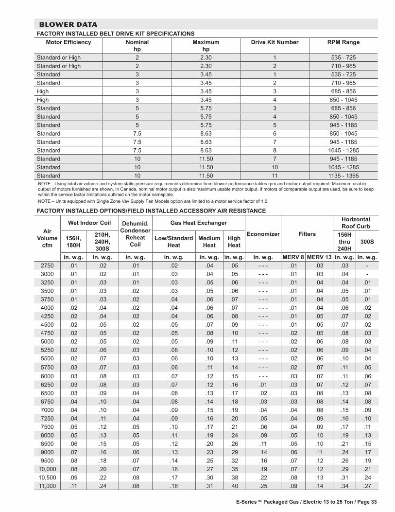
E-Series™ Packaged Gas / Electric 13 to 25 Ton / Page 33
BLOWER DATAFACTORY INSTALLED BELT DRIVE KIT SPECIFICATIONS
Motor Efficiency Nominal hp
Maximum hp
Drive Kit Number RPM Range
Standard or High 2 2.30 1 535 - 725Standard or High 2 2.30 2 710 - 965Standard 3 3.45 1 535 - 725Standard 3 3.45 2 710 - 965High 3 3.45 3 685 - 856High 3 3.45 4 850 - 1045Standard 5 5.75 3 685 - 856Standard 5 5.75 4 850 - 1045Standard 5 5.75 5 945 - 1185Standard 7.5 8.63 6 850 - 1045Standard 7.5 8.63 7 945 - 1185Standard 7.5 8.63 8 1045 - 1285Standard 10 11.50 7 945 - 1185Standard 10 11.50 10 1045 - 1285Standard 10 11.50 11 1135 - 1365NOTE - Using total air volume and system static pressure requirements determine from blower performance tables rpm and motor output required. Maximum usable output of motors furnished are shown. In Canada, nominal motor output is also maximum usable motor output. If motors of comparable output are used, be sure to keep within the service factor limitations outlined on the motor nameplate.NOTE – Units equipped with Single Zone Vav Supply Fan Models option are limited to a motor service factor of 1.0.
FACTORY INSTALLED OPTIONS/FIELD INSTALLED ACCESSORY AIR RESISTANCE
Air Volume
cfm
Wet Indoor Coil Dehumid.Condenser
Reheat Coil
Gas Heat Exchanger
Economizer Filters
Horizontal Roof Curb
156H, 180H
210H, 240H, 300S
Low/Standard Heat
Medium Heat
High Heat
156H thru 240H
300S
in. w.g. in. w.g. in. w.g. in. w.g. in. w.g. in. w.g. in. w.g. MERV 8 MERV 13 in. w.g. in. w.g.2750 .01 .02 .01 .02 .04 .05 - - - .01 .03 .03 -3000 .01 .02 .01 .03 .04 .05 - - - .01 .03 .04 -3250 .01 .03 .01 .03 .05 .06 - - - .01 .04 .04 .013500 .01 .03 .02 .03 .05 .06 - - - .01 .04 .05 .013750 .01 .03 .02 .04 .06 .07 - - - .01 .04 .05 .014000 .02 .04 .02 .04 .06 .07 - - - .01 .04 .06 .024250 .02 .04 .02 .04 .06 .08 - - - .01 .05 .07 .024500 .02 .05 .02 .05 .07 .09 - - - .01 .05 .07 .024750 .02 .05 .02 .05 .08 .10 - - - .02 .05 .08 .035000 .02 .05 .02 .05 .09 .11 - - - .02 .06 .08 .035250 .02 .06 .03 .06 .10 .12 - - - .02 .06 .09 .045500 .02 .07 .03 .06 .10 .13 - - - .02 .06 .10 .045750 .03 .07 .03 .06 .11 .14 - - - .02 .07 .11 .056000 .03 .08 .03 .07 .12 .15 - - - .03 .07 .11 .066250 .03 .08 .03 .07 .12 .16 .01 .03 .07 .12 .076500 .03 .09 .04 .08 .13 .17 .02 .03 .08 .13 .086750 .04 .10 .04 .08 .14 .18 .03 .03 .08 .14 .087000 .04 .10 .04 .09 .15 .19 .04 .04 .08 .15 .097250 .04 .11 .04 .09 .16 .20 .05 .04 .09 .16 .107500 .05 .12 .05 .10 .17 .21 .06 .04 .09 .17 .118000 .05 .13 .05 .11 .19 .24 .09 .05 .10 .19 .138500 .06 .15 .05 .12 .20 .26 .11 .05 .10 .21 .159000 .07 .16 .06 .13 .23 .29 .14 .06 .11 .24 .179500 .08 .18 .07 .14 .25 .32 .16 .07 .12 .26 .19
10,000 .08 .20 .07 .16 .27 .35 .19 .07 .12 .29 .2110,500 .09 .22 .08 .17 .30 .38 .22 .08 .13 .31 .2411,000 .11 .24 .08 .18 .31 .40 .25 .09 .14 .34 .27

E-Series™ Packaged Gas / Electric 13 to 25 Ton / Page 34
POWER EXHAUST FAN PERFORMANCE Return Air System Static Pressure Air Volume Exhausted
in. w.g. cfm 0.00 86300.05 82100.10 77250.15 71100.20 64700.25 57900.30 50600.35 43000.40 35100.45 26900.50 1840
BLOWER DATA
CEILING DIFFUSER AIR RESISTANCE - in. w.g.
Air Volume
cfm
Step-Down Diffuser Flush DiffuserRTD11-185 RTD11-275
FD11-185 FD11-2752 Ends Open 1 Side/2 Ends
OpenAll Ends & Sides Open 2 Ends Open 1 Side/2 Ends
OpenAll Ends & Sides Open
5000 .51 .44 .39 - - - - - - - - - .27 - - -5200 .56 .48 .42 - - - - - - - - - .30 - - -5400 .61 .52 .45 - - - - - - - - - .33 - - -5600 .66 .56 .48 - - - - - - - - - .36 - - -5800 .71 .59 .51 - - - - - - - - - .39 - - -6000 .76 .63 .55 .36 .31 .27 .42 .296200 .80 .68 .59 - - - - - - - - - .46 - - -6400 .86 .72 .63 - - - - - - - - - .50 - - -6500 - - - - - - - - - .42 .36 .31 - - - .346600 .92 .77 .67 - - - - - - - - - .54 - - -6800 .99 .83 .72 - - - - - - - - - .58 - - -7000 1.03 .87 .76 .49 .41 .36 .62 .407200 1.09 .92 .80 - - - - - - - - - .66 - - -7400 1.15 .97 .84 - - - - - - - - - .70 - - -7500 - - - - - - - - - .51 .46 .41 - - - .457600 1.20 1.02 .88 - - - - - - - - - .74 - - -8000 - - - - - - - - - .59 .49 .43 - - - .508500 - - - - - - - - - .69 .58 .50 - - - .579000 - - - - - - - - - .79 .67 .58 - - - .669500 - - - - - - - - - .89 .75 .65 - - - .74
10,000 - - - - - - - - - 1.00 .84 .73 - - - .8110,500 - - - - - - - - - 1.10 .92 .80 - - - .8911,000 - - - - - - - - - 1.21 1.01 .88 - - - .96
CEILING DIFFUSER AIR THROW DATA - ft.
Model No.
Air Volume cfm
1 Effective Throw Range - ft.Model
No.Air Volume
cfm
1 Effective Throw Range - ft.RTD11-185 Step-Down
FD11-185 Flush
RTD11-275 Step-Down
FD11-275 Flush
156 180
5600 39 - 49 28 - 37
210 240 300
7200 33 - 38 26 - 355800 42 - 51 29 - 38 7400 35 - 40 28 - 376000 44 - 54 40 - 50 7600 36 - 41 29 - 386200 45 - 55 42 - 51 7800 38 - 43 40 - 506400 46 - 55 43 - 52 8000 39 - 44 42 - 516600 47 - 56 45 - 56 8200 41 - 46 43 - 52
1 Throw is the horizontal or vertical distance an airstream travels on leaving the outletor diffuser before the maximum velocity is reduced to 50 ft. per minute. Four sides open.
8400 43 - 49 44 - 548600 44 - 50 46 - 578800 47 - 55 48 - 59

E-Series™ Packaged Gas / Electric 13 to 25 Ton / Page 35
ELECTRICAL DATA 13 TON13 TON HIGH EFFICIENCY (R-410A) LGH156H41 Voltage - 60hz 208/230V - 3 Ph 460V - 3 Ph 575V - 3 PhCompressor 1 Rated Load Amps 14.5 6.3 6
Locked Rotor Amps 98 55 41Compressor 2 Rated Load Amps 14.5 6.3 6
Locked Rotor Amps 98 55 41Compressor 3 Rated Load Amps 14.5 6.3 6
Locked Rotor Amps 98 55 41Outdoor Fan Motors (3)
Full Load Amps(total)
2.4(7.2)
1.3(3.9)
1(3)
Power Exhaust (2) 0.33 HP
Full Load Amps(total)
2.4(4.8)
1.3(2.6)
1(2)
Service Outlet 115V GFI (amps) 15 15 20Indoor Blower Motor
Horsepower 2 3 5 2 3 5 2 3 5Full Load Amps 7.5 10.6 16.7 3.4 4.8 7.6 2.7 3.9 6.1
2 Maximum Overcurrent Protection
Unit Only 70 70 80 30 35 35 30 30 30With (2) 0.33 HP
Power Exhaust80 80 90 35 35 40 30 30 35
3 Minimum Circuit Ampacity
Unit Only 62 65 72 28 30 33 26 27 29With (2) 0.33 HP
Power Exhaust67 70 77 31 32 35 28 29 31
ELECTRICAL DATA 15 TON15 TON HIGH EFFICIENCY (R-410A) LGH180H41 Voltage - 60hz 208/230V - 3 Ph 460V - 3 Ph 575V - 3 PhCompressor 1 Rated Load Amps 13.5 8 5
Locked Rotor Amps 109 59 40Compressor 2 Rated Load Amps 13.5 8 5
Locked Rotor Amps 109 59 40Compressor 3 Rated Load Amps 13.5 8 5
Locked Rotor Amps 109 59 40Outdoor Fan Motors (4)
Full Load Amps(total)
2.4(9.6)
1.3(5.2)
1(4)
Power Exhaust (2) 0.33 HP
Full Load Amps(total)
2.4(4.8)
1.3(2.6)
1(2)
Service Outlet 115V GFI (amps) 15 15 20Indoor Blower Motor
Horsepower 3 5 7.5 3 5 7.5 3 5 7.5Full Load Amps 10.6 16.7 24.2 4.8 7.6 11 3.9 6.1 9
2 Maximum Overcurrent Protection
Unit Only 70 80 100 40 45 50 25 30 35With (2) 0.33 HP
Power Exhaust80 90 100 45 45 50 30 30 40
3 Minimum Circuit Ampacity
Unit Only 65 71 81 36 39 43 25 27 31With (2) 0.33 HP
Power Exhaust69 76 86 39 42 46 27 29 33
NOTE - All units have a minimum Short Circuit Current Rating (SCCR) of 5000 amps.1 Extremes of operating range are plus and minus 10% of line voltage.2 HACR type breaker or fuse.3 Refer to National or Canadian Electrical Code manual to determine wire, fuse and disconnect size requirements.4 Factory installed circuit breaker not available.

E-Series™ Packaged Gas / Electric 13 to 25 Ton / Page 36
ELECTRICAL DATA 17.5 TON17.5 TON HIGH EFFICIENCY (R-410A) LGH210H41 Voltage - 60hz 208/230V - 3 Ph 460V - 3 Ph 575V - 3 PhCompressor 1 Rated Load Amps 15.6 7.8 5.8
Locked Rotor Amps 110 52 38.9Compressor 2 Rated Load Amps 15.6 7.8 5.8
Locked Rotor Amps 110 52 38.9Compressor 3 Rated Load Amps 19.6 8.2 6.6
Locked Rotor Amps 136 66.1 55.3Outdoor Fan Motors (6)
Full Load Amps(total)
2.4(14.4)
1.3(7.8)
1(6)
Power Exhaust (2) 0.33 HP
Full Load Amps(total)
2.4(4.8)
1.3(2.6)
1(2)
Service Outlet 115V GFI (amps) 15 15 20Indoor Blower Motor
Horsepower 3 5 7.5 3 5 7.5 3 5 7.5Full Load Amps 10.6 16.7 24.2 4.8 7.6 11 3.9 6.1 9
2 Maximum Overcurrent Protection
Unit Only 100 100 110 45 45 50 35 35 40With (2) 0.33 HP
Power Exhaust100 110 110 45 50 50 35 40 45
3 Minimum Circuit Ampacity
Unit Only 81 87 96 39 42 46 30 32 36With (2) 0.33 HP
Power Exhaust86 92 101 42 44 48 32 34 38
ELECTRICAL DATA 20 TON20 TON HIGH EFFICIENCY (R-410A) LGH240H41 Voltage - 60hz 208/230V - 3 Ph 460V - 3 Ph 575V - 3 PhCompressor 1 Rated Load Amps 13.5 8 5
Locked Rotor Amps 109 59 40Compressor 2 Rated Load Amps 13.5 8 5
Locked Rotor Amps 109 59 40Compressor 3 Rated Load Amps 13.5 8 5
Locked Rotor Amps 109 59 40Compressor 4 Rated Load Amps 13.5 8 5
Locked Rotor Amps 109 59 40Outdoor Fan Motors (6)
Full Load Amps(total)
2.4(14.4)
1.3(7.8)
1(6)
Power Exhaust (2) 0.33 HP
Full Load Amps(total)
2.4(4.8)
1.3(2.6)
1(2)
Service Outlet 115V GFI (amps) 15 15 20Indoor Blower Motor
Horsepower 5 7.5 10 5 7.5 10 5 7.5 10Full Load Amps 16.7 24.2 30.8 7.6 11 14 6.1 9 11
2 Maximum Overcurrent Protection
Unit Only 100 110 125 50 60 70 35 45 50With (2) 0.33 HP
Power Exhaust110 125 125 60 60 70 40 45 50
3 Minimum Circuit Ampacity
Unit Only 90 99 107 50 54 58 34 38 40With (2) 0.33 HP
Power Exhaust95 104 112 53 57 60 36 40 42
NOTE - All units have a minimum Short Circuit Current Rating (SCCR) of 5000 amps.1 Extremes of operating range are plus and minus 10% of line voltage.2 HACR type breaker or fuse.3 Refer to National or Canadian Electrical Code manual to determine wire, fuse and disconnect size requirements.4 Factory installed circuit breaker not available.

E-Series™ Packaged Gas / Electric 13 to 25 Ton / Page 37
ELECTRICAL DATA 25 TON25 TON STANDARD EFFICIENCY (R-410A) LGH300S41 Voltage - 60hz 208/230V - 3 Ph 460V - 3 Ph 575V - 3 PhCompressor 1 Rated Load Amps 19.6 8.2 6.6
Locked Rotor Amps 136 66.1 55.3Compressor 2 Rated Load Amps 19.6 8.2 6.6
Locked Rotor Amps 136 66.1 55.3Compressor 3 Rated Load Amps 19.6 8.2 6.6
Locked Rotor Amps 136 66.1 55.3Compressor 4 Rated Load Amps 19.6 8.2 6.6
Locked Rotor Amps 136 66.1 55.3Outdoor Fan Motors (6)
Full Load Amps(total)
2.4(14.4)
1.3(7.8)
1(6)
Power Exhaust (2) 0.33 HP
Full Load Amps(total)
2.4(4.8)
1.3(2.6)
1(2)
Service Outlet 115V GFI (amps) 15 15 20Indoor Blower Motor
Horsepower 5 7.5 10 5 7.5 10 5 7.5 10Full Load Amps 16.7 24.2 30.8 7.6 11 14 6.1 9 11
2 Maximum Overcurrent Protection
Unit Only 125 125 150 60 60 70 45 50 50With (2) 0.33 HP
Power Exhaust125 150 150 60 60 70 45 50 50
3 Minimum Circuit Ampacity
Unit Only 115 124 132 51 55 59 41 44 47With (2) 0.33 HP
Power Exhaust120 128 137 53 57 61 43 46 49
NOTE - All units have a minimum Short Circuit Current Rating (SCCR) of 5000 amps.1 Extremes of operating range are plus and minus 10% of line voltage.2 HACR type breaker or fuse.3 Refer to National or Canadian Electrical Code manual to determine wire, fuse and disconnect size requirements.4 Factory installed circuit breaker not available.
ELECTRICAL ACCESSORIESDISCONNECTS
Voltage 208V 230V 208V 230V 208V 230V 460V 460V 460V 575V 575V 575VModel No. LGH156H4
Blower Motor HP 2 3 5 2 3 5 2 3 5Unit Only 54W88 54W88 54W88 54W88 54W88 54W88 54W88 54W88 54W88 54W88 54W88 54W88
Unit w/ Power Exhaust 54W88 54W88 54W88 54W88 54W89 54W89 54W88 54W88 54W88 54W88 54W88 54W88Model No. LGH180H4
Blower Motor HP 3 5 7.5 3 5 7.5 3 5 7.5Unit Only 54W88 54W88 54W88 54W88 54W89 54W89 54W88 54W88 54W88 54W88 54W88 54W88
Unit w/ Power Exhaust 54W88 54W88 54W89 54W89 54W89 54W89 54W88 54W88 54W88 54W88 54W88 54W88Model No. LGH210H4
Blower Motor HP 3 5 7.5 3 5 7.5 3 5 7.5Unit Only 54W89 54W89 54W89 54W89 54W89 54W89 54W88 54W88 54W88 54W88 54W88 54W88
Unit w/ Power Exhaust 54W89 54W89 54W89 54W89 54W89 54W89 54W88 54W88 54W88 54W88 54W88 54W88Model No. LGH240H4
Blower Motor HP 5 7.5 10 5 7.5 10 5 7.5 10Unit Only 54W89 54W89 54W89 54W89 54W89 54W89 54W88 54W88 54W88 54W88 54W88 54W88
Unit w/ Power Exhaust 54W89 54W89 54W89 54W89 54W89 54W89 54W88 54W88 54W88 54W88 54W88 54W88Model No. LGH300S4
Blower Motor HP 5 7.5 10 5 7.5 10 5 7.5 10Unit Only 54W89 54W89 54W89 54W89 54W89 54W89 54W88 54W88 54W88 54W88 54W88 54W88
Unit w/ Power Exhaust 54W89 54W89 54W89 54W89 54W89 54W89 54W88 54W88 54W88 54W88 54W88 54W88

E-Series™ Packaged Gas / Electric 13 to 25 Ton / Page 38
UNIT CLEARANCES - INCHES (MM)
1 Unit ClearanceA B C D Top
Clearancein. mm in. mm in. mm in. mmService Clearance 60 1524 36 914 36 934 66 1676
UnobstructedClearance to Combustibles 36 914 1 25 1 25 1 25Minimum Operation Clearance 45 1143 36 914 36 914 41 1041NOTE - Entire perimeter of unit base requires support when elevated above the mounting surface.1 Service Clearance - Required for removal of serviceable parts.
Clearance to Combustibles - Required clearance to combustible material. Minimum Operation Clearance - Required clearance for proper unit operation.
Note: 210-240-300 sizes shown
Unit With Economizer
D
OUTDOORAIR HOOD
B
C
A

E-Series™ Packaged Gas / Electric 13 to 25 Ton / Page 39
OUTDOOR SOUND DATA
Unit Model Number
Octave Band Linear Sound Power Levels dB, re 10-12 Watts - Center Frequency - Hz 1 Sound Rating Number (SRN)
(dBA)125 250 500 1000 2000 4000 8000
156 71 78 81 81 76 71 63 86
180 80 83 87 88 84 80 71 93
210, 240, 300 79 84 88 89 85 82 73 94
Note - The octave sound power data does not include tonal corrections.1 Sound Rating Number according to ARI Standard 370-2001 (includes pure tone penalty). “SRN” is the overall A-Weighted Sound Power Level, (LWA), dB (100 Hz to
10,000 Hz).

E-Series™ Packaged Gas / Electric 13 to 25 Ton / Page 40
OPTIONS / ACCESSORIES
DescriptionShipping Weight
lbs. kgCEILING DIFFUSERSStep-Down
RTD11-185 392 178RTD11-275 403 183
FlushFD11-185 289 131FD11-275 363 165
Transitions LASRT18 80 36
LASRT21/24 75 34ECONOMIZER / OUTDOOR AIR / EXHAUSTEconomizerEconomizer Dampers 102 46Barometric Relief Dampers (downflow) 30 14Barometric Relief Dampers (horizontal) 20 9Outdoor Air DampersOutdoor Air Damper Section (downflow) - Automatic 52 24Outdoor Air Damper Section (downflow) - Manual 49 22Outdoor Air Damper Hood (downflow) 65 29Power Exhaust 62 28GAS HEAT EXCHANGER (NET WEIGHT)
Medium Heat (adder over standard heat) 18 8High Heat (adder over standard heat) 64 29
DEHUMIDIFICATION SYSTEMDehumification Option (Net Weight) 50 23Single Zone VAV Supply Fan SUPPLY AIR BLOWER OPTIONVariable Frequency Drive (VFD) and associated components 10 5ROOF CURBSHybrid Roof Curbs, Downflow8 in. height 75 3414 in. height 105 4818 in. height 125 5724 in. height 155 70Adjustable Pitch Curb, Downflow14 in. height 262 119Horizontal, Standard26 in. height 470 21337 in. height 505 22930 in. height 575 26141 in. height 610 277PACKAGINGLTL Packaging (less than truck load) 310 141
WEIGHT DATA
Model Number Outdoor Coil
Net Shipping Outdoor Coil
Net Shippinglbs. kg lbs. kg lbs. kg lbs. kg
156 Base Unit Eco-last™ 1935 878 2135 968 Fin/Tube 2000 907 2200 998156 Max. Unit Eco-last™ 2205 1000 2405 1091 Fin/Tube 2270 1030 2470 1120180 Base Unit Eco-last™ 2115 959 2315 1050 Fin/Tube 2220 1007 2420 1098180 Max. Unit Eco-last™ 2400 1089 2600 1179 Fin/Tube 2505 1136 2705 1227210 Base Unit Eco-last™ 2240 1016 2440 1107 Fin/Tube 2330 1057 2530 1148210 Max. Unit Eco-last™ 2525 1145 2725 1236 Fin/Tube 2615 1186 2815 1277240 Base Unit Eco-last™ 2325 1055 2525 1145 Fin/Tube 2430 1102 2630 1193240 Max. Unit Eco-last™ 2610 1184 2810 1275 Fin/Tube 2715 1232 2915 1322300 Base Unit Eco-last™ 2430 1102 2630 1193 Fin/Tube 2495 1132 2695 1222300 Max. Unit Eco-last™ 2715 1232 2915 1322 Fin/Tube 2780 1261 2980 1352

E-Series™ Packaged Gas / Electric 13 to 25 Ton / Page 41
4-1/4 (108)
4(102)
12-3/8(314)
BOTTOM POWER ENTRY5 X 8 inches (127 X 203 mm)
BOTTOM SUPPLYAIR OPENINGS
BOTTOM RETURNAIR OPENING
28(711)
28(711)
20 (508) 20 (508)
15 (381)60-1/2 (1537)
AA BB
CCDD
CENTER OFGRAVITY
EE
FF
TOP VIEW
4-1/2(114)
12-3/8(314)
4(102)
END VIEW
90-1/8(2289)
28-3/4(730)
5-3/8(137)
3-1/4(83)
54-1/4(1378)
51(1295)
91-1/8 (2315)BASE
SIDE ELECTRICAL
INLETS
8-1/4(210)
10-1/4(260)
4(102)
GAS SUPPLYINLET
OPTIONALDISCONNECT
(Factory Installed)
CONDENSATEDRAIN
GAS SUPPLY OUTLET(For Bottom
Gas Supply Only)
SIDE VIEW
FORKLIFT SLOTS(Front and Left Side Only)
LIFTING HOLES(For Rigging
Front and Back) 107-3/4 (2737)BASE
106-1/2(2705)OPTIONAL
115 VOLT OUTLET(Factory Installed Inside Unit)
FLUEOUT LET
ALTERNATE (THRU THE BASE)CONDENSATE DRAIN LOCATION
1-5/8 in. (41 mm) Diameter
18 (457)
28-3/8(721)
5-5/8 (143)
DIMENSIONS - UNIT - INCHES (MM) LGH156CORNER WEIGHTS CENTER OF GRAVITY
Model No. AA BB CC DD EE FFlbs. kg lbs. kg lbs. kg lbs. kg in. mm in. mm
LGH156 Base Unit (Eco-last™) 473 215 367 167 483 219 612 278 47-1/4 1200 39-1/2 1003LGH156 Max. Unit (Eco-last™) 586 266 447 203 510 232 663 301 46-3/4 1187 42-3/4 1086LGH156 Base Unit (Fin/Tube Coil) 476 216 397 180 513 233 615 279 49 1245 39-3/4 1010
LGH156 Max. Unit (Fin/Tube Coil) 588 267 477 216 540 245 665 302 48-1/4 1226 42-3/4 1086Base Unit - The unit with NO INTERNAL OPTIONS.Max. Unit - The unit with ALL INTERNAL OPTIONS Installed. (Economizer, Standard Static Power Exhaust Fans, Controls, etc.). Does not include accessories external to unit or high static power exhaust.

E-Series™ Packaged Gas / Electric 13 to 25 Ton / Page 42
DIMENSIONS - UNIT - INCHES (MM) LGH180CORNER WEIGHTS CENTER OF GRAVITY
Model No. AA BB CC DD EE FFlbs. kg lbs. kg lbs. kg lbs. kg in. mm in. mm
LGH180 Base Unit lEco-last™) 487 221 423 192 569 259 636 289 50-3/4 1289 39-1/4 997LGH180 Max. Unit (Eco-last™) 597 272 505 229 599 272 699 318 49-3/4 1264 42 1067LGH180 Base Unit (Fin/Tube) 487 221 476 216 622 282 636 288 53-/4 1353 39-1/2 1003LGH180 Max. Unit (Fin/Tube) 597 271 557 253 652 296 699 317 52 1321 42 1067Base Unit - The unit with NO INTERNAL OPTIONS.Max. Unit - The unit with ALL INTERNAL OPTIONS Installed. (Economizer, Standard Static Power Exhaust Fans, Controls, etc.). Does not include accessories external to unit or high static power exhaust.
END VIEW
90-1/8(2289)
28-3/4(730 )
5-3/8(137)
3-1/4(83)
54-1/4(1378)
51(1295)
91-1/8 (2315)BASE
8-1/4(210)
10-1/4(260)
4(102)
4-1/4 (108)
BOTTOM POWER ENTRY5 X 8 inches (127 X 203 mm)
BOTTOM SUPPLYAIR OPENINGS
BOTTOM RETURNAIR OPENING
28(711)
28(711)
4(102)
4(102)
12-3/8(314)
12-3/8(314)
20 (508)
15 (381)60-1/2 (1537)
AA BB
CCDD
CENTER OFGRAVITY
EE
FF
TOP VIEW
4-1/2(114)
20 (508)
SIDE VIEW
FORKLIFT SLOTS(Front and Left Side Only)
132-5/8(3369)
LIFTING HOLES(For Rigging
Front and Back)25-3/8(645)
107-3/4 (2737)BASE
OPTIONAL115 VOLT OUTLET
(Factory Installed Inside Unit)
FLUEOUT LET
OPTIONALDISCONNECT
(Factory Installed)
CONDENSATEDRAIN
ALTERNATE (THRU THE BASE)CONDENSATE DRAIN LOCATION
1-5/8 in. (41 mm) Diameter
18 (457)
28-3/8(721)
5-5/8 (143)
SIDE ELECTRICAL
INLETS
GAS SUPPLYINLET
GAS SUPPLY OUTLET(For Bottom
Gas Supply Only)

E-Series™ Packaged Gas / Electric 13 to 25 Ton / Page 43
4-1/4 (108)12-3/8(314)
(314)12-3/8
4(102)
BOTTOM SUPPLYAIR OPENINGS
BOTTOM RETURNAIR OPENING
28(711)
28(711)
20 (508)
15 (381)60-1/2 (1537)
AA BB
CCDD
CENTER OFGRAVITY
EE
FF
TOP VIEW
4-1/2(114)
20 (508)
BOTTOM POWER ENTRY5 X 8 inches (127 X 203 mm)
4(102)
END VIEW
90-1/8(2289)
28-3/4(730)
5-3/8(137)
3-1/4(83)
54-1/4(1378)
51(1295)
91-1/8 (2315)BASE
8-1/4(210)
10-1/4(260)
4(102)
OPTIONALDISCONNECT
(Factory Installed)
CONDENSATEDRAIN
SIDE ELECTRICAL
INLETS
GAS SUPPLYINLET
GAS SUPPLY OUTLET(For Bottom
Gas Supply Only)
FLUEOUT LET
SIDE VIEW
FORKLIFT SLOTS(Front and Left Side Only)
132-5/8(3369)
LIFTING HOLES(For Rigging
Front and Back)25-3/8(645)
107-3/4 (2737)BASE
OPTIONAL115 VOLT OUTLET
(Factory Installed Inside Unit)
FLUEOUT LET
ALTERNATE (THRU THE BASE)CONDENSATE DRAIN LOCATION
1-5/8 in. (41 mm) Diameter
18 (457)
28-3/8(721)
5-5/8 (143)
DIMENSIONS - UNIT - INCHES (MM) LGH210, LGH240, LGH300CORNER WEIGHTS CENTER OF GRAVITY
Model No. AA BB CC DD EE FFlbs. kg lbs. kg lbs. kg lbs. kg in. mm in. mm
LGH210 Base Unit (Eco-last™) 497 226 468 213 626 284 649 295 52-3/4 1340 39-1/4 997LGH210 Max. Unit (Eco-last™) 607 276 553 252 655 298 710 323 51-1/2 1308 42 1067LGH210 Base Unit (Fin/Tube Coil) 497 225 513 233 671 304 649 294 54-3/4 1391 39-1/2 1003
LGH210 Max. Unit (Fin/Tube Coil) 607 275 598 271 700 318 710 322 53-1/2 1359 42 1067
LGH240 Base Unit (Eco-last™) 507 230 481 219 660 300 677 308 53 1346 38-3/4 984
LGH240 Max. Unit (Eco-last™) 617 280 567 258 688 313 738 335 52 1321 41-1/2 1054
LGH240 Base Unit (Fin/TubeCoil) 507 230 533 242 713 323 677 307 55-1/4 1403 39 991
LGH240 Max. Unit (Fin/TubeCoil) 617 280 620 281 741 336 738 335 54 1372 41-1/2 1054
LGH300 Base Unit (Eco-last™) 513 233 535 243 739 335 709 322 55 1397 38-1/4 972
LGH300 Max. Unit (Eco-last™) 623 283 620 281 767 348 770 349 53-3/4 1365 40-3/4 1035
LGH300 Base Unit (Fin/Tube Coil) 513 233 502 228 706 321 709 322 53-1/2 1359 38 965LGH300 Max. Unit (Fin/Tube Coil) 623 283 588 267 734 334 770 350 52-1/2 1334 40-3/4 1035Base Unit - The unit with NO INTERNAL OPTIONS.Max. Unit - The unit with ALL INTERNAL OPTIONS Installed. (Economizer, Standard Static Power Exhaust Fans, Controls, etc.). Does not include accessories external to unit or high static power exhaust.

E-Series™ Packaged Gas / Electric 13 to 25 Ton / Page 44
DIMENSIONS - ACCESSORIES - INCHES (MM)
16(406)
FRONT VIEW SIDE VIEW
31-5/8 (803)
14-1/2(368)
1 13(330)
6-1/2(165)1 29-1/2 (749)
NOTE - Two furnished per order no. 1 NOTE - Opening size required in return air duct.
OPTIONAL HORIZONTAL BAROMETRIC RELIEF DAMPERS WITH HOOD(Field installed in horizontal return air duct adjacent to unit)
OUTDOOR AIR HOOD DETAIL
OUTDOOR AIR HOOD(Furnished with Economizer or
Outdoor Air Damper)
EXHAUST AIR HOOD(Furnished with Optional
Downflow BarometricRelief Dampers, Field Installed)

E-Series™ Packaged Gas / Electric 13 to 25 Ton / Page 45
DIMENSIONS - ACCESSORIES - INCHES (MM)
RETURNOPENING
SUPPLYOPENING
NOTE - Roof deck may be omitted within confines of curb.
TYPICAL FLASHING DETAIL FOR ROOF CURB
ROOF CURB(Extends around entire
perimeter of unit)
FIBERGLASSINSULATION
(Furnished)COUNTER FLASHING(Field Supplied)
BASE BOTTOM
RIGID INSULATION(Field Supplied)
ROOFINGMATERIAL
CANT STRIP(Field Supplied)
PACKAGEDUNIT
NAILER STRIP(Furnished)
DETAIL ROOF CURB
FACTORY INSTALLEDPERIMETER WOODNAILER STRIP
HYBRID ROOF CURBS - DOUBLE DUCT OPENING
8 (203)14 (356)18 (457)24 (610)
8 (203)14 (356)18 (457)24 (610)
1-3/4(44)
1/2 (13)
1-3/4(44)
98-1/2(2502)
81-1/2(2070)
61-1/2(1562)
86-1/8(2188)
82-5/8(2099)
21(533)
17(432)
16(406)
8-1/4(210)
61-1/2(1562) 102
(2591)

E-Series™ Packaged Gas / Electric 13 to 25 Ton / Page 46
DIMENSIONS - ACCESSORIES - INCHES (MM)
TYPICAL FLASHING DETAIL FOR ROOF CURB
ROOF CURB(Extends around entire
perimeter of unit)
FIBERGLASSINSULATION
(Furnished)COUNTER FLASHING(Field Supplied)
BASE BOTTOM
RIGID INSULATION(Field Supplied)
ROOFINGMATERIAL
CANT STRIP(Field Supplied)
PACKAGEDUNIT
NAILER STRIP(Furnished)
DETAIL ROOF CURB
FACTORY INSTALLEDPERIMETER WOODNAILER STRIP
RETURNOPENING
ADJUSTABLE PITCH CURB - DOUBLE DUCT OPENING
SUPPLYOPENING
BOTTOM CURBASSEMBLY
NOTE - Maximum slope pitch is 3/4 in. per 1 foot (19 mm per 305 mm)in any one direction.
FACTORY INSTALLEDPERIMETER WOODNAILER STRIP
102-1/8(2594)
98-1/2(2502)
14 (356)
1-3/4(44)
1/2 (13)
1-3/4(44)
21(533)82-5/8
(2099)
14 (356)
86-1/8(2188)
17(432)
16(406)
1-3/4(44)
8-1/4(210)
61-1/2(1562)
8-1/4(210)
61-1/2(1562)

E-Series™ Packaged Gas / Electric 13 to 25 Ton / Page 47
DIMENSIONS - ACCESSORIES - INCHES (MM)
ROOF CURBS WITH SUPPLY & RETURN AIR TRANSITIONS FOR CEILING DIFFUSERS
SUPPLY TRANSITION
RETURN TRANSITION
RETURN AIROPENING
SUPPLY AIROPENINGS
TOP VIEW
54(1372)
69-1/4 (1759)
3/4(19) Typ.
4-1/2(114)
SUPPORTANGLE
(Furnished withTransitions)
B
A
B
69-1/4(1759)
2(51)
8 (203)
26-1/2(673)
1-1/2(38) Typ.
TRANSITION DETAIL
A
AB
TRANSITION OPENING SIZES
Model A BModelNumber inch mm inch mm
C1DIFF33C-1 18 457 36 914
C1DIFF34C-1 24 610 48 1219

E-Series™ Packaged Gas / Electric 13 to 25 Ton / Page 48
DIMENSIONS - ACCESSORIES - INCHES (MM)
HORIZONTAL ROOF CURBS − Requires Optional Horizontal Return Air Panel Kit
PANEL TO COVER RETURN AIR OPENING IN BOTTOM OF UNIT(Furnished With Optional Horizontal Return Air Panel Kit)
SIDE VIEW(Packaged Unit)
SIDE VIEW86-5/8 (2200)
NAILER STRIP(Furnished)
SUPPLYDUCT
PANELS(Furnished)
SUPPLY AIRTURNING VANE
(Furnished)
86-1/4 (2191)
1 26 (660)2 37 (940)3 30 (762)4 41 (1041)
102-1/8 (2594)
TOP VIEW
Fram
eO
peni
ng
FrameOpening
54(1372)
98-1/2 (2502)
82-5/8(2099)
98-1/2 (2502)
1 (25)
2 (51)SECTION A-A
1-13/16 (46)
NAILER STRIP(Furnished)
A
NOTE − Roof deck may be omitted within confines of curb.
SUPPLY AIRTURNING VANE
(Furnished)
1-13/16(46)
1-13/16(46)
1-13/16 (46)1-13/16 (46)
A
86-1/4(2191)
HORIZONTALSUPPLY AIR OPENING
HORIZONTAL ROOF CURB(Required For Horizontal Applications)
1,2 8-1/4 (210)3,4 13-1/4 (337)75 (1905)
HORIZONTAL RETURNAIR OPENING
12-3/8(314)
15 (381)60-1/2 (1537)
2 (51)
54-1/4(1378)
NOTE − Top of Roof Curb extends 4inch (102 mm) inside bottom of unitbase. See Typical flashing detail.
OPTIONAL RETURN AIR PANEL KIT(Required for Horizontal Applications)
1,3 6-1/2 (165)2,4 17-1/2 (445)
1 22 (559)2 33 (838)3 26 (660)4 37 (940)
1 76-1/4 (1937)2 87-1/4 (2216)3 80-1/4 (2038)4 91-1/4 (2318)
1,2 14 (356)3,4 18 (457)
30-3/8(772)
HORIZONTAL SUPPLY AND RETURN AIR OPENINGSWITH HORIZONTAL ROOF CURB
1 C1CURB14C-1 2 C1CURB16C-13 C1CURB15C-1 (used with 300S Models Only)4 C1CURB17C-1 (used with 300S Models Only)
1 C1CURB14C-1 2 C1CURB16C-1 3 C1CURB15C-1 (used with 300S) 4 C1CURB17C-1 (used with 300S)
NOTE C1CURB14C-1 and C1CURB15C-1are designed for horizontal dischargewhen unit is mounted on a slab.C1CURB16C-1 and C1CURB17C-1are designed for horizontal dischargewhen unit is mounted on a rooftop.
1,2 14 (356)3,4 18 (457)
102-1/2 (2604)
CURB SUPPLYAIR OPENING
With 1-1/2 in. (38 mm) FLANGE
75(1905)
5-1/2 (140)
102-1/8 (2594)
1,2 8-1/4 (210)3,4 13-1/4 (337)
1,3 6-1/2 (165)2,4 17-1/2 (445)
1 26 (660)2 37 (940)3 30 (762)4 41 (1041)
FRONT VIEW

E-Series™ Packaged Gas / Electric 13 to 25 Ton / Page 49
DIMENSIONS - ACCESSORIES - INCHES (MM)
COMBINATION CEILING SUPPLY AND RETURN DIFFUSERSRESUFFID GNILIEC HSULFRESUFFID GNILIEC NWOD-PETS
L
A
C
HJG
FE
B
M
N
K
DG
2 (51)
A
C
HJG
FE
B
K
DG
2 (51)
Model Number RTD11-185 RTD11-275A in. 47-5/8 59-5/8
mm 1210 1514B in. 47-5/8 59-5/8
mm 1210 1514C in. 24-5/8 30-5/8
mm 625 778D in. 45-1/2 57-1/2
mm 1156 1461E in. 45-1/2 57-1/2
mm 1156 1461F in. 4-1/2 4-1/2
mm 114 114G in. 18 24
mm 457 610H in. 2-1/2 2-1/2
mm 64 64J in. 36 48
mm 914 1219K in. 4-3/4 4-3/4
mm 121 121L in. 45-1/2 57-1/2
mm 1156 1461M in. 45-1/2 57-1/2
mm 1156 1461N in. 10-1/8 11-1/8
mm 257 283Duct Size in. 18 x 36 24 x 48
mm 457 x 914 610 x 1219
Model Number FD11-185 FD11-275A in. 47-5/8 59-5/8
mm 1210 1514B in. 47-5/8 59-5/8
mm 1210 1514C in. 29-1/4 35-1/4
mm 743 895D in. 45 57
mm 1143 1148E in. 45 57
mm 1143 1448F in. 4-1/2 4-1/2
mm 114 114G in. 18 24
mm 457 610H in. 2-1/4 2-1/4
mm 57 57J in. 36 48
mm 914 1219K in. 4-1/2 4-1/2
mm 114 114Duct Size in. 18 x 36 24 x 48
mm 457 x 914 610 x 1219


REVISIONS
Sections Description of Change
Options/AccessoriesUpdated LPG/Propane Conversion Kits’ catalog and model numbers. Updated Standard Economizer catalog and model numbers. Updated Low Temperature Vestibule Heater catalog and model numbers.
NOTE - Due to Allied Commercial ongoing commitment to quality, Specifications, Ratings and Dimensions subject to change without notice and without incurring liability. Improper installation, adjustment, alteration, service or maintenance can cause property damage or personal injury. Installation and service must be performed by a qualified installer and servicing agency.
©2015 Allied Air Enterprises LLC, a Lennox International Inc. Company
Visit us at www.allied-commercial.com
For the latest technical information, visit us at www.allied-commercial.com
Contact us at 1-800-448-5872
Copyright © 2022 FDOKUMEN