VENTUS LINE - Cooling India
112
VTS IS A GLOBAL MANUFACTURER OF INNOVATIVE HVAC PRODUCTS SERVING CUSTOMERS AT MORE THAN 50 MARKETS ALL OVER THE WORLD VENTUS LINE HIGH-TECH TECHNOLOGY IN AFFORDABLE PRICE For all kinds of buildings with any capacity Wide range of optional functions Warranty of up to 5 years on selected components High performance PLUG fan Week lead time Energy recovery www.vtsgroup.com [email protected] Logistic Centre – West VTS TF Air Systems (P) LTD D-6, Unit A, Indian Logistics Complex, Near Mankoli Naka, BHIWANDI, Thane - 421 302, MAHARASHTRA Tel. +91.22.42660129 Logistic Centre – South VTS TF Air Systems (P) LTD Plot No.- 222 to 224 & 229 to 232 KIADB Industrial Area, MALUR, KOLAR - 563130, KARNATAKA Tel. +91.80.22716202 AHU N° 06.06.320 Range: VENTUS VS 10 - VS 650 TÜV derabad - Chennai - Kolkata - Cochin Vol. 11 No. 7 February 2016 ` 100 Visit us at Hall No. 1, Stall K-38
-
Upload
khangminh22 -
Category
Documents
-
view
5 -
download
0
Transcript of VENTUS LINE - Cooling India

Feb
ruary 2016
VTS IS A GLOBAL MANUFACTURER OF INNOVATIVE HVAC PRODUCTS SERVING CUSTOMERS
AT MORE THAN 50 MARKETS ALL OVER THE WORLD
VENTUS LINEHIGH-TECH TECHNOLOGY IN AFFORDABLE PRICE
For all kinds of buildings with any capacity
Wide range of optional functions
Warranty of up to 5 years on selected components
High performance PLUG fan
Week lead time
Energy recovery
Logistic Centre – WestVTS TF Air Systems (P) LTDD-6, Unit A, Indian Logistics Complex,Near Mankoli Naka, BHIWANDI,Thane - 421 302, MAHARASHTRA
Tel. +91.22.42660129
Logistic Centre – SouthVTS TF Air Systems (P) LTDPlot No.- 222 to 224 & 229 to 232KIADB Industrial Area, MALUR,KOLAR - 563130, KARNATAKA
Tel. +91.80.22716202
AHU N° 06.06.320Range: VENTUS VS 10 - VS 650 TÜV
derabad - Chennai - Kolkata - Cochin
ulotka_indie_215x215_160128.indd 1 2016-01-28 12:14:31
Vol. 11 No. 7 February 2016 ` 100
Visit us at
Hall No. 1, Stall K-38


Visit us at
Vol. 11 No. 7 February 2016 ` 100
Feb
ruary
2016
If the answer to the above is...Yes, it's important
Then, you are almost at it.You just need to be…in it.
We are known by
the company we keep
Print, online
& newsletter
Solution one . . .
Options many
For more information, talk to our representative on +91 22 25073313
Email: [email protected]
www.coolingindia.in
How is itimportantto build your brandto your customers?

Hyderabad
Hyderbad
Kolkata
Chennai
Kochi
Bangalore
Mumbai
New Delhi
Distributor Presence
Your local distributors of world class
condensate drain pumps for HVAC applications
large tank
Hi-flow 2L
288 l/h max. flow, 5 m max. head
Perfect for large quantities of water
Mini Aqua
12 l/h max. flow, 10 m max. head
Perfect for installing directly inside the unit
smallest in the world
ultra quick fit
Hi-wall
10 l/h max. flow, 8 m max. head
Where easy maintenance is key
q
To find your nearest Aspen Pumps®
India distributor please contact
Dheeraj Jagga today!
Dheeraj JaggaCountry Manager for India
Meet us at stand C42!
Follow usASPENPUMPS.COMdesigned by engineers for engineers
Micro-v
14.5 l/h max. flow, 10 m max. head
Quietest operation 19dB(A)
speed control
NEW!


Publisher’s Letter
LetterPublisher’s
www.facebook.com/coolingindiamagazine www.linkedin.com/in/coolingindia www.twitter.com/coolingmagazine www.google.com/+coolingindiainmagazine
6 Cooling India February 2016
Smart buildings make smart cities; however, the concept of true smart buildings is still to reach the common people. According to a communiqué from Honeywell and Ernst & Young in mid 2015, “With the advent of new technologies, the role buildings play
is being redefined from a static environment to a more dynamic and interactive space that impacts the lifestyles, wellbeing and productivity of their occupants.” It’s a nice overview of the actual concept.
They further summarised the entire concept under three basic heads, namely, Green, Safe and Productive. Elaborating further on it (based on their research) they communicated, the ‘green’ aspect in buildings is well known, and for good reason. The economic and sustainability benefits of green buildings have been proven through extensive academic and applied research. But the ‘safe’ aspect in buildings is not equally well researched or illustrated. The value of human life and property is critical and should be given the highest priority in any building. Also, the conversation around ‘productive’ buildings is still nascent. However, this is the one area that is likely to see the fastest change in relevance and importance, driven by two major megatrends: connectivity and comfort.
It’s pleasant to note that now globally a wave is rising centering around the smart building design. Although they are essential functional elements, it’s not just IT and automation that make a building smart. Many a conference, symposium and event will now focus on this aspect to spread awareness of the expanse, design, advantages etc., of really smart buildings. The International Conference on Efficient Building Design – Materials and HVAC Equipment Technologies (ICEBD-MET2); which is being organised by the American University of Beirut (AUB), ASHRAE and the ASHRAE Lebanese Chapter; will take place in Beirut, from September 22 to 23, 2016. The organizers highlight that buildings consume more than 40% of energy worldwide. Thus, the utilization and adaptability of technologies of natural materials (instead of those created using high amounts of energy) and energy efficiency standards in buildings will form two major pillars of the event. Obviously, this reflects the changing paradigm.
Please send your comments at [email protected]
Pravita IyerPublisher & Director
A Wider Concept Of Smart Buildings
SubscribingCooling India is now a
click away Just log on to
www.coolingindia.in l


8 Cooling India February 2016
ContentsVol. 11 No. 7, February 2016
Contents
Publisher’s letter ............................................. 06
Editorial .......................................................... 12
News .............................................................. 14
Appointments ................................................. 24
Product Details.............................................. 112
Cooling Museum ..........................................113
Product Profile.............................................. 114
Index to Advertisers....................................... 115
Departments
Articles
Interview
HVAC systems and Air Quality
Challenges and Opportunities
Deep Coil Cleaning
Examining Pipe Joining Techniques
PCM based Solar Refrigeration Systems
Loading Bay – The Most Overlooked Area
2632
36
Milind Pawar, Country Manager
OvenTrop
Ajit Khanuja, India Country Manager
Aggreko Energy Rental India Pvt Ltd
Virendra Kamdar, CEO
Kahan Controls
8042 98
4652
58

1973 2013
carel.com
Control Solutions for Air Handling unitsThe CAREL solution for Air Handling Units encompasses a complete
range of products for the Air Handling Unit market, offering all the
components needed to control a wide variety of models.
Electrical panels, humidifiers, differential pressure transducers, temperature
& humidity sensors, differential pressure switches, programmable controllers,
a wide range of BMS connectivity, and excellent technical support.
Electrical panels
Variable
Frequency
Drive
pressure
transducerspCO sistema range of
programmable controllersSerial communication with
actuators for dampers and valves
Combined CO2+VOC
Air Quality sensor
pressure
switches
Temperature and
Humidity sensors
AD
CCTS
15CH
High
Solutions.
CAREL ACR Systems India Pvt. Ltd. Mumbai: Offi ce No.s 402 & 403 , Vikas Commercial, Bhakti Marg, Next to Tridev Apartment,Mulund (West) 400 080, India, phone (+91) 22 4119 2929 - fax (+91) 22 4119 2930Delhi: Suite S5, 1st Floor, Tower-II, Vatika Business Park, Sector-49, Sohna Road, Gurgaon, Haryana - 122 018, India Tel: +91.124.4418 666 Ext. 721

10 Cooling India February 2016
ContentsVol. 11 No. 7, February 2016
Contents
Reflective Insulation
The Importance Of Ionized Air
Solar Refrigerations
Brines
Heat Exchanger Technology and Applications
Sustainability in Design & Construction
Moving Towards Natural Refrigerants
Magnetic Cooling A Future Technology
Articles
68717382
90
103100
107
Features
Testing the Train
62
Saving Energy in Paint Shop
97
Creating a Pleasant Climate on Board
86


DirectorsMahadevan IyerPravita Iyer
Accounts Dattakumar [email protected]
Subscription Department Nafisa [email protected]
Design Nilesh Nimkar
Advertising DepartmentJigar [email protected]
Editorial Coordinator Nafisa [email protected]
EditorP K [email protected]
` 100/- Per Copy` 1000/- Annual Subscription
Disclaimer: Chary Publications does not take responsibility for claims made by advertisers relating to ownership, patents, and use of trademarks, copyrights and such other rights. While all efforts have been made to ensure the accuracy of the information in this magazine, opinions expressed and images are those of the authors, and do not necessarily reflect the views/collection of the owner, publisher, editor or the editorial team. Chary Publications shall not be held responsible/ liable for any consequences; in the event, such claims are found - not to be true. All objections, disputes, differences, claims and proceedings are subject to Mumbai jurisdiction only.
Printed by Pravita Iyer and Published by Pravita Iyer on behalf of Chary Publications Pvt Ltd., and Printed at PRINT TECH, C-18, Royal Ind. Est., Naigaum Cross Road, Wadala, Mumbai 400031 and Published at 201, Premalaya, Opp. Telecom Factory, Deonar, Mumbai 400088.
Editor: P K Chatterjee
www.facebook.com/coolingindiamagazine www.linkedin.com/in/coolingindia www.twitter.com/coolingmagazine www.google.com/+coolingindiainmagazine
12 Cooling India February 2016
Editorial, Subscription & Advt. Office:
201, Premalaya, Next to Cafe Coffee Day, Opp. Telecom Factory, Deonar, Mumbai - 400 088.Tel.: (022) 2507 3300 / 01
Chary Publications Pvt Ltd
PublisherPravita Iyer
FROM THEEDITOR
Some started earlier others have begun of late. But all have the same goal to reduce the impact of their operations on the environment. Proposals, plannings,
R&Ds and implementations are going on at huge pace. However, we are yet to find a better alternative for HFCs, which will have better heat removal capacity, lower or no GWP and no ODP. The present trend is towards using natural refrigerants and some synthetic alternatives for HFCs. Many companies, who are exhaustively using refrigeration systems as parts of their operations, have initiated good drives and that are yielding favourable results (though much more improvement is desired). It’s noteworthy that the large scale users are realizing the importance of switching over to the new refrigerants, and they are working towards that. For example, Carrefour, the global retail chain company, which maintains over 12,000 stores in more than 30 countries, has committed to reduce energy consumption by 30% and CO2 emissions generated by refrigeration by 40% by 2025. Even by 2012, in more than 30 stores across Europe, they were using a hybrid solution such as a cascade system, which combined synthetic refrigerants and CO2. As a part of the group’s effort to mitigate climate change by reducing HFC refrigerant charge and refrigerant leakage, the group had set a goal to phase out HCFCs in new refrigeration equipment by 2015. It was progressively rolling out full CO2 systems, having installed its first CO2 transcritical refrigeration system in Istanbul, Turkey, at the Kurtköy Millennium Carrefour Express, which started operation on 9th May 2012.
Yet another example is Unilever. As the world’s largest ice cream producer, the company has more than two million point-of-sale freezers in 40 countries. As per the company, one of their major challenges is reducing greenhouse gas emissions from their point-of-sale freezer cabinets. Long back they realised that Hydro Fluoro Carbon (HFC) refrigerants are greenhouse gases, and they are more potent than CO2. That’s why they have been taking action since 2004, when they started to pioneer the use of naturally occurring Hydro Carbon (HC) refrigerants in their ice cream cabinets.
Pl. send your views at [email protected]
Climate Actions Around Us
There is enough reason to believe that the market is throwing up many exciting opportunities...


news
14 Cooling India February 2016
The 2016 edition of ACREX India, South Asia’s leading industry trade show in the fields of heating, ventilation, air conditioning, refrigeration (HVAC&R) and building services, is set to surpass the success of its
previous edition. Event producer Nürnberg Messe and the organizing Indian Society of Heating, Refrigeration and Air-conditioning Engineers (ISHRAE) expect a record attendance. The event focuses on the tremendous opportunities of the Indian construction market and the increasing demand for adequate safety measures. ACREX India will take place from February 25 to 27, 2016 at BCEC in Mumbai.
'MAKE IN India - Infinite Opportunities for HVAC&R and the Building Services Industry' is the theme of the 17th edition of ACREX India, which will make Mumbai the hub for international construction experts in February 2016. The organizers expect a record number of 30,000 trade visitors and 500 companies that exhibit their products and services on a display area of more than 30,000 square meters. With the participation of major global companies and country pavilions for China, Germany, USA, Korea, and first-time Turkey, ACREX India offers a 360-degree view on worldwide trends in building design.
“ACREX India is developing into a key gathering of the national and international market players in the HVAC, refrigeration and building services segments. From architects to specifiers, from consultants to developers – all look forward to this annual event. Both, ISHRAE and Nürnberg Messe Group, see further growth potential of ACREX India over the coming years. Our goal is to open new avenues and make ACREX India the must-go-event for the building and construction industry,” says Sonia Prashar, Managing Director of Nürnberg Messe India.
Restaurant-style pizza has long been an aspiration for home chefs everywhere, but lacking has been a reliable way to achieve the perfect slice. Residential pizza oven options have run the gamut from cumbersome and complicated to convenient yet disappointing, spurring the
development of the new Monogram Pizza Oven.Perfectly crisp crust, browned, bubbling mozzarella: GE’s
Monogram Pizza Oven brings restaurant-quality cooking capabilities to the home kitchen, enabling home chefs, entertainers, families and pizza enthusiasts to recreate their favorite pies – from the perfect Neapolitan to New York style and everything in between – quickly and with ease. Combining elegant Monogram styling and the sophisticated technology of FirstBuild, the Monogram Pizza Oven brings authentic old world taste to today’s high-end kitchens.
The Monogram Pizza Oven fits into the small space of a standard wall oven cavity, yet is spacious enough to fit a pizza peel and large pies for the whole family. Best of all, the oven incorporates a compact interior ventilation system, requiring no special installation or construction – a one-of-a-kind feature.
According to the manufacturer, the Monogram Pizza Oven can cook pizzas in just two minutes after a speedy 30 minute preheat. Using regular electric power, the oven delivers precise zone-controlled heating, enabling exact temperatures for your perfect pie. The device is app-enabled, and can easily be attached to a smartphone.
The Monogram Pizza Oven was developed through FirstBuild, a new model of manufacturing that challenges makers around the world to ideate and help design innovations in home appliances. As the high-end consumer appliance market continues its upward trajectory, the Monogram Pizza oven marks a significant early innovation and a sign of cutting edge products yet to come.
“We saw a considerable market gap when it came to the available at-home options for pizza enthusiasts and home chefs. Outdoor pizza ovens lacked convenience, and indoor options often require substantial ventilation. The Monogram Pizza Oven easily integrates into the luxury kitchen, offering professional-style pizzas any time,” said Wayne Davis, Commercial Leader at FirstBuild.
ACREX India 2016 is expected to draw a record crowd
GE’s Monogram Pizza Oven to enter market in the third quarter of 2016
Though industrial refrigeration systems are very similar to commercial and residential refrigeration systems, certain parameters
are defined, which qualify them for industrial use. According to a recent research report by Research and Markets, the global industrial refrigeration market is to grow at a CAGR of 6.72% during the period 2016-2020. These (industrial) refrigeration systems find application mainly in the food processing, oil and gas, and chemicals and pharmaceuticals industries.
According to the report, one of the major trends of the market is increased safety and environmental requirements. In the last decade, the industrial refrigeration market has undergone considerable change. Mergers have played a big part in this transformation, with several larger companies acquiring refrigeration contracting companies. This has led to the creation of several global refrigeration companies.
The report also communicates that factors such as increasing safety and environmental regulations and capital intensiveness of refrigeration systems will pose a challenge to the growth of the market.
Global industrial refrigeration market to witness 6.72% CAGR
Following the massive, historic winter storm in the Mid-Atlantic region, the Air Conditioning, Heating, and Refrigeration Institute (AHRI) reminded local residents
to protect their heat pumps by clearing piled up snow away from the top and sides of stand-alone, outdoor units.
"With a massive winter storm blasting the Nation's Capital, it is important to clear away snow and other debris that block airflow through the outdoor part of your heat pump," said AHRI President Stephen Yurek. "We have so many things on our minds during a massive storm like this, but it is very important for those who use heat pumps to keep warm, to keep the outdoor part of their unit clear of snow. In heating mode, the outdoor unit works as an evaporator, and keeping snow away from the unit will allow for proper heat exchange, thereby helping to heat the house properly and efficiently,” he added.
Yurek also reminded those who have highly efficient furnaces (those that require through-the-wall venting) to keep the vents clear of snow and ice. Failure to do so can result in a buildup of deadly carbon monoxide gas. "Today's most efficient furnaces require side venting rather than the traditional, through-the-roof furnace flue," Yurek said. "It is vitally important that those with that particular type of furnace to keep the vent on the side or rear of the house clear of snow and ice, for their safety and that of their loved ones," he stressed on.
Keep outdoor HP units, furnace vents clear of snow and ice: AHRI


16 Cooling India February 2016
news
James Hall & Co., a Lancashire-based wholesaler and distributor for SPAR, has taken delivery of four new trailers fitted with Vector
1950 MT (multi-temperature) systems in its first ever order from Carrier Transicold UK. Carrier Transicold, which operates in the UK as Carrier Transicold UK, is a part of UTC Climate, Controls & Security, a unit of United Technologies Corp.
Mounted to 11.2 metre Gray & Adams trailers, the new units will operate from the company’s purpose-built distribution centre in Preston, delivering a mix of ambient, fresh and frozen produce to the 540 SPAR outlets it services across northern England. The order adds to a refrigerated fleet of 44 trailers and 37 rigid trucks already operated by James Hall & Co.
“After hearing great things about the Vector 1950 MT unit, we decided to put it to the test for ourselves with an initial order of four units. The nature of our business means trailer utilisation is high and ensuring reliable performance from our fleet is critical to keep our business running smoothly. Based on what we have experienced so far, we feel safe knowing that the new Carrier Transicold systems will prove reliable additions to our fleet,” said Ian Farnworth, Fleet Engineering Manager, James Hall & Co.
With a high refrigeration capacity of 18,875 watts, the Vector 1950 MT is well suited to maintain precise temperature control of sensitive goods on intensive distribution routes with multiple door openings. Multi-zone control allows for a flexible trailer configuration whilst the 5,700 m3/h airflow helps to protect the cargo with unparalleled pull-down speeds and even air distribution.
Featuring Carrier Transicold’s patented E-Drive all-electric technology, the Vector 1950 MT units will help James Hall & Co. reduce carbon dioxide emissions by reducing refrigerant leaks by up to 55% versus conventional technology systems.
In follow-up to the document that Tecumseh issued in June 2015 regarding recommended refrigerants, the company has continued to test various low GWP options with the objective of determining suitable replacements for R404A and R134a.
For commercial refrigeration equipment employing the use of remote condensing units, Tecumseh has approved R449A and R452A as acceptable alternatives to refrigerant R404A. However, due to the higher discharge temperatures prevalent with R449A, compressors used in the above mentioned applications must maintain strict compliance with the requirements outlined in the relevant Tecumseh Policy Bulletins and Application Guidelines. The company is in the process of releasing a full line of R449A compressors and associated condensing units for Low, Medium and High temperature commercial refrigeration applications.
Specific to the United States, the use of refrigerant R452A in new remote condensing units is still under review by the U.S. EPA, and is not approved as a replacement for R404A in these applications. Refrigerant R448A is still being reviewed by Tecumseh.
For self-contained / stand-alone commercial refrigeration equipment with capacities less than ½ HP, Tecumseh continues to support HC refrigerant R290 (Propane) as the preferred choice. However, because R290 is classified as an ‘A3’ (highly flammable) refrigerant, charge limitations and safety requirements must be taken into consideration. Typical applications for R290 include beverage coolers, reach-ins, vending equipment and, commercial refrigerators and freezers.
Tecumseh has also approved R513A as an acceptable alternative to R134a and requires that compressors meet the guidelines outlined in the relevant Tecumseh Policy Bulletins and Application Guidelines. Refrigerant R450A is still being reviewed by Tecumseh.
Tecumseh has the interest of its customers and the environment in mind by promoting eco-friendly refrigerants that don’t have an adverse effect on product reliability. Another key objective is to limit the number of medium term refrigerants that can work across their product range and within commercial refrigeration operating temperatures.
Carrier Transicold bags first order from James Hall
Tecumseh moves one step ahead with recommended refrigerants
Smartcool has entered into an LOI (Letter Of Intent) with Connected Holdings of Newport Beach, California. The LOI is expected to lead to signing of a formal License Agreement during the first Quarter of 2016. Connected Holdings, a known name in M2M and IoT platforms, will be responsible for the development of a Smartcool cellular enabled device and a cloud based Smartcool application for integration with HVAC control systems. Connected Holdings will fund the development work – and manage the production of these new devices and cloud services.
Connected Holdings will form a subsidiary for the purposes of marketing this new connected solution. They anticipate leveraging their relationships with cellular network providers and under the license agreement, will be provided exclusive rights to sell through this channel. Connected Holdings and its associated entities, currently sell in excess of 100,000 cellular IoT devices per month. As a result of this existing business, Connected Holdings benefits from strong relationships with its manufacturers and cellular network providers.
Mitsubishi Electric US, Inc. Cooling & Heating Division (Mitsubishi Electric) has developed a new cloud-based life
cycle cost simulator, called the CITY MULTI Efficiency Evaluator, for commercial facility managers, building owners, engineers, HVAC contractors and architects. This exclusive tool, only available from Mitsubishi Electric, is used to make multiple life cycle cost comparisons for old and new buildings in order to specify the best HVAC system.
This cloud-based application compares Mitsubishi Electric's Variable Refrigerant Flow (VRF) systems to other existing or proposed HVAC systems including Variable Air Volume (VAV) systems, water source heat pumps, fan coils and chillers/boilers.
It calculates expected whole building energy usages, life cycle costs, maintenance costs and estimated LEED points for each system using a sophisticated building simulation platform called WeidtSim, developed by The Weidt Group. The Efficiency Evaluator instantly builds full DOE2 simulations using minimal inputs. This allows commercial equipment specifiers to demonstrate to customers just how the systems stack up.
Smartcool enters into an LOI with Connected Holdings
Nortek introduces two brands with Active Noise Control technology
Trailer with Vector1950 MT systems...


18 Cooling India February 2016
news
Continuing on from the success enjoyed in 2015, AIRAH has scheduled a suite of engaging and informative HVAC conferences for 2016. The Institute has announced an exciting conference programme, featuring the Solar Heating and Cooling Workshop, The Future of
HVAC 2016, as well the Digitisation Workshop and Tropical Air Conditioning Workshop. An AIRAH refrigeration conference has been slated for 2017.
Now in its fourth year, The Future of HVAC Conference heads to Brisbane in 2016 from September 7 to 8. The Future of HVAC 2016 Conference provides insight into the issues, practices, technologies, regulation and design approaches affecting the HVAC industry now and into the future.
“AIRAH continues to be unwavering in its duty to improve HVAC&R technical knowledge and expertise. Naturally, our conference programme remains at the core of what we do and what we strive to deliver. We are offering a comprehensive line-up in 2016, designed to appeal to the learning needs of AIRAH’s members, as well as the wider HVAC&R industry. Our one-day workshops have proved incredibly popular, so in 2016 – an ARBS year – we will host three of these to complement The Future of HVAC 2016,” said AIRAH COO Neil Cox.
Kicking off the 2016 schedule, the Solar Heating and Cooling Workshop 2016 will take place in Melbourne on March 17. Now an event staple on the AIRAH calendar, the Solar Heating and Cooling Workshop will once again put one of the hottest topics in HVAC into the spotlight. Exploring different aspects of solar heating and cooling, the conference will cover everything from case studies and industry applications, to policy and industry development, to practical components and mechanisms.
Next year will also see the staging of two brand new Workshops from AIRAH. The first, the Digitisation Workshop, takes place in Perth in June (date TBC), and will have a focus on Building Information Modelling (BIM) and the latest IT technologies within the industry.
Also making its debut, Sydney’s Tropical Air Conditioning Workshop in August (date to be announced) will coincide with the release of AIRAH’s updated DA20 manual, covering climate and design conditions, heat and moisture flow, building considerations, system design, equipment selection and application, and commissioning and maintenance in tropical locales.
Li e b h e r r -T r a n s p o r t a t i o n Systems has been
selected recently by Arriva TrainCare, Cheshire (United Kingdom) to supply new heating, ventilation and air conditioning (HVAC) systems for 35 Class 158 regional express vehicles. The trains will be retrofitted with systems consisting of two off packaged HVAC units located within the vestibule ceiling. They are powered by a hydraulically driven alternator unit located beneath the vehicle. The units will be controlled via existing control systems.
Liebherr will also overhaul and modernize eight cars already equipped with Liebherr HVAC systems. The company will provide the support from its service center in Gatwick, London (United Kingdom), which is specialized on HVAC systems.
The diesel multiple-units trains are operated by Great Western Railway Ltd. on some of the busiest routes in and around the South West of England “With this project, Liebherr-Transportation Systems has proven once more that the company is a reliable partner for the railway industry with extensive experience in the field of supply, maintenance and overhaul of heating, ventilation and air conditioning systems,” commented Dirk Junghans, Managing Director Sales, Marketing and Customer Services of Liebherr-Transportation Systems GmbH & Co KG.
AIRAH announces conference schedule for 2016
The joint-venture partnership of Advance Realty and F. Greek Development joined Woodbridge Township Mayor John McCormac and executives from Preferred Freezer Services (PFS) to celebrate the opening of a 190,000-square-foot, refrigerated storage and distribution center in the township.
“This is a day not only to celebrate and welcome an outstanding new member of Woodbridge’s business community and the creation of 60 new jobs, but also to mark a milestone in the Township’s presence on the global logistics stage. We see the rising demand for logistics capacity near Port Newark/Elizabeth as a tremendous opportunity for Woodbridge. Preferred Freezer, which is recognized as the global industry leader, sees that Middlesex County is the ideal corridor as the need for sophisticated storage solutions moves inland and south. And we have no doubt that other logistics companies will follow,” McCormac said.
PFS, a worldwide operator of temperature-controlled warehouses, has leased the massive, built-to-suit facility located on 9.3 acres.
Woodbridge’s new refrigerated storage facility inaugurated
Liebherr to supply HVAC systems for Great Western Railway
Liebherr Gatwick Facility...
Daniel (Dan) Arler has been appointed new Head of Major Appliances Europe, Middle East and Africa, and Executive Vice President of AB Electrolux. He is currently Senior Vice President of the Kitchen product line with the business area.
Alan Shaw has been appointed new Head of Major Appliances North America and Executive Vice President of AB Electrolux. His most recent position was President of Husqvarna AB’s Consumer Brands division.
Both new appointments are effective as of February 1.
Electrolux names new heads
Alan Shaw
Daniel Arler

For further information, please contact us at:
FLIR Systems India Pvt. Ltd.1111, D Mall, Netaji Subhash Place, Pitampura, New Delhi – 110034Tel: +91-11-4560 3555 Fax: +91-11-4721 2006 E mail: [email protected]: www.flir.in
CHECK HEATING SYSTEM
SEE ELECTRICAL HOTSPOTS
LOCATE PIPES IN WALL
FIND MISSING INSULATION

22 Cooling India February 2016
news
HMX, which offers a range of solutions in the area of Indirect Evaporative Cooling (IEC), has now added a new production facility at Bengaluru. This is to meet the growing demand for its products and solutions, which has resulted in significant growth in its business this year
over the corresponding period of the last year. It also shows the growing popularity of Indirect Evaporative Cooling (IEC) and Indirect Direct Evaporative Cooling (IDEC) worldwide due to their superior life cycle costs.
This new manufacturing facility, admeasuring over 22,000 square feet, was inaugurated in October 2015. HMX would now be operating out of two units in Bengaluru, and will soon be equipped to deliver machines with a capacity of 1 million CFM per month.
HMX designs and manufactures unique, energy-efficient and eco-friendly products for space and process cooling for the industrial and commercial sectors using its patented and highly successful DAMA (Dry Air Moist Air) technology. Growing at an annual compounded rate of 48.4% over the past two years, HMX currently has the largest IEC/IDEC installed base of 21 million CFM across the globe, cooling more than 4.2 million square feet of area, and is considered a pioneer in all kinds of indirect evaporative cooling worldwide.
HMX’s fast growing client base includes a number of marquee customers such as Volkswagen, Bosch, Amazon, Infosys and Coca-Cola, to name a few. Besides being the preferred choice in indirect evaporative cooling in India, HMX is also beginning to establish its footprint in other markets. It is a business unit of A.T.E., a multifaceted engineering group, headquartered in Mumbai, India, with 75+ years of experience.
The Consumer Goods Forum (CGF, Paris) has announced the successful closing of its 2010 Board Resolution on Refrigeration and the publication of its first-ever Refrigeration Booklet.
The CGF Board has also called on the Sustainability Steering Committee to develop a potential resolution to show how the industry will further scale up low carbon refrigeration in the future.
In 2010, the CGF made a commitment to tackle the growing climate impact of the refrigeration systems used by its members. The refrigerant gases used in the majority of systems [known as hydrofluorocarbons (HFCs)] are powerful greenhouse gases. At the time, the low carbon technologies to replace HFCs were unproven – and so took the decision to commit to trialing new approaches to refrigeration by 2015.
Today, CGF members have installed low carbon refrigeration systems in over 4,000 supermarkets, four million ice cream and drinks chiller units worldwide, and industrial plants with the majority being natural refrigerants.
This work has taught the industry valuable lessons about issues such as low carbon technology options; deployment costs; energy demands; performance in hotter climates; and the availability of skilled installers and maintenance engineers.
These learnings have been captured in the all-new Refrigeration Booklet, which highlights over a dozen real-life examples from the CGF’s retailer and manufacturer members on how they are phasing out HFCs and successfully piloting and implementing natural refrigeration alternatives. The CGF applauds the engagement of its members on this critical issue and hopes the booklet will help inspire others to take up the baton.
HMX adds a new production facility
Consumer goods industry calls for positive next steps
Many homes in North America have inadequate attic ventilation systems, which can often be attributed to the
lack of proper attic intake ventilation – and without proper intake ventilation, attic ventilation systems can be rendered useless. GAF, Nor th America’s largest roofing manufacturer, is offering a variety of ventilation solutions, including the new Cobra IntakePro Rooftop Intake Vent.
As per the company, it’s a smart choice for homeowners. The Cobra IntakePro Rooftop Intake Vent promotes energy efficiency – and helps guard against roof system rot, ice damming, and mildew growth. It can also improve attic ventilation airflow up to 20% when installed with existing soffit/undereave vents in a properly balanced ventilation system (based on GAF ASHRAE airflow testing at 5 mph wind speed). This new vent eliminates the need for time-consuming alterations at the soffit, rolls out and fastens with included 1 ¾“ coil nails, and offers both versatility and durability. It’s also fully tested to withstand wind-driven rain, snow and ice-dam infiltration.
KBI Electrical Services of the Dallas area has completed several installations of commercial refrigeration control and
energy efficient lighting retrofits. KBI Electrical offers services including new construction electrical installations, upfits and commercial cabling in the Dallas-Fort Worth area including Arlington, Plano, Irving, Frisco, Carrollton, Mesquite and the surrounding towns in Texas.
"We have completed numerous large installations with major grocery store chains helping them save money with new refrigeration controls and energy-efficient lighting," said Gary Edwards, President of KBI Electrical Services. "Energy-efficient lighting and refrigeration control management," continued Edwards, "can help a typical supermarket lower their energy usage by up to 20%."
KBI has licensed electricians that specialise in commercial and large scale electrical supply. It also installs fiber optic cables, voice-data cabling, CAT5, and card access control security systems with CCTV surveillance and monitoring.
GAF introduces new solution for intake venting
KBI helps grocery stores reduce their energy consumption
Today, CGF members have installed low carbon refrigeration systems in over 4,000 supermarkets…


appointments
24 Cooling India February 2016
Dr Pearson becomes Group Managing Director of Star Refrigeration
The UK’s largest independent industrial refrigeration and heating contractor, Star Refrigeration has appointed Dr. Andy Pearson
as Group Managing Director. Dr Pearson has been working for Star since 1986, and has recently been promoted from his position as Group Engineering Director, a role he has held since 2010.
Dr Pearson is one of the leading names in refrigeration and engineering industry, and his work is world renowned. Recently awarded an ASHRAE Fellowship, he is a respected voice in the sector, and has edited books on ammonia and carbon dioxide for the International Institute of Refrigeration, as well as being a lead author for UNEP’s Refrigeration, Air Conditioning and Heat Pumps Technical Options
Committee since 2006. Dr Pearson also contributes a popular monthly column to the ASHRAE Journal. He writes extensively on subjects related to industrial refrigeration, particularly with regard to natural, zero carbon ammonia and carbon dioxide, safety, energy efficiency and system design improvements.
Dr Pearson will be responsible for the management of the multi-million pound industrial refrigeration company and all the existing businesses within the group, including large capacity district and industrial heat pump contractor Star Renewable Energy, consultants Star Technical Solutions, M&E contractor SMES, education provider Star Learning Solutions, freezing and chilling company Starfrost and US chiller manufacturer Azane Inc.
Dr Pearson is one of the leading names in refrig-eration and engineering industry, and his work is world renowned...
Dr Kencht will be re-sponsible for Strategy, Corporate Development and Legal & Compliance issues…
Vedika Bhandarkar takes over as Managing Director of Water.org
Hellmann Worldwide Logistics inducts Dr Knecht
Vedika Bhandarkar has been appointed as the Managing Director of Water.org. Bhandarkar will serve as Water.org’s senior leader in India,
overseeing the organization’s water and sanitation program expansion in the country.
To date, Water.org has enabled access to water and sanitation to more than 2.4 million people in India. The organization achieves this through its Water Credit model – an approach that aims to empower families as powerful consumers of water and sanitation services through access to capital.
Water Credit uses philanthropic funding to drive credit for water and sanitation, primarily through microfinance, to increase access to improved drinking water and sanitation in a long-term and scalable manner.
Given the distinct financial model that Water.org employs, Bhandarkar offers a unique blend of deep banking and capital markets experience and expertise to Water.org’s team at a time when the organization is forecasting enormous growth and scale, and a broadening of its approach to deploying capital.
Hellmann Worldwide Logistics has appointed Dr Thomas Knecht to its Management Team. He will be responsible for Strategy, Corporate
Development and Legal & Compliance issues. At the same time, Hellmann Worldwide Logistics has also appointed a new governing body, the Executive Board, to lead the company into the future. The board consists of a Management Board including the two owners and the MD, the Company Management with four directors.
“The logistics industry, specifically the German and European markets have been impacted by intense competition and high margin pressures in recent years. We will lead the Hellmann group into the future with our
new leadership organization, with which we are more strongly focused on the market,“ said Klaus Hellmann, owner of the company.
“As a family-owned company, the Hellmann Group has distinguished itself through great dedication and commitment to its customers from its founding. We intend to build on these qualities in order to overcome the challenges that lie ahead and to ensure the long-term development and future viability of the company. I am looking forward to this role and our future cooperation,” said Dr Thomas Knecht.
Dr. Andy Pearson
Vedika Bhandarkar
Dr Thomas Knecht
To date, Water.org has enabled access to water and sanitation to more than 2.4 million people in India…


26 Cooling India February 2016
ventilation
HVAC Systemsair quality
Studies have shown that indoor air pollution can be as high as 3 to 5 times the outdoor pollution levels and with people spending around 80 to 90% of their time indoors, the problems related to indoor air quality get amplified...
Air Quality or the lack of it is a key topic of discussions in all forms of media these days. Rising air pollution levels are being recorded not only across all major cities in the country but also in smaller
towns. There is also a greater awareness amongst the population of the ill effects of pollutions and the sources of pollution as well. People are now aware of the impact of Particulate Matter (PM) 10 and 2.5 in the air, a major change from a few years back when air pollution always meant smog. With greater urbanization and rapidly expanding population of cities and towns, the work is moving from outdoors as was the case with people employees in agriculture, to indoors. More and more people are spending more time inside buildings and work spaces than out one the open and hence, the quality of air within these spaces is as important as the air outside in environment.
Ventilation plays a key role in making buildings, work spaces as well as the places we reside inhabitable. Traditional homes had natural ventilation arrangements such as openings near the ceiling to allow hot and stale air to move out as it got displaced by the cooler outside air. Modern buildings which house large numbers of workers can no longer
&

High density storage achieved with Schaefer Orbiter System.
Many logistics managers are unaware of the potential optimisation and streamlining of homogenous goods storage that modern warehouse systems can offer. The Schaefer Orbiter System allows you to compress your storage and speed up operations with storage and retrieval speed at 1m/second. Contact us today, we can show you how you can achieve effective storage needs.
Schaefer Systems International Pvt LtdP: +91/22/6111 4700 · [email protected] · www.ssi-schaefer.com

28 Cooling India February 2016
ventilation
rely on natural ventilation and mechanical ventilation is essential to make the space usable. Thus, ventilation of the work or living space is critical to ensure a healthy atmosphere for the occupants.
Ventilation Systems in BuildingsThe 'V' in HVAC stands for 'Ventilation,'
which is an important component of building systems that enable the occupants to work or inhabit the space in a safe and comfortable manner. Ventilation essentially means movement of air or circulation of air in the work space with the aim of transferring heat as well as maintaining a healthy atmosphere for the occupants. The key functions of a ventilation system in a building are:- Supply of fresh, outside air and removal of
the stale air within the work space- Removal of heat from the space – heat
from equipment’s, occupants etc.- Transfer of cool air to work spaces for
comfort air conditioning- Removal of odours in spaces such as
washrooms, kitchens, closets etc.- Excavation of smoke in emergencies - Extraction of pollutants in basements from
vehicular exhaust system
Supply of air is one of the main functions of the ventilations system in a building. To provide a comfortable work environment, air is cooled and conditioned in the Air Handling Unit (AHU) and directed into the workspace. The heated room air is then drawn into the AHU via the return air ducts where the air loses its heat across the heat exchanger and again sent to the room. The air is essentially recirculated in the room and will end up getting stale or saturated with carbon dioxide that the occupants breathe out. Thus, to maintain the air quality of the recirculated air, a small amount of external 'fresh' air is mixed with the return air and sent into the room. The amount of air introduced can vary from as low as 5 – 10% to a full 100% fresh air change, depending upon the application. Typical work space fresh air induction ranges between 5 to 10 %.
Outdoor and Indoor Air Quality Building air conditioning systems take in
small amount of air from the external environment to keep the indoor air healthy. Thus, the quality of air going into the AHU is as important as the quality of air within the work space. The air quality in the environment around the AHU and building is usually not in
control of the building manager. The indoor air can be managed better as the building management team has access to a number of equipment and technologies to monitor as well as maintain the air quality. The key pollutants that are found in external and internal air are listed in table 1.
As can be seen from Table 1, while outdoor air pollution is a major cause of worry, the indoor air pollutants are even more important as occupants spend a large part of their day indoors. The exposure to pollutants is thus more in indoors, and hence the health effects are more serious.
Studies have shown that indoor air pollution can be as high as 3 to 5 times the outdoor pollution levels and with people spending around 80 to 90% of their time indoors, the problems related to indoor air quality get amplified.
Managing Indoor Air Quality through Ventilation
ASHRAE Standard 62.1-2013 - Ventilation for Acceptable Indoor Air Quality is the most widely used reference document for ventilation in buildings. The standard defines and lays
Table 1: Main Pollutants in the air we breathe...
Pollutants Sources
Molds Water damage, high humidity regions, and humid areas of homes, like bathrooms and basements; most common molds are Aspergillus, Stachybotrys, and Penicillium; Aspergillus is a primary food for dust mites.
Bioaerosols (Bio contaminants such as airborne bacteria, viruses, etc.)
Humans, pets, moist surfaces, humidifiers, ventilation systems, drip pans, cooling coils in air handling units (can cause Legionnaires' disease and "humidifier fever")
Combustion By-products (PAH, CO, CO2, NOx) Unvented kerosene and gas heaters, gas appliances, fireplaces, chimneys and furnaces, tobacco smoke, automobile exhaust from attached garages
Tobacco Smoke (including second-hand smoke) Cigarettes, cigars, pipes can release mixtures of over 4,000 compounds
Formaldehyde Pressed wood products (hardwood, plywood, fiberboard, etc.), urea-formaldehyde foam insulation, mattresses, clothing, nail polish, permanent press textiles, glue and adhesives, stoves, fireplaces, automobile exhaust
Arsenic Pressure-treated wood products used for decks and playground are often treated with arsenic-containing pesticides
Other Volatile Organic Compounds (VOCs) Paints, solvents, wood preservatives, aerosol sprays, cleaners and disinfectants, copy machines/printers/faxes, carpets, moth repellents, air fresheners, dry cleaned clothes, hobby supplies
Phthalates (plasticizers) Vinyl flooring, food packaging, shower curtains, wall coverings, adhesives, detergents, personal care products, toys, PVC pipe
Pesticides Pest control poisons, garden and lawn chemicals
Asbestos Deteriorating or damaged insulation, fireproofing, or acoustical materials
Heavy Metals (lead, mercury, cadmium, chromium, etc.)
Paints, cars, tobacco smoke, soil and dust; huge industrial pollutants
Radon (a radioactive gas that comes from uranium)
Building materials such as granite, well water, soil, outside air, smoke detectors, certain clocks and watches; radon is second leading cause of lung cancer in the U.S.


30 Cooling India February 2016
ventilation
downs various processes and parameters that ensure the minimum acceptable levels of air quality in the work space.
The standard primarily addresses the design considerations. In addition to adhering to a good design, best practices in operation of the ventilation system as well as workplace hygiene help in improving the air quality. Some of the methods that building managers can adopt to ensure a high level of IAQ are shown in figure 1 above and explained below:- Maintenance of AHU filters: Filtration is
the first step in preventing pollutants entering the work space. Most modern AHUs have multi-layer filtration systems and the maintenance team needs to carry out filter upkeep as per the manufactures guidelines. While this seems a very basic task, experience shows that filter cleaning is often not carried out due to in accessibility of the filters, lack of staff or time for cleaning the filters or simply lack of awareness of the need to maintained the system.
- Keep the AHU room clean: Most occupants of a building do not ever enter an AHU room and hence do not know what’s inside. Where the building management is not so concerned about IAQ, one would generally find the AHU rooms being used as store rooms or change rooms for the maintenance staff. Cleaning chemicals are often kept in the AHU rooms. Since the return air system takes in air from the AHU room for mixing
with the return air, any contaminants due to these unwanted items in the AHU room will impact the IAQ.
- Maintain AC discipline: Any air entering the work space other than from the AHU will be untreated air as it has not passed through a filter. Thus, ingress of untreated air should be minimized by using suitable technologies such as air curtains and air locks. Awareness amongst the occupants on the need to maintain the air conditioned space discipline by keeping doors closed when not in use is also essential to improve IAQ.
- Measure air quality: What cannot be measured cannot be measured is a famous management phrase, and this applies to ventilation as well. Measurement of the air quality in the work space is essential to assess effectiveness of the ventilation system. There are some key parameters that are typically measured in an IAQ test. The test should be done at least once a year. Low cost measurement devices are now available that allow online measurement of a few important parameters such as CO and par ticulate matter.
- Maintaining outdoor air quality: The air that circulates in a building comes from the surroundings of the buildings, and hence, efforts should be made to keep the environment around the building as healthy as possible. Air intake systems should be free from obstructions and no debris or air
pollution causing agents should be allowed near the air inlets. - Operating AHUs at design points: The air flow rates of AHU’s are designed keeping in mind the occupancy and layout of the office space. The air flow rate depends on the number of people as well as floor area. Thus, any change in the floor occupancy density will require a change in the AHU flow rates. This however does not occur in practice and leads to poor air quality in the work space. - Air balancing: The occupancy of the floor or the layouts keep on changing in any office environment, due to operational requirements or space constraints. The original ducting of the office is designed for the original layout and aims to provide the right quality of air to the various spaces in the office. When changes
occur in the work space (Say, meeting room converted to cubicle seating), or the density of staff increases, the original AHU flow patterns do not work. There is thus a need to reassess the flow whenever such change occurs to ensure that the IAQ is maintained. This may also involve tweaking with the AHU air flow rates.Humans breathe in about 10,000 – 70,000
liters of air every day, while we eat only about 2 – 3 Kg. Yet, we fuss over that 2- 3 KG food much more than the air we breathe. The rising urbanization and use of fossil fuel is increasing the outdoor pollution levels.
This is in turn impacting the indoor air quality as that same polluted outdoor air enters our homes and buildings.
While governments and individuals are working to reduce the source of the outdoor pollution, ventilation systems can be harnessed to maintain the IAQ within the work spaces and indoors where we spend so much of our time. Effective maintenance and operations of the ventilations system will go a long way to ensure a healthy and productive work force.
Aneesh KadyanDirector - Operations
CBRE South Asia Pvt Ltd., Asset Services - India
Figure 1: Ventilation for good IAQ...

32 Cooling India February 2016
phase down
India became party to the Montreal Protocol on17th September 1992. The per capita consumption of ODS in India did not cross 20g between 1995-97 (base line) as against 300g permitted under the
Protocol. India was self sufficient in production of CFCs. India was mainly producing and used nine of the 96 substances controlled under the Montreal Protocol. These are CFC-11, CFC-12, CFC-113, HCFC-22, Halon-1211, Halon-1301, CTC, Methyl Chloroform and Methyl Bromide.
The situation today: CFC / HCFC phase-out in IndiaIndia has phased out production and consumption of CFCs, CTC and
halons as on 1. 1. 2010 except use of pharmaceutical grade CFCs in manufacturing of MDIs for Asthma and Chronic Obstructive Pulmonary Diseases (COPD) patients under Essential Use Nomination (EUN)of the Montreal Protocol.
The 19th MOP took a decision to accelerate the phase-out of production and consumption of HCFCs for developed and developing countries. The new phase-out schedule for Article 5 Parties as per the decision of the 19th MOP is as follows:• Base-level for production & consumption: the average of 2009 and
2010.• Freeze = 2013 at the base-level• 10% reduction in 2015• 35% reduction in 2020• 67.5% reduction in 2025
With extensive work on alternatives to CFCs and HCFCs, initially HFCs, which are ozone friendly with zero ODP, were considered to be long-term solutions. However, owing to their high GWP, they are also being phased out...
ChallengesOpportunities&


34 Cooling India February 2016
phase down
• 100% reduction in 2030 allowing for servicing an annual average of 2.5% during the period 2030-2040.
Challenges of HCFC phase-outThe implementation of the accelerated
phase out schedule for HCFCs is a challenging task specially in emerging economies like India, where there is a high growth in the use of these chemicals in Refrigeration and Air conditioning (RAC) manufacturing, foam manufacturing, RAC servicing and other applications to cater the needs of growing industrialization and GDP of the country.
The predominant consumption of HCFCs in India is of HCFC 22, HCFC 141b and small amounts of HCFC 123/ 124. Other HCFCs are consumed in very small quantities. The annual consumption growth of these chemicals is in the range of10 to 15%.
HFC phasedown proposals It is true that any effort to reduce the CFC
and HCFC emissions will also assist in ameliorating the global warming. With extensive work on alternatives to CFCs and HCFCs, initially HFCs, which are ozone friendly with zero ODP, were considered to be long-term solutions. The most common alternative HFC options for HCFCs have a very high GWP, typically in the range 600 to 4000. Although climate-friendly technologies using natural refrigerants are available for most applications, HFCs have been extensively used and likely to continue to be introduced to phase out HCFCs.
International experts working on short-lived climate pollutants (SLCPs), which include HFCs, agree that cutting down only CO2 or HFCs
individually cannot restrain the temperature rise within safe limits. A global agreement to phase down HFCs could avoid warming of 0.50C by year 2100, providing a shot in the arm to the deal that was just signed in Paris.
Technology required for phasing down HFCs is readily available, and rapidly becoming more viable. Given the urgent need for concerted action to address global warming on multiple fronts, countries and businesses should make it a priority to work towards phasing down HFCs under Montreal Protocol.
Since 2009, multiple proposals had been submitting to amend Montreal Protocol to include HFCs. In November 2015, world nations agreed in Dubai to phase down production and use of HFCs using the Montreal Protocol. A final agreement is expected in 2016.
Opportunities for RAC sectorThe refrigeration and air conditioning sector
is by far the largest consumer of HCFCs and HFCs in India. HCFC 22 is the predominant substance, used as refrigerant. The RAC industry in India can decrease its dependence on HCFCs and HFCs in various ways. Key stakeholders in RAC sector are equipment manufacturers, servicing sector and equipment owners. Increased awareness on Ozone depletion and Montreal Protocol offers the opportunity of early adoption to alternative products and technologies.
Equipment manufactures Various challenges and opportunities exist
for them be it large or small scale enterprise. We can categorize them in 3 heads; Transition to ODS free and low GWP alternatives, emission control by design and emission control in manufacturing.
• Transition to low GWP and Zero ODP alternatives
Two-pronged rationale exists for Indian manufacturers to begin transitioning.
First, developed countries continue to rapidly discontinue their use of HCFCs and HFCs. US, Japan and the E.U. have stringent regulations on use of HCFC and HFC in new equipment. If India is to remain an active participant in the RAC export market moving forward, it must make the transition, so it can continue to supply RAC equipment to developed countries.
Second, the HVAC&R industry is now designing new equipment specifically for use with low GWP alternatives. In addition to helping countries decrease their dependence on HCFCs and meet the protocol phase-out requirements, this new equipment is also proving to be highly energy efficient. The energy savings that can result from using equipment designed for alternatives is an incentive for India and other developing countries to discontinue its use of HCFCs and HFCs.
• Emission control by design Two key emission control opportunities
that exist in equipment design are refrigerant charge size reduction and leak tight design. There is a lot that can be done at design stage to minimize leakage and optimize charge size. The key is to design the pipe work carefully and to use connections that remain leak free in all modes of operation. During selection and design of evaporator and condenser, considering leakage and refrigerant charge size can play a significant role.
• Emission control in manufacturing There are various sources of emission of
refrigerant within equipment manufacturing process. Filling losses includes, loss of refrigerant from connection while charging the equipment, leakage within refrigerant charging machine or pumping system and emission from connection between packaging and pumping system. All these emissions can be minimized by careful consideration while designing the system and during O&M of same.
Servicing sector Environment-friendly products and
technologies offer business opportunities for service sector. It can help the industry decrease its dependence and consumption of HCFC and HFC in various ways as listed below.
The accelerated phase-out schedule of HCFCs
Allowing for servicing an annual average of 2.5% during the period 2030-2040...
35Cooling India February 2016
phase down• Understanding and educating equipment
owner on HFC phase down and HCFC phase-out requirements and deadlines and staying aware of updates in developing countries, as well as in developed countries.
• Taking steps to minimize emissions by repairing leaks immediately, regardless of the type of refrigerant or substitute being used, and ensuring proper equipment design and installation for all new equipment. In new and existing equipment, it is also important to track system performance relative to regulatory requirements.
• Increasing awareness of new equipment that is designed specifically for alternative refrigerants. In addition to addressing environmental considerations, new equipment designed for environment friendly refrigerant is a viable option when existing systems must be replaced due to age or leaks.
• Retrofitting existing equipment to zero-ODP and low GWP alternative refrigerants. Retrofit refrigerants deliver the same, or better, performance as HCFCs and high GWP HFCs, in many cases, and decrease dependence on these compounds. They enable continued use of existing refrigeration equipment, eliminating costly equipment replacement and minimising business disruption and downtime. Since they have zero ODP, they are not subject to the Montreal Protocol phase-out schedule; however, some alternatives may be HFC but with lower GWPs then they are replacing and should be managed responsibly.
Equipment ownersAll private and public sector organization with
large population of installed equipment based on HCFCs and HFCs need to proactively work on transition to alternate products and technologies. This includes developing their own phase-out plans in line or in advance to country phase-out plans. Key steps of same can be:
• New equipments should be purchased based on environment friendly technologies where they are available. This policy can reduce dependence on HCFCs and HFCs. In most cases, new technologies and systems are more energy efficient. In future, servicing a system that uses HCFCs will be increasingly difficult and expensive.
• HCFC phase-out strategy should include: Assess the risk – identify all
systems containing HCFCs and estimate their associated business risks
Prioritize – identify the most business-critical systems and address these first. But do not neglect all the other systems, those must also be managed.
Determine the phase-out solution –The best phase-out option depends on the age and efficiency of existing equipment. If the equipment is old, unreliable or inefficient, it is best to consider its replacement. If the plant still has some years of useful life then it may be possible to retrofit with a HFC replacement refrigerant. Three main options are available to: Replace the whole plant with a
new system. This is the most expensive option, but enables owner to minimize leakage and maximize energy efficiency.
Retrofit to alternative refrigerant. This is much cheaper than a new equipment, and enables you with continued use of existing equipment.
Leave As-is. This is initially the easiest option, but it is only delaying the decision and it is a high risk strategy. It can be only applicable if equipment represents no business critical risk or is likely to be approaching the end of life.
Planning and Budgeting – develop a phase-out plan, with phased implementation of the phase-out solutions. Depending on the size of your operation, it is unlikely to be possible or desirable to carry out all the actions at once. This will need to be done in association with your refrigeration contractor, in order to ensure their commitment.
Implementation – carry out the plan, with monitoring and regular review.
Managing emissions – there are three main sources of refrigerant emissions and these should be managed carefully. Leakage during operation. If
leakage is slow it can go unnoticed for long periods and result in emission refrigerant and poor refrigeration plant performance, which often leads to wasted energy. It is not uncommon for a major failure to occur and for a system to lose all refrigerant in a short time period, e.g., a refrigerant pipe burst. On a large system this can lead to a significant loss of refrigerant.
Emission during equipment maintenance. If a component needs to be replaced during maintenance it may be necessary to remove some or the entire refrigerant from the system. To avoid refrigerant loss during maintenance it is vital that suitable recovery equipment is used.
Emissions at end of plant life. It is vital to properly recover refrigerant from older plants during decommissioning, using suitable recovery equipment and appropriately trained personnel.
ConclusionIn accordance with the Montreal Protocol,
India has already phased-out CFC-based refrigerants in air conditioning and refrigeration. The implementation of the accelerated phase-out schedule for HCFCs is a challenging task especially.
Equipment manufacturers, contractors and equipment owners must understand what options are available to help them reduce their HCFCs and HFCs consumption.
Using refrigerants with zero ODP and low GWP for new and existing equipment is one way to safely and cost-effectively facilitate a smooth transition from HCFCs and HFCs (which have high GWP) with minimal disruption to businesses.
Kapil Singhal Founder
B P Refcool, Gurgaon

36 Cooling India February 2016
issues & solutions
DEEP
Deep coil cleaning may be done after, every three to five years for thick, hard working, dense coils, which are running continuously, should be cleaned intensely, or else it will start guzzling more power, spreading illness and giving cooling complain headaches...
Coil Cleaning
M
ahesh Mehta
Fig.1: HVAC or HAVOC?

www.lti.com.sg

38 Cooling India February 2016
issues & solutions
HVAC facility managers (FMs), have you ever felt better outside of your office rather than inside the office? Ever
thought why? HVAC besides carrying cool air also carries contamination. End users are unaware about quality of air being breathe. Does it contain pollutants, contamination, viruses, and bacteria like deadly Legionella apart from other air borne contaminations?
FMs need to take an extremely serious stance on HVAC cleaning and maintenance, viz. Professional Coil cleaning, Hygiene, Energy consumption etc. One work of DEEP Cleaning will bring all this additional benefits, without any extra cost. Energy savings of 2 to 5% can recover extra costing.
HVAC is more prone to failure, bio-growth, and high energy consumptions. FMs interested to make employees work efficiently in buildings, or let mall customers have cool time while shopping in harsh summers and also have management ‘pat’ for energy savings with longer equipment life are welcome aboard.
Above site is nothing less than a nightmare to professional FMs, and their building occupants are more prone to health risks.(This is not a government site photo, but a true professional, leading company site.) What lead to this coil situation? Simple Blatant cost cutting, boiled down to this stage. This leading housekeeping company is one of the best, they might be thoroughly ‘combing’ their working premises (floor) 8 to10 times a day, with the help of an efficient housekeeping company, impressing their International + Indian clients’ day in & out. But, AHUs are a ‘Black Hole,’ which has not been deeply cleaned for years, nor properly supervised after cleaning. Meager amount is paid for coil cleaning to bogey HVAC contractor, cleaning without efficiency and accountability should be a crime against entire organization and business visitors. Beware; such situation can occur, anywhere and everywhere, right under your nose.
Our rishis (saints) talked about ‘Panch Maha Bhuat (Tatvas)’: Air, Wind, Water, Earth, Fire and Space, these basics, are equally important in our present day to day life, as it was in those Vedic times. Look at the present situation: we have polluted them to the brim, in just few decades. Now, we can’t find solutions to clean them.
Air in HVAC is also one of the basic carriers, which not only carries the coolness from one place to another, but also carries pollutions and pollutants with it. If we do not filter, clean and treat them at regular intervals
efficiently, Fig1 is the only ultimate situation, where we will be heading.
HVAC starts with great sale race, follows with project completion time, and in haste such sites are created that maintenance staff cannot work effectively.
I have walked through so many sites with leading MNC, Industries, IT, Pharma, Chemical, Food Industries, 5 star hotels, Hospitals etc. Rarely found proper set up, maintenance schedule and trained staff with effective equipments and chemicals. Such sites are ‘dumped’ to be maintained.
Effectively planned HVAC service offers client several benefits • Non-choke coils, less work pressure on chillers / CT / condensers• Reduction of cooling complaints• Better IAQ, makes healthy employee!• Reduction in Energy bills• Cleanliness awareness leads to hygiene• Better equipment life, say bye to corrosion,
rusting, bio-growth colonies, Legionella etc• ROI, every one loves it.
Better buildings maintenance challenge
It is the need of the hour between all the HVAC contractors, building managers, facility managers, employee-occupants. They need to sit down an chalk a plan for changing work place to a better managed one with energy savings, IAQ as additional benefits as well:• Better preventive maintenance, is a MUST,
if audited by a concerned person/s, as said above, makes the task easier for FMs. Attention to minute details brings major efficiency + savings, ROI! Deploy modern practices and achieve unbelievable results.
• All HVAC equipments should be jointly inspected; checked and compared with the efficiency standards of others versus the new units. Professional DEEP efficient cleaning + Hygiene has to be carried out by trusted contractors, who have credentials with modern equipments + world class effective chemical to achieve better results, Involve an neutral 3rd party to give certification, such cost can be recovered in short period against benefits achieved! Or else, we are in same time wrap of complains, inefficiency, high cost, low equipments life etc.
• Employee involvement, as said earlier, is a major force to reckon with, since they are occupying space for more then 1/3rd part of
the day. They can keep an eye on the facility being run & keep the contractor as well as the Facility Managers on their toes, by not allowing inefficiency to creep in. Plan inspection routine, catch problems in infancy, and solve them immediately, so damages can be brought under control at earliest. Regular training, upgrading of knowledge of such task forces can create wonder for companies in achieving best results.Installation of performance sensors /
programs at various key HVAC points can keep FM & core staff updated on their desk top, mobile, etc., regarding, tracking inspections, maintenance, checklists and schedules. Being always connected, helps get right data all the time for betterment of Facility Space Management of HVAC, Light, etc. A good Facility Manager helps CEOs or CFOs achieve their financial goals more easily.
As a contractor, I have visited best industries & facilities all over country, hardly few can be counted on 1 or 2 fingers, except few people, others are worth forgetting for their practices, behaviours, attitudes etc. Agreed FMs or concerned managers are over burdened with jobs, but not being leader, innovator, demander, thinker, they cannot extract work from the staff, and conditions prevail as they were or even worsens. Simple demand of any cleaning process photographs before and after cleaning can put pressure on ground level persons.
It is rightly said, picture is worth 1000 words. Just checking inlet vs outlet temperature difference, before and after cleaning says the entire story. Demanding / using effective chemical and modern cleaning equipments can make a difference of Day Vs Night.
If you do not ask, the contractor is going to spend money on flashy mobiles, cars, homes etc., making his life richer at your cost.
DEEP cleaning benefitsLets us come back to Figure 1. This AHU
is the right example of inefficient cleaning over long duration of time, which now is 100% choked and spreading mold in cleaning area. Imagine havoc it can create if the cooling area is a PHARMA R&D area, Food Facility, IT area with high density occupation.
There is no doubt that if proper cleaning practices are not adopted, cleaning personnel’s and rest all are going to land themselves in more serious health problems. Who were working / sitting on this cleaning program, was AMC ever questioned? Results checked, verified, IAQ tested?

39Cooling India February 2016
issues & solutions
• Such AHUs lead to unhealthy air being circulated in the cooling area, effecting occupants health, production of food,
medicines, etc is deeply affected.· Dirty coil is burden on HVAC system effecting
efficiency and increasing energy cost.
· Dust, dirt grime etc, hardens over period of time, making it difficult to remove and increases bio-growth chances, ultimately reducing equipment life.
· IAQ is very badly compromised increasing respiratory diseases among the occupants.
· Deep Coil cleaning not only makes unit efficient but can save energy from 2 to 50C, you can postpone investment in energy efficient equipments or new AHUs.
Deep cleaning processa) Start the process with a Professional
Contractor having Professional Pressure pump with range of accessories to work in ‘tight place’; choose pump effectively of required Pressure and Water flow. For DEEP row coils Aerosol type mist spray with more water flow is recommended. Mist spray should not damage the fins, even under high pressure of 100-130 bar pressure. Start from small area test, if OK, then first do plain water cleaning, if possible, start with Vacuum cleaning, so dry dust does not enter coil.
b) You need to use various mix of safe + highly effective, Eco-friendly, Metal Safe,
Figure 2: Cleaned Bio-Growth contamination residue in tray at another site. Avoid contamination spread, follow safety rules strictly...
M
ahesh Mehta
Figure 3: View 6 row coil cleaning process in action, at a site, left bottom corner is dirty coil, move clock wise, final clean coil at right hand bottom side, Observe bright fins+ 2-3 rows deep visibility, No fins damage even after intense cleaning. Hard works pay at end...
M
ahesh Mehta

issues & solutionsNon-Toxic, coil cleaners of Acid, Alkaline, Degreasers, Bio-Growth coil cleaners in various rounds, one after another and final long stretch of water cleaning, for clean coil.
c) Observe from coil bottom area water draining out; if contamination is still coming out, in such case repeat cleaning process. Start with Alkaline chemical, followed with water cleaning, then use Degreasers with water cleaning, followed with Acidic round and final Mold cleaner, use as per label direction for dilution, contact time, cleaning process, safety parameters should not be overlooked.
d) Cleaning personnel should use HIGH quality Medical mask, while cleaning, or else it gives vomiting nausea. Dry, dead Mold becomes dangerous, once again if it comes in contact with water and drifts in air like pollen particle.
e) Ensure drain is not choked and all contamination is properly disposed off.
f) Mold being transparent, allows light to pass through its body, so do not get enthused, if you are able to see light through the coil, in starting or between the operation.
g) Best indication of clean coils is i) Water passing through entire coil, easily. And ii)
No contamination being carried out by water passing from coil bottom.
h) After cleaning the coil, clean drain, coil bottom area, header, U-bends, blower etc properly with an safe non-corrosive biocide.
i) AHU room should also be fully sanitized, as you will find Mold traces on walls (Black spots), leaking valves, sensors, filters, by jelly type growth.
j) Entire operation time depends on coil size, number of rows in coils, area affected, etc. Coil cleaning time should differ from coil to coil, depending on contamination present. Minimum 12 hours for smallest coil to 3 days, hectic activities are regular schedule for intense cleaning.
k) Such coils should be kept under strict observations, for next 12 months.
l) If possible, clean the coils after 1 month, 2 month and 3 months periods, ensuring bio-growth does not re-surface.
m) It is recommended that all facility managers take a more serious stance on cleaning their all AHUs regularly.
NOTEFins coating after this stage with special
NANO particle base chemicals and process, turns old/new coils to ‘self cleaning coils’,
without effecting Delta T, reducing coil cleaning process, as condensate water does not allow contamination build-up and cooling efficiency is maintained with near zero choking rate, above multiple gains can be extended for longer period and future coil cleaning operations will be ‘chemical free’ with plain water only.
Con clusionDeep coil cleaning may be done after,
every 3 to 5 years for thick, hard working, dense coils, which are running continuously, should be cleaned intensely, or else it will start guzzling more power, spreading illness and giving cooling complain headaches.
FM can clean 100% choked coils on spot (Figure 3, collectively), with Professional Deep cleaning, bringing cool healthy cheers to occupiers and Management can reap benefits of power savings, Hygiene, Improvement of IAQ, fulfill Green Building goals and ROI (Return on Investment) to pocket ‘extra profits’ in this era of competition.
Mahesh Mehta EcoChemPlus, Mumbai

Keep Processes Up With Temporary Cooling That Won’t Let You DownWhen it comes to cooling, no one beats Aggreko. We understand what our customers
want, which is why we’ve designed our equipment to deliver maximum performance
at the lowest running costs. Perfect for any cooling, as standby capacity or as part of
a robust Disaster Recovery Plan, our fleet of high-spec chillers, cooling towers,
air conditioners is the largest in the world.
So whatever challenges you’re facing, we can address them quickly and cost effectively
with a full end-to-end service managed by highly trained specialists.
Aggreko operates from over 200 locations throughout the world.
For the location nearest you, please go to: www.aggreko.com/contact
Aggreko, Cooling Specialists in India
Aggreko Energy Rental India Pvt Ltd
T: +91 20 66237200E: [email protected]

42 Cooling India February 2016
Interview
“We believe that our cooling fleet is set to bring a paradigm change...”
Aggreko operates in the specialist industrial temporary power and temperature control marketplace. By offering innovative power
generation and industrial heating or cooling solutions implemented by highly qualified people,
they are continually increasing their list of satisfied and long-term customers in India, and around the
world. In an exclusive interview with Cooling India, Ajit Khanuja, India Country Manager of the
company is briefing P K Chatterjee on the status quo of their India business. Excerpts…


44 Cooling India February 2016
How is the business of Aggreko India shaping up?We started operating in India in 2009, with the acquisition of the
rental arm of Cummins India. Since then we have built a strong reputation for the reliable delivery of temporary power and cooling solutions across a broad range of industry sectors.
We provide containerised power generating sets designed to operate on diesel, natural gas or heavy fuel oil, along with accessories like transformers, cables and power distribution boards. We also provide load bank services with accessories for testing power systems.
This broad and flexible offering means we can mobilise quickly to solve any challenge a customer may face.
Our Temperature Control (TC) fleet or cooling solutions are extensive and include air-conditioners, spot coolers, cooling towers, air handlers, heat exchangers, heaters and other temperature control accessories. Our breadth and experience enables us to help customers by ensuring optimum operating conditions for their workforce and operations, and thus minimise losses through down-time and perhaps costly litigation.
We have also identified key industries where cooling is critical for operations, like oil and gas, petro-chemical and refining, fertilizer, food and beverage to name a few. We have also identified specific applications, such as overhead condenser cooling, dense air injection and HC cooling. These are all growth industries that we have identified as key areas where we can bring real benefit and value.
Under our traditional set up, how easy is it to make people understand the usefulness of rented cooling packages?
We understand that there is an inbuilt capital equipment mentality in India. However, this is changing fast and many are now starting to see the benefit of rental TC solutions. In India, it can be a challenge to overcome the mind-set that owning equipment is cheaper than renting. There are many indirect costs attached to owning equipment. While it does have its long term benefit, in the short to medium term, during leaner times or for emergencies, rental options make more sense. Continued efforts in educating potential users and sharing our global experience is set to change things in the market over time.
At Aggreko, we don’t merely rent equipment – as some companies do – we focus on providing end to end solutions tailored to manage whatever our individual customers require. Our solutions are turn-key including chillers, AHU, heat exchangers – complete with 24/ 7 operation and maintenance. What that basically means is peace of mind to get on with operations, while we take care of the rest. We launched our customised cooling solutions in India a couple of years ago, but we are pleased to say that in this short time, we have successfully completed projects in a variety of industrial sectors, as well as in commercial segments and at prestigious events like Vibrant Gujarat, Auto Expo, Aero Show, MCHI, to mention a few.
How strategically are you disseminating the concept?
We have been in the business of rental power and TC solutions for more than 50 years and have operations in 211 offices or site locations around the world, so the success of Aggreko speaks for itself. We cut across all major sectors, such as events, mining, manufacturing, shipping, oil and gas, both
off- and onshore, construction etc. This means we have the equipment and the experience and know-how to offer the right solutions. We have identified key stakeholders in these industries and we are continuously engaging with them. Also, our global experience and credentials in these sectors provides us with ample opportunities for growth.
What are the most common operational areas where these packages work best?
As far as TC packages are concerned, we manage cooling projects up to about 5000 TR (Tons of Refrigeration), which can be up and running in about two weeks. These packages are well suited for turnaround services in refineries and petrochemical plants, summer augmentation, performance improvement, pilot testing, maintenance outages, seasonal demands, emergency failures in permanent set ups, early project commission, providing comfort cooling for events etc.
We believe that our cooling fleet is set to bring a paradigm change in the way the industry currently looks at cooling during various situations to reduce down-time and production losses. Our products are standardised, modular and custom-built to allow for ease of mobility and each solution is customised to address the customer’s issue efficiently and reliably.What are the areas where these packages will help users save money?
Some of the potential areas we can focus on to provide comfort cooling are for underground mines, which have direct linkage to productivity by reducing cost per ton, ensuring zero stoppage during maintenance of plant, and providing supplement cooling during peak
Aggreko’s chiller installation for process cooling applications...

45Cooling India February 2016
periods, as this avoids the need to invest in larger chilling plants.
Another potential area is the cold stacking of large vessels that are awaiting or undergoing maintenance. Apar t from such niche applications there could also be process cooling, summer cooling applications across industrial segments.
How do you address the specific requirement of each and every client?
As stated above, we are not purely a rental equipment supply company – we are the total solution provider. We work with customers to understand their real needs, diagnose the problem and provide a comprehensive and cost effective solution.
For example, we also offer cooling towers on a temporary basis – if that is the best solution for the customer. That could vary from one month to one year or more.
This flexible approach brings benefits to customers during periods of expansion – and if they are experiencing low performance from their permanent installation. All our equipment is modular in design, so is built for frequent mobilisation and quick deployment.
How do you manage to provide service to the clients all over India?
This is where our 50 years of experience and global presence comes into its own. India has a huge geography and for a service company, covering the entire country is undoubtedly a big challenge. Currently, we have depots in Delhi, Chennai, Vizag and Hyderabad, as well as Pune.
These are strategically positioned by industrial clusters. We are also equipped to serve remote locations, such as oil fields in the north east.
Aggreko is known in the industry for providing reliable and high eff iciency equipment following global standards for quality, health and safety – and for fulfilling customer requirements effectively through a sales network in about fifteen major cities in this country (India).
How do you manage in- and out- bound logistics at interior places?
Over the years, we have commissioned installations in some of the world’s remotest and most challenging locations, so we know how to effectively manage projects in our (Indian) interiors.
Our contracts tend to be medium to long term where customers turn to us for our reliable and efficient operation.
So, managing the logistics for such contacts is something we are confident to tackle.
In other words, we engage with our clients early on and become a trusted partner with them. This allows us to mobilise our resources to provide the best-in-industry service to each and every customer.
How does your service help a user in fulfilling compliance requirements?
All our equipment, whether for power or cooling projects, is designed to meet statutory compliance requirements, including emission standards for all our power equipment.
Aggreko is known for providing the highest standard of QHSE across the globe. We are the preferred supplierfor many global companies and prestigious events in India, as we are known for complying and exceeding their expectation on quality and safety.
The nature of our business means that we give primary focus to QHSE. Aggreko uses daily Key Performance Indicators (KPIs) including Frequency Accident Rating (FAR) to measure the ongoing effectiveness of our safety programmes. Safety for Life, an all-encompassing employee safety programme, is an integral part of all of our operations, in all parts of the world.
What woul d you like to communicate to your potential customers?
Aggreko believes in building long-term partnerships with customers based on trust, reliability, safety and cost effectiveness. We partner with them not only during their new or upcoming projects or plants for construction power or cooling solutions, but once their plants are operational we also help them during production and operation. We are proud to see how positively customers respond following the successful implementation of their projects.
By supporting them, through understanding their challenges, and working with them as a team, we create an effective solution that lets them get on with their operation. Our emphasis is on transforming the customer experience, leveraging our product quality and offering our unique and time-tested service across all industries and covering all applications. Aggreko’s modular cooling tower...
High standard of QHSE followed at Aggreko...

46 Cooling India February 2016
piping
Grooved piping systems can offer significant advantages over their flanged equivalents – because of their speed of installation, maintainability and alignment ease...
ExaminingPipe Joining
Techniques


48 Cooling India February 2016
piping
Many piping systems including HVAC use flanges in pipe runs to join pipe, and to allow pipe sections to
be assembled and disassembled if a piping system has to be modified or maintained in the future.
An effective alternative to flanging is the use of grooved mechanical joints that offer faster installation and disassembly when maintenance is required, as well as other performance and design benefits.
Simon Ouellette, Engineering Manager at Victaulic, the world's leading producer of grooved mechanical couplings and pipe-joining systems, compares the flanged and grooved pipe-joining methodologies and the advantages they deliver.
Traditional flangingFlanging is one of the more '’traditional'’
pipe joining methods and has been around for many years. Because of this tradition many piping components – such as pumps, valves and chillers – are supplied with flanged connections. Flanging is commonly used in certain scenarios where speed and a degree of flexibility is required although it is not a system that allows for easy system contraction and expansion.
Depending on the pipe joining system employed, installation and maintenance time will
increase reducing system efficiencies. A flanged pipe joint is a good example of this. Flanges are bolted together, compressing a gasket to create a seal. The bolts and nuts of a flanged union and gasket absorb and compensate for system forces and, over time, the bolts and nuts can stretch due to surges, system working pressure, vibration, and expansion and contraction. When these bolts yield, the gasket can 'slip' which can result in a leak.
Depending on the location and service of the piping system, subsequent leaks can be costly and hazardous, resulting in downtime and exposure to risk.
Gasket replacement may be required, particularly when the flange is taken apart. Also, over time, the gasket can bond to the flanged pipe ends. When the joint is disassembled, the gasket will need to be scraped off the flanged pipe end and replaced, again increasing downtime due to maintenance. Because of system expansion and contraction flange gaskets can also take on compression
over time, resulting in leakage, as well.
Safe and robustA solution for these common problems is
to use grooved couplings in place of flanges. In fact mechanical connections are becoming more common as they can offer practical as well as economical advantages.
A mechanical joint, or coupling, comprises four basic but robust elements: the pipe groove, the gasket, the coupling housings, and the nuts and bolts. A pipe groove is formed by cold forming or machining a groove into the end of a pipe – using a variety of grooving tools, it is possible to do this onsite or offsite in a workshop enabling prefabrication.
The coupling gasket is pressure responsive and is encased by the coupling housing when it engages in the groove around the circumference of the pipe. The gasket then creates a seal unified joint that is enhanced when the system is pressurized.
With both rigid and flexible style couplings available, couplings can be used in virtually every application instead of a flange. Rigid grooved mechanical couplings are designed to provide a rigid pipe joint connection, permitting neither linear, angular nor rotational movement at the joints.
Flexible grooved mechanical couplings on the other hand are designed to allow controlled linear and angular movement at each joint that can accommodate pipeline deflection. They offer security whilst also accommodating potential misalignments without the need to install the expensive and delicate specialized equipment that are necessary with flanged or welded systems.
A third benefit can be derived from the use of three flexible couplings used near a source of vibration. Flexible couplings reduce noise and vibration and eliminate the need for specialized noise reduction components.
Flanges, a rigid pipe joining method, are not ideal for environments in which there is pipe movement, such as thermal expansion, vibration or building settlement. Expansion and contraction can stress the flange and piping, which can compromise the gasket over time. When this occurs, the joint is at risk of leaking. Grooved flexible couplings can provide pipe movement in the form of axial movement or angular deflection, and can accommodate thermal pipe movement.
In many ways, mechanical pipe joining can offer a more efficient solution than flanging and is a widely accepted method for joining pipe based on the simple system access they provide and their proven reliability couplings can match the pressure ratings of flanges with no significant difference in flow dynamics.
Grooved couplings also reduce the weight of a system and only require two bolts to complete a joint, versus eight bolts in a like size flange.
Flanged joints in a mechanical room: flanges are roughly twice the width of the pipe they are attached to...

49Cooling India February 2016
piping
Installation flexibilityOn initial installation, bolt holes of a flange
must be precisely aligned, and then tightened to hold the joint. Also, the bolt-hole index on equipment inlets and outlets must line up perfectly with the flange on the piping to be connected to the unit. With only one of a number of fixed positions determined by the number of holes in a flange, a fitting or valve can only be rotated to match the bolt holes. All this results in an increased risk of misalignment issues in the field.
Grooved systems do not have this problem and allow much more convenient installation with a full 360-degree rotation. There is no bolt-hole pattern to line up, and a coupling can be oriented at any angle around the joint. The coupling can be 'free floated' around the pipe in the field to provide easy access to the bolts, and in turn, simplify access to the equipment.
In addition to eliminating misalignment issues during installation, a coupling’s 360-degree orientation capabilities coupled with its smaller profile, compared to a flange, makes the installation of grooved systems ideal for confined spaces. Flanges are roughly twice the width of the pipe they are attached to.
On average, Victaulic grooved couplings are only half this size. The size advantage of the smaller design makes the grooved system ideal for jobs where space is limited – such as mechanical rooms and refurbishment of existing buildings – and any jobs that demand additional flexibility.
Assembly speedBecause couplings also
have fewer bolts and typically no torque requirements, grooved piping is up to six times faster to install than flanging. Couplings require just two bolts and for larger sizes (over 26”/660mm) just four bolts. For comparison at this higher size range a flange would require a minimum of 20 nuts and bolts.
So for example, to flange a 6”/150 mm joint on Schedule 40 Carbon Steel pipe requires eight bolts and would take approximately 1.5 man hours to complete. This could be
completed in just 20 minutes using a grooved solution, or around 10 minutes using a Victaulic Installation-Ready coupling, since these do not require disassembly prior to installation. Both grooved solutions require just two nuts and bolts.
These time savings only increase with larger diameter piping systems. For example, a 36”/900mm flange joint on Standard Wall (3/8”/9.7mm) carbon steel pipe would require 32 nuts and bolts and around 10 man-hours to complete, but only four nuts and bolts and around two hours with a Victaulic grooved coupling.
In addition, flanges require time consuming star pattern tightening with specialised wrenches to measure and ensure that correct torque ratings are achieved. Grooved technology allows couplings to be assembled by simple hand tools and the joint is properly installed once bolt pads of the coupling housings meet metal-to-metal.
Victaulic grooved systems are designed for visual inspection to ensure complete assembly. When the bolt pads are metal-to-metal this indicates a properly installed coupling. Flanges, on the other hand, do not provide visual confirmation and the only measure to ensure proper assembly is to fill and pressurise the system and check for leaks.
MaintainabilityThe same characteristic of grooved
systems that accelerate installation fewer bolts and no torque requirements also makes system maintenance a quick and simple task. When piping needs to be moved, rotated, changed or added, the two or four bolts of a coupling make these maintenance tasks much more efficient than a flange, which can have up to eight times as many bolts.
A mechanical coupling has 360-degree orientation capabilities and a low profile - making it ideal for installation in confined spaces...
The mechanical grooved joint is comprised of four elements: grooved pipe, gasket, coupling housings and nuts and bolts...

50 Cooling India February 2016
piping
Simon OuelletteVictaulic Engineering
Manager
To gain access to a pump or valve, for example, the two bolts of the coupling are loosened, and the housings and gasket are removed from the joint. In a flanged system, multiple bolts need to be removed. The same time-consuming bolt-tightening sequence required upon initial installation is also required upon reassembly of the flange.
Couplings eliminate a lot of the regular maintenance associated with flanges, decreasing maintenance downtime, because they do not require regular retightening. Unlike a flange that puts variable stress on the gasket and nuts and bolts, a coupling holds the gasket in precise compression from the outside of the pipe joint. Additionally, coupling gaskets do not need to be replaced on a regular maintenance schedule, while flange gaskets need to be replaced when the system is disassembled for maintenance.
Better vibrationsOver the life of a system, flanging can
require quite a bit more work to maintain joint integrity. Pumps and other equipment frequently create vibration and noise in a piping system. For example, oscillatory forces can be generated due to the lack of balance of rotating components such as from pump vanes. Although field balancing can reduce this, it requires specialized equipment, which can become difficult, expensive and impractical.
System vibration and other forces can lead to joint problems in a flanged system. Flanging employs a series of bolts and nuts to compress a gasket between two flat-faced, flanged pipe ends. The torque on the bolts employs a high compressive load on the internal gasket, which can cause the gasket to adhere to one or both of the flanges. When the joint is disassembled, the gasket can tear, resulting in failure upon reinstallation if not replaced.
In order to accommodate system vibration and reduce noise, flanged systems employ specialised and expensive rubber bellows or braided flexible hoses to accommodate this vibration. Over time or due to over extension, these products can wear out or fail, requiring replacement.
Furthermore, the bolts and nuts of a flanged union absorb system forces, and over a time, can relax due to surges, system working pressure, vibration, and expansion and contraction. When the bolts lose tension, the gasket can 'slip,' which can result in a leak. Flange gaskets can take on compression over time, also resulting in leakage. To prevent or stop leaks, routine bolt and nut tightening is required.
The ability of grooved couplings to accommodate system vibration reduces the risk of joint issues. Grooved systems can accommodate vibration without the need for speciality products that require periodic repair or replacement. The resilient elastomeric gasket contained within both flexible and rigid couplings aids in dampening noise and vibration.
Recently, acoustical consulting firm SSA Acoustics, in Seattle, Washington, undertook a field measurement that showed three Victaulic couplings, placed in series in a pipe section, have a comparable performance to twin-sphere neoprene connectors and a superior performance to braided metal hoses. Victaulic couplings dampened the overall vibration amplitude by 80 to 90%.
Each successive joint creates a further reduction in vibration. Independent test laboratory Nutech Testing Corporation/SE Laboratories used Victaulic mechanical couplings in its testing, and concluded that, for any given pipe diameter, less vibration is transmitted with each additional Victaulic coupling, regardless of whether flexible or rigid couplings are used.
The gasket absorbs the vibrations, not the bolts and nuts. Over the life of the system, the nuts and bolts do not require regular
retightening and will not slip or relax, thus maintaining a leak-tight seal.
The gasket of a grooved coupling has a C-shaped cross section seal that is very durable and can handle significant compressive and cyclical loading. A system can be pressurized and depressurized repeatedly without fatiguing the rubber. Gaskets from Victaulic are rated for life-of-the-system service.
ConclusionsIn summary, grooved piping systems can
offer significant advantages over their flanged equivalents because of their speed of installation, maintainability and alignment ease. These characteristics, coupled with additional benefits such as design versatility, safety and reduced total installed costs, are leading many installers, engineers and owners to choose grooved mechanical systems instead of flanges.
Mechanical couplings are not only faster and easier to install than flanges – they are also more flexible and are stronger...


52 Cooling India February 2016
new material
Today, we are living a lifestyle, which demands energy consumption and this demand will continue to rise. Conventional methods of power production like burning of fossil fuels are extensively used
to meet the ever increasing energy demands throughout the world.However, the fossil fuels are scarce. Renewable Energy sources like Solar Energy can be harnessed to meet our energy demand. There are number of ways to utilize solar energy in a cleaner and sustainable approach and to do that we need to develop the right technology which is economically sound and certainly advantageous than our conventional methods of energy generation.
Use of Solar Energy for heating or electricity production is intuitive but driving a refrigeration process from solar energy may not be that intuitive. Phase Change Material (PCM) has revolutionized the Vapour Compression Cycle based Solar Refrigerator. PCMs are special thermal energy storage materials, that change phase from solid to liquid or vice versa at a particular phase change temperature.They have very high latent heat capacity and can store large amounts of thermal energy when available. In the Vapour Compression Cycle, when the irradiation from the sun is greater, a compressor can be run to obtain cooling such that PCM freezes. The frozen PCM has the ability to maintain the lower temperature during the time, when compressor cannot be operated due to unavailability of the solar energy. The thermal storage system can reduce the
PCM can be used to create a low cost solar driven refrigerator. The usage of PCM as a thermal storage application is tested for commercial refrigerators by Centre of Excellence...
PCM based Solar Refrigeration Systems
Source: http://inhabitat.com
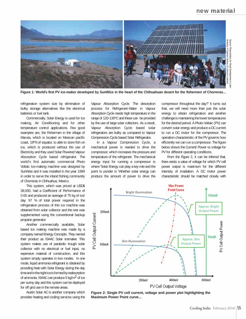
55Cooling India February 2016
new material
refrigeration system size by elimination of bulky storage alternatives like the electrical batteries or fuel tank.
Commercially, Solar Energy is used for Ice making, Air Conditioning and for other temperature control applications. Few good examples are, the Fishermen in the village of Maruta, which is located on Mexican pacific coast, 18ºN of equator, to able to store fish on ice, which is produced without the use of Electricity and they used Solar Powered Vapour Absorption Cycle based refrigerator. The world’s first automatic commercial Photo Voltaic Ice-making machine was designed by SunWize and it was installed in the year 1999 in order to serve the inland fishing community of Chorreras in Chihuahua, Mexico.
This system, which was priced at USD$ 38,000, had a Coefficient of Performance of 0.65 and produced an average of 75 kg of ice/day. 97 % of total power required in the refrigeration process of this ice machine was obtained from solar collector and the rest was supplemented using the conventional backup propane generator.
Another commercially available, Solar based Ice making machine was made by a company named Energy Concepts. They named their product as ISAAC Solar Icemaker. This system makes use of parabolic trough solar collector with no electrical or fuel input, no expensive material of construction, and this system simply operates in two modes. In one mode, liquid ammonia refrigerant is obtained by providing heat with Solar Energy during the day time and in the night ice is formed by reabsorption of ammonia. ISAAC can produce 5 kg/m2 of ice per sunny day and this system can be deployed for off grid use in the remote areas.
Austin Solar AC is another company which provides heating and cooling services using the
Vapour Absorption Cycle. The desorption process for Refrigerant-Water in Vapour Absorption Cycle needs high temperature in the range of 120-130ºC and these can be provided by the use of large solar collectors. As a result, Vapour Absorption Cycle based solar refrigerators are bulky as compared to Vapour Compression Cycle based Solar Refrigerator.
In a Vapour Compression Cycle, a mechanical power is needed to drive the compressor, which increases the pressure and temperature of the refrigerant. The mechanical energy input for running a compressor is where 'Solar Energy can play a key role and the point to ponder is 'Whether solar energy can produce the amount of power to drive the
compressor throughout the day?' It turns out that, we will need more than just the solar energy to obtain refrigeration and another challenge is maintaining the lower temperatures for the desired period. A Photo Voltaic (PV) can convert solar energy and produce a DC current to run a DC motor for the compressor. The operation characteristic of the PV governs how efficiently we can run a compressor. The figure below shows the Current/ Power vs voltage for PV for different operating conditions.
From the Figure 2, it can be inferred that, there exists a value of voltage for which PV cell power output is maximum for the different intensity of irradiation. A DC motor power characteristic should be matched closely with
Figure 1: World's first PV ice-maker developed by SunWize in the heart of the Chihuahuan desert for the fishermen of Chorreras...
Figure 2: Single PV cell current, voltage and power plot highlighting the Maximum Power Point curve...
Source: Photovoltaics for Rural Development in Latin
America: A Quarter Century of Lessons Learned

56Cooling India February 2016
new material
that of maximum power point curve in-order to perform an efficient job to run a compressor with available intensity of irradiation from the sun.
The novel technology of using the Direct PV along with PCM in solar refrigeration is patented by innovators at NASA’s Johnson Space Centre.This refrigeration system finds application in the rural areas, where grid electricity is unavailable and solar energy is abundant. A company named SunDanzer, has commercialized the PCM based Solar Refigerator. They cater to refrigeration needs of the household with their chest style freezers, refrigeration needs of the medicine field with its proprietary PCMs for storing heat sensitive vaccine in solar PV driven freezers and refrigeration needs of the military by reducing its fuel consumption in battlefield by use of solar driven potable water cooling, storage and air conditioning systems.
Another, similar technology was developed in an international project partnered by Greenpeace technology, GTZ, UNICEF, UNEP, WHO, industrial par tners and Danish Technological Institute. They developed a product named SolarChill a Solar PV refrigerator, which runs without the electrical battery. The main objective of the SolarChill Project is to help deliver vaccines and
refrigeration to the rural poor. Successful trials of this refrigerator was carried out at Copenhagen, Indonesia and Cuba, and it was found that vaccine can be kept between 0-8ºC after the PCM is frozen, for outside ambient temperature of 20ºC.This technology uses ice as a phase change material which can provide 62 % more energy than conventional 50 Ah-12 V batteries. Newer versions of SolarChill are aimed for optimization with regard to control strategy for different climatic conditions, reduction in cost and module area.
PCM can be used to create a low cost solar driven refrigerator. The usage of PCM as a thermal storage application is tested for commercial refrigerators by Centre of Excellence – Renewable and Sustainable Energy studies, Jaipur. They used a 165 L Videocon refrigerator which had a R134 Refrigerant, solar panels, Solar Sine wave UPS along with the battery.
Three sets of experiments were performed on the system. In case one, the refrigerator was operated using solar energy with no load inside the refrigerator. In second case, the refrigerator was operated by loading 2kg PCM. In the third case, backup obtained due to energy stored in PCM was tested by shutting off the compressor. The experiment was
performed for 6 hours in all three cases. While in the unloaded operation, the temperature of freezer section reached -5ºC and goes up to -6.8ºC in 6 hours while in the vegetable section temperature reaches up to 10ºC. In loading condition, a minimum temperature of only -2ºC was attained in the freezer while vegetable section managed to attain 10ºC, which is agreeable as energy is consumed in freezing of Ice gel packs.
In the backup test the PCM was able to maintain the temperature around 5ºC during the 6 hours of operation. The cost of procuring the system in India is much lower as compared to what available in the developed markets and with efficient design, optimizing heat losses and removing dependence on battery, a tailored solution can be made that can cater to the needs of refrigeration in remote areas for India as well as other developing markets.
Kunal BhagatAssociate - Application
EngineeringPluss Advanced Technologies
Pvt Ltd
Figure 3: First Solar Chill Prototype...
Sour
ce: S
olar
Chill
- a
sola
r PV
refri
gera
tor w
ithou
t bat
tery
To Subscribe - Fill The Subscription FormPage Number
53Page Number
87


58 Cooling India February 2016
warehouse logistics
The importance of efficiently loading goods has always been evident. It has only increased with the years. Higher cost of skilled manpower consequently causes the necessity of hiring less
qualified personnel. The cost of the goods is made up by the costs of raw materials’ production, storage, loading and shipment to the destination. With the introduction of better performing, precise and safe production machineries, a major chunk of the cost is passed over from the production to the storage and the loading process. The cost of loading the goods is a precise, inevitable phase, exactly definable that allows a scientific approach to problems and therefore, being able to arrive at solutions which may be quantified as Return on Investments.
Efficient loading and unloading of goodsFor efficient loading and unloading of goods at the loading bay,
the basic equipment comprises Dock Levelers, Sectional Overhead Doors and Dock Shelters. They appear to be independent equipment, but installation of any one without the other may not result in a complete solution at the loading bay. All three equipment are unbelievably interdependent. However, the choice of either one of the three depends on many factors. For example, the type of goods, the weight, volume, quantity, dimension of the cour tyard, the frequency of goods movement, the type of vehicles and the temperature to be maintained within the facility.
The cost of loading the goods is a precise, inevitable phase, exactly definable that allows a scientific approach to problems and therefore, being able to arrive at solutions – which may be quantified as Return on Investments…
Loading Bay– The Most Overlooked Area

59Cooling India February 2016
warehouse logistics
The loading bays: how to equip them?
With the approach mentioned above the motivation to reach the objective of cost reduction are the following:
Operators at the loading bay:• Safeguards the operators from the risk of
accidents• Grants to the operator better environmental
conditions, lowering their absences due to illnesses and increasing their productivity
• Loading and unloading with the lesser possible effort.
Material at the bay:• To avoid material damages to the goods• To avoid breaking the frozen food cold
chain• To protect goods from diverse weather
conditions.
Ecology and energy savings:• To avoid heating waste• To reduce heating and/ or air-conditioning
costs.
Maintaining the quality:To grant a constant quality of the goods
during loading and until their arrival at the consumer.
Vehicles:• To facilitate the vehicles approach
operations• To fill in the available spaces on the
vehicles• To load and unload as quickly as possible,
minimizing the waiting time of the vehicles.
Speeding up the operations:• Remote controlling of the loading bay state• Remote addressing of the vehicles to the
assigned bay• Remote calling of the driver when the load
is finished.
Equipping also when it seems impossible:• Disposing of adequate equipment also in
the warehouses without docks, at ground level
• Disposing of equipment when it seems that the space of docking the vehicles lacks
• Properly equipping the dock for loading light commercial vehicles.
Choosing equipment that allow the maximum building integration:• That conforms to the necessity of the
modern prefabrication• That may be installed only at the end of the
building works
• That preserves the integrity of the building parts.
To choose the equipment that allows maximum electrical integration:• By drastically reducing the number of the
electrical feeding descents• By reducing to the minimum the total
engaged power.
To choose equipment with adequate materials and finishing:• Painted with two components catalysed
anti-rust and with two oven-dried components catalysed end-finished enamel, previously ecologically degreased at 100 C degrees, double phosphate, for destination on common environments
• Hot dip galvanized for very humid, salted or aggressive environments
• Stainless steel where fish, meat, milk is treated
• Anti-burst where needed.
Choosing the adequate equipment:• For the type of activity and for the
necessary carrying capacities• That does not require maintenance• That conforms to the existing regulations• That is CE certified.
Each one of the above mentioned points has to be duly evaluated – and each one must find the precise reply within the adopted decision.
The ‘Deep Cold Loading Bays’: This system includes a Telescopic Dock
Leveler with a lip of one metre that remains - in rest position - closed by a Sectional Door that descends to cover the front of the whole Leveler.
The Sectional Door, that for the deep cold is 80 mm thick, has a trapeze and reduced-width bottom panel that enters and seals the inside of the pit, against special insulating par ts. A horizontal insulating panel under the leveler pit insulates the tail-lift room (when existing).
The best is obtained by the option ‘automatic return to rest position’ of the Dock Leveler. In case of deep cold, the insulation can be increased by the use of Inflatable Dock Shelters, reaching the top of the energy saving. For avoiding collisions to the rigid insulated panels of the Inflatable Dock Shelters, Vehicle Wheel Guides are
used. Also, Dock-Houses can be supplied with the ‘Recessed Loading Bay’ system, for ‘fresh’ and ‘deep cold’.
How to load in order to saveIt is possible to load and unload your
products in a safe way – and in the process obtain remarkable energy savings.
The loading bay remains with the Dock Leveler in rest position and the Sectional Overhead Door closed, until the vehicle is positioned. The driver drives back centering to
the Dock Shelter and stops the vehicle the moment it gets in contact with the bumpers.
The Sectional Overhead Door is then opened only when the vehicle is positioned, brakes applied and engines shut off. This eliminates the exit of hot air, intake of cold air (or the opposite in hot and inside conditioned places) and intake of exhausting gases in the warehouse. After the Sectional Overhead Door opens, the lip of the Dock Leveler connects to the truck bed for loading / unloading to take place.
At the end of the loading/unloading the Dock Leveler is put in the rest position and the Sectional Overhead Door is closed, without moving the vehicle. The vehicle then departs at the end of the process.
How much time elapses between the arriving of the vehicle and the beginning of the loading is the big question that must be solved. The shor ter it is, the greater is the saving and consequently has a bearing on the material cost.
Kartik GandhiDirector
Gandhi Automations Pvt Ltd


62 Cooling India February 2016
Test & Inspection
Rail customers expect to be served by trains that function perfectly from the very first day of service.
This is par ticularly true for the new Intercity platform that will be operated by Deutsche Bahn (DB). Expected to account for around 70% of revenue, the ICE 4 will be the backbone of DB's future long-distance service.
Two ICE 4 trains will enter passenger service in the fall of 2016 as part of a twelve-month period of trial operations. Until then, the trains will be subjected to rigorous testing.
Before the first passengers board the train, however, the ICE 4 has to prove that it can operate even under the most extreme weather conditions, in blazing heat as well as freezing cold. The tests, conducted at the Climatic Wind Tunnel operated by Rail Tec Arsenal (RTA) in Vienna, subject the train to conditions far more stringent than required by European norms. Deutsche Bahn commissioned supplementary tests that are specifically designed to ensure that the train's heating, ventilation and air conditioning (HVAC) operate faultlessly.
In addition, tests check if the pantograph moves up and down and functions in ice and snow, if the windscreen wiper keeps the driver's vision free, if the doors open and close smoothly, the folding steps function and the toilets operate without problems.
In May 2011, Deutsche Bahn awarded Siemens a frame contract for up to 300 multiple-unit trains. The first series production trains will enter passenger service with the change of the timetable in December 2017. The trains are initially foreseen for service in Germany, Austria and Switzerland.
Testingthe Train
Before the first passengers board the train, the
ICE 4 has to prove that it can operate even under
the most extreme weather conditions, in blazing
heat as well as freezing cold...
Credit for all photos: www.siemens.com/press

63Cooling India February 2016
Test & Inspection
Climatic Wind TunnelThe new Intercity train from Siemens underwent a 12-week comprehensive
testing program at Rail Tec Arsenal (RTA) in Vienna. Here, in the longest climatic wind tunnel in the world, the train had to prove that it can operate flawlessly at
speeds up to 200 kilometers an hour, at temperatures ranging from minus 25 to plus 45 degrees Celsius, as well as in snow, ice rain or in blazing sun.
ICE 4 withstands ice and snowEngineers at Rail Tec Arsenal (RTA) in Vienna are warmly packed in their winter jackets. Scarves and hats are essential at sub-zero temperatures (°C). The men stand in the icy wind and aim the snow cannons: thick hoses that spray a mixture of air and water at the train at high pressure: the mix freezes instantly in the air. Using this technique, they can build up thick ice shields and snow drifts on the train.
Comfortable interior temperatures The air conditioning systems in the ICE 4 are designed to maintain comfortable interior
temperatures at outside temperatures ranging from minus 20 to plus 40 degrees Celsius. The system can handle exterior temperatures of up to 45 degrees Celsius with only a slight
increase in the interior temperature. The train's air conditioning system is partly redundant: two independent air conditioning units work together to cool the cars. In case one of the units fails,
one cooling function will be maintained.
500 sensors collect data on the interior climateNot only is the functionality of all components tested in the Climatic Wind Tunnel, but the measuring data is also used to finely tune and optimize the air conditioning system. The goal is to ensure the greatest comfort for the passengers. To achieve this, 500 highly sensitive sensors are located in the interior of the ICE 4. They measure interior temperature and humidity and also monitor whether the air conditioning system fans are properly adjusted to eliminate any draughts.

64 Cooling India February 2016
Test & Inspection
Occupancy tests check the functionality of a fully occupied train
With red heating pads simulating the body warmth of passengers and humidifiers simulating their transpiration, the proper functioning of all
systems can be tested for a fully occupied train under realistic operating conditions. A seated passenger radiates around 120 watts of heat. The
Siemens engineers take this and other factors into account when designing and adjusting the ICE 4’s air conditioning system.
Weather experts can make nearly everything possibleThe RTA weather experts in Vienna spray the ICE 4 with water from nozzles to form a thick and wet layer of snow on the head vehicle of the ICE 4. Nearly every form of precipitation can be produced in the RTA Climatic Wind Tunnel by accordingly adjusting temperature, wind and the air-water mix from the nozzles – from the finest fog to pounding ice rain. A day’s testing at the facility costs up to 27,000 euros – largely due to the energy costs: Under full power, the tunnel consumes as much electricity as a small German city.
Functionality under all weather conditionsDrifting snow and icing present special challenges to the complex
technology of the ICE 4. Doors, brakes, air intakes – everything must function flawlessly. To ensure this is the case, numerous so-called functional tests are conducted during the climate tests. The train's
galley and all toilets must also operate optimally even at extremely low temperatures. Such systems present the biggest challenges, since
there are numerous water-conducting components in the train. No part may freeze even at temperatures of minus 25 degrees Celsius, and all
equipment must operate reliably. To ensure this, the RTA program rigorously tests whether all functions work at minus 25 degrees
Celsius under simulated operating conditions.
Weather experts can make nearly everything possibleThe RTA weather experts in Vienna spray the ICE 4 with water from nozzles to form a thick and wet layer of snow on the head vehicle of the ICE 4. Nearly every form of precipitation can be produced in the RTA Climatic Wind Tunnel by accordingly adjusting temperature, wind and the air-water mix from the nozzles – from the finest fog to pounding ice rain. A day’s testing at the facility costs up to 27,000 euros – largely due to the energy costs: Under full power, the tunnel consumes as much electricity as a small German city.
Unobstructed visibility with ice and snowA clear view at speeds of 250 kilometers an hour is absolutely essential for the driver of the ICE 4. So it's extremely important that the windscreen wiper operate flawlessly even while handling heavy wet snow. Tests in the Climatic Wind Tunnel make sure this is the case.

The World’s Best
Efficiency Pumps
Regd. Office: 7/46-1, Keeranatham Road, Saravanampatty, Coimbatore - 641 035. Tamilnadu, INDIA.
Phone : +91-422-3027000 Fax : +91-422-3027005
E-mail : [email protected] www.crigroups.com Toll Free 1800 200 1234
Pumping Solutions, Engineered
Less downtime Low operating cost Readily available technical supportI I
CRI pumps offers world class flow management solutions with an impressive range of
high performance pumps to take on the "tall challenges" of high raising infrastructure
like Skyscrapers, Hotels ect. these pumps, powered by innovation and backed by the
CRI brand ensure high performance and efficiency.
Unobstructed visibility in any weatherEven if the windscreen wiper of the ICE 4 is iced, it still ensures
a clear view for the driver: The field of view is free of streaks and the windscreen nozzles are fully functional despite the icy temperatures. But not all tests are conducted by sight alone:
Experts from Siemens and Rail Tec Arsenal (RTA) have installed around 500 highly sensitive sensors in the train cars to
precisely monitor how the train reacts to heat, cold and ice.
Reliable components under any weather conditions
Doors, brakes, air intakes – everything must function perfectly in icy conditions and drifting snow. The climate tests at the RTA
facility rigorously focus on such details. Components based on proven technology – such as the SF 500 power bogie of the ICE 4 cars – also are tested under every weather condition. These bogies
were already used in the ICE 3 Series 407, but due to their redesigned 100 millimetre wider wheelbase, are more compact and 136 millimetres shorter than the bogie used in the Velaro D (ICE 3 Series 407). As a result of these changes, the new design has to undergo a comprehensive test program to ensure everything here
runs as smoothly as with the new ICE 3.

67 Cooling India February 2016
refrigerant
Johnson Controls takes a holistic approach to carbon emission reductions…
Johnson ControlsChooses Low-GWP Refrigerant – Opteon XP10
The corporate headquarters of Johnson Controls in Glendale, Wisconsin
Johnson Controls is a company that creates healthier, more productive building environments delivering energy savings, operational savings and sustainable solutions. Whether it is for homeowners, schools or major military installations,
their technology and services produce better results. They have smart ways to improve buildings, empower the people within and meet their goals of home comfort, a better learning environment for children, a safer country – and everything in between.
The company is advancing its White House Council on Environmental Quality commitment by enhancing HFC product lines to be fully compatible with the non-flammable, low-GWP refrigerant – Opteon XP10 (R-513A) manufactured by The Chemours Company. York centrifugal and screw chillers ranging from 125 to 6,000 tons (440 to 21,100 kW) are compatible with R-513A.
“Our customers can have peace of mind when specifying or purchasing current R-134a-based product offerings, knowing their purchase will provide the full economic benefit, regardless of any potential HFC regulations during the life span of their equipment. We always choose refrigerants that will best meet the needs of our customers and the environment based on safety, efficiency, reliability, availability and cost,” said Laura Wand, Vice
President, Building Efficiency, Global Chiller Business, Johnson Controls. “Just as we addressed ozone depletion years ago, specifically with regard to CFCs
and HCFCs, we discontinued the use of R-123-based products to avoid potential obsolescence of equipment in the later stages of equipment lifetime. We are always thinking and planning decades ahead, so our customers don’t have to worry about it. Our chillers are ready for the future,” added Wand.
Chemours’ Opteon XP10 (R-513A) is a non-flammable (A1) azeotropic alternative to R-134a, providing 56% lower GWP and comparable performance. XP10 was commercialised as a part of a broad portfolio of Opteon refrigerants, which represent a breakthrough line of low-GWP solutions developed to help meet the current and proposed HFC regulations while maintaining or improving performance compared to incumbent products.
“As the HVACR industry faces increasing pressure to shrink its growing environmental footprint, Opteon XP10 provides equipment owners with a hydrofluoroolefin (HFO)-based, low-GWP and non-flammable solution to reduce their refrigerant’s carbon footprint, in a broad range of end-use applications and climates, without compromising system performance,” said Diego Boeri, Global Business Director, Chemours Fluorochemicals.
Johnson Controls takes a holistic approach to carbon emission reductions. While low-GWP refrigerants are important for the future, energy efficiency represents the greatest opportunity for true greenhouse gas emission reductions. Energy consumption represents as much as 95% of a chiller’s lifetime carbon emissions.

68 Cooling India February 2016
heat management
The radiant heat is invisible and has no temperature, just energy. When this energy strikes another surface, it is absorbed and increases the temperature of that surface. In
summer, radiation from the sun strikes the outer surfaces of walls and ceilings and is absorbed causing the surface to heat up. This heat flows from the outer wall to the inner wall through conduction which is then radiated again, through the air spaces in the building, to other surfaces within the building. Radiation between surfaces is through invisible, infra-red heat rays.
Different types of insulation products reduce the heat transferred by conduction, convection and radiation to varying degrees. As a result, each provides different thermal performance and corresponding ‘R’ values. The primary function of reflective insulation is to reduce radiant heat transfer across open spaces, which is a significant contributor to heat gain in summer and heat loss in winter.
There are many types of materials that reduce heat gain and heat loss. Some materials provide greater resistance than others, depending on the mode of heat transfer: convection, conduction or radiation. Most insulation materials work on the principle of trapped air gas being a good insulator. Mass insulation like, ‘INSUshield’- closed cell, FR cross linked polyethylene foam, use cellular walls of plastics, Fibre glass wool uses glass fibers to reduce convection thereby decreasing the
A reflective insulation system is typically formed by layers of aluminium or a low emittance material, and enclosed air spaces, which in turn provide highly reflective or low emittance cavities (Air bubble film) adjacent to a heated region...
ReflectiveInsulation


70 Cooling India February 2016
heat managementtransfer of heat. These materials also reduce heat transfer by conduction due to the presence of trapped air. (However, these products, like most building materials, have very high radiant transfer rates. Most building materials, including fiberglass, foam and cellulose have ‘E’ values in excess of 0.70.
Reflective insulation typically have ‘E’ values of 0.03 (again, the lower the better). Therefore, reflective insulation is superior to other types of insulating materials in reducing heat flow by radiation.
When reflective insulation is installed in building cavities, it traps air (like other insulation materials) and therefore reduces heat flow by convection thus addressing all three modes of heat transfer.
In all cases, the reflective material must be adjacent to an air space. Aluminium, when sandwiched between two pieces of plywood or between two concrete layers for example, will conduct heat at a high rate. The conductive insulation material should always be in contact with the substrate for better insulation.
Understanding a Reflective Insulation System (RIS)
A reflective insulation system is typically formed by layers of aluminium or a low emittance material, and enclosed air spaces, which in turn provide highly reflective or low emittance cavities (Air bubble film) adjacent to a heated region.
The performance of the system is determined by the emittance of the material(s), the lower the better, and the size of the enclosed air spaces. The smaller the air space, the less heat will transfer by convection. Therefore, to lessen heat flow by convection, a reflective insulation, with its multiple layers of aluminium and enclosed air space (INSUreflector), is positioned in a building cavity (stud wall, furred-out masonry wall, floor joist, ceiling joist, etc.) to divide the larger cavity (3/4” furring, 2” x 4”, 2” x 6”, etc.) into smaller air spaces. These smaller trapped air spaces reduce convective heat flow.
Reflective insulation differs from conventional mass insulation in the following ways:• Reflective insulation has very low
emittance values ‘E-values’ (typically 0.03 compared to 0.90 for most insulation) thus significantly reduces heat transfer by radiation
• A reflective insulation does not have significant mass to absorb and retain heat
• Reflective insulation has lower moisture transfer and absorption rates, in most cases
• Reflective insulation traps air with layers of aluminium & Air bubble film plastic as opposed to mass insulation, which uses fibers of glass, particles of foam, or ground up paper
• Reflective insulation does not irritate the skin, eyes, or throat and contains no substances which will out-gas
• The change in thermal performance due to compaction or moisture absorption, a common concern with mass insulation, is not an issue with reflective insulation.
Supreme’s Thermal Insulation Division offers solutions in the following areas:• Ducting insulation in hospitals, shopping
malls, airports, PEBs, IT/BPO etc.• Pipe insulation for split AC tubings, chiller
piping, drain pipes, chilled water lines etc.• Floor insulation in server rooms, data
centres, medical and diagnostic centres, and control rooms for petrochemicals.
• Underdeck insulation in PEBs, textile units, malls, airports etc.
• Overdeck and wall insulation in commercial buildings, residential buildings, cold storages etc.
‘INSUreflector’ offered by Supreme is made of polyethylene Air Bubble Film (ABF) laminated with aluminium foil on one or both sides. The bright surface of the aluminium foil reflects 96 to 995 infra-red radiation received by the surface of a heated slate roof. It protects the building from undesirable heat gain. The thin reflective foil having low emissivity and high reflectivity when installed with an air space restricts the transfer of far-infrared radiation making it an ideal material to be used for underdeck application.
‘INSUshield’ is a non-fibrous, fire retardant, closed cell, tri dimensional chemically crosslinked polyethylene foam XLPE. An ideal environment-friendly insulation material, with a perfect solution for all your insulation needs for ducts, roofs, pipes, vessels, etc. The divergent advantages of ‘INSUshields’ are ease of installation, low thermal conductivity and good moisture and vapours resistance preventing microbial growth and optimum condensation protection.
Atul KhannaGeneral Manager - Thermal
Insulation DivisionThe Supreme Industries Ltd.
INSUreflector - Underdeck Insulation…

71Cooling India February 2016
indoor air
The Importance Of
The ions generated are the same positive and negative ions found in abundance in nature. They turn into OH- radicals only on the surface of harmful substances to inactivate them, so they are completely harmless to the human body...
Ionized Air

72 Cooling India February 2016
indoor air
Modern living areas of indoor and outdoor spaces include public and private areas, air-conditioned,
ventilated or open air areas like: hotels, restaurants, shops, houses, vehicles; traffic roads; surface and air transportation, urban zone and more. These facilities experience environmental challenges from a variety of volatile, par ticulate, and microbial air contaminants arising from natural and human sources. The air contaminants include general pollutants (smoke, dust, pollen, odors), specific chemicals (unburned hydrocarbons, carbon monoxide), and microbial (bacteria, molds). Comfort and health aspects of indoor air environments are affected by these contaminants.
The objectives for environmental management are multiple: minimising pollutant sources; providing good air handling; and improving Indoor Air Quality (IAQ). Technologies treating air contaminants involve filtration, adsorption, and electronic processes (Ionization).
Demands for more complete treatment of indoor air environments have led to the development of practical engineered systems
based upon bipolar air ionization. Bipolar air ionization involves generation of negative and positive ions by applying electrical energy to air molecules. In the ionized air, reactive species are created that oxidize Volatile Organic Compounds (VOCs) and agglomerate fine Particulate Matter (PMx).
Air ionization modules are usually fitted directly into central air handling units to treat entire airflows in order to meet challenges from external sources. Modules also can be fitted into existing ductwork, immediately downstream of central HVAC systems. Free standing devices can also be placed in individual room spaces to meet immediate demands from internal sources.
Field applications of bipolar air ionization systems require optimization of process variables of the physical air handling system and the air quality demand. The central process control unit is programmed for fixed situation design parameters (ion level, power capacity, and airflow area), and for monitored demand parameters (airflow, humidity, outside and return air quality, and ozone). Optimal design should take these parameters into consideration during the design process.
Some features and benefitsThe ions generated are the same positive
and negative ions found in abundance in nature, for example, in forests. They turn into OH- radicals only on the surface of harmful substances to inactivate them, so they are completely harmless to the human body.
The amount of ozone generated Coil*Tech IONIZER is less than 0.003 ppm, significantly below the 0.050 ppm value set as the American standard for industry and for electrical equipment. Compared to passive air cleaning systems that trap airborne contaminants by using a fan to draw air through a filter, air purification systems based on Bipolar Ion Technology effectively eliminate harmful substances by working directly on the air contained in the entire room. Coil*Tech IONIZER emitting electrodes are outside the airflow, so only a small amount of dust settles on them.
Gopal Banerjee CEO
Coil*Tech

73Cooling India February 2016
tecnnology options
Solar
A solar electric refrigeration system consists mainly of photovoltaic panels and an electrical refrigeration device. Solar cells are basically semiconductors whose efficiency and cost vary widely depending on the material and the manufacturing methods...
Refrigerations
technology options

74 Cooling India February 2016
technology options
In the present context, the energy demand is increasing with increase in the population and improvement in the living standard. It
is the crucial input to the social, economical, industrial and technological development of any country.
Refrigeration is available in the industrialized countries through the availability of electricity but is not readily available in the major part
of the world. Air conditioning demand has increased in recent years, due to the demand of higher comfort conditions inside buildings. This has led to a widespread use of air conditioning systems based on compression technology, resulting in significant increase of electric power peak demand in summer.
The International Institute of Refrigeration in Paris (IIF/IIR) has estimated that approximately 15% of all the electricity produced in the whole world is employed for refrigeration and air-conditioning processes of various kinds. The energy consumption for air-conditioning systems has recently been estimated to 45% of the whole households and commercial buildings. A rational use of energy brings both economic and environmental benefits, by reducing consumption of fossil fuels, electricity and pollutant emissions.
In general, refrigeration is defined as any process of heat removal from a place for preserving foods and medicines by enhancing their shelf life (the same is applied in space cooling). To achieve refrigeration, a heat source is required to drive the refrigeration system. There are several sources of energy for production of refrigeration, the most important being gas, electricity and solar energy. With increasing gas and electricity tariffs, solar energy becomes attractive and as such the system has been installed. As part of renewable energy sources, solar energy is advantageous to developing countries, especially in subtropical countries. Solar cooling is more attractive because:
(a) The demand for cooling is generally the greatest at times of maximum availability of solar radiation, and
(b) The cooling is far more needed in hotter regions than in colder climate.
A variety of solar refrigeration technologies have been developed and many of them are available in the market at much cheaper prices than ever.
Classifications of solar refrigeration systems
Solar cooling technology can be classified into three categories: solar electrical cooling,
solar thermal cooling, and solar combined power and cooling, as illustrated in Figure 1.1. Detailed discussion of each solar cooling technology follows.
Solar electric refrigeration systemA solar electric refrigeration system
consists mainly of photovoltaic panels and an electrical refrigeration device. Solar cells are basically semiconductors whose efficiency and cost vary widely depending on the material and the manufacturing methods they are made from. Most of the solar cells commercially available in the market are made from silicon.
In Eq. (1.1), efficiency of a solar panel is defined by the ratio of power W (kW) to the product of solar panel surface area As (m2) and the direct irradiation of solar beams Ip (kW/m2). Ip = 1 kW/m2 is commonly used for the calculation of nominal efficiency.
… (1.1)
Although higher efficiencies are reported from laboratories a high-performance solar panel sold in the market yields about 15% efficiency under the midday sun in a clear day.
Fig. 1.1: Energy conversion option for solar cooling...

75Cooling India February 2016
tecnnology options
A study on building-integrated solar panels reported an overall efficiency of 10.3%. Price of a solar panel varies widely in the market. For example, retail price of a solar panel in India varies between Rs. 350-550 per Wp (peak Watt), i.e., production of 1W under 1 kW/m2 of solar radiation.
The biggest advantage of using solar panels for refrigeration is the simple construction and high overall efficiency when combined with a conventional vapour compression system. A schematic diagram of such a system is given in Figure 1.2(b). In Figure 1.2(b), the work ‘W’ is consumed by the mechanical compressor to produce the cooling power Qe. Refrigeration machine efficiency is defined as the cooling power Qe divided by the work input W:
… (1.2)
Combination of the two efficiencies in Eq. (1.1) and Eq. (1.2) gives the solar-to-cooling or the overall efficiency of a solar electric cooling system:
… (1.3)
COP (Coefficient of Performance) is an alternative term to efficiency commonly used in thermodynamics. Solar electric vapour compression refrigeration systems are limited and only a few systems are found in literature. Several solar electric refrigeration systems were designed for autonomous operation and packaged in standard containers. COPs of the vapour compression machines in those systems ranged from 1.1 to 3.3 for different evaporator temperatures between -5ºC and -15ºC and condenser temperatures between 45ºC and 61ºC. Monocrystalline PV modules and variable-speed compressors were used with batteries or generators as a back up.
There are several challenges in the broader commercialization of this type of systems. Firstly, the systems should be equipped with some means to cope with the varying electricity production rate with time, e.g., electric battery,
mixed use of solar and grid-electricity or a variable-capacity compressor. Secondly, the price of a solar photovoltaic panel should be further decreased to compete with other solar cooling technologies. If a 10% efficiency solar photovoltaic panel is combined with a vapour compression air conditioner with 3.0 COP, the overall efficiency will be 30%.
Besides vapour compression cooling, some other types of electric refrigeration technologies can be used in combination with solar panels. Thermoelectric elements are made of semiconducting materials such as bismuth telluride and antimony telluride alloys (Bi2Te3 and Sb2Te3). Since they have neither moving parts nor refrigerant and can be made very small, they have been used in electronic chip cooling, portable refrigerators and in space applications like satellite and space ships where physical size of a cooling system is extremely limited. COP of this system is currently very low, ranging from 0.3 to 0.6. Small thermoelectric air-conditioners with a few hundred watt capacities are available in the market.
A Stirling refrigerator can be connected to solar panels to provide cooling. Although an ideal Stirling cycle should work as efficiently as Carnot cycle, COPs of the Stirling refrigerators are lower than those of vapour compression counterparts. Researchers conducted many investigations and results show that there
were many practical difficulties in developing an efficient refrigerator. Major problems are low COP and limited power density due to the poor heat transfer between working fluids (mostly helium) and the ambient (Kribus, 2002).
Electrically driven thermo-acoustic refrigeration machines are another option for solar refrigeration. These machines use pressure changes in acoustic waves to transfer heat between two reservoirs at different temperature levels. The working principle is discussed in American Institute of Physics (2004). Efficiencies of thermo-acoustic cooling systems are lower than those of vapour compression systems. Although a thermo-acoustic system has a very simple construction with no moving part, cooling power density is low and no machine has been reported with a reasonably large capacity for air conditioning.
Magnetic cooling, which has long been used in cryogenics, is also a possibility. Recently, a few permanent-magnet room temperature magnetic refrigeration systems have been developed. Gschneider (2001) demonstrated an overall COP of 3.0 with a rotary magnetic refrigerator/ freezer. Although this technology has a potential of outperforming conventional vapour compression technology, the cost of magnetic material is prohibitively expensive Rs. 91500/kW cooling for practical application.
Solar thermal refrigerationSolar thermal systems use solar heat
rather than solar electricity to produce refrigeration effect. Flat-plate solar collectors are the most common type, which consist of a metallic absorber and an insulated casing topped with glass plate(s). Evacuated collectors have less heat loss and perform better at high temperatures. Evacuated collectors are typically made in a glass tube design, i.e., a metallic absorber inserted in an evacuated glass tube, to withstand the pressure
Fig.1.2. (a) Schematic diagram of a solar photovoltaic panel... (b) Solar electric compression refrigeration system...
Fig. 1.3 Schematic diagrams of non concentrating solar collectors (a) flat plate type and (b) evacuated type...

76 Cooling India February 2016
technology optionsdifference between the vacuum and the atmosphere. Figure 1.3 shows schematic diagrams of these two collectors. A solar collector provides heat to the ‘heat engine’ or ‘thermal compressor’ in a heat-driven refrigeration machine. The efficiency of a solar collector is primarily determined by its working temperature. At a higher working temperature, the collector looses more heat to ambient and delivers less heat. On the other hand, the heat engine or thermal compressor generally works more efficiently with a higher temperature. A solar thermal system is designed in consideration of these two opposing trends.
(a) Thermo-mechanical refrigerationIn a solar thermo-mechanical refrigeration
system, a heat engine converts solar heat to mechanical work, which in turn drives a mechanical compressor of a vapour compression refrigeration machine. A schematic diagram of such a cooling system is shown in Figure 1.4. In the figure, a solar collector receives solar radiation Qs from the sun and supplies Qg to a heat engine at the temperature TH. The ratio of supply heat Qg to the radiation Qs is defined as the thermal efficiency of a solar thermal collector.
… (1.4)
ηsol-heat is less than 1 due to optical and thermal losses. A heat engine produces mechanical work W and rejects heat Qa to ambient at temperature TM. The efficiency of engine, ηheat-pow is defined as the work produced per heat input Qg in Eq. (1.5).
… (1.5)
The mechanical work W in turn drives the compressor of the refrigeration machine to remove heat Qe from the cooling load at temperature TL. Waste heat Qc, which is equal to the sum of Qe and W, is rejected to ambient at the temperature TM. Efficiency of the refrigeration machine is the same as in Eq. (1.2)
Then the overall efficiency of a solar thermo-mechanical refrigeration system is given by the three efficiencies in Eqs. (1.4), (1.5) and (1.2) as follows:
… (1.6)
The maximum efficiencies of the real engine and refrigeration machine are limited by those of Carnot cycles working at the same
temperatures. The efficiency of a Carnot power cycle working between TH and TM is given by
… (1.7)
and the efficiency of a Carnot refrigeration cycle working between TM and TL is given by
… (1.8)
The product of the two Carnot efficiencies in Eqs. (7) and (8) gives the efficiency of an ideal heat-driven refrigeration machine working between the three temperatures as
… (1.9)
which limits the maximum efficiency achievable with any real heat-driven refrigeration machine working between the same temperatures. In a solar thermo-mechanical system, the efficiency of a heat engine is of particular interest. Because the heat source temperature TH varies in different projects, the performance of a real engine is often compared to that of a Carnot cycle working at the same temperatures. The ratio of real efficiency to Carnot efficiency is called ‘second law efficiency’. This is a measure of how closely a real machine operates to an ideal machine. For solar power generation, Rankine and Stirling power engines have been frequently considered.
(b) Sorption refrigerationSorption refrigeration uses physical or
chemical attraction between a pair of substances to produce refrigeration effect. A sorption system has a unique capability of transforming thermal energy directly into cooling power. Among the pair of substances, the substance with lower boiling temperature is called sorbate and the other is called sorbent. The sorbate plays the role of refrigerant.
Fig. 1.5 shows a schematic diagram of a closed sorption system. The component where sorption takes place is denoted as absorber and the one where desorption takes place is denoted as generator. The generator receives heat Qg from the solar collector to regenerate the sorbent that has absorbed the refrigerant in the absorber.
The refrigerant vapour generated in this process condenses in the condenser rejecting the condensation heat Qc to ambient. The regenerated sorbent from the generator is sent back to the absorber, where the sorbent absorbs the refrigerant vapour from the evaporator rejecting the sorption heat Qa to ambient. In the evaporator, the liquefied refrigerant from the condenser evaporates removing the heat Qe from the cooling load.
Fig. 1.4 Solar thermo-mechanical refrigeration system...
Fig. 1.5 Solar absorption refrigeration system...

77Cooling India February 2016
tecnnology options
In an adsorption system, each of the adsorbent beds alternates generator and absorber function due to the difficulty of transporting solid sorbent from one to another. In sorption refrigeration machines, a single heat-to-cooling efficiency is often defined by
… (1.10)
where Wel in the denominator denotes electrical work. This efficiency, also called COP, is often compared with the ideal efficiency in Eq. (1.9) to measure how the system efficiency deviates from ideal efficiency.
Absorption refers to a sorption process where a liquid or solid sorbent absorbs refrigerant molecules into its inside and changes physically and chemically in the process. Adsorption, on the other hand, involves a solid sorbent that attracts refrigerant molecules onto its surface by physical or chemical force and does not change its form in the process. Desiccation refers to a sorption process where a sorbent, i.e., a desiccant, absorbs moisture from humid air. This process is employed in open sorption cycles, which are classified into either liquid or solid desiccant cycles depending on the phase of the desiccant used.
(b1) AbsorptionAbsorption refrigeration has been most
frequently adopted for solar refrigeration. It requires very low or no electric input and, for the same capacity, the physical dimensions of an absorption machine are smaller than those for adsorption machines due to the high heat transfer coefficient of the absorbent. Besides, the fluidity of the absorbent gives greater flexibility in realizing a more compact and/or efficient machine.
Current absorption technology can provide various absorption machines with COPs ranging from 0.3 to 1.2. Choice of an absorption cooling machine is primarily dependent on the performance of the solar collector to be used. For solar collectors capable of efficiently working at around 150ºC, double-effect LiBr–water chillers with COPs around 1.2 are available for air conditioning. For refrigeration, ammonia– water GAX chillers with COPs around 0.8 can be considered. Heat transfer medium can be either a liquid with a high boiling temperature or steam. A high performance evacuated tube or a concentrating type collector can be considered. It must be noted that the solar collector efficiencies listed above are only indicative and actual efficiencies will depend on ambient air temperature and solar radiation.
(b2) Adsorption coolingPhysical adsorption: Adsorbents like
zeolite, silica gel, activated carbon and alumina are physical adsorbents having highly porous structures with surface–volume ratios in the order of several hundred that can selectively catch and hold refrigerants. When saturated, they can be regenerated simply by being heated. If an adsorbent and a refrigerant are contained in the same vessel, the adsorbent would maintain the pressure by adsorbing the evaporating refrigerant. The process is intermittent because the adsorbent must be regenerated when it is saturated. For this reason, multiple adsorbent beds are required for continuous operation. Employed working pairs include activated carbon and methanol or ammonia and silica gel–water.
For a high Specific Cooling Power (SCP), various ideas have been tried including the use of extended surfaces such as plate-fin heat exchangers, adsorbent-coated heat exchangers, and consolidated composite adsorbents. Adsorption chillers seem to be comparable with absorption chillers in terms ofmaximumachievable COP. But their cooling power densities are much lower. Adsorption technology may be competitive in large solar cooling systems where its low power density is not a problem. For small- or medium-size solar cooling systems, it tends to be too bulky and expensive.
Chemical adsorption: Chemical adsorption is characterized by the strong chemical bond between the adsorbate and the adsorbent. Therefore, it is more difficult to reverse and thus requires more energy to remove the adsorbed molecules than in physical adsorption.
The most commonly used chemical adsorbent in solar cooling applications has been calcium chloride (CaCl2). Calcium
chloride adsorbs ammonia to produce CaCl28NH3 and water to produce CaCl26H2O as a product. It has also been used together with other physical adsorbents including some silicates.
Metal hydride refrigeration uses hydrogen as a refrigerant. The interest in metal hydride refrigeration systems is increasing for their integration into hydrogen-fuelled systems. In a basic two-bed refrigeration system, one bed is filled with a high-temperature hydride and the other is filled with a low-temperature hydride. In recharge mode, the high temperature bed is heated to release hydrogen while the low-temperature bed is cooled to absorb the hydrogen. When the high-temperature bed is cooled in cooling mode, hydrogen is released from the low-temperature bed creating heating effect by absorbing heat. The research issues on metal hydride refrigeration are basically the same as the other adsorption technologies including the enhancement of specific cooling capacity and heat transfer in the beds. Driving temperature of a single-stage system starts from as low as 80ºC depending on the hydride and the heat rejection temperature. COPs of single-stage systems are in the vicinity of 0.5.
Desiccant cooling: Open sorption cooling is more commonly called desiccant cooling because sorbent is used to dehumidify air. Various desiccants are available in liquid or solid phases. Basically all water absorbing sorbents can be used as a desiccant. Examples are silica gel, activated alumina, zeolite, LiCl and LiBr.
In a liquid desiccant cooling system, the liquid desiccant circulates between an absorber and a regenerator in the same way as in an absorption system. Main difference is that the equilibrium temperature of a liquid desiccant is determined not by the total pressure but by the partial pressure of water in the humid air to
Fig. 1.6 A liquid desiccant cooling system with solar collector...

78 Cooling India February 2016
technology optionswhich the solution is exposed to. A typical liquid desiccant system is shown in Fig. 1.6. In the dehumidifier of Fig. 1.6, a concentrated solution is sprayed at point A over the cooling coil at point B while ambient or return air at point 1 is blown across the stream. The solution absorbs moisture from the air and is simultaneously cooled down by the cooling coil. The results of this process are the cool dry air at point 2 and the diluted solution at point C. Eventually an after cooler cools this air stream further down.
In the regenerator, the diluted solution from the dehumidifier is sprayed over the heating coil at point E that is connected to solar collectors and the ambient air at point 4 is blown across the solution stream.
Some water is taken away from the diluted solution by the air while the solution is being heated by the heating coil. The resulting concentrated solution is collected at point F and hot humid air is rejected to the ambient at point 5. A recuperative heat exchanger preheats the cool diluted solution from the dehumidifier using the waste heat of the hot concentrated solution from the regenerator, resulting in a higher COP.
A solid desiccant cooling system is quite different in its construction mainly due to its non-fluid desiccant. Fig. 1.7 shows an example of a solar-driven solid desiccant cooling system. The system has two slowly revolving wheels and several other components between the two air streams from and to a conditioned space. The return air from the conditioned space first goes through a direct evaporative cooler and enters the heat exchange wheel with a reduced temperature (A/B).
It cools down a segment of the heat exchange wheel which it passes through (B/C). This resulting warm and humid air stream is further heated to an elevated temperature by the solar heat in the heating coil (C/D). The resulting hot and humid air regenerates the desiccant wheel and is rejected to ambient (D/E ). On the other side, fresh air from ambient enters the regenerated part of desiccant wheel (1/2).
Dry and hot air comes out of the wheel as the result of dehumidification. This air is cooled down by the heat exchange wheel to a certain temperature (2/3).
Depending on the temperature level, it is directly supplied to the conditioned space or further cooled in an after cooler (3/4). If no after cooler is used, cooling effect is created only by the heat exchange wheel, which was
previously cooled by the humid return air at point B on the other side.
Temperature at point 3, T3, cannot be lower than TB, which in turn is a function of the return air condition at point A.
From a thermodynamic point of view, the dehumidification process is not much different from a closed sorption process. Neglecting the enthalpy changes in the air flow, the same heat will be required to remove 1 kg of water from a sorbent regardless it is in a closed vessel or it is in a humid air stream.
Therefore, in principle, the COP of an open desiccant system is similar to its closed counterpart. But in practice, COP varies widely depending on operating conditions. A desiccant cooling system is actually a complete HVAC system which has ventilation, humidity and temperature control devices in a ductwork. Therefore, it is inappropriate to compare a desiccant cooling system with such components as chillers.
Desiccant dehumidification offers a more efficient humidity control than the other technologies. When there is a large ventilation or dehumidification demand, solar-driven desiccant dehumidification can be a very good option.
Other technologiesElectrochemical refrigeration is a new
concept, which uses the thermal effects of the reversible electrochemical reactions such as in a reversible electrochemical cell. This new refrigeration concept is based on the idea that a reversible electrochemical cell that releases heat when voltage is applied would absorb heat when the voltage is reversed. This technology is very young and currently being investigated for its technical feasibility.
Fig.1.7 A solid desiccant cooling system with solar collector...
Ejector refrigeration technology was used for air conditioning of trains and large buildings. With a generator temperature between 85 and 95ºC, COPs reported are in the range of 0.2–0.33 for a condenser temperature between 28 and 32ºC. And the COP may be 0.85 only if heat source temperature at 200ºC.
Although the simple construction of ejector systems is a great advantage, their COP makes it difficult to compete with the other heat-driven technologies.
A variety of combined or hybrid systems have also been investigated. By selectively combining different technologies, creation of new functions or enhancement of performance was intended.
ConclusionThe greatest demand for cooling occurs
when the solar radiation is most intense, thus making its use for cooling is all the more attractive.
Cooling load and availability of solar radiation are approximately in phase. In a tropical country, like India, the importance of refrigeration can hardly be over emphasized.
Solar photovoltaic is best option to operate refrigeration in remote area, where electricity is not available.
Dr. Kapil SamarProject Manager
Biogas Development and Training Center CTAE, Udaipur

79Cooling India February 2016
award
RobecoSAM recognizes Electrolux in the yearbook
as Industry Leader for the fifth consecutive year…
Electrolux has been ranked Industry Leader Household Durables in the Robeco SAM Sustainability Yearbook, an annual rating of the sustainability performance among more than 2,000 of the world’s largest companies.
It is the fifth consecutive year that RobecoSAM recognizes Electrolux in the yearbook as Industry Leader, a distinction awarded to the top performing company in each of 59 industries. RobecoSAM, which also publishes the globally prestigious Dow Jones Sustainability Indices (DJSI), said in the yearbook it had measured companies based on their sustainability performance in three dimensions: economic, environmental and social.
“Sustainability is an integral part of the Electrolux business strategy and through an extensive engagement program over the past year, we have defined clear priorities to ensure we continue to perform well while making a real difference in people’s lives and for our planet. Our biggest priority is efficiency – continuing to cut down the energy and water our products use, extracting fewer resources, minimizing hazardous substances and shrinking the impact of our operational footprint,” said Henrik Sundström, Vice President Sustainability at Electrolux.
In addition to being named Industry Leader, Electrolux received the Gold Class award, which goes to the companies with the highest scores in each industry.
Electroluxagain becomes sustainability ranking topper
As a leading manufacturer of com-ponents for refrigeration engineering and air conditioning, Güntner pro-vides qualifi ed technical assistance and personal support from the be-ginning. Different products must be cooled and stored in commercial cooling. This makes high demands on selecting the right air cooler.
Güntner offers a wide range of heat exchangers for all application areas, which are suitable for all current coolants and refrigerants. Our com-petent employees advise you with professional Güntner know-how by phone and in person on site.
Güntner Middle East FZEMiddle East, India & Africa
Tel: +971 4 371 2826
www.guentner.eu
Refrigeration technology for any application

80 Cooling India February 2016
Interview
Oventrop is one of the leading European manufacturers of valves and controls for the Building Services Industry. In an e-interview,
Milind Pawar, Country Manager of the Indian wing of the company is highlighting various aspects of
their business to P K Chatterjee. Excerpts...
“Oventrop products are a combination of quality and durability...”

81Cooling India February 2016
What are the product lines that Oventrop is now marketing in India?
Oventrop is a German organization, and pioneered in hydronic balancing and control products for HVAC, potable water systems and solar thermal systems. Oventrop manufactures all products under strict quality control in its own factories in Germany. OV products are certified by competent authorities like DVGW, DNV etc. These products are being used in India and repeat purchase from customers talks big about our product quality and reliability. Our products are more focused on life cycle cost rather than just initial cost. Being manufactured in Germany, quality and usability of products remain our prime focus.
How is the company’s business shaping up in India?It’s being nine years since Oventrop started its operation in India and
we achieved continuous growth ever since. Customers are becoming quality cautious and demanding quality products backed up by after sales support, which is acting as booster to our business. Mechanics being integral part of German manufacturing, our products are almost maintenance free, and our service engineers are utilizing their time for marketing activities rather than handling customer complaints. This speaks lot about our quality and operational advantages. We can proudly say that Oventrop products are with very minimal failure rate and offer trouble free operation to our esteemed customers.
Which sectors are you particularly eying on in India?As hydronic balancing is important for every sector, we do not limit
ourselves to any particular sector. We have customers across all industries like commercial, luxury hotels, pharmaceuticals, shipbuilding and industry as a whole. Our major focus was on HVAC, however we started gaining sizable market share in potable water side as well. Oventrop has products and systems for potable cold and hot water that can be very efficient and attracts energy and water saving (+ Hygiene, legionella etc.).
Today, plumbing industry is adopting more and more international standards and raising Indian plumbing standards, this is a very good sign for highly efficient Oventrop products. Other than HVAC and plumbing, we also focus on solar thermal related systems with highly efficient pumping system for individual villas / houses wherein quality is must and OV products serve this purpose to its best strength. Oventrop is a leader in providing potable water system in Europe, and our target is to penetrate in Indian market as well. With kind of positive changes happening in plumbing industry in India, this is quiet possible and achievable.
What are your latest technologies for India?Continuous research and development in products offering with
respect to global demand is the key for sustainable growth for Oventrop’s business. Oventrop is well equipped with its own R&D centre to ensure market demands are met with required products and innovation on regular basis. Some of the latest technologies in different sectors are:
a. HVAC: Pressure Independent Dynamic Control Valves (PICVs) upt o DN200, Fly pass ( Bypass arrangement for initial flushing of water), Double regulating and commissioning valves up to DN450. Our products’ operating range is -20 Deg C to +150 Deg C. Our PICVs (Cocon Q) are green products and are approved in Malaysian and Singapore green building council.
b. Potable Water: Thermostatic Mixing Valve, Hot water recirculation pumping station within build VFD, Thermal Balancing Valve (takes care of legionella virus in the hot water and cold water systems), All products are DVGW certified.
c. Solar Thermal: Closed circuit hot water Generation system and
also supplies only pumping station for hot water system to various other manufacturers in industry. All valves and controls required for safety and operation of solar hot water are supplied by Oventrop in India as well as globally.
d. Shipbuilding Products: Balancing valves, Butterlfy valves, NRVs suitable for marine environment and all our products are DNV certified so as to use in Shipbuilding Industry.
Do you manufacture any product in India?All products that Oventrop supplies are manufactured in our facilities
in Olsberg and Brilon, Germany. Currently, we do not have any manufacturing facility in any other country than Germany.
How is our respected Prime Minister’s call ‘Make in India’ impacting your business?
It’s a very good initiative by our Central Government, and has a wide scope for Indian as well as global organizations to start manufacturing their products in India. It will surely have an impact as competition will be stronger and healthy, also quality of products will take the front stage.
Oventrop is already equipped to face such healthy competition in future and serve Indian market with qualitative products. This initiative will ensure growth in manufacturing as well as economic growth of India and as a result there will be demand for goods and services in all sectors. We really look forward for sustainable growth.
Tell me something about the cost competitiveness of your products in India.
Oventrop products are a combination of quality and durability, which is the trade mark of German manufacturing. Considering lifecycle cost, energy saving and manpower optimization; Oventrop products are well competitive in the market – and accepted by major customer whose prime decision making factor remains operation cost and energy efficiency.
Who are your major clients and on which product groups?Oventrop supplies to various customers across India and all our
customers are equally important to us. We provide all required technical support to all our existing customers – so as to have trouble free operation of Oventrop products that they have trusted from time to time. Our customers like Accor Group of hotels, Marriott, Hyatt Group of hotels, Leela Hotels, ACG Pharma, Novartis Pharma, Bengal Chemical, Mission Pharma, K. Raheja Construction, I –Gate, Mumbai International Airport, Khubchandani Hospital, Hiranandani Hospital have trusted Oventrop products for their existing as well as upcoming projects. We support them with Hydronic balancing and potable water related products.
Do you have any plan to start manufacturing in India in near future?
Our Manufacturing facility in Germany is sufficient to take care of any additional demand, and currently we don’t have any plans to manufacture outside Germany.
What is your advice to your prospective customers?Indian customers are well educated and don’t really need any advice.
However, I would like them to look into lifecycle cost rather than initial cost. Technical criteria, after sales support and ease of operation must be considered while making purchase decision.
Very importantly end customer’s technical team must be involved in procurement process even though actual procurement and execution is to be carried out by the contractor. Consultants put in good amount of efforts while designing systems by considering various efficient products in the market and the same must be adhered to while making a purchase decision.

82 Cooling India February 2016
secondary refrigerant
Sodium Chloride (common salt) is cheaper than calcium chloride. But since the freezing point of sodium chloride brine is comparatively high, it can be used only in applications requiring brine temperature not lower than about – 12ºC (10ºF). Calcium chloride brine is favoured for most applications...
BrinesA Large Scale Cooling Solution

83Cooling India February 2016
secondary refrigerant
In large capacity refrigeration plants with evaporators located at widely spread out areas or locations of application of cooling,
it become necessary to run long lengths of refrigerant lines to the evaporators, which will raise the refrigerant charge, increase the pressure drop in the refrigerant side and also increase the chances of refrigerant leakage.
For such applications, a liquid is chilled in a centrally located chiller package and it is circulated by pumps between the chiller and the various cooling coils (in AHUs) or heat exchanger jackets in industrial processing, located at the cooling application points, for effecting transfer of heat from the substance to be cooled. Thus the liquid becomes a carrier of refrigeration and so is known as 'Secondary Refrigerant.' As is evident the secondary refrigerant does not undergo any change of state.
Water is used as the secondary refrigerant for temperature applications above its freezing point of 0ºC and for sub-zero application brines or glycols are employed.
Brine is a solution formed by dissolving a soluble substance in water. The soluble substance could be a salt, like, sodium chloride or calcium chloride or a glycol. On mixing a soluble substance in water, its freezing point is lowered, or in other words, the solution so formed has a lower freezing point than water.
The weight of the salt or glycol in the solution, expressed as a percent of the total weight of the solution, is known as the ‘strength’ or ‘concentration’ of the brines. As the
concentration of the solution increases, its freezing point goes down. Thus, for a particular concentration of a solution, there is a definite freezing point. When a solution at a particular concentration is cooled below its freezing point, some portion of water in the solution will freeze out as pure ice. With the reduced water content, the remaining solution attains higher concentration and consequently a lower freezing point. Ultimately, on further cooling the solution itself freezes and the temperature at which this happens is known as its eutectic point.
With the addition of a soluble substance in water, the density or specific gravity of the resulting solution will be higher; but its specific heat becomes lower than that of water. Since both specific gravity and specific heat of water are one, the specific gravity of a brine / solution will always be higher than one, while its specific heat will be less than one. Further, the specific gravity of a brine at a particular concentration decrease as its temperature is increased, while its specific heat increases. Therefore, while calculating the heat removal from brine, its specific gravity and specific heat values for the particular concentration should be used.
Following are the important factors to be considered in selecting the brine.
Freezing Point: The brines should have a concentration for which the freezing point has necessarily to be lower than the brine temperature to be maintained for the application – generally by about 5 to 8ºC. This difference is to prevent sudden crystallization
of the brine, if the temperature of the brine falls down accidentally.
Safety: The brine should be non-inflammable and non-toxic.
Suitability: Should be compatible with the materials of the equipment.
pH Value: Ideally should be neutral, to minimize corrosion. But neutral or near neutral brine can become corrosive with contamination during the operation.
Specific Heat: Determines the rate of flow of brine required – higher the specific heat, lower will be the rate of flow required.
Density: has no bearing on heat transfer aspects, but is helpful in finding the strength of a brine with the help of a hydrometer and thermometer.
Viscosity: again does not influence the heat transfer aspect; but where the viscosity of a brine rises fast as its temperature falls, the pumping head and so the pumping horsepower will go uneconomically high. A typical example is propylene glycol – its viscosity rises very high below a temperature of 7ºC (20ºF).
The brines in common use are of sodium chloride, calcium chloride and glycols, such as ethylene glycol, propylene glycol, etc.
Salt Brines: Sodium Chloride (common salt) is cheaper than calcium chloride. But since the freezing point of sodium chloride brine is comparatively high, it can be used only in applications requiring brine temperature not lower than about – 12ºC (10ºF). Calcium chloride brine is favoured for most applications, because of its lower freezing point. Where
Brines are secondary refrigerants to be used in industrial chilling plants. Different types of salts or glycol are mixed properly percentage wise with
water and required temperature is achieved...
Application of Various Brines
ApplicationSalt Brines Glycols
Sodium–Chloride Calcium-Chloride Ethylene Glycol Propylene Glycol
Dairies √ √ √
Food Processing √ √ √
Ice-cream √ √
Breweries √
Meat Packing √ √
Special Low Temp. √ √
Skating Ring √ √
Ice Plants √
Chemical Plants √ √ √

84 Cooling India February 2016
secondary refrigerant
contact with calcium chloride brine is not permitted, sodium chloride brine is used, such as in fast freezing / glazing of fresh catch of fish in fishing trawlers and other foods.
Ideal pH value for sodium and calcium chloride brine is 7.5 to 8.5; a brine slightly alkaline is considered safer than being slightly acidic. To correct acidic condition of these brines, caustic soda (an alkaly) dissolved in warm water is added, while for correcting an alkaline condition, acetic or chromic or hydro-chloric acid is used.
Standard steel pipes can be used for brines piping – copper pipe cannot be used.
Glycols: Ethylene and propylene glycols are widely used in cooling as well as heating applications. Ethylene glycol solution is
Properties of Brines and Glycols
Application Temperature
Concentration % by weight
Freezing Point Specific Gravity Specific Heat Viscosity Cent poise
Sodium-Chloride - 1.1 C 12 - 8 C 1.093 0.86 2.2
(30 F) (17.5 F)
- 9.4 C 21 - 17.2 C 1.166 0.8 4.2
(15 F) (1 F)
Calcium – Chloride - 1.1 C 12 -7.2 C 1.109 0.83 2.4
(30 F) (19 F)
- 9.4 C 20 - 17.2 C 1.199 0.72 4.8
(15 F) (1 F)
- 20.6 C 25 -29.4 C 1.256 0.67 10.3
(-5 F) (-21 F)
- 34.4 C 30 - 44 C 1.316 0.63 27.8
(-30 F) (-47 F)
Ethylene Glycol - 1.1 C 25 -10.6 C 1.037 0.92 3.7
(30 F) (12.9 F)
- 9.4 C 35 - 17.8 C 1.058 0.86 6.8
(15 F) (0 F)
- 20.6 C 45 -26.4 C 1.08 0.79 17.2
(-5 F) (-15.5 F)
- 34.4 C 55 - 41.7 C 1.106 0.73 75
(-30 F) (-43 F)
Propylene Glycol - 1.1 C 30 -10.6 C 1.034 0.94 8
(30 F) (13 F)
- 9.4 C 40 - 20.1 C 1.046 0.89 20
(15 F) (- 4.2 F)
- 20.6 C 50 -33.9 C 1.066 0.83 80
(-5 F) (-29 F)
- 34.4 C 60 - 48.3 C 1.077 0.77 700
(-30 F)

85Cooling India February 2016
secondary refrigerant
Prof. Dilip M. PatelPrincipal
Shree V & K Patel Inst. of Eng, Gujarat
usually preferred, as it has more desirable proper ties at lower temperatures, but operation below – 50ºC (-60ºF) is not advisable. However, for food and beverage cooling processing applications, where there are chances of the glycol solution coming in contact with the food or beverages, only propylene glycol is employed, as propylene is not toxic as ethylene glycol.
Glycols are circulated by centrifugal pumps, with rubber impregnated asbestos or equivalent for the gland packing. However, to prevent / minimize drip losses of glycol solution through the pump gland, mechanical seal is preferable.
Glycols attack galvanized surfaces, forming sludge, so should be avoided. Standard steel and copper piping can be used for glycol lines.
Corrosive effect of brines and glycol solution
The salt brines can become corrosive, due to contamination, in handling and operation, like, when too much air gets mixed with the brines. So excessive aeration of brines is to be avoided – as far as possible, should be kept in closed systems, the brine tanks should be kept covered etc. These brines attack copper and steel parts, resulting in pitting of surfaces. If brine enters the refrigeration system, it will naturally affect the system, calling for elaborate flushing, cleaning, dehydrating, etc. So, in addition to correcting the pH of the brines, inhibiters have to be added to combat corrosion. Inhibiters, like sodium chromate or sodium – dichromate is found to be effective
with these brine in overcoming corrosion. The recommended inhibitor concentration is :for calcium chloride brine ……… 2 kg per 1000 litres (1.67 lb per 100 US gals) of brinefor sodium chloride brines …….. 3.2 kg per 1000 litres ( 2.67 lb / 100 US gal) of brine
Dichromate comes in granular form and it dissolves very slowly in cold brine. So it should not be added directly to low temperature brine ; dissolve it in warm water and add the solution away from the brine pump suction take off point in the brine tank, so that only dilute solution reaches the pump. A word of caution – if the chromate or its solution comes in contact with skin, rashes can develop – wash skin immediately with water.
Both ethylene and propylene glycols, when pure, are less corrosive than even water, but due to the quality of water used for preparing the solution they can turn to be corrosive, particularly when air gets mixed. Soft water or if possible distilled water or condensate water should be used for preparing the solution to avoid the effects of bad water quality. In any case, inhibited glycols, which are available, should be used. If inhibited glycol is not available, the glycol manufacturer should be approached for recommending the suitable inhibitor.
Sodium dichromate or chromate should not be used as inhibitors with glycols, as oxidation of glycol can occur, making the solution more corrosive.
Maintenance: To ensure fairly non-corrosive solutions for a long period of time, it is very important to monitor the inhibitor concentration and replenish the inhibitor as necessary. For this, the pH reading should be regularly recorded followed with periodical analysis of solution sample. This systematic approach also will prevent indiscriminate addition of inhibitor, which is also very harmful.
The rate of depletion of the inhibitor in a solution depends upon the usage of the plant- this may vary from job to job. Hence, in the initial stages on commissioning the plant, it may be necessary to do the analysis of the solution frequently to establish a pattern for the maintenance schedule.
Since these solutions are generally used in industrial applications as secondary refrigerants, it should not be difficult to adhere to these simple yet very import maintenance steps. Plant failures due to corrosion can be attributed to ignorance or callous negligence of these maintenance steps – the necessity of these steps has to be overemphasized.
Other secondary refrigerants: Many of the halocarbon refrigerants also have been in use as secondary refrigerants, because of their favourable properties such as, low freezing points, good heat transfer co-efficient, non-flammability, stability, low viscosities, etc. But because of environmental considerations now these cannot be used.
Chilled special grade oils for heat treatment purposes, chilled kerosene oil as coolant for machining cast iron, etc are others in this category.

86 Cooling India February 2016
comfort zone
Webasto Group based in Stockdorf near Munich has been a family-owned business ever since the company was founded in 1901. The group operates internationally at over 50 locations (over 30 of
these production plants) in the divisions roof and thermo systems. Webasto is one of the top 100 automotive suppliers worldwide.
Anyone under way on their boat or yacht – whether in chilly breezes or tropical climes – would like to have a sense of well-being in the cabin. Webasto is a systems supplier to offer heating, air-conditioning and roof systems for maritime vessels. The custom-tailored solutions for every type of ship create a ‘climate of luxury.’
Heating via smartphone: the new Air Top 2000 STC Is there anything more wonderful than putting out to sea with your boat,
watching the sun set on the water and leaving the cares of everyday life behind you? Having a Webasto heater on board allows owners to extend their boating season and to experience the fascination of the sea even on cooler days. There’s hardly a more comfortable place than a warm and cozy ship’s cabin, when the wind is howling outside and it’s raining. Webasto offers boating fans who own an up to eight metre long small or mid-size boat, the new Air Top 2000 STC air heater as a solution for rapidly heating the cabin. It is inexpensive, lightweight and compact – and what’s more, it can be easily retrofitted. Thanks to minimal operating noise, the heater is scarcely audible and helps the entire crew relax. Moreover, the heater features an instant on button and a 7-day timer. The built-in timer allows for preprogramming three preset times per day of the week.
The absolute highlight: in combination with the ThermoCall, the heater can be conveniently controlled via smartphone. Thus, you can turn your heater on from anywhere and return from dinner at the harbour restaurant or from an evening promenade stroll to a cabin with very pleasant temperature.
Feel-good climate around the globeA boat or yacht offers you the freedom to sail around the world,
exploring the seven seas. No matter where the trip may take you: The Webasto BlueCool air-conditioning systems ensure that the desired on-board climate prevails on ships of all sizes. They provide the appropriate solution for refreshing coolness below deck as well as for pleasant warmth. For boats with up to three cabins, Webasto offers the compact air-conditioning systems in the BlueCool S-series, which can also be retrofitted. Boat owners have a choice of six models with various cooling capacities.
Webasto offers boating fans who own an up to eight metre long
small or mid-size boat, the new Air Top 2000 STC air heater as a
solution for rapidly heating the cabin...
Creating a Pleasant Climateon Board
In combination with the ThermoCall, the heater can be
conveniently controlled via smartphone…
For boats up to eight meter long, Webasto offers the Air Top 2000 STC as a solution for rapidly heating the cabin…
comfort zone

89Cooling India February 2016
comfort zone
Customized cooling even for super yachtsOn a yacht, there are almost no limits in terms of size and features.
The more cabins there are below deck, the more diverse the demands on air-conditioning become. While the master bedroom should be pleasantly cool, one generally prefers warmer temperatures in the living area. The
central chiller system is the right choice for owners who would like to control the temperature in three or more cabins on their yacht individually and independently of one another. In addition to a central control unit, the system features a separate control panel for each and every room. If smaller chiller systems are sought, the Blue Cool C-series is most suitable.
The models in the Blue Cool P-series are designed for use in yachts ranging from mid-size all the way to super yachts and commercial vessels, and cover a very broad spectrum. All air-conditioners in the P-series come with the Blue
Cool Expert Tool as standard equipment, which enables easy commissioning and diagnosis along with multiple system settings.
Even those, who have only a limited power supply available on board, do not have to give up pleasantly air-conditioned cabins. With its Blue Cool V50 M, Webasto offers an appropriate solution, especially for sailing and motor yachts. The efficient Eco mode of this ultra-quiet, compact and lightweight model allows for particularly economical operation.
The Webasto BlueCool air-conditioning systems ensure that the desired on-board climate prevails on ships of all sizes...

90 Cooling India February 2016
heat pump
Heat pump technology can be used for heating only, or for cooling only, or be ‘reversible’ and used for heating and cooling depending on the demand. Reversible heat pumps generally have lower COPs than heating only heat pumps...
Heat ExchangerTechnology & Application

91Cooling India February 2016
heat pump
The earth’s surface acts as a huge solar collector, absorbing radiation from the sun. In the UK, the ground maintains a
constant temperature of 11-13oC several metres below the surface all the year around.
Among many other alternative energy resources and new potential technologies, the Ground Source Heat Pumps (GSHPs) are receiving increasing interest because of their potential to reduce primary energy consumption and thus reduced emissions of greenhouse gases.
Direct expansion GSHPs are well suited to space heating and cooling and can produce significant reduction in carbon emissions. In the vast majority of systems, space cooling has not been normally considered, and this leaves ground-source heat pumps with some economic constraints, as they are not fully utilised throughout the year. The tools that are currently available for design of a GSHP system require the use of key site-specific parameters such as temperature gradient and the thermal and geotechnical properties of the local area.
A main core with several channels will be able to handle heating and cooling simultaneously, provided that the channels to some extent are thermally insulated and can be operated independently as single units, but at the same time function as integral parts of the entire core. Loading of the core is done by diverting warm and cold air from the heat pump through the core during periods of excess capacity compared to the current needs of the building. The cold section of the core can also be loaded directly with air during the night, especially in spring and fall when nighttimes are cooler and daytimes are warmer. The shapes and numbers of the internal channels and the optimum configuration will obviously depend on the operating characteristics of each installation. Efficiency of a GSHP system is generally much greater than that of the conventional air-source heat pump systems. Higher COP (Coefficient of Performance) is achieved by a GSHP because the source/sink ear th temperature is relatively constant compared to air temperatures. Additionally, heat is absorbed and rejected through water, which is a more desirable heat transfer medium due to its relatively high heat capacity. The GSHPs in some homes also provide:• Radiant floor heating• Heating tubes in roads or footbaths to melt
snow in the winter• Hot water for outside hot tubs• Energy to heat hot water.
With the improvement of people’s living standards and the development of economies, heat pumps have become widely used for air conditioning. The driver to this was that environmental problems associated with the use of refrigeration equipment, the ozone layer depletion and global warming are increasingly becoming the main concerns in developed and developing countries alike. With development and enlargement of the cities in cold regions, the conventional heating methods can severely pollute the environment. In order to clean the cities, the governments drew many measures to restrict citizen heating by burning coal and oil and encourage them to use electric or gas-burning heating. New approaches are being studied and solar-assisted reversible absorption heat pump for small power applications using water-ammonia is under development (Ramshaw, 1995).
An air-source heat pump is convenient to use and so it is a better method for electric heating. The ambient temperature in winter is comparatively high in most regions, so heat pumps with high efficiency can satisfy their heating requirement. On the other hand, a conventional heat pump is unable to meet the heating requirement in severely cold regions anyway, because its heating capacity decreases rapidly when ambient temperature is below -10°C. According to the weather data in cold regions, the air-source heat pump for heating applications must operate for long times with high efficiency and reliability when ambient
temperature is as low as -15°C. Hence, much research and development has been conducted to enable heat pumps to operate steadily with high efficiency and reliability in low temperature environments. For example, the burner of a room air conditioner, which uses kerosene, was developed to improve the performance in low outside temperature. Similarly, the packaged heat pump with variable frequency scroll compressor was developed to realise high temperature air supply and high capacity even under the low ambient temperature of –10 to –20°C (Mandelbrot, 1982). Such a heat pump systems can be conveniently used for heating in cold regions. However, the importance of targeting the low capacity range is clear if one has in mind that the air conditioning units below 10 kW cooling account for more than 90% of the total number of units installed in the EU.
Methods and Laboratory Measurements
This communication describes the details of the prototype GSHP test rig, details of the construction and installation of the heat pump, heat exchanger, heat injection fan and water supply system. It also, presents a discussion of the experimental tests being carried out.
Main Experimental Test RigThe schematic of the test rig that was used
to support the two ground-loop heat exchangers is shown in Figure 1. It consisted of two main loops: heat source loop and evaporation heat
Figure 1: Sketch of installing heat pump...

92 Cooling India February 2016
heat pump
pump. Three boreholes were drilled each 30 meters deep to provide sufficient energy. The closed-loop systems were laid and installed in a vertical well. The ground-loop heat exchaners were connected to the heat pump.
Direct Expansion Heat Pump Installation
The experimental work undertaken was separated into three parts. The first part dealt with drilling three boreholes each 30 meter deep, digging out the pit and connection of the manifolds and preparation of coils. Holes were grouted with bentonite and sand. The pipes were laid and tested with nitrogen. Then, the pit was backfilled and the heat pump was installed. The second part was concerned with the setting up of the main experimental rig: construction and installation of the heat injection fan, water pump, expansion valve, flow meter, electricity supply, heat exchanger and heat pump. The third part was an installation of refrigerator and measurements.
The aim of this project is to present and develop a GSHP system to provide heating and cooling for buildings (Figure 2). The heat source loop consisted of two earth loops: one for vapour and one for liquid. A refrigeration application is only concerned with the low temperature effect produced at the evaporator; while a heat pump is also concerned with the heating effect produced at the condenser.
The earth-energy systems, EESs, have two parts; a circuit of underground piping outside the house, and a heat pump unit
inside the house. And unlike the air-source heat pump, where one heat exchanger (and frequently the compressor) is located outside, the entire GSHP unit for the EES is located inside the house.
The outdoor piping system can be either an open system or closed loop. An open system takes advantage of the heat retained in an underground body of water. The water is drawn up through a well directly to the heat exchanger, where its heat is extracted. The water is discharged either to an above ground body of water, such as a stream or pond, or back to the underground water body through a separate well.
Closed-loop systems, on the other hand, collect heat from the ground by means of a continuous loop of piping buried underground. An antifreeze solution (or refrigerant in the case of a DX earth-energy system), which has been chilled by the heat pump's
refrigeration system to several degrees colder than the outside soil, and circulates through the piping, absorbing heat from the surrounding soil.
The direct expansion (DX) GSHP installed for this study was designed taking into account the local meteorological and geological conditions. The site was at the School of the Built Environment, University of Nottingham, where the demonstration and performance monitoring efforts were undertaken Figures (3-4). The heat pump has been fitted and monitored for one-year period.
The study involved development of a design and simulation tool for modelling the performance of the cooling system, which acts a supplemental heat rejecting system using a closed-loop GSHP system. With the help of the Jackson Refrigeration (Refrigeration and Air Conditioning engineers) the following were carried out:• Connection of the ground loops to the heat
pump• Connection of the heat pump to the heat
exchanger• Vacuum on the system• Charging the refrigeration loop with R407C
refrigerant.
Figure 2: Shows the connections of ground loops to heat pump and heat exchanger...
Figure 3. Showing the drilling (1-2) digging of the pit (3), connection of the manifolds (4), grouting, preparation of the coils (5-6) and the source loop, which consists of two earth loops: one for vapour and one for liquid (7-9)...

93Cooling India February 2016
heat pump
Water Supply SystemThe water supply system consisted of
water pump, boiler, water tank, expansion and valve flow metre (Figure 4). A thermostatically controlled water heater supplied warm water, which was circulated between the warm water supply tank and warm water storage tank using a pump to keep the surface temperature of the trenches at a desired level.
The ground source heat pump system, which uses a ground source with a smaller annual temperature variation for heating and cooling systems, has increasingly attracted market attention due to lower expenses to mine for installing underground heat absorption pipes and lower costs of dedicated heat pumps, supported by environmentally oriented policies. The theme undertakes an evaluation of heat absorption properties in the soil and carries out a performance test for a DX heat pump and a simulated operation test for the system. In fact, these policies are necessary for identifying operational performance suitable for heating and cooling, in order to obtain technical data on the heat pump system for its dissemination and maintain the system in an effort of electrification. In these circumstances, the study estimated the heat properties of the soil in the city of Nottingham and measured thermal conductivity for the soil at some points
in this city, aimed at identifying applicable areas for ground source heat pump system.
Design and InstallationInstallation of the heat pump system and
especially the ground heat exchanger needs to be carefully programmed so that it does not interfere with or delay any other construction activities. The time for installation depends on soil conditions, length of pipe, equipment required and weather conditions. The DX systems are most suitable for smaller domestic applications.
The most important first step in the design of a GSHP installation is accurate calculation of the building’s heat loss, its related energy consumption profile and the domestic hot water requirements. This will allow accurate sizing of the heat pump system. This is particularly important because the capital cost of a GSHP system is generally higher than for alternative conventional systems and economies of scale are more limited.
Oversizing will significantly increase the installed cost for little operational saving and will mean that the period of operation under part load is increased. Frequent cycling reduces equipment life and operating efficiency. Conversely, if the system is undersized design conditions may not be met and the use of top-
up heating, usually direct acting electric heating, will reduce the overall system efficiency. In order to determine the length of heat exchanger needed to piping material. The piping material used affects life; maintenance costs, pumping energy, capital cost and heat pump performance.
Heat Pump Performance
The need for alternative low-cost energy resources has given rise to the development of the DX-GSHPs for space cooling and heating. The performance of the heat pump depends on the performance of the ground loop and vice versa. It is therefore essential to design them together. Closed-loop
GSHP systems will not normally require permissions/authorisations from the environment agencies. However, the agency can provide comment on proposed schemes with a view to reducing the risk of groundwater pollution or derogation that might result. The main concerns are:• Risk of the underground pipes/boreholes
creating undesirable hydraulic connections between different water bearing strata.
• Undesirable temperature changes in the aquifer that may result from the operation of a GSHP.
• Pollution of groundwater that might occur from leakage of additive chemicals used in the system. Efficiencies for the GSHPs can be high
because the ground maintains a relatively stable temperature allowing the heat pump to operate close to its optimal design point. Efficiencies are inherently higher than for air source heat pumps because the air temperature varies both throughout the day and seasonally such that air temperatures, and therefore efficiencies, are lowest at times of peak heating demand.
A heat pump is a device for removing heat from one place - the ‘source’ - and transferring it at a higher temperature to another place. The heat pumps consist of a compressor, a pressure release valve, a circuit containing fluid (refrigerant), and a pump to drive the fluid around the circuit. When the fluid passes through the compressor it increases in temperature. This heat is then given off by the circuit while the pressure is maintained. When the fluid passes through the relief valve the rapid drop in pressure results in a cooling of the fluid. The fluid then absorbs heat from the surroundings before being re-compressed.
In the case of domestic heating, the pressurised circuit provides the heating within the dwelling. The depressurised component is external and, in the case of ground source heat pumps, is buried in the ground. Heat pump efficiencies improve as the temperature differential between ‘source’ and demand temperature decreases, and when the system can be ‘optimised’ for a par ticular situation. The relatively stable ground temperatures moderate the differential at times of peak heat demand and provide a good basis for optimisation.
The refrigerant circulated directly through the ground heat exchanger in a direct expansion (DX) system but most commonly GSHPs are indirect systems, where a water/antifreeze solution circulates through the ground loop and
Figure 4. Showing preparation of coils (1-2), installation of heat pump (3-6) and connection of water supply system (water pump, flow metre, expansion valve and the boiler) (7-9)...

94 Cooling India February 2016
heat pump
energy is transferred to or from the heat pump refrigerant circuit via a heat exchanger. This application will only consider closed loop systems. The provision of cooling, however, will result in increased energy consumption and the efficiently it is supplied. The GSHPs are particularly suitable for new build as the technology is most efficient when used to supply low temperature distribution systems such as underfloor heating. They can also be used for retrofit especially in conjunction with measures to reduce heat demand. They can be particularly cost effective in areas where mains gas is not available or for developments where there is an advantage in simplifying the infrastructure provided.
Figure 5: Variation of temperatures per day for the DX system...
Coefficient of Performance (COP)Heat pump technology can be used for
heating only, or for cooling only, or be ‘reversible’ and used for heating and cooling depending on the demand. Reversible heat pumps generally have lower COPs than heating only heat pumps. They will, therefore, result in higher running costs and emissions. Several tools are available to measure heat pump performance. The heat delivered by the heat pump is theoretically the sum of the heat extracted from the heat source and the energy needed to deliver the cycle. Figure 5 shows the variations of temperature with the system operation hours. Several tools are available to measure heat pump performance. The heat delivered by the heat pump is theoretically the sum of the heat extracted from the heat source and the energy needed to derive the cycle. For electrically driven heat pumps the steady state performance at a given set of temperatures is referred to as the coefficient pf performance (COP). It is defined as the ratio of the heat delivered by the heat pump and the electricity supplied to the compressor:COP = [heat output (kWth)] / [electricity input (kWel)] (1)
For an ideal heat pump the COP is determined solely by the condensation
temperature and the temperature lift:COP = [condensing temperature (oC)] / [temperature lift (oC)] (2)
Figure 6 shows the COP of heat pump as a function of the evaporation temperature. Figure 7 shows the COP of heat pump as a function of the condensation temperature. As can be seen the theoretically efficiency is strongly dependent on the temperature lift. It is important not only to have as high a source temperature as possible but also to keep the sink temperature (i.e., heating distribution temperature) as low as possible. The achievable heat pump efficiency is lower than the ideal efficiency because of losses during the transportation of heat from the source to the evaporator and from the condenser to the room and the compressor. Technological developments are steadily improving the performance of the heat pumps.
The need for alternative low-cost energy has given rise to the development of the GSHP systems for space cooling and heating in residential and commercial buildings. The GSHP systems work with the environment to provide clean, efficient and energy-saving heating and cooling the year round. The GSHP systems use less energy than alternative heating and cooling systems, helping to conserve the natural resources. The GSHP systems do not need large cooling towers and their running costs are lower than conventional heating and air-conditioning systems. As a result, GSHP systems have increasingly been used for building heating and cooling with an annual rate of increase of 10% in recent years. While in some zones such as hot summer and cold winter areas, there is a major difference between heating load in winter and cooling load in summer. Thus, the soil temperature increases gradually after yearly operation of the GSHP system because of the inefficient recovery of soil temperature as the result of imbalance loads (Figure 8). Finally, the increase of soil temperature will decrease the COP of the system.
The first law of thermodynamics is often called the law of conservation of energy. Based on the first law or the law of conservation of energy for any system, open or closed, there is an energy balance as:[Net amount of energy added to system] = [Net increase of stored energy in system] (3)
or[Energy in] – [Energy out] = [Increased of stored energy in system] (4)
In a cycle, the reduction of work produced by a power cycle (or the increase in work required by a refrigeration cycle) equals the absolute ambient temperature multiplied by the
sum of irreversibilities in all processes in the cycle. Thus, the difference in reversible and actual work for any refrigeration cycle, theoretical or real, operating under the same conditions becomes:Wactual = Wreversible + To ∑I (5)
Figure 6: Heat pump performance vs evaporation temperature...
Figure 7: Heat pump performance vs condensation temperature...
Figure 8: Seasonal temperature variations...Where:
I is the irreversibility rate, kW/K.To is the absolute ambient temperature, KRefrigeration cycles transfer thermal
energy from a region of low temperature to one of higher temperature. Usually the higher temperature heat sink is the ambient air or cooling water, at temperature To, the temperature of the surroundings. Performance of a refrigeration cycle is usually described by a coefficient of performance (COP), defined as the benefit of the cycle (amount of heat removed) divided by the required energy input to operate the cycle:COP = [Useful refrigeration effect]/
[Net energy supplied from external sources] (6)
For a mechanical vapour compression system, the net energy supplied is usually in the form of work, mechanical or electrical and may include work to the compressor and fans
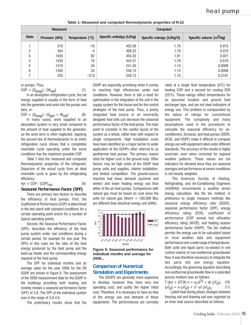
95Cooling India February 2016
heat pump
or pumps. Thus,COP = [Qevap] / [Wnet] (7)
In an absorption refrigeration cycle, the net energy supplied is usually in the form of heat into the generator and work into the pumps and fans, or:COP = (Qevap) / (Qgen + Wnet) (8)
In many cases, work supplied to an absorption system is very small compared to the amount of heat supplied to the generator, so the work term is often neglected. Applying the second law of thermodynamic to an entire refrigeration cycle shows that a completely reversible cycle operating under the same conditions has the maximum possible COP.
Table 1 lists the measured and computed thermodynamic properties of the refrigerant. Departure of the actual cycle from an ideal reversible cycle is given by the refrigerating efficiency:ηR = COP / (COP)rev (9)
Seasonal Performance Factor (SPF)There are primary two factors to describe
the efficiency of heat pumps. First, the Coefficient of Performance (COP) is determined in the test stand with standard conditions for a certain operating point and/or for a number of typical operating points.
Second, the Seasonal Performance Factor (SPF), describes the efficiency of the heat pump system under real conditions during a certain period, for example for one year. The SPFs in this case are the ratio of the heat energy produced by the heat pump and the back-up heater and the corresponding energy required of the heat pump.
The SPF for individual months and an average value for the year 2008 for the DX GSHP are shown in Figure 9. The assessment of the 2008 measurement data for the GSHP in the buildings providing both heating and cooling reveals a seasonal performance factor (SPF) of 3.8. The SPF of the individual system was in the range of 3.0-4.6.
The preliminary results show that the
GSHP are especially promising when it comes to reaching high efficiencies under real conditions. However, there is still a need for optimisation in the integration of the unit in the supply system for the house and for the control strategies of the heat pump. Thus, a poorly integrated heat source or an incorrectly designed heat sink can decrease the seasonal performance factor of the heat pump. The main point to consider is the careful layout of the system as a whole, rather than with respect to single components. High installation costs have been identified as a major barrier to wider application of the GSHPs often referred to as geothermal heat pumps. The primary reason cited for higher cost is the ground loop. Other factors may be high costs of the GSHP heat pump units and supplies, interior installation, and limited competition. The ground-source machine had lower demand (summer and winter) and lower heating energy use than either of the air heat pumps. Comparisons with natural gas must be based on cost since the units for natural gas (therm = 100,000 Btu) are different than electrical energy unit (kWh).
Figure 9: Seasonal performance for individual months and average for 2008...
Comparison of Numerical Simulation and Experiments
The GSHPS are generally more expensive to develop, however they have very low operating cost, and justify the higher initial cost. Therefore, it is necessary to have an idea of the energy use and demand of these equipments. The performances are normally
rated at a single fluid temperature (0°C) for heating COP and a second for cooling EER (25°C). These ratings reflect temperatures for an assumed location and ground heat exchanger type, and are not ideal indicators of energy use. This problem is compounded by the nature of ratings for conventional equipment. The complexity and many assumptions used in the procedures to calculate the seasonal efficiency for air-conditioners, furnaces, and heat pumps (SEER, AFUE, and HSPF) make it difficult to compare energy use with equipment rated under different standards. The accuracy of the results is highly uncertain, even when corrected for regional weather patterns. These values are not indicators for demand since they are seasonal averages and performance at severe conditions is not heavily weighted.
The American Society of Heating, Refrigerating, and Air-Conditioning Engineers (ASHRAE) recommends a weather driven energy calculation, like the bin method, in preference to single measure methods like seasonal energy efficiency ratio (SEER), seasonal performance factor (SPF), energy efficiency rating (EER), coefficient of performance (COP annual fuel utilisation efficiency rating (AFUE), and heating season performance factor (HSPF). The bin method permits the energy use to be calculated based on local weather data and equipment performance over a wide range of temperatures. Both solid and liquid parts co-existed in one control volume of non-isothermal groundwater flow. It was therefore necessary to integrate the two par ts into one energy equation. Accordingly, the governing equation describing non-isothermal groundwater flow in a saturated porous medium was as follows:T (∆v) + (δT/δt) σ = αt ∆
2T + qt/ (ρCp)f (10) (ρCp)t = ψ (ρCp)f + (1- ψ) (ρCp)s (11)
Latent heat during phase changes between freezing soil and thawing soil was regarded as an inner heat source described as follows:
Table 1: Measured and computed thermodynamic properties of R-22
Measured Computed
State Pressure (kPa) Temperature (°C) Specific enthalpy (kJ/kg) Specific entropy (kJ/kg°K) Specific volume (m3/kg)
1234567
310304
1450143514101405
320
-10-482703433
-12.8
402.08406.25454.20444.31241.40240.13240.13
1.781.791.811.781.141.131.15
0.0750.0790.0210.019
0.00080.00080.0191

96 Cooling India February 2016
heat pump
WH (σd) δfs/δts = qs (12)(δT/δt) σ + Ux δTf/δx = αt ∆
2T + qt/ (ρCp)f (13)Where: Cp is the specific heat (J kg-1 K-1); q is the
internal heat source (Wm-3).W is the water content in soil (%); T is the
temperature (°C).H is the condensation latent heat of water (J kg-1).t is the times (s); U is the velocity (ms-1).fs is the solid phase ratio.s is the soil; f is the groundwater.Ψ is the porosity.α is the convective heat transfer coefficient
(Wm-2K-1).δ is volumetric specific heat ratio.ρ is the density (kg m-3).
The experiments and calculations are conducted for unsaturated soil without groundwater flow (US), saturated soil without groundwater flow (SS) and saturated soil with groundwater flow (SSG) under same conditions and their results are compared with each other in Figures 10-12. The temperature in vertical boreholes used, as heat source for GSHPs will slowly drop with time, the more so the more energy is extracted. This can be mitigated either by a deeper borehole (in a new installation) or a system to replenish the energy extracted from the hole (in both new and existing installations). Raising the brine temperature from -5°C to 0°C may improve the COP by 10-50% depending on the type of heat pump.
Figure 10: Comparison of calculations and experiments for saturated soil with groundwater flow (SSG)...
Figure 11: Comparison of calculations and experiments for saturated soil... without groundwater flow (SS)...
Figure 12: Comparison of calculations and experiments for unsaturated soil without groundwater flow (US)...
ConclusionThe direct expansion (DX) Ground Source
Heat Pump (GSHP) systems have been identified as one of the best sustainable energy technologies for space heating and cooling in residential and commercial buildings. The GSHPs for building heating and cooling are extendable to more comprehensive applications and can be combined with the ground heat exchanger in foundation piles as well as seasonal thermal energy storage from solar thermal collectors.
Heat pump technology can be used for heating only, or for cooling only, or be ‘reversible’ and used for heating and cooling depending on the demand. Reversible heat pumps generally have lower COPs than heating only heat pumps. They will, therefore, result in higher running costs and emissions and are not recommended as an energy-efficient heating option.
The GSHP system can provide 91.7% of the total heating requirement of the building and 55.3% of the domestic water-heating requirement, although only sized to meet half the design-heating load.
The heat pump can operate reliably and its performance appears to be at least as good as its specification.
The system has a measured annual performance factor of 3.16. The heat pump
system for domestic applications could be mounted in a cupboard under the stairs and does not reduce the useful space in the house, and there are no visible signs of the installation externally (no flue, vents, etc.).
The performance of the heat pump system could also be improved by eliminating unnecessary running of the integral distribution pump.
It is estimated that reducing the running time of the pump, which currently runs virtually continuously, would increase the overall performance factor to 3.43. This would improve both the economics and the environmental performance of the system. More generally, there is still potential for improvement in the performance of heat pumps, and seasonal efficiencies for ground source heat pumps of 4.0 are being achieved.It is also likely the unit costs will fall as production volumes increase. By comparison, there is little scope to further improve the efficiency of gas- or oil-fired boilers.
Abdeen Mustafa OmerEnergy Research Institute (ERI)
Nottingham, UK

97Cooling India February 2016
pleasant climate
In 2015, the Mercedes AMG Petronas Formula One Team defended its Constructors’ World Championship, and Lewis Hamilton and Nico Rosberg took first and second places in the drivers’ standings for the second consecutive season. Over 800 engineers, technicians and designers worked through the entire year at team headquarters in Brackley, UK, to achieve this success. Among the workforce are 15 employees from the paint shop. This group of employees enjoyed the benefits of an upgrade of the air conditioning system a few months ago – which has transformed their working environment into a pleasantly cooled workspace quietly maintained by EC fans from ebm-papst.
The upgrade was also beneficial from a financial point of view. The air conditioning system at Mercedes AMG Petronas now uses 64% less energy and will have paid for itself in just two years.
Prior to the upgrade in the team’s paint shop, the AC fans in the facility were difficult to control and the air flowed through the ducts too quickly, causing continuous background noise. To reduce the noise, staff closed the outlets. The consequence of these factors was a hot and uncomfortable environment – especially in the summer months, even with the air conditioning system running at full power.
Mercedes AMG Petronas turned to its team partner, ebm-papst, who had helped the team at the track with tailor-made cooling solutions for the race cars, and the team garages in hot climates. ebm-papst replaced the paint shop AC fans with RadiPac EC fans, which are easy to adjust to the required speed. With a user-friendly fan control system installed as part of the solution, the building will be adaptable the system to changing conditions.
As soon as the retrofitting work was completed, the UK experienced one of the hottest weeks of the year – a real test for the converted air conditioning system under extreme conditions. "The feedback from the employees in the paint shop was very positive, because the system has a very pleasant cooling effect and is also very quiet," said Robert Yeowart, Director Business Development & Logistics at Mercedes AMG Petronas. "Not only that – now freshly painted parts dry more consistently," he added.
An upgrade was beneficial
from a financial point of
view. The air conditioning
system at Mercedes AMG
Petronas now uses 64% less
energy and will have paid
for itself in just two years…
Saving Energyin Paint Shop
The energy consumption of MERCEDES AMG PETRONAS paint shop in Brackley, UK has been reduced by 64% – thanks to EC fans from ebm-papst… (Fig. MERCEDES AMG PETRONAS)
The RadiPac fans from ebm-papst in the air handling unit...

98 Cooling India February 2016
Interview
“It is
extremely important to have a
high quality control system…”
989898989898898998989898898998889899888888988989 CoCCoCoCoCoCoCoCoCoCCoCoCoCoCooCoCoCoCCoCCoCCoCCooCoCoCCCCoo lololololllololllololololololololoololoololololollooolololooolollolooooooloooloolinininninininnniniinniniinininnininninininnniniiinnniniiniinnggggggg gggggggggggggggggggggggggggggggggggggggggggggggggggggggg Innnnnnnnnnnnnnnnnnnnnnnnnnnnnnnnnnnnnnnnnnnnnnnnnnnnnnnnnnnnnnnnnnnnnnnnnnnnnnnnnnnnnnnnnnnnnnnnnnnnnnnnnnnnnndidddddididdidddididdididddiddididididiididididddiddididdididdiddidididididididddiddddddiddididddididddidddiddididddddidddidididdddidididididddiiidididididdddidddddididiiiididdddddiddddididdiddididiiiidddddddidddidididdidiididididddddddddddidididddidiididddddddddddidiiiiididddddddddididddiiiiddidddiddddddiddddiiiidiididdddddiddidididdddiiiiiiiddidddddiddiiiiiiiididdddddiiiddddiddididddiiiidididdddddiiiiddddddidiiiiiddddiddddiiddiddddiddddiiidddddiddddiddididdddddddiddidddddddddidiiidddddddddddiiiiiddddddddddidiiiiddddddddddddiiiiidddddddddiiiididddddddiiiddddiiaaaaaaa aaaaaa aa a aaaaaaaaaaaaaaaaaaaaaaaaaaaaaaaaaaaaaaaa aaaaaaaaaaaa a aaaaaaaaaaaaaaaaa a aaaaaaaaaaaa aaa aaaaaaaaaaaaaaaaaaaaaaaaa aaaaaaaaaaaaaaaaaaaaaaaaaaaaaaaaaaaaaaaaaaa aaaaaaaaaaaaaaaaaaaaaa aaaaaaaa aaaaaaaa aaaaaaaaaaaaaaaaaaaaaaa FeFFeFeFFeFeFeFFFeFeFFFeeeFFFeFFeFeFeFFeFFeFeFFFeFFFeFeFeFeeeFeeeeFeFFeFFeFFFFFFFFFFeFFFeFFeFeeeFFFFFFFeFFeFFeFeFFFeFeFeeFeFeFeeFeFeFFFFFeFFeFeFFFeFFFFeFFeFeFFeFeFFFFFFFFFFFFFFFFFFFeFFFFFFeFeFFFeFeFFeFFFFeFeFeFeFeFFFFeFFeFFFFFFFFFeFFeFeFFFFFFFeFFFFFFFFFFeFeFeFFFFFFFeFeFFeFeFFeFFeFeFeFeFeFFeFFFFFFFeFFeeeeeeeeeeFeFFFFFeFFFFFFeFFFeeFeeeeeeeeeeFFFFFeFFFFeFFFFFeFeeeeeeeeFFFFFeFeFFFFeFFeFeeeFeeeeeFFFFFFFFFFFFeFeeeFFFFFFFFFFFeeeeeeeFFFFFFFFFFFeFFFeFFeeeeeeeeeeFFFeFFFFFFFFFFeFeeeeeFFFFFFFFFFFFFFeeeFeeeeeeeeFFFFFFFFFFFFFeFFFeeeeeeeeeFFFFFFFFeFFFFeFeeeeeeeFeeFFFFFeFFFFFFFeeeFeeeeeFFFFFFFFFFFFFeeeeeeeeFFFFFFFFFFFeeeeeeeeeFFFFeFFFFFeeFeeeeeeFFeFFFFFeFFFeeeeeeFFFFFFeeeeeeeeeFFeFFFeFeeeeebbbbbbbrbrbrbrbrbrbrbrbrbbbbbbrbrbrbrbrbbbbrbrbrbrbbbbrbbrbrbbrbrbbrbrbbbbbbbbrbrbbrbrbrbrbbbbbrbbrbbbbbbrbrrbrbbbbbbbrbrbrbbbbbrbrbbbbrbbbrbbbbbbbrrbrbbrbbbbbrbrbbbbbbrrrrbbbbbbbbrbbbrbrbrbrbrbrbrbrbrbrbrbbbbbrbbbbbrbrbrbbbrbbrbrbrbrrbbbbbrbrbbbbbbbbbrbrbrbbbrbbrbbbbbbbrrrrbrbbbbrbbbrbrbrbbbbbbrrrbrrbrbrbrrbrbrrbrbbbbrbrbrbbbbbbbrrrbrrrrrbrbbrbbbbbbrbrbbbbbrbrrbrrbrrrrrbbrbbbrbrbbbrrrrbrrrrrrbbbbbbbbbrbrrrrbrrrrrbbbbrrrrrrrrbbbbbbbrbrbbbbrrbrrrbrbbbrbrbbbbbbbrrrbbbbbrrbrbbrbbbbbbbbrrrbbbbbbbbbbrrbrbbbbbrbbrrrbrbrrrrbbbbbbbrbbbbbrrbrrrrrbbbbbbbbrbrrrbbbbrbbbbbbbrrrrrbbbbbbrbbbbbbbrrrrrrrrrbbbbbbbbbrrrrrrbbbbbbbbbrrrrrrruauuuauauauauauauuuauauaauaauauuuuauuauaauauauauauauuauauuauuauuaauauauauuuuuuuuuuuauuauuuuuuuauaaaaaaaauauaaaauauuuauuuuuauuuuauuauuuuaauaaauaauauaauauuauuuuauuuuuuuuuuuaaaaaauauaaauaauauauuuuuuuuuuauuuaaauaaaaaaaaauaauauauuuuuauuuauuuuauuuaaaaaaaaauaauaauauuauuuuauuuuuauuuauauaauauaaaauauauauuuuuuuuuuuaaaaaaaauauauaaauauuuuauuuuuauauuauuuuaaaaaaaaaaauauuuuauuuuuuuuaaaaaaaaauaauaauuuuauuuuuuauuuauaaaauaaaaaauauuauauuuuauauauuaaaaaaaaauuuauuuuuuuaaaaaaaaaauauuuuuuuaaaaauuuuuuuuuuuaaaaaaaauauauuuuuuuuuaaaaaaaauuuauuuuuuuuuuaaaaaaaaaaaauuuuauauuuuuuuauuuaaaaaaaauauuuuauuuuuuuuaaaauaaaaryryrryryryryryryyyryyyryryrryryryryryyrryyyryyyyyrrryrrryrryrryryryyryryrrryrrrryrrrrryyyyryyyyyyyryrrrryrrrrryrrrrryyyyryryyyyryyyryrrrrryryrrrrrryyyyyyyyyryyyyyrrrryryrryryryrrryryyyyryyyryyryryryryyyyryrryrrrryrrrrryyryyyyyyyyyyyyyyryryrrrrrrrrryryyyyyryyyyyyyyrrrrryryrryrrryryryyyyyyyyyryyyyyyrryryrrrrryryyyyyyyyyyryryryyryyrrrrrryryrrrryyyyyyyyyyyyyyryrrrrrrrryrrryyyyyyryyyyyyyryrrrryrrryryryrryyyyyryyyyyyyrrrrrrryyyyyyryyyyyyyyyyryrrrrrrryyyyyyyyyyyrrrrrrryyyyyyyyyyrrryrrrrryyyyyyyyyyyrrrryrrrrryyyyyyyyyrryrrrryrrryyyyyyyyyyyyyyyyyyyyyyyyyyyyyyyyyyyyyyyyyyyyyyyyyyyyyyyyyyyyyyyyyyyyyyyyyyyyyyyyyyyyyyyyyyyyyyyyyyyyyyyyyyyyyyyyyyyyyy 222222222222222222222222222222222222222222222222222222222222222222222222222222222222222222222222222222222222222222222222222222222222222222222222222222222222222222222222222222222222222222222222222222222222222222222222222222222222222222222222222222222222222222222222222222222222222222222222222222222222222222220101000001111010010001100010110100001101101000100100100101010111111110100001001001000010000111110111111110001001000010000100110111011111111100001010010100001001011011111101101111001010101010100000011110110111111010001010000000101010111110101010110000010100100001101101011010000000000001111110100000010001111001001010000000010101110110100010000111000000001111010110110000001111100000101111100010000010111100000100000110111110000101010000001111111010100100010000000101111111000100000000010111111100000000000000001111111011110000000000001111111100000000010001111111110100000100011111000000001011111111000001000001111110010000000111111116666666666666666666666666666666666666666666666666666666666666666666666666666666666666666666666666666666666666666666666666666666666666666666666666666666666666666666666666666666666666666666666666666666666666666666666666666666666666666666666666666666666666666666666666666666666666666666666666666666666666666666666666666666666666666666666666666666666666666666666666666666666666666666666666
Kahan Controls is a young and dynamic company providing Controls, Automation and Technological products to the
refrigeration industry with supplies to all major OEMs, Contractors and End Customers. The company started business by representing
Dixell Italy as a Sole Distributor for India. Now, it is representing more than 8 MNCs exclusively in the Indian market. In an exclusive
interview with Cooling India, Virendra Kamdar, CEO of the company is narrating his observation on the dynamics of the Indian
HVAC&R market to P K Chatterjee. Excerpts…

99Cooling India February 2016
What kind of transformation has taken place in the HVAC&R control arena in the last say one decade?
In last one decade, there is a big shift in mindset of Indian HVAC&R industry mainly towards Controls. Earlier, Electronic Controls were considered to be an optional item, whereas today you cannot imagine any project, which works on Mechanical Controls. Electronic Controls, PLC, BMS, CMS, EMS are integral parts of any project. Customers have become more Energy Efficient today than they were a decade ago. So, we see a good shift of transformation towards Controls & Technologies in past one decade.
What are the emerging trends in this segment of the HVAC&R industry?
Emerging trends in HVAC&R industry are Green Technologies and Energy Efficient Technologies.
Which are the industry sectors where you are finding very good potential as on date?
As we are present in both the segments of HVAC and also Refrigeration, we feel a great potential in Cold Chains, Controlled Atmosphere Storages, Food Parks, Super Markets & Hyper Markets, Pharmaceuticals, Clean Rooms etc.
How important is it to have a high quality control system (say) from safety, energy savings and system lifecycle angles?
This is extremely important to have a high quality control system. In the field of electronics, if you do not have high standards of quality hardware then it can give a big trouble, and the complete project can fail.
In today’s era, all HVAC&R equipments like Chiller, AHU, VAV etc., run on Electronic Controllers and so, you can feel the importance of reliable electronic controller without which you cannot even think of any small operations.
In fact, not only hardware, but also software and a good System Integrator plays a very important part of any project. Just imagine an excellent Hardware of Controller without a proper logic of Energy Saving – or imagine the best quality of hardware and no local site support for software. So, I am firmly believing, Good quality Hardware along with good System Integrator having handsome knowledge of HVAC&R industry is must for any successful energy efficient HVAC&R plant.
What kinds of new technologies are being introduced in the control devices to make them more intelligent?
This is the era of Software, and in HVAC&R applications also, Software plays an important role to make Control System more intelligent. We feel that an experienced HVAC&R System Integrator who has wide system knowledge can play an important role in providing Intelligent Solutions.
He can prepare customized logic and software for any particular applications and that results into great Energy Saving for the customer. This can boost efficiency of the plant to the next level and going forward, we see a big opportunity in Intelligent Technological Solution than mere completion of project with basic controls.
What is the impact of such technology infusion in their pricing?
Of course, this will definitely have an impact on pricing but if the plant runs more efficiently than before, I am sure the customer will be happy to accept the new technology. If the customer is saving their monthly energy and if their product quality is improved due to proper ambient conditions, then I am sure that the customer will be satisfied and happy. At the end, if the customer can see RoI (Return on Investment), which is not more than 24 months, why they can’t invest in technology which can boost their productivity and make their plant efficient to match up the global standard?
What are the new types of equipment that you are planning to launch in near future?
As our company name suggests, we are committed to bring best Controls & Technologies related to our HVAC&R Industry from all over the globe. We are launching Adiabatic Misting/Cooling System, which is a replacement for old technologies like Air Washer where efficiency is
quite less and the system requires heavy investment on Ducting, Installation – and also running cost is quite high as compared to the Misting system. We see a big opportunity in this technology in the coming years.
What is your contribution in reefer truck cooling management area?
Our Refrigeration Ver tical provides complete solution for Reefer Truck Controls from Dixell
Italy, Data Logging System, Web Tracking & Monitoring system as per HACCP compliance.
What kind of competition are you facing in placing your products in the Indian market?
To explain this, I need to divide HVAC and Refrigeration as two different applications. Now, if I talk about the Refrigeration Market, it is a completely unorganized market – but as we are present here since past 15 years or more, every customer knows us – so, the introduction of the new products in the market are much easier. But, here customers are not much educated, thus convincing them about new technologies is little difficult.
On the other hand, HVAC is a well organized sector in India with more knowledgeable people handling various positions in different companies. So, here acceptance of new technologies is much easier, whereas we are finding a big resistance at entrance level where old players are already present with a huge penetration across India since many years.
What is your suggestion to the system integrators and decision makers in the HVAC&R field?
I see a big gap between commitments and executions from System Integrators, especially, in our Controls and BMS jobs. I see many jobs are incomplete and customers are suffering a lot due to lack of electronics knowledge, and their 100% dependence on System Integrators of BMS.
My suggestion to the system integrators is to design hardware architecture right from the beginning stage to avoid wrong selection and then complete the job with proper Wiring and Software support without which no plants can work efficiently over a long period.
This is the era of Software, and in HVAC&R applications also, Software plays an important role to make Control System more intelligent. We feel that an experienced HVAC&R System Integrator who has wide system knowledge can play an important role in providing Intelligent Solutions...

100 Cooling India February 2016
information modeling
This article is the next part of the author’s article on “BIM - A Technology for Efficient Building Construction,” which was published in the cooling India’s issue of April 2014, wherein the author mentioned, how BIM can benefit the new age developments and associated challenges...
Sustainability inDesign & Construction

101Cooling India February 2016
information modeling
We all realize the need to reduce energy consumption during construction phase, measures to
enhance workmanship quality, reduce cost and minimise completion schedules of a project, to make a project more efficient and sustainable.
Some of the common features defined in a Sustainable Development by most of the rating institutions are:
1) A development which causes minimum disturbance to the Mother Nature & Environment
2) Protect existing plantations and fertile top soil
3) Utilizes local and rapidly renewable building materials
4) Take measures to minimize energy consumption
5) Maximize usage of renewable energy such as Solar energy & Wind energy
6) Use measures to save water, Implement rain water harvesting; Design for zero water discharge
7) Use CFC free equipment, etc.However, most of the Rating Systems
have neither made any specific mention to encourage utilization of minimum energy or green energy during the construction phase nor have any provision for penalty for abortive works or project delays. There is a lot of scope for reducing the energy usage during the construction phase – and thus reducing the carbon footprint of a project.
To motivate developers for energy saving during the construction phase, the rating system should provide reward points for reduced energy consumption during the construction and encourage project planners and managers to develop designs and construction methods to avoid abortive works, and shorten the construction period, thus
making the development truly sustainable.Effective utilization of Virtual Design and
Construction (VDC) or Building Information Modeling (BIM) can assist to ensure that all the Design Drawings whether from Architects, Structural Consultants, MEP Consultants or any other specialist consultants are correct and coordinated. The model prepared as per the design drawings can be checked for clashes, if any and design engineers may be advised to revise or coordinate their drawings. The model should be updated as per the revised drawings and once again checked for clashes. This exercise will ensure that the drawings issued at site for execution are properly coordinated and clash free.
BIM can also be used to extract coordinated isometric views. These views if provided at site will help the workmen in carrying out the installation correctly – and in correct sequence. Since, most of the time the site progress is delayed or affected due to discrepancies in the drawings issued for construction and due to coordination issues. Hence, BIM will assist all the stake holders in completing the installation work at site with minimum queries and with better coordination.
The completion schedule and energy requirements during installation may be further reduced by reducing site fabrication. Precast or Prefabricated materials usage will accelerate the construction activity, and expedite the installation of services at site. This will not only make the site safer and less polluted but also reduce the material wastages.
One method, which is greatly used overseas for faster completion, is standardizing the projects layout, increasing the repetitions and maximizing the usage of precast and prefabricated materials. The higher the
repetition the more beneficial will be the usage of prefabricated material.
There are many services in a project, which undergo minor or no change at all, irrespective of the project size. While the list may vary from project to project, however, some of such areas are Kitchens, Bath Rooms, Plant rooms, Pump rooms, Plumbing Risers, Fire Risers, Pressurization shafts, Stairs, Façades etc.
In any residential or hotel project, prefabricated materials can be used for installation of MEP services in Bath Rooms. In such a project not more than 4 to 5 bathroom layouts or modules are used. Using BIM, we can also determine the size and lengths of pipes and no. of fittings required in a bathroom. The predetermined lengths may be made ready at the workshop and tagged. The material is then brought to site and is installed in the pre-determined manner. For effective coordination it’s important that each vendor carries out installation exactly as per the coordinated shop drawings. In case a vendor deviates from the coordinated drawings by error, he must communicate the same to BIM Coordinator immediately, to ensure that corrective measures are taken in time, to avoid wrong delivery of materials by other vendors.
By reducing the type of layouts, we can increase the repetitions and expedite the completion schedule. In site fabrication, the measurements for pipe pieces required for connecting the fixtures and associated fittings is taken at site and pipes are cut from the full

102 Cooling India February 2016
information modeling
pipe length. The remaining pipe length is used for another smaller piece and the last cut piece is termed as scrap and sold to scarp dealer for negligible amount. The cost of this scrap is added to the cost of installed pipe and is paid by the owner or property developer, thus causing loss to all the stake holders. However, if we use a standard layout or modular design for a bathroom, we will know the exact length of pipes required for installation in the project and can be prefabricated. Also, the vendor may procure the desired length of pipes from the manufacturer to avoid the waste generation.
This also reduces the workmen hours spent in taking frequent measurements. Material may be sent to site in one lot for a module, and thus ensuring much quicker installation, at much lower material and labour cost.
Another advantage of centralized fabrication or factory fabricated material is that this reduces the cut lengths wastages, if any by increasing the chances of their utilization either in the same project or in the next project.
HVAC industry had started the factory fabricated ducting almost two decades ago in India – and today there is hardly any project, where factory fabricated ducting is not used. The same process needs to be undertaken for plumbing, drainage, fire-fighting and other services including civil works. Standardization will also ensure better workmanship and hence lesser leakage/seepage problems.
Some of the major coordination issues encountered in a project are related to false ceiling levels, access door location, drain pipe levels, space for indoor air-conditioning unit and its maintenance needs, TFA duct connection to the supply air grill of fan coil
units, condensate’s drain pipe level and its routing etc.
All these issues are very well taken care on a BIM platform and provide opportunity to utilize the void space optimally, thus ensuring maximum false ceiling height. Even the suitability of the access door can be verified by the operation team through the Model or using 3D Walkthrough.
Some other areas where modular construction can be highly effective are Commercial Kitchens of Restaurants, Fast food joints and that of Hotels. These are major energy guzzlers and very rarely, we find a kitchen which is energy efficient, well ventilated and having occupants with no complain. While frequent air imbalance taking place due to choked filters is one of the major reasons, inappropriate air distribution adds to the problem. In
appropriate air exhaust velocities are major causes of spread of cooking fumes outside the kitchen exhaust hoods, thus making the utensils & surfaces in kitchen greasy and increasing cost of cleanliness efforts required to maintain the hygiene in the kitchen.
Most of the fast food restaurants have a fixed kitchen layout, however, still most of their kitchen installations face teething problems due to poor coordination and space constraint. The major reason is that most of the coordination issues are addressed at site during the installation work by the site engineer.
Usage of BIM can help in dealing with such problems, as the decision may be taken by core expert team during the design stage itself, thus avoiding coordination issues at site.
To get better quality kitchen designs, we may also consider developing modules of kitchen, incorporating all equipment’s and services. To avoid energy wastage during lean hours Demand Controlled Ventilation (DCV) should be incorporated in the design. All the stake holders such as developer/operator, kitchen consultant, HVAC consultant, end users/the kitchen staff, electrical consultant, plumbing & fire consultant etc. should provide their inputs to the BIM consultant and a Model should be prepared for review and clash coordination by all.
Even the end user i.e., the kitchen staff and operation & maintenance team, who are either not consulted during the design stage or find difficult to provide their feedback on a 2D drawing, shall be able to provide valuable inputs while reviewing the 3D Model. The BIM walkthroughs can also help in ensuring
sufficient working space around the kitchen equipment, right location of access door or service opening and optimum utilization of void space above false ceiling.
Standardization of a detail not only makes the detail rich and complete, it also helps in quicker decision making, reducing wastage and thus making the project delivery faster and avoiding cost over runs.
In today’s age with increasing labour cost, stress on faster delivery and to avoid cost over runs, standardization is not only inevitable but need of the hour. Standardization needs to be documented with specifications, 2D drawings, 3D isometric views and quantities. The detailing should not only include the ASMEP coordination but also the requirements of the operation and maintenance team.
Hence, we may say that a truly sustainable development is one which avoids abortive work, optimizes the utilization of raw materials and consumes minimum energy & water, during construction and post construction, while achieving shorter completion period.
The shorter completion schedule will also improve the utilization of Project Managers & Project Engineers and thus will help in reducing the Project Management Cost.
Most of the time we face complex challenges in each of the project and with lots of detailing and some time by compromising on some of the design features, we find a way to solve the problem. However, we do not pay much attention in documenting record of such challenges and their solutions. In next project again a new team faces the similar issue and the wheel takes a full circle.
Virtual Design & Construction OR BIM (Building Information Modeling) is not only a tool for assisting in sustainable development but can also be used as a repository for all our project experience and decisions, in 2D as well as 3D environment. A tool for making modules, which can be customized to suit to specific project needs/design.
Some of the progressive developers have already taken initiative but there is a long way to go, when this will become a reality and needs close coordination and involvement of all the stake holders of a project, be it client, consultant or contractor.
Dhiraj RastogiCertified Energy Auditor & Energy Manager

103Cooling India February 2016
refrigerants
In the early 70s, scientists Sherwood Roland and Mario Molina at the University of California at Irvine were the first to discover the loss of ozone in stratosphere while investigating the ozone layer from highflying aircraft and spacecraft...
Natural RefrigerantsMoving Towards
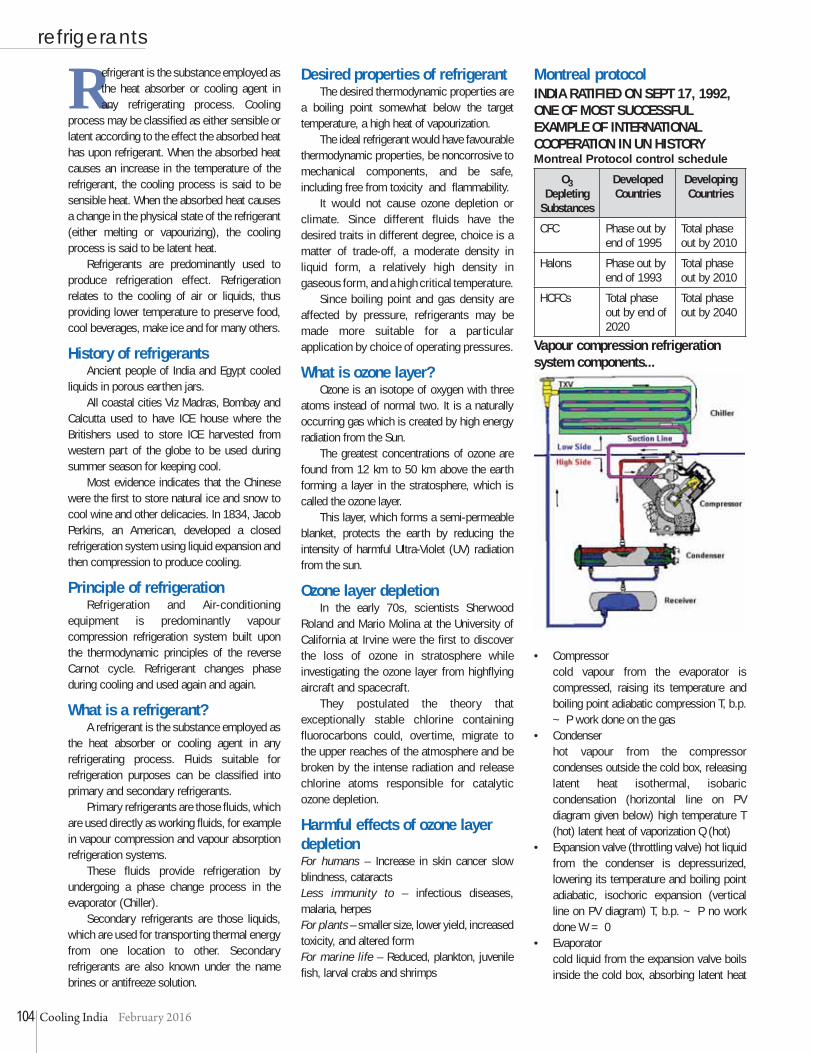
104 Cooling India February 2016
refrigerants
Refrigerant is the substance employed as the heat absorber or cooling agent in any refrigerating process. Cooling
process may be classified as either sensible or latent according to the effect the absorbed heat has upon refrigerant. When the absorbed heat causes an increase in the temperature of the refrigerant, the cooling process is said to be sensible heat. When the absorbed heat causes a change in the physical state of the refrigerant (either melting or vapourizing), the cooling process is said to be latent heat.
Refrigerants are predominantly used to produce refrigeration effect. Refrigeration relates to the cooling of air or liquids, thus providing lower temperature to preserve food, cool beverages, make ice and for many others.
History of refrigerantsAncient people of India and Egypt cooled
liquids in porous earthen jars.All coastal cities Viz Madras, Bombay and
Calcutta used to have ICE house where the Britishers used to store ICE harvested from western part of the globe to be used during summer season for keeping cool.
Most evidence indicates that the Chinese were the first to store natural ice and snow to cool wine and other delicacies. In 1834, Jacob Perkins, an American, developed a closed refrigeration system using liquid expansion and then compression to produce cooling.
Principle of refrigerationRefrigeration and Air-conditioning
equipment is predominantly vapour compression refrigeration system built upon the thermodynamic principles of the reverse Carnot cycle. Refrigerant changes phase during cooling and used again and again.
What is a refrigerant?A refrigerant is the substance employed as
the heat absorber or cooling agent in any refrigerating process. Fluids suitable for refrigeration purposes can be classified into primary and secondary refrigerants.
Primary refrigerants are those fluids, which are used directly as working fluids, for example in vapour compression and vapour absorption refrigeration systems.
These fluids provide refrigeration by undergoing a phase change process in the evaporator (Chiller).
Secondary refrigerants are those liquids, which are used for transporting thermal energy from one location to other. Secondary refrigerants are also known under the name brines or antifreeze solution.
Desired properties of refrigerantThe desired thermodynamic properties are
a boiling point somewhat below the target temperature, a high heat of vapourization.
The ideal refrigerant would have favourable thermodynamic properties, be noncorrosive to mechanical components, and be safe, including free from toxicity and flammability.
It would not cause ozone depletion or climate. Since different fluids have the desired traits in different degree, choice is a matter of trade-off, a moderate density in liquid form, a relatively high density in gaseous form, and a high critical temperature.
Since boiling point and gas density are affected by pressure, refrigerants may be made more suitable for a par ticular application by choice of operating pressures.
What is ozone layer?Ozone is an isotope of oxygen with three
atoms instead of normal two. It is a naturally occurring gas which is created by high energy radiation from the Sun.
The greatest concentrations of ozone are found from 12 km to 50 km above the earth forming a layer in the stratosphere, which is called the ozone layer.
This layer, which forms a semi-permeable blanket, protects the earth by reducing the intensity of harmful Ultra-Violet (UV) radiation from the sun.
Ozone layer depletionIn the early 70s, scientists Sherwood
Roland and Mario Molina at the University of California at Irvine were the first to discover the loss of ozone in stratosphere while investigating the ozone layer from highflying aircraft and spacecraft.
They postulated the theory that exceptionally stable chlorine containing fluorocarbons could, over time, migrate to the upper reaches of the atmosphere and be broken by the intense radiation and release chlorine atoms responsible for catalytic ozone depletion.
Harmful effects of ozone layer depletionFor humans – Increase in skin cancer slow blindness, cataractsLess immunity to – infectious diseases, malaria, herpes For plants – smaller size, lower yield, increased toxicity, and altered formFor marine life – Reduced, plankton, juvenile fish, larval crabs and shrimps
Montreal protocolINDIA RATIFIED ON SEPT 17, 1992, ONE OF MOST SUCCESSFUL EXAMPLE OF INTERNATIONAL COOPERATION IN UN HISTORYMontreal Protocol control schedule
O3 Depleting
Substances
Developed Countries
Developing Countries
CFC Phase out by end of 1995
Total phase out by 2010
Halons Phase out by end of 1993
Total phase out by 2010
HCFCs Total phase out by end of 2020
Total phase out by 2040
Vapour compression refrigeration system components...
• Compressorcold vapour from the evaporator is compressed, raising its temperature and boiling point adiabatic compression T, b.p. ~ P work done on the gas
• Condenserhot vapour from the compressor condenses outside the cold box, releasing latent heat isothermal, isobaric condensation (horizontal line on PV diagram given below) high temperature T (hot) latent heat of vaporization Q (hot)
• Expansion valve (throttling valve) hot liquid from the condenser is depressurized, lowering its temperature and boiling pointadiabatic, isochoric expansion (vertical line on PV diagram) T, b.p. ~ P no work done W = 0
• Evaporatorcold liquid from the expansion valve boils inside the cold box, absorbing latent heat

105Cooling India February 2016
refrigerants
isothermal, isobaric boiling (horizontal line on PV diagram) low temperature T (cold)latent heat of vaporization Q (cold)
Importance of refrigerant• The thermodynamic efficiency of a
refrigeration system depends mainly on its operating temperatures.
• However, impor tant practical issues such as the system design, size, initial and operating costs, safety, reliability, and serviceability etc. depend very much on the type of refrigerant selected for a given application.
• Due to several environmental issues such as ozone layer depletion and global warming and their relation to the various refrigerants used, the selection of suitable refrigerant has become one of the most important issues in recent times.
Refrigerant selection criteria• Selection of refrigerant for a particular
application is based on the following requirements: – Thermodynamic and thermo-physical
properties – Environmental and safety properties– Economics
Thermodynamic and thermo-physical properties• The requirements are:
a) Suction pressure: At a given evaporator
temperature, the saturation pressure should be above atmospheric for prevention of air or moisture ingress into the system and ease of leak detection. Higher suction pressure is better as it leads to smaller compressor displacement
b) Discharge pressure: At a given condenser temperature, the discharge pressure should be as small as possible to allow light-weight construction of compressor, condenser etc.
c) Pressure ratio: Should be as small as possible for high volumetric efficiency and low power consumption
d) Latent heat of vaporization: Should be as large as possible so that the required mass flow rate per unit cooling capacity will be small.
In addition to the above proper ties; the following proper ties are also impor tant:
e) Isentropic index of compression: Should be as small as possible so that the temperature rise during compression will be small
f) Liquid specific heat: Should be small so that degree of subcooling will be large leading
to smaller amount of flash gas at evaporator inlet
g) Vapour specific heat: Should be large so that the degree of superheating will be small
h) Thermal conductivity: Thermal conductivity in both liquid as well as vapour phase should be high for higher heat transfer coefficients
i) Viscosity: Viscosity should be small in both liquid and vapour phases for smaller frictional pressure drops
• The thermodynamic proper ties are interrelated and mainly depend on normal boiling point, critical temperature, molecular weight and structure.
Environmental effects of refrigerantsGlobal warming: Refrigerants directly
contributing to global warming when released to the atmosphere
Indirect contribution based on the energy consumption of among others the compressors ( CO2 produced by power stations )
Environmental and safety properties
Global Warming Potential (GWP): Refrigerants should have as low a GWP value as possible to minimize the problem of global warming. Refrigerants with zero ODP but a high value of GWP (e.g., R134a) are likely to be regulated in future.
Total Equivalent Warming Index (TEWI): The factor TEWI considers both direct (due to release into atmosphere) and indirect (through energy consumption) contributions of refrigerants to global warming. Naturally, refrigerants with as a low a value of TEWI are preferable from global warming point of view.
Toxicity: Ideally, refrigerants used in a refrigeration system should be non-toxic. Toxicity is a relative term, which becomes meaningful only when the degree of concentration and time of exposure required to produce harmful effects are specified. Some

106 Cooling India February 2016
refrigerants
fluids are toxic even in small concentrations. Some fluids are mildly toxic, i.e., they are dangerous only when the concentration is large and duration of exposure is long. In general the degree of hazard depends on: – Amount of refrigerant used vs total space – Type of occupancy – Presence of open flames – Odor of refrigerant, and – Maintenance condition
Flammability: The refrigerants should preferably be non-flammable and non-explosive. For flammable refrigerants special precautions should be taken to avoid accidents.
Chemical stability: The refrigerants should be chemically stable as long as they are inside the refrigeration system.
Compatibility with common materials of construction (both metals and non-metals).
Miscibility with lubricating oils: Oil separators have to be used if the refrigerant is not miscible with lubricating oil (e.g. ammonia). Refrigerants that are completely miscible with oils are easier to handle (R12).
Ease of leak detection: In the event of leakage of refrigerant from the system, it should be easy to detect the leaks.
Economic properties The refrigerant used should preferably be
inexpensive and easily available.ECO Friendly Refrigerants
CFC Alternatives
HCFCR22, R124
HFCR134a
Natural RefrigerantNH3, HC's
Halocarbon Refrigerant is all synthetically produced and was developed as the Freon family of refrigerants.Examples: – CFC’s : R11, R12, R113, R114,
R115
– HCFC’s : R22, R123 – HFC’s : R134a, R404a, R407C,
R410a
HFCRemain a popular choice -especially for
R22 phase out Good effor ts at improving leakage
performance - e.g., Real Zero projectInterest in R407A to replace R404A - 50%
reduction in GWP
Inorganic Refrigerants• Carbon Dioxide, Water, Ammonia, Air,
Sulphur dioxideConclusions: In the aftermath of the
Montreal protocol, HFCs have predominantly replaced CFCs and HCFCs in Refrigerating and air conditioning equipment. Due to their high GWP, HFC’s are not a long term replacement solution.
The solutions are the natural refrigerants: Ammonia, Hydrocarbons and Carbon dioxide
System need to have low TEWI (Total Equivalent Warming Index) factor.
High efficiency with ammonia and lower power consumption with hydrocarbons.
Even among the natural refrigerants ammonia and hydrocarbons are popular and carbon dioxide is not yet taken off in India as the working pressure is 80 Kg/cm2(80 Bar).
Survey of RefrigerantsRefrigerant Group Atmospheric life ODP GWP
R11 CFC 130 1 4000
R12 CFC 130 1 8500
R22 HCFC 15 .05 1500
R134a HFC 16 0 1300
R404a HFC 16 0 3260
R410a HFC 16 0 1720
R507 HFC 130 1 3300
R717 NH3 - 0 0
R744 CO2 - 0 1
R290 HC < 1 0 8
R600a HC < 1 0 8
V. SRIDHAREnervac Engineering
Consultants

107Cooling India February 2016
issues & solutions
Ferromagnetic materials are known to heat up when magnetized and to cool down when the magnetic field is removed.Materials with advanced magnetic and super conductive properties have been developed to improve magnetic refrigeration efficiency...
A FUTURE TECHNOLOGYMAGNETIC COOLING

108 Cooling India February 2016
issues & solutions
A team of Canadian-Bulgarian researchers has developed a promising novel approach for
magnetic cooling that’s far more efficient and 'greener' than today’s standard fluid-compression form of refrigeration.
WASHINGTON D.C., June 10, 2014 – Magnetic cooling is a promising new refrigeration technology boasting several advantages – ranging from lower energy consumption to eliminating the use of hazardous fluids – that combine to make it a much more environmentally friendly option than today’s standard fluid-compression form of refrigeration.
One novel magnetic cooling approach, developed by a team of Canadian-Bulgarian researchers, relies on solid magnetic substances called magneto caloric materials to act as the refrigerant in miniaturized magnetic refrigerators. As the team describes in Applied Physics Letters, these materials are the key to the development of a 'green' cooling technology whose efficiency is able to scale directly with the generated magneto caloric effect.'
The magneto caloric effect is 'the thermal response of a magnetic material to the change of an external magnetic field, which manifests as a change in its temperature,' explained Mohamed Balli, a researcher in the physics department at the Université de Sherbrooke in Quebec, Canada.
Ferromagnetic materials, for example, are known to heat up when magnetized and to cool down when the magnetic field is removed.
“The presence of a magnetic field makes ferromagnetic materials become more ordered. This is accompanied by disorder within the atomic lattice, which causes an increase in the material’s temperature,” Balli said.
“Inversely, the absence of a magnetic field means that the atomic lattice is more ordered and results in a temperature decrease. Magnetic refrigeration essentially works by recapturing produced cooling energy via a heat transfer fluid, such as water,” he added.
The researchers originally set out to measure the standard magneto caloric effect in the multiferroic compound HoMn2O5, because this material possesses an insulating behaviour that prevents energy losses associated with electric currents passing through it when altering its magnetic field.
But, much to their surprise, they discovered that a giant magneto caloric effect can be obtained by simply rotating a crystal of HoMn2O5 within a constant magnetic field – without requiring moving it in and out of the magnetic field zone (which is the case for materials exhibiting standard magneto caloric effects).
This discovery is an important step toward the development of magnetic cooling technology, and will likely lead to efficient, 'green' cooling systems for both domestic and industrial applications.
“Using the rotating magneto caloric effect means that the energy absorbed by the cooling machine can be largely reduced,” Balli noted. “It also opens the door to building simplified, efficient, and compact
Figure 1: The rotation of the HoMn2O5 crystal in a constant magnetic field around 10K changes its temperature, which can be used for the liquefaction of helium and hydrogen... CREDIT: Applied Physics Letters/ M. Balli, et. Al
Figure 2
Figure 3

109Cooling India February 2016
issues & solutions
magnetic cooling systems in the future,” he added fur ther.
These prototypes work like rotary heat recovery machines applied with success for decades in air conditioning. A first step is the magnetization of a porous solid magneto caloric structure in a magnetic field, followed by a simultaneous heating up of the material [see (A)]. By a fluid flow this structure is cooled [also in region (A)], and after that it turns out of the magnetic field and shows a demagnetization process (B). Here the magneto caloric alloy becomes cold and is heated by a fluid flow, which preferable has the opposite direction to the first flow [also in region (B)]. If the hot fluid on side (A) is used it’s a heat pump application, if the cold fluid is applied then the machine is a cooler or a refrigerator.
Magnetic refrigeration background
Magnetic refrigeration is based on the magneto caloric effect, discovered by E. Warburg in 1881. Similarly to mechanical compression and expansion of gases, there are some materials that raise their temperatures
when adiabatically magnetised, and drop their temperature when adiabatically demagnetised. This refrigeration effect has been routinely used since mid 20th c, in the liquefaction of hydrogen and helium, but it is not yet competitive for room refrigeration because of the small cooling effect (it is difficult to drop more than 10ºC even with a strong field of several tesla).
The magneto caloric effect depends on the pyromagnetic coefficient, M/T (the variation of magnetization with temperature), which is maximum near the Curie point, i.e., the temperature at which a magnetic substance loses its coercive force and transforms from ferromagnetic to paramagnetic, near which the sensitivity of magnetization with temperature is highest in ferromagnetic materials (it is near 0 K for paramagnetic materials). A strong magnetic field applied to a solid material near its Curie point forces the magnetic moments of its atoms to become aligned with the field; the thermal
energy that was distributed between the vibration and spin levels is suddenly concentrated in less vibration levels, with a consequent temperature rise (again similarly to adiabatic gas compression: forcing more order, without allowing for entropy to escape, raises the temperature; compare the magneto caloric
cycle, Fig. 8, with the inverse Brayton cycle in gas refrigerators, Fig. 5); other type of cycles may be applied, as for instance the Ericson cycle using heat regenerators (see Power). The farther away from the Curie point, the weaker the magneto caloric effect (the useful portion of the magneto caloric effect usually spans about 25 ºC on either side of that point.
Materials with advanced magnetic and super conductive properties have been developed to improve magnetic refrigeration efficiency. Materials are magnetized to several tesla using superconductors and electromagnets, and cooled by contact with the high-temperature sink region, then suddenly demagnetized (adiabatically), reaching low temperatures and cooling the load while returning to the initial state.
Most magneto caloric materials are rare earths; usually gadolinium compounds [Gd and notably Gd5(SixGe1−x)4), with densities in the range 6000..8000 kg/m3, thermal capacities around 200 J/(kg∙K), thermal conductivities around 10 W/m∙K), and Curie temperatures around 300 K. A large magnetic entropy change has been found to occur in MnFeP0.45As0.55 at room temperature, making it an attractive candidate for commercial applications in magnetic refrigeration. Energy efficiency may approach 50 % of Carnot limit, against some 10 % for typical mechanical compression refrigerators, without moving parts and associated noise and maintenance burden.
Another application of the magneto caloric effect is to drive a magnetic fluid in a cooling fluid loop. A magnetic fluid (a kind of the new substances known as nanofluids) is a normal fluid (usually a hydrocarbon) seeded with
Figure 4: An axial magnetic refrigerator is shown on the top and a radial machine at bottom. The first has the advantage of a constant axial fluid velocity and the second a preferable positioning of the magnets assembly (from Egolf et al., 2006a)...
Fig. 5: T–s diagram for magnetic refrigeration using a Brayton-type magneto caloric cycle.

110 Cooling India February 2016
issues & solutionsmagnetic particles (e.g. Mn–Zn ferrites) of nanometric size (of about 10 nm in diameter, coated with a surfactant layer); with typical low concentrations say 5 % in volume) the colloidal fluid has nearly the same flow properties than the base liquid. The driving force is proportional to H(M/T)T, i.e. to the magnetic field, H (usually achieved with a permanent NdFeB magnet), times the pyromagnetic coefficient, times the temperature gradient).
Typical velocities achieved are small, say a few mm/s, but the absence of moving parts, the positive response (the speed is directly proportional to the thermal gradient), and the controllability (H is usually achieved with a permanent NdFeB magnet, but), makes this pumping mechanism ideal for thermal control, particularly aboard spacecraft.
Principle of magnetic refrigeration
Description of Technology: A magnetic refrigeration cycle employs a solid-state magnetic material as the working refrigerant, and exploits the Magneto Caloric Effect (MCE), or the ability of a material to warmup in the presence of a magnetic field and cool down when the field is removed.
Heat absorption and heat rejection are facilitated by thermally linking the magnetic material with the cold source and hot sink respectively, using an environmentally benign heat transfer fluid such as water, anti-freeze mixture or a gas, depending on the operating temperature range. The forces involved in applying and removing the magnetic field provide
the necessary net work input to the cycle for heat pumping from the source to the sink.
Magnetization and demagnetization of a magnetic refrigerant can be viewed as analogous to compression and expansion in a vapour compression refrigeration cycle, but in contrast these magnetic processes are virtually loss free and reversible for soft ferromagnetic materials. Further advantages associated with the solidstate nature of magnetic refrigerants are the absence of vapour pressure, resulting in zero ODP and zero GWP, and a large magnetic entropy density, which is the key thermodynamic property determining the magnitude of the MCE. Magnetic refrigeration, therefore offers the prospect of efficient, environmentally friendly and compact cooling.
State of development of magnetic refrigeration technology for operating temperatures near to room temperature, including both magnetic materials and systems design, is under active development by several teams in North America, the Far East and Europe and a number of prototype systems (including both reciprocating and rotary designs) have been announced. Cooling capacities of prototypes are low, maximum reported to date is 540 W, with a COP of 1.8 at room temperature.
Potential application to the food sector Considerable research and development is still required for the successful commercialisation of magnetic refrigeration systems. The most important challenge is the development of materials with high magnetocaloric effect, to reduce the size, weight and cost of the system. Other important areas of research are the development of effective methods of heat transfer between the refrigerant and secondary heat transfer fluid and overall thermal management and control.
Magnetic refrigeration has the potential for use across the whole refrigeration temperature range, down to cryogenic temperatures. It is anticipated that the first commercial applications will be for low capacity stationary and mobile refrigeration systems. Time to commercialisation is estimated to be greater than ten years.
Dr. OmPrakash G. KulkarniScientist, Mentor, Adviser,
Technology Provider and Consulting Engineer
Renewable Energy and Others...
Active magnetic regeneration cycle (from Russek and Zimm, International Journal of Refrigeration, 29, 1366-1373, 2006.

111Cooling India February 2016
online shopping
Online shopping is continuously becoming more and more popular and safer every single day. There has been tremendous growth in the online shopping industry in just a few years in India. More and more people are realizing the
advantages of purchasing online at their convenience. A few of the advantages: • Save precious time and energy• The best prices• Secure payment systems• At your convenient time• Compare prices and features
Infinity HVAC Spares & Tools has been a leading supplier of high quality tools for the last two decades all over India. Infinity also has exclusive retail outlets in Dadar, Thane, Pune and Nashik.
Over the years, Infinity has developed a reputation for dealing in great products at honest prices. www.hvacmall.in is an extension of the same. Here, they are enabling their customers to purchase online from the comfort of their home globally tested products of reputed brands.
Your online shopping experience at www.hvacmall.in is easy, enjoyable and secure. It has a wide range of products from thermometers, indoor unit hoopers, vacuum gauges, vacuum pumps, data loggers, measuring instruments, manifolds, hand tools, jet pressure pumps, etc. A few of its benefits for you:• Their best prices – Infinity offers their best prices at www.hvacmall.in. • Free Shipping – You get free shipping (limited period offer) that saves you more
money.• Cash on delivery- COD option is available within the city limits of Mumbai,
Thane, Pune & Nashik.• Secure payments – www.hvacmall.in is tied up with Infibeam, one of the largest
online retailer and a premier technology provider in India. • Company backing – The online portal is run by the reliable and trusted Infinity
HVAC Spares & Tools Pvt. Ltd., so you have the backing and after sales support.• Top brands – All the best brands - Supco, Sievert, Refco, Mighty Mounts, Rex,
Kyowa, Bacharach, well known in the industry for years.• Way to the future – The online retail industry is the way of the future, so step in
and reap the benefits…
Buy the best HVAC
Tools from your
home or office,
anytime…
An Exclusive HVAC Mall
At Your Fingertips

112 Cooling India February 2016
product details
For humans to feel comfortable in a room, the air quality, among other factors, must be ensured. Assuming closed rooms, this quality results from the volume flows of the installed VAC system. In order to respect the
regulations for Indoor Air Quality, regular checking of the total volume flow of the VAC system is necessary.
ChallengeA high CO2 concentration in a room leads to fatigue, and can even cause
illness. For this reason, sufficient oxygen must be introduced by an exchange of fresh air, especially in commercial buildings, offices and schools. The workplace directive DIN EN 13779 even requires certain outside air flows, depending on the activity of the persons in the room:• 20-40 m3 /h per person with a predominantly sitting activity• 40-60 m3 /h per person with a predominantly non-sitting activity• Over 65 m3 /h per person with a heavy physical activity.
In order to meet these norms, the air conditioning technician regularly tests the total volume flows of the VAC system. To do this, up to fifty measurements at different outlets can be necessary, which means a high physical burden. In addition to this, these rooms have large swirl outlets installed as standard, which do not blow the air into the room straight, but instead continually swirl it, consequently air flows are often incorrectly measured at these locations. And this complicates the determination of the volume flow substantial.
SolutionThe volume flow hood testo 420 sets new standards regarding weight and
precision. With only 2.9 kg and ergonomic handles, frequent or difficult measurements too, can be carried out comfortably, without inducing fatigue, and therefore safely. It converts the turbulence at the swirl outlets into an almost uniform air flow, leading to a considerably more accurate measurement. In addition to this, the hood records the ambient climate using an integrated temperature and humidity sensor as well as an absolute pressure sensor.
The application is simple too: funnel-shaped tension rod sockets support easy and quick set-up, and the trolley included in delivery ensures safe transport. Via Bluetooth App integration, smartphones and tablets can be used as a second display and remote control. After the measurement, the App allows the finalization and sending of the measurement protocol directly on site. Differential pressure or Pitot tube measurements are also possible with the removable measuring instrument by simply entering the duct geometry. With the volume flow hood testo 420, users can quickly and accurately fulfil the legal regulations on Indoor Air Quality for ventilation and air conditioning systems in commercial buildings and schools.
Advantages• More precise measurement of volume flow at larger swirl outlets• Uniquely light, with only 2.9 kg• Fast set-up, easy handling and convenient operation thanks to mobile App.
For further information: [email protected]
With the volume flow hood testo 420, users can quickly and accurately fulfil the legal regulations on Indoor Air Quality for ventilation and air conditioning systems in commercial buildings and schools...
Precise Measurementof Volume Flows
testo 420...
Tiltable and removable display...

cooling museum
113Cooling India December 2015
Headquartered in Orlando, Florida since 1978, Cuhaci & Peterson is a national A/E/P firm specialising in commercial design. The firm offers Architectural, SMEP Engineering, Fire Alarm/Protection and Landscape and Planning services
on a variety of project types, as well as, in-house permitting and interior design.Cuhaci & Peterson Architects, Engineers and Planners recently completed design
on a two-story, 20,000 square feet office building in Reunion, Florida for Citi Communities, LLC, whose parent company, Encore, is also developing Margarita Village in Osceola County. Construction is anticipated to begin this year (2016). Citi Communities will own and occupy the building.
Cuhaci & Peterson's comprehensive suite of services allows them to be constantly and consistently interacting with each other, learning from each other and finding ways to understand their clients’ needs and vision, and improve with each project that they touch. (Source: Cuhaci & Peterson)
Cuhaci & Peterson completes design of a modern building
Completed in 2015, Framework was likened by its design team to a ship in a bottle—with its elegant wood structure visible to passers-by through its taut glass skin. With four stories of Type V heavy timber-frame office space over
ground-level retail, it is structurally similar to neighbouring 100-year-old buildings, except, instead of masonry walls, an aluminium and glass curtain wall system clads the timber frame. It is this combination of convention and innovation that contributes to its success. The concrete base is carved, rising up to hold the framework display. Eighty percent of the wood is left exposed, and connections were custom designed to accentuate the framing system.
In addition to Douglas-fir glulam columns and beams, Framework includes several other mass timber products and dimension lumber framing and decking. This 24,447-sf project was completed for a construction cost of $2.95 million. Commercial Wood Design: Framework, Portland, OR Architect – Works Partnership Architecture Engineer – TM Rippey Consulting Engineers, General Contractor – Yorke & Curtis, Inc. (Source: Works Partnership Architecture LLC)
Framework bagged the Commercial Wood Design Award 2016
LYCS Architecture, an international practice based in Hangzhou and Hong Kong and engaged in cutting-edge architectural design, won the first prize in the design competition of the No. 2 kindergarten and a nine-year education school
in Hangzhou future-tech city. The project locates in the future-tech city in Wuchang neighborhood of Yuhang district, Hangzhou. It is sounded by the building of China Mobile Communication Corp. in the north, a complex in the west, faculty apartment of a university, and a resident neighborhood in the east.
The design is based on the concept of 'township,' which aims to create a campus with familiar sizes of mass and convenient measures.
The configuration of the school reminds people of the planning of the city, with the idea of active and static divisions, and city interface, which is concluded by 'active west, quiet east, lower south, and higher north.'
The interior spaces were designed to cater to the kids, based on their sizes and experience, while still keeps both practical and flexible, and with designed views among them. All the efforts were paid to offer kids a place to learn and play with joy. (Source: LYCS Architecture)
LYRC Architecture won first prize for a design based on 'township'
The design is based on the concept of 'township,' that aims to create a campus with familiar sizes of mass and convenient measures…
Framework includes several mass timber products and dimension lumber framing and decking…
The design for the two-story, 20,000 square feet office building in Reunion, Florida for Citi Communities, LLC…

114 Cooling India February 2016
product profi le
This instrument monitors moisture in wood either directly with the built-in moisture pins or using remote hand-press probe on hard surfaces. Designed in a rugged double moulded housing construction, it is pocket sized for one-handed operation. It has
integrated pins and remote hand press probe.Features:• Memory contains 8 wood groups with calibrations for approximately 170 species of
wood• Measurements can be taken using the integral pin electrodes (replaceable pins) or a
heavy duty remote probe (included)• Automatically temperature compensated (ATC) readings when used with the temperature
probe (included)• Built-in calibration check• User settable Auto power off (1 to 9 minutes) with disable• Low battery indication• Complete with remote hand-press moisture probe, temperature probe, protective cap,
replacement pins, pouch case and two AAA batteries.
Website: www.extech.com
New Greenheck dampers protect non-concrete fire rated barriers
Greenheck introduces the industry’s first line of fire and combination fire/smoke dampers approved for installation in horizontal, non-concrete, fire rated barriers. The company’s DFD, FD and FSD Series dampers can now be specified for use in UL floor/
ceiling design I503, which is a two-hour fire rated floor/ceiling assembly made from steel studs and gypsum board.
This unique installation method greatly simplifies the difficult task designers and contractors face trying to protect duct penetrations at the top and bottom of fire-rated building shafts. Installing Greenheck’s DFD, FD and FSD series dampers in a horizontal non-concrete barrier results in more usable space for the owner, more flexibility for the design professional, and greatly reduces installation time for contractors.
Website: www.greenheck.com
Extech offers wood moisture meter
GAF introduces exterior wall insulation panels
In order to address the need for increased R-value at the sidewalls GAF, North America’s largest roofing manufacturer, has introduced a product called ThermaCal Wall Insulation Panels.
Designed to add insulation value to the outside of exterior sidewalls while serving as a nailable base for exterior sidewall coverings, ThermaCal Wall Exterior Wall Insulation Panels help reduce heat loss and cold drive into the living space of a home. They can also help reduce associated energy costs and meet the increased R-value energy code requirements being adopted in certain climate zones. ThermaCal Wall Panels attach to structural exterior sidewalls and can be fastened to outside wall sheathing, metal, or masonry walls.
Website: www.gaf.com

115Cooling India February 2016
index to advertisers
MECO offers a Single Phase Multifunction Appliance Meter –
TRMS, Model EM09 (20A, 5A and 1A). It measures 10 parameters on 10 display pages on a large LCD display (20mm). It is equipped with 5 keys to view all the parameters and for programming of the meter. As per the company, the meter is ideal for HVAC industry.
ENSAVIOR Key advantages of Flowcon Valves:• Continuous Display of Flow Rate• LCD Display• Optional Fail-Safe Power Storage Feature• Communication with BMS thru RS- 485• BACnet Compatible • 51 Different Maximum Flow Rate Settings• 100% Valve AuthorityKey focus of Ensavior would be the Hospitality, Education, Industries, Corporates and Health Cares...
Website: www.ensavior.com
Features• Measures V, A, PF, Hz, KW,
KVA, KVar, KWh, KVAh, KVarh
• TRMS Measurement• Can be used for
Continuous Monitoring• Auto / Manual Scroll
Display (User Selectable)• State of Art Microcontroller
Design• Portable, Easy to Carry
and Simple to Use• LCD Display with Backlight• RS-485 Port (5kV Isolated)
with MODBUS RTU Protocol (Optional)
• POWER MASTER Software for MIS Reports (Optional)
Applications• Appliances Testing (AC,
Refrigerator, Washing Machine, Air Cooler, Microwave Oven etc.)
• LED Lights Testing, Power Management
• Can be given to Field Technicians in their Tool Kit
• Can be used by R&D Dept. in Designing Energy Efficient Products
• Energy Audit and Plant Maintenance
• Studying Energy Efficiency of Electrical Equipment
• Building Management Systems
Ensavior becomes Flowcon’s exclusive Indian distributor
MECO presents 1 phase multifunction appliance meter
Website: www.mecoinst.com
Company Name Page No.
Aggreko Energy Rental India Pvt. Ltd. 41
ALM Engineering & Instrumentation Pvt. Ltd. I F C - 1
Aspen Pumps I F C - 2
Carel ACR Systems India Pvt. Ltd. 9
CRI Pumps Pvt. Ltd. 65
EBM Papst India Pvt. Ltd. 5
Ensavior Technologies Pvt. Ltd. 22, 23
Flir Systems Pvt. Ltd. 19
Frascold India Pvt. Ltd. 57
Frick India Ltd. 51
Gandhi Automations Pvt. Ltd. 13
Guntner AG & Co. 79
H.M.X Pvt. Ltd. 43
Hitachi Home & Life Solutions (India) Ltd. 17
ICE Make Refrigeration Pvt. Ltd. 89
Infi nity HVAC Spares & Tools Pvt. Ltd. 47
International Copper Association Pvt. Ltd. 29
Kaal Flex Pvt. Ltd. 11
Kahan Contols 25
Kirloskar Pneumatic Co. Ltd. 40
LTI Ventilatoren 37
Maico Ventilation 60, 61
Meco Meters Pvt. Ltd. 21
RV Cooling Tech 96
Sam Products Pvt. Ltd. 72
Schaefer Systems International Pvt. Ltd. 27
Sekisui Foam International 116, 117
Setra Systmes 69
Superfreeze India Ltd. 15
Testo India Pvt. Ltd. 33
The Supreme Industries Ltd. 31
Thermofi n GMBH 66
TSI India Pvt. Ltd. Back Cover
UL India Ltd. 7
VTS TF Air Systems Pvt. Ltd. Front Cover

For further details contact:Sekisui Foam International RepresentativesBangalore. Tel: 080-26538257 Fax: 080-26538273 Mob: 09880666600Website: www.sekisuifoam.com.au
M/s. Thorobuildcare, Pune. Tel: 020-40097029 Fax: 020-30525952Orient Traders, Bangalore. Tel: 080-40542000 Fax: 080-40542005Seven Star Aircon Ancillaries Pvt. Ltd, Chennai. Tel: 044-42124014 Fax: 044-42124016Seven Star Aircon Pvt. Ltd, Delhi. Tel: 0124-4009433 Fax: 0124-4377853M/s. Revolve Engineers Pvt. Ltd, Hyderabad. Tel: 040-44545113 Fax: 040-44545125

ACCURATE.DEPENDABLE.VERSATILE.
Only TSI IAQ instruments can
provide immediate data and trending
analysis for confi dence in accurate,
real-time measurements. To minimize
risk and alleviate indoor air quality
problems, TSI provides you with
the essential answers to facilitate
immediate corrective action.
TSI off ers complete solutions to:
+ Measure key IAQ parameters
+ Control construction dust
and other aerosols
+ Locate ultrafi ne particles
polluting indoor air
+ Maintain ventilation
eff ectiveness
Choose TSI to help you effi ciently
manage the most healthy and
comfortable indoor environment.
TSI In• •• •• • •••• •• ••••••••••••••Tel: Web: www.tsi.com/iaq
UNDERSTANDING, ACCELERATED