Delta InfraSuite Precision Cooling
128
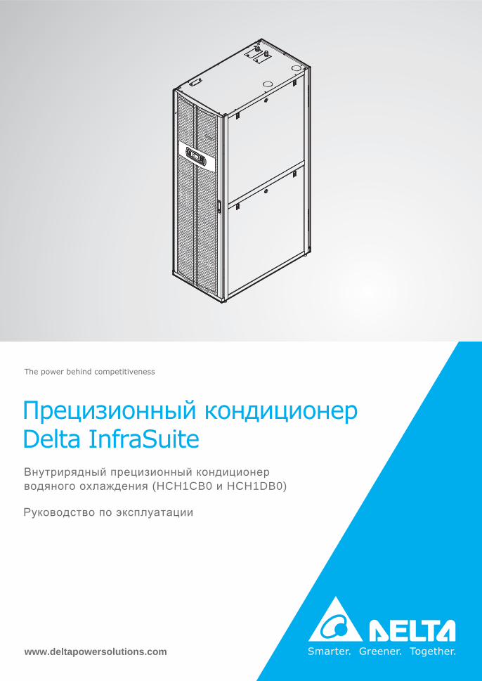
Delta InfraSuite Precision Cooling The power behind competitiveness www.deltapowersolutions.com RowCool Chilled Water Type (HCH1CB0 & HCH1DB0) User Manual
-
Upload
khangminh22 -
Category
Documents
-
view
1 -
download
0
Transcript of Delta InfraSuite Precision Cooling

Delta InfraSuite Precision Cooling
The power behind competitiveness
www.deltapowersolutions.com
RowCoolChilled Water Type (HCH1CB0 & HCH1DB0)
User Manual
i iInfraSuite RowCool Precision Cooling – Chilled Water
Save This Manual
This manual contains important instructions and warnings that you should follow during the installation, operation, storage and maintenance of this product. Failure to heed these instructions and warnings will void the warranty.
Copyright © 2014 by Delta Electronics Inc. All Rights Reserved. All rights of this User Manual (“Man-
by Delta Electronics Inc. (“Delta”). The Manual can only be applied to the operation or the use of this
or usage of this Manual in whole or in part is prohibited without the prior written permission of Delta. Given that Delta will continuously improve and develop the product, changes may be made to the in-formation in this Manual at any time without obligation to notify any person of such revision or changes. Delta will make all possible efforts to secure the accuracy and the integrity of this Manual. Delta dis-
-ing but not limited to the completeness, faultlessness, accuracy, non-infringement, merchantability or
i i i
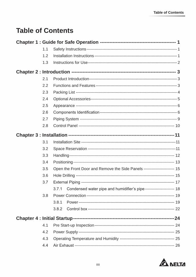
Table of Contents
Table of ContentsChapter 1 : Guide for Safe Operation ------------------------------------------------ 1
1.1 Safety Instructions -------------------------------------------------------------------- 1
1.2 Installation Instructions -------------------------------------------------------------- 1
1.3 Instructions for Use ------------------------------------------------------------------- 2
Chapter 2 : Introduction ------------------------------------------------------------------ 32.1 Product Introduction ------------------------------------------------------------------ 3
2.2 Functions and Features ------------------------------------------------------------- 3
2.3 Packing List ---------------------------------------------------------------------------- 4
2.4 Optional Accessories----------------------------------------------------------------- 5
2.5 Appearance ---------------------------------------------------------------------------- 6
---------------------------------------------------------- 6
2.7 Piping System ------------------------------------------------------------------------- 9
2.8 Control Panel ------------------------------------------------------------------------ 10
Chapter 3 : Installation -------------------------------------------------------------------113.1 Installation Site -----------------------------------------------------------------------11
3.2 Space Reservation ------------------------------------------------------------------11
3.3 Handling ------------------------------------------------------------------------------- 12
3.4 Positioning ---------------------------------------------------------------------------- 13
3.5 Open the Front Door and Remove the Side Panels ----------------------- 15
3.6 Hole Drilling -------------------------------------------------------------------------- 15
---------------------------------------------------------------------- 17
---------------------- 18
3.8 Power Connection ------------------------------------------------------------------ 19
3.8.1 Power ------------------------------------------------------------------------ 19
----------------------------------------------------------------- 22
Chapter 4 : Initial Startup ----------------------------------------------------------------244.1 Pre Start-up Inspection ------------------------------------------------------------ 24
4.2 Power Supply ------------------------------------------------------------------------ 25
4.3 Operating Temperature and Humidity ----------------------------------------- 25
--------------------------------------------------------------------------- 26
ivInfraSuite RowCool Precision Cooling – Chilled Water
4.5 Water Leakage Detector ---------------------------------------------------------- 27
4.6 Water Balance ----------------------------------------------------------------------- 28
4.7 PID Setting --------------------------------------------------------------------------- 29
Chapter 5 : Operation ---------------------------------------------------------------------325.1 LCD Display Hierarchy ------------------------------------------------------------ 32
5.2 Control Panel Operation ---------------------------------------------------------- 33
5.3 Status Screen and Main Menu -------------------------------------------------- 34
5.4 Account Authority and Login ----------------------------------------------------- 35
5.5 Operation Modes-------------------------------------------------------------------- 35
5.6 Shutdown ----------------------------------------------------------------------------- 36
5.7 Setting of Cooling Unit ------------------------------------------------------------- 37
5.7.1 Local setting ---------------------------------------------------------------- 37
5.7.2 Set point --------------------------------------------------------------------- 39
5.7.3 Controller setting ---------------------------------------------------------- 40
5.7.4 Setting of automatic control mode ------------------------------------ 41
5.7.5 Alarm setting --------------------------------------------------------------- 42
5.7.6 Inquiry of system status ------------------------------------------------- 43
5.7.7 Inquiry/ elimination of event log --------------------------------------- 44
5.7.8 Inquiry / reset of running hours ---------------------------------------- 45
5.7.9 Change of system type -------------------------------------------------- 46
5.7.10 Restoration of defaults --------------------------------------------------- 46
Chapter 6 : Maintenance and Cleaning ---------------------------------------------476.1 Firmware Upgrade ------------------------------------------------------------------ 47
6.2 Storage -------------------------------------------------------------------------------- 47
Chapter 7 : Troubleshooting -----------------------------------------------------------48
----------------------------------------------55
Appendix 2 : Periodic Inspection/ Maintenance List ---------------------------56
Appendix 3 : Glycol Correction Table ----------------------------------------------58
Appendix 4 : Warranty --------------------------------------------------------------------59

1
Chapter 1 Guide for Safe Operation
Chapter 1 : Guide for Safe Operation
1.1 Safety Instructions Please carefully read all chapters of the Manual before any installation, operation, and maintenance. To avoid personal injury and equipment damage, please be sure to oper-ate the product in accordance with the instructions in this Manual and the markings on the cabinet.
The unit should only be moved by at least two people so as to guarantee safety.
In handling or removal of the equipment, please pay attention to its height and center of gravity. When using a transportation tool for handling, it must be raised from the bottom to avoid toppling.
The unit contains moving components. Be careful to keep it away from your arms, legs, hair, clothes or jewelry so as to avoid any danger.
This appliance is not intended for use by persons (including children) with reduced
have been given supervision or instruction concerning use of the appliance by a person responsible for their safety.
Children should be supervised to ensure that they do not play with the appliance.
1.2 Installation Instructions The unit can be connected with a single or dual power source. Make sure the input power
this.
-
This unit is only intended for indoor use. The indoor environment must be separated from the outside air so as to avoid temperature and humidity interference. Consult the national or local regulations for separating the installation environment.
The appliance shall be installed in accordance with national wiring regulations. Meanwhile, the grounding wires of the unit must be effectively connected with the grounding system.
The appliance is fitted with means for disconnection from the supply mains having a contact separation in all poles that provide full disconnection under overvoltage category
with the wiring rules.
If the supply cord is damaged, it must be replaced by the manufacturer, its service agent
2InfraSuite RowCool Precision Cooling – Chilled Water
1.3 Instructions for Use The inner high voltage of the unit may be fatal! The inner components may have hidden
lead to serious injury or death or equipment damage. Be sure to follow all the instructions and warnings contained in the Manual.
When replacing the side panels or front or back doors, make sure there is no foreign mat-ter in the cabinet.
3
Chapter 2 Introduction
Chapter 2 : Introduction
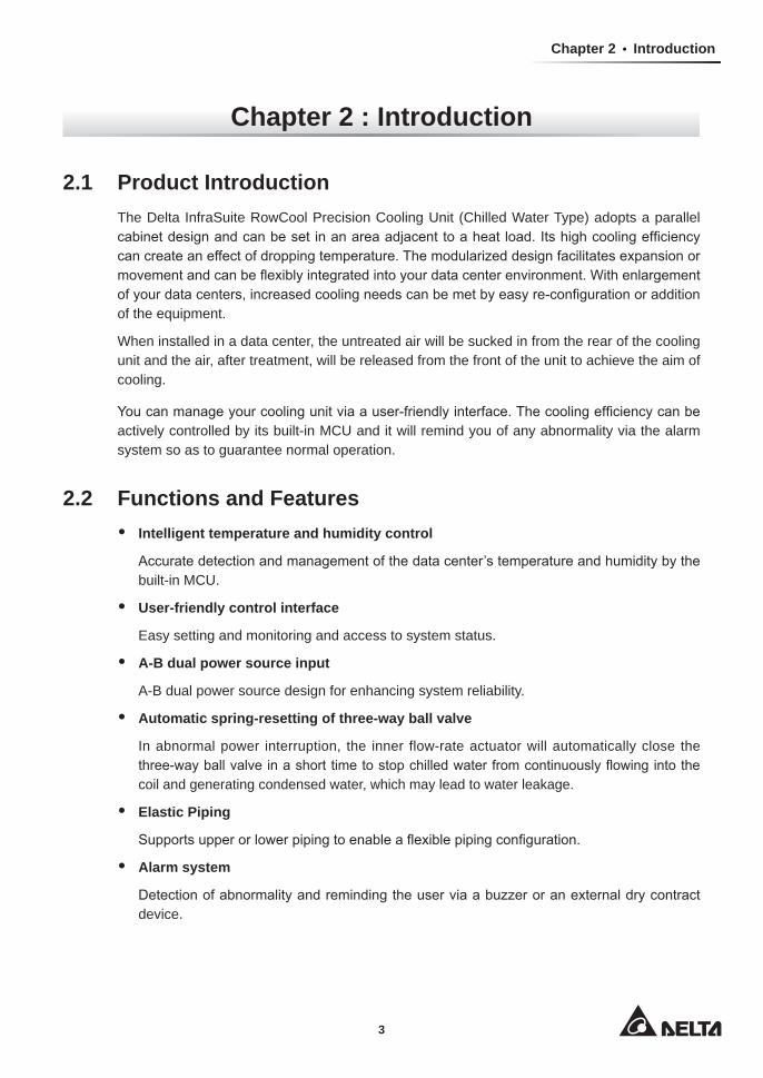
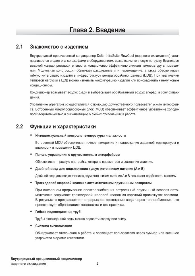
2.1 Product IntroductionThe Delta InfraSuite RowCool Precision Cooling Unit (Chilled Water Type) adopts a parallel
of the equipment.
When installed in a data center, the untreated air will be sucked in from the rear of the cooling unit and the air, after treatment, will be released from the front of the unit to achieve the aim of cooling.
actively controlled by its built-in MCU and it will remind you of any abnormality via the alarm system so as to guarantee normal operation.
2.2 Functions and FeaturesIntelligent temperature and humidity control
built-in MCU.
User-friendly control interface
Easy setting and monitoring and access to system status.
A-B dual power source input
A-B dual power source design for enhancing system reliability.
Automatic spring-resetting of three-way ball valve
In abnormal power interruption, the inner flow-rate actuator will automatically close the
coil and generating condensed water, which may lead to water leakage.
Elastic Piping
Alarm system
device.
4InfraSuite RowCool Precision Cooling – Chilled Water
Detection of heat load temperature
Accurate monitor of the heat load temperature and humidity by remote temperature and humidity sensors.
Leakage detection
immediately inform the user of any water leakage so as to protect the safety of the equip-ment.
Output and input dry contacts
Heat insulation side panels
Isolate the interference of outside temperature.
Lockable front and rear doors and side panels
Condensed water pump
The condensed water pump at the bottom of the cabinet automatically drains the condensed
Casters
For convenient movement or relocation.
Compatible SNMP card (optional)
Monitoring management through SNMP protocol.
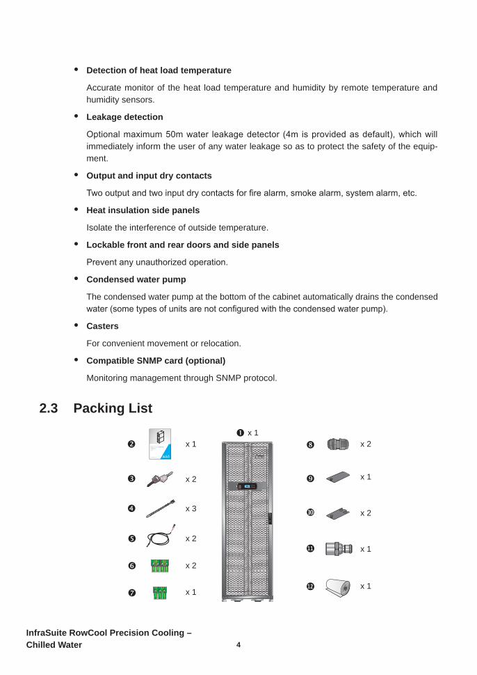
2.3 Packing List
x 2
x 3
x 2
x 1 x 1
x 1
x 2
x 2
x 1
12
x 2
x 111
x 1
www.deltagreentech.com.cn
The power behind competitiveness
InfraSuite
5
Chapter 2 Introduction
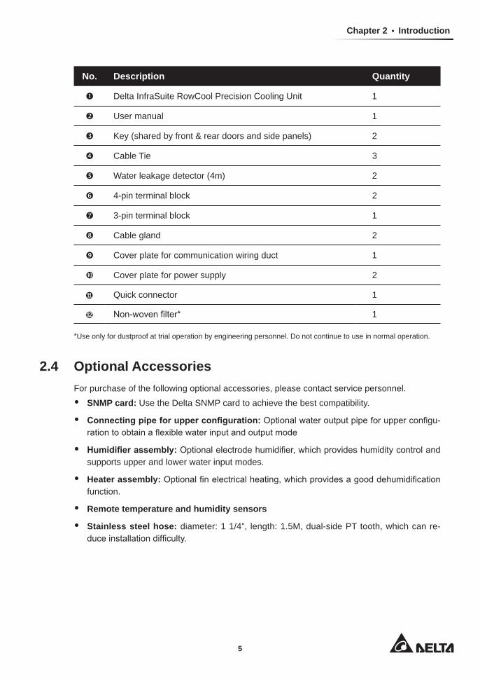
No. Description Quantity
Delta InfraSuite RowCool Precision Cooling Unit 1
User manual 1
Key (shared by front & rear doors and side panels) 2
Cable Tie 3
Water leakage detector (4m) 2
4-pin terminal block 2
3-pin terminal block 1
Cable gland 2
Cover plate for communication wiring duct 1
Cover plate for power supply 2
11 Quick connector 1
12 1
Use only for dustproof at trial operation by engineering personnel. Do not continue to use in normal operation.
2.4 Optional AccessoriesFor purchase of the following optional accessories, please contact service personnel.
SNMP card: Use the Delta SNMP card to achieve the best compatibility.
-
supports upper and lower water input modes.
Heater assembly: function.
Remote temperature and humidity sensors
Stainless steel hose: diameter: 1 1/4”, length: 1.5M, dual-side PT tooth, which can re-
6InfraSuite RowCool Precision Cooling – Chilled Water
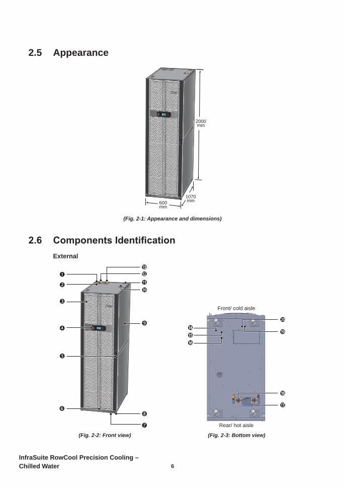
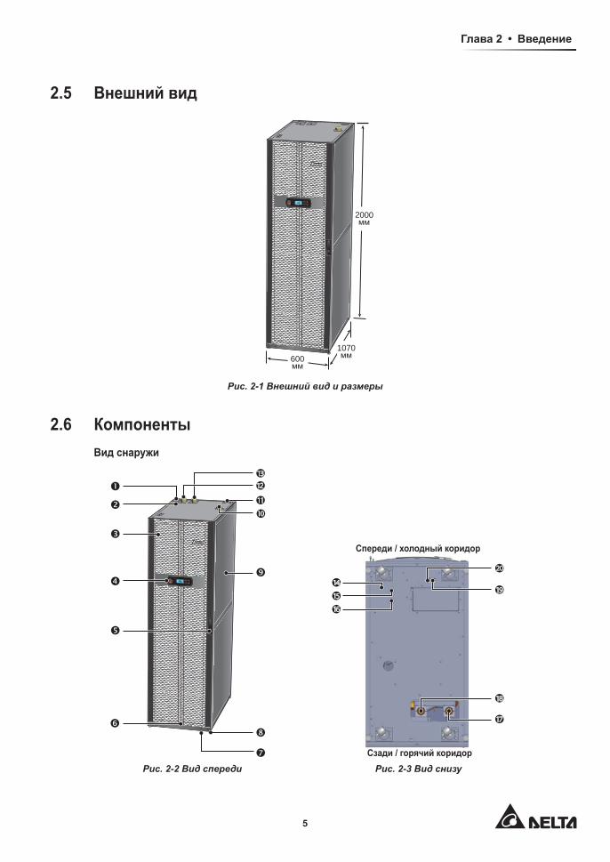
2.5 Appearance
2000mm
1070mm600
mm
(Fig. 2-1: Appearance and dimensions)
External
(Fig. 2-2: Front view)
11
12
13
Rear/ hot aisle
Front/ cold aisle
14
15
16
17
18
19
20
(Fig. 2-3: Bottom view)
7
Chapter 2 Introduction
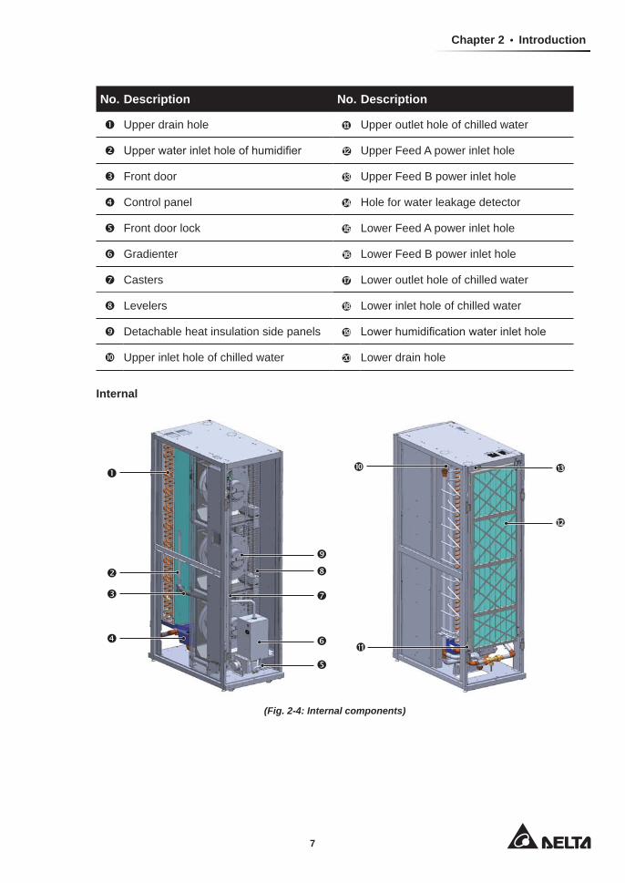
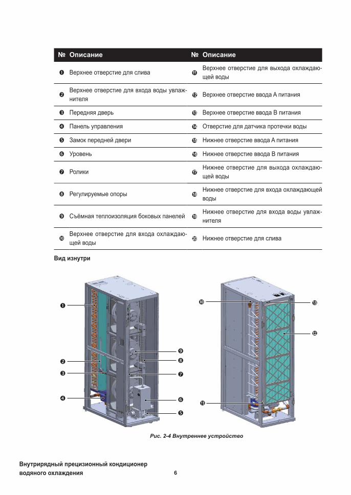
No. Description No. Description
Upper drain hole 11 Upper outlet hole of chilled water
12 Upper Feed A power inlet hole
Front door 13 Upper Feed B power inlet hole
Control panel 14 Hole for water leakage detector
Front door lock 15 Lower Feed A power inlet hole
Gradienter 16 Lower Feed B power inlet hole
Casters 17 Lower outlet hole of chilled water
Levelers 18 Lower inlet hole of chilled water
Detachable heat insulation side panels 19
Upper inlet hole of chilled water 20 Lower drain hole
Internal
11
12
13
(Fig. 2-4: Internal components)

8InfraSuite RowCool Precision Cooling – Chilled Water
No. Description No. Description
Coil
Fans
Upper water inlet pipe
Condensed water pan 11 Joint of upper outlet water pipe
Drain pump 12 Filters
13
Electric panel
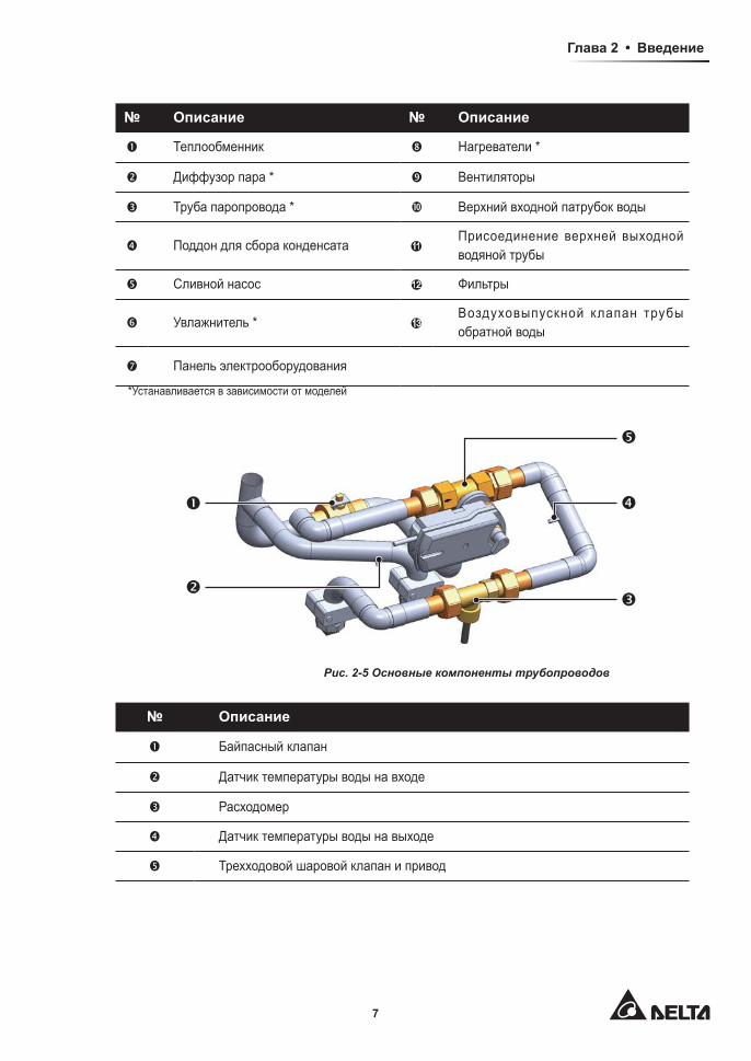
(Fig. 2-5: Main pipe components)
No. Description
Bypass value
Inlet water temperature sensor
Flow meter
Outlet water temperature sensor
Three-way ball valve and actuator
9
Chapter 2 Introduction
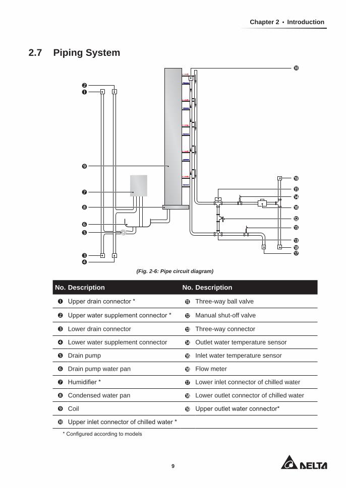
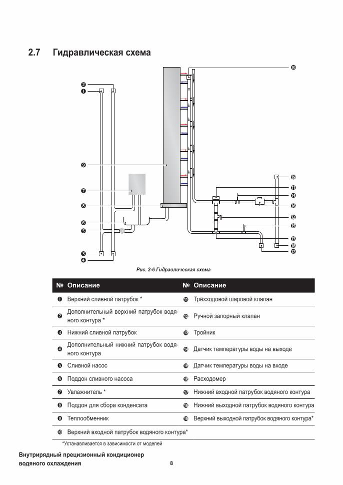
2.7 Piping System
(Fig. 2-6: Pipe circuit diagram)
11
12
13
16
1718
19
15
14
No. Description No. Description
11 Three-way ball valve
12 Manual shut-off valve
Lower drain connector 13 Three-way connector
Lower water supplement connector 14 Outlet water temperature sensor
Drain pump 15 Inlet water temperature sensor
Drain pump water pan 16 Flow meter
17 Lower inlet connector of chilled water
Condensed water pan 18 Lower outlet connector of chilled water
Coil 19
10InfraSuite RowCool Precision Cooling – Chilled Water
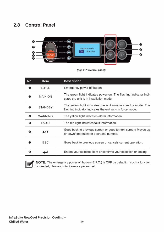
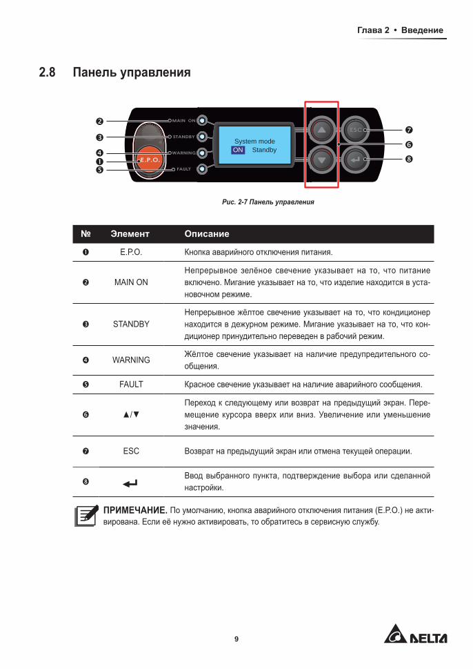
2.8 Control Panel
System modeON Standby
(Fig. 2-7: Control panel)
No. Item Description
E.P.O. Emergency power off button.
MAIN ON-
cates the unit is in installation mode.
STANDBYThe yellow light indicates the unit runs in standby mode. The
WARNING The yellow light indicates alarm information.
FAULT The red light indicates fault information.
or down/ Increases or decrease number.
ESC Goes back to previous screen or cancels current operation.
NOTE: The emergency power off button (E.P.O.) is OFF by default. If such a function is needed, please contact service personnel.
11
Chapter 3 Installation
Chapter 3 : Installation
WARNING: 1. Only service personnel can perform the following installation procedures. No installation,
damage and personal injury.
2. The high voltage in the equipment is potentially fatal! The inner components have poten-
3.1 Installation SiteWhen planning the installation site for the cooling unit, you must take the following into con-
Environmental requirements: The installation site must allow the equipment to move in
for maintenance, operation, and pipe repair. The cooling unit can only be located indoors and the indoor environment must be isolated from the outside air to avoid temperature and
the local or national regulations so as to avoid the increase of operation costs due to loss of cooling capacity.
Humidity and heat source: Implement water-proof and heat insulation engineering for the indoor environment so as to isolate the outside humid hot air.
NOTE: (refer to 4.3 Operating Temperature and Humidity), the condensation of the water of the coil may lead to a rise in the water level of the condensed water pan, triggering an alarm.
Noise impact: At a high load, the operation of this cooling unit may produce loud noise.
Input power: In connecting the power supply, make sure that the power conforms to the -
spect the rated values of each unit and make sure they have been properly grounded. One branch circuit or power distribution device can only be connected with one cooling unit.
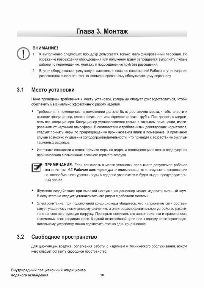
3.2 Space ReservationIn order to facilitate maintenance, operation, and air circulation, please reserve a net space around the equipment.
12InfraSuite RowCool Precision Cooling – Chilled Water
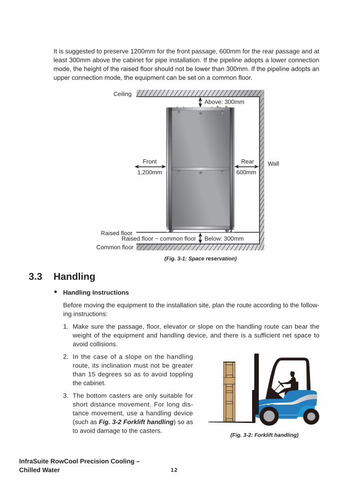
It is suggested to preserve 1200mm for the front passage, 600mm for the rear passage and at least 300mm above the cabinet for pipe installation. If the pipeline adopts a lower connection
Ceiling
Wall
Raised floor
Common floor
Above: 300mm
Below: 300mmRaised floor ~ common floor
1,200mm 600mm
Front Rear
(Fig. 3-1: Space reservation)
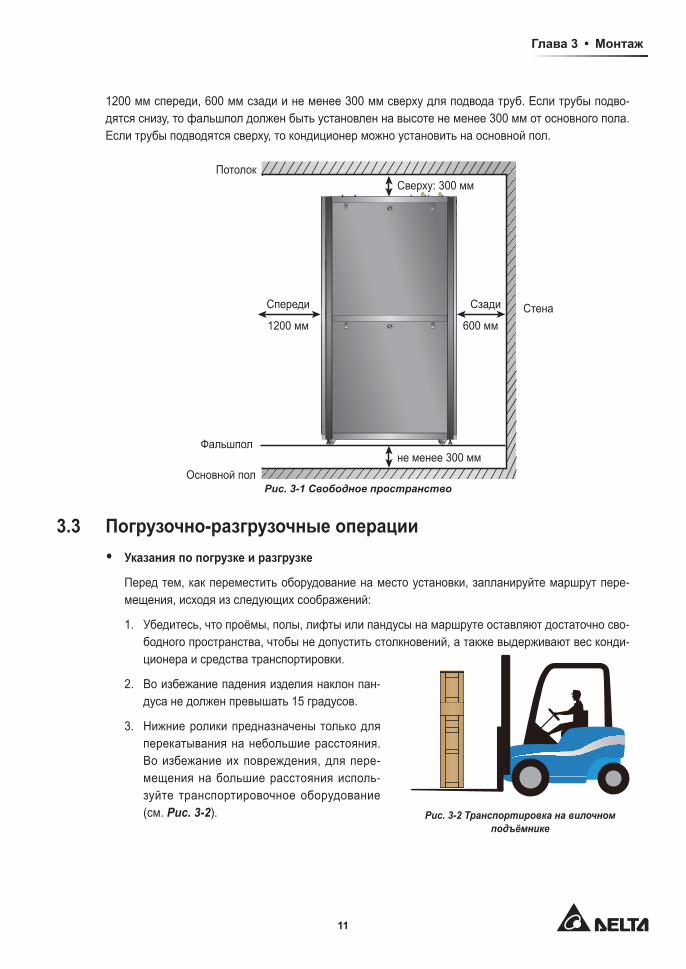
3.3 HandlingHandling Instructions
Before moving the equipment to the installation site, plan the route according to the follow-ing instructions:
1. Make sure the passage, floor, elevator or slope on the handling route can bear the weight of the equipment and handling device, and there is a sufficient net space to avoid collisions.
2. In the case of a slope on the handling route, its inclination must not be greater than 15 degrees so as to avoid toppling the cabinet.
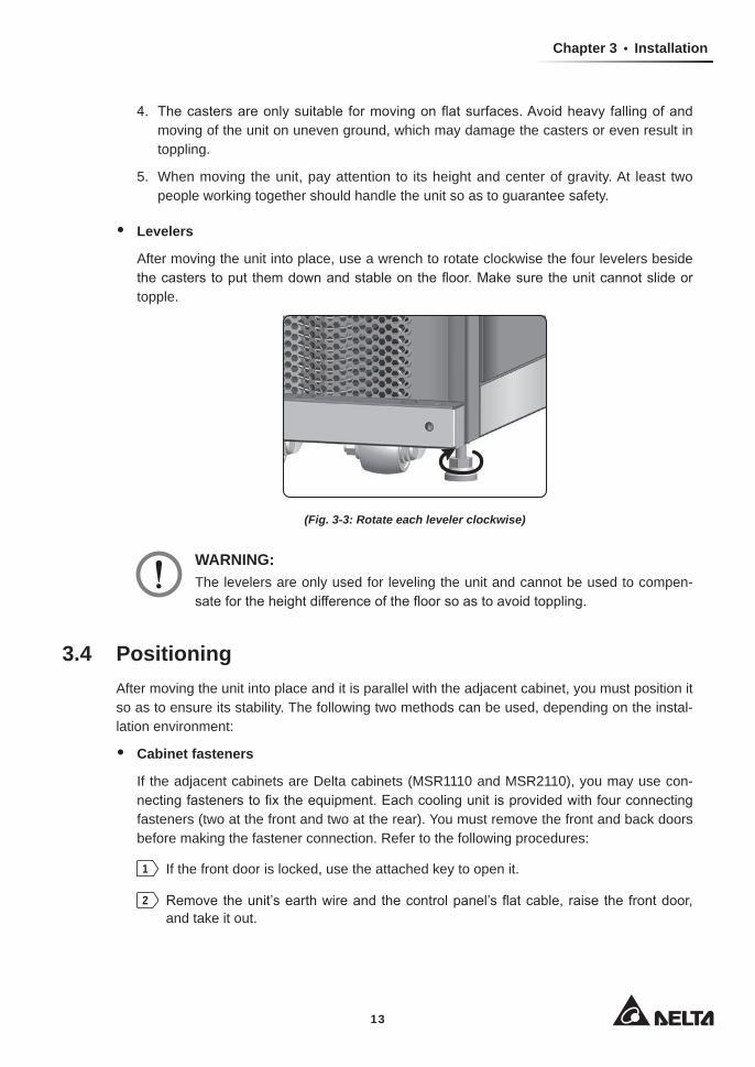
3. The bottom casters are only suitable for short distance movement. For long dis-tance movement, use a handling device (such as Fig. 3-2 Forklift handling) so as to avoid damage to the casters.
(Fig. 3-2: Forklift handling)
13
Chapter 3 Installation
moving of the unit on uneven ground, which may damage the casters or even result in toppling.
5. When moving the unit, pay attention to its height and center of gravity. At least two people working together should handle the unit so as to guarantee safety.
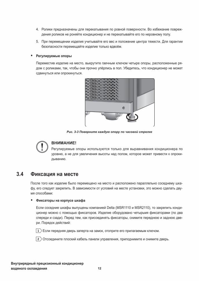
Levelers
After moving the unit into place, use a wrench to rotate clockwise the four levelers beside
topple.
(Fig. 3-3: Rotate each leveler clockwise)
WARNING:The levelers are only used for leveling the unit and cannot be used to compen-
3.4 PositioningAfter moving the unit into place and it is parallel with the adjacent cabinet, you must position it so as to ensure its stability. The following two methods can be used, depending on the instal-lation environment:
Cabinet fasteners
If the adjacent cabinets are Delta cabinets (MSR1110 and MSR2110), you may use con-
fasteners (two at the front and two at the rear). You must remove the front and back doors before making the fastener connection. Refer to the following procedures:
1 If the front door is locked, use the attached key to open it.
2and take it out.
14InfraSuite RowCool Precision Cooling – Chilled Water
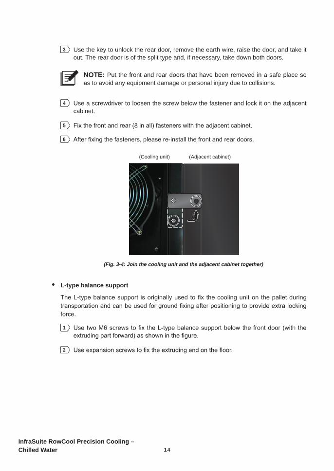
3 Use the key to unlock the rear door, remove the earth wire, raise the door, and take it out. The rear door is of the split type and, if necessary, take down both doors.
NOTE: Put the front and rear doors that have been removed in a safe place so as to avoid any equipment damage or personal injury due to collisions.
4 Use a screwdriver to loosen the screw below the fastener and lock it on the adjacent cabinet.
5
6
(Fig. 3-4: Join the cooling unit and the adjacent cabinet together)
(Cooling unit) (Adjacent cabinet)
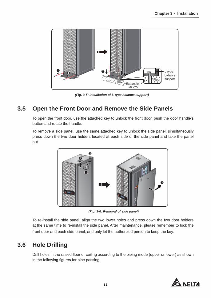
L-type balance support
force.
1
2
15
Chapter 3 Installation
Expansionscrews
L-typebalancesupportFloor
(Fig. 3-5: Installation of L-type balance support)
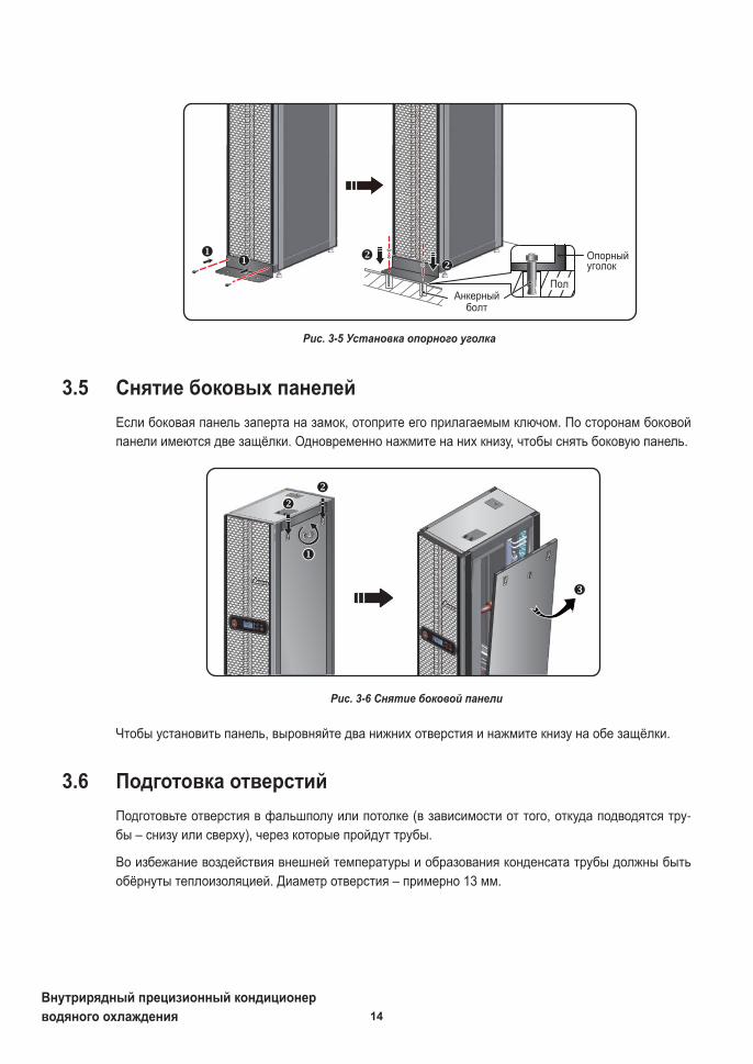
3.5 Open the Front Door and Remove the Side Panels
button and rotate the handle.
To remove a side panel, use the same attached key to unlock the side panel, simultaneously press down the two door holders located at each side of the side panel and take the panel out.
(Fig. 3-6: Removal of side panel)
To re-install the side panel, align the two lower holes and press down the two door holders at the same time to re-install the side panel. After maintenance, please remember to lock the
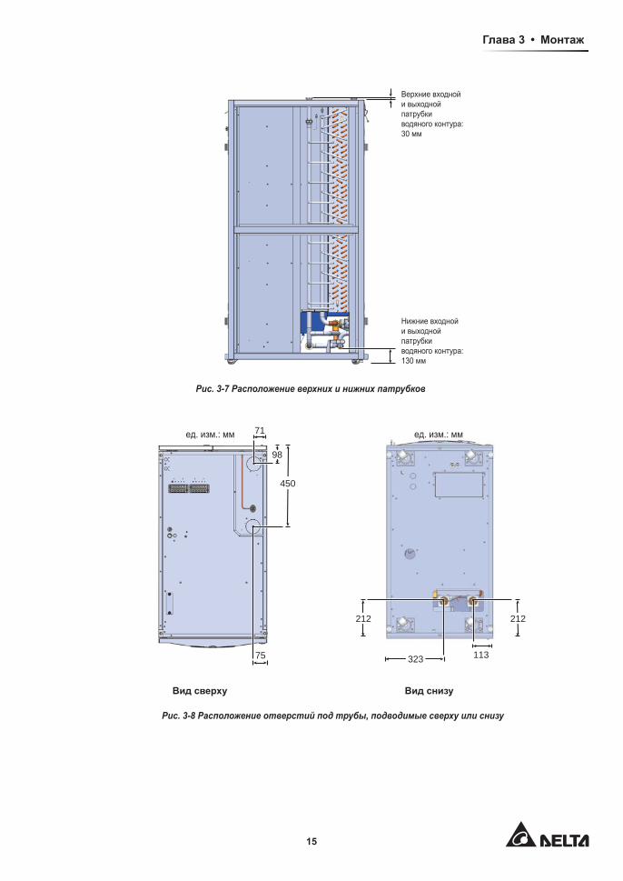
3.6 Hole Drilling
16InfraSuite RowCool Precision Cooling – Chilled Water
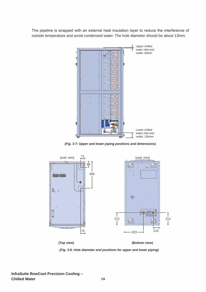
outside temperature and avoid condensed water. The hole diameter should be about 13mm.
Lower chilled water inlet and outlet: 130mm
Upper chilled water inlet and outlet: 30mm
(Fig. 3-7: Upper and lower piping positions and dimensions)
71
75
98
450
212 212
323 113
(unit: mm) (unit: mm)
(Bottom view) (Top view)
(Fig. 3-8: Hole diameter and positions for upper and lower piping)
17
Chapter 3 Installation
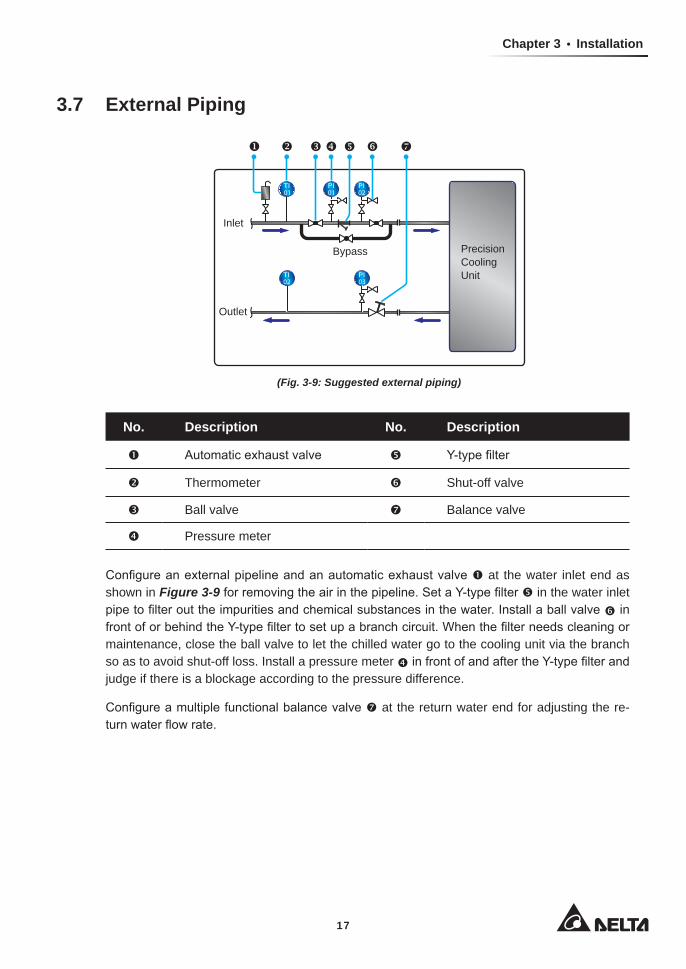
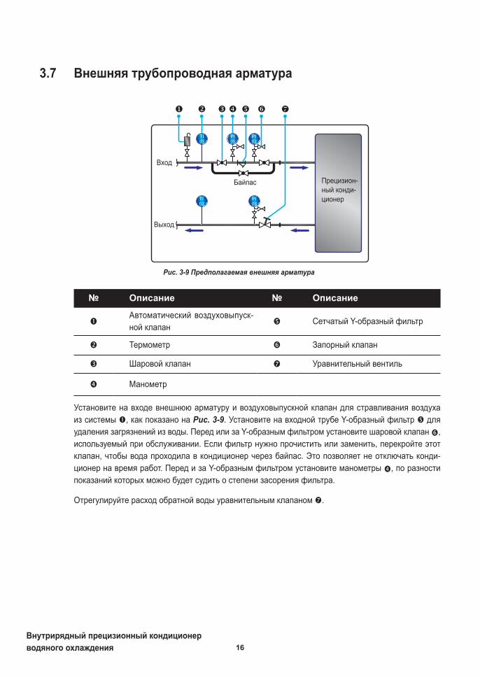
3.7 External Piping
Bypass
PI03
PI02
TI01
TI02
PI01
Inlet
Outlet
PrecisionCoolingUnit
(Fig. 3-9: Suggested external piping)
No. Description No. Description
Thermometer Shut-off valve
Ball valve Balance valve
Pressure meter
at the water inlet end as shown in Figure 3-9 in the water inlet
in
maintenance, close the ball valve to let the chilled water go to the cooling unit via the branch so as to avoid shut-off loss. Install a pressure meter judge if there is a blockage according to the pressure difference.
at the return water end for adjusting the re-
18InfraSuite RowCool Precision Cooling – Chilled Water
Pipeline washing
To guarantee cooling efficiency, you must purify the pipeline to filter out impurities and chemical substances. For pipeline washing, use a hose to create a short circuit to make the chilled water go directly from the inlet end to the return end without passing through
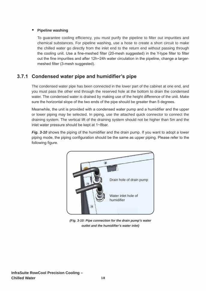
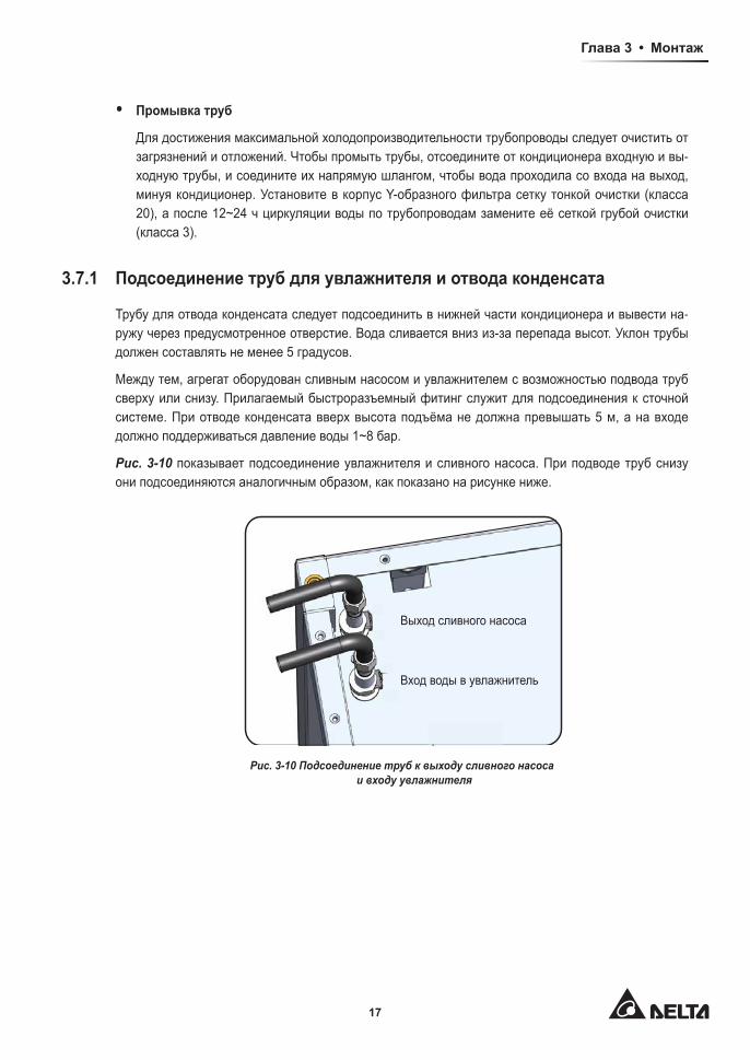
The condensed water pipe has been connected in the lower part of the cabinet at one end, and you must pass the other end through the reserved hole at the bottom to drain the condensed water. The condensed water is drained by making use of the height difference of the unit. Make
or lower piping may be selected. In piping, use the attached quick connector to connect the draining system. The vertical lift of the draining system should not be higher than 5m and the
Fig. 3-10
Drain hole of drain pump
Water inlet hole of humidifier
(Fig. 3-10: Pipe connection for the drain pump’s wateroutlet and the humidifier’s water inlet)
19
Chapter 3 Installation
3.8 Power Connection
3.8.1 Power
WARNING: 1. The input power must conform to the rated value on the equipment nameplate.
2. The appliance of the power wires and backup connecting wires should conform
PVC cord with a diameter of 10AWG (4.0mm2) and a temperature resistance of 105°C.
3. In locking the screws for wiring at the power terminal block, use the recommend-ed installation torque (12.2Kgf-cm ).
4. If there is no wire passing through the communication wire duct at the top of the cabinet, cover the duct with the cover plate provided in the accessory package so as to avoid dust accumulation.
5. Reserve inlet wire length on site wiring and make sure the G wire is longer than the R, S, T, and N wires.
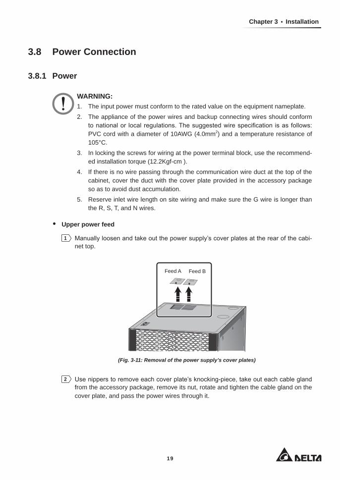
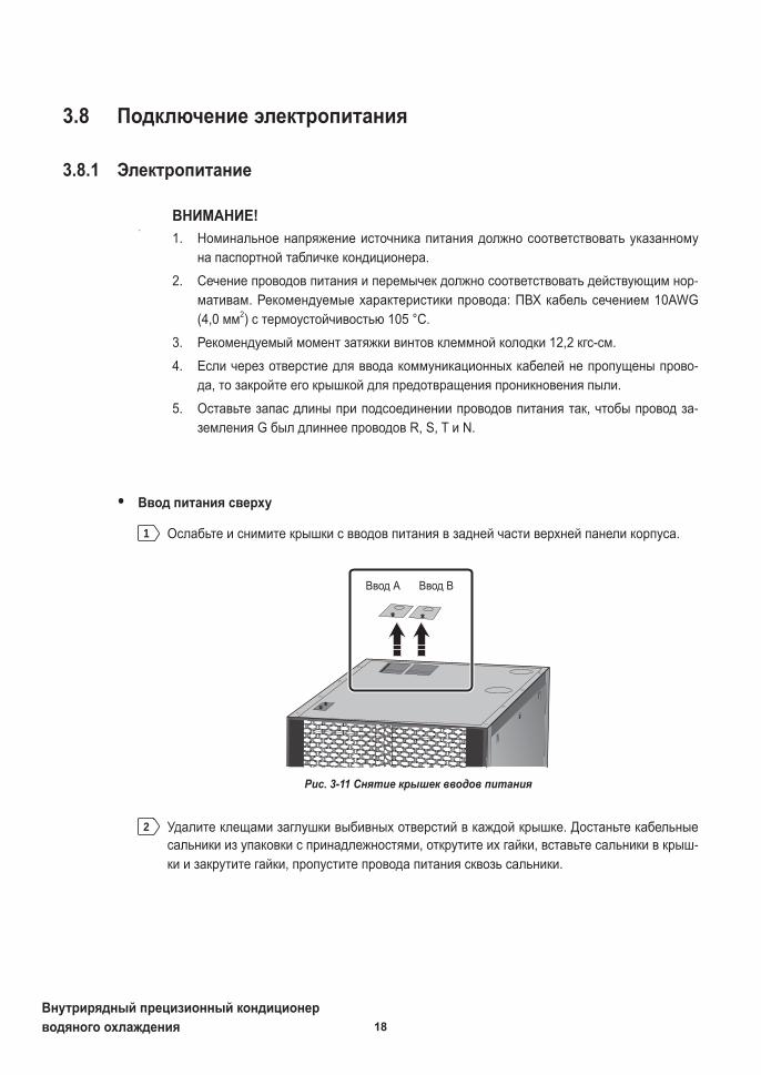
Upper power feed
1 -net top.
Feed A Feed B
(Fig. 3-11: Removal of the power supply’s cover plates)
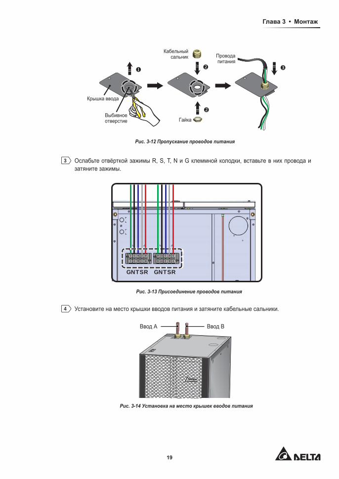
2from the accessory package, remove its nut, rotate and tighten the cable gland on the cover plate, and pass the power wires through it.
20InfraSuite RowCool Precision Cooling – Chilled Water
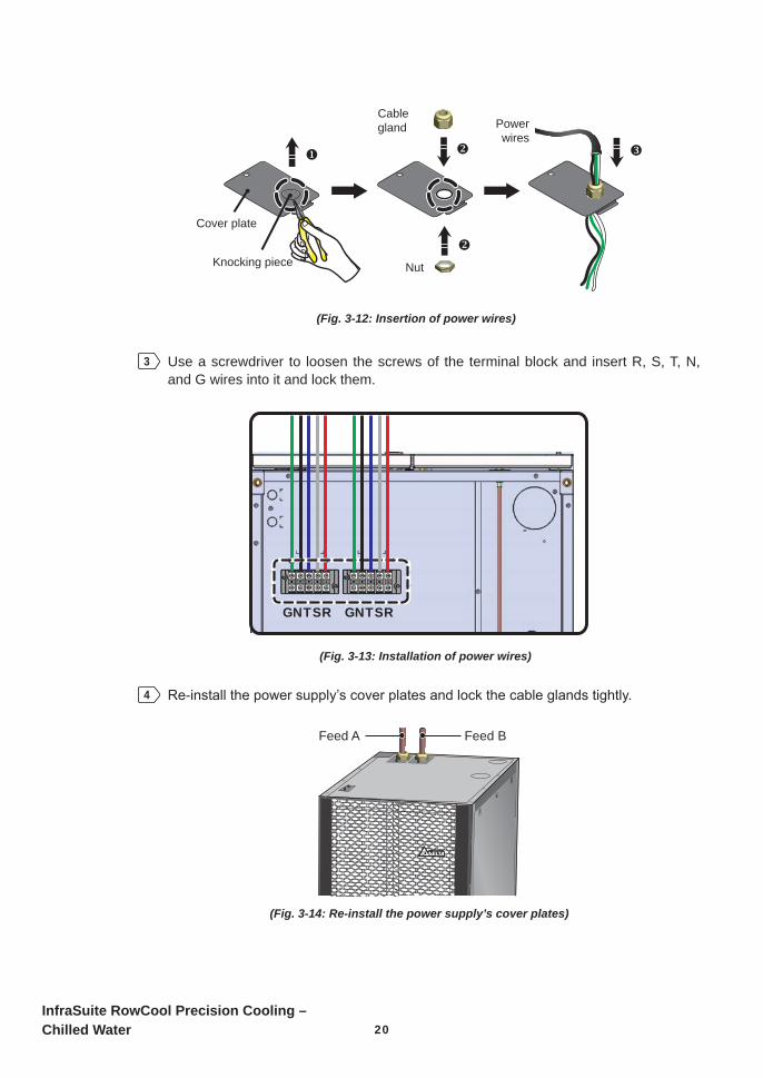
Powerwires
Cable gland
Cover plate
Knocking piece Nut
(Fig. 3-12: Insertion of power wires)
3 Use a screwdriver to loosen the screws of the terminal block and insert R, S, T, N, and G wires into it and lock them.
RSTNG RSTNG
(Fig. 3-13: Installation of power wires)
4
(Fig. 3-14: Re-install the power supply’s cover plates)
Feed A Feed B
21
Chapter 3 Installation
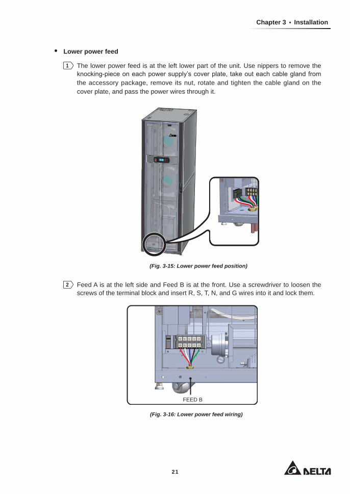
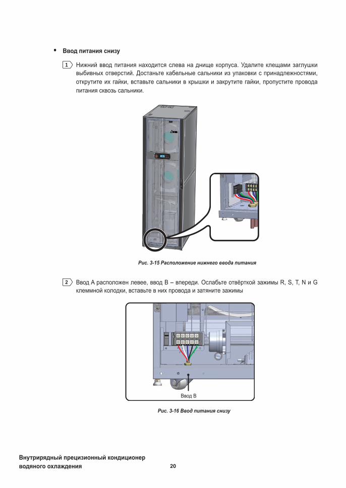
Lower power feed
1 The lower power feed is at the left lower part of the unit. Use nippers to remove the
the accessory package, remove its nut, rotate and tighten the cable gland on the cover plate, and pass the power wires through it.
(Fig. 3-15: Lower power feed position)
2 Feed A is at the left side and Feed B is at the front. Use a screwdriver to loosen the screws of the terminal block and insert R, S, T, N, and G wires into it and lock them.
FEED B
(Fig. 3-16: Lower power feed wiring)
22InfraSuite RowCool Precision Cooling – Chilled Water
3.8.2 Control box
Front
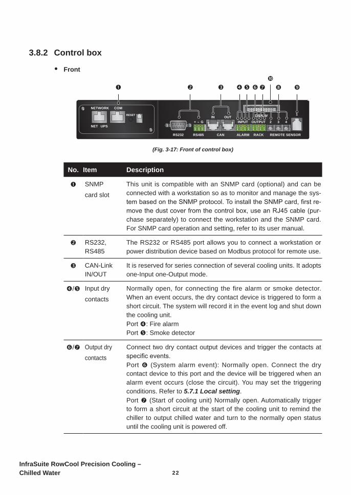
(Fig. 3-17: Front of control box)
NETWORK COM
NET UPS
RESET
RS232 RS485 CAN
INPUTOUTIN
OUTPUT
ALARM RACK REMOTE SENSOR
2
1
3 4+ - G
DISPLAY
No. Item Description
SNMP
card slot
This unit is compatible with an SNMP card (optional) and can be connected with a workstation so as to monitor and manage the sys-
--
chase separately) to connect the workstation and the SNMP card. For SNMP card operation and setting, refer to its user manual.
RS232,RS485
The RS232 or RS485 port allows you to connect a workstation or power distribution device based on Modbus protocol for remote use.
CAN-Link IN/OUT
It is reserved for series connection of several cooling units. It adopts one-Input one-Output mode.
/ Input dry
contacts
Normally open, for connecting the fire alarm or smoke detector. When an event occurs, the dry contact device is triggered to form a short circuit. The system will record it in the event log and shut down the cooling unit. Port : Fire alarm Port : Smoke detector
/ Output dry
contacts
Connect two dry contact output devices and trigger the contacts at
Port (System alarm event): Normally open. Connect the dry contact device to this port and the device will be triggered when an alarm event occurs (close the circuit). You may set the triggering conditions. Refer to 5.7.1 Local setting.Port (Start of cooling unit) Normally open. Automatically trigger to form a short circuit at the start of the cooling unit to remind the chiller to output chilled water and turn to the normally open status until the cooling unit is powered off.
23
Chapter 3 Installation
No. Item Description
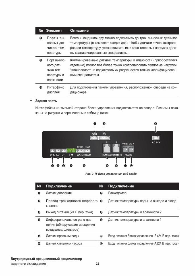
Remote tempera-ture sensor ports
At most, three remote temperature sensors (two are provided) can
them for you in installation for accurate detection of the temperature of heat loads.
Remote temperature and humidity sensor port
Connects the remote temperature-humidity sensor (purchase sepa-rately) for accurate detection of the temperature and humidity of
installation.
Display
interface
Connects the control panel locating in front of the unit for informa-tion output.
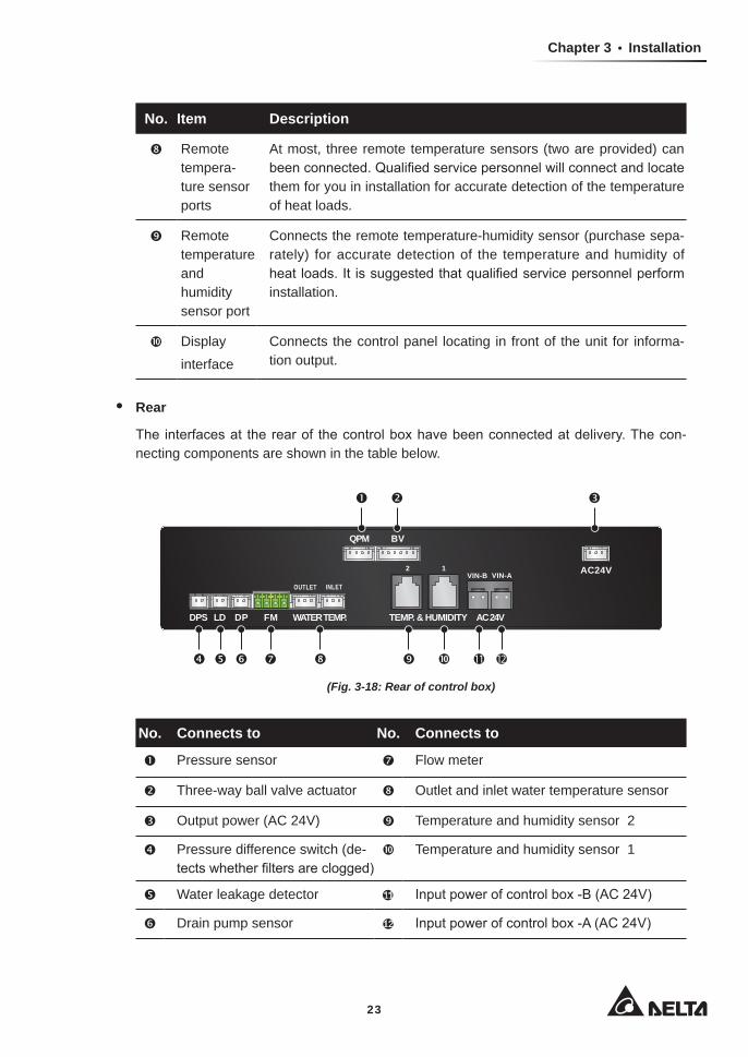
Rear
-necting components are shown in the table below.
TEMP. & HUMIDITYLD DP FM
INLETOUTLET
WATER TEMP. AC 24V
VIN-B2 1
VIN-A
QPM BV
AC24V
DPS
11 12
(Fig. 3-18: Rear of control box)
No. Connects to No. Connects to
Pressure sensor Flow meter
Three-way ball valve actuator Outlet and inlet water temperature sensor
Output power (AC 24V) Temperature and humidity sensor 2
Pressure difference switch (de- Temperature and humidity sensor 1
Water leakage detector 11
Drain pump sensor 12

24InfraSuite RowCool Precision Cooling – Chilled Water
Chapter 4 : Initial Startup
4.1 Pre Start-up Inspection
WARNING:
chapter.
2. The inner high voltage of this unit is potentially fatal! Make sure the input power has been disconnected before the following actions.
3. A startup without correctly completing 4.1 Pre Start-up Inspection may lead to serious personal injury or equipment damage!
Please complete all the following inspections before implementing the initial startup proce-dures.
Inspection List
General items
___All the installation procedures have been performed in accordance with the instructions in Chapter 3: Installation.
___The pipes in and outside the cabinet have been correctly connected and the thermal insulating layer of the pipes are free of damage and leakage.
has been connected.
Environment
___The inner environment is an enclosed space and isolated from interference from out-side temperature and humidity.
___The reserved space around the cabinet conforms to the regulation (See 3.2 Space Reservation).
Electronic connection
___The rated value of the input power conforms to that marked on the nameplate.
___The equipment has been properly grounded.
___All electronic connections are tight and stable.
25
Chapter 4 Initial Startup
___The remote temperature (humidity) sensors have been correctly connected and locat-ed properly.
___The water leakage detector has been correctly laid.
Mechanical connection
___The pipes and valves are free of breaks or damage.
___The condensed water drain pipe has been correctly connected and led to the draining site.
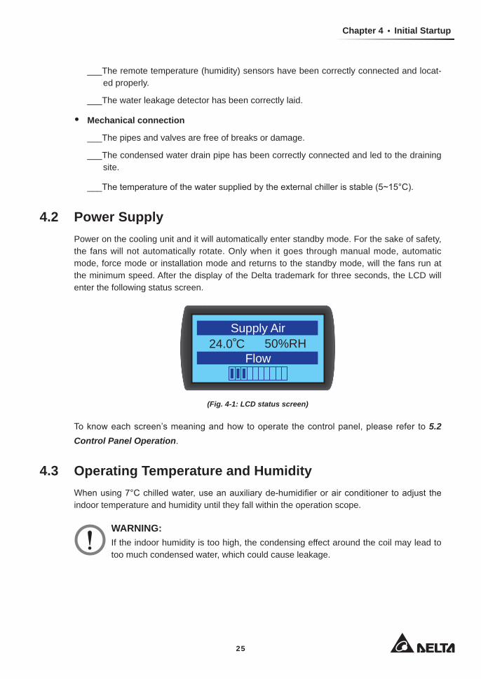
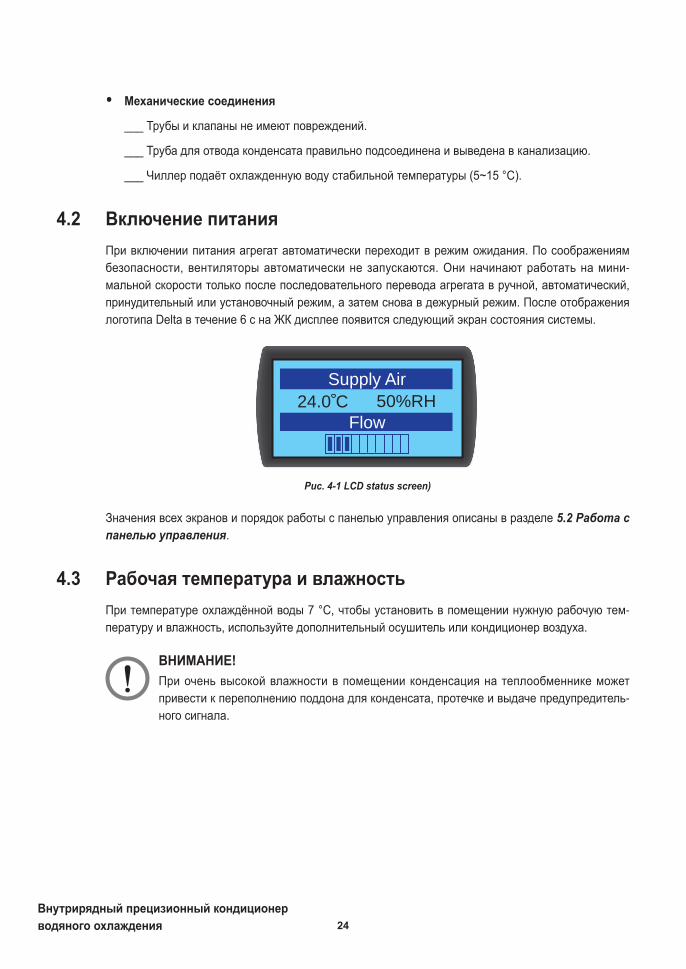
4.2 Power SupplyPower on the cooling unit and it will automatically enter standby mode. For the sake of safety, the fans will not automatically rotate. Only when it goes through manual mode, automatic mode, force mode or installation mode and returns to the standby mode, will the fans run at the minimum speed. After the display of the Delta trademark for three seconds, the LCD will enter the following status screen.
Supply Air
Flow50%RH24.0 C
(Fig. 4-1: LCD status screen)
5.2 Control Panel Operation.
4.3 Operating Temperature and Humidity
indoor temperature and humidity until they fall within the operation scope.
WARNING: If the indoor humidity is too high, the condensing effect around the coil may lead to too much condensed water, which could cause leakage.
26InfraSuite RowCool Precision Cooling – Chilled Water
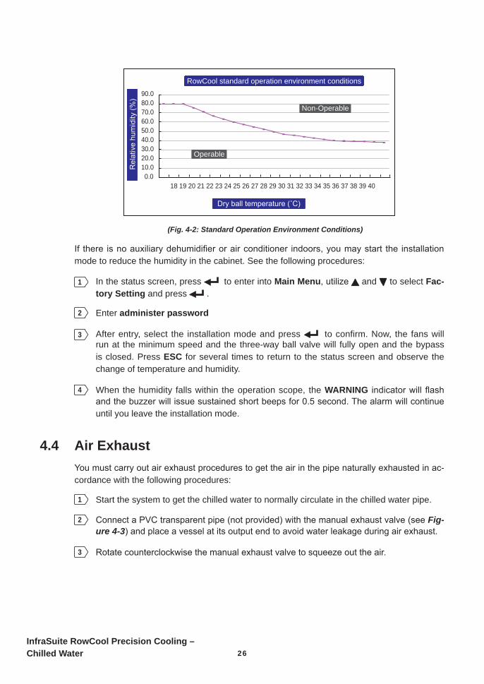
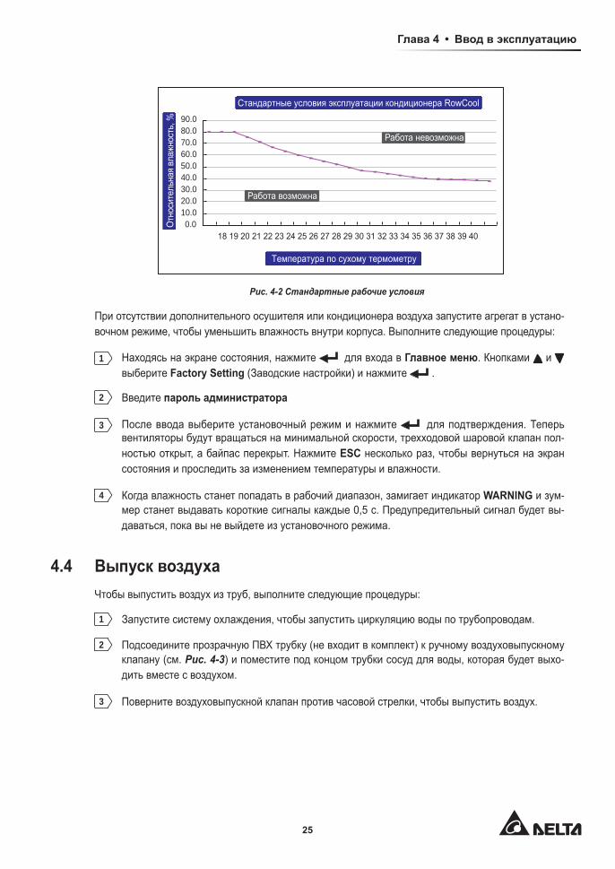
RowCool standard operation environment conditions90.080.070.060.050.040.030.020.010.00.0
18 19 20 21 22 23 24 25 26 27 28 29 30 31 32 33 34 35 36 37 38 39 40
Non-Operable
Operable
(Fig. 4-2: Standard Operation Environment Conditions)
mode to reduce the humidity in the cabinet. See the following procedures:
1 In the status screen, press to enter into Main Menu and to select Fac-tory Setting and press .
2 Enter administer password
3 After entry, select the installation mode and press to confirm. Now, the fans will run at the minimum speed and the three-way ball valve will fully open and the bypass is closed. Press ESC for several times to return to the status screen and observe the change of temperature and humidity.
4 When the humidity falls within the operation scope, the WARNING
until you leave the installation mode.
4.4 Air Exhaust-
cordance with the following procedures:
1 Start the system to get the chilled water to normally circulate in the chilled water pipe.
2 Fig-ure 4-3
3
27
Chapter 4 Initial Startup
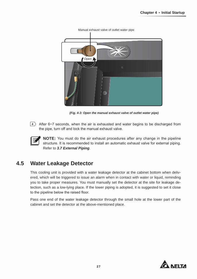
(Fig. 4-3: Open the manual exhaust valve of outlet water pipe)
Manual exhaust valve of outlet water pipe
Open
4
NOTE:
Refer to 3.7 External Piping.
4.5 Water Leakage DetectorThis cooling unit is provided with a water leakage detector at the cabinet bottom when deliv-ered, which will be triggered to issue an alarm when in contact with water or liquid, reminding you to take proper measures. You must manually set the detector at the site for leakage de-tection, such as a low-lying place. If the lower piping is adopted, it is suggested to set it close
Pass one end of the water leakage detector through the small hole at the lower part of the cabinet and set the detector at the above-mentioned place.
28InfraSuite RowCool Precision Cooling – Chilled Water
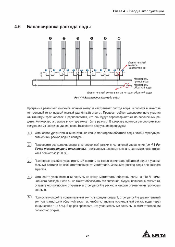
4.6 Water Balance
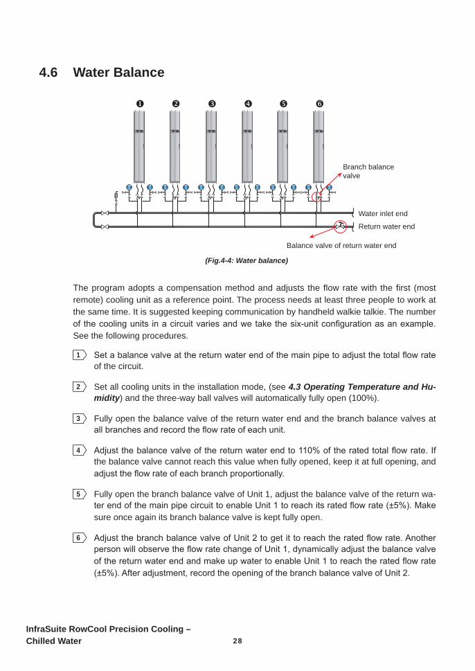
(Fig.4-4: Water balance)
PI03
PI01
PI03
PI01
PI03
PI01
PI03
PI01
PI03
PI01
PI03
PI01
Water inlet end
Return water end
Balance valve of return water end
Branch balance valve
The program adopts a compensation method and adjusts the flow rate with the first (most remote) cooling unit as a reference point. The process needs at least three people to work at the same time. It is suggested keeping communication by handheld walkie talkie. The number
See the following procedures.
1of the circuit.
2 Set all cooling units in the installation mode, (see 4.3 Operating Temperature and Hu-midity) and the three-way ball valves will automatically fully open (100%).
3 Fully open the balance valve of the return water end and the branch balance valves at
4the balance valve cannot reach this value when fully opened, keep it at full opening, and
5 Fully open the branch balance valve of Unit 1, adjust the balance valve of the return wa-
sure once again its branch balance valve is kept fully open.
6
29
Chapter 4 Initial Startup
7-
8 Repeat the procedures 6 7branch balance valves.
9 When all units are adjusted, record the opening of the balance valve of the return water
10
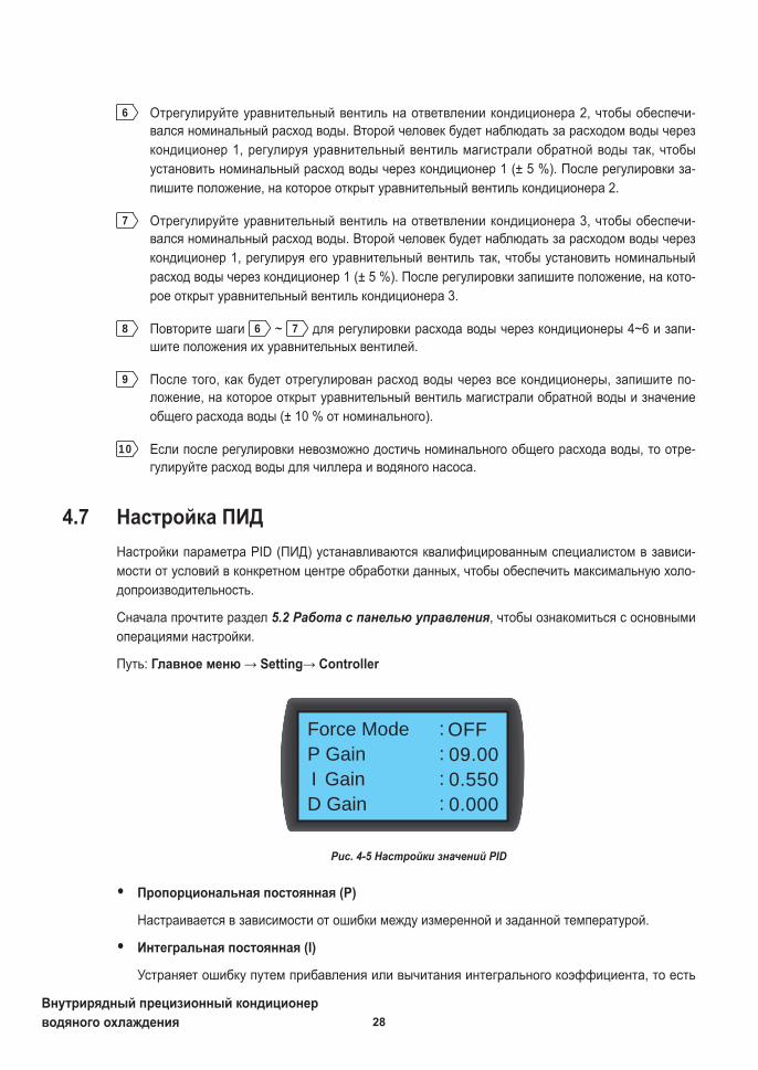
4.7 PID SettingIn light of different environmental conditions of data centers, the PID parameter values must
5.2 Control Panel Operation to get familiar with basic operation.
Path:
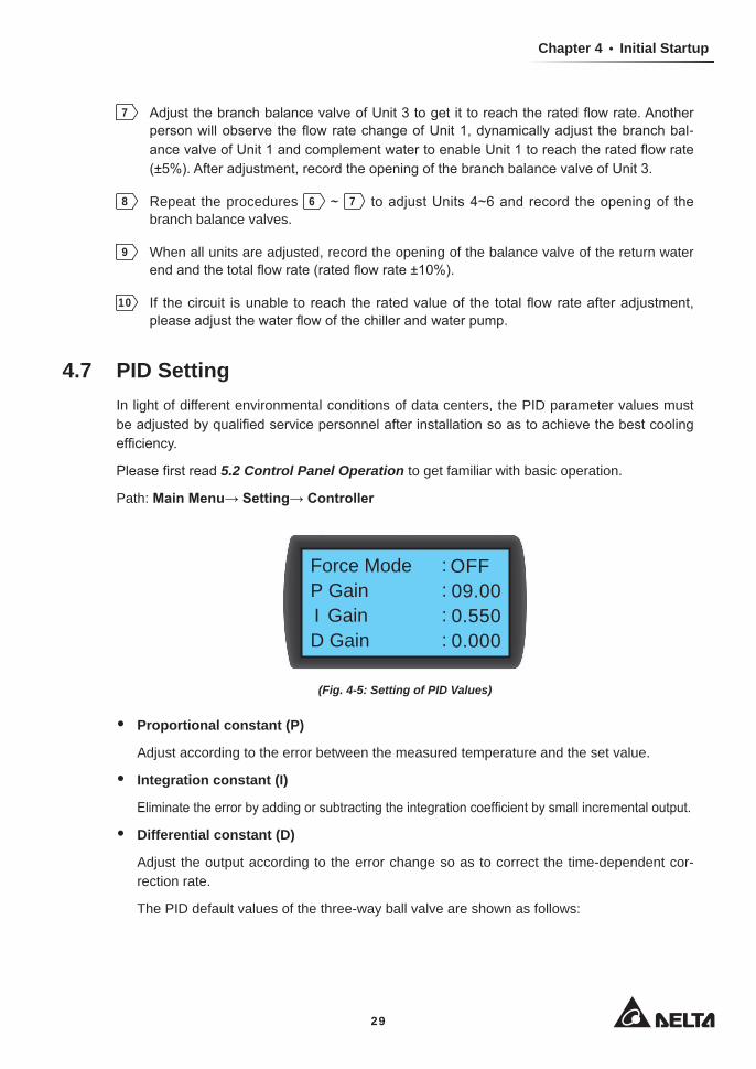
::::
Force ModeP Gain I GainD Gain
OFF 09.000.5500.000
(Fig. 4-5: Setting of PID Values)
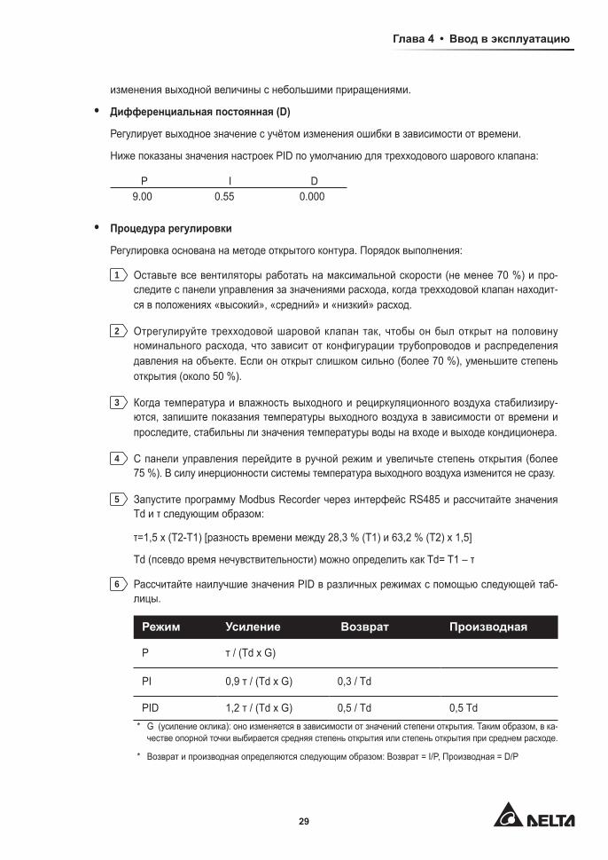
Proportional constant (P)
Adjust according to the error between the measured temperature and the set value.
Integration constant (I)
Differential constant (D)
Adjust the output according to the error change so as to correct the time-dependent cor-rection rate.
The PID default values of the three-way ball valve are shown as follows:
30InfraSuite RowCool Precision Cooling – Chilled Water
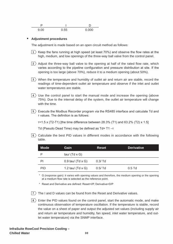
P I D 9.00 0.55 0.000
Adjustment procedures
The adjustment is made based on an open circuit method as follows:
1high, medium, and low openings of the three-way ball valve from the control panel.
2 Adjust the three-way ball valve to the opening at half of the rated flow rate, which
opening is too large (above 70%), reduce it to a medium opening (about 50%).
3 When the temperature and humidity of outlet air and return air are stable, record the readings of time-dependent outlet air temperature and observe if the inlet and outlet water temperatures are stable.
4 Use the control panel to start the manual mode and increase the opening (above 75%). Due to the internal delay of the system, the outlet air temperature will change with the time.
5
6 Calculate the best PID values in different modes in accordance with the following table.
Mode Gain Reset Derivative
P
PI 0.3/ Td
PID 0.5/ Td 0.5 Td
(response gain): it varies with opening values and therefore, the medium opening or the opening
7 The I and D values can be found from the Reset and Derivative values.
8 Enter the PID values found on the control panel, start the automatic mode, and make continuous observation of temperature oscillation. If the temperature is stable, record the value on a sheet of paper and output the adjusted set values (including supply air and return air temperature and humidity, fan speed, inlet water temperature, and out-let water temperature) via the SNMP interface.
31
Chapter 4 Initial Startup
Operation trial
2. Change the set point, record the stability time (reaching the set point of supply air tem-perature) via the SNMP interface, and observe if there is instability and temperature oscillation.
32InfraSuite RowCool Precision Cooling – Chilled Water
Chapter 5 : Operation
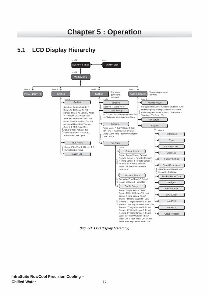
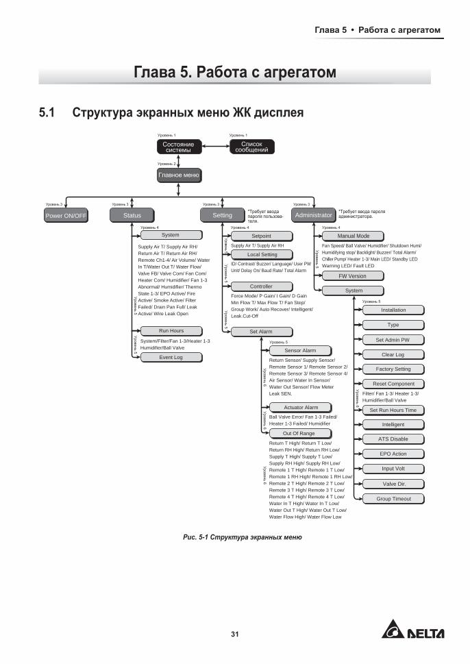
5.1 LCD Display HierarchyLevel 1
Level 2
Level 1
Level 3 Level 3 Level 3 Level 3
Level 4 Level 4 Level 4
Level 5
System/Filter/Fan 1-3/Heater 1-3Humidifier/Ball Valve
Supply Air T/ Supply Air RH
ID/ Contrast/ Buzzer/ Language/ User PWUnit/ Delay On/ Baud Rate/ Total Alarm
Force Mode/ P Gain/ I Gain/ D GainMin Flow T/ Max Flow T/ Fan Step/Group Work/ Auto Recover/ Intelligent/Leak.Cut-Off
Return Sensor/ Supply Sensor/Remote Sensor 1/ Remote Sensor 2/Remote Sensor 3/ Remote Sensor 4/Air Sensor/ Water In Sensor/ Water Out Sensor/ Flow MeterLeak SEN.
Ball Valve Error/ Fan 1-3 Failed/ Heater 1-3 Failed/ Humidifier
Return T High/ Return T Low/ Return RH High/ Return RH Low/ Supply T High/ Supply T Low/ Supply RH High/ Supply RH Low/ Remote 1 T High/ Remote 1 T Low/Remote 1 RH High/ Remote 1 RH Low/Remote 2 T High/ Remote 2 T Low/ Remote 3 T High/ Remote 3 T Low/Remote 4 T High/ Remote 4 T Low/Water In T High/ Water In T Low/ Water Out T High/ Water Out T Low/Water Flow High/ Water Flow Low
Level 5Level 5
Level 5Level 5
Level 5
Fan Speed/ Ball Valve/ Humidifier/ Shutdown Humi/Humidifying stop/ Backlight/ Buzzer/ Total Alarm/Chiller Pump/ Heater 1-3/ Main LED/ Standby LEDWarning LED/ Fault LED
Level 6Level 6
Level 6
Level 5
Level 5
Level 6
Filter/ Fan 1-3/ Heater 1-3/ Humidifier/Ball Valve
*The user’s password required.
*The admin password required.
System
Run Hours
Event Log
Setpoint
Controller
Set Alarm
Local Setting
Sensor Alarm
Out Of Range
System
Installation
Set Admin PW
Type
Clear Log
Factory Setting
Reset Component
Set Run Hours Time
Intelligent
ATS Disable
Power ON/OFF SettingStatus Administrator
Main Menu
System Status Alarm List
Group Timeout
EPO Action
Input Volt
Valve Dir.
Manual Mode
FW Version
Supply Air T/ Supply Air RH/ Return Air T/ Return Air RH/ Remote Ch1-4/ Air Volume/ Water In T/Water Out T/ Water Flow/ Valve FB/ Valve Com/ Fan Com/ Heater Com/ Humidifier/ Fan 1-3 Abnormal/ Humidifier/ Thermo State 1-3/ EPO Active/ Fire Active/ Smoke Active/ Filter Failed/ Drain Pan Full/ Leak Active/ Wire Leak Open
Actuator Alarm
(Fig. 5-1: LCD display hierarchy)
33
Chapter 5 Operation
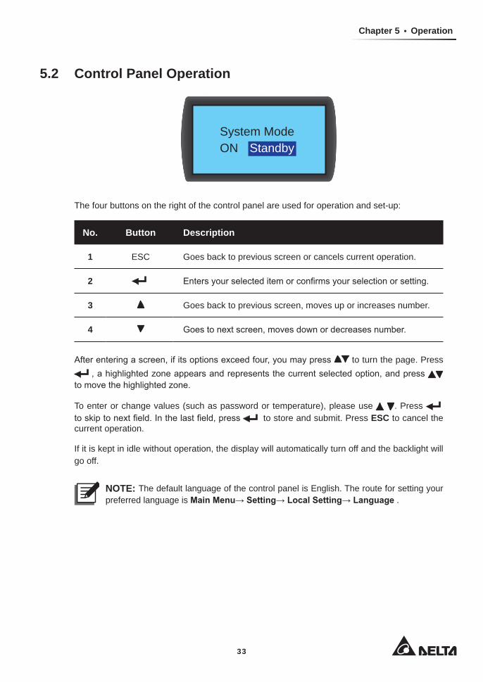
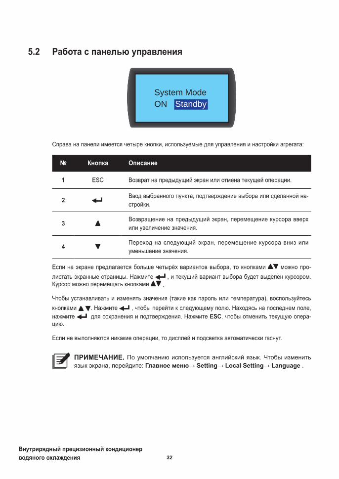
5.2 Control Panel Operation
System ModeON Standby
The four buttons on the right of the control panel are used for operation and set-up:
No. Button Description
1 ESC Goes back to previous screen or cancels current operation.
2
3 Goes back to previous screen, moves up or increases number.
4
to turn the page. Press
To enter or change values (such as password or temperature), please use . Press to store and submit. Press ESC to cancel the
current operation.
If it is kept in idle without operation, the display will automatically turn off and the backlight will go off.
NOTE: The default language of the control panel is English. The route for setting your preferred language is .
34InfraSuite RowCool Precision Cooling – Chilled Water
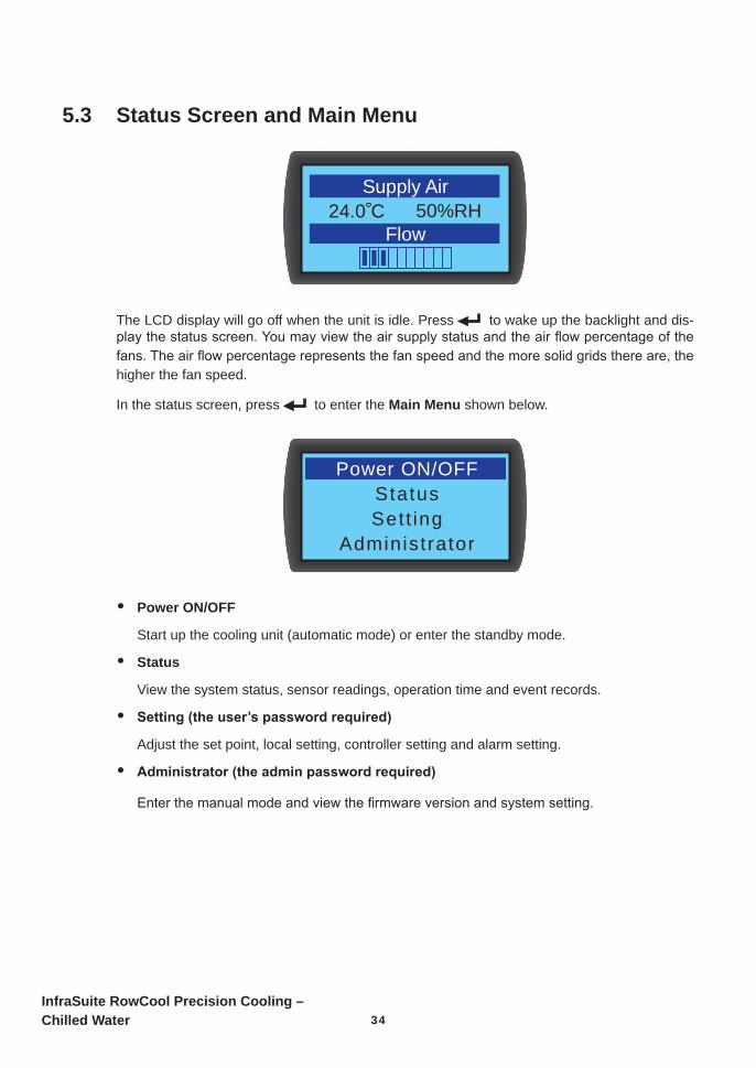
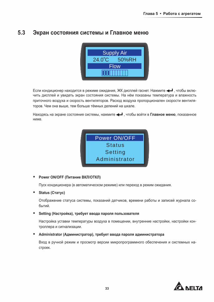
5.3 Status Screen and Main Menu
Supply Air
Flow50%RH24.0 C
The LCD display will go off when the unit is idle. Press to wake up the backlight and dis-
higher the fan speed.
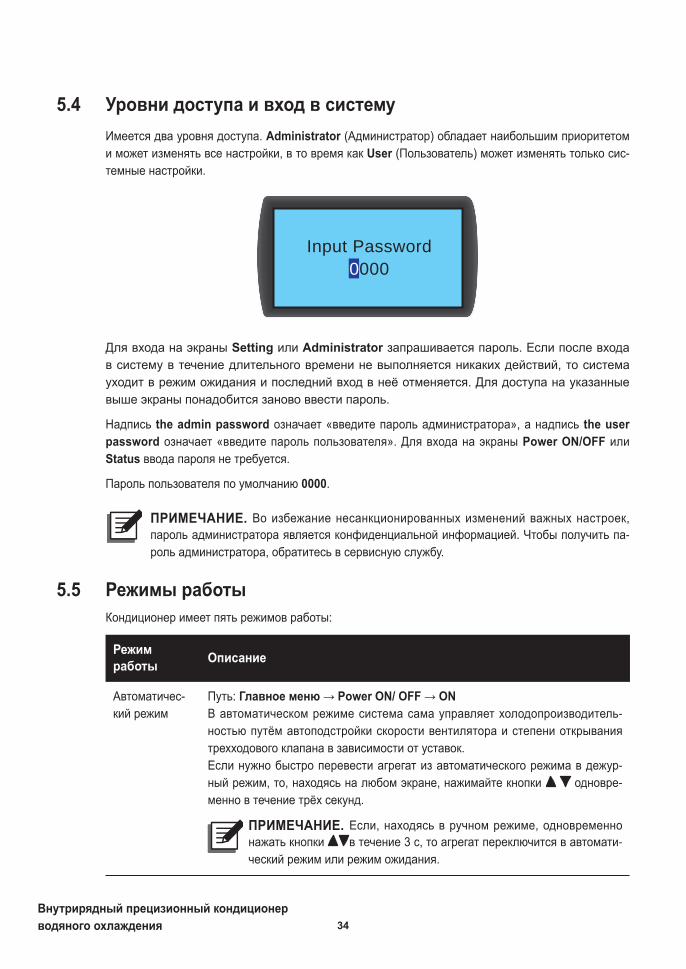
In the status screen, press to enter the Main Menu shown below.
Power ON/OFFStatusSett ing
Administrator
Power ON/OFF
Start up the cooling unit (automatic mode) or enter the standby mode.
Status
View the system status, sensor readings, operation time and event records.
Adjust the set point, local setting, controller setting and alarm setting.
35
Chapter 5 Operation
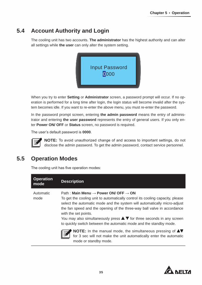
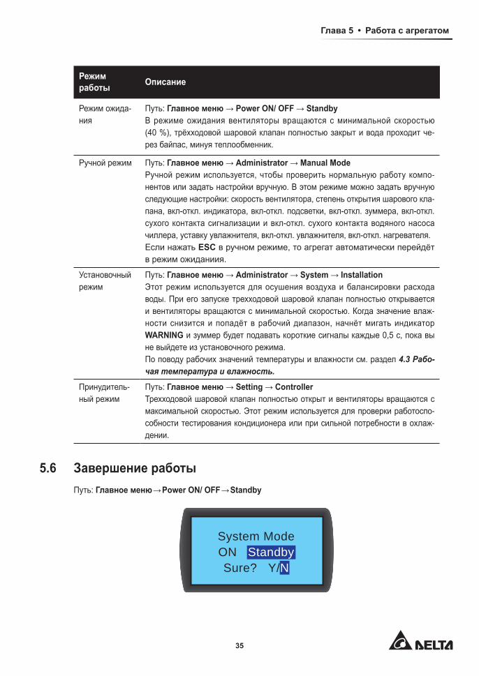
5.4 Account Authority and LoginThe cooling unit has two accounts. The administrator has the highest authority and can alter all settings while the user can only alter the system setting.
Input Password0000
When you try to enter Setting or Administrator screen, a password prompt will occur. If no op-eration is performed for a long time after login, the login status will become invalid after the sys-tem becomes idle. If you want to re-enter the above menu, you must re-enter the password.
In the password prompt screen, entering the admin password means the entry of adminis-trator and entering the user password represents the entry of general users. If you only en-ter Power ON/ OFF or Status screen, no password is required.
0000.
NOTE: disclose the admin password. To get the admin password, contact service personnel.
5.5 Operation Modes
Operation mode Description
Automatic mode
Path : Main Menu Power ON/ OFF ONTo get the cooling unit to automatically control its cooling capacity, please select the automatic mode and the system will automatically micro-adjust the fan speed and the opening of the three-way ball valve in accordance with the set points. You may also simultaneously press for three seconds in any screen to quickly switch between the automatic mode and the standby mode.
NOTE: In the manual mode, the simultaneous pressing of for 3 sec will not make the unit automatically enter the automatic mode or standby mode.

36InfraSuite RowCool Precision Cooling – Chilled Water
Operation mode Description
Standby mode
Path: Main Menu Power ON/ OFF StandbyIn the standby mode, the fans run at the minimum speed (40%), the three-way ball valve is fully closed and the chilled water goes through bypass without passing the coil.
Manual mode Path: Main Menu Administrator Manual ModeThe manual mode is used to test if the components work normally or make the system operate in accordance with the manual setting. In this mode, you may manually set: fan speed, ball valve opening, indicator on-
heater on-off. In the manual mode, press ESC to automatically return to the standby mode.
Installation mode
Path: Main Menu Administrator System Installation This mode is used to de-humidify and adjust the water balance. When it is started, the three-way ball valve will fully open and the fans will rotate at the minimum speed. When the system humidity falls within the operation scope, the WARNING short beeps continuously until you leave the installation mode. For the operating temperature and humidity, refer to 4.3 Operating Tem-perature and Humidity.
Force mode Path: Main Menu Setting Controller The three-way ball valve is fully open and the fans run at the highest speed. This mode is generally used for unit testing or emergency cooling request.
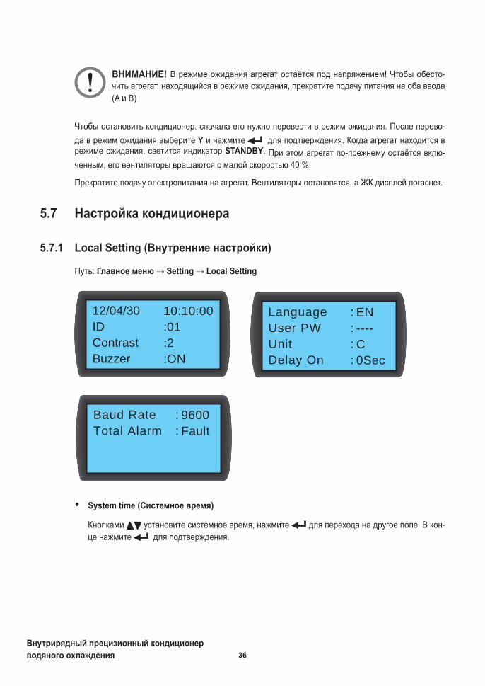
5.6 ShutdownPath: Main Menu Power ON/ OFF Standby
System ModeON StandbySure? Y/N
37
Chapter 5 Operation
WARNING: In the standby mode, the unit is still in power-on status! In the standby mode, you must disconnect the input power or two circuits of feeds (Feed A & Feed B) to get the unit to fully power-off.
standby mode, select Y and press STANDBY indicator lights, the unit is in the standby mode. Now, the cooling unit is still in power-on status and the fans run at 40% low speed.
off.
5.7 Setting of Cooling Unit
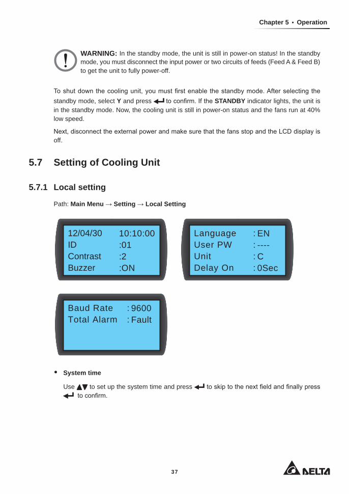
5.7.1 Local setting
Path: Main Menu Setting Local Setting
12/04/30IDContrastBuzzer
10:10:00:01:2:ON
LanguageUser PWUnitDelay On
EN----C0Sec
::::
Baud RateTotal Alarm
9600Fault
::
System time
Use to set up the system time and press

38InfraSuite RowCool Precision Cooling – Chilled Water
ID (Number)
Represent the number of the cooling unit connected in series and also the ID in the Mod-bus protocol. The default number is 1. If several cooling units are connected in series, you must designate each unit with a different number.
Contrast
2.
Buzzer
The default is ON.
Language
Set the display language. Select a language and press -lish (EN).
User PW
Unit
Set the temperature unit and the default is (°C).
Delay On
The time difference between setting the startup of automatic mode and the actual opera-tion. The cooling unit will start up in the seconds you have designated.
Baud rate
Please set the on-line speed based on the Modbus protocol. The options include 9600, 19200, 38400 and 57600 and the default value is 9600.
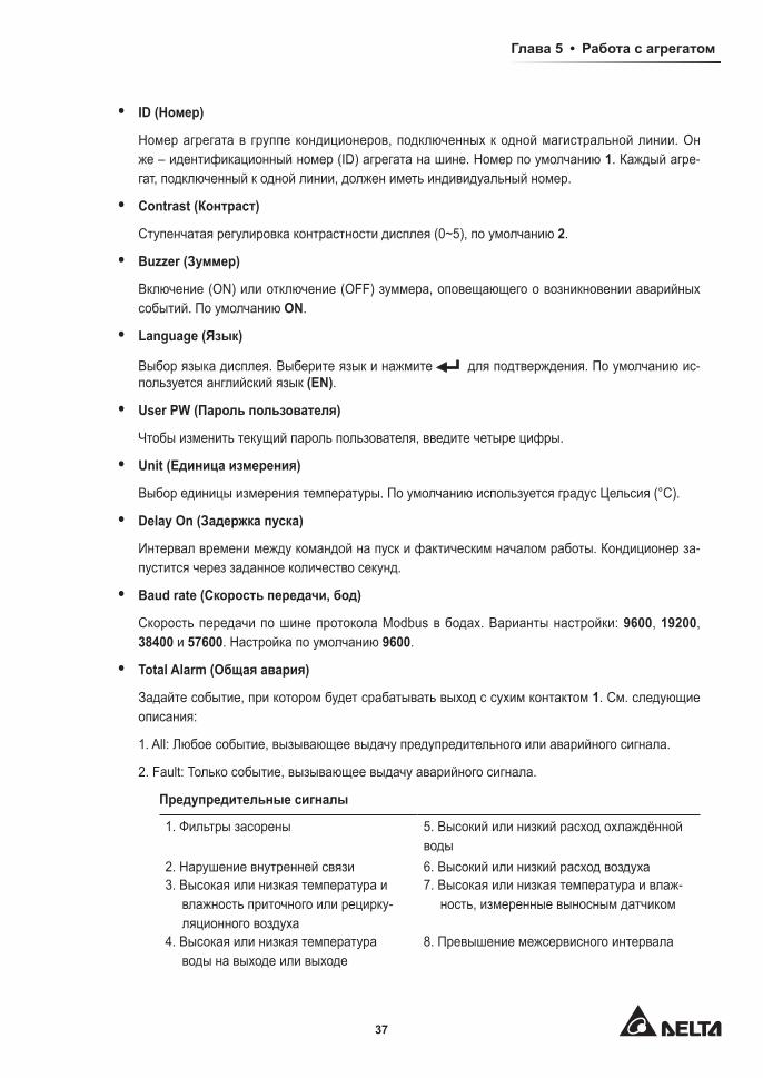
Total Alarm
Decide what event can trigger the output dry contact 1. Please refer to the following de-scriptions:
1. All: Any alarm and fault event can trigger it.
2. Fault: Only fault events can trigger it.
Alarm events
1. Filters are clogged 2. Abnormal internal communication 6. High and low air volume 3. High and low of air supply/ return
temperature and humidity 7. High and low of remote temperature
and humidity4. High and low chilled water
inlet/ outlet temperature 8. Overtime of maintenance
39
Chapter 5 Operation
Fault events
1. Emergency stop/ remote emergency stop 8. Abnormal remote sensor 9. Abnormal chilled water
inlet/ outlet sensor 3. Leakage alarm/ leakage open-circuit alarm4. Fire 11. Abnormal fan 5. Smoke 12. Abnormal three-way ball valve 6. Abnormal air supply/ return temperature
and humidity sensor13. Abnormal heater
7. Abnormal input voltage/ current/ branch circuit
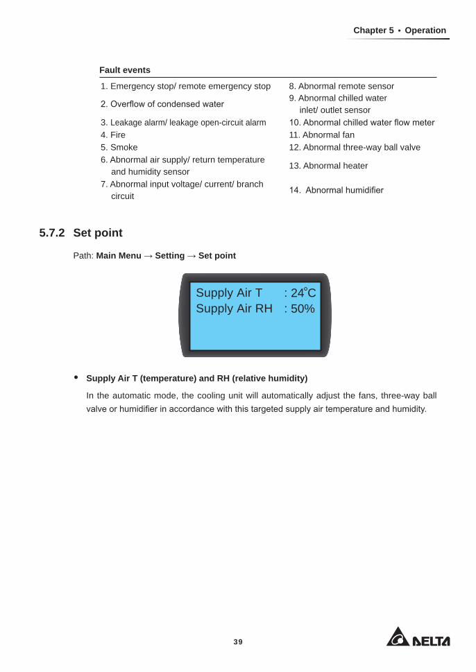
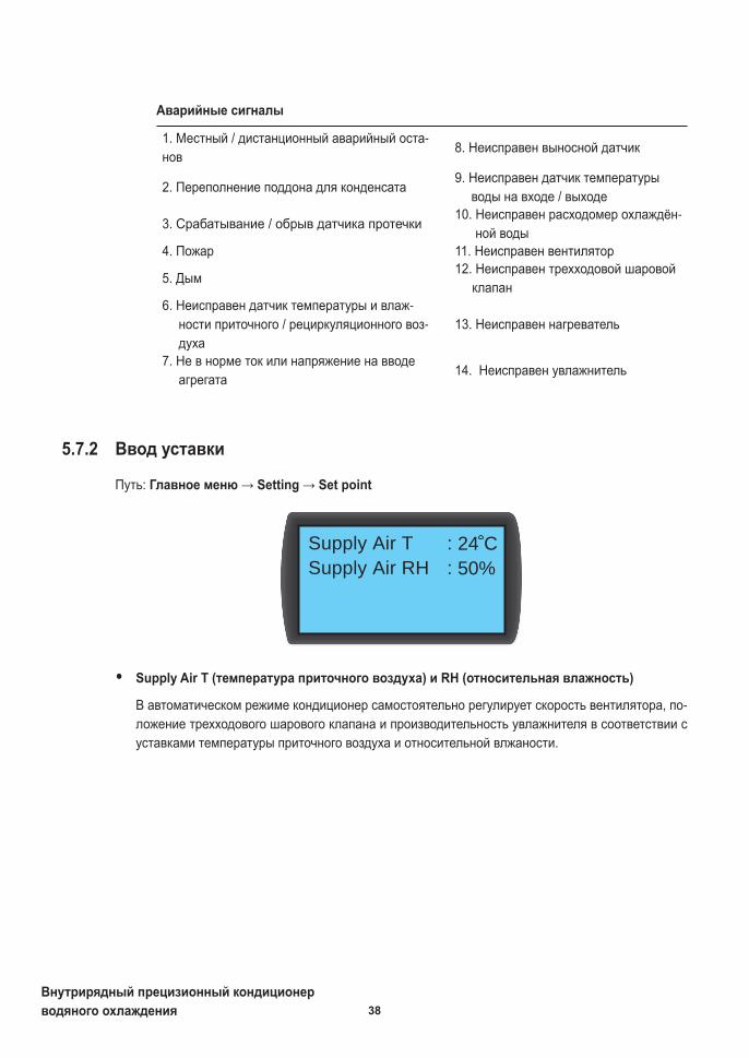
5.7.2 Set point
Path: Main Menu Setting Set point
Supply Air TSupply Air RH
::
24 C50%
Supply Air T (temperature) and RH (relative humidity)
In the automatic mode, the cooling unit will automatically adjust the fans, three-way ball
40InfraSuite RowCool Precision Cooling – Chilled Water
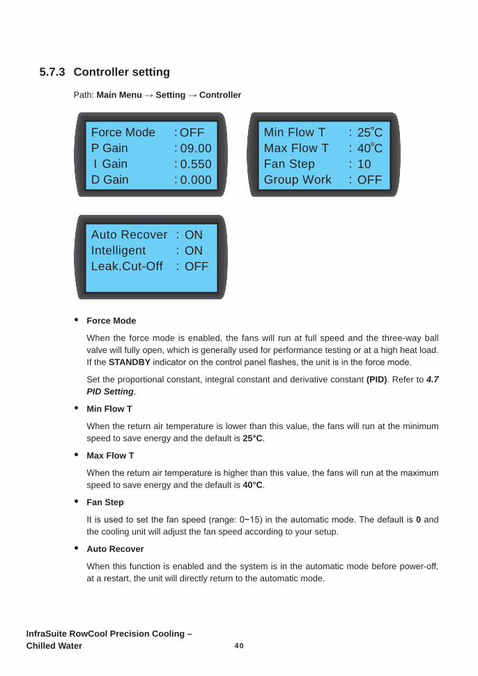
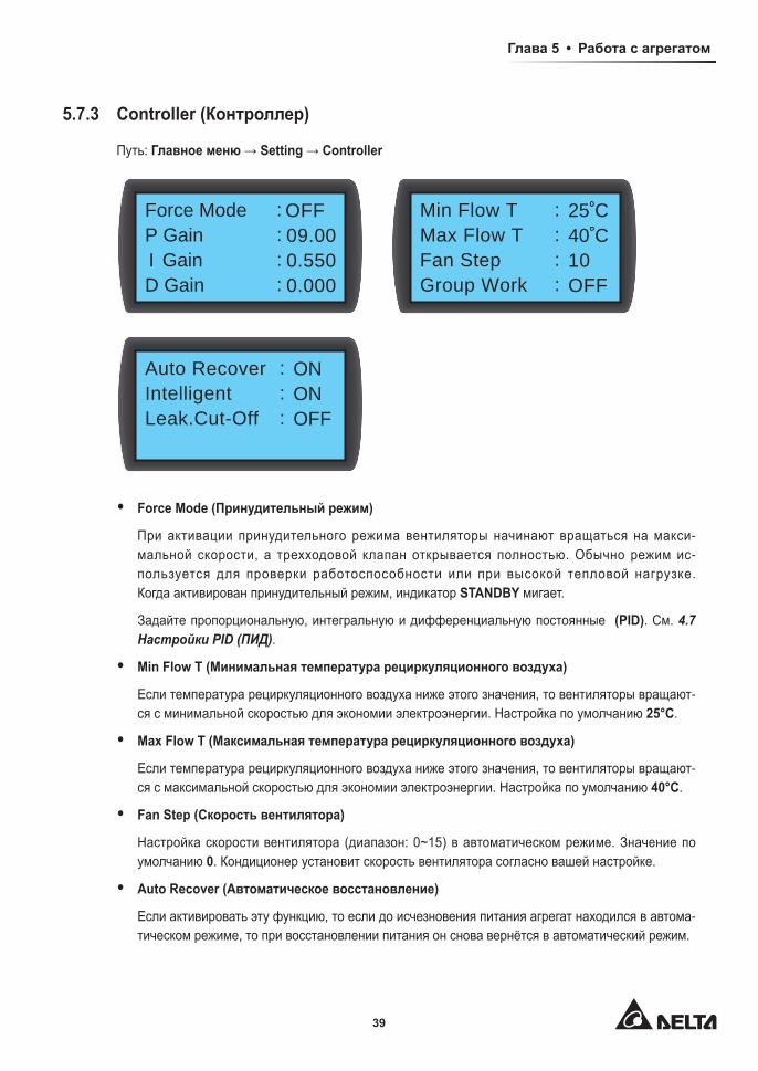
5.7.3 Controller setting
Path: Main Menu Setting Controller
::::
Force ModeP Gain I GainD Gain
OFF 09.000.5500.000
::::
Min Flow TMax Flow TFan StepGroup Work
25 C40 C10OFF
:::
Auto RecoverIntelligentLeak.Cut-Off
ONONOFF
Force Mode
When the force mode is enabled, the fans will run at full speed and the three-way ball valve will fully open, which is generally used for performance testing or at a high heat load. If the STANDBY
Set the proportional constant, integral constant and derivative constant (PID). Refer to 4.7 PID Setting.
Min Flow T
When the return air temperature is lower than this value, the fans will run at the minimum speed to save energy and the default is 25°C.
Max Flow T
speed to save energy and the default is 40°C.
Fan Step
0 and the cooling unit will adjust the fan speed according to your setup.
Auto Recover
When this function is enabled and the system is in the automatic mode before power-off, at a restart, the unit will directly return to the automatic mode.
41
Chapter 5 Operation
Intelligent
Display if the intelligent temperature control is enabled. This option only displays the status. You cannot change the setting. For change of setting, refer to 5.7.4 Setting of automatic control mode.
Leak. Cut-Off
Set if the unit will stop when the water leakage detector detects any leakage so as to pre-
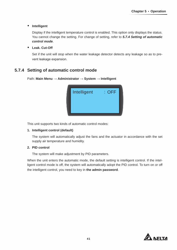
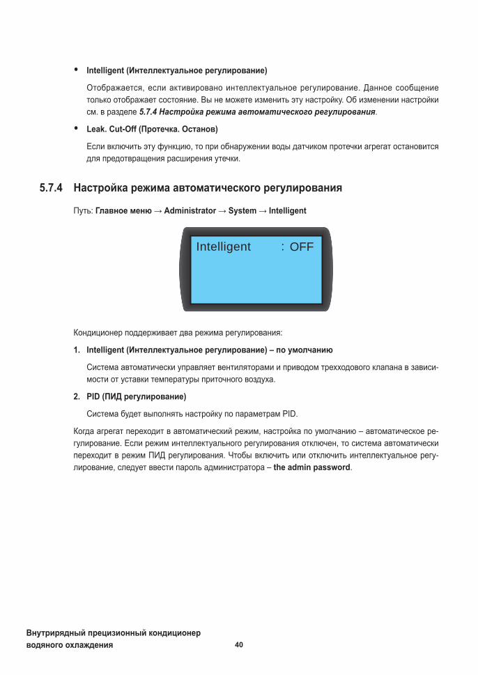
5.7.4 Setting of automatic control mode
Path: Main Menu Administrator System Intelligent
:Intelligent OFF
This unit supports two kinds of automatic control modes:
1. Intelligent control (default)
The system will automatically adjust the fans and the actuator in accordance with the set supply air temperature and humidity.
2. PID control
The system will make adjustment by PID parameters.
When the unit enters the automatic mode, the default setting is intelligent control. If the intel-ligent control mode is off, the system will automatically adopt the PID control. To turn on or off the intelligent control, you need to key in the admin password.
42InfraSuite RowCool Precision Cooling – Chilled Water
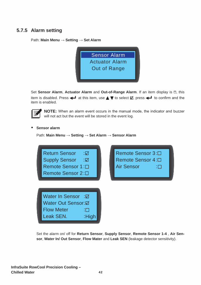
5.7.5 Alarm setting
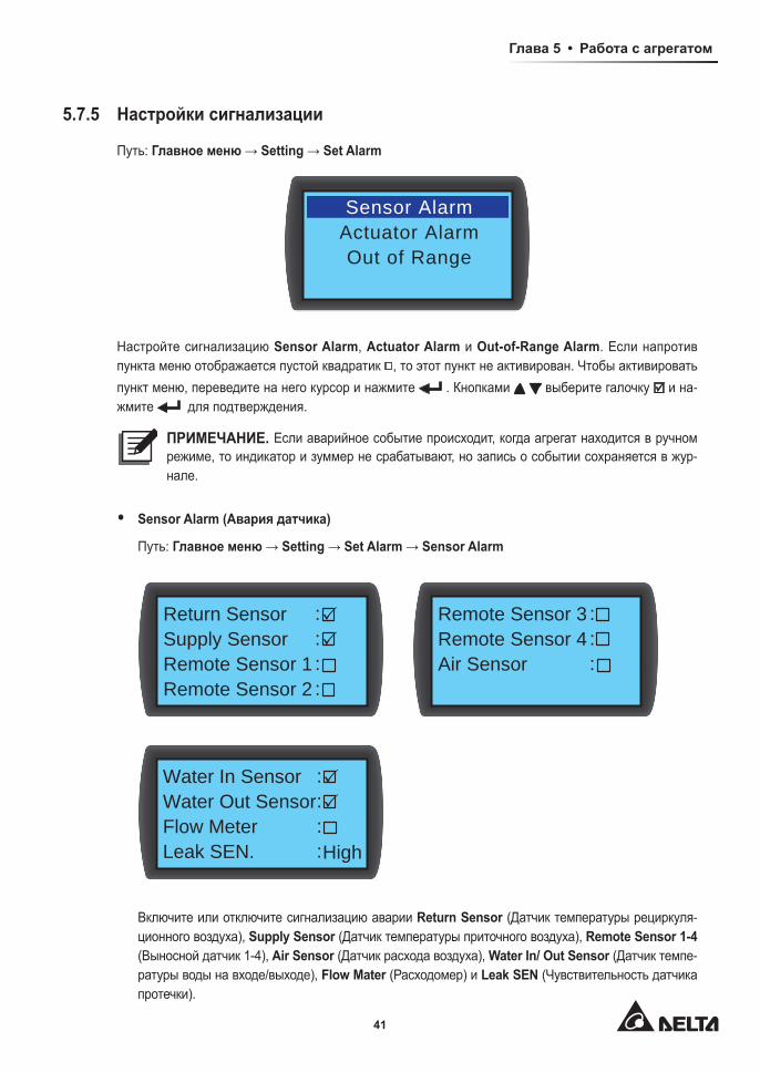
Path: Main Menu Setting Set Alarm
Sensor AlarmActuator AlarmOut of Range
Set Sensor Alarm, Actuator Alarm and Out-of-Range Alarm. If an item display is , this item is disabled. Press at this item, use to select , press item is enabled.
NOTE: will not act but the event will be stored in the event log.
Sensor alarm
Path: Main Menu Setting Set Alarm Sensor Alarm
::::
Return SensorSupply SensorRemote Sensor 1Remote Sensor 2
:::
Remote Sensor 3Remote Sensor 4Air Sensor
::::
Water In SensorWater Out SensorFlow MeterLeak SEN. High
Set the alarm on/ off for Return Sensor, Supply Sensor, Remote Sensor 1-4 , Air Sen-sor, Water In/ Out Sensor, Flow Mater and Leak SEN (leakage detector sensitivity).
43
Chapter 5 Operation
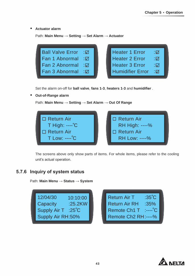
Actuator alarm
Path: Main Menu Setting Set Alarm Actuator
::::
Ball Valve ErrorFan 1 AbnormalFan 2 AbnormalFan 3 Abnormal
::::
Heater 1 ErrorHeater 2 ErrorHeater 3 ErrorHumidifier Error
Set the alarm on-off for ball valve, fans 1-3, heaters 1-3 and .
Out-of-Range alarm
Path: Main Menu Setting Set Alarm Out Of Range
Return AirT High: ---- CReturn AirT Low: ---- C
Return AirRH High: ----%Return AirRH Low: ----%
The screens above only show parts of items. For whole items, please refer to the cooling
Path: Main Menu Status System
12/04/30CapacitySupply Air TSupply Air RH
10:10:00:25.2KW:25 C:50%
Return Air TReturn Air RHRemote Ch1 TRemote Ch2 RH
:35 C:35%:---- C:----%
44InfraSuite RowCool Precision Cooling – Chilled Water
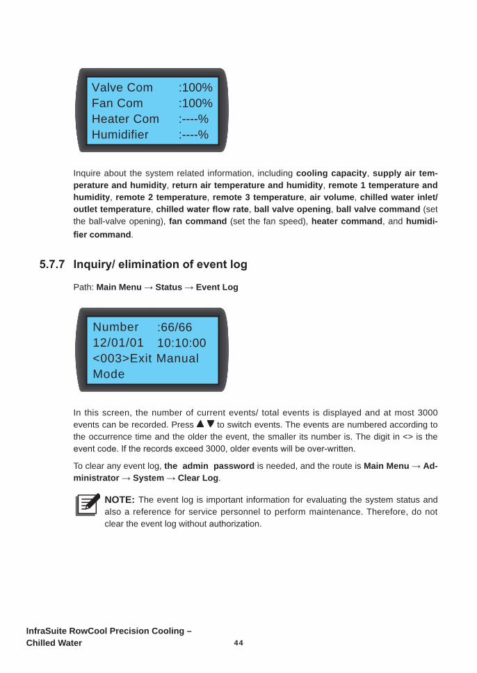
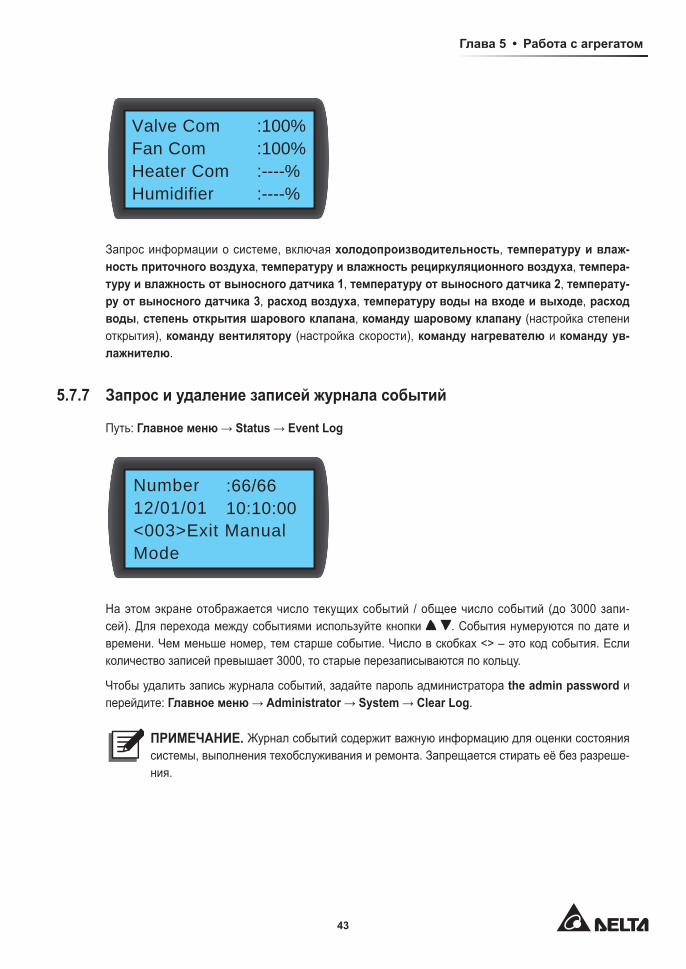
Valve ComFan ComHeater ComHumidifier
:100%:100%:----%:----%
Inquire about the system related information, including cooling capacity, supply air tem-perature and humidity, return air temperature and humidity, remote 1 temperature and humidity, remote 2 temperature, remote 3 temperature, air volume, chilled water inlet/ outlet temperature, , ball valve opening, ball valve command (set the ball-valve opening), fan command (set the fan speed), heater command, and humidi-
.
Path: Main Menu Status Event Log
Number12/01/01<003>Exit ManualMode
:66/6610:10:00
In this screen, the number of current events/ total events is displayed and at most 3000 events can be recorded. Press to switch events. The events are numbered according to the occurrence time and the older the event, the smaller its number is. The digit in <> is the
To clear any event log, the admin password is needed, and the route is Main Menu Ad-ministrator System Clear Log.
NOTE: The event log is important information for evaluating the system status and also a reference for service personnel to perform maintenance. Therefore, do not clear the event log without
45
Chapter 5 Operation
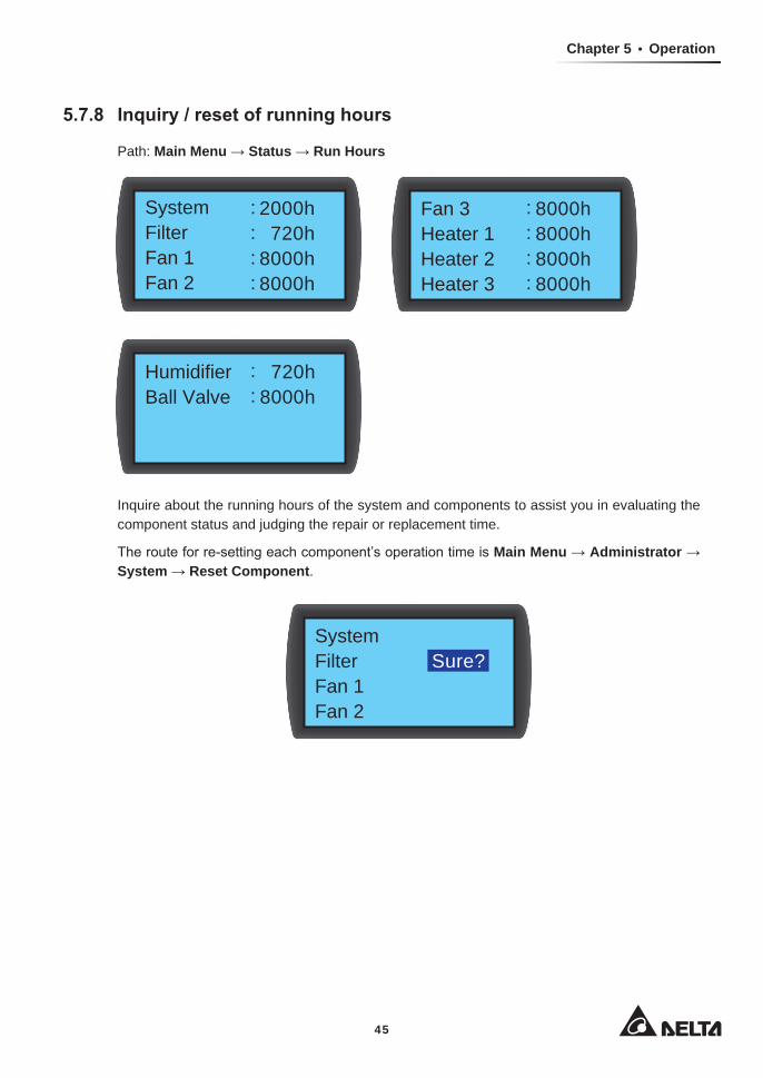
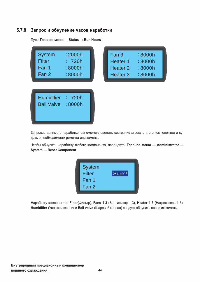
Path: Main Menu Status Run Hours
SystemFilterFan 1Fan 2
2000h720h
8000h8000h
::::
Fan 3Heater 1Heater 2Heater 3
8000h8000h8000h8000h
::::
HumidifierBall Valve
720h8000h
::
Inquire about the running hours of the system and components to assist you in evaluating the component status and judging the repair or replacement time.
Main Menu Administrator System Reset Component.
SystemFilterFan 1Fan 2
Sure?

46InfraSuite RowCool Precision Cooling – Chilled Water
After a component is changed, reset the operation time of Filter, Fans 1-3, Heater 1-3, Hu- or Ball valve.
5.7.9 Change of system type
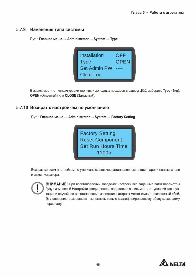
Path: Main Menu Administrator System Type
InstallationTypeSet Admin PWClear Log
OFFOPEN----
:::
Type as OPEN or CLOSE.
5.7.10 Restoration of defaults
Path: Main Menu Administrator System Factory Setting
Factory SettingReset ComponentSet Run Hours Time 1100h
Restore all factory defaults, including the set options and user and admin passwords.
WARNING: The restoration of factory defaults will reset the settings or parameters that have been changed! The cooling unit has selected different settings according to the different environment and random restoration may lead to system error. The

Chapter 6 Maintenance and Cleaning
47
Chapter 6 : Maintenance and Cleaning
Periodic inspection and cleaning of the cooling unit can guarantee the equipment to operate at the best status. The internal components such as fans and condensed water pan need periodic cleaning and inspec-tion. This unit contains replaceable components and the cleaning and inspection of them can be done
6.1 Firmware Upgrade
6.2 StorageIf you do not use this unit for long time, it is recommended that you wrap the unit using the original packing material and store it in a place with well controlled temperature and humidity
NOTE: For information and method of maintenance and cleaning, contact your local dealer or customer service. Do not perform maintenance if you are not trained for it.
48InfraSuite RowCool Precision Cooling – Chilled Water
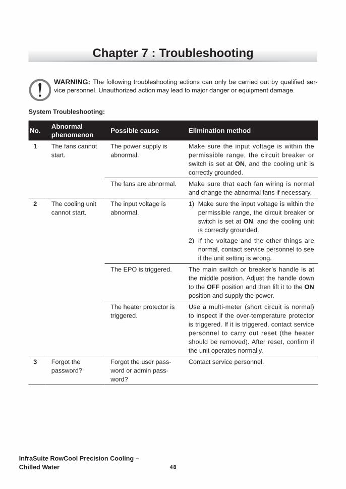
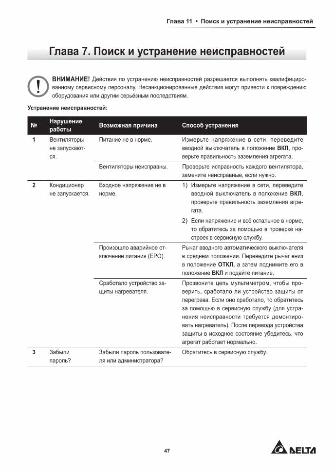
Chapter 7 : Troubleshooting
WARNING: -
System Troubleshooting:
No. Abnormal phenomenon Possible cause Elimination method
1 The fans cannot start.
The power supply is abnormal.
Make sure the input voltage is within the permissible range, the circuit breaker or switch is set at ON, and the cooling unit is correctly grounded.
The fans are abnormal. Make sure that each fan wiring is normal and change the abnormal fans if necessary.
2 The cooling unit cannot start.
The input voltage is abnormal.
1) Make sure the input voltage is within the permissible range, the circuit breaker or switch is set at ON, and the cooling unit is correctly grounded.
2) If the voltage and the other things are normal, contact service personnel to see if the unit setting is wrong.
The EPO is triggered. the middle position. Adjust the handle down to the OFF position and then lift it to the ON position and supply the power.
The heater protector is triggered.
Use a multi-meter (short circuit is normal) to inspect if the over-temperature protector is triggered. If it is triggered, contact service personnel to carry out reset (the heater should be removed). After reset, confirm if the unit operates normally.
3 Forgot the password?
Forgot the user pass-word or admin pass-word?
Contact service personnel.
Chapter 7 Troubleshooting
49
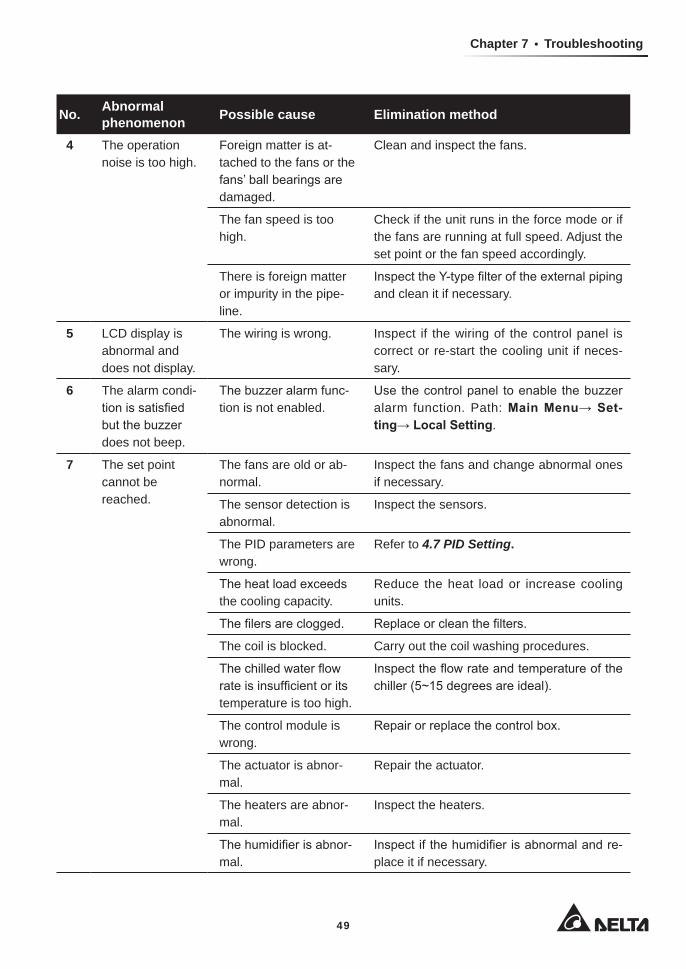
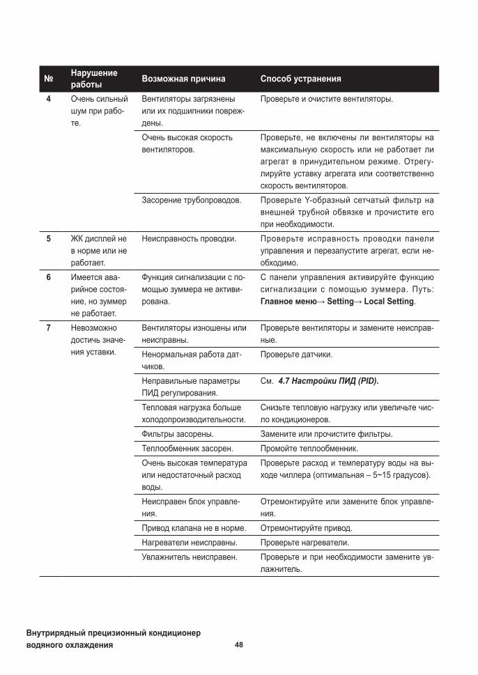
No. Abnormal phenomenon Possible cause Elimination method
4 The operation noise is too high.
Foreign matter is at-tached to the fans or the
damaged.
Clean and inspect the fans.
The fan speed is too high.
Check if the unit runs in the force mode or if the fans are running at full speed. Adjust the set point or the fan speed accordingly.
There is foreign matter or impurity in the pipe-line.
and clean it if necessary.
5 LCD display is abnormal and does not display.
The wiring is wrong. Inspect if the wiring of the control panel is correct or re-start the cooling unit if neces-sary.
6 The alarm condi-
does not beep.
-tion is not enabled. alarm function. Path: -
.
7 The set point cannot be reached.
The fans are old or ab-normal.
Inspect the fans and change abnormal ones if necessary.
The sensor detection is abnormal.
Inspect the sensors.
The PID parameters are wrong.
Refer to 4.7 PID Setting.
the cooling capacity. Reduce the heat load or increase cooling units.
The coil is blocked. Carry out the coil washing procedures.
temperature is too high.
The control module is wrong.
The actuator is abnor-mal.
Repair the actuator.
The heaters are abnor-mal.
Inspect the heaters.
-mal.
-place it if necessary.
50InfraSuite RowCool Precision Cooling – Chilled Water
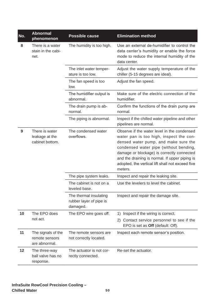
No. Abnormal phenomenon Possible cause Elimination method
8 There is a water stain in the cabi-net.
The humidity is too high.
mode to reduce the internal humidity of the data center.
The inlet water temper-ature is too low.
Adjust the water supply temperature of the chiller (5-15 degrees are ideal).
The fan speed is too low.
Adjust the fan speed.
abnormal. Make sure of the electric connection of the
The drain pump is ab-normal. normal.
The piping is abnormal. Inspect if the chilled water pipeline and other pipelines are normal.
9 There is water leakage at the cabinet bottom.
The condensed water Observe if the water level in the condensed water pan is too high, inspect the con-densed water pump, and make sure the condensed water pipe (without bending, damage or blockage) is correctly connected and the draining is normal. If upper piping is
meters.
The pipe system leaks. Inspect and repair the leaking site.
The cabinet is not on a leveled base.
Use the levelers to level the cabinet.
The thermal insulating rubber layer of pipe is damaged.
Inspect and repair the damage site.
10 The EPO does not act.
The EPO wire goes off. 1) Inspect if the wiring is correct.
2) Contact service personnel to see if the EPO is set as Off (default: Off).
11 The signals of the remote sensors are abnormal.
The remote sensors are not correctly located.
12 The three-way ball valve has no response.
The actuator is not cor-rectly connected.
Re-set the actuator.

Chapter 7 Troubleshooting
51
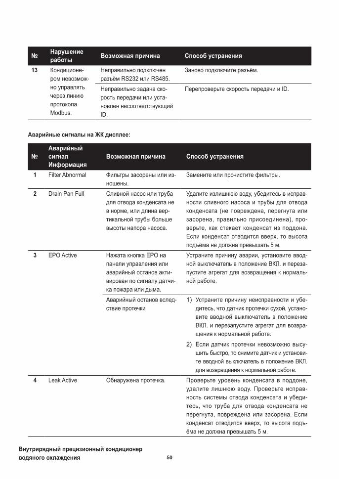
No. Abnormal phenomenon Possible cause Elimination method
13 It is unable to get on-line via the Modbus protocol.
The RS232 or RS485 connector is not cor-rectly connected.
Re-connect the connector.
The Baud rate setting is abnormal or the ID does not match.
Alarm information on the LCD:
No. Alarm Information Possible cause Elimination method
1 Filter Abnormal foreign matter or are old.
2 Drain Pan Full The condensed water pipe or the condensed water pump is abnormal.
vertical lift.
Remove the surplus water, inspect the condensed water pump and make sure the condensed water pipe (without bending, damage or blockage) is correctly connected and the draining is normal. If upper piping is adopted, make sure the vertical lift does not
3 EPO Active The EPO button on the control panel is pressed or emergency stop is
smoke.
Eliminate the abnormality, reset the circuit breaker of the unit and re-start the unit to recover the normal operation.
Emergency stop is trig-gered due to leakage
1) Eliminate the abnormality, make sure the water leakage detector is dry, reset the circuit breaker of the unit and re-start the unit to recover the normal operation.
2) If the water leakage detector cannot be dried in a short time, remove the detec-tor first and reset the circuit breaker of the unit to recover the operation.
4 Leak Active Leakage is detected. Remove the surplus water and inspect the water level of the condensed water pan. Inspect if the drain function is normal and
no bending, damage or blockage. If upper piping is adopted, make sure the vertical lift
52InfraSuite RowCool Precision Cooling – Chilled Water
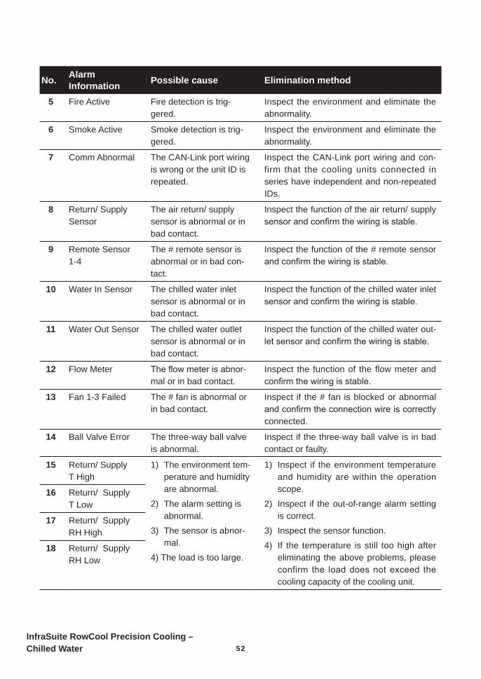
No. Alarm Information Possible cause Elimination method
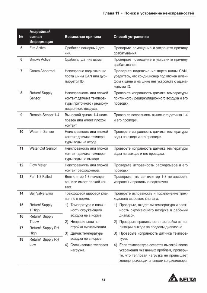
5 Fire Active Fire detection is trig-gered.
Inspect the environment and eliminate the abnormality.
6 Smoke Active Smoke detection is trig-gered.
Inspect the environment and eliminate the abnormality.
7 Comm Abnormal The CAN-Link port wiring is wrong or the unit ID is repeated.
Inspect the CAN-Link port wiring and con-firm that the cooling units connected in series have independent and non-repeated IDs.
8 Return/ Supply Sensor
The air return/ supply sensor is abnormal or in bad contact.
Inspect the function of the air return/ supply
9 Remote Sensor 1-4
The # remote sensor is abnormal or in bad con-tact.
Inspect the function of the # remote sensor
10 Water In Sensor The chilled water inlet sensor is abnormal or in bad contact.
Inspect the function of the chilled water inlet
11 Water Out Sensor The chilled water outlet sensor is abnormal or in bad contact.
Inspect the function of the chilled water out-
12 Flow Meter -mal or in bad contact.
Inspect the function of the flow meter and
13 Fan 1-3 Failed The # fan is abnormal or in bad contact.
Inspect if the # fan is blocked or abnormal
connected.
14 Ball Valve Error The three-way ball valve is abnormal.
Inspect if the three-way ball valve is in bad contact or faulty.
15 Return/ Supply T High
1) The environment tem-perature and humidity are abnormal.
2) The alarm setting is abnormal.
3) The sensor is abnor-mal.
4) The load is too large.
1) Inspect if the environment temperature and humidity are within the operation scope.
2) Inspect if the out-of-range alarm setting is correct.
3) Inspect the sensor function.
4) If the temperature is still too high after eliminating the above problems, please
cooling capacity of the cooling unit.
16 Return/ Supply T Low
17 Return/ Supply RH High
18 Return/ Supply RH Low
Chapter 7 Troubleshooting
53
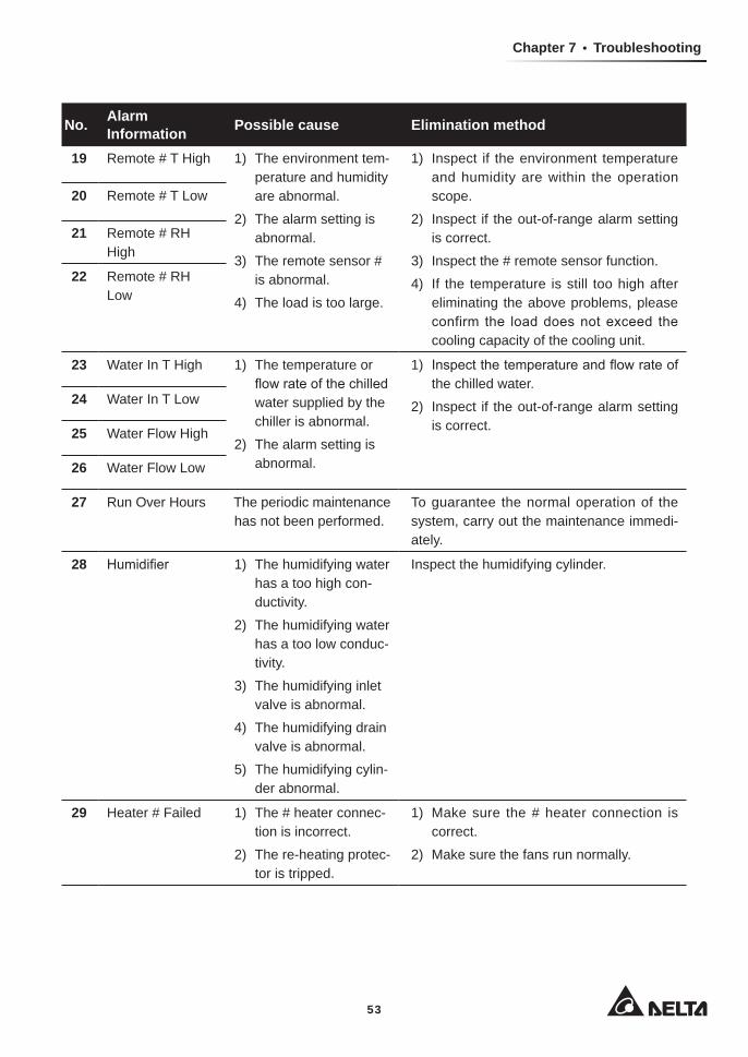
No. Alarm Information Possible cause Elimination method
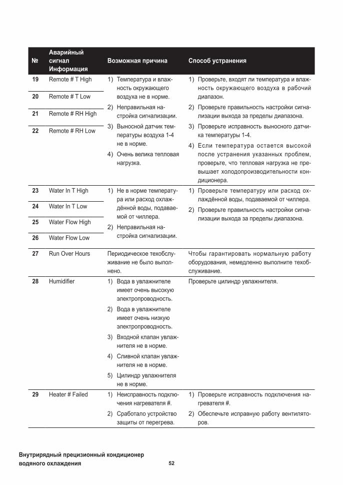
19 Remote # T High 1) The environment tem-perature and humidity are abnormal.
2) The alarm setting is abnormal.
3) The remote sensor # is abnormal.
4) The load is too large.
1) Inspect if the environment temperature and humidity are within the operation scope.
2) Inspect if the out-of-range alarm setting is correct.
3) Inspect the # remote sensor function.
4) If the temperature is still too high after eliminating the above problems, please
cooling capacity of the cooling unit.
20 Remote # T Low
21 Remote # RH High
22 Remote # RH Low
23 Water In T High 1) The temperature or
water supplied by the chiller is abnormal.
2) The alarm setting is abnormal.
1)the chilled water.
2) Inspect if the out-of-range alarm setting is correct.
24 Water In T Low
25 Water Flow High
26 Water Flow Low
27 Run Over Hours The periodic maintenance has not been performed.
To guarantee the normal operation of the system, carry out the maintenance immedi-ately.
28 1) The humidifying water has a too high con-ductivity.
2) The humidifying water has a too low conduc-tivity.
3) The humidifying inlet valve is abnormal.
4) The humidifying drain valve is abnormal.
5) The humidifying cylin-der abnormal.
Inspect the humidifying cylinder.
29 Heater # Failed 1) The # heater connec-tion is incorrect.
2) The re-heating protec-tor is tripped.
1) Make sure the # heater connection is correct.
2) Make sure the fans run normally.

54InfraSuite RowCool Precision Cooling – Chilled Water
No. Alarm Information Possible cause Elimination method
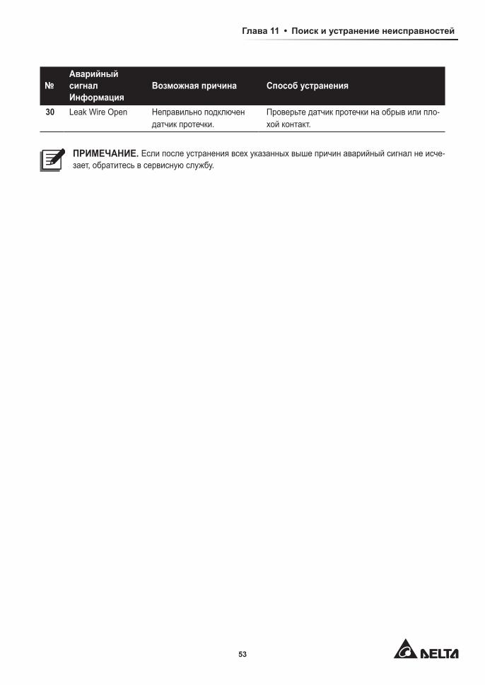
30 Leak Wire Open The water leakage detec-tor is not correctly con-nected.
Inspect if the water leakage detector is loose, in bad contact or broken.
NOTE: your dealer or customer service.
Appendix 1
55
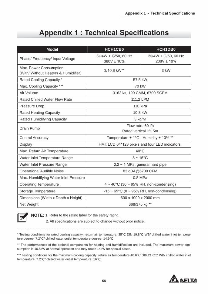
Appendix
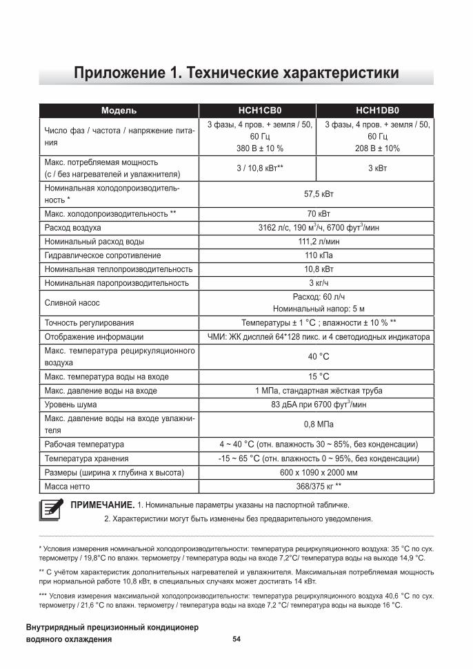
Model HCH1CB0 HCH1DB0
Phase/ Frequency/ Input Voltage
3 kW
57.5 kW
70 kW
Air Volume 3162 l/s, 190 CMM, 6700 SCFM
Rated Chilled Water Flow Rate 111.2 LPM
Pressure Drop 110 kPa
Rated Heating Capacity 10.8 kW
Rated Humidifying Capacity 3 kg/hr
Drain Pump Flow rate: 60 l/h
Rated vertical lift: 5m
Control Accuracy °C Display
40°CWater Inlet Temperature Range °CWater Inlet Pressure Range
Operational Audible Noise 83 dBA@6700 CFM
0.8 MPa
Operating Temperature °CStorage Temperature °C
Net Weight
NOTE: 1. Refer to the rating label for the safety rating.
Testing conditions for rated cooling capacity: return air temperature: 35°C DB/ 19.8°C WB/ chilled water inlet tempera-ture degree: 7.2°C/ chilled water outlet temperature degree: 14.9°C.
-sumption is 10.8kW at normal operation and may reach 14kW for special cases.
°C DB/ 21.6°C WB/ chilled water inlet temperature: 7.2°C/ chilled water outlet temperature: 16°C.
56InfraSuite RowCool Precision Cooling – Chilled Water
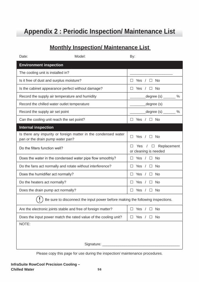
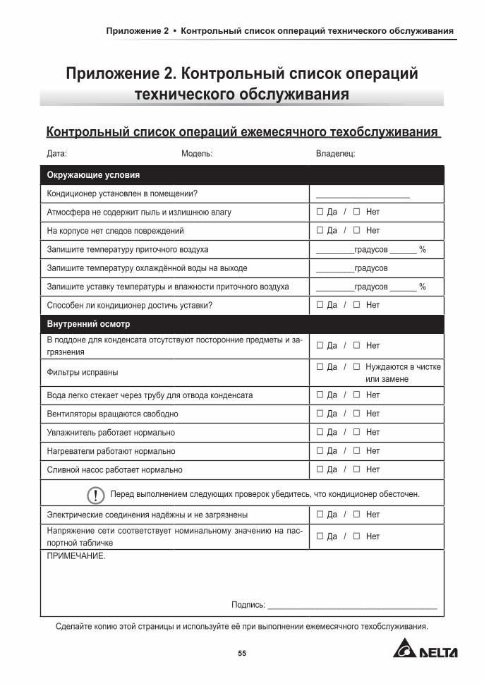
Appendix 2 : Periodic Inspection/ Maintenance List
Monthly Inspection/ Maintenance List Date: Model: By:
Environment inspection
The cooling unit is installed in? _____________________
Is it free of dust and surplus moisture? Yes / No
Is the cabinet appearance perfect without damage? Yes / No
Record the supply air temperature and humidity ________degree (s) ______ %
Record the chilled water outlet temperature ________degree (s)
Record the supply air set point ________degree (s) ______ %
Can the cooling unit reach the set point? Yes / No
Internal inspection Is there any impurity or foreign matter in the condensed water pan or the drain pump water pan?
Yes / No
Yes / Replacement or cleaning is needed
Yes / No
Do the fans act normally and rotate without interference? Yes / No
Yes / No
Do the heaters act normally? Yes / No
Does the drain pump act normally? Yes / No
Be sure to disconnect the input power before making the following inspections.
Are the electronic joints stable and free of foreign matter? Yes / No
Does the input power match the rated value of the cooling unit? Yes / No
NOTE:
Signature: ______________________________________
Please copy this page for use during the inspection/ maintenance procedures.
Appendix 2 List of Periodic Maintenance Inspections
57
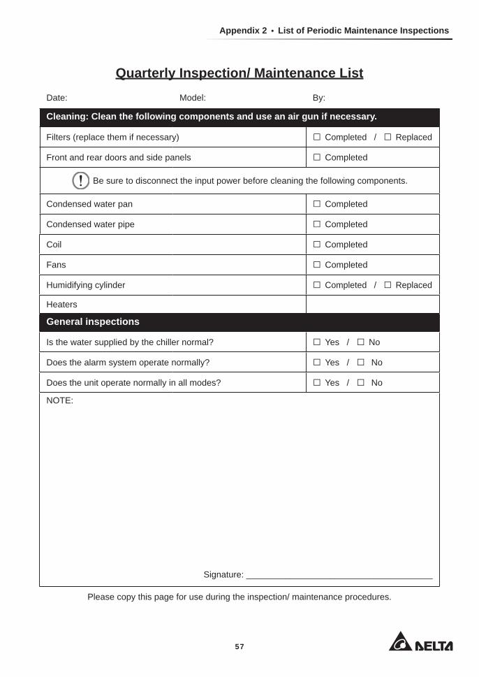
Quarterly Inspection/ Maintenance ListDate: Model: By:
Cleaning: Clean the following components and use an air gun if necessary.
Filters (replace them if necessary) Completed / Replaced
Front and rear doors and side panels Completed
Be sure to disconnect the input power before cleaning the following components.
Condensed water pan Completed
Condensed water pipe Completed
Coil Completed
Fans Completed
Humidifying cylinder Completed / Replaced
Heaters
General inspections
Is the water supplied by the chiller normal? Yes / No
Does the alarm system operate normally? Yes / No
Does the unit operate normally in all modes? Yes / No
NOTE:
Signature: ______________________________________
Please copy this page for use during the inspection/ maintenance procedures.
58InfraSuite RowCool Precision Cooling – Chilled Water
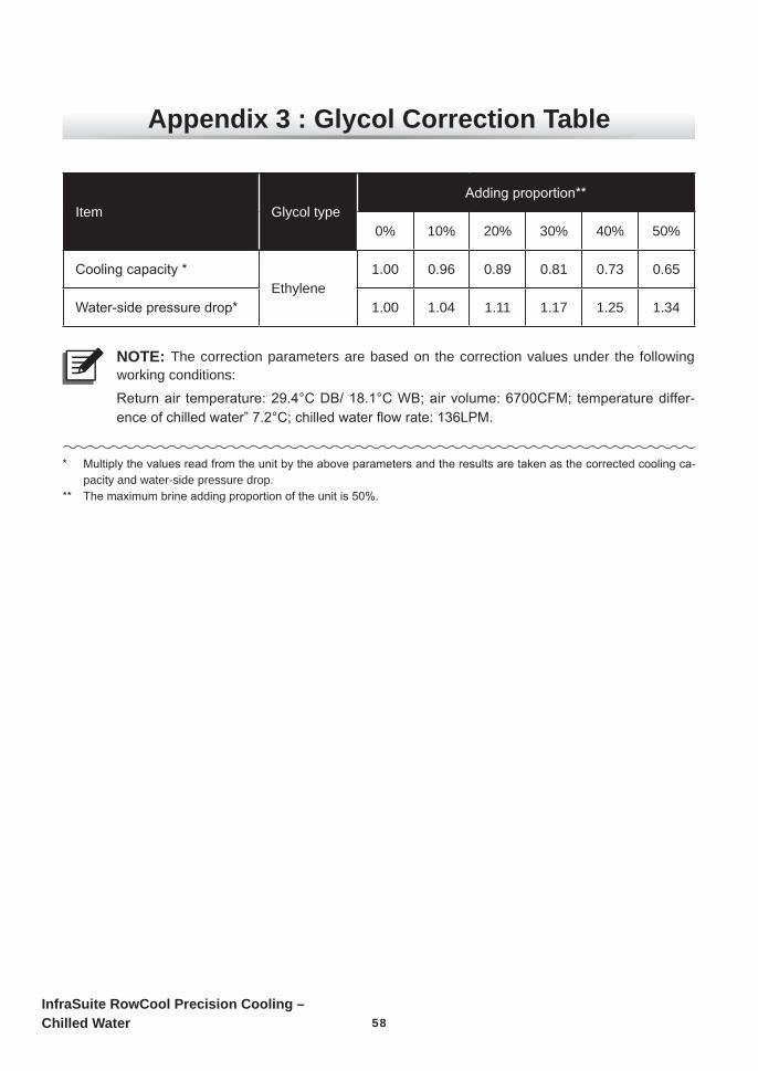
Appendix 3 : Glycol Correction Table
Item Glycol type0% 10% 20% 30% 40% 50%
Ethylene1.00 0.96 0.89 0.81 0.73 0.65
1.00 1.04 1.11 1.17 1.25 1.34
NOTE: The correction parameters are based on the correction values under the following working conditions:
-.
-pacity and water-side pressure drop.
Appendix 4 Warranty
59
Appendix 4 : Warranty
Seller warrants this product, if used in accordance with all applicable instructions, to be free from origi-nal defects in material and workmanship within the warranty period. If the product has any failure prob-lem within the warranty period, Seller will repair or replace the product at its sole discretion according to the failure situation.
This warranty does not apply to normal wear or to damage resulting from improper installation, opera-
Maintenance service for a fee is provided for any damage out of the warranty period. If any mainte-nance is required, please directly contact the supplier or Seller.
WARNING! The individual user should take care to determine prior to use whether the environment and the load characteristic are suitable, adequate or safe for the installation and the usage of this product. The User Manual must be carefully followed. Seller makes no representation or

www.deltapowersolutions.com
(HCH1CB0 HCH1DB0)
--
--
ii
--------------------------------------------------------
8
9
-------
iii

iv

--
--
-
-
-
-
-
-
--
-

-
-
-
x 2
x 3
x 2
x 1 x 1
x 1
x 2
x 2
x 1
12
x 2
x 111
x 1
www.deltagreentech.com.cn
The power behind competitiveness
InfraSuite

-
-
-
2000
1070600
11
12
13
Rear/ hot aisle
Front/ cold aisle
14
15
16
17
18
19
20
-
-
-
-
-
11
12
13
11
12
13
16
1718
19
15
14
-
-
System modeON Standby
-
-
-
-
-
9
--
-
-
--
-
-
-
--
-
--
-
-
-
--
-
-
1
2

3
4
5
6
-
1 -
2
-
71
75
98
450
212 212
323 113
PI03
PI02
TI01
TI02
PI01
-
-
-
-
-
-
-
1
2-
3
RSTNG RSTNG
4
1
2

NETWORK COM
NET UPS
RESET
RS232 RS485 CAN
INPUTOUTIN
OUTPUT
ALARM RACK REMOTE SENSOR
2
1
3 4+ - G
DISPLAY
-
-
-
-
---
-
-
---
--
--- -
-
-
TEMP. & HUMIDITYLD DP FM
INLETOUTLET
WATER TEMP. AC 24V
VIN-B2 1
VIN-A
QPM BV
AC24V
DPS
11 12
-
-
-
-
Supply Air
Flow50%RH24.0 C
-
-
90.080.070.060.050.040.030.020.010.00.0
-
1
2
3-
4 --
1
2-
3

4 -
-
-
PI03
PI01
PI03
PI01
PI03
PI01
PI03
PI01
PI03
PI01
PI03
PI01
--
1 -
2-
3 -
4 -
-
5
6 -
-
7 -
-
8 6 7 -
9 -
10 -
--
::::
Force ModeP Gain I GainD Gain
OFF 09.000.5500.000
1 --
2
3 -
4
5
6
-
7
8-
-
-
Return T High/ Return T Low/ Return RH High/ Return RH Low/ Supply T High/ Supply T Low/ Supply RH High/ Supply RH Low/ Remote 1 T High/ Remote 1 T Low/Remote 1 RH High/ Remote 1 RH Low/Remote 2 T High/ Remote 2 T Low/ Remote 3 T High/ Remote 3 T Low/Remote 4 T High/ Remote 4 T Low/Water In T High/ Water In T Low/ Water Out T High/ Water Out T Low/Water Flow High/ Water Flow Low
System/Filter/Fan 1-3/Heater 1-3Humidifier/Ball Valve
Supply Air T/ Supply Air RH
ID/ Contrast/ Buzzer/ Language/ User PWUnit/ Delay On/ Baud Rate/ Total Alarm
Force Mode/ P Gain/ I Gain/ D GainMin Flow T/ Max Flow T/ Fan Step/Group Work/ Auto Recover/ Intelligent/Leak.Cut-Off
Return Sensor/ Supply Sensor/Remote Sensor 1/ Remote Sensor 2/Remote Sensor 3/ Remote Sensor 4/Air Sensor/ Water In Sensor/ Water Out Sensor/ Flow MeterLeak SEN.
Ball Valve Error/ Fan 1-3 Failed/ Heater 1-3 Failed/ Humidifier
Fan Speed/ Ball Valve/ Humidifier/ Shutdown Humi/Humidifying stop/ Backlight/ Buzzer/ Total Alarm/Chiller Pump/ Heater 1-3/ Main LED/ Standby LEDWarning LED/ Fault LED
Filter/ Fan 1-3/ Heater 1-3/ Humidifier/Ball Valve
System
Run Hours
Event Log
Setpoint
Controller
Set Alarm
Local Setting
Sensor Alarm
Out Of Range
System
Installation
Set Admin PW
Type
Clear Log
Factory Setting
Reset Component
Set Run Hours Time
Intelligent
ATS Disable
Power ON/OFF SettingStatus Administrator
Group Timeout
EPO Action
Input Volt
Valve Dir.
Manual Mode
FW Version
Supply Air T/ Supply Air RH/ Return Air T/ Return Air RH/ Remote Ch1-4/ Air Volume/ Water In T/Water Out T/ Water Flow/ Valve FB/ Valve Com/ Fan Com/ Heater Com/ Humidifier/ Fan 1-3 Abnormal/ Humidifier/ Thermo State 1-3/ EPO Active/ Fire Active/ Smoke Active/ Filter Failed/ Drain Pan Full/ Leak Active/ Wire Leak Open
Actuator Alarm
System ModeON Standby
-
-
-
Supply Air
Flow50%RH24.0 C
-
-
Power ON/OFFStatusSett ing
Administrator
-
-
-
Input Password0000
-
-
--
-
-
-
-
-
-
-
--
System ModeON StandbySure? Y/N
-
-Y
-
12/04/30IDContrastBuzzer
10:10:00:01:2:ON
LanguageUser PWUnitDelay On
EN----C0Sec
::::
Baud RateTotal Alarm
9600Fault
::
-
-
-
-
--
-
-
--
Supply Air TSupply Air RH
::
24 C50%
-
::::
Force ModeP Gain I GainD Gain
OFF 09.000.5500.000
::::
Min Flow TMax Flow TFan StepGroup Work
25 C40 C10OFF
:::
Auto RecoverIntelligentLeak.Cut-Off
ONONOFF
--
-
-
-
:Intelligent OFF
-
-
-
Sensor AlarmActuator AlarmOut of Range
-
-
::::
Return SensorSupply SensorRemote Sensor 1Remote Sensor 2
:::
Remote Sensor 3Remote Sensor 4Air Sensor
::::
Water In SensorWater Out SensorFlow MeterLeak SEN. High
-
-

::::
Ball Valve ErrorFan 1 AbnormalFan 2 AbnormalFan 3 Abnormal
::::
Heater 1 ErrorHeater 2 ErrorHeater 3 ErrorHumidifier Error
-
Return AirT High: ---- CReturn AirT Low: ---- C
Return AirRH High: ----%Return AirRH Low: ----%
12/04/30CapacitySupply Air TSupply Air RH
10:10:00:25.2KW:25 C:50%
Return Air TReturn Air RHRemote Ch1 TRemote Ch2 RH
:35 C:35%:---- C:----%
Valve ComFan ComHeater ComHumidifier
:100%:100%:----%:----%
Number12/01/01<003>Exit ManualMode
:66/6610:10:00
-
-
SystemFilterFan 1Fan 2
2000h720h
8000h8000h
::::
Fan 3Heater 1Heater 2Heater 3
8000h8000h8000h8000h
::::
HumidifierBall Valve
720h8000h
::
-
SystemFilterFan 1Fan 2
Sure?
InstallationTypeSet Admin PWClear Log
OFFOPEN----
:::
Factory SettingReset ComponentSet Run Hours Time 1100h
-
-
-
-
-
- -
-
-
-
- -
--
-
- -
-
-
--
--
--
-
-
-
- -
-

-
-
--
-
-
9
-
-
--
--
-
--
--
--
-
-
-
-
--
--
- --
-
--
--
-
-
--
--
9 -
-
-
--
- -
-
-
-
-
-
-
-
-
-
-
-
-
--
--
-
-
-
-
-- -
-
-
- -
-
-
-
-
-
-
_____________________
________
________
________
-

______________________________________

-
-
-
-
-


5013223500