
High precision Tripolye settlement plans, demographic estimations and settlement organization
Upload
khangminh22Category
view
0download
0
311
REA
MER
S
HIGH PRECISION REAMING

ISCAR312
REA
MER
S
DCONMS
OALLBXL5
DCN/DCX
SSC
Designation ULDR(1) DCN(2) DCX(3) LBX OAL L5 DCONMS SSC(4)
RM-BNT5-1.5D-16C 1.5 11.501 13.500 20.3 68.25 9.50 16.00 BN5 RM-BN5-SR RM-BN5-KRM-BNT6-1.5D-16C 1.5 13.501 16.000 24.0 72.00 9.50 16.00 BN6 RM-BN6-SR RM-BN6-KRM-BNT7-1.5D-20C 1.5 16.001 20.000 30.0 80.00 10.70 20.00 BN7 RM-BN7-SR RM-BN7-KRM-BNT8-1.5D-20C 1.5 20.001 25.400 38.1 88.10 12.90 20.00 BN8 RM-BN8-SR RM-BN8-KRM-BNT9-1.5D-25C 1.5 25.401 32.000 48.0 104.00 12.90 25.00 BN9 RM-BN9-SR RM-BN9-KRM-BNT9-1.5D-32C 1.5 25.401 32.000 48.0 108.00 12.90 32.00 BN9 RM-BN9-SR RM-BN9-KRM-BNT5-3D-16C 3.0 11.501 13.500 40.5 88.50 9.50 16.00 BN5 RM-BN5-SR RM-BN5-KRM-BNT6-3D-16C 3.0 13.501 16.000 48.0 96.00 9.50 16.00 BN6 RM-BN6-SR RM-BN6-KRM-BNT7-3D-20C 3.0 16.001 20.000 60.0 110.00 10.70 20.00 BN7 RM-BN7-SR RM-BN7-KRM-BNT8-3D-20C 3.0 20.001 25.400 75.0 125.00 12.90 20.00 BN8 RM-BN8-SR RM-BN8-KRM-BNT9-3D-25C 3.0 25.401 32.000 94.2 150.20 12.90 25.00 BN9 RM-BN9-SR RM-BN9-KRM-BNT9-3D-32C 3.0 25.401 32.000 94.2 154.20 12.90 32.00 BN9 RM-BN9-SR RM-BN9-KRM-BNT5-5D-16C 5.0 11.501 13.500 67.7 115.70 9.50 16.00 BN5 RM-BN5-SR RM-BN5-KRM-BNT6-5D-16C 5.0 13.501 16.000 80.0 128.00 9.50 16.00 BN6 RM-BN6-SR RM-BN6-KRM-BNT7-5D-20C 5.0 16.001 20.000 100.0 150.00 10.70 20.00 BN7 RM-BN7-SR RM-BN7-KRM-BNT8-5D-20C 5.0 20.001 25.400 125.0 175.00 12.90 20.00 BN8 RM-BN8-SR RM-BN8-KRM-BNT9-5D-32C 5.0 25.401 32.000 158.2 218.20 12.90 32.00 BN9 RM-BN9-SR RM-BN9-KRM-BNT5-8D-16C 8.0 11.501 13.500 108.2 156.20 9.50 16.00 BN5 RM-BN5-SR RM-BN5-KRM-BNT6-8D-16C 8.0 13.501 16.000 128.0 176.00 9.50 16.00 BN6 RM-BN6-SR RM-BN6-KRM-BNT7-8D-20C 8.0 16.001 20.000 160.0 210.00 10.70 20.00 BN7 RM-BN7-SR RM-BN7-KRM-BNT8-8D-20C 8.0 20.001 25.400 200.0 250.00 12.90 20.00 BN8 RM-BN8-SR RM-BN8-KRM-BNT9-8D-32C 8.0 25.401 32.000 254.2 314.20 12.90 32.00 BN9 RM-BN9-SR RM-BN9-K
(1) Usable length diameter ratio (2) Reamer min. diameter (3) Reamer max. diameter (4) Connection size
RM-BNT (Shanks)Shanks for BAYO T-REAM Interchangeable Head Reamers
Reamer Shank Diameter
Shank Type
Shank Material
BayonetTool Size
Functional Length
- - -RM BNT6 3D 16
Holder Designation Code Key
- -(2)
C(1)
(1) C- cylindrical, W-Weldon, M-Morse(2) No letter - Steel (default), C-Carbide, W- Heavy metal
Bayonet Screw
Clamping Key
M
Designation Head Diameter Bayonet Size MRM-BN5-SR 11.501-13.500 BN5 M5RM-BN6-SR 13.501-16.000 BN6 M6RM-BN7-SR 16.001-20.000 BN7 M7RM-BN8-SR 20.001-25.400 BN8 M8RM-BN9-SR 25.401-32.000 BN9 M9
Designation Head Diameter Bayonet SizeRM-BN5-K 11.501-13.500 BN5 RM-BN6-K 13.501-16.000 BN6 RM-BN7-K 16.001-20.000 BN7 RM-BN8-K 20.001-25.400 BN8 RM-BN9-K 25.401-32.000 BN9

313
REA
MER
S
OAL
BD
THID
DCONMS DCON
DH7
Designation BD OAL DCONMS THID SS(1) DCON(2)
RM-BN5-RC-RING 20.00 20.00 16.20 M5x0.5 RM-BNT5 16.00 RM-BN5-RC-SRRM-BN6-RC-RING 20.00 22.00 16.20 M6x0.5 RM-BNT6 16.00 RM-BN6-RC-SRRM-BN7-RC-RING 24.00 26.00 20.20 M8x0.5 RM-BNT7 20.00 RM-BN7/8/9-RC-SRRM-BN8-RC-RING 27.00 33.00 20.20 M8x0.5 RM-BNT8 20.00 RM-BN7/8/9-RC-SRRM-BN9-RC-RING 39.00 35.00 32.20 M8x0.5 RM-BNT9 32.00 RM-BN7/8/9-RC-SR
(1) Reamer bayonet size (2) RM-BNT reamer holder shank size
RM-BN-RC-RINGRunout Adjustment Rings for RM-BNT Reamer Holders

ISCAR314
REA
MER
SV
1.07
V
FHA
25°DC
LPR
SSC
Dimensions Tough 1 Hard
Designation SSC(2) DC LPR NOF(3) FHA IC08
IC90
8
RM-BN5-11.501-H7LB BN5 11.501 9.50 6 20.0 • •RM-BN5-12.000-H7LB BN5 12.000 9.50 6 20.0 • •RM-BN5-13.000-H7LB BN5 13.000 9.50 6 20.0 • •RM-BN5-13.500-H7LB BN5 13.500 9.50 6 20.0 • •RM-BN6-13.501-H7LB BN6 13.501 9.50 6 20.0 • •RM-BN6-14.000-H7LB BN6 14.000 9.50 6 20.0 • •RM-BN6-15.000-H7LB BN6 15.000 9.50 6 20.0 • •RM-BN6-16.000-H7LB BN6 16.000 9.50 6 20.0 • •RM-BN7-16.001-H7LB BN7 16.001 10.70 6 20.0 • •RM-BN7-17.000-H7LB BN7 17.000 10.70 6 20.0 • •RM-BN7-18.000-H7LB BN7 18.000 10.70 6 20.0 • •RM-BN7-19.000-H7LB BN7 19.000 10.70 6 20.0 • •RM-BN7-20.000-H7LB BN7 20.000 10.70 6 20.0 • •RM-BN8-20.001-H7LB BN8 20.001 12.90 8 20.0 • •RM-BN8-21.000-H7LB BN8 21.000 12.90 8 20.0 • •RM-BN8-22.000-H7LB BN8 22.000 10.90 8 20.0 • •RM-BN8-23.000-H7LB BN8 23.000 12.90 8 20.0 • •RM-BN8-24.000-H7LB BN8 24.000 12.90 8 20.0 • •RM-BN8-25.000-H7LB BN8 25.000 12.90 8 20.0 • •RM-BN9-26.000-H7LB (1) BN9 26.000 12.90 8 20.0 •RM-BN9-27.000-H7LB (1) BN9 27.000 12.90 8 20.0 •RM-BN9-28.000-H7LB (1) BN9 28.000 12.90 8 20.0 •RM-BN9-29.000-H7LB (1) BN9 29.000 12.90 8 20.0 •RM-BN9-30.000-H7LB (1) BN9 30.000 12.90 8 20.0 •RM-BN9-31.000-H7LB (1) BN9 31.000 12.90 8 20.0 •RM-BN9-32.000-H7LB (1) BN9 32.000 12.90 8 20.0 •
• For user guide, see pages 316-321(1) The uncoated fine grain IC08 is available on request (2) Seat size code (3) Number of flutes
Complementary Grades (on request):IC30N cermet tipped, recommended for reaming the following materials: non-alloyed (mild) steel,low alloyed steel (<5% of alloying elements), free cutting steel, tempered steel (tensile strength <1100 N/mm2) and nodular iron (GGG40, GGG60, etc.)
ID5 (PCD) recommended for high speed reaming of aluminum (special cases).RN01 (DLC coating) recommended for reaming the following materials: aluminum alloys (cast, wrought, etc.), brass, bronze and other nonferrous materials.
RM-BN-H7LBQuick Change Left-Hand Flute Interchangeable Solid Carbide Reaming Heads for High Speed Reaming of Through Holes

315
REA
MER
S
V
0.5
V
45°DC
LPR
SSC
Dimensions Tough 1 Hard
Designation SSC(2) DC LPR NOF(3)
IC08
IC90
8
RM-BN5-11.501-H7SA BN5 11.501 9.50 6 • •RM-BN5-12.000-H7SA BN5 12.000 9.50 6 • •RM-BN5-13.000-H7SA BN5 13.000 9.50 6 • •RM-BN5-13.500-H7SA BN5 13.500 9.50 6 • •RM-BN6-13.501-H7SA BN6 13.501 9.50 6 • •RM-BN6-14.000-H7SA BN6 14.000 9.50 6 • •RM-BN6-15.000-H7SA BN6 15.000 9.50 6 • •RM-BN6-16.000-H7SA BN6 16.000 9.50 6 • •RM-BN7-16.001-H7SA BN7 16.001 10.70 6 • •RM-BN7-17.000-H7SA BN7 17.000 10.70 6 • •RM-BN7-18.000-H7SA BN7 18.000 10.70 6 • •RM-BN7-19.000-H7SA BN7 19.000 10.70 6 • •RM-BN7-20.000-H7SA BN7 20.000 10.70 6 • •RM-BN8-20.001-H7SA BN8 20.001 12.90 8 • •RM-BN8-21.000-H7SA BN8 21.000 12.90 8 • •RM-BN8-22.000-H7SA BN8 22.000 12.90 8 • •RM-BN8-23.000-H7SA BN8 23.000 12.90 8 •RM-BN8-24.000-H7SA BN8 24.000 12.90 8 • •RM-BN8-25.000-H7SA BN8 25.000 12.90 8 • •RM-BN9-26.000-H7SA BN9 26.000 12.90 8 • •RM-BN9-27.000-H7SA (1) BN9 27.000 12.90 8 •RM-BN9-28.000-H7SA (1) BN9 28.000 12.90 8 •RM-BN9-29.000-H7SA (1) BN9 29.000 12.90 8 •RM-BN9-30.000-H7SA (1) BN9 30.000 12.90 8 •RM-BN9-31.000-H7SA (1) BN9 31.000 12.90 8 •RM-BN9-32.000-H7SA (1) BN9 32.000 12.90 8 •
• For user guide, see pages 316-321(1) The uncoated fine grain IC08 is available on request (2) Seat size code (3) Number of flutes
Complementary Grades (on request):IC30N cermet tipped, recommended for reaming the following materials: non-alloyed (mild) steel,low alloyed steel (<5% of alloying elements), free cutting steel, tempered steel (tensile strength <1100 N/mm2) and nodular iron (GGG40, GGG60, etc.)
ID5 (PCD) recommended for high speed reaming of aluminum (special cases).RN01 (DLC coating) recommended for reaming the following materials: aluminum alloys (cast, wrought, etc.), brass, bronze and other nonferrous materials.
RM-BN-H7SAQuick Change Straight Flute Interchangeable Solid Carbide Reaming Heads for High Speed Reaming of Blind Holes

ISCAR316
USER GUIDER
EAM
ERS
The BAYO T-REAM Line is Available in 5 Sizes
Each size has its own diameter range and holder. For example: The same RM-BN7 holder can hold any head between Ø16.001–20.000 mm
NO SETUP TIME!
Key Reamer Head
Bayonet Screw
Holder
RM-BN9 RM-BN8 RM-BN7 RM-BN6 RM-BN5
Ø25.401-32.000 mm
Ø20.001-25.400 mm
Ø16.001-20.000 mm
Ø13.501-16.000 mm
Ø11.500-13.500 mm
Through Hole Blind Hole
Left-Hand FluteThe left-hand spiral is designed especially for through hole reaming. Due to this design, the chips are being pushed forward immediately after formation.
Straight FluteThe coolant flow assists the chip evacuation process. It directs the just-formed chips backwards. The chips pass through the straight flutes and are thrown out of the hole, without causing any damage to the reamer or hole surface.

317
USER GUIDE
REA
MER
S
ATTENTION: Cutting tools can break during use. To avoid injury always use safety precautions such as gloves, shields and eye protection.
Assembly Instructions (BN5-BN9)
First Assembly• Clean the toolholder pocket (Fig. 1)• Clean the reamer head clamping cone• Insert the clamping screw into the holder and rotate
it 2-3 turns in a clockwise direction (Fig. 2)• Clamp the reaming head on the screw; note, BN8
and BN9 can be assembled only in a specific position relative to the screw (rotate the head until locating the correct position) (Fig. 3)
• Manually rotate the reaming head until it sits firmly in the pocket
• Tighten with the special key (Fig. 4)• Make sure there is no face gap between the
toolholder and the reaming head (Fig. 5)
Indexing• Release the reaming head with the key, turning in a
counterclockwise direction until it rotates freely• Rotate another one turn by hand• Remove the reamer head from the tool; the
clamping screw should remain inside!!!• Clean the pocket of the toolholder (Fig. 1)• Clean the cone on the new reamer head• Clamp the reaming head on the screw; note,
BN8 and BN9 can be assembled only in a specific position relative to the screw (rotate the head until locating the correct position) (Fig. 3)
• Manually rotate the reaming head. In the beginning it should rotate without the screw and then (after 1/6 of a turn) it should engage with the screw. Rotate until it sits firmly in the pocket. If the screw rotates together with the reaming head from the beginning, remove the reaming head and open the screw another one turn.
• Tighten with the special key (Fig. 4) • Make sure that there is no face gap between
the toolholder and the reaming head (Fig. 5)
1 2 3
4 5
BN9: 21-23 N*m
BN8: 17-20 N*m
BN7: 13-15 N*m
BN6: 8-10 N*m
BN5: 7-8 N*m
β¡γ¡
b
a
Lead Code / Parameter
β° a [mm] g° b [mm]
A 45° 0.5 ־ ־B 25° 1.07 ־ ־C 45° 0.5 8° 0.75D 30° 0.5 4° 1.85E 45° 0.2 ־ ־F 90° ־ ־ ־G 75° 0.15 ־ ־X Specially Tailored (undesignated)
When choosing a reamer, it is important to select a lead geometry that covers the reaming allowance.
Reaming AllowanceReaming allowance is the stock material which should be removed by reaming. It is recommended to leave different reaming allowances depending on the workpiece material and the pre-hole quality. Pre-hole should be smooth and straight, without deep scratches on it.
Complementary Grades (on request):IC30N cermet tipped, recommended for reaming the following materials: non-alloyed (mild) steel, low alloyed steel (<5% of alloying elements), free cutting steel, tempered steel (tensile strength <1100 N/mm2) and nodular iron (GGG40, GGG60, etc.) ID5 (PCD) recommended for high speed reaming of aluminum (special cases). RN01 (DLC coating) recommended for reaming the following materials: aluminum alloys (cast, wrought, etc.), brass, bronze and other nonferrous materials.
Pre-hole
ØDRReaming
ØDP
MaterialHole Ø mm
< 9.5 9.5 - 11.5
11.5 - 13.5
13.5 - 16
16 - 32 >32
Steel and Cast Iron
0.07-0.10
0.07-0.15
0.10-0.20
0.10-0.30
0.10-0.30
0.20-0.40
mm/Ø
Aluminum and Brass
0.07-0.10
0.10-0.15
0.15-0.25
0.20-0.30
0.20-0.40
0.20-0.50
mm/Ø
Δ - Reaming allowance Δ = ∅DR - ∅DP

ISCAR318
USER GUIDER
EAM
ERS
Recommeded Cutting Conditions for BAYO T-REAM High Speed Reaming HeadsInterrupted Through HoleThrough Hole
Mat
eria
l No.
(1)
ConditionMaterial
ISO
Second ChoiceFirst ChoiceSecond ChoiceFirst Choice
SAIC908LBIC908LAIC30NLBIC9081Annealed
Non-alloy steel and cast steel, free cutting steel
P
Vc = 60 - 120Vc = 60 - 120Vc = 90 - 240Vc = 80 - 200 2Annealed
fz = 0.05 - 0.15BN4 - BN6fz = 0.06 - 0.18BN4 - BN6fz = 0.08 - 0.21BN4 - BN6fz = 0.08 - 0.21BN4 - BN63
Quenched & tempered
4Annealed
fz = 0.07 - 0.16BN7 - BN9fz = 0.09 - 0.21BN7 - BN9fz = 0.12 - 0.27BN7 - BN9fz = 0.12 - 0.27BN7 - BN95Quenched &
temperedSAIC908LBIC908LAIC30NLBIC9086
Annealed Low alloy and cast steel (less than 5% of alloying elements)
Vc = 60 - 120Vc = 60 - 120Vc = 90 - 240Vc = 80 - 200 7fz = 0.05 - 0.15BN4 - BN6fz = 0.06 - 0.18BN4 - BN6fz = 0.08 - 0.21BN4 - BN6fz = 0.08 - 0.21BN4 - BN68Quenched &
tempered fz = 0.07 - 0.16BN7 - BN9fz = 0.09 - 0.21BN7 - BN9fz = 0.12 - 0.27BN7 - BN9fz = 0.12 - 0.27BN7 - BN99
SAIC908LBIC908SAIC908LBIC90810Annealed High alloyed
steel, cast steel and tool steel
Vc = 20 - 60Vc = 20 - 60Vc = 20 - 60Vc = 20 - 60fz = 0.03 - 0.09BN4 - BN6fz = 0.04 - 0.11BN4 - BN6fz = 0.04 - 0.11BN4 - BN6fz = 0.05 - 0.13BN4 - BN6
11Quenched &
tempered fz = 0.04 - 0.11BN7 - BN9fz = 0.05 - 0.14BN7 - BN9fz = 0.06 - 0.14BN7 - BN9fz = 0.07 - 0.17BN7 - BN9SAIC908LBIC908SAIC908LBIC908
12Ferritic /
martensiticStainless steel Vc = 20 - 40Vc = 20 - 40Vc = 20 - 40Vc = 20 - 40fz = 0.03 - 0.09BN4 - BN6fz = 0.04 - 0.11BN4 - BN6fz = 0.04 - 0.11BN4 - BN6fz = 0.05 - 0.13BN4 - BN613Martensiticfz = 0.04 - 0.11BN7 - BN9fz = 0.05 - 0.14BN7 - BN9fz = 0.06 - 0.14BN7 - BN9fz = 0.07 - 0.17BN7 - BN914AustenticStainless steelM
SAIC908LBIC908SAIC908LBIC90815Ferritic
Grey iron (GG)
K
Vc = 80 - 200Vc = 80 - 200Vc = 120 - 220Vc = 120 - 220fz = 0.05 - 0.13BN4 - BN6fz = 0.05 - 0.13BN4 - BN6fz = 0.08 - 0.16BN4 - BN6fz = 0.08 - 0.18BN4 - BN6
16Pearliticfz = 0.07 - 0.17BN7 - BN9fz = 0.07 - 0.17BN7 - BN9fz = 0.10 - 0.22BN7 - BN9fz = 0.10 - 0.24BN7 - BN9
SAIC908LBIC908LAIC30NSA or LBIC90817Pearlitic / ferritic
Nodular iron (GGG)
Vc = 150 - 250Vc = 150 - 250Vc = 160 - 300Vc = 160 - 280fz = 0.06 - 0.15BN4 - BN6fz = 0.06 - 0.15BN4 - BN6fz = 0.11 - 0.20BN4 - BN6fz = 0.11 - 0.20BN4 - BN6
18Pearlitic /
martensitic fz = 0.08 - 0.19BN7 - BN9fz = 0.08 - 0.19BN7 - BN9fz = 0.11 - 0.24BN7 - BN9fz = 0.11 - 0.24BN7 - BN9SAIC908LBIC908LA or SAIC30NSA or LBIC908
19FerriticMalleable iron, Nodular iron ferritic / pearlitic
Vc = 100 - 220Vc = 100 - 220Vc = 100 - 240Vc = 100 - 220fz = 0.06 - 0.15BN4 - BN6fz = 0.06 - 0.15BN4 - BN6fz = 0.11 - 0.20BN4 - BN6fz = 0.11 - 0.20BN4 - BN6
20Pearliticfz = 0.08 - 0.19BN7 - BN9fz = 0.08 - 0.20BN7 - BN9fz = 0.11 - 0.24BN7 - BN9fz = 0.11 - 0.24BN7 - BN9
SGID5LGRN01SGID5LG or SGRN0121Not cureableAluminum wrought alloy
N
Vc = 200 - 500Vc = 150 - 350Vc = 200 - 500Vc = 150 - 40022Cured23Not cureable
Aluminum - cast, alloyed
fz = 0.08 - 0.2BN4 - BN6fz = 0.08 - 0.16BN4 - BN6fz = 0.08 - 0.2BN4 - BN6fz = 0.08 - 0.16BN4 - BN624Curedfz = 0.11 - 0.24BN7 - BN9fz = 0.10 - 0.20BN7 - BN9fz = 0.11 - 0.24BN7 - BN9fz = 0.10 - 0.20BN7 - BN925High temperature
SG or SAIC08SG or SAIC08SA or SGIC30N26Free cutting
Copper alloys Brass, bronze
Vc = 30 - 100Vc = 30 - 100Vc = 180 - 240fz = 0.04 - 0.13BN4 - BN6fz = 0.04 - 0.13BN4 - BN6fz = 0.05 - 0.16BN4 - BN627Brassfz = 0.05 - 0.16BN7 - BN9fz = 0.05 - 0.16BN7 - BN9fz = 0.04 - 0.20BN7 - BN928Electrolitic copper
LBIC908SAIC908LBIC908SAIC90829
Duroplastics, fiber plastics
Non-metallicVc = 25 - 80Vc = 25 - 80Vc = 25 - 80Vc = 25 - 80
fz = 0.05 - 0.12BN4 - BN6fz = 0.05 - 0.10BN4 - BN6fz = 0.05 - 0.12BN4 - BN6fz = 0.05 - 0.10BN4 - BN630Hard rubber
fz = 0.10 - 0.23BN7 - BN9fz = 0.10 - 0.20BN7 - BN9fz = 0.10 - 0.23BN7 - BN9fz = 0.10 - 0.20BN7 - BN9S*IC908L*IC908S*IC908L *IC90831Annealed
* High temp. alloysS
Vc = 15 - 50Vc = 15 - 50Vc = 15 - 50Vc = 15 - 5032Cured33Annealed
fz = 0.03 - 0.08BN4 - BN6fz = 0.03 - 0.08BN4 - BN6fz = 0.04 - 0.10BN4 - BN6fz = 0.04 - 0.10BN4 - BN634Cured35Cast
fz = 0.04 - 0.11BN7 - BN9fz = 0.04 - 0.11BN7 - BN9fz = 0.05 - 0.13BN7 - BN9fz = 0.05 - 0.13BN7 - BN9
SAIC908LBIC908SAIC908LBIC90838HardenedHardened steelH
Vc = 25 - 50Vc = 25 - 50Vc = 25 - 50Vc = 25 - 5039Hardenedfz = 0.05 - 0.13BN4 - BN6fz = 0.06 - 0.15BN4 - BN6fz = 0.05 - 0.13BN4 - BN6fz = 0.06 - 0.15BN4 - BN640Castfz = 0.10 - 0.20BN7 - BN9fz = 0.10 - 0.20BN7 - BN9fz = 0.10 - 0.20BN7 - BN9fz = 0.10 - 0.20BN7 - BN941Hardened
* Standard edge geometries are not suitable for reaming titanium and high temperature alloys. In order to choose a proper geometry, please ask for our recommendations. • The given cutting data recommendations refer to the short holders (3xD effective reaming overhang). For longer holders, the cutting speed should be reduced proportionally. • For relatively large leading angles (spot-facing geometries), the feed should be reduced up to 30%. • All the given cutting data recommendations refer to the machines with spindle through coolant supply. (1) For workpiece materials list, see pages 495-524

319
USER GUIDE
REA
MER
S
IC08 Interrupted Blind HoleBlind Hole
Mat
eria
l No.
Through Hole - LB Blind Hole - SASecond ChoiceFirst ChoiceSecond ChoiceFirst Choice
Vc = 6 - 10SAIC908SAIC30NSAIC9081
Vc = 60 - 120Vc = 90 - 200Vc = 60-1602
fz = 0.05 - 0.17BN4 - BN6fz = 0.05 - 0.15BN4 - BN6fz = 0.06 - 0.18BN4 - BN6fz = 0.06 - 0.18BN4 - BN63
4
fz = 0.07 - 0.20BN7 - BN9fz = 0.07 - 0.16BN7 - BN9fz = 0.08 - 0.21BN7 - BN9fz = 0.08 - 0.20BN7 - BN95
Vc = 6 - 10SAIC908SAIC30NSAIC9086
Vc = 60 - 120Vc = 90 - 200Vc = 60-1607fz = 0.05 - 0.17BN4 - BN6fz = 0.05 - 0.15BN4 - BN6fz = 0.06 - 0.18BN4 - BN6fz = 0.06 - 0.18BN4 - BN68
fz = 0.07 - 0.20BN7 - BN9fz = 0.07 - 0.16BN7 - BN9fz = 0.08 - 0.21BN7 - BN9fz = 0.08 - 0.20BN7 - BN99
Vc = 6 - 10SAIC908SAIC908
10Vc = 20 - 60Vc = 20 - 60
fz = 0.03 - 0.08BN4 - BN6fz = 0.03 - 0.08BN4 - BN6fz = 0.04 - 0.10BN4 - BN611
fz = 0.05 - 0.10BN7 - BN9fz = 0.04 - 0.10BN7 - BN9fz = 0.05 - 0.13BN7 - BN9
Vc = 4 - 8SAIC908SAIC908
12Vc = 20 - 40Vc = 20 - 40
fz = 0.03 - 0.08BN4 - BN6fz = 0.03 - 0.08BN4 - BN6fz = 0.04 - 0.10BN4 - BN613fz = 0.05 - 0.10BN7 - BN9fz = 0.05 - 0.10BN7 - BN9fz = 0.05 - 0.13BN7 - BN914
Vc = 8 - 20SAIC908SAIC908
15Vc = 60 - 120Vc = 80 - 200
fz = 0.08 - 0.16BN4 - BN6fz = 0.05 - 0.13BN4 - BN6fz = 0.06 - 0.18BN4 - BN616
fz = 0.10 - 0.20BN7 - BN9fz = 0.08 - 0.18BN7 - BN9fz = 0.08 - 0.23BN7 - BN9
Vc = 9 - 20SAIC908SAIC30NSAIC908
17Vc = 160 - 240Vc = 160 - 280Vc = 160 - 280
fz = 0.06 - 0.16BN4 - BN6fz = 0.06 - 0.16BN4 - BN6fz = 0.06 - 0.18BN4 - BN6fz = 0.06 - 0.18BN4 - BN618
fz = 0.08 - 0.20BN7 - BN9fz = 0.08 - 0.18BN7 - BN9fz = 0.08 - 0.24BN7 - BN9fz = 0.08 - 0.23BN7 - BN9
Vc = 10 - 20SAIC908SAIC30NSAIC908
19Vc = 100 - 220Vc = 100 - 240Vc = 100 - 220
fz = 0.05 - 0.15BN4 - BN6fz = 0.05 - 0.15BN4 - BN6fz = 0.06 - 0.18BN4 - BN6fz = 0.06 - 0.18BN4 - BN620
fz = 0.08 - 0.15BN7 - BN9fz = 0.08 - 0.20BN7 - BN9fz = 0.08 - 0.23BN7 - BN9fz = 0.08 - 0.23BN7 - BN9
Vc = 10 - 30SG or SAID5SG or SARN01SG or SAID5SG or SARN0121
Vc = 200 - 400Vc = 150 - 300Vc = 200 - 400Vc = 150 - 4002223
fz = 0.05 - 0.12BN4 - BN6fz = 0.08 - 0.16BN4 - BN6fz = 0.07 - 0.15BN4 - BN6fz = 0.08 - 0.16BN4 - BN6fz = 0.08 - 0.16BN4 - BN624fz = 0.08 - 0.15BN7 - BN9fz = 0.11- 0.24BN7 - BN9fz = 0.11 - 0.20BN7 - BN9fz = 0.11 - 0.24BN7 - BN9fz = 0.11 - 0.20BN7 - BN925
Vc = 30 - 100SG or SAIC08SG or SAIC08SG or SAIC30N
26Vc = 30 - 100Vc = 30 - 100Vc = 180 - 240
fz = 0.04 - 0.13BN4 - BN6fz = 0.04 - 0.13BN4 - BN6fz = 0.04 - 0.13BN4 - BN6fz = 0.05 - 0.16BN4 - BN627fz = 0.05 - 0.16BN7 - BN9fz = 0.05 - 0.16BN7 - BN9fz = 0.05 - 0.16BN7 - BN9fz = 0.05 - 0.21BN7 - BN928
Vc = 10 - 20SAIC908SAIC908
29Vc = 25 - 80Vc = 25 - 80
fz = 0.05 - 0.12BN4 - BN6fz = 0.05 - 0.10BN4 - BN6fz = 0.05 - 0.10BN4 - BN630
fz = 0.08 - 0.16BN7 - BN9fz = 0.10 - 0.20BN7 - BN9fz = 0.10 - 0.20BN7 - BN9S*IC908S*IC90831
Vc = 15 - 50Vc = 15 - 503233
fz = 0.03 - 0.08BN4 - BN6fz = 0.03 - 0.08BN4 - BN63435
fz = 0.04 - 0.11BN7 - BN9fz = 0.04 - 0.11BN7 - BN9
SAIC908SAIC90838Vc = 25 - 50Vc = 25 - 5039
fz = 0.05 - 0.13BN4 - BN6fz = 0.05 - 0.13BN4 - BN640fz = 0.10 - 0.20BN7 - BN9fz = 0.10 - 0.20BN7 - BN941
Legend:Cutting geometryIC908LBGrade
Vc = 10 - 20Cutting speed [m/min]Feed [mm/tooth]BN4-BN6fz = 0.04 - 0.15
BAYO T-REAM head sizeBN7-BN9fz = 0.05 - 0.20

ISCAR320
USER GUIDER
EAM
ERS
Solu
tions
Cutting Data/Allowance Tool; Toolholder Workpiece Machine Machining Process
Feed
fZ
Spin
dle
spee
d m
in-1
Diam
eter
allo
wan
ce
Geo
met
ry a
ngle
Runo
ut m
axim
um 5
µm
Wea
r che
ck /
Chan
ge in
sert
Opt
imize
tool
leng
th a
nd d
iam
eter
Floa
ting
chuc
k G
FIS
ADJ
chuc
k F
ineF
it/RC
RIN
G
Wor
kpie
ce fi
xtur
e / P
ress
ure
Cool
ant m
ixtu
re
Cool
ant p
ress
ure
Angl
e er
ror /
Cen
tic e
rror
/ Axi
s de
viat
ion
Spin
dle
spee
d on
ent
ry
Ent
ry g
eom
erty
/ Ch
amfe
r /
Obl
ique
sur
face
at e
ntry
Feed
in a
nd o
ut s
ame
Chip
eva
cuat
ion
Prob
lem
Hole
too
larg
e
Vibration • • • • • • •Runout
error • • •Built up edge • • • • •
Diameter allowance • •
Hole
too
smal
l
Tool wear • •• •••• •Compression
of material • • •• • •Compression of clamping • •
Diameter allowance •
Tape
red
hole
Deformation by clamping
• ••
Unequal wall thickness
• •
Machine• • • • •
Chip flow• • •
Hole
sho
ws
chat
ter m
arks
Vibration
• • • • • • • • • • •
Rumout error• • • • •
Insu
ffici
ent s
urfa
ce
Vibration • • • • • • • • •Built up edge • • • • •Runout error • • •
Cutting geometry • • •Machine • • •

321
USER GUIDE
REA
MER
S
Solu
tions
Cutting Data/Allowance Tool; Toolholder Workpiece Machine Machining Process
Feed
fZ
Spin
dle
spee
d m
in-1
Diam
eter
allo
wan
ce
Geo
met
ry a
ngle
Runo
ut m
axim
um 5
µm
Wea
r che
ck /
Chan
ge in
sert
Opt
imize
tool
leng
th a
nd d
iam
eter
Floa
ting
chuc
k G
FIS
ADJ
chuc
k F
ineF
it/RC
RIN
G
Wor
kpie
ce fi
xtur
e / P
ress
ure
Cool
ant m
ixtu
re
Cool
ant p
ress
ure
Angl
e er
ror /
Cen
tic e
rror
/ Axi
s de
viat
ion
Spin
dle
spee
d on
ent
ry
Ent
ry g
eom
erty
/ Ch
amfe
r /
Obl
ique
sur
face
at e
ntry
Feed
in a
nd o
ut s
ame
Chip
eva
cuat
ion
Prob
lem
Retra
ctio
n m
arks
Built up edge • • • • • • • • • •Compression
of material • • • • • • • • •Compression of clamping
Slig
ht d
efec
t in
shap
e / n
onci
rcul
ar h
ole
Tool wear • • •
Chip flow • • • •
Machine • • • • • • • •• •Compression of clamping
• •
• check / optimize• increase / improve• reduce / decrease• apply / use

ISCAR322
REA
MER
S
DCONMS h6DC H7
LPLGL
OALLU
LCF
BD
60°
DC 1 - 3 mm: Without internal coolant hole
Dimensions
Designation DC L PLGL LCF BD LU OAL NOF(1) DCONMS CSP(2) EVO
RM-MTR-0100-H7S-CS-C 1.000 6.00 0.100 11.0 0.90 21.0 50.00 3 4.00 0 •RM-MTR-0150-H7S-CS-C 1.500 9.00 0.150 15.0 1.10 21.0 50.00 3 4.00 0 •RM-MTR-0200-H7S-CS-C 2.000 12.00 0.150 16.0 1.60 21.0 50.00 4 4.00 0 •RM-MTR-0250-H7S-CS-C 2.500 12.00 0.200 19.0 2.10 31.0 60.00 4 4.00 0 •RM-MTR-0300-H7S-CS-C 3.000 12.00 0.250 21.0 2.40 31.0 60.00 4 4.00 0 •RM-MTR-0350-H7S-CS-C 3.500 12.00 0.250 21.0 2.90 40.0 68.00 4 4.00 1 •RM-MTR-0400-H7S-CS-C 4.000 12.00 0.400 17.0 3.40 40.0 68.00 4 6.00 1 •RM-MTR-0450-H7S-CS-C 4.500 12.00 0.400 17.0 3.40 40.0 76.00 4 6.00 1 •RM-MTR-0500-H7S-CS-C 5.000 12.00 0.400 17.0 3.80 40.0 76.00 4 6.00 1 •RM-MTR-0550-H7S-CS-C 5.500 12.00 0.400 17.0 4.10 40.0 76.00 4 6.00 1 •RM-MTR-0600-H7S-CS-C 6.000 12.00 0.400 17.0 4.50 40.0 76.00 4 6.00 1 •RM-MTR-0650-H7S-CS-C 6.500 15.00 0.400 20.0 5.20 65.0 101.00 6 8.00 1 •RM-MTR-0700-H7S-CS-C 7.000 15.00 0.400 20.0 5.60 65.0 101.00 6 8.00 1 •RM-MTR-0750-H7S-CS-C 7.500 15.00 0.400 20.0 6.00 65.0 101.00 6 8.00 1 •RM-MTR-0800-H7S-CS-C 8.000 15.00 0.400 20.0 6.40 65.0 101.00 6 8.00 1 •RM-MTR-0850-H7S-CS-C 8.500 18.00 0.400 23.0 6.80 61.0 101.00 6 10.00 1 •RM-MTR-0900-H7S-CS-C 9.000 18.00 0.400 23.0 7.20 61.0 101.00 6 10.00 1 •RM-MTR-0950-H7S-CS-C 9.500 18.00 0.400 23.0 7.60 61.0 101.00 6 10.00 1 •RM-MTR-1000-H7S-CS-C 10.000 18.00 0.500 23.0 8.00 61.0 101.00 6 10.00 1 •RM-MTR-1050-H7S-CS-C 10.500 18.00 0.500 23.0 8.40 85.0 130.00 6 12.00 1 •RM-MTR-1100-H7S-CS-C 11.000 18.00 0.500 23.0 8.80 85.0 130.00 6 12.00 1 •RM-MTR-1150-H7S-CS-C 11.500 18.00 0.500 23.0 9.20 85.0 130.00 6 12.00 1 •RM-MTR-1200-H7S-CS-C 12.000 18.00 0.500 23.0 9.60 85.0 130.00 6 12.00 1 •
• EVO is a hard submicron IC07 carbide substrate with an ultra-thin silicon based PVD coating, obtained by High Density Plasma (HDP) technology • Hole tolerance: H7 manufacturing tolerance according to DIN 1420(1) Number of flutes (2) 0 - Without coolant supply, 1 - With coolant supply
RM-MTR-H7S-CS-CUOP Solid Carbide Reamers with Straight Flutes, Unequal Pitch and Coolant Holes for High Speed Reaming of Blind Holes

323
REA
MER
S
DCONMS h6DC H7
LPLGL
OALLU
BD30°
Dimensions
Designation DC L PLGL BD LU OAL NOF(1) DCONMS CSP(2) EVO
RM-MTR-0100-H7N-CS-C 1.000 6.00 0.200 0.80 21.0 50.00 3 4.00 0 •RM-MTR-0150-H7N-CS-C 1.500 7.00 0.350 1.10 21.0 50.00 3 4.00 0 •RM-MTR-0200-H7N-CS-C 2.000 9.00 0.450 1.50 21.0 50.00 4 4.00 0 •RM-MTR-0250-H7N-CS-C 2.500 12.00 0.550 1.90 31.0 60.00 4 4.00 0 •RM-MTR-0300-H7N-CS-C 3.000 12.00 0.700 2.20 31.0 60.00 4 4.00 0 •RM-MTR-0350-H7N-CS-C 3.500 12.00 0.700 2.60 40.0 68.00 4 4.00 0 •RM-MTR-0400-H7N-CS-C 4.000 12.00 0.700 3.00 40.0 68.00 4 6.00 1 •RM-MTR-0450-H7N-CS-C 4.500 12.00 0.900 3.40 40.0 76.00 4 6.00 1 •RM-MTR-0500-H7N-CS-C 5.000 12.00 0.900 3.80 40.0 76.00 4 6.00 1 •RM-MTR-0550-H7N-CS-C 5.500 12.00 0.900 4.10 40.0 76.00 4 6.00 1 •RM-MTR-0600-H7N-CS-C 6.000 12.00 0.900 4.50 40.0 76.00 4 6.00 1 •RM-MTR-0650-H7N-CS-C 6.500 15.00 0.900 5.20 65.0 101.00 6 8.00 1 •RM-MTR-0700-H7N-CS-C 7.000 15.00 0.900 5.60 65.0 101.00 6 8.00 1 •RM-MTR-0750-H7N-CS-C 7.500 15.00 0.900 6.00 65.0 101.00 6 8.00 1 •RM-MTR-0800-H7N-CS-C 8.000 15.00 0.900 6.40 65.0 101.00 6 8.00 1 •RM-MTR-0850-H7N-CS-C 8.500 18.00 0.950 6.80 61.0 101.00 6 10.00 1 •RM-MTR-0900-H7N-CS-C 9.000 18.00 0.950 7.20 61.0 101.00 6 10.00 1 •RM-MTR-0950-H7N-CS-C 9.500 18.00 0.950 7.60 61.0 101.00 6 10.00 1 •RM-MTR-1000-H7N-CS-C 10.000 18.00 0.950 8.00 61.0 101.00 6 10.00 1 •RM-MTR-1050-H7N-CS-C 10.500 18.00 1.050 8.40 85.0 130.00 6 12.00 1 •RM-MTR-1100-H7N-CS-C 11.000 18.00 1.050 8.80 85.0 130.00 6 12.00 1 •RM-MTR-1150-H7N-CS-C 11.500 18.00 1.050 9.20 85.0 130.00 6 12.00 1 •RM-MTR-1200-H7N-CS-C 12.000 18.00 1.050 9.60 85.0 130.00 6 12.00 1 •
• EVO is a hard submicron IC07 carbide substrate with an ultra-thin silicon based PVD coating, obtained by High Density Plasma (HDP) technology • Hole tolerance: H7 manufacturing tolerance according to DIN 1420(1) Number of flutes (2) 0 - Without coolant supply, 1 - With coolant supply
RM-MTR Cutting Speed Recommendations
ISO Main Material Group Material Type ISCAR Material Group Vc (m/min)
P SteelNon-alloy and alloy steel 1-10 120-250High alloy and tool steel 11 70-120
Ferritic and martensitic stainless steel 12,13 60-120
M Stainless steelAustenitic stainless steel
1460-120
Duplex and super duplex stainless steel 25-60
K Cast ironGrey cast iron 15-16 70-120
Nodular cast iron 17-18 60-110Malleable cast iron 19-20 60-110
N Non-ferrous metals Aluminium alloys 21-24 150-300
S Superalloys and titaniumFe- based HRSA 31-32 40-80
Ni- or Co- based HRSA 33-35 25-50Titanium or titanium alloys 36-37 30-80
H Hard materials Hardened steel and cast iron, chilled cast iron 38,40-41 25-60
Feed Recommendations
Reamer Diameter mm Feed mm/rev1.00-1.50 0.05-0.102.00-3.50 0.10-0.204.00-5.00 0.10-0.405.50-7.50 0.15-0.708.00-10.0 0.50-1.4010.5-12.0 0.80-1.60
Runout max 0.005 mm
RM-MTR-H7N-CS-CSolid Carbide Reamers with Helical Flutes, Unequal Pitch and Coolant Grooves for High Speed Reaming of Through Holes

ISCAR324
REA
MER
S
DCONMS
L
LH
OAL
BD
DC H7
Dimensions
Designation DC L LH BD OAL NOF(1) DCONMS IC07
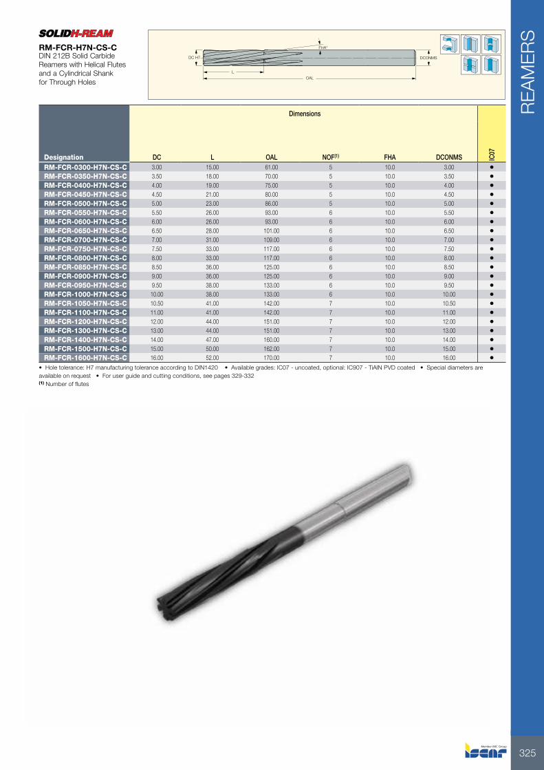
RM-FCR-0300-H7S-CS-C 3.00 15.00 30.0 - 61.00 6 3.00 •RM-FCR-0320-H7S-CS-C 3.20 18.00 33.0 - 70.00 6 3.20 •RM-FCR-0350-H7S-CS-C 3.50 18.00 33.0 - 70.00 6 3.50 •RM-FCR-0400-H7S-CS-C 4.00 19.00 44.0 3.50 75.00 6 4.00 •RM-FCR-0450-H7S-CS-C 4.50 21.00 46.0 4.00 80.00 6 4.50 •RM-FCR-0500-H7S-CS-C 5.00 23.00 53.0 4.30 86.00 6 5.00 •RM-FCR-0550-H7S-CS-C 5.50 26.00 56.0 4.50 93.00 6 5.60 •RM-FCR-0600-H7S-CS-C 6.00 26.00 56.0 5.00 93.00 6 5.60 •RM-FCR-0650-H7S-CS-C 6.50 28.00 63.0 5.50 101.00 6 6.30 •RM-FCR-0700-H7S-CS-C 7.00 31.00 69.0 6.50 109.00 6 7.10 •RM-FCR-0750-H7S-CS-C 7.50 31.00 69.0 6.50 109.00 6 7.10 •RM-FCR-0800-H7S-CS-C 8.00 33.00 75.0 7.00 117.00 6 8.00 •RM-FCR-0850-H7S-CS-C 8.50 33.00 75.0 7.00 117.00 6 8.00 •RM-FCR-0900-H7S-CS-C 9.00 36.00 81.0 8.00 125.00 6 9.00 •RM-FCR-0950-H7S-CS-C 9.50 36.00 81.0 8.00 125.00 6 9.00 •RM-FCR-1000-H7S-CS-C 10.00 38.00 87.0 9.00 133.00 6 10.00 •RM-FCR-1050-H7S-CS-C 10.50 38.00 87.0 9.00 133.00 6 10.00 •RM-FCR-1100-H7S-CS-C 11.00 41.00 96.0 9.00 142.00 6 10.00 •RM-FCR-1200-H7S-CS-C 12.00 44.00 105.0 9.00 151.00 6 10.00 •RM-FCR-1300-H7S-CS-C 13.00 44.00 105.0 9.00 151.00 6 10.00 •RM-FCR-1400-H7S-CS-C 14.00 47.00 110.0 11.50 160.00 8 12.50 •RM-FCR-1500-H7S-CS-C 15.00 50.00 112.0 11.50 162.00 8 12.50 •RM-FCR-1600-H7S-CS-C 16.00 52.00 120.0 11.50 170.00 8 12.50 •
• Hole tolerance: H7 manufacturing tolerance according to DIN1420 • Available grades: IC07 - uncoated, optional: IC907 - TiAlN PVD coated • Special diameters are available on request • For user guide and cutting conditions, see pages 329-332(1) Number of flutes
RM-FCR-H7S-CS-CDIN 212C Solid Carbide Reamers with Straight Flutes and a Cylindrical Shank for Blind Holes
325
REA
MER
S
DC H7 DCONMS
OAL
FHA°
L
Dimensions
Designation DC L OAL NOF(1) FHA DCONMS IC07
RM-FCR-0300-H7N-CS-C 3.00 15.00 61.00 5 10.0 3.00 •RM-FCR-0350-H7N-CS-C 3.50 18.00 70.00 5 10.0 3.50 •RM-FCR-0400-H7N-CS-C 4.00 19.00 75.00 5 10.0 4.00 •RM-FCR-0450-H7N-CS-C 4.50 21.00 80.00 5 10.0 4.50 •RM-FCR-0500-H7N-CS-C 5.00 23.00 86.00 5 10.0 5.00 •RM-FCR-0550-H7N-CS-C 5.50 26.00 93.00 6 10.0 5.50 •RM-FCR-0600-H7N-CS-C 6.00 26.00 93.00 6 10.0 6.00 •RM-FCR-0650-H7N-CS-C 6.50 28.00 101.00 6 10.0 6.50 •RM-FCR-0700-H7N-CS-C 7.00 31.00 109.00 6 10.0 7.00 •RM-FCR-0750-H7N-CS-C 7.50 33.00 117.00 6 10.0 7.50 •RM-FCR-0800-H7N-CS-C 8.00 33.00 117.00 6 10.0 8.00 •RM-FCR-0850-H7N-CS-C 8.50 36.00 125.00 6 10.0 8.50 •RM-FCR-0900-H7N-CS-C 9.00 36.00 125.00 6 10.0 9.00 •RM-FCR-0950-H7N-CS-C 9.50 38.00 133.00 6 10.0 9.50 •RM-FCR-1000-H7N-CS-C 10.00 38.00 133.00 6 10.0 10.00 •RM-FCR-1050-H7N-CS-C 10.50 41.00 142.00 7 10.0 10.50 •RM-FCR-1100-H7N-CS-C 11.00 41.00 142.00 7 10.0 11.00 •RM-FCR-1200-H7N-CS-C 12.00 44.00 151.00 7 10.0 12.00 •RM-FCR-1300-H7N-CS-C 13.00 44.00 151.00 7 10.0 13.00 •RM-FCR-1400-H7N-CS-C 14.00 47.00 160.00 7 10.0 14.00 •RM-FCR-1500-H7N-CS-C 15.00 50.00 162.00 7 10.0 15.00 •RM-FCR-1600-H7N-CS-C 16.00 52.00 170.00 7 10.0 16.00 •
• Hole tolerance: H7 manufacturing tolerance according to DIN1420 • Available grades: IC07 - uncoated, optional: IC907 - TiAlN PVD coated • Special diameters are available on request • For user guide and cutting conditions, see pages 329-332(1) Number of flutes
RM-FCR-H7N-CS-CDIN 212B Solid Carbide Reamers with Helical Flutes and a Cylindrical Shank for Through Holes

ISCAR326
REA
MER
S
LLU
OAL
SS
DC
CH
CB
Dimensions
Designation DC OAL LU L NOF(1) SS IC07
RM-SHR-0500-H7S-MT1-CH 5.000 133.00 67.5 23.00 4 MT1 •RM-SHR-0600-H7S-MT1-CH 6.000 138.00 72.5 26.00 4 MT1 •RM-SHR-0700-H7S-MT1-CH 7.000 150.00 84.5 31.00 4 MT1 •RM-SHR-0800-H7S-MT1-CH 8.000 156.00 90.5 33.00 4 MT1 •RM-SHR-0900-H7S-MT1-CH 9.000 162.00 96.5 36.00 4 MT1 •RM-SHR-1000-H7S-MT1-CH 10.000 168.00 102.5 38.00 6 MT1 •RM-SHR-1100-H7S-MT1-CH 11.000 175.00 109.5 41.00 6 MT1 •RM-SHR-1300-H7S-MT1-CH 13.000 182.00 116.5 44.00 6 MT1 •RM-SHR-1400-H7S-MT1-CH 14.000 189.00 123.5 47.00 6 MT1 •RM-SHR-1500-H7S-MT2-CH 15.000 204.00 124.0 50.00 6 MT2 •RM-SHR-1600-H7S-MT2-CH 16.000 210.00 130.0 52.00 6 MT2 •RM-SHR-1700-H7S-MT2-CB 17.000 214.00 134.0 54.00 6 MT2 •RM-SHR-1800-H7S-MT2-CB 18.000 219.00 139.0 56.00 6 MT2 •RM-SHR-1900-H7S-MT2-CB 19.000 223.00 143.0 58.00 6 MT2 •RM-SHR-2000-H7S-MT2-CB 20.000 228.00 148.0 60.00 6 MT2 •RM-SHR-2200-H7S-MT2-CB 22.000 237.00 157.0 64.00 8 MT2 •RM-SHR-2400-H7S-MT3-CB 24.000 268.00 169.0 68.00 8 MT3 •RM-SHR-2500-H7S-MT3-CB 25.000 268.00 169.0 68.00 8 MT3 •RM-SHR-2600-H7S-MT3-CB 26.000 273.00 174.0 70.00 8 MT3 •RM-SHR-2800-H7S-MT3-CB 28.000 277.00 178.0 71.00 8 MT3 •RM-SHR-3000-H7S-MT3-CB 30.000 281.00 182.0 73.00 8 MT3 •RM-SHR-3200-H7S-MT4-CB 32.000 317.00 193.0 77.00 8 MT4 •RM-SHR-3400-H7S-MT4-CB 34.000 321.00 197.0 78.00 8 MT4 •RM-SHR-3600-H7S-MT4-CB 36.000 325.00 201.0 79.00 8 MT4 •RM-SHR-4000-H7S-MT4-CB 40.000 329.00 205.0 81.00 8 MT4 •
• Requires a price and delivery time quotation • Available only upon request • -CH: Brazed solid carbide head • -CB: Brazed solid carbide tips • Hole tolerance: H7 manufacturing tolerance according to DIN 1420 • Available grades: IC07 (uncoated), optional: IC907 (TiAlN PVD coated) • For user guide and cutting conditions, see pages 329-332(1) Number of flutes
RM-SHR-H7S-MTDIN 8094 Solid Carbide Reamers with Straight Flutes and a Morse Taper Shank for Blind Holes

327
REA
MER
S
DC
L LUOAL
SS
CH
CB
Dimensions
Designation DC OAL LU L NOF(1) SS IC07
RM-SHR-0500-H7N-MT1-CH 5.000 133.00 67.5 23.00 4 MT1 •RM-SHR-0600-H7N-MT1-CH 6.000 138.00 72.5 26.00 4 TM1 •RM-SHR-0700-H7N-MT1-CH 7.000 150.00 84.5 31.00 4 MT1 •RM-SHR-0800-H7N-MT1-CH 8.000 156.00 90.5 33.00 4 MT1 •RM-SHR-0900-H7N-MT1-CH 9.000 162.00 96.5 36.00 4 MT1 •RM-SHR-1000-H7N-MT1-CH 10.000 168.00 102.5 38.00 6 MT1 •RM-SHR-1100-H7N-MT1-CH 11.000 175.00 109.5 41.00 6 MT1 •RM-SHR-1200-H7N-MT1-CH 12.000 182.00 116.5 44.00 6 MT1 •RM-SHR-1300-H7N-MT1-CH 13.000 182.00 116.5 44.00 6 MT1 •RM-SHR-1400-H7N-MT1-CH 14.000 189.00 123.5 47.00 6 MT1 •RM-SHR-1500-H7N-MT2-CH 15.000 204.00 124.0 50.00 6 MT2 •RM-SHR-1600-H7N-MT2-CH 16.000 210.00 130.0 52.00 6 MT2 •RM-SHR-1800-H7N-MT2-CB 18.000 219.00 139.0 56.00 6 MT2 •RM-SHR-1900-H7N-MT2-CB 19.000 223.00 143.0 58.00 6 MT2 •RM-SHR-2000-H7N-MT2-CB 20.000 228.00 148.0 60.00 6 MT2 •RM-SHR-2200-H7N-MT2-CB 22.000 237.00 157.0 64.00 8 MT2 •RM-SHR-2500-H7N-MT3-CB 25.000 268.00 169.0 68.00 8 MT3 •RM-SHR-2600-H7N-MT3-CB 26.000 273.00 174.0 70.00 8 MT3 •RM-SHR-2800-H7N-MT3-CB 28.000 277.00 178.0 71.00 8 MT3 •RM-SHR-3000-H7N-MT3-CB 30.000 281.00 182.0 73.00 8 MT3 •RM-SHR-3200-H7N-MT4-CB 32.000 317.00 193.0 77.00 8 MT4 •RM-SHR-3400-H7N-MT4-CB 34.000 321.00 197.0 78.00 8 MT4 •RM-SHR-3500-H7N-MT4-CB 35.000 321.00 197.0 78.00 8 MT4 •RM-SHR-3600-H7N-MT4-CB 36.000 325.00 201.0 79.00 8 MT4 •RM-SHR-3800-H7N-MT4-CB 38.000 329.00 205.0 81.00 8 MT4 •
• Requires a price and delivery time quotation • Available only upon request • -CH: Brazed solid carbide head • -CB: Brazed solid carbide tips • Hole tolerance: H7 manufacturing tolerance according to DIN 1420 • Available grades: IC07 (uncoated), optional: IC907 (TiAlN PVD coated) • For user guide and cutting conditions, see pages 329-332(1) Number of flutes
RM-SHR-H7N-MTDIN 8093 Solid Carbide Reamers with Spiral Flutes and a Morse Taper Shank for Through Holes

ISCAR328
REA
MER
S
SSC
S
DC H7
L
1:30 conical connection with brazed tips
Dimensions
Designation DC S L SSC(1) NOF(2) IC07
RM-SR25.000H7S-13 25.000 45.00 30.00 13.00 6 •RM-SR30.000H7S-13 30.000 45.00 30.00 13.00 6 •RM-SR34.000H7S-13 34.000 45.00 30.00 13.00 8 •RM-SR35.000H7S-13 35.000 45.00 30.00 13.00 8 •RM-SR36.000H7S-16 36.000 50.00 30.00 16.00 8 •RM-SR37.000H7S-16 37.000 50.00 30.00 16.00 8 •RM-SR38.000H7S-16 38.000 50.00 30.00 16.00 8 •RM-SR40.000H7S-16 40.000 50.00 30.00 16.00 8 •RM-SR42.000H7S-16 42.000 50.00 30.00 16.00 8 •RM-SR44.000H7S-16 44.000 50.00 30.00 16.00 8 •RM-SR45.000H7S-16 45.000 50.00 30.00 16.00 8 •RM-SR48.000H7S-19 48.000 56.00 30.00 19.00 10 •RM-SR50.000H7S-19 50.000 56.00 30.00 19.00 10 •RM-SR55.000H7S-22 55.000 63.00 30.00 22.00 10 •RM-SR58.000H7S-22 58.000 63.00 30.00 22.00 10 •RM-SR60.000H7S-22 60.000 63.00 30.00 22.00 10 •RM-SR70.000H7S-27 70.000 71.00 30.00 27.00 12 •
• Available only upon request • Right-hand, H7 manufacturing tolerance according to DIN 1420 • For user guide and cutting conditions, see pages 329-332(1) Seat size code
RM-SR-H7SDIN 8054 Brazed Carbide Tip Shell Reamers with Straight Flutes
Driving Ring Extracting Nut
OAL
LSCWS DCONWS
LB
SS
1:30 conical connection with an extraction nut, driving ring and a key.
Designation DCONWS DCN(1) DCX(2) OAL LB LSCWS SSRM-SRH Q13-MT3 13.00 25.00 35.00 250.00 149.46 45.00 MT3RM-SRH Q16-MT3 16.00 36.00 45.00 261.00 160.45 50.00 MT3RM-SRH Q19-MT3 19.00 48.00 52.00 298.00 173.54 56.00 MT3RM-SRH Q19-MT4 19.00 48.00 52.00 273.00 174.00 56.00 MT4RM-SRH Q22-MT3 22.00 55.00 62.00 312.00 187.54 63.00 MT3RM-SRH Q22-MT4 22.00 55.00 62.00 312.00 188.00 63.00 MT4RM-SRH Q27-MT4 27.00 65.00 75.00 359.00 198.80 71.00 MT4RM-SRH Q27-MT5 27.00 65.00 75.00 327.00 200.63 71.00 MT5
• Available only upon request(1) Minimum insert diameter (2) Maximum insert diameter
RM-SRH-Q-MTDIN 217 Shell Reamer Shanks with a Morse Taper Connection

329
USER GUIDE
REA
MER
S
Machining Conditions for Solid Carbide Reamers
MaterialTensile Strength or
Brinell Hardness N/mm2 bzw. HB
Reamer Diameter mm
Reaming Allowance Relative
to DiameterFeed mm/rev Cutting Speed
m/min
Steel
up to 10 0.04-0.10 0.15-0.25up to 1000 10-25 0.10-0.25 0.20-0.35 6-20
25-40 0.25-0.40 0.30-0.50up to 10 0.04-0.10 0.12-0.20
1000-1400 10-25 0.10-0.25 0.15-0.30 6-1525-40 0.25-0.40 0.20-0.40
Cast steel
up to 10 0.05-0.10 0.15-0.25400-500 10-25 0.10-0.25 0.20-0.40 10-20
25-40 0.25-0.40 0.30-0.50up to 10 0.04-0.10 0.12-0.20
500-700 10-25 0.10-0.25 0.15-0.30 6-1525-40 0.25-0.40 0.20-0.40
Titanium Titanium Alloy
up to 10 0.06-0.12 0.12-0.20500-1300 10-25 0.10-0.25 0.15-0.30 6-15
25-40 0.25-0.40 0.20-0.40
Grey cast iron
up to 10 0.06-0.12 0.20-0.30up to 220 HB 10-25 0.10-0.30 0.30-0.45 10-25
25-40 0.30-0.50 0.40-0.70up to 10 0.06-0.12 0.15-0.25
over 220 HB 10-25 0.10-0.30 0.20-0.35 10-2025-40 0.30-0.50 0.30-0.50
Spheroidal graphite Cast iron Malleable cast iron
up to 10 0.06-0.12 0.15-0.2510-25 0.10-0.25 0.20-0.40 8-1525-40 0.25-0.40 0.30-0.60
Aluminum alloyup to 10 0.06-0.12 0.20-0.30 Si<7% 10-30
over 80 HB 10-25 0.10-0.30 0.30-0.5025-40 0.30-0.50 0.40-0.70 Si<7% 30-60
Copperup to 10 0.10-0.20 0.30-0.6010-25 0.20-0.40 0.40-0.80 20-6025-40 0.40-0.60 0.50-1.00
Brass Red bronze Cast bronze
up to 10 0.06-0.12 0.20-0.3010-25 0.10-0.30 0.30-0.50 15-5025-40 0.30-0.50 0.40-0.70
Thermoset polymersup to 10 0.10-0.25 0.30-0.6010-25 0.20-0.40 0.40-0.80 15-3025-40 0.40-0.60 0.50-1.00

ISCAR330
USER GUIDER
EAM
ERS
Nominal Diameter of Reamer D1 in mm
Reamer Manufacturing Tolerances DIN 1420
Admissible maximum and minimum reamer dimensions of nominal diameter d1 in µm for drilling tolerance range
Over Up to A9 A11 B8 B9 B10 B11 C8 C9 C10 C111 3 +291 +321 +151 +161 +174 +191 + 71 + 81 + 94 +111
+282 +300 +146 +152 +160 +170 + 66 + 72 + 80 + 903 6 +295 +333 +155 +165 +180 +203 + 85 + 95 +110 +133
+284 +306 +148 +154 +163 +176 + 78 + 84 + 93 +1066 10 +310 +356 +168 +180 +199 +226 + 98 +110 +129 +156
+297 +324 +160 +167 +178 +194 + 90 + 97 +108 +12410 18 +326 +383 +172 +186 +209 +243 +117 +131 +154 +188
+310 +344 +162 +170 +184 +204 +107 +115 +129 +14918 30 +344 +410 +188 +204 +231 +270 +138 +154 +181 +220
+325 +364 +176 +185 +201 +224 +126 +135 +151 +17430 40 +362 +446 +203 +222 +255 +206 +153 +172 +205 +256
+340 +390 +189 +200 +220 +250 +139 +150 +170 +20040 50 +372 +456 +213 +232 +265 +316 +163 +182 +215 +266
+350 +400 +199 +210 +230 +260 +149 +160 +180 +21050 65 +402 +501 +229 +252 +292 +351 +179 +202 +242 +301
+376 +434 +212 +226 +250 +284 +162 +176 +200 +23465 80 +422 +521 +239 +262 +302 +361 +189 +212 +252 +311
+396 +454 +222 +236 +260 +294 +172 +186 +210 +24480 100 +453 +567 +265 +293 +339 +407 +215 +243 +289 +357
+422 +490 +246 +262 +290 +330 +196 +212 +240 +280100 120 +483 +597 +285 +313 +359 +427 +225 +253 +299 +367
+452 +520 +266 +282 +310 +350 +206 +222 +250 +290120 140 +545 +672 +313 +345 +396 +472 +253 +285 +336 +412
+510 +584 +290 +310 +340 +384 +230 +250 +280 +324140 160 +605 +732 +333 +365 +416 +492 +263 +295 +346 +422
+570 +644 +310 +330 +360 +404 +240 +260 +290 +334160 180 +665 +792 +363 +395 +446 +522 +283 +315 +366 +442
+630 +704 +340 +360 +390 +434 +260 +280 +310 +354Over Up to D8 D9 D10 D11 E7 E8 E9 F6 F7 F8 F9 G6 G7
1 3 + 31 + 41 + 54 + 71 + 22 + 25 + 35 + 11 + 14 + 17 + 27 + 7 + 10+ 26 + 32 + 40 + 50 + 18 + 20 + 26 + 8 + 10 + 12 + 18 + 4 + 6
3 6 + 45 + 55 + 70 + 93 + 30 + 35 + 45 + 16 + 20 + 25 + 35 + 10 + 14+ 38 + 44 + 53 + 66 + 25 + 28 + 34 + 13 + 15 + 18 + 24 + 7 + 9
6 10 + 58 + 70 + 89 +116 + 37 + 43 + 55 + 20 + 25 + 31 + 43 + 12 + 17+ 50 + 57 + 68 + 84 + 31 + 35 + 42 + 16 + 19 + 23 + 30 + 8 + 11
10 18 + 72 + 86 +109 +143 + 47 + 54 + 68 + 25 + 31 + 38 + 52 + 15 + 21+ 62 + 70 + 84 +104 + 40 + 44 + 52 + 21 + 24 + 28 + 36 + 11 + 14
18 30 + 93 +109 +136 +175 + 57 + 68 + 84 + 31 + 37 + 48 + 64 + 18 + 24+ 81 + 90 +106 +129 + 49 + 56 + 65 + 26 + 29 + 36 + 45 + 13 + 16
30 50 +113 +132 +165 +216 + 71 + 83 + 102 + 38 + 46 + 58 + 77 + 22 + 30+ 99 +110 +130 +160 + 62 + 69 + 80 + 32 + 37 + 44 + 55 + 16 + 21
50 80 +139 +162 +202 +261 + 5 + 99 +122 + 46 + 55 + 69 + 92 + 26 + 35+122 +136 +160 +194 + 74 + 82 + 96 + 39 + 44 + 52 + 66 + 19 + 24
80 120 +165 +193 +239 +307 +101 +117 +145 + 54 + 65 + 81 +109 + 30 + 41+146 +162 +190 +230 + 88 + 98 +114 + 46 + 52 + 62 + 78 + 22 + 28
120 180 +198 +230 +281 +357 +119 +138 +170 + 64 + 77 + 96 + 128 + 35 + 48+175 +195 +225 +269 +105 +115 +135 + 55 + 63 + 73 + 93 + 26 + 34
Reamer Manufacturing Tolerances

331
USER GUIDE
REA
MER
S
Reamer Manufacturing Tolerances (continued)
Nominal Diameter of Reamer D1 in mm
Reamer Manufacturing Tolerances DIN 1420
Admissible maximum and minimum reamer dimensions of nominal diameter d1 in µm for drilling tolerance range
Over Up to R6 R7 S6 S7 T6 U6 U7 U10 X10 X11 Z10 Z111 3 -11 -12 -15 -16 -19 -19 -20 -24 -26 -29 -32 -35
-14 -16 -18 -20 -22 -22 -24 -38 -40 -50 -46 -563 6 -14 -13 -18 -17 -22 -22 -21 -31 -36 -40 -43 -47
-17 -18 -21 -22 -25 -25 -26 -48 -53 -67 -60 -566 10 -18 -16 -22 -20 -27 -27 -25 -37 -43 -48 -51 -47
-22 -22 -26 -26 -31 -31 -31 -58 -64 -80 -72 -7410 14 -22 -19 -27 -24 -32 -32 -29 -44 -51 -57 -61 -56
-26 -26 -31 -31 -36 -36 -36 -69 -76 -96 -86 -8814 18 -22 -19 -27 -24 -32 -32 -29 -44 - 56 -62 -71 -67
-26 -26 -31 -31 -36 -36 -36 -69 - 81 -101 -96 -10618 24 -26 -24 -33 -31 -39 -39 -37 -54 - 67 -74 -86 -77
-31 -32 -38 -39 -44 -44 -45 -84 - 97 -120 -116 -11624 30 -26 -24 -33 -31 -39 -46 -44 -61 - 77 -84 -101 -108
-31 -32 -38 -39 -44 -51 -52 -69 -107 -130 -131 -15430 40 -32 -29 -41 -38 -46 -58 -55 -75 - 95 -104 -127 -136
-38 -38 -47 -47 -52 -64 -64 -110 -130 -160 -162 -19240 50 -32 -29 -41 -38 -52 -68 -65 -85 -112 -121 -151 -160
-38 -38 -47 -47 -58 -74 -74 -120 -147 -177 -186 -21650 65 -38 -35 -50 -47 -63 -84 -81 -105 -140 -151 -190 -201
-45 -46 -57 -58 -70 -91 -92 -147 -182 -218 -232 -26865 80 -40 -37 -56 -53 -72 -99 -96 -120 -164 -175 -228 -239
-47 -48 -63 -64 -79 -106 -107 -162 -206 -242 -170 -30680 100 -48 -44 -68 -64 -88 -121 -117 -145 -199 -211 -179 -291
-56 -57 -76 -77 -96 -129 -130 -194 -248 -288 -328 -368100 120 -51 -47 -76 -72 -101 -141 -139 -165 -231 -243 -331 -343
-59 -60 -84 -85 -109 -149 -150 -214 -280 -320 -380 -420120 140 -60 -54 -89 -83 -119 -167 -161 -194 -272 -286 -389 -403
-69 -68 -98 -97 -128 -176 -175 -250 -328 -374 -445 -491140 160 -62 -56 -97 -91 -131 -187 -181 -214 -304 -318 -439 -453
-71 -70 -106 -105 -140 -196 -195 -270 -360 -406 -495 -541Over Up to H6 H7 H8 H9 H10 H11 H12 J6 J7 J8 JS6 JS7 JS8 JS9
1 3 +5 +8 +11 +21 +34 +51 +85 +1 +2 +3 +2 +3 +4 +8+2 +4 +6 +12 +20 +30 +50 -2 -2 -2 -1 -1 -1 -1
3 6 +6 +10 +15 +25 +40 +63 +102 +3 +4 +7 +2 +4 +6 +10+3 +5 +8 +14 +23 +30 +60 0 -1 0 -1 -1 -1 -1
6 10 +7 +12 +18 +30 +49 +76 +127 +3 +5 +8 +3 +5 +7 +12+3 +6 +10 +17 +28 +44 +74 -1 -1 0 -1 -1 -1 -1
10 16 +9 +15 +22 +36 +59 +93 +153 +4 +7 +10 +3 +6 +9 +15+5 +8 +12 +20 +34 +54 +90 0 0 0 -1 -1 -1 -1
18 30 +11 +17 +28 +44 +71 +110 +178 +6 +8 +15 +4 +7 +11 +18+6 +9 +16 +25 +41 +64 +104 +1 0 +3 -1 -1 -1 -1
30 50 +13 +21 +33 +52 +85 +136 +212 +7 +10 +18 +5 +8 +13 +21+7 +12 +19 +30 +50 +80 +124 +1 +1 +4 -1 -1 -1 -1
50 80 +16 +25 +39 +62 +102 +161 +255 +10 +13 +21 +6 +10 +16 +25+9 +14 +22 +36 +60 +94 +150 +3 +2 +4 -1 -1 -1 -1
90 120 +18 +29 +45 +73 +119 +187 +297 +12 +16 +25 +7 +12 +18 +30+10 +16 +26 +42 +70 +110 +174 +4 +3 +6 -1 -1 -1 -1
120 180 +21 +34 +53 +85 +136 +212 +360 +14 +20 +31 +8 +16 +72 +35+12 +20 +30 +50 +80 +124 +200 +5 +6 +8 -1 0 -1 0
Over Up to K6 K7 K8 M6 M7 M8 N6 N7 N8 N9 N10 N11 P6 P71 3 -1 -2 -3 -3 -4 -5 -5 -6 -7 -8 -10 -13 -7 -8
-4 -6 -8 -6 -8 -10 -8 -10 -12 -17 -24 -34 -10 -123 6 0 +1 +2 -3 -2 -1 -7 -6 -5 -5 -8 -12 -11 -10
-3 -4 -5 -6 -7 -8 -10 -11 -12 -16 -25 -39 -14 -156 10 0 +2 +2 -5 -3 -3 -9 -7 -7 -6 -9 -14 -14 -12
-4 -4 -6 -9 -9 -11 -13 -13 -15 -19 -30 -46 -18 -1810 18 0 +3 +3 -6 -3 -3 -11 -8 -8 -7 -11 -17 -17 -14
-4 -4 -7 -10 -10 -13 -15 -15 -18 -23 -36 -56 -21 -2118 30 0 +2 +5 -6 -4 -1 -13 -11 -8 -8 -13 -20 -20 -18
-5 -6 -7 -11 -12 -13 -18 -19 -20 -27 -43 -66 -25 -2630 50 0 +3 +6 -7 -4 -1 -15 -12 -9 -10 -15 -24 -24 -21
-6 -6 -8 -13 -13 -15 -21 -21 -23 -32 -50 -80 -30 -3050 80 +1 +4 +7 -8 -5 -2 -17 -14 -11 -12 -18 -29 -29 -26
-6 -7 -10 -15 -16 -19 -24 -25 -28 -38 -60 -96 -36 -3780 120 0 +4 +7 -10 -6 -3 -20 -16 -13 -14 -21 -33 -34 -30
-8 -9 -12 -18 -19 -22 -28 -29 -32 -45 -70 -110 -42 -43120 180 0 +6 +10 -12 -6 -2 -24 -18 -14 -15 -24 -38 -40 -34
-9 -8 -13 -21 -20 -25 -33 -32 -37 -50 -80 -126 -49 +48

ISCAR332
USER GUIDER
EAM
ERS
Cutting SpeedThe cutting speed has the highest influence on the surface quality of the reamed hole and on the life of the tool. Increasing the cutting speed beyond the optimum speed will cause increased tool wear due to the increased cutting temperature. The increased speed also causes an increase in the built-up edge (material that is welded to the cutting edge). The built-up edge damages the surface finish and shortens the life of the tool. In order to achieve high surface quality and longer tool life, the cutting speed for reaming should be kept relatively low.
Feed RateThe feed rate directly influences the wear on the cutting edge. As the feed rate is increased, the cutting forces increase almost proportionally. The feed, however, has less influence on the machined surface quality and tool wear than the cutting speed (i.e. the feed can be varied in a relatively wide range without having material influence the quality of the machined hole and the respective tool life). It is therefore recommended to select the highest possible feed in order to shorten reaming times without significantly reducing the tool life.
Reaming AllowanceThe reaming allowance (the amount of material to be reamed) also influences the tool life. In order to achieve high tool life, the reaming allowance should be kept at a reasonable minimum considering the process to be performed. If the reaming allowance is too small, it may result in a high dimensional variation (inability to maintain the required tolerances) and a decrease in the machined surface quality. When reaming materials that have surface defects or have been welded or flame cut, the reaming allowance should be increased so these factors do not appear on the reamed surface.
Coolant/LubricationThe high degree of friction between the tool and the wall being reamed demands the use of a fluid for lubrication and cooling. Using lubrication is more critical for maintaining tolerances than using a coolant. General cutting oils and emulsions may be used. It should be noted that in some cases emulsions will yield a better surface finish than cutting oils. Emulsions are thinner fluids that are able to reach and more uniformly lubricate the cutting edges better than viscous cutting oils (especially when performing deep applications). In order to determine the most suitable lubricant for a particular application, tests should be run on the material to be cut, on a case-to-case basis.
Reaming PrerequisitesIn order to achieve high tolerances for reaming applications, there are certain requirements that must be considered.
1 Condition of the tool - If the tool is reground, both an exact concentricity and high quality grinding are indispensable.
2 Workpiece material - Axis shifting and warping (i.e. incorrect hole positioning) can only be corrected to a certain degree when reaming. A critical factor is the initial opening in the workpiece. This opening must be even, or if the prepared hole is countersunk, a cone countersink must be used. Failure to properly prepare the initial opening can result in irregular countersinking that leads to the reamer being pushed out of its proper alignment. Ideally, pre-machining should be performed in a chuck to avoid alignment defects.
3 Through holes - For best results, the holes to be reamed should extend completely through the workpiece material. This allows for easy exit of both the cutting fluid and the reamed material. Negative flute reamers are advantageous in through hole reaming.
4 Blind holes - Use straight flute reamers for blind holes.

333
USER GUIDE
REA
MER
S
Tool Designation Code Key
RM SET 12.000(1) H6 T B C16 s
Reamer Single-Edged Tool Hole Diameter Hole Tolerance
Hole Type
B Blind
T Through
Lead Type(2)
A, B, C, D (see page 338) Note: A, C, D - optional
Shank Type
C Cylindrical
W Weldon
F Flat
(1) To be ordered for each specific diameter and tolerance(2) Tool lead type - according to insert’s lead type
Reamer Length S-Short
High Speed Reaming System with Internal Coolant Holes The INDEXH-REAM standard line covers reaming applications of 8-32 mm hole diameters. The indexable cutting insert has two cutting corners with 4 lead angle options and 3 rake angle variations, covering most workpiece material types. The INDEXH-REAM single indexable insert with carbide pads provides a combination of economical and high precision results on a very wide range of materials.
ImportantLead type of the tool (pads) should be compatible with the lead type of the insert. Using an improper insert will damage the tool and the reamed part.
Guiding Pad Line
The guiding pads are precisely ground for a specific diameter, and therefore, can only be used for reaming on appropriate hole sizes. The adjustment mechanism is designed for a specific diameter setting and for wear compensation (a few microns only). The same tool can not be used for reaming different diameters.
≤20µm (≤0.75µin)Guiding Pad Line

ISCAR334
REA
MER
S
LUL6
OALLS
DCONMS
APMX
DC
Designation DC APMX L6(1) LU LS OAL DCONMS SSC(2)
RM-SET8.000H6T-B-C16S 8.000 15.50 30.00 75.0 45.0 123.50 16.00 1.0RM-SET9.000H6T-B-C16S 9.000 15.50 30.00 75.0 45.0 123.50 16.00 1.0RM-SET10.000H6T-B-C16S 10.000 15.50 30.00 75.0 45.0 123.50 16.00 2.0RM-SET11.000H6T-B-C16S 11.000 15.50 30.00 75.0 45.0 123.50 16.00 2.0RM-SET12.000H6T-B-C16S 12.000 17.00 30.00 85.0 45.0 135.00 16.00 3.0RM-SET13.000H6T-B-C16S 13.000 17.00 30.00 85.0 45.0 135.00 16.00 3.0RM-SET14.000H6T-B-C16S 14.000 17.00 30.00 85.0 45.0 135.00 16.00 3.0RM-SET15.000H6T-B-C16S 15.000 17.00 30.00 85.0 45.0 135.00 16.00 3.0RM-SET16.000H6T-B-C20S 16.000 17.00 30.00 110.0 50.0 165.00 20.00 3.0RM-SET17.000H6T-B-C20S 17.000 17.00 30.00 110.0 50.0 165.00 20.00 3.0RM-SET18.000H6T-B-C20S 18.000 17.00 30.00 110.0 50.0 165.00 20.00 3.0RM-SET19.000H6T-B-C20S 19.000 17.00 30.00 110.0 50.0 165.00 20.00 3.0RM-SET20.000H6T-B-C25S 20.000 17.00 30.00 110.0 56.0 171.00 25.00 3.0RM-SET21.000H6T-B-C25S 21.000 17.00 30.00 110.0 56.0 171.00 25.00 3.0RM-SET22.000H6T-B-C25S 22.000 17.00 30.00 130.0 56.0 191.00 25.00 3.0RM-SET23.000H6T-B-C25S 23.000 17.00 30.00 130.0 56.0 191.00 25.00 3.0RM-SET24.000H6T-B-C25S 24.000 17.00 30.00 130.0 56.0 191.00 25.00 3.0RM-SET25.000H6T-B-C25S 25.000 17.00 30.00 130.0 56.0 191.00 25.00 3.0RM-SET26.000H6T-B-C25S 26.000 22.50 30.00 160.0 56.0 221.00 25.00 4.0RM-SET27.000H6T-B-C25S 27.000 22.50 30.00 160.0 56.0 221.00 25.00 4.0RM-SET28.000H6T-B-C25S 28.000 22.50 30.00 160.0 56.0 221.00 25.00 4.0RM-SET29.000H6T-B-C25S 29.000 22.50 30.00 160.0 56.0 221.00 25.00 4.0RM-SET30.000H6T-B-C25S 30.000 22.50 30.00 160.0 56.0 221.00 25.00 4.0RM-SET31.000H6T-B-C25S 31.000 22.50 30.00 160.0 56.0 221.00 25.00 4.0RM-SET32.000H6T-B-C25S 32.000 22.50 30.00 160.0 56.0 221.00 25.00 4.0
• For spare parts, see page 335 • For user guide and cutting conditions, see pages 338-343(1) Pad length (2) Insert size For inserts, see pages: RM-SEI-B (336)
RM-SET-T-BSingle-Edged Indexable Reamers for Through Holes

335
REA
MER
S
LUL6
OALLS
DCONMS
APMX
DC
Designation DC APMX OAL LS LU L6(1) DCONMS SSC(2)
RM-SET8.000H6B-B-C16S 8.000 15.50 123.50 45.0 75.0 30.00 16.00 1.0RM-SET9.000H6B-B-C16S 9.000 15.50 123.50 45.0 75.0 30.00 16.00 1.0RM-SET10.000H6B-B-C16S 10.000 15.50 123.50 45.0 75.0 30.00 16.00 2.0RM-SET11.000H6B-B-C16S 11.000 15.50 123.50 45.0 75.0 30.00 16.00 2.0RM-SET12.000H6B-B-C16S 12.000 17.00 135.00 45.0 85.0 30.00 16.00 3.0RM-SET13.000H6B-B-C16S 13.000 17.00 135.00 45.0 85.0 30.00 16.00 3.0RM-SET14.000H6B-B-C16S 14.000 17.00 135.00 45.0 85.0 30.00 16.00 3.0RM-SET15.000H6B-B-C16S 15.000 17.00 135.00 45.0 85.0 30.00 16.00 3.0RM-SET16.000H6B-B-C20S 16.000 17.00 165.00 50.0 110.0 30.00 20.00 3.0RM-SET17.000H6B-B-C20S 17.000 17.00 165.00 50.0 110.0 30.00 20.00 3.0RM-SET18.000H6B-B-C20S 18.000 17.00 165.00 50.0 110.0 30.00 20.00 3.0RM-SET19.000H6B-B-C20S 19.000 17.00 165.00 50.0 110.0 30.00 20.00 3.0RM-SET20.000H6B-B-C25S 20.000 17.00 171.00 56.0 110.0 30.00 25.00 3.0RM-SET21.000H6B-B-C25S 21.000 17.00 171.00 56.0 110.0 30.00 25.00 3.0RM-SET22.000H6B-B-C25S 22.000 17.00 191.00 56.0 130.0 30.00 25.00 3.0RM-SET23.000H6B-B-C25S 23.000 17.00 191.00 56.0 130.0 30.00 25.00 3.0RM-SET24.000H6B-B-C25S 24.000 17.00 191.00 56.0 130.0 30.00 25.00 3.0RM-SET25.000H6B-B-C25S 25.000 17.00 191.00 56.0 130.0 30.00 25.00 3.0RM-SET26.000H6B-B-C25S 26.000 22.50 221.00 56.0 160.0 30.00 25.00 4.0RM-SET27.000H6B-B-C25S 27.000 22.50 221.00 56.0 160.0 30.00 25.00 4.0RM-SET28.000H6B-B-C25S 28.000 22.50 221.00 56.0 160.0 30.00 25.00 4.0RM-SET29.000H6B-B-C25S 29.000 22.50 221.00 56.0 160.0 30.00 25.00 4.0RM-SET30.000H6B-B-C25S 30.000 22.50 221.00 56.0 160.0 30.00 25.00 4.0RM-SET31.000H6B-B-C25S 31.000 22.50 221.00 56.0 160.0 30.00 25.00 4.0RM-SET32.000H6B-B-C25S 32.000 22.50 221.00 56.0 160.0 30.00 25.00 4.0
• For user guide and cutting conditions, see pages 338-343(1) Pad length (2) Insert size For inserts, see pages: RM-SEI-B (336)
AdjustmentScrew
AdjustmentPin
ClampingScrew
ClampingWedge
AdjustmentScrew
AdjustmentPin
ClampingScrew
ClampingWedge
D [mm] Clamping Wedge Clamping Screw Adjustment Screw Adjustment Pin Insert Size8 WDG-RM-SE-1 SR-CL-RM-SE-1 SR-ADJ-M3x2.5 PIN-ADJ-RM-SE-1 19 WDG-RM-SE-1 SR-CL-RM-SE-1 SR-ADJ-M3x3 PIN-ADJ-RM-SE-1 110 WDG-RM-SE-2 SR-CL-RM-SE-1 SR-ADJ-M3x3 PIN-ADJ-RM-SE-2 211 WDG-RM-SE-2 SR-CL-RM-SE-1 SR-ADJ-M3x4 PIN-ADJ-RM-SE-2 212 WDG-RM-SE-3 SR-CL-RM-SE-3 SR-ADJ-M4x4 PIN-ADJ-RM-SE-3 313 WDG-RM-SE-3 SR-CL-RM-SE-3 SR-ADJ-M4x4 PIN-ADJ-RM-SE-3 314 WDG-RM-SE-3 SR-CL-RM-SE-3 SR-ADJ-M4x4 PIN-ADJ-RM-SE-3 315 WDG-RM-SE-3 SR-CL-RM-SE-3 SR-ADJ-M4x6 PIN-ADJ-RM-SE-3 316 WDG-RM-SE-3 SR-CL-RM-SE-3 SR-ADJ-M4x6 PIN-ADJ-RM-SE-3 317 WDG-RM-SE-3 SR-CL-RM-SE-3 SR-ADJ-M4x8 PIN-ADJ-RM-SE-3 318 WDG-RM-SE-3 SR-CL-RM-SE-3 SR-ADJ-M4x8 PIN-ADJ-RM-SE-3 319 WDG-RM-SE-3 SR-CL-RM-SE-3 SR-ADJ-M4x8 PIN-ADJ-RM-SE-3 320 WDG-RM-SE-3 SR-CL-RM-SE-3 SR-ADJ-M4x10 PIN-ADJ-RM-SE-3 321 WDG-RM-SE-3 SR-CL-RM-SE-3 SR-ADJ-M4x10 PIN-ADJ-RM-SE-3 322 WDG-RM-SE-3 SR-CL-RM-SE-3 SR-ADJ-M4x10 PIN-ADJ-RM-SE-3 323 WDG-RM-SE-3 SR-CL-RM-SE-3 SR-ADJ-M4x10 PIN-ADJ-RM-SE-3 324 WDG-RM-SE-3 SR-CL-RM-SE-3 SR-ADJ-M4x10 PIN-ADJ-RM-SE-3 325 WDG-RM-SE-3 SR-CL-RM-SE-3 SR-ADJ-M4x10 PIN-ADJ-RM-SE-3 326 WDG-RM-SE-4 SR-CL-RM-SE-4 SR-ADJ-M4x10 PIN-ADJ-RM-SE-4 427 WDG-RM-SE-4 SR-CL-RM-SE-4 SR-ADJ-M4x10 PIN-ADJ-RM-SE-4 428 WDG-RM-SE-4 SR-CL-RM-SE-4 SR-ADJ-M4x10 PIN-ADJ-RM-SE-4 429 WDG-RM-SE-4 SR-CL-RM-SE-4 SR-ADJ-M4x10 PIN-ADJ-RM-SE-4 430 WDG-RM-SE-4 SR-CL-RM-SE-4 SR-ADJ-M4x10 PIN-ADJ-RM-SE-4 431 WDG-RM-SE-4 SR-CL-RM-SE-4 SR-ADJ-M4x10 PIN-ADJ-RM-SE-4 432 WDG-RM-SE-4 SR-CL-RM-SE-4 SR-ADJ-M4x10 PIN-ADJ-RM-SE-4 4
Spare Parts
RM-SET-B-BSingle-Edged Indexable Reamers for Blind Holes
ISCAR336
REA
MER
S
30° 3°
1.3
S
a°
L
W1
Dimensions Tough 1 Hard
Designation SSC(1) a° L W1 S IC30
N
IC07
IC50
7
IC90
7
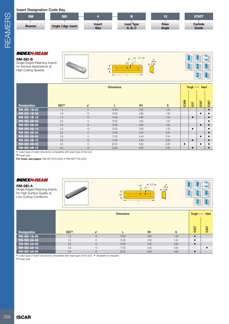
RM-SEI-1B-00 1.0 0 15.50 2.80 1.50 •RM-SEI-1B-06 1.0 6 15.50 2.80 1.50 • •RM-SEI-1B-12 1.0 12 15.50 2.80 1.50 • •RM-SEI-2B-00 2.0 0 15.50 3.60 1.50 •RM-SEI-2B-06 2.0 6 15.50 3.60 1.50 • •RM-SEI-2B-12 2.0 12 15.50 3.60 1.50 • •RM-SEI-3B-00 3.0 0 17.00 4.40 2.00 •RM-SEI-3B-06 3.0 6 17.00 4.40 2.00 • •RM-SEI-3B-12 3.0 12 17.00 4.40 2.00 • •RM-SEI-4B-06 4.0 6 22.50 6.60 3.00 • • •RM-SEI-4B-12 4.0 12 22.50 6.60 3.00 • •
• Lead type of insert should be compatible with lead type of the tool(1) Insert size For tools, see pages: RM-SET-B-B (335) • RM-SET-T-B (334)
RM-SEI-BSingle-Edged Reaming Inserts for General Applications at High Cutting Speeds
S
a°15°3°
3.0
L
W1
Dimensions Tough 1 Hard
Designation SSC(1) a° L W1 S IC50
7
IC90
7
RM-SEI-1A-06 1.0 6 15.50 2.80 1.50 •RM-SEI-2A-06 2.0 6 15.50 3.60 1.50 •RM-SEI-3A-06 3.0 6 15.50 4.40 2.00 •RM-SEI-3A-12 3.0 12 17.00 4.40 2.00 •RM-SEI-4A-06 4.0 6 22.50 6.60 3.00 •
• Lead type of insert should be compatible with lead type of the tool • Available on request(1) Insert size
RM-SEI-ASingle-Edged Reaming Inserts for High Surface Quality at Low Cutting Conditions
RM
Reamer
SEI
Single Edge Insert
4
InsertSize
B
Lead TypeA, B, C
12
RakeAngle
IC907
CarbideGrade
Insert Designation Code Key

337
REA
MER
S
75°
L5
S
a°
L
W1
Dimensions
Designation SSC(1) a° L W1 S PLGL IC07
RM-SEI-1C-12 1.0 12 15.50 2.80 1.50 0.550 •RM-SEI-2C-12 2.0 12 15.50 3.60 1.50 0.550 •RM-SEI-3C-12 3.0 12 17.00 4.40 2.00 0.550 •RM-SEI-4C-12 4.0 12 22.50 6.60 3.00 0.550 •
• Lead type of insert should be compatible with lead type of the tool • Available on request(1) Insert size
RM-SEI-CSingle-Edged Reaming Inserts for Aluminum and Brass
Lmax
l1
dmax
Designation L max l1 d maxkg
RM SETTING DEVICE 265.0 450.00 170.0 25.00
RM SETTING DEVICEReamer Setting Device

ISCAR338
USER GUIDER
EAM
ERS
Front Angles and Cutting Geometries
4 standard lead angles are available:
Lead L [mm] Use
A 3
Higher surface quality, lower cutting conditions (not recommended for nonferrous materials)
15˚ 3˚ L
B 1.3
Universal use, high speed cutting conditions. Can be used on a wide range of materials
L
3˚30˚
C 0.55
Suitable for aluminum andbrass at high cutting speed
L
75˚
D(1) 0.6
When needed for blind hole - lower feed
L3˚
30˚
(1) On request
3 standard cutting angles are available:
Angle [deg.] Use
000˚
For cast iron applications
066˚
General use
1212˚
For stainless steel and aluminum
Carbide GradesIC07 grade is the basic substrate for reaming inserts. It is a very versatile submicron grade. IC07 features very high fracture toughness and wear resistance, which is required for efficient high speed reaming. An uncoated IC07 can be used for machining nonferrous (N type material group) applications. Two types of standard coatings are available:
• IC907 – a TiAlN PVD coating for steel (P) and stainless steel (M) workpiece material groups
• IC507 - a TiCN+TiN PVD coating for cast iron (K) workpiece material group.
The following grades can be provided on request:
• PCD grade for machining aluminum• PCBN grade for machining cast iron• IC30N (cermet) for machining steel

339
USER GUIDE
REA
MER
S
Concept
The INDEXH-REAM Line is available in 4 sizes and features two different holder geometries (short flute and long flute). The holder selection depends on the hole type (through or blind).
RM-SEI-1 RM-SEI-2 RM-SEI-3 RM-SEI-4
Ø8.00-9.99 mm (Ø.315-.393")
Ø10.00-11.99 mm (Ø.393-.472")
Ø12.00-25.99 mm (Ø.472-1.024")
Ø26.00-32.00 mm (Ø1.024-1.260")
Insert Holder
Applications
Through Hole Blind Hole
Through Hole Short Flute Holder. This holder has a lateral coolant outlet located right above the insert. The coolant is pointed directly to the cutting edge to lubricate it and divert the chips forward. Additional coolant outlets are located behind the guiding pads. Their purpose is to reduce high friction that is created between the pads and the reamed surface during machining.
Blind Hole Long Flute Holder. This holder has a frontal coolant outlet. The liquid reaches the bottom of the blind hole and evacuates the formed chips. These chips are conveyed backwards through the long chip gullet (flute) of the holder.

ISCAR340
USER GUIDER
EAM
ERS
Setting Procedure
1 Place the reamer between the centering pins of the device.
2 Use the pad as a reference for setting the indicator to zero.
3 Rotate and place the inserts against indicators.
4 Tighten the adjustment screws in a clockwise direction.
5 Adjust the frontal side of the insert to: +15 µm (+0.6 µin) on D≤9.99, +20 µm (+0.8 µin) on D≤10.00
6 Adjust the rear side of insert to: +5 µm (+0.2 µin) on D≤9.99, +10 µm (+0.4 µin) on D≤10.00
Back TaperThe back taper prevents the reamer from jamming, as well as lowering reaming forces and improving surface quality. Incorrect back taper may cause unstable reaming, accelerated wear and rough surface finish.
High Friction Lubricated Zones
Insert Indexing1 Rotate the adjustment screws one turn
counterclockwise (CCW).
2 Rotate the clamping screw CCW from the top and/or clockwise (CW) from the bottom, turning both sides simultaneously.
3 Remove the insert. Clean the insert and the pocket. Place the sharp edge on the outer position. Press the insert against the back stopper and the two adjustment pins. Tighten the clamping wedge by rotating the clamping screw CW from the top or CCW from the bottom.

341
USER GUIDE
REA
MER
S
Setting Methods
There are two optional setting methods - comparison micrometer and setting device. Comparison micrometer with dial gauge, although a low cost solution and readily available for small workshops, is prone to damaging the cutting edge and therefore not recommended.
Using a Comparison MicrometerSet the micrometer to the correct diameter using the precision blocks. Adjust the frontal diameter and back taper by turning the adjustment screw clockwise. The frontal diameter should be larger than the rear diameter by approximately 0.015 mm.(0.6 µin).
Using a Setting DeviceISCAR’s mechanical setting device enables easy, quick and accurate adjustment. Due to its modular construction, it can be used for standard, special and more complicated reamer adjustments.
Setting Device Located Between Centers• Shorter setting time• Modular system• Higher accuracy• No risk of damaging the cutting edge

ISCAR342
USER GUIDER
EAM
ERS
The cutting conditions in the table below should be used to start a new application. Optimal conditions for a specific application should be evaluated by examining the results and changing the machining conditions accordingly.
Mat
eria
l No.
Material
Lead A=15°/3° L3 (reaming allowance = 0.1-0.3) Lead B=30°/3° L1.3 (reaming allowance = 0.1-0.3)
Feed
[mm
/rev
]
Rak
e [ °
]
Cutting Speed Vc [m/min]
Feed
[mm
/rev
]
Rak
e [ °
]
Cutting Speed Vc [m/min]
Car
bide
Coa
ted
Car
bide
Cer
met
PCD
CB
N
Car
bide
Coa
ted
Car
bide
Cer
met
PCD
CB
N
1-5Non-alloy steel and cast steel, free cutting steel
0.1-0.4 6 40-60 60-80 110-160 0.1-0.3 6 60-80 80-120 110-160
6-9Low alloy and cast steel (less than 5% of alloying elements)
0.1-0.4 6 20-40 40-60 110-160 0.1-0.3 6 60-80 80-120 110-160
10-11High alloyed steel, cast steel and tool steel
0.1-0.4 6 20-40 20-60 20-60 0.1-0.3 6 40-60 40-80 40-80
12-13Stainless steel and cast steel
0.1-0.3 12 20-40 40-60 40-60 0.1-0.2 12 40-60 60-80 60-80
15-16 Grey cast iron (GG) 0.1-0.3 0/6 40-60 60-100Please
ask
0.1-0.3 0/6 60-80 80-120Please
ask17-18
Nodular cast iron (GGG)
0.1-0.3 0/6 40-60 60-100 0.1-0.3 0/6 60-80 80-120
19-20 Malleable cast iron 0.1-0.3 0/6 40-60 60-100 0.1-0.3 0/6 60-80 80-120
21-22Aluminum wrought alloy
Please ask
0.1-0.3 12 160-200
Please ask
23-25Aluminum -cast, alloyed
0.1-0.3 12 160-200
26-28 Copper alloys 0.1-0.2 0 80-10029-30 Non-metallic 0.1-0.3 0 10-70
Mat
eria
l No. Material
Lead D=30°/3° L0.6 (reaming allowance = 0.1-0.2) Lead C=75°/3° L0.55 (reaming allowance = 0.2-0.4)
Feed
[mm
/rev
]
Rak
e [ °
]
Cutting Speed Vc [m/min]
Feed
[mm
/rev
]
Rak
e [ °
]
Cutting Speed Vc [m/min]
Car
bide
Coa
ted
Car
bide
Cer
met
PCD
CB
N
Car
bide
Coa
ted
Car
bide
Cer
met
PCD
CB
N
1-5Non-alloy steel and cast steel, free cutting steel
0.05-0.2 6 60-80 80-120 110-160
6-9Low alloy and cast steel (less than 5% of alloying elements)
0.05-0.2 6 60-80 80-120 110-160
10-11High alloyed steel, cast steel and tool steel and tool steel
0.05-0.2 6 40-60 40-80 40-80
12-13Stainless steel and cast steel
0.05-0.2 12 40-60 60-80 60-80
15-16 Grey cast iron (GG) 0.05-0.2 0/6 60-80 80-120Please
askPlease
ask17-18
Nodular cast iron (GGG)
0.05-0.2 0/6 60-80 80-120
19-20 Malleable cast iron 0.05-0.2 0/6 60-80 80-120
21-22Aluminum wrought alloy
0.05-0.2 12 110-200
Please ask
0.15-0.3 12 150-250
Please ask
23-25Aluminum -cast, alloyed
0.05-0.2 12 180-200 0.15-0.3 12 150-250
26-28 Copper alloys 0.05-0.2 0 80-10029-30 Non-metallic
H-REAM Cutting Conditions

343
USER GUIDE
REA
MER
S
Troubleshooting
Problem Cause SolutionHole too large • Reamer or pilot hole not centered
• Reamer too large• Cooling / lubrication problems
• Use a floating reamer chuck or correct pilot hole• Check size of reamer and correct if necessary• Change lubricant and increase coolant pressure
dnom
Hole too small • Worn reamer • Reaming allowance too small• Cooling / lubrication problems
• Replace the reamer• Increase reaming allowance• Change lubricant and increase coolant pressure
dnom
Conical hole (larger bottom)
• Misalignment between pre hole and reamer centers
• Re-align or use a floating reamer chuck
dnom
Conical hole (larger entrance)
• Misalignment between pre-hole and reamer centers
• Material jammed between reamer and hole in the upper hole section
• Re-align or use a floating reamer chuck• Secure the tool axially
dnom
Poor surface finish • Worn reamer• Misalignment between pre-hole
and reamer centers• Problems with chip evacuation• Incorrect cutting parameters• Built-up edge
• Replace the tool• Re-align or use a floating reamer chuck• Increase coolant pressure• Change cutting parameters• Change cutting parameters or coolant conditions

ISCAR344
TAP
S
Complete Machining Solutions TAPS

345
TAP
S
TABLE OF CONTENTS
Tap Selection Guide .................................................................................... 346
Tap Designation Code Key ........................................................................ 348
Hand Taps ................................................................................................... 349Hand Taps “W” .............................................................................................349
Machine Taps .............................................................................................. 350
One Taps ..................................................................................................... 350Gun Point Taps for Through Hole (TPG) ........................................................350Metric Coarse “M” for Multi-Material ApplicationMetric Fine “M” for Multi-Material Application Unified Coarse “M” for Multi-Material ApplicationUnified Fine “M” for Multi-Material Application Spiral Flute Taps for Blind Hole (TPS)............................................................353Metric Coarse “M” for Multi-Material ApplicationMetric Fine “M” for Multi-Material ApplicationUnified Coarse “M” for Multi-Material ApplicationUnified Fine “M” for Multi-Material Application
Colored Taps ............................................................................................... 356Gun Point Taps for Through Hole (TPG) ........................................................356Metric Coarse “S” for Stainless Steel Metric Coarse “H” for Hardened Steel and H.T.A Spiral Flute Taps for Blind Hole (TPS) ..........................................................357
Metric Coarse “S” for Low Alloyed SteelMetric Coarse “H” for Hardened Steel and H.T.A Straight Flute Taps (TPST) ...........................................................................359Metric Coarse “G” for Short Chip MaterialsForming Taps (TPF) .....................................................................................360Metric Coarse “F” for Any Material with 8~10% Elongation
Tap User Guide ........................................................................................... 361

ISCAR346
USER GUIDETA
PS
Tap Selection Guide and Cutting Speed Recommendations
Mat
eria
l No.
Hole Type(4) Tap Color Code(1)
Tool Material(1)
Surface Treatment/Coating(2)
Flute Hand and Angle
Lead According to DIN 2197(3)
1 2 3 4 5 Hole Type(4)
Material Condition Tensile Strength [N/mm2] Hardness HB Chip Coolant
1
Non-alloy steel and cast steel, free cutting steel
< 0.25 %C Annealed 420 125 Ext. Long T2 >= 0.25 %C Annealed 650 190 Medium T3 < 0.55 %C Quench and tempered 850 250 Long T4 >= 0.55 %C Annealed 750 220 Long T7 930 275 Long X8 Quench and tempered 1000 300 Long X9 1200 350 Long A
10 Non-alloy steel and cast steel, free cutting steel
Annealed 680 200 Long X11 Quench and tempered 1100 325 Long X12
Stainless steelFerritic/Martensitis 680 200 Medium A
13 Martensitic 820 240 Long A14 Stainless steel Austenitic 600 180 Long A15
Grey cast iron (GG) Ferritic/pearlitic 180 Ext. Short X
16 Pearlitic 260 Ext. Short X17
Cast iron nodular (GGG)Ferritic 160 Short X
18 Pearlitic 250 Ext. Short X19
Malleable cast ironFerritic 130 Short X
20 Pearlitic 230 Short X21
Aluminum-wrought alloyNot cureable 60 Medium T
22 Cured 100 Medium T23
Aluminum-cast, alloyed
<=12% Si Not cureable 75 Short T24 Cured 90 Short T25 >12% Si High temp. 130 Short T26
Copper alloys>1% Pb Free cutting 110 Med/Short T
27 Brass 90 Long T28 Electrolitic copper 100 Long T29 Non-metalic Duroplastics, fiber plastics Short Z31
High temp. alloys Fe basedAnnealed 200 Long A
32 Cured 280 Long A33
Super alloys Ni or Co basedAnnealed 250 Long A
34 Cured 350 Long A35 Cast 250 Long A36
Titanium and Ti alloys Alpha+beta alloys cured400 Med/Short A
37 1050 Med/Short A(1) See page 348(2) See page 362(3) See page 363(4) See page 363
CoolantA - Cutting oilT - Oil emulsionX - Oil or emulsionZ - Dry or emulsion

347
USER GUIDE
TAP
S
W(1) M M M M M M S H N H G F
HSS HSS-E HSS-E HSS-E HSS-E HSS-E HSS-E HSS-E HSS-E HSS-E HSS-E HSS-E HSS-E
- - TI ST - TI ST ST - ST ST NI TI
- - - - R40° R40° R40° - - R40° R40° - -
1\2\3 B B B C C C B B C C C C1-2-3-4-5 4-5 4-5 4-5 1-2-3 1-2-3 1-2-3 4-5 4-5 1-2-3 1-2-3 1-2-3-4-5 1-2-3-4-5m/min m/min m/min m/min m/min m/min m/min m/min m/min m/min m/min m/min m/min
• 10-25 •• 15-45 • 8-25 •• 20-25 •• 15-45 • 8-25 •• 20-25 •• 8-25 • 20-25 •• 20-60• 10-20 •• 12-40 • 10-35 •• 15-20 •• 12-40 • 10-35 •• 15-20 •• 10-35 •• 15-20 •• 20-60• 12-18 •• 15-25 • 6-12 •• 12-18 •• 15-25 • 6-12 •• 12-18 •• 12-18 •• 17-55• 12-18 •• 15-40 • 6-20 •• 12-18 •• 15-40 • 6-20 •• 12-18 •• 12-18 •• 17-55• 10-15 •• 5-25 • 4-10 •• 10-15 •• 5-25 • 4-10 •• 10-15 •• 10-15 ••• 6-10 •• 5-25 • 4-10 •• 6-10 •• 5-25 • 4-10 •• 6-10 •• 6-10 ••• 3-5 •• 5-20 • 3-5 •• 3-5 •• 5-20 • 3-5 •• 3-5 •• 3-5 ••• 10-15 •• 20-30 • 7-12 •• 10-15 •• 20-30 • 7-12 •• 10-15 •• 10-15 •• 10-30• 7-13 •• 12-25 • 5-10 •• 7-13 •• 12-25 • 5-10 •• 7-13 •• 7-13 ••• 5-9 •• 8-18 • 1-5 • 5-9 •• 2-10 • 1-5 • 2-10 • 5-9 •• 7-15• 4-6 •• 8-15 • 1-5 • 4-6 •• 2-10 • 1-5 • 2-10 • 4-6 ••• 5-9 •• 8-15 • 1-4 • 5-9 •• 2-10 • 1-4 • 2-10 • 5-9 ••• 10-15 •• 15-45 •• 13-20 • 10-15 •• 15-45 •• 13-20 • 10-15 •• 10-30 •• 8-12 •• 10-40 •• 21-31 • 8-12 •• 10-40 •• 21-31 • 8-12 •• 10-30 •• 8-12 • 10-25 •• 21-31 • 8-12 • 10-25 • 21-31 • 8-12 •• 10-40 •• 8-12 •• 10-20 •• 21-31 • 8-12 •• 10-20 •• 21-31 • 8-12 •• 10-35 •• 10-15 • 15-45 •• 13-20 • 10-15 •• 15-45 •• 13-20 • 10-15 •• 10-45 •• 10-15 • 10-40 •• 13-20 • 10-15 •• 10-40 •• 13-20 • 10-15 •• 10-40 •• 25-35 • 50-70 • 12-25 •• 25-35 • 30-60 • 12-25 •• 12-25 •• 25-35 ••• 25-35 • 50-70 • 12-25 •• 25-35 • 30-60 • 12-25 •• 12-25 •• 25-35 ••• 10-15 • 10-40 • 10-25 •• 10-15 • 15-40 • 10-25 •• 10-25 •• 10-15 ••• 10-15 • 10-40 • 10-25 •• 10-15 • 15-40 • 10-25 •• 10-25 •• 10-15 ••• 10-15 • 10-30 • 10-20 •• 10-15 • 15-30 • 10-20 •• 10-20 •• 10-15 ••• 25-35 • 50-70 • 20-40 •• 25-35 • 30-65 • 20-40 •• 20-40 •• 25-35 •• 17-40• 15-20 • 5-60 • 13-30 •• 15-20 • 20-45 • 13-30 •• 13-30 •• 15-20 •• 20-60• 15-20 • 5-25 • 10-17 •• 15-20 • 15-30 • 10-17 •• 10-17 •• 15-20 •• 20-60• 6-10 • 5-25 • 6-13 •• 6-10 • 10-20 • 6-13 •• 6-13 •• 6-10 ••• 2-4 •• 4-8 • 2-4 • 3-7 •• 2-4 2-4 •• 2-4 •• 4-8 • 2-4 3-7 •• 2-4 2-4 •• 2-4 •• 4-8 • 2-4 3-7 •• 2-4 2-4 •• 2-4 •• 4-8 • 2-4 3-7 •• 2-4 2-4 •• 2-4 •• 4-8 • 2-4 3-7 •• 2-4 2-4 •• 6-10 •• 6-10 •• 6-10 6-10 •• 6-10 • 6-10 •• 6-10 6-10 •
• Recommended•• Suitable(1) Hand Tap

ISCAR348
USER GUIDETA
PS
Tap Designation Code Key
TPG UNC 1/4-20 M HE Ti
Tap StyleB - Bore
for CoolantCoating Types*
TPH - Hand Tap D- TPI (on request) Ni - NitridingTPF - Forming Tap D- Pitch Ti - TiNTPG - Gun Point TC - TiCNTPS - Spiral Flute TA - TiAlNTPST - Straight Flute St - Black Oxide
* On request
Thread Standard Tap Color Codes(1) Tap Materials
M - ISO Metric Coars Thread DIN-13
M - Multi-Material Application HS - H.S.S. (M2)
MF - ISO Metric Fine Thread DIN-13
W - Steel with Good Machinability Rm<750 N/mm2
HE - H.S.S- E 5% Co. HSS (M35)
UNF - Unfied Fine Thread
S - Stainless Steel PM - Compacted Powder
UNC - Unfied Coarse Thread
H - Hardened Steel and High Temp./Super Alloys Rm>750 N/mm2
HM - Solid Carbide
G - Grey Cast Iron
N - Low Alloy Steel Rm<600 N/mm2
A - Aluminum and Aluminum Alloys
F - Any Material with at least 8~10% Elongation
(1) The tools have a matching colored ring around the shank
Chamfer Lead According to DIN2197 (specified for each tool family)
A Form A (Chamfer Lead 5-6 Threads)
B Form B (with Gun-Nose and Chamfer Lead 4-5 Threads)
C Form C (Chamfer Lead 2-3 Threads)
D Form D (Chamfer Lead 4-5 Threads)
E Form E (Chamfer Lead 1.5-2 Threads)

349
TAP
S
DRVS
TDZ DCONMS
OALTHL
W HSS 6H
60˚P
I/II/III
Dimensions
Designation TDZ TP(2) OAL THL DCONMS NOF(3) DRVS(4) Pre-hole Standard HS
TPH M-2X0.4-W M2 0.400 36.00 8.0 2.80 3 2.10 1.60 DIN 352 •TPH M-2.2X0.45-W M2.2 0.450 36.00 9.0 2.80 3 2.10 1.75 DIN 352 •TPH M-2.5X0.45-W M2.5 0.450 40.00 9.0 2.80 3 2.10 2.05 DIN 352 •TPH M-2.6X0.45-W (1) M2.6 0.450 40.00 9.0 2.80 3 2.10 2.10 DIN 352 •TPH M-3X0.5-W M3 0.500 40.00 11.0 3.50 3 2.70 2.50 DIN 352 •TPH M-3.5X0.6-W M3.5 0.600 45.00 13.0 4.00 3 3.00 2.90 DIN 352 •TPH M-4X0.7-W M4 0.700 45.00 13.0 4.50 3 3.40 3.30 DIN 352 •TPH M-4.5X0.75-W M4.5 0.750 50.00 16.0 6.00 3 4.90 3.70 DIN 352 •TPH M-5X0.8-W M5 0.800 52.00 16.0 6.00 3 4.90 4.20 DIN 352 •TPH M-5.5X0.9-W M5.5 0.900 56.00 18.0 6.00 3 4.90 4.60 DIN 352 •TPH M-6X1.0-W M6 1.000 56.00 18.0 6.00 3 4.90 5.00 DIN 352 •TPH M-7X1.0-W M7 1.000 56.00 18.0 6.00 3 4.90 6.00 DIN 352 •TPH M-8X1.25-W M8 1.250 63.00 20.0 6.00 3 4.90 6.80 DIN 352 •TPH M-9X1.25-W M9 1.250 63.00 20.0 7.00 4 5.50 7.80 DIN 352 •TPH M-10X1.5-W M10 1.500 70.00 22.0 7.00 4 5.50 8.50 DIN 352 •TPH M-11X1.5-W M11 1.500 70.00 22.0 8.00 4 6.20 9.50 DIN 352 •TPH M-12X1.75-W M12 1.750 80.00 24.0 9.00 4 7.00 10.20 DIN 352 •TPH M-14X2.0-W M14 2.000 80.00 26.0 11.00 4 9.00 12.00 DIN 352 •TPH M-16X2.0-W M16 2.000 80.00 27.0 12.00 4 9.00 14.00 DIN 352 •TPH M-18X2.5-W M18 2.500 95.00 30.0 14.00 4 11.00 15.50 DIN 352 •TPH M-20X2.5-W M20 2.500 95.00 32.0 16.00 4 12.00 17.50 DIN 352 •
• NOTE: Each set contains 2 or 3 taps • For user guide and cutting conditions, see pages 346-348, 361-382(1) DIN profile (2) Thread pitch (3) Number of flutes (4) Torque key size
TPH M-W (HSS)DIN 13 HSS Hand Tap Set for ISO Metric Coarse Threads

ISCAR350
TAP
S
DRVS
TDZ DCONMS
OALTHL
LU
M
HSS-E 6H60˚P
B
Dimensions Tough 1 Hard
Designation TDZ TP(1) OAL THL LU DCONMS NOF(2) DRVS(3) Pre-hole Standard HE HEST
HETI
TPG M-2X0.4-M M2 0.400 45.00 8.0 13.0 2.80 3 2.10 1.60 DIN 371 • • •TPG M-2.2X0.45-M M2.2 0.450 45.00 8.0 13.0 2.80 3 2.10 1.75 DIN 371 • • •TPG M-2.3X0.4-M M2.3 0.400 45.00 8.0 13.0 2.80 3 2.10 1.90 DIN 371 • • •TPG M-2.5X0.45-M M2.5 0.450 50.00 9.0 15.0 2.80 3 2.10 2.05 DIN 371 • • •TPG M-2.6X0.45-M M2.6 0.450 50.00 9.0 15.0 2.80 3 2.10 2.10 DIN 371 • • •TPG M-3X0.5-M M3 0.500 56.00 11.0 18.0 3.50 3 2.70 2.50 DIN 371 • • •TPG M-3.5X0.6-M M3.5 0.600 56.00 12.0 20.0 4.00 3 3.00 2.90 DIN 371 • • •TPG M-4X0.7-M M4 0.700 63.00 13.0 21.0 4.50 3 3.40 3.30 DIN 371 • • •TPG M-4.5X0.75-M M4.5 0.750 70.00 14.0 25.0 6.00 3 4.90 3.70 DIN 371 • • •TPG M-5X0.8-M M5 0.800 70.00 15.0 25.0 6.00 3 4.90 4.20 DIN 371 • • •TPG M-6X1.0-M M6 1.000 80.00 17.0 30.0 6.00 3 4.90 5.00 DIN 371 • • •TPG M-7X1.0-M M7 1.000 80.00 17.0 30.0 7.00 3 5.50 6.00 DIN 371 • • •TPG M-8X1.25-M M8 1.250 90.00 20.0 35.0 8.00 3 6.20 6.80 DIN 371 • • •TPG M-9X1.25-M M9 1.250 90.00 20.0 35.0 9.00 3 7.00 7.80 DIN 371 • • •TPG M-10X1.5-M M10 1.500 100.00 22.0 39.0 10.00 3 8.00 8.50 DIN 371 • • •TPG M-11X1.5-M M11 1.500 100.00 22.0 - 8.00 3 6.20 9.50 DIN 376 • • •TPG M-12X1.75-M M12 1.750 110.00 24.0 - 9.00 3 7.00 10.20 DIN 376 • • •TPG M-14X2.0-M M14 2.000 110.00 26.0 - 11.00 3 9.00 12.00 DIN 376 • • •TPG M-16X2.0-M M16 2.000 110.00 27.0 - 12.00 3 9.00 14.00 DIN 376 • • •TPG M-18X2.5-M M18 2.500 125.00 30.0 - 14.00 4 11.00 15.50 DIN 376 • • •TPG M-20X2.5-M M20 2.500 140.00 32.0 - 16.00 4 12.00 17.50 DIN 376 • • •TPG M-22X2.5-M M22 2.500 140.00 32.0 - 18.00 4 14.50 19.50 DIN 376 • • •TPG M-24X3.0-M M24 3.000 160.00 34.0 - 18.00 4 14.50 21.00 DIN 376 • • •TPG M-27X3.0-M M27 3.000 160.00 36.0 - 20.00 4 16.00 24.00 DIN 376 • • •TPG M-30X3.5-M M30 3.500 180.00 40.0 - 22.00 4 18.00 26.50 DIN 376 • • •
• For user guide and cutting conditions, see pages 346-348, 361-382(1) Thread pitch (2) Number of flutes (3) Torque key size
TPG M (HSS)DIN 13 HSS Gun Point Machine Taps for ISO Metric Coarse Threads for a Wide Range of Materials

351
TAP
S
DRVS
TDZ DCONMS
OALTHL
M
HSS-E 6H60˚P
B
Dimensions Tough 1 Hard
Designation TDZ TP(1) OAL THL DCONMS NOF(2) DRVS(3) Pre-hole Standard HE HEST
HETI
TPG MF-4X0.5-M M4 0.500 63.00 10.0 2.80 3 2.10 3.50 DIN 374 • • •TPG MF-5X0.5-M M5 0.500 70.00 11.0 3.50 3 2.70 4.50 DIN 374 • • •TPG MF-6X0.75-M M6 0.750 80.00 13.0 4.50 3 3.40 5.20 DIN 374 • • •TPG MF-6X0.5-M M6 0.500 80.00 13.0 4.50 3 3.40 5.50 DIN 374 • • •TPG MF-7X0.75-M M7 0.750 80.00 14.0 5.50 3 4.30 6.20 DIN 374 • • •TPG MF-8X1.0-M M8 1.000 90.00 17.0 6.00 3 4.90 7.00 DIN 374 • • •TPG MF-8X0.75-M M8 0.750 80.00 14.0 6.00 3 4.90 7.20 DIN 374 • • •TPG MF-10X1.25-M M10 1.250 100.00 22.0 7.00 3 5.50 8.80 DIN 374 • • •TPG MF-10X1.0-M M10 1.000 90.00 18.0 7.00 3 5.50 9.00 DIN 374 • • •TPG MF-10X0.75-M M10 0.750 90.00 18.0 7.00 3 5.50 9.20 DIN 374 • • •TPG MF-12X1.5-M M12 1.500 100.00 22.0 9.00 3 7.00 10.50 DIN 374 • • •TPG MF-12X1.25-M M12 1.250 100.00 22.0 9.00 3 7.00 10.80 DIN 374 • • •TPG MF-12X1.0-M M12 1.000 100.00 18.0 9.00 3 7.00 11.00 DIN 374 • • •TPG MF-14X1.5-M M14 1.500 100.00 22.0 11.00 3 9.00 12.50 DIN 374 • • •TPG MF-14X1.25-M M14 1.250 100.00 22.0 11.00 3 9.00 12.80 DIN 374 • • •TPG MF-14X1.0-M M14 1.000 100.00 18.0 11.00 3 9.00 13.00 DIN 374 • • •TPG MF-16X1.5-M M16 1.500 100.00 22.0 12.00 3 9.00 14.50 DIN 374 • •TPG MF-16X1.0-M M16 1.000 100.00 18.0 12.00 3 9.00 15.00 DIN 374 • • •TPG MF-18X1.5-M M18 1.500 110.00 25.0 14.00 4 11.00 16.50 DIN 374 • • •TPG MF-18X1.0-M M18 1.000 110.00 20.0 14.00 4 11.00 17.00 DIN 374 • • •TPG MF-20X1.5-M M20 1.500 125.00 25.0 16.00 4 12.00 18.50 DIN 374 • •TPG MF-20X1.0-M M20 1.000 125.00 20.0 16.00 4 12.00 19.00 DIN 374 • • •TPG MF-22X1.5-M M22 1.500 125.00 25.0 18.00 4 14.50 20.50 DIN 374 • • •TPG MF-22X1.0-M M22 1.000 125.00 20.0 18.00 4 14.50 21.00 DIN 374 • • •TPG MF-24X2.0-M M24 2.000 140.00 27.0 18.00 4 14.50 22.00 DIN 374 • • •TPG MF-24X1.5-M M24 1.500 140.00 27.0 18.00 4 14.50 22.50 DIN 374 • • •TPG MF-26X1.5-M M26 1.500 140.00 28.0 18.00 4 14.50 24.50 DIN 374 • • •TPG MF-27X2.0-M M27 2.000 140.00 28.0 20.00 4 16.00 25.00 DIN 374 • • •TPG MF-27X1.5-M M27 1.500 140.00 28.0 20.00 4 16.00 25.50 DIN 374 • • •TPG MF-28X1.5-M M28 1.500 140.00 28.0 20.00 4 16.00 26.50 DIN 374 • • •TPG MF-30X2.0-M M30 2.000 150.00 30.0 22.00 4 18.00 28.00 DIN 374 • • •TPG MF-30X1.5-M M30 1.500 150.00 30.0 22.00 4 18.00 28.50 DIN 374 • • •
• For user guide and cutting conditions, see pages 346-348, 361-382(1) Thread pitch (2) Number of flutes (3) Torque key size
TPG MF (HSS)DIN 13 HSS Gun Point Machine Taps for ISO Metric Fine Threads for a Wide Range of Materials

ISCAR352
TAP
S
DRVS
TDZ DCONMS
OALTHL
LU
M
HSS-E 2B60˚P
B
Dimensions Tough 1 Hard
Designation TDZ TPI(1) OAL THL LU DCONMS NOF(2) DRVS(3)Pre-hole Standard HE HE
ST
HETI
TPG UNC-#4-40-M #4 40.0 56.00 11.0 18.0 3.50 3 2.70 2.30 DIN 371 • • •TPG UNC-#5-40-M #5 40.0 56.00 11.0 18.0 3.50 3 2.70 2.60 DIN 371 • • •TPG UNC-#6-32-M #6 32.0 56.00 12.0 20.0 4.00 3 3.00 2.85 DIN 371 • • •TPG UNC-#8-32-M #8 32.0 63.00 13.0 21.0 4.50 3 3.40 3.50 DIN 371 • •TPG UNC-#10-24-M #10 24.0 70.00 15.0 25.0 6.00 3 4.90 3.90 DIN 371 • • •TPG UNC-#12-24-M #12 24.0 80.00 16.0 30.0 6.00 3 4.90 4.50 DIN 371 • • •TPG UNC-1/4-20-M 1/4" 20.0 80.00 17.0 30.0 7.00 3 5.50 5.20 DIN 371 • • •TPG UNC-5/16-18-M 5/16" 18.0 90.00 20.0 35.0 8.00 3 6.20 6.60 DIN 371 • • •TPG UNC-3/8-16-M 3/8" 16.0 100.00 22.0 39.0 9.00 3 7.00 8.00 DIN 371 • • •TPG UNC-7/16-14-M 7/16" 14.0 100.00 22.0 - 8.00 3 6.20 9.40 DIN 376 • • •TPG UNC-1/2-13-M 1/2" 13.0 110.00 25.0 - 9.00 3 7.00 10.75 DIN 376 • • •TPG UNC-9/16-12-M 9/16" 12.0 110.00 26.0 - 11.00 3 9.00 12.25 DIN 376 • • •TPG UNC-5/8-11-M 5/8" 11.0 110.00 27.0 - 12.00 3 9.00 13.50 DIN 376 • • •TPG UNC-3/4-10-M 3/4" 10.0 125.00 30.0 - 14.00 4 11.00 16.50 DIN 376 • • •TPG UNC-7/8-9-M 7/8" 9.0 140.00 32.0 - 18.00 4 14.50 19.50 DIN 376 • • •TPG UNC-1-8-M 1" 8.0 160.00 36.0 - 20.00 4 16.00 22.25 DIN 376 • • •
• For user guide and cutting conditions, see pages 346-348, 361-382(1) Threads per inch (2) Number of flutes (3) Torque key size
TPG UNC (HSS)HSS Gun Point Machine Taps for Unified Coarse Threads for a Wide Range of Materials
DRVS
TDZ DCONMS
OALTHL
LU
M
HSS-E 2B60˚P
B
Dimensions Tough 1 Hard
Designation TDZ TPI(1) OAL THL LU DCONMS NOF(2) DRVS(3)Pre-hole Standard HE HE
ST
HETI
TPG UNF-#4-48-M #4 48.0 56.00 11.0 18.0 3.50 3 2.70 2.40 DIN 371 • • •TPG UNF-#5-44-M #5 44.0 56.00 11.0 18.0 3.50 3 2.70 2.70 DIN 371 • • •TPG UNF-#6-40-M #6 40.0 56.00 12.0 20.0 4.00 3 3.00 3.00 DIN 371 • • •TPG UNF-#8-36-M #8 36.0 63.00 13.0 21.0 4.50 3 3.40 3.50 DIN 371 • • •TPG UNF-#10-32-M #10 32.0 70.00 15.0 25.0 6.00 3 4.90 4.10 DIN 371 • • •TPG UNF-#12-28-M #12 28.0 80.00 16.0 30.0 6.00 3 4.90 4.70 DIN 371 • • •TPG UNF-1/4-28-M 1/4" 28.0 80.00 17.0 30.0 7.00 3 5.50 5.50 DIN 371 • • •TPG UNF-5/16-24-M 5/16" 24.0 90.00 17.0 35.0 8.00 3 6.20 6.90 DIN 371 • • •TPG UNF-3/8-24-M 3/8" 24.0 100.00 18.0 39.0 9.00 3 7.00 8.50 DIN 371 • • •TPG UNF-7/16-20-M 7/16" 20.0 100.00 22.0 - 8.00 3 6.20 9.90 DIN 374 • • •TPG UNF-1/2-20-M 1/2" 20.0 100.00 22.0 - 9.00 3 7.00 11.50 DIN 374 • • •TPG UNF-9/16-18-M 9/16" 18.0 100.00 22.0 - 11.00 3 9.00 12.90 DIN 374 • • •TPG UNF-5/8-18-M 5/8" 18.0 100.00 22.0 - 12.00 3 9.00 14.50 DIN 374 • • •TPG UNF-3/4-16-M 3/4" 16.0 110.00 25.0 - 14.00 4 11.00 17.50 DIN 374 • • •TPG UNF-7/8-14-M 7/8" 14.0 125.00 26.0 - 18.00 4 14.50 20.50 DIN 374 • • •TPG UNF-1-12-M 1" 12.0 140.00 28.0 - 20.00 4 16.00 23.25 DIN 374 • • •
• For user guide and cutting conditions, see pages 346-348, 361-382(1) Threads per inch (2) Number of flutes (3) Torque key size
TPG UNF (HSS)HSS Gun Point Machine Taps for Unified Fine Threads for a Wide Range of Materials

353
TAP
S
DRVS
TDZ DCONMS
OALTHL
LU
M HSS-E 6H
60˚P
C
Dimensions Tough 1 Hard
Designation TDZ TP(1) OAL THL LU DCONMS NOF(2) DRVS(3)Pre-hole Standard CSP(4) HE HE
ST
HETI
TPS M-2X0.4-M M2 0.400 45.00 8.0 13.0 2.80 3 2.10 1.60 DIN 371 0 • • •TPS M-2.2X0.45-M M2.2 0.450 45.00 8.0 13.0 2.80 3 2.10 1.75 DIN 371 0 • • •TPS M-2.3X0.4-M M2.3 0.400 45.00 8.0 13.0 2.80 3 2.10 1.90 DIN 371 0 • • •TPS M-2.5X0.45-M M2.5 0.450 50.00 9.0 15.0 2.80 3 2.10 2.05 DIN 371 0 • • •TPS M-2.6X0.45-M M2.6 0.450 50.00 9.0 15.0 2.80 3 2.10 2.10 DIN 371 0 • • •TPS M-3X0.5-M M3 0.500 56.00 6.0 18.0 3.50 3 2.70 2.50 DIN 371 0 • • •TPS M-3.5X0.6-M M3.5 0.600 56.00 7.0 20.0 4.00 3 3.00 2.90 DIN 371 0 • • •TPS M-4X0.7-M M4 0.700 63.00 7.0 21.0 4.50 3 3.40 3.30 DIN 371 0 • • •TPS M-4.5X0.75-M M4.5 0.750 70.00 8.0 25.0 6.00 3 4.90 3.70 DIN 371 0 • • •TPS M-5X0.8-M M5 0.800 70.00 8.0 25.0 6.00 3 4.90 4.20 DIN 371 0 • • •TPS M-6X1.0-M M6 1.000 80.00 10.0 30.0 6.00 3 4.90 5.00 DIN 371 0 • • •TPS M-7X1.0-M M7 1.000 80.00 10.0 30.0 7.00 3 5.50 6.00 DIN 371 0 • • •TPS M-8X1.25-M M8 1.250 90.00 13.0 35.0 8.00 3 6.20 6.80 DIN 371 0 • • •TPS M-9X1.25-M M9 1.250 90.00 13.0 35.0 9.00 3 7.00 7.80 DIN 371 0 • • •TPS M-10X1.5-M M10 1.500 100.00 15.0 39.0 10.00 3 8.00 8.50 DIN 371 0 • • •TPS M-11X1.5-M M11 1.500 100.00 17.0 - 8.00 3 6.20 9.50 DIN 376 0 • • •TPS M-12X1.75-M M12 1.750 110.00 18.0 - 9.00 3 7.00 10.20 DIN 376 0 • • •TPS M-14X2.0-M M14 2.000 110.00 20.0 - 11.00 3 9.00 12.00 DIN 376 0 • • •TPS M-16X2.0-M M16 2.000 110.00 20.0 - 12.00 3 9.00 14.00 DIN 376 0 • • •TPS M-16X2.0-M-B M16 2.000 110.00 20.0 - 12.00 3 9.00 14.00 DIN 376 1 •TPS M-18X2.5-M M18 2.500 125.00 25.0 - 14.00 4 11.00 15.50 DIN 376 0 • • •TPS M-18X2.5-M-B M18 2.500 125.00 25.0 - 14.00 4 11.00 15.50 DIN 376 1 •TPS M-20X2.5-M M20 2.500 140.00 25.0 - 16.00 4 12.00 17.50 DIN 376 0 • • •TPS M-20X2.5-M-B M20 2.500 140.00 25.0 - 16.00 4 12.00 17.50 DIN 376 1 •TPS M-22X2.5-M M22 2.500 140.00 25.0 - 18.00 4 14.50 19.50 DIN 376 0 • • •TPS M-22X2.5-M-B M22 2.500 140.00 25.0 - 18.00 4 14.50 19.50 DIN 376 1 •TPS M-24X3.0-M M24 3.000 160.00 30.0 - 18.00 4 14.50 21.00 DIN 376 0 • • •TPS M-24X3.0-M-B M24 3.000 160.00 30.0 - 18.00 4 14.50 21.00 DIN 376 1 •TPS M-27X3.0-M M27 3.000 160.00 30.0 - 20.00 4 16.00 24.00 DIN 376 0 • • •TPS M-30X3.5-M M30 3.500 180.00 35.0 - 22.00 4 18.00 26.50 DIN 376 0 • • •TPS M-30X3.5-M-B M30 3.500 180.00 35.0 - 22.00 4 18.00 26.50 DIN 376 1 •
• For user guide and cutting conditions, see pages 346-348, 361-382(1) Thread pitch (2) Number of flutes (3) Torque key size (4) 0 - Without coolant supply, 1 - With coolant supply
TPS M (HSS)DIN 13 HSS Spiral Flute Machine Taps for Metric Coarse Threads for a Wide Range of Materials
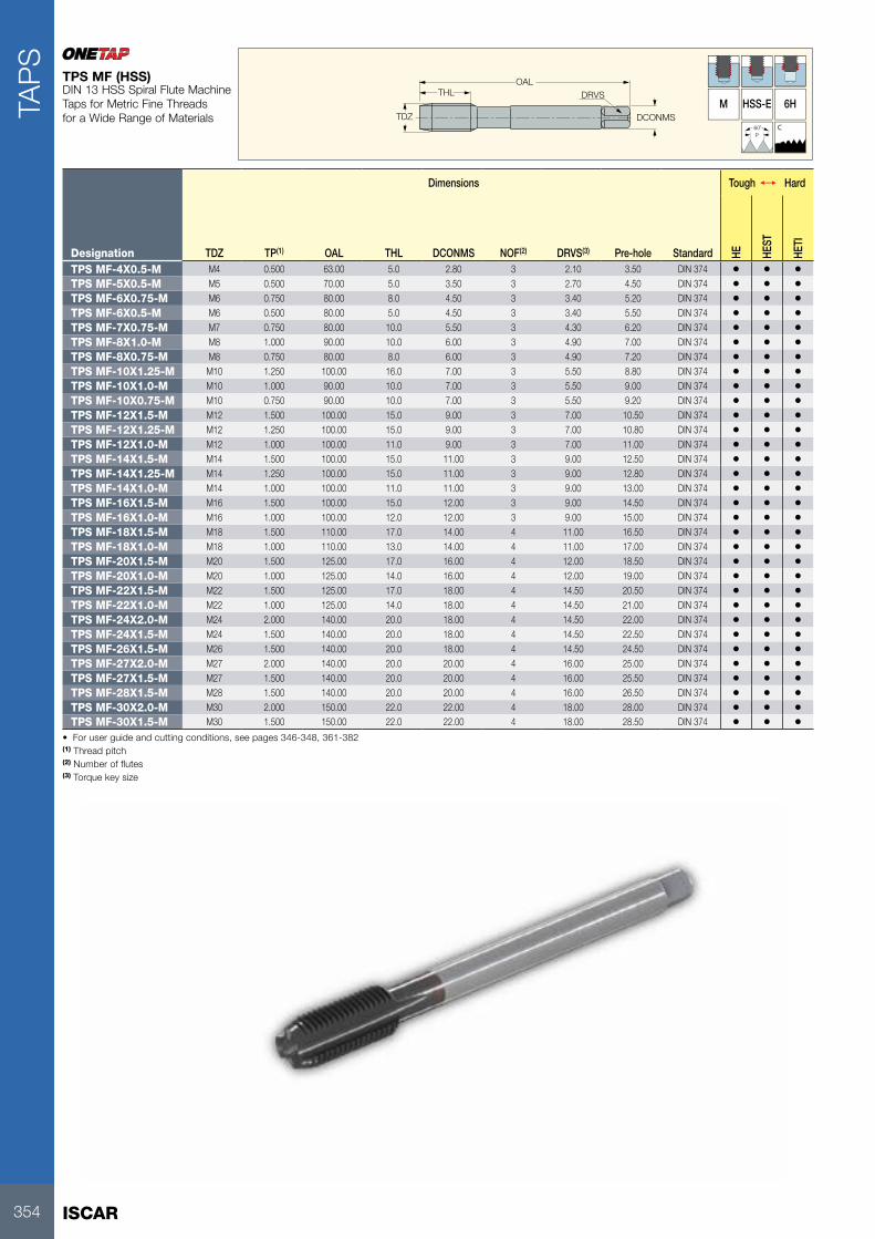
ISCAR354
TAP
S
DRVS
TDZ DCONMS
OALTHL
M HSS-E 6H
60˚P
C
Dimensions Tough 1 Hard
Designation TDZ TP(1) OAL THL DCONMS NOF(2) DRVS(3) Pre-hole Standard HE HEST
HETI
TPS MF-4X0.5-M M4 0.500 63.00 5.0 2.80 3 2.10 3.50 DIN 374 • • •TPS MF-5X0.5-M M5 0.500 70.00 5.0 3.50 3 2.70 4.50 DIN 374 • • •TPS MF-6X0.75-M M6 0.750 80.00 8.0 4.50 3 3.40 5.20 DIN 374 • • •TPS MF-6X0.5-M M6 0.500 80.00 5.0 4.50 3 3.40 5.50 DIN 374 • • •TPS MF-7X0.75-M M7 0.750 80.00 10.0 5.50 3 4.30 6.20 DIN 374 • • •TPS MF-8X1.0-M M8 1.000 90.00 10.0 6.00 3 4.90 7.00 DIN 374 • • •TPS MF-8X0.75-M M8 0.750 80.00 8.0 6.00 3 4.90 7.20 DIN 374 • • •TPS MF-10X1.25-M M10 1.250 100.00 16.0 7.00 3 5.50 8.80 DIN 374 • • •TPS MF-10X1.0-M M10 1.000 90.00 10.0 7.00 3 5.50 9.00 DIN 374 • • •TPS MF-10X0.75-M M10 0.750 90.00 10.0 7.00 3 5.50 9.20 DIN 374 • • •TPS MF-12X1.5-M M12 1.500 100.00 15.0 9.00 3 7.00 10.50 DIN 374 • • •TPS MF-12X1.25-M M12 1.250 100.00 15.0 9.00 3 7.00 10.80 DIN 374 • • •TPS MF-12X1.0-M M12 1.000 100.00 11.0 9.00 3 7.00 11.00 DIN 374 • • •TPS MF-14X1.5-M M14 1.500 100.00 15.0 11.00 3 9.00 12.50 DIN 374 • • •TPS MF-14X1.25-M M14 1.250 100.00 15.0 11.00 3 9.00 12.80 DIN 374 • • •TPS MF-14X1.0-M M14 1.000 100.00 11.0 11.00 3 9.00 13.00 DIN 374 • • •TPS MF-16X1.5-M M16 1.500 100.00 15.0 12.00 3 9.00 14.50 DIN 374 • • •TPS MF-16X1.0-M M16 1.000 100.00 12.0 12.00 3 9.00 15.00 DIN 374 • • •TPS MF-18X1.5-M M18 1.500 110.00 17.0 14.00 4 11.00 16.50 DIN 374 • • •TPS MF-18X1.0-M M18 1.000 110.00 13.0 14.00 4 11.00 17.00 DIN 374 • • •TPS MF-20X1.5-M M20 1.500 125.00 17.0 16.00 4 12.00 18.50 DIN 374 • • •TPS MF-20X1.0-M M20 1.000 125.00 14.0 16.00 4 12.00 19.00 DIN 374 • • •TPS MF-22X1.5-M M22 1.500 125.00 17.0 18.00 4 14.50 20.50 DIN 374 • • •TPS MF-22X1.0-M M22 1.000 125.00 14.0 18.00 4 14.50 21.00 DIN 374 • • •TPS MF-24X2.0-M M24 2.000 140.00 20.0 18.00 4 14.50 22.00 DIN 374 • • •TPS MF-24X1.5-M M24 1.500 140.00 20.0 18.00 4 14.50 22.50 DIN 374 • • •TPS MF-26X1.5-M M26 1.500 140.00 20.0 18.00 4 14.50 24.50 DIN 374 • • •TPS MF-27X2.0-M M27 2.000 140.00 20.0 20.00 4 16.00 25.00 DIN 374 • • •TPS MF-27X1.5-M M27 1.500 140.00 20.0 20.00 4 16.00 25.50 DIN 374 • • •TPS MF-28X1.5-M M28 1.500 140.00 20.0 20.00 4 16.00 26.50 DIN 374 • • •TPS MF-30X2.0-M M30 2.000 150.00 22.0 22.00 4 18.00 28.00 DIN 374 • • •TPS MF-30X1.5-M M30 1.500 150.00 22.0 22.00 4 18.00 28.50 DIN 374 • • •
• For user guide and cutting conditions, see pages 346-348, 361-382(1) Thread pitch (2) Number of flutes (3) Torque key size
TPS MF (HSS)DIN 13 HSS Spiral Flute Machine Taps for Metric Fine Threads for a Wide Range of Materials

355
TAP
S
DRVS
TDZ DCONMS
OALTHL
LU
M HSS-E 2B
60˚P
C
Dimensions Tough 1 Hard
Designation TDZ TPI(1) OAL THL LU DCONMS NOF(2) DRVS(3)Pre-hole Standard HE HE
ST
HETI
TPS UNC-#4-40-M #4 40.0 56.00 6.0 18.0 3.50 3 2.70 2.30 DIN 371 • • •TPS UNC-#5-40-M #5 40.0 56.00 7.0 18.0 3.50 3 2.70 2.60 DIN 371 • • •TPS UNC-#6-32-M #6 32.0 56.00 7.0 20.0 4.00 3 3.00 2.85 DIN 371 • • •TPS UNC-#8-32-M #8 32.0 63.00 8.0 21.0 4.50 3 3.40 3.50 DIN 371 • • •TPS UNC-#10-24-M #10 24.0 70.00 10.0 25.0 6.00 3 4.90 3.90 DIN 371 • • •TPS UNC-#12-24-M #12 24.0 80.00 10.0 30.0 6.00 3 4.90 4.50 DIN 371 • • •TPS UNC-1/4-20-M 1/4" 20.0 80.00 13.0 30.0 7.00 3 5.50 5.20 DIN 371 • • •TPS UNC-5/16-18-M 5/16" 18.0 90.00 14.0 35.0 8.00 3 6.20 6.60 DIN 371 • • •TPS UNC-3/8-16-M 3/8" 16.0 100.00 16.0 39.0 9.00 3 7.00 8.00 DIN 371 • • •TPS UNC-7/16-14-M 7/16" 14.0 100.00 17.0 - 8.00 3 6.20 9.40 DIN 376 • • •TPS UNC-1/2-13-M 1/2" 13.0 110.00 20.0 - 9.00 3 7.00 10.75 DIN 376 • • •TPS UNC-9/16-12-M 9/16" 12.0 110.00 20.0 - 11.00 3 9.00 12.25 DIN 376 • • •TPS UNC-5/8-11-M 5/8" 11.0 110.00 22.0 - 12.00 3 9.00 13.50 DIN 376 • • •TPS UNC-3/4-10-M 3/4" 10.0 125.00 25.0 - 14.00 4 11.00 16.50 DIN 376 • •TPS UNC-7/8-9-M 7/8" 9.0 140.00 27.0 - 18.00 4 14.50 19.50 DIN 376 • • •TPS UNC-1-8-M 1" 8.0 160.00 30.0 - 20.00 4 16.00 22.25 DIN 376 • • •
• For user guide and cutting conditions, see pages 346-348, 361-382(1) Threads per inch (2) Number of flutes (3) Torque key size
TPS UNC (HSS)HSS Spiral Flute Machine Taps for Unified Coarse Threads for a Wide Range of Materials
DRVS
TDZ DCONMS
OALTHL
LU
M HSS-E 2B
60˚P
C
Dimensions Tough 1 Hard
Designation TDZ TPI(1) OAL THL LU DCONMS NOF(2) DRVS(3)Pre-hole Standard HE HE
ST
HETI
TPS UNF-#4-48-M #4 48.0 56.00 6.0 18.0 3.50 3 2.70 2.40 DIN 371 • • •TPS UNF-#5-44-M #5 44.0 56.00 7.0 18.0 3.50 3 2.70 2.70 DIN 371 • • •TPS UNF-#6-40-M #6 40.0 56.00 7.0 20.0 4.00 3 3.00 3.00 DIN 371 • • •TPS UNF-#8-36-M #8 36.0 63.00 8.0 21.0 4.50 3 3.40 3.50 DIN 371 • • •TPS UNF-#10-32-M #10 32.0 70.00 10.0 25.0 6.00 3 4.90 4.10 DIN 371 • • •TPS UNF-#12-28-M #12 28.0 80.00 10.0 30.0 6.00 3 4.90 4.70 DIN 371 • • •TPS UNF-1/4-28-M 1/4" 28.0 80.00 10.0 30.0 7.00 3 5.50 5.50 DIN 371 • • •TPS UNF-5/16-24-M 5/16" 24.0 90.00 10.0 35.0 8.00 3 6.20 6.90 DIN 371 • • •TPS UNF-3/8-24-M 3/8" 24.0 100.00 10.0 39.0 9.00 3 7.00 8.50 DIN 371 • • •TPS UNF-7/16-20-M 7/16" 20.0 100.00 13.0 - 8.00 3 6.20 9.90 DIN 374 • • •TPS UNF-1/2-20-M 1/2" 20.0 100.00 13.0 - 9.00 3 7.00 11.50 DIN 374 • •TPS UNF-9/16-18-M 9/16" 18.0 100.00 15.0 - 11.00 3 9.00 12.90 DIN 374 • • •TPS UNF-5/8-18-M 5/8" 18.0 100.00 15.0 - 12.00 3 9.00 14.50 DIN 374 • • •TPS UNF-3/4-16-M 3/4" 16.0 110.00 17.0 - 14.00 4 11.00 17.50 DIN 374 • • •TPS UNF-7/8-14-M 7/8" 14.0 125.00 17.0 - 18.00 4 14.50 20.50 DIN 374 • • •TPS UNF-1-12-M 1" 12.0 140.00 20.0 - 20.00 4 16.00 23.25 DIN 374 • • •
• For user guide and cutting conditions, see pages 346-348, 361-382(1) Threads per inch (2) Number of flutes (3) Torque key size
TPS UNF (HSS)HSS Spiral Flute Machine Taps for Unified Fine Threads for a Wide Range of Materials

ISCAR356
TAP
S
DRVS
TDZ DCONMS
OALTHL
LU
S
HSS-E 6HX60˚P
B
Dimensions
Designation TDZ TP(1) OAL THL LU DCONMS NOF(2) DRVS(3) Pre-hole HEST
TPG M-2.2X0.45-S M2.2 0.450 45.00 8.0 - 2.80 3 2.10 1.75 •TPG M-2.3X0.4-S M2.3 0.400 45.00 8.0 - 2.80 3 2.10 1.90 •TPG M-2.5X0.45-S M2.5 0.450 50.00 9.0 - 2.80 3 2.10 2.05 •TPG M-2.6X0.45-S M2.6 0.450 50.00 9.0 - 2.80 3 2.10 2.10 •TPG M-3X0.5-S M3 0.500 56.00 11.0 18.0 3.50 3 2.70 2.50 •TPG M-3.5X0.6-S M3.5 0.600 56.00 12.0 20.0 4.00 3 3.00 2.90 •TPG M-4X0.7-S M4 0.700 63.00 13.0 21.0 4.50 3 3.40 3.30 •TPG M-4.5X0.75-S M4.5 0.750 70.00 14.0 25.0 6.00 3 4.90 3.70 •TPG M-5X0.8-S M5 0.800 70.00 15.0 25.0 6.00 3 4.90 4.20 •TPG M-6X1.0-S M6 1.000 80.00 17.0 30.0 6.00 3 4.90 5.00 •TPG M-8X1.25-S M8 1.250 90.00 20.0 35.0 8.00 3 6.20 6.80 •TPG M-10X1.5-S M10 1.500 100.00 22.0 39.0 10.00 3 8.00 8.50 •TPG M-11X1.5-S M11 1.500 100.00 22.0 - 8.00 3 6.20 9.50 •TPG M-12X1.75-S M12 1.750 110.00 24.0 - 9.00 4 7.00 10.20 •TPG M-16X2.0-S M16 2.000 110.00 27.0 - 12.00 4 9.00 14.00 •TPG M-18X2.5-S M18 2.500 125.00 30.0 - 14.00 4 11.00 15.50 •TPG M-20X2.5-S M20 2.500 140.00 32.0 - 16.00 4 12.00 17.50 •
• For user guide and cutting conditions, see pages 346-348, 361-382(1) Thread pitch (2) Number of flutes (3) Torque key size
TPG M-S (HSS)HSS Gun Point Machine Taps According to DIN 13 for ISO Metric Coarse Threads on Steel with Good Machinability
DRVS
TDZ DCONMS
OALTHL
LU
H
HSS-E 6H60˚P
B
Dimensions
Designation TDZ TP(1) OAL THL LU DCONMS NOF(2) DRVS(3) Pre-hole HE
TPG M-2X0.4-H M2 0.400 45.00 8.0 - 2.80 3 2.10 1.60 •TPG M-2.3X0.4-H M2.3 0.400 45.00 8.0 - 2.80 3 2.10 1.90 •TPG M-2.5X0.45-H M2.5 0.450 50.00 9.0 - 2.80 3 2.10 2.05 •TPG M-2.6X0.45-H M2.6 0.450 50.00 9.0 - 2.80 3 2.10 2.10 •TPG M-3X0.5-H M3 0.500 56.00 11.0 18.0 3.50 3 2.70 2.50 •TPG M-3.5X0.6-H M3.5 0.600 56.00 12.0 20.0 4.00 3 3.00 2.90 •TPG M-4X0.7-H M4 0.700 63.00 13.0 21.0 4.50 3 3.40 3.30 •TPG M-4.5X0.75-H M4.5 0.750 70.00 14.0 25.0 6.00 3 4.90 3.70 •TPG M-5X0.8-H M5 0.800 70.00 15.0 25.0 6.00 3 4.90 4.20 •TPG M-6X1.0-H M6 1.000 80.00 17.0 30.0 6.00 3 4.90 5.00 •TPG M-7X1.0-H M7 1.000 80.00 17.0 30.0 7.00 3 5.50 6.00 •TPG M-8X1.25-H M8 1.250 90.00 20.0 35.0 8.00 3 6.20 6.80 •TPG M-10X1.5-H M10 1.500 100.00 22.0 39.0 10.00 3 8.00 8.50 •TPG M-11X1.5-H M11 1.500 100.00 22.0 - 8.00 3 6.20 9.50 •TPG M-12X1.75-H M12 1.750 110.00 24.0 - 9.00 3 7.00 10.20 •TPG M-14X2.0-H M14 2.000 110.00 26.0 - 11.00 3 9.00 12.00 •TPG M-16X2.0-H M16 2.000 110.00 27.0 - 12.00 3 9.00 14.00 •TPG M-18X2.5-H M18 2.500 125.00 30.0 - 14.00 4 11.00 15.50 •TPG M-20X2.5-H M20 2.500 140.00 32.0 - 16.00 4 12.00 17.50 •
• For user guide and cutting conditions, see pages 346-348, 361-382(1) Thread pitch (2) Number of flutes (3) Torque key size
TPG M-H (HSS)DIN 13 HSS Gun Point Machine Taps for ISO Metric Coarse Threads for Hardened Steel and H.T.A.

357
TAP
S
DRVS
TDZ DCONMS
OALTHL
LU
N HSS-E 6H
60˚P
C
Dimensions
Designation TDZ TP(2) OAL THL LU DCONMS NOF(3) DRVS(4) Pre-hole FHA Standard HEST
TPS M-2X0.4-N M2 0.400 45.00 8.0 - 2.80 3 2.10 1.60 40.0 DIN 371 •TPS M-2.2X0.45-N M2.2 0.450 45.00 8.0 - 2.80 3 2.10 1.75 40.0 DIN 371 •TPS M-2.3X0.4-N (1) M2.3 0.400 45.00 8.0 - 2.80 3 2.10 1.90 40.0 DIN 371 •TPS M-2.5X0.45-N M2.5 0.450 50.00 9.0 - 2.80 3 2.10 2.05 40.0 DIN 371 •TPS M-3X0.5-N M3 0.500 56.00 6.0 18.0 3.50 3 2.70 2.50 40.0 DIN 371 •TPS M-3.5X0.6-N M3.5 0.600 56.00 7.0 20.0 4.00 3 3.00 2.90 40.0 DIN 371 •TPS M-4X0.7-N M4 0.700 63.00 7.0 21.0 4.50 3 3.40 3.30 40.0 DIN 371 •TPS M-4.5X0.75-N M4.5 0.750 70.00 8.0 25.0 6.00 3 4.90 3.70 40.0 DIN 371 •TPS M-5X0.8-N M5 0.800 70.00 8.0 25.0 6.00 3 4.90 4.20 40.0 DIN 371 •TPS M-6X1.0-N M6 1.000 80.00 10.0 30.0 6.00 3 4.90 5.00 40.0 DIN 371 •TPS M-7X1.0-N M7 1.000 80.00 10.0 30.0 7.00 3 5.50 6.00 40.0 DIN 371 •TPS M-8X1.25-N M8 1.250 90.00 13.0 35.0 8.00 3 6.20 6.80 40.0 DIN 371 •TPS M-9X1.25-N M9 1.250 90.00 13.0 35.0 9.00 3 7.00 7.80 40.0 DIN 371 •TPS M-10X1.5-N M10 1.500 100.00 15.0 39.0 10.00 3 8.00 8.50 40.0 DIN 371 •TPS M-11X1.5-N M11 1.500 100.00 17.0 - 8.00 3 6.20 9.50 40.0 DIN 376 •TPS M-12X1.75-N M12 1.750 110.00 18.0 - 9.00 3 7.00 10.20 40.0 DIN 376 •TPS M-14X2.0-N M14 2.000 110.00 20.0 - 11.00 3 9.00 12.00 40.0 DIN 376 •TPS M-16X2.0-N M16 2.000 110.00 20.0 - 12.00 3 9.00 14.00 40.0 DIN 376 •TPS M-18X2.5-N M18 2.500 125.00 25.0 - 14.00 4 11.00 15.50 40.0 DIN 376 •TPS M-20X2.5-N M20 2.500 140.00 25.0 - 16.00 4 12.00 17.50 40.0 DIN 376 •
• For user guide and cutting conditions, see pages 346-348, 361-382(1) DIN profile (2) Thread pitch (3) Number of flutes (4) Torque key size
TPS M-N (HSS)DIN 13 HSS R.H. 40° Spiral Flute Machine Taps for ISO Metric Coarse Threads for Low Alloyed Steel

ISCAR358
TAP
S
DRVS
TDZ DCONMS
OALTHL
LU
H HSS-E 6H
60˚P
C
Dimensions
Designation TDZ TP(2) OAL THL LU DCONMS NOF(3) DRVS(4) Pre-hole FHA HEST
TPS M-2X0.4-H M2 0.400 45.00 8.0 - 2.80 3 2.10 1.60 40.0 •TPS M-2.2X0.45-H M2.2 0.450 45.00 8.0 - 2.80 3 2.10 1.75 40.0 •TPS M-2.5X0.45-H M2.5 0.450 50.00 9.0 - 2.80 3 2.10 2.05 40.0 •TPS M-2.6X0.45-H (1) M2.6 0.450 50.00 9.0 - 2.80 3 2.10 2.10 40.0 •TPS M-3X0.5-H M3 0.500 56.00 6.0 18.0 3.50 3 2.70 2.50 40.0 •TPS M-3.5X0.6-H M3.5 0.600 56.00 7.0 20.0 4.00 3 3.00 2.90 40.0 •TPS M-4X0.7-H M4 0.700 63.00 7.0 21.0 4.50 3 3.40 3.30 40.0 •TPS M-4.5X0.75-H M4.5 0.750 70.00 8.0 25.0 6.00 3 4.90 3.70 40.0 •TPS M-5X0.8-H M5 0.800 70.00 8.0 25.0 6.00 3 4.90 4.20 40.0 •TPS M-6X1.0-H M6 1.000 80.00 10.0 30.0 6.00 3 4.90 5.00 40.0 •TPS M-7X1.0-H M7 1.000 80.00 10.0 30.0 7.00 3 5.50 6.00 40.0 •TPS M-8X1.25-H M8 1.250 90.00 13.0 35.0 8.00 3 6.20 6.80 40.0 •TPS M-9X1.25-H M9 1.250 90.00 13.0 35.0 9.00 3 7.00 7.80 40.0 •TPS M-10X1.5-H M10 1.500 100.00 15.0 39.0 10.00 3 8.00 8.50 40.0 •TPS M-11X1.5-H M11 1.500 100.00 17.0 - 8.00 3 6.20 9.50 40.0 •TPS M-12X1.75-H M12 1.750 110.00 18.0 - 9.00 3 7.00 10.20 40.0 •TPS M-14X2.0-H M14 2.000 110.00 20.0 - 11.00 3 9.00 12.00 40.0 •TPS M-16X2.0-H M16 2.000 110.00 20.0 - 12.00 3 9.00 14.00 40.0 •TPS M-18X2.5-H M18 2.500 125.00 25.0 - 14.00 4 11.00 15.50 40.0 •TPS M-20X2.5-H M20 2.500 140.00 25.0 - 16.00 4 12.00 17.50 40.0 •
• For user guide and cutting conditions, see pages 346-348, 361-382(1) DIN profile (2) Thread pitch (3) Number of flutes (4) Torque key size
TPS M-H (HSS)DIN 13 HSS Right-Hand 40° Spiral Flute Machine Taps for ISO Metric Coarse Threads for H.T.A.

359
TAP
S
DRVS
TDZ DCONMS
OALTHL
LU
G HSS-E 6HX
60˚P
C
Dimensions
Designation TDZ TP(2) OAL THL LU DCONMS NOF(3) DRVS(4) Pre-hole HENI
TPST M-2.2X0.45-G M2.2 0.450 45.00 8.0 - 2.80 3 2.10 1.75 •TPST M-2.3X0.4-G (1) M2.3 0.400 45.00 8.0 - 2.80 3 2.10 1.90 •TPST M-2.5X0.45-G M2.5 0.450 50.00 9.0 - 2.80 3 2.10 2.05 •TPST M-2.6X0.45-G (1) M2.6 0.450 50.00 9.0 - 2.80 3 2.10 2.10 •TPST M-3.5X0.6-G M3.5 0.600 56.00 12.0 20.0 4.00 3 3.00 2.90 •TPST M-4X0.7-G M4 0.700 63.00 13.0 21.0 4.50 3 3.40 3.30 •TPST M-4.5X0.75-G M4.5 0.750 70.00 14.0 25.0 6.00 3 4.90 3.70 •TPST M-5X0.8-G M5 0.800 70.00 15.0 25.0 6.00 4 4.90 4.20 •TPST M-6X1.0-G M6 1.000 80.00 17.0 30.0 6.00 4 4.90 5.00 •TPST M-8X1.25-G M8 1.250 90.00 20.0 35.0 8.00 4 6.20 6.80 •TPST M-9X1.25-G M9 1.250 90.00 20.0 35.0 9.00 4 7.00 7.80 •TPST M-10X1.5-G M10 1.500 100.00 22.0 39.0 10.00 4 8.00 8.50 •TPST M-11X1.5-G M11 1.500 100.00 22.0 - 8.00 4 6.20 9.50 •TPST M-12X1.75-G M12 1.750 110.00 24.0 - 9.00 4 7.00 10.20 •TPST M-14X2.0-G M14 2.000 110.00 26.0 - 11.00 4 9.00 12.00 •TPST M-16X2.0-G M16 2.000 110.00 27.0 - 12.00 4 9.00 14.00 •TPST M-18X2.5-G M18 2.500 125.00 30.0 - 14.00 4 11.00 15.50 •TPST M-20X2.5-G M20 2.500 140.00 32.0 - 16.00 4 12.00 17.50 •
• For user guide and cutting conditions, see pages 346-348, 361-382(1) DIN profile (2) Thread pitch (3) Number of flutes (4) Torque key size
TPST M-G (HSS)DIN 13 HSS Straight Flute Machine Taps for ISO Metric Coarse Threads for Grey Cast Iron
DRVS
TDZ DCONMS
OALTHL
G HSS-E 6HX
60˚P
C
Dimensions
Designation TDZ TP(1) OAL THL DCONMS NOF(2) DRVS(3) Pre-hole HENI
TPST MF-10X1.0-G M10 1.000 90.00 18.0 7.00 3 5.50 9.00 •TPST MF-10X1.25-G M10 1.250 100.00 22.0 7.00 3 5.50 8.80 •TPST MF-12X1.25-G M12 1.250 100.00 22.0 9.00 3 7.00 10.80 •TPST MF-14X1.5-G M14 1.500 100.00 22.0 11.00 3 9.00 12.50 •TPST MF-16X1.5-G M16 1.500 100.00 22.0 12.00 4 9.00 14.50 •TPST MF-22X1.5-G M22 1.500 125.00 25.0 18.00 4 14.50 20.50 •
• For user guide and cutting conditions, see pages 346-348, 361-382(1) Thread pitch (2) Number of flutes (3) Torque key size
TPST MF-G (HSS)DIN 13 HSS Straight Flute Machine Taps for ISO Metric Fine Threads for Grey Cast Iron

ISCAR360
TAP
S
DRVS
TDZ DCONMS
OALTHL
LU
F HSS-E 6HX
60˚P
C
TI
Dimensions
Designation TDZ TP(2) OAL THL LU DCONMS NOF(3) DRVS(4) Pre-hole Standard HETI
TPF M-2X0.4-F M2 0.400 45.00 8.0 - 2.80 5 2.10 1.83 DIN 371 •TPF M-2.2X0.45-F M2.2 0.450 45.00 8.0 - 2.80 5 2.10 2.00 DIN 371 •TPF M-2.3X0.4-F (1) M2.3 0.400 45.00 8.0 - 2.80 5 2.10 2.10 DIN 371 •TPF M-2.5X0.45-F M2.5 0.450 50.00 9.0 - 2.80 5 2.10 2.30 DIN 371 •TPF M-3X0.5-F M3 0.500 56.00 11.0 18.0 3.50 5 2.70 2.80 DIN 371 •TPF M-3.5X0.6-F M3.5 0.600 56.00 12.0 20.0 4.00 5 3.00 3.25 DIN 371 •TPF M-4X0.7-F M4 0.700 63.00 13.0 21.0 4.50 5 3.40 3.70 DIN 371 •TPF M-4.5X0.75-F M4.5 0.750 70.00 14.0 25.0 6.00 5 4.90 4.15 DIN 371 •TPF M-5X0.8-F M5 0.800 70.00 15.0 25.0 6.00 5 4.90 4.65 DIN 371 •TPF M-6X1.0-F M6 1.000 80.00 17.0 30.0 6.00 5 4.90 5.55 DIN 371 •TPF M-7X1.0-F M7 1.000 80.00 17.0 30.0 7.00 5 5.50 6.55 DIN 371 •TPF M-8X1.25-F M8 1.250 90.00 20.0 35.0 8.00 5 6.20 7.40 DIN 371 •TPF M-9X1.25-F M9 1.250 90.00 20.0 35.0 9.00 5 7.00 8.40 DIN 371 •TPF M-10X1.5-F M10 1.500 100.00 22.0 39.0 10.00 5 8.00 9.30 DIN 371 •TPF M-11X1.5-F M11 1.500 100.00 22.0 - 8.00 5 6.20 10.30 DIN 376 •TPF M-12X1.75-F M12 1.750 110.00 24.0 - 9.00 5 7.00 11.20 DIN 376 •TPF M-14X2.0-F M14 2.000 110.00 26.0 - 11.00 5 9.00 13.00 DIN 376 •TPF M-16X2.0-F M16 2.000 110.00 27.0 - 12.00 6 9.00 15.00 DIN 376 •TPF M-18X2.5-F M18 2.500 125.00 30.0 - 14.00 6 11.00 16.80 DIN 376 •TPF M-20X2.5-F M20 2.500 140.00 32.0 - 16.00 6 12.00 18.80 DIN 376 •
• For user guide and cutting conditions, see pages 346-348,361-382(1) DIN profile (2) Thread pitch (3) Number of flutes (4) Torque key size
TPF M-F (HSS)DIN 13 HSS Cold Forming Machine Taps for ISO Metric Coarse Threads
361
TAP
S
USER GUIDE CONTENTS
Tap Surface Treatment and Coating Types .................................................. 362
Tolerances According to DIN EN 22857.... .................................................. 362
Taps Nomenclature and Standards ............................................................. 363
Pre-Tapping Hole Size .... ............................................................................ 364
Tap Standard Dimensions ............................................................................ 366
Tap Tolerances.... ........................................................................................ 372
Troubleshooting .... ...................................................................................... 374
Regrinding ................................................................................................... 376
Test Report Form......................................................................................... 378
Thread Standards List ................................................................................. 380
Tapping Attachments ................................................................................... 381

ISCAR362
USER GUIDETA
PS
Tap Surface Treatments and Coating Types
The high speed steels we use grant high wear resistance and toughness. For machining certain materials, various surface treatments are an advantage.
Steam Tempered (ST)The steam tempered is a Fe3O4 oxide coating which reduces the friction between the tool and workpiece and prevents cold welding.
Nitriding (NI)Recommended surface treatment for machining hard wear/abrasive materials such as grey cast iron, aluminum alloys with high silicon percentage (more than 10%).
TiN Coating (TI)The TiN coating has a hardness of approximately 2,300 HV and is temperature resistant up to approximately 600°C. This is an excellent golden colored coating for general applications.
TiCN-COATING – TiCNTiCN takes place of TiN when the conditions require the coating to have a different hardness and toughness. The TiCN brings an advantage to machining very difficult steels or cutting interrupted bores. The TiCN-coating has a hardness of approx. 3,000 HV, but is temperature resistant up to approx. 400° only. That means TiCN needs excellent cooling for long service life. Color: Blue-grey coefficient of friction against steel : 0.4
TiAIN-COATING – TiAINThis is a special coating for machining abrasive materials such as: grey cast iron, alu-alloys with silicon, fiber reinforced plastics, etc., or machining under high temperatures, which means with insufficient cooling, or high speeds ≥ 600m/min. TiAIN has a hardness of approx. 3,000 HV and is temperature resistant up to approx. 800°. Color: Violet-grey coefficient of friction against steel : 0.4
Hardslick-COATING – HardslickHardslick combines in a novel way the advantages of an extremely hard, thermally stable TiAIN-coating with the sliding and lubricating properties of an outer WC/C (Tungsten carbide/carbon) coating. The hardslick coating has a hardness of approx. 3,000 HV and is temperature-resistant up to approx. 800°. Color: Violet-grey coefficient of friction against steel : 0.2
Tolerances According to DIN EN 22857For taps with ISO metric threads. The following chart gives a comparison between the new standard DIN EN 22857 and the withdrawn standard DIN 802 part 1. An important change is the re-classification from tap tolerance to tap application class.
Application class for taps to DIN EN 22857
Tolerance class to withdrawn standard DIN 802 part 1
Allotment of the tolerance zones of the nut thread to be cut
Class 1 ISO 1 4H 4H 5H - - -Class 2 ISO 2 6H 5G 5G 6H - -Class 3 ISO 3 6G - - 6G 7H 8H
- - 7G - - - 7G 8G
A suitable transition period is to be expected. Codes for tolerance classes 7G/8G and <X> tolerance zones have yet to be standardized within DIN EN 22857, and the values from DIN 802 part will remain valid.

363
USER GUIDE
TAP
S
Tap Nomenclature and StandardsDIN 371
D d3
L1Cm L4
d4d2
L2 S
L3
L
L5
D - Major diameterd2 - Shank diameterd3 - Chamfer diameterd4 - Neck diameter
DIN 376
L6
Cf
d3
L1 L4
L
L2
d4
D
L - Total lengthL - Total lengthL1 - Thread lengthL2 - Shank lengthL3 - Square lengthL4 - Neck lengthL5 - Chamfer lengthL6 - Flute lengthS - Square sizeCm - Center maleCf - Center female
Chamfer Lead Forms According to DIN 2197
A6-8 threads Form A
Long, 6-8 threads for short through holes.
B3.5-5 threads Form B
Medium, 3.5-5 threads, with spiral point for all through holes and deep tapping holes.
C2-3 threads Form C
Long, 2-3 threads for blind holes and generally for aluminum grey cast iron and brass.
D3.5-5 threads Form D
Medium, 3.5-5 threads for through and blind holes with sufficient runout.
E1.5-2 threads Form E
Extremely short, 1.5-2 threads for blind holes with little runout depth. Avoid use if possible.
F1-1.5 threads Form F
Extremely short, 1-1.5 threads for blind holes with little runout depth. Avoid use if possible.
Chamfer Lead Length for Sets of 3 Hand Tapsca. 6 threads ca. 4 threads ca. 2 threads
First taper tap Second tap Bottoming tap
Tap Styles for Hole TypesThroughole
1 Straight fluted tap with spiral point
2 Left-hand spiral fluted tap
3 Straight fluted tap with long chamfer lead
Blind hole
1 Right-hand spiral fluted tap
2 Straight fluted tap with short chamfer lead
Front and End Configurations According to DIN2197
Front End Shank End
1 External Center 4 External Center
2 Stepped External Center 5 Chamfer
3 Internal Center 6 Internal Center
Thread Dia. Range (mm) Front End Shank End Tap Standard
≤Ø6 1 4 5 DIN352Ø7 1 2 4 5 6 DIN371
≥Ø8 1 2 3 5 6 DIN376

ISCAR364
USER GUIDETA
PS
Pre-Tapping Hole Sizes
ISO Metric Threads Coarse Pitch
M Pitch mm
Max Core
Dia.mm
Drill Size mm
1 0.25 0.785 0.751.1 0.25 0.885 0.851.2 0.25 0.985 0.951.4 0.30 1.160 1.101.6 0.35 1.321 1.251.7 0.35 1.346 1.301.8 0.35 1.521 1.452 0.40 1.679 1.60
2.2 0.45 1.838 1.752.3 0.40 1.920 1.902.5 0.45 2.138 2.052.6 0.45 2.176 2.103 0.50 2.599 2.50
3.5 0.60 3.010 2.904 0.70 3.422 3.30
4,5 0.75 3.878 3.705 0.80 4.334 4.206 1.00 5.153 5.007 1.00 6.153 6.008 1.25 6.912 6.809 1,25 7.912 7.80
10 1.50 8.676 8.5011 1.50 9.676 9.5012 1.75 10.441 10.2014 2.00 12.210 12.0016 2.00 14.210 14.0018 2.50 15.744 15.5020 2.50 17.744 17.5022 2.50 19.744 19.5024 3.00 21.252 21.0027 3.00 24.252 24.0030 3.50 26.771 26.5033 3.50 29.771 29.5036 4.00 32.270 32.0039 4.00 35.270 35.0042 4.50 37.799 37.5045 4.50 40.799 40.5048 5.00 43.297 43.0052 5.00 47.297 47.0056 5.50 50.796 50.5060 5.50 54.796 54.5064 6.00 58.305 58.0068 6.00 62.305 62.00
ISO Metric Threads Fine Pitch
MF Pitch mm
Max Core
Dia.mm
Drill Size mm
2.5 0.35 2.221 2.153 0.35 2.271 2.65
3.5 0.35 3.221 3.154 0.50 3.599 3.50
4.5 0.50 4.099 4.005 0.50 4.599 4.50
5.5 0.50 5.099 5.006 0.75 5.378 5.207 0.75 6.378 6.208 0.75 7.378 7.208 1.00 7.153 7.009 0.75 8.378 8.209 1.00 8.153 8.00
10 0.75 9.378 9.2010 1.00 9.153 9.0010 1.25 8.912 8.8011 0.75 10.378 10.2011 1.00 10.153 10.0012 1.00 11.153 11.0012 1,25 10.912 10.8012 1,50 10.676 10.5014 1,00 13.153 13.0014 1,25 12.912 12.8014 1.50 12.676 12.5015 1.00 14.153 14.0015 1.50 13.676 13.5016 1.00 15.153 15.0016 1.50 14.676 14.5017 1.00 16.153 16.0017 1.50 15.676 15.5018 1.00 17.153 17.0018 1.50 16.676 16.5018 2.00 16.210 16.0020 1.00 19.153 19.0020 1.50 18.676 18.5020 2.00 18.210 18.0022 1,00 21.153 21.0022 1.50 20.676 20.5022 2.00 20.210 20.0024 1.00 23.153 23.0024 1,50 22.676 22.5024 2,00 22.210 22.0025 1.00 24.153 24.0025 1.50 23.676 23.50
ISO Metric Threads Fine Pitch
MF Pitch mm
Max Core
Dia.mm
Drill Size mm
25 2.00 23.210 23.0026 1.50 24.676 24.5027 1.00 26.153 26.0027 1.50 25.676 25.5027 2.00 25.210 25.0028 1.00 27.153 27.0028 1.50 26.676 26.5028 2.00 26.210 26.0030 1.00 29.153 29.0030 1.50 28.676 28.5030 2.00 28.210 28.0030 3.00 27.252 27.0032 1.50 30.675 30.5032 2.00 30.210 30.0033 1.50 31.676 31.5033 2.00 31.210 31.0033 3.00 30.252 30.0035 1.50 33.676 33.5036 1.50 34.676 34.5036 2.00 34.210 34.0036 3.00 33.252 33.0038 1.50 36.676 36.5039 1.50 37.676 37.5039 2.00 37.210 37.0039 3.00 36.252 36.0040 1,50 38.676 38.5040 2.00 38.210 38.0040 3,00 37.252 37.0042 1,50 40.676 40.5042 2,00 40.210 40.0042 3,00 39.252 39.0045 1.50 43.676 43.5045 2.00 43.210 43.0045 3.00 42.252 42.0048 1.50 46.676 46.5048 2.00 46.210 46.0048 3.00 45.252 45.0050 1.50 48.676 48.5050 2.00 48.210 48.0050 3.00 47.252 47.0052 1.50 50.676 50.5052 2.00 50.210 50.0052 3.00 49.252 49.00

365
USER GUIDE
TAP
S
Pre-Tapping Hole Sizes - Forming Taps
Recommended Tap Drill Size
M Pitch mm
Drill Size mm
1 0.25 0.91.1 0.25 11.2 0.25 1.11.4 0.3 1.281.6 0.35 1.471.7 0.35 1.571.8 0.35 1.672 0.4 1.85
2.2 0.45 2.032.3 0.4 2.152.5 0.45 2.332.6 0.45 2.433 0.5 2.8
3.5 0.6 3.254 0.7 3.7
4.5 0.75 4.25 0.8 4.656 1 5.557 1 6.558 1.25 6.69 1.25 7.4510 1.5 8.4511 1.5 9.3512 1.75 11.2514 2 13.116 2 15.118 2.5 16.8520 2.5 18.8522 2.5 20.8524 3 22.6527 3 25.6530 3.5 28.433 3.5 31.436 4 34.1539 4 37.1542 4.5 39.945 4.5 42.948 5 45.65
Recommended Tap Drill Size
MF Pitch mm
Drill Size mm
2.5 0.35 2.372.6 0.35 2.473 0.35 2.88
3.5 0.35 3.384 0.5 3.85 0.5 4.86 0.5 5.86 0.75 5.77 0.75 6.78 0.75 7.78 1 7.69 0.75 8.79 1 8.610 0.75 9.710 1 9.610 1.25 9.4511 1 10.612 1 11.612 1.25 11.4512 1.5 11.3514 1 13.614 1.25 13.4514 1.5 13.3515 1 14.615 1.5 14.3516 1 15.616 1.5 15.3518 4 17.618 1.5 17.3518 2 17.120 1 19.620 1.5 19.3520 2 19.124 2 23.130 2 29.136 3 34.6542 4 40.1548 3 46.65
Pre-Tapping Hole Sizes - General Taps
American Unified Coarse Threads
UNC T.P.I
Max. Core Dia. inch
Drill Size mm
#1 64 1.585 1.5#2 56 1.872 1.8#3 48 2.146 2.1#4 40 2.385 2.3#5 40 2.697 2.6#6 32 2.896 2.85#8 32 3.528 3.5
#10 24 3.95 3.9#12 24 4.59 4.51/4" 20 5.25 5.2
5/16" 18 6.68 6.63/8" 16 8.082 87/16" 14 9.441 9.41/2" 13 10.881 10.75
9/16" 12 12.301 12.255/8" 11 13.693 13.53/4" 10 16.624 16.57/8" 9 19.52 19.51" 8 22.344 22.25
1*1/8" 7 25.082 251*1/4" 7 28.258 28.251*3/8" 6 30.851 30.751*1/2" 6 34.026 341*3/4" 5 39.56 39.5
2" 4.5 45.367 45.25
American Unified Fine Threads
UNF T.P.I
Max. Core Dia. inch
Drill Size mm
#0 80 1.306 1.3#1 72 1.613 1.6#2 64 1.913 1.9#3 56 2.197 2.1#4 48 2.459 2.4#5 44 2.741 2.7#6 40 3.012 3#8 36 3.597 3.5#10 32 4.168 4.1#12 28 4.717 4.71/4" 28 5.563 5.5
5/16" 24 6.995 6.93/8" 24 8.565 8.5
7/16" 20 9.947 9.91/2" 20 11.524 11.5
9/16" 18 12.969 12.95/8" 18 14.554 14.53/4" 16 17.546 17.57/8" 14 20.493 20.51" 12 23.363 23.25
1*1/8" 12 26.538 26.51*1/4" 12 29.713 29.51*3/8" 12 32.888 32.71*1/2" 12 36.063 36

ISCAR366
USER GUIDETA
PS
ISO Metric Thread Nominal Dimensions According to UNI 4535-64
Tap flank diameter production tolerances for ISO 6H Nut threads limit dimensions - nut threads ISO 6H
Coarse Pitch Threads Dimensions in mm
H
1/2·H
1/2·H
D D2 D1
H1
Nut thread
60°
60°Screw
P
r
d3
1/8·H
1/4·H
d2
h3
d
1/6·H
H = 0.86603P
H1 = 5 8 H = 0.54127P
h3 = 1724 H = 0.61343P
d2 = D2 = d- 34 H = d-0.64952P
d3 = d-2h3 = d-1.22687P
r = H6 = 0.14434P
Nominal Dia. d=D Pitch P Flank Dia.
d2=D2
Minor Diameter Thread DepthRadius r
Flank Dia. Tap Tolerance 6H d2
Flank Dia. Tap Tolerance 6H
Screw d3 Nut D1 Screw
h3 Nut H1 Min. Max. Min. Max.
M1.6 0.35 1.373 1.171 1.221 0.215 0.189 0.051 1.393 1.407 1.373 1.458M1.8 0.35 1.573 1.371 1.421 0.215 0.189 0.051 1.593 1.607 1.573 1.658M2 0.4 1.740 1.509 1.567 0.245 0.217 0.058 1.761 1.776 1.740 1.830
M2.2 0.45 1.908 1.648 1.713 0.276 0.244 0.065 1.931 1.946 1.908 2.003M2.5 0.45 2.208 1.948 2.013 0.276 0.244 0.065 2.231 2.246 2.208 2.303M3 0.5 2.675 2.387 2.459 0.307 0.271 0.072 2.699 2.715 2.675 2.775
M3.5 0.6 3.110 2.764 2.850 0.368 0.325 0.087 3.137 3.155 3.110 3.222M4 0.7 3.545 3.141 3.242 0.429 0.379 0.101 3.574 3.593 3.545 3.663
M4.5 0.75 4.013 3.580 3.688 0.460 0.406 0.108 4.042 4.061 4.013 4.131M5 0.8 4.480 4.019 4.134 0.491 0.433 0.115 4.510 4.530 4.480 4.605M6 1 5.350 4.773 4.917 0.613 0.541 0.144 5.385 5.409 5.350 5.500M7 1 6.350 5.773 5.917 0.613 0.541 0.144 6.385 6.409 6.350 6.500M8 1.25 7.188 6.466 6.647 0.767 0.677 0.180 7.226 7.251 7.188 7.348M9 1.25 8.188 7.466 7.647 0.767 0.677 0.180 8.226 8.251 8.188 8.348M10 1.5 9.026 8.160 8.376 0.920 0.812 0.217 9.068 9.096 9.026 9.206M11 1.5 10.026 9.160 9.376 0.920 0.812 0.217 10.068 10.096 10.026 10.206M12 1.75 10.863 9.853 10.106 1.074 0.947 0.253 10.911 10.943 10.863 11.063M14 2 12.701 11.546 11.835 1.227 1.083 0.289 12.752 12.786 12.701 12.913M16 2 14.701 13.546 13.835 1.227 1.083 0.289 14.752 14.786 14.701 14.913M18 2.5 16.376 14.933 15.294 1.534 1.353 0.361 16.430 16.466 16.376 16.600M20 2.5 18.376 16.933 17.294 1.534 1.353 0.361 18.430 18.466 18.376 18.600M22 2.5 20.376 18.933 19.294 1.534 1.353 0.361 20.430 20.466 20.376 20.600M24 3 22.051 20.319 20.752 1.840 1.624 0.433 22.115 22.157 22.051 22.316M27 3 25.051 23.319 23.752 1.840 1.624 0.433 25.115 25.157 25.051 25.316M30 3.5 27.727 25.706 26.211 2.147 1.894 0.505 27.794 27.839 27.727 28.007M33 3.5 30.727 28.706 29.211 2.147 1.894 0.505 30.794 30.839 30.727 31.007M36 4 33.402 31.093 31.670 2.454 2.165 0.577 33.473 33.520 33.402 33.702M39 4 36.402 34.093 34.670 2.454 2.165 0.577 36.473 36.520 36.402 36.702M42 4.5 39.077 36.479 37.129 2.760 2.436 0.650 39.152 39.202 39.077 39.392M45 4.5 42.077 39.479 40.129 2.760 2.436 0.650 42.152 42.202 42.077 42.392M48 5 44.752 41.866 42.587 3.067 2.706 0.722 44.832 44.885 44.752 45.087M52 5 48.752 45.866 46.587 3.067 2.706 0.722 48.832 48.885 48.752 49.087M56 5.5 52.428 49.252 50.046 3.374 2.977 0.794 52.512 52.568 52.428 52.783M60 5.5 56.428 53.252 54.046 3.374 2.977 0.794 56.512 56.568 56.428 56.783M64 6 60.103 56.639 57.505 3.681 3.248 0.866 60.193 60.253 60.103 60.478M68 6 64.103 60.639 61.505 3.681 3.248 0.866 64.193 64.253 64.103 64.478
Metric Thread MA (old UNI 159 profile) Nut Tolerance SH8M1.7 0.35 1.473 1.246 1.246 0.227 0.227 0.040 1.493 1,507 1.473 1.529M2.3 0.4 2.040 1.780 1.780 0.260 0.260 0.040 2.061 2.076 2.040 2.120M2.6 0.45 2.308 2.016 2.016 0.292 0.292 0.050 2.331 2.346 2.308 2.388

367
USER GUIDE
TAP
S
ISO Metric Fine Thread Nominal Dimensions According to UNI 4535-64
Tap flank diameter production tolerances for ISO 6H Nut threads limit dimensions - nut threads ISO 6H
Coarse Pitch Threads Dimensions in mm
H
1/2·H
1/2·H
D D2 D1
H1
Nut thread
60°
60°Screw
P
r
d3
1/8·H
1/4·H
d2
h3
d
1/6·H
H = 0.86603P
H1 = 5 8 H = 0.54127P
h3 = 1724 H = 0.61343P
d2 = D2 = d- 34 H = d-0.64952P
d3 = d-2h3 = d-1.22687P
r = H6 = 0.14434P
Nominal Dia. d=D Pitch P Flank Dia.
d2=D2
Minor Diameter Thread DepthRadius r
Flank Dia. Tap Tolerance 6H d2
Flank Dia. Tap Tolerance 6H
Screw d3 Nut D1 Screw
h3 Nut H1 Min. Max. Min. Max.
M 2 0.25 1.838 1.693 1.729 0.153 0.135 0.036 1.844 1.856 1.838 1.886M 2.5 0.35 2.273 2.701 2.121 0.215 0.189 0.051 2.293 2.307 2.273 2.358M 3 0.35 2.773 2.571 2.621 0.215 0.189 0.051 2.794 2.809 2.773 2.863
M 3.5 0.35 3.273 3.071 3.121 0.215 0.189 0.051 3.294 3.309 3.273 3.363M 4 0.5 3.675 3.387 3.459 0.307 0.271 0.072 3.699 3.715 3.675 3.775
M 4.5 0.5 4.175 3.887 3.959 0.307 0.271 0.072 4.199 4.215 4.175 4.275M 5 0.5 4.675 4.387 4.459 0.307 0.271 0.072 4.699 4.715 4.675 4.775
M 5.5 0.5 5.175 4.887 4.959 0.307 0.271 0.072 5.199 5.215 5.175 5.275M 6 0.5 5.675 5.387 5.459 0.307 0.271 0.072 5.702 5.72 5.675 5.787M 6 0.75 5.513 5.08 5.188 0.46 0.406 0.108 5.545 5.566 5.513 5.645M 7 0.75 6.513 6.08 6.188 0.46 0.406 0.108 6.545 6.566 6.513 6.645M 8 0.5 7.675 7.387 7.459 0.307 0.271 0.072 7.702 7.72 7.675 7.787M 8 0.75 7.513 7.08 7.188 0.46 0.406 0.108 7.545 7.566 7.513 7.645M 8 1 7.35 6.773 6.917 0.613 0.541 0.144 7.835 7.409 7.35 7.5M 9 0.75 8.513 8.08 8.188 0.46 0.406 0.108 8.545 8.566 8.513 8.645M 9 1 8.35 7.773 7.917 0.613 0.541 0.144 8.385 8.409 8.35 8.5M 10 0.5 9.675 9.387 9.459 0.307 0.271 0.072 9.702 9.72 9.675 9.787M 10 0.75 9.513 9.08 9.188 0.46 0.406 0.108 9.545 9.566 9.513 9.645M 10 1 9.35 8.773 8.917 0.613 0.541 0.144 9.385 9.409 9.35 9.5M 10 1.25 9.188 8.466 8.647 0.767 0.677 0.18 9.226 9.251 9.188 9.348M 11 0.75 10.513 10.08 10.188 0.46 0.406 0.108 10.545 10.566 10.513 10.645M 11 1 10.35 9.773 9.917 0.613 0.541 0.144 10.385 10.409 10.35 10.5M 12 0.75 11.513 11.08 11.188 0.46 0.406 0.108 11.547 11.569 11.513 11.653M 12 1 11.35 10.773 10.917 0.613 0.541 0.144 11.388 11.413 11.35 11.51M 12 1.25 11.188 10.466 10.647 0.767 0.677 0.18 11.23 11.258 11.188 11.368M 12 1.5 11.026 10.16 10.376 0.92 0.812 0.217 11.071 11.101 11.026 11.216M 13 1 12.35 11.773 11.917 0.613 0.541 0.144 12.388 12.413 12.35 12.51M 14 1 13.35 12.773 12.917 0.613 0.541 0.144 13.388 13.413 13.35 13.51M 14 1.25 13.188 12.466 12.647 0.767 0.677 0.18 13.23 13.258 13.188 13.368M 14 1.5 13.026 12.16 12.376 0.92 0.812 0.217 13.071 13.101 13.026 13.216M 15 1 14.35 13.773 13.917 0.613 0.541 0.144 14.388 14.413 14.35 14.51M 15 1.5 14.026 13.16 13.376 0.92 0.812 0.217 14.071 14.101 14.026 14.216M 16 1 15.35 14.773 14.917 0.613 0.541 0.144 15.388 15.413 15.35 15.51M 16 1.25 15.188 14.466 14.647 0.767 0.677 0.18 15.23 15.258 15.188 15.368M 16 1.5 15.026 14.16 14.376 0.92 0.812 0.217 15.071 15.101 15.026 15.216M 17 1 16.35 15.773 15.917 0.613 0.541 0.144 16.388 16.413 16.35 16.51M 17 1.5 16.026 15.16 15.376 0.92 0.812 0.217 16.071 16.101 16.026 16.216M 18 1 17.350 16.773 16.917 0.613 0.541 0.144 17.388 17.413 17.35 17.51M 18 1.5 17.026 16.16 16.376 0.92 0.812 0.217 17.071 17.101 17.026 17.216M 18 2 16.701 15.546 15.835 1.227 1.083 0.289 16.752 16.786 16.701 16.913

ISCAR368
USER GUIDETA
PS
ISO Metric Fine Thread Nominal Dimensions According to UNI 4535-64
Tap flank diameter production tolerances for ISO 6H Nut threads limit dimensions - nut threads ISO 6H
Coarse Pitch Threads Dimensions in mm
H
1/2·H
1/2·H
D D2 D1
H1
Nut thread
60°
60°Screw
P
r
d3
1/8·H
1/4·H
d2
h3
d
1/6·H
H = 0.86603P
H1 = 5 8 H = 0.54127P
h3 = 1724 H = 0.61343P
d2 = D2 = d- 34 H = d-0.64952P
d3 = d-2h3 = d-1.22687P
r = H6 = 0.14434P
Nominal Dia. d=D Pitch P Flank Dia.
d2=D2
Minor Diameter Thread DepthRadius r
Flank Dia. Tap Tolerance 6H d2
Flank Dia. Tap Tolerance 6H
Screw d3 Nut D1 Screw
h3 Nut H1 Min. Max. Min. Max.
M 20 1 19.35 18.773 18.917 0.613 0.541 0.144 19.388 19.413 19.35 19.51M 20 1.5 19.026 18.16 18.376 0.92 0.812 0.217 19.071 19.101 19.026 19.216M 20 2 18.701 17.546 17.835 1.227 1.083 0.289 18.752 18.786 18.701 18.913M 22 1 21.35 20.773 20.917 0.613 0.541 0.144 21.388 21.413 21.35 21.51M 22 1.5 21.026 20.16 20.376 0.92 0.812 0.217 21.071 21.101 21.026 21.216M 22 2 20.701 19.546 19.835 1.227 1.083 0.289 20.752 20.786 20.701 20.913M 24 1 23.350 22.773 22.917 0.613 0.541 0.144 23.390 23.416 23.350 23.520M 24 1.5 23.026 22.160 22.376 0.920 0.812 0.217 23.074 23.106 23.026 23.226M 24 2 22.701 21.546 21.835 1.227 1.083 0.289 22.754 22.791 22.701 22.925M 25 1 24.350 23.773 23.917 0.613 0.541 0.144 24.390 24.416 24.350 24.520M 25 1.5 24.026 23.160 23.376 0.920 0.812 0.217 24.074 24.106 24.026 24.226M 25 2 23.701 22.546 22.835 1.227 1.083 0.289 23.754 23.791 23.701 23.925M 26 1 25.350 24.773 24.917 0.613 0.541 0.144 25.390 25.416 25.350 25.520M 26 1.5 25.026 24.160 24.376 0.920 0.812 0.217 25.074 25.106 25.026 25.226M 26 2 24.701 23.546 23.835 1.227 1.083 0.289 24.754 24.791 24.701 24.925M 27 1 26.350 25.773 25.917 0.613 0.541 0.144 26.390 26.416 26.350 26.520M 27 1.5 26.026 25.160 25.376 0.920 0.812 0.217 26.074 26.106 26.026 26.226M 27 2 25.701 24.546 24.835 1.227 1.083 0.289 25.754 25.791 25.701 25.925M 28 1 27.350 26.773 26.917 0.613 0.541 0.144 27.390 27.416 27.350 27.520M 28 1.5 27.026 26.160 26.376 0.920 0.812 0.217 27.074 27.106 27.026 27.226M 28 2 26.701 25.546 25.835 1.227 1.083 0.289 26.754 26.791 26.701 26.925M 30 1 29.350 28.773 28.917 0.613 0.541 0.144 29.390 29.416 29.350 29.520M 30 1.5 29.026 28.160 28.376 0.920 0.812 0.217 29.074 29.106 29.026 29.226M 30 2 28.701 27.546 27.835 1.227 1.083 0.289 28.754 28.791 28.701 28.925M 30 3 28.051 26.319 26.752 1.840 1.624 0.433 28.115 28.157 28.051 28.316M 32 1.5 31.026 30.160 30.376 0.920 0.812 0.217 31.074 31.106 31.026 31.226M 32 2 30.701 29.546 29.835 1.227 1.083 0.289 30.754 30.791 30.701 30.925M 33 1.5 32.026 31.160 31.376 0.920 0.812 0.217 32.074 32.106 32.026 32.226M 33 2 31.701 30.546 30.835 1.227 1.083 0.289 31.754 31.791 31.701 31.925M 33 3 31.051 29.319 29.752 1.840 1.624 0.433 31.115 31.157 31.051 31.316M 35 1.5 34.026 33.160 33.376 0.920 0.812 0.217 34.074 34.106 34.026 34.226M 35 2 33.701 32.546 32.835 1.227 1.083 0.289 33.754 33.791 33.701 33.925M 36 1.5 35.026 34.160 34.376 0.920 0.812 0.217 35.074 35.106 35.026 35.226M 36 2 34.701 33.546 33.835 1.227 1.083 0.289 34.754 34.791 34.701 34.925M 36 3 34.051 32.319 32.752 1.840 1.624 0.433 34.115 34.157 34.051 34.316M 38 1.5 37.026 36.160 36.376 0.920 0.812 0.217 37.074 37.106 37.026 37.226M 39 1.5 38.026 37.160 37.376 0.920 0.812 0.217 38.074 38.106 38.026 38.226M 39 2 37.701 36.546 36.835 1.227 1.083 0.289 37.754 37.791 37.701 37.925M 39 3 37.051 35.319 35.752 1.840 1.624 0.433 37.115 37.157 37.051 37.316M 40 1.5 39.026 38.160 38.376 0.920 0.812 0.217 39.074 39.106 39.026 39.226

369
USER GUIDE
TAP
S
ISO Metric Fine Thread Nominal Dimensions According to UNI 4535-64
Tap flank diameter production tolerances for ISO 6H Nut threads limit dimensions - nut threads ISO 6H
Coarse Pitch Threads Dimensions in mm
H
1/2·H
1/2·H
D D2 D1
H1
Nut thread
60°
60°Screw
P
r
d3
1/8·H
1/4·H
d2
h3
d
1/6·H
H = 0.86603P
H1 = 5 8 H = 0.54127P
h3 = 1724 H = 0.61343P
d2 = D2 = d- 34 H = d-0.64952P
d3 = d-2h3 = d-1.22687P
r = H6 = 0.14434P
Nominal Dia. d=D Pitch P Flank Dia.
d2=D2
Minor Diameter Thread DepthRadius r
Flank Dia. Tap Tolerance 6H d2
Flank Dia. Tap Tolerance 6H
Screw d3 Nut D1 Screw
h3 Nut H1 Min. Max. Min. Max.
M 40 2 38.701 37.546 37.835 1.227 1.083 0.289 38.754 38.791 38.701 38.925M 40 3 38.051 36.319 36.752 1.840 1.624 0.433 38.115 38.157 38.051 38.316M 42 1.5 41.026 40.160 40.376 0.920 0.812 0.217 41.074 41.106 41.026 41.226M 42 2 40.701 39.546 39.835 1.227 1.083 0.289 40.754 40.791 40.701 40.925M 42 3 40.051 38.319 38.752 1.840 1.624 0.433 40.115 40.157 40.051 40.316M 45 1.5 44.026 43.160 43.376 0.920 0.812 0.217 44.074 44.106 44.026 44.226M 45 2 43.701 42.546 42.835 1.227 1.083 0.289 43.754 43.791 43.701 43.925M 45 3 43.051 41.319 41.752 1.840 1.624 0.433 43.115 43.157 43.051 43.316M 48 1.5 47.026 46.160 46.376 0.920 0.812 0.217 47.077 47.111 47.026 47.238M 48 2 46.701 45.546 45.835 1.227 1.083 0.289 46.758 46.796 46.701 46.937M 48 3 46.051 44.319 44.752 1.840 1.624 0.433 46.118 46.163 46.051 46.331M 50 1.5 49.026 48.160 48.376 0.920 0.812 0.217 49.077 49.111 49.026 49.238M 50 2 48.701 47.546 47.835 1.227 1.083 0.289 48.758 48.796 48.701 48.937M 50 3 48.051 46.319 46.752 1.840 1.624 0.433 48.118 48.163 48.051 48.331M 52 1.5 51.026 50.160 50.376 0.920 0.812 0.217 51.077 51.111 51.026 51.238M 52 2 50.701 49.546 49.835 1.227 1.083 0.289 50.758 50.796 50.701 50.937M 52 3 50.051 48.319 48.752 1.840 1.624 0.433 50.118 50.163 50.051 50.331M 55 1.5 54.026 53.160 53.376 0.920 0.812 0.217 54.077 54.111 54.026 54.238M 55 2 53.701 52.546 52.835 1.227 1.083 0.289 53.758 53.796 53.701 53.937M 55 3 53.051 51.319 51.752 1.840 1.624 0.433 53.118 53.163 53.051 53.331M 56 1.5 55.026 54.160 54.376 0.920 0.812 0.217 55.077 55.111 55.026 55.238M 56 2 54.701 53.546 53.835 1.227 1.083 0.289 54.758 54.796 54.701 54.937M 56 3 54.051 52.319 52.752 1.840 1.624 0.433 54.118 54.163 54.051 54.331M 58 1.5 57.026 56.160 56.376 0.920 0.812 0.217 57.077 57.111 57.026 57.238M 58 2 56.701 55.546 55.835 1.227 1.083 0.289 56.758 56.796 56.701 56.937M 58 3 56.051 54.319 54.752 1.840 1.624 0.433 56.118 56.163 56.051 56.331M 60 1.5 59.026 58.160 58.376 0.920 0.812 0.217 59.077 59.111 59.026 59.238M 60 2 58.701 57.546 57.835 1.227 1.083 0.289 58.758 58.796 58.701 58.937M 60 3 58.051 56.319 56.752 1.840 1.624 0.433 58.118 58.163 58.051 58.331
Metric thread MA (old UNI 160 Profile) Nut Tolerance SH8M 2,3 0.25 2.138 1.976 1.976 0.162 0.162 0.03 2.144 2.156 2.138 2.194M 2,6 0.35 2.373 2.146 2.146 0.227 0.227 0.04 2.393 2.407 2.373 2.429

ISCAR370
USER GUIDETA
PS
UNIFIED Coarse Thread Nominal Dimensions According to ANSI B1.1
Tap flank diameter production tolerances for ISO 2B Nut threads limit dimensions - nut threads ANSI B1.1, 2B-3B
Coarse Pitch Threads Dimensions in mm
H
1/2·H
1/2·H
D D2 D1
H1
Nut thread
60°
60°Screw
P
r
d3
1/8·H
1/4·H
d2
h3
d
1/6·H
H = 0.86603P
H1 = 5 8 H = 0.54127P
h3 = 1724 H = 0.61343P
d2 = D2 = d- 34 H = d-0.64952P
d3 = d-2h3 = d-1.22687P
r = H6 = 0.14434P
Nominal T.P.I Dia. Pitch P External Dia. d=D
Flank Dia. d2=D2
Minor diameter Pitch diameter Tap tolerance 2B
Pitch diameter Nut tolerance
Nut D1 Screw h3 Min. Max. max.
2B/3B max. 2B max. 3B
UNC#1 64 0.397 1.854 1.598 1.425 1.367 1.610 1.623 1.598 1.664 1.646UNC# 2 64 0.454 2.184 1.890 1.694 1.628 1.902 1.915 1.890 1.961 1.943UNC#3 48 0.529 2.515 2.172 1.941 1.864 2.184 2.197 2.172 2.248 2.228UNC# 4 40 0.635 2.845 2.433 2.156 2.065 2.446 2.459 2.433 2.517 2.494UNC# 5 40 0.635 3.175 2.764 2.487 2.395 2.776 2.789 2.764 2.847 2.827UNC# 6 32 0.794 3.505 2.990 2.647 2.532 3.105 3.028 2.990 3.084 3.058UNC# 8 32 0.794 4.166 3.650 3.307 3.193 3.675 3.688 3.650 3.746 3.721UNC# 10 24 1.058 4.826 4.138 3.680 3.528 4.163 4.176 4.138 4.247 4.219UNC# 12 24 1.058 5.486 4.798 4.341 4.188 4.823 4.836 4.798 4.910 4.882UNC 1/4" 20 1.270 6.350 5.524 4.976 4.793 5.575 5.588 5.524 5.646 5.616UNC 5/16" 18 1.411 7.938 7.021 6.411 6.205 7.071 7.084 7.021 7.155 7.120UNC 3/8" 16 1.588 9.525 8.494 7.805 7.577 8.545 8.557 8.494 8.639 8.603UNC 7/16" 14 1.814 11.112 9.934 9.149 8.887 9.985 9.997 9.934 10.089 10.051UNC 1/2" 13 1.954 12.700 11.430 10.584 10.302 11.481 11.494 11.430 11.595 11.552UNC 9/16" 12 2.117 14.288 12.913 11.996 11.692 12.964 12.977 12.913 13.086 13.043UNC 5/8" 11 2.309 15.875 14.376 13.376 13.043 14.427 14.440 14.376 14.559 14.514UNC 3/4" 10 2.540 19.050 17.399 16.229 15.933 17.450 17.463 17.399 17.595 17.544UNC 7/8" 9 2.822 22.225 20.391 19.169 18.763 20.455 20.467 20.391 20.599 20.546UNC 1" 8 3.175 25.400 23.338 21.963 21.504 23.401 23.414 23.338 23.561 23.505
UNC 1 1/8" 7 3.629 28.575 26.218 24.648 24.122 26.294 26.319 26.218 26.457 26.398UNC 1 1/4" 7 3.629 31.750 29.393 27.823 27.297 29.469 29.494 29.393 29.637 29.576UNC 1 3/8" 6 4.233 34.925 32.174 30.343 29.731 32.250 32.276 32.174 32.438 32.372UNC 1 1/2" 6 4.233 38.100 35.349 33.518 32.906 35.425 35.451 35.349 35.616 35.550UNC 1 3/4" 5 5.080 44.450 41.151 38.951 38.217 41.241 41.266 41.151 41.445 41.372
UNC 2" 4 1/2 5.644 50.800 47.135 44.689 43.876 47.235 47.260 47.135 47.450 47.371UNC 2 1/4" 4 1/2 5.644 57.150 53.485 51.039 50.226 53.485 53.805 53.726UNC 2 1/2" 4 6.350 63.500 59.375 56.627 55.710 59.375 59.718 59.632UNC 2 3/4" 4 6.350 69.850 65.725 62.977 62.060 65.725 66.073 65.987
UNC 3" 4 6.350 76.200 72.075 69.327 68.410 72.075 72.428 72.339UNC 3 1/4" 4 6.350 82.550 78.425 75.677 74.760 78.425 78.783 78.694UNC 3 1/2" 4 6.350 88.900 84.775 82.027 81.110 84.775 85.183 85.049UNC 3 3/4" 4 6.350 95.250 91.125 88.377 87.460 91.125 91.493 91.402
UNC 4" 4 6.350 101.600 97.475 94.727 93.810 97.475 97.848 97.757

371
USER GUIDE
TAP
S
UNIFIED Fine Thread Nominal Dimensions According to ANSI B1.1
Tap flank diameter production tolerances for ISO 2B Nut threads limit dimensions - nut threads ANSI B1.1, 2B-3B
Coarse Pitch Threads Dimensions in mm
H
1/2·H
1/2·H
D D2 D1
H1
Nut thread
60°
60°Screw
P
r
d3
1/8·H
1/4·H
d2
h3
d
1/6·H
H = 0.86603P
H1 = 5 8 H = 0.54127P
h3 = 1724 H = 0.61343P
d2 = D2 = d- 34 H = d-0.64952P
d3 = d-2h3 = d-1.22687P
r = H6 = 0.14434P
Nominal T.P.I Dia. Pitch P External Dia. d=D
Flank Dia.
d2=D2
Minor diameter Pitch diameter Tap tolerance 2B
Pitch diameter Nut tolerance
Nut D1 Screw h3 Min. Max. max.
2B/3B max. 2B max. 3B
UNF#0 80 0.318 1.524 1.318 1.181 1.135 1.331 1.344 1.318 1.377 1.361UNF#1 72 0.353 1.854 1.626 1.473 1.422 1.638 1.651 1.626 1.689 1.674UNF#2 64 0.397 2.184 1.928 1.755 1.697 1.941 1.953 1.928 1.996 1.979UNF#3 56 0.454 2.515 2.220 2.024 1.958 2.233 2.245 2.220 2.291 2.273UNF#4 48 0.529 2.845 2.502 2.271 2.195 2.515 2.527 2.502 2.581 2.560UNF#5 44 0.577 3.175 2.799 2.550 2.466 2.812 2.824 2.799 2.880 2.860UNF#6 40 0.635 3.505 3.094 2.817 2.725 3.108 3.119 3.094 3.180 3.157UNF#8 36 0.706 4.166 3.708 3.401 3.299 3.721 3.734 3.708 3.800 3.777UNF#10 32 0.794 4.826 4.310 3.967 3.853 4.336 4.348 4.310 4.409 4.384UNF#12 28 0.907 5.486 4.897 4.503 4.374 4.923 4.935 4.897 5.004 4.976UNF 1/4" 28 0.907 6.350 5.761 5.367 5.237 5.799 5.812 5.761 5.870 5.842UNF 5/16" 24 1.058 7.938 7.249 6.792 6.640 7.287 7.300 7.249 7.371 7.341UNF 3/8" 24 1.058 9.525 8.837 8.379 8.227 8.875 8.887 8.837 8.961 8.931UNF 7/16" 20 1.270 11.112 10.287 9.738 9.555 10.338 10.351 10.287 10.424 10.391UNF 1/2" 20 1.270 12.700 11.874 11.326 11.143 11.925 11.938 11.874 12.017 11.981
UNF 9/16" 18 1.411 14.288 13.371 12.761 12.555 13.421 13.434 13.371 13.520 13.482UNF 5/8" 18 1.411 15.875 14.958 14.348 14.143 15.009 15.022 14.958 15.110 15.072UNF 3/4" 16 1.588 19.050 18.019 17.330 17.102 18.070 18.082 18.019 18.184 18.143UNF 7/8" 14 1.814 22.225 21.046 20.262 20.000 21.110 21.123 21.046 21.224 21.181UNF 1" 12 2.117 25.400 24.026 23.109 22.804 24.089 24.102 24.026 24.219 24.171
UNF 1*1/8" 12 2.117 28.575 27.201 26.284 25.979 27.252 27.277 27.201 27.339 27.351UNF 1*1/4" 12 2.117 31.750 30.376 29.459 29.154 30.427 30.452 30.376 30.579 30.528UNF 1*3/8" 12 2.117 34.925 33.551 32.634 32.329 33.602 33.627 33.551 33.759 33.706UNF 1*1/2" 12 2.117 38.100 36.726 35.809 35.504 36.777 36.802 36.726 36.937 36.886

ISCAR372
USER GUIDETA
PS
Tap TolerancesTolerance classes of taps and tolerance positions for screw threads as per ISO metric standard.
Tap tolerance Nut threads according to H tolerance
Nut thread positioning of H tolerance
Tolerance classes for taps
Nut thread positioning of G tolerance
7H
6H
5H
4H
8H
4H
6H
6G
7G
7G
6G
5G
4G
D2
Au
D2
=0
Au
Basic Pitch DiameterAu = Basic Deviation of Pitch
For Optimum Tapping Conditions, Reduced Machining Times and Increased Tap Life
Selection of the Most Suitable TapAs a general rule, materials with deformation capability of at least 10% can be cold-formed. To decide on the most suitable tap, please refer to the tap recommendation table on page 346.
Pre-Tapping HolesCheck that the holes are within the prescribed size range depending on the application (see table on page 364) The holes should be clean and swarf-free.
LubricationFrequently the lubricant content of the coolant used for general machining is too low for tapping.
• If it is not possible to increase the lubricant content, following are some possible solutions:
• A separate Iubricating unit can be connected to the machine control to deliver the required quantity of concentrated emulsion into the core hole or onto the tap.Tapping in separate operations allows the use of the ideal tapping lubricant.
Tapping SpeedsThe tapping speed has a great influence on chip flow and the life of the tap. It is worthwhile to establish the ideal speed by tapping trials. For recommended initial values, see table on page 346. In addition, the following should be taken into consideration: characteristics of the material, machine and clamping method.
Effects of Unsuitable Tapping Speed• forced tapping• tap lead chipping caused by overloaded cutting tooth• torn threads• unsatisfactory tap life• rejected threads

373
USER GUIDE
TAP
S
Chip ExplusionTap selection is also influenced by the type of hole being threaded. Through hole tapping usually requires a tap that pushes the chips out in front of the cutting edge and through the other end of the hole. A bottom hole tap must pull chips up and out of the hole.
Tap JammingSome possible causes of tap jamming are:
• unsuitable tap • tap with incorrect cutting geometry• unsuitable coolant for material• insufficient coolant• axial pressure (pull or push) on the tap• core hole too small• breaks in walls of core hole• speed too high or too low• swarf trapped in the hole• incorrect alignment of tap and core hole• tap eccentricity
Results of Tap Jamming• torn threads• short tap life• rejected threads• tap breakage• scrap workpieces
Tap MountingThe tap must be mounted on the axis of the core hole. On non-synchronized machines (feed/speed) we recommend using a tapping spindle. (ISCAR GTI, GTINcollets, see pages 381-382)
Tapping HeadsAs a rule, with non-synchronized machine spindles (feed/ speed), the feed rate should be programmed approximately 5-10% lower than the thread pitch. In these cases, a tapping chuck must be used which will compensate the difference between the feed rate and the thread pitch. It is important that the tension spring in the axial compensation is set to a minimum pressure to avoid axially loading the tap. The compression spring should be tensioned so the tap starts to cut by compressing the spring up to one-half pitch.
ImportantVerify that the correct speed has been selected. Ensure that ample lubricating coolant is being used. Machine and equipment stability are essential for optimal performance and results.
Forming TapsForming taps (roll forming or cold forming) produce threads by deforming the material near the hole walls rather than by cutting the material. This method often works well in ductile materials. However, in brittle materials it often results in unsatisfactory threads.
Torque requirements for forming taps are considerably higher than for cutting taps. When forming taps are used, chuck capacity must be decreased by 25%. Forming taps do not produce chips.

ISCAR374
USER GUIDETA
PS
TroubleshootingProblem Cause Solution
Tapped hole oversized
Incorrect tap (cutting geometry unsuitable for application) Use tap selected from the relevant material groupFaulty alignment Ensure that the tap is correctly aligned with the core hole axis
Tap jammingImprove lubrication and direction of coolant Adjust cutting speed
Incorrectly reground tap (lead tip is not concentric) Regrind tap
Stripped threads
Incorrect tap (cutting geometry incorrect for application) Use a tap from the relevant material group
Spindle speed and feed rate are not synchronizedCheck feed rate programming and/or pitch of leading spindle. Use a tapping spindle with axial float (GTI/GTIN)
Insufficient starting pressure exerted on tap (causes peeling) Increase starting pressure
Bell mouthed tapped hole Incorrect starting pressure Use a tapping spindle with axial float (GTI/GTIN)
Unsatisfactory thread surface
finish
Incorrect tap (cutting geometry unsuitable for application)
Select tap for the relevant material group
The tap is blunt Replace or regrind tap
Tap badly re-ground Regrind tap. Check that cutting geometry is suitable for material
Incorrect lubricant, concentration or quantity Ensure the use of a suitable coolant and an ample supply
Partial tap chipping
Swarf jamming Check cutting speed. Use alternative tap
Tap has jammed against bottom of pre-hole Check hole and thread depths. Drill a deeper pre-hole
Tap incorrectly reground (lead-in diameter too short, therefore too few cutting teeth)
Ensure that correct dimensions are maintained when regrinding
Irregular workpiece material structure Adjust cutting speed. Improve lubricant quality of coolant
Excessive tap wear
Incorrect cutting speed Adjust cutting speed to suit workpiece material
Coolant lacking in lubricating qualities and/or quantity
Ensure the use of a suitable coolant and an ample supply. Check that the coolant is reaching the cutting zone
Surface of the pre-hole is compactedCheck pre-hole drilling conditions (drill carefully to reduce risk of surface compacting). Check drill cutting edges
Tap breakage
Incorrect tap in use (cutting geometry unsuitable for application) Use tap from the relevant material group
Centering error Ensure that axes of tap and pre-hole are aligned
Blunt tap regrind tap
Tap has reached bottom of pre-holeUse tapping spindle with axial float and slipping clutch (GTI/GTIN)
Pre-hole too small Check for correct pre-hole size, see pages 364-365

375
USER GUIDE
TAP
S
A
d3
�
di dm d1
�
�
�
1
A
P�
A-A
A
B
B
ε
1
T
S
d5B-B
γ
Δ
d1 Major diameterdm Flank diameterdi Minor diameterd3 Chamfer diameterP Pitcha Flank angleß Chamfer anglej Gun nose angleϒ Gun nose front rake angle Δ Chamfer reliefΔ 1 Pitch diameter relief
on the landϒ1 Rake angleT Width of landS Flute widthd5 Web thicknessε Angle of spiral flute
Tap Nomenclature (Regrinding)

ISCAR376
USER GUIDETA
PS
Regrinding
RegrindingTap regrinding takes place in two steps:
1 regrinding of relieved chamfer2 regrinding of flutes (see picture 1)
Regrinding of Relieved ChamferIt is recommended that the resharpening be executed either on specific tap regrinding machines or on conventional resharpening machines equipped with an auxiliary device to generate the circular back relief. Picture 2 shows regrinding done with the cylindrical surface of a grinding wheel. Before regrinding, verify that the tap, fixed between points or on the pincer, runs concentrical. Also ensure that angle B is in the correct order to keep the same number of threads on chamfer.
Resharpening of FlutesThe rake angle g is obtained by moving the tap axis, in relation to the regrinding surface, of an amount X to be calculated with the formula: X = 1/2 d1 sin (ϒ) (see picture 3). (d1 =tap major diameter)
Example:
Tap 10 X 1,5 to cut on steel strength = 600 N/mm2
d1 = 10 mm ; ϒ = 15° ; sin (ϒ) = 0,25882;
X = 0.25885 2 x10 ; X=1.29 mm
On all taps with spiral flutes, it is possible to find the pitch of the spiral in reference to the lead screw necessary for resharpening. In case of using taps equipped with a deburring tool, it is necessary to extend the flutes according to the supplier’s recommendation. As the wear on a tap is mainly on the chamfer area, for taps with a gun nose, regrinding the flutes can be done on the front area only (see picture 4). In cases where the thread flanks are worn (in addition to the active edges), regrinding as described above is impractical. In this case restoration is done, by cutting the chamfer away (thus creating a shorter tap) and then reproducing the chamfer with same angle and relief. (see picture 5) In the absence of special regrinding machines, such restoration is advisable for regrinding taps with spiral flutes. This is because regrinding the flutes becomes unnecessary.
Picture 1
Picture 2
β
Picture 3
X
γ
Picture 4
ϕ
Picture 5Flank wear
Chamfer
New chamfer
Part to be cut away

377
USER GUIDE
TAP
S
General Recommendations (Regrinding)
MaintenanceIt is important to periodically regrind the worn tap. This is to avoid permanent damage or even tool breakage.
The Grinding WheelsThe structure and grain of grinding wheels must be appropriate for the tap to be resharpened.
Taps for Cast IronTaps used on cast iron can rarely be resharpened, as it is very abrasive and tends to wear the flank in such a way that it becomes grossly out of tolerance.
Taps for AluminunAfter regrinding it is advisable to remove the steel burrs with a wire brush.
Tap InspectionIt is important to inspect the tap after regrinding to ensure that all of the dimensions and angles have remained according to its specifications.
Controls (tests)Once the tap is resharpened, it is always best to test it to correctly obtain the same threads as when the tap was new.
• The chamfer must be perfectly on axis in order to avoid the effects of picture 6. The cutters must have correct divisions.
• The results of resharpening with an incorrect division is shown in picture 7.
• The length and number of threads in chamfer must be precisely identical to those of the new tap.
Picture 6
Chamfer out of center
Picture 7
b
a
3
2
1
4
γ
Incorrect division-cutters not concentric

ISCAR378
USER GUIDETA
PS
Test Report Form
Company Department
Address Phone
Tool
Description of the tap being used at present Thread diameter and pitch Make Type
Class of tolerance
o Right-hand cutting o Left-hand cutting
o Fluteless o Right-hand spiral flutes degrees
o Straight flutes o Left-hand spiral flutes degrees
o Spiral point o Length of chamfer mm
Additional information for special pitches or thread forms Major diameter
Pitch diameter Flank angle degrees
Minor diameter
P=
Pitc
h Ø
=
maj
or Ø
=
d1=
a=
Hole
Tap drill diameter Length of hole
o Through hold Depth of full thread
o Blind hole
Special requirements or unusual characteristics of the threaded product
Unusual characteristics of the threaded product or of the tapping method.
ie. counterbore, tapping on an angle, etc.

379
USER GUIDE
TAP
S
Test Report Form
Tapping speedm/min
RPM
Lubricanto none o Emulsion % o Cutting oil oOther
o Under pressure o Vaporization
Machine Type o Horizontal Tapping o Vertical Tapping
Drivingo Tap revolvers Number of spindles
o Workpiece revolvers
Feed o Without o Power o CNC %
Toolholder o Rigid o Floating o Safety clutch
Make Type
Material to be tapped
Material no. or designation
Composition, if known
Tensile strength or hardness N/mm2 HB HRc
Chip form o Short o Long
o Annealed steel o Hardened steel o Heat treated steel
More details:
Contact person
Date Signature

ISCAR380
USER GUIDETA
PS
Thread Standards
Cylindrical ThreadsUNC Unified coarse thread seriesUNF Unified fine thread seriesUNEF Unified extra-fine thread seriesUN Constant pitch series - threads with constant
pitch of T.P.I. 4, 6, 8, 12, 16, 20, 28, 32UNS Selected combinations - threads with
special dia. - pitch combinationsUNJ Unified threads with constant pitch with radius on
minor diameter from 0.15011 pitch to 0.18042 pitchUNJC Unified coarse thread with radius on minor
diameter from 0.15011 pitch to 0.18042 pitchUNJEF Unified extra-fine thread with radius on minor
diameter from 0.15011 pitch to 0.18042 pitchUNJF Unified fine threads with radius on minor
diameter from 0.15011 pitch to 0.18042 pitch
Pipe Cylindrical ThreadsNPS Cylindrical threads for pipeNPSC American Standard for pipe couplingNPSF American Standard for internal
threads on pipe, drysealNPSH American Standard for cylindrical threads
for pipes, joints and nipplesNPSI American Standard for internal cylindrical
threads on pipe (dryseal)NPSL American Standard for cylindrical
threads on pipes for nutsNPSM American Standard for cylindrical threads
on pipes for mechanical jointsNGO American National pipe threads for gas exhaustNGS American National pipe threads for gas
Taper Pipe ThreadsANPT Taper pipe threads for Army, Navy and AirforceF-PTE Taper pipe fine threads (dryseal)
Taper Pipe ThreadsNPT Taper pipe threadsNPTF Taper pipe threads (dryseal)NPTR Taper pipe threads for railway equipmentPTF-SAE SHORT Taper pipe short threads (dryseal)-SAEPTF-SPL SHORT
Taper pipe special threads (dryseal)-SAE
PTF-SPL EXTRA SHORT
Extra short special threads (dryseal)-SAE
SPL-PTF Special taper pipe dryseal threadsNGT National American taper pipe threadsSGT Special taper pipe threadsAPI American Petroleum Institute
taper pipe threads
Trapezoidal and Saw Tooth ThreadsACME-C ACME Self-centering threadsACME-G ACME Generical applicationSTUB-ACME ACME Flat threads with
reduced thread depth60º STUB-ACME ACME Flat threads with 60º flank angleN BUTT American National Saw tooth threads
British StandardBSW Whitworth British Standard coarse pitchBSF Whitworth British Standard fine pitchWHIT Whitworth Standard special pitchR British Standard external threading for
taper pipe (dryseal) (already BSP-Tr)Rc British Standard internal threading
taper thread for pipe (BSP-Tr)Rp British Standard cylindrical thread
for pipe (already BSP.PI)BA British Standard Association threadsBSC British Standard threads for bicyclesCEI British Standard for bicycles

381
USER GUIDE
TAP
S
GTI / GTIN - Tapping Attachment
Compact tapping collet with tension and compression floating mechanism for ER32 collet chucks. A tapping collet for standard and rigid tapping operations. The GTIN ER32 collet makes tap removal and replacement easy, quick and reliable. Designed for stationary and rotating applications, the GTIN ER32 collets are economical and efficient due to the ability to use existing ER32 collet chucks (with various shank sizes and types).
Applications:The GTIN ER32 tapping collet is designed especially for CNC mill/turn centers, for regular and rigid tapping.
Advantages:Quick tap change with a front clamping nut
• Compact design for minimal clearance between the turret and chuck
• Fits every type of stationary and rotating ER32 collet chuck• Positive tap drive with internal square driver• Compensates for machine feed and tap pitch
variance, resulting in greater thread accuracy• Floating mechanism compensates for
misalignment between tap and workpiece• High accuracy due to tension and
compression mechanism• Available for all tap shank standards (DIN, ISO, ANSI, JIS)• Tapping range M1-M16 (#0 to 5/8”)• Saves setup time by quick tap changing
without removing GTIN from the machine• Optimal for machines which have limited
space between the turret and workpiece

ISCAR382
USER GUIDETA
PS
GTI / GTIN - Tapping Attachment
OperationFor through- and blind-hole tapping:
1 Enter feed rate according to thread pitch (or 1-2 % lower).Set spindle to starting point with 0.08 mm clearance.
1
2 Start spindle forward with right hand rotation until reaching desired depth.
2
3 Stop feed and rotation and reverse to starting point.
3
Description:Short tap chucks for ER collets.
Application:
Axial float/tension/compression type for CNC milling machines and lathes with reversing motors and rigid tapping.
Features:• Compensates for machine feed and tap pitch variance• Floating mechanism compensates for
misalignment between tap and workpiece• Right- and left-hand tapping
Advantages:• Practical and efficient tap holding by the ER
spring collet without using jaw drive• Compact design for minimal clearance applications• Heavy duty design for high torque drive ensures
the same accuracy as the tap itself
CAT ANSI B5.50
BT MAS-403 Straight Shank GTIN
Copyright © 2022 FDOKUMEN