FINE CYCLO® High Precision Gearboxes - Sumitomo Drive ...
44
No.FM2001E-3 Maintenance Manual ■ This product should be handled by only those who have been trained for the work. Please read this manual carefully before use. ■ Deliver this manual to the customer who will actually use the product. ■ This instruction manual should be carefully stored. FINE CYCLO® High Precision Gearboxes A Series D Series DA Series C Series T Series UA Series <Note> JE-01
-
Upload
khangminh22 -
Category
Documents
-
view
4 -
download
0
Transcript of FINE CYCLO® High Precision Gearboxes - Sumitomo Drive ...

No.FM2001E-3Maintenance Manual
■ This product should be handled by only those who have been trained for the work.Please read this manual carefully before use.
■ Deliver this manual to the customer who will actually use the product.■ This instruction manual should be carefully stored.
FINE CYCLO®High Precision GearboxesA SeriesD SeriesDA SeriesC SeriesT SeriesUA Series
<Note>
JE-01

ii
【Introduction】 Safety Precautions

1ii
【Introduction】 Safety Precautions
• Carefully read this maintenance manual and all accompanying documents before use (installation, operation, maintenance, inspection, etc.). Thoroughly understand the machine, information about safety, and all precautions for correct operation. Maintain this manual for future reference.
• Pay particular attention to the "DANGER" and "CAUTION" warnings regarding safety and proper use.
Improper handling may result in physical damage, serious personal injury and/or death.
Improper handling may result in physical damage and/or personal injury.
Matters described in may lead to serious danger depending on the situation.
Be sure to observe important matters described herein.
DANGER
● Transport, installation, plumbing, wiring, operation, maintenance and inspections should be handled by properly trained technicians; otherwise, electric shock, injury, fire, or damage to the equipment may result.
● When the unit is to be used in a system for transport of human beings, a protective device should be installed. There is a risk of personal injury or damage to the equipment due to runaway or falling.
● When the unit is to be used in an elevator, install a protective device on the elevator side to prevent it from falling; otherwise, personal injury, death, or damage to the equipment may result.

2
【1】 Inspection Upon Delivery
2
【Contents】
Contents
【Introduction】 Safety Precautions ………………………………………………………………… 1
【Contents】 ………………………………………………………………………………………… 2
【1】 Inspection Upon Delivery ……………………………………………………………………… 3
【2】 Storage ………………………………………………………………………………………… 5
【3】 Transportation ………………………………………………………………………………… 6
【4】 Installation ……………………………………………………………………………………… 7
【5】 Lubrication ……………………………………………………………………………………… 8
【6】 Coupling with Other Machines ………………………………………………………………… 15
【7】 Operation ……………………………………………………………………………………… 32
【8】 Daily Inspection and Maintenance …………………………………………………………… 33
【9】 Structural Drawing ……………………………………………………………………………… 35
【10】 Warranty ……………………………………………………………………………………… 41

32
【1】 Inspection Upon Delivery
2
CAUTION
● Unpack the unit after verifying that it is positioned right side up; otherwise, injury may result.
● Verify that the unit received is in fact the unit ordered. When a different unit is installed, injury or damage to the equipment may result.
● Do not remove the nameplate.
Upon delivery and receipt of the reducer check the following. If a nonconformity or problem is found, contact our nearest agent, distributor, or sales office.[1] Do the items on the nameplate conform to what was ordered?[2] Were there any parts that were broken during transport?[3] Are all bolts and nuts tightened firmly?
1-1 How to Refer to the Nameplate
When making an inquiry, advise us of the [1] Nomenclature and [2] Serial No.
1-2 Lubrication Method
• All models of the CYCLO Drive for Precision Control use grease lubrication.• There are models that have been greased at the time of shipment, and models that have not been
greased. For models that have not been greased, lubricate with the recommended grease before operation. For details, refer to P8–14.
[1] Nomenclature
[2] Serial No.F2CS-T355-119
F7BX598 AW7108G

4
【2】 Storage
4
【1】 Inspection Upon Delivery
1-3 Nomenclature
The meanings of the symbols are as follows. Verify that the nomenclature matches that of the order.
F 4C F DA25 59
Type of main bearing
C Without bearing suppor t for output flange
1C Output shaft with single cross roller bearing
2C Output shaft with integrated taper roller bearings
4C Output shaft with angular contact ball bearing
Case design
Blank Cylindrical shape
F With flange
Special specificationBlank Standard Specifications
S Special specification
Symbol of FINE CYCLOF FINE CYCLO High Precision Gearboxes
Specification suffix All models
Reduction ratio
Frame sizeA series D series DA series C series T series UA series
A15 D15 DA15 C15 T155 UA15A25 D25 DA25 C25 T255 UA25A35 D30 DA35 C35 T355 UA35A45 D35 DA40 C45 T455 UA45A65 D45 DA45 C55 T555 UA55A75 DA50 C65 T655 UA65
T755 UA80

54
【2】 Storage
4
When storing reducers for any extended period of time, consider the following important points.
2-1 Storage Location
Store the unit indoors in a clean dry location.
Do NOT store the unit outdoors or in locations where there is excessive moisture, dust, severe temperature change, corrosive gas, etc.
2-2 Storage Period
• Storage period should be less than 1 year.• Standard Rust Prevention Specifications External rust prevention Standard specification is no coating. The unit is packaged with volatile
rustproof paper, however, the surface condition should be checked for rust on the machined surfaces 6 months after shipment. When long-term storage is necessary, rust prevention such as application of rust prevention oil should be performed.
Internal rust prevention The unit should generally be stored inside a factory or warehouse in an environment that is free from moisture, dust, severe temperature change, corrosive gas, etc.
• When the unit will be shipped overseas or stored for a period of longer than 1 year, please contact us for special rust prevention specifications.
• When the unit will be stored for a period of longer than 1 year, the unit should be operated for a few minutes under no-load conditions every two or three months.
2-3 Use After Storage
• The oil seal is prone to deterioration due to the surrounding conditions such as temperature, ultraviolet rays, etc., so after long-term storage, the unit should be inspected before operation, and any deteriorated parts should be replaced with new parts.
• When the storage period is 2 years or longer, the oil seals and grease should be replaced before starting operation.
• At the start of operation, make sure there is no abnormal noise, vibration, heat, etc. If any abnormality is found, immediately contact the nearest agent, dealer or our sales office.

6
【4】 Installation
6
【3】 Transportation
DANGER
● Do not stand directly under a unit suspended by a crane or other lifting mechanism; otherwise, injury or death may result.
CAUTION
● Exercise ample care so as not to drop or tip over the unit during transportation.
● When lifting the unit using eye bolts in the threaded holes provided on the main unit, refer to the package, exterior drawings, catalog, etc., and do no lift a unit that is heavier than the rated load of the eye bolts; otherwise, the falling/tumbling of the unit or damage to the lifting devices may cause personal injury or equipment damage.
● After the unit has been mounted in the machine, avoid lifting the entire machine with using the eye bolts; otherwise, it may result in injury or damage to the equipment due to the unit falling or tipping over, or due to failure of the eye bolts.
● Use proper lifting fixtures, and make sure the eye bolts and nuts are not loose before lifting.
76
【4】 Installation
6
CAUTION
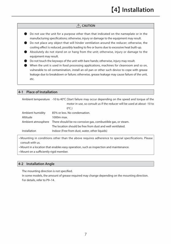
● Do not use the unit for a purpose other than that indicated on the nameplate or in the manufacturing specifications; otherwise, injury or damage to the equipment may result.
● Do not place any object that will hinder ventilation around the reducer; otherwise, the cooling effect is reduced, possibly leading to fire or burns due to excessive heat built-up.
● Absolutely do not stand on or hang from the unit; otherwise, injury or damage to the equipment may result.
● Do not touch the keyways of the unit with bare hands; otherwise, injury may result.
● When the unit is used in food processing applications, machines for cleanroom and so on, vulnerable to oil contamination, install an oil pan or other such device to cope with grease leakage due to breakdown or failure; otherwise, grease leakage may cause failure of the unit, etc.
4-1 Place of Installation
Ambient temperature -10 to 40°C (Start failure may occur depending on the speed and torque of the motor in use, so consult us if the reducer will be used at about -10 to 0°C.)
Ambient humidity 85% or less. No condensation.Altitude 1000m max.Ambient atmosphere There should be no corrosive gas, combustible gas, or steam. The location should be free from dust and well ventilated.Installation Indoor (Free from dust, water, other liquids)
• Mounting in conditions other than the above requires adherence to special specifications. Please consult with us.
• Mount in a location that enables easy operation, such as inspection and maintenance.• Mount on a sufficiently rigid member.
4-2 Installation Angle
The mounting direction is not specified.In some models, the amount of grease required may change depending on the mounting direction.For details, refer to P9–14.

8
【5】 Lubrication【5】 Lubrication
DANGER
● For models that have not been lubricated with grease, be sure to lubricate with the recommended grease before operation. Operating the unit without lubricating with the proper grease could result in failure of the equipment caused by damage to the internal parts of the reducer, and locking of the reducer.
● Be sure to use the recommended lubricating grease. If grease other than the recommended grease is used, not only will the performance and life of unit be greatly decreased, but failure of the equipment could occur due to damage to the internal parts of the reducer, and locking of the reducer.
CAUTION
● Further adding grease to models that have already be greased may cause heat generation or grease leakage to occur.
- Excessive grease filling causes rise in the internal pressure, which causes heat generation, grease leak and oil seal detachment.
Insufficient grease will cause improper lubrication, resulting in damage to the parts.
● Dispose of the reducer as general industrial waste.
5-1 Grease
• Depending on the specifications for use, the actual grease used may differ from the listed grease, so be sure to check the delivery specifications.
• As a guide, change the grease and perform an overhaul of the equipment after every 20,000 hours of operation or every 3 to 5 years. When performing an overhaul of the equipment, contact the nearest agent, dealer or sales office.
■ A SeriesThe unit is filled with grease before shipment, so the unit can be used as is.
Table 5-1 Recommended greaseProduct Name Manufacturer Ambient temperatureCitrax FA No.2 Kyodo Yushi Co., Ltd. –10 to 40°C
■ D Series with servo motor adapterThe unit is filled with grease before shipment, so the unit can be used as is.
Table 5-2 Recommended greaseProduct Name Manufacturer Ambient temperature
Multemp FZ No.00 Kyodo Yushi Co., Ltd. –10 to 40°C
■ C SeriesThe unit is filled with grease before shipment, so the unit can be used as is.
Table 5-3 Recommended greaseProduct Name Manufacturer Ambient temperature
Multemp FZ No.00 Kyodo Yushi Co., Ltd. –10 to 40°C

98
【5】 Lubrication
■ D Series (Except for models with a servo motor adapter)
• Always lubricate with the recommended grease before operation.• The recommended grease may not same as shown in the table below depending on the specifications,
so check the delivery specifications.• The actual amount of grease used varies depending on differences in structure, etc. Even in cases where
the amount indicated below is supplied, there may be an excess or deficiency in the filling amount, so be sure to always check the grease level.
Table 5-4 Recommended greaseProduct Name Manufacturer Ambient temperature
Multemp FZ No.00 Kyodo Yushi Co., Ltd. –10 to 40°C
Table 5-5 Grease filling quantity (g)Frame size D15 D25 D30 D35 D45
Vertical (1) (Output flange is downward) 55 100 220 190 320Vertical (2) (Output flange is upward) 40 45 85 150 260
Horizontal 50 95 200 160 270
• For horizontal mounting, align the output grease fill/drain port with the position of dimension A (refer to Table 5-6).• When filling grease for the first time, use the lower grease fill/drain port, and thoroughly fill grease into the reducer.
Gre
ase
leve
l
AG
reas
e le
vel
Grease �lland drain port
Gre
ase
leve
l
Grease �lland drain port
Grease �lland drain port
Grease �lland drain port
Grease �lland drain port
Grease �lland drain port
Gre
ase
leve
l
AG
reas
e le
vel
Grease �lland drain port
Gre
ase
leve
lGrease �lland drain port
Grease �lland drain port
Grease �lland drain port
Grease �lland drain port
Grease �lland drain port
Gre
ase
leve
l
AG
reas
e le
vel
Grease �lland drain port
Gre
ase
leve
l
Grease �lland drain port
Grease �lland drain port
Grease �lland drain port
Grease �lland drain port
Grease �lland drain port
Fig. 5-1 Vertical (1) (Output flange is downward)
Fig. 5-3 Horizontal mounting
Fig. 5-2 Vertical (2) (Output flange is upward)
Table 5-6 Position of output fill/drain port in horizontal mounting (mm)
Frame size Dimension AD15 20D25 26D30 29D35 34D45 39

10
【5】 Lubrication【5】 Lubrication
■ DA Series
• Always lubricate with the recommended grease before operation.• The recommended grease may not same as shown in the table below depending on the specifications,
so check the delivery specifications.• The actual amount of grease used varies depending on differences in structure, etc. Even in cases where
the amount indicated below is supplied, there may be an excess or deficiency in the filling amount, so be sure to always check the grease level.
Table 5-7 Recommended greaseProduct Name Manufacturer Ambient
temperatureMultemp FZ No.00 Kyodo Yushi Co., Ltd. –10 to 40°C
Table 5-8 Grease filling quantity (g)Frame size DA15 DA25 DA35 DA40 DA45 DA50
Vertical (1) (Output flange is downward) 52 113 196 204 222 305Vertical (2) (Output flange is upward) 52 113 196 204 222 305
Horizontal 39 91 161 170 178 252
• For horizontal mounting, align the output grease fill/drain port with the position of dimension A (refer to Table 5-9).
• When filling grease for the first time, use the lower grease fill/drain port, and thoroughly fill grease into the reducer.
• Table 5-8 indicates the amount of grease to be filled in the reducer drive space. Grease must also be supplied to the device-side space ([1], [2]).
(1) Vertical (1) (Output flange is downward)
• Supply grease to the reducer drive space.• Supply grease equal to the volume to the device-side space [2].• To prevent an increase in internal pressure, secure a space equal to 10 to 20% of the total volume (reducer
drive space + device-side space [1] + device-side space [2]) for the device-side space [1].
(2) Vertical (2) (Output flange is upward)
• Supply grease to the reducer drive space.• Supply grease equal to the volume to the device-side space [1].• To prevent an increase in internal pressure, secure a space equal to 10 to 20% of the total volume (reducer
drive space + device-side space [1] + device-side space [2]) for the device-side space [2].
(3) Horizontal mounting
• Supply grease to the reducer drive space.• Fill about 70% to 80% of the volume of device-side space [1], [2] with grease.

1110
【5】 Lubrication
Fig. 5-4 Vertical (1) (Output flange is downward)
Fig. 5-6 Horizontal mounting
Fig. 5-5 Vertical (2) (Output flange is upward)
Table5-9Positionofoutputfill/drainportinhorizontalmounting(mm)
Frame size Dimension ADA15 20DA25 27DA35 34DA40 36DA45 39DA50 43
Grease �lland drain port
Grease �lland drain port
Grease �lland drain port
Grease �lland drain port
Grease �lland drain port
Grease �lland drain port
Device-side space [2]
Device-side space [2]
Device-side space [2]
Drive space Device-side space [1]
Device-side space [1]
Device-side space [1]
Drive space
Drive space
A
Gre
ase
posi
tion
Gre
ase
posi
tion
Gre
ase
posi
tion
Grease �lland drain port
Grease �lland drain port
Grease �lland drain port
Grease �lland drain port
Grease �lland drain port
Grease �lland drain port
Device-side space [2]
Device-side space [2]
Device-side space [2]
Drive space Device-side space [1]
Device-side space [1]
Device-side space [1]
Drive space
Drive space
A
Gre
ase
posi
tion
Gre
ase
posi
tion
Gre
ase
posi
tion

12
【5】 Lubrication【5】 Lubrication
■ T Series
• Always lubricate with the recommended grease before operation.• The recommended grease may not same as shown in the table below depending on the specifications,
so check the delivery specifications.• The actual amount of grease used varies depending on differences in structure, etc. Even in cases where
the amount indicated below is supplied, there may be an excess or deficiency in the filling amount, so be sure to always check the grease level.
Table 5-10 Recommended grease
Product Name Manufacturer Ambient temperatureMultemp FZ No.00 Kyodo Yushi Co., Ltd.
–10 to 40°CSell Alvania EP Grease R0 Shell Lubricants Japan
Table 5-11 Grease filling quantity (g)
Frame size T155 T255 T355 T455 T555 T655 T755Vertical mounting (1) (2) 80 120 230 300 400 700 800
Horizontal 60 100 180 240 320 560 640
• Align the output grease fill/drain port with the position of dimension A on the eccentric planetary shaft (refer to Table 5-12).• When filling grease for the first time, use the lower grease fill/drain port, and thoroughly fill grease into the reducer.
Fig. 5-7 Vertical (1) (Output flange is downward)
Fig. 5-9 Horizontal mounting
Fig. 5-8 Vertical (2) (Output flange is upward)
Table 5-12 Output grease fill/drain port (mm)
Frame size Dimension AT155 25T255 31T355 39T455 47T555 55T655 63T755 72
Eccentric planetaryshaft bearing
Gre
ase
leve
l
Eccentric planetaryshaft bearing
Eccentric planetaryshaft bearing
Gre
ase
leve
l
Gre
ase
leve
l
Grease �lland drain port
Grease �lland drain port
Grease �lland drain port
Grease �lland drain port
A
A
A
Grease �lland drain port
Grease �lland drain port
Eccentric planetaryshaft bearing
Gre
ase
leve
l
Eccentric planetaryshaft bearing
Eccentric planetaryshaft bearing
Gre
ase
leve
l
Gre
ase
leve
l
Grease �lland drain port
Grease �lland drain port
Grease �lland drain port
Grease �lland drain port
A
A
A
Grease �lland drain port
Grease �lland drain port
Eccentric planetaryshaft bearing
Gre
ase
leve
l
Eccentric planetaryshaft bearing
Eccentric planetaryshaft bearing
Gre
ase
leve
l
Gre
ase
leve
l
Grease �lland drain port
Grease �lland drain port
Grease �lland drain port
Grease �lland drain port
A
A
A
Grease �lland drain port
Grease �lland drain port

1312
【5】 Lubrication
■ UA Series
• Always lubricate with the recommended grease before operation.• The recommended grease may not same as shown in the table below depending on the specifications,
so check the delivery specifications.• The actual amount of grease used varies depending on differences in structure, etc. Even in cases where
the amount indicated below is supplied, there may be an excess or deficiency in the filling amount, so be sure to always check the grease level.
Table 5-13Recommended grease
Product Name Manufacturer Ambient temperatureMultemp FZ No.00 Kyodo Yushi Co., Ltd. –10 to40°C
Table 5-14 Reducer drive space grease filling amount (g)
Frame size UA15 UA25 UA35 UA45 UA55 UA65 UA80Vertical (1) (Output flange is downward) 152 261 400 487 818 1180 2140
Vertical (2) (Output flange is upward) 143 227 361 417 748 1090 1995Horizontal 122 209 313 383 679 940 1700
• Align the output grease fill/drain port with the position of dimension A on the eccentric planetary shaft (refer to Table 5-15).
• When filling grease for the first time, use the lower grease fill/drain port, and thoroughly fill grease into the reducer.
• Table 5-14 indicates the amount of grease to be filled in the reducer drive space. It is also necessary to fill grease to the device-side space ([1], [4]).
(1) Vertical (1) (Output flange is downward)
• Supply grease to the reducer drive space.• To prevent an increase in internal pressure, secure a space equal to 10 to 20% of the total volume (reducer
drive space + device-side space [2]) for the device-side space [2].
(2) Vertical (2) (Output flange is upward)
• Supply grease to the reducer drive space.• Supply grease equal to the volume to the device-side space [4].• To prevent an increase in internal pressure, secure a space equal to 10 to 20% of the total volume (reducer
drive space + device-side space [3] + device-side space [4]) for the device-side space [3].
(3) Horizontal mounting
• Supply grease to the reducer drive space.• Supply grease equal to 70 to 80% the volume of [1] to the device-side space [1].

14
【6】 Coupling with Other Machines
14
【5】 Lubrication
Drive space
Drive space
Device-sidespace [1]
Device-sidespace [2]
Grease �lland drain port
Grease �lland drain port
Grease �lland drain portA
Grease �lland drain port
Eccentric planetaryshaft bearing
Gre
ase
leve
l
Gre
ase
leve
l
Drive space
Device-sidespace [4]
Device-sidespace [3]Grease �ll
and drain port
Grease �lland drain port
AA
Gre
ase
leve
l B
Table 5-15 Output grease fill/drain port (mm)
Frame size Dimension AUA15 29UA25 34UA35 39UA45 49UA55 54UA65 63UA80 71
Table 5-16 Vertical mounting grease level (mm)
Frame size Dimension BUA15 33UA25 34UA35 45UA45 50UA55 65UA65 74UA80 75
Fig. 5-10 Vertical (1) (Output flange is downward)
Fig. 5-12 Horizontal mounting
Fig. 5-11 Vertical (2) (Output flange is upward)

1514
【6】 Coupling with Other Machines
14
CAUTION
● Confirm the direction of rotation before coupling with the driven machine; otherwise, injury or damage to the equipment may result.
● Provide a cover etc. so that the rotating part cannot be touched; otherwise, injury may result.
● When coupling the reducer with a load, check that the centering, belt tension, parallelism of the pulleys, etc. are within the specified limits. When the unit is directly coupled with another machine, check that the direct coupling accuracy is within the specified limits. When a belt is used for coupling the unit with another machine, check the belt tension. Correctly tighten bolts on the pulley and coupling before operation; otherwise, injury may result because of misalignment.
● Make sure to use the designated number of bolts and tightening torque, when fixing the ring gear housing to the output flange. Reducer may not function optimally when fixed with with improper number of bolts or tightening torque.
6-1 Coupling Installation
• When installing a coupling, do not apply an impact force or excessive thrust to the output flange or shaft; otherwise, the bearing may be damaged.
• When chain sprockets, gears or pullers are coupled with the reducer, please use within the range of the allowable radial axial load, or shaft and bearing may be damaged.

16
【6】 Coupling with Other Machines【6】 Coupling with Other Machines
6-2 Speed Ratio and Rotation Direction
The rotation direction and speed ratio are as illustrated in Fig. 6-1 to 6-3 depending on the fixed, input, and output locations.
• i : Speed ratio (= [Output speed]/[Input speed]) *"-" indicates opposite direction. + of the speed ratio i indicate that the input and output are in the same and opposite directions, respectively.
• n : Reduction ratio.
■ A Series, D Series, DA Series, C Series
Eccentric high speed shaft(high speed shaft)
ReducerInput: Eccentric high speed shaft (High speed shaft)Output: Output �ange (Slow speed shaft)Fixed: Ring gear housingi=−1/n
ReducerInput: Eccentric high speed shaft(High speed shaft)Output: Ring gear housingFixed: Output �ange(Slow speed shaft)i=1/(n+1)
ReducerInput: Output �ange (Slow speed shaft)Output: Ring gear housingFixed: Eccentric high speed shaft (High speed shaft)i=n/(n+1)
IncreaserInput: Output �ange (Slow speed shaft)Output: Eccentric high speed shaft (High speed shaft)Fixed: Ring gear housingi=−n
IncreaserInput: Ring gear housingOutput: Eccentric high speed shaft (High speed shaft)Fixed: Output �ange (Slow speed shaft)i=n+1
IncreaserInput: Ring gear housingOutput: Output �ange (Slow speed shaft)Fixed: Eccentric high speed shaft (High speed shaft)i=(n+1)/n
Ring gearhousing
Output �ange (slow speed shaft)
When the eccentric high speed shaft (high speed shaft), ring gear housing and output �ange (slow speed shaft) all rotate, a combination of 1 to 6 is necessary.
ReducerInput: Input shaft gear (High speed shaft)Output: Ring gear housingFixed: Output �ange (Slow speed shaft)i=-1/(n-1)
ReducerInput: Output �ange (Slow speed shaft)Output: Ring gear housingFixed: Input shaft gear (High speed shaft)i = n/(n-1)
ReducerInput: Input shaft gear (High speed shaft)Output: Output �ange (Slow speed shaft)Fixed: Ring gear housingi=1/n
Output �ange (slow speed shaft)Input shaft bearing(high speed shaft)
Ring gearhousing
Output �ange (slow speed shaft)Ring gearhousing Input shaft bearing (high speed shaft)
ReducerInput: Input shaft bearing (high speed shaft)Output: Output �ange (slow speed shaft)Fixed: Ring gear housingi =1/n
ReducerInput: Input shaft bearing (high speed shaft)Output: Ring gear housingFixed: Output �ange (slow speed shaft)i = −1/(n−1)
Fig. 6-1 Direction of rotation and speed ratio (A series, D series, DA series, C series)
■ T Series
Figure 6-2 Speed Ratio and Rotation Direction (T series)
■ UA Series
Figure 6-3 Speed Ratio and Rotation Direction (UA series)
[1]
[4]
[7]
[1]
[1] [2]
[2] [3]
[2]
[5]
[3]
[6]

1716
【6】 Coupling with Other Machines
6-3 Keyless Shaft Motor Assembly (D Series With Servo Motor Adapter)
[1] Remove the oil and dust inside the motor shaft and eccentric high speed shaft. ( Rust-prevention oil is applied to the inside of the eccentric high speed shaft before shipping.)
[2] Place the reducer on a suitable base so that the output flange is facing down.[3] Align the notches on the eccentric high speed shaft and clamp ring.)[4] Remove the cap on the adapter plate, and insert a hex wrench from the set hole into the hex socket
head bolt. In that state, insert the motor shaft into the eccentric high speed shaft.[5] When assembling the motor and CYCLO reducer, make sure that center of the both shafts are aligned.
Do not forcibly assemble in a state where the shafts are inclined or misaligned.[6] Tighten the motor and adapter plate with the motor mounting bolts. Before tightening make sure that
the spigot of the motor is securely in the spigot of the adapter plate. If the bolts are tightened in a state where the spigots are not joined, tightening will be one sided and may damage the internal bearings, etc.
[7] Tighten the hex socket head bolt of the clamp ring to the torque indicated in Table 6-1.[8] After operating at low speed, re-tighten the bolt to the torque indicated in Table 6-1.[9] Attach the removed adapter plate cap.
Table 6-1 Tightening torque for the hex socket head bolt of the clamp ring
Size of bolts M5 M6 M8 M10
Tightening torque (N • m) 5.5 9.6 23 46
Fig. 6-4 Assembly drawing
L
Cap / Set hole
Motor
Eccentric highspeed shaft
Clamp ring
Adapter plate

18
【6】 Coupling with Other Machines【6】 Coupling with Other Machines
Assembly surface a
Eccentric high speed shaft
Motor adapter plate
[1] [2]
[3] [4]
6-4 Assembly Procedure
■ A Series FC Type
• Attach the CYCLO output flange to the output shaft of the device with bolts. (Spigot Ⓑ)
• Adjust the phase of the reducer and machine casing bolt holes by rotating the eccentric high speed shaft with the output- flange fixed.
• Fix the reducer part to the casing of machine with bolts.• When mounting the motor adapter plate, apply liquid
gasket to the assembly surface a, and fasten the motor adapter plate and the reducer to the machine casing with bolts. (Spigot Ⓒ)
• Align the phase of the slow speed shaft pin of the output flange with the slow speed shaft roller of the reducer, and attach the reducer to the machine casing. (Spigot Ⓐ)
• Apply an anti-fretting agent to the motor shaft.• Align the key phases of the motor shaft and the
eccentric high speed shaft, and fasten the motor to the reducer with bolts.
Fig. 6-5 Assembly procedure A series FC type
When attaching the reducer to the machine casing, be sure to assemble the reducer with the slow speed shaft roller to the output flange, otherwise the ring (refer to P35) may be damaged.
Output flange(Slow speed shaft)
Slow speed shaft pin
Slow speed shaft roller
Casing of machine
CYCLO reducer

1918
【6】 Coupling with Other Machines
Table 6-2 Mounting bolts A series FC type
Frame size
Tightening of the output flange Tightening of the reducer part
BoltNumber and size
Bolt tightening torque
N·m
BoltNumber and size
Bolt tightening torque
N·mA15 12-M5 9.32 8−M5 9.32
A25 12−M6 15.7 8−M6 15.7
A35 12−M8 38.3 8−M8 38.3
A45 12−M10 76.5 12−M8 38.3
A65 12−M12 133 12−M10 76.5
A75 12−M12 133 12−M10 76.5
• Bolt: Hexagon socket head bolts of strength class 12.9 of JIS B 1176.• Seat scratching measures: Spring washer (JIS B 1251, 2 types)• Locking measure: adhesive (Loctite 262, etc) in addition to conical spring washers • Recommended liquid gasket: ThreeBond Co., Ltd., Liquid gasket ThreeBond 1215

20
【6】 Coupling with Other Machines【6】 Coupling with Other Machines
Assembly surface a
Casing of machine
Assemblysurface b
Output flange
[1] [2]
[3]
■ A series F1C type (assembly example 1)
• Apply liquid gasket to the assembly surface and fix the FINE CYCLO to the casing of machine with bolts. (Spigot Ⓒ)(In this assembly example, the casing of machine and motor adapter are shared.)
・ Apply liquid gasket to the assembly surface b, and fasten the output flange to the output shaft of the machine with bolts. (Spigot Ⓑ)
• Apply anti-fretting agent to the motor shaft.• Align the key phase of the motor shaft and
the high speed shaft and fix the motor to the FINE CYCLO with bolts.
Fig. 6-6 Assembly procedure A series F1C type (assembly example 1)
Eccentrichigh speed shaft

2120
【6】 Coupling with Other Machines
■ A series F1C type (assembly example 2)
• Fix the FINE CYCLO to the casing of machine with bolts. (Spigot Ⓐ)
• When mounting the motor adapter plate, apply liquid gasket to the assembly surface a, and fasten the motor adapter plate and CYCLO reducer to the machine casing with bolts. (Spigot Ⓒ)
• Apply liquid gasket to the assembly surface b, and fasten the output flange to the output shaft of the machine with bolts.(Spigot Ⓑ)
• Apply anti-fretting agent to the motor shaft.• Align the key phases of the motor shaft and
the eccentric high speed shaft, and fasten the motor to the CYCLO reducer with bolts.
Table 6-3 Mounting bolts A series F1C type (for assembly examples 1 and 2)
Frame size
Tightening of the output flange Tightening of the reducer part
BoltNumber and size
Bolt tightening torqueN • m
BoltNumber and size
Bolt tightening torqueN • m
A15 12−M6 15.7 12−M6 15.7
A25 12−M8 38.3 12−M8 38.3
A35 12−M10 76.5 12−M10 76.5
• Bolt: Hexagon socket head bolts of strength class 12.9 of JIS B 1176.• Seat scratching measures: Spring washer (JIS B 1251, 2 types)• Locking measure: Adhesive (Loctite 262, etc) in addition to conical spring washers • Recommended liquid gasket: ThreeBond Co., Ltd., Liquid gasket ThreeBond 1215
Assembly surface a
Motor adapter plateCasing of machine
Assemblysurface b
Output flange
[1] [2]
[3]
Fig. 6-7 Assembly procedure A series F1C type (assembly example 2)
Eccentric high speed shaft

22
【6】 Coupling with Other Machines【6】 Coupling with Other Machines
■ A series F2C type (assembly example 1)
C
B
A C
B
Casing of machine
Eccentric high speed shaft Eccentric high speed shaft
Output �ange
Motor adapter plate
Casing of machine
Output �ange
Assemblysurface b
Assemblysurface b
Assemblysurface a
Assemblysurface a
C
B
A C
B
Casing of machine
Eccentric high speed shaft Eccentric high speed shaft
Output �ange
Motor adapter plate
Casing of machine
Output �ange
Assemblysurface b
Assemblysurface b
Assemblysurface a
Assemblysurface a
[1] [2]C
B
A C
B
Casing of machine
Eccentric high speed shaft Eccentric high speed shaft
Output �ange
Motor adapter plate
Casing of machine
Output �ange
Assemblysurface b
Assemblysurface b
Assemblysurface a
Assemblysurface a
[3]
• Apply liquid gasket to the assembly surface a, and fix the FINE CYCLO to the casing of machine with bolts. (Spigot Ⓒ)(In this assembly example, the casing of machine and motor adapter are shared.)
• Apply anti-fretting agent to the motor shaft.• Align the key phases of the motor shaft and
the eccentric high speed shaft, and fasten the motor to the CYCLO reducer with bolts.
• Apply liquid gasket to the assembly surface b, and fasten the output flange to the output shaft of the machine with bolts. (Spigot Ⓑ)
Fig. 6-8 Assembly procedure A series F2C type (assembly example 1)

2322
【6】 Coupling with Other Machines
■ A series F2C type (assembly example 2)
Table 6-4 Mounting bolts A series F2C type (for assembly examples 1 and 2)
Frame size
Tightening of the output flange Tightening of the reducer part
BoltNumber and size
Bolt tightening torqueN • m
BoltNumber and size
Bolt tightening torqueN • m
A15 12−M6 15.7 16−M6 12.8A25 12−M8 38.3 12−M8 31.4A35 12−M10 76.5 16−M8 31.4A45 12−M14 206 12−M12 107
• Bolt: Hexagon socket head bolts of strength class 12.9 of JIS B 1176.• Seat scratching measures: Spring washer (JIS B 1251, 2 types)• Locking measure: Adhesive (Loctite 262, etc) in addition to conical spring washers • Recommended liquid gasket: ThreeBond Co., Ltd., Liquid gasket ThreeBond 1215
C
B
A C
B
Casing of machine
Eccentric high speed shaft Eccentric high speed shaft
Output �ange
Motor adapter plate
Casing of machine
Output �ange
Assemblysurface b
Assemblysurface b
Assemblysurface a
Assemblysurface a
C
B
A C
B
Casing of machine
Eccentric high speed shaft Eccentric high speed shaft
Output �ange
Motor adapter plate
Casing of machine
Output �ange
Assemblysurface b
Assemblysurface b
Assemblysurface a
Assemblysurface a
C
B
A C
B
Casing of machine
Eccentric high speed shaft Eccentric high speed shaft
Output �ange
Motor adapter plate
Casing of machine
Output �ange
Assemblysurface b
Assemblysurface b
Assemblysurface a
Assemblysurface a
[1] [2]
[3]
• Fix the FINE CYCLO to the casing of machine with bolts. (Spigot Ⓐ )•When mounting the motor adapter plate, apply
liquid gasket to the assembly surface a, and fasten the motor adapter plate and CYCLO reducer to the machine casing with bolts. (Spigot Ⓒ)
• Apply liquid gasket to the assembly surface b, and fasten the output flange to the output shaft of the machine with bolts. (Spigot Ⓑ)
• Apply anti-fretting agent to the motor shaft.• Align the key phases of the motor shaft and
the eccentric high speed shaft, and fasten the motor to the CYCLO reducer with bolts.
Fig. 6-9 Assembly procedure A series F2C type (assembly example 2)

24
【6】 Coupling with Other Machines【6】 Coupling with Other Machines
■ D Series, DA Series (assembly example 1)
Casingof machine
Eccentric highspeed shaft
C
Assemblysurface
Output �angeB
[1] [2]
[3]
• Fix the FINE CYCLO to the casing of machine with bolts. (Spigot Ⓒ )(In this assembly example, the casing of machine and motor adapter are shared.)Use a seal structure between the motor adapter and the eccentric high speed shaft.)
• Apply anti-fretting agent to the motor shaft.• Align the key phases of the motor shaft and
the eccentric high speed shaft, and fasten the motor to the CYCLO reducer with bolts.
• Apply liquid gasket to the assembly surface and attach the output flange to the output shaft of the machine with bolts. (Spigot Ⓑ)
Fig. 6-10 Assembly procedure D series, DA series (assembly example 1)

2524
【6】 Coupling with Other Machines
■ D Series, DA Series (assembly example 2)
Casing of machine
Motor adapter plate
Eccentric highspeed shaft
A C
Output �ange
Assemblysurface
B
[1] [2]
[3]
• Fix the FINE CYCLO to the casing of machine with bolts. (Spigot Ⓐ)
• When mounting the motor adapter plate, fasten the motor adapter plate and the CYCLO reducer to the machine casing with bolts. (Spigot Ⓒ)(Use a seal structure between the motor adapter and the eccentric high speed shaft.)
• Apply liquid gasket to the assembly surface and attach the output flange to the output shaft of the machine with bolts. (Spigot Ⓑ )
• Apply anti-fretting agent to the motor shaft.• Align the key phases of the motor shaft and the
eccentric high speed shaft, and fasten the motor to the CYCLO reducer with bolts.
Fig. 6-11 Assembly procedure D series, DA series(assembly example 2)
Table 6-5 Mounting bolts D series(for assembly examples 1 and 2)
Frame size
Tightening of the output flange
Tightening of the reducer part
BoltNumber–
size
Bolt tightening
torqueN • m
BoltNumber and size
Bolt tightening
torqueN • m
D15 12-M8 38.3 12-M6 15.7D25 12-M8 38.3 16-M6 15.7D30 16-M8 38.3 16-M6 15.7D35 12-M10 76.5 16-M8 38.3D45 16-M12 133 16-M10 76.5
DA15 12-M8 38.3 16-M5 9.1DA25 18-M8 38.3 16-M6 15.7DA35 16-M10 76.5 16-M8 38.3DA40 16-M10 76.5 18-M8 38.3DA45 18-M10 76.5 16-M10 76.5DA50 18-M12 133 16-M10 76.5
• Bolt: Hexagon socket head bolts of strength class 12.9 of JIS B 1176
• Seat scratching measures: Spring washer (JIS B 1251, 2 types)
• Locking measure: Adhesive (Loctite 262, etc) in addition to conical spring washers
• Recommended liquid gasket: ThreeBond Co., Ltd., Liquid gasket ThreeBond 1215

26
【6】 Coupling with Other Machines【6】 Coupling with Other Machines
Assemblysurface a
Machinecasing
A
Motor shaft
Eccentrichighspeedshaft
C
B
[1] [2]
[3]
• Apply liquid gasket to the assembly surface a as necessary, and fasten the CYCLO reducer to the machine casing with bolts. (Spigot Ⓐ)
• Attach the output flange to the output shaft of the device with bolts. (Spigot Ⓑ)
Fig. 6-12 Assembly procedure C series
• Fasten the pulleys and other input members to the eccentric high speed shaft with bolts. (Spigot Ⓒ)
■ C Series
Table6-6MountingboltsCseries
Frame size
Tightening of the output flange Tightening of the reducer partBolt
Number and sizeBolt tightening torque
N • mBolt
Number and sizeBolt tightening torque
N • mC15 16-M6 13.6 12-M6 13.6C25 12-M8 33.4 12-M8 33.4C35 12-M10 65.7 8-M10 65.7C45 12-M12 114 8-M12 114C55 12-M14 181 12-M12 114C65 12-M16 284 16-M12 114
Frame size
Eccentric high speed shaftBolt
Number and sizeBolt tightening torque
N • mC15 6-M3 1.67C25 6-M3 1.67C35 6-M4 3.92C45 6-M4 3.92C55 8-M5 8.04C65 12-M5 8.04
• Bolt: Hexagon socket head bolts of strength class 10.9 of JIS B 1176.
• Seat scratching measures: Spring washer (JIS B 1251, 2 types)
• Locking measure: adhesive (Loctite 262, etc) in addition to conical spring washers
• Recommended liquid gasket: ThreeBond Co., Ltd., Liquid gasket ThreeBond 1215

2726
【6】 Coupling with Other Machines
A Casing of machineEccentricshaft gear
Inputshaftgear
Seal washerAssemblysurfacea
Greasefillanddrainport
Greasefillanddrainport
Outputflange
Assemblysurfaceb
B
[1] [2]
[3]
• Apply liquid gasket to the assembly surface a, and fix the FINE CYCLO to the casing of machine with bolts. (Spigot Ⓐ)(In this assembly example, the casing of machine and motor adapter are shared.)
• Apply liquid gasket to the assembly surface b, and fasten the output flange to the output shaft of the machine with bolts. (Spigot Ⓑ)
• Fill the grease from the machine casing grease fill/drain port (refer to P12), and close each grease fill/drain port.
• Apply an anti-fretting agent to the motor shaft.• Fasten the input shaft gear to the motor shaft a
key and bolts ( Put a seal washer on the bolt.)• Align the phase of the input shaft gear and
eccentric shaft gear, and fasten the motor to the CYCLO reducer with bolts.
■ T Series (assembly example 1)
Fig. 6-13 Assembly procedure T series (assembly example 1)

28
【6】 Coupling with Other Machines【6】 Coupling with Other Machines
[1] [2]
[3]
•Apply liquid gasket to the assembly surface a, and fasten the motor adapter plate and CYCLO reducer to the machine casing with bolts. (Spigot Ⓐ , Ⓒ )
• Apply liquid gasket to the assembly surface b, and fasten the output flange to the output shaft of the machine with bolts. (Spigot Ⓑ)
• Fill the grease from the machine casing grease fill/drain port (refer to P12), and close each grease fill/drain port.
•Apply an anti-fretting agent to the motor shaft.• Fasten the input shaft gear to the motor shaft a
key and bolts(Put a seal washer on the bolt.)• Align the phase of the input shaft gear and
eccentric shaft gear, and fasten the motor to the CYCLO reducer with bolts.
■ T Series (assembly example 2)
Fig. 6-14 Assembly procedure T series (assembly example 2)
C A
MotorAdapter plate
Assembly surface a
Assembly surface b
Grease fill port
Grease filler port
Casing of machine
Input shaft gear
Eccentric shaft gear
B
Output flange
2928
【6】 Coupling with Other Machines
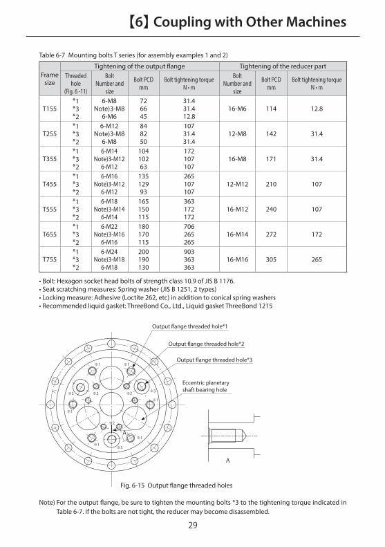
Note) For the output flange, be sure to tighten the mounting bolts *3 to the tightening torque indicated in Table 6-7. If the bolts are not tight, the reducer may become disassembled.
Table 6-7Mounting bolts T series (for assembly examples 1 and 2)
Frame size
Tightening of the output flange Tightening of the reducer partThreaded
hole(Fig. 6 -11)
BoltNumber and
size
Bolt PCD mm
Bolt tightening torqueN • m
BoltNumber and
size
Bolt PCD mm
Bolt tightening torqueN • m
T155*1*3*2
6-M8Note)3-M8
6-M6
726645
31.431.412.8
16-M6 114 12.8
T255*1*3*2
6-M12Note)3-M8
6-M8
848250
10731.431.4
12-M8 142 31.4
T355*1*3*2
6-M14Note)3-M12
6-M12
10410263
172107107
16-M8 171 31.4
T455*1*3*2
6-M16Note)3-M12
6-M12
13512993
265107107
12-M12 210 107
T555*1*3*2
6-M18Note)3-M14
6-M14
165150115
363172172
16-M12 240 107
T655*1*3*2
6-M22Note)3-M16
6-M16
180170115
706265265
16-M14 272 172
T755*1*3*2
6-M24Note)3-M18
6-M18
200190130
903363363
16-M16 305 265
• Bolt: Hexagon socket head bolts of strength class 10.9 of JIS B 1176.• Seat scratching measures: Spring washer (JIS B 1251, 2 types)• Locking measure: Adhesive (Loctite 262, etc) in addition to conical spring washers • Recommended liquid gasket: ThreeBond Co., Ltd., Liquid gasket ThreeBond 1215
※1 ※1
※1
※1
※1
※1
※2 ※3※2
※2
※3
A
A
※3
Output �ange threaded hole*1
Output �ange threaded hole*2
Output �ange threaded hole*3
Eccentric planetaryshaft bearing hole
Fig. 6-15 Output flange threaded holes

30
【6】 Coupling with Other Machines【6】 Coupling with Other Machines
O-ring
Oil seal
Casing of machine
Ⓐ
Input shaft gear
Seal washer
Outputflange
Grease filland drain port
Grease filland drain port
Assemblysurface
Ⓑ
[1] [2]
[3]
• Insert the O-ring into the frame and fasten the CYCLO reducer to the machine casing with bolts. (Spigot Ⓐ)(Use a seal structure between the input shaft
gear and the machine casing.) In this assembly example, the casing of machine and motor adapter are shared.)
•Apply liquidgasket totheassemblysurfaceandattachtheoutputflangetotheoutputshaftofthemachinewithbolts.(SpigotⒷ)•Fill thegreasefromthemachinecasinggreasefill/drainport(refertoP13),andcloseeachgreasefill/drainport.
• Apply an anti-fretting agent to the motor shaft.• Fasten the input shaft gear to the motor shaft a
key and bolts Put a seal washer on the bolt.)
• Align the phase of the input shaft gear and eccentric shaft gear, and fasten the motor to the CYCLO reducer with bolts.
■ UA Series (assembly example 1)
Fig.6-16 AssemblyprocedureUAseries(assemblyexample1)
3130
【6】 Coupling with Other Machines
ⒶⒸO-ring
Oil seal
Motor adapter
Casing of machine
Input shaft gear
Seal washer
O-ring
Outputflange
Grease filland drain port
Grease filland drain port
Assemblysurface
Oil seal
Ⓓ
[1] [2]
[3]
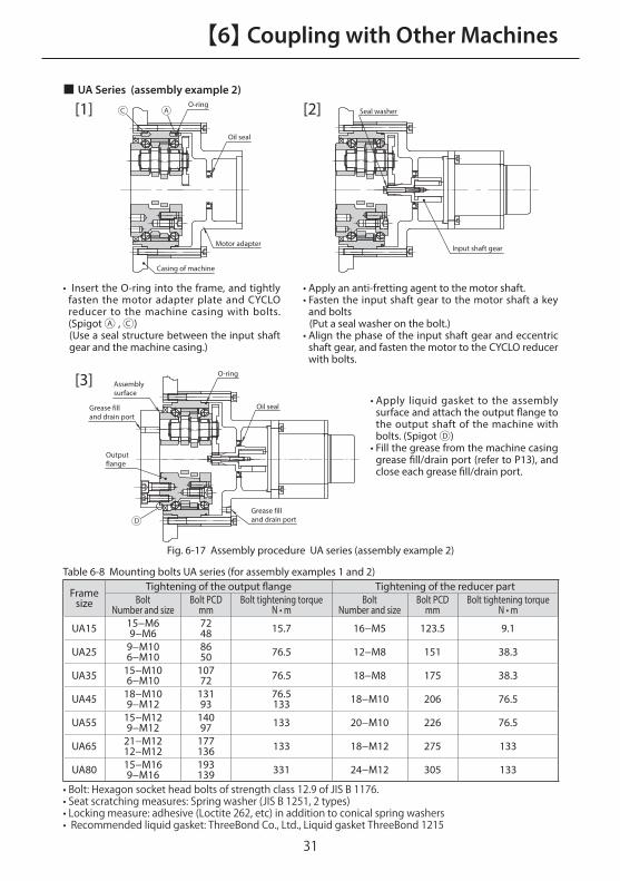
• Insert the O-ring into the frame, and tightly fasten the motor adapter plate and CYCLO reducer to the machine casing with bolts. (Spigot Ⓐ , Ⓒ)(Use a seal structure between the input shaft gear and the machine casing.)
• Apply liquid gasket to the assembly surface and attach the output flange to the output shaft of the machine with bolts. (Spigot Ⓓ)
• Fill the grease from the machine casing grease fill/drain port (refer to P13), and close each grease fill/drain port.
• Apply an anti-fretting agent to the motor shaft.• Fasten the input shaft gear to the motor shaft a key
and bolts( Put a seal washer on the bolt.)
• Align the phase of the input shaft gear and eccentric shaft gear, and fasten the motor to the CYCLO reducer with bolts.
■ UA Series (assembly example 2)
Fig. 6-17 Assembly procedure UA series (assembly example 2)
Table 6-8 Mounting bolts UA series (for assembly examples 1 and 2)
Frame size
Tightening of the output flange Tightening of the reducer partBolt
Number and sizeBolt PCD
mmBolt tightening torque
N • mBolt
Number and sizeBolt PCD
mmBolt tightening torque
N • m
UA15 15−M69−M6
7248 15.7 16−M5 123.5 9.1
UA25 9−M106−M10
8650 76.5 12−M8 151 38.3
UA35 15−M106−M10
10772 76.5 18−M8 175 38.3
UA45 18−M109−M12
13193
76.5133 18−M10 206 76.5
UA55 15−M129−M12
14097 133 20−M10 226 76.5
UA65 21−M1212−M12
177136 133 18−M12 275 133
UA80 15−M169−M16
193139 331 24−M12 305 133
•Bolt:Hexagonsocketheadboltsofstrengthclass12.9ofJISB1176.•Seatscratchingmeasures:Springwasher(JISB1251,2types)•Lockingmeasure:adhesive(Loctite262,etc)inadditiontoconicalspringwashers•Recommendedliquidgasket:ThreeBondCo.,Ltd.,LiquidgasketThreeBond1215

32
【8】 Daily Inspection and Maintenance
32
【7】 Operation
DANGER
● Do not touch rotating parts during operation; otherwise, loose clothing caught in these rotating parts may result in serious injury.
CAUTION
● Do not put fingers or foreign object into the opening of the reducer; otherwise, injury or damage to the equipment may result.
● The reducer will become very hot during operation. Do not touch or come in contact with the unit; otherwise, burns may result.
● If anomaly occurs during operation, stop operation immediately; otherwise, injury may result.
● Do not operate the unit in excess of the rating; otherwise, injury or damage to the equipment may result.
7-1 Check Before Operation
After installation, check the following items before starting operation.• Is the coupling with the driven machine performed correctly?• Are the mounting bolts for each part securely tightened?• Is the direction of rotation as planned?
After checking the items described above, perform a no-load break-in operation and gradually apply a load. When doing this, check the items in Table 7-1.
7-2 Check During Operation
Table 7-1 Check items during operation
I s t h e r e a ny a b n o r m a l n o i s e o r vibration?
•Is the housing distorted because the installation surface is not flat?•Is there vibration due to insufficient rigidity of installed parts?•Does the center axis of the driven machine match?•Is vibration of the driven machine transmitted to the reducer?
Is the surface temperature abnormally high?
•Is the ambient temperature at the place of usage high?
Whenanabnormalityisfound,stopoperationandcontactthenearestagent,dealerorsalesoffice.

3332
【8】 Daily Inspection and Maintenance
32
DANGER
● Do not approach or touch any rotating parts during maintenance or inspection of the unit; otherwise, loose clothing caught in these rotating parts may result in injury or death.
CAUTION
● Do not put fingers or foreign object into the opening of the reducer; otherwise, injury or damage to the equipment may result.
● The reducer will become very hot during operation. Do not touch the unit with bare hands; otherwise, burns may result.
● Identify and provide appropriate corrective action in a timely fashion and according to this maintenance manual if any abnormal operating characteristics are observed. Do not operate the unit corrective action has been taken.
● Do not use damaged reducers; otherwise, injury or damage to the equipment may result.
● We can not assume any responsibility for damage or injury as a result of an unauthorized modification by a customer.
● Dispose of the reducer as general industrial waste.

34
【9】 Structural Drawing
34
【8】 Daily Inspection and Maintenance
8-1 Daily Inspection
To ensure proper and continued optimum operation, use table1 to perform daily inspections. All of the answers should be "No."
Table 8-1 Daily Inspection
Inspection Item Details of Inspection
Noise Is there abnormal sound? Is there sudden change in sound?
Vibration Is vibration abnormally large? Does vibration change suddenly?
Surface temperatureIs the surface temperature abnormally high? Does the surface temperature rise suddenly?
Grease leakageIs there any grease leakage from mounting surfaces or oil seal part? Is there any rust on the sliding surface of the oil seal?
Mounting bolts Have any of the mounting bolts become loose?
Lost motion Has lost motion increased?
• If any abnormality is found during daily inspection, contact the nearest agent, dealer or sales office.
8-2 Maintenance of Main Unit
• Oil seals have a life, and after long-term use there may be a decrease in the seal effect due to natural deterioration and wear. Although the seal life greatly differs depending on the operating conditions and surrounding environment of the reducer, it is recommended that the seal be replaced every 1 to 3 years.If the sliding surface of the oil seal becomes worn or rusted, replace the seal with a new one.The sliding surface is made of a carbon steel, so rusting may occur and advance due to moisture, etc., which may lead to damage of the oil seal, so periodically take rust prevention measures.
• Overhauls such as replacing oil seals and grease, disassembly inspection and repairs should never be attempted by the customer, but should always be performed by a skilled worker of this company who has special tools and expertise.Consult with the nearest agent, dealer or sales office regarding overhauls, disassembly inspection or repairs.

3534
【9】 Structural Drawing
34
9-1 Structural Drawing (A series)
Fig. 9-1 FC Type
Fig. 9-2 F1C Type
Inner cover
Curved support
Ring gear housing pin
Slow speed shaft pinRing
Slow speed shaft roller
High speed shaft bearing B (contact type with seal is standard)
Eccentric high speed shaft (high speed shaft)
Bearing for eccentric
High speed shaft bearing A
Cycloid disc
Output flange (slow speed shaft)
Ring gear housing
Inner cover
Curved support
Ring gear housing pin
Slow speed shaft pin
Slow speed shaft roller
High speed shaft bearing B (contact type with seal is standard)Eccentric high speed shaft (high speed shaft)
High speed shaft bearing A (contact type with seal is standard)
Bearing for eccentric body
Cycloid disc
Output flange (slow speed shaft)
Ring gear housing
Oil seal
Output shaft with single cross roller bearing
O-ringOuter cover

36
【9】 Structural Drawing【9】 Structural Drawing
9-1 Structural Drawing (A series)
Fig. 9-3 F2C Type
Oil seal
Main bearing (taper roller bearing)
Ring gear housing
Carrier
Slow speed shaft pin
Slow speed shaft rollerHigh-speed shaft support bearing B (contact type with seal is standard)Eccentric high speed shaft(high speed shaft)
High-speed shaft support bearing A(contact type with seal is standard)Bearing for eccentric bodyCycloid disc
Ring
Carrier nut
Carrier bolt
Ring gear housing pin
Ring gear housing pin retainer
Output �ange (slow speed shaft)

3736
【9】 Structural Drawing
Main bearing(angular contact ball bearings)
Carrier
Ring gear housing
Oil seal
Eccentric high speed shaft(high speed shaft)
Output �ange(slow speed shaft)
Bearing for eccentric body
Slow speed shaft roller
High speed shaft support bearings
Cycloid disc
Ring gear housing pin
Main bearing(angular contact ball bearings)
Carrier
Ring gear housing
Oil seal
Eccentric high speed shaft(high speed shaft)
Output �ange(slow speed shaft)
Bearing for eccentric body
Slow speed shaft roller
High speed shaft support bearings
Cycloid disc
Ring gear housing pin
9-2 Structural Drawing (D Series, DA Series)
Fig.9-4F4CType

38
【9】 Structural Drawing【9】 Structural Drawing
9-3 Structural Drawing (C Series)
Fig. 9-5 F4C Type
Fig. 9-6 F2C Type
Slow speed shaft oil seal
Main bearing (taper roller bearing)
High speed shaft bearing(non-contact type with double seals)
Bearing for eccentric
Carrier bolt
Carrier nut
Ring gear housing pin
Output �ange(slow speed shaft)
High speed shaft oil seal
Cycloid disc
Slow speed shaft roller
Slow speed shaft pin
Ring gear housing
Carrier
Eccentric high speed shaft(high speed shaft)
Slow speed shaft oil seal
Main bearing(angular contact ball bearings)
High speed shaft support bearings
Bearing for eccentric
Ring gear housing pin
Output �ange(slow speed shaft)
High speed shaft oil seal
Cycloid disc
Slow speed shaft roller
Carrier bolt
Slow speed shaft pin
Ring gear housing
Carrier
Eccentric high speed shaft(high speed shaft)

3938
【9】 Structural Drawing
9-3 Structural Drawing (T Series)
Fig. 9-7 F2C Type
Main Bearing
Carrier
Cycloid disc
Bearing for eccentric body
Input shaft bearing (high speed shaft)
Ring gear housing pin
Output flange (slow speed shaft)
Eccentric planetary shaft bearing
Eccentric planetary shaft bearing
Eccentric shaft gear
Carrier pin
Oil seal
Ring gear housing

40
【10】 Warranty
40
【9】 Structural Drawing
Main bearing(angular contact ball bearings)
Ring gear housing
Output ange(slow speed shaft)
Eccentric planetaryshaft bearing
Cycloid disc
Oil seal
Ring gearhousing pin
Ring gear housing
Output ange(slow speed shaft)
Eccentric planetaryshaft bearing
Cycloid disc
Oil seal
Ring gearhousing pin
Eccentric shaft gear
Bearing for eccentric body
Eccentric planetary shaft bearing
Input shaft bearing(high-speed shaft)
Knock pin
Bolt
Carrier
Main bearing(taper roller bearing)
Eccentric shaft gear
Eccentric planetary shaft bearing
Bearing for eccentric body
Input shaft bearing(high-speed shaft)
Knock pin
Bolt
Carrier
9-5 Structural Drawing (UA Series)
Fig. 9-8 F4C Type
Fig. 9-9 F2C Type

4140
【10】 Warranty
40
The scope of warranty of our delivered products is limited only to what we manufactured.Warranty (period and contents)
Warranty Period
The warranty period for the Products shall be 18 months after the shipment of the Products from the seller's works or 12 months from the Products coming into operation, whether comes first.
Warranty Condition
In the event that any problem or damage to the Product arises during the“Warranty Period”from defects in the Product whenever the Product is properly installed and combined with the Buyer's equipment or machines, maintained as specified in this manual, and properly operated under the conditions described in this manual, or as otherwise agree upon in writing between the Seller and the Buyer or its customers; the Seller will provide, at its sole discretion, appropriate repair or replacement of the Product without charge at a designted facility, except as stipulated in the“Warranty Exclusions”as described below.However, if the Product is installed or integrated into the Buyer's equipment or machines, the Seller shall not reimburse the cost of : removal or re-installation of the Product or other incidental costs related thereto, any lost opportunity, any profit loss or other incidental or consequential losses or damages incurred by the Buyer or its customers.
Warranty Exclusions
Notwithstanding the above warranty, the warranty as set forth herein shall not apply to any problem or damage to the Product that is caused by:1. installation, connection, combination or integration of the Product in or to the other
equipment or machine that is rendered by any person or entity other than the Seller ;2. insufficient maintenance or improper operation by the Buyer or its customers, such that
the Product is not maintained in accordance with the maintenance manual provided or designated by the Seller ;
3. improper use or operation of the Product by the Buyer or its customers that is not informed to the Seller, including, without limitation, the Buyer's or its customers, operation of the Product not in conformity with the specifications, or use of lubricating oil in the Product that is not recommended by the Seller ;
4. any problem or damage on any equipment or machine to which the Product is installed, connected or combined or on any specifications particular to the Buyer or its customers ;
5. any changes, modifications, improvements or alterations to the Product or those functions that are rendered on the Product by any person or entity other than the Seller ;
6. any parts in the Product that are supplied or designated by the Buyer or its customers ;7. earthquake, fire, flood, sea-breeze, gas, thunder, acts of God or any other reasons beyond
the control of the Seller ;8. normal wear and tear, or deterioration of the Product's parts, such as bearings, oil-seals ;9. any other troubles, problems or damage to the Product that are not attributable to the
Seller.

Power Transmission & Controls Group
Headquarter ThinkPark Tower, 1-1 Osaki 2-chome, Shinagawa-ku, Tokyo 141-6025, Japan
Specifications, dimensions, and other items are subject to change without prior notice.
No.FM2001E-3.0EA10 Printed 2019.08
Worldwide Locations
U.S.ASumitomo Machinery Corporation of America (SMA)4200 Holland Blvd. Chesapeake, VA 23323, U.S.A.TEL (1)757-485-3355 FAX (1)757-485-7490
CanadaSM Cyclo of Canada, Ltd. (SMC)1453 Cornwall Road, Oakville, Canada ON L6J 7T5TEL (1)905-469-1050 FAX (1)905-469-1055
MexicoSM Cyclo de Mexico, S.A. de C.V. (SMME)Av. Desarrollo 541, Col. Finsa, Guadalupe,Nuevo León, México, CP67132TEL (52)81-8144-5130 FAX (52)81-8144-5130
BrazilSumitomo Industrias Pesadas do Brasil Ltda. (SHIB)Rodovia do Acucar (SP-075) Km 26Itu, Sao Paulo, BrasilTEL (55)11-4886-1000 FAX (55)11-4886-1000
ChileSM-Cyclo de Chile Ltda. (SMCH)Camino Lo Echevers 550, Bodegas 5 y 6, Quilicura, Región Metropolitana, ChileTEL (56)2-892-7000 FAX (56)2-892-7001
ArgentinaSM-Cyclo de Argentina S.A. (SMAR)Ing Delpini 2230, B1615KGB Grand Bourg, Malvinas Argentinas, Buenos Aires, Argentina TEL (54)3327-45-4095 FAX (54)3327-45-4099
GuatemalaSM Cyclo de Guatemala Ensambladora, Ltda. (SMGT)Parque Industrial Unisur, 0 Calle B 19-50 Zona 3,Bodega D-1 Delta Bárcenas en Villa Nueva, GuatemalaTEL (502)6648-0500 FAX (502)6631-9171
ColombiaSM Cyclo Colombia, S.A.S. (SMCO)Parque Industrial Celta, Km 7.0 Autopista Medellín, Costado Occidental, Funza, Cundinamarca, ColombiaTEL (57)1-826-9766
PeruSM Cyclo de Perú, S.A.C (SMPE)Jr. Monte Rosa 255, Oficina 702, Lima,Santiago de Surco, Perú TEL (51)1-713-0342 FAX (51)1-715-0223
GermanySumitomo (SHI) Cyclo Drive Germany GmbH (SCG)Cyclostraße 92, 85229 Markt Indersdorf, GermanyTEL (49)8136-66-0 FAX (49)8136-5771
AustriaSumitomo (SHI) Cyclo Drive Germany GmbH (SCG)SCG Branch Austria O�ceGruentalerstraße 30A, 4020 Linz, AustriaTEL (43)732-330958 FAX (43)732-331978
BelgiumHansen Industrial Transmissions NV (HIT) Leonardo da Vincilaan 1, Edegem, Belgium TEL (32)34-50-12-11 FAX (32)34-50-12-20
FranceSM-Cyclo France SAS (SMFR)8 Avenue Christian Doppler, 77700 Serris, FranceTEL (33)164171717 FAX (33)164171718
ItalySM-Cyclo Italy Srl (SMIT)Via dell' Artigianato 23, 20010 Cornaredo (MI), Italy TEL (39)293-481101 FAX (39)293-481103
SpainSM-Cyclo Iberia, S.L.U. (SMIB)C/Gran Vía Nº 63 Bis, Planta 1, Departamento 1B48011 Bilbao–Vizcaya, SpainTEL (34)9448-05389 FAX (34)9448-01550
United KingdomSM-Cyclo UK Ltd. (SMUK)Unit 29, Bergen Way, Sutton Fields Industrial Estate, Kingston upon Hull, HU7 0YQ, East Yorkshire, United KingdomTEL (44)1482-790340 FAX (44)1482-790321
TurkeySM Cyclo Turkey Güç Aktarım Sis. Tic. Ltd. Sti. (SMTR)Barbaros Mh. Çiğdem Sk. Ağaoğlu, Office Mrk. No:1 Kat:4 D.18Ataşehir, İstanbul, Turkey TEL (90)216-250-6069 FAX (90)216-250-5556
IndiaSumi-Cyclo Drive India Private Limited (SDI)Gat No. 186, Raisoni Industrial Park, Alandi Markal Road,Fulgaon-Pune, Maharashtra, IndiaTEL (91)96-0774-5353
ChinaSumitomo (SHI) Cyclo Drive China, Ltd. (SCT) 11F, SMEG Plaza, No. 1386 Hongqiao Road,Changning District, Shanghai, China (P.C. 200336)TEL (86)21-3462-7877 FAX (86)21-3462-7922
Hong KongSM-Cyclo of Hong Kong Co., Ltd. (SMHK)Rm 1301, CEO Tower, 77 Wing Hong Street,Cheung Sha Wan, Kowloon, Hong Kong TEL (852)2460-1881 FAX (852)2460-1882
KoreaSumitomo (SHI) Cyclo Drive Korea, Ltd. (SCK)Royal Bldg. 19 Rm. 913, 5 Saemunan-ro 5-Gil Jongro-Gu Seoul, Korea 03173TEL (82)2-730-0151 FAX (82)2-730-0156
TaiwanTatung SM-Cyclo Co., Ltd. (TSC)22 Chungshan N. Road 3rd., Sec. Taipei, Taiwan 104, R.O.C.TEL (886)2-2595-7275 FAX (886)2-2595-5594
SingaporeSumitomo (SHI) Cyclo Drive Asia Paci�c Pte. Ltd. (SCA)15 Kwong Min Road, Singapore 628718 TEL (65)6591-7800 FAX (65)6863-4238
PhilippinesSumitomo (SHI) Cyclo Drive Asia Paci�c Pte. Ltd.Philippines Branch O�ce (SMPH)C4 & C5 Buildings Granville Industrial Complex, Carmona,Cavite 4116, PhilippinesTEL (63)2-584-4921 FAX (63)2-584-4922
VietnamSM-Cyclo (Vietnam) Co., Ltd. (SMVN)Factory 2B, Lot K1-2-5, Road No. 2-3-5A,Le Minh Xuan Industrial Park, Binh Chanh Dist.,HCMC, Vietnam TEL (84)8-3766-3709 FAX (84)8-3766-3710
MalaysiaSM-Cyclo (Malaysia) Sdn. Bhd. (SMMA)No.7C, Jalan Anggerik Mokara 31/56, Kota Kemuning, Seksyen 31, 40460 Shah Alam, Selangor Darul Ehsan, Malaysia TEL (60)3-5121-0455 FAX (60)3-5121-0578
IndonesiaPT. SM-Cyclo Indonesia (SMID)Jalan Sungkai Blok F 25 No. 09 K, Delta Silicon III,Lippo Cikarang, Bekasi 17530, IndonesiaTEL (62)21-2961-2100 FAX (62)21-2961-2211
ThailandSM-Cyclo (Thailand) Co., Ltd. (SMTH)195 Empire Tower, Unit 2103-4, 21st Floor, South Sathorn Road, Yannawa, Sathorn, Bangkok 10120, ThailandTEL (66)2670-0998 FAX (66)2670-0999
AustraliaSumitomo (SHI) Hansen Australia Pty. Ltd. (SHAU)181 Power St, Glendenning, NSW 2761, AustraliaTEL (61)2-9208-3000 FAX (61)2-9208-3050
JapanSumitomo Heavy Industries, Ltd. (SHI)ThinkPark Tower, 1-1 Osaki 2-chome, Shinagawa-ku, Tokyo 141-6025, Japan TEL (81)3-6737-2511 FAX (81)3-6866-5160