“SPEED CONTROL OF INDUCTION MOTOR USING CYCLO ...
65
VISVESWARAYA TECHNOLOGICAL UNIVERSITY, BELAGAVI NEW HORIZON COLLEGE OF ENGINEERING, BANGALORE Autonomous College Permanently Affiliated to VTU Approved by AICTE Accredited by NAAC with ‘A’ grade PROJECT REPORT ON “SPEED CONTROL OF INDUCTION MOTOR USING CYCLO CONVERTER WITH THYRISTORS ” Submitted in partial fulfilment as a requirement for the award of degree of BACHELOR OF ENGINEERING IN ELECTRICAL AND ELECTRONICS UNDER THE GUIDANCE OF Asst Prof. MUNIPRAKASH SUBMITTED BY JAYARAMA REDDY NARASIMHARAJU D L 1NH15EE415 1NH15EE418 2017-2018
-
Upload
khangminh22 -
Category
Documents
-
view
2 -
download
0
Transcript of “SPEED CONTROL OF INDUCTION MOTOR USING CYCLO ...

VISVESWARAYA TECHNOLOGICAL UNIVERSITY, BELAGAVI
NEW HORIZON COLLEGE OF ENGINEERING, BANGALORE Autonomous College Permanently Affiliated to VTU Approved by AICTE Accredited
by NAAC with ‘A’ grade
PROJECT REPORT ON
“SPEED CONTROL OF INDUCTION MOTOR USING
CYCLO CONVERTER WITH THYRISTORS ”
Submitted in partial fulfilment as a requirement for the award of degree of BACHELOR OF ENGINEERING
IN ELECTRICAL AND ELECTRONICS
UNDER THE GUIDANCE OF
Asst Prof. MUNIPRAKASH
SUBMITTED BY
JAYARAMA REDDY NARASIMHARAJU D L
1NH15EE415 1NH15EE418
2017-2018

VISVESWARAYA TECHNOLOGICAL UNIVERSITY, BELAGAVI
NEW HORIZON COLLEGE OF ENGINEERING, BANGALORE Autonomous College Permanently Affiliated to VTU Approved by AICTE
Accredited by NAAC with ‘A’ grade
DEPARTMENT OF ELECTRICAL AND ELECTRONICS
ENGINEERING
CERTIFICATE
This is to certify that the project work entitled “ SPEED CONTROL OF INDUCTION MOTOR USING CYCLO CONVERTER WIYH THYRISTORS” is a bonofide work carried out by STUDENT JAYARAMA REDDY(1NH15EE415),NARASIMHARAJU D L (1NH15EE418) submitted in partial Fulfilment for the award of Bachelor of Engineering degree in VIII
semester of the Visveswaraya Technological University, Belagavi during the academic year
2017-18. It is certified that all the corrections and suggestions indicated for Internal Assessment
have been incorporated in the report deposited in the Department library. The project work has been
approved as it satisfies the academic requirement in respect of Project Work (10EEP85)
prescribed for BACHELOR OF ENGINEERING DEGREE IN ELECTRICAL AND
ELECTRONICS ENGINEERING.
GUIDE
HOD
PRINCIPAL
Prof.MUNIPRAKASH
Dr.ELUMALAI R
Dr.MANJUNATH
NAME OF THE EXAMINERS SIGN WITH
DATE 1 2


ACKNOWLEDGMENT
Gratitude takes three forms –“A feeling from heart, an expression in words and a
giving in return”. We take this opportunity to express our heart-feelings.
First and foremost, we wish to express our profound gratitude to our respected Principal
Dr.MANJUANATHA, for providing all the facilities in the college. We would like to
express our sincere thanks to Dr.ELUMALAI K, Head of the department of Electrical and
Electronics Engineering for his continuous support and encouragement.
We feel deeply indebted to our esteemed guide Prof.MUNIPRAKASH for her
guidance, right from the conception and visualization to the very presentation of the project.
She has been our guiding light throughout.
We are greatly indebted to our faculties, both teaching and supporting staff, Department
of Electrical and Electronics Engineering, who took great interest in our project work. They
motivated and guided us throughout the accomplishment of this goal. We express our
profound thanks for their meticulous guidance.
Finally, we would like to express our heartfelt thanks to our beloved parents for their
blessings, our friends for their help and wishes for the successful completion of this project
work.
JAYARAMA REDDY
NARASIMHA RAJU D L

ABSTRACT
Induction motors are widely used in many industries and domestic applications. They are
used commonly in many open-loop control applications due to their cost, size, efficiency,
less maintenance, simplicity and easy manufacture. In the past traditional speed control
methods were used to control the speed of the DC motors, But DC motors have
commutator and brushes which require more maintenance and hazardous. So Induction
motors are more preferred in these fields. Since most of the industries use Induction
motors, controlling of it plays a major role. This project deals with controlling the speed
of Induction Motor using cycloconverter with IOT. The It decodes the signal and
generates the pulse width signals which activates its circuit and gives the change in speed
of induction motor with respect to the change in firing angle of TRAIC. This way speed
can be easily varied and maintained as per the required values. We are not only
controlling the speed of the induction motor, we can also provide time to time updation of
running motor through the IOT. Which can be displayed through mobile app.. Therefore,
this project will be helpful in households, commercial use, industries etc. A
cycloconverter is a power electronic device used to convert constant voltage constant
Frequency AC power to adjustable voltage adjustable frequency AC power without a DC
link. In among all the methods this method is simple, reliable and economical. The
various speed of induction motor is obtained by varying the supply frequency by using
cycloconverter.

TABLE OF CONTENTS
CHAPTERS CONTENTS PAGE NUMBER
1 Introduction 1-3
2 Literature survey 4-5
3 Block Diagram 6
4 Hardware Components 7-52
5 Advantages and 53
disadvantages
6 Applications 54
7 Conclusion 55
8 Bibliography 56

Speed control of induction motor using cyclo-converter with thyristors
CHAPTER 1
INTRODUCTION
Speed control of induction motor is necessary in industrial applications. There are several
methods for the speed control of induction motor. Cyclo-converters are used in very large
variable frequency drives with ratings from few megawatts up to many tens of megawatts . A
cycloconverter is controlled through the timing of its firing pulses, so that it produces an
alternating output voltage. It can also be considered as a static frequency changer and
typically contains silicon controlled rectifiers.The development of the semiconductor devices
has made it possible to control the frequency of the cycloconverter according to the
requirement and deliver a large amount of controlled power with the help of semiconductor
switching devices like Thyristors MOSFET’s in order to get alternating output of variable
frequency. The quality of the output waveform improves if more switching devices are used.
Split-phase induction motors are widely used in many applications due to their energy
efficient characteristics. Improvements in its performance mean a great saving in electrical
energy consumption. Thus, a cycloconverter has the facility for continuous and independent
control over both its output frequency and voltage. Cycloconverter eliminates the use of
flywheel because the presence of flywheel in machine increases tensional vibration and
fatigue in the component of power transmission system.
The characteristics of single phase induction motors are identical to 3-phase induction motors
except that single phase induction motor has no inherent starting torque and some special
arrangements have to be made for making it self-starting. Though single phase induction
motors are not self-starting we are using it because the 3-phase supply is not present at
everywhere especially in domestic purposes single phase induction motors are widely used.
In many electrical appliances namely ceiling fan, refrigerator, washing machines etc. we are
using this type of motor. The main reason behind using it is the availability of single phase
supply and one more is economical i.e., less costly in price. So speed control of induction
motor is important. The complete control circuitry depends on only one parameter i.e.,
Voltage.
NHCE Department of EEE Page 1
Speed control of induction motor using cyclo-converter with thyristors
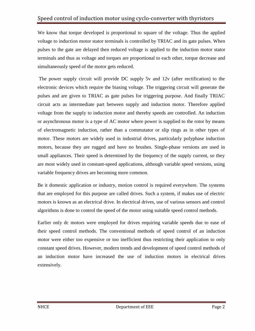
We know that torque developed is proportional to square of the voltage. Thus the applied
voltage to induction motor stator terminals is controlled by TRIAC and its gate pulses. When
pulses to the gate are delayed then reduced voltage is applied to the induction motor stator
terminals and thus as voltage and torques are proportional to each other, torque decrease and
simultaneously speed of the motor gets reduced.
The power supply circuit will provide DC supply 5v and 12v (after rectification) to the
electronic devices which require the biasing voltage. The triggering circuit will generate the
pulses and are given to TRIAC as gate pulses for triggering purpose. And finally TRIAC
circuit acts as intermediate part between supply and induction motor. Therefore applied
voltage from the supply to induction motor and thereby speeds are controlled. An induction
or asynchronous motor is a type of AC motor where power is supplied to the rotor by means
of electromagnetic induction, rather than a commutator or slip rings as in other types of
motor. These motors are widely used in industrial drives, particularly polyphase induction
motors, because they are rugged and have no brushes. Single-phase versions are used in
small appliances. Their speed is determined by the frequency of the supply current, so they
are most widely used in constant-speed applications, although variable speed versions, using
variable frequency drives are becoming more common.
Be it domestic application or industry, motion control is required everywhere. The systems
that are employed for this purpose are called drives. Such a system, if makes use of electric
motors is known as an electrical drive. In electrical drives, use of various sensors and control
algorithms is done to control the speed of the motor using suitable speed control methods.
Earlier only dc motors were employed for drives requiring variable speeds due to ease of
their speed control methods. The conventional methods of speed control of an induction
motor were either too expensive or too inefficient thus restricting their application to only
constant speed drives. However, modern trends and development of speed control methods of
an induction motor have increased the use of induction motors in electrical drives
extensively.
NHCE Department of EEE Page 2

Speed control of induction motor using cyclo-converter with thyristors
Fig 1.1 Cross section of single phase induction motor
The purpose of this project is to control the speed and direction of AC Motor using
Microcontroller and Bluetooth with android phone. (Here Voltage control technique is
applied to control the speed of AC motor) Android provides access to a wide range of
useful libraries and tools that can be used to build such applications. In addition, Android
includes a full set of tools that have been built from the ground up alongside the platform
providing developers with high productivity and deep insight into their applications.
The objectives of this project are to control the speed of the single phase AC motor using
wireless Bluetooth technology, to control the speed of the single phase AC motor using
limited power supply, to facilitate the flexible control of the speed of single phase AC
induction motor used in industries, Along with speed control, it also gives feedback for
temperature rise and to detect the over voltage and low voltage indicating in mobile phon
NHCE Department of EEE Page 3

Speed control of induction motor using cyclo-converter with thyristors
CHAPTER 2
LITERATURE SURVEY
In order to improve the quality product many industrial application demands for constant
speed and adjustable speed. Due to the rapid advancement in automation and process,
controlling the Field of adjustable speed drives has become a necessity. In the recent
technology, for the selection of speed of the drive system various alternate Techniques
are available. The most preferred choice for variable speed drive application were Dc
motor Up to the 1980‟s. In most of the applications such as automotive control, Industrial
drives control, etc Induction motors are being used. In the past few years, there has been
an increasing demand in industries for compressors, Fan pumps, paper machines,
domestic applications, adjustable speed drives etc. Due to the many disadvantages of DC
motors, there has been a lot of research and development done towards the control of ac
drive.
Whenever, there is no availability of three phase supply for domestic and commercial
application, Single phase induction motors are being used, which is one of the most
widely used low power motor in the world. An induction motor is a type of AC motor, in
which power to the rotor is supplied by means of EMI (electromagnetic induction).
Several methods have been developed in the past few years for the speed control of ac
motor one of which is to vary the voltage and frequency of the motor. For a single phase
motor Speed modulation can be usually achieved either by switching windings of the
motor to change the number of poles for the different operating condition as required Or
by some electrical means, that is reducing supply voltage (through auto-transformer).
In this project used cyclo-converter for variation of speed of induction motors. If you go
for before century all machine were too bulky and it consumed more power and less
efficiency and loss are more. In the present scenario bigger machine came into compact
size with high efficiency, high power and good ratings.
NHCE Department of EEE Page 4

Speed control of induction motor using cyclo-converter with thyristors
Nowadays its applications are more. In industries running the machines day and night for
two hours of operation. In our project we remove this part we can run whenever we want,
decrease and increase the performance of the machine, thus this is our future scope of
project.
NHCE Department of EEE Page 5

Speed control of induction motor using cyclo-converter with thyristors
CHAPTER 3
BLOCK DIAGRAM
IOT
NHCE Department of EEE Page 6

Speed control of induction motor using cyclo-converter with thyristors
CHAPTER 4
CIRCUIT COMPONENTS
4.1 HARDWARE
1. Transformer
2. Filter
3. IC7805 - Voltage Regulator
4. Switch
5. ATmega328p Microcontroller
6. LCD Display
7. TRIAC
8. Opto-Coupler
9. Single Phase Induction Motor
10. IOT Module
11. Arduino Board
4.2 SOFTWARE
1. Arduino IDE
2. Kiel software
NHCE Department of EEE Page 7

Speed control of induction motor using cyclo-converter with thyristors
HARDWARE COMPONENTS
Chapter 4.1
Transformer
A transformer is a device that transfers electrical energy from one circuit to another through
inductively coupled conductors—the transformer's coils. A varying current in the first or
primary winding creates a varying magnetic flux in the transformer's core, and thus a varying
magnetic field through the secondary winding. This varying magnetic field induces a varying
electromotive force (EMF) or "voltage" in the secondary winding. This effect is called
mutual induction.
Figure 4.1: Transformer Symbol
Transformer is a device that converts the one form energy to another form of energy like a
transducer. Figure: Transformer
Figure 4.2: Transformer
NHCE Department of EEE Page 8

Speed control of induction motor using cyclo-converter with thyristors
4.1.1 Basic Principle
A transformer makes use of Faraday's law and the ferromagnetic properties of an iron core to
efficiently raise or lower AC voltages. It of course cannot increase power so that if the voltage
is raised, the current is proportionally lowered and vice versa.
Figure 4.3: Basic Principle
4.1.2 Transformer Working
A transformer consists of two coils (often called 'windings') linked by an iron core, as shown
in figure below. There is no electrical connection between the coils; instead they are linked
by a magnetic field created in the core.
NHCE Department of EEE Page 9

Speed control of induction motor using cyclo-converter with thyristors
Figure 4.4 : Basic Transformer
Transformers are used to convert electricity from one voltage to another with minimal loss of power.
They only work with AC (alternating current) because they require a changing magnetic field to be
created in their core. Transformers can increase voltage (step-up) as well as reduce voltage (step-
down).
Alternating current flowing in the primary (input) coil creates a continually changing magnetic field
in the iron core. This field also passes through the secondary (output) coil and the changing strength
of the magnetic field induces an alternating voltage in the secondary coil. If the secondary coil is
connected to a load the induced voltage will make an induced current flow. The correct term for the
induced voltage is 'induced electromotive force' which is usually abbreviated to induced e.m.f.
The iron core is laminated to prevent 'eddy currents' flowing in the core. These are currents produced
by the alternating magnetic field inducing a small voltage in the core, just like that induced in the
secondary coil. Eddy currents waste power by needlessly heating up the core but they are reduced to a
negligible amount by laminating the iron because this increases the electrical resistance of the core
without affecting its magnetic properties.
Transformers have two great advantages over other methods of changing voltage:
1. They provide total electrical isolation between the input and output, so they can be safely
used to reduce the high voltage of the mains supply.
2. Almost no power is wasted in a transformer. They have a high efficiency (power out / power
in) of 95% or more.
NHCE Department of EEE Page 10

Speed control of induction motor using cyclo-converter with thyristors
Chapter 4.2
Capacitor Filter
The capacitor-input filter, also called "Pi" filter due to its shape that looks like the Greek
letterpi, is a type of electronic filter. Filter circuits are used to remove unwanted or
undesired frequencies from a signal
Figure 4.1: Capacitor Filter
A typical capacitor input filter consists of a filter capacitor C1, connected across the rectifier output,
an inductor L, in series and another filter capacitor connected across the load.
1. The capacitor C1 offers low reactance to the AC component of the rectifier output while it
offers infinite reactance to the DC component. As a result the capacitor shunts an appreciable
amount of the AC component while the DC component continues its journey to the inductor
2. The inductor L offers high reactance to the AC component but it offers almost zero reactance
to the DC component. As a result the DC component flows through the inductor while the AC
component is blocked.
3. The capacitor C2 bypasses the AC component which the inductor had failed to block. As a
result only the DC component appears across the load RL.
Figure 4.2: Centered Tapped Full-Wave Rectifier with a Capacitor Filter
NHCE Department of EEE Page 11

Speed control of induction motor using cyclo-converter with thyristors
Chapter 4.3
Regulator
A voltage regulator is an electrical regulator designed to automatically maintain a constant
voltage level. It may use an electromechanical mechanism, or passive or active electronic
components. Depending on the design, it may be used to regulate one or more AC or DC
voltages. There are two types of regulator are they.
➢ Positive Voltage Series (78xx) and
➢ Negative Voltage Series (79xx)
78xx:
’78’ indicate the positive series and ‘xx’indicates the voltage rating. Suppose 7805 produces
the maximum 5V.’05’indicates the regulator output is 5V.
79xx:
’78’ indicate the negative series and ‘xx’indicates the voltage rating. Suppose 7905 produces
the maximum -5V.’05’indicates the regulator output is -5V.
These regulators consists the three pins there are
Pin1: It is used for input pin.
Pin2: This is ground pin for regulator
Pin3: It is used for output pin. Through this pin we get the output.
Figure 4.3: Regulator
NHCE Department of EEE Page 12

Speed control of induction motor using cyclo-converter with thyristors
Chapter 4.4
SWITCHES:
4.4.1 Switches and Pushbuttons
In electronics, a switch is an electrical component that can break an electrical circuit,
interrupting the current or diverting it from one conductor to another.[1][2]
The most familiar form of switch is a manually operated electromechanical device with one
or more sets of electrical contacts, which are connected to external circuits. Each set of
contacts can be in one of two states: either "closed" meaning the contacts are touching and
electricity can flow between them, or "open", meaning the contacts are separated and the
switch is non conducting. The mechanism actuating the transition between these two states
(open or closed) can be either a "toggle" (flip switch for continuous "on" or "off") or
"momentary" (push-for "on" or push-for "off") type.
A switch may be directly manipulated by a human as a control signal to a system, such as a
computer keyboard button, or to control power flow in a circuit, such as alight switch.
Automatically operated switches can be used to control the motions of machines, for
example, to indicate that a garage door has reached its full open position or that a machine
tool is in a position to accept another work piece. Switches may be operated by process
variables such as pressure, temperature, flow, current, voltage, and force, acting as sensors in
a process and used to automatically control a system
Push Button Switch with High quality and durable square tactile button which are easily fitted in
breadboard and PCB.Dimension: 6x6mm and button height is 2.5mm.
NHCE Department of EEE Page 13

Speed control of induction motor using cyclo-converter with thyristors
Chapter 4.5
ATmega328p Microcontroller
Arduino Uno is a microcontroller board which contains mainly Microcontroller. Atmel’s
ATmega328P is 8 bit microprocessor in 28 pin which is of DIP package. It is based on
enhanced RISC architecture. It is an 8 bit CMOS microcontroller. It has a special feature of
executing heavy instructions that is huge number of codes written on it in a clock cycle.
This special feature of ATmega328P is due to that it achieves outputs around 1 Million
Instructions per Second (MIPS) per MHz for this the designer is empowered to optimize the
device processing speed vs Power Consumption.
4.4.1 Features
• Low power and high performance Atmel 8-bit AVR Microcontroller Family
• Powerful 131 Instructions
• Advanced RISC Architecture
• Fully Static Operation
• On-chip 2-cycle Multiplier
• Most Single Clock Cycle execution
• 1KBs EEPROM
• 2KBs Internal SRAM
• Data Retention is of 20 years at 85 degree C / 100 years at 25 degree C
• Internal Calibrated Oscillator
• 23 Programmable I/O Pins
NHCE Department of EEE Page 14

Speed control of induction motor using cyclo-converter with thyristors
Fig 4.4.1 Block Diagram
It has rich instruction with 32 general purpose working registers. All registers are directly
connected to ALU allowing two independent registers to be accessed in a single instruction
executed in one clock cycle.
The device is manufactured using high density non-volatile memory technology. The on-chip
Flash allows the program memory to be executed or by an On-chip Boot program running on
the AVR core. The Boot program can use any interface to download the application program
in Application Flash Section. Providing true Read-While-Write operation, software in the
boot flash can use any interface to download the application program in the Application
Flash is updated.
NHCE Department of EEE Page 15

Speed control of induction motor using cyclo-converter with thyristors
Fig 4.4.2 Pin Diagram
• VCC- Digital Supply Voltage
• GND- Ground
• Port B (XTAL1/ XTAL2/ TOSC1/ TOSC2) -
Port B is an 8-bit bi-directional I/O port. It has pull-up resistors. Output buffers have
symmetrical drive characteristics with both high sink and source capability. Inputs are
externally pulled low will source current if pull-up resistors are activated.
• Port C-
It’s a 7-bit bi-directional I/O port with internal pull-up resistors. Output buffers have
symmetrical drive characteristics with both high sink and source capability. Inputs are
externally pulled low will source current if the pull-up resistors are activated. It is tri-
stated when reset conditions become active, even if the clock is not running.
NHCE Department of EEE Page 16

Speed control of induction motor using cyclo-converter with thyristors
• PC 6 (RESET)~
If this pin is programmed, it’s used as an I/O pin. The electrical characteristics differ
from other pins of port C.
If this pin is unprogrammed, it’s used as rest pin. A low level on this pin for longer
than the minimum pulse length will generate a Rest, even if clock isn’t running.
• Port D-
It’s an 8-bit bi-directional I/O port with internal pull-up registers. Output buffers have
symmetrical drive characteristics with both high sink and source capability. As inputs
are extremely pulled low, it will source current if the pull-up resistors are activated.
It’s tri-stated when a reset condition becomes active, even if clock is running.
• AVcc –
It’s the supply voltage pin for A/D Convertor. It should be externally connected to
Vcc, even if ADC is not used. If ADC is used, it should be connected to Vcc through
a low-pass filter.
• AREF-
It’s an analog reference pin for the A/D Convertor.
• ADC (TQFP and VFQFN Package Only)-
It serves as analog inputs to A/D converter. These pins are powered from analog
supply and serve as 10-bit ADC channels.
NHCE Department of EEE Page 17

Speed control of induction motor using cyclo-converter with thyristors
Chapter 4.6
LIQUID CRYSTAL DISPLAY
LCD stands for Liquid Crystal Display. LCD is finding wide spread use replacing LEDs
(seven segment LEDs or other multi segment LEDs) because of the following reasons:
1. The declining prices of LCDs.
2. The ability to display numbers, characters and graphics. This is in contrast to LEDs,
which are limited to numbers and a few characters.
3. Incorporation of a refreshing controller into the LCD, thereby relieving the CPU of
the task of refreshing the LCD. In contrast, the LED must be refreshed by the CPU to
keep displaying the data.
4. Ease of programming for characters and graphics.
These components are “specialized” for being used with the microcontrollers, which means
that they cannot be activated by standard IC circuits. They are used for writing different
messages on a miniature LCD.
Fig 4.6.1 LCD Display
NHCE Department of EEE Page 18

Speed control of induction motor using cyclo-converter with thyristors
.
Pins Functions
There are pins along one side of the small printed board used for connection to the
microcontroller. There are total of 14 pins marked with numbers (16 in case the background
light is built in). Their function is described in the table below:
Function Pin Number Name Logic State Description
Ground 1 Vss - 0V
Power supply 2 Vdd - +5V
Contrast 3 Vee - 0 - Vdd
4 RS
0 D0 – D7 are interpreted as commands
1
D0 – D7 are interpreted as data
5 R/W
0 Write data (from controller to LCD)
Control of
1
Read data (from LCD to controller)
operating
0
Access to LCD disabled
Normal operating 6 E 1
Data/commands are transferred to
From 1 to 0 LCD
7 D0 0/1 Bit 0 LSB
8 D1 0/1 Bit 1
9 D2 0/1 Bit 2
10 D3 0/1 Bit 3 Data / commands
11 D4 0/1 Bit 4
12 D5 0/1 Bit 5
13 D6 0/1 Bit 6
14 D7 0/1 Bit 7 MSB
NHCE Department of EEE Page 19

Speed control of induction motor using cyclo-converter with thyristors
LCD screen:
LCD screen consists of two lines with 16 characters each. Each character consists of 5x7 dot matrix.
Contrast on display depends on the power supply voltage and whether messages are displayed in one
or two lines. For that reason, variable voltage 0-Vdd is applied on pin marked as Vee. Trimmer
potentiometer is usually used for that purpose. Some versions of displays have built in backlight
(blue or green diodes). When used during operating, a resistor for current limitation should be used
(like with any LE diode).
4.5.1 LCD Basic Commands
All data transferred to LCD through outputs D0-D7 will be interpreted as commands or as
data, which depends on logic state on pin RS:
RS = 1 - Bits D0 - D7 are addresses of characters that should be displayed. Built in processor
addresses built in “map of characters” and displays corresponding symbols. Displaying
position is determined by DDRAM address. This address is either previously defined or the
address of previously transferred character is automatically incremented.
RS = 0 - Bits D0 - D7 are commands which determine display mode. List of commands
which LCD recognizes are given in the table below:
NHCE Department of EEE Page 20

Speed control of induction motor using cyclo-converter with thyristors
Command RS
RW
D7 D6
D5 D4
D3 D2
D1
D0
Execution
Time
Clear display 0 0 0 0 0 0 0 0 0 1 1.64mS
Cursor home 0 0 0 0 0 0 0 0 1 x 1.64mS
Entry mode set 0 0 0 0 0 0 0 1 I/D S 40uS
Display on/off control 0 0 0 0 0 0 1 D U B 40uS
Cursor/Display Shift 0 0 0 0 0 1 D/C R/L x x 40uS
Function set 0 0 0 0 1 DL N F x x 40uS
Set CGRAM address 0 0 0 1 CGRAM address 40uS
Set DDRAM address 0 0 1 DDRAM address 40uS
Read “BUSY” flag (BF) 0 1 BF DDRAM address -
Write to CGRAM or DDRAM 1 0 D7 D6 D5 D4 D3 D2 D1 D0 40uS
Read from CGRAM or DDRAM 1 1 D7 D6 D5 D4 D3 D2 D1 D0 40uS
I/D 1 = Increment (by 1)
0 = Decrement (by 1)
R/L 1 = Shift right
0 = Shift left
S 1 = Display shift on
0 = Display shift off
DL 1 = 8-bit interface
0 = 4-bit interface
D 1 = Display on
0 = Display off
N 1 = Display in two lines
0 = Display in one line
U 1 = Cursor on F 1 = Character format 5x10 dots
NHCE Department of EEE Page 21

Speed control of induction motor using cyclo-converter with thyristors
0 = Cursor off 0 = Character format 5x7 dots
B 1 = Cursor blink on
0 = Cursor blink off
D/C 1 = Display shift
0 = Cursor shift
LCD Connection
Depending on how many lines are used for connection to the microcontroller, there
are 8-bit and 4-bit LCD modes. The appropriate mode is determined at the beginning of the
process in a phase called “initialization”. In the first case, the data are transferred through
outputs D0-D7 as it has been already explained. In case of 4-bit LED mode, for the sake of
saving valuable I/O pins of the microcontroller, there are only 4 higher bits (D4-D7) used for
communication, while other may be left unconnected.
Consequently, each data is sent to LCD in two steps: four higher bits are sent first
(that normally would be sent through lines D4-D7), four lower bits are sent afterwards. With
the help of initialization, LCD will correctly connect and interpret each data received.
Besides, with regards to the fact that data are rarely read from LCD (data mainly are
transferred from microcontroller to LCD) one more I/O pin may be saved by simple
connecting R/W pin to the Ground. Such saving has its price. Even though message
displaying will be normally performed, it will not be possible to read from busy flag since it
is not possible to read from display.
NHCE Department of EEE Page 22

Speed control of induction motor using cyclo-converter with thyristors
Chapter 4.7
TRIAC UNIT.
Fig 4.7.2 : TRIAC control circuit
TRIAC or Triode for AC:
It is a power electronic component which can conduct in both directions, when it is triggered
through a gate. It is widely used in switching and power control applications. It also finds
applications in phase control, switching, chopper designs, speed control in fans, brightness
control in lamps, induction motors etc. They can be used in both AC and DC circuits.
It is an equivalent circuit of two SCRs that are connected in inverse parallel with its gates
connected together. Due to which the TRIAC acts as a Bidirectional switch (i.e., to pass the
current in both directions) once the gate is triggered. It is a three terminal device(with a Main
terminal1 ( MT1), Main terminal 2( MT2) and a Gate.)
NHCE Department of EEE Page 23

Speed control of induction motor using cyclo-converter with thyristors
MT1 and MT2 - used to connect Phase and Neutral lines.
Gate - to feed the triggering pulse(can be triggered by a positive voltage or negative voltage)
When the terminal MT2 gets a positive voltage w.r.t. the terminal MT1 and the Gate gets a
positive trigger, then only the left SCR of the TRIAC triggers and circuit completes. When
the polarity of the terminals MT2 and MT1 are reversed and the Gate gets a negative trigger,
then the right SCR of the TRIAC triggers and circuit conducts. When the Gate current is
removed the TRIAC switches off. Therefore to keep the TRIAC conducting, a minimum
holding current is to be maintained.
FEATURES OF TRIAC (BT136):
Current Rating – 6A
High blocking voltage capacity
NHCE Department of EEE Page 24

Speed control of induction motor using cyclo-converter with thyristors
Direct triggering from low power drivers and logic ICs
Planar passivated for voltage ruggedness and reliability
Triggering in all four quadrants Sensitive gate
Low holding current for low current loads and lowest EMI at commutation
Fig 4.5.3 : waveform of TRIAC operation
From the figure it is observed that at time t1, the angle of sinusoid is 45‟ i.e., when the
TRIAC is triggered at this angle, only blue shaded area will pass through the TRIAC and
therefore through the load(motor).It can be observed that blue shaded area has RMS
voltage less than pure sinusoid.
Here the firing requires a small pulse at the gate of GTRAIC which is given by the
microcontroller (Atmega328). Also at firing angle 90‟ (at time t2) , only the red shaded
part of the sinusoid will be passing through the TRIAC which gives an RMS voltage of
220V.
NHCE Department of EEE Page 25

Speed control of induction motor using cyclo-converter with thyristors
Chapter 4.8
OPTOCOUPLER (MOC3021)
Fig 5.8: Circuit diagram opto-coupler
It is an opto-triac, used for isolation between power and driving circuitry. When the applied
voltage is greater than 0.7V, opto-triac will be triggered. As the opto-triac is triggered now,
the positive or negative voltage (whichever is applied) will pass through the gate of the
TRIAC BT136 and hence triggers it. By using this arrangement, the RMS voltage in both
directions can be controlled. Provided that the triggering time or firing angle is taken care of.
For the firing angle to be 90' for 220V 50Hz AC signal, a delay of 2.5 ms (t1=2.5ms) is
needed right after each zero crossing. Here the microcontroller (Atmega328) drives the opto-
coupler MOC3021 in order to give the firing pulse based on the interrupts that is generated
by the zero-crossing detector
NHCE Department of EEE Page 26

Speed control of induction motor using cyclo-converter with thyristors
Chapter 4.9
SINGLE PHASE INDUCTION MOTOR
Single phase induction motor is an AC motor were electrical energy is converted to
mechanical energy to perform some physical task. This induction motor requires only
one power phase for their proper operation. They are commonly used in low power
applications, in domestic and industrial use. Simple construction, cheap cost, better
reliability, eases to repair and better maintenance are some of its makeable advantages.
Fig5.9 : Construction of Single Phase Induction Motor
The main components of the Single Phase induction motor are stator and rotor. Stator is
known to be the stationary part. Usually, the single phase alternating supply is given to
the stator winding. Rotor is the rotating part of the motor. Rotor is connected to the
mechanical load with the help of a shaft. A squirrel cage rotor is used here. It has a
laminated iron core with many slots. Rotor slots are closed or semi-closed type. The rotor
windings are symmetrical and at the same type it is short circuited. An air gap is there
between the rotor and the stator. The most practical applications of this motor are in
refrigerators, clocks, drills, pumps, washing machines etc. The stator winding in the 1Ø
induction motor has two parts: Main Winding and Auxiliary Winding. Usually, the
Auxiliary winding is perpendicular to the main winding. In 1Ø induction motor the
winding with more turns is known as main winding. While the other wire is called as
auxiliary winding.
NHCE Department of EEE Page 27

Speed control of induction motor using cyclo-converter with thyristors
Principle of Operation
Single phase AC supply is given to the stator winding. Due to this a magnetic field is
produced which pulsates in sinusoidal manner. After sometime the field polarity reverses
and the alternating flux cannot provide the required rotation to the motor. But if the motor
is moved by external means, the motor will rotate with finite speed.
MOTOR SPECIFICATIONS (FAN MOTOR)
Stator width: 74mm
Thickness: 12-25 mm
Max rpm: 1330rpm
Min rpm: 400 rpm
NHCE Department of EEE Page 28

Speed control of induction motor using cyclo-converter with thyristors
Chapter 4.10
IOT MODULE
4.6 WIFI MODULE
ESP8266EX
NHCE Department of EEE Page 29

Speed control of induction motor using cyclo-converter with thyristors
4.10.1 Introduction
Espressif Systems’ Smart Connectivity Platform (ESCP) is a set of high performance, high
integration wireless SOCs, designed for space and power constrained mobile platform designers. It
provides unsurpassed ability to embed Wi-Fi capabilities within other systems, or to function as a
standalone application, with the lowest cost, and minimal space requirement
ESP8266EX offers a complete and self-contained Wi-Fi networking solution; it can be used to host
the application or to offload Wi-Fi networking functions from another application processor.
When ESP8266EX hosts the application, it boots up directly from an external flash. In has
integrated cache to improve the performance of the system in such applications. Alternately,
serving as a Wi-Fi adapter, wireless internet access can be added to any micro controller-based
design with simple connectivity (SPI/SDIO or I2C/UART interface).ESP8266EX is among the
most integrated Wi-Fi chip in the industry; it integrates the antenna switches, RF balun, power
amplifier, low noise receive amplifier, filters, power management modules, it requires minimal
external circuitry, and the entire solution, including front-end module, is designed to occupy
minimal PCB area.ESP8266EX also integrates an enhanced version of Ten silica’s L106 Diamond
series 32-bit processor, with on-chip SRAM, besides the Wi-Fi functionalities. ESP8266EX is often
integrated with external sensors and other application specific devices through its GPIOs; sample
codes for such applications are provided in the software development kit (SDK).
NHCE Department of EEE Page 30

Speed control of induction motor using cyclo-converter with thyristors
4.10.2 Features
• 802.11 b/g/n
• Integrated low power 32-bit MCU
• Integrated 10-bit ADC
• Integrated TCP/IP protocol stack
• Integrated TR switch, balun, LNA, power amplifier and matching network
• Integrated PLL, regulators, and power management units
• Supports antenna diversity
• Wi-Fi 2.4 GHz, support WPA/WPA2
• Support STA/AP/STA+AP operation modes
• Support Smart Link Function for both Android and iOS devices
• SDIO 2.0, (H) SPI, UART, I2C, I2S, IR Remote Control, PWM, GPIO
• STBC, 1x1 MIMO, 2x1 MIMO
• A-MPDU & A-MSDU aggregation & 0.4s guard interval
• Deep sleep power <10uA, Power down leakage current < 5uA
• Wake up and transmit packets in < 2ms
• Standby power consumption of < 1.0mW (DTIM3)
• +20 dBm output power in 802.11b mode
• Operating temperature range -40C ~ 125C
• FCC, CE, TELEC, Wi-Fi Alliance, and SRRC certified
NHCE Department of EEE Page 31

Speed control of induction motor using cyclo-converter with thyristors
4.10.3 Parameters
Categories Items Values
Certificates FCC/CE/TELEC/SRRC
Wi-Fi Protocles 802.11 b/g/n
Frequency Range 2.4G-2.5G (2400M-2483.5M)
802.11 b: +20 dBm
Tx Power 802.11 g: +17 dBm
WiFi Paramters 802.11 n: +14 dBm
802.11 b: -91 dbm (11 Mbps)
Rx Sensitivity 802.11 g: -75 dbm (54 Mbps)
802.11 n: -72 dbm (MCS7)
Types of Antenna
PCB Trace, External, IPEX Connector,
Ceramic Chip
UART/SDIO/SPI/I2C/I2S/IR Remote Control
Peripheral Bus
GPIO/PWM
Operating Voltage 3.0~3.6V
Hardware Operating Current Average value: 80mA
Paramaters Operating Temperature Range -40°~125°
Ambient Temperature Range Normal temperature
Package Size 5x5mm
External Interface N/A
Wi-Fi mode station/softAP/SoftAP+station
Security WPA/WPA2
Encryption WEP/TKIP/AES
Software Firmware Upgrade UART Download / OTA (via network)
Supports Cloud Server Development / SDK
Parameters Software Development
for custom firmware development
Network Protocols IPv4, TCP/UDP/HTTP/FTP
NHCE Department of EEE Page 32

Speed control of induction motor using cyclo-converter with thyristors
4.10.4 Ultra Low Power Technology:
ESP8266EX has been designed for mobile, wearable electronics and Internet of Things
applications with the aim of achieving the lowest power consumption with a combination
of several proprietary techniques. The power saving architecture operates mainly in 3
modes: active mode, sleep mode and deep sleep mode.
By using advance power management techniques and logic to power-down functions not
required and to control switching between sleep and active modes, ESP8266EX consumes
about than 60uA in deep sleep mode (with RTC clock still running) and less than 1.0mA
(DTIM=3) or less than 0.5mA (DTIM=10) to stay connected to the access point.
When in sleep mode, only the calibrated real-time clock and watchdog remains active. The
real-time clock can be programmed to wake up the ESP8266EX at any required interval.
The ESP8266EX can be programmed to wake up when a specified condition is detected.
This minimal wake-up time feature of the ESP8266EX can be utilized by mobile device
SOCs, allowing them to remain in the low-power standby mode until Wi-Fi is needed. In
order to satisfy the power demand of mobile and wearable electronics, ESP8266EX can be
programmed to reduce the output power of the PA to fit various application profiles, by
trading off range for power consumption.
Major Applications:
Major Fields of ESP8266EX applications to Internet-of-Things include:
• Home Appliances
• Home Automation
• Smart Plug and lights
• Mesh Network
• Industrial Wireless Control
• Baby Monitors
• IP Cameras
• Sensor Networks
• Wearable Electronics
NHCE Department of EEE Page 33

Speed control of induction motor using cyclo-converter with thyristors
COMPONENTS DESIGN
ATMEGA-328P
Fig 5.1: Atmega328 pin diagram
NHCE Department of EEE Page 34

Speed control of induction motor using cyclo-converter with thyristors
VOLTAGE REGULATOR (IC7805)
Fig 5.3:LM7805 pin diagram
PIN NO FUNCTION RANGE
Pin-1 to give input voltage 7V - 12V
Pin-2 connected to the ground 0V(neutral)
Pin-3 to obtain regulated output(5V) 4.8V-5.2V
NHCE Department of EEE Page 35

Speed control of induction motor using cyclo-converter with thyristors
LCD (16x2)
NHCE Department of EEE Page 36

Speed control of induction motor using cyclo-converter with thyristors
TRIAC UNIT
Specifications
Triac Type Standard
Configuration
Single
Voltage - Off State 600V
Current - On State (It (RMS)) (Max)
4A
Voltage - Gate Trigger (Vgt) (Max) 1.5V
Current - Gate Trigger (Igt) (Max)
35mA
Current - Hold (Ih) (Max) 15mA
Current - Non Rep. Surge 50, 60Hz (Itsm)
25A, 27A
NHCE Department of EEE Page 37

Speed control of induction motor using cyclo-converter with thyristors
PROGRAM
#include<reg51.h> //speed control of DC motor
#define lcd_data P2
sbit lcd_rs = P2^0; // Here we are using LCD in four bit mode that's why LCD's Data pins and control
sbit lcd_en = P2^1;
sbit motor=P1^0; //motor PWM
sbit sw1=P1^1;
sbit sw2=P1^2;
sbit sw3=P1^3;
int rtr=0;
unsigned char rcg;
void delay(unsigned int value)
{
unsigned int x,y;
for(x=0;x<value;x++)
for(y=0;y<200;y++);
}
void lcdcmd(unsigned char value)
// LCD COMMAND
NHCE
Department of EEE
Page 38

Speed control of induction motor using cyclo-converter with thyristors
{
// lcd_data=value; //slcd_end msb 4 bits
// lcd_rs=0; //select command register
// lcd_en=1; //lcd_enable the lcd to execute command
// delay(10);
// lcd_en=0;
// delay(10);
lcd_data=value&(0xf0); //slcd_end msb 4 bits
lcd_rs=0; //select command register
lcd_en=1; //lcd_enable the lcd to execute command
delay(3);
lcd_en=0;
lcd_data=((value<<4)&(0xf0)); //slcd_end lsb 4 bits
lcd_rs=0; //select command register
lcd_en=1; //lcd_enable the lcd to execute command
delay(3);
lcd_en=0;
}
void lcd_init(void)
{
lcdcmd(0x02);
lcdcmd(0x02);
lcdcmd(0x28); //intialise the lcd in 4 bit mode*/
lcdcmd(0x28); //intialise the lcd in 4 bit mode*/
NHCE Department of EEE Page 39

Speed control of induction motor using cyclo-converter with thyristors
lcdcmd(0x0e); //culcd_rsor blinking
lcdcmd(0x06); //move the culcd_rsor to right side
lcdcmd(0x01); //clear the lcd
// lcdcmd(0x38);
// lcdcmd(0x0e);
// lcdcmd(0x06);
// lcdcmd(0x01);
// lcdcmd(0x80);
}
void lcddata(unsigned char value)
{
lcd_data=value&(0xf0); //send msb 4 bits
lcd_rs=1; //select data register
lcd_en=1; //enable the lcd to execute data
delay(3);
lcd_en=0;
lcd_data=((value<<4)&(0xf0)); //send lsb 4 bits
lcd_rs=1; //select data register
lcd_en=1; //enable the lcd to execute data
delay(3);
lcd_en=0;
delay(3);
}
NHCE Department of EEE Page 40

Speed control of induction motor using cyclo-converter with thyristors
void msgdisplay(unsigned char b[]) // send string to lcd
{
unsigned char s,count=0;
for(s=0;b[s]!='\0';s++)
{
count++;
if(s==16)
lcdcmd(0xc0);
if(s==32)
{
lcdcmd(1);
count=0;
}
lcddata(b[s]);
}
}
void pwm(unsigned int x,unsigned int y)
{
motor=0;
delay(x);
motor=1;
delay(y);
}
NHCE Department of EEE Page 41

Speed control of induction motor using cyclo-converter with thyristors
void serinit()
{
TMOD=0x20;
TH1=0xFD; //9600
SCON=0x50;
TR1=1;
}
unsigned char receive()
{
unsigned char rx;
while(RI == 0);
rx=SBUF;
RI=0;
return rx;
}
void sertxs(unsigned char *tx)
{
//unsigned char v;
for(;*tx != '\0';tx++)
{
SBUF=*tx;
while(TI == 0);
TI=0;
// v= receive();
//delay(2);
NHCE Department of EEE Page 42

Speed control of induction motor using cyclo-converter with thyristors
}
}
void sertx(unsigned char tx)
{
///unsigned char v;
SBUF=tx;
while(TI == 0);
TI=0;
//v= receive();
//delay(2);
}
void okcheck()
{
do{
rcg=receive();
}while(rcg!='K');
}
void okc()
{
do{
NHCE Department of EEE Page 43

Speed control of induction motor using cyclo-converter with thyristors
rcg=receive();
}while(rcg!='K');
}
unsigned convert1(unsigned int value)
{
unsigned int i,j,x,k,l;
i=value/100;
x=i|0x30;
sertx(x);
// converts the data to digital as per the address selection
j=value%100;
k=j/10;
x=k|0x30;
sertx(x);
l=j%10;
x=l|0x30;
sertx(x);
return 1;
}
NHCE Department of EEE Page 44

Speed control of induction motor using cyclo-converter with thyristors
void wifiinit()
{
//stringlcd(0x80,"Wifi Initilizing");
lcdcmd(1);lcdcmd(0x80);msgdisplay("Wifi Initializing");
sertxs("AT\r\n");
//okc();
delay(400);
sertxs("ATE0\r\n");
okc();
delay(400);
// sertxs("AT+CWMODE=1\r\n");
// delay(400);
// txs("AT+CWSAP=\"org_6327\",\"connectnow\",5,0\r\n"); //1st time enable after disable
// delay(400);
sertxs("AT+CWJAP=\"projecta\",\"project12345\"\r\n");
okc();
//delay(400);
sertxs("AT+CIPMUX=1\r\n");
delay(400);
/*stringlcd(0x80,"WAITING FOR CONNCT");
stringlcd(0xC0,"org_6327");
*/
lcdcmd(1);lcdcmd(0x80);msgdisplay("Connected");
NHCE Department of EEE Page 45

Speed control of induction motor using cyclo-converter with thyristors
//lcdcmd(0xc0);msgdisplay("org_6547");
// while(receive()!='L');
}
void things_send()
{
unsigned char recr;
sertxs("AT+CIPSTART=4,\"TCP\",\"184.106.153.149\",80\r\n"); delay(1000);
//OK LINKED
/*
do{
recr = receive();
}while(recr != 'L'); delay(500);
*/
sertxs("AT+CIPSEND=4,77\r\n"); /*
do{
recr = receive();
}while(recr != '>'); */ delay(300);
sertxs("GET https://api.thingspeak.com/update?api_key=6P4KQY4U4938IPGI&");
}
void things_done()
{
sertxs("\r\n\r\n"); delay(1000);/*
NHCE Department of EEE Page 46

Speed control of induction motor using cyclo-converter with thyristors
do{
rec = receive();
}while(rec != 'U'); */
}
void main()
{
int count=0;
unsigned char cnts=0;
sw1=sw2=sw3=0;
motor=1;
P2=0xff;
serinit();
lcd_init();
msgdisplay("Sped Ctrl-Motor ");
delay(700);
wifiinit();
// lcdcmd(1);
// msgdisplay("CONNECTED");
delay(800);
while(1)
{
// lcdcmd(0x87);
NHCE Department of EEE Page 47

Speed control of induction motor using cyclo-converter with thyristors
if(sw1 == 1)
{
// Increasing
while(sw1 == 1);
count++;
if(count >=9 )
{lcdcmd(0x01);
msgdisplay("Max Speed ");
count=9;
}
else
{
cnts = (count+48);
lcdcmd(1);
lcddata(cnts);
}
lcdcmd(0xcb);lcddata(' ');lcddata(' ');lcddata(' ');lcddata(' ');lcddata(' ');
lcdcmd(0xcf);lcddata('S');
things_send();
sertxs("field1=");//100");
convert1(count);
things_done();
lcdcmd(0xcf);lcddata(' ');
for(rtr=0;rtr<15;rtr++){lcdcmd(0xcb);convert1(rtr);delay(300);}
}
NHCE Department of EEE Page 48

Speed control of induction motor using cyclo-converter with thyristors
if(sw2 == 1)
{
// Decreasing
while(sw2 == 1);
count--;
if(count <= 0)
{ lcdcmd(0x01); count=0;
msgdisplay("0 Speed Dnt Dec ");
}
else
{
cnts = (count+48);
lcdcmd(1);
lcddata(cnts);
}
lcdcmd(0xcb);lcddata(' ');lcddata(' ');lcddata(' ');lcddata(' ');lcddata(' ');
lcdcmd(0xcf);lcddata('S');
things_send();
sertxs("field1=");//100");
convert1(count);
things_done();
lcdcmd(0xcf);lcddata(' ');
for(rtr=0;rtr<15;rtr++){lcdcmd(0xcb);convert1(rtr);delay(300);}
NHCE Department of EEE Page 49

Speed control of induction motor using cyclo-converter with thyristors
}
if(sw3 == 1)
{while(sw3 == 1);
count = 0;
lcdcmd(0x01);
msgdisplay("0 Speed Dnt Dec ");
lcdcmd(0xcb);lcddata(' ');lcddata(' ');lcddata(' ');lcddata(' ');lcddata(' ');
lcdcmd(0xcf);lcddata('S');
things_send();
sertxs("field1=");//100");
convert1(count);
things_done();
lcdcmd(0xcf);lcddata(' ');
for(rtr=0;rtr<15;rtr++){lcdcmd(0xcb);convert1(rtr);delay(300);}
}
if(count == 0)
{
//lcdcmd(0xc0);
//msgdisplay("Mtr stp ");
motor=1;
}
if(count == 1)
{
pwm(1,9);
//lcdcmd(0xc0);
NHCE Department of EEE Page 50

Speed control of induction motor using cyclo-converter with thyristors
//msgdisplay("Speed 1 ");
}
if(count == 2)
{
pwm(2,8);
//lcdcmd(0xc0);
//msgdisplay("Speed 2 ");
}
if(count == 3)
{
pwm(3,7);
//lcdcmd(0xc0);
//msgdisplay("Speed 3 ");
}
if(count == 4)
{
pwm(4,6);
//lcdcmd(0xc0);
//msgdisplay("Speed 4 ");
}
if(count == 5)
{
pwm(5,5);
//lcdcmd(0xc0);
//msgdisplay("Speed 5 ");
}
if(count == 6)
{
pwm(6,4);
NHCE Department of EEE Page 51

Speed control of induction motor using cyclo-converter with thyristors
//lcdcmd(0xc0);
//msgdisplay("Speed 6 ");
}
if(count == 7)
{
pwm(7,3);
//lcdcmd(0xc0);
//msgdisplay("Speed 7 ");
}
if(count == 8)
{
pwm(8,2);
//lcdcmd(0xc0);
//msgdisplay("Speed 8 ");
}
if(count >= 9)
{
//pwm(9,1);
motor=0;
//lcdcmd(0xc0);
//msgdisplay("Speed 9 ");
}
}
}
NHCE Department of EEE Page 52

Speed control of induction motor using cyclo-converter with thyristors
CHAPTER 5
ADVANTAGES AND DISADVANTAGES
Advantages:
• Ease of operation
• Low maintenance cost
• Fit and forget system
• No wastage of time
• Durability
• Accuracy
• It will provide a time to time updation and monitor
Disadvantages
• If you go for real time for project it costs more. • Operating and maintainace cost of induction motor is more
• Induction motors have high input surge currents, which are reffered as magnetizing
inrush current. This causes a reduction voltage at time to starting the motor • Which will take time for updating the information to IOT module • For each operation it will take time to run the motor
NHCE Department of EEE Page 53

Speed control of induction motor using cyclo-converter with thyristors
CHAPTER 6
Applications
• It can be used for domestic applications (eg: for controlling the speed of the fan). • It can be used to operate the small conveyors, large blowers, pumps etc.,
• Wood working machinery air compressors, water pumps, high processors and it
is also used for high torque application. • It can be used to control various devices at home. • It does not require any controlling unit or remote. • It can be used in shopping malls. • It can be used in oil and biogas systems • And also it can be used in auto motive and elevators, escalators • Now a days it is also used in electric cars etc.. • The cyclo converters are used in
NHCE Department of EEE Page 54

Speed control of induction motor using cyclo-converter with thyristors
CHAPTER 7
CONCLUSION
Our main objective for this project is to control the speed of a single phase induction motor
by using an cycloconverter and this has been achieved successfully. We have used IOT
technology
From this work and result analysis, it is observed that speed of an induction motor can be
efficiently controlled by using Cycloconverter. The role of Cycloconverter in speed control of
induction motor is to vary the supply frequency which in turn, changes the speed of motor, in the
present work. Single phase Cyclo-converter used to change the speed of induction motor
with the help of microcontroller, different desired frequency is obtained to equalize the
desired speed. This different frequency of cyclo-converter is obtaind in the manner of
adjustable speed to F, F/2 & F/3. Furthermore, it provides means for limiting the slip and
consequently the motor current, also high voltage circuit from affecting the system
receving the signal can be prevent with the help of opto-coupler. This means a reduction in
the Cyclo-converter rating and better efficiency.
NHCE Department of EEE Page 55

Speed control of induction motor using cyclo-converter with thyristors
CHAPTER 8
Bibliography
[1]MoeenHassanalieragh; Alex Page ; TolgaSoyata; Gaurav Sharma ; Mehmet
aktas; Gonzalo Mateos; BurakKantarci; SilvanaAndreescu ,”Health Monitoring and
Management Using Internet-of-Things (IoT)Sensing with Cloud-Based Processing:
Opportunities and Challenges”, 2015
[2] M. Shamim, Ghulam Muhammad, “Cloud-assisted Industrial Internet of
Things (iiot) – Enabled framework for health monitoring”, 2016
[3] H. S. Park, H. M. Lee, HojjatAdeli, I. Lee, “2006”,A New Approach for Health Monitoring of Structures: Terrestrial Laser Scanning
[4] Nicola Bui, Michele Zorzi, “Health care applications: a solution based on
the internet of things”, 2011
[5] Min Chen, Yujun Ma, Jeungeun Song, Chin-Feng Lai, Bin Hu, “Smart
Clothing: Connecting Human with Clouds and Big Data for Sustainable Health
Monitoring”, 2016
[6] In Lee, Kyoochun Lee, “The Internet of Things (iot): Applications,
investments, and challenges for enterprises”, 2015
[7] Hongyang Zhang; JunqiGuo; Xiaobo Xie; RongfangBie; Yunchuan Sun, “Environmental Effect Removal Based Structural Health Monitoring in the Internet
of Things”, 2013
[8] Junaid Mohammed; Chung-Horng Lung; Adrian Ocneanu; AbhinavThakral;
Colin Jones; Andy Adler, “Internet of Things: Remote Patient Monitoring Using
Internet Services and Cloud Computing”, 2014
[9] CharithPerera, ArkadyZaslavsky, Peter Christen, DimitriosGeorgakopoulos, “Sensing as a service model for smart cities supported by Internet of Things”, 2013
[10] Himadri Nath Saha, “Comparative Performance Analysis between
nrf24l01+ and XBEE ZB Module Based Wireless Ad-hoc Networks”, 2017
[11] HN Saha, A Mandal, S Abhirup, “Recent trends in the Internet of Things”,
2017