ELECTRO- MAGNETIC INDUCTION - RSKR
20
Learning Objectives C H A P T E R Relation Between Magnetismand Electricity Production of Induced E.M.F. and Current Faraday’s Laws of Electromagnetic Induction Direction of Induced E.M.F. and Current Lenz’s Law Induced E.M.F. Dynamically-induced E.M.F. Statically-induced E.M.F. Self-Inductance Coefficient of Self-Inductance (L) Mutual Inductance Coefficient of Mutual Inductance (M) Coefficient of Coupling Inductances in Series Inductances in Parallel ELECTRO- MAGNETIC INDUCTION The above figure shows the picture of a hydro-electric generator. Electric generators, motors, transformers, etc., work based on the principle of electromagnetic induction
-
Upload
khangminh22 -
Category
Documents
-
view
1 -
download
0
Transcript of ELECTRO- MAGNETIC INDUCTION - RSKR

Learning Objectives
C H A P T E R
Relation Between Magnetism and
Electricity Production of Induced E.M.F. and
Current Faraday’s Laws of
Electromagnetic Induction Direction of Induced E.M.F. and
Current Lenz’s Law Induced E.M.F. Dynamically-induced E.M.F. Statically-induced E.M.F. Self-Inductance Coefficient of Self-Inductance (L) Mutual Inductance Coefficient of Mutual
Inductance (M) Coefficient of Coupling Inductances in Series Inductances in Parallel
ELECTRO- MAGNETIC INDUCTION
The above figure shows the picture of a hydro-electric generator. Electric generators, motors, transformers, etc., work based on the principle of
electromagnetic induction

298 Electrical Technology
Relation Between Magnetism and Electricity
It is well known that whenever an electric current flows through a conductor, a magnetic field is immediately brought into existence in the space surrounding the conductor. It can be said that when electrons are in motion, they produce a magnetic field. The converse of this is also true i.e. when a magnetic field embracing a conductor moves relative to the conductor, it produces a flow of electrons in the conductor. This phenomenon whereby an e.m.f. and hence current (i.e. flow of electrons) is induced in any conductor which is cut across or is cut by a magnetic flux is known as electromagnetic induction. The historical background of this phenomenon is this :
After the discovery (by Oersted) that electric current produces a magnetic field, scientists began to search for the converse phenomenon from about 1821 onwards. The problem they put to them- selves was how to ‘convert’ magnetism into electricity. It is recorded that Michael Faraday* was in the habit of walking about with magnets in his pockets so as to constantly remind him of the problem. After nine years of continuous research and experimentation, he succeeded in producing electricity by ‘converting magnetism’. In 1831, he formulated basic laws underlying the phenomenon of elec- tromagnetic induction (known after his name), upon which is based the operation of most of the commercial apparatus like motors, generators and transformers etc.
Production of Induced E.M.F. and Current
In Fig. 7.1 is shown an insulated coil whose terminals are connected to a sensitive galvanometer G. It is placed close to a stationary bar magnet initially at position AB (shown dotted). As seen, some flux from the N-pole of the magnet is linked with or threads through the coil but, as yet, there is no deflection of the galvanometer. Now, suppose that the magnet is suddenly brought closer to the coil in position CD (see figure). Then, it is found that there is a jerk or a sudden but a momentary deflection
Fig. 7.1. Fig. 7.2.
in the galvanometer and that this lasts so long as the magnet is in motion relative to the coil, not otherwise. The deflection is reduced to zero when the magnet becomes again stationary at its new position CD. It should be noted that due to the approach of the magnet, flux linked with the coil is increased.
Next, the magnet is suddenly withdrawn away from the coil as in Fig. 7.2. It is found that again there is a momentary deflection in the galvanometer and it persists so long as the magnet is in motion, not when it becomes stationary. It is important to note that this deflection is in a direction opposite to that of Fig. 7.1. Obviously, due to the withdrawal of the magnet, flux linked with the coil is decreased.
The deflection of the galvanometer indicates the production of e.m.f. in the coil. The only cause of the production can be the sudden approach or withdrawal of the magnet from the coil. It is found that the actual cause of this e.m.f. is the change of flux linking with the coil. This e.m.f. exists so long as the change in flux exists. Stationary flux, however strong, will never induce any e.m.f. in a station- ary conductor. In fact, the same results can be obtained by keeping the bar magnet stationary and moving the coil suddenly away or towards the magnet.
* Michael Faraday (1791-1867), an English physicist and chemist.
299 Electromagnetic Induction
Example 7.1. The field coils of a 6-pole d.c. generator each having 500 turns, are connected in series. When the field is excited, there is a magnetic flux of 0.02 Wb/pole. If the field circuit is opened in 0.02 second and residual magnetism is 0.002 Wb/pole, calculate the average voltage which is induced across the field terminals. In which direction is this voltage directed relative to the direction of the current.
dt e = N
d volt
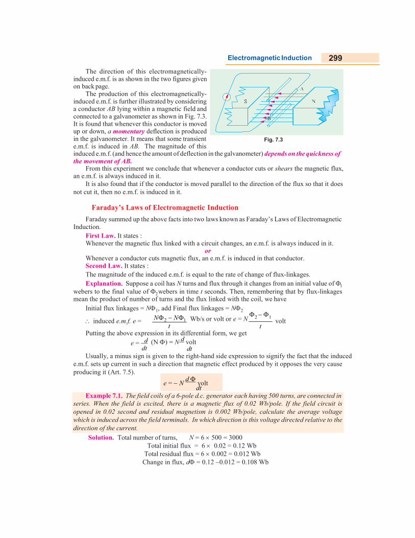
The direction of this electromagnetically- induced e.m.f. is as shown in the two figures given on back page.
The production of this electromagnetically- induced e.m.f. is further illustrated by considering a conductor AB lying within a magnetic field and connected to a galvanometer as shown in Fig. 7.3. It is found that whenever this conductor is moved up or down, a momentary deflection is produced in the galvanometer. It means that some transient e.m.f. is induced in AB. The magnitude of this
Fig. 7.3
induced e.m.f. (and hence the amount of deflection in the galvanometer) depends on the quickness of the movement of AB.
From this experiment we conclude that whenever a conductor cuts or shears the magnetic flux, an e.m.f. is always induced in it.
It is also found that if the conductor is moved parallel to the direction of the flux so that it does not cut it, then no e.m.f. is induced in it.
Faraday’s Laws of Electromagnetic Induction
Faraday summed up the above facts into two laws known as Faraday’s Laws of Electromagnetic Induction.
First Law. It states : Whenever the magnetic flux linked with a circuit changes, an e.m.f. is always induced in it.
or Whenever a conductor cuts magnetic flux, an e.m.f. is induced in that conductor. Second Law. It states : The magnitude of the induced e.m.f. is equal to the rate of change of flux-linkages. Explanation. Suppose a coil has N turns and flux through it changes from an initial value of
webers to the final value of 2 webers in time t seconds. Then, remembering that by flux-linkages mean the product of number of turns and the flux linked with the coil, we have
Initial flux linkages = N1, add Final flux linkages = N2
induced e.m.f. e = N 2 N 1
t Wb/s or volt or e = N
2 1
t volt
Putting the above expression in its differential form, we get
e = d dt
(N ) = N d volt dt
Usually, a minus sign is given to the right-hand side expression to signify the fact that the induced e.m.f. sets up current in such a direction that magnetic effect produced by it opposes the very cause producing it (Art. 7.5).
Solution. Total number of turns, N = 6 500 = 3000 Total initial flux = 6 0.02 = 0.12 Wb
Total residual flux = 6 0.002 = 0.012 Wb Change in flux, d = 0.12 0.012 = 0.108 Wb

300 Electrical Technology
Example 7.3. The time variation of the flux linked with a coil of 500 turns during a complete cycle is as follows :
= 0.04 (1 4 t/T) Weber 0 < t < T/2 = 0.04 (4t/T 3) Weber T/2 < t < T
where T represents time period and equals 0.04 second. Sketch the waveforms of the flux and in- duced e.m.f. and also determine the maximum value of the induced e.m.f..
Time of opening the circuit, dt = 0.02 second
Induced e.m.f. = N d
volt 3000 0.108 = 16,200 V dt 0.02
The direction of this induced e.m.f. is the same as the initial direction of the exciting current.
Solution. Induced e.m.f. = N . d
volt dt
Here d = 1 0.2 = 0.8 mWb = 0.8 103 Wb
dt = 1/10 = 0.1 second ; N = 100
e = 100 0.8 103/0.1 = 0.8 V
Total circuit resistance = 100 + 400 = 500 Current induced = 0.8/500 = 1.6 103 A = 1.6 mA
Fig. 7.4.
Solution. The variation of flux is linear as seen from the following table.
t (second) : 0 T/4 T/2 3T/4 T
F (Weber) : 0.04 0 0.04 0 0.04
The induced e.m.f. is given by e = Nd /dt
From t = 0 to t = T/2, d/dt = 0.04 4/T = 4 Wb/s e = 500 (4) = 2000 V
From t = T/2 to t = T, d/dt = 0.04 4/T = 4 Wb/s e = 500 4 = 2000 V.
The waveforms are selected in Fig. 7.4.
Direction of induced e.m.f. and currents
There exists a definite relation between the direction of the induced current, the direction of the flux and the direction of motion of the conductor. The direction of the induced current may be found easily by applying either Fleming’s Right-hand Rule or Flat-hand rule or Lenz’s Law. Fleming’s rule
Example 7.2. A coil of resistance 100 is placed in a magnetic field of 1 mWb. The coil has 100 turns and a galvanometer of 400 resistance is connected in series with it. Find the average
e.m.f. and the current if the coil is moved in 1/10th second from the given field to a field of 0.2 mWb.

301 Electromagnetic Induction
(Fig. 7.5) is used where induced e.m.f. is due to flux-cutting (i.e., dynamically induced e.m.f.) and Lenz’s when it is used to change by flux-linkages (i.e., statically induced e.m.f.).
Fig. 7.5. Fig. 7.6.
Fig. 7.6 shows another way of finding the direction of the induced e.m.f. It is known as Right Flat-hand rule. Here, the front side of the hand is held perpendicular to the incident flux with the thumb pointing in the direction of the motion of the conductor. The direction of the fingers give the direction of the induced e.m.f. and current.
Lenz’s Law
The direction of the induced current may also be found by this law which was formulated by Lenz* in 1835. This law states, in effect, that electromagnetically induced current always flows in such direction that the action of the magnetic field set up by it tends to oppose the very cause which produces it.
This statement will be clarified with reference to Fig. 7.1 and 7.2. It is found that when N-pole of the bar magnet approaches the coil, the induced current set up by induced e.m.f. flows in the anti- clockwise direction in the coil as seen from the magnet side. The result is that face of the coil becomes a N-pole and so tends to oppose the onward approach of the N-Pole of the magnet (like poles repel each other). The mechanical energy spent in overcoming this repulsive force is converted into electrical energy which appears in the coil.
When the magnet is withdrawn as in Fig. 7.2, the induced current flows in the clockwise direc- tion thus making the face of the coil (facing the magnet) a S-pole. Therefore, the N-pole of the magnet has to withdrawn against this attractive force of the S-pole of coil. Again, the mechanical energy required to overcome this force of attraction is converted into electric energy.
It can be shown that Lenz’s law is a direct consequence of Law of Conservation of Energy. Imagine for a moment that when N-pole of the magnet (Fig. 7.1) approaches the coil, induced current flows in such a direction as to make the coil face a S-pole. Then, due to inherent attraction between unlike poles, the magnet would be automatically pulled towards the coil without the expenditure of any mechanical energy. It means that we would be able to create electric energy out of nothing, which is denied by the inviolable Law of Conservation of Energy. In fact, to maintain the sanctity of this law, it is imperative for the induced current to flow in such a direction that the magnetic effect produced by it tends to oppose the very cause which produces it. In the present case, it is relative motion of the magnet with magnet with respect to the coil which is the cause of the production of the induced current. Hence, the induced current always flows in such a direction to oppose this relative motion i.e., the approach or withdrawal of the magnet.
* After the Russian born geologist and physicist Heinrich Friedrich Emil Lenz (1808 - 1865).

302 Electrical Technology
dt dt
Example 7.5. A square coil of 10 cm side and with 100 turns is rotated at a uniform speed of 500 rpm about an axis at right angle to a uniform field of 0.5 Wb/m2. Calculate the instantaneous value of induced e.m.f. when the plane of the coil is (i) at right angle to the plane of the field. (ii) in the plane of the field. (iii) at 45º with the field direction. (Elect. Engg. A.M.Ae. S.I. Dec. 1991)
Induced e.m.f.
Induced e.m.f. can be either (i) dynamically induced or (ii) stati- cally induced. In the first case, usually the field is stationary and conduc- tors cut across it (as in d.c. generators). But in the second case, usually the conductors or the coil remains stationary and flux linked with it is changed by simply increasing or decreasing the current producing this flux (as in transformers).
Dynamically induced e.m.f.
In Fig. 7.7. a conductor A is shown in cross-section, lying m2 within a uniform magnetic field of flux density B Wb/m2. The arrow attached to A shows its direction of motion. Consider the conditions shown in Fig. 7.7 (a) when A cuts across at right angles to the flux. Suppose ‘l’ is its length lying within the field and let it move a distance dx in time dt. Then area swept by it is = ldx. Hence, flux cut = l.dx B webers.
Change in flux = Bldx weber Time taken = dt second
Hence, according to Faraday’s Laws (Art. 7.3.) the e.m.f. induced in it (known as dynamically induced e.m.f.) is
rate of change of flux linkages = Bldx Bl dx
If the conductor A moves at an angle with the direction of flux [Fig. 7.7 (b)] then the induced e.m.f. is e = Bl sin volts = l B (i.e. as cross product vector and B ).
The direction of the induced e.m.f. is given by Fleming’s Right-hand rule (Art. 7.5) or Flat-hand rule and most easily by vector cross product given above.
It should be noted that generators work on the production of dynamically induced e.m.f. in the con- ductors housed in a revolving armature lying within
= Blv volt where dx
dt
= velocity
a strong magnetic field. Fig. 7.7
Solution. Here B = 1.5 Wb/m2 l = 1 m = 50 m/s ; e = ? Now e = Bl = 1.5 1 50 = 75 V. In the second case = 30º sin 30º = 0.5 e = 75 0.5 = 37.5 V
Solution. As seen from Art. 12.2, e.m.f. induced in the coil would be zero when its plane is at right angles to the plane of the field, even though it will have maximum flux linked with it. However, the coil will have maximum e.m.f. induced in it when its plane lies parallel to the plane of the field even though it will have minimum flux linked with it. In general, the value of the induced e.m.f. is given by e = Nm
sin = Em sin where is the angle between the axis of zero e.m.f. and the plane of the coil. Here, f = 500/ 60 = 25/ 3 r.p.s ; N = 100 ; B = 0.5 Wb/ m2 ; A = (10 10) 104 = 102 m2. Em = 2 f NBA = 2 (25/3) 100 0.5 10 = 26.2 V (i) since = 0 ; sin = 0 ; therefore, 2
e = 0. (ii) Here, = 90° ; e = Em sin 90º = 26.2 1 = 26.2 V (iii) sin 45º = 1/ = 18.5 V
; e = 26.2 1/
Example 7.4. A conductor of length 1 metre moves at right angles to a uniform magnetic field of flux density 1.5 Wb/m2 with a velocity of 50 metre/second. Calculate the e.m.f. induced in it. Find also the value of induced e.m.f. when the conductor moves at an angle of 30º to the direction of the field.
windmill to turn
coil
Coil
Brushes
Direction of
Magnetsmovement
Electric current Lamp
The principle of electric generation
2 2

303 Electromagnetic Induction
Example 7.7 In a 4-pole dynamo, the flux/pole is 15 mWb. Calculate the average e.m.f. induced in one of the armature conductors, if armature is driven at 600 r.p.m.
Example 7.6. A conducting rod AB (Fig. 7.8) makes contact with metal rails AD and BC which are 50 cm apart in a uniform magnetic field of B = 1.0 Wb/m2 perpendicular to the plane ABCD. The total resistance (assumed constant) of the circuit ABCD is 0.4 .
(a) What is the direction and magnitude of the e.m.f. induced in the rod when it is moved to the left with a velocity of 8 m/s ?
(b) What force is required to keep the rod in motion ? (c) Compare the rate at which mechanical work is done by the force F with the rate of develop-
ment of electric power in the circuit.
Solution. (a) Since AB moves to the left, direction of the induced current, as found by applying Fleming’s Right-hand rule is from A to B. Magnitude of the in- duced e.m.f. is given by
e = l volt = 1 0.5 8 = 4 volt (b) Current through AB = 4/0.4 = 10 A Force on AB i.e. F = BIl = 1 10 0.5 = 5 N The direction of this force, as found by applying
Fleming’s left-hand rule, is to the right. (c) Rate of doing mechanical work = F = 5 8 = 40 J/s or W
Electric power produced = e i = 4 10 = 40 W
Fig. 7.8
From the above, it is obvious that the mechanical work done in moving the conductor against force F is converted into electric energy.
Solution. It should be noted that each time the conductor passes under a pole (whether N or S) it cuts a flux of 15 mWb. Hence, the flux cut in one revolution is 15 4 = 60 mWb. Since conductor is rotating at 600/60 = 10 r.p.s. time taken for one revolution is 1/10 = 0.1 second.
average e.m.f. generated = N d volt dt
N = 1; d = 60 mWb = 6 102 Wb ; dt = 0.1 second e = 1 6 102/0.1 = 0.6 V
Statically Induced E.M.F.
It can be further sub-divided into (a) mutu- ally induced e.m.f. and (b) self-induced e.m.f.
(a) Mutually-induced e.m.f. Consider two coils A and B lying close to each other (Fig. 7.9).
Coil A is joined to a battery, a switch and a variable resistance R whereas coil B is connected
Fig. 7.9
Tutorial Problems No. 7.1
1. A conductor of active length 30 cm carries a current of 100 A and lies at right angles to a magnetic field of strength 0.4 Wb/m2. Calculate the force in newtons exerted on it. If the force causes the conductor to move at a velocity of 10 m/s, calculate (a) the e.m.f. induced in it and (b) the power in watts developed by it. [12 N; 1.2 V, 120 W]
2. A straight horizontal wire carries a steady current of 150 A and is situated in a uniform magnetic field of 0.6 Wb/m2 acting vertically downwards. Determine the magnitude of the force in kg/metre length of conductor and the direction in which it works. [9.175 kg/m horizontally]
3. A conductor, 10 cm in length, moves with a uniform velocity of 2 m/s at right angles to itself and to a uniform magnetic field having a flux density of 1 Wb/m2. Calculate the induced e.m.f. between the ends of the conductor. [0.2 V]

304 Electrical Technology
to a sensitive voltmeter V. Whenis established by closing the switch, its magnetic field is set up which partly links with or through the coil B. As current throughthe flux linked with B is also changed. Hence, mutually induced e.m.f. is produced in magnitude is given by Faraday’s Laws (Art. and direction by Lenz’s Law (Art.
If, now, battery is connected to reversed and now a change of current in
It is obvious that in the examplesflux variations being brought aboutone coil by the influence of the
(b) Self-induced e.m.f. This is the e.m.f. induced in a coil due to linked with it. If current throughwill also change, which will produceself-induced e.m.f. The direction(as given by Lenz’s law) would be such as to oppose any change of flux which is, inits production. Hence, it is also known as the opposing or counter e.m.f. of self-induction.
Self-inductance
Imagine a coil of wire similar to the one shown in Fig. 7.11 connected to a battery through a rheostat. It is found that wheneveris always opposed by the instantaneousto overcome this opposition is suppliedis stored in the additional flux
If, now an effort is made toto the production of self-induceddue to which it opposes any increase or decrease or current of flux through it, is known as inductance. It is quantitativelyanalogous to inertia in a material heavy body into motion, but oncelarge self-induction, it is initiallyequally difficult to withdraw it. Hence, selfinertia or electromagnetic inertia.
Coefficient of Self-induction
It may be defined in any one of the three ways given below :(i) First Method for L The coefficient of self-induction of a coil is defined as
the weberBy ‘weber-turns’ is meant
flux is linked. In other words, it is the fluConsider a solenoid having
webers, the weber-turns are
By definition,
* After the American scientist Joseph Henry (1797
Technology
When current through A is established by closing the switch, its magnetic field is set up which partly links with or threads
through A is changed, is also changed. Hence,
mutually induced e.m.f. is produced in B whose magnitude is given by Faraday’s Laws (Art. 7.3) and direction by Lenz’s Law (Art. 7.5).
Fig. 7.10
If, now, battery is connected to B and the voltmeter across A (Fig. 7.10), then the situation is reversed and now a change of current in B will produce mutually-induced e.m.f. in A.
examples considered above, there is no movement of any conductor,about by variations in current strength only. Such an e.m.f.
the other coil is called (statically but) mutually induced e.m.f.This is the e.m.f. induced in a coil due to the change of its own flux
through the coil (Fig. 7.11) is changed, then the flux linked with itsproduce in it what is called
direction of this induced e.m.f. (as given by Lenz’s law) would be such as to oppose
in fact, the very cause of its production. Hence, it is also known as the oppos-
induction.
Fig. 7.11
Imagine a coil of wire similar to the one shown in Fig. 7.11 connected to a battery through a whenever an effort is made to increase current (and hence flux) throughinstantaneous production of counter e.m.f. of self-induction. Energy
supplied by the battery. As will be fully explained later on, produced.
to decrease the current (and hence the flux), then again it is delayedinduced e.m.f., this time in the opposite direction. This property
due to which it opposes any increase or decrease or current of flux through it, is known as quantitatively measured in terms of coefficient of self induction L. This
analogous to inertia in a material body. We know by experience that initially it is difficult to set a once in motion, it is equally difficult to stop it. Similarly, in a
initially difficult to establish a current through it, but once established,equally difficult to withdraw it. Hence, self-induction is sometimes analogously called
inertia.
induction (L)
It may be defined in any one of the three ways given below :
induction of a coil is defined as the weber-turns per ampere in the coil
meant the product of flux in webers and the number of turns withflux is linked. In other words, it is the flux-linkages of the coil.
Consider a solenoid having N turns and carrying a current of I amperes. If the flux produced isturns are N. Hence, weber-turns per ampere are N /I.
L = N
. The unit of self-induction is henry*. L
After the American scientist Joseph Henry (1797 - 1878), a company of Faraday.
(Fig. 7.10), then the situation is
conductor, the e.m.f. induced in
e.m.f. the change of its own flux
its own turns
Imagine a coil of wire similar to the one shown in Fig. 7.11 connected to a battery through a through it, it
Energy required on, this energy
delayed due property of the coil
due to which it opposes any increase or decrease or current of flux through it, is known as self- This property is
by experience that initially it is difficult to set a a coil having
established, it is induction is sometimes analogously called electrical
with which the
amperes. If the flux produced is

305 Electromagnetic Induction
0.3
I
dt
H
dt
Example 7.8. The field winding of a d.c. electromagnet is wound with 960 turns and has resis- tance of 50 when the exciting voltages is 230 V, the magnetic flux linking the coil is 0.005 Wb. Calculate the self-inductance of the coil and the energy stored in the magnetic field.
Example 7.10. If a coil of 150 turns is linked with a flux of 0.01 Wb when carrying current of 10 A, calculate the inductance of the coil. If this current is uniformly reversed in 0.01 second, calculating the induced electromotive force.
If in the above relation, N = 1 Wb-turn, I = 1 ampere, then L = 1 henry (H) Hence a coil is said to have a self-inductance of one henry if a current of 1 ampere when
flowing through it produced flux-linkages of 1 Wb-turn in it.
Therefore, the above relation becomes
Solution. Formula used : L = N
H L
Current through coil = 230/50 = 4.6 A = 0.005 Wb ; N = 960
L = 960 0.005
4.6 = 1.0435 H. Energy stored =
1 L I 2 1 1 1.0435 4.62 = 11.04 J 2 2
Second Method for L
We have seen in Art. 6.20 that flux produced in a solenoid is
= NI l / 0r A
N Now L = N I I / 0r A
N . N H I I / 0r A
L = N 2
l / A N 2
S or AN 2
L 0 r H 0 r l
It gives the value of self-induction in terms of the dimensions of the solenoid*.
Solution. L = AN2/l. Here N = 400 ; A = 2 2 = 4 cm2 = 4 104 m2 ; l = 0.3 m ; = 800 0 r r
L = 4 107 800 4 104 (400)2/ = 68.3 mH
Note. The cross-section of the wire is not relevant to the given question.
Third Method for L
It will be seen from Art. 7.10 (i) above that L = N
N = LI or N = L I
Differentiating both sides, we get d
(N) = L . dI
(assuming L to be constant) ;
N . d dt
dt dt L . dI
dt
As seen from Art. 7.3, N . d
= self-induced e.m.f. eL L dI dt
dI = 1 ampere/second and e = 1 volt, then L = 1 H
Hence, a coil has a self-inductance of one henry if one volt is induced in it when current through it changes at the rate of one ampere/second.
Solution. L = N/I = 150 0.01/10 = 0.15 H
Now, eL = L dI/dt ; dI = 10 (10) = 20 A
eL = 0.15 20/0.01 = 300 V
* In practice, the inductance of a short solenoid is given by L = Kμ0 μr.AN2/l where K is Nagaoka’s constant.
I L =
N henry
Example 7.9. An iron ring 30 cm mean diameter is made of square of iron of 2 cm 2 cm cross- section and is uniformly wound with 400 turns of wire of 2 mm2 cross-section. Calculate the value of the self-inductance of the coil. Assume r = 800. (Elect. Technology. I, Gwalior Univ.)
=
If
=
L
306 Electrical Technology
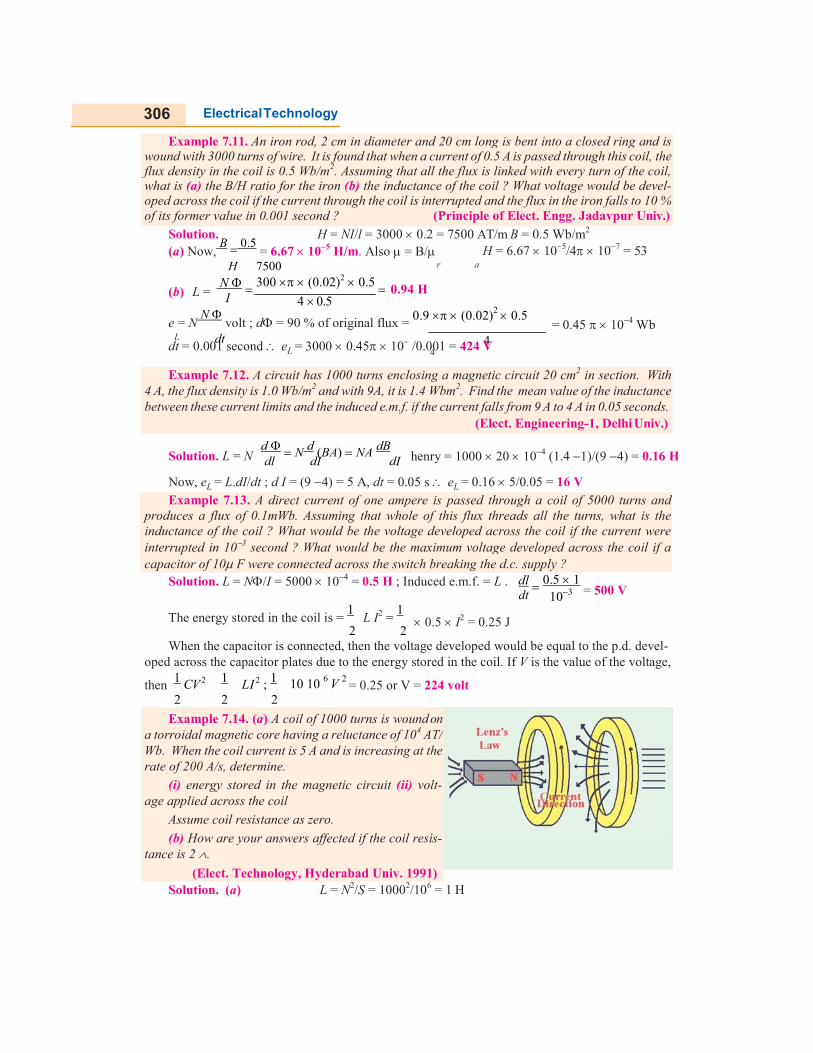
Solution. H = NI/l = 3000 0.2 = 7500 AT/m B = 0.5 Wb/m2 (a) Now,
B 0.5 = 6.67 105 H/m. Also = B/ H = 6.67 105/4 107 = 53
H 7500 r a
N 300 (0.02)2 0.5 (b) L = I 4 0.5
0.94 H
e = N N
volt ; d = 90 % of original flux = 0.9 (0.02) 0.5
= 0.45 104 Wb L dt 4
dt = 0.001 second eL = 3000 0.45 10 /0.001 = 424 V 4
Solution. L = N
d N d (BA) NA dB dl dI dI
henry = 1000 20 104 (1.4 1)/(9 4) = 0.16 H
Now, eL = L.dI/dt ; d I = (9 4) = 5 A, dt = 0.05 s eL = 0.16 5/0.05 = 16 V
Solution. L = N/I = 5000 104 = 0.5 H ; Induced e.m.f. = L . dl
0.5 1 = 500 V
The energy stored in the coil is = 1
2
L I2 = 1 2
dt
0.5 I2 = 0.25 J
103
When the capacitor is connected, then the voltage developed would be equal to the p.d. devel- oped across the capacitor plates due to the energy stored in the coil. If V is the value of the voltage,
then 1 CV 2 1 LI 2 ; 1 10 10 6 V 2
= 0.25 or V = 224 volt 2 2 2
Solution. (a) L = N2/S = 10002/106 = 1 H
Example 7.14. (a) A coil of 1000 turns is wound on a torroidal magnetic core having a reluctance of 104 AT/ Wb. When the coil current is 5 A and is increasing at the rate of 200 A/s, determine.
(i) energy stored in the magnetic circuit (ii) volt- age applied across the coil
Assume coil resistance as zero.
(b) How are your answers affected if the coil resis- tance is 2 .
(Elect. Technology, Hyderabad Univ. 1991)
Example 7.13. A direct current of one ampere is passed through a coil of 5000 turns and produces a flux of 0.1mWb. Assuming that whole of this flux threads all the turns, what is the inductance of the coil ? What would be the voltage developed across the coil if the current were interrupted in 103 second ? What would be the maximum voltage developed across the coil if a capacitor of 10 F were connected across the switch breaking the d.c. supply ?
Example 7.12. A circuit has 1000 turns enclosing a magnetic circuit 20 cm2 in section. With 4 A, the flux density is 1.0 Wb/m2 and with 9A, it is 1.4 Wbm2. Find the mean value of the inductance between these current limits and the induced e.m.f. if the current falls from 9 A to 4 A in 0.05 seconds.
(Elect. Engineering-1, Delhi Univ.)
Example 7.11. An iron rod, 2 cm in diameter and 20 cm long is bent into a closed ring and is wound with 3000 turns of wire. It is found that when a current of 0.5 A is passed through this coil, the flux density in the coil is 0.5 Wb/m2. Assuming that all the flux is linked with every turn of the coil, what is (a) the B/H ratio for the iron (b) the inductance of the coil ? What voltage would be devel- oped across the coil if the current through the coil is interrupted and the flux in the iron falls to 10 % of its former value in 0.001 second ? (Principle of Elect. Engg. Jadavpur Univ.)

307 Electromagnetic Induction
Example 7.15. A single element has the current and voltage functions graphed in figure 7.12. (a) and (b). Determine the element. [Bombay University 2001]
(i) Energy stored =
1 LI 1 1 52 12.5 J 2 2
(ii) Voltage applied across coil= self-induced e.m.f. in the coil = L.dI/dt = 1 200 = 200 V (b) Though there would be additional energy loss of 52 2 = 50 W over the coil resistance,
energy stored in the coil would remain the same. However, voltage across the coil would increase by an amount = 5 2 = 10 V i.e., now its value would be 210 V.
Mutual Inductance
In Art. 7.8 (Fig. 7.9) we have that any change of current in coil A is always accompanied by the production of mutually-induced e.m.f. in coil B. Mutual inductance may, therefore, be defined as the ability of one coil (or circuit) to produce an e.m.f. in a nearby coil by induction when the current in the first coil changes. This action being reciprocal, the second coil can also induce an e.m.f. in the first when current in the second coil changes. This ability of reciprocal induction is measured in terms of the coefficient of mutual induction M.
Fig. 7.12 (a)
Fig. 7.12 (b)
Solution. Observations from the graph are tabulated below. Sr. No. Between time di/dt
amp/sec V L
1 0 - 2 m Sec 5000 15 15/5000 = 3mH 2 2 - 4 m Sec 0 0 –
3 4 - 6 m Sec – 10,000 – 30 – 30 / (– 10,000) = 3 mH 4 6 - 8 m Sec 0 0 –
The element is a 3-mH inductor.
Coefficient of Mutual Inductance (M)
It can also be defined in three ways as given below : (i) First Method for M Let there be two magnetically-coupled coils having N1 and N2 turns respectively (Fig. 7.9).
Coefficient of mutual inductance between the two coils is defined as the weber-turns in one coil due to one ampere current in the other.

308 Electrical Technology
4
4
Let a current I1 ampere when flowing in the first coil produce a flux 1 webers in it. It is supposed that whole of this flux links with the turns of the second coil*. Then, flux-linkages i.e., webers-turns in the second coil for unit current in the first coil are N2 1/I1. Hence, by definition
If weber-turns in second coil due to one ampere current in the first coil i.e. N2 1/I1 = 1 then, as seen from above, M = 1H.
Hence, two coils are said to have a mutual inductance of 1 henry is one ampere current when flowing in one coil produces flux-linkages of one Wb-turn in the other.
Solution. Formula used M = N21
I1 H ; Flux produced in X = 0.5 mWb = 0.5 103 Wb
Flux linked with Y = 0.5 103 0.8 = 0.4 103 Wb ; M = 1000 0.4103
5 = 0.08 H
Solution. The two cases (a) and (b) are shown in Fig. 7.13 (a) and (b) respectively.
(a) Let I1 be the current flowing through the solenoid. Then B = H × NI /l = 2500 I Wb/m2 ... l = 1 m 0 0 1 0 1
Area of search coil A1 = 82 104 = 16 104 m2
Flux linked with search coil is = BA1
= 2500 0I1 16 104 = 15.79 I 106 Wb
N 12015.39I 106 M = 2 1 1 = 1.895 103 H
I1 I1
(b) Since the field strength outside the solenoid is negligible, the effective area of the search coil, in this case, equals the area of the long solenoid.
A2 =
Fig. 7.13
102 104 =
102m2 ;
4
* If whole of this flux does not link with turns of the second coil, then only that part of the flux which is actually linked is taken instead. (Ex. 7.13 and 7.17). In general, M = N22/I1.
Example 7.17. A long single layer solenoid has an effective diameter of 10 cm and is wound with 2500 AT/metre. There is a small concentrated coil having its plane lying in the centre cross- sectional plane of the solenoid. Calculate the mutual inductance between the two coils in each case if the concentrated coil has 120 turns on an effective diameter of (a) 8 cm and (b) 12 cm.
(Elect. Science - II Allahabad Univ. 1992)
Example 7.16. Two identical coils X and Y of 1,000 turns each lie in parallel planes such that 80% of flux produced by one coil links with the other. If a current of 5 A flowing in X produces a flux of 0.5 mWb in it, find the mutual inductance between X and Y. (Elect. Engg. A,M.Ae.S.I.)
M = N2 1
I1
1

309 Electromagnetic Induction
1
= BA2 = 2500 0I1
102 = 24.68 I
4 1 106 Wb
120 24.68 I 106 M = I1
= 2.962 103 H
N
900 0.5 103
Solution. (i) Inductance of the first coil = I 3
= 0.15 H
(ii) e.m.f. induced e = L di 0.15 (5 0) = 750 V
1 dt 1 103
(iii)
M N21
I1
600 0.5 103 =
3
= 0.1 H
(ii) Second Method for M
We will now deduce an expression for coefficient of mutual inductance in terms of the dimen- sions of the two coils.
Flux in the first coil 1 = N2I1
l / 0r A Wb ; Flux/ampere =
1 I1
N1
l / 0r A Assuming that whole of this flux (it usually is some percentage of it) is linked with the other coil
having N2 turns, the weber-turns in it due to the flux/ampere in the first coil is
M = N21
I1
N2 N1
l / 0r A M =
0r A N1N2
l
Also M = N1N2
l / 0r A N1N2
reluctance
N1N2 H
S
Solution. L1 = N11/I1 = 150 0.01/10 = 0.15 H
e = L di/dt = 0.15 [10 (10)]/0.1 = 1 = 30 V
M = N2/I1 = 100 0.01/10 = 0.1 H (iii) Third Method for M
As seen from Art. 7.12 (i) M =
N21
I1
N21 = MI1 or N21 = MI1
Differentiating both sides, we get : d
(N ) = M dI1
(assuming M to be constant) dt 2 1 dt
Now, d
(N ) = mutually-induced e.m.f. in the second coil = e e = M dI1
dt 2 1 M M dt
If dI1/dt = 1 A/s ; eM = 1 volt, then M = 1 H.
Hence, two coils are said to have a mutual inductance of one henry if current changing at the rate of 1 ampere/second in one coil induces an e.m.f. of one volt in the other.
Example 7.19. If a coil of 150 turns is linked with a flux of 0.01 Wb when carrying a current of 10 A ; calculate the inductance of the coil. If this current is uniformly reversed in 0.1 second, calculate the induced e.m.f. If a second coil of 100 turns is uniformly wound over the first coil, find the mutual inductance between the coils. (F. E. Pune Univ.)
Example 7.18. A flux of 0.5 mWb is produced by a coil of 900 turns wound on a ring with a current of 3 A in it. Calculate (i) the inductance of the coil (ii) the e.m.f. induced in the coil when a current of 5 A is switched off, assuming the current to fall to zero in 1 milli second and (iii) the mutual inductance between the coils, if a second coil of 600 turns is uniformly wound over the first coil.
(F. E. Pune Univ.)
H

310 Electrical Technology
Nl / A
1
Example 7.21. Two coils A and B each having 1200 turns are placed near each other. When coil B is open-circuited and coil A carries a current of 5 A, the flux produced by coil A is 0.2 Wb and 30% of this flux links with all the turns of coil B. Determine the voltage induced in coil B on open- circuit when the current in the coil A is changing at the rate of 2 A/s.
Solution. Formula used : M = N1N2
l / 0r A H, N1 = 30 ; N2 = 600 ; A = 100 104 = 102m2, l = 2m
M = A N N /l = 4 107 2000 102 30 600/2 = 0.226 H 0 r 1 2
dI1 = 20 0 = 20 A ; dt = 0.02 s ; eM = MdI1/dt 0.226 20/0.2 = 226 V
Solution. Coefficient of mutual induction between the two coils is M = N22/I1
Flux linked with coil B is 30 per cent of 0.2 Wb i.e. 0.06 Wb
M = 1200 0.06/5 = 14.4 H
Mutually-induced e.m.f. in coil B is eM = MdI1/dt = 14.4 2 = 28.8 V
Solution. Induced e.m.f. in coil A is e = N d where N is the number of turns of coil A.
1 dt 1
0.25 = N1 103 N = 250 5
Now, flux linkages in coil A due to 2 A current in coil B = 250 10
M = flux linkages in coil A
current in coil B = 250 105/2 = 1.25 mH
Coefficient of Coupling
Consider two magnetically-coupled coils A and B having N1 and N2 turns respectively. Their individual coefficients of self-induction are,
L1 =
2 1
l / 0r A
N 2
and L2 = 2
0 r
The flux 1 produced in A due to a current I1 ampere is 1 = N1I1
l / 0r A Suppose a fraction k1 of this flux i.e. k11 is linked with coil B.
Then M = k11 N2
I1 where k1ñ1.
Substituting the value of 1, we have, M = k1 N1N2
l / A
...(i) 0 r
Similarly, the flux 2 produced in B due to I2 ampere in it is 2 = N2I2
l / 0r A Suppose a fraction k2 of this flux i.e. k22 is linked with A.
Then M = k22 N1 k
I2
N1N2
2 l / 0r A ...(ii)
Example 7.22. Two coils are wound side by side on a paper-tube former. An e.m.f. of 0.25 V is induced in coil A when the flux linking it changes at the rate of 103 Wb/s. A current of 2 A in coil B causes a flux of 105 Wb to link coil A. What is the mutual inductance between the coils ?
(Elect. Engg-I, Bombay Univ.)
Example 7.20. Two coils having 30 and 600 turns respectively are wound side-by-side on a closed iron circuit of area of cross-section 100 sq.cm. and mean length 200 cm. Estimate the mutual inductance between the coils if the relative permeability of the iron is 2000. If a current of zero ampere grows to 20 A in a time of 0.02 second in the first coil, find the e.m.f. induced in the second coil. (Elect. Engg. I, JNT Univ., Warangal)

ML
Example 7.24. Two coils,60 % of flux produced in A links coil B. It is found that a current of 5A in A produces a flux of 0.6 mWb while the same current(ii) coupling coefficient.
L1L2
Example 7.23. Two identical 750 turn coils A and B lie in at the rate of 1500 A/s in A inducesarrangement. If the self-inductance of each coil is 15 mH, calculate the flux produced in coil A per ampere and the percentage of this flux which links the turns of
Multiplying Eq. (i) and (ii
Putting = k, we have
The constant k is called the inductance actually present between the two coils to the maximum possible valueto one coil completely links withall link with the other, then k = when k = 0, the coils are magnetically
Solution. Now,
N11
Now, L1 =
1
Now, k =
Solution. (i) Flux/ampere in
Flux linked with
Now, L1 = 12, 500
5
(ii)
Note. We could find k in another way also.
Solution. M = 32 103 H
Average e.m.f. induced = Now
Now M =
k1k2
2L1
Example 7.25. Two magneticallythe average e.m.f. induced in one,second ? Given that one coil has twice the number of turns in the each coil. Neglect leakage.
I
Electromagnetic Induction
M L1L2
coils, A of 12,500 turns and B of 16,000 turns, lie in parallel planes60 % of flux produced in A links coil B. It is found that a current of 5A in A produces a flux of 0.6
current in B produces 0.8 mWb. Determine (i) mutual inductance
1 2
1
I
identical 750 turn coils A and B lie in parallel planes. A current changing induces an e.m.f. of 11.25 V in B. Calculate the mutual inductance
inductance of each coil is 15 mH, calculate the flux produced in coil A per percentage of this flux which links the turns of B.
ii), we get 2 N 2 N 2
2
M = k k 1 2 l / 0r A l / 0r A
or M = k1k2L1L2
, we have M = k L1L2 or k = M L1L2
is called the coefficient of coupling and may be defined as the ratio of inductance actually present between the two coils to the maximum possible value. If the flux due
with the other, then value of k is unity. If the flux of one coil 0. In the first case, when k = 1, coils are said to be tightly coupled
magnetically isolated from each other.
eM = MdI1/dt
M = eM
dI1 / dt
11.25 = 7.5 103 H = 7.5 mH 1500
1 L1 15 103
5 =
1 N1 750 = 2 10 Wb/A
7.5 10 3 =
7.5 10 3
15 10 3 = 0.5 = 50% (ä L1 = L2
Flux/ampere in A = 0.6/5 = 0.12 mWb
Flux linked with B = 0.12 0.6 = 0.072 mWb
M = 0.072 103 16,000 = 1.15 H
0.6 = 150 103 H ; L =
16, 000 0.8 5
= 256 10
k = M/ 1.15 / = 0.586
in another way also. Value of k1 = 0.6, that of k2 could also be found, then
H ; dI = 15 3 = 12 mA = 12 103 A ; dt = 0.004 second
dI1 32 103 12 103
3
Average e.m.f. induced = M dt
0.004 = 96 10 V
L = N2A/l = k N 2 where k = A/l (taking 1 0
(2N)2 A 2 L = 0 2kN ; L2
0
2kN 2
2 = 2 L
= 2
2 2 l L1 kN 2
= 32, L1 = 32 / 16/ 2mH ; L2 = 2 16/ 32
L2
L1L2 1.5 2.56
L1 2 2
magnetically-coupled coils have a mutual inductance of 32 mH. What is one, if the current through the other changes from 3 to 15 mA
second ? Given that one coil has twice the number of turns in the other, calculate the inductance of
2
311 Induction
planes so that 60 % of flux produced in A links coil B. It is found that a current of 5A in A produces a flux of 0.6
inductance and
k1k2
2
parallel planes. A current changing inductance of the
inductance of each coil is 15 mH, calculate the flux produced in coil A per
and may be defined as the ratio of mutual If the flux due
coil does not at coupled and
...Art. 7.12
...Art. 7.10
2 = L) ...Art. 7.13
3 H
could also be found, then k = .
second
(taking = 1) r
= 2L
1
32 mH
coupled coils have a mutual inductance of 32 mH. What is mA in 0.004
e the inductance of
312 Electrical Technology
1
1
Solution. (i)
(ii)
(iii)
Inductances in Series
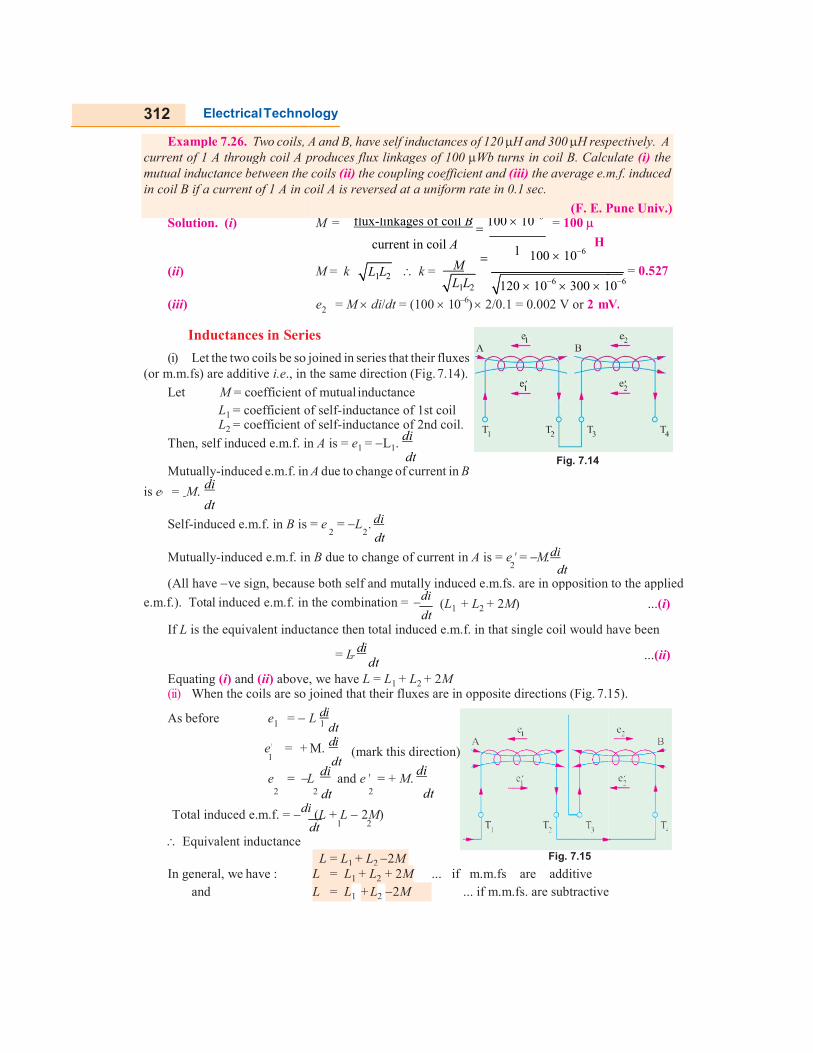
(i) Let the two coils be so(or m.m.fs) are additive i.e., in the same direction (Fig.
Let M = coefficient of mutualL1 = coefficient of selfL2 = coefficient of self
Then, self induced e.m.f. in
Mutually-induced e.m.f. in
is e = M. di
dt
Self-induced e.m.f. in B is =
Mutually-induced e.m.f. in
(All have ve sign, because both self and mutally induced e.m.fs. are in opposition to the applied
e.m.f.). Total induced e.m.f. in the combination =
If L is the equivalent inductance then total induced e.m.f. in that single coil would have been
Equating (i) and (ii) above, we have (ii) When the coils are so joined that their fluxes are in opposite directions (Fig.
As before e =
e = +
e = 2
Total induced e.m.f. = di
Equivalent inductance
In general, we have : and
Example 7.26. Two coils,current of 1 A through coil A produces flux linkages of 100 mutual inductance between thein coil B if a current of 1 A in coil A is reversed at a uniform rate in 0.1
Technology
2
2 2
2
1
1 2
M = flux-linkages of coil B 100 106
= 100
current in coil A
1 H
100 106 M = k k =
120 106 300 10
e = M di/dt = (100 106) 2/0.1 = 0.002 V or 2 mV.
Series
so joined in series that their fluxes ., in the same direction (Fig. 7.14).
= coefficient of mutual inductance = coefficient of self-inductance of 1st coil = coefficient of self-inductance of 2nd coil.
Then, self induced e.m.f. in A is = e1 = L1. di
dt
in A due to change of current in B
is = e = L . di dt
Fig. 7.14
induced e.m.f. in B due to change of current in A is = e = M. di dt
ve sign, because both self and mutally induced e.m.fs. are in opposition to the applied
e.m.f. in the combination = di dt
(L1 + L2 + 2M)
is the equivalent inductance then total induced e.m.f. in that single coil would have been
= L di dt
above, we have L = L1 + L2 + 2M When the coils are so joined that their fluxes are in opposite directions (Fig. 7.15).
L di dt
+ M. di dt
(mark this direction)
L di
and e = + M. di
2 dt 2 dt
di (L + L 2M) dt
L = L1 + L2 2M Fig. 7.15
L = L1 + L2 + 2M ... if m.m.fs are additive L = L1 + L2 2M ... if m.m.fs. are subtractive
coils, A and B, have self inductances of 120 H and 300 H respectively.current of 1 A through coil A produces flux linkages of 100 Wb turns in coil B. Calculate
the coils (ii) the coupling coefficient and (iii) the average e.m.f.in coil B if a current of 1 A in coil A is reversed at a uniform rate in 0.1 sec.
(F. E. Pune Univ.)
L1L2 M
L1L2
= 0.527 106
mV.
ve sign, because both self and mutally induced e.m.fs. are in opposition to the applied
...(i)
is the equivalent inductance then total induced e.m.f. in that single coil would have been
7.15).
...(ii)
... if m.m.fs. are subtractive
respectively. A turns in coil B. Calculate (i) the
e.m.f. induced
(F. E. Pune Univ.)

313 Electromagnetic Induction
L1L2
coils ? Also, determine the inductance between T1 and T3 when T2 is joined to T4. (Electrical Circuit, Nagpur Univ. 1991)
Example 7.30. Two coils with terminals T1, T2 and T3, T4 respectively are placed side by side. When measured separately, the inductance of the first coil is 1200 mH and that of the second is 800 mH. With T2 joined to T3, the inductance between T1 and T4 is 2500 mH. What is the mutual inductance between the two
Example 7.27. Two coils with a coefficient of coupling of 0.5 between them, are connected in series so as to magnetise (a) in the same direction (b) in the opposite direction. The corresponding values of total inductances are for (a) 1.9 H and for (b) 0.7 H. Find the self-inductances of the two coils and the mutual inductance between them.
Solution. (a) L = L1 + L2 + 2M or 1.9 = L1 + L2 + 2M ...(i) (b) Here L = L1 + L2 2M or 0.7 = L1 + L2 2M ...(ii) Subtracting (ii) from (i), we get
1.2 = 4M M = 0.3 H Putting this value in (i) above, we get L1 + L2 = 1.3 H ...(iii)
We know that, in general, M = k
= M 0.3 = 0.6 L L = 0.36 k 0.5 1 2
From (iii), we get (L + L )2 4L L = (L L )2
1 2 2 1 2 1 2
(L1 L2) = 0.25 or L1 L2 = 0.5 ...(iv) From (iii) and (iv), we get L1 = 0.9 H and L2 = 0.4 H
Solution. (i) L = L1 + L2 + 2M or 0.6 = L1 + L2 + 2M ...(i) and 0.1 = L1 + L2 2M ...(ii) (a) From (i) and (ii) we get,M = 0.125 H Let L1 = 0.2 H, then substituting this value in (i) above, we get L2 = 0.15 H (b) Coupling coefficient k = M 0.125 / = 0.72
Solution. If each coil has an inductance of L henry, then L1 = L2= L ; M = k When connected in series comulatively, the total inductance of the coils is
L1L2 k L L = kL
= L1 + L2 + 2M = 2L + 2M = 2L + 2kL = 2L (1 + 0.25) = 2.5L 2.5 L = 80 or L = 32 mH When connected in series differentially, the total inductance of the coils is
= L1 + L2 2M = 2L 2M = 2L 2kL = 2L (1 k) = 2L (1 0.25) 2L 0.75 = 2 32 0.75 = 48 mH.
Fig. 7.16
Solution. L1 = 1200 mH, L2 = 800 mH Fig. 7.16 (a) shows additive series. L = L1 + L2 + 2M or 2500 = 1200 + 800 + 2M ; M = 250 mH
Example 7.29. Two similar coils have a coupling coefficient of 0.25. When they are connected in series cumulatively, the total inductance is 80 mH. Calculate the self inductance of each coil. Also calculate the total inductance when the coils are connected in series differentially.
(F. E. Pune Univ.)
Example 7.28. The combined inductance of two coils connected in series is 0.6 H or 0.1 H depending on the relative directions of the currents in the coils. If one of the coils when isolated has a self-inductance of 0.2 H, calculate (a) mutual inductance and (b) coupling coefficient.
(Elect. Technology, Univ. of Indore)
L1L2
L1L2 0.2 0.15

314 Electrical Technology
Example 7.32. Find the equivalent in- ductance LAB in Fig. 7.17
(Bombay University, 2001)
L1L2
2
dt
Example 7.31. The total inductance of two coils, A and B, when connected in series, is 0.5 H or H, depending on the relative directions of the current in the coils. Coil A, when isolated from coil B, has a self-inductance of 0.2 H. Calculate
(a) the mutual inductance between the two coils (b) the self-inductance of coil B (c) the coupling factor between the coils. (d) the two possible values of the induced e.m.f. in coil A when the current is decreasing at 1000
A per second in the series circuit. (Elect. Technology, Hyderabad Univ. 1992)
Fig. 7.16 (b) shows the case of subtractive or opposing series.
Here, L = L1 + L2 2M = 1200 + 800 2 250 = 1500 mH
Solution. (a) Combined inductance is given by L = L1 + L2 ± 2M 0.5 = L1 + L2 + 2M ...(i), 0.2 = L1 + L2 2M ...(ii) Subtracting (ii) from (i), we have 4M = 0.3 or M = 0.075 H (b) Adding (i) and (ii) we have 0.7 = 2 0.2 + 2L2 = 0.15 H (c) Coupling factor or coefficient is k = M/ 0.075 / = 0.433 or 43.4%
(d) e
= L di M di
1 1 dt dt
e1 = (0.2 + 0.075) 1000 = 275 V ...‘cumulative connection’ = (0.2 0.075) 1000 = 125 V ...‘differential connection’
Solution. Series Parallel combination of Inductors has to be dealt with. Note that there is no mutual coupling between coils. LAB = 0.5 + [0.6 0.3/(0.3 + 0.3)] = 0.7 H
Inductance in Parallel
In Fig. 7.18, two inductances of values L1 and L2 henry are connected in parallel. Let the coefficient of mutual inductance between the two be M. Let i be the main sup- ply current and i1 and i2 be the branch currents
Obviously, i = i1 + i2
Fig. 7.17
di = dt
di1 di2
dt dt ...(i)
Fig. 7.18
In each coil, both self and mutually induced e.m.fs. are produced. Since the coils are in parallel, these e.m.fs. are equal. For a case when self-induced e.m.f., we get
e = L di1 M di2
= L di2 M
di1
L di1 M
di2 L
di2 M di1
1 dt dt
2 dt dt
1 dt dt
2 dt dt
or di1 (L M) = dt 1
di2 (L M) dt 2
di1 =
dt L2 M di2 L M dt ...(ii)
Hence, (i) above becomes di
= dt L M L M
di2 1 dt
1 ...(iii)
1
If L is the equivalent inductance, then e = L. di
= induced e.m.f. in the parallel combination
= induced e.m.f. in any one coil = L . di1
M
di2
1 dt dt
0.2 0.15
315 Electromagnetic Induction
Example 7.33. Two coils of inductances 4 and 6 henry are connected in parallel. If their mutual inductance is 3 henry, calculate the equivalent inductance of the combination if (i) mutual inductance assists the self-inductance (ii) mutual inductance opposes the self-inductance.
1 2
1 2
1 2
di = 1
L di1 M
di2
...(iv) dt L 1 dt dt L
di 1
L 2
M M di2
Substituting the value of di1/dt from (ii) in (iv), we get dt
= L
1 L M dt ...(v)
1 Hence, equating (iii) to (iv), we have L2 M + 1 = 1 L
L2 M M
L1 M
L 1 L M
L L 2M 1 L L M 2
1
or 1 2 1 2
L1 M L L1 M
L =
Similarly, L =
LL M 2
L1 L2 2M LL M 2
L1 L2 2M
when mutual field assists the separate fields.
when the two fields oppose each other.
Solution. (i) L = LL M 2
4 6 32 15
= 3.75 H
L1 L2 2M LL M 2
4 6 2 3 4 24 9 15
(ii) L = 1 2
L1 L2 2M
16
16 = 0.94 H (approx.)
Tutorial Problems No. 7.2
1. Two coils are wound close together on the same paxolin tube. Current is passed through the first coil and is varied at a uniform rate of 500 mA per second, inducing an e.m.f. of 0.1 V in the second coil. The second coil has 100 turns. Calculate the number of turns in the first coil if its inductance is 0.4 H.
[200 turns] 2. Two coils have 50 and 500 turns respectively are wound side by side on a closed iron circuit of section
50 cm2 and mean length 120 cm. Estimate the mutual inductance between the coils if the permeability of iron is 1000. Also, find the self-inductance of each coil. If the current in one coil grows steadily from zero to 5A in 0.01 second, find the e.m.f. induced in the other coil.
[M = 0.131 H, L1 = 0.0131 H, L2 = 1.21 H, E = 65.4 V] 3. An iron-cored choke is designed to have an inductance of 20 H when operating at a flux density of
1 Wb/m2, the corresponding relative permeability of iron core is 4000. Determine the number of turns in the winding, given that the magnetic flux path has a mean length of 22 cm in the iron core and of 1 mm in air-gap that its cross-section is 10 cm2. Neglect leakage and fringing. [4100]
4. A non-magnetic ring having a mean diameter of 30 cm and a cross-sectional area of 4 cm2 is uni- formly wound with two coils A and B, one over the other. A has 90 turns and B has 240 turns. Calculate from first principles the mutual inductance between the coils. Also, calculate the e.m.f. induced in B when a current of 6 A in A is reversed in 0.02 second.
[11.52 H, 6.912 mV] 5. Two coils A and B, of 600 and 100 turns respectively are wound uniformly around a wooden ring
having a mean circumference of 30 cm. The cross-sectional area of the ring is 4 cm2. Calculate (a) the mutual inductance of the coils and (b) the e.m.f. induced in coil B when a current of 2 A in coil A is reversed in 0.01 second. [(a) 100.5 H (b) 40.2 mV]
6. A coil consists of 1,000 turns of wire uniformly wound on a non-magnetic ring of mean diameter 40 cm and cross-sectional area 20 cm2. Calculate (a) the inductance of the coil (b) the energy stored in the magnetic field when the coil is carrying a current of 15 A (c) the e.m.f. induced in the coil if this current is completely interrupted in 0.01 second. [(a) 2mH (b) 0.225 joule (c) 3V]
7. A coil of 50 turns having a mean diameter of 3 cm is placed co-axially at the centre of a solenoid 60 cm long, wound with 2,500 turns and carrying a current of 2 A. Determine mutual inductance of the arrangement. [0.185 mH]
8. A coil having a resistance of 2 and an inductance of 0.5 H has a current passed through it which

316 Electrical Technology
OBJECTIVE TESTS – 7
1. According to Faraday’s Laws of Electromag- netic Induction, an e.m.f. is induced in a con- ductor whenever it (a) lies in a magnetic field (b) cuts magnetic flux (c) moves parallel to the direction of the
magnetic field (d) lies perpendicular to the magnetic flux.
2. A pole of driving point admittance function implies (a) zero current for a finite value of driving
voltage (b) zero voltage for a finite value of driving
current (c) an open circuit condition (d) None of (a), (b) and (c) mentioned in the
question (ESE 2001) 3. The inductance of a long solenoid of length
1000 mm wound uniformly with 3000 turns on a cylindrical paper tube of 60 mm diameter is
(a) 3.2 μH (b) 3.2 mH (c) 32.0 mH (d) 3.2 H
(GATE 2004) 4. A moving iron ammeter produced a full scale
torque of 240 μNm with a deflection of 1200
at a current of 10 A. The rate of change of self inductance (μH/radian) of the instrument at full scale is (a) 2.0 μH/radian (b) 4.8 μH/radian (c) 12.0 μH/radian (d) 114.6 μH/radian
(GATE 2004) 5. The self-inductance of a long cylindrical
conductor due to its internal flux linkages is k H/m. If the diameter of the conductor is doubled, then the selfinductance of the conductor due its internal flux linkages would be (a) 0.5 K H/m (b) K H/m (c) 1.414 K H/m (d) 4 K H/m
(GATE)
varies in the following manner ; (a) a uniform change from zero to 50 A in 1 second (b) constant at 50 A for 1 second (c) a uniform change from 50 A to zero in 2 seconds. Plot the current graph to a time base. Tabulate the p.d. applied to the coil during each of the above periods and plot the graph of p.d. to a time base. [(a) 25 to 125 V (b) 100 V (c) 87.5 V to 12.5 V]
9. A primary coil having an inductance of 100 H is con- nected in series with a secondary coil of 240 H and the total inductance of the combination is measured as 146 H. Determine the coefficient of coupling.
10. Find the total inductance measured from A-B terminals, in Fig. 7.19.[62.6%] (Circuit Theory, Jadavpur Univ.) [Hint : L = 100 + 50 (2 60) = 30 μH, due to opposite senses of currents with respect to dot-markings.]
11. Given that relative permeablility of cast iron as 200, that Fig. 7.19
of cast steel is 1200 and for Copper μ0 = 1. (Nagpur University, Summer 2003) 12. State Faraday's laws of electromagnetic induction. Distinguish between statically induced emf and
dynamically induced emf with examples. (V.T.U., Belgaum Karnataka University, February 2002)
13. State : (i) Flemming's right hand rule, and (ii) Fleming's left hand rule. Mention their applications. (V.T.U., Belgaum Karnataka University, Winter 2003)
14. Define : (i) Self inductance, and (ii) Mutual inductance. Mention their units and formula to calculate each of them. Derive an expression for the energy stored in an inductor of self inductance ‘L’ henry carrying the current of ‘I’ amperes.
(V.T.U., Belgaum Karnataka University, Winter 2003) 15. State and explain Faraday's laws of electro magnetic induction, Lenz's Law. Fleming's right hand
rule and Fleming's left hand rule. (V.T.U., Belgaum Karnataka University, Summer 2003) 16. A coil of 300 turns wound on a core of non magnetic material has an inductance of 10mH. Calculate
(i) the flux produced by a current of 5A (ii) the average value of the emf induced when a current of 5Amps is reversed in 8 mills seconds.(V.T.U., Belgaum Karnataka University, Summer 2003)