Electromagnetic Induction
33
Copyright © 2012 Pearson Education Inc. PowerPoint ® Lectures for University Physics, Thirteenth Edition – Hugh D. Young and Roger A. Freedman Lectures by Wayne Anderson Chapter 29 Electromagnetic Induction
-
Upload
independent -
Category
Documents
-
view
3 -
download
0
Transcript of Electromagnetic Induction
Copyright © 2012 Pearson Education Inc.
PowerPoint® Lectures for University Physics, Thirteenth Edition – Hugh D. Young and Roger A. Freedman
Lectures by Wayne Anderson
Chapter 29
Electromagnetic Induction
Copyright © 2012 Pearson Education Inc.
Goals for Chapter 29
• To examine experimental evidence that a changing magnetic field induces an emf
• To learn how Faraday’s law relates the induced emf to the change in flux
• To determine the direction of an induced emf
• To calculate the emf induced by a moving conductor
• To learn how a changing magnetic flux generates an electric field
• To study the four fundamental equations that describe electricity and magnetism

Copyright © 2012 Pearson Education Inc.
Introduction
• How is a credit card reader related to magnetism?
• Energy conversion makes use of electromagnetic induction.
• Faraday’s law and Lenz’s law tell us about induced currents.
• Maxwell’s equations describe the behavior of electric and magnetic fields in any situation.

Copyright © 2012 Pearson Education Inc.
Induced current • A changing magnetic flux causes an induced current. See Figure
29.1 below.
• The induced emf is the corresponding emf causing the current.

Copyright © 2012 Pearson Education Inc.
Magnetic flux through an area element • Figure 29.3 below shows how to calculate the magnetic
flux through an element of area.

Copyright © 2012 Pearson Education Inc.
Faraday’s law • The flux depends on the orientation of the surface with respect
to the magnetic field. See Figure 29.4 below.
• Faraday’s law: The induced emf in a closed loop equals the negative of the time rate of change of magnetic flux through the loop, or = –dB/dt.
Copyright © 2012 Pearson Education Inc.
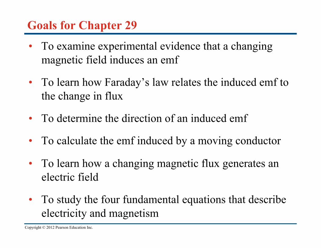
Emf and the current induced in a loop
• Follow Example 29.1 using Figure 29.5 below.
Copyright © 2012 Pearson Education Inc.
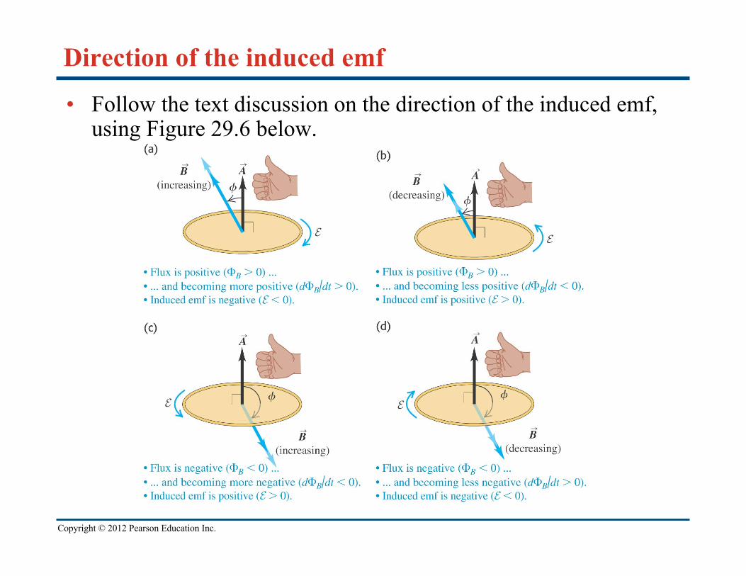
Direction of the induced emf
• Follow the text discussion on the direction of the induced emf, using Figure 29.6 below.
Copyright © 2012 Pearson Education Inc.
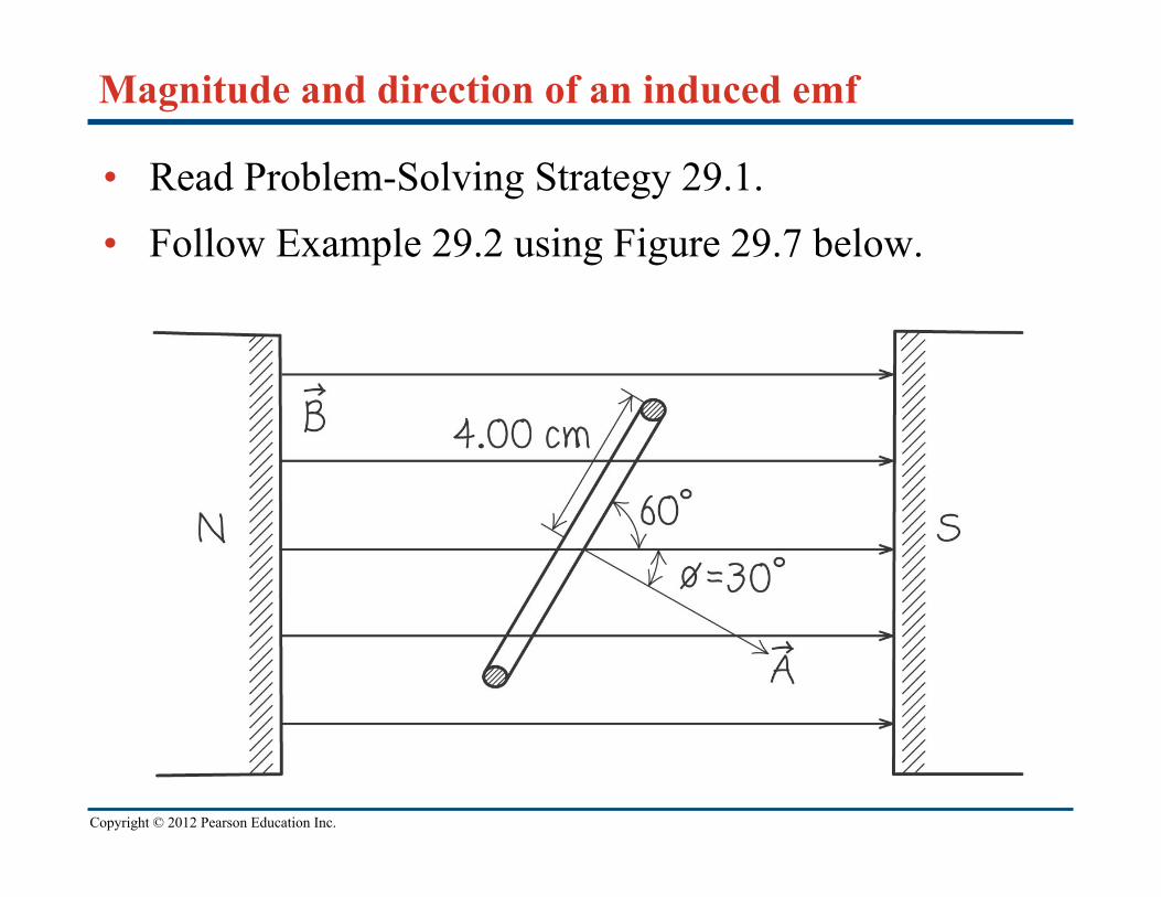
Magnitude and direction of an induced emf
• Read Problem-Solving Strategy 29.1. • Follow Example 29.2 using Figure 29.7 below.

Copyright © 2012 Pearson Education Inc.
A simple alternator
• Follow Example 29.3 using Figures 29.8 (below) and 29.9 (right).

Copyright © 2012 Pearson Education Inc.
DC generator and back emf in a motor
• Follow Example 29.4 using Figure 29.10 below.

Copyright © 2012 Pearson Education Inc.
Slidewire generator
• Follow Example 29.5 using Figure 29.11 below.

Copyright © 2012 Pearson Education Inc.
Work and power in the slidewire generator
• Follow Example 29.6 using Figure 29.12 below.

Copyright © 2012 Pearson Education Inc.
Lenz’s law
• Lenz’s law: The direction of any magnetic induction effect is such as to oppose the cause of the effect.
• Follow Conceptual Example 29.7.

Copyright © 2012 Pearson Education Inc.
Lenz’s law and the direction of induced current
• Follow Example 29.8 using Figures 29.13 (right) and 29.14 (below).

Copyright © 2012 Pearson Education Inc.
Motional electromotive force • The motional electromotive force across the ends of a rod
moving perpendicular to a magnetic field is = vBL. Figure 29.15 below shows the direction of the induced current.
• Follow the general form of motional emf in the text.

Copyright © 2012 Pearson Education Inc.
A slidewire generator and a dynamo • Follow Example 29.9 for the slidewire generator.
• Follow Example 29.10 for the Faraday disk dynamo, using Figure 29.16 below.

Copyright © 2012 Pearson Education Inc.
Induced electric fields • Changing magnetic flux
causes an induced electric field.
• See Figure 29.17 at the right to see the induced electric field for a solenoid.
• Follow the text discussion for Faraday’s law restated in terms of the induced electric field.
• Follow Example 29.11 using Figure 29.17.
Copyright © 2012 Pearson Education Inc.
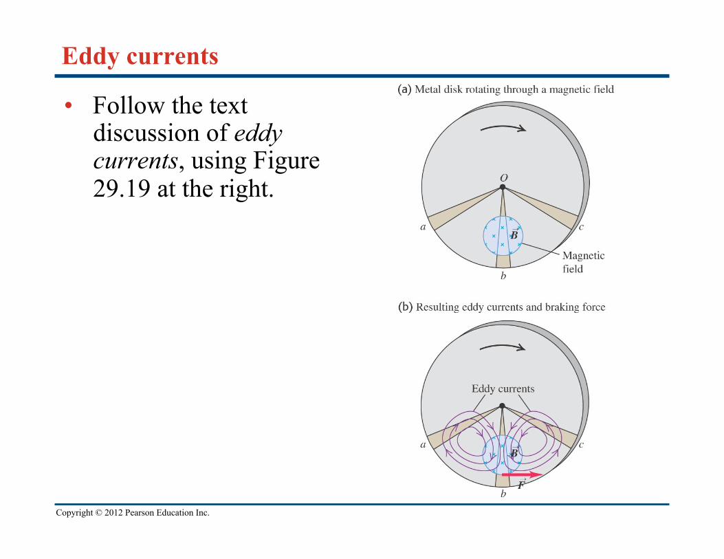
Eddy currents
• Follow the text discussion of eddy currents, using Figure 29.19 at the right.

Copyright © 2012 Pearson Education Inc.
Using eddy currents
• Figure 29.20 below illustrates an airport metal detector and a portable metal detector, both of which use eddy currents in their design.

Copyright © 2012 Pearson Education Inc.
Displacement current
• Follow the text discussion displacement current using Figures 29.21 and 29.22 below.

Copyright © 2012 Pearson Education Inc.
Maxwell’s equations
• Maxwell’s equations consist of
Gauss’s law for the electric field
Gauss’s law for the magnetic field
Ampere’s law
Faraday’s law.
• Follow the text discussion for the mathematical form of these four fundamental laws.

Copyright © 2012 Pearson Education Inc.
Superconductivity
• When a superconductor is cooled below its critical temperature, it loses all electrical resistance.
• Follow the text discussion using Figures 29.23 (below) and 29.24 (right).
Copyright © 2012 Pearson Education Inc.
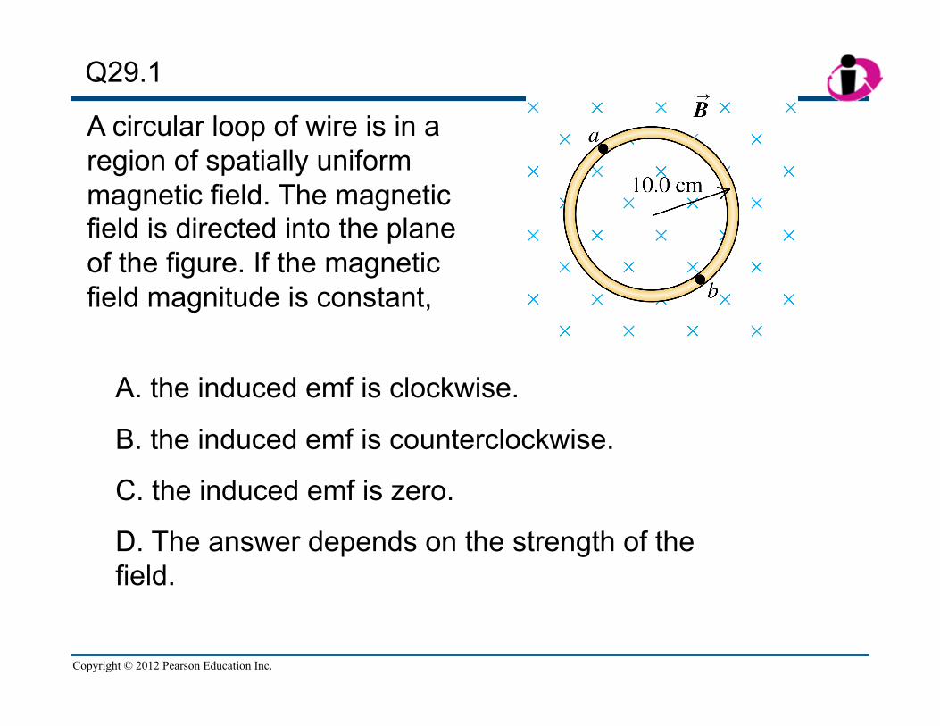
A circular loop of wire is in a region of spatially uniform magnetic field. The magnetic field is directed into the plane of the figure. If the magnetic field magnitude is constant,
Q29.1
A. the induced emf is clockwise.
B. the induced emf is counterclockwise.
C. the induced emf is zero.
D. The answer depends on the strength of the field.

Copyright © 2012 Pearson Education Inc.
A circular loop of wire is in a region of spatially uniform magnetic field. The magnetic field is directed into the plane of the figure. If the magnetic field magnitude is decreasing,
Q29.2
A. the induced emf is clockwise.
B. the induced emf is counterclockwise.
C. the induced emf is zero.
D. The answer depends on the strength of the field.

Copyright © 2012 Pearson Education Inc.
A circular loop of wire is placed next to a long straight wire. The current I in the long straight wire is increasing. What current does this induce in the circular loop?
Q29.3
A. a clockwise current
B. a counterclockwise current
C. zero current
D. not enough information given to decide

Copyright © 2012 Pearson Education Inc.
Q29.4
A. flows downward through resistor R and is proportional to B.
B. flows upward through resistor R and is proportional to B.
C. flows downward through resistor R and is proportional to B2.
D. flows upward through resistor R and is proportional to B2.
E. none of the above
A flexible loop of wire lies in a uniform magnetic field of magnitude B directed into the plane of the picture. The loop is pulled as shown, reducing its area. The induced current
[Insert figure P29.57 here]
Copyright © 2012 Pearson Education Inc.
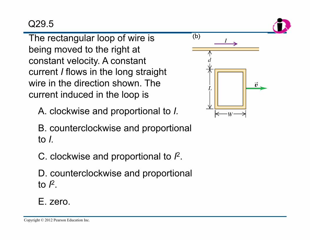
The rectangular loop of wire is being moved to the right at constant velocity. A constant current I flows in the long straight wire in the direction shown. The current induced in the loop is
Q29.5
A. clockwise and proportional to I.
B. counterclockwise and proportional to I.
C. clockwise and proportional to I2.
D. counterclockwise and proportional to I2.
E. zero.

Copyright © 2012 Pearson Education Inc.
The loop of wire is being moved to the right at constant velocity. A constant current I flows in the long straight wire in the direction shown. The current induced in the loop is
Q29.6
A. clockwise and proportional to I.
B. counterclockwise and proportional to I.
C. clockwise and proportional to I2.
D. counterclockwise and proportional to I2.
E. zero.

Copyright © 2012 Pearson Education Inc.
Q29.7
A. L: to the left; R: to the left
B. L: to the left; R: to the right
C. L: to the right; R: to the left
D. L: to the right; R: to the right
The rectangular loop of wire is being moved to the right at constant velocity. A constant current I flows in the long wire in the direction shown. What are the directions of the magnetic forces on the left-hand (L) and right-hand (R) sides of the loop?

Copyright © 2012 Pearson Education Inc.
The drawing shows the uniform magnetic field inside a long, straight solenoid. The field is directed into the plane of the drawing and is increasing.
What is the direction of the electric force on a positive point charge placed at point a?
Q29.8
A. to the left
B. to the right
C. straight up
D. straight down
E. misleading question—the electric force at this point is zero

Copyright © 2012 Pearson Education Inc.
The drawing shows the uniform magnetic field inside a long, straight solenoid. The field is directed into the plane of the drawing and is increasing.
What is the direction of the electric force on a positive point charge placed at point b?
Q29.9
A. to the left
B. to the right
C. straight up
D. straight down
E. misleading question—the electric force at this point is zero

Copyright © 2012 Pearson Education Inc.
The drawing shows the uniform magnetic field inside a long, straight solenoid. The field is directed into the plane of the drawing and is increasing.
What is the direction of the electric force on a positive point charge placed at point c (at the center of the solenoid)?
Q29.10
A. to the left
B. to the right
C. straight up
D. straight down
E. misleading question—the electric force at this point is zero