Electromagnetic Field Investigation - Alpine Boulevard
240
One Embarcadero Center, Suite 740 San Francisco, CA 94111 650-373-1200 www.panoramaenv.com CALIFORNIA PUBLIC UTILITIES COMMISSION Electromagnetic Field Investigation Alpine Boulevard – Sunrise Powerlink June 6, 2016
-
Upload
khangminh22 -
Category
Documents
-
view
1 -
download
0
Transcript of Electromagnetic Field Investigation - Alpine Boulevard
One Embarcadero Center, Suite 740 San Francisco, CA 94111 650-373-1200 www.panoramaenv.com
CALIFORNIA PUBLIC UTILITIES COMMISSION
Electromagnetic Field Investigation Alpine Boulevard – Sunrise Powerlink
June 6, 2016

One Embarcadero Center, Suite 740 San Francisco, CA 94111 650-373-1200 www.panoramaenv.com
CALIFORNIA PUBLIC UTILITIES COMMISSION
Electromagnetic Field Investigation Alpine Boulevard – Sunrise Powerlink June 6, 2016 Prepared for: California Public Utilities Commission 505 Van Ness Ave San Francisco, CA 94111 Prepared by: Phaseline, LLC 10658 Durland Ave NE Seattle, WA 98125 Contact: Chuck Williams
Panorama Environmental, Inc. One Embarcadero Center, Suite 740 San Francisco, CA 94111 Contacts: Susanne Heim and Jeff Thomas

TABLE OF CONTENTS
Electromagnetic Field Investigation Alpine Boulevard – Sunrise Powerlink June 2016 i
TABLE OF CONTENTS
Glossary and Abbreviations ............................................................................................................... v
Executive Summary ............................................................................................................................ 1 Purpose of this EMF Investigation and Uses of This Report ....................................................... 1
EMF Research and Public Exposure ............................................................................................. 1
Regulatory Framework ................................................................................................................... 2
Background ..................................................................................................................................... 3
Recent Magnetic Field Reports and Investigations .................................................................. 4
CPUC Study Results......................................................................................................................... 5
Conclusion ....................................................................................................................................... 9
1 Introduction ............................................................................................................................. 1-1 1.1 Purpose of This EMF investigation ....................................................................................... 1-1
1.2 Inquiries Prompting Investigation ........................................................................................ 1-1
1.3 Contents of EMF Investigation Report ............................................................................... 1-2
2 EMF Overview ......................................................................................................................... 2-1 2.1 EMF Sources ........................................................................................................................... 2-1
2.2 EMF Research ........................................................................................................................ 2-3
2.3 General Public Exposures .................................................................................................... 2-8
2.4 Exposures in the Vicinity of Transmission Corridors ......................................................... 2-10
3 Regulatory Framework ........................................................................................................... 3-1 3.1 CPUC Decisions Related to EMF ......................................................................................... 3-1
3.2 California Department of Education Regulation............................................................. 3-2
3.3 National and International Regulations ............................................................................ 3-3
4 Background on Sunrise Powerlink 230-kV ............................................................................ 4-1 4.1 Project Overview ................................................................................................................... 4-1
4.2 Sunrise Powerlink 230-kV Circuits in Alpine ........................................................................ 4-2
4.3 Consideration of EMF in the Sunrise Powerlink EIR/EIS ..................................................... 4-2
4.4 Consideration of EMF in the CPUC Decision on the Sunrise Powerlink Project ........... 4-6
5 Sunrise Powerlink Magnetic Field Management Plan ........................................................ 5-1 5.1 Information Included in the Field Management Plan ..................................................... 5-1
5.2 SDG&E Magnetic Field Calculations ................................................................................. 5-1
TABLE OF CONTENTS
Electromagnetic Field Investigation Alpine Boulevard – Sunrise Powerlink June 2016 ii
5.3 Field Management Plan Information Pertinent To Alpine Boulevard .......................... 5-2
6 Recent Alpine Area Magnetic Field Reports on EMF Exposures ........................................ 6-1 6.1 Faulkner and Milligan Study ................................................................................................ 6-1
6.2 Alpine Unified School District – JPA Report ....................................................................... 6-3
6.3 San Diego County Office of Education - PlaceWorks Report ....................................... 6-3
6.4 San Diego Gas & Electric Residential Measurements ..................................................... 6-5
6.5 Conclusion ............................................................................................................................. 6-5
7 CPUC EMF Investigation ......................................................................................................... 7-1 7.1 Methodology ......................................................................................................................... 7-1
7.2 Alpine Magnetic Field Measurement Results ................................................................... 7-5
7.3 Discussion ............................................................................................................................. 7-18
7.4 Conclusion ........................................................................................................................... 7-18
8 References .............................................................................................................................. 8-1
List of Appendices
Appendix A – Correspondence Regarding EMF Investigation
Appendix B – EMF Design Guidelines for Electrical Facilities
Appendix C – EMF Measurement Locations and Surrounding Land Uses
Appendix D – SDG&E Field Management Plan
Appendix E – Faulkner and Milligan Study
Appendix F – Alpine Unified School District Study
Appendix G – San Diego County Office of Education Study
Appendix H – EMF Meter Calibration
Appendix I – Field Notes
List of Tables
Table ES-1 Calculated Magnetic Fields for Alpine Boulevard Underground Segment .... ES-4 Table ES-2 Magnetic Fields at Edge of Alpine Boulevard ..................................................... ES-6 Table ES-3 Comparison of CPUC and PlaceWorks EMF Measurements at
Alpine Elementary School ....................................................................................... ES-9 Table 2.3-1 Typical Magnetic Fields from Household Appliances ........................................... 2-8 Table 2.3-2 Estimated Average Magnetic Field Exposure of the U.S. Population ................. 2-9 Table 3.3-1 Regulatory and Guidance for EMF Exposure ......................................................... 3-4 Table 3.3-2 Florida and New York Regulated Limits to Avoid Increases in EMF Exposure... 3-5 Table 5.3-1 Calculated Magnetic Fields for Alpine Underground Segment ......................... 5-3 Table 7.2-1 Alpine Boulevard Magnetic Field Values .............................................................. 7-11
TABLE OF CONTENTS
Electromagnetic Field Investigation Alpine Boulevard – Sunrise Powerlink June 2016 iii
Table 7.2-2 Comparison of CPUC and PlaceWorks EMF Measurements at Alpine Elementary School ................................................................................... 7-15
Table 7.2-3 Alpine Community Magnetic Field Values (mG) ................................................. 7-16
List of Figures
Figure ES-1 Magnetic Field Measurement Locations .............................................................. 2-10 Figure 2.3-1 Magnetic Field Personal Exposure Record ........................................................... 2-10 Figure 2.4-1 Magnetic Field versus Lateral Distance ................................................................. 2-12 Figure 4.2-1 Sunrise Powerlink 230-kV Underground Transmission Line Location .................... 4-3 Figure 4.2-2 Sunrise Powerlink 230-kV Underground Transmission Line Cross-section ............ 4-5 Figure 7.1-1 EMF Measurement Locations .................................................................................... 7-3 Figure 7.2-1 Magnetic Field Cross-Section South Grade Road ................................................. 7-6 Figure 7.2-2 Magnetic Field Cross-Section Medical Center West of Tavern Road ................ 7-6 Figure 7.2-3 Magnetic Field Cross-Section Near Future Alpine High School Site .................... 7-7 Figure 7.2-4 Magnetic Field Cross-Section West Victoria Drive ................................................. 7-7 Figure 7.2-5 Magnetic Field Cross-Section Alpine Elementary School ..................................... 7-8 Figure 7.2-6 Magnetic Field Cross-Section Casino Inn ................................................................ 7-8 Figure 7.2-7 Magnetic Field Cross-Section West Alpine ............................................................. 7-9 Figure 7.2-8 Alpine Elementary School Magnetic Field Values Friday, April 22 and
Saturday, April 23, 2016 ............................................................................................ 7-14

TABLE OF CONTENTS
Electromagnetic Field Investigation Alpine Boulevard – Sunrise Powerlink June 2016 iv
This page is intentionally left blank.
GLOSSARY AND ABBREVIATIONS
Electromagnetic Field Investigation Alpine Boulevard – Sunrise Powerlink June 2016 v
GLOSSARY AND ABBREVIATIONS
AC Alternating current
ACGIH American Conference of Governmental Industrial Hygienists
ANSI American National Standards Institute
bgs below ground surface
BPA Bonneville Power Administration
CDE California Department of Education
CEQA California Environmental Quality Act
CPUC California Public Utilities Commission
DC Direct current
DHS Department of Health Services
DOE Department of Energy
EIR Environmental Impact Report; an environmental impact
assessment document prepared in accordance with the California
Environmental Quality Act (CEQA)
ELF Extremely low frequency, from 1 Hz to 300 Hz
EMF Electric and Magnetic Field
EPA U.S. Environmental Protection Agency; a federal agency that
works to protect the environment
EPRI Electric Power Research Institute
Hz Hertz; a measure of frequency in cycles per second
IARC International Agency for Research on Cancer
ICES International Committee on Electromagnetic Safety
ICNIRP International Commission on Non‐Ionizing Radiation Protection

GLOSSARY AND ABBREVIATIONS
Electromagnetic Field Investigation Alpine Boulevard – Sunrise Powerlink June 2016 vi
IEEE Institute of Electrical and Electronic Engineers
IID Imperial Irrigation District
IRPA International Radiation Protection Association
kV Kilovolt; a measure of electric voltage, one thousand volts
kV/m Kilovolts per meter; a measure of electric field strength
kW kilowatt; a measure of electric power equal to 1,000 watts
mG Milligauss; a measure of magnetic field strength, one thousandth
of a gauss
Microtesla (T) A measure of magnetic field strength, one millionth of a tesla
NESC National Electrical Safety Code
NIEHS National Institute of Environmental Health Sciences
Non‐Ionizing Radiation Radiation that does not have enough energy to ionize molecules
or atoms
NRPB National Radiation Protection Board
OSHA U.S. Occupational Safety and Health Administration
Precautionary Principle Where there are threats of serious or irreversible damage,
precautionary measures should be taken even if cause‐and‐effect
relationships are not clearly established
RAPID Research and Public Information Dissemination.
Right‐of‐way (ROW) An easement, lease, permit, or license across an area or strip of
land to allow access or to allow a utility to pass thought lands
SDG&E San Diego Gas and Electric Company
U.S. United States
WHO World Health Organization
EXECUTIVE SUMMARY
Electromagnetic Field Investigation Alpine Boulevard – Sunrise Powerlink June 2016 ES-1
EXECUTIVE SUMMARY
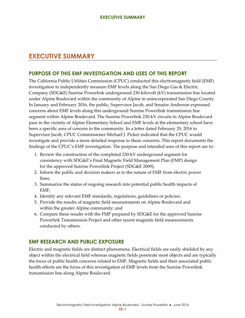
PURPOSE OF THIS EMF INVESTIGATION AND USES OF THIS REPORT The California Public Utilities Commission (CPUC) conducted this electromagnetic field (EMF)
investigation to independently measure EMF levels along the San Diego Gas & Electric
Company (SDG&E) Sunrise Powerlink underground 230‐kilovolt (kV) transmission line located
under Alpine Boulevard within the community of Alpine in unincorporated San Diego County.
In January and February 2016, the public, Supervisor Jacob, and Senator Anderson expressed
concerns about EMF levels along this underground Sunrise Powerlink transmission line
segment within Alpine Boulevard. The Sunrise Powerlink 230‐kV circuits in Alpine Boulevard
pass in the vicinity of Alpine Elementary School and EMF levels at the elementary school have
been a specific area of concern to the community. In a letter dated February 29, 2016 to
Supervisor Jacob, CPUC Commissioner Michael J. Picker indicated that the CPUC would
investigate and provide a more detailed response to these concerns. This report documents the
findings of the CPUC’s EMF investigation. The purpose and intended uses of this report are to:
1. Review the construction of the completed 230‐kV underground segment for
consistency with SDG&E’s Final Magnetic Field Management Plan (FMP) design
for the approved Sunrise Powerlink Project (SDG&E 2009);
2. Inform the public and decision makers as to the nature of EMF from electric power
lines;
3. Summarize the status of ongoing research into potential public health impacts of
EMF;
4. Identify any relevant EMF standards, regulations, guidelines or policies;
5. Provide the results of magnetic field measurements on Alpine Boulevard and
within the greater Alpine community; and
6. Compare these results with the FMP prepared by SDG&E for the approved Sunrise
Powerlink Transmission Project and other recent magnetic field measurements
conducted by others.
EMF RESEARCH AND PUBLIC EXPOSURE Electric and magnetic fields are distinct phenomena. Electrical fields are easily shielded by any
object within the electrical field whereas magnetic fields penetrate most objects and are typically
the focus of public health concerns related to EMF. Magnetic fields and their associated public
health effects are the focus of this investigation of EMF levels from the Sunrise Powerlink
transmission line along Alpine Boulevard.
EXECUTIVE SUMMARY
Electromagnetic Field Investigation Alpine Boulevard – Sunrise Powerlink June 2016 ES-2
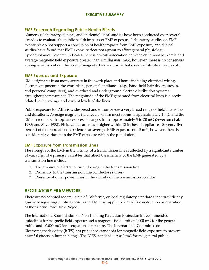
EMF Research Regarding Public Health Effects Numerous laboratory, clinical, and epidemiological studies have been conducted over several
decades to evaluate the public health impacts of EMF exposure. Laboratory studies on EMF
exposures do not support a conclusion of health impacts from EMF exposure, and clinical
studies have found that EMF exposure does not appear to affect general physiology.
Epidemiological research indicates there is a weak association between childhood leukemia and
average magnetic field exposure greater than 4 milligauss (mG); however, there is no consensus
among scientists about the level of magnetic field exposure that could constitute a health risk.
EMF Sources and Exposure EMF originates from many sources in the work place and home including electrical wiring,
electric equipment in the workplace, personal appliances (e.g., hand‐held hair dryers, stoves,
and personal computers), and overhead and underground electric distribution systems
throughout communities. The magnitude of the EMF generated from electrical lines is directly
related to the voltage and current levels of the lines.
Public exposure to EMFs is widespread and encompasses a very broad range of field intensities
and durations. Average magnetic field levels within most rooms is approximately 1 mG and the
EMF in rooms with appliances present ranges from approximately 9 to 20 mG (Severson et al.
1988; and Silva 1988). Field values are much higher within 12 inches of appliances. Seventy‐five
percent of the population experiences an average EMF exposure of 0.5 mG; however, there is
considerable variation in the EMF exposure within the population.
EMF Exposure from Transmission Lines The strength of the EMF in the vicinity of a transmission line is affected by a significant number
of variables. The primary variables that affect the intensity of the EMF generated by a
transmission line include:
1. The amount of electric current flowing in the transmission line
2. Proximity to the transmission line conductors (wires)
3. Presence of other power lines in the vicinity of the transmission corridor
REGULATORY FRAMEWORK There are no adopted federal, state of California, or local regulatory standards that provide any
guidance regarding public exposures to EMF that apply to SDG&E’s construction or operation
of the Sunrise Powerlink Project.
The International Commission on Non‐Ionizing Radiation Protection in recommended
guidelines for magnetic field exposure set a magnetic field limit of 2,000 mG for the general
public and 10,000 mG for occupational exposure. The International Committee on
Electromagnetic Safety (ICES) has published standards for magnetic field exposure to prevent
harmful effects in human beings. The ICES standard is 9,040 mG for the general public.
EXECUTIVE SUMMARY
Electromagnetic Field Investigation Alpine Boulevard – Sunrise Powerlink June 2016 ES-3
The State of Florida and the State of New York have adopted limits for magnetic fields at the
edge of transmission line right‐of‐ways (ROWs). Florida set a limit of 150 mG at the edge of
ROW for 230‐kV transmission lines. The New York limit is 200 mG at the edge of ROW for
transmission lines rated 125 kV and greater.
CPUC The CPUC, in Decisions D.93‐11‐013 and D.06‐01‐042, requires regulated utilities to evaluate
EMFs from new and upgraded transmission lines and substation projects and implement “no
cost” and “low cost” measures to reduce EMFs. Regulated utilities are also required to submit a
Final FMP, which describes:
EMF reduction measures that were considered by the utility
“No cost” and “low cost” EMF reduction measures that are proposed as a part of
the project
EMF modeling indicating relative differences in magnetic field reductions between
different transmission line construction methods
SDG&E and other regulated utilities developed FMP design guidelines in accordance with
Decisions D.93‐11‐013 and D.06‐01‐042. The FMP design guidelines describe routine magnetic
field reduction measures that all regulated California electric utilities will consider for new and
upgraded transmission line and substation projects. The guidelines also define standard
requirements for FMPs.
California Department of Education The California Department of Education (CDE) includes EMF as one criterion for evaluating the
safety of potential school sites and has established “setback” limits for new school sites and
electrical power lines. The CDE selection criteria specifies a setback of 37.5 feet between a new
school property and the easement for a 230‐kV transmission line. The CDE criteria is applied to
selection of new school sites. There are no guidelines that apply to the siting of transmission
lines in proximity to existing schools.
BACKGROUND
CPUC Decision on Sunrise Powerlink Transmission Project The CPUC, in Decision 08‐12‐058, certified the Final Environmental Impact
Report/Environmental Impact Statement (EIR/EIS) and granted a Certificate of Public
Convenience and Necessity (CPCN) to SDG&E to construct the Sunrise Powerlink Transmission
Project using the Final Environmentally Superior Southern Route. The approved route included
an approximately 6.2‐mile segment of double‐circuit underground 230‐kV transmission line in
Alpine Boulevard located in the unincorporated community of Alpine in San Diego County,
California. The CPUC required SDG&E to prepare a FMP for the Environmentally Superior
EXECUTIVE SUMMARY
Electromagnetic Field Investigation Alpine Boulevard – Sunrise Powerlink June 2016 ES-4
Southern Route as part of Decision D.08‐12‐058. SDG&E completed the FMP for the approved
Sunrise Powerlink Transmission Project in 2009.
SD&GE constructed the two approved underground duct banks, primarily within Alpine
Boulevard and placed two 230‐kV circuits (TL23054, TL23055) into service in mid‐2012.
SDG&E Magnetic Field Management Plan SDG&E adopted two no‐cost measures to reduce magnetic field levels along the underground
230‐kV transmission line within Alpine Boulevard including:
1. Split and reversed phasing for the 230‐kV circuits
2. Locating the power lines closer to the center of the road corridor to the extent
practicable.
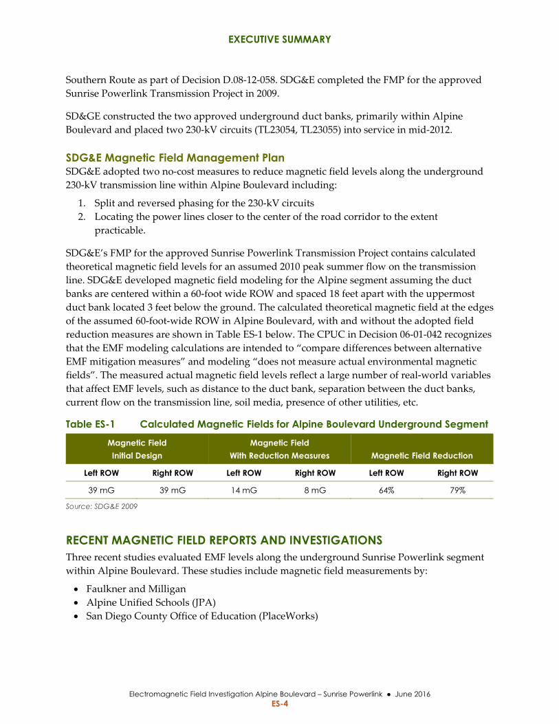
SDG&E’s FMP for the approved Sunrise Powerlink Transmission Project contains calculated
theoretical magnetic field levels for an assumed 2010 peak summer flow on the transmission
line. SDG&E developed magnetic field modeling for the Alpine segment assuming the duct
banks are centered within a 60‐foot wide ROW and spaced 18 feet apart with the uppermost
duct bank located 3 feet below the ground. The calculated theoretical magnetic field at the edges
of the assumed 60‐foot‐wide ROW in Alpine Boulevard, with and without the adopted field
reduction measures are shown in Table ES‐1 below. The CPUC in Decision 06‐01‐042 recognizes
that the EMF modeling calculations are intended to “compare differences between alternative
EMF mitigation measures” and modeling “does not measure actual environmental magnetic
fields”. The measured actual magnetic field levels reflect a large number of real‐world variables
that affect EMF levels, such as distance to the duct bank, separation between the duct banks,
current flow on the transmission line, soil media, presence of other utilities, etc.
Table ES-1 Calculated Magnetic Fields for Alpine Boulevard Underground Segment
Magnetic Field Initial Design
Magnetic Field With Reduction Measures Magnetic Field Reduction
Left ROW Right ROW Left ROW Right ROW Left ROW Right ROW
39 mG 39 mG 14 mG 8 mG 64% 79%
Source: SDG&E 2009
RECENT MAGNETIC FIELD REPORTS AND INVESTIGATIONS Three recent studies evaluated EMF levels along the underground Sunrise Powerlink segment
within Alpine Boulevard. These studies include magnetic field measurements by:
Faulkner and Milligan
Alpine Unified Schools (JPA)
San Diego County Office of Education (PlaceWorks)
EXECUTIVE SUMMARY
Electromagnetic Field Investigation Alpine Boulevard – Sunrise Powerlink June 2016 ES-5
The Institute of Electrical and Electronic Engineers (IEEE) Standard Procedures for Measurement of
Power Frequency Electric and Magnetic Fields from AC Power Lines (1994) is the industry standard
used to perform EMF measurements. The measurements performed by Faulkner and Milligan
(2016) did not follow industry standards for EMF measurement because:
It appears that the magnetic fields reported were for only a single axis and lacked
measurements along three axes, which would not allow calculation of the three‐axis
(x, y, z) maximum magnetic field at each location
Some of the magnetic field values at the center and edge of Alpine Boulevard were
averaged in the study – averaging measured values is inappropriate because
magnetic field values are non‐linear
Some measurements were recorded from an F150 vehicle and may reflect some
component of magnetic field from the vehicle rather than the magnetic field from
only the transmission line
The Faulkner and Milligan study (2016) does not contribute to an understanding of the
magnetic fields from the Sunrise Powerlink Project within Alpine Boulevard because the study
measurements were not obtained using industry standard protocols. Both of the other studies
(JPA 2016 and PlaceWorks 2016) focused on EMF within the Alpine Elementary School property
and found very similar magnetic field levels at locations outside the school.
The PlaceWorks study was conducted following IEEE standards and included indoor
measurements at the elementary school. The PlaceWorks study found magnetic field levels
generally below 1.0 mG in classrooms. This level of magnetic field is consistent with magnetic
field surveys conducted across multiple schools in California and indicates that the
transmission line in Alpine Boulevard is not a source for magnetic field exposures within the
elementary school. The PlaceWorks study concluded that the Sunrise Powerlink transmission
line does not pose a significant safety or health risk to the Alpine Elementary School site.
CPUC STUDY RESULTS
Sunrise Powerlink 230-kV Construction The CPUC staff and consultants reviewed the as‐built documentation obtained from SDG&E
and compared it with the constructed facilities. The Sunrise Powerlink 230‐kV transmission line
within Alpine Boulevard was constructed in accordance with the CPUC‐approved
configuration and the FMP that was filed for the approved Sunrise Powerlink Transmission
Project. Generally, the double‐circuit 230‐kV transmission line is contained in two separate duct
banks, buried 3 feet below Alpine Boulevard. The horizontal placement and spacing of the duct
banks within Alpine Boulevard varies noticeably within the roadway in order to route the
transmission line around other existing underground utilities such as water pipelines, storm
drains, communication lines, and electric distribution lines.
In the vicinity of Alpine Elementary School, the duct banks have been located beyond the center
of Alpine Boulevard (i.e., further away from the school) providing greater separation between
EXECUTIVE SUMMARY
Electromagnetic Field Investigation Alpine Boulevard – Sunrise Powerlink June 2016 ES-6
the school and the transmission line. One duct bank is located 45 feet from the school property
line and the second duct bank is located 61 feet from the school property. These setbacks are in
excess of the CDE requirements for new school facilities located in proximity to underground
230‐kV transmission lines. The portion of the school property that is closest to the power line is
the driveway and parking lot. School buildings are set back farther from the transmission line.
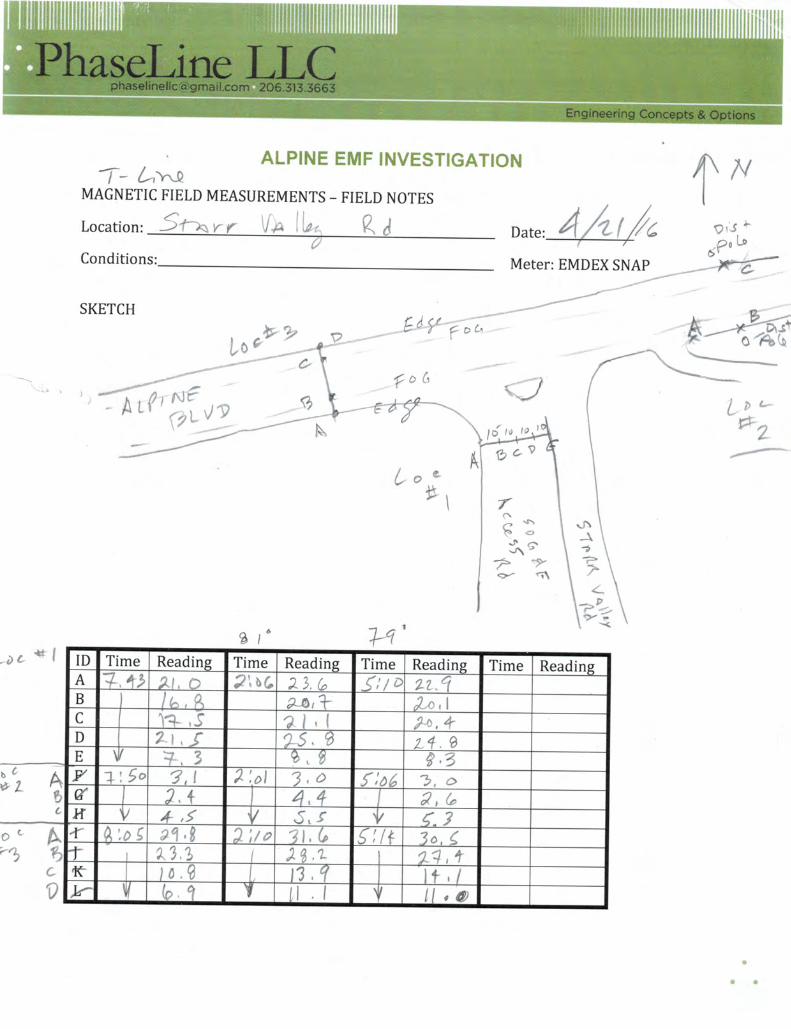
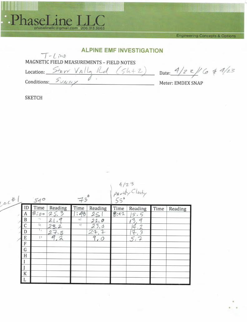
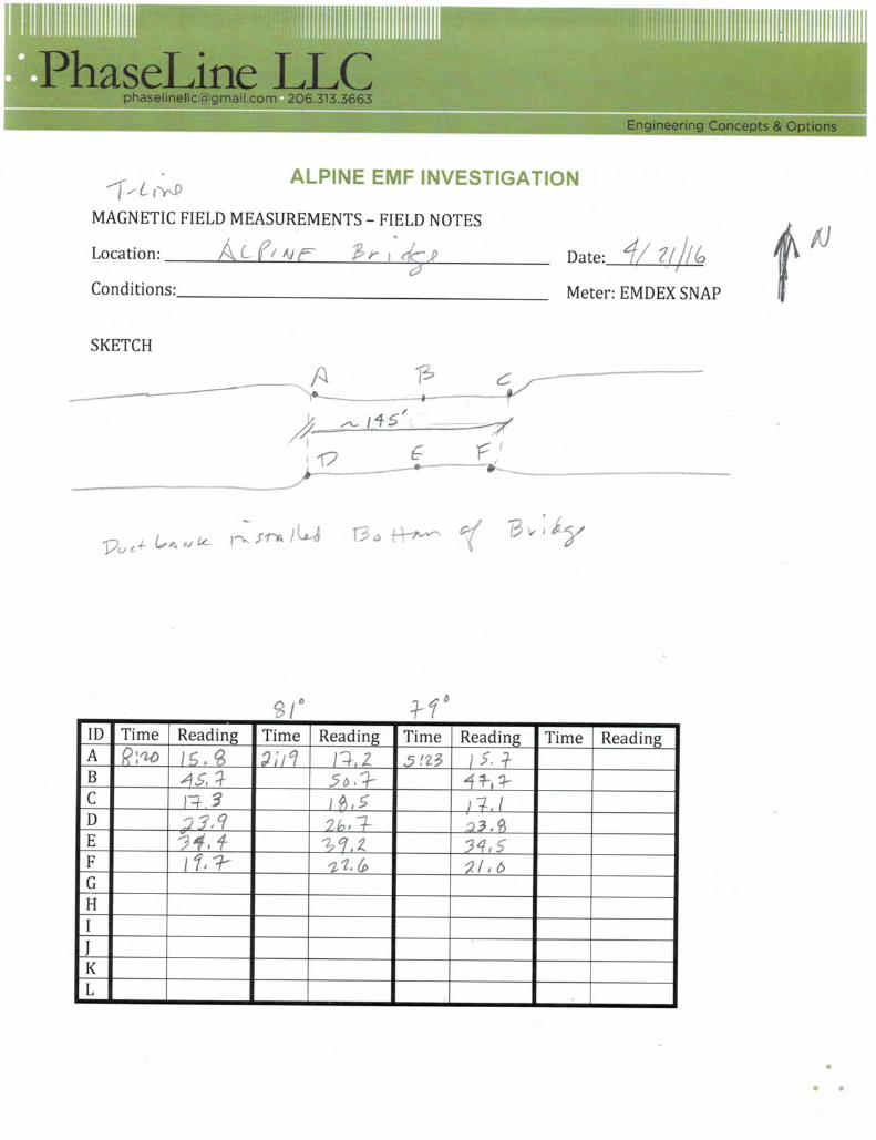
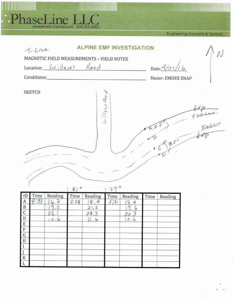
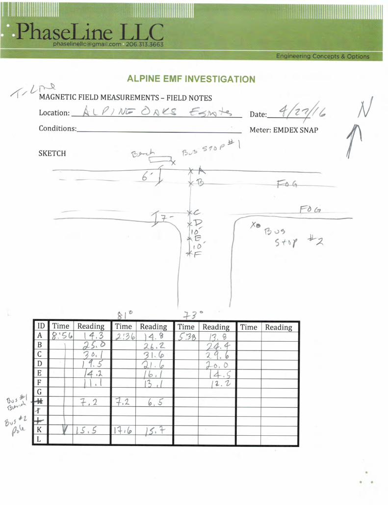
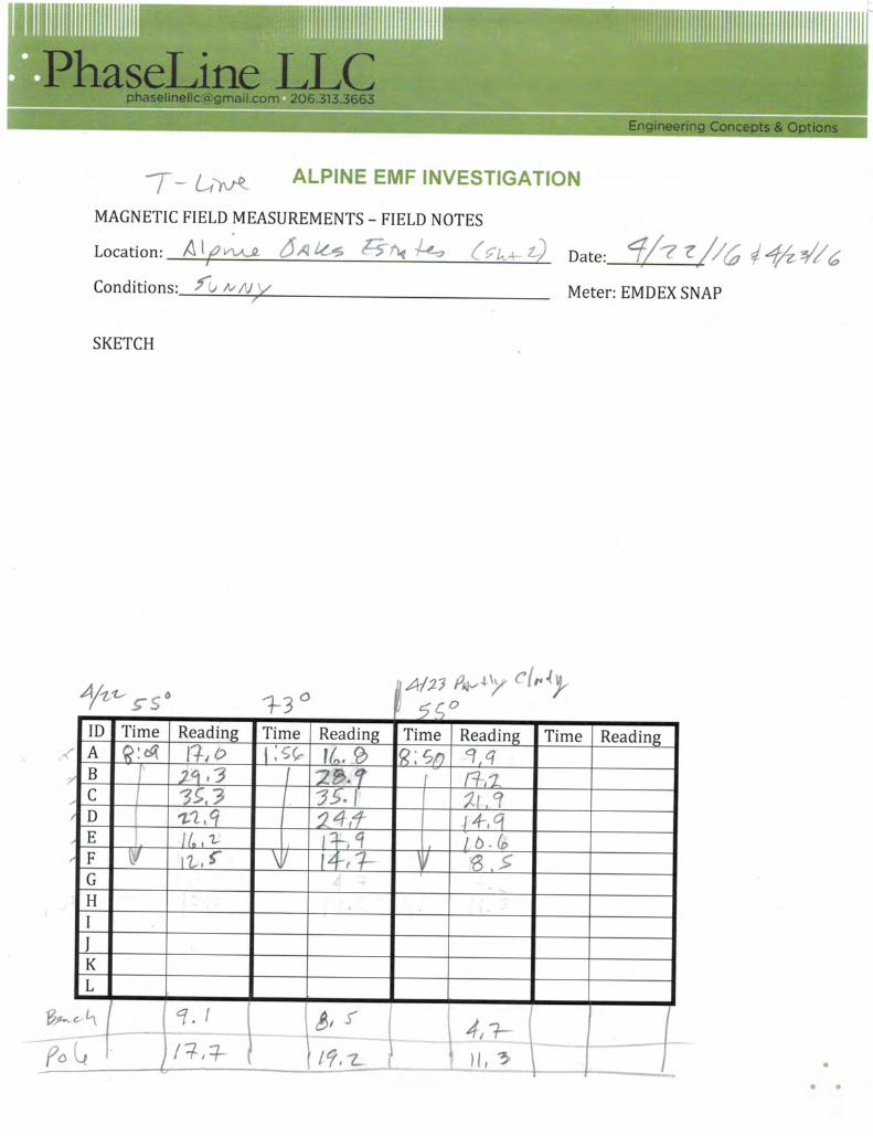
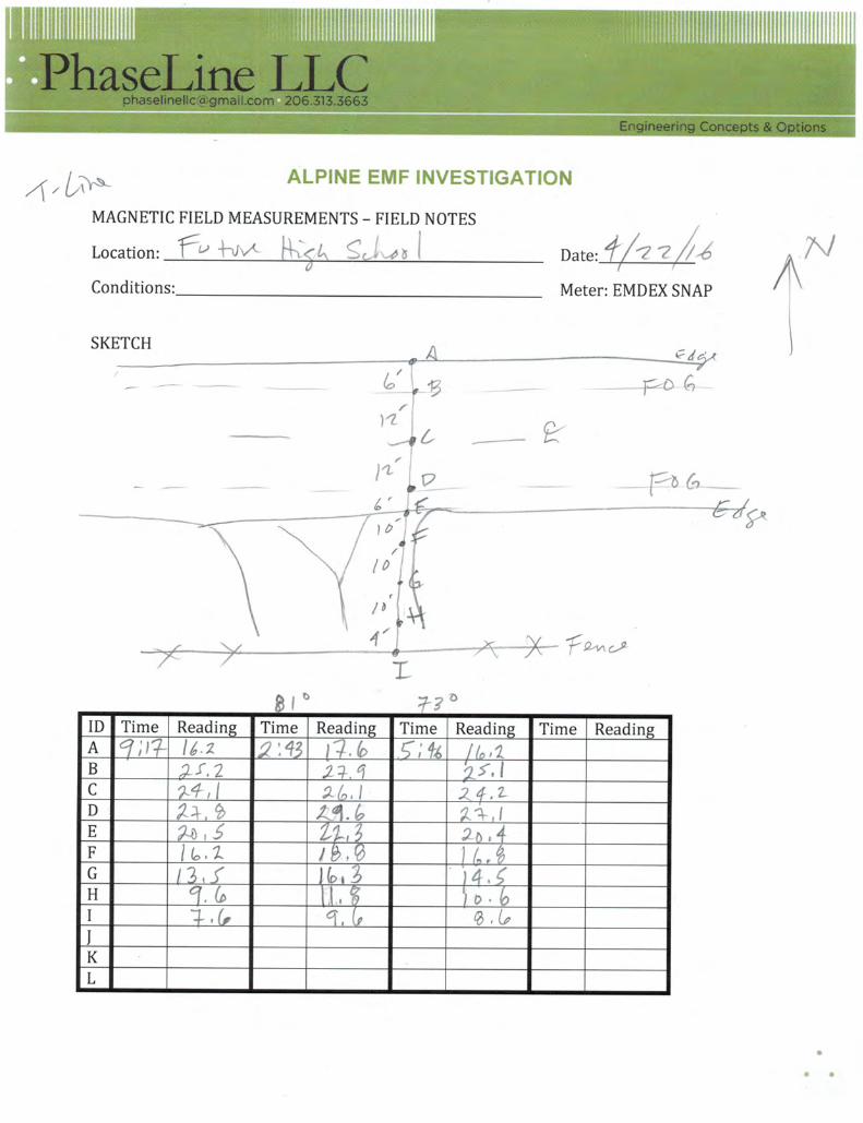
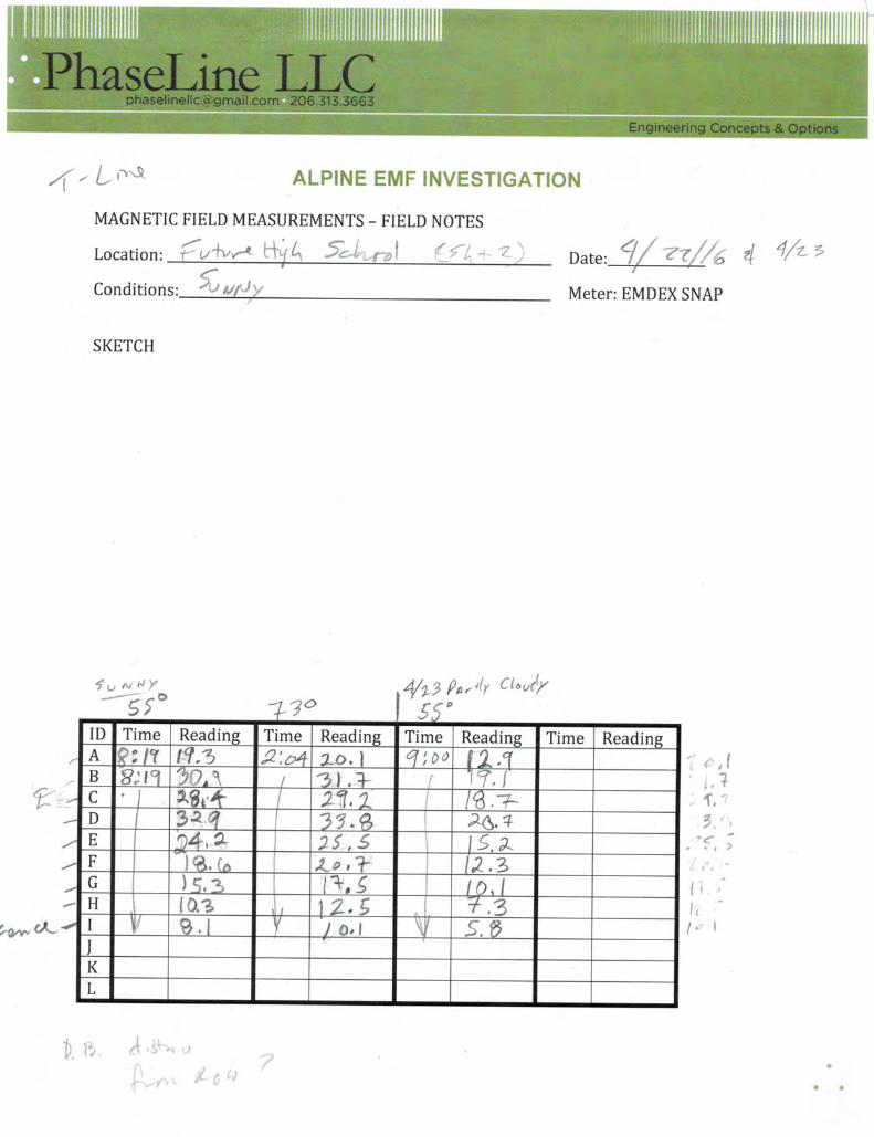
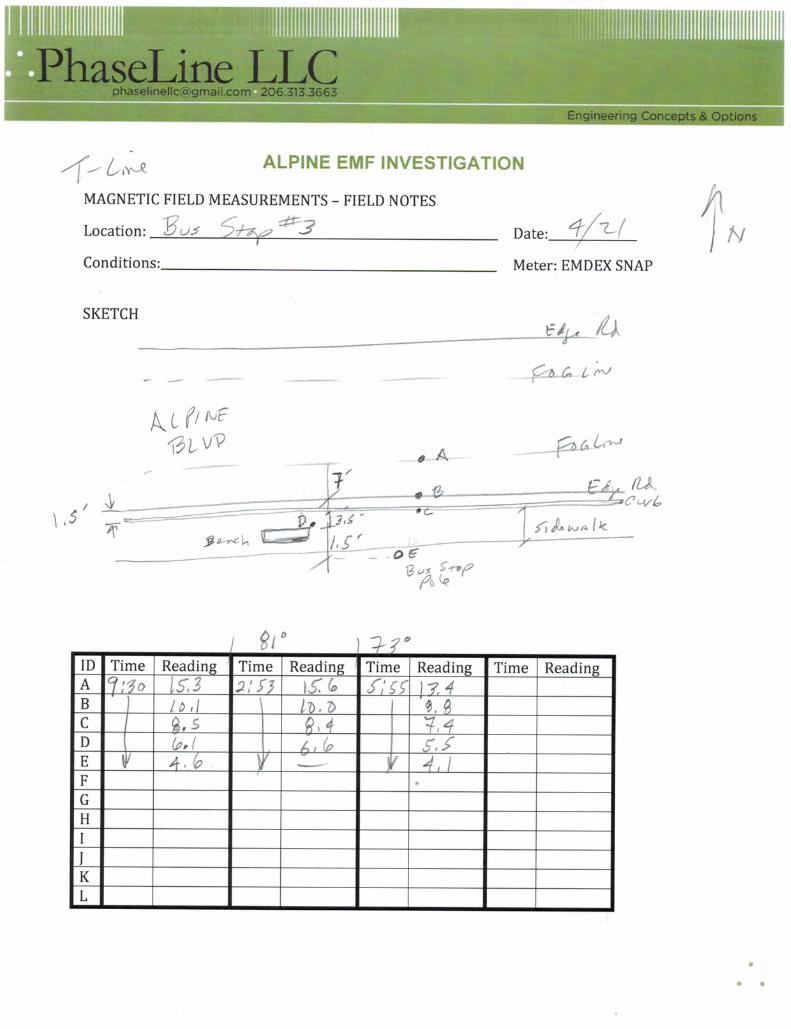
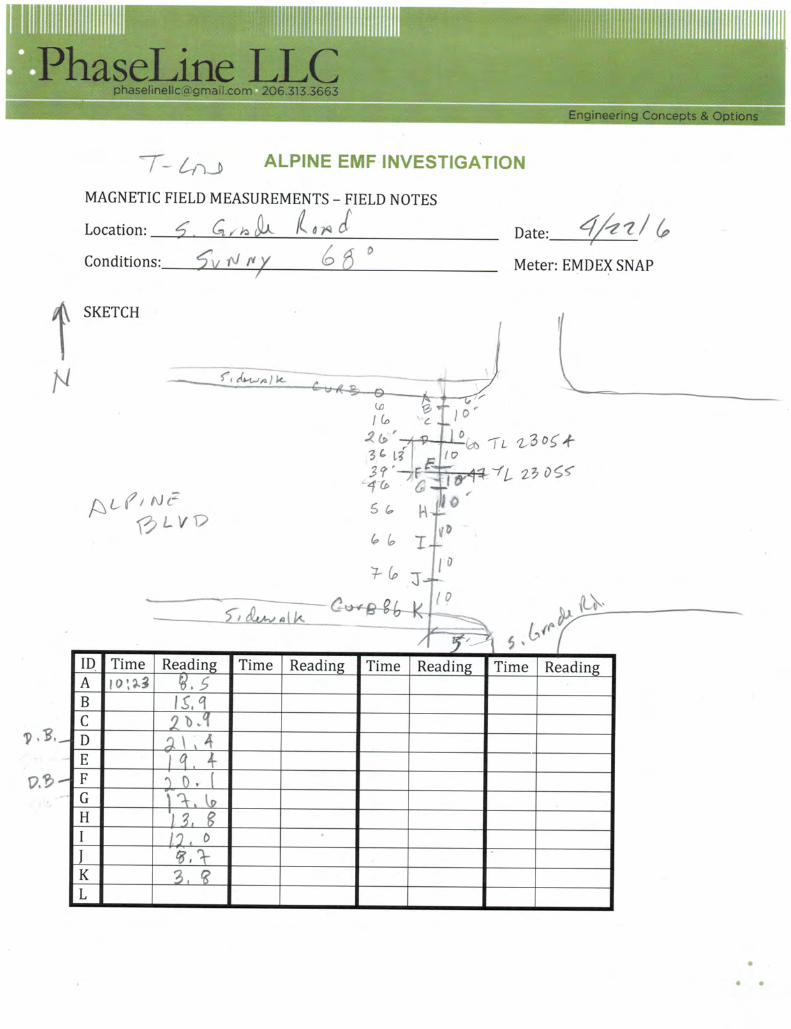
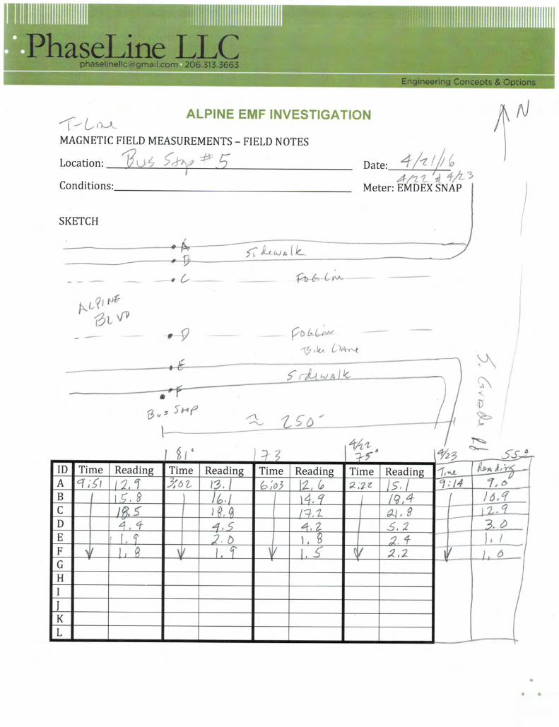
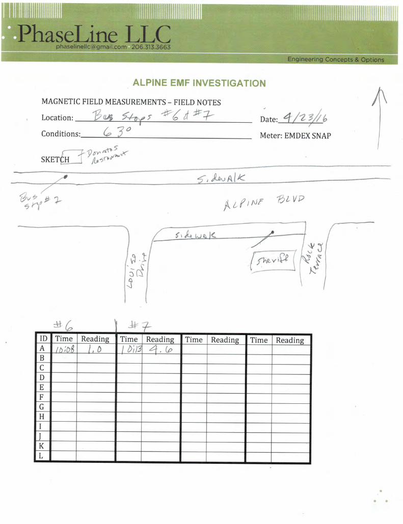
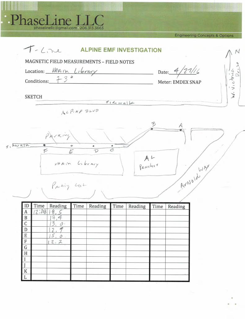
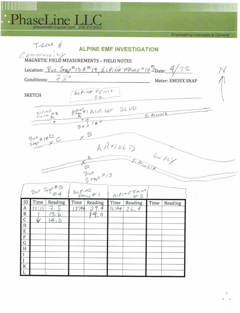
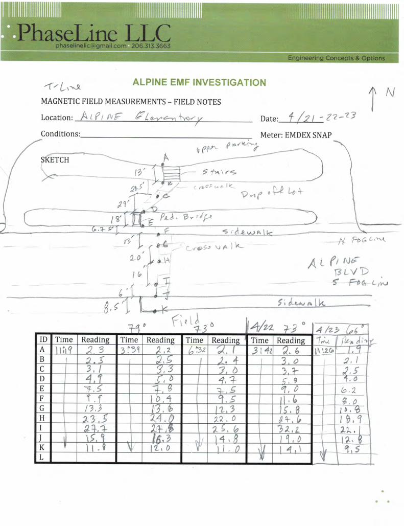
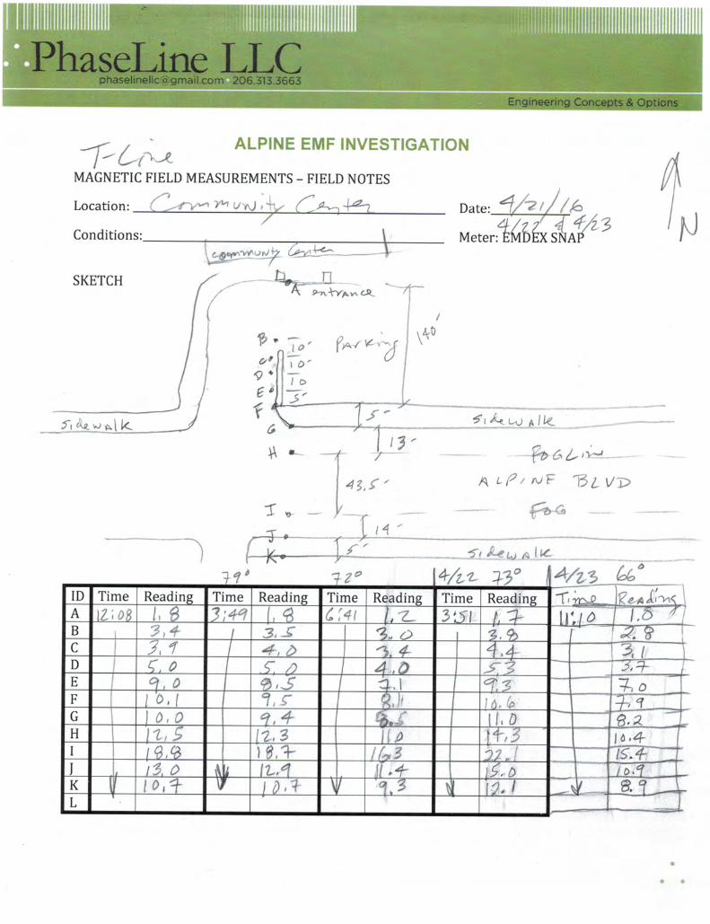
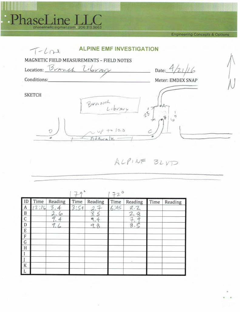
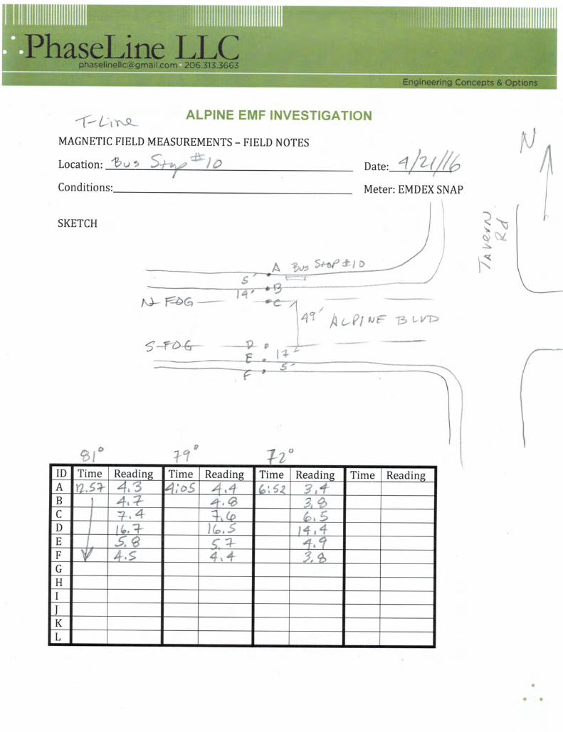
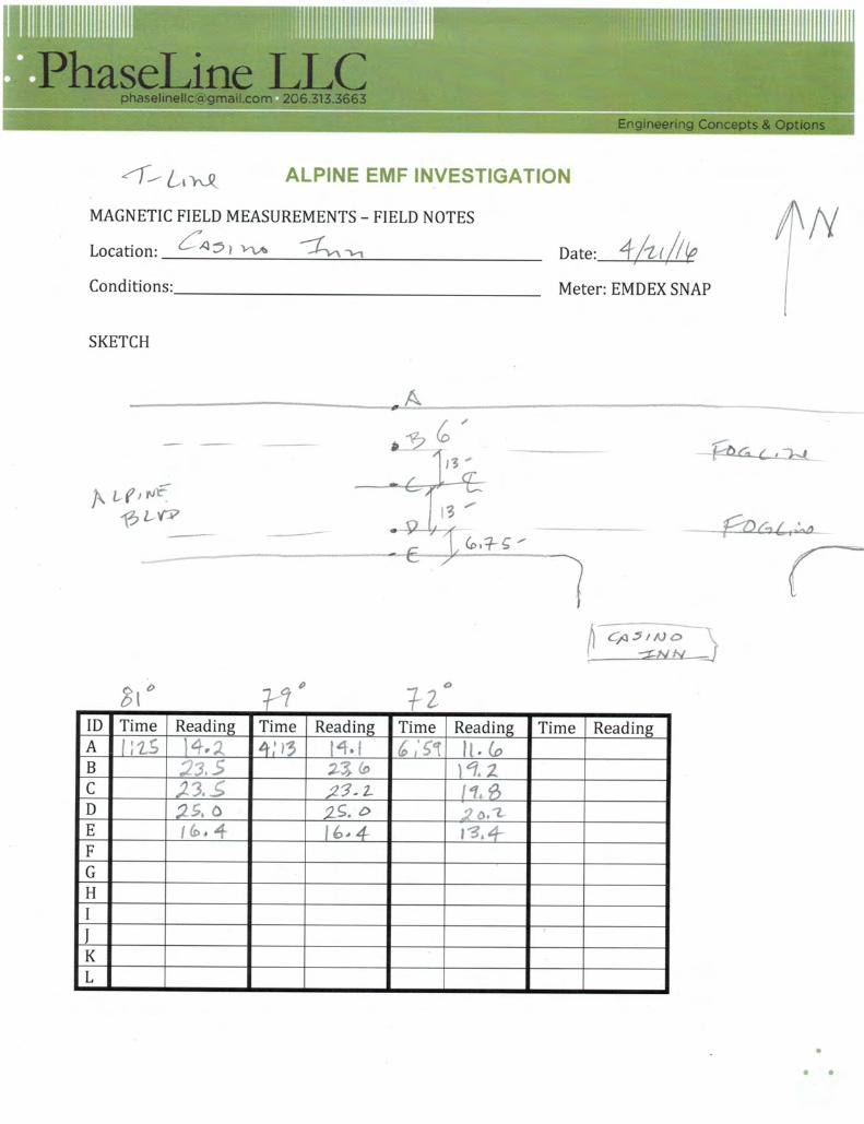
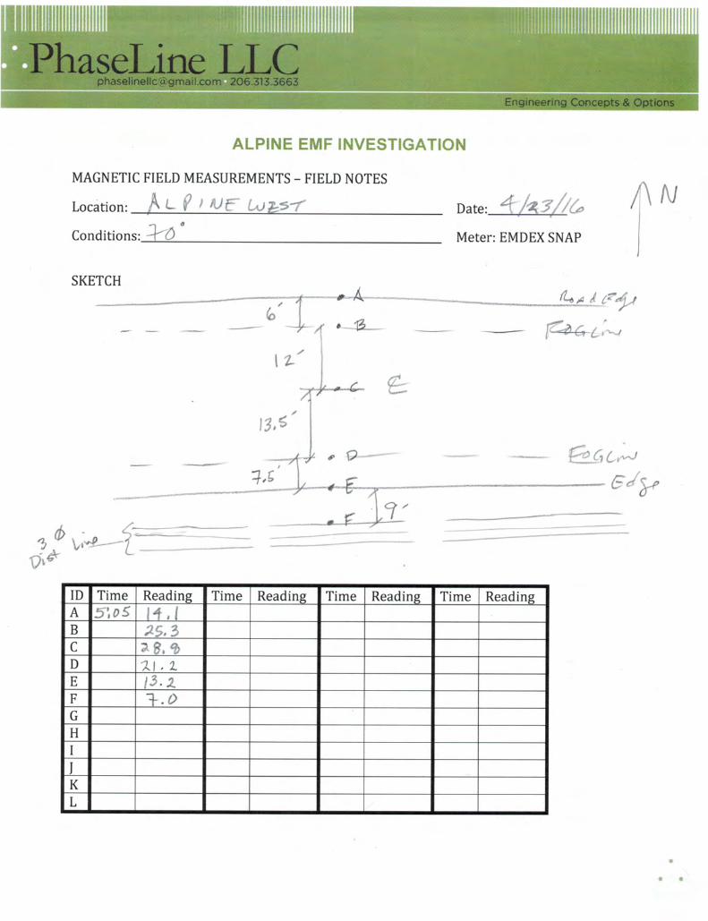
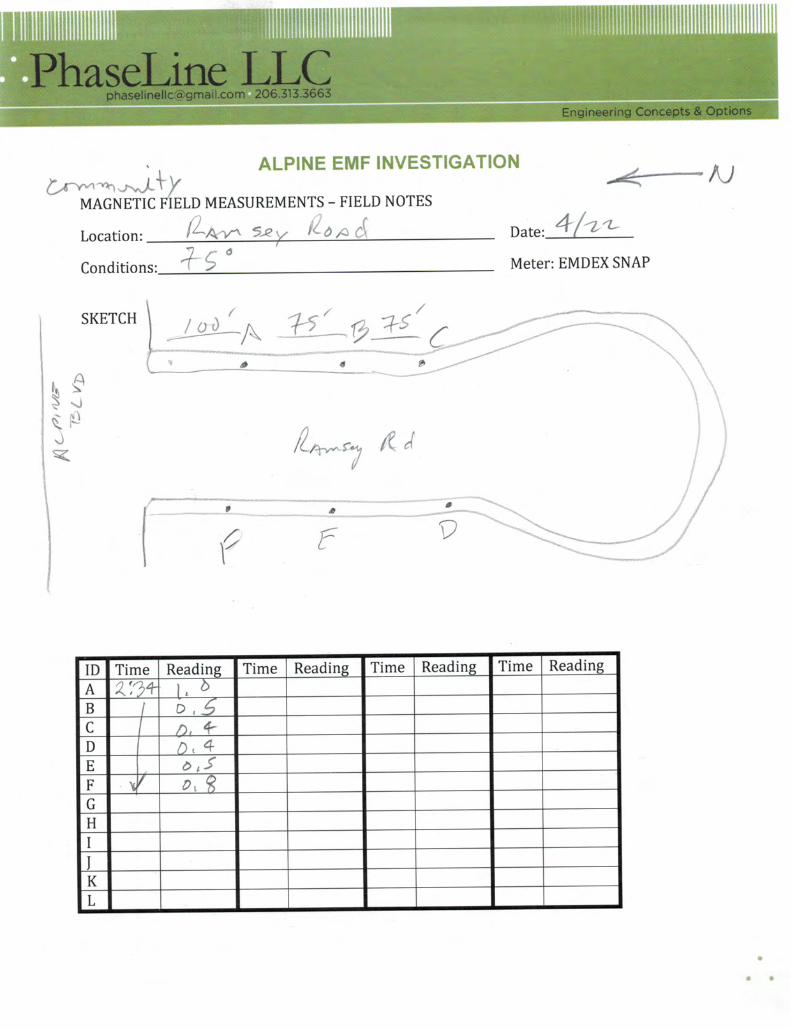
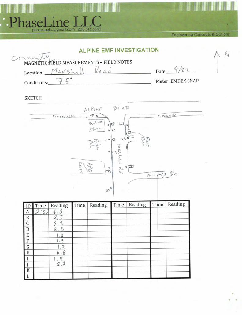
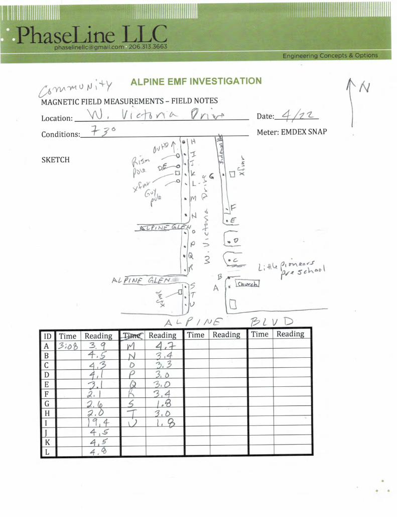
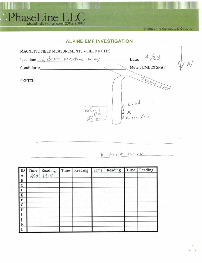
Magnetic Field Measurements
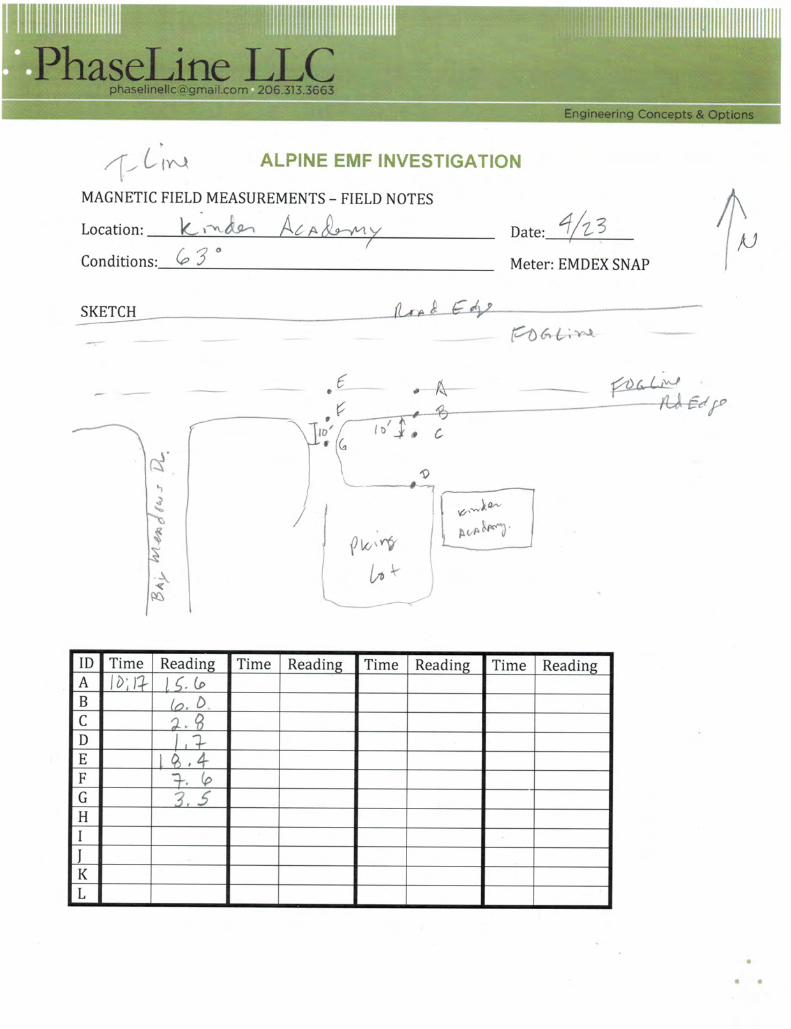
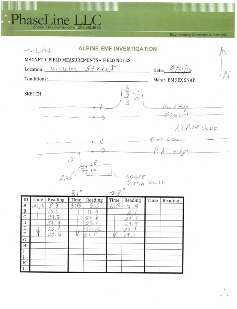
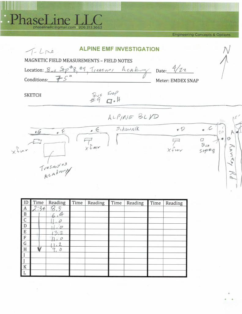
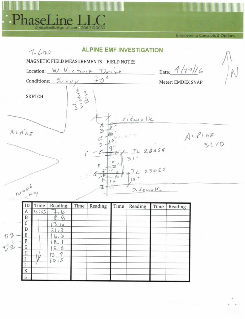
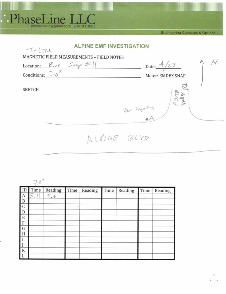
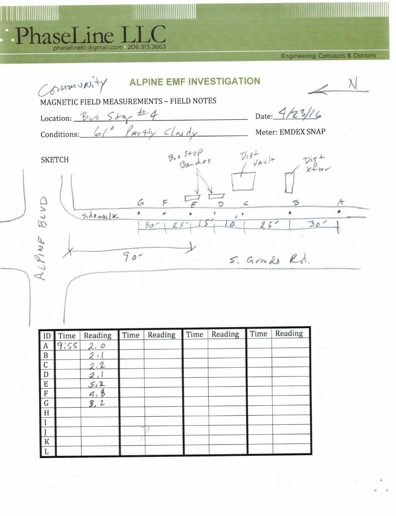
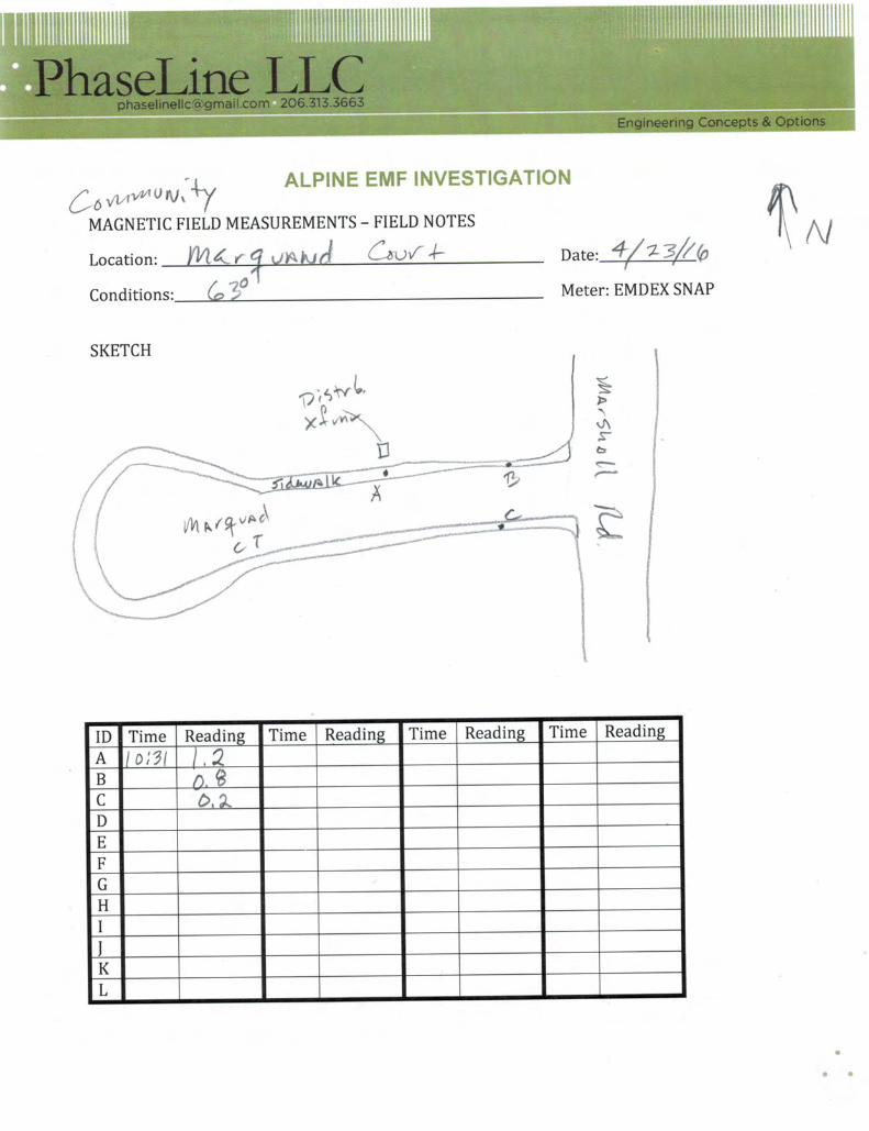
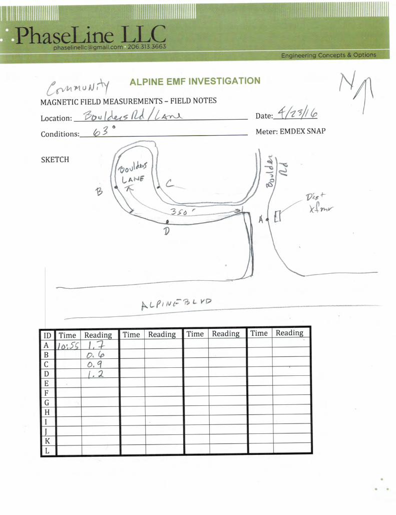
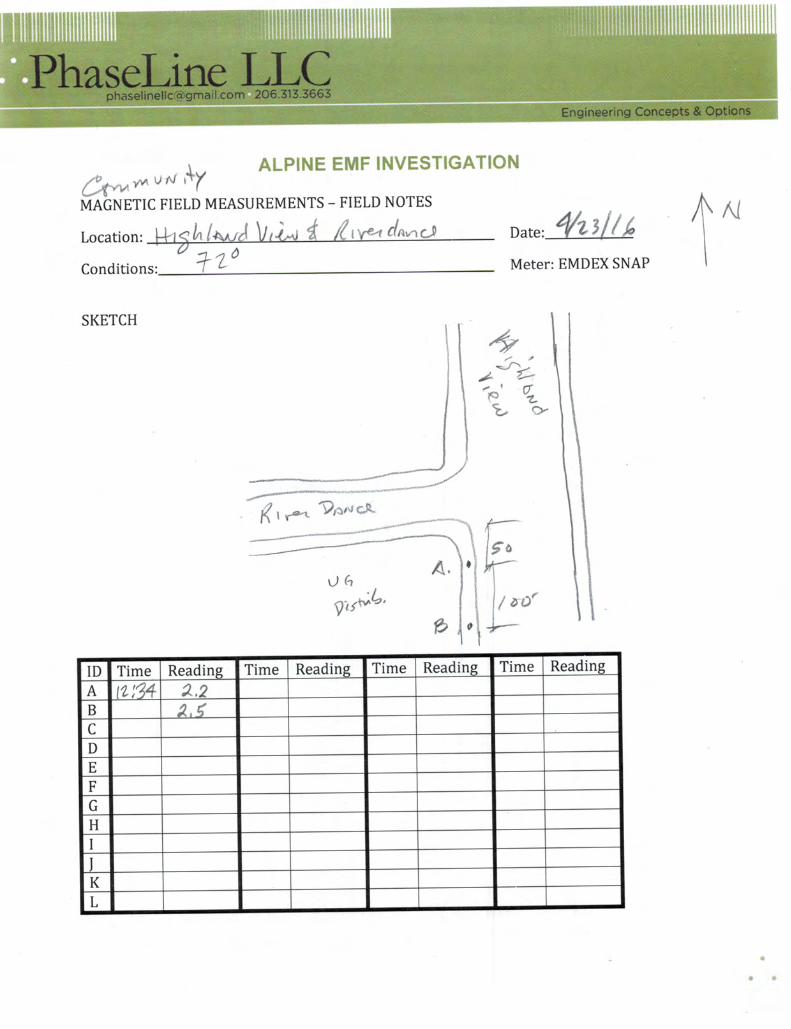
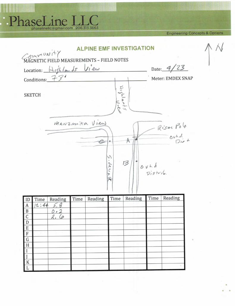
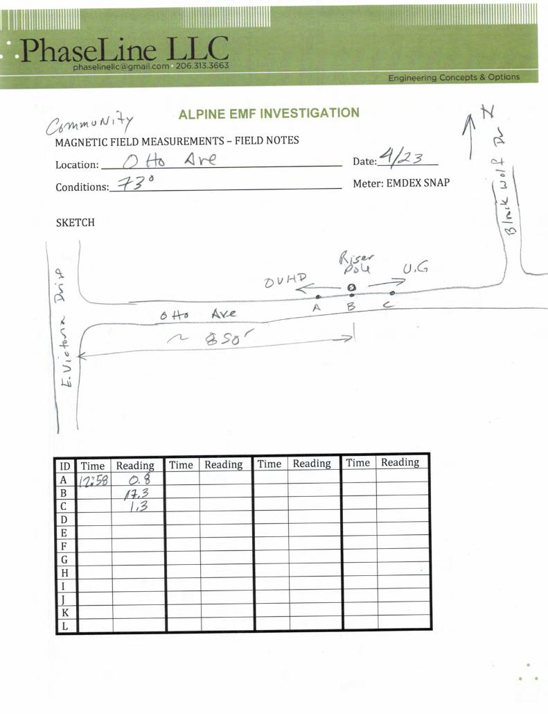
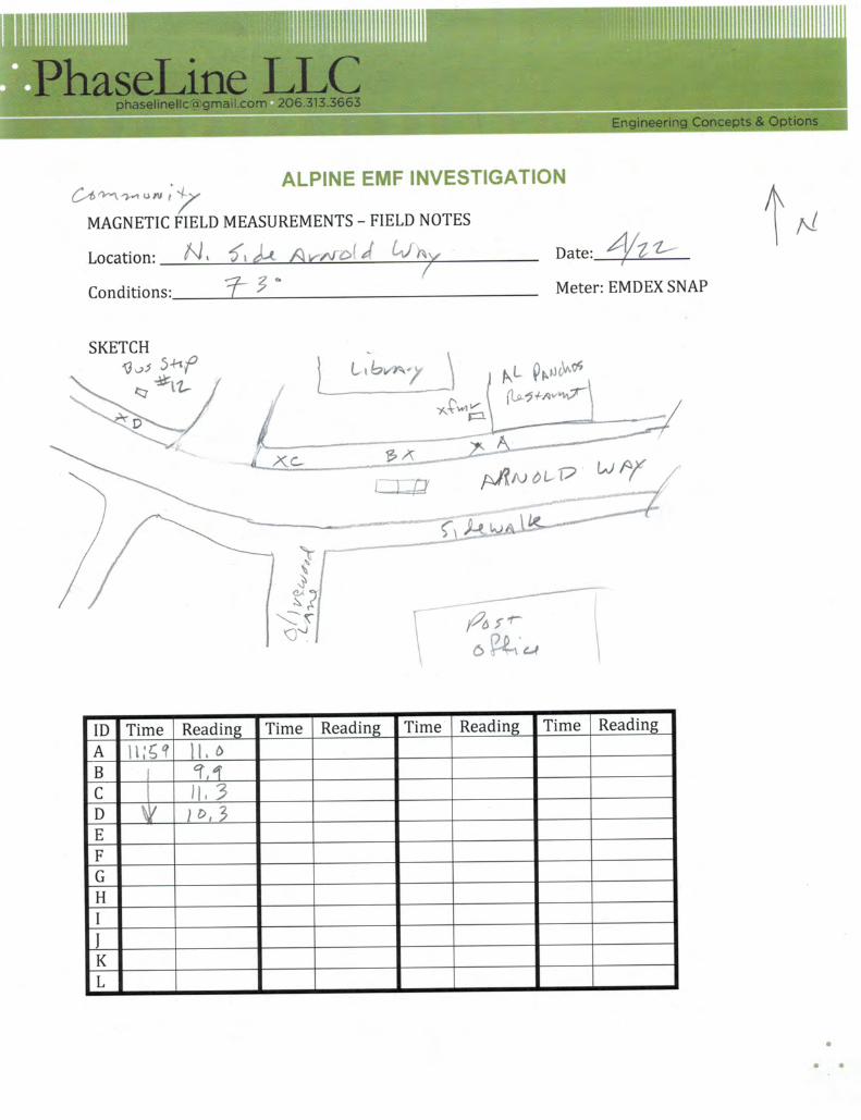
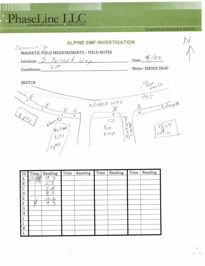
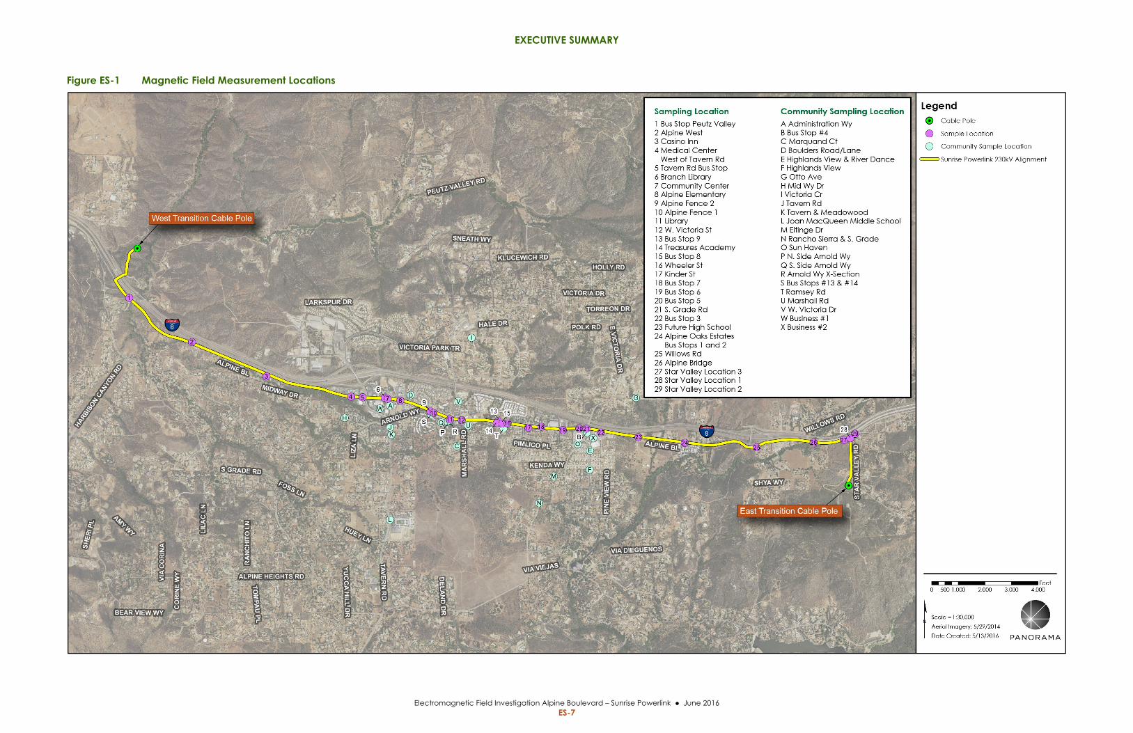
Methodology This investigation included magnetic field measures taken over a 3‐day period (April 21 to
April 23, 2016). Magnetic field measurements were recorded at 29 locations along Alpine
Boulevard and 24 additional locations within the Alpine community. The magnetic field
measurement locations are shown on Figure ES‐1 below. Field measurements were performed
in accordance with Institute of Electrical and Electronic Engineers (IEEE) standards.
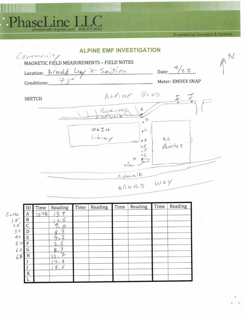
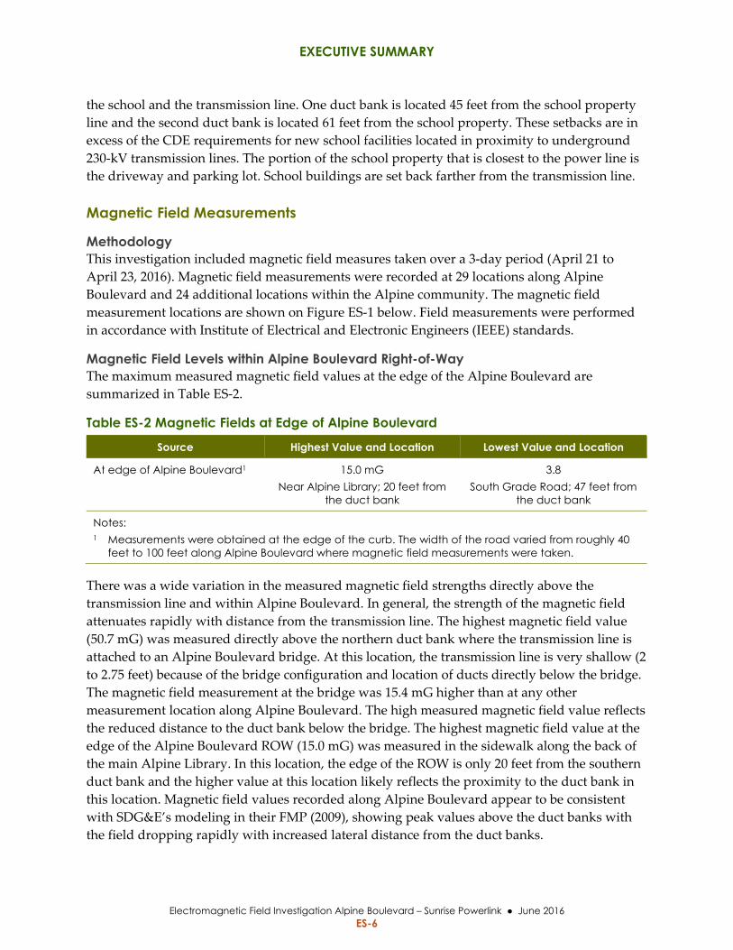
Magnetic Field Levels within Alpine Boulevard Right-of-Way The maximum measured magnetic field values at the edge of the Alpine Boulevard are
summarized in Table ES‐2.
Table ES-2 Magnetic Fields at Edge of Alpine Boulevard
Source Highest Value and Location Lowest Value and Location
At edge of Alpine Boulevard1 15.0 mG Near Alpine Library; 20 feet from
the duct bank
3.8 South Grade Road; 47 feet from
the duct bank
Notes: 1 Measurements were obtained at the edge of the curb. The width of the road varied from roughly 40
feet to 100 feet along Alpine Boulevard where magnetic field measurements were taken.
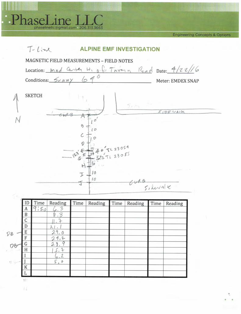
There was a wide variation in the measured magnetic field strengths directly above the
transmission line and within Alpine Boulevard. In general, the strength of the magnetic field
attenuates rapidly with distance from the transmission line. The highest magnetic field value
(50.7 mG) was measured directly above the northern duct bank where the transmission line is
attached to an Alpine Boulevard bridge. At this location, the transmission line is very shallow (2
to 2.75 feet) because of the bridge configuration and location of ducts directly below the bridge.
The magnetic field measurement at the bridge was 15.4 mG higher than at any other
measurement location along Alpine Boulevard. The high measured magnetic field value reflects
the reduced distance to the duct bank below the bridge. The highest magnetic field value at the
edge of the Alpine Boulevard ROW (15.0 mG) was measured in the sidewalk along the back of
the main Alpine Library. In this location, the edge of the ROW is only 20 feet from the southern
duct bank and the higher value at this location likely reflects the proximity to the duct bank in
this location. Magnetic field values recorded along Alpine Boulevard appear to be consistent
with SDG&E’s modeling in their FMP (2009), showing peak values above the duct banks with
the field dropping rapidly with increased lateral distance from the duct banks.
EXECUTIVE SUMMARY
Electromagnetic Field Investigation Alpine Boulevard – Sunrise Powerlink June 2016 ES-7
Figure ES-1 Magnetic Field Measurement Locations

EXECUTIVE SUMMARY
Electromagnetic Field Investigation Alpine Boulevard – Sunrise Powerlink June 2016 ES-8
This page is intentionally left blank.
EXECUTIVE SUMMARY
Electromagnetic Field Investigation Alpine Boulevard – Sunrise Powerlink June 2016 ES-9
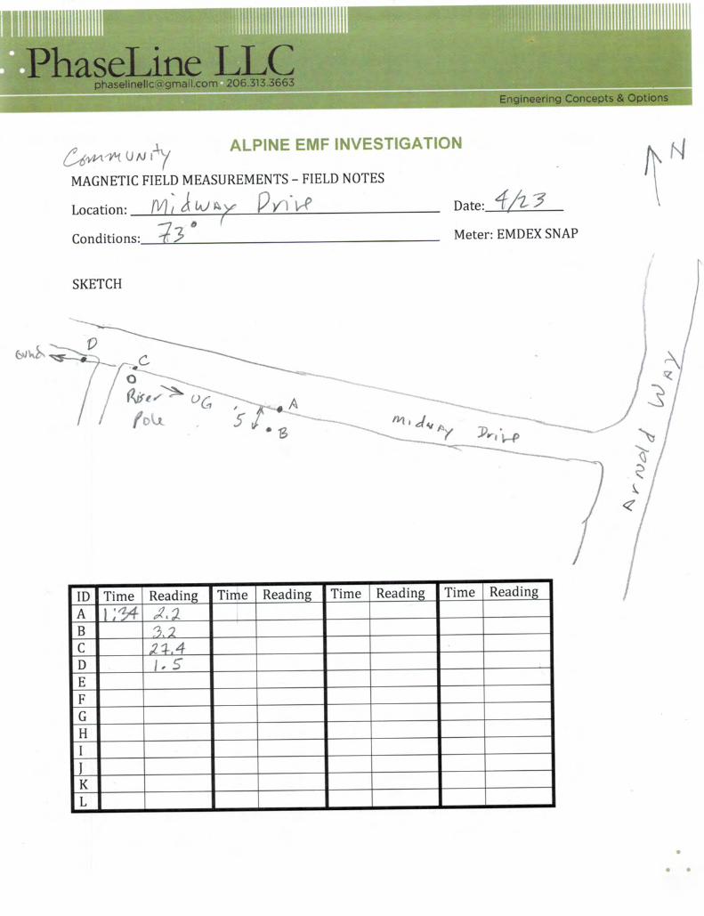
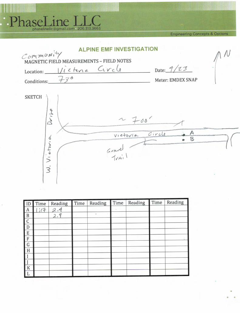
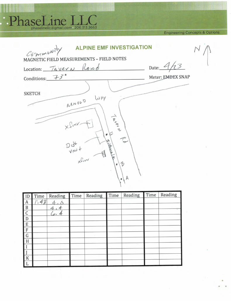
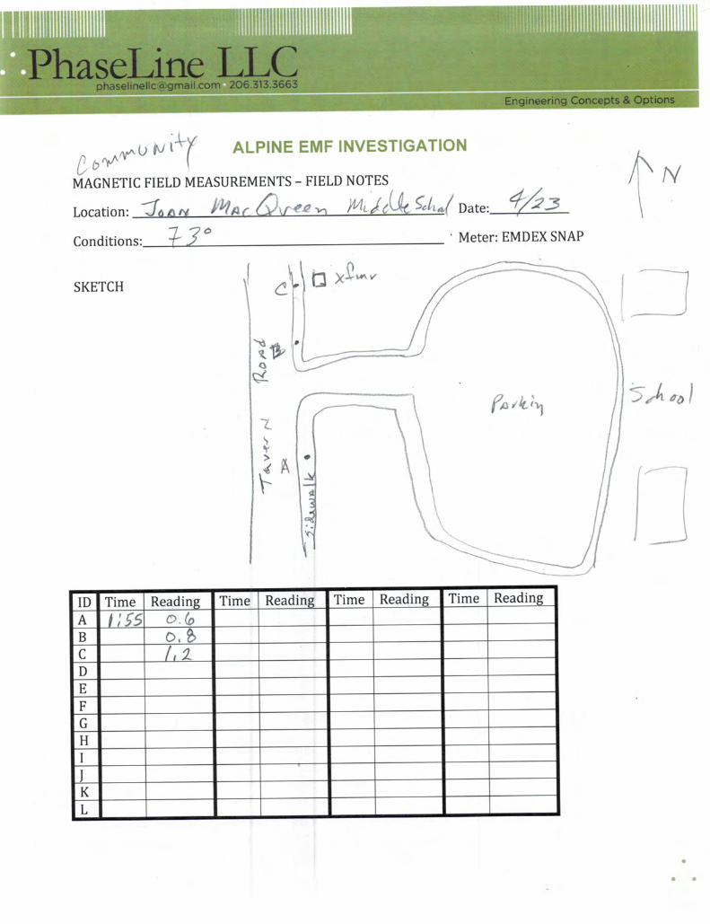
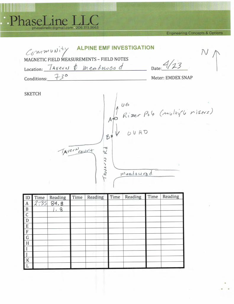
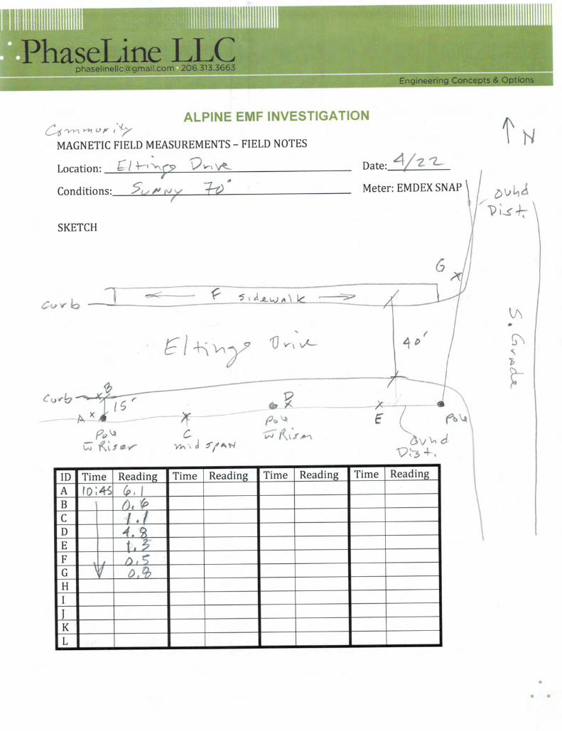
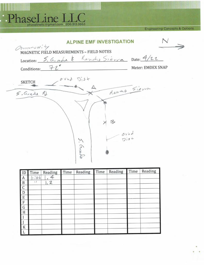
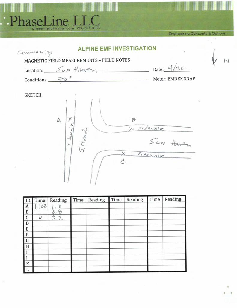
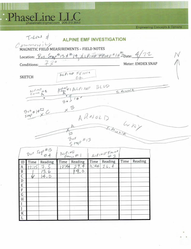
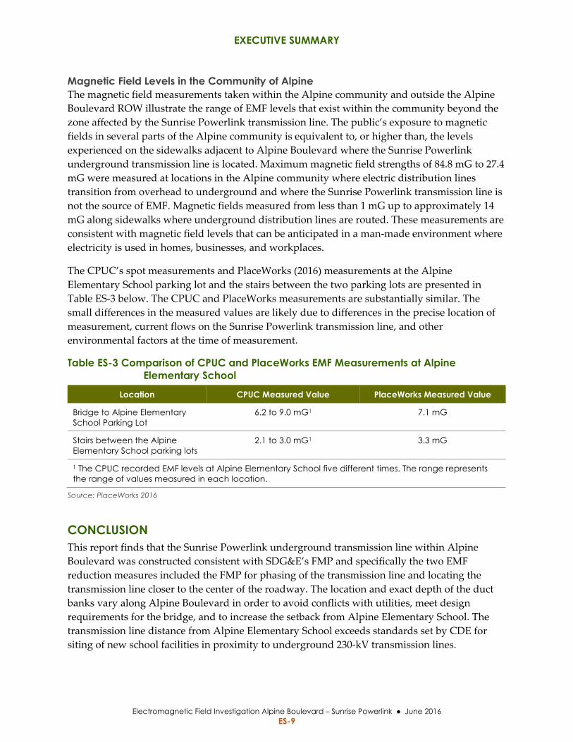
Magnetic Field Levels in the Community of Alpine The magnetic field measurements taken within the Alpine community and outside the Alpine
Boulevard ROW illustrate the range of EMF levels that exist within the community beyond the
zone affected by the Sunrise Powerlink transmission line. The public’s exposure to magnetic
fields in several parts of the Alpine community is equivalent to, or higher than, the levels
experienced on the sidewalks adjacent to Alpine Boulevard where the Sunrise Powerlink
underground transmission line is located. Maximum magnetic field strengths of 84.8 mG to 27.4
mG were measured at locations in the Alpine community where electric distribution lines
transition from overhead to underground and where the Sunrise Powerlink transmission line is
not the source of EMF. Magnetic fields measured from less than 1 mG up to approximately 14
mG along sidewalks where underground distribution lines are routed. These measurements are
consistent with magnetic field levels that can be anticipated in a man‐made environment where
electricity is used in homes, businesses, and workplaces.
The CPUC’s spot measurements and PlaceWorks (2016) measurements at the Alpine
Elementary School parking lot and the stairs between the two parking lots are presented in
Table ES‐3 below. The CPUC and PlaceWorks measurements are substantially similar. The
small differences in the measured values are likely due to differences in the precise location of
measurement, current flows on the Sunrise Powerlink transmission line, and other
environmental factors at the time of measurement.
Table ES-3 Comparison of CPUC and PlaceWorks EMF Measurements at Alpine Elementary School
Location CPUC Measured Value PlaceWorks Measured Value
Bridge to Alpine Elementary School Parking Lot
6.2 to 9.0 mG1 7.1 mG
Stairs between the Alpine Elementary School parking lots
2.1 to 3.0 mG1 3.3 mG
1 The CPUC recorded EMF levels at Alpine Elementary School five different times. The range represents the range of values measured in each location.
Source: PlaceWorks 2016
CONCLUSION This report finds that the Sunrise Powerlink underground transmission line within Alpine
Boulevard was constructed consistent with SDG&E’s FMP and specifically the two EMF
reduction measures included the FMP for phasing of the transmission line and locating the
transmission line closer to the center of the roadway. The location and exact depth of the duct
banks vary along Alpine Boulevard in order to avoid conflicts with utilities, meet design
requirements for the bridge, and to increase the setback from Alpine Elementary School. The
transmission line distance from Alpine Elementary School exceeds standards set by CDE for
siting of new school facilities in proximity to underground 230‐kV transmission lines.
EXECUTIVE SUMMARY
Electromagnetic Field Investigation Alpine Boulevard – Sunrise Powerlink June 2016 ES-10
Measured EMF levels outside of Alpine Elementary School were consistent with measurements
in recent studies by JPA (2016) and PlaceWorks (2016). The PlaceWorks (2016) study concluded
on the basis of these and other measurements inside Alpine Elementary School, that the Sunrise
Powerlink transmission line does not pose a significant safety or health risk to the Alpine
Elementary School site.
Measured EMF levels from Alpine Boulevard appear to be consistent with SDG&E’s modeling
in their FMP with peak values above the duct banks and rapidly diminishing values moving
laterally away from the duct banks. All of the magnetic fields measured along Alpine Boulevard
are substantially below levels suggested as standards by several international organizations and
by several states outside of California. The measured EMF levels along Alpine Boulevard are
also within the range of magnetic field levels observed elsewhere in the community of Alpine
where the Sunrise Powerlink transmission line is not the dominant source of EMF.
1 INTRODUCTION
Electromagnetic Field Investigation Alpine Boulevard – Sunrise Powerlink June 2016 1-1
1 INTRODUCTION
1.1 PURPOSE OF THIS EMF INVESTIGATION The California Public Utilities Commission (CPUC) conducted this electromagnetic field (EMF)
investigation to independently measure magnetic field levels along the San Diego Gas &
Electric Company (SDG&E) Sunrise Powerlink underground 230‐kilovolt (kV) transmission line
located under Alpine Boulevard within the community of Alpine in unincorporated San Diego
County. The construction of the underground 230‐kV transmission line was completed by
SDG&E in 2012. This report documents the findings of the CPUC’s EMF investigation. The
purpose and intended uses of this report are to:
1. Review the construction of the completed 230‐kV underground segment for
consistency with SDG&E’s Final Magnetic Field Management Plan (FMP) design
for the approved Sunrise Powerlink Project (SDG&E 2009);
2. Inform the public and decision makers as to the nature of EMF from electric power
lines;
3. Summarize the status of ongoing research into potential public health impacts of
EMF;
4. Identify any relevant EMF standards, regulations, guidelines or policies;
5. Provide the results of magnetic field measurements on Alpine Boulevard and
within the greater Alpine community; and
6. Compare these results with the FMP prepared by SDG&E for the approved Sunrise
Powerlink Transmission Project and other recent magnetic field measurements
conducted by others.
1.2 INQUIRIES PROMPTING INVESTIGATION An article published in the Alpine Sun on February 4, 2016, and re‐reported in the East County
Magazine, discussed a report by a local engineer and contractor (Faulkner and Milligan 2016)
that provided the results of EMF measurements along Alpine Boulevard before and after the
construction of the Sunrise Powerlink underground double‐circuit 230‐kV transmission line.
The report stated that it appeared that children in Alpine may be at risk for leukemia and asked
that San Diego County examine Alpine children for leukemia, annually, as a precaution.
Subsequent to the publication of these articles the public expressed concern regarding public
exposure to EMF and in particular for students at Alpine Elementary School located along the
alignment of the underground transmission line. Over 200 members of the public attended an
EMF informational meeting held on February 23, 2016 at Alpine Elementary School. The
meeting included a panel of representatives from Alpine Schools, Alpine Community Planning
1 INTRODUCTION
Electromagnetic Field Investigation Alpine Boulevard – Sunrise Powerlink June 2016 1-2
Group, San Diego County Board of Supervisors, San Diego Public Health and Human Services,
and SDG&E.
During the informational meeting, a representative from Alpine Schools announced that they
had received the results of EMF measurements taken at Alpine Elementary School by Risk
Management JPA Fringe Benefits Consortium and that they were also hiring an independent
analyst to further review EMF levels at Alpine Elementary School.
In addition to the articles described above, follow‐on articles have been published in local
media including coverage of the informational meeting on February 23, 2016 by a television
news broadcast.
On February 17, 2016, San Diego Supervisor Dianne Jacob requested that the CPUC conduct an
investigation and independent review of EMF levels in the greater Alpine area (Appendix A).
CPUC Commissioner Michael Picker responded to this request on February 29, 2016, by
indicating that the CPUC would investigate the EMF levels and provide a more detailed
response to the public concerns (Appendix A). On March 8, 2016, Senator Joel Anderson filed a
constituent complaint form and requested clarification on CPUC investigation into EMF levels
(Appendix A). This report provides the results of the CPUC’s EMF investigation prepared in
response to community concern and complaints filed by San Diego Supervisor Dianne Jacob
and Senator Joel Anderson.
1.3 CONTENTS OF EMF INVESTIGATION REPORT This report provides information on EMFs, including background on the Sunrise Powerlink
Project and studies of EMF levels in the Alpine community. This report is organized as follows:
Executive Summary: an executive summary of the information included in the
report.
Section 1 ‐ Introduction: describes the purpose of the report and events leading to the CPUC initiating an EMF investigation.
Section 2 ‐ EMF Overview: provides an overview of EMFs as a phenomenon and
includes information on research related to EMFs and health concerns and public
exposures to EMFs.
Section 3 ‐ Regulatory Framework: provides the regulatory framework related to
public exposure to EMF from power lines as well as the CPUC decisions on the
topic of EMFs and approvals for the Sunrise Powerlink Project.
Section 4 ‐ Background: provides background on SDG&E’s Sunrise Powerlink
Project.
Section 5 ‐ Sunrise Powerlink FMP: includes an overview of the FMP prepared by
SDG&E for the Sunrise Powerlink Project.
Section 6 ‐ Recent Magnetic Field Reports: includes a review of other recent EMF
studies in Alpine.
1 INTRODUCTION
Electromagnetic Field Investigation Alpine Boulevard – Sunrise Powerlink June 2016 1-3
Section 7 – CPUC EMF Investigation: provides the methodology used for this EMF
investigation, including the locations of EMF sampling in the Alpine community
and the EMF data gathered in Alpine over three consecutive days in April 2016.
Sections 8 ‐ References: includes references used in this report. Appendix A – Correspondence Regarding the EMF Investigation: includes copies
of letters from Supervisor Jacob, Senator Anderson, and Commissioner Picker.
Appendix B – EMF Design Guidelines for Electrical Facilities: includes the general EMF design guidelines that apply to regulated utilities.
Appendix C ‐ EMF Measurement Locations and Surrounding Land Uses: includes figures showing the locations of EMF measurements within the Alpine community.
Appendix D ‐ Field Management Plan: includes a copy of the FMP prepared by
SDG&E for the Sunrise Powerlink Project.
Appendix E – Faulkner and Milligan Study: includes a copy of the EMF study
prepared by Faulkner and Milligan
Appendix F ‐ Alpine Unified School District Study: includes a copy of the EMF
study performed by JPA for Alpine Unified School District
Appendix G ‐ San Diego County Office of Education Study: includes a copy of the study performed by PlaceWorks for San Diego County Office of Education
Appendix H ‐ Meter Calibration: Documentation of EMDEX SNAP magnetic field
meter calibration and unit specifications.
Appendix I ‐ Field Notes: includes a copy of field notes prepared during the 3 days
of magnetic field measurements in Alpine.

1 INTRODUCTION
Electromagnetic Field Investigation Alpine Boulevard – Sunrise Powerlink June 2016 1-4
This page is intentionally left blank.
2 EMF OVERVIEW
Electromagnetic Field Investigation Alpine Boulevard – Sunrise Powerlink June 2016 2-1
2 EMF OVERVIEW
This Section provides general information on EMFs and sources of EMFs, research on the health
effects of EMF exposure, and general exposure levels from typical sources of EMFs in
households and the community, and exposure levels from overhead and underground
transmission lines.
2.1 EMF SOURCES Electric and magnetic fields are separate phenomena and occur both naturally and as a result of
human activity across a broad electrical spectrum. The weather and the earth’s geomagnetic
field cause naturally occurring electric and magnetic fields. The fields caused by human activity
result from technological application of the electromagnetic spectrum for uses such as
communications, the generation, transmission, and local distribution of electricity and from the
use of electrical equipment in the work place or electrical appliances in the home.
The frequency of electromagnetic energy is a critical parameter in how EMFs interact with the
physical environment including with living organisms. The higher the frequency of
electromagnetic fields, the shorter their wavelength, and the shorter the wavelength, the greater
the energy that is imparted when interacting with physical objects.
The frequency of electric power lines is determined by the rate at which electric and magnetic
fields change their direction each second. For power lines in the United States (U.S.), the
frequency of change is 60 times per second and is defined as 60‐Hertz (Hz) power, which is
considered an extremely low frequency (ELF). Power frequency EMFs carry very little energy
and have no ionizing effects. In comparison, radio and communication waves operate at much
higher frequencies, 500,000 Hz to 1 billion Hz and microwaves at 2 billion Hz. The information
presented in this report is limited to the ELFs‐EMFs from power lines operating at frequencies
of 60 Hz.
Electric power flows across power line systems from generating sources to serve electrical loads
within the community. From an EMF perspective, the relevant parameters of a power line are
its voltage and current. These two parameters determine the power flowing over a power line.
The higher the voltage level of the power line, the lower the amount of current needed to
deliver the same amount of power. For example, a 115‐kV transmission line with 200 amps of
current will transmit approximately 40,000 kilowatts (kW), and a 230‐kV transmission line
requires only 100 amps of current to deliver the same 40,000 kW. The voltage and current levels
of a transmission line also dictate the magnitude of the electric and magnetic fields produced by
the line.

2 EMF OVERVIEW
Electromagnetic Field Investigation Alpine Boulevard – Sunrise Powerlink June 2016 2-2
2.1.1 Electric Fields Electric fields from power lines are created whenever the lines are energized, with the strength
of the field dependent directly on the voltage of the line creating it. Electric field strength is
typically described in terms of kilovolt per meter (kV/m). Electric field strength attenuates
(reduces) rapidly as the distance from the source increases. Electric fields are reduced at many
receptors because most objects or materials such as trees or houses, effectively shield them (PTI
1993).
Unlike magnetic fields, which penetrate almost everything and are unaffected by buildings,
trees, and other obstacles, electric fields are distorted by any object that is within the electric
field, including the human body. Even trying to measure an electric field with electronic
instruments is difficult because the devices themselves may alter the levels recorded.
Determining an individual’s exposure to electric fields requires an understanding of many
variables, one of which is the electric field itself, with others including how effectively the
person is grounded and their body surface area within the electric field.
Electric fields in the vicinity of power lines can cause the same phenomena as the static
electricity experienced on a dry winter day, or with clothing just removed from a clothes dryer,
and may result in small nuisance electric discharges when touching long metal fences,
pipelines, or large vehicles.
Potential health effects from exposure to electric fields from power lines is typically not of
concern since electric fields are effectively shielded, as noted above; therefore, the majority of
the following information related to EMF focuses primarily on exposure to magnetic fields from
power lines.
2.1.2 Magnetic Fields Magnetic fields from power lines are created whenever current flows through power lines at
any voltage. The strength of the field is directly dependent on the current in the line. In the U.S.,
magnetic field strength is typically measured in milliGauss (mG). Similar to electric fields,
magnetic field strength attenuates rapidly with distance from the source. However, unlike
electric fields, objects or materials do not easily shield magnetic fields.
The nature of a magnetic field can be illustrated by considering a household appliance. When
the appliance is energized by being plugged into an outlet but not turned on, no current flows
through it. Under such circumstances, an electric field is generated around the cord and
appliance, but no magnetic field is present. If the appliance is switched on, the electric field
would still be present and a magnetic field would also be created. The electric field strength is
directly related to the magnitude of the voltage from the outlet and the magnetic field strength
is directly related to the magnitude of the current flowing in the cord and appliance.
2 EMF OVERVIEW
Electromagnetic Field Investigation Alpine Boulevard – Sunrise Powerlink June 2016 2-3
2.2 EMF RESEARCH
2.2.1 Overview Research has been conducted to investigate the potential effects within the environment of
EMFs from power lines. Research results remain inconclusive after several decades of study
regarding potential public health risks from exposure to power line EMFs. Early studies of
EMFs focused primarily on interactions with the electric fields from power lines. Since 1979,
public interest and concern, specifically regarding magnetic fields from power lines, has
increased. This increase has generally been attributed to publication of the results of a single
epidemiological study (Wertheimer and Leeper 1979), which documented an observed
association between the wiring configurations on electric power lines outside of homes in
Denver and the incidence of childhood cancer. Many epidemiological, laboratory, and animal
studies regarding magnetic fields were conducted following publication of the Wertheimer and
Leeper study.
Research related to EMFs can be grouped into three general categories: laboratory studies
conducted at the cellular level to understand biological mechanisms and using animals to
observe effects under controlled conditions; clinical studies that monitor human physiological
responses when exposed to EMF; and epidemiological studies that compare human population
groups to identify differences between exposed and unexposed populations.
As outlined below, a substantial amount of research investigating EMFs has been conducted
over the past several decades. The following discussion is not a recounting of the results of
numerous individual studies but rather characterizes the body of research and whether there is
any generally accepted consensus or conclusion from scientists and researchers that identify an
EMF public health impact.
2.2.2 Laboratory Studies ELF magnetic fields have been shown to interact with tissues and cells by inducing electric
fields and electric currents when in these fields; however, the electric currents induced in cells
by magnetic fields at levels commonly found in the environment are normally much lower than
the strongest electric currents naturally occurring in the body, such as those that control the
beating of the heart. Laboratory studies have identified various other biologic effects from
exposure to EMFs (NIEHS/NIH 2002). It is important to note that a cellular interaction or
biological effect from a magnetic field does not necessarily translate to a health effect since the
biological response may fall within the normal range of variation (NIEHS/NIH 2002).
Further, in vivo (live) studies have not found that magnetic fields induce or promote cancer in
animals exposed for their entire lifespan under highly controlled conditions, nor have in vitro
studies found a cellular mechanism by which magnetic fields could induce carcinogenesis.
The lack of a biological mechanism indicating alteration that harms cells or tissue results in
laboratory studies not being able to identify a cause‐effect relationship between EMF exposure
and health impacts. Laboratory studies of cancer outcomes in groups of animals have provided
2 EMF OVERVIEW
Electromagnetic Field Investigation Alpine Boulevard – Sunrise Powerlink June 2016 2-4
mixed results and often utilize magnetic field exposures well in excess of field levels that would
be experienced in the vicinity of electric power lines (NRC 1997). To date, the results of these
animal studies have not supported a conclusion of health impacts from power line frequency
EMF (NRC 1997).
2.2.3 Clinical Studies Clinical studies consider the results of laboratory testing and explore theories of biological
mechanisms to try to quantify effects on persons. In clinical studies, human volunteers are
exposed with different treatments, such as static or time‐varying fields, to accurately measure
the actual effects. Clinical studies provide an opportunity to closely control the exposure level
of subjects and directly measure physiological responses. For studies of EMF effects, medical
researchers use controlled exposure rates on volunteers to look for measurable changes, such as
brain activity and hormonal levels.
Clinical studies with human individuals rely on volunteers in a last step toward determining
the degree of an agent’s ability to cause effects on physiology in a way that may affect health.
Clinical studies have varying degrees of rigor and can depend in part on how the volunteer
study participants cooperate with the researchers as well as the researchers’ control over the
volunteer participants. Human responses have been demonstrated in clinical studies at
magnetic field levels generally much higher than experienced by the general public or workers
and have not demonstrated an association with health hazards (SSM 2014). In a recent 2014
update on the results of clinical studies of ELF‐EMF, the Swedish Radiation Safety Authority’s
Council on EMFs noted that new studies underline the conclusion from the previous Council
report that ELF magnetic fields do not seem to have any effects on general physiology (SSM
2014).
2.2.4 Epidemiological Studies Epidemiology is the study of patterns of disease in populations. EMF‐related epidemiological
studies search for statistical links or associations between exposures to EMFs and disease in
human populations. Epidemiological studies are usually observational in nature and consider
historical data for groups of individuals, meaning that researchers investigate what happens as
people go about their daily lives. Epidemiologists work to interpret health outcomes by
comparing populations that are “exposed versus non‐exposed” to a given vector. In the case of
EMF populations, calculated or measured data on field strengths cannot be representative of the
time frame involved in epidemiology studies. Surrogates of exposure have been utilized in
some instances, such as wire‐codes or living in close proximity to transmission line corridors.
Remaining uncertainty and controversy surrounding magnetic fields is still related to the
research on childhood leukemia. Some epidemiology studies reported that children with
leukemia were more likely to live closer to power lines, or have higher estimates of magnetic
field exposure, compared to children without leukemia; however, other epidemiology studies
did not report this statistical association. When a number of the relevant studies were combined
in a single analysis, no association was evident at lower exposure levels, but a weak association
2 EMF OVERVIEW
Electromagnetic Field Investigation Alpine Boulevard – Sunrise Powerlink June 2016 2-5
(odds ratio 2.0) was reported between childhood leukemia and estimates of average magnetic
field exposures greater than 4 mG (WHO 2001).
The epidemiology‐pooled analyses provide some evidence for an association between magnetic
fields and childhood leukemia. Because of the inherent uncertainty associated with
observational epidemiology studies, the results of these pooled analyses were considered to
provide only limited epidemiologic support for a causal relationship; chance, bias and
confounding could not be ruled out with reasonable confidence (WHO 2001).
In addition to the uncertainty regarding the level of health risk posed by EMFs, individual
studies and scientific panels have not been able to determine or reach consensus regarding what
level of magnetic field exposure might constitute a health risk. Increased health risks were
discussed for average field levels greater than 2 mG in some early epidemiological studies. The
International Agency for Research on Cancer (IARC) scientific working group indicated that
studies with average magnetic field levels of 3 to 4 mG played a pivotal role in their
classification of EMFs as possible carcinogens (IARC 2002).
Considering all the evidence together, the World Health Organization (WHO), as well as other
scientific panels, classified magnetic fields as a possible cause of childhood leukemia (NRPB
2001; IARC 2002; ICNIRP 2001; HCN 2004; WHO 2007). The term “possible” denotes an
exposure for which epidemiologic evidence points to a statistical association, but other
explanations cannot be ruled out as the cause of that statistical association (e.g., bias and
confounding) and experimental evidence does not support a cause‐and‐effect relationship.
The WHO has not prompted scientific organizations to recommend that the classification of
“possible carcinogen” be changed to any other IARC category such as “probable” or “known
human carcinogen” (SSI 2008; ICNIRP 2009; SCENIHR 2009). The WHO and other scientific
panels have stressed the importance of reconciling the epidemiologic data on childhood
leukemia and the lack of evidence from experimental studies through innovative research. Just
like any other cancer, researchers believe that the development of childhood leukemia is
influenced by a multitude of different factors, e.g., genetics, environmental exposures, and
infectious agents (Buffler et al. 2005; McNally et al. 2006).
The source of public concern is often a result of media portrayal of the results of epidemiology
studies of EMFs as showing a doubling of the risk of childhood leukemia. In order to
understand what the risks really are, it is important to distinguish between relative risk and
absolute risk. Epidemiology studies utilize relative risk ratios to compare the incidence of
leukemia in the study population versus the general population. A relative risk ratio tells how
much more likely it is that leukemia would develop in one group compared to another, but it
does not tell anything about the overall likelihood of developing leukemia, which is the
absolute risk. The absolute risk of contracting leukemia in the general population is 4.5 cases per
100,000 children, which can be expressed as a 0.0045% chance that an individual would contract
the disease (CDC 2012). A doubling of the relative risk ratio for leukemia means there would be
2 EMF OVERVIEW
Electromagnetic Field Investigation Alpine Boulevard – Sunrise Powerlink June 2016 2-6
an increase of the absolute risk to a 0.009% chance that an individual would contract the
disease.
2.2.5 Scientific Panel Reviews of EMF Studies Scientific, health, and regulatory organizations worldwide have convened numerous panels of
experts in an effort to understand the phenomenon of EMFs from electric power lines and the
interaction with the public. In many instances these evaluations have been conducted in order
to advise governmental agencies or professional standard‐setting groups. These panels of
scientists first evaluate the available studies individually, not only to determine what specific
information they can offer, but also in terms of the validity of their experimental design,
methods of data collection, analysis, and suitability of the authors’ conclusions to the nature
and quality of the data presented. Subsequently, the individual studies, with their previously
identified strengths and weaknesses, are evaluated collectively in an effort to identify whether
there is a consistent pattern or trend in the data that would lead to a determination of possible
or probable hazards to human health resulting from exposure to these fields.
Scientific reviews include those prepared by international agencies such as the WHO (WHO
1984; WHO 1987; and WHO 2001) and the International Non‐Ionizing Radiation Committee of
the International Radiation Protection Association (IRPA/INIRC 1990) as well as governmental
agencies of a number of countries, such as the National Radiological Protection Board of the
United Kingdom, the Swedish Radiation Safety Authority, the Health Council of the
Netherlands, and the French and Danish Ministries of Health.
These scientific panels have varied conclusions on the strength of the scientific evidence
suggesting that power frequency EMF exposures pose any health risk. The results of the
scientific reviews are summarized below. None of the reviews that included a large panel of
independent scientists with a broad spectrum of expertise from multiple organizations have
arrived at a conclusion that electric or magnetic fields are a known or likely cause of any
adverse health effect at long‐term low‐level exposures found in the environment.
2.2.5.1 National Institute of Environmental Health Sciences In May 1999, the National Institute of Environmental Health Sciences (NIEHS) submitted to
Congress its report titled, Health Effects from Exposure to Power‐Line Frequency Electric and
Magnetic Fields, containing the following conclusion regarding EMFs and health effects:
“Using criteria developed by the International Agency for Research on Cancer
(IARC), none of the Working Group considered the evidence strong enough to
label ELF‐EMF exposure as a known human carcinogen or probable human
carcinogen. However, a majority of the members of this Working Group
concluded that exposure to power‐line frequency ELF‐EMF is a possible
carcinogen.”
2.2.5.2 World Health Organization In 2002, a scientific working group of IARC (an agency of WHO) reviewed studies related to the
carcinogenicity of EMFs. Magnetic fields were classified as “possibly carcinogenic to humans”,
2 EMF OVERVIEW
Electromagnetic Field Investigation Alpine Boulevard – Sunrise Powerlink June 2016 2-7
based on epidemiological studies. “Possibly carcinogenic to humans” is a classification used to
denote an agent for which there is limited evidence of carcinogenicity in humans and less than
sufficient evidence of carcinogenicity in experimental animals. Other agents identified as
“possibly carcinogenic to humans” include gasoline exhaust, styrene, welding fumes, and coffee
(WHO 2001).
2.2.5.3 California Department of Health Services On behalf of the CPUC, the California Department of Health Services (DHS) completed a
comprehensive review of existing studies related to EMF from power lines and potential health
risks. The three staff scientists with the DHS who undertook this risk evaluation were all
epidemiologists, and their work took place from 2000 to 2002. The results of this review titled,
An Evaluation of the Possible Risks from Electric and Magnetic Fields (EMFs) from Power Lines,
Internal Wiring, Electrical Occupations, and Appliances, was published in June 2002 (DHS 2002).
The conclusions contained in the executive summary are provided below:
To one degree or another, all three of the DHS scientists are inclined to believe that
EMFs can cause some degree of increased risk of childhood leukemia, adult brain
cancer, Lou Gehrig’s Disease, and miscarriage.
They strongly believe that EMFs do not increase the risk of birth defects or low birth
weight.
They strongly believe that EMFs are not universal carcinogens, since there are a
number of cancer types that are not associated with EMF exposure.
To one degree or another they are inclined to believe that EMFs do not cause an
increased risk of breast cancer, heart disease, Alzheimer’s disease, depression, or
symptoms attributed by some to sensitivity to EMFs. However, all three scientists
had judgments that were “close to the dividing line between believing and not
believing” that EMFs cause some degree of increased risk of suicide.
For adult leukemia, two of the scientists are “close to the dividing line between
believing or not believing” and one was “prone to believe” that EMFs cause some
degree of increased risk.
The report indicates that the DHS scientists are more inclined to believe that EMF exposure
increased the risk of the above health problems than the majority of the members of scientific
committees that have previously convened to evaluate the scientific literature. With regard to
why the DHS review’s conclusions differ from those of other recent reviews, the report states:
“The three DHS scientists thought there were reasons why animal and test tube
experiments might have failed to pick up a mechanism or a health problem;
hence, the absence of much support from such animal and test tube studies did
not reduce their confidence much or lead them to strongly distrust
epidemiological evidence from statistical studies in human populations. They
therefore had more faith in the quality of the epidemiological studies in human
populations and hence gave more credence to them.”
2 EMF OVERVIEW
Electromagnetic Field Investigation Alpine Boulevard – Sunrise Powerlink June 2016 2-8
While the results of the DHS report indicate these scientists believe that EMF can cause some
degree of increased risk for certain health problems, the report did not quantify the degree of
risk, or make any specific recommendations to the CPUC.
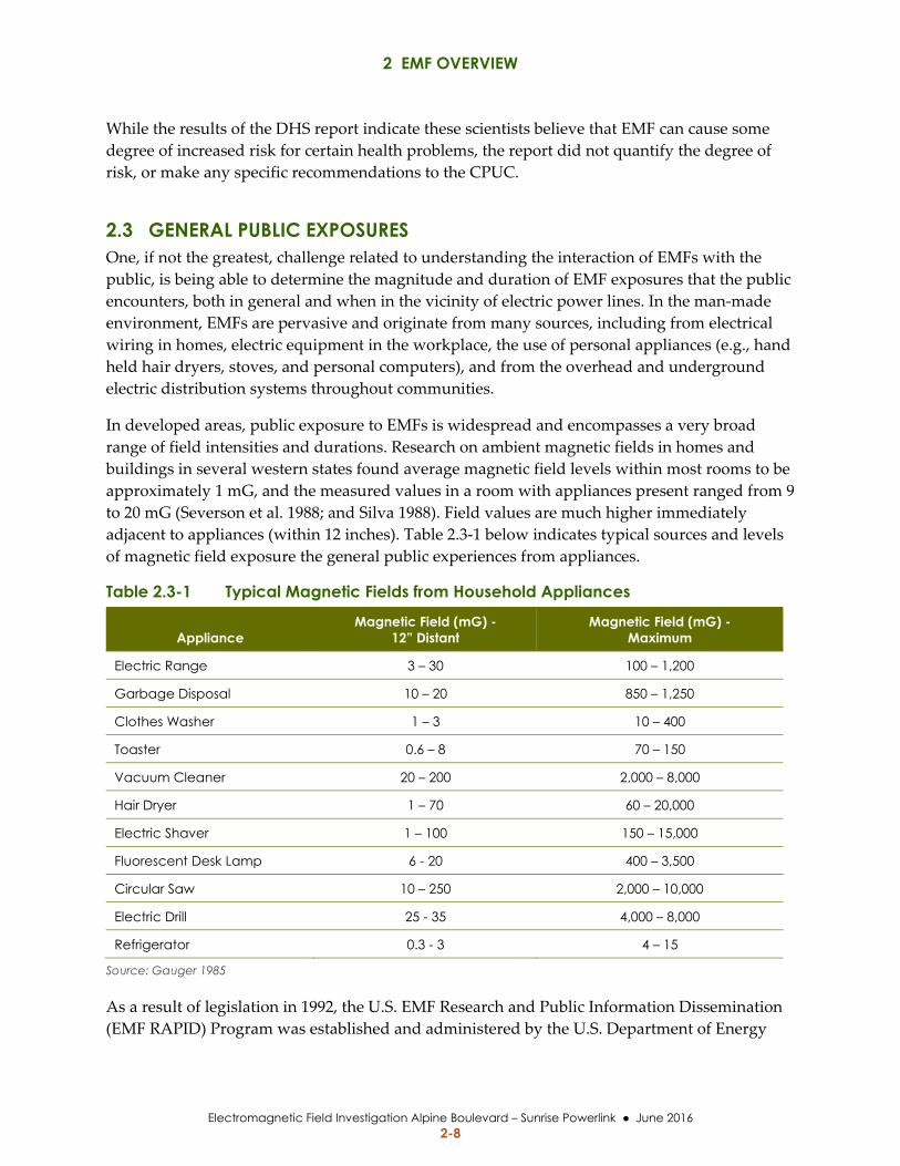
2.3 GENERAL PUBLIC EXPOSURES One, if not the greatest, challenge related to understanding the interaction of EMFs with the
public, is being able to determine the magnitude and duration of EMF exposures that the public
encounters, both in general and when in the vicinity of electric power lines. In the man‐made
environment, EMFs are pervasive and originate from many sources, including from electrical
wiring in homes, electric equipment in the workplace, the use of personal appliances (e.g., hand
held hair dryers, stoves, and personal computers), and from the overhead and underground
electric distribution systems throughout communities.
In developed areas, public exposure to EMFs is widespread and encompasses a very broad
range of field intensities and durations. Research on ambient magnetic fields in homes and
buildings in several western states found average magnetic field levels within most rooms to be
approximately 1 mG, and the measured values in a room with appliances present ranged from 9
to 20 mG (Severson et al. 1988; and Silva 1988). Field values are much higher immediately
adjacent to appliances (within 12 inches). Table 2.3‐1 below indicates typical sources and levels
of magnetic field exposure the general public experiences from appliances.
Table 2.3-1 Typical Magnetic Fields from Household Appliances
Appliance Magnetic Field (mG) -
12” Distant Magnetic Field (mG) -
Maximum
Electric Range 3 – 30 100 – 1,200
Garbage Disposal 10 – 20 850 – 1,250
Clothes Washer 1 – 3 10 – 400
Toaster 0.6 – 8 70 – 150
Vacuum Cleaner 20 – 200 2,000 – 8,000
Hair Dryer 1 – 70 60 – 20,000
Electric Shaver 1 – 100 150 – 15,000
Fluorescent Desk Lamp 6 - 20 400 – 3,500
Circular Saw 10 – 250 2,000 – 10,000
Electric Drill 25 - 35 4,000 – 8,000
Refrigerator 0.3 - 3 4 – 15
Source: Gauger 1985
As a result of legislation in 1992, the U.S. EMF Research and Public Information Dissemination
(EMF RAPID) Program was established and administered by the U.S. Department of Energy
2 EMF OVERVIEW
Electromagnetic Field Investigation Alpine Boulevard – Sunrise Powerlink June 2016 2-9
(DOE). Working with the DOE, the NIEHS oversaw numerous studies including assessment of
public exposures to EMFs. A study of typical personal exposures measured the exposure of
1,000 randomly selected individuals utilizing a personal exposure meter that measured
magnetic field continuously (at least every 1.5 seconds) over a 24‐hour period. The study found
magnetic field exposures to be similar for different regions of the country and for both men and
women (NIEHS/NIH 2002).
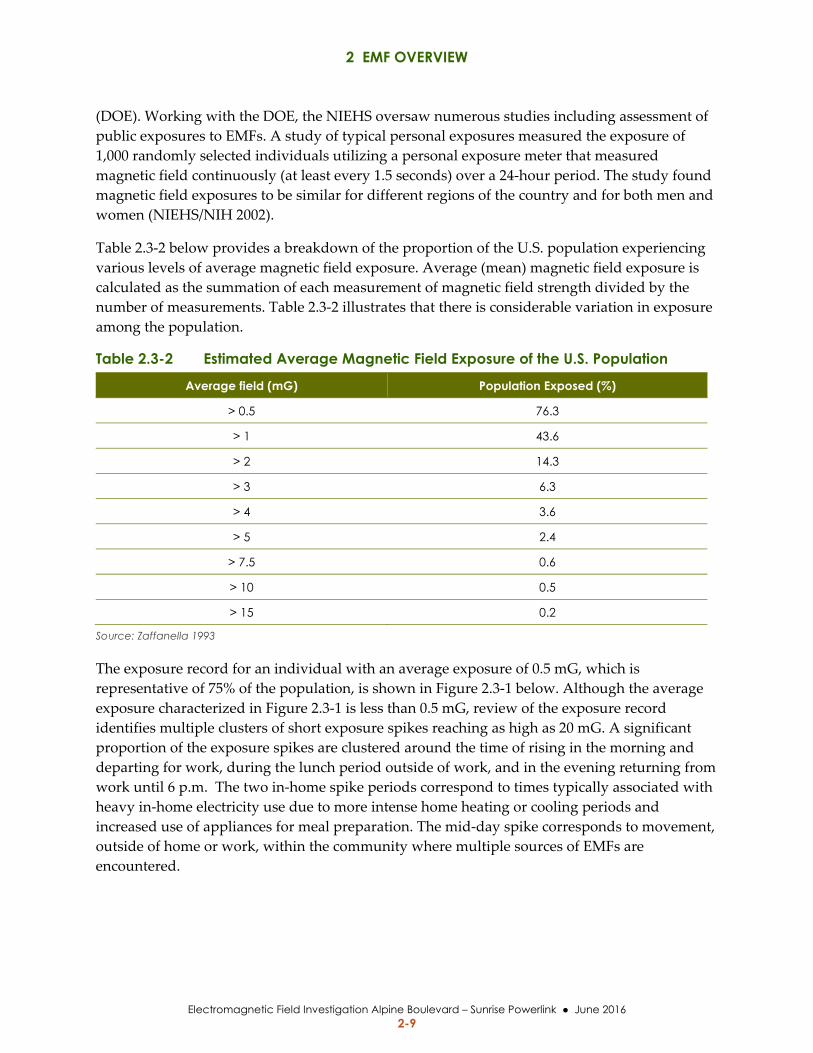
Table 2.3‐2 below provides a breakdown of the proportion of the U.S. population experiencing
various levels of average magnetic field exposure. Average (mean) magnetic field exposure is
calculated as the summation of each measurement of magnetic field strength divided by the
number of measurements. Table 2.3‐2 illustrates that there is considerable variation in exposure
among the population.
Table 2.3-2 Estimated Average Magnetic Field Exposure of the U.S. Population
Average field (mG) Population Exposed (%)
> 0.5 76.3
> 1 43.6
> 2 14.3
> 3 6.3
> 4 3.6
> 5 2.4
> 7.5 0.6
> 10 0.5
> 15 0.2
Source: Zaffanella 1993
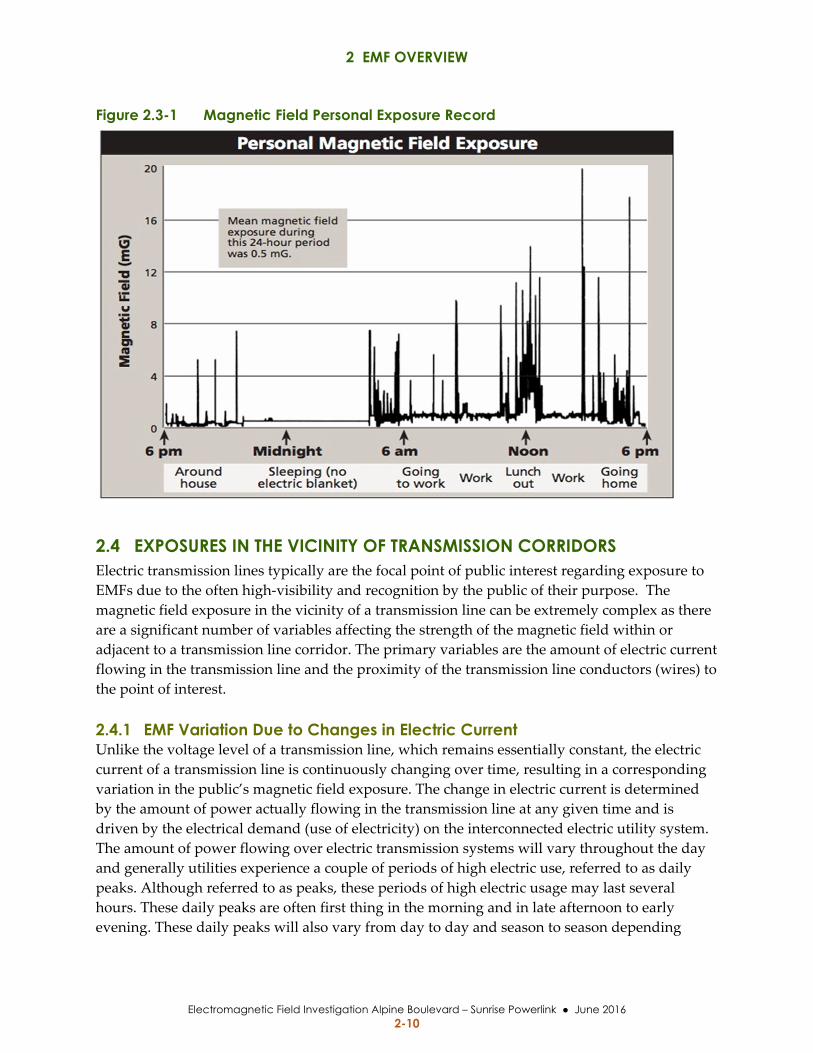
The exposure record for an individual with an average exposure of 0.5 mG, which is
representative of 75% of the population, is shown in Figure 2.3‐1 below. Although the average
exposure characterized in Figure 2.3‐1 is less than 0.5 mG, review of the exposure record
identifies multiple clusters of short exposure spikes reaching as high as 20 mG. A significant
proportion of the exposure spikes are clustered around the time of rising in the morning and
departing for work, during the lunch period outside of work, and in the evening returning from
work until 6 p.m. The two in‐home spike periods correspond to times typically associated with
heavy in‐home electricity use due to more intense home heating or cooling periods and
increased use of appliances for meal preparation. The mid‐day spike corresponds to movement,
outside of home or work, within the community where multiple sources of EMFs are
encountered.
2 EMF OVERVIEW
Electromagnetic Field Investigation Alpine Boulevard – Sunrise Powerlink June 2016 2-10
Figure 2.3-1 Magnetic Field Personal Exposure Record
2.4 EXPOSURES IN THE VICINITY OF TRANSMISSION CORRIDORS Electric transmission lines typically are the focal point of public interest regarding exposure to
EMFs due to the often high‐visibility and recognition by the public of their purpose. The
magnetic field exposure in the vicinity of a transmission line can be extremely complex as there
are a significant number of variables affecting the strength of the magnetic field within or
adjacent to a transmission line corridor. The primary variables are the amount of electric current
flowing in the transmission line and the proximity of the transmission line conductors (wires) to
the point of interest.
2.4.1 EMF Variation Due to Changes in Electric Current Unlike the voltage level of a transmission line, which remains essentially constant, the electric
current of a transmission line is continuously changing over time, resulting in a corresponding
variation in the public’s magnetic field exposure. The change in electric current is determined
by the amount of power actually flowing in the transmission line at any given time and is
driven by the electrical demand (use of electricity) on the interconnected electric utility system.
The amount of power flowing over electric transmission systems will vary throughout the day
and generally utilities experience a couple of periods of high electric use, referred to as daily
peaks. Although referred to as peaks, these periods of high electric usage may last several
hours. These daily peaks are often first thing in the morning and in late afternoon to early
evening. These daily peaks will also vary from day to day and season to season depending
2 EMF OVERVIEW
Electromagnetic Field Investigation Alpine Boulevard – Sunrise Powerlink June 2016 2-11
upon multiple factors such as day of the week, and local weather conditions (winter vs.
summer).
Over the life of a given transmission line, the magnitude of the daily peaks typically increase
year over year and in direct relation to the utility’s load growth. Load growth can be tied to
multiple factors within the community that are a reflection of changes such as an increase in
number of homes, new commercial or industrial development or trends of increased personal
use of electricity due to adoption of technology.
2.4.2 EMF Variations Due to Distance from Source The distance from the transmission line will also dictate variations in the magnetic field
exposure. Typically, the highest magnetic field occurs within the ROW and directly at the
centerline of the transmission line. The strength of the magnetic field decreases as one moves
laterally from the transmission line. This lateral drop in magnetic field exposure can be
relatively rapid as it is dictated by the square of the distance from the transmission line.
Another complicating factor potentially affecting the public’s magnetic field exposure in the
vicinity of a transmission line corridor is the presence of other power lines (distribution lines).
Magnetic fields from adjacent lines can interact in a number of ways, but cannot be assumed to
be additive. In the case where power is flowing in different directions on adjacent lines there
may be a substantial decrease in the level of magnetic field than if the lines were not in
proximity to each other. The arrangement of the conductors on adjacent lines will also affect the
magnetic field exposure and could be additive or subtractive. When more than one
transmission line is in the same right‐of‐way, utilities often strive to manage the magnetic field
levels by arranging the phases of the different circuits to optimize magnetic field cancellation.
The graphs included in Figure 2.4‐1 below depict the magnetic field strength calculated for
transmission lines, carrying the same current, in order to illustrate several characteristics of
magnetic field for both overhead and underground transmission lines. First, the two plots
demonstrate how the strength of magnetic field varies with increasing distance from a
transmission line. Second, the plots also show how current flow on transmission lines increases
over time, due to growth in electricity consumption and that this increase would result in
higher magnetic field on any given transmission line with load growth. Finally, comparing the
plots for the overhead versus underground transmission line illustrates a number of points, one
being that magnetic field is not eliminated by burying transmission lines. The underground plot
also reflects the fact that, for a given current flow, the peak magnetic field can be expected to be
higher directly above an underground line since the cables are much closer to the ground than
overhead wires; however, the typical arrangement of underground transmission line cables
does result in increased magnetic field cancellation and a much more rapid drop in the strength
of the magnetic field as one moves away from the transmission line. Contrary to the public’s
perception, magnetic fields near transmission lines may be lower than the magnetic field in the
vicinity of lower voltage distribution lines within a community since distribution lines often
carry a high electrical current. Information prepared by the NIEHS/NIH (2002) related to
distribution lines shows typical magnetic field levels directly below main feeder lines vary from
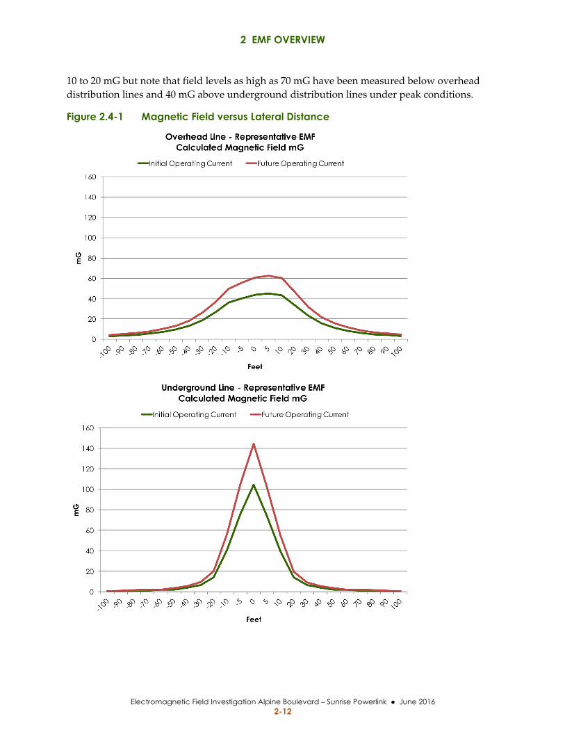
2 EMF OVERVIEW
Electromagnetic Field Investigation Alpine Boulevard – Sunrise Powerlink June 2016 2-12
10 to 20 mG but note that field levels as high as 70 mG have been measured below overhead
distribution lines and 40 mG above underground distribution lines under peak conditions.
Figure 2.4-1 Magnetic Field versus Lateral Distance
3 REGULATORY FRAMEWORK
Electromagnetic Field Investigation Alpine Boulevard – Sunrise Powerlink June 2016 3-1
3 REGULATORY FRAMEWORK
This Section provides a brief summary of the guidelines and regulatory activity regarding EMF.
A number of local governments, states, and national and international bodies have adopted or
considered guidelines, regulations or policies related to EMF exposure. The reasons for
establishing guidelines, regulations, and policies have been varied. Some guidelines draw upon
the experience of specific groups, such as industrial hygienists, to establish worker protections
in environments where EMF levels are far in excess of exposures experienced by the general
public. In other cases, the actions can be attributed to maintaining a status quo of existing
exposures or addressing public reaction to and perception of EMF as opposed to responding to
the findings of any specific scientific research. Specific setback distances or magnetic field levels
are specified in some cases; however, the basis for these specific values is generally not
provided.
3.1 CPUC DECISIONS RELATED TO EMF In 1991, the CPUC initiated an investigation into electric and magnetic fields associated with
electric power facilities. This investigation explored the approach to potential mitigation
measures for reducing public health impacts and possible development of policies, procedures
or regulations.
Following input from interested parties, the CPUC (1993) implemented a decision (D.93‐11‐013)
that requires that utilities use “low‐cost or no‐cost” mitigation measures for facilities requiring
certification under General Order 131‐D. The decision directed the utilities to use a 4%
benchmark on the low‐cost mitigation. This decision also implemented a number of EMF
measurement, research, and education programs. The CPUC did not adopt any specific
numerical limits or regulation on EMF levels related to electric power facilities.
In Decision D.93‐11‐013, the CPUC addressed mitigation of EMF from utility facilities. The
CPUC implemented the following recommendations:
No‐cost and low‐cost steps to reduce EMF levels
Workshops to develop EMF design guidelines
Uniform residential and workplace programs
Stakeholder and public involvement
A four‐year education program
A four‐year non‐experimental and administrative research program
An authorization of federal experimental research conducted under the National
Energy Policy Act of 1992
3 REGULATORY FRAMEWORK
Electromagnetic Field Investigation Alpine Boulevard – Sunrise Powerlink June 2016 3-2
The CPUC (2006) revisited the topic of EMF and issued Decision D.06‐01‐042 on January 26,
2006, affirming the low‐cost/no cost policy to mitigate EMF exposure from new utility
transmission and substation projects. This decision also adopted rules and policies to improve
utility design guidelines for reducing EMF. The CPUC stated “at this time we are unable to
determine whether there is a significant scientifically verifiable relationship between EMF
exposure and negative health consequences.”
SDG&E and other regulated utilities developed FMP design guidelines in accordance with
Decisions D.93‐11‐013 and D.06‐01‐042 (Appendix B). The FMP design guidelines describe
routine magnetic field reduction measures that all regulated California electric utilities will
consider for new and upgraded transmission line and substation projects. The guidelines also
define standard requirements for FMPs.
3.2 CALIFORNIA DEPARTMENT OF EDUCATION REGULATION The California Department of Education (CDE) evaluates potential school sites under a range of
criteria, including environmental and safety issues. California Code of Regulations Title 5,
§14010(c) has established the following “setback” limits for locating any part of a school site
property line near the edge of existing easements for any overhead electrical power lines rated
50 kV and above:
100 feet for lines from 50 to 133‐kV
150 feet for lines from 220 to 230‐kV
350 feet for lines from 500 to 550‐kV
The CDE 2006 guidance stated that CDE shall interpret the Title 5 regulations to provide
setback distance from underground transmission lines that are at least 25% of the setbacks for
overhead lines, specifically:
25 feet for lines from 50 to 133‐kV
37.5 feet for lines from 220 to 230‐kV
87.5 feet for lines from 500 to 550‐kV
The guidance allows for exemptions to the setbacks defined in Title 5. The guidance also allows
for the measurement of setbacks from the transmission line instead of the easement boundary
“if it can be reasonably determined that it is extremely unlikely that new or relocated overhead
transmission lines of at least 50 kV would be placed closer to the school within the easement,
unless such planned lines would result in a net reduction of magnetic fields on the usable
portions of the school site.” School districts that have sites that do not meet the CDE setbacks
may still obtain construction approval from the State of California by submitting an EMF
mitigation plan. The mitigation plan should consider possible reductions of EMF from all
potential sources, including power lines, internal wiring, office equipment, and mechanical
equipment.
3 REGULATORY FRAMEWORK
Electromagnetic Field Investigation Alpine Boulevard – Sunrise Powerlink June 2016 3-3
3.3 NATIONAL AND INTERNATIONAL REGULATIONS
3.3.1 National Guidelines The U.S. Environmental Protection Agency (EPA) has conducted investigations into EMF
related to power lines and public health risks. There have been a number of studies sponsored
by the U.S. EPA, the Electric Power Research Institute (EPRI), and other institutions. Several
bills addressing EMF have been introduced at the congressional level and have provided
funding for research; however, no bill has been enacted that regulates EMF levels.
The 1999 National Institute of Environmental Health Sciences (NIEHS) report to Congress
suggested that the evidence supporting exposure to EMF as a health hazard was insufficient to
warrant aggressive regulatory actions. The report suggested passive measures to educate the
public and regulators on means aimed at reducing exposures. NIEHS also suggested the power
industry continue its practice of siting lines to reduce public exposure to EMF and to explore
ways to reduce the creation of magnetic fields around lines.
The American Conference of Governmental Industrial Hygienists (ACGIH) is a professional
association of industrial hygienists and practitioners of related professions. ACGIH has
developed a suggested standard for limiting work place exposures to magnetic fields to 10,000
mG and to electric fields of 25 kilovolts per meter (kV/m). ACGIH has not developed any
information related to public exposures and in any event the AGCIH standard is not a
regulatory requirement.
The Occupational Safety and Health Administration (OSHA) is the main federal agency that
sets and enforces protective workplace safety and health standards. There are currently no
specific OSHA standards that address EMF.
3.3.2 International Guidelines The International Commission on Non‐Ionizing Radiation Protection (ICNIRP), in cooperation
with the WHO, has published recommended guidelines (ICNIRP 2010) for electric and
magnetic field exposures. Neither of these organizations has any governmental authority nor
recognized jurisdiction to enforce these guidelines. The guidelines have been given merit
particularly in Europe because a broad base of scientists developed the guidelines. The ICNIRP
guidelines may be considered by utilities and regulators when reviewing EMF levels from
electric power lines.
The International Committee on Electromagnetic Safety (ICES) is a committee under the
sponsorship of the U.S. based IEEE, (IEEE Standards Coordinating Committee
28). ICES develops different standards for different frequency ranges, and has published IEEE
Standard C95.6 that provides recommendations to prevent harmful effects in human beings
exposed to electromagnetic fields. Although the ICES standard is generally based on the same
body of evidence as ICNIRP, they indicate use of a more detailed approach in developing the
standard. In any event, no countries have adopted the ICES standards.
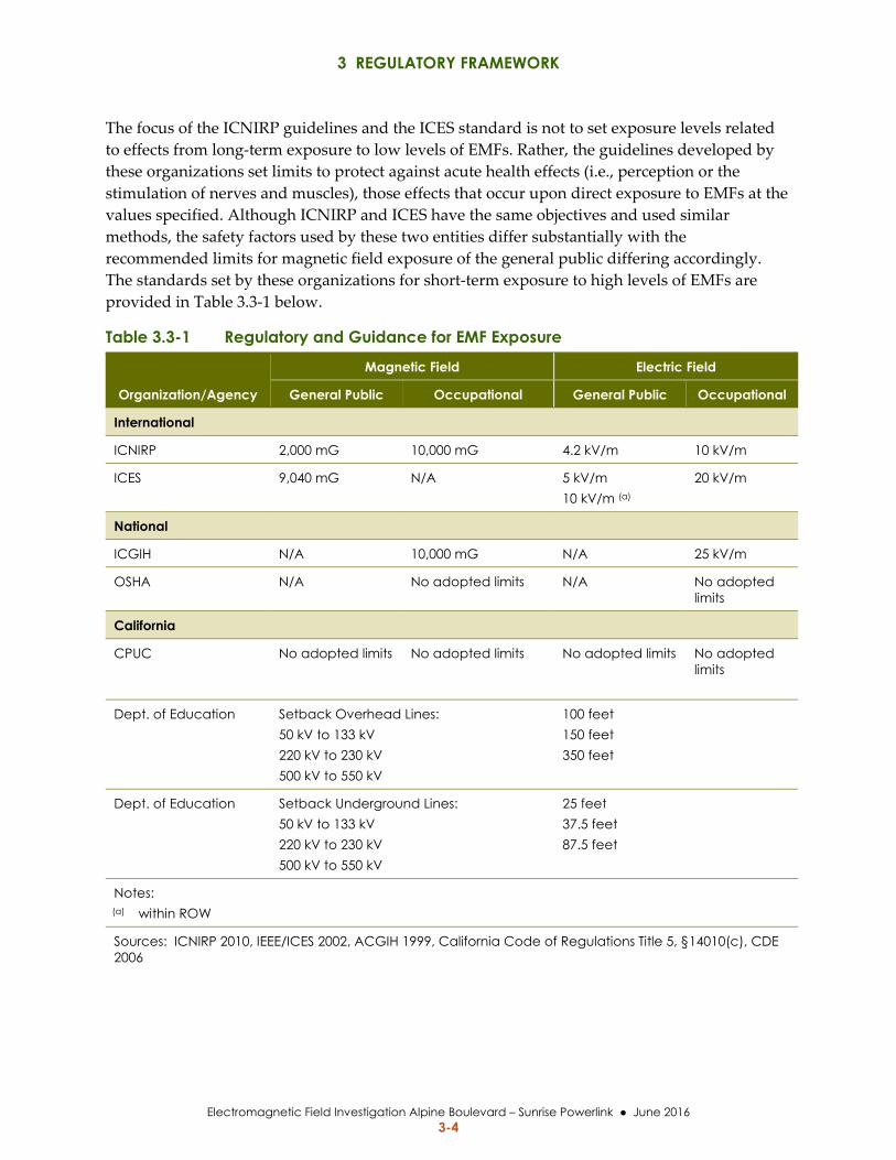
3 REGULATORY FRAMEWORK
Electromagnetic Field Investigation Alpine Boulevard – Sunrise Powerlink June 2016 3-4
The focus of the ICNIRP guidelines and the ICES standard is not to set exposure levels related
to effects from long‐term exposure to low levels of EMFs. Rather, the guidelines developed by
these organizations set limits to protect against acute health effects (i.e., perception or the
stimulation of nerves and muscles), those effects that occur upon direct exposure to EMFs at the
values specified. Although ICNIRP and ICES have the same objectives and used similar
methods, the safety factors used by these two entities differ substantially with the
recommended limits for magnetic field exposure of the general public differing accordingly.
The standards set by these organizations for short‐term exposure to high levels of EMFs are
provided in Table 3.3‐1 below.
Table 3.3-1 Regulatory and Guidance for EMF Exposure
Organization/Agency
Magnetic Field Electric Field
General Public Occupational General Public Occupational
International
ICNIRP 2,000 mG 10,000 mG 4.2 kV/m 10 kV/m
ICES 9,040 mG N/A 5 kV/m 10 kV/m (a)
20 kV/m
National
ICGIH N/A 10,000 mG N/A 25 kV/m
OSHA N/A No adopted limits N/A No adopted limits
California
CPUC No adopted limits No adopted limits No adopted limits No adopted limits
Dept. of Education Setback Overhead Lines: 50 kV to 133 kV 220 kV to 230 kV 500 kV to 550 kV
100 feet 150 feet 350 feet
Dept. of Education Setback Underground Lines: 50 kV to 133 kV 220 kV to 230 kV 500 kV to 550 kV
25 feet 37.5 feet 87.5 feet
Notes: (a) within ROW
Sources: ICNIRP 2010, IEEE/ICES 2002, ACGIH 1999, California Code of Regulations Title 5, §14010(c), CDE 2006
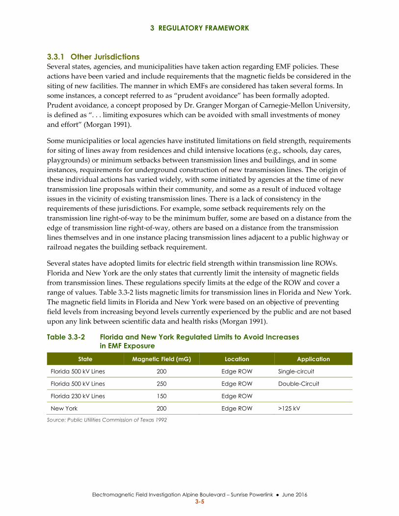
3 REGULATORY FRAMEWORK
Electromagnetic Field Investigation Alpine Boulevard – Sunrise Powerlink June 2016 3-5
3.3.1 Other Jurisdictions Several states, agencies, and municipalities have taken action regarding EMF policies. These
actions have been varied and include requirements that the magnetic fields be considered in the
siting of new facilities. The manner in which EMFs are considered has taken several forms. In
some instances, a concept referred to as “prudent avoidance” has been formally adopted.
Prudent avoidance, a concept proposed by Dr. Granger Morgan of Carnegie‐Mellon University,
is defined as “. . . limiting exposures which can be avoided with small investments of money
and effort” (Morgan 1991).
Some municipalities or local agencies have instituted limitations on field strength, requirements
for siting of lines away from residences and child intensive locations (e.g., schools, day cares,
playgrounds) or minimum setbacks between transmission lines and buildings, and in some
instances, requirements for underground construction of new transmission lines. The origin of
these individual actions has varied widely, with some initiated by agencies at the time of new
transmission line proposals within their community, and some as a result of induced voltage
issues in the vicinity of existing transmission lines. There is a lack of consistency in the
requirements of these jurisdictions. For example, some setback requirements rely on the
transmission line right‐of‐way to be the minimum buffer, some are based on a distance from the
edge of transmission line right‐of‐way, others are based on a distance from the transmission
lines themselves and in one instance placing transmission lines adjacent to a public highway or
railroad negates the building setback requirement.
Several states have adopted limits for electric field strength within transmission line ROWs.
Florida and New York are the only states that currently limit the intensity of magnetic fields
from transmission lines. These regulations specify limits at the edge of the ROW and cover a
range of values. Table 3.3‐2 lists magnetic limits for transmission lines in Florida and New York.
The magnetic field limits in Florida and New York were based on an objective of preventing
field levels from increasing beyond levels currently experienced by the public and are not based
upon any link between scientific data and health risks (Morgan 1991).
Table 3.3-2 Florida and New York Regulated Limits to Avoid Increases in EMF Exposure
State Magnetic Field (mG) Location Application
Florida 500 kV Lines 200 Edge ROW Single-circuit
Florida 500 kV Lines 250 Edge ROW Double-Circuit
Florida 230 kV Lines 150 Edge ROW
New York 200 Edge ROW >125 kV
Source: Public Utilities Commission of Texas 1992

3 REGULATORY FRAMEWORK
Electromagnetic Field Investigation Alpine Boulevard – Sunrise Powerlink June 2016 3-6
This page is intentionally left blank.
4 BACKGROUND ON SUNRISE POWERLINK 230-KV
Electromagnetic Field Investigation Alpine Boulevard – Sunrise Powerlink June 2016 4-1
4 BACKGROUND ON SUNRISE POWERLINK 230-KV
4.1 PROJECT OVERVIEW SDG&E filed Application A.06‐12‐014 requesting a CPCN for the Sunrise Powerlink Project in
December of 2005. This application was superseded in August 2006 when SDG&E filed a new
application A.06‐08‐010.
The Sunrise Powerlink Project as proposed by SDG&E consisted of roughly 150 miles of
transmission line from the Imperial Valley Substation, near El Centro in Imperial County, to the
Peñasquitos Substation near Interstate 805 in coastal San Diego. SDG&E’s Proposed Project
included 91 miles of 500‐kV transmission line and 59 miles of 230‐kV transmission line,
replacement of transmission cable for several other lines, a new substation, and modification of
several existing substations.
A combined EIR/EIS was prepared for the Sunrise Powerlink Project by the CPUC as Lead
Agency under the California Environmental Quality Act (CEQA) and the U.S. Department of
the Interior, Bureau of Land Management (BLM) as the federal Lead Agency under the National
Environmental Policy Act (NEPA). The EIR/EIS analyzed the environmental impacts of
SDG&E’s Proposed Project as well as several alternatives that were developed as a result of
public and agency input.
During the development of the EIR/EIS, the public was informed through numerous
notifications, utilizing a mailing list as well as posting of information on the CPUC website. All
property owners within 300 feet of alternative alignments were included on the mailing list, as
well as groups and individuals the EIR/EIS team identified or who identified themselves to be
stakeholders. In addition, all attendees at scoping meetings, informational workshops, and
commenters on the Draft EIR/EIS or Recirculated DEIR/Supplemental DEIS were added to the
mailing list.
As part of the EIR/EIS preparation, a 230‐kV underground alternative in Alpine Boulevard was
identified in Alpine and the CPUC published a Notice of Second Round of Scoping on
Alternatives in January 2007. Eight additional public scoping meetings were held to support the
evaluation of alternatives for the Sunrise Powerlink Project, including one meeting in Alpine on
February 7, 2007. A notice was published in March 2007 regarding conclusions about the
alternatives that would be carried forward for full analysis in the EIR/EIS.
On December 18, 2008, in Decision D.08‐12‐058, the CPUC granted a CPCN to construct the
Sunrise Powerlink Transmission Project using the Final Environmentally Superior Southern
4 BACKGROUND ON SUNRISE POWERLINK 230-KV
Electromagnetic Field Investigation Alpine Boulevard – Sunrise Powerlink June 2016 4-2
Route, which included a segment of 230‐kV double‐circuit underground transmission line in the
Alpine community.
4.2 SUNRISE POWERLINK 230-KV CIRCUITS IN ALPINE The approved Sunrise Powerlink Project, including the approximately 6.2‐mile underground
230‐kV segment within Alpine Boulevard was completed in 2012 by SDG&E with the two
circuits designated as TL23054 and TL23055.
4.2.1 Underground 230-kV Route The existing underground segment of Sunrise Powerlink transmission line in the community of
Alpine transitions from overhead to underground along Star Valley Road, south of Alpine
Boulevard and transitions back to overhead on the north side of Interstate 8 (I‐8). Refer to
Figure 4.2‐1 for the location of the underground segment. While the transmission line alignment
primarily follows Alpine Boulevard, the location of the underground line varies laterally within
the road ROW in order to avoid other existing underground utilities. Refer to Appendix C for
detailed maps of the underground transmission line within Alpine Boulevard.
4.2.2 230-kV Underground Configuration Each underground 230‐kV circuit utilizes six, solid dielectric (XLPE) cables, as conductors for
the transmission line. These cables are placed in underground duct banks, which consist of nine
PVC conduits encased in concrete. The duct banks are periodically routed into large
underground concrete vaults to enable splicing of the XLPE cables due to cable length pulling
limitations. The concrete duct banks are buried to a typical depth of 3 to 4 feet below ground
surface (bgs). The duct banks are often located at depths greater than 4 feet bgs where they have
to cross below other existing underground utilities. The double‐circuit 230‐kV underground
transmission line in Alpine Boulevard includes two duct banks with an 18‐foot (typical)
horizontal separation due to heating considerations. Figure 4.2‐2 shows a representative cross
section of the double‐circuit 230‐kV duct banks.
4.3 CONSIDERATION OF EMF IN THE SUNRISE POWERLINK EIR/EIS The Final EIR/EIS for the Sunrise Powerlink addressed EMF in Section D‐10, Public Health and
Safety. The Final EIR/EIS included background research related to EMF and health risk, existing
regulations pertaining to public exposure to EMF similar to information provided in Section 3 of
this report, and a discussion about EMF levels for each alternative, including the underground
transmission line within Alpine Boulevard (refer to Section D‐10 of the Final EIR/EIS).
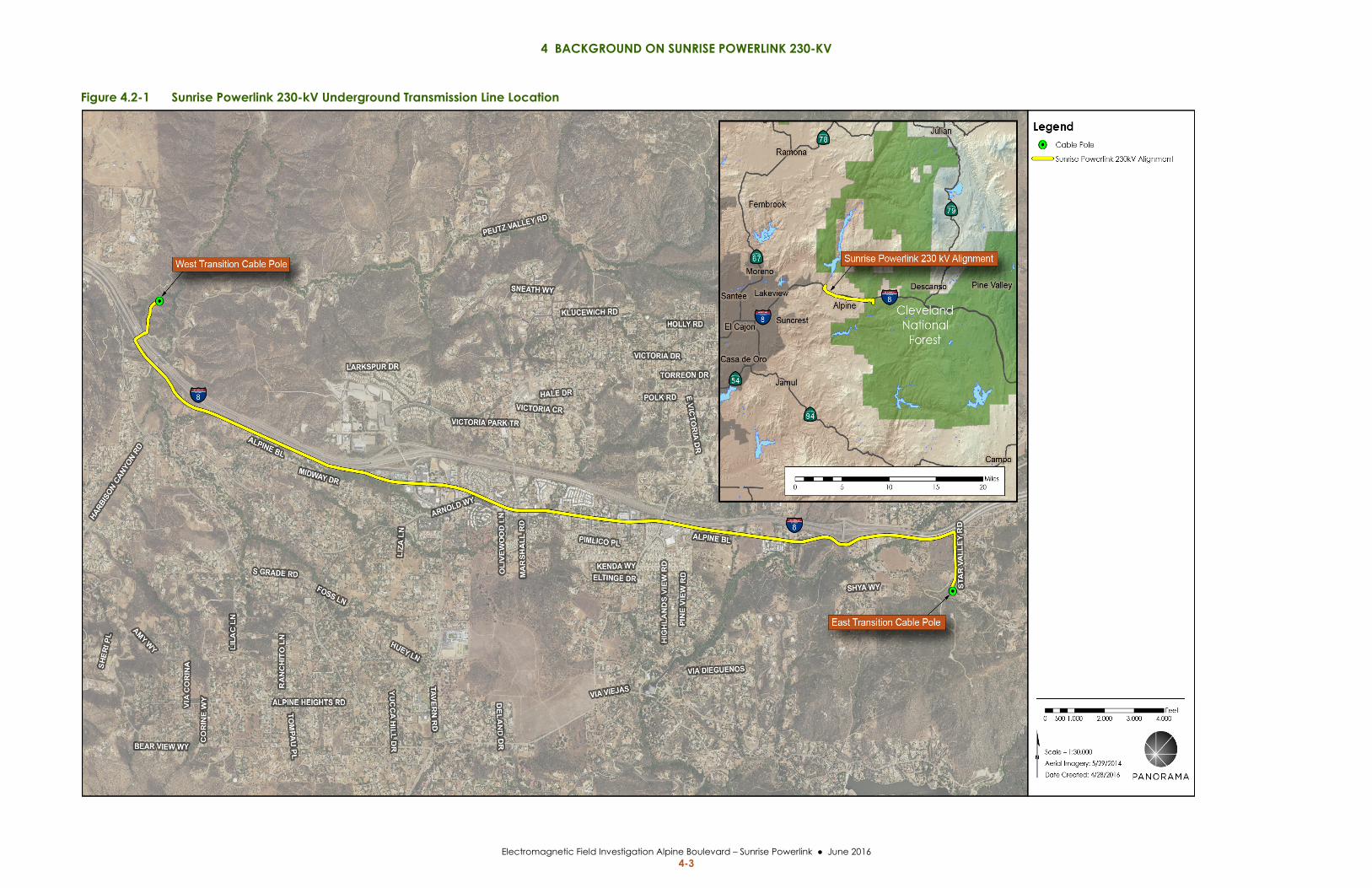
4 BACKGROUND ON SUNRISE POWERLINK 230-KV
Electromagnetic Field Investigation Alpine Boulevard – Sunrise Powerlink June 2016 4-3
Figure 4.2-1 Sunrise Powerlink 230-kV Underground Transmission Line Location

4 BACKGROUND ON SUNRISE POWERLINK 230-KV
Electromagnetic Field Investigation Alpine Boulevard – Sunrise Powerlink June 2016 4-4
This page is intentionally left blank.
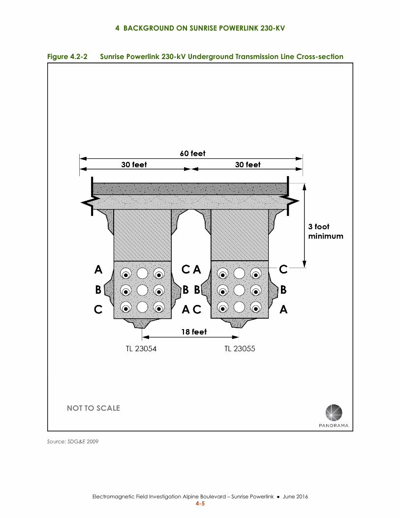
4 BACKGROUND ON SUNRISE POWERLINK 230-KV
Electromagnetic Field Investigation Alpine Boulevard – Sunrise Powerlink June 2016 4-5
Figure 4.2-2 Sunrise Powerlink 230-kV Underground Transmission Line Cross-section
Source: SDG&E 2009
4 BACKGROUND ON SUNRISE POWERLINK 230-KV
Electromagnetic Field Investigation Alpine Boulevard – Sunrise Powerlink June 2016 4-6
The Final EIR/EIS also included information about SDG&E’s FMP for the Proposed Project,
including:
Potential low‐cost and no‐cost measures for managing magnetic field levels
Results of SDG&E modeling of relative differences in magnetic field reductions
between different transmission line construction methods.
An overview of methods to reduce EMF from power lines
EMF mitigation proposed by SDG&E
4.4 CONSIDERATION OF EMF IN THE CPUC DECISION ON THE SUNRISE POWERLINK PROJECT
The CPUC in Decision D.08‐12‐058 (2008) for the Sunrise Powerlink Project stated the following
with respect to the CPUC’s policies on EMF and measures to reduce EMF:
“The Commission has examined EMF impacts in several previous proceedings.
We found the scientific evidence presented in those proceedings was too
uncertain to adopt any related numerical standards. Because there is no
agreement among scientists that exposure to EMF creates any potential health
risk, and because CEQA does not define or adopt any standards to address the
potential health risk impacts of possible exposure to EMFs, the Commission does
not consider magnetic fields in the context of CEQA and determination of
environmental impacts.
However, recognizing that public concern remains, we do require, pursuant to
GO 131‐D, Section X.A, that all requests for a CPCN include a description of the
measures taken or proposed by the utility to reduce the potential for exposure to
EMFs generated by the proposed project.”
The CPUC noted in Decision D.08‐12‐058 that the FMP submitted by SDG&E for the Proposed
Project does not analyze potential impacts across each of the various alternative route
alignments in the EIR/EIS, including the Environmentally Superior Alternative. The CPUC
included the following requirement in their Decision on the Sunrise Powerlink EIR/EIR:
As discussed elsewhere in this order, we authorize SDG&E to construct the Final
Environmentally Superior Southern Route along an alignment that differs
significantly from that originally proposed by the utility in the Proposed Project.
Given these modifications, SDG&E shall amend its EMF management plan as
needed to apply its no‐cost EMF management techniques to the Final
Environmentally Superior Southern Route.
SDG&E’s FMP for the Final Environmentally Superior Alternative is provided in Appendix D.
In September 2009, SDG&E prepared a Final FMP for the approved Sunrise Powerlink Project in
accordance with Decision D.08‐12‐058 and the EMF Design Guidelines for Electrical Facilities
(Appendix B). The 230‐kV underground transmission line segment in Alpine Boulevard was
addressed in the 2009 FMP.
5 SUNRISE POWERLINK MAGNETIC FIELD MANAGEMENT PLAN
Electromagnetic Field Investigation Alpine Boulevard – Sunrise Powerlink June 2016 5-1
5 SUNRISE POWERLINK MAGNETIC FIELD MANAGEMENT PLAN
5.1 INFORMATION INCLUDED IN THE FIELD MANAGEMENT PLAN The approved Sunrise Powerlink FMP prepared by SDG&E (2009) provides information on the
magnetic field management design guidelines (EMF Guidelines) and the methodology used to
apply these EMF Guidelines to the Sunrise Powerlink Project. The FMP discusses potential
magnetic field reduction measures considered for the project and recommends the field
reduction measures to be adopted for the project.
The FMP provides typical cross‐section views of each section of the Sunrise Powerlink Project
showing the transmission line configuration to be built, the location of the transmission line
within the ROW, the arrangement of the phases of each circuit, and the width of ROW. The
FMP includes tabulation, by section, of the magnetic field calculated at the edge of the ROW for
the initial design of the project and the magnetic field calculated after adopted magnetic field
reductions measures are incorporated in the project.
5.2 SDG&E MAGNETIC FIELD CALCULATIONS Computer models are used to calculate magnetic field levels in the vicinity of electric
transmission lines. The calculations of magnetic field levels are based upon a theoretical model.
The model analyzes the specific configuration of the phases for each electric circuit in the
model, the specific current carried in each phase, the direction of current flow and the specific
distance between the circuits and the ground. The calculations determine the magnetic field
level at a standard reference height of one meter above the ground. Note that this is also the
standard height used in the field to measure actual magnetic fields.
It is important to recognize that, as a model of a fixed scenario, magnetic fields calculated for
transmission lines represent a single snap shot under the specific conditions described above.
Actual magnetic fields in the vicinity of transmission lines may vary from the theoretical levels
determined by modeling programs due to several factors. These factors include the presence of
other electric circuits, such as distribution lines, that were not included in the model; different
current flow than was modeled; and a different distance between the circuit and the ground
than was used in the model. The CPUC in Decision 06‐01‐042 recognizes that the EMF modeling
calculations are intended to “compare differences between alternative EMF mitigation
measures” and modeling “does not measure actual environmental magnetic fields”.
In general, the magnetic field modeling included in a utility FMP is prepared for the purpose of
comparison and evaluation of potential magnetic field reduction measures. Limited calculated
5 SUNRISE POWERLINK MAGNETIC FIELD MANAGEMENT PLAN
Electromagnetic Field Investigation Alpine Boulevard – Sunrise Powerlink June 2016 5-2
magnetic field information for the two 230‐kV lines is available from the FMP developed by
SDG&E. Based upon information provided by SDG&E, the modeling included in the 2009 FMP
was prepared for a 2010 summer peak load forecast.
5.3 FIELD MANAGEMENT PLAN INFORMATION PERTINENT TO ALPINE BOULEVARD
The Alpine Boulevard underground segment of the Sunrise Powerlink Project in the community
of Alpine is identified in the FMP as the segment from Mileposts 93 to 99. Figure 4.2‐2 shows
the typical cross‐section view of the double‐circuit 230‐kV transmission line that was included
in the FMP.
No‐cost measures that SDG&E considered for the underground segment of the transmission
line in the community of Alpine included:
a. Locate power lines closer to center of the utility corridor (ROW).
b. Phase circuits1 to reduce magnetic fields.
Low‐cost measures that SDG&E considered for the Alpine line section included:
c. Increase trench depth. d. Increase right‐of‐way width.
SDG&E determined that the feasible and appropriate EMF reduction measures to include in the
Alpine segment of the project were the two no‐cost measures, items A and B above.
SDG&E did not adopt low‐cost measure C (increase trench depth) because a trench depth of at
least 11 feet would be required to achieve an additional average 15% reduction at the edges of
right‐of‐way, which would result in decreased ampacity (i.e., the electrical current capacity) of
the lines. It was also noted that trenching for greater depth would extend construction time and
could increase construction‐related traffic and disruption to local neighborhoods. SDG&E did
not adopt low‐cost measure D, increase ROW width, because acquisition of additional ROW
along the Alpine segment would be very difficult and very expensive.
The magnetic field modeling for the Alpine segment was developed for the representative
cross‐section shown in Figure 4.2‐2. This configuration assumes the duct banks are centered
within the roadway, at an 18‐foot spacing, the uppermost duct is 3‐feet below the ground, and
the road ROW is 60‐feet wide. The calculated magnetic field at the edges of the ROW in Alpine,
with and without the adopted field reduction measures are shown in Table 5.3‐1 below.
1 A transmission line circuit consists of three “phases” made up of single or bundled conductor(s). EMF
reduction or cancellation can be accomplished through the particular arrangement of phase wires from
different circuits that are near each other.
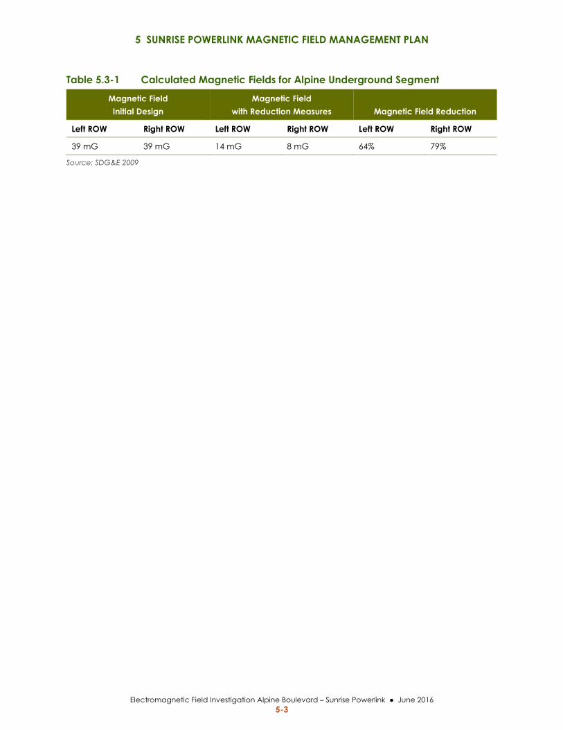
5 SUNRISE POWERLINK MAGNETIC FIELD MANAGEMENT PLAN
Electromagnetic Field Investigation Alpine Boulevard – Sunrise Powerlink June 2016 5-3
Table 5.3-1 Calculated Magnetic Fields for Alpine Underground Segment
Magnetic Field Initial Design
Magnetic Field with Reduction Measures Magnetic Field Reduction
Left ROW Right ROW Left ROW Right ROW Left ROW Right ROW
39 mG 39 mG 14 mG 8 mG 64% 79%
Source: SDG&E 2009

5 SUNRISE POWERLINK MAGNETIC FIELD MANAGEMENT PLAN
Electromagnetic Field Investigation Alpine Boulevard – Sunrise Powerlink June 2016 5-4
This page is intentionally left blank.
6 RECENT ALPINE AREA MAGNETIC FIELD REPORTS ON EMF EXPOSURES
Electromagnetic Field Investigation Alpine Boulevard – Sunrise Powerlink June 2016 6-1
6 RECENT ALPINE AREA MAGNETIC FIELD REPORTS ON EMF EXPOSURES
Several recent studies were conducted to evaluate EMF levels along the underground segment
of the Sunrise Powerlink 230‐kV transmission line within the community of Alpine. These
studies are provided as appendices to this report and include:
Faulkner and Milligan study (Appendix E)
Alpine Unified School District investigation (Appendix F)
San Diego County Office of Education study (Appendix G)
The results of these studies are discussed below. SDG&E has also performed EMF
measurements at individual residences in Alpine upon request from home owners.
6.1 FAULKNER AND MILLIGAN STUDY A Faulkner and Milligan study regarding EMF levels in the Alpine community was presented
in a comment letter to the CPUC scoping process for the Sun Crest Dynamic Reactive Power
Support Project and has been referenced in a local publication (East County Magazine). The
Faulkner and Milligan study appears to be the initial source of information that has prompted
the public concern over EMF in Alpine; however, the magnetic field values reported in the
study contain inaccuracies and may be misinterpreted, as discussed below.
6.1.1 Methodology A statement of the equipment used for magnetic field measurements and a table of measured
EMF values along Alpine Boulevard with accompanying footnotes was submitted to the CPUC
through scoping comments on the Sun Crest Application (A.15‐08‐027) Notice of Preparation
for an EIR. The table of measured values includes entries for measurements in March 2012, June
2012, and January 25 and 26, 2016.
The device used in the Faulkner and Milligan study to measure magnetic fields is identified as a
Lutron EMF Field Tester, Model EMF‐822A. Based on the specifications from the manufacturer
this model of tester is a single‐axis meter, with an accuracy of ± 4%.
6.1.2 Results An East County Magazine article of April 6, 2016 reported that based on the magnetic field
levels measured along Alpine Boulevard, “the authors (Faulkner and Milligan) recommended
that children in Alpine be tested regularly for leukemia.” The highest reported magnetic field
value reported by Faulkner and Milligan is 2.12 T (21.2 mG). As noted in Section 3 of this
report, there are no adopted public exposure standards or guidelines in California or nationally,
6 RECENT ALPINE AREA MAGNETIC FIELD REPORTS ON EMF EXPOSURES
Electromagnetic Field Investigation Alpine Boulevard – Sunrise Powerlink June 2016 6-2
and international guidelines for EMF exposure are roughly 100 times higher than this reported
value. The Faulkner and Milligan study attaches the synopsis for two studies that appear to
identify a higher relative risk for childhood leukemia; however, it does not provide a medical
basis for the author’s recommendation to test children regularly for leukemia.
6.1.3 Discussion As described in Section 7.1 of this report, there is a published standard procedure for the
measurement of magnetic fields (IEEE Standard 644‐1994). As related below, it appears that the
Faulkner and Milligan study may not adhere to this standard in a number of significant ways,
making comparison of their measured magnetic fields to the measurements in this
investigation, or any other of the recent studies, impracticable.
In order to take a measurement of the maximum magnetic field using a single‐axis field meter
the device needs to be oriented in multiple directions, with readings acquired along each of the
three major axes (x, y, z). From the three measurements a maximum magnetic field reading can
be identified. Alternatively, the three measurements can be used to calculate the resultant
magnetic field (BR), which will be larger than the measured maximum field, using the following
equation.
The Faulkner and Milligan study does not identify whether or not the sampling consisted of a
single measurement of the magnetic field strength on only one axis or if measurements were
taken on all three major axes. A single measurement would be insufficient to provide a
meaningful value of the maximum or resultant magnetic field strength at any given location.
The Faulkner and Milligan study indicates the reported magnetic field values at some locations
as an average of measurements from the center and edge of Alpine Boulevard. In view of the
non‐linear nature of magnetic fields from power lines and the decrease in field strength with the
square of the distance from the source, it can be expected that the magnetic field strengths at
these two locations would be substantially different; therefore, it is not appropriate to utilize an
averaging function as this could lead to misinterpretation. For example, the 0.38 micro Tesla
(T) value shown for the elementary school location could be made up of a much higher T at the middle of the road and a much lower T at the edge of the road; therefore, the value shown
in their study table either overstates the magnetic field level if one is considering the public
exposure at the sidewalk or understates the magnetic field level for public exposure within the
roadway.
The Faulkner and Milligan study indicates that some of the magnetic field measurements were
recorded in an F150 truck, but the study does not specify if the vehicle was moving or
stationary. Hand held meters such as the Lutron Field Tester, used in the Faulkner and Milligan
study, as well as the EMDEX SNAP meter, used for this investigation, are to be used in a
stationary position. Due to the complex geometry of magnetic fields from power lines and the
dynamic nature of the fields, special circuitry is necessary in order to measure magnetic field
with a meter that is moving. Further, magnetic fields can be generated by motor vehicles and
could potentially interact with the magnetic fields from the underground transmission line;

6 RECENT ALPINE AREA MAGNETIC FIELD REPORTS ON EMF EXPOSURES
Electromagnetic Field Investigation Alpine Boulevard – Sunrise Powerlink June 2016 6-3
therefore, the reported Faulkner and Milligan magnetic field values that were recorded in a
vehicle may not be considered reliable because they may include some component of magnetic
field from the vehicle.
Given these discrepancies, the magnetic field values reported in the Faulkner and Milligan
study do not contribute to understanding of the strength of magnetic field coming from the
underground transmission line in Alpine Boulevard.
6.2 ALPINE UNIFIED SCHOOL DISTRICT – JPA REPORT An analyst from Risk Management JPA Fringe Benefits Consortium conducted EMF testing for
the Alpine Unified School District (AUSD) at the Alpine Elementary School, located adjacent to
the SDG&E underground double‐circuit transmission line (JPA 2016).
6.2.1 Methodology Field measurements were conducted on February 17, 2016, with the results included in a letter
to AUSD dated February 18, 2016. This report for the AUSD did not indicate whether the EMF
measurement procedures specified in IEEE Standard 644‐1994 were utilized. The device used
for measuring EMF was a Teslatronics Triaxial Magnetic Field Meter 710. Based on the
designation of this meter as a three‐axis meter, it is expected that it would provide the resultant
magnetic field, regardless of the orientation of the device.
6.2.2 Results EMF measurements were taken at 18 outside locations within the school property. The magnetic
field measurements ranged from 0.4 mG to 6.6 mG with the highest values obtained in the
parking lots closest to Alpine Boulevard.
6.2.3 Discussion The 6.6 mG value at the small pedestrian bridge between Alpine Boulevard and the school
parking lot is similar to the magnetic field values measured in this study for the CPUC, as
discussed further in Section 8.1 below.
6.3 SAN DIEGO COUNTY OFFICE OF EDUCATION - PLACEWORKS REPORT Following the magnetic field measurements taken for AUSD, the San Diego County Office of
Education (SDCOE) retained PlaceWorks to prepare an independent EMF survey and
assessment for the Alpine Elementary School campus located adjacent to the SDG&E
underground double‐circuit transmission line within Alpine Boulevard (PlaceWorks 2016).
6.3.1 Methodology The magnetic field measurements by PlaceWorks were performed in accordance with the IEEE
Standard 644‐1994 stipulating procedures for measurement of EMF. The device used by
PlaceWorks to measure magnetic fields was an EMDEX SNAP meter, the same meter used for
6 RECENT ALPINE AREA MAGNETIC FIELD REPORTS ON EMF EXPOSURES
Electromagnetic Field Investigation Alpine Boulevard – Sunrise Powerlink June 2016 6-4
this investigation. Based on the specifications from the manufacturer this model of meter is a
three‐axis meter that provides the resultant magnetic field, regardless of the orientation of the
device, with an accuracy of ± 1 to 3%.
Field measurements by PlaceWorks were conducted on February 23, 2016, with a final report
issued in March 2016. EMF measurements were taken at 32 indoor locations within the school
and 18 outside locations, generally replicating the outside locations used for the AUSD
measurements.
6.3.2 Results The largest value of magnetic field reported, at outside locations, in the PlaceWorks report was
7.1 mG at the small pedestrian bridge between Alpine Boulevard and the school parking lot.
Within the school property the largest magnetic field reported for an outside location in the
PlaceWorks report was 3.3 mG on the stairs between the schools upper and lower parking lots.
The largest magnetic field measured by PlaceWorks was for an indoor location adjacent to the
electrical room within the school. The magnetic field measured at this location was 10 mG.
Other indoor locations at the school with elevated magnetic field levels were the boy’s
restroom, adjacent to the electrical room, and the teacher’s lounge, which included an electrical
panel. In each of these locations the level of magnetic field may be attributed to the school
electric system, rather than the transmission line. The 10 mG indoor magnetic field level is in
excess of fields measured at the school property locations closest to the transmission line.
The PlaceWorks report noted, “After nearly 40 years of research including hundreds of studies,
none of the scientific organizations that conducted weight‐of‐evidence reviews concluded that
exposure to EMF is a demonstrated cause of any long‐ term adverse health effect.” The report
also recognized that the WHO does list EMF as a Class 2B ”possible carcinogen.” The report
goes on to describe that “This classification was based on pooled analyses of epidemiological
studies demonstrating a consistent pattern of a two‐fold increase in childhood leukemia
associated with average exposure to residential power‐frequency magnetic field above 0.3 to 0.4
μT (3 to 4 mG).” The report states that scientists place less weight on these statistical
associations because the multiple studies are often inconsistent due to errors in study design,
errors in how the study was conducted, and EMF exposure measurement methods that are
unreliable.
The PlaceWorks report commented on the lack of state or national regulatory thresholds for
public exposure to magnetic fields from power lines and observed that the local media and
community focus on magnetic fields above 3 to 4 mG is problematic since these values are not
regulatory thresholds.
The PlaceWorks report indicates that the school boundary closest to Alpine Boulevard is
approximately 50 feet from the underground 230‐kV transmission line. The report noted that
this distance is in excess of the State of California Code of Regulations setback utilized by the
California Department of Education for proposed school sites. The report states “if this were a
6 RECENT ALPINE AREA MAGNETIC FIELD REPORTS ON EMF EXPOSURES
Electromagnetic Field Investigation Alpine Boulevard – Sunrise Powerlink June 2016 6-5
proposed new school site, one could reasonably conclude it would not be precluded due to the
presence of the 230‐kV underground power line.”
The overall conclusion of the PlaceWorks report states, “this EMF survey and exposure
assessment demonstrates that the SDG&E transmission line does not pose a significant safety or
health risk to the Alpine Elementary School site.”
6.3.3 Discussion The 7.1 mG value at the small pedestrian bridge between Alpine Boulevard and the school
parking lot and the 3.3 mG value on the stairs between the schools upper and lower parking lots
are similar to the magnetic field values measured in this study for the CPUC, as discussed
further in Section 8.1 below.
6.4 SAN DIEGO GAS & ELECTRIC RESIDENTIAL MEASUREMENTS At a customer’s request SDG&E will visit homes or businesses to sample EMF levels on the
customer’s properties and within buildings or residences. In February and March of this year
SDG&E responded to 31 requests for EMF sampling. As noted for the magnetic field
measurements taken in the vicinity of the underground 230‐kV transmission line, the sampling
done by SDG&E within buildings is only a single snapshot in time and it is anticipated that
measurements on different days or at different times could yield different results.
A review of the results of the SDG&E sampling found that for approximately two‐thirds of the
EMF samplings performed, interior average magnetic fields were less than 1 mG. For the other
third of EMF samplings the measured magnetic fields varied with the largest values occurring
within businesses in the vicinity of equipment. There were a number of residences with interior
magnetic fields in a range from 1.0 to 5 mG and it was noted that a number of these residences
were not in the vicinity of the 230‐kV underground transmission line.
6.5 CONCLUSION The Faulkner and Milligan study did not follow standards procedures for measurement of
magnetic fields. The study utilized a meter only capable of providing the magnetic field
strength on one‐axis, and did not indicate that separate measurements were taken from all three
axes, which is necessary in order to identify the maximum magnetic field. The report also
utilized average magnetic field values in most cases. The magnetic values reported by Faulkner
and Milligan also may not be considered reliable where they were recorded from a vehicle and
were likely influenced by some component of the vehicle’s magnetic field. Therefore, the
magnetic field values reported in the study do not contribute to an understanding of the
strength of magnetic field coming from the underground transmission line in Alpine Boulevard.
The JPA study conducted at the Alpine school site was limited in scope, only providing a
tabulation of magnetic fields measured outside school buildings at the school site. The results of
the JPA study do correspond closely to the measurements in the PlaceWorks study. The
6 RECENT ALPINE AREA MAGNETIC FIELD REPORTS ON EMF EXPOSURES
Electromagnetic Field Investigation Alpine Boulevard – Sunrise Powerlink June 2016 6-6
PlaceWorks study also tabulated measured magnetic fields but included both indoor and
outdoor measurements. The indoor measurements by PlaceWorks found magnetic field levels
generally below 1.0 mG in classrooms, with a few exceptions. This level of magnetic field is
consistent with magnetic field surveys conducted across multiple schools in California and
indicates that the transmission line in Alpine Boulevard is not a source for magnetic field
exposures within the school. The exceptions in the PlaceWorks study where higher magnetic
field levels were measures included: the electrical room, kitchen, and teacher’s lounge. These
measurements illustrate that in areas with electrical equipment, magnetic field exposures within
the school can be equivalent to or higher than the magnetic field exposures from the
transmission line measured at the edge of the school property adjacent to Alpine Boulevard.
A conclusion of the PlaceWorks study was that based on their average survey results, the
SDG&E transmission line does not pose a significant safety or health risk to the Alpine
Elementary School site.
7 CPUC EMF INVESTIGATION
Electromagnetic Field Investigation Alpine Boulevard – Sunrise Powerlink June 2016 7-1
7 CPUC EMF INVESTIGATION
7.1 METHODOLOGY
7.1.1 Procedures for Magnetic Field Measurements The CPUC EMF investigation described in this report was accomplished following the uniform
procedures established in IEEE Standard 644‐1994 (R2008): IEEE Standard Procedures for
Measurement of Power Frequency Electric and Magnetic Fields from AC Power Lines (IEEE 1994). The
magnetic field measurements reported herein were taken using an EMDEX SNAP, 3‐Axis
Magnetic Field Survey Meter manufactured by EMDEX LLC. The EMDEX SNAP was calibrated
by the manufacturer on April 7, 2016, as attested by Certificate of Calibration included in
Appendix H. Based upon the specifications for the EMDEX SNAP, also in Appendix H, the
meter sample rate is every 0.5 seconds with a measurement range of 0.1 mG to 1,000 mG with
an accuracy of +/‐ 1 to 3%.
The EMDEX SNAP utilizes three orthogonal magnetic field coils to measure the magnetic field
simultaneously for the three spatial components (x, y, z) and displays a single true RMS (root
mean square) resultant magnetic field value.
Magnetic field measurements were taken at a height of 1 meter above ground level for a
minimum of three samples (1.5 seconds), with the highest value displayed, recorded as the
measurement.
7.1.2 Magnetic Field Sampling Magnetic field sampling was conducted over a 3‐day period from April 21 through April 23,
2016. Magnetic field levels were obtained at 53 different locations along the transmission line
corridor and within the Alpine community. The approach to taking EMF measurements is
described below and the locations of the measurements are further described and shown in
Sections 7.3 and 7.4. A total of 525 discrete magnetic field measurements were recorded over the
3‐day sampling period. The results of the EMF sampling are discussed in Section 8 and the field
data is provided in Appendix I.
As described in Section 2, the electric current in a transmission line is continuously changing
over time; therefore, at a number of the locations sampled, the magnetic field measurements
were repeated at multiple times on the same day and again on each of the two ensuing days in
order to assess the magnetic field strength in relation to the power flowing on the transmission
line. The amount of electric power flowing on a power line can vary in time due to the season or
weather conditions, or random fluctuations in power usage. The measurements taken during
the survey are a one‐day snapshot in time; however, the EMF results collected outside during
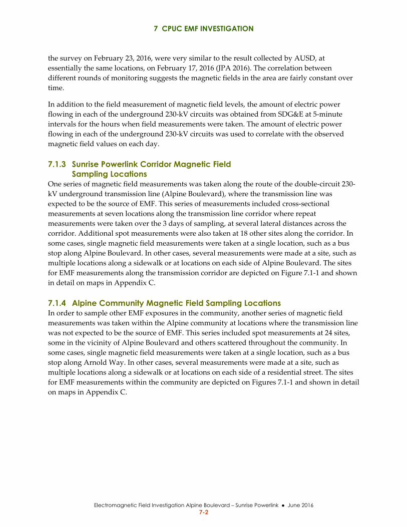
7 CPUC EMF INVESTIGATION
Electromagnetic Field Investigation Alpine Boulevard – Sunrise Powerlink June 2016 7-2
the survey on February 23, 2016, were very similar to the result collected by AUSD, at
essentially the same locations, on February 17, 2016 (JPA 2016). The correlation between
different rounds of monitoring suggests the magnetic fields in the area are fairly constant over
time.
In addition to the field measurement of magnetic field levels, the amount of electric power
flowing in each of the underground 230‐kV circuits was obtained from SDG&E at 5‐minute
intervals for the hours when field measurements were taken. The amount of electric power
flowing in each of the underground 230‐kV circuits was used to correlate with the observed
magnetic field values on each day.
7.1.3 Sunrise Powerlink Corridor Magnetic Field Sampling Locations
One series of magnetic field measurements was taken along the route of the double‐circuit 230‐
kV underground transmission line (Alpine Boulevard), where the transmission line was
expected to be the source of EMF. This series of measurements included cross‐sectional
measurements at seven locations along the transmission line corridor where repeat
measurements were taken over the 3 days of sampling, at several lateral distances across the
corridor. Additional spot measurements were also taken at 18 other sites along the corridor. In
some cases, single magnetic field measurements were taken at a single location, such as a bus
stop along Alpine Boulevard. In other cases, several measurements were made at a site, such as
multiple locations along a sidewalk or at locations on each side of Alpine Boulevard. The sites
for EMF measurements along the transmission corridor are depicted on Figure 7.1‐1 and shown
in detail on maps in Appendix C.
7.1.4 Alpine Community Magnetic Field Sampling Locations In order to sample other EMF exposures in the community, another series of magnetic field
measurements was taken within the Alpine community at locations where the transmission line
was not expected to be the source of EMF. This series included spot measurements at 24 sites,
some in the vicinity of Alpine Boulevard and others scattered throughout the community. In
some cases, single magnetic field measurements were taken at a single location, such as a bus
stop along Arnold Way. In other cases, several measurements were made at a site, such as
multiple locations along a sidewalk or at locations on each side of a residential street. The sites
for EMF measurements within the community are depicted on Figures 7.1‐1 and shown in detail
on maps in Appendix C.
7 CPUC EMF INVESTIGATION
Electromagnetic Field Investigation Alpine Boulevard – Sunrise Powerlink June 2016 7-3
Figure 7.1-1 EMF Measurement Locations

7 CPUC EMF INVESTIGATION
Electromagnetic Field Investigation Alpine Boulevard – Sunrise Powerlink June 2016 7-4
This page is intentionally left blank.
7 CPUC EMF INVESTIGATION
Electromagnetic Field Investigation Alpine Boulevard – Sunrise Powerlink June 2016 7-5
7.2 ALPINE MAGNETIC FIELD MEASUREMENT RESULTS
7.2.1 Field Data Field notes prepared during the 3 days of magnetic field sampling are included in Appendix I. The
field notes include a rudimentary sketch depicting the site of the magnetic field measurements and
individual locations within the site where the magnetic field measurements were taken. The field
notes include the location, date, time and weather conditions at the time of the measurements. Since
a three‐axis meter was used, the magnetic field measurements reported are the resultant magnetic
field, in mG. These mG values can be converted to T by dividing the mG value by 10.
The weather conditions at the time of the magnetic field measurements is relevant to the
measurements within the community, because the primary source of magnetic fields within the
community is the electric distribution system. It is expected that local weather conditions affect the
amount of power being used and thereby the amount of current flowing on the distribution system
(e.g., higher energy use due to air conditioning during hot weather or heating during cold weather).
In the case of the underground double‐circuit 230‐kV transmission line, the power being
transmitted is delivered and used at points distant from Alpine; therefore, local weather is not
considered to directly affect the amount of power flowing on the transmission line.
Magnetic field sampling provided both cross‐section measurements and spot measurements, which
are separately discussed below.
7.2.2 Transmission Corridor Magnetic Field Measurements
7.2.2.1 Magnetic Field Cross-Section Measurements Field data was obtained from seven locations along the Alpine Boulevard underground portion of
the transmission line. EMF measurements were collected at several lateral distances across the
road at each of the seven locations to document the magnetic field levels across the road ROW. The
data from these sites was used to prepare cross‐section graphs of the magnetic field strength
versus distance from the transmission line. These graphs illustrate how the magnetic field varies
with lateral distance from the two underground transmission circuits. Figures 7.2‐1 through 7.2‐7
provides graphs for measurements taken across Alpine Boulevard at the following approximate
locations:
South Grade Road
Medical Center just west of Tavern Road
Future Alpine High School Site
West Victoria Drive
Alpine Elementary School
Casino Inn
West Alpine
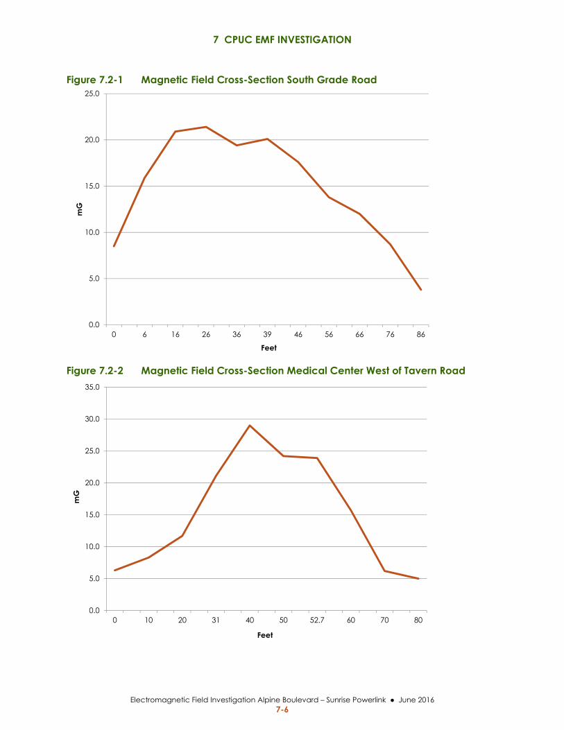
7 CPUC EMF INVESTIGATION
Electromagnetic Field Investigation Alpine Boulevard – Sunrise Powerlink June 2016 7-6
Figure 7.2-1 Magnetic Field Cross-Section South Grade Road
Figure 7.2-2 Magnetic Field Cross-Section Medical Center West of Tavern Road
0.0
5.0
10.0
15.0
20.0
25.0
0 6 16 26 36 39 46 56 66 76 86
mG
Feet
0.0
5.0
10.0
15.0
20.0
25.0
30.0
35.0
0 10 20 31 40 50 52.7 60 70 80
mG
Feet
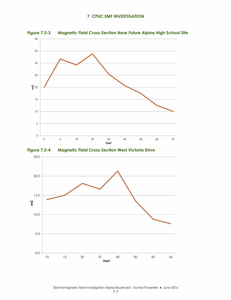
7 CPUC EMF INVESTIGATION
Electromagnetic Field Investigation Alpine Boulevard – Sunrise Powerlink June 2016 7-7
Figure 7.2-3 Magnetic Field Cross-Section Near Future Alpine High School Site
Figure 7.2-4 Magnetic Field Cross-Section West Victoria Drive
0
5
10
15
20
25
30
35
40
0 6 18 30 36 46 56 66 76
mG
Feet
0.0
5.0
10.0
15.0
20.0
25.0
10 13 20 31 40 50 60 65
mG
Feet
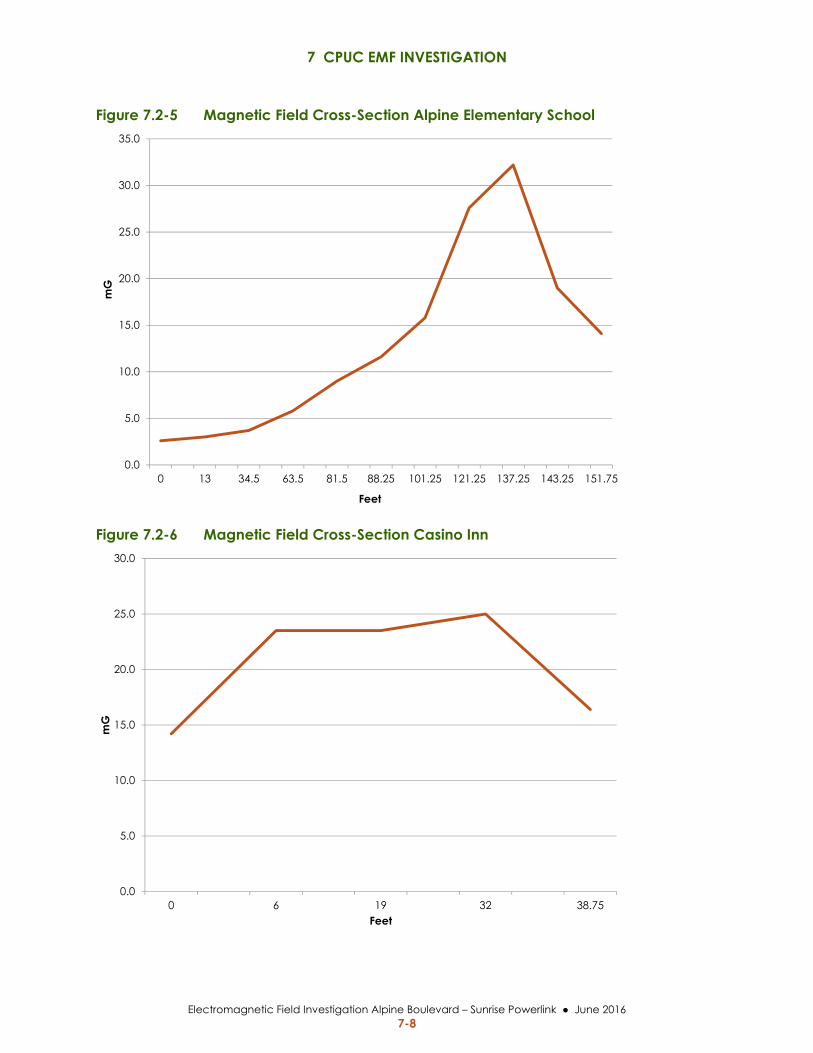
7 CPUC EMF INVESTIGATION
Electromagnetic Field Investigation Alpine Boulevard – Sunrise Powerlink June 2016 7-8
Figure 7.2-5 Magnetic Field Cross-Section Alpine Elementary School
Figure 7.2-6 Magnetic Field Cross-Section Casino Inn
0.0
5.0
10.0
15.0
20.0
25.0
30.0
35.0
0 13 34.5 63.5 81.5 88.25 101.25 121.25 137.25 143.25 151.75
mG
Feet
0.0
5.0
10.0
15.0
20.0
25.0
30.0
0 6 19 32 38.75
mG
Feet
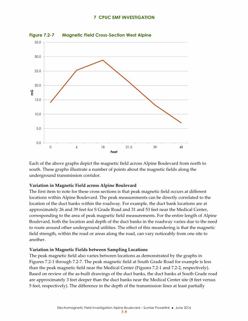
7 CPUC EMF INVESTIGATION
Electromagnetic Field Investigation Alpine Boulevard – Sunrise Powerlink June 2016 7-9
Figure 7.2-7 Magnetic Field Cross-Section West Alpine
Each of the above graphs depict the magnetic field across Alpine Boulevard from north to
south. These graphs illustrate a number of points about the magnetic fields along the
underground transmission corridor.
Variation in Magnetic Field across Alpine Boulevard
The first item to note for these cross sections is that peak magnetic field occurs at different
locations within Alpine Boulevard. The peak measurements can be directly correlated to the
location of the duct banks within the roadway. For example, the duct bank locations are at
approximately 26 and 39 feet for S Grade Road and 31 and 53 feet near the Medical Center,
corresponding to the area of peak magnetic field measurements. For the entire length of Alpine
Boulevard, both the location and depth of the duct banks in the roadway varies due to the need
to route around other underground utilities. The effect of this meandering is that the magnetic
field strength, within the road or areas along the road, can vary noticeably from one site to
another.
Variation in Magnetic Fields between Sampling Locations
The peak magnetic field also varies between locations as demonstrated by the graphs in
Figures 7.2‐1 through 7.2‐7. The peak magnetic field at South Grade Road for example is less
than the peak magnetic field near the Medical Center (Figures 7.2‐1 and 7.2‐2, respectively).
Based on review of the as‐built drawings of the duct banks, the duct banks at South Grade road
are approximately 3 feet deeper than the duct banks near the Medical Center site (8 feet versus
5 feet, respectively). The difference in the depth of the transmission lines at least partially
0.0
5.0
10.0
15.0
20.0
25.0
30.0
35.0
0 6 18 31.5 39 48
mG
Feet
7 CPUC EMF INVESTIGATION
Electromagnetic Field Investigation Alpine Boulevard – Sunrise Powerlink June 2016 7-10
explains the difference in magnetic field strength, since the magnetic field decreases with
distance from the source. In addition, the South Grade Road site does not appear to have any
underground distribution circuits and the magnetic field measured can be attributed to the
underground transmission line only. As discussed in Section 2.4, distribution lines can have an
additive or subtractive effect on the measured magnetic fields. At the Medical Center site there
is an underground distribution circuit and the magnetic field measured at this site is assumed to
reflect some interaction of the magnetic fields from the underground transmission line and
distribution line.
For the South Grade Road site (Figure 7.2‐1), at each of the locations above the duct banks a
peak magnetic field was detected. The presence of two peaks is expected and conforms to the
magnetic field modeling that was prepared by SDG&E for the amended FMP (Appendix D). For
the Medical Center site (Figure 7.2‐2), the presence of underground distribution may have the
effect of partially altering the strength of the magnetic field such that two distinct peaks at the
duct banks are not as easily discerned.
7.2.2.2 Magnetic Field Spot Measurements – Along Alpine Boulevard At the majority of sites along Alpine Boulevard, where magnetic field sampling was conducted,
field data was obtained as spot measurements. At some sites, such as bus stops, a single
magnetic field measurement was obtained, while at other sites, measurements were obtained
for several locations within the site with potential relevance (e.g., distribution transformers or
receptors of interest). The sketches shown on the field notes in Appendix I indicate the location
for spot measurements at the different sites.
The two highest magnetic field spot measurements recorded along the transmission line
corridor over the 3‐days of sampling, were obtained at the center of the bridge on Alpine Road
with measurements of 50.7 mG at the north bridge edge and 39.2 mG at the south bridge edge.
At this site the 230‐kV circuits are installed at the edge of the bridge and at their shallowest
depth (2 to 2.75 feet), as they are installed directly on the bottom of the bridge.
The highest magnetic field spot measurement recorded where the transmission line is buried
within the roadway was 35.3 mG at the Alpine Oaks site south of Alpine Boulevard. The Alpine
Oaks sampling site with the highest magnetic field measurement is approximately 5 feet from
the southern duct bank. The lowest magnetic field measured at the Alpine Oaks site was 8.5 mG
approximately 20 feet from the edge of the roadway, with the nearest duct bank at
approximately 30 feet from the sampling site.
Table 7.2‐1 indicates the maximum and minimum magnetic field spot measurement data at the
various sites along Alpine Boulevard.
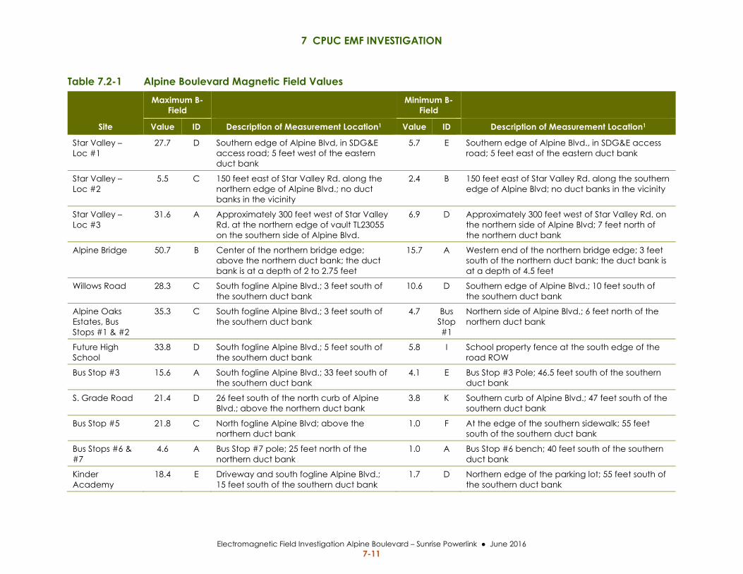
7 CPUC EMF INVESTIGATION
Electromagnetic Field Investigation Alpine Boulevard – Sunrise Powerlink June 2016 7-11
Table 7.2-1 Alpine Boulevard Magnetic Field Values
Site
Maximum B-Field
Minimum B-Field
Value ID Description of Measurement Location1 Value ID Description of Measurement Location1
Star Valley – Loc #1
27.7 D Southern edge of Alpine Blvd, in SDG&E access road; 5 feet west of the eastern duct bank
5.7 E Southern edge of Alpine Blvd., in SDG&E access road; 5 feet east of the eastern duct bank
Star Valley – Loc #2
5.5 C 150 feet east of Star Valley Rd. along the northern edge of Alpine Blvd.; no duct banks in the vicinity
2.4 B 150 feet east of Star Valley Rd. along the southern edge of Alpine Blvd; no duct banks in the vicinity
Star Valley – Loc #3
31.6 A Approximately 300 feet west of Star Valley Rd. at the northern edge of vault TL23055 on the southern side of Alpine Blvd.
6.9 D Approximately 300 feet west of Star Valley Rd. on the northern side of Alpine Blvd; 7 feet north of the northern duct bank
Alpine Bridge 50.7 B Center of the northern bridge edge; above the northern duct bank; the duct bank is at a depth of 2 to 2.75 feet
15.7 A Western end of the northern bridge edge; 3 feet south of the northern duct bank; the duct bank is at a depth of 4.5 feet
Willows Road 28.3 C South fogline Alpine Blvd.; 3 feet south of the southern duct bank
10.6 D Southern edge of Alpine Blvd.; 10 feet south of the southern duct bank
Alpine Oaks Estates, Bus Stops #1 & #2
35.3 C South fogline Alpine Blvd.; 3 feet south of the southern duct bank
4.7 Bus Stop #1
Northern side of Alpine Blvd.; 6 feet north of the northern duct bank
Future High School
33.8 D South fogline Alpine Blvd.; 5 feet south of the southern duct bank
5.8 I School property fence at the south edge of the road ROW
Bus Stop #3 15.6 A South fogline Alpine Blvd.; 33 feet south of the southern duct bank
4.1 E Bus Stop #3 Pole; 46.5 feet south of the southern duct bank
S. Grade Road 21.4 D 26 feet south of the north curb of Alpine Blvd.; above the northern duct bank
3.8 K Southern curb of Alpine Blvd.; 47 feet south of the southern duct bank
Bus Stop #5 21.8 C North fogline Alpine Blvd; above the northern duct bank
1.0 F At the edge of the southern sidewalk; 55 feet south of the southern duct bank
Bus Stops #6 & #7
4.6 A Bus Stop #7 pole; 25 feet north of the northern duct bank
1.0 A Bus Stop #6 bench; 40 feet south of the southern duct bank
Kinder Academy
18.4 E Driveway and south fogline Alpine Blvd.; 15 feet south of the southern duct bank
1.7 D Northern edge of the parking lot; 55 feet south of the southern duct bank
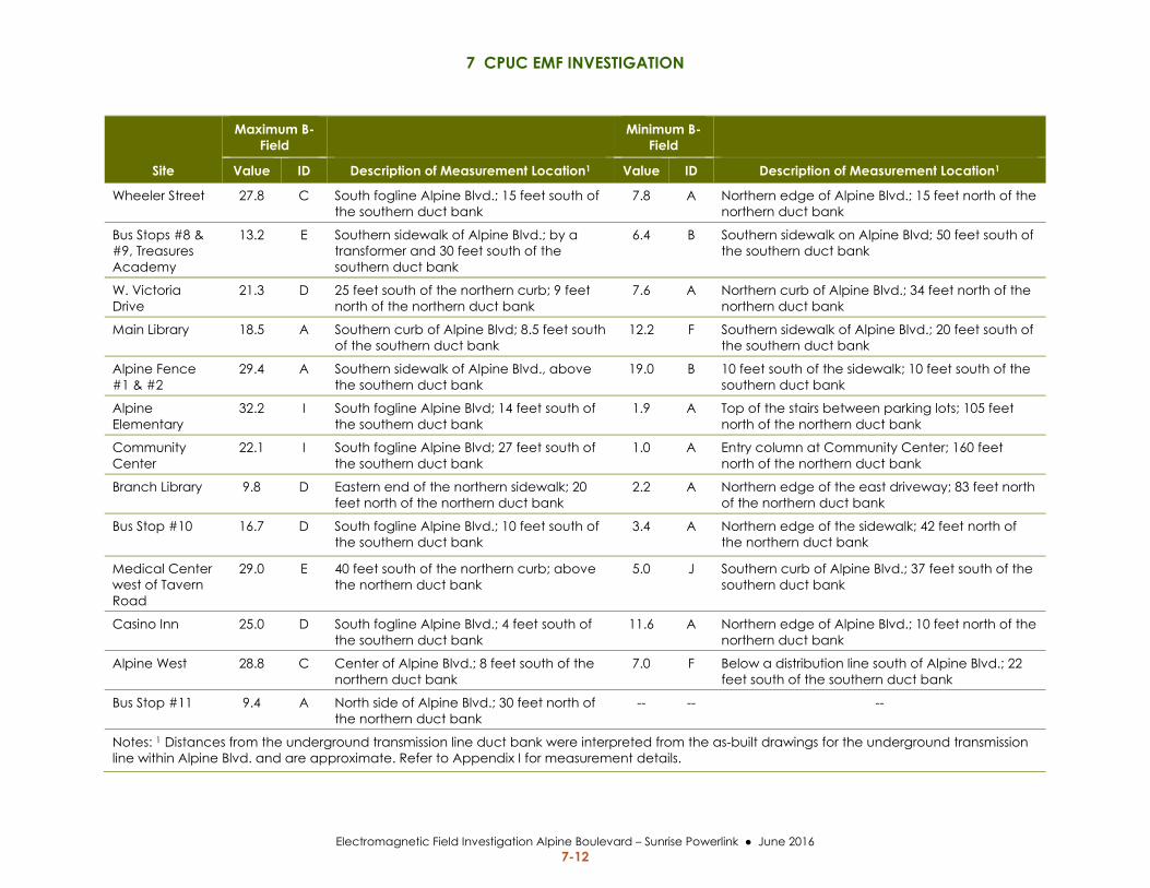
7 CPUC EMF INVESTIGATION
Electromagnetic Field Investigation Alpine Boulevard – Sunrise Powerlink June 2016 7-12
Site
Maximum B-Field
Minimum B-Field
Value ID Description of Measurement Location1 Value ID Description of Measurement Location1
Wheeler Street 27.8 C South fogline Alpine Blvd.; 15 feet south of the southern duct bank
7.8 A Northern edge of Alpine Blvd.; 15 feet north of the northern duct bank
Bus Stops #8 & #9, Treasures Academy
13.2 E Southern sidewalk of Alpine Blvd.; by a transformer and 30 feet south of the southern duct bank
6.4 B Southern sidewalk on Alpine Blvd; 50 feet south of the southern duct bank
W. Victoria Drive
21.3 D 25 feet south of the northern curb; 9 feet north of the northern duct bank
7.6 A Northern curb of Alpine Blvd.; 34 feet north of the northern duct bank
Main Library 18.5 A Southern curb of Alpine Blvd; 8.5 feet south of the southern duct bank
12.2 F Southern sidewalk of Alpine Blvd.; 20 feet south of the southern duct bank
Alpine Fence #1 & #2
29.4 A Southern sidewalk of Alpine Blvd., above the southern duct bank
19.0 B 10 feet south of the sidewalk; 10 feet south of the southern duct bank
Alpine Elementary
32.2 I South fogline Alpine Blvd; 14 feet south of the southern duct bank
1.9 A Top of the stairs between parking lots; 105 feet north of the northern duct bank
Community Center
22.1 I South fogline Alpine Blvd; 27 feet south of the southern duct bank
1.0 A Entry column at Community Center; 160 feet north of the northern duct bank
Branch Library 9.8 D Eastern end of the northern sidewalk; 20 feet north of the northern duct bank
2.2 A Northern edge of the east driveway; 83 feet north of the northern duct bank
Bus Stop #10 16.7 D South fogline Alpine Blvd.; 10 feet south of the southern duct bank
3.4 A Northern edge of the sidewalk; 42 feet north of the northern duct bank
Medical Center west of Tavern Road
29.0 E 40 feet south of the northern curb; above the northern duct bank
5.0 J Southern curb of Alpine Blvd.; 37 feet south of the southern duct bank
Casino Inn 25.0 D South fogline Alpine Blvd.; 4 feet south of the southern duct bank
11.6 A Northern edge of Alpine Blvd.; 10 feet north of the northern duct bank
Alpine West 28.8 C Center of Alpine Blvd.; 8 feet south of the northern duct bank
7.0 F Below a distribution line south of Alpine Blvd.; 22 feet south of the southern duct bank
Bus Stop #11 9.4 A North side of Alpine Blvd.; 30 feet north of the northern duct bank
-- -- --
Notes: 1 Distances from the underground transmission line duct bank were interpreted from the as-built drawings for the underground transmission line within Alpine Blvd. and are approximate. Refer to Appendix I for measurement details.

7 CPUC EMF INVESTIGATION
Electromagnetic Field Investigation Alpine Boulevard – Sunrise Powerlink June 2016 7-13
7.2.2.3 Magnetic Field Spot Measurements – School Sites Recognizing the additional focus in the community on school sites, a separate discussion is
provided with the sampling results at the Alpine Elementary School site and the site of the
future high school.
Alpine Elementary School Site
Multiple data sets of magnetic field were collected at the Alpine Elementary School site over 3
days. Measurements on Friday April 22, 2016, resulted in the highest magnetic field values
while the measurements on Saturday April 23, 2016, resulted in the lowest values. As described
in Section 5.1.2 the magnetic field from a transmission line is directly related to the power flow
or current being carried by the line. In the case of the underground double‐circuit 230‐kV lines
in Alpine Boulevard, information from SDG&E shows that the amount of current flowing in the
two transmission lines although relatively balanced (i.e., each circuit carries roughly the same
current), does vary over the course of the day and from one day to the next.
The variations in measured magnetic field at the Alpine School site over the 3 days of sampling
can be expected since the power flow on Friday was higher than on Thursday. On Saturday the
power flow was lower than on both Thursday and Friday. It is important to note that because
the measurements are like snapshots in time, it is tenuous to extrapolate individual magnetic
field measurements as representative of a given situation. For example, the fact that power flow
was higher on Friday than on Thursday is not indicative that power flow on Fridays is always
higher than on Thursdays.
The graphs in Figure 7.2‐8 illustrate the fluctuation in magnetic field at Alpine Elementary with
variance in the power flow in the transmission line. The first measurement point on the graph
was taken at the top of the stairs separating the two parking lots at Alpine Elementary. The
points measured extends for approximately 152 feet to the south edge of the sidewalk on the far
side of Alpine Boulevard (farthest from the school).
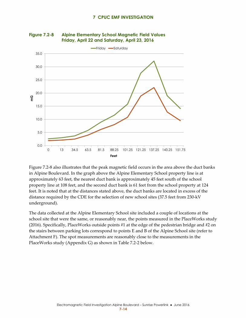
7 CPUC EMF INVESTIGATION
Electromagnetic Field Investigation Alpine Boulevard – Sunrise Powerlink June 2016 7-14
Figure 7.2-8 Alpine Elementary School Magnetic Field Values Friday, April 22 and Saturday, April 23, 2016
Figure 7.2‐8 also illustrates that the peak magnetic field occurs in the area above the duct banks
in Alpine Boulevard. In the graph above the Alpine Elementary School property line is at
approximately 63 feet, the nearest duct bank is approximately 45 feet south of the school
property line at 108 feet, and the second duct bank is 61 feet from the school property at 124
feet. It is noted that at the distances stated above, the duct banks are located in excess of the
distance required by the CDE for the selection of new school sites (37.5 feet from 230‐kV
underground).
The data collected at the Alpine Elementary School site included a couple of locations at the
school site that were the same, or reasonably near, the points measured in the PlaceWorks study
(2016). Specifically, PlaceWorks outside points #1 at the edge of the pedestrian bridge and #2 on
the stairs between parking lots correspond to points E and B of the Alpine School site (refer to
Attachment F). The spot measurements are reasonably close to the measurements in the
PlaceWorks study (Appendix G) as shown in Table 7.2‐2 below.
0.0
5.0
10.0
15.0
20.0
25.0
30.0
35.0
0 13 34.5 63.5 81.5 88.25 101.25 121.25 137.25 143.25 151.75
mG
Feet
Friday Saturday
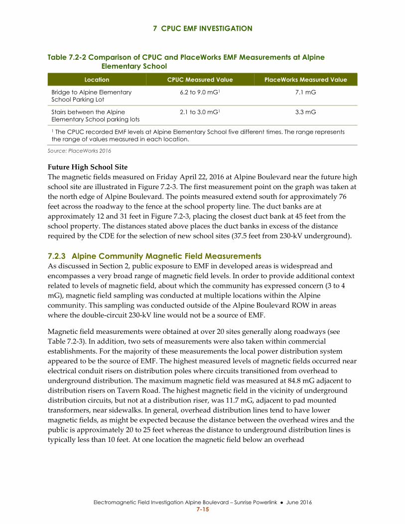
7 CPUC EMF INVESTIGATION
Electromagnetic Field Investigation Alpine Boulevard – Sunrise Powerlink June 2016 7-15
Table 7.2-2 Comparison of CPUC and PlaceWorks EMF Measurements at Alpine Elementary School
Location CPUC Measured Value PlaceWorks Measured Value
Bridge to Alpine Elementary School Parking Lot
6.2 to 9.0 mG1 7.1 mG
Stairs between the Alpine Elementary School parking lots
2.1 to 3.0 mG1 3.3 mG
1 The CPUC recorded EMF levels at Alpine Elementary School five different times. The range represents the range of values measured in each location.
Source: PlaceWorks 2016
Future High School Site
The magnetic fields measured on Friday April 22, 2016 at Alpine Boulevard near the future high
school site are illustrated in Figure 7.2‐3. The first measurement point on the graph was taken at
the north edge of Alpine Boulevard. The points measured extend south for approximately 76
feet across the roadway to the fence at the school property line. The duct banks are at
approximately 12 and 31 feet in Figure 7.2‐3, placing the closest duct bank at 45 feet from the
school property. The distances stated above places the duct banks in excess of the distance
required by the CDE for the selection of new school sites (37.5 feet from 230‐kV underground).
7.2.3 Alpine Community Magnetic Field Measurements As discussed in Section 2, public exposure to EMF in developed areas is widespread and
encompasses a very broad range of magnetic field levels. In order to provide additional context
related to levels of magnetic field, about which the community has expressed concern (3 to 4
mG), magnetic field sampling was conducted at multiple locations within the Alpine
community. This sampling was conducted outside of the Alpine Boulevard ROW in areas
where the double‐circuit 230‐kV line would not be a source of EMF.
Magnetic field measurements were obtained at over 20 sites generally along roadways (see
Table 7.2‐3). In addition, two sets of measurements were also taken within commercial
establishments. For the majority of these measurements the local power distribution system
appeared to be the source of EMF. The highest measured levels of magnetic fields occurred near
electrical conduit risers on distribution poles where circuits transitioned from overhead to
underground distribution. The maximum magnetic field was measured at 84.8 mG adjacent to
distribution risers on Tavern Road. The highest magnetic field in the vicinity of underground
distribution circuits, but not at a distribution riser, was 11.7 mG, adjacent to pad mounted
transformers, near sidewalks. In general, overhead distribution lines tend to have lower
magnetic fields, as might be expected because the distance between the overhead wires and the
public is approximately 20 to 25 feet whereas the distance to underground distribution lines is
typically less than 10 feet. At one location the magnetic field below an overhead
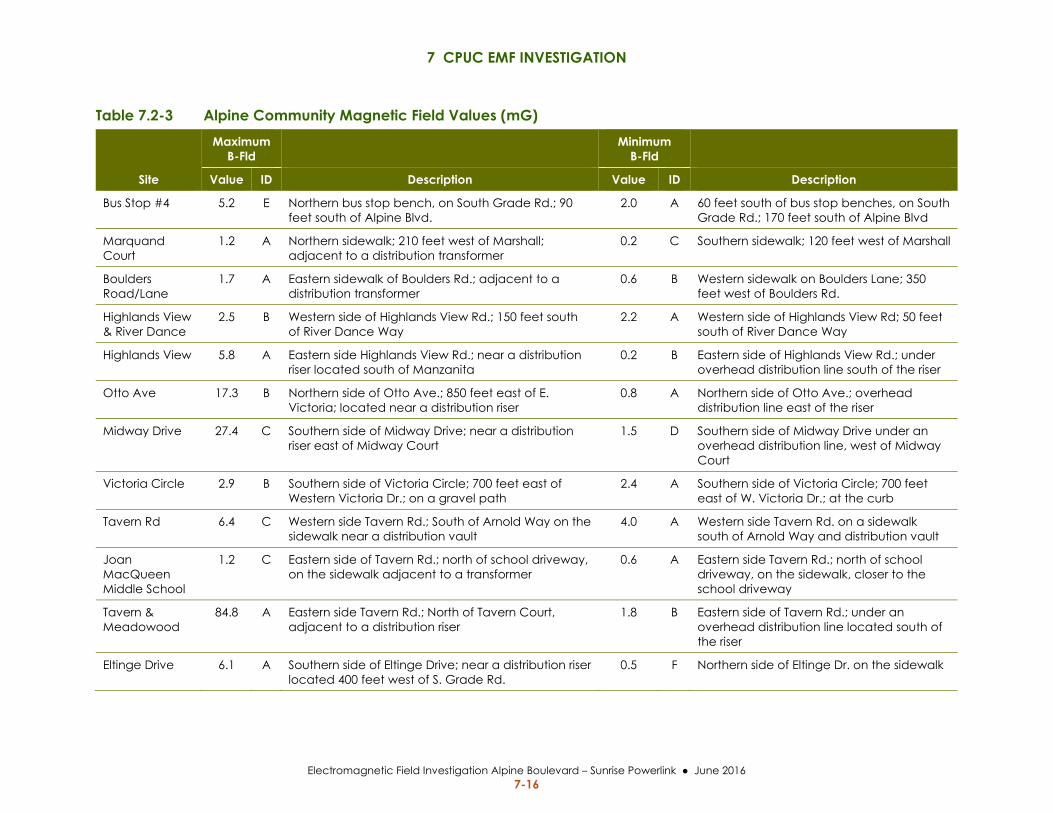
7 CPUC EMF INVESTIGATION
Electromagnetic Field Investigation Alpine Boulevard – Sunrise Powerlink June 2016 7-16
Table 7.2-3 Alpine Community Magnetic Field Values (mG)
Site
Maximum B-Fld
Minimum B-Fld
Value ID Description Value ID Description
Bus Stop #4 5.2 E Northern bus stop bench, on South Grade Rd.; 90 feet south of Alpine Blvd.
2.0 A 60 feet south of bus stop benches, on South Grade Rd.; 170 feet south of Alpine Blvd
Marquand Court
1.2 A Northern sidewalk; 210 feet west of Marshall; adjacent to a distribution transformer
0.2 C Southern sidewalk; 120 feet west of Marshall
Boulders Road/Lane
1.7 A Eastern sidewalk of Boulders Rd.; adjacent to a distribution transformer
0.6 B Western sidewalk on Boulders Lane; 350 feet west of Boulders Rd.
Highlands View & River Dance
2.5 B Western side of Highlands View Rd.; 150 feet south of River Dance Way
2.2 A Western side of Highlands View Rd; 50 feet south of River Dance Way
Highlands View 5.8 A Eastern side Highlands View Rd.; near a distribution riser located south of Manzanita
0.2 B Eastern side of Highlands View Rd.; under overhead distribution line south of the riser
Otto Ave 17.3 B Northern side of Otto Ave.; 850 feet east of E. Victoria; located near a distribution riser
0.8 A Northern side of Otto Ave.; overhead distribution line east of the riser
Midway Drive 27.4 C Southern side of Midway Drive; near a distribution riser east of Midway Court
1.5 D Southern side of Midway Drive under an overhead distribution line, west of Midway Court
Victoria Circle 2.9 B Southern side of Victoria Circle; 700 feet east of Western Victoria Dr.; on a gravel path
2.4 A Southern side of Victoria Circle; 700 feet east of W. Victoria Dr.; at the curb
Tavern Rd 6.4 C Western side Tavern Rd.; South of Arnold Way on the sidewalk near a distribution vault
4.0 A Western side Tavern Rd. on a sidewalk south of Arnold Way and distribution vault
Joan MacQueen Middle School
1.2 C Eastern side of Tavern Rd.; north of school driveway, on the sidewalk adjacent to a transformer
0.6 A Eastern side Tavern Rd.; north of school driveway, on the sidewalk, closer to the school driveway
Tavern & Meadowood
84.8 A Eastern side Tavern Rd.; North of Tavern Court, adjacent to a distribution riser
1.8 B Eastern side of Tavern Rd.; under an overhead distribution line located south of the riser
Eltinge Drive 6.1 A Southern side of Eltinge Drive; near a distribution riser located 400 feet west of S. Grade Rd.
0.5 F Northern side of Eltinge Dr. on the sidewalk
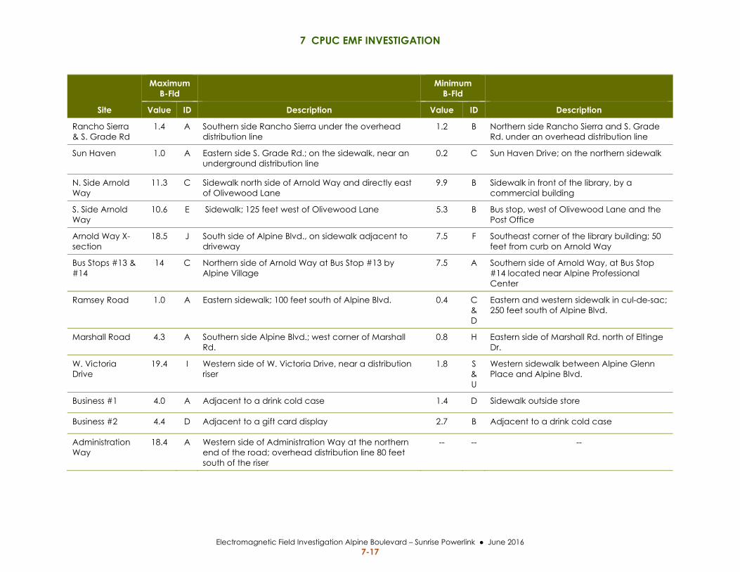
7 CPUC EMF INVESTIGATION
Electromagnetic Field Investigation Alpine Boulevard – Sunrise Powerlink June 2016 7-17
Site
Maximum B-Fld
Minimum B-Fld
Value ID Description Value ID Description
Rancho Sierra & S. Grade Rd
1.4 A Southern side Rancho Sierra under the overhead distribution line
1.2 B Northern side Rancho Sierra and S. Grade Rd. under an overhead distribution line
Sun Haven 1.0 A Eastern side S. Grade Rd.; on the sidewalk, near an underground distribution line
0.2 C Sun Haven Drive; on the northern sidewalk
N. Side Arnold Way
11.3 C Sidewalk north side of Arnold Way and directly east of Olivewood Lane
9.9 B Sidewalk in front of the library, by a commercial building
S. Side Arnold Way
10.6 E Sidewalk; 125 feet west of Olivewood Lane 5.3 B Bus stop, west of Olivewood Lane and the Post Office
Arnold Way X-section
18.5 J South side of Alpine Blvd., on sidewalk adjacent to driveway
7.5 F Southeast corner of the library building; 50 feet from curb on Arnold Way
Bus Stops #13 & #14
14 C Northern side of Arnold Way at Bus Stop #13 by Alpine Village
7.5 A Southern side of Arnold Way, at Bus Stop #14 located near Alpine Professional Center
Ramsey Road 1.0 A Eastern sidewalk; 100 feet south of Alpine Blvd. 0.4 C & D
Eastern and western sidewalk in cul-de-sac; 250 feet south of Alpine Blvd.
Marshall Road 4.3 A Southern side Alpine Blvd.; west corner of Marshall Rd.
0.8 H Eastern side of Marshall Rd. north of Eltinge Dr.
W. Victoria Drive
19.4 I Western side of W. Victoria Drive, near a distribution riser
1.8 S & U
Western sidewalk between Alpine Glenn Place and Alpine Blvd.
Business #1 4.0 A Adjacent to a drink cold case 1.4 D Sidewalk outside store
Business #2 4.4 D Adjacent to a gift card display 2.7 B Adjacent to a drink cold case
Administration Way
18.4 A Western side of Administration Way at the northern end of the road; overhead distribution line 80 feet south of the riser
-- -- --
7 CPUC EMF INVESTIGATION
Electromagnetic Field Investigation Alpine Boulevard – Sunrise Powerlink June 2016 7-18
distribution line was measured at 18.4 mG. Inside of commercial establishments, a maximum
magnetic field level of 4.4 mG was measured in the vicinity of a couple of displays.
There was a wide range of magnetic field measurements from 0.2 mG up to 11.3 mG along
sidewalks in the community. The lower values along sidewalks were in several residential areas
or cul‐de‐sacs where it appeared the distribution circuits may have only been serving a
relatively small number of homes. In areas where the sidewalks had higher magnetic field
levels (>3 mG), such as along Arnold Way, Tavern Way and West Victoria Drive, there
appeared to be major underground primary distribution circuit(s) based on the presence of
large utility vaults.
7.3 DISCUSSION Many of the magnetic field measurements included in this investigation appear to be at similar
locations, such as the edge of the roadway or within sidewalks along Alpine Boulevard;
however, the measured magnetic field values vary widely. This variance in measured magnetic
field values is expected due to notable differences that may not be readily observed at the
sampling locations. The magnetic field on Alpine Boulevard is primarily affected by the
following factors:
Differences in the location of the duct banks within the roadway ‐ the magnetic field
generated at any given location along Alpine Boulevard is a function of both the
lateral distance from the duct banks and the depth of the duct banks.
The spacing between the two underground electrical circuits as this affects the
amount of magnetic field cancellation.
Presence of other nearby underground electric circuits as these generate their own
magnetic fields that will interact with the transmission line and can be either
additive or subtractive.
All of these factors vary along the length of Alpine Boulevard as a result of routing of the
underground transmission line around the other existing underground utilities.
7.4 CONCLUSION
7.4.1 Compliance with FMP SDG&E has constructed the transmission line in accordance with the measures in the approved
2009 FMP based on review of the as‐built construction drawings for the underground 230‐kV
Sunrise Powerlink transmission line within Alpine Boulevard. The transmission line is buried at
a depth of 3 feet or more in all locations except for the bridge on Alpine Boulevard where the
depth (2 to 2.75 feet) was dictated by the bridge configuration. The duct bank is generally
within the center of the roadway, but the actual duct bank locations vary along the roadway
because the transmission line was routed to avoid conflicts with existing underground utilities.
7 CPUC EMF INVESTIGATION
Electromagnetic Field Investigation Alpine Boulevard – Sunrise Powerlink June 2016 7-19
7.4.2 EMF Levels at Alpine Elementary School The separation between the Sunrise Powerlink transmission line within Alpine Boulevard and
both Alpine Elementary School and the proposed future high school site exceed CDE standards
for siting of new school facilities.
The measurements of magnetic field levels at Alpine Elementary School align closely with
measurements by JPA (2016) and PlaceWorks (2016) in similar locations. The close alignment
between these measurements validates that the Sunrise Powerlink is not a significant source of
magnetic fields within the elementary school.
7.4.3 Summary Based on the magnetic field sampling and data gathered in this investigation, it is concluded
that public exposure to magnetic fields at the edge of Alpine Boulevard are consistent with the
EMF modeling in SDG&E’s FMP for the Sunrise Powerlink Project (2009). The magnetic field
levels along Alpine Boulevard are similar in magnitude to magnetic field values measured in
the Alpine Community outside of Alpine Boulevard right‐of‐way, where the Sunrise Powerlink
is not a primary source of EMFs.

7 CPUC EMF INVESTIGATION
Electromagnetic Field Investigation Alpine Boulevard – Sunrise Powerlink June 2016 7-20
This page is intentionally left blank.

8 REFERENCES
Electromagnetic Field Investigation Alpine Boulevard – Sunrise Powerlink June 2016 8-1
8 REFERENCES
ACGIH (American Conference of Governmental Industrial Hygienists). 1999. Occupational
Threshold Limit Values for 60‐Hz EMF.
Buffler, P.A., Kwan, M.L., Reynolds, P., and Urayama, K.Y. 2005. Environmental and Genetic
Risk Factors for Childhood Leukemia: Appraising the Evidence.
California Code of Regulations. Title 5, Division 1, Chapter 13, Subchapter 1. School Facilities
Construction, Article 2. School Sites, 14010. Standards for School Site Selection,
subparagraph c.
CDC (Centers for Disease Control and Prevention). 2012. United States Cancer Statistics.
Childhood Leukemia Incidence Rates.
CDE (California Department of Education). 2006. Power Line Setback Exemption Guidance.
CPUC (California Public Utility Commission). General Order 131‐D Rules Relating to the
Planning and Construction of Electric Generation, Transmission/Power/Distribution
Line Facilities and Substations Located in California.
______. 1993. Decision D.93‐11‐013: Order Instituting Investigation on the Commissionʹs own
motion to develop policies and procedures for addressing the potential health effects of
electric and magnetic fields of utility facilities.
______. 2006. Decision D.06‐01‐042: Opinion On Commission Policies Addressing
Electromagnetic Fields Emanating from Regulated Utility Facilities.
______. 2008. Decision D.08‐12‐058: Decision Granting a Certificate of Public Convenience and
Necessity for the Sunrise Powerlink Transmission Project.
Danish Ministry of Health, Expert Group on Non‐Ionizing Radiation. 1992. Report on the Risk
of Cancer in Children Living in Homes Exposed to 50Hz Magnetic Fields from High‐
voltage Lines.
DHS (California Department of Health Services). 2002. An Evaluation of the Possible Risks from
Electric and Magnetic Fields (EMFs) From Power Lines, Internal Wiring, Electrical
Occupations, and Appliances.
Faulkner, R. and M. Milligan. 2016. Study of EMF Levels on Alpine Boulevard in Alpine,
California Before and After Sunrise Powerlink Energization. January 21, 2016.
8 REFERENCES
Electromagnetic Field Investigation Alpine Boulevard – Sunrise Powerlink June 2016 8-2
Gauger, J. R. 1985. Household Appliance Magnetic Field Survey. Institute of Electrical and
Electronics Engineers, Vol. PAS‐104, No. 9:2436‐44.
HCN (Health Council of the Netherlands (HCN). 2004. Electromagnetic Fields Annual Update
2003, Electromagnetic Fields Committee.
IARC (International Agency for Research on Cancer). 2002. Non‐ionizing radiation, Part 1, Static
and extremely low‐frequency (ELF) electric and magnetic fields/IARC Working Group
on the Evaluation of Carcinogenic Risks to Humans.
ICNIRP (International Commission on Non‐Ionizing Radiation Protection, Standing Committee
on Epidemiology). 2001. Review of the Epidemiologic Literature on EMF and Health,
Environmental Health Perspectives. Vol. 109.
______. 2010. Guidelines for limiting exposure to time‐varying electric, magnetic, and
electromagnetic fields (1Hz ‐ 1kHz), Health Physics.
IEEE (Institute of Electrical and Electronics Engineers). 1994. Standard Procedures for
Measurement of Power Frequency Electric and Magnetic Fields from Ac Power Lines.
IEEE/ANSI (Institute of Electrical and Electronics Engineers and American National Standards
Institute). 2012. National Electrical Safety Code (NESC).
IEEE/ICES (Institute of Electrical and Electronics Engineers/International Committee on
Electromagnetic Safety). 2002. Standard C95.6, Standard for Safety Levels with Respect
to Human Exposure to Electromagnetic Fields, 0‐3 kHz.
Jacob, Dianne. 2016a. Correspondence with Commission Michael Picker dated February 17,
2016.
______. 2016b: Correspondence with Commission Michael Picker dated March 4, 2016.
JPA (Joint Powers Authority). 2016. Electromagnetic Field Testing Results for Alpine Unified
School District at Alpine Elementary School. Prepared by the JPA Fringe Benefits
Consortium for San Diego County and Imperial County Schools. February 18, 2016.
London, S.J. et al. 1994. Exposure to magnetic fields among electrical workers in relation to
leukemia risk in Los Angeles County. American Journal of Industrial Medicine.
McNally, R.J. and L. Parker. 2006. Environmental factors and childhood acute leukemias and
lymphomas.
Morgan, M. G. 1991. 60 Hz Electric and Magnetic Fields, An Overview of the Issues. Carnegie
Mellon University.
NIEHS (National Institute of Environmental Health Sciences). 1999. Health Effects from
Exposure to Power‐Line Frequency Electric and Magnetic Fields. NIH No. 99‐4493.
8 REFERENCES
Electromagnetic Field Investigation Alpine Boulevard – Sunrise Powerlink June 2016 8-3
NIEHS/NIH (National Institute of Environmental Health Sciences/National Institutes of
Health). 2002. EMF Electric and Magnetic Fields Associated with the Use of Electric
Power, Questions & Answers.
NRC (National Research Council). 1997. Potential Health Effects of Exposure to Residential
Electric and Magnetic Fields.
NRPB (National Radiological Protection Board). 1992 & 2001. ELF Electromagnetic Fields and
the Risk of Cancer: Report of an Advisory Group on Non‐Ionizing Radiation.
Documents of the NRPB Vol. 12, No. 1.
Picker, Michael. 2016. Correspondence with Supervisor Dianne Jacob dated February 29, 2016.
PlaceWorks. 2016. EMF Survey and Exposure Assessment for Alpine Elementary School,
Alpine, California. Prepared for San Diego County Office of Education. March 2016.
PTI (Power Technologies, Inc.). 1993. Attenuation of Electromagnetic Fields from Electrical
Transmission Lines.
Public Utilities Commission of Texas. 1992. Health Effects of Exposure to Power Line Frequency
Electric and Magnetic Fields.
SDG&E (San Diego Gas and Electric). 2009. Application of San Diego Gas and Electric Company
for a Certificate of Public Convenience and Necessity to Construct the Sunrise Powerlink
500 kV Project, Appendix A. Field Management Plan.
SCENIHR (Scientific Committee on Emerging and Newly Identified Health Risks). 2009. Health
Effects of Exposure to EMF.
Severson, R.K. et al. 1988. Acute Non‐Lymphocytic Leukemia and Residential exposure to
Power Frequency Magnetic Fields. American Journal of Epidemiology.
Silva, J.M. et al. 1988. Power Frequency Magnetic Fields in the Home. Institute of Electrical and
Electronics Engineers, No. 88 WM 101‐8.
SSI (Swedish Radiation Protection Agency). 2008. Recent Research on EMF and Health Risks:
Fifth annual report, Revised edition. Independent Expert Group on Electromagnetic
Fields.
SSM (Swedish Radiation Safety Authority). 2014. EMF 9th Update Report Number 2014:16
ISSN:2000‐0456.
Wertheimer, N., and E. Leeper. 1979. Electrical Wiring Configurations and Childhood Cancer.
American Journal of Epidemiology.
WHO (World Health Organization). 1984. Environmental Health Criteria 35. Extremely Low
Frequency Fields.
8 REFERENCES
Electromagnetic Field Investigation Alpine Boulevard – Sunrise Powerlink June 2016 8-4
______. 1987. Environmental Health Criteria 69. Magnetic Fields.
______. 2001. World Health Organization, Fact Sheet No. 263, Electromagnetic Fields and Public
Health, Extremely Low Frequency Fields and Cancer.
______. 2007. World Health Organization. Environmental Health Criteria 238. Extremely low
frequency fields.
Zaffanela L. 1993. Survey of Residential Magnetic Field Sources. EPRI TR102759‐V1, TR102759‐
V2.
Zaffanela, L.E. and G. W. Kalton. 1998. Survey of Personal Magnetic Field Exposure 1000‐
Person Survey EMFRAPID Program Engineering Project #6.
APPENDIX A
Correspondence Regarding EMF Investigation
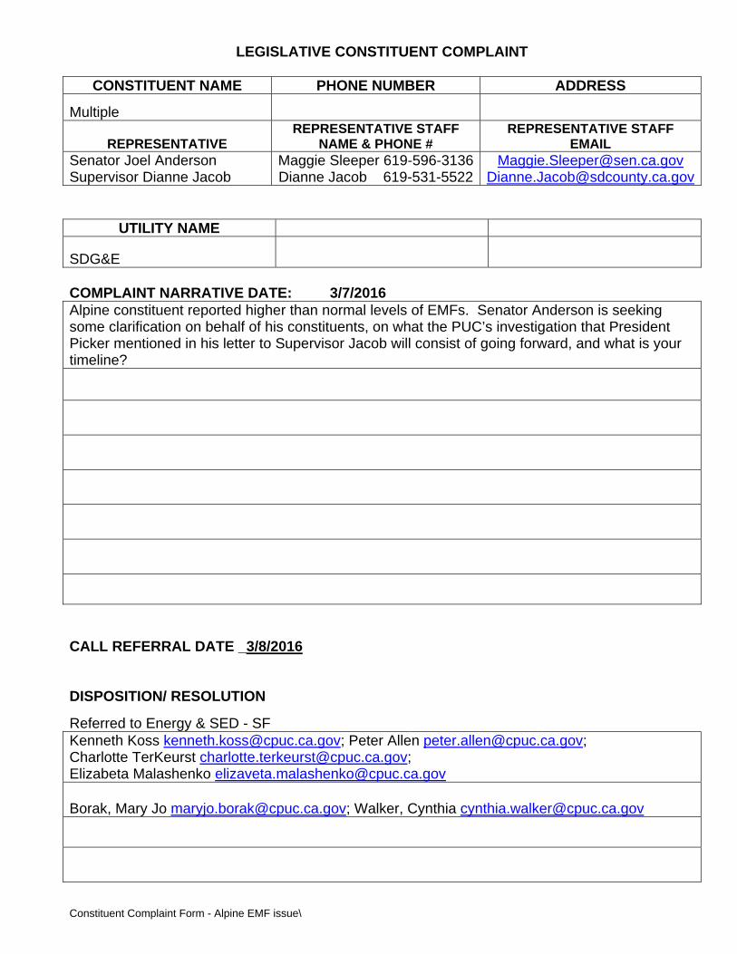
LEGISLATIVE CONSTITUENT COMPLAINT
Constituent Complaint Form - Alpine EMF issue\
CONSTITUENT NAME PHONE NUMBER ADDRESS
Multiple
REPRESENTATIVE REPRESENTATIVE STAFF
NAME & PHONE # REPRESENTATIVE STAFF
EMAIL Senator Joel Anderson Supervisor Dianne Jacob
Maggie Sleeper 619-596-3136Dianne Jacob 619-531-5522
[email protected] [email protected]
UTILITY NAME
SDG&E COMPLAINT NARRATIVE DATE: 3/7/2016 Alpine constituent reported higher than normal levels of EMFs. Senator Anderson is seeking some clarification on behalf of his constituents, on what the PUC’s investigation that President Picker mentioned in his letter to Supervisor Jacob will consist of going forward, and what is your timeline?
CALL REFERRAL DATE _3/8/2016 DISPOSITION/ RESOLUTION
Referred to Energy & SED - SF Kenneth Koss [email protected]; Peter Allen [email protected]; Charlotte TerKeurst [email protected]; Elizabeta Malashenko [email protected]
Borak, Mary Jo [email protected]; Walker, Cynthia [email protected]
APPENDIX B
EMF Design Guidelines for Electrical Facilities
EMF Design Guidelines for Electrical Facilities
July 21, 2006
Table of Contents
1 CALIFORNIA EMF POLICY..........................................................................................1
1.1 HISTORICALBACKGROUND OF CALIFORNIAEMF POLICY .............................................1
1.2 CURRENTCALIFORNIA EMF POLICY.............................................................................1
1.2.1 Standardized EMF Design Guidelines ..............................................................3
1.2.2 Standardized Table of Magnetic Field Reduction Measures..............................3
1.2.3 Additional Considerations Used in the Design Guidelines ................................4
2 METHODS FOR REDUCING MAGNETIC FIELDS....................................................5
2.1 INCREASING THE DISTANCE FROM ELECTRICAL FACILITIES............................................5
2.2 REDUCINGCONDUCTOR (PHASE) SPACING ....................................................................5
2.3 PHASINGCIRCUITS TO REDUCE MAGNETIC FIELDS ........................................................5
3 THE FIELD MANAGEMENT PLAN PROCESS...........................................................6
3.1 THE FIELD MANAGEMENT PLAN ...................................................................................6
3.2 TYPES OF FMP .............................................................................................................6
3.3 DETERMINING IF AN FMP IS REQUIRED, AND IF SO,WHATTYPE....................................6
3.4 PROJECTS EXEMPT FROM THE FMP REQUIREMENT ......................................................11
3.5 PRIORITIZING WITHIN AND BETWEEN LAND USE CLASSES...........................................12
4 FIELD MANAGEMENT PLANS FOR TRANSMISSION LINES ..............................13
4.1 PROJECTDESCRIPTION................................................................................................13
4.2 TWODIMENSIONALMAGNETIC FIELD MODELING FOR TRANSMISSION LINES ..............13
5 FIELD MANAGEMENT PLANS FOR SUBSTATIONS .............................................15
6 CALIFORNIA DEPARTMENT OF EDUCATION’S (CDE) CRITERIA FOR
SITING NEW SCHOOLS ADJACENT TO ELECTRIC POWER LINES RATED 50 KV
AND ABOVE ..........................................................................................................................16
1
EMF Design Guidelines for Electrical Facilities 1 California EMF Policy
1.1 Historical Background of California EMF Policy
In 1993, the California Public Utilities Commission (CPUC) issued Decision 9311013, establishing EMF policy for California’s regulated electric utilities.
The Decision acknowledged that scientific research had not demonstrated that exposures to EMF cause health hazards and that it was inappropriate to set numeric standards that would limit exposure. In recognizing the scientific uncertainty, the CPUC addressed public concern over EMF by establishing a nocost and lowcost EMF reduction policy that utilities would follow for proposed electrical facilities.
In workshops ordered by the CPUC, the utilities developed the initial EMF Design Guidelines based upon the nocost and lowcost EMF policy. Fundamental elements of the policy and the Design Guidelines included the following:
A) Nocost and lowcost magnetic field reduction measures would be considered on new and upgraded projects.
B) Lowcost measures, in aggregate, would: a. Cost in the range of 4% of the total project cost.
b. Achieve a noticeable magnetic field reduction. The CPUC stated,
“We direct the utilities to use 4 percent as a benchmark in developing their EMF mitigation guidelines. We will not establish 4 percent as an absolute cap at this time because we do not want to arbitrarily eliminate a potential measure that might be available but costs more than the 4 percent figure. Conversely, the utilities are encouraged to use effective measures that cost less than 4 percent.” 1
C) For distribution facilities, utilities would apply nocost and lowcost measures by integrating reduction measures into construction and design standards, rather than evaluating nocost and lowcost measures for each project.
1.2 Current California EMF Policy
In 2006, the CPUC updated its EMF Policy in Decision 0601042. The decision reaffirmed that health hazards from exposures to EMF have not been established and that state and federal public health regulatory agencies have determined that setting numeric exposure limits is not appropriate. The CPUC also reaffirmed that the existing nocost and lowcost precautionary
1 CPUC Decision 9311013, Section 3.3.2, p.10
2
based EMF policy should be continued. In the decision, the CPUC required the utilities to update their EMF Design Guidelines to reflect the following key elements of the updated EMF Policy:
A) “The Commission [CPUC] has exclusive jurisdiction over issues related to EMF exposure from regulated utility facilities.” 2
B) “…while we continue our current policy of lowcost and no cost EMF mitigation, as defined by a 4% benchmark of total project cost, we would consider minor increases above the 4% benchmark if justified under unique circumstances, but not as a routine application in utility design guidelines. We add the additional distinction that any EMF mitigation cost increases above the 4% benchmark should result in significant EMF mitigation to be justified, and the total costs should be relatively low.” 3
C) For low cost mitigation, the “EMF reductions will be 15% or greater at the utility ROW [rightofway]…” 4
D) “Parties generally agree on the following group prioritization for land use categories in determining how mitigation costs will be applied:
1. Schools and licensed day care 5
2. Residential
3. Commercial/industrial
4. Recreational
5. Agricultural
6. Undeveloped land”
E) “Lowcost EMF mitigation is not necessary in agricultural and undeveloped land except for permanently occupied residences, schools or hospitals located on these lands.” 6
F) “Although equal mitigation for an entire class is a desirable goal, we will not limit the spending of EMF mitigation to zero on the basis that not all class members can benefit.” 7
G) “…. We [CPUC] do not request that utilities include nonroutine mitigation measures, or other mitigation measures that are based on numeric values of EMF exposure, in revised design guidelines…” 8
2 CPUC Decision 0601042, p. 21 3 Ibid., p. 7 4 Ibid., p. 10 5 “As an additional fixed location of young children, we will add hospitals to this category.” Ibid., p. 7 6 Ibid., p. 20 7 Ibid., p. 10 8 Ibid., p. 17
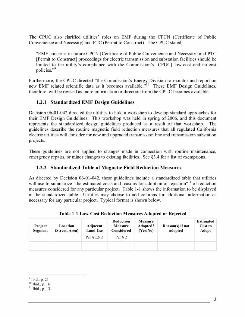
3
The CPUC also clarified utilities’ roles on EMF during the CPCN (Certificate of Public Convenience and Necessity) and PTC (Permit to Construct). The CPUC stated,
“EMF concerns in future CPCN [Certificate of Public Convenience and Necessity] and PTC [Permit to Construct] proceedings for electric transmission and substation facilities should be limited to the utility’s compliance with the Commission’s [CPUC] lowcost and nocost policies.” 9
Furthermore, the CPUC directed “the Commission’s Energy Division to monitor and report on new EMF related scientific data as it becomes available.” 10 These EMF Design Guidelines, therefore, will be revised as more information or direction from the CPUC becomes available.
1.2.1 Standardized EMF Design Guidelines
Decision 0601042 directed the utilities to hold a workshop to develop standard approaches for their EMF Design Guidelines. This workshop was held in spring of 2006, and this document represents the standardized design guidelines produced as a result of that workshop. The guidelines describe the routine magnetic field reduction measures that all regulated California electric utilities will consider for new and upgraded transmission line and transmission substation projects.
These guidelines are not applied to changes made in connection with routine maintenance, emergency repairs, or minor changes to existing facilities. See §3.4 for a list of exemptions.
1.2.2 Standardized Table of Magnetic Field Reduction Measures
As directed by Decision 0601042, these guidelines include a standardized table that utilities will use to summarize "the estimated costs and reasons for adoption or rejection" 11 of reduction measures considered for any particular project. Table 11 shows the information to be displayed in the standardized table. Utilities may choose to add columns for additional information as necessary for any particular project. Typical format is shown below.
Table 11 LowCost Reduction Measures Adopted or Rejected
Project Segment
Location (Street, Area)
Adjacent Land Use
Reduction Measure
Considered
Measure Adopted? (Yes/No)
Reason(s) if not adopted
Estimated Cost to Adopt
Per §1.2D Per § 2
9 Ibid., p. 21 10 Ibid., p. 16 11 Ibid., p. 13.
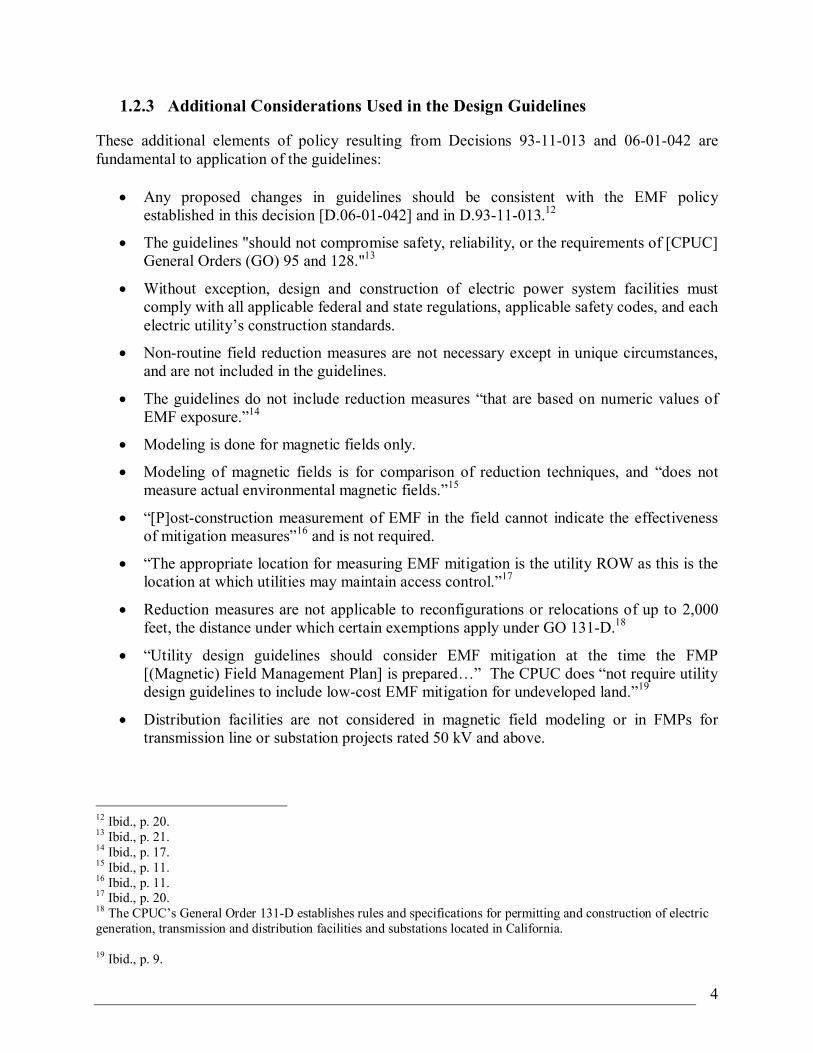
4
1.2.3 Additional Considerations Used in the Design Guidelines
These additional elements of policy resulting from Decisions 9311013 and 0601042 are fundamental to application of the guidelines:
• Any proposed changes in guidelines should be consistent with the EMF policy established in this decision [D.0601042] and in D.9311013. 12
• The guidelines "should not compromise safety, reliability, or the requirements of [CPUC] General Orders (GO) 95 and 128." 13
• Without exception, design and construction of electric power system facilities must comply with all applicable federal and state regulations, applicable safety codes, and each electric utility’s construction standards.
• Nonroutine field reduction measures are not necessary except in unique circumstances, and are not included in the guidelines.
• The guidelines do not include reduction measures “that are based on numeric values of EMF exposure.” 14
• Modeling is done for magnetic fields only.
• Modeling of magnetic fields is for comparison of reduction techniques, and “does not measure actual environmental magnetic fields.” 15
• “[P]ostconstruction measurement of EMF in the field cannot indicate the effectiveness of mitigation measures” 16 and is not required.
• “The appropriate location for measuring EMF mitigation is the utility ROW as this is the location at which utilities may maintain access control.” 17
• Reduction measures are not applicable to reconfigurations or relocations of up to 2,000 feet, the distance under which certain exemptions apply under GO 131D. 18
• “Utility design guidelines should consider EMF mitigation at the time the FMP [(Magnetic) Field Management Plan] is prepared…” The CPUC does “not require utility design guidelines to include lowcost EMF mitigation for undeveloped land.” 19
• Distribution facilities are not considered in magnetic field modeling or in FMPs for transmission line or substation projects rated 50 kV and above.
12 Ibid., p. 20. 13 Ibid., p. 21. 14 Ibid., p. 17. 15 Ibid., p. 11. 16 Ibid., p. 11. 17 Ibid., p. 20. 18 The CPUC’s General Order 131D establishes rules and specifications for permitting and construction of electric generation, transmission and distribution facilities and substations located in California.
19 Ibid., p. 9.
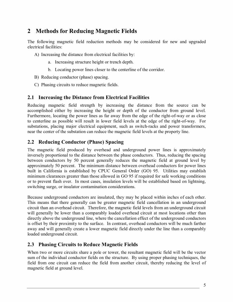
5
2 Methods for Reducing Magnetic Fields The following magnetic field reduction methods may be considered for new and upgraded electrical facilities:
A) Increasing the distance from electrical facilities by: a. Increasing structure height or trench depth.
b. Locating power lines closer to the centerline of the corridor. B) Reducing conductor (phase) spacing.
C) Phasing circuits to reduce magnetic fields.
2.1 Increasing the Distance from Electrical Facilities Reducing magnetic field strength by increasing the distance from the source can be accomplished either by increasing the height or depth of the conductor from ground level. Furthermore, locating the power lines as far away from the edge of the rightofway or as close to centerline as possible will result in lower field levels at the edge of the rightofway. For substations, placing major electrical equipment, such as switchracks and power transformers, near the center of the substation can reduce the magnetic field levels at the property line.
2.2 Reducing Conductor (Phase) Spacing The magnetic field produced by overhead and underground power lines is approximately inversely proportional to the distance between the phase conductors. Thus, reducing the spacing between conductors by 50 percent generally reduces the magnetic field at ground level by approximately 50 percent. The minimum distance between overhead conductors for power lines built in California is established by CPUC General Order (GO) 95. Utilities may establish minimum clearances greater than those allowed in GO 95 if required for safe working conditions or to prevent flash over. In most cases, insulation levels will be established based on lightning, switching surge, or insulator contamination considerations.
Because underground conductors are insulated, they may be placed within inches of each other. This means that there generally can be greater magnetic field cancellation in an underground circuit than an overhead circuit. Therefore, the magnetic field levels from an underground circuit will generally be lower than a comparably loaded overhead circuit at most locations other than directly above the underground line, where the cancellation effect of the underground conductors is offset by their proximity to the surface. In contrast, overhead conductors will be much farther away and will generally create a lower magnetic field directly under the line than a comparably loaded underground circuit.
2.3 Phasing Circuits to Reduce Magnetic Fields When two or more circuits share a pole or tower, the resultant magnetic field will be the vector sum of the individual conductor fields on the structure. By using proper phasing techniques, the field from one circuit can reduce the field from another circuit, thereby reducing the level of magnetic field at ground level.
6
3 The Field Management Plan Process
3.1 The Field Management Plan
The Field Management Plan (FMP) documents the consideration of nocost and lowcost magnetic field reduction measures for new or significantly reconstructed transmission lines and substations rated 50 kV and above (refer to § 3.4 for exceptions).
FMPs will be prepared for relevant transmission projects and will be retained with the work order. For any project requiring a permit under GO 131D, the FMP will be incorporated as a part of the GO 131D filing.
Utilities have incorporated magnetic field reduction measures into their distribution construction and design standards. Therefore, FMPs are not prepared for any distribution projects.
Basic elements of the FMP include a project description, an evaluation of nocost and lowcost magnetic field reduction measures, and specific recommendations regarding magnetic field reduction measures to be incorporated into the transmission line and substation design (see §§ 4 and 5 of these guidelines for additional information concerning the contents of transmission line and substation FMPs).
3.2 Types of FMP
There are two types of FMP for transmission line projects, a “Basic FMP” and a “Detailed FMP,” and a “Checklist FMP” for substation projects.
For transmission line projects with limited work scope, as described in Table 31 below, a Basic FMP is sufficient to document nocost and lowcost magnetic field reduction measures. The Basic FMP consists of a transmission line project description, applicable nocost and lowcost magnetic field reduction measures without magnetic field model(s), and recommendations.
The Detailed FMP consists of a transmission line project description, evaluation of nocost and lowcost magnetic field reduction measures, magnetic field models, and recommendations (refer to § 3.3 to determine what types of transmission line projects require a Detailed FMP).
For substation projects, a checklist FMP, showing an evaluation of magnetic field reduction measures adopted or rejected, will be used. An example of the Checklist FMP is shown on Table 51.
3.3 Determining If an FMP is Required, and If so, What Type
The CPUC in Decision 9311013 (§ 3.4.2, p. 15) states, “Utility management should have reasonable latitude to deviate and modify their guidelines as conditions warrant and as new magnetic fields information is received.” Table 31 provides criteria to determine if the project requires a Detailed FMP, a Basic FMP, a Checklist FMP, or no FMP.
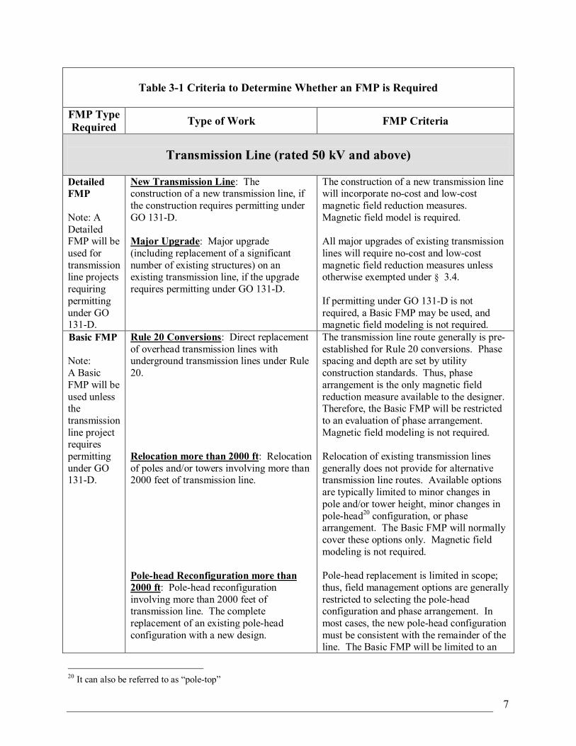
7
Table 31 Criteria to Determine Whether an FMP is Required
FMP Type Required Type of Work FMP Criteria
Transmission Line (rated 50 kV and above)
Detailed FMP
Note: A Detailed FMP will be used for transmission line projects requiring permitting under GO 131D.
New Transmission Line: The construction of a new transmission line, if the construction requires permitting under GO 131D.
Major Upgrade: Major upgrade (including replacement of a significant number of existing structures) on an existing transmission line, if the upgrade requires permitting under GO 131D.
The construction of a new transmission line will incorporate nocost and lowcost magnetic field reduction measures. Magnetic field model is required.
All major upgrades of existing transmission lines will require nocost and lowcost magnetic field reduction measures unless otherwise exempted under § 3.4.
If permitting under GO 131D is not required, a Basic FMP may be used, and magnetic field modeling is not required.
Basic FMP
Note: A Basic FMP will be used unless the transmission line project requires permitting under GO 131D.
Rule 20 Conversions: Direct replacement of overhead transmission lines with underground transmission lines under Rule 20.
Relocation more than 2000 ft: Relocation of poles and/or towers involving more than 2000 feet of transmission line.
Polehead Reconfiguration more than 2000 ft: Polehead reconfiguration involving more than 2000 feet of transmission line. The complete replacement of an existing polehead configuration with a new design.
The transmission line route generally is pre established for Rule 20 conversions. Phase spacing and depth are set by utility construction standards. Thus, phase arrangement is the only magnetic field reduction measure available to the designer. Therefore, the Basic FMP will be restricted to an evaluation of phase arrangement. Magnetic field modeling is not required.
Relocation of existing transmission lines generally does not provide for alternative transmission line routes. Available options are typically limited to minor changes in pole and/or tower height, minor changes in polehead 20 configuration, or phase arrangement. The Basic FMP will normally cover these options only. Magnetic field modeling is not required.
Polehead replacement is limited in scope; thus, field management options are generally restricted to selecting the polehead configuration and phase arrangement. In most cases, the new polehead configuration must be consistent with the remainder of the line. The Basic FMP will be limited to an
20 It can also be referred to as “poletop”
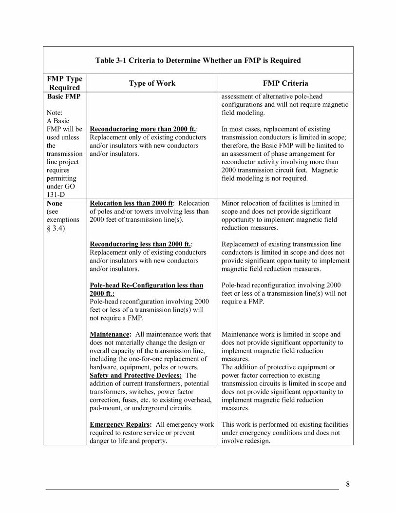
8
Table 31 Criteria to Determine Whether an FMP is Required
FMP Type Required Type of Work FMP Criteria
Basic FMP
Note: A Basic FMP will be used unless the transmission line project requires permitting under GO 131D
Reconductoring more than 2000 ft.: Replacement only of existing conductors and/or insulators with new conductors and/or insulators.
assessment of alternative polehead configurations and will not require magnetic field modeling.
In most cases, replacement of existing transmission conductors is limited in scope; therefore, the Basic FMP will be limited to an assessment of phase arrangement for reconductor activity involving more than 2000 transmission circuit feet. Magnetic field modeling is not required.
None (see exemptions § 3.4)
Relocation less than 2000 ft: Relocation of poles and/or towers involving less than 2000 feet of transmission line(s).
Reconductoring less than 2000 ft.: Replacement only of existing conductors and/or insulators with new conductors and/or insulators.
Polehead ReConfiguration less than 2000 ft.: Polehead reconfiguration involving 2000 feet or less of a transmission line(s) will not require a FMP.
Maintenance: All maintenance work that does not materially change the design or overall capacity of the transmission line, including the oneforone replacement of hardware, equipment, poles or towers. Safety and Protective Devices: The addition of current transformers, potential transformers, switches, power factor correction, fuses, etc. to existing overhead, padmount, or underground circuits.
Emergency Repairs: All emergency work required to restore service or prevent danger to life and property.
Minor relocation of facilities is limited in scope and does not provide significant opportunity to implement magnetic field reduction measures.
Replacement of existing transmission line conductors is limited in scope and does not provide significant opportunity to implement magnetic field reduction measures.
Polehead reconfiguration involving 2000 feet or less of a transmission line(s) will not require a FMP.
Maintenance work is limited in scope and does not provide significant opportunity to implement magnetic field reduction measures. The addition of protective equipment or power factor correction to existing transmission circuits is limited in scope and does not provide significant opportunity to implement magnetic field reduction measures.
This work is performed on existing facilities under emergency conditions and does not involve redesign.
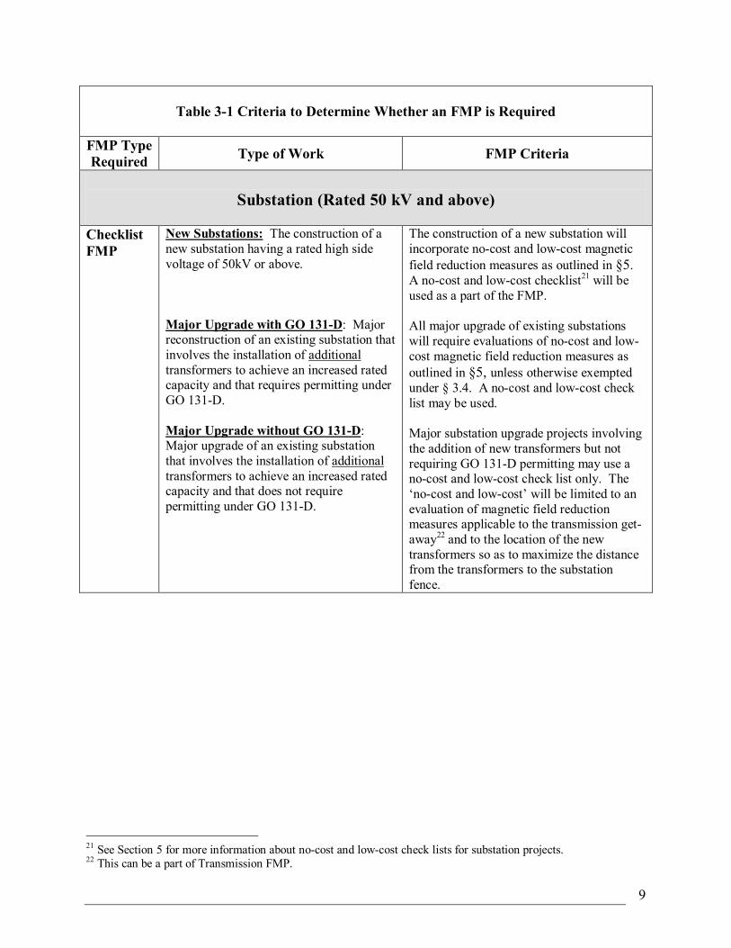
9
Table 31 Criteria to Determine Whether an FMP is Required
FMP Type Required Type of Work FMP Criteria
Substation (Rated 50 kV and above)
Checklist FMP
New Substations: The construction of a new substation having a rated high side voltage of 50kV or above.
Major Upgrade with GO 131D: Major reconstruction of an existing substation that involves the installation of additional transformers to achieve an increased rated capacity and that requires permitting under GO 131D.
Major Upgrade without GO 131D: Major upgrade of an existing substation that involves the installation of additional transformers to achieve an increased rated capacity and that does not require permitting under GO 131D.
The construction of a new substation will incorporate nocost and lowcost magnetic field reduction measures as outlined in §5. A nocost and lowcost checklist 21 will be used as a part of the FMP.
All major upgrade of existing substations will require evaluations of nocost and low cost magnetic field reduction measures as outlined in §5, unless otherwise exempted under § 3.4. A nocost and lowcost check list may be used.
Major substation upgrade projects involving the addition of new transformers but not requiring GO 131D permitting may use a nocost and lowcost check list only. The ‘nocost and lowcost’ will be limited to an evaluation of magnetic field reduction measures applicable to the transmission get away 22 and to the location of the new transformers so as to maximize the distance from the transformers to the substation fence.
21 See Section 5 for more information about nocost and lowcost check lists for substation projects. 22 This can be a part of Transmission FMP.
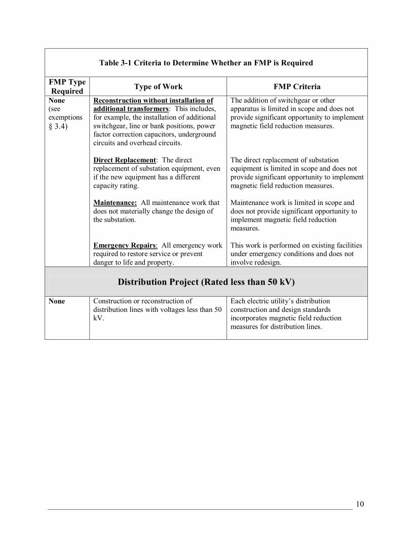
10
Table 31 Criteria to Determine Whether an FMP is Required
FMP Type Required Type of Work FMP Criteria
None (see exemptions § 3.4)
Reconstruction without installation of additional transformers: This includes, for example, the installation of additional switchgear, line or bank positions, power factor correction capacitors, underground circuits and overhead circuits.
Direct Replacement: The direct replacement of substation equipment, even if the new equipment has a different capacity rating.
Maintenance: All maintenance work that does not materially change the design of the substation.
Emergency Repairs: All emergency work required to restore service or prevent danger to life and property.
The addition of switchgear or other apparatus is limited in scope and does not provide significant opportunity to implement magnetic field reduction measures.
The direct replacement of substation equipment is limited in scope and does not provide significant opportunity to implement magnetic field reduction measures.
Maintenance work is limited in scope and does not provide significant opportunity to implement magnetic field reduction measures.
This work is performed on existing facilities under emergency conditions and does not involve redesign.
Distribution Project (Rated less than 50 kV)
None Construction or reconstruction of distribution lines with voltages less than 50 kV.
Each electric utility’s distribution construction and design standards incorporates magnetic field reduction measures for distribution lines.
11
3.4 Projects Exempt from the FMP Requirement
The CPUC, in Decision 9311013, recognized that some flexibility was required in the EMF Design Guidelines. In section 3.4.2 of the Decision, the CPUC stated: “Electric utility management should have flexibility to modify the guidelines and to incorporate additional concepts and criteria as new EMF information becomes available. However, if the EMF Design Guidelines are to be truly used as guidelines, the utilities should incorporate criteria which justify exempting specific types of projects from the guidelines.”
The following criteria to determine those transmission and substation projects exempted from the requirement for consideration of nocost and lowcost magnetic field reduction measures:
1. Emergency
• All work required to restore service or remove an unsafe condition. 2. Operation & Maintenance
• Washing and switching operations.
• Replacing crossarms, insulators, or line hardware.
• Replacing deteriorated poles.
• Maintaining underground cable and vaults.
• Replacing line and substation equipment with equipment serving the same purpose and with similar ratings.
• Repairing line and substation equipment. 3. Relocations
• Line relocation of up to 2000 feet.
• Installation of guy poles or trenching poles only. 4. Minor Improvements
• Addition of safety devices.
• Reconductoring up to 2000 feet, where changing polehead configuration is not required.
• Installation of overhead switches.
• Insulator replacement.
• Modification of protective equipment and monitoring equipment.
• Intersetting of additional structures between existing support structures. 5. Projects located exclusively adjacent to undeveloped land—including land under the
jurisdiction of the National Park Service, the State Department of Parks and Recreation, U.S. Forest Service, or Bureau of Land Management (BLM).
12
3.5 Prioritizing Within and Between Land Use Classes
The CPUC stated in Decision 0601042, “[a]lthough equal mitigation for an entire class is a desirable goal, we will not limit the spending of EMF mitigation to zero on the basis that not all class members can benefit.” 23
While Decision 0601042 directs the utilities to favor schools, daycare facilities and hospitals over residential areas when applying lowcost magnetic field reduction measures, prioritization within a class can be difficult on a project casebycase basis because schools, daycare facilities, and hospitals are often integrated into residential areas, and many licensed daycare facilities are housed in private homes that can be easily moved from one location to another. Therefore, utilities may group public schools, licensed daycare centers, hospitals, and residential together to receive highest prioritization for lowcost magnetic field reduction measures. Commercial and industrial areas may be grouped as a second priority group, followed by recreational and agricultural areas as the third group. Lowcost magnetic field reduction measures will not be considered for undeveloped land such as open space, state and national parks, Bureau of Land Management and National Forest Service Land.
When spending for lowcost measures would otherwise disallow equitable magnetic field reduction for all areas within a single landuse class, prioritization can be achieved by considering location and/or density of permanently occupied structures on lands adjacent to the projects, as appropriate.
23 Ibid., p. 10
13
4 Field Management Plans for Transmission Lines Construction of a new transmission line or the major upgrade of an existing transmission line, if they require GO131D permitting, or the relocation of 2000 feet or more of an existing transmission line will require the preparation of a FMP; refer to § 3.3 to determine if a Detailed FMP (or Basic FMP) is needed; refer to § 3.4 for exemption criteria.
Transmission FMPs should include the following sections:
• Project Description;
• Evaluation of NoCost Magnetic Field Reduction Measures;
• Evaluation of LowCost Magnetic Field Reduction Measures; and
• Recommendations including a table showing magnetic field reduction measures.
In addition to these requirements, a twodimensional (2D) magnetic field model is required for a Detailed FMP.
4.1 Project Description
The project description portion of the transmission line FMP will include the following:
• For a Detailed FMP, the proposed line route should be shown on an attached project map illustrating the transmission line route, alternative line route (if applicable), and major streets and highways. A Basic FMP should briefly describe the scope of work including the line route;
• Description of land use adjacent to the line route for both Basic and Detailed FMPs;
• Circuit name and rated voltage, and circuit phasing if more than one circuit is present in the same corridor for both Basic and Detailed FMPs (rated 50 kV and above);
• Description of proposed design. For a Detailed FMP, include circuit configuration, and minimum ground clearance for overhead design. For a Basic FMP, include circuit configuration. For underground facilities (for both Detailed FMP or Basic FMP), show the depth and configuration of duct bank;
• Include estimated total project costs for proposed design.(for a Detailed FMP).
4.2 TwoDimensional Magnetic Field Modeling for Transmission Lines
The purpose of magnetic field modeling is to evaluate relative effectiveness of various magnetic field reduction measures, not to predict magnetic field levels, as the CPUC recognized in Decision 0601042:
“Utility modeling methodology is intended to compare differences between alternative EMF mitigation measures and not determine actual EMF amounts.” 24
24 Ibid., p. 20
14
“… the modeling indicates relative differences in magnetic field reductions between different transmission line construction methods, but does not measure actual environmental magnetic fields. In the same way, these relative differences in mitigation measures will be evident regardless of whether a maximum peak or a projected peak is used for the comparisons… It is also true that post construction measurement of EMF in the field cannot indicate the effectiveness of mitigation measures used as it would be extremely difficult to eliminate all other EMF sources.” 25
Twodimensional magnetic field software can be used to evaluate the magnetic field characteristics of the proposed construction and various magnetic field reduction alternatives. Estimates of magnetic field levels are calculated based on a specific set of conditions. Therefore, it is important to make logical assumptions as to what these conditions will be and to keep these calculation conditions consistent when comparing two or more different cases.
Typical twodimensional magnetic field modeling assumptions include:
• The line will be considered operating at forecasted design load;
• Magnetic field strength is calculated at a height of three feet above ground (assuming flat terrain);
• Resultant magnetic fields are being used;
• All line loadings are considered as balanced (i.e. neutral or ground currents are not considered);
• The line is considered working under normal operating conditions (emergency conditions are not modeled);
• Terrain is flat;
• Dominant power flow directions are being used; and
• Contribution of shield wire currents is not included.
25 Ibid., p. 11
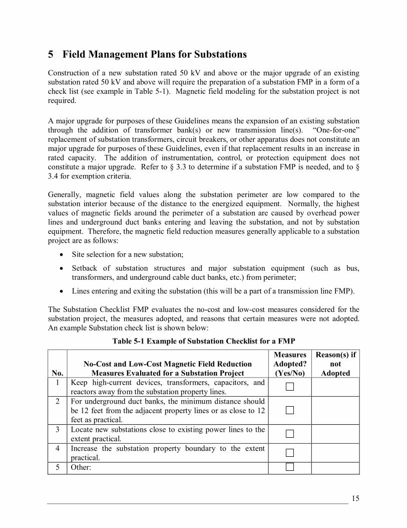
15
5 Field Management Plans for Substations Construction of a new substation rated 50 kV and above or the major upgrade of an existing substation rated 50 kV and above will require the preparation of a substation FMP in a form of a check list (see example in Table 51). Magnetic field modeling for the substation project is not required.
A major upgrade for purposes of these Guidelines means the expansion of an existing substation through the addition of transformer bank(s) or new transmission line(s). “Oneforone” replacement of substation transformers, circuit breakers, or other apparatus does not constitute an major upgrade for purposes of these Guidelines, even if that replacement results in an increase in rated capacity. The addition of instrumentation, control, or protection equipment does not constitute a major upgrade. Refer to § 3.3 to determine if a substation FMP is needed, and to § 3.4 for exemption criteria.
Generally, magnetic field values along the substation perimeter are low compared to the substation interior because of the distance to the energized equipment. Normally, the highest values of magnetic fields around the perimeter of a substation are caused by overhead power lines and underground duct banks entering and leaving the substation, and not by substation equipment. Therefore, the magnetic field reduction measures generally applicable to a substation project are as follows:
• Site selection for a new substation;
• Setback of substation structures and major substation equipment (such as bus, transformers, and underground cable duct banks, etc.) from perimeter;
• Lines entering and exiting the substation (this will be a part of a transmission line FMP).
The Substation Checklist FMP evaluates the nocost and lowcost measures considered for the substation project, the measures adopted, and reasons that certain measures were not adopted. An example Substation check list is shown below:
Table 51 Example of Substation Checklist for a FMP
No. NoCost and LowCost Magnetic Field Reduction Measures Evaluated for a Substation Project
Measures Adopted? (Yes/No)
Reason(s) if not
Adopted 1 Keep highcurrent devices, transformers, capacitors, and
reactors away from the substation property lines. 2 For underground duct banks, the minimum distance should
be 12 feet from the adjacent property lines or as close to 12 feet as practical.
3 Locate new substations close to existing power lines to the extent practical.
4 Increase the substation property boundary to the extent practical.
5 Other:
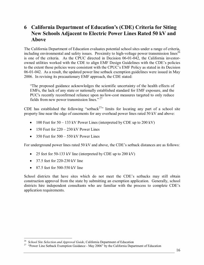
16
6 California Department of Education’s (CDE) Criteria for Siting New Schools Adjacent to Electric Power Lines Rated 50 kV and Above
The California Department of Education evaluates potential school sites under a range of criteria, including environmental and safety issues. Proximity to highvoltage power transmission lines 26 is one of the criteria. As the CPUC directed in Decision 0601042, the California investor owned utilities worked with the CDE to align EMF Design Guidelines with the CDE’s policies to the extent those policies were consistent with the CPUC’s EMF Policy as stated in its Decision 0601042. As a result, the updated power line setback exemption guidelines were issued in May 2006. In revising its precautionary EMF approach, the CDE stated:
“The proposed guidance acknowledges the scientific uncertainty of the health effects of EMFs, the lack of any state or nationally established standard for EMF exposure, and the PUC's recently reconfirmed reliance upon no/lowcost measures targeted to only reduce fields from new power transmission lines.” 27
CDE has established the following “setback 27 ” limits for locating any part of a school site property line near the edge of easements for any overhead power lines rated 50 kV and above:
• 100 Feet for 50 – 133 kV Power Lines (interpreted by CDE up to 200 kV)
• 150 Feet for 220 – 230 kV Power Lines
• 350 Feet for 500 – 550 kV Power Lines
For underground power lines rated 50 kV and above, the CDE’s setback distances are as follows:
• 25 feet for 50133 kV line (interpreted by CDE up to 200 kV)
• 37.5 feet for 220230 kV line
• 87.5 feet for 500550 kV line
School districts that have sites which do not meet the CDE’s setbacks may still obtain construction approval from the state by submitting an exemption application. Generally, school districts hire independent consultants who are familiar with the process to complete CDE’s application requirements.
26 School Site Selection and Approval Guide, California Department of Education 27 “Power Line Setback Exemption Guidance May 2006” by the California Department of Education
APPENDIX C
EMF Measurement Locations and Surrounding Land Uses
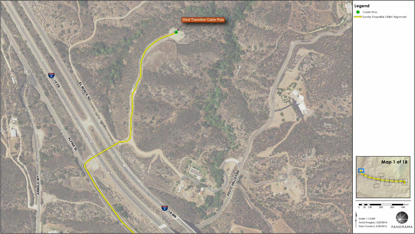
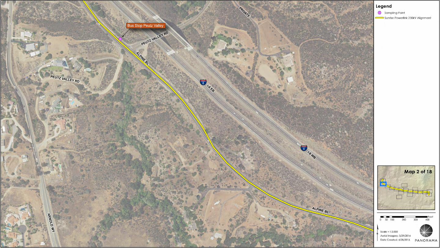
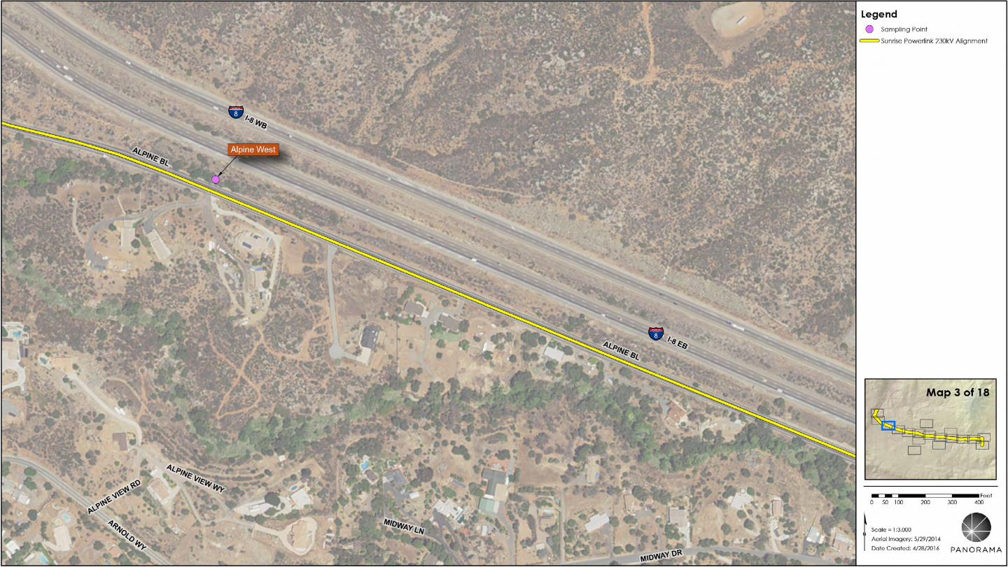
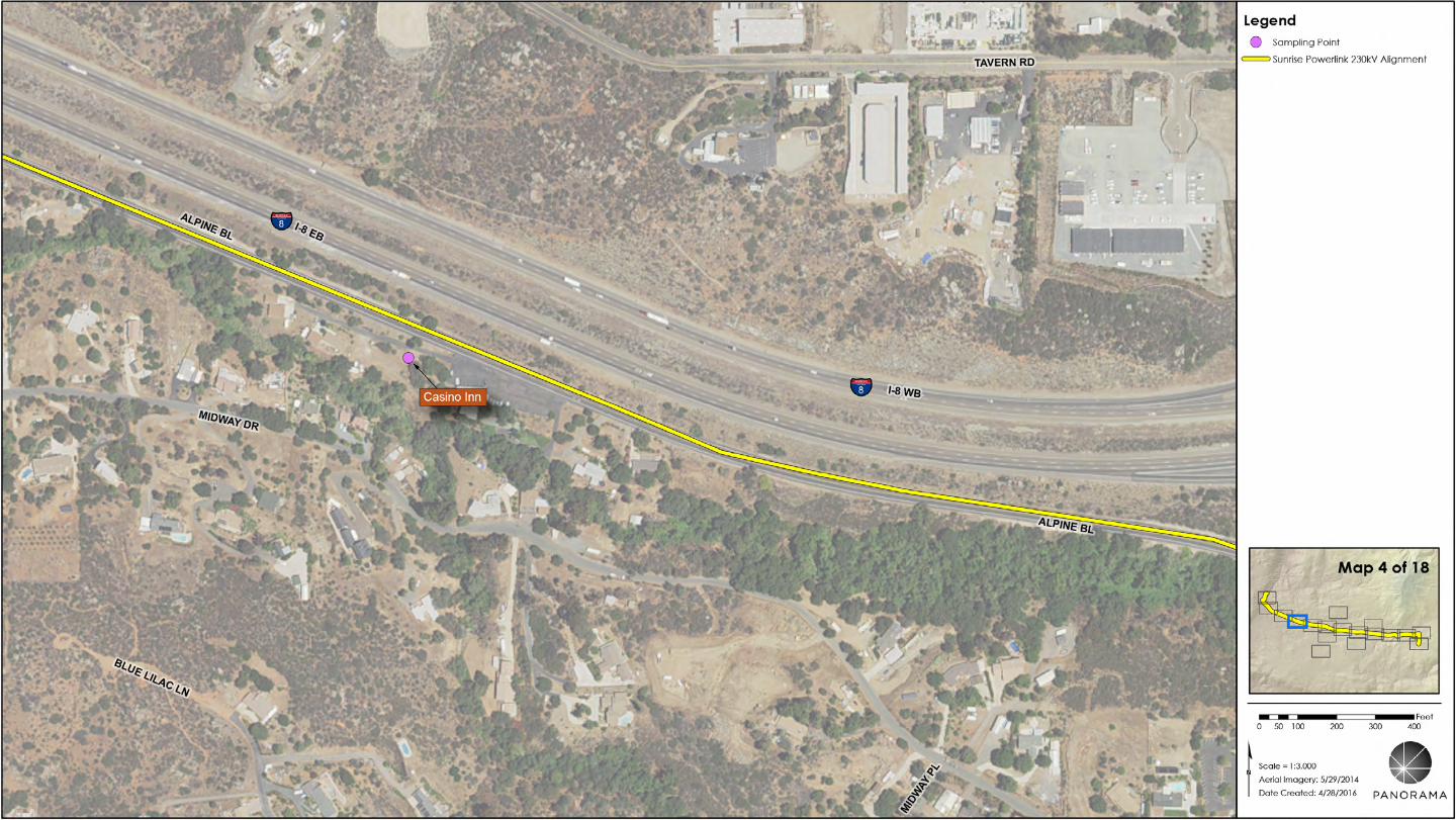
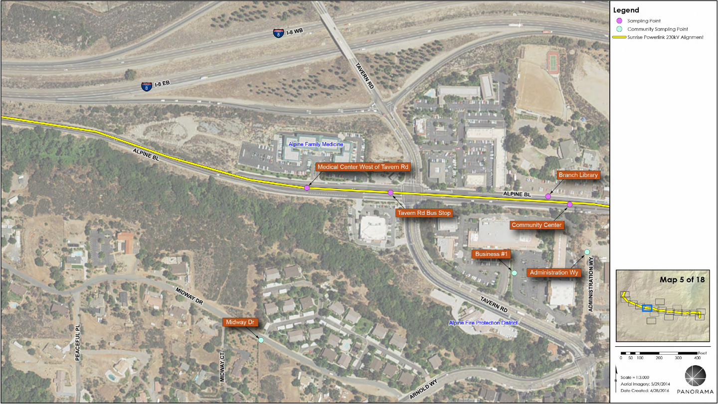
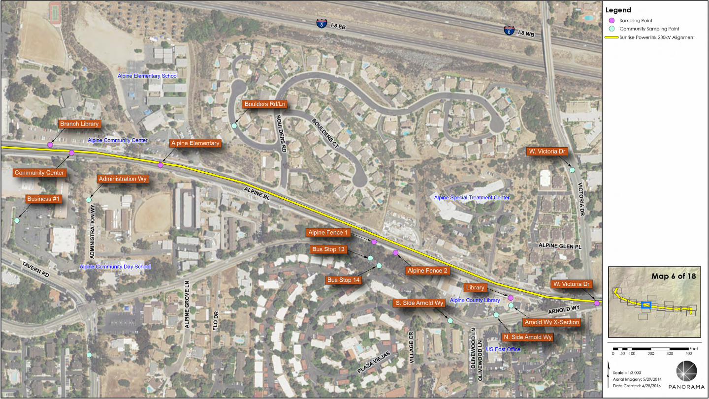
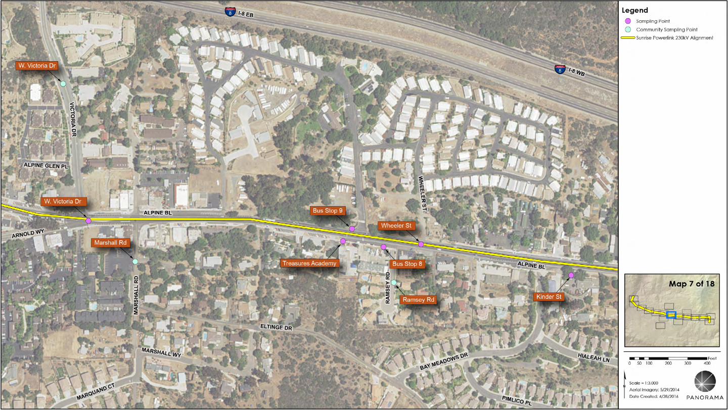
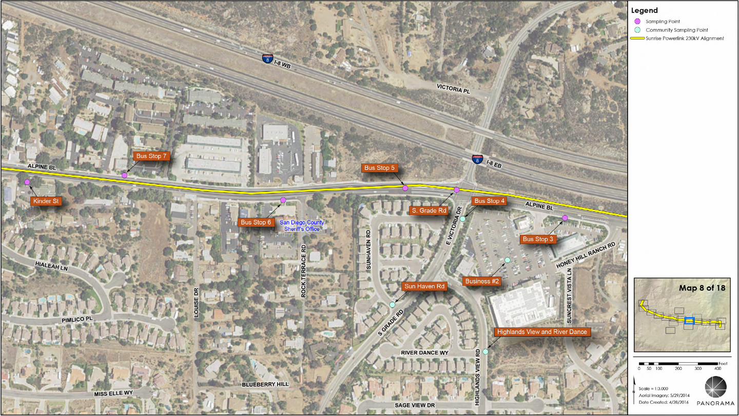
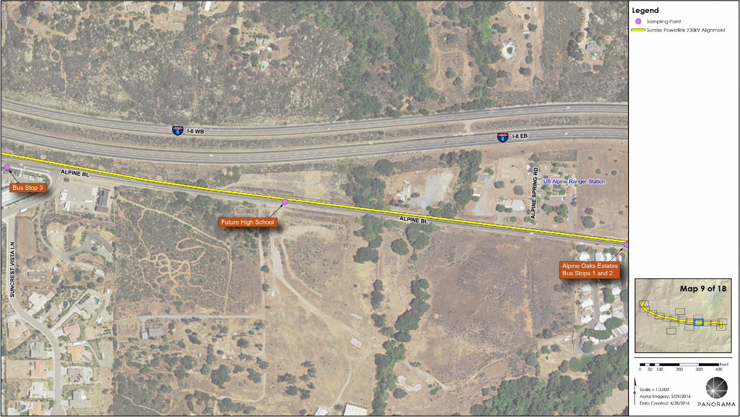
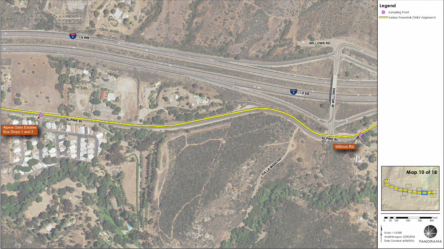
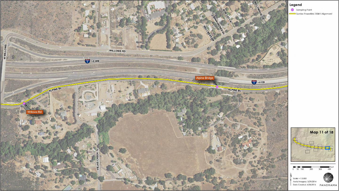
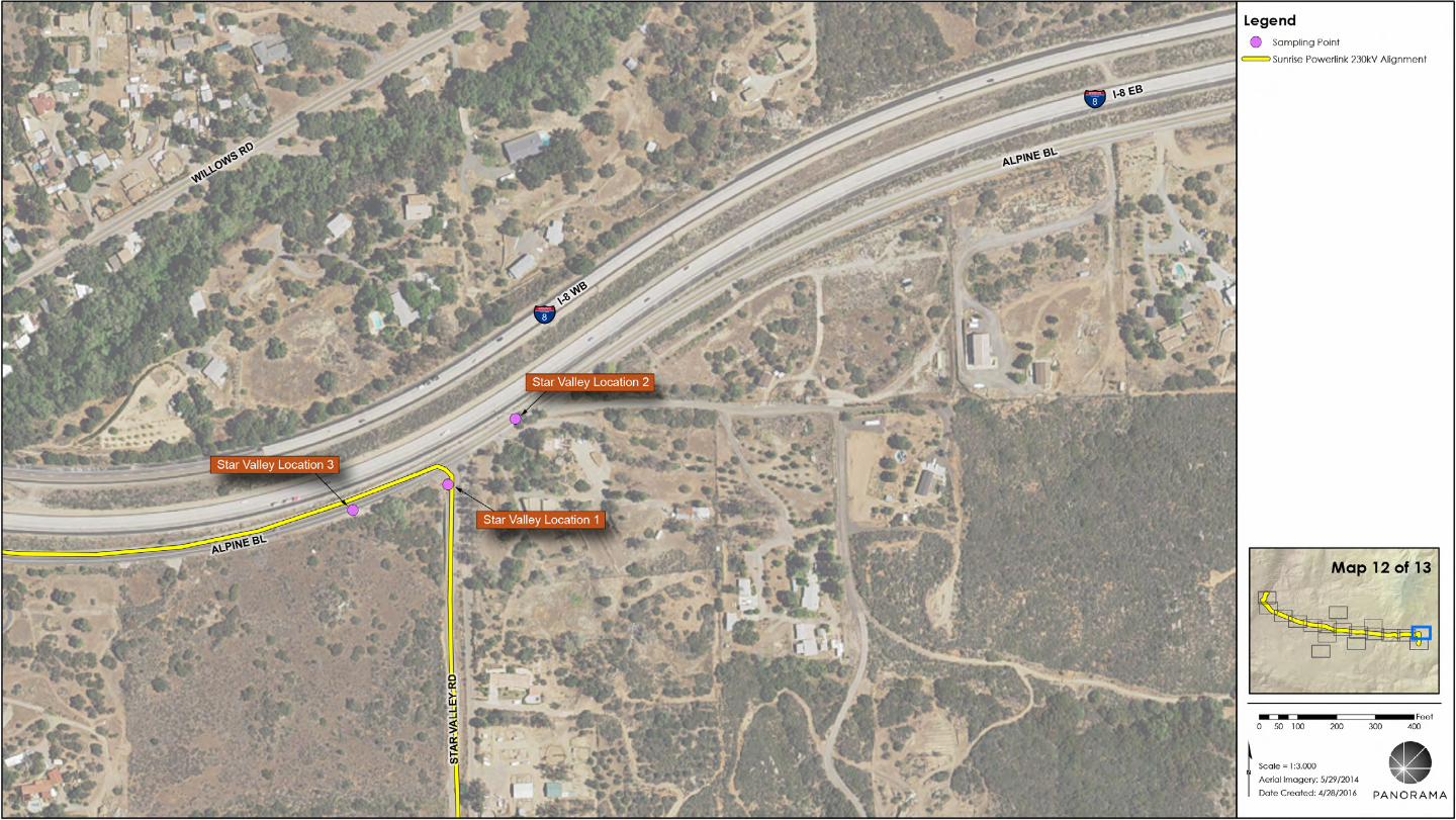
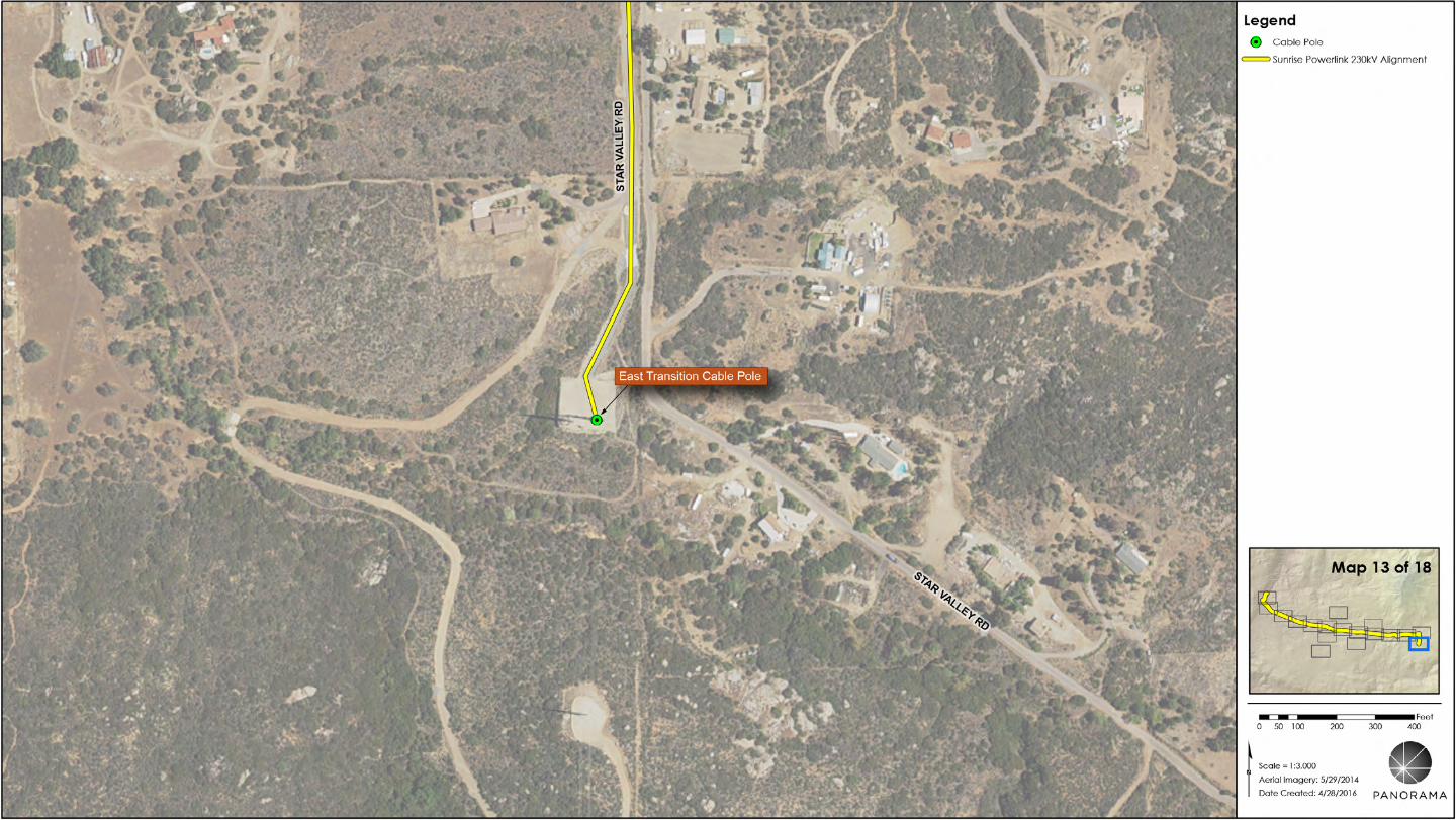
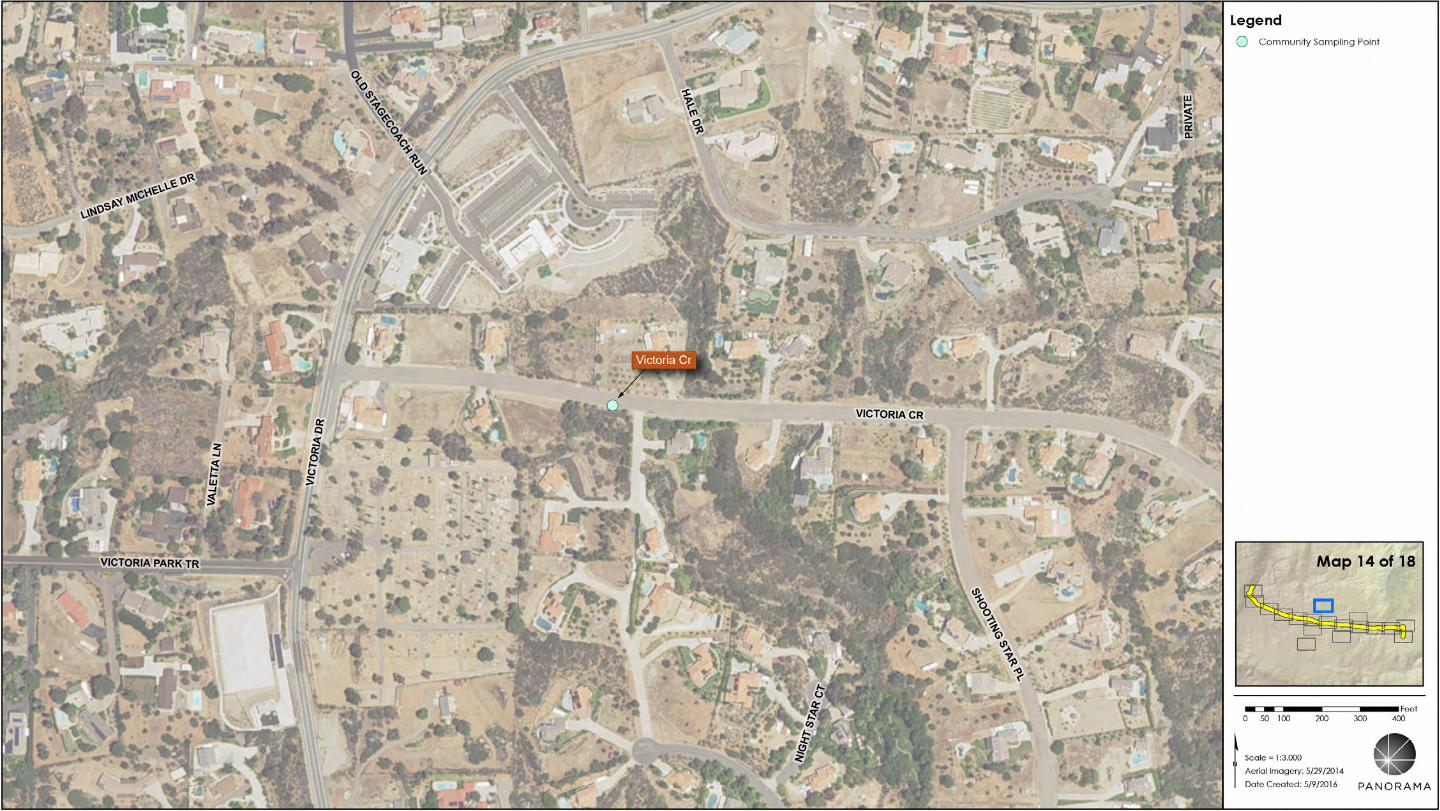
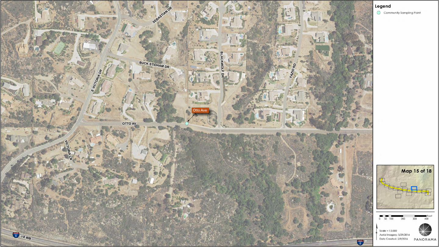
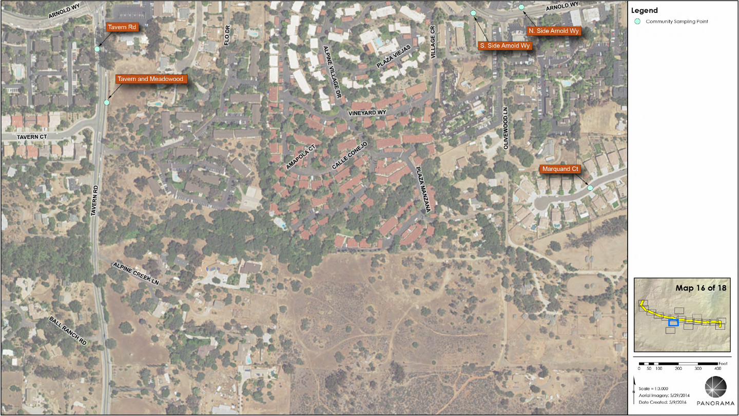
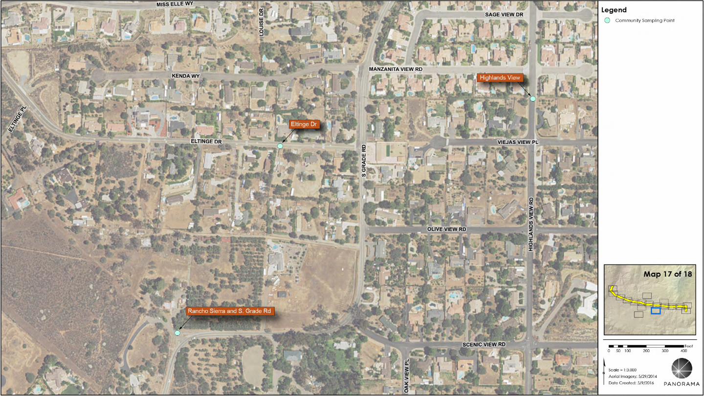
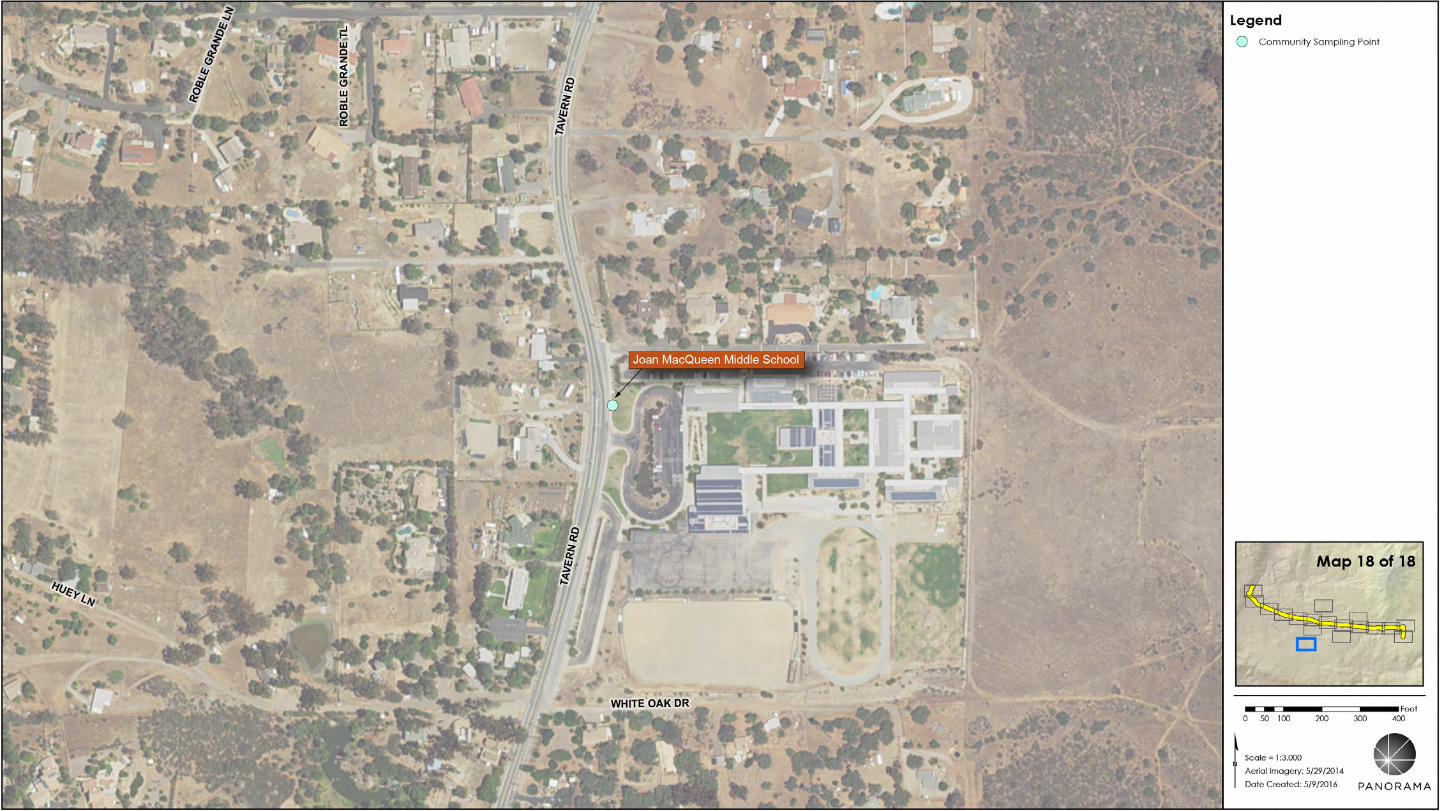
APPENDIX D
SDG&E Field Management Plan
Magnetic Field Management Plan
Sunrise Powerlink 500 kV/230 kV Project
2 of 18
Project Manager: J. Woldemariam
Project Engineer:
Project Designer: Sargent & Lundy Engineers, Ltd
In-Service Date: June 2012
File:
Prepared by: Sargent & Lundy Engineers, Ltd, B.C. Wood
J. Turman, San Diego Gas & Electric
09/30/2009
3 of 18
Table of Contents
I. Scope ................................................................................................................................. 4
II. Magnetic Field Management Design Guidelines ................................................................. 4
III. Methodology .................................................................................................................... 4
IV. Project Description ........................................................................................................... 5
V. Sunrise Powerlink—Project Sections .................................................................................. 6
Mileposts 0 – 34, Sections 9 and 10, Overhead Construction: Imperial Valley – Parallel to Existing 500 kV Southwest Powerlink ...................................................................................................... 6
Mileposts 34 – 67, 73 – 80 and 82 – 91, Sections 8 and 9, Overhead Construction: Imperial Valley to Suncrest Substation .................................................................................................................. 7
Mileposts 67 – 73, Sections 8C and 8D, Overhead Construction: Imperial Valley to Suncrest Substation ................................................................................................................................................ 8
Mileposts 80 – 82, Section 8A, Overhead Construction: Imperial Valley to Suncrest Substation ........... 9
Mileposts 91 – 93, Section 7, Overhead Construction: Suncrest Substation to Alpine Overhead-to-Underground Transition, East Alpine ............................................................................... 10
Mileposts 93 – 99, Section 6, Underground Construction: Alpine ........................................................ 11
Mileposts 99 – 113, Section 5, Overhead Construction: Alpine Underground-to-Overhead Transition, West Alpine to Lakeside ...................................................................................................... 12
Mileposts 113 – 118, Section 4, Overhead Construction: Lakeside to Sycamore Canyon Substation .............................................................................................................................................. 13
VI. Magnetic Field Reduction Measures Considered for the Project ...................................... 14
Field Reduction Measures Considered for Suncrest Substation ........................................................... 14
Field Reduction Measures Considered for Project Transmission Lines ................................................. 14
Table 1: Transmission Line Sections—Magnetic Field Reduction Measures Considered .................. 15
Table 2: Transmission Line Sections—Reasons Magnetic Field Reduction Measures Were Rejected .............................................................................................................................................. 17
VII. Magnetic Field Reduction Measures Recommended for the Project ............................... 18
Field Reduction Measures Recommended for Suncrest Substation ..................................................... 18
Field Reduction Measures Recommended for Project Transmission Lines ........................................... 18
Table 3: Magnetic Field Values and Reductions Calculated for Project Transmission Line Sections .............................................................................................................................................. 18
4 of 18
I. Scope
The Sunrise Powerlink 500 kV/230 kV Project (the Project) was approved by the California Public Utilities Commission (CPUC) in CPCN Decision 08-12-058. The Project provides means to import renewable energy from the Imperial Valley into the San Diego area and to relieve congestion on existing SDG&E circuits.
In brief, Project construction entails (1) a new single-circuit 500 kV transmission line, approximately 91 miles long, from Imperial Valley to (2) a new Suncrest 500 kV/230 kV Substation in the Alpine area in central San Diego County, and (3) a new double-circuit 230 kV transmission line, approximately 28 miles long, from the new Suncrest Substation to SDG&E’s existing Sycamore Canyon Substation near Poway, CA. See Section IV of this document for a detailed project description.
II. Magnetic Field Management Design Guidelines
The CPUC requires SDG&E to apply its EMF1Design Guidelines for Electrical Facilities ("EMF Guidelines") to all new electrical projects to reduce public exposure to magnetic fields. SDG&E filed its EMF Guidelines with the CPUC in accordance with CPUC Decisions 93-11-013 and 06-01-042.
Consistent with SDG&E’s EMF Guidelines, this Magnetic Field Management Plan ("Plan") deals solely with magnetic fields since that has been the focus of the EMF research. Also, per the EMF Guidelines, reducing magnetic field strength is only one of many factors to consider in planning and designing a transmission system, such as safety, environmental concerns, reliability, insulation and electrical clearance requirements, aesthetics, cost, operations and maintenance.
III. Methodology
SDG&E will apply its EMF Guidelines to this Project as follows:
Identify “no-cost” measures in the design stage which will not involve an increase in project costs but will reduce the magnetic field strength.
Identify “low-cost” measures which cost in the range of 4% of the total Project cost and will reduce the magnetic field strength in an area by 15% or more at the edge of the Project right-of-way.2
When there is a sufficiency of “low-cost” measures available to reduce the strength of the magnetic fields, such that it is difficult to stay within the 4% cost range, apply the identified “low-cost” measures based on the following priorities identified in CPUC Decision 06-01-042:
o Schools, licensed day-care centers and hospitals
o Residential
o Commercial/Industrial
o Recreational
o Agricultural3
o Undeveloped Land3
The new and existing lines for the Project were examined along the proposed and existing rights-of-way to determine conductor configurations and placements resulting in magnetic field reduction. Magnetic field levels were calculated at a height of one meter, across and up to both edges of the right-of-way,
1 EMF refers to electric and magnetic fields.
2 CPUC Decision 06-01-042, p. 10.
3 Ibid., p. 20: “Low-cost EMF mitigation is not necessary in agricultural and undeveloped land except for permanently occupied residences, schools or hospitals located on these lands.”
5 of 18
using currents (amps) based on the projected 2010 SDG&E system summer peak load. Magnetic fields vary with current levels.
To evaluate the effectiveness of various magnetic field reduction measures, calculated values for a given measure were compared to calculated values without the measure. This comparison was performed at both edges of the transmission right-of-way.
IV. Project Description
The Project includes construction of a new 500 kV transmission line, approximately 91 miles long, located on a new 200-foot right-of-way, from SDG&E’s existing Imperial Valley Substation near El Centro, CA to the new Suncrest Substation in the Alpine area in central San Diego County. Two new 230 kV transmission circuits will be constructed as a double-circuit line consisting of 16.5 miles of overhead double-circuit lattice towers within a new 300-foot-wide right-of-way, 6.2 miles of underground double-circuit construction through the Alpine community, and 5.5 miles of double-circuit lattice towers within an existing 100-foot-wide right-of-way from Highway 67 in Lakeside to Sycamore Canyon Substation.
Construction of the new 500 kV/230 kV Suncrest Substation in the Alpine area will include installation of new transformers, power circuit breakers, disconnect switches, as well as ancillary equipment and supporting structures. The substation will be located on property to be purchased for the Project.
Modifications will be needed at the Imperial Valley and Sycamore Canyon Substations, including new 500 kV and 230 kV circuit breakers and associated disconnect switches, steel and protection equipment. All substation modifications will be on existing utility-owned property, within existing, developed substations.
The Project is located in Imperial and San Diego Counties and passes through the City of San Diego, City of Alpine, Marine Corps Air Station Miramar and unincorporated areas in portions of both counties. Existing land use around the Project varies from primarily undeveloped open space and agricultural lands in the east, sparse occasional residential and light commercial areas in the central, and low-density residential areas in the western portion of the Project.
Construction is scheduled to begin in the fall of 2009 with an in-service date of June 2012.
Seven transmission line sections numbered 4 through 10 were identified for the Project based on their different magnetic field characteristics. Milepost (MP) numbers consistent with those used in SDG&E’s Final Environmental Impact Report (FEIR) are used in subsequent pages to describe the approximate starting and ending points of each section. Note that Sections 1, 2 and 3 identified in the FEIR were not retained in the final approved Project, and are not represented in this document.
All sections, mileposts and proposed configurations are described and shown on the drawings below and are presented sequentially from Imperial Valley Substation to Sycamore Canyon Substation.
Existing circuits, and new transmission circuits created by work associated with this Project, are referred to herein as tielines ("TL") referencing their voltage level and numeric assignment. For example, the new Imperial Valley Substation-to-Suncrest Substation 500 kV transmission line is identified as TL 50003; the new Suncrest Substation-to-Sycamore Canyon Substation 230 kV lines are identified as TL 23054 and TL 23055. Existing transmission circuits along the Project rights-of-way include, at 500 kV, TL 50001 and, at 69 kV, TL 6917, TL 6923, and TL 625.
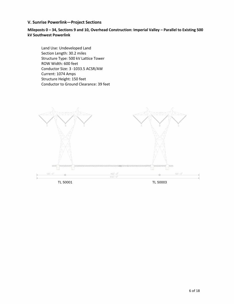
6 of 18
V. Sunrise Powerlink—Project Sections
Mileposts 0 – 34, Sections 9 and 10, Overhead Construction: Imperial Valley – Parallel to Existing 500 kV Southwest Powerlink
Land Use: Undeveloped Land Section Length: 30.2 miles Structure Type: 500 kV Lattice Tower ROW Width: 600 feet Conductor Size: 3 -1033.5 ACSR/AW Current: 1074 Amps Structure Height: 150 feet Conductor to Ground Clearance: 39 feet
TL 50003 TL 50001
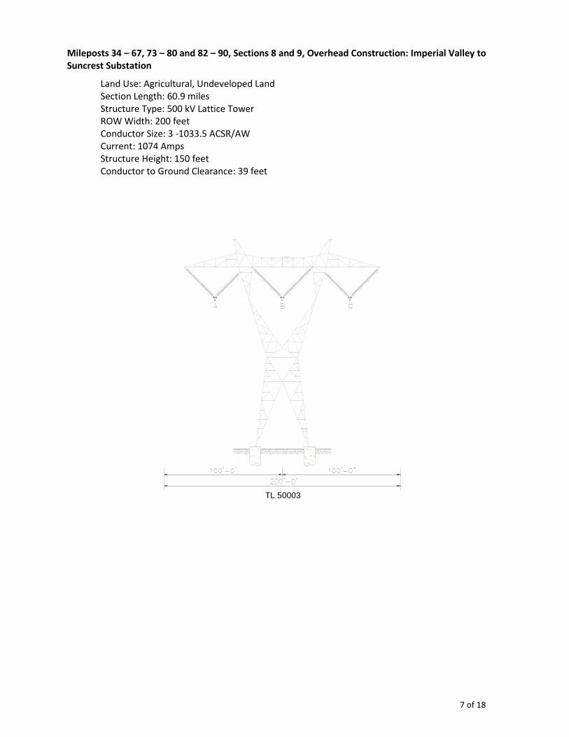
7 of 18
Mileposts 34 – 67, 73 – 80 and 82 – 90, Sections 8 and 9, Overhead Construction: Imperial Valley to Suncrest Substation
Land Use: Agricultural, Undeveloped Land Section Length: 60.9 miles Structure Type: 500 kV Lattice Tower ROW Width: 200 feet Conductor Size: 3 -1033.5 ACSR/AW Current: 1074 Amps Structure Height: 150 feet Conductor to Ground Clearance: 39 feet
TL 50003
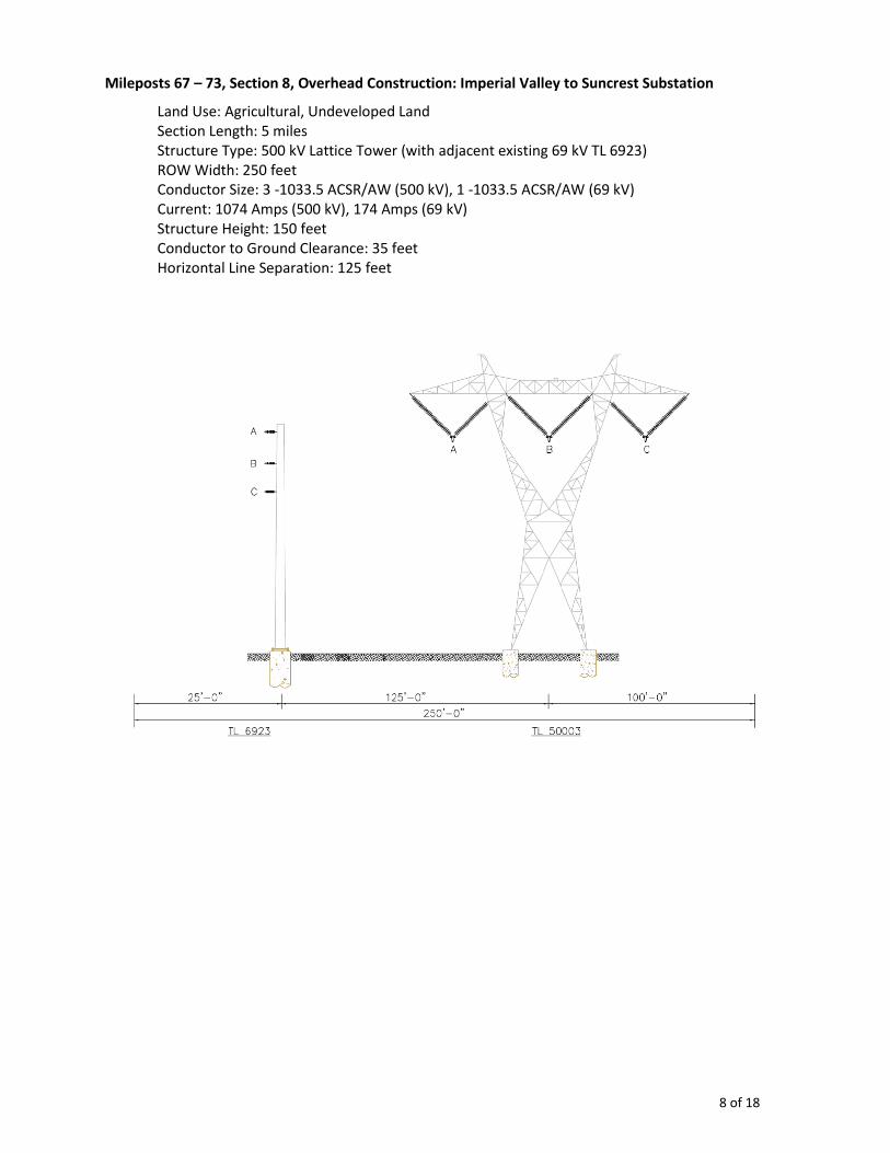
8 of 18
Mileposts 67 – 73, Section 8, Overhead Construction: Imperial Valley to Suncrest Substation
Land Use: Agricultural, Undeveloped Land Section Length: 5 miles Structure Type: 500 kV Lattice Tower (with adjacent existing 69 kV TL 6923) ROW Width: 250 feet Conductor Size: 3 -1033.5 ACSR/AW (500 kV), 1 -1033.5 ACSR/AW (69 kV) Current: 1074 Amps (500 kV), 174 Amps (69 kV) Structure Height: 150 feet Conductor to Ground Clearance: 35 feet Horizontal Line Separation: 125 feet
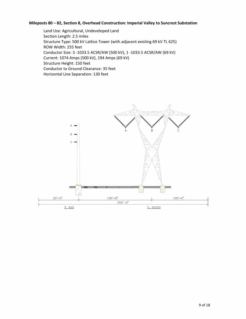
9 of 18
Mileposts 80 – 82, Section 8, Overhead Construction: Imperial Valley to Suncrest Substation
Land Use: Agricultural, Undeveloped Land Section Length: 2.5 miles Structure Type: 500 kV Lattice Tower (with adjacent existing 69 kV TL 625) ROW Width: 255 feet Conductor Size: 3 -1033.5 ACSR/AW (500 kV), 1 -1033.5 ACSR/AW (69 kV) Current: 1074 Amps (500 kV), 194 Amps (69 kV) Structure Height: 150 feet Conductor to Ground Clearance: 35 feet Horizontal Line Separation: 130 feet
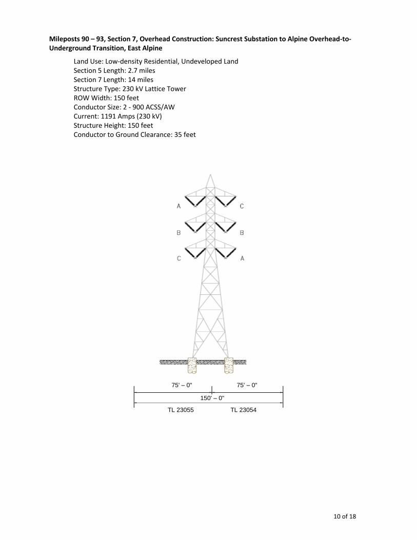
10 of 18
Mileposts 90 – 93, Section 7, Overhead Construction: Suncrest Substation to Alpine Overhead-to-Underground Transition, East Alpine
Land Use: Low-density Residential, Undeveloped Land Section 5 Length: 2.7 miles Section 7 Length: 14 miles Structure Type: 230 kV Lattice Tower ROW Width: 150 feet Conductor Size: 2 - 900 ACSS/AW Current: 1191 Amps (230 kV) Structure Height: 150 feet Conductor to Ground Clearance: 35 feet
TL 23055 TL 23054
75' – 0" 75' – 0"
150' – 0"
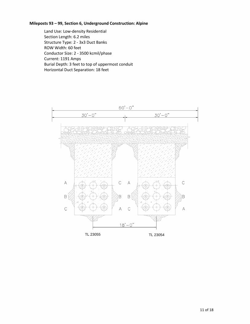
11 of 18
Mileposts 93 – 99, Section 6, Underground Construction: Alpine
Land Use: Low-density Residential Section Length: 6.2 miles Structure Type: 2 - 3x3 Duct Banks ROW Width: 60 feet Conductor Size: 2 - 3500 kcmil/phase Current: 1191 Amps Burial Depth: 3 feet to top of uppermost conduit Horizontal Duct Separation: 18 feet
TL 23055 TL 23054
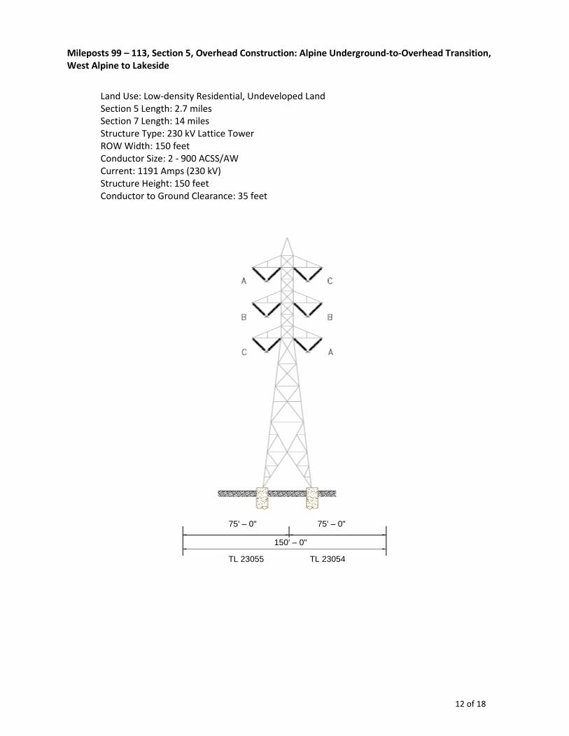
12 of 18
Mileposts 99 – 113, Section 5, Overhead Construction: Alpine Underground-to-Overhead Transition, West Alpine to Lakeside
Land Use: Low-density Residential, Undeveloped Land Section 5 Length: 2.7 miles Section 7 Length: 14 miles Structure Type: 230 kV Lattice Tower ROW Width: 150 feet Conductor Size: 2 - 900 ACSS/AW Current: 1191 Amps (230 kV) Structure Height: 150 feet Conductor to Ground Clearance: 35 feet
TL 23055 TL 23054
75' – 0" 75' – 0"
150' – 0"
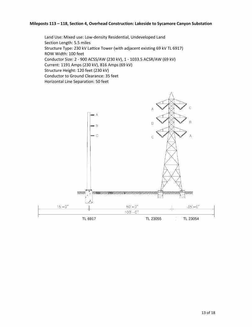
13 of 18
Mileposts 113 – 118, Section 4, Overhead Construction: Lakeside to Sycamore Canyon Substation
Land Use: Mixed use: Low-density Residential, Undeveloped Land Section Length: 5.5 miles Structure Type: 230 kV Lattice Tower (with adjacent existing 69 kV TL 6917) ROW Width: 100 feet Conductor Size: 2 - 900 ACSS/AW (230 kV), 1 - 1033.5 ACSR/AW (69 kV) Current: 1191 Amps (230 kV), 816 Amps (69 kV) Structure Height: 120 feet (230 kV) Conductor to Ground Clearance: 35 feet Horizontal Line Separation: 50 feet
TL 23055 TL 23054 TL 6917

14 of 18
VI. Magnetic Field Reduction Measures Considered for the Project
Field Reduction Measures Considered for Suncrest Substation
SDG&E has designed the Suncrest Substation to include the following magnetic field reduction measures, to the extent practical. These measures are considered “no-cost” since they are part of the initial design of the facilities:
Keep substation electrical equipment as compact as possible.
Orient buses and cables so that parallel runs are as far from the property lines as practical.
Keep high current devices, transformers, capacitors, and reactors, away from the substation fence.
Utilize setbacks and landscaping to restrict public access to the area around the substation.
Locate the substation away from normally occupied areas.
Field Reduction Measures Considered for Project Transmission Lines
Based on its EMF Guidelines, SDG&E considered the following "no-cost" and "low-cost" measures for reducing magnetic fields at the edge of the right-of-way for the Project transmission line sections.
“No-Cost” Field Reduction Measures Considered
(A) Locate power lines closer to center of the utility corridor (right-of-way).
(B) Phase circuits to reduce magnetic fields.
“Low-Cost” Field Reduction Measures Considered
The assessment of “low-cost” magnetic field reduction measures is a function of the total project cost. “Low-cost” has been defined by the CPUC as “in the range of 4% of the total cost of a budgeted project.”4 Additionally, for "low-cost" measures, the CPUC has directed that “EMF reductions will be 15% or greater at the utility ROW [right-of-way].”5
“Low-cost” field-reduction measures considered for some or all Project sections include:
(C) Increase conductor height.
(D) Increase trench depth.
(E) Increase right-of-way width.
Table 1 below identifies those "no-cost" and "low-cost" measures which were feasible and appropriate to consider for the different Project transmission line sections, and whether the measures were adopted.
Table 2 below lists the reasons for rejection of those measures which were considered but not adopted.
4 CPUC Decision 93-11-013, § 3.3.2.
5 CPUC Decision 06-01-042, p. 10.
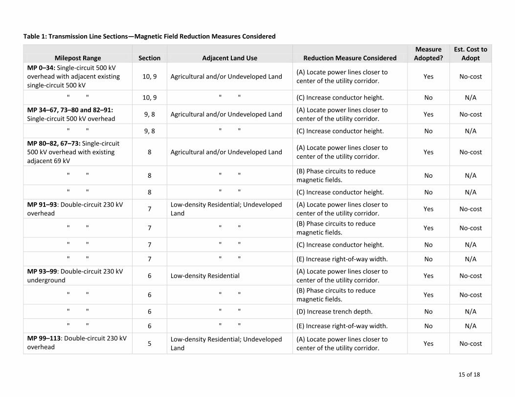
15 of 18
Table 1: Transmission Line Sections—Magnetic Field Reduction Measures Considered
Milepost Range Section Adjacent Land Use Reduction Measure Considered Measure Adopted?
Est. Cost to Adopt
MP 0–34: Single-circuit 500 kV overhead with adjacent existing single-circuit 500 kV
10, 9 Agricultural and/or Undeveloped Land (A) Locate power lines closer to center of the utility corridor.
Yes No-cost
" " 10, 9 " " (C) Increase conductor height. No N/A
MP 34–67, 73–80 and 82–91: Single-circuit 500 kV overhead
9, 8 Agricultural and/or Undeveloped Land (A) Locate power lines closer to center of the utility corridor.
Yes No-cost
" " 9, 8 " " (C) Increase conductor height. No N/A
MP 80–82, 67–73: Single-circuit 500 kV overhead with existing adjacent 69 kV
8 Agricultural and/or Undeveloped Land (A) Locate power lines closer to center of the utility corridor.
Yes No-cost
" " 8 " " (B) Phase circuits to reduce magnetic fields.
No N/A
" " 8 " " (C) Increase conductor height. No N/A
MP 91–93: Double-circuit 230 kV overhead
7 Low-density Residential; Undeveloped Land
(A) Locate power lines closer to center of the utility corridor.
Yes No-cost
" " 7 " " (B) Phase circuits to reduce magnetic fields.
Yes No-cost
" " 7 " " (C) Increase conductor height. No N/A
" " 7 " " (E) Increase right-of-way width. No N/A
MP 93–99: Double-circuit 230 kV underground
6 Low-density Residential (A) Locate power lines closer to center of the utility corridor.
Yes No-cost
" " 6 " " (B) Phase circuits to reduce magnetic fields.
Yes No-cost
" " 6 " " (D) Increase trench depth. No N/A
" " 6 " " (E) Increase right-of-way width. No N/A
MP 99–113: Double-circuit 230 kV overhead 5
Low-density Residential; Undeveloped Land
(A) Locate power lines closer to center of the utility corridor.
Yes No-cost
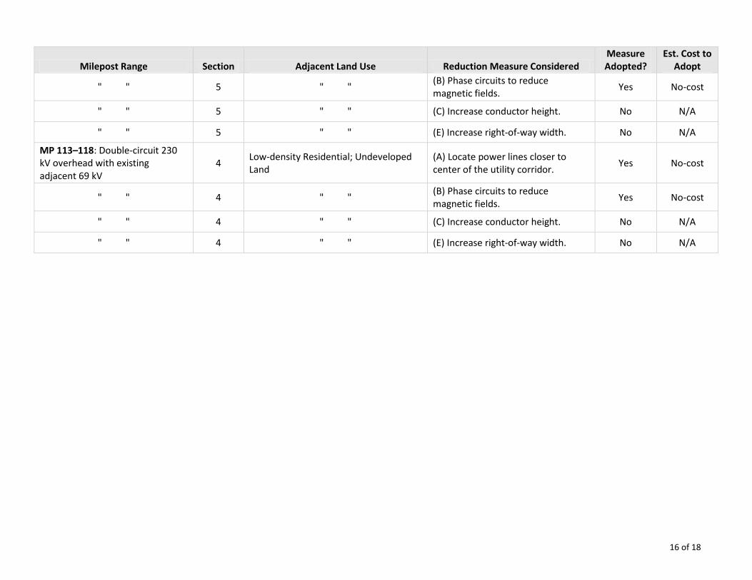
16 of 18
Milepost Range Section Adjacent Land Use Reduction Measure Considered Measure Adopted?
Est. Cost to Adopt
" " 5 " " (B) Phase circuits to reduce magnetic fields.
Yes No-cost
" " 5 " " (C) Increase conductor height. No N/A
" " 5 " " (E) Increase right-of-way width. No N/A
MP 113–118: Double-circuit 230 kV overhead with existing adjacent 69 kV
4 Low-density Residential; Undeveloped Land
(A) Locate power lines closer to center of the utility corridor.
Yes No-cost
" " 4 " " (B) Phase circuits to reduce magnetic fields.
Yes No-cost
" " 4 " " (C) Increase conductor height. No N/A
" " 4 " " (E) Increase right-of-way width. No N/A
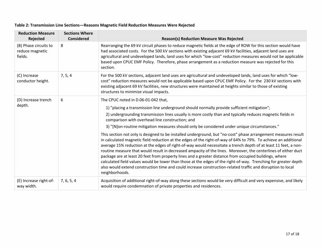
17 of 18
Table 2: Transmission Line Sections—Reasons Magnetic Field Reduction Measures Were Rejected
Reduction Measure Rejected
Sections Where Considered Reason(s) Reduction Measure Was Rejected
(B) Phase circuits to reduce magnetic fields.
8 Rearranging the 69 kV circuit phases to reduce magnetic fields at the edge of ROW for this section would have had associated costs. For the 500 kV sections with existing adjacent 69 kV facilities, adjacent land uses are agricultural and undeveloped lands, land uses for which "low-cost" reduction measures would not be applicable based upon CPUC EMF Policy. Therefore, phase arrangement as a reduction measure was rejected for this section.
(C) Increase conductor height.
7, 5, 4 For the 500 kV sections, adjacent land uses are agricultural and undeveloped lands, land uses for which "low-cost" reduction measures would not be applicable based upon CPUC EMF Policy. For the 230 kV sections with existing adjacent 69 kV facilities, new structures were maintained at heights similar to those of existing structures to minimize visual impacts.
(D) Increase trench depth.
6 The CPUC noted in D.06-01-042 that,
1) "placing a transmission line underground should normally provide sufficient mitigation";
2) undergrounding transmission lines usually is more costly than and typically reduces magnetic fields in comparison with overhead line construction; and
3) "[N]on-routine mitigation measures should only be considered under unique circumstances."
This section not only is designed to be installed underground, but "no-cost" phase arrangement measures result in calculated magnetic field reduction at the edges of the right-of-way of 64% to 79%. To achieve an additional average 15% reduction at the edges of right-of-way would necessitate a trench depth of at least 11 feet, a non-routine measure that would result in decreased ampacity of the lines. Moreover, the centerlines of either duct package are at least 20 feet from property lines and a greater distance from occupied buildings, where calculated field values would be lower than those at the edges of the right-of-way. Trenching for greater depth also would extend construction time and could increase construction-related traffic and disruption to local neighborhoods.
(E) Increase right-of-way width.
7, 6, 5, 4 Acquisition of additional right-of-way along these sections would be very difficult and very expensive, and likely would require condemnation of private properties and residences.
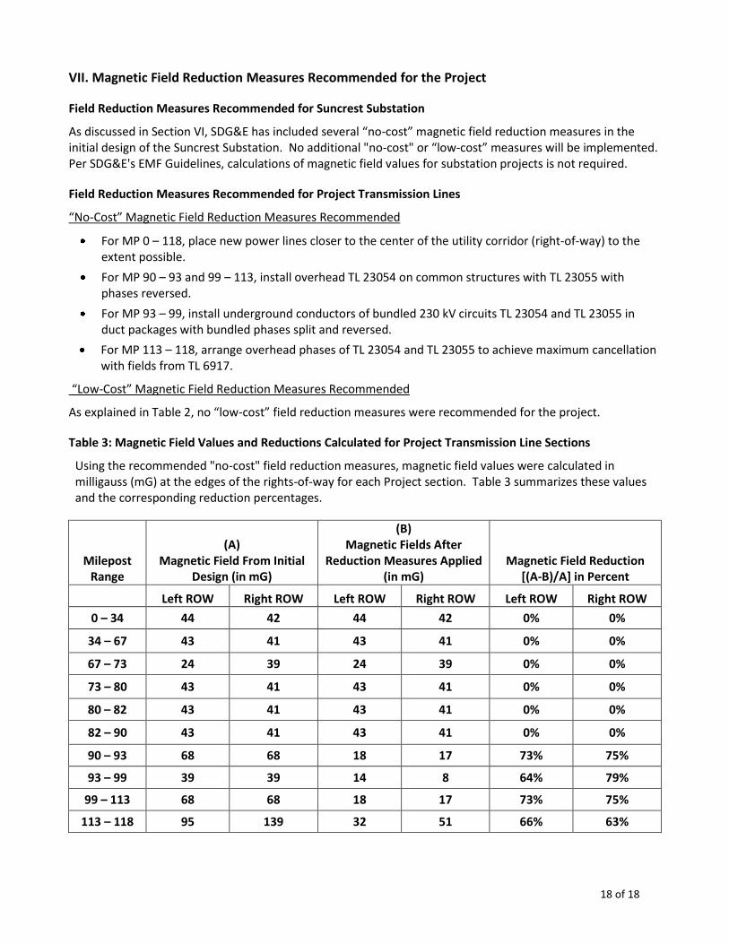
18 of 18
VII. Magnetic Field Reduction Measures Recommended for the Project
Field Reduction Measures Recommended for Suncrest Substation
As discussed in Section VI, SDG&E has included several “no-cost” magnetic field reduction measures in the initial design of the Suncrest Substation. No additional "no-cost" or “low-cost” measures will be implemented. Per SDG&E's EMF Guidelines, calculations of magnetic field values for substation projects is not required.
Field Reduction Measures Recommended for Project Transmission Lines
“No-Cost” Magnetic Field Reduction Measures Recommended
For MP 0 – 118, place new power lines closer to the center of the utility corridor (right-of-way) to the extent possible.
For MP 90 – 93 and 99 – 113, install overhead TL 23054 on common structures with TL 23055 with phases reversed.
For MP 93 – 99, install underground conductors of bundled 230 kV circuits TL 23054 and TL 23055 in duct packages with bundled phases split and reversed.
For MP 113 – 118, arrange overhead phases of TL 23054 and TL 23055 to achieve maximum cancellation with fields from TL 6917.
“Low-Cost” Magnetic Field Reduction Measures Recommended
As explained in Table 2, no “low-cost” field reduction measures were recommended for the project.
Table 3: Magnetic Field Values and Reductions Calculated for Project Transmission Line Sections
Using the recommended "no-cost" field reduction measures, magnetic field values were calculated in milligauss (mG) at the edges of the rights-of-way for each Project section. Table 3 summarizes these values and the corresponding reduction percentages.
Milepost Range
(A) Magnetic Field From Initial
Design (in mG)
(B) Magnetic Fields After
Reduction Measures Applied (in mG)
Magnetic Field Reduction [(A-B)/A] in Percent
Left ROW Right ROW Left ROW Right ROW Left ROW Right ROW
0 – 34 44 42 44 42 0% 0%
34 – 67 43 41 43 41 0% 0%
67 – 73 24 39 24 39 0% 0%
73 – 80 43 41 43 41 0% 0%
80 – 82 43 41 43 41 0% 0%
82 – 90 43 41 43 41 0% 0%
90 – 93 68 68 18 17 73% 75%
93 – 99 39 39 14 8 64% 79%
99 – 113 68 68 18 17 73% 75%
113 – 118 95 139 32 51 66% 63%
APPENDIX E
Faulkner-Milligan Study
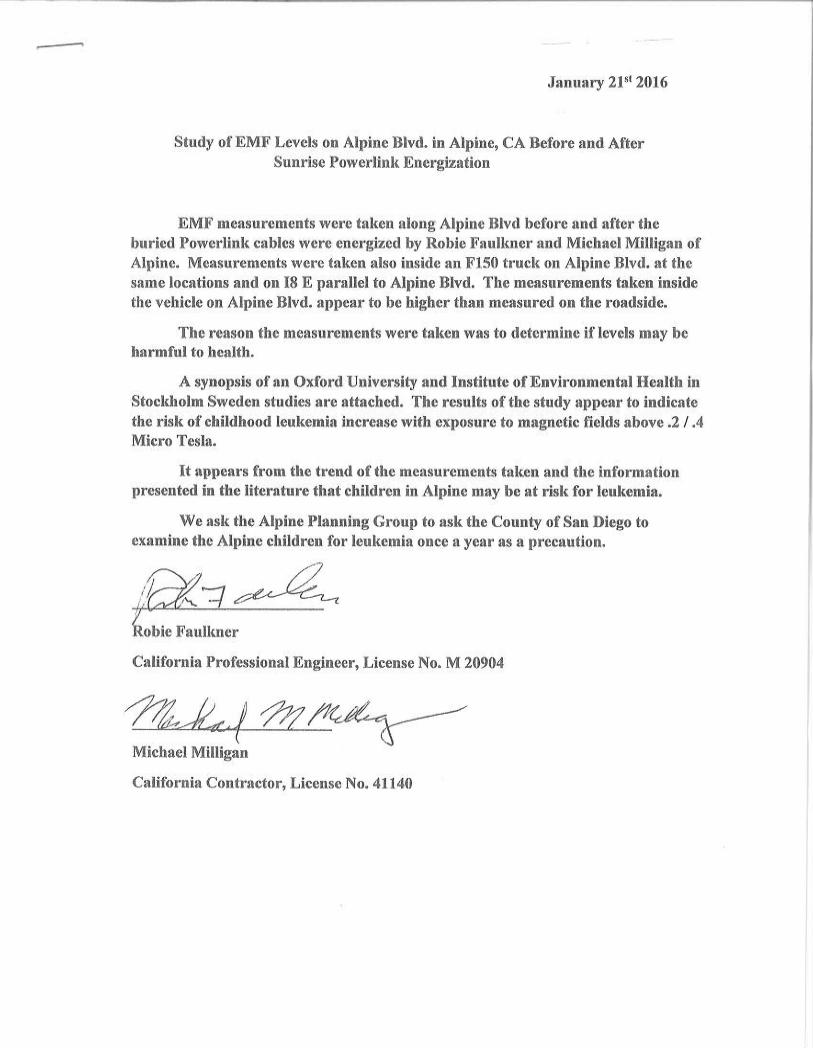
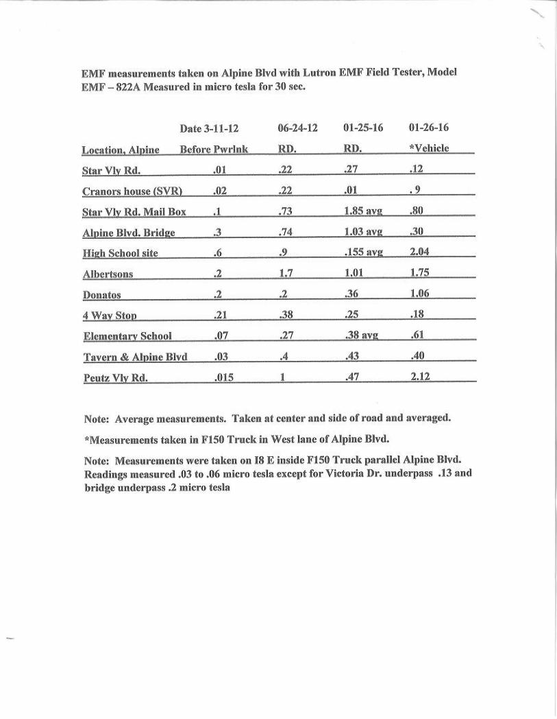
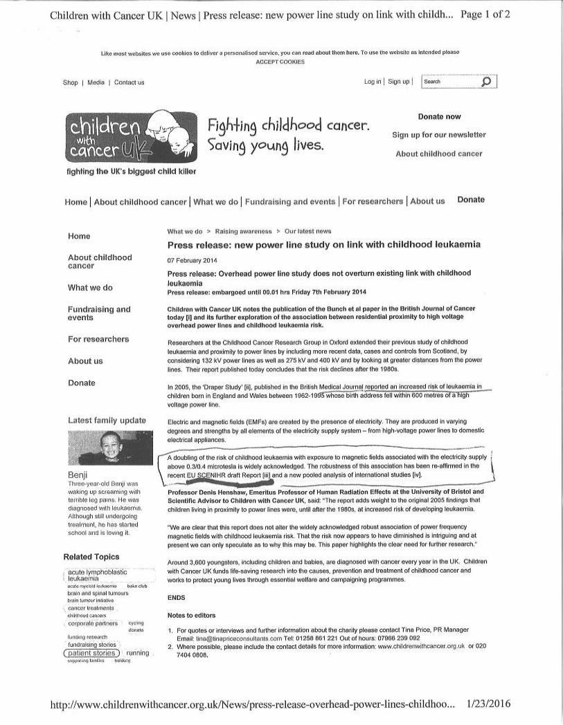
APPENDIX F
Alpine Unified School District Study
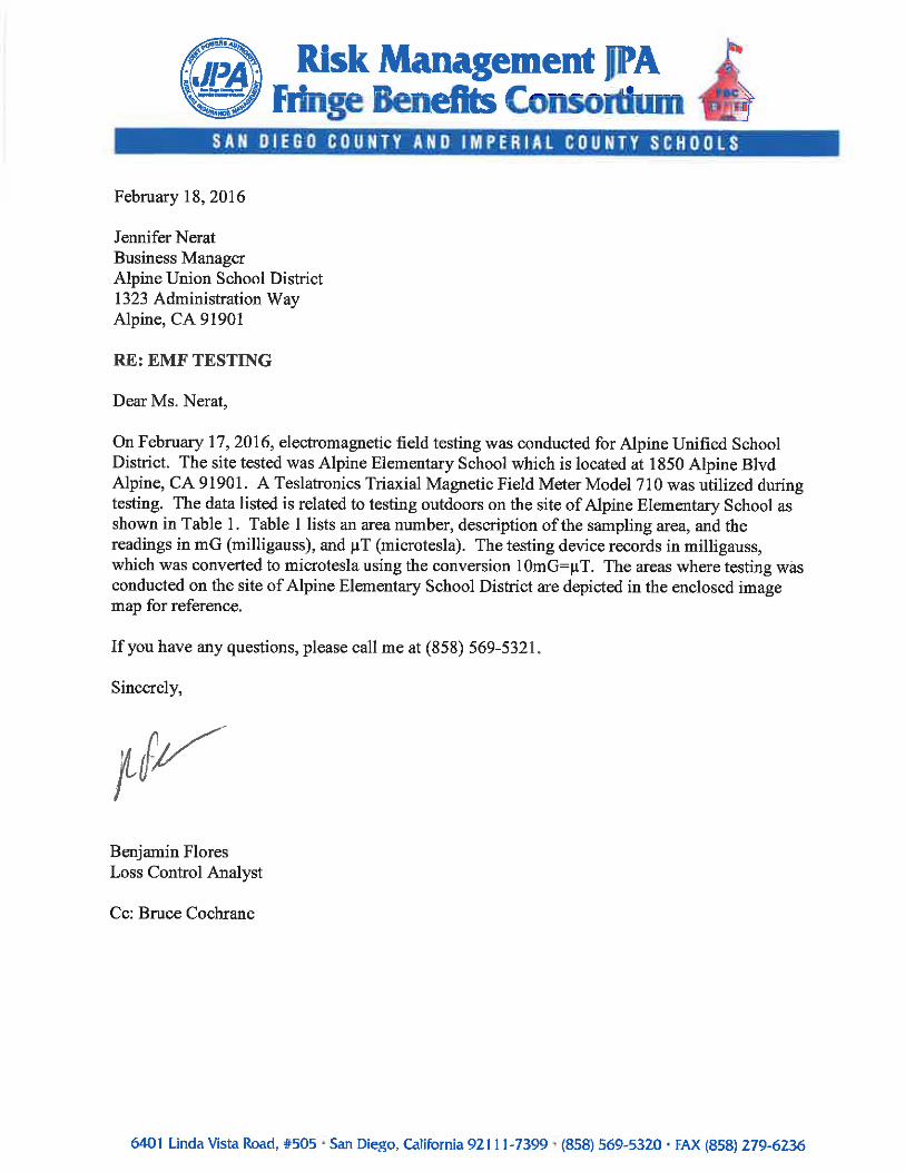
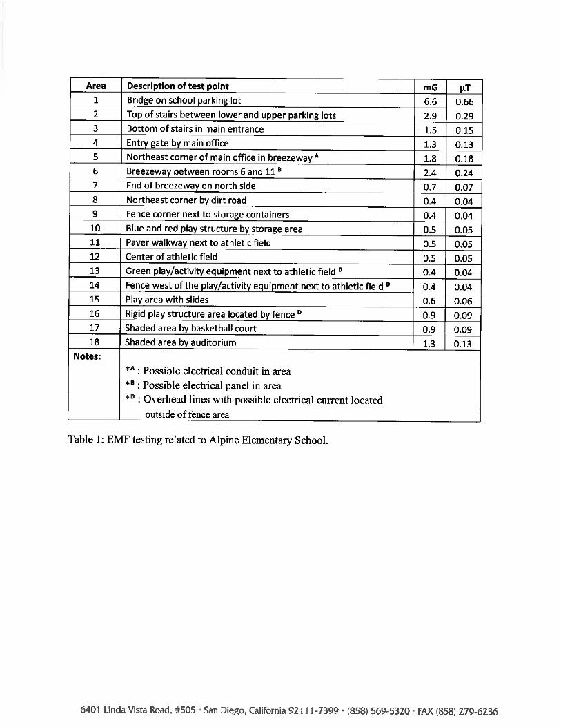
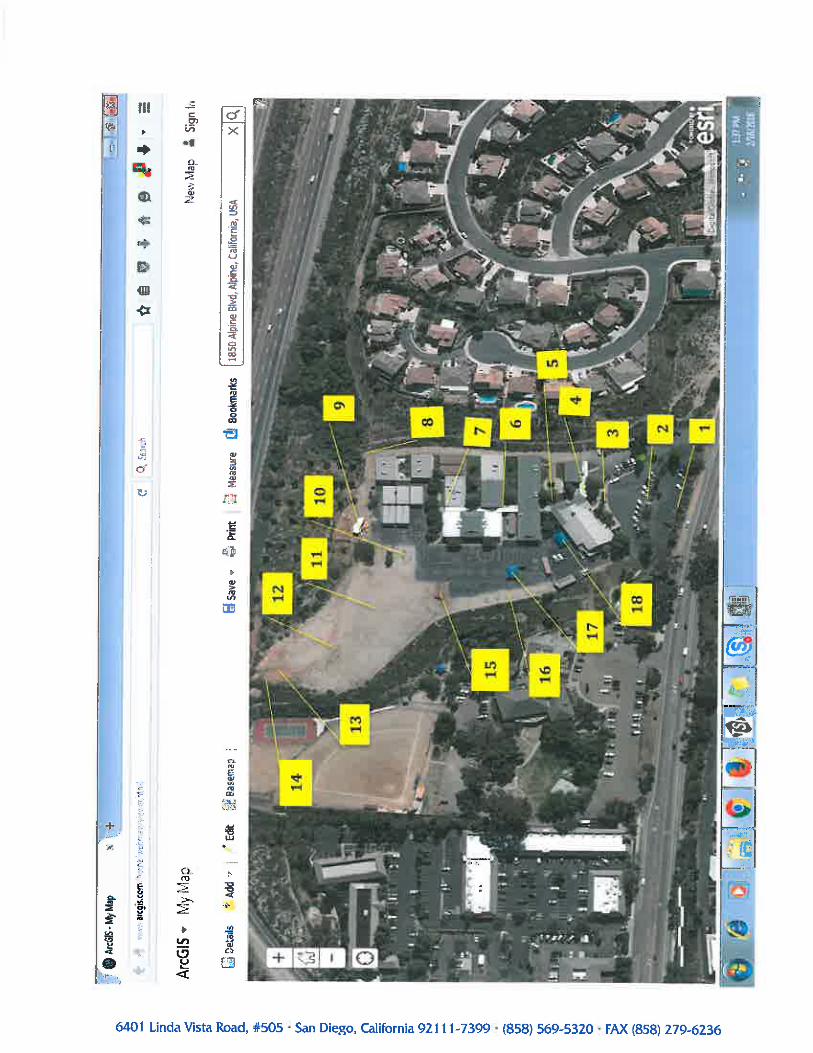
APPENDIX G
San Diego County Office of Education Study

March 2016| San Diego County Office of Education
EMF Survey and Exposure Assessment for Alpine Elementary School, Alpine, California
Prepared for:
San Diego County Office of Education Contact: Contact Mr. Rick Rinear
6401 Linda Vista Road, Room 505 San Diego, CA 92111
858.292.3871
Project Number: SDCO-01.0
Prepared by:
PlaceWorks Contact: Karl Rodenbaugh, D. Env., Senior Scientist
9841 Airport Boulevard, Suite 1010 Los Angeles, California 90045
310.670.9221 [email protected] www.placeworks.com
A L P I N E E L E M E N T A R Y S C H O O L - E M F S U R V E Y A L P I N E U N I O N S C H O O L D I S T R I C T
Table of Contents
Section Page
March 2016 PlaceWorks • Page i
1. Introduction and Executive Summary ......................................................................................................... 1 2. Project Site Description ................................................................................................................................ 3 3. Regulatory Setting ......................................................................................................................................... 7
3.1 POTENTIAL EFFECTS OF EMF EXPOSRE FROM TRANSMISSION LINES .............. 7 3.2 CDE TRANSMISISON LINE SETBACK REQUIREMENTS ................................................ 8
4. Methodology ................................................................................................................................................ 10 5. Exposure Levels .......................................................................................................................................... 11
5.1 SUMMARY OF RESULTS............................................................................................................... 11 5.1.1 Spatial Average of Outdoor EMF Measurements .......................................................... 11 5.1.2 Spatial Average of Indoor EMF Measurements ............................................................. 11 5.1.3 Overall Spatial Average of EMF Measurements ............................................................ 11 5.1.4 Annual Average EMF Exposure ....................................................................................... 12 5.1.5 Comparison to EMF at Other Schools and Households .............................................. 12
6. Summary and Conclusion........................................................................................................................... 13 7. References ................................................................................................................................................... 15
A L P I N E E L E M E N T A R Y S C H O O L - E M F S U R V E Y A L P I N E U N I O N S C H O O L D I S T R I C T
Table of Contents
March 2016 PlaceWorks • Page ii
List of Figures
Figure Page
Figure 1 Regional Location ................................................................................................................................. 4 Figure 2 Site Aerial Photograph ......................................................................................................................... 5 Figure 3 School Site Plan ..................................................................................................................................... 6
List of Appendices
Appendix A. EMF Monitoring Results Table A-1. Outdoor Measurements Table A-2. Indoor Measurements
Appendix B. Certificate of Calibration and Accuracy Report for EMDEX Snap Magnetic Field Survey Meter
March 2016 PlaceWorks • Page 1
1. Introduction and Executive SummaryThe San Diego County Office of Education (SDCOE) requested a survey and assessment of electro-magnetic fields (EMF) at Alpine Elementary School (ES), located at 1850 Alpine Blvd. Alpine, CA. A San Diego Gas & Electric (SDGE) 230 kV transmission line is buried beneath the middle of Alpine Blvd. The school boundary closest to Alpine Blvd is approximately 50 feet from the underground 230 kV transmission line. There is significant concern in the community regarding potential health effects, especially for children, due to EMF exposure at the school from the SDGE transmission line.
The scope of work for this EMF survey and exposure assessment encompassed measuring magnetic field strength, expressed as milligauss (mG), at indoor and outdoor locations across the school site on February 23, 2016. A total of 94 measurements of magnetic field strength were collected. Readings were recorded in milligauss (mG) using an Emdex “Snap” 3-Axis magnetic field strength meter. The mG readings were later converted to microtesla (uT), for ease of comparison to readings previously reported at the school and to reference levels reported in the local media.
Figure 2 and Figure 3 in this report show outdoor and indoor monitoring locations, respectively. Tables A-1 and A-2 (in Appendix A) show magnetic field strength readings (expressed as mG and uT) collected at all outdoor and indoor school locations, respectively.
Evidence in support of a causal relationship between EMF and adverse health effects is founded largely, if not entirely, on limited epidemiology studies that reported statistical associations between EMF exposure and diseases. After nearly 40 years of research including hundreds of studies, none of the scientific organizations that conducted weight-of-evidence reviews concluded that exposure to EMF is a demonstrated cause of any long-term adverse health effect. As a result, there are no state or nationally recognized regulatory standards for EMF exposure for the general public. Therefore, it is not possible to simply state that a particular value is safe or unsafe. However, we note that the fields detected during the survey within and around the structures at Alpine ES, while not representative of a pristine EMF environment, were within a normal range of exposures one could expect in a society with electric power.
A comprehensive survey of California public schools indicated that 80% of the surveyed school areas and 83% of the classrooms had average magnetic fields of less than 1 mG (CDHS, 2001). The EMF measurements across the Alpine Elementary School site (excluding non-student areas and the parking lot) averaged less than 0.9 mG overall, and 0.75 mG for classrooms, both of which are slightly less than the comprehensive surveyed values at public schools.
The World Health Organization (WHO) has not established health-based thresholds for EMF exposure. WHO does, however, list EMFs as a Class 2B "possible carcinogen," based on a determination by the International Agency for Research on Cancer (IARC). This classification was based on pooled analyses of epidemiological studies demonstrating a consistent pattern of a two-fold increase in childhood leukemia
A L P I N E E L E M E N T A R Y S C H O O L - E M F S U R V E Y A L P I N E U N I O N S C H O O L D I S T R I C T
1. Introduction and Executive Summary
March 2016 PlaceWorks • Page 2
associated with average exposure to residential power-frequency magnetic field above 0.3 to 0.4 µT (3 to 4 mG).
The local media and community members from Alpine apparently have focused on magnetic fields above 0.3 to 0.4 µT (3 to 4 mG) as thresholds of concern. This focus is problematic because these values are not regulatory thresholds. Nevertheless, given that focus, it is useful to point out that all of the average values determined during the EMF survey at Alpine ES are less than the levels tied to the basis for IARC’s determination (i.e., 0.3 to 0.4 µT [3 to 4 mG])
We also evaluate the distance between the school and the transmission line (and by inference the EMF exposure of concern at the school) in the context of what the California Department of Education (CDE) would require if a new school were to be proposed at the site of the Alpine ES and the 230 kV line was already in place. California Code of Regulations (CCR), Title 5, Section 14010(c) requires new schools be setback a prescribed distance from electric power transmission lines; the distance depends on the voltage of the line. Based on CDE’s policy of “prudent avoidance” regarding EMF exposure, CDE guidance (Power Line Setback Exemption Guidance Policy; CDE, 2006) indicates the setback for a 230 kV underground line would be 37.5 feet. The closest school boundary to the SDG&E transmission line is about 50 feet. Therefore, if this were a proposed new school site, one could reasonably conclude it would not be precluded due to the presence of the 230kV underground power line.
In conclusion, this EMF survey and exposure assessment demonstrates that the transmission line does not pose a significant safety or health risk to the school site, based on 1) comparison to CDE setback requirements for underground lines for new schools; 2) published average exposure values at public schools in California; and 3) comparison of average survey results that are less than the levels tied to the basis for IARC’s determination that EMF is a Class 2 B carcinogen (i.e., 0.3 to 0.4 µT [3 to 4 mG]).
March 2016 PlaceWorks • Page 3
2. Project Site DescriptionThe Alpine ES Site is bounded by Alpine Boulevard to the south, residential land uses to the east, a community center and undeveloped land to the west, and Interstate Highway 8 to the north. The regional location of the Site is depicted in Figure 1. An aerial photograph of the Site is depicted in Figure 2. A school Site plan is presented in Figure 3.
A 230 kV electric power transmission line owned and operated by SDG&E is buried beneath the middle of Alpine Boulevard. The southern edge of the school “drop-off ” parking lot is 50 feet north of the transmission line. The nearest school building to the transmission line is the main office, 155 feet to the north east. The next closest school building is the library, 240 feet to the north east from the line.
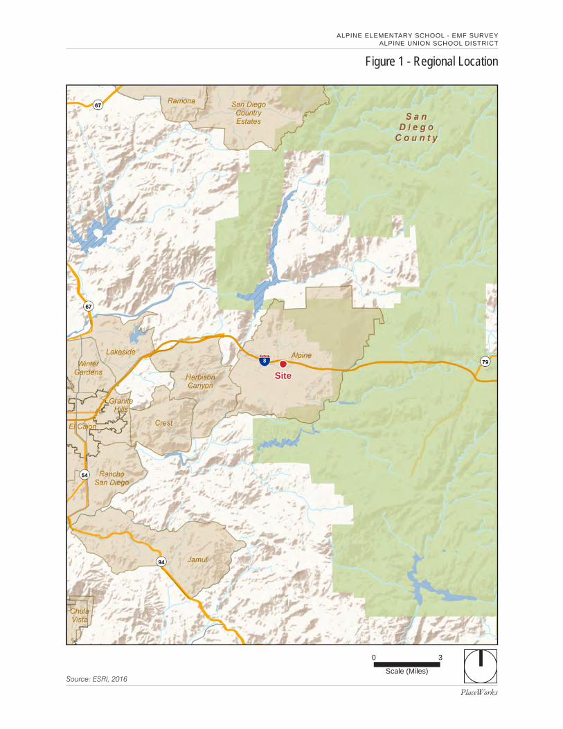
PlaceWorks
Figure 1 - Regional Location
Source: ESRI, 2016
0
Scale (Miles)
3
Site
ALPINE ELEMENTARY SCHOOL - EMF SURVEYALPINE UNION SCHOOL DISTRICT
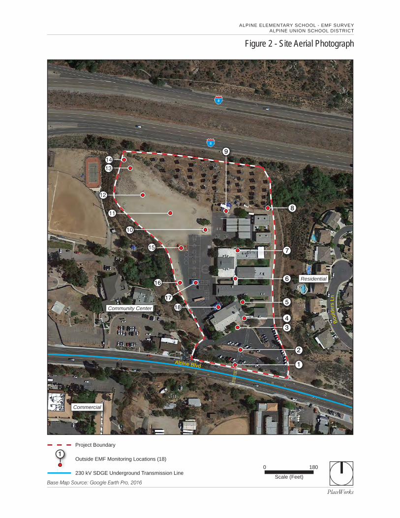
PlaceWorks
Figure 2 - Site Aerial Photograph
ALPINE ELEMENTARY SCHOOL - EMF SURVEYALPINE UNION SCHOOL DISTRICT
Base Map Source: Google Earth Pro, 2016
0
Scale (Feet)
180
8
Alpine Blvd
8
Commercial
Residential
Project Boundary
Community Center
Outside EMF Monitoring Locations (18)
Bou
lder
s Ln
1
230 kV SDGE Underground Transmission Line
2
1
7
6
43
5
8
16
17
18
9
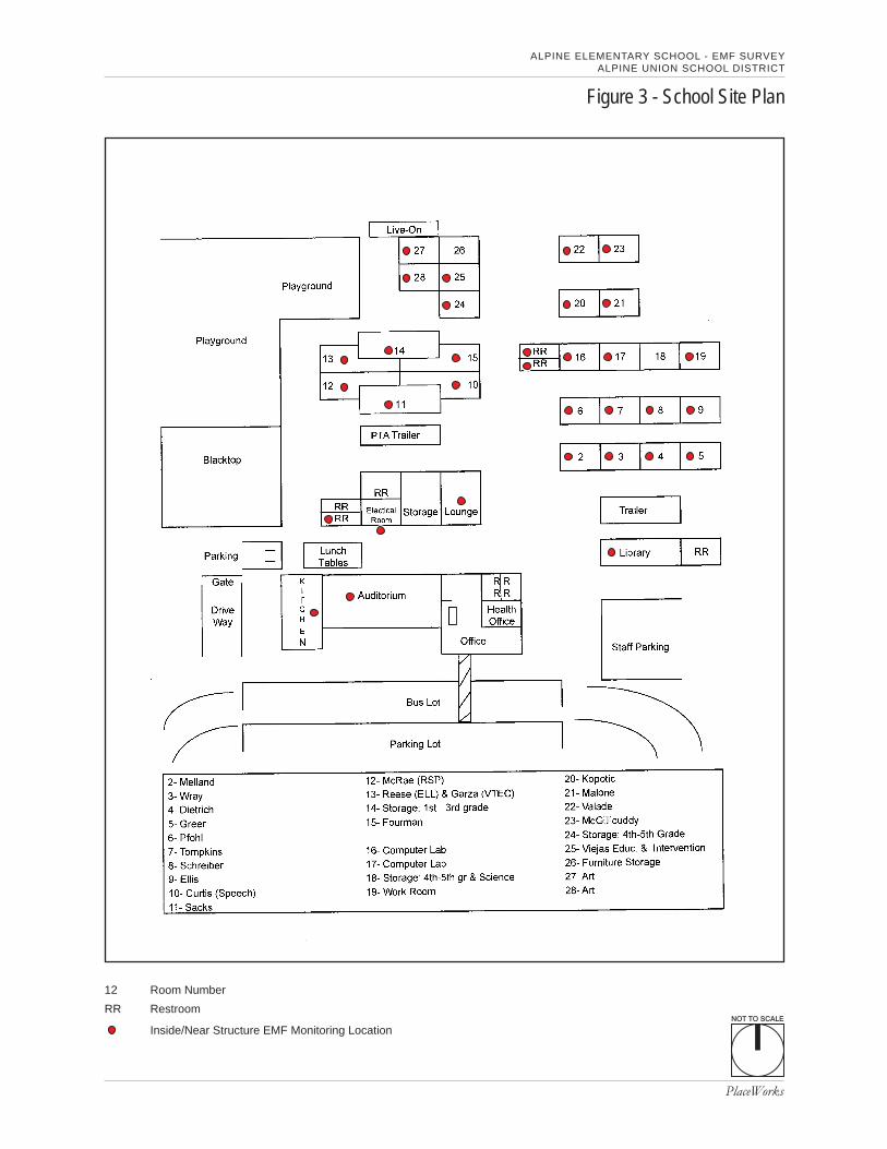
NOT TO SCALE
PlaceWorks
Figure 3 - School Site Plan
ALPINE ELEMENTARY SCHOOL - EMF SURVEYALPINE UNION SCHOOL DISTRICT
Inside/Near Structure EMF Monitoring Location
Room Number
Restroom
12
RR
March 2016 PlaceWorks • Page 7
3. Regulatory Setting3.1 POTENTIAL EFFECTS OF EMF EXPOSRE FROM TRANSMISSION
LINES There are no state or nationally recognized regulatory standards for EMF exposure of the general public. In addition, the California Department of Education (CDE) has not established thresholds for exposure to EMF emissions from transmission lines.
The World Health Organization (WHO) also has not established health-based thresholds for EMF exposure. WHO does, however, list EMFs as a Class 2B "possible carcinogen," based on a determination by the International Agency for Research on Cancer (IARC). The 2B classification is used to denote an agent for which there is limited evidence of carcinogenicity in humans and less than sufficient evidence for carcinogenicity in experimental animals. This classification was based on pooled analyses of epidemiological studies demonstrating a consistent pattern of a two-fold increase in childhood leukemia associated with average exposure to residential power-frequency magnetic field above 0.3 to 0.4 µT (3 to 4 mG)1. Other Class 2B listed possible carcinogens include coffee, welding fumes and carpentry2.
After nearly 40 years of research including hundreds of studies, none of the scientific organizations that conducted weight-of-evidence reviews concluded that exposure to EMF is a demonstrated cause of any long-term adverse health effect. The evidence in support of a causal relationship is founded largely, if not entirely, on limited epidemiology studies that reported statistical associations between EMF exposure and diseases. Scientists have placed less weight on these associations because they are often inconsistent across studies, have errors in the way the study was designed or conducted, and use methods to measure EMF exposure that are unreliable. Overall, laboratory studies have not reported an increase in cancer among animals exposure to high levels of electric or magnetic fields, and no mechanism has been discovered in cellular studies that explains how electric or magnetic fields might initiate disease (Kabat, 2008).
In some epidemiology studies, a weak but statistically significant association has been reported between childhood leukemia and estimates of long-term exposure to EMF levels. The reported associations are weak and there is no evidence of a consistent exposure-response relationship. The strongest epidemiological studies of childhood leukemia and magnetic fields, which were conducted in the US, Canada, and the United Kingdom, do not indicate a statistical association.
The absence of clear adverse effects after continued testing increases the certainty that there is no adverse effect from long-term exposure. However, no scientific review panel can ever completely rule out the
1 World Health Organization (WHO), 2007. WHO web page Fact Sheet on “Electromagnetic fields and public health,” http://www.who.int/peh-emf/publications/facts/fs322/en/ , accessed February 26, 2016. 2 IARC, 2016. IARC web page, List of Classifications of Carcinogens, http://monographs.iarc.fr/ENG/Classification/latest_classif.php, accessed February 26, 2016.
A L P I N E E L E M E N T A R Y S C H O O L - E M F S U R V E Y A L P I N E U N I O N S C H O O L D I S T R I C T
3. Regulatory Setting
March 2016 PlaceWorks • Page 8
possibility that EMF in the community and workplace might have some adverse effect, due to the inherent limitations of scientific investigations. Therefore, the CDE is employing the “precautionary principle” to ensure that students and staff at school sites do not suffer adverse health effects from exposure to EMF associated with high-voltage transmission lines by establishing setback zones to minimize exposure.
3.2 CDE TRANSMISISON LINE SETBACK REQUIREMENTS The existing California Code of Regulations (CCR), Title 5, Section 14010(c) specifies a distance setback requirement of 150 feet from overhead 230 kV power lines for proposed school sites. The regulatory citation reads as follows:
The property line of the site even if it is a joint use agreement as described in subsection (o) of this section shall be at least the following distance from the edge of respective power line easements:
100 feet for 50-133 kV line.
150 feet for 220-230 kV line.
350 feet for 500-550 kV line.
CDE has a policy that allows schools within the vicinity of overhead lines to apply for variances to this regulation as described in the Power Line Setback Exemption Guidance Policy (CDE, 2006). This guidance has been developed in consultation with international experts on the health effects of EMF, state agencies such as the Department of Public Health (DPH), the Division of the State Architect (DSA), and the California Public Utilities Commission (PUC), electric utilities, school districts, consultants, and private citizens with an interest in the topic. CDE's past endorsement of prudent avoidance continues to form the basis of this guidance while recognizing that in specified circumstances, encroachment into the setback areas may be necessary to provide schools in areas with limited site choices. The proposed guidance acknowledges the scientific uncertainty of the health effects of EMFs, the lack of any state or nationally established standard for EMF exposure, and the PUC's recently reconfirmed reliance upon no/low-cost measures targeted to only reduce fields from new power transmission lines.
The 2006 guidance states CDE shall interpret the Title 5 regulations to provide that for existing underground transmission lines, the setback distance to usable unrestricted portions of the site shall be at least 25% of that stated in the Title 5 setbacks for overhead lines; specifically:
Underground transmission line easement setbacks
25 feet for 50-133kV line (interpreted by CDE up to <200kV)
37.5 feet for 220-230kV line
87.5 feet for 500-550 kV line
A L P I N E E L E M E N T A R Y S C H O O L - E M F S U R V E Y A L P I N E U N I O N S C H O O L D I S T R I C T
3. Regulatory Setting
March 2016 PlaceWorks • Page 9
CDE also allows for setback exemption requests for limited use activities of school sites, as presented below.
The uses listed below will be allowed by CDE within the Title 5 power line setback distances if committed to in writing by the LEA in a Title 5 exemption request via a site approval request letter, on SFPD form 4.02, and with transmission line limited use setback areas designated on all future SFPD form 4.07 plan submittals:
Staff/visitor/student/joint-use parking
Bus and parent drop-off/loading
Driveways, access roads, sidewalks
Internal vehicular circulation and fire lanes
Landscaping (excluding play and activity fields)
Gross acres that are unusable for school purposes or activities, e.g., retention basins, steep slopes, wetlands, waterways, etc.
Other such similar limited activity uses as determined by CDE on a case-by-case basis, including but not limited to supportfacilities and plant operations such as warehouses, boiler rooms, etc. that would have only occupancy for infrequent andlimited periods of time.
March 2016 PlaceWorks • Page 10
4. MethodologyThis EMF survey was conducted following the procedures described in ANSI/IEEE Standard 644: IEEE Standard Procedures for Measurement of Power Frequency Electric and Magnetic Fields From AC Power Lines (IEEE, 1994). Measurements of magnetic field levels were conducted using an EMDEX Snap 3-Axis Magnetic Field Survey Meter manufactured by Enertech. Prior to use in the field survey, the meter was calibrated by Enertech Consultants. A copy of the calibration certification is provided in Appendix B. EMF measurements typically were taken at a height of approximately 1 meter above ground level.
Each of the three-axis sensors measures the magnetic field and the meter calculates a resultant field value, which is the root square mean reading. The EMDEX Snap meter has a range of 0.1 mG up to 1,000 mG. The meter displays resultant magnetic field levels every 0.5 seconds with an accuracy of + 1%.
A total of 94 measurements were collected across the school at indoor and outside locations. A total of 32 indoor spaces were surveyed, including all classrooms, as well as other indoor spaces (cafeteria, kitchen, library, lounge, bathrooms, etc). Two rounds of monitoring were conducted at 27 indoor spaces, including all classrooms currently in use. Two rounds of outdoor measurements were taken at the 18 outside locations previously monitored by the San Diego County and Imperial County Schools Risk Management JPA Fringe Benefits Consortium (as documented in a letter report dated February 18, 2016; Risk Management JPA, 2016).
It should be noted that magnetic fields can vary in time due to time of day, day of week, season or weather conditions, or random fluctuations in local power usage. Therefore, the measurements taken during the survey are a one day snapshot in time. However, the EMF results collected outside (see Figure 2) during the survey on February 23, 2016, were very similar to the result collected by SDCOE, at essentially the same locations, on February 17, 2016 (Risk Management JPA, 2016). In addition, as noted, two rounds of monitoring were performed on February 23rd; the readings for these two rounds were essentially the same. The correlation between different rounds of monitoring suggests the magnetic fields at the Site are fairly constant over time.
March 2016 PlaceWorks • Page 11
5. Exposure LevelsAppendix A includes all EMF survey results, including the date, time and location of the reading. Tables A-1 and A-2 (in Appendix A) show magnetic field strength readings (expressed as mG and uT) collected at all outdoor and indoor school locations, respectively. Figure 2 and Figure 3 in this report show the outdoor and indoor monitoring locations, respectively.
5.1 SUMMARY OF RESULTS 5.1.1 Spatial Average of Outdoor EMF Measurements The spatial average of all outdoor magnetic field measurements of the two rounds of monitoring performed at 18 locations (see Table A-1 and Figure 2) was 1.33 mG (0.133 uT). The maximum outdoor reading was 7.1 mG (0.71 uT) at outdoor location #1, the foot bridge leading to the school “drop-off ” parking lot. Sixty feet further north from the transmission line, at monitoring location #2., the middle of the stairs separating the lower and upper parking lots, the magnetic field strength had diminished to 3.3 mG (0.33 uT). At location #4, 120 feet further north from location #2, and 240 feet from the transmission line, the reading was further diminished to 1.4 to 1.5 mG (0.14 to 0.15 uT). Excluding the two readings in the parking lot (locations #1 and #2), where students spend very little time, the spatial average of outdoor readings was less than 0.9 mG (0.09 uT).
5.1.2 Spatial Average of Indoor EMF Measurements The spatial average of all indoor measurements (see Table A-2 and Figure 3), excluding readings at areas not used by students (teacher’s lounge and electrical room), was 0.84 mG (0.084 uT). Excluding the electrical room, teacher’s lounge, and kitchen, the maximum indoor EMF reading was 1.6 mG (0.16 uT) in two classrooms and the auditorium. The EMF in the auditorium ranged from 1.4 to 1.8 mG (0.14 to 0.18 uT); the spatial variability was a function of the size of the room and varying influence of magnetic fields across the room. The spatial average in the auditorium was 1.6 mG (0.16 uT). The minimum magnetic field detected indoors was 0.4 mG (0.04 uT) in a classroom.
The average exposure in classrooms only, where students spend most of their time, was 0.75 mG (0.075 uT).
5.1.3 Overall Spatial Average of EMF Measurements The overall average of indoor and outdoor measurements combined, excluding the electrical room, teacher’s lounge, and parking lot, is less than 0.9 mG (0.09 uT).
A L P I N E E L E M E N T A R Y S C H O O L - E M F S U R V E Y A L P I N E U N I O N S C H O O L D I S T R I C T
5. Exposure Levels
March 2016 PlaceWorks • Page 12
5.1.4 Annual Average EMF Exposure The average annual exposure to students at the school was calculated, based on the EMF survey results. Exposure is defined as the time-averaged magnetic field strength. Assuming that a student would spend 8 hours a day for 180 days/year at the school site and the average magnetic field exposure across the school site is 0.9 mG, the contribution of the magnetic fields at the school to the average annual exposure is as follows:
Magnetic field exposure = Exposure duration x magnetic field strength = 0.9 mG x 1,440 hr/yr
Divided by total hours per year 8760 hr/yr
The result is 0.15 mG, which is the contribution of school exposure to annual average exposure.
5.1.5 Comparison to EMF at Other Schools and Households A comprehensive survey of California public schools indicated that 80% of the surveyed school areas and 83% of the classrooms had average magnetic fields of less than 1 mG (CDHS, 2001). The EMF measurements across the Alpine ES site (excluding non-student areas and the parking lot) averaged less than 0.9 mG overall, and 0.75 mG for classrooms, both of which are slightly less than the comprehensive surveyed values at public schools. US households report an average magnetic field of 1.25 mG over a 24-hour exposure period (Enertech, 1998). Therefore, results from this EMF survey indicate that the magnetic fields detected at Alpine ES are not exceptional.
March 2016 PlaceWorks • Page 13
6. Summary and ConclusionThe average of all outdoor magnetic field values detected in student use areas at Alpine Elementary School, including the parking lots, was 1.33 mG (0.133 uT). The average of all outdoor readings, excluding the parking lots, was less than 09. mG (0.09 uT). The average of all indoor readings, excluding non-student areas (teacher’s lounge and electrical room), was 0.84 mG (0.084 uT). The overall average of indoor and outdoor measurements combined, excluding the electrical room, teacher’s lounge, and parking lot, is less than 0.9 mG (0.09 uT).
After nearly 40 years of research including hundreds of studies, none of the scientific organizations that conducted weight-of-evidence reviews concluded that exposure to EMF is a demonstrated cause of any long-term adverse health effect. As a result, there are no applicable health based exposure standards for EMF from power lines promulgated by any regulatory agencies in California or nationally. The WHO also has not established health-based thresholds for EMF exposure. WHO does, however, list EMF as a Class 2B "possible carcinogen," based on a determination by IARC. This classification was based on pooled analyses of epidemiological studies demonstrating a consistent pattern of a two-fold increase in childhood leukemia associated with average exposure to residential power-frequency magnetic field above 0.3 to 0.4 µT (3 to 4 mG).
The local media and community members from Alpine apparently have focused on magnetic fields above 0.3 to 0.4 µT (3 to 4 mG) as thresholds of concern. This focus is problematic because these values are not regulatory thresholds. Nevertheless, given that focus, it is useful to point out that all of the average values determined during the EMF survey at Alpine ES are less than the levels tied to the basis for IARC’s determination (i.e., 0.3 to 0.4 µT [3 to 4 mG]).
The CDE has not established exposure limits for EMF. However, CDE endorses a “prudent avoidance” approach. Based on this prudent avoidance approach, the CDE has established electric power line setback guidance (and by inference, corresponding EMF levels of concern) for new schools, as well as guidance for exemptions from the setback requirements. The CDE setback for a 230 kV aboveground power line is 150 feet. The equivalent setback for an underground line is 25% of the aboveground line setback; or 37.5 feet for an underground 230 kV line. Exemption provisions are allowed for “limited use activities” of school grounds, including: staff/visitor/student parking; bus and parent drop off/loading; and driveways, access roads and sidewalks. The SDGE 230 kV line is buried in the middle of Alpine Blvd. It is about 50 feet from the southern edge of the drop off parking lot, and about 155 feet from the nearest school structure (Main Office). As such, if this were a proposed new school site, one could reasonably conclude it would not be precluded due to the presence of the 230kV underground power line.
A comprehensive survey of California public schools indicated that 80% of the surveyed school areas and 83% of the classrooms had average magnetic fields of less than 1 mG (CDHS, 2001). The EMF measurements across the Alpine ES site (excluding non-student areas and the parking lot) averaged less than 0.9
A L P I N E E L E M E N T A R Y S C H O O L - E M F S U R V E Y A L P I N E U N I O N S C H O O L D I S T R I C T
6. Summary and Conclusions
March 2016 PlaceWorks • Page 14
mG overall, and 0.75 mG for classrooms, both of which are slightly below the less than 1 mG average value determined by a comprehensive survey of California public schools. It has been reported that US households have an average magnetic field of 1.25 mG over a 24-hour exposure period. Therefore, results from this EMF survey indicate that the magnetic fields detected at Alpine ES are not exceptional.
In conclusion, this EMF survey and exposure assessment demonstrates that the SDG&E transmission line does not pose a significant safety or health risk to the Alpine Elementary School site, based on 1) comparison to CDE setback requirements for underground lines for new schools; 2) published average exposure values at public schools in California; and 3) average survey results that are less than the average levels tied to the basis for IARC’s determination that EMF is a Class 2 B carcinogen (i.e., 0.3 to 0.4 µT [3 to 4 mG]).
March 2016 PlaceWorks • Page 15
7. References1. California Department of Education (CDE), 2006. Power Line Setback Exemption Guidance – May
2006. Prepared by School Facilities Planning Division, CDE, Sacramento, CA.
2. California Department of Health Services (CDHS). 2001. Electric and Magnetic Fields in CaliforniaPublic Schools. California Electric and Magnetic Fields Program. Project of CDHS and the Public HealthInstitute.
3. California EMF Program, 2014. EMF Checklist. Accessed at: http://www.ehib.org/emf/lstform.html onMay 1, 2014.
4. Enertech Consultants. 1998. Survey of Personal Magnetic Field Exposure. Phase III: 1,000 PersonSurvey. Dated May 1998.
5. Kabat, Geoffrey C., 2008. Hyping Health Risks: Environmental Hazards in Daily Life and the Science ofEpidemiology. Columbia University Press, New York, 250 pp.
6. Institute of Electrical and Electronic Engineers (IEEE), 1994. IEEE Standard Procedures forMeasurement of Power Frequency Electric and Magnetic Fields From AC Power Lines. IEEE StandardsBoard. Adopted December 13, 1994.
7. Risk Management JPA, 2016. EMF Testing at Alpine Elementary School, February 17, 2016, performedby Risk Management JPA Fringe Benefits Consortium, San Diego County and Imperial County Schools,report dated February 18, 2016.
A L P I N E E L E M E N T A R Y S C H O O L - E M F S U R V E Y A L P I N E U N I O N S C H O O L D I S T R I C T
Appendix
March 2016 PlaceWorks
Appendix A. EMF Monitoring Results
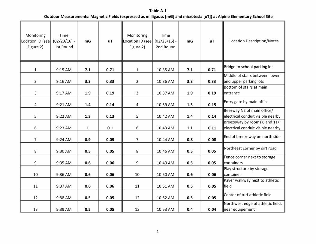
Table A-1 Outdoor Measurements: Magnetic Fields (expressed as milligauss [mG] and microtesla [uT]) at Alpine Elementary School Site
1
Monitoring Location ID (see
Figure 2)
Time (02/23/16) - 1st Round
mG uTMonitoring
Location ID (see Figure 2)
Time (02/23/16) - 2nd Round
mG uT
1 9:15 AM 7.1 0.71 1 10:35 AM 7.1 0.71
2 9:16 AM 3.3 0.33 2 10:36 AM 3.3 0.33
3 9:17 AM 1.9 0.19 3 10:37 AM 1.9 0.19
4 9:21 AM 1.4 0.14 4 10:39 AM 1.5 0.15
5 9:22 AM 1.3 0.13 5 10:42 AM 1.4 0.14
6 9:23 AM 1 0.1 6 10:43 AM 1.1 0.11
7 9:24 AM 0.9 0.09 7 10:44 AM 0.8 0.08
8 9:30 AM 0.5 0.05 8 10:46 AM 0.5 0.05
9 9:35 AM 0.6 0.06 9 10:49 AM 0.5 0.05
10 9:36 AM 0.6 0.06 10 10:50 AM 0.6 0.06
11 9:37 AM 0.6 0.06 11 10:51 AM 0.5 0.05
12 9:38 AM 0.5 0.05 12 10:52 AM 0.5 0.05
13 9:39 AM 0.5 0.05 13 10:53 AM 0.4 0.04
Play structure by storage containerPaver walkway next to athletic field
Center of turf athletic field
Beezway NE of main office/ electrical conduit visible nearbyBreezeway by rooms 6 and 11/ electrical conduit visible nearby
End of breezeway on north side
Northeast corner by dirt road
Fence corner next to storage containers
Location Description/Notes
Bridge to school parking lot
Middle of stairs between lower and upper parking lotsBottom of stairs at main entrance
Entry gate by main office
Northwest edge of athletic field, near equipement
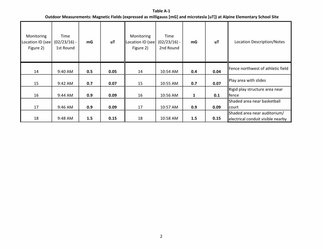
Table A-1 Outdoor Measurements: Magnetic Fields (expressed as milligauss [mG] and microtesla [uT]) at Alpine Elementary School Site
2
Monitoring Location ID (see
Figure 2)
Time (02/23/16) - 1st Round
mG uTMonitoring
Location ID (see Figure 2)
Time (02/23/16) - 2nd Round
mG uT Location Description/Notes
14 9:40 AM 0.5 0.05 14 10:54 AM 0.4 0.04
15 9:42 AM 0.7 0.07 15 10:55 AM 0.7 0.07
16 9:44 AM 0.9 0.09 16 10:56 AM 1 0.1
17 9:46 AM 0.9 0.09 17 10:57 AM 0.9 0.09
18 9:48 AM 1.5 0.15 18 10:58 AM 1.5 0.15Shaded area near auditorium/ electrical conduit visible nearby
Fence northwest of athletic field
Play area with slides
Rigid play structure area near fenceShaded area near basketball court
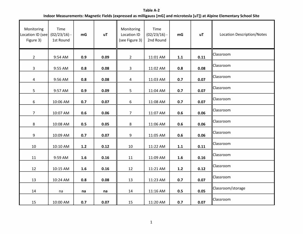
Table A-2Indoor Measurements: Magnetic Fields (expressed as milligauss [mG] and microtesla [uT]) at Alpine Elementary School Site
1
Monitoring Location ID (see
Figure 3)
Time (02/23/16) - 1st Round
mG uTMonitoring Location ID
(see Figure 3)
Time (02/23/16) - 2nd Round
mG uT
2 9:54 AM 0.9 0.09 2 11:01 AM 1.1 0.11
3 9:55 AM 0.8 0.08 3 11:02 AM 0.8 0.08
4 9:56 AM 0.8 0.08 4 11:03 AM 0.7 0.07
5 9:57 AM 0.9 0.09 5 11:04 AM 0.7 0.07
6 10:06 AM 0.7 0.07 6 11:08 AM 0.7 0.07
7 10:07 AM 0.6 0.06 7 11:07 AM 0.6 0.06
8 10:08 AM 0.5 0.05 8 11:06 AM 0.6 0.06
9 10:09 AM 0.7 0.07 9 11:05 AM 0.6 0.06
10 10:10 AM 1.2 0.12 10 11:22 AM 1.1 0.11
11 9:59 AM 1.6 0.16 11 11:09 AM 1.6 0.16
12 10:15 AM 1.6 0.16 12 11:21 AM 1.2 0.12
13 10:24 AM 0.8 0.08 13 11:23 AM 0.7 0.07
14 na na na 14 11:16 AM 0.5 0.05
15 10:00 AM 0.7 0.07 15 11:20 AM 0.7 0.07
Classroom
Classroom/storage
Classroom
Location Description/Notes
Classroom
Classroom
Classroom
Classroom
Classroom
Classroom
Classroom
Classroom
Classroom
Classroom
Classroom
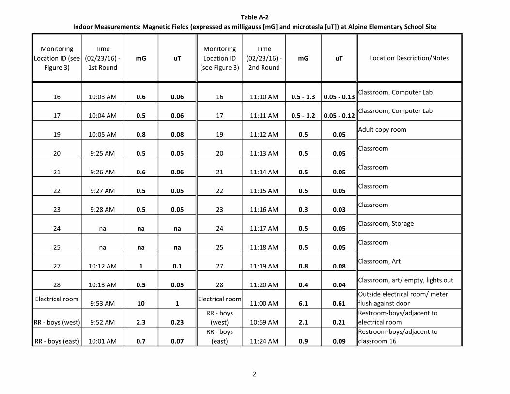
Table A-2Indoor Measurements: Magnetic Fields (expressed as milligauss [mG] and microtesla [uT]) at Alpine Elementary School Site
2
Monitoring Location ID (see
Figure 3)
Time (02/23/16) - 1st Round
mG uTMonitoring Location ID
(see Figure 3)
Time (02/23/16) - 2nd Round
mG uT Location Description/Notes
16 10:03 AM 0.6 0.06 16 11:10 AM 0.5 - 1.3 0.05 - 0.13
17 10:04 AM 0.5 0.06 17 11:11 AM 0.5 - 1.2 0.05 - 0.12
19 10:05 AM 0.8 0.08 19 11:12 AM 0.5 0.05
20 9:25 AM 0.5 0.05 20 11:13 AM 0.5 0.05
21 9:26 AM 0.6 0.06 21 11:14 AM 0.5 0.05
22 9:27 AM 0.5 0.05 22 11:15 AM 0.5 0.05
23 9:28 AM 0.5 0.05 23 11:16 AM 0.3 0.03
24 na na na 24 11:17 AM 0.5 0.05
25 na na na 25 11:18 AM 0.5 0.05
27 10:12 AM 1 0.1 27 11:19 AM 0.8 0.08
28 10:13 AM 0.5 0.05 28 11:20 AM 0.4 0.04
Electrical room 9:53 AM 10 1
Electrical room 11:00 AM 6.1 0.61
RR - boys (west) 9:52 AM 2.3 0.23RR - boys
(west) 10:59 AM 2.1 0.21
RR - boys (east) 10:01 AM 0.7 0.07RR - boys
(east) 11:24 AM 0.9 0.09Restroom-boys/adjacent to classroom 16
Classroom, art/ empty, lights out
Restroom-boys/adjacent to electrical room
Adult copy room
Classroom
Classroom
Classroom
Classroom
Classroom, Storage
Classroom
Classroom, Art
Outside electrical room/ meter flush against door
Classroom, Computer Lab
Classroom, Computer Lab
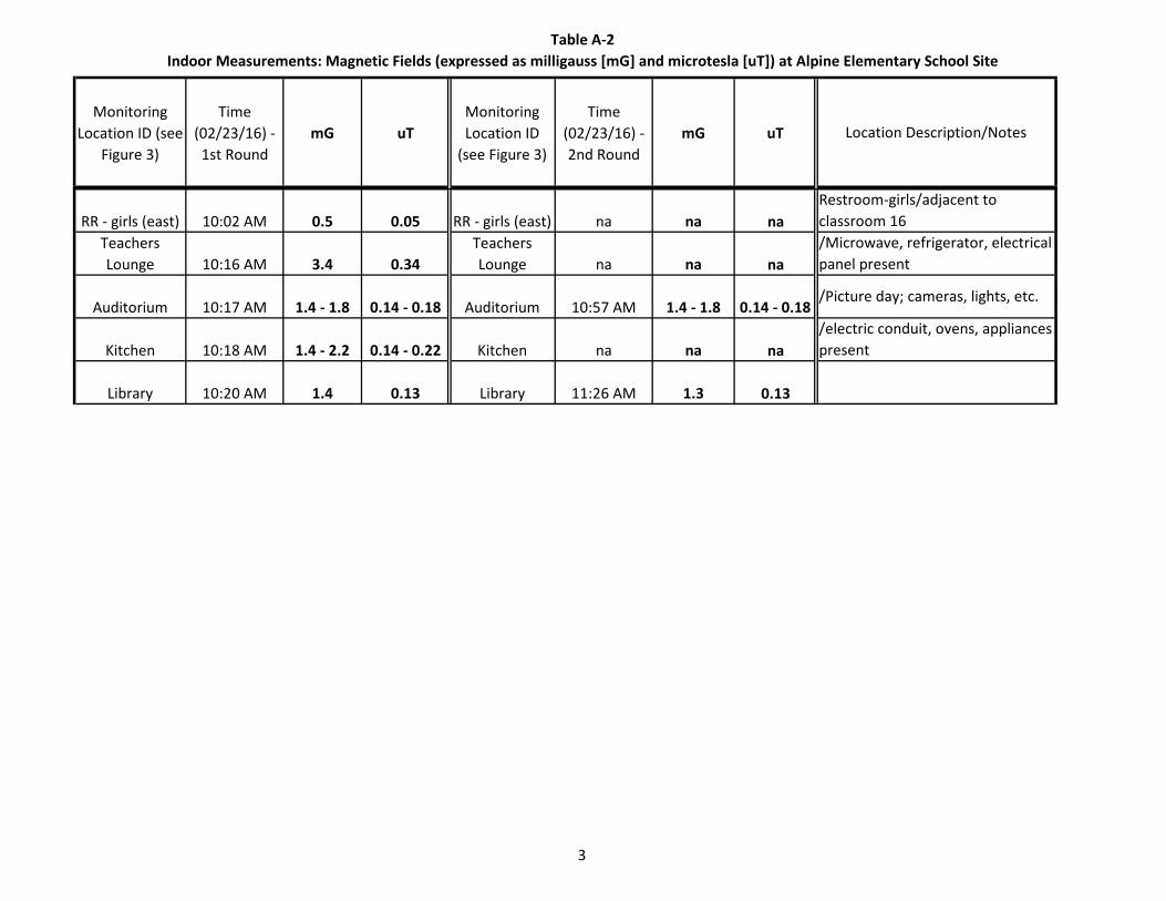
Table A-2Indoor Measurements: Magnetic Fields (expressed as milligauss [mG] and microtesla [uT]) at Alpine Elementary School Site
3
Monitoring Location ID (see
Figure 3)
Time (02/23/16) - 1st Round
mG uTMonitoring Location ID
(see Figure 3)
Time (02/23/16) - 2nd Round
mG uT Location Description/Notes
RR - girls (east) 10:02 AM 0.5 0.05 RR - girls (east) na na naTeachers Lounge 10:16 AM 3.4 0.34
Teachers Lounge na na na
Auditorium 10:17 AM 1.4 - 1.8 0.14 - 0.18 Auditorium 10:57 AM 1.4 - 1.8 0.14 - 0.18
Kitchen 10:18 AM 1.4 - 2.2 0.14 - 0.22 Kitchen na na na
Library 10:20 AM 1.4 0.13 Library 11:26 AM 1.3 0.13
Restroom-girls/adjacent to classroom 16/Microwave, refrigerator, electrical panel present
/Picture day; cameras, lights, etc.
/electric conduit, ovens, appliances present
A L P I N E E L E M E N T A R Y S C H O O L - E M F S U R V E Y A L P I N E U N I O N S C H O O L D I S T R I C T
Appendix
March 2016 PlaceWorks
Appendix B. Certificate of Calibration and Accuracy Report for EMDEX Snap Magnetic Field Survey Meter
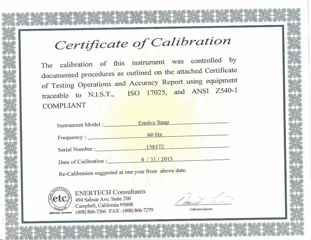
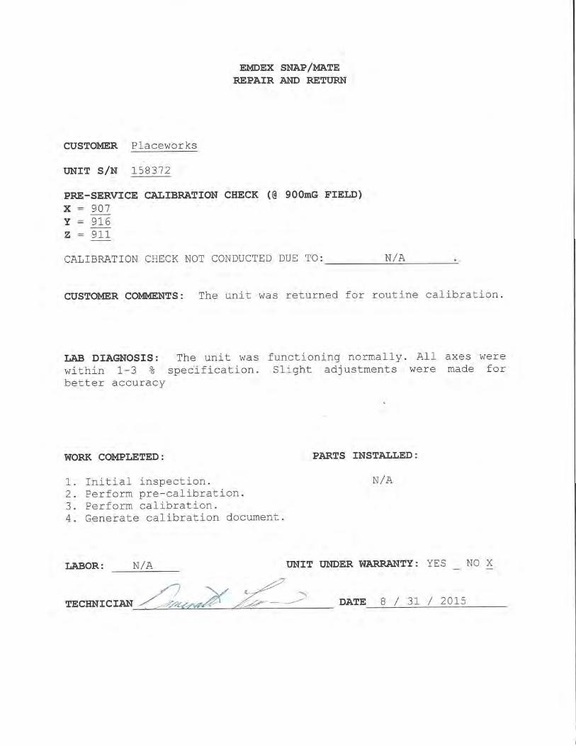
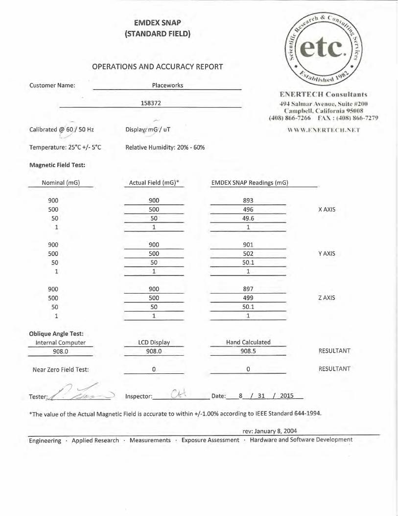
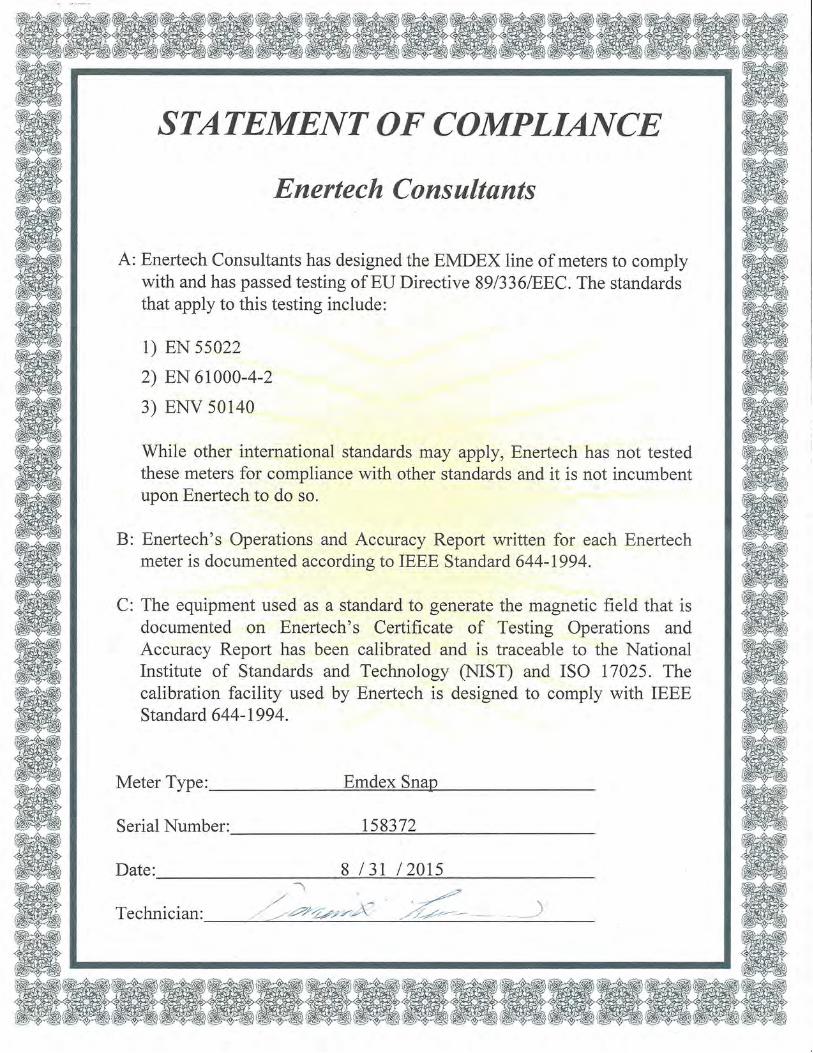
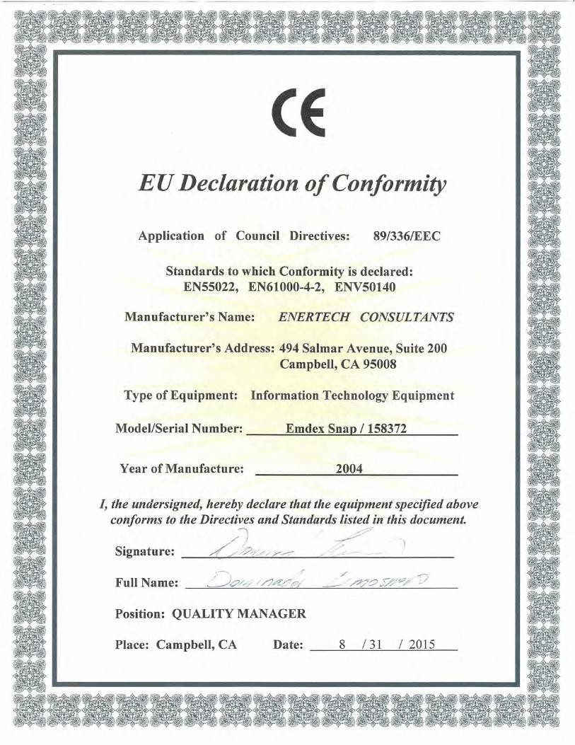

APPENDIX H
EMF Meter Calibration
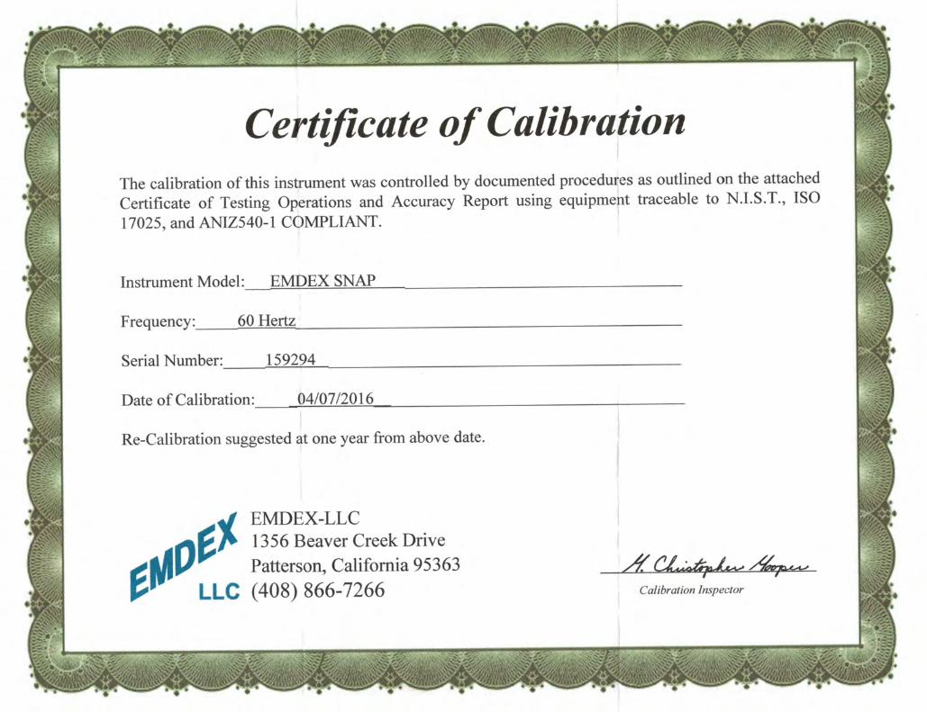

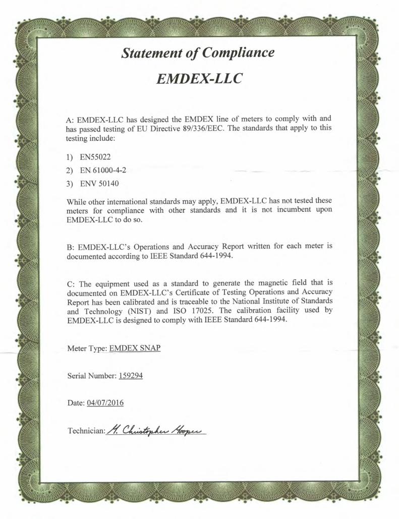
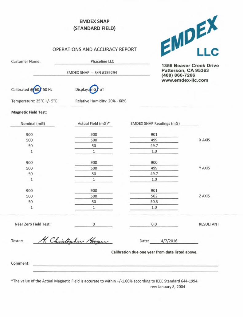
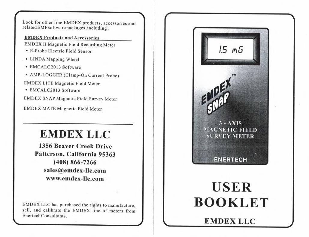
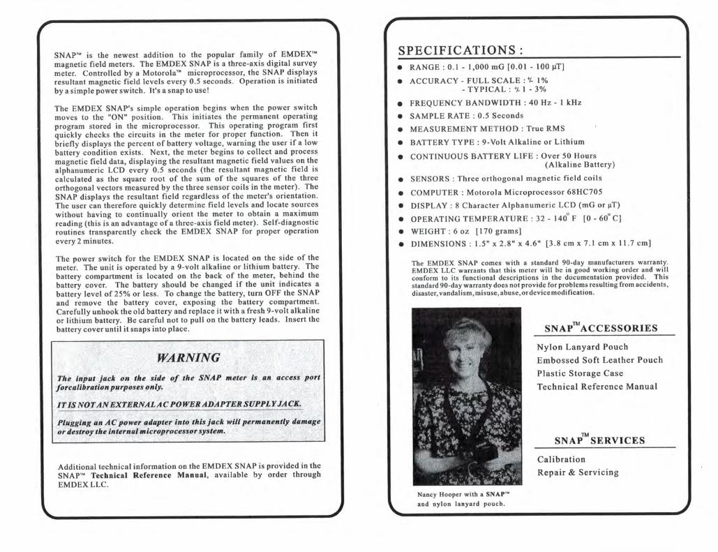

APPENDIX I
Field Notes