
Activation and electro-dynamic dampers, key technologies for the operation of superconducting...
16
Activation and electro-dynamic dampers, key technologies for the operation of superconducting magnetic bearings Hardo May, Jan Hoffmann and Wolf-Ruediger Canders Institute of Electrical Machines, Technical University of Braunschweig, Braunschweig, Germany, and Ryszard Palka Faculty of Electrical Engineering, Szczecin University of Technology, Szczecin, Poland Abstract Purpose – The purpose of this paper is to focus on superconducting magnetic bearings (SMB). SMB for high-speed rotors are contact free and offer inherently stable operations thus they are best qualified for the support of horizontally aligned rotors of turbo machines for gas-compressors and expanders, e.g. special attentions have to be concentrated on the force activation of the SMB without dislocating the rotor from the aligned position. Design/methodology/approach – For the activation of cylindrically shaped SMB-designs, appropriate units with movable superconductor parts have been developed. They permit the maintenance of the rotor together with the field excitation unit in the aligned un-displaced position. The eddy currents in the conducting cylinder of an EDD are induced by spatial fluctuations of the field and thus have been determined by transient calculations. The mechanical oscillation of the rotor was considered by a step-wise displacement of the damper-plate. Findings – As the rotors of both the machine and the SMB operate best with reduced clearance to the stators, the shaft cannot be displaced to activate the force of horizontally aligned superconducting bearing assemblies. Thus, for cylindrical, co-axial SMB-designs the stator is shaped as two half shells embracing the SMB-rotor. For the force activation the following procedure has to be carried out within the Dewar without displacing the shaft: at first the half shells are retreated from the rotor (warm HTSC) and after the cooling they are moved against the inner part of the warm bore thus generating the forces to compensate the weight and disturbances of the rotor. In case of planar-cylindrical SMB-designs, which are specially suited for extreme high speed applications, the bearing stators consist of a planar cylinder plate of HTSC-bulks. The force activation is realised by lifting and descending the Dewar with the HTSC parts as a whole independently from the position of the rotor. The radial forces of the EDD and their partitioning in components which contribute to the damping- and to the spring-force have been determined for different frequencies up to 160 Hz. To achieve accuracies in the percent range, the values of the time steps have to be well adapted to the electro dynamic conditions as oscillation frequency and conductivity. Originality/value – Only the presented activation devices with movable HTSC stator parts enable the application of SMB even for horizontally aligned high-speed rotors with reduced radial clearance. The recently developed fully integrated EDD secure a safe run of the rotor even during the speed up – passing the eigenfrequency in particular. Keywords Electric motors, Bearings, Eigenvalues and eigenfunctions, Conductance, Superconductors Paper type Research paper The current issue and full text archive of this journal is available at www.emeraldinsight.com/0332-1649.htm COMPEL 28,1 188 COMPEL: The International Journal for Computation and Mathematics in Electrical and Electronic Engineering Vol. 28 No. 1, 2009 pp. 188-203 q Emerald Group Publishing Limited 0332-1649 DOI 10.1108/03321640910918986
-
Upload
independent -
Category
Documents
-
view
3 -
download
0
Transcript of Activation and electro-dynamic dampers, key technologies for the operation of superconducting...
Activation and electro-dynamicdampers, key technologies for the
operation of superconductingmagnetic bearings
Hardo May, Jan Hoffmann and Wolf-Ruediger CandersInstitute of Electrical Machines, Technical University of Braunschweig,
Braunschweig, Germany, and
Ryszard PalkaFaculty of Electrical Engineering, Szczecin University of Technology,
Szczecin, Poland
Abstract
Purpose – The purpose of this paper is to focus on superconducting magnetic bearings (SMB). SMBfor high-speed rotors are contact free and offer inherently stable operations thus they are best qualifiedfor the support of horizontally aligned rotors of turbo machines for gas-compressors and expanders,e.g. special attentions have to be concentrated on the force activation of the SMB without dislocatingthe rotor from the aligned position.
Design/methodology/approach – For the activation of cylindrically shaped SMB-designs,appropriate units with movable superconductor parts have been developed. They permit themaintenance of the rotor together with the field excitation unit in the aligned un-displaced position.The eddy currents in the conducting cylinder of an EDD are induced by spatial fluctuations of the fieldand thus have been determined by transient calculations. The mechanical oscillation of the rotor wasconsidered by a step-wise displacement of the damper-plate.
Findings – As the rotors of both the machine and the SMB operate best with reduced clearance to thestators, the shaft cannot be displaced to activate the force of horizontally aligned superconductingbearing assemblies. Thus, for cylindrical, co-axial SMB-designs the stator is shaped as two half shellsembracing the SMB-rotor. For the force activation the following procedure has to be carried out withinthe Dewar without displacing the shaft: at first the half shells are retreated from the rotor (warmHTSC) and after the cooling they are moved against the inner part of the warm bore thus generatingthe forces to compensate the weight and disturbances of the rotor. In case of planar-cylindricalSMB-designs, which are specially suited for extreme high speed applications, the bearing statorsconsist of a planar cylinder plate of HTSC-bulks. The force activation is realised by lifting anddescending the Dewar with the HTSC parts as a whole independently from the position of the rotor.The radial forces of the EDD and their partitioning in components which contribute to the damping-and to the spring-force have been determined for different frequencies up to 160 Hz. To achieveaccuracies in the percent range, the values of the time steps have to be well adapted to the electrodynamic conditions as oscillation frequency and conductivity.
Originality/value – Only the presented activation devices with movable HTSC stator parts enablethe application of SMB even for horizontally aligned high-speed rotors with reduced radial clearance.The recently developed fully integrated EDD secure a safe run of the rotor even during the speed up –passing the eigenfrequency in particular.
Keywords Electric motors, Bearings, Eigenvalues and eigenfunctions, Conductance, Superconductors
Paper type Research paper
The current issue and full text archive of this journal is available at
www.emeraldinsight.com/0332-1649.htm
COMPEL28,1
188
COMPEL: The International Journalfor Computation and Mathematics inElectrical and Electronic EngineeringVol. 28 No. 1, 2009pp. 188-203q Emerald Group Publishing Limited0332-1649DOI 10.1108/03321640910918986

1. IntroductionSuperconducting magnetic bearings (SMBs) are one of the most promising applications ofhigh-Tc superconductors (HTSC). They are based on the force interaction of a magneticfield excitation unit –, e.g. permanent magnets (PMs) – and HTSC-bulks (May et al., 2004;Krabbes et al., 2006). Owing to their function the bearing capability will be maintained forhours even after a breakdown of the energy supply for supplementary machines such ascryo-coolers or vacuum-pumps. Contrarily to active magnetic bearings (AMBs) SMBsrequire no complex control-units, offer a very high reliability and are not vulnerable toEMC-problems so that the auxiliary bearings can be designed with reduced dimensions.Even a short touch down in these safety units does not affect the stability of SMBs andafter the disturbing forces are removed the bearing will return to stable operation again.Based on these favourable performances SMBs present advanced alternatives to AMBs.
The phenomena of the force generation between an HTSC and a field excitationsystem can be used for different contact-free bearing designs for linear transportsystems and fast rotating shafts as shown in Figure 1 (Weh et al., 1995, 1994; Weh andMay, 1990; Kuehn et al., 2006).
A fundamental calculation model of SMBs from Figure 1 and a field plot with theHTSC in activation position are shown in Figure 2.
Based on this model different basic force relations for vertical and lateraldisplacements of the HTSC from the cooling (activation) position are shown in Figure 3.
While approaching the HTSC from the activation position gact towards theexcitation system an exponentially increasing repulsive force can be observed.Contrary, by retreating the HTSC from the excitation system an attractive force will becaused. While this movement the force passes through a maximum value that indicatesthe range of operational of the SMB. Sideward displacements affect restoring forces –independent of their direction (Figure 3).
Extensive calculations have been carried out for flux concentration excitationsystems (Figure 2) to optimize the force- and stiffness-densities of SMBs (May et al., 2004;Krabbes et al., 2006). Based on these optimizations further engineering efforts aim at theimplementation of force activation structures and procedures (May et al., 2005), as well
Figure 1.SMB-topologies for linear
and rotary motions
Direction ofmovement
HTSC
Field excitation
Suspension forlinear transport
Notes: Left, linear basis-topology; mid, planar SMB (linear basis system bended over vertical axis);right, radial SMB (linear basis system bended over horizontal axis)
Suspensionof a fly wheel
Axis ofrotation Axis of
rotation
SMB forrotating shafts
yx
Iron
yok
e
z
Cold headHTSC HTSC
Activation andelectro-dynamic
dampers
189

as at appropriate designs of dampers for the particular requirements of fast rotatingshafts of electrical machines with restricted radial gap clearance. Whereas in Werfel et al.(2000) the inherent losses due to flux fluctuations within the HTSC bulks of the SMBscreate damping forces, in Komori and Kamogawa (2004) an extra damper-coil isimplemented to prevent the SMB from extreme oscillation deflexions.
2. Operation and activation of SMBs for rotating machinesMain topologies of SMBs for horizontally rotating shafts are shown in Figure 4.
Figure 2.Left, linear model of anSMB with periodic fluxcollection excitation; right,field distribution of aperiodic SMB in theactivation (cooling)position
Possible displacements fromthe position of cooling
(force activation)
CFRP-bandage
HTSC
z
y
Iron IronIron
HTSC incooling position
Pole pitch
CFRP-bandage(centrifugal-force protection)
Flux collection poles
Field excitation(P-magnets)
Wi WM
hi
hpgact
hm
Figure 3.Left, normalforce-displacementrelations for differentactivation clearances gact
of Figure 2; right, forcerelations vs lateraldisplacement from thecentral activation position
Range of operation
Fext
Fext
Fext0.8
0.6
Bea
ring
for
ce [
p.u.
]
Lat
eral
for
ce [
p.u.
]
attr
activ
ere
puls
ive
0.4
0.2
0.0
1.0
–0.2
0.80.60.40.20.0
–0.2–0.4–0.6–0.8
1.0
–1.0–0.8 –0.6 –0.4 –0.2
Lateral displacement: y/pole pitch
Cooling position
Range of operation
0.0 0.2 0.4 0.6 0.8–1.0 1.0–1 0 1 2Vertical displacement: z [mm]
gact = 2mm
3 4 5 6–2 7
Figure 4.Topologies of SMBsin the aligned positionfor horizontally rotatingshafts
Machine-rotor
mg
Basement
HT
SC
HT
SCMachine-rotor
Inter-polar CFRP-bandages
mg
Basement
HTSC
HTSC
HTSC
HTSC
Notes: Left, radial and right: planar SMB designs
COMPEL28,1
190

To operate the rotor – as shown in Figure 4 – weight compensated in the positionaligned with the HTSC-system, the force activation sequence of radial bearingsaccording to Figure 5 (left) proceeds as follows: at first the rotor is fixed in an elevatedposition – approx. a couple of millimetres above the aligned one – and subsequently,after cooling below the critical temperature Tc, the shaft is detached from the externalsupport. While the rotor descends to the weight compensated aligned operationalposition, with this the retreat from the upper part of the HTSC-shell and the approachtowards the lower one, attractive, respectively, repulsive forces are created Figure 5(left). But as this activation mode is not realizable for high force-density designs withvery small air gaps offering limited bearing clearances ,1 mm, by the use of newlypatented activation schemes with split HTSC-half shells, the rotor can favourablyalways remain in aligned position.
Description of the activation procedure according to Figure 5 (mid and right):beginning with the shaft fixed in the aligned and the lower HTSC-half shell in adescended position after the cooling, this half shell will be lifted and the lower repulsivebearing forces will support the rotor. To use the upper attractive forces additionallyduring this activation scheme the rotor can be lifted within the restricted clearanceagainst the upper warm bore limitation.
A radial SMB in the 5,000 kN force range (Figures 6 and 7), designed and activatedaccording to Figure 5 (right and mid), was recently built and tested in cooperation withSiemens AG and Nexans superconductors (Walter et al., 2005).
The Dewar of this SMB, in which the HTSC cluster from Figure 6 was incorporatedtogether with the two copper half-shells, is shown in Figure 7.
Figure 5.Activation schemes forradial SMB-topologies
Conventional force activationwith displaced shaft
Advanced force activation techniquewith movable HTSC half-shells
(shaft remains in the fixed position)
Upper half-shellSuper insulation
x
y
Forceactivation
gap
Field excitation(warn bore)
Lower movablehalf-shellCold head
HTSC clusterSuper insulation
Stabilizing forcesWeight compensationand stabilizing forces
Movement forforce activation
P-magnets
Shaft
Coolingposition
Operatingposition
HTSC cluster
Notes: Left, conventional activation with displacing – misaligning – the rotor while cooling down;mid, force activation in the aligned position of the rotor by moving – after the cooling – the lower part ofthe HTSC-half-shell within the Dewar, right; major parts of an SMB showing the rotating field excitationpart in the warm bore and the HTSC-shell positioned in the Dewar
Activation andelectro-dynamic
dampers
191
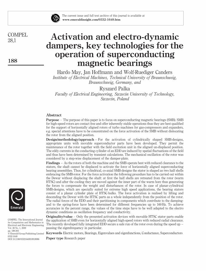
The test results of this 5,000 kN SMB have been executed by the Siemens AG(Kummeth et al., 2005) and confirm the required data with respect to the radial stiffness(5 kN/mm) and rotating accuracy (Figure 8).
A disadvantage of these radial SMB designs is their restricted speed range of,100 m/s approx. Enlarged centrifugal force protecting bandages in the inter-poleregion of the excitation system (Figure 2) will be associated with increased stray fieldsand thus worsen the bearing performances drastically. Newly developed planar SMBdesigns shown in Figure 4 (right) and Figure 9 can operate up to highest speeds, as theCFRP-protection bandage embraces the excitation system circumferentially (Figure 9).
Figure 6.Main components of theheavy load SMB: left, SMBstator: thermallyconnected half shellscomposed of copper coldheads and HTSC-clusters;right, SMB-rotor:PM-excitation system in aflux collectionarrangement withCFRP-protection bandagesbetween the flux collectioniron poles
UpperHTSC half-shell
Iron poles(flux collection
excitation)CFRP-bandages
(permanent magnets)
HTSCcluster
Thermal connectionslower upper HTSC half-shells
Note: Figure 4 leftSource: Kummeth et al. (2005)
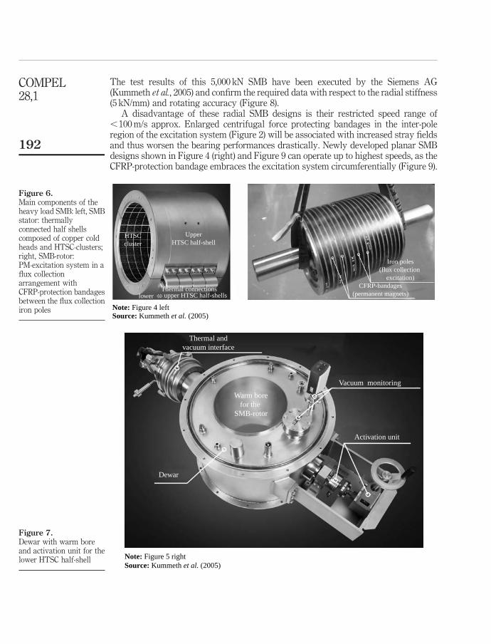
Figure 7.Dewar with warm boreand activation unit for thelower HTSC half-shell
Thermal andvacuum interface
Vacuum monitoring
Activation unit
Dewar
Warm borefor the
SMB-rotor
Note: Figure 5 rightSource: Kummeth et al. (2005)
COMPEL28,1
192
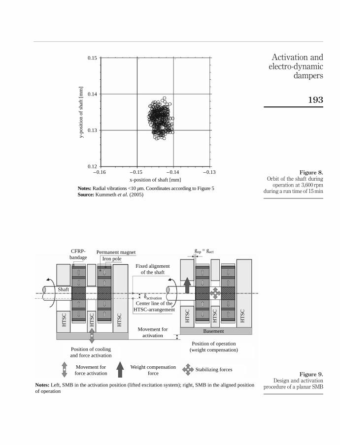
Figure 8.Orbit of the shaft during
operation at 3,600 rpmduring a run time of 15 min
0.15
y-po
sitio
n of
sha
ft [
mm
]
0.14
0.13
0.12–0.16 –0.15
x-position of shaft [mm]
–0.14 –0.13
Notes: Radial vibrations <10 µm. Coordinates according to Figure 5Source: Kummeth et al. (2005)
Figure 9.Design and activation
procedure of a planar SMB
CFRP-bandage
Permanent magnet
Fixed alignmentof the shaft
gop = gact
Center line of theHTSC-arrangement
Shaft
Movement foractivation
Weight compensationforce
Stabilizing forces
Position of operation(weight compensation)Position of cooling
and force activation
Basement
HT
SC
HT
SC
HT
SC
HT
SC
HT
SC
HT
SC
Movement forforce activation
δactivation
Iron pole
Notes: Left, SMB in the activation position (lifted excitation system); right, SMB in the aligned positionof operation
Activation andelectro-dynamic
dampers
193

Furthermore, this protection does not affect the magnetic air gap and thus the bearingperformance at all. The appropriate activation scheme for these SMB designs is shownin Figure 9. Contrarily to the activation scheme known for radial bearings (Figure 5),the complete Dewar-HTSC arrangement will be lowered while the rotor remains in thealigned position. After the cooling the Dewar will be lifted and thus the SMB will createthe required lift forces and stiffness to compensate the rotor loads at all speeds, at leastin the range different from the bearing eigenfrequencies.
3. Electro-dynamic vibration dampers for SMBs: basicsWith the progress in manufacturing of high quality HTSC-blocks, newest SMBsexhibit negligible losses leading to increased, nearly un-damped oscillations duringpassing the bearing eigenfrequencies of the accelerating rotor. As the radial stiffness ofSMBs is relatively small compared with ball bearings, conventional mechanicaldampers placed on the fix points of the machine assembly (e.g. SFD in Figure 10)cannot be applied. To avoid increased displacements or even contacts of the rotor withthe HTSC-structure, stand-alone electro dynamic vibration dampers (EDD Figure 17)have been designed by the authors, manufactured by Nexans superconductors andtested by the Siemens AG.
As long as rigid body oscillations are assumed (cylindrical modes), the radialdisplacements from the nominal position, caused by the unbalanced rotor massesduring speeding-up, can be determined on the bases of the d’Alembert equation ofmovement (one mass oscillator, left side of Figure 10 without SFD):
inertia-force
mr · €rzffl}|ffl{
þ
damping-force
k · _rz}|{
þ
spring-force
c · rz}|{
¼
force
FðvÞzffl}|ffl{
; ð1Þ
or equivalent:
€rþ 2Dv0 · _rþ v20 · r ¼
FðvÞ
mr; ð2Þ
with eigenfrequency: v0 ¼ffiffiffiffiffiffiffiffiffiffic=mr
pand Lehr’s damping: D ¼ ðk=2mrÞ · ð1=v0Þ:
These radial displacements Dr of the rotor, which lead to unavoidable gapvariations Dgap, have to be kept within certain limits. They are caused by radial forcesdue to rotor unbalances which increase quadratically with the rotational speed(F(v) / v2) and are limited by the counteracting damping forces equation (1) of anEDD (Figures 10 and 11) as well as by the way of running through the eigenfrequency
Figure 10.Typical SMB arrangementfor horizontal rotors withdifferent dampertechnologies (Figure 4)
gap 2F(ω)
RotorHTSC HTSCCopper Copper
r
z
ϕ
EDD SFDSMBmb
2mr
Notes: SMB consists of stator: cold head (Cu), HTSC and rotor: PM-excitation, EDD: electro dynamicdamper; SFD: squeeze film damper
COMPEL28,1
194

during the rotating speed-up. Figure 11 right exhibits simulation results of the radialdisplacement during the acceleration of a rotor, e.g. at which both the damping forcesand the time needed to pass through the range of the eigenfrequency determinethe maximum deviation Dgapmax from the nominal gap of Figure 10. Thus, theimplementation of appropriate damping units within a superconductingmagnetic bearing system is of major importance and their optimization is a greatchallenge.
4. EDD for SMBs: damping force calculationAll electromagnetic force phenomena are based on the Lorentz force relations. Theirz-component in the y-z-plane of Figure 12 amounts to:
Fz ¼
ððacp
sx ·Bydydz; ð3Þ
Figure 12.Calculation model for the
determination ofelectro-dynamic forces
Direction of oscillationsof the excitation system
Iron p
ole
y
y 2·(pole pitch)
Iron pole
PM
Copper plate
Cross-section acp
thrr
gap(t)
x
z
z
Copper plate
Notes: Left: Cartesian arrangement with PM-excitation system and copper reaction rail (unwound representationin Cartesian coordinates of the cylindrical arrangement of Figure11); right: detail view of the field-distribution inthe y-z-plane of the EDD based on numerical field calculations
Figure 11.Left: design of a
stand-aloneelectro-dynamic vibration
damper. Detail view of theEDD shown in Figure 10
left; right, radialoscillation behaviour of
the SMB with anintegrated EDD during
rotor speeding-up
0.08Permanent magnet
excitation system
Coppercylinder
Direction ofoscillations
∆r [
mm
]
0.06
0.04
0.02
0.00
–0.02
–0.04
–0.06
–0.080 1 2 3 4 5
t [s]
–∆gapmax
+∆gapmax
6 7
Activation andelectro-dynamic
dampers
195

with Fz: the force which counteracts the vertical movements. sx: current density, By:flux density in the y-direction and acp: y-z cross section of the copper plate. Onlythat part of Fz which is in phase with the velocity (Figure 14) represents thedamping force.
Corresponding damping forces counteracting horizontal vibrations Fy are generatedby the same component of the current density but by appropriate flux densities in thez-direction.
The distribution and the values of the two force creating field terms (s and B,respectively) are based on Maxwell’s field equations, which are generally solved by theuse of numerical methods (Weh and May, 1980). The general relation of the electricfield associated with the time variations of the magnetic field (e.g. caused by oscillatingPMs) is given by Faraday’s law:
rot~E ¼_~B ð4Þ
and yields in eddy currents within the copper plate of the damper. In case of fieldvariations in time and moving conducting media (e.g. cooper plate Figure 12) theirdistribution is determined by Ohm’s law:
~s ¼ sð~Etime þ ~v £ ~BÞ ð5Þ
with the electric field strength: ~E ¼ ~Etime þ~Emove: As indicated, their value can be
divided into two parts: ~Etime qualifies that part, which is induced by sole time variationswhile the B-distribution remains constant. A second part is induced in a movingconducting plate:
rot~Emove ¼ 2_~B ¼ 2
›~B
›j
dj
dt¼ 2
d~B
djV j; ð6Þ
under the precondition of the existence of a B-field gradient in the direction of j. Withinthe copper plate of the damper arrangement of Figure 12 such field gradients can beobserved in both the lateral ðj ¼ yÞ and the vertical ðj ¼ zÞ directions.
The radial velocity which is caused by rotor unbalances (Figure 10) perform asinusoidal velocity in time: v ¼ vr · max · sinðvtÞ: This would enable a complex approachfor the field equations (quasi-static solution), but the spatial field gradients in thecopper plate enforce basically a transient field calculation in time (Weh and May, 1980).Nevertheless, the next chapter will deal with the differences between quasi-static andtransient field calculation results.
5. EDD for SMBs: validation of calculation modelsAs described, even if sinusoidal displacements of the damper parts (Figure 11) occur infields with spatial gradients, transient field calculations have to be applied for thedamping force determination. Based on the planar-cylindrical damper arrangement ofFigure 13, the numerical field calculation has been validated by comparisons oftheoretically determined damping forces and measurement results (Portabella et al., 1999).
Beside the refinement of the grid (FEM) to achieve an accurate solution, the validationof the transient calculation aims at the determination of the required (minimal)sub-divisions in time. The transient calculations have been carried out with different timesteps between dt ¼ 1.0 £ 1025 and 1.0 £ 1027 s. In the frequency range up to 120 Hz,
COMPEL28,1
196

the latter time step dt seems to be sufficiently small for accuracies in the percentage range.Although the specification of the time-step values is very informative, the declaration ofthe number of time steps within one time period: spp is better suited for transientcalculations. From their values the time steps can be easily determined: dt ¼ 1=ð f · sppÞ:
Assuming a frequency of 80 Hz, an oscillation amplitude of Dz ¼ 0.2 mm and thegeometrical and material data from Figure 13, the transient build-up of thedamping force after initiating of vertical oscillations is shown in Figure 14.For this transient calculation 40,000 spp have been assumed, resulting in a time step
Figure 13.Left, calculation model for
the planar-cylindricaldamper arrangement:
right, field distribution inthe r-z plane of the damper
under examination
HTSC
z
hsc
hPM
hl
thrr
r
air-gap
Damper plate(copper)
z
HTSC
r
Iron yoke
ϕ
copper-cylinder
sque
eze-
fiel
dga
pdi
rect
ion
ofos
cilla
tion
PM
Iron yoke
D
Notes: All dimensions in mm: Diron-yoke = DPM = 25, hi = 6, hPM = 15, air-gap (nominal) = 1.25,Dcop-cyl = 65, thrr = 2; material data: remanence of the PM: Br = 1.2 T, conductivity of the coppercylinder: s Cu = 50×106 S/m
Figure 14.Transient build-up of the
damping force afterinitiation a vertical
oscillation of the damperplate ( f ¼ 80 Hz)
0.6
0.4
0.2
0.0
norm
al f
orce
[N
]
–0.2
–0.4
–0.60 2 4
velocity(run only)
damping force
ϕf–ϕvϕf–ϕv:
6 8 10 12 14
time [ms]
16 18 20 22 24 26 28
2
1 3 5 7
62
84
1 =20.7°;3 =23.0°;5 =20.7°;7 =23.0°;
=23.7°;4 =17.7°;6 =24.8°;8 =18.8°;
Notes: Calculation model according to Figure13 right. The velocity run is displayed as reference for thephase angles only
Activation andelectro-dynamic
dampers
197

of dt ¼ 3:125 £ 1027 s: Under the precondition of harmonic oscillations, thefrequency of 80 Hz and the maximal deviation of 0.2 mm effect a maximal velocityof: vmax ¼ v £ 0:2 £ 1023 ¼ 100:5 mm=s: This results for the transient calculation in astepwise displacement from the nominal gap of:DzðtnÞ ¼ 0:2 £ 1023 · sinðv · n · dtÞ;witha remarkable small first maximum displacement-step ofDzðt1Þ ¼ 3:142 £ 1022 mm:Thevalue of spp has to be well adjusted to the physical conditions of the damper set-up andthe operating condition (frequency and Dzmax) which can be qualified by the magneticReynolds’ number. This factor is a criterion with respect to the value and phase angle ofthe induced eddy currents and is based on the Maxwell’s equation: Rmavms (Weh andMay, 1980), with m: permeability and s: conductivity of the damper plate. Beside thestep-size the meshing of the field area determines the accuracy and stability of thetransient calculation. In this case the cylindrical model of Figure 13 was subdivided intosome 58,000 triangles and the total calculation time to determine the normal force run for2.1 periods shown in Figure 14 lasted with an Intel Core 2 Duo Processor (3.0 GHz) 4.6 happroximately. The transient calculation started with initial values derived from atransient pre-estimation, where the damper plate of Figure 13 was placed in the nominalposition and the maximum speed of vmax ¼ 100.5 mm/s was assumed. Thismeasurement reduced the transient settling time drastically in comparison to thecalculation of the full switch-on effect from the standstill and un-magnetised state.
The displayed run of the assumed velocity in Figure 14 serves as reference for thephase angle of the force characteristic only.
Following a transient settling, Figure 14 shows more or less steady statebehaviour of the damping forces. The zero force crossing points 3 and 7 indicate thesituations of utmost approaches of the magnet (smallest air-gap) and the points 1and 5 indicate the maximum displacements of the copper plate. The other pointsindicate the crossing of the nominal air-gap. It can be stated that the phase anglesfeature nearly identical values at the positions of maximum displacement, but majordifferences can be observed if the magnet crosses the nominal air gap in theapproaching (points 2 and 6) or retreating direction (points 4 and 8). These phasedetails are of fundamental interest as they apportion the nominal force distributioninto two parts.
Fourier analysis of the normal force curves in the steady state range (t $ 6 ms) leadto the angles f of Table I. The jFmeanj · cosðfÞ values reflect that part of the normal
Frequency(Hz)
Phase angle (8)w ¼ wf–wv
jFjmean · cos (w)(N)
(transient calculations)
jFjmean
(N)(quasi-static calculations)
jFjmean
(N)(measured)
20 3.9 9.387 £ 1022 9.152 £ 1022 8.244 £ 1022
40 8.1 1.934 £ 1021 1.831 £ 1021 1.592 £ 1021
60 12.7 2.924 £ 1021 2.746 £ 1021 2.486 £ 1021
80 17.5 3.865 £ 1021 3.661 £ 1021
100 22.5 4.705 £ 1021 4.577 £ 1021
120 27.6 5.374 £ 1021 5.493 £ 1021
160 37.6 6.143 £ 1021 7.324 £ 1021
Note: Further columns: operative effective values of the damping forces determined by differentcalculation methods and measurements
Table I.Second column: phaseangles between thefrequency dependingcurves of velocity anddamping force
COMPEL28,1
198

forces which are in phase with the velocities and thus constitute the dampingforces (1). Contrary, the jFmeanj · sinðfÞ values are in phase with the displacements andcontribute additionally to the spring forces of the SMB (1). E.g. for the assumedoscillation frequency of 80 Hz, their value amounts to 30 per cent of the mean valueof jf(t)j.
Further examinations have proved that in the range of these limited oscillationfrequencies and displacements quasi-static field calculations result in similardamping force values as transient calculations (Table I). As mentioned above, aplanar cylindrical damper was built (model shown in Figure 13) and tested with theset-up (an electro-dynamic shaker) described in Portabella et al. (1999). Themeasurement results are presented in Table I and Figure 15, respectively. As theelectric conductivity of the copper cylinder is not known exactly and does changedue to heating effects during long time measurements, the superior agreement of thequasi-static calculations with the measurements are more or less accidental.Nevertheless, a good agreement between the different calculation methods and themeasurements can be ascertained.
To judge both calculation models it can be stated that the quasi-static assumptionslead to shortest calculation times (few seconds), but the dynamic spring-forcecontributions of electro-dynamic dampers (EDD) can be determined by the applicationof transient calculations only, but consuming several hours.
From the mean values of the damping force the ohmic losses can be concluded:Pohm ¼ Fmean · vmean; which results in 23 mW in the case of an oscillation frequency of80 Hz and the data of the model shown in Figure 13. It can be stated, that the lossesassociated with the damping forces will not heat up the system under normal ambientconditions. But if the HTSC-bulks serve themselves as damping units (Werfel et al., 2000),these losses will heat the superconductors and have to be extracted from the Dewar byenergy consuming cryo-coolers.
Figure 15.Comparison of measuredand calculated damping
forces
0.6
dam
ping
-for
ce [
N]
0.5
0.4
0.3
0.2
0.1
0.00 20 40 60 80 100 120
frequency [Hz]
measurements
transientcalculations
quasi-stationarycalculations
Assumed values:Br = 1.20T; σcu = 50·106 S/mgap = 1.25 mm; ∆gap = ±0.2 mm
Note: Mean value of | f(t) | vs frequency. Model data are given in Figure13
Activation andelectro-dynamic
dampers
199
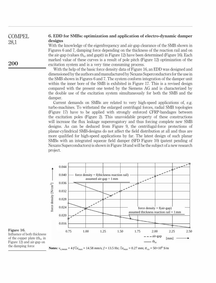
6. EDD for SMBs: optimization and application of electro-dynamic damperdesignsWith the knowledge of the eigenfrequency and air-gap clearance of the SMB shown inFigures 6 and 7, damping force depending on the thickness of the reaction rail and onthe air-gap (values thrr and gap(t) in Figure 12) have been determined (Figure 16). Eachmarked value of these curves is a result of pole pitch (Figure 12) optimization of theexcitation system and is a very time consuming process.
With the help of the basic force density data of Figure 16, an EDD was designed anddimensioned by the authors and manufactured by Nexans Superconductors for the use inthe SMB shown in Figures 6 and 7. The system conform integration of the damper unitwithin the inner bore of the SMB is exhibited in Figure 17. This is a revised designcompared with the present one tested by the Siemens AG and is characterized bythe double use of the excitation system simultaneously for both the SMB and thedamper.
Current demands on SMBs are related to very high-speed applications of, e.g.turbo-machines. To withstand the enlarged centrifugal forces, radial SMB topologies(Figure 17) have to be applied with strongly enforced CFRP-bandages betweenthe excitation poles (Figure 2). This unavoidable property of these constructionswill increase the flux leakage supererogatory and thus forcing complete new SMBdesigns. As can be deduced from Figure 9, the centrifugal-force protections ofplanar-cylindrical SMB-designs do not affect the field distribution at all and thus aremore qualified for high-speed applications by far. The latest design of such planarSMBs with an integrated squeeze field damper (SFD Figure 10) (patent pending ofNexans Superconductors) is shown in Figure 18 and will be the subject of a new researchproject.
Figure 16.Influence of both thicknessof the copper plate (thrr inFigure 12) and air-gap onthe damping force
0.044
0.040
0.036
0.032
0.028
0.024
forc
e de
nsity
[N
/cm
2 ]
0.020
0.016
0.75 1.00 1.25 1.50 1.75 2.00
[mm]air-gap
thrr
2.25 2.50
force density = f(air-gap)assumed thickness reaction rail = 1mm
force density = f(thickness reaction rail)assumed air-gap = 1 mm
Notes: vz,mean = 4·f·∆zmax = 14.58 mm/s; f = 13.5 Hz; ∆zmax = 0.27 mm; σcu = 50×106 S/m
COMPEL28,1
200

Figure 17.Design of a radial SMB
with a space-savingintegration of the EDD
within the bore
PM-excitation forboth SMB and EDD
(dual-use)
Cold head (copper)
SMB unit
Rotor-shaft
Copper cylinder for EDD
HTSC-blocks
Figure 18.New planar acting SMB
(Figure 4 right andFigure 9) with integrated
SFD
Static damper part:copper discs PM excitation
system for bothSMM and EDD
HTSC-blocks
Shaft of theSMB
Detail view of thesqueeze field technique
Activation andelectro-dynamic
dampers
201
References
Komori, M. and Kamogawa, G. (2004), “Magnetically levitated conveyer using superconductingmagnetic levitation”, Proc. 9th International Symposium on Magnetic Bearings, Lexington,Kentucky, USA, 3-6 August.
Krabbes, G., Fuchs, G., Canders, W-R., May, H. and Palka, R. (2006), High TemperatureSuperconducting Bulk Materials, Wiley-VCH Verlag GmbH & Co., Weinheim.
Kuehn, L., Mueller, M., Schubert, R., Beyer, C., de Haas, O. and Schultz, L. (2006), “Dynamicbehaviour of a linear superconducting levitation transport system using YBCO bulkmaterial”, Proc. “Maglev” 2006, The 19th International Conference on MagneticallyLevitated Systems, Dresden, Germany, 13-15 September.
Kummeth, R. et al. (2005), “Heavy load superconducting bearing for a 4 MVA generator”, paperpresented at 8th ISMST-Dresden, 26-28 September.
May, H., Palka, R., Portabella, E. and Canders, W-R. (2004), “Evaluation of the magnetic field –high temperature superconductor interactions”, COMPEL, Vol. 23 No. 1, pp. 286-304.
May, H. et al. (2005), “Advanced force activation set-ups for superconducting magnetic bearings”,paper presented at 8th ISMST-Dresden, 26-28 September.
Portabella, E., Palka, R., May, H. and Canders, W-R. (1999), “Vibrations in HTSC-PM bearings:computation and experiments”, COMPEL, Vol. 19 No. 2, pp. 724-9.
Walter, H., Bock, J., Frohne, Ch., Schippl, K., May, H., Canders, W-R., Kummeth, P., Nick, W. andNeumueller, H-W. (2005), “First heavy load bearing for industrial application with shaftloads up to 10 kN”, Proc. EUCAS’05, European Conference on Applied Superconductivity,Vienna, Austria, 11-15 September.
Weh, H. and May, H. (1980), “Numerical calculations on magnetic circuits”, Journal of Magnetismand Magnetic Materials, Vol. 19 Nos 1/3, pp. 301-19.
Weh, H. and May, H. (1990), Field Conditioning by Superconducting Screens, VDI, Dusseldorf.
Weh, H., May, H., Hupe, H. and Steingroever, A. (1994), “Possible applications of HTcSC materialin energy conversion and magnetic support technique”, Proc. “Speedam”, Taormina, Italy,8-10 June.
Weh, H., Pahl, H., Hupe, H., Steingroever, A. and May, H. (1995), “HTc superconductorscalculation model and possible applications”, Proc. “Maglev” 1995, The 14th InternationalConference on Magnetically Levitated Systems, Bremen, Germany, 26-29 November.
Werfel, F.N., Flogel-Delor, U., Rothfeld, R., Wippich, D. and Riedel, T. (2000), “Applicationadvances in HTS bearing technology”, Proc. 7th International Symposium on MagneticBearings, Zurich, Switzerland, 23-25 August.
About the authorsHardo May started at the IMAB (1970) and developed the first freely programmable numericcalculation codes for static, harmonic and transient magnetic field states. His activities aimed atcontactless magnetic bearings as well as the evolution of complex energy converters with 3Dfield runs: the scientific interests are focused on dynamic simulations, synthesis of magneticfields and identification of field sources. Hardo May is the corresponding author and can becontacted at: [email protected]
Jan Hoffmann started as Mechanical Engineer (2002) at the IMAB and was involved in thedesign and construction of a rotating energy storage system in the 11 kWh range. Based oncommercial programmes as ANSYS and Solid Works, he investigated the stresses and dynamicsof high speed rotating bodies in combination with the properties of superconducting magneticbearings as forces, stiffness and damping capability.
COMPEL28,1
202

Wolf-Ruediger Canders finalised his employment at the IMAB (1976-1982) with a PhD-degreeand joint Piller, a manufacturer of fans and special machines. He was responsible forthe development, calculation and construction of all electric machines in the mid-power range.He became full Professor (1995) at the IMAB with special interests on all aspect of energystorage, high-speed and high-torque machines and superconducting magnetic bearings.
Ryszard Palka is a Scientific Assistant at the Department of Electrical and ComputerEngineering, TU Szczecin, Poland, since 1976; PhD Eng.: TU Poznan, Poland, 1979; DSc PhDEng.: IE Warsaw, Poland, 1986. Scientific researcher at the Institute of Electrical Machines,Traction and Drives, TU Braunschweig, Germany, 1987-2005. Professor at the Faculty ofElectrical Engineering, Szczecin University of Technology, since 1992. Scientific interests: fieldtheory, synthesis and optimization of magnetic fields, electrical machines and high-temperaturesuperconductivity.
To purchase reprints of this article please e-mail: [email protected] visit our web site for further details: www.emeraldinsight.com/reprints
Activation andelectro-dynamic
dampers
203