spherical bearings loader slot bearings rod end bearings ...
Upload
khangminh22Category
view
0download
0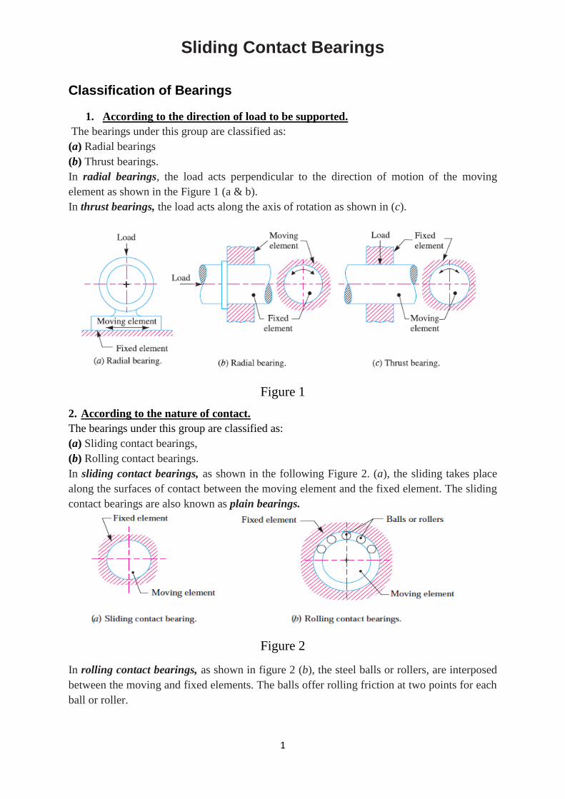
1
Sliding Contact Bearings
Classification of Bearings
1. According to the direction of load to be supported.
The bearings under this group are classified as:
(a) Radial bearings
(b) Thrust bearings.
In radial bearings, the load acts perpendicular to the direction of motion of the moving
element as shown in the Figure 1 (a & b).
In thrust bearings, the load acts along the axis of rotation as shown in (c).
Figure 1
2. According to the nature of contact.
The bearings under this group are classified as:
(a) Sliding contact bearings,
(b) Rolling contact bearings.
In sliding contact bearings, as shown in the following Figure 2. (a), the sliding takes place
along the surfaces of contact between the moving element and the fixed element. The sliding
contact bearings are also known as plain bearings.
Figure 2
In rolling contact bearings, as shown in figure 2 (b), the steel balls or rollers, are interposed
between the moving and fixed elements. The balls offer rolling friction at two points for each
ball or roller.

2
Types of Sliding Contact Bearings
The sliding contact bearings in which the sliding action is guided in a straight line and
carrying radial loads, as shown in figure 3 (a), may be called slipper or guide bearings. Such
type of bearings are usually found in cross-head of steam engines.
Figure 3
The sliding contact bearings in which the sliding action is along the circumference of a circle
or an arc of a circle and carrying radial loads are known as journal or sleeve bearings. When
the angle of contact of the bearing with the journal is 360° as shown in the above figure (a),
then the bearing is called a full journal bearing. This type of bearing is commonly used in
industrial machinery to accommodate bearing loads in any radial direction.
When the angle of contact of the bearing with the journal is 120°, as shown in figure 3 (b),
then the bearing is said to be partial journal bearing. This type of bearing has less friction
than full journal bearing, but it can be used only where the load is always in one direction.
The most common application of the partial journal bearings is found in rail road car axles.
The full and partial journal bearings may be called as clearance bearings because the
diameter of the journal is less than that of bearing.
When a partial journal bearing has no clearance i.e. the diameters of the journal and bearing
are equal, then the bearing is called a fitted bearing, as shown in figure 3 (c).
The sliding contact bearings, according to the thickness of layer of the lubricant between the
bearing and the journal, may also be classified as follows:
1. Thick film bearings. The thick film bearings are those in which the working surfaces are
completely separated from each other by the lubricant. Such type of bearings are also called
as hydrodynamic lubricated bearings.
2. Thin film bearings. The thin film bearings are those in which, although lubricant is
present, the working surfaces partially contact each other atleast part of the time. Such type of
bearings are also called boundary lubricated bearings.
3. Zero film bearings. The zero film bearings are those which operate without any lubricant
present.
4. Hydrostatic or externally pressurized lubricated bearings. The hydrostatic bearings are
those which can support steady loads without any relative motion between the journal and the
bearing. This is achieved by forcing externally pressurized lubricant between the members.
Hydrodynamic Lubricated Bearings
We have already discussed that in hydrodynamic lubricated bearings, there is a thick film of
lubricant between the journal and the bearing. A little consideration will show that when the

3
bearing is supplied with sufficient lubricant, a pressure is build up in the clearance space
when the journal is rotating about an axis that is eccentric with the bearing axis. The load can
be supported by this fluid pressure without any actual contact between the journal and
bearing. The load carrying ability of a hydrodynamic bearing arises simply because a viscous
fluid resists being pushed around. Under the proper conditions, this resistance to motion will
develop a pressure distribution in the lubricant film that can support a useful load. The load
supporting pressure in hydrodynamic bearings arises from either:
1. The flow of a viscous fluid in a converging channel (known as wedge film lubrication).
2. The resistance of a viscous fluid to being squeezed out from between approaching surfaces
(known as squeeze film lubrication).
Assumptions in Hydrodynamic Lubricated Bearings
The following are the basic assumptions used in the theory of hydrodynamic lubricated
bearings:
1. The lubricant obeys Newton's law of viscous flow.
2. The pressure is assumed to be constant throughout the film thickness.
3. The lubricant is assumed to be incompressible.
4. The viscosity is assumed to be constant throughout the film.
5. The flow is one dimensional, i.e. the side leakage is neglected.
Important Factors for the Formation of Thick Oil Film in Hydrodynamic Lubricated
Bearings
According to Reynolds, the following factors are essential for the formation of a thick film of
oil in hydrodynamic lubricated bearings:
1. A continuous supply of oil.
2. A relative motion between the two surfaces in a direction approximately tangential to the
surfaces.
3. The ability of one of the surfaces to take up a small inclination to the other surface in the
direction of the relative motion.
4. The line of action of resultant oil pressure must coincide with the line of action of the
external load between the surfaces.
Wedge Film Journal Bearings
The load carrying ability of a wedge-film journal bearing results when the journal and/or the
bearing rotates relative to the load. The most common case is that of a steady load, a fixed
(nonrotating) bearing and a rotating journal. Fig.4 (a) shows a journal at rest with metal to
metal contact at A on the line of action of the supported load. When the journal rotates slowly
in the anticlockwise direction, as shown in Fig.4 (b), the point of contact will move to B, so
that the angle AOB is the angle of sliding friction of the surfaces in contact at B. In the
absence of a lubricant, there will be dry metal to metal friction. If a lubricant is present in the
clearance space of the bearing and journal, then a thin absorbed film of the lubricant may
partly separate the surface, but a continuous fluid film completely separating the surfaces will
not exist because of slow speed.

4
Figure 4
When the speed of the journal is increased, a continuous fluid film is established as in (c).
The center of the journal has moved so that the minimum film thickness is at C. It may be
noted that from D to C in the direction of motion, the film is continually narrowing and hence
is a converging film. The curved converging film may be considered as a wedge shaped film
of a slipper bearing wrapped around the journal. A little consideration will show that from C
to D in the direction of rotation, as shown in (c), the film is diverging and cannot give rise to
a positive pressure or a supporting action. The following Figure 5 shows the two views of the
bearing shown in (c) above, with the variation of pressure in the converging film. Actually,
because of side leakage, the angle of contact on which pressure acts is less than 180°.
Figure 5
Lubricants
The lubricants are used in bearings to reduce friction between the rubbing surfaces and to
carry away the heat generated by friction. It also protects the bearing against corrosion. All
lubricants are classified into the following three groups:
1. Liquid, 2. Semi-liquid, and 3. Solid.
The liquid lubricants usually used in bearings are mineral oils and synthetic oils. The mineral
oils are most commonly used because of their cheapness and stability. The liquid lubricants
are usually preferred where they may be retained. A grease is a semi-liquid lubricant having
higher viscosity than oils. The greases are employed where slow speed and heavy pressure
exist and where oil drip from the bearing is undesirable. The solid lubricants are useful in
reducing friction where oil films cannot be maintained because of pressures or temperatures.
They should be softer than materials being lubricated. A graphite is the most common of the
solid lubricants either alone or mixed with oil or grease.

5
Properties of Lubricants
1. Viscosity. It is the measure of degree of fluidity of a liquid. It is a physical property by
virtue of which an oil is able to form, retain and offer resistance to shearing a buffer film-
under heat and pressure. The greater the heat and pressure, the greater viscosity is required of
a lubricant to prevent thinning and squeezing out of the film. The fundamental meaning of
viscosity may be understood by considering a flat plate moving under a force P parallel to a
stationary plate, the two plates being separated by a thin film of a fluid lubricant of thickness
h, as shown in Fig.6. The particles of the lubricant adhere strongly to the moving and
stationary plates. The motion is accompanied by a linear slip or shear between the particles
throughout the entire height (h) of the film thickness. If A is the area of the plate in contact
with the lubricant, then the unit shear stress is given by
𝝉 = 𝑷
𝑨
According to Newton's law of viscous flow, the magnitude of this shear stress varies directly
with the velocity gradient (dV / dy). It is assumed that
(a) The lubricant completely fills the space between the two surfaces,
(b) The velocity of the lubricant at each surface is same as that of the surface, and
(c) Any flow of the lubricant perpendicular to the velocity of the plate is negligible.
𝝉 = 𝑷
𝑨 ∝
𝒅𝑽
𝒅𝒚 𝒐𝒓 𝝉 = 𝒁 ×
𝒅𝑽
𝒅𝒚
Where Z is a constant of proportionality and is known as absolute viscosity (or simply
viscosity) of the lubricant.
Figure 6
When the thickness of the fluid lubricant is small which is the case for bearings, then the
velocity gradient is very nearly constant as shown in Fig.6, so that
𝑑𝑉
𝑑𝑦=
𝑉
𝑦=
𝑉
ℎ
∴ 𝜏 = 𝑍 ×𝑉
ℎ 𝑜𝑟 𝑍 = 𝜏 ×
ℎ
𝑉

6
When is in N/m2, h is in meters and V is in m/s, then the unit of absolute viscosity is given
by
However, the common practice is to express the absolute viscosity in mass units, such that
Thus the unit of absolute viscosity in S.I. units is kg / m-s.
The viscosity of the lubricant is measured by Saybolt universal viscometer. It determines the
time required for a standard volume of oil at a certain temperature to flow under a certain
head through a tube of standard diameter and length. The time so determined in seconds is
the Saybolt universal viscosity. In order to convert Saybolt universal viscosity in seconds to
absolute viscosity (in kg / m-s), the following formula may be used:
2. Oiliness. It is a joint property of the lubricant and the bearing surfaces in contact. It is a
measure of the lubricating qualities under boundary conditions where base metal to metal is
prevented only by absorbed film. There is no absolute measure of oiliness.
3. Density. This property has no relation to lubricating value but is useful in changing the
kinematic viscosity to absolute viscosity.
Mathematically Absolute viscosity = × Kinematic viscosity (in m2/s)
Where = Density of the lubricating oil.
The density of most of the oils at 15.5°C varies from 860 to 950 kg / m3 (the average value
may be taken as 900 kg / m3). The density at any other temperature (t) may be obtained from
the following relation, i.e.
t = 15.5 – 0.000 657 t
Where 15.5 = Density of oil at 15.5° C.
4. Viscosity index. The term viscosity index is used to denote the degree of variation of
viscosity with temperature.
5. Flash point. It is the lowest temperature at which an oil gives off sufficient vapor to
support a momentary flash without actually setting fire to the oil when a flame is brought
within 6 mm at the surface of the oil.
6. Fire point. It is the temperature at which an oil gives off sufficient vapor to burn it
continuously when ignited.
7. Pour point or freezing point. It is the temperature at which an oil will cease to flow when
cooled.

7
A hydrodynamic journal bearing is shown in Fig.7, in which O is the center of the journal and
O ‘is the center of the bearing.
Let D = Diameter of the bearing,
d = Diameter of the journal,
And l = Length of the bearing.
Figure 7
The following terms used in hydrodynamic journal bearing are important from the subject
point of view:
1. Diametral clearance. It is the difference between the diameters of the bearing and the
journal. Mathematically, diametral clearance,
c = D – d
Note: The diametral clearance (c) in a bearing should be small enough to produce the
necessary velocity gradient, so that the pressure built up will support the load. Also the small
clearance has the advantage of decreasing side leakage. However, the allowance must be
made for manufacturing tolerances in the journal and bushing. A commonly used clearance in
industrial machines is 0.025 mm per cm of journal diameter.
2. Radial clearance. It is the difference between the radii of the bearing and the journal.
Mathematically, radial clearance,
𝑐1 = 𝑅 − 𝑟 =𝐷−𝑑
2=
𝑐
2
3. Diametral clearance ratio. It is the ratio of the diametral clearance to the diameter of the
journal. Mathematically, diametral clearance ratio
=𝑐
𝑑=
𝐷−𝑑
𝑑

8
4. Eccentricity. It is the radial distance between the center (O) of the bearing and the
displaced center (O ‘) of the bearing under load. It is denoted by e.
5. Minimum oil film thickness. It is the minimum distance between the bearing and the
journal, under complete lubrication condition. It is denoted by h0 and occurs at the line of
centers as shown in Fig.7. Its value may be assumed as c / 4.
6. Attitude or eccentricity ratio. It is the ratio of the eccentricity to the radial clearance.
Mathematically, attitude or eccentricity ratio,
𝜀 =𝑒
𝑐1=
𝑐1−ℎ𝑜
𝑐1= 1 −
ℎ𝑜
𝑐1= 1 −
2ℎ𝑜
𝑐
7. Short and long bearing. If the ratio of the length to the diameter of the journal (i.e. l / d) is
less than 1, then the bearing is said to be short bearing. On the other hand, if l / d is greater
than 1, then the bearing is known as long bearing.
Notes:
1. When the length of the journal (l) is equal to the diameter of the journal (d), then the
bearing is called square bearing.
2. Because of the side leakage of the lubricant from the bearing, the pressure in the film is
atmospheric at the ends of the bearing. The average pressure will be higher for a long bearing
than for a short or square bearing. Therefore, from the stand point of side leakage, a bearing
with a large l / d ratio is preferable. However, space requirements, manufacturing, tolerances
and shaft deflections are better met with a short bearing. The value of l / d may be taken as 1
to 2 for general industrial machinery. In crank shaft bearings, the l / d ratio is frequently less
than 1.
Bearing Characteristic Number and Bearing Modulus for Journal Bearings
The coefficient of friction in design of bearings is of great importance, because it affords a
means for determining the loss of power due to bearing friction. It has been shown by
experiments that the coefficient of friction for a full lubricated journal bearing is a function of
three variables, i.e.
(i) 𝑍𝑁
𝑝 (ii)
𝑑
𝑐 (iii)
𝑙
𝑑
Therefore the coefficient of friction may be expressed as
𝜇 = 𝜑 (𝑍𝑁
𝑝,
𝑑
𝑐,
𝑙
𝑑)
Where 𝜇 = Coefficient of friction,
𝜑 = A functional relationship,
Z = Absolute viscosity of the lubricant, in kg / m-s,
N = Speed of the journal in r.p.m.,

9
p = Bearing pressure on the projected bearing area in N/mm2,
= Load on the journal ÷ l × d
d = Diameter of the journal,
l = Length of the bearing, and
c = Diametral clearance.
The factor ZN / p is termed as bearing characteristic number and is a dimensionless number.
Coefficient of Friction for Journal Bearings
In order to determine the coefficient of friction for well lubricated full journal bearings, the
following empirical relation established by McKee based on the experimental data, may be
used.
Coefficient of friction,
𝜇 =33
108 (𝑍𝑁
𝑝) (
𝑑
𝑐) + 𝑘 (When Z is in kg / m-s and p is in N / mm2)
Where Z, N, p, d and c have usual meanings as discussed in previous article, and
k = Factor to correct for end leakage. It depends upon the ratio of length to the diameter of the
bearing (i.e. l / d).
= 0.002 for l / d ratios of 0.75 to 2.8.
The operating values of ZN / p should be compared with values given in special Tables to
ensure safe margin between operating conditions and the point of film breakdown.

10

11
Critical Pressure of the Journal Bearing
The pressure at which the oil film breaks down so that metal to metal contact begins, is
known as critical pressure or the minimum operating pressure of the bearing. It may be
obtained by the following empirical relation, i.e. Critical pressure or minimum operating
pressure,
𝑝 =𝑍𝑁
4.75×10⁶ (𝑑
𝑐)
2(
𝑙
𝑑+𝑙) 𝑁/𝑚𝑚2 ...(when Z is in kg / m-s)
Sommerfeld Number
The Sommerfeld number is also a dimensionless parameter used extensively in the design of
journal bearings. Mathematically,
𝑠𝑜𝑚𝑚𝑒𝑟𝑓𝑒𝑙𝑑 𝑛𝑢𝑚𝑏𝑒𝑟 =𝑍𝑁
𝑝(
𝑑
𝑐)
2
For design purposes, its value is taken as follows:
𝑍𝑁
𝑝(
𝑑
𝑐)
2= 14.3 × 10⁶ (When Z is in kg / m-s and p is in N / mm2)
Heat Generated in a Journal Bearing
The heat generated in a bearing is due to the fluid friction and friction of the parts having
relative motion. Mathematically, heat generated in a bearing,
Qg = μ.W.V N-m/s or J/s or watts
Where μ = Coefficient of friction,
W = Load on the bearing in N,
= Pressure on the bearing in N/mm2 × Projected area of the bearing in mm2 = p (l × d),
V = Rubbing velocity in m/s = 𝜋𝑑𝑁
60
d is in meters, and N = Speed of the journal in r.p.m.
After the thermal equilibrium has been reached, heat will be dissipated at the outer surface of
the bearing at the same rate at which it is generated in the oil film. The amount of heat
dissipated will depend upon the temperature difference, size and mass of the radiating surface
and on the amount of air flowing around the bearing. However, for the convenience in
bearing design, the actual heat dissipating area may be expressed in terms of the projected
area of the journal.
Heat dissipated by the bearing,
𝑄𝑑 = 𝐶. 𝐴 (𝑡𝑏 − 𝑡𝑎) 𝐽
𝑠𝑜𝑟 𝑊
Where C = Heat dissipation coefficient in W/m2/°C,
A = Projected area of the bearing in m2 = l × d,

12
tb = Temperature of the bearing surface in °C, and
ta = Temperature of the surrounding air in °C.
The value of C have been determined experimentally by O. Lasche. The values depend upon
the type of bearing, its ventilation and the temperature difference. The average values of C (in
W/m2/°C),
for journal bearings may be taken as follows :
For unventilated bearings (Still air) = 140 to 420 W/m2/°C
For well ventilated bearings = 490 to 1400 W/m2/°C
It has been shown by experiments that the temperature of the bearing (tb) is approximately
mid-way between the temperature of the oil film (t0) and the temperature of the outside air
(ta). In other words,
𝑡𝑏 − 𝑡𝑎 =1
2(𝑡𝑜 − 𝑡𝑎)
Notes:
1. For well-designed bearing, the temperature of the oil film should not be more than 60°C,
otherwise the viscosity of the oil decreases rapidly and the operation of the bearing is found
to suffer. The temperature of the oil film is often called as the operating temperature of the
bearing.
2. In case the temperature of the oil film is higher, then the bearing is cooled by circulating
water through coils built in the bearing.
3. The mass of the oil to remove the heat generated at the bearing may be obtained by
equating the heat generated to the heat taken away by the oil. We know that the heat taken
away by the oil,
Qt = m . S . t J/s or watts
Where m = Mass of the oil in kg / s,
S = Specific heat of the oil. Its value may be taken as 1840 to 2100 J / kg / °C,
t = Difference between outlet and inlet temperature of the oil in °C.
Copyright © 2022 FDOKUMEN