spherical bearings loader slot bearings rod end bearings ...
91
spherical bearings loader slot bearings rod end bearings sleeve bearings A STRO D IVISION P RODUCTS AND E NGINEERING
-
Upload
khangminh22 -
Category
Documents
-
view
0 -
download
0
Transcript of spherical bearings loader slot bearings rod end bearings ...

spherical bearings
loader slot bearings
rod end bearings
sleeve bearings
AS T R O D I V I S I O N
PR O D U C T S A N D
EN G I N E E R I N G

© 2014 NHBB, Inc. NHBB reserves the right to change specifications and other information included in this catalog without notice. All information, data and dimension tables in this catalog have been carefully compiled and thoroughly checked. However, no responsibility for possible errors or omissions can be assumed.
The Astro Division of NHBB has firmly established its leadership position in the rod end and spherical-bearing business by providing engineering solutions for complex application problems.
Product quality is NHBB’s first priority. The employees of the Astro Division are dedicated to manufacturing products that meet the exacting specifications of today’s demanding market environment. Initiatives such as AS9100 Rev. C, ISO 9001:2008 and D6-82479 are the foundation for our organization’s commitment to quality.
While the Astro Division is well positioned to provide a standard product line at a competitive price, the Division also has extraordinary strength in custom design and production. This catalog is designed to help you find both the custom and standard products you may need for your applications.
Please contact Astro’s sales or engineering groups for assistance with your specific requirements.
Welcome to the Astro Division of NHBB

Table of Contents
1
SECTION 1 SPHERICAL BEARINGS – Self-LubricatingAS81820 Narrow . . . . . . . . . . . . . . . . . . . . . . . . . . . . . . . . . . . . . . . . . . . . . . . . . . . . . . . . . . . . . . . . . . . . . . . . . . . . . . . . . 4
AS81820 Wide . . . . . . . . . . . . . . . . . . . . . . . . . . . . . . . . . . . . . . . . . . . . . . . . . . . . . . . . . . . . . . . . . . . . . . . . . . . . . . . . . . . 5 AS81820 Lined Bore Series – Narrow . . . . . . . . . . . . . . . . . . . . . . . . . . . . . . . . . . . . . . . . . . . . . . . . . . . . . . . . . . . . . . . . 6 AS81820 Lined Bore Series – Wide . . . . . . . . . . . . . . . . . . . . . . . . . . . . . . . . . . . . . . . . . . . . . . . . . . . . . . . . . . . . . . . . . . 7 High Misalignment . . . . . . . . . . . . . . . . . . . . . . . . . . . . . . . . . . . . . . . . . . . . . . . . . . . . . . . . . . . . . . . . . . . . . . . . . . . . . . . . 8 Sealed Narrow . . . . . . . . . . . . . . . . . . . . . . . . . . . . . . . . . . . . . . . . . . . . . . . . . . . . . . . . . . . . . . . . . . . . . . . . . . . . . . . . . . 10 Sealed Wide . . . . . . . . . . . . . . . . . . . . . . . . . . . . . . . . . . . . . . . . . . . . . . . . . . . . . . . . . . . . . . . . . . . . . . . . . . . . . . . . . . . 11
SECTION 2 SPHERICAL BEARINGS – Metal-to-MetalAS81936 Beryllium Copper Ball . . . . . . . . . . . . . . . . . . . . . . . . . . . . . . . . . . . . . . . . . . . . . . . . . . . . . . . . . . . . . . . . . . . . 14
AS8976 – Narrow . . . . . . . . . . . . . . . . . . . . . . . . . . . . . . . . . . . . . . . . . . . . . . . . . . . . . . . . . . . . . . . . . . . . . . . . . . . . . . . 16 Narrow . . . . . . . . . . . . . . . . . . . . . . . . . . . . . . . . . . . . . . . . . . . . . . . . . . . . . . . . . . . . . . . . . . . . . . . . . . . . . . . . . . . . . . . . 18 Wide . . . . . . . . . . . . . . . . . . . . . . . . . . . . . . . . . . . . . . . . . . . . . . . . . . . . . . . . . . . . . . . . . . . . . . . . . . . . . . . . . . . . . . . . . . 19 High Misalignment . . . . . . . . . . . . . . . . . . . . . . . . . . . . . . . . . . . . . . . . . . . . . . . . . . . . . . . . . . . . . . . . . . . . . . . . . . . . . . . 20 High Temperature . . . . . . . . . . . . . . . . . . . . . . . . . . . . . . . . . . . . . . . . . . . . . . . . . . . . . . . . . . . . . . . . . . . . . . . . . . . . . . . 21
SECTION 3 LOADER SLOT BEARINGSPlain . . . . . . . . . . . . . . . . . . . . . . . . . . . . . . . . . . . . . . . . . . . . . . . . . . . . . . . . . . . . . . . . . . . . . . . . . . . . . . . . . . . . . . . . . . 24
Sealed . . . . . . . . . . . . . . . . . . . . . . . . . . . . . . . . . . . . . . . . . . . . . . . . . . . . . . . . . . . . . . . . . . . . . . . . . . . . . . . . . . . . . . . . 25 Rod End – 2-Piece Male Thread . . . . . . . . . . . . . . . . . . . . . . . . . . . . . . . . . . . . . . . . . . . . . . . . . . . . . . . . . . . . . . . . . . . . 26
SECTION 4 ROD END BEARINGS – Self-LubricatingAS81935/4 Narrow – Male Thread . . . . . . . . . . . . . . . . . . . . . . . . . . . . . . . . . . . . . . . . . . . . . . . . . . . . . . . . . . . . . . . . . . 30
AS81935/1 Wide – Male Thread . . . . . . . . . . . . . . . . . . . . . . . . . . . . . . . . . . . . . . . . . . . . . . . . . . . . . . . . . . . . . . . . . . . . 31 AS81935/5 Narrow – Female Thread . . . . . . . . . . . . . . . . . . . . . . . . . . . . . . . . . . . . . . . . . . . . . . . . . . . . . . . . . . . . . . . . 32 AS81935/2 Wide – Female Thread . . . . . . . . . . . . . . . . . . . . . . . . . . . . . . . . . . . . . . . . . . . . . . . . . . . . . . . . . . . . . . . . . . 33 3-Piece Heavy Duty – Male & Female Threads . . . . . . . . . . . . . . . . . . . . . . . . . . . . . . . . . . . . . . . . . . . . . . . . . . . . . . . . 34 3-Piece High Misalignment – Male & Female Threads . . . . . . . . . . . . . . . . . . . . . . . . . . . . . . . . . . . . . . . . . . . . . . . . . . . 35
SECTION 5 ROD END BEARINGS – Metal-to-Metal3-Piece Male Thread . . . . . . . . . . . . . . . . . . . . . . . . . . . . . . . . . . . . . . . . . . . . . . . . . . . . . . . . . . . . . . . . . . . . . . . . . . . . . 38
3-Piece Female Thread . . . . . . . . . . . . . . . . . . . . . . . . . . . . . . . . . . . . . . . . . . . . . . . . . . . . . . . . . . . . . . . . . . . . . . . . . . . 39 3-Piece Heavy Duty – Male & Female Threads . . . . . . . . . . . . . . . . . . . . . . . . . . . . . . . . . . . . . . . . . . . . . . . . . . . . . . . . 40 3-Piece Standard – Male & Female Threads . . . . . . . . . . . . . . . . . . . . . . . . . . . . . . . . . . . . . . . . . . . . . . . . . . . . . . . . . . 41 3-Piece High Misalignment – Male Thread . . . . . . . . . . . . . . . . . . . . . . . . . . . . . . . . . . . . . . . . . . . . . . . . . . . . . . . . . . . . 42 3-Piece High Misalignment – Female Thread . . . . . . . . . . . . . . . . . . . . . . . . . . . . . . . . . . . . . . . . . . . . . . . . . . . . . . . . . . 43
SECTION 6 SLEEVE BEARINGS – Self-LubricatingAS81934/1 Plain . . . . . . . . . . . . . . . . . . . . . . . . . . . . . . . . . . . . . . . . . . . . . . . . . . . . . . . . . . . . . . . . . . . . . . . . . . . . . . . . 46
AS81934/2 Flanged . . . . . . . . . . . . . . . . . . . . . . . . . . . . . . . . . . . . . . . . . . . . . . . . . . . . . . . . . . . . . . . . . . . . . . . . . . . . . 48
SECTION 7 ENGINEERINGProduct Applications . . . . . . . . . . . . . . . . . . . . . . . . . . . . . . . . . . . . . . . . . . . . . . . . . . . . . . . . . . . . . . . . . . . . . . . . . . . . . 52
Bearing Types and Details of Construction . . . . . . . . . . . . . . . . . . . . . . . . . . . . . . . . . . . . . . . . . . . . . . . . . . . . . . . . . . . 53 Bearing Materials . . . . . . . . . . . . . . . . . . . . . . . . . . . . . . . . . . . . . . . . . . . . . . . . . . . . . . . . . . . . . . . . . . . . . . . . . . . . . . . . 58 Self-Lubricating Liner Systems . . . . . . . . . . . . . . . . . . . . . . . . . . . . . . . . . . . . . . . . . . . . . . . . . . . . . . . . . . . . . . . . . . . . . 59 Grease and Dry Film Lubricants . . . . . . . . . . . . . . . . . . . . . . . . . . . . . . . . . . . . . . . . . . . . . . . . . . . . . . . . . . . . . . . . . . . . 66 Locking Devices, Keys and Keyways . . . . . . . . . . . . . . . . . . . . . . . . . . . . . . . . . . . . . . . . . . . . . . . . . . . . . . . . . . . . . . . . 68 Sealed Bearings . . . . . . . . . . . . . . . . . . . . . . . . . . . . . . . . . . . . . . . . . . . . . . . . . . . . . . . . . . . . . . . . . . . . . . . . . . . . . . . . 70 Bearing Installation and Retention . . . . . . . . . . . . . . . . . . . . . . . . . . . . . . . . . . . . . . . . . . . . . . . . . . . . . . . . . . . . . . . . . . 71 Staking Tool Sets – Ordering Information . . . . . . . . . . . . . . . . . . . . . . . . . . . . . . . . . . . . . . . . . . . . . . . . . . . . . . . . . . . . . 77 Load Ratings and Misalignment Capabilities . . . . . . . . . . . . . . . . . . . . . . . . . . . . . . . . . . . . . . . . . . . . . . . . . . . . . . . . . . 78 Bearing Selection Factors . . . . . . . . . . . . . . . . . . . . . . . . . . . . . . . . . . . . . . . . . . . . . . . . . . . . . . . . . . . . . . . . . . . . . . . . . 84 Specifications Compliance . . . . . . . . . . . . . . . . . . . . . . . . . . . . . . . . . . . . . . . . . . . . . . . . . . . . . . . . . . . . . . . . . . . . . . . . 86 Inch/Metric Conversion Table . . . . . . . . . . . . . . . . . . . . . . . . . . . . . . . . . . . . . . . . . . . . . . . . . . . . . . . . . . . . . . . . . . . . . . 87 Fahrenheit/Celsius Conversion Table . . . . . . . . . . . . . . . . . . . . . . . . . . . . . . . . . . . . . . . . . . . . . . . . . . . . . . . . . . . . . . . . 88

2

AS81820 Narrow . . . . . . . . . . . . . . . . . . . . . . . . . . . . . . . . . . . . . . . . . . . . . . . . . . . . . .4
AS81820 Wide . . . . . . . . . . . . . . . . . . . . . . . . . . . . . . . . . . . . . . . . . . . . . . . . . . . . . . .5
AS81820 Lined Bore Series – Narrow . . . . . . . . . . . . . . . . . . . . . . . . . . . . . . . . . . . . . .6
AS81820 Lined Bore Series – Wide . . . . . . . . . . . . . . . . . . . . . . . . . . . . . . . . . . . . . . . .7
High Misalignment . . . . . . . . . . . . . . . . . . . . . . . . . . . . . . . . . . . . . . . . . . . . . . . . . . . .8
Sealed Narrow . . . . . . . . . . . . . . . . . . . . . . . . . . . . . . . . . . . . . . . . . . . . . . . . . . . . . .10
Sealed Wide . . . . . . . . . . . . . . . . . . . . . . . . . . . . . . . . . . . . . . . . . . . . . . . . . . . . . . . .11
3
SECTION 1SPHERICAL BEARINGS – Self-Lubricating

SPHERICAL BEARINGS – Self-Lubricating
Notes:• Bearing sizes 3 through 16 listed in the tables are approved for procurement to
AS81820 and Aerospace Standards AS14101 through AS14104.
• Bearing sizes 18 through 24 listed are not included in current Aerospace Standards, but are offered as NHBB catalog items only.
• Temperature: Operating temperature range per AS81820 is -65° to 325°F. Broader temperature capabilities are achievable.
MaterialsPart No. Ball Race Liner
Catalog No. CRES 440C CRES 17-4PH PTFE/Fabric AMS 5630 AMS 5643 Bonded to Race Rc55-62 Rc28-37 I.D. No Lub. Required
Catalog No. CRES PH13-8Mo CRES 17-4PH PTFE/Fabric+ 13-8 AMS 5629 AMS 5643 Bonded to Race Rc43-47 Rc28-37 I.D. No Lub. Required
4
CHAMFER TYPE
LINERT
O/ O O/ B O/ D
0/ .005
0/ .005
Q(Ref.)
SIZE (TYP.)
-3 thru -5
-6 thru -10
-12 thru -24
x 45°
x 45°
x 45°
V-GROOVE TYPE.005 RMAX.
(TYP.)
A
A
x 45° CHAMFER (TY P .)
STAKING GROOVE DETAIL
20° MIN. -3, -4 and -5A ONLY.30° MIN. -5, -6 thru -24.
30°
P
.040
.030
.030
.020
.020
.010
SIZE
-6 thru -24
-3 thru -5A R
R
.010
.005
.017
.010.015.005 E DIA.
W
A
AS81820 Narrow
Inch Inch Inch Inch Inch Inch Inch Inch Degree lbs. lbs. lbs. lbs.
MS14101 +.0000 +.0000 +.000 ±.005 Min. Ref. +.000 +.000 Ref. Ref.
MS14104 -.0005 -.0005 -.002 -.008 -.010
ADB3V(L) -3 .1900 .5625 .281 .218 .293 .406 .500 .025 10° 3975 150 1500 .020
ADB4V(L) -4 .2500 .6562 .343 .250 .364 .500 .594 .025 10° 6040 430 3320 .020
ADB5V(L) -5 .3125 .7500 .375 .281 .419 .562 .650 .035 10° 8750 700 5460 .030
ADB5VA(L) -5A .3125 .7500 .375 .281 .419 .562 .660 .035 10° 8750 700 5460 .030
ADB6V(L) -6 .3750 .8125 .406 .312 .475 .656 .712 .035 9° 10540 1100 6600 .040
ADB7V(L) -7 .4375 .9062 .437 .343 .530 .718 .806 .035 8° 13200 1400 8050 .050
ADB8V(L) -8 .5000 1.0000 .500 .390 .600 .813 .876 .055 8° 17900 2100 10400 .070
ADB9V(L) -9 .5625 1.0937 .562 .437 .670 .875 .970 .055 8° 23200 3680 13000 .090
ADB10V(L) -10 .6250 1.1875 .625 .500 .739 .968 1.063 .055 8° 30500 4720 16450 .120
ADB12V(L) -12 .7500 1.4375 .750 .593 .920 1.187 1.313 .055 8° 46400 6750 23600 .210
ADB14V(L) -14 .8750 1.5625 .875 .703 .980 1.312 1.438 .055 8° 62200 9350 30250 .270
ADB16V(L) -16 1.0000 1.7500 1.000 .797 1.118 1.500 1.626 .055 8° 82200 12160 38000 .390
ADB18V(L) – 1.1250 2.1250 1.125 .900 1.334 1.750 2.003 .055 8° 105880 13500 42350 .720
ADB20V(L) – 1.2500 2.3125 1.250 1.000 1.473 1.937 2.190 .055 8° 131230 16930 52490 .930
ADB22V(L) – 1.3750 2.5625 1.375 1.100 1.654 2.156 2.440 .055 8° 161700 20750 64680 1.280
ADB24V(L) – 1.5000 2.8125 1.500 1.200 1.794 2.344 2.690 .055 8° 191973 24950 77110 1.670
Part (B) (D) (W) (T) (O) (E) (P) (Q°) Number MS Dash Bore Outside Ball Race Shoulder Ball Pitch Groove Misalignment Limit Static Limit Static Dynamic Osc. V-Grooved* No. Diameter Diameter Width Width Diameter Diameter Diameter Depth Radial Load Axial Load Radial Load Weight
*For chamfered version, delete ‘V’ from part number.

Inch Inch Inch Inch Inch Inch Inch Inch Degree lbs. lbs. lbs. lbs.
MS14102 +.0000 +.0000 +.000 Min. Ref. +.000 +.000 Ref. Ref.
MS14103 -.0005 -.0005 -.002 ±.005 -.008 -.010
ADW3V(L) -3 .1900 .6250 .437 .327 .300 .531 .563 .025 15° 2500 1770 4900 .031
ADW4V(L) -4 .2500 .6250 .437 .327 .300 .531 .563 .025 15° 5500 1770 4900 .031
ADW5V(L) -5 .3125 .6875 .437 .317 .360 .593 .625 .025 14° 9400 1640 6050 .035
ADW6V(L) -6 .3750 .8125 .500 .406 .466 .687 .712 .035 8° 13700 2630 8310 .060
ADW7V(L) -7 .4375 .9375 .562 .442 .537 .781 .837 .035 10° 20700 3650 11750 .080
ADW7V52(L) -7A .4375 .9062 .562 .442 .537 .781 .806 .035 10° 19700 3650 11750 .080
ADW8V(L) -8 .5000 1.0000 .625 .505 .607 .875 .900 .035 9° 21400 4970 14950 .100
ADW9V(L) -9 .5625 1.1250 .687 .536 .721 1.000 1.025 .035 10° 26600 5370 18100 .135
ADW10V(L) -10 .6250 1.1875 .750 .567 .747 1.062 1.087 .035 12° 29000 6130 20250 .160
ADW12V(L) -12 .7500 1.3750 .875 .630 .845 1.250 1.251 .055 13° 37000 7730 26200 .240
ADW14V(L) -14 .8750 1.6250 .875 .755 .995 1.375 1.501 .055 6° 65200 10800 33600 .350
ADW16V(L) -16 1.0000 2.1250 1.375 1.005 1.269 1.875 2.001 .055 12° 104000 19300 56250 .970
ADW18V(L) – 1.1250 2.2500 1.437 1.067 1.338 1.968 2.128 .055 14° 142570 19640 57000 1.000
ADW20V(L) – 1.2500 2.3750 1.500 1.130 1.460 2.093 2.253 .055 13° 159200 21970 63680 1.120
ADW20-5V(L) – 1.2500 2.0000 1.093 .942 1.406 1.781 1.878 .055 6° 112360 14890 44940 .564
ADW22V(L) – 1.3750 2.5625 1.687 1.223 1.535 2.281 2.440 .055 15° 190000 25970 76000 1.390
ADW24V(L) – 1.5000 2.6875 1.687 1.223 1.693 2.390 2.567 .055 14° 199000 25970 79640 1.480
P/N Series NHBB P/N DescriptionMS14101 ADB V Narrow Grooved
MS14102 ADW Wide Chamfered
MS14103 ADW V Wide Grooved
MS14104 ADB Narrow Chamfered
5
AS81820 Wide
† Cadmium plate MS14102 & MS14104 O.D. and O.D. chamfers per AMS-QQ-P-416, Type II, Class 2. Dimensions apply after plating.
†† Cadmium plate MS14101 & MS14103 O.D. and on the flats between the outside diameter and the grooves per AMS-QQ-P-416, Type II, Class 2. Dimensions apply after plating.
Part (B) (D) (W) (T) (O) (E) (P) (Q°) Number MS Dash Bore Outside Ball Race Shoulder Ball Pitch Groove Misalignment Limit Static Limit Static Dynamic Osc. V-Grooved* No. Diameter Diameter Width Width Diameter Diameter Diameter Depth Radial Load Axial Load Radial Load Weight
*For chamfered version, delete ‘V’ from part number.
NHBB P/N
AD X X V X X X X (L)Indicates L1420 Liner(For Optional Liners, contact NHBB Applications Engineering)
No Suffix Indicates Standard Race Diameter“/010” Indicates .010 Oversize Race Diameter (For Repair Only)“/020” Indicates .020 Oversize Race Diameter (For Repair Only)
Letter “K” Indicates Low Breakaway TorqueTorqueTNo Letter Indicates Standard Breakaway TorqueTorqueT
Letter “P” Indicates Cadmium Plating††No Letter Indicates No Plating
Suffix-13-8 Indicates PH13-8Mo Ball MaterialNo Suffix Indicates 440C Ball Material
Letter “V” Indicates V-Grooved Outer Race (MS14101 & MS14103)No Letter Indicates Chamfered Outer Race (MS14102 & MS14104)
Bore Diameter: Same As Aerospace Standard P/N
“B” is Narrow Bearing. “W” is Wide Bearing.
NHBB P/N
Aerospace Standard P/N
No Letter Indicates Standard Race Diameter“T” Indicates .010 Oversize Race Diameter (For Repair Only)“U” Indicates .020 Oversize Race Diameter (For Repair Only)
No Letter Indicates Standard Breakaway TorqueLetter “K” Indicates Low Breakaway TorqueTorqueT
No Letter Indicates No PlatingLetter “P” Indicates Cadmium Plating†
No Letter Indicates 440C Ball MaterialLetter “C” Indicates PH13-8Mo Ball Material
Bore Diameter in Multiples of 1/16 inches
MS P/N
MS14101 X X X X X
No Load Breakaway TorqueBore Sizes Standard (in - lbs.) “K” Type
3 & 4 0.25 to 5.0 0 to 0.55 to 12 0.25 to 8.0 0 to 1.014 & 16 0.25 to 12.0 0 to 2.018 & 20 0.25 to 18.0 0 to 2.022 & 24 0.25 to 24.0 0 to 2.0
Radial and Axial PlayP/N Series MS14101 & MS14104
Bore Size Max. Radial Play Max. Axial Play
3K Thru 12K 0.0007 Inch 0.0028 Inch14K Thru 16K 0.0010 Inch 0.0040 Inch
P/N Series MS14102 & MS14103
Bore Size Max. Radial Play Max. Axial Play
3K Thru 12K 0.0007 Inch 0.0021 Inch14K Thru 16K 0.0010 Inch 0.0030 Inch
SPHERICAL BEARINGS – Self-Lubricating
Inch Inch Inch Inch Inch Inch Inch Degree lbs. lbs. lbs. lbs.
M81820/1 +.0000 +.0000 +.000 ±.005 Ref. +.000 +.000 Ref. Ref.
M81820/4 -.0010 -.0005 -.002 -.008 -.010
ADBL4V(L) -4 .2510 .6562 .343 .250 .500 .594 .025 10° 5550 430 2650 .020
ADBL5V(L) -5 .3135 .7500 .375 .281 .562 .660 .035 10° 7700 700 3700 .030
ADBL6V(L) -6 .3760 .8125 .406 .312 .656 .712 .035 9° 10200 1100 4900 .040
ADBL7V(L) -7 .4385 .9062 .437 .343 .718 .806 .035 8° 12950 1400 6700 .050
ADBL8V(L) -8 .5010 1.0000 .500 .390 .813 .876 .055 8° 17250 2100 8250 .070
ADBL9V(L) -9 .5635 1.0937 .562 .437 .875 .970 .055 8° 22150 3680 10600 .090
ADBL10V(L) -10 .6260 1.1875 .625 .500 .968 1.063 .055 8° 27700 4720 13250 .120
ADBL12V(L) -12 .7510 1.4375 .750 .593 1.187 1.313 .055 8° 40600 6750 19400 .210
ADBL14V(L) -14 .8760 1.5625 .875 .703 1.312 1.438 .055 8° 55950 9350 26750 .270
ADBL16V(L) -16 1.0010 1.7500 1.000 .797 1.500 1.626 .055 9° 73800 12160 35250 .390
ADBL18V(L) – 1.1260 2.1250 1.125 .900 1.750 2.001 .055 8° 94080 13500 37870 .720
ADBL20V(L) – 1.2510 2.3125 1.250 1.000 1.937 2.188 .055 8° 116250 16930 46920 .930
ADBL22V(L) – 1.3760 2.5625 1.375 1.100 2.156 2.438 .055 8° 140770 20750 56950 1.280
ADBL24V(L) – 1.5010 2.8125 1.500 1.200 2.344 2.688 .055 8° 167630 24950 67950 1.670
AS81820 Lined Bore Series – Narrow
SPHERICAL BEARINGS – Self-Lubricating
6
Notes:• All dimensions, materials and configurations of sizes 4 through 16 conform to
requirements of Aerospace Standards. Consult QPL for NHBB approvals to P/N series AS81820/1 through AS81820/4.
• Bearing sizes 18 thru 24 are not included in current Aerospace Standards but are offered as NHBB catalog items only.
• Temperature: Operating temperature range per AS81820 is -65° to 325°F. Broader temperature capabilities are achievable.
MaterialsPart No. Ball Race Liner
Catalog No. CRES PH13-8Mo CRES 17-4PH PTFE/Fabric AMS 5629 AMS 5643 Bonded to Race Cond. H-1000 Rc28-37 I.D. & Ball Bore (Rc43 min.) No Lub. Required
CHAMFER TYPE
LINERT
Q(Ref.)
V-GROOVE TYPE
SIZE (TYP.)
-4 thru -5 NARROW x 45°
-5 WIDE
-12 thru -24
x 45°
x 45°
x 45°
.030 MIN. FLAT
A
.005 MAX. BREAKEDGE BEFORELINER (TYP.)
.005 RMAX.(TYP.)
.020
.010
.040
.030
.030
.020
.025
.015
-8 thru -10 W
STAKING GROOVE DETAIL
20° MIN. -4 and -5 NARROW ONLY.30° MIN. -5 thru -24.
30°
P
SIZE-4 thru-5 NARROW ONLY-5 thru-24
R
R
.010
.005
.017
.010
E DIA.O/ B O/ D
AA
0/ .006
0/ .006
Part MS (B) (D) (W) (T) (E) (P) (Q°) Number Dash Bore Outside Ball Race Ball Pitch Groove Mis- Limit Static Limit Static Dynamic Osc. V-Grooved* No. Diameter Diameter Width Width Diameter Diameter Depth alignment Radial Load Axial Load Radial Load Weight
*For chamfered version, delete ‘V’ from part number.

Inch Inch Inch Inch Inch Inch Inch Degree lbs. lbs. lbs. lbs.
M81820/2 +.0000 +.0000 +.000 Ref. +.000 +.000 Ref. Ref.
M81820/3 -.0010 -.0005 -.002 ±.005 -.008 -.010
ADWL5V(L) -5 .3135 .6875 .437 .317 .593 .625 .025 14° 9250 1640 4450 .035
ADWL6V(L) -6 .3760 .8125 .500 .406 .687 .712 .035 8° 13000 2630 6200 .060
ADWL7V(L) -7 .4385 .9375 .562 .442 .781 .837 .035 10° 17300 3650 8250 .080
ADWL7V52(L) -7A .4385 .9062 .562 .442 .781 .806 .035 10° 17250 3650 8250 .080
ADWL8V(L) -8 .5010 1.0000 .625 .505 .875 .900 .035 9° 21400 4970 10600 .100
ADWL9V(L) -9 .5635 1.1250 .687 .536 1.000 1.025 .035 10° 26600 5370 13200 .135
ADWL10V(L) -10 .6260 1.1875 .750 .567 1.062 1.087 .035 12° 29000 6130 16150 .160
ADWL12V(L) -12 .7510 1.3750 .875 .630 1.250 1.251 .055 13° 37000 7730 24800 .240
ADWL14V(L) -14 .8760 1.6250 .875 .755 1.375 1.501 .055 6° 56000 10800 26750 .350
ADWL16V(L) -16 1.0010 2.1250 1.375 1.005 1.875 2.001 .055 12° 103300 19300 49300 .970
ADWL18V(L) – 1.1260 2.2500 1.437 1.067 1.968 2.126 .055 14° 120410 19640 48760 1.000
ADWL20V(L) – 1.2510 2.3750 1.500 1.130 2.093 2.251 .055 13° 139690 21970 56620 1.120
ADWL20-5V(L) – 1.2510 2.0000 1.093 .942 1.781 1.876 .055 6° 101540 14890 40840 .564
ADWL22V(L) – 1.3760 2.5625 1.687 1.223 2.281 2.438 .055 15° 172940 25970 70250 1.390
ADWL24V(L) – 1.5010 2.6875 1.687 1.223 2.390 2.563 .055 14° 188670 25970 76640 1.480
7
AS81820 Lined Bore Series – Wide
† Cadmium plate M81820/1 & M81820/3 O.D. and on the flats between the outside diameter and the grooves per AMS-QQ-P-416, Type II, Class 2. Dimensions apply after plating.
†† Cadmium plate M81820/2 & M81820/4 O.D. and O.D. chamfers per AMS-QQ-P-416, Type II, Class 2. Dimensions apply after plating.
NHBB P/N
ADBL X V X X X (L)Indicates L1420 Liner (For Optional Liners, contact NHBBApplications Engineering)
No Suffix Indicates Standard Race Diameter“/010” Indicates .010 Oversize Race Diameter (For Repair Only)“/020” Indicates .020 Oversize Race Diameter (For Repair Only)
Letter “K” Indicates Low Breakaway TorqueNo Letter Indicates Standard Breakaway Torque
Letter “P” Indicates Cadmium Plating††No Letter Indicates No Plating
Letter “V” Indicates V-Grooved Outer Race (M81820/1 and /3)No Letter Indicates Chamfered Outer Race (M81820/2 and /4)
Bore Diameter: Same As Aerospace Standard P/N
NHBB P/N
Aerospace Standard P/N
No Letter Indicates Standard Race Diameter“T” Indicates .010 Oversize Race Diameter (For Repair Only)“U” Indicates .020 Oversize Race Diameter (For Repair Only)
No Letter Indicates Standard Breakaway TorqueLetter “K” Indicates Low Breakaway Torque
No Letter Indicates No PlatingLetter “P” Indicates Cadmium Plating†
Bore Diameter in Multiples of 1/16 inches
AS P/N Prefix with Liner on Race Spherical Surface and Ball Bore.See below for detail table.
M81820/1 – X X X X
Aerospace Standard P/N NHBB P/N DescriptionM81820/1 ADBL V Narrow Grooved
M81820/2 ADWL Wide Chamfered
M81820/3 ADWL V Wide Grooved
M81820/4 ADBL Narrow Chamfered
Part MS (B) (D) (W) (T) (E) (P) (Q°) Number Dash Bore Outside Ball Race Ball Pitch Groove Mis- Limit Static Limit Static Dynamic Osc. V-Grooved* No. Diameter Diameter Width Width Diameter Diameter Depth alignment Radial Load Axial Load Radial Load Weight
*For chamfered version, delete ‘V’ from part number.
No Load Breakaway TorqueBore Sizes Standard (in - lbs.) “K” Type
4 (Narrow only) 1.0 to 5.0 0 to 0.55 to 12 1.0 to 15.0 0 to 1.014 to 24 1.0 to 25.0 0 to 2.0
Radial and Axial PlayP/N Series M81820/1 & M81820/4
Bore Size Max. Radial Play Max. Axial Play
3K Thru 12K 0.0007 Inch 0.0028 Inch14K Thru 16K 0.0010 Inch 0.0040 Inch
P/N Series M81820/2 & M81820/3
Bore Size Max. Radial Play Max. Axial Play
3K Thru 12K 0.0007 Inch 0.0021 Inch14K Thru 16K 0.0010 Inch 0.0030 Inch
Inch Inch Inch Inch Inch Inch Inch Ref. Inch Inch Inch Inch Inch - lbs. lbs. lbs. lbs.
+.0000 +.0000 +.000 +.010 Ref. Ref. +.000 +.000 +.000 +.000 +.000 Ref.
-.0005 -.0005 -.005 -.000 -.010 -.015 -.010 -.010 -.010
ADBY3V(L) .1900 .5625 .500 .205 .319 .437 .020 15° .030 .015 .020 .045 0.25-5.0 6440 3780 .018
ADBY4V(L) .2500 .7400 .593 .250 .390 .593 .020 24° .030 .015 .020 .045 0.25-5.0 10790 5390 .036
ADBY5V(L) .3125 .6875 .625 .250 .418 .593 .020 20° .030 .015 .020 .045 1.0-15.0 10790 5390 .029
ADBY6V(L) .3750 .9060 .813 .340 .512 .781 .030 23° .030 .015 .020 .045 1.0-15.0 19170 9580 .068
ADBY7V(L) .4375 1.0000 .875 .340 .618 .875 .030 22° .030 .015 .020 .045 1.0-15.0 21720 10860 .095
ADBY8V(L) .5000 1.1250 .937 .396 .730 1.000 .030 20° .030 .015 .020 .045 1.0-15.0 28810 14400 .159
ADBY10V(L) .6250 1.3750 1.200 .562 .856 1.250 .030 20° .040 .020 .030 .055 1.0-15.0 50260 25130 .245
ADBY12V(L) .7500 1.5625 1.280 .615 .970 1.375 .040 18° .060 .020 .030 .080 1.0-15.0 60500 30250 .315
ADBY14V(L) .8750 1.7500 1.400 .620 1.140 1.531 .040 18° .060 .020 .030 .080 1.0-24.0 68640 34320 .430
ADBY16V(L) 1.0000 2.1250 1.875 .830 1.278 1.875 .040 21° .060 .020 .030 .080 1.0-24.0 111280 55640 .831
ADBY18V(L) 1.1250** 2.3125** 1.875 .937 1.400 2.062 .040 20° .060 .020 .030 .080 1.0-24.0 138100 68970 1.096
ADBY20V(L) 1.2500** 2.5000** 1.875 1.000 1.523 2.250 .040 21° .060 .020 .030 .080 1.0-24.0 160660 80330 1.318
ADBY22V(L) 1.3750** 2.7500** 2.125 1.093 1.670 2.500 .040 22° .060 .020 .030 .080 1.0-24.0 195310 97550 1.800
ADBY24V(L) 1.5000** 3.0000** 2.250 1.170 1.800 2.672 .040 21° .060 .020 .030 .080 1.0-24.0 223470 111740 2.223
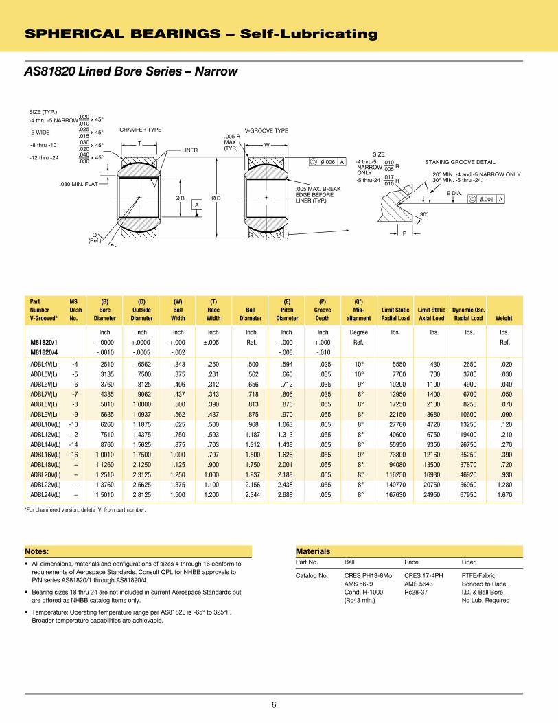
High Misalignment
SPHERICAL BEARINGS – Self-Lubricating
8
Notes:• Temperature: Operating temperature range -65° to 325°F.
Broader temperature capabilities are achievable.
• Options: Bearings with PH13-8Mo balls will be designated by “13-8” suffix (Example: ADBY16-13-8(L)). For outside race diameter with plate per AMS-QQ-P-416, Type II, Class 2, add suffix “P” (Example: ADBY16VP(L)).
• Qualification: Liner approved to AS81820.
MaterialsPart No. Ball Race Liner
Catalog No. CRES 440C CRES 17-4PH PTFE/Fabric AMS 5630 AMS 5643 Bonded to Race Rc55-62 Rc28-37 I.D. No Lub. Required
Catalog CRES CRES 17-4PH PTFE/Fabric No. + 13-8 PH13-8Mo AMS 5643 Bonded to Race AMS 5629 Rc28-37 I.D. No Lub. Required Rc43-47
Q
T W
A
V-GROOVE TYPECHAMFER TYPE
LINERF
.015
.005
P S
R
60° X
STAKING GROOVE DETAIL x 45 CHAMFER (TYP.) O/ O O/ B O/ D
A
0/ .005
Part (B) (D) (W) (T) (O) (F) (Q) (P) (R) (S) (X) Limit Dynamic Number Bore Outside Ball Race Shoulder Ball Mis- Static Osc. V-Grooved* Diameter Diameter Width Width Diameter Diameter alignment Staking Groove Data Radial Load Radial Load Weight
* For chamfered version, delete ‘V’ from part number.** Bore and O.D. tolerances: +.0000, -.0008.
No Load Rotational Breakaway
Torque
Race Chamfered
x 45°

9
Notes:

Inch Inch Inch Inch Inch Inch Inch Min. Inch Inch Inch Inch - lbs. lbs. lbs. lbs. lbs.
+.0000 +.0000 +.000 ±.005 Min. Ref. +.000 +.000 +.000 Ref.
-.0005 -.0005 -.002 -.010 -.010 -.015
ADB3VN(L) .1900 .5625 .281 .218 .293 .406 .020 5° .502 .030 .005-.010 20° min. 0.25-8.0 3975 150 1500 .020
ADB4VN(L) .2500 .6562 .343 .250 .364 .500 .020 5° .596 .030 .005-.010 20° min. 0.25-8.0 6040 430 3320 .020
ADB5VN(L) .3125 .7500 .375 .281 .419 .562 .020 5° .652 .040 .005-.010 30° 1.0-20.0 8750 700 5460 .030
ADB5VAN(L) .3125 .7500 .375 .281 .419 .562 — 5° .662 .040 .005-.010 20° 1.0-20.0 8750 700 5460 .030
ADB6VN(L) .3750 .8125 .406 .312 .475 .656 .030 4.5° .714 .040 .010-.020 30° 1.0-20.0 10540 1100 6600 .040
ADB7VN(L) .4375 .9062 .437 .343 .530 .718 .030 4° .808 .040 .010-.020 30° 1.0-20.0 13200 1400 8050 .050
ADB8VN(L) .5000 1.0000 .500 .390 .600 .813 .030 4° .878 .060 .010-.020 30° 1.0-20.0 17900 2100 10400 .070
ADB9VN(L) .5625 1.0937 .562 .437 .670 .875 .030 4° .972 .060 .010-.020 30° 1.0-20.0 23200 3680 13000 .090
ADB10VN(L) .6250 1.1875 .625 .500 .739 .968 .030 4° 1.065 .060 .010-.020 30° 1.0-20.0 30500 4720 16450 .120
ADB12VN(L) .7500 1.4375 .750 .593 .920 1.187 .040 4° 1.315 .060 .010-.020 30° 1.0-20.0 46400 6750 23600 .210
ADB14VN(L) .8750 1.5625 .875 .703 .980 1.312 .040 4° 1.440 .060 .010-.020 30° 1.0-30.0 62200 9350 30250 .270
ADB16VN(L) 1.0000 1.7500 1.000 .797 1.118 1.500 .040 4.5° 1.628 .060 .010-.020 30° 1.0-30.0 82200 12160 38000 .390
ADB18VN(L) 1.1250 2.1250 1.125 .900 1.334 1.750 .040 4° 2.003 .060 .010-.020 30° 1.0-30.0 105880 13500 42350 .720
ADB20VN(L) 1.2500 2.3125 1.250 1.000 1.473 1.937 .040 4° 2.190 .060 .010-.020 30° 1.0-30.0 131230 16930 52490 .930
ADB22VN(L) 1.3750 2.5625 1.375 1.100 1.654 2.156 .040 4° 2.440 .060 .010-.020 30° 1.0-30.0 161700 20750 64680 1.280
ADB24VN(L) 1.5000 2.8125 1.500 1.200 1.794 2.344 .040 4° 2.690 .060 .010-.020 30° 1.0-30.0 192780 24950 77110 1.670
Sealed Narrow
SPHERICAL BEARINGS – Self-Lubricating
10
Notes:• For more information on sealed bearings, see page 70.
• Temperature: Operating temperature range -65° to 325°F. Broader temperature capabilities are achievable.
• Options: Bearings with PH13-8Mo balls will be designated by “13-8” suffix (Example: ADB16VN13-8(L)). For outside race diameter with cadmium plate per AMS-QQ-P-416, Type II, Class 2, add suffix “P” (Example: ADW16VNP(L)).
• Qualification: Liner approved to AS81820.
MaterialsPart No. Ball Race Liner
Catalog No. CRES 440C CRES 17-4PH PTFE/Fabric AMS 5630 AMS 5643 Bonded to Race Rc55-62 Rc28-37 I.D. No Lub. Required
Catalog CRES CRES 17-4PH PTFE/Fabric No. + 13-8 PH13-8Mo AMS 5643 Bonded to Race AMS 5629 Rc28-37 I.D. No Lub. Required Rc43-47
Part (B) (D) (W) (T) (O) (F) (Q) (E) (P) (R) (X) Limit Limit Dynamic Number Bore Outside Ball Race Shoulder Ball Mis- Pitch Diam. Static Static Osc. V-Grooved* Diameter Diameter Width Width Diameter Diameter alignment Staking Groove Data Radial Load Axial Load Radial Load Weight
No Load Rotational Breakaway
Torque
Race Chamfered
x45°
*For chamfered version, delete ‘V’ from part number.
CHAMFER TYPE
LINERT
V-GROOVE TYPE
Q
F
A
x 45° CHAMFER (TYP.)
.015
.005
A
R
BALL
P
30°
SHIELD
SEAL
X°
STAKING GROOVE DETAIL W
O/ O O/ B O/ D
0/ .005
0/ .005
O/ E
A

Inch Inch Inch Inch Inch Inch Inch Min. Inch Inch Inch Inch - lbs. lbs. lbs. lbs. lbs.
+.0000 +.0000 +.000 ±.005 Min. Ref. +.000 +.000 +.000 Ref.
-.0005 -.0005 -.002 -.010 -.010 -.015
ADW3VN(L) .1900 .6250 .437 .327 .300 .531 .025 7.5° .565 .030 .005-.015 20° min. 0.25-8.0 2500 1770 4900 .031
ADW4VN(L) .2500 .6250 .437 .327 .300 .531 .025 7.5° .565 .030 .005-.015 20° min. 0.25-8.0 5500 1770 4900 .031
ADW5VN(L) .3125 .6875 .437 .317 .360 .593 .025 7° .627 .030 .005-.015 30° 1.0-20.0 9400 1640 6050 .035
ADW6VN(L) .3750 .8125 .500 .406 .466 .687 .030 4° .714 .040 .010-.020 30° 1.0-20.0 13700 2630 8310 .060
ADW7VN(L) .4375 .9375 .562 .442 .537 .781 .030 5° .839 .040 .010-.020 30° 1.0-20.0 20700 3650 11750 .080
ADW7V52N(L) .4375 .9062 .562 .442 .537 .781 — 5° .808 .040 .010-.020 30° 1.0-20.0 19700 3650 11750 .080
ADW8VN(L) .5000 1.0000 .625 .505 .607 .875 .030 4.5° .902 .040 .010-.020 30° 1.0-20.0 21400 4970 14950 .100
ADW9VN(L) .5625 1.1250 .687 .536 .721 1.000 .030 5° 1.027 .040 .010-.020 30° 1.0-20.0 26600 5370 18100 .135
ADW10VN(L) .6250 1.1875 .750 .567 .747 1.062 .030 6° 1.089 .040 .010-.020 30° 1.0-20.0 29000 6130 20250 .160
ADW12VN(L) .7500 1.3750 .875 .630 .845 1.250 .040 7.5° 1.253 .060 .010-.020 30° 1.0-20.0 37000 7730 26200 .240
ADW14VN(L) .8750 1.6250 .875 .755 .995 1.375 .040 3° 1.503 .060 .010-.020 30° 1.0-30.0 65200 10800 33600 .350
ADW16VN(L) 1.0000 2.1250 1.375 1.005 1.269 1.875 .040 6° 2.003 .060 .010-.020 30° 1.0-30.0 104000 19300 56250 .970
ADW18VN(L) 1.1250 2.2500 1.437 1.067 1.338 1.968 .040 7° 2.128 .060 .010-.020 30° 1.0-30.0 142570 19640 57000 1.000
ADW20VN(L) 1.2500 2.3750 1.500 1.130 1.460 2.093 .040 6.5° 2.253 .060 .010-.020 30° 1.0-30.0 159200 21970 63680 1.120
ADW20-5VN(L) 1.2500 2.0000 1.093 .942 1.406 1.781 .040 3° 1.878 .060 .010-.020 30° 1.0-30.0 112360 14890 44940 .564
ADW22VN(L) 1.3750 2.5625 1.687 1.223 1.535 2.281 .040 7.5° 2.440 .060 .010-.020 30° 1.0-30.0 190000 25970 76000 1.390
ADW24VN(L) 1.5000 2.6875 1.687 1.223 1.693 2.390 .040 7° 2.567 .060 .010-.020 30° 1.0-30.0 199000 25970 79640 1.480
11
Sealed Wide
Notes:• For more information on sealed bearings, see page 70.
• Temperature: Operating temperature range -65° to 325°F. Broader temperature capabilities are achievable.
• Options: Bearings with PH13-8Mo balls will be designated by “13-8” suffix (Example: ADB16VN13-8(L)). For outside race diameter with cadmium plate per AMS-QQ-P-416, Type II, Class 2, add suffix “P” (Example: ADW16VNP(L)).
• Qualification: Liner approved to AS81820.
MaterialsPart No. Ball Race Liner
Catalog No. CRES 440C CRES 17-4PH PTFE/Fabric AMS 5630 AMS 5643 Bonded to Race Rc55-62 Rc28-37 I.D. No Lub. Required
Catalog CRES CRES 17-4PH PTFE/Fabric No. + 13-8 PH13-8Mo AMS 5643 Bonded to Race AMS 5629 Rc28-37 I.D. No Lub. Required Rc43-47
Part (B) (D) (W) (T) (O) (F) (Q) (E) (P) (R) (X) Limit Limit Dynamic Number Bore Outside Ball Race Shoulder Ball Mis- Pitch Diam. Static Static Osc. V-Grooved* Diameter Diameter Width Width Diameter Diameter alignment Staking Groove Data Radial Load Axial Load Radial Load Weight
No Load Rotational Breakaway
Torque
Race Chamfered
x 45°
*For chamfered version, delete ‘V’ from part number.
CHAMFER TYPE
LINERT
V-GROOVE TYPE
Q
F
A
x 45° CHAMFER (TYP.)
.015
.005
A
R
BALL
P
30°
SHIELD
SEAL
X°
STAKING GROOVE DETAIL W
O/ O O/ B O/ D
0/ .005
0/ .005
O/ E
A

12

13
SECTION 2SPHERICAL BEARINGS – Metal-to-Metal
AS81936 Beryllium Copper Ball . . . . . . . . . . . . . . . . . . . . . . . . . . . . . . . . . . . . . . . . . 14
AS8976 – Narrow . . . . . . . . . . . . . . . . . . . . . . . . . . . . . . . . . . . . . . . . . . . . . . . . . . . 16
Narrow . . . . . . . . . . . . . . . . . . . . . . . . . . . . . . . . . . . . . . . . . . . . . . . . . . . . . . . . . . . . . . . 18
Wide . . . . . . . . . . . . . . . . . . . . . . . . . . . . . . . . . . . . . . . . . . . . . . . . . . . . . . . . . . . . . 19
High Misalignment . . . . . . . . . . . . . . . . . . . . . . . . . . . . . . . . . . . . . . . . . . . . . . . . . . 20
High Temperature. . . . . . . . . . . . . . . . . . . . . . . . . . . . . . . . . . . . . . . . . . . . . . . . . . . 21

Notes:• Radial Clearance: Free turning to 0.001.
• Axial Clearance: Free turning to 0.005.
• Concentricity: Outside diameter (D) and pitch diameter (E) to bore diameter (B) within .005 FIM.
• Bearings prepacked with MIL-PRF-81322.
• Temperature: Operating temperature range -65° to 350°F.
• Groove dimensions on ID of race and grease holes through race are before bearing assembly, but swaging shall not restrict grease flow.
AS81936 Beryllium Copper Ball
SPHERICAL BEARINGS – Metal-to-Metal
14
MaterialsBall Race
BeCu, ASTM B196† CRES 17-4PH, AMS 5643 Condition TH04†† Cond. H-1150 Rc37 min. (Rc28-36)
†Formerly QQ-C-530 ††Formerly HT
Lubrication
AGB & AGB-V Lubrication grooves in race and 3 equally spaced holes through race only.
AGB-A & AGB-VA Lubrication grooves in race and bore of ball and 3 equally spaced holes through race and ball.
T
W
Q
M81936/1-(*)
M81936/2-(**)R ANDM81936/1-(**)R NOTSHOWN. SAME ASSHOWN EXCEPT NOLUBE GROOVES/HOLES IN BALL.
LUBRICATION HOLESAND GROOVES
30°
P
S
STAKING GROOVE DETAIL
20° MIN. for -430° MIN. for allothers
RACE CHAMFERDIMENSION DETAIL
K
LR
LUBE GROOVERACE O.D. DETAIL
.040
.010
.015
.010
x 45°
x 45°.015.005
CHAMFER (TYP
CHAMFER
.)
CHAMFER TYPE V-GROOVE TYPE
M81936/2-(*)
O/ O O/ D
O/ E
O/ B
Inch Inch Inch Inch Inch Inch Inch Inch Inch Inch Inch Inch lbs. lbs. lbs.
+.0000 +.0000 +.000 +.000 Min. Ref. +.000 +.000 +.000 Ref.
M81936/1-(**)R M81936/1-(**) -.0005 -.0005 -.002 -.005 -.010 -.010 -.015
AGB4V AGB4VA .2500 .6562 .343 .250 .357 .501 .032-.062 .042-.078 .030-.062 .596 .020 .030 6330 1930 .02
AGB5V AGB5VA .3125 .7500 .375 .281 .413 .563 .042-.062 .042-.078 .030-.062 .652 .030 .040 8460 2450 .03
AGB6V AGB6VA .3750 .8125 .406 .312 .509 .657 .042-.062 .042-.078 .030-.062 .714 .030 .040 11400 3090 .04
AGB7V AGB7VA .4375 .9062 .437 .343 .563 .719 .052-.062 .065-.094 .060-.094 .808 .030 .040 14800 3740 .05
AGB8V AGB8VA .5000 1.0000 .500 .390 .634 .814 .052-.062 .065-.094 .060-.094 .878 .030 .060 20400 4860 .07
AGB9V AGB9VA .5625 1.0937 .562 .437 .664 .876 .052-.062 .065-.094 .060-.094 .972 .030 .060 26700 6100 .09
AGB10V AGB10VA .6250 1.1875 .625 .500 .732 .969 .062-.078 .073-.109 .070-.125 1.065 .030 .060 33100 8080 .11
AGB12V AGB12VA .7500 1.4375 .750 .593 .913 1.188 .062-.078 .073-.109 .070-.125 1.315 .030 .060 50000 11440 .21
AGB13V AGB13VA .8125 1.5625 .812 .650 .984 1.282 .062-.078 .073-.109 .070-.125 1.440 .030 .060 59000 13800 .24
AGB14V AGB14VA .8750 1.6562 .875 .703 1.054 1.376 .062-.078 .073-.109 .070-.125 1.534 .030 .060 70300 16160 .27
AGB16V AGB16VA 1.0000 1.8750 1.000 .797 1.193 1.563 .078-.093 .082-.109 .090-.125 1.753 .030 .060 77700 20850 .39
AGB18V AGB18VA 1.1250 2.1250 1.125 .900 1.334 1.751 .078-.093 .082-.109 .090-.125 2.003 .030 .060 121500 26740 .72
AGB20V AGB20VA 1.2500 2.3125 1.250 1.000 1.473 1.938 .078-.093 .082-.109 .090-.125 2.190 .030 .060 152000 33065 .93
AGB22V AGB22VA 1.3750 2.5625 1.375 1.100 1.654 2.157 .078-.093 .082-.109 .090-.125 2.440 .030 .060 186000 40120 1.28
AGB24V AGB24VA 1.5000 2.8125 1.500 1.200 1.794 2.345 .078-.093 .082-.109 .090-.125 2.690 .030 .060 224000 47820 1.67
(B) (D) (W) (T) (O) (K) (L) (R) (E) (S) (P) Groove Width Groove Radius Pitch Limit Limit Lube ID & OD ID & OD Diameter Static Static Part Number Part Number Bore Outside Ball Race Shoulder Ball Hole of Race & of Race & Radial Axial V-Grooved* V-Grooved* Diameter Diameter Width Width Diameter Diameter Diameter ID of Ball ID of Ball Staking Groove Data Load Load Weight
* For chamfered version, delete ‘V’ from part number (M81936/2 -(*)).** Add bore codes in multiples of 1/16.

15
Aerospace Standard P/N
No Letter Indicates Standard Race Diameter“T” Indicates .010 Oversize Race Diameter (For Repair Only)“U” Indicates .020 Oversize Race Diameter (For Repair Only)
Add “R” Suffix for Lubrication Grooves and Oil Holes in Race Only.No “R” indicates Lubrication Provisions in Ball and Race
Bore Diameter in Multiples of 1/16 Inches
Bearing Type:1=V-Grooved Race2=Chamfered Race
AS P/N Prefix Denoting Beryllium Copper Ball & CRES Race withLubrication Grooves and Holes
M81936/ X -X X X
NHBB P/N
AGB X X X XNo Suffix Indicates Standard Race Diameter“/010” Indicates .010 Oversize Race Diameter (For Repair Only)“/020” Indicates .020 Oversize Race Diameter (For Repair Only)
No Letter “A” Indicates Lubrication Grooves and Holes in Race OnlyAdd “A” Suffix for Bearing with Lubrication Grooves and Holes in Ball
Letter “V” Indicates V-Grooved Outer Race (M81936/1)No Letter Indicates Chamfered Outer Race (M81936/2)
Bore Diameter in multiples of 1/16 inch
NHBB P/N Prefix for Beryllium Copper Ball & CRES Race with LubricationGrooves and Oil Holes
AS81936 Beryllium Copper Ball
Inch Inch Inch Inch Inch Inch Inch Inch Inch Inch Inch Inch lbs. lbs. lbs.
+.0000 +.0000 +.000 +.000 Min. Ref. +.000 +.000 +.000 Ref.
M81936/1-(**)R M81936/1-(**) -.0005 -.0005 -.002 -.005 -.010 -.010 -.015
AGB4V AGB4VA .2500 .6562 .343 .250 .357 .501 .032-.062 .042-.078 .030-.062 .596 .020 .030 6330 1930 .02
AGB5V AGB5VA .3125 .7500 .375 .281 .413 .563 .042-.062 .042-.078 .030-.062 .652 .030 .040 8460 2450 .03
AGB6V AGB6VA .3750 .8125 .406 .312 .509 .657 .042-.062 .042-.078 .030-.062 .714 .030 .040 11400 3090 .04
AGB7V AGB7VA .4375 .9062 .437 .343 .563 .719 .052-.062 .065-.094 .060-.094 .808 .030 .040 14800 3740 .05
AGB8V AGB8VA .5000 1.0000 .500 .390 .634 .814 .052-.062 .065-.094 .060-.094 .878 .030 .060 20400 4860 .07
AGB9V AGB9VA .5625 1.0937 .562 .437 .664 .876 .052-.062 .065-.094 .060-.094 .972 .030 .060 26700 6100 .09
AGB10V AGB10VA .6250 1.1875 .625 .500 .732 .969 .062-.078 .073-.109 .070-.125 1.065 .030 .060 33100 8080 .11
AGB12V AGB12VA .7500 1.4375 .750 .593 .913 1.188 .062-.078 .073-.109 .070-.125 1.315 .030 .060 50000 11440 .21
AGB13V AGB13VA .8125 1.5625 .812 .650 .984 1.282 .062-.078 .073-.109 .070-.125 1.440 .030 .060 59000 13800 .24
AGB14V AGB14VA .8750 1.6562 .875 .703 1.054 1.376 .062-.078 .073-.109 .070-.125 1.534 .030 .060 70300 16160 .27
AGB16V AGB16VA 1.0000 1.8750 1.000 .797 1.193 1.563 .078-.093 .082-.109 .090-.125 1.753 .030 .060 77700 20850 .39
AGB18V AGB18VA 1.1250 2.1250 1.125 .900 1.334 1.751 .078-.093 .082-.109 .090-.125 2.003 .030 .060 121500 26740 .72
AGB20V AGB20VA 1.2500 2.3125 1.250 1.000 1.473 1.938 .078-.093 .082-.109 .090-.125 2.190 .030 .060 152000 33065 .93
AGB22V AGB22VA 1.3750 2.5625 1.375 1.100 1.654 2.157 .078-.093 .082-.109 .090-.125 2.440 .030 .060 186000 40120 1.28
AGB24V AGB24VA 1.5000 2.8125 1.500 1.200 1.794 2.345 .078-.093 .082-.109 .090-.125 2.690 .030 .060 224000 47820 1.67
(B) (D) (W) (T) (O) (K) (L) (R) (E) (S) (P) Groove Width Groove Radius Pitch Limit Limit Lube ID & OD ID & OD Diameter Static Static Part Number Part Number Bore Outside Ball Race Shoulder Ball Hole of Race & of Race & Radial Axial V-Grooved* V-Grooved* Diameter Diameter Width Width Diameter Diameter Diameter ID of Ball ID of Ball Staking Groove Data Load Load Weight

Inch Inch Inch Inch Inch Inch Inch Inch Inch Min. Inch Inch Inch Inch lbs. lbs. lbs. lbs. lbs.
+.0000 +.0000 +.000 +.005 Min. Max. Max. +.010 +.005 Ref. +.000 +.000 +.000 Ref.
MS21154S(**) MS21154B(**) -.0005 -.0005 -.002 -.005 -.010 -.005 -.010 -.015 -.010
ABG3VA(L) ABG3VA-501(L) .1900 .5625 .281 .218 .293 .438 .407 .047 .062 10° .045 .502 .030 .045 2800 850 4600 2100 .02
ABG4VA(L) ABG4VA-501(L) .2500 .6562 .343 .250 .364 .501 .501 .047 .062 10° .045 .596 .030 .045 4300 1100 7080 2800 .02
ABG5VA(L) ABG5VA-501(L) .3125 .7500 .375 .281 .419 .594 .563 .062 .078 10° .065 .662 .040 .055 5200 1400 8500 3550 .03
ABG6VA(L) ABG6VA-501(L) .3750 .8125 .406 .312 .475 .657 .657 .062 .078 9° .065 .714 .040 .055 6750 1760 11050 4400 .04
ABG7VA(L) ABG7VA-501(L) .4375 .9062 .437 .343 .530 .719 .719 .062 .078 8° .065 .808 .040 .055 8500 2150 13900 5400 .05
ABG8VA(L) ABG8VA-501(L) .5000 1.0000 .500 .390 .600 .814 .814 .062 .078 8° .065 .878 .060 .080 11500 2800 18850 7050 .07
ABG9VA(L) ABG9VA-501(L) .5625 1.0937 .562 .437 .670 .907 .907 .062 .078 8° .065 .972 .060 .080 15600 3550 25500 8900 .09
ABG10VA(L) ABG10VA-501(L) .6250 1.1875 .625 .500 .739 1.001 .907 .078 .093 8° .088 1.065 .060 .080 19500 4650 31950 11700 .11
ABG12VA(L) ABG12VA-501(L) .7500 1.4375 .755 .593 .920 1.251 1.188 .078 .093 8° .088 1.315 .060 .080 28500 6575 46750 16500 .21
ABG14VA(L) ABG14VA-501(L) .8750 1.5625 .875 .703 .980 1.376 1.313 .078 .093 8° .088 1.440 .060 .080 38300 9300 62750 23300 .27
ABG16VA(L) ABG16VA-501(L) 1.0000 1.7500 1.000 .797 1.118 1.563 1.501 .078 .093 9° .088 1.628 .060 .080 51000 12000 83350 30000 .39
(B) (D) (W) (T) (O) (K) (L) (Q) (R) (E) (P) (X) Groove Groove Pitch Ball Width Radius Diameter Part Number Part Number Diameter Lube ID & OD ID & OD Limit Static Load V-Grooved* V-Grooved* Bore Outside Ball Race Shoulder Bronze Steel Hole of Race & of Race & Bronze Race Steel Race Steel Race Bronze Race Diameter Diameter Width Width Diameter Race Race Diameter ID of Ball Misalignment ID of Ball
Staking Groove Data Radial Axial Radial Axial Weight
SPHERICAL BEARINGS – Metal-to-Metal
AS8976 – Narrow
16
Notes:• Radial Clearance: 0.0005 to 0.0020.
• Axial Clearance: 0.010 Maximum.
• Dimensions: All dimensions apply after plating.
• Concentricity: Outside diameter (D) to bore diameter (B) within .005 FIM.
• Temperature: Operating temperature range -65° to 250°F.
• Lubrication: MIL-PRF-21164.
• Groove dimensions on ID of race and grease holes through race are before bearing assembly, but swaging shall not restrict grease flow.
MaterialsPart No. Ball Race
ABG-A ABG-VA 52100 Alloy Steel 4340 STL/AMS6415 Rc56 Min. 4130 STL, or 8630 STL Chrome Plated† Rc27-36, Cadmium Plated
ABG-A-501 ABG-VA-501 Aluminum Bronze (AMS 4635 and ASTM B 50/B150M), Cadmium Plated
† Plating: When specified in materials block, ball spherical diameter and ends are hard chrome plated per AMS-QQ-C-320, CL. 2 (.0002 to .0005 inch thickness). All external surfaces of race are cadmium plated per AMS-QQ-P-416.
* For chamfered version MS21155, delete ‘V’ from part number.** Add bore codes in multiples of 1/16.
STAKING GROOVE DETAIL
P20° min for -4 only30° min for all others
X
T
W
Q
LUBRICATION HOLESAND GROOVES
x 45°CHAMFER(TYP.)
.015
.005
V-GROOVE TYPE
MS21155 MS21154
CHAMFER TYPE RACE CHAMFERDIMENSION DETAIL
K
LR
LUBE GROOVERACE O.D. DETAIL
.040
.010
.015
.010
x 45°
O/ O O/ B O/ D
O/ E30°

17
NHBB P/N
ABG 3 V A X X (L)NHBB Manufacturing Code
Letters “CR” Indicate Optional 440C Ball Material
“-501” Indicates Aluminum Bronze (AMS 4635) Race MaterialBlank Indicates Alloy Steel (4340, 4130 or 8630) Race Material
Letter “A” Indicates Lube Groove and Lube Holes in Ball
Letter “V” Indicates V-Grooved Outer Race (MS21154)No Letter “V” Indicates Chamfered Outer Race (MS21155)
Bore Diameter in multiples of 1/16 inch
NHBB P/N Prefix for Narrow, Metal-to-Metal Spherical Bearing
Aerospace Standard P/N
Bore Diameter in Multiples of 1/16 Inch (2 Digits)
Letter “S” Indicates Alloy Steel (4340, 4130 or 8630) Race MaterialLetter “B” Indicates Aluminum Bronze (AMS 4635) Race Material
AS P/N Prefix Denoting Narrow, Metal on Metal Spherical Bearing withLube Grooves and Lube Holes in Race and Ball(MS21154=V-Grooved, MS21155=Chamfered)
MS21154 S 03
Inch Inch Inch Inch Inch Inch Inch Inch Inch Min. Inch Inch Inch Inch lbs. lbs. lbs. lbs. lbs.
+.0000 +.0000 +.000 +.005 Min. Max. Max. +.010 +.005 Ref. +.000 +.000 +.000 Ref.
MS21154S(**) MS21154B(**) -.0005 -.0005 -.002 -.005 -.010 -.005 -.010 -.015 -.010
ABG3VA(L) ABG3VA-501(L) .1900 .5625 .281 .218 .293 .438 .407 .047 .062 10° .045 .502 .030 .045 2800 850 4600 2100 .02
ABG4VA(L) ABG4VA-501(L) .2500 .6562 .343 .250 .364 .501 .501 .047 .062 10° .045 .596 .030 .045 4300 1100 7080 2800 .02
ABG5VA(L) ABG5VA-501(L) .3125 .7500 .375 .281 .419 .594 .563 .062 .078 10° .065 .662 .040 .055 5200 1400 8500 3550 .03
ABG6VA(L) ABG6VA-501(L) .3750 .8125 .406 .312 .475 .657 .657 .062 .078 9° .065 .714 .040 .055 6750 1760 11050 4400 .04
ABG7VA(L) ABG7VA-501(L) .4375 .9062 .437 .343 .530 .719 .719 .062 .078 8° .065 .808 .040 .055 8500 2150 13900 5400 .05
ABG8VA(L) ABG8VA-501(L) .5000 1.0000 .500 .390 .600 .814 .814 .062 .078 8° .065 .878 .060 .080 11500 2800 18850 7050 .07
ABG9VA(L) ABG9VA-501(L) .5625 1.0937 .562 .437 .670 .907 .907 .062 .078 8° .065 .972 .060 .080 15600 3550 25500 8900 .09
ABG10VA(L) ABG10VA-501(L) .6250 1.1875 .625 .500 .739 1.001 .907 .078 .093 8° .088 1.065 .060 .080 19500 4650 31950 11700 .11
ABG12VA(L) ABG12VA-501(L) .7500 1.4375 .755 .593 .920 1.251 1.188 .078 .093 8° .088 1.315 .060 .080 28500 6575 46750 16500 .21
ABG14VA(L) ABG14VA-501(L) .8750 1.5625 .875 .703 .980 1.376 1.313 .078 .093 8° .088 1.440 .060 .080 38300 9300 62750 23300 .27
ABG16VA(L) ABG16VA-501(L) 1.0000 1.7500 1.000 .797 1.118 1.563 1.501 .078 .093 9° .088 1.628 .060 .080 51000 12000 83350 30000 .39
(B) (D) (W) (T) (O) (K) (L) (Q) (R) (E) (P) (X) Groove Groove Pitch Ball Width Radius Diameter Part Number Part Number Diameter Lube ID & OD ID & OD Limit Static Load V-Grooved* V-Grooved* Bore Outside Ball Race Shoulder Bronze Steel Hole of Race & of Race & Bronze Race Steel Race Steel Race Bronze Race Diameter Diameter Width Width Diameter Race Race Diameter ID of Ball Misalignment ID of Ball
Staking Groove Data Radial Axial Radial Axial Weight
SPHERICAL BEARINGS – Metal-to-Metal
AS8976 – Narrow

NHBB P/ N
AG 3 V SS 3 V SS 3 V A X 123 A X 123 A X Dr y-film Lubricatio n
-1 F ilm on Spherical Surface of Race -2 F ilm on Bore of Bal l -3 F ilm on Spherical Surface of Bal l
.0005 Maximum Radial Clearance
Letter “A” Indicates Lube Groove and Holes in Ball Add suffix “300” for bearing without lube groove and holes
Material Code
Staking Groove
Bore Diameter in multiples of 1/16 inch
Narrow Series
STAKING GROOVE DETAIL
P S
60° X
TF
W
Q
LUBRICATION HOLES AND GROOVES
x 45° CHAMFER (TYP.)
.015
.005
V-GROOVE TYPE CHAMFER TYPE
R O/ O O/ B O/ D
SPHERICAL BEARINGS – Metal-to-Metal
18
Narrow
Inch Inch Inch Inch Inch Inch Inch Ref. Inch Inch Inch Inch lbs. lbs. lbs.
+.0000 +.0000 +.000 +.005 Ref. Ref. +.000 +.000 +.000 +.000 +.000 Ref.
-.0005 -.0005 -.005 -.005 -.010 -.015 -.010 -.010 -.010
AG3V .1900 .5625 .281 .218 .293 .406 .020 11° .030 .015 .020 .045 2350 4060 ** .02
AG4V .2500 .6562 .343 .250 .364 .500 .022 13° .030 .015 .020 .045 3700 6660 .02
AG5V .3125 .7500 .375 .281 .419 .562 .032 11.5° .040 .020 .030 .055 4580 8240 .03
AG6V .3750 .8125 .406 .312 .517 .656 .032 9.5° .040 .020 .030 .055 6360 11450 .04
AG7V .4375 .9062 .437 .343 .572 .718 .032 9° .040 .020 .030 .055 8080 14540 .05
AG8V .5000 1.0000 .500 .390 .642 .813 .032 9° .060 .020 .030 .080 11060 19900 .07
AG9V .5625 1.0937 .562 .437 .671 .875 .032 10° .060 .020 .030 .080 13960 25120 .09
AG10V .6250 1.1875 .625 .500 .739 .968 .032 9° .060 .020 .030 .080 17760 31970 .11
AG12V .7500 1.4375 .750 .593 .920 1.187 .040 9° .060 .020 .030 .080 27300 49140 .21
AG14V .8750 1.5625 .875 .703 .980 1.312 .040 9° .060 .020 .030 .080 36080 64940 .27
AG16V 1.0000 1.7500 1.000 .797 1.118 1.500 .040 9.5° .060 .020 .030 .080 48300 86940 .39
AG18V 1.1250 2.1250 1.125 .900 1.334 1.750 .040 8° .060 .020 .030 .080 63000 113400 .72
AG20V 1.2500 2.3125 1.250 1.000 1.473 1.937 .040 8° .060 .020 .030 .080 79420 142950 .93
AG22V 1.3750 2.5625 1.375 1.100 1.654 2.156 .040 8° .060 .020 .030 .080 99180 178520 1.28
AG24V 1.5000 2.8125 1.500 1.200 1.794 2.344 .040 8° .060 .020 .030 .080 119540 215180 1.67
(B) (D) (W) (T) (O) (F) (Q) (P) (R) (S) (X) Limit Static Part Number Bore Outside Ball Race Shoulder Ball Race Mis- Radial Load V-Grooved* Diameter Diameter Width Width Diameter Diameter Chamfered x 45° alignment Staking Groove Data Bronze Race Steel Race Weight
* For chamfered version, delete ‘V’ from part number. ** Based on pin limitation.
Notes:• Radial Clearance: Free running to .002 max.
• Dimensions: All dimensions apply after plating.
• Groove dimensions on ID of race and grease holes through race are before bearing assembly, but swaging shall not restrict grease flow.
MaterialsPart No. Ball Race
Catalog No. 52100 Alloy Steel Aluminum Bronze Chrome Plated† (AMS 4635 and ASTM B 50/B150M) Cadmium Plated†
Catalog No. + S “ 4130 Alloy Steel Cadmium Plated†
Catalog No. + SS “ CRES 17-4PH
Catalog No. + CR CRES 440C “
Catalog No. + CRP CRES 440C, “ Chrome Plated†† Plating: When specified in materials block, ball spherical diameter and ends are hard chrome plated per AMS-QQ-C-320, CL. 2 (.0002 to .0005 inch thickness). All external surfaces of race are cadmium plated per AMS-QQ-P-416.

T
Q
CHAMFER TYPE
F
V-GROOVE TYPE
W
x 45° CHAMFER (TYP.)
.015
.005
STAKING GROOVE DETAIL
P S
60° X
R O/ O O/ B O/ D
19
Wide
Inch Inch Inch Inch Inch Inch Inch Ref. Inch Inch Inch Inch lbs. lbs. lbs.
+.0000 +.0000 +.000 +.010 Ref. Ref. +.000 +.000 +.000 +.000 +.000 Ref.
-.0005 -.0005 -.005 -.000 -.015 -.015 -.010 -.010 -.010
AW3-5V .1900 .6250 .437 .322 .301 .531 .025 18° .030 .015 .020 .045 4060 ** 4060 ** .030
AW3V .1900 .5000 .359 .281 .249 .437 .025 15° .030 .015 .020 .045 4060 ** 4060 ** .015
AW4V .2500 .6250 .437 .322 .301 .531 .025 18° .030 .015 .020 .045 7040 ** 7040 ** .030
AW5V .3125 .6875 .437 .312 .401 .593 .025 15.5° .030 .015 .020 .045 8360 11010 ** .033
AW6V .3750 .8125 .500 .401 .471 .687 .025 11° .040 .020 .030 .055 12740 15860 ** .053
AW7V .4375 .9375 .562 .437 .542 .781 .025 12° .040 .020 .030 .055 15890 21600 ** .079
AW8V .5000 1.0000 .625 .500 .612 .875 .035 10.5° .040 .020 .030 .055 20560 28220 ** .097
AW9V .5625 1.1250 .687 .531 .726 1.000 .035 11° .040 .020 .030 .055 23550 35720 ** .133
AW10V .6250 1.1875 .750 .562 .752 1.062 .035 13° .040 .020 .030 .055 26660 44110 ** .140
AW12V .7500 1.3750 .875 .625 .892 1.250 .035 14° .060 .020 .030 .080 35310 63520 .232
AW14V .8750 1.6250 .875 .750 1.061 1.375 .035 6.5° .060 .020 .030 .080 47440 85390 .346
AW15-101V .9375 1.3750 .450 .350 1.100 1.188 .025 5° .060 .020 .030 .080 19010 34210 .090
AW16V 1.0000 2.1250 1.375 1.000 1.275 1.875 .035 15° .060 .020 .030 .080 88120 112980 ** .970
AW18V 1.1250 2.2500 1.437 1.067 1.338 1.968 .035 14° .060 .020 .030 .080 98600 143010 ** 1.000
AW20V 1.2500 2.3750 1.500 1.125 1.460 2.093 .035 13° .060 .020 .030 .080 111450 176570 ** 1.110
AW20-5V 1.2500 2.0000 1.093 .937 1.406 1.781 .035 6° .060 .020 .030 .080 78100 140570 .564
AW22V 1.3750*** 2.5625 1.687 1.218 1.535 2.281 .045 15° .060 .020 .030 .080 129790 213670 ** 1.390
AW24V 1.5000*** 2.6875 1.687 1.218 1.693 2.390 .045 14° .060 .020 .030 .080 135990 244780 1.480
AW26V 1.6250*** 2.8750 1.750 1.281 1.828 2.531 .045 13° .060 .020 .030 .080 121580 273570 1.750
AW28V 1.7500*** 3.0000*** 1.812 1.312 1.964 2.672 .045 13° .060 .020 .030 .080 131670 296270 1.910
AW30V 1.8750*** 3.1250*** 1.875 1.343 2.096 2.812 .045 13° .060 .020 .030 .080 142060 319640 2.120
AW32V 2.0000*** 3.2500*** 1.937 1.375 2.208 2.937 .045 13° .060 .020 .030 .080 152140 342310 2.220
AW36V 2.2500*** 3.6250*** 2.000 1.406 2.442 3.156 .045 12.5° .060 .020 .030 .080 167390 376640 2.780
AW40V 2.5000*** 3.9375*** 2.062 1.437 2.750 3.437 .045 12° .060 .020 .030 .080 186560 419760 3.280
AW44V 2.7500*** 4.1250*** 2.187 1.500 2.968 3.687 .045 12° .060 .020 .030 .080 209420 471200 3.550
AW48V 3.0000*** 4.3750*** 2.312 1.562 3.187 3.937 .045 12.5° .060 .020 .030 .080 233380 525120 4.000
(B) (D) (W) (T) (O) (F) (Q) (P) (R) (S) (X) Limit Static Part Number Bore Outside Ball Race Shoulder Ball Race Mis- Radial Load◊ V-Grooved* Diameter Diameter Width Width Diameter Diameter Chamfered x 45° alignment Staking Groove Data Bronze Race Steel Race Weight
* For chamfered version, delete ‘V’ from part number.** Based on pin limitation.*** Tolerance: +.0000-.0008.◊ Loads based on parts with no lubrication grooves.
NHBB P/N
AW 3 V SS G
Lube Holes and Grooves in Race
Material Code
Staking Groove
Bore Diameter in multiples of 1/16 inch
Wide Series
A X 123Dry-film Lubrication
-1 Film on Spherical Surface of Race-2 Film on Bore of Ball-3 Film on Spherical Surface of Ball
.0005 Maximum Radial Clearance
Letter “A” Indicates Lube Grooveand Holes in Ball

High Misalignment
SPHERICAL BEARINGS – Metal-to-Metal
20
Q
T W
V-GROOVE TYPECHAMFER TYPE
F
x 45° CHAMFER (TYP.).015.005
P S
R
60° X
STAKING GROOVE DETAIL
O/ O O/ B O/ D
Inch Inch Inch Inch Inch Inch Inch Ref. Inch Inch Inch Inch lbs. lbs. lbs.
+.0000 +.0000 +.000 +.010 Ref. Ref. +.000 +.000 +.000 +.000 +.000 Ref.
-.0005 -.0005 -.005 -.000 -.010 -.015 -.010 -.010 -.010
ASBY3V .1900 .5625 .500 .205 .319 .437 .020 15° .030 .015 .020 .045 2470 4060 ** .018
ASBY4V .2500 .7400 .593 .250 .390 .593 .022 24° .030 .015 .020 .045 4680 7040 ** .036
ASBY5V .3125 .6875 .625 .250 .418 .593 .022 20° .030 .015 .020 .045 4680 8430 .029
ASBY6V .3750 .9060 .813 .340 .512 .781 .032 23° .030 .015 .020 .045 9060 15860 ** .068
ASBY7V .4375 1.0000 .875 .340 .618 .875 .032 22° .030 .015 .020 .045 10150 18270 .095
ASBY8V .5000 1.1250 .937 .396 .730 1.000 .032 20° .040 .020 .030 .055 14400 25920 .159
ASBY10V .6250 1.3750 1.200 .562 .856 1.250 .032 20° .040 .020 .030 .055 27440 49390 .245
ASBY12V .7500 1.5625 1.280 .615 .970 1.375 .044 18° .040 .020 .030 .055 33820 60880 .315
ASBY14V .8750 1.7500 1.400 .620 1.140 1.531 .044 18° .060 .020 .030 .080 36510 65720 .430
ASBY16V 1.0000 2.1250 1.875 .830 1.278 1.875 .044 21° .060 .020 .030 .080 64410 115930 .831
ASBY18V 1.1250*** 2.3125*** 1.875 .937 1.400 2.062 .044 20° .060 .020 .030 .080 78560 141410 1.096
ASBY20V 1.2500*** 2.5000*** 1.875 1.000 1.523 2.250 .044 21° .060 .020 .030 .080 92810 167060 1.318
ASBY22V 1.3750*** 2.7500*** 2.125 1.093 1.670 2.500 .044 22° .060 .020 .030 .080 91800 206550 1.800
ASBY24V 1.5000*** 3.0000*** 2.250 1.170 1.800 2.672 .044 21° .060 .020 .030 .080 106340 239280 2.223
(B) (D) (W) (T) (O) (F) (Q) (P) (R) (S) (X) Limit Static Part Number Bore Outside Ball Race Shoulder Ball Race Mis- Radial Load V-Grooved* Diameter Diameter Width Width Diameter Diameter Chamfered x 45° alignment Staking Groove Data Bronze Race Steel Race Weight
* For chamfered version, delete ‘V’ from part number.** Based on pin limitation.*** Bore and O.D. tolerance: +.0000-.0008.
NHBB P/ N
ASBY 3 V SS 3 V SS 3 V A X 123 A X 123 A X Dr y-film Lubricatio n
-1 F ilm on Spherical Surface of Race -2 F ilm on Bore of Bal l -3 F ilm on Spherical Surface of Bal l
.0005 Maximum Radial Clearance
Letter “A” Indicates Lube Groove and Holes in Ball Add suffix “300” for bearing without lube groove and holes
Material Code
Staking Groove
Bore Diameter in multiples of 1/16 inch
High Misalignment Series
Notes:• Radial Clearance: Free running to .002 max.
• Dimensions: All dimensions apply after plating.
• Groove dimensions on ID of race and grease holes through race are before bearing assembly, but swaging shall not restrict grease flow.
MaterialsPart No. Ball Race
Catalog No. 52100 Alloy Steel, Aluminum Bronze Chrome Plated† (AMS 4635 and ASTM B 50/B150M) Cadmium Plated†
Catalog No. + S “ 4130 Alloy Steel, Cadmium Plated†
Catalog No. + SS “ CRES 17-4PH
Catalog No. + CR CRES 440C “
Catalog No. + CRP CRES 440C, “ Chrome Plated†
† Plating: When specified in materials block, ball spherical diameter and ends are hard chrome plated per AMS-QQ-C-320, CL. 2 (.0002 to .0005 inch thickness). All external surfaces of race are cadmium plated per AMS-QQ-P-416.

21
Notes:• Load ratings are based on short-term exposure. Not intended for continuous use
at temperature shown.
• Radial clearance: Free running to .002 max.
MaterialsSeries Ball Race Temp.
AHT INCONEL® alloy 718, CRES A-286, Brief exposure thin dense chrome solution treated to 1000°F plated and aged, spherical surface silver plated
AHET STELLITE® alloy #3, “ Brief exposure thin dense chrome to 1200°F plated
INCONEL® is a registered trademark of Inco Alloys International, Inc. STELLITE ® is a registered trademark of Kennametal, Inc.
High Temperature
P S
R
60° X
STAKING GROOVE DETAIL
CHAMFER TYPE
T W
V-GROOVE TYPE
Q
F
x 45° CHAMFER (TYP.)
.015
.005
O/ O O/ B O/ D
Inch Inch Inch Inch Inch Inch Inch Ref. Inch Inch Inch Inch lbs. lbs. lbs.
+.0000 +.0000 +.000 +.000 Ref. Ref. +.000 +.000 +.000 +.000 +.000 Ref.
-.0005 -.0005 -.005 -.005 -.010 -.015 -.010 -.010 -.010
AHT3V AHET3V .1900 .5625 .281 .218 .293 .406 .020 11° .030 .015 .020 .045 4060 ** 4060 ** .02
AHT4V AHET4V .2500 .6562 .343 .250 .364 .500 .022 13° .030 .015 .020 .045 7040 ** 6390 .02
AHT5V AHET5V .3125 .7500 .375 .281 .419 .562 .032 11.5° .040 .020 .030 .055 10080 8210 .03
AHT6V AHET6V .3750 .8125 .406 .312 .517 .656 .032 9.5° .040 .020 .030 .055 13250 10790 .04
AHT7V AHET7V .4375 .9062 .437 .343 .572 .718 .032 9° .040 .020 .030 .055 16120 13140 .05
AHT8V AHET8V .5000 1.0000 .500 .390 .642 .813 .032 9° .060 .020 .030 .080 21040 17140 .07
AHT9V AHET9V .5625 1.0937 .562 .437 .671 .875 .032 10° .060 .020 .030 .080 23730 19330 .09
AHT10V AHET10V .6250 1.1875 .625 .500 .739 .968 .032 9° .060 .020 .030 .080 30700 25010 .11
AHT12V AHET12V .7500 1.4375 .750 .593 .920 1.187 .040 9° .060 .020 .030 .080 45690 37230 .21
AHT14V AHET14V .8750 1.5625 .875 .703 .980 1.312 .040 9° .060 .020 .030 .080 61020 49720 .27
AHT16V AHET16V 1.0000 1.7500 1.000 .797 1.118 1.500 .040 9.5° .060 .020 .030 .080 80040 65220 .39
(B) (D) (W) (T) (O) (F) (Q) (P) (R) (S) (X) Limit Static Part Number Part Number Bore Outside Ball Race Shoulder Ball Race Mis- Radial Load V-Grooved* V-Grooved* Diameter Diameter Width Width Diameter Diameter Chamfered x 45° alignment Staking Groove Data AHT @ AHET @ Weight 1000° F 1200° F
* For chamfered version, delete ‘V’ from part number.** Based on pin limitation.
SPHERICAL BEARINGS – Metal-to-Metal

22

23
SECTION 3LOADER SLOT BEARINGS
Plain . . . . . . . . . . . . . . . . . . . . . . . . . . . . . . . . . . . . . . . . . . . . . . . . . . . . . . . . . . . . . .24
Sealed . . . . . . . . . . . . . . . . . . . . . . . . . . . . . . . . . . . . . . . . . . . . . . . . . . . . . . . . . . . .25
Rod End – 2-Piece Male Thread . . . . . . . . . . . . . . . . . . . . . . . . . . . . . . . . . . . . . . . . .26

LOADER SLOT BEARINGS
WTCLCLC
Q
B C
16
DETAIL B DETAIL DETAIL DET C
.020
.005R
.012
.008
45°
.010 MAX.010 MAX.010 MA.010.005R
60°
P
30°
.015
.005 REF.8
32
STAKING GROOVE DETSTAKING GROOVE DETST AIAKING GROOVE DETAIAKING GROOVE DET L
SECTION A - A
.015
.005x 45° CHAMFER (TYP.)CHAMFER (TYP.)CHAMFER (TYP
O/ FD O/ A O/ B O/ D
O/ RD
O/ BD
O/ X
O/ TB
A
A
Plain
Notes:• Nitride or Malcomize spherical race ID.
• Balls rotate freely under finger pressure @ 72°F.
• Balls are fully interchangeable. No selective assembly allowed.
• Operating temperature range -65°F to 350°F.
Materials (AMB)Part No. Ball Race
Catalog No. STELLITE® alloy #6 17-4PH AMS 5387 AMS 5643 Rc37 min. Rc34-40STELLITE® is a registered trademark of Kennametal, Inc.
Inch Inch Inch Inch Inch Inch Inch Inch Ref. Inch Inch Inch lbs. lbs. lbs.
+.0000 +.0000 +.000 +.003 +.0000 +.0005 Ref. +.003 +.002 +.004 +.003 Ref. Ref.
-.0005 -.0005 -.002 -.003 -.0005 -.0000 -.003 -.002 -.004 -.003
AMB3 .1900 .5625 .281 .218 .4060 .4070 .293 .360 10° .582 .026 .494 2820 995 .02
AMB4 .2500 .6562 .343 .250 .5000 .5010 .364 .449 12° .676 .026 .588 4880 1160 .02
AMB5 .3125 .7500 .375 .281 .5625 .5635 .419 .503 11° .770 .026 .682 8920 1320 .03
AMB6 .3750 .8125 .406 .312 .6250 .6260 .475 .563 10° .852 .036 .714 14260 1630 .04
AMB7 .4375 .9062 .437 .343 .7180 .7190 .572 .651 9° .946 .036 .808 20800 1810 .05
AMB8 .5000 1.0000 .500 .390 .8125 .8135 .640 .733 9° 1.040 .036 .902 23800 2000 .07
AMB9 .5625 1.0937 .562 .437 .8750 .8760 .671 .785 9° 1.174 .056 .970 26890 2550 .09
AMB10 .6250 1.1875 .625 .500 .9680 .9690 .739 .875 9° 1.267 .056 1.064 29070 2770 .11
AMB12 .7500 1.4375 .750 .593 1.1870 1.1880 .920 1.056 9° 1.517 .056 1.314 35210 3350 .21
AMB14 .8750 1.5625 .875 .703 1.3120 1.3130 .978 1.138 9° 1.642 .056 1.439 40500 3640 .27
AMB16 1.0000 1.7500 1.000 .797 1.5000 1.5010 1.118 1.300 9° 1.830 .056 1.627 46580 4080 .39
(B) (D) (W) (T) (BD) (RD) (A) (TB) (Q) (FD) (P) (X) Ball Race Bore Outside Ball Race Spherical Spherical Ball Mis- Flange V-Groove V-Groove Radial Static Axial Static Part Number Diameter Diameter Width Width Diameter Diameter Flat Diameter Thru Bore alignment Diameter Depth Centerline Limit Load◊ Limit Load◊ Weight
◊ Static limit loads calculated are approximate values, based on the following: Radial - .0018 inch pin deflection. Axial - bearing push-out (of housing).
“ ”-Bearing Assembly (No Suffix Required) “B”-Replacement Ball Component Onl y
Dr y F ilm Lubricant“1”-Race Spherical Surface “2”-Ball Bore “3”-Ball Spherical Surface
Chamfer/V-Groove And Flange/Double V -Groove “ ”-Chamfered Outer Race (No Suffix Required) “V”-V -Groove And Flange “V V”-Double V -Groove No Flange
Bore Size In 1/16” Increment s
Basic P art Number
NHBB Part Numberin g
AMB X XX X X
24

25
Inch Inch Inch Inch Inch Inch Inch Inch Ref. Inch Inch Inch lbs. lbs. lbs.
+.0000 +.0000 +.000 +.002 +.0000 +.0005 +.003 +.002 +.004 +.003 Ref.
-.0005 -.0005 -.002 -.002 -.0003 -.0000 -.003 -.002 -.004 -.003
AMBG4 .2500 .7500 .375 .280 .5625 .5635 .419 .515 11° .770 .026 .682 3650 1320 .04
AMBG5 .3125 .8125 .375 .300 .6250 .6260 .500 .574 7.5° .852 .036 .714 8370 1630 .04
AMBG6 .3750 .8750 .406 .312 .6865 .6875 .554 .635 8° .915 .036 .777 14200 1750 .05
AMBG7 .4375 .9375 .437 .360 .7500 .7510 .610 .698 6.5° .977 .036 .839 19900 1880 .06
AMBG8 .5000 1.0000 .500 .410 .8125 .8135 .640 .740 7° 1.040 .036 .902 22750 2000 .08
AMBG9 .5625 1.1250 .562 .460 .9060 .9070 .710 .814 7.5° 1.205 .056 1.002 25690 2620 .11
AMBG10 .6250 1.2500 .625 .510 1.0000 1.0010 .780 .900 7.5° 1.330 .056 1.127 26530 2910 .15
AMBG12 .7500 1.5000 .750 .624 1.1875 1.1885 .920 1.075 7° 1.580 .056 1.377 33640 3500 .25
AMBG14 .8750 1.7500 .875 .730 1.3750 1.3760 1.060 1.238 7° 1.830 .056 1.627 39140 4080 .40
AMBG16 1.0000 1.8750 1.000 .812 1.5625 1.5635 1.200 1.410 8° 1.955 .056 1.752 45790 4370 .49
AMBG18 1.1250 2.1250 1.125 .936 1.7500* 1.7510 1.340 1.556 7.5° 2.205 .056 2.002 50420 7960 .73
AMBG20 1.2500 2.3125 1.250 1.030 1.9375* 1.9385 1.480 1.720 8° 2.392 .056 2.189 56870 8670 .94
AMBG22 1.3750 2.5625 1.375 1.124 2.1250* 2.1260 1.620 1.885 7.5° 2.642 .056 2.439 62560 9610 1.27
+.0010 +.0000 +.000 +.0000 +.0006
-.0000 -.0008 -.003 -.0005 -.0000
AMBG24 1.5000 2.8125 1.500 1.250 2.3125* 2.3135 1.760 2.030 7.5° 2.892 .056 2.689 67280 10540 1.70
AMBG26 1.6250 3.0000 1.625 1.350 2.5000* 2.5010 1.900 2.190 7.5° 3.080 .056 2.877 73060 11250 2.07
AMBG28 1.7500 3.1875 1.750 1.450 2.6875 2.6885 2.040 2.350 8° 3.267 .056 3.064 78840 11950 2.49
AMBG30 1.8750 3.3750 1.875 1.560 2.8750 2.8760 2.180 2.505 7.5° 3.455 .056 3.252 84150 12650 2.96
AMBG32 2.0000 3.6250 2.000 1.680 3.1250 3.1260 2.401 2.725 7° 3.705 .056 3.502 88980 13590 3.72
(B) (D) (W) (T) (BD) (RD) (A) (TB) (Q) (FD) (P) (X) Ball Race Bore Outside Ball Race Spherical Spherical Ball Mis- Flange V-Groove V-Groove Radial Static Axial Static Part Number Diameter Diameter Width Width Diameter Diameter Flat Diameter Thru Bore alignment Diameter Depth Centerline Limit Load◊ Limit Load◊ Weight
SEAL AND RETAINESEAL AND RETAINESEAL AND RET ROMITTED FOR CLARITY
SECTION A – A DETAIL B DETAIL C
.010
.005R
60°
P
STAKING GROOVE DETSTAKING GROOVE DETST AIAKING GROOVE DETAIAKING GROOVE DET L
WTCLCLC
Q
B C
16
.015
.005 REFF.F8
32
.015
.005x 45° CHAMFER (TYP. )P. )P
.020
.005R
.012
.008
45°
.010 MAX.010 MAX.010 MA
30°
O/ AO/ FD
O/ TB
A
A
O/ B O/ D
O/ RD
O/ BD
O/ X
* Ball spherical diameter tolerance +.0000/-.0004. ◊ Static limit loads are calculated approximate values, based on the following: Radial - .0018 inch pin deflection. Axial - bearing push-out (of housing).
Sealed
“ ” -Bearing Assembly (No Suffix Required)“B”-Replacement Ball Component Only
“N”-No Lubrication Holes Or Grooves. Use With Code “C” Only“G”-Circumferential Lube Groove On Race O.D. With Equally Spaced
Lube Holes “A”-Circumferential Lube Groove On Ball O.D. And Bore With Equally
Spaced Lube Holes And T ransverse Grooves On Ball O.D. T ransverse Grooves On Ball O.D. T “GA”-Both “G” And “A” As Detailed Above
“D”-Ber yllium Copper/ASTM B196 (Rc37 Min) Ball** “C”-STELLITE® alloy #6/AMS 5387 (Rc37 Min) Ball
V -Groove And Flange
Bore Size In 1/16” Increments
Basic P art Number
NHBB Part Numberin g
AMBG X V V V X XX X
**BeCu Balls 18+ up Rc36 min.
Notes:• Nitride or Malcomize spherical race ID.
• Balls rotate freely under finger pressure @ 72°F.
• Balls are fully interchangeable. No selective assembly allowed.
• Operating temperature range -65°F to 350°F.
Materials (AMBG)Part Number Ball Race Seal Retainer Pellet/Patch
Catalog BeCu 17-4PH PTFE 17-4PH Nylon No. + D ASTM B196 AMS 5643 AMS 5643 Rc36 min. Rc34-40 Rc40-44
Catalog STELLITE® ” ” ” ” alloy #6No. + C AMS 5387 Rc37 min.
STELLITE ® is a registered trademark of Kennametal, Inc.
LOADER SLOT BEARINGS

LOADER SLOT BEARINGS
26
Notes:
• Nitride or Malcomize spherical body ID.
• Balls rotate freely under finger pressure @ 72°F.
• Balls are fully interchangeable. No selective assembly allowed.
• After limit load, slight crazing of the Nitride/Malcomized surface treatment may occur.
MaterialsPart No. Ball Body
Catalog No. STELLITE® alloy #6, 17-4PH AMS 5387, AMS 5643 or Rc37 min. AMS 5355, Rc34-40STELLITE® is a registered trademark of Kennametal, Inc.
Inch Inch Inch Inch Inch Inch Inch Ref. Inch Inch Inch Inch lbs. lbs. lbs.
+.0000 +.010 +.000 +.010 +.0000 +.0005 Ref. +.003 +.010 +.031 +.020 Ref.
-.0005 -.010 -.002 -.010 -.0005 -.0000 -.003 -.010 UNJF-3A -.031 -.020
AMBM3 .1900 .680 .281 .228 .4060 .4070 .293 10° .360 1.315 1/4-28 .775 .896 2820 4950 .04
AMBM4 .2500 .827 .343 .260 .5000 .5010 .364 10° .449 1.443 1/4-28 .775 .896 3380 7200 .05
AMBM5 .3125 .984 .375 .291 .5625 .5635 .419 10° .503 1.948 5/16-24 1.187 1.308 5440 * 11250 .08
AMBM6 .3750 1.131 .406 .322 .6250 .6260 .475 9° .563 2.030 3/8-24 1.187 1.308 8380 * 15750 .12
AMBM7 .4375 1.294 .437 .353 .7180 .7190 .530 8° .651 2.250 7/16-20 1.281 1.402 11320 * 19350 .17
AMBM8 .5000 1.459 .500 .400 .8125 .8135 .600 8° .733 2.544 1/2-20 1.468 1.589 15420 * 25200 .25
AMBM10 .6250 1.763 .625 .510 .9680 .9690 .739 8° .857 2.832 5/8-18 1.562 1.683 24910 * 40500 .46
AMBM12 .7500 2.140 .750 .603 1.1870 1.1880 .920 8° 1.056 3.193 3/4-16 1.687 1.808 35210 58500 .77
AMBM14 .8750 2.372 .875 .713 1.3120 1.3130 .980 8° 1.138 3.677 7/8-14 2.000 2.121 40500 78300 1.14
AMBM16 1.0000 2.681 1.000 .807 1.5000 1.5010 1.118 9° 1.300 3.968 1-12 2.100 2.221 46580 101250 1.65
(B) (D) (W) (T) (BD) (RD) (A) (Q) (TB) (F) (E) (L) (G) Ball Rod End Ball Ball Limit Ultimate Part Bore Head Ball Body Spherical Spherical Flat Mis- Thru C/L To Thread Thread Keyway Static Static Number Diameter Diameter Width Width Diameter Diameter Diameter alignment Bore End Size Length Flat Radial Load Radial Load Weight
SECTION A – A
CLCLC
.005
.015REF.REF.REF
L
35°MAXMAXMA
E
SECTION B – B
Q
G
OPTIONALKEYWAYWAYWA
TW
Δ
16
8
O/ BDO/ RD O/ B O/ A
F
O/ TB
B B
O/ D
A
A
Δ For keyway details, refer to engineering section, pages 68-69.
Rod End – 2-Piece Male Thread
“ ”-Rod End Assembly (No Suffix Required)“B”-Replacement Ball Component Onl y
Dr y F ilm Lubricant “1”-Race Spherical Surface “2”-Ball Bore “3”-Ball Spherical Surface
Add “W” F or Keyway
Bore Diameter in multiples of 1/16 inch
Add “L” F or Left Hand Thread
Basic P art Number
NHBB Part Numberin g
AMBM L (X) W X X
* Shank limited.

27
Notes:

28

29
SECTION 4ROD END BEARINGS – Self-Lubricating
AS81935/4 Narrow – Male Thread . . . . . . . . . . . . . . . . . . . . . . . . . . . . . . . . . . . . . . . 30
AS81935/1 Wide – Male Thread. . . . . . . . . . . . . . . . . . . . . . . . . . . . . . . . . . . . . . . . . 31
AS81935/5 Narrow – Female Thread . . . . . . . . . . . . . . . . . . . . . . . . . . . . . . . . . . . . . 32
AS81935/2 Wide – Female Thread. . . . . . . . . . . . . . . . . . . . . . . . . . . . . . . . . . . . . . . 33
3-Piece Heavy Duty – Male & Female Threads . . . . . . . . . . . . . . . . . . . . . . . . . . . . 34
3-Piece High Misalignment – Male & Female Threads. . . . . . . . . . . . . . . . . . . . . . . 35

ROD END BEARINGS – Self-Lubricating
35°MAXMAXMA
OPTIONAL KEYWAYOPTIONAL KEYWAYOPTIONAL KEYW
ATHREADPITCHDIA.
E
G LTHREAD PER AS8879
OPTIONAL KEYWAYOPTIONAL KEYWAYOPTIONAL KEYW :AY:AY03 THROUGH 08 SIZESPER AS81935/310 THROUGH 16 SIZESPER NAS 559
WT LINER
Q
R .063 MIN.
O/ O O/ B O/ J
O/ D
ROD END BEARINGS – Self-Lubricating
AS81935/4 Narrow – Male Thread
30
MaterialsPart No. Ball Race Liner Body
Catalog CRES 440C CRES 17-4PH PTFE/Fabric 4340 Alloy Steel No. AMS 5630 AMS 5643 Bonded to Race AMS6415 Rc55-62 Rc28-37 I.D. No Lub. Rc39-42 Required H.T. Cadmium Plated††
Catalog CRES 440C CRES 17-4PH PTFE/Fabric CRES 17-4PH No. + CR† AMS 5630 AMS 5643 Bonded to Race AMS 5643 Rc55-62 Rc28-37 I.D. No Lub. Rc39-44 Required Passivated
†† Body cadmium plated per AMS-QQ-P-416, Type II, CL. 2 on all surfaces including body bore.
† Stainless Steel Series is not available to Aerospace Standard, but may be ordered to NHBB Part Number as indicated. Example: ADNE4CRJ or ADNE4-382CR
Performance Properties - Narrow No Load Ultimate Axial Rotational Static Static Breakaway Radial Proof Fatigue Approx. Torque Load Load Load Weight
In-lbs. lbs. lbs. lbs. lbs. MSM81935/4 Dash No.
ADNE3-382 -03 0.5-6.0 3000 150 1100 .038ADNE4-382 -04 0.5-6.0 5300 430 1500 .045ADNE5-382 -05 1.0-15.0 8600 700 2400 .081ADNE6-382 -06 1.0-15.0 13000 1100 3600 .120ADNE7-382 -07 1.0-15.0 17800 1400 5000 .172ADNE8-382 -08 1.0-15.0 24200 2040 6800 .254ADNE10-382 -10 1.0-15.0 38500 2430 10800 .455 ADNE12-382 -12 1.0-15.0 56600 2940 16000 .774 ADNE14-382 -14 1.0-24.0 77400 3190 21900 1.141ADNE16-382 -16 1.0-24.0 101400 3570 28600 1.646
Δ For keyway details, refer to the engineering section, pages 68-69.
NHBB P/N - Nar ro w
ADNE X X -382 X X -382 X X X Add “W” for Keyway (See pages 68-69 for Keyway Details )
Bore Diameter in Multiples of 1/16 inches
Add “L” “L” “L for Left Hand Thread
NHBB P/N Prefix for Male Rod End
“-382” indicates AS8879 Thread. This is mandatory on M81935/1 and M81935/4 Rod Ends
Aerospace Standard P/N - Narrow
Add “L” for Left Hand Thread
Add “K” for Keyway
Bore Diameter in Multiples of 1/16 inches
Rod End Type: Male, Narrow
AS P/N Prefix
M81935/ 4- X X X
Inch Inch Inch Inch Inch Inch Inch Inch Inch Inch Ref.
+.0000 +.010 +.000 +.005 Min. Ref. +.010 +.031 Max. +.000
M81935/4 -.0005 -.010 -.002 -.005 -.010 UNJF-3A -.031 -.020
ADNE3-382 -03 .1900 .680 .281 .228 .293 .406 1.315 1/4-28 .775 .5625 .896 10°
ADNE4-382 -04 .2500 .827 .343 .260 .364 .500 1.443 1/4-28 .775 .6562 .896 10°
ADNE5-382 -05 .3125 .984 .375 .291 .419 .562 1.948 5/16-24 1.187 .7500 1.308 10°
ADNE6-382 -06 .3750 1.131 .406 .322 .475 .656 2.030 3/8-24 1.187 .8125 1.308 9°
ADNE7-382 -07 .4375 1.294 .437 .353 .530 .718 2.250 7/16-20 1.281 .9062 1.402 8°
ADNE8-382 -08 .5000 1.459 .500 .400 .600 .813 2.544 1/2-20 1.468 1.0000 1.589 8°
ADNE10-382 -10 .6250 1.763 .625 .510 .739 .968 2.832 5/8-18 1.562 1.1875 1.683 8°
ADNE12-382 -12 .7500 2.140 .750 .603 .920 1.187 3.193 3/4-16 1.687 1.4375 1.808 8°
ADNE14-382 -14 .8750 2.372 .875 .713 .980 1.312 3.677 7/8-14 2.000 1.5625 2.121 8°
ADNE16-382 -16 1.0000 2.681 1.000 .807 1.118 1.500 3.968 1-12 2.100 1.7500 2.221 9°
MS (B) (D) (W) (T) (O) (A) (E) (L) (J) (G) (Q) Part Dash Bore Head Ball Body Shoulder Ball Ball C/L Thread Complete Housing Keyway Mis- Number No. Diameter Diameter Width Width Diameter Diameter to End Size Thread I.D. Flat alignment
Notes:• Bearings listed in the tables are approved for procurement
to AS81935.
• Temperature: Operating temperature range per AS81935; -65° to 325°F . Broader temperature capabilities are achiev-able. Contact NHBB Applications Engineering.

ROD END BEARINGS – Self-Lubricating
Inch Inch Inch Inch Inch Inch Inch Inch Inch Inch Ref.
+.0000 +.010 +.000 +.005 +.010 +.031 +.000
M81935/1* -.0005 -.010 -.002 -.005 Min. Ref. -.010 UNJF-3A -.031 Max. -.020
ADNE3J -03 .1900 .806 .437 .337 .300 .531 1.562 5/16-24 .968 .6250 .980 15°
ADNE4J -04 .2500 .806 .437 .337 .300 .531 1.562 5/16-24 .968 .6250 .980 15°
ADNE5J -05 .3125 .900 .437 .327 .360 .593 1.875 5/16-24 1.187 .6875 1.270 14°
ADNE6J -06 .3750 1.025 .500 .416 .470 .687 1.938 3/8-24 1.187 .8125 1.235 8°
ADNE7J -07 .4375 1.150 .562 .452 .540 .781 2.125 7/16-20 1.281 .9062 1.402 10°
ADNE8J -08 .5000 1.337 .625 .515 .610 .875 2.438 1/2-20 1.468 1.0000 1.589 9°
ADNE10J -10 .6250 1.525 .750 .577 .750 1.062 2.625 5/8-18 1.562 1.1875 1.683 12°
ADNE12J -12 .7500 1.775 .875 .640 .850 1.250 2.875 3/4-16 1.687 1.3750 1.808 13°
ADNE14J -14 .8750 2.025 .875 .765 1.000 1.375 3.375 7/8-14 2.000 1.6250 2.121 6°
ADNE16J -16 1.0000 2.775 1.375 1.015 1.270 1.875 4.125 1 1/4-12 2.343 2.1250 2.464 12°
MS (B) (D) (W) (T) (O) (A) (E) (L) (J) (G) (Q) Part Dash Bore Head Ball Body Shoulder Ball Ball C/L Thread Complete Housing Keyway Mis- Number No. Diameter Diameter Width Width Diameter Diameter to End Size Thread I.D. Flat alignment
AS81935/1 Wide – Male Thread
MaterialsPart No. Ball Race Liner Body
Catalog CRES 440C CRES 17-4PH PTFE/Fabric 4340 Alloy Steel No. AMS 5630 AMS 5643 Bonded to Race AMS6415 Rc55-62 Rc28-37 I.D. No Lub. Rc39-42 Required H.T. Cadmium Plated††
Catalog CRES 440C CRES 17-4PH PTFE/Fabric CRES 17-4PH No. + CR† AMS 5630 AMS 5643 Bonded to Race AMS 5643 Rc55-62 Rc28-37 I.D. No Lub. Rc39-44 Required Passivated
†† Body cadmium plated per AMS-QQ-P-416, Type II, CL. 2 on all surfaces including body bore.
† Stainless Steel Series is not available to Aerospace Standard, but may be ordered to NHBB Part Number as indicated. Example: ADNE4CRJ or ADNE4-382CR
Performance Properties - Wide No Load Ultimate Axial Rotational Static Static Breakaway Radial Proof Fatigue Approx. Torque Load Load Load Weight
In-lbs. lbs. lbs. lbs. lbs. MSM81935/1* Dash No.
ADNE3J -03 0.5-6.0 2360 1000 1470 .072ADNE4J -04 0.5-6.0 4860 1000 2380 .072ADNE5J -05 1.0-15.0 7180 1100 2770 .087ADNE6J -06 1.0-15.0 8550 1660 3570 .136ADNE7J -07 1.0-15.0 12000 1850 4800 .183ADNE8J -08 1.0-15.0 19500 2040 7680 .278ADNE10J -10 1.0-15.0 21900 2430 9180 .424 ADNE12J -12 1.0-15.0 29300 2810 11600 .639 ADNE14J -14 1.0-24.0 34500 3320 13100 .963ADNE16J -16 1.0-24.0 80300 4340 30400 2.546
*For rod ends with threads per MIL-S-7742 Rev. D (UNF-3A), omit “J” from part number.
31
35°MAXMAXMA
OPTIONAL KEYWAYOPTIONAL KEYWAYOPTIONAL KEYW
ATHREADPITCHDIA.
E
G LTHREAD PER AS8879
OPTIONAL KEYWAYOPTIONAL KEYWAYOPTIONAL KEYW :AY:AY03 THROUGH 08 SIZESPER AS81935/310 THROUGH 16 SIZESPER NAS 559
WT LINER
Q
R .063 MIN.
O/ O O/ B O/ J
O/ D
Δ For keyway details, refer to the engineering section, pages 68-69.
*For rod ends with threads per MIL-S-7742 Rev. D (UNF-3A), omit “J” from part number.
NHBB P/N - Wide
ADNE X X J X Add “W” for Keyway (See pages 68-69 for Keyway Details )
“J” Indicates AS8879 Thread. This is Mandato ry onM81935/1 & M81935/4 Rod Ends
Bore Diameter in Multiples of 1/16 inches
Add “L” for Left Hand Thread
NHBB P/N Prefix for Male Rod End
Aerospace Standard P/N - Wide
Add “L” for Left Hand Thread
Add “K” for Keyway
Bore Diameter in Multiples of 1/16 inches
Rod End Type: Male, Wide
AS P/N Prefix
M81935/ 1- X X X
Notes:• Bearings listed in the tables are approved for procurement
to AS81935.
• Temperature: Operating temperature range per AS81935; -65° to 325°F . Broader temperature capabilities are achiev-able. Contact NHBB Applications Engineering.
ROD END BEARINGS – Self-Lubricating
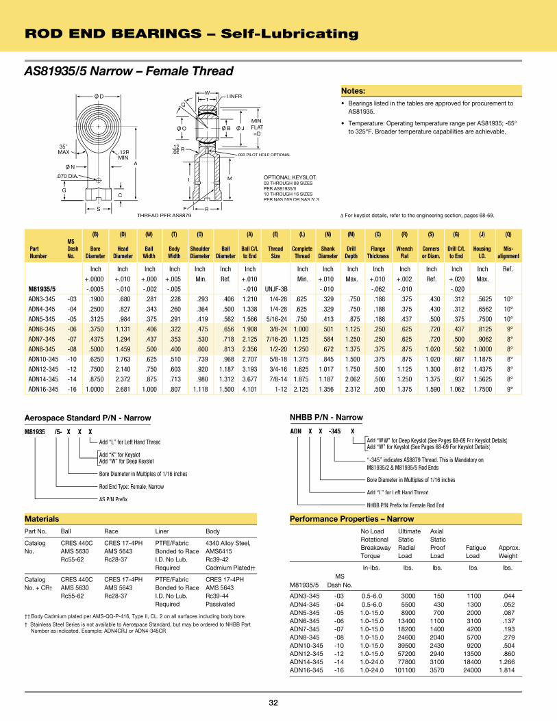
Inch Inch Inch Inch Inch Inch Inch Inch Inch Inch Inch Inch Inch Inch Inch Ref.
+.0000 +.010 +.000 +.005 Min. Ref. +.010 Min. +.010 Max. +.010 +.002 Ref. +.020 Max.
M81935/5 -.0005 -.010 -.002 -.005 -.010 UNJF-3B -.010 -.062 -.010 -.020
ADN3-345 -03 .1900 .680 .281 .228 .293 .406 1.210 1/4-28 .625 .329 .750 .188 .375 .430 .312 .5625 10°
ADN4-345 -04 .2500 .827 .343 .260 .364 .500 1.338 1/4-28 .625 .329 .750 .188 .375 .430 .312 .6562 10°
ADN5-345 -05 .3125 .984 .375 .291 .419 .562 1.566 5/16-24 .750 .413 .875 .188 .437 .500 .375 .7500 10°
ADN6-345 -06 .3750 1.131 .406 .322 .475 .656 1.908 3/8-24 1.000 .501 1.125 .250 .625 .720 .437 .8125 9°
ADN7-345 -07 .4375 1.294 .437 .353 .530 .718 2.125 7/16-20 1.125 .584 1.250 .250 .625 .720 .500 .9062 8°
ADN8-345 -08 .5000 1.459 .500 .400 .600 .813 2.356 1/2-20 1.250 .672 1.375 .375 .875 1.020 .562 1.0000 8°
ADN10-345 -10 .6250 1.763 .625 .510 .739 .968 2.707 5/8-18 1.375 .845 1.500 .375 .875 1.020 .687 1.1875 8°
ADN12-345 -12 .7500 2.140 .750 .603 .920 1.187 3.193 3/4-16 1.625 1.017 1.750 .500 1.125 1.300 .812 1.4375 8°
ADN14-345 -14 .8750 2.372 .875 .713 .980 1.312 3.677 7/8-14 1.875 1.187 2.062 .500 1.250 1.375 .937 1.5625 8°
ADN16-345 -16 1.0000 2.681 1.000 .807 1.118 1.500 4.101 1-12 2.125 1.356 2.312 .500 1.375 1.590 1.062 1.7500 9°
AS81935/5 Narrow – Female Thread
ROD END BEARINGS – Self-Lubricating
32
35°MAXMAXMA
A
G
THREAD PER AS8879
OPTIONAL KEYSLOT:OPTIONAL KEYSLOT:OPTIONAL KEYSLOT03 THROUGH 08 SIZESPER AS81935/510 THROUGH 16 SIZESPER NAS 559 OR NAS 513
.12RMIN.
C
S
.070 DIA.
WT
LINER
MIN.FLATFLATFLA=D
M
RE
L
R
Q
.093 PILOT HOLE OPTIONAL
.12
.06
O/ O O/ B O/ J
O/ D
O/ N
(B) (D) (W) (T) (O) (A) (E) (L) (N) (M) (C) (R) (S) (G) (J) (Q) MS Part Dash Bore Head Ball Body Shoulder Ball Ball C/L Thread Complete Shank Drill Flange Wrench Corners Drill C/L Housing Mis- Number No. Diameter Diameter Width Width Diameter Diameter to End Size Thread Diameter Depth Thickness Flat or Diam. to End I.D. alignment
Δ For keyslot details, refer to the engineering section, pages 68-69.
MaterialsPart No. Ball Race Liner Body
Catalog CRES 440C CRES 17-4PH PTFE/Fabric 4340 Alloy Steel, No. AMS 5630 AMS 5643 Bonded to Race AMS6415 Rc55-62 Rc28-37 I.D. No Lub. Rc39-42 Required Cadmium Plated††
Catalog CRES 440C CRES 17-4PH PTFE/Fabric CRES 17-4PH No. + CR† AMS 5630 AMS 5643 Bonded to Race AMS 5643 Rc55-62 Rc28-37 I.D. No Lub. Rc39-44 Required Passivated
†† Body Cadmium plated per AMS-QQ-P-416, Type II, CL. 2 on all surfaces including body bore.
† Stainless Steel Series is not available to Aerospace Standard, but may be ordered to NHBB Part Number as indicated. Example: ADN4CRJ or ADN4-345CR
Performance Properties – Narrow No Load Ultimate Axial Rotational Static Static Breakaway Radial Proof Fatigue Approx. Torque Load Load Load Weight
In-lbs. lbs. lbs. lbs. lbs. MSM81935/5 Dash No.
ADN3-345 -03 0.5-6.0 3000 150 1100 .044ADN4-345 -04 0.5-6.0 5500 430 1300 .052ADN5-345 -05 1.0-15.0 8900 700 2000 .087ADN6-345 -06 1.0-15.0 13400 1100 3100 .137ADN7-345 -07 1.0-15.0 18200 1400 4200 .193ADN8-345 -08 1.0-15.0 24600 2040 5700 .279ADN10-345 -10 1.0-15.0 39500 2430 9200 .504ADN12-345 -12 1.0-15.0 57200 2940 13500 .860ADN14-345 -14 1.0-24.0 77800 3100 18400 1.266ADN16-345 -16 1.0-24.0 101100 3570 24000 1.814
Notes:• Bearings listed in the tables are approved for procurement to
AS81935.
• Temperature: Operating temperature range per AS81935; -65° to 325°F. Broader temperature capabilities are achievable.
Add “W W” for Deep Keyslot (See Pages 68-69 For Keyslot Details)Add “W” for Keyslot (See Pages 68-69 For Keyslot Details)
Bore Diameter in Multiples of 1/16 inches
Add “L” for Left Hand Thread
NHBB P/N Prefix for Female Rod End
NHBB P/N - Narrow
ADN X X -345 X
“-345” indicates AS8879 Thread. This is Mandatory on M81935/2 & M81935/5 Rod Ends
Aerospace Standard P/N - Narrow
Add “L” for Left Hand Thread
Add “K” for KeyslotAdd “W” for Deep Keyslot
Bore Diameter in Multiples of 1/16 inches
Rod End Type: Female, Narrow
AS P/N Prefix
M81935 /5- X X X

Inch Inch Inch Inch Inch Inch Inch Inch Inch Inch Inch Inch Inch Inch Inch Ref.
+.0000 +.010 +.000 +.005 Min. Ref. +.010 Min. +.010 Max. +.010 +.002 Ref. +.020 Max.
M81935/2* -.0005 -.010 -.002 -.005 -.010 UNJF-3B -.010 -.062 -.010 -.020
ADN3J -03 .1900 .806 .437 .337 .300 .531 1.375 5/16-24 .750 .422 .875 .188 .437 .500 .375 .6250 15°
ADN4J -04 .2500 .806 .437 .337 .300 .531 1.469 5/16-24 .750 .422 .875 .188 .437 .500 .375 .6250 15°
ADN5J -05 .3125 .900 .437 .327 .360 .593 1.625 3/8-24 .875 .485 1.000 .250 .500 .580 .437 .6875 14°
ADN6J -06 .3750 1.025 .500 .416 .470 .687 1.812 3/8-24 1.000 .547 1.125 .250 .562 .660 .437 .8125 8°
ADN7J -07 .4375 1.150 .562 .452 .540 .781 2.000 7/16-20 1.125 .610 1.250 .250 .625 .720 .500 .9062 10°
ADN8J -08 .5000 1.337 .625 .515 .610 .875 2.250 1/2-20 1.250 .735 1.375 .250 .750 .880 .562 1.0000 9°
ADN10J -10 .6250 1.525 .750 .577 .750 1.062 2.500 5/8-18 1.375 .860 1.500 .375 .875 1.020 .687 1.1875 12°
ADN12J -12 .7500 1.775 .875 .640 .850 1.250 2.875 3/4-16 1.625 .985 1.750 .375 1.000 1.160 .812 1.3750 13°
ADN14J -14 .8750 2.025 .875 .765 1.000 1.375 3.375 7/8-14 1.875 1.110 2.062 .500 1.125 1.300 .937 1.6250 6°
ADN16J -16 1.0000 2.775 1.375 1.015 1.270 1.875 4.125 1 1/4-12 2.125 1.688 2.312 .563 1.750 2.020 1.312 2.1250 12°
33
AS81935/2 Wide – Female Thread
MaterialsPart No. Ball Race Liner Body
Catalog CRES 440C CRES 17-4PH PTFE/Fabric 4340 Alloy Steel, No. AMS 5630 AMS 5643 Bonded to Race AMS6415 Rc55-62 Rc28-37 I.D. No Lub. Rc39-42 Required Cadmium Plated††
Catalog CRES 440C CRES 17-4PH PTFE/Fabric CRES 17-4PH No. + CR† AMS 5630 AMS 5643 Bonded to Race AMS 5643 Rc55-62 Rc28-37 I.D. No Lub. Rc39-44 Required Passivated
†† Body Cadmium plated per AMS-QQ-P-416, Type II, CL. 2 on all surfaces including body bore.
† Stainless Steel Series is not available to Aerospace Standard, but may be ordered to NHBB Part
Number as indicated. Example: ADN4CRJ or ADN4-345CR
Performance Properties – Wide
No Load Ultimate Axial Rotational Static Static Breakaway Radial Proof Fatigue Approx. Torque Load Load Load Weight
In-lbs. lbs. lbs. lbs. lbs. MSM81935/2* Dash No.
ADN3J -03 0.5-6.0 2360 1000 1470 .080 ADN4J -04 0.5-6.0 4860 1000 2380 .084ADN5J -05 1.0-15.0 7180 1100 3020 .102ADN6J -06 1.0-15.0 8550 1660 3570 .161ADN7J -07 1.0-15.0 12000 1850 4800 .212ADN8J -08 1.0-15.0 19500 2040 8260 .325ADN10J -10 1.0-15.0 21900 2430 9180 .481ADN12J -12 1.0-15.0 29300 2810 11600 .673ADN14J -14 1.0-24.0 34500 3320 13100 .959ADN16J -16 1.0-24.0 80300 4340 30400 2.717
* For rod ends with threads per MIL-S-7742 Rev. D (UNF-3B), omit “J” from part number
Aer ospace Standar d P/N - Wide
Add “WW” for Deep Keyslot (See Pa ges 68-69 Fo r Keyslot Details )Add “W” for Keyslot (See Pa ges 68-69 F or Keyslot Details )
“J” Indicates AS8879 Thread. This is Mandator y onM81935/2 & M81935/5 Rod Ends
Bore Diameter in Multiples of 1/16 inches Bore Diameter in Multiples of 1/16 inches Bore Diameter
Add “L” for Left Hand Thread
NHBB P/N Prefix for F emale Rod End
NHBB P/N - Wide
ADN X X J X
Aerospace Standard P/N - Wide
Add “L” for Left Hand Thread
Add “K” for KeyslotAdd “W” for Deep Keyslot
Bore Diameter in Multiples of 1/16 inches
Rod End Type: Female, Wide
AS P/N Prefix
M81935 /2- X X X
(B) (D) (W) (T) (O) (A) (E) (L) (N) (M) (C) (R) (S) (G) (J) (Q) MS Part Dash Bore Head Ball Body Shoulder Ball Ball C/L Thread Complete Shank Drill Flange Wrench Corners Drill C/L Housing Mis- Number No. Diameter Diameter Width Width Diameter Diameter to End Size Thread Diameter Depth Thickness Flat or Diam. to End I.D. alignment
* For rod ends with threads per MIL-S-7742 Rev. D (UNF-3B), omit “J” from part number.
35°MAXMAXMA
A
G
THREAD PER AS8879
OPTIONAL KEYSLOT:OPTIONAL KEYSLOT:OPTIONAL KEYSLOT03 THROUGH 08 SIZESPER AS81935/210 THROUGH 16 SIZESPER NAS 559 OR NAS 513
.12RMIN.
C
S
.070 DIA.
WT
LINER
MIN.FLATFLATFLA=D
M
RE
L
R
Q
.093 PILOT HOLE OPTIONAL
.12
.06
O/ O
O/ N
O/ B O/ J
O/ DNotes:• Bearings listed in the tables are approved for procurement to
AS81935.
• Temperature: Operating temperature range per AS81935; -65° to 325°F. Broader temperature capabilities are achievable.
ROD END BEARINGS – Self-Lubricating
Δ For keyslot details, refer to the engineering section, pages 68-69.

Inch Inch Inch Inch Inch Inch Inch Inch Inch Inch Inch Inch Inch Inch Inch - lbs. lbs. lbs. lbs.
+.0000 +.010 +.000 +.005 +.010 UNF - 3A* +.031 +.010 +.010 +.002 Ref.
-.0005 -.010 -.002 -.005 Ref. Ref. -.010 UNF - 3B* Ref. -.031 Min. Ref. -.010 Ref. -.062 -.010
ARHT4E .2500 .806 .375 .337 .531 .375 1.562 5/16 - 24 5˚ .968 0.5- 6.0 6060 1000 .067
ARHT4 1.469 .750 .375 .485 .562 .188 .500 .084
ARHT5E .3125 .900 .437 .327 .593 .401 1.875 3/8 - 24 14˚ 1.187 1.0-10.0 7290 1100 .095
ARHT5 1.625 .875 .437 .547 .625 .250 .562 .102
ARHT6E .3750 1.025 .500 .416 .687 .471 1.938 7/16 - 20 9˚ 1.187 1.0-10.0 8870 1660 .140
ARHT6 1.812 1.000 .500 .610 .687 .250 .625 .160
ARHT7E .4375 1.150 .562 .452 .781 .542 2.125 1/2 - 20 10˚ 1.281 1.0-10.0 9560 1850 .210
ARHT7 2.000 1.125 .562 .735 .875 .250 .750 .230
ARHT8E .5000 1.337 .625 .515 .875 .612 2.438 5/8 - 18 9˚ 1.468 1.0-10.0 18560 2040 .330
ARHT8 2.250 1.250 .687 .860 1.000 .250 .875 .340
ARHT10E .6250 1.525 .750 .577 1.062 .752 2.625 3/4 - 16 12˚ 1.562 1.0-10.0 20610 2430 .480
ARHT10 2.500 1.375 .812 .985 1.125 .375 1.000 .490
ARHT12E .7500 1.775 .875 .640 1.250 .892 2.875 7/8 - 14 13˚ 1.687 1.0-10.0 27640 2810 .730
ARHT12 2.875 1.625 .937 1.110 1.250 .375 1.125 .740
ROD END BEARINGS – Self-Lubricating
Notes:
• †Plating: When specified in materials block, body cadmium plated all surfaces per AMS-QQ-P-416.
• Dimensions: Dimensions apply after plating.
• Temperature: Operating temperature range -65° to 350°F (ADY only).
• Qualifications: Liner is approved to MIL-B-8942 Rev. A (ARHT series only).
• Options:
1. For left hand threads, add “L” to prefix.(Examples: ARHTL4E or ARHTL4)
2. For Keyway or keyslot options add suffix “W” to part number.
3. For “J” form threads per AS8879, add suffix “J” to part number. (Examples: ARHT10EJW or ARHT10JW)
Materials (ARHT)Designation Ball Race Liner Body
Basic† CRES 440C Stainless PTFE C.M. Steel Part No. AMS 5630 Steel, H.T.†† Fabric H.T., Rc55-62 Bonded to Cadmium Race I.D. Plated
No. + CR CRES 440C Stainless PTFE CRES 17-4PH AMS 5630 Steel, H.T.†† Fabric AMS 5643 Rc55-62 Bonded to H.T. Race I.D.† Stainless Steel Series may be ordered to NHBB Part Number as indicated.
†† Part No. designation as shown furnished with CRES 410 race material. To specify CRES
17-4PH race material, add suffix “H” to designation. Examples: ARHT8ECRH or ARHT8CRH.
3-Piece Heavy Duty – Male & Female Threads
(B) (D) (W) (T) (O) (A) (E) (Q) (CM) (CF) (G) (N) (S) (C) (R) No Load Limit Axial Rotational Static Static Part Bore Head Ball Body Ball Flat Ball Thread Mis- Thread Thread Drill C/L Shank Flange Flange Wrench Breakaway Radial Proof Number Diameter Diameter Width Width Diameter Diameter C/L to End Size alignment Length Depth to end Diameter Diameter Thickness Flat Torque Load Load Weight
* UNF-3A = Male Thread. UNF-3B = Female Thread per MIL-S-7742, Rev. D.
Δ For keyway and keyslot details, refer to the engineering section, pages 68-69.
34
A
CM OPTIONAL KEYWAYOPTIONAL KEYWAYOPTIONAL KEYWWHEN SPECIFIED Δ
W
T
Q
E
LINER A
C
S
G
INSPECTIONHOLE
CF
R
RREF.
HREF.REF.REF
OPTIONALKEYSLOTWHEN SPECIFIED Δ
ARHT E ARHT
LINER
E
WT
Q
O/ O O/ BO/ O O/ B
O/ DO/ D
O/ N

Inch Inch Inch Inch Inch Inch Inch Inch Inch Inch Inch Inch Inch Inch - lbs. lbs. lbs.
+.0000 +.000 +.005 +.06 UNF - 3A* +.06 +.010 +.010 +.002 Ref.
-.0005 Max. -.005 -.005 Ref. Ref. -.06 UNF - 3B* Ref. -.06 -.010 Ref. Ref. -.062 -.010
ADYE3(L) .1900 .781 .560 .337 .301 .531 1.562 5/16 - 24 16˚ 1.000 0.5-6.0 2425 .07
ADY3(L) 1.625 .750 .500 .515 .562 .250 .375 .08
ADYE3-101(L) .1900 .750 .500 .220 .319 .437 1.500 5/16 - 24 15˚ 1.000 0.5-6.0 4060 ** .07
ADY3-101(L) 1.375 .750 .437 .452 .500 .250 .375 .06
ADYE4(L) .2500 1.000 .593 .265 .390 .593 1.938 3/8 - 24 23˚ 1.250 1.0-15.0 7040 ** .11
ADY4(L) 1.625 .937 .562 .577 .625 .250 .437 .11
ADYE5(L) .3125 1.125 .813 .355 .512 .781 2.125 7/16 - 20 23˚ 1.375 1.0-15.0 8260 .16
ADY5(L) 1.812 1.062 .625 .640 .688 .250 .500 .18
ADYE6(L) .3750 1.125 .813 .355 .512 .781 2.125 7/16 - 20 23˚ 1.375 1.0-15.0 8260 .15
ADY6(L) 1.812 1.062 .625 .640 .688 .250 .500 .17
ADYE7(L) .4375 1.312 .875 .355 .618 .875 2.437 1/2 - 20 22˚ 1.500 1.0-15.0 12420 .25
ADY7(L) 2.125 1.125 .750 .765 .812 .250 .562 .26
ADYE8(L) .5000 1.500 .937 .411 .730 1.000 2.625 5/8 - 18 20˚ 1.625 1.0-15.0 17430 .39
ADY8(L) 2.625 1.500 .875 .890 .938 .375 .687 .40
ADYE10(L) .6250 1.750 1.200 .577 .856 1.250 2.875 3/4 - 16 20˚ 1.750 1.0-15.0 23620 .62
ADY10(L) 2.875 1.750 1.000 1.015 1.125 .375 .812 .63
ADYE12(L) .7500 2.000 1.280 .630 .970 1.375 3.375 7/8 - 14 18˚ 1.875 1.0-24.0 30550 .90
ADY12(L) 3.375 1.875 1.125 1.140 1.250 .500 .937 .87
ADYE14(L) .8750 2.200 1.400 .635 1.140 1.531 3.750 7/8 - 14 18˚ 2.000 1.0-24.0 31970 1.08
ADY14(L) 3.750 2.000 1.125 1.140 1.250 .500 .937 1.01
ADYE16(L) 1.0000 2.750 1.875 .845 1.278 1.875 4.125 1 1/4 - 12 21˚ 2.125 1.0-24.0 59510 2.20
ADY16(L) 4.125 2.125 1.688 1.703 1.813 .562 1.312 2.31
ADYE20(L) 1.2500 3.125 1.875 1.015 1.523 2.250 5.000 1 1/4 - 12 21˚ 2.875 1.0-24.0 70060 3.10
ADY20(L) 5.000 3.125 1.688 1.703 1.813 .562 1.312 3.15
ΔFor keyway and keyslot details, refer to the engineering section, page 68-69.
35
(B) (D) (W) (T) (O) (A) (E) (Q) (L) (N) (R) (S) (C) (G) No Load Limit Rotational Static Part Bore Head Ball Body Shoulder Ball Ball C/L Thread Mis- Thread Shank Wrench Flange Flange Drill C/L Breakaway Radial Number Diameter Diameter Width Width Diameter Diameter to End Size alignment Length Diameter Flat Diameter Thickness to End Torque Load Weight
* UNF-3A = Male Thread. UNF-3B = Female Thread per MIL-S-7742, Rev. D. ** Load based on pin limitation.
3-Piece High Misalignment – Male & Female Threads
C
WT
Q
ML
E ROPTIONAL KEYSLOT
G
S
ADY
OPTIONAL KEYSLOTOPTIONAL KEYSLOT:OPTIONAL KEYSLOT:OPTIONAL KEYSLOTREF. NAS 559 . NAS 559 REF. NAS 559 REF ΔWHEN SPECIFIED
OPTIONALKEYWAYWAYWAREF. NAS 559 ΔWHENSPECIFIED
ADYELINER
L
WT
Q
AE
LINER
INSPECTIONHOLE
O/ O
A
O/ B
O/ D
O/ N
O/ D
O/ B O/ O
Notes:
• †Plating: When specified in materials block, body cadmium plated all surfaces per AMS-QQ-P-416.
• Dimensions: Dimensions apply after plating.
• Temperature: Operating temperature range -65° to 350°F (ADY only).
• Qualifications: Liner is approved to AS81820 (ADY series only.)
• Options:
1. For left hand threads, add “L” to prefix.(Examples: ADYEL4(L) or ADYL4(L))
2. For Keyway or keyslot options add suffix “W” to part number.
3. For “J” form threads per AS8879, add suffix “J” to part number. (Examples: ADYE4JW(L) or ADY4JW(L))
Materials (ADYE & ADY)Part No. Ball Race Liner Body
Catalog No. CRES 440C CRES 17-4PH PTFE 4130 Alloy Steel AMS 5630 AMS 5643 Fabric Bonded H.T., and Rc55-62 Rc28-37 to Race I.D. Cadmium No Lub.Required Plated†
Catalog No. CRES 440C CRES 17-4PH PTFE CRES 17-4PH + SS AMS 5630 AMS 5643 Fabric Bonded AMS 5643 Rc55-62 Rc28-37 to Race I.D. H.T., and No Lub.Required Passivated
† Stainless Steel Series may be ordered to NHBB Part Number as indicated.
ROD END BEARINGS – Self-Lubricating

36

37
SECTION 5ROD END BEARINGS – Metal-to-Metal
Metal-to-Metal
3-Piece Male Thread . . . . . . . . . . . . . . . . . . . . . . . . . . . . . . . . . . . . . . . . . . . . . .38
3-Piece Female Thread . . . . . . . . . . . . . . . . . . . . . . . . . . . . . . . . . . . . . . . . . . . .39
3-Piece Heavy Duty – Male & Female Threads . . . . . . . . . . . . . . . . . . . . . . . . .40
3-Piece Standard – Male & Female Threads. . . . . . . . . . . . . . . . . . . . . . . . . . . .41
3-Piece High Misalignment – Male Thread . . . . . . . . . . . . . . . . . . . . . . . . . . . . .42
3-Piece High Misalignment – Female Thread . . . . . . . . . . . . . . . . . . . . . . . . . . .43
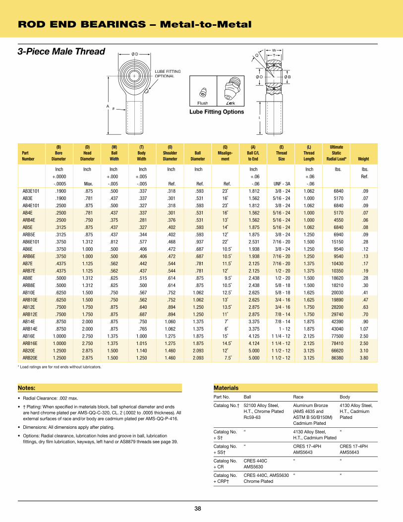
ROD END BEARINGS – Metal-to-Metal
38
Inch Inch Inch Inch Inch Inch Inch Inch lbs. lbs.
+.0000 +.000 +.005 +.06 +.06 Ref.
-.0005 Max. -.005 -.005 Ref. Ref. Ref. -.06 UNF - 3A -.06
AB3E101 .1900 .875 .500 .337 .318 .593 23˚ 1.812 3/8 - 24 1.062 6840 .09
AB3E .1900 .781 .437 .337 .301 .531 16˚ 1.562 5/16 - 24 1.000 5170 .07
AB4E101 .2500 .875 .500 .327 .318 .593 23˚ 1.812 3/8 - 24 1.062 6840 .09
AB4E .2500 .781 .437 .337 .301 .531 16˚ 1.562 5/16 - 24 1.000 5170 .07
ARB4E .2500 .750 .375 .281 .376 .531 13˚ 1.562 5/16 - 24 1.000 4550 .06
AB5E .3125 .875 .437 .327 .402 .593 14˚ 1.875 5/16 - 24 1.062 6840 .08
ARB5E .3125 .875 .437 .344 .402 .593 12˚ 1.875 3/8 - 24 1.250 6940 .09
AB6E101 .3750 1.312 .812 .577 .468 .937 22˚ 2.531 7/16 - 20 1.500 15150 .28
AB6E .3750 1.000 .500 .406 .472 .687 10.5˚ 1.938 3/8 - 24 1.250 9540 .12
ARB6E .3750 1.000 .500 .406 .472 .687 10.5˚ 1.938 7/16 - 20 1.250 9540 .13
AB7E .4375 1.125 .562 .442 .544 .781 11.5˚ 2.125 7/16 - 20 1.375 10430 .17
ARB7E .4375 1.125 .562 .437 .544 .781 12˚ 2.125 1/2 - 20 1.375 10350 .19
AB8E .5000 1.312 .625 .515 .614 .875 9.5˚ 2.438 1/2 - 20 1.500 18620 .28
ARB8E .5000 1.312 .625 .500 .614 .875 10.5˚ 2.438 5/8 - 18 1.500 18210 .30
AB10E .6250 1.500 .750 .567 .752 1.062 12.5˚ 2.625 5/8 - 18 1.625 20030 .41
ARB10E .6250 1.500 .750 .562 .752 1.062 13˚ 2.625 3/4 - 16 1.625 19890 .47
AB12E .7500 1.750 .875 .640 .894 1.250 13.5˚ 2.875 3/4 - 16 1.750 28200 .63
ARB12E .7500 1.750 .875 .687 .894 1.250 11˚ 2.875 7/8 - 14 1.750 29740 .70
AB14E .8750 2.000 .875 .750 1.060 1.375 7˚ 3.375 7/8 - 14 1.875 42390 .90
ARB14E .8750 2.000 .875 .765 1.062 1.375 6˚ 3.375 1 - 12 1.875 43040 1.07
AB16E 1.0000 2.750 1.375 1.000 1.275 1.875 15˚ 4.125 1 1/4 - 12 2.125 77500 2.50
ARB16E 1.0000 2.750 1.375 1.015 1.275 1.875 14.5˚ 4.124 1 1/4 - 12 2.125 78410 2.50
AB20E 1.2500 2.875 1.500 1.140 1.460 2.093 12˚ 5.000 1 1/2 - 12 3.125 66620 3.10
ARB20E 1.2500 2.875 1.500 1.250 1.460 2.093 7.5˚ 5.000 1 1/2 - 12 3.125 86380 3.80
(B) (D) (W) (T) (O) (Q) (A) (E) (L) Ultimate Part Bore Head Ball Body Shoulder Ball Misalign- Ball C/L Thread Thread Static Number Diameter Diameter Width Width Diameter Diameter ment to End Size Length Radial Load* Weight
WTQ
L
EA
O/ D
O/ O O/ BLUBE FITTINGOPTIONAL
* Load ratings are for rod ends without lubricators.
3-Piece Male Thread
Notes:
• Radial Clearance: .002 max.
• † Plating: When specified in materials block, ball spherical diameter and ends are hard chrome plated per AMS-QQ-C-320, CL. 2 (.0002 to .0005 thickness). All external surfaces of race and/or body are cadmium plated per AMS-QQ-P-416.
• Dimensions: All dimensions apply after plating.
• Options: Radial clearance, lubrication holes and groove in ball, lubrication fittings, dry film lubrication, keyways, left hand or AS8879 threads see page 39.
MaterialsPart No. Ball Race Body
Catalog No.† 52100 Alloy Steel, Aluminum Bronze 4130 Alloy Steel, H.T., Chrome Plated (AMS 4635 and H.T., Cadmium Rc59-63 ASTM B 50/B150M) Plated Cadmium Plated
Catalog No. “ 4130 Alloy Steel, “ + S† H.T., Cadmium Plated
Catalog No. “ CRES 17-4PH CRES 17-4PH + SS† AMS5643 AMS5643
Catalog No. CRES 440C “ “ + CR AMS5630
Catalog No. CRES 440C, AMS5630 “ “ + CRP† Chrome Plated
ZerkFlush
Lube Fitting Options

39
Inch Inch Inch Inch Inch Inch Inch Inch Inch Inch Inch lbs. lbs.
+.0000 +.000 +.005 +.06 +.00 +.010 Ref.
-.0005 Max. -.005 -.005 Ref. Ref. -.06 UNF - 3B Ref. -.09 -.010 Ref. Ref.
AB3 .1900 .781 .437 .337 .301 .531 1.375 5/16 - 24 16˚ .750 .437 .500 .180 5170 .06
AB3-101 .1900 .781 .437 .337 .301 .531 1.000 1/4 - 28 16˚ .375 .375 .440 .180 5170 .06
AB3-102 .1900 .781 .437 .337 .301 .531 1.375 1/4 - 28 16˚ .750 .375 .440 .180 5170 .07
AB3-103 .1900 .875 .500 .337 .318 .593 1.625 5/16 - 24 23˚ .750 .500 .560 .180 6840 .11
AB4 .2500 .781 .437 .337 .301 .531 1.375 1/4 - 28 16˚ .750 .375 .440 .180 5170 .07
AB4-101 .2500 .781 .437 .337 .301 .531 1.469 5/16 - 24 16˚ .750 .437 .500 .180 5170 .08
AB4-102 .2500 .875 .500 .327 .318 .593 1.625 5/16 - 24 24˚ .750 .500 .560 .180 6680 .10
AB4-103 .2500 .750 .375 .296 .376 .531 1.312 1/4 - 28 11˚ .750 .375 .440 .180 4750 .06
ARB4 .2500 .750 .375 .281 .376 .531 1.312 1/4 - 28 13˚ .750 .375 .437 .180 4550 .06
AB5 .3125 .875 .437 .327 .402 .593 1.375 5/16 - 24 14˚ .750 .437 .500 .180 6680 .08
ARB5 .3125 .875 .437 .344 .402 .593 1.375 5/16 - 24 12˚ .750 .437 .500 .180 6940 .07
AB6 .3750 1.000 .500 .406 .472 .687 1.625 3/8 - 24 10.5˚ .937 .562 .620 .180 9540 .12
ARB6 .3750 1.000 .500 .406 .472 .687 1.625 3/8 - 24 10.5˚ .937 .562 .625 .180 9540 .12
AB7 .4375 1.125 .562 .442 .544 .781 1.812 7/16 - 20 11.5˚ 1.062 .625 .680 .180 10430 .18
ARB7 .4375 1.125 .562 .437 .544 .781 1.812 7/16 - 20 12˚ 1.062 .625 .750 .180 10350 .18
AB8 .5000 1.312 .625 .515 .614 .875 2.125 1/2 - 20 9.5˚ 1.125 .750 .870 .180 18620 .28
ARB8 .5000 1.312 .625 .500 .614 .875 2.125 1/2 - 20 10.5˚ 1.187 .750 .875 .180 18210 .28
AB10 .6250 1.500 .750 .567 .752 1.062 2.625 5/8 - 18 12.5˚ 1.500 .875 .930 .250 20030 .42
ARB10 .6250 1.500 .750 .562 .752 1.062 2.500 5/8 - 18 13˚ 1.500 .875 .937 .250 19890 .42
AB12 .7500 1.750 .875 .640 .894 1.250 2.875 3/4 - 16 13.5˚ 1.750 1.000 1.060 .250 28200 .63
ARB12 .7500 1.750 .875 .687 .894 1.250 2.875 3/4 - 16 11˚ 1.750 1.000 1.062 .250 29740 .63
ARB14 .8750 2.000 .875 .765 1.062 1.375 3.375 7/8 - 14 6˚ 1.875 1.125 1.187 .312 43040 .90
ARB16 1.0000 2.750 1.375 1.015 1.275 1.875 4.125 1 - 12 14.5˚ 2.125 1.250 1.312 .375 78410 2.00
ARB20 1.2500 2.875 1.500 1.250 1.460 2.093 5.000 1 1/4 - 12 7.5˚ 3.125 1.688 1.750 .375 86380 3.10
(B) (D) (W) (T) (O) (A) (E) (Q) (L) (N) (S) (C) Ultimate Part Bore Head Ball Body Shoulder Ball Ball C/L Thread Misalign- Thread Shank Flange Flange Static Number Diameter Diameter Width Width Diameter Diameter to End Size ment Depth Diameter Diameter Thickness Radial Load* Weight
* Load ratings are for rod ends without lubrication fittings.
L
E
INSPECTION HOLE
A
E + .06C
S
WTQ
LUBE FITTINGOPTIONAL
O/ D
O/ O O/ B
O/ N
3-Piece Female Thread
Dry-film Lubrication–1 Film on Spherical Surface of Race–2 Film on Bore of Ball–3 Film on Spherical Surface of Ball
.0005 Maximum Radial Clearance
Keyway or Keyslot Option (Pages 68-69)
“J” for AS8879 Threads (UNJF-3A)Threads (UNJF-3A)Threads (UNJF-3AOmit J for MIL-S-7742 Rev. D Threads (UNF-3A)
Flush Type of Lube Fitting = FNZerk Type of Lube Fitting = F
Lubrication Holes & Groove in Ball
Material Code
Male Thread
Bore of Ball in Sixteenths
Left-hand Thread
Series (“ARB” or “AB”)
NHBB P/N
ARB L 4 E CR A FN J W X 123
ZerkFlush
Lube Fitting Options
ROD END BEARINGS – Metal-to-Metal

3-Piece Heavy Duty – Male & Female Threads
ROD END BEARINGS – Metal-to-Metal
40
Inch Inch Inch Inch Inch Inch Inch Inch Inch Inch Inch lbs. lbs. lbs.
+.0005 +.010 +.000 +.005 +.010 UNF - 3A* +.031 +.010 Ref.
-.0005 -.010 -.005 -.005 Ref. Ref. -.010 UNF - 3B* -.031 Ref. Ref. Ref. -.062
ARH4E .2500 .806 .375 .337 .375 .531 1.562 5/16 - 24 .968 5˚ 6060 6060 .067
ARH4 1.469 .750 .485 .562 .188 .084
ARH5E .3125 .900 .437 .327 .401 .593 1.875 3/8 - 24 1.187 14˚ 7290 7290 .095
ARH5 1.625 .875 .547 .625 .250 .102
ARH6E .3750 1.025 .500 .416 .471 .687 1.938 7/16 - 20 1.187 9˚ 8860 8860 .140
ARH6 1.812 1.000 .610 .687 .250 .160
ARH7E .4375 1.150 .562 .452 .542 .781 2.125 1/2 - 20 1.281 10˚ 9560 9560 .210
ARH7 2.000 1.125 .735 .875 .250 .230
ARH8E .5000 1.337 .625 .515 .612 .875 2.438 5/8 - 18 1.468 9˚ 18560 18560 .330
ARH8 2.225 1.250 .860 1.000 .250 .340
ARH10E .6250 1.525 .750 .577 .752 1.062 2.625 3/4 - 16 1.562 12˚ 20610 20610 .480
ARH10 2.500 1.375 .985 1.125 .375 .490
ARH12E .7500 1.775 .875 .644 .892 1.250 2.875 7/8 - 14 1.687 13˚ 27640 27640 .730
ARH12 2.875 1.625 1.110 1.250 .375 .740
(B) (D) (W) (T) (O) (A) (E) (L) (Q) (N) (S) (C) Static Radial Part Bore Head Ball Body Shoulder Ball Ball C/L Thread Thread Misalign- Shank Flange Flange Limit Load** Number Diameter Diameter Width Width Diameter Diameter to End Size Length ment Diameter Diameter Thickness Steel Race Bronze Race Weight
A
L
LUBE FITTINGOPTIONAL
LUBRICATIOLUBRICATIOLUBRICA NGROOVES & HOLES
ONLY WHEN LUBEONLY WHEN LUBEONLFITTING SPECIFIED
E
E
LUBRICATION HOLELUBRICATION HOLELUBRICAWHEN LUBE FITTINGSPECIFIED
WRENCH FLATWRENCH FLATWRENCH FLAWIDTH = N
LUBRICATIOLUBRICATIOLUBRICA NGROOVES & HOLESWHEN LUBE FITTINGSPECIFIED
ARH E ARH
A
C E + .06
INSPECTIONHOLE
LUBEFITTING OPTIONAL
S
WT
Q
L
WT
QO/ D O/ D
O/ N
O/ O O/ B O/ O O/ B
Notes:
• Radial Clearance: .002 max.
• † Plating: When specified in materials block, ball spherical diameter and ends are hard chrome plated per AMS-QQ-C-320, CL. 2 (.0002 to .0005 thickness). All external surfaces of race and/or body are cadmium plated per AMS-QQ-P-416.
• Unless otherwise noted, part number designation as shown furnished with CRES 410 race material. To specify CRES 17-4PH, add suffix “H” to designation. Example: ARH8ECRPLH or ARH8CRPLH.
• Dimensions: All dimensions apply after plating.
• Options: Radial clearance, lubrication holes and groove in ball, lubrication fittings, dry film lubrication, keyways, left hand or AS8879 threads see page 41.
MaterialsDesignation Ball Race Body
Basic Part No.† 52100 Alloy 4130 Alloy Steel, C.M. Steel, Steel, H.T. & H.T. & H.T. & Chrome Plated Cad. Plated Cad. Plated
Part No. + SS† 52100 Alloy Stainless Steel† C.M. Steel, Steel, H.T. & H.T. H.T. & Chrome Plated Cad. Plated
Part No. + CR† CRES 440C Stainless Steel† CRES 17-4PH H.T. H.T. H.T.
Part No. + CRPL† CRES 440C Stainless Steel† CRES 17-4PH H.T. & H.T. H.T. Chrome Plated
Part No. + 501† 52100 Alloy Steel Aluminum Bronze C.M. Steel, H.T. & (AMS 4635 and H.T. & Chrome Plated ASTM B 50/B150M) Cad. Plated Cad. Plated
* UNF-3A = Male Thread, UNF-3B = Female Thread, per MIL-S-7742 Rev. D.
** Load ratings are based on male rod ends without lubrication fitting. For rod end load ratings with lubrication fittings please contact NHBB engineering department.
ZerkFlush
Lube Fitting Options
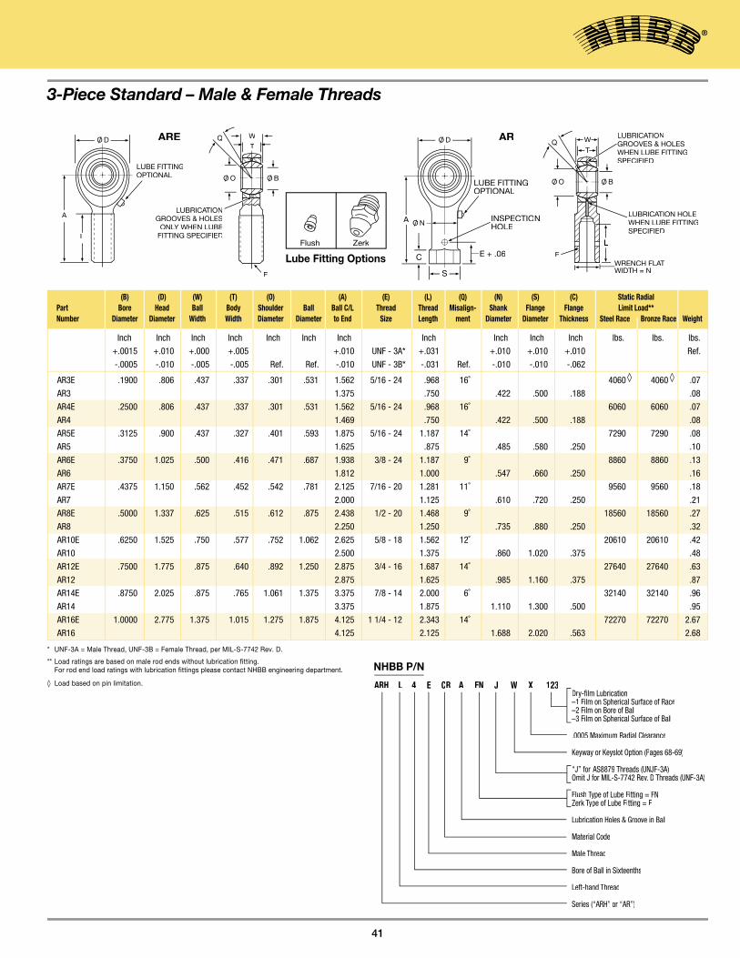
41
3-Piece Standard – Male & Female Threads
Inch Inch Inch Inch Inch Inch Inch Inch Inch Inch Inch lbs. lbs. lbs.
+.0015 +.010 +.000 +.005 +.010 UNF - 3A* +.031 +.010 +.010 +.010 Ref.
-.0005 -.010 -.005 -.005 Ref. Ref. -.010 UNF - 3B* -.031 Ref. -.010 -.010 -.062
AR3E .1900 .806 .437 .337 .301 .531 1.562 5/16 - 24 .968 16˚ 4060 ◊ 4060 ◊ .07
AR3 1.375 .750 .422 .500 .188 .08
AR4E .2500 .806 .437 .337 .301 .531 1.562 5/16 - 24 .968 16˚ 6060 6060 .07
AR4 1.469 .750 .422 .500 .188 .08
AR5E .3125 .900 .437 .327 .401 .593 1.875 5/16 - 24 1.187 14˚ 7290 7290 .08
AR5 1.625 .875 .485 .580 .250 .10
AR6E .3750 1.025 .500 .416 .471 .687 1.938 3/8 - 24 1.187 9˚ 8860 8860 .13
AR6 1.812 1.000 .547 .660 .250 .16
AR7E .4375 1.150 .562 .452 .542 .781 2.125 7/16 - 20 1.281 11˚ 9560 9560 .18
AR7 2.000 1.125 .610 .720 .250 .21
AR8E .5000 1.337 .625 .515 .612 .875 2.438 1/2 - 20 1.468 9˚ 18560 18560 .27
AR8 2.250 1.250 .735 .880 .250 .32
AR10E .6250 1.525 .750 .577 .752 1.062 2.625 5/8 - 18 1.562 12˚ 20610 20610 .42
AR10 2.500 1.375 .860 1.020 .375 .48
AR12E .7500 1.775 .875 .640 .892 1.250 2.875 3/4 - 16 1.687 14˚ 27640 27640 .63
AR12 2.875 1.625 .985 1.160 .375 .87
AR14E .8750 2.025 .875 .765 1.061 1.375 3.375 7/8 - 14 2.000 6˚ 32140 32140 .96
AR14 3.375 1.875 1.110 1.300 .500 .95
AR16E 1.0000 2.775 1.375 1.015 1.275 1.875 4.125 1 1/4 - 12 2.343 14˚ 72270 72270 2.67
AR16 4.125 2.125 1.688 2.020 .563 2.68
(B) (D) (W) (T) (O) (A) (E) (L) (Q) (N) (S) (C) Static Radial Part Bore Head Ball Body Shoulder Ball Ball C/L Thread Thread Misalign- Shank Flange Flange Limit Load** Number Diameter Diameter Width Width Diameter Diameter to End Size Length ment Diameter Diameter Thickness Steel Race Bronze Race Weight
* UNF-3A = Male Thread, UNF-3B = Female Thread, per MIL-S-7742 Rev. D.
** Load ratings are based on male rod ends without lubrication fitting. For rod end load ratings with lubrication fittings please contact NHBB engineering department.
◊ Load based on pin limitation.
A
L
LUBE FITTINGOPTIONAL
LUBRICATIOLUBRICATIOLUBRICA NGROOVES & HOLES
ONLY WHEN LUBEONLY WHEN LUBEONLFITTING SPECIFIED
E
E
LUBRICATION HOLLUBRICATION HOLLUBRICA EWHEN LUBE FITTINGSPECIFIED
WRENCH FLATWRENCH FLATWRENCH FLAWIDTH = N
LUBRICATIOLUBRICATIOLUBRICA NGROOVES & HOLESWHEN LUBE FITTINGSPECIFIED
ARE AR
A
C E + .06
INSPECTIONHOLE
LUBE FITTINGOPTIONAL
S
WT
Q
L
WT
QO/ D O/ D
O/ N
O/ O O/ B O/ O O/ B
Dry-film Lubrication–1 Film on Spherical Surface of Race–2 Film on Bore of Ball–3 Film on Spherical Surface of Ball
.0005 Maximum Radial Clearance
Keyway or Keyslot Option (Pages 68-69)
“J” for AS8879 Threads (UNJF-3A)Threads (UNJF-3A)Threads (UNJF-3AOmit J for MIL-S-7742 Rev. D Threads (UNF-3A)
Flush Type of Lube Fitting = FNZerk Type of Lube Fitting = F
Lubrication Holes & Groove in Ball
Material Code
Male Thread
Bore of Ball in Sixteenths
Left-hand Thread
Series (“ARH” or “AR”)
NHBB P/N
ARH L 4 E CR A FN J W X 123
ZerkFlush
Lube Fitting Options
ROD END BEARINGS – Metal-to-Metal

3-Piece High Misalignment – Male Thread
ROD END BEARINGS – Metal-to-Metal
42
Notes:
• Radial Clearance: .002 max.
• † Plating: When specified in materials block, ball spherical diameter and ends are hard chrome plated per AMS-QQ-C-320, CL. 2 (.0002 to .0005 thickness). All external surfaces of race and/or body are cadmium plated per AMS-QQ-P-416.
• Dimensions: All dimensions apply after plating.
• Options: Radial clearance, lubrication holes and groove in ball, lubrication fittings, dry film lubrication, keyways, left hand or AS8879 threads see page 43.
MaterialsPart No. Ball Race Body
Catalog No.† 52100 Alloy Steel, Aluminum Bronze, 4130 Alloy Steel, H.T., Chrome Plated (AMS 4635 and H.T., Cadmium Rc59-63 ASTM B 50/B150M) Plated Cadmium Plated
Catalog No. “ 4130 Alloy Steel, H.T., “ + S† Cadmium Plated
Catalog No. “ CRES 17-4PH CRES 17-4PH + SS† AMS5643 AMS5643
Catalog No. CRES 440C “ “ + CR† AMS5630
Catalog No. CRES 440C, AMS5630 “ “ + CRP† Chrome Plated.
Inch Inch Inch Inch Inch Inch Inch Inch Ref. lbs. lbs.
+.0000 Max. +.000 +.005 Ref. Ref. +.06 UNF - 3A* +.06 Ref.
-.0005 -.005 -.005 -.005 -.06 -.06
ARY3 .1900 .781 .560 .337 .301 .531 1.562 5/16 - 24 1.000 16˚ 4060 ◊ .07
ARY3-101 .1900 .750 .500 .220 .319 .437 1.500 5/16 - 24 1.000 15˚ 4060 ◊ .07
ARY4 .2500 1.000 .593 .265 .390 .593 1.938 3/8 - 24 1.250 23˚ 7040 ◊ .11
ARY5 .3125 1.125 .813 .355 .512 .781 2.125 7/16 - 20 1.375 23˚ 8260 .16
ARY5-101 .3125 .875 .625 .265 .418 .593 1.875 5/16 - 24 1.062 16˚ 5290 .09
ARY 6 .3750 1.125 .813 .355 .512 .781 2.125 7/16 - 20 1.375 23˚ 8260 .15
ARY7 .4375 1.312 .875 .355 .618 .875 2.437 1/2 - 20 1.500 22˚ 12420 .25
ARY8 .5000 1.500 .937 .411 .730 1.000 2.625 5/8 - 18 1.625 20˚ 17430 .39
ARY10 .6250 1.750 1.200 .577 .856 1.250 2.875 3/4 - 16 1.750 20˚ 23620 .62
ARY12 .7500 2.000 1.280 .630 .970 1.375 3.375 7/8 - 14 1.875 18˚ 30550 .90
ARY14 .8750 2.200 1.400 .635 1.140 1.531 3.750 7/8 - 14 2.000 18.5˚ 31970 1.08
ARY16 1.0000 2.750 1.875 .845 1.278 1.875 4.125 1 1/4 - 12 2.125 21˚ 59510 2.20
ARY20 1.2500 3.125 1.875 1.015 1.523 2.250 5.000 1 1/4 - 12 2.875 21˚ 70060 3.10
(B) (D) (W) (T) (O) (A) (E) (L) (Q) Part Bore Head Ball Body Shoulder Ball Ball C/L Thread Thread Misalign- Limit Static Number Diameter Diameter Width Width Diameter Diameter to End Size Length ment Radial Load** Weight
W
T
Q
LUBRICATIOLUBRICATIOLUBRICA NGROOVES & HOLESWHEN LUBE FITTINGSPECIFIED
E
.015
.005OR 45° CHAMFER (TYP.) CHAMFER (TYP.) CHAMFER (TYP
R
A
L
LUBE FITTINGOPTIONAL
O/ D
O/ BO/ O
* UNF-3A = Male Thread, per MIL-S-7742 Rev. D.** Load ratings are for rod ends without lubrication fittings.◊ Based on pin limitation.
ZerkFlush
Lube Fitting Options

43
A
C E + .06
INSPECTIONHOLE
LUBEFITTING OPTIONAL
S
Q
E
LUBRICATION HOLEWHEN LUBE FITTINGSPECIFIED
WRENCH FLATWRENCH FLATWRENCH FLWIDTH = N
LUBRICATIONGROOVES & HOLESWHEN LUBE FITTINGSPECIFIED
L
.015
.005 R OR 45°CHAMFER (TYP.)CHAMFER (TYP.)CHAMFER (TYP
W
TO/ D
O/ BO/ O
O/ N
Inch Inch Inch Inch Inch Inch Inch Inch Ref. Inch Inch Inch lbs. lbs.
+.0000 Max. +.000 +.005 Ref. Ref. +.06 +.06 +.010 Ref. Ref. Ref.
-.0005 -.005 -.005 -.06 UNF - 3B* -.06 -.010
ARYF3 .1900 .781 .560 .337 .301 .531 1.625 5/16 - 24 .750 16˚ .500 .562 .250 4060 ◊ .08
ARYF3-101 .1900 .750 .500 .220 .319 .437 1.375 5/16 - 24 .750 15˚ .437 .500 .250 4060 ◊ .06
ARYF4 .2500 1.000 .593 .265 .390 .593 1.625 3/8 - 24 .937 23˚ .562 .625 .250 7040 ◊ .11
ARYF5 .3125 1.125 .813 .355 .512 .781 1.812 7/16 - 20 1.062 23˚ .625 .688 .250 8260 .18
ARYF5-101 .3125 .875 .625 .265 .418 .593 1.375 5/16 - 24 .750 16˚ .437 .500 .250 5290 .10
ARYF6 .3750 1.125 .813 .355 .512 .781 1.812 7/16 - 20 1.062 23˚ .625 .688 .250 8260 .17
ARYF7 .4375 1.312 .875 .355 .618 .875 2.125 1/2 - 20 1.125 22˚ .750 .812 .250 12420 .26
ARYF8 .5000 1.500 .937 .411 .730 1.000 2.625 5/8 - 18 1.500 20˚ .875 .938 .375 17430 .40
ARYF10 .6250 1.750 1.200 .577 .856 1.250 2.875 3/4 - 16 1.750 20˚ 1.000 1.125 .375 23620 .63
ARYF12 .7500 2.000 1.280 .630 .970 1.375 3.375 7/8 - 14 1.875 18˚ 1.125 1.250 .500 30550 .87
ARYF14 .8750 2.200 1.400 .635 1.140 1.531 3.750 7/8 - 14 2.000 18.5˚ 1.125 1.250 .500 31970 1.01
ARYF16 1.0000 2.750 1.875 .845 1.278 1.875 4.125 1 1/4 - 12 2.125 21˚ 1.688 1.813 .562 59510 2.31
ARYF20 1.2500 3.125 1.875 1.015 1.523 2.250 5.000 1 1/4 - 12 3.125 21˚ 1.688 1.813 .562 70060 3.15
(B) (D) (W) (T) (O) (A) (E) (L) (Q) (N) (S) (C) Part Bore Head Ball Body Shoulder Ball Ball C/L Thread Thread Misalign- Shank Flange Flange Limit Static Number Diameter Diameter Width Width Diameter Diameter to End Size Length ment Diameter Diameter Thickness Radial Load** Weight
* UNF-3B = Female Thread per MIL-S-7742 Rev. D.** Load ratings are for rod ends without lubrication fittings.◊ Based on pin limitation.
Dry-film Lubrication–1 Film on Spherical Surface of Race–2 Film on Bore of Ball–3 Film on Spherical Surface of Ball
.0005 Maximum Radial Clearance
Keyway or Keyslot Option (Pages 68-69)
J for AS8879 Threads (UNJF-3A)Omit J for MIL-S-7742 Rev. D Threads (UNF-3A)Threads (UNF-3A)Threads (UNF-3A
Flush Type of Lube Fitting = FNZerk Type of Lube Fitting = F
Lubrication Holes & Groove in Ball
Material Code
Bore of Ball in Sixteenths
Left-hand Thread
Series (“ARY” or “ARYF”)or “ARYF”)or “AR
NHBB P/N
ARY L 4 CR A FN J W X 123
ZerkFlush
Lube Fitting Options
3-Piece High Misalignment – Female Thread

44

45
SECTION 6SLEEVE BEARINGS – Self-Lubricating
AS81934/1 Plain . . . . . . . . . . . . . . . . . . . . . . . . . . . . . . . . . . . . . . . . . . . . . . . . . . . . .46
AS81934/2 Flanged . . . . . . . . . . . . . . . . . . . . . . . . . . . . . . . . . . . . . . . . . . . . . . . . . .48

Inch lb/in lb/in
+.0000
M81934/1 -.0010
AD04 .2512 .3760 .3860 .3960 .006 .016
AD05 .3140 .4386 .4486 .4586 .007 .019
AD06 .3765 .5012 .5112 .5212 .008 .022
AD07 .4390 .5638 .5738 .5838 .009 .025
AD08 .5015 .6265 .6365 .6465 .011 .028
AD09 .5640 .6892 .6992 .7092 .012 .031
AD10 .6265 .8142 .8242 .8342 .021 .056
AD11 .6890 .8767 .8867 .8967 .022 .060
AD12 .7515 .9393 .9493 .9593 .024 .065
AD14 .8765 1.0645 1.0745 1.0845 .028 .075
AD16 1.0015 1.1898 1.1998 1.2098 .031 .084
AD18 1.1265 1.3148 1.3248 1.3348 .035 .094
AD20 1.2515 1.4398 1.4498 1.4598 .038 .103
AD22 1.3765 1.5648 1.5748 1.5848 .041 .113
AD24 1.5015 1.7523 1.7623 1.7723 .062 .171
AD26 1.6265 1.8773 1.8873 1.8973 .067 .183
AD28 1.7515 2.0023 2.0123 2.0223 .071 .196
AD32 2.0015 2.2523 2.2623 2.2723 .081 .222
SLEEVE BEARINGS – Self-Lubricating
.030
.020CHAMFER
15° ±2°
.010 MAX. FOR LENGTH CODE 12 OR LESS;
.025 MAX. FOR ALL OTHER LENGTHS
.015 x 45° MAX. CHAMFER
CHAMFER DETAIL (TYCHAMFER DETAIL (TYCHAMFER DET P.)
LINER
LENGTH+.000-.010
O/ DO/ B
AS81934/1 Plain
46
Notes:
• Static Limit Load: Alum., 50,000 psi X B(L - .10) = lbs. CRES, 78,500 psi X B(L - .10) = lbs.
• Dynamic Capacity: 37,500 X B(L - .10) = lbs.
• Temperature: Operating temperature range -65° to 325°F.
• Concentricity tolerance between B and D diameters shall not exceed .003 FIM.
• Bearings listed in table are approved for procurement to AS81934 .
MaterialsMaterial Code Sleeve Liner
A Aluminum Alloy PTFE/Fabric 2024-T851 or Bonded to Bore, 2024-T8511 per No Lub. Required AMS-QQ-A-225/6 or AMS-QQ-A-200/3.Finish Anodized per AMS-A-8625, Type I or II or Alodine per AMS-C-5541
C CRES 17-4PH H.T. to Condition H-1150 per AMS-H-6875
(B) (D) Outside Diameter Weight lbs./ In (Ref) Part Bore Alum. Tol. +.0005/-.0005 CRES Tol. +.0000/-.0005 L = 1.000 Number Diameter Standard 1st Oversize 2nd Oversize Alum. CRES

Bore
Code 5/32 3/16 7/32 1/4 9/32 5/16 11/32 3/8 7/16 1/2 9/16 5/8 11/16 3/4 7/8 1 11/8 11/4 13/8 11/2 15/8 13/4 17/8 2 21/8 21/4 23/8 21/2 23 /4 3
04 05 06 07 08 09 10 11 12 14
05 05 06 07 08 09 10 11 12 14 16 18
06 05 06 07 08 09 10 11 12 14 16 18 20 22
07 05 06 07 08 09 10 11 12 14 16 18 20 22 24 28
08 05 06 07 08 09 10 11 12 14 16 18 20 22 24 28
09 05 06 07 08 09 10 11 12 14 16 18 20 22 24 28 32 36
10 05 06 07 08 09 10 11 12 14 16 18 20 22 24 28 32 36 40 44
11 08 09 10 11 12 14 16 18 20 22 24 28 32 36 40 44 48 52
12 08 09 10 11 12 14 16 18 20 22 24 28 32 36 40 44 48 52
14 08 09 10 11 12 14 16 18 20 22 24 28 32 36 40 44 48 52
16 08 09 10 11 12 14 16 18 20 22 24 28 32 36 40 44 48 52 56 60
18 10 11 12 14 16 18 20 22 24 28 32 36 40 44 48 52 56 60
20 12 14 16 18 20 22 24 28 32 36 40 44 48 52 56 60 64 68
22 12 14 16 18 20 22 24 28 32 36 40 44 48 52 56 60 64 68
24 12 14 16 18 20 22 24 28 32 36 40 44 48 52 56 60 64 68 72 76 80 88
26 16 18 20 22 24 28 32 36 40 44 48 52 56 60 64 68 72 76 80 88 96
28 16 18 20 22 24 28 32 36 40 44 48 52 56 60 64 68 72 76 80 88 96
32 16 18 20 22 24 28 32 36 40 44 48 52 56 60 64 68 72 76 80 88 96
47
Shaft HousingDiameter B - .001 D - .0006
to - .002 to - .0011
Taper and Not to Not to Roundness exceed .0005 exceed .0005
Finish 8 max. Polished or honed after grind
Hardness Rc50 min.
Shaft and Housing InformationFor optimum performance with lined sleeve bearings, considerable care must be exercised in the design of housings and shafts. For extreme applications involv-ing dissimilar materials, elevated temperatures, or extreme loads, contact NHBB Applications Engineering for application recommendations. The adjacent table applies to normal conditions.
Length (Tolerance +.000, -.010)
“T” Indicates .010 Oversize Diameter “D”(For Repair Only)“U” Indicates .020 Oversize Diameter “D”(For Repair Only)No Letter Standard Size O.D.
Letter “P” Indicates Optional CAD Plating Per AMS-QQ-P-416 For CRES 17-4PH Sleeve BearingNo Letter Indicates No Plating
Length Code in Multiples of 1/32 Inches (3 Digits)
Material Code:(A = Aluminum 2024, C = CRES 17-4PH)
Bore Diameter in Multiples of 1/16 Inches
AS P/N Prefix
Aerospace Standard P/N
M81934/1 -04 A 008 P T
SLEEVE BEARINGS – Self-Lubricating
NHBB P/N
AD 04 A 08 P /010“/010” Indicates .010 Oversize Diameter “D” (For Repair Only)“/020” Indicates .020 Oversize Diameter “D” (For Repair Only)No Letter Standard Size O.D.
Letter “P” Indicates Optional CAD Plating Per AMS-QQ-P-416 For CRES 17-4PH Sleeve BearingNo Letter For CRES Indicates No Plating: “P” Is Not An OptionFor Alum
Length Code in Multiples of 1/32 Inches (2 Digits)
Material Code: (A = Aluminum 2024, C = CRES 17-4PH)
Bore Diameter in Multiples of 1/16 Inches
NHBB P/N Prefix

SLEEVE BEARINGS – Self-Lubricating
48
Inch Inch Inch Inch Inch lb/in lb/in
+.0000 +.000 +.000 -.005 -.005
M81934/2 -.0010 -.020 -.005
ADLF04 .2515 .3760 .3860 .3960 .750 .0625 .006 .016 .002 .006
ADLF05 .3140 .4386 .4486 .4586 .812 .0625 .007 .019 .003 .007
ADLF06 .3765 .5012 .5112 .5212 .875 .0625 .008 .022 .003 .007
ADLF07 .4390 .5638 .5738 .5838 .937 .0625 .009 .025 .003 .008
ADLF08 .5015 .6265 .6365 .6465 1.000 .0625 .011 .028 .003 .009
ADLF09 .5640 .6892 .6992 .7092 1.125 .0625 .012 .031 .004 .011
ADLF10 .6265 .8142 .8242 .8342 1.250 .0625 .021 .056 .005 .014
ADLF11 .6890 .8767 .8867 .8967 1.375 .0625 .022 .060 .006 .016
ADLF12 .7515 .9393 .9493 .9593 1.500 .0625 .024 .065 .007 .020
ADLF14 .8765 1.0645 1.0745 1.0845 1.625 .0625 .028 .075 .008 .022
ADLF16 1.0015 1.1898 1.1998 1.2098 1.750 .0625 .031 .084 .009 .024
ADLF18 1.1265 1.3148 1.3248 1.3348 1.875 .0937 .035 .094 .015 .041
ADLF20 1.2515 1.4398 1.4498 1.4598 2.000 .0937 .038 .103 .016 .045
ADLF22 1.3765 1.5648 1.5748 1.5848 2.125 .0937 .041 .113 .017 .048
ADLF24 1.5015 1.7523 1.7623 1.7723 2.250 .0937 .062 .171 .018 .051
ADLF26 1.6265 1.8773 1.8873 1.8973 2.375 .0937 .067 .183 .020 .055
ADLF28 1.7515 2.0023 2.0123 2.0223 2.500 .0937 .071 .196 .021 .058
ADLF32 2.0015 2.2523 2.2623 2.2723 2.750 .0937 .081 .222 .023 .065
(B) (D) Outside Diameter (H) (F) Approx. Sleeve Weight Flange Weight Part Bore Diameter Alum. Tol. +.0005/-.0005 CRES Tol. +.0000/-.0005 Flange Flange LB. In. (Ref.) L = 1.000 lbs. (Ref.) Number Standard 1st Oversize 2nd Oversize Diameter Thickness Alum. CRES Alum. CRES
F REF.
.062 MAX.
.015 R.005
.005MAX. UNDERCUT
.020 x 45° MAX. CHAMFER
.045 MAX.
.020 MAX.
.020 MAX.
.050 REF.
F
LENGTH+.000-.010
LINERS
O/ B +.100MAX.
15° ±2°
.015 x 45° MAX. CHAMFER
.010 MAX. FOR LENGTH CODE 12 OR LESS;
.025 FOR ALL OTHER LENGTHS
.030 CHAMFER.020
FLANGE DETAIFLANGE DETAIFLANGE DET L CHAMFER DETAICHAMFER DETAICHAMFER DET L
O/ H O/ B O/ D
Notes:
• Static Limit Load: Alum., 50,000 psi X B(L + F - .13) = lbs. CRES, 78,500 psi X B(L + F - .13) = lbs.
• Dynamic Capacity: 37,500 X B(L + F - .13) = lbs.
• Temperature: Operating temperature range -65° to 325°F.
• Concentricity tolerance between B and D diameters shall not exceed .003 FIM.
• Bearings listed in table are approved for procurement to AS81934.
MaterialsMaterial Code Sleeve Liner
A Aluminum Alloy PTFE/Fabric 2024-T851 or Bonded to Bore 2024-T8511 per and Flange AMS-QQ-A-225/6 or Face. No Lub. AMS-QQ-A-200/3. Finish Required. Anodized per AMS-A-8625, Type I or II or Alodine per AMS-C-5541
C CRES 17-4PH H.T. to Condition “ H-1150 per AMS-H-6875
AS81934/2 Flanged

Bore
Code 5/32 3/16 7/32 1/4 9/32 5/16 11/32 3/8 7/16 1/2 9/16 5/8 11/16 3/4 7/8 1 11/8 11/4 13/8 11/2 15/8 13/4 17/8 2 21/8 21/4 23/8 21/2 23 /4 3
04 05 06 07 08 09 10 11 12 14
05 05 06 07 08 09 10 11 12 14 16 18
06 05 06 07 08 09 10 11 12 14 16 18 20 22
07 05 06 07 08 09 10 11 12 14 16 18 20 22 24 28
08 05 06 07 08 09 10 11 12 14 16 18 20 22 24 28
09 05 06 07 08 09 10 11 12 14 16 18 20 22 24 28 32 36
10 05 06 07 08 09 10 11 12 14 16 18 20 22 24 28 32 36 40 44
11 08 09 10 11 12 14 16 18 20 22 24 28 32 36 40 44 48 52
12 08 09 10 11 12 14 16 18 20 22 24 28 32 36 40 44 48 52
14 08 09 10 11 12 14 16 18 20 22 24 28 32 36 40 44 48 52
16 08 09 10 11 12 14 16 18 20 22 24 28 32 36 40 44 48 52 56 60
18 10 11 12 14 16 18 20 22 24 28 32 36 40 44 48 52 56 60
20 12 14 16 18 20 22 24 28 32 36 40 44 48 52 56 60 64 68
22 12 14 16 18 20 22 24 28 32 36 40 44 48 52 56 60 64 68
24 12 14 16 18 20 22 24 28 32 36 40 44 48 52 56 60 64 68 72 76 80 88
26 16 18 20 22 24 28 32 36 40 44 48 52 56 60 64 68 72 76 80 88 96
28 16 18 20 22 24 28 32 36 40 44 48 52 56 60 64 68 72 76 80 88 96
32 16 18 20 22 24 28 32 36 40 44 48 52 56 60 64 68 72 76 80 88 96
49
Shaft HousingDiameter B - .001 D - .0006 to - .002 to - .0011
Taper and Not to Not to Roundness exceed .0005 exceed .0005
Finish 8 max. Polished or honed after grind
Hardness Rc50 min.
Shaft and Housing InformationFor optimum performance with lined sleeve bearings, considerable care must be exercised in the design of housings and shafts. For extreme applications involv-ing dissimilar materials, elevated temperatures, or extreme loads, contact NHBB Applications Engineering for application recommendations. The adjacent table applies to normal conditions.
NHBB P/ N
ADLF 04 A 08 P /010 “/010” Indicates .010 Oversize Diameter “D” (F or Repair Only)“/020” Indicates .020 Oversize Diameter “D” (F or Repair Only)No Letter Standard Size O.D.
Letter “P” Indicates Optional CAD Plating P er AMS-QQ-P-416 For CRES 17-4PH Sleeve Bearing No Letter F or CRES Indicates No Plating: “P” Is Not An Optio n F or Alum
Length Code in Multiples of 1/32 Inches (2 Digits )
Material Code: (A = Aluminum 2024, C = CRES 17-4PH)
Bore Diameter in Multiples of 1/16 Inches
NHBB P/N Prefix
“T” Indicates .010 Oversize Diameter “D” (For Repair Only)“U” Indicates .020 Oversize Diameter “D” (For Repair Only)No Letter Standard Size O.D.
Letter “P” Indicates Optional CAD Plating Per AMS-QQ-P-416 For CRES 17-4PH Sleeve BearingNo Letter Indicates No Plating
Length Code in Multiples of 1/32 Inches (3 Digits)
Material Code:(A = Aluminum 2024, C = CRES 17-4PH)
Bore Diameter in Multiples of 1/16 Inches
AS P/N Prefix
Aerospace Standard P/N
M81934/2 -04 A 008 P T
Length (Tolerance +.000, -.010)
SLEEVE BEARINGS – Self-Lubricating

50
51
SECTION 7ENGINEERING
Product Applications . . . . . . . . . . . . . . . . . . . . . . . . . . . . . . . . . . . . . . . . . . . . . . . . . . . . 52
Bearing Types and Details of Construction. . . . . . . . . . . . . . . . . . . . . . . . . . . . . . . . . . . 53
Bearing Materials . . . . . . . . . . . . . . . . . . . . . . . . . . . . . . . . . . . . . . . . . . . . . . . . . . . . . . . 58
Self-Lubricating Liner systems . . . . . . . . . . . . . . . . . . . . . . . . . . . . . . . . . . . . . . . . . . . . 59
Grease and Dry Film Lubricants . . . . . . . . . . . . . . . . . . . . . . . . . . . . . . . . . . . . . . . . . . . 66
Locking Devices, Keys and Keyways . . . . . . . . . . . . . . . . . . . . . . . . . . . . . . . . . . . . . . . 68
Sealed Bearings. . . . . . . . . . . . . . . . . . . . . . . . . . . . . . . . . . . . . . . . . . . . . . . . . . . . . . . . 70
Bearing Installation and Retention. . . . . . . . . . . . . . . . . . . . . . . . . . . . . . . . . . . . . . . . . . 71
Staking Tool Sets – Ordering Information . . . . . . . . . . . . . . . . . . . . . . . . . . . . . . . . . . . . 77
Load Ratings and Misalignment Capabilities . . . . . . . . . . . . . . . . . . . . . . . . . . . . . . . . . 78
Bearing Selection Factors . . . . . . . . . . . . . . . . . . . . . . . . . . . . . . . . . . . . . . . . . . . . . . . . 84
Specifications Compliance . . . . . . . . . . . . . . . . . . . . . . . . . . . . . . . . . . . . . . . . . . . . . . . 86
Inch/Metric Conversion Table . . . . . . . . . . . . . . . . . . . . . . . . . . . . . . . . . . . . . . . . . . . . . 87
Fahrenheit/Celsius Conversion Table . . . . . . . . . . . . . . . . . . . . . . . . . . . . . . . . . . . . . . . 88

Product Applications
ENGINEERING
52
1
2
3
4
5
1
2
3
4A
5
4D4B
4C
6
7,8
1 2
34
5
67,8
2
3
1
NHBB manufactures many different styles of spherical, rod end, and sleeve bearings. NHBB products are used extensively in the aerospace industry in rotary wing aircraft, fixed wing air-craft, and jet engine applications.
1, 2 and 3 illustrate the various areas in which NHBB bearings continue to find wide acceptance.
1 Rotary wing aircraft applications for spherical, rod end, and sleeve bearings. (1) Main rotor pitch change links, damper bearings,
and swashplate bearings;
(2) tail rotor pitch change links and bearings;
(3) landing gear actuator and support bearings;
(4) engine mount bearings;
(5) controls for main and tail rotor.
2 Fixed wing aircraft applications for spherical, rod end, track roller, and sleeve bearings. (1) Nose landing gear actuator, steering and support
bearings;
(2) main landing gear actuator and support bearings;
(3) door and canopy actuator and support bearings;
(4A) leading edge slat actuator and support bearings;
(4B) trailing edge flap actuator and support bearings;
(4C) spoiler actuator and support bearings;
(4D) aileron actuator and support bearings;
(5) horizontal stabilizer actuator and support bearings;
(6) vertical stabilizer actuator and support bearings;
(7) thrust reverser actuator bearings;
(8) pylon and engine mount bearings.
3 Jet engine applications for spherical, rod end, track roller, and sleeve bearings. (1) Fan, variable geometry actuator bearings;
(2) compressor, variable geometry actuator bearings;
(3) variable nozzle, actuator bearings;
(4) thrust reverser and blocker door actuator and supportbearings;
(5) engine mounts;
(6) gearbox mounts;
(7) oil tank mounts;
(8) oil cooler mounts.

NHBB, Astro Division produces a variety of sliding surface bearings. The construction and material selection of each varies depending on factors such as load, temperature, hard-ness, and dimensional limitations. NHBB engineers are also pleased to discuss the design and manufacture of special bearing designs.
For a discussion of the available liner and lubrication systems, see pages 59-60 and 66-67, respectively.
SWAGED BEARINGS
The primary product of NHBB, Astro Division is the swaged spherical bearing. This bearing is manufactured by swaging a ductile race around a hardened ball. The race is machined and the assembly loosened (released) to obtain proper clearance or torque, or both, and then ground to finished size.
Swaged sphericals normally feature 80% to 100% contact between the race I.D. and the ball O.D. The large contact area between ball and race allows the all-metal bearing to take very high static loads and beryllium copper and PTFE lined bearings to take high static and dynamic loads.
4 Shows the assembly procedures for a swaged spherical bearing.
An alternative swaging method used when the bearing geome-try precludes or renders impractical the double swaging method is shown in 5 . The pre-form design is used when the bearing outer race is not symmetrical about the spherical cen-terline due to a flange or a wide overhang on one side, or a combination of both. In such case, the problem side of the race is pre-formed by machining and grinding, and the opposite side only is swaged.
Bearing Types and Details of Construction
53
RACE(Metal/Metal)
RACE(Lined)
BALL CHAMFER TYPE
BEARING(As Swaged)
V-GROOVE TYPEV-GROOVE TYPEV
BALL
PRE-FORM RACEPRE-FORM RACEPRE-FORM RACE ASSEMBLYASSEMBLYASSEMBL
4
5

LOADER SLOT BEARINGS
A loader slot bearing, is a non-swaged bearing type (see 6 ).The spherical race ID is fully machined, case hardened, and lapped. The race has entry slots machined 180° apart into one face of the race to facilitate assembly of the ball.Attributes of this design are:• Non-swageable race materials can be used.
• Race spherical ID’s can be chemically or physically enhanced to improve wear resistance (ie: nitriding or plating).
• Ball replaceability; generally, the ball wears at a more rapid rate than the hardened race spherical ID. The loader slot design allows for the ball to be replaced without removing the bearing assembly from the housing. The net effect is reduced down time and maintenance cost due to on-wing repair.
• Race spherical ID can be lapped to a very close tolerance to provide excellent ball-to-race conformity.
• When required, the race can be designed with the sphere/slot entry intersection off-center. This design provides for a slight entry slot/ball interference (sometimes referred to as pop-in). This prevents the ball from falling out of the slot during shipping or handling.
• Entry slots should be oriented 90° with respect to the load. This bearing is generally recommended for applications with vibratory or static loads where there is small relative motion between the ball and race. This bearing is not recommend-ed for applications where there is moderate to high relative motion between the ball and race under load. Under these conditions for long durations, these bearings exhibit high friction and excessive wear.
SPLIT BALL SPHERICAL BEARINGS
Split ball spherical bearings (see 7 ) are designed to offer similar advantages to grease lubricated load slot bearings. Unlike the load slot bearing, there is no loss of bearing area due to the entry slot. Split ball designs are intended for applications only where pin rotation will occur. There is no clamping on the ball faces.
The split ball is machined and ground in matched sets with a “zero” gap at the separation plane. The ball is typically a copper alloy. Like the load slot bearing, the race is fully machined, wear surface hardened, then finished with a lap operation. Because the race is the harder member, wear is intended to occur on the ball. The split ball feature allows the ball to be replaced “on the aircraft” in certain applications.
Bearing Types and Details of Construction
ENGINEERING
54
BALL
SLOTTED RACE ASSEMBLYASSEMBLYASSEMBL
6
7
Loader Slot Bearing
Two-Piece, Split Ball Spherical Bearing

FRACTURED RACE BEARINGS
Fractured race bearings (see 8 ) are an alternative to loader slot bearings. In this design the race is ground all over (including the race I.D.), notched, and transversely fractured in half.
This bearing has full ball-to-race contact, which reduces stress and results in reduced wear, particularly in high vibration appli-cations. This type of bearing must utilize a very hard race to facilitate the fracturing process.
The advantage of fractured race bearings is that no bearing area is sacrificed. PTFE liners are not usually used in these bearings.
SPLIT RACE BEARINGS
Split race bearings (see 9 ) have a race that is circumferentially or transversely split. The resulting two half races are placed around the ball and retained by a housing.
Split race designs are used principally on larger bearings when installation in the application is difficult. These bearings can be made of any material and can incorporate a PTFE liner.
SNAP-ASSEMBLED BEARINGS
Snap-Assembled bearings, sometimes referred to as “snap-in”, are generally designed with a relatively large diameter, thin cross section, and narrow ball geometries (see 10). NHBB uses a race width to ball diameter ratio of .20 as a design consider-ation for this bearing configuration. Snap-assembly is accom-plished by deflecting the race, ball, or both within their elastic limits to allow entry of the ball into the race. This type of design is generally used only when all other methods are impractical or impossible due to problem geometry or processing restraints.
55
RACE
RACE
BALL
RETAININGRETAININGRETRING GROOVE(Optional)
ASSEMBLYASSEMBLYASSEMBL
ASSEMBLYASSEMBLYASSEMBL(Lined Race)
ASSEMBLYASSEMBLYASSEMBL(Metal/Metal)
8
9
10
Fractured Race Bearing
Split Race Bearing
Snap-Assembled Bearings
Bearing Types and Details of Construction
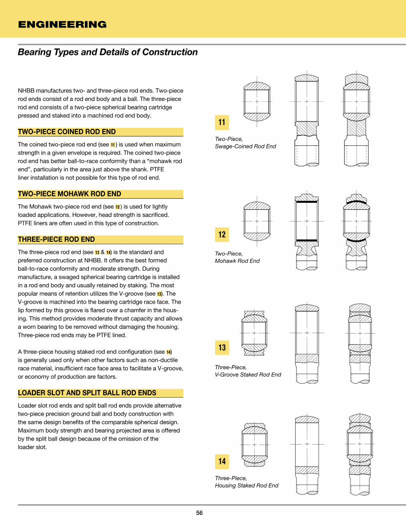
Bearing Types and Details of Construction
ENGINEERING
56
NHBB manufactures two- and three-piece rod ends. Two-piece rod ends consist of a rod end body and a ball. The three-piece rod end consists of a two-piece spherical bearing cartridge pressed and staked into a machined rod end body.
TWO-PIECE COINED ROD END
The coined two-piece rod end (see 11 ) is used when maximum strength in a given envelope is required. The coined two-piece rod end has better ball-to-race conformity than a “mohawk rod end”, particularly in the area just above the shank. PTFEliner installation is not possible for this type of rod end.
TWO-PIECE MOHAWK ROD END
The Mohawk two-piece rod end (see 12 ) is used for lightly loaded applications. However, head strength is sacrificed. PTFE liners are often used in this type of construction.
THREE-PIECE ROD END
The three-piece rod end (see 13 & 14) is the standard and preferred construction at NHBB. It offers the best formed ball-to-race conformity and moderate strength. During manufacture, a swaged spherical bearing cartridge is installed in a rod end body and usually retained by staking. The most popular means of retention utilizes the V-groove (see 13). The V-groove is machined into the bearing cartridge race face. The lip formed by this groove is flared over a chamfer in the hous-ing. This method provides moderate thrust capacity and allows a worn bearing to be removed without damaging the housing. Three-piece rod ends may be PTFE lined.
A three-piece housing staked rod end configuration (see 14) is generally used only when other factors such as non-ductile race material, insufficient race face area to facilitate a V-groove, or economy of production are factors.
LOADER SLOT AND SPLIT BALL ROD ENDS
Loader slot rod ends and split ball rod ends provide alternative two-piece precision ground ball and body construction with the same design benefits of the comparable spherical design. Maximum body strength and bearing projected area is offered by the split ball design because of the omission of the loader slot.
Two-Piece, Swage-Coined Rod End
Two-Piece, Mohawk Rod End
Three-Piece, V-Groove Staked Rod End
Three-Piece, Housing Staked Rod End
11
12
13
14

TRACK ROLLERS
NHBB manufactures track rollers (see 15 and 16) as an alternative to needle roller bearings. The PTFE composite track roller can be designed to existing needle roller envelope dimensions. The track roller is made up of an outer member (roller) which slides over an inner member (bushing or stud) and these two members sandwich a low friction, low wearing PTFE composite material. The inner and outer members are retained in the axial direction by thrust washers that are either press fit, staked or welded onto the inner member to support axial loading.
Design features of NHBB’s track rollers are high load carrying capability, resistance to many corrosive chemicals and environ-mental contaminants, and the ability to absorb heavy vibratory loads. Sliding surface track rollers offer improved bearing performance over needle rollers with respect to these design features.
While this product may be utilized in many rolling applications, it is not recommended for high rotational speeds or where low needle roller type frictional characteristics are required. For additional information, please contact NHBB Applications Engineering Department.
57
15
16
17
18
SLEEVE BEARINGS (SELF-LUBRICATING) MILITARY SERIES
17 Shows the NHBB AD series which are approved for procurement to M81934/1 P/N series.
18 Shows the NHBB ADLF series which are approved for procurement to M81934/2 P/N series.
Plain, PTFE Lined
Flanged, PTFE Lined
Bearing Types and Details of Construction

Bearing Materials
ENGINEERING
58
BALL, RACE, AND ROD END BODY MATERIALS
In addition to the more common metals, NHBB’s engineers and machinists work regularly with exotic materials. A partial list of commonly used ball, race, rod end body, and sleeve materials
is given in table 2. For materials not listed, please contact NHBB for available information.
TABLE 2: Common Bearing Alloys And Applications
303 Inconel® 718 Stellite® 3 6Al 4V Al Bronze 2024 4140
440C Inconel® X-750 Stellite® 6 Al-Ni Bronze 6061 4340
PH13-8Mo Rene 41 Stellite® 6B Beryllium Copper 7075 52100
15-5PH Waspaloy L-605 M-2
BALL 17-4PH MP35N® M-42
A-286 M-50
BG42® Maraging 250
Greek Ascoloy Maraging 300
D-2
303, 304 Inconel® 718 L-605 6Al 4V Al Bronze 2024 4130
410, 416, 422 Inconel® X-750 3Al 2.5V Beryllium Copper 6061 4140
431, 440C Monel® 400 7075 4340
PH13-8Mo Monel® K500 52100
RACE 15-5PH Rene 41 Maraging 300
17-4PH Waspaloy
A-286
AM-355
Greek Ascoloy
Nitronic® 60
BG42®
303, 316, 321 Inconel® 718 MP159® 6Al 4V 2024 1018
410, 416 Inconel® X-750 L-605 7075 4130
ROD END/ PH13-8Mo Rene 41 4340
LINK 15-5PH Waspaloy Maraging 250
BODY 17-4PH 8620
A-286
AM-355
321 Inconel® 718 L-605 6Al 4V Al Bronze 2024 4130
410, 416 Inconel® 625 Al-Ni Bronze 6061 4140
SLEEVE 430, 440C Rene 41 Beryllium Copper 7075 4340
BEARINGS PH13-8Mo Waspaloy 9310
15-5PH
17-4PH
BG42®
Corrosion Resistant Nickel Cobalt Titanium Copper Aluminum Low Alloy Application Steel Based Based Based Based Based Steels
MP35N® and MP159® are registered trademarks of Standard Press Steel.INCONEL® is a registered trademark of Inco Alloys International, Inc. and The International Nickel Company, Inc.MONEL® is a registered trademark of Huntington Alloys Corporation. NITRONIC® is a registered trademark of AK Steel Corporation. STELLITE® is a registered trademark of Kennametal, Inc. BG42® is a registered trademark of Latrobe Steel Company.

LINER CONSTRUCTION LAMINATES
Laminates consist of an open weave backing fabric such as nylon, a porous PTFE bearing sheet, and a thermosetting phenolic adhesive bonding agent. The porous PTFE fabric is compressed into the backing fab-ric and impregnated with adhesive. Laminate construction is shown in 19 .
WOVEN MATERIALS
Woven materials consist of PTFE threads inter-woven with high strength fillers such as nylon, Polyester or fiber-glass threads. The majority of the PTFE threads are on the bearing surface while the high-strength filler material supports the PTFE and acts as a bonding surface. As with laminates, the adhesive agent is a thermosetting phenolic. Woven material construction is shown in 20 .
METALLIC-BACKED COMPOSITES
Metallic-backed composites consist of a steel backing, a porous bronze inner structure, and a PTFE and lead overlay. In addition to using bonding techniques, this liner type can also be mechanically retained. Metallic-backed composite construction is shown in 21 .
FILLER THREADS
BONDING AGENT
SUBSTRATESUBSTRATESUBSTRA
PTFE
LEAD AND
POROUS BRONZE INNERSTRUCTURE
SUBSTRATESUBSTRATESUBSTRA
PTFE OVERLAY
Self-lubricating plain bearings incorporate a liner that includes polytetrafluorethylene (PTFE) on the bearing surface. The selection of a bearing liner system is based on factors of load, temperature, speed of oscillation, and the directional nature of the load.
NHBB uses three basic constructions for PTFE liner systems: laminates, woven materials, and metallic-backed composites (see 19 , 20 , and 21 ). Each PTFE liner system (except the DU® bearing material which is mechanically
retained) is bonded to the race surface and during use, PTFE transfers to the mating ball surface, forming a lubricating film that is continually replaced throughout the life of the liner material.
PTFE liner systems can also be applied to customer-supplied parts. Flat surfaces, cylindrical O.D.’s, cylindrical I.D.’s, spherical surfaces, and special configurations are routinely lined by NHBB’s custom lining department by means of standard hard tooling or autoclave bonding.
Self-Lubricating Liner Systems
59
NYLON BACKING
BONDING AGENT
SUBSTRATESUBSTRATESUBSTRA
PTFE
DU® is a registered trademark of GGB, Inc.
Woven Construction
Laminate Construction
Metallic-Backed Composite Construction
19
20
21

Liner Model L-1291/L-1420 X-1820 L-1276 X-1470
Construction PTFE/Nylon PTFE/Nylon PTFE/Polyester PTFE/Polyester
Laminate Weave Weave Weave
Thickness .010-.012 .013-.015 .013-.015 .016-.018
Temperature -65° to 400°F -65° to 400°F -65° to 250°F -65° to 250°F
Static Limit Load 75000 psi 75000 psi 75000 psi 75000 psi
Typical Performance 37500 psi 37500 psi Contact NHBB Contact NHBB
At ±25° and 10 cpm, at ±25° and 10 cpm, Engr. Dept. Engr. Dept.
.0045 wear max. .0045 wear max.
at 25000 cycles at 25000 cycles
Dynamic Capabilities Light to heavy, uni-directional Light to heavy, uni-directional Light to medium, alternating or Light to medium, alternating or
or alternating loads. Low or alternating loads. Low reversing loads. Medium to High reversing loads. Medium to High
speed, intermittent to continuous speed, intermittent to continuous speed, intermittent to continuous speed, intermittent to continuous
misalignment, intermittent misalignment, intermittent misalignment, intermittent to misalignment, intermittent to
to continuous oscillation to continuous oscillation continuous oscillation continuous oscillation
Typical Uses Fixed wing aircraft, rotary Fixed wing aircraft, rotary Rotary wing aircraft and Rotary wing aircraft and
wing aircraft and jet wing aircraft and jet landing gear landing gear
engines. Control, support engines. Control, support
and actuation bearings and actuation bearings
Comments Intermittent use to 500°F Intermittent use to 500°F Good stick/slip properties. Good stick/slip properties.
Good for vibratory conditions Good for vibratory
conditions. Extended life
over D liners due to
additional thickness
Liner Model L-1340 X-1118 L-1390
Construction PTFE/Polyester PTFE/Fiberglass PTFE/Fiberglass PTFE/Lead
Weave Weave Weave Bronze Composite
Thickness .013-.015 .010-.012 .012-.014 .028-.030
Temperature -65° to 250°F -65° to 250°F -65° to 625°F -65° to 550°F
Static Limit Load 75000 psi 75000 psi 75000 psi 58000 psi
Typical Performance (Contact NHBB) 25000 psi 12500 psi 5000 psi
at ±25° and 10 cpm, at ±25° and 10 cpm, at ±25° and 10 cpm,
.006 wear max. .0045 wear max. .0030 wear max.
at 5000 cycles at 25000 cycles at 25000 cycles
Dynamic Capabilities Light to medium, unidirec- Light, uni-directional loads. Light to medium, uni- Light, uni-directional or
tional loads. High speed, Low speed, intermittent directional or alternating alternating loads. Low to
intermittent to continuous to continuous misalignment, loads. Low speed, inter- high speed, intermittent to
misalignment, intermittent intermittent to continuous mittent to continuous continuous misalignment,
to continuous oscillation oscillation misalignment, intermittent intermittent to continuous
to continuous oscillation oscillation
Typical Uses Rotary wing aircraft Landing gear support Jet engine bearings and Rotary and fixed wing air-
and actuation bearings bushings craft bearings and hinge
bushings
Comments DH (L-1480) liner offers Good stick/slip properties Recommended for long term
same operating conditions but high temperature use,
with a liner thickness of .018 450° to 625°F
Self-Lubricating Liner Systems
ENGINEERING
60
TABLE 3: Self-Lubricating PTFE Liner Systems
DU® is a registered trademark of GGB, Inc.
Liner Type AD/AD (L) or AK K D DD
Liner Type HS AT HT DU® bearing material

61
AD, AK AND K LINER SYSTEMS (DURALINERS)
NHBB’s, AD, AK and K liner systems consist of PTFE, Nylon and a thermosetting phenolic resin. The AD, AK and K liners are suitable for many fixed wing aircraft applications, such as actuators, hinges, and control bearings, where oscillation angles vary considerably but at slow oscillation speeds.
The AD, AK and K liners are qualified to AS81820 and AS81934. To qualify to AS81820, a lined bearing will be tested at room temperature for 25,000 cycles of ±25 degrees at 10 cpm and at 37500 psi. Maximum allowable wear is 0.0045. When tested at elevated temperature requirement, the allow-able wear is 0.006. When tested at -65°F, the load is reduced to 75% of the room temperature requirement, and the allow-able wear is 0.008. AS81820 also has a test requirement for bearings to be immersed in various fluids for 24 hours at 160°F, removed from the fluid, and dynamically tested at 75% of the room temperature load requirement. NHBB’s AD, AK and K liners consistently exhibit less wear than specifications allow. See 22 for typical liner performance at ambient temperature.
The AD, AK and K liners are capable of operating for long dura-tions when exposed to 350°F and short durations up to 500°F.
Tests reveal that the AD liner meets most vacuum outgassing requirements of space applications.
D AND DD LINER SYSTEMS
NHBB’s D and DD liner systems consist of a PTFE and Dacron weave coated with a thermosetting resin. The D and DD liners differ in the thickness of the liner. The DD liner has a liner thick-ness of .017 (Ref) and the D liner has a thickness of .014 (Ref). The additional liner thickness offers additional bearing liner life.
The D and DD liners were developed to accommodate alternating and reversing loads typically found in rotary wing applications where there are relatively low loading (approximately 2,000 psi) and the speed of oscillation is relatively high (approximately 300 cpm). See 23 for typical DD bearing life in a wet, reversing and alternating load test environment.
Current applications for the D and DD liners include landing gear shock struts, main and tail rotor pitch control link bearings, and damper bearings.
22
23
Typical Performance of AS81820 Liner Systems (Life Cycles ±25° Oscillation)
Typical Performance of the DD Liner System (Reversing Load)
Self-Lubricating Liner Systems
Test Conditions, DD Liner Ball Race PV@ Bearing Diameter Width Osc. CPM Stress Max. Load Contamination
A 1.500 .797 ±10° 300 0 ±2000 psi 26200 Water
B 1.500 .797 ±10° 300 2000 psi 52400 Water ±2000 psi
.008
.006
.004
.002
0
WE
AR
0 200 400 600 1400 1600TIME (HOURS)
BEARING A
BEARING B
AS81820LIMITS@37500 LB/in2
MIL-B-8942LIMITS@25000 LB/in2
TYPICAL DURALINER WEAR(AD, AK, and K)
.006
.005
.004
.003
.002
.001
WE
AR
5000 10000 15000 20000 25000LIFE CYCLES (±(±( 25° OSCILLATION) OSCILLATION) OSCILLA

Self-Lubricating Liner Systems
ENGINEERING
62
HS LINER SYSTEMS
NHBB’s HS liner system consists of a PTFE and Polyester Weave coated with a high temperature thermosetting resin. The HS liner has a thickness of .014 (Ref.).
The HS liner was developed to accommodate rotary wing air-craft applications in which high speeds (approximately 300 to 1500 cpm) and light uni-directional loading (approximately 2,000 psi) conditions exist. See 24 for typical HS bearing life in a wet, uni-directional load test environment.
The DH liner is available for applications similar to HS but requiring a thicker liner .018 (Ref.). For additional information, please contact NHBB’s Applications Engineering Department.
HIGH TEMPERATURE (HT) LINER SYSTEMS
NHBB HT liner systems are PTFE and fiberglass woven cloth that are impregnated with a high temperature polyimide resin. The HT liner is suitable for engine applications such as found in variable stators for fans and compressors, throttle linkages, vane guide sleeves and actuators in and around the engine. These applications require liner systems that can accommodate temperature up to 625°F. While the loading and motion are similar to fixed wing conditions, the high tempera-tures require a greater temperature resistant adhesive such as that used in the HT liners. The HT liner system is designed to meet higher operating temperatures but at reduced loads to
those required for fixed wing applications (AS81820). 25 shows the typical performance of the HT liner system at 12500 psi loading at 550 to 625°F at 20 cpm.
LINER SYSTEM WITH DU® BEARING MATERIAL
The liner system with DU® bearing material consists of a low carbon steel sheet coated with a mixture of PTFE, lead, and sintered bronze.
Bearings with liner systems containing DU® bearing material can be used in applications up to 550°F, but significant life-reduction factors must be applied.
.006
.005
.004
.003
.002
.001
WE
AR
100 1000 10000 25000NUMBER OF CYCLES
TYPICAL WEAR: 550° to 625° to 625° to 625 ° F
OSC. LOAD: 2950 LBOSC. ANGLE: ± 25°OSC. SPEED: 20 CPMBRG. STRESS: 12500 psi
Typical performance of the HT liner system (oscillation under radial load, wear vs. life)
Typical performance of the HS liner system (uni-directional load)24
25
Test Conditions, HS Liner Ball Race Bearing Diameter Width Osc. CPM Stress PV Contamination
A .656 .312 ±6° 1500 2000 psi 34400 Water and dust
B 1.500 .797 ±10° 300 2000 psi 26200 Water and dust
.007
.006
.005
.004
.003
.002
.001
00
WE
AR
0 200 400 600 800TIME (HOURS)
BEARING A
BEARING B
DU® is a registered trademark of GGB, Inc.

63
CHARACTERISTICS OF SELF-LUBRICATINGPTFE LINED BEARINGS
1. Modulus of elasticity: 4.5x10⁵ psi.
2. Coefficient of thermal expansion: 11.6x10⁻⁶ in/in/°F.
3. Low coefficient of friction ranging from approximately .02 to .10. As shown in 26 , the coefficient decreases as load and temperatures increase. However the coefficient also increas-es as surface speed and mating surface roughness increase.
4. Non-corrosive.
5. Resistant to most chemicals, greases and oils, however wear rates may increase when movement takes place under contaminated conditions.
6. Non-conductive and non-magnetic.
7. Wear rates remain low and relatively constant after an initial run-in period.
8. Continues to function satisfactorily with wear as high as .010.
TORQUE
The standard method for checking no-load rotational break-away torque is described in Military Specification AS81820. The procedure is to hand-rotate the ball to initiate movement. Then the race is locked on a torque meter. The outer race is held in such a manner as to minimize bearing distortion and the resultant effect on the bearing preload. Torque is gradually applied to the ball. The torque required to start the ball moving is then recorded.
NHBB uses the same method to check torque, except that the ball is locked on the torque meter and the race is rotated.
Breaking the ball free from the race before checking torque is very important. Because of preload between the ball and race, the liner, under compression, slowly conforms to the micro-scopic surface irregularities of the ball. To initiate rotation after a period of time, all of the microscopic liner projections into the ball surface must be sheared off. Once this has been accom-plished, the torque reverts back to its rated value. All torque testing should be performed with the outer race restrained in such a manner as to minimize bearing distortion and the resultant effect on the torque reading obtained. Torque readings can vary appreciably as the result of incorrect or excessive clamping, presence of contaminants, excessive speeds and differences in atmospheric conditions.
Rotational Breakaway Torque is the highest value attained
just prior to ball movement. The ball should be hand rotated
through several revolutions immediately before testing.
Rotational Torque is the value required to maintain 2 rpm
rotation of the ball about its centerline.
Misalignment Torque is the value required to move the ball
in a mode other than rotation about the bore centerline.
26 Effect of temperature and load on coefficient of friction
Self-Lubricating Liner Systems
.10
.08
.06
.04
.02
CO
EFF
ICIE
NT
OF
FRIC
TIO
N (A
PP
RO
XIM
ATE
)C
OE
FFIC
IEN
T O
F FR
ICTI
ON
(AP
PR
OX
IMAT
E)
CO
EFF
ICIE
NT
OF
FRIC
TIO
N (A
PP
RO
XIM
A
-100ϒF 0ϒF 0ϒ ϒFϒFϒ +100ϒFϒFϒ +200ϒFϒFϒ +300ϒFϒFϒ +400ϒFϒFϒ +500ϒFϒFϒTEMPERATURETEMPERATURETEMPERA
5000 PSI10000 PSI
40000 PSI
PTFE-lined spherical bearings are typically specified with preload between the ball and race in terms of no load rotational breakaway torque (inch-pounds or inch-ounces). This is the torsional force required to initiate rotation between the ball and race. Bearings can also be manufactured with a misaligning torque requirement.
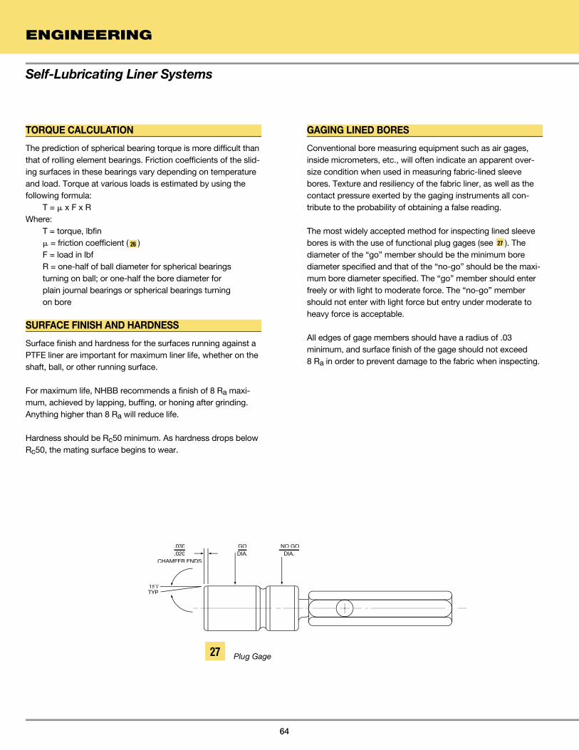
Self-Lubricating Liner Systems
ENGINEERING
64
TORQUE CALCULATION
The prediction of spherical bearing torque is more difficult than that of rolling element bearings. Friction coefficients of the slid-ing surfaces in these bearings vary depending on temperature and load. Torque at various loads is estimated by using the following formula: T = � x F x RWhere: T = torque, lbfin
� = friction coefficient ( 26 ) F = load in lbf R = one-half of ball diameter for spherical bearings turning on ball; or one-half the bore diameter for plain journal bearings or spherical bearings turning on bore
SURFACE FINISH AND HARDNESS
Surface finish and hardness for the surfaces running against a PTFE liner are important for maximum liner life, whether on the shaft, ball, or other running surface.
For maximum life, NHBB recommends a finish of 8 Ra maxi-mum, achieved by lapping, buffing, or honing after grinding. Anything higher than 8 Ra will reduce life.
Hardness should be Rc50 minimum. As hardness drops below Rc50, the mating surface begins to wear.
GAGING LINED BORES
Conventional bore measuring equipment such as air gages, inside micrometers, etc., will often indicate an apparent over-size condition when used in measuring fabric-lined sleeve bores. Texture and resiliency of the fabric liner, as well as the contact pressure exerted by the gaging instruments all con-tribute to the probability of obtaining a false reading.
The most widely accepted method for inspecting lined sleeve bores is with the use of functional plug gages (see 27 ). The diameter of the “go” member should be the minimum bore diameter specified and that of the “no-go” should be the maxi-mum bore diameter specified. The “go” member should enter freely or with light to moderate force. The “no-go” member should not enter with light force but entry under moderate to heavy force is acceptable.
All edges of gage members should have a radius of .03 minimum, and surface finish of the gage should not exceed 8 Ra in order to prevent damage to the fabric when inspecting.
.030
.020CHAMFER ENDS
GODIA.
NO GODIA.
15ϒTYP
27 Plug Gage

65
An answer to situations where the performance envelope cannot be covered by metal-to-metal bearings is to consider PTFE lined bearings. Here, the lubricant configuration is such that it functions as the load carrying element of the bearing, as represented by the liner systems currently in use. PTFE bearings may be specified under all or some of the following situations:
1. Where lubrication is undesirable, difficult to perform, or impossible.
2. Where loads are high and angular movement is low.
3. Where space is limited.
4. Where vibration is present.
5. Where temperature of the environment renders greasing unfeasible.
6. Where a joint must remain static for an extended period of time before movement is initiated.
7. Where friction in a greased bearing would be so high as to render the joint area useless after a limited number of cycles or impose an unacceptable fatigue situation.
8. Where, in static joints, fretting is a problem.
While PTFE lined bearings can do an excellent job in many areas, there have been areas of misapplication. Also, there exist some misunderstandings regarding life and failure as applied to hardware of this type. Following are important clarifications concerning these products:
1. The PTFE lined bearing starts life with a finite rotational pre-load torque or clearance.
2. This rotational pre-load torque always decreases with bearing usage and clearance always increases with usage.
3. A bearing may be said to have failed if the rotational pre-load torque drops below some specified value. This is always a systems application characteristic.
4. A bearing may be said to have failed when the clearance generated by wear exceeds some specified value. This, again, is always some specified systems characteristic.
5. A bearing may be said to have failed if the liner wears through enough to permit the ball to contact the race.
6. No bearing, including PTFE lined bearings, will last forever. The “lifetime” lubrication concept applies to the bearing alone, not to the end usage item.
7. The presence of liner debris on a bearing is not a definitive indication of failure.
8. PTFE lined bearings tend to telegraph their impending failure by increased radial and axial play.
When evaluating the probable service life of a PTFE lined bear-ing application, there are some factors that do not appear in the PV = K relationship, (see page 82). Some considerations for a given application might include:
1. Surface sliding speed
2. Maximum ambient temperature
3. Size of the heat sink
4. Acceptable friction levels
5. Load per unit of area, or liner stress level
6. Mode of load application; i.e., the duty cycle
7. Service alignment accuracy, particularly with respect to sleeve and flanged bearings
8. Surrounding atmosphere
9. Tolerable wear rate
10. Surface finish of the bearing mating shaft and the shaft material
Cost is not included in the above list since it does not affect the serviceability of any bearing. Higher individual bearing costs may result in a more economical or lower priced finished assembly.
Self-Lubricating Liner Systems
FACTORS AFFECTING THE SELECTION, PERFORMANCE AND EVALUATION OF PTFE LINED SPHERICAL, ROD END AND SLEEVE BEARINGS

Grease, aircraft and MIL-PRF-23827 Lithium soap, ester oil, -100° to +250°F General purpose grease. Extreme
instrument, gear, and anti-rust and E.P. agents pressure (E.P.) properties, good water
actuator screw resistance
Grease, MoS2, for high and low MIL-PRF-21164 Same as MIL-PRF-23827, -100° to +250°F Similar to MIL-PRF-23827 but has
temperatures except 5% MoS2 added added MoS2 for extra E.P. properties
and anti-wear action under marginal
lubrication conditions
Grease, Aircraft MIL-PRF-81322 Synthetic oil and thickener -65° to +350°F High temperature grease
Grease and Dry Film Lubricants
ENGINEERING
66
The selection of lubricants is based on bearing materials, design, environment, and operating conditions. The following sections describe grease and dry film lubricants and list the most commonly used types.
GreaseGrease is an oil to which a metallic soap, synthetic filler, thick-ener, or a combination of these has been added to prevent oil migration from the lubrication site. The operative properties of grease depend almost wholly on the base oil.
Grease lubricants can be used on metal-to-metal spherical and rod end bearings such as a steel ball against a steel race, a steel ball against an aluminum bronze race, and a beryllium copper ball against a steel race.
The three most common grease lubricants used with NHBB bearings are shown in table 4. Grease-lubricated bearings are usually furnished with lubrication holes and grooves, and, in the case of rod ends, lubrication fittings for periodic relubrica-tion. These bearings have a tendency to gall unless lubrication is very frequent and loads are reversing so that the grease is not squeezed out of the load area.
In applications with uni-directional loading, the grease will quickly be squeezed out of the bearing area. In these applica-tions, dry film can be used. The use of PTFE also should be investigated.
NHBB grease lubricants are suitable for most airframe applications. If bearings will be required to operate in unusual conditions (for example, high vacuum, radiation, or near chemicals such as phosphate ester fluids or propellants), please consult the NHBB Applications Engineering Department before ordering.
28 illustrates a lubrication network which provides for lubricat-ing both the ball/race and the ball/shaft (or pin) interfaces. Further, relubrication can be accomplished via the race housing or the ball shaft or pin. If relubrication is to be done via the race housing, and no lubrication is required in the ball bore, lube holes and I.D. lube groove in the ball may be omit-ted. Conversely, if relubri-cation is to be done via the shaft or pin, lube holes and O.D. groove in the race may be omitted.
29 shows a transverse lube groove configuration for use on medium to large size spherical bearings in critical applications where lubrication demands are more extreme. The transverse grooves are machined into the cylindrical race blank prior to swaging. These bearings are often bushed with copper alloy sleeves which in turn may incorpo-rate transverse or equiva-lent lube groove patterns to provide for maximum possible lubrication.
TABLE 4: Grease Lubricants
28
29
Race Blank Bearing Assembly
Lube Groove Size and DepthExaggerated for Clarity
Type Specification Composition Temperature Range Use and Remarks
Race ace
Ball

Solid film, MIL-PRF-46010 MoS2 (no graphite Organic resins -65° to +450°F Good wear life.
heat cured, Type I or powdered Used for most bearing
corrosion metals), and applications other
inhibiting corrosion than extreme temper-
inhibitors ature situations
Solid film, MIL-PRF-46010 MoS2 (no graphite Organic resins -90° to +400°F Similar to MIL-PRF-46010, TY I
heat cured, Type II or powdered except that it will
corrosion metals), and provide added corrosion
inhibiting corrosion protection to substrate.
Inhibitors Must have phosphate
coating pretreatment
for effective use on steel
Solid film, MIL-PRF-81329 MoS2 and other Inorganic -300° to +1200°F To be used in extreme
extreme solid lubricants binders environments, i.e.,
environment vacuum, liquid oxygen,
high temperatures.
Wear life not as good as
resin-bonded types
Type Specification Lubricant Binder Temperature Range Use and Remarks
67
DRY FILM
Dry film lubricants consist of MoS2 and small quantities of other materials such as graphite or powdered metals. These are bonded to the bearing race I.D., and often the ball O.D. and bore, by either organic resins or inorganic binders (phenolic, sodium silicate, or other glass compositions). Hardening or curing is achieved by baking at temperatures ranging from 300° to 1000°F depending upon the binding material.
NHBB can apply dry film lubricants to all metal-to-metal spherical and rod end bearings.
The three most common dry film lubricants used with NHBB bearings are shown in table 5. The advantages of dry film include good tenacity, low coefficient of friction (0.05 to 0.25), and resistance to high bearing pressure (up to 90000 psi on hard substrates). Dry film, however, is not as predictable as PTFE liners regarding wear characteristics.
30 illustrates the difference in bearing life between dry filmed bearings and bearings that have not been lubricated.
NHBB dry film lubricated bearings are generally used in aircraft and engine applications in which extreme temperature conditions exist (-300° to +1200°F).
.006.006
.005.005
.004.004
.003.003
.002.002
.001.001
0
WE
AR
00 500500 10001000 1500015000NUMBER OF CYCLES
DRY FILM ON RACE I.D. ANDDRY FILM ON RACE I.D. ANDDRBALL O.D.
NO DRY FILMNO DRY FILMNO DR
BALL SEIZURE
LOAD 150 LB – 1290 PSIOSC ANGLE: ±30°SPEED: 10 CPMTEMP: 350°F
TABLE 5: Dry Film Lubricants
Dry Film Lubricated vs. Non-Lubricated Bearings
Commonly Used Dry FilmsProduct Specification Temperature Range
Everlube® 967 -300° to +750°F
Lubeco M-390 -65° to +500°F
Surf-Kote® LBO-1800-G -65° to +1100°F
Molykote® 106 -321° to +450°F
Everlube® 811 MIL-PRF-81329 -300° to +750°F
Vitrolube 1220 -400° to +700°F
30
Grease and Dry Film Lubricants
EVERLUBE® is a registered trademark of Metal Improvement Company, LLC
MOLYKOTE® is a registered trademark of Dow Corning Corporation
SURF-KOTE® is a registered trademark of Hohman Plating & Mfg. INC.
Bearing Life

Locking Devices, Keys and Keyways
ENGINEERING
68
Keys as represented here are metallic locking devices which, when assembled into keyways and keyslots, prevent relative motion between mating components of bearing linkage assemblies. NHBB does not manufacture keys, nuts or lock wire as separate items. These items are readily available from other sources. Keyways and keyslots are optional. To specify, add suffix “W” to NHBB catalog rod end part number.
Thread (E) (F) (Male) +.005 +.000 � -.000 -.0051/4-28UNJF-3A .062 .207
5/16-24UNJF-3A .062 .268
3/8-24UNJF-3A .093 .319
7/16-20UNJF-3A .093 .383
1/2-20UNJF-3A .093 .445
Notes:AS81935 KEY
• 1. AS81935/3 keys are used on AS81935 sizes -03 through -08 when optioned. The keyways and keyslots used in conjunction with these keys are shown in
33 and 34 .
• � AS81935/3 keys are available for thread sizes 1/4 through 1/2 inches.
.225R±.010
.010R +.015-.000
E
F
33
34
Female keyslot
Male keyway
AS81935/3 KEY
NAS 509 NUT
ROD ENDROD
AS81935/3 KEY,AS81935/3 KEY,AS81935/3 KEYTYPICAL INSTALLATYPICAL INSTALLATYPICAL INST TIONALLATIONALLA
AS81935 KEY
Thread (D) (E) (F) (R) Size +.005 +.005 +.000 ±.010 � -.000 -.000 -.005
.250 .056 .062 .201 .255
.312 .056 .062 .260 .255
.375 .056 .093 .311 .255
.437 .069 .093 .370 .255
.500 .069 .093 .436 .255
.562 .077 .125 .478 .255
.625 .077 .125 .541 .255
.750 .077 .125 .663 .255
.875 .086 .156 .777 .318
1.000 .094 .156 .900 .318
1.125 .094 .187 1.010 .382
1.250 .116 .187 1.136 .382
1.375 .116 .250 1.236 .445
1.500 .116 .250 1.361 .445
1.625 .129 .250 1.477 .445
1.750 .129 .312 1.589 .508
1.875 .129 .312 1.714 .508
2.000 .129 .312 1.839 .508
2.125 .129 .312 1.955 .508
2.250 .129 .312 2.080 .508
+.010- .000.055
90° ±1°
+.010- .000.078R
2 SLOTS IN AS81935/2 & /5FOR SIZES -03, -04, -05, -06
4 SLOTS IN AS81935/2 & /5FOR SIZES -07, -08
Notes:NAS 559 TYPE A KEY
• � The keyways and keyslots used in conjunction with these keys are shown in 31 and 32 . The NAS 559 keys are available for thread sizes 1/4 through 2-1/4 inches.
• � Keyway flat may vary from standard on smaller size rod ends but shall extend at least beyond minimum thread length in all cases.
NAS 559 TYPE A
NAS 559TYPE A KEY
NAS 509 NUT
ROD ROD END
NAS 559 KEY,NAS 559 KEY,NAS 559 KEYTYPICAL INSTALLAINSTALLAINST TIONALLATIONALLA
DE2
E TYP.E TYP.E TYP.015 R.005 TYP..005 TYP..005 TYP
R
.090
KEYWAYKEYWAYKEYWFLATFLATFLA
E
F
R .015.005
�THREADLENGTH
32
31Female keyslot
NAS 559 TYPE A KEY
Male keyway

69
NAS 513 KEY NAS 509 NUT
ROD ENDROD
(DD optional)�2 SLOTS ONLY2 SLOTS ONLY2 SLOTS ONLREQUIRED FORTHREAD SIZES:.250.312.375
DE2
E TYP.E TYP.E TYP.015 R.005 TYP..005 TYP..005 TYP
.005
.015RF
E
NAS 1193-1 NAS 1193-2
303030°°° ±3°ROD
NAS 1193...-2
NAS 1193...-1
ROD END
NAS 1193 KEY, TYPICAL INSTNAS 1193 KEY, TYPICAL INSTNAS 1193 KEY ALLA, TYPICAL INSTALLA, TYPICAL INST TIONALLATIONALLA
NAS 509 NUT
Notes:NAS 513 KEY
• 1. NAS 513 keys are used on AS81935 sizes -10 through -16 rod ends when optioned. The keyways and keyslots used in conjunction with these keys are shown in 35 and 36 .
• � For female rod ends with deep square slot keyslot option AS81935 designation “W”, the slot depth is modified as detailed in 35 . This deep slot “W” is also compatible with NASM14198, SAE-AS14227, NAS 1193 and NAS 559 keyways.
• � NAS 513 keys are available for thread sizes 1/4 through 2-1/4 inches.
Notes:NAS 1193 KEY
• 1. NAS 1193 keys are for positive indexing. They are used in applications in which a fine adjustment is required, within .001.
• 2. These keys can be used in conjunction with NAS 513, NAS 559 and AS81935/3 keyways or keyslots and are available for thread sizes 1/4 through 2-1/4 inches.
35Female Keyslot
36Male Keyway
NAS 513 KEY
NAS 1193 KEY
Thread (D) (DD) � (E) (F) Size +.005 +.005 +.005 +.000 � -.000 -.000 -.000 -.005
.250 .056 .110 .062 .201
.312 .056 .110 .062 .260
.375 .056 .110 .093 .311
.437 .069 .110 .093 .370
.500 .069 .110 .093 .436
.562 .077 —— .125 .478
.625 .077 .125 .125 .541
.750 .077 .125 .125 .663
.875 .086 .156 .156 .777
1.000 .094 .156 .156 .900
1.125 .094 —— .187 1.010
1.250 .116 —— .187 1.136
1.375 .116 —— .250 1.236
1.500 .116 —— .250 1.361
1.625 .129 —— .250 1.477
1.750 .129 —— .312 1.589
1.875 .129 —— .312 1.714
2.000 .129 —— .312 1.839
2.125 .129 —— .312 1.955
2.250 .129 —— .312 2.080
Locking Devices, Keys and Keyways

For applications in which airborne or fluid contaminants threat-en the useful life of spherical or rod end bearings, NHBB offers a combination metal shield and silicone seal to isolate and protect bearing surfaces.
The NHBB sealing system ( 37 ) comprises a pair of .010 (Ref.)stainless steel (or any other compatible weldable metal) shields and molded wedge-shaped silicone rubber seals. This seal system design does not significantly increase the weight of the bearing.
The shields are welded to the outer race of the bearing so that the seals are seated at the juncture of the ball and the race. As ball movement occurs, the seals wipe contaminants from the ball surface. This self-cleaning action prohibits most contami-nants from reaching the load bearing area. Seals do not reduce the load bearing area or change the load rating of a bearing.
NHBB sealed bearings have been subjected to extensive dynamic testing by major aircraft manufacturers for resistance to contamination by MIL-H-5606 hydraulic oil and SAE AS 8243 de-icing fluid. Sealed bearing wear after 25,000 cycles was considerably less than unsealed bearing wear.
NHBB can seal any size metal-to-metal or self-lubricated bearing. The seal typically does not affect external mounting dimensions or dimensionally affect function on V-groove installations. Form, fit, and function interchangeability are maintained. However, a seal does reduce misalignment capability. NHBB seals can be used with bearings having staking grooves in the outer race, as well as with bearings having chamfered outer race configurations. For information on seal damage prevention when installing in counter bores that may contact the race face, contact NHBB Applications Engineering.
SHIELD
BALL
SEAL
OUTER RACE
PTFELINER
OUTER RACE
BALL
SEAL
SHIELD
LINER
BALL
SEAL
SHIELD
OUTER RACE
PTFE
Sealed Bearings
ENGINEERING
70
37 NHBB Bearing Seal
Sealed PTFE Lined Bearing
Recessed Seal Design
Sealed Metal to Metal Bearing

Bearing Installation and Retention
71
Installation and retention details are important considerations when designing a bearing. Features such as pins or bolts, housings, corrosion resistance, installation method, and reten-tion methods must be considered to ensure optimum bearing performance.
38 This typical bearing installation, which is staked into the housing, is assembled with a mating clevis, bolt, nut, washers, and plain and flanged bushings.
In most applications, the bolt is preloaded with the nut to clamp up the ball and force the ball to rotate on the race I.D. Caution must be exercised when clamping the ball. Excessive force expands the ball and will bind it in the race. If the ball is not clamped up, motion will usually take place on the bore, in which case the bolt, the bearing bore, or both must have suitable surfaces for this motion.
THE PIN OR BOLT
In addition to carrying the structural loads through the joint, the pin or bolt may function as a journal, and must therefore meet the multiple requirements of adequate strength, minimum wear, low friction, and corrosion resistance. In these instances, the following provisions for relubrication should be made:
1. PTFE line the bearing bore or the pin or bolt O.D.
2. Dry film the bearing bore and/or the pin or bolt O.D.
3. Introduce lubrication holes and grooves in the pin or bolt or the ball members
Suggested pin materials are 17-4PH and PH13-8Mo stainless steel, and 4130/4340 steel chrome plated .002 thick. Pins, either bare or plated, should be heat treated to the required shear strength (108,000 psi Ref.) and ground and polished to the required dimensions with a surface finish of 8 Ra or better. The recommended fit between the pin or bolt and the bearing bore is line-to-line to .001 loose.
38Typical Bearing Installation
39Chamfered Size Calculation for V-Groove Retention
*See 46 for groove dimensions, page 75.
Chamfer Dia.(C) = D + [H - T + (2 X E)]
(Tolerance + .008/ - .007)
H = average housing thickness
T = average outer race width
E = average V-groove depth in race,
depending on groove.
Avg. Groove V-Groove Depth Size* (E)
A .023
B .033
C .053
D .073
45 °
CHAMFER DIAMETER (C)
A
Bearing O.D.
A
0/ .005
O/ D
H
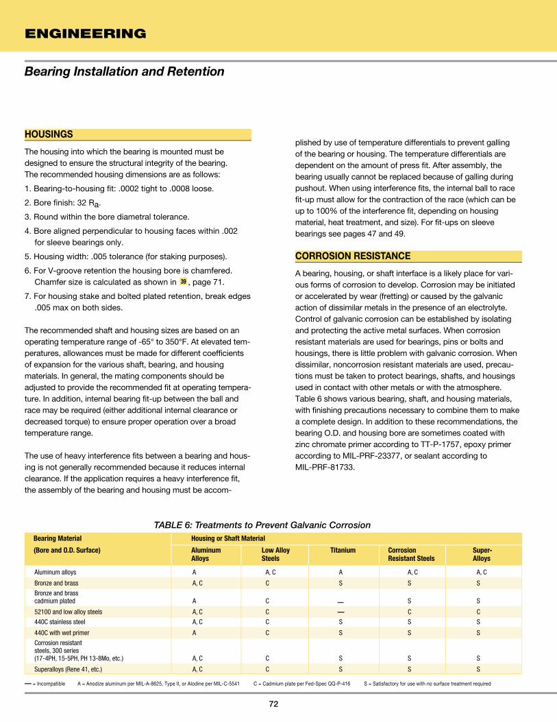
Bearing Installation and Retention
ENGINEERING
72
HOUSINGS
The housing into which the bearing is mounted must be designed to ensure the structural integrity of the bearing. The recommended housing dimensions are as follows:
1. Bearing-to-housing fit: .0002 tight to .0008 loose.
2. Bore finish: 32 Ra.
3. Round within the bore diametral tolerance.
4. Bore aligned perpendicular to housing faces within .002 for sleeve bearings only.
5. Housing width: .005 tolerance (for staking purposes).
6. For V-groove retention the housing bore is chamfered. Chamfer size is calculated as shown in 39 , page 71.
7. For housing stake and bolted plated retention, break edges .005 max on both sides.
The recommended shaft and housing sizes are based on an operating temperature range of -65° to 350°F. At elevated tem-peratures, allowances must be made for different coefficients of expansion for the various shaft, bearing, and housing materials. In general, the mating components should be adjusted to provide the recommended fit at operating tempera-ture. In addition, internal bearing fit-up between the ball and race may be required (either additional internal clearance or decreased torque) to ensure proper operation over a broad temperature range.
The use of heavy interference fits between a bearing and hous-ing is not generally recommended because it reduces internal clearance. If the application requires a heavy interference fit, the assembly of the bearing and housing must be accom-
plished by use of temperature differentials to prevent galling of the bearing or housing. The temperature differentials are dependent on the amount of press fit. After assembly, the bearing usually cannot be replaced because of galling during pushout. When using interference fits, the internal ball to race fit-up must allow for the contraction of the race (which can be up to 100% of the interference fit, depending on housing material, heat treatment, and size). For fit-ups on sleeve bearings see pages 47 and 49.
CORROSION RESISTANCE
A bearing, housing, or shaft interface is a likely place for vari-ous forms of corrosion to develop. Corrosion may be initiated or accelerated by wear (fretting) or caused by the galvanic action of dissimilar metals in the presence of an electrolyte. Control of galvanic corrosion can be established by isolating and protecting the active metal surfaces. When corrosion resistant materials are used for bearings, pins or bolts and housings, there is little problem with galvanic corrosion. When dissimilar, noncorrosion resistant materials are used, precau-tions must be taken to protect bearings, shafts, and housings used in contact with other metals or with the atmosphere. Table 6 shows various bearing, shaft, and housing materials, with finishing precautions necessary to combine them to make a complete design. In addition to these recommendations, the bearing O.D. and housing bore are sometimes coated with zinc chromate primer according to TT-P-1757, epoxy primer according to MIL-PRF-23377, or sealant according to MIL-PRF-81733.
TABLE 6: Treatments to Prevent Galvanic Corrosion
Aluminum alloys A A, C A A, C A, C
Bronze and brass A, C C S S S
Bronze and brass cadmium plated A C — S S
52100 and low alloy steels A, C C — C C
440C stainless steel A, C C S S S
440C with wet primer A C S S S
Corrosion resistant steels, 300 series (17-4PH, 15-5PH, PH 13-8Mo, etc.) A, C C S S S
Superalloys (Rene 41, etc.) A, C C S S S
Bearing Material Housing or Shaft Material
(Bore and O.D. Surface) Aluminum Low Alloy Titanium Corrosion Super- Alloys Steels Resistant Steels Alloys
— = Incompatible A = Anodize aluminum per MIL-A-8625, Type II, or Alodine per MIL-C-5541 C = Cadmium plate per Fed-Spec QQ-P-416 S = Satisfactory for use with no surface treatment required
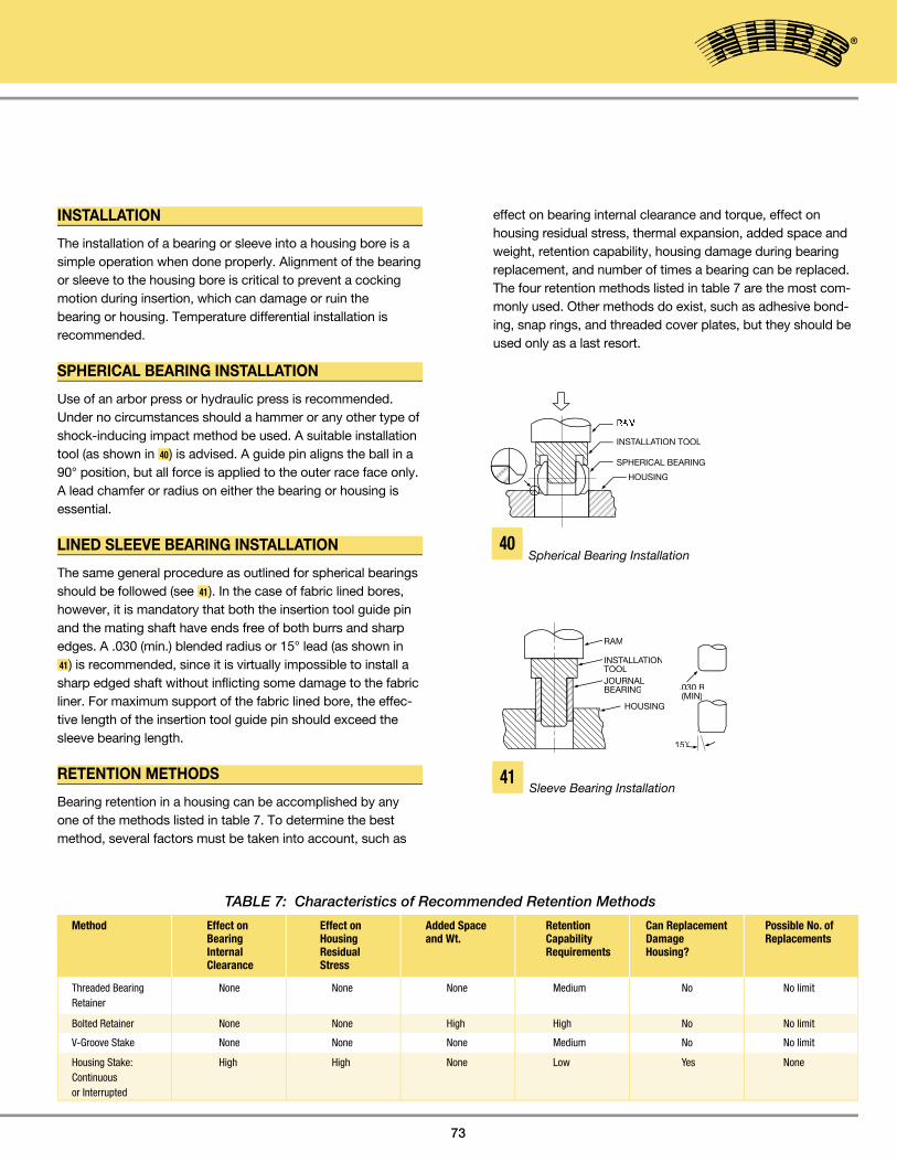
73
RAM
INSTALLAINSTALLAINST TION TOOLALLATION TOOLALLA
SPHERICAL BEARING
HOUSING
TABLE 7: Characteristics of Recommended Retention Methods
Threaded Bearing None None None Medium No No limit Retainer
Bolted Retainer None None High High No No limit
V-Groove Stake None None None Medium No No limit
Housing Stake: High High None Low Yes None Continuous or Interrupted
Method Effect on Effect on Added Space Retention Can Replacement Possible No. of Bearing Housing and Wt. Capability Damage Replacements Internal Residual Requirements Housing? Clearance Stress
Bearing Installation and Retention
40
RAM
INSTALLAINSTALLAINST TIONALLATIONALLATOOLJOURNALBEARING
HOUSING
.030 R(MIN)
15ϒ
Spherical Bearing Installation
41Sleeve Bearing Installation
INSTALLATION
The installation of a bearing or sleeve into a housing bore is a simple operation when done properly. Alignment of the bearing or sleeve to the housing bore is critical to prevent a cocking motion during insertion, which can damage or ruin the bearing or housing. Temperature differential installation is recommended.
SPHERICAL BEARING INSTALLATION
Use of an arbor press or hydraulic press is recommended. Under no circumstances should a hammer or any other type of shock-inducing impact method be used. A suitable installation tool (as shown in 40) is advised. A guide pin aligns the ball in a 90° position, but all force is applied to the outer race face only. A lead chamfer or radius on either the bearing or housing is essential.
LINED SLEEVE BEARING INSTALLATION
The same general procedure as outlined for spherical bearings should be followed (see 41). In the case of fabric lined bores, however, it is mandatory that both the insertion tool guide pin and the mating shaft have ends free of both burrs and sharp edges. A .030 (min.) blended radius or 15° lead (as shown in 41) is recommended, since it is virtually impossible to install a sharp edged shaft without inflicting some damage to the fabric liner. For maximum support of the fabric lined bore, the effec-tive length of the insertion tool guide pin should exceed the sleeve bearing length.
RETENTION METHODS
Bearing retention in a housing can be accomplished by any one of the methods listed in table 7. To determine the best method, several factors must be taken into account, such as
effect on bearing internal clearance and torque, effect on housing residual stress, thermal expansion, added space and weight, retention capability, housing damage during bearing replacement, and number of times a bearing can be replaced.The four retention methods listed in table 7 are the most com-monly used. Other methods do exist, such as adhesive bond-ing, snap rings, and threaded cover plates, but they should be used only as a last resort.

THREADED RETAINER RETENTION
Threaded bearing retainers, as shown in 42 , offer an excellent bearing retention method due to ease of bearing replacement, high axial thrust load capabilities, and ease of assembly in areas where accessibility to conventional staking would be difficult.
BOLTED PLATE RETENTION
For high retention capability and ease of bearing replacement, the bolted plate method, as shown in 43 , is recommended. However, space requirements and weight will increase.
HOUSING STAKE RETENTION
Housing stake retention, as shown in 44 , has many shortcom-ings when compared to V-groove staking. The major consider-ation is race contraction, which adversely affects internal fit-up. Housing stake retention should be used only when there is insufficient space on the race face for a V-groove or the race material is not ductile. When mounting, the bearing and its housing are supported by an anvil while the staking tool is forced into one side of the housing near the edge of the bearing. This action displaces a small amount of the housing material over the race chamfer. The opposite side of the housing is then staked in the same manner.
V-GROOVE RETENTION
V-groove retention, as shown in 45 , is the most widely used and recommended. The bearing outer race has a small groove machined into each face, which leaves a lip on the race O.D. corners. With the use of staking tools, these lips are swaged (flared) over the chamfered edges of the housing.
The prerequisites for good V-groove staking are proper size housing chamfers, staking tools that match the V-groove size, and the availability of a hydraulic or pneumatic press capable of applying the staking force. To use V-groove staking successfully, the following conditions must be met:
1. Race hardness: Rc40 max.
2. Sufficient space on the race face for machining a groove. For V-groove sizes, see 46 .
3. V-groove size capable of carrying the axial load, see 47 .
STAKING PROCEDURE
1. Install bearing into housing per 40 and position it symmetri-cal about housing centerline within .005.
2. Mount bearing and top anvil over bottom anvil guide pin as shown in 45 .
3. A trial assembly should be made for each new bearing lot to determine the staking force necessary to meet the axial retention load required. Excessive force should be avoided since this may result in bearing distortion and seriously impair bearing function and life. (See table 8 for recom-mended Staking Force, page 75).
4. Apply the staking force established by trial assembly, rotate assembly 90° and re-apply force.
5. After staking, a slight gap may exist between race lip and housing chamfer as shown in detail in 45 . This gap should not be a cause for rejection providing the bearing meets the thrust load specified.
Bearing Installation and Retention
ENGINEERING
74
STAKING TOOLSTAKING TOOLST
45°
90°
.022 REF.
STAKINSTAKINST GANVIL
STAKINGSTAKINGSTTOOL
GUIDEPINBEARING
HOUSING
STAKINGSTAKINGSTANVIL
5 DETAILDETAILDET
43
45
Bolted PlateRetention
Housing Stake Retention
V-Groove Staking Method
Threaded Retainer Retention
42
44
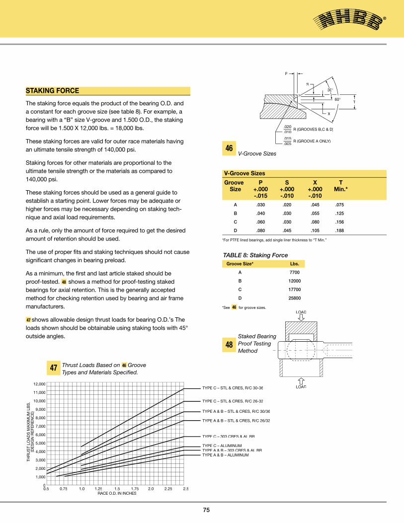
75
STAKING FORCE
The staking force equals the product of the bearing O.D. and a constant for each groove size (see table 8). For example, a bearing with a “B” size V-groove and 1.500 O.D., the staking force will be 1.500 X 12,000 lbs. = 18,000 lbs.
These staking forces are valid for outer race materials having an ultimate tensile strength of 140,000 psi.
Staking forces for other materials are proportional to the ultimate tensile strength or the materials as compared to 140,000 psi.
These staking forces should be used as a general guide to establish a starting point. Lower forces may be adequate or higher forces may be necessary depending on staking tech-nique and axial load requirements.
As a rule, only the amount of force required to get the desired amount of retention should be used.
The use of proper fits and staking techniques should not cause significant changes in bearing preload.
As a minimum, the first and last article staked should be proof-tested. 48 shows a method for proof-testing staked bearings for axial retention. This is the generally accepted method for checking retention used by bearing and air frame manufacturers.
47 shows allowable design thrust loads for bearing O.D.’s The loads shown should be obtainable using staking tools with 45° outside angles.
P
S
60°T
X
.020
.010R (GROOVES B,C & D)
.015
.005R (GROOVE A ONLY)LY)LY
30°
Groove Size* Lbs.
A 7700
B 12000
C 17700
D 25800
*See 46 for groove sizes.
TABLE 8: Staking Force
46V-Groove Sizes
LOALOADD
LOAD
Bearing Installation and Retention
V-Groove Sizes
Groove P S X T Size +.000 +.000 +.000 Min.* -.015 -.010 -.010
A .030 .020 .045 .075
B .040 .030 .055 .125
C .060 .030 .080 .156
D .080 .045 .105 .188
*For PTFE lined bearings, add single liner thickness to “T Min.”
48
Thrust Loads Based on 46 Groove Types and Materials Specified.
47
Staked Bearing Proof Testing Method
TYPE C – STL & CRES, R/C 30-36
TYPE C – STL & CRES, R/C 26-32
TYPE A & B – STL & CRES, R/C 30/36
TYPE A & B – STL & CRES, R/C 26/32
TYPE C – 303 CRES & AL BR
TYPE C – ALUMINUMTYPE A & B – 303 CRES & AL BRTYPE A & B – ALUMINUM
0.5 0.75 1.0 1.25 1.5 1.75 2.0 2.25 2.5
12,000
11,000
10,000
9,000
8,000
7,000
6,000
5,000
4,000
3,000
2,000
1,000
0
THR
US
T LO
AD
S M
AX
IMU
M L
BS
.(D
ES
IGN
RE
FER
EN
CE
)
RACE O.D. IN INCHES

Bearing Installation and Retention
ENGINEERING
76
D
.001 E
0 / 0 / 0 .001 E E 0 / 0 / 0 .005
O/ C O/ AO/ B
.001 E
E
V-GROOVE STAKING TOOL
The staking tool and staking anvil depicted in 49 and 50 are made from tough, hardenable tool steel (for example, A-2) and heat treated to Rc55 to 60. The critical dimension of the tools are as listed. As a final check on the staking tool and anvil, a
final layout drawing should be made to check fit-up. NHBB manufactures staking tools to meet many customers’ needs. To obtain staking tools specially manufactured by NHBB, please refer to ordering information on page 77.
.001 D .010 .005 R CONTINUOUS
D
C
25 °21 °
(A) PIN DIAMETER
D
.001 D
D
8
O/ B
0/ .001
0/ .001
49 Staking tool design
50Staking Anvil Design
A = Ball bore min. - .001
(Tolerance + .000/ - .001)
B = Bearing O.D. - 2 X Min. lip thickness - Min. groove width
(Tolerance + .005/ - .000. See 46 for lip thickness (page 75)
“S” and groove width “X”.)
C = Adequate stakes for most applications are obtained with staking tools having
45° to 50° outside angles. When required, secondary staking tools having an
outside angle of 60° to 70° can be used to obtain maximum retention and to
reduce the amount of gap between the housing chamfer and the lip of the outer race.
A = Ball bore min. - .001
(Tolerance + .000/ - .001)
B = Ball spherical dia.2 - Race width2 + .030
(Tolerance ± .010)
C = Body head dia.2 - Body width2
(Tolerance ± .010)
D = Ball width max. - Race width min. +.015
2
(Tolerance ± .010)
�
�

Staking Tool Sets – Ordering Information
77
NHBB Staking Tool Part Number Bore Part Number ADB( )V 3 STN 0003
ADB( )V(L) 4 STN 0004
HT( )V(L1) 5 STN 0005
AG( )V 6 STN 0006
AG( )V300 7 STN 0007
HSBG( )V 8 STN 0008
AHT( )V 9 STN 0009
AHET( )V 10 STN 0010
ABG( )V(L) 12 STN 0012
ABG( )V-501(L) 14 STN 0014
ADBL( )V
HTL( )V(L1)
ADW( )V 3 STW 0003
AW( )V 4 STW 0004
ADW( )V(L) 5 STW 0005
WHT( )V(L1) 6 STW 0006
ADWL( )V 7 STW 0007
ADWL( )V(L) 8 STW 0008
WHTL( )V(L1) 9 STW 0009
10 STW 0010
12 STW 0012
14 STW 0014
16 STW 0016
ADBY( )V 3 STY 0003
ASBY( )V 4 STY 0004
ADBY( )V(L) 5 STY 0005
6 STY 0006
7 STY 0007
8 STY 0008
9 STY 0009
10 STY 0010
12 STY 0012
14 STY 0014
16 STY 0016
20 STY 0020
24 STY 0024
Hydraulic (Anvil) staking tools are available for all NHBB stan-dard and special spherical bearings with staking grooves. Each set consists of one staking (flaring) tool and one staking anvil, both with guide pins installed. For spherical bearings in this catalog, order staking tool sets by the part numbers below.
For special (non-catalog) bearings or larger sizes, consult NHBB.
EXAMPLES: NHBB P/N STAKING TOOL 1. ADB10V STN 0010
2. ABG8V (L) STN 0008
3. ADW5V STW 0005
4. ADBY6V STY 0006

DEFINITIONS FOR ROD END AND SPHERICAL BEARING TERMINOLOGY
Radial LoadA load applied normal to the bearing bore axis (see 51A ).
Axial LoadA load applied along the bearing bore axis (see 51B ).
Static LoadThe load to be supported while the bearing is stationary.
Dynamic LoadThe load to be supported while the bearing is moving 52 .
Static Radial Limit LoadThat static load required to produce a specified permanent set in the bearing. It will vary for a given size as a function of configuration. It may also be pin limited, or may be limited as a function of body restraints as in the case of a rod end bearing. Structurally, it is the maximum load which the bearing can see once in its application without impairing its performance.
Static Radial Ultimate LoadThat load which can be applied to a bearing without fracturing the ball, race or rod end eye. The ultimate load rating is usually, but not always, 1.5 times the limit load. Plastic deformation may occur.
Static Axial Limit LoadThat load which can be applied to a bearing to produce a specified permanent set in the bearing structure. Structurally, it is the maximum load which the bearing can see once in its application without impairing its performance.
Static Axial Ultimate LoadThat load which can be applied to a bearing without separating the ball from the race. The ultimate load rating is usually, but not always, 1.5 times the limit load.
Axial Proof LoadThat axial load which can be applied to a mounted spherical bearing without impairing the integrity of the bearing mounting or bearing performance. It is always less than the static axial limit load. Bearing movement after proof load is usually .003 or less. See the Bearing Installation and Retention section for further information beginning on page 75.
Load Ratings and Misalignment Capabilities
ENGINEERING
78
MISALIGNMENT
ANGLE OFMISALIGNMENT
AXIALRADIAL
RADIAL
TENSION LOAD
COMPRESSION LOAD
OSCILLATIONOSCILLATIONOSCILLA
51A 51B
51C
52
53

79
RotationIs the relative angular displacement between the ball and race that occurs within the plane perpendicular to the axis of the ball bore (see 53 ). The direction of rotation is about the axis of the ball bore.
MisalignmentIs the relative angular displacement between the ball and race that occurs within any plane that coincides with the axis of the ball bore (see 51C ). The direction of misalignment is about any axis perpendicular to the ball bore.
Oscillating Radial Load or Dynamic Load The uni-directional load produces a specified maximum amount of wear when the bearing is oscillated at a specified frequency and amplitude. This rating is usually applied to self-lubricating bearings only. The dynamic capability of metal-to-metal bearings depends upon the degree and frequency of grease lubrication, and that of dry film lubricated bearings upon the characteristics of the specific dry film lubricant applied.
Radial PlayRadial play (or radial clearance) is the total movement between the ball and the race in both radial directions less shaft clear-ance (when applicable). Industry specifications have estab-lished the gaging load at ±5.5 lbs., and this is now considered as the industry standard (see 54 and 55 ). Unless otherwise specified, the industry wide standard for metal-to-metal spheri-cal bearing and rod end radial clearance is “free-running to .002 max.” Radial play is sometimes referred to as “Diametral clearance.” The two terms are synonymous.
Axial PlayAxial play (or axial clearance) is the total movement between the ball and the race in both axial directions (see 56 ). The gaging load is again ±5.5 lbs. Axial play is a resultant, being a function of radial play, of ball diameter and race width. The ratio between radial and axial play varies with bearing geometry.
Fatigue Load of Rod EndsAerospace Standard series rod end bearings AS81935 must be capable of withstanding a minimum of 50,000 cycles of loading when tested as follows: The loading must be tension-tension with the maximum load equal to the fatigue loads listed on the NHBB drawing of the ADNE and ADN series rod end bearings. The minimum load must be equal to 10% of the fatigue loads.
HOUSINGGAGELOAD
BEARING
DIALINDICATOR
0.000 - 0.001LOOSE FIT
PIN
SUPPORT
DIAL INDICATORDIAL INDICATORDIAL INDICA
SPHERICAL BEARING
5.5 LBS.GAGE LOAD
5.5 LBS.GAGE LOAD
GAGELOAD
DIALINDICATORINDICATORINDICA
BEARINGHOUSING
54Radial Test Fixture
55 Method of Measuring Radial Play
56Axial Test Fixture
Load Ratings and Misalignment Capabilities

LOAD RATINGS
The load rating of a bearing is determined by the dimensions and strength of its weakest component. External factors, such as mounting components, pins, bolts, and housings are not considered part of a bearing when load ratings are investigated but should be considered separately.
SPHERICAL BEARING LOAD RATINGS
The weakest part, or load-limiting area, of a spherical bearing is its race. For this reason, formulas have been developed that use the race to calculate static load ratings based on size and material strength. The static load rating formulas for self-lubri-cating and metal-to-metal spherical bearings are shown in 57
and 58 . These formulas will yield approximate ratings, which should be used as ballpark numbers for bearing design.
The allowable radial stress values given in the tables were determined from the ultimate tensile strength specifications for various race materials. Allowable axial stress values were derived from material yield strengths.
Load Ratings and Misalignment Capabilities
ENGINEERING
80
d RADIAL
T AVG.T AVG.T A
AXIAL
DBG
d RADIAL
T AVG.T AVG.T A
AXIAL
DB
57 Static Load Rating Formulas for Self-Lubricating Spherical Bearings 58 Static Load Rating Formulas for
Metal-to-Metal Spherical Bearings
Allowable Stress Metal-to-Metal Bearings (psi)Race Radial AxialMaterial Ultimate Limit Ultimate Limit
17-4PH, Rc32-36 150000 100000 125000 83000
4130 Rc32-36 150000 100000 125000 83000
A286 (AMS 5737) 140000 93000 95000 63000
AMS 4635 and 75000 50000 45000 30000 ASTM B 50/B150M
Allowable Stress PTFE Lined Bearings (psi)Race Radial AxialMaterial Ultimate Limit Ultimate Limit
17-4PH, Rc28 MIN 112500 75000 67500 45000
ALUM 2024-T351 60000 40000 36000 24000
Allowable Stress - PTFE-Lined Bearings Allowable Stress - Metal-to-Metal Bearings
Load = Projected Area x Allowable Stress
Radial Projected Area = (.91T) (DB)
Axial Projected Area = .636T2 _ .05DB
Load = Projected Area x Allowable Stress
Radial Projected Area = (.83T _ .92G)(DB)
Axial Projected Area = .636T2
Bearing Size G Bore Code Width
3 & 4 .062
5 - 10 .078
12 - 16 .094
20 & above .109
Standard Groove Sizes

81
ROD END BEARING LOAD RATING
Rod end bearing load ratings can be generated only after care-fully determining the load restrictions that each element of the rod end bearing imposes on the entire unit. In order to generate a frame of reference, consider the rod end bearing as a clock face, with the shank pointing down to the 6 o’clock position. The limiting factors in rating a rod end bearing are as follows:
1. The double shear capability of the bolt passing through the ball bore.
2. The bearing capability, a function of race material or self-lubricating liner system.
3. The rod end eye or hoop tension stress in the 3 o’clock-9 o’clock position.
4. The shank stress area, as a function of male or female rod end configuration.
5. The stress in the transition area between the threaded shank transition diameter and the rod end eye or hoop.
Most rod ends will fail under tension loading in about the 4 o’clock-8 o’clock portion of the eye or hoop. The Net Tension Area (NTA) can be found as follows:
NTA = .008726 x D2 x Sin-1 D2– T 2 – BxT
Solve the Sin-1 in units of degrees, not radians.
This simple rod end load rating formula does not take into consideration such variables as special body shapes, thin race sections, hardness variation, lubrication holes, grooves, and hoop tension, which could significantly affect the load rat-ing. Contact NHBB Applications Engineering for assistance in determining the load rating for specially designed Rod Ends and Sphericals.
The shank stress area (SSA) is a function of being either male or female, as follows:For the male:SSA = (minor thread diameter)2
For the female:SSA = [J2 – (major thread diameter)2]
Pin shear stress (PSS) for load "F" is as follows:PSS =
The axial load capability of a rod end is a function of the following:
1. The retention method used to mount the bearing in the rod end eye. See the Bearing Installation and Retention section for further information beginning on page 71.
2. The axial load capability of the bearing element.
3. The bending moment, if any, placed on the rod end.
FEMALE
dAXIAL
T MIN.
NORMALFAILUREZONE
D MIN.
J MIN.
B
MALE
RADIAL
59
Load Ratings and Misalignment Capabilities
π4
π4
2Fπd2
T(D)
T T(D) + 2 ������

PV FactorWhile not a type of loading, the PV factor is very useful in com-paring and predicting test results on high speed-low load appli-cations such as helicopter conditions.
PV is the product of the stress (psi) and the velocity (fpm) applied to a bearing. Caution must be advised when consider-ing extreme values of psi and fpm. The extreme must be con-sidered individually, as well as together.
Because the PV factor is derived from the geometry and operating conditions of a bearing, it serves as a common denominator in comparing or predicting test results. For this reason PV values are included in the wear curves of 22 and 23 (page 61) in the Self-Lubricating PTFE Liner Systems section, page 60.
The formula for determining the PV value for a spherical bearing is as follows:PV = (∞) (cpm) (DB) (psi) (.00073)
Where:∞ = total angular travel in degrees per cycle
(ie. + 25°=100° total travel)
cpm = cycles per minute (oscillation rate)DB = ball diameterpsi = bearing stress
Dynamic Oscillating Radial LoadThe dynamic oscillating radial load ratings given in this cata-log for ADB, ADW, ADBY, ADB-N, ADW-N, ADBL and ADWL series self-lubricating spherical bearings are based on testing in accordance with AS81820. For conditions other than those specified by AS81820 contact NHBB Applications Engineering.
NHBB TESTING CAPABILITIES
Mechanical Test EquipmentNHBB has a variety of equipment to test spherical and rod end bearings under diverse conditions. NHBB performance data exceeds military and individual manufacturers’ design require-ments. Maximum capabilities of NHBB testing machines are shown in table 9.
Polymer Test EquipmentNHBB has the following thermal analysis (TA) equipment to support and control the quality of composites/polymers through analytical techniques that measure the physical and mechanical properties as a function of temperature and time:
1. Differential Scanning Calorimeter (DSC)
2. Thermogravimetric Analyzer (TGA)
3. Dynamic Mechanical Analyzer (DMA)
4. Thermomechanical Analyzer (TMA)
5. Thermo-Oxidative Stability Test (TOS)
6. Acid Digestion System
7. Fourier Transform Infrared Spectroscopy (FTIR)
Load Ratings and Misalignment Capabilities
ENGINEERING
82
ForceMaterial Testing (Universal Testing Machine) 110,000 Lbs.
Static Compression/Tension 200,000 Lbs.
Low Speed Oscillation (up to 50 cpm)
Uni-directional Loading
(1 machine, 2 station) (700°F) 20,000 Lbs.
(1 machine, 2 station) (700°F) 70,000 Lbs.
Moderate To High Speed Oscillation
Uni-directional Load (room temp.)
(1 machine, 2 station) (1000 cpm) 1,000 Lbs.
(1 machine, 2 station) (1500 cpm) 1,000 Lbs.
(1 machine, 6 station) (200-600 cpm) 8,000 Lbs.
Low Speed Oscillation
Reversing or Alternating Load (room temp.)
(1 machine, 2 station) (up to 50 cpm) 40,000 Lbs.
High Speed, Oscillation
Reversing and Alternating Load (room temp.)
(2 machines, 1 station each) (400 cpm) 2,500 Lbs.
Airframe Track Roller
Testing Machine (roller against flat plate) 60,000 Lbs.
TABLE 9: NHBB Testing Capabilities
-

83
The misalignment angle of a rod end or spherical bearing refers to the angle between the ball centerline and the outer member centerline when the ball is misaligned to the extreme position allowed by the clevis or shaft design, as applicable.NOTE: Since angle “A” applies equally on both sides of the centerline, it follows that total mis-
alignment of the bearing is double the value obtained for “A”.
60 through 63 illustrate varying types of bearing misalignment and a formula for calculating eachWhere:
A = angle of misalignment B = bore of ballD = head diameter (rod end) E = ball spherical diameterS = shoulder diameter (neck ball) T = housing (race) widthW = width of ball
64 illustrates how misalignment angles for standard ball spheri-cal bearings and rod ends are represented in NHBB catalogs. The misalignment angle is calculated per 60 formula. Neck ball (high misalignment) bearings and rod ends are represented in the same manner, but are calculated per 62 formula.
NHBB prefers not to use rod end clevis misalignment for the following reason. The rod end clevis misalignment formula pre- supposes a clevis configuration as shown in 63 in which the clevis slot and ball faces are of equal width and in direct con-tact. In aircraft applications the configuration shown in 65 is
more typical than that of 63. As pictured in 65, the clevis slot is wider than the ball to permit installation of flanged bushings and/or spacers. This results in a higher but more variable mis-alignment capability, and the angle of misalignment becomes a function of the user’s bushing flange or spacer diameter instead of the fixed rod end head diameter.
A = SIN-1 W – SIN-1 T
E – SIN
E – SIN
E
A
60 62 63
HOW NHBB SPECIFIES CATALOG BEARING AND ROD END MISALIGNMENT
AA
A
64 65
Typical Rod End/Clevis Installation
FORMULA FOR DETERMINING MISALIGNMENT OF ROD END & SPHERICAL BEARINGS
Load Ratings and Misalignment Capabilities
A = COS-1 B – SIN – SIN-1 T
E – SIN
E – SIN
E
A
A = COS -1 S – SI – SI
S – SI
S N -1 T
E – SI
E – SI N
E N
E
A
A
A = SIN-1 W – SIN-1 T
D – SIN
D – SIN
D
60 Standard Method
Most standard rod end and
spherical bearing misalignment
angles specified in NHBB cata-
logs are based on this method.
61 Design Reference
This method may be used as
design reference for installation
purposes, but should not be
used as a functioning misalign-
ment under load.
62 High MisalignmentSeries Method
(Neck balls only)
63 Rod End ClevisMisalignment
61

Bearing Selection Factors
ENGINEERING
84
ROLLING ELEMENT BEARINGS
1. Low load – high speed bearings should usually be antifriction rolling element bearings, except for lubricated sleeve bearings under very low load and constant rotation rather than oscillatory.
METAL-TO-METAL SPHERICALS AND ROD ENDS
1. These are recommended for most joints which are primarily static, need only periodic lubrication and require a minimum of permanent set under high loads.
2. They are also recommended for some moving applica-tions such as landing gears, where most of the motion occurs under low loading, but where the bearing is nearly static under the high impact loads when the gear is locked.
3. Hardened 52100 or 440C balls with heat-treated outer races of either chrome-moly, alloy steel, or precipitation hardened stainless steel are recommended when loads are very high in relation to the available envelope.
4. Aluminum bronze races are less apt to seize or gall under vibratory conditions or if lubrication conditions are mini-mal, providing the required maximum load capacity is not too great (the load capacity is usually about 1/2 that of the heat treated steel race bearings). In general, materi-als containing an appreciable amount of copper are good bearing materials.
5. A beryllium-copper ball operating against a heat treated stainless steel race is an excellent combination for dynamic oscillating conditions under very high loads, providing adequate lubrication is present. This requires either an automatic lube system or frequent maintenance provisions.
6. Metal-to-metal spherical bearings and rod ends are often fitted with aluminum-nickel-bronze sleeves in the ball bore, with lubrication provisions, so that the relative motion and resulting wear take place between the shaft and the sleeve, with only misalignment taking place at the ball spherical surface. This allows replacement of the sleeves without replacement of the expensive portion of the bearing.
7. For extremely high load carrying capacity in a limited envelope, spherical bearings with both ball and swaged outer race made of heat-treated maraging steel of 300ksi tensile strength are sometimes used, and can be formed by a special processing procedure.
8. Special types of metal-to-metal sphericals such as loader slot bearings, fractured outer race bearings, or snap-assembled bearings (page 54 and 55) are used for some applications where very hard inner and outer races are desirable for wear and strength reasons, but require spe-cial geometry (a relatively narrow ball).
9. Spherical and rod end bearings for both high temperature and cryogenic applications are available using special materials such as the INCONEL®alloys, STELLITE®alloys and other cobalt alloys, A-286, Rene 41 and others. Special dry film lubricants or silverplating in the race I.D. are sometimes used in these bearings.
10. Two-piece swage-coined rod ends (page 56 11 ) should be used primarily for applications which require high load carrying capacity in a basically static condition with some misalignment capability, since the rod end body cross-sectional area available to carry tension is greater than with a 3-piece rod end, the insert outer race area having been replaced by body area. However, ball-to-race con-formity is usually poor, hence rapid wear and/or fretting and galling can occur under dynamic or oscillating loading.
11. Two-piece Mohawk rod ends (page 56 12 ) for commercial use or non-critical applications are available. The Mohawk design has better ball-to-race conformity than the 2-piece swage-coined design and can be used in dynamic appli-cations but only at relatively low loads.
12. Most metal-to-metal bearings are designed with a small radial clearance to facilitate assembly with the mat-ing part and assure that the bearing does not bind up if assembled into its housing with an interference fit. However, they may be made with a preload, providing there is a fairly large tolerance on this preload, for appli-cations where absolutely no play can be tolerated.
INCONEL® is a registered trademark of Inco Alloys International, Inc. and The International Nickel Company, Inc.
STELLITE® is a registered trademark of Kennametal, Inc.

85
SELF-LUBRICATING PTFE TYPE LINEDSLEEVES, SPHERICALS AND ROD END BEARINGS
1. These consist of a relatively thin composite liner containing PTFE (polytetrafluoroethylene) as a lubricant and bonded to a metallic backing material.
2. They are recommended for applications requiring consider-able oscillation and misalignment under very heavy loads and where frequent lubrication is undesirable or impossi-ble. To gain full life from these bearings, a wear of about .005 from the liner surface must be tolerable.
3. This type is especially suited for hydraulic actuators, many aircraft landing gear door applications, vibration damping devices, hinge and actuation link bearings for control surfaces, sliding guide bearings for flaps and leading edge slats, and power control system drive linkage bearings, along with many others not mentioned.
CHECK LIST OF FACTORS TO BE CONSIDERED BYTHE APPLICATIONS ENGINEER IN SELECTION ORDESIGN OF SPHERICAL BEARINGS
1. Bearing envelope requirements and/or restrictions
2. Weight limitations
3. Whether used in a static or dynamic application
4. For sleeve bearings, whether the shaft is oscillating or
rotating continuously in one direction or both directions
5. Loading:
(A) Maximum static radial or axial
(B) Maximum and normal dynamic
(C) Reversing or uni-directional
(D) Shock or vibratory conditions
6. Relative movement
(A) Angle of oscillation
(B) Velocity in terms of rpm or cycles per minute
(C) Required angle of misalignment
(D) Load-velocity phase relationship 7. Allowable wear
8. Life requirement, preferably in number of cycles
9. Operating temperature range
10. Preload or clearance requirements
11. Lubrication methods, accessibility, and frequency of
maintenance available
12. Environmental conditions including exposure to dirt,
moisture and other contaminants
13. Installation requirements, including staking methods,
housing and shaft fits, etc.
For additional considerations, please consult NHBB Applications Engineering staff.
Bearing Selection Factors

Specifications Compliance
ENGINEERING
86
NHBB complies with many government specifications in the manufacture of its products. The most common of these specifications are listed in table 10.
NHBB also complies with most of the major aerospace manufacturers specifications regarding procedures such as plating, testing, and heat treating.
*NHBB Standards
TABLE 10: Specifications Compliance
Plating, Coating and Surface Treatment
Alodine * SAE AMS-C-5541
Anodize (Chromic) SAE AMS-A-8625 Type I Class 1
Anodize (Sulphuric) * SAE AMS-A-8625 Type II Class 1
Anodize (Hard) * SAE AMS-A-8625 Type III Class 1
Cadmium * SAE AMS-QQ-P-416 Type I Class 3 (Races)
Cadmium (Supplementary Chromate Treatment) * SAE AMS-QQ-P-416 Type II Class 2 (Bodies)
Cadmium (Vacuum Deposited) SAE AMS-C-8837
Chromium * SAE AMS-QQ-C-320 Class 2 (.0002" to .0005" thickness)
Chromium AMS 2406
Nickel (Electroless) SAE AMS-C-26074
Nickel (Electrodeposited) SAE AMS-QQ-N-290
Passivate AMS QQ-P-35 or ASTM-A 967
Silver AMS 2410
Zinc (Chromate Primer) TT-P-1757
Heat Treatment
Steel, Alloy and Stainless SAE-AMS-H-6875
Aluminum SAE-AMS-H-6088
Beryllium Copper SAE-AMS-H-7199
Titanium AS-H-81200
Non-Destructive Testing
Fluorescent Penetrant ASTM-E-1417
Magnetic Particle ASTM-E-1444
Ultrasonic SAE AMS STD 2154
Quality Control
Quality Systems ISO 9001
Aerospace Quality Systems AS 9000
Sampling Procedures and Tables for Inspection by Attributes ANSI/ASQE Z 1.4
Machining
Threads, Rolled or Turned AS 8879 and MIL-S-7742
Marking and Packaging
Military Packaging MIL-STD-129
Marking MIL-STD-130
Preservation MIL-DTL-197
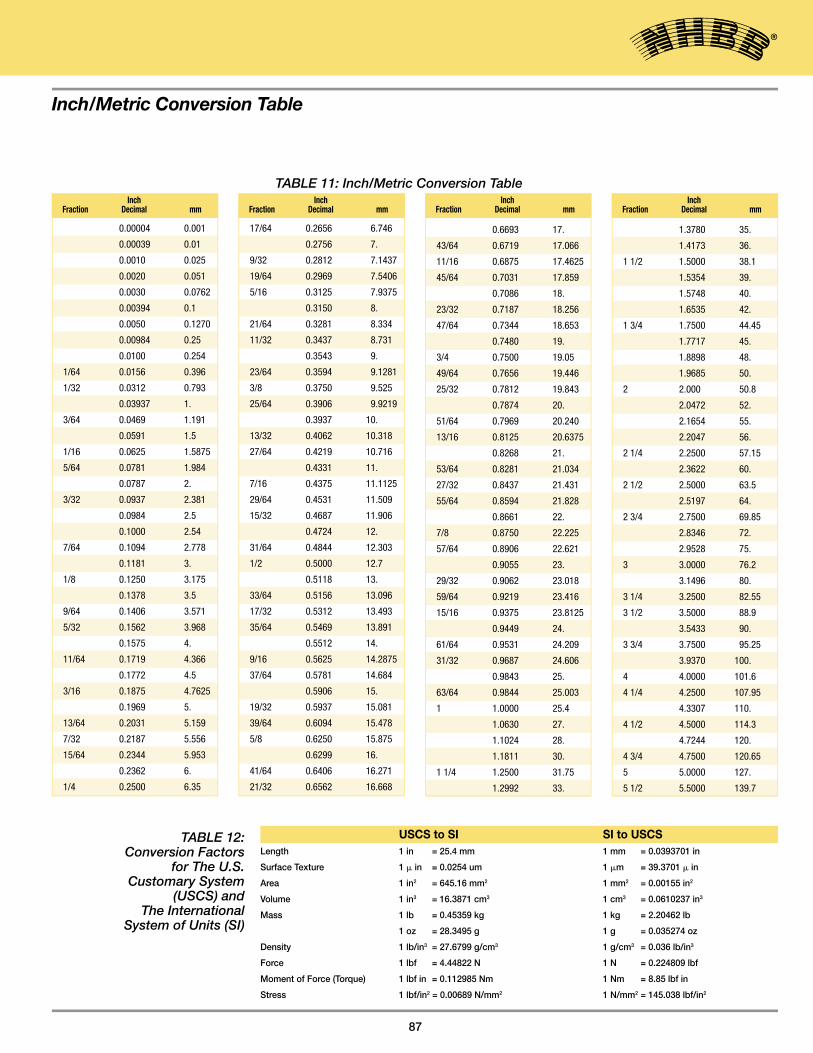
Inch/Metric Conversion Table
87
0.00004 0.001
0.00039 0.01
0.0010 0.025
0.0020 0.051
0.0030 0.0762
0.00394 0.1
0.0050 0.1270
0.00984 0.25
0.0100 0.254
1/64 0.0156 0.396
1/32 0.0312 0.793
0.03937 1.
3/64 0.0469 1.191
0.0591 1.5
1/16 0.0625 1.5875
5/64 0.0781 1.984
0.0787 2.
3/32 0.0937 2.381
0.0984 2.5
0.1000 2.54
7/64 0.1094 2.778
0.1181 3.
1/8 0.1250 3.175
0.1378 3.5
9/64 0.1406 3.571
5/32 0.1562 3.968
0.1575 4.
11/64 0.1719 4.366
0.1772 4.5
3/16 0.1875 4.7625
0.1969 5.
13/64 0.2031 5.159
7/32 0.2187 5.556
15/64 0.2344 5.953
0.2362 6.
1/4 0.2500 6.35
Inch Fraction Decimal mm
17/64 0.2656 6.746
0.2756 7.
9/32 0.2812 7.1437
19/64 0.2969 7.5406
5/16 0.3125 7.9375
0.3150 8.
21/64 0.3281 8.334
11/32 0.3437 8.731
0.3543 9.
23/64 0.3594 9.1281
3/8 0.3750 9.525
25/64 0.3906 9.9219
0.3937 10.
13/32 0.4062 10.318
27/64 0.4219 10.716
0.4331 11.
7/16 0.4375 11.1125
29/64 0.4531 11.509
15/32 0.4687 11.906
0.4724 12.
31/64 0.4844 12.303
1/2 0.5000 12.7
0.5118 13.
33/64 0.5156 13.096
17/32 0.5312 13.493
35/64 0.5469 13.891
0.5512 14.
9/16 0.5625 14.2875
37/64 0.5781 14.684
0.5906 15.
19/32 0.5937 15.081
39/64 0.6094 15.478
5/8 0.6250 15.875
0.6299 16.
41/64 0.6406 16.271
21/32 0.6562 16.668
Inch Fraction Decimal mm
0.6693 17.
43/64 0.6719 17.066
11/16 0.6875 17.4625
45/64 0.7031 17.859
0.7086 18.
23/32 0.7187 18.256
47/64 0.7344 18.653
0.7480 19.
3/4 0.7500 19.05
49/64 0.7656 19.446
25/32 0.7812 19.843
0.7874 20.
51/64 0.7969 20.240
13/16 0.8125 20.6375
0.8268 21.
53/64 0.8281 21.034
27/32 0.8437 21.431
55/64 0.8594 21.828
0.8661 22.
7/8 0.8750 22.225
57/64 0.8906 22.621
0.9055 23.
29/32 0.9062 23.018
59/64 0.9219 23.416
15/16 0.9375 23.8125
0.9449 24.
61/64 0.9531 24.209
31/32 0.9687 24.606
0.9843 25.
63/64 0.9844 25.003
1 1.0000 25.4
1.0630 27.
1.1024 28.
1.1811 30.
1 1/4 1.2500 31.75
1.2992 33.
Inch Fraction Decimal mm
1.3780 35.
1.4173 36.
1 1/2 1.5000 38.1
1.5354 39.
1.5748 40.
1.6535 42.
1 3/4 1.7500 44.45
1.7717 45.
1.8898 48.
1.9685 50.
2 2.000 50.8
2.0472 52.
2.1654 55.
2.2047 56.
2 1/4 2.2500 57.15
2.3622 60.
2 1/2 2.5000 63.5
2.5197 64.
2 3/4 2.7500 69.85
2.8346 72.
2.9528 75.
3 3.0000 76.2
3.1496 80.
3 1/4 3.2500 82.55
3 1/2 3.5000 88.9
3.5433 90.
3 3/4 3.7500 95.25
3.9370 100.
4 4.0000 101.6
4 1/4 4.2500 107.95
4.3307 110.
4 1/2 4.5000 114.3
4.7244 120.
4 3/4 4.7500 120.65
5 5.0000 127.
5 1/2 5.5000 139.7
Inch Fraction Decimal mm
TABLE 11: Inch/Metric Conversion Table
TABLE 12: Conversion Factors
for The U.S. Customary System
(USCS) andThe International
System of Units (SI)
USCS to SI SI to USCSLength 1 in = 25.4 mm 1 mm = 0.0393701 in
Surface Texture 1 � in = 0.0254 um 1 �m = 39.3701 � in
Area 1 in2 = 645.16 mm2 1 mm2 = 0.00155 in2
Volume 1 in3 = 16.3871 cm3 1 cm3 = 0.0610237 in3
Mass 1 lb = 0.45359 kg 1 kg = 2.20462 lb
1 oz = 28.3495 g 1 g = 0.035274 oz
Density 1 lb/in3 = 27.6799 g/cm3 1 g/cm3 = 0.036 lb/in3
Force 1 lbf = 4.44822 N 1 N = 0.224809 lbf
Moment of Force (Torque) 1 lbf in = 0.112985 Nm 1 Nm = 8.85 lbf in
Stress 1 lbf/in2 = 0.00689 N/mm2 1 N/mm2 = 145.038 lbf/in2
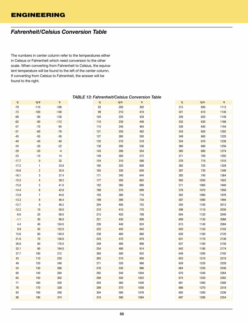
Fahrenheit/Celsius Conversion Table
ENGINEERING
88
The numbers in center column refer to the temperatures either in Celsius or Fahrenheit which need conversion to the other scale. When converting from Fahrenheit to Celsius, the equiva-lent temperature will be found to the left of the center column. If converting from Celsius to Fahrenheit, the answer will be found to the right.
-79 -110 -166
-73 -100 -148
-68 -90 -130
-62 -80 -112
-57 -70 -94
-51 -60 -76
-45 -50 -58
-40 -40 -40
-34 -30 -22
-29 -20 -4
-23 -10 14
-17.7 0 32
-17.2 1 33.8
-16.6 2 35.6
-16.1 3 37.4
-15.5 4 39.2
-15.0 5 41.0
-14.4 6 42.8
-13.9 7 44.6
-13.3 8 46.4
-12.7 9 48.2
-12.2 10 50.0
-6.6 20 68.0
-1.1 30 86.0
4.4 40 104.0
9.9 50 122.0
15.6 60 140.0
21.0 70 158.0
26.8 80 176.0
32.1 90 194.0
37.7 100 212
43 110 230
49 120 248
54 130 266
60 140 284
65 150 302
71 160 320
76 170 338
83 180 356
88 190 374
°C °C/°F °F
93 200 392
99 210 410
104 220 428
110 230 446
115 240 464
121 250 482
127 260 500
132 270 518
138 280 536
143 290 554
149 300 572
154 310 590
160 320 608
165 330 626
171 340 644
177 350 662
182 360 680
188 370 698
193 380 716
199 390 734
204 400 752
210 410 770
215 420 788
221 430 806
226 440 824
232 450 842
238 460 860
243 470 878
249 480 896
254 490 914
260 500 932
265 510 950
271 520 968
276 530 986
282 540 1004
288 550 1022
293 560 1040
299 570 1058
304 580 1076
310 590 1094
°C °C/°F °F
315 600 1112
321 610 1130
326 620 1148
332 630 1166
338 640 1184
343 650 1202
349 660 1220
354 670 1238
360 680 1256
365 690 1274
371 700 1292
376 710 1310
382 720 1328
387 730 1346
393 740 1364
565 1050 1922
571 1060 1940
576 1070 1958
582 1080 1976
587 1090 1994
593 1100 2012
598 1110 2030
604 1120 2048
609 1130 2066
615 1140 2084
620 1150 2102
626 1160 2120
631 1170 2138
637 1180 2156
642 1190 2174
648 1200 2192
653 1210 2210
659 1220 2228
664 1230 2246
670 1240 2264
675 1250 2282
681 1260 2300
686 1270 2318
692 1280 2336
697 1290 2354
°C °C/°F °F
TABLE 13: Fahrenheit/Celsius Conversion Table

© 2014 NHBB, Inc.
Astro Division155 Lexington Drive Laconia, NH 03246
tel: 603.524.0004 fax: 603.524.9025
Other NHBB Divisions
Precision Division andCorporate Headquarters9700 Independence Avenue
Chatsworth, CA 91311tel: 818.993.4100 fax: 818.407.5020
HiTech Division175 Jaffrey Road
Peterborough, NH 03458 tel: 603.924.4100 fax: 603.924.4419
myonic USA
9700 Independence AvenueChatsworth, CA 91311
tel: 818.701.4833 fax: 818.407.5020
NHBB EuropeSiemensstrasse 30
63225 LangenGermany
tel: (49) 6103.913.341 fax: (49) 6103.913.342
nhbb.com