Linear Slot Diffuser - Products
24
HELLA Linear Slot Diffuser Data Sheet Air Distribution Products
-
Upload
khangminh22 -
Category
Documents
-
view
2 -
download
0
Transcript of Linear Slot Diffuser - Products

HELLALinear Slot DiffuserData Sheet
Air Distribution Products
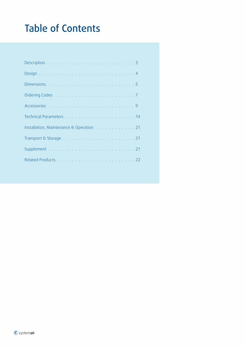
Table of Contents
Description . . . . . . . . . . . . . . . . . . . . . . . . . . . 3
Design . . . . . . . . . . . . . . . . . . . . . . . . . . . . . 4
Dimensions . . . . . . . . . . . . . . . . . . . . . . . . . . . 5
Ordering Codes . . . . . . . . . . . . . . . . . . . . . . . . 7
Accessories . . . . . . . . . . . . . . . . . . . . . . . . . . 9
Technical Parameters . . . . . . . . . . . . . . . . . . . . . 14
Installation, Maintenance & Operation . . . . . . . . . . . . 21
Transport & Storage . . . . . . . . . . . . . . . . . . . . . . 21
Supplement . . . . . . . . . . . . . . . . . . . . . . . . . . 21
Related Products . . . . . . . . . . . . . . . . . . . . . . . . 22
Linear Diffusers | 3 / 24
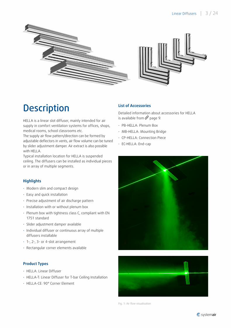
DescriptionHELLA is a linear slot diffuser, mainly intended for air supply in comfort ventilation systems for offices, shops, medical rooms, school classrooms etc . The supply air flow pattern/direction can be formed by adjustable deflectors in vents, air flow volume can be tuned by slider adjustment damper. Air extract is also possible with HELLA. Typical installation location for HELLA is suspended ceiling. The diffusers can be installed as individual pieces or in array of multiple segments .
Highlights
• Modern slim and compact design
• Easy and quick installation
• Precise adjustment of air discharge pattern
• Installation with or without plenum box
• Plenum box with tightness class C, compliant with EN 1751 standard
• Slider adjustment damper available
• Individual diffuser or continuous array of multiple diffusers installable
• 1-, 2-, 3- or 4-slot arrangement
• Rectangular corner elements available
Product Types
• HELLA: Linear Diffuser
• HELLA-T: Linear Diffuser for T-bar Ceiling Installation
• HELLA-CE: 90° Corner Element
List of Accessories
Detailed information about accessories for HELLA is available from page 9 .
• PB-HELLA: Plenum Box
• MB-HELLA: Mounting Bridge
• CP-HELLA: Connection Piece
• EC-HELLA: End-cap
Fig . 1: Air flow visualisation
4 / 24 | Linear Diffusers
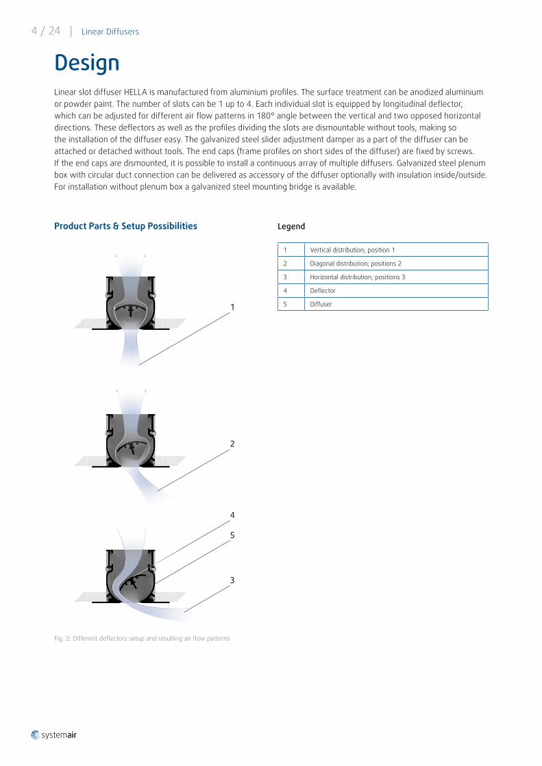
DesignLinear slot diffuser HELLA is manufactured from aluminium profiles. The surface treatment can be anodized aluminium or powder paint. The number of slots can be 1 up to 4. Each individual slot is equipped by longitudinal deflector, which can be adjusted for different air flow patterns in 180° angle between the vertical and two opposed horizontal directions. These deflectors as well as the profiles dividing the slots are dismountable without tools, making so the installation of the diffuser easy. The galvanized steel slider adjustment damper as a part of the diffuser can be attached or detached without tools. The end caps (frame profiles on short sides of the diffuser) are fixed by screws. If the end caps are dismounted, it is possible to install a continuous array of multiple diffusers. Galvanized steel plenum box with circular duct connection can be delivered as accessory of the diffuser optionally with insulation inside/outside. For installation without plenum box a galvanized steel mounting bridge is available.
Fig . 2: Different deflectors setup and resulting air flow patterns
4
1
2
3
5
1 Vertical distribution; position 1
2 Diagonal distribution; positions 2
3 Horizontal distribution; positions 3
4 Deflector
5 Diffuser
Legend Product Parts & Setup Possibilities
Linear Diffusers | 5 / 24
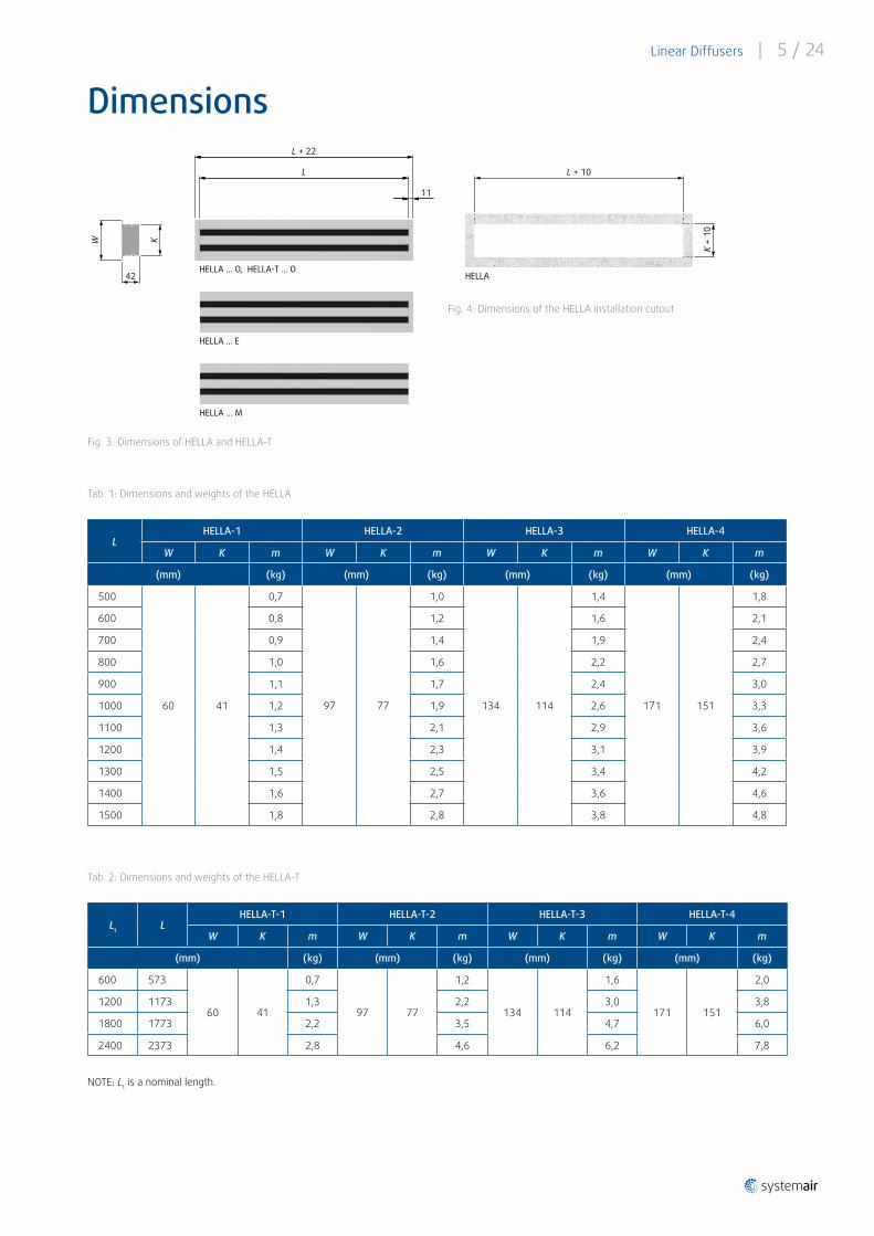
Fig . 3: Dimensions of HELLA and HELLA-T
Dimensions
Tab. 1: Dimensions and weights of the HELLA
L HELLA-1 HELLA-2 HELLA-3 HELLA-4
W K m W K m W K m W K m
(mm) (kg) (mm) (kg) (mm) (kg) (mm) (kg)
500
60 41
0,7
97 77
1,0
134 114
1,4
171 151
1,8
600 0,8 1,2 1,6 2,1
700 0,9 1,4 1,9 2,4
800 1,0 1,6 2,2 2,7
900 1,1 1,7 2,4 3,0
1000 1,2 1,9 2,6 3,3
1100 1,3 2,1 2,9 3,6
1200 1,4 2,3 3,1 3,9
1300 1,5 2,5 3,4 4,2
1400 1,6 2,7 3,6 4,6
1500 1,8 2,8 3,8 4,8
Tab. 2: Dimensions and weights of the HELLA-T
Lt L HELLA-T-1 HELLA-T-2 HELLA-T-3 HELLA-T-4
W K m W K m W K m W K m
(mm) (kg) (mm) (kg) (mm) (kg) (mm) (kg)
600 573
60 41
0,7
97 77
1,2
134 114
1,6
171 151
2,0
1200 1173 1,3 2,2 3,0 3,8
1800 1773 2,2 3,5 4,7 6,0
2400 2373 2,8 4,6 6,2 7,8
W
L
L + 22
11
42
K
HELLA ... O, HELLA-T ... O
HELLA ... E
HELLA ... M
L + 10
K +
10
HELLA
NOTE: Lt is a nominal length .
Fig . 4: Dimensions of the HELLA installation cutout
6 / 24 | Linear Diffusers
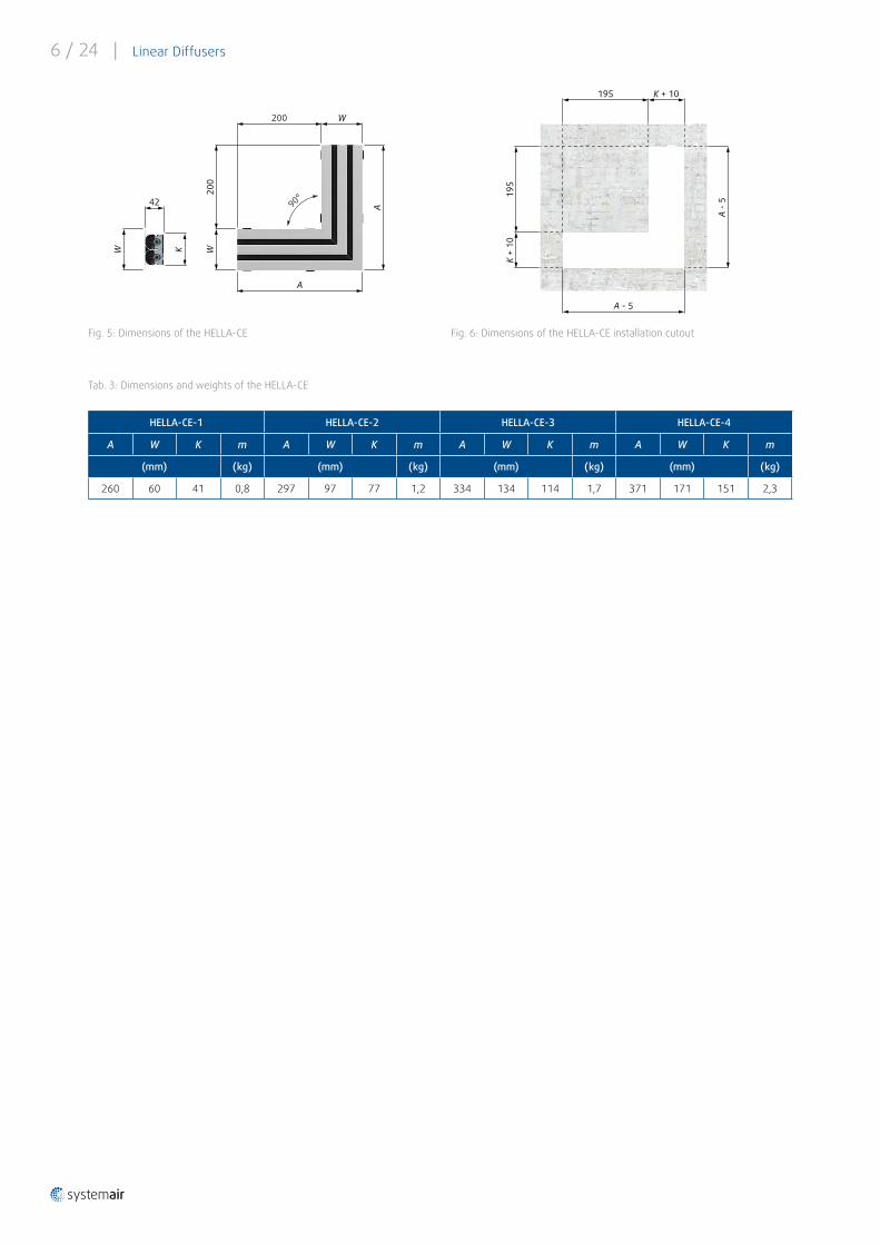
Fig . 5: Dimensions of the HELLA-CE
Tab. 3: Dimensions and weights of the HELLA-CE
HELLA-CE-1 HELLA-CE-2 HELLA-CE-3 HELLA-CE-4
A W K m A W K m A W K m A W K m
(mm) (kg) (mm) (kg) (mm) (kg) (mm) (kg)
260 60 41 0,8 297 97 77 1,2 334 134 114 1,7 371 171 151 2,3
Fig . 6: Dimensions of the HELLA-CE installation cutout
90°
A
A
200
200
W
W
42
W K
A -
5
A - 5
K + 10
K +
10
195
195

Linear Diffusers | 7 / 24
Ordering CodesHELLA
Linear Diffuser
Example of the Ordering Code
HELLA-2-1500-B-0-0-AN
Diffuser with 2 slots, 1500 mm length, black deflectors, without damper, complete unit including side frame at both ends, anodized aluminium finish.
NOTES:
1) Standard sizes for non-specific installation. L represents the length of the diffuser part immersed in the ceiling .
2) End cap is the detouchable short side of the frame on HELLA diffuser (see page 13).
HELLA- - - - - -
Number of Slots 1 . . . 4
Diffuser Length L (mm) 1) Increment 100 mm 500 . . . 1500
Black B
Deflector Colour White (extra charge) W
Slider adjustment damper R
Damper No damper 0
Complete unit including end caps at both ends 2) 0
End unit for linear assembly E
Diffuser Construction Middle unit for linear assembly M
Anodized aluminium finish AN
Powder coating - signal white RAL9003 SW
Powder coating - white RAL9010 W
Surface Finish Powder coating - other RAL colour RALXXXX
8 / 24 | Linear Diffusers
Example of the Ordering Code
HELLA-T-2-1200-B-0-AN
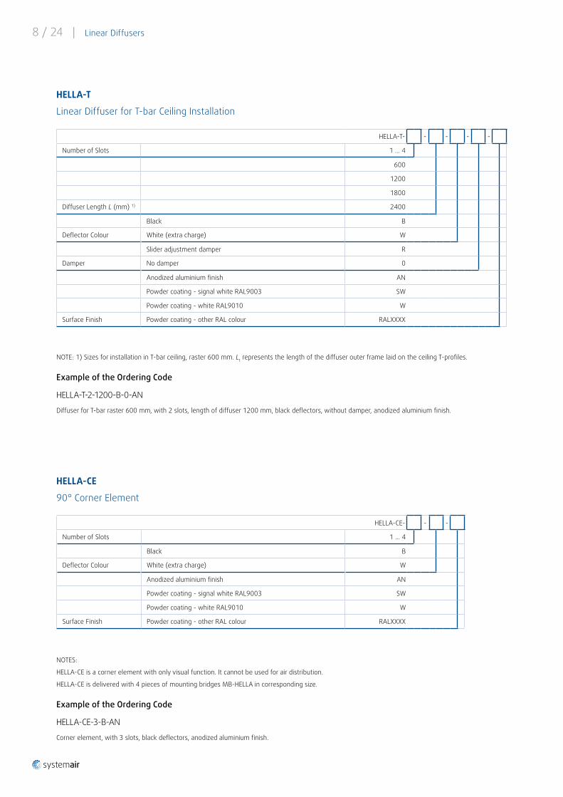
Diffuser for T-bar raster 600 mm, with 2 slots, length of diffuser 1200 mm, black deflectors, without damper, anodized aluminium finish.
NOTE: 1) Sizes for installation in T-bar ceiling, raster 600 mm. Lt represents the length of the diffuser outer frame laid on the ceiling T-profiles.
Example of the Ordering Code
HELLA-CE-3-B-AN
Corner element, with 3 slots, black deflectors, anodized aluminium finish.
NOTES:
HELLA-CE is a corner element with only visual function. It cannot be used for air distribution.
HELLA-CE is delivered with 4 pieces of mounting bridges MB-HELLA in corresponding size.
HELLA-T
Linear Diffuser for T-bar Ceiling Installation
HELLA-CE
90° Corner Element
HELLA-T- - - - -
Number of Slots 1 . . . 4
600
1200
1800
Diffuser Length L (mm) 1) 2400
Black B
Deflector Colour White (extra charge) W
Slider adjustment damper R
Damper No damper 0
Anodized aluminium finish AN
Powder coating - signal white RAL9003 SW
Powder coating - white RAL9010 W
Surface Finish Powder coating - other RAL colour RALXXXX
HELLA-CE- - -
Number of Slots 1 . . . 4
Black B
Deflector Colour White (extra charge) W
Anodized aluminium finish AN
Powder coating - signal white RAL9003 SW
Powder coating - white RAL9010 W
Surface Finish Powder coating - other RAL colour RALXXXX
Linear Diffusers | 9 / 24
AccessoriesPB-HELLA & PB-HELLA-T
Plenum Boxes
Description
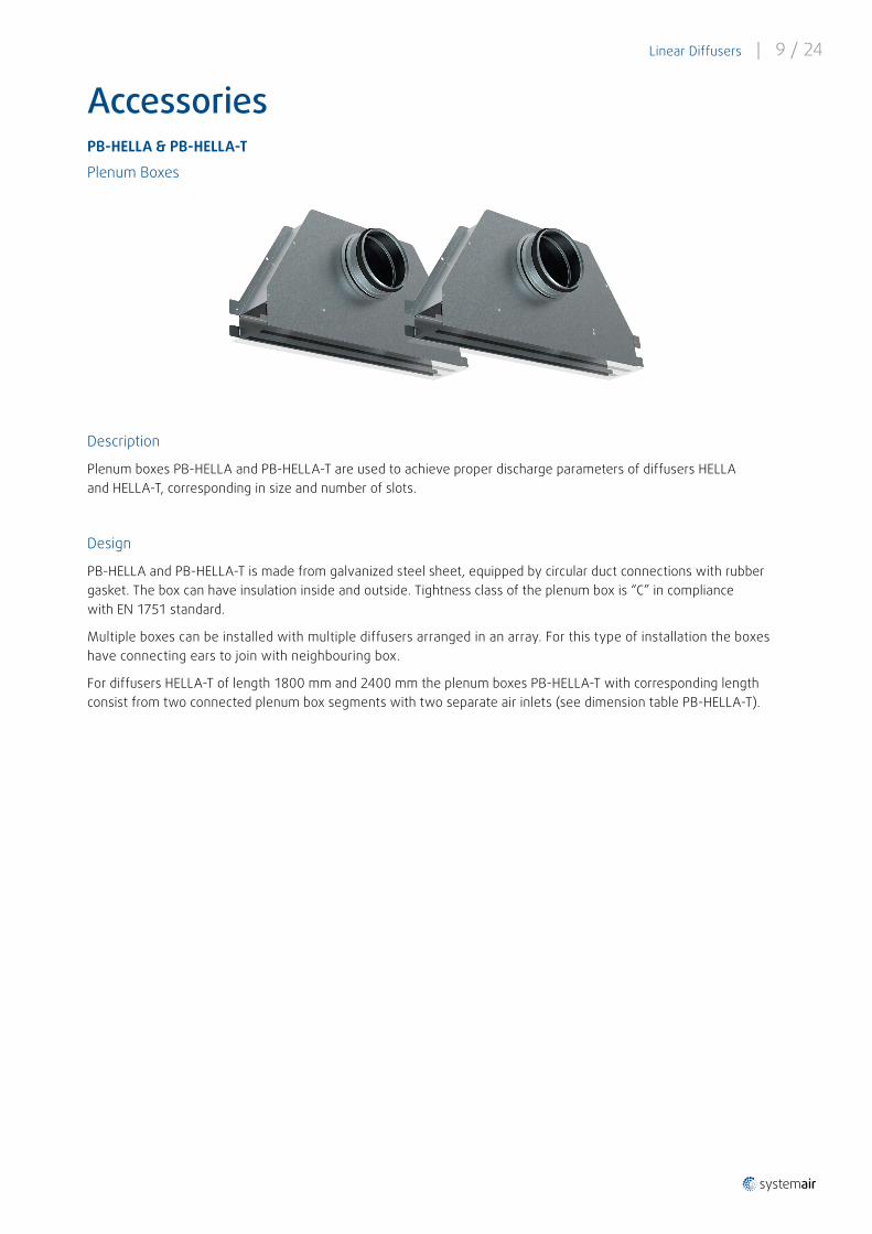
Plenum boxes PB-HELLA and PB-HELLA-T are used to achieve proper discharge parameters of diffusers HELLA and HELLA-T, corresponding in size and number of slots.
Design
PB-HELLA and PB-HELLA-T is made from galvanized steel sheet, equipped by circular duct connections with rubber gasket. The box can have insulation inside and outside. Tightness class of the plenum box is “C” in compliance with EN 1751 standard.
Multiple boxes can be installed with multiple diffusers arranged in an array. For this type of installation the boxes have connecting ears to join with neighbouring box.
For diffusers HELLA-T of length 1800 mm and 2400 mm the plenum boxes PB-HELLA-T with corresponding length consist from two connected plenum box segments with two separate air inlets (see dimension table PB-HELLA-T).

10 / 24 | Linear Diffusers
Fig . 7: Dimensions of the PB-HELLA and PB-HELLA-T
Dimensions
øD
H
L T
min. 57
NOTE: The external insulation J (see the Ordering code on previous page) increases the dimension T by approximately 2 × 6 mm.
PB-HELLA-3
L
(mm)
500
600
700
800
900
1000
1100
1200
1300
1400
1500
H 282
T 118
øD 160 200
m (kg) 1,9 2,2 2,4 2,7 2,9 3,3 3,5 3,8 4,1 4,3 4,6
PB-HELLA-4
L
(mm)
500
600
700
800
900
1000
1100
1200
1300
1400
1500
H 337
T 155
øD 200 250
m (kg) 2,4 2,7 2,9 3,2 3,5 3,9 4,2 4,5 4,8 5,1 5,4
PB-HELLA-T-1
Lt (mm) 600 1200 1800 2400
n 1 2
L
(mm)
573 1173 1773 2373
H 214
T 44
øD 100 125 100 125
m (kg) 1,5 2,8 4,2 5,6
PB-HELLA-T-2
600 1200 1800 2400
1 2
573 1173 1773 2373
250
81
125 160 125 160
1,6 3,3 5 6,6
PB-HELLA-T-3
600 1200 1800 2400
1 2
573 1173 1773 2373
282
118
160 200 160 200
1,9 3,8 5,8 7,6
PB-HELLA-T-4
600 1200 1800 2400
1 2
573 1173 1773 2373
337
155
200 250 200 250
2,4 4,5 7 9
Tab. 4: Dimensions of the PB-HELLA-T
NOTES:
Lt = Nominal length of diffuser HELLA-T
n = Number of plenum box segments
L, H, T = Physical dimensions of plenum box PB-HELLA-T. See the Dimensions picture on previous page .
The external insulation J (see the Ordering code on page 13) increases the dimension T by approximately 2 × 6 mm.
For sizes 1800 and 2400 L is overall length of both plenum box segments together.
The weight m (kg) is stated for the whole plenum box set regardless if it consists of one or two plenum box segments.
PB-HELLA-1
L
(mm)
500
600
700
800
900
1000
1100
1200
1300
1400
1500
H 214
T 44
øD 100 125
m (kg) 1,3 1,5 1,7 1,9 2,1 2,3 2,5 2,8 3,0 3,2 3,4
Tab. 5: Dimensions of the PB-HELLA
PB-HELLA-2
L
(mm)
500
600
700
800
900
1000
1100
1200
1300
1400
1500
H 250
T 81
øD 125 160
m (kg) 1,6 1,8 2,0 2,3 2,5 2,8 3,0 3,3 3,5 3,7 4,0
Linear Diffusers | 11 / 24
Ordering Codes
PB-HELLA Plenum Box for HELLA Diffuser
NOTES:
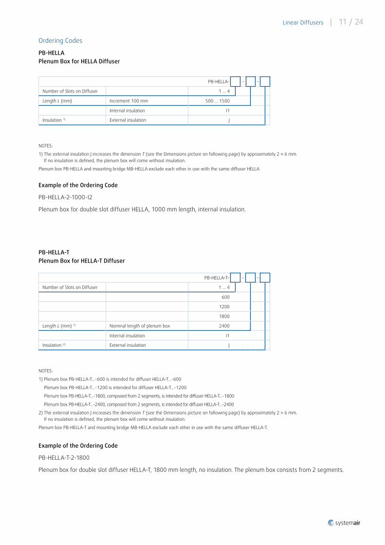
1) The external insulation J increases the dimension T (see the Dimensions picture on following page) by approximately 2 × 6 mm. If no insulation is defined, the plenum box will come without insulation.
Plenum box PB-HELLA and mounting bridge MB-HELLA exclude each other in use with the same diffuser HELLA
Example of the Ordering Code
PB-HELLA-2-1000-I2
Plenum box for double slot diffuser HELLA, 1000 mm length, internal insulation.
PB-HELLA-T Plenum Box for HELLA-T Diffuser
NOTES:
1) Plenum box PB-HELLA-T...-600 is intended for diffuser HELLA-T...-600 Plenum box PB-HELLA-T...-1200 is intended for diffuser HELLA-T...-1200 Plenum box PB-HELLA-T...-1800, composed from 2 segments, is intended for diffuser HELLA-T...-1800 Plenum box PB-HELLA-T...-2400, composed from 2 segments, is intended for diffuser HELLA-T...-2400
2) The external insulation J increases the dimension T (see the Dimensions picture on following page) by approximately 2 × 6 mm. If no insulation is defined, the plenum box will come without insulation.
Plenum box PB-HELLA-T and mounting bridge MB-HELLA exclude each other in use with the same diffuser HELLA-T.
Example of the Ordering Code
PB-HELLA-T-2-1800
Plenum box for double slot diffuser HELLA-T, 1800 mm length, no insulation. The plenum box consists from 2 segments.
PB-HELLA- - -
Number of Slots on Diffuser 1 . . . 4
Length L (mm) Increment 100 mm 500 . . . 1500
Internal insulation I1
Insulation 1) External insulation J
PB-HELLA-T- - -
Number of Slots on Diffuser 1 . . . 4
600
1200
1800
Length L (mm) 1) Nominal length of plenum box 2400
Internal insulation I1
Insulation 2) External insulation J
12 / 24 | Linear Diffusers
MB-HELLA
Mounting Bridge
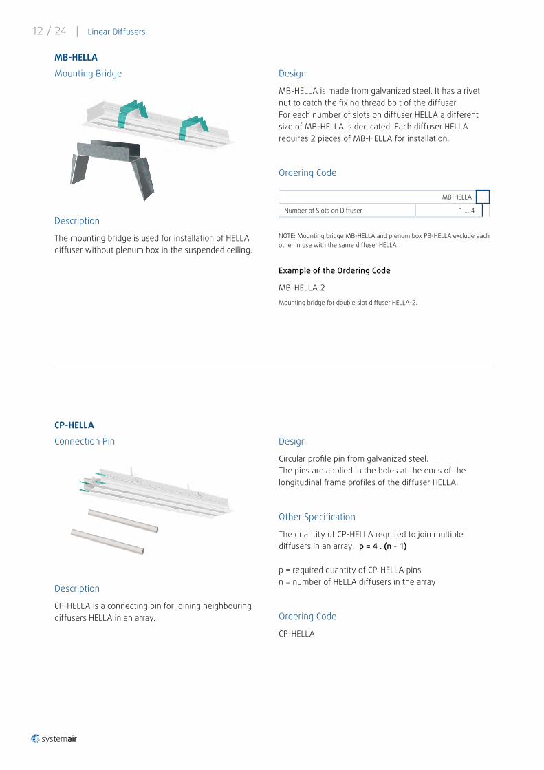
NOTE: Mounting bridge MB-HELLA and plenum box PB-HELLA exclude each other in use with the same diffuser HELLA.
Example of the Ordering Code
MB-HELLA-2
Mounting bridge for double slot diffuser HELLA-2.
Description
The mounting bridge is used for installation of HELLA diffuser without plenum box in the suspended ceiling.
CP-HELLA
Connection Pin
Description
CP-HELLA is a connecting pin for joining neighbouring diffusers HELLA in an array .
Design
Circular profile pin from galvanized steel. The pins are applied in the holes at the ends of the longitudinal frame profiles of the diffuser HELLA.
Other Specification
The quantity of CP-HELLA required to join multiple diffusers in an array: p = 4 . (n - 1)
p = required quantity of CP-HELLA pinsn = number of HELLA diffusers in the array
Ordering Code
CP-HELLA
MB-HELLA-
Number of Slots on Diffuser 1 . . . 4
Design
MB-HELLA is made from galvanized steel. It has a rivet nut to catch the fixing thread bolt of the diffuser.For each number of slots on diffuser HELLA a different size of MB-HELLA is dedicated. Each diffuser HELLA requires 2 pieces of MB-HELLA for installation .
Ordering Code
Linear Diffusers | 13 / 24
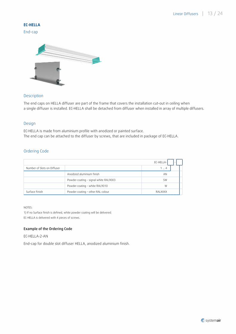
EC-HELLA
End-cap
NOTES:
1) If no Surface finish is defined, white powder coating will be delivered.
EC-HELLA is delivered with 4 pieces of screws.
Example of the Ordering Code
EC-HELLA-2-AN
End-cap for double slot diffuser HELLA, anodized aluminium finish.
Description
The end caps on HELLA diffuser are part of the frame that covers the installation cut-out in ceiling when a single diffuser is installed. EC-HELLA shall be detached from diffuser when installed in array of multiple diffusers.
Design
EC-HELLA is made from aluminium profile with anodized or painted surface. The end cap can be attached to the diffuser by screws, that are included in package of EC-HELLA.
Ordering Code
EC-HELLA- -
Number of Slots on Diffuser 1 . . . 4
Anodized aluminium finish AN
Powder coating - signal white RAL9003 SW
Powder coating - white RAL9010 W
Surface Finish Powder coating - other RAL colour RALXXXX
14 / 24 | Linear Diffusers
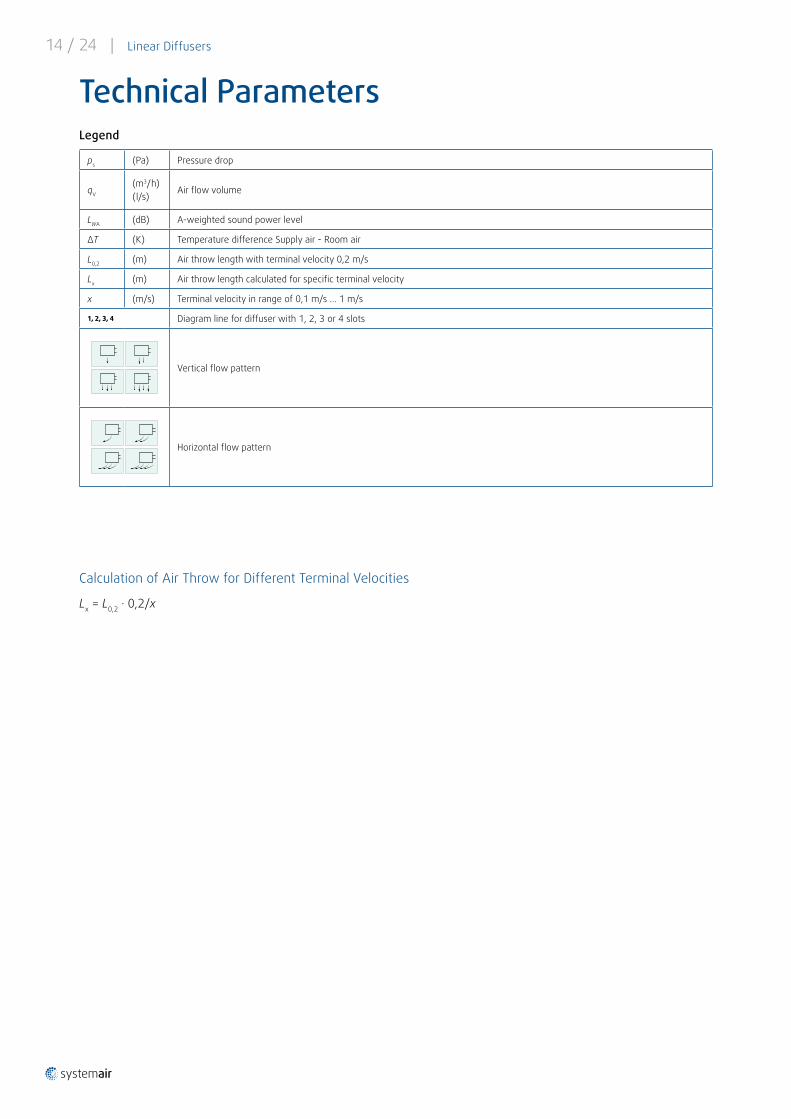
Technical Parameters
ps (Pa) Pressure drop
qV
(m3/h) (l/s)
Air flow volume
LWA (dB) A-weighted sound power level
ΔT (K) Temperature difference Supply air - Room air
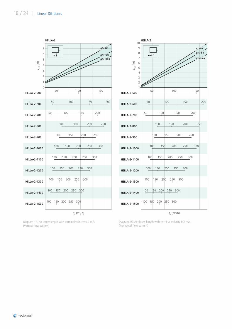
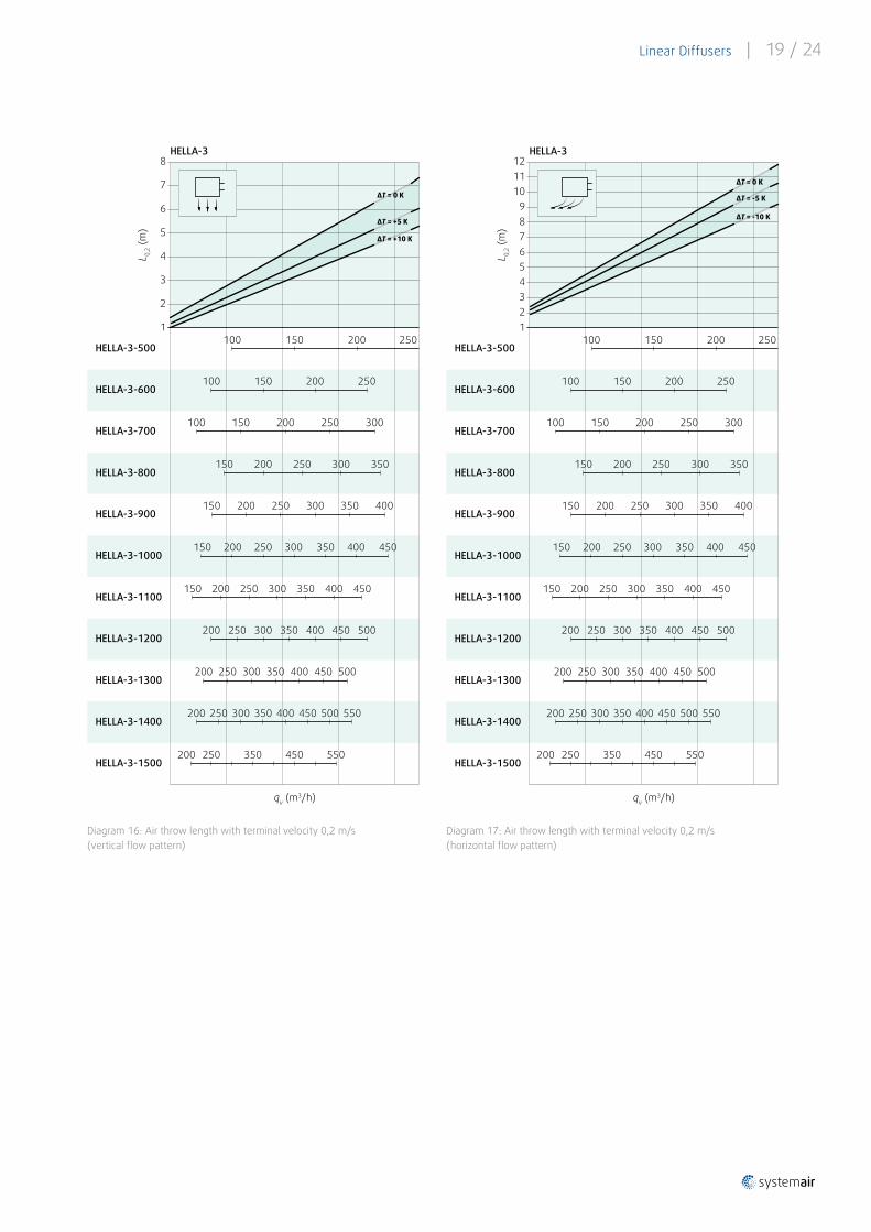
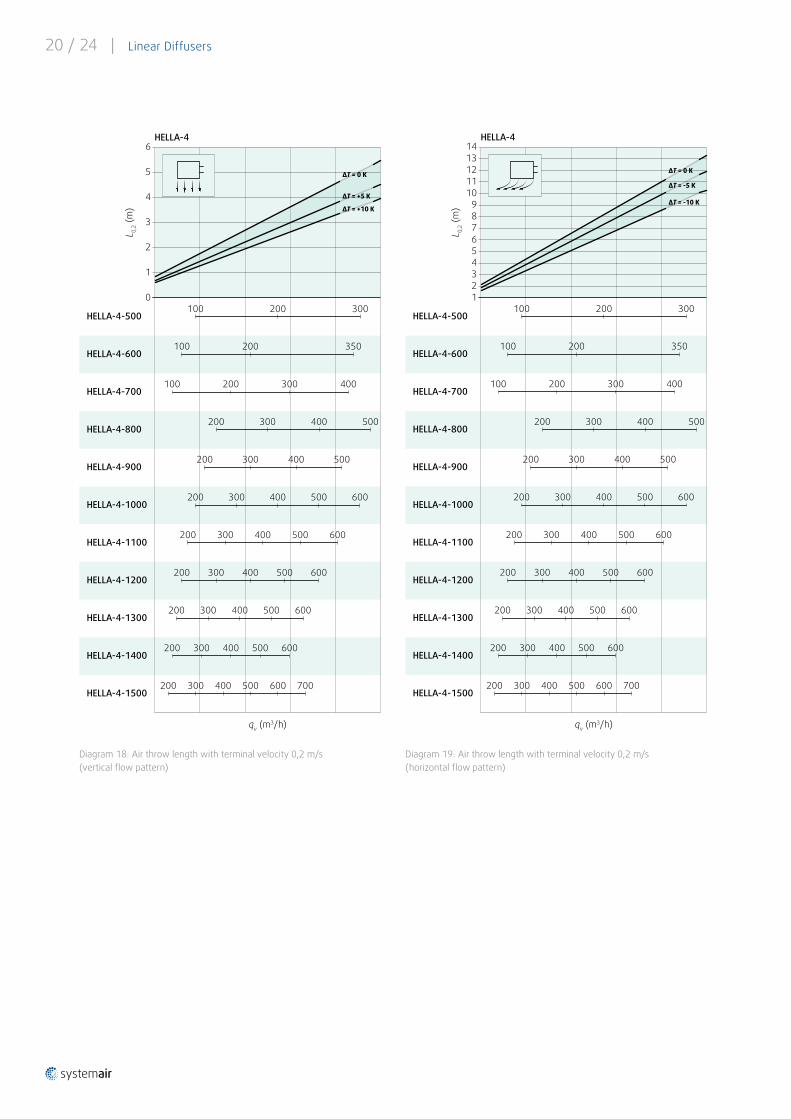
L0,2 (m) Air throw length with terminal velocity 0,2 m/s
Lx (m) Air throw length calculated for specific terminal velocity
x (m/s) Terminal velocity in range of 0,1 m/s . . . 1 m/s
1, 2, 3, 4 Diagram line for diffuser with 1, 2, 3 or 4 slots
Vertical flow pattern
Horizontal flow pattern
Legend
Calculation of Air Throw for Different Terminal Velocities
Lx = L0,2 · 0,2/x
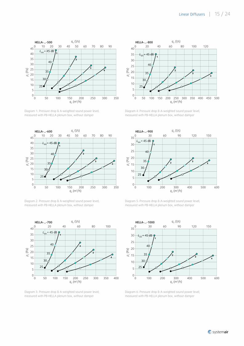
Linear Diffusers | 15 / 24
Diagram 1: Pressure drop & A-weighted sound power level; measured with PB-HELLA plenum box, without damper
Diagram 2: Pressure drop & A-weighted sound power level; measured with PB-HELLA plenum box, without damper
Diagram 3: Pressure drop & A-weighted sound power level; measured with PB-HELLA plenum box, without damper
Diagram 4: Pressure drop & A-weighted sound power level; measured with PB-HELLA plenum box, without damper
Diagram 5: Pressure drop & A-weighted sound power level; measured with PB-HELLA plenum box, without damper
45
40
35
30
25
20
15
10
0
10 30 50 60 70
350150 300
20 400
50 100 200 250
90HELLA-...-500
80
0
qV (m3/h)
qV (l/s)
p s (Pa
)
5
LWA = 45 dB
25
40
35
30
1
2
34
45
40
35
30
25
20
15
10
0
10 30 50 60 70
350150 300
20 400
50 100 200 250
90HELLA-...-600
80
0
qV (m3/h)
qV (l/s)
p s (Pa
)
5
LWA = 45 dB
25
40
35
30
1
2
34
40
35
30
25
20
15
10
0
60
400150 300
20 400
50 100 200 250
100HELLA-...-700
80
0
qV (m3/h)
qV (l/s)
p s (Pa
)
5
LWA = 45 dB
25
40
35
30
1
2
3
4
350
0
60 100
500150 300
20 400
50 100 200 250
120HELLA-...-800
80
qV (m3/h)
qV (l/s)
p s (Pa
)
LWA = 45 dB
25
40
35
30
1
23
4
40
35
30
25
20
15
10
0
5
450350 400
35
30
25
20
15
10
0 600300
0
100 200 400
HELLA-...-900
0
qV (m3/h)
qV (l/s)p s (
Pa)
5
LWA = 45 dB
25
40
35
30
1
23
4
500
9030 60 150120
Diagram 6: Pressure drop & A-weighted sound power level; measured with PB-HELLA plenum box, without damper
HELLA-...-1000
qV (m3/h)
qV (l/s)
p s (Pa
)
LWA = 45 dB
25
40
35
30
1
23
4
35
30
25
20
15
10
0 600300
0
100 200 4000
5
500
9030 60 150120

16 / 24 | Linear Diffusers
Diagram 7: Pressure drop & A-weighted sound power level; measured with PB-HELLA plenum box, without damper
Diagram 8: Pressure drop & A-weighted sound power level; measured with PB-HELLA plenum box, without damper
Diagram 9: Pressure drop & A-weighted sound power level; measured with PB-HELLA plenum box, without damper
Diagram 10: Pressure drop & A-weighted sound power level; measured with PB-HELLA plenum box, without damper
Diagram 11: Pressure drop & A-weighted sound power level; measured with PB-HELLA plenum box, without damper
30
25
20
15
10
HELLA-...-1100
0
qV (m3/h)
qV (l/s)
p s (Pa
)
5
LWA = 45 dB
25
40
35
30
1
23
4
0 600300
0
100 200 400 500
9030 60 150120
30
25
20
15
10
0
5
30 120 15060 900HELLA-...-1200
180
qV (m3/h)
qV (l/s)
p s (Pa
)
LWA = 45 dB
25
40
35
30
1
2
34
0 700300 600100 200 400 500
30
25
20
15
10
0
5
30 120 15060 900HELLA-...-1300
180
qV (m3/h)
qV (l/s)
p s (Pa
)
LWA = 45 dB
25
40
35
30
1
2
34
0 700300 600100 200 400 500
30
25
20
15
10
0
5
30 120 15060 900HELLA-...-1400
180
qV (m3/h)
qV (l/s)
p s (Pa
)
LWA = 45 dB
25
40
35
30
1
2
3
4
0 700300 600100 200 400 500
30
25
20
15
10
0
5
30 120 15060 900HELLA-...-1500
180
qV (m3/h)
qV (l/s)p s (
Pa)
LWA = 45 dB
25
40
35
30
1
2
3
4
0 700300 600100 200 400 500
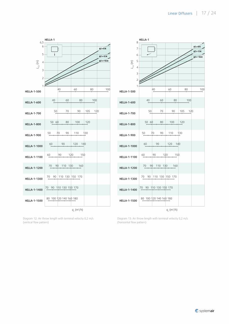
Linear Diffusers | 17 / 24
Diagram 12: Air throw length with terminal velocity 0,2 m/s (vertical flow pattern)
Diagram 13: Air throw length with terminal velocity 0,2 m/s (horizontal flow pattern)
qv (m3/h)
HELLA-1
L 0,2 (
m)
8
5
4
3
2
1
7
6
40
80 100
90 12050
100
12050 60
50 70 90 130110
90 15012060
90 11070 170150130
70 90 150 170130
70 90 160110 130
HELLA-1-500
HELLA-1-600
HELLA-1-700
HELLA-1-800
HELLA-1-900
HELLA-1-1000
HELLA-1-1100
HELLA-1-1200
HELLA-1-1300
HELLA-1-1400
60 90 140120
ΔT = 0 K
ΔT = -5 K
ΔT = -10 K
18080 120 140100HELLA-1-1500
80 100
10570
40 60
60 80
160
110
qv (m3/h)
HELLA-1L 0,
2 (m
)
6,5
4
3
2
1
6
5
40
80 100
90 12050
100
12050 60
50 70 90 130110
90 15012060
90 11070 170150130
70 110 150 170130
70 90 160110 130
HELLA-1-500
HELLA-1-600
HELLA-1-700
HELLA-1-800
HELLA-1-900
HELLA-1-1000
HELLA-1-1100
HELLA-1-1200
HELLA-1-1300
HELLA-1-1400
60 90 140120
ΔT = 0 K
ΔT = +5 K
ΔT = +10 K
18080 120 160100HELLA-1-1500
80 100
10570
40 60
60 80
90
140
18 / 24 | Linear Diffusers
Diagram 14: Air throw length with terminal velocity 0,2 m/s (vertical flow pattern)
Diagram 15: Air throw length with terminal velocity 0,2 m/s (horizontal flow pattern)
qv (m3/h)
HELLA-2
L 0,2 (
m)
10
7
6
4
1
9
8
200
200
150
250100 150
200100 150 250
150 250200100
150100 200 250 300
100 150 200 250 300
100 150 300200 250
HELLA-2-500
HELLA-2-600
HELLA-2-700
HELLA-2-800
HELLA-2-900
HELLA-2-1000
HELLA-2-1100
HELLA-2-1200
HELLA-2-1300
HELLA-2-1400
100 150 250200
ΔT = 0 K
ΔT = -5 K
ΔT = -10 K
2
100 150 300200HELLA-2-1500
200
300
300
100
100
100
5
3
50
15050
15050
250
qv (m3/h)
HELLA-2L 0,
2 (m
)
8
5
4
3
0
7
6
200
200
150
250100 150
200100 150 250
150 250200100
150100 200 250 300
100 150 200 250 300
100 150 300200 250
HELLA-2-500
HELLA-2-600
HELLA-2-700
HELLA-2-800
HELLA-2-900
HELLA-2-1000
HELLA-2-1100
HELLA-2-1200
HELLA-2-1300
HELLA-2-1400
100 150 250200
ΔT = 0 K
ΔT = +5 K
ΔT = +10 K
1
100 150 300200HELLA-2-1500
200
300
300
100
100
100
2
50
15050
15050
250
Linear Diffusers | 19 / 24
Diagram 16: Air throw length with terminal velocity 0,2 m/s (vertical flow pattern)
Diagram 17: Air throw length with terminal velocity 0,2 m/s (horizontal flow pattern)
qv (m3/h)
HELLA-3
L 0,2 (
m)
12
4
21
6
250
300100
250
350150 200
150 250 400
250 450350150
250 400200 350 450 500
200 250 350 450 550400
300 500450
HELLA-3-500
HELLA-3-600
HELLA-3-700
HELLA-3-800
HELLA-3-900
HELLA-3-1000
HELLA-3-1100
HELLA-3-1200
HELLA-3-1300
HELLA-3-1400
150 250 450350
ΔT = 0 K
ΔT = -5 K
ΔT = -10 K
5
7
HELLA-3-1500
100
150
200 350 450
89
1011
250
300
300 500
250
3
200150
200100
250150 200
250 300
200 300 350
200 300 400
200 400300
200 400350
550
qv (m3/h)
HELLA-3L 0,
2 (m
)
8
4
2
1
6
250
300100
250
350150 200
150 250 400
250 450350150
250 400200 350 450 500
200 250 350 450 550400
300 500450
HELLA-3-500
HELLA-3-600
HELLA-3-700
HELLA-3-800
HELLA-3-900
HELLA-3-1000
HELLA-3-1100
HELLA-3-1200
HELLA-3-1300
HELLA-3-1400
150 250 450350
ΔT = 0 K
ΔT = +5 K
ΔT = +10 K5
7
HELLA-3-1500
100
150
200 350 450
250
300
300 500
250
3
200150
200100
250150 200
250 300
200 300 350
200 300 400
200 400300
200 400350
550
20 / 24 | Linear Diffusers
Diagram 18: Air throw length with terminal velocity 0,2 m/s (vertical flow pattern)
Diagram 19: Air throw length with terminal velocity 0,2 m/s (horizontal flow pattern)
qv (m3/h)
HELLA-4
L 0,2 (
m)
14
10
8
6
4
1
7
12
100
400100
300
500400300
500200 400300
400 600500200
500400200 600
200 300 400 600500
200 300 600400 500
HELLA-4-500
HELLA-4-600
HELLA-4-700
HELLA-4-800
HELLA-4-900
HELLA-4-1000
HELLA-4-1100
HELLA-4-1200
HELLA-4-1300
HELLA-4-1400
200 500 600400
ΔT = 0 K
ΔT = -5 K
ΔT = -10 K9
13
11
2
HELLA-4-1500
200
350
300 400 700500
200
300
300
200
5
3
100
200
300200
300
600
qv (m3/h)
HELLA-4L 0,
2 (m
)
6
4
0
5
100
400100
300
500400300
500200 400300
400 600500200
500400200 600
200 300 400 600500
200 300 600400 500
HELLA-4-500
HELLA-4-600
HELLA-4-700
HELLA-4-800
HELLA-4-900
HELLA-4-1000
HELLA-4-1100
HELLA-4-1200
HELLA-4-1300
HELLA-4-1400
200 500 600400
ΔT = 0 K
ΔT = +5 K
ΔT = +10 K
2
HELLA-4-1500
200
350
300 400 700500
200
300
300
200
3
100
200
300200
300
600
1
Linear Diffusers | 21 / 24
Installation, Maintenance & OperationInformation about installation, maintenance and operation is available in the “UserManual_HELLA” document on Systemair DESIGN.
Dry indoor conditions with an operation temperature range of -20°C to +70°C.
Transport & Storage Dry indoor conditions with a temperature range of -40°C to +50°C.
SupplementAny deviations from the technical specifications contained herein and the terms should be discussed with the manufacturer. We reserve the right to make any changes to the product without prior notice, provided that these changes do not affect the quality of the product and the required parameters .
Current information on all products is available on Systemair DESIGN .
22 / 24 | Linear Diffusers
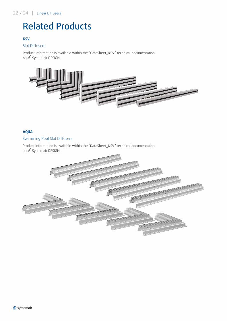
Related ProductsKSV
Slot Diffusers
Product information is available within the “DataSheet_KSV” technical documentation on Systemair DESIGN.
AQUA
Swimming Pool Slot Diffusers
Product information is available within the “DataSheet_KSV” technical documentation on Systemair DESIGN.
Linear Diffusers | 23 / 24

www.systemair.com
Syst
emai
r Pro
duct
ion
a.s.
· D
ataS
heet
_HEL
LA_E
N_2
0200
3