FRENIC Loader VG - Fuji Electric Europe
109
Instruction Manual Inverter Support Software FRENIC Loader VG (WPS-VG1-STR) Thank you for purchasing our high-performance, vector control FRENIC-VG series of inverters. • This manual provides all the information on Fuji’s inverter support software FRENIC Loader VG. Read this manual carefully for correct use of FRENIC Loader VG • This manual does not contain information on the inverter itself. Read the inverter user's manual, inverter instruction manual in conjunction with this manual. • Incorrect handling may prevent Loader from operating correctly, shorten the inverter service life, or cause problems. Fuji Electric Co., Ltd. INR-SI47-1617b-E
-
Upload
khangminh22 -
Category
Documents
-
view
2 -
download
0
Transcript of FRENIC Loader VG - Fuji Electric Europe

Instruction Manual
Inverter Support Software
FRENIC Loader VG
(WPS-VG1-STR)
Thank you for purchasing our high-performance, vector control FRENIC-VG series of inverters. • This manual provides all the information on Fuji’s inverter support software FRENIC Loader VG.
Read this manual carefully for correct use of FRENIC Loader VG
• This manual does not contain information on the inverter itself. Read the inverter user's manual, inverter instruction manual in conjunction with this manual.
• Incorrect handling may prevent Loader from operating correctly, shorten the inverter service life, or cause problems.
Fuji Electric Co., Ltd. INR-SI47-1617b-E

Copyright © 2012 Fuji Electric Co., Ltd.
All rights reserved.
No part of this publication may be reproduced or copied without prior written permission from Fuji
Electric Systems Co., Ltd.
Microsoft and Windows are registered trademarks of Microsoft Corporation in the United States. All
other products and company names mentioned in this manual are trademarks or registered trademarks
of their respective holders.
The information contained herein is subject to change without prior notice for improvement.

Preface This manual provides all the information on Fuji’s inverter support software FRENIC Loader VG.
Read this manual carefully for correct use of FRENIC Loader VG
This manual does not contain information on the inverter itself. Read the inverter user's manual,
inverter instruction manual in conjunction with this manual.
Incorrect handling may prevent Loader from operating correctly, shorten the inverter service life, or
cause problems.
■ Safety Precautions Read this manual thoroughly before proceeding with installation, connections (wiring), or operation. Ensure you have sound knowledge of the device and software and have familiarized yourself with all safety information and precautions before proceeding to operate the inverter via FRENIC Loader VG
Safety precautions are classified into the following two categories in this manual.
Failure to heed the information indicated by this symbol may result in death or serious injury.
Failure to heed the information indicated by this symbol may result in minor or light injury and/or substantial property damage.
Wiring and Connection of Cables
• Be sure to turn off the power to the inverters and related devices before making RS-485 connection.
Risk of electric shock if this warning is not heeded.
i

ii
Contents
Preface ...................................................................................................................................................................... i
Chapter 1 Before Using FRENIC Loader VG ...........................................................................................................1
1.1. Overview............................................................................................................................................................1
1.1.1. Features ...................................................................................................................................................1
1.1.2. Warranty ...................................................................................................................................................1
1.2. Connecting Inverters to a PC.............................................................................................................................2
1.2.1. Connection ...............................................................................................................................................2
1.2.2. Configuring USB network .........................................................................................................................3
1.2.2.1. Example of networking .......................................................................................................................3
1.2.3. Configuring an RS-485 communications network.....................................................................................4
1.2.3.1. Example of networking .......................................................................................................................4
1.2.3.2. Communications support devices for RS-485.....................................................................................5
1.2.3.3. Noise suppression ..............................................................................................................................5
1.3. Installation .........................................................................................................................................................6
1.3.1. Installing software.....................................................................................................................................6
1.3.1.1. Installing FRENIC Loader VG.............................................................................................................7 [ 1 ] Windows 7 / Windows Vista ................................................................................................................. 7 [ 2 ] Windows XP .......................................................................................................................................11
1.3.1.2. Installing Message Manager.............................................................................................................15
1.3.1.3. Installing USB driver .........................................................................................................................18 [ 3 ] Windows 7 ......................................................................................................................................... 18 [ 4 ] Windows Vista ................................................................................................................................... 21 [ 5 ] Windows XP ...................................................................................................................................... 24
1.3.1.4. Checking the installation of the USB driver.......................................................................................26
1.3.2. Uninstallation ..........................................................................................................................................27
1.3.2.1. Uninstalling FRENIC Loader VG.......................................................................................................27 [ 1 ] Windows 7 / Windows Vista ............................................................................................................... 27 [ 2 ] Windows XP ...................................................................................................................................... 28
1.3.2.2. Before uninstalling Message Manager..............................................................................................29 [ 3 ] Windows 7 ......................................................................................................................................... 29 [ 4 ] Windows Vista / XP............................................................................................................................ 30
1.3.2.3. Uninstalling Message Manager ........................................................................................................30 [ 1 ] Windows 7 / Windows Vista ............................................................................................................... 30 [ 2 ] Windows XP ...................................................................................................................................... 31
1.4. Configuring the Settings for Inverter(s) and Loader.........................................................................................32
1.4.1. Configuring communication-related function codes in the inverter (Case of RS-485 connection) ..........32
1.4.2. Checking the COM port on the PC (when using a communications level converter)..............................33
1.4.3. Configuring Loader .................................................................................................................................34
1.4.4. Communication Settings.........................................................................................................................36
1.4.5. Connection settings ................................................................................................................................39 [ 1 ] For connection to USB port................................................................................................................ 39 [ 2 ] For connection to RS-485 port........................................................................................................... 40 [ 3 ] For connection to Communication board (Ethernet) .......................................................................... 41

iii
Chapter 2 Description of Functions ........................................................................................................................42
2.1. Main Window...................................................................................................................................................42
2.2. File...................................................................................................................................................................43
2.2.1. Create New File......................................................................................................................................43
2.2.2. Open.......................................................................................................................................................43
2.2.3. Close ......................................................................................................................................................44
2.2.4. Save .......................................................................................................................................................44
2.2.5. Save As …..............................................................................................................................................44
2.2.6. Print ........................................................................................................................................................44
2.2.7. Print Preview ..........................................................................................................................................45
2.2.8. Page Setup.............................................................................................................................................45
2.2.9. End .........................................................................................................................................................45
2.3. Menu ...............................................................................................................................................................46
2.3.1. Function Code Setting ............................................................................................................................46
2.3.1.1. Create New Function Setting............................................................................................................46
2.3.1.2. Read File from the file.......................................................................................................................46
2.3.1.3. Read from the Inverter......................................................................................................................46
2.3.1.4. Edit List.............................................................................................................................................47 [ 1 ] Read the function code setting values from the inverter .................................................................... 48 [ 2 ] Write the function codes from the loader to the inverter..................................................................... 48 [ 3 ] Change the setting value ................................................................................................................... 49 [ 4 ] Save................................................................................................................................................... 50 [ 5 ] Print ................................................................................................................................................... 52 [ 6 ] Compare ............................................................................................................................................ 53 [ 7 ] User Definition (Display desired function codes only) ........................................................................ 54 [ 8 ] Search (Search function code terminologically) ................................................................................. 57
2.3.1.5. Auto Tuning.......................................................................................................................................58
2.3.1.6. File Information.................................................................................................................................59 [ 1 ] Change models(VG7 → VG1, or VG1 → VG7) ......................................................................... 60 [ 2 ] Change of inverter capacity ............................................................................................................... 61 [ 3 ] Change of definition file ..................................................................................................................... 62
2.3.2. Read and write (SF code) code safety functions ....................................................................................64
2.3.2.1. Read.................................................................................................................................................64
2.3.2.2. Write (Unlock Functional safety password).......................................................................................64
2.3.2.3. Change of the functional safety password ........................................................................................66
2.3.2.4. Safety function code initialization......................................................................................................67
2.3.3. Trace back..............................................................................................................................................68
2.3.3.1. Trace back screen ............................................................................................................................69
2.3.3.2. Read Waveform Data .......................................................................................................................70
2.3.3.3. Read Function Code Settings (during Trace Back)...........................................................................70
2.3.3.4. Save Trace Data ...............................................................................................................................71
2.3.3.5. Copy Trace Back Data Screen .........................................................................................................71
2.3.3.6. Print Trace Data................................................................................................................................72
2.3.3.7. Sub Window .....................................................................................................................................73 [ 1 ] Cursor ................................................................................................................................................ 73 [ 2 ] Adjust graph position ......................................................................................................................... 74

iv
2.3.3.8. Waveform Detail Settings .................................................................................................................76 [ 1 ] Channel configuration setting ............................................................................................................ 76 [ 2 ] Ch1 to Ch8 (analog setting) ............................................................................................................... 76 [ 3 ] Ch1 to Ch16 (digital setting) .............................................................................................................. 79 [ 4 ] Ch setting check (analog/digital) ........................................................................................................ 84 [ 5 ] Other settings (including sampling time setting) ................................................................................ 85
2.4. Setup ...............................................................................................................................................................87
2.4.1. Communication Setup ............................................................................................................................87
2.4.2. Language ...............................................................................................................................................87
2.4.3. Date time ................................................................................................................................................88
2.5. View.................................................................................................................................................................89
2.5.1. Toolbar....................................................................................................................................................89
2.5.2. Status bar ...............................................................................................................................................89
2.6. Window............................................................................................................................................................90
2.6.1. Cascade windows...................................................................................................................................90
2.6.2. Tile windows ...........................................................................................................................................91
2.6.3. Tile windows vertically ............................................................................................................................91
2.6.4. Arrange icons .........................................................................................................................................92
2.7. Help .................................................................................................................................................................92
2.7.1. Version Information.................................................................................................................................92
Chapter 3 Frequently asked questions (FAQ) ........................................................................................................93
3.1.1. Cannot communicate with inverter (Failed to get inverter information)...................................................93
3.1.1.1. Message Manager not installed correctly .........................................................................................93
3.1.1.2. USB driver not installed correctly......................................................................................................94
3.1.1.3. USB driver installed correctly............................................................................................................99
3.1.1.4. USB communication impossible after the PC has gone standby or to sleep) .................................100
Chapter 4 Specifications.......................................................................................................................................101

Chapter 1 Before Using
1
Chapter 1 Before Using FRENIC Loader VG
This chapter gives an overview of the inverter support software FRENIC Loader VG and provisions for
its installation and operation.
1.1. Overview
1.1.1. Features ・ Loader enables a PC to support remote operation of inverters either individually or collectively
via the RS-485 port or the USB port on the inverters.
・ Simplified operation of Loader allows you to easily manage and set the function code data for the inverter.
1.1.2. Warranty
Limited
Warranty
In no event will Fuji Electric Co., Ltd. be held liable for any damage (including, but not limited to lost profit, suspension or interruption of operations, loss of operational data or other monetary loss) whatsoever resulting from the use of the software or malfunction of the same or from information contained in this document.

1.2. Connecting Inverters to a PC
1.2.1. Connection
The table below lists the connection methods available for connecting inverters to a PC.
PC : Inverters On PC On inverter Connection
USB USB Using a USB cable
USB RS-485 Via a USB / RS-485 converter 1 : 1 COM port (RS-232C) RS-485 Via an RS-232C / RS-485 converter
USB RS-485
Via an RS-232C / RS-485 converter
When using an RJ-45 connector, use a branch adapter for multi-drop connection for each of the 2nd and the subsequent inverters.
1 : n
COM port (RS-232C) RS-485 Via an RS-232C / RS-485 converter
1) For details about the RS-232C / RS-485 converter and USB / RS-485 converter,
refer to Section 1.2.3.2. " Communications support devices for RS-485".
2) To minimize the effects of noise, separate the signal lines from the power lines. Refer to Section 1.2.3.2. " RS-485 Noise suppression.
3) The inverter cannot be concurrently shared by the Loader-running PC and other host equipment (e.g., PLC). To use Loader, therefore, be sure to disconnect the cables of other host equipment from the RS-485 port on the inverter.
4) For multi-drop connection of inverters, assign different station addresses to each of the inverters connected.
• Be sure to turn off the power to the inverters and related devices before making RS-485 connection.
Risk of electric shock if this warning is not heeded.
2

Chapter 1 Before Using
3
1.2.2. Configuring USB network
1.2.2.1. Example of networking
To configure a USB network connecting the inverter and a Loader-running PC, use a
commercially available USB cable (mini B connector). (See below.)
Connection using the USB connector
For connection using the USB connector, refer to Section 1.4.4. "Setting up communications
parameters."
USB miniB connector
FRENIC-VG
MAX. 5m
USB A connectorUSB cable
Figure 1.2.2-1 USB Network Using a USB Cable (mini B)
Table 1.2.2-1 Specifications of USB Network
Specifications USB 1.1 compliant
Transmission speed 12M bps
Wiring length Max. 5 m
Connector USB mini B connector
When connecting the inverter to a PC via the USB port, be sure to connect them, one
to one. Do not use a USB hub.

1.2.3. Configuring an RS-485 communications network
1.2.3.1. Example of networking
To configure an RS-485 communications network connecting inverters and a Loader-running PC,
use a Shielded twisted pair cable for long distance transmission. (See below.)
FRENIC Loader VG USB or RS-232C
TXD RXD
USB / RS-485 converter or
RS-232C / RS-485 converter
Commercial item (2-wire)
FRENIC-VG Inverter 1
DX+
DX-
FRENIC-VG Inverter 2
DX+
DX-
FRENIC-VG Inverter n
DX+
DX-
ShieldStation address
:01
Use internal termination resistorsSW4
112 ohm
MAX. 31
(2-wire)
(2-wire)
Station address :n
(2-wire)
Station address:02
Figure 1.2.3-1 RS-485 Multi-drop Network (Terminal Block Connections)
When selecting communications support devices that protect parts on the printed
circuit boards of inverters from damage or malfunction due to external electrical noise
or to keep the network in high noise immunity level, carefully read through the
descriptions in FRENIC-VG user's manual Section 5.1.4 "Communications support
devices for RS-485".
4

Chapter 1 Before Using
5
1.2.3.2. Communications support devices for RS-485
Description of the equipment needed when connecting to a PC not equipped with an RS485
interface, refer to FRENIC-VG user's manual Section 5.1.4 "Communications support devices for
RS-485".
1.2.3.3. Noise suppression
Depending on the operating environment, instruments may malfunction due to the noise
generated by the inverter. Possible measures to prevent such malfunction are: separating the
wiring, use of shielded cable, isolating the power supply, and adding an inductance component.
Show below is an example of adding an inductance component.
Adding inductance components
To suppress or eliminate noise for keeping the network in high noise immunity level, insert
inductance components such as choke coils in series in the signal circuit, or pass the RS-485
communications cable through a ferrite core ring or wind it around by 2 or 3 turns as shown
below to keep the impedance of the signal lines high.
RS-485 converter
RS-485 communications cable Ferrite core
Inverter
Pass the wiring through the ferrite core or wind the ferrite core with the wiring a few times
Figure 1.2.3-2 Adding an Inductance Component

1.3. Installation
1.3.1. Installing software
Before installation
Execute the following before installation.
Check items Requirements
Windows OS Microsoft Windows XP, Vista (32-bit), or 7 (32-bit / 64-bit)
Hard disk space Free space of approx. 9 MB or more
Other applications Terminate all the applications being in execution.
Uninstalling the Earlier version of Loader
If any earlier versions of FRENIC Loader VG have been installed on your PC, uninstall it.
Uninstalling the Message Manager of VG7 loader
If Message Manager of VG7 loader has been installed on your PC, uninstall it.
[FRENIC Loader VG Setup.exe] and [MsgMgr USB Setup. exe] are contained in the CD that
comes with Fuji Inverter FRENIC VG. Copy these setup files to any folder.
To use FRENIC Loader VG, you need to install two setup files: the loader software
main program [FRENIC Loader VG Setup.exe] and the message manager [MsgMgr
USB Setup.exe] that manages communications.
To install the loader software, install with an account that has sufficient authority to
install the software.
Paid version (WPS-VG1-PCL) and free version (WPS-VG1-STR) of FRENIC Loader
VG can not be installed at the same time. Install the loader software of one or the
other.
6

Chapter 1 Before Using
7
1.3.1.1. Installing FRENIC Loader VG
[ 1 ] Windows 7 / Windows Vista
Follow the wizard and install Loader as shown below.
Double-click the FRENIC Loader VG Setup.exe icon.
The exe automatically starts the installation wizard.
To continue, click Install.
* Windows 7 only
To continue, click Yes.

* Windows Vista only
To continue, click Allow.
To continue, click Next.
Carefully read the license agreement.
To view the entire contents of the agreement, scroll the screen up and down using the Page Up/Down keys or the scroll bar.
If you agree, click Next to proceed.
8

Chapter 1 Before Using
9
Enter your user name and company name.
After entry, click Next to proceed.
Select the destination folder to install. A default folder has appeared.
To select a different folder, click Browse….
Click Next to proceed.
The screen confirming your selection appears.
If you want to change the selection, click Back to return to the previous screen.
If OK, click Install to proceed.
To abort the installation, click Cancel.

To continue, click Yes.
Upon completion of the installation, the screen at left appears.
To exit the installation wizard and return to Windows, click Finish.
10

Chapter 1 Before Using
11
[ 2 ] Windows XP
Follow the wizard and install Loader as shown below.
Double-click the FRENIC Loader VG Setup.exe icon.
The exe automatically starts the installation wizard.
To continue, click Install.
To abort the installation, click Cancel.

To continue, click Next.
Carefully read the license agreement.
To view the entire contents of the agreement, scroll the screen up and down using the Page Up/Down keys or the scroll bar.
If you agree, click Next to proceed.
Enter your user name and company name.
After entry, click Next to proceed.
12

Chapter 1 Before Using
13
Select the destination folder to install. A default folder has appeared.
To select a different folder, click Browse….
Click Next to proceed.
The screen confirming your selection appears.
If you want to change the selection, click Back to return to the previous screen.
When it is ready to restart, click Yes Install.
*If you do not restart FRENIC Loader VG, the program cannot be normally installed.
The installation progress bar appears.
To abort the installation, click Cancel.

Upon completion of the installation, the screen at left appears.
To exit the installation wizard and return to Windows, click Finish.
When it is ready to restart, click Yes.
*If you do not restart FRENIC Loader VG, the program cannot be normally installed.
14

Chapter 1 Before Using
15
1.3.1.2. Installing Message Manager
Follow the wizard and install Message Manager as shown below.
Double-click the MsgMgr USB Setup.exe icon.
The exe automatically starts the installation wizard.
To continue, click Yes.
To continue, click Next.

Carefully read the license agreement.
To view the entire contents of the agreement, scroll the screen up and down using the Page Up/Down keys or the scroll bar.
If you agree, click Yes to proceed.
Select the destination folder to install. A default folder has appeared.
To select a different folder, click Browse….
Click Next to proceed.
Select the start menu folder that the shortcut to FRENIC Loader is to be added to.
You can select one from existing folders in the list or create a new one.
After entry, click Next to proceed.
16

Chapter 1 Before Using
17
The screen confirming your selection appears.
If you want to change the selection, click Back to return to the previous screen.
If OK, click Next to proceed.
To abort the installation, click Cancel.
Upon completion of the installation, the screen at left appears.
To exit the installation wizard and return to Windows, click Finish.

1.3.1.3. Installing USB driver
Using the USB interface for accessing the inverter(s) requires installing the USB driver to your
PC. The driver installation is required only once at the first use of the USB interface.
If the USB driver has not been installed correctly, no communication via the USB
interface is possible.
First of all, connect the USB connector (A) on the PC and the USB connector (mini B) on the
inverter's keypad with each other using a USB cable.
Before installation of the USB driver, install Loader and Message Manager.
[ 3 ] Windows 7
When the OS finds a USB device of the Loader, it displays the following.
The system-supplied driver setup wizard does not run automatically. Install the USB driver as shown below.
From the Start menu, select and right-click Computer to show the submenu. Click Properties.
Wait for the Control Panel Home screen and click Device Manager.
18

Chapter 1 Before Using
19
On the Device Manager window, right-click Unknown device to show the drop-down list. Click Update Driver Software….
Click Browse my computer for driver software.
Click Browse….

In the folder in which FRENIC Loader has been installed, select ¥Driver¥MICREXSX and then click OK. The default folder is C:¥Fuji Electric ¥FRENIC_Loader_VG¥Driver¥ MICREXSX when the OS drive is C.
To continue, click Next.
Click Install this driver software anyway.
Upon completion of the installation, the screen at left appears. To exit the installation wizard and return to Windows, click Close.
20

Chapter 1 Before Using
21
[ 4 ] Windows Vista
When the OS finds a USB device of the Loader, it displays the following. Follow the wizard and
install Loader as shown below.
Click Locate and install driver software.
Click Continue to proceed.
Click Don’t search online.

Click Browse my computer for driver software (advanced).
Click Browse….
In the folder in which FRENIC Loader has been installed, select ¥Driver¥MICREXSX and then click OK. The default folder is C:¥ Fuji Electric ¥FRENIC Loader VG¥Driver¥ MICREXSX when the OS drive is C.
To continue, click Next.
22

Chapter 1 Before Using
23
Click Install this driver software anyway.
Upon completion of the installation, the screen at left appears. To exit the installation wizard and return to Windows, click Close.
This message appears when the USB driver has been successfully installed.

[ 5 ] Windows XP
When the OS finds a USB device of the Loader, it displays the following. Follow the wizard and
install Loader as shown below.
Wait for this screen to appear, select Yes, now and every time I connect a device, then click Next.
Select Install from a list or specific location (Advanced), then click Next.
Select Search for the best driver in these locations and the Include this location in the search check box, then click Browse….
24

Chapter 1 Before Using
25
In the folder in which FRENIC Loader has been installed, select ¥Driver¥MICREXSX and then click OK. The default folder is C:¥Fuji Electric ¥FRENIC Loader VG¥Driver¥ MICREXSX when the OS drive is C.
Click Next. Installation starts.
Upon completion of the installation, the screen at left appears. To exit the installation wizard and return to Windows, click Finish.

1.3.1.4. Checking the installation of the USB driver
To check whether the USB driver has been installed correctly, open Device Manager. If FRENIC
is added to the sub-tree of Loader USB device, the driver has been installed correctly.
Installation finished successfully Installation failed
26

Chapter 1 Before Using
27
1.3.2. Uninstallation
1.3.2.1. Uninstalling FRENIC Loader VG
[ 1 ] Windows 7 / Windows Vista
From the Start menu, select All Programs | FRENIC Loader VG | FRENIC Loader VG
Uninstall.
The confirmation screen at left appears. Click Yes.
The confirmation screen at left appears. Click Yes.

The uninstallation progress bar appears. To abort the uninstallation, click Cancel.
In the above procedure, perform the uninstallation.
[ 2 ] Windows XP
From the Start menu, select All Programs | FRENIC Loader VG | FRENIC Loader VG
Uninstall.
The uninstallation confirmation screen appears as shown left. To proceed and uninstall Loader, click Yes.
The uninstallation progress bar appears. To abort the uninstallation, click Cancel.
In the above procedure, perform the uninstallation.
28

Chapter 1 Before Using
29
1.3.2.2. Before uninstalling Message Manager
Before uninstalling Message Manager, be sure to quit both Loader and Message Manager.
Quitting Message Manager
Message Manager is software that manages communication between the PC and
inverters. To make sure that Message Manager has quitted, check that no Message
Manager icon is displayed in the task tray. If the icon is displayed, right-click it to quit
Message Manager. If doing so cannot quit it, shut down or log off Windows.
Once you uninstall Loader when Message Manager is running, a new version of Loader
installed after that cannot run properly, that is, it may no longer be able to recognize
inverters. If this happens, first delete the folder (including its contents) named Fuji
Electric Shared in the file path as shown below, and then reinstall Loader.
C:¥Program Files¥Common Files¥Fuji Electric Shared
(In the file path shown above, "C" represents the drive letter of the partition or hard disk
where Windows is installed. If Windows is installed on a different drive in your system,
replace "C" with the letter corresponding to that drive.)
Quitting Message Manager
[ 3 ] Windows 7
Click this to display the hidden icons as shown below.
Right-click this icon to display Exit MessageManager, then click it. The confirmation window
appears. Click Yes to quit Message Manager.

[ 4 ] Windows Vista / XP
Right-click the Message Manager icon to display Exit MessageManager, then click it.
The confirmation window appears. Click Yes to quit Message Manager.
1.3.2.3. Uninstalling Message Manager
[ 1 ] Windows 7 / Windows Vista
From the Start menu, select All Programs | Message Manager | Message Manager Uninstall.
To continue, click Yes.
30

Chapter 1 Before Using
31
The confirmation screen at left appears. To continue the uninstallation procedure, click Yes.
In the above procedure, perform the uninstallation.
When it is ready to restart, click Finish.
[ 2 ] Windows XP
From the Start menu, select All Programs | Message Manager | Message Manager Uninstall.
The uninstallation confirmation screen appears as shown left. To proceed and uninstall Loader, click Yes.
In the above procedure, perform the uninstallation.

When it is ready to restart, click Finish.
1.4. Configuring the Settings for Inverter(s) and Loader
1.4.1. Configuring communication-related function codes in the inverter (Case of RS-485 connection)
The table below lists inverter's function codes related to Loader. Configure those codes before
connecting Loader to the inverter
Function code
Name Setting range Factory default
H31 Station address 1~255 1
H34 Baud rate 0:2400 bps 2:9600 bps 4:38400 bps
1:4800 bps 3:19200 bps
4
H40 Protocol 0:Modbus RTU protocol 1:SX protocol (Loader protocol) 2:Fuji general-purpose inverter protocol
1
H31:Station address
Set the H31 data to the same value as the RS-485 Station address. setting made in
Loader's Device connection list. (see Section 1.4.5. , [ 2 ] )
H34:Baud rate
Set the H34 data to the same value as the baud rate setting made in Loader's
Communication Setting window. (see Section 1.4.4. )
H40:Protocol
Set the H40 data to "1" (FRENIC Loader protocol).
In the case of USB connection, the above function code setting is not required.
32

Chapter 1 Before Using
33
1.4.2. Checking the COM port on the PC (when using a communications level converter)
Loader running on the PC uses the RS-232C communications port (COM) to interface with
inverters.
When an RS-232C / RS-485 converter is connected to the PC, check what COM port number
(COM#) on the PC is assigned to the RS-232C / RS-485 converter.
To use the USB interface, select a USB / RS-485 converter that functions as a virtual RS-232C
communications port (COM). When a USB / RS-485 converter is connected, Windows
automatically assigns a free COM port on the PC to the converter. To check the assignment,
follow the procedure below.
Windows 7 / Windows Vista
From the Start menu, select Control Panel | Hardware and Sound | Device Manager.
Windows XP
From the Start menu, select Control Panel | System | Hardware | Device Manager.
Click + preceding Ports (COM & LPT) to show details. Check the number "n" in USB Serial Port (COMn). This example shows that COM3 is assigned to the USB Serial Port.

1.4.3. Configuring Loader
When Loader has been installed on your PC, selecting All Programs | FRENIC Loader VG |
FRENIC Loader VG Start from the Start menu starts Loader.
34

Chapter 1 Before Using
35
If Loader starts, the Quick Access Menu first appears as shown below.
This menu contains the 4 quick-start icons for the programs contained in Loader. To start a program, simply click the corresponding icon.
Details of the programs are described in Chapter 2.
When using Loader for the first time or after having changed the supporting inverter(s), you need to configure the operating environment by setting up the communications parameters (COM Setting).
Click the COM Setting icon to open the Communication Setting dialog or Device connection list window.
Configures communications parameters
If the Quick Access Menu is not displayed, click the icon on the toolbar (shown
below) at the bottom of the Loader top window to open the menu.

1.4.4. Communication Settings
Click [COM.Setting.] icon in the left row in Simple Menu to display the screen which sets the
methods to connect the loader, targets to be connected and communication conditions. Enter
the data by referring to the following descriptions. Alternatively, by selecting Setup |
Communication Settings from Main Menu, you can display the communication setting screen
without using Simple Menu.
[ 1 ] Connection Methods
Select the method to connect the loader.
Connect Loader Directly to Inverter
Select this method when connecting your PC to the inverter directly, not via MICREX-SX
Controller.
(You can select one of the two communication types: RS485 or USB.)
Communicate via MICREX-SX
Select this method when communicating with the inverter via MICREX-SX Controller.
(You can select one of the three communication types: RS485, USB or communication board (Ethernet)).
SX bus address
This entry becomes available when “Communicate via MICREX-SX” is selected. You should select the SX bus address.
36

Chapter 1 Before Using
37
[ 2 ] Port
You can do settings on communications. (In the initial status, you can establish
communications without changing any setting because the PC initial settings are well matched
with those of the inverter.)
RS-485
Select this method when connecting your PC to the inverter via RS-485.
・Port setting
Select the communication port of the PC to which the RS-232C / RS-485 converter is connected.
・Baud rate
Set the transmission rate. You must select the transmission rate same as the one for the inverter.
・Flow control
Since the recommended converter manages the flow control by automatic switching through transmission data monitoring, you do not have to change this setting. The flow control is a method that uses RS-232C control signals to control RS-485 transmission/reception switching.
・Data length
Set the data length per frame. However, regardless of the setting is fixed to "8bit".
・Parity
Set the parity type. However, regardless of the setting is fixed to "Even".
・Stop bit
Set the stop bit length per frame. However, regardless of the setting is fixed to "1bit".
USB
Select this method when connecting your PC to the inverter directly via USB.
Communication board
This entry becomes available when “Communicate via MICREX-SX” is selected. You should do
settings on the communication board.
・Type
Set the communication board type. Currently, you can select “Ethernet” only.
・Parameter
Set the parameter to be used for the communication board. Currently, Ethernet IP address is set as the parameter.
・Port number
Set the port number that will be used on Ethernet to be connected.
When using MICREX-SX, the port No is fixed to 507.
Port No. 507 = Loader command interface server port 251 + Own standard port 256

38
[ 3 ] Communication Conditions
Do the settings on the communication retry.
・Retry count
This sets how many times communication allows retry in case of failure. As the retry count increases, the possibility to succeed communications may increase. However, it will take time until the error dialog appears. The count of one or so is recommended.
・Timeout
If no response is received from the inverter within the time limit set here, the communication error dialog will open. A shorter timeout setting allows sooner display of the error dialog. However, an extremely short timeout may cause a communication error even during normal operation, for example, when taking long time to handle the inverter rather than the communication errors.
[ 4 ] Perform Connection Check
Connection Check is a function to always monitor the communication status between your PC
and the inverter that is registered through the connection settings. By clicking the check box to
the left of [Perform Connection Check] and checking the box, the PC will automatically check the
status of connection with the inverter and displays the communication status on the status bar.
If one of the previously registered inverters disables to communicate due to disconnection or
other problem, the response performance will become very slow. Be sure to remove the
disabled inverter from the connection settings.

Chapter 1 Before Using
39
1.4.5. Connection settings
Click COM setting | Connection Setting to display the Connection Settings screen.
[ 1 ] For connection to USB port
When "USB: Data in inverter" is selected
Only a single line appears as shown below. After making sure that the equipment name and
RS-485 num. (station address) are correct, click the Browse button to monitor the current
communications link status.
Selection of inverters to be monitored
To make an inverter enable to be monitored, put a check mark () in the box located at the left end column of the list.
Browse
Clicking this button checks whether a link between Loader and the inverter is established. The result appears in the Status column.
Status column
- Unknown : The communications status has been unknown.
- Connecting : The communications link has been established.
- Disconnected : The communications link has not yet been established.
Advance…
Clicking the row to be modified and clicking this Advance button calls up the Advanced dialog shown at the right.
Clicking the OK button returns to the Device connection list window.
After completion of data entry, check the settings again and click OK to exit the device connection operation.

[ 2 ] For connection to RS-485 port
When "RS-485: Data in inverter" is selected
The Device connection list window shows the inverters available for RS-485 communication.
Double-clicking (or use the Advance… button) the row where the inverter to be modified or
added is listed calls up Advanced dialog shown below.
Selection of inverters to be monitored
To make an inverter enable to be monitored, put a check mark () in the box located at the left end column of the list.
Delete
Clicking the row to be deleted and clicking this Delete button deletes the inverter listed in that row. Use this for the inverter(s) that has been disconnected from Loader.
Browse
Clicking this button checks whether a link between Loader and the inverter(s) (marked with ) is established. The result appears in the Status column.
Status column
- Unknown : The communications status has been unknown.
- Connecting : The communications link has been established.
- Disconnected : The communications link has not yet been established.
Advance…
Clicking the row to be modified or added and clicking this Advance button calls up the Advanced dialog shown at the right.
Fill in the Equipment name and RS-485 address (station address) boxes in the dialog and click OK. To cancel your entry or selection, click Cancel.
Clicking the OK button returns to the Device connection list window.
After completion of data entry, check the settings again and click OK to exit the device connection operation.
40

Chapter 1 Before Using
41
[ 3 ] For connection to Communication board (Ethernet)
When " Communication board (Ethernet)" is selected
Only a single line appears as shown below. After making sure that the equipment name and
RS-485 num. (station address) are correct, click the Browse button to monitor the current
communications link status.
Browse
Clicking this button checks whether a link between Loader and the inverter is established. The result appears in the Status column.
Status column
- Unknown : The communications status has been unknown.
- Connecting : The communications link has been established.
- Disconnected : The communications link has not yet been established.
Advance…
Clicking the row to be modified and clicking this Advance button calls up the Advanced dialog shown at the right.
Clicking the OK button returns to the Device connection list window.
After completion of data entry, check the settings again and click OK to exit the device connection operation.

Chapter 2 Description of Functions 2.1. Main Window
Main Window is the first screen appearing after starting the loader. Simple Menu is displayed on
Main Window. (The following example omits the display.)
Main Menu
You can select all the Loader functions.
Tool Bar
You can select primary Loader functions.
Status Bar
This shows the outline of the function to be selected. It also displays the status of connection with the inverter inthe upper right box.
Main Menu
It contains six selectable functions: [File], [Menu], [Setup], [View], [Window] and [Help].
Tool Bar
This allows you to select common functions quickly and easily. For example, to open a file
which contains the function code data, you should normally click [File] on Main Menu and then
click [Open] under [File] menu; accordingly two actions are required. Using Tool Bar, you can
open the file simply by clicking icon.
Status Bar
Place the mouse pointer on the function icon or menu being displayed. Then, the statement
appears, describing the meaning of the function or menu.
When “Perform Connection Check” is selected in Communication Setting (see “1.4.3
Communication Settings and Connection Settings of Loader”), the status of connection with the
inverter is displayed in the upper right box. (In the above example, “Unknown” is displayed.)
42

Chapter 2 Description of Functions
43
2.2. File
This section describes main functions of File.
2.2.1. Create New File
This function creates a new file of function code data.
Function selection tab This tab displays the type of the Inverter model selected.
FRENIC VG : VG1 FRENIC VG7 : VG7
Area Specification You can select the specification by area. Currently, only J: JAPAN is supported.
Inverter Capacity You can select the inverter capacity and voltage.
You can also open a list of function code data defaulted by the loader.
Therefore, you can edit the function code data even if the inverter is not connected to your PC
2.2.2. Open
This function reads a file of Function code data, Traceback data, Realtime trace data or
Historical trace data that has been already created and saved in your PC and opens the window
to edit the file data.
Open This button opens the selected file.
File type
1) Function code data : [*.FN1] (VG1/VG7), [*.FNC] (VG7)
2) Traceback data : [*.TB1] (VG1)

2.2.3. Close
This function closes the active window.
2.2.4. Save
This function overwrites and saves the active function code setting. If the data has not been
saved before, the Save function does the same operation for the data as “5) Save As…”.
2.2.5. Save As …
This function opens the following dialog, which allows you to enter the name of the active file and
save it under the name.
* The types of files you can save are as below:
1) Function code data : [*.FN1] (VG1/VG7)
2) Traceback data : [*.TB1] (VG1)
3) Comma delimiter : [*.CSV] (VG1/VG7)
4) trace data (Graph image) : [*.JPG] (VG1)
2.2.6. Print
This function sets the printer used to print the data.
44

Chapter 2 Description of Functions
45
2.2.7. Print Preview
This function displays the print preview of the printable data of the active function code setting.
2.2.8. Page Setup
Make settings for the paper.
2.2.9. End
This function terminates the loader.
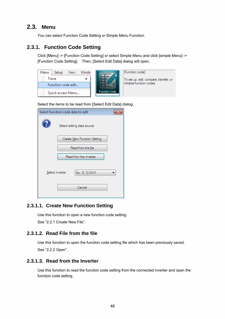
2.3. Menu
You can select Function Code Setting or Simple Menu Function.
2.3.1. Function Code Setting
Click [Menu] -> [Function Code Setting] or select Simple Menu and click [simple Menu] ->
[Function Code Setting]. Then, [Select Edit Data] dialog will open.
Select the items to be read from [Select Edit Data] dialog.
2.3.1.1. Create New Function Setting
Use this function to open a new function code setting.
See “2.2.1 Create New File”.
2.3.1.2. Read File from the file
Use this function to open the function code setting file which has been previously saved.
See “2.2.2 Open”.
2.3.1.3. Read from the Inverter
Use this function to read the function code setting from the connected inverter and open the
function code setting.
46

Chapter 2 Description of Functions
47
2.3.1.4. Edit List
This function allows you to list the function code setting values and setting ranges and edit them.
You can display the function codes by various classifications. [Edit] menu on Menu Bar is displayed only when the Edit List window opens.
・Function
・Change from Factory-set Values
・Contents of change (Blue)
・R/W failure (Pink)
・User Definition
・Communication Code
・Comparison Result
・Search Result
: Display the function codes by group.
: Displays the function codes of the setting values different from the factory-set values (excluding communication codes).
: Displays the edited function codes before written to the inverter.
: Displays the function codes which have failed to write to the inverter.
: The user can freely define the display items.
: Displays communication function codes only.
: Displays comparison results with the inverter or saved files only.
: Displays the execution result of [Edit] -> [Search].
Change of Setting Values:
You can select the function code data from Drop down Menu or Edit Window.
[Read] [Write] [Factory-set] [Func. Code set] [Function code info] [Initialize] [Advanced] [Print] [Comparison]
: Reads the function codes of the inverter selected in [Target Inverter] to the loader.
: Write the function codes of the loader to the inverter selected in [Target Inverter].
: Resets the selected function code to the factory-set value.
: Displays a dialog to edit the selected function code setting values.
: Displays the selected function code information.
: Initializes the function code setting values within the inverter.
: Displays a dialog to change the display items, function code attributes and printing setting.
: Prints the function code list selected in the tree in the left pane.
: Displays the comparison results with the saved data or the inverter data.
[Target Inverter]: Selects the target inverter to/from which data is read/written.
[Close]: Closes the Function Code Setting window.

[ 1 ] Read the function code setting values from the inverter
When you want to update the function code setting values read from the inverter
Click [Read] button to open the following dialog. Click [OK] to read the function code setting
values from the inverter again.
[ 2 ] Write the function codes from the loader to the inverter
To write the function codes to the inverter, use [Write] button displayed at the lower bottom of the
List Edit window appearing when editing function codes.
・Editing function code data (blue part) only
This function writes to the inverter only the setting values of the function codes that are
edited by the loader and have not been written to the inverter yet (displayed in blue).
・Registered user definition function code data only
This function writes only the setting values of the function codes registered to the user
definition on the List Edit window.
・Different from the factory function code data (with *) only
This function writes the setting values to the inverter only when those of function codes are
different from the factory-set values (excluding communication codes).
・All function code data
This function writes all the function code setting values in the table (excluding
communication codes).
48

Chapter 2 Description of Functions
49
[ 3 ] Change the setting value
The method to change the setting values varies depending on the function code.
(1) For the function codes which set speed, time, voltage or other numeric values, double-click
the field of the function code setting value to be changed. When [Set Values] dialog
appears, set the new value.
(2) For the function codes which set the code data values (for example, F00 Data Protection,
F01 Speed setting N1, F02 Operation method), click the field of the function code setting
value to be changed to check that button appears. Click the button to display the
selection menu which lists the function data that can be set and the meaning of each
function.
When the changed function code data has not been written to the inverter yet, the
data is displayed in blue.
When the changed function code data is different from the factory-set values, it is
marked with * leftmost on the Edit List window.

[ 4 ] Save
To save the function code settings opening on the loader, select [File] -> [Save] or [Save As …]
from Main Menu.
When selecting [Save] for the data for the first time, the following dialog will open in the same
manner as when selecting [Save As …].
Select [Save to …] and enter the file name under which the data is saved in [File Name]. Click
[Save] and confirm the entry.
50

Chapter 2 Description of Functions
51
After selecting [Save to …] and select the file type from [File Type], click [Save] to save the data
to the specified type of file.
*.FN1 : File format specific to the loader. Files in this format can be opened only on the
FRENIC Loader VG.
*.CSV : Comma delimiter format. Files in this format can be opened on Microsoft Excel or
equivalent. However, they cannot be opened on the general-purpose inverter loader.

[ 5 ] Print
The items selected from the tree in the left pane on the Edit List tab are target to be printed.
When selecting “Function” or “Code group” from the tree in the left pane on the Edit List tab,
function codes such as F, E, C, … or the group name will appear.
Click [Print] button displayed at the lower right of the [Edit List] window or select [File] -> [Print]
from Main Menu to display [Print] window.
Set the printer to be used, printing range
and number of copies and click [OK]
button.
How to set simple printing
To print only the function code numbers and setting values from among the items in the Edit List
window, click [Detail Setting] at the bottom of that window to open the Detail Setting dialog and
click [Print Setting]. When the [Print Setting] dialog appears, check the box of [Simple Printing]
and click [OK]. Note that this operation determines the setting only and does not actually print
the setting.
How to check the printed appearance before actually printing
Select [File] -> [Print Preview] from Main Menu.
52

Chapter 2 Description of Functions
53
[ 6 ] Compare
You can compare the function code setting data being edited to the data saved in the file or the
data set in the inverter that is selected in [Target Inverter] and display the results.
Compared with inverter Compare the function code setting data being edited to the function code setting data in the inverter.
Compared with File
Compare the function code setting data being edited to the function code setting data saved in the file.
Comparison results include ReadOnly
By marking the check BOX, ReadOnly function codes are included in the comparison target.
Comparison results include Communication code
By marking the check BOX, “communication code” function codes are included in the comparison target.
Close
Close the Select Comparison Target dialog.
* You should select the inverters to be compared in advance by clicking of [Select Inverter]
displayed at the bottom of the [Edit List] window.
By selecting “Comparison Results” in the tree in [Edit List], you can check the same contents.

[ 7 ] User Definition (Display desired function codes only)
Select the function code from the Edit List window and right-click it to display the window related
to “User Definition”. Select one of User Definition 1 to 5 and left-click it to register the selected
function code to “User Definition”.
Select any one of User Definition 1 to 5 from the tree in the left pane of the Edit List tab. Then,
the registered function codes will be listed.
54

Chapter 2 Description of Functions
55
To unregister the function code, select the target one and right-click it to display the window
related to “User Definition”. Then, select Reset User Definition and left-click it to unregister the
target function code from “User Definition”.
To unregister the function code from all the user definition groups (1 to 5), select “Relese User
Definition” and left-click it. Then, the function code will be unregistered from all the user
definition groups.
Name change of User definition
“User definition” name for the tree view can be Changed.
Select “User definition” on the tree view → Right click → Select "Name change", the character
input is possible.

Send Limited function code information
Only the function code selected by “User definition” displayed on the touch panel of the inverter.
By “User definition”, Select the function code to be limited display on the touch panel, Select
“User definition” on the tree view → Right click → Select "Send Limited function code
information".
Click the [OK] button, and send "Limited function code information" to the inverter.
If it is sent successfully, the following dialog will be displayed.
About the operation of the touch panel of the inverter, Refer to FRENIC-VG user's
manual Section 3.4.4.13 Limiting function codes to be displayed -- Menu #14 "LIMITED
FC".
56

Chapter 2 Description of Functions
57
[ 8 ] Search (Search function code terminologically)
Select [Edit] -> [Search] from Main Menu to display [Search] dialog.
From among words on the Edit List window, enter the key word to be searched, for example, speed or gain, and click [OK] button. If the entry is correct, the program automatically moves to [Search Results] in the tree in the left pane of the Edit List tab and the function codes including the entered key word are listed. The following figure shows the example of search results with “Speed” and “Gain” as the key word.
The search target range covers all items (changes, No., function code names,
setting values, etc.) However, the items set to be “hidden” by [Advanced] ->
[Display Item] are also included in the search target.
The contents of function code information are not included in the search target.

2.3.1.5. Auto Tuning
This function automatically measures the motor constants and saves them to the inverter as parameters of Motor 1 to Motor 3. Function code H01: Function to perform motor auto tuning using the tuning operation selection and display the tuning results.
・ Be sure to refer to the inverter user’s manual (FRN-VG1) "[ 4.3.5 ]
H01:tuning operation selection" before executing motor parameter auto tuning.
Select Tuning Operation Select which motor constant is to be tuned.
Current Process Display the tuning progression status.
Tuning Results Read the values before and after tuning and display them.
Motor Constant Read the motor constant set in the target inverter and display it.
Auto Tuning Start the tuning operation.
All Save Save the tuning results to the inverter EPROM.
Select Inverter Select the tuning target inverter.
Target Motor Display Motor 1 (M1), Motor 2 (M2) and Motor 3 (M3).
Select tuning operation
1: ASR (speed control) tuning (disabled during v/f control) (to be supported soon) 2: Motor constant tuning (for VG standard motors)
Motor stop status : R1, Lσ 3: Motor constant tuning (for non-standard motors) (disabled during v/f control)
Motor stop status : %R1, %X, exciting current, rated skidding, magnetic saturation coefficient, inductive voltage, secondary constant
4: Motor constant tuning (for non-standard motors) (disabled during v/f control) Motor stop status : %R1, %X Motor rotation status : Exciting current, rated skidding, magnetic status coefficient, inductive
voltage, secondary constant
When H01 = 1 or 4, the motor rotates during tuning. Make sure that there is no danger in rotating the motor. Injuries could occur.
58

Chapter 2 Description of Functions
59
2.3.1.6. File Information
This function displays the information which may affect the function codes. You can change
“Type”, “Voltage”, “Capacity” and “Definition File” as you want.
・ When reading the information codes from the inverter, the information on that inverter is
displayed.
・When creating a new code, the default information by machine type is displayed.
・If the VG loader free version is after "1.3.0.0", the ROM version of an inverter and the loading
information on an option card will also be displayed (not expressed as the function code data
of VG7 series).
When clicking on the file information [Change] button, the Settings dialog is displayed.

[ 1 ] Change models(VG7 → VG1, or VG1 → VG7)
To use the function code data read from the inverter of "FRENIC-VG7" for the inverter of
"FRENIC-VG", it is necessary to change a "model" into "VG1" from "VG7."
It is also the same as when using the function code data of "VG1" for "VG7."
The function code which exists in the model before conversion and does not exist in the model
after conversion is displayed on the dialog of a file reading error.
(The following figure is a case where it changes into "VG1" from "VG7".)
・ Change models (VG7 → VG1/VG1 → VG7) is only possible if the standard or
semi-standard(CC,SX,FB) products.
60

Chapter 2 Description of Functions
61
[ 2 ] Change of inverter capacity
Change the "capacity inverter" of the current function code list.
It will be changed into the value of the capacity as which the "preset value" of the
following function code and the "factory-shipments value" were chosen if "Inverter
capacity" is changed.
Function code
Name Function
code Name
F04 M1 Maximum Speed P15 M1 Magnetic Saturation Factor 1 F05 M1 Rated Voltage P16 M1 Magnetic Saturation Factor 2
F11 M1 Electronic Thermal Overload Protection (Detection level)
P17 M1 Magnetic Saturation Factor 3
F12 M1 Electronic Thermal Overload Protection (Thermal time constant)
P18 M1 Magnetic Saturation Factor 4
F26 Motor Sound (Carrier frequency) P19 M1 Magnetic Saturation Factor 5 P02 M1 Motor Selection P20 M1 Secondary Time Constant P03 M1 Rated Capacity P21 M1 Induced Voltage Factor P04 M1 Rated Current P22 M1 R2 Correction Factor 1 P05 M1 Number of Poles P23 M1 R2 Correction Factor 2 P06 M1 %R1 P24 M1 R2 Correction Factor 3
P07 M1 %X P25 M1 Exciting Current Correction Factor
P08 M1 Exciting Current/Magnetic Flux Weakening Current (-Id)
P33 M1 Maximum Output Voltage/ Maximum Voltage Limit
P09 M1 Torque Current H15 Restart Mode after Momentary Power Failure (Continuous running level)
P10 M1 Slip Frequency (For driving) H51 Observer (M1 load inertia) P11 M1 Slip Frequency (For braking) P12 M1 Iron Loss Factor 1 P13 M1 Iron Loss Factor 2 P14 M1 Iron Loss Factor 3

[ 3 ] Change of definition file
"Definition file" of the function code list is a one-to-one correspondence to the inverter ROM
version. The inverter ROM version is displayed in the "MAIN" on the fifth page of the Key pad of
the "5. Maintenance". (Refer to the operation manual "3.4.6 See maintenance information" of the
main part of an inverter for operation.)
When checking by a loader, Check an "M25 : Inverter ROM (main control) version" after reading
function code data from an inverter.
Shows the relationship between the "Inverter ROM version" and "Definition file" below.
Inverter ROM version Definition file Key pad display : H10011 Loader M25 display : 0x11
fnc_E_vg_1_0000b30a.csv
Key pad display : H10012 Loader M25 display : 0x12
fnc_E_vg_1_0000b33.csv
When changing the "definition file" of the current function code list, click [change] button and
displays the dialog "Open file."
62

Chapter 2 Description of Functions
63
Select the definition file that corresponds to the ROM version of the inverter. Then, click the
[Open] button.
The function code which exists in the definition file before conversion and does not exist in the
definition file after conversion is displayed on the dialog of a file reading error.
(The following figure is a case where it changes into "fnc_vg_1_0000b28a.csv" from
"fnc_vg_1_0000b33.csv".)
After changing the definition file, the setting of function code other than an error
reading the file is transferred intact.

2.3.2. Read and write (SF code) code safety functions
In order to conform to the functional safety standards, writing of code safety functions, you
must follow the instructions in the instruction manual of functional safety card.
For details, Refer to "INR-SI47-1541-JE OPC-VG1-SAFE instruction manual."
To read or write properly safety function codes, must be attached a functional safety
card (OPC-VG1-SAFE) to the inverter.
2.3.2.1. Read
Read of a safety function code can be performed by the same operation as read of the usual
function codes other than safety function code. (Refer to "2.3.1 Setting function code.")
2.3.2.2. Write (Unlock Functional safety password)
The writing of a safety function code needs to open the list display of a function code edit, and
unlock Functional safety password.
Select the "menu" -> "Functional safety", then the functional safety password entry screen is
opened.
Enter functional safety password the 8-digit characters (0 to 9, A to F). And, click the [OK] button.
The following dialog is displayed after the safe password is unlocked.
If Functional safe password is unlocked, the writing of a safety function code can carry out by the
same operation as the writing of the usual function codes other than the safety function codes.
(Refer to "2.3.1.4 List edit.")
64

Chapter 2 Description of Functions
65
Write the safety function codes after unlocking the functional safety password.
Safety function codes are only temporarily stored in the functional safety card
(OPC-VG1-SAFE). To save the safety function codes even when the power is turned
off, Select "Send all save command" when closing a list edit display. then click "OK".
Make a selection of whether to save settings to a file function code.
Completes the write operation (SF code) Safety functions codes using the loader.
Steps continue, refer to the "INR-SI47-1541-JE OPC-VG1-SAFE instruction manual".

2.3.2.3. Change of the functional safety password
Select the "menu" -> "Functional safety", then the functional safety password entry screen is
opened. And, Click the "Change" button.
In order to change the functional safe password, it is necessary to unlock the
password.
Enter functional safety password the 8-digit characters (0 to 9, A to F). Moreover, Enter the same
password also into the check of a new password. And, click the [OK] button.
If the input password is incorrect, the following dialog will be displayed.
Try again to enter the password.
After the successful password change, the following dialog will be displayed.
If the password is changed, it will return to the password lock state.
Write the safety function codes after unlocking the functional safety password again.
66

Chapter 2 Description of Functions
67
2.3.2.4. Safety function code initialization
To initialize the safety function code, open the edit screen of function code list, click the
[Initialization...] button, display the dialog of initialization selection. Then, select the
"Initialization the safety function code", click the [OK] button.
・Safety function code will be initialized even if the functional safety password is not
unlocked.
・When the safety function code are initialized, functional safety password will return to
the default setting.

2.3.3. Trace back
The operation status of an inverter can be observed as continuous waveform data.
The trace (shown below) provides the following three types functions.
The inverter operation status at occurrence of alarm is saved into the memory in the inverter as
waveform data. Trace Back is a function to read the saved waveform data and display it in the
graph. This is suitable to reference for troubleshooting.
The waveform data for the last 3 times including the latest alarm is saved. The waveform data
before the last 3 alarm is cleared.
Item Trace Back
Sampling time
Current detection, Electrical angle :
50us to 83.36us 100us to 166.72us
Others : 400us to 666.88us 1ms to 1s
Number of samplings
1100 point/Ch Before trigger :1000 point/Ch After trigger : 100 point/Ch
Number of displayed data
Analog : 8
Digital : 16
Number of selectable data
Analog : 26
Digital :
IN : 16 OUT : 16 x 8 blocks
Click [Menu] -> [Trace] -> [Trace Back] or select Simple Menu and click [Simple Menu] ->
[Trace Back] . Then, [Select Edit Data] dialog will open.
・ VG7 does not support the each trace.
・ When using trace, do not assign the function code (E01 to E13 : X function selection) "23 :
Write enable through link". When you assign 23, set to "Allow".
・ If you want to keep the data for the trace back, when you turn off the inverter power supply,
you need a battery for memory backup(22kW or less : Options, more than 30kW :
Standard accessories). For more information about the battery for memory backup, refer
to the inverter's instruction manual (FRN-VG1) "7.4.2 battery".
・ Trace back data saved in VG loader free version "1.1.0.0" can not be opened in earlier
versions loader. Do the version up to "1.1.0.0".
68

Chapter 2 Description of Functions
69
2.3.3.1. Trace back screen
The following shows the Trace Back window.
Sub window ・Monitor ・Graph position
adjustment ・Bank setting
Cursor position
Update Bank setting
Trace type display
Save trace data
Waveform monitor hardcopy
Trace operation status display
Cursor movement bar
Trace start/stop (not selectable)
Read waveform data
Waveform screen scroll bar
Cursor B
Cursor A
Waveform monitor
Re-read waveform data (not selectable)
Detail setting of each channel
Read function code at alarm

2.3.3.2. Read Waveform Data
You can read the trace back waveform data saved in the memory within the inverter.
Follow the steps below:
(1) Select [Bank Setting] tab.
(2) Select the alarm to be read from [Select Trace Back Data] up to the past three times and
click [Update] button.
(3) The alarm information saved in the inverter appears. If the contents are OK, click [Read
Waveform] button.
2.3.3.3. Read Function Code Settings (during Trace Back)
You can read the function code setting values when trace back waveform data is saved.
Follow the steps below:
(1) Select [Bank Setting] tab and select the alarm to be read from [Select Trace Back Data] up
to the past three times.
(2) Click [Update] button.
(3) The alarm information saved in the inverter appears. If the contents are OK, click [Read
Function Code] button.
70

Chapter 2 Description of Functions
71
2.3.3.4. Save Trace Data
To save each trace data, click [Save] button in the upper center in the trace window or select
[File] -> [Save As…].
When selecting [Save] for the data for the first time, the following dialog will open in the same
manner as when selecting [Save As …]. Select [Save to…] and [File Type], enter the file name
under which the file is saved in [File Name] and then click [Save] to determine the entry.
・ Trace back data is saved as *.TB1 file. (VG1)
・ The comma delimiter format is saved as *.CSV (VG1)
・ Trace data (Graph image) is saved as *.JPG file. (VG1)
2.3.3.5. Copy Trace Back Data Screen
To copy each trace data screen, click [Copy] button in the upper center in the trance screen.
Then, the screen is copied in the clip board. You can paste it onto the target document.

2.3.3.6. Print Trace Data
To print the trace data, set the trace screen in the active state and select [File] -> [Print]. The
trace data is printed as shown below.
72

Chapter 2 Description of Functions
73
2.3.3.7. Sub Window
[ 1 ] Cursor
Each box in the cursor sub window shows the channel setting values or status at each cursor
position.
Cursor values at analog Channel Settings on cursors
Cursor B Cursor A Cursor value monitor vertical slide bar
Cursor values at digital Channel
Select cursor display
Vertical: Two cursors (Cursor A, Cursor B, Cursors A and B) Horizontal: Two cursors (Cursor A, Cursor B, Cursors A and B) No display
Cursor value monitor
Analog channel: 8 channels Digital channel: 16 channels (You can display the hidden portions using the cursor value monitor vertical slide bar.)
Use the scroll bar to move to the waveform screen to be analyzed and click the point to be
observed in the graph. The cursor will move to that position. The cursor movement position is
the sampling point (time point) closest to the clicked point. The trace data of all channels on the
cursor appears in the measurement monitor.
Alternatively, you can move the cursor using the cursor movement bar or by dragging the mouse.
The cursor keys on the keyboard are also available.
However, while tracing, neither waveform screen nor cursor can be moved.

[ 2 ] Adjust graph position
Each box in the cursor sub window shows the channel setting values or status at each cursor
position.
You can use the boxes to adjust the graph position at each channel.
Select CH
Select the channel at which the graph position is adjusted.
Display
Display only the channels with checked mark. Hide the channels without checked mark.
Y axis display position
Set the Y axis display position of the selected channel. The upper end comes to 0 point (50 points each at grid).
X axis display position
Set the X axis display position of the selected channel. The leftmost end comes to 0 point (200 points each at grid).
Amplitude
Set the amplitude of the selected channel by magnification (in increments of 0.25).
Change the magnification using 0 point for reference.
As changing the amplitude input value, Scale/DIV value changes in unison and the graph display also changes according to the Scale/DIV value.
Scale Set the scale of the selected channel.
Enter the numeric value per DIV. This setting covers the analog setting channels only.
Graph position reset Reset the display position and amplitude setting of the selected channel to the initial values.
・Y axis display position: Ch1 = 50 and the value increments by +50 for the subsequent channels.
・X axis display position: Each Ch = 0
・Amplitude: 1.00
74

Chapter 2 Description of Functions
75
Optimize Y axis graph Arrange the Y axis display position and scale of the displayed channels without overlapping by channel. Reset the amplitude setting to the initial value.
・Y axis display position: Ch1=100 and the value increments by +100 for the subsequent channels.
・Scale: Set the scale value so that the maximum value can be within two grids. (Minimum unit: 50)
Detect waveform peak Move Cursor A to the maximum value of the selected channel automatically. If there are two or more peaks, the cursor moves to the earliest one.
Display range in one DIV Set the time to be displayed in one waveform monitor screen.
Ttrace back:
(1ms, 5ms, 10ms, 20ms, 50ms, 100ms, 200ms, 500ms, 1s, 2s, 5s, 10s, 20s, 30s, 1min, 5min, 10min)
Color setting
The color setting data is held. When obtaining the waveform, you can change the color setting.
Ch line
Line color and line type of the trace data of the selected channel
Cursor line A
Select the line color, line type and line thickness of Cursor line A.
Color line B
Select the line color, line type and line thickness of Cursor line B.
Trigger line
Select the line color, line type and line thickness of the trigger line.
Grid line
Select the line color, line type and line thickness of the grid line.
Graph background color setting
Select the waveform monitor background color.
The settings of the trace line of each CH are as below:
Color Type of line Thickness

2.3.3.8. Waveform Detail Settings
[ 1 ] Channel configuration setting
You can set the configuration of analog channels and digital channels to be traced. See [2] to
[5] for detail settings of each channel.
Target inverter
Select No. of the inverter registered in Connection Setting.
[ 2 ] Ch1 to Ch8 (analog setting)
You can set the analog channels.
76

Chapter 2 Description of Functions
77
Filter setting
You can do settings on filters of each channel.
Not used
Select this when no file is used.
Manual filter
Low path filter with filter time constant freely set.
Set the filter time constant using numeric values.
The setting range is from 1 [ms] to 1 [s].
(Common to historical/real time/trace back)
Trigger
In Trace-back, this setting is disabled.

Signal selection
The information items of the inverters that can be monitored are as shown below.
Analog channel signal selection items (trace back)
No Item Fast
/Lower Note
0 Speed setting 2 (before calculating acceleration/deceleration)
Lower
1 Speed setting 4 (ASR input) Lower
2 Speed detected value Lower
3 Torque command Lower 100%:Rated motor torque
4 Torque current command Lower 100%:Rated motor torque (P09,A11,A111)
5 Torque current calculation value Lower 100%:Motor rated torque current (P09,A11,A111)
6 Exciting current command Lower 100%:Motor rated excitation current (P08,A10,A110)
7 Exciting current detection Lower 100%:Motor rated excitation current (P08,A10,A110)
8 Magnetic-flux calculation Lower
9 Output current effective value Lower
10 Output voltage effective value Lower
11 DC intermediate voltage Lower
12 Motor temperature Lower
13 Line speed detected value Lower
14 U phase voltage detected value Lower 100%: Motor rated voltage (F05,A04,A104)
15 V phase voltage detected value Lower 100%: Motor rated voltage (F05,A04,A104)
16 W phase voltage detected value Lower 100%: Motor rated voltage (F05,A04,A104)
17 Cooling fin temperature Lower
18 PID output Lower
19 Torque bias Lower
20 Ai1 adjusted value Lower 10000/10V
21 Ai2 adjusted value Lower 10000/10V
22 U phase current detected value Fast 100%: Motor rated current (P04,A03,A103)
23 V phase current detected value Fast 100%: Motor rated current (P04,A03,A103)
24 W phase current detected value Fast 100%: Motor rated current (P04,A03,A103)
25 Electric angle Fast 8192/360°
26 Reserve 1 (No polarity) Fast * Do not set.
27 Reserve 1 (With polarity) Fast * Do not set.
28 Reserve 2 (No polarity) Fast * Do not set.
29 Reserve 2 (With polarity) Fast * Do not set.
30 Reserve 3 (No polarity) Lower * Do not set.
31 Reserve 3 (With polarity) Lower * Do not set.
If you choose a mixture of high-speed data and low-speed data, displays only part
of the low-speed data that was retrieved for the time axis to the length of the
high-speed data side.
78

Chapter 2 Description of Functions
79
[ 3 ] Ch1 to Ch16 (digital setting)
You can set the digital channels.
Trigger
In Trace-back, this setting is disabled.

Signal selection block
80
Output 6 Y terminal function (80 – 95) 1: Low speed
Signal selection block High speed / low speed
Input terminal (FWD, REV, X1 – X14, RST) 1: Low speed
Operation status 1: Low speed
Output terminal (Y1 – Y4, RY, X11 – X18) 1: Low speed
Output 1 Y terminal function (0 – 15) 1: Low speed
Output 2 Y terminal function (16 – 31) 1: Low speed
Output 3 Y terminal function (32 – 47) 1: Low speed
Output 4 Y terminal function (48 – 63) 1: Low speed
Output 5 Y terminal function (64 – 79) 1: Low speed
Signal selection
The information items of the inverters that can be monitored are as shown below.
Signal selection block “Input terminal (FWD, REV, X1 - X14, RST)” items
No Item 0 FWD (Forward run command) 1 REV (Reverse run command) 2 X1 3 X2 4 X3 5 X4 6 X5 7 X6 8 X7 9 X8
10 X9 11 X11 12 X12 13 X13 14 X14 15 RST (RESET command)
Signal selection block “Operation status” items
No Item 0 FWD (forward running) 1 REV (reverse running) 2 EXT (DC controlling, pre-exciting) 3 INT (inverter shutoff) 4 BRK (braking) 5 NUV (DC intermediate voltage established) 6 TL (torque limiting) 7 VL (voltage limiting) 8 IL (current limiting) 9 ACC (accelerating)
10 DEC (decelerating) 11 ALM (overall trouble) 12 - 13 - 14 - 15 -

Chapter 2 Description of Functions
81
Signal selection block “Output terminal (Y1 - Y5, Y11 - Y18)” items
No Item 0 Y1 1 Y2 2 Y3 3 Y4 4 RY 5 Y11 6 Y12 7 Y13 8 Y14 9 Y15
10 Y16 11 Y17 12 Y18 13 - 14 - 15 -
Signal selection block “Output 1 Y terminal function (0 - 15)” items
No Item 0 0: Inverter running [RUN] 1 1: Speed existence signal [N-EX] 2 2: Speed agreement signal 1 [N-AG1] 3 3: Speed arrival signal [N-AR] 4 4: Speed level detection 1 [N-DT1] 5 5: Speed level detection 2 [N-DT2] 6 6: Speed level detection 3 [N-DT3] 7 7: Stopping on undervoltage [LU] 8 8: Detected TRQ. polarity(Brake/Drive) [B/D] 9 9: Torque limiting [TL]
10 10: Torque detection 1 [T-DT1] 11 11: Torque detection 2 [T-DT2] 12 12: KEYPAD operation mode [KP] 13 13: Inverter stopping [STOP] 14 14: Operation ready output [RDY] 15 15: Magnetic-flux detection [MF-DT]
Signal selection block “Output 2 Y terminal function (16 - 31)” items
No Item 0 16: Motor M2 selected [SW-M2] 1 17: Motor M3 selected [SW-M3] 2 18: Brake release signal [BRK] 3 19: Alarm content [AL1] 4 20: Alarm content [AL2] 5 21: Alarm content [AL4] 6 22: Alarm content [AL8] 7 23: Cooling fan running [FAN] 8 24: Retry function running [TRY] 9 25: Universal DO [U-DO]
10 26: Cooling fin OH. forecast [INV-OH] 11 27: Synchronization completed [SY-C] 12 28: Service life forecast [LIFE] 13 29: Under acceleration [U-ACC] 14 30: Under deceleration [U-DEC] 15 31: Inverter OL. forecast [INV-OL]

82
Signal selection block “Output 3 Y terminal function (32 - 47)” items
No Item
0 32: Motor temperature OH. forecast [M-OH] 1 33: Motor OL. forecast [M-OL] 2 34: DB OL. forecast [DB-OL] 3 35: Transmission error [LK-ERR] 4 36: Load adaptive control under limit [ANL] 5 37: Load adaptive control under calc. [ANC] 6 38: Analog torque bias hold [TBH] 7 39:Custom Do1[C-DO1] 8 40:Custom Do2[C-DO2] 9 41:Custom Do3[C-DO3]
10 42:Custom Do4[C-DO4] 11 43:Custom Do5[C-DO5] 12 44:Custom Do6[C-DO6] 13 45:Custom Do7[C-DO7] 14 46:Custom Do8[C-DO8] 15 47:Custom Do9[C-DO9]
Signal selection block “Output 4 Y terminal function (48 - 63)” items
No Item
0 48:Custom Do10[C-DO10] 1 49: - 2 50: Z phase detect completed [Z-RDY] 3 51: Multiplex sys. com. establishment [MTS] 4 52: Multiplex sys. cansel response [MES-AB] 5 53: Master selected [MSS] 6 54: Multiplex system self-alarm [AL-SF] 7 55: Communication error stop [LES] 8 56: Overall alarm [ALM] 9 57: Slight trouble [L-ALM]
10 58: Maintenance forecast [MNT] 11 59: Brake transistor error [DBAL] 12 60: DC fan lock signal [DCFL] 13 61: Speed match 2 [N-AG2] 14 62: Speed match 3 [N-AG3] 15 63: Electric motor fan stop [MFAN]
Signal selection block “Output 5 Y terminal function (64 - 79)” items
No Item
0 64: Assign ready[AS-RDY] 1 65: - 2 66: Droop select response [DSAB] 3 67: TRQ.(current) ref. cansel response [TCL-C] 4 68: TRQ. limit 1 cansel response [F40-AB] 5 69: - 6 70: - 7 71: 73-on reference[PRT-73] 8 72: Y terminal test output ON [Y-ON] 9 73: Y terminal test output OFF [Y-OFF]
10 74: - 11 75: Clock battery life [BATT] 12 76: Tune in Pole position [TUN-MG] 13 77: SPGT battery warning [SPGT-B]
14 78: - 15 79: -

Chapter 2 Description of Functions
83
Signal selection block “Output 6 Y terminal function (80 - 95)” items
No Item
0 80: EN terminal detected circuit Err. [DECF] 1 81: EN terminal OFF [ENOFF] 2 82: Safety func. operating [SF-RUN] 3 83: - 4 84: STO test by safety func. [SF-TST] 5 85: - 6 86: - 7 87: - 8 88: - 9 89: -
10 90: - 11 91: - 12 92: - 13 93: - 14 94: - 15 95: -
・ Item of "Output terminal function 6 Y (80 - 95)" is only supported with the
inverter (VG1) rom number after H0020.

[ 4 ] Ch setting check (analog/digital)
The data set in each channel is listed. To reflect the setting, click OK button. To cancel the
setting, click Cancel button.
84

Chapter 2 Description of Functions
85
[ 5 ] Other settings (including sampling time setting)
In the Trace Back operation, you can change the sampling time only.
Sampling time setting
Sampling time setting is as shown below:
Sampling time setting Trace back Real-time Historical Time set 1 * ( 50.00 to 83.36us) Y : Fast N Y Time set 2 * (100.00 to 166.72us) Y : Fast N Y Time set 3 * (400.00 to 666.88us) Y : Lower N Y
1ms Y : Lower Y Y 2ms Y : Lower Y Y 5ms Y : Lower Y Y 10ms Y : Lower Y Y 20ms Y : Lower Y Y 30ms Y : Lower Y Y 50ms Y : Lower Y Y
100ms Y : Lower Y Y 200ms Y: Lower Y Y 500ms Y : Lower Y Y
1s Y : Lower Y Y
Y: Available, N: Not available
* The sampling time of the Time set 1 to 3 is varied by the setting of F26 : Motor sound(Carrier freq.).

Trigger position
In Trace-back, this setting is disabled.
Detection conditions
In Trace-back, this setting is disabled.
Set trace start date and time
In Trace-back, this setting is disabled.
Auto Save
In Trace-back, this setting is disabled.
Save data file size
In Trace-back, this setting is disabled.
86

Chapter 2 Description of Functions
87
2.4. Setup
2.4.1. Communication Setup
Refer to "1.4.4 Communication Settings".
2.4.2. Language
Sets the language of the loader. Select the [Setup] → [Language] → [Japanese] or [English],
then exit the loader.
You can select "English" and "Japanese" language.
After you have selected a language, exit the loader and restart the loader.
Switches to the selected language when restart the loader.
* If you do not exit the loader and restart the loader, language is not changed.

2.4.3. Date time
Allow the setting of the date and time of the inverter from the loader. Select the [Setup] → [Date
time], then setting dialog is opened.
Setting the date and time, perform from the following dialog.
* If you check the mark of "send the date and time of the OS", the date and time which is
managed by OS are sent to the inverter.
* If you remove the mark of "Send the date and time of the OS", any date and time are sent to
the inverter.
After mounting a memory backup battery (option for inverters of 22 kW or below,
attached as standard for those of 33 kW or above), set the date and time. When a
memory backup battery is not mounted, the calendar clock does not work
correctly. For more information about the battery for memory backup, refer to the
inverter's (FRN-VG1) instruction manual "7.4.2 Battery".
88

Chapter 2 Description of Functions
89
2.5. View
Selecting View | Toolbar | Main shows or hides the toolbar.
Selecting View | Status Bar shows or hides the status bar.
Toolbar
Status bar
2.5.1. Toolbar
The toolbar, which is usually located at the top of the Loader window, contains program icons
and allows you to access the desired function (program) with a single click.
2.5.2. Status bar
The status bar, which is usually located at the bottom of the Loader window (as shown above),
shows the running status of the currently selected inverter and the program execution status.

2.6. Window
Specify how to display the Loader windows on the Loader top window. This facility becomes
active only if any window is opened on the top window.
2.6.1. Cascade windows
Selecting Window | Cascade arrange multiple windows, overlapping each other. You can call an
inactive window up by clicking its title bar.
90

Chapter 2 Description of Functions
91
2.6.2. Tile windows
Selecting Window | Tile tiles multiple windows so that all windows are seen together.
2.6.3. Tile windows vertically
Selecting Window | Tile vertically tiles multiple windows vertically.

2.6.4. Arrange icons
Selecting Window | Arrange Icons arranges icons of the active windows or programs at the
bottom of the Loader top window.
2.7. Help
2.7.1. Version Information
Version Information shows the Loader version, copyright.
92

Chapter 3 Troubleshooting
93
Chapter 3 Frequently asked questions (FAQ)
3.1.1. Cannot communicate with inverter (Failed to get inverter information)
3.1.1.1. Message Manager not installed correctly
Message Manager is software that manages communication between the PC and inverter.
If Message Manager has not been installed correctly, your PC cannot communicate with the
inverter. The installation state can be checked in the task bar of Windows OS (see the Message
Manager icon sample given below). If no Message Manager icon is displayed in the task bar,
Message Manager has not been installed correctly.
Delete the folder (including its contents) named Fuji Electric Shared in the file path as shown
below, and then Uninstall Loader.
C:\Program Files\Common Files\Fuji Electric Shared
(In the file path shown above, "C" represents the drive letter of the partition or hard disk where
Windows is installed. If Windows is installed on a different drive in your system, replace "C" with
the letter corresponding to that drive.)
Message Manager icon sample
[ 1 ] Windows 7
Click here to show the hidden icon.
[ 2 ] Windows Vista/ Windows XP/ Windows 2000

3.1.1.2. USB driver not installed correctly
To communicate with the inverter via the USB connector, the USB driver (Loader USB device)
should be installed.
If the USB driver has not been installed correctly, Unknown device appears as shown below.
Installation finished successfully Installation failed
[ 1 ] Windows 7
Refer to Section 1.3.1.3. "Installing the USB driver, [ 1 ] Windows 7."
94

Chapter 3 Troubleshooting
95
[ 2 ] Windows Vista
Follow the wizard and install the USB driver as shown below.
From the Start menu, select Control Panel| Hardware and Sound | Device Managerto open Device Manager as shown at left. Right-click Unknown device to show the drop-down list. Click Update Driver Software… to proceed.
Click Browse my computer for driver software.

Click Browse….
In the folder in which FRENIC Loader has been installed, select ¥Driver¥MICREXSX and then click OK. The default folder is C: ¥Fuji Electric ¥FRENIC Loader3 EN¥Driver¥ MICREXSX when the OS drive is C.
To continue, click Next.
96

Chapter 3 Troubleshooting
97
Click Install this driver software anyway.
Installation starts.
Upon completion of the installation, the screen at left appears.
To exit the installation wizard and return to Windows, click Close.

[ 3 ] Windows XP
Follow the wizard and install the USB driver as shown below.
From the Start menu, select Control Panel| System | Hardware | Device Manager to open Device Manager as shown at left. On the sub-tree of Other devices, right-click USB Device to show the drop-down list. Click Update Driver… to start the update wizard of the hardware. Install the USB driver, referring to Section 1.3.1.3. "Installing the USB driver."
98

Chapter 3 Troubleshooting
99
3.1.1.3. USB driver installed correctly
Although the USB driver has been installed correctly, Loader cannot communicate with the
inverter. This problem is considered to be caused by installing the USB driver when Message
Manager is running.
In this case, Message Manager is no longer able to recognize the USB driver, so it is necessary
to quit both Loader and Message Manager and then start Loader again.
Quitting Message Manager
[ 1 ] Windows 7
Click this to display the hidden icons as shown below.
Right-click this icon to display Exit MessageManager, then click it. The confirmation window
appears. Click Yes to quit Message Manager.
[ 2 ] Windows Vista / Windows XP
Right-click the Message Manager icon to display Exit MessageManager, then click it. The
confirmation window appears. Click Yes to quit Message Manager.

100
3.1.1.4. USB communication impossible after the PC has gone standby or to sleep)
If Windows 7 or Windows Vista goes standby or to sleep, Loader cannot recognize the USB
driver so that it cannot communication with the inverter. Follow the instructions given below.
[ 1 ] Windows 7
Turn the PC power OFF and ON, then restart Loader.
Note: Unplugging and plugging the USB connector cannot enable the OS to recognize the USB
driver again.
[ 2 ] Windows Vista / Windows XP
Unplug and plug the USB connector, then restart Loader.
Note: Unplugging and plugging the USB connector enables the OS to recognize the USB driver
again.

Chapter 4 FRENIC Loader VG Standard Specifications
101
Chapter 4 Specifications
Item Specifications Remarks
Name of software FRENIC Loader VG
Supported inverter FRENIC-VG,FRENIC-VG7
No. of supported inverters
For USB connection: Only one inverter
For RS-485 connection: Up to 31 inverters
Recommended cable
USB : USB cable (mini B connecter)
RS-485 : Shielded twisted pair cable for long distance transmission
Refer to Section 1.2.3.2 "Communications support devices for RS-485"
OS *
Microsoft Windows XP(SP2 or later)
Microsoft Windows Vista
Microsoft Windows 7
***
Memory 512MB or more RAM 2GB or more is recommended
Hard disk 8.5MB MB or more free space
COM port RS-232C or USB Conversion to RS-485 communications required to connect inverters O
pera
ting
envi
ronm
ent
Monitor resolution 800 600 or higher XGA (1024 768)/32-bit color is recommended
COM port ** COM1 to COM255 PC COM ports assigned to Loader
Transmission rates **
USB connection : Fixed at 12 Mbps
RS-485 connection :
38400, 19200, 9600, 4800 and 2400 bps
38400bps or more is recommended.
Character length 8 bits Prefixed
Stop bit length 1 bit Prefixed
Parity Even Prefixed
No. of retries ** None or 1 to 3 to 10 No. of retry times before detecting communications error
Tra
nsm
issi
on r
equ
irem
ent
s
Timeout setting ** 100ms, 300ms, 500ms, 1.0s to 1.9s, 2.0 to 9.0s, 10.0 to 60.0s
This setting should be longer than the response interval time specified by the function code H39.
* Use on the PC downgraded to Windows XP from Windows7 or Windows Vista is not recommended.
** Bolded, underlined values are factory defaults.
*** Only support 32bit version of Windows XP, Windows Vista.
Support both 32bit and 64bit version of Windows 7.

Inverter Support Software
FRENIC Loader VG (WPS-VG1-STR)
Instruction Manual
First Edition, August 2012 3rd Edition, June 2013
Fuji Electric Co., Ltd.
The purpose of this instruction manual is to provide accurate information in handling, setting up and operating of the FRENIC-VG series of inverters. Please feel free to send your comments regarding any errors or omissions you may have found, or any suggestions you may have for generally improving the manual.
In no event will Fuji Electric Co., Ltd. be liable for any direct or indirect damages resulting from the application of the information in this manual.

Fuji Electric Co., Ltd.
Gate City Ohsaki, East Tower, 11-2, Osaki 1-chome, Shinagawa-ku, Tokyo, 141-0032, Japan
Phone: +81 3 5435 7058 Fax: +81 3 5435 7420
URL http://www.fujielectric.com/
2013-6