Flash Loader Development Guide
20
UFLX-4 1 Flash Loader Development Guide for IAR Embedded Workbench® This guide describes the flash loader mechanism in IAR Embedded Workbench. You will get information about how to use the flash loader in the IAR Embedded Workbench IDE. The guide also describes how to write and debug your own flash loader. Finally, the flash loader framework API functions are described in detail. Flash loader framework version 2. IAR, IAR Systems, IAR Embedded Workbench, C-SPY, visualState, From Idea To Target, IAR KickStart Kit, IAR PowerPac and the logotype are trademarks or registered trademarks owned by IAR Systems. All information is subject to change without notice. IAR Systems assumes no responsibility for errors and shall not be liable for any damage or expenses. © Copyright 2010 IAR Systems AB. Part number: UFLX-4. Fourth edition: January 2010
-
Upload
khangminh22 -
Category
Documents
-
view
4 -
download
0
Transcript of Flash Loader Development Guide

UFLX-4
1
Flash Loader Development Guide for IAR Embedded Workbench®
This guide describes the flash loader mechanism in IAR Embedded Workbench. You will get information about how to use the flash loader in the IAR Embedded Workbench IDE. The guide also describes how to write and debug your own flash loader. Finally, the flash loader framework API functions are described in detail.
Flash loader framework version 2.
IAR, IAR Systems, IAR Embedded Workbench, C-SPY, visualState, From Idea To Target, IAR KickStart Kit, IAR PowerPac and the logotype are trademarks or registered trademarks owned by IAR Systems.
All information is subject to change without notice. IAR Systems assumes no responsibility for errors and shall not be liable for any damage or expenses.
© Copyright 2010 IAR Systems AB. Part number: UFLX-4. Fourth edition: January 2010

Flash Loader Development Guide for IAR Embedded Workbench®
UFLX-4
2
Content
Introduction ..................................................................................................... 4
The process in brief ......................................................................................... 4
Flash loading components .............................................................................. 5
The flash loader ..................................................................................................................................................5
The flash memory device configuration files ...............................................................................................5
The flash memory system configuration file ...............................................................................................5
Flash memory concepts .................................................................................. 6
Using flash loaders ........................................................................................... 6
The flash programming process in more detail ........................................... 8
Creating a flash loader .................................................................................... 9
A simple example ........................................................................................................................................... 10
Building a flash loader .................................................................................................................................... 11
The flash memory device configuration file in detail ................................. 11
Mandatory elements ...................................................................................................................................... 12
Optional elements .......................................................................................................................................... 12
The flash memory system configuration file in detail ................................ 13
Mandatory elements ...................................................................................................................................... 13
Optional elements .......................................................................................................................................... 14
Framework reference ................................................................................... 14
FlashWrite ........................................................................................................................................................ 14
FlashErase ......................................................................................................................................................... 15
FlashInit ............................................................................................................................................................. 15
Advanced FlashInit functionality .................................................................................................................. 15
Overriding the page size ............................................................................................................................... 16
Overriding the buffer size ............................................................................................................................. 16
Overriding the block layout ......................................................................................................................... 16
Combining overrides ..................................................................................................................................... 17

Flash Loader Development Guide for IAR Embedded Workbench®
UFLX-4
3
Overriding the flash loader itself ................................................................................................................ 17
Flags.................................................................................................................................................................... 18
FlashChecksum ................................................................................................................................................ 18
FlashSignoff ....................................................................................................................................................... 18
Debugging ....................................................................................................... 18

Flash Loader Development Guide for IAR Embedded Workbench®
UFLX-4
4
Introduction
Many development boards use flash memory as the primary code memory. Normally, flash memory cannot be written directly from C-SPY when a program is to be downloaded and debugged, but must instead be flashed or programmed by a dedicated program—the flash loader—that executes on the target system.
Note: The flash loader mechanism is useful for any sort of memory that cannot be directly written to by the debugger, but instead has to be written to by a dedicated program that executes on the target system. Although, the flash loader is mostly used for flash memory, it can for example also be used for various forms of external RAM or disk-like storage devices. However, in the rest of this guide, flash memory is the assumed memory.
The process in brief
This is the problem: you need to download an application image to flash memory, but C-SPY can only download data directly to RAM.
To solve the problem, this procedure is performed:
1 Download a dedicated flash loader into RAM.
Part of RAM is also reserved for a download buffer.
2 The image is written to the RAM buffer.
3 The flash loader is started by C-SPY. The flash loader reads data from the RAM buffer and programs the flash memory.
Memory: Flash Flash loader running Image
Memory: Flash Flash loader RAM Buffer
Image
Memory: Flash RAM
Flash loader
Memory: Flash RAM
Image
?
Flash Loader Development Guide for IAR Embedded Workbench®
UFLX-4
5
Flash loading components
When using flash loading, there are two major components involved:
The flash loader program (in short, the flash loader)
The flash loader configuration files (the flash memory device configuration file and the flash memory system configuration file)
The flash loader
A flash loader is usually a rather small program which can program a certain flash memory device, or family of devices. The flash loader consists of a small set of functions, mainly for erasing or writing designated portions of the flash memory. C-SPY downloads this program into RAM (it must be linked to an address in RAM). To run the program, C-SPY positions the PC at one of the functions in the flash loader, writes data and directives for that function into a RAM buffer, and starts execution. When the function returns, execution will hit a breakpoint. C-SPY will then know that the function has finished and can proceed to make further calls to continue the flash loading process. In short, C-SPY calls functions in the flash loader.
The flash memory device configuration files
The flash memory device configuration file is an XML file (filename extension flash) which describes for C-SPY all relevant properties of a certain flash device. For example, the base address of the flash memory and details such as block and page sizes. The file also specifies which flash loader to use.
The flash memory system configuration file
The flash memory system specification file is an XML file (filename extension board) which describes for C-SPY the flash loading properties of the complete development board. This file can sometimes contain references to more than one flash device (through the appropriate .flash files), if the board has more than one type of flash memory that needs to be programmed separately in several passes. In this case, the .board file also specifies specific address ranges of the image which belongs to different flash devices.
One .board file fully specifies the information needed to perform flash loading for a specific board. Such a file can be prepared in advance for various development boards, and can also be created or modified in the project Options dialog box in the IAR Embedded Workbench IDE.
Note that a .board file does not necessarily describe everything about the flash memory of a certain board, but rather everything that is needed for using the board with a given IAR Embedded Workbench project. For example, if a board contains two flash devices, where one is used only for a boot loader and the other for the application, only one of them would be relevant for any given project. There would then be two different .board files, one for each kind of project.
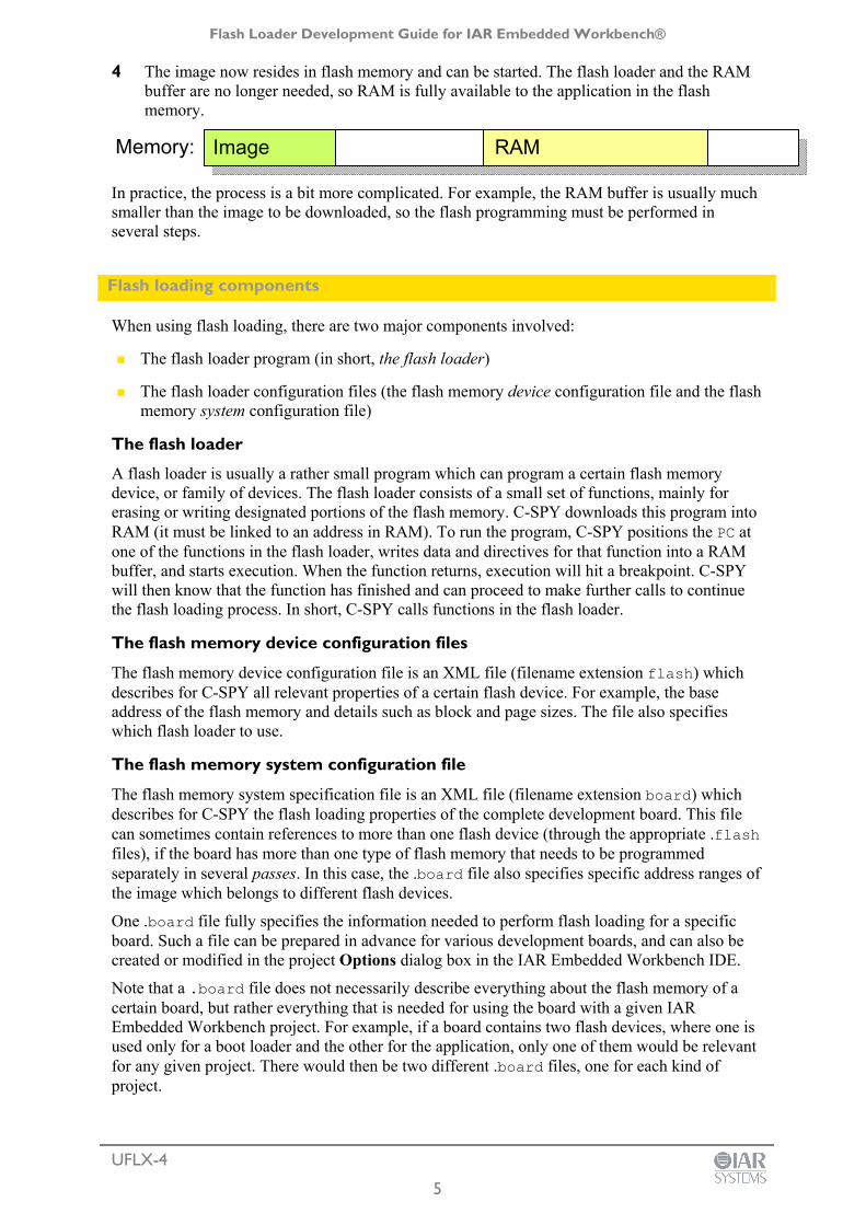
4 The image now resides in flash memory and can be started. The flash loader and the RAM buffer are no longer needed, so RAM is fully available to the application in the flash memory.
In practice, the process is a bit more complicated. For example, the RAM buffer is usually much smaller than the image to be downloaded, so the flash programming must be performed in several steps.
Memory: Image RAM

Flash Loader Development Guide for IAR Embedded Workbench®
UFLX-4
6
Flash memory concepts
To accommodate a large range of different flash devices, C-SPY uses a few concepts which detail the characteristics of flash devices.
Page A page is the smallest writable unit of the flash memory. Many flash devices cannot write less than for example 128 or 256 bytes in a single write operation. C-SPY will never request the flash loader to write anything smaller than a page, and uses padding if necessary to fill out a page. Of course, some flash devices have no such restrictions and can specify a page size of 1 byte.
Block A block is the smallest erasable unit of the flash memory. For example, a flash device with a 256-byte page size could still require that flash memory should be erased in 4-Kbyte chunks. The block size must always be a multiple of the page size. A flash device can consist of several blocks of different sizes. It can also lack such restrictions, in which case the block size would be the same as the page size.
Base address This is the start address of the flash memory device, when it is written. Some flash memories are simply memory mapped into a fixed address range and the base address is then the start of that range. Other flash memories are mapped into different addresses when being programmed and when the application is later executing. The base address is then the address where these memories are mapped when being programmed. Yet other flash memories are not memory mapped at all, but work more like external disk-like devices. The base address is then simply the preferred address to be used for the start of the memory when it is being programmed.
From the C-SPY perspective, a flash memory device starts at a given address and consists of a sequence of blocks (possibly of different sizes), each of which consists of a number of pages. The sequence can also contain gaps.
Using flash loaders
1 To activate flash loading using the IAR Embedded Workbench IDE, choose Project>Options>Debugger>Download.

Flash Loader Development Guide for IAR Embedded Workbench®
UFLX-4
7
Select the options Use flash loader(s) and Override default board file, and specify a flash memory system configuration file (.board). Use the browse button to select a predefined file suitable for your system. If no such file is available, you can create a new file or modify an existing file by clicking the Edit button.
2 The Flash Loader Overview dialog box is displayed. Note that if you edit one of the predefined files located in the IAR Embedded Workbench installation directory, you will subsequently be prompted to save the modified file to a different directory.
The dialog box displays one row of information for each separate flash memory device on the board, or for each flash loader pass. Click New to define a new pass, Edit to modify an existing pass, or Delete to remove a pass from the list.
3 Click the New or Edit button to display the Flash Loader Configuration dialog box.

Flash Loader Development Guide for IAR Embedded Workbench®
UFLX-4
8
The flash programming process in more detail
The two most important functions in the flash loader are called FlashWrite and FlashErase. The former writes or copies, a number of bytes (always a whole number of pages) of data from the RAM buffer to the flash memory. The latter erases one flash memory block. Using data from the image file, C-SPY repeatedly writes data to the RAM buffer and invokes the FlashWrite operation in the flash loader, with these constraints:
Writing is sequential, starting at the lowest address
The buffer will always contain an integral number of pages
The buffer is padded whenever the data does not naturally fill a page
Before the first page of any given block is written, the FlashErase function is invoked to erase that whole block.
In more detail, this is what happens:
1 The application to be downloaded to flash memory exists as an image file. A .board file is read by C-SPY and specifies one or more flash loading passes, one for each flash memory device on the board.
The Memory range section specifies which subset of the full debug file to be used for this pass. The Relocate section specifies an optional relocation of the debug file data before programming the flash. The Flash loader path text field specifies the .flash file for this particular flash memory device. The Extra parameters text field contains space-separated command line arguments to be passed to the flash loader (that is, argc/argv parameters to the FlashInit function). The Parameter descriptions text field displays information about the possible extra parameters that can be used, if any.
Click OK when you are finished.
4 The result is one .board file, which specifies the full flash loading sequence.

Flash Loader Development Guide for IAR Embedded Workbench®
UFLX-4
9
2 For each pass, a specific address range (or subset) of the original image file is specified. The image file is split accordingly into a separate image file for each pass. If there is only one pass, the original image file is used as is.
3 Each pass specifies a flash device file (a .flash file) which, among other things, designates a specific flash loader.
4 C-SPY downloads the flash loader of the current pass into RAM.
5 If the pass specifies an offset, all records from the image file are relocated accordingly.
6 C-SPY sets PC to FlashInit (or technically, to a label that will subsequently call FlashInit).
7 Parameters and data are written to the RAM buffer.
8 Execution is started, FlashInit is executed, and C-SPY regains control when execution hits a special breakpoint. FlashInit has the opportunity to override some information from the .flash file, such as the page size and block layout.
9 C-SPY partitions the data from the image file into suitable pieces with respect to the page and block layout of the flash memory, and to the size of the RAM buffer.
10 Before a certain block can be written to for the first time, the block must first be erased. In this case, the procedure continues with the next step. Otherwise, the procedure continues at step 13.
11 The RAM parameters are assigned the size of the block and its address.
12 C-SPY sets PC to FlashErase and starts the execution. When the function is done, the breakpoint is hit.
13 C-SPY writes some of the data to the RAM buffer.
14 C-SPY sets PC to FlashWrite and starts the execution. When the function is done, the breakpoint is hit.
15 If there is more data, the procedure returns to step 10.
16 If there are more passes, the procedure returns to step 3.
17 The debug information that corresponds to the final application is read.
18 C-SPY sets PC to the start address of the final application.
19 Optionally, execution starts at main.
Creating a flash loader
If there is no ready-made flash loader suitable for your target system, you can develop your own flash loader.
The flash loader is a native application that you can develop using IAR Embedded Workbench, and it consists of two parts:
The flash loader framework source code, supplied with IAR Embedded Workbench
The device-specific source code—normally, a small set of C functions—which you must implement.

Flash Loader Development Guide for IAR Embedded Workbench®
UFLX-4
10
A simple example
The following example shows the source code for a complete flash loader (except the source code for the framework), but with a flash programming algorithm which simply copies bytes from the RAM buffer to the destination address: #include "flash_loader.h" uint32_t FlashInit(void *base_of_flash, uint32_t image_size, uint32_t link_address, uint32_t flags) { return RESULT_OK; } uint32_t FlashWrite(void *block_start, uint32_t offset_into_block, uint32_t count, char const *buffer) { char *to = (char*)block_start + offset_into_block; while (count--) { *to++ = *buffer++; } return RESULT_OK; } uint32_t FlashErase(void *block_start, uint32_t block_size) { char *p = (char*)block_start; while (block_size--) { *p++ = 0; } return RESULT_OK; }
Framework: C-SPY uses labels and variables defined here to interact with the flash loader.
Device specific code: Called by framework. FlashWrite() FlashErase() FlashConfigure()
Framework: C-SPY uses labels and variables defined here to interact with the flash loader.
Device-specific code: Called by framework. FlashWrite() FlashErase() FlashInit()

Flash Loader Development Guide for IAR Embedded Workbench®
UFLX-4
11
The parameters to FlashWrite and FlashErase, in combination with the flash memory base address given in FlashInit, fully specify the addresses of the portions of the flash memory to be programmed. Thus, a given flash loader can be used for any number of different flash devices, with different total size, page size, or block layout, provided that they all employ the same flash programming algorithm. The flash memory device configuration file (.flash) is used for specifying such variations between flash memory devices.
The reference section at the end of this document describes all framework functions in detail.
Building a flash loader
As already mentioned, the flash loader is built from some framework source code and some device-specific source code that you provide. The following files are part of the framework and should be available for use in your flash loader: flash_loader.c Framework source code. This file should be part of your flash
loader project, but should be used as is and not modified. flash_loader.h Framework declarations, for example the C prototypes of your
source code. flash_loader_extra.h Additional framework declarations, rarely needed by your
source code. flash_loader_asm.s Low-level, processor-specific framework source code. Note
that this file might have a different filename extension depending on your microcontroller. This file should be part of your flash loader project, but should be used as is and not be modified.
Template\flash_config.h Template for your own configuration file. You should make a copy of it and edit your copy according to the guidelines available in the file.
Copies of the files and examples of flash loaders can be found in target\src\flashloader in the installation directory. When you build the flash loader there are some considerations to make, for example, the flash loader must be linked to an address in RAM, and the flash loader does not contain an entry point like a main function.
The flash memory device configuration file in detail
As already mentioned, the flash memory device configuration file (.flash) is an XML file that specifies the properties of a certain flash memory device, including which flash loader to be used for programming it. This is an example of such a file: <?xml version="1.0" encoding="iso-8859-1"?> <flash_device> <exe>$TOOLKIT_DIR$\config\flash\P8_family\flash_p8.out</exe> <flash_base>0x20000</flash_base> <page>256</page> <block>2 0x100</block> <block>3 0x200</block> </flash_device> The file consists of elements (some mandatory and some optional), where each element consists of tags and some contents.

Flash Loader Development Guide for IAR Embedded Workbench®
UFLX-4
12
Mandatory elements exe Specifies the path to the flash loader. The path can contain an argument
variable such as $TOOLKIT_DIR$. flash_base Specifies the base address of the flash memory when it is written to. page Specifies the flash memory page size. block Specifies the block layout of the flash memory using one or more of this
element, in order. Each element contains a decimal count value followed by a block size in hexadecimal form. The element sequence should fully specify the sequence of blocks for the flash memory. In the above example, the flash device contains two blocks of size 0x100, followed by three blocks of size 0x200, for a total size of 0x800.
Optional elements gap The specified block sequence can also contain one or more gap
elements intermixed with block elements. Each gap element contains a gap size in hexadecimal form. The gap size specifies an area within the extent of the flash memory device which does not contain flash memory. C-SPY will issue an error for any data in the image file that would be placed in a gap.
macro Specifies the path to a C-SPY macro file, which will be loaded in conjunction with downloading the flash loader. There are three C-SPY macro functions that will be called automatically if they are defined in this macro file.
execUserFlashInit is called immediately before loading the flash loader.
execUserFlashReset is called immediately after the reset that follows the loading.
execUserFlashExit is called immediately after flash loading has finished, but before the flash loader is unloaded.
filler Specifies a decimal number which is the byte value to use when padding write operations to page boundaries. The default value is 255 (0xFF).
checks If this element contains 0, the error return values from the flash loader functions (such as FlashWrite) are not checked. Disabling these checks will lead to slightly increased performance. Note that this element should only be used when you know from experience that these checks are superfluous.
aggregate If this element contains 1, C-SPY will try to use the RAM download buffer more efficiently by combining write operations to more than one block. This is a useful performance optimization if, and only if, block sizes are significantly smaller than the RAM buffer, so that at least two (or preferably more) blocks will fit in the download buffer. This element requires that the flash loader can program more than one block in a single operation.
args Passes arguments to the flash loader, in the form argc/argv to the FlashInit function. The parameters should be separated by the newline character.
args_doc Specifies descriptions of the parameters accepted by the flash loader FlashInit function. The descriptions are displayed in the Flash

Flash Loader Development Guide for IAR Embedded Workbench®
UFLX-4
13
Loader Configuration dialog box in the IAR Embedded Workbench IDE. This element can contain multiple lines of text, separated by the newline character.
Often, a certain microprocessor is available in many variants, each with the same type of flash memory but with different sizes and addresses, and possibly block layouts. For such a scenario, only one flash loader is needed, but several .flash files. Consider the following table which describes some variants of the hypothetical P8 processor family:
Variant Flash size (Kbyte)
Flash base address
Flash block layout Configuration file
P8_1 1 0x10000 4 * 0x100 flash_p8_1.flash
P8_2a 2 0x10000 8 * 0x100 flash_p8_2a.flash
P8_2b 2 0x10000 4 * 0x200 flash_p8_2b.flash
P8_4a 4 0x10000 8 * 0x100
4 * 0x200
flash_p8_4a.flash
P8_4b 4 0x20000 16 * 0x100 flash_p8_bb.flash
In this example, there would be five different .flash files, but each of the files would specify the same flash loader, because each of the processor variant has a flash memory device of the same type, requiring the same flash programming algorithm.
The flash memory system configuration file in detail
As already mentioned, the flash memory system configuration file (.board) is an XML file that specifies the properties of a certain development board with respect to flash memory devices. The file consists of elements, where each element consists of tags and some contents. On the highest level, the file describes one or more passes, each specified by a pass element. This is an example of such a file, which specifies two programming passes for two different flash memory devices. <?xml version="1.0" encoding="iso-8859-1"?> <flash_board> <pass> <loader>$TOOLKIT_DIR$\config\flash\flash_p8_2a.flash</loader> <range>CODE 0x20000 0x207ff</range> <abs_offset>0x10000</abs_offset> </pass> <pass> <loader>$TOOLKIT_DIR$\config\flash\flash_p8_2b.flash</loader> <range>CODE 0x20800 0x21000</range> <abs_offset>0x10000</abs_offset> </pass> <ignore>CODE 0x22000 0x220ff</ignore> </flash_board> Each pass element contains additional elements, some mandatory and some optional, as follows:
Mandatory elements loader Specifies the path to the flash memory device configuration file
(.flash). The path can contain an argument variable such as

Flash Loader Development Guide for IAR Embedded Workbench®
UFLX-4
14
$TOOLKIT_DIR$.
Optional elements range Specifies the subset of the original image file, which should be
programmed in this particular flash memory device. The contents of this element is a segment name (usually CODE), followed by the address of the first and last byte of the range in hexadecimal form. If there is only one flash memory device, the default range is the range of the whole image file. If there is more than one pass, this element is mandatory because C-SPY needs to know how to partition the image.
abs_offset This element is used for writing the image to flash memory at an address different from the address where the image was placed by the linker. For example, if the flash memory device is mapped into the memory at a certain address when it is programmed and then later remapped to another address when executing, we would need to use an appropriate offset to compensate when programming the flash memory. This element specifies an absolute address where the first byte of the image file should be placed.
rel_offset This element is similar to the abs_offset, but specifies a relative offset with which each record in the image file should be displaced before writing to flash. The offset can be either a positive or a negative number. You must use either abs_offset or rel_offset as both cannot be used for the same pass.
flash_base Specifies the base address of the flash memory when it is written to. If this element is included, it overrides the corresponding element in the .flash file.
args Passes arguments to the flash loader, in the form argc/argv to the FlashInit function. The parameters should be separated by the newline character. The parameters are appended to any parameters specified in the .flash file. If the flash loader handles parameters appropriately, these parameters can thus override the ones specified in the device configuration file.
ignore Specifies a subset of the original image file which should not be subject to flash loading. This element consists of a segment name (usually CODE), followed by the address of the first and last byte of the range, in hexadecimal form. The element can be used for example, when parts of the original image shall be downloaded to RAM or when parts are already present in some ROM. The element can be repeated to specify several ranges. Note that this element is specified on the same level as the pass elements.
Framework reference
The following functions must be implemented by a flash loader:
FlashWrite uint32_t FlashWrite(void *block_start, uint32_t offset_into_block, uint32_t count, char const *buffer);

Flash Loader Development Guide for IAR Embedded Workbench®
UFLX-4
15
Parameters: block_start Points to the first byte of the block into which this write
operation writes. offset_into_block Specifies how far into the current block that this write
operation shall start. The absolute address of the first byte to write is block_start + offset_into_block.
count Specifies the number of bytes to write. buffer A pointer to the buffer that contains the bytes to write.
Return value: Either RESULT_OK or RESULT_ERROR.
FlashErase uint32_t FlashErase(void *block_start, uint32_t block_size); Parameters: block_start Points to the first byte of the block to erase. block_size Specifies the size of the block, in bytes.
Return value: Either RESULT_OK or RESULT_ERROR.
FlashInit #if USE_ARGC_ARGV uint32_t FlashInit(void *base_of_flash, uint32_t image_size, uint32_t link_address, uint32_t flags, int argc, char const *argv[]); #else uint32_t FlashInit(void *base_of_flash, uint32_t image_size, uint32_t link_address, uint32_t flags); #endif;
As shown above, there are two different prototypes for FlashInit, determined by the value of the pre-processor macro USE_ARGC_ARGV which you must specify in flash_config.h. Use the flavour with arguments if you need that extra flexibility. The actual arguments can be specified in the .flash file, or in the project Options dialog box in the IAR Embedded Workbench IDE.
Parameters: base_of_flash Points to the first byte of the whole flash memory range. image_size Specifies the size of the whole image that is to be written to
flash memory, in bytes. link_address Specifies the original link address of the first byte of the
image, before any offsets or, if there are multiple passes, the first byte of the subset of the image used for this pass. Not all flash loaders need this parameter.
flags Specifies optional flags. See below for details.
Return value: Either RESULT_OK or RESULT_ERROR, but also other return values can be used (see below for details).
Advanced FlashInit functionality
The FlashInit function is the first function called in the flash loader. As such, it provides an opportunity to provide extra information to C-SPY before the actual flash programming starts.
Flash Loader Development Guide for IAR Embedded Workbench®
UFLX-4
16
To provide extra information you must override the properties specified in the .flash file. Use a set of macros which are defined in the optional header file flash_loader_extra.h. Internally, this functionality requires access to a structure variable defined in the framework, which is used for passing information back and forth between C-SPY and the flash loader. The name of the variable is theFlashParams and is also declared in the header file, like this: typedef struct { uint32_t base_ptr; uint32_t count; uint32_t offset_into_block; void *buffer; uint32_t block_size; } FlashParamsHolder; extern FlashParamsHolder theFlashParams;
Overriding the page size
To override the page size, use the SET_PAGESIZE_OVERRIDE macro and set the bit OVERRIDE_PAGESIZE in the return value, like in this example: uint32_t FlashInit(void *base_of_flash, uint32_t image_size) { SET_PAGESIZE_OVERRIDE(128); // New page size return RESULT_OK | OVERRIDE_PAGESIZE; }
Overriding the buffer size
The download buffer size is normally determined by the position of two labels, FlashBufferStart and FlashBufferEnd, which get their positions at link time. To use the same flash loader for multiple devices which only differ in RAM size, the flash loader can override the buffer size (if the flash loader can determine the actual amount of RAM available). Use the SET_BUFSIZE_OVERRIDE macro and set the OVERRIDE_BUFSIZE bit in the return value from the FlashInit function. Do not try to decrease the buffer size. uint32_t FlashInit(void *base_of_flash, uint32_t image_size) { SET_BUFSIZE_OVERRIDE(0x1000); // New buffer size return RESULT_OK | OVERRIDE_BUFSIZE; }
Overriding the block layout
Normally, the .flash file specifies the block layout of the flash memory, using the block and gap tags. Sometimes, it is more practical to let the flash loader determine the block layout by quering the flash memory device itself in some fashion. If the flash loader wants to specify a layout, it should put the layout description in the flash download buffer and add the constant OVERRIDE_LAYOUT to the result code of FlashInit. A pointer to the download buffer is available using the OVERRIDE_BUFFER_PTR macro. The syntax is the same as in the file (a decimal block count followed by a hexadecimal block size), except that blocks are separated by comma, like in this example: uint32_t FlashInit(void *base_of_flash, uint32_t image_size) { strcpy(OVERRIDE_BUFFER_PTR, "2 0x100,7 0x200,7 0x1000"); return RESULT_OK | OVERRIDE_LAYOUT; }
Flash Loader Development Guide for IAR Embedded Workbench®
UFLX-4
17
To specify a gap, use a block count of 0. For example, "0 0x1000" specifies a gap of 0x1000 bytes.
Combining overrides
All of the above overrides can be combined. This example uses all overrides: uint32_t FlashInit(void *base_of_flash, uint32_t image_size) { strcpy(LAYOUT_OVERRIDE_BUFFER, "2 0x100,7 0x200,7 0x1000"); SET_PAGESIZE_OVERRIDE(128); // New page size SET_BUFSIZE_OVERRIDE(0x1000); // New buffer size return RESULT_OK | OVERRIDE_LAYOUT | OVERRIDE_PAGESIZE | OVERRIDE_BUFSIZE; };
Overriding the flash loader itself
The most drastic override is if the flash loader detects that the flash memory device does not match the capabilities of the flash loader, typically, that the wrong flash loader has started. This would normally be the consequence of some misconfiguration, and many flash loaders cannot even check this. But if the flash loader can detect the flash memory device at runtime, it has an opportunity to report the device to C-SPY and let C-SPY try again with another flash loader. This is done by putting a device identifier in the buffer and returning the special result code RESULT_OVERRIDE_DEVICE, for example like this: uint32_t FlashInit(void *base_of_flash, uint32_t image_size) { if ('unexpected flash device was found') { strcpy(OVERRIDE_BUFFER_PTR, "P8_16c"); return RESULT_OVERRIDE_DEVICE; } }
Note that the replacement flash loader is specified indirectly, as a flash memory device identifier. This identifier is read by C-SPY and is then used as the key in a table lookup to locate another flash loader. The table is constructed like this:
C-SPY finds all files with the filename extension flashdict in the $TOOLKIT_DIR\config\flashloader directory (and all subdirectories).
Each such file can contribute a portion of the table. The file should look like this: <?xml version="1.0" encoding="iso-8859-1"?> <loaders> <loader> <key>P8_16c</key> <path>$TOOLKIT_DIR$\config\flashloader\P8\f_p8_16c.flash</path> </loader> <loader> <key>P8_16d</key> <path>$TOOLKIT_DIR$\config\flashloader\P8\f_p8_16d.flash</path> </loader> </loaders> If the key is found anywhere in the table, the newly specified flash memory configuration file is used instead.

Flash Loader Development Guide for IAR Embedded Workbench®
UFLX-4
18
Flags
The flags parameter to FlashInit specifies optional flags bits. Only one flag value is currently defined. FLAG_ERASE_ONLY If this bit is set (when the expression (flags &
FLAG_EASE_ONLY) is non-zero), the flash loader has been invoked with the sole purpose of erasing the whole flash memory. If the flash device supports a one-step global erase function, it can be invoked directly from FlashInit, which should return the constant RESULT_ERASE_DONE. Otherwise, C-SPY will continue and invoke the FlashErase function for each block.
FlashChecksum
This is an optional function. You need to implement it if you want to enable checksum verification of the download flash memory contents, but you can implement it with a helper function from the framework (Crc16), like this: OPTIONAL_CHECKSUM uint32_t FlashChecksum(void const *begin, uint32_t count) { return Crc16((uint8_t const *)begin, count); }
Note the OPTIONAL_CHECKSUM macro. This is needed to make sure that this optional function and its framework wrapper are both included in the linking of the flash loader.
FlashSignoff
This is an optional function. You can implement it if you need to perform some cleanup after flash loading has finished. The function is called after the last call to FlashWrite (or after FlashChecksum if it exists). OPTIONAL_SIGNOFF uint32_t FlashSignoff() { return RESULT_OK; }
Note the OPTIONAL_SIGNOFF macro. This is needed to make sure that this optional function and its framework wrapper are both included in the linking of the flash loader.
Debugging
Because the flash loader is not a standalone program, with a main function, it cannot very easily be debugged.
While developing the flash loader, it is probably best to first make a very simple test harness containing a main function which simply calls FlashInit, FlashWrite, and FlashErase with suitably prepared, or generated, data and parameters. This program should be linked to a RAM address and can then be debugged as a normal application until the basic flash programming code seems correct.
Then, when the flash loader is used in the actual flash loading process, you will get some help from a log file which describes the flash loading process in some detail. When you start a debug session which uses flash loaders, a log file named flash0.trace is generated in the project

Flash Loader Development Guide for IAR Embedded Workbench®
UFLX-4
19
directory ($PROJ_DIR$), the directory where the active project file (ewp) resides. This file is only generated if a file with that name already exists in that directory. To enable trace output, simply create an empty file named flash0.trace, and trace output will be produced every time a debug session with flash loading is started, until the file is removed again.
If there are multiple flash loading passes, multiple trace files will be generated (flash0.trace, flash1.trace, etc.), but you only need to create flash0.trace to enable tracing.
This is an example log file: File generated Wed Dec 09 14:53:55 2009 Pass 1 of 1 Starting fragment-style flashloader pass. FlashInitEntry is at 0x2000012D FlashWriteEntry is at 0x20000135 FlashEraseWriteEntry is at 0x2000013D FlashBreak is at 0x20000128 FlashBufferStart is at 0x20000200 FlashBufferEnd is at 0x2000BD94 FlashChecksumEntry not found FlashSignoffEntry not found page size is 2 (0x2) filler is 0xff buffer size is 48020 (0xbb94) SimpleCode records (after offset): Record 0: @ 0x8000000 [53284 (0xd024) bytes] 0x8000000 - 0x800d023 [0 4 0] Base of flash at 0x8000000 ->init : base @ 0x8000000, image size d024 Args: (argc = 1) C:\sample\blabla.out timing(init): 0.0156 (CPU) 0.0500 (elapsed) Transaction list: Transaction @ 0x8000000 (0xb800 bytes) 23 packet(s). Will erase 23 block(s): 0: 0x8000000 (0x800 bytes) 1: 0x8000800 (0x800 bytes) 2: 0x8001000 (0x800 bytes) 3: 0x8001800 (0x800 bytes) 4: 0x8002000 (0x800 bytes) 5: 0x8002800 (0x800 bytes) 6: 0x8003000 (0x800 bytes) 7: 0x8003800 (0x800 bytes) 8: 0x8004000 (0x800 bytes) 9: 0x8004800 (0x800 bytes) 10: 0x8005000 (0x800 bytes) 11: 0x8005800 (0x800 bytes) 12: 0x8006000 (0x800 bytes) 13: 0x8006800 (0x800 bytes) 14: 0x8007000 (0x800 bytes) 15: 0x8007800 (0x800 bytes) 16: 0x8008000 (0x800 bytes) 17: 0x8008800 (0x800 bytes) 18: 0x8009000 (0x800 bytes) 19: 0x8009800 (0x800 bytes) 20: 0x800a000 (0x800 bytes) 21: 0x800a800 (0x800 bytes) 22: 0x800b000 (0x800 bytes) Transaction @ 0x800b800 (0x1824 bytes) 4 packet(s). Will erase 4 block(s):

Flash Loader Development Guide for IAR Embedded Workbench®
UFLX-4
20
0: 0x800b800 (0x800 bytes) 1: 0x800c000 (0x800 bytes) 2: 0x800c800 (0x800 bytes) 3: 0x800d000 (0x800 bytes) ->multi_erase: 23 blocks (0xb8 bytes in buffer) [0 0 0] timing(erase): 0.1716 (CPU) 0.5460 (elapsed) ->write : @ 0x8000000 (0xb800 bytes, offset 0x0 into block @ 0x8000000) [0 4 0] timing(write): 0.0000 (CPU) 1.3960 (elapsed) ->multi_erase: 4 blocks (0x20 bytes in buffer) [0 b8 0] timing(erase): 0.0000 (CPU) 0.1310 (elapsed) ->write : @ 0x800b800 (0x1824 bytes, offset 0x0 into block @ 0x800b800) [1b 68 1b] timing(write): 0.0000 (CPU) 0.2200 (elapsed) Duration: 1.28 (CPU) 4.34 (elapsed) of which on target: 0.1872 (CPU) 2.3430 (elapsed) Flash loading pass finished
First, the file lists the addresses of some key functions in the flash loader, and some basic properties of the flash memory and flash loader. Then, the data records from the image to be downloaded are listed. The main part is the sequence of write and erase operations, each containing the start address, the size, and at the end of the line, the three first bytes of the data for that operation. Optionally, at the end of the list file, checksum operations are listed.