Flash Lighting Space Sampling
13
Flash Lighting Space Sampling Matteo Dellepiane, Marco Callieri, Massimiliano Corsini, Paolo Cignoni, and Roberto Scopigno Visual Computing Lab, ISTI-CNR, Pisa, Italy [email protected] http://vcg.isti.cnr.it Abstract. Flash light of digital cameras is a very useful way to picture scenes with low quality illumination. Nevertheless, especially low-end cameras integrated flash lights are considered as not reliable for high quality images, due to known artifacts (sharp shadows, highlights, un- even lighting) generated in images. Moreover, a mathematical model of this kind of light seems difficult to create. In this paper we present a color correction space which, given some information about the geometry of the pictured scene, is able to provide a space-dependent correction of each pixel of the image. The correction space can be calculated once in a lifetime using a quite fast acquisition procedure; after 3D spatial calibra- tion, obtained color correction function can be applied to every image where flash is the dominant illuminant. The correction space presents several advantages: it is independent from the kind of light used (pro- vided that it is bound to the camera), it gives the possibly to correct only determinate artifacts (for example color deviation) introduced by flash light, and it has a wide range of possible applications, from image enhancement to material color estimation. Keywords: Color, shading, shadowing, and texture. 1 Introduction The vast diffusion of digital cameras started a revolution in the way photogra- phy is used to measure the appearance of real-world objects. However, despite the significant improvements of this kind of devices, there are several issues, regarding the correctness of the acquired data, that need a careful evaluation. Particularly, the setup and calibration of the lighting environment is often one of the most limiting aspects for simplified appearance acquisition techniques. All cameras are equipped with a flash: this tool can provide a practical, easy, cheap controlled lighting environment. Unfortunately, built-in flashes usually produce a variety of undesirable effects, like uneven lighting (overexposed in the near field and dark in the distance), highlights and distracting sharp shadows. Moreover, ”white balance” setting for flash is not effective because it applies the same correction throughout the image. More interesting results could be obtained by knowing the geometry of the scene, and using a model of the behavior of flash light. However, a mathematical modeling of flash light spatial behavior can be A. Gagalowicz and W. Philips (Eds.): MIRAGE 2009, LNCS 5496, pp. 217–229, 2009. c Springer-Verlag Berlin Heidelberg 2009
-
Upload
independent -
Category
Documents
-
view
0 -
download
0
Transcript of Flash Lighting Space Sampling

Flash Lighting Space Sampling
Matteo Dellepiane, Marco Callieri, Massimiliano Corsini, Paolo Cignoni,and Roberto Scopigno
Visual Computing Lab, ISTI-CNR, Pisa, [email protected]
http://vcg.isti.cnr.it
Abstract. Flash light of digital cameras is a very useful way to picturescenes with low quality illumination. Nevertheless, especially low-endcameras integrated flash lights are considered as not reliable for highquality images, due to known artifacts (sharp shadows, highlights, un-even lighting) generated in images. Moreover, a mathematical model ofthis kind of light seems difficult to create. In this paper we present a colorcorrection space which, given some information about the geometry ofthe pictured scene, is able to provide a space-dependent correction ofeach pixel of the image. The correction space can be calculated once in alifetime using a quite fast acquisition procedure; after 3D spatial calibra-tion, obtained color correction function can be applied to every imagewhere flash is the dominant illuminant. The correction space presentsseveral advantages: it is independent from the kind of light used (pro-vided that it is bound to the camera), it gives the possibly to correctonly determinate artifacts (for example color deviation) introduced byflash light, and it has a wide range of possible applications, from imageenhancement to material color estimation.
Keywords: Color, shading, shadowing, and texture.
1 Introduction
The vast diffusion of digital cameras started a revolution in the way photogra-phy is used to measure the appearance of real-world objects. However, despitethe significant improvements of this kind of devices, there are several issues,regarding the correctness of the acquired data, that need a careful evaluation.Particularly, the setup and calibration of the lighting environment is often oneof the most limiting aspects for simplified appearance acquisition techniques.
All cameras are equipped with a flash: this tool can provide a practical, easy,cheap controlled lighting environment. Unfortunately, built-in flashes usuallyproduce a variety of undesirable effects, like uneven lighting (overexposed in thenear field and dark in the distance), highlights and distracting sharp shadows.Moreover, ”white balance” setting for flash is not effective because it applies thesame correction throughout the image. More interesting results could be obtainedby knowing the geometry of the scene, and using a model of the behavior of flashlight. However, a mathematical modeling of flash light spatial behavior can be
A. Gagalowicz and W. Philips (Eds.): MIRAGE 2009, LNCS 5496, pp. 217–229, 2009.c© Springer-Verlag Berlin Heidelberg 2009

218 M. Dellepiane et al.
hard to be obtained, because of the large variety of camera/flash models, and theirregular spatial light distribution produced by the flash reflectors and lenses.
For these reasons we propose Flash Lighting Space Sampling (FLiSS), a cor-rection space where a correction matrix is associated to each point in the camerafield of view. Once that basic information about the geometry of the scene isknown, the proposed structure permits to correct each pixel according to the po-sition of the corresponding point in space. This structure proves to be simple andeffective, and it has several advantages, which will be presented and discussedduring the analysis of results and the concluding remarks.
2 Related Work
The work proposed in this paper shares some aspects with various subjects, suchas computational photography, image enhancement and lighting modeling andestimation. Some of the most interesting and related works will be presented.
Flash/No-Flash Digital Photography. The use of flash/no-flash pairs to en-hance the appearance of photographs is a relatively recent research topic whereseveral interesting works appeared. The continuous flash [17] was a seminal work,where flash and no-flash pairs were combined to create adjustable images. Twoalmost contemporaneous papers [9,23] proposed techniques to enhance detailsand reduce noise in ambient images, by using flash/no-flash pairs. These worksprovide features for detail transfer, color and noise correction, shadows and high-lights removal. While the systems are not completely automatic, very interestingresults can be easily obtained. The goal of a more recent work [1] is to enhanceflash photography by introducing a flash imaging model and a gradient projec-tion scheme, to reduce the visual effects of noise. Flash/no-flash pairs are usedby [21] to detect and remove ambient shadows.
Color constancy and white balance. White balance is a key issue in thecontext of the color constancy problem, that studies the constancy of perceivedcolors of surfaces under changes in the intensity and spectral composition of theillumination. Several works in this field rely on the assumption that a singleilluminant is present: the enhancement of photos can be based on geometricmodels of color spaces [10], statistical analysis of lights and colors [11] or naturalimages [12], study of the edges of the image [25].
Another group of papers deals with mixed lighting conditions. Methods canbe semi-automatic [20] or automatic. Automatic methods usually work well un-der quite strong assumptions, like hard shadows and black-body radiators lights[19] or localized gray-world model [8]. A very recent work [18] proposes a whitebalance technique which renders visually pleasing images by recovering a setof dominant material colors using the technique proposed by [22]. One of theassumptions is that no more than two light types (specified by the user) illumi-nate the scene. Most of the cited works share some of the main hypotheses of our

Flash Lighting Space Sampling 219
method. Nevertheless, the knowledge of some information about the geometry ofthe scene eliminates the need for other restricting assumptions (such as smoothillumination, gray-world theory, need of user interaction).
Illumination estimation and light models. The works in the field of illu-mination estimation have two principal aims: the estimation of the lighting ofan environment [7,24] or the measure of the characteristics of a luminary. Ourwork is more related to the second group.
One of the first attempts to model both the distant and the near behavior of alight source is the near-field photometry approach of Ashdown [2]. Near-field pho-tometry regards the acquisition of a luminary by positioning a number of pinholecameras (or moving a single camera) around it, and measuring the incident irradi-ance on a CCD sensor. The results are mapped onto an hemicube that representsthe final model of the luminary acquired. Heidrich et al used a similar method[16] by moving the camera on a virtual plane and representing the light sourceswith a Lumigraph [14]. This representation was named canned light source. Morerecently, Goesele et al. [13] improved the near-field photometric approach using acorrection filter to compensate the fact that a digital camera is not a real pinholecamera. Our approach recalls near-field photometry; the main difference is thatwe estimate the data to “correct” the effect of the light source on known colors,instead of building a model of the light source of interest.
3 Definition of FLiSS
The aim of our work is to build a spatial color correction function that associatesa specific color correction procedure to each point in the camera frustum space.We call this particular data structure color correction space. Such an approachallows to override the limitations assumed in most of the color correction ap-proaches [3,4], that is that the illumination is constant, or easily model-able,across the scene. Our main assumptions are: flash light can be considered thedominant illumination in the scene; the light interaction can be described usingjust sRGB space (we do not account full spectra data); surfaces are non-emitting.These hypotheses are common among existing techniques which deal with singleillumination, and they cover most of the real cases. Typically, the color calibra-tion of digital photographs consists in taking a snapshot of a pre-defined colorreference target, such as a Macbeth ColorCheckerTM or an AGFA IT8TM, placednear the subject of interest, and estimating the parameters of a transformationthat maps the colors of the reference target in the image into its real colors.
A quite simple to model the correction is a linear affine transformation c′ =Ac + B. Obviously, due to the nonlinear nature of image color formation, thiskind of correction is a rough approximation and many other approaches could beused [3,4]. Moreover, the correction is effective for the image parts that are close(and with a similar illumination) to the reference target. On the other hand, inpractice, this simple and compact approach works reasonably well in most cases.

220 M. Dellepiane et al.
The linear transformation can be written as a 4 × 3 matrix:
⎛⎝
R′
G′
B′
⎞⎠ =
⎡⎣
c11 c12 c13 c14
c21 c22 c23 c24
c31 c32 c33 c34
⎤⎦
⎛⎜⎜⎝
RGB1
⎞⎟⎟⎠ (1)
In the following we refer to this matrix as the color correction matrix C andto its elements as the correction parameters. We explain how we estimate C inSection 4.
Roughly speaking, the parameters of C have the following meaning: (c11, c22,c33) are related to the change in contrast of the color; (c12, c13, c21, c23, c31, c32)are related to the color deviation caused by the color of the flash light (if theflash is purely white light, these components tend to zero); (c14, c24, c34) arerelated to the intensity offset. We use the term contrast in the sense that themultiplication for the coefficients expands the range of values of the channels.
Given the assumptions above, we can finally define FLiSS. Flash LightingSpace Sampling is a color correction space where a color correction matrix isassociated to each point in a camera frustum. The correction space will be cal-culated starting from several sampled points in the camera space. The process ofcorrecting an image will, for each pixel in the image, use the appropriate correc-tion matrix according its corresponding position in the camera space. Due thecontinuous nature of the correction space, the correction will prove to be reliableeven without a precise digital model of the scene, so that an approximate recon-struction such as the ones generated, for example, by stereo matching could beused as well.
4 Acquisition Procedure and Data Processing
The aim of our work was to try to build a procedure which could be used in ageneral case, without using prototypal or expensive devices. The computation ofour color correction space is necessary only once (or very few times) in a cam-era lifetime. But even with this assumption, it was important to define some assimple and fast as possible acquisition procedures. Hence, we decided to samplethe camera space view frustum by taking flash lighted photos of a small colortarget, calculating the correction matrix in those points and subsequently build-ing the entire space by interpolation. We performed the acquisition with threedifferent models of digital cameras, shown in Figure 1(left). These models arerepresentative of three categories of non-professional cameras: compact, digitalSLR (single-lens reflex) and digital SLR with external flash.
As a color target we used a Mini Macbeth ColorChecker; its size (about3.5′′ × 2.5′′) allows the assumption that the light variation across it is negli-gible. To sample the view frustum of the camera we sliced it with several planesof acquisition at different distances, moving the Mini Macbeth in different posi-tions for each plane. We divided a distance range between 50 and 220 cm in 7planes, with 25 positions for each plane, as shown in Figure 1(right). The color

Flash Lighting Space Sampling 221
Fig. 1. Left: Digital cameras used for light space sampling. Right: the scheme of ac-quisition for flash space sampling, with a snapshot of the acquisition setup.
target was placed on a tripod, and always faced towards the camera. For eachposition multiple snapshots were taken, in order to deal with the known vari-ability of flash behavior, and keeping a fixed exposure time and aperture duringthe entire procedure.
The snapshots were acquired in sRGB RAW format to avoid any other internalprocessing by the digital camera, except for the Casio compact camera, withwhich we were forced to use JPEG images. The acquisition procedure of all theneeded images for each model took a couple of hours. The processing of acquireddata was subdivided in two main phases. In the first one we calibrated all theacquired images, using the color target reference. In the second phase we builtthe color correction space through parameters interpolation. Figure 2 shows aschematization of the entire data processing.
Color CalibrationThe color calibration was done using the calibration model explained in Sec-tion 3. The parameters of the matrix C were estimated by solving a linear systemwith the cij as unknowns. Our parameter estimation algorithm takes inspirationfrom the RANSAC approach.
Since four colors could be sufficient to write a system with 12 equations and12 unknowns, several random combinations of colors are used to find the bestsolution in terms of quality. The quality of the color correction is evaluated
Fig. 2. Data processing. Left: The acquired color targets are calibrated generatinga set of color correction matrices, and then interpolated on each plane. Right: Eachcorrection parameter is interpolated to fill the whole camera space.

222 M. Dellepiane et al.
considering the CIELab distance [6] between the real colors and the correctedones. Hence, after extracting the Mini Macbeth in a semi-automatic way andsegmenting each color patch, several permutations of the colors are tried in orderto find the best estimation in terms of quality. This robust approach producesbetter results from a perceptual point of view than a standard least squareapproach.
After calibration, each image is associated to: the 12 parameters of the matrixC, the position of the Mini Macbeth relative to the camera view and the distanceat which the image has been taken. Since several shots of the same position of thetarget are taken, obtained values are the means of all the obtained estimations.Before this, the data are further processed with a statistical analysis [15] toremove the outliers from the acquired data.
Data InterpolationStarting from a set of color correction matrices for several points in the space, wecould try either to fit a mathematical function or to calculate the intermediatecolor correction matrix through interpolation. Here, we opt for interpolation,leaving the first approach as an interesting direction of future research. Given apoint p in camera space, we calculate the corresponding color correction matrixas the linear interpolation in the squared distance between the camera center Oand the point p in the following way:
Cij(p) = Cij(p1) + (d2 − d21)Cij(p2) − Cij(p1)
d22 − d2
1
(2)
where C(x) indicates the color correction matrix at the point x; p1 and p2 arethe intersection points between the line starting from O and passing through p.These points lie on the acquisition plane immediately before and after p (Figure2right); d1, d and d2 are the distances between the point O and p1, p and p2.
Since C(p1) and C(p2) are not known in advance, they have to be estimated toevaluate (2). In fact, only few positions on the acquisition plane are measured:hence another interpolation is required. For this planar interpolation we useradial basis method, with gaussians centered on each sample: standard deviationσ defines how much each sample influences the neighbors. In formulas:
Cij(p) =
N∑i=1
Cij(Pi) exp[− (p − Pi)2
σ2
]
N∑i=1
exp−[(p − Pi)2
σ2
] (3)
where N is the total number of samples for the plane and Pi are the positionsof samples.
In conclusion, in order to calculate a color correction matrix for a point in thecamera space, we first need to calculate two linear interpolations in the acquisi-tion planes, then a linear squared interpolation for the final result.
Flash Lighting Space Sampling 223
Regarding the practical implementation, the pre-computed interpolationplanes are stored as floating point textures plus, for each texture, some ad-ditional information (the distance from the camera center and a scale factor).With this representation, the correction algorithm can be entirely implementedon the GPU, and the pre-computation of the interpolation planes reduces theevaluation of Cij(p1) and Cij(p2) in (2) to two texture lookups.
5 Data Analysis
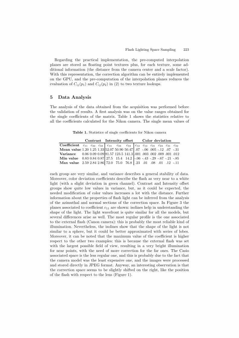
The analysis of the data obtained from the acquisition was performed beforethe validation of results. A first analysis was on the value ranges obtained forthe single coefficients of the matrix. Table 1 shows the statistics relative toall the coefficients calculated for the Nikon camera. The single mean values of
Table 1. Statistics of single coefficients for Nikon camera
Contrast Intensity offset Color deviation
Coefficient c11 c22 c33 c14 c24 c34 c12 c13 c21 c23 c31 c32
Mean value 1.20 1.25 1.33 52.07 50.90 50.47 .07 -.06 .005 -.12 .07 -.31Variance 0.06 0.09 0.09 81.57 123.5 141.3 .001 .003 .002 .009 .001 .012Min value 0.83 0.84 0.87 27.5 15.4 14.2 -.06 -.43 -.29 -.67 -.21 -.85Max value 2.59 2.84 2.86 72.0 75.0 76.8 .23 .01 .08 .01 .12 -.11
each group are very similar, and variance describes a general stability of data.Moreover, color deviation coefficients describe the flash as very near to a whitelight (with a slight deviation in green channel). Contrast and Intensity offsetgroups show quite low values in variance, but, as it could be expected, theneeded modification of color values increases a lot with the distance. Furtherinformation about the properties of flash light can be inferred from the analysisof the azimuthal and normal sections of the correction space. In Figure 3 theplanes associated to coefficient c11 are shown: isolines help in understanding theshape of the light. The light wavefront is quite similar for all the models, butseveral differences arise as well. The most regular profile is the one associatedto the external flash (Canon camera): this is probably the most reliable kind ofillumination. Nevertheless, the isolines show that the shape of the light is notsimilar to a sphere, but it could be better approximated with series of lobes.Moreover, it can be noted that the maximum value of the coefficient is higherrespect to the other two examples: this is because the external flash was setwith the largest possible field of view, resulting in a very bright illuminationfor near points, with the need of more correction for the far ones. The Casioassociated space is the less regular one, and this is probably due to the fact thatthe camera model was the least expensive one, and the images were processedand stored directly in JPEG format. Anyway, an interesting observation is thatthe correction space seems to be slightly shifted on the right, like the positionof the flash with respect to the lens (Figure 1).

224 M. Dellepiane et al.
Fig. 3. Azimuthal and normal plane for parameter c11 in camera space. (Left) Nikoncamera. (Center) Canon camera. (Right) Casio camera.
6 Results
In order to evaluate the results of the correction introduced by FLiSS, we createda setup where the color values in selected regions were known in advance: thescene was formed by a series of identical objects, set at different distances fromthe camera. The reference objects were simple structures (formed by bricks ofdifferent colors) of LEGO DUPLO c©, whose size and color are known to be prac-tically identical for all components. The reference RGB color value of each brickwas calculated by calibration with the Mini Macbeth. Seven blocks of LEGO c©bricks were put in a setting shown in Figure 4(left), and the corresponding 3Dmodel of this configuration was created. This scene has the advantage that, inevery single photos, identical elements are present in different parts of the imageand at different distances in space. Images were aligned to the 3D model usinga registration tool: thus color correction was performed on each pixel which wasframing a structure.
One possible criticism to our work could be: would a simple model, for ex-ample a point light, be enough to provide a good correction? For this reason,we modeled the flash as a point light and we corrected the same images usingthis model. We obtained an acceptable estimation of the intensity of the light,by modeling the light degradation with a quadratic law and taking into accountthe knowledge of the distance of each pixel in the scene, and its reference color:we used this light estimation to correct the color value. Results of corrections onone of the images are shown in Figure 4(left): the original, the Fliss corrected,

Flash Lighting Space Sampling 225
and the point light corrected images are shown. While in both cases the colorsacross the scene seem similar, obtained color values are clearly different betweenthe two results. In order to check the accuracy of color correction we measuredthe perceptual distance between produced colors and the previously calculatedreference colors. We chose the CIE76 Delta E measure, which is the Euclideandistance between the CIELAB values associated to two colors. If Delta E issmaller than one, colors are perceived as identical; for values smaller than eight-ten, the colors can be considered as very similar.
Figure 4 shows the results of the calculation of these distance values. The topboxes display reference colors, then for each piece (each line is associated to thepiece number indicated in Figure 4 left) the three columns represent the averagecolor value for original, Fliss corrected and point light corrected image. The DeltaE value for each color shows the distance with respect to the reference. It is quiteclear that, although producing similar colors, the point light correction returnsresults which are different respect to the reference: only red color is accuratelycorrected. Slight improvements are introduced only for distant objects. In orderto achieve better results, probably a different modeling for each channel wouldbe necessary. On the contrary, Fliss correction proves to be very reliable, withan average Delta E value which is always smaller than ten. Only in the case ofblock number 1 the correction is less effective: this can be due to the fact thatthe object is out of focus, or the color in the original image may be saturated.
A second validation experiment was performed in order to show that thecorrection introduced by Fliss ca be reliable also with low quality geometricinformation of the scene. We reconstructed the geometry of a common scenestarting from a few photos, using the Arc3D web service [26]. Figure 5 shows the
Fig. 4. Left: example of images used for validation: top, original; center, Fliss corrected;bottom, point light model corrected. Only the Lego blocks part of the image wascorrected. Right: correction accuracy estimation: for each Lego block, average color andDelta E value (respect to reference) in original (left column), Fliss corrected (centercolumn) and Point Light corrected (right column) images are shown
226 M. Dellepiane et al.
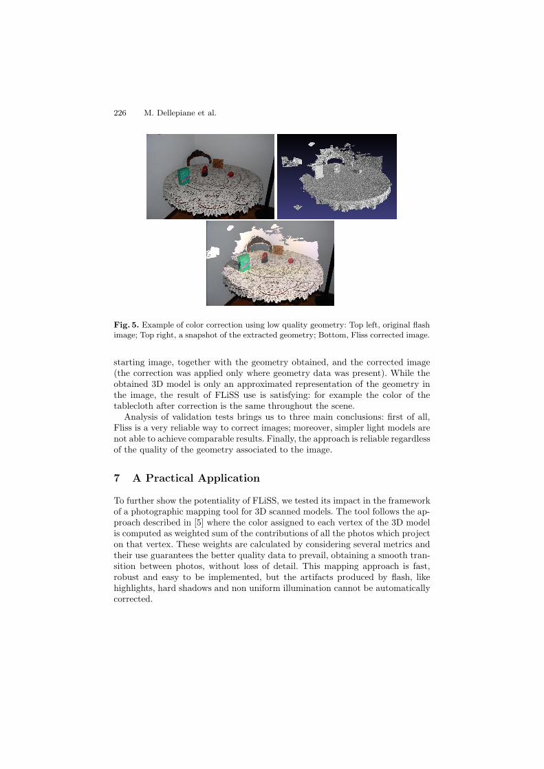
Fig. 5. Example of color correction using low quality geometry: Top left, original flashimage; Top right, a snapshot of the extracted geometry; Bottom, Fliss corrected image.
starting image, together with the geometry obtained, and the corrected image(the correction was applied only where geometry data was present). While theobtained 3D model is only an approximated representation of the geometry inthe image, the result of FLiSS use is satisfying: for example the color of thetablecloth after correction is the same throughout the scene.
Analysis of validation tests brings us to three main conclusions: first of all,Fliss is a very reliable way to correct images; moreover, simpler light models arenot able to achieve comparable results. Finally, the approach is reliable regardlessof the quality of the geometry associated to the image.
7 A Practical Application
To further show the potentiality of FLiSS, we tested its impact in the frameworkof a photographic mapping tool for 3D scanned models. The tool follows the ap-proach described in [5] where the color assigned to each vertex of the 3D modelis computed as weighted sum of the contributions of all the photos which projecton that vertex. These weights are calculated by considering several metrics andtheir use guarantees the better quality data to prevail, obtaining a smooth tran-sition between photos, without loss of detail. This mapping approach is fast,robust and easy to be implemented, but the artifacts produced by flash, likehighlights, hard shadows and non uniform illumination cannot be automaticallycorrected.

Flash Lighting Space Sampling 227
Fig. 6. Top: an example of color correction on a flash photograph: the original image(left); a normalized map of the offset correction on the image (center); the correctedimage (right). Bottom: a colored 3D model, visualized with no illumination (only colorvalues assigned to vertices). Color correction OFF in left image, ON in right one.
We selected a test set of objects (colored Nativity statues of different heightsand materials), to assess the quality and the impact of the flash light correction.We generated the 3D models of the statues with a Minolta 3D scanner and thephotos with the Nikon D40x and flash light as the principal illuminant. Imageswere aligned on the models, and each image of the set was corrected using FLiSS:an example of color correction on a single image is shown in Figure 6.
With an accurate estimation of light position (obtained with a simple proce-dure involving a simple LEGO c© calibration rig), it was also easy to detect thezones where shadows and highlights were present, and remove them by using theredundancy of data provided by the images of the set.
The effects of color correction on a final 3D Model can be seen in Figure6: the model on the right, obtained with color correction, appears much more”flat” with respect to the model produced without color correction and artifactremoval (left). In conclusion, these images show one of the possible applicationsof our color correction space, where the effectiveness of results is strengthenedby the fact that acquisition of color information was fast and easy.

228 M. Dellepiane et al.
8 Concluding Remarks and Future Work
We presented FLiSS, a novel structure to apply a spatial color correction onimages taken using flash light. The method requires basic information of thegeometry of the scene, and it’s able to automatically correct the color values inthe image. FLiSS needs to be estimated only once in a camera lifetime, and thiscalibration procedure is adequately fast and easy. FLiSS has several advantages:it is robust and flexible, and although its use best fits with the case of flash light,the structure can be used with any kind of light which is bound to the camera.Future work can include both improvements in the proposed structure and ex-ploitation of its possible uses. Regarding the first issue, further effort could beput in trying to find even simpler acquisition procedures, or reduce the num-ber of samples positions. Regarding possible future applications, FLiSS could beused in the context of image enhancement, by applying for example only part ofthe elements of the correction matrix to obtain visual pleasantness or enhancedreadability. Moreover, by working on different flash-lighted images and extract-ing the local illumination data from the FLiSS, it should be possible to recoversimple models of the optical properties of a surface. Finally, while the simplepoint light model for flash exhibits strong limitations, FLiSS data could be usedto obtain a more complex model that could approximate in a very accurate waythe behavior of the flash light.
Acknowledgements. This work was partially funded by EU IST IP 3DCO-FORM and Tuscany Regional Project STArT. We would like to thank MichaelGoesele for his kind support, Giuliano Kraft and Francesco Dellepiane for pro-viding us the hardware for experimental studies.
References
1. Agrawal, A., Raskar, R., Nayar, S.K., Li, Y.: Removing photography artifacts us-ing gradient projection and flash-exposure sampling. ACM Tr. on Graphics 24(3),828–835 (2005)
2. Ashdown, I.: Near-Field Photometry: Measuring and Modeling Complex 3-D LightSources. In: ACM SIGGRAPH 1995 Course Notes, pp. 1–15 (1995)
3. Barnard, K., Cardei, V., Funt, B.: A comparison of computational color constancyalgorithms. I: Methodology and experiments with synthesized data. Image Pro-cessing, IEEE Trans. 11(9), 972–984 (2002)
4. Barnard, K., Martin, L., Coath, A., Funt, B.: A Comparison of ComputationalColor Constancy Algorithms Part II: Experiments With Image Data. IEEE Trans.on Image processing 11(9), 985 (2002)
5. Callieri, M., Cignoni, P., Corsini, M., Scopigno, R.: Masked photo blending: map-ping dense photographic dataset on high-resolution 3d models. Computer & Graph-ics 32(4), 464–473 (2008)
6. Commission Internationale de l’Eclairage (CIE). Colorimetry CIE 15 (2004)7. Debevec, P.: Rendering synthetic objects into real scenes: bridging traditional and
image-based graphics with global illumination and high dynamic range photogra-phy. In: SIGGRAPH 1998, pp. 189–198. ACM Press, New York (1998)

Flash Lighting Space Sampling 229
8. Ebner, M.: Color constancy using local color shifts. In: Pajdla, T., Matas, J(G.)(eds.) ECCV 2004. LNCS, vol. 3023, pp. 276–287. Springer, Heidelberg (2004)
9. Eisemann, E., Durand, F.: Flash photography enhancement via intrinsic relighting.In: ACM Trans. on Graphics, vol. 23, ACM Press, New York (2004)
10. Finlayson, G.D., Hordley, S.D.: Improving gamut mapping color constancy. IEEETrans. on Image Processing 9(10), 1774–1783 (2000)
11. Finlayson, G.D., Hordley, S.D., Hubel, P.M.: Color by correlation: A simple, unify-ing framework for color constancy. IEEE Trans. on Pattern Analysis and MachineIntelligence 23(11), 1209–1221 (2001)
12. Gijsenij, A., Gevers, T.: Color constancy using natural image statistics. In: Int.Conf. on Comp. Vision and Pat. Recogn., Minneapolis, USA, June 2007, pp. 1–8(2007)
13. Goesele, M., Granier, X., Heidrich, W., Seidel, H.-P.: Accurate light source acqui-sition and rendering. ACM Tr. Gr. 22(3), 621–630 (2003)
14. Gortler, S.J., Grzeszczuk, R., Szeliski, R., Cohen, M.F.: The lumigraph. In: SIG-GRAPH 1996, pp. 43–54 (1996)
15. Grubbs, F.: Procedures for detecting outlying observations in samples. Technomet-rics 11, 1–21 (1969)
16. Heidrich, W., Kautz, J., Slusallek, P., Seidel, H.-P.: Canned lightsources. In: Rend.Tech., pp. 293–300 (1998)
17. Hoppe, H., Toyama, K.: Continuous flash. Technical Report MSR-TR-2003-63,Microsoft Research (2003)
18. Hsu, E., Mertens, T., Paris, S., Avidan, S., Durand, F.: Light mixture estimationfor spatially varying white balance. In: SIGGRAPH 2008, ACM Press, New York(2008)
19. Kawakami, R., Ikeuchi, K., Tan, R.T.: Consistent surface color for texturing largeobjects in outdoor scenes. In: ICCV 2005: Int. Conf. on Computer Vision, Wash-ington, DC, USA, pp. 1200–1207 (2005)
20. Lischinski, D., Farbman, Z., Uyttendaele, M., Szeliski, R.: Interactive local adjust-ment of tonal values. ACM Tr. Gr. 25(3), 646–653 (2006)
21. Lu, C., Drew, M.S., Finlayson, G.D.: Shadow removal via flash/noflash illumina-tion. In: W. on Mult. Signal Processing, pp. 198–201 (2006)
22. Omer, I., Werman, M.: Color lines: Image specific color representation. In: CVPR2004, June 2004, vol. II, pp. 946–953. IEEE, Los Alamitos (2004)
23. Petschnigg, G., Szeliski, R., Agrawala, M., Cohen, M., Hoppe, H., Toyama, K.:Digital photography with flash and no-flash image pairs. In: SIGGRAPH 2004,pp. 664–672 (2004)
24. Unger, J., Wenger, A., Hawkins, T., Gardner, A., Debevec, P.: Capturing andrendering with incident light fields. In: EGRW 2003, pp. 141–149 (2003)
25. van de Weijer, J., Gevers, T.: Color constancy based on the grey-edge hypothesis.In: ICIP, pp. 722–725 (2005)
26. Vergauwen, M., Van Gool, L.: Web-based 3d reconstruction service. Mach. VisionAppl. 17(6), 411–426 (2006)