
Smart Lighting Presentation.pptx
37
1 Smart Lighting Controller
-
Upload
khangminh22 -
Category
Documents
-
view
5 -
download
0
Transcript of Smart Lighting Presentation.pptx

1!
Smart Lighting Controller !!

2!
Smart lighting!
No need to spend energy lighting the room if!» It’s already bright enough from natural light!» There’s nobody in the room!
Idea is to detect these things, and turn off lights when not needed!
We’ll build a circuit to turn off the lights when the room is bright!

3!
What we’ll do!
We’ll learn how the circuit works!
We’ll learn to read a schematic!
We’ll build the circuit!
We’ll use an LED to represent the room lights!

4!
Block diagram!
Battery! Rail splitter!
Sensor!Trans-impedance amplifier! Comparator!
Threshold set!
http://blogs.stthomas.edu/realestate/2011/01/24/residential-real-estate-professionals-how-do-you-develop-new-ideas-and-strategies-for-your-business/!

5!
Here’s the schematic!

6!
Rail splitter!
Also called voltage divider! Ohm’s Law: V=IR! Same current flows through both resistors!
If R1=R2, then Vout will be half of Vin.!
Vout =R 2
R1 + R2
⎛⎝⎜
⎞⎠⎟Vin
We’ll use this as a reference for the next stage!
Vin = I(R1 + R2 )Vout = IR2VoutVin
= IR2I R1 + R2( ) =
R2R1 + R2

7!
Light sensor!
We’ll use a phototransistor!
When light shines on it, current flows!
This will be the other input to the next stage!

8!
Next stage: uses an op amp!
9!
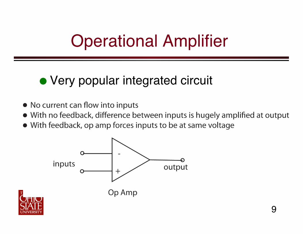
Operational Amplifier!
Very popular integrated circuit!

10!
What’s it for? !!
Just about everything! ! Depends on how you hook it up! We’ll use two of them, in two different
ways! First way: transimpedance amplifier !!
» Convert current to voltage!» So does a resistor, hence
“transimpedance”!

11!
This one has feedback!
There is a connection between the output and the input!
Therefore forces inputs to same voltage!

12!
How it works!
Both inputs at same voltage !» 4.5 volts from rail
splitter! No current can flow
into input! Thus photocurrent
must flow through feedback resistor!
4.5 V!4.5 V!
X!

13!
Current creates voltage across Vr!
Voltage at both inputs=Vref!
Voltage at output =??!

14!
Kirchhoff Voltage Law!
Sum of voltages around a loop equals zero!
Pick a direction (clockwise)!
If you find a + sign first, voltage is positive!
15!
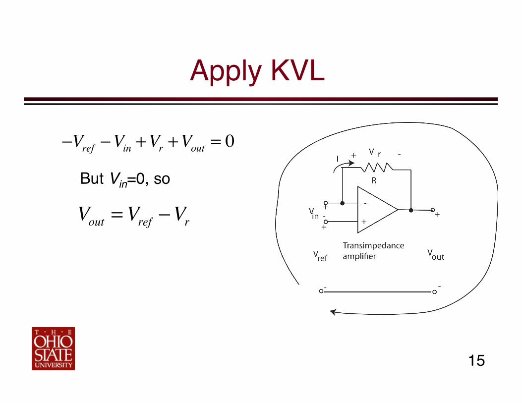
Apply KVL!
−Vref −Vin +Vr +Vout = 0
But Vin=0, so!
Vout =Vref −Vr

16!
But V=IR!
Vout =Vref − IR
Therefore, as light increases, the current increases, and the output voltage decreases!
Use this as input to the next stage!
17!
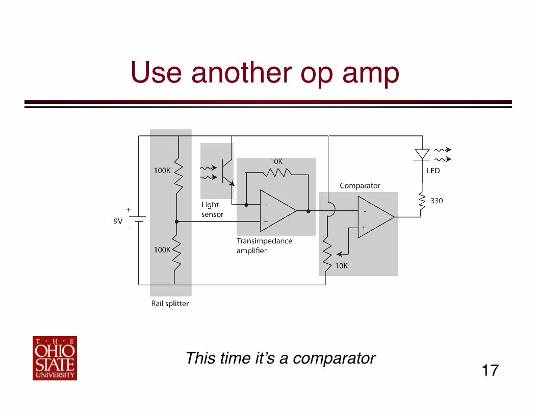
Use another op amp!
This time it’s a comparator!

18!
This one does NOT have feedback!
No connection from output back to input!
This will amplify any difference in voltage between the inputs!» One input comes from
previous stage!» It decreases as ambient
light increases!» Other input is a reference
that we will adjust!

19!
Gain is about a zillion!
Suppose Vin is greater than Vref (this would be when the room is dark)!
Comparator multiplies difference by a zillion, wants to go to a zillions volts!
But, battery is only 9 V, so that’s as high as it can go!
Similarly, can’t go lower than 0V!

20!
Operation:!
If input higher than ref, output goes to 9V!
If input lower than ref, output goes to 0 V!
Nothing in between!

21!
Adjusting the reference!
Use a variable resistor (potentiometer)!
As you turn the knob, the voltage changes!» Remind you of the
voltage divider rail splitter? Except now we adjust the voltage!

22!
Now, when light goes dim…!
We want the lights to come on!!
When light goes dim, photocurrent increases, input to comparator goes down!
When it goes below the reference (which we set), output goes to 0V!
Turn on an LED!
23!
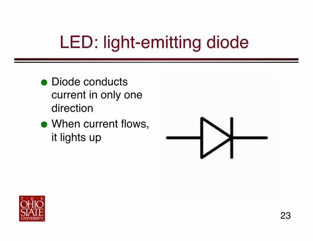
LED: light-emitting diode!
Diode conducts current in only one direction!
When current flows, it lights up!

24!
OK, we’re ready to build!!
This is the breadboard!
Stick wires into the holes!
Green lines: busses!» All holes connected
together! Blue lines: nodes!
» Five holes connected together!

25!
First make power connections!
Connect red lead (positive) from batter to one buss!
Connect black lead (negative) to another buss!
Useful to connect additional busses on other side!

26!
Check against schematic!

27!
Next, rail splitter!
Disconnect battery!! Two resistors!
» 100K Ω: brown, black, yellow!
» Add a wire to connect to next stage!

28!
About the op amp!
Two op amps in one package! Notice divot: tells you which end is up! Diagram shows how pins are
numbered!
Vcc: code for “positive”!
GND: negative!
Divot or dot!

29!
Connect op amp power and ground!
Pin 8 to positive buss!
Divot!
Pin 4 to negative buss!

30!
Light sensor and Transimpedance amp!
Sensor and first op amp!
Light sensor: long lead corresponds to arrow on sensor symbol!
Will connect to pin 2! Other end connects to
positive buss!

31!
And rest of first stage!
Output of rail splitter connects to pin 3!
Feedback resistor: 10 KΩ= brown, black, orange!
» Connects between pin 2 and pin 1!

32!
The potentiometer!
Pin 1: positive! Pin 2: connect to pin 5
of op amp! Pin 3: negative!
1!3! 2!

33!
Rest of stage 2!
Output of stage 1 (pin 1) connects to “-” input of stage 2 (pin 6)!

34!
LED circuit!
LED = light-emitting diode!
Diodes conduct current in one direction only!
When current flows, it lights up!
Long lead is the “anode” (positive)!

35!
LED Circuit, continued!
Resistor = 330Ω (orange, orange, brown)!
Long lead to positive buss!Flat side to resistor!

36!
Now connect battery and try it!
Adjust pot until light just turns on or off!» Then go to just
barely off! It’s a 25-turn pot! Then cover sensor,
see if light comes on! Adjust!
37!
Troubleshooting!
LED never comes on?!» Check polarity of LED!
LED never goes off?!» Check polarity of light sensor!
Battery gets hot?!» DISCONNECT IMMEDIATELY! Check wiring!
Chip gets hot?!» DISCONNECT BATTERY IMMEDIATELY!