Rolling Bearings - NSK
283
Rolling Bearings
-
Upload
khangminh22 -
Category
Documents
-
view
1 -
download
0
Transcript of Rolling Bearings - NSK

Rolling Bearings
Rolling
Bearings
CAT. No. E1102m 2013 C-11 Printed in Japan ©NSK Ltd. First edition published in MAR. 2005
2013/10/16

Technical Information A7Page No.
Deep Groove Ball Brgs. B4
Angular Contact Ball Brgs. B46
Self-Aligning Ball Brgs. B76
Cylindrical Roller Brgs. B84
Tapered Roller Brgs. B110
Spherical Roller Brgs. B182
Thrust Brgs. B206
Needle Roller Brgs. B244
Ball Brg. Units B280
Plummer Blocks B304
Cylindrical Roller Brgs. for Sheaves B326
Balls and Rollers B346
Roll-Neck Brgs. (4-Rows)Railway Rolling Stock Brgs.
B334
Accessories for Rolling Brgs. B356
NSK Products and Appendices C1
Tech.Info.
ThrustBrgs.
Sheaves
Appendices
Sleeves
Roll Neck Railway
mikaesiE.indd 1-2mikaesiE.indd 1-2 11/20/13 4:48:42 PM11/20/13 4:48:42 PM
Rolling Bearings
CAT. No. E1102m
A001-005E.indd 1A001-005E.indd 1 11/20/13 4:49:05 PM11/20/13 4:49:05 PM
We want to thank you for your interest in this edition of our Rolling Bearing Catalog. It has been revised with our customers in mind, and we hope it fills your needs.
Recently, technology has been advancing at a remarkable pace, and with it has come a host of new products in many fields including computers, office automation, audio-visual equipment, medical equipment, and many others. Accordingly, rolling bearings, which are highly important machine elements, must be designed to satisfy increasingly stringent requirements for higher speeds, greater precision, higher reliability, and other challenging demands.We edited this Rolling Bearing Catalog to reflect the growing number of NSK products, new developments, and technical progress. In it, you will find a wide range of bearings that will satisfy almost any requirement.
This catalog was revised to reflect the growing number of NSK products and certain revisions in JIS and ISO and to better serve our customers. The first part contains general information about rolling bearings to facilitate selection of the most appropriate type. Next supplementary technical information is provided regarding bearing life, load ratings, limiting speeds, handling and mounting, lubrication, etc. Finally, the catalog presents extensive tables containing most bearing numbers and showing dimensions and pertinent design data listed in the order of increasing bore size. Data in the table are given in both the international Unit System (SI) and Engineering Unit System (Gravitational System of Units).
We hope this catalog will allow you to select the optimum bearing for your application. However, if assistance is required, please contact NSK, and the company’s engineers and computer programs can quickly supply the information you need.
Introduction to Revised NSK Rolling Bearing Catalog(CAT.No.E1102m)
NSK Web site A http://www.nsk.com
A001-005E.indd 2-3A001-005E.indd 2-3 11/20/13 4:49:06 PM11/20/13 4:49:06 PM

A 5A 4
CONTENTS
1 TYPES AND FEATURES OF ROLLING BEARINGS ···················································· A 7
1.1 Design and Classification ························ A 71.2 Characteristics of Rolling Bearings ········· A 7
2 BEARING SELECTION PROCEDURE ·············· A16
3 SELECTION OF BEARING TYPE ····················· A183.1 Allowable Bearing Space ························· A183.2 Load Capacity and Bearing Types ············ A183.3 Permissible Speed and Bearing Types ····· A183.4 Misalignment of Inner/Outer Rings and
Bearing Types ········································· A183.5 Rigidity and Bearing Types ······················ A193.6 Noise and Torque of Various Bearing
Types ······················································ A193.7 Running Accuracy and Bearing Types ····· A193.8 Mounting and Dismounting of Various
Bearing Types ········································· A19
4 SELECTION OF BEARING ARRANGEMENT ···· A204.1 Fixed-End and Free-End Bearings ··········· A204.2 Examples of Bearing Arrangements ········ A21
5 SELECTION OF BEARING SIZE ······················ A245.1 Bearing Life ············································ A24
5.1.1 Rolling Fatigue Life and Basic Rating Life ··················································· A24
5.2 Basic Load Rating and Fatigue Life ········· A245.2.1 Basic Load Rating ····························· A245.2.2 Machinery in which Bearings are
Used and Projected Life ···················· A245.2.3 Selection of Bearing Size Based on
Basic Load Rating ····························· A255.2.4 Temperature Correction for Basic Load
Rating ··············································· A265.2.5 Correction of Basic Rating Life ········· A27
5.3 Calculation of Bearing Loads ···················· A285.3.1 Load Factor ······································· A285.3.2 Bearing Loads in Belt or Chain
Transmission Applications ················· A285.3.3 Bearing Loads in Gear Transmission
Applications ······································ A295.3.4 Load Distribution on Bearings ············· A295.3.5 Average of Fluctuating load ················· A29
Pages5.4 Equivalent Load ········································ A30
5.4.1 Calculation of Equivalent Loads ··········· A315.4.2 Axial Load Components in Angular
Contact Ball Bearings and Tapered Roller Bearings ································· A31
5.5 Static Load Ratings and Static Equivalent Loads ····················································· A32
5.5.1 Static Load Ratings ··························· A325.5.2 Static Equivalent Loads ····················· A325.5.3 Permissible Static Load Factor ·········· A32
5.6 Maximum Permissible Axial Loads for Cylindrical Roller Bearings ······················ A33
5.7 Examples of Bearing Calculations ············· A34
6 LIMITING SPEED ··········································· A376.1 Correction of Limiting Speed ·················· A376.2 Limiting Speed for Rubber Contact Seals
for Ball Bearings ····································· A37
7 BOUNDARY DIMENSIONS AND IDENTIFYING NUMBERS FOR BEARINGS ···························· A38
7.1 Boundary Dimensions and Dimensions of Snap Ring Grooves ································· A38
7.1.1 Boundary Dimensions ······················· A387.1.2 Dimensions of Snap Ring Grooves
and Locating Snap Rings ··················· A387.2 Formulation of Bearing Numbers ············ A54
8 BEARING TOLERANCES ································· A588.1 Bearing Tolerance Standards ··················· A588.2 Selection of Accuracy Classes ················· A81
9 FITS AND INTERNAL CLEARANCES ··············· A829.1 Fits ························································· A82
9.1.1 Importance of Proper Fits ················· A829.1.2 Selection of Fit ·································· A829.1.3 Recommended Fits ··························· A83
9.2 Bearing Internal Clearances ···················· A889.2.1 Internal Clearances and Their
Standards ········································· A889.2.2 Selection of Bearing Internal
Clearances ········································ A94
10 PRELOAD ···················································· A9610.1 Purpose of Preload ······························· A9610.2 Preloading Methods ······························ A96
10.2.1 Position Preload ······························ A9610.2.2 Constant-Pressure Preload ·············· A96
Pages10.3 Preload and Rigidity ······························ A96
10.3.1 Position Preload and Rigidity ·········· A9610.3.2 Constant-Pressure Preload and
Rigidity ··········································· A9710.4 Selection of Preloading Method and
Amount of Preload ································ A9710.4.1 Comparison of Preloading
Methods ·········································· A9710.4.2 Amount of Preload ·························· A98
11 DESIGN OF SHAFTS AND HOUSINGS ········ A10011.1 Accuracy and Surface Finish of Shafts
and Housings ····································· A10011.2 Shoulder and Fillet Dimensions ··········· A10011.3 Bearing Seals ······································ A102
11.3.1 Non-Contact Types Seals ··············· A10211.3.2 Contact Type Seals ························ A104
12 LUBRICATION ············································ A10512.1 Purposes of Lubrication ······················ A10512.2 Lubricating Methods ··························· A105
12.2.1 Grease Lubrication ························ A10512.2.2 Oil Lubrication ······························ A107
12.3 Lubricants ·········································· A11012.3.1 Lubricating Grease ························ A11012.3.2 Lubricating Oil ······························ A112
13 BEARING MATERIALS ································ A11413.1 Materials for Bearing Rings and Rolling
Elements ············································ A11413.2 Cage Materials ···································· A115
14 BEARING HANDLING ································· A11614.1 Precautions for Proper Handling of
Bearings ············································· A11614.2 Mounting ············································ A116
14.2.1 Mounting of Bearings with Cylindrical Bores ··························· A116
14.2.2 Mounting of Bearings with Tapered Bores ············································ A118
14.3 Operation Inspection ··························· A11814.4 Dismounting ······································· A121
14.4.1 Dismounting of Outer Rings ·········· A12114.4.2 Dismounting of Bearings with
Cylindrical Bores ··························· A12114.4.3 Dismounting of Bearings with
Tapered Bores ······························· A12214.5 Inspection of Bearings ························ A123
14.5.1 Bearing Cleaning ··························· A12314.5.2 Inspection and Evaluation of
Bearings ········································ A123
Pages14.6 Maintenance and Inspection ··············· A124
14.6.1 Detecting and Correcting Irregularities ································· A124
14.6.2 Bearing Failures and Measures ······································ A124
15 TECHNICAL DATA ······································ A12615.1 Axial Displacement of Bearings ··········· A12815.2 Fits ····················································· A13015.3 Radial and Axial Internal Clearances ···· A13215.4 Preload and Starting Torque ················ A13415.5 Coefficients of Dynamic Friction and
Other Bearing Data ····························· A13615.6 Brands and Properties of Lubricating
Greases ·············································· A138
BEARING TABLES
CONTENTS ···························································· B2
INTRODUCTION OF NSK PRODUCTS-APPENDICES
CONTENTS ·························································· C 1Photos of NSK Products ····································· C 2Appendix 1 Conversion from SI (International
Units) System ································· C 8Appendix 2 N-kgf Conversion Table ················· C10Appendix 3 kg-lb Conversion Table ·················· C11Appendix 4 °C-°F Temperature Conversion
Table ·············································· C12Appendix 5 Viscosity Conversion Table ············· C13Appendix 6 Inch-mm Conversion Table ··········· C14Appendix 7 Hardness Conversion Table ············· C16Appendix 8 Physical and Mechanical Properties
of Materials ···································· C17Appendix 9 Tolerances for Shaft Diameters ······· C18Appendix 10 Tolerances for Housing Bore
Diameters ······································· C20Appendix 11 Values of Standard Tolerance Grades
IT ·················································· C22Appendix 12 Speed Factor fn ······························· C24Appendix 13 Fatigue Life Factor fh and Fatigue
Life L-Lh ······································· C25Appendix 14 Index of Inch Design Tapered Roller
Bearings ········································· C26
PagesTECHNICAL INFORMATION
A001-005E.indd 4-5A001-005E.indd 4-5 11/20/13 4:49:06 PM11/20/13 4:49:06 PM
A 6 A 7
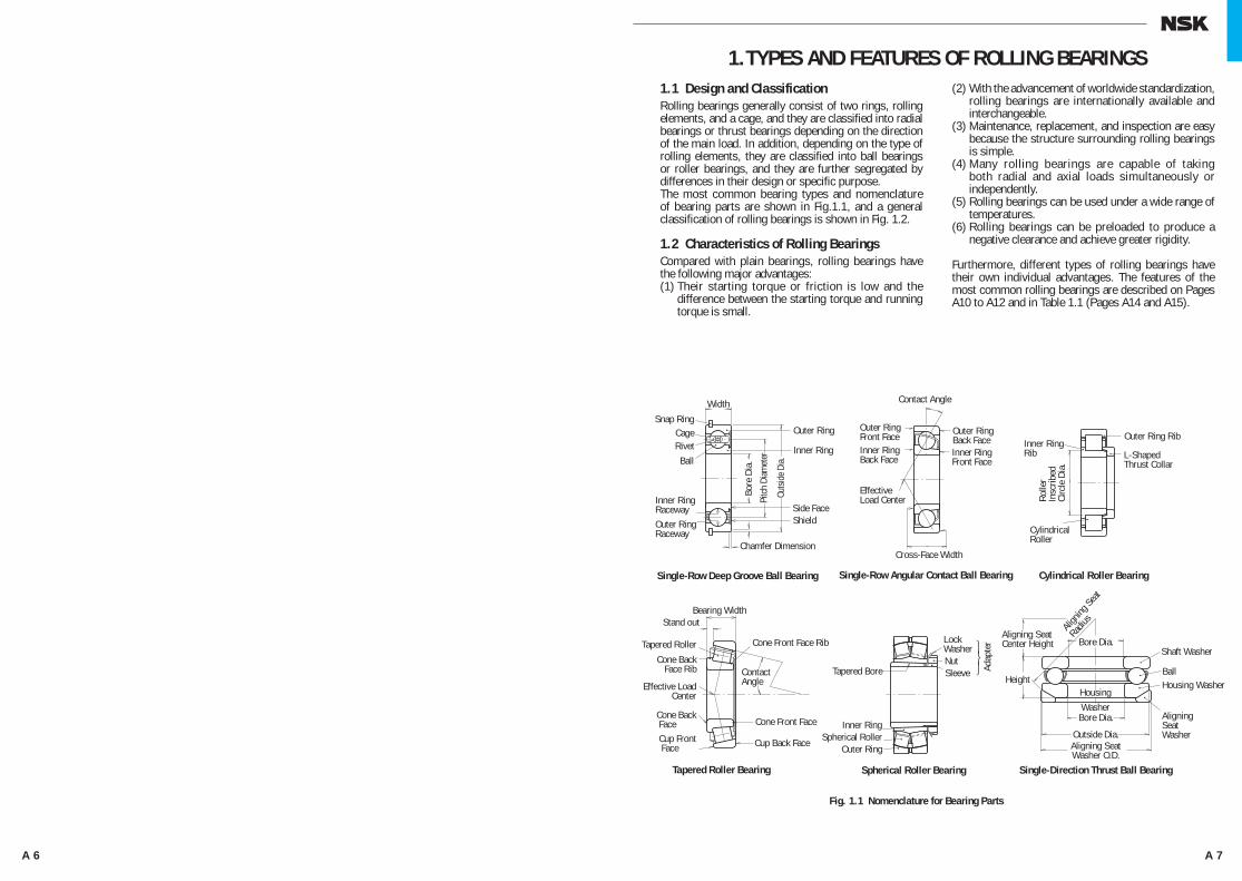
1.1 Design and ClassificationRolling bearings generally consist of two rings, rolling elements, and a cage, and they are classified into radial bearings or thrust bearings depending on the direction of the main load. In addition, depending on the type of rolling elements, they are classified into ball bearings or roller bearings, and they are further segregated by differences in their design or specific purpose.The most common bearing types and nomenclature of bearing parts are shown in Fig.1.1, and a general classification of rolling bearings is shown in Fig. 1.2.
1.2 Characteristics of Rolling BearingsCompared with plain bearings, rolling bearings have the following major advantages:(1) Their starting torque or friction is low and the
difference between the starting torque and running torque is small.
(2) With the advancement of worldwide standardization, rolling bearings are internationally available and interchangeable.
(3) Maintenance, replacement, and inspection are easy because the structure surrounding rolling bearings is simple.
(4) Many rolling bearings are capable of taking both radial and axial loads simultaneously or independently.
(5) Rolling bearings can be used under a wide range of temperatures.
(6) Rolling bearings can be preloaded to produce a negative clearance and achieve greater rigidity.
Furthermore, different types of rolling bearings have their own individual advantages. The features of the most common rolling bearings are described on Pages A10 to A12 and in Table 1.1 (Pages A14 and A15).
Width
Snap RingCageRivet
Ball
Inner RingRacewayOuter RingRaceway
Chamfer Dimension
Bearing Width
Cross-Face Width
Outer Ring
Inner Ring
Side FaceShield
Bore
Dia
.
Outs
ide D
ia.
Pitc
h Di
amet
erTapered Roller Bearing Spherical Roller Bearing Single-Direction Thrust Ball Bearing
Single-Row Deep Groove Ball Bearing Single-Row Angular Contact Ball Bearing Cylindrical Roller Bearing
Stand out
Cone Front Face Rib
Cone BackFace Rib
Tapered Roller
Effective LoadCenter
EffectiveLoad Center
ContactAngle
Contact Angle
Cone Back FaceCup Front Face
Inner RingBack Face
Outer RingFront Face
Cone Front Face
Cup Back Face
Inner RingFront Face
Outer RingBack Face
Aligning Seat Center Height
Alignin
g Sea
t
Radius
Bore Dia.
HeightHousingWasher
Bore Dia.
Aligning SeatWasher O.D.
Outside Dia.
Shaft Washer
BallHousing Washer
AligningSeatWasher
Outer Ring Rib
L-ShapedThrust Collar
Inner RingRib
CylindricalRoller
Rolle
rIn
scrib
edCi
rcle
Dia
.
Tapered Bore
Inner RingSpherical Roller
Outer Ring
LockWasherNutSleeve Ad
apte
r
Fig. 1.1 Nomenclature for Bearing Parts
1.TYPES AND FEATURES OF ROLLING BEARINGS
A007-023E.indd 6-7 A007-023E.indd 6-7 11/20/13 4:49:25 PM11/20/13 4:49:25 PM
A 8 A 9
TYPES AND FEATURES OF ROLLING BEARINGS
Deep Groove Ball Bearing
Angular Contact Ball Bearing
Self-Aligning Ball Bearing
Cylindrical Roller Bearing
Needle Roller Bearing
Tapered Roller Bearing
Single-Direction Thrust Ball Bearing
Thrust Cylindrical Roller Bearing
Thrust Spherical Roller Bearing
Sealed Axle Bearing
Cylindrical Roller Bearing for Sheaves
Spherical Roller Bearing
Thrust Tapered Roller Bearing
SingleRow
DoubleRow
SingleRow
DoubleRow
BallBearings
Matched
Deep Groove Ball Bearings
MagnetoBearings
SingleRow
DoubleRow
CylindricalRollerBearings
Long-RollerBearings
AngularContact Ball Bearings
SingleRow
DoubleRow
FourRow
Tapered RollerBearings
SphericalRollerBearings
RollerBearings
Self-AligningBall Bearings
Ball Bearings for Bearing Units
Three- Point/Four-Point Contact Ball Bearings
ROLLING BEARINGS
BallBearings
RollerBearings
Thrust Ball Bearings
Angular Contact Thrust Ball Bearings
Thrust CylindricalRoller Bearings
Thrust NeedleRoller Bearings
Thrust TaperedRoller Bearings
Thrust Spherical Roller Bearings
Automotive Clutch Release Bearings
Rolling Stock Axle Bearings
Crane-SheaveBearingsBearings for Specific Uses
Chain Conveyor Bearings
Others
SingleDirection
DoubleDirection
Automotive Water Pump Bearings
(Thrust Bearings)(Radial Bearings)
Needle Roller Bearings
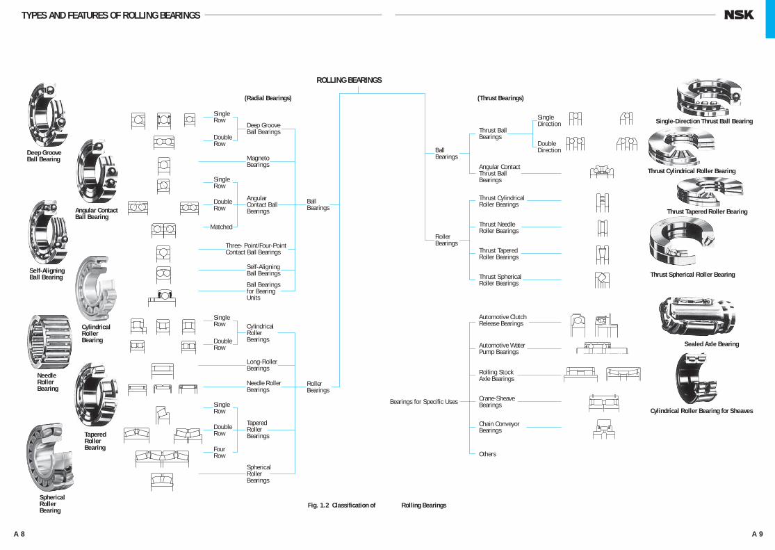
Fig. 1.2 Classification of Rolling Bearings
A007-023E.indd 8-9 A007-023E.indd 8-9 11/20/13 4:49:26 PM11/20/13 4:49:26 PM
A 10 A 11
TYPES AND FEATURES OF ROLLING BEARINGS
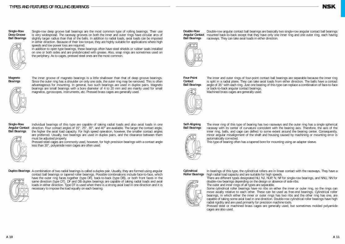
Single-row deep groove ball bearings are the most common type of rolling bearings. Their use is very widespread. The raceway grooves on both the inner and outer rings have circular arcs of slightly larger radius than that of the balls. In addition to radial loads, axial loads can be imposed in either direction. Because of their low torque, they are highly suitable for applications where high speeds and low power loss are required.In addition to open type bearings, these bearings often have steel shields or rubber seals installed on one or both sides and are prelubricated with grease. Also, snap rings are sometimes used on the periphery. As to cages, pressed steel ones are the most common.
Single-Row Deep Groove Ball Bearings
The inner groove of magneto bearings is a little shallower than that of deep groove bearings. Since the outer ring has a shoulder on only one side, the outer ring may be removed. This is often advantageous for mounting. In general, two such bearings are used in duplex pairs. Magneto bearings are small bearings with a bore diameter of 4 to 20 mm and are mainly used for small magnetos, gyroscopes, instruments, etc. Pressed brass cages are generally used.
Magneto Bearings
Individual bearings of this type are capable of taking radial loads and also axial loads in one direction. Four contact angles of 15°, 25°, 30°, and 40° are available. The larger the contact angle, the higher the axial load capacity. For high speed operation, however, the smaller contact angles are preferred. Usually, two bearings are used in duplex pairs, and the clearance between them must be adjusted properly. Pressed-steel cages are commonly used, however, for high precision bearings with a contact angle less than 30°, polyamide resin cages are often used.
Single-Row Angular Contact Ball Bearings
A combination of two radial bearings is called a duplex pair. Usually, they are formed using angular contact ball bearings or tapered roller bearings. Possible combinations include face-to-face, which have the outer ring faces together (type DF), back-to-back (type DB), or both front faces in the same direction (type DT). DF and DB duplex bearings are capable of taking radial loads and axial loads in either direction. Type DT is used when there is a strong axial load in one direction and it is necessary to impose the load equally on each bearing.
Duplex Bearings
Double-row angular contact ball bearings are basically two single-row angular contact ball bearings mounted back-to-back except that they have only one inner ring and one outer ring, each having raceways. They can take axial loads in either direction.
Double-Row Angular Contact Ball Bearings
The inner and outer rings of four-point contact ball bearings are separable because the inner ring is split in a radial plane. They can take axial loads from either direction. The balls have a contact angle of 35° with each ring. Just one bearing of this type can replace a combination of face-to-face or back-to-back angular contact bearings. Machined brass cages are generally used.
Four-Point Contact Ball Bearings
The inner ring of this type of bearing has two raceways and the outer ring has a single spherical raceway with its center of curvature coincident with the bearing axis. Therefore, the axis of the inner ring, balls, and cage can deflect to some extent around the bearing center. Consequently, minor angular misalignment of the shaft and housing caused by machining or mounting error is automatically corrected.This type of bearing often has a tapered bore for mounting using an adapter sleeve.
Self-Aligning Ball Bearings
In bearings of this type, the cylindrical rollers are in linear contact with the raceways. They have a high radial load capacity and are suitable for high speeds.There are different types designated NU, NJ, NUP, N, NF for single-row bearings, and NNU, NN for double-row bearings depending on the design or absence of side ribs.The outer and inner rings of all types are separable.Some cylindrical roller bearings have no ribs on either the inner or outer ring, so the rings can move axially relative to each other. These can be used as free-end bearings. Cylindrical roller bearings, in which either the inner or outer rings has two ribs and the other ring has one, are capable of taking some axial load in one direction. Double-row cylindrical roller bearings have high radial rigidity and are used primarily for precision machine tools.Pressed steel or machined brass cages are generally used, but sometimes molded polyamide cages are also used.
Cylindrical Roller Bearings
A007-023E.indd 10-11 A007-023E.indd 10-11 11/20/13 4:49:29 PM11/20/13 4:49:29 PM

A 12 A 13
TYPES AND FEATURES OF ROLLING BEARINGS
Needle roller bearings contain many slender rollers with a length 3 to 10 times their diameter. As a result, the ratio of the bearing outside diameter to the inscribed circle diameter is small, and they have a rather high radial load capacity.There are numerous types available, and many have no inner rings. The drawn-cup type has a pressed steel outer ring and the solid type has a machined outer ring. There are also cage and roller assemblies without rings. Most bearings have pressed steel cages, but some are without cages.
NeedleRoller Bearings
Bearings of this type use conical rollers guided by a back-face rib on the cone. These bearings are capable of taking high radial loads and also axial loads in one direction. In the HR series, the rollers are increased in both size and number giving it an even higher load capacity. They are generally mounted in pairs in a manner similar to single-row angular contact ball bearings. In this case, the proper internal clearance can be obtained by adjusting the axial distance between the cones or cups of the two opposed bearings. Since they are separable, the cone assemblies and cups can be mounted independently.Depending upon the contact angle, tapered roller bearings are divided into three types called the normal angle, medium angle, and steep angle. Double-row and four-row tapered roller bearings are also available. Pressed steel cages are generally used.
TaperedRoller Bearings
These bearings have barrel-shaped rollers between the inner ring, which has two raceways, and the outer ring which has one spherical raceway. Since the center of curvature of the outer ring raceway surface coincides with the bearing axis, they are self-aligning in a manner similar to that of self-aligning ball bearings. Therefore, if there is deflection of the shaft or housing or misalignment of their axes, it is automatically corrected so excessive force is not applied to the bearings.Spherical roller bearings can take, not only heavy radial loads, but also some axial loads in either direction. They have excellent radial load-carrying capacity and are suitable for use where there are heavy or impact loads.Some bearings have tapered bores and may be mounted directly on tapered shafts or cylindrical shafts using adapters or withdrawal sleeves.Pressed steel and machined brass cages are used.
Spherical Roller Bearings
Single-direction thrust ball bearings are composed of washer-like bearing rings with raceway grooves. The ring attached to the shaft is called the shaft washer (or inner ring) while that attached to the housing is called the housing washer(or outer ring).In double-direction thrust ball bearings, there are three rings with the middle one (center ring) being fixed to the shaft.There are also thrust ball bearings with an aligning seat washer beneath the housing washer in order to compensate for shaft misalignment or mounting error.Pressed steel cages are usually used in the smaller bearings and machined cages in the larger ones.
Single-Direction Thrust BallBearings
Double-Direction Thrust BallBearings
These bearings have a spherical raceway in the housing washer and barrel-shaped rollers obliquely arranged around it. Since the raceway in the housing washer in spherical, these bearings are self-aligning. They have a very high axial load capacity and are capable of taking moderate radial loads when an axial load is applied.Pressed steel cages or machined brass cages are usually used.
Spherical Thrust Roller Bearings
A007-023E.indd 12-13 A007-023E.indd 12-13 11/20/13 4:49:32 PM11/20/13 4:49:32 PM
A 14 A 15
TYPES AND FEATURES OF ROLLING BEARINGS
CylindricalRollerBearingswithSingle Rib
Double-RowCylindricalRollerBearings
CylindricalRollerBearings
Self-AligningBallBearings
Four-PointContactBallBearings
DuplexAngularContactBallBearings
Double-RowAngularContactBallBearings
AngularContactBallBearings
MagnetoBearings
DeepGrooveBallBearings
BearingTypes
Features
Radial Loads
Axial Loads
CombinedLoads
High Speeds
High Accuracy
Low Noise andTorque
Rigidity
AngularMisalignment
Self-AligningCapability
RingSeparability
Fixed-EndBearing
Free-EndBearing
Tapered Borein Inner Ring
Remarks
B5B31
B5B28 B47 B47
B70 B47 B47B72 B77 B85 B85
B110 B85
Two
bear
ings
are
us
ually
mou
nted
in
oppo
sitio
n.
Conta
ct an
gles o
f 15o , 2
5o
30o , a
nd 40
o . Two
beari
ngs a
re us
ually
mou
nted i
n opp
ositio
n.Cle
aranc
e adju
stmen
t is
nece
ssary
.
Com
binati
on o
f DF a
nd
DT p
airs i
s pos
sible,
but
us
e on
free-
end
is no
t po
ssibl
e.
Cont
act a
ngle
of 3
5o
Incl
udin
g N
type
Incl
udin
g NN
U ty
pe
Incl
udin
g NF
type
Incl
udin
g NU
P ty
pe
Two
bear
ings a
re u
suall
y m
ount
ed in
opp
ositio
n.Cl
eara
nce a
djustm
ent i
s ne
cess
ary.
KH, K
V ty
pes
are
also
ava
ilabl
e bu
t us
e on
free
-end
is
impo
ssib
le.
Incl
udin
g ne
edle
ro
ller t
hrus
t bea
rings
To b
e us
ed w
ith o
il lu
bric
atio
n
Page No.
× ×
× ×
i
i i i i i
i i i i i
I I I I I i i
i i
Page No.
⎯
⎯
⎯
A18A37
A19A58A81
A19
A19A96
A18Blue pages ofeach brg.type
A18
A19A20
A20~~A21
A20~~A27
A800A118A122
ThrustSphericalRollerBearings
ThrustTaperedRollerBearings
ThrustCylindricalRollerBearings
Double-DirectionAngularContactThrustBallBearings
Thrust BallBearingswithAligningSeat
ThrustBallBearings
SphericalRollerBearings
Double-andMultiple-RowTaperedRollerBearings
TaperedRollerBearings
B115B115B176B299
B183 B207 B207 B235 B207B224 ⎯ B207
B228
NeedleRollerBearings
⎯
CylindricalRollerBearingswith ThrustCollars
B85
i i i
i i i i i i i i i i
i i i
i I I
i
×
×
×
× ×
× ×
× × ×
× × × ×
× × × ×
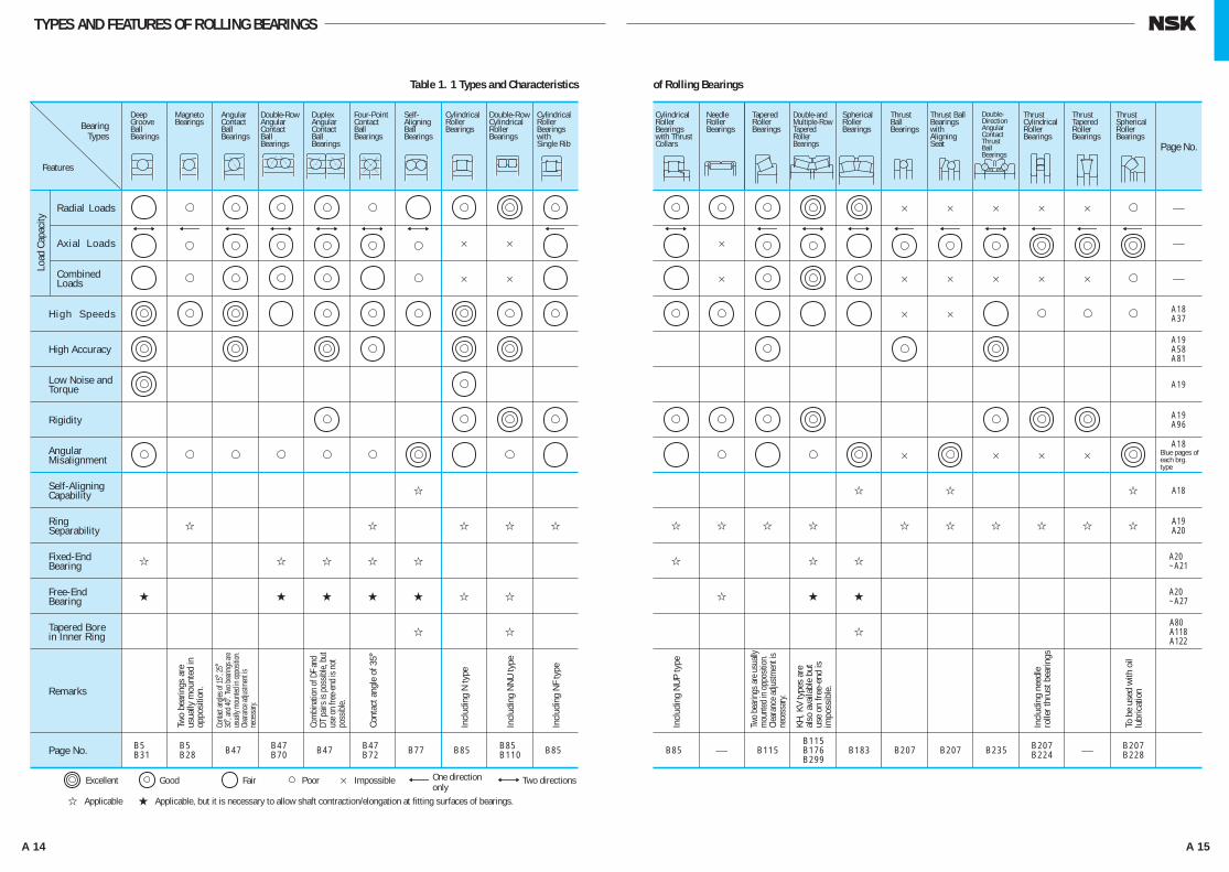
Excellent Good Fair Poor × Impossible Two directions
i Applicable I Applicable, but it is necessary to allow shaft contraction/elongation at fitting surfaces of bearings.
Table 1. 1 Types and Characteristics of Rolling Bearings
Load
Cap
acity
One directiononly
A007-023E.indd 14-15 A007-023E.indd 14-15 11/20/13 4:49:34 PM11/20/13 4:49:34 PM

A 16 A 17
A Operating conditions and required performanceA Environmental conditionsA Dimensions of shaft and housing
A Allowable spaceA Magnitude and direction of loadsA Vibration and shockA Operating speed, maximum speedA Misalignment of inner and outer ringsA Fixing in axial direction and mounting arrangementA Ease of bearing mounting and dismountingA Sound and torqueA Required rigidityA Availability and cost
Determination of bearingtype and mounting
arrangement
Determination of bearing size
Page numberA18, A38A18A18A18, A37A18
A20 to A23
A19
A19A19, A96
Evaluation of bearing types
Page numberA19A18, A37, A81A19
Evaluation of accuracy
Page number
A95
A18
A98
Examination of internal clearance
Page numberA116, A121
A116, A121A100
Examination of ease of mounting/ dismounting
Page numberA106, A107, A110, A112A37A105A102A123
Examination of lubricatingmethods
Study of cage
A Expected life of machineA Dynamic and static equivalent loadsA SpeedA Permissible static load factorA Permissible axial loads (in the case of cylindrical roller bearings)
A Running accuracyA Rotational stabilityA Torque fluctuation
A FittingA Difference in temperature between inner and outer ringsA SpeedA Misalignment of inner and outer ringsA Amount of preload
Determination ofinternal clearance
Selection of bearingaccuracy class
Selection of cage typeand material
A SpeedA NoiseA Operating temperatureA External vibration and shockA Rapid acceleration and decelerationA Moment load and misalignment
Selection of lubricatingmethod, lubricant, and
type of seals
A Operating temperature rangeA SpeedA Lubricating methodsA Type of sealsA Maintenance and inspection intervals
Determination of dimensionsaffecting mounting and
procedure for mounting/dismounting
Final specifications forbearing and surrounding
parts
A Procedure for mounting and dismountingA Necessary equipmentA Dimensions affecting mounting
Page numberA24, A25A30, A32--A32A33
Determination of bearing size
Page numberA57
Examination of special specifications
Selection of specialmaterial, heat treatmentfor dimensional stability
A Operating temperatureA Environment (seawater, vacuum, gases, chemicals, etc.)A Type of lubrication
Page numberA82A82, A83
A83A84, A100
Examination of fitting
Determination of fitting
A Operating conditionsA Magnitude and character- istics of loadsA Temperature rangeA Materials, size, accuracies of shaft and housing
The number of applications for rolling bearings is almost countless and the operating conditions and environments also vary greatly. In addition, the diversity of operating conditions and bearing requirements continue to grow with the rapid advancement of technology. Therefore, it is necessary to study bearings carefully from many angles to select the best one from the thousands of types and sizes available.Usually, a bearing type is provisionally chosen considering the operating conditions, mounting arrangement, ease of mounting in the machine, allowable space, cost, availability, and other factors.
Then the size of the bearing is chosen to satisfy the desired life requirement. When doing this, in addition to fatigue life, it is necessary to consider grease life, noise and vibration, wear, and other factors. There is no fixed procedure for selecting bearings. It is good to investigate experience with similar applications and studies relevant to any special requirements for your specific application. When selecting bearings for new machines, unusual operating conditions, or harsh environments, please consult with NSK.The following diagram (Fig.2.1) shows an example of the bearing selection procedure.
2. BEARING SELECTION PROCEDURE
Fig. 2.1 Flow Chart for Selection of Rolling Bearings
A007-023E.indd 16-17 A007-023E.indd 16-17 11/20/13 4:49:36 PM11/20/13 4:49:36 PM

A 18 A 19
3.1 Allowable Bearing SpaceThe allowable space for a rolling bearing and its adjacent parts is generally limited so the type and size of the bearing must be selected within such limits. In most cases, the shaft diameter is fixed first by the machine design; therefore, the bearing is often selected based on its bore size. For rolling bearings, there are numerous standardized dimension series and types, and the selection of the optimum bearing from among them is necessary. Fig. 3.1 shows the dimension series of radial bearings and corresponding bearing types.
3.2 Load Capacity and Bearing TypesThe axial load carrying capacity of a bearing is closely related to the radial load capacity (see Page A24) in a manner that depends on the bearing design as shown in Fig. 3.2. This figure makes it clear that when bearings of the same dimension series are compared, roller bearings have a higher load capacity than ball bearings and are superior if shock loads exist.
3.3 Permissible Speed and Bearing TypesThe maximum speed of rolling bearings varies depending, not only the type of bearing, but also its size, type of cage, loads, lubricating method, heat dissipation, etc. Assuming the common oil bath lubrication method, the bearing types are roughly ranked from higher speed to lower as shown in Fig. 3.3.
3.4 Misalignment of Inner/Outer Rings and Bearing Types
Because of deflection of a shaft caused by applied loads, dimensional error of the shaft and housing, and mounting errors, the inner and outer rings are slightly misaligned. The permissible misalignment varies depending on the bearing type and operating conditions, but usually it is a small angle less than 0.0012 radian (4').When a large misalignment is expected, bearings having a self-aligning capability, such as self-aligning ball bearings, spherical roller bearings, and certain bearing units should be selected (Figs. 3.4 and 3.5).
3. SELECTION OF BEARING TYPESPermissible bearing misalignment is given at the beginning of the dimensional tables for each bearing type.
3.5 Rigidity and Bearing TypesWhen loads are imposed on a rolling bearing, some elastic deformation occurs in the contact areas between the rolling elements and raceways. The rigidity of the bearing is determined by the ratio of bearing load to the amount of elastic deformation of the inner and outer rings and rolling elements. For the main spindles of machine tools, it is necessary to have high rigidity of the bearings together with the rest of the spindle. Consequently, since roller bearings are deformed less by load, they are more often selected than ball bearings. When extra high rigidity is required, bearings are given a preload, which means that they have a negative clearance. Angular contact ball bearings and tapered roller bearings are often preloaded.
3.6 Noise and Torque of Various Bearing Types
Since rolling bearings are manufactured with very high precision, noise and torque are minimal. For deep groove ball bearings and cylindrical roller bearings particularly, the noise level is sometimes specified depending on their purpose. For high precision miniature ball bearings, the starting torque is specified. Deep groove ball bearings are recommended for applications in which low noise and torque are required, such as motors and instruments.
3.7 Running Accuracy and Bearing TypesFor the main spindles of machine tools that require high running accuracy or high speed applications like superchargers, high precision bearings of Class 5, 4 or 2 are usually used.The running accuracy of rolling bearings is specified in various ways, and the specified accuracy classes vary depending on the bearing type. A comparison of the inner ring radial runout for the highest running accuracy specified for each bearing type is shown in Fig. 3.6.For applications requiring high running accuracy, deep groove ball bearings, angular contact ball bearings, and cylindrical roller bearings are most suitable.
3.8 Mounting and Dismounting of Various Bearing Types
Separable types of bearings like cylindrical roller bearings, needle roller bearings and tapered roller bearings are convenient for mounting and dismounting. For machines in which bearings are mounted and dismounted rather often for periodic inspection, these types of bearings are recommended. Also, self-aligning ball bearings and spherical roller bearings (small ones) with tapered bores can be mounted and dismounted relatively easily using sleeves.
I I I III
II I I
III
I
I
I III I
I I
II I II
II II II
III
I
I I II
I I
I
II
II
I
0 1 2 3 4 5 643208
19
08 09 00 01 02 03 04 18 19 10 29 20 22 23 39 30 31 32 33 48 49 40 41 59 50 69
Width Series
Diameter Series
DimensionSeries
Deep Groove Ball BearingsAngular Contact Ball BearingsSelf-Aligning Ball BearingsCylindrical Roller BearingsSpherical Roller BearingsNeedle Roller BearingsTapered Roller Bearings
Fig. 3.1 Dimension Series of Radial Bearings
Fig. 3.2 Relative Load Capacities of Various Bearing Types Fig. 3.3 Relative Permissible Speeds of Various Bearing Types
θ
θ
θ
θ
Fig. 3.4 Permissible Misalignment of Spherical Roller Bearings
Fig. 3.5 Permissible Misalignment of Ball Bearing Units
Fig. 3.6 Relative Inner Ring Radial Runout of Highest Accuracy Class for Various Bearing Types
Bearing Type Radial load capacity1 2 3 4
Single-Row Deep Groove Ball Bearings
Single-Row Angular Contact Ball Bearings
Cylindrical Roller(1)Bearings
Tapered Roller Bearings
Spherical Roller Bearings
Axial load capacity1 2 3 4 Bearing Types Relative permissible speed
1 4 7 10 13
Deep GrooveBall BearingsAngular ContactBall BearingsCylindrical RollerBearingsNeedle RollerBearingsTapered RollerBearingsSpherical RollerBearingsThrust Ball Bearings
Note(1) The bearings with ribs can take some axial loads. Remarks Oil bath lubricationWith special measures to increase speed limit
Bearing TypesTolerance comparison of inner ring radial runout
Highestaccuracyspecified 1 2 3 4 5
Deep Groove Ball Bearings
Angular Contact Ball Bearings
Cylindrical Roller Bearings
Tapered Roller Bearings
Spherical Roller Bearings
Class 2
Class 2
Class 2
Class 4
Normal
A007-023E.indd 18-19 A007-023E.indd 18-19 11/20/13 4:49:37 PM11/20/13 4:49:37 PM

A 20 A 21
In general, shafts are supported by only two bearings. When considering the bearing mounting arrangement, the following items must be investigated:(1) Expansion and contraction of the shaft caused by
temperature variations.(2) Ease of bearing mounting and dismounting.(3) Misalignment of the inner and outer rings caused
by deflection of the shaft or mounting error.(4) Rigidity of the entire system including bearings and
preloading method.(5) Capability to sustain the loads at their proper
positions and to transmit them.
4.1 Fixed-End and Free-End BearingsAmong the bearings on a shaft, only one can be a "fixed-end" bearing that is used to fix the shaft axially. For this fixed-end bearing, a type which can carry both radial and axial loads must be selected. Bearings other than the fixed-end one must be "free-end" bearings that carry only radial loads to relieve the shaft's thermal elongation and contraction.
If measures to relieve a shaft’s thermal elongation and contraction are insufficient, abnormal axial loads are applied to the bearings, which can cause premature failure.For free-end bearings, cylindrical roller bearings or needle roller bearings with separable inner and outer rings that are free to move axially (NU, N types, etc.) are recommended. When these types are used, mounting and dismounting are also easier. When non-separable types are used as free-end bearings, usually the fit between the outer ring and housing is loose to allow axial movement of the running shaft together with the bearing. Sometimes, such elongation is relieved by a loose fitting between the inner ring and shaft.When the distance between the bearings is short and the influence of the shaft elongation and contraction is negligible, two opposed angular contact ball bearings or tapered roller bearings are used. The axial clearance (possible axial movement) after the mounting is adjusted using nuts or shims.
4. SELECTION OF BEARING ARRANGEMENTThe distinction between free-end and fixed-end bearings and some possible bearing mounting arrangements for various bearing types are shown in Fig. 4.1.
4.2 Example of Bearing ArrangementsSome representative bearing mounting arrangements considering preload and rigidity of the entire assembly, shaft elongation and contraction, mounting error, etc. are shown in Table 4.1.
A B
A
D
C
D
F F
E E
Fixed-end Free-end (separable bearing)
Fixed-end Free-end (non-separable bearing)
No distinction between fixed-end and free-end
No distinction between fixed-end and free-end
No distinction between fixed-end and free-end
Bearing ArrangementsRemarks
fThis is a common arrangement in which abnormal loads are not applied to bearings even if the shaft expands or contracts.fIf the mounting error is small, this is suitable
for high speeds.
Medium size electric motors, blowers
fThis can withstand heavy loads and shock loads and can take some axial load.
fEvery type of cylindrical roller bearing is separable. This is helpful when interference is necessary for both the inner and outer rings.
Traction motors for rolling stock
fThis is used when loads are relatively heavy.fFor maximum rigidity of the fixed-end bearing,
it is a back-to-back type.fBoth the shaft and housing must have high
accuracy and the mounting error must be small.
Table rollers for steel mills, main spindles of lathes
fThis is also suitable when interference is necessary for both the inner and outer rings. Heavy axial loads cannot be applied.
Calender rolls of paper making machines, axles of diesel locomotives
fThis is suitable for high speeds and heavy radial loads. Moderate axial loads can also be applied.
fIt is necessary to provide some clearance between the outer ring of the deep groove ball bearing and the housing bore in order to avoid subjecting it to radial loads.
Reduction gears in diesel locomotives
Application ExamplesFixed-end Free-end
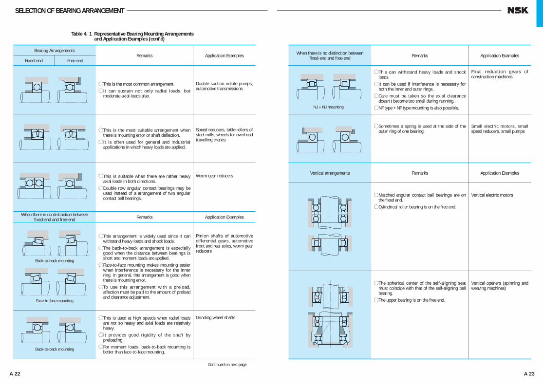
Table 4. 1 Representative Bearing Mounting Arrangements and Application Examples
Continued on next page
BEARING A⋅Deep Groove Ball Bearing⋅ Matched Angular Contact Ball Bearing
⋅ Double-Row Angular Contact Ball Bearing
⋅Self-Aligning Ball Bearing⋅ Cylindrical Roller Bearing with Ribs (NH, NUP types)
⋅ Double-Row Tapered Roller Bearing
⋅Spherical Roller Bearing
BEARING B⋅ Cylindrical Roller Bearing (NU, N types)
⋅ Needle Roller Bearing (NA type, etc.)
BEARING C(1)⋅Deep Groove Ball Bearing⋅ Matched Angular Contact Ball Bearing (back-to-back)
⋅ Double-Row Angular Contact Ball Bearing
⋅Self-Aligning Ball Bearing ⋅ Double-Row Tapered Roller Bearing (KBE type)
⋅Spherical Roller Bearing
BEARING F⋅Deep Groove Ball Bearing⋅Self-Aligning Ball Bearing⋅Spherical Roller Bearing
BEARING D,E(2)⋅ Angular Contact Ball Bearing
⋅Tapered Roller Bearing⋅Magneto Bearing⋅ Cylindrical Roller Bearing (NJ, NF types)
Notes: (1) In the figure, shaft elongation and contraction are relieved at the outside surface of the outer ring, but sometimes it is done at the bore.
(2) For each type, two bearings are used in opposition.
Fig. 4.1 Bearing Mounting Arrangements and Bearing Types
A007-023E.indd 20-21 A007-023E.indd 20-21 11/20/13 4:49:38 PM11/20/13 4:49:38 PM
A 22 A 23
Bearing Arrangements
When there is no distinction between fixed-end and free-end Remarks Application Examples
fThis arrangement is widely used since it can withstand heavy loads and shock loads.
fThe back-to-back arrangement is especially good when the distance between bearings is short and moment loads are applied.
fFace-to-face mounting makes mounting easier when interference is necessary for the inner ring. In general, this arrangement is good when there is mounting error.
fTo use this arrangement with a preload, affection must be paid to the amount of preload and clearance adjustment.
Pinion shafts of automotive differential gears, automotive front and rear axles, worm gear reducers
Remarks
fThis is the most common arrangement.fIt can sustain not only radial loads, but
moderate axial loads also.
Double suction volute pumps, automotive transmissions
fThis is the most suitable arrangement when there is mounting error or shaft deflection.
fIt is often used for general and industrial applications in which heavy loads are applied.
Speed reducers, table rollers of steel mills, wheels for overhead travelling cranes
fThis is suitable when there are rather heavy axial loads in both directions.
fDouble row angular contact bearings may be used instead of a arrangement of two angular contact ball bearings.
Worm gear reducers
fThis is used at high speeds when radial loads are not so heavy and axial loads are relatively heavy.
fIt provides good rigidity of the shaft by preloading.
fFor moment loads, back-to-back mounting is better than face-to-face mounting.
Grinding wheel shafts
Application ExamplesFixed-end Free-end
Back-to-back mounting
Back-to-back mounting
Face-to-face mounting
Table 4. 1 Representative Bearing Mounting Arrangements and Application Examples (cont'd)
Continued on next page
SELECTION OF BEARING ARRANGEMENT
When there is no distinction betweenfixed-end and free-end
Vertical arrangements Remarks Application Examples
fMatched angular contact ball bearings are on the fixed end.
fCylindrical roller bearing is on the free end.
Vertical electric motors
Remarks
fThis can withstand heavy loads and shock loads.
fIt can be used if interference is necessary for both the inner and outer rings.
fCare must be taken so the axial clearance doesn't become too small during running.
fNF type + NF type mounting is also possible.
F inal reduct ion gears of construction machines
fSometimes a spring is used at the side of the outer ring of one bearing.
Small electric motors, small speed reducers, small pumps
fThe spherical center of the self-aligning seat must coincide with that of the self-aligning ball bearing.
fThe upper bearing is on the free end.
Vertical openers (spinning and weaving machines)
Application Examples
NJ + NJ mounting
A007-023E.indd 22-23 A007-023E.indd 22-23 11/20/13 4:49:39 PM11/20/13 4:49:39 PM

A 24 A 25
By designating the basic rating life as Lh (h), bearing speed as n (min–1), fatigue life factor as fh, and speed factor as fn, the relations shown in Table 5.2 are obtained:
on which the bearings are to be mounted should also be considered. Bearings are used in a wide range of applications and the design life varies with specific applications and operating conditions. Table 5.1 gives an empirical fatigue life factor derived from customary operating experience for various machines. Also refer to Table 5.2.
5.2.3 Selection of Bearing Size Based on Basic Load Rating
The following relation exists between bearing load and basic rating life:
For ball bearings L = ( CP )3
. . . . . . . . . . . . . . . . (5.1)
For roller bearings L = ( CP )
103
. . . . . . . . . . . . . . (5.2)
where L : Basic rating life (106 rev) P : Bearing load (equivalent load) (N), {kgf} ..........(Refer to Page A30) C : Basic load rating (N), {kgf} For radial bearings, C is written Cr For thrust bearings, C is written Ca
In the case of bearings that run at a constant speed, it is convenient to express the fatigue life in terms of hours. In general, the fatigue life of bearings used in automobiles and other vehicles is given in terms of mileage.
5.1 Bearing LifeThe various functions required of rolling bearings vary according to the bearing application. These functions must be performed for a prolonged period. Even if bearings are properly mounted and correctly operated, they will eventually fail to perform satisfactorily due to an increase in noise and vibration, loss of running accuracy, deterioration of grease, or fatigue flaking of the rolling surfaces.Bearing life, in the broad sense of the term, is the period during which bearings continue to operate and to satisfy their required functions. This bearing life may be defined as noise life, abrasion life, grease life, or rolling fatigue life, depending on which one causes loss of bearing service.Aside from the failure of bearings to function due to natural deterioration, bearings may fail when conditions such as heat-seizure, fracture, scoring of the rings, damage of the seals or the cage, or other damage occurs.Conditions such as these should not be interpreted as normal bearing failure since they often occur as a result of errors in bearing selection, improper design or manufacture of the bearing surroundings, incorrect mounting, or insufficient maintenance.
5.1.1 Rolling Fatigue Life and Basic Rating LifeWhen rolling bearings are operated under load, the raceways of their inner and outer rings and rolling elements are subjected to repeated cyclic stress. Because of metal fatigue of the rolling contact surfaces of the raceways and rolling elements, scaly particles may separate from the bearing material (Fig. 5.1). This phenomenon is called "flaking". Rolling fatigue life is represented by the total number of revolutions at which time the bearing surface will start flaking due to stress. This is called fatigue life. As shown in Fig. 5.2, even for seemingly identical bearings, which are of the same type, size, and material and receive the same heat treatment and other processing, the rolling fatigue life varies greatly even under identical operating conditions. This is because the flaking of materials due to fatigue is subject to many other variables. Consequently, "basic rating life", in which rolling fatigue life is treated as a statistical phenomenon, is used in preference to actual rolling fatigue life.Suppose a number of bearings of the same type are operated individually under the same conditions. After a certain period of time, 10 % of them fail as a result of flaking caused by rolling fatigue. The total number of revolutions at this point is defined as the basic rating life or, if the speed is constant, the basic rating life is often expressed by the total number of operating hours completed when 10 % of the bearings become inoperable due to flaking.In determining bearing life, basic rating life is often the only factor considered. However, other factors must also be taken into account. For example, the grease life
of grease-prelubricated bearings (refer to Section 12, Lubrication, Page A107) can be estimated. Since noise life and abrasion life are judged according to individual standards for different applications, specific values for noise or abrasion life must be determined empirically.
5.2 Basic Load Rating and Fatigue Life5.2.1 Basic Load RatingThe basic load rating is defined as the constant load applied on bearings with stationary outer rings that the inner rings can endure for a rating life of one million revolutions (106 rev). The basic load rating of radial bearings is defined as a central radial load of constant direction and magnitude, while the basic load rating of thrust bearings is defined as an axial load of constant magnitude in the same direction as the central axis. The load ratings are listed under C r for radial bearings and C a for thrust bearings in the dimension tables.
5.2.2 Machinery in which Bearings are Used and Projected Life
It is not advisable to select bearings with unnecessarily high load ratings, for such bearings may be too large and uneconomical. In addition, the bearing life alone should not be the deciding factor in the selection of bearings. The strength, rigidity, and design of the shaft
5. SELECTION OF BEARING SIZE
Failu
re P
roba
bilit
y
Ratin
g Li
fe
Aver
age
Life
Life
Fig. 5.2 Failure Probability and Bearing Life
Fig. 5.1 Example of Flaking
Operating PeriodsFatigue Life Factor fh
~3 2~4 3~5 4~7 6~
Infrequently used or only for short periods
Used only occasionally but reliability is impor-tant
Used intermittently for relatively long periods
Used intermittently for more than eight hours daily
Used continuously and high reliability is impor-tant
• Small motors for home appliances like vacuum cleaners and washing machines
• Hand power tools
• Rolling mill roll necks
• Agricultural equipment
• Motors for home heaters and air conditioners
• Construction equipment
• Small motors• Deck cranes• General cargo cranes
• Pinion stands• Passenger cars• Escalators
• Conveyors• Elevator cable sheaves
• Factory motors• Machine tools• Transmissions• Vibrating screens• Crushers
• Centrifugal separators
• Air conditioning equipment
• Blowers• Woodworking machines
• Large motors• Axle boxes on railway rolling stock
• Crane sheaves• Compressors• Specialized transmissions
• Mine hoists• Press flywheels• Railway traction motors
• Locomotive axle boxes
• Paper making machines
• Waterworks pumps• Electric power stations
• Mine draining pumps
Table 5. 1 Fatigue Life Factor fh for Various Bearing Applications
LifeParameters
BasicRatingLife
FatigueLifeFactor
SpeedFactor
Ball Bearings Roller Bearings
Table 5. 2 Basic Rating Life, Fatigue Life Factor and Speed Factor
n, fn...... Fig. 5.3 (See Page A26), Appendix Table 12 (See Page C24)
Lh, fh.... Fig. 5.4 (See Page A26), Appendix Table 13 (See Page C25)
Lh=106
60n(CP)3
=500 fh3
fh = fnCP
fn =( 106
500×60n ) 13
=(0.03n)-13
fn =( 106
500×60n ) 310
=(0.03n)-310
fh = fnCP
Lh=106
60n(CP)10
3 =500 fh
103
A024-057E.indd 24-25 A024-057E.indd 24-25 11/20/13 4:50:10 PM11/20/13 4:50:10 PM

A 26 A 27
If the bearing load P and speed n are known, determine a fatigue life factor fh appropriate for the projected life of the machine and then calculate the basic load rating C by means of the following equation.
C = fh ⋅ P
fn . . . . . . . . . . . . . . . . . . . . . . . (5.3)
A bearing which satisfies this value of C should then be selected from the bearing tables.
5.2.4 Temperature Adjustment for Basic Load Rating
If rolling bearings are used at high temperature, the hardness of the bearing steel decreases. Consequently, the basic load rating, which depends on the physical properties of the material, also decreases. Therefore, the basic load rating should be adjusted for the higher temperature using the following equation:
Ct = f t ⋅ C . . . . . . . . . . . . . . . . . . . . . . . (5.4)
where Ct : Basic load rating after temperature correction(N), {kgf}
f t : Temperature factor(See Table 5.3.)
C : Basic load rating before temperature adjustment(N), {kgf}
If large bearings are used at higher than 120oC, they must be given special dimensional stability heat treatment to prevent excessive dimensional changes. The basic load rating of bearings given such special dimensional stability heat treatment may become lower than the basic load rating listed in the bearing tables.
5.2.5 Correction of Basic Rating LifeAs described previously, the basic equations for calculating the basic rating life are as follows:
For ball bearings L10 = ( CP )3
. . . . . . . . . . . . . . . . . (5.5)
For roller bearings L10 = ( CP )
103 . . . . . . . . . . . . . . . (5.6)
The L10 life is defined as the basic rating life with a statistical reliability of 90%. Depending on the machines in which the bearings are used, sometimes a reliability higher than 90% may be required. However, recent improvements in bearing material have greatly extended the fatigue life. In addition, the developent of the Elasto-Hydrodynamic Theory of Lubrication proves that the thickness of the lubricating film in the contact zone between rings and rolling elements greatly influences bearing life. To reflect such improvements in the calculation of fatigue life, the basic rating life is adjusted using the following adjustment factors:
Lna = a1 a2 a3 L10 . . . . . . . . . . . . . . . . . . . . . . . . . . . (5.7)
where Lna : Adjusted rating life in which reliability, material improvements, lubricating conditions, etc. are considered
L10 : Basic rating life with a reliability of 90% a1 : Life adjustment factor for reliability a2 : Life adjustment factor for special bearing
properties a3 : Life adjustment factor for operating
conditionsThe life adjustment factor for reliability, a1, is listed in Table 5.4 for reliabilities higher than 90%.The life adjustment factor for special bearing properties, a 2, is used to reflect improvements in bearing steel.NSK now uses vacuum degassed bearing steel, and the results of tests by NSK show that life is greatly improved when compared with earlier materials. The basic load ratings Cr and Ca listed in the bearing tables were calculated considering the extended life achieved by improvements in materials and manufacturing techniques. Consequently, when estimating life using Equation (5.7), it is sufficient to assume that is greater than one.
The life adjustment factor for operating conditions a3 is used to adjust for various factors, particularly lubrication. If there is no misalignment between the inner and outer rings and the thickness of the lubricating film in the contact zones of the bearing is sufficient, it is possible for a3 to be greater than one; however, a3 is less than one in the following cases:
• When the viscosity of the lubricant in the contact zones between the raceways and rolling elements is low.
• When the circumferential speed of the rolling elements is very slow.
• When the bearing temperature is high.• When the lubricant is contaminated by water or foreign matter.
• When misalignment of the inner and outer rings is excessive.
It is difficult to determine the proper value for a3 for specific operating conditions because there are still many unknowns. Since the special bearing property factor a2 is also influenced by the operating conditions, there is a proposal to combine a2 and a3 into one quantity(a2×a3), and not consider them independently. In this case, under normal lubricating and operating conditions, the product (a2×a3) should be assumed equal to one. However, if the viscosity of the lubricant is too low, the value drops to as low as 0.2.If there is no misalignment and a lubricant with high viscosity is used so sufficient fluid-film thickness is secured, the product of (a2×a3) may be about two.
When selecting a bearing based on the basic load rating, it is best to choose an a 1 reliability factor appropriate for the projected use and an empirically determined C/P or fh value derived from past results for lubrication, temperature, mounting conditions, etc. in similar machines.
The basic rating life equations (5.1), (5.2), (5.5), and (5.6) give satisfactory results for a broad range of bearing loads. However, extra heavy loads may cause detrimental plastic deformation at ball/raceway contact points. When Pr exceeds C 0r (Basic static load rating) or 0.5 Cr, whichever is smaller, for radial bearings or Pa exceeds 0.5 Ca for thrust bearings, please consult NSK to establish the applicablity of the rating fatigue life equations.
SELECTION OF BEARING SIZE
Fig. 5.3 Bearing Speed and Speed Factor
Fig. 5.4 Fatigue Life Factor and Fatigue Life
Bearing
Temperature oC 125 150 175 200 250
1.00 1.00 0.95 0.90 0.75Temperature
Factor ft
Table 5.3 Temperature Factor f t
Reliability (%) 90 95 96 97 98 99
1.00 0.62 0.53 0.44 0.33 0.21a1
Table 5.4 Reliability Factor a1
60000 0.08
0.09
0.1
0.12
0.14
0.16
0.18
0.20
0.25
0.3
0.4
0.5
0.6
0.7
0.8
0.9
1.0
1.1
1.2
1.31.41.5
40000
30000
20000
15000
10000
8000
6000
4000
3000
2000
1500
1000
800
600
400
300
200
150
100
80
6050
40
30
20
15
10
60000 0.1050.11
0.12
0.13
0.14
0.15
0.16
0.170.180.190.20
0.25
0.30
0.35
0.40
0.45
0.5
0.6
0.7
0.8
0.9
1.0
1.1
1.2
1.3
1.4
40000
30000
20000
15000
10000
8000
6000
4000
3000
2000
1500
1000
800
600
400
300
200
150
100
80
6050
40
30
20
15
10
80000
60000
40000
30000
20000
15000
10000
8000
6000
4000
3000
2000
1500
1000
800
600
500
400
300
200
5.5
5.0
4.5
4.0
3.5
3.0
2.5
2.0
1.9
1.8
1.7
1.6
1.5
1.4
1.3
1.2
1.1
1.0
0.950.90
0.85
0.80
0.75
80000
60000
40000
30000
20000
15000
10000
8000
6000
4000
3000
2000
1500
1000
800
600
500
400
300
200
4.5
4.0
3.5
3.0
2.5
2.0
1.9
1.8
1.7
1.6
1.5
1.4
1.3
1.2
1.1
1.0
0.95
0.90
0.85
0.80
0.75
n fn fn fhLh
(min–1)n
(min–1) (h)fhLh
(h)
BallBearings
RollerBearings
BallBearings
RollerBearings
A024-057E.indd 26-27 A024-057E.indd 26-27 11/20/13 4:50:12 PM11/20/13 4:50:12 PM

A 28 A 29
5.3.3 Bearing Loads in Gear Transmission Applications
The loads imposed on gears in gear transmissions vary according to the type of gears used. In the simplest case of spur gears, the load is calculated as follows:
M = 9 550 000H / n ....(N ⋅ mm ) }...........(5.12) = 0 974 000H / n ....{kgf ⋅mm}
Pk = M / r .............................................(5.13)Sk = Pk tan θ ...........................................(5.14)Kc = √⎯
Pk2+⎯Sk2 = Pk sec θ .........................(5.15)
where M : Torque applied to gear(N . mm),{kgf . mm}
Pk : Tangential force on gear (N), {kgf} Sk : Radial force on gear (N), {kgf} Kc : Combined force imposed on gear
(N), {kgf} H : Power transmitted (kW)
n : Speed (min–1)
r : Pitch circle radius of drive gear (mm)
θ : Pressure angle
In addition to the theoretical load calculated above, vibration and shock (which depend on how accurately the gear is finished) should be included using the gear factor fg by multiplying the theoretically calculated load by this factor.The values of fg should generally be those in Table 5.7. When vibration from other sources accompanies gear operation, the actual load is obtained by multiplying the load factor by this gear factor.
5.3.4 Load Distribution on BearingsIn the simple examples shown in Figs. 5.5 and 5.6. The radial loads on bearings 1 and 2 can be calculated using the following equations:
FC1 = bc K ...............................................(5.16)
FC2 = ac K ..............................................(5.17)
where FC1 : Radial load applied on bearing1(N), {kgf}
FC2 : Radial load applied on bearing 2(N), {kgf}
K : Shaft load (N), {kgf}
When these loads are applied simultaneously, first the radial load for each should be obtained, and then, the sum of the vectors may be calculated according to the load direction.
5.3.5 Average of Fluctuating LoadWhen the load applied on bearings fluctuates, an average load which will yield the same bearing life as the fluctuating load should be calculated.
(1) When the relation between load and rotating speed is divided into the following steps (Fig. 5.7)
Load F1 : Speed n1 ; Operating time t1 Load F2 : Speed n2 ; Operating time t2
………
Load Fn : Speed nn ; Operating time tn
Then, the average load Fm may be calculated using the following equation:
Fm = p√⎯⎯⎯⎯⎯⎯⎯⎯⎯⎯⎯⎯ F1
pn1t1+F2pn2t2+ ...+Fn
pnntn
n1t1+ n2t2+ .........+nntn ..........................(5.18)
where Fm : Average fluctuating load (N), {kgf} p = 3 for ball bearings p = 10/3 for roller bearings
SELECTION OF BEARING SIZE
5.3 Calculation of Bearing LoadsThe loads applied on bearings generally include the weight of the body to be supported by the bearings, the weight of the revolving elements themselves, the transmission power of gears and belting, the load produced by the operation of the machine in which the bearings are used, etc. These loads can be theoretically calculated, but some of them are difficult to estimate. Therefore, it becomes necessary to correct the estimated using empirically derived data.
5.3.1 Load FactorWhen a radial or axial load has been mathematically calculated, the actual load on the bearing may be greater than the calculated load because of vibration and shock present during operation of the machine. The actual load may be calculated using the following equation:
Fr = fw ⋅ Frc } . . . . . . . . . . . . . . . . . . . . . . . . . . . . . . . . (5.8)Fa = fw ⋅ Fac
where Fr, Fa : Loads applied on bearing (N), {kgf} Frc, Fac : Theoretically calculated load (N),
{kgf} fw : Load factor
The values given in Table 5.5 are usually used for the load factor fw.
5.3.2 Bearing Loads in Belt or Chain Transmission Applications
The force acting on the pulley or sprocket wheel when power is transmitted by a belt or chain is calculated using the following equations.
M = 9 550 000H / n ....(N ⋅ mm ) }.............(5.9) = 0 974 000H / n ....{kgf ⋅mm}
Pk = M / r .............................................(5.10)
where M : Torque acting on pulley or sprocket wheel (N ⋅mm), {kgf ⋅ mm}
Pk : Effective force transmitted by belt or chain (N), {kgf}
H : Power transmitted(kW)
n : Speed (min–1)
r : Effective radius of pulley or sprocket wheel (mm)
When calculating the load on a pulley shaft, the belt tension must be included. Thus, to calculate the actual load Kb in the case of a belt transmission, the effective transmitting power is multiplied by the belt factor fb, which represents the belt tension. The values of the belt factor fb for different types of belts are shown in Table 5.6. Kb = fb ⋅ Pk .........................................(5.11)In the case of a chain transmission, the values corresponding to fb should be 1.25 to 1.5.
Operating Conditions
Smooth operationfree from shocks
Normal operation
Operationaccompanied byshock and vibration
Electric motors,Machine tools,Air conditioners
Air blowers,Compressors,Elevators, Cranes,Paper makingmachines
Constructionequipment, Crushers,Vibrating screens,Rolling mills
1.0 to 1.2
1.2 to 1.5
1.5 to 3.0
Typical Applications fw
Table 5. 5 Values of Load Factor fw
Type of Belt
Toothed belts 1.3 to 2.0
V belts 2.0 to 2.5
Flat belts with tension pulley 2.5 to 3.0
Flat belts 4.0 to 5.0
fb
Table 5. 6 Belt Factor fb
ca b
F
K
C1 FC2
Bearing1 Bearing2
Fig. 5.5 Radial Load Distribution (1)
ca
b
FC1
FK
C2Bearing1 Bearing2
Fig. 5.6 Radial Load Distribution (2)
Gear Finish Accuracy
Precision ground gears 1.0~1.1
Ordinary machined gears 1.1~1.3
fg
Table 5. 7 Values of Gear Factor fg
A024-057E.indd 28-29 A024-057E.indd 28-29 11/20/13 4:50:13 PM11/20/13 4:50:13 PM

A 30 A 31
niti
F
F
0
(a)
m
Fmax
niti
F
F
0
(b)
m
Fmax
Fig. 5.9 Sinusoidal Load Variation
n1 t1 n2 t2 nn tn
F
F
0
1
F2 Fm
Fn
Fmax
Fig. 5.7 Incremental Load Variation Fig. 5.8 Simple Load Fluctuation Fig. 5.10 Rotating Load and Stationary Load
F
0
FmFs
FRFmin
∑
niti∑
∑
5.4.1 Calculation of Equivalent LoadsThe equivalent load on radial bearings may be calculated using the following equation:
P = XFr + YFa ........................................(5.25)where P : Equivalent Load (N), {kgf} Fr : Radial load (N), {kgf} Fa : Axial load (N), {kgf} X : Radial load factor Y : Axial load factorThe values of X and Y are listed in the bearing tables. The equivalent radial load for radial roller bearings with α = 0° is
P = Fr
In general, thrust ball bearings cannot take radial loads, but spherical thrust roller bearings can take some radial loads. In this case, the equivalent load may be calculated using the following equation:
P = Fa + 1.2Fr ..................................(5.26)
where Fr
Fa≤0.55
5.4.2 Axial Load Components in Angular Contact Ball Bearings and Tapered Roller Bearings
The effective load center of both angular contact ball bearings and tapered roller bearings is at the point of intersection of the shaft center line and a line representing the load applied on the rolling element by the outer ring as shown in Fig. 5.11. This effective load
center for each bearing is listed in the bearing tables.When radial loads are applied to these types of bearings, a component of load is produced in the axial direction. In order to balance this component load, bearings of the same type are used in pairs, placed face to face or back to back. These axial loads can be calculated using the following equation:
Fa i = 0.6Y
Fr ...................................(5.27)
where Fa i : Component load in the axial direction (N), {kgf}
Fr : Radial load (N), {kgf} Y : Axial load factorAssume that radial loads Fr1 and Fr2 are applied on bearings1and 2 (Fig. 5.12) respectively, and an external axial load Fae is applied as shown. If the axial load factors are Y1, Y2 and the radial load factor is X, then the equivalent loads P1 , P2 may be calculated as follows:
where Fae + 0.6Y2
Fr2≥0.6Y1
Fr1
P1 = XFr1 + Y1 (Fae + 0.6Y2
Fr2) } ..............(5.28)P2 = Fr2
where Fae + 0.6Y2
Fr2<0.6Y1
Fr1
P1 = Fr1 } ...............(5.29)P2 = XFr2 + Y2 ( 0.6
Y1 Fr1 − Fae)
SELECTION OF BEARING SIZE
The average speed nm may be calculated as follows:
nm = n1t1+n2t2+ ...+nntn
t1+ t2+ .........+ tn ........................(5.19)
(2) When the load fluctuates almost linearly (Fig. 5.8), the average load may be calculated as follows:
FmH 13
(Fmin + 2Fmax) .........................(5.20)
where Fmin : Minimum value of fluctuating load(N), {kgf}
Fmax : Maximum value of fluctuating load(N), {kgf}
(3) When the load fluctuation is similar to a sine wave (Fig. 5.9), an approximate value for the average load Fm may be calculated from the following equation:In the case of Fig. 5.9 (a)FmH0.65 Fmax ........................................(5.21)In the case of Fig. 5.9 (b)FmH0.75 Fmax ........................................(5.22)
(4) When both a rotating load and a stationary load are applied (Fig. 5.10).
FR : Rotating load (N), {kgf} FS : Stationary load (N), {kgf}
An approximate value for the average load Fm may be calculated as follows:
a) Where FR≥FS FmHFR + 0.3FS + 0.2
FS2
FR..........................(5.23)
b) Where FR<FS
FmHFS + 0.3FR + 0.2FR
2
FS..........................(5.24)
5.4 Equivalent LoadIn some cases, the loads applied on bearings are purely radial or axial loads; however, in most cases, the loads are a combination of both. In addition, such loads usually fluctuate in both magnitude and direction. In such cases, the loads actually applied on bearings cannot be used for bearing life calculations; therefore, a hypothetical load that has a constant magnitude and passes through the center of the bearing, and will give the same bearing life that the bearing would attain under actual conditions of load and rotation should be estimated. Such a hypothetical load is called the equivalent load.
a a
FrI
FaeFr2
Bearing I Bearing2
Fig. 5.11 Effective Load Centers Fig. 5.12 Loads in Opposed Duplex Arrangement
α α
(a)
FrIFae Fr2
Bearing I Bearing2
(b)
A024-057E.indd 30-31 A024-057E.indd 30-31 11/20/13 4:50:15 PM11/20/13 4:50:15 PM

A 32 A 33
5.6 Maximum Permissible Axial Loads for Cylindrical Roller Bearings
Cylindrical roller bearings having inner and outer rings with ribs, loose ribs or thrust collars are capable of sustaining radial loads and limited axial loads simultaneously. The maximum permissible axial load is limited by an abnormal temperature rise or heat seizure due to sliding friction between the end faces of rollers and the rib face, or the rib strength.The maximum permissible axial load (the load considered the heat generation between the end face of rollers and the rib face) for bearings of diameter series 3 that are continuously loaded and lubricated with grease or oil is shown in Fig. 5.13.
Grease lubrication (Empirical equation)
CA = 9.8f { 900 (k⋅d)2
n + 1 500 − 0.023 × (k⋅d)2.5}...(N)
} .......(5.34) = f { 900 (k⋅d)2
n + 1 500 − 0.023 × (k⋅d)2.5}.....{kgf}
Oil lubrication (Empirical equation)
CA = 9.8f {490 (k⋅d)2
n + 1 000 − 0.000135 × (k⋅d)3.4}...(N)
} ...(5.35) = f { 490 (k⋅d)2
n + 1 000 − 0.000135 × (k⋅d)3.4}.....{kgf}
where CA : Permissible axial load (N), {kgf} d : Bearing bore diameter (mm) n : Speed (min–1)
In the equations (5.34) and (5.35), the examination for the rib strength is excluded. Concerning the rib strength, please consult with NSK.In addition, for cylindrical roller bearings to have a stable axial-load carrying capacity, the following precautions are required for the bearings and their surroundings:
• Radial load must be applied and the magnitude of radial load should be larger than that of axial load by 2.5 times or more.
• Sufficient lubricant must exist between the roller end faces and ribs.
• Superior extreme-pressure grease must be used.• Sufficient running-in should be done.• The mounting accuracy must be good.• The radial clearance should not be more than necessary.
In cases where the bearing speed is extremely slow, the speed exceeds the limiting speed by more than 50%, or the bore diameter is more than 200mm, careful study is necessary for each case regarding lubrication, cooling, etc. In such a case, please consult with NSK.
SELECTION OF BEARING SIZE
5.5 Static Load Ratings and Static Equivalent Loads
5.5.1 Static Load RatingsWhen subjected to an excessive load or a strong shock load, rolling bearings may incur a local permanent deformation of the rolling elements and permanent deformation of the rolling elements and raceway surface if the elastic limit is exceeded. The nonelastic deformation increases in area and depth as the load increases, and when the load exceeds a certain limit, the smooth running of the bearing is impeded.The basic static load rating is defined as that static load which produces the following calculated contact stress at the center of the contact area between the rolling element subjected to the maximum stress and the raceway surface.
For self-aligning ball bearings 4 600MPa {469kgf/mm2}For other ball bearings 4 200MPa {428kgf/mm2}For roller bearings 4 000MPa {408kgf/mm2}
In this most heavily stressed contact area, the sum of the permanent deformation of the rolling element and that of the raceway is nearly 0.0001 times the rolling element's diameter. The basic static load rating Co is written Cor for radial bearings and Coa for thrust bearings in the bearing tables.In addition, following the modification of the criteria for basic static load rating by ISO, the new Co values for NSK's ball bearings became about 0.8 to 1.3 times the past values and those for roller bearings about 1.5 to 1.9 times. Consequently, the values of permissible static load factor fs have also changed, so please pay attention to this.
5.5.2 Static Equivalent LoadsThe static equivalent load is a hypothetical load that produces a contact stress equal to the above maximum stress under actual conditions, while the bearing is stationary (including very slow rotation or oscillation), in the area of contact between the most heavily stressed rolling element and bearing raceway. The static radial load passing through the bearing center is taken as the static equivalent load for radial bearings, while the static axial load in the direction coinciding with the central axis is taken as the static equivalent load for thrust bearings.(a) Static equivalent load on radial bearingsThe greater of the two values calculated from the following equations should be adopted as the static equivalent load on radial bearings.
Po = XoFr + YoFa ...................................(5.30)Po = Fr ..................................................(5.31)
where Po : Static equivalent load (N), {kgf} Fr : Radial load (N), {kgf} Fa : Axial load (N), {kgf} Xo : Static radial load factor Yo : Static axial load factor (b)Static equivalent load on thrust bearings
Po = XoFr + Fa α =/ 90° .......................(5.32)
where Po : Static equivalent load (N), {kgf} α : Contact angleWhen Fa<Xo Fr , this equation becomes less accurate.The values of Xo and Yo for Equations (5.30) and (5.32) are listed in the bearing tables.The static equivalent load for thrust roller bearings with
α = 90° is Po = Fa
5.5.3 Permissible Static Load FactorThe permissible static equivalent load on bearings varies depending on the basic static load rating and also their application and operating conditions.The permissible static load factor fs is a safety factor that is applied to the basic static load rating, and it is defined by the ratio in Equation (5.33). The generally recommended values of fs are listed in Table 5.8. Conforming to the modification of the static load rating, the values of fs were revised, especially for bearings for which the values of Co were increased, please keep this in mind when selecting bearings.
fs = CoPo
...............................................(5.33)
where Co : Basic static load rating (N), {kgf} Po : Static equivalent load (N), {kgf}For spherical thrust roller bearings, the values of fs should be greater than 4.
Loading Interval Value of f
Continuous 1 Intermittent 2 Short time only 3
Diameter series Value of k
2 0.75 3 1 4 1.2
f : Load Factor k : Size Factor
kgf N
C
n
A
min–1
5,0004,000
3,000
2,000
1,000800
600500400300
200
10080
6050
50,00040,000
30,000
20,000
10,0008,000
6,0005,0004,000
3,000
2,000
1,000800
600500
200 300 400 600 1,000 2,000 4,000 6,000 10,000
d=12010080
6050
40
Grease Lubrication
kgf N
n min–1
5,0004,000
3,000
2,000
1,000800
600500400300
200
10080
6050
50,00040,000
30,000
20,000
10,0008,000
6,0005,0004,000
3,000
2,000
1,000800
600500
200 300 400 600 1,000 2,000 4,000 6,000 10,000
d=12010080
6050
40
Oil Lubrication
Fig. 5.13 Permissible Axial Load for Cylindrical Roller BearingsFor Diameter Series 3 bearings (k=1.0) operating under a continuous load and lubricated with grease or oil.
CA
Operating Conditions
Low-noise applications 2.0 3.0 Bearings subjected to vibration and shock loads 1.5 2.0
Standard operating conditions 1.0 1.5
Lower Limit of fs
Table 5. 8 Values of Permissible Static Load Factor fs
Ball Bearings Roller Bearings
A024-057E.indd 32-33 A024-057E.indd 32-33 11/20/13 4:50:16 PM11/20/13 4:50:16 PM
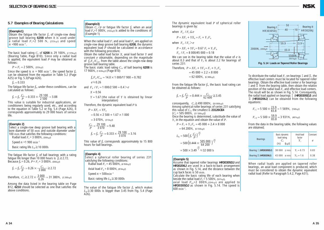
A 34 A 35
The dynamic equivalent load P of spherical roller bearings is given by:
when Fa / Fr≤eP = XFr + YXa = Fr + Y3 Fa
when Fa / Fr>eP = XFr + YFa = 0.67 Fr + Y2 Fa
Fa / Fr = 8 000/45 000 = 0.18We can see in the bearing table that the value of e is about 0.3 and that of Y3 is about 2.2 for bearings of series 231:Therefore, P = XFr + YFa = Fr + Y3 Fa
= 45 000 + 2.2 × 8 000 = 62 600N, {6 380kgf}
From the fatigue life factor fh, the basic load rating can be obtained as follows:
fh = fn CrP
= 0.444 × Cr62 600≥3.45
consequently, Cr≥490 000N, {50 000kgf}Among spherical roller bearings of series 231 satisfying this value of Cr, the smallest is 23126CE4(Cr = 505 000N, {51 500kgf})Once the bearing is determined, substitude the value of Y3 in the equation and obtain the value of P.
P = Fr + Y3 Fa = 45 000 + 2.4 × 8 000 = 64 200N, {6 550kgf}
Lh = 500 ( fn CrP )
103
= 500 (0.444 × 505 00064 200 )
103
= 500 × 3.49103H32 000 h
To distribute the radial load Fr on bearings1and 2, the effective load centers must be located for tapered roller bearings. Obtain the effective load center a for bearings 1and 2 from the bearing table, then obtain the relative position of the radial load Fr and effective load centers. The result will be as shown in Fig. 5.14. Consequently, the radial load applied on bearings1 (HR30305DJ) and 2 (HR30206J) can be obtained from the following equations:
Fr1 = 5 500 × 23.983.8
= 1 569N, {160kgf}
Fr2 = 5 500 × 59.983.8
= 3 931N, {401kgf}
From the data in the bearing table, the following values are obtained;
When radial loads are applied on tapered roller bearings, an axial load component is produced, which must be considered to obtain the dynamic equivalent radial load (Refer to Paragraph 5.4.2, Page A31).
SELECTION OF BEARING SIZE
5.7 Examples of Bearing Calculations
The basic load rating Cr of 6208 is 29 100N, {2 970kgf} (Bearing Table, Page B10). Since only a radial load is applied, the equivalent load P may be obtained as follows:
P = Fr = 2 500N, {255kgf}
Since the speed is n = 900 min–1, the speed factor fn can be obtained from the equation in Table 5.2 (Page A25) or Fig. 5.3(Page A26).
fn = 0.333The fatigue life factor fh, under these conditions, can be calculated as follows:
fh = fn CrP = 0.333 × 29 100
2 500 = 3.88
This value is suitable for industrial applications, air conditioners being regularly used, etc., and according to the equation in Table 5.2 or Fig. 5.4 (Page A26), it corresponds approximately to 29 000 hours of service life.
The fatigue life factor fh of ball bearings with a rating fatigue life longer than 10 000 hours is fh≥2.72.Because fn = 0.26, P = Fr = 3 000N. {306kgf}
fh = fn CrP
= 0.26 × Cr3 000 ≥2.72
therefore, Cr≥2.72 × 3 0000.26
= 31 380N, {3 200kgf}
Among the data listed in the bearing table on Page B12, 6210 should be selected as one that satisfies the above conditions.
When the radial load Fr and axial load Fa are applied on single-row deep groove ball bearing 6208, the dynamic equivalent load P should be calculated in accordance with the following procedure.Obtain the radial load factor X, axial load factor Y and constant e obtainable, depending on the magnitude of foFa /Cor, from the table above the single-row deep groove ball bearing table.The basic static load rating Cor of ball bearing 6208 is17 900N, {1 820kgf} (Page B10)
foFa /Cor = 14.0 × 1 000/17 900 = 0.782
eH0.26
and Fa / Fr = 1 000/2 500 = 0.4>e
X = 0.56
Y = 1.67 (the value of Y is obtained by linear interpolation)
Therefore, the dynamic equivalent load P is
P = XFr + YFa
= 0.56 × 2 500 + 1.67 × 1 000
= 3 070N, {313kgf}
CrP
= 29 1003 070 = 9.48
fh = fn CrP
= 0.333 × 29 1003 070
= 3.16
This value of fh corresponds approximately to 15 800 hours for ball bearings.
The value of the fatigue life factor fh which makes Lh≥30 000h is bigger than 3.45 from Fig. 5.4 (Page A26).
(Example1)Obtain the fatigue life factor fh of single-row deep groove ball bearing 6208 when it is used under a radial load Fr=2 500 N, {255kgf} and speedn =900 min–1.
(Example 2)Select a single-row deep groove ball bearing with a bore diameter of 50 mm and outside diameter under 100 mm that satisfies the following conditions:
Radial load Fr = 3 000N, {306kgf}
Speed n =1 900 min–1
Basic rating life Lh≥10 000h
(Example3)Obtain Cr / P or fatigue life factor fh when an axial load Fa=1 000N, {102kgf} is added to the conditions of (Example 1)
(Example 4)Select a spherical roller bearing of series 231 satisfying the following conditions:
Radial load Fr = 45 000N, {4 950kgf}
Axial load Fa = 8 000N, {816kgf}
Speed n = 500min–1
Basic rating life Lh≥30 000h
Fig. 5.14 Loads on Tapered Roller Bearings
Bearing I Bearing II50
40 10HR30305DJ HR30206J
59.9
83.8
23.9
5500N
2000N, {204kgf}
{561kgf}
Bearings
Basic dynamicload rating
Cr (N) {kgf}
Axial loadfactorY1
Constant
e
Bearing 1 (HR30305DJ) 38 000 {3 900} Y1 = 0.73 0.83
Bearing 2 (HR30206J) 43 000 {4 400} Y2 = 1.60 0.38
(Example 5)Assume that tapered roller bearings HR30305DJ and HR30206J are used in a back-to-back arrangement as shown in Fig. 5.14, and the distance between the cup back faces is 50 mm.Calculate the basic rating life of each bearing when beside the radial load Fr = 5 500N, {561kgf},axial load Fae=2 000N, {204kgf} are applied to HR30305DJ as shown in Fig. 5.14. The speed is 600 min–1.
A024-057E.indd 34-35 A024-057E.indd 34-35 11/20/13 4:50:17 PM11/20/13 4:50:17 PM
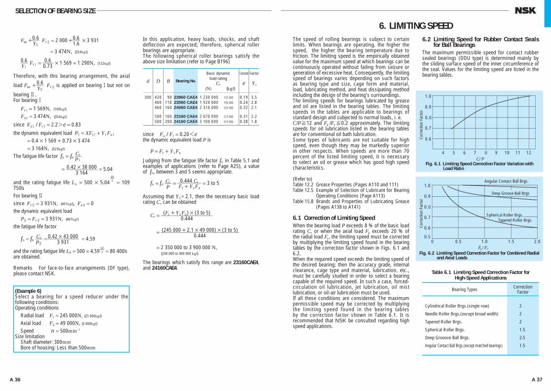
A 36 A 37
The speed of rolling bearings is subject to certain limits. When bearings are operating, the higher the speed, the higher the bearing temperature due to friction. The limiting speed is the empirically obtained value for the maximum speed at which bearings can be continuously operated without failing from seizure or generation of excessive heat. Consequently, the limiting speed of bearings varies depending on such factors as bearing type and size, cage form and material, load, lubricating method, and heat dissipating method including the design of the bearing's surroundings.The limiting speeds for bearings lubricated by grease and oil are listed in the bearing tables. The limiting speeds in the tables are applicable to bearings of standard design and subjected to normal loads, i. e.C/P≥12 and Fa /Fr≤0.2 approximately. The limiting speeds for oil lubrication listed in the bearing tables are for conventional oil bath lubrication.Some types of lubricants are not suitable for high speed, even though they may be markedly superior in other respects. When speeds are more than 70 percent of the listed limiting speed, it is necessary to select an oil or grease which has good high speed characteristics.
(Refer to)Table 12.2 Grease Properties (Pages A110 and 111)Table 12.5 Example of Selection of Lubricant for Bearing
Operating Conditions (Page A113)Table 15.8 Brands and Properties of Lubricating Grease
(Pages A138 to A141)
6.1 Correction of Limiting SpeedWhen the bearing load P exceeds 8 % of the basic load rating C, or when the axial load Fa exceeds 20 % of the radial load Fr, the limiting speed must be corrected by multiplying the limiting speed found in the bearing tables by the correction factor shown in Figs. 6.1 and 6.2.When the required speed exceeds the limiting speed of the desired bearing; then the accuracy grade, internal clearance, cage type and material, lubrication, etc., must be carefully studied in order to select a bearing capable of the required speed. In such a case, forced-circulation oil lubrication, jet lubrication, oil mist lubrication, or oil-air lubrication must be used.If all these conditions are considered. The maximum permissible speed may be corrected by multiplying the limiting speed found in the bearing tables by the correction factor shown in Table 6.1. It is recommended that NSK be consulted regarding high speed applications.
6.2 Limiting Speed for Rubber Contact Seals for Ball Bearings
The maximum permissible speed for contact rubber sealed bearings (DDU type) is determined mainly by the sliding surface speed of the inner circumference of the seal. Values for the limiting speed are listed in the bearing tables.
6. LIMITING SPEED
SELECTION OF BEARING SIZE
Fae + 0.6Y2
Fr2 = 2 000 + 0.61.6 × 3 931
= 3 474N, {354kgf}
0.6Y1
Fr1 = 0.60.73 × 1 569 = 1 290N, {132kgf}
Therefore, with this bearing arrangement, the axial
load Fae + 0.6Y2
Fr2 is applied on bearing1but not on
bearing 2.For bearing1
Fr1 = 1 569N, {160kgf}
Fa1 = 3 474N, {354kgf}
since Fa1 / Fr1 = 2.2>e = 0.83
the dynamic equivalent load P1 = XFr1 + Y1Fa1
= 0.4 × 1 569 + 0.73 × 3 474= 3 164N, {323kgf}
The fatigue life factor fh = fn CrP1
= 0.42 × 38 0003 164
= 5.04
and the rating fatigue life Lh = 500 × 5.04103 = 109
750hFor bearing 2since Fr2 = 3 931N, {401kgf}, Fa2 = 0the dynamic equivalent load
P2 = Fr2 = 3 931N, {401kgf}
the fatigue life factor
fh = fn CrP2
= 0.42 × 43 0003 931
= 4.59
and the rating fatigue life Lh = 500 × 4.59103 = 80 400h
are obtained.
Remarks For face-to-face arrangements (DF type), please contact NSK.
In this application, heavy loads, shocks, and shaft deflection are expected; therefore, spherical roller bearings are appropriate.The following spherical roller bearings satisfy the above size limitation (refer to Page B196)
since Fa / Fr = 0.20<e the dynamic equivalent load P is
P = Fr + Y3 Fa
Judging from the fatigue life factor fh in Table 5.1 and examples of applications (refer to Page A25), a value of fh, between 3 and 5 seems appropriate.
fh = fn CrP
= 0.444 Cr
Fr + Y3 Fa = 3 to 5
Assuming that Y3 = 2.1, then the necessary basic load rating Cr can be obtained
Cr = (Fr + Y3 Fa) × (3 to 5)0.444
= (245 000 + 2.1 × 49 000) × (3 to 5)0.444
= 2 350 000 to 3 900 000 N, {240 000 to 400 000 kgf}
The bearings which satisfy this range are 23160CAE4, and 24160CAE4.
Angular Contact Ball Brgs.
Deep Groove Ball Brgs
Spherical Roller Brgs. Tapered Roller Brgs.
Fig. 6.1 Limiting Speed Correction Factor Variation with Load Ratio
Fig. 6.2 Limiting Speed Correction Factor for Combined Radial and Axial Loads
1.0
0.9
0.8
0.7
0.6
1.0
0.9
0.8
0.7
0.6
0.5
4 5
0 0.5 1.0 1.5 2.0
6 7 8 9 10 11 12C/P
F /Fa r
Corr
ectio
n Fa
ctor
Corr
ectio
n Fa
ctor
Bearing Types
Cylindrical Roller Brgs.(single row) 2
Needle Roller Brgs.(except broad width) 2
Tapered Roller Brgs. 2
Spherical Roller Brgs. 1.5
Deep Grooove Ball Brgs. 2.5
Angular Contact Ball Brgs.(except matched bearings) 1.5
Table 6.1 Limiting Speed Correction Factor forHigh-Speed Applications
(Example 6)Select a bearing for a speed reducer under the following conditions:Operating conditions
Radial load Fr = 245 000N, {25 000kgf}
Axial load Fa = 49 000N, {5 000kgf}
Speed n = 500min–1
Size limitationShaft diameter: 300mmBore of housing: Less than 500mm
d D B
Basic dynamicload rating
Cr(N) {kgf}
Constant
e
Factor
Y3
300 420 90 23960 CAE4 1 230 000 125 000 0.19 3.5 460 118 23060 CAE4 1 920 000 196 000 0.24 2.8 460 160 24060 CAE4 2 310 000 235 000 0.32 2.1
500 160 23160 CAE4 2 670 000 273 000 0.31 2.2 500 200 24160 CAE4 3 100 000 315 000 0.38 1.8
Bearing No.
CorrectionFactor
A024-057E.indd 36-37 A024-057E.indd 36-37 11/20/13 4:50:19 PM11/20/13 4:50:19 PM

A 38 A 39
7.1 Boundary Dimensions and Dimensions of Snap Ring Grooves
7.1.1 Boundary DimensionsThe boundary dimensions of rolling bearings, which are shown in Figs.7.1 through 7.5, are the dimensions that define their external geometry. They include bore diameter d, outside diameter D, width B, bearing width(or height) T, chamfer dimension r, etc. It is necessary to know all of these dimensions when mounting a bearing on a shaft and in a housing. These boundary dimensions have been internationally standardized (ISO15) and adopted by JIS B 1512 (Boundary Dimensions of Rolling Bearings).The boundary dimensions and dimension series of radial bearings, tapered roller bearings, and thrust bearings are listed in Table 7.1 to 7.3 (Pages A40 to A49).In these boundary dimension tables, for each bore number, which prescribes the bore diameter, other boundary dimensions are listed for each diameter series and dimension series. A very large number of series are possible; however, not all of them are commercially available so more can be added in the future. Across the top of each bearing table (7.1 to 7.3), representative bearing types and series symbols are shown (refer to Table 7.5, Bearing Series Symbols, Page A55).The relative cross-sectional dimensions of radial bearings (except tapered roller bearings) and thrust bearings for the various series classifications are shown in Figs. 7.6 and 7.7 respectively.
7.1.2 Dimensions of Snap Ring Grooves and Locating Snap Rings
The dimensions of Snap ring grooves in the outer surfaces of bearings are specified by ISO 464. Also, the dimensions and accuracy of the locating snap rings themselves are specified by ISO 464. The dimensions of snap ring grooves and locating snap ring for bearings of diameter series 8, 9, 0, 2, 3, and 4, are shown in Table 7.4 (Pages A50 to A53).
7. BOUNDARY DIMENSIONS AND IDENTIFYING NUMBERS FOR BEARINGS
Fig. 7.1 Boundary Dimensions of Radial Ball and Roller Bearings
jdr r
r r
r r
rr
jD
B
08 1 2 3 4 5 6432
08
19
Width Series
Diam
eter
Serie
sDi
men
sion
Serie
s
Fig. 7.6 Comparison of Cross Sections of Radial Bearings (except Tapered Roller Bearings) for various Dimensional Series
82
83
08
09
00
04
18
19
10
11
12
13
28
29
20
21
22
23
24
38
39
30
31
32
33
48
49
40
41
42
58
59
50
68
69
60
03
02
01
7
9
1
2
01 2 3 4
DiameterSeries Height
SeriesDimension series
Fig. 7.7 Comparison of Cross Sections of Thrust Bearings (except Diameter Series 5) for Various Dimension Series
7071
7273
74
9091
9293
94
101112
13
14
22
23
24
jd
jD
r
r
r
r
r r
r
r rjD
T
T
r
r
r
C
Bjd
Fig. 7.2 Tapered Roller Bearings
Fig. 7.3 Single-Direction Thrust Ball Bearings
1
1
1
1
1
2
1
1
1
1
jd
jd
jd
jD
jD
r
T
T
2
2
TB T
r
rr
r
rr
r r
r
r
Fig. 7.4 Double-Direction Thrust Ball Bearings
Fig. 7.5 Spherical Thrust Roller Bearings
r
A024-057E.indd 38-39 A024-057E.indd 38-39 11/20/13 4:50:20 PM11/20/13 4:50:20 PM
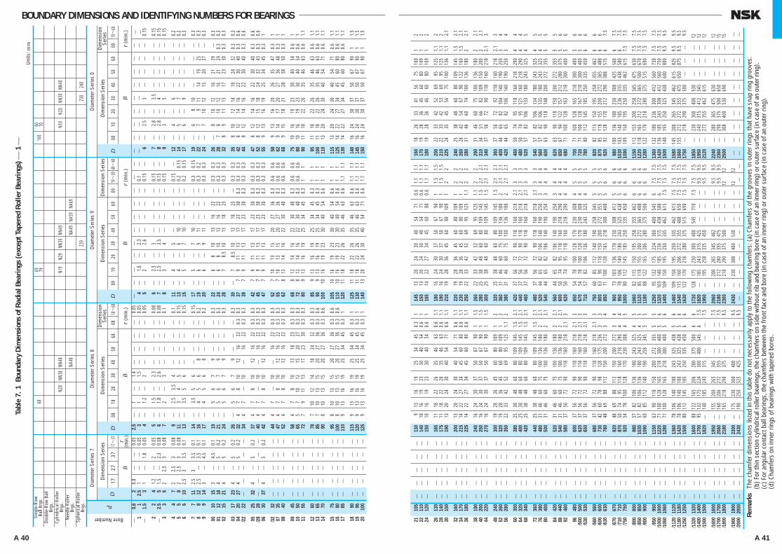
A 40 A 41
BOUNDARY DIMENSIONS AND IDENTIFYING NUMBERS FOR BEARINGS
Sing
le-R
owBa
ll Br
gs.
Dou
ble-
Row
Bal
lBr
gs.
Cylin
dric
al R
olle
rBr
gs.
Nee
dle
Rol
ler
Brgs
.Sp
heric
al R
olle
rBr
gs.
68
N28
NN38
NN
48
NA48
N1
9 N2
9 NN
39
NN49
NA49
NA
59
NA69
23
9
160
N1
0 N2
0 NN
30
NN40
23
0 24
0
Dia
met
er S
erie
s 7
Dia
met
er S
erie
s 8
Dim
ensi
on S
erie
s
17
B2737
17~
37 r (m
in.)
Dim
ensi
on S
erie
sD
imen
sion
Se
ries
08
B
1828
3848
5868
0818~
68
r (m
in.)
dD
D
Dia
met
er S
erie
s 9
Dim
ensi
on S
erie
sD
imen
sion
Ser
ies
09
B
1929
3949
5969
0919~
3949~
69
r (m
in.)
D
Dia
met
er S
erie
s 0
Dim
ensi
on S
erie
sD
imen
sion
Se
ries
00
B
1020
3040
5060
0010~
60
r (m
in.)
D
0.6
2 0.
8
0.
05
2.5
01
01.4
0.
05
1 1
2.5
1
0.
05
3
01
01
.5
0.05
1.5
3 1
1.
8 0.
05
4
01.2
02
0.05
2
2 4
1.2
2
0.05
5
01
.5
02
.3
0.08
2.5
5 1.
5
2.3
0.08
6
01
.8
02
.6
0.08
3
3 6
2 2.
5 3
0.08
7
02
03
0.1
4
4 7
2 2.
5 3
0.08
9
02
.5
03.5
04
0.
1
5 5
8 2
2.5
3 0.
08
11
03
04
05
0.
15
6 6
10
2.5
3 3.
5 0.
1 13
03.5
05
06
0.
15
7
7 11
2.
5 3
3.5
0.1
14
03
.5
05
06
0.15
8
8 12
2.
5
3.5
0.1
16
04
05
06
8
0.
2
9 9
14
3
4.5
0.1
17
04
05
06
8
0.
2
00
10
15
3
4.
5 0.
1 19
05
06
07
9
0.3
01
12
18
4
5
0.2
21
05
06
07
9
0.
3
02
15
21
4
5 0.
2 24
05
06
07
9
0.3
03
17
23
4
5
0.2
26
05
06
07
9
0.
3
04
20
27
4
5 0.
2 32
4
07
08
10
12
16
22
0.3
0.3
/2
2 22
34
4 07
10
16
22
0.
3 0.
3
05
25
32
4
5
0.2
37
4 07
08
10
12
16
22
0.
3 0.
3
/28
28
40
4
07
10
16
22
0.3
0.3
06
30
37
4
5
0.2
42
4 07
08
10
12
16
22
0.
3 0.
3
/3
2 32
44
4 07
10
16
22
0.
3 0.
3
07
35
47
4
07
08
10
12
16
22
0.3
0.3
08
40
52
4 07
08
10
12
16
22
0.
3 0.
3
09
45
58
4 07
08
10
13
18
23
0.
3 0.
3
10
50
65
5
07
10
12
15
20
27
0.3
0.3
11
55
72
7 09
11
13
17
23
30
0.
3 0.
3
12
60
78
7 10
12
14
18
24
32
0.
3 0.
3
13
65
85
7
10
13
15
20
27
36
0.3
0.6
14
70
90
8 10
13
15
20
27
36
0.
3 0.
6
15
75
95
8 10
13
15
20
27
36
0.
3 0.
6
16
80
10
0 8
10
13
15
20
27
36
0.3
0.6
17
85
110
9 13
16
19
25
34
45
0.
3 1
18
90
115
9 13
16
19
25
34
45
0.
3 1
19
95
120
9 13
16
19
25
34
45
0.
3 1
20
10
0
125
9 13
16
19
25
34
45
0.
3 1
4
01.6
02.3
0.
1
5
02
02
.6
0.15
6
02
.3
03
0.
15
7
02
.5
03
.5
0.15
8
03
04
0.
15
11
04
05
0.
15
13
04
06
10
0.2
0.15
15
05
07
10
0.2
0.15
17
05
07
10
0.3
0.15
19
06
09
11
0.3
0.2
20
06
09
11
0.3
0.3
22
06
8 10
13
16
22
0.3
0.3
24
06
8 10
13
16
22
0.3
0.3
28
07
8.5
10
13
18
23
0.
3 0.
3
30
07
8.5
10
13
18
23
0.
3 0.
3
37
7 09
11
13
17
23
30
0.
3 0.
3 0.
3
39
7 09
11
13
17
23
30
0.
3 0.
3 0.
3
42
7
09
11
13
17
23
30
0.3
0.3
0.3
45
7
09
11
13
17
23
30
0.3
0.3
0.3
47
7
09
11
13
17
23
30
0.3
0.3
0.3
52
7
10
13
15
20
27
36
0.3
0.6
0.6
55
7
10
13
15
20
27
36
0.3
0.6
0.6
62
8
12
14
16
22
30
40
0.3
0.6
0.6
68
8
12
14
16
22
30
40
0.3
0.6
0.6
72
8
12
14
16
22
30
40
0.3
0.6
0.6
80
9
13
16
19
25
34
45
0.3
1 1
85
9
13
16
19
25
34
45
0.3
1 1
90
9
13
16
19
25
34
45
0.3
1 1
10
0 10
16
19
23
30
40
54
0.
6 1
1
10
5 10
16
19
23
30
40
54
0.
6 1
1
110
10
16
19
23
30
40
54
0.6
1 1
12
0 11
18
22
26
35
46
63
0.
6 1.
1 1.
1
12
5 11
18
22
26
35
46
63
0.
6 1.
1 1.
1
130
11
18
22
26
35
46
63
0.6
1.1
1.1
14
0 13
20
24
30
40
54
71
0.
6 1.
1 1.
1
6
02
.5
03
0.
15
7
02
.8
03
.5
0.15
8
02
.8
04
0.
15
9
03
05
0.
15
12
04
06
0.
2
14
05
07
0.2
17
06
09
0.
3
19
06
8 10
0.
3
22
07
9
11
14
19
25
0.
3
24
07
10
12
15
20
27
0.3
26
08
10
12
16
21
29
0.
3
28
7 08
10
12
16
21
29
0.
3 0.
3
32
8 09
11
13
17
23
30
0.
3 0.
3
35
8
10
12
14
18
24
32
0.3
0.3
42
8
12
14
16
22
30
40
0.3
0.6
44
8
12
14
16
22
30
40
0.3
0.6
47
8
12
14
16
22
30
40
0.3
0.6
52
8
12
15
18
24
32
43
0.3
0.6
55
9
13
16
19
25
34
45
0.3
1
58
9
13
16
20
26
35
47
0.3
1
62
9 14
17
20
27
36
48
0.
3 1
68
9
15
18
21
28
38
50
0.3
1
75
10
16
19
23
30
40
54
0.
6 1
80
10
16
19
23
30
40
54
0.
6 1
90
11
18
22
26
35
46
63
0.
6 1.
1
95
11
18
22
26
35
46
63
0.
6 1.
1
100
11
18
22
26
35
46
63
0.6
1.1
11
0 13
20
24
30
40
54
71
0.
6 1.
1
11
5 13
20
24
30
40
54
71
0.
6 1.
1
125
14
22
27
34
45
60
80
0.6
1.1
13
0 14
22
27
34
45
60
80
0.
6 1.
1
14
0 16
24
30
37
50
67
90
1
1.5
14
5 16
24
30
37
50
67
90
1
1.5
15
0 16
24
30
37
50
67
90
1
1.5
69 7960 70
Tabl
e 7.
1 B
ound
ary
Dim
ensi
ons
of R
adia
l Bea
rings
(exc
ept T
aper
ed R
olle
r Bea
rings
) ⎯ 1
⎯U
nits
: mm
Bore Number
⎯ ⎯ ⎯
⎯ ⎯ ⎯ ⎯ ⎯ ⎯ ⎯ ⎯ ⎯ ⎯ ⎯ ⎯ ⎯ ⎯ ⎯ ⎯ ⎯
⎯ ⎯ ⎯ ⎯ ⎯ ⎯ ⎯ ⎯ ⎯ ⎯ ⎯ ⎯ ⎯ ⎯ ⎯ ⎯ ⎯
⎯ ⎯ ⎯ ⎯ ⎯ ⎯ ⎯ ⎯ ⎯ ⎯ ⎯ ⎯ ⎯ ⎯ ⎯ ⎯ ⎯ ⎯ ⎯ ⎯ ⎯ ⎯ ⎯ ⎯ ⎯ ⎯ ⎯ ⎯ ⎯ ⎯ ⎯
⎯ ⎯ ⎯ ⎯ ⎯ ⎯ ⎯ ⎯ ⎯ ⎯ ⎯ ⎯ ⎯ ⎯ ⎯ ⎯ ⎯ ⎯ ⎯
⎯ ⎯ ⎯ ⎯ ⎯ ⎯ ⎯ ⎯ ⎯ ⎯ ⎯ ⎯ ⎯ ⎯ ⎯ ⎯ ⎯
⎯ ⎯ ⎯ ⎯ ⎯ ⎯ ⎯ ⎯ ⎯ ⎯ ⎯ ⎯ ⎯ ⎯ ⎯ ⎯
⎯ ⎯ ⎯ ⎯ ⎯ ⎯ ⎯ ⎯ ⎯
⎯ ⎯ ⎯ ⎯ ⎯ ⎯ ⎯ ⎯ ⎯ ⎯ ⎯ ⎯ ⎯
⎯ ⎯ ⎯ ⎯ ⎯ ⎯ ⎯ ⎯ ⎯ ⎯ ⎯ ⎯ ⎯ ⎯ ⎯ ⎯
⎯ ⎯ ⎯ ⎯ ⎯ ⎯ ⎯ ⎯ ⎯ ⎯ ⎯ ⎯ ⎯ ⎯ ⎯ ⎯
⎯ ⎯ ⎯ ⎯ ⎯ ⎯ ⎯ ⎯ ⎯ ⎯ ⎯ ⎯ ⎯ ⎯ ⎯ ⎯
⎯⎯ ⎯ ⎯ ⎯ ⎯ ⎯ ⎯ ⎯ ⎯ ⎯ ⎯ ⎯ ⎯ ⎯ ⎯ ⎯
⎯⎯ ⎯ ⎯ ⎯ ⎯ ⎯ ⎯ ⎯ ⎯ ⎯ ⎯ ⎯
⎯⎯ ⎯ ⎯ ⎯ ⎯ ⎯ ⎯
⎯ ⎯ ⎯ ⎯ ⎯ ⎯ ⎯ ⎯ ⎯ ⎯ ⎯ ⎯
⎯ ⎯ ⎯ ⎯ ⎯ ⎯ ⎯ ⎯ ⎯ ⎯ ⎯ ⎯
⎯ ⎯ ⎯ ⎯ ⎯ ⎯ ⎯ ⎯ ⎯ ⎯ ⎯ ⎯ ⎯ ⎯ ⎯ ⎯
⎯⎯ ⎯ ⎯ ⎯ ⎯ ⎯ ⎯
⎯ ⎯⎯ ⎯ ⎯ ⎯ ⎯ ⎯ ⎯ ⎯ ⎯ ⎯ ⎯ ⎯ ⎯
⎯ ⎯⎯ ⎯ ⎯ ⎯ ⎯ ⎯ ⎯ ⎯ ⎯
⎯ ⎯⎯ ⎯ ⎯ ⎯ ⎯ ⎯ ⎯ ⎯ ⎯ ⎯
⎯ ⎯ ⎯ ⎯ ⎯ ⎯ ⎯ ⎯ ⎯ ⎯
⎯ ⎯ ⎯ ⎯ ⎯ ⎯ ⎯ ⎯ ⎯ ⎯
⎯ ⎯ ⎯ ⎯ ⎯ ⎯ ⎯ ⎯ ⎯ ⎯ ⎯ ⎯ ⎯
⎯ ⎯
21
10
5
130
9 13
16
19
25
34
45
0.
3 1
22
11
0
140
10
16
19
23
30
40
54
0.6
1
24
120
15
0 10
16
19
23
30
40
54
0.
6 1
26
13
0
165
11
18
22
26
35
46
63
0.6
1.1
28
14
0
175
11
18
22
26
35
46
63
0.6
1.1
30
15
0
190
13
20
24
30
40
54
71
0.6
1.1
32
16
0
200
13
20
24
30
40
54
71
0.6
1.1
34
17
0
215
14
22
27
34
45
60
80
0.6
1.1
36
18
0
225
14
22
27
34
45
60
80
0.6
1.1
38
19
0
240
16
24
30
37
50
67
90
1 1.
5
40
200
25
0 16
24
30
37
50
67
90
1
1.5
44
22
0
270
16
24
30
37
50
67
90
1 1.
5
48
24
0
300
19
28
36
45
60
80
109
1 2
52
26
0
320
19
28
36
45
60
80
109
1 2
56
28
0
350
22
33
42
52
69
95
125
1.1
2
60
30
0
380
25
38
48
60
80
109
145
1.5
2.1
64
32
0
400
25
38
48
60
80
109
145
1.5
2.1
68
34
0
420
25
38
48
60
80
109
145
1.5
2.1
72
36
0
440
25
38
48
60
80
109
145
1.5
2.1
76
38
0
480
31
46
60
75
100
136
180
2 2.
1
80
400
50
0 31
46
60
75
10
0 13
6 18
0 2
2.1
84
42
0
520
31
46
60
75
100
136
180
2 2.
1
88
440
54
0 31
46
60
75
10
0 13
6 18
0 2
2.1
92
46
0
580
37
56
72
90
118
160
218
2.1
3
96
48
0
600
37
56
72
90
118
160
218
2.1
3
/500
50
0
620
37
56
72
90
118
160
218
2.1
3
/530
53
0
650
37
56
72
90
118
160
218
2.1
3
/5
60
560
68
0 37
56
72
90
11
8 16
0 21
8 2.
1 3
/6
00
600
73
0 42
60
78
98
12
8 17
5 23
6 3
3
/630
63
0
780
48
69
88
112
150
200
272
3 4
/6
70
670
82
0 48
69
88
11
2 15
0 20
0 27
2 3
4
/710
71
0
870
50
74
95
118
160
218
290
4 4
/7
50
750
92
0 54
78
10
0 12
8 17
0 23
0 30
8 4
5
/8
00
800
98
0 57
82
10
6 13
6 18
0 24
3 32
5 4
5
/850
85
0
1030
57
82
10
6 13
6 18
0 24
3 32
5 4
5
/900
90
0
1090
60
85
11
2 14
0 19
0 25
8 34
5 5
5
/9
50
950
11
50
63
90
118
150
200
272
355
5 5
/100
0 10
00
12
20
71
100
128
165
218
300
400
5 6
/106
0 10
60
12
80
71
100
128
165
218
300
400
5 6
/112
0 11
20
13
60
78
106
140
180
243
325
438
5 6
/118
0 11
80
14
20
78
106
140
180
243
325
438
5 6
/125
0 12
50
15
00
80
112
145
185
250
335
450
6 6
/132
0 13
20
16
00
88
122
165
206
280
375
500
6 6
/140
0 14
00
17
00
95
132
175
224
300
400
545
6 7.
5 /1
500
1500
1820
140
185
243
315
7.
5
/160
0 16
00
19
50
15
5 20
0 26
5 34
5
7.5
/170
0 17
00
20
60
16
0 20
6 27
2 35
5
7.5
/180
0 18
00
21
80
16
5 21
8 29
0 37
5
9.5
/190
0 19
00
23
00
17
5 23
0 30
0 40
0
9.5
/200
0 20
00
24
30
19
0 25
0 32
5 42
5
9.5
14
5 13
20
24
30
40
54
71
0.
6 1.
1 1.
1
150
13
20
24
30
40
54
71
0.6
1.1
1.1
16
5 14
22
27
34
45
60
80
0.
6 1.
1 1.
1
18
0 16
24
30
37
50
67
90
1
1.5
1.5
19
0 16
24
30
37
50
67
90
1
1.5
1.5
21
0 19
28
36
45
60
80
10
9 1
2 2
22
0 19
28
36
45
60
80
10
9 1
2 2
23
0 19
28
36
45
60
80
10
9 1
2 2
25
0 22
33
42
52
69
95
12
5 1.
1 2
2
26
0 22
33
42
52
69
95
12
5 1.
1 2
2
280
25
38
48
60
80
109
145
1.5
2.1
2.1
30
0 25
38
48
60
80
10
9 14
5 1.
5 2.
1 2.
1
32
0 25
38
48
60
80
10
9 14
5 1.
5 2.
1 2.
1
360
31
46
60
75
100
136
180
2 2.
1 2.
1
380
31
46
60
75
100
136
180
2 2.
1 2.
1
42
0 37
56
72
90
11
8 16
0 21
8 2.
1 3
3
440
37
56
72
90
118
160
218
2.1
3 3
46
0 37
56
72
90
11
8 16
0 21
8 2.
1 3
3
48
0 37
56
72
90
11
8 16
0 21
8 2.
1 3
3
520
44
65
82
106
140
190
250
3 4
4
540
44
65
82
106
140
190
250
3 4
4
56
0 44
65
82
10
6 14
0 19
0 25
0 3
4 4
60
0 50
74
95
11
8 16
0 21
8 29
0 4
4 4
62
0 50
74
95
11
8 16
0 21
8 29
0 4
4 4
65
0 54
78
10
0 12
8 17
0 23
0 30
8 4
5 5
67
0 54
78
10
0 12
8 17
0 23
0 30
8 4
5 5
71
0 57
82
10
6 13
6 18
0 24
3 32
5 4
5 5
75
0 60
85
11
2 14
0 19
0 25
8 34
5 5
5 5
80
0 63
90
11
8 15
0 20
0 27
2 35
5 5
5 5
85
0 71
10
0 12
8 16
5 21
8 30
0 40
0 5
6 6
90
0 73
10
3 13
6 17
0 23
0 30
8 41
2 5
6 6
95
0 78
10
6 14
0 18
0 24
3 32
5 43
8 5
6 6
100
0 80
11
2 14
5 18
5 25
0 33
5 45
0 6
6 6
106
0 82
11
5 15
0 19
5 25
8 35
5 46
2 6
6 6
112
0 85
11
8 15
5 20
0 27
2 36
5 48
8 6
6 6
118
0 88
12
2 16
5 20
6 28
0 37
5 50
0 6
6 6
125
0 95
13
2 17
5 22
4 30
0 40
0 54
5 6
7.5
7.5
132
0 10
3 14
0 18
5 23
6 31
5 43
8 58
0 6
7.5
7.5
140
0 10
9 15
0 19
5 25
0 33
5 46
2 61
5 7.
5 7.
5 7.
5
146
0 10
9 15
0 19
5 25
0 33
5 46
2 61
5 7.
5 7.
5 7.
5 1
540
115
160
206
272
355
488
650
7.5
7.5
7.5
163
0 12
2 17
0 21
8 28
0 37
5 51
5 69
0 7.
5 7.
5 7.
5
172
0 12
8 17
5 23
0 30
0 40
0 54
5 71
0 7.
5 7.
5 7.
5 1
820
18
5 24
3 31
5 42
5
9.5
9.5
195
0
195
258
335
450
9.
5 9.
5
206
0
200
265
345
462
9.
5 9.
5 2
180
21
2 28
0 35
5 47
5
9.5
9.5
230
0
218
290
375
500
12
12
243
0
230
308
400
530
12
12
16
0 18
26
33
41
56
75
10
0 1
02
170
19
28
36
45
60
80
109
1 02
18
0 19
28
36
46
60
80
10
9 1
02
20
0 22
33
42
52
69
95
12
5 1.
1 02
21
0 22
33
42
53
69
95
12
5 1.
1 02
22
5 24
35
45
56
75
10
0 13
6 1.
1 02
.1
24
0 25
38
48
60
80
10
9 14
5 1.
5 02
.1
260
28
42
54
67
90
122
160
1.5
02.1
28
0 31
46
60
74
10
0 13
6 18
0 2
02.1
29
0 31
46
60
75
10
0 13
6 18
0 2
02.1
31
0 34
51
66
82
10
9 15
0 20
0 2
02.1
34
0 37
56
72
90
11
8 16
0 21
8 2.
1 03
36
0 37
56
72
92
11
8 16
0 21
8 2.
1 03
40
0 44
65
82
10
4 14
0 19
0 25
0 3
04
420
44
65
82
106
140
190
250
3 04
46
0 50
74
95
11
8 16
0 21
8 29
0 4
04
480
50
74
95
121
160
218
290
4 04
52
0 57
82
10
6 13
3 18
0 24
3 32
5 4
05
54
0 57
82
10
6 13
4 18
0 24
3 32
5 4
05
560
57
82
106
135
180
243
325
4 05
60
0 63
90
11
8 14
8 20
0 27
2 35
5 5
05
62
0 63
90
11
8 15
0 20
0 27
2 35
5 5
05
650
67
94
122
157
212
280
375
5 06
68
0 71
10
0 12
8 16
3 21
8 30
0 40
0 5
06
70
0 71
10
0 12
8 16
5 21
8 30
0 40
0 5
06
720
71
100
128
167
218
300
400
5 06
78
0 80
11
2 14
5 18
5 25
0 33
5 45
0 6
06
82
0 82
11
5 15
0 19
5 25
8 35
5 46
2 6
06
870
85
118
155
200
272
365
488
6 06
92
0 92
12
8 17
0 21
2 29
0 38
8 51
5 6
07.5
98
0 10
0 13
6 18
0 23
0 30
8 42
5 56
0 6
07.5
103
0 10
3 14
0 18
5 23
6 31
5 43
8 58
0 6
07.5
109
0 10
9 15
0 19
5 25
0 33
5 46
2 61
5 7.
5 07
.5
115
0 11
2 15
5 20
0 25
8 34
5 47
5 63
0 7.
5 07
.5 1
220
118
165
212
272
365
500
670
7.5
07.5
128
0 12
2 17
0 21
8 28
0 37
5 51
5 69
0 7.
5 07
.5
136
0 13
2 18
0 23
6 30
0 41
2 56
0 73
0 7.
5 07
.5 1
420
136
185
243
308
412
560
750
7.5
07.5
150
0 14
0 19
5 25
0 32
5 43
8 60
0 80
0 9.
5 09
.5
158
0 14
5 20
0 26
5 34
5 46
2 61
5 82
5 9.
5 09
.5 1
660
155
212
272
355
475
650
875
9.5
09.5
175
0
218
290
375
500
09
.5
185
0
230
300
400
530
12
195
0
243
315
412
545
12
212
0
272
355
462
615
12
224
0
280
365
475
630
12
236
0
290
375
500
650
15
250
0
308
400
530
690
15
Rem
arks
Th
e ch
amfe
r dim
ensi
ons
liste
d in
this
tabl
e do
not
nec
essa
rily
appl
y to
the
follo
win
g ch
amfe
rs: (
a) C
ham
fers
of t
he g
roov
es in
out
er ri
ngs
that
hav
e sn
ap ri
ng g
roov
es.
(b)
For
thin
sec
tion
cylin
dric
al ro
ller b
earin
gs, t
he c
ham
fers
on
side
with
out r
ib a
nd b
earin
g bo
re (i
n ca
se o
f an
inne
r rin
g) o
r out
er s
urfa
ce (i
n ca
se o
f an
oute
r rin
g).
(c)
For
ang
ular
con
tact
bal
l bea
rings
, the
cha
mfe
rs b
etw
een
the
front
face
and
bor
e (in
cas
e of
an
inne
r rin
g) o
r out
er s
urfa
ce (i
n ca
se o
f an
oute
r rin
g).
(d)
Cha
mfe
rs o
n in
ner r
ings
of b
earin
gs w
ith ta
pere
d bo
res.
⎯ ⎯ ⎯ ⎯ ⎯ ⎯ ⎯ ⎯ ⎯ ⎯ ⎯ ⎯ ⎯ ⎯ ⎯ ⎯ ⎯ ⎯ ⎯ ⎯ ⎯ ⎯ ⎯ ⎯ ⎯ ⎯ ⎯ ⎯ ⎯ ⎯ ⎯ ⎯ ⎯ ⎯ ⎯ ⎯ ⎯ ⎯ ⎯ ⎯ ⎯ ⎯ ⎯ ⎯ ⎯ ⎯ ⎯ ⎯ ⎯ ⎯
⎯ ⎯ ⎯ ⎯ ⎯ ⎯ ⎯ ⎯ ⎯ ⎯ ⎯ ⎯ ⎯ ⎯ ⎯ ⎯ ⎯ ⎯ ⎯ ⎯ ⎯ ⎯ ⎯ ⎯ ⎯ ⎯ ⎯ ⎯ ⎯ ⎯ ⎯ ⎯ ⎯ ⎯ ⎯ ⎯ ⎯ ⎯ ⎯ ⎯ ⎯ ⎯ ⎯ ⎯ ⎯ ⎯ ⎯ ⎯ ⎯ ⎯
⎯ ⎯ ⎯ ⎯ ⎯ ⎯ ⎯ ⎯ ⎯ ⎯ ⎯ ⎯ ⎯ ⎯ ⎯ ⎯ ⎯ ⎯ ⎯ ⎯ ⎯ ⎯ ⎯ ⎯ ⎯ ⎯ ⎯ ⎯ ⎯ ⎯ ⎯ ⎯ ⎯ ⎯ ⎯ ⎯ ⎯ ⎯ ⎯ ⎯ ⎯ ⎯ ⎯ ⎯ ⎯ ⎯ ⎯ ⎯ ⎯ ⎯
⎯ ⎯ ⎯ ⎯ ⎯ ⎯ ⎯ ⎯ ⎯ ⎯ ⎯ ⎯ ⎯ ⎯ ⎯ ⎯ ⎯ ⎯ ⎯ ⎯ ⎯ ⎯ ⎯ ⎯ ⎯ ⎯ ⎯ ⎯ ⎯ ⎯ ⎯ ⎯ ⎯ ⎯ ⎯ ⎯ ⎯ ⎯ ⎯ ⎯ ⎯ ⎯ ⎯ ⎯ ⎯ ⎯ ⎯ ⎯ ⎯ ⎯
⎯ ⎯ ⎯ ⎯ ⎯ ⎯ ⎯ ⎯ ⎯ ⎯ ⎯ ⎯ ⎯ ⎯ ⎯ ⎯ ⎯ ⎯ ⎯ ⎯ ⎯ ⎯ ⎯ ⎯ ⎯ ⎯ ⎯ ⎯ ⎯ ⎯ ⎯ ⎯ ⎯ ⎯ ⎯ ⎯ ⎯ ⎯ ⎯ ⎯ ⎯ ⎯ ⎯ ⎯ ⎯ ⎯ ⎯ ⎯ ⎯ ⎯
⎯ ⎯ ⎯ ⎯ ⎯ ⎯
⎯ ⎯ ⎯ ⎯ ⎯ ⎯
⎯ ⎯ ⎯ ⎯ ⎯ ⎯
⎯ ⎯ ⎯ ⎯ ⎯ ⎯⎯
⎯ ⎯ ⎯ ⎯ ⎯ ⎯ ⎯⎯
⎯⎯
⎯
⎯ ⎯ ⎯ ⎯ ⎯ ⎯ ⎯
⎯ ⎯ ⎯ ⎯ ⎯ ⎯ ⎯
⎯ ⎯ ⎯ ⎯ ⎯ ⎯ ⎯⎯
⎯⎯ ⎯
⎯ ⎯ ⎯ ⎯ ⎯ ⎯ ⎯ ⎯ ⎯⎯ ⎯
⎯ ⎯⎯ ⎯
⎯ ⎯
⎯ ⎯ ⎯ ⎯ ⎯ ⎯ ⎯ ⎯ ⎯
⎯ ⎯ ⎯ ⎯ ⎯ ⎯ ⎯ ⎯ ⎯
⎯ ⎯ ⎯ ⎯ ⎯ ⎯ ⎯ ⎯ ⎯⎯ ⎯
A024-057E.indd 40-41 A024-057E.indd 40-41 11/20/13 4:50:21 PM11/20/13 4:50:21 PM

A 42 A 43
BOUNDARY DIMENSIONS AND IDENTIFYING NUMBERS FOR BEARINGS
Sing
le-R
ow B
all B
rgs.
Dou
ble-
Row
Ball
Brgs
.Cy
lindr
ical
Rol
ler
Brgs
.N
eedl
e R
olle
rBr
gs.
Sphe
rical
Rol
ler
Brgs
.
622
632
12
NN 3
1
N 2
N
22
N 32
231
241
222
232
62
3 63
3
13
10
4
N
3
N 23
N
33
N
4
21
3
223
Dia
met
er S
erie
s 1
Dim
ensi
on S
erie
s
0111
2131
4101
11~
41
B
Dim
ensi
on
Serie
s
r (m
in.)
dD
0.6
1
1
1.
5
2
2
2.
5
3 3
10
02.5
4
05
0.
1
0.15
4
4
13
03
5
07
0.
15
0.2
5
5
7
16
03
.5
5
08
0.15
0.
3
6 6
8
10
19
04
6
10
0.
2
0.3
7
7
9 11
14
22
05
7
11
0.
3
0.3
8
8
10
12
15
24
05
8
12
0.3
0.
3
9 9
10
12
16
26
06
8
13
0.
3
0.3
00
10
12
14
18
30
07
9
14
14.3
0.3
0.
6
01
12
12
14
18
32
07
10
14
15.9
0.3
0.
6
02
15
12
14
18
35
08
11
14
15.9
20
0.
3
0.6
03
17
13
15
20
40
08
12
16
17
.5
22
0.3
0.
6
04
20
15
18
24
47
09
14
18
20.6
27
0.
3
1
/22
22
16
19
25
50
09
14
18
20.6
27
0.
3
1
05
25
16
19
25
52
10
15
18
20
.6
27
0.3
1
/2
8 28
17
20
27
58
10
16
19
23
30
0.
6
1
06
30
18
21
28
62
10
16
20
23.8
32
0.
6
1
/3
2 32
19
23
30
65
11
17
21
25
33
0.
6
1
07
35
21
25
33
72
12
17
23
27
37
0.6
1.
1
08
40
22
26
35
80
13
18
23
30.2
40
0.
6
1.1
09
45
22
26
35
85
13
19
23
30
.2
40
0.6
1.
1
10
50
22
26
35
90
13
20
23
30.2
40
0.
6
1.1
11
55
24
30
40
100
14
21
25
33
.3
45
0.6
1.
5
12
60
24
30
40
110
16
22
28
36
.5
50
1
1.5
13
65
27
34
45
120
18
23
31
38
.1
56
1
1.5
14
70
27
34
45
125
18
24
31
39
.7
56
1
1.5
15
75
30
37
50
130
18
25
31
41
.3
56
1
1.5
16
80
30
37
50
140
19
26
33
44
.4
60
1
2
17
85
31
41
56
15
0 21
28
36
49.2
65
1.
1
2
18
90
15
0
33
45
60
2
160
22
30
40
52
.4
69
1.1
2
19
95
16
0
39
52
65
2
170
24
32
43
55
.6
75
1.1
2.
1
20
100
165
21
30
39
52
65
1.1
2
18
0 25
34
46
60.3
80
1.
5
2.1
13
5
07
0.2
16
5
09
0.3
19
6
10
0.3
22
7
11
13
0.
3
26
9
13
15
0.
3
28
9
13
15
0.3
30
10
14
0.
6
30
10
14
16
0.
6
32
11
15
0.6
35
9
11
17
19
0.
3
0.6
37
12
16
0.
6
37
9 12
17
19
0.3
1
42
13
19
1
42
9
13
17
19
0.
3
1
52
15
24
1.1
47
10
14
19
22.2
0.
6
1
62
17
29
1.1
52
10
15
21
22.2
0.
6
1.1
72
19
33
1.
1
56
11
16
21
25
0.
6
1.1
62
12
17
24
25.4
0.
6
1.1
80
21
36
1.
5
68
13
18
24
30
0.
6
1.1
72
13
19
27
30.2
0.
6
1.1
90
23
40
1.
5
75
14
20
28
32
0.6
1.
1
80
14
21
31
34
.9
0.6
1.
5
100
25
43
1.5
90
16
23
33
36.5
1
1.
5
110
27
46
2
10
0 17
25
36
39.7
1
1.
5
120
29
50
2
110
19
27
40
44
.4
1
2
130
31
53
2.1
12
0 21
29
43
49.2
1.
1
2
140
33
57
2.1
13
0 22
31
46
54
1.1
2.
1
150
35
60
2.1
14
0 24
33
48
58.7
1.
1
2.1
16
0 37
64
2.
1
150
25
35
51
63
.5
1.5
2.
1
180
42
74
3
16
0 27
37
55
68.3
1.
5
2.1
19
0 45
77
3
17
0 28
39
58
68.3
1.
5
2.1
20
0 48
80
3
18
0 30
41
60
73
2
3
210
52
86
4
19
0 30
43
64
73
2
3
225
54
90
4
200
33
45
67
77
.8
2
3
240
55
95
4
215
36
47
51
73
82.6
2.
1
3
250
58
98
4
Dia
met
er S
erie
s 2
Dim
ensi
on S
erie
s
8202
1222
3242
8202~
42
B
Dim
ensi
on
Serie
s
r (m
in.)
D
Dia
met
er S
erie
s 3
Dim
ensi
on S
erie
s
8303
1323
3383
03~
33
B
Dim
ensi
on
Serie
s
r (m
in.)
D
Dia
met
er S
erie
s 4
Dim
ensi
on
Serie
s04
2404~
24
B
Dimen
sion
Serie
s r (m
in.)
D
62 7263 73
43 2353 33
64 7442 22
52 53
Tabl
e 7.
1 B
ound
ary
Dim
ensi
ons
of R
adia
l Bea
rings
(exc
ept T
aper
ed R
olle
r Bea
rings
) ⎯ 2
⎯U
nits
: mm
Bore Number
⎯ ⎯ ⎯
⎯ ⎯ ⎯ ⎯ ⎯ ⎯ ⎯ ⎯ ⎯ ⎯ ⎯ ⎯ ⎯ ⎯ ⎯ ⎯ ⎯ ⎯ ⎯ ⎯ ⎯ ⎯ ⎯ ⎯ ⎯ ⎯ ⎯ ⎯ ⎯ ⎯ ⎯ ⎯ ⎯
⎯ ⎯ ⎯ ⎯ ⎯ ⎯ ⎯ ⎯ ⎯ ⎯ ⎯ ⎯ ⎯ ⎯ ⎯ ⎯ ⎯ ⎯ ⎯ ⎯ ⎯ ⎯ ⎯ ⎯ ⎯ ⎯ ⎯ ⎯ ⎯ ⎯ ⎯ ⎯ ⎯ ⎯ ⎯
⎯ ⎯ ⎯ ⎯ ⎯ ⎯ ⎯ ⎯ ⎯ ⎯ ⎯ ⎯ ⎯ ⎯ ⎯ ⎯ ⎯ ⎯ ⎯ ⎯ ⎯ ⎯ ⎯ ⎯ ⎯ ⎯ ⎯ ⎯ ⎯ ⎯ ⎯ ⎯ ⎯ ⎯ ⎯
⎯ ⎯ ⎯ ⎯ ⎯ ⎯ ⎯ ⎯
⎯ ⎯ ⎯ ⎯ ⎯ ⎯ ⎯
⎯ ⎯ ⎯ ⎯ ⎯ ⎯ ⎯ ⎯ ⎯
⎯ ⎯ ⎯ ⎯ ⎯ ⎯ ⎯ ⎯ ⎯ ⎯ ⎯ ⎯ ⎯ ⎯ ⎯ ⎯ ⎯ ⎯ ⎯ ⎯ ⎯ ⎯ ⎯ ⎯ ⎯ ⎯ ⎯ ⎯ ⎯ ⎯ ⎯ ⎯ ⎯ ⎯ ⎯
⎯ ⎯ ⎯ ⎯ ⎯ ⎯ ⎯ ⎯ ⎯ ⎯ ⎯ ⎯ ⎯ ⎯ ⎯ ⎯ ⎯ ⎯ ⎯ ⎯ ⎯ ⎯ ⎯ ⎯ ⎯ ⎯ ⎯ ⎯ ⎯ ⎯ ⎯ ⎯ ⎯
⎯ ⎯ ⎯ ⎯ ⎯
⎯ ⎯ ⎯ ⎯ ⎯
⎯ ⎯ ⎯ ⎯ ⎯
⎯ ⎯ ⎯ ⎯ ⎯ ⎯ ⎯ ⎯ ⎯ ⎯ ⎯ ⎯ ⎯ ⎯ ⎯ ⎯ ⎯ ⎯ ⎯ ⎯ ⎯ ⎯ ⎯ ⎯ ⎯ ⎯ ⎯ ⎯ ⎯ ⎯ ⎯ ⎯ ⎯ ⎯ ⎯ ⎯
⎯ ⎯ ⎯ ⎯ ⎯ ⎯ ⎯ ⎯ ⎯ ⎯ ⎯ ⎯
⎯ ⎯ ⎯ ⎯ ⎯
⎯ ⎯ ⎯ ⎯ ⎯ ⎯ ⎯ ⎯ ⎯ ⎯ ⎯ ⎯ ⎯ ⎯
⎯ ⎯ ⎯ ⎯ ⎯
⎯ ⎯ ⎯ ⎯ ⎯
⎯ ⎯ ⎯ ⎯ ⎯
⎯ ⎯ ⎯ ⎯ ⎯ ⎯ ⎯ ⎯ ⎯ ⎯ ⎯ ⎯
⎯ ⎯ ⎯ ⎯ ⎯
⎯ ⎯ ⎯ ⎯ ⎯ ⎯ ⎯ ⎯ ⎯ ⎯ ⎯ ⎯ ⎯ ⎯ ⎯ ⎯ ⎯ ⎯ ⎯ ⎯ ⎯ ⎯ ⎯ ⎯ ⎯ ⎯ ⎯ ⎯ ⎯ ⎯ ⎯ ⎯ ⎯ ⎯ ⎯
⎯ ⎯ ⎯ ⎯ ⎯ ⎯ ⎯ ⎯
⎯ ⎯ ⎯ ⎯ ⎯
⎯ ⎯ ⎯ ⎯ ⎯ ⎯ ⎯ ⎯ ⎯ ⎯ ⎯ ⎯
⎯ ⎯ ⎯ ⎯ ⎯
⎯ ⎯ ⎯ ⎯ ⎯ ⎯ ⎯ ⎯ ⎯ ⎯ ⎯ ⎯ ⎯
⎯ ⎯ ⎯ ⎯ ⎯ ⎯ ⎯ ⎯ ⎯ ⎯ ⎯ ⎯ ⎯
⎯ ⎯ ⎯ ⎯ ⎯ ⎯ ⎯ ⎯ ⎯ ⎯ ⎯ ⎯ ⎯
⎯ ⎯ ⎯ ⎯ ⎯ ⎯ ⎯ ⎯ ⎯ ⎯ ⎯ ⎯ ⎯
21
10
5 17
5 22
33
42
56
69
01
.1
02
190
27
36
50
06
5.1
85
1.
5
02.1
22
11
0 18
0 22
33
42
56
69
01
.1
02
200
28
38
53
06
9.8
90
1.
5
02.1
24
12
0 20
0 25
38
48
62
80
01
.5
02
215
40
42
58
07
6 95
02.1
26
13
0 21
0 25
38
48
64
80
01
.5
02
230
40
46
64
08
0 10
0
03
28
140
225
27
40
50
68
85
01.5
02
.1
250
42
50
68
08
8 10
9
03
30
150
250
31
46
60
80
100
02
02.1
27
0
45
54
73
096
118
03
32
16
0 27
0 34
51
66
86
10
9 02
02
.1
290
48
58
80
10
4 12
8
03
34
170
280
34
51
66
88
109
02
02.1
31
0
52
62
86
110
140
04
36
18
0 30
0 37
56
72
96
11
8 02
.1
03
320
52
62
86
11
2 14
0
04
38
19
0 32
0 42
60
78
10
4 12
8 03
03
34
0
55
65
92
120
150
04
40
20
0 34
0 44
65
82
11
2 14
0 03
03
36
0
58
70
98
128
160
04
44
22
0 37
0 48
69
88
12
0 15
0 03
04
40
0
65
78
108
144
180
04
48
24
0 40
0 50
74
95
12
8 16
0 04
04
44
0
72
85
120
160
200
04
52
26
0 44
0 57
82
10
6 14
4 18
0 04
04
48
0
80
90
130
174
218
05
56
28
0 46
0 57
82
10
6 14
6 18
0 04
05
50
0
80
90
130
176
218
05
60
30
0 50
0 63
90
11
8 16
0 20
0 05
05
54
0
85
98
140
192
243
05
64
32
0 54
0 71
10
0 12
8 17
6 21
8 05
05
58
0
92
105
150
208
258
05
68
34
0 58
0 78
10
6 14
0 19
0 24
3 05
05
62
0
92
118
165
224
280
06
72
36
0 60
0 78
10
6 14
0 19
2 24
3 05
05
65
0
95
122
170
232
290
06
76
38
0 62
0 78
10
6 14
0 19
4 24
3 05
05
68
0
95
132
175
240
300
06
80
40
0 65
0 80
11
2 14
5 20
0 25
0 06
06
72
0
103
140
185
256
315
06
84
42
0 70
0 88
12
2 16
5 22
4 28
0 06
06
76
0
109
150
195
272
335
07
.5
88
440
720
88
122
165
226
280
06
06
790
11
2 15
5 20
0 28
0 34
5
07.5
92
46
0 76
0 95
13
2 17
5 24
0 30
0 06
07
.5
830
11
8 16
5 21
2 29
6 36
5
07.5
96
48
0 79
0 10
0 13
6 18
0 24
8 30
8 06
07
.5
870
12
5 17
0 22
4 31
0 38
8
07.5
/5
00
500
830
106
145
190
264
325
07.5
07
.5
920
13
6 18
5 24
3 33
6 41
2
07.5
/5
30
530
870
109
150
195
272
335
07.5
07
.5
980
14
5 20
0 25
8 35
5 45
0
09.5
/5
60
560
920
115
160
206
280
355
07.5
07
.5
1030
150
206
272
365
475
09
.5
/6
00
600
980
122
170
218
300
375
07.5
07
.5
1090
155
212
280
388
488
09
.5
/6
30
630
1030
12
8 17
5 23
0 31
5 40
0 07
.5
07.5
11
50
16
5 23
0 30
0 41
2 51
5
12
/6
70
670
1090
13
6 18
5 24
3 33
6 41
2 07
.5
07.5
12
20
17
5 24
3 31
5 43
8 54
5
12
/710
71
0 11
50
140
195
250
345
438
09.5
09
.5
1280
180
250
325
450
560
12
/7
50
750
1220
15
0 20
6 27
2 36
5 47
5 09
.5
09.5
13
60
19
5 26
5 34
5 47
5 61
5
15
/8
00
800
1280
15
5 21
2 27
2 37
5 47
5 09
.5
09.5
14
20
20
0 27
2 35
5 48
8 61
5
15
/850
85
0 13
60
165
224
290
400
500
12
12
1500
206
280
375
515
650
15
/9
00
900
1420
16
5 23
0 30
0 41
2 51
5 12
12
15
80
21
8 30
0 38
8 51
5 67
0
15
/9
50
950
1500
17
5 24
3 31
5 43
8 54
5 12
12
16
60
23
0 31
5 41
2 53
0 71
0
15
/100
0 10
00
1580
18
5 25
8 33
5 46
2 58
0 12
12
17
50
24
3 33
0 42
5 56
0 75
0
15
/106
0 10
60
1660
19
0 26
5 34
5 47
5 60
0 12
15
/1
120
1120
17
50
28
0 36
5 47
5 63
0
15
/1
180
1180
18
50
29
0 38
8 50
0 67
0
15
/1
250
1250
19
50
30
8 40
0 53
0 71
0
15
/1
320
1320
20
60
32
5 42
5 56
0 75
0
15
/1
400
1400
21
80
34
5 45
0 58
0 77
5
19
/1
500
1500
23
00
35
5 46
2 60
0 80
0
19
22
5 37
49
53
77
08
7.3
2.
1
03
260
60
100
04
240
42
50
57
80
092.
1
3
03
280
65
108
04
26
0 44
55
62
86
10
6
3
03
310
72
118
05
28
0 48
58
66
93
11
2
3
04
340
78
128
05
30
0 50
62
70
10
2 11
8
4
04
360
82
132
05
32
0
65
75
108
128
04
380
85
138
05
34
0
68
79
114
136
04
400
88
142
05
36
0
72
84
120
140
04
420
92
145
05
38
0
75
88
126
150
04
440
95
150
06
40
0
78
92
132
155
05
460
98
155
06
42
0
80
97
138
165
05
480
102
160
06
46
0
88
106
145
180
05
540
115
180
06
50
0
95
114
155
195
05
580
122
190
06
54
0
102
123
165
206
06
620
132
206
07.5
580
10
8 13
2 17
5 22
4
06
67
0 14
0 22
4 07
.5
62
0
109
140
185
236
07.5
71
0 15
0 23
6 07
.5
67
0
112
155
200
258
07.5
75
0 15
5 25
0 09
.5
71
0
118
165
212
272
07.5
80
0 16
5 26
5 09
.5
75
0
125
170
224
290
07.5
85
0 18
0 28
0 09
.5
78
0
128
175
230
300
07.5
90
0 19
0 30
0 09
.5
82
0
136
185
243
308
07.5
95
0 20
0 31
5 12
85
0
136
190
250
315
09.5
98
0 20
6 32
5 12
900
14
5 20
0 26
5 34
5
09
.5
1030
21
2 33
5 12
950
15
5 21
2 28
0 36
5
09
.5
1060
21
8 34
5 12
98
0
160
218
290
375
09.5
11
20
230
365
15
10
30
17
0 23
0 30
0 38
8
12
11
50
236
375
15
10
90
18
0 24
3 32
5 41
2
12
12
20
250
400
15
11
50
19
0 25
8 33
5 43
8
12
12
80
258
412
15
12
20
20
0 27
2 35
5 46
2
15
13
60
272
438
15
12
80
20
6 28
0 37
5 48
8
15
14
20
280
450
15
13
60
21
8 30
0 40
0 51
5
15
15
00
290
475
15
14
20
22
4 30
8 41
2 53
0
15
15
00
23
6 32
5 43
8 56
0
15
16
00
25
8 35
5 46
2 60
0
15
17
00
27
2 37
5 48
8 63
0
19
17
80
28
0 38
8 50
0 65
0
19
18
50
29
0 40
0 51
5 67
0
19
19
50
30
0 41
2 54
5 71
0
19
Rem
arks
Th
e ch
amfe
r dim
ensi
ons
liste
d in
this
tabl
e do
not
nec
essa
rily
appl
y to
the
follo
win
g ch
amfe
rs: (
a) C
ham
fers
of t
he g
roov
es in
out
er ri
ngs
that
hav
e sn
ap ri
ng g
roov
es.
(b)
For
thin
sec
tion
cylin
dric
al ro
ller b
earin
gs, t
he c
ham
fers
on
side
with
out r
ib a
nd b
earin
g bo
re (i
n ca
se o
f an
inne
r rin
g) o
r out
er s
urfa
ce (i
n ca
se o
f an
oute
r rin
g).
(c)
For
ang
ular
con
tact
bal
l bea
rings
, the
cha
mfe
rs b
etw
een
the
front
face
and
bor
e (in
cas
e of
an
inne
r rin
g) o
r out
er s
urfa
ce (i
n ca
se o
f an
oute
r rin
g).
(d)
Cha
mfe
rs o
n in
ner r
ings
of b
earin
gs w
ith ta
pere
d bo
res.
⎯ ⎯ ⎯ ⎯ ⎯ ⎯
⎯ ⎯ ⎯ ⎯ ⎯ ⎯
⎯ ⎯ ⎯ ⎯ ⎯ ⎯ ⎯
⎯ ⎯ ⎯ ⎯ ⎯ ⎯ ⎯ ⎯ ⎯ ⎯ ⎯ ⎯ ⎯ ⎯ ⎯ ⎯ ⎯ ⎯ ⎯ ⎯ ⎯ ⎯ ⎯ ⎯ ⎯ ⎯ ⎯ ⎯ ⎯ ⎯ ⎯ ⎯ ⎯ ⎯ ⎯ ⎯ ⎯ ⎯ ⎯ ⎯ ⎯ ⎯ ⎯
⎯ ⎯ ⎯ ⎯ ⎯ ⎯ ⎯
⎯ ⎯ ⎯ ⎯ ⎯ ⎯ ⎯ ⎯ ⎯
⎯ ⎯ ⎯ ⎯ ⎯ ⎯ ⎯
⎯ ⎯ ⎯ ⎯ ⎯ ⎯ ⎯
⎯ ⎯ ⎯ ⎯ ⎯ ⎯ ⎯
⎯ ⎯ ⎯ ⎯ ⎯ ⎯ ⎯ ⎯ ⎯ ⎯ ⎯ ⎯ ⎯ ⎯ ⎯ ⎯ ⎯ ⎯ ⎯ ⎯ ⎯ ⎯ ⎯ ⎯ ⎯ ⎯ ⎯ ⎯ ⎯ ⎯ ⎯ ⎯ ⎯ ⎯ ⎯ ⎯ ⎯ ⎯ ⎯ ⎯ ⎯ ⎯ ⎯
⎯ ⎯ ⎯ ⎯ ⎯ ⎯ ⎯
⎯ ⎯ ⎯ ⎯ ⎯ ⎯ ⎯
⎯ ⎯ ⎯ ⎯ ⎯ ⎯ ⎯ ⎯ ⎯ ⎯ ⎯ ⎯ ⎯ ⎯ ⎯ ⎯ ⎯ ⎯ ⎯ ⎯ ⎯ ⎯ ⎯ ⎯ ⎯ ⎯ ⎯ ⎯ ⎯ ⎯ ⎯ ⎯ ⎯ ⎯ ⎯ ⎯ ⎯ ⎯ ⎯ ⎯
⎯ ⎯ ⎯ ⎯ ⎯ ⎯ ⎯
⎯ ⎯ ⎯ ⎯ ⎯ ⎯ ⎯
⎯ ⎯ ⎯ ⎯ ⎯ ⎯ ⎯
⎯ ⎯ ⎯ ⎯ ⎯ ⎯ ⎯
⎯ ⎯ ⎯ ⎯ ⎯ ⎯ ⎯ ⎯ ⎯ ⎯ ⎯ ⎯ ⎯ ⎯ ⎯ ⎯ ⎯ ⎯ ⎯ ⎯ ⎯ ⎯ ⎯ ⎯ ⎯ ⎯ ⎯ ⎯ ⎯ ⎯ ⎯ ⎯ ⎯ ⎯ ⎯ ⎯ ⎯ ⎯ ⎯ ⎯
⎯ ⎯ ⎯ ⎯ ⎯ ⎯ ⎯
⎯ ⎯ ⎯ ⎯ ⎯ ⎯ ⎯ ⎯ ⎯ ⎯ ⎯ ⎯ ⎯ ⎯
⎯ ⎯ ⎯ ⎯ ⎯ ⎯ ⎯ ⎯ ⎯ ⎯ ⎯ ⎯ ⎯ ⎯
⎯ ⎯ ⎯ ⎯ ⎯ ⎯ ⎯ ⎯ ⎯ ⎯ ⎯ ⎯ ⎯ ⎯
⎯ ⎯ ⎯ ⎯ ⎯ ⎯ ⎯ ⎯ ⎯ ⎯ ⎯ ⎯ ⎯ ⎯
A024-057E.indd 42-43 A024-057E.indd 42-43 11/20/13 4:50:25 PM11/20/13 4:50:25 PM
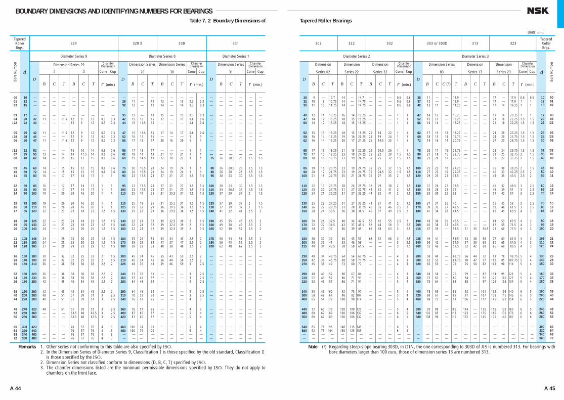
A 44 A 45
BOUNDARY DIMENSIONS AND IDENTIFYING NUMBERS FOR BEARINGS
TaperedRollerBrgs.
329
Diameter Series 9 Diameter Series 0 Diameter Series 1
Dimension Series 29
1
r (min.) r (min.) r (min.)
2
Chamfer Dimension
Cone Cup Cone Cup Cone Cup
Dimension Series
20
Dimension Series
30
Chamfer Dimension Dimension Series
31
Chamfer Dimension
320 X 330 331
D
B C T B C T
00 10 ⎯ ⎯ ⎯ ⎯ ⎯ ⎯ ⎯ ⎯ ⎯ 01 12 ⎯ ⎯ ⎯ ⎯ ⎯ ⎯ ⎯ ⎯ ⎯ 02 15 ⎯ ⎯ ⎯ ⎯ ⎯ ⎯ ⎯ ⎯ ⎯
03 17 ⎯ ⎯ ⎯ ⎯ ⎯ ⎯ ⎯ ⎯ ⎯ 04 20 37 11 ⎯ 11.6 12 9 12 0.3 0.3 /22 22 40 ⎯ ⎯ ⎯ 12 9 12 0.3 0.3
05 25 42 11 ⎯ 11.6 12 9 12 0.3 0.3 /28 28 45 ⎯ ⎯ ⎯ 12 9 12 0.3 0.3 06 30 47 11 ⎯ 11.6 12 9 12 0.3 0.3
/32 32 52 ⎯ ⎯ ⎯ 15 10 14 0.6 0.6 07 35 55 13 ⎯ 14 14 11.5 14 0.6 0.6 08 40 62 14 ⎯ 15 15 12 15 0.6 0.6
09 45 68 14 ⎯ 15 15 12 15 0.6 0.6 10 50 72 14 ⎯ 15 15 12 15 0.6 0.6 11 55 80 16 ⎯ 17 17 14 17 1 1
12 60 85 16 ⎯ 17 17 14 17 1 1 13 65 90 16 ⎯ 17 17 14 17 1 1 14 70 100 19 ⎯ 20 20 16 20 1 1
15 75 105 19 ⎯ 20 20 16 20 1 1 16 80 110 19 ⎯ 20 20 16 20 1 1 17 85 120 22 ⎯ 23 23 18 23 1.5 1.5
18 90 125 22 ⎯ 23 23 18 23 1.5 1.5 19 95 130 22 ⎯ 23 23 18 23 1.5 1.5 20 100 140 24 ⎯ 25 25 20 25 1.5 1.5
21 105 145 24 ⎯ 25 25 20 25 1.5 1.5 22 110 150 24 ⎯ 25 25 20 25 1.5 1.5 24 120 165 27 ⎯ 29 29 23 29 1.5 1.5
26 130 180 30 ⎯ 32 32 25 32 2 1.5 28 140 190 30 ⎯ 32 32 25 32 2 1.5 30 150 210 36 ⎯ 38 38 30 38 2.5 2
32 160 220 36 ⎯ 38 38 30 38 2.5 2 34 170 230 36 ⎯ 38 38 30 38 2.5 2 36 180 250 42 ⎯ 45 45 34 45 2.5 2
38 190 260 42 ⎯ 45 45 34 45 2.5 2 40 200 280 48 ⎯ 51 51 39 51 3 2.5 44 220 300 48 ⎯ 51 51 39 51 3 2.5
48 240 320 48 ⎯ 51 51 39 51 3 2.5 52 260 360 ⎯ ⎯ ⎯ 63.5 48 63.5 3 2.5 56 280 380 ⎯ ⎯ ⎯ 63.5 48 63.5 3 2.5
60 300 420 ⎯ ⎯ ⎯ 76 57 76 4 3 64 320 440 ⎯ ⎯ ⎯ 76 57 76 4 3 68 340 460 ⎯ ⎯ ⎯ 76 57 76 4 3 72 360 480 ⎯ ⎯ ⎯ 76 57 76 4 3
D
B C T B C T D
B C T
⎯ ⎯ ⎯ ⎯ ⎯ ⎯ ⎯ ⎯ ⎯ ⎯ ⎯ ⎯ ⎯ ⎯ ⎯ 28 11 ⎯ 11 13 ⎯ 13 0.3 0.3 ⎯ ⎯ ⎯ ⎯ ⎯ ⎯ 32 12 ⎯ 12 14 ⎯ 14 0.3 0.3 ⎯ ⎯ ⎯ ⎯ ⎯ ⎯
35 13 ⎯ 13 15 ⎯ 15 0.3 0.3 ⎯ ⎯ ⎯ ⎯ ⎯ ⎯ 42 15 12 15 17 ⎯ 17 0.6 0.6 ⎯ ⎯ ⎯ ⎯ ⎯ ⎯ 44 15 11.5 15 ⎯ ⎯ ⎯ 0.6 0.6 ⎯ ⎯ ⎯ ⎯ ⎯ ⎯
47 15 11.5 15 17 14 17 0.6 0.6 ⎯ ⎯ ⎯ ⎯ ⎯ ⎯ 52 16 12 16 ⎯ ⎯ ⎯ 1 1 ⎯ ⎯ ⎯ ⎯ ⎯ ⎯ 55 17 13 17 20 16 20 1 1 ⎯ ⎯ ⎯ ⎯ ⎯ ⎯
58 17 13 17 ⎯ ⎯ ⎯ 1 1 ⎯ ⎯ ⎯ ⎯ ⎯ ⎯ 62 18 14 18 21 17 21 1 1 ⎯ ⎯ ⎯ ⎯ ⎯ ⎯ 68 19 14.5 19 22 18 22 1 1 75 26 20.5 26 1.5 1.5
75 20 15.5 20 24 19 24 1 1 80 26 20.5 26 1.5 1.5 80 20 15.5 20 24 19 24 1 1 85 26 20 26 1.5 1.5 90 23 17.5 23 27 21 27 1.5 1.5 95 30 23 30 1.5 1.5
95 23 17.5 23 27 21 27 1.5 1.5 100 30 23 30 1.5 1.5 100 23 17.5 23 27 21 27 1.5 1.5 110 34 26.5 34 1.5 1.5 110 25 19 25 31 25.5 31 1.5 1.5 120 37 29 37 2 1.5
115 25 19 25 31 25.5 31 1.5 1.5 125 37 29 37 2 1.5 125 29 22 29 36 29.5 36 1.5 1.5 130 37 29 37 2 1.5 130 29 22 29 36 29.5 36 1.5 1.5 140 41 32 41 2.5 2
140 32 24 32 39 32.5 39 2 1.5 150 45 35 45 2.5 2 145 32 24 32 39 32.5 39 2 1.5 160 49 38 49 2.5 2 150 32 24 32 39 32.5 39 2 1.5 165 52 40 52 2.5 2
160 35 26 35 43 34 43 2.5 2 175 56 44 56 2.5 2 170 38 29 38 47 37 47 2.5 2 180 56 43 56 2.5 2 180 38 29 38 48 38 48 2.5 2 200 62 48 62 2.5 2
200 45 34 45 55 43 55 2.5 2 ⎯ ⎯ ⎯ ⎯ ⎯ ⎯ 210 45 34 45 56 44 56 2.5 2 ⎯ ⎯ ⎯ ⎯ ⎯ ⎯ 225 48 36 48 59 46 59 3 2.5 ⎯ ⎯ ⎯ ⎯ ⎯ ⎯
240 51 38 51 ⎯ ⎯ ⎯ 3 2.5 ⎯ ⎯ ⎯ ⎯ ⎯ ⎯ 260 57 43 57 ⎯ ⎯ ⎯ 3 2.5 ⎯ ⎯ ⎯ ⎯ ⎯ ⎯ 280 64 48 64 ⎯ ⎯ ⎯ 3 2.5 ⎯ ⎯ ⎯ ⎯ ⎯ ⎯
290 64 48 64 ⎯ ⎯ ⎯ 3 2.5 ⎯ ⎯ ⎯ ⎯ ⎯ ⎯ 310 70 53 70 ⎯ ⎯ ⎯ 3 2.5 ⎯ ⎯ ⎯ ⎯ ⎯ ⎯ 340 76 57 76 ⎯ ⎯ ⎯ 4 3 ⎯ ⎯ ⎯ ⎯ ⎯ ⎯
360 76 57 76 ⎯ ⎯ ⎯ 4 3 ⎯ ⎯ ⎯ ⎯ ⎯ ⎯ 400 87 65 87 ⎯ ⎯ ⎯ 5 4 ⎯ ⎯ ⎯ ⎯ ⎯ ⎯ 420 87 65 87 ⎯ ⎯ ⎯ 5 4 ⎯ ⎯ ⎯ ⎯ ⎯ ⎯
460 100 74 100 ⎯ ⎯ ⎯ 5 4 ⎯ ⎯ ⎯ ⎯ ⎯ ⎯ 480 100 74 100 ⎯ ⎯ ⎯ 5 4 ⎯ ⎯ ⎯ ⎯ ⎯ ⎯ ⎯ ⎯ ⎯ ⎯ ⎯ ⎯ ⎯ ⎯ ⎯ ⎯ ⎯ ⎯ ⎯ ⎯ ⎯ ⎯ ⎯ ⎯ ⎯ ⎯ ⎯ ⎯ ⎯ ⎯ ⎯ ⎯ ⎯ ⎯ ⎯ ⎯
Remarks 1. Other series not conforming to this table are also specified by ISO.Remarks 2. In the Dimension Series of Diameter Series 9, Classification1is those specified by the old standard, Classification 2
is those specified by the ISO.Remarks 2. Dimension Series not classified conform to dimensions (D, B, C, T) specified by ISO.Remarks 3. The chamfer dimensions listed are the minimum permissible dimensions specified by ISO. They do not apply to
chamfers on the front face.
Note (1) Regarding steep-slope bearing 303D, in DIN, the one corresponding to 303D of JIS is numbered 313. For bearings with bore diameters larger than 100 mm, those of dimension series 13 are numbered 313.
302 322 332 303 or 303D 313 323TaperedRollerBrgs.
Diameter Series 2 Diameter Series 3
Dimension
Series 02
Dimension
Series 22
Dimension
Series 32
Dimension Series
03
Dimension
Series 13
Dimension
Series 23
r (min.) r (min.)
Chamfer Dimension
Cone Cup Cone Cup
Chamfer Dimension
D
B C T B C T B C T D
B C C (1) T B C T B C T
d
30 9 ⎯ 9.70 14 ⎯ 014.7 ⎯ ⎯ ⎯ 0.6 0.6 32 10 9 10.75 14 ⎯ 014.75 ⎯ ⎯ ⎯ 0.6 0.6 35 11 10 11.75 14 ⎯ 014.75 ⎯ ⎯ ⎯ 0.6 0.6
40 12 11 13.25 16 14 017.25 ⎯ ⎯ ⎯ 1 1 47 14 12 15.25 18 15 019.25 ⎯ ⎯ ⎯ 1 1 50 14 12 15.25 18 15 019.25 ⎯ ⎯ ⎯ 1 1
52 15 13 16.25 18 15 019.25 22 18 22 1 1 58 16 14 17.25 19 16 020.25 24 19 24 1 1 62 16 14 17.25 20 17 021.25 25 19.5 25 1 1
65 17 15 18.25 21 18 022.25 26 20.5 26 1 1 72 17 15 18.25 23 19 024.25 28 22 28 1.5 1.5 80 18 16 19.75 23 19 024.75 32 25 32 1.5 1.5
85 19 16 20.75 23 19 024.75 32 25 32 1.5 1.5 90 20 17 21.75 23 19 024.75 32 24.5 32 1.5 1.5 100 21 18 22.75 25 21 026.75 35 27 35 2 1.5
110 22 19 23.75 28 24 029.75 38 29 38 2 1.5 120 23 20 24.75 31 27 032.75 41 32 41 2 1.5 125 24 21 26.25 31 27 033.25 41 32 41 2 1.5
130 25 22 27.25 31 27 033.25 41 31 41 2 1.5 140 26 22 28.25 33 28 035.25 46 35 46 2.5 2 150 28 24 30.50 36 30 038.5 49 37 49 2.5 2
160 30 26 32.50 40 34 042.5 55 42 55 2.5 2 170 32 27 34.50 43 37 045.5 58 44 58 3 2.5 180 34 29 37.00 46 39 049 63 48 63 3 2.5
190 36 30 39.00 50 43 053 68 52 68 3 2.5 200 38 32 41.00 53 46 056 ⎯ ⎯ ⎯ 3 2.5 215 40 34 43.50 58 50 061.5 ⎯ ⎯ ⎯ 3 2.5
230 40 34 43.75 64 54 067.75 ⎯ ⎯ ⎯ 4 3 250 42 36 45.75 68 58 071.75 ⎯ ⎯ ⎯ 4 3 270 45 38 49.00 73 60 077 ⎯ ⎯ ⎯ 4 3
290 48 40 52.00 80 67 084 ⎯ ⎯ ⎯ 4 3 310 52 43 57.00 86 71 091 ⎯ ⎯ ⎯ 5 4 320 52 43 57.00 86 71 091 ⎯ ⎯ ⎯ 5 4
340 55 46 60.00 92 75 097 ⎯ ⎯ ⎯ 5 4 360 58 48 64.00 98 82 104 ⎯ ⎯ ⎯ 5 4 400 65 54 72.00 108 90 114 ⎯ ⎯ ⎯ 5 4
440 72 60 79.00 120 100 127 ⎯ ⎯ ⎯ 5 4 480 80 67 89.00 130 106 137 ⎯ ⎯ ⎯ 6 5 500 80 67 89.00 130 106 137 ⎯ ⎯ ⎯ 6 5
540 85 71 96.00 140 115 149 ⎯ ⎯ ⎯ 6 5 580 92 75 104.00 150 125 159 ⎯ ⎯ ⎯ 6 5 ⎯ ⎯ ⎯ ⎯ ⎯ ⎯ ⎯ ⎯ ⎯ ⎯ ⎯ ⎯ ⎯ ⎯ ⎯ ⎯ ⎯ ⎯ ⎯ ⎯ ⎯ ⎯ ⎯ ⎯
35 11 ⎯ ⎯ 011.9 ⎯ ⎯ ⎯ 17 ⎯ 017.9 0.6 0.6 37 12 ⎯ ⎯ 012.9 ⎯ ⎯ ⎯ 17 ⎯ 017.9 1 1 42 13 11 ⎯ 014.25 ⎯ ⎯ ⎯ 17 14 018.25 1 1
47 14 12 ⎯ 015.25 ⎯ ⎯ ⎯ 19 16 020.25 1 1 52 15 13 ⎯ 016.25 ⎯ ⎯ ⎯ 21 18 022.25 1.5 1.5 56 16 14 ⎯ 017.25 ⎯ ⎯ ⎯ 21 18 022.25 1.5 1.5
62 17 15 13 018.25 ⎯ ⎯ ⎯ 24 20 025.25 1.5 1.5 68 18 15 14 019.75 ⎯ ⎯ ⎯ 24 20 025.75 1.5 1.5 72 19 16 14 020.75 ⎯ ⎯ ⎯ 27 23 028.75 1.5 1.5
75 20 17 15 021.75 ⎯ ⎯ ⎯ 28 24 029.75 1.5 1.5 80 21 18 15 022.75 ⎯ ⎯ ⎯ 31 25 032.75 2 1.5 90 23 20 17 025.25 ⎯ ⎯ ⎯ 33 27 035.25 2 1.5
100 25 22 18 027.25 ⎯ ⎯ ⎯ 36 30 038.25 2 1.5 110 27 23 19 029.25 ⎯ ⎯ ⎯ 40 33 042.25 2.5 2 120 29 25 21 031.5 ⎯ ⎯ ⎯ 43 35 045.5 2.5 2
130 31 26 22 033.5 ⎯ ⎯ ⎯ 46 37 048.5 3 2.5 140 33 28 23 036 ⎯ ⎯ ⎯ 48 39 051 3 2.5 150 35 30 25 038 ⎯ ⎯ ⎯ 51 42 054 3 2.5
160 37 31 26 040 ⎯ ⎯ ⎯ 55 45 058 3 2.5 170 39 33 27 042.5 ⎯ ⎯ ⎯ 58 48 061.5 3 2.5 180 41 34 28 044.5 ⎯ ⎯ ⎯ 60 49 063.5 4 3
190 43 36 30 046.5 ⎯ ⎯ ⎯ 64 53 067.5 4 3 200 45 38 32 049.5 ⎯ ⎯ ⎯ 67 55 071.5 4 3 215 47 39 ⎯ 051.5 51 35 56.5 73 60 077.5 4 3
225 49 41 ⎯ 053.5 53 36 58.0 77 63 081.5 4 3 240 50 42 ⎯ 054.5 57 38 63.0 80 65 084.5 4 3 260 55 46 ⎯ 059.5 62 42 68.0 86 69 090.5 4 3
280 58 49 ⎯ 063.75 66 44 72.0 93 78 098.75 5 4 300 62 53 ⎯ 067.75 70 47 77.0 102 85 107.75 5 4 320 65 55 ⎯ 072 75 50 82.0 108 90 114 5 4
340 68 58 ⎯ 075 79 ⎯ 87.0 114 95 121 5 4 360 72 62 ⎯ 080 84 ⎯ 92.0 120 100 127 5 4 380 75 64 ⎯ 083 88 ⎯ 97.0 126 106 134 5 4
400 78 65 ⎯ 086 92 ⎯ 101.0 132 109 140 6 5 420 80 67 ⎯ 089 97 ⎯ 107.0 138 115 146 6 5 460 88 73 ⎯ 097 106 ⎯ 117.0 145 122 154 6 5
500 95 80 ⎯ 105 114 ⎯ 125.0 155 132 165 6 5 540 102 85 ⎯ 113 123 ⎯ 135.0 165 136 176 6 6 580 108 90 ⎯ 119 132 ⎯ 145.0 175 145 187 6 6
⎯ ⎯ ⎯ ⎯ ⎯ ⎯ ⎯ ⎯ ⎯ ⎯ ⎯ ⎯ ⎯ ⎯ ⎯ ⎯ ⎯ ⎯ ⎯ ⎯ ⎯ ⎯ ⎯ ⎯ ⎯ ⎯ ⎯ ⎯ ⎯ ⎯ ⎯ ⎯ ⎯ ⎯ ⎯ ⎯ ⎯ ⎯ ⎯ ⎯ ⎯ ⎯ ⎯ ⎯ ⎯ ⎯ ⎯ ⎯ ⎯ ⎯ ⎯ ⎯
10 00 12 01 15 02
17 03 20 04 22 /22
25 05 28 /28 30 06
32 /32 35 07 40 08
45 09 50 10 55 11
60 12 65 13 70 14
75 15 80 16 85 17
90 18 95 19 100 20
105 21 110 22 120 24
130 26 140 28 150 30
160 32 170 34 180 36
190 38 200 40 220 44
240 48 260 52 280 56
300 60 320 64 340 68 360 72
Table 7. 2 Boundary Dimensions of Tapered Roller Bearings
Units: mm
Bore
Num
ber
Bore
Num
ber
d
A024-057E.indd 44-45 A024-057E.indd 44-45 11/20/13 4:50:29 PM11/20/13 4:50:29 PM
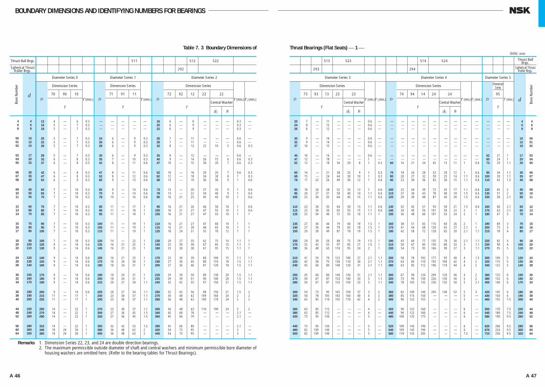
A 46 A 47
BOUNDARY DIMENSIONS AND IDENTIFYING NUMBERS FOR BEARINGS
Thrust Ball Brgs.
Spherical Thrust Roller Brgs.
511 512 522
292
513 523 514 524
293 294
12 4 ⎯ 6 0.3 ⎯ ⎯ ⎯ ⎯ ⎯ 16 6 ⎯ 8 ⎯ ⎯ ⎯ 0.3 ⎯ 16 5 ⎯ 7 0.3 ⎯ ⎯ ⎯ ⎯ ⎯ 20 6 ⎯ 9 ⎯ ⎯ ⎯ 0.3 ⎯ 18 5 ⎯ 7 0.3 ⎯ ⎯ ⎯ ⎯ ⎯ 22 6 ⎯ 9 ⎯ ⎯ ⎯ 0.3 ⎯
20 5 ⎯ 7 0.3 24 6 ⎯ 9 0.3 26 7 ⎯ 11 ⎯ ⎯ ⎯ 0.6 ⎯ 22 5 ⎯ 7 0.3 26 6 ⎯ 9 0.3 28 7 ⎯ 11 ⎯ ⎯ ⎯ 0.6 ⎯ 26 5 ⎯ 7 0.3 28 6 ⎯ 9 0.3 32 8 ⎯ 12 22 10 5 0.6 0.3
28 5 ⎯ 7 0.3 30 6 ⎯ 9 0.3 35 8 ⎯ 12 ⎯ ⎯ ⎯ 0.6 ⎯ 32 6 ⎯ 8 0.3 35 7 ⎯ 10 0.3 40 9 ⎯ 14 26 15 6 0.6 0.3 37 6 ⎯ 8 0.3 42 8 ⎯ 11 0.6 47 10 ⎯ 15 28 20 7 0.6 0.3
42 6 ⎯ 8 0.3 47 8 ⎯ 11 0.6 52 10 ⎯ 16 29 25 7 0.6 0.3 47 6 ⎯ 8 0.3 52 8 ⎯ 12 0.6 62 12 ⎯ 18 34 30 8 1 0.3 52 6 ⎯ 9 0.3 60 9 ⎯ 13 0.6 68 13 ⎯ 19 36 30 9 1 0.6
60 7 ⎯ 10 0.3 65 9 ⎯ 14 0.6 73 13 ⎯ 20 37 35 9 1 0.6 65 7 ⎯ 10 0.3 70 9 ⎯ 14 0.6 78 13 ⎯ 22 39 40 9 1 0.6 70 7 ⎯ 10 0.3 78 10 ⎯ 16 0.6 90 16 21 25 45 45 10 1 0.6
75 7 ⎯ 10 0.3 85 11 ⎯ 17 1 95 16 21 26 46 50 10 1 0.6 80 7 ⎯ 10 0.3 90 11 ⎯ 18 1 100 16 21 27 47 55 10 1 0.6 85 7 ⎯ 10 0.3 95 11 ⎯ 18 1 105 16 21 27 47 55 10 1 1
90 7 ⎯ 10 0.3 100 11 ⎯ 19 1 110 16 21 27 47 60 10 1 1 95 7 ⎯ 10 0.3 105 11 ⎯ 19 1 115 16 21 28 48 65 10 1 1 100 7 ⎯ 10 0.3 110 11 ⎯ 19 1 125 18 24 31 55 70 12 1 1
105 7 ⎯ 10 0.3 120 14 ⎯ 22 1 135 20 27 35 62 75 14 1.1 1 120 9 ⎯ 14 0.6 135 16 21 25 1 150 23 30 38 67 85 15 1.1 1 130 9 ⎯ 14 0.6 145 16 21 25 1 160 23 30 38 67 95 15 1.1 1
140 9 ⎯ 14 0.6 155 16 21 25 1 170 23 30 39 68 100 15 1.1 1.1 150 9 ⎯ 14 0.6 170 18 24 30 1 190 27 36 45 80 110 18 1.5 1.1 160 9 ⎯ 14 0.6 180 18 24 31 1 200 27 36 46 81 120 18 1.5 1.1
170 9 ⎯ 14 0.6 190 18 24 31 1 215 29 39 50 89 130 20 1.5 1.1 180 9 ⎯ 14 0.6 200 18 24 31 1 225 29 39 51 90 140 20 1.5 1.1 190 9 ⎯ 14 0.6 215 20 27 34 1.1 240 32 42 55 97 150 21 1.5 1.1
200 9 ⎯ 14 0.6 225 20 27 34 1.1 250 32 42 56 98 150 21 1.5 2 215 11 ⎯ 17 1 240 23 30 37 1.1 270 36 48 62 109 160 24 2 2 225 11 ⎯ 17 1 250 23 30 37 1.1 280 36 48 62 109 170 24 2 2
250 14 ⎯ 22 1 270 23 30 37 1.1 300 36 48 63 110 190 24 2 2 270 14 ⎯ 22 1 300 27 36 45 1.5 340 45 60 78 ⎯ ⎯ ⎯ 2.1 ⎯ 290 14 ⎯ 22 1 320 27 36 45 1.5 360 45 60 79 ⎯ ⎯ ⎯ 2.1 ⎯
310 14 ⎯ 22 1 350 32 42 53 1.5 380 45 60 80 ⎯ ⎯ ⎯ 2.1 ⎯ 340 18 24 30 1 380 36 48 62 2 420 54 73 95 ⎯ ⎯ ⎯ 3 ⎯ 360 18 24 30 1 400 36 48 63 2 440 54 73 95 ⎯ ⎯ ⎯ 3 ⎯
dD Dr (min.) Dr (min.) r1 (min.)r (min.)
Diameter Series 0
Dimension Series
70 90 10
T
Diameter Series 1
Dimension Series
71 91 11
T
Diameter Series 2
Dimension Series
72 92 12 22 22
Central Washer
d2 BT
Remarks 1. Dimension Series 22, 23, and 24 are double direction bearings.Remarks 2. The maximum permissible outside diameter of shaft and central washers and minimum permissible bore diameter of
housing washers are omitted here. (Refer to the bearing tables for Thrust Bearings).
4 4 6 6 8 8
00 10 01 12 02 15
03 17 04 20 05 25
06 30 07 35 08 40
09 45 10 50 11 55
12 60 13 65 14 70
15 75 16 80 17 85
18 90 20 100 22 110
24 120 26 130 28 140
30 150 32 160 34 170
36 180 38 190 40 200
44 220 48 240 52 260
56 280 60 300 64 320
Thrust Ball Brgs.
Spherical Thrust Roller Brgs.
dD r (min.)
Diameter Series 3
Dimension Series
73 93 13 23 23
T
r1 (min.)Central Washer
d2 B
D r (min.) D
Diameter Series 4 Diameter Series 5
Dimension Series
74 94 14 24 24
T
Dimension Series
95
T
r (min.)r1 (min.)Central Washer
d2 B
⎯ ⎯ ⎯ 4 4 ⎯ ⎯ ⎯ 6 6 ⎯ ⎯ ⎯ 8 8
⎯ ⎯ ⎯ 10 00 ⎯ ⎯ ⎯ 12 01 ⎯ ⎯ ⎯ 15 02
52 21 1 17 03 60 24 1 20 04 73 29 1.1 25 05
85 34 1.1 30 06 100 39 1.1 35 07 110 42 1.5 40 08
120 45 2 45 09 135 51 2 50 10 150 58 2.1 55 11
160 60 2.1 60 12 170 63 2.1 65 13 180 67 3 70 14
190 69 3 75 15 200 73 3 80 16 215 78 4 85 17
225 82 4 90 18 250 90 4 100 20 270 95 5 110 22
300 109 5 120 24 320 115 5 130 26 340 122 5 140 28
360 125 6 150 30 380 132 6 160 32 400 140 6 170 34
420 145 6 180 36 440 150 6 190 38 460 155 7.5 200 40
500 170 7.5 220 44 540 180 7.5 240 48 580 190 9.5 260 52
620 206 9.5 280 56 670 224 9.5 300 60 710 236 9.5 320 64
20 7 ⎯ 11 ⎯ ⎯ ⎯ 0.6 ⎯ ⎯ ⎯ ⎯ ⎯ ⎯ ⎯ ⎯ ⎯ ⎯ 24 8 ⎯ 12 ⎯ ⎯ ⎯ 0.6 ⎯ ⎯ ⎯ ⎯ ⎯ ⎯ ⎯ ⎯ ⎯ ⎯ 26 8 ⎯ 12 ⎯ ⎯ ⎯ 0.6 ⎯ ⎯ ⎯ ⎯ ⎯ ⎯ ⎯ ⎯ ⎯ ⎯
30 9 ⎯ 14 ⎯ ⎯ ⎯ 0.6 ⎯ ⎯ ⎯ ⎯ ⎯ ⎯ ⎯ ⎯ ⎯ ⎯ 32 9 ⎯ 14 ⎯ ⎯ ⎯ 0.6 ⎯ ⎯ ⎯ ⎯ ⎯ ⎯ ⎯ ⎯ ⎯ ⎯ 37 10 ⎯ 15 ⎯ ⎯ ⎯ 0.6 ⎯ ⎯ ⎯ ⎯ ⎯ ⎯ ⎯ ⎯ ⎯ ⎯
40 10 ⎯ 16 ⎯ ⎯ ⎯ 0.6 ⎯ ⎯ ⎯ ⎯ ⎯ ⎯ ⎯ ⎯ ⎯ ⎯ 47 12 ⎯ 18 ⎯ ⎯ ⎯ 1 ⎯ ⎯ ⎯ ⎯ ⎯ ⎯ ⎯ ⎯ ⎯ ⎯ 52 12 ⎯ 18 34 20 8 1 0.3 60 16 21 24 45 15 11 1 0.6
60 14 ⎯ 21 38 25 9 1 0.3 70 18 24 28 52 20 12 1 0.6 68 15 ⎯ 24 44 30 10 1 0.3 80 20 27 32 59 25 14 1.1 0.6 78 17 22 26 49 30 12 1 0.6 90 23 30 36 65 30 15 1.1 0.6
85 18 24 28 52 35 12 1 0.6 100 25 34 39 72 35 17 1.1 0.6 95 20 27 31 58 40 14 1.1 0.6 110 27 36 43 78 40 18 1.5 0.6 105 23 30 35 64 45 15 1.1 0.6 120 29 39 48 87 45 20 1.5 0.6
110 23 30 35 64 50 15 1.1 0.6 130 32 42 51 93 50 21 1.5 0.6 115 23 30 36 65 55 15 1.1 0.6 140 34 45 56 101 50 23 2 1 125 25 34 40 72 55 16 1.1 1 150 36 48 60 107 55 24 2 1
135 27 36 44 79 60 18 1.5 1 160 38 51 65 115 60 26 2 1 140 27 36 44 79 65 18 1.5 1 170 41 54 68 120 65 27 2.1 1 150 29 39 49 87 70 19 1.5 1 180 42 58 72 128 65 29 2.1 1.1
155 29 39 50 88 75 19 1.5 1 190 45 60 77 135 70 30 2.1 1.1 170 32 42 55 97 85 21 1.5 1 210 50 67 85 150 80 33 3 1.1 190 36 48 63 110 95 24 2 1 230 54 73 95 166 90 37 3 1.1
210 41 54 70 123 100 27 2.1 1.1 250 58 78 102 177 95 40 4 1.5 225 42 58 75 130 110 30 2.1 1.1 270 63 85 110 192 100 42 4 2 240 45 60 80 140 120 31 2.1 1.1 280 63 85 112 196 110 44 4 2
250 45 60 80 140 130 31 2.1 1.1 300 67 90 120 209 120 46 4 2 270 50 67 87 153 140 33 3 1.1 320 73 95 130 226 130 50 5 2 280 50 67 87 153 150 33 3 1.1 340 78 103 135 236 135 50 5 2.1
300 54 73 95 165 150 37 3 2 360 82 109 140 245 140 52 5 3 320 58 78 105 183 160 40 4 2 380 85 115 150 ⎯ ⎯ ⎯ 5 ⎯ 340 63 85 110 192 170 42 4 2 400 90 122 155 ⎯ ⎯ ⎯ 5 ⎯
360 63 85 112 ⎯ ⎯ ⎯ 4 ⎯ 420 90 122 160 ⎯ ⎯ ⎯ 6 ⎯ 380 63 85 112 ⎯ ⎯ ⎯ 4 ⎯ 440 90 122 160 ⎯ ⎯ ⎯ 6 ⎯ 420 73 95 130 ⎯ ⎯ ⎯ 5 ⎯ 480 100 132 175 ⎯ ⎯ ⎯ 6 ⎯
440 73 95 130 ⎯ ⎯ ⎯ 5 ⎯ 520 109 145 190 ⎯ ⎯ ⎯ 6 ⎯ 480 82 109 140 ⎯ ⎯ ⎯ 5 ⎯ 540 109 145 190 ⎯ ⎯ ⎯ 6 ⎯ 500 82 109 140 ⎯ ⎯ ⎯ 5 ⎯ 580 118 155 205 ⎯ ⎯ ⎯ 7.5 ⎯
Table 7. 3 Boundary Dimensions of Thrust Bearings (Flat Seats) ⎯ 1 ⎯Units: mm
Bore
Num
ber
Bore
Num
ber
A024-057E.indd 46-47 A024-057E.indd 46-47 11/20/13 4:50:31 PM11/20/13 4:50:31 PM
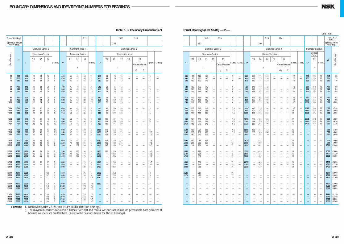
A 48 A 49
BOUNDARY DIMENSIONS AND IDENTIFYING NUMBERS FOR BEARINGS
Thrust Ball Brgs.
Spherical Thrust Roller Brgs.
511 512 522
292
380 18 24 30 1 420 36 48 64 2 460 54 073 96 ⎯ ⎯ ⎯ 3 ⎯ 400 18 24 30 1 440 36 48 65 2 500 63 085 110 ⎯ ⎯ ⎯ 4 ⎯ 420 18 24 30 1 460 36 48 65 2 520 63 085 112 ⎯ ⎯ ⎯ 4 ⎯
440 18 24 30 1 480 36 48 65 2 540 63 085 112 ⎯ ⎯ ⎯ 4 ⎯ 460 18 24 30 1 500 36 48 65 2 580 73 095 130 ⎯ ⎯ ⎯ 5 ⎯ 480 18 24 30 1 540 45 60 80 2.1 600 73 095 130 ⎯ ⎯ ⎯ 5 ⎯
500 18 24 30 1 560 45 60 80 2.1 620 73 095 130 ⎯ ⎯ ⎯ 5 ⎯ 520 18 24 30 1 580 45 60 80 2.1 650 78 103 135 ⎯ ⎯ ⎯ 5 ⎯ 540 18 24 30 1 600 45 60 80 2.1 670 78 103 135 ⎯ ⎯ ⎯ 5 ⎯
580 23 30 38 1.1 640 50 67 85 3 710 82 109 140 ⎯ ⎯ ⎯ 5 ⎯ 610 23 30 38 1.1 670 50 67 85 3 750 85 115 150 ⎯ ⎯ ⎯ 5 ⎯ 650 23 30 38 1.1 710 50 67 85 3 800 90 122 160 ⎯ ⎯ ⎯ 5 ⎯
680 23 30 38 1.1 750 54 73 95 3 850 100 132 175 ⎯ ⎯ ⎯ 6 ⎯ 730 27 36 45 1.5 800 58 78 105 4 900 103 140 180 ⎯ ⎯ ⎯ 6 ⎯ 780 32 42 53 1.5 850 63 85 112 4 950 109 145 190 ⎯ ⎯ ⎯ 6 ⎯
820 32 42 53 1.5 900 67 90 120 4 1000 112 150 195 ⎯ ⎯ ⎯ 6 ⎯ 870 32 42 53 1.5 950 67 90 120 4 1060 118 155 205 ⎯ ⎯ ⎯ 7.5 ⎯ 920 32 42 53 1.5 1000 67 90 120 4 1120 122 160 212 ⎯ ⎯ ⎯ 7.5 ⎯
980 36 48 63 2 1060 73 95 130 5 1180 125 170 220 ⎯ ⎯ ⎯ 7.5 ⎯ 1030 36 48 63 2 1120 78 103 135 5 1250 136 180 236 ⎯ ⎯ ⎯ 7.5 ⎯ 1090 41 54 70 2.1 1180 82 109 140 5 1320 145 190 250 ⎯ ⎯ ⎯ 9.5 ⎯
1150 41 54 70 2.1 1250 85 115 150 5 1400 155 206 265 ⎯ ⎯ ⎯ 9.5 ⎯ 1220 45 60 80 2.1 1320 90 122 160 5 1460 ⎯ 206 ⎯ ⎯ ⎯ ⎯ 9.5 ⎯ 1280 45 60 80 2.1 1400 100 132 175 6 1520 ⎯ 206 ⎯ ⎯ ⎯ ⎯ 9.5 ⎯
1360 50 67 85 3 1460 ⎯ ⎯ 175 6 1610 ⎯ 216 ⎯ ⎯ ⎯ ⎯ 9.5 ⎯ 1440 ⎯ ⎯ 95 3 1540 ⎯ ⎯ 175 6 1700 ⎯ 228 ⎯ ⎯ ⎯ ⎯ 9.5 ⎯ 1520 ⎯ ⎯ 95 3 1630 ⎯ ⎯ 180 6 1790 ⎯ 234 ⎯ ⎯ ⎯ ⎯ 12 ⎯
1630 ⎯ ⎯ 105 4 1750 ⎯ ⎯ 195 6 1920 ⎯ 252 ⎯ ⎯ ⎯ ⎯ 12 ⎯ 1730 ⎯ ⎯ 105 4 1850 ⎯ ⎯ 195 6 2040 ⎯ 264 ⎯ ⎯ ⎯ ⎯ 15 ⎯ 1840 ⎯ ⎯ 112 4 1970 ⎯ ⎯ 212 7.5 2160 ⎯ 276 ⎯ ⎯ ⎯ ⎯ 15 ⎯
1950 ⎯ ⎯ 120 4 2080 ⎯ ⎯ 220 7.5 2280 ⎯ 288 ⎯ ⎯ ⎯ ⎯ 15 ⎯ 2060 ⎯ ⎯ 130 5 2180 ⎯ ⎯ 220 7.5 ⎯ ⎯ ⎯ ⎯ ⎯ ⎯ ⎯ ⎯ ⎯ 2160 ⎯ ⎯ 130 5 2300 ⎯ ⎯ 236 7.5 ⎯ ⎯ ⎯ ⎯ ⎯ ⎯ ⎯ ⎯ ⎯
2300 ⎯ ⎯ 140 5 2430 ⎯ ⎯ 243 7.5 ⎯ ⎯ ⎯ ⎯ ⎯ ⎯ ⎯ ⎯ ⎯ 2430 ⎯ ⎯ 150 5 2570 ⎯ ⎯ 258 9.5 ⎯ ⎯ ⎯ ⎯ ⎯ ⎯ ⎯ ⎯ ⎯ 2550 ⎯ ⎯ 150 5 2700 ⎯ ⎯ 265 9.5 ⎯ ⎯ ⎯ ⎯ ⎯ ⎯ ⎯ ⎯ ⎯ 2700 ⎯ ⎯ 160 5 2850 ⎯ ⎯ 272 9.5 ⎯ ⎯ ⎯ ⎯ ⎯ ⎯ ⎯ ⎯ ⎯
dD Dr (min.) Dr (min.) r1 (min.)r (min.)
Diameter Series 0
Dimension Series
70 90 10
T
Diameter Series 1
Dimension Series
71 91 11
T
Diameter Series 2
Dimension Series
72 92 12 22 22
Central Washer
d2 BT
Remarks 1. Dimension Series 22, 23, and 24 are double direction bearings.Remarks 2. The maximum permissible outside diameter of shaft and central washers and minimum permissible bore diameter of
housing washers are omitted here. (Refer to the bearings tables for Thrust Bearings).
68 340 72 360 76 380
80 400 84 420 88 440
92 460 96 480 /500 500
/530 530 /560 560 /600 600
/630 630 /670 670 /710 710
/750 750 /800 800 /850 850
/900 900 /950 950 /1000 1000
/1060 1060 /1120 1120 /1180 1180
/1250 1250 /1320 1320 /1400 1400
/1500 1500 /1600 1600 /1700 1700
/1800 1800 /1900 1900 /2000 2000
/2120 2120 /2240 2240 /2360 2360 /2500 2500
Table 7. 3 Boundary Dimensions of
513 523 514 524
293 294
Thrust Ball Brgs.
Spherical Thrust Roller Brgs.
dD r (min.)
Diameter Series 3
Dimension Series
73 93 13 23 23
T
r1 (min.)Central Washer
d2 B
D r (min.) D
Diameter Series 4 Diameter Series 5
Dimension Series
74 94 14 24 24
T
Dimension Series
95
T
r (min.)r1 (min.)Central Washer
d2 B
750 243 12 340 68 780 250 12 360 72 820 265 12 380 76
850 272 12 400 80 900 290 15 420 84 950 308 15 440 88
980 315 15 460 92 1000 315 15 480 96 1060 335 15 500 /500
1090 335 15 530 /530 1150 355 15 560 /560 1220 375 15 600 /600
1280 388 15 630 /630 1320 388 15 670 /670 1400 412 15 710 /710
⎯ ⎯ ⎯ 750 /750 ⎯ ⎯ ⎯ 800 /800 ⎯ ⎯ ⎯ 850 /850
⎯ ⎯ ⎯ 900 /900 ⎯ ⎯ ⎯ 950 /950 ⎯ ⎯ ⎯ 1000 /1000
⎯ ⎯ ⎯ 1060 /1060 ⎯ ⎯ ⎯ 1120 /1120 ⎯ ⎯ ⎯ 1180 /1180
⎯ ⎯ ⎯ 1250 /1250 ⎯ ⎯ ⎯ 1320 /1320 ⎯ ⎯ ⎯ 1400 /1400
⎯ ⎯ ⎯ 1500 /1500 ⎯ ⎯ ⎯ 1600 /1600 ⎯ ⎯ ⎯ 1700 /1700
⎯ ⎯ ⎯ 1800 /1800 ⎯ ⎯ ⎯ 1900 /1900 ⎯ ⎯ ⎯ 2000 /2000
⎯ ⎯ ⎯ 2120 /2120 ⎯ ⎯ ⎯ 2240 /2240 ⎯ ⎯ ⎯ 2360 /2360 ⎯ ⎯ ⎯ 2500 /2500
540 90 122 160 ⎯ ⎯ ⎯ 5 ⎯ 620 125 170 220 ⎯ ⎯ ⎯ 7.5 ⎯ 560 90 122 160 ⎯ ⎯ ⎯ 5 ⎯ 640 125 170 220 ⎯ ⎯ ⎯ 7.5 ⎯ 600 100 132 175 ⎯ ⎯ ⎯ 6 ⎯ 670 132 175 224 ⎯ ⎯ ⎯ 7.5 ⎯
620 100 132 175 ⎯ ⎯ ⎯ 6 ⎯ 710 140 185 243 ⎯ ⎯ ⎯ 7.5 ⎯ 650 103 140 180 ⎯ ⎯ ⎯ 6 ⎯ 730 140 185 243 ⎯ ⎯ ⎯ 7.5 ⎯ 680 109 145 190 ⎯ ⎯ ⎯ 6 ⎯ 780 155 206 265 ⎯ ⎯ ⎯ 9.5 ⎯
710 112 150 195 ⎯ ⎯ ⎯ 6 ⎯ 800 155 206 265 ⎯ ⎯ ⎯ 9.5 ⎯ 730 112 150 195 ⎯ ⎯ ⎯ 6 ⎯ 850 165 224 290 ⎯ ⎯ ⎯ 9.5 ⎯ 750 112 150 195 ⎯ ⎯ ⎯ 6 ⎯ 870 165 224 290 ⎯ ⎯ ⎯ 9.5 ⎯
800 122 160 212 ⎯ ⎯ ⎯ 7.5 ⎯ 920 175 236 308 ⎯ ⎯ ⎯ 9.5 ⎯ 850 132 175 224 ⎯ ⎯ ⎯ 7.5 ⎯ 980 190 250 335 ⎯ ⎯ ⎯ 12 ⎯ 900 136 180 236 ⎯ ⎯ ⎯ 7.5 ⎯ 1030 195 258 335 ⎯ ⎯ ⎯ 12 ⎯
950 145 190 250 ⎯ ⎯ ⎯ 9.5 ⎯ 1090 206 280 365 ⎯ ⎯ ⎯ 12 ⎯ 1000 150 200 258 ⎯ ⎯ ⎯ 9.5 ⎯ 1150 218 290 375 ⎯ ⎯ ⎯ 15 ⎯ 1060 160 212 272 ⎯ ⎯ ⎯ 9.5 ⎯ 1220 230 308 400 ⎯ ⎯ ⎯ 15 ⎯
1120 165 224 290 ⎯ ⎯ ⎯ 9.5 ⎯ 1280 236 315 412 ⎯ ⎯ ⎯ 15 ⎯ 1180 170 230 300 ⎯ ⎯ ⎯ 9.5 ⎯ 1360 250 335 438 ⎯ ⎯ ⎯ 15 ⎯ 1250 180 243 315 ⎯ ⎯ ⎯ 12 ⎯ 1440 ⎯ 354 ⎯ ⎯ ⎯ ⎯ 15 ⎯
1320 190 250 335 ⎯ ⎯ ⎯ 12 ⎯ 1520 ⎯ 372 ⎯ ⎯ ⎯ ⎯ 15 ⎯ 1400 200 272 355 ⎯ ⎯ ⎯ 12 ⎯ 1600 ⎯ 390 ⎯ ⎯ ⎯ ⎯ 15 ⎯ 1460 ⎯ 276 ⎯ ⎯ ⎯ ⎯ 12 ⎯ 1670 ⎯ 402 ⎯ ⎯ ⎯ ⎯ 15 ⎯
1540 ⎯ 288 ⎯ ⎯ ⎯ ⎯ 15 ⎯ 1770 ⎯ 426 ⎯ ⎯ ⎯ ⎯ 15 ⎯ 1630 ⎯ 306 ⎯ ⎯ ⎯ ⎯ 15 ⎯ 1860 ⎯ 444 ⎯ ⎯ ⎯ ⎯ 15 ⎯ 1710 ⎯ 318 ⎯ ⎯ ⎯ ⎯ 15 ⎯ 1950 ⎯ 462 ⎯ ⎯ ⎯ ⎯ 19 ⎯
1800 ⎯ 330 ⎯ ⎯ ⎯ ⎯ 19 ⎯ 2050 ⎯ 480 ⎯ ⎯ ⎯ ⎯ 19 ⎯ 1900 ⎯ 348 ⎯ ⎯ ⎯ ⎯ 19 ⎯ 2160 ⎯ 505 ⎯ ⎯ ⎯ ⎯ 19 ⎯ 2000 ⎯ 360 ⎯ ⎯ ⎯ ⎯ 19 ⎯ 2280 ⎯ 530 ⎯ ⎯ ⎯ ⎯ 19 ⎯
2140 ⎯ 384 ⎯ ⎯ ⎯ ⎯ 19 ⎯ ⎯ ⎯ ⎯ ⎯ ⎯ ⎯ ⎯ ⎯ ⎯ 2270 ⎯ 402 ⎯ ⎯ ⎯ ⎯ 19 ⎯ ⎯ ⎯ ⎯ ⎯ ⎯ ⎯ ⎯ ⎯ ⎯ ⎯ ⎯ ⎯ ⎯ ⎯ ⎯ ⎯ ⎯ ⎯ ⎯ ⎯ ⎯ ⎯ ⎯ ⎯ ⎯ ⎯ ⎯
⎯ ⎯ ⎯ ⎯ ⎯ ⎯ ⎯ ⎯ ⎯ ⎯ ⎯ ⎯ ⎯ ⎯ ⎯ ⎯ ⎯ ⎯ ⎯ ⎯ ⎯ ⎯ ⎯ ⎯ ⎯ ⎯ ⎯ ⎯ ⎯ ⎯ ⎯ ⎯ ⎯ ⎯ ⎯ ⎯ ⎯ ⎯ ⎯ ⎯ ⎯ ⎯ ⎯ ⎯ ⎯ ⎯ ⎯ ⎯ ⎯ ⎯ ⎯ ⎯ ⎯
⎯ ⎯ ⎯ ⎯ ⎯ ⎯ ⎯ ⎯ ⎯ ⎯ ⎯ ⎯ ⎯ ⎯ ⎯ ⎯ ⎯ ⎯ ⎯ ⎯ ⎯ ⎯ ⎯ ⎯ ⎯ ⎯ ⎯ ⎯ ⎯ ⎯ ⎯ ⎯ ⎯ ⎯ ⎯ ⎯ ⎯ ⎯ ⎯ ⎯ ⎯ ⎯ ⎯ ⎯ ⎯ ⎯ ⎯ ⎯ ⎯ ⎯ ⎯ ⎯ ⎯ ⎯ ⎯ ⎯ ⎯ ⎯ ⎯ ⎯ ⎯ ⎯ ⎯ ⎯ ⎯ ⎯ ⎯ ⎯ ⎯ ⎯ ⎯ ⎯
Thrust Bearings (Flat Seats) ⎯ 2 ⎯Units: mm
Bore
Num
ber
Bore
Num
ber
A024-057E.indd 48-49 A024-057E.indd 48-49 11/20/13 4:50:33 PM11/20/13 4:50:33 PM
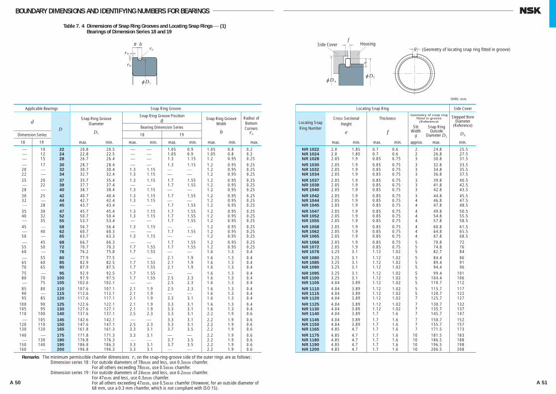
A 50 A 51
BOUNDARY DIMENSIONS AND IDENTIFYING NUMBERS FOR BEARINGS
jD
0
1
bar
Nr
Nr
jD2jD x
e
f
gSide Cover Housing
(Geometry of locating snap ring fitted in groove)
Applicable Bearings
d
Dimension SeriesD
Snap Ring GrooveDiameter
D1
Snap Ring Groove Positiona Snap Ring Groove
Width
b
Radius of Bottom Corners
r0
Bearing Dimension Series
18 19
18 19 max. min. max. min. max. min. max. min. max.
⎯ 10 22 20.8 20.5 ⎯ ⎯ 1.05 0.9 1.05 0.8 0.2 ⎯ 12 24 22.8 22.5 ⎯ ⎯ 1.05 0.9 1.05 0.8 0.2 ⎯ 15 28 26.7 26.4 ⎯ ⎯ 1.3 1.15 1.2 0.95 0.25 ⎯ 17 30 28.7 28.4 ⎯ ⎯ 1.3 1.15 1.2 0.95 0.25 20 ⎯ 32 30.7 30.4 1.3 1.15 ⎯ ⎯ 1.2 0.95 0.25 22 ⎯ 34 32.7 32.4 1.3 1.15 ⎯ ⎯ 1.2 0.95 0.25 25 20 37 35.7 35.4 1.3 1.15 1.7 1.55 1.2 0.95 0.25 ⎯ 22 39 37.7 37.4 ⎯ ⎯ 1.7 1.55 1.2 0.95 0.25 28 ⎯ 40 38.7 38.4 1.3 1.15 ⎯ ⎯ 1.2 0.95 0.25 30 25 42 40.7 40.4 1.3 1.15 1.7 1.55 1.2 0.95 0.25 32 ⎯ 44 42.7 42.4 1.3 1.15 ⎯ ⎯ 1.2 0.95 0.25 ⎯ 28 45 43.7 43.4 ⎯ ⎯ 1.7 1.55 1.2 0.95 0.25 35 30 47 45.7 45.4 1.3 1.15 1.7 1.55 1.2 0.95 0.25 40 32 52 50.7 50.4 1.3 1.15 1.7 1.55 1.2 0.95 0.25 ⎯ 35 55 53.7 53.4 ⎯ ⎯ 1.7 1.55 1.2 0.95 0.25 45 ⎯ 58 56.7 56.4 1.3 1.15 ⎯ ⎯ 1.2 0.95 0.25 ⎯ 40 62 60.7 60.3 ⎯ ⎯ 1.7 1.55 1.2 0.95 0.25 50 ⎯ 65 63.7 63.3 1.3 1.15 ⎯ ⎯ 1.2 0.95 0.25 ⎯ 45 68 66.7 66.3 ⎯ ⎯ 1.7 1.55 1.2 0.95 0.25 55 50 72 70.7 70.3 1.7 1.55 1.7 1.55 1.2 0.95 0.25 60 ⎯ 78 76.2 75.8 1.7 1.55 ⎯ ⎯ 1.6 1.3 0.4 ⎯ 55 80 77.9 77.5 ⎯ ⎯ 2.1 1.9 1.6 1.3 0.4 65 60 85 82.9 82.5 1.7 1.55 2.1 1.9 1.6 1.3 0.4 70 65 90 87.9 87.5 1.7 1.55 2.1 1.9 1.6 1.3 0.4 75 ⎯ 95 92.9 92.5 1.7 1.55 ⎯ ⎯ 1.6 1.3 0.4 80 70 100 97.9 97.5 1.7 1.55 2.5 2.3 1.6 1.3 0.4 ⎯ 75 105 102.6 102.1 ⎯ ⎯ 2.5 2.3 1.6 1.3 0.4 85 80 110 107.6 107.1 2.1 1.9 2.5 2.3 1.6 1.3 0.4 90 ⎯ 115 112.6 112.1 2.1 1.9 ⎯ ⎯ 1.6 1.3 0.4 95 85 120 117.6 117.1 2.1 1.9 3.3 3.1 1.6 1.3 0.4 100 90 125 122.6 122.1 2.1 1.9 3.3 3.1 1.6 1.3 0.4 105 95 130 127.6 127.1 2.1 1.9 3.3 3.1 1.6 1.3 0.4 110 100 140 137.6 137.1 2.5 2.3 3.3 3.1 2.2 1.9 0.6 ⎯ 105 145 142.6 142.1 ⎯ ⎯ 3.3 3.1 2.2 1.9 0.6 120 110 150 147.6 147.1 2.5 2.3 3.3 3.1 2.2 1.9 0.6 130 120 165 161.8 161.3 3.3 3.1 3.7 3.5 2.2 1.9 0.6 140 ⎯ 175 171.8 171.3 3.3 3.1 ⎯ ⎯ 2.2 1.9 0.6 ⎯ 130 180 176.8 176.3 ⎯ ⎯ 3.7 3.5 2.2 1.9 0.6 150 140 190 186.8 186.3 3.3 3.1 3.7 3.5 2.2 1.9 0.6 160 ⎯ 200 196.8 196.3 3.3 3.1 ⎯ ⎯ 2.2 1.9 0.6
Snap Ring Groove Locating Snap Ring
Locating Snap Ring Number
Cross SectionalHeight
e
Thickness
f
Geometry of snap ring fitted in groove
(Reference)Stepped Bore
Diameter(Reference)
DX
SlitWidth
g
Snap RingOutside
Diameter D2
max. min. max. min. approx. max. min.
NR 1022 2.0 1.85 0.7 0.6 2 24.8 25.5 NR 1024 2.0 1.85 0.7 0.6 2 26.8 27.5 NR 1028 2.05 1.9 0.85 0.75 3 30.8 31.5 NR 1030 2.05 1.9 0.85 0.75 3 32.8 33.5 NR 1032 2.05 1.9 0.85 0.75 3 34.8 35.5 NR 1034 2.05 1.9 0.85 0.75 3 36.8 37.5 NR 1037 2.05 1.9 0.85 0.75 3 39.8 40.5 NR 1039 2.05 1.9 0.85 0.75 3 41.8 42.5 NR 1040 2.05 1.9 0.85 0.75 3 42.8 43.5 NR 1042 2.05 1.9 0.85 0.75 3 44.8 45.5 NR 1044 2.05 1.9 0.85 0.75 4 46.8 47.5 NR 1045 2.05 1.9 0.85 0.75 4 47.8 48.5 NR 1047 2.05 1.9 0.85 0.75 4 49.8 50.5 NR 1052 2.05 1.9 0.85 0.75 4 54.8 55.5 NR 1055 2.05 1.9 0.85 0.75 4 57.8 58.5 NR 1058 2.05 1.9 0.85 0.75 4 60.8 61.5 NR 1062 2.05 1.9 0.85 0.75 4 64.8 65.5 NR 1065 2.05 1.9 0.85 0.75 4 67.8 68.5 NR 1068 2.05 1.9 0.85 0.75 5 70.8 72 NR 1072 2.05 1.9 0.85 0.75 5 74.8 76 NR 1078 3.25 3.1 1.12 1.02 5 82.7 84 NR 1080 3.25 3.1 1.12 1.02 5 84.4 86 NR 1085 3.25 3.1 1.12 1.02 5 89.4 91 NR 1090 3.25 3.1 1.12 1.02 5 94.4 96 NR 1095 3.25 3.1 1.12 1.02 5 99.4 101 NR 1100 3.25 3.1 1.12 1.02 5 104.4 106 NR 1105 4.04 3.89 1.12 1.02 5 110.7 112 NR 1110 4.04 3.89 1.12 1.02 5 115.7 117 NR 1115 4.04 3.89 1.12 1.02 5 120.7 122 NR 1120 4.04 3.89 1.12 1.02 7 125.7 127 NR 1125 4.04 3.89 1.12 1.02 7 130.7 132 NR 1130 4.04 3.89 1.12 1.02 7 135.7 137 NR 1140 4.04 3.89 1.7 1.6 7 145.7 147 NR 1145 4.04 3.89 1.7 1.6 7 150.7 152 NR 1150 4.04 3.89 1.7 1.6 7 155.7 157 NR 1165 4.85 4.7 1.7 1.6 7 171.5 173 NR 1175 4.85 4.7 1.7 1.6 10 181.5 183 NR 1180 4.85 4.7 1.7 1.6 10 186.5 188 NR 1190 4.85 4.7 1.7 1.6 10 196.5 198 NR 1200 4.85 4.7 1.7 1.6 10 206.5 208
Side Cover
Remarks The minimum permissible chamfer dimensions rN on the snap-ring-groove side of the outer rings are as follows:Dimension series 18 : For outside diameters of 78mm and less, use 0.3mm chamfer.
For all others exceeding 78mm, use 0.5mm chamfer.Dimension series 19 : For outside diameters of 24mm and less, use 0.2mm chamfer.
For 47mm and less, use 0.3mm chamfer.For all others exceeding 47mm, use 0.5mm chamfer (However, for an outside diameter of 68 mm, use a 0.3 mm chamfer, which is not compliant with ISO 15).
Units: mm
Table 7. 4 Dimensions of Snap Ring Grooves and Locating Snap Rings ⎯ (1) Bearings of Dimension Series 18 and 19
A024-057E.indd 50-51 A024-057E.indd 50-51 11/20/13 4:50:35 PM11/20/13 4:50:35 PM

A 52 A 53
BOUNDARY DIMENSIONS AND IDENTIFYING NUMBERS FOR BEARINGS
jD
0
1
bar
Nr
Nr
Applicable Bearings
d
Diameter SeriesD
Snap Ring GrooveDiameter
D1
Snap Ring Groove Positiona Snap Ring Groove
Width
b
Radius of
Bottom Corners
r0
Bearing Diameter Series
0 2, 3, 4
0 2 3 4 max. min. max. min. max. min. max. min. max.
10 ⎯ ⎯ ⎯ 26 24.5 24.25 1.35 1.19 ⎯ ⎯ 1.17 0.87 0.2 12 ⎯ ⎯ ⎯ 28 26.5 26.25 1.35 1.19 ⎯ ⎯ 1.17 0.87 0.2 ⎯ 10 9 8 30 28.17 27.91 ⎯ ⎯ 2.06 1.9 1.65 1.35 0.4 15 12 ⎯ 9 32 30.15 29.9 2.06 1.9 2.06 1.9 1.65 1.35 0.4 17 15 10 ⎯ 35 33.17 32.92 2.06 1.9 2.06 1.9 1.65 1.35 0.4 ⎯ ⎯ 12 10 37 34.77 34.52 ⎯ ⎯ 2.06 1.9 1.65 1.35 0.4 ⎯ 17 ⎯ ⎯ 40 38.1 37.85 ⎯ ⎯ 2.06 1.9 1.65 1.35 0.4 20 ⎯ 15 12 42 39.75 39.5 2.06 1.9 2.06 1.9 1.65 1.35 0.4 22 ⎯ ⎯ ⎯ 44 41.75 41.5 2.06 1.9 ⎯ ⎯ 1.65 1.35 0.4 25 20 17 ⎯ 47 44.6 44.35 2.06 1.9 2.46 2.31 1.65 1.35 0.4 ⎯ 22 ⎯ ⎯ 50 47.6 47.35 ⎯ ⎯ 2.46 2.31 1.65 1.35 0.4 28 25 20 15 52 49.73 49.48 2.06 1.9 2.46 2.31 1.65 1.35 0.4 30 ⎯ ⎯ ⎯ 55 52.6 52.35 2.08 1.88 ⎯ ⎯ 1.65 1.35 0.4 ⎯ ⎯ 22 ⎯ 56 53.6 53.35 ⎯ ⎯ 2.46 2.31 1.65 1.35 0.4 32 28 ⎯ ⎯ 58 55.6 55.35 2.08 1.88 2.46 2.31 1.65 1.35 0.4 35 30 25 17 62 59.61 59.11 2.08 1.88 3.28 3.07 2.2 1.9 0.6 ⎯ 32 ⎯ ⎯ 65 62.6 62.1 ⎯ ⎯ 3.28 3.07 2.2 1.9 0.6 40 ⎯ 28 ⎯ 68 64.82 64.31 2.49 2.29 3.28 3.07 2.2 1.9 0.6 ⎯ 35 30 20 72 68.81 68.3 ⎯ ⎯ 3.28 3.07 2.2 1.9 0.6 45 ⎯ 32 ⎯ 75 71.83 71.32 2.49 2.29 3.28 3.07 2.2 1.9 0.6 50 40 35 25 80 76.81 76.3 2.49 2.29 3.28 3.07 2.2 1.9 0.6 ⎯ 45 ⎯ ⎯ 85 81.81 81.31 ⎯ ⎯ 3.28 3.07 2.2 1.9 0.6 55 50 40 30 90 86.79 86.28 2.87 2.67 3.28 3.07 3 2.7 0.6 60 ⎯ ⎯ ⎯ 95 91.82 91.31 2.87 2.67 ⎯ ⎯ 3 2.7 0.6 65 55 45 35 100 96.8 96.29 2.87 2.67 3.28 3.07 3 2.7 0.6 70 60 50 40 110 106.81 106.3 2.87 2.67 3.28 3.07 3 2.7 0.6 75 ⎯ ⎯ ⎯ 115 111.81 111.3 2.87 2.67 ⎯ ⎯ 3 2.7 0.6 ⎯ 65 55 45 120 115.21 114.71 ⎯ ⎯ 4.06 3.86 3.4 3.1 0.6 80 70 ⎯ ⎯ 125 120.22 119.71 2.87 2.67 4.06 3.86 3.4 3.1 0.6 85 75 60 50 130 125.22 124.71 2.87 2.67 4.06 3.86 3.4 3.1 0.6 90 80 65 55 140 135.23 134.72 3.71 3.45 4.9 4.65 3.4 3.1 0.6 95 ⎯ ⎯ ⎯ 145 140.23 139.73 3.71 3.45 ⎯ ⎯ 3.4 3.1 0.6 100 85 70 60 150 145.24 144.73 3.71 3.45 4.9 4.65 3.4 3.1 0.6 105 90 75 65 160 155.22 154.71 3.71 3.45 4.9 4.65 3.4 3.1 0.6 110 95 80 ⎯ 170 163.65 163.14 3.71 3.45 5.69 5.44 3.8 3.5 0.6 120 100 85 70 180 173.66 173.15 3.71 3.45 5.69 5.44 3.8 3.5 0.6 ⎯ 105 90 75 190 183.64 183.13 ⎯ ⎯ 5.69 5.44 3.8 3.5 0.6 130 110 95 80 200 193.65 193.14 5.69 5.44 5.69 5.44 3.8 3.5 0.6
Snap Ring Groove
Note (1) The locating snap rings and snap ring grooves of these bearings are not specified by ISO.Remarks 1. The dimensions of these snap ring grooves are not applicable to bearings of dimension series 00, 82, and 83.
2. The minimum permissible chamfer dimension rN on the snap-ring side of outer rings is 0.5mm. However, for bearings of diameter series 0 having outside diameters 35mm and below, it is 0.3mm.
jD2jD x
e
f
gSide Cover Housing
(Geometry of locating snap ring fitted in groove)
Locating Snap Ring
Locating Snap Ring Number
Cross SectionalHeight
e
Thickness
f
Geometry of snap ring fitted in groove
(Reference)Stepped Bore
Diameter(Reference)
DX
SlitWidth
g
Snap RingOutside
Diameter D2
max. min. max. min. approx. max. min.
NR 026 (1) 2.06 1.91 0.84 0.74 03 28.7 29.4 NR 028 (1) 2.06 1.91 0.84 0.74 03 30.7 31.4 NR 030 3.25 3.1 1.12 1.02 03 34.7 35.5 NR 032 3.25 3.1 1.12 1.02 03 36.7 37.5 NR 035 3.25 3.1 1.12 1.02 03 39.7 40.5 NR 037 3.25 3.1 1.12 1.02 03 41.3 42 NR 040 3.25 3.1 1.12 1.02 03 44.6 45.5 NR 042 3.25 3.1 1.12 1.02 03 46.3 47 NR 044 3.25 3.1 1.12 1.02 03 48.3 49 NR 047 4.04 3.89 1.12 1.02 04 52.7 53.5 NR 050 4.04 3.89 1.12 1.02 04 55.7 56.5 NR 052 4.04 3.89 1.12 1.02 04 57.9 58.5 NR 055 4.04 3.89 1.12 1.02 04 60.7 61.5 NR 056 4.04 3.89 1.12 1.02 04 61.7 62.5 NR 058 4.04 3.89 1.12 1.02 04 63.7 64.5 NR 062 4.04 3.89 1.7 1.6 04 67.7 68.5 NR 065 4.04 3.89 1.7 1.6 04 70.7 71.5 NR 068 4.85 4.7 1.7 1.6 05 74.6 76 NR 072 4.85 4.7 1.7 1.6 05 78.6 80 NR 075 4.85 4.7 1.7 1.6 05 81.6 83 NR 080 4.85 4.7 1.7 1.6 05 86.6 88 NR 085 4.85 4.7 1.7 1.6 05 91.6 93 NR 090 4.85 4.7 2.46 2.36 05 96.5 98 NR 095 4.85 4.7 2.46 2.36 05 101.6 103 NR 100 4.85 4.7 2.46 2.36 05 106.5 108 NR 110 4.85 4.7 2.46 2.36 05 116.6 118 NR 115 4.85 4.7 2.46 2.36 05 121.6 123 NR 120 7.21 7.06 2.82 2.72 07 129.7 131.5 NR 125 7.21 7.06 2.82 2.72 07 134.7 136.5 NR 130 7.21 7.06 2.82 2.72 07 139.7 141.5 NR 140 7.21 7.06 2.82 2.72 07 149.7 152 NR 145 7.21 7.06 2.82 2.72 07 154.7 157 NR 150 7.21 7.06 2.82 2.72 07 159.7 162 NR 160 7.21 7.06 2.82 2.72 07 169.7 172 NR 170 9.6 9.45 3.1 3 10 182.9 185 NR 180 9.6 9.45 3.1 3 10 192.9 195 NR 190 9.6 9.45 3.1 3 10 202.9 205 NR 200 9.6 9.45 3.1 3 10 212.9 215
Side Cover
Units: mm
Table 7. 4 Dimensions of Snap Ring Grooves and Locating Snap Rings ⎯ (2) Bearing of Diameter Series 0, 2, 3, and 4
A024-057E.indd 52-53 A024-057E.indd 52-53 11/20/13 4:50:36 PM11/20/13 4:50:36 PM
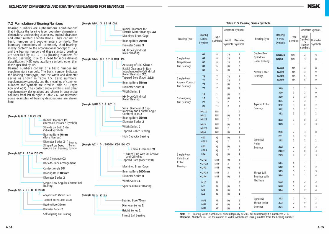
A 54 A 55
BOUNDARY DIMENSIONS AND IDENTIFYING NUMBERS FOR BEARINGS
7.2 Formulation of Bearing NumbersBearing numbers are alphanumeric combinations that indicate the bearing type, boundary dimensions, dimensional and running accuracies, internal clearance, and other related specifications. They consist of basic numbers and supplementary symbols. The boundary dimensions of commonly used bearings mostly conform to the organizational concept of ISO, and the bearing numbers of these standard bearings are specified by JIS B 1513 (Bearing Numbers for Rolling Bearings). Due to a need for more detailed classification, NSK uses auxiliary symbols other than those specified by JIS.Bearing numbers consist of a basic number and supplementary symbols. The basic number indicates the bearing series(type) and the width and diameter series as shown in Table 7.5. Basic numbers, supplementary symbols, and the meanings of common numbers and symbols are listed in Table 7.6 (Pages A56 and A57). The contact angle symbols and other supplementary designations are shown in successive columns from left to right in Table 7.6. For reference, some examples of bearing designations are shown here:
Bearing TypeBearing Series
Symbols
Type Symbols
Single-Row Deep Groove Ball Bearings
68 6 (1) 8
69 6 (1) 9
60 6 (1) 0
62 6 (0) 2
63 6 (0) 3
Single-Row Angular Contact Ball Bearings
79 7 (1) 9
70 7 (1) 0
72 7 (0) 2
73 7 (0) 3
Self-Aligning Ball Bearings
12 1 (0) 2
13 1 (0) 3
22 (1) 2 2
23 (1) 2 3
Single-Row Cylindrical Roller Bearings
NU10 NU 1 0
NU20 NU (0) 2
NU22 NU 2 2
NU30 NU (0) 3
NU23 NU 2 3
NU40 NU (0) 4
NJ20 NJ (0) 2
NJ22 NJ 2 2
NJ30 NJ (0) 3
NJ23 NJ 2 3
NJ40 NJ (0) 4
NUP20 NUP (0) 2
NUP22 NUP 2 2
NUP30 NUP (0) 3
NUP23 NUP 2 3
NUP40 NUP (0) 4
N10 N 1 0
N20 N (0) 2
N30 N (0) 3
N40 N (0) 4
NF2 NF (0) 2
NF3 NF (0) 3
NF4 NF (0) 4
Width Symbols
Dimension Symbols
Diameter Symbols
Bearing TypeBearing Series
Symbols
Type Symbols
Double-Row Cylindrical Roller Bearings
NNU49 NNU 4 9
NN30U NNU 3 0
Needle Roller Bearings
NA48 NA 4 8
NA49 NA 4 9
NA59 NA 5 9
NA69 NA 6 9
Tapered Roller Bearings
329 3 2 9
320 3 2 0
330 3 3 0
331 3 3 1
302 3 0 2
322 3 2 2
332 3 3 2
303 3 0 3
323 3 2 3
Spherical Roller Bearings
230 2 3 0
231 2 3 1
222 2 2 2
232 2 3 2
213 (1) 2 0 3
223 2 2 3
Thrust Ball Bearings with Flat Seats
511 5 1 1
512 5 1 2
513 5 1 3
514 5 1 4
522 5 2 2
523 5 2 3
524 5 2 4
Spherical Thrust Roller Bearings
292 2 9 2
293 2 9 3
294 2 9 4
Width Symbols
orHeight
Symbols
Dimension Symbols
Diameter Symbols
Note (1) Bearing Series Symbol 213 should logically be 203, but customarily it is numbered 213.Remarks Numbers in ( ) in the column of width symbols are usually omitted from the bearing number.
Table 7. 5 Bearing Series Symbols
(Example 1) 6 3 0 8 ZZ C3
Radial Clearance C3(Internal Clearance Symbol)Shields on Both Sides(Shield Symbol)Bearing Bore 40mm(Bore Number)Diameter Series 3Single-Row DeepGroove Ball Bearing
(Example 2) 7 2 2 0 A DB C3
Axial Clearance C3Back-to-Back Arrangement
Contact Angle 30o
Bearing Bore 100mmDiameter Series 2
Single-Row Angular Contact Ball Bearing
(Example 3) 1 2 0 6 K +H206X
Adapter with 25mm Bore
Tapered Bore (Taper 1:12)
Bearing Bore 30mm
Diameter Series 2
Self-Aligning Ball Bearing
(Example 8) 5 1 2 1 5
Bearing Bore 75mm
Diameter Series 2
Height Series 1
Thrust Ball Bearing
(Example 4) NU 3 1 8 M CM
Radial Clearance for Electric-Motor Bearings CMMachined Brass Cage
Bearing Bore 90mmDiameter Series 3
NU Type Cylindrical Roller Bearing
(Example 6) HR 3 0 2 0 7 J
Small Diameter of Cup Raceway and Contact Angle Conform to ISOBearing Bore 35mmDiameter Series 2
Width Series 0Tapered Roller Bearing
High Capacity Bearing
(Example 7) 2 4 0 /1000 M K30 E4 C3
Radial Clearance C3 Outer Ring with Oil Groove
and Oil HolesTapered Bore (Taper 1:30)
Machined Brass Cage
Bearing Bore 1000mmDiameter Series 0
Width Series 4
Spherical Roller Bearing
(Example 5) NN 3 0 1 7 K CC1 P4
Accuracy of ISO Class 4Radial Clearance in Non-Interchangeable Cylindrical Roller Bearings CC1Tapered Bore (Taper 1:12)
Bearing Bore 85mmDiameter Series 0Width Series 3
NN Type Cylindrical Roller Bearing
} Bearing Series Symbol
A024-057E.indd 54-55 A024-057E.indd 54-55 11/20/13 4:50:37 PM11/20/13 4:50:37 PM

A 56 A 57
BOUNDARY DIMENSIONS AND IDENTIFYING NUMBERS FOR BEARINGS
Auxiliary Symbols
SymbolArrangement
SymbolInternal Clearance Symbol
Preload SymbolTolerance Class
SymbolSpecial
Specification Symbol
Spacer or Sleeve Symbol Grease Symbol
Symbol for Designof Rings
Symbol
K
K30
E
E4
N
NR
Meaning Symbol Meaning Symbol Meaning (radial clearance) Symbol Meaning Symbol Meaning Symbol Meaning Symbol Meaning
DB
DF
DT
C1
C2
Omitted
C3
C4
C5
Omitted ISO Normal
P6 ISO Class 6
P6X ISO Class 6X
P5 ISO Class 5
P4 ISO Class 4
P2 ISO Class 2
X26
X28
X29
S11
+K
+L
+KL
H
AH
HJ
AS2
ENS
NS7
PS2
Omitted Class 4
PN2 Class 2
PN3 Class 3
PN0 Class 0
PN00 Class 00
ABMA(7)( Tapered ) roller bearing
For A
ll Ra
dial
Brg
s.
CC1
CC2
CC
CC3
CC4
CC5
For
Non-I
nte
rchan
gea
ble
C
ylin
dri
cal R
olle
r B
rgs.
MC1
MC2
MC3
MC4
MC5
MC6
CM
CT
CM
EL Extra light Preload L Light Preload M Medium Preload H Heavy Preload
For
Ext
ra-S
mal
lan
d M
inia
ture
Bal
l Brg
s.
Partially thesame asJIS(5)
In Principle, Marked on Bearings Not Marked on Bearings
Same asJIS(5) NSK Symbol Same as JIS(5) NSK Symbol, Partially the same as JIS(5)
Bearing NumbersTable 7. 6 Formulation of
Basic Numbers
Bearing SeriesSymbols (1) Bore Number Contact Angle
Symbol Internal Design Symbol Material Symbol Cage SymbolExternal Features
Seals, ShieldsSymbol
Symbol
68
69
60
:
70
72
73
:
12
13
22
:
NU10
NJ 2
N 3
NN 30
:
NA48
NA49
NA69
:
320
322
323
:
230
222
223
:
511
512
513
:
292
293
294
:
Meaning Symbol Meaning Symbol Meaning Symbol Meaning Symbol Meaning Symbol Meaning Symbol Meaning
1 1mm
2 2
3 3 ⋅ ⋅ ⋅ ⋅ ⋅ ⋅ ⋅ ⋅ ⋅ ⋅ ⋅ ⋅ 9 9
00 100
01 120
02 150
03 170
/22 220
/28 280
/32 320
04(3) 200
05 250
06 300 ⋅ ⋅ ⋅ ⋅ ⋅ ⋅ ⋅ ⋅ ⋅ ⋅ ⋅ ⋅ 88 4400
92 4600
96 4800
/500 5000
/530 5300
/560 5600 ⋅ ⋅ ⋅ ⋅ ⋅ ⋅ ⋅ ⋅ ⋅ ⋅ /2 360 2 360 00
/2 500 2 500 00
A
A5
B
C
Omitted
C
D
A
J
C
CA
CD
EA
E
E
g
h
M
W
T
V
Z } ZS
ZZ } ZZS
DU
DDU
V
VV
Symbols and Numbers Conform to JIS(5)
Marked on Bearings Not Markedon Bearings
NSK Symbol NSK Symbol
Spherical Roller Bearings
Notes (1) Bearing Series Symbols conform to Table 7.5.(2) For basic numbers of tapered roller bearings in ISO's new series, refer to Page B111.(3) For Bearing Bore Numbers 04 through 96, five times the bore number gives the bore size (mm) (except double-
direction thrust ball bearings).(4) HR is prefix to bearing series symbols and it is NSK's original prefix.
Notes (5) JIS : Japanese Industrial Standards.(6) BAS : The Japan Bearing Industrial Association Standard.(7) ABMA : The American Bearing Manufacturers Association.
Single-Row Deep Groove Ball Bearings
CylindricalRollerBearings
Single-Row Angular Contact Ball Bearings
Self-Aligning Ball Bearings
Angular(Contact Ball) BearingsStandard Contact Angle of 30°
Internal Design Differs from Standard One
Case-Hardened Steel Used in Rings, Rolling Elements
Machined Brass Cage
Shieldon One Side Only
Tapered Bore of Inner Ring (Taper 1:12)
Clearance Less than C2Clearance Less than CN
CN Clearance
Clearance Greater than CNClearance Greater than C3Clearance Greater than C4
Clearance Less than CC2Clearance Less than CC
Normal Clearance
Clearance Greater than CCClearance Greater than CC3Clearance Greater than CC4
Clearance Less than MC2Clearance Less than MC3
Normal Clearance
Clearance Greater than MC3Clearance Greater than MC4Clearance Greater than MC5
Clearance in Deep Groove Ball Bearings for Electric Motors
Clearance in Cylindrical Roller Bearings for Electric Motors
Back-to-Back Arrangement
Face-to-Face Arrangement
Tandem Arrangement
Tapered Bore of Inner Ring (Taper 1:30)
Notch or Lubricating Groove in Ring
Lubricating Groove in Outside Surface and Holes in Outer Ring
Snap Ring Groove in Outer Ring
Snap Ring Groove with Snap Ring in Outer Ring
Shields on Both Sides
Contact Rubber Seal on One Side Only
Contact RubberSeals onBoth Sides
Non-Contact Rubber Seal on One Side Only
Non-Contact Rubber Seals on Both Sides
Pressed Steel Cage
Synthetic Resin Cage
Without Cage
Stainless Steel Used in Rings, Rolling Elements
(For High Capacity) Bearings
(Preload of Angular Contact) Ball Bearing
Cylindrical Roller Bearings
Spherical Thrust Roller Bearings
HR(4) High Capacity Tapered Roller Bearings, and others
Smaller Diameter of Outer Ring Raceway, Contact Angle, and Outer Ring Width of Tapered Roller Bearings Conform to ISO 355
Needle Roller Bearings
Tapered Roller Bearings(2)
Spherical Roller Bearings
Thrust Ball Bearing with Flat Seats
Thrust Spherical Roller Bearings
BearingBore
Standard Contact Angle of 25°
Standard Contact Angle of 40°
Standard Contact Angle of 15°
Contact Angle about 20°
Contact Angle about 28°
Tapered(Roller ) BearingsContact Angle Less than 17°
Bearings( treated for ) Dimensional Stabilization
Working Temperature Lower than 150 °C
Working Temperature Lower than 200 °C
Working Temperature Lower than 250 °C
Dimensional Stabilizing TreatmentWorking Temperature Lower than 200°C
Spherical (Roller ) Bearings
Bearingswith Outer RingSpacers
SHELL ALVANIA GREASE S2
ENS GREASE
NS HI-LUBE
MULTEMP PS No. 2
Bearingswith Inner RingSpacers
Bearingswith Both Inner and Outer Ring Spacers
Adapter Designation
Withdrawal Sleeve Designation
Thrust Collar Designation
Partially thesame as JIS(5)/BAS(6)
A024-057E.indd 56-57 A024-057E.indd 56-57 11/20/13 4:50:38 PM11/20/13 4:50:38 PM
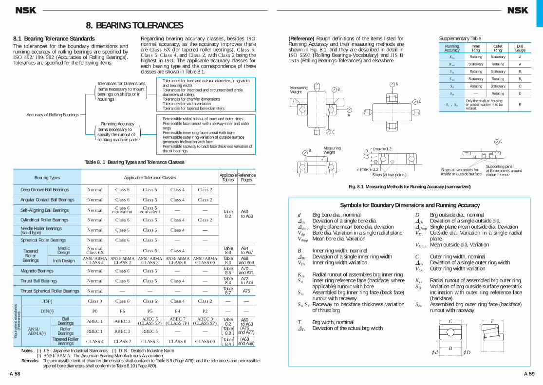
A 58 A 59
B2
B1
A
C
D
A
C
r (max.)×1.2
r (max.)×1.2Stops (at two points)
E
MeasuringWeight
MeasuringWeight
Stops at two points forinside or outside surface
Supporting pinsat three points aroundcircumference
(Reference) Rough definitions of the items listed for Running Accuracy and their measuring methods are shown in Fig. 8.1, and they are described in detail in ISO 5593 (Rolling Bearings-Vocabulary) and JIS B 1515 (Rolling Bearings-Tolerances) and elsewhere.
8.1 Bearing Tolerance StandardsThe tolerances for the boundary dimensions and running accuracy of rolling bearings are specified by ISO 492/199/582 (Accuracies of Rolling Bearings). Tolerances are specified for the following items:
Regarding bearing accuracy classes, besides ISO normal accuracy, as the accuracy improves there are Class 6X (for tapered roller bearings), Class 6, Class 5, Class 4, and Class 2, with Class 2 being the highest in ISO. The applicable accuracy classes for each bearing type and the correspondence of these classes are shown in Table 8.1.
8. BEARING TOLERANCES
Fig. 8.1 Measuring Methods for Running Accuracy (summarized)
Accuracy of Rolling Bearings
( )Tolerances for Dimensions ⋅ Tolerances for bore and outside diameters, ring width
and bearing width⋅ Tolerances for inscribed and circumscribed circle
diameters of rollers⋅ Tolerances for chamfer dimensions⋅ Tolerances for width variation⋅ Tolerances for tapered bore diameters
⋅ Permissible radial runout of inner and outer rings⋅ Permissible face runout with raceway inner and outer
rings⋅ Permissible inner ring face runout with bore⋅ Permissible outer ring variation of outside surface
generatrix inclination with face⋅ Permissible raceway to back face thickness variation of
thrust bearings
Items necessary to mountbearings on shafts or in housings
( )Running Accuracy
Items necessary to specify the runout of rotating machine parts
Notes (1) JIS : Japanese Industrial Standards (2) DIN : Deutsch Industrie Norm(3) ANSI/ABMA : The American Bearing Manufacturers Association
Remarks The permissible limit of chamfer dimensions shall conform to Table 8.9 (Page A78), and the tolerances and permissible tapered bore diameters shall conform to Table 8.10 (Page A80).
Supplementary TableRunning Accuracy
InnerRing
OuterRing
DialGauge
Kia Rotating Stationary A
Kea Stationary Rotating A
Sia Rotating Stationary B1
Sea Stationary Rotating B2
Sd Rotating Stationary C
SD ⎯ Rotating D
Si , Se EOnly the shaft or housing or central washer is to be rotated.
Symbols for Boundary Dimensions and Running Accuracy
d Brg bore dia., nominal&ds Deviation of a single bore dia.&dmp Single plane mean bore dia. deviationVdp Bore dia. Variation in a single radial plane Vdmp Mean bore dia. Variation
B Inner ring width, nominal&Bs Deviation of a single inner ring widthVBs Inner ring width variation
Kia Radial runout of assembles brg inner ringSd inner ring reference face (backface, where
applicable) runout with boreSia Assembled brg inner ring face (back face)
runout with racewaySi, Se Raceway to backface thickness variation
of thrust brg
T Brg width, nominal&Ts Deviation of the actual brg width
D Brg outside dia., nominal&Ds Deviation of a single outside dia.&Dmp Single plane mean outside dia. DeviationVDp Outside dia. Variation in a single radial
planeVDmp Mean outside dia. Variation
C Outer ring width, nominal&Cs Deviation of a single outer ring widthVCs Outer ring width variation
Kea Radial runout of assembled brg outer ring SD Variation of brg outside surface generatrix
inclination with outer ring reference face (backface)
Sea Assembled brg outer ring face (backface) runout with raceway
TC
BjDjd
Table 8. 1 Bearing Types and Tolerance Classes
Bearing Types Applicable Tolerance Classes Applicable Reference Tables Pages
Deep Groove Ball Bearings Normal Class 6 Class 5 Class 4 Class 2
Angular Contact Ball Bearings Normal Class 6 Class 5 Class 4 Class 2
Self-Aligning Ball Bearings Normal Class 6 Class 5 ⎯ ⎯ Table A60 equivalent equivalent
Cylindrical Roller Bearings Normal Class 6 Class 5 Class 4 Class 2 8.2 to A63
Normal Class 6 Class 5 Class 4 ⎯
Spherical Roller Bearings Normal Class 6 Class 5 ⎯ ⎯
Metric Normal ⎯ Class 5 Class 4 ⎯ Table A64 Design Class 6X 8.3 to A67 Inch Design ANSI/ABMA ANSI/ABMA ANSI/ABMA ANSI/ABMA ANSI/ABMA Table A68 CLASS 4 CLASS 2 CLASS 3 CLASS 0 CLASS 00 8.4 and A69 Magneto Bearings Normal Class 6 Class 5 ⎯ ⎯ Table A70 8.5 and A71 Thrust Ball Bearings Normal Class 6 Class 5 Class 4 ⎯ Table A72 8.4 to A74 Thrust Spherical Roller Bearings Normal ⎯ ⎯ ⎯ ⎯ Table A75 8.7
JIS(1) Class 0 Class 6 Class 5 Class 4 Class 2 ⎯ ⎯
DIN(2) P0 P6 P5 P4 P2 ⎯ ⎯
Ball ABEC 1 ABEC 3 ABEC 5 ABEC 7 ABEC 9 A60 Bearings (CLASS 5P) (CLASS 7P) (CLASS 9P) to A63 ANSI/ Roller RBEC 1 RBEC 3 RBEC 5 ⎯ ⎯ (A76 ABMA(3) Bearings and A77) Tapered Roller CLASS 4 CLASS 2 CLASS 3 CLASS 0 CLASS 00 (A68 Bearings and A69)
Eq
uiv
alen
t st
andar
ds
(Ref
eren
ce)
TaperedRoller
Bearings
Table8.2
Table8.8[ ]
Table8.4[ ]
Needle Roller Bearings(solid type)
A058-081E.indd 58-59 A058-081E.indd 58-59 11/20/13 4:51:06 PM11/20/13 4:51:06 PM
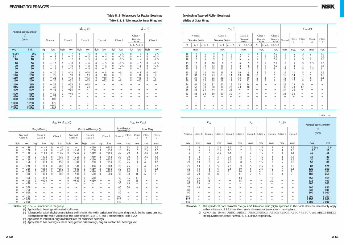
A 60 A 61
BEARING TOLERANCEBEARING TOLERANCES
Table 8. 2 Tolerances for Radial BearingsTable 8. 2. 1 Tolerances for Inner Rings and
(excluding Tapered Roller Bearings)Widths of Outer Rings
& dmp (2) & ds (2)
Nominal Bore Diameter
d Class 4
(mm) Normal Class 6 Class 5 Class 4 Class 2 Class 2
0, 1, 2, 3, 4
over incl. high low high low high low high low high low high low high low
0.6(1) 2.5 0 - 8 0 - 7 0 - 5 0 - 4 0 -2.5 0 - 4 0 -2.5 2.5 10 0 - 8 0 - 7 0 - 5 0 - 4 0 -2.5 0 - 4 0 -2.5 10 18 0 - 8 0 - 7 0 - 5 0 - 4 0 -2.5 0 - 4 0 -2.5
18 30 0 - 10 0 - 8 0 - 6 0 - 5 0 -2.5 0 - 5 0 -2.5 30 50 0 - 12 0 -10 0 - 8 0 - 6 0 -2.5 0 - 6 0 -2.5 50 80 0 - 15 0 -12 0 - 9 0 - 7 0 -4 0 - 7 0 -4
80 120 0 - 20 0 -15 0 -10 0 - 8 0 -5 0 - 8 0 -5 120 150 0 - 25 0 -18 0 -13 0 -10 0 -7 0 -10 0 -7 150 180 0 - 25 0 -18 0 -13 0 -10 0 -7 0 -10 0 -7 180 250 0 - 30 0 -22 0 -15 0 -12 0 -8 0 -12 0 -8
250 315 0 - 35 0 -25 0 -18 - - - - - - - - 315 400 0 - 40 0 -30 0 -23 - - - - - - - - 400 500 0 - 45 0 -35 - - - - - - - - - - 500 630 0 - 50 0 -40 - - - - - - - - - - 630 800 0 - 75 - - - - - - - - - - - - 800 1 000 0 -100 - - - - - - - - - - - - 1 000 1 250 0 -125 - - - - - - - - - - - - 1 250 1 600 0 -160 - - - - - - - - - - - - 1 600 2 000 0 -200 - - - - - - - - - - - -
& Bs (or & Cs )(3) V Bs (or V Cs )
Single Bearing Combined Bearings (4) Inner Ring
Normal Class 5 Class 2 Normal Class 5 Class 2 Normal Class Class Class Class Class 6 Class 4 Class 6 Class 4 6 5 4 2
high low high low high low high low high low high low max. max. max. max. max.
0 - 40 0 - 40 0 - 40 ⎯ ⎯ 0 -250 0 -250 12 12 5 2.5 1.5 0 - 120 0 - 40 0 - 40 0 -250 0 -250 0 -250 15 15 5 2.5 1.5 0 - 120 0 - 80 0 - 80 0 -250 0 -250 0 -250 20 20 5 2.5 1.5
0 - 120 0 -120 0 -120 0 -250 0 -250 0 -250 20 20 5 2.5 1.5 0 - 120 0 -120 0 -120 0 -250 0 -250 0 -250 20 20 5 3 1.5 0 - 150 0 -150 0 -150 0 -380 0 -250 0 -250 25 25 6 4 1.5
0 - 200 0 -200 0 -200 0 -380 0 -380 0 -380 25 25 7 4 2.5 0 - 250 0 -250 0 -250 0 -500 0 -380 0 -380 30 30 8 5 2.5 0 - 250 0 -250 0 -250 0 -500 0 -380 0 -380 30 30 8 5 4 0 - 300 0 -300 0 -300 0 -500 0 -500 0 -500 30 30 10 6 5
0 - 350 0 -350 - - 0 -500 0 -500 - - 35 35 13 - - 0 - 400 0 -400 - - 0 -630 0 -630 - - 40 40 15 - - 0 - 450 - - - - - - - - - - 50 45 - - - 0 - 500 - - - - - - - - - - 60 50 - - - 0 - 750 - - - - - - - - - - 70 - - - - 0 -1 000 - - - - - - - - - - 80 - - - - 0 -1 250 - - - - - - - - - - 100 - - - - 0 -1 600 - - - - - - - - - - 120 - - - - 0 -2 000 - - - - - - - - - - 140 - - - -
Notes (1) 0.6mm is included in the group.(2) Applicable to bearings with cylindrical bores.(3) Tolerance for width deviation and tolerance limits for the width variation of the outer ring should be the same bearing.
Tolerances for the width variation of the outer ring of Class 5, 4, and 2 are shown in Table 8.2.2.(4) Applicable to individual rings manufactured for combined bearings.(5) Applicable to ball bearings such as deep groove ball bearings, angular contact ball bearings, etc.
V dp (2) V dmp (2)
Normal Class 6 Class 5 Class 4 Class 2
Diameter Series Diameter Series Normal
9 0, 1 2, 3, 4 9 0, 1 2, 3, 4 9 0,1,2,3,4 9 0,1,2,3,4 0,1,2,3,4
max. max. max. max. max. max. max. max. max. max.
10 8 6 9 7 5 5 4 4 3 2.5 6 5 3 2 1.5 10 8 6 9 7 5 5 4 4 3 2.5 6 5 3 2 1.5 10 8 6 9 7 5 5 4 4 3 2.5 6 5 3 2 1.5
13 10 8 10 8 6 6 5 5 4 2.5 8 6 3 2.5 1.5 15 12 9 13 10 8 8 6 6 5 2.5 9 8 4 3 1.5 19 19 11 15 15 9 9 7 7 5 4 11 9 5 3.5 2
25 25 15 19 19 11 10 8 8 6 5 15 11 5 4 2.5 31 31 19 23 23 14 13 10 10 8 7 19 14 7 5 3.5 31 31 19 23 23 14 13 10 10 8 7 19 14 7 5 3.5 38 38 23 28 28 17 15 12 12 9 8 23 17 8 6 4
44 44 26 31 31 19 18 14 - - - 26 19 9 - - 50 50 30 38 38 23 23 18 - - - 30 23 12 - - 56 56 34 44 44 26 - - - - - 34 26 - - - 63 63 38 50 50 30 - - - - - 38 30 - - - - - - - - - - - - - - - - - - - - - - - - - - - - - - - - - - - - - - - - - - - - - - - - - - - - - - - - - - - - - - - - - - - - - - - - - - - - - - - - - - -
K ia S d
S ia (5) Nominal Bore Diameter
d Normal Class 6 Class 5 Class 4 Class 2 Class 5 Class 4 Class 2 Class 5 Class 4 Class 2 (mm)
max. max. max. max. max. max. max. max. max. max. max. over incl.
10 5 4 2.5 1.5 7 3 1.5 7 3 1.5 0.6(1) 2.5 10 6 4 2.5 1.5 7 3 1.5 7 3 1.5 2.5 10 10 7 4 2.5 1.5 7 3 1.5 7 3 1.5 10 18
13 8 4 3 2.5 8 4 1.5 8 4 2.5 18 30 15 10 5 4 2.5 8 4 1.5 8 4 2.5 30 50 20 10 5 4 2.5 8 5 1.5 8 5 2.5 50 80
25 13 6 5 2.5 9 5 2.5 9 5 2.5 80 120 30 18 8 6 2.5 10 6 2.5 10 7 2.5 120 150 30 18 8 6 5 10 6 4 10 7 5 150 180 40 20 10 8 5 11 7 5 13 8 5 180 250
50 25 13 - - 13 - - 15 - - 250 315 60 30 15 - - 15 - - 20 - - 315 400 65 35 - - - - - - - - - 400 500
70 40 - - - - - - - - - 500 630 80 - - - - - - - - - - 630 800 90 - - - - - - - - - - 800 1 000
100 - - - - - - - - - - 1 000 1 250 120 - - - - - - - - - - 1 250 1 600 140 - - - - - - - - - - 1 600 2 000
Remarks 1. The cylindrical bore diameter "no-go side" tolerance limit (high) specified in this table does not necessarily apply within a distance of 1.2 times the chamfer dimension r (max.) from the ring face.
2. ABMA Std 20-1996: ABEC1⋅RBEC1, ABEC3⋅RBEC3, ABEC5⋅RBEC5, ABEC7⋅RBEC7, and ABEC9⋅RBEC9 are equivalent to Classes Normal, 6, 5, 4, and 2 respectively.
Units : μm
DiameterSeries
Inner Ring (orOuter Ring) (3)
DiameterSeries
DiameterSeries
DiameterSeries
Class6
Class5
Class4
Class2
A058-081E.indd 60-61 A058-081E.indd 60-61 11/20/13 4:51:07 PM11/20/13 4:51:07 PM
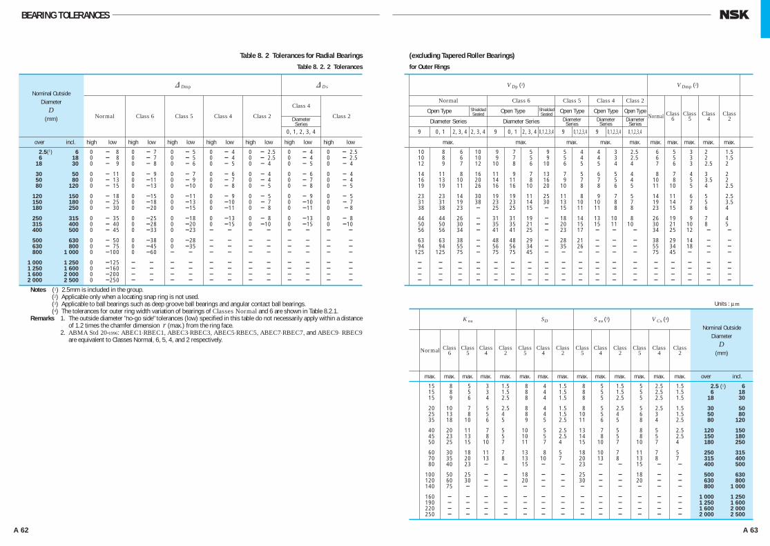
A 62 A 63
BEARING TOLERANCE
& Dmp
& Ds
Normal Class 6 Class 5 Class 4 Class 2
Class 4
Class 2
0, 1, 2, 3, 4
over incl. high low high low high low high low high low high low high low
2.5(1) 6 0 - 8 0 - 7 0 - 5 0 - 4 0 - 2.5 0 - 4 0 - 2.5 6 18 0 - 8 0 - 7 0 - 5 0 - 4 0 - 2.5 0 - 4 0 - 2.5 18 30 0 - 9 0 - 8 0 - 6 0 - 5 0 - 4 0 - 5 0 - 4
30 50 0 - 11 0 - 9 0 - 7 0 - 6 0 - 4 0 - 6 0 - 4 50 80 0 - 13 0 -11 0 - 9 0 - 7 0 - 4 0 - 7 0 - 4 80 120 0 - 15 0 -13 0 -10 0 - 8 0 - 5 0 - 8 0 - 5
120 150 0 - 18 0 -15 0 -11 0 - 9 0 - 5 0 - 9 0 - 5 150 180 0 - 25 0 -18 0 -13 0 -10 0 - 7 0 -10 0 - 7 180 250 0 - 30 0 -20 0 -15 0 -11 0 - 8 0 -11 0 - 8
250 315 0 - 35 0 -25 0 -18 0 -13 0 - 8 0 -13 0 - 8 315 400 0 - 40 0 -28 0 -20 0 -15 0 -10 0 -15 0 -10 400 500 0 - 45 0 -33 0 -23 - - - - - - - - 500 630 0 - 50 0 -38 0 -28 - - - - - - - - 630 800 0 - 75 0 -45 0 -35 - - - - - - - - 800 1 000 0 -100 0 -60 - - - - - - - - - - 1 000 1 250 0 -125 - - - - - - - - - - - - 1 250 1 600 0 -160 - - - - - - - - - - - - 1 600 2 000 0 -200 - - - - - - - - - - - - 2 000 2 500 0 -250 - - - - - - - - - - - -
Notes (1) 2.5mm is included in the group.(2) Applicable only when a locating snap ring is not used.(3) Applicable to ball bearings such as deep groove ball bearings and angular contact ball bearings.(4) The tolerances for outer ring width variation of bearings of Classes Normal and 6 are shown in Table 8.2.1.
Remarks 1. The outside diameter "no-go side" tolerances (low) specified in this table do not necessarily apply within a distance of 1.2 times the chamfer dimension r (max.) from the ring face.
2. ABMA Std 20-1996: ABEC1⋅RBEC1, ABEC3⋅RBEC3, ABEC5⋅RBEC5, ABEC7⋅RBEC7, and ABEC9⋅ RBEC9 are equivalent to Classes Normal, 6, 5, 4, and 2 respectively.
Nominal OutsideDiameter
D(mm)
Nominal OutsideDiameter
D(mm)
Units : μm
K ea SD
S ea (3) V Cs (4)
Normal
Class Class Class Class Class Class Class Class Class Class Class Class Class 6 5 4 2 5 4 2 5 4 2 5 4 2
max. max. max. max. max. max. max. max. max. max. max. max. max. max. over incl.
15 8 5 3 1.5 8 4 1.5 8 5 1.5 5 2.5 1.5 2.5 (1) 6
15 8 5 3 1.5 8 4 1.5 8 5 1.5 5 2.5 1.5 6 18 15 9 6 4 2.5 8 4 1.5 8 5 2.5 5 2.5 1.5 18 30
20 10 7 5 2.5 8 4 1.5 8 5 2.5 5 2.5 1.5 30 50 25 13 8 5 4 8 4 1.5 10 5 4 6 3 1.5 50 80 35 18 10 6 5 9 5 2.5 11 6 5 8 4 2.5 80 120
40 20 11 7 5 10 5 2.5 13 7 5 8 5 2.5 120 150 45 23 13 8 5 10 5 2.5 14 8 5 8 5 2.5 150 180 50 25 15 10 7 11 7 4 15 10 7 10 7 4 180 250
60 30 18 11 7 13 8 5 18 10 7 11 7 5 250 315 70 35 20 13 8 13 10 7 20 13 8 13 8 7 315 400 80 40 23 - - 15 - - 23 - - 15 - - 400 500
100 50 25 - - 18 - - 25 - - 18 - - 500 630 120 60 30 - - 20 - - 30 - - 20 - - 630 800 140 75 - - - - - - - - - - - - 800 1 000
160 - - - - - - - - - - - - - 1 000 1 250 190 - - - - - - - - - - - - - 1 250 1 600 220 - - - - - - - - - - - - - 1 600 2 000 250 - - - - - - - - - - - - - 2 000 2 500
V Dp (2) V Dmp (2)
Normal Class 6 Class 5 Class 4 Class 2
Open Type Open Type Open Type Open Type Open Type Normal Class Class Class Class
Diameter Series Diameter Series 6 5 4 2
9 0, 1 2, 3, 4 2, 3, 4 9 0, 1 2, 3, 4 0,1,2,3,4 9 0,1,2,3,4 9 0,1,2,3,4 0,1,2,3,4
max. max. max. max. max. max. max. max. max. max.
10 8 6 10 9 7 5 9 5 4 4 3 2.5 6 5 3 2 1.5 10 8 6 10 9 7 5 9 5 4 4 3 2.5 6 5 3 2 1.5 12 9 7 12 10 8 6 10 6 5 5 4 4 7 6 3 2.5 2
14 11 8 16 11 9 7 13 7 5 6 5 4 8 7 4 3 2 16 13 10 20 14 11 8 16 9 7 7 5 4 10 8 5 3.5 2 19 19 11 26 16 16 10 20 10 8 8 6 5 11 10 5 4 2.5
23 23 14 30 19 19 11 25 11 8 9 7 5 14 11 6 5 2.5 31 31 19 38 23 23 14 30 13 10 10 8 7 19 14 7 5 3.5 38 38 23 - 25 25 15 - 15 11 11 8 8 23 15 8 6 4
44 44 26 - 31 31 19 - 18 14 13 10 8 26 19 9 7 4 50 50 30 - 35 35 21 - 20 15 15 11 10 30 21 10 8 5 56 56 34 - 41 41 25 - 23 17 - - - 34 25 12 - - 63 63 38 - 48 48 29 - 28 21 - - - 38 29 14 - - 94 94 55 - 56 56 34 - 35 26 - - - 55 34 18 - - 125 125 75 - 75 75 45 - - - - - - 75 45 - - - - - - - - - - - - - - - - - - - - - - - - - - - - - - - - - - - - - - - - - - - - - - - - - - - - - - - - - - - - - - - - - - - - - - - - - - -
ShieldedSealed
ShieldedSealed
BEARING TOLERANCES
Table 8. 2 Tolerances for Radial BearingsTable 8. 2. 2 Tolerances
(excluding Tapered Roller Bearings)for Outer Rings
DiameterSeries
DiameterSeries
DiameterSeries
DiameterSeries
A058-081E.indd 62-63 A058-081E.indd 62-63 11/20/13 4:51:08 PM11/20/13 4:51:08 PM
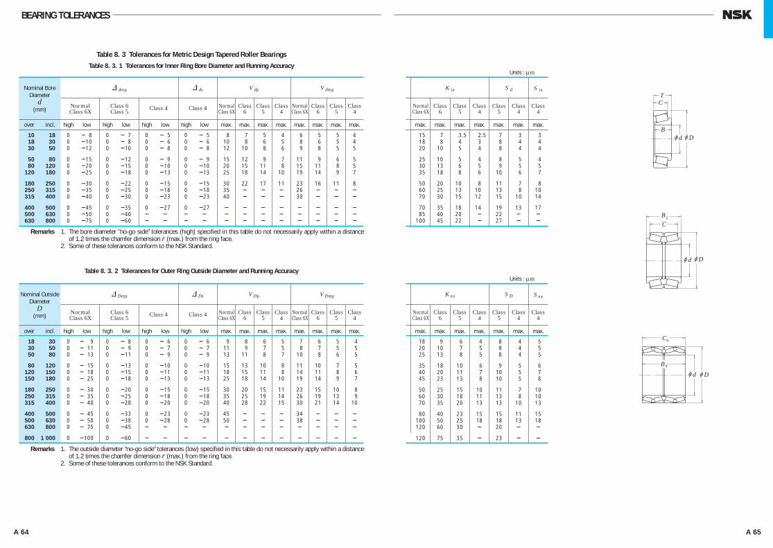
A 64 A 65
BEARING TOLERANCE
Table 8. 3 Tolerances for Metric Design Tapered Roller BearingsTable 8. 3. 1 Tolerances for Inner Ring Bore Diameter and Running Accuracy
& dmp & ds V dp V dmp
Normal Class 6 Normal Class Class Class Normal Class Class Class Class 6X Class 5 Class 4 Class 4 Class 6X 6 5 4 Class 6X 6 5 4
over incl. high low high low high low high low max. max. max. max. max. max. max. max.
10 18 0 - 8 0 - 7 0 - 5 0 - 5 8 7 5 4 6 5 5 4 18 30 0 -10 0 - 8 0 - 6 0 - 6 10 8 6 5 8 6 5 4 30 50 0 -12 0 -10 0 - 8 0 - 8 12 10 8 6 9 8 5 5
50 80 0 -15 0 -12 0 - 9 0 - 9 15 12 9 7 11 9 6 5 80 120 0 -20 0 -15 0 -10 0 -10 20 15 11 8 15 11 8 5 120 180 0 -25 0 -18 0 -13 0 -13 25 18 14 10 19 14 9 7
180 250 0 -30 0 -22 0 -15 0 -15 30 22 17 11 23 16 11 8 250 315 0 -35 0 -25 0 -18 0 -18 35 - - - 26 - - - 315 400 0 -40 0 -30 0 -23 0 -23 40 - - - 30 - - - 400 500 0 -45 0 -35 0 -27 0 -27 - - - - - - - - 500 630 0 -50 0 -40 - - - - - - - - - - - - 630 800 0 -75 0 -60 - - - - - - - - - - - -
Remarks 1. The bore diameter "no-go side" tolerances (high) specified in this table do not necessarily apply within a distance of 1.2 times the chamfer dimension r (max.) from the ring face.
2. Some of these tolerances conform to the NSK Standard.
Nominal BoreDiameter
d(mm)
Table 8. 3. 2 Tolerances for Outer Ring Outside Diameter and Running Accuracy
& Dmp & Ds V Dp V Dmp
Normal Class 6 Normal Class Class Class Normal Class Class Class Class 6X Class 5 Class 4 Class 4 Class 6X 6 5 4 Class 6X 6 5 4
over incl. high low high low high low high low max. max. max. max. max. max. max. max.
18 30 0 - 9 0 - 8 0 - 6 0 - 6 9 8 6 5 7 6 5 4 30 50 0 - 11 0 - 9 0 - 7 0 - 7 11 9 7 5 8 7 5 5 50 80 0 - 13 0 -11 0 - 9 0 - 9 13 11 8 7 10 8 6 5
80 120 0 - 15 0 -13 0 -10 0 -10 15 13 10 8 11 10 7 5 120 150 0 - 18 0 -15 0 -11 0 -11 18 15 11 8 14 11 8 6 150 180 0 - 25 0 -18 0 -13 0 -13 25 18 14 10 19 14 9 7
180 250 0 - 30 0 -20 0 -15 0 -15 30 20 15 11 23 15 10 8 250 315 0 - 35 0 -25 0 -18 0 -18 35 25 19 14 26 19 13 9 315 400 0 - 40 0 -28 0 -20 0 -20 40 28 22 15 30 21 14 10
400 500 0 - 45 0 -33 0 -23 0 -23 45 - - - 34 - - - 500 630 0 - 50 0 -38 0 -28 0 -28 50 - - - 38 - - - 630 800 0 - 75 0 -45 - - - - - - - - - - - - 800 1 000 0 -100 0 -60 - - - - - - - - - - - -
Remarks 1. The outside diameter "no-go side" tolerances (low) specified in this table do not necessarily apply within a distance of 1.2 times the chamfer dimension r (max.) from the ring face.
2. Some of these tolerances conform to the NSK Standard.
Nominal Outside Diameter
D(mm)
Units : μm
K ia S d
Normal Class Class Class Class Class Class Class 6X 6 5 4 5 4 4
max. max. max. max. max. max. max.
15 7 3.5 2.5 7 3 3 18 8 4 3 8 4 4 20 10 5 4 8 4 4
25 10 5 4 8 5 4 30 13 6 5 9 5 5 35 18 8 6 10 6 7
50 20 10 8 11 7 8 60 25 13 10 13 8 10 70 30 15 12 15 10 14
70 35 18 14 19 13 17 85 40 20 - 22 - - 100 45 22 - 27 - -
S ia
Units : μm
K ea S D
Normal Class Class Class Class Class Class Class 6X 6 5 4 5 4 4
max. max. max. max. max. max. max.
18 9 6 4 8 4 5 20 10 7 5 8 4 5 25 13 8 5 8 4 5
35 18 10 6 9 5 6 40 20 11 7 10 5 7 45 23 13 8 10 5 8
50 25 15 10 11 7 10 60 30 18 11 13 8 10 70 35 20 13 13 10 13
80 40 23 15 15 11 15 100 50 25 18 18 13 18 120 60 30 - 20 - - 120 75 35 - 23 - -
S ea
jDjd
jDjd
BC
2
B
TC
jDjd
B
C4
4
BEARING TOLERANCES
A058-081E.indd 64-65 A058-081E.indd 64-65 11/20/13 4:51:09 PM11/20/13 4:51:09 PM
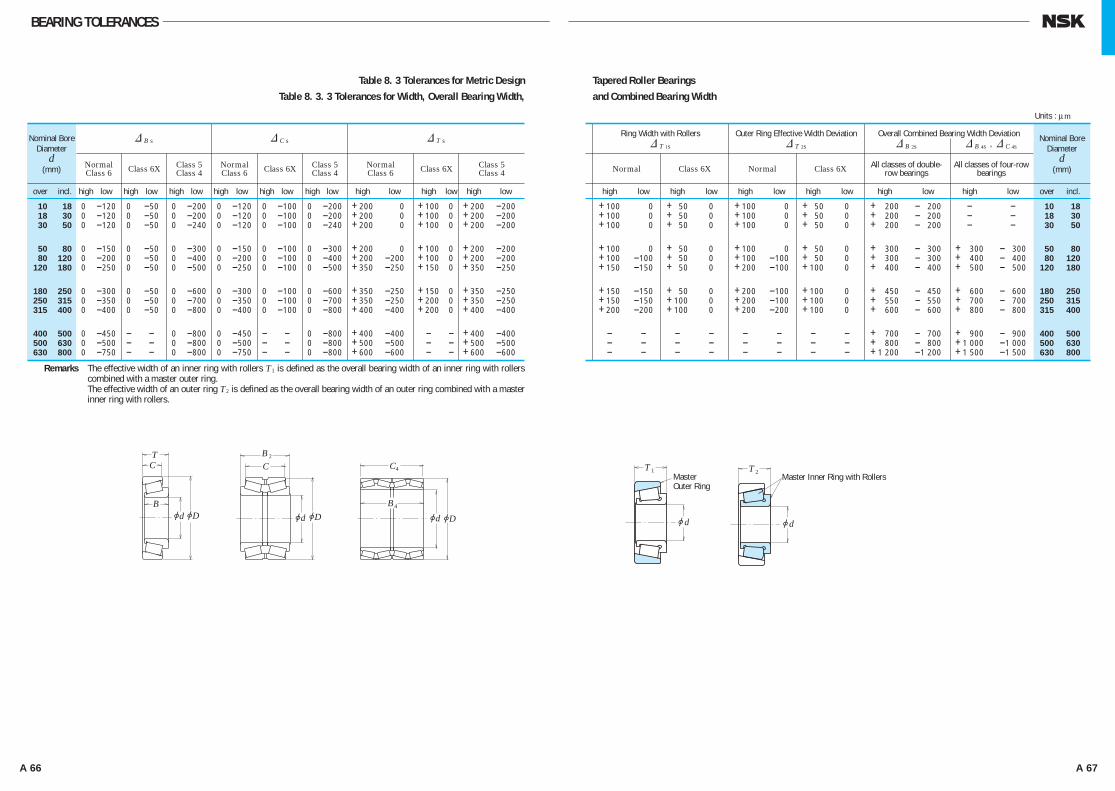
A 66 A 67
BEARING TOLERANCE
jDjd jDjd
BC
2
B
TC
jDjd
B
C4
4
jd
1TMasterOuter Ring
jd
2TMaster Inner Ring with Rollers
BEARING TOLERANCES
Table 8. 3 Tolerances for Metric DesignTable 8. 3. 3 Tolerances for Width, Overall Bearing Width,
Tapered Roller Bearingsand Combined Bearing Width
& B s & C s & T s
Normal Class 5 Normal Class 5 Normal Class 5 Class 6 Class 6X Class 4 Class 6 Class 6X Class 4 Class 6 Class 6X Class 4
over incl. high low high low high low high low high low high low high low high low high low
10 18 0 -120 0 -50 0 -200 0 -120 0 -100 0 -200 +200 -200 +100 0 +200 -200 18 30 0 -120 0 -50 0 -200 0 -120 0 -100 0 -200 +200 -200 +100 0 +200 -200 30 50 0 -120 0 -50 0 -240 0 -120 0 -100 0 -240 +200 -200 +100 0 +200 -200
50 80 0 -150 0 -50 0 -300 0 -150 0 -100 0 -300 +200 -200 +100 0 +200 -200 80 120 0 -200 0 -50 0 -400 0 -200 0 -100 0 -400 +200 -200 +100 0 +200 -200 120 180 0 -250 0 -50 0 -500 0 -250 0 -100 0 -500 +350 -250 +150 0 +350 -250
180 250 0 -300 0 -50 0 -600 0 -300 0 -100 0 -600 +350 -250 +150 0 +350 -250 250 315 0 -350 0 -50 0 -700 0 -350 0 -100 0 -700 +350 -250 +200 0 +350 -250 315 400 0 -400 0 -50 0 -800 0 -400 0 -100 0 -800 +400 -400 +200 0 +400 -400
400 500 0 -450 - - 0 -800 0 -450 - - 0 -800 +400 -400 - - +400 -400 500 630 0 -500 - - 0 -800 0 -500 - - 0 -800 +500 -500 - - +500 -500 630 800 0 -750 - - 0 -800 0 -750 - - 0 -800 +600 -600 - - +600 -600
Remarks The effective width of an inner ring with rollers T1 is defined as the overall bearing width of an inner ring with rollers combined with a master outer ring.
Remarks The effective width of an outer ring T2 is defined as the overall bearing width of an outer ring combined with a master inner ring with rollers.
Nominal BoreDiameter
d(mm)
Ring Width with Rollers Outer Ring Effective Width Deviation Overall Combined Bearing Width Deviation & T 1s & T 2s & B 2s & B 4s , & C 4s
Normal Class 6X Normal Class 6X All classes of double- All classes of four-row row bearings bearings
high low high low high low high low high low high low over incl.
+100 -100 + 50 0 +100 -100 + 50 0 + 200 - 200 - - 10 18 +100 -100 + 50 0 +100 -100 + 50 0 + 200 - 200 - - 18 30 +100 -100 + 50 0 +100 -100 + 50 0 + 200 - 200 - - 30 50
+100 -100 + 50 0 +100 -100 + 50 0 + 300 - 300 + 300 - 300 50 80 +100 -100 + 50 0 +100 -100 + 50 0 + 300 - 300 + 400 - 400 80 120 +150 -150 + 50 0 +200 -100 +100 0 + 400 - 400 + 500 - 500 120 180
+150 -150 + 50 0 +200 -100 +100 0 + 450 - 450 + 600 - 600 180 250 +150 -150 +100 0 +200 -100 +100 0 + 550 - 550 + 700 - 700 250 315 +200 -200 +100 0 +200 -200 +100 0 + 600 - 600 + 800 - 800 315 400
- - - - - - - - + 700 - 700 + 900 - 900 400 500 - - - - - - - - + 800 - 800 +1 000 -1 000 500 630 - - - - - - - - +1 200 -1 200 +1 500 -1 500 630 800
Units : μm
Nominal BoreDiameter
d(mm)
A058-081E.indd 66-67 A058-081E.indd 66-67 11/20/13 4:51:10 PM11/20/13 4:51:10 PM

A 68 A 69
BEARING TOLERANCE
Table 8. 4 Tolerances for Inch Design Tapered Roller Bearings(Refer to page A58 Table 8. 1 for the tolerance class "CLASS ** " that is the tolerance classes of ANSI/ABMA.)
Table 8. 4. 1 Tolerances for Inner Ring Bore Diameter
Table 8. 4. 2 Tolerances for Outer Ring Outside Diameter and Radial Runout of Inner and Outer Rings
Table 8. 4. 3 Tolerances for Overall Width and Combined Width
Units : μm
Nominal Bore Diameter d & ds
over incl. CLASS 4, 2 CLASS 3, 0 CLASS 00
(mm) 1/25.4 (mm) 1/25.4 high low high low high low
- - 76.200 3.0000 + 13 0 +13 0 +8 0 76.200 3.0000 266.700 10.5000 + 25 0 +13 0 +8 0 266.700 10.5000 304.800 12.0000 + 25 0 +13 0 - -
304.800 12.0000 609.600 24.0000 + 51 0 +25 0 - - 609.600 24.0000 914.400 36.0000 + 76 0 +38 0 - - 914.400 36.0000 1 219.200 48.0000 +102 0 +51 0 - - 1 219.200 48.0000 - - +127 0 +76 0 - -
Nominal Outside Diameter D & Ds
over incl. CLASS 4, 2 CLASS 3, 0 CLASS 00
(mm) 1/25.4 (mm) 1/25.4 high low high low high low
- - 266.700 10.5000 + 25 0 +13 0 +8 0 266.700 10.5000 304.800 12.0000 + 25 0 +13 0 +8 0 304.800 12.0000 609.600 24.0000 + 51 0 +25 0 - -
609.600 24.0000 914.400 36.0000 + 76 0 +38 0 - - 914.400 36.0000 1 219.200 48.0000 +102 0 +51 0 - - 1 219.200 48.0000 - - +127 0 +76 0 - -
Nominal Bore Diameter d & Ts
over incl. CLASS 4 CLASS 2
CLASS 3 CLASS 0, 00
D≤508.000 (mm) D>508.000 (mm)
(mm) 1/25.4 (mm) 1/25.4 high low high low high low high low high low
- - 101.600 4.0000 +203 0 +203 0 +203 -203 +203 -203 +203 -203 101.600 4.0000 304.800 12.0000 +356 -254 +203 0 +203 -203 +203 -203 +203 -203
304.800 12.0000 609.600 24.0000 +381 -381 +381 -381 +203 -203 +381 -381 - - 609.600 24.0000 - - +381 -381 - - +381 -381 +381 -381 - -
Units : μm
Units : μm
K ia , K ea
CLASS 4 CLASS 2 CLASS 3 CLASS 0 CLASS 00
max. max. max. max. max.
51 38 8 4 2 51 38 8 4 2 51 38 18 - -
76 51 51 - - 76 - 76 - - 76 - 76 - -
Double-Row Bearings (KBE Type) Four-Row Bearings (KV Type) & B 2s & B 4s , & C 4s
CLASS 4 CLASS 2
CLASS 3 CLASS 0,00 CLASS 4, 3
D≤508.000 (mm) D>508.000 (mm)
high low high low high low high low high low high low
+406 0 +406 0 +406 -406 +406 -406 +406 -406 +1 524 -1 524 +711 -508 +406 -203 +406 -406 +406 -406 +406 -406 +1 524 -1 524
+762 -762 +762 -762 +406 -406 +762 -762 - - +1 524 -1 524 +762 -762 - - +762 -762 +762 -762 - - +1 524 -1 524
jDjd jDjd
BC
2
B
TC
jDjd
B
C4
4
BEARING TOLERANCES
KBE KV
A058-081E.indd 68-69 A058-081E.indd 68-69 11/20/13 4:51:11 PM11/20/13 4:51:11 PM

A 70 A 71
BEARING TOLERANCES
Table 8. 5 Tolerances for Magneto Bearings Table 8. 5. 1 Tolerances for Inner Rings and Width of Outer Rings
Table 8. 5. 2 Tolerances for Outer Rings
& dmp V dp V dmp & Bs (or & Cs) (1)
Normal Class 6 Class 5 Normal Class Class Normal Class Class Normal Class 5 6 5 6 5 Class 6
over incl. high low high low high low max. max. max. max. max. max. high low high low
2.5 10 0 - 8 0 -7 0 -5 6 5 4 6 5 3 0 -120 0 - 40
10 18 0 - 8 0 -7 0 -5 6 5 4 6 5 3 0 -120 0 - 80
18 30 0 -10 0 -8 0 -6 8 6 5 8 6 3 0 -120 0 -120
Note (1) The width deviation and width variation of an outer ring is determined according to the inner ring of the same bearing.
Remarks The bore diameter "no-go side" tolerances (high) specified in this table do not necessarily apply within a distance of 1.2 times the chamfer dimension r (max.) from the ring face.
Nominal BoreDiameter
d(mm)
& Dmp V Dp
Bearing Series E Bearing Series EN
Normal Class 6 Class 5 Normal Class 6 Class 5 Normal
over incl. high low high low high low high low high low high low max. max. max.
6 18 + 8 0 +7 0 +5 0 0 - 8 0 -7 0 -5 6 5 4
18 30 + 9 0 +8 0 +6 0 0 - 9 0 -8 0 -6 7 6 5
30 50 +11 0 +9 0 +7 0 0 -11 0 -9 0 -7 8 7 5
Remarks The outside diameter "no-go side" tolerances (low) do not necessarily apply within a distance of 1.2 times the chamfer dimension r (max.) from the ring face.
V Bs (or V Cs ) (1) & T s K ia S d S ia
Normal Normal Class 6 Class 6 Class 5 Class 5 Normal Class 6 Class 5 Class 5 Class 5
max. max. high low max. max. max. max. max.
15 5 +120 -120 10 6 4 7 7
20 5 +120 -120 10 7 4 7 7
20 5 +120 -120 13 8 4 8 8
Units : μm
Units : μm
V Dmp K ea
Normal Class Class Normal Class Class Class Class 6 5 6 5 5 5
max. max. max. max. max. max. max. max.
6 5 3 15 8 5 8 8
7 6 3 15 9 6 8 8
8 7 4 20 10 7 8 8
S ea S DNominal Outside
DiameterD
(mm) Class6
Class5
A058-081E.indd 70-71 A058-081E.indd 70-71 11/20/13 4:51:12 PM11/20/13 4:51:12 PM

A 72 A 73
BEARING TOLERANCES
Table 8. 6 Tolerances for Thrust Ball BearingsTable 8. 6. 1 Tolerances for Shaft Washer Bore Diameter and Running Accuracy Table 8. 6. 2 Tolerances for Outside Diameter of Housing Washers and Aligning Seat Washers
& d mp or & d 2mp V d p or V d 2p S i or S e (1)
Normal Normal Class Class Class Class Class 6 Class 4 Class 6 Normal Class 5 Class 5 4 6 5 4
over incl. high low high low max. max. max. max. max. max.
- 18 0 - 8 0 - 7 6 5 10 5 3 2 18 30 0 - 10 0 - 8 8 6 10 5 3 2 30 50 0 - 12 0 -10 9 8 10 6 3 2
50 80 0 - 15 0 -12 11 9 10 7 4 3 80 120 0 - 20 0 -15 15 11 15 8 4 3 120 180 0 - 25 0 -18 19 14 15 9 5 4
180 250 0 - 30 0 -22 23 17 20 10 5 4 250 315 0 - 35 0 -25 26 19 25 13 7 5 315 400 0 - 40 0 -30 30 23 30 15 7 5
400 500 0 - 45 0 -35 34 26 30 18 9 6 500 630 0 - 50 0 -40 38 30 35 21 11 7 630 800 0 - 75 0 -50 - - 40 25 13 8
800 1 000 0 -100 - - - - 45 30 15 - 1 000 1 250 0 -125 - - - - 50 35 18 -
Note (1) For double-direction bearings, the thickness variation doesn't depend on the bore diameter d2 , but on d for single-direction bearings with the same D in the same diameter series.The thickness variation of housing washers, Se, applies only to flat-seat thrust bearings.
Units : μm
Nominal BoreDiameterd or d2
(mm)
& Dmp V Dp
Flat Seat Type
Normal Normal Normal Normal Class 6 Class 4 Class 6 Class 4 Class 5 Class 6 Class 5 Class 6
over incl. high low high low high low max. max. high low
10 18 0 - 11 0 - 7 0 - 17 8 5 0 - 25 18 30 0 - 13 0 - 8 0 - 20 10 6 0 - 30 30 50 0 - 16 0 - 9 0 - 24 12 7 0 - 35
50 80 0 - 19 0 -11 0 - 29 14 8 0 - 45 80 120 0 - 22 0 -13 0 - 33 17 10 0 - 60 120 180 0 - 25 0 -15 0 - 38 19 11 0 - 75
180 250 0 - 30 0 -20 0 - 45 23 15 0 - 90 250 315 0 - 35 0 -25 0 - 53 26 19 0 -105 315 400 0 - 40 0 -28 0 - 60 30 21 0 -120
400 500 0 - 45 0 -33 0 - 68 34 25 0 -135 500 630 0 - 50 0 -38 0 - 75 38 29 0 -180 630 800 0 - 75 0 -45 0 -113 55 34 0 -225
800 1 000 0 -100 - - - - 75 - - - 1 000 1 250 0 -125 - - - - - - - - 1 250 1 600 0 -160 - - - - - - - -
Nominal Outside Diameter of Bearing or Aligning
Seat WasherD or D3
(mm)
1
jD
jDjdB T
22 T
T
jdjd jD
jDjD
jd2
3
3 4T T
jd
jD3
8
7T
6TB5T T
Aligning Seat WasherOutside Diameter
Deviation & D 3s
Units : μm
Aligning SeatWasher Type
A058-081E.indd 72-73 A058-081E.indd 72-73 11/20/13 4:51:13 PM11/20/13 4:51:13 PM

A 74 A 75
BEARING TOLERANCES
Table 8. 7 Tolerances for Thrust Spherical Roller Bearings
Table 8. 7. 1 Tolerances for Bore Diameters of Shaft Rings and Height (Class Normal)
Table 8. 6. 3 Tolerances for Thrust Ball Bearing Height and Central Washer Height
Flat Seat Type Aligning Seat Washer Type With Aligning Seat Washer
& Ts or & T2s & T1s & T3s or & T6s & T5s & T4s or & T8s & T7s
Normal, Class 6 Normal, Class 6 Normal Normal Normal Normal Normal, Class 6 Class 5, Class 4 Class 5, Class 4 Class 6 Class 6 Class 6 Class 6 Class 5, Class 4
over incl. high low high low high low high low high low high low high low
- 30 0 - 75 + 50 -150 0 - 75 + 50 -150 + 50 - 75 +150 -150 0 - 50 30 50 0 -100 + 75 -200 0 -100 + 75 -200 + 50 -100 +175 -200 0 - 75 50 80 0 -125 +100 -250 0 -125 +100 -250 + 75 -125 +250 -250 0 -100
80 120 0 -150 +125 -300 0 -150 +125 -300 + 75 -150 +275 -300 0 -125 120 180 0 -175 +150 -350 0 -175 +150 -350 +100 -175 +350 -350 0 -150 180 250 0 -200 +175 -400 0 -200 +175 -400 +100 -200 +375 -400 0 -175
250 315 0 -225 +200 -450 0 -225 +200 -450 +125 -225 +450 -450 0 -200 315 400 0 -300 +250 -600 0 -300 +250 -600 +150 -275 +550 -550 0 -250
Note (1) For double-direction bearings, its classification depends on d for single-direction bearings with the same D in the same diameter series.
Remarks & Ts in the table is the deviation in the respective heights T in figures below.
Nominal Bore
Diameter
d (1)(mm)
Height Deviation of Central Washer
& Bs
Units : μm
Units : μm
Reference
& dmp V dp
over incl. high low max. max. high low
50 80 0 -15 11 25 +150 -150 80 120 0 -20 15 25 +200 -200 120 180 0 -25 19 30 +250 -250
180 250 0 -30 23 30 +300 -300 250 315 0 -35 26 35 +350 -350 315 400 0 -40 30 40 +400 -400
400 500 0 -45 34 45 +450 -450
Remarks The bore diameter "no-go side" tolerances (high) specified in this table do not necessarily apply within a distance of 1.2 times the chamfer dimension r (max.) from the ring face.
Nominal BoreDiameter
d(mm)
S d & Ts
Table 8. 7. 2 Tolerances for Housing Ring Diameter (Class Normal)
Units : μm
Nominal Outside Diameter D & Dmp (mm)
over incl. high low
120 180 0 - 25 180 250 0 - 30 250 315 0 - 35
315 400 0 - 40 400 500 0 - 45 500 630 0 - 50
630 800 0 - 75 800 1 000 0 -100
Remarks The outside diameter "no-go side" tolerances (low) specified in this table do not necessarily apply within a distance of 1.2 times the chamfer dimension r (max.) from the ring face.
jD
jDjD
jd2
3
3 4T T
jd
jD3
8
7T
6TB5T T
1
jD
jD
jdB T2
2 T
T
jd
jd
jD
T
jd
A058-081E.indd 74-75 A058-081E.indd 74-75 11/20/13 4:51:14 PM11/20/13 4:51:14 PM
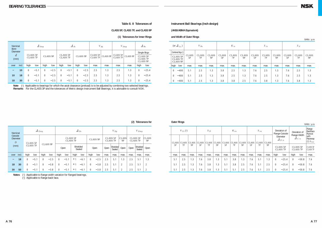
A 76 A 77
BEARING TOLERANCES
Table 8. 8 Tolerances of Instrument Ball Bearings (Inch design)
CLASS 5P, CLASS 7P, and CLASS 9P (ANSI/ABMA Equivalent)
(1) Tolerances for Inner Rings and Width of Outer Rings
(2) Tolerances for Outer Rings
Units : μm
Units : μm
& d mp & ds V dp V d mp & Bs
Single Brgs CLASS 5P CLASS 9P CLASS 5P CLASS 9P CLASS 5P CLASS 9P CLASS 5P CLASS 9P CLASS 5P CLASS 7P CLASS 7P CLASS 7P CLASS 7P CLASS 7P CLASS 9P
over incl. high low high low high low high low max. max. max. max. high low
- 10 0 -5.1 0 -2.5 0 -5.1 0 -2.5 2.5 1.3 2.5 1.3 0 -25.4
10 18 0 -5.1 0 -2.5 0 -5.1 0 -2.5 2.5 1.3 2.5 1.3 0 -25.4
18 30 0 -5.1 0 -2.5 0 -5.1 0 -2.5 2.5 1.3 2.5 1.3 0 -25.4
Note (1) Applicable to bearings for which the axial clearance (preload) is to be adjusted by combining two selected bearings.Remarks For the CLASS 3P and the tolerances of Metric design Instrument Ball Bearings, it is advisable to consult NSK.
NominalBoreDiameter
d(mm)
(or & Cs ) V Bs K ia S ia S d
Combined Brgs (1)
CLASS 5P CLASS CLASS CLASS CLASS CLASS CLASS CLASS CLASS CLASS CLASS CLASS CLASS CLASS 7P 5P 7P 9P 5P 7P 9P 5P 7P 9P 5P 7P 9P CLASS 9P
high low max. max. max. max. max. max. max. max. max. max. max. max.
0 -400 5.1 2.5 1.3 3.8 2.5 1.3 7.6 2.5 1.3 7.6 2.5 1.3
0 -400 5.1 2.5 1.3 3.8 2.5 1.3 7.6 2.5 1.3 7.6 2.5 1.3
0 -400 5.1 2.5 1.3 3.8 3.8 2.5 7.6 3.8 1.3 7.6 3.8 1.3
& D mp & Ds V Dp V D mp
CLASS 5P CLASS 5P CLASS CLASS 5P CLASS CLASS 7P CLASS 9P CLASS 7P 9P CLASS 7P 9P
CLASS 5P
CLASS 9P Shielded CLASS 7P
Open Sealed Open Open Open Open Open
over incl. high low high low high low high low high low max. max. max. max. max. max.
- 18 0 -5.1 0 -2.5 0 -5.1 +1 -6.1 0 -2.5 2.5 5.1 1.3 2.5 5.1 1.3
18 30 0 -5.1 0 -3.8 0 -5.1 +1 -6.1 0 -3.8 2.5 5.1 2 2.5 5.1 2
30 50 0 -5.1 0 -3.8 0 -5.1 +1 -6.1 0 -3.8 2.5 5.1 2 2.5 5.1 2
Nominal Outside Diameter
D(mm) Shielded
SealedShielded Sealed
V Cs (1) S D K ea S ea
CLASS CLASS CLASS CLASS CLASS CLASS CLASS CLASS CLASS CLASS CLASS CLASS 5P 7P 9P 5P 7P 9P 5P 7P 9P 5P 7P 9P CLASS 5P CLASS 5P CLASS 5P CLASS 7P CLASS 7P CLASS 7P
max. max. max. max. max. max. max. max. max. max. max. max. high low high low max.
5.1 2.5 1.3 7.6 3.8 1.3 5.1 3.8 1.3 7.6 5.1 1.3 0 -25.4 0 -50.8 7.6
5.1 2.5 1.3 7.6 3.8 1.3 5.1 3.8 2.5 7.6 5.1 2.5 0 -25.4 0 -50.8 7.6
5.1 2.5 1.3 7.6 3.8 1.3 5.1 5.1 2.5 7.6 5.1 2.5 0 -25.4 0 -50.8 7.6
Notes (1) Applicable to flange width variation for flanged bearings.(2) Applicable to flange back face.
Flange Backface Runoutwith Raceway(2) Sea1
Deviation of Flange Width& C 1s
Deviation of Flange Outside
Diameter& D 1s
A058-081E.indd 76-77 A058-081E.indd 76-77 11/20/13 4:51:15 PM11/20/13 4:51:15 PM
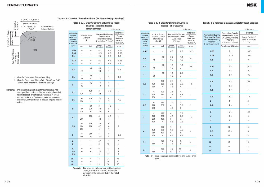
A 78 A 79
BEARING TOLERANCES
Table 8. 9. 2 Chamfer Dimension Limits for Tapered Roller Bearings
Permissible Chamfer
Dimension for Inner/
Outer Rings
r (min.)
Nominal Bore or Nominal Outside
Diameter (1)d or D
over incl. Radial Axial Direction Direction max.
Permissible Chamfer Dimension for Inner/
Outer Ringsr (max.)
Reference
Corner Radius of Shaft or
Housing ra
0.15 - - 0.3 0.6 0.15
- 40 0.7 1.4
0.3 40 - 0.9 1.6
0.3
- 40 1.1 1.7
0.6 40 - 1.3 2
0.6
- 50 1.6 2.5
1 50 - 1.9 3
1
- 120 2.3 3 1.5 120 250 2.8 3.5 1.5 250 - 3.5 4
- 120 2.8 4 2 120 250 3.5 4.5 2 250 - 4 5
- 120 3.5 5 2.5 120 250 4 5.5 2 250 - 4.5 6
- 120 4 5.5 120 250 4.5 6.5
3 250 400 5 7
2.5
400 - 5.5 7.5
- 120 5 7 120 250 5.5 7.5
4 250 400 6 8
3
400 - 6.5 8.5
- 180 6.5 8
5 180 - 7.5 9
4
- 180 7.5 10
6 180 - 9 11
5
Units : mm
Table 8. 9. 3 Chamfer Dimension Limits for Thrust Bearings
Permissible Chamfer Dimension for Shaft (or Central)/Housing
Washersr (min.) or r1 (min.)
Radial or Axial Direction max.
Permissible Chamfer Dimension for Shaft(or Central)/Housing
Washersr (max.) or r1 (max.)
Reference
Corner Radius of Shaft or Housing
ra
0.05 0.1 0.05
0.08 0.16 0.08
0.1 0.2 0.1
0.15 0.3 0.15
0.2 0.5 0.2
0.3 0.8 0.3
0.6 1.5 0.6
1 2.2 1
1.1 2.7 1
1.5 3.5 1.5
2 4 2
2.1 4.5 2
3 5.5 2.5
4 6.5 3
5 8 4
6 10 5
7.5 12.5 6
9.5 15 8
12 18 10
15 21 12
19 25 15
Units : mm
Note (1) Inner Rings are classified by d and Outer Rings by D.
Side
Fac
e of
Inne
r/Ou
ter R
ing
orCe
ntra
l Was
her
r (m
ax.)
or r 1
(max
.)
(Rad
ial D
irect
ion)
r (min.) orr1 (min.)
r (min.) orr1 (min.)r (
min
.) or
r 1 (m
in.)
r (max.) or r1 (max.)
(Axial Direction)Bore Surface orOutside Surface
Ring
r : Chamfer Dimension of Inner/Outer Ringr1 : Chamfer Dimension of Inner/Outer Ring (Front Side) or of Central Washer of Thrust Ball Bearings
Table 8. 9 Chamfer Dimension Limits (for Metric Design Bearings)
Table 8. 9. 1 Chamfer Dimension Limits for Radial Bearings (excluding Tapered
Roller Bearings)
Permissible Chamfer
Dimension for Inner/
Outer Ringsr (min.) or r1 (min.)
Nominal Bore Diameter
d
over incl. Radial Axial Direction Direction max.
Permissible Chamfer Dimension for
Inner/Outer Ringsr (max.) or r1 (max.)
Reference
Corner Radius of Shaft or
Housing ra
0.05 - - 0.1 0.2 0.05 0.08 - - 0.16 0.3 0.08 0.1 - - 0.2 0.4 0.1
0.15 - - 0.3 0.6 0.15 0.2 - - 0.5 0.8 0.2
- 40 0.6 1
0.3 40 - 0.8 1
0.3
- 40 1 2
0.6 40 - 1.3 2
0.6
- 50 1.5 3
1 50 - 1.9 3
1
- 120 2 3.5
1.1 120 - 2.5 4
1
- 120 2.3 4
1.5 120 - 3 5
1.5
- 80 3 4.5 2 80 220 3.5 5 2 220 - 3.8 6
- 280 4 6.5
2.1 280 - 4.5 7
2
- 100 3.8 6 2.5 100 280 4.5 6 2 280 - 5 7
- 280 5 8
3 280 - 5.5 8
2.5
4 - - 6.5 9 3 5 - - 8 10 4
6 - - 10 13 5 7.5 - - 12.5 17 6 9.5 - - 15 19 8
12 - - 18 24 10 15 - - 21 30 12 19 - - 25 38 15
Units : mm
Remarks The precise shape of chamfer surfaces has not been specified but its profile in the axial plane shall not intersect an arc of radius r (min.) or r1 (min.) touching the side face of an inner ring or central washer and bore surface, or the side face of an outer ring and outside surface.
Remarks For bearings with nominal widths less than 2mm, the value of r (max.) in the axial direction is the same as that in the radial direction.
A058-081E.indd 78-79 A058-081E.indd 78-79 11/20/13 4:51:15 PM11/20/13 4:51:15 PM
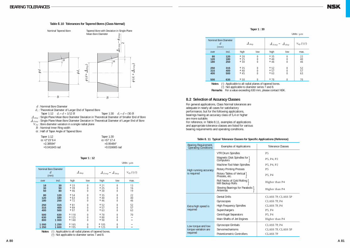
A 80 A 81
BEARING TOLERANCES
j(d
+&
dmp)
&d
1mp
–jd
mp
j(d
1+&
d1m
p)
2
jd
α α
1j
d
B B
Table 8.10 Tolerances for Tapered Bores (Class Normal)
Nominal Tapered Bore Tapered Bore with Deviation in Single Plane Mean Bore Diameter
Taper 1 : 12
Nominal Bore Diameterd
(mm)
over incl. high low high low max.
18 30 +33 0 +21 0 13 30 50 +39 0 +25 0 16 50 80 +46 0 +30 0 19
80 120 +54 0 +35 0 22 120 180 +63 0 +40 0 40 180 250 +72 0 +46 0 46
250 315 +81 0 +52 0 52 315 400 +89 0 +57 0 57 400 500 +97 0 +63 0 63
500 630 +110 0 +70 0 70 630 800 +125 0 +80 0 - 800 1 000 +140 0 +90 0 - 1 000 1 250 +165 0 +105 0 - 1 250 1 600 +195 0 +125 0 -
& dmp & d1mp - & dmp Vdp (1) (2)
Units : μm
Notes (1) Applicable to all radial planes of tapered bores.(2) Not applicable to diameter series 7 and 8.
d : Nominal Bore Diameter d1 : Theoretical Diameter of Larger End of Tapered Bore
Taper 1:12 d1 = d + 1/12 B Taper 1:30 d1 = d + /30 B & dmp : Single Plane Mean Bore Diameter Deviation in Theoretical Diameter of Smaller End of Bore & d1mp : Single Plane Mean Bore Diameter Deviation in Theoretical Diameter of Larger End of Bore Vd p : Bore diameter variation in a single radial plane B : Nominal Inner Ring width α : Half of Taper Angle of Tapered Bore
Taper 1:12 Taper 1:30 α =2°23´9.4 α =57´17.4 =2.38594° =0.95484° =0.041643 rad =0.016665 rad
Taper 1 : 30
Nominal Bore Diameterd
(mm)
over incl. high low high low max.
80 120 +20 0 +35 0 22 120 180 +25 0 +40 0 40 180 250 +30 0 +46 0 46
250 315 +35 0 +52 0 52 315 400 +40 0 +57 0 57 400 500 +45 0 +63 0 63
500 630 +50 0 +70 0 70
& dmp & d1mp - & dmp Vdp (1) (2)
Units : μm
Notes (1) Applicable to all radial planes of tapered bores.(2) Not applicable to diameter series 7 and 8.
Remarks For a value exceeding 630 mm, please contact NSK.
8.2 Selection of Accuracy ClassesFor general applications, Class Normal tolerances are adequate in nearly all cases for satisfactory performance, but for the following applications, bearings having an accuracy class of 5,4 or higher are more suitable.For reference, in Table 8.11, examples of applications and appropriate tolerance classes are listed for various bearing requirements and operating conditions.
Table 8. 11 Typical Tolerance Classes for Specific Applications (Reference)
Bearing Requirement, Operating Conditions Examples of Applications Tolerance Classes
High running accuracy is required
VTR Drum Spindles Magnetic Disk Spindles for }Computers Machine-Tool Main Spindles Rotary Printing Presses Rotary Tables of Vertical }Presses, etc. Roll Necks of Cold Rolling }Mill Backup Rolls Slewing Bearings for Parabolic }Antennas
P5
P5, P4, P2
P5, P4, P2P5
P5, P4
Higher than P4
Higher than P4
Extra high speed is required
Dental Drills Gyroscopes High Frequency Spindles Superchargers Centrifugal Separators Main Shafts of Jet Engines
CLASS 7P, CLASS 5PCLASS 7P, P4CLASS 7P, P4P5, P4P5, P4Higher than P4
Low torque and low torque variation are required
Gyroscope Gimbals Servomechanisms Potentiometric Controllers
CLASS 7P, P4CLASS 7P, CLASS 5PCLASS 7P
A058-081E.indd 80-81 A058-081E.indd 80-81 11/20/13 4:51:16 PM11/20/13 4:51:16 PM

A 82 A 83
9.1 Fits9.1.1 Importance of Proper FitsIn the case of a rolling bearing with the inner ring fitted to the shaft with only slight interference, a harmful circumferential slipping may occur between the inner ring and shaft. This slipping of the inner ring, which is called “creep”, results in a circumferential displacement of the ring relative to the shaft if the interference fit is not sufficiently tight. When creep occurs, the fitted surfaces become abraded, causing wear and considerable damage to the shaft. Abnormal heating and vibration may also occur due to abrasive metallic particles entering the interior of the bearing.It is important to prevent creep by having sufficient interference to firmly secure that ring which rotates to either the shaft or housing. Creep cannot always be eliminated using only axial tightening through the bearing ring faces. Generally, it is not necessary, however, to provide interference for rings subjected only to stationary loads. Fits are sometimes made without any interference for either the inner or outer ring, to accommodate certain operating conditions, or to facilitate mounting and dismounting. In this case, to prevent damage to the fitting surfaces due to creep, lubrication of other applicable methods should be considered.
9.1.2 Selection of Fit(1) Load Conditions and FitThe proper fit may be selected from Table 9.1 based on the load and operating conditions.
(2) Magnitude of Load and InterferenceThe interference of the inner ring is slightly reduced by the bearing load; therefore, the loss of interference should be estimated using the following equations:
where & dF : Interference decrease of inner ring (mm)
d : Bearing bore diameter (mm) B : Nominal inner ring width (mm) Fr : Radial load applied on bearing
(N), {kgf}
9. FITS AND INTERNAL CLEARANCESTherefore, the effective interference &d should be larger than the interference given by Equation (9.1).However, in the case of heavy loads where the radial load exceeds 20% of the basic static load rating C 0r, under the operating condition, interference often becomes shortage. Therefore, interference should be estimated using Equation (9.2):
where & d : Effective interference (mm) Fr : Radial load applied on bearing
(N), {kgf} B : Nominal inner ring width (mm)
(3) Interference Variation Caused by Temperature Difference between Bearing and Shaft or Housing
The effective interference decreases due to the increasing bearing temperature during operation. If the temperature difference between the bearing and housing is & T (°C), then the temperature difference between the fitted surfaces of the shaft and inner ring is estimated to be about (0.1~0.15) & T in case that the shaft is cooled. The decrease in the interference of the inner ring due to this temperature difference & d T may be calculated using Equation (9.3):
& d T = (0.10 to 0.15) × & T⋅α⋅d H0.0015& T ⋅d × 10–3 . . . . . . . . . . . . . . . . . . . (9.3)
where & d T : Decrease in interference of inner ring due to temperature difference (mm)
& T : Temperature difference between bearing interior and surrounding parts (°C)
α : Coefficient of linear expansion of bearing steel=12.5×10⁻⁶ (1/°C)
d : Bearing nominal bore diameter (mm)
In addition, depending on the temperature difference between the outer ring and housing, or difference in their coefficients of linear expansion, the interference may increase.
(4) Effective Interference and Finish of Shaft and Housing
Since the roughness of fitted surfaces is reduced during fitting, the effective interference becomes less than the apparent interference. The amount of this interference decrease varies depending on the
roughness of the surfaces and may be estimated using the following equations:
For ground shafts
For machined shafts
where & d : Effective interference (mm) & d a : Apparent interference (mm) d : Bearing nominal bore diameter (mm)
According to Equations (9.4) and (9.5), the effective interference of bearings with a bore diameter of 30 to 150 mm is about 95% of the apparent interference.
(5) Fitting Stress and Ring Expansion and Contraction
When bearings are mounted with interference on a shaft or in a housing, the rings either expand or contract and stress is produced. Excessive interference may damage the bearings; therefore, as a general guide, the maximum interference should be kept under approximately 7/10 000 of the shaft diameter.The pressure between fitted surfaces, expansion or contraction of the rings, and circumferential stress may be calculated using the equations in Section 15.2, Fitting(1) (Pages A130 and A131).
9.1.3 Recommended FitsAs described previously, many factors, such as the characteristics and magnitude of bearing load, temperature differences, means of bearing mounting and dismounting, must be considered when selecting the proper fit.If the housing is thin or the bearing is mounted on a hollow shaft, a tighter than usual fit is necessary. A split housing often deforms the bearing into an oval shape; therefore, a split housing should be avoided when a tight fit with the outer ring is required. The fits of both the inner and outer rings should be tight in applications where the shaft is subjected to considerable vibration.The recommended fits for some common applications are shown in Table 9.2 to 9.7. In the case of unusual operating conditions, it is advisable to consult NSK. For the accuracy and surface finish of shafts and housings, please refer to Section 11.1 (Page A100).
Rotating
Load ApplicationInner Ring
Bearing OperationOuter Ring
LoadConditions Inner Ring
FittingOuter Ring
Stationary
Stationary
Stationary
Rotating
Rotating or Stationary
Direction of load indeterminate due to variation of direction or unbalanced load
Rotating
Rotating
Stationary
Rotating or Stationary
Direction of Load Indeterminate Tight Fit Tight Fit
Rotating Inner Ring
Load
Stationary Outer Ring
Load
Rotating Outer Ring
Load
Stationary Inner Ring
Load
Tight Fit
Loose Fit
Loose Fit
Tight Fit
Table 9.1 Loading Conditions and Fits
LoadStationary
LoadRotating
Load Stationary
Load Rotating
& dF =0.08 Fr 10–3 (N). . . . . . . .dB
& dF =0.25 Fr 10–3dB {kgf}. . . . .
. . . (9.1)
& d≥0.02 10–3 (N). . . . . . . . . .FrB
& d≥0.2 10–3FrB
. . . . . . . . . {kgf}. . . . . . . (9.2)
& d= & dad
d+2 . . . . . . . . . . . . (9.4)
& d= & dad
d+3 . . . . . . . . . . . . (9.5)
A082-099E.indd 82-83 A082-099E.indd 82-83 11/20/13 4:51:45 PM11/20/13 4:51:45 PM

A 84 A 85
FITS AND INTERNAL CLEARANCES
Load Conditions
Rotating Outer
Ring Load
Rotating Inner Ring Load or Direction of
Load Indeterminate
Axial Loads Only
All Types of Loading
Central Axial Load Only
Stationary Inner Ring Load
Rotating Inner Ring Load or Direction
of Load Indeterminate
Combined Radial and Axial Loads (Spherical
Thrust Roller Bearings)
Easy axial displacement of inner ring on shaft desirable.
Light Loads or Variable Loads(<0.06Cr(1))
Normal Loads(0.06 to 0.13Cr(1))
Heavy Loads or Shock Loads(>0.13Cr(1))
Easy axial displacement of inner ring on shaft unnecessary
Wheels on Stationary Axles
Electrical HomeAppliances Pumps,Blowers, TransportVehicles, PrecisionMachinery,Machine Tools
General BearingApplications,Medium andLarge Motors(3),Turbines, Pumps,Engine MainBearings,Gears,WoodworkingMachines
Railway Axleboxes, Industrial Vehicles, Traction Motors, Construction Equipment, Crushers
General bearing Applications, Railway AxleboxesTransmission Shafts, Woodworking Spindles
Main Shafts of Lathes
Cone Crushers
Paper Pulp Refiners, Plastic Extruders
<18
18 to 100
100 to 200
—
<18
18 to 100
100 to 140
140 to 200
200 to 280
—
—
—
—
—
—
—
—
<40
40 to 140
140 to 200
—
<40
40 to 100
100 to 140
140 to 200
200 to 400
—
—
50 to 140
140 to 200
over 200
—
—
—
—
—
—
<40
40 to 65
65 to 100
100 to 140
140 to 280
280 to 500
over 500
50 to 100
100 to 140
140 to 200
200 to 500
js5
js6(j6)
k6
m6
js5 or js6 (j5 or j6)
k5 or k6
m5 or m6
m6
n6
p6
r6
r7
n6
p6
r6
r7
All Shaft Diameters
All Shaft Diameters
All Shaft Diameters
All Shaft Diameters
All Shaft Diameters
<200
200 to 400
over 400
g6Use g5 and h5 where accuracy is required. In case of large bearings, f6 can be used to allow easy axial movement.
k6 and m6 can be used for single-row tapered rollerbearings and single-row angular contactball bearingsinstead of k5 andm5.
More than CN bearing internal clearance is necessary.
—
IT5 and IT7 mean that the deviation of the shaft from its true geometric form, e. g. roundness and cylindricity should be within the tolerances of IT5 and IT7 respectively.
—
h6
js6 (j6)
h9/IT5(2)
h10/IT7(2)
h6 orjs6 (j6)
js6 (j6)
k6
m6
n6
Tension Pulleys Rope Sheaves
Radial Bearings with Cylindrical Bores
Radial Bearings with Tapered Bores and Sleeves
ExamplesBall Brgs
Cylindrical Roller Brgs, Tapered
Roller Brgs
Spherical Roller Brgs
Tolerance of Shaft Remarks
Shaft Diameter (mm)
Table 9.2 Fits of Radial Bearings with Shafts
Load Conditions Examples Tolerance of Shaft RemarksShaft Diameter (mm)
Table 9.3 Fits of Thrust Bearings with Shafts
Notes (1) Cr represents the basic load rating of the bearing. (2) Refer to Appendix Table 11 on page C22 for the values of standard tolerance grades IT. (3) Refer to Tables 9.13.1 and 9.13.2 for the recommended fits of shafts used in electric motors for deep groove ball
bearings with bore diameters ranging from 10 mm to 160 mm, and for cylindrical roller bearings with bore diameters ranging from 24 mm to 200 mm.
Remarks This table is applicable only to solid steel shafts.
Load Conditions Examples Axial Displacement of Outer Ring RemarksTolerances for
Housing Bores
Table 9.4 Fits of Radial Bearings with Housings
Note (1) Refer to Tables 9.13.1 and 9.13.2 for the recommended fits of housing bores of deep groove ball bearings and cylindrical roller bearings for electric motors.
Remarks 1. This table is applicable to cast iron and steel housings. For housings made of light alloys, the interference should be tighter than those in this table.
2. Refer to the introductory section of the bearing dimension tables (blue pages) for special fits such as drawn cup needle roller bearings.
Solid Housings
Rotating Outer Ring
Load
Heavy Loads on Bearing in Thin-Walled Housing or Heavy Shock Loads
Automotive Wheel Hubs (Roller Bearings) Crane Travelling Wheels
P7
N7
M7
K7
JS7 (J7)
H7
H8
G7
JS6 (J6)
K6
M6 or N6
H6
Impossible —
Load Conditions Bearing Types RemarksTolerances for Housing Bores
Table 9.5 Fits of Thrust Bearings with Housings
Axial Loads Only
Stationary Outer Ring Loads
Rotating Outer Ring Loads or Direction of Load Indeterminate
Combined Radial
and Axial Loads
Thrust Ball Bearings
Spherical Thrust Roller Bearings Steep Angle Tapered Roller Bearings
Spherical Thrust Roller Bearings
Clearance over 0.25mmH8
Outer ring has radial clearance.
H7 or JS7 (J7)
K7M7
For General ApplicationsWhen precision is required
When radial loads are sustained by other bearings.
Normal LoadsRelatively Heavy Radial Loads
—
If axial displacement of the outer ring is not required.
Axial displacement of outer ring is necessary.
—
—
For heavy loads, interference fit tighter than K is used. When high accuracy is required, very strict tolerances should be used for fitting.
—
Generally Impossible
Possible
Easily possible
Possible
Generally Impossible
Impossible
Easily Possible
Automotive Wheel Hubs (Ball Bearings) Vibrating Screens
Conveyor Rollers Rope Sheaves Tension Pulleys
Traction Motors
Pumps Crankshaft Main Bearings Medium and Large Motors(1)
General Bearing Applications, Railway Axleboxes
Plummer Blocks
Paper Dryers
Grinding Spindle Rear Ball Bearings High Speed Centrifugal Compessor Free Bearings
Grinding Spindle Front Ball Bearings High Speed Centrifugal Compressor Fixed Bearings
Cylindrical Roller Bearings for Machine Tool Main Spindle
Electrical Home Appliances
Normal or Heavy Loads
Light or Variable Loads
Heavy Shock Loads
Normal or Heavy Loads
Normal or Light Loads
Loads of All kinds
Normal or Light LoadsHigh Temperature Rise of Inner Ring Through Shaft
Accurate Running Desirable under Normal or Light Loads
Accurate Running and High Rigidity Desirable under Variable Loads
Minimum noise is required.
Direction of Load
Indeterminate
Rotating Inner Ring
Load
Direction of Load
Indeterminate
Rotating Inner Ring
Load
Solid or Split
Housings
Solid Housing
A082-099E.indd 84-85 A082-099E.indd 84-85 11/20/13 4:51:46 PM11/20/13 4:51:46 PM

A 86 A 87
FITS AND INTERNAL CLEARANCES
Operating Conditions
Rota
ting I
nner
R
ing L
oad
sR
ota
ting O
ute
r R
ing L
oad
s
Normal Loads
⎯ 76.200 3.0000 304.800 12.0000 609.600 24.0000
76.200 3.0000 304.800 12.0000 609.600 24.0000 914.400 36.0000
+13 0 +25 0 +51 0 +76 0 +13 0 +25 0 +51 0 +76 0 +13 0 +25 0 +51 0 +76 0 +13 0 +25 0 +51 0 +76 0
+ 38 + 25 + 64 + 38 +127 + 76 +190 +114 + 64 + 38 g g +381 +305 + 13 0 + 25 0 + 51 0 + 76 0 0 − 13 0 − 25 0 − 51 0 − 76
76.200 3.0000 304.800 12.0000 609.600 24.0000 914.400 36.0000 76.200 3.0000 304.800 12.0000 609.600 24.0000 914.400 36.0000 76.200 3.0000 304.800 12.0000 609.600 24.0000 914.400 36.0000
⎯ 76.200 3.0000 304.800 12.0000 609.600 24.0000
⎯ 76.200 3.0000 304.800 12.0000 609.600 24.0000
⎯ 76.200 3.0000 304.800 12.0000 609.600 24.0000
Heavy Loads Shock Loads High Speeds
Normal Loads without Shocks
Nominal Bore Diameters d
over
(mm) 1/25.4
incl.
(mm) 1/25.4
Shaft Diameter Tolerances
high low
Remarks
For bearings with d≤152.4 mm, clearance is usually larger than CN.
In general, bearings with a clear-ance larger than CN are used. g means that the average interference is about 0.0005 d.
The inner ring cannot be displaced axially. When heavy or shock loads exist, the figures in the above (Rotating inner ring loads, heavy or shock loads) apply.
The inner ring can be displacedaxially.
Bore Diameter Tolerances& ds
high low
Table 9.6 Fits of Inch Design Tapered Roller Bearings with Shafts
(1) Bearings of Precision Classes 4 and 2 Units : μm
Units : μm
Operating Conditions
Rota
ting I
nner
R
ing L
oad
sRo
tatin
g Ou
ter
Ring
Loa
ds
Precision Machine-Tool Main Spindles
⎯ 76.200 3.0000 304.800 12.0000 609.600 24.0000
76.200 3.0000 304.800 12.0000 609.600 24.0000 914.400 36.0000
+13 0 +13 0 +25 0 +38 0 +13 0 +13 0 +25 0 +38 0 +13 0 +13 0 +25 0 +38 0
+ 30 +18 + 30 +18 + 64 +38 +102 +64
⎯⎯⎯⎯
+ 30 +18 + 30 +18 + 64 +38 +102 +64
76.200 3.0000 304.800 12.0000 609.600 24.0000 914.400 36.0000 76.200 3.0000 304.800 12.0000 609.600 24.0000 914.400 36.0000
⎯ 76.200 3.0000 304.800 12.0000 609.600 24.0000
⎯ 76.200 3.0000 304.800 12.0000 609.600 24.0000
Heavy Loads Shock Loads High Speeds
Precision Machine-Tool Main Spindles
Nominal Bore Diameters d
over
(mm) 1/25.4
incl.
(mm) 1/25.4
Shaft Diameter Tolerances
high low
Remarks
⎯
A minimum interference of about 0.00025 d is used.
⎯
Bore Diameter Tolerances& ds
high low
(2) Bearings of Precision Classes 3 and 0 (1)
Note (1) For bearings with d greater than 304.8 mm, Class 0 does not exist.
Operating Conditions
Rota
ting
Inne
r Rin
g Lo
ads
Rota
ting
Oute
r Ri
ng L
oads
Used either on free-end or fixed-end
The outer ring position can be adjusted axially.
The outer ring position cannot be adjusted axially.
Normal Loads The outer ring position cannot be adjusted axially.
⎯ 76.200 3.0000 127.000 5.0000 304.800 12.0000 609.600 24.0000
⎯ 76.200 3.0000 127.000 5.0000 304.800 12.0000 609.600 24.0000
⎯ 76.200 3.0000 127.000 5.0000 304.800 12.0000 609.600 24.0000
⎯ 76.200 3.0000 127.000 5.0000 304.800 12.0000 609.600 24.0000
76.200 3.0000 127.000 5.0000 304.800 12.0000 609.600 24.0000 914.400 36.0000 76.200 3.0000 127.000 5.0000 304.800 12.0000 609.600 24.0000 914.400 36.0000 76.200 3.0000 127.000 5.0000 304.800 12.0000 609.600 24.0000 914.400 36.0000 76.200 3.0000 127.000 5.0000 304.800 12.0000 609.600 24.0000 914.400 36.0000
+25 0 +25 0 +25 0 +51 0 +76 0 +25 0 +25 0 +25 0 +51 0 +76 0 +25 0 +25 0 +25 0 +51 0 +76 0 +25 0 +25 0 +25 0 +51 0 +76 0
+ 76 + 51 + 76 + 51 + 76 + 51 +152 +102 +229 +152 + 25 0 + 25 0 + 51 0 + 76 + 25 +127 + 51 − 13 − 38 − 25 − 51 − 25 − 51 − 25 − 76 − 25 −102 − 13 − 38 − 25 − 51 − 25 − 51 − 25 − 76 − 25 −102
Nominal Outside Diameters D
over
(mm) 1/25.4
incl.
(mm) 1/25.4
Housing Bore Diameter
Tolerances
high low
Remarks
The outer ring can be easily displaced axially.
The outer ring can be displaced axially.
Generally, the outer ring is fixed axially.
The outer ring is fixed axially.
Outside Diameter Tolerances& Ds
high low
Table 9.7 Fits of Inch Design Tapered Roller Bearings with Housings
(1) Bearings of Precision Classes 4 and 2 Units : μm
Units : μm
Operating Conditions
Rota
ting
Inne
r Rin
g Lo
ads
Rota
ting
Oute
r Ri
ng L
oads
Used on free-end
⎯ 152.400 6.0000 304.800 12.0000 609.600 24.0000
152.400 6.0000 304.800 12.0000 609.600 24.0000 914.400 36.0000
+13 0 +13 0 +25 0 +38 0 +13 0 +13 0 +25 0 +38 0 +13 0 +13 0 +25 0 +38 0 +13 0 +13 0 +25 0 +38 0 +13 0 +13 0 +13 0 +25 0 +38 0
+38 +25 +38 +25 +64 +38 +89 +51 +25 +13 +25 +13 +51 +25 +76 +38 +13 0 +25 0 +25 0 +38 0 0 −13 0 −25 0 −25 0 −38 −13 −25 −13 −25 −13 −38 −13 −38 −13 −51
152.400 6.0000 304.800 12.0000 609.600 24.0000 914.400 36.0000 152.400 6.0000 304.800 12.0000 609.600 24.0000 914.400 36.0000 152.400 6.0000 304.800 12.0000 609.600 24.0000 914.400 36.0000 76.200 3.0000 152.400 6.0000 304.800 12.0000 609.600 24.0000 914.400 36.0000
⎯ 152.400 6.0000 304.800 12.0000 609.600 24.0000
⎯ 152.400 6.0000 304.800 12.0000 609.600 24.0000
⎯ 152.400 6.0000 304.800 12.0000 609.600 24.0000
⎯ 76.200 3.0000 152.400 6.0000 304.800 12.0000 609.600 24.0000
Used on fixed-end
The outer ring position can be adjusted axially.
The outer ring position cannot be adjusted axially.
Normal Loads The outer ring position cannot be adjusted axially.
Nominal Outside Diameters D
over
(mm) 1/25.4
incl.
(mm) 1/25.4
Housing Bore Diameter
Tolerances
high low
Remarks
The outer ring can be easily displaced axially.
The outer ring can be displaced axially.
Generally, the outer ring is fixed axially.
The outer ring is fixed axially.
The outer ring is fixed axially.
Outside Diameter Tolerances& Ds
high low
(2) Bearings of Precision Classes 3 and 0 (1)
Note (1) For bearings with D greater than 304.8 mm, Class 0 does not exist.
A082-099E.indd 86-87 A082-099E.indd 86-87 11/20/13 4:51:48 PM11/20/13 4:51:48 PM

A 88 A 89
FITS AND INTERNAL CLEARANCES
9.2 Bearing Internal Clearances9.2.1 Internal Clearances and Their StandardsThe internal clearance in rolling bearings in operation greatly influences bearing performance including fatigue life, vibration, noise, heat-generation, etc. Consequently, the selection of the proper internal clearance is one of the most important tasks when choosing a bearing after the type and size have been determined.This bearing internal clearance is the combined clearances between the inner/outer rings and rolling elements. The radial and axial clearances are defined as the total amount that one ring can be displaced relative to the other in the radial and axial directions respectively (Fig. 9.1).
To obtain accurate measurements, the clearance is generally measured by applying a specified measuring load on the bearing; therefore, the measured clearance (sometimes called “measured clearance” to make a distinction) is always slightly larger than the theoretical internal clearance (called “geometrical clearance” for radial bearings) by the amount of elastic deformation caused by the measuring load.Therefore, the theoretical internal clearance may be obtained by correcting the measured clearance by the amount of elastic deformation. However, in the case of roller bearings this elastic deformation is negligibly small.Usually the clearance before mounting is the one specified as the theoretical internal clearance. In Table 9.8, reference table and page numbers are listed by bearing types.
Radial Clearance Axial Clearance
Table 9.8 Bearing Internal Clearance
Table 9.8 Index for Radial Internal Clearances by Bearing Types
Table Page Bearing Types Number Number
Deep Groove Ball Bearings 9.9 A89
Extra Small and Miniature Ball Bearings 9.10 A89
Magneto Bearings 9.11 A89
Self-Aligning Ball Bearings 9.12 A90
9.13.1 A90
For Motors
9.13.2 A90
Deep Groove Ball Bearings
Cylindrical Roller Bearings
Cylindrical Roller Bearings
Spherical Roller Bearings
Double-Row and Combined Tapered Roller Bearings
Combined Angular Contact Ball Bearings (1)
Four-Point Contact Ball Bearings (1)
With Cylindrical Bores
With Cylindrical Bores (Matched)
With Tapered Bores (Matched)
With Cylindrical Bores
With Tapered Bores
9.14
9.15
9.15
9.17
9.18
A91
A92
A93
A94
A94
Note (1) Values given are axial clearances.
Table 9.9 Radial Internal Clearances in Deep Groove Ball Bearings
C2 CN C3 C4 C5
Nominal Bore Diameter d (mm)
Clearance
over incl. min. max. min. max. min. max. min. max. min. max.
10 only 0 7 2 13 8 23 14 29 20 37 10 18 0 9 3 18 11 25 18 33 25 45 18 24 0 10 5 20 13 28 20 36 28 48
24 30 1 11 5 20 13 28 23 41 30 53 30 40 1 11 6 20 15 33 28 46 40 64 40 50 1 11 6 23 18 36 30 51 45 73
50 65 1 15 8 28 23 43 38 61 55 90 65 80 1 15 10 30 25 51 46 71 65 105 80 100 1 18 12 36 30 58 53 84 75 120
100 120 2 20 15 41 36 66 61 97 90 140 120 140 2 23 18 48 41 81 71 114 105 160 140 160 2 23 18 53 46 91 81 130 120 180
160 180 2 25 20 61 53 102 91 147 135 200 180 200 2 30 25 71 63 117 107 163 150 230 200 225 2 35 25 85 75 140 125 195 175 265
225 250 2 40 30 95 85 160 145 225 205 300 250 280 2 45 35 105 90 170 155 245 225 340 280 315 2 55 40 115 100 190 175 270 245 370
315 355 3 60 45 125 110 210 195 300 275 410 355 400 3 70 55 145 130 240 225 340 315 460 400 450 3 80 60 170 150 270 250 380 350 510
450 500 3 90 70 190 170 300 280 420 390 570 500 560 10 100 80 210 190 330 310 470 440 630 560 630 10 110 90 230 210 360 340 520 490 690
630 710 20 130 110 260 240 400 380 570 540 760 710 800 20 140 120 290 270 450 430 630 600 840
Units : μm Units : μm
Table 9.10 Radial Internal Clearances in Extra Small and Miniature Ball Bearings
Clear-ance
Symbol MC1 MC2 MC3 MC4 MC5 MC6
min. max. min. max. min. max. min. max. min. max. min. max.
0 5 3 8 5 10 8 13 13 20 20 28Clear-ance
Nominal Bore Dia. d (mm) Measuring
Load (N) {kgf}
Radial Clearance Correction Amount
C2 CN C3 C4 C5 over incl.
10 (incl) 18
18 50
50 280
24.5 {2.5} 49 {5} 147 {15}
3 to 4 4 4 4 4 4 to 5 5 6 6 6 6 to 8 8 9 9 9
Units : μm
Remarks To obtain the measured values, use the clearance correction for radial clearance increase caused by the measuring load in the table below.
Remarks For the C2 clearance class, the smaller value should be used for bearings with minimum clearance and the larger value for bearings near the maximum clearance range.
Remarks For values exceeding 280 mm, please contact NSK.
Units : μm
Table 9.11 Radial Internal Clearances in Magneto Bearings
Nominal Bore Diameterd (mm)
Bearing Series
Clearance
over incl.
2.5 30EN
E
10 50
30 60
min. max.
Units : μm
Clearance Symbol
Clearance Correction
Value
MC1 MC2 MC3 MC4 MC5 MC6
1 1 1 1 2 2
Remarks 1. The standard clearance is MC3.Remarks 2. To obtain the measured value, add
correction amount in the table below.
The measuring loads are as follows : For miniature ball bearings*
2.5N {0.25kgf} For extra small ball bearings*
4.4N {0.45kgf}*For their classification, refer to
Table 1 on Page B 31.
A082-099E.indd 88-89 A082-099E.indd 88-89 11/20/13 4:51:49 PM11/20/13 4:51:49 PM
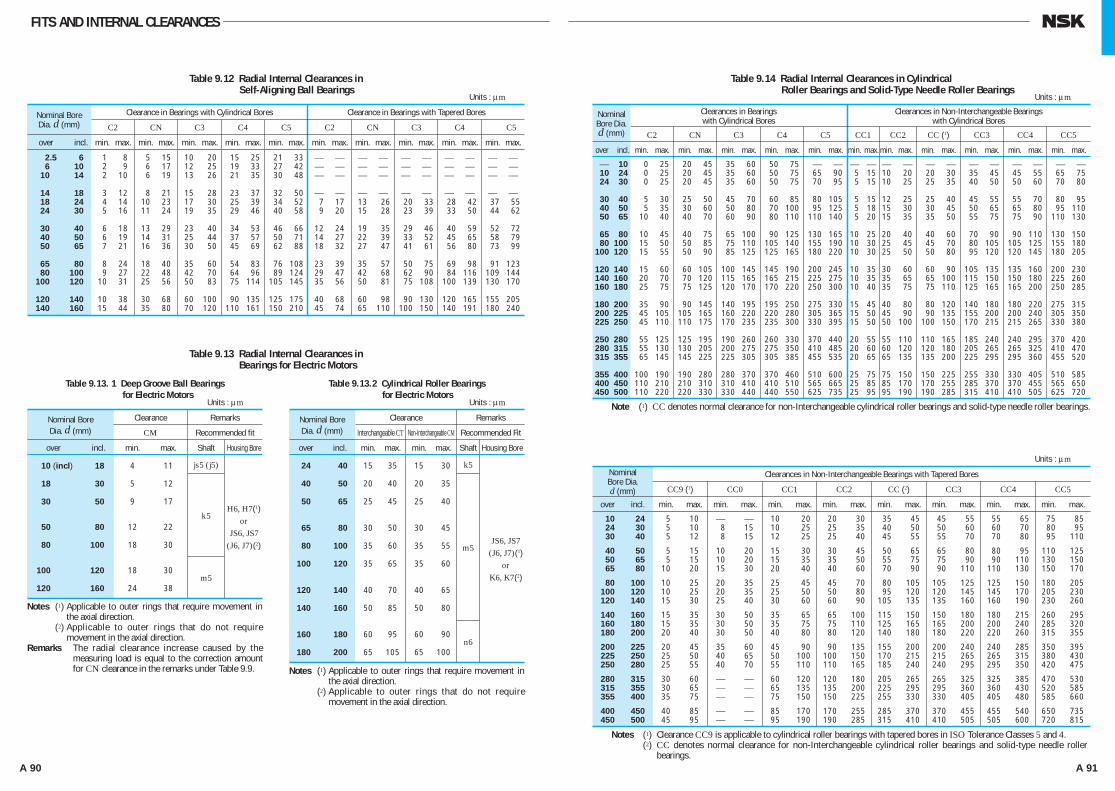
A 90 A 91
FITS AND INTERNAL CLEARANCES
2.5 6 6 10 10 14
14 18 18 24 24 30
30 40 40 50 50 65
65 80 80 100 100 120
120 140 140 160
1 8 5 15 10 20 15 25 21 33 ⎯ ⎯ ⎯ ⎯ ⎯ ⎯ ⎯ ⎯ ⎯ ⎯ 2 9 6 17 12 25 19 33 27 42 ⎯ ⎯ ⎯ ⎯ ⎯ ⎯ ⎯ ⎯ ⎯ ⎯ 2 10 6 19 13 26 21 35 30 48 ⎯ ⎯ ⎯ ⎯ ⎯ ⎯ ⎯ ⎯ ⎯ ⎯
3 12 8 21 15 28 23 37 32 50 ⎯ ⎯ ⎯ ⎯ ⎯ ⎯ ⎯ ⎯ ⎯ ⎯ 4 14 10 23 17 30 25 39 34 52 7 17 13 26 20 33 28 42 37 55 5 16 11 24 19 35 29 46 40 58 9 20 15 28 23 39 33 50 44 62
6 18 13 29 23 40 34 53 46 66 12 24 19 35 29 46 40 59 52 72 6 19 14 31 25 44 37 57 50 71 14 27 22 39 33 52 45 65 58 79 7 21 16 36 30 50 45 69 62 88 18 32 27 47 41 61 56 80 73 99
8 24 18 40 35 60 54 83 76 108 23 39 35 57 50 75 69 98 91 123 9 27 22 48 42 70 64 96 89 124 29 47 42 68 62 90 84 116 109 144 10 31 25 56 50 83 75 114 105 145 35 56 50 81 75 108 100 139 130 170
10 38 30 68 60 100 90 135 125 175 40 68 60 98 90 130 120 165 155 205 15 44 35 80 70 120 110 161 150 210 45 74 65 110 100 150 140 191 180 240
0 25 20 45 35 60 50 75 ⎯ ⎯ 0 25 20 45 35 60 50 75 65 90 0 25 20 45 35 60 50 75 70 95
5 30 25 50 45 70 60 85 80 105 5 35 30 60 50 80 70 100 95 125 10 40 40 70 60 90 80 110 110 140
10 45 40 75 65 100 90 125 130 165 15 50 50 85 75 110 105 140 155 190 15 55 50 90 85 125 125 165 180 220
15 60 60 105 100 145 145 190 200 245 20 70 70 120 115 165 165 215 225 275 25 75 75 125 120 170 170 220 250 300
35 90 90 145 140 195 195 250 275 330 45 105 105 165 160 220 220 280 305 365 45 110 110 175 170 235 235 300 330 395
55 125 125 195 190 260 260 330 370 440 55 130 130 205 200 275 275 350 410 485 65 145 145 225 225 305 305 385 455 535
100 190 190 280 280 370 370 460 510 600 110 210 210 310 310 410 410 510 565 665 110 220 220 330 330 440 440 550 625 735
⎯ ⎯ ⎯ ⎯ ⎯ ⎯ ⎯ ⎯ ⎯ ⎯ ⎯ ⎯ 5 15 10 20 20 30 35 45 45 55 65 75 5 15 10 25 25 35 40 50 50 60 70 80
5 15 12 25 25 40 45 55 55 70 80 95 5 18 15 30 30 45 50 65 65 80 95 110 5 20 15 35 35 50 55 75 75 90 110 130
10 25 20 40 40 60 70 90 90 110 130 150 10 30 25 45 45 70 80 105 105 125 155 180 10 30 25 50 50 80 95 120 120 145 180 205
10 35 30 60 60 90 105 135 135 160 200 230 10 35 35 65 65 100 115 150 150 180 225 260 10 40 35 75 75 110 125 165 165 200 250 285
15 45 40 80 80 120 140 180 180 220 275 315 15 50 45 90 90 135 155 200 200 240 305 350 15 50 50 100 100 150 170 215 215 265 330 380
20 55 55 110 110 165 185 240 240 295 370 420 20 60 60 120 120 180 205 265 265 325 410 470 20 65 65 135 135 200 225 295 295 360 455 520
25 75 75 150 150 225 255 330 330 405 510 585 25 85 85 170 170 255 285 370 370 455 565 650 25 95 95 190 190 285 315 410 410 505 625 720
⎯ 10 10 24 24 30
30 40 40 50 50 65
65 80 80 100 100 120
120 140 140 160 160 180
180 200 200 225 225 250
250 280 280 315 315 355
355 400 400 450 450 500
Nominal Bore Dia. d (mm)
over incl. min. max. min. max. min. max. min. max. min. max. min. max. min. max. min. max. min. max. min. max.
Clearance in Bearings with Cylindrical Bores
C2 CN C3 C4 C5 C2 CN C3 C4 C5
Clearance in Bearings with Tapered Bores
Table 9.12 Radial Internal Clearances in Self-Aligning Ball Bearings
Units : μm
Nominal Bore Dia. d (mm)
over incl. min. max. min. max. min. max. min. max. min. max. min. max. min. max. min. max. min. max. min. max. min. max.
Clearances in Bearingswith Cylindrical Bores
C2 CN C3 C4 C5 CC1 CC2 CC (1) CC3 CC4 CC5
Clearances in Non-Interchangeable Bearingswith Cylindrical Bores
Table 9.14 Radial Internal Clearances in Cylindrical Roller Bearings and Solid-Type Needle Roller Bearings
Units : μm
10 24 5 10 ⎯ ⎯ 10 20 20 30 35 45 45 55 55 65 75 85 24 30 5 10 8 15 10 25 25 35 40 50 50 60 60 70 80 95 30 40 5 12 8 15 12 25 25 40 45 55 55 70 70 80 95 110
40 50 5 15 10 20 15 30 30 45 50 65 65 80 80 95 110 125 50 65 5 15 10 20 15 35 35 50 55 75 75 90 90 110 130 150 65 80 10 20 15 30 20 40 40 60 70 90 90 110 110 130 150 170
80 100 10 25 20 35 25 45 45 70 80 105 105 125 125 150 180 205 100 120 10 25 20 35 25 50 50 80 95 120 120 145 145 170 205 230 120 140 15 30 25 40 30 60 60 90 105 135 135 160 160 190 230 260
140 160 15 35 30 50 35 65 65 100 115 150 150 180 180 215 260 295 160 180 15 35 30 50 35 75 75 110 125 165 165 200 200 240 285 320 180 200 20 40 30 50 40 80 80 120 140 180 180 220 220 260 315 355
200 225 20 45 35 60 45 90 90 135 155 200 200 240 240 285 350 395 225 250 25 50 40 65 50 100 100 150 170 215 215 265 265 315 380 430 250 280 25 55 40 70 55 110 110 165 185 240 240 295 295 350 420 475
280 315 30 60 ⎯ ⎯ 60 120 120 180 205 265 265 325 325 385 470 530 315 355 30 65 ⎯ ⎯ 65 135 135 200 225 295 295 360 360 430 520 585 355 400 35 75 ⎯ ⎯ 75 150 150 225 255 330 330 405 405 480 585 660
400 450 40 85 ⎯ ⎯ 85 170 170 255 285 370 370 455 455 540 650 735 450 500 45 95 ⎯ ⎯ 95 190 190 285 315 410 410 505 505 600 720 815
Nominal Bore Dia. d (mm)
over incl. min. max. min. max. min. max. min. max. min. max. min. max. min. max. min. max.
Clearances in Non-Interchangeable Bearings with Tapered Bores
CC9 (1) CC0 CC1 CC2 CC (2) CC3 CC4 CC5
Units : μm
Nominal Bore Clearance Remarks
Dia. d (mm) CM Recommended fit
over incl. min. max. Shaft Housing Bore
10 (incl) 18 4 11
18 30 5 12
30 50 9 17
50 80 12 22
80 100 18 30
100 120 18 30
120 160 24 38
js5 (j5)
k5
m5
H6, H7(1)or
JS6, JS7(J6, J7)(2)
Table 9.13 Radial Internal Clearances in Bearings for Electric Motors
Units : μm
Table 9.13. 1 Deep Groove Ball Bearings for Electric Motors
Notes (1) Applicable to outer rings that require movement in the axial direction.
(2) Applicable to outer rings that do not require movement in the axial direction.
Remarks The radial clearance increase caused by the measuring load is equal to the correction amount for CN clearance in the remarks under Table 9.9.
Nominal Bore Clearance Remarks
Dia. d (mm) Interchangeable CT Non-Interchangeable CM Recommended Fit
over incl. min. max. min. max. Shaft Housing Bore
24 40 15 35 15 30
40 50 20 40 20 35
50 65 25 45 25 40
65 80 30 50 30 45
80 100 35 60 35 55
100 120 35 65 35 60
120 140 40 70 40 65
140 160 50 85 50 80
160 180 60 95 60 90
180 200 65 105 65 100
k5
m5
n6
JS6, JS7(J6, J7)(1)
orK6, K7(2)
Units : μm
Table 9.13.2 Cylindrical Roller Bearings for Electric Motors
Note (1) CC denotes normal clearance for non-Interchangeable cylindrical roller bearings and solid-type needle roller bearings.
Notes (1) Clearance CC9 is applicable to cylindrical roller bearings with tapered bores in ISO Tolerance Classes 5 and 4.Notes (2) CC denotes normal clearance for non-Interchangeable cylindrical roller bearings and solid-type needle roller
bearings.
Notes (1) Applicable to outer rings that require movement in the axial direction.
(2) Applicable to outer rings that do not require movement in the axial direction.
A082-099E.indd 90-91 A082-099E.indd 90-91 11/20/13 4:51:50 PM11/20/13 4:51:50 PM

A 92 A 93
FITS AND INTERNAL CLEARANCES
15 25 25 40 40 55 55 75 75 95 20 30 30 40 40 55 55 75 75 95 15 30 30 45 45 60 60 80 80 100 25 35 35 50 50 65 65 85 85 105 20 35 35 55 55 75 75 100 100 125 30 45 45 60 60 80 80 100 100 130
20 40 40 65 65 90 90 120 120 150 40 55 55 75 75 95 95 120 120 160 30 50 50 80 80 110 110 145 145 180 50 70 70 95 95 120 120 150 150 200 35 60 60 100 100 135 135 180 180 225 55 80 80 110 110 140 140 180 180 230
40 75 75 120 120 160 160 210 210 260 65 100 100 135 135 170 170 220 220 280 50 95 95 145 145 190 190 240 240 300 80 120 120 160 160 200 200 260 260 330 60 110 110 170 170 220 220 280 280 350 90 130 130 180 180 230 230 300 300 380
65 120 120 180 180 240 240 310 310 390 100 140 140 200 200 260 260 340 340 430 70 130 130 200 200 260 260 340 340 430 110 160 160 220 220 290 290 370 370 470 80 140 140 220 220 290 290 380 380 470 120 180 180 250 250 320 320 410 410 520
90 150 150 240 240 320 320 420 420 520 140 200 200 270 270 350 350 450 450 570 100 170 170 260 260 350 350 460 460 570 150 220 220 300 300 390 390 490 490 620 110 190 190 280 280 370 370 500 500 630 170 240 240 330 330 430 430 540 540 680
120 200 200 310 310 410 410 550 550 690 190 270 270 360 360 470 470 590 590 740 130 220 220 340 340 450 450 600 600 750 210 300 300 400 400 520 520 650 650 820 140 240 240 370 370 500 500 660 660 820 230 330 330 440 440 570 570 720 720 910
140 260 260 410 410 550 550 720 720 900 260 370 370 490 490 630 630 790 790 1 000 150 280 280 440 440 600 600 780 780 1 000 290 410 410 540 540 680 680 870 870 1 100 170 310 310 480 480 650 650 850 850 1 100 320 460 460 600 600 760 760 980 980 1 230
190 350 350 530 530 700 700 920 920 1 190 350 510 510 670 670 850 850 1 090 1 090 1 360 210 390 390 580 580 770 770 1 010 1 010 1 300 390 570 570 750 750 960 960 1 220 1 220 1 500 230 430 430 650 650 860 860 1 120 1 120 1 440 440 640 640 840 840 1 070 1 070 1 370 1 370 1 690
260 480 480 710 710 930 930 1 220 1 220 1 570 490 710 710 930 930 1 190 1 190 1 520 1 520 1 860 290 530 530 780 780 1 020 1 020 1 330 ⎯ ⎯ 530 770 770 1 030 1 030 1 300 1 300 1 670 ⎯ ⎯ 320 580 580 860 860 1 120 1 120 1 460 ⎯ ⎯ 570 830 830 1 120 1 120 1 420 1 420 1 830 ⎯ ⎯ 350 640 640 950 950 1 240 1 240 1 620 ⎯ ⎯ 620 910 910 1 230 1 230 1 560 1 560 2 000 ⎯ ⎯
⎯ 18 0 10 10 20 20 30 35 45 50 60 65 75 18 24 0 10 10 20 20 30 35 45 50 60 65 75 24 30 0 10 10 20 20 30 40 50 50 60 70 80
30 40 0 12 12 25 25 40 45 60 60 75 80 95 40 50 0 15 15 30 30 45 50 65 65 80 95 110 50 65 0 15 15 35 35 55 60 80 80 100 110 130
65 80 0 20 20 40 40 60 70 90 90 110 130 150 80 100 0 25 25 50 50 75 80 105 105 130 155 180 100 120 5 30 30 55 55 80 90 115 120 145 180 210
120 140 5 35 35 65 65 95 100 130 135 165 200 230 140 160 10 40 40 70 70 100 110 140 150 180 220 260 160 180 10 45 45 80 80 115 125 160 165 200 250 290
180 200 10 50 50 90 90 130 140 180 180 220 280 320 200 225 20 60 60 100 100 140 150 190 200 240 300 340 225 250 20 65 65 110 110 155 165 210 220 270 330 380
250 280 20 70 70 120 120 170 180 230 240 290 370 420 280 315 30 80 80 130 130 180 190 240 260 310 410 460 315 355 30 80 80 130 140 190 210 260 290 350 450 510
355 400 40 90 90 140 150 200 220 280 330 390 510 570 400 450 45 95 95 145 170 220 250 310 370 430 560 620 450 500 50 100 100 150 190 240 280 340 410 470 620 680
500 560 60 110 110 160 210 260 310 380 450 520 700 770 560 630 70 120 120 170 230 290 350 420 500 570 780 850 630 710 80 130 130 180 260 310 390 470 560 640 870 950
710 800 90 140 150 200 290 340 430 510 630 710 980 1 060 800 900 100 150 160 210 320 370 480 570 700 790 1 100 1 200 900 1 000 120 170 180 230 360 410 540 630 780 870 1 200 1 300
1 000 1 120 130 190 200 260 400 460 600 700 ⎯ ⎯ ⎯ ⎯ 1 120 1 250 150 210 220 280 450 510 670 770 ⎯ ⎯ ⎯ ⎯ 1 250 1 400 170 240 250 320 500 570 750 870 ⎯ ⎯ ⎯ ⎯
24 30 30 40 40 50
50 65 65 80 80 100
100 120 120 140 140 160
160 180 180 200 200 225
225 250 250 280 280 315
315 355 355 400 400 450
450 500 500 560 560 630
630 710 710 800 800 900
900 1 000 1 000 1 120 1 120 1 250 1 250 1 400
Nominal Bore Dia. d (mm)
over incl.
over incl. min. max. min. max. min. max. min. max. min. max. min. max.
min. max. min. max. min. max. min. max. min. max. min. max. min. max. min. max. min. max. min. max.
Clearance in Bearings with Cylindrical Bores
C2 CN C3 C4 C5 C2 CN C3 C4 C5 C1 C2 CN C3 C4 C5
⎯ C1 C2 CN C3 C4
Clearance in Bearings with Tapered Bores
Table 9.15 Radial Internal Clearances in Spherical Roller Bearings
Units : μm
Nominal Bore Dia. d (mm)
Clearance
Table 9.16 Radial Internal Clearances in Double-Row and Combined Tapered Roller Bearings
Units : μm
Cylindrical BoreTapered Bore
Remarks Axial internal clearance &a = & r cot αH & r
Remarks where & r : Radial internal clearance α : Contact angle e : Constant (Listed in bearing tables)
1.5e
A082-099E.indd 92-93 A082-099E.indd 92-93 11/20/13 4:51:51 PM11/20/13 4:51:51 PM
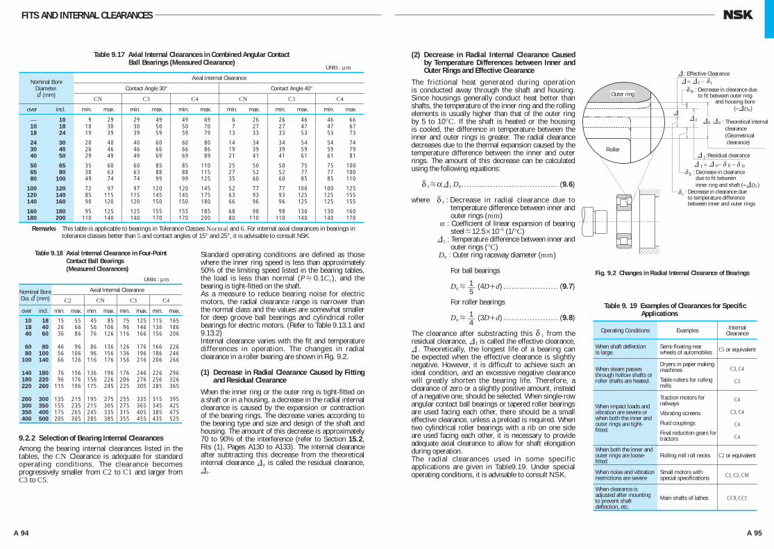
A 94 A 95
FITS AND INTERNAL CLEARANCES
⎯ 10 9 29 29 49 49 69 6 26 26 46 46 66 10 18 10 30 30 50 50 70 7 27 27 47 47 67 18 24 19 39 39 59 59 79 13 33 33 53 53 73
24 30 20 40 40 60 60 80 14 34 34 54 54 74 30 40 26 46 46 66 66 86 19 39 39 59 59 79 40 50 29 49 49 69 69 89 21 41 41 61 61 81
50 65 35 60 60 85 85 110 25 50 50 75 75 100 65 80 38 63 63 88 88 115 27 52 52 77 77 100 80 100 49 74 74 99 99 125 35 60 60 85 85 110
100 120 72 97 97 120 120 145 52 77 77 100 100 125 120 140 85 115 115 145 145 175 63 93 93 125 125 155 140 160 90 120 120 150 150 180 66 96 96 125 125 155
160 180 95 125 125 155 155 185 68 98 98 130 130 160 180 200 110 140 140 170 170 200 80 110 110 140 140 170
Nominal Bore Diameter. d (mm)
over incl. min. max. min. max. min. max. min. max. min. max. min. max.
Axial Internal Clearance
Contact Angle 30° Contact Angle 40°
CN C3 C4 CN C3 C4
Table 9.17 Axial Internal Clearances in Combined Angular Contact Ball Bearings (Measured Clearance)
Units : μm
10 18 15 55 45 85 75 125 115 165 18 40 26 66 56 106 96 146 136 186 40 60 36 86 76 126 116 166 156 206
60 80 46 96 86 136 126 176 166 226 80 100 56 106 96 156 136 196 186 246 100 140 66 126 116 176 156 216 206 266
140 180 76 156 136 196 176 246 226 296 180 220 96 176 156 226 206 276 256 326 220 260 115 196 175 245 225 305 285 365
260 300 135 215 195 275 255 335 315 395 300 350 155 235 215 305 275 365 345 425 350 400 175 265 245 335 315 405 385 475 400 500 205 305 285 385 355 455 435 525
Nominal Bore Dia. d (mm)
over incl. min. max. min. max. min. max. min. max.
Axial Internal Clearance
C2 CN C3 C4
Table 9.18 Axial Internal Clearance in Four-Point Contact Ball Bearings (Measured Clearances)
Units : μm
Remarks This table is applicable to bearings in Tolerance Classes Normal and 6. For internal axial clearances in bearings in tolerance classes better than 5 and contact angles of 15° and 25°, it is advisable to consult NSK.
9.2.2 Selection of Bearing Internal ClearancesAmong the bearing internal clearances listed in the tables, the CN Clearance is adequate for standard operating conditions. The clearance becomes progressively smaller from C2 to C1 and larger from C3 to C5.
Standard operating conditions are defined as those where the inner ring speed is less than approximately 50% of the limiting speed listed in the bearing tables, the load is less than normal (PH0.1C r), and the bearing is tight-fitted on the shaft.As a measure to reduce bearing noise for electric motors, the radial clearance range is narrower than the normal class and the values are somewhat smaller for deep groove ball bearings and cylindrical roller bearings for electric motors. (Refer to Table 9.13.1 and 9.13.2)Internal clearance varies with the fit and temperature differences in operation. The changes in radial clearance in a roller bearing are shown in Fig. 9.2.
(1) Decrease in Radial Clearance Caused by Fitting and Residual Clearance
When the inner ring or the outer ring is tight-fitted on a shaft or in a housing, a decrease in the radial internal clearance is caused by the expansion or contraction of the bearing rings. The decrease varies according to the bearing type and size and design of the shaft and housing. The amount of this decrease is approximately 70 to 90% of the interference (refer to Section 15.2, Fits (1), Pages A130 to A133). The internal clearance after subtracting this decrease from the theoretical internal clearance & 0 is called the residual clearance, & f.
(2) Decrease in Radial Internal Clearance Caused by Temperature Differences between Inner and Outer Rings and Effective Clearance
The frictional heat generated during operation is conducted away through the shaft and housing. Since housings generally conduct heat better than shafts, the temperature of the inner ring and the rolling elements is usually higher than that of the outer ring by 5 to 10°C. If the shaft is heated or the housing is cooled, the difference in temperature between the inner and outer rings is greater. The radial clearance decreases due to the thermal expansion caused by the temperature difference between the inner and outer rings. The amount of this decrease can be calculated using the following equations:
δ tHα& t De . . . . . . . . . . . . . . . . . . . . . . . . . . . . . . . . . . . . . (9.6)
where δ t : Decrease in radial clearance due to temperature difference between inner and outer rings (mm)
α : Coefficient of linear expansion of bearing steelH12.5×10−6 (1/°C)
& t : Temperature difference between inner and outer rings (°C)
De : Outer ring raceway diameter (mm)
For ball bearings
DeH (4D+d) . . . . . . . . . . . . . . . . . . . . . (9.7)
For roller bearings
DeH (3D+d) . . . . . . . . . . . . . . . . . . . . . (9.8)
The clearance after substracting this δ t from the residual clearance, & f is called the effective clearance, & . Theoretically, the longest life of a bearing can be expected when the effective clearance is slightly negative. However, it is difficult to achieve such an ideal condition, and an excessive negative clearance will greatly shorten the bearing life. Therefore, a clearance of zero or a slightly positive amount, instead of a negative one, should be selected. When single-row angular contact ball bearings or tapered roller bearings are used facing each other, there should be a small effective clearance, unless a preload is required. When two cylindrical roller bearings with a rib on one side are used facing each other, it is necessary to provide adequate axial clearance to allow for shaft elongation during operation.The radial clearances used in some specific applications are given in Table9.19. Under special operating conditions, it is advisable to consult NSK.
15
14
Fig. 9.2 Changes in Radial Internal Clearance of Bearings
Outer ring
Roller
& : Effective Clearance& = & f − δ t
δ fe
&&
f
f
&0
& 0
&
&
f& fiδfiδ
tδ
feδ
0 : Theoretical internal clearance (Geometrical clearance)
: Decrease in clearance due to temperature difference between inner and outer rings
:Residual clearance
: Decrease in clearance due to fit between inner ring and shaft (=&Di )
= − −
: Decrease in clearance due to fit between outer ring and housing bore (=&De)
Table 9. 19 Examples of Clearances for Specific Applications
Operating Conditions Examples InternalClearance
When shaft deflection is large.
Semi-floating rear wheels of automobiles C5 or equivalent
When steam passes through hollow shafts or roller shafts are heated.
Dryers in paper making machines
Table rollers for rolling mills
C3, C4
C3
When impact loads and vibration are severe or when both the inner and outer rings are tight-fitted.
Traction motors for railways
Vibrating screens
Fluid couplings
Final reduction gears for tractors
C4
C3, C4
C4
C4
When both the inner and outer rings are loose-fitted
Rolling mill roll necks C2 or equivalent
When noise and vibration restrictions are severe
Small motors with special specifications C1, C2, CM
When clearance is adjusted after mounting to prevent shaft deflection, etc.
Main shafts of lathes CC9, CC1
A082-099E.indd 94-95 A082-099E.indd 94-95 11/20/13 4:51:52 PM11/20/13 4:51:52 PM

A 96 A 97
Rolling bearings usually retain some internal clearance while in operation. In some cases, however, it is desirable to provide a negative clearance to keep them internally stressed. This is called “preloading
„.
A preload is usually applied to bearings in which the clearance can be adjusted during mounting, such as angular contact ball bearings or tapered roller bearings. Usually, two bearings are mounted face-to-face or back-to-back to form a duplex set with a preload.
10.1 Purpose of PreloadThe main purposes and some typical applications of preloaded bearings are as follows:
(1) To maintain the bearings in exact position both radially and axially and to maintain the running accuracy of the shaft....Main shafts of machine tools, precision instruments, etc.
(2) To increase bearing rigidity...Main shafts of machine tools, pinion shafts of final drive gears of automobiles, etc.
(3) To minimize noise due to axial vibration and resonance...Small electric motors, etc.
(4) To prevent sliding between the rolling elements and raceways due to gyroscopic moments. . .High speed or high acceleration applications of angular contact ball bearings, and thrust ball bearings
(5) To maintain the rolling elements in their proper position with the bearing rings...Thrust ball bearings and spherical thrust roller bearings mounted on a horizontal shaft
10.2 Preloading Methods10.2.1 Position Preload
A position preload is achieved by fixing two axially opposed bearings in such a way that a preload is imposed on them. Their position, once fixed, remain unchanged while in operation.In practice, the following three methods are generally used to obtain a position preload.
(1) By installing a duplex bearing set with previously adjusted stand-out dimensions (see Page A7, Fig. 1.1) and axial clearance.
(2) By using a spacer or shim of proper size to obtain the required spacing and preload. (Refer to Fig. 10.1)
(3) By utilizing bolts or nuts to allow adjustment of the axial preload. In this case, the starting torque should be measured to verify the proper preload.
10.2.2 Constant-Pressure Preload
A constant pressure preload is achieved using a coil or leaf spring to impose a constant preload. Even if the relative position of the bearings changes during operation, the magnitude of the preload remains relatively constant (refer to Fig. 10.2)
10.3 Preload and Rigidity10.3.1 Position Preload and Rigidity
When the inner rings of the duplex bearings shown in Fig.10.3 are fixed axially, bearings A and B are displaced δ a0 and axial space 2δ a0 between the inner rings is eliminated. With this condition, a preload Fa0 is imposed on each bearing. A preload diagram showing bearing rigidity, that is the relation between load and displacement with a given axial load Fa imposed on a duplex set, is shown in Fig. 10.4.
10. PRELOAD
Fig. 10.1 Position Preload
Fig. 10.2 Constant-Pressure Preload
Fig. 10.3 Back-to-Back Duplex Bearing Preload
BearingA
BearingB
FaFa0 Fa0
δ a0 δ a0
10.3.2 Constant-Pressure Preload and Rigidity
A preload diagram for duplex bearings under a constant-pressure preload is shown in Fig. 10.5. The deflection curve of the spring is nearly parallel to the horizontal axis because the rigidity of springs is lower than that of the bearing. As a result, the rigidity under a constant-pressure preload is approximately equal to that for a single bearing with a preload Fa 0 applied to it. Fig. 10.6 presents a comparison of the rigidity of a bearing with a position preload and one with a constant-pressure preload.
10.4 Selection of Preloading Method and Amount of Preload
10.4.1 Comparison of Preloading Methods
A comparison of the rigidity using both preloading methods is shown in Fig. 10.6. The position preload and constant-pressure preload may be compared as follows:
(1) When both of the preloads are equal, the position preload provides greater bearing rigidity, in other words, the deflection due to external loads is less for bearings with a position preload.
(2) In the case of a position preload, the preload varies depending on such factors as a difference in axial expansion due to a temperature difference between the shaft and housing, a difference in radial expansion due to a temperature difference between the inner and outer rings, deflection due to load, etc.
In the case of a constant-pressure preload, it is possible to minimize any change in the preload because the variation of the spring load with shaft expansion and contraction is negligible. From the foregoing explanation, it is seen that position preloads are generally preferred for increasing rigidity and constant-pressure preloads are more suitable for high speed applications, for prevention of axial vibration, for use with thrust bearings on horizontal shafts, etc.
Fa0
δa
δa
δa
FaA
FaB
Fa
Fa
a0
Fa0
Fa
Bearing ABearing B
Axia
l Loa
d
Axial Displacement
FaFa AFaB
a
a AaB
: Axial load applied from outside: Axial load imposed on Bearing A: Axial load imposed on Bearing B
: Displacement of duplex bearing set: Displacement of Bearing A: Displacement of Bearing B
Fig. 10.4 Axial Displacement with Position Preload
Axial Displacement
Axia
l Loa
d Bear
ing
with
Posi
tion
Prel
oad
Bear
ing
with
Cons
tant
-Pre
ssur
e Pr
eload
Bear
ing
with
out P
relo
ad
Fig. 10.6 Comparison of Rigidities and Preloading Methods
Bearing A
Axia
l Loa
d
Axial Displacement
Fig. 10.5 Axial Displacement with Constant-Pressure Preload
δa
δaA
δa0 δa0
δaB
δ
δδ
δ
aAδ
aδ
A082-099E.indd 96-97 A082-099E.indd 96-97 11/20/13 4:51:53 PM11/20/13 4:51:53 PM
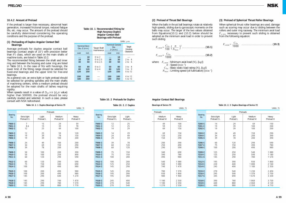
A 98 A 99
PRELOAD
10.4.2 Amount of Preload
If the preload is larger than necessary, abnormal heart generation, increased frictional torque, reduced fatigue life, etc. may occur. The amount of the preload should be carefully determined considering the operating conditions and the purpose of the preload.
(1) Preloading of Duplex Angular Contact BallBearings
Average preloads for duplex angular contact ball bearings (contact angle of 15°) with precision better than P5 class, which are used on the main shafts of machine tools, are listed in Table 10.2.The recommended fitting between the shaft and inner ring and between the housing and outer ring are listed in Table 10.1. In the case of fits with housings, the lower limit of the fitting range should be selected for fixed-end bearings and the upper limit for free-end bearings.As a general rule, an extra light or light preload should be selected for grinding spindles and the main shafts of machining centers, while a medium preload should be adopted for the main shafts of lathes requiring rigidity.When speeds result in a value of Dpw×n (dmn value) higher than 500000, the preload should be very carefully studied and selected. In such a case, please consult with NSK beforehand.
(2) Preload of Thrust Ball Bearings
When the balls in thrust ball bearings rotate at relatively high speeds, sliding due to gyroscopic moments on the balls may occur. The larger of the two values obtained from Equations(10.1) and (10.2) below should be adopted as the minimum axial load in order to prevent such sliding
Fa min= ( )2 . . . . . . . . . . . . . . . . . . . . . . . . (10.1)
Fa min= . . . . . . . . . . . . . . . . . . . . . . . . . . . . . . . . (10.2)
where Fa min : Minimum axial load (N), {kgf} n : Speed (min–1) C0a : Basic static load rating (N), {kgf} Nmax : Limiting speed (oil lubrication) (min–1)
(3) Preload of Spherical Thrust Roller Bearings
When spherical thrust roller bearings are used, damage such as scoring may occur due to sliding between the rollers and outer ring raceway. The minimum axial load Fa min necessary to prevent such sliding is obtained from the following equation:
Fa min= . . . . . . . . . . . . . . . . . . . . . . . . . . . . . . . . (10.3)
C0a1000
C0a1000C0a
100n
Nmax
7900 C 7 15 29 59 7901 C 8.6 15 39 78 7902 C 12 25 49 100
7903 C 12 25 59 120 7904 C 19 39 78 150 7905 C 19 39 100 200
7906 C 24 49 100 200 7907 C 34 69 150 290 7908 C 39 78 200 390
7909 C 50 100 200 390 7910 C 50 100 250 490 7911 C 60 120 290 590
7912 C 60 120 290 590 7913 C 75 150 340 690 7914 C 100 200 490 980
7915 C 100 200 490 980 7916 C 100 200 490 980 7917 C 145 290 640 1 270
7918 C 145 290 740 1 470 7919 C 145 290 780 1 570 7920 C 195 390 880 1 770
BearingNo.
Preloads
Extra lightPreload EL
LightPreload L
MediumPreload M
HeavyPreload H
Table 10. 2. 1 Duplex Bearings of Series 79Units : N
⎯ 18 0 to 2.5 ⎯ 18 ⎯ 18 30 0 to 2.5 18 30 2 to 6 30 50 0 to 2.5 30 50 2 to 6
50 80 0 to 3.5 50 80 3 to 8 80 120 0 to 4.5 80 120 3 to 9 120 150 ⎯ 120 150 4 to 12
150 180 ⎯ 150 180 4 to 12 180 250 ⎯ 180 250 5 to 15
Nominal BoreDia. d (mm)
Nominal OutsideDia.
D (mm)
over incl. over incl.
Target Shaft Interference
Target Housing Clearance
Table 10. 1 Recommended Fitting for High Accuracy Duplex
Angular Contact Ball Bearings with Preload
Units : μm
7000 C 12 25 7001 C 12 25 7002 C 14 29
7003 C 14 29 7004 C 24 49 7005 C 29 59
7006 C 39 78 7007 C 60 120 7008 C 60 120
7009 C 75 150 7010 C 75 150 7011 C 100 200
7012 C 100 200 7013 C 125 250 7014 C 145 290
7015 C 145 290 7016 C 195 390 7017 C 195 390
7018 C 245 490 7019 C 270 540 7020 C 270 540
49 100 59 120 69 150
69 150 120 250 150 290
200 390 250 490 290 590
340 690 390 780 490 980
540 1 080 540 1 080 740 1 470
780 1 570 930 1 860 980 1 960
1 180 2 350 1 180 2 350 1 270 2 550
BearingNo. Extra light
Preload ELLight
Preload LMedium
Preload MHeavy
Preload H
Table 10. 2. 2 DuplexUnits : N
7200 C 14 29 69 150 7201 C 19 39 100 200 7202 C 19 39 100 200
7203 C 24 49 150 290 7204 C 34 69 200 390 7205 C 39 78 200 390
7206 C 60 120 290 590 7207 C 75 150 390 780 7208 C 100 200 490 980
7209 C 125 250 540 1 080 7210 C 125 250 590 1 180 7211 C 145 290 780 1 570
7212 C 195 390 930 1 860 7213 C 220 440 1 080 2 160 7214 C 245 490 1 180 2 350
7215 C 270 540 1 230 2 450 7216 C 295 590 1 370 2 750 7217 C 345 690 1 670 3 330
7218 C 390 780 1 860 3 730 7219 C 440 880 2 060 4 120 7220 C 490 980 2 350 4 710
BearingNo.
Preloads
Extra lightPreload EL
LightPreload L
MediumPreload M
HeavyPreload H
Table 10. 2. 3 Duplex Bearings of Series 72Units : N
Table 10. 2 Preloads for Duplex Angular Contact Ball Bearings
Preloads
Bearings of Series 70
A082-099E.indd 98-99 A082-099E.indd 98-99 11/20/13 4:51:54 PM11/20/13 4:51:54 PM
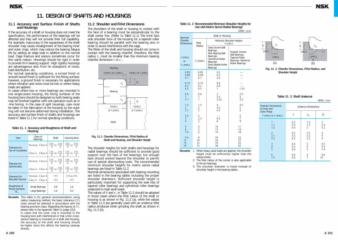
A 100 A 101
11.1 Accuracy and Surface Finish of Shafts and Housings
If the accuracy of a shaft or housing does not meet the specification, the performance of the bearings will be affected and they will not provide their full capability. For example, inaccuracy in the squareness of the shaft shoulder may cause misalignment of the bearing inner and outer rings, which may reduce the bearing fatigue life by adding an edge load in addition to the normal load. Cage fracture and seizure sometimes occur for this same reason. Housings should be rigid in order to provide firm bearing support. High rigidity housings are advantageous also from he standpoint of noise, load distribution, etc.For normal operating conditions, a turned finish or smooth bored finish is sufficient for the fitting surface; however, a ground finish is necessary for applications where vibration and noise must be low or where heavy loads are applied.In cases where two or more bearings are mounted in one single-piece housing, the fitting surfaces of the housing bore should be designed so both bearing seats may be finished together with one operation such as in -line boring. In the case of split housings, care must be taken in the fabrication of the housing so the outer ring will not become deformed during installation. The accuracy and surface finish of shafts and housings are listed in Table 11.1 for normal operating conditions.
11.2 Shoulder and Fillet DimensionsThe shoulders of the shaft or housing in contact with the face of a bearing must be perpendicular to the shaft center line. (Refer to Table 11.1) The front face side shoulder bore of the housing for a tapered roller bearing should be parallel with the bearing axis in order to avoid interference with the cage.The fillets of the shaft and housing should not come in contact with the bearing chamfer; therefore, the fillet radius ra must be smaller than the minimum bearing chamfer dimension r or r1 .
The shoulder heights for both shafts and housings for radial bearings should be sufficient to provide good support over the face of the bearings, but enough face should extend beyond the shoulder to permit use of special dismounting tools. The recommended minimum shoulder heights for metric series radial bearings are listed in Table 11.2Nominal dimensions associated with bearing mounting are listed in the bearing tables including the proper shoulder diameters. Sufficient shoulder height is particularly important for supporting the side ribs of tapered roller bearings and cylindrical roller bearings subjected to high axial loads.The values of h and ra in Table 11.2 should be adopted in those cases where the fillet radius of the shaft or housing is as shown in Fig. 11.2 (a), while the values in Table 11.3 are generally used with an undercut fillet radius produced when grinding the shaft as shown in Fig. 11.2 (b).
11. DESIGN OF SHAFTS AND HOUSINGS
Housing
ra
ra
h
h
Fig. 11.1 Chamfer Dimensions, Fillet Radius ofFig.11.1 Shaft and Housing, and Shoulder Height
Shaft
r(min.) or r1(min.) r(min.) or r1(min.)
Bearing
r(min.)or r1(min.)
r(min.)or r1(min.)
Table 11. 1 Accuracy and Roughness of Shaft and Housing
Remarks This table is for general recommendation using radius measuring method, the basic tolerance (IT) class should be selected in accordance with the bearing precision class. Regarding the figures of IT, please refer to the Appendix Table 11 (page C22).
Remarks In cases that the outer ring is mounted in the housing bore with interference or that a thin cross-section bearing is mounted on a shaft and housing, the accuracy of the shaft and housing should be higher since this affects the bearing raceway directly.
Remarks 1. When heavy axial loads are applied, the shoulder height must be sufficiently higher than the values listed.
Remarks 2. The fillet radius of the corner is also applicable to thrust bearings.
Remarks 3. The shoulder diameter is listed instead of shoulder height in the bearing tables.
ra (max.)
Table 11. 2 Recommended Minimum Shoulder Heights for Use with Metric Series Radial Bearings
Units : mm
0.05 0.05 0.2 — 0.08 0.08 0.3 — 0.1 0.1 0.4 —
0.15 0.15 0.6 — 0.2 0.2 0.8 — 0.3 0.3 1 1.25
0.6 0.6 2 2.5 1 1 2.5 3 1.1 1 3.25 3.5
1.5 1.5 4 4.5 2 2 4.5 5 2.1 2 5.5 6
2.5 2 — 6 3 2.5 6.5 7 4 3 8 9
5 4 10 11 6 5 13 14 7.5 6 16 18
9.5 8 20 22 12 10 24 27 15 12 29 32 19 15 38 42
NominalChamferDimensions
r (min.) orr1 (min.)
Shaft or Housing
Minimun Shoulder Heightsh (min.)Fillet
RadiusDeep Groove Ball Bearings,Self-Aligning Ball Bearings,Cylindrical Roller Bearings,Solid Needle Roller Bearings
Angular ContactBall Bearings,Tapered RollerBearings, Spherical Roller Bearings
(min.)
(min.)
rar
r
h
Fig. 11. 2 Chamfer Dimensions, Fillet Radius, andFig.11. 2 Shoulder Height
(a)
(min.)
(min.)
rgrt
r
b
h
(b)
Table 11. 3 Shaft UndercutUnits : mm
1 0.2 1.3 2 1.1 0.3 1.5 2.4 1.5 0.4 2 3.2
2 0.5 2.5 4 2.1 0.5 2.5 4 2.5 0.5 2.5 4
3 0.5 3 4.7 4 0.5 4 5.9 5 0.6 5 7.4
6 0.6 6 8.6 7.5 0.6 7 10
Chamfer Dimensionsof Inner and Outer Rings
r (min.) or r1 (min.)
Undercut Dimensions
t rg b
Item
Tolerance forOut-of-roundness
Tolerance for Cylindricality
Tolerance for Shoulder Runout
Roughness of Fitting Surfaces
Ra
Class ofBearings
Normal, Class 6
Class 5, Class 4
Normal, Class 6
Class 5, Class 4
Normal, Class 6Class 5, Class 4
Small Bearings
Large Bearings
Shaft
to
to
I T3I T3
0.8
1.6
Housing Bore
I T3 to I T4I T3
1.6
3.2
I T32
I T22
I T42
I T32
to
to
I T42
I T22
I T52
I T32
to
to
I T32
I T22
I T42
I T32
to
to
I T42
I T22
I T52
I T32
A100-125E.indd 100-101 A100-125E.indd 100-101 11/20/13 4:52:18 PM11/20/13 4:52:18 PM
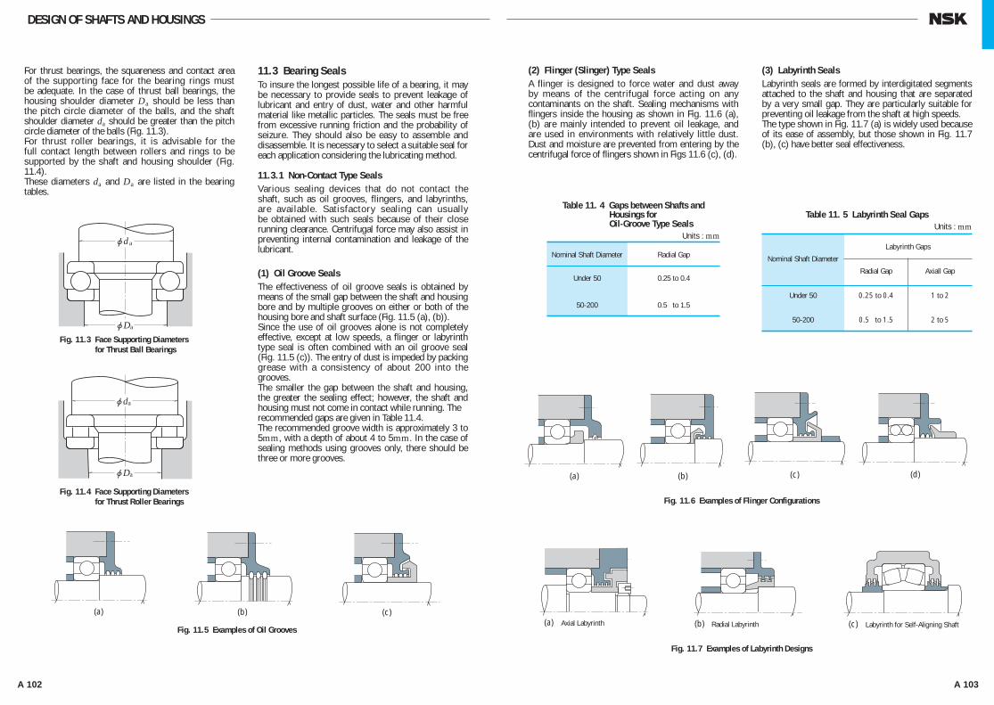
A 102 A 103
DESIGN OF SHAFTS AND HOUSINGS
jd a
jDa
jda
jDa
(a) (b) (c)
Fig. 11.3 Face Supporting Diameters Fig. 11. 3 for Thrust Ball Bearings
Fig. 11.4 Face Supporting Diameters Fig. 11.4 for Thrust Roller Bearings
Fig. 11.5 Examples of Oil Grooves
(a)
(a)
(b) (d)(c)
Axial Labyrinth (b) Radial Labyrinth (c) Labyrinth for Self-Aligning Shaft
Fig. 11.7 Examples of Labyrinth Designs
Fig. 11.6 Examples of Flinger Configurations
(2) Flinger (Slinger) Type SealsA flinger is designed to force water and dust away by means of the centrifugal force acting on any contaminants on the shaft. Sealing mechanisms with flingers inside the housing as shown in Fig. 11.6 (a), (b) are mainly intended to prevent oil leakage, and are used in environments with relatively little dust. Dust and moisture are prevented from entering by the centrifugal force of flingers shown in Figs 11.6 (c), (d).
(3) Labyrinth SealsLabyrinth seals are formed by interdigitated segments attached to the shaft and housing that are separated by a very small gap. They are particularly suitable for preventing oil leakage from the shaft at high speeds.The type shown in Fig. 11.7 (a) is widely used because of its ease of assembly, but those shown in Fig. 11.7 (b), (c) have better seal effectiveness.
For thrust bearings, the squareness and contact area of the supporting face for the bearing rings must be adequate. In the case of thrust ball bearings, the housing shoulder diameter Da should be less than the pitch circle diameter of the balls, and the shaft shoulder diameter da should be greater than the pitch circle diameter of the balls (Fig. 11.3).For thrust roller bearings, it is advisable for the full contact length between rollers and rings to be supported by the shaft and housing shoulder (Fig. 11.4).These diameters da and Da are listed in the bearing tables.
11.3 Bearing SealsTo insure the longest possible life of a bearing, it may be necessary to provide seals to prevent leakage of lubricant and entry of dust, water and other harmful material like metallic particles. The seals must be free from excessive running friction and the probability of seizure. They should also be easy to assemble and disassemble. It is necessary to select a suitable seal for each application considering the lubricating method.
11.3.1 Non-Contact Type SealsVarious sealing devices that do not contact the shaft, such as oil grooves, flingers, and labyrinths, are available. Satisfactory sealing can usually be obtained with such seals because of their close running clearance. Centrifugal force may also assist in preventing internal contamination and leakage of the lubricant.
(1) Oil Groove SealsThe effectiveness of oil groove seals is obtained by means of the small gap between the shaft and housing bore and by multiple grooves on either or both of the housing bore and shaft surface (Fig. 11.5 (a), (b)).Since the use of oil grooves alone is not completely effective, except at low speeds, a flinger or labyrinth type seal is often combined with an oil groove seal (Fig. 11.5 (c)). The entry of dust is impeded by packing grease with a consistency of about 200 into the grooves.The smaller the gap between the shaft and housing, the greater the sealing effect; however, the shaft and housing must not come in contact while running. The recommended gaps are given in Table 11.4.The recommended groove width is approximately 3 to 5mm, with a depth of about 4 to 5mm. In the case of sealing methods using grooves only, there should be three or more grooves.
Table 11. 4 Gaps between Shafts and Housings for Oil-Groove Type Seals
Units : mm
Table 11. 5 Labyrinth Seal GapsUnits : mm
Nominal Shaft Diameter
Labyrinth Gaps
Radial Gap Axiall Gap
Under 50 0.25 to 0.4 1 to 2
50-200 0.5 to 1.5 2 to 5
Nominal Shaft Diameter
Under 50
50-200
Radial Gap
0.25 to 0.4
0.5 to 1.5
A100-125E.indd 102-103 A100-125E.indd 102-103 11/20/13 4:52:20 PM11/20/13 4:52:20 PM

A 104 A 105
(2) Felt SealsFelt seals are one of the simplest and most common seals being used for transmission shafts, etc.However, since oil permeation and leakage are unavoidable if oil is used, this type of seal is used only
for grease lubrication, primarily to prevent dust and other foreign matter from entering. Felt seals are not suitable for circumferential surface speeds exceeding 4 m/sec; therefore, it is preferable to replace them with synthetic rubber seals depending on the application.
12. LUBRICATION
DESIGN OF SHAFTS AND HOUSINGS
11.3.2 Contact Type SealsThe effectiveness of contact seals is achieved by the physical contact between the shaft and seal, which may be made of synthetic rubber, synthetic resin, felt, etc. Oil seals with synthetic rubber lips are most frequently used.
(1) Oil SealsMany types of oil seals are used to prevent lubricant from leaking out as well as to prevent dust, water, and other foreign matter from entering (Figs. 11.8 and 11.9)In Japan, such oil seals are standardized (Refer to JIS B 2402) on the basis of type and size. Since many oil seals are equipped with circumferential springs to maintain adequate contact force, oil seals can follow the non-uniform rotational movement of a shaft to some degree.Seal lip materials are usually synthetic rubber including nitrile, acrylate, silicone, and fluorine. Tetrafluoride ethylene is also used. The maximum allowable operating temperature for each material increases in this same order.Synthetic rubber oil seals may cause trouble such as overheating, wear, and seizure, unless there is an oil film between the seal lip and shaft. Therefore, some lubricant should be applied to the seal lip when the
seals are installed. It is also desirable for the lubricant inside the housing to spread a little between the sliding surfaces. However, please be aware that ester-based grease will cause acrylic rubber material to swell. Also, low aniline point mineral oil, silicone-based grease,and silicon-based oil will cause silicone-based material to swell. Moreover, urea-based grease will cause fluorine-based material to deteriorate.The permissible circumferential speed for oil seals varies depending on the type, the finish of the shaft surface, liquid to be sealed, temperature, shaft eccentricity, etc. The temperature range for oil seals is restricted by the lip material. Approximate circumferential surface speeds and temperature permitted under favorable conditions are listed in Table 11.6.When oil seals are used at high circumferential surface speed or under high internal pressure, the contact surface of the shaft must be smoothly finished and the shaft eccentricity should be less than 0.02 to 0.05 mm.The hardness of the shaft's contact surface should be made higher than HRC40 by means of heat treatment or hard chrome plating in order to gain abrasion resistance. If possible, a hardness of more than HRC 55 is recommended.The approximate level of contact surface finish required for several shaft circumferential surface speeds is given in Table 11.7.
Fig. 11.8 Example of Application Fig. 11 .8 of Oil Seal (1)
Fig. 11.9 Example of Application Fig. 1 1.9 of Oil Seal (2)
Table 11. 6 Permissible Circumferential Surface Speeds and Temperature Range for Oil Seals
Table 11. 7 Shaft Circumferential Surface Speeds and Finish of Contact Surfaces
Under 5 0.8
5 to 10 0.4
Over 10 0.2
Note (1) The upper limit of the temperature range may be raised about 20 °C for operation for short intervais.
Seal MaterialsPermissible
CircumferentialSpeeds(m/sec)
OperatingTemperature
Range(°C)(1)
SyntheticRubber
Tetrafluoride Ethylene Resin Under 15 –50 to +220
Nitrile Rubber
Acrylic Rubber
Silicone Rubber
Fluorine-containes Rubber
Under 16
Under 25
Under 32
Under 32
–25 to +100
–15 to +130
–70 to +200
–30 to +200
Circumferential SurfaceSpeeds(m/s)
Surface FinishRa (µm)
12.1 Purposes of LubricationThe main purposes of lubrication are to reduce friction and wear inside the bearings that may cause premature failure. The effects of lubrication may be briefly explained as follows:
(1) Reduction of Friction and WearDirect metallic contact between the bearing rings, rolling elements and cage, which are the basic components of a bearing, is prevented by an oil film which reduces the friction and wear in the contact areas.(2) Extension of Fatigue LifeThe rolling fatigue life of bearings depends greatly upon the viscosity and film thickness between the rolling contact surfaces. A heavy film thickness prolongs the fatigue life, but it is shortened if the viscosity of the oil is too low so the film thickness is insufficient.(3) Dissipation of Frictional Heat and CoolingCirculation lubrication may be used to carry away frictional heat or heat transferred from the outside to prevent the bearing from overheating and the oil from deteriorating.(4) OthersAdequate lubrication also helps to prevent foreign material from entering the bearings and guards against corrosion or rusting.
12.2 Lubricating MethodsThe various lubricating methods are first divided into either grease or oil lubrication. Satisfactory bearing performance can be achieved by adopting the lubricating method which is most suitable for the particular application and operating condition.In general, oil offers superior lubrication; however, grease lubrication allows a simpler structure around the bearings. A comparison of grease and oil lubrication is given in Table 12.1.
12.2.1 Grease Lubrication(1) Grease QuantityThe quantity of grease to be packed in a housing depends on the housing design and free space, grease characteristics, and ambient temperature. For example, the bearings for the main shafts of machine tools, where the accuracy may be impaired by a small temperature rise, require only a small amount of grease. The quantity of grease for ordinary bearings is determined as follows.Sufficient grease must be packed inside the bearing including the cage guide face. The available space inside the housing to be packed with grease depends on the speed as follows:1/2 to 2/3 of the space … When the speed is less than
50% of the limiting speed.1/3 to 1/2 of the space … When the speed is more than
50% of the limiting speed.
Table 12. 1 Comparison of Grease and Oil Lubrication
Item Grease Lubrication Oil Lubrication
Housing Structure and Sealing Method
Speed
Cooling Effect
Fluidity
Full Lubricant Replacement
Removal of Foreign Matter
ExternalContamination due to Leakage
Simple
Limiting speed is 65% to 80% of that with oil lubrication.
Poor
Poor
Sometimes difficult
Removal of particlesfrom grese is impossible.
Surroundings seldom contaminated by leakage.
May be complex, Careful maintenance required.
Higher limiting speed.
Heat transter is possible using forced oil circulation.
Good
Easy
Easy
Often leaks without proper countermeasures.Not suitable if external contamination must be avoided.
A100-125E.indd 104-105 A100-125E.indd 104-105 11/20/13 4:52:21 PM11/20/13 4:52:21 PM

A 106 A 107
h h
Speed n min–1Speed n min–1
20 000 10 000
8 000
6 0005 0004 000
3 000
2 000
1 000800
600500400
300
200 100
200
300
400500600
800
1 000
2 000
3 000
4 0005 000
7 000
10 000
200 300 400 600 800 1 000 2 000 4 000 6 000 10 000 10 0006 0004 0002 0001 00060040030020010020 000
20 000
10 0008 000
6 0005 0004 000
3 000
2 000
1 000800
600
400
A
AA- A
203040
5060
7080
100120
140160
180220
260300
d=10
30
4050
6070
80100
120140
160200
240280
340420
500
d=20
Fig. 12.1 Combination of Partitioned Grease Fig. 12. 1 Reservoir and Grease Valve
Fig. 12.2 Grease Replenishment Intervals
Radial Ball BearingsCylindrical Roller Bearings
(1) Radial Ball Bearings, Cylindrical Roller Bearings (2) Tapered Roller Bearings, Spherical Roller Bearings
Grea
se R
eple
nish
men
t Int
erva
l, t f
Grea
se R
eple
nish
men
t Int
erva
l, t f
(3) Load factor P/C ≤0.06 0.1 0.13 0.16
Load factor 1.5 1 0.65 0.45
h
n/Nmax
150 000
100 000
50 000
20 000
10 000
5 000
3 000
2 000
1 000
500
2000.25 0.3 0.4 0.5 0.6 0.7 0.8 0.9 1
8080 9090 100100
110
110120
130
T=70T=70
Fig. 12.3 Grease Life of Sealed Ball BearingsFig. 12.5 Drip FeedFig. 12.5 LubricationFig. 12.4 Oil Bath Lubrication
Aver
age
grea
se li
fe, t
General purpose greaseWide-range grease
(4) Grease Life of Sealed Ball BearingsWhen grease is packed into single-row deep groove ball bearings, the grease life may be estimated using Equation (12.1) or (12.2) or Fig. 12.3:(General purpose grease (1))
log t = 6.54 – 2.6 n
Nmax – (0.025 – 0.012
nNmax )T
……………………(12.1)(Wide-range grease (2))
log t = 6.12 – 1.4 nNmax
– (0.018 – 0.006 n
Nmax )T ……………………(12.2)
where t : Average grease life, (h) n : Speed (min–1) Nmax : Limiting speed with grease lubrication
(min–1) (values for ZZ and VV types listed in the
bearing tables) T : Operating temperature °CEquations (12.1) and (12.2) and Fig. 12.3 apply under the following conditions:(a) Speed, n
0.25 ≤ n
Nmax ≤ 1
when n
Nmax <0.25, assume n
Nmax = 0.25
(b) Operating Temperature, TFor general purpose grease (1) 70 °C≤T≤110 °C
For wide-range grease (2)
70 °C≤T≤130 °C
When T<70 °C assume T = 70 °C
(c) Bearing LoadsThe bearing loads should be about 1/10 or less of the basic load rating Cr. Notes (1) Mineral-oil base greases (e.g. lithium soap
base grease) which are often used over a temperature range of around – 10 to 110 °C.
Notes (2) Synthetic-oil base greases are usable over a wide temperature range of around – 40 to 130 °C.
12.2.2 Oil Lubrication(1) Oil Bath LubricationOil bath lubrication is a widely used with low or medium speeds. The oil level should be at the center of the lowest rolling element. It is desirable to provide a sight gauge so the proper oil level may be maintained (Fig. 12.4)
(2) Drip-Feed LubricationDrip feed lubrication is widely used for small ball bearings operated at relatively high speeds. As shown in Fig. 12.5, oil is stored in a visible oiler. The oil drip rate is controlled with the screw in the top.
(2) Replacement of GreaseGrease, once packed, usually need not be replenished for a long time; however, for severe operating conditions, grease should be frequently replenished or replaced. In such cases, the bearing housing should be designed to facilitate grease replenishment and replacement.When replenishment intervals are short, provide replenishment and discharge ports at appropriate positions so deteriorated grease is replaced by fresh grease. For example, the housing space on the grease supply side can be divided into several sections with partitions. The grease on the partitioned side gradually passes through the bearings and old grease forced from the bearing is discharged through a grease valve (Fig. 12.1). If a grease valve is not used, the space on
the discharge side is made larger than the partitioned side so it can retain the old grease, which is removed periodically by removing the cover.
(3) Replenishing IntervalEven if high-quality grease is used, there is deterioration of its properties with time; therefore, periodic replenishment is required. Figs 12.2 (1) and (2) show the replenishment time intervals for various bearing types running at different speeds. Figs.12.2 (1) and (2) apply for the condition of high-quality lithium soap-mineral oil grease, bearing temperature of 70°C, and normal load (P/C=0.1).· TemperatureIf the bearing temperature exceeds 70°C, the replenishment time interval must be reduced by half for every 15°C temperature rise of the bearings.· GreaseIn case of ball bearings especially, the replenishing time interval can be extended depending on used grease type. (For example, high-quality lithium soap-synthetic oil grease may extend about two times of replenishing time interval shown in Fig.12.2 (1). If the temperature of the bearings is less than 70°C, the usage of lithium soap-mineral oil grease or lithium soap-synthetic oil grease is appropriate.)It is advisable to consult NSK.· LoadThe replenishing time interval depends on the magnitude of the bearing load.Please refer to Fig.12.2 (3).If P/C exceeds 0.16, it is advisable to consult NSK.
LUBRICATION
A100-125E.indd 106-107 A100-125E.indd 106-107 11/20/13 4:52:22 PM11/20/13 4:52:22 PM
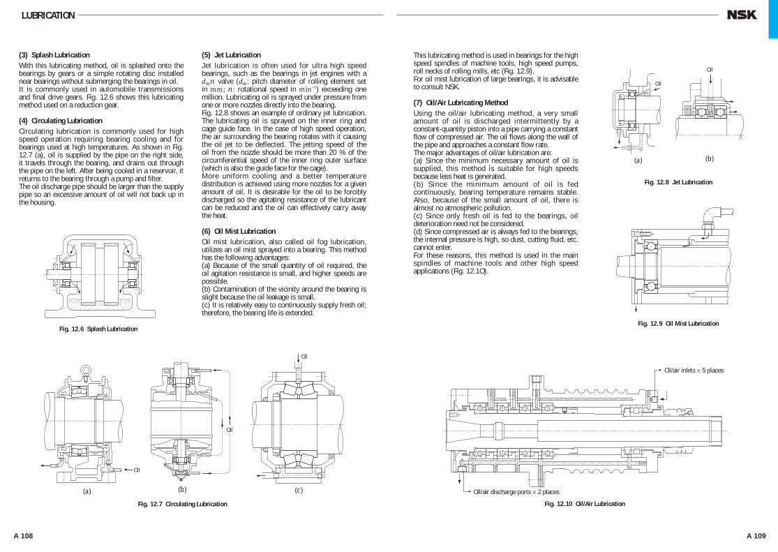
A 108 A 109
(a) (b) (c)
Fig. 12.6 Splash Lubrication
Fig. 12.7 Circulating Lubrication
Oil
Oil
Oil
(a) (b)
Fig. 12.8 Jet Lubrication
Fig. 12.9 Oil Mist Lubrication
Fig. 12.10 Oil/Air Lubrication
Oil/air discharge ports × 2 places
Oil/air inlets × 5 places
Oil
Oil
This lubricating method is used in bearings for the high speed spindles of machine tools, high speed pumps, roll necks of rolling mills, etc (Fig. 12.9).For oil mist lubrication of large bearings, it is advisable to consult NSK.
(7) Oil/Air Lubricating MethodUsing the oil/air lubricating method, a very small amount of oil is discharged intermittently by a constant-quantity piston into a pipe carrying a constant flow of compressed air. The oil flows along the wall of the pipe and approaches a constant flow rate.The major advantages of oil/air lubrication are:(a) Since the minimum necessary amount of oil is supplied, this method is suitable for high speeds because less heat is generated.(b) Since the minimum amount of oil is fed continuously, bearing temperature remains stable. Also, because of the small amount of oil, there is almost no atmospheric pollution.(c) Since only fresh oil is fed to the bearings, oil deterioration need not be considered.(d) Since compressed air is always fed to the bearings, the internal pressure is high, so dust, cutting fluid, etc. cannot enter.For these reasons, this method is used in the main spindles of machine tools and other high speed applications (Fig. 12.1O).
(3) Splash LubricationWith this lubricating method, oil is splashed onto the bearings by gears or a simple rotating disc installed near bearings without submerging the bearings in oil.It is commonly used in automobile transmissions and final drive gears. Fig. 12.6 shows this lubricating method used on a reduction gear.
(4) Circulating LubricationCirculating lubrication is commonly used for high speed operation requiring bearing cooling and for bearings used at high temperatures. As shown in Fig. 12.7 (a), oil is supplied by the pipe on the right side, it travels through the bearing, and drains out through the pipe on the left. After being cooled in a reservoir, it returns to the bearing through a pump and filter.The oil discharge pipe should be larger than the supply pipe so an excessive amount of oil will not back up in the housing.
(5) Jet LubricationJet lubrication is often used for ultra high speed bearings, such as the bearings in jet engines with a dmn valve (dm: pitch diameter of rolling element set in mm; n: rotational speed in min–1) exceeding one million. Lubricating oil is sprayed under pressure from one or more nozzles directly into the bearing.Fig. 12.8 shows an example of ordinary jet lubrication. The lubricating oil is sprayed on the inner ring and cage guide face. In the case of high speed operation, the air surrounding the bearing rotates with it causing the oil jet to be deflected. The jetting speed of the oil from the nozzle should be more than 20 % of the circumferential speed of the inner ring outer surface (which is also the guide face for the cage).More uniform cooling and a better temperature distribution is achieved using more nozzles for a given amount of oil. It is desirable for the oil to be forcibly discharged so the agitating resistance of the lubricant can be reduced and the oil can effectively carry away the heat.
(6) Oil Mist LubricationOil mist lubrication, also called oil fog lubrication, utilizes an oil mist sprayed into a bearing. This method has the following advantages:(a) Because of the small quantity of oil required, the oil agitation resistance is small, and higher speeds are possible.(b) Contamination of the vicinity around the bearing is slight because the oil leakage is small.(c) It is relatively easy to continuously supply fresh oil; therefore, the bearing life is extended.
LUBRICATION
A100-125E.indd 108-109 A100-125E.indd 108-109 11/20/13 4:52:23 PM11/20/13 4:52:23 PM
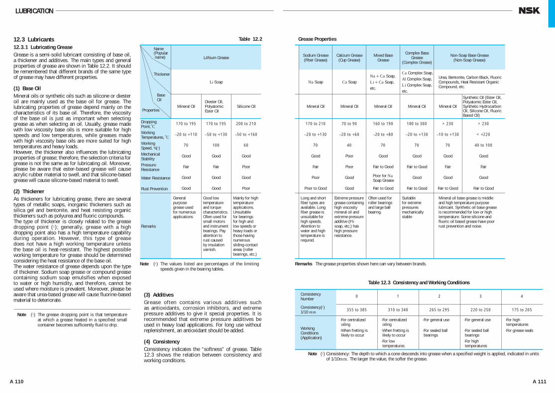
A 110 A 111
12.3 Lubricants12.3.1 Lubricating GreaseGrease is a semi-solid lubricant consisting of base oil, a thickener and additives. The main types and general properties of grease are shown in Table 12.2. It should be remembered that different brands of the same type of grease may have different properties.
(1) Base OilMineral oils or synthetic oils such as silicone or diester oil are mainly used as the base oil for grease. The lubricating properties of grease depend mainly on the characteristics of its base oil. Therefore, the viscosity of the base oil is just as important when selecting grease as when selecting an oil. Usually, grease made with low viscosity base oils is more suitable for high speeds and low temperatures, while greases made with high viscosity base oils are more suited for high temperatures and heavy loads.However, the thickener also influences the lubricating properties of grease; therefore, the selection criteria for grease is not the same as for lubricating oil. Moreover, please be aware that ester-based grease will cause acrylic rubber material to swell, and that silicone-based grease will cause silicone-based material to swell.
(2) ThickenerAs thickeners for lubricating grease, there are several types of metallic soaps, inorganic thickeners such as silica gel and bentonite, and heat resisting organic thickeners such as polyurea and fluoric compounds.The type of thickener is closely related to the grease dropping point (1); generally, grease with a high dropping point also has a high temperature capability during operation. However, this type of grease does not have a high working temperature unless the base oil is heat-resistant. The highest possible working temperature for grease should be determined considering the heat resistance of the base oil.The water resistance of grease depends upon the type of thickener. Sodium soap grease or compound grease containing sodium soap emulsifies when exposed to water or high humidity, and therefore, cannot be used where moisture is prevalent. Moreover, please be aware that urea-based grease will cause fluorine-based material to deteriorate.
(3) AdditivesGrease often contains various additives such as antioxidants, corrosion inhibitors, and extreme pressure additives to give it special properties. It is recommended that extreme pressure additives be used in heavy load applications. For long use without replenishment, an antioxidant should be added.
(4) ConsistencyConsistency indicates the “softness” of grease. Table 12.3 shows the relation between consistency and working conditions.
Note (1) The grease dropping point is that temperature at which a grease heated in a specified small container becomes sufficiently fluid to drip.
Lithium Grease Sodium Grease (Fiber Grease)
Calcium Grease (Cup Grease)
Mixed BaseGrease
Complex Base Grease
(Complex Grease)
Non-Soap Base Grease(Non-Soap Grease)
Li Soap Na Soap Ca SoapNa + Ca Soap,Li + Ca Soap,etc.
Ca Complex Soap,Al Complex Soap,Li Complex Soap,etc.
Urea, Bentonite, Carbon Black, Fluoric Compounds, Heat Resistant Organic Compound, etc.
Mineral Oil Properties
Diester Oil, Polyatomic Ester Oil
Silicone Oil Mineral Oil Mineral Oil Mineral Oil Mineral Oil Mineral Oil
Synthetic Oil (Ester Oil, Polyatomic Ester Oil, Synthetic Hydrocarbon Oil, Silicone Oil, Fluoric Based Oil)
170 to 195 170 to 195 200 to 210 170 to 210 70 to 90 160 to 190 180 to 300 > 230 > 230
–20 to +110 –50 to +130 –50 to +160 –20 to +130 –20 to +60 –20 to +80 –20 to +130 –10 to +130 < +220
70 100 60 70 40 70 70 70 40 to 100
Good Good Good Good Poor Good Good Good Good
Fair Fair Poor Fair Poor Fair to Good Fair to Good Fair Fair
Good Good Good Poor Good Good Good Good
Good Good Poor Poor to Good Good Fair to Good Fair to Good Fair to Good Fair to Good
Remarks
General purpose grease used for numerous applications
Good low temperature and torque characteristics. Often used for small motors and instrument bearings. Pay attention to rust caused by insulation varnish.
Mainly for high temperature applications. Unsuitable for bearings for high and low speeds or heavy loads or those having numerous sliding-contact areas (roller bearings, etc.)
Long and short fiber types are available. Long fiber grease is unsuitable for high speeds. Attention to water and high temperature is requred.
Extreme pressure grease containing high viscosity mineral oil and extreme pressure additive (Pb soap, etc.) has high pressure resistance.
Often used for roller bearings and large ball bearing.
Suitable for extreme pressures mechanically stable
Mineral oil base grease is middle and high temperature purpose lubricant. Synthetic oil base grease is recommended for low or high temperature. Some silicone and fluoric oil based grease have poor rust prevention and noise.
Table 12.2 Grease Properties
Note (1) The values listed are percentages of the limiting speeds given in the bearing tables.
Remarks The grease properties shown here can vary between brands.
Note (1) Consistency: The depth to which a cone descends into grease when a specified weight is applied, indicated in units of 1/10mm. The larger the value, the softer the grease.
Table 12.3 Consistency and Working Conditions
0 1 2 3 4
355 to 385 310 to 340 265 to 295 220 to 250 175 to 205
WorkingConditions(Application)
· For centralized oiling· When fretting is likely to occur
· For centralized oiling
· When fretting is likely to occur
· For low temperatures
· For general use
· For sealed ball bearings
· For general use
· For sealed ball bearings
· For high temperatures
· For high temperatures· For grease seals
LUBRICATION
Name(Popular name)
Thickener
BaseOil
Dropping Point,°CWorking Temperatures, °CWorking Speed, %(1)Mechanical StabilityPressure Resistance
Water Resistance Poor for Na Soap Grease
Rust Prevention
Consistency Number
Consistency(1) 1/10 mm
A100-125E.indd 110-111 A100-125E.indd 110-111 11/20/13 4:52:24 PM11/20/13 4:52:24 PM

A 112 A 113
Oil Replacement IntervalsOil replacement intervals depend on the operating conditions and oil quantity.In those cases where the operating temperature is less than 50˚C, and the environmental conditions are good with little dust, the oil should be replaced approximately once a year. However, in cases where the oil temperature is about 100˚C, the oil must be changed at least once every three months.
If moisture may enter or if foreign matter may be mixed in the oil, then the oil replacement interval must be shortened.Mixing different brands of oil must be prevented for the same reason given previously for grease.
(5) Mixing Different Types of GreaseIn general, different brands of grease must not be mixed. Mixing grease with different types of thickneners may destroy its composition and physical properties. Even if the thickeners are of the same type, possible differences in the additive may cause detrimental effects.
12.3.2 Lubricating OilThe lubricating oils used for rolling bearings are usually highly refined mineral oil or synthetic oil that have a high oil film strength and superior oxidation and corrosion resistance. When selecting a lubricating oil, the viscosity at the operating conditions is important. If the viscosity is too low, a proper oil film is not formed and abnormal wear and seizure may occur. On the other hand, if the viscosity is too high, excessive viscous resistance may cause heating or large power loss. In general, low viscosity oils should be used at high speed; however, the viscosity should increase
with increasing bearing load and size.Table 12.4 gives generally recommended viscosities for bearings under normal operating conditions.For use when selecting the proper lubricating oil, Fig. 12.11 shows the relationship between oil temperature and viscosity, and examples of selection are shown in Table 12.5.
A B C D E F G H J K L M N
ABCDEFG
:::::::
VG 7VG 10VG 15VG 22VG 32VG 46VG 68
HJKLMN
::::::
VG 100VG 150VG 220VG 320VG 460VG 680
-20
-20
0
5 000
2 0001 000
500
300200
10080
6050
40
5 0002 0001 000
500300200
100
50403020
10
54
2 0001 000
500300200
10080
60
50
40
0
20
20
40
40
60
60
80
80
100
100 120 160 200 240 280 320
120 140 160
mm2/s
Fig. 12.11 Temperature-Viscosity Chart
ISO Viscosity Grade assumed V.I.80
Redwood(Seconds)
Saybolt(Seconds)
Visc
osity
Temperature
°C
°F
Table 12. 4 Bearing Types and Proper Viscosity of Lubricating Oils
Remarks 1mm2/s=1cSt (centistokes)
Remarks 1. For the limiting speed, use the values listed in the bearing tables.Remarks 2. Refer to Refrigerating Machine Oils (JIS K 2211), Bearing Oils (JIS K 2239), Turbine Oils (JIS K
2213), Gear Oils (JIS K 2219).Remarks 3. If the operating temperature is near the high end of the temperature range listed in the left column,
select a high viscosity oil.Remarks 4. If the operating temperature is lower than -30°C or higher than 110°C , it is advisable to consult
NSK.
Table 12. 5 Examples of Selection Lubricating Oils
LUBRICATION
Proper Viscosityat OperatingTemperature
Bearing Type
Ball Bearings and Higher than 13mm2/s Cylindrical Roller Bearings
Tapered Roller Bearings and Higher than 20mm2/s Spherical Roller Bearings
Spherical Thrust Roller Bearings Higher than 32mm2/s
OperatingTemperature Speed Light or normal Load Heavy or Shock Load
− 30 to 0 °C Less than limiting speed ISO VG 15, 22, 32 ( refrigerating machine oil)
−
0 to 50 °C
Less than 50% of limiting speed
50 to 100% of limiting speed
More than limiting speed
ISO VG 32, 46, 68 ( bearing oil, turbine oil)
ISO VG 15, 22, 32 ( bearing oil, turbine oil)
ISO VG 10, 15, 22 (bearing oil)
ISO VG 46, 68, 100 ( bearing oil,turbine oil)
ISO VG 22, 32, 46 ( bearing oil, turbine oil)
−
50 to 80 °C
Less than 50% of limiting speed
50 to 100% of limiting speed
More than limiting speed
ISO VG 100, 150, 220 (bearings oil)
ISO VG 46, 68, 100 ( bearing oil, turbine oil)
ISO VG 32, 46, 68 ( bearing oil, turbine oil)
ISO VG 150, 220, 320 ( bearing oil)
ISO VG 68, 100, 150 ( bearing oil, turbine oil)
−
80 to 110 °C
Less than 50% of limiting speed
50 to 100% of limiting speed
More than limiting speed
ISO VG 320, 460 (bearing oil)
ISO VG 150, 220 (bearing oil)
ISO VG 68, 100 ( bearing oil, turbine oil)
ISO VG 460, 680 ( bearing oil, gear oil)
ISO VG 220, 320 (bearing oil)
−
A100-125E.indd 112-113 A100-125E.indd 112-113 11/20/13 4:52:25 PM11/20/13 4:52:25 PM
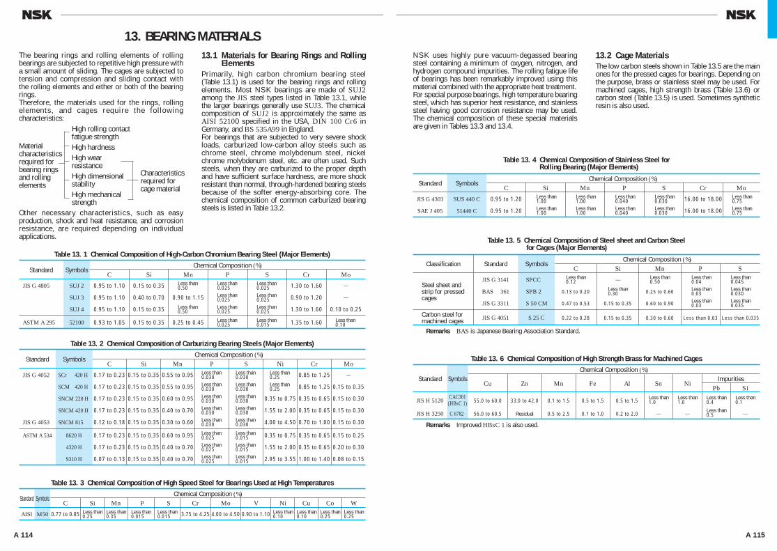
A 114 A 115
NSK uses highly pure vacuum-degassed bearing steel containing a minimum of oxygen, nitrogen, and hydrogen compound impurities. The rolling fatigue life of bearings has been remarkably improved using this material combined with the appropriate heat treatment.For special purpose bearings, high temperature bearing steel, which has superior heat resistance, and stainless steel having good corrosion resistance may be used. The chemical composition of these special materials are given in Tables 13.3 and 13.4.
13.2 Cage MaterialsThe low carbon steels shown in Table 13.5 are the main ones for the pressed cages for bearings. Depending on the purpose, brass or stainless steel may be used. For machined cages, high strength brass (Table 13.6) or carbon steel (Table 13.5) is used. Sometimes synthetic resin is also used.
The bearing rings and rolling elements of rolling bearings are subjected to repetitive high pressure with a small amount of sliding. The cages are subjected to tension and compression and sliding contact with the rolling elements and either or both of the bearing rings.Therefore, the materials used for the rings, rolling e lements, and cages require the fo l lowing characteristics:
Other necessary characteristics, such as easy production, shock and heat resistance, and corrosion resistance, are required depending on individual applications.
13.1 Materials for Bearing Rings and Rolling Elements
Primarily, high carbon chromium bearing steel (Table 13.1) is used for the bearing rings and rolling elements. Most NSK bearings are made of SUJ2 among the JIS steel types listed in Table 13.1, while the larger bearings generally use SUJ3. The chemical composition of SUJ2 is approximately the same as AISI 52100 specified in the USA, DIN 100 Cr6 in Germany, and BS 535A99 in England.For bearings that are subjected to very severe shock loads, carburized low-carbon alloy steels such as chrome steel, chrome molybdenum steel, nickel chrome molybdenum steel, etc. are often used. Such steels, when they are carburized to the proper depth and have sufficient surface hardness, are more shock resistant than normal, through-hardened bearing steels because of the softer energy-absorbing core. The chemical composition of common carburized bearing steels is listed in Table 13.2.
13. BEARING MATERIALS
Material characteristics required for bearing rings and rolling elements
High rolling contact fatigue strengthHigh hardnessHigh wear resistanceHigh dimensional stabilityHigh mechanical strength
Impurities Pb Si
Table 13. 6 Chemical Composition of High Strength Brass for Machined CagesChemical Composition (%)
Standard Symbols Cu Zn Mn Fe Al Sn Ni
JIS H 5120 55.0 to 60.0 33.0 to 42.0 0.1 to 1.5 0.5 to 1.5 0.5 to 1.5
JIS H 3250 C 6782 56.0 to 60.5 Residual 0.5 to 2.5 0.1 to 1.0 0.2 to 2.0 − − −
Remarks Improved HBsC 1 is also used.
Characteristics required for cage material
Table 13. 1 Chemical Composition of High-Carbon Chromium Bearing Steel (Major Elements)Chemical Composition (%)
Standard Symbols C Si Mn P S Cr Mo
JIS G 4805 SUJ 2 0.95 to 1.10 0.15 to 0.35 1.30 to 1.60 −
SUJ 3 0.95 to 1.10 0.40 to 0.70 0.90 to 1.15 0.90 to 1.20 −
SUJ 4 0.95 to 1.10 0.15 to 0.35 1.30 to 1.60 0.10 to 0.25
ASTM A 295 52100 0.93 to 1.05 0.15 to 0.35 0.25 to 0.45 1.35 to 1.60
Less than0.50
Less than0.025Less than0.025Less than0.025
Less than0.025
Less than0.025Less than0.025Less than0.025
Less than0.015
Less than0.10
Less than0.50
Less than0.25Less than0.25
Table 13. 2 Chemical Composition of Carburizing Bearing Steels (Major Elements)Chemical Composition (%)
Standard Symbols C Si Mn P S Ni Cr Mo
JIS G 4052 SCr 420 H 0.17 to 0.23 0.15 to 0.35 0.55 to 0.95 0.85 to 1.25 −
SCM 420 H 0.17 to 0.23 0.15 to 0.35 0.55 to 0.95 0.85 to 1.25 0.15 to 0.35
SNCM 220 H 0.17 to 0.23 0.15 to 0.35 0.60 to 0.95 0.35 to 0.75 0.35 to 0.65 0.15 to 0.30
SNCM 420 H 0.17 to 0.23 0.15 to 0.35 0.40 to 0.70 1.55 to 2.00 0.35 to 0.65 0.15 to 0.30
JIS G 4053 SNCM 815 0.12 to 0.18 0.15 to 0.35 0.30 to 0.60 4.00 to 4.50 0.70 to 1.00 0.15 to 0.30
ASTM A 534 8620 H 0.17 to 0.23 0.15 to 0.35 0.60 to 0.95 0.35 to 0.75 0.35 to 0.65 0.15 to 0.25
4320 H 0.17 to 0.23 0.15 to 0.35 0.40 to 0.70 1.55 to 2.00 0.35 to 0.65 0.20 to 0.30
9310 H 0.07 to 0.13 0.15 to 0.35 0.40 to 0.70 2.95 to 3.55 1.00 to 1.40 0.08 to 0.15
Less than0.030Less than0.030Less than0.030Less than0.030Less than0.030
Less than0.025Less than0.025Less than0.025
Less than0.030Less than0.030Less than0.030Less than0.030Less than0.030
Less than0.015Less than0.015Less than0.015
Table 13. 3 Chemical Composition of High Speed Steel for Bearings Used at High TemperaturesChemical Composition (%)
Standard Symbols C Si Mn P S Cr Mo V Ni Cu Co W
AISI M50 0.77 to 0.85 3.75 to 4.25 4.00 to 4.50 0.90 to 1.10 Less than0.25
Less than0.35
Less than0.015
Less than0.015
Less than0.10
Less than0.10
Less than0.25
Less than0.25
Table 13. 5 Chemical Composition of Steel sheet and Carbon Steelfor Cages (Major Elements)
Chemical Composition (%)Classification Standard Symbols
C Si Mn P S
JIS G 3141 SPCC −
BAS 361 SPB 2 0.13 to 0.20 0.25 to 0.60
JIS G 3311 S 50 CM 0.47 to 0.53 0.15 to 0.35 0.60 to 0.90
JIS G 4051 S 25 C 0.22 to 0.28 0.15 to 0.35 0.30 to 0.60 Less than 0.03 Less than 0.035
Remarks BAS is Japanese Bearing Association Standard.
Steel sheet andstrip for pressedcages
Carbon steel formachined cages
Less than0.12
Less than0.30
Less than0.50
Less than0.04Less than0.03Less than0.03
Less than0.045Less than0.030Less than0.035
Table 13. 4 Chemical Composition of Stainless Steel forRolling Bearing (Major Elements)
Chemical Composition (%)Standard Symbols
C Si Mn P S Cr Mo
JIS G 4303 SUS 440 C 0.95 to 1.20 16.00 to 18.00
SAE J 405 51440 C 0.95 to 1.20 16.00 to 18.00
Less than1.00Less than1.00
Less than1.00Less than1.00
Less than0.040Less than0.040
Less than0.030Less than0.030
Less than0.75Less than0.75
Less than0.5
Less than0.4
Less than1.0
Less than1.0
Less than0.1
CAC301(HBsC 1)
A100-125E.indd 114-115 A100-125E.indd 114-115 11/20/13 4:52:26 PM11/20/13 4:52:26 PM
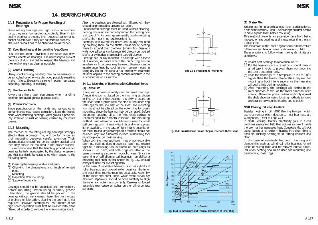
A 116 A 117
(2) Shrink FitsSince press fitting large bearings requires a large force, a shrink fit is widely used. The bearings are first heated in oil to expand them before mounting.This method prevents an excessive force from being imposed on the bearings and allows mounting them in a short time.The expansion of the inner ring for various temperature differences and bearing sizes is shown in Fig. 14.3.The precautions to follow when making shrink fits are as follows:
(a) Do not heat bearings to more than 120˚C.(b) Put the bearings on a wire net or suspend them in
an oil tank in order to prevent them from touching the tank's bottom directly.
(c) Heat the bearings to a temperature 20 to 30˚C higher than the lowest temperature required for mounting without interference since the inner ring will cool a little during mounting.
(d) After mounting, the bearings will shrink in the axial direction as well as the radial direction while cooling. Therefore, press the bearing firmly against the shaft shoulder using locating methods to avoid a clearance between the bearing and shoulder.
NSK Bearing Induction HeatersBesides heating in oil, NSK Bearing Heaters, which use electromagnetic induction to heat bearings, are widely used. (Refer to Page C7.)In NSK Bearing Heaters, electricity (AC) in a coil produces a magnetic field that induces a current inside the bearing that generates heat. Consequently, without using flames or oil uniform heating in a short time is possible, making bearing shrink fitting efficient and clean.In the case of relatively frequent mounting and dismounting such as cylindrical roller bearings for roll necks of rolling mills and for railway journal boxes, induction heating should be used for mounting and dismounting inner rings.
14.1 Precautions for Proper Handling of Bearings
Since rolling bearings are high precision machine parts, they must be handled accordingly. Even if high quality bearings are used, their expected performance cannot be achieved if they are not handled properly.The main precautions to be observed are as follows:
(1) Keep Bearings and Surrounding Area CleanDust and dirt, even if invisible to the naked eye, have harmful effects on bearings. It is necessary to prevent the entry of dust and dirt by keeping the bearings and their environment as clean as possible.
(2) Careful HandlingHeavy shocks during handling may cause bearings to be scratched or otherwise damaged possibly resulting in their failure. Excessively strong impacts may cause brinelling, breaking, or cracking.
(3) Use Proper ToolsAlways use the proper equipment when handling bearings and avoid general purpose tools.
(4) Prevent CorrosionSince perspiration on the hands and various other contaminants may cause corrosion, keep the hands clean when handling bearings. Wear gloves if possible. Pay attention to rust of bearing caused by corrosive gasses.
14.2 MountingThe method of mounting rolling bearings strongly affects their accuracy, life, and performance, so their mounting deserves careful attention. Their characteristics should first be thoroughly studied, and then they should be mounted in the proper manner. It is recommended that the handling procedures for bearings be fully investigated by the design engineers and that standards be established with respect to the following items:
(1) Cleaning the bearings and related parts.(2) Checking the dimensions and finish of related
parts.(3) Mounting(4) Inspection after mounting.(5) Supply of lubricants.
Bearings should not be unpacked until immediately before mounting. When using ordinary grease lubrication, the grease should be packed in the bearings without first cleaning them. Even in the case of ordinary oil lubrication, cleaning the bearings is not required. However, bearings for instruments or for high speed operation must first be cleaned with clean filtered oil in order to remove the anti-corrosion agent.
After the bearings are cleaned with filtered oil, they should be protected to prevent corrosion.Prelubricated bearings must be used without cleaning. Bearing mounting methods depend on the bearing type and type of fit. As bearings are usually used on rotating shafts, the inner rings require a tight fit.Bearings with cylindrical bores are usually mounted by pressing them on the shafts (press fit) or heating them to expand their diameter (shrink fit). Bearings with tapered bores can be mounted directly on tapered shafts or cylindrical shafts using tapered sleeves.Bearings are usually mounted in housings with a loose fit. However, in cases where the outer ring has an interference fit, a press may be used. Bearings can be interference-fitted by cooling them before mounting using dry ice. In this case, a rust preventive treatment must be applied to the bearing because moisture in the air condenses on its surface.
14.2.1 Mounting of Bearings with Cylindrical Bores(1) Press FitsFitting with a press is widely used for small bearings. A mounting tool is placed on the inner ring as shown in Fig. 14.1 and the bearing is slowly pressed on the shaft with a press until the side of the inner ring rests against the shoulder of the shaft. The mounting tool must not be placed on the outer ring for press mounting, since the bearing may be damaged. Before mounting, applying oil to the fitted shaft surface is recommended for smooth insertion. The mounting method using a hammer should only be used for small ball bearings with minimally tight fits and when a press is not available. In the case of tight interference fits or for medium and large bearings, this method should not be used. Any time a hammer is used, a mounting tool must be placed on the inner ring.When both the inner and outer rings of non-separable bearings, such as deep groove ball bearings, require tight-fit, a mounting tool is placed on both rings as shown in Fig. 14.2, and both rings are fitted at the same time using a screw or hydraulic press. Since the outer ring of self-aligning ball bearings may deflect a mounting tool such as that shown in Fig. 14.2 should always be used for mounting them.In the case of separable bearings, such as cylindrical roller bearings and tapered roller bearings, the inner and outer rings may be mounted separately. Assembly of the inner and outer rings, which were previously mounted separately, should be done carefully to align the inner and outer rings correctly. Careless or forced assembly may cause scratches on the rolling contact surfaces.
14. BEARING HANDLING
240
220
200
180
160
140
120
100
80
60
40
2080 120 180 250 315 400 500
mm
μm
k5
j5
m5
n6
p6
r6
&T
= 80 °C
70 °C
60 °C
50 °C
40 °C
30 °C
20 °C
Fig. 14.1 Press Fitting Inner Ring
Fig. 14.2 Simultaneous Press Fitting of Inner and Outer Rings
Fig. 14.3 Temperature and Thermal Expansion of Inner Ring
Tem
pera
ture
Diff
eren
ce
Bore Diameter
Bore
Exp
ansi
on
A100-125E.indd 116-117 A100-125E.indd 116-117 11/20/13 4:52:27 PM11/20/13 4:52:27 PM

A 118 A 119
Large machines, which cannot be turned by hand, can be started after examination with no load, and the power immediately cutoff and the machine allowed to coast to a stop. Confirm that there is no abnormality such as vibration, noise, contact of rotating parts, etc.Powered operation should be started slowly without load and the operation should be observed carefully until it is determined that no abnormalities exist, then gradually increase the speed, load, etc. to their normal levels. Items to be checked during the test operation include the existence of abnormal noise, excessive rise of bearing temperature, leakage and contamination of lubricants, etc. If any abnormality is found during the test operation, it must be stopped immediately and the machine should be inspected. If necessary, the bearing should be dismounted for examination.
14.2.2 Mounting of Bearings with Tapered BoresBearings with tapered bores are mounted on tapered shafts directly or on cylindrical shafts with adapters or withdrawal sleeves (Figs. 14.4 and 14.5). Large spherical roller bearings are often mounted using hydraulic pressure. Fig. 14.6 shows a bearing mounting utilizing a sleeve and hydraulic nut. Fig. 14.7 shows another mounting method. Holes are drilled in the sleeve which are used to feed oil under pressure to the bearing seat. As the bearing expands radially, the sleeve is inserted axially with adjusting bolts.Spherical roller bearings should be mounted while checking their radial-clearance reduction and referring to the push-in amounts listed in Table 14.1. The radial clearance must be measured using clearance gauges.In this measurement, as shown in Fig. 14.8, the clearance for both rows of rollers must be measured simultaneously, and these two values should be kept roughly the same by adjusting the relative position of the outer and inner rings.When a large bearing is mounted on a shaft, the outer ring may be deformed into an oval shape by its own weight. If the clearance is measured at the lowest part of the deformed bearing, the measured value may be bigger than the true value. If an incorrect radial internal clearance is obtained in this manner and the values in Table 14.1 are used, then the interference fit may
become too tight and the true residual clearance may become too small. In this case, as shown in Fig. 14.9. one half of the total clearance at points and b (which are on a horizontal line passing through the bearing center) and c (which is at the lowest position of the bearing) may be used as the residual clearance.When a self-aligning ball bearing is mounted on a shaft with an adapter, be sure that the residual clearance does not become too small. Sufficient clearance for easy alignment of the outer ring must be allowed.
14.3 Operation InspectionAfter the mounting has been completed, a running test should be conducted to determine if the bearing has been mounted correctly. Small machines may be manually operated to assure that they rotate smoothly.Items to be checked include sticking due to foreign matter or visible flaws, uneven torque caused by improper mounting or an improper mounting surface, and excessive torque caused by an inadequate clearance, mounting error, or seal friction. If there are no abnormalities, powered operation may be started.
Fig. 14.4 Mounting with Adapter Fig. 14.5 Mounting with Withdrawal Sleeve
Fig. 14.6 Mounting withFig. 14.6 Hydraulic Nut
Fig. 14.7 Mounting with Special SleeveFig. 14.7 and Hydraulic Pressure
Fig. 14.8 Clearance MeasurementFig. 14.8 of Spherical Roller Bearing
Oil
CC a bc c c
Fig. 14.9 Measuring Clearance in Large Spherical RollerFig. 14.9 Bearing
Remarks The values for reduction in radial internal clearance are for bearings with CN clearance. For bearing with C3 Clearance,the maximum values listed should be used for the reduction in radial internal clearance.
Table 14.1 Mounting of Spherical Roller Bearings with Tapered BoresUnits : mm
Bearing BoreDiameter
d over incl.
Reduction in RadialClearance
min. max.
Push-in amount in axial direction
Taper 1 : 12 Taper 1 : 30
min. max. min. max.
Minimum PermissibleResidual Clearance
CN C3
30 40 0.025 0.030 0.40 0.45 − − 0.010 0.025 40 50 0.030 0.035 0.45 0.55 − − 0.015 0.030 50 65 0.030 0.035 0.45 0.55 − − 0.025 0.035 65 80 0.040 0.045 0.60 0.70 − − 0.030 0.040
80 100 0.045 0.055 0.70 0.85 1.75 2.15 0.035 0.050 100 120 0.050 0.060 0.75 0.90 1.9 2.25 0.045 0.065 120 140 0.060 0.070 0.90 1.1 2.25 2.75 0.055 0.080
140 160 0.065 0.080 1.0 1.3 2.5 3.25 0.060 0.100 160 180 0.070 0.090 1.1 1.4 2.75 3.5 0.070 0.110 180 200 0.080 0.100 1.3 1.6 3.25 4.0 0.070 0.110
200 225 0.090 0.110 1.4 1.7 3.5 4.25 0.080 0.130 225 250 0.100 0.120 1.6 1.9 4.0 4.75 0.090 0.140 250 280 0.110 0.140 1.7 2.2 4.25 5.5 0.100 0.150
280 315 0.120 0.150 1.9 2.4 4.75 6.0 0.110 0.160 315 355 0.140 0.170 2.2 2.7 5.5 6.75 0.120 0.180 355 400 0.150 0.190 2.4 3.0 6.0 7.5 0.130 0.200
400 450 0.170 0.210 2.7 3.3 6.75 8.25 0.140 0.220 450 500 0.190 0.240 3.0 3.7 7.5 9.25 0.160 0.240 500 560 0.210 0.270 3.4 4.3 8.5 11.0 0.170 0.270
560 630 0.230 0.300 3.7 4.8 9.25 12.0 0.200 0.310 630 710 0.260 0.330 4.2 5.3 10.5 13.0 0.220 0.330 710 800 0.280 0.370 4.5 5.9 11.5 15.0 0.240 0.390
800 900 0.310 0.410 5.0 6.6 12.5 16.5 0.280 0.430 900 1 000 0.340 0.460 5.5 7.4 14.0 18.5 0.310 0.470 1 000 1 120 0.370 0.500 5.9 8.0 15.0 20.0 0.360 0.530
BEARING HANDLING
A100-125E.indd 118-119 A100-125E.indd 118-119 11/20/13 4:52:28 PM11/20/13 4:52:28 PM
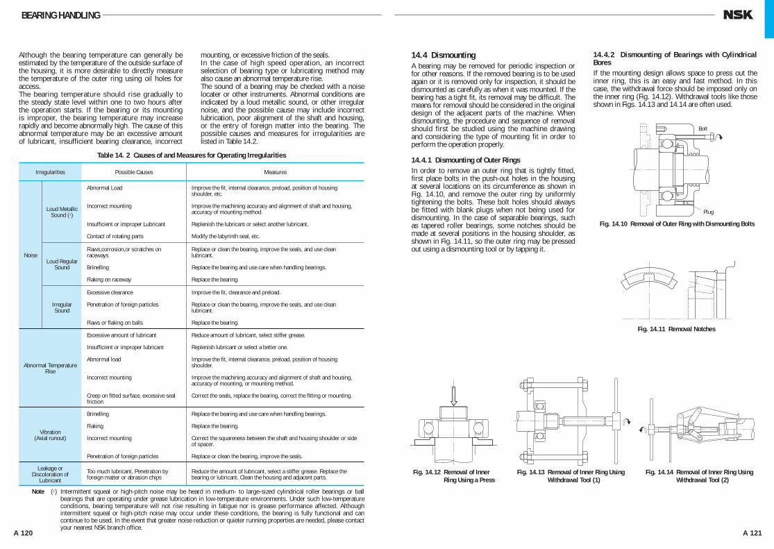
A 120 A 121
Although the bearing temperature can generally be estimated by the temperature of the outside surface of the housing, it is more desirable to directly measure the temperature of the outer ring using oil holes for access.The bearing temperature should rise gradually to the steady state level within one to two hours after the operation starts. If the bearing or its mounting is improper, the bearing temperature may increase rapidly and become abnormally high. The cause of this abnormal temperature may be an excessive amount of lubricant, insufficient bearing clearance, incorrect
mounting, or excessive friction of the seals.In the case of high speed operation, an incorrect selection of bearing type or lubricating method may also cause an abnormal temperature rise.The sound of a bearing may be checked with a noise locater or other instruments. Abnormal conditions are indicated by a loud metallic sound, or other irregular noise, and the possible cause may include incorrect lubrication, poor alignment of the shaft and housing, or the entry of foreign matter into the bearing. The possible causes and measures for irregularities are listed in Table 14.2.
Fig. 14.10 Removal of Outer Ring with Dismounting Bolts
Fig. 14.11 Removal Notches
Fig. 14.12 Removal of InnerFig. 14.1 2 Ring Using a Press
Fig. 14.13 Removal of Inner Ring Using Fig. 14.13 Withdrawal Tool (1)
Fig. 14.14 Removal of Inner Ring Using Fig. 14.14 Withdrawal Tool (2)
Bolt
Plug
14.4 DismountingA bearing may be removed for periodic inspection or for other reasons. If the removed bearing is to be used again or it is removed only for inspection, it should be dismounted as carefully as when it was mounted. If the bearing has a tight fit, its removal may be difficult. The means for removal should be considered in the original design of the adjacent parts of the machine. When dismounting, the procedure and sequence of removal should first be studied using the machine drawing and considering the type of mounting fit in order to perform the operation properly.
14.4.1 Dismounting of Outer RingsIn order to remove an outer ring that is tightly fitted, first place bolts in the push-out holes in the housing at several locations on its circumference as shown in Fig. 14.10, and remove the outer ring by uniformly tightening the bolts. These bolt holes should always be fitted with blank plugs when not being used for dismounting. In the case of separable bearings, such as tapered roller bearings, some notches should be made at several positions in the housing shoulder, as shown in Fig. 14.11, so the outer ring may be pressed out using a dismounting tool or by tapping it.
14.4.2 Dismounting of Bearings with Cylindrical BoresIf the mounting design allows space to press out the inner ring, this is an easy and fast method. In this case, the withdrawal force should be imposed only on the inner ring (Fig. 14.12). Withdrawal tools like those shown in Figs. 14.13 and 14.14 are often used.
Note (1) Intermittent squeal or high-pitch noise may be heard in medium- to large-sized cylindrical roller bearings or ball bearings that are operating under grease lubrication in low-temperature environments. Under such low-temperature conditions, bearing temperature will not rise resulting in fatigue nor is grease performance affected. Although intermittent squeal or high-pitch noise may occur under these conditions, the bearing is fully functional and can continue to be used. In the event that greater noise reduction or quieter running properties are needed, please contact your nearest NSK branch office.
Table 14. 2 Causes of and Measures for Operating Irregularities
Irregularities Possible Causes Measures
Noise
Abnormal TemperatureRise
Vibration(Axial runout)
Leakage orDiscoloration of
Lubricant
Loud MetallicSound (1)
Abnormal Load
Incorrect mounting
Insufficient or improper Lubricant
Contact of rotating parts
Improve the fit, internal clearance, preload, position of housing shoulder, etc.
Improve the machining accuracy and alignment of shaft and housing, accuracy of mounting method.
Replenish the lubricant or select another lubricant.
Modify the labyrinth seal, etc.
Flaws,corrosion,or scratches on raceways
Brinelling
Flaking on raceway
Excessive clearance
Penetration of foreign particles
Flaws or flaking on balls
Excessive amount of lubricant
Insufficient or improper lubricant
Abnormal load
Incorrect mounting
Creep on fitted surface, excessive seal friction
Brinelling
Flaking
Incorrect mounting
Penetration of foreign particles
Too much lubricant, Penetration by foreign matter or abrasion chips
Replace or clean the bearing, improve the seals, and use clean lubricant.
Replace the bearing and use care when handling bearings.
Replace the bearing.
Improve the fit, clearance and preload.
Replace or clean the bearing, improve the seals, and use clean lubricant.
Replace the bearing.
Reduce amount of lubricant, select stiffer grease.
Replenish lubricant or select a better one.
Improve the fit, internal clearance, preload, position of housing shoulder.
Improve the machining accuracy and alignment of shaft and housing, accuracy of mounting, or mounting method.
Correct the seals, replace the bearing, correct the fitting or mounting.
Replace the bearing and use care when handling bearings.
Replace the bearing.
Correct the squareness between the shaft and housing shoulder or side of spacer.
Replace or clean the bearing, improve the seals.
Reduce the amount of lubricant, select a stiffer grease. Replace the bearing or lubricant. Clean the housing and adjacent parts.
Loud RegularSound
IrregularSound
BEARING HANDLING
A100-125E.indd 120-121 A100-125E.indd 120-121 11/20/13 4:52:29 PM11/20/13 4:52:29 PM

A 122 A 123
14.5 Inspection of Bearings14.5.1 Bearing CleaningWhen bearings are inspected, the appearance of the bearings should first be recorded and the amount and condition of the residual lubricant should be checked.After the lubricant has been sampled for examination, the bearings should be cleaned. In general, light oil or kerosene may be used as a cleaning solution.Dismounted bearings should first be given a preliminary cleaning followed by a finishing rinse. Each bath should be provided with a metal net to support the bearings in the oil without touching the sides or bottom of the tank. If the bearings are rotated with foreign matter in them during preliminary cleaning, the raceways may be damaged. The lubricant and other deposits should be removed in the oil bath during the initial rough cleaning with a brush or other means. After the bearing is relatively clean, it is given the finishing rinse. The finishing rinse should be done carefully with the bearing being rotated while immersed in the rinsing oil. It is necessary to always keep the rinsing oil clean.
14.5.2 Inspection and Evaluation of BearingsAfter being thoroughly cleaned, bearings should be examined for the condition of their raceways and external surfaces, the amount of cage wear, the increase in internal clearance, and degradation of tolerances. These should be carefully checked, in addition to examination for possible damage or other abnormalities, in order to determine the possibility for its reuse.In the case of small non-separable ball bearings, hold the bearing horizontally in one hand, and then rotate the outer ring to confirm that it turns smoothly.Separable bearings such as tapered roller bearings may be checked by individually examining their rolling elements and the outer ring raceway.Large bearings cannot be rotated manually; however, the rolling elements, raceway surfaces, cages, and contact surface of the ribs should be carefully examined visually. The more important a bearing is, the more carefully it should be inspected.The determination to reuse a bearing should be made only after considering the degree of bearing wear, the function of the machine, the importance of the bearings in the machine, operating conditions, and the time until the next inspection. However, if any of the following defects exist, reuse is impossible and replacement is necessary.
(a) When there are cracks in the inner or outer rings, rolling elements, or cage.
(b) When there is flaking of the raceway or rolling elements.
(c) When there is significant smearing of the raceway surfaces, ribs, or rolling elements.
(d) When the cage is significantly worn or rivets are loose.
(e) When there is rust or scoring on the raceway surfaces or rolling elements.
(f ) When there are any significant impact or brinell traces on the raceway surfaces or rolling elements.
(g) When there is significant evidence of creep on the bore or the periphery of the outer ring.
(h) When discoloration by heat is evident.( i ) When significant damage to the seals or shields of
grease sealed bearings has occurred.
In both cases, the claws of the tools must substantially engage the face of the inner ring; therefore, it is advisable to consider the size of the shaft shoulder or to cut grooves in the shoulder to accommodate the withdrawal tools (Fig. 14.14).The oil injection method is usually used for the withdrawal of large bearings. The withdrawal is achieved easily by mean of oil pressure applied through holes in the shaft. In the case of extra wide bearings, the oil injection method is used together with a withdrawal tool.Induction heating is used to remove the inner rings of NU and NJ types of cylindrical roller bearings. The inner rings are expanded by brief local heating, and then withdrawn (Fig. 14.15). Induction heating is also used to mount several bearings of these types on a shaft.
14.4.3 Dismounting of Bearings with Tapered BoresWhen dismounting relatively small bearings with adapters, the inner ring is held by a stop fastened to the shaft and the nut is loosened several turns. This is followed by hammering on the sleeve using a suitable tool as shown in Fig. 14.18. Fig. 14.16 shows one procedure for dismounting a withdrawal sleeve by tightening the removal nut. If this procedure is difficult, it may be possible to drill and tap bolt holes in the nut and withdraw the sleeve by tightening the bolts as shown in Fig. 14.17.Large bearings may be withdrawn easily using oil pressure. Fig. 14.19 illustrates the removal of a bearing by forcing oil under pressure through a hole and groove in a tapered shaft to expand the inner ring. The bearing may suddenly move axially when the interference is relieved during this procedure so a stop nut is recommended for protection. Fig. 14.20 shows a withdrawal using a hydraulic nut.
Fig. 14.16 Removal of Withdrawal Fig. 14 .16 Sleeve Using Withdrawal Nut (1)
Fig. 14.17 Removal of Withdrawal Fig. 14.17 Sleeve Using Withdrawal Nut (2)
Fig. 14.18 Removal of Adapter with Stop and Axial Pressure Fig. 14.19 Removal Using Oil Injection Hydraulic Pump
Fig. 14.15 Removal of Inner Ring Using Fig. 14. 15 Induction Heater
Inner Ring
Withdrawal Claw
Fig. 14.20 Removal Using Hydraulic Nut
Oil
BEARING HANDLING
A100-125E.indd 122-123 A100-125E.indd 122-123 11/20/13 4:52:29 PM11/20/13 4:52:29 PM
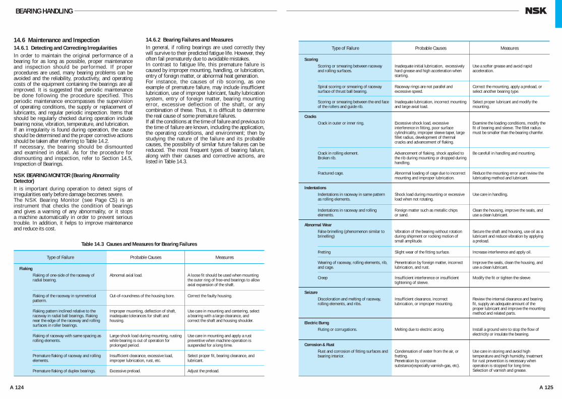
A 124 A 125
14.6 Maintenance and Inspection14.6.1 Detecting and Correcting IrregularitiesIn order to maintain the original performance of a bearing for as long as possible, proper maintenance and inspection should be performed. If proper procedures are used, many bearing problems can be avoided and the reliability, productivity, and operating costs of the equipment containing the bearings are all improved. It is suggested that periodic maintenance be done following the procedure specified. This periodic maintenance encompasses the supervision of operating conditions, the supply or replacement of lubricants, and regular periodic inspection. Items that should be regularly checked during operation include bearing noise, vibration, temperature, and lubrication.If an irregularity is found during operation, the cause should be determined and the proper corrective actions should be taken after referring to Table 14.2.If necessary, the bearing should be dismounted and examined in detail. As for the procedure for dismounting and inspection, refer to Section 14.5, Inspection of Bearings.
NSK BEARING MONITOR (Bearing Abnormality Detector)It is important during operation to detect signs of irregularities early before damage becomes severe.The NSK Bearing Monitor (see Page C5) is an instrument that checks the condition of bearings and gives a warning of any abnormality, or it stops a machine automatically in order to prevent serious trouble. In addition, it helps to improve maintenance and reduce its cost.
14.6.2 Bearing Failures and MeasuresIn general, if rolling bearings are used correctly they will survive to their predicted fatigue life. However, they often fail prematurely due to avoidable mistakes.In contrast to fatigue life, this premature failure is caused by improper mounting, handling, or lubrication, entry of foreign matter, or abnormal heat generation.For instance, the causes of rib scoring, as one example of premature failure, may include insufficient lubrication, use of improper lubricant, faulty lubrication system, entry of foreign matter, bearing mounting error, excessive deflection of the shaft, or any combination of these. Thus, it is difficult to determine the real cause of some premature failures.If all the conditions at the time of failure and previous to the time of failure are known, including the application, the operating conditions, and environment; then by studying the nature of the failure and its probable causes, the possibility of similar future failures can be reduced. The most frequent types of bearing failure, along with their causes and corrective actions, are listed in Table 14.3.
Table 14.3 Causes and Measures for Bearing Failures
Type of Failure Probable Causes Measures
FlakingFlaking of one-side of the raceway of radial bearing.
Abnomal axial load. A loose fit should be used when mounting the outer ring of free-end bearings to allow axial expansion of the shaft.
Flaking of the raceway in symmetrical patterm.
Out-of-roundness of the housing bore. Correct the faulty housing.
Flaking pattern inclined relative to the raceway in radial ball bearings. Flaking near the edge of the raceway and rolling surfaces in roller bearings.
Improper muonting, deflection of shaft, inadequate tolerances for shaft and housing.
Use care in mounting and centering, select a bearing with a large clearance, and correct the shaft and housing shoulder.
Flaking of raceway with same spacing as rolling elements.
Large shock load during mounting, rusting while bearing is out of operation for prolonged period.
Use care in mounting and apply a rust preventive when machine operation is suspended for a long time.
Premature flaking of raceway and rolling elements.
Insufficient clearance, excessive load, improper lubrication, rust, etc.
Select proper fit, bearing clearance, and lubricant.
Premature flaking of duplex bearings. Excessive preload. Adjust the preload.
BEARING HANDLING
Type of Failure Probable Causes Measures
Scoring
Cracks
Scoring or smearing between raceway and rolling surfaces.
Inadequate initial lubrication, excessively hard grease and high acceleration when starting.
Use a softer grease and avoid rapid acceleration.
Spiral scoring or smearing of raceway surface of thrust ball bearing.
Raceway rings are not parallel and excessive speed.
Correct the mounting, apply a preload, or select another bearing type.
Scoring or smearing between the end face of the rollers and guide rib.
Inadequate lubrication, incorrect mounting and large axial load.
Select proper lubricant and modify the mounting.
Crack in rolling element.Broken rib.
Advancement of flaking, shock applied to the rib during mounting or dropped during handling.
Be carefull in handling and mounting.
Fractured cage. Abnormal loading of cage due to incorrect mounting and improper lubrication.
Reduce the mounting error and review the lubricating method and lubricant.
Indentations in raceway and rolling elements.
Foreign matter such as metallic chips or sand.
Clean the housing, improve the seals, and use a clean lubricant.
Wearing of raceway, rolling elements, rib, and cage.
Penentration by foreign matter, incorrect lubrication, and rust.
Improve the seals, clean the housing, and use a clean lubricant.
Fretting Slight wear of the fitting surface. Increase interference and apply oil.
Crack in outer or inner ring. Excessive shock load, excessive interference in fitting, poor surface cylindricality, improper sleeve taper, large fillet radius, development of thermal cracks and advancement of flaking.
Examine the loading conditions, modify the fit of bearing and sleeve. The fillet radius must be smaller than the bearing chamfer.
IndentationsIndentations in raceway in same pattern as rolling elements.
Shock load during mounting or excessive load when not rotating.
Use care in handling.
Abnormal Wear
Seizure
False brinelling (phenomenon similar to brinelling)
Vibration of the bearing without rotation during shipment or rocking motion of small amplitude.
Secure the shaft and housing, use oil as a lubricant and reduce vibration by applying a preload.
Discoloration and melting of raceway, rolling elements, and ribs.
Insufficient clearance, incorrect lubrication, or improper mounting.
Review the internal clearance and bearing fit, supply an adequate amount of the proper lubricant and improve the mounting method and related parts.
Creep Insufficient interference or insufficient tightening of sleeve.
Modify the fit or tighten the sleeve
Electric BurngFluting or corrugations. Melting due to electric arcing. Install a ground wire to stop the flow of
electricity or insulate the beaning.
Corrosion & RustRust and corrosion of fitting surfaces and bearing interior.
Condensation of water from the air, or fretting.Penetration by corrosive substance(especially varnish-gas, etc).
Use care in storing and avoid high temperature and high humidity, treatment for rust prevention is necessary when operation is stopped for long time.Selection of varnish and grease.
A100-125E.indd 124-125 A100-125E.indd 124-125 11/20/13 4:52:30 PM11/20/13 4:52:30 PM
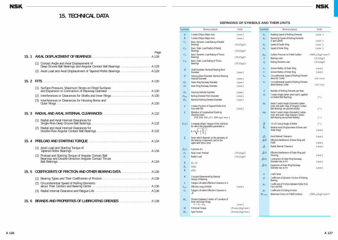
A 126 A 127
DEFINIONS OF SYMBOLS AND THEIR UNITS
15. 1 AXIAL DISPLACEMENT OF BEARINGS • • • • • • • • • • • • • • • • • • • • • • • • • • • • • • • • • • • • • • • • • • • • • • • • • • • • • • • • • • • • A 128
(1) Contact Angle and Axial Displacement of Deep Groove Ball Bearings and Angular Contact Ball Bearings • • • • • • • • • • • • • • • • • • • • • • • • • • • • • • A 128
(2) Axial Load and Axial Displacement of Tapered Roller Bearings • • • • • • • • • • • • • • • • • • • • • • • • • • • • • • A 128
15. 2 FITS • • • • • • • • • • • • • • • • • • • • • • • • • • • • • • • • • • • • • • • • • • • • • • • • • • • • • • • • • • • • • • • • • • • • • • • • • • • • • • • • • • • • • • • • • • • • • • • • • • • • • • • • • • • • • • • • A 130
(1) Surface Pressure, Maximum Stress on Fitted Surfaces and Expansion or Contraction of Raceway Diameter • • • • • • • • • • • • • • • • • • • • • • • • • • • • • • • • • • • • • • • • • • • • A 130
(2) Interferences or Clearances for Shafts and Inner Rings • • • • • • • • • • • • • • • • • • • • • • • • • • • • • • • • • • • • • • • • A 130 (3) Interferences or Clearances for Housing Bores and
Outer Rings • • • • • • • • • • • • • • • • • • • • • • • • • • • • • • • • • • • • • • • • • • • • • • • • • • • • • • • • • • • • • • • • • • • • • • • • • • • • • • • • • • • • • • • • • • • • • • • • • A 130
15. 3 RADIAL AND AXIAL INTERNAL CLEARANCES • • • • • • • • • • • • • • • • • • • • • • • • • • • • • • • • • • • • • • • • • • • • • • • • • A 132
(1) Radial and Axial Internal Clearances for Single-Row Deep Groove Ball Bearings • • • • • • • • • • • • • • • • • • • • • • • • • • • • • • • • • • • • • • • • • • • • • • • • • • • • • • • • • • • • • A 132
(2) Radial and Axial Internal Clearances for Double-Row Angular Contact Ball Bearings • • • • • • • • • • • • • • • • • • • • • • • • • • • • • • • • • • • • • • • • • • • • • • • • • • • • • • • A 132
15. 4 PRELOAD AND STARTING TORQUE • • • • • • • • • • • • • • • • • • • • • • • • • • • • • • • • • • • • • • • • • • • • • • • • • • • • • • • • • • • • • • • • A 134
(1) Axial Load and Starting Torque of Tapered Roller Bearings • • • • • • • • • • • • • • • • • • • • • • • • • • • • • • • • • • • • • • • • • • • • • • • • • • • • • • • • • • • • • • • • • • • • • • • • • • • • • • • • • A 134
(2) Preload and Starting Torque of Angular Contact Ball Bearings and Double-Direction Angular Contact Thrust Ball Bearings • • • • • • • • • • • • • • • • • • • • • • • • • • • • • • • • • • • • • • • • • • • • • • • • • • • • • • • • • • • • • • • • • • • • • • • • • • • • • • • • • • • • • • • • • • • • • • • • A 134
15. 5 COEFFICIENTS OF FRICTION AND OTHER BEARING DATA • • • • • • • • • • • • • • • • • • • • • • • • • • • • • • A 136
(1) Bearing Types and Their Coefficients of Friction • • • • • • • • • • • • • • • • • • • • • • • • • • • • • • • • • • • • • • • • • • • • • • • • • • A 136 (2) Circumferential Speed of Rolling Elements
about Their Centers and Bearing Center • • • • • • • • • • • • • • • • • • • • • • • • • • • • • • • • • • • • • • • • • • • • • • • • • • • • • • • • • • • • A 136 (3) Radial Internal Clearance and Fatigue Life • • • • • • • • • • • • • • • • • • • • • • • • • • • • • • • • • • • • • • • • • • • • • • • • • • • • • • • • • A 136
15. 6 BRANDS AND PROPERTIES OF LUBRICATING GREASES • • • • • • • • • • • • • • • • • • • • • • • • • • • • • • • • A 138
Page
15. TECHNICAL DATA
Symbols Nomenclature Units
a Contact Ellipse Major Axis (mm) b Contact Ellipse Major Axis (mm) Cr Basic Dynamic Load Rating of Radial
Bearings (N){kgf} C0r Basic Static Load Radial of Radial
Bearings (N){kgf} Ca Basic Dynamic Load Rating of Thrust
Bearings (N){kgf} C0a Basic Static Load Rating of Thrust
Bearings (N){kgf}
d Shaft Diameter, Nominal Bearing Bore Diameter (mm)
D Housing Bore Diameter, Nominal Bearing Outside Diameter (mm)
De Outer Ring Raceway Diameter (mm) Di Inner Ring Raceway Diameter (mm)
D0 Housing Outside Diameter (mm) Dpw Rolling Element Pitch Diameter (mm) Dw Nominal Rolling Element Diameter (mm)
e Contact Position of Tapered Roller End Face with Rib (mm)
E Modulus of Longitudinal Elasticity (Bearing Steel) 208 000 MPa{21 200 kgf/mm2}
E(k) Complete elliptic integral of the 2nd kind for which the population parameter is
k=√—1–
—
( b—a—
)—
2
f0 factor which depends on the geometry of the bearing components and on the applicable stress level
f (ε) Function of ε Fa Axial Load, Preload (N){kgf} Fr Radial Load (N){kgf}
h De/D h0 D/D0
k d /Di
K Constant Determined by InternalDesign of Bearing
L Fatigue Life when Effective Clearance is 0 Lwe Effective Leng of Roller (mm) Lε Fatigue Life when Effective Clearance is
&
m0 Distance between Centers of Curvature of Inner and Outer Rings ri + re –Dw (mm)
M Frictional Torque (N·mm){kgf ·mm} Ms Spin Friction (N·mm){kgf ·mm}
Symbols Nomenclature Units
na Rotating Speed of Rolling Elements (min–1) nc Revolving Speed of Rolling Elements (Cape Speed) (min–1) ne Speed of Ouder Ring (min–1) ni Speed of Inner Ring (min–1)
pm Surface Pressure on Fitted Surface (MPa){kgf/mm2} P Bearing Load (N){kgf} Q Rolling Element Load (N){kgf}
re Groove Radius of Outer Ring (mm) ri Groove Radius of Inner Ring (mm) va Circumferential Speed of Rolling Element
about Its Center (m/sec) vc Circumferential Speed of Rolling Element
about Beaing Center (m/sec)
Z Number of Rolling Elements per Row α Contact Angle (when axial load is applied
on Radial Ball Bearning (°)
α0 Initial Confact Angle (Geometri) (wheninner and outer rings of Angular Contact Ball Bearings are pushed axially) (°)
αR Initial Contact Angle (Geometric) (when inner and outer rings Angular Contact Ball Bearing are pushed radially) (°)
β 1/2 of Conical Angle of Roller (°) δa Relative Axial Displacement of Inner and
Outer Rings (mm)
& a Axial Internal Clearance (mm) & d Effective Interference of Inner Ring and
Shaft (mm) & r Radial Internal Clearance (mm)
& D Effective Interference of Outer Ring and Housing (mm)
& De Contraction of Outer Ring Raceway Diameter due to Fit (mm)
& Di Expansion of Inner Ring Raceway Diameter dus to Fit (mm)
ε Load Factor μ Coefficient of Dynamic Friction of Rolling
Bearing μe Coefficient of Friction between Roller End
Face and Rib μs Coefficient of Sliding Friction σt max Maximum Stress on Fitted Surfaces (MPa){kgf/mm2}
A126-141E.indd 126-127 A126-141E.indd 126-127 11/20/13 4:53:03 PM11/20/13 4:53:03 PM
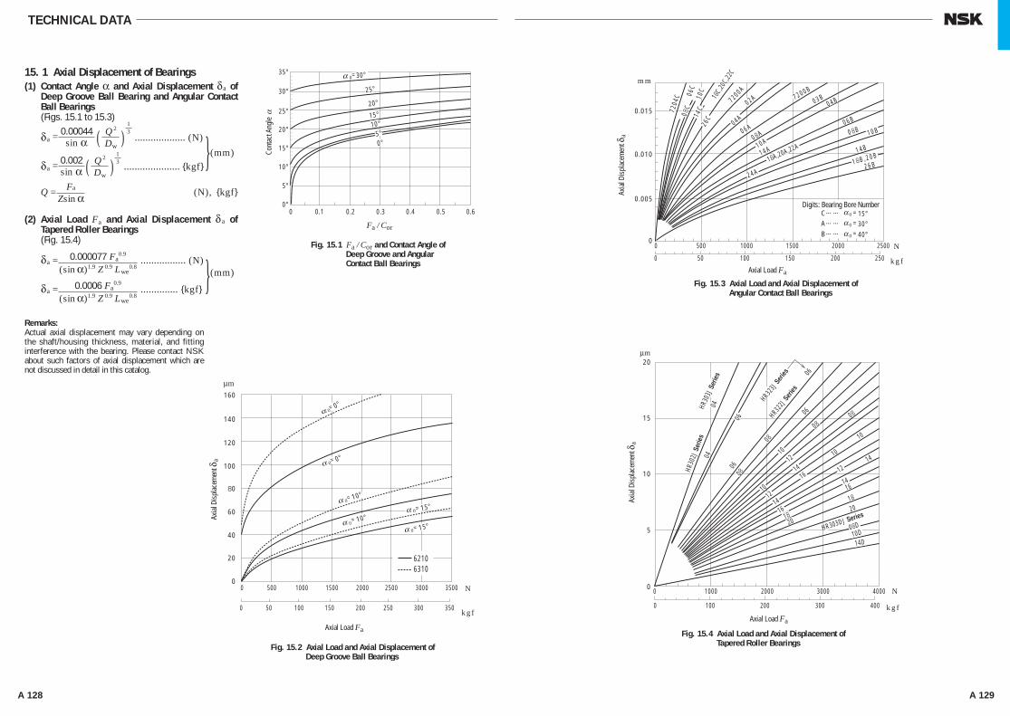
A 128 A 129
TECHNICAL DATA
15. 1 Axial Displacement of Bearings(1) Contact Angle α and Axial Displacement δa of
Deep Groove Ball Bearing and Angular Contact Ball Bearings
(Figs. 15.1 to 15.3)
δa = ( )
................... (N)(mm)
δa = ( )
..................... {kgf}
Q = (N), {kgf}
(2) Axial Load Fa and Axial Displacement δa of Tapered Roller Bearings
(Fig. 15.4)
δa = ................. (N)(mm)
δa = .............. {kgf}
Remarks:Actual axial displacement may vary depending on the shaft/housing thickness, material, and fitting interference with the bearing. Please contact NSK about such factors of axial displacement which are not discussed in detail in this catalog.
0.00044sin α
0.002sin α
Fa
Zsin α
0.000077 Fa0.9
(sin α)1.9 Z 0.9 Lwe0.8
0.0006 Fa0.9
(sin α)1.9 Z 0.9 Lwe0.8
}
}Fig. 15.1 Fa /Cor and Contact Angle of
Deep Groove and Angular Contact Ball Bearings
Fa /Cor
0α =30°35°
30°
25°
20°
15°
10°
5°
0°0 0.1 0.2 0.3 0.4 0.5 0.6
25°
20°
15°10°
5°0°
Cont
act A
ngle
α
Fig. 15.2 Axial Load and Axial Displacement of Deep Groove Ball Bearings
N
kgf
160
140
120
100
80
60
40
20
00
0 50 100 150 200 250 300 350
500 1000 1500 2000 2500 3000 3500
62106310
0α = 0°
0α = 0°
0α =10°
0α =10°0α =15°
0α =15°
Axial
Disp
lacem
ent δ
a
Axial Load Fa
μm
N
kgf
N
kgf
μm
mm
0
0
5
10
15
20
0.005
0.010
0.015
0
0 1000 2000 3000 4000
500 1000 1500 2000 2500
0
0 100 200 300 400
50 100 150 200 250
=15°C……
=30°A……
=40°B……
7200A
7200B
18B,20B18A,20A,22A
18C,
20C,
22C
06C
10C
14C
26C
02A
04A
06A08A
10A10B
14B
26B
14A
24A
03B
08B06B
04B
08C72
04C
HR30
3JS
erie
s
08D
0404
06
0606
08
08
10
10
1012
14
14
14
1618
18
20
20
1616
14
12
12
1008
08
06
10D14D
HR30
2JS
erie
s
HR323J
Serie
s
HR322J
Serie
s
HR303DJ Series
Fig. 15.3 Axial Load and Axial Displacement ofAngular Contact Ball Bearings
Axial
Disp
lacem
ent δ
a
Axial Load Fa
Fig. 15.4 Axial Load and Axial Displacement ofTapered Roller Bearings
Axial
Disp
lacem
ent δ
a
Axial Load Fa
Digits: Bearing Bore Number0α0α0α
Q 2
Dw
13
Q 2
Dw
13
A126-141E.indd 128-129 A126-141E.indd 128-129 11/20/13 4:53:04 PM11/20/13 4:53:04 PM
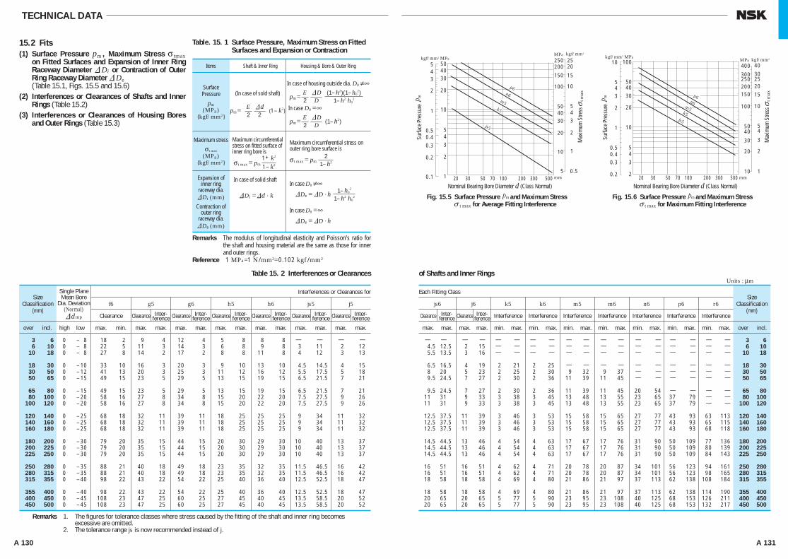
A 130 A 131
— — — — — — — — — — — — — — — — — — 3 6 4.5 12.5 2 15 — — — — — — — — — — — — — — 6 10 5.5 13.5 3 16 — — — — — — — — — — — — — — 10 18
6.5 16.5 4 19 2 21 2 25 — — — — — — — — — — 18 30 8 20 5 23 2 25 2 30 9 32 9 37 — — — — — — 30 50 9.5 24.5 7 27 2 30 2 36 11 39 11 45 — — — — — — 50 65
9.5 24.5 7 27 2 30 2 36 11 39 11 45 20 54 — — — — 65 80 11 31 9 33 3 38 3 45 13 48 13 55 23 65 37 79 — — 80 100 11 31 9 33 3 38 3 45 13 48 13 55 23 65 37 79 — — 100 120
12.5 37.5 11 39 3 46 3 53 15 58 15 65 27 77 43 93 63 113 120 140 12.5 37.5 11 39 3 46 3 53 15 58 15 65 27 77 43 93 65 115 140 160 12.5 37.5 11 39 3 46 3 53 15 58 15 65 27 77 43 93 68 118 160 180
14.5 44.5 13 46 4 54 4 63 17 67 17 76 31 90 50 109 77 136 180 200 14.5 44.5 13 46 4 54 4 63 17 67 17 76 31 90 50 109 80 139 200 225 14.5 44.5 13 46 4 54 4 63 17 67 17 76 31 90 50 109 84 143 225 250
16 51 16 51 4 62 4 71 20 78 20 87 34 101 56 123 94 161 250 280 16 51 16 51 4 62 4 71 20 78 20 87 34 101 56 123 98 165 280 315 18 58 18 58 4 69 4 80 21 86 21 97 37 113 62 138 108 184 315 355
18 58 18 58 4 69 4 80 21 86 21 97 37 113 62 138 114 190 355 400 20 65 20 65 5 77 5 90 23 95 23 108 40 125 68 153 126 211 400 450 20 65 20 65 5 77 5 90 23 95 23 108 40 125 68 153 132 217 450 500
Each Fitting Class
max. max. max. max. min. max. min. max. min. max. min. max. min. max. min. max. min. max. over incl.
js6 j6 k5 k6 m5 m6 n6 p6 r6
Clearance Clearance Interference Interference Interference Interference Interference Interference Interference
SizeClassification
(mm)
Units : μm
3 6 0 – 8 18 2 9 4 12 4 5 8 8 8 — — — — 6 10 0 – 8 22 5 11 3 14 3 6 8 9 8 3 11 2 12 10 18 0 – 8 27 8 14 2 17 2 8 8 11 8 4 12 3 13
18 30 0 – 10 33 10 16 3 20 3 9 10 13 10 4.5 14.5 4 15 30 50 0 – 12 41 13 20 3 25 3 11 12 16 12 5.5 17.5 5 18 50 65 0 – 15 49 15 23 5 29 5 13 15 19 15 6.5 21.5 7 21
65 80 0 – 15 49 15 23 5 29 5 13 15 19 15 6.5 21.5 7 21 80 100 0 – 20 58 16 27 8 34 8 15 20 22 20 7.5 27.5 9 26 100 120 0 – 20 58 16 27 8 34 8 15 20 22 20 7.5 27.5 9 26
120 140 0 – 25 68 18 32 11 39 11 18 25 25 25 9 34 11 32 140 160 0 – 25 68 18 32 11 39 11 18 25 25 25 9 34 11 32 160 180 0 – 25 68 18 32 11 39 11 18 25 25 25 9 34 11 32
180 200 0 – 30 79 20 35 15 44 15 20 30 29 30 10 40 13 37 200 225 0 – 30 79 20 35 15 44 15 20 30 29 30 10 40 13 37 225 250 0 – 30 79 20 35 15 44 15 20 30 29 30 10 40 13 37
250 280 0 – 35 88 21 40 18 49 18 23 35 32 35 11.5 46.5 16 42 280 315 0 – 35 88 21 40 18 49 18 23 35 32 35 11.5 46.5 16 42 315 355 0 – 40 98 22 43 22 54 22 25 40 36 40 12.5 52.5 18 47
355 400 0 – 40 98 22 43 22 54 22 25 40 36 40 12.5 52.5 18 47 400 450 0 – 45 108 23 47 25 60 25 27 45 40 45 13.5 58.5 20 52 450 500 0 – 45 108 23 47 25 60 25 27 45 40 45 13.5 58.5 20 52
f6 g5 g6 h5 h6 js5 j5
Clearance Clearance Clearance Clearance Clearance Clearance Clearance
Interferences or Clearances forSize
Classification(mm)
Single PlaneMean Bore
Dia. Deviation(Normal)&dmp
over incl. high low max. min. max. max. max. max. max. max. max. max. max. max. max. max.
TECHNICAL DATA
15.2 Fits(1) Surface Pressure pm , Maximum Stress σ tmax
on Fitted Surfaces and Expansion of Inner Ring Raceway Diameter &Di or Contraction of Outer Ring Raceway Diameter &De
(Table 15.1, Figs. 15.5 and 15.6)(2) Interferences or Clearances of Shafts and Inner
Rings (Table 15.2)(3) Interferences or Clearances of Housing Bores
and Outer Rings (Table 15.3)
SurfacePressure
pm(MPa)
{kgf/mm2}
(In case of sold shaft)
pm= (1 – k2)
In case of housing outside dia. D0 ≠∞
pm=In case D0 =∞
pm= (1– h2)
Maximum stress
σ t max
(MPa){kgf/mm2}
Maximum circumferential stress on fitted surface of inner ring bore is
σt max = pm
Maximum circumferential stress on outer ring bore surface is
σt max = pm
Expansion ofinner ring
raceway dia.&Di (mm)Contraction of
outer ringraceway dia.&De (mm)
In case of solid shaft
&Di =&d . k
In case D0 ≠∞ &De = &D · h
In case D0 =∞ &De = &D · h
Table. 15. 1 Surface Pressure, Maximum Stress on FittedSurfaces and Expansion or Contraction
Table 15. 2 Interferences or Clearances of Shafts and Inner Rings
Remarks The modulus of longitudinal elasticity and Poisson's ratio for the shaft and housing material are the same as those for inner and outer rings.
Reference 1 MPa=1 N/mm2=0.102 kgf /mm2
Items Shaft & Inner Ring Housing & Bore & Outer Ring
(1– h2)(1– h02)
1– h2 h02
kgf/mm2 MPakgf/mm2
543
2
1
0.50.40.3
0.2
0.1
10
543
2
1
20
304050
250200
150
100
504030
20
10
5
2520
15
10
543
2
1
0.5100 200 300 50070503020
m
m
mm
MPa
p6n6
m5k5
js5
kgf/mm2 MPa kgf/mm2
5
10
43
2
1
0.50.40.3
0.2
10
543
2
20
304050
100
250300
400
200150
100
5040
30
20
10
2520
30
40
15
10
54
3
2
1100 200 300 50070503020 mm
MPa
p6n6
m5k5
js5
Fig. 15.5 Surface Pressure and Maximum Stress t max for Average Fitting Interference
Surfa
ce P
ress
ure
mSu
rface
Pre
ssur
e
Max
imum
Stre
ss
t m
ax
Max
imum
Stre
ss
t m
ax
Nominal Bearing Bore Diameter d (Class Normal)
mFig. 15.6 Surface Pressure and Maximum Stress t max for Maximum Fitting Interference
Nominal Bearing Bore Diameter d (Class Normal)
σ σ
σ σ
Remarks 1. The figures for tolerance classes where stress caused by the fitting of the shaft and inner ring becomes excessive are omitted.2. The tolerance range js is now recommended instead of j.
Inter-ference
Inter-ference
Inter-ference
Inter-ference
Inter-ference
Inter-ference
Inter-ference
Inter-ference
E2&d2
1 + k2
1 – k2
E2&DD
E2&DD
21– h2
1– h02
1– h2 h02
A126-141E.indd 130-131 A126-141E.indd 130-131 11/20/13 4:53:06 PM11/20/13 4:53:06 PM
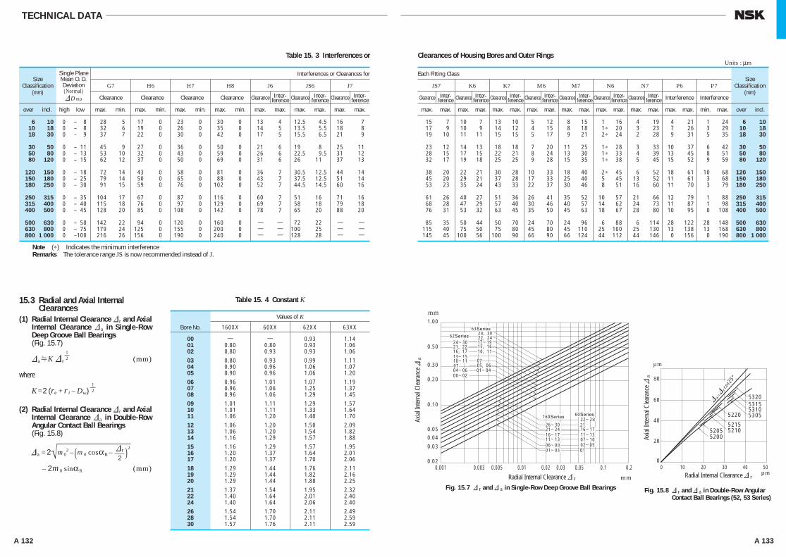
A 132 A 133
TECHNICAL DATA
15.3 Radial and Axial Internal Clearances
(1) Radial Internal Clearance & r and Axial Internal Clearance & a in Single-Row Deep Groove Ball Bearings
(Fig. 15.7)
&aHK & r (mm)
where
K=2 (re + r i – Dw)
(2) Radial Internal Clearance & r and Axial Internal Clearance &a in Double-Row Angular Contact Ball Bearings
(Fig. 15.8)
&a = 2√m02 – (m 0 cosαR – )2
– 2m0 sinαR (mm)
00 — — 0.93 1.14 01 0.80 0.80 0.93 1.06 02 0.80 0.93 0.93 1.06 03 0.80 0.93 0.99 1.11 04 0.90 0.96 1.06 1.07 05 0.90 0.96 1.06 1.20 06 0.96 1.01 1.07 1.19 07 0.96 1.06 1.25 1.37 08 0.96 1.06 1.29 1.45 09 1.01 1.11 1.29 1.57 10 1.01 1.11 1.33 1.64 11 1.06 1.20 1.40 1.70 12 1.06 1.20 1.50 2.09 13 1.06 1.20 1.54 1.82 14 1.16 1.29 1.57 1.88 15 1.16 1.29 1.57 1.95 16 1.20 1.37 1.64 2.01 17 1.20 1.37 1.70 2.06 18 1.29 1.44 1.76 2.11 19 1.29 1.44 1.82 2.16 20 1.29 1.44 1.88 2.25 21 1.37 1.54 1.95 2.32 22 1.40 1.64 2.01 2.40 24 1.40 1.64 2.06 2.40 26 1.54 1.70 2.11 2.49 28 1.54 1.70 2.11 2.59 30 1.57 1.76 2.11 2.59
Values of K
Bore No. 160XX 60XX 62XX 63XX
Table 15. 4 Constant K
JS7 K6 K7 M6 M7 N6 N7 P6 P7
15 7 10 7 13 10 5 12 8 15 1 16 4 19 4 21 1 24 6 10 17 9 10 9 14 12 4 15 8 18 1∗ 20 3 23 7 26 3 29 10 18 19 10 11 11 15 15 5 17 9 21 2∗ 24 2 28 9 31 5 35 18 30
23 12 14 13 18 18 7 20 11 25 1∗ 28 3 33 10 37 6 42 30 50 28 15 17 15 22 21 8 24 13 30 1∗ 33 4 39 13 45 8 51 50 80 32 17 19 18 25 25 9 28 15 35 1∗ 38 5 45 15 52 9 59 80 120
38 20 22 21 30 28 10 33 18 40 2∗ 45 6 52 18 61 10 68 120 150 45 20 29 21 37 28 17 33 25 40 5 45 13 52 11 61 3 68 150 180 53 23 35 24 43 33 22 37 30 46 8 51 16 60 11 70 3 79 180 250
61 26 40 27 51 36 26 41 35 52 10 57 21 66 12 79 1 88 250 315 68 28 47 29 57 40 30 46 40 57 14 62 24 73 11 87 1 98 315 400 76 31 53 32 63 45 35 50 45 63 18 67 28 80 10 95 0 108 400 500
85 35 50 44 50 70 24 70 24 96 6 88 6 114 28 122 28 148 500 630 115 40 75 50 75 80 45 80 45 110 25 100 25 130 13 138 13 168 630 800 145 45 100 56 100 90 66 90 66 124 44 112 44 146 0 156 0 190 800 1 000
Each Fitting Class
max. max. max. max. max. max. max. max. max. max. max. max. max. max. max. max. min. max. over incl.
Clearance Clearance Clearance Clearance Clearance Clearance Clearance Interference Interference
SizeClassification
(mm)
Units : μm
6 10 0 – 8 28 5 17 0 23 0 30 0 13 4 12.5 4.5 16 7 10 18 0 – 8 32 6 19 0 26 0 35 0 14 5 13.5 5.5 18 8 18 30 0 – 9 37 7 22 0 30 0 42 0 17 5 15.5 6.5 21 9
30 50 0 – 11 45 9 27 0 36 0 50 0 21 6 19 8 25 11 50 80 0 – 13 53 10 32 0 43 0 59 0 26 6 22.5 9.5 31 12 80 120 0 – 15 62 12 37 0 50 0 69 0 31 6 26 11 37 13
120 150 0 – 18 72 14 43 0 58 0 81 0 36 7 30.5 12.5 44 14 150 180 0 – 25 79 14 50 0 65 0 88 0 43 7 37.5 12.5 51 14 180 250 0 – 30 91 15 59 0 76 0 102 0 52 7 44.5 14.5 60 16
250 315 0 – 35 104 17 67 0 87 0 116 0 60 7 51 16 71 16 315 400 0 – 40 115 18 76 0 97 0 129 0 69 7 58 18 79 18 400 500 0 – 45 128 20 85 0 108 0 142 0 78 7 65 20 88 20
500 630 0 – 50 142 22 94 0 120 0 160 0 — — 72 22 — — 630 800 0 – 75 179 24 125 0 155 0 200 0 — — 100 25 — — 800 1 000 0 –100 216 26 156 0 190 0 240 0 — — 128 28 — —
G7 H6 H7 H8 J6 JS6 J7
Clearance Clearance Clearance Clearance Clearance Clearance Clearance
Interferences or Clearances forSize
Classification(mm)
Single PlaneMean O. D.Deviation(Normal)&Dmp
over incl. high low max. min. max. min. max. min. max. min. max. max. max. max. max. max.
Table 15. 3 Interferences or Clearances of Housing Bores and Outer Rings
Note (∗) Indicates the minimum interferenceRemarks The tolerance range JS is now recommended instead of J.
1.00
0.50
0.30
0.20
0.10
0.05
0.04
0.03
0.020.001 0.003 0.005 0.01 0.02 0.03 0.05 0.1 0.2
20
0
40
60
80
20 30 40 50100
mm
mm
63Series
62Series
160Series 60Series22~28
16~1711~1307~1002~05
26~3021~2416~1711~1306~0801~03
24~30 17~19
13~1510~11
00~0201~04
21, 22
28, 3022, 24
15, 1610, 1116, 17
04~0605, 06
21
01
0707
53205315531053055220
521552105205
5200
& a=&rc
ot25°
Fig. 15.7 & r and & a in Single-Row Deep Groove Ball Bearings Fig. 15.8 & r and & a in Double-Row Angular Contact Ball Bearings (52, 53 Series)
Axial
Inter
nal C
leara
nce &
a
Axial
Inter
nal C
leara
nce &
a
Radial Internal Clearance & r Radial Internal Clearance & r
µm
µm
Inter-ference
Inter-ference
Inter-ference
Inter-ference
Inter-ference
Inter-ference
Inter-ference
Inter-ference
Inter-ference
Inter-ference
12
12
& r2
A126-141E.indd 132-133 A126-141E.indd 132-133 11/20/13 4:53:07 PM11/20/13 4:53:07 PM
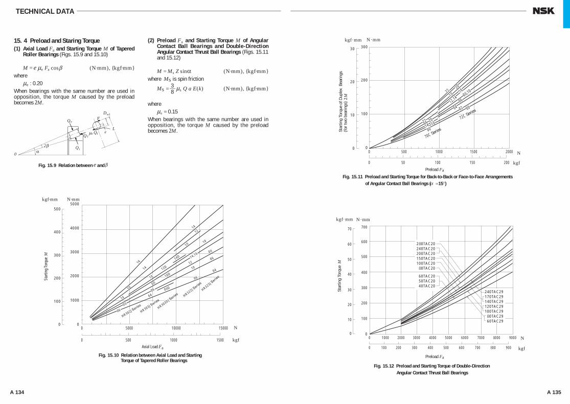
A 134 A 135
TECHNICAL DATA
15. 4 Preload and Staring Torque(1) Axial Load Fa and Starting Torque M of Tapered
Roller Bearings (Figs. 15.9 and 15.10)
M = e μe Fa cosβ (N·mm), {kgf·mm}where μe : 0.20 When bearings with the same number are used in opposition, the torque M caused by the preload becomes 2M.
(2) Preload Fa and Starting Torque M of Angular Contact Ball Bearings and Double-Direction Angular Contact Thrust Ball Bearings (Figs. 15.11 and 15.12)
M = Ms Z sinα (N·mm), {kgf·mm}where Ms is spin friction
Ms = 3—8 μs Q a E(k) (N·mm), {kgf·mm}
where μs = 0.15 When bearings with the same number are used in opposition, the torque M caused by the preload becomes 2M.
DF
L
w1
fe
e
f
i
eQQ
Q
Q2
0 α
μ
β
βFig. 15.9 Relation between and e
0
100
200
300
400
5005000
4000
3000
2000
1000
00 5000 10000 15000
0 500 1000 1500
kgf·mm
kgf
N·mm
N
M
HR302JSeries
HR303JSerie
s
HR303DJSerie
s HR322JSerie
s
HR323JSerie
s
16
14
14
12
18 10
10
08
06
06
06
1012
08
04
04
18
08
06
14
14,16
12D
10D
08D
14D
Fig. 15.10 Relation between Axial Load and Starting Torque of Tapered Roller Bearings
Star
ting
Torq
ue
Axial Load Fa kgf
300
200
100
00 500 1000 1500 2000
0 50 100 150 200
30
20
10
0
kgf .mm
kgf .mm
N.mm
kgf
N
N .mm
N2M
M
Fig. 15.11 Preload and Starting Torque for Back-to-Back or Face-to-Face Arrangements of Angular Contact Ball Bearings ( =15°)
Preload Fa
Star
ting
Torq
ue o
f Dup
lex
Bea
rings
(for t
wo
bear
ings
) St
artin
g To
rque
Fig. 15.12 Preload and Starting Torque of Double-Direction Angular Contact Thrust Ball Bearings
Preload Fa
22
22 2014 10
00
20
06
04 02 00
1816
12,14 08,10
70C Series
72C Series
700
600
500
400
300
200
100
0
70
60
50
40
30
20
10
00 1000 2000 3000 4000 5000 6000 7000 8000 9000
0 100 200 300 400 500 600 700 800 900
280TAC20240TAC20200TAC20150TAC20100TAC2080TAC20
60TAC2050TAC2040TAC20
240TAC29170TAC29140TAC29120TAC29100TAC2980TAC2960TAC29
α
A126-141E.indd 134-135 A126-141E.indd 134-135 11/20/13 4:53:08 PM11/20/13 4:53:08 PM
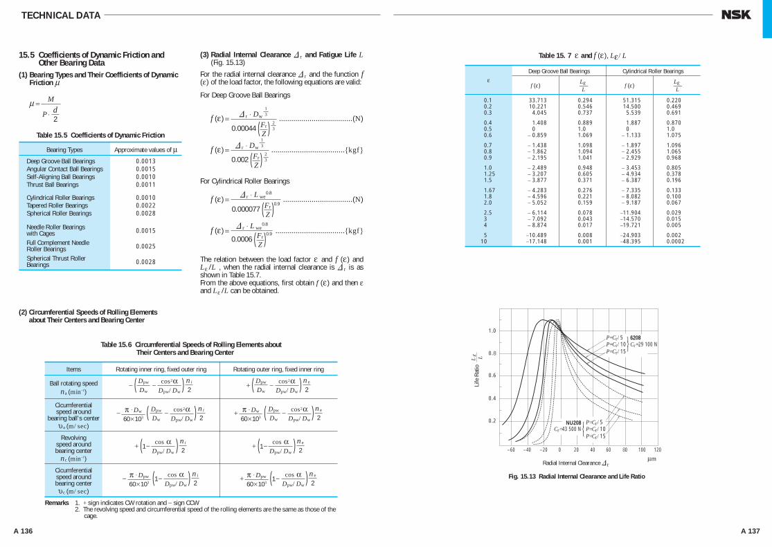
A 136 A 137
Table 15. 7 ε and f (ε), Lε/L
Fig. 15.13 Radial Internal Clearance and Life Ratio
1.0
0.8
0.6
0.4
0.2
40200−20−40−60 60 80 100 120
μmRadial Internal Clearance
Life
Rat
io
r&
P=Cr/5P=Cr/10P=Cr/15
P=Cr/5P=Cr/10P=Cr/15
6208
NU208Cr=43 500 N
Cr=29 100 N
L Lε
Deep Groove Ball Bearings Cylindrical Roller Bearings
f (ε) Lε⎯L
f (ε) Lε⎯L
0.1 33.713 0.294 51.315 0.220 0.2 10.221 0.546 14.500 0.469 0.3 4.045 0.737 5.539 0.691
0.4 1.408 0.889 1.887 0.870 0.5 0 1.0 0 1.0 0.6 − 0.859 1.069 − 1.133 1.075
0.7 − 1.438 1.098 − 1.897 1.096 0.8 − 1.862 1.094 − 2.455 1.065 0.9 − 2.195 1.041 − 2.929 0.968
1.0 − 2.489 0.948 − 3.453 0.805 1.25 − 3.207 0.605 − 4.934 0.378 1.5 − 3.877 0.371 − 6.387 0.196
1.67 − 4.283 0.276 − 7.335 0.133 1.8 − 4.596 0.221 − 8.082 0.100 2.0 − 5.052 0.159 − 9.187 0.067
2.5 − 6.114 0.078 −11.904 0.029 3 − 7.092 0.043 −14.570 0.015 4 − 8.874 0.017 −19.721 0.005
5 −10.489 0.008 −24.903 0.002 10 −17.148 0.001 −48.395 0.0002
ε
TECHNICAL DATA
15.5 Coefficients of Dynamic Friction and Other Bearing Data
(1) Bearing Types and Their Coefficients of Dynamic Friction μ
μ =
(2) Circumferential Speeds of Rolling Elements about Their Centers and Bearing Center
(3) Radial Internal Clearance & r and Fatigue Life L (Fig. 15.13)
For the radial internal clearance & r and the function f (ε) of the load factor, the following equations are valid:
For Deep Groove Ball Bearings
f (ε) = ....................................(N)
f (ε) = ....................................{kgf}
For Cylindrical Roller Bearings
f (ε) = ..................................(N)
f (ε) = ..................................{kgf}
The relation between the load factor ε and f (ε) and Lε /L , when the radial internal clearance is & r is as shown in Table 15.7.From the above equations, first obtain f (ε) and then ε and Lε /L can be obtained.
Deep Groove Ball Bearings 0.0013 Angular Contact Ball Bearings 0.0015 Self-Aligning Ball Bearings 0.0010 Thrust Ball Bearings 0.0011
Cylindrical Roller Bearings 0.0010 Tapered Roller Bearings 0.0022 Spherical Roller Bearings 0.0028
Needle Roller Bearings 0.0015 with Cages
Full Complement Needle 0.0025 Roller Bearings
Spherical Thrust Roller 0.0028 Bearings
Bearing Types Approximate values of μ
Table 15.5 Coefficients of Dynamic Friction
M
P ⋅ d2
Remarks 1. + sign indicates CW rotation and − sign CCWRemarks 2. The revolving speed and circumferential speed of the rolling elements are the same as those of the
cage.
Items Rotating inner ring, fixed outer ring Rotating outer ring, fixed inner ring
Ball rotating speedna (min–1)
− ( − )Cicumferentialspeed around
bearing ball's center υa (m/sec)
Revolvingspeed aroundbearing center
nc (min–1)
Cicumferentialspeed aroundbearing center υc (m/sec)
Table 15.6 Circumferential Speeds of Rolling Elements about Their Centers and Bearing Center
Dpw
Dw
ni
2cos2α
Dpw/Dw+ ( − )Dpw
Dw
ne
2cos2α
Dpw/Dw
− ( − )π ⋅ Dw
60×103
ni
2cos2α
Dpw/Dw
Dpw
Dw
− (1− )π ⋅ Dpw
60×103
ni
2cos α
Dpw/Dw+ (1− )π ⋅ Dpw
60×103
ne
2cos α
Dpw/Dw
+ (1− ) ni
2cos α
Dpw/Dw+ (1− ) ne
2cos α
Dpw/Dw
+ ( − )π ⋅ Dw
60×103
ne
2cos2α
Dpw/Dw
Dpw
Dw
13& r ⋅ Dw
230.00044 ( )Fr
Z13& r ⋅ Dw
230.002 ( )Fr
Z
& r ⋅ L we0.8
0.000077 ( )0.9Fr
Z& r ⋅ L we
0.8
0.0006 ( )0.9Fr
Z
A126-141E.indd 136-137 A126-141E.indd 136-137 11/20/13 4:53:09 PM11/20/13 4:53:09 PM
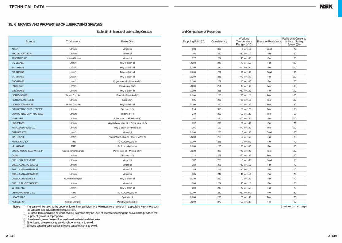
A 138 A 139
and Comparison of Properties
TECHNICAL DATA
15. 6 BRANDS AND PROPERTIES OF LUBRICATING GREASES
Table 15. 8 Brands of Lubricating Greases
ADLEX Lithium Mineral oil 198 300 0 to +110 Good 70
APOLOIL AUTOLEX A Lithium Mineral oil 198 280 −10 to +110 Fair 60
ARAPEN RB 300 Lithium/Calcium Mineral oil 177 294 −10 to + 80 Fair 70
EA2 GREASE Urea (3) Poly-α-olefin oil ≥260 243 −40 to +150 Fair 100
EA3 GREASE Urea (3) Poly-α-olefin oil ≥260 230 −40 to +150 Fair 100
EA5 GREASE Urea (3) Poly-α-olefin oil ≥260 251 −40 to +160 Good 60
EA7 GREASE Urea (3) Poly-α-olefin oil ≥260 243 −40 to +160 Fair 100
ENC GREASE Urea (3) Polyol ester oil + Mineral oil (4) ≥260 262 −40 to +160 Fair 70
ENS GREASE Urea (3) Polyol ester oil (4) ≥260 264 −40 to +160 Poor 100
ECE GREASE Lithium Poly-α-olefin oil ≥260 235 −10 to +120 Fair 100
ISOFLEX NBU 15 Barium Complex Ester oil + Mineral oil (4) ≥260 280 −30 to +120 Poor 100
ISOFLEX SUPER LDS 18 Lithium Ester oil (4) 195 280 −50 to +110 Poor 100
ISOFLEX TOPAS NB 52 Barium Complex Poly-α-olefin oil ≥260 280 −40 to +130 Poor 90
DOW CORNING SH 33 L GREASE Lithium Silicone oil (5) 210 310 −60 to +120 Poor 60
DOW CORNING SH 44 M GREASE Lithium Silicone oil (5) 210 260 −30 to +130 Poor 60
NS HI-LUBE Lithium Polyol ester oil + Diester oil (4) 192 250 −40 to +130 Fair 100
NSC GREASE Lithium Alkyldiphenyl ether oil + Polyol ester oil (4) 192 235 −30 to +140 Fair 70
NSK CLEAN GREASE LG2 Lithium Poly-α-olefin oil + Mineral oil 201 199 −40 to +130 Poor 100
EMALUBE 8030 Urea (3) Mineral oil ≥260 280 0 to +130 Good 60
MA8 GREASE Urea (3) Alkyldiphenyl ether oil + Poly-α-olefin oil ≥260 283 −30 to +160 Fair 70
KRYTOX GPL-524 PTFE Perfluoropolyether oil ≥260 265 0 to +200 Fair 70
KP1 GREASE PTFE Perfluoropolyether oil ≥260 280 −30 to +200 Fair 60
COSMO WIDE GREASE WR No.3N Sodium Terephtalamate Polyol ester oil + Mineral oil (4) ≥230 227 −40 to +130 Poor 100
G-40M Lithium Silicone oil (5) 223 252 −30 to +130 Poor 60
SHELL GADUS S2 V220 2 Lithium Mineral oil 187 276 0 to + 80 Good 60
SHELL ALVANIA GREASE S1 Lithium Mineral oil 182 323 −10 to +110 Fair 70
SHELL ALVANIA GREASE S2 Lithium Mineral oil 185 275 −10 to +110 Fair 70
SHELL ALVANIA GREASE S3 Lithium Mineral oil 185 242 −10 to +110 Fair 70
CASSIDA GREASE RLS 2 Aluminum Complex Poly-α-olefin oil ≥240 280 0 to +120 Fair 70
SHELL SUNLIGHT GREASE 2 Lithium Mineral oil 200 274 −10 to +110 Fair 70
WPH GREASE Urea (3) Poly-α-olefin oil 259 240 −40 to +150 Fair 70
DEMNUM GREASE L-200 PTFE Perfluoropolyether oil ≥260 280 −30 to +200 Fair 60
NIGACE WR-S Urea (3) Synthetic oil ≥260 230 −30 to +150 Poor 70
NIGLUBE RSH Sodium Complex Polyalkylene Glycol oil ≥260 270 −20 to +120 Fair 60
Brands Thickeners Base Oils Dropping Point (˚C) Consistency Pressure ResistanceWorking
Temperature Range(1)(°C)
Usable Limit Compared to Listed Limiting
Speed(2)(%)
Notes (1) If grease will be used at the upper or lower limit sufficient of the temperature range or in a special environment such as vacuum, it is advisable to consult NSK.
Notes (2) For short-term operation or when cooling is grease may be used at speeds exceeding the above limits provided the supply of grease is appropriate.
Notes (3) Urea-based grease causes fluorine-based material to deteriorate.Notes (4) Ester-based grease causes acrylic rubber material to swell.Notes (5) Silicone-based grease causes silicone-based material to swell.
(continued on next page)
A126-141E.indd 138-139 A126-141E.indd 138-139 11/20/13 4:53:10 PM11/20/13 4:53:10 PM

A 140 A 141
PALMAX RBG Lithium Complex Mineral oil 216 300 −10 to +130 Good 70
BEACON 325 Lithium Diester oil (4) 190 274 −50 to +100 Poor 100
MULTEMP PS No.2 Lithium Poly-α-olefin oil + Diester oil (4) 190 275 −50 to +110 Poor 100
MOLYKOTE FS-3451 GREASE PTFE Fluorosilicone oil (5) ≥260 285 0 to +180 Fair 70
UME GREASE Urea Mineral oil ≥260 268 −10 to +130 Fair 70
RAREMAX AF-1 Urea Mineral oil ≥260 300 −10 to +130 Fair 70
Brands Thickeners Base Oils Dropping Point (˚C) Consistency Pressure Resistance
Notes (1) If grease will be used at the upper or lower limit sufficient of the temperature range or in a special environment such as vacuum, it is advisable to consult NSK.
Notes (2) For short-term operation or when cooling is grease may be used at speeds exceeding the above limits provided the supply of grease is appropriate.
Notes (3) Urea-based grease causes fluorine-based material to deteriorate.Notes (4) Ester-based grease causes acrylic rubber material to swell.Notes (5) Silicone-based grease causes silicone-based material to swell.
Working Temperature Range(1)(°C)
Usable Limit Compared to Listed Limiting
Speed(2)(%)
TECHNICAL DATA
A126-141E.indd 140-141 A126-141E.indd 140-141 11/20/13 4:53:11 PM11/20/13 4:53:11 PM

BEARING TABLES
B001-029E.indd 1B001-029E.indd 1 11/20/13 4:53:34 PM11/20/13 4:53:34 PM

BEARING TABLE CONTENTS
PageDEEP GROOVE BALL BEARINGS ··············································································································· B4 Bore Dia.
SINGLE-ROW DEEP GROOVE BALL BEARINGS 10 – 800mm ······························· B8MAXIMUM TYPE BALL BEARINGS 25 – 110mm ······························· B26MAGNETO BEARINGS 4 – 20mm ································ B28EXTRA SMALL BALL BEARINGS AND
MINIATURE BALL BEARINGS ···················································· B30Metric Design 1 – 9mm ····································· B34Inch Design 1.016 – 9.525mm ························ B42
ANGULAR CONTACT BALL BEARINGS ····································································································· B46 Bore Dia.
SINGLE-ROW ANGULAR CONTACT BALL BEARINGS 10 – 200mm ······························· B50MATCHED ANGULAR CONTACT BALL BEARINGS 10 – 200mm ······························· B50DOUBLE-ROW ANGULAR CONTACT BALL BEARINGS 10 – 85mm ······························· B70FOUR-POINT CONTACT BALL BEARINGS 30 – 200mm ······························· B72
SELF-ALIGNING BALL BEARINGS············································································································· B76 Bore Dia.
SELF-ALIGNING BALL BEARINGS 5 – 110mm ································· B78
CYLINDRICAL ROLLER BEARINGS ··········································································································· B84 Bore Dia.
SINGLE-ROW CYLINDRICAL ROLLER BEARINGS 20 – 500mm ······························· B88L-SHAPED THRUST COLLARS FOR CYLINDRICAL ROLLERBEARINGS 20 – 320mm ······························· B104DOUBLE-ROW CYLINDRICAL ROLLER BEARINGS 25 – 360mm ······························· B106
TAPERED ROLLER BEARINGS ··················································································································· B110 Bore Dia.
METRIC DESIGN TAPERED ROLLER BEARINGS 15 – 440mm ······························· B116INCH DESIGN TAPERED ROLLER BEARINGS 12.000 – 206.375mm ·················· B136DOUBLE-ROW TAPERED ROLLER BEARINGS 80 – 260mm ······························· B172
SPHERICAL ROLLER BEARINGS ··············································································································· B182 Bore Dia.
SPHERICAL ROLLER BEARINGS 25 – 1400mm······························ B184
THRUST BEARINGS ···································································································································· B206 Bore Dia.
SINGLE-DIRECTION THRUST BALL BEARINGS 10 – 360mm ······························· B210DOUBLE-DIRECTION THRUST BALL BEARINGS 10 – 190mm ······························· B218CYLINDRICAL ROLLER THRUST BEARINGS 35 – 320mm ······························· B224SPHERICAL THRUST ROLLER BEARINGS 60 – 500mm ······························· B228ANGULAR CONTACT THRUST BALL BEARINGS ···················································· B234
Double-Direction Angular Contact Thrust Ball Bearings 35 – 280mm ······························· B238Angular Contact Thrust Ball Bearings for Ball Screws 15 – 60mm ······························· B242
Needle Roller Bearings ····························································································································· B244 Bore Dia.
CAGE & NEEDLE ROLLER ASSEMBLIES 5 – 100mm ······························· B252DRAWN CUP NEEDLE ROLLER BEARINGS 4 – 55mm ······························· B258SOLID NEEDLE ROLLER BEARINGS 9 – 390mm ······························· B264THRUST NEEDLE ROLLER BEARINGS 10 – 100mm ······························· B274CAM FOLLOWERS 16 – 90mm ······························· B276ROLLER FOLLOWERS 5 – 50mm ······························· B278
Page
BALL BEARING UNITS································································································································ B280SET SCREW TYPE
Shaft Dia.Pillow blocks cast housing
UCP2 12 – 90mm ································· B286Flanged units cast housing
UCF2 12 – 90mm ································· B292UCFL2 12 – 90mm ································· B298
PLUMMER BLOCKS ···································································································································· B304 Shaft Dia.
STANDARD TYPE PLUMMER BLOCKS 20 – 140mm ····························· B306LARGE PLUMMER BLOCKS 150 – 450mm······························ B312DUSTPROOF PLUMMER BLOCKS 50 – 180mm ····························· B316STEPPED-SHAFT TYPE PLUMMER BLOCKS 25 – 320mm ····························· B318
CYLINDRICAL ROLLER BEARINGS FOR SHEAVES ················································································· B326 Bore Dia.
Open Type 50 – 560mm ······························· B328Prelubricated Type 40 – 400mm ······························· B332
ROLL-NECK BEARINGS ······························································································································ B334 Bore Dia.
FOUR-ROW TAPERED ROLLER BEARINGS 100 – 939.800mm ······················· B338FOUR-ROW CYLINDRICAL ROLLER BEARINGS 100 – 920mm······························ B340
RAILWAY ROLLING STOCK BEARINGS ···································································································· B344
ROLLING ELEMENTS ·································································································································· B346 Basic Dia.STEEL BALLS FOR BALL BEARINGS 0.3 – 114.3mm···························· B348CYLINDRICAL ROLLERS FOR ROLLER BEARINGS 3 – 80mm ······························ B350LONG CYLINDRICAL ROLLERS FOR ROLLER BEARINGS 5.5 – 15mm ······························ B352NEEDLE ROLLERS FOR ROLLER BEARINGS 1 – 5mm ······························ B354
ACCESSORIES FOR ROLLING BEARINGS ································································································ B356 Shaft Dia.ADAPTERS FOR ROLLING BEARINGS 17 – 470mm ······························· B358WITHDRAWAL SLEEVES FOR ROLLING BEARINGS 35 – 480mm ······························· B366NUTS FOR ROLLING BEARINGS ···················································· B372STOPPERS FOR ROLLING BEARINGS ···················································· B377LOCK-WASHERS FOR ROLLING BEARINGS ···················································· B378
B 2 B 3
B001-029E.indd 2-3B001-029E.indd 2-3 11/20/13 4:53:35 PM11/20/13 4:53:35 PM
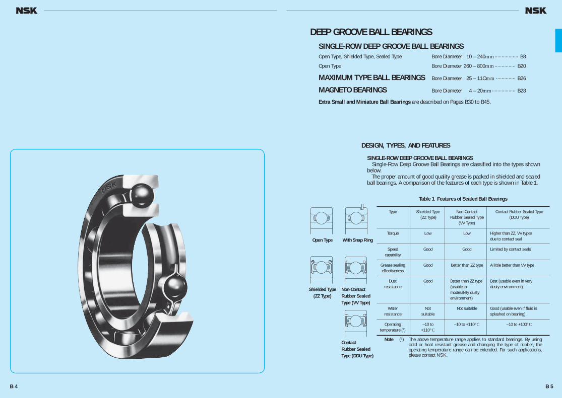
DEEP GROOVE BALL BEARINGSSINGLE-ROW DEEP GROOVE BALL BEARINGSOpen Type, Shielded Type, Sealed Type Bore Diameter 10 – 240mm ················· B8
Open Type Bore Diameter 260 – 800mm ··············· B20
MAXIMUM TYPE BALL BEARINGS Bore Diameter 25 – 11Omm ·············· B26
MAGNETO BEARINGS Bore Diameter 4 – 20mm ················· B28
Extra Small and Miniature Ball Bearings are described on Pages B30 to B45.
DESIGN, TYPES, AND FEATURES
SINGLE-ROW DEEP GROOVE BALL BEARINGS Single-Row Deep Groove Ball Bearings are classified into the types shown below. The proper amount of good quality grease is packed in shielded and sealed ball bearings. A comparison of the features of each type is shown in Table 1.
Table 1 Features of Sealed Ball Bearings
Type Shielded Type Non-Contact Contact Rubber Sealed Type (ZZ Type) Rubber Sealed Type (DDU Type) (VV Type)
Torque Low Low Higher than ZZ, VV types due to contact seal
Speed Good Good Limited by contact seals capability
Grease sealing Good Better than ZZ type A little better than VV type effectiveness
Dust Good Better than ZZ type Best (usable even in very resistance (usable in dusty environment) moderately dusty environment)
Water Not Not suitable Good (usable even if fluid is resistance suitable splashed on bearing)
Operating –10 to –10 to +110°C –10 to +100°C temperature (1) +110°C
Note (1) The above temperature range applies to standard bearings. By using cold or heat resistant grease and changing the type of rubber, the operating temperature range can be extended. For such applications, please contact NSK.
Open Type With Snap Ring
Shielded Type(ZZ Type)
Non-Contact Rubber Sealed Type (VV Type)
ContactRubber Sealed Type (DDU Type)
B 4 B 5
B001-029E.indd 4-5B001-029E.indd 4-5 11/20/13 4:53:36 PM11/20/13 4:53:36 PM
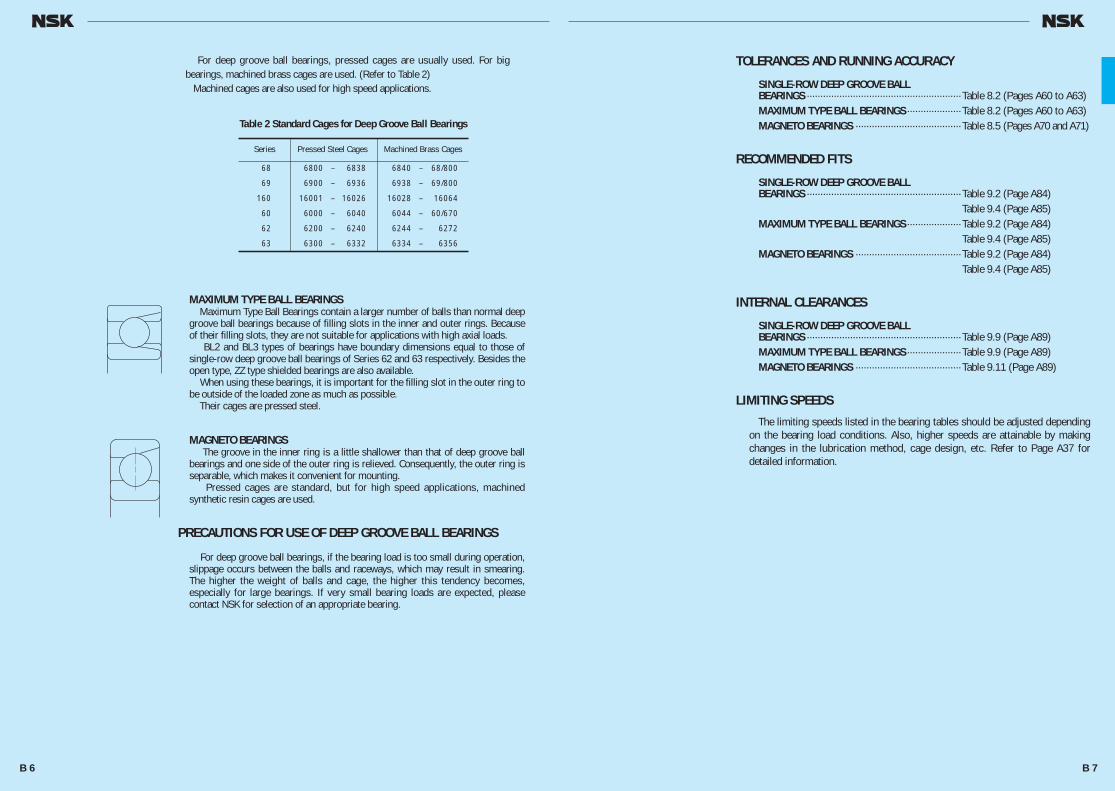
TOLERANCES AND RUNNING ACCURACY
SINGLE-ROW DEEP GROOVE BALLBEARINGS ························································· Table 8.2 (Pages A60 to A63)MAXIMUM TYPE BALL BEARINGS ···················· Table 8.2 (Pages A60 to A63)MAGNETO BEARINGS ······································· Table 8.5 (Pages A70 and A71)
RECOMMENDED FITS
SINGLE-ROW DEEP GROOVE BALLBEARINGS ························································· Table 9.2 (Page A84) Table 9.4 (Page A85)MAXIMUM TYPE BALL BEARINGS ···················· Table 9.2 (Page A84) Table 9.4 (Page A85)MAGNETO BEARINGS ······································· Table 9.2 (Page A84) Table 9.4 (Page A85)
INTERNAL CLEARANCES
SINGLE-ROW DEEP GROOVE BALLBEARINGS ························································· Table 9.9 (Page A89)MAXIMUM TYPE BALL BEARINGS ···················· Table 9.9 (Page A89)MAGNETO BEARINGS ······································· Table 9.11 (Page A89)
LIMITING SPEEDS
The limiting speeds listed in the bearing tables should be adjusted depending on the bearing load conditions. Also, higher speeds are attainable by making changes in the lubrication method, cage design, etc. Refer to Page A37 for detailed information.
Series Pressed Steel Cages Machined Brass Cages
68 6800 – 6838 6840 – 68/800
69 6900 – 6936 6938 – 69/800
160 16001 – 16026 16028 – 16064
60 6000 – 6040 6044 – 60/670
62 6200 – 6240 6244 – 6272
63 6300 – 6332 6334 – 6356
Table 2 Standard Cages for Deep Groove Ball Bearings
For deep groove ball bearings, pressed cages are usually used. For big bearings, machined brass cages are used. (Refer to Table 2) Machined cages are also used for high speed applications.
MAXIMUM TYPE BALL BEARINGS Maximum Type Ball Bearings contain a larger number of balls than normal deep groove ball bearings because of filling slots in the inner and outer rings. Because of their filling slots, they are not suitable for applications with high axial loads. BL2 and BL3 types of bearings have boundary dimensions equal to those of single-row deep groove ball bearings of Series 62 and 63 respectively. Besides the open type, ZZ type shielded bearings are also available. When using these bearings, it is important for the filling slot in the outer ring to be outside of the loaded zone as much as possible. Their cages are pressed steel.
MAGNETO BEARINGS The groove in the inner ring is a little shallower than that of deep groove ball bearings and one side of the outer ring is relieved. Consequently, the outer ring is separable, which makes it convenient for mounting. Pressed cages are standard, but for high speed applications, machined synthetic resin cages are used.
PRECAUTIONS FOR USE OF DEEP GROOVE BALL BEARINGS
For deep groove ball bearings, if the bearing load is too small during operation, slippage occurs between the balls and raceways, which may result in smearing. The higher the weight of balls and cage, the higher this tendency becomes, especially for large bearings. If very small bearing loads are expected, please contact NSK for selection of an appropriate bearing.
B 6 B 7
B001-029E.indd 6-7B001-029E.indd 6-7 11/20/13 4:53:36 PM11/20/13 4:53:36 PM
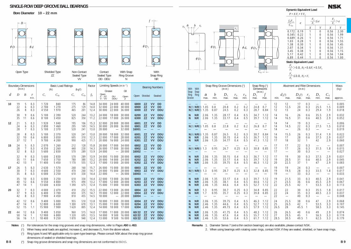
SINGLE-ROW DEEP GROOVE BALL BEARINGSBore Diameter 10 – 22 mm
— — — — — — — — — 12 12 17 0.3 — — 0.005 N(3) NR(3) 1.05 0.80 20.80 0.20 0.2 24.8 0.70 12 12.5 20 0.3 25.5 1.5 0.009 N(4) NR(4) 1.35 0.87 24.50 0.20 0.3 28.7 0.84 12 13 24 0.3 29.4 1.9 0.018
N NR 2.06 1.35 28.17 0.40 0.5 34.7 1.12 14 16 26 0.6 35.5 2.9 0.032 N NR 2.06 1.35 33.17 0.40 0.5 39.7 1.12 14 16.5 31 0.6 40.5 2.9 0.052
— — — — — — — — — 14 14 19 0.3 — — 0.006 N(3) NR(3) 1.05 0.80 22.80 0.20 0.2 26.8 0.70 14 14.5 22 0.3 27.5 1.5 0.010 — — — — — — — — — 14 — 26 0.3 — — 0.019
N(4) NR(4) 1.35 0.87 26.50 0.20 0.3 30.7 0.84 14 15.5 26 0.3 31.4 1.9 0.022 N NR 2.06 1.35 30.15 0.40 0.5 36.7 1.12 16 17 28 0.6 37.5 2.9 0.037 N NR 2.06 1.35 34.77 0.40 0.5 41.3 1.12 17 18 32 1 42 2.9 0.060
— — — — — — — — — 17 17 22 0.3 — — 0.007 N(3) NR(3) 1.30 0.95 26.70 0.25 0.3 30.8 0.85 17 17 26 0.3 31.5 1.8 0.015 — — — — — — — — — 17 — 30 0.3 — — 0.027
N NR 2.06 1.35 30.15 0.40 0.3 36.7 1.12 17 19 30 0.3 37.5 2.9 0.031 N NR 2.06 1.35 33.17 0.40 0.5 39.7 1.12 19 20.5 31 0.6 40.5 2.9 0.045 N NR 2.06 1.35 39.75 0.40 0.5 46.3 1.12 20 22.5 37 1 47 2.9 0.083
— — — — — — — — — 19 19 24 0.3 — — 0.007 N(3) NR(3) 1.30 0.95 28.70 0.25 0.3 32.8 0.85 19 19.5 28 0.3 33.5 1.8 0.017 — — — — — — — — — 19 — 33 0.3 — — 0.033
N NR 2.06 1.35 33.17 0.40 0.3 39.7 1.12 19 21.5 33 0.3 40.5 2.9 0.041 N NR 2.06 1.35 38.10 0.40 0.5 44.6 1.12 21 23.5 36 0.6 45.5 2.9 0.067 N NR 2.46 1.35 44.60 0.40 0.5 52.7 1.12 22 25.5 42 1 53.5 3.3 0.113
N NR 1.30 0.95 30.70 0.25 0.3 34.8 0.85 22 22 30 0.3 35.5 1.8 0.017 N NR 1.70 0.95 35.70 0.25 0.3 39.8 0.85 22 24 35 0.3 40.5 2.3 0.037 — — — — — — — — — 22 — 40 0.3 — — 0.048
N NR 2.06 1.35 39.75 0.40 0.5 46.3 1.12 24 25.5 38 0.6 47 2.9 0.068 N NR 2.46 1.35 44.60 0.40 0.5 52.7 1.12 25 26.5 42 1 53.5 3.3 0.107 N NR 2.46 1.35 49.73 0.40 0.5 57.9 1.12 26.5 28 45.5 1 58.5 3.3 0.145
N NR 2.06 1.35 41.75 0.40 0.5 48.3 1.12 26 26.5 40 0.6 49 2.9 0.074 N NR 2.46 1.35 47.60 0.40 0.5 55.7 1.12 27 29.5 45 1 56.5 3.3 0.119 N NR 2.46 1.35 53.60 0.40 0.5 61.7 1.12 28.5 30.5 49.5 1 62.5 3.3 0.179
With With Snap Snap Ring Ring Groove
Bearing Numbers
Open Shielded Sealed
Snap Ring Groove Dimensions (1)(mm)
a b D1 r0 rN max. min. max. max. min.
Snap Ring (1)Dimensions
(mm) D2 f max. max.
Abutment and Fillet Dimensions(mm)
da(2) Da(2) ra Dx CY min. max. max. max. min. max.
Mass(kg)
approx.
10 19 5 0.3 1 720 840 175 86 14.8 34 000 24 000 40 000 6800 ZZ VV DD 22 6 0.3 2 700 1 270 275 129 14.0 32 000 22 000 38 000 6900 ZZ VV DD 26 8 0.3 4 550 1 970 465 201 12.4 30 000 22 000 36 000 6000 ZZ VV DDU
30 9 0.6 5 100 2 390 520 244 13.2 24 000 18 000 30 000 6200 ZZ VV DDU 35 11 0.6 8 100 3 450 825 350 11.2 22 000 17 000 26 000 6300 ZZ VV DDU
12 21 5 0.3 1 920 1 040 195 106 15.3 32 000 20 000 38 000 6801 ZZ VV DD 24 6 0.3 2 890 1 460 295 149 14.5 30 000 20 000 36 000 6901 ZZ VV DD 28 7 0.3 5 100 2 370 520 241 13.0 28 000 — 32 000 16001 — — —
28 8 0.3 5 100 2 370 520 241 13.0 28 000 18 000 32 000 6001 ZZ VV DDU 32 10 0.6 6 800 3 050 695 310 12.3 22 000 17 000 28 000 6201 ZZ VV DDU 37 12 1 9 700 4 200 990 425 11.1 20 000 16 000 24 000 6301 ZZ VV DDU
15 24 5 0.3 2 070 1 260 212 128 15.8 28 000 17 000 34 000 6802 ZZ VV DD 28 7 0.3 4 350 2 260 440 230 14.3 26 000 17 000 30 000 6902 ZZ VV DD 32 8 0.3 5 600 2 830 570 289 13.9 24 000 — 28 000 16002 — — —
32 9 0.3 5 600 2 830 570 289 13.9 24 000 15 000 28 000 6002 ZZ VV DDU 35 11 0.6 7 650 3 750 780 380 13.2 20 000 14 000 24 000 6202 ZZ VV DDU 42 13 1 11 400 5 450 1 170 555 12.3 17 000 13 000 20 000 6302 ZZ VV DDU
17 26 5 0.3 2 630 1 570 268 160 15.7 26 000 15 000 30 000 6803 ZZ VV DD 30 7 0.3 4 600 2 550 470 260 14.7 24 000 15 000 28 000 6903 ZZ VV DDU 35 8 0.3 6 000 3 250 610 330 14.4 22 000 — 26 000 16003 — — —
35 10 0.3 6 000 3 250 610 330 14.4 22 000 13 000 26 000 6003 ZZ VV DDU 40 12 0.6 9 550 4 800 975 490 13.2 17 000 12 000 20 000 6203 ZZ VV DDU 47 14 1 13 600 6 650 1 390 675 12.4 15 000 11 000 18 000 6303 ZZ VV DDU
20 32 7 0.3 4 000 2 470 410 252 15.5 22 000 13 000 26 000 6804 ZZ VV DD 37 9 0.3 6 400 3 700 650 375 14.7 19 000 12 000 22 000 6904 ZZ VV DDU 42 8 0.3 7 900 4 450 810 455 14.5 18 000 — 20 000 16004 — — —
42 12 0.6 9 400 5 000 955 510 13.8 18 000 11 000 20 000 6004 ZZ VV DDU 47 14 1 12 800 6 600 1 300 670 13.1 15 000 11 000 18 000 6204 ZZ VV DDU 52 15 1.1 15 900 7 900 1 620 805 12.4 14 000 10 000 17 000 6304 ZZ VV DDU
22 44 12 0.6 9 400 5 050 960 515 14.0 17 000 11 000 20 000 60/22 ZZ VV DDU 50 14 1 12 900 6 800 1 320 695 13.5 14 000 9 500 16 000 62/22 ZZ VV DDU 56 16 1.1 18 400 9 250 1 870 940 12.4 13 000 9 500 16 000 63/22 ZZ VV DDU
Boundary Dimensions(mm)
d D B r min.
Limiting Speeds (min–1)
Grease Oil Open Z · ZZ DU Open V · VV DDU Z
Factor
f0
Basic Load Ratings (N) {kgf}
Cr C0r Cr C0r
Notes (1) For tolerances for the snap ring grooves and snap ring dimensions, refer to Pages A50 to A53. (2) When heavy axial loads are applied, increase da and decrease Da from the above values. (3) Ring types N and NR applicable only to open-type bearings. Please consult NSK about the snap ring groove
dimensions of sealed or shielded bearings. (4) Snap ring groove dimensions and snap ring dimensions are not conformed to ISO15.
r
r
jD jd
B
jD
f
2
ra
r0rN
jdajDa
jD1
ra
ra
jD
C
X
Y
ba
Shielded TypeZZ
Non-ContactSealed Type
VV
ContactSealed TypeDD · DDU
With SnapRing Groove
N
WithSnap Ring
NR
Open Type
Remarks 1. Diameter Series 7 (extra thin section bearings) are also available, please contact NSK. 2. When using bearings with rotating outer rings, contact NSK if they are sealed, shielded, or have snap rings.
X Y X Y 0.172 0.19 1 0 0.56 2.30 0.345 0.22 1 0 0.56 1.99 0.689 0.26 1 0 0.56 1.71 1.03 0.28 1 0 0.56 1.55 1.38 0.30 1 0 0.56 1.45 2.07 0.34 1 0 0.56 1.31 3.45 0.38 1 0 0.56 1.15 5.17 0.42 1 0 0.56 1.04 6.89 0.44 1 0 0.56 1.00
f 0Fa
C 0re
Fa ≤e Fr
Fa >e Fr
Dynamic Equivalent LoadP =XFr +YFa
Static Equivalent LoadFa Fr>0.8, P0 =0.6Fr +0.5Fa
Fa Fr≤0.8, P0 =Fr
B 8 B 9
B001-029E.indd 8-9B001-029E.indd 8-9 11/20/13 4:53:37 PM11/20/13 4:53:37 PM

SINGLE-ROW DEEP GROOVE BALL BEARINGS
N NR 1.30 0.95 35.70 0.25 0.3 39.8 0.85 27 27 35 0.3 40.5 1.8 0.021 N(3) NR(3) 1.70 0.95 40.70 0.25 0.3 44.8 0.85 27 28.5 40 0.3 45.5 2.3 0.042 — — — — — — — — — 27 — 45 0.3 — — 0.059 N NR 2.06 1.35 44.60 0.40 0.5 52.7 1.12 29 30 43 0.6 53.5 2.9 0.079 N NR 2.46 1.35 49.73 0.40 0.5 57.9 1.12 30 32 47 1 58.5 3.3 0.129 N NR 3.28 1.90 59.61 0.60 0.5 67.7 1.70 31.5 36 55.5 1 68.5 4.6 0.235 N NR 2.06 1.35 49.73 0.40 0.5 57.9 1.12 32 34 48 0.6 58.5 2.9 0.096 N NR 2.46 1.35 55.60 0.40 0.5 63.7 1.12 33 35.5 53 1 64.5 3.3 0.175 N NR 3.28 1.90 64.82 0.60 0.5 74.6 1.70 34.5 38 61.5 1 76 4.6 0.287 N NR 1.30 0.95 40.70 0.25 0.3 44.8 0.85 32 32 40 0.3 45.5 1.8 0.024 N NR 1.70 0.95 45.70 0.25 0.3 49.8 0.85 32 34 45 0.3 50.5 2.3 0.052 — — — — — — — — — 32 — 53 0.3 — — 0.087 N NR 2.08 1.35 52.60 0.40 0.5 60.7 1.12 35 36.5 50 1 61.5 2.9 0.116 N NR 3.28 1.90 59.61 0.60 0.5 67.7 1.70 35 38.5 57 1 68.5 4.6 0.199 N NR 3.28 1.90 68.81 0.60 0.5 78.6 1.70 36.5 42.5 65.5 1 80 4.6 0.345 N NR 2.08 1.35 55.60 0.40 0.5 63.7 1.12 37 38.5 53 1 64.5 2.9 0.122 N NR 3.28 1.90 62.60 0.60 0.5 70.7 1.70 37 40 60 1 71.5 4.6 0.225 N NR 3.28 1.90 71.83 0.60 0.5 81.6 1.70 38.5 44.5 68.5 1 83 4.6 0.389 N NR 1.30 0.95 45.70 0.25 0.3 49.8 0.85 37 37 45 0.3 50.5 1.8 0.027 N NR 1.70 0.95 53.70 0.25 0.5 57.8 0.85 39 39 51 0.6 58.5 2.3 0.075 — — — — — — — — — 37 — 60 0.3 — — 0.107 N NR 2.08 1.90 59.61 0.60 0.5 67.7 1.70 40 41.5 57 1 68.5 3.4 0.151 N NR 3.28 1.90 68.81 0.60 0.5 78.6 1.70 41.5 44.5 65.5 1 80 4.6 0.284 N NR 3.28 1.90 76.81 0.60 0.5 86.6 1.70 43 47 72 1.5 88 4.6 0.464 N NR 1.30 0.95 50.70 0.25 0.3 54.8 0.85 42 42 50 0.3 55.5 1.8 0.031 N NR 1.70 0.95 60.70 0.25 0.5 64.8 0.85 44 46 58 0.6 65.5 2.3 0.112 — — — — — — — — — 42 — 66 0.3 — — 0.13 N NR 2.49 1.90 64.82 0.60 0.5 74.6 1.70 45 47.5 63 1 76 3.8 0.19 N NR 3.28 1.90 76.81 0.60 0.5 86.6 1.70 46.5 50.5 73.5 1 88 4.6 0.366 N NR 3.28 2.70 86.79 0.60 0.5 96.5 2.46 48 53 82 1.5 98 5.4 0.636 N NR 1.30 0.95 56.70 0.25 0.3 60.8 0.85 47 47.5 56 0.3 61.5 1.8 0.038 N NR 1.70 0.95 66.70 0.25 0.3(4) 70.8 0.85 49 50 64 0.6 72 2.3 0.126 — — — — — — — — — 49 — 71 0.6 — — 0.167 N NR 2.49 1.90 71.83 0.60 0.5 81.6 1.70 50 53.5 70 1 83 3.8 0.241 N NR 3.28 1.90 81.81 0.60 0.5 91.6 1.70 51.5 55.5 78.5 1 93 4.6 0.42 N NR 3.28 2.70 96.80 0.60 0.5 106.50 2.46 53 61.5 92 1.5 108 5.4 0.829
With With Snap Snap Ring Ring Groove
Bearing Numbers
Open Shielded Sealed
Snap Ring Groove Dimensions (1)(mm)
a b D1 r0 rN max. min. max. max. min.
Snap Ring (1)Dimensions
(mm) D2 f max. max.
Abutment and Fillet Dimensions(mm)
da(2) Da(2) ra Dx CY min. max. max. max. min. max.
Mass(kg)
approx.
25 37 7 0.3 4 500 3 150 455 320 16.1 18 000 10 000 22 000 6805 ZZ VV DD 42 9 0.3 7 050 4 550 715 460 15.4 16 000 10 000 19 000 6905 ZZ VV DDU 47 8 0.3 8 850 5 600 905 570 15.1 15 000 — 18 000 16005 — — — 47 12 0.6 10 100 5 850 1 030 595 14.5 15 000 9 500 18 000 6005 ZZ VV DDU 52 15 1 14 000 7 850 1 430 800 13.9 13 000 9 000 15 000 6205 ZZ VV DDU 62 17 1.1 20 600 11 200 2 100 1 150 13.2 11 000 8 000 13 000 6305 ZZ VV DDU
28 52 12 0.6 12 500 7 400 1 270 755 14.5 14 000 8 500 16 000 60/28 ZZ VV DDU 58 16 1 16 600 9 500 1 700 970 13.9 12 000 8 000 14 000 62/28 ZZ VV DDU 68 18 1.1 26 700 14 000 2 730 1 430 12.4 10 000 7 500 13 000 63/28 ZZ VV DDU
30 42 7 0.3 4 700 3 650 480 370 16.4 15 000 9 000 18 000 6806 ZZ VV DD 47 9 0.3 7 250 5 000 740 510 15.8 14 000 8 500 17 000 6906 ZZ VV DDU 55 9 0.3 11 200 7 350 1 150 750 15.2 13 000 — 15 000 16006 — — — 55 13 1 13 200 8 300 1 350 845 14.7 13 000 8 000 15 000 6006 ZZ VV DDU 62 16 1 19 500 11 300 1 980 1 150 13.8 11 000 7 500 13 000 6206 ZZ VV DDU 72 19 1.1 26 700 15 000 2 720 1 530 13.3 9 500 6 700 12 000 6306 ZZ VV DDU
32 58 13 1 15 100 9 150 1 530 935 14.5 12 000 7 500 14 000 60/32 ZZ VV DDU 65 17 1 20 700 11 600 2 120 1 190 13.6 10 000 7 100 12 000 62/32 ZZ VV DDU 75 20 1.1 29 900 17 000 3 050 1 730 13.2 9 000 6 300 11 000 63/32 ZZ VV DDU
35 47 7 0.3 4 900 4 100 500 420 16.7 14 000 7 500 16 000 6807 ZZ VV DD 55 10 0.6 10 600 7 250 1 080 740 15.5 12 000 7 500 15 000 6907 ZZ VV DDU 62 9 0.3 11 700 8 200 1 190 835 15.6 11 000 — 13 000 16007 — — — 62 14 1 16 000 10 300 1 630 1 050 14.8 11 000 6 700 13 000 6007 ZZ VV DDU 72 17 1.1 25 700 15 300 2 620 1 560 13.8 9 500 6 300 11 000 6207 ZZ VV DDU 80 21 1.5 33 500 19 200 3 400 1 960 13.2 8 500 6 000 10 000 6307 ZZ VV DDU
40 52 7 0.3 6 350 5 550 650 565 17.0 12 000 6 700 14 000 6808 ZZ VV DD 62 12 0.6 13 700 10 000 1 390 1 020 15.7 11 000 6 300 13 000 6908 ZZ VV DDU 68 9 0.3 12 600 9 650 1 290 985 16.0 10 000 — 12 000 16008 — — — 68 15 1 16 800 11 500 1 710 1 180 15.3 10 000 6 000 12 000 6008 ZZ VV DDU 80 18 1.1 29 100 17 900 2 970 1 820 14.0 8 500 5 600 10 000 6208 ZZ VV DDU 90 23 1.5 40 500 24 000 4 150 2 450 13.2 7 500 5 300 9 000 6308 ZZ VV DDU
45 58 7 0.3 6 600 6 150 670 625 17.2 11 000 6 000 13 000 6809 ZZ VV DD 68 12 0.6 14 100 10 900 1 440 1 110 15.9 9 500 5 600 12 000 6909 ZZ VV DDU 75 10 0.6 14 900 11 400 1 520 1 160 15.9 9 000 — 11 000 16009 — — — 75 16 1 20 900 15 200 2 140 1 550 15.3 9 000 5 300 11 000 6009 ZZ VV DDU 85 19 1.1 31 500 20 400 3 200 2 080 14.4 7 500 5 300 9 000 6209 ZZ VV DDU 100 25 1.5 53 000 32 000 5 400 3 250 13.1 6 700 4 800 8 000 6309 ZZ VV DDU
Boundary Dimensions(mm)
d D B r min.
Limiting Speeds (min–1)
Grease Oil Open Z · ZZ DU Open V · VV DDU Z
Factor
f0
Basic Load Ratings (N) {kgf}
Cr C0r Cr C0r
Notes (1) For tolerances for the snap ring grooves and snap ring dimensions, refer to Pages A50 to A53. (2) When heavy axial loads are applied, increase da and decrease Da from the above values. (3) Ring types N and NR applicable only to open-type bearings. Please consult NSK about the snap ring groove
dimensions of sealed or shielded bearings. (4) Not conformed to ISO15.
r
r
jD jd
B
jD
f
2
ra
r0rN
jdajDa
jD1
ra
ra
jD
C
X
Y
ba
Shielded TypeZZ
Non-ContactSealed Type
VV
ContactSealed TypeDD · DDU
With SnapRing Groove
N
WithSnap Ring
NR
Open Type
Remarks 1. Diameter Series 7 (extra thin section bearings) are also available, please contact NSK. 2. When using bearings with rotating outer rings, contact NSK if they are sealed, shielded, or have snap rings.
X Y X Y 0.172 0.19 1 0 0.56 2.30 0.345 0.22 1 0 0.56 1.99 0.689 0.26 1 0 0.56 1.71 1.03 0.28 1 0 0.56 1.55 1.38 0.30 1 0 0.56 1.45 2.07 0.34 1 0 0.56 1.31 3.45 0.38 1 0 0.56 1.15 5.17 0.42 1 0 0.56 1.04 6.89 0.44 1 0 0.56 1.00
f 0Fa
C 0re
Fa ≤e Fr
Fa >e Fr
Dynamic Equivalent LoadP =XFr +YFa
Static Equivalent LoadFa Fr>0.8, P0 =0.6Fr +0.5Fa
Fa Fr≤0.8, P0 =Fr
Bore Diameter 25 – 45 mm
B 10 B 11
B001-029E.indd 10-11B001-029E.indd 10-11 11/20/13 4:53:38 PM11/20/13 4:53:38 PM

SINGLE-ROW DEEP GROOVE BALL BEARINGSBore Diameter 50 – 75 mm
N NR 1.30 0.95 63.7 0.25 0.3 067.8 0.85 52 52.5 63 0.3 68.5 1.8 0.050 N NR 1.70 0.95 70.7 0.25 0.5 074.8 0.85 54 55 68 0.6 76 2.3 0.135 — — — — — — — — — 54 — 76 0.6 — — 0.175 N NR 2.49 1.90 076.81 0.60 0.5 086.6 1.70 55 58.5 75 1 88 3.8 0.261 N NR 3.28 2.70 086.79 0.60 0.5 096.5 2.46 56.5 60 83.5 1 98 5.4 0.459 N NR 3.28 2.70 106.81 0.60 0.5 116.6 2.46 59 68 101 2 118 5.4 1.06 N NR 1.70 0.95 70.7 0.25 0.3 074.8 0.85 57 59 70 0.3 76 2.3 0.081 N NR 2.10 1.30 77.9 0.40 0.5 084.4 1.12 60 61.5 75 1 86 2.9 0.189 — — — — — — — — — 59 — 86 0.6 — — 0.257 N NR 2.87 2.70 086.79 0.60 0.5 096.5 2.46 61.5 64 83.5 1 98 5.0 0.381 N NR 3.28 2.70 96.8 0.60 0.5 106.5 2.46 63 66.5 92 1.5 108 5.4 0.619 N NR 4.06 3.10 115.21 0.60 0.5 129.7 2.82 64 72.5 111 2 131.5 6.5 1.37 N NR 1.70 1.30 76.2 0.40 0.3 082.7 1.12 62 64 76 0.3 84 2.5 0.103 N NR 2.10 1.30 82.9 0.40 0.5 089.4 1.12 65 66 80 1 91 2.9 0.192 — — — — — — — — — 64 — 91 0.6 — — 0.281 N NR 2.87 2.70 091.82 0.60 0.5 101.6 2.46 66.5 69 88.5 1 103 5.0 0.412 N NR 3.28 2.70 106.81 0.60 0.5 116.6 2.46 68 74.5 102 1.5 118 5.4 0.783 N NR 4.06 3.10 125.22 0.60 0.5 139.7 2.82 71 79 119 2 141.5 6.5 1.72 N NR 1.70 1.30 82.9 0.40 0.5 089.4 1.12 69 69 81 0.6 91 2.5 0.128 N NR 2.10 1.30 87.9 0.40 0.5 094.4 1.12 70 71.5 85 1 96 2.9 0.218 — — — — — — — — — 69 — 96 0.6 — — 0.30 N NR 2.87 2.70 96.8 0.60 0.5 106.5 2.46 71.5 73 93.5 1 108 5.0 0.439 N NR 4.06 3.10 115.21 0.60 0.5 129.7 2.82 73 80 112 1.5 131.5 6.5 1.0 N NR 4.90 3.10 135.23 0.60 0.5 149.7 2.82 76 85.5 129 2 152 7.3 2.11 N NR 1.70 1.30 87.9 0.40 0.5 094.4 1.12 74 74.5 86 0.6 96 2.5 0.134 N NR 2.50 1.30 97.9 0.40 0.5 104.4 1.12 75 77.5 95 1 106 3.3 0.349 — — — — — — — — — 74 — 106 0.6 — — 0.441 N NR 2.87 2.70 106.81 0.60 0.5 116.6 2.46 76.5 80.5 103.5 1 118 5.0 0.608 N NR 4.06 3.10 120.22 0.60 0.5 134.7 2.82 78 84 117 1.5 136.5 6.5 1.09 N NR 4.90 3.10 145.24 0.60 0.5 159.7 2.82 81 92 139 2 162 7.3 2.57 N NR 1.70 1.30 92.9 0.40 0.5 099.4 1.12 79 79.5 91 0.6 101 2.5 0.149 N NR 2.50 1.30 102.60 0.40 0.5 110.7 1.12 80 82 100 1 112 3.3 0.364 — — — — — — — — — 79 — 111 0.6 — — 0.463 N NR 2.87 2.70 111.81 0.60 0.5 121.6 2.46 81.5 85.5 108.5 1 123 5.0 0.649 N NR 4.06 3.10 125.22 0.60 0.5 139.7 2.82 83 90 122 1.5 141.5 6.5 1.19 N NR 4.90 3.10 155.22 0.60 0.5 169.7 2.82 86 98.5 149 2 172 7.3 3.08
With With Snap Snap Ring Ring Groove
Bearing Numbers
Open Shielded Sealed
Snap Ring Groove Dimensions (1)(mm)
a b D1 r0 rN max. min. max. max. min.
Snap Ring (1)Dimensions
(mm) D2 f max. max.
Abutment and Fillet Dimensions(mm)
da(2) Da(2) ra Dx CY min. max. max. max. min. max.
Mass(kg)
approx.
50 65 7 0.3 6 400 6 200 655 635 17.2 9 500 5 300 11 000 6810 ZZ VV DDU 72 12 0.6 14 500 11 700 1 480 1 200 16.1 9 000 5 300 11 000 6910 ZZ VV DDU 80 10 0.6 15 400 12 400 1 570 1 260 16.1 8 500 — 10 000 16010 — — — 80 16 1 21 800 16 600 2 220 1 700 15.6 8 500 4 800 10 000 6010 ZZ VV DDU 90 20 1.1 35 000 23 200 3 600 2 370 14.4 7 100 4 800 8 500 6210 ZZ VV DDU 110 27 2 62 000 38 500 6 300 3 900 13.2 6 000 4 300 7 500 6310 ZZ VV DDU
55 72 9 0.3 8 800 8 500 900 865 17.0 8 500 4 800 10 000 6811 ZZ VV DDU 80 13 1 16 000 13 300 1 630 1 350 16.2 8 000 4 500 9 500 6911 ZZ VV DDU 90 11 0.6 19 400 16 300 1 980 1 660 16.2 7 500 — 9 000 16011 — — — 90 18 1.1 28 300 21 200 2 880 2 170 15.3 7 500 4 500 9 000 6011 ZZ VV DDU 100 21 1.5 43 500 29 300 4 450 2 980 14.3 6 300 4 300 7 500 6211 ZZ VV DDU 120 29 2 71 500 44 500 7 300 4 550 13.1 5 600 4 000 6 700 6311 ZZ VV DDU
60 78 10 0.3 11 500 10 900 1 170 1 120 16.9 8 000 4 500 9 500 6812 ZZ VV DD 85 13 1 19 400 16 300 1 980 1 660 16.2 7 500 4 300 9 000 6912 ZZ VV DDU 95 11 0.6 20 000 17 500 2 040 1 780 16.3 7 100 — 8 500 16012 — — — 95 18 1.1 29 500 23 200 3 000 2 370 15.6 7 100 4 000 8 500 6012 ZZ VV DDU 110 22 1.5 52 500 36 000 5 350 3 700 14.3 5 600 3 800 7 100 6212 ZZ VV DDU 130 31 2.1 82 000 52 000 8 350 5 300 13.1 5 300 3 600 6 300 6312 ZZ VV DDU
65 85 10 0.6 11 900 12 100 1 220 1 230 17.0 7 500 4 000 8 500 6813 ZZ VV DD 90 13 1 17 400 16 100 1 770 1 640 16.6 7 100 4 000 8 500 6913 ZZ VV DDU 100 11 0.6 20 500 18 700 2 090 1 910 16.5 6 700 — 8 000 16013 — — — 100 18 1.1 30 500 25 200 3 100 2 570 15.8 6 700 4 000 8 000 6013 ZZ VV DDU 120 23 1.5 57 500 40 000 5 850 4 100 14.4 5 300 3 600 6 300 6213 ZZ VV DDU 140 33 2.1 92 500 60 000 9 450 6 100 13.2 4 800 3 400 6 000 6313 ZZ VV DDU
70 90 10 0.6 12 100 12 700 1 230 1 300 17.2 6 700 3 800 8 000 6814 ZZ VV DD 100 16 1 23 700 21 200 2 420 2 160 16.3 6 300 3 600 7 500 6914 ZZ VV DDU 110 13 0.6 26 800 23 600 2 730 2 410 16.3 6 000 — 7 100 16014 — — — 110 20 1.1 38 000 31 000 3 900 3 150 15.6 6 000 3 600 7 100 6014 ZZ VV DDU 125 24 1.5 62 000 44 000 6 350 4 500 14.5 5 000 3 400 6 300 6214 ZZ VV DDU 150 35 2.1 104 000 68 000 10 600 6 950 13.2 4 500 3 200 5 300 6314 ZZ VV DDU
75 95 10 0.6 12 500 13 900 1 280 1 410 17.3 6 300 3 600 7 500 6815 ZZ VV DDU 105 16 1 24 400 22 600 2 480 2 300 16.5 6 000 3 400 7 100 6915 ZZ VV DDU 115 13 0.6 27 600 25 300 2 820 2 580 16.4 5 600 — 6 700 16015 — — — 115 20 1.1 39 500 33 500 4 050 3 400 15.8 5 600 3 400 6 700 6015 ZZ VV DDU 130 25 1.5 66 000 49 500 6 750 5 050 14.7 4 800 3 200 5 600 6215 ZZ VV DDU 160 37 2.1 113 000 77 000 11 600 7 850 13.2 4 300 2 800 5 000 6315 ZZ VV DDU
Boundary Dimensions(mm)
d D B r min.
Limiting Speeds (min–1)
Grease Oil Open Z · ZZ DU Open V · VV DDU Z
Factor
f0
Basic Load Ratings (N) {kgf}
Cr C0r Cr C0r
Notes (1) For tolerances for the snap ring grooves and snap ring dimensions, refer to Pages A50 to A53. (2) When heavy axial loads are applied, increase da and decrease Da from the above values.
r
r
jD jd
B
jD
f
2
ra
r0rN
jdajDa
jD1
ra
ra
jD
C
X
Y
ba
Shielded TypeZZ
Non-ContactSealed Type
VV
ContactSealed TypeDD · DDU
With SnapRing Groove
N
WithSnap Ring
NR
Open Type
Remarks 1. Diameter Series 7 (extra thin section bearings) are also available, please contact NSK. 2. When using bearings with rotating outer rings, contact NSK if they are sealed, shielded, or have snap rings. 3. Please consult NSK about the snap ring groove dimensions of sealed and shielded bearings when the diameter of
dimension series 18 and 19 is 50 mm or more.
X Y X Y 0.172 0.19 1 0 0.56 2.30 0.345 0.22 1 0 0.56 1.99 0.689 0.26 1 0 0.56 1.71 1.03 0.28 1 0 0.56 1.55 1.38 0.30 1 0 0.56 1.45 2.07 0.34 1 0 0.56 1.31 3.45 0.38 1 0 0.56 1.15 5.17 0.42 1 0 0.56 1.04 6.89 0.44 1 0 0.56 1.00
f 0Fa
C 0re
Fa ≤e Fr
Fa >e Fr
Dynamic Equivalent LoadP =XFr +YFa
Static Equivalent LoadFa Fr>0.8, P0 =0.6Fr +0.5Fa
Fa Fr≤0.8, P0 =Fr
B 12 B 13
B001-029E.indd 12-13B001-029E.indd 12-13 11/20/13 4:53:40 PM11/20/13 4:53:40 PM
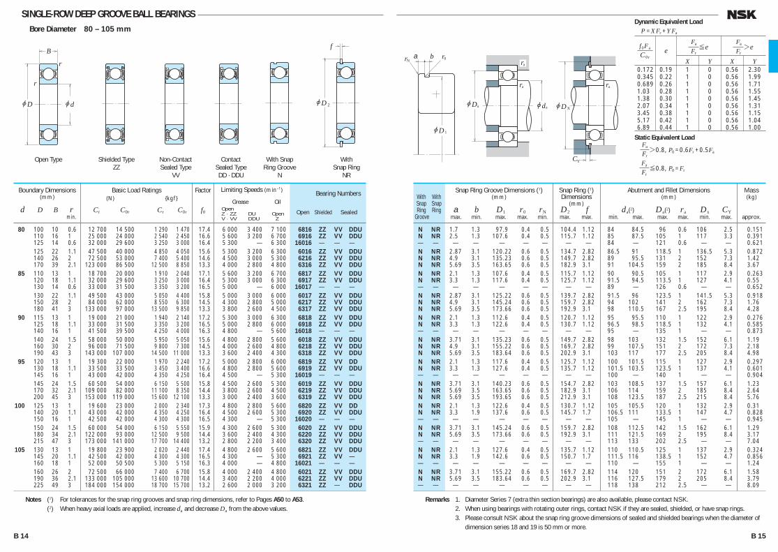
SINGLE-ROW DEEP GROOVE BALL BEARINGSBore Diameter 80 – 105 mm
N NR 1.70 1.3 97.9 0.4 0.5 104.4 1.12 84 84.5 96 0.6 106 2.5 0.151 N NR 2.50 1.3 107.60 0.4 0.5 115.7 1.12 85 87.5 105 1 117 3.3 0.391 — — — — — — — — — 84 — 121 0.6 — — 0.621 N NR 2.87 3.1 120.22 0.6 0.5 134.7 2.82 86.5 91 118.5 1 136.5 5.3 0.872 N NR 4.90 3.1 135.23 0.6 0.5 149.7 2.82 89 95.5 131 2 152 7.3 1.42 N NR 5.69 3.5 163.65 0.6 0.5 182.9 3.10 91 104.5 159 2 185 8.4 3.67 N NR 2.10 1.3 107.60 0.4 0.5 115.7 1.12 90 90.5 105 1 117 2.9 0.263 N NR 3.30 1.3 117.60 0.4 0.5 125.7 1.12 91.5 94.5 113.5 1 127 4.1 0.55 — — — — — — — — — 89 — 126 0.6 — — 0.652 N NR 2.87 3.1 125.22 0.6 0.5 139.7 2.82 91.5 96 123.5 1 141.5 5.3 0.918 N NR 4.90 3.1 145.24 0.6 0.5 159.7 2.82 94 102 141 2 162 7.3 1.76 N NR 5.69 3.5 173.66 0.6 0.5 192.9 3.10 98 110.5 167 2.5 195 8.4 4.28 N NR 2.10 1.3 112.60 0.4 0.5 120.7 1.12 95 95.5 110 1 122 2.9 0.276 N NR 3.30 1.3 122.60 0.4 0.5 130.7 1.12 96.5 98.5 118.5 1 132 4.1 0.585 — — — — — — — — — 95 — 135 1 — — 0.873 N NR 3.71 3.1 135.23 0.6 0.5 149.7 2.82 98 103 132 1.5 152 6.1 1.19 N NR 4.90 3.1 155.22 0.6 0.5 169.7 2.82 99 107.5 151 2 172 7.3 2.18 N NR 5.69 3.5 183.64 0.6 0.5 202.9 3.10 103 117 177 2.5 205 8.4 4.98 N NR 2.10 1.3 117.60 0.4 0.5 125.7 1.12 100 101.5 115 1 127 2.9 0.297 N NR 3.30 1.3 127.60 0.4 0.5 135.7 1.12 101.5 103.5 123.5 1 137 4.1 0.601 — — — — — — — — — 100 — 140 1 — — 0.904 N NR 3.71 3.1 140.23 0.6 0.5 154.7 2.82 103 108.5 137 1.5 157 6.1 1.23 N NR 5.69 3.5 163.65 0.6 0.5 182.9 3.10 106 114 159 2 185 8.4 2.64 N NR 5.69 3.5 193.65 0.6 0.5 212.9 3.10 108 123.5 187 2.5 215 8.4 5.76 N NR 2.10 1.3 122.60 0.4 0.5 130.7 1.12 105 105.5 120 1 132 2.9 0.31 N NR 3.30 1.9 137.60 0.6 0.5 145.7 1.70 106.5 111 133.5 1 147 4.7 0.828 — — — — — — — — — 105 — 145 1 — — 0.945 N NR 3.71 3.1 145.24 0.6 0.5 159.7 2.82 108 112.5 142 1.5 162 6.1 1.29 N NR 5.69 3.5 173.66 0.6 0.5 192.9 3.10 111 121.5 169 2 195 8.4 3.17 — — — — — — — — — 113 133 202 2.5 — — 7.04 N NR 2.10 1.3 127.60 0.4 0.5 135.7 1.12 110 110.5 125 1 137 2.9 0.324 N NR 3.30 1.9 142.60 0.6 0.5 150.7 1.70 111.5 116 138.5 1 152 4.7 0.856 — — — — — — — — — 110 — 155 1 — — 1.24 N NR 3.71 3.1 155.22 0.6 0.5 169.7 2.82 114 120 151 2 172 6.1 1.58 N NR 5.69 3.5 183.64 0.6 0.5 202.9 3.10 116 127.5 179 2 205 8.4 3.79 — — — — — — — — — 118 138 212 2.5 — — 8.09
With With Snap Snap Ring Ring Groove
Bearing Numbers
Open Shielded Sealed
Snap Ring Groove Dimensions (1)(mm)
a b D1 r0 rN max. min. max. max. min.
Snap Ring (1)Dimensions
(mm) D2 f max. max.
Abutment and Fillet Dimensions(mm)
da(2) Da(2) ra Dx CY min. max. max. max. min. max.
Mass(kg)
approx.
80 100 10 0.6 12 700 14 500 1 290 1 470 17.4 6 000 3 400 7 100 6816 ZZ VV DDU 110 16 1 25 000 24 000 2 540 2 450 16.6 5 600 3 200 6 700 6916 ZZ VV DDU 125 14 0.6 32 000 29 600 3 250 3 000 16.4 5 300 — 6 300 16016 — — — 125 22 1.1 47 500 40 000 4 850 4 050 15.6 5 300 3 200 6 300 6016 ZZ VV DDU 140 26 2 72 500 53 000 7 400 5 400 14.6 4 500 3 000 5 300 6216 ZZ VV DDU 170 39 2.1 123 000 86 500 12 500 8 850 13.3 4 000 2 800 4 800 6316 ZZ VV DDU
85 110 13 1 18 700 20 000 1 910 2 040 17.1 5 600 3 200 6 700 6817 ZZ VV DDU 120 18 1.1 32 000 29 600 3 250 3 000 16.4 5 300 3 000 6 300 6917 ZZ VV DDU 130 14 0.6 33 000 31 500 3 350 3 200 16.5 5 000 — 6 000 16017 — — — 130 22 1.1 49 500 43 000 5 050 4 400 15.8 5 000 3 000 6 000 6017 ZZ VV DDU 150 28 2 84 000 62 000 8 550 6 300 14.5 4 300 2 800 5 000 6217 ZZ VV DDU 180 41 3 133 000 97 000 13 500 9 850 13.3 3 800 2 600 4 500 6317 ZZ VV DDU
90 115 13 1 19 000 21 000 1 940 2 140 17.2 5 300 3 000 6 300 6818 ZZ VV DDU 125 18 1.1 33 000 31 500 3 350 3 200 16.5 5 000 2 800 6 000 6918 ZZ VV DDU 140 16 1 41 500 39 500 4 250 4 000 16.3 4 800 — 5 600 16018 — — — 140 24 1.5 58 000 50 000 5 950 5 050 15.6 4 800 2 800 5 600 6018 ZZ VV DDU 160 30 2 96 000 71 500 9 800 7 300 14.5 4 000 2 600 4 800 6218 ZZ VV DDU 190 43 3 143 000 107 000 14 500 11 000 13.3 3 600 2 400 4 300 6318 ZZ VV DDU
95 120 13 1 19 300 22 000 1 970 2 240 17.2 5 000 2 800 6 000 6819 ZZ VV DD 130 18 1.1 33 500 33 500 3 450 3 400 16.6 4 800 2 800 5 600 6919 ZZ VV DDU 145 16 1 43 000 42 000 4 350 4 250 16.4 4 500 — 5 300 16019 — — — 145 24 1.5 60 500 54 000 6 150 5 500 15.8 4 500 2 600 5 300 6019 ZZ VV DDU 170 32 2.1 109 000 82 000 11 100 8 350 14.4 3 800 2 600 4 500 6219 ZZ VV DDU 200 45 3 153 000 119 000 15 600 12 100 13.3 3 000 2 400 3 600 6319 ZZ VV DDU
100 125 13 1 19 600 23 000 2 000 2 340 17.3 4 800 2 800 5 600 6820 ZZ VV DD 140 20 1.1 43 000 42 000 4 350 4 250 16.4 4 500 2 600 5 300 6920 ZZ VV DDU 150 16 1 42 500 42 000 4 300 4 300 16.5 4 300 — 5 300 16020 — — — 150 24 1.5 60 000 54 000 6 150 5 550 15.9 4 300 2 600 5 300 6020 ZZ VV DDU 180 34 2.1 122 000 93 000 12 500 9 500 14.4 3 600 2 400 4 300 6220 ZZ VV DDU 215 47 3 173 000 141 000 17 700 14 400 13.2 2 800 2 200 3 400 6320 ZZ VV DDU
105 130 13 1 19 800 23 900 2 020 2 440 17.4 4 800 2 600 5 600 6821 ZZ VV DDU 145 20 1.1 42 500 42 000 4 300 4 300 16.5 4 300 — 5 300 6921 ZZ VV — 160 18 1 52 000 50 500 5 300 5 150 16.3 4 000 — 4 800 16021 — — — 160 26 2 72 500 66 000 7 400 6 700 15.8 4 000 2 400 4 800 6021 ZZ VV DDU 190 36 2.1 133 000 105 000 13 600 10 700 14.4 3 400 2 200 4 000 6221 ZZ VV DDU 225 49 3 184 000 154 000 18 700 15 700 13.2 2 600 2 000 3 200 6321 ZZ — DDU
Boundary Dimensions(mm)
d D B r min.
Limiting Speeds (min–1)
Grease Oil Open Z · ZZ DU Open V · VV DDU Z
Factor
f0
Basic Load Ratings (N) {kgf}
Cr C0r Cr C0r
Notes (1) For tolerances for the snap ring grooves and snap ring dimensions, refer to Pages A50 to A53. (2) When heavy axial loads are applied, increase da and decrease Da from the above values.
r
r
jD jd
B
jD
f
2
ra
r0rN
jdajDa
jD1
ra
ra
jD
C
X
Y
ba
Shielded TypeZZ
Non-ContactSealed Type
VV
ContactSealed TypeDD · DDU
With SnapRing Groove
N
WithSnap Ring
NR
Open Type
Remarks 1. Diameter Series 7 (extra thin section bearings) are also available, please contact NSK. 2. When using bearings with rotating outer rings, contact NSK if they are sealed, shielded, or have snap rings. 3. Please consult NSK about the snap ring groove dimensions of sealed and shielded bearings when the diameter of
dimension series 18 and 19 is 50 mm or more.
X Y X Y 0.172 0.19 1 0 0.56 2.30 0.345 0.22 1 0 0.56 1.99 0.689 0.26 1 0 0.56 1.71 1.03 0.28 1 0 0.56 1.55 1.38 0.30 1 0 0.56 1.45 2.07 0.34 1 0 0.56 1.31 3.45 0.38 1 0 0.56 1.15 5.17 0.42 1 0 0.56 1.04 6.89 0.44 1 0 0.56 1.00
f 0Fa
C 0re
Fa ≤e Fr
Fa >e Fr
Dynamic Equivalent LoadP =XFr +YFa
Static Equivalent LoadFa Fr>0.8, P0 =0.6Fr +0.5Fa
Fa Fr≤0.8, P0 =Fr
B 14 B 15
B001-029E.indd 14-15B001-029E.indd 14-15 11/20/13 4:53:41 PM11/20/13 4:53:41 PM
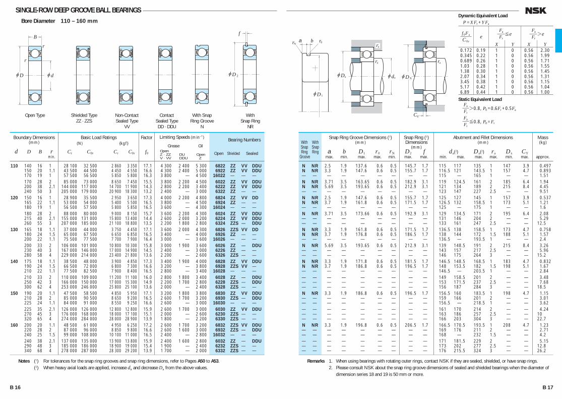
SINGLE-ROW DEEP GROOVE BALL BEARINGSBore Diameter 110 – 160 mm
N NR 2.50 1.9 137.60 0.6 0.5 145.7 1.7 115 117 135 1 147 3.9 0.497 N NR 3.30 1.9 147.60 0.6 0.5 155.7 1.7 116.5 121 143.5 1 157 4.7 0.893 — — — — — — — — — 115 — 165 1 — — 1.51 N NR 3.71 3.5 163.65 0.6 0.5 182.9 3.1 119 124.5 161 2 185 6.4 1.94 N NR 5.69 3.5 193.65 0.6 0.5 212.9 3.1 121 134 189 2 215 8.4 4.45 — — — — — — — — — 123 147 227 2.5 — — 9.51 N NR 2.50 1.9 147.60 0.6 0.5 155.7 1.7 125 127 145 1 157 3.9 0.537 N NR 3.70 1.9 161.80 0.6 0.5 171.5 1.7 126.5 132 158.5 1 173 5.1 1.21 — — — — — — — — — 125 — 175 1 — — 1.6 N NR 3.71 3.5 173.66 0.6 0.5 192.9 3.1 129 134.5 171 2 195 6.4 2.08 — — — — — — — — — 131 146 204 2 — — 5.29 — — — — — — — — — 133 161 247 2.5 — — 12.5 N NR 3.30 1.9 161.80 0.6 0.5 171.5 1.7 136.5 138 158.5 1 173 4.7 0.758 N NR 3.70 1.9 176.80 0.6 0.5 186.5 1.7 138 144 172 1.5 188 5.1 1.57 — — — — — — — — — 136.5 — 193.5 1 — — 2.4 N NR 5.69 3.5 193.65 0.6 0.5 212.9 3.1 139 148.5 191 2 215 8.4 3.26 — — — — — — — — — 143 157 217 2.5 — — 5.96 — — — — — — — — — 146 175 264 3 — — 15.2 N NR 3.30 1.9 171.80 0.6 0.5 181.5 1.7 146.5 148.5 168.5 1 183 4.7 0.832 N NR 3.70 1.9 186.80 0.6 0.5 196.5 1.7 148 153.5 182 1.5 198 5.1 1.67 — — — — — — — — — 146.5 — 203.5 1 — — 2.84 — — — — — — — — — 149 158.5 201 2 — — 3.48 — — — — — — — — — 153 171.5 237 2.5 — — 7.68 — — — — — — — — — 156 187 284 3 — — 18.5 N NR 3.30 1.9 186.80 0.6 0.5 196.5 1.7 156.5 160 183.5 1 198 4.7 1.15 — — — — — — — — — 159 166 201 2 — — 3.01 — — — — — — — — — 156.5 — 218.5 1 — — 3.62 — — — — — — — — — 161 170 214 2 — — 4.24 — — — — — — — — — 163 186 257 2.5 — — 10 — — — — — — — — — 166 203 304 3 — — 22.7 N NR 3.30 1.9 196.80 0.6 0.5 206.5 1.7 166.5 170.5 193.5 1 208 4.7 1.23 — — — — — — — — — 169 176 211 2 — — 2.71 — — — — — — — — — 168 — 232 1.5 — — 4.2 — — — — — — — — — 171 181.5 229 2 — — 5.15 — — — — — — — — — 173 202 277 2.5 — — 12.8 — — — — — — — — — 176 215.5 324 3 — — 26.2
With With Snap Snap Ring Ring Groove
Bearing Numbers
Open Shielded Sealed
Snap Ring Groove Dimensions (1)(mm)
a b D1 r0 rN max. min. max. max. min.
Snap Ring (1)Dimensions
(mm) D2 f max. max.
Abutment and Fillet Dimensions(mm)
da(2) Da(2) ra Dx CY min. max. max. max. min. max.
Mass(kg)
approx.
110 140 16 1 28 100 32 500 2 860 3 350 17.1 4 300 2 400 5 300 6822 ZZ VV DDU 150 20 1.1 43 500 44 500 4 450 4 550 16.6 4 300 2 400 5 000 6922 ZZ VV DDU 170 19 1 57 500 56 500 5 850 5 800 16.3 3 800 — 4 500 16022 — — — 170 28 2 85 000 73 000 8 650 7 450 15.5 3 800 2 200 4 500 6022 ZZ VV DDU 200 38 2.1 144 000 117 000 14 700 11 900 14.3 2 800 2 200 3 400 6222 ZZ VV DDU 240 50 3 205 000 179 000 20 900 18 300 13.2 2 400 — 3 000 6322 ZZ — — 120 150 16 1 28 900 35 500 2 950 3 650 17.3 4 000 2 200 4 800 6824 ZZ VV DD 165 22 1.1 53 000 54 000 5 400 5 500 16.5 3 800 — 4 500 6924 ZZ — — 180 19 1 56 500 57 500 5 800 5 850 16.5 3 600 — 4 300 16024 — — — 180 28 2 88 000 80 000 9 000 8 150 15.7 3 600 2 200 4 300 6024 ZZ VV DDU 215 40 2.1 155 000 131 000 15 800 13 400 14.4 2 600 2 000 3 200 6224 ZZ VV DDU 260 55 3 207 000 185 000 21 100 18 800 13.5 2 200 1 800 2 800 6324 ZZS — DDU
130 165 18 1.1 37 000 44 000 3 750 4 450 17.1 3 600 2 000 4 300 6826 ZZS VV DD 180 24 1.5 65 000 67 500 6 650 6 850 16.5 3 400 — 4 000 6926 ZZ — — 200 22 1.1 75 500 77 500 7 700 7 900 16.4 3 000 — 3 600 16026 — — — 200 33 2 106 000 101 000 10 800 10 300 15.8 3 000 1 900 3 600 6026 ZZ — DDU 230 40 3 167 000 146 000 17 000 14 900 14.5 2 400 — 3 000 6226 ZZ — — 280 58 4 229 000 214 000 23 400 21 800 13.6 2 200 — 2 600 6326 ZZS — — 140 175 18 1.1 38 500 48 000 3 900 4 850 17.3 3 400 1 900 4 000 6828 ZZ VV DDU 190 24 1.5 66 500 72 000 6 800 7 300 16.6 3 200 — 3 800 6928 ZZS VV — 210 22 1.1 77 500 82 500 7 900 8 400 16.5 2 800 — 3 400 16028 — — — 210 33 2 110 000 109 000 11 200 11 100 16.0 2 800 1 800 3 400 6028 ZZ — DDU 250 42 3 166 000 150 000 17 000 15 300 14.9 2 200 1 700 2 800 6228 ZZS — DDU 300 62 4 253 000 246 000 25 800 25 100 13.6 2 000 — 2 400 6328 ZZS — — 150 190 20 1.1 47 500 58 500 4 850 5 950 17.1 3 200 1 800 3 800 6830 ZZ VV DDU 210 28 2 85 000 90 500 8 650 9 200 16.5 2 600 1 700 3 200 6930 ZZS — DDU 225 24 1.1 84 000 91 000 8 550 9 250 16.6 2 600 — 3 000 16030 — — — 225 35 2.1 126 000 126 000 12 800 12 800 15.9 2 600 1 700 3 000 6030 ZZ VV DDU 270 45 3 176 000 168 000 18 000 17 100 15.1 2 000 — 2 600 6230 ZZS — — 320 65 4 274 000 284 000 28 000 28 900 13.9 1 800 — 2 200 6330 ZZS — — 160 200 20 1.1 48 500 61 000 4 950 6 250 17.2 2 600 1 700 3 200 6832 ZZS VV DDU 220 28 2 87 000 96 000 8 850 9 800 16.6 2 600 1 600 3 000 6932 ZZS — DDU 240 25 1.5 99 000 108 000 10 100 11 000 16.5 2 400 — 2 800 16032 — — — 240 38 2.1 137 000 135 000 13 900 13 800 15.9 2 400 1 600 2 800 6032 ZZ — DDU 290 48 3 185 000 186 000 18 900 19 000 15.4 1 900 — 2 400 6232 ZZS — — 340 68 4 278 000 287 000 28 300 29 200 13.9 1 700 — 2 000 6332 ZZS — —
Boundary Dimensions(mm)
d D B r min.
Limiting Speeds (min–1)
Grease Oil Open Z · ZZ DU Open V · VV DDU Z
Factor
f0
Basic Load Ratings (N) {kgf}
Cr C0r Cr C0r
Notes (1) For tolerances for the snap ring grooves and snap ring dimensions, refer to Pages A50 to A53. (2) When heavy axial loads are applied, increase da and decrease Da from the above values.
r
r
jD jd
B
jD
f
2
ra
r0rN
jdajDa
jD1
ra
ra
jD
C
X
Y
ba
Shielded TypeZZ · ZZS
Non-ContactSealed Type
VV
ContactSealed TypeDD · DDU
With SnapRing Groove
N
WithSnap Ring
NR
Open Type
Remarks 1. When using bearings with rotating outer rings, contact NSK if they are sealed, shielded, or have snap rings. 2. Please consult NSK about the snap ring groove dimensions of sealed and shielded bearings when the diameter of
dimension series 18 and 19 is 50 mm or more.
X Y X Y 0.172 0.19 1 0 0.56 2.30 0.345 0.22 1 0 0.56 1.99 0.689 0.26 1 0 0.56 1.71 1.03 0.28 1 0 0.56 1.55 1.38 0.30 1 0 0.56 1.45 2.07 0.34 1 0 0.56 1.31 3.45 0.38 1 0 0.56 1.15 5.17 0.42 1 0 0.56 1.04 6.89 0.44 1 0 0.56 1.00
f 0Fa
C 0re
Fa ≤e Fr
Fa >e Fr
Dynamic Equivalent LoadP =XFr +YFa
Static Equivalent LoadFa Fr>0.8, P0 =0.6Fr +0.5Fa
Fa Fr≤0.8, P0 =Fr
B 16 B 17
B001-029E.indd 16-17B001-029E.indd 16-17 11/20/13 4:53:43 PM11/20/13 4:53:43 PM
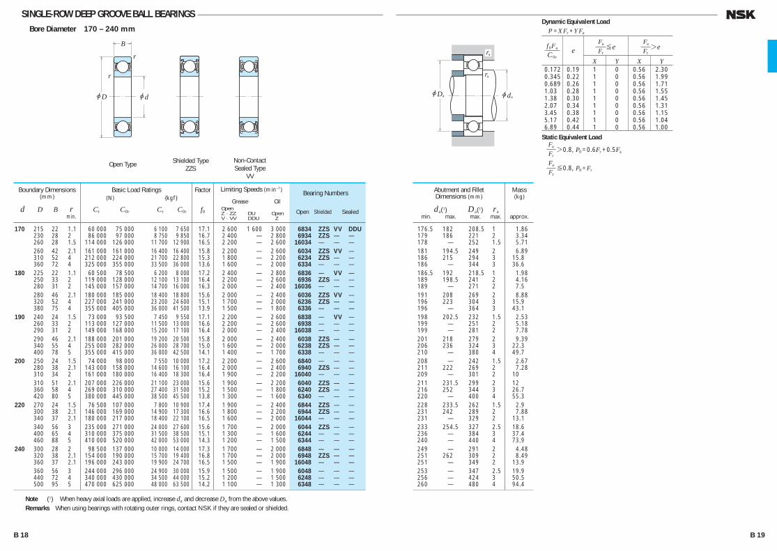
SINGLE-ROW DEEP GROOVE BALL BEARINGSBore Diameter 170 – 240 mm
176.5 182.0 208.5 1 1.86 179 186.0 221 2 3.34 178 — 252 1.5 5.71 181 194.5 249 2 6.89 186 215.0 294 3 15.8 186 — 344 3 36.6 186.5 192.0 218.5 1 1.98 189 198.5 241 2 4.16 189 — 271 2 7.5 191 208.0 269 2 8.88 196 223.0 304 3 15.9 196 — 364 3 43.1 198 202.5 232 1.5 2.53 199 — 251 2 5.18 199 — 281 2 7.78 201 218.0 279 2 9.39 206 236.0 324 3 22.3 210 — 380 4 49.7 208 — 242 1.5 2.67 211 222.0 269 2 7.28 209 — 301 2 10 211 231.5 299 2 12 216 252.0 344 3 26.7 220 — 400 4 55.3 228 233.5 262 1.5 2.9 231 242.0 289 2 7.88 231 — 329 2 13.1 233 254.5 327 2.5 18.6 236 — 384 3 37.4 240 — 440 4 73.9 249 — 291 2 4.48 251 262.0 309 2 8.49 251 — 349 2 13.9 253 — 347 2.5 19.9 256 — 424 3 50.5 260 — 480 4 94.4
Bearing Numbers
Open Shielded Sealed
Abutment and FilletDimensions (mm)
da(1) Da(1) ra min. max. max. max.
Mass(kg)
approx.
170 215 22 1.1 60 000 75 000 6 100 7 650 17.1 2 600 1 600 3 000 6834 ZZS VV DDU 230 28 2 86 000 97 000 8 750 9 850 16.7 2 400 — 2 800 6934 ZZS — — 260 28 1.5 114 000 126 000 11 700 12 900 16.5 2 200 — 2 600 16034 — — — 260 42 2.1 161 000 161 000 16 400 16 400 15.8 2 200 — 2 600 6034 ZZS VV — 310 52 4 212 000 224 000 21 700 22 800 15.3 1 800 — 2 200 6234 ZZS — — 360 72 4 325 000 355 000 33 500 36 000 13.6 1 600 — 2 000 6334 — — — 180 225 22 1.1 60 500 78 500 6 200 8 000 17.2 2 400 — 2 800 6836 — VV — 250 33 2 119 000 128 000 12 100 13 100 16.4 2 200 — 2 600 6936 ZZS — — 280 31 2 145 000 157 000 14 700 16 000 16.3 2 000 — 2 400 16036 — — — 280 46 2.1 180 000 185 000 18 400 18 800 15.6 2 000 — 2 400 6036 ZZS VV — 320 52 4 227 000 241 000 23 200 24 600 15.1 1 700 — 2 000 6236 ZZS — — 380 75 4 355 000 405 000 36 000 41 500 13.9 1 500 — 1 800 6336 — — — 190 240 24 1.5 73 000 93 500 7 450 9 550 17.1 2 200 — 2 600 6838 — VV — 260 33 2 113 000 127 000 11 500 13 000 16.6 2 200 — 2 600 6938 — — — 290 31 2 149 000 168 000 15 200 17 100 16.4 2 000 — 2 400 16038 — — — 290 46 2.1 188 000 201 000 19 200 20 500 15.8 2 000 — 2 400 6038 ZZS — — 340 55 4 255 000 282 000 26 000 28 700 15.0 1 600 — 2 000 6238 ZZS — — 400 78 5 355 000 415 000 36 000 42 500 14.1 1 400 — 1 700 6338 — — — 200 250 24 1.5 74 000 98 000 7 550 10 000 17.2 2 200 — 2 600 6840 — — — 280 38 2.1 143 000 158 000 14 600 16 100 16.4 2 000 — 2 400 6940 ZZS — — 310 34 2 161 000 180 000 16 400 18 300 16.4 1 900 — 2 200 16040 — — — 310 51 2.1 207 000 226 000 21 100 23 000 15.6 1 900 — 2 200 6040 ZZS — — 360 58 4 269 000 310 000 27 400 31 500 15.2 1 500 — 1 800 6240 ZZS — — 420 80 5 380 000 445 000 38 500 45 500 13.8 1 300 — 1 600 6340 — — — 220 270 24 1.5 76 500 107 000 7 800 10 900 17.4 1 900 — 2 400 6844 ZZS — — 300 38 2.1 146 000 169 000 14 900 17 300 16.6 1 800 — 2 200 6944 ZZS — — 340 37 2.1 180 000 217 000 18 400 22 100 16.5 1 600 — 2 000 16044 — — — 340 56 3 235 000 271 000 24 000 27 600 15.6 1 700 — 2 000 6044 ZZS — — 400 65 4 310 000 375 000 31 500 38 500 15.1 1 300 — 1 600 6244 — — — 460 88 5 410 000 520 000 42 000 53 000 14.3 1 200 — 1 500 6344 — — — 240 300 28 2 98 500 137 000 10 000 14 000 17.3 1 700 — 2 000 6848 — — — 320 38 2.1 154 000 190 000 15 700 19 400 16.8 1 700 — 2 000 6948 ZZS — — 360 37 2.1 196 000 243 000 19 900 24 700 16.5 1 500 — 1 900 16048 — — — 360 56 3 244 000 296 000 24 900 30 000 15.9 1 500 — 1 900 6048 — — — 440 72 4 340 000 430 000 34 500 44 000 15.2 1 200 — 1 500 6248 — — — 500 95 5 470 000 625 000 48 000 63 500 14.2 1 100 — 1 300 6348 — — —
Boundary Dimensions(mm)
d D B r min.
Limiting Speeds (min–1)
Grease Oil Open Z · ZZ DU Open V · VV DDU Z
Factor
f0
Basic Load Ratings (N) {kgf}
Cr C0r Cr C0r
Note (1) When heavy axial loads are applied, increase da and decrease Da from the above values.Remarks When using bearings with rotating outer rings, contact NSK if they are sealed or shielded.
r
r
jD jd
B
ra
jdajDa
ra
Shielded TypeZZS
Non-ContactSealed Type
VV
Open Type
X Y X Y 0.172 0.19 1 0 0.56 2.30 0.345 0.22 1 0 0.56 1.99 0.689 0.26 1 0 0.56 1.71 1.03 0.28 1 0 0.56 1.55 1.38 0.30 1 0 0.56 1.45 2.07 0.34 1 0 0.56 1.31 3.45 0.38 1 0 0.56 1.15 5.17 0.42 1 0 0.56 1.04 6.89 0.44 1 0 0.56 1.00
f 0Fa
C 0re
Fa ≤e Fr
Fa >e Fr
Dynamic Equivalent LoadP =XFr +YFa
Static Equivalent LoadFa Fr>0.8, P0 =0.6Fr +0.5Fa
Fa Fr≤0.8, P0 =Fr
B 18 B 19
B001-029E.indd 18-19B001-029E.indd 18-19 11/20/13 4:53:44 PM11/20/13 4:53:44 PM
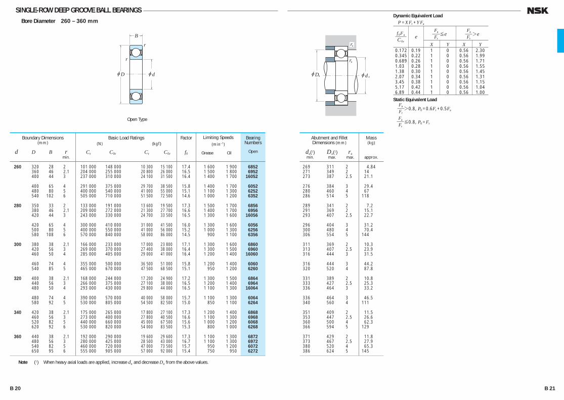
SINGLE-ROW DEEP GROOVE BALL BEARINGSBore Diameter 260 – 360 mm
269 311 2 4.84 271 349 2 14 273 387 2.5 21.1
276 384 3 29.4 280 460 4 67 286 514 5 118
289 341 2 7.2 291 369 2 15.1 293 407 2.5 22.7
296 404 3 31.2 300 480 4 70.4 306 554 5 144
311 369 2 10.3 313 407 2.5 23.9 316 444 3 31.5
316 444 3 44.2 320 520 4 87.8
331 389 2 10.8 333 427 2.5 25.3 336 464 3 33.2
336 464 3 46.5 340 560 4 111
351 409 2 11.5 353 447 2.5 26.6 360 500 4 62.3 366 594 5 129
371 429 2 11.8 373 467 2.5 27.9 380 520 4 65.3 386 624 5 145
Bearing Numbers
Open
Abutment and Fillet Dimensions (mm)
da(1) Da(1) ra min. max. max.
Mass(kg)
approx.
260 320 28 2 101 000 148 000 10 300 15 100 17.4 1 600 1 900 6852 360 46 2.1 204 000 255 000 20 800 26 000 16.5 1 500 1 800 6952 400 44 3 237 000 310 000 24 100 31 500 16.4 1 400 1 700 16052
400 65 4 291 000 375 000 29 700 38 500 15.8 1 400 1 700 6052 480 80 5 400 000 540 000 41 000 55 000 15.1 1 100 1 300 6252 540 102 6 505 000 710 000 51 500 72 500 14.6 1 000 1 200 6352
280 350 33 2 133 000 191 000 13 600 19 500 17.3 1 500 1 700 6856 380 46 2.1 209 000 272 000 21 300 27 700 16.6 1 400 1 700 6956 420 44 3 243 000 330 000 24 700 33 500 16.5 1 300 1 600 16056
420 65 4 300 000 410 000 31 000 41 500 16.0 1 300 1 600 6056 500 80 5 400 000 550 000 41 000 56 000 15.2 1 000 1 300 6256 580 108 6 570 000 840 000 58 000 86 000 14.5 900 1 100 6356
300 380 38 2.1 166 000 233 000 17 000 23 800 17.1 1 300 1 600 6860 420 56 3 269 000 370 000 27 400 38 000 16.4 1 300 1 500 6960 460 50 4 285 000 405 000 29 000 41 000 16.4 1 200 1 400 16060
460 74 4 355 000 500 000 36 500 51 000 15.8 1 200 1 400 6060 540 85 5 465 000 670 000 47 500 68 500 15.1 950 1 200 6260
320 400 38 2.1 168 000 244 000 17 200 24 900 17.2 1 300 1 500 6864 440 56 3 266 000 375 000 27 100 38 000 16.5 1 200 1 400 6964 480 50 4 293 000 430 000 29 800 44 000 16.5 1 100 1 300 16064
480 74 4 390 000 570 000 40 000 58 000 15.7 1 100 1 300 6064 580 92 5 530 000 805 000 54 500 82 500 15.0 850 1 100 6264
340 420 38 2.1 175 000 265 000 17 800 27 100 17.3 1 200 1 400 6868 460 56 3 273 000 400 000 27 800 40 500 16.6 1 100 1 300 6968 520 82 5 440 000 660 000 45 000 67 500 15.6 1 000 1 200 6068 620 92 6 530 000 820 000 54 000 83 500 15.3 800 1 000 6268
360 440 38 2.1 192 000 290 000 19 600 29 600 17.3 1 100 1 300 6872 480 56 3 280 000 425 000 28 500 43 000 16.7 1 100 1 300 6972 540 82 5 460 000 720 000 47 000 73 500 15.7 950 1 200 6072 650 95 6 555 000 905 000 57 000 92 000 15.4 750 950 6272
Boundary Dimensions(mm)
d D B r min.
Limiting Speeds(min–1)
Grease Oil
Factor
f0
Basic Load Ratings (N) {kgf}
Cr C0r Cr C0r
Note (1) When heavy axial loads are applied, increase da and decrease Da from the above values.
r
r
jD jd
B
ra
jd ajDa
ra
Open Type
X Y X Y 0.172 0.19 1 0 0.56 2.30 0.345 0.22 1 0 0.56 1.99 0.689 0.26 1 0 0.56 1.71 1.03 0.28 1 0 0.56 1.55 1.38 0.30 1 0 0.56 1.45 2.07 0.34 1 0 0.56 1.31 3.45 0.38 1 0 0.56 1.15 5.17 0.42 1 0 0.56 1.04 6.89 0.44 1 0 0.56 1.00
f 0Fa
C 0re
Fa ≤e Fr
Fa >e Fr
Dynamic Equivalent LoadP =XFr +YFa
Static Equivalent LoadFa Fr>0.8, P0 =0.6Fr +0.5Fa
Fa Fr≤0.8, P0 =Fr
B 20 B 21
B001-029E.indd 20-21B001-029E.indd 20-21 11/20/13 4:53:45 PM11/20/13 4:53:45 PM
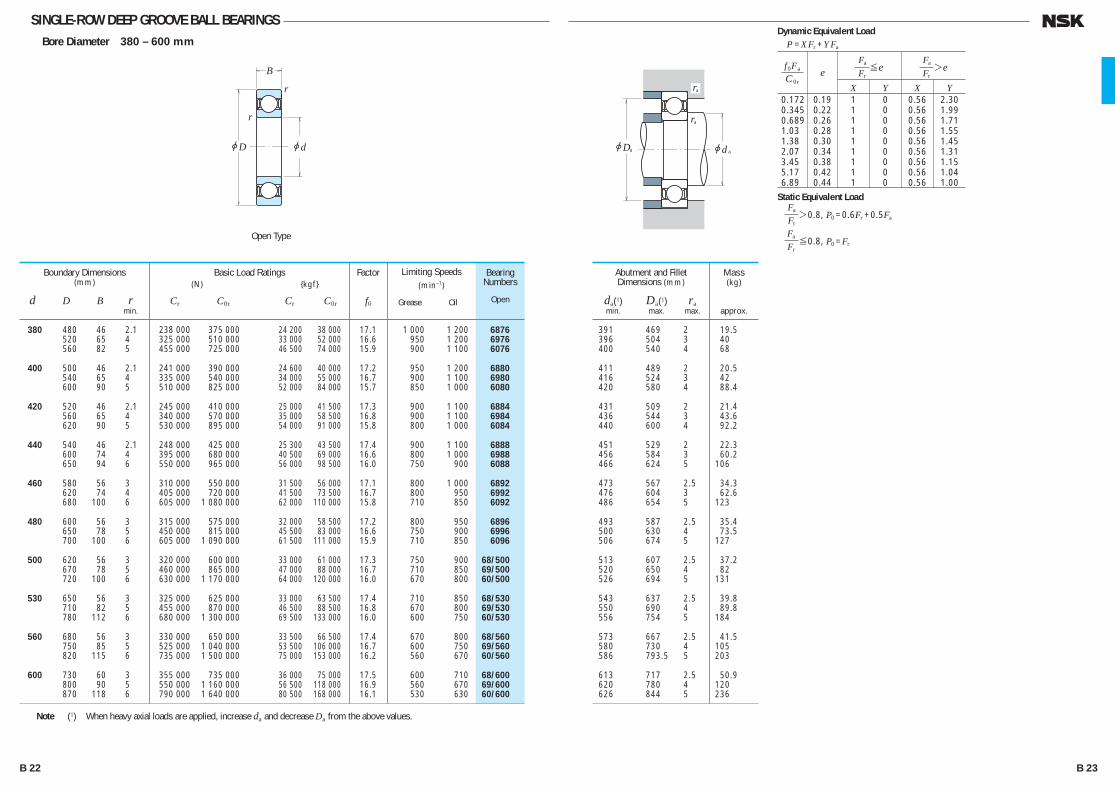
SINGLE-ROW DEEP GROOVE BALL BEARINGSBore Diameter 380 – 600 mm
391 469 2 19.5 396 504 3 40 400 540 4 68
411 489 2 20.5 416 524 3 42 420 580 4 88.4
431 509 2 21.4 436 544 3 43.6 440 600 4 92.2
451 529 2 22.3 456 584 3 60.2 466 624 5 106
473 567 2.5 34.3 476 604 3 62.6 486 654 5 123
493 587 2.5 35.4 500 630 4 73.5 506 674 5 127
513 607 2.5 37.2 520 650 4 82 526 694 5 131
543 637 2.5 39.8 550 690 4 89.8 556 754 5 184
573 667 2.5 41.5 580 730 4 105 586 793.5 5 203
613 717 2.5 50.9 620 780 4 120 626 844 5 236
Bearing Numbers
Open
Abutment and Fillet Dimensions (mm)
da(1) Da(1) ra min. max. max.
Mass(kg)
approx.
380 480 46 2.1 238 000 375 000 24 200 38 000 17.1 1 000 1 200 6876 520 65 4 325 000 510 000 33 000 52 000 16.6 950 1 200 6976 560 82 5 455 000 725 000 46 500 74 000 15.9 900 1 100 6076
400 500 46 2.1 241 000 390 000 24 600 40 000 17.2 950 1 200 6880 540 65 4 335 000 540 000 34 000 55 000 16.7 900 1 100 6980 600 90 5 510 000 825 000 52 000 84 000 15.7 850 1 000 6080
420 520 46 2.1 245 000 410 000 25 000 41 500 17.3 900 1 100 6884 560 65 4 340 000 570 000 35 000 58 500 16.8 900 1 100 6984 620 90 5 530 000 895 000 54 000 91 000 15.8 800 1 000 6084
440 540 46 2.1 248 000 425 000 25 300 43 500 17.4 900 1 100 6888 600 74 4 395 000 680 000 40 500 69 000 16.6 800 1 000 6988 650 94 6 550 000 965 000 56 000 98 500 16.0 750 900 6088
460 580 56 3 310 000 550 000 31 500 56 000 17.1 800 1 000 6892 620 74 4 405 000 720 000 41 500 73 500 16.7 800 950 6992 680 100 6 605 000 1 080 000 62 000 110 000 15.8 710 850 6092
480 600 56 3 315 000 575 000 32 000 58 500 17.2 800 950 6896 650 78 5 450 000 815 000 45 500 83 000 16.6 750 900 6996 700 100 6 605 000 1 090 000 61 500 111 000 15.9 710 850 6096
500 620 56 3 320 000 600 000 33 000 61 000 17.3 750 900 68/500 670 78 5 460 000 865 000 47 000 88 000 16.7 710 850 69/500 720 100 6 630 000 1 170 000 64 000 120 000 16.0 670 800 60/500
530 650 56 3 325 000 625 000 33 000 63 500 17.4 710 850 68/530 710 82 5 455 000 870 000 46 500 88 500 16.8 670 800 69/530 780 112 6 680 000 1 300 000 69 500 133 000 16.0 600 750 60/530
560 680 56 3 330 000 650 000 33 500 66 500 17.4 670 800 68/560 750 85 5 525 000 1 040 000 53 500 106 000 16.7 600 750 69/560 820 115 6 735 000 1 500 000 75 000 153 000 16.2 560 670 60/560
600 730 60 3 355 000 735 000 36 000 75 000 17.5 600 710 68/600 800 90 5 550 000 1 160 000 56 500 118 000 16.9 560 670 69/600 870 118 6 790 000 1 640 000 80 500 168 000 16.1 530 630 60/600
Boundary Dimensions(mm)
d D B r min.
Limiting Speeds(min–1)
Grease Oil
Factor
f0
Basic Load Ratings (N) {kgf}
Cr C0r Cr C0r
Note (1) When heavy axial loads are applied, increase da and decrease Da from the above values.
r
r
jD jd
B
ra
jd ajDa
ra
Open Type
X Y X Y 0.172 0.19 1 0 0.56 2.30 0.345 0.22 1 0 0.56 1.99 0.689 0.26 1 0 0.56 1.71 1.03 0.28 1 0 0.56 1.55 1.38 0.30 1 0 0.56 1.45 2.07 0.34 1 0 0.56 1.31 3.45 0.38 1 0 0.56 1.15 5.17 0.42 1 0 0.56 1.04 6.89 0.44 1 0 0.56 1.00
f 0Fa
C 0re
Fa ≤e Fr
Fa >e Fr
Dynamic Equivalent LoadP =XFr +YFa
Static Equivalent LoadFa Fr>0.8, P0 =0.6Fr +0.5Fa
Fa Fr≤0.8, P0 =Fr
B 22 B 23
B001-029E.indd 22-23B001-029E.indd 22-23 11/20/13 4:53:46 PM11/20/13 4:53:46 PM
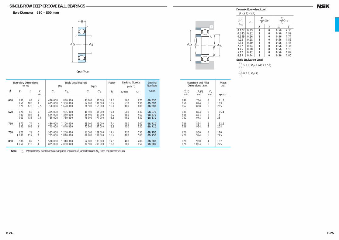
SINGLE-ROW DEEP GROOVE BALL BEARINGSBore Diameter 630 – 800 mm
646 764 3 71.3 656 824 5 163 662 888 6 285
686 804 3 75.4 696 874 5 181 702 948 6 351
726 854 3 92.6 736 924 5 208
770 900 4 110 776 974 5 245
820 960 4 132 826 1 034 5 275
Bearing Numbers
Open
Abutment and Fillet Dimensions (mm)
da(1) Da(1) ra min. max. max.
Mass(kg)
approx.
630 780 69 4 420 000 890 000 43 000 90 500 17.3 560 670 68/630 850 100 6 625 000 1 350 000 64 000 138 000 16.7 530 630 69/630 920 128 7.5 750 000 1 620 000 76 500 165 000 16.4 480 600 60/630
670 820 69 4 435 000 965 000 44 500 98 000 17.4 500 630 68/670 900 103 6 675 000 1 460 000 68 500 149 000 16.7 480 560 69/670 980 136 7.5 765 000 1 730 000 78 000 177 000 16.6 450 530 60/670
710 870 74 4 480 000 1 100 000 49 000 113 000 17.4 480 560 68/710 950 106 6 715 000 1 640 000 72 500 167 000 16.8 450 530 69/710
750 920 78 5 525 000 1 260 000 53 500 128 000 17.4 430 530 68/750 1 000 112 6 785 000 1 840 000 80 000 188 000 16.7 400 500 69/750
800 980 82 5 530 000 1 310 000 54 000 133 000 17.5 400 480 68/800 1 060 115 6 825 000 2 050 000 84 500 209 000 16.8 380 450 69/800
Boundary Dimensions(mm)
d D B r min.
Limiting Speeds(min–1)
Grease Oil
Factor
f0
Basic Load Ratings (N) {kgf}
Cr C0r Cr C0r
Note (1) When heavy axial loads are applied, increase da and decrease Da from the above values.
r
r
jD jd
B
ra
jd ajDa
ra
Open Type
X Y X Y 0.172 0.19 1 0 0.56 2.30 0.345 0.22 1 0 0.56 1.99 0.689 0.26 1 0 0.56 1.71 1.03 0.28 1 0 0.56 1.55 1.38 0.30 1 0 0.56 1.45 2.07 0.34 1 0 0.56 1.31 3.45 0.38 1 0 0.56 1.15 5.17 0.42 1 0 0.56 1.04 6.89 0.44 1 0 0.56 1.00
f 0Fa
C 0re
Fa ≤e Fr
Fa >e Fr
Dynamic Equivalent LoadP =XFr +YFa
Static Equivalent LoadFa Fr>0.8, P0 =0.6Fr +0.5Fa
Fa Fr≤0.8, P0 =Fr
B 24 B 25
B001-029E.indd 24-25B001-029E.indd 24-25 11/20/13 4:53:47 PM11/20/13 4:53:47 PM
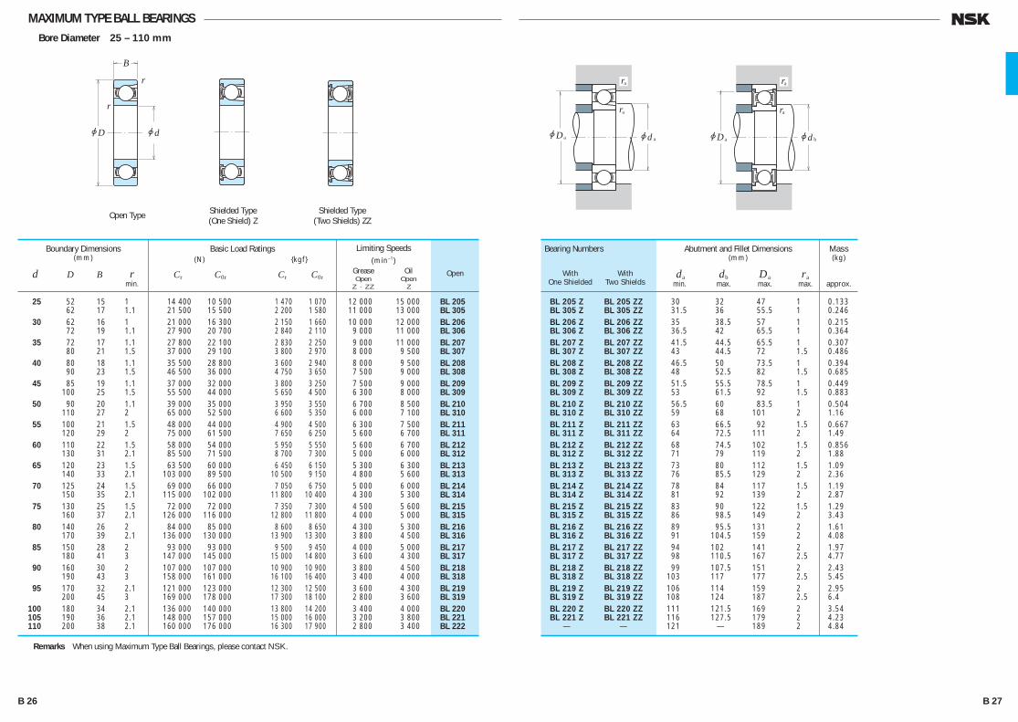
MAXIMUM TYPE BALL BEARINGSBore Diameter 25 – 110 mm
BL 205 Z BL 205 ZZ 30 32 47 1 0.133 BL 305 Z BL 305 ZZ 31.5 36 55.5 1 0.246 BL 206 Z BL 206 ZZ 35 38.5 57 1 0.215 BL 306 Z BL 306 ZZ 36.5 42 65.5 1 0.364 BL 207 Z BL 207 ZZ 41.5 44.5 65.5 1 0.307 BL 307 Z BL 307 ZZ 43 44.5 72 1.5 0.486 BL 208 Z BL 208 ZZ 46.5 50 73.5 1 0.394 BL 308 Z BL 308 ZZ 48 52.5 82 1.5 0.685 BL 209 Z BL 209 ZZ 51.5 55.5 78.5 1 0.449 BL 309 Z BL 309 ZZ 53 61.5 92 1.5 0.883 BL 210 Z BL 210 ZZ 56.5 60 83.5 1 0.504 BL 310 Z BL 310 ZZ 59 68 101 2 1.16 BL 211 Z BL 211 ZZ 63 66.5 92 1.5 0.667 BL 311 Z BL 311 ZZ 64 72.5 111 2 1.49 BL 212 Z BL 212 ZZ 68 74.5 102 1.5 0.856 BL 312 Z BL 312 ZZ 71 79 119 2 1.88 BL 213 Z BL 213 ZZ 73 80 112 1.5 1.09 BL 313 Z BL 313 ZZ 76 85.5 129 2 2.36 BL 214 Z BL 214 ZZ 78 84 117 1.5 1.19 BL 314 Z BL 314 ZZ 81 92 139 2 2.87 BL 215 Z BL 215 ZZ 83 90 122 1.5 1.29 BL 315 Z BL 315 ZZ 86 98.5 149 2 3.43 BL 216 Z BL 216 ZZ 89 95.5 131 2 1.61 BL 316 Z BL 316 ZZ 91 104.5 159 2 4.08 BL 217 Z BL 217 ZZ 94 102 141 2 1.97 BL 317 Z BL 317 ZZ 98 110.5 167 2.5 4.77 BL 218 Z BL 218 ZZ 99 107.5 151 2 2.43 BL 318 Z BL 318 ZZ 103 117 177 2.5 5.45 BL 219 Z BL 219 ZZ 106 114 159 2 2.95 BL 319 Z BL 319 ZZ 108 124 187 2.5 6.4 BL 220 Z BL 220 ZZ 111 121.5 169 2 3.54 BL 221 Z BL 221 ZZ 116 127.5 179 2 4.23 — — 121 — 189 2 4.84
Bearing Numbers
With With One Shielded Two Shields
Open
Abutment and Fillet Dimensions(mm)
da db Da ra min. max. max. max.
Mass(kg)
approx.
25 52 15 1 14 400 10 500 1 470 1 070 12 000 15 000 BL 205 62 17 1.1 21 500 15 500 2 200 1 580 11 000 13 000 BL 305
30 62 16 1 21 000 16 300 2 150 1 660 10 000 12 000 BL 206 72 19 1.1 27 900 20 700 2 840 2 110 9 000 11 000 BL 306
35 72 17 1.1 27 800 22 100 2 830 2 250 9 000 11 000 BL 207 80 21 1.5 37 000 29 100 3 800 2 970 8 000 9 500 BL 307
40 80 18 1.1 35 500 28 800 3 600 2 940 8 000 9 500 BL 208 90 23 1.5 46 500 36 000 4 750 3 650 7 500 9 000 BL 308
45 85 19 1.1 37 000 32 000 3 800 3 250 7 500 9 000 BL 209 100 25 1.5 55 500 44 000 5 650 4 500 6 300 8 000 BL 309
50 90 20 1.1 39 000 35 000 3 950 3 550 6 700 8 500 BL 210 110 27 2 65 000 52 500 6 600 5 350 6 000 7 100 BL 310
55 100 21 1.5 48 000 44 000 4 900 4 500 6 300 7 500 BL 211 120 29 2 75 000 61 500 7 650 6 250 5 600 6 700 BL 311
60 110 22 1.5 58 000 54 000 5 950 5 550 5 600 6 700 BL 212 130 31 2.1 85 500 71 500 8 700 7 300 5 000 6 000 BL 312
65 120 23 1.5 63 500 60 000 6 450 6 150 5 300 6 300 BL 213 140 33 2.1 103 000 89 500 10 500 9 150 4 800 5 600 BL 313
70 125 24 1.5 69 000 66 000 7 050 6 750 5 000 6 000 BL 214 150 35 2.1 115 000 102 000 11 800 10 400 4 300 5 300 BL 314
75 130 25 1.5 72 000 72 000 7 350 7 300 4 500 5 600 BL 215 160 37 2.1 126 000 116 000 12 800 11 800 4 000 5 000 BL 315
80 140 26 2 84 000 85 000 8 600 8 650 4 300 5 300 BL 216 170 39 2.1 136 000 130 000 13 900 13 300 3 800 4 500 BL 316
85 150 28 2 93 000 93 000 9 500 9 450 4 000 5 000 BL 217 180 41 3 147 000 145 000 15 000 14 800 3 600 4 300 BL 317
90 160 30 2 107 000 107 000 10 900 10 900 3 800 4 500 BL 218 190 43 3 158 000 161 000 16 100 16 400 3 400 4 000 BL 318
95 170 32 2.1 121 000 123 000 12 300 12 500 3 600 4 300 BL 219 200 45 3 169 000 178 000 17 300 18 100 2 800 3 600 BL 319
100 180 34 2.1 136 000 140 000 13 800 14 200 3 400 4 000 BL 220 105 190 36 2.1 148 000 157 000 15 000 16 000 3 200 3 800 BL 221 110 200 38 2.1 160 000 176 000 16 300 17 900 2 800 3 400 BL 222
Boundary Dimensions(mm)
d D B r min.
Limiting Speeds(min–1)
Grease Oil Open Open Z · ZZ Z
Basic Load Ratings (N) {kgf}
Cr C0r Cr C0r
r
r
jD jd
B
ra
jd ajDa
ra
ra
jd bjDa
ra
Shielded Type(One Shield) Z
Shielded Type(Two Shields) ZZ
Open Type
Remarks When using Maximum Type Ball Bearings, please contact NSK.
B 26 B 27
B001-029E.indd 26-27B001-029E.indd 26-27 11/20/13 4:53:47 PM11/20/13 4:53:47 PM

MAGNETO BEARINGSBore Diameter 4 – 20 mm
5.2 14.8 0.15 0.005 6.2 14.8 0.15 0.004 8 19 0.3 0.011
9 20 0.3 0.013 10 22 0.3 0.014 11 26 0.3 0.022
12 26 0.3 0.021 13 30 0.3 0.029 14 30 0.3 0.028
15 28 0.3 0.021 16 33 0.3 0.035
17 33 0.3 0.034 19 36 0.6 0.055 20 34 0.6 0.049
21 36 0.6 0.051 21 40 0.6 0.080 21 40 0.6 0.080
22 36 0.6 0.051 23 36 0.6 0.049
25 42 1 0.089 25 42 1 0.101
Bearing Numbers
E Series EN Series
Abutment and Fillet Dimensions (mm)
da Da ra min. max. max.
Mass(kg)
approx.
4 16 5 0.15 0.1 1 650 288 168 29 34 000 40 000 E 4 EN 4 5 16 5 0.15 0.1 1 650 288 168 29 34 000 40 000 E 5 EN 5 6 21 7 0.3 0.15 2 490 445 254 46 30 000 36 000 E 6 EN 6
7 22 7 0.3 0.15 2 490 445 254 46 30 000 36 000 E 7 EN 7 8 24 7 0.3 0.15 3 450 650 350 66 28 000 34 000 E 8 EN 8 9 28 8 0.3 0.15 4 550 880 465 90 24 000 30 000 E 9 EN 9
10 28 8 0.3 0.15 4 550 880 465 90 24 000 30 000 E 10 EN 10 11 32 7 0.3 0.15 4 400 845 450 86 22 000 26 000 E 11 EN 11 12 32 7 0.3 0.15 4 400 845 450 86 22 000 26 000 E 12 EN 12
13 30 7 0.3 0.15 4 400 845 450 86 22 000 26 000 E 13 EN 13 14 35 8 0.3 0.15 5 800 1 150 590 117 19 000 22 000 — EN 14
15 35 8 0.3 0.15 5 800 1 150 590 117 19 000 22 000 E 15 EN 15 40 10 0.6 0.3 7 400 1 500 750 153 17 000 20 000 BO 15 — 16 38 10 0.6 0.2 6 900 1 380 705 141 17 000 22 000 — EN 16
17 40 10 0.6 0.3 7 400 1 500 750 153 17 000 20 000 L 17 — 44 11 0.6 0.3 7 350 1 500 750 153 16 000 19 000 — EN 17 44 11 0.6 0.3 7 350 1 500 750 153 16 000 19 000 BO 17 —
18 40 9 0.6 0.2 5 050 1 030 515 105 17 000 20 000 — EN 18 19 40 9 0.6 0.2 5 050 1 030 515 105 17 000 20 000 E 19 EN 19
20 47 12 1 0.6 11 000 2 380 1 120 243 14 000 17 000 E 20 EN 20 47 14 1 0.6 11 000 2 380 1 120 243 14 000 17 000 L 20 —
Boundary Dimensions(mm)
d D B,C,T r r1 min. min.
Limiting Speeds(min–1)
Grease Oil
Basic Load Ratings (N) {kgf}
Cr C0r Cr C0r
Remarks 1. The outside diameters of Magneto Bearings Series E always have plus tolerances. 2. When using Magneto Bearings other than E, please contact NSK.
r
r
jD jd
TC
B
r1
ra
jdajDa
ra
E Series EN Series
Over Incl. High Low High Low — 10 + 8 0 0 – 8 10 18 + 8 0 0 – 8 18 30 + 9 0 0 – 9 30 50 +11 0 0 –11
Outside Diameter Tolerance (Class N)
Units : μm
Fa/Fr≤e Fa/Fr>e
X Y X Y e
1 0 0.5 2.5 0.2
Dynamic Equivalent Load
P =XFr +YFa
Nominal Outside
DiameterD (mm)
Single Plane Mean Outside Diameter&Dmp
B 28 B 29
B001-029E.indd 28-29B001-029E.indd 28-29 11/20/13 4:53:48 PM11/20/13 4:53:48 PM

Table 1 Size Ranges of BearingsUnits : mm
Design Extra Small Ball Bearings Miniature Ball Bearings
Metric Outside diameter D ≥ 9 Outside diameter D < 9
Bore diameter d < 10
Inch Outside diameter D ≥ 9.525 Outside diameter D < 9.525
Bore diameter d < 10
Please refer to NSK Miniature Ball Bearings (CAT. No. E126) for details.
ZZ ZZS DD VV
EXTRA SMALL BALL BEARINGS AND MINIATURE BALL BEARINGS
EXTRA SMALL BALL BEARINGS · MINIATURE BALL BEARINGSMetric Design Bore Diameter 1 – 9mm ····················································· B34
With Flange Bore Diameter 1 – 9mm ····················································· B38
Inch Design Bore Diameter 1.016 – 9.525mm ······································· B42
With Flange Bore Diameter 1.191 – 9.525mm ······································· B44
DESIGN AND TYPES The size ranges of extra small and miniature ball bearings are shown in Table 1. The design, types, and type symbols are shown in Table 2. Those types among them that are listed in the bearing tables are indicated by the shading in Table 2.
B 30 B 31
B030-045E.indd 30-31B030-045E.indd 30-31 11/20/13 4:54:14 PM11/20/13 4:54:14 PM

TOLERANCES AND RUNNING ACCURACY
METRIC DESIGN BEARINGS ·································Table 8.2(Pages A60 to A63)The flange tolerances for metric design bearings are listed in Table 3.
INCH DESIGN BEARINGS ····································Table 8.2 (Pages A60 to A63) The flange tolerances for inch design flanged bearings are listed in Table 8.8(2) (Pages A76 and A77).
INSTRUMENT BALL BEARINGS ··························Table 8.8 (Pages A76 to A77)
RECOMMENDED FITS
Please refer to NSK Miniature Ball Bearings (CAT.No.E126).
INTERNAL CLEARANCES ·································Table 9.10 (Page A89)
LIMITING SPEEDS
The limiting speeds listed in the bearing tables should be adjusted depending on the bearing toad conditions. Also, higher speeds are attainable by making changes in the lubrication method, cage design, etc. Refer to Page A37 for detailed information.
Table 2 Design, Types, and Type Symbols
Thin section
With flange
Extended inner ring
For synchro motors
With flange and extended inner ring
Sing
le-R
ow D
eep
Groo
ve B
all B
earin
gsPi
vot B
all
Bear
ings
Thru
st B
all
Bear
ings
Remarks Single-row angular contact ball bearings are available besides those shown above.
Type Symbols
Design · Types Metric Inch
Special Remarks
Metric Inch
Shielded · sealed
6 � � R MR — bearings are
available.
— — SMT —
Shielded · sealed
F6 � � FR MF — bearings are
available.
Shielded bearings
— — — RW are available.
Shielded bearings
— — — FRW are available.
Shielded bearings
— — — SR00X00 are available.
— — BCF —
— — F —
(2) Flange Width Tolerances and Running Accuracies Related to Flange Units : μm
Normal and Classes 6,5,4,2 Normal and class 6 Class 5 Class 4 Class 2 Class 5 Class 4 Class 2 Class 5 Class 4 Class 2 over incl. high low max. max. max.
2.5(1) 6 5 2.5 1.5 8 4 1.5 11 7 3
6 18 5 2.5 1.5 8 4 1.5 11 7 3
18 30 5 2.5 1.5 8 4 1.5 11 7 3
Table 3 Flange Tolerances for Metric Flanged Bearings
(1) Tolerances of Flange Outside Diameter Units : μm
Nominal Flange Deviation of Flange Outside Diameter
Outside Diameter &D 1S
D1(mm) 1 2
over incl. high low high low
10 +220 —36 0 —36
10 18 +270 —43 0 —43
18 30 +330 —52 0 —52
Remarks 2is applied when the flange outside diameter is used for positioning.
Notes (1) 2.5 mm is included
Deviation ofFlange Width&C 1S
NominalBearing Outside
DiameterD
(mm)
Variation ofFlange Width&C 1S
VC 1S
Variation of Bearing Outside Surface Generatrix Inclination with Flange Backface
SD1
Use the &BS tolerance for d of the same bearing of the same class
Use the & VBS tolerance for d of the same bearing of the same class
Flange BackfaceRunout with Raceway
S ea1
B 32 B 33
B030-045E.indd 32-33B030-045E.indd 32-33 11/20/13 4:54:15 PM11/20/13 4:54:15 PM

EXTRA SMALL BALL BEARINGS · MINIATURE BALL BEARINGSMetric DesignBore Diameter 1 – 4 mm
— — — 1.4 — 02.6 — 0.05 — 0.03 — — — — 1.4 — 02.6 — 0.05 — 0.04 — — — — 1.8 — 03.2 — 0.10 — 0.09 — MR 41 XZZ — — 2.0 1.9 03.2 03.5 0.10 0.10 0.10 0.14 681 XZZ — — 1.9 2.1 03.6 03.6 0.05 0.05 0.07 0.11 691 XZZ — — 2.7 2.5 03.8 04.3 0.15 0.15 0.17 0.20 601 XZZ — — 2.7 3.0 04.8 05.4 0.15 0.15 0.33 0.38 682 ZZ — — 2.6 2.7 04.4 04.2 0.08 0.08 0.12 0.17 MR 52 BZZ — — 2.8 2.7 04.2 04.4 0.10 0.10 0.16 0.23 692 ZZ — — 3.2 3.0 04.8 05.4 0.15 0.15 0.28 0.38 MR 62 ZZ — — 3.2 3.0 04.8 05.2 0.15 0.15 0.30 0.29 MR 72 ZZ — — 3.2 3.8 05.8 06.2 0.15 0.15 0.45 0.49 602 ZZ — — 3.2 3.8 05.8 06.2 0.15 0.15 0.51 0.58 682 XZZ — — 3.1 3.7 05.4 05.4 0.08 0.08 0.23 0.29 692 XZZ — — 3.7 3.8 05.8 06.2 0.15 0.15 0.41 0.55 — — — 4.1 — 06.4 — 0.20 — 0.56 — 602 XZZ — — 3.7 4.1 06.8 07.0 0.15 0.15 0.63 0.83 MR 63 ZZ — — 3.8 3.7 05.2 05.4 0.10 0.10 0.20 0.27 683 AZZ — — 3.8 4.0 06.2 06.4 0.10 0.10 0.32 0.45 — — — 4.2 — 06.8 — 0.15 — 0.54 — 693 ZZ — — 4.2 4.3 06.8 07.3 0.15 0.15 0.61 0.83 MR 93 ZZ — — 4.6 4.3 07.4 07.9 0.20 0.15 0.73 1.18 603 ZZ — — 4.2 4.3 07.8 07.9 0.15 0.15 0.87 1.45 623 ZZ — — 4.2 4.3 08.8 08.0 0.15 0.15 1.65 1.66 633 ZZ — — 4.6 6.0 11.4 11.3 0.20 0.20 3.38 3.33 — — — 4.8 — 06.2 — 0.10 — 0.22 — MR 74 ZZ — — — 4.8 — 06.3 — 0.10 — 0.29 MR 84 ZZ — — 5.2 5.0 06.8 07.4 0.15 0.10 0.36 0.56 684 AZZ — — 4.8 5.2 08.2 08.1 0.10 0.10 0.63 1.01 MR 104 BZZ — — 5.6 5.9 08.4 08.8 0.20 0.15 1.04 1.42 694 ZZ — — 5.2 5.6 09.8 09.9 0.15 0.15 1.7 1.75 604 ZZ — — 5.6 5.6 10.4 09.9 0.20 0.20 2.25 2.29 624 ZZ — — 5.6 6.0 11.4 11.3 0.20 0.20 3.03 3.04 634 ZZ1 — — 6.0 7.5 14.0 13.8 0.30 0.30 5.24 5.21
Bearing Numbers
Shielded SealedOpen
Abutment and Fillet Dimensions(mm)
da db Da Db ra rb min. max. max. min. max. max.
Mass(g)
approx. Open Shielded
1 3 1.0 — 0.05 — 80 23 8 2.5 130 000 150 000 681 3 1.5 — 0.05 — 80 23 8 2.5 130 000 150 000 MR 31 4 1.6 — 0.10 — 138 35 14 3.5 100 000 120 000 691 1.2 4 1.8 2.5 0.10 0.10 138 35 14 3.5 110 000 130 000 MR 41 X
1.5 4 1.2 2.0 0.05 0.05 112 33 11 3.5 100 000 120 000 681 X 5 2.0 2.6 0.15 0.15 237 69 24 7 85 000 100 000 691 X 6 2.5 3.0 0.15 0.15 330 98 34 10 75 000 90 000 601 X
2 5 1.5 2.3 0.08 0.08 169 50 17 5 85 000 100 000 682 5 2.0 2.5 0.10 0.10 187 58 19 6 85 000 100 000 MR 52 B 6 2.3 3.0 0.15 0.15 330 98 34 10 75 000 90 000 692 6 2.5 2.5 0.15 0.15 330 98 34 10 75 000 90 000 MR 62 7 2.5 3.0 0.15 0.15 385 127 39 13 63 000 75 000 MR 72 7 2.8 3.5 0.15 0.15 385 127 39 13 63 000 75 000 602
2.5 6 1.8 2.6 0.08 0.08 208 74 21 7.5 71 000 80 000 682 X 7 2.5 3.5 0.15 0.15 385 127 39 13 63 000 75 000 692 X 8 2.5 — 0.20 — 560 179 57 18 60 000 67 000 MR 82 X 8 2.8 4.0 0.15 0.15 550 175 56 18 60 000 71 000 602 X
3 6 2.0 2.5 0.10 0.10 208 74 21 7.5 71 000 80 000 MR 63 7 2.0 3.0 0.10 0.10 390 130 40 13 63 000 75 000 683 A 8 2.5 — 0.15 — 560 179 57 18 60 000 67 000 MR 83
8 3.0 4.0 0.15 0.15 560 179 57 18 60 000 67 000 693 9 2.5 4.0 0.20 0.15 570 187 58 19 56 000 67 000 MR 93 9 3.0 5.0 0.15 0.15 570 187 58 19 56 000 67 000 603 10 4.0 4.0 0.15 0.15 630 218 64 22 50 000 60 000 623 13 5.0 5.0 0.20 0.20 1 300 485 133 49 40 000 48 000 633
4 7 2.0 — 0.10 — 310 115 32 12 60 000 67 000 MR 74 7 — 2.5 — 0.10 255 107 26 11 60 000 71 000 — 8 2.0 3.0 0.15 0.10 395 139 40 14 56 000 67 000 MR 84 9 2.5 4.0 (0.15) (0.15) 640 225 65 23 53 000 63 000 684 A
10 3.0 4.0 0.20 0.15 710 270 73 28 50 000 60 000 MR 104 B 11 4.0 4.0 0.15 0.15 960 345 98 35 48 000 56 000 694 12 4.0 4.0 0.20 0.20 960 345 98 35 48 000 56 000 604
13 5.0 5.0 0.20 0.20 1 300 485 133 49 40 000 48 000 624 16 5.0 5.0 0.30 0.30 1 730 670 177 68 36 000 43 000 634
Boundary Dimensions(mm)
d D B B1 r (1) r1 (1) min. min.
Limiting Speeds(min–1)
Grease Oil Open Open Z · ZZ Z
Basic Load Ratings (N) {kgf}
Cr C0r Cr C0r
Note (1) The values in parentheses are not based on ISO 15.Remarks When using bearings with a rotating outer ring, please contact NSK if they are shielded.
r
r
jD jd
B
jD jd
B
r 1
1
r 1
jDjD
ra
jd aa b
ra
rb
jd b
rb
Shielded TypeZZ · ZZ1
Open Type
B 34 B 35
B030-045E.indd 34-35B030-045E.indd 34-35 11/20/13 4:54:16 PM11/20/13 4:54:16 PM
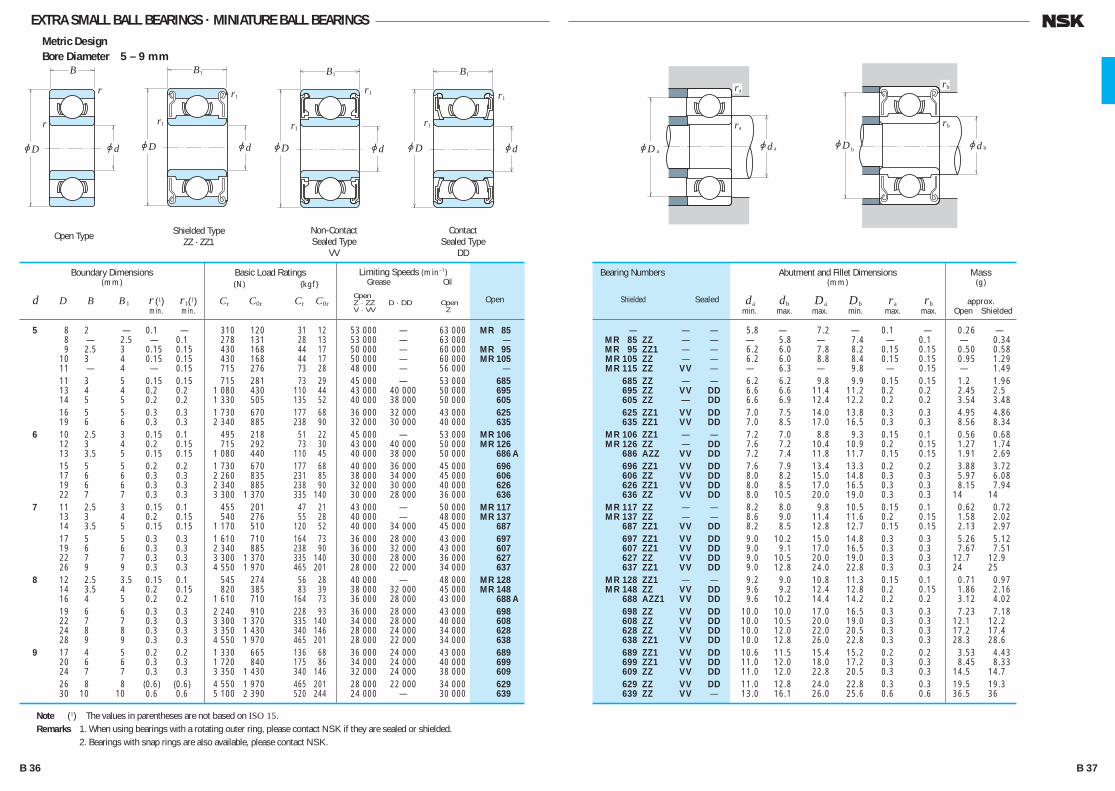
EXTRA SMALL BALL BEARINGS · MINIATURE BALL BEARINGSMetric DesignBore Diameter 5 – 9 mm
— — — 05.8 — 07.2 — 0.10 — 00.26 — MR 85 ZZ — — — 05.8 — 07.4 — 0.10 — 00.34 MR 95 ZZ1 — — 06.2 06.0 07.8 08.2 0.15 0.15 00.50 00.58 MR 105 ZZ — — 06.2 06.0 08.8 08.4 0.15 0.15 00.95 01.29 MR 115 ZZ VV — — 06.3 — 09.8 — 0.15 — 01.49 685 ZZ — — 06.2 06.2 09.8 09.9 0.15 0.15 01.20 01.96 695 ZZ VV DD 06.6 06.6 11.4 11.2 0.20 0.20 02.45 02.50 605 ZZ — DD 06.6 06.9 12.4 12.2 0.20 0.20 03.54 03.48 625 ZZ1 VV DD 07.0 07.5 14.0 13.8 0.30 0.30 04.95 04.86 635 ZZ1 VV DD 07.0 08.5 17.0 16.5 0.30 0.30 08.56 08.34 MR 106 ZZ1 — — 07.2 07.0 08.8 09.3 0.15 0.10 00.56 00.68 MR 126 ZZ — DD 07.6 07.2 10.4 10.9 0.20 0.15 01.27 01.74 686 AZZ VV DD 07.2 07.4 11.8 11.7 0.15 0.15 01.91 02.69 696 ZZ1 VV DD 07.6 07.9 13.4 13.3 0.20 0.20 03.88 03.72 606 ZZ VV DD 08.0 08.2 15.0 14.8 0.30 0.30 05.97 06.08 626 ZZ1 VV DD 08.0 08.5 17.0 16.5 0.30 0.30 08.15 07.94 636 ZZ VV DD 08.0 10.5 20.0 19.0 0.30 0.30 14.00 14.00 MR 117 ZZ — — 08.2 08.0 09.8 10.5 0.15 0.10 00.62 00.72 MR 137 ZZ — — 08.6 09.0 11.4 11.6 0.20 0.15 01.58 02.02 687 ZZ1 VV DD 08.2 08.5 12.8 12.7 0.15 0.15 02.13 02.97 697 ZZ1 VV DD 09.0 10.2 15.0 14.8 0.30 0.30 05.26 05.12 607 ZZ1 VV DD 09.0 09.1 17.0 16.5 0.30 0.30 07.67 07.51 627 ZZ VV DD 09.0 10.5 20.0 19.0 0.30 0.30 12.70 12.90 637 ZZ1 VV DD 09.0 12.8 24.0 22.8 0.30 0.30 24.00 25.00 MR 128 ZZ1 — — 09.2 09.0 10.8 11.3 0.15 0.10 00.71 00.97 MR 148 ZZ VV DD 09.6 09.2 12.4 12.8 0.20 0.15 01.86 02.16 688 AZZ1 VV DD 09.6 10.2 14.4 14.2 0.20 0.20 03.12 04.02 698 ZZ VV DD 10.0 10.0 17.0 16.5 0.30 0.30 07.23 07.18 608 ZZ VV DD 10.0 10.5 20.0 19.0 0.30 0.30 12.10 12.20 628 ZZ VV DD 10.0 12.0 22.0 20.5 0.30 0.30 17.20 17.40 638 ZZ1 VV DD 10.0 12.8 26.0 22.8 0.30 0.30 28.30 28.60 689 ZZ1 VV DD 10.6 11.5 15.4 15.2 0.20 0.20 03.53 04.43 699 ZZ1 VV DD 11.0 12.0 18.0 17.2 0.30 0.30 08.45 08.33 609 ZZ VV DD 11.0 12.0 22.8 20.5 0.30 0.30 14.50 14.70 629 ZZ VV DD 11.0 12.8 24.0 22.8 0.30 0.30 19.50 19.30 639 ZZ VV — 13.0 16.1 26.0 25.6 0.60 0.60 36.50 36.00
Bearing Numbers
Shielded SealedOpen
Abutment and Fillet Dimensions(mm)
da db Da Db ra rb min. max. max. min. max. max.
Mass(g)
approx. Open Shielded
5 8 2.0 — 0.10 — 310 120 31 12 53 000 — 63 000 MR 85 8 — 2.5 — 0.10 278 131 28 13 53 000 — 63 000 — 9 2.5 3.0 0.15 0.15 430 168 44 17 50 000 — 60 000 MR 95 10 3.0 4.0 0.15 0.15 430 168 44 17 50 000 — 60 000 MR 105 11 — 4.0 — 0.15 715 276 73 28 48 000 — 56 000 — 11 3.0 5.0 0.15 0.15 715 281 73 29 45 000 — 53 000 685 13 4.0 4.0 0.20 0.20 1 080 430 110 44 43 000 40 000 50 000 695 14 5.0 5.0 0.20 0.20 1 330 505 135 52 40 000 38 000 50 000 605 16 5.0 5.0 0.30 0.30 1 730 670 177 68 36 000 32 000 43 000 625 19 6.0 6.0 0.30 0.30 2 340 885 238 90 32 000 30 000 40 000 635
6 10 2.5 3.0 0.15 0.10 495 218 51 22 45 000 — 53 000 MR 106 12 3.0 4.0 0.20 0.15 715 292 73 30 43 000 40 000 50 000 MR 126 13 3.5 5.0 0.15 0.15 1 080 440 110 45 40 000 38 000 50 000 686 A
15 5.0 5.0 0.20 0.20 1 730 670 177 68 40 000 36 000 45 000 696 17 6.0 6.0 0.30 0.30 2 260 835 231 85 38 000 34 000 45 000 606 19 6.0 6.0 0.30 0.30 2 340 885 238 90 32 000 30 000 40 000 626 22 7.0 7.0 0.30 0.30 3 300 1 370 335 140 30 000 28 000 36 000 636
7 11 2.5 3.0 0.15 0.10 455 201 47 21 43 000 — 50 000 MR 117 13 3.0 4.0 0.20 0.15 540 276 55 28 40 000 — 48 000 MR 137 14 3.5 5.0 0.15 0.15 1 170 510 120 52 40 000 34 000 45 000 687 17 5.0 5.0 0.30 0.30 1 610 710 164 73 36 000 28 000 43 000 697 19 6.0 6.0 0.30 0.30 2 340 885 238 90 36 000 32 000 43 000 607 22 7.0 7.0 0.30 0.30 3 300 1 370 335 140 30 000 28 000 36 000 627 26 9.0 9.0 0.30 0.30 4 550 1 970 465 201 28 000 22 000 34 000 637 8 12 2.5 3.5 0.15 0.10 545 274 56 28 40 000 — 48 000 MR 128 14 3.5 4.0 0.20 0.15 820 385 83 39 38 000 32 000 45 000 MR 148 16 4.0 5.0 0.20 0.20 1 610 710 164 73 36 000 28 000 43 000 688 A
19 6.0 6.0 0.30 0.30 2 240 910 228 93 36 000 28 000 43 000 698 22 7.0 7.0 0.30 0.30 3 300 1 370 335 140 34 000 28 000 40 000 608 24 8.0 8.0 0.30 0.30 3 350 1 430 340 146 28 000 24 000 34 000 628 28 9.0 9.0 0.30 0.30 4 550 1 970 465 201 28 000 22 000 34 000 638 9 17 4.0 5.0 0.20 0.20 1 330 665 136 68 36 000 24 000 43 000 689 20 6.0 6.0 0.30 0.30 1 720 840 175 86 34 000 24 000 40 000 699 24 7.0 7.0 0.30 0.30 3 350 1 430 340 146 32 000 24 000 38 000 609
26 8.0 8.0 (0.6)0 (0.6)0 4 550 1 970 465 201 28 000 22 000 34 000 629 30 10.00 10.00 0.60 0.60 5 100 2 390 520 244 24 000 — 30 000 639
Boundary Dimensions(mm)
d D B B1 r (1) r1(1) min. min.
Limiting Speeds (min–1) Grease Oil
Open Z · ZZ D · DD Open V · VV Z
Basic Load Ratings (N) {kgf}
Cr C0r Cr C0r
Note (1) The values in parentheses are not based on ISO 15.Remarks 1. When using bearings with a rotating outer ring, please contact NSK if they are sealed or shielded. 2. Bearings with snap rings are also available, please contact NSK.
r
r
jD jd
B
jD jd
B
r1
1
r1
jD jd
B
r1
1
r1
jD jd
B
r1
1
r1
jDjD
ra
jd aa b
ra
rb
jd b
rb
Shielded TypeZZ · ZZ1
Non-ContactSealed Type
VV
ContactSealed Type
DD
Open Type
B 36 B 37
B030-045E.indd 36-37B030-045E.indd 36-37 11/20/13 4:54:17 PM11/20/13 4:54:17 PM

EXTRA SMALL BALL BEARINGS · MINIATURE BALL BEARINGSMetric Design With FlangeBore Diameter 1 – 4 mm
F 681 — — — 1.4 — 0.05 — 0.04 — F 691 — — — 1.8 — 0.10 — 0.14 —
MF 41 X — — — 2.0 — 0.10 — 0.12 —
F 681 X F 681 XZZ — — 1.9 2.1 0.05 0.05 0.09 0.14 F 691 X F 691 XZZ — — 2.7 2.5 0.15 0.15 0.23 0.28 F 601 X F 601 XZZ — — 2.7 3.0 0.15 0.15 0.42 0.52
F 682 F 682 ZZ — — 2.6 2.7 0.08 0.08 0.16 0.22 MF 52 B MF 52 BZZ — — 2.8 2.7 0.10 0.10 0.21 0.27 F 692 F 692 ZZ — — 3.2 3.0 0.15 0.15 0.35 0.48
MF 62 — — — 3.2 — 0.15 — 0.36 — MF 72 MF 72 ZZ — — 3.2 3.8 0.15 0.15 0.52 0.56 F 602 F 602 ZZ — — 3.2 3.1 0.15 0.15 0.60 0.71
F 682 X F 682 XZZ — — 3.1 3.7 0.08 0.08 0.25 0.36 F 692 X F 692 XZZ — — 3.7 3.8 0.15 0.15 0.51 0.68 MF 82 X — — — 4.1 — 0.20 — 0.62 — F 602 X F 602 XZZ — — 3.7 3.5 0.15 0.15 0.74 0.98
MF 63 MF 63 ZZ — — 3.8 3.7 0.10 0.10 0.27 0.33 F 683 A F 683 AZZ — — 3.8 4.0 0.10 0.10 0.37 0.53 MF 83 — — — 4.2 — 0.15 — 0.56 —
F 693 F 693 ZZ — — 4.2 4.3 0.15 0.15 0.70 0.97 MF 93 MF 93 ZZ — — 4.6 4.3 0.20 0.15 0.81 1.34 F 603 F 603 ZZ — — 4.2 4.3 0.15 0.15 1.00 1.63 F 623 F 623 ZZ — — 4.2 4.3 0.15 0.15 1.85 1.86 F 633 F 633 ZZ — — 4.6 6.0 0.20 0.20 3.73 3.59
MF 74 — — — 4.8 — 0.10 — 0.29 — — MF 74 ZZ — — — 4.8 — 0.10 — 0.35 MF 84 MF 84 ZZ — — 5.2 5.0 0.15 0.10 0.44 0.63 F 684 F 684 ZZ — — 4.8 5.2 0.10 0.10 0.70 1.14
MF 104 B MF 104 BZZ — — 5.6 5.9 0.20 0.15 1.13 1.59 F 694 F 694 ZZ — — 5.2 5.6 0.15 0.15 1.91 1.96 F 604 F 604 ZZ — — 5.6 5.6 0.20 0.20 2.53 2.53
F 624 F 624 ZZ — — 5.6 6.0 0.20 0.20 3.38 3.53 F 634 F 634 ZZ1 — — 6.0 7.5 0.30 0.30 5.73 5.62
Bearing Numbers
Open Shielded Sealed
Abutment and Fillet Dimensions(mm)
da db ra rb min. max. max. max.
Mass(g)
approx. Open Shielded
1 3 03.8 — 1.0 — 0.3 — 0.05 — 80 23 8 2.5 130 000 150 000 4 05.0 — 1.6 — 0.5 — 0.10 — 140 36 14 3.5 100 000 120 000
1.2 4 04.8 — 1.8 — 0.4 — 0.10 — 138 35 14 3.5 110 000 130 000
1.5 4 05.0 05.0 1.2 2.0 0.4 0.6 0.05 0.05 112 33 11 3.5 100 000 120 000 5 06.5 06.5 2.0 2.6 0.6 0.8 0.15 0.15 237 69 24 7 85 000 100 000 6 07.5 07.5 2.5 3.0 0.6 0.8 0.15 0.15 330 98 34 10 75 000 90 000
2 5 06.1 06.1 1.5 2.3 0.5 0.6 0.08 0.08 169 50 17 5 85 000 100 000 5 06.2 06.2 2.0 2.5 0.6 0.6 0.10 0.10 187 58 19 6 85 000 100 000 6 07.5 07.5 2.3 3.0 0.6 0.8 0.15 0.15 330 98 34 10 75 000 90 000
6 07.2 — 2.5 — 0.6 — 0.15 — 330 98 34 10 75 000 90 000 7 08.2 08.2 2.5 3.0 0.6 0.6 0.15 0.15 385 127 39 13 63 000 75 000 7 08.5 08.5 2.8 3.5 0.7 0.9 0.15 0.15 385 127 39 13 63 000 75 000
2.5 6 07.1 07.1 1.8 2.6 0.5 0.8 0.08 0.08 208 74 21 7.5 71 000 80 000 7 08.5 08.5 2.5 3.5 0.7 0.9 0.15 0.15 385 127 39 13 63 000 75 000 8 09.2 — 2.5 — 0.6 — 0.20 — 560 179 57 18 60 000 67 000 8 09.5 09.5 2.8 4.0 0.7 0.9 0.15 0.15 550 175 56 18 60 000 71 000
3 6 07.2 07.2 2.0 2.5 0.6 0.6 0.10 0.10 208 74 21 7.5 71 000 80 000 7 08.1 08.1 2.0 3.0 0.5 0.8 0.10 0.10 390 130 40 13 63 000 75 000 8 09.2 — 2.5 — 0.6 — 0.15 — 560 179 57 18 60 000 67 000
8 09.5 09.5 3.0 4.0 0.7 0.9 0.15 0.15 560 179 57 18 60 000 67 000 9 10.2 10.6 2.5 4.0 0.6 0.8 0.20 0.15 570 187 58 19 56 000 67 000 9 10.5 10.5 3.0 5.0 0.7 1.0 0.15 0.15 570 187 58 19 56 000 67 000 10 11.5 11.5 4.0 4.0 1.0 1.0 0.15 0.15 630 218 64 22 50 000 60 000 13 15.0 15.0 5.0 5.0 1.0 1.0 0.20 0.20 1 300 485 133 49 36 000 43 000
4 7 08.2 — 2.0 — 0.6 — 0.10 — 310 115 32 12 60 000 67 000 7 — 08.2 — 2.5 — 0.6 — 0.10 255 107 26 11 60 000 71 000 8 09.2 09.2 2.0 3.0 0.6 0.6 0.15 0.10 395 139 40 14 56 000 67 000 9 10.3 10.3 2.5 4.0 0.6 1.0 (0.15) (0.15) 640 225 65 23 53 000 63 000
10 11.2 11.6 3.0 4.0 0.6 0.8 0.20 0.15 710 270 73 28 50 000 60 000 11 12.5 12.5 4.0 4.0 1.0 1.0 0.15 0.15 960 345 98 35 48 000 56 000 12 13.5 13.5 4.0 4.0 1.0 1.0 0.20 0.20 960 345 98 35 48 000 56 000
13 15.0 15.0 5.0 5.0 1.0 1.0 0.20 0.20 1 300 485 133 49 40 000 48 000 16 18.0 18.0 5.0 5.0 1.0 1.0 0.30 0.30 1 730 670 177 68 36 000 43 000
Boundary Dimensions(mm)
d D D1 D2 B B1 C1 C2 r (1) r1(1) min. min.
Limiting Speeds(min–1)
Grease Oil Open Open Z · ZZ Z
Basic Load Ratings (N) {kgf}
Cr C0r Cr C0r
Note (1) The values in parentheses are not based on ISO 15.Remarks When using bearings with a rotating outer ring, please contact NSK if they are shielded.
r
r
jD jd
B
jDjD jDjd
B C1
r1
r1
1
1
C2
2
ra
jda
rb
jdb
Shielded TypeZZ · ZZ1
Open Type
B 38 B 39
B030-045E.indd 38-39B030-045E.indd 38-39 11/20/13 4:54:19 PM11/20/13 4:54:19 PM

EXTRA SMALL BALL BEARINGS · MINIATURE BALL BEARINGSMetric Design With FlangeBore Diameter 5 – 9 mm
MF 85 — — — 05.8 — 0.10 — 00.33 — — MF 85 ZZ — — — 05.8 — 0.10 — 00.41 MF 95 MF 95 ZZ1 — — 06.2 06.0 0.15 0.15 00.59 00.66 MF 105 MF 105 ZZ — — 06.2 06.0 0.15 0.15 01.05 01.46
F 685 F 685 ZZ — — 06.2 06.2 0.15 0.15 01.37 02.18 F 695 F 695 ZZ VV DD 06.6 06.6 0.20 0.20 02.79 02.84 F 605 F 605 ZZ — DD 06.6 06.9 0.20 0.20 03.90 03.85
F 625 F 625 ZZ1 VV DD 07.0 07.5 0.30 0.30 05.37 05.27 F 635 F 635 ZZ1 VV DD 07.0 08.5 0.30 0.30 09.49 09.49
MF 106 MF 106 ZZ1 — — 07.2 07.0 0.15 0.10 00.65 00.77 MF 126 MF 126 ZZ — DD 07.6 07.2 0.20 0.15 01.38 01.94 F 686 A F 686 AZZ VV DD 07.2 07.4 0.15 0.15 02.25 03.04
F 696 F 696 ZZ1 VV DD 07.6 07.9 0.20 0.20 04.34 04.26 F 606 F 606 ZZ VV DD 08.0 08.2 0.30 0.30 06.58 06.61 F 626 F 626 ZZ1 VV DD 08.0 08.5 0.30 0.30 09.09 09.09 F 636 F 636 ZZ VV DD 08.0 10.5 0.30 0.30 14.60 14.70
MF 117 MF 117 ZZ — — 08.2 08.0 0.15 0.10 00.72 00.82 MF 137 MF 137 ZZ — — 08.6 09.0 0.20 0.15 01.70 02.23 F 687 F 687 ZZ1 VV DD 08.2 08.5 0.15 0.15 02.48 03.37
F 697 F 697 ZZ1 VV DD 09.0 10.2 0.30 0.30 05.65 05.65 F 607 F 607 ZZ1 VV DD 09.0 09.1 0.30 0.30 08.66 08.66 F 627 F 627 ZZ VV DD 09.0 10.5 0.30 0.30 14.20 14.20
MF 128 MF 128 ZZ1 — — 09.2 09.0 0.15 0.10 00.82 01.15 MF 148 MF 148 ZZ VV DD 09.6 09.2 0.20 0.15 02.09 02.39 F 688 A F 688 AZZ VV DD 09.6 10.2 0.20 0.20 03.54 04.47
F 698 F 698 ZZ VV DD 10.0 10.0 0.30 0.30 08.35 08.30 F 608 F 608 ZZ VV DD 10.0 10.5 0.30 0.30 13.40 13.50
F 689 F 689 ZZ1 VV DD 10.6 11.5 0.20 0.20 03.97 04.91 F 699 F 699 ZZ1 VV DD 11.0 12.0 0.30 0.30 09.51 09.51
Bearing Numbers
Open Shielded Sealed
Abutment and FilletDimensions (mm)
da db ra rb min. max. max. max.
Mass(g)
approx. Open Shielded
5 8 09.2 — 2.0 — 0.6 — 0.10 — 310 120 31 12 53 000 — 63 000 8 — 09.2 — 2.5 — 0.6 — 0.10 278 131 28 13 53 000 — 63 000 9 10.2 10.2 2.5 3.0 0.6 0.6 0.15 0.15 430 168 44 17 50 000 — 60 000 10 11.2 11.6 3.0 4.0 0.6 0.8 0.15 0.15 430 168 44 17 50 000 — 60 000
11 12.5 12.5 3.0 5.0 0.8 1.0 0.15 0.15 715 281 73 29 45 000 — 53 000 13 15.0 15.0 4.0 4.0 1.0 1.0 0.20 0.20 1 080 430 110 44 43 000 40 000 50 000 14 16.0 16.0 5.0 5.0 1.0 1.0 0.20 0.20 1 330 505 135 52 40 000 38 000 50 000
16 18.0 18.0 5.0 5.0 1.0 1.0 0.30 0.30 1 730 670 177 68 36 000 32 000 43 000 19 22.0 22.0 6.0 6.0 1.5 1.5 0.30 0.30 2 340 885 238 90 32 000 30 000 40 000
6 10 11.2 11.2 2.5 3.0 0.6 0.6 0.15 0.10 495 218 51 22 45 000 — 53 000 12 13.2 13.6 3.0 4.0 0.6 0.8 0.20 0.15 715 292 73 30 43 000 40 000 50 000 13 15.0 15.0 3.5 5.0 1.0 1.1 0.15 0.15 1 080 440 110 45 40 000 38 000 50 000
15 17.0 17.0 5.0 5.0 1.2 1.2 0.20 0.20 1 730 670 177 68 40 000 36 000 45 000 17 19.0 19.0 6.0 6.0 1.2 1.2 0.30 0.30 2 260 835 231 85 38 000 34 000 45 000 19 22.0 22.0 6.0 6.0 1.5 1.5 0.30 0.30 2 340 885 238 90 32 000 30 000 40 000 22 25.0 25.0 7.0 7.0 1.5 1.5 0.30 0.30 3 300 1 370 335 140 30 000 28 000 36 000
7 11 12.2 12.2 2.5 3.0 0.6 0.6 0.15 0.10 455 201 47 21 43 000 — 50 000 13 14.2 14.6 3.0 4.0 0.6 0.8 0.20 0.15 540 276 55 28 40 000 — 48 000 14 16.0 16.0 3.5 5.0 1.0 1.1 0.15 0.15 1 170 510 120 52 40 000 34 000 45 000
17 19.0 19.0 5.0 5.0 1.2 1.2 0.30 0.30 1 610 715 164 73 36 000 28 000 43 000 19 22.0 22.0 6.0 6.0 1.5 1.5 0.30 0.30 2 340 885 238 90 36 000 32 000 43 000 22 25.0 25.0 7.0 7.0 1.5 1.5 0.30 0.30 3 300 1 370 335 140 30 000 28 000 36 000
8 12 13.2 13.6 2.5 3.5 0.6 0.8 0.15 0.10 545 274 56 28 40 000 — 48 000 14 15.6 15.6 3.5 4.0 0.8 0.8 0.20 0.15 820 385 83 39 38 000 32 000 45 000 16 18.0 18.0 4.0 5.0 1.0 1.1 0.20 0.20 1 610 710 164 73 36 000 30 000 43 000
19 22.0 22.0 6.0 6.0 1.5 1.5 0.30 0.30 2 240 910 228 93 36 000 28 000 43 000 22 25.0 25.0 7.0 7.0 1.5 1.5 0.30 0.30 3 300 1 370 335 140 34 000 28 000 40 000
9 17 19.0 19.0 4.0 5.0 1.0 1.1 0.20 0.20 1 330 665 136 68 36 000 24 000 43 000 20 23.0 23.0 6.0 6.0 1.5 1.5 0.30 0.30 1 720 840 175 86 34 000 24 000 40 000
Boundary Dimensions(mm)
d D D1 D2 B B1 C1 C2 r r1 min. min.
Limiting Speeds (min–1) Grease Oil
Open Open Z · ZZ D · DD Z V · VV
Basic Load Ratings (N) {kgf}
Cr C0r Cr C0r
Remarks When using bearings with a rotating outer ring, please contact NSK if they are shielded.
r
r
jD jd
B
jDjD jDjd
B C 1
r1
r1
1
1
C 2
2 jdjD2 jdjD2
B1 C 2B1 C 2
jD jD
r1
r1
r1
r1
ra
jda
rb
jdb
Shielded TypeZZ · ZZ1
ContactSealed Type
DD
Non-ContactSealed Type
VVOpen Type
B 40 B 41
B030-045E.indd 40-41B030-045E.indd 40-41 11/20/13 4:54:20 PM11/20/13 4:54:20 PM

EXTRA SMALL BALL BEARINGS · MINIATURE BALL BEARINGSInch DesignBore Diameter 1.016 – 9.525 mm
— 01.9 — 02.3 — 0.1 0.04 —
R 0 ZZ 02.0 01.9 03.1 03.5 0.1 0.09 00.11
R 1 ZZ 02.2 02.3 03.9 04.1 0.1 0.15 00.19
R 1-4 ZZ 02.8 03.9 05.5 05.9 0.1 0.35 00.50
— 03.2 — 03.9 — 0.1 0.10 — R 133 ZZS — 03.0 — 04.2 0.1 — 00.13 R 1-5 ZZ 03.6 04.1 06.7 07.0 0.15 0.60 00.72
R 144 ZZ 04.0 03.9 05.5 05.9 0.1 0.25 00.27 R 2-5 ZZ 04.0 04.3 07.1 07.3 0.1 0.55 00.72 R 2-6 ZZS 04.4 04.6 08.3 08.2 0.15 0.96 01.13
R 2 ZZ 05.2 04.8 07.5 08.0 0.3 1.36 01.39 R 2A ZZ 05.2 04.6 10.7 08.2 0.3 3.30 03.23
R 155 ZZS 04.8 05.5 07.1 07.3 0.1 0.51 00.56
R 156 ZZS 05.6 05.5 07.1 07.3 0.1 0.39 00.42 R 166 ZZ 05.6 05.9 08.7 08.8 0.1 0.81 00.85 R 3 ZZ 06.8 06.5 10.7 11.2 0.3 2.21 02.79
R 168 BZZ 07.2 07.0 08.7 08.9 0.1 0.58 00.62 R 188 ZZ 07.6 07.4 11.5 11.6 0.15 1.53 02.21
R 4B ZZ 08.4 08.4 13.8 13.8 0.3 4.50 04.43 R 4AA ZZ 09.4 09.0 16.0 16.6 0.4 7.48 09.17
R 1810 ZZ 09.2 09.0 11.5 11.6 0.15 1.56 01.48
R 6 ZZ 12.6 11.9 19.2 20.0 0.4 9.02 11.00
Numbers
Shielded
Bearing
Open
Abutment and Fillet Dimensions(mm)
da db Da Db ra min. max. max. min. max.
Mass(g)
approx. Open Shielded
1.016 3.175 1.191 — 0.1 80 23 8 2.5 130 000 150 000 R 09
1.191 3.967 1.588 2.380 0.1 138 35 14 3.5 110 000 130 000 R 0
1.397 4.762 1.984 2.779 0.1 231 66 24 6.5 90 000 110 000 R 1
1.984 6.350 2.380 3.571 0.1 310 108 32 11 67 000 80 000 R 1-4
2.380 4.762 1.588 — 0.1 188 60 19 6 80 000 95 000 R 133 4.762 — 2.380 0.1 143 52 15 5.5 80 000 95 000 — 7.938 2.779 3.571 0.15 550 175 56 18 60 000 71 000 R 1-5
3.175 6.350 2.380 2.779 0.1 283 95 29 9.5 67 000 80 000 R 144 7.938 2.779 3.571 0.1 560 179 57 18 60 000 67 000 R 2-5 9.525 2.779 3.571 0.15 640 225 65 23 53 000 63 000 R 2-6
9.525 3.967 3.967 0.3 630 218 64 22 56 000 67 000 R 2 12.700 4.366 4.366 0.3 640 225 65 23 53 000 63 000 R 2A
3.967 7.938 2.779 3.175 0.1 360 149 37 15 53 000 63 000 R 155
4.762 7.938 2.779 3.175 0.1 360 149 37 15 53 000 63 000 R 156 9.525 3.175 3.175 0.1 710 270 73 28 50 000 60 000 R 166 12.700 3.967 4.978 0.3 1 300 485 133 49 43 000 53 000 R 3
6.350 9.525 3.175 3.175 0.1 420 204 43 21 48 000 56 000 R 168B 12.700 3.175 4.762 0.15 1 080 440 110 45 40 000 50 000 R 188
15.875 4.978 4.978 0.3 1 610 660 164 68 38 000 45 000 R 4B 19.050 5.558 7.142 0.4 2 620 1 060 267 108 36 000 43 000 R 4AA
7.938 12.700 3.967 3.967 0.15 540 276 55 28 40 000 48 000 R 1810
9.525 22.225 5.558 7.142 0.4 3 350 1 410 340 144 32 000 38 000 R 6
Boundary Dimensions(mm)
d D B B1 r min.
Limiting Speeds(min–1)
Grease Oil Open Open Z · ZZ Z
Basic Load Ratings (N) {kgf}
Cr C0r Cr C0r
Remarks 1. When using bearings with a rotating outer ring, please contact NSK if they are shielded. 2. Bearings with double shields (ZZ, ZZS) are also available with single shields (Z, ZS).
r
r
jD jd
B
jD jd
B
r
1
r
jDjD
ra
jd aa b
ra
ra
jd b
ra
Shielded TypeZZ · ZZS
Open Type
B 42 B 43
B030-045E.indd 42-43B030-045E.indd 42-43 11/20/13 4:54:22 PM11/20/13 4:54:22 PM

EXTRA SMALL BALL BEARINGS · MINIATURE BALL BEARINGSInch Design With FlangeBore Diameter 1.191 – 9.525 mm
110 000 130 000 FR 0 FR 0 ZZ 02.0 01.9 0.1 00.11 00.16 90 000 110 000 FR 1 FR 1 ZZ 02.2 02.3 0.1 00.20 00.25 67 000 80 000 FR 1-4 FR 1-4 ZZ 02.8 03.9 0.1 00.41 00.58 80 000 95 000 FR 133 — 03.2 — 0.1 00.13 — 80 000 95 000 — FR 133 ZZS — 03.0 0.1 — 00.19 60 000 71 000 FR 1-5 FR 1-5 ZZ 03.6 04.1 0.15 00.68 00.82 67 000 80 000 FR 144 FR 144 ZZ 04.0 03.9 0.1 00.31 00.35 60 000 67 000 FR 2-5 FR 2-5 ZZ 04.0 04.3 0.1 00.62 00.81 53 000 63 000 FR 2-6 FR 2-6 ZZS 04.4 04.6 0.15 01.04 01.25 56 000 67 000 FR 2 FR 2 ZZ 05.2 04.8 0.3 01.51 01.55 53 000 63 000 FR 155 FR 155 ZZS 04.8 05.5 0.1 00.59 00.67 53 000 63 000 FR 156 FR 156 ZZS 05.6 05.5 0.1 00.47 00.53 50 000 60 000 FR 166 FR 166 ZZ 05.6 05.9 0.1 00.90 00.98 43 000 53 000 FR 3 FR 3 ZZ 06.8 06.5 0.3 02.97 03.09 48 000 56 000 FR 168B FR 168 BZZ 07.2 07.0 0.1 00.66 00.75 40 000 50 000 FR 188 FR 188 ZZ 07.6 07.4 0.15 01.64 02.49 38 000 45 000 FR 4B FR 4B ZZ 08.4 08.4 0.3 04.78 04.78 40 000 48 000 FR 1810 FR 1810 ZZ 09.2 09.0 0.15 01.71 01.63 32 000 38 000 FR 6 FR 6 ZZ 12.6 11.9 0.4 10.10 12.10
Bearing Numbers
Open Shielded
Abutment and Fillet Dimensions (mm)
da db ra min. max. max.
Mass(g)
approx. Open Shielded
1.191 3.967 5.156 1.588 2.380 0.330 0.790 0.1 138 35 14 3.5 1.397 4.762 5.944 1.984 2.779 0.580 0.790 0.1 231 66 24 6.5 1.984 6.350 7.518 2.380 3.571 0.580 0.790 0.1 310 108 32 11 2.380 4.762 5.944 1.588 — 0.460 — 0.1 188 60 19 6 4.762 5.944 — 2.380 — 0.790 0.1 143 52 15 5.5 7.938 9.119 2.779 3.571 0.580 0.790 0.15 550 175 56 18 3.175 6.350 7.518 2.380 2.779 0.580 0.790 0.1 283 95 29 9.5 7.938 9.119 2.779 3.571 0.580 0.790 0.1 560 179 57 18 9.525 10.719 2.779 3.571 0.580 0.790 0.15 640 225 65 23 9.525 11.176 3.967 3.967 0.760 0.760 0.3 630 218 64 22 3.967 7.938 9.119 2.779 3.175 0.580 0.910 0.1 360 149 37 15 4.762 7.938 9.119 2.779 3.175 0.580 0.910 0.1 360 149 37 15 9.525 10.719 3.175 3.175 0.580 0.790 0.1 710 270 73 28 12.700 14.351 4.978 4.978 1.070 1.070 0.3 1 300 485 133 49 6.350 9.525 10.719 3.175 3.175 0.580 0.910 0.1 420 204 43 21 12.700 13.894 3.175 4.762 0.580 1.140 0.15 1 080 440 110 45 15.875 17.526 4.978 4.978 1.070 1.070 0.3 1 610 660 164 68 7.938 12.700 13.894 3.967 3.967 0.790 0.790 0.15 540 276 55 28 9.525 22.225 24.613 7.142 7.142 1.570 1.570 0.4 3 350 1 410 340 144
Boundary Dimensions(mm)
d D D1 B B1 C1 C2 r min.
Limiting Speeds(min–1)
Grease Oil Open Open Z · ZZ Z
Basic Load Ratings (N) {kgf}
Cr C0r Cr C0r
Remarks 1. When using bearings with a rotating outer ring, please contact NSK if they are shielded. 2. Bearings with double shields (ZZ, ZZS) are also available with single shields (Z, ZS).
r
r
jD jd
B
jDjD jDjd
B C1
r
r
1
1
C 2
1
ra
jd a
ra
jd b
Shielded TypeZZ · ZZS
Open Type
B 44 B 45
B030-045E.indd 44-45B030-045E.indd 44-45 11/20/13 4:54:23 PM11/20/13 4:54:23 PM
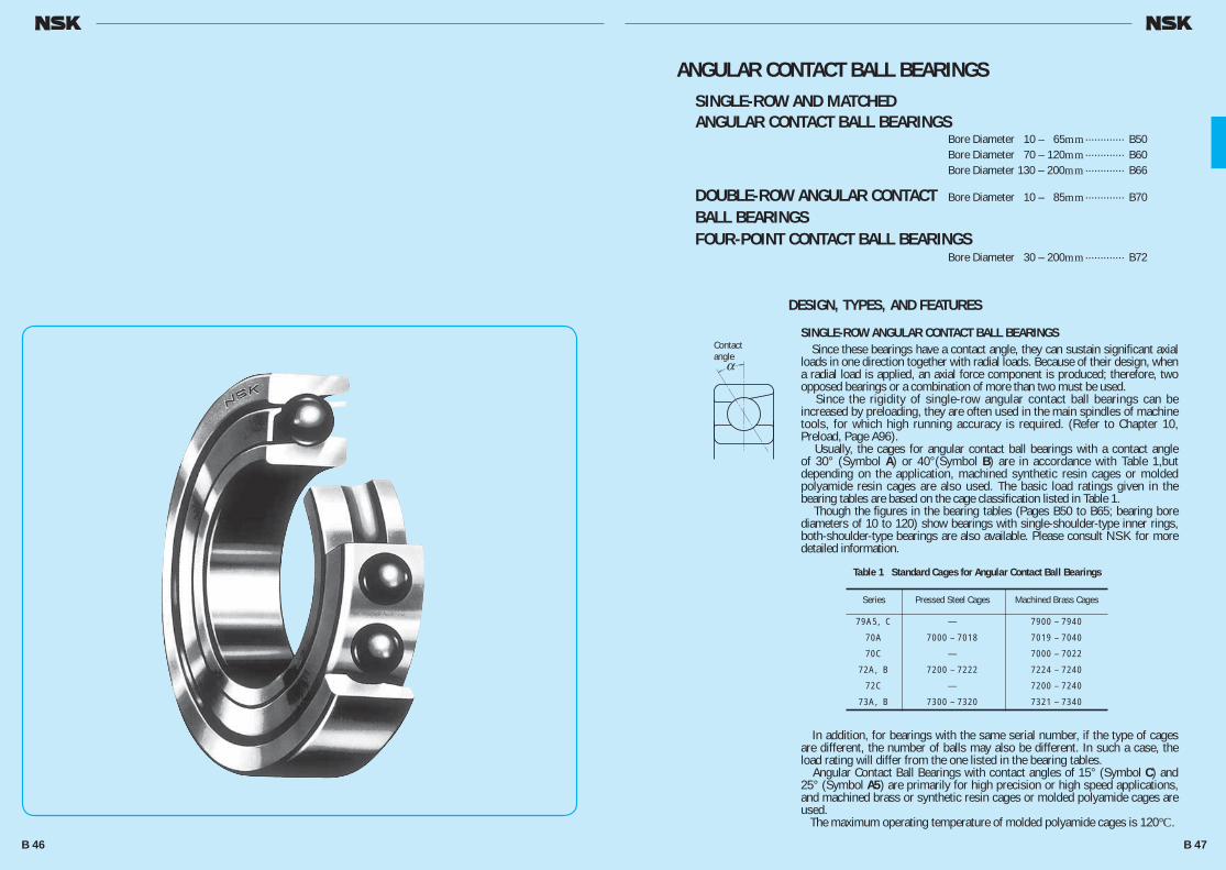
Table 1 Standard Cages for Angular Contact Ball Bearings
αContactangle
ANGULAR CONTACT BALL BEARINGSSINGLE-ROW AND MATCHEDANGULAR CONTACT BALL BEARINGS Bore Diameter 10 – 65mm ············· B50 Bore Diameter 70 – 120mm ············· B60 Bore Diameter 130 – 200mm ············· B66
DOUBLE-ROW ANGULAR CONTACT Bore Diameter 10 – 85mm ············· B70
BALL BEARINGSFOUR-POINT CONTACT BALL BEARINGS Bore Diameter 30 – 200mm ············· B72
DESIGN, TYPES, AND FEATURES
SINGLE-ROW ANGULAR CONTACT BALL BEARINGS Since these bearings have a contact angle, they can sustain significant axial loads in one direction together with radial loads. Because of their design, when a radial load is applied, an axial force component is produced; therefore, two opposed bearings or a combination of more than two must be used. Since the rigidity of single-row angular contact ball bearings can be increased by preloading, they are often used in the main spindles of machine tools, for which high running accuracy is required. (Refer to Chapter 10, Preload, Page A96). Usually, the cages for angular contact ball bearings with a contact angle of 30° (Symbol A) or 40°(Symbol B) are in accordance with Table 1,but depending on the application, machined synthetic resin cages or molded polyamide resin cages are also used. The basic load ratings given in the bearing tables are based on the cage classification listed in Table 1. Though the figures in the bearing tables (Pages B50 to B65; bearing bore diameters of 10 to 120) show bearings with single-shoulder-type inner rings, both-shoulder-type bearings are also available. Please consult NSK for more detailed information.
In addition, for bearings with the same serial number, if the type of cages are different, the number of balls may also be different. In such a case, the load rating will differ from the one listed in the bearing tables. Angular Contact Ball Bearings with contact angles of 15° (Symbol C) and 25° (Symbol A5) are primarily for high precision or high speed applications, and machined brass or synthetic resin cages or molded polyamide cages are used. The maximum operating temperature of molded polyamide cages is 120°C.
Series Pressed Steel Cages Machined Brass Cages
79A5, C — 7900 – 7940
70A 7000 – 7018 7019 – 7040
70C — 7000 – 7022
72A, B 7200 – 7222 7224 – 7240
72C — 7200 – 7240
73A, B 7300 – 7320 7321 – 7340
B 46 B 47
B046-075E.indd 46-47B046-075E.indd 46-47 11/20/13 4:55:02 PM11/20/13 4:55:02 PM

MATCHED ANGULAR CONTACT BALL BEARINGS The types and features of matched angular contact ball bearings are shown in Table 2.
NSKHPS ANGULAR CONTACT BALL BEARINGS In comparison with standard angular contact ball bearings, these bearings have high capacity, high limiting speed, and highly accurate universal matching as the features. The molded polyamide cages are standard specification for the HPS type.
DOUBLE-ROW ANGULAR CONTACT BALL BEARINGS This is basically a back-to-back mounting of two single-row angular contact ball bearings, but their inner and outer rings are each integrated into one. Axial loads in both directions can be sustained, and the capacity to sustain moments is good. This type is used as fixed-end bearings. Their cages are pressed steel.
FOUR-POINT CONTACT BALL BEARINGS The inner ring is split radially into two pieces. Their design allows one bearing to sustain significant axial loads in either direction. The contact angle is 35°, so the axial load capacity is high. This type is suitable for carrying pure axial loads or combined loads where the axial loads are high. The cages are made of machined brass.
PRECAUTIONS FOR USE OF ANGULAR CONTACT BALL BEARINGS
Under severe operating conditions where the speed and temperature are close to their limits, lubrication is marginal, vibration and moment loads are heavy, they may not be suitable, particularly for certain types of cages. In such a case, please consult with NSK beforehand. And if the load on angular contact ball bearings becomes too small, or if the ratio of the axial and radial loads for matched bearings exceeds ‘e’ (e is listed in the bearings tables) during operation, slippage occurs between the balls and raceways, which may result in smearing. Especially with large bearings since the weight of the balls and cage is high. If such load conditions are expected, please consult with NSK for selection of the bearings.
TOLERANCES AND RUNNING ACCURACYSINGLE-ROW ANGULAR CONTACT BALL BEARINGS ····························································Table 8.2 (Pages A60 to A63)NSKHPS ANGULAR CONTACT BALL BEARINGS Tolerance for Dimensions: Class 6, Running Accuracy: Class 5 ·········································Table 8.2 (Pages A60 to A63)MATCHED ANGULAR CONTACT BALL BEARINGS ····························································Table 8.2 (Pages A60 to A63)DOUBLE-ROW ANGULAR CONTACT BALL BEARINGS ····························································Table 8.2 (Pages A60 to A63)FOUR-POINT CONTACT BALL BEARINGS ······································································Table 8.2 (Pages A60 to A63)
RECOMMENDED FITSSINGLE-ROW ANGULAR CONTACT BALL BEARINGS AND HPS ANGULAR CONTACT BALL BEARINGS ····························································Table 9.2 (Page A84) Table 9.4 (Page A85)MATCHED ANGULAR CONTACT BALL BEARINGS ········Table 9.2 (Page A84) Table 9.4 (Page A85)DOUBLE-ROW ANGULAR CONTACT BALL BEARINGS ······································································Table 9.2 (Page A84) Table 9.4 (Page A85)FOUR-POINT CONTACT BALL BEARINGS ·····················Table 9.2 (Page A84) Table 9.4 (Page A85)
INTERNAL CLEARANCESMATCHED ANGULAR CONTACT BALL BEARINGS ······ Table 9. 17 (Page A94) Matched angular contact ball bearings with precision better than P5 are primarily used in the main spindles of machine tools, so they are used with a preload for rigidity. For convenience of selection, internal clearances are adjusted to produce Very Light, Light, Medium, and Heavy Preloads. Their fitting is also special. Concerning these matters, please refer to Tables 10.1 and 10.2 (Pages A98 and A99). The clearance (or preload) of matched bearings is obtained by axially tightening a pair of bearings till the side faces of their inner or outer rings are pressed against each other.NSKHPS ANGULAR CONTACT BALL BEARINGS
DOUBLE-ROW ANGULAR CONTACT BALL BEARINGS For the clearance in double-row angular contact ball bearings, please consult with NSK.FOUR-POINT CONTACT BALL BEARINGS ·····················Table 9.18 (Page A94)
LIMITING SPEEDS In cases of single-row and matched angular contact ball bearings, the Limiting speeds listed in the bearing table are for bearings with machined cage. For those with pressed cages, the listed speeds must be reduced by 20%. The limiting speeds of bearings with contact angles of 15° (Symbol C) and 25° (Symbol A5) are for bearings with precision of P5 and better (with machined synthetic-resin cages or molded polyamide cages). The limiting speeds listed in the bearing tables should be adjusted depending on the bearing load conditions. Also, higher speeds are attainable by making changes in the lubrication method, cage design, etc. Refer to Page A37 for detailed information.
Figure Arrangement Features
Table 2 Types and Features of Matched Angular Contact Ball Bearings
0
0
a
a
Back-to-back(DB)
(Example)7208 A DB
Radial loads and axial loads in both directions can be sustained. Since the distance between the effective load centers a0 is big, this type is suitable if moments are applied.
Face-to-face(DF)
(Example)7208 B DF
Radial loads and axial loads in both directions can be sustained. Compared with the DB Type, the distance between the effective load centers is small, so the capacity to sustain moments is inferior to the DB Type.
Tandem(DT)
(Example)7208 A DT
Radial loads and axial loads in one direction can be sustained. Since two bearings share the axial load, this arrangement is used when the load in one direction is heavy.
Axial Internal Clearance (Measured Clearances) Units : μm
Nominal Bore Diameter Axial Internal Clearance d (mm) CNB GA over incl. min. max. min. max. 12 18 17 25 18 30 20 28 –2 6 30 50 24 32 50 80 29 41 –3 9
B 48 B 49
B046-075E.indd 48-49B046-075E.indd 48-49 11/20/13 4:55:03 PM11/20/13 4:55:03 PM

ANGULAR CONTACT BALL BEARINGSSINGLE/MATCHED MOUNTINGSBore Diameter 10 – 15 mm
7900 A5 DB DF DT 4 700 2 900 475 296 32 000 43 000 13.5 1.5 — 20.8 0.15 7900 C DB DF DT 4 900 3 050 500 310 38 000 53 000 10.3 1.7 — 20.8 0.15 7000 A DB DF DT 8 750 5 200 890 530 24 000 34 000 18.4 2.4 11.2 24.8 0.15
7000 C DB DF DT 8 650 5 000 880 510 36 000 50 000 12.8 3.2 — 24.8 0.15 7200 A DB DF DT 8 800 5 400 900 555 22 000 30 000 20.5 2.5 12.5 27.5 0.3 7200 B DB DF DT 8 100 5 000 825 510 16 000 22 000 25.8 7.8 12.5 27.5 0.3
7200 C DB DF DT 8 800 5 200 895 530 32 000 45 000 14.4 3.6 — 27.5 0.3 7300 A DB DF DT 15 100 8 600 1 540 880 16 000 22 000 24.0 2.0 12.5 32.5 0.3 7300 B DB DF DT 14 200 8 100 1 450 825 14 000 20 000 29.9 7.9 12.5 32.5 0.3
7901 A5 DB DF DT 5 200 3 550 530 360 30 000 43 000 14.4 2.4 — 22.8 0.15 7901 C DB DF DT 5 450 3 700 555 380 36 000 50 000 10.8 1.2 — 22.8 0.15 7001 A DB DF DT 9 400 5 950 955 610 22 000 30 000 19.5 3.5 13.2 26.8 0.15
7001 C DB DF DT 9 400 5 800 960 590 32 000 45 000 13.4 2.6 — 26.8 0.15 7201 A DB DF DT 13 000 8 050 1 330 820 20 000 28 000 22.7 2.7 14.5 29.5 0.3 7201 B DB DF DT 12 100 7 500 1 230 765 15 000 20 000 28.5 8.5 14.5 29.5 0.3
*7201 BEA — — — — 16 000 24 000 28.5 8.5 14.5 29.5 0.3 7201 C DB DF DT 12 800 7 700 1 310 785 30 000 40 000 15.9 4.1 — 29.5 0.3 7301 A DB DF DT 15 400 9 000 1 570 915 15 000 20 000 26.1 2.1 17 32 0.6
7301 B DB DF DT 14 400 8 400 1 460 855 13 000 18 000 32.6 8.6 17 32 0.6*7301 BEA — — — — 15 000 22 000 32.6 8.6 17 32 0.6
7902 A5 DB DF DT 7 400 5 050 755 515 26 000 34 000 17.0 3.0 — 26.8 0.15 7902 C DB DF DT 7 750 5 300 790 540 30 000 43 000 12.8 1.2 — 26.8 0.15 7002 A DB DF DT 9 950 6 850 1 010 700 19 000 26 000 22.6 4.6 16.2 30.8 0.15
7002 C DB DF DT 10 100 6 750 1 030 690 28 000 38 000 15.3 2.7 — 30.8 0.15 7202 A DB DF DT 14 000 9 300 1 430 950 18 000 24 000 25.4 3.4 17.5 32.5 0.3 7202 B DB DF DT 12 900 8 600 1 310 875 13 000 18 000 32.0 10.0 17.5 32.5 0.3
*7202 BEA — — — — 14 000 20 000 32.0 10.0 17.5 32.5 0.3 7202 C DB DF DT 14 100 9 050 1 440 925 26 000 36 000 17.7 4.3 — 32.5 0.3 7302 A DB DF DT 21 800 14 200 2 220 1 440 13 000 17 000 29.5 3.5 20 37 0.6
7302 B DB DF DT 20 200 13 200 2 060 1 340 11 000 15 000 36.9 10.9 20 37 0.6*7302 BEA — — — — 13 000 18 000 36.9 10.9 20 37 0.6
Bearing Numbers (2)
Single Duplex
Abutment and Fillet Dimensions (mm)
da Da ra min. max. max.
Abutment and Fillet Dimensions (mm)
db (3) Db rb (3) min. max. max.
10 22 6 0.3 0.15 2 880 1 450 294 148 — 40 000 56 000 6.7 12.5 19.5 0.3 0.009 22 6 0.3 0.15 3 000 1 520 305 155 14.1 48 000 63 000 5.1 12.5 19.5 0.3 0.009 26 8 0.3 0.15 5 350 2 600 550 266 — 32 000 43 000 9.2 12.5 23.5 0.3 0.019
26 8 0.3 0.15 5 300 2 490 540 254 12.6 45 000 63 000 6.4 12.5 23.5 0.3 0.021 30 9 0.6 0.3 5 400 2 710 555 276 — 28 000 38 000 10.3 15 25 0.6 0.032 30 9 0.6 0.3 5 000 2 500 510 255 — 20 000 28 000 12.9 15 25 0.6 0.032
30 9 0.6 0.3 5 400 2 610 550 266 13.2 40 000 56 000 7.2 15 25 0.6 0.036 35 11 0.6 0.3 9 300 4 300 950 440 — 20 000 26 000 12.0 15 30 0.6 0.053 35 11 0.6 0.3 8 750 4 050 890 410 — 18 000 24 000 14.9 15 30 0.6 0.054
12 24 6 0.3 0.15 3 200 1 770 325 181 — 38 000 53 000 7.2 14.5 21.5 0.3 0.011 24 6 0.3 0.15 3 350 1 860 340 189 14.7 45 000 63 000 5.4 14.5 21.5 0.3 0.011 28 8 0.3 0.15 5 800 2 980 590 305 — 28 000 38 000 9.8 14.5 25.5 0.3 0.021
28 8 0.3 0.15 5 800 2 900 590 296 13.2 40 000 56 000 6.7 14.5 25.5 0.3 0.024 32 10 0.6 0.3 8 000 4 050 815 410 — 26 000 34 000 11.4 17 27 0.6 0.037 32 10 0.6 0.3 7 450 3 750 760 380 — 18 000 26 000 14.2 17 27 0.6 0.038
32 10 0.6 0.3 8 150 3 750 830 380 — 20 000 30 000 14.2 17 27 0.6 0.036 32 10 0.6 0.3 7 900 3 850 805 395 12.5 36 000 50 000 7.9 17 27 0.6 0.041 37 12 1 0.6 9 450 4 500 965 460 — 18 000 24 000 13.1 18 31 1 0.060
37 12 1 0.6 8 850 4 200 900 425 — 16 000 22 000 16.3 18 31 1 0.062 37 12 1 0.6 11 100 4 950 1 130 505 — 18 000 26 000 16.3 18 31 1 0.061
15 28 7 0.3 0.15 4 550 2 530 465 258 — 32 000 43 000 8.5 17.5 25.5 0.3 0.015 28 7 0.3 0.15 4 750 2 640 485 270 14.5 38 000 53 000 6.4 17.5 25.5 0.3 0.015 32 9 0.3 0.15 6 100 3 450 625 350 — 24 000 32 000 11.3 17.5 29.5 0.3 0.030
32 9 0.3 0.15 6 250 3 400 635 345 14.1 34 000 48 000 7.6 17.5 29.5 0.3 0.034 35 11 0.6 0.3 8 650 4 650 880 475 — 22 000 30 000 12.7 20 30 0.6 0.045 35 11 0.6 0.3 7 950 4 300 810 440 — 16 000 22 000 16.0 20 30 0.6 0.046
35 11 0.6 0.3 9 800 4 800 995 490 — 18 000 26 000 16.0 20 30 0.6 0.044 35 11 0.6 0.3 8 650 4 550 885 460 13.2 32 000 45 000 8.8 20 30 0.6 0.052 42 13 1 0.6 13 400 7 100 1 370 720 — 16 000 22 000 14.7 21 36 1 0.084
42 13 1 0.6 12 500 6 600 1 270 670 — 14 000 19 000 18.5 21 36 1 0.086 42 13 1 0.6 14 300 6 900 1 460 705 — 16 000 22 000 18.5 21 36 1 0.084
Boundary Dimensions(mm)
d D B r r1 min. min.
Limiting Speeds (1)
(min–1) Grease Oil
Limiting Speeds (1) (Matched)
(min–1) Grease Oil
Load Center Spacings (mm)
a0 DB DF
Basic Load Ratings (Single) (N) {kgf}
Cr C0r Cr C0r
Basic Load Ratings (Matched) (N) {kgf}
Cr C0r Cr C0r
Notes (1) For applications operating near the limiting speed, refer to Page B49. (2) The suffixes A, A5, B, and C represent contact angles of 30°, 25°, 40°, and 15° respectively.
Note (3) For bearings marked — in the column for db, db and rb for shafts are da (min) and ra (max) respectively.Remarks The bearings denoted by an asterisk (*) are NSKHPS Angular contact ball bearings and the column of Duplex in Bearing
Numbers indicates the universal matching.
r
r
r
jD jd
2B 2BB
a0 a0
1
r1
a
jD jd
ra
aa
2Bra
jD
ra
b jd a
rb
jD
rb
a jd b
ra
Back-to-BackDB
Face-to-FaceDF
TandemDT
Single
Factor
f0
Mass(kg)
approx.
Eff.Load Centers (mm)
a
Dynamic Equivalent Load P =XFr +YFa
*For i , use 2 for DB, DF and 1 for DT
Contact
Single, DT DB or DF
Angle e Fa/Fr≤e Fa/Fr>e Fa/Fr≤e Fa/Fr>e
X Y X Y X Y X Y 0.178 0.38 1 0 0.44 1.47 1 1.65 0.72 2.39 0.357 0.40 1 0 0.44 1.40 1 1.57 0.72 2.28 0.714 0.43 1 0 0.44 1.30 1 1.46 0.72 2.11 15º 1.07 0.46 1 0 0.44 1.23 1 1.38 0.72 2.00 1.43 0.47 1 0 0.44 1.19 1 1.34 0.72 1.93 2.14 0.50 1 0 0.44 1.12 1 1.26 0.72 1.82 3.57 0.55 1 0 0.44 1.02 1 1.14 0.72 1.66 5.35 0.56 1 0 0.44 1.00 1 1.12 0.72 1.63 25º — 0.68 1 0 0.41 0.87 1 0.92 0.67 1.41 30º — 0.80 1 0 0.39 0.76 1 0.78 0.63 1.24 40º — 1.14 1 0 0.35 0.57 1 0.55 0.57 0.93
i f0 Fa*Cor
Static Equivalent Load P0=X 0Fr +Y 0Fa
Contact Single, DT DB or DF Angle X0 Y0 X0 Y0
15º 0.5 0.46 1 0.92 25º 0.5 0.38 1 0.76 30º 0.5 0.33 1 0.66 40º 0.5 0.26 1 0.52
Single or DTmountingWhenFr>0.5Fr+Y0Fause P0=Fr
B 50 B 51
B046-075E.indd 50-51B046-075E.indd 50-51 11/20/13 4:55:04 PM11/20/13 4:55:04 PM
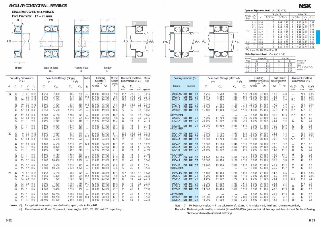
ANGULAR CONTACT BALL BEARINGSSINGLE/MATCHED MOUNTINGSBore Diameter 17 – 25 mm
7903 A5 DB DF DT 7 750 5 600 790 570 24 000 32 000 18.0 4.0 — 28.8 0.15 7903 C DB DF DT 8 150 5 850 830 600 28 000 38 000 13.3 0.7 — 28.8 0.15 7003 A DB DF DT 10 400 7 650 1 060 780 17 000 24 000 25.0 5.0 18.2 33.8 0.15
7003 C DB DF DT 10 700 7 600 1 100 775 26 000 34 000 17.0 3.0 — 33.8 0.15 7203 A DB DF DT 17 600 12 000 1 790 1 220 16 000 22 000 28.5 4.5 19.5 37.5 0.3 7203 B DB DF DT 16 100 11 000 1 650 1 130 11 000 15 000 35.9 11.9 19.5 37.5 0.3
*7203 BEA — — — — 13 000 18 000 36.3 12.3 19.5 37.5 0.3 7203 C DB DF DT 17 600 11 700 1 800 1 190 22 000 32 000 19.6 4.4 — 37.5 0.3 7303 A DB DF DT 25 900 17 300 2 640 1 760 11 000 15 000 32.5 4.5 22 42 0.6
7303 B DB DF DT 24 000 16 000 2 450 1 640 10 000 14 000 40.9 12.9 22 42 0.6*7303 BEA — — — — 11 000 16 000 40.9 12.9 22 42 0.6
7904 A5 DB DF DT 10 700 8 100 1 090 825 19 000 26 000 22.3 4.3 — 35.8 0.15 7904 C DB DF DT 11 300 8 500 1 150 865 22 000 32 000 16.6 1.4 — 35.8 0.15 7004 A DB DF DT 17 600 13 200 1 800 1 340 15 000 20 000 29.9 5.9 22.5 39.5 0.3
7004 C DB DF DT 18 000 13 100 1 840 1 330 20 000 30 000 20.3 3.7 — 39.5 0.3 7204 A DB DF DT 23 500 16 600 2 400 1 690 13 000 19 000 33.3 5.3 25 42 0.6 7204 B DB DF DT 21 600 15 300 2 210 1 560 9 500 13 000 42.1 14.1 25 42 0.6
*7204 BEA — — — — 11 000 16 000 42.1 14.1 25 42 0.6 7204 C DB DF DT 23 600 16 100 2 410 1 650 19 000 26 000 23.0 5.0 — 42 0.6 7304 A DB DF DT 30 500 20 800 3 100 2 130 10 000 13 000 35.8 5.8 25 47 0.6
7304 B DB DF DT 28 200 19 300 2 870 1 970 9 000 12 000 45.2 15.2 25 47 0.6*7304 BEA — — — — 10 000 14 000 45.2 15.2 25 47 0.6
7905 A5 DB DF DT 12 100 10 300 1 230 1 050 16 000 22 000 24.6 6.6 — 40.8 0.15 7905 C DB DF DT 12 700 10 800 1 300 1 110 19 000 26 000 18.0 0.0 — 40.8 0.15 7005 A DB DF DT 18 300 14 800 1 870 1 510 13 000 17 000 32.8 8.8 27.5 44.5 0.3
7005 C DB DF DT 19 000 14 800 1 940 1 510 18 000 26 000 21.6 2.4 — 44.5 0.3 7205 A DB DF DT 26 300 20 500 2 690 2 090 12 000 16 000 37.2 7.2 30 47 0.6 7205 B DB DF DT 24 000 18 800 2 450 1 920 8 500 11 000 47.3 17.3 30 47 0.6
*7205 BEA — — — — 9 500 14 000 47.3 17.3 30 47 0.6 7205 C DB DF DT 27 000 20 400 2 750 2 080 17 000 24 000 25.3 4.7 — 47 0.6 7305 A DB DF DT 43 000 31 500 4 400 3 250 8 500 11 000 42.1 8.1 30 57 0.6
Bearing Numbers (2)
Single Duplex
Abutment and Fillet Dimensions (mm)
da Da ra min. max. max.
Abutment and Fillet Dimensions (mm)
db (3) Db rb (3) min. max. max.
17 30 7 0.3 0.15 4 750 2 800 485 286 — 30 000 40 000 9.0 19.5 27.5 0.3 0.017 30 7 0.3 0.15 5 000 2 940 510 299 14.8 34 000 48 000 6.6 19.5 27.5 0.3 0.017 35 10 0.3 0.15 6 400 3 800 655 390 — 22 000 30 000 12.5 19.5 32.5 0.3 0.040
35 10 0.3 0.15 6 600 3 800 675 390 14.5 32 000 43 000 8.5 19.5 32.5 0.3 0.044 40 12 0.6 0.3 10 800 6 000 1 100 610 — 20 000 28 000 14.2 22 35 0.6 0.067 40 12 0.6 0.3 9 950 5 500 1 010 565 — 14 000 19 000 18.0 22 35 0.6 0.068
40 12 0.6 0.3 11 600 6 100 1 180 625 — 16 000 22 000 18.2 22 35 0.6 0.065 40 12 0.6 0.3 10 900 5 850 1 110 595 13.3 28 000 38 000 9.8 22 35 0.6 0.075 47 14 1 0.6 15 900 8 650 1 630 880 — 14 000 19 000 16.2 23 41 1 0.116
47 14 1 0.6 14 800 8 000 1 510 820 — 13 000 17 000 20.4 23 41 1 0.118 47 14 1 0.6 16 800 8 300 1 720 850 — 14 000 20 000 20.4 23 41 1 0.113
20 37 9 0.3 0.15 6 600 4 050 675 410 — 24 000 32 000 11.1 22.5 34.5 0.3 0.036 37 9 0.3 0.15 6 950 4 250 710 430 14.9 28 000 38 000 8.3 22.5 34.5 0.3 0.036 42 12 0.6 0.3 10 800 6 600 1 110 670 — 18 000 24 000 14.9 25 37 0.6 0.068
42 12 0.6 0.3 11 100 6 550 1 130 665 14.0 26 000 36 000 10.1 25 37 0.6 0.076 47 14 1 0.6 14 500 8 300 1 480 845 — 17 000 22 000 16.7 26 41 1 0.106 47 14 1 0.6 13 300 7 650 1 360 780 — 12 000 16 000 21.1 26 41 1 0.109
47 14 1 0.6 15 600 8 150 1 590 830 — 13 000 19 000 21.1 26 41 1 0.103 47 14 1 0.6 14 600 8 050 1 480 825 13.3 24 000 34 000 11.5 26 41 1 0.118 52 15 1.1 0.6 18 700 10 400 1 910 1 060 — 13 000 17 000 17.9 27 45 1 0.146
52 15 1.1 0.6 17 300 9 650 1 770 985 — 11 000 15 000 22.6 27 45 1 0.15 52 15 1.1 0.6 19 800 10 500 2 020 1 070 — 13 000 18 000 22.6 27 45 1 0.149
25 42 9 0.3 0.15 7 450 5 150 760 525 — 20 000 28 000 12.3 27.5 39.5 0.3 0.043 42 9 0.3 0.15 7 850 5 400 800 555 15.5 24 000 34 000 9.0 27.5 39.5 0.3 0.042 47 12 0.6 0.3 11 300 7 400 1 150 750 — 16 000 22 000 16.4 30 42 0.6 0.079
47 12 0.6 0.3 11 700 7 400 1 190 755 14.7 22 000 30 000 10.8 30 42 0.6 0.089 52 15 1 0.6 16 200 10 300 1 650 1 050 — 15 000 20 000 18.6 31 46 1 0.13 52 15 1 0.6 14 800 9 400 1 510 960 — 10 000 14 000 23.7 31 46 1 0.133
52 15 1 0.6 17 600 10 200 1 790 1 040 — 12 000 17 000 23.7 31 46 1 0.127 52 15 1 0.6 16 600 10 200 1 690 1 040 14.0 22 000 28 000 12.7 31 46 1 0.143 62 17 1.1 0.6 26 400 15 800 2 690 1 610 — 10 000 14 000 21.1 32 55 1 0.235
Boundary Dimensions(mm)
d D B r r1 min. min.
Limiting Speeds (1)
(min–1) Grease Oil
Limiting Speeds (1) (Matched)
(min–1) Grease Oil
Load Center Spacings (mm)
a0 DB DF
Basic Load Ratings (Single) (N) {kgf}
Cr C0r Cr C0r
Basic Load Ratings (Matched) (N) {kgf}
Cr C0r Cr C0r
Notes (1) For applications operating near the limiting speed, refer to Page B49. (2) The suffixes A, A5, B, and C represent contact angles of 30°, 25°, 40°, and 15° respectively.
Note (3) For bearings marked — in the column for db, db and rb for shafts are da (min) and ra (max) respectively.Remarks The bearings denoted by an asterisk (*) are NSKHPS Angular contact ball bearings and the column of Duplex in Bearing
Numbers indicates the universal matching.
r
r
r
jD jd
2B 2BB
a0 a0
1
r1
a
jD jd
ra
aa
2Bra
jD
ra
b jd a
rb
jD
rb
a jd b
ra
Back-to-BackDB
Face-to-FaceDF
TandemDT
Single
Factor
f0
Mass(kg)
approx.
Eff.Load Centers (mm)
a
Dynamic Equivalent Load P =XFr +YFa
*For i , use 2 for DB, DF and 1 for DT
Contact
Single, DT DB or DF
Angle e Fa/Fr≤e Fa/Fr>e Fa/Fr≤e Fa/Fr>e
X Y X Y X Y X Y 0.178 0.38 1 0 0.44 1.47 1 1.65 0.72 2.39 0.357 0.40 1 0 0.44 1.40 1 1.57 0.72 2.28 0.714 0.43 1 0 0.44 1.30 1 1.46 0.72 2.11 15º 1.07 0.46 1 0 0.44 1.23 1 1.38 0.72 2.00 1.43 0.47 1 0 0.44 1.19 1 1.34 0.72 1.93 2.14 0.50 1 0 0.44 1.12 1 1.26 0.72 1.82 3.57 0.55 1 0 0.44 1.02 1 1.14 0.72 1.66 5.35 0.56 1 0 0.44 1.00 1 1.12 0.72 1.63 25º — 0.68 1 0 0.41 0.87 1 0.92 0.67 1.41 30º — 0.80 1 0 0.39 0.76 1 0.78 0.63 1.24 40º — 1.14 1 0 0.35 0.57 1 0.55 0.57 0.93
i f0 Fa*Cor
Static Equivalent Load P0=X 0Fr +Y 0Fa
Contact Single, DT DB or DF Angle X0 Y0 X0 Y0
15º 0.5 0.46 1 0.92 25º 0.5 0.38 1 0.76 30º 0.5 0.33 1 0.66 40º 0.5 0.26 1 0.52
Single or DTmountingWhenFr>0.5Fr+Y0Fause P0=Fr
B 52 B 53
B046-075E.indd 52-53B046-075E.indd 52-53 11/20/13 4:55:05 PM11/20/13 4:55:05 PM
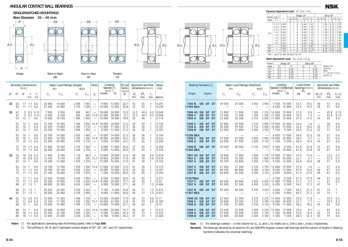
ANGULAR CONTACT BALL BEARINGSSINGLE/MATCHED MOUNTINGSBore Diameter 25 – 40 mm
7305 B DB DF DT 39 500 29 300 4 050 2 980 7 500 10 000 53.5 19.5 30 57 0.6*7305 BEA — — — — 8 500 12 000 53.5 19.5 30 57 0.6
7906 A5 DB DF DT 12 800 11 900 1 300 1 210 14 000 19 000 27.0 9.0 — 45.8 0.15 7906 C DB DF DT 13 500 12 500 1 380 1 280 17 000 24 000 19.3 1.3 — 45.8 0.15 7006 A DB DF DT 23 600 20 200 2 410 2 060 11 000 15 000 37.5 11.5 35 50 0.6
7006 C DB DF DT 24 600 20 500 2 510 2 090 15 000 22 000 24.4 1.6 — 50 0.6 7206 A DB DF DT 36 500 29 500 3 750 3 000 10 000 13 000 42.6 10.6 35 57 0.6 7206 B DB DF DT 33 500 27 000 3 400 2 760 7 100 9 500 54.6 22.6 35 57 0.6
*7206 BEA — — — — 8 000 11 000 54.6 22.6 35 57 0.6 7206 C DB DF DT 37 500 29 300 3 800 2 990 14 000 20 000 28.3 3.7 — 57 0.6 7306 A DB DF DT 54 500 41 500 5 600 4 250 7 100 9 500 48.4 10.4 35 67 0.6
7306 B DB DF DT 50 500 38 500 5 150 3 950 6 300 8 500 61.8 23.8 35 67 0.6*7306 BEA — — — — 7 100 10 000 61.8 23.8 35 67 0.6
7907 A5 DB DF DT 18 600 17 400 1 890 1 770 12 000 17 000 31.0 11.0 — 52.5 0.3 7907 C DB DF DT 19 600 18 300 2 000 1 860 14 000 20 000 22.1 2.1 — 52.5 0.3 7007 A DB DF DT 29 700 26 800 3 050 2 740 9 500 13 000 42.0 14.0 40 57 0.6
7007 C DB DF DT 31 000 27 300 3 150 2 790 13 000 19 000 27.0 1.0 — 57 0.6 7207 A DB DF DT 48 500 40 000 4 900 4 100 8 500 12 000 47.9 13.9 40 67 0.6 7207 B DB DF DT 44 000 36 500 4 500 3 750 6 000 8 000 61.9 27.9 40 67 0.6
*7207BEA — — — — 6 700 9 500 61.9 27.9 40 67 0.6 7207 C DB DF DT 49 500 40 000 5 050 4 050 12 000 17 000 31.3 2.7 — 67 0.6 7307 A DB DF DT 65 000 52 500 6 600 5 350 6 300 8 500 54.2 12.2 41 74 1
7307 B DB DF DT 59 500 48 500 6 100 4 950 5 600 7 500 69.2 27.2 41 74 1*7307 BEA — — — — 6 300 9 000 69.2 27.2 41 74 1
7908 A5 DB DF DT 23 300 22 300 2 370 2 270 11 000 15 000 35.8 11.8 — 59.5 0.3 7908 C DB DF DT 24 600 23 500 2 510 2 390 13 000 18 000 25.7 1.7 — 59.5 0.3 7008 A DB DF DT 31 500 31 000 3 250 3 150 8 500 11 000 46.2 16.2 45 63 0.6
7008 C DB DF DT 33 500 32 000 3 400 3 250 12 000 17 000 29.5 0.5 — 63 0.6 7208 A DB DF DT 57 500 50 500 5 850 5 150 7 500 10 000 52.6 16.6 45 75 0.6 7208 B DB DF DT 52 000 46 000 5 300 4 700 5 300 7 500 68.3 32.3 45 75 0.6
Bearing Numbers (2)
Single Duplex
Abutment and Fillet Dimensions (mm)
da Da ra min. max. max.
Abutment and Fillet Dimensions (mm)
db (3) Db rb (3) min. max. max.
25 62 17 1.1 0.6 24 400 14 600 2 490 1 490 — 9 000 13 000 26.7 32 55 1 0.241 62 17 1.1 0.6 27 200 14 900 2 770 1 520 — 10 000 15 000 26.8 32 55 1 0.229
30 47 9 0.3 0.15 7 850 5 950 800 605 — 18 000 24 000 13.5 32.5 44.5 0.3 0.049 47 9 0.3 0.15 8 300 6 250 845 640 15.9 22 000 28 000 9.7 32.5 44.5 0.3 0.049 55 13 1 0.6 14 500 10 100 1 480 1 030 — 13 000 18 000 18.8 36 49 1 0.116
55 13 1 0.6 15 100 10 300 1 540 1 050 14.9 19 000 26 000 12.2 36 49 1 0.134 62 16 1 0.6 22 500 14 800 2 300 1 510 — 12 000 17 000 21.3 36 56 1 0.197 62 16 1 0.6 20 500 13 500 2 090 1 380 — 8 500 12 000 27.3 36 56 1 0.202
62 16 1 0.6 23 700 14 300 2 420 1 460 — 10 000 14 000 27.3 36 56 1 0.194 62 16 1 0.6 23 000 14 700 2 350 1 500 13.9 18 000 24 000 14.2 36 56 1 0.222 72 19 1.1 0.6 33 500 20 900 3 450 2 130 — 9 000 12 000 24.2 37 65 1 0.346
72 19 1.1 0.6 31 000 19 300 3 150 1 960 — 8 000 11 000 30.9 37 65 1 0.354 72 19 1.1 0.6 36 500 20 600 3 700 2 100 — 9 000 13 000 30.9 37 65 1 0.336
35 55 10 0.6 0.3 11 400 8 700 1 170 885 — 15 000 20 000 15.5 40 50 0.6 0.074 55 10 0.6 0.3 12 100 9 150 1 230 930 15.7 18 000 24 000 11.0 40 50 0.6 0.074 62 14 1 0.6 18 300 13 400 1 870 1 370 — 12 000 16 000 21.0 41 56 1 0.153
62 14 1 0.6 19 100 13 700 1 950 1 390 15.0 17 000 22 000 13.5 41 56 1 0.173 72 17 1.1 0.6 29 700 20 100 3 050 2 050 — 10 000 14 000 23.9 42 65 1 0.287 72 17 1.1 0.6 27 100 18 400 2 760 1 870 — 7 500 10 000 30.9 42 65 1 0.294
72 17 1.1 0.6 32 500 19 600 3 300 1 990 — 8 500 12 000 30.9 42 65 1 0.271 72 17 1.1 0.6 30 500 19 900 3 100 2 030 13.9 15 000 20 000 15.7 42 65 1 0.32 80 21 1.5 1 40 000 26 300 4 050 2 680 — 8 000 10 000 27.1 44 71 1.5 0.464
80 21 1.5 1 36 500 24 200 3 750 2 460 — 7 100 9 500 34.6 44 71 1.5 0.474 80 21 1.5 1 40 500 24 400 4 100 2 490 — 8 000 11 000 34.6 44 71 1.5 0.451
40 62 12 0.6 0.3 14 300 11 200 1 460 1 140 — 14 000 18 000 17.9 45 57 0.6 0.11 62 12 0.6 0.3 15 100 11 700 1 540 1 200 15.7 16 000 22 000 12.8 45 57 0.6 0.109 68 15 1 0.6 19 500 15 400 1 990 1 570 — 10 000 14 000 23.1 46 62 1 0.19
68 15 1 0.6 20 600 15 900 2 100 1 620 15.4 15 000 20 000 14.7 46 62 1 0.213 80 18 1.1 0.6 35 500 25 100 3 600 2 560 — 9 500 13 000 26.3 47 73 1 0.375 80 18 1.1 0.6 32 000 23 000 3 250 2 340 — 6 700 9 000 34.2 47 73 1 0.383
Boundary Dimensions(mm)
d D B r r1 min. min.
Limiting Speeds (1)
(min–1) Grease Oil
Limiting Speeds (1) (Matched)
(min–1) Grease Oil
Load Center Spacings (mm)
a0 DB DF
Basic Load Ratings (Single) (N) {kgf}
Cr C0r Cr C0r
Basic Load Ratings (Matched) (N) {kgf}
Cr C0r Cr C0r
Notes (1) For applications operating near the limiting speed, refer to Page B49. (2) The suffixes A, A5, B, and C represent contact angles of 30°, 25°, 40°, and 15° respectively.
Note (3) For bearings marked — in the column for db, db and rb for shafts are da (min.) and ra (max.) respectively.Remarks The bearings denoted by an asterisk (*) are NSKHPS Angular contact ball bearings and the column of Duplex in Bearing
Numbers indicates the universal matching.
r
r
r
jD jd
2B 2BB
a0 a0
1
r1
a
jD jd
ra
aa
2Bra
jD
ra
b jd a
rb
jD
rb
a jd b
ra
Back-to-BackDB
Face-to-FaceDF
TandemDT
Single
Factor
f0
Mass(kg)
approx.
Eff.Load Centers (mm)
a
Dynamic Equivalent Load P =XFr +YFa
*For i , use 2 for DB, DF and 1 for DT
Contact
Single, DT DB or DF
Angle e Fa/Fr≤e Fa/Fr>e Fa/Fr≤e Fa/Fr>e
X Y X Y X Y X Y 0.178 0.38 1 0 0.44 1.47 1 1.65 0.72 2.39 0.357 0.40 1 0 0.44 1.40 1 1.57 0.72 2.28 0.714 0.43 1 0 0.44 1.30 1 1.46 0.72 2.11 15º 1.07 0.46 1 0 0.44 1.23 1 1.38 0.72 2.00 1.43 0.47 1 0 0.44 1.19 1 1.34 0.72 1.93 2.14 0.50 1 0 0.44 1.12 1 1.26 0.72 1.82 3.57 0.55 1 0 0.44 1.02 1 1.14 0.72 1.66 5.35 0.56 1 0 0.44 1.00 1 1.12 0.72 1.63 25º — 0.68 1 0 0.41 0.87 1 0.92 0.67 1.41 30º — 0.80 1 0 0.39 0.76 1 0.78 0.63 1.24 40º — 1.14 1 0 0.35 0.57 1 0.55 0.57 0.93
i f0 Fa*Cor
Static Equivalent Load P0=X 0Fr +Y 0Fa
Contact Single, DT DB or DF Angle X0 Y0 X0 Y0
15º 0.5 0.46 1 0.92 25º 0.5 0.38 1 0.76 30º 0.5 0.33 1 0.66 40º 0.5 0.26 1 0.52
Single or DTmountingWhenFr>0.5Fr+Y0Fause P0=Fr
B 54 B 55
B046-075E.indd 54-55B046-075E.indd 54-55 11/20/13 4:55:06 PM11/20/13 4:55:06 PM

ANGULAR CONTACT BALL BEARINGSSINGLE/MATCHED MOUNTINGSBore Diameter 40 – 55 mm
*7208 BEA — — — — 6 000 8 500 68.3 32.3 45 75 0.6 7208 C DB DF DT 59 000 50 500 6 000 5 150 11 000 15 000 34.1 1.9 — 75 0.6 7308 A DB DF DT 79 500 66 000 8 100 6 700 5 600 7 500 60.5 14.5 46 84 1
7308 B DB DF DT 73 000 60 500 7 400 6 200 5 000 6 700 77.5 31.5 46 84 1*7308 BEA — — — — 5 600 8 000 77.5 31.5 46 84 1
7909 A5 DB DF DT 24 600 25 400 2 510 2 590 9 500 13 000 38.4 14.4 — 65.5 0.3 7909 C DB DF DT 26 000 26 800 2 660 2 730 12 000 16 000 27.1 3.1 — 65.5 0.3 7009 A DB DF DT 37 500 37 500 3 850 3 800 7 500 10 000 50.6 18.6 50 70 0.6
7009 C DB DF DT 39 500 38 500 4 050 3 950 11 000 15 000 32.1 0.1 — 70 0.6 7209 A DB DF DT 64 500 57 500 6 550 5 850 7 100 9 500 56.5 18.5 50 80 0.6 7209 B DB DF DT 58 500 52 500 5 950 5 350 5 000 6 700 73.5 35.5 50 80 0.6
*7209 BEA — — — — 5 600 8 000 73.5 35.5 50 80 0.6 7209 C DB DF DT 66 500 57 500 6 750 5 850 10 000 14 000 36.4 1.6 — 80 0.6 7309 A DB DF DT 103 000 87 000 10 500 8 900 5 000 6 700 66.9 16.9 51 94 1
7309 B DB DF DT 95 000 80 500 9 650 8 200 4 500 6 000 85.8 35.8 51 94 1*7309 BEA — — — — 5 000 7 100 85.8 35.8 51 94 1
7910 A5 DB DF DT 25 900 28 400 2 640 2 900 9 000 12 000 40.5 16.5 — 69.5 0.3 7910 C DB DF DT 27 400 30 000 2 800 3 050 11 000 15 000 28.3 4.3 — 69.5 0.3 7010 A DB DF DT 40 000 42 000 4 050 4 300 7 100 9 500 53.5 21.5 55 75 0.6
7010 C DB DF DT 42 000 44 000 4 300 4 450 10 000 14 000 33.4 1.4 — 75 0.6 7210 A DB DF DT 67 000 63 000 6 850 6 400 6 300 9 000 60.4 20.4 55 85 0.6 7210 B DB DF DT 60 500 57 000 6 200 5 850 4 500 6 300 78.7 38.7 55 85 0.6
*7210 BEA — — — — 5 000 7 500 78.7 38.7 55 85 0.6 7210 C DB DF DT 69 500 63 500 7 100 6 450 9 500 13 000 38.7 1.3 — 85 0.6 7310 A DB DF DT 121 000 104 000 12 300 10 600 4 500 6 000 73.2 19.2 56 104 1
7310 B DB DF DT 111 000 96 000 11 300 9 800 4 000 5 600 94.1 40.1 56 104 1*7310 BEA — — — — 4 500 6 700 94.1 40.1 56 104 1
7911 A5 DB DF DT 29 300 33 500 2 990 3 400 8 000 11 000 44.5 18.5 — 75 0.6 7911 C DB DF DT 31 000 35 500 3 150 3 600 9 500 13 000 31.1 5.1 — 75 0.6 7011 A DB DF DT 52 500 55 500 5 350 5 650 6 300 8 500 59.9 23.9 60 85 0.6
Bearing Numbers (2)
Single Duplex
Abutment and Fillet Dimensions (mm)
da Da ra min. max. max.
Abutment and Fillet Dimensions (mm)
db (3) Db rb (3) min. max. max.
40 80 18 1.1 0.6 38 500 24 500 3 900 2 500 — 7 500 11 000 34.2 47 73 1 0.357 80 18 1.1 0.6 36 500 25 200 3 700 2 570 14.1 14 000 19 000 17.0 47 73 1 0.418 90 23 1.5 1 49 000 33 000 5 000 3 350 — 7 100 9 000 30.3 49 81 1.5 0.633
90 23 1.5 1 45 000 30 500 4 550 3 100 — 6 300 8 500 38.8 49 81 1.5 0.648 90 23 1.5 1 53 000 33 000 5 400 3 350 — 7 100 10 000 38.8 49 81 1.5 0.619
45 68 12 0.6 0.3 15 100 12 700 1 540 1 290 — 12 000 17 000 19.2 50 63 0.6 0.13 68 12 0.6 0.3 16 000 13 400 1 630 1 360 16.0 14 000 20 000 13.6 50 63 0.6 0.129 75 16 1 0.6 23 100 18 700 2 360 1 910 — 9 500 13 000 25.3 51 69 1 0.25
75 16 1 0.6 24 400 19 300 2 490 1 960 15.4 14 000 19 000 16.0 51 69 1 0.274 85 19 1.1 0.6 39 500 28 700 4 050 2 930 — 8 500 12 000 28.3 52 78 1 0.411 85 19 1.1 0.6 36 000 26 200 3 650 2 680 — 6 300 8 500 36.8 52 78 1 0.421
85 19 1.1 0.6 40 500 27 100 4 100 2 760 — 7 100 10 000 36.8 52 78 1 0.40 85 19 1.1 0.6 41 000 28 800 4 150 2 940 14.2 12 000 17 000 18.2 52 78 1 0.468 100 25 1.5 1 63 500 43 500 6 450 4 450 — 6 300 8 500 33.4 54 91 1.5 0.848
100 25 1.5 1 58 500 40 000 5 950 4 100 — 5 600 7 500 42.9 54 91 1.5 0.869 100 25 1.5 1 62 500 39 500 6 400 4 050 — 6 300 9 000 42.9 54 91 1.5 0.823
50 72 12 0.6 0.3 15 900 14 200 1 630 1 450 — 11 000 15 000 20.2 55 67 0.6 0.132 72 12 0.6 0.3 16 900 15 000 1 720 1 530 16.2 13 000 18 000 14.2 55 67 0.6 0.13 80 16 1 0.6 24 500 21 100 2 500 2 150 — 8 500 12 000 26.8 56 74 1 0.263
80 16 1 0.6 26 000 21 900 2 650 2 230 15.7 12 000 17 000 16.7 56 74 1 0.293 90 20 1.1 0.6 41 500 31 500 4 200 3 200 — 8 000 11 000 30.2 57 83 1 0.466 90 20 1.1 0.6 37 500 28 600 3 800 2 920 — 5 600 8 000 39.4 57 83 1 0.477
90 20 1.1 0.6 42 000 29 700 4 300 3 050 — 6 300 9 500 39.4 57 83 1 0.453 90 20 1.1 0.6 43 000 31 500 4 350 3 250 14.5 12 000 16 000 19.4 57 83 1 0.528 110 27 2 1 74 000 52 000 7 550 5 300 — 5 600 7 500 36.6 60 100 2 1.1
110 27 2 1 68 000 48 000 6 950 4 900 — 5 000 6 700 47.1 60 100 2 1.12 110 27 2 1 78 000 50 500 7 950 5 150 — 5 600 8 000 47.1 60 100 2 1.07
55 80 13 1 0.6 18 100 16 800 1 840 1 710 — 10 000 14 000 22.2 61 74 1 0.184 80 13 1 0.6 19 100 17 700 1 950 1 810 16.3 12 000 16 000 15.5 61 74 1 0.182 90 18 1.1 0.6 32 500 27 700 3 300 2 830 — 7 500 11 000 29.9 62 83 1 0.391
Boundary Dimensions(mm)
d D B r r1 min. min.
Limiting Speeds (1)
(min–1) Grease Oil
Limiting Speeds (1) (Matched)
(min–1) Grease Oil
Load Center Spacings (mm)
a0 DB DF
Basic Load Ratings (Single) (N) {kgf}
Cr C0r Cr C0r
Basic Load Ratings (Matched) (N) {kgf}
Cr C0r Cr C0r
Notes (1) For applications operating near the limiting speed, refer to Page B49. (2) The suffixes A, A5, B, and C represent contact angles of 30°, 25°, 40°, and 15° respectively.
Note (3) For bearings marked — in the column for db, db and rb for shafts are da (min.) and ra (max.) respectively.Remarks The bearings denoted by an asterisk (*) are NSKHPS Angular contact ball bearings and the column of Duplex in Bearing
Numbers indicates the universal matching.
r
r
r
jD jd
2B 2BB
a0 a0
1
r1
a
jD jd
ra
aa
2Bra
jD
ra
b jd a
rb
jD
rb
a jd b
ra
Back-to-BackDB
Face-to-FaceDF
TandemDT
Single
Factor
f0
Mass(kg)
approx.
Eff.Load Centers (mm)
a
Dynamic Equivalent Load P =XFr +YFa
*For i , use 2 for DB, DF and 1 for DT
Contact
Single, DT DB or DF
Angle e Fa/Fr≤e Fa/Fr>e Fa/Fr≤e Fa/Fr>e
X Y X Y X Y X Y 0.178 0.38 1 0 0.44 1.47 1 1.65 0.72 2.39 0.357 0.40 1 0 0.44 1.40 1 1.57 0.72 2.28 0.714 0.43 1 0 0.44 1.30 1 1.46 0.72 2.11 15º 1.07 0.46 1 0 0.44 1.23 1 1.38 0.72 2.00 1.43 0.47 1 0 0.44 1.19 1 1.34 0.72 1.93 2.14 0.50 1 0 0.44 1.12 1 1.26 0.72 1.82 3.57 0.55 1 0 0.44 1.02 1 1.14 0.72 1.66 5.35 0.56 1 0 0.44 1.00 1 1.12 0.72 1.63 25º — 0.68 1 0 0.41 0.87 1 0.92 0.67 1.41 30º — 0.80 1 0 0.39 0.76 1 0.78 0.63 1.24 40º — 1.14 1 0 0.35 0.57 1 0.55 0.57 0.93
i f0 Fa*Cor
Static Equivalent Load P0=X 0Fr +Y 0Fa
Contact Single, DT DB or DF Angle X0 Y0 X0 Y0
15º 0.5 0.46 1 0.92 25º 0.5 0.38 1 0.76 30º 0.5 0.33 1 0.66 40º 0.5 0.26 1 0.52
Single or DTmountingWhenFr>0.5Fr+Y0Fause P0=Fr
B 56 B 57
B046-075E.indd 56-57B046-075E.indd 56-57 11/20/13 4:55:08 PM11/20/13 4:55:08 PM

ANGULAR CONTACT BALL BEARINGSSINGLE/MATCHED MOUNTINGSBore Diameter 55 – 65 mm
7011 C DB DF DT 55 500 57 500 5 650 5 850 9 000 12 000 37.4 1.4 — 85 0.6 7211 A DB DF DT 83 000 79 000 8 450 8 050 6 000 8 000 65.7 23.7 61 94 1 7211 B DB DF DT 75 000 72 000 7 650 7 350 4 000 5 600 86.0 44.0 61 94 1
*7211 BEA — — — — 4 500 6 700 86.0 44.0 61 94 1 7211 C DB DF DT 86 000 80 000 8 800 8 150 8 500 12 000 41.7 0.3 — 94 1 7311 A DB DF DT 139 000 123 000 14 200 12 500 4 000 5 600 79.5 21.5 61 114 1
7311 B DB DF DT 128 000 113 000 13 100 11 500 3 600 5 000 102.4 44.4 61 114 1*7311 BEA — — — — 4 000 6 000 102.4 44.4 61 114 1
7912 A5 DB DF DT 29 800 35 500 3 050 3 600 7 500 10 000 46.8 20.8 — 80 0.6 7912 C DB DF DT 31 500 37 500 3 200 3 800 9 000 12 000 32.4 6.4 — 80 0.6 7012 A DB DF DT 53 500 59 000 5 450 6 000 6 000 8 000 62.7 26.7 65 90 0.6
7012 C DB DF DT 57 000 61 500 5 800 6 250 8 500 12 000 38.8 2.8 — 90 0.6 7212 A DB DF DT 100 000 97 500 10 200 9 950 5 300 7 100 71.1 27.1 66 104 1 7212 B DB DF DT 91 000 89 000 9 300 9 050 3 800 5 300 93.3 49.3 66 104 1
*7212 BEA — — — — 4 300 6 000 93.3 49.3 66 104 1 7212 C DB DF DT 104 000 98 500 10 600 10 000 7 500 11 000 44.8 0.8 — 104 1 7312 A DB DF DT 159 000 143 000 16 200 14 500 3 800 5 000 85.9 23.9 67 123 1
7312 B DB DF DT 146 000 131 000 14 900 13 400 3 400 4 500 110.7 48.7 67 123 1*7312 BEA — — — — 3 800 5 600 110.7 48.7 67 123 1
7913 A5 DB DF DT 31 000 39 000 3 150 3 950 7 100 9 500 49.1 23.1 — 85 0.6 7913 C DB DF DT 33 000 41 000 3 350 4 200 8 500 12 000 33.8 7.8 — 85 0.6 7013 A DB DF DT 56 500 65 500 5 750 6 700 5 600 7 500 65.6 29.6 70 95 0.6
7013 C DB DF DT 60 500 68 500 6 150 7 000 8 000 11 000 40.1 4.1 — 95 0.6 7213 A DB DF DT 114 000 116 000 11 600 11 800 4 800 6 700 76.4 30.4 71 114 1 7213 B DB DF DT 103 000 105 000 10 500 10 700 3 400 4 800 100.6 54.6 71 114 1
*7213 BEA — — — — 3 800 5 600 100.6 54.6 71 114 1 7213 C DB DF DT 119 000 117 000 12 100 12 000 7 100 9 500 47.8 1.8 — 114 1 7313 A DB DF DT 180 000 164 000 18 400 16 700 3 600 4 800 92.2 26.2 72 133 1
7313 B DB DF DT 166 000 151 000 16 900 15 400 3 200 4 300 119.0 53.0 72 133 1*7313 BEA — — — — 3 600 5 000 119.0 53.0 72 133 1
Bearing Numbers (2)
Single Duplex
Abutment and Fillet Dimensions (mm)
da Da ra min. max. max.
Abutment and Fillet Dimensions (mm)
db (3) Db rb (3) min. max. max.
55 90 18 1.1 0.6 34 000 28 600 3 500 2 920 15.5 11 000 15 000 18.7 62 83 1 0.43 100 21 1.5 1 51 000 39 500 5 200 4 050 — 7 100 10 000 32.9 64 91 1.5 0.613 100 21 1.5 1 46 500 36 000 4 700 3 700 — 5 300 7 100 43.0 64 91 1.5 0.627
100 21 1.5 1 51 500 37 000 5 250 3 800 — 6 000 8 500 43.0 64 91 1.5 0.596 100 21 1.5 1 53 000 40 000 5 400 4 100 14.5 10 000 14 000 20.9 64 91 1.5 0.688 120 29 2 1 86 000 61 500 8 750 6 250 — 5 000 6 700 39.8 65 110 2 1.41
120 29 2 1 79 000 56 500 8 050 5 750 — 4 500 6 300 51.2 65 110 2 1.45 120 29 2 1 89 000 58 500 9 100 6 000 — 5 000 7 500 51.2 65 110 2 1.36
60 85 13 1 0.6 18 300 17 700 1 870 1 810 — 9 500 13 000 23.4 66 79 1 0.197 85 13 1 0.6 19 400 18 700 1 980 1 910 16.5 11 000 15 000 16.2 66 79 1 0.194 95 18 1.1 0.6 33 000 29 500 3 350 3 000 — 7 100 10 000 31.4 67 88 1 0.417
95 18 1.1 0.6 35 000 30 500 3 600 3 150 15.7 10 000 14 000 19.4 67 88 1 0.46 110 22 1.5 1 62 000 48 500 6 300 4 950 — 6 700 9 000 35.5 69 101 1.5 0.798 110 22 1.5 1 56 000 44 500 5 700 4 550 — 4 800 6 300 46.7 69 101 1.5 0.815
110 22 1.5 1 61 500 45 000 6 300 4 600 — 5 300 7 500 46.7 69 101 1.5 0.791 110 22 1.5 1 64 000 49 000 6 550 5 000 14.4 9 500 13 000 22.4 69 101 1.5 0.889 130 31 2.1 1.1 98 000 71 500 10 000 7 250 — 4 800 6 300 42.9 72 118 2 1.74
130 31 2.1 1.1 90 000 65 500 9 200 6 700 — 4 300 5 600 55.4 72 118 2 1.78 130 31 2.1 1.1 102 000 68 500 10 500 7 000 — 4 800 6 700 55.4 72 118 2 1.7
65 90 13 1 0.6 19 100 19 400 1 940 1 980 — 9 000 12 000 24.6 71 84 1 0.211 90 13 1 0.6 20 200 20 500 2 060 2 090 16.7 10 000 14 000 16.9 71 84 1 0.208 100 18 1.1 0.6 35 000 33 000 3 550 3 350 — 6 700 9 500 32.8 72 93 1 0.455
100 18 1.1 0.6 37 000 34 500 3 800 3 500 15.9 10 000 13 000 20.0 72 93 1 0.493 120 23 1.5 1 70 500 58 000 7 150 5 900 — 6 000 8 500 38.2 74 111 1.5 1.03 120 23 1.5 1 63 500 52 500 6 500 5 350 — 4 300 6 000 50.3 74 111 1.5 1.05
120 23 1.5 1 70 000 53 500 7 150 5 450 — 4 800 7 100 50.3 74 111 1.5 1.01 120 23 1.5 1 73 000 58 500 7 450 6 000 14.6 9 000 12 000 23.9 74 111 1.5 1.14 140 33 2.1 1.1 111 000 82 000 11 300 8 350 — 4 300 6 000 46.1 77 128 2 2.12
140 33 2.1 1.1 102 000 75 500 10 400 7 700 — 3 800 5 300 59.5 77 128 2 2.17 140 33 2.1 1.1 114 000 77 000 11 600 7 850 — 4 300 6 300 59.5 77 128 2 2.09
Boundary Dimensions(mm)
d D B r r1 min. min.
Limiting Speeds (1)
(min–1) Grease Oil
Limiting Speeds (1) (Matched)
(min–1) Grease Oil
Load Center Spacings (mm)
a0 DB DF
Basic Load Ratings (Single) (N) {kgf}
Cr C0r Cr C0r
Basic Load Ratings (Matched) (N) {kgf}
Cr C0r Cr C0r
Notes (1) For applications operating near the limiting speed, refer to Page B49. (2) The suffixes A, A5, B, and C represent contact angles of 30°, 25°, 40°, and 15° respectively.
Note (3) For bearings marked — in the column for db, db and rb for shafts are da (min.) and ra (max.) respectively.Remarks The bearings denoted by an asterisk (*) are NSKHPS Angular contact ball bearings and the column of Duplex in Bearing
Numbers indicates the universal matching.
r
r
r
jD jd
2B 2BB
a0 a0
1
r1
a
jD jd
ra
aa
2Bra
jD
ra
b jd a
rb
jD
rb
a jd b
ra
Back-to-BackDB
Face-to-FaceDF
TandemDT
Single
Factor
0
Mass(kg)
approx.
Eff.Load Centers (mm)
a
Dynamic Equivalent Load = r + a
*For , use 2 for DB, DF and 1 for DT
Contact
Single, DT DB or DF
Angle a/ r≤ a/ r> a/ r≤ a/ r>
0.178 0.38 1 0 0.44 1.47 1 1.65 0.72 2.39 0.357 0.40 1 0 0.44 1.40 1 1.57 0.72 2.28 0.714 0.43 1 0 0.44 1.30 1 1.46 0.72 2.11 15º 1.07 0.46 1 0 0.44 1.23 1 1.38 0.72 2.00 1.43 0.47 1 0 0.44 1.19 1 1.34 0.72 1.93 2.14 0.50 1 0 0.44 1.12 1 1.26 0.72 1.82 3.57 0.55 1 0 0.44 1.02 1 1.14 0.72 1.66 5.35 0.56 1 0 0.44 1.00 1 1.12 0.72 1.63 25º — 0.68 1 0 0.41 0.87 1 0.92 0.67 1.41 30º — 0.80 1 0 0.39 0.76 1 0.78 0.63 1.24 40º — 1.14 1 0 0.35 0.57 1 0.55 0.57 0.93
0 a*Cor
Static Equivalent Load 0= 0 r + 0 a
Contact Single, DT DB or DF Angle 0 0 0 0
15º 0.5 0.46 1 0.92 25º 0.5 0.38 1 0.76 30º 0.5 0.33 1 0.66 40º 0.5 0.26 1 0.52
Single or DTmountingWhen
r>0.5 r+ 0 ause 0= r
B 58 B 59
B046-075E.indd 58-59B046-075E.indd 58-59 11/20/13 4:55:09 PM11/20/13 4:55:09 PM

ANGULAR CONTACT BALL BEARINGSSINGLE/MATCHED MOUNTINGSBore Diameter 70 – 80 mm
7914 A5 DB DF DT 43 000 52 500 4 400 5 350 6 300 9 000 55.6 23.6 — 95 0.6 7914 C DB DF DT 45 500 55 500 4 650 5 650 7 500 11 000 38.8 6.8 — 95 0.6 7014 A DB DF DT 71 500 82 500 7 300 8 450 5 000 6 700 72.0 32.0 75 105 0.6
7014 C DB DF DT 76 000 86 000 7 750 8 750 7 100 10 000 44.1 4.1 — 105 0.6 7214 A DB DF DT 124 000 127 000 12 600 13 000 4 500 6 300 80.3 32.3 76 119 1 7214 B DB DF DT 112 000 116 000 11 500 11 800 3 200 4 500 105.8 57.8 76 119 1
*7214 BEA — — — — 3 600 5 300 105.8 57.8 76 119 1 7214 C DB DF DT 129 000 129 000 13 200 13 200 6 700 9 000 50.1 2.1 — 119 1 7314 A DB DF DT 203 000 187 000 20 700 19 100 3 200 4 300 98.5 28.5 77 143 1
7314 B DB DF DT 186 000 172 000 19 000 17 500 2 800 4 000 127.3 57.3 77 143 1*7314 BEA — — — — 3 200 4 800 127.3 57.3 77 143 1
7915 A5 DB DF DT 44 000 55 500 4 450 5 650 6 000 8 500 58.0 26.0 — 100 0.6 7915 C DB DF DT 46 500 58 500 4 750 5 950 7 100 10 000 40.1 8.1 — 100 0.6 7015 A DB DF DT 73 000 87 500 7 450 8 900 4 800 6 700 74.8 34.8 80 110 0.6
7015 C DB DF DT 78 000 91 500 7 950 9 300 6 700 9 500 45.4 5.4 — 110 0.6 7215 A DB DF DT 123 000 129 000 12 600 13 100 4 300 6 000 84.2 34.2 81 124 1 7215 B DB DF DT 112 000 117 000 11 400 11 900 3 200 4 300 111.0 61.0 81 124 1
*7215 BEA — — — — 3 600 5 000 111.0 61.0 81 124 1 7215 C DB DF DT 134 000 140 000 13 700 14 200 6 300 9 000 52.4 2.4 — 124 1 7315 A DB DF DT 221 000 212 000 22 500 21 600 3 000 4 000 104.8 30.8 82 153 1 7315 B DB DF DT 202 000 195 000 20 600 19 800 2 800 3 800 135.6 61.6 82 153 1
7916 A5 DB DF DT 44 500 58 000 4 550 5 900 5 600 8 000 60.3 28.3 — 105 0.6 7916 C DB DF DT 47 000 61 500 4 800 6 250 6 700 9 500 41.5 9.5 — 105 0.6 7016 A DB DF DT 89 500 106 000 9 150 10 800 4 300 6 000 81.2 37.2 85 120 0.6
7016 C DB DF DT 95 500 111 000 9 700 11 300 6 300 9 000 49.4 5.4 — 120 0.6 7216 A DB DF DT 145 000 152 000 14 700 15 600 4 000 5 600 89.5 37.5 86 134 1 7216 B DB DF DT 131 000 139 000 13 300 14 100 2 800 4 000 118.3 66.3 86 134 1
*7216 BEA — — — — 3 200 4 800 118.3 66.3 86 134 1 7216 C DB DF DT 151 000 155 000 15 400 15 800 6 000 8 000 55.5 3.5 — 134 1 7316 A DB DF DT 239 000 238 000 24 400 24 200 2 800 3 800 111.2 33.2 87 163 1 7316 B DB DF DT 219 000 218 000 22 400 22 300 2 600 3 400 143.9 65.9 87 163 1
Bearing Numbers (2)
Single Duplex
Abutment and Fillet Dimensions (mm)
da Da ra min. max. max.
Abutment and Fillet Dimensions (mm)
db (3) Db rb (3) min. max. max.
70 100 16 1 0.6 26 500 26 300 2 710 2 680 — 8 000 11 000 27.8 76 94 1 0.341 100 16 1 0.6 28 100 27 800 2 870 2 830 16.4 9 500 13 000 19.4 76 94 1 0.338 110 20 1.1 0.6 44 000 41 500 4 500 4 200 — 6 300 8 500 36.0 77 103 1 0.625
110 20 1.1 0.6 47 000 43 000 4 800 4 400 15.7 9 000 12 000 22.1 77 103 1 0.698 125 24 1.5 1 76 500 63 500 7 800 6 500 — 5 600 8 000 40.1 79 116 1.5 1.11 125 24 1.5 1 69 000 58 000 7 050 5 900 — 4 000 5 600 52.9 79 116 1.5 1.14
125 24 1.5 1 75 500 58 500 7 700 6 000 — 4 500 6 700 52.9 79 116 1.5 1.08 125 24 1.5 1 79 500 64 500 8 100 6 600 14.6 8 500 11 000 25.1 79 116 1.5 1.24 150 35 2.1 1.1 125 000 93 500 12 700 9 550 — 4 000 5 300 49.3 82 138 2 2.6
150 35 2.1 1.1 114 000 86 000 11 700 8 750 — 3 600 5 000 63.6 82 138 2 2.65 150 35 2.1 1.1 124 000 87 500 12 600 8 900 — 4 000 6 000 63.7 82 138 2 2.53
75 105 16 1 0.6 26 900 27 700 2 750 2 820 — 7 500 10 000 29.0 81 99 1 0.355 105 16 1 0.6 28 600 29 300 2 910 2 980 16.6 9 000 12 000 20.1 81 99 1 0.357 115 20 1.1 0.6 45 000 43 500 4 600 4 450 — 6 000 8 000 37.4 82 108 1 0.661
115 20 1.1 0.6 48 000 45 500 4 900 4 650 15.9 8 500 12 000 22.7 82 108 1 0.748 130 25 1.5 1 76 000 64 500 7 750 6 550 — 5 600 7 500 42.1 84 121 1.5 1.19 130 25 1.5 1 68 500 58 500 7 000 5 950 — 3 800 5 300 55.5 84 121 1.5 1.22
130 25 1.5 1 78 500 63 500 8 000 6 450 — 4 300 6 300 55.5 84 121 1.5 1.18 130 25 1.5 1 83 000 70 000 8 450 7 100 14.8 8 000 11 000 26.2 84 121 1.5 1.36 160 37 2.1 1.1 136 000 106 000 13 800 10 800 — 3 800 5 000 52.4 87 148 2 3.13 160 37 2.1 1.1 125 000 97 500 12 700 9 900 — 3 400 4 800 67.8 87 148 2 3.19
80 110 16 1 0.6 27 300 29 000 2 790 2 960 — 7 100 10 000 30.2 86 104 1 0.38 110 16 1 0.6 29 000 30 500 2 960 3 150 16.7 8 500 12 000 20.7 86 104 1 0.376 125 22 1.1 0.6 55 000 53 000 5 650 5 400 — 5 600 7 500 40.6 87 118 1 0.88
125 22 1.1 0.6 58 500 55 500 6 000 5 650 15.7 8 000 11 000 24.7 87 118 1 0.966 140 26 2 1 89 000 76 000 9 100 7 750 — 5 000 7 100 44.8 90 130 2 1.46 140 26 2 1 80 500 69 500 8 200 7 050 — 3 600 5 000 59.1 90 130 2 1.49
140 26 2 1 87 500 70 000 8 950 7 150 — 4 000 6 000 59.2 90 130 2 1.42 140 26 2 1 93 000 77 500 9 450 7 900 14.7 7 500 10 000 27.7 90 130 2 1.63 170 39 2.1 1.1 147 000 119 000 15 000 12 100 — 3 600 4 800 55.6 92 158 2 3.71 170 39 2.1 1.1 135 000 109 000 13 800 11 100 — 3 200 4 300 71.9 92 158 2 3.79
Boundary Dimensions(mm)
d D B r r1 min. min.
Limiting Speeds (1)
(min–1) Grease Oil
Limiting Speeds (1) (Matched)
(min–1) Grease Oil
Load Center Spacings (mm)
a0 DB DF
Basic Load Ratings (Single) (N) {kgf}
Cr C0r Cr C0r
Basic Load Ratings (Matched) (N) {kgf}
Cr C0r Cr C0r
Notes (1) For applications operating near the limiting speed, refer to Page B49. (2) The suffixes A, A5, B, and C represent contact angles of 30°, 25°, 40°, and 15° respectively.
Note (3) For bearings marked — in the column for db, db and rb for shafts are da (min.) and ra (max.) respectively.Remarks The bearings denoted by an asterisk (*) are NSKHPS Angular contact ball bearings and the column of Duplex in Bearing
Numbers indicates the universal matching.
r
r
r
jD jd
2B 2BB
a0 a0
1
r1
a
jD jd
ra
aa
2Bra
jD
ra
b jd a
rb
jD
rb
a jd b
ra
Back-to-BackDB
Face-to-FaceDF
TandemDT
Single
Factor
f0
Mass(kg)
approx.
Eff.Load Centers (mm)
a
Dynamic Equivalent Load P =XFr +YFa
*For i , use 2 for DB, DF and 1 for DT
Contact
Single, DT DB or DF
Angle e Fa/Fr≤e Fa/Fr>e Fa/Fr≤e Fa/Fr>e
X Y X Y X Y X Y 0.178 0.38 1 0 0.44 1.47 1 1.65 0.72 2.39 0.357 0.40 1 0 0.44 1.40 1 1.57 0.72 2.28 0.714 0.43 1 0 0.44 1.30 1 1.46 0.72 2.11 15º 1.07 0.46 1 0 0.44 1.23 1 1.38 0.72 2.00 1.43 0.47 1 0 0.44 1.19 1 1.34 0.72 1.93 2.14 0.50 1 0 0.44 1.12 1 1.26 0.72 1.82 3.57 0.55 1 0 0.44 1.02 1 1.14 0.72 1.66 5.35 0.56 1 0 0.44 1.00 1 1.12 0.72 1.63 25º — 0.68 1 0 0.41 0.87 1 0.92 0.67 1.41 30º — 0.80 1 0 0.39 0.76 1 0.78 0.63 1.24 40º — 1.14 1 0 0.35 0.57 1 0.55 0.57 0.93
i f0 Fa*Cor
Static Equivalent Load P0=X 0Fr +Y 0Fa
Contact Single, DT DB or DF Angle X0 Y0 X0 Y0
15º 0.5 0.46 1 0.92 25º 0.5 0.38 1 0.76 30º 0.5 0.33 1 0.66 40º 0.5 0.26 1 0.52
Single or DTmountingWhenFr>0.5Fr+Y0Fause P0=Fr
B 60 B 61
B046-075E.indd 60-61B046-075E.indd 60-61 11/20/13 4:55:10 PM11/20/13 4:55:10 PM

ANGULAR CONTACT BALL BEARINGSSINGLE/MATCHED MOUNTINGSBore Diameter 85 – 100 mm
7917 A5 DB DF DT 59 500 77 000 6 100 7 850 5 300 7 500 65.8 29.8 — 115 0.6 7917 C DB DF DT 63 000 81 500 6 450 8 300 6 300 9 000 45.5 9.5 — 115 0.6 7017 A DB DF DT 91 500 112 000 9 350 11 400 4 300 5 600 84.1 40.1 90 125 0.6
7017 C DB DF DT 98 000 117 000 9 950 12 000 6 000 8 500 50.8 6.8 — 125 0.6 7217 A DB DF DT 167 000 178 000 17 100 18 200 3 800 5 300 95.8 39.8 91 144 1 7217 B DB DF DT 151 000 162 000 15 400 16 500 2 800 3 800 126.6 70.6 91 144 1
7217 C DB DF DT 174 000 181 000 17 800 18 500 5 600 7 500 59.5 3.5 — 144 1 7317 A DB DF DT 258 000 265 000 26 300 27 000 2 600 3 600 117.5 35.5 92 173 1 7317 B DB DF DT 236 000 244 000 24 100 24 800 2 400 3 200 152.2 70.2 92 173 1
7918 A5 DB DF DT 64 000 87 000 6 500 8 900 5 000 7 100 68.1 32.1 — 120 0.6 7918 C DB DF DT 67 500 92 000 6 900 9 400 6 000 8 500 46.8 10.8 — 120 0.6 7018 A DB DF DT 109 000 133 000 11 200 13 500 3 800 5 300 90.4 42.4 96 134 1
7018 C DB DF DT 116 000 138 000 11 900 14 100 5 600 8 000 54.8 6.8 — 134 1 7218 A DB DF DT 191 000 206 000 19 500 21 000 3 600 5 000 102.2 42.2 96 154 1 7218 B DB DF DT 173 000 188 000 17 700 19 100 2 600 3 400 134.9 74.9 96 154 1
7218 C DB DF DT 199 000 209 000 20 300 21 400 5 300 7 100 63.5 3.5 — 154 1 7318 A DB DF DT 277 000 294 000 28 300 30 000 2 600 3 400 123.8 37.8 97 183 1 7318 B DB DF DT 254 000 270 000 25 900 27 600 2 200 3 000 160.5 74.5 97 183 1
7919 A5 DB DF DT 64 500 91 000 6 600 9 250 4 800 6 700 70.5 34.5 — 125 0.6 7919 C DB DF DT 68 500 96 000 7 000 9 800 5 600 8 000 48.1 12.1 — 125 0.6 7019 A DB DF DT 109 000 134 000 11 100 13 600 3 800 5 000 93.3 45.3 — 139 1
7019 C DB DF DT 119 000 146 000 12 200 14 900 5 300 7 500 56.1 8.1 — 139 1 7219 A DB DF DT 208 000 221 000 21 200 22 600 3 400 4 500 108.5 44.5 102 163 1 7219 B DB DF DT 188 000 202 000 19 200 20 500 2 400 3 200 143.2 79.2 102 163 1
7219 C DB DF DT 216 000 224 000 22 000 22 800 4 800 6 700 67.5 3.5 — 163 1 7319 A DB DF DT 297 000 325 000 30 500 33 000 2 400 3 200 130.2 40.2 102 193 1 7319 B DB DF DT 272 000 298 000 27 700 30 500 2 200 3 000 168.7 78.7 102 193 1
7920 A5 DB DF DT 77 000 103 000 7 850 10 500 4 500 6 300 76.0 36.0 — 135 0.6 7920 C DB DF DT 81 500 108 000 8 300 11 100 5 300 7 500 52.2 12.2 — 135 0.6 7020 A DB DF DT 111 000 141 000 11 300 14 400 3 600 5 000 96.2 48.2 — 144 1
Bearing Numbers (2)
Single Duplex
Abutment and Fillet Dimensions (mm)
da Da ra min. max. max.
Abutment and Fillet Dimensions (mm)
db (3) Db rb (3) min. max. max.
85 120 18 1.1 0.6 36 500 38 500 3 750 3 900 — 6 700 9 000 32.9 92 113 1 0.541 120 18 1.1 0.6 39 000 40 500 3 950 4 150 16.5 8 000 11 000 22.7 92 113 1 0.534 130 22 1.1 0.6 56 500 56 000 5 750 5 700 — 5 300 7 100 42.0 92 123 1 0.913
130 22 1.1 0.6 60 000 58 500 6 150 6 000 15.9 7 500 10 000 25.4 92 123 1 1.01 150 28 2 1 103 000 89 000 10 500 9 100 — 4 800 6 700 47.9 95 140 2 1.83 150 28 2 1 93 000 81 000 9 500 8 250 — 3 400 4 800 63.3 95 140 2 1.87
150 28 2 1 107 000 90 500 10 900 9 250 14.7 6 700 9 500 29.7 95 140 2 2.04 180 41 3 1.1 159 000 133 000 16 200 13 500 — 3 400 4 500 58.8 99 166 2.5 4.33 180 41 3 1.1 146 000 122 000 14 800 12 400 — 3 000 4 000 76.1 99 166 2.5 4.42
90 125 18 1.1 0.6 39 500 43 500 4 000 4 450 — 6 300 8 500 34.1 97 118 1 0.56 125 18 1.1 0.6 41 500 46 000 4 250 4 700 16.6 7 500 10 000 23.4 97 118 1 0.563 140 24 1.5 1 67 500 66 500 6 850 6 750 — 4 800 6 700 45.2 99 131 1.5 1.19
140 24 1.5 1 71 500 69 000 7 300 7 050 15.7 7 100 9 500 27.4 99 131 1.5 1.34 160 30 2 1 118 000 103 000 12 000 10 500 — 4 500 6 000 51.1 100 150 2 2.25 160 30 2 1 107 000 94 000 10 900 9 550 — 3 200 4 300 67.4 100 150 2 2.29
160 30 2 1 123 000 105 000 12 500 10 700 14.6 6 300 9 000 31.7 100 150 2 2.51 190 43 3 1.1 171 000 147 000 17 400 15 000 — 3 200 4 300 61.9 104 176 2.5 5.06 190 43 3 1.1 156 000 135 000 15 900 13 800 — 2 800 3 800 80.2 104 176 2.5 5.17
95 130 18 1.1 0.6 40 000 45 500 4 050 4 650 — 6 000 8 500 35.2 102 123 1 0.597 130 18 1.1 0.6 42 500 48 000 4 300 4 900 16.7 7 100 10 000 24.1 102 123 1 0.591 145 24 1.5 1 67 000 67 000 6 800 6 800 — 4 500 6 300 46.6 104 136 1.5 1.43
145 24 1.5 1 73 500 73 000 7 500 7 450 15.9 6 700 9 000 28.1 104 136 1.5 1.42 170 32 2.1 1.1 128 000 111 000 13 000 11 300 — 4 300 5 600 54.2 107 158 2 2.68 170 32 2.1 1.1 116 000 101 000 11 800 10 300 — 3 000 4 000 71.6 107 158 2 2.74
170 32 2.1 1.1 133 000 112 000 13 500 11 400 14.6 6 000 8 500 33.7 107 158 2 3.05 200 45 3 1.1 183 000 162 000 18 600 16 600 — 3 000 4 000 65.1 109 186 2.5 5.83 200 45 3 1.1 167 000 149 000 17 100 15 200 — 2 600 3 600 84.3 109 186 2.5 5.98
100 140 20 1.1 0.6 47 500 51 500 4 850 5 250 — 5 600 8 000 38.0 107 133 1 0.804 140 20 1.1 0.6 50 000 54 000 5 100 5 550 16.5 6 700 9 000 26.1 107 133 1 0.794 150 24 1.5 1 68 500 70 500 6 950 7 200 — 4 500 6 000 48.1 109 141 1.5 1.48
Boundary Dimensions(mm)
d D B r r1 min. min.
Limiting Speeds (1)
(min–1) Grease Oil
Limiting Speeds (1) (Matched)
(min–1) Grease Oil
Load Center Spacings (mm)
a0 DB DF
Basic Load Ratings (Single) (N) {kgf}
Cr C0r Cr C0r
Basic Load Ratings (Matched) (N) {kgf}
Cr C0r Cr C0r
Notes (1) For applications operating near the limiting speed, refer to Page B49. (2) The suffixes A, A5, B, and C represent contact angles of 30°, 25°, 40°, and 15° respectively.
Note (3) For bearings marked — in the column for db, db and rb for shafts are da (min.) and ra (max.) respectively.
Factor
f0
Mass(kg)
approx.
Eff.Load Centers (mm)
a
Dynamic Equivalent Load P =XFr +YFa
*For i , use 2 for DB, DF and 1 for DT
Contact
Single, DT DB or DF
Angle e Fa/Fr≤e Fa/Fr>e Fa/Fr≤e Fa/Fr>e
X Y X Y X Y X Y 0.178 0.38 1 0 0.44 1.47 1 1.65 0.72 2.39 0.357 0.40 1 0 0.44 1.40 1 1.57 0.72 2.28 0.714 0.43 1 0 0.44 1.30 1 1.46 0.72 2.11 15º 1.07 0.46 1 0 0.44 1.23 1 1.38 0.72 2.00 1.43 0.47 1 0 0.44 1.19 1 1.34 0.72 1.93 2.14 0.50 1 0 0.44 1.12 1 1.26 0.72 1.82 3.57 0.55 1 0 0.44 1.02 1 1.14 0.72 1.66 5.35 0.56 1 0 0.44 1.00 1 1.12 0.72 1.63 25º — 0.68 1 0 0.41 0.87 1 0.92 0.67 1.41 30º — 0.80 1 0 0.39 0.76 1 0.78 0.63 1.24 40º — 1.14 1 0 0.35 0.57 1 0.55 0.57 0.93
i f0 Fa*Cor
Static Equivalent Load P0=X 0Fr +Y 0Fa
Contact Single, DT DB or DF Angle X0 Y0 X0 Y0
15º 0.5 0.46 1 0.92 25º 0.5 0.38 1 0.76 30º 0.5 0.33 1 0.66 40º 0.5 0.26 1 0.52
Single or DTmountingWhenFr>0.5Fr+Y0Fause P0=Fr
r
r
r
jD jd
2B 2BB
a0 a0
1
r1
a
jD jd
ra
aa
2Bra
jD
ra
b jd a
rb
jD
rb
a jd b
ra
Back-to-BackDB
Face-to-FaceDF
TandemDT
Single
B 62 B 63
B046-075E.indd 62-63B046-075E.indd 62-63 11/20/13 4:55:11 PM11/20/13 4:55:11 PM
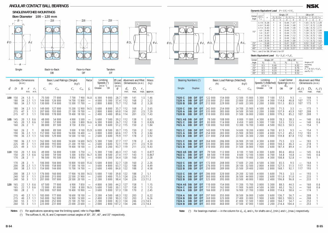
ANGULAR CONTACT BALL BEARINGSSINGLE/MATCHED MOUNTINGSBore Diameter 100 – 120 mm
7020 C DB DF DT 122 000 154 000 12 500 15 800 5 300 7 100 57.5 9.5 — 144 1 7220 A DB DF DT 233 000 251 000 23 800 25 600 3 200 4 300 114.8 46.8 107 173 1 7220 B DB DF DT 212 000 229 000 21 600 23 300 2 200 3 000 151.5 83.5 107 173 1
7220 C DB DF DT 242 000 254 000 24 700 25 900 4 500 6 300 71.5 3.5 — 173 1 7320 A DB DF DT 335 000 385 000 34 500 39 500 2 200 3 000 137.9 43.9 107 208 1 7320 B DB DF DT 310 000 355 000 31 500 36 000 2 000 2 800 179.2 85.2 107 208 1
7921 A5 DB DF DT 78 500 108 000 8 000 11 000 4 300 6 000 78.3 38.3 — 140 0.6 7921 C DB DF DT 83 000 114 000 8 450 11 600 5 300 7 100 53.5 13.5 — 140 0.6 7021 A DB DF DT 130 000 163 000 13 300 16 700 3 400 4 500 102.5 50.5 — 154 1
7021 C DB DF DT 143 000 179 000 14 600 18 200 4 800 6 700 61.5 9.5 — 154 1 7221 A DB DF DT 254 000 283 000 25 900 28 900 3 000 4 000 121.2 49.2 112 183 1 7221 B DB DF DT 231 000 258 000 23 500 26 300 2 200 3 000 159.8 87.8 112 183 1
7221 C DB DF DT 264 000 286 000 26 900 29 100 4 300 6 000 75.5 3.5 — 183 1 7321 A DB DF DT 335 000 385 000 34 500 39 500 2 200 2 800 144.3 46.3 — 218 1 7321 B DB DF DT 310 000 355 000 31 500 36 000 1 900 2 600 187.4 89.4 — 218 1
7922 A5 DB DF DT 79 500 112 000 8 100 11 500 4 300 5 600 80.6 40.6 — 145 0.6 7922 C DB DF DT 84 500 119 000 8 600 12 100 5 000 6 700 54.8 14.8 — 145 0.6 7022 A DB DF DT 157 000 191 000 16 000 19 400 3 200 4 300 108.8 52.8 — 164 1
7022 C DB DF DT 172 000 208 000 17 600 21 200 4 500 6 300 65.5 9.5 — 164 1 7222 A DB DF DT 276 000 315 000 28 100 32 500 2 800 4 000 127.5 51.5 117 193 1 7222 B DB DF DT 250 000 289 000 25 500 29 400 2 000 2 800 168.1 92.1 117 193 1
7222 C DB DF DT 286 000 320 000 29 200 32 500 4 000 5 600 79.5 3.5 — 193 1 7322 A DB DF DT 360 000 430 000 36 500 44 000 2 000 2 600 151.0 51.0 — 233 1 7322 B DB DF DT 325 000 395 000 33 500 40 000 1 800 2 400 196.8 96.8 — 233 1
7924 A5 DB DF DT 110 000 154 000 11 200 15 700 3 800 5 300 88.5 44.5 — 160 0.6 7924 C DB DF DT 117 000 162 000 11 900 16 600 4 500 6 300 60.2 16.2 — 160 0.6 7024 A DB DF DT 166 000 213 000 16 900 21 700 3 000 4 000 114.6 58.6 — 174 1
7224 A DB DF DT 297 000 355 000 30 500 36 000 2 600 3 600 136.7 56.7 — 208 1 7224 B DB DF DT 269 000 325 000 27 400 33 000 1 900 2 600 180.5 100.5 — 208 1 7324 A DB DF DT 400 000 505 000 41 000 51 500 1 800 2 400 164.7 54.7 — 253 1 7324 B DB DF DT 365 000 460 000 37 500 47 000 1 600 2 200 214.4 104.4 — 253 1
Bearing Numbers (2)
Single Duplex
Abutment and Fillet Dimensions (mm)
da Da ra min. max. max.
Abutment and Fillet Dimensions (mm)
db (3) Db rb (3) min. max. max.
100 150 24 1.5 1 75 500 77 000 7 700 7 900 16.0 6 300 9 000 28.7 109 141 1.5 1.46 180 34 2.1 1.1 144 000 126 000 14 700 12 800 — 4 000 5 300 57.4 112 168 2 3.22 180 34 2.1 1.1 130 000 114 000 13 300 11 700 — 2 800 3 800 75.7 112 168 2 3.28
180 34 2.1 1.1 149 000 127 000 15 200 12 900 14.5 5 600 8 000 35.7 112 168 2 3.65 215 47 3 1.1 207 000 193 000 21 100 19 700 — 2 800 3 800 69.0 114 201 2.5 7.29 215 47 3 1.1 190 000 178 000 19 400 18 100 — 2 400 3 400 89.6 114 201 2.5 7.43
105 145 20 1.1 0.6 48 000 54 000 4 900 5 500 — 5 600 7 500 39.2 112 138 1 0.82 145 20 1.1 0.6 51 000 57 000 5 200 5 800 16.6 6 300 9 000 26.7 112 138 1 0.826 160 26 2 1 80 000 81 500 8 150 8 350 — 4 300 5 600 51.2 115 150 2 1.84
160 26 2 1 88 000 89 500 9 000 9 100 15.9 6 000 8 500 30.7 115 150 2 1.82 190 36 2.1 1.1 157 000 142 000 16 000 14 400 — 3 800 5 000 60.6 117 178 2 3.84 190 36 2.1 1.1 142 000 129 000 14 500 13 100 — 2 600 3 600 79.9 117 178 2 3.92
190 36 2.1 1.1 162 000 143 000 16 600 14 600 14.5 5 300 7 500 37.7 117 178 2 4.33 225 49 3 1.1 208 000 193 000 21 200 19 700 — 2 600 3 600 72.1 119 211 2.5 9.34 225 49 3 1.1 191 000 177 000 19 400 18 100 — 2 400 3 200 93.7 119 211 2.5 9.43
110 150 20 1.1 0.6 49 000 56 000 5 000 5 750 — 5 300 7 100 40.3 117 143 1 0.877 150 20 1.1 0.6 52 000 59 500 5 300 6 050 16.7 6 300 8 500 27.4 117 143 1 0.867 170 28 2 1 96 500 95 500 9 850 9 700 — 4 000 5 300 54.4 120 160 2 2.28
170 28 2 1 106 000 104 000 10 800 10 600 15.6 5 600 8 000 32.7 120 160 2 2.26 200 38 2.1 1.1 170 000 158 000 17 300 16 100 — 3 600 4 800 63.7 122 188 2 4.49 200 38 2.1 1.1 154 000 144 000 15 700 14 700 — 2 600 3 400 84.0 122 188 2 4.58
200 38 2.1 1.1 176 000 160 000 17 900 16 300 14.5 5 000 7 100 39.8 122 188 2 5.1 240 50 3 1.1 220 000 215 000 22 500 21 900 — 2 600 3 400 75.5 124 226 2.5 11.1 240 50 3 1.1 201 000 197 000 20 500 20 100 — 2 200 3 000 98.4 124 226 2.5 11.2
120 165 22 1.1 0.6 67 500 77 000 6 900 7 850 — 4 800 6 300 44.2 127 158 1 1.15 165 22 1.1 0.6 72 000 81 000 7 300 8 300 16.5 5 600 7 500 30.1 127 158 1 1.15 180 28 2 1 102 000 107 000 10 400 10 900 — 3 600 5 000 57.3 130 170 2 2.45
215 40 2.1 1.1 183 000 177 000 18 600 18 100 — 3 200 4 500 68.3 132 203 2 6.22 215 40 2.1 1.1 165 000 162 000 16 900 16 500 — 2 400 3 200 90.3 132 203 2 6.26 260 55 3 1.1 246 000 252 000 25 100 25 700 — 2 200 3 000 82.3 134 246 2.5 14.5 260 55 3 1.1 225 000 231 000 23 000 23 600 — 2 000 2 800 107.2 134 246 2.5 14.4
Boundary Dimensions(mm)
d D B r r1 min. min.
Limiting Speeds (1)
(min–1) Grease Oil
Limiting Speeds (1) (Matched)
(min–1) Grease Oil
Load Center Spacings (mm)
a0 DB DF
Basic Load Ratings (Single) (N) {kgf}
Cr C0r Cr C0r
Basic Load Ratings (Matched) (N) {kgf}
Cr C0r Cr C0r
Notes (1) For applications operating near the limiting speed, refer to Page B49. (2) The suffixes A, A5, B, and C represent contact angles of 30°, 25°, 40°, and 15° respectively.
Note (3) For bearings marked — in the column for db, db and rb for shafts are da (min.) and ra (max.) respectively.
Factor
f0
Mass(kg)
approx.
Eff.Load Centers (mm)
a
Dynamic Equivalent Load P =XFr +YFa
*For i , use 2 for DB, DF and 1 for DT
Contact
Single, DT DB or DF
Angle e Fa/Fr≤e Fa/Fr>e Fa/Fr≤e Fa/Fr>e
X Y X Y X Y X Y 0.178 0.38 1 0 0.44 1.47 1 1.65 0.72 2.39 0.357 0.40 1 0 0.44 1.40 1 1.57 0.72 2.28 0.714 0.43 1 0 0.44 1.30 1 1.46 0.72 2.11 15º 1.07 0.46 1 0 0.44 1.23 1 1.38 0.72 2.00 1.43 0.47 1 0 0.44 1.19 1 1.34 0.72 1.93 2.14 0.50 1 0 0.44 1.12 1 1.26 0.72 1.82 3.57 0.55 1 0 0.44 1.02 1 1.14 0.72 1.66 5.35 0.56 1 0 0.44 1.00 1 1.12 0.72 1.63 25º — 0.68 1 0 0.41 0.87 1 0.92 0.67 1.41 30º — 0.80 1 0 0.39 0.76 1 0.78 0.63 1.24 40º — 1.14 1 0 0.35 0.57 1 0.55 0.57 0.93
i f0 Fa*Cor
Static Equivalent Load P0=X 0Fr +Y 0Fa
Contact Single, DT DB or DF Angle X0 Y0 X0 Y0
15º 0.5 0.46 1 0.92 25º 0.5 0.38 1 0.76 30º 0.5 0.33 1 0.66 40º 0.5 0.26 1 0.52
Single or DTmountingWhenFr>0.5Fr+Y0Fause P0=Fr
r
r
r
jD jd
2B 2BB
a0 a0
1
r1
a
jD jd
ra
aa
2Bra
jD
ra
b jd a
rb
jD
rb
a jd b
ra
Back-to-BackDB
Face-to-FaceDF
TandemDT
Single
B 64 B 65
B046-075E.indd 64-65B046-075E.indd 64-65 11/20/13 4:55:13 PM11/20/13 4:55:13 PM
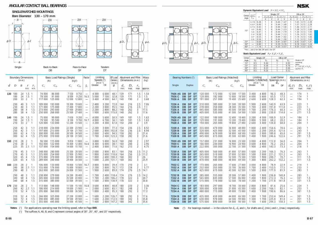
ANGULAR CONTACT BALL BEARINGSSINGLE/MATCHED MOUNTINGSBore Diameter 130 – 170 mm
7926 A5 DB DF DT 120 000 172 000 12 300 17 500 3 400 4 800 96.3 48.3 — 174 1 7926 C DB DF DT 128 000 182 000 13 000 18 500 4 000 5 600 65.5 17.5 — 174 1 7026 A DB DF DT 191 000 251 000 19 400 25 600 2 600 3 600 128.3 62.3 — 194 1
7226 A DB DF DT 310 000 385 000 31 500 39 500 1 900 2 600 143.9 63.9 — 223 1 7226 B DB DF DT 278 000 350 000 28 300 35 500 1 700 2 400 191.0 111.0 — 223 1 7326 A DB DF DT 445 000 585 000 45 500 59 500 1 700 2 200 176.3 60.3 — 271 1.5 7326 B DB DF DT 405 000 535 000 41 500 54 500 1 500 2 000 230.0 114.0 — 271 1.5
7928 A5 DB DF DT 122 000 180 000 12 400 18 400 3 200 4 500 100.9 52.9 — 184 1 7928 C DB DF DT 129 000 191 000 13 200 19 400 3 800 5 300 68.2 20.2 — 184 1 7028 A DB DF DT 194 000 265 000 19 800 27 000 2 600 3 400 134.0 68.0 — 204 1
7228 A DB DF DT 355 000 470 000 36 000 48 000 1 800 2 400 154.6 70.6 — 243 1 7228 B DB DF DT 320 000 425 000 32 500 43 500 1 600 2 200 205.6 121.6 — 243 1 7328 A DB DF DT 490 000 670 000 50 000 68 500 1 600 2 000 189.0 65.0 — 291 1.5 7328 B DB DF DT 445 000 615 000 45 500 63 000 1 400 1 900 246.6 122.6 — 291 1.5
7930 A5 DB DF DT 157 000 231 000 16 000 23 500 3 000 4 000 112.0 56.0 — 204 1 7930 C DB DF DT 166 000 244 000 16 900 24 900 3 600 4 800 76.2 20.2 — 204 1 7030 A DB DF DT 222 000 305 000 22 700 31 500 1 900 2 400 143.3 73.3 — 218 1
7230 A DB DF DT 405 000 560 000 41 000 57 000 1 600 2 200 166.3 76.3 — 263 1 7230 B DB DF DT 365 000 510 000 37 000 52 000 1 500 2 000 221.2 131.2 — 263 1 7330 A DB DF DT 515 000 745 000 52 500 75 500 1 500 1 900 200.7 70.7 — 311 1.5 7330 B DB DF DT 470 000 680 000 48 000 69 500 1 300 1 800 262.2 132.2 — 311 1.5
7932 C DB DF DT 173 000 265 000 17 600 27 000 3 000 4 000 78.9 22.9 — 214 1 7032 A DB DF DT 252 000 355 000 25 700 36 000 1 700 2 400 153.5 77.5 — 233 1 7232 A DB DF DT 425 000 615 000 43 500 62 500 1 500 2 000 177.9 81.9 — 283 1
7232 B DB DF DT 385 000 555 000 39 500 57 000 1 400 1 900 236.8 140.8 — 283 1 7332 A DB DF DT 565 000 845 000 57 500 86 000 1 400 1 800 212.3 76.3 — 331 1.5 7332 B DB DF DT 515 000 770 000 52 500 78 500 1 200 1 700 277.8 141.8 — 331 1.5
7934 C DB DF DT 183 000 297 000 18 700 30 000 2 800 3 800 81.6 25.6 — 224 1 7034 A DB DF DT 300 000 430 000 31 000 43 500 1 600 2 200 166.1 82.1 — 253 1 7234 A DB DF DT 480 000 715 000 49 000 73 000 1 400 1 900 190.6 86.6 — 301 1.5
7234 B DB DF DT 435 000 650 000 44 000 66 500 1 300 1 700 253.4 149.4 — 301 1.5 7334 A DB DF DT 630 000 970 000 64 500 99 000 1 300 1 700 225.0 81.0 — 351 1.5 7334 B DB DF DT 575 000 890 000 59 000 90 500 1 100 1 600 294.3 150.3 — 351 1.5
Bearing Numbers (2)
Single Duplex
Abutment and Fillet Dimensions (mm)
da Da ra min. max. max.
Abutment and Fillet Dimensions (mm)
db (3) Db rb (3) min. max. max.
130 180 24 1.5 1 74 000 86 000 7 550 8 750 — 4 300 6 000 48.1 139 171 1.5 1.54 180 24 1.5 1 78 500 91 000 8 000 9 250 16.5 5 000 7 100 32.8 139 171 1.5 1.5 200 33 2 1 117 000 125 000 12 000 12 800 — 3 400 4 500 64.1 140 190 2 3.68
230 40 3 1.1 189 000 193 000 19 300 19 600 — 2 400 3 200 72.0 144 216 2.5 7.06 230 40 3 1.1 171 000 175 000 17 400 17 800 — 2 200 3 000 95.5 144 216 2.5 7.1 280 58 4 1.5 273 000 293 000 27 900 29 800 — 2 200 2 800 88.2 148 262 3 17.5 280 58 4 1.5 250 000 268 000 25 500 27 400 — 1 900 2 600 115.0 148 262 3 17.6
140 190 24 1.5 1 75 000 90 000 7 650 9 200 — 4 000 5 600 50.5 149 181 1.5 1.63 190 24 1.5 1 79 500 95 500 8 100 9 700 16.7 4 800 6 700 34.1 149 181 1.5 1.63 210 33 2 1 120 000 133 000 12 200 13 500 — 3 200 4 300 67.0 150 200 2 3.9
250 42 3 1.1 218 000 234 000 22 300 23 900 — 2 200 3 000 77.3 154 236 2.5 8.92 250 42 3 1.1 197 000 213 000 20 100 21 700 — 2 000 2 800 102.8 154 236 2.5 8.94 300 62 4 1.5 300 000 335 000 30 500 34 500 — 2 000 2 600 94.5 158 282 3 21.4 300 62 4 1.5 275 000 310 000 28 100 31 500 — 1 700 2 400 123.3 158 282 3 21.6
150 210 28 2 1 96 500 115 000 9 850 11 800 — 3 800 5 000 56.0 160 200 2 2.97 210 28 2 1 102 000 122 000 10 400 12 400 16.6 4 300 6 000 38.1 160 200 2 2.96 225 35 2.1 1.1 137 000 154 000 14 000 15 700 — 2 400 3 000 71.6 162 213 2 4.75
270 45 3 1.1 248 000 280 000 25 300 28 500 — 2 000 2 800 83.1 164 256 2.5 11.2 270 45 3 1.1 225 000 254 000 22 900 25 900 — 1 800 2 600 110.6 164 256 2.5 11.2 320 65 4 1.5 315 000 370 000 32 500 38 000 — 1 800 2 400 100.3 168 302 3 26 320 65 4 1.5 289 000 340 000 29 400 34 500 — 1 600 2 200 131.1 168 302 3 25.9
160 220 28 2 1 106 000 133 000 10 800 13 500 16.7 3 800 5 000 39.4 170 210 2 3.1 240 38 2.1 1.1 155 000 176 000 15 800 18 000 — 2 200 2 800 76.7 172 228 2 5.77 290 48 3 1.1 263 000 305 000 26 800 31 500 — 1 900 2 600 89.0 174 276 2.5 14.1
290 48 3 1.1 238 000 279 000 24 200 28 400 — 1 700 2 400 118.4 174 276 2.5 14.2 340 68 4 1.5 345 000 420 000 35 500 43 000 — 1 700 2 200 106.2 178 322 3 30.7 340 68 4 1.5 315 000 385 000 32 000 39 500 — 1 500 2 000 138.9 178 322 3 30.8
170 230 28 2 1 113 000 148 000 11 500 15 100 16.8 3 600 4 800 40.8 180 220 2 3.36 260 42 2.1 1.1 186 000 214 000 19 000 21 900 — 2 000 2 600 83.1 182 248 2 7.9 310 52 4 1.5 295 000 360 000 30 000 36 500 — 1 800 2 400 95.3 188 292 3 17.3
310 52 4 1.5 266 000 325 000 27 200 33 000 — 1 600 2 200 126.7 188 292 3 17.6 360 72 4 1.5 390 000 485 000 39 500 49 500 — 1 600 2 200 112.5 188 342 3 35.8 360 72 4 1.5 355 000 445 000 36 000 45 500 — 1 400 2 000 147.2 188 342 3 35.6
Boundary Dimensions(mm)
d D B r r1 min. min.
Limiting Speeds (1)
(min–1) Grease Oil
Limiting Speeds (1) (Matched)
(min–1) Grease Oil
Load Center Spacings (mm)
a0 DB DF
Basic Load Ratings (Single) (N) {kgf}
Cr C0r Cr C0r
Basic Load Ratings (Matched) (N) {kgf}
Cr C0r Cr C0r
Notes (1) For applications operating near the limiting speed, refer to Page B49. (2) The suffixes A, A5, B, and C represent contact angles of 30°, 25°, 40°, and 15° respectively.
Note (3) For bearings marked — in the column for db, db and rb for shafts are da (min.) and ra (max.) respectively.
rr
r
jD jd
2B 2BB
a0 a0
1
r
a
jD jd
ra
aa
2Bra
jD
ra
b jd a
rb
jD
ra
a jd b
ra
Back-to-BackDB
Face-to-FaceDF
TandemDT
Single
Factor
f0
Mass(kg)
approx.
Eff.Load Centers (mm)
a
Dynamic Equivalent Load P =XFr +YFa
*For i , use 2 for DB, DF and 1 for DT
Contact
Single, DT DB or DF
Angle e Fa/Fr≤e Fa/Fr>e Fa/Fr≤e Fa/Fr>e
X Y X Y X Y X Y 0.178 0.38 1 0 0.44 1.47 1 1.65 0.72 2.39 0.357 0.40 1 0 0.44 1.40 1 1.57 0.72 2.28 0.714 0.43 1 0 0.44 1.30 1 1.46 0.72 2.11 15º 1.07 0.46 1 0 0.44 1.23 1 1.38 0.72 2.00 1.43 0.47 1 0 0.44 1.19 1 1.34 0.72 1.93 2.14 0.50 1 0 0.44 1.12 1 1.26 0.72 1.82 3.57 0.55 1 0 0.44 1.02 1 1.14 0.72 1.66 5.35 0.56 1 0 0.44 1.00 1 1.12 0.72 1.63 25º — 0.68 1 0 0.41 0.87 1 0.92 0.67 1.41 30º — 0.80 1 0 0.39 0.76 1 0.78 0.63 1.24 40º — 1.14 1 0 0.35 0.57 1 0.55 0.57 0.93
i f0 Fa*Cor
Static Equivalent Load P0=X 0Fr +Y 0Fa
Contact Single, DT DB or DF Angle X0 Y0 X0 Y0
15º 0.5 0.46 1 0.92 25º 0.5 0.38 1 0.76 30º 0.5 0.33 1 0.66 40º 0.5 0.26 1 0.52
Single or DTmountingWhenFr>0.5Fr+Y0Fause P0=Fr
B 66 B 67
B046-075E.indd 66-67B046-075E.indd 66-67 11/20/13 4:55:14 PM11/20/13 4:55:14 PM
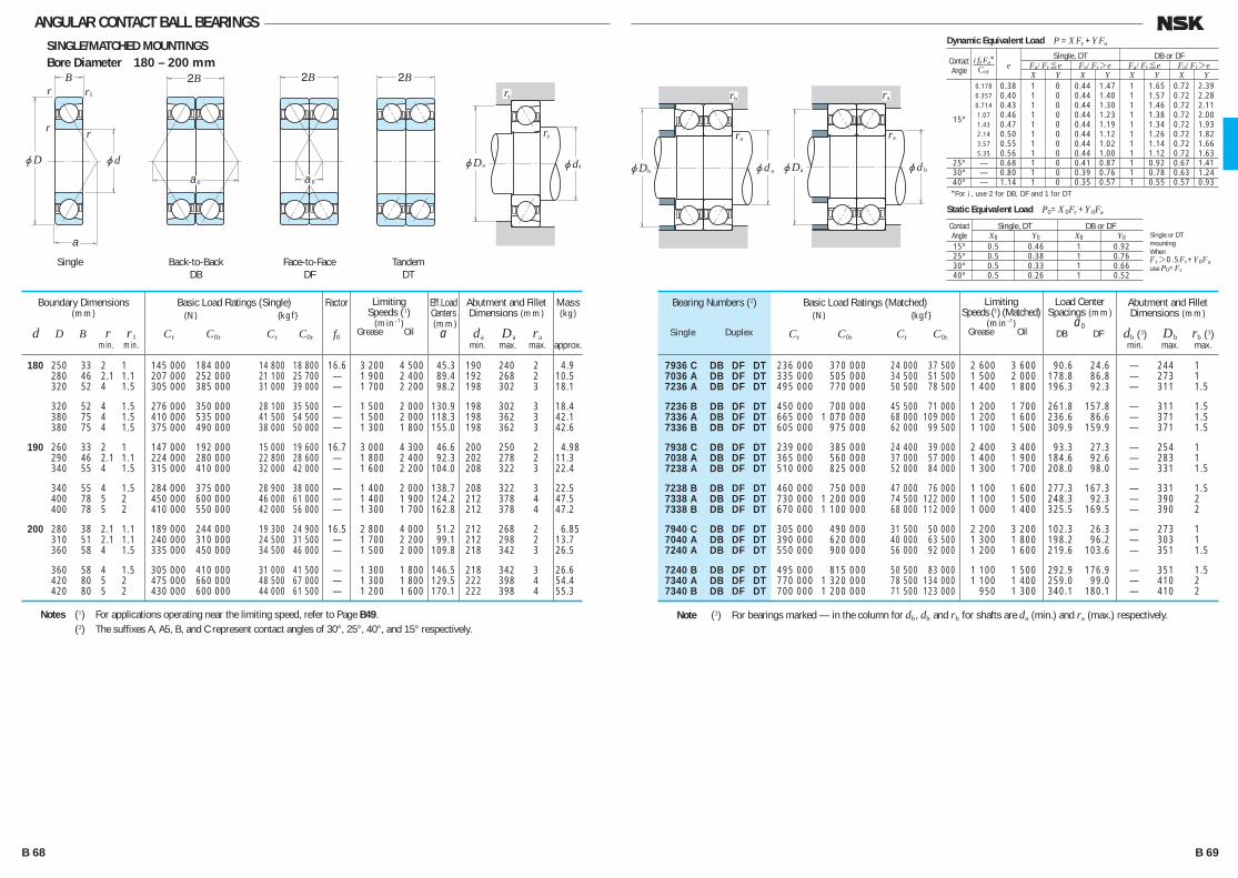
ANGULAR CONTACT BALL BEARINGSSINGLE/MATCHED MOUNTINGSBore Diameter 180 – 200 mm
7936 C DB DF DT 236 000 370 000 24 000 37 500 2 600 3 600 90.6 24.6 — 244 1 7036 A DB DF DT 335 000 505 000 34 500 51 500 1 500 2 000 178.8 86.8 — 273 1 7236 A DB DF DT 495 000 770 000 50 500 78 500 1 400 1 800 196.3 92.3 — 311 1.5
7236 B DB DF DT 450 000 700 000 45 500 71 000 1 200 1 700 261.8 157.8 — 311 1.5 7336 A DB DF DT 665 000 1 070 000 68 000 109 000 1 200 1 600 236.6 86.6 — 371 1.5 7336 B DB DF DT 605 000 975 000 62 000 99 500 1 100 1 500 309.9 159.9 — 371 1.5
7938 C DB DF DT 239 000 385 000 24 400 39 000 2 400 3 400 93.3 27.3 — 254 1 7038 A DB DF DT 365 000 560 000 37 000 57 000 1 400 1 900 184.6 92.6 — 283 1 7238 A DB DF DT 510 000 825 000 52 000 84 000 1 300 1 700 208.0 98.0 — 331 1.5
7238 B DB DF DT 460 000 750 000 47 000 76 000 1 100 1 600 277.3 167.3 — 331 1.5 7338 A DB DF DT 730 000 1 200 000 74 500 122 000 1 100 1 500 248.3 92.3 — 390 2 7338 B DB DF DT 670 000 1 100 000 68 000 112 000 1 000 1 400 325.5 169.5 — 390 2
7940 C DB DF DT 305 000 490 000 31 500 50 000 2 200 3 200 102.3 26.3 — 273 1 7040 A DB DF DT 390 000 620 000 40 000 63 500 1 300 1 800 198.2 96.2 — 303 1 7240 A DB DF DT 550 000 900 000 56 000 92 000 1 200 1 600 219.6 103.6 — 351 1.5
7240 B DB DF DT 495 000 815 000 50 500 83 000 1 100 1 500 292.9 176.9 — 351 1.5 7340 A DB DF DT 770 000 1 320 000 78 500 134 000 1 100 1 400 259.0 99.0 — 410 2 7340 B DB DF DT 700 000 1 200 000 71 500 123 000 950 1 300 340.1 180.1 — 410 2
Bearing Numbers (2)
Single Duplex
Abutment and Fillet Dimensions (mm)
da Da ra min. max. max.
Abutment and Fillet Dimensions (mm)
db (3) Db rb (3) min. max. max.
180 250 33 2 1 145 000 184 000 14 800 18 800 16.6 3 200 4 500 45.3 190 240 2 4.9 280 46 2.1 1.1 207 000 252 000 21 100 25 700 — 1 900 2 400 89.4 192 268 2 10.5 320 52 4 1.5 305 000 385 000 31 000 39 000 — 1 700 2 200 98.2 198 302 3 18.1
320 52 4 1.5 276 000 350 000 28 100 35 500 — 1 500 2 000 130.9 198 302 3 18.4 380 75 4 1.5 410 000 535 000 41 500 54 500 — 1 500 2 000 118.3 198 362 3 42.1 380 75 4 1.5 375 000 490 000 38 000 50 000 — 1 300 1 800 155.0 198 362 3 42.6
190 260 33 2 1 147 000 192 000 15 000 19 600 16.7 3 000 4 300 46.6 200 250 2 4.98 290 46 2.1 1.1 224 000 280 000 22 800 28 600 — 1 800 2 400 92.3 202 278 2 11.3 340 55 4 1.5 315 000 410 000 32 000 42 000 — 1 600 2 200 104.0 208 322 3 22.4
340 55 4 1.5 284 000 375 000 28 900 38 000 — 1 400 2 000 138.7 208 322 3 22.5 400 78 5 2 450 000 600 000 46 000 61 000 — 1 400 1 900 124.2 212 378 4 47.5 400 78 5 2 410 000 550 000 42 000 56 000 — 1 300 1 700 162.8 212 378 4 47.2
200 280 38 2.1 1.1 189 000 244 000 19 300 24 900 16.5 2 800 4 000 51.2 212 268 2 6.85 310 51 2.1 1.1 240 000 310 000 24 500 31 500 — 1 700 2 200 99.1 212 298 2 13.7 360 58 4 1.5 335 000 450 000 34 500 46 000 — 1 500 2 000 109.8 218 342 3 26.5
360 58 4 1.5 305 000 410 000 31 000 41 500 — 1 300 1 800 146.5 218 342 3 26.6 420 80 5 2 475 000 660 000 48 500 67 000 — 1 300 1 800 129.5 222 398 4 54.4 420 80 5 2 430 000 600 000 44 000 61 500 — 1 200 1 600 170.1 222 398 4 55.3
Boundary Dimensions(mm)
d D B r r1 min. min.
Limiting Speeds (1)
(min–1) Grease Oil
Limiting Speeds (1) (Matched)
(min–1) Grease Oil
Load Center Spacings (mm)
a0 DB DF
Basic Load Ratings (Single) (N) {kgf}
Cr C0r Cr C0r
Basic Load Ratings (Matched) (N) {kgf}
Cr C0r Cr C0r
Notes (1) For applications operating near the limiting speed, refer to Page B49. (2) The suffixes A, A5, B, and C represent contact angles of 30°, 25°, 40°, and 15° respectively.
Note (3) For bearings marked — in the column for db, db and rb for shafts are da (min.) and ra (max.) respectively.
rr
r
jD jd
2B 2BB
a0 a0
1
r
a
jD jd
ra
aa
2Bra
jD
ra
b jd a
rb
jD
ra
a jd b
ra
Back-to-BackDB
Face-to-FaceDF
TandemDT
Single
Factor
f0
Mass(kg)
approx.
Eff.Load Centers (mm)
a
Dynamic Equivalent Load P =XFr +YFa
*For i , use 2 for DB, DF and 1 for DT
Contact
Single, DT DB or DF
Angle e Fa/Fr≤e Fa/Fr>e Fa/Fr≤e Fa/Fr>e
X Y X Y X Y X Y 0.178 0.38 1 0 0.44 1.47 1 1.65 0.72 2.39 0.357 0.40 1 0 0.44 1.40 1 1.57 0.72 2.28 0.714 0.43 1 0 0.44 1.30 1 1.46 0.72 2.11 15º 1.07 0.46 1 0 0.44 1.23 1 1.38 0.72 2.00 1.43 0.47 1 0 0.44 1.19 1 1.34 0.72 1.93 2.14 0.50 1 0 0.44 1.12 1 1.26 0.72 1.82 3.57 0.55 1 0 0.44 1.02 1 1.14 0.72 1.66 5.35 0.56 1 0 0.44 1.00 1 1.12 0.72 1.63 25º — 0.68 1 0 0.41 0.87 1 0.92 0.67 1.41 30º — 0.80 1 0 0.39 0.76 1 0.78 0.63 1.24 40º — 1.14 1 0 0.35 0.57 1 0.55 0.57 0.93
i f0 Fa*Cor
Static Equivalent Load P0=X 0Fr +Y 0Fa
Contact Single, DT DB or DF Angle X0 Y0 X0 Y0
15º 0.5 0.46 1 0.92 25º 0.5 0.38 1 0.76 30º 0.5 0.33 1 0.66 40º 0.5 0.26 1 0.52
Single or DTmountingWhenFr>0.5Fr+Y0Fause P0=Fr
B 68 B 69
B046-075E.indd 68-69B046-075E.indd 68-69 11/20/13 4:55:16 PM11/20/13 4:55:16 PM
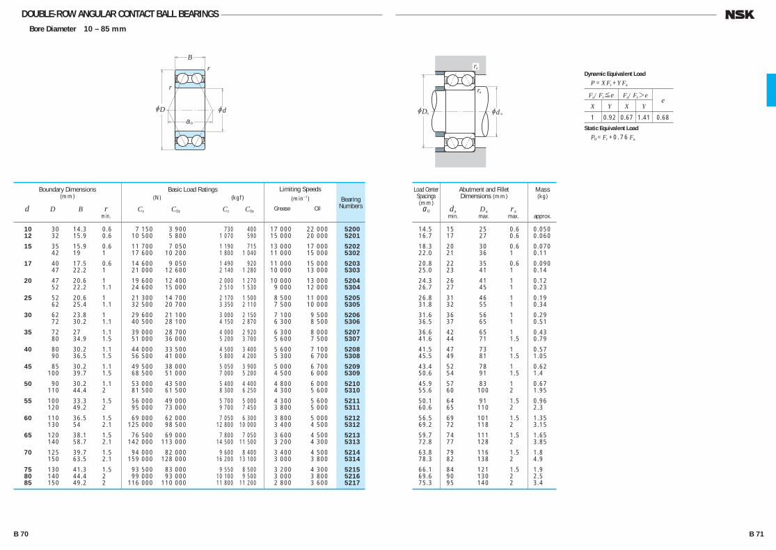
DOUBLE-ROW ANGULAR CONTACT BALL BEARINGSBore Diameter 10 – 85 mm
10 30 14.3 0.6 7 150 3 900 730 400 17 000 22 000 5200 12 32 15.9 0.6 10 500 5 800 1 070 590 15 000 20 000 5201
15 35 15.9 0.6 11 700 7 050 1 190 715 13 000 17 000 5202 42 19 1 17 600 10 200 1 800 1 040 11 000 15 000 5302
17 40 17.5 0.6 14 600 9 050 1 490 920 11 000 15 000 5203 47 22.2 1 21 000 12 600 2 140 1 280 10 000 13 000 5303
20 47 20.6 1 19 600 12 400 2 000 1 270 10 000 13 000 5204 52 22.2 1.1 24 600 15 000 2 510 1 530 9 000 12 000 5304
25 52 20.6 1 21 300 14 700 2 170 1 500 8 500 11 000 5205 62 25.4 1.1 32 500 20 700 3 350 2 110 7 500 10 000 5305
30 62 23.8 1 29 600 21 100 3 000 2 150 7 100 9 500 5206 72 30.2 1.1 40 500 28 100 4 150 2 870 6 300 8 500 5306
35 72 27 1.1 39 000 28 700 4 000 2 920 6 300 8 000 5207 80 34.9 1.5 51 000 36 000 5 200 3 700 5 600 7 500 5307
40 80 30.2 1.1 44 000 33 500 4 500 3 400 5 600 7 100 5208 90 36.5 1.5 56 500 41 000 5 800 4 200 5 300 6 700 5308
45 85 30.2 1.1 49 500 38 000 5 050 3 900 5 000 6 700 5209 100 39.7 1.5 68 500 51 000 7 000 5 200 4 500 6 000 5309
50 90 30.2 1.1 53 000 43 500 5 400 4 400 4 800 6 000 5210 110 44.4 2 81 500 61 500 8 300 6 250 4 300 5 600 5310
55 100 33.3 1.5 56 000 49 000 5 700 5 000 4 300 5 600 5211 120 49.2 2 95 000 73 000 9 700 7 450 3 800 5 000 5311
60 110 36.5 1.5 69 000 62 000 7 050 6 300 3 800 5 000 5212 130 54 2.1 125 000 98 500 12 800 10 000 3 400 4 500 5312
65 120 38.1 1.5 76 500 69 000 7 800 7 050 3 600 4 500 5213 140 58.7 2.1 142 000 113 000 14 500 11 500 3 200 4 300 5313
70 125 39.7 1.5 94 000 82 000 9 600 8 400 3 400 4 500 5214 150 63.5 2.1 159 000 128 000 16 200 13 100 3 000 3 800 5314
75 130 41.3 1.5 93 500 83 000 9 550 8 500 3 200 4 300 5215 80 140 44.4 2 99 000 93 000 10 100 9 500 3 000 3 800 5216 85 150 49.2 2 116 000 110 000 11 800 11 200 2 800 3 600 5217
Boundary Dimensions(mm)
d D B r min.
Limiting Speeds (min–1)
Grease Oil
Basic Load Ratings (N) {kgf}
Cr C0r Cr C0r
Bearing Numbers
jD jda0
r
rB
jD jd
ra
ra
aa
14.5 15 25 0.6 0.050 16.7 17 27 0.6 0.060
18.3 20 30 0.6 0.070 22.0 21 36 1 0.11
20.8 22 35 0.6 0.090 25.0 23 41 1 0.14
24.3 26 41 1 0.12 26.7 27 45 1 0.23
26.8 31 46 1 0.19 31.8 32 55 1 0.34
31.6 36 56 1 0.29 36.5 37 65 1 0.51
36.6 42 65 1 0.43 41.6 44 71 1.5 0.79
41.5 47 73 1 0.57 45.5 49 81 1.5 1.05
43.4 52 78 1 0.62 50.6 54 91 1.5 1.4
45.9 57 83 1 0.67 55.6 60 100 2 1.95
50.1 64 91 1.5 0.96 60.6 65 110 2 2.3
56.5 69 101 1.5 1.35 69.2 72 118 2 3.15
59.7 74 111 1.5 1.65 72.8 77 128 2 3.85
63.8 79 116 1.5 1.8 78.3 82 138 2 4.9
66.1 84 121 1.5 1.9 69.6 90 130 2 2.5 75.3 95 140 2 3.4
Load Center Spacings (mm)a0
Mass(kg)
approx.
Abutment and FilletDimensions (mm)
da Da ra min. max. max.
Fa/Fr≤e Fa/Fr>e
X Y X Y e
1 0.92 0.67 1.41 0.68
Dynamic Equivalent Load
P =XFr +YFa
Static Equivalent Load
P0 =Fr +0.76 Fa
B 70 B 71
B046-075E.indd 70-71B046-075E.indd 70-71 11/20/13 4:55:17 PM11/20/13 4:55:17 PM
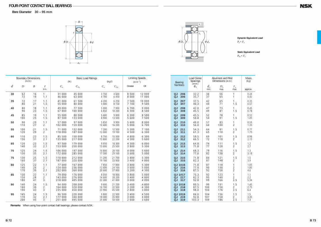
FOUR-POINT CONTACT BALL BEARINGSBore Diameter 30 – 95 mm
30 62 16 1 31 000 45 000 3 150 4 600 8 500 12 000 72 19 1.1 46 000 63 000 4 700 6 450 8 000 11 000
35 72 17 1.1 41 000 61 500 4 200 6 250 7 500 10 000 80 21 1.5 55 000 80 000 5 600 8 150 7 100 9 500
40 80 18 1.1 49 000 77 500 5 000 7 900 6 700 9 000 90 23 1.5 67 000 100 000 6 850 10 200 6 300 8 500
45 85 19 1.1 55 000 88 500 5 600 9 000 6 300 8 500 100 25 1.5 87 500 133 000 8 900 13 500 5 600 7 500
50 90 20 1.1 57 000 97 000 5 850 9 900 5 600 8 000 110 27 2 102 000 159 000 10 400 16 200 5 000 6 700
55 100 21 1.5 71 000 122 000 7 200 12 500 5 300 7 100 120 29 2 118 000 187 000 12 000 19 100 4 500 6 300
60 110 22 1.5 85 500 150 000 8 750 15 300 4 800 6 300 130 31 2.1 135 000 217 000 13 800 22 200 4 300 5 600
65 120 23 1.5 97 500 179 000 9 950 18 300 4 300 6 000 140 33 2.1 153 000 250 000 15 600 25 500 3 800 5 300
70 125 24 1.5 106 000 197 000 10 800 20 100 4 000 5 600 150 35 2.1 172 000 285 000 17 500 29 100 3 600 5 000
75 130 25 1.5 110 000 212 000 11 200 21 700 3 800 5 300 160 37 2.1 187 000 320 000 19 100 33 000 3 400 4 800
80 125 22 1.1 77 000 167 000 7 850 17 000 3 800 5 300 140 26 2 124 000 236 000 12 600 24 100 3 600 5 000 170 39 2.1 202 000 360 000 20 600 37 000 3 200 4 300
85 130 22 1.1 79 000 176 000 8 050 18 000 3 800 5 000 150 28 2 143 000 276 000 14 600 28 200 3 400 4 800 180 41 3 218 000 405 000 22 300 41 000 3 000 4 000
90 140 24 1.5 94 000 208 000 9 600 21 200 3 400 4 800 160 30 2 164 000 320 000 16 700 32 500 3 200 4 300 190 43 3 235 000 450 000 23 900 45 500 2 800 3 800
95 145 24 1.5 96 500 220 000 9 800 22 500 3 400 4 500 170 32 2.1 177 000 340 000 18 000 35 000 3 000 4 000 200 45 3 251 000 495 000 25 600 50 500 2 600 3 600
Boundary Dimensions(mm)
d D B r min.
Limiting Speeds(min–1)
Grease Oil
Basic Load Ratings (N) {kgf}
Ca C0a Ca C0a
QJ 206 32.2 36 56 1 0.24 QJ 306 35.7 37 65 1 0.42
QJ 207 37.5 42 65 1 0.35 QJ 307 40.3 44 71 1.5 0.57
QJ 208 42.0 47 73 1 0.45 QJ 308 45.5 49 81 1.5 0.78
QJ 209 45.5 52 78 1 0.52 QJ 309 50.8 54 91 1.5 1.05
QJ 210 49.0 57 83 1 0.59 QJ 310 56.0 60 100 2 1.35
QJ 211 54.3 64 91 1.5 0.77 QJ 311 61.3 65 110 2 1.75
QJ 212 59.5 69 101 1.5 0.98 QJ 312 66.5 72 118 2 2.15
QJ 213 64.8 74 111 1.5 1.2 QJ 313 71.8 77 128 2 2.7
QJ 214 68.3 79 116 1.5 1.3 QJ 314 77.0 82 138 2 3.18
QJ 215 71.8 84 121 1.5 1.5 QJ 315 82.3 87 148 2 3.9
QJ 1016 71.8 87 118 1 1.05 QJ 216 77.0 90 130 2 1.85 QJ 316 87.5 92 158 2 4.6
QJ 1017 75.3 92 123 1 1.1 QJ 217 82.3 95 140 2 2.2 QJ 317 92.8 99 166 2.5 5.34
QJ 1018 80.5 99 131 1.5 1.45 QJ 218 87.5 100 150 2 2.75 QJ 318 98.0 104 176 2.5 6.4
QJ 1019 84.0 104 136 1.5 1.5 QJ 219 92.8 107 158 2 3.35 QJ 319 103.3 109 186 2.5 7.4
Load Center Spacings
(mm)a0
Bearing Numbers
Abutment and FilletDimensions (mm)
da Da ra min. max. max.
Mass(kg)
approx.
Remarks When using four-point contact ball bearings, please contact NSK.
r
r
jD jd
a
B
0
r
jD jd
a
ra
aa
Dynamic Equivalent Load
Pa =Fa
Static Equivalent Load
P0a =Fa
B 72 B 73
B046-075E.indd 72-73B046-075E.indd 72-73 11/20/13 4:55:18 PM11/20/13 4:55:18 PM
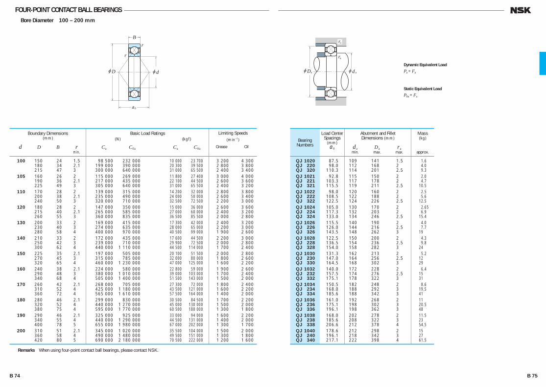
FOUR-POINT CONTACT BALL BEARINGSBore Diameter 100 – 200 mm
100 150 24 1.5 98 500 232 000 10 000 23 700 3 200 4 300 180 34 2.1 199 000 390 000 20 300 39 500 2 800 3 800 215 47 3 300 000 640 000 31 000 65 500 2 400 3 400 105 160 26 2 115 000 269 000 11 800 27 400 3 000 4 000 190 36 2.1 217 000 435 000 22 100 44 500 2 600 3 600 225 49 3 305 000 640 000 31 000 65 500 2 400 3 200 110 170 28 2 139 000 315 000 14 200 32 000 2 800 3 800 200 38 2.1 235 000 490 000 24 000 50 000 2 600 3 400 240 50 3 320 000 710 000 32 500 72 500 2 200 3 000 120 180 28 2 147 000 350 000 15 000 36 000 2 600 3 600 215 40 2.1 265 000 585 000 27 000 60 000 2 400 3 200 260 55 3 360 000 835 000 36 500 85 500 2 000 2 800 130 200 33 2 169 000 415 000 17 300 42 000 2 400 3 200 230 40 3 274 000 635 000 28 000 65 000 2 200 3 000 280 58 4 400 000 970 000 40 500 99 000 1 900 2 600 140 210 33 2 172 000 435 000 17 600 44 500 2 200 3 000 250 42 3 239 000 710 000 29 900 72 500 2 000 2 800 300 62 4 440 000 1 110 000 44 500 114 000 1 700 2 400 150 225 35 2.1 197 000 505 000 20 100 51 500 2 000 2 800 270 45 3 315 000 785 000 32 000 80 000 1 800 2 600 320 65 4 460 000 1 230 000 47 000 125 000 1 600 2 200 160 240 38 2.1 224 000 580 000 22 800 59 000 1 900 2 600 290 48 3 380 000 1 010 000 39 000 103 000 1 700 2 400 340 68 4 505 000 1 400 000 51 500 143 000 1 500 2 000 170 260 42 2.1 268 000 705 000 27 300 72 000 1 800 2 400 310 52 4 425 000 1 180 000 43 500 121 000 1 600 2 200 360 72 4 565 000 1 610 000 57 500 164 000 1 400 2 000 180 280 46 2.1 299 000 830 000 30 500 84 500 1 700 2 200 320 52 4 440 000 1 270 000 45 000 130 000 1 500 2 000 380 75 4 595 000 1 770 000 60 500 180 000 1 300 1 800 190 290 46 2.1 325 000 925 000 33 000 94 000 1 600 2 200 340 55 4 440 000 1 290 000 44 500 131 000 1 400 2 000 400 78 5 655 000 1 980 000 67 000 202 000 1 300 1 700 200 310 51 2.1 345 000 1 020 000 35 500 104 000 1 500 2 000 360 58 4 490 000 1 480 000 49 500 151 000 1 300 1 800 420 80 5 690 000 2 180 000 70 500 222 000 1 200 1 600
Boundary Dimensions(mm)
d D B r min.
Limiting Speeds(min–1)
Grease Oil
Basic Load Ratings (N) {kgf}
Ca C0a Ca C0a
QJ 1020 87.5 109 141 1.5 1.6 QJ 220 98.0 112 168 2 4.0 QJ 320 110.3 114 201 2.5 9.3 QJ 1021 92.8 115 150 2 2.0 QJ 221 103.3 117 178 2 4.7 QJ 321 115.5 119 211 2.5 10.5 QJ 1022 98.0 120 160 2 2.5 QJ 222 108.5 122 188 2 5.6 QJ 322 122.5 124 226 2.5 12.5 QJ 1024 105.0 130 170 2 2.65 QJ 224 117.3 132 203 2 6.9 QJ 324 133.0 134 246 2.5 15.4 QJ 1026 115.5 140 190 2 4.0 QJ 226 126.0 144 216 2.5 7.7 QJ 326 143.5 148 262 3 19 QJ 1028 122.5 150 200 2 4.3 QJ 228 136.5 154 236 2.5 9.8 QJ 328 154.0 158 282 3 24 QJ 1030 131.3 162 213 2 5.2 QJ 230 147.0 164 256 2.5 12 QJ 330 164.5 168 302 3 29 QJ 1032 140.0 172 228 2 6.4 QJ 232 157.5 174 276 2.5 15 QJ 332 175.1 178 322 3 31 QJ 1034 150.5 182 248 2 8.6 QJ 234 168.0 188 292 3 19.5 QJ 334 185.6 188 342 3 41 QJ 1036 161.0 192 268 2 11 QJ 236 175.1 198 302 3 20.5 QJ 336 196.1 198 362 3 48 QJ 1038 168.0 202 278 2 11.5 QJ 238 185.6 208 322 3 23 QJ 338 206.6 212 378 4 54.5 QJ 1040 178.6 212 298 2 15 QJ 240 196.1 218 342 3 27 QJ 340 217.1 222 398 4 61.5
Load Center Spacings
(mm)a0
Bearing Numbers
Abutment and FilletDimensions (mm)
da Da ra min. max. max.
Mass(kg)
approx.
Remarks When using four-point contact ball bearings, please contact NSK.
r
r
jD jd
a
B
0
r
jD jd
a
ra
aa
Dynamic Equivalent Load
Pa =Fa
Static Equivalent Load
P0a =Fa
B 74 B 75
B046-075E.indd 74-75B046-075E.indd 74-75 11/20/13 4:55:19 PM11/20/13 4:55:19 PM

b1 Bearing No. b1 (mm)
2222(K), 2316(K) 0.5
2319(K), 2320(K) 0.5 2321 , 2322(K)
1318(K) 1.5
1319(K) 2
1320(K), 1321 3 1322(K)
SELF-ALIGNING BALL BEARINGSSELF-ALIGNING BALL BEARINGS Bore Diameter 5 – 110 mm ··············· B78
DESIGN, TYPES, AND FEATURES
The outer ring has a spherical raceway and its center of curvature coincides with that of the bearing; therefore, the axis of the inner ring, balls and cage can deflect to some extent around the bearing center. This type is recommended when the alignment of the shaft and housing is difficult and when the shaft may bend. Since the contact angle is small, the axial load capacity is low. Pressed steel cages are usually used.
PROTRUSION AMOUNT OF BALLS
Among self-aligning ball bearings, there are some in which the balls protrude from the side face as shown below. This protrusion amount b1 is listed in the following table.
TOLERANCES AND RUNNING ACCURACY ······························································· Table 8.2 (Pages A60 to A63)
RECOMMENDED FITS ·········································· Table 9.2 (Page A84) Table 9.4 (Page A85)
INTERNAL CLEARANCE ······································· Table 9.12 (Page A90)
PERMISSIBLE MISALIGNMENT
The permissible misalignment of self-aligning ball bearings is approximately 0.07 to 0.12 radian (4° to 7°) under normal loads. However, depending on the surrounding structure, such an angle may not be possible. Use care in the structural design.
B 76 B 77
B076-083E.indd 76-77B076-083E.indd 76-77 11/20/13 4:55:41 PM11/20/13 4:55:41 PM
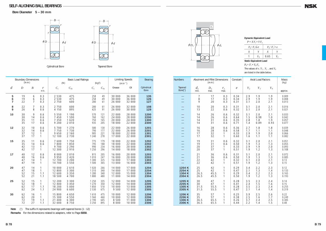
SELF-ALIGNING BALL BEARINGSBore Diameter 5 – 30 mm
5 19 6 0.3 2 530 475 258 49 30 000 36 000 135 6 19 6 0.3 2 530 475 258 49 30 000 36 000 126 7 22 7 0.3 2 750 600 280 61 26 000 32 000 127
8 22 7 0.3 2 750 600 280 61 26 000 32 000 108 9 26 8 0.6 4 150 895 425 91 26 000 30 000 129
10 30 9 0.6 5 550 1 190 570 121 22 000 28 000 1200 30 14 0.6 7 450 1 590 760 162 24 000 28 000 2200 35 11 0.6 7 350 1 620 750 165 20 000 24 000 1300 35 17 0.6 9 200 2 010 935 205 18 000 22 000 2300
12 32 10 0.6 5 700 1 270 580 130 22 000 26 000 1201 32 14 0.6 7 750 1 730 790 177 22 000 26 000 2201 37 12 1 9 650 2 160 985 221 18 000 22 000 1301 37 17 1 12 100 2 730 1 240 278 17 000 22 000 2301
15 35 11 0.6 7 600 1 750 775 179 18 000 22 000 1202 35 14 0.6 7 800 1 850 795 188 18 000 22 000 2202 42 13 1 9 700 2 290 990 234 16 000 20 000 1302 42 17 1 12 300 2 910 1 250 296 14 000 18 000 2302
17 40 12 0.6 8 000 2 010 815 205 16 000 20 000 1203 40 16 0.6 9 950 2 420 1 010 247 16 000 20 000 2203 47 14 1 12 700 3 200 1 300 325 14 000 17 000 1303 47 19 1 14 700 3 550 1 500 365 13 000 16 000 2303
20 47 14 1 10 000 2 610 1 020 266 14 000 17 000 1204 47 18 1 12 800 3 300 1 310 340 14 000 17 000 2204 52 15 1.1 12 600 3 350 1 280 340 12 000 15 000 1304 52 21 1.1 18 500 4 700 1 880 480 11 000 14 000 2304
25 52 15 1 12 200 3 300 1 250 335 12 000 14 000 1205 52 18 1 12 400 3 450 1 270 350 12 000 14 000 2205 62 17 1.1 18 200 5 000 1 850 510 10 000 13 000 1305 62 24 1.1 24 900 6 600 2 530 675 9 500 12 000 2305
30 62 16 1 15 800 4 650 1 610 475 10 000 12 000 1206 62 20 1 15 300 4 550 1 560 460 10 000 12 000 2206 72 19 1.1 21 400 6 300 2 190 645 8 500 11 000 1306 72 27 1.1 32 000 8 750 3 250 895 8 000 10 000 2306
Boundary Dimensions(mm)
d D B r min.
Limiting Speeds(min–1)
Grease Oil
Basic Load Ratings (N) {kgf}
Cr C0r Cr C0r
— 7 17 0.3 0.34 2.9 1.9 1.9 0.009 — 8 17 0.3 0.34 2.9 1.9 1.9 0.008 — 9 20 0.3 0.31 3.1 2.0 2.1 0.013
— 10 20 0.3 0.31 3.1 2.0 2.1 0.016 — 13 22 0.6 0.32 3.1 2.0 2.1 0.021
— 14 26 0.6 0.32 3.1 2.0 2.1 0.033 — 14 26 0.6 0.64 1.5 0.98 1.0 0.042 — 14 31 0.6 0.35 2.8 1.8 1.9 0.057 — 14 31 0.6 0.71 1.4 0.89 0.93 0.077
— 16 28 0.6 0.36 2.7 1.8 1.8 0.039 — 16 28 0.6 0.58 1.7 1.1 1.1 0.048 — 17 32 1 0.33 2.9 1.9 2.0 0.066 — 17 32 1 0.60 1.6 1.1 1.1 0.082
— 19 31 0.6 0.32 3.1 2.0 2.1 0.051 — 19 31 0.6 0.50 1.9 1.3 1.3 0.055 — 20 37 1 0.33 2.9 1.9 2.0 0.093 — 20 37 1 0.51 1.9 1.2 1.3 0.108
— 21 36 0.6 0.31 3.1 2.0 2.1 0.072 — 21 36 0.6 0.50 1.9 1.3 1.3 0.085 — 22 42 1 0.32 3.1 2.0 2.1 0.13 — 22 42 1 0.51 1.9 1.2 1.3 0.15
1204 K 25 42 1 0.29 3.4 2.2 2.3 0.12 2204 K 25 42 1 0.47 2.1 1.3 1.4 0.133 1304 K 26.5 45.5 1 0.29 3.4 2.2 2.3 0.165 2304 K 26.5 45.5 1 0.50 1.9 1.2 1.3 0.193
1205 K 30 47 1 0.28 3.5 2.3 2.4 0.14 2205 K 30 47 1 0.41 2.4 1.5 1.6 0.15 1305 K 31.5 55.5 1 0.28 3.5 2.3 2.4 0.255 2305 K 31.5 55.5 1 0.47 2.1 1.4 1.4 0.319
1206 K 35 57 1 0.25 3.9 2.5 2.6 0.22 2206 K 35 57 1 0.38 2.5 1.6 1.7 0.249 1306 K 36.5 65.5 1 0.26 3.7 2.4 2.5 0.385 2306 K 36.5 65.5 1 0.44 2.2 1.4 1.5 0.48
Numbers
TaperedBore(1)
Bearing
CylindricalBore
Abutment and Fillet Dimensions(mm)
da Da ra min. max. max.
Axial Load Factors
Y2 Y3 Y0
Constant
e
Mass(kg)
approx.
Note (1) The suffix K represents bearings with tapered bores (1 : 12)Remarks For the dimensions related to adapters, refer to Page B358.
r
r
jD jd
B
r
jD jd
B
jD jd
ra
ra
aa
Fa/Fr≤e Fa/Fr>e
X Y X Y
1 Y3 0.65 Y2
Dynamic Equivalent Load
P =XFr +YFa
Static Equivalent Load
P0 =Fr +Y0 Fa
The values of e, Y2 , Y3 , and Y0
are listed in the table below.
Cylindrical Bore Tapered Bore
B 78 B 79
B076-083E.indd 78-79B076-083E.indd 78-79 11/20/13 4:55:41 PM11/20/13 4:55:41 PM
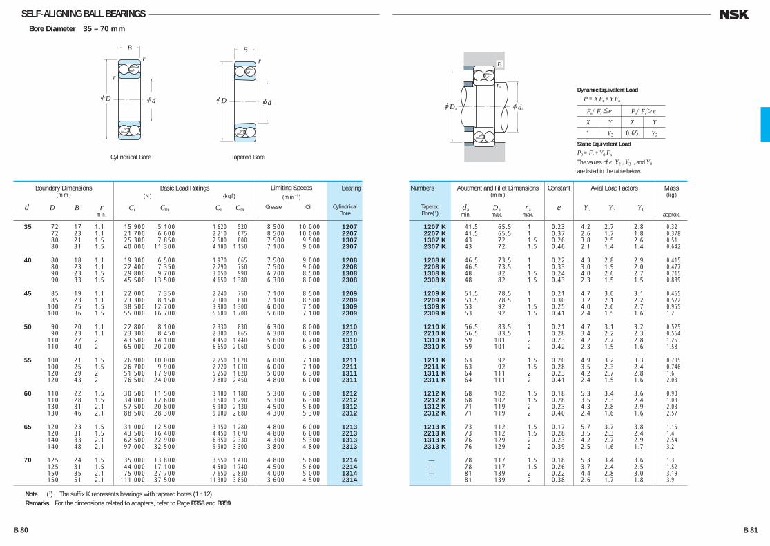
SELF-ALIGNING BALL BEARINGSBore Diameter 35 – 70 mm
35 72 17 1.1 15 900 5 100 1 620 520 8 500 10 000 1207 72 23 1.1 21 700 6 600 2 210 675 8 500 10 000 2207 80 21 1.5 25 300 7 850 2 580 800 7 500 9 500 1307 80 31 1.5 40 000 11 300 4 100 1 150 7 100 9 000 2307
40 80 18 1.1 19 300 6 500 1 970 665 7 500 9 000 1208 80 23 1.1 22 400 7 350 2 290 750 7 500 9 000 2208 90 23 1.5 29 800 9 700 3 050 990 6 700 8 500 1308 90 33 1.5 45 500 13 500 4 650 1 380 6 300 8 000 2308
45 85 19 1.1 22 000 7 350 2 240 750 7 100 8 500 1209 85 23 1.1 23 300 8 150 2 380 830 7 100 8 500 2209 100 25 1.5 38 500 12 700 3 900 1 300 6 000 7 500 1309 100 36 1.5 55 000 16 700 5 600 1 700 5 600 7 100 2309
50 90 20 1.1 22 800 8 100 2 330 830 6 300 8 000 1210 90 23 1.1 23 300 8 450 2 380 865 6 300 8 000 2210 110 27 2 43 500 14 100 4 450 1 440 5 600 6 700 1310 110 40 2 65 000 20 200 6 650 2 060 5 000 6 300 2310
55 100 21 1.5 26 900 10 000 2 750 1 020 6 000 7 100 1211 100 25 1.5 26 700 9 900 2 720 1 010 6 000 7 100 2211 120 29 2 51 500 17 900 5 250 1 820 5 000 6 300 1311 120 43 2 76 500 24 000 7 800 2 450 4 800 6 000 2311
60 110 22 1.5 30 500 11 500 3 100 1 180 5 300 6 300 1212 110 28 1.5 34 000 12 600 3 500 1 290 5 300 6 300 2212 130 31 2.1 57 500 20 800 5 900 2 130 4 500 5 600 1312 130 46 2.1 88 500 28 300 9 000 2 880 4 300 5 300 2312
65 120 23 1.5 31 000 12 500 3 150 1 280 4 800 6 000 1213 120 31 1.5 43 500 16 400 4 450 1 670 4 800 6 000 2213 140 33 2.1 62 500 22 900 6 350 2 330 4 300 5 300 1313 140 48 2.1 97 000 32 500 9 900 3 300 3 800 4 800 2313
70 125 24 1.5 35 000 13 800 3 550 1 410 4 800 5 600 1214 125 31 1.5 44 000 17 100 4 500 1 740 4 500 5 600 2214 150 35 2.1 75 000 27 700 7 650 2 830 4 000 5 000 1314 150 51 2.1 111 000 37 500 11 300 3 850 3 600 4 500 2314
Boundary Dimensions(mm)
d D B r min.
Limiting Speeds(min–1)
Grease Oil
Basic Load Ratings (N) {kgf}
Cr C0r Cr C0r
1207 K 41.5 65.5 1 0.23 4.2 2.7 2.8 0.32 2207 K 41.5 65.5 1 0.37 2.6 1.7 1.8 0.378 1307 K 43 72 1.5 0.26 3.8 2.5 2.6 0.51 2307 K 43 72 1.5 0.46 2.1 1.4 1.4 0.642
1208 K 46.5 73.5 1 0.22 4.3 2.8 2.9 0.415 2208 K 46.5 73.5 1 0.33 3.0 1.9 2.0 0.477 1308 K 48 82 1.5 0.24 4.0 2.6 2.7 0.715 2308 K 48 82 1.5 0.43 2.3 1.5 1.5 0.889
1209 K 51.5 78.5 1 0.21 4.7 3.0 3.1 0.465 2209 K 51.5 78.5 1 0.30 3.2 2.1 2.2 0.522 1309 K 53 92 1.5 0.25 4.0 2.6 2.7 0.955 2309 K 53 92 1.5 0.41 2.4 1.5 1.6 1.2
1210 K 56.5 83.5 1 0.21 4.7 3.1 3.2 0.525 2210 K 56.5 83.5 1 0.28 3.4 2.2 2.3 0.564 1310 K 59 101 2 0.23 4.2 2.7 2.8 1.25 2310 K 59 101 2 0.42 2.3 1.5 1.6 1.58
1211 K 63 92 1.5 0.20 4.9 3.2 3.3 0.705 2211 K 63 92 1.5 0.28 3.5 2.3 2.4 0.746 1311 K 64 111 2 0.23 4.2 2.7 2.8 1.6 2311 K 64 111 2 0.41 2.4 1.5 1.6 2.03
1212 K 68 102 1.5 0.18 5.3 3.4 3.6 0.90 2212 K 68 102 1.5 0.28 3.5 2.3 2.4 1.03 1312 K 71 119 2 0.23 4.3 2.8 2.9 2.03 2312 K 71 119 2 0.40 2.4 1.6 1.6 2.57
1213 K 73 112 1.5 0.17 5.7 3.7 3.8 1.15 2213 K 73 112 1.5 0.28 3.5 2.3 2.4 1.4 1313 K 76 129 2 0.23 4.2 2.7 2.9 2.54 2313 K 76 129 2 0.39 2.5 1.6 1.7 3.2
— 78 117 1.5 0.18 5.3 3.4 3.6 1.3 — 78 117 1.5 0.26 3.7 2.4 2.5 1.52 — 81 139 2 0.22 4.4 2.8 3.0 3.19 — 81 139 2 0.38 2.6 1.7 1.8 3.9
Numbers
TaperedBore(1)
Bearing
CylindricalBore
Abutment and Fillet Dimensions(mm)
da Da ra min. max. max.
Axial Load Factors
Y2 Y3 Y0
Constant
e
Mass(kg)
approx.
Note (1) The suffix K represents bearings with tapered bores (1 : 12)Remarks For the dimensions related to adapters, refer to Page B358 and B359.
r
r
jD jd
B
r
jD jd
B
jD jd
ra
ra
aa
Fa/Fr≤e Fa/Fr>e
X Y X Y
1 Y3 0.65 Y2
Dynamic Equivalent Load
P =XFr +YFa
Static Equivalent Load
P0 =Fr +Y0 Fa
The values of e, Y2 , Y3 , and Y0
are listed in the table below.
Cylindrical Bore Tapered Bore
B 80 B 81
B076-083E.indd 80-81B076-083E.indd 80-81 11/20/13 4:55:42 PM11/20/13 4:55:42 PM

SELF-ALIGNING BALL BEARINGSBore Diameter 75 – 110 mm
75 130 25 1.5 39 000 15 700 4 000 1 600 4 300 5 300 1215 130 31 1.5 44 500 17 800 4 550 1 820 4 300 5 300 2215 160 37 2.1 80 000 30 000 8 150 3 050 3 800 4 500 1315 160 55 2.1 125 000 43 000 12 700 4 400 3 400 4 300 2315
80 140 26 2 40 000 17 000 4 100 1 730 4 000 5 000 1216 140 33 2 49 000 19 900 5 000 2 030 4 000 5 000 2216 170 39 2.1 89 000 33 000 9 100 3 400 3 600 4 300 1316 170 58 2.1 130 000 45 000 13 200 4 600 3 200 4 000 * 2316
85 150 28 2 49 500 20 800 5 050 2 120 3 800 4 500 1217 150 36 2 58 500 23 600 5 950 2 400 3 800 4 800 2217 180 41 3 98 500 38 000 10 000 3 850 3 400 4 000 1317 180 60 3 142 000 51 500 14 500 5 250 3 000 3 800 2317
90 160 30 2 57 500 23 500 5 850 2 400 3 600 4 300 1218 160 40 2 70 500 28 700 7 200 2 930 3 600 4 300 2218 190 43 3 117 000 44 500 12 000 4 550 3 200 3 800 * 1318 190 64 3 154 000 57 500 15 700 5 850 2 800 3 600 2318
95 170 32 2.1 64 000 27 100 6 550 2 770 3 400 4 000 1219 170 43 2.1 84 000 34 500 8 550 3 500 3 400 4 000 2219 200 45 3 129 000 51 000 13 200 5 200 3 000 3 600 * 1319 200 67 3 161 000 64 500 16 400 6 550 2 800 3 400 * 2319
100 180 34 2.1 69 500 29 700 7 100 3 050 3 200 3 800 1220 180 46 2.1 94 500 38 500 9 650 3 900 3 200 3 800 2220 215 47 3 140 000 57 500 14 300 5 850 2 800 3 400 * 1320 215 73 3 187 000 79 000 19 100 8 050 2 400 3 200 * 2320
105 190 36 2.1 75 000 32 500 7 650 3 300 3 000 3 600 1221 190 50 2.1 109 000 45 000 11 100 4 550 3 000 3 600 2221 225 49 3 154 000 64 500 15 700 6 600 2 600 3 200 * 1321 225 77 3 200 000 87 000 20 400 8 850 2 400 3 000 * 2321
110 200 38 2.1 87 000 38 500 8 900 3 950 2 800 3 400 1222 200 53 2.1 122 000 51 500 12 500 5 250 2 800 3 400 * 2222 240 50 3 161 000 72 000 16 400 7 300 2 400 3 000 * 1322 240 80 3 211 000 94 500 21 600 9 650 2 200 2 800 * 2322
Boundary Dimensions(mm)
d D B r min.
Limiting Speeds(min–1)
Grease Oil
Basic Load Ratings (N) {kgf}
Cr C0r Cr C0r
1215 K 83 122 1.5 0.17 5.6 3.6 3.8 1.41 2215 K 83 122 1.5 0.25 3.9 2.5 2.6 1.6 1315 K 86 149 2 0.22 4.4 2.8 2.9 3.65 2315 K 86 149 2 0.38 2.5 1.6 1.7 4.77
1216 K 89 131 2 0.16 6.0 3.9 4.1 1.73 2216 K 89 131 2 0.25 3.9 2.5 2.7 1.97 1316 K 91 159 2 0.22 4.5 2.9 3.1 4.31 * 2316 K 91 159 2 0.39 2.5 1.6 1.7 5.54
1217 K 94 141 2 0.17 5.7 3.7 3.8 2.09 2217 K 94 141 2 0.25 3.9 2.5 2.6 2.48 1317 K 98 167 2.5 0.21 4.6 2.9 3.1 5.13 2317 K 98 167 2.5 0.37 2.6 1.7 1.8 6.56
1218 K 99 151 2 0.17 5.8 3.8 3.9 2.55 2218 K 99 151 2 0.27 3.7 2.4 2.5 3.13 * 1318 K 103 177 2.5 0.22 4.3 2.8 2.9 5.94 2318 K 103 177 2.5 0.38 2.6 1.7 1.7 7.76
1219 K 106 159 2 0.17 5.8 3.7 3.9 3.21 2219 K 106 159 2 0.27 3.7 2.4 2.5 3.87 * 1319 K 108 187 2.5 0.23 4.3 2.8 2.9 6.84 * 2319 K 108 187 2.5 0.38 2.6 1.7 1.8 9.01
1220 K 111 169 2 0.17 5.6 3.6 3.8 3.82 2220 K 111 169 2 0.27 3.7 2.4 2.5 4.53 * 1320 K 113 202 2.5 0.24 4.1 2.7 2.8 8.46 * 2320 K 113 202 2.5 0.38 2.6 1.7 1.8 11.6
— 116 179 2 0.18 5.5 3.6 3.7 4.52 — 116 179 2 0.28 3.5 2.3 2.4 5.64 — 118 212 2.5 0.23 4.2 2.7 2.9 10 — 118 212 2.5 0.38 2.6 1.7 1.7 14.4
1222 K 121 189 2 0.17 5.7 3.7 3.9 5.33 * 2222 K 121 189 2 0.28 3.5 2.2 2.3 6.64 * 1322 K 123 227 2.5 0.22 4.4 2.8 3.0 12 * 2322 K 123 227 2.5 0.37 2.6 1.7 1.8 17.4
Numbers
TaperedBore(1)
Bearing
CylindricalBore
Abutment and Fillet Dimensions(mm)
da Da ra min. max. max.
Axial Load Factors
Y2 Y3 Y0
Constant
e
Mass(kg)
approx.
Notes (1) The suffix K represents bearings with tapered bores (1 : 12) (*) The balls of the bearings marked * protrude slightly from the bearing face. The protrusion amounts are shown on
Page B77.Remarks For the dimensions related to adapters, refer to Pages B360 and B361.
r
r
jD jd
B
r
jD jd
B
jD jd
ra
ra
aa
Fa/Fr≤e Fa/Fr>e
X Y X Y
1 Y3 0.65 Y2
Dynamic Equivalent Load
P =XFr +YFa
Static Equivalent Load
P0 =Fr +Y0 Fa
The values of e, Y2 , Y3 , and Y0
are listed in the table below.
Cylindrical Bore Tapered Bore
B 82 B 83
B076-083E.indd 82-83B076-083E.indd 82-83 11/20/13 4:55:43 PM11/20/13 4:55:43 PM

NU NJ N NF NH
NNNNU
NUP
CYLINDRICAL ROLLER BEARINGSSINGLE-ROW CYLINDRICAL ROLLER BEARINGS Bore Diameter 20 – 65mm ············ B 88 Bore Diameter 70 – 160mm ············ B 94 Bore Diameter 170 – 500mm ············ B102L-SHAPED THRUST COLLARS FOR CYLINDRICAL ROLLER BEARINGS Bore Diameter 20 – 320mm ············ B106
DOUBLE-ROW CYLINDRICAL ROLLER BEARINGS Bore Diameter 25 – 360mm ············ B110
Four-Row Cylindrical Roller Bearings are described on Pages B334 to B343.
DESIGN, TYPES, AND FEATURES Depending on the existence of ribs on their rings, Cylindrical RollerBearings are classified into the following types.
Types NU, N, NNU, and NN are suitable as free-end bearings. Types NJ and NF can sustain limited axial loads in one direction. Types NH and NUP can be used as fixed-end bearings. NH-type cylindrical roller bearings consist of the NJ-type cylindrical roller bearings and HJ-type L-shaped thrust collars (See Page B104 to B105). The inner ring loose rib of a NUP-type cylindrical roller bearing should be mounted so that the marked side is on the outside.
B 84 B 85
B084-109E.indd 84-85B084-109E.indd 84-85 11/20/13 4:56:07 PM11/20/13 4:56:07 PM
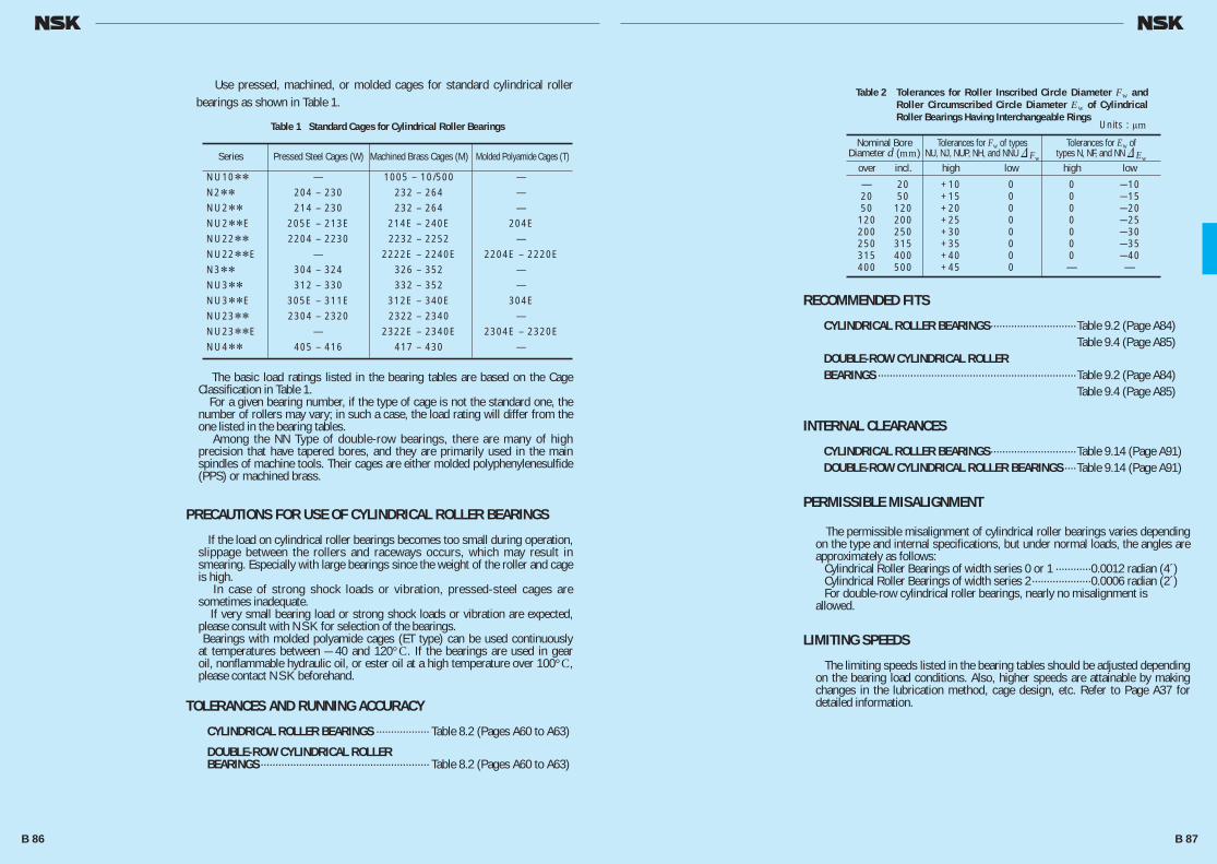
The basic load ratings listed in the bearing tables are based on the Cage Classification in Table 1. For a given bearing number, if the type of cage is not the standard one, the number of rollers may vary; in such a case, the load rating will differ from the one listed in the bearing tables. Among the NN Type of double-row bearings, there are many of high precision that have tapered bores, and they are primarily used in the main spindles of machine tools. Their cages are either molded polyphenylenesulfide (PPS) or machined brass.
PRECAUTIONS FOR USE OF CYLINDRICAL ROLLER BEARINGS
If the load on cylindrical roller bearings becomes too small during operation, slippage between the rollers and raceways occurs, which may result in smearing. Especially with large bearings since the weight of the roller and cage is high. In case of strong shock loads or vibration, pressed-steel cages are sometimes inadequate. If very small bearing load or strong shock loads or vibration are expected, please consult with NSK for selection of the bearings. Bearings with molded polyamide cages (ET type) can be used continuously at temperatures between — 40 and 120°C. If the bearings are used in gear oil, nonflammable hydraulic oil, or ester oil at a high temperature over 100°C, please contact NSK beforehand.
TOLERANCES AND RUNNING ACCURACY
CYLINDRICAL ROLLER BEARINGS ·················· Table 8.2 (Pages A60 to A63)
DOUBLE-ROW CYLINDRICAL ROLLER BEARINGS ························································· Table 8.2 (Pages A60 to A63)
Use pressed, machined, or molded cages for standard cylindrical roller bearings as shown in Table 1.
Table 1 Standard Cages for Cylindrical Roller Bearings
Table 2 Tolerances for Roller Inscribed Circle Diameter Fw and Roller Circumscribed Circle Diameter Ew of Cylindrical Roller Bearings Having Interchangeable Rings
Series Pressed Steel Cages (W) Machined Brass Cages (M) Molded Polyamide Cages (T)
NU10** — 1005 – 10/500 — N2** 204 – 230 232 – 264 — NU2** 214 – 230 232 – 264 — NU2**E 205E – 213E 214E – 240E 204E NU22** 2204 – 2230 2232 – 2252 — NU22**E — 2222E – 2240E 2204E – 2220E N3** 304 – 324 326 – 352 — NU3** 312 – 330 332 – 352 — NU3**E 305E – 311E 312E – 340E 304E NU23** 2304 – 2320 2322 – 2340 — NU23**E — 2322E – 2340E 2304E – 2320E NU4** 405 – 416 417 – 430 —
RECOMMENDED FITS
CYLINDRICAL ROLLER BEARINGS·····························Table 9.2 (Page A84) Table 9.4 (Page A85)DOUBLE-ROW CYLINDRICAL ROLLER BEARINGS ···································································Table 9.2 (Page A84) Table 9.4 (Page A85)
INTERNAL CLEARANCES
CYLINDRICAL ROLLER BEARINGS·····························Table 9.14 (Page A91)DOUBLE-ROW CYLINDRICAL ROLLER BEARINGS ····Table 9.14 (Page A91)
PERMISSIBLE MISALIGNMENT
The permissible misalignment of cylindrical roller bearings varies depending on the type and internal specifications, but under normal loads, the angles are approximately as follows: Cylindrical Roller Bearings of width series 0 or 1 ············0.0012 radian (4´) Cylindrical Roller Bearings of width series 2 ····················0.0006 radian (2´) For double-row cylindrical roller bearings, nearly no misalignment is allowed.
LIMITING SPEEDS
The limiting speeds listed in the bearing tables should be adjusted depending on the bearing load conditions. Also, higher speeds are attainable by making changes in the lubrication method, cage design, etc. Refer to Page A37 for detailed information.
over incl. high low high low
— 20 +10 0 0 —10 20 50 +15 0 0 —15 50 120 +20 0 0 —20 120 200 +25 0 0 —25 200 250 +30 0 0 —30 250 315 +35 0 0 —35 315 400 +40 0 0 —40 400 500 +45 0 — —
Nominal BoreDiameter d (mm)
Tolerances for Fw of typesNU, NJ, NUP, NH, and NNU & Fw
Tolerances for Ew oftypes N, NF, and NN & Ew
Units : μm
B 86 B 87
B084-109E.indd 86-87B084-109E.indd 86-87 11/20/13 4:56:08 PM11/20/13 4:56:08 PM
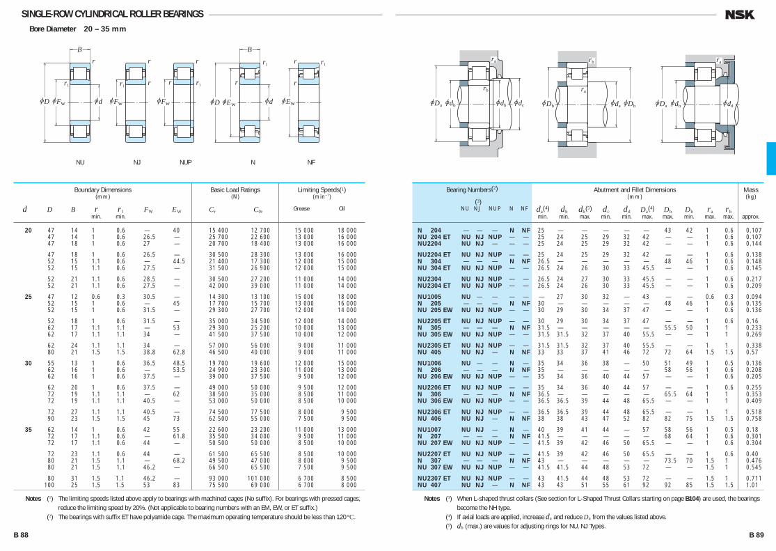
SINGLE-ROW CYLINDRICAL ROLLER BEARINGSBore Diameter 20 – 35 mm
20 47 14 1 0.6 — 40 15 400 12 700 15 000 18 000 47 14 1 0.6 26.5 — 25 700 22 600 13 000 16 000 47 18 1 0.6 27 — 20 700 18 400 13 000 16 000
47 18 1 0.6 26.5 — 30 500 28 300 13 000 16 000 52 15 1.1 0.6 — 44.5 21 400 17 300 12 000 15 000 52 15 1.1 0.6 27.5 — 31 500 26 900 12 000 15 000
52 21 1.1 0.6 28.5 — 30 500 27 200 11 000 14 000 52 21 1.1 0.6 27.5 — 42 000 39 000 11 000 14 000
25 47 12 0.6 0.3 30.5 — 14 300 13 100 15 000 18 000 52 15 1 0.6 — 45 17 700 15 700 13 000 16 000 52 15 1 0.6 31.5 — 29 300 27 700 12 000 14 000
52 18 1 0.6 31.5 — 35 000 34 500 12 000 14 000 62 17 1.1 1.1 — 53 29 300 25 200 10 000 13 000 62 17 1.1 1.1 34 — 41 500 37 500 10 000 12 000
62 24 1.1 1.1 34 — 57 000 56 000 9 000 11 000 80 21 1.5 1.5 38.8 62.8 46 500 40 000 9 000 11 000
30 55 13 1 0.6 36.5 48.5 19 700 19 600 12 000 15 000 62 16 1 0.6 — 53.5 24 900 23 300 11 000 13 000 62 16 1 0.6 37.5 — 39 000 37 500 9 500 12 000
62 20 1 0.6 37.5 — 49 000 50 000 9 500 12 000 72 19 1.1 1.1 — 62 38 500 35 000 8 500 11 000 72 19 1.1 1.1 40.5 — 53 000 50 000 8 500 10 000
72 27 1.1 1.1 40.5 — 74 500 77 500 8 000 9 500 90 23 1.5 1.5 45 73 62 500 55 000 7 500 9 500
35 62 14 1 0.6 42 55 22 600 23 200 11 000 13 000 72 17 1.1 0.6 — 61.8 35 500 34 000 9 500 11 000 72 17 1.1 0.6 44 — 50 500 50 000 8 500 10 000
72 23 1.1 0.6 44 — 61 500 65 500 8 500 10 000 80 21 1.5 1.1 — 68.2 49 500 47 000 8 000 9 500 80 21 1.5 1.1 46.2 — 66 500 65 500 7 500 9 500
80 31 1.5 1.1 46.2 — 93 000 101 000 6 700 8 500 100 25 1.5 1.5 53 83 75 500 69 000 6 700 8 000
Boundary Dimensions(mm)
d D B r r1 FW EW min. min.
Limiting Speeds(1)(min–1)
Grease Oil
Basic Load Ratings(N)
Cr C0r
N 204 — — — N NF 25 — — — — — 43 42 1 0.6 0.107 NU 204 ET NU NJ NUP — — 25 24 25 29 32 42 — — 1 0.6 0.107 NU 2204 NU NJ — — — 25 24 25 29 32 42 — — 1 0.6 0.144
NU 2204 ET NU NJ NUP — — 25 24 25 29 32 42 — — 1 0.6 0.138 N 304 — — — N NF 26.5 — — — — — 48 46 1 0.6 0.148 NU 304 ET NU NJ NUP — — 26.5 24 26 30 33 45.5 — — 1 0.6 0.145
NU 2304 NU NJ NUP — — 26.5 24 27 30 33 45.5 — — 1 0.6 0.217 NU 2304 ET NU NJ NUP — — 26.5 24 26 30 33 45.5 — — 1 0.6 0.209
NU 1005 NU — — — — — 27 30 32 — 43 — — 0.6 0.3 0.094 N 205 — — — N NF 30 — — — — — 48 46 1 0.6 0.135 NU 205 EW NU NJ NUP — — 30 29 30 34 37 47 — — 1 0.6 0.136
NU 2205 ET NU NJ NUP — — 30 29 30 34 37 47 — — 1 0.6 0.16 N 305 — — — N NF 31.5 — — — — — 55.5 50 1 1 0.233 NU 305 EW NU NJ NUP — — 31.5 31.5 32 37 40 55.5 — — 1 1 0.269
NU 2305 ET NU NJ NUP — — 31.5 31.5 32 37 40 55.5 — — 1 1 0.338 NU 405 NU NJ — N NF 33 33 37 41 46 72 72 64 1.5 1.5 0.57
NU 1006 NU — — N — 35 34 36 38 — 50 51 49 1 0.5 0.136 N 206 — — — N NF 35 — — — — — 58 56 1 0.6 0.208 NU 206 EW NU NJ NUP — — 35 34 36 40 44 57 — — 1 0.6 0.205
NU 2206 ET NU NJ NUP — — 35 34 36 40 44 57 — — 1 0.6 0.255 N 306 — — — N NF 36.5 — — — — — 65.5 64 1 1 0.353 NU 306 EW NU NJ NUP — — 36.5 36.5 39 44 48 65.5 — — 1 1 0.409
NU 2306 ET NU NJ NUP — — 36.5 36.5 39 44 48 65.5 — — 1 1 0.518 NU 406 NU NJ — N NF 38 38 43 47 52 82 82 75 1.5 1.5 0.758
NU 1007 NU NJ — N — 40 39 41 44 — 57 58 56 1 0.5 0.18 N 207 — — — N NF 41.5 — — — — — 68 64 1 0.6 0.301 NU 207 EW NU NJ NUP — — 41.5 39 42 46 50 65.5 — — 1 0.6 0.304
NU 2207 ET NU NJ NUP — — 41.5 39 42 46 50 65.5 — — 1 0.6 0.40 N 307 — — — N NF 43 — — — — — 73.5 70 1.5 1 0.476 NU 307 EW NU NJ NUP — — 41.5 41.5 44 48 53 72 — — 1.5 1 0.545
NU 2307 ET NU NJ NUP — — 43 41.5 44 48 53 72 — — 1.5 1 0.711 NU 407 NU NJ — N NF 43 43 51 55 61 92 92 85 1.5 1.5 1.01
Bearing Numbers(2)
(3) NU NJ NUP N NF
Abutment and Fillet Dimensions(mm)
da(4) db db(5) dc dd Da(4) Db Db ra rb min. min. max. min. min. max. max. min. max. max.
Mass(kg)
approx.
Notes (1) The limiting speeds listed above apply to bearings with machined cages (No suffix). For bearings with pressed cages, reduce the limiting speed by 20%. (Not applicable to bearing numbers with an EM, EW, or ET suffix.)
(2) The bearings with suffix ET have polyamide cage. The maximum operating temperature should be less than 120°C.
Notes (3) When L-shaped thrust collars (See section for L-Shaped Thrust Collars starting on page B104) are used, the bearings become the NH type.
(4) If axial loads are applied, increase da and reduce Da from the values listed above. (5) db (max.) are values for adjusting rings for NU, NJ Types.
r
r1 r
jFw
r1
jd
r
r1r
jEwjD
B
jEwjFw
r1r
rr
r
r1
jD jd
B
jFw
ra
rb
jdbjDa jdb jdc
rb
ra
jDb jdajDb
ra
jddjdbjDa
NU NJ NUP NFN
B 88 B 89
B084-109E.indd 88-89B084-109E.indd 88-89 11/20/13 4:56:08 PM11/20/13 4:56:08 PM
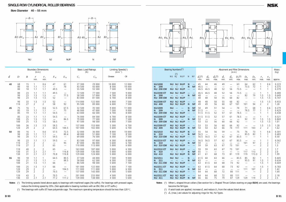
SINGLE-ROW CYLINDRICAL ROLLER BEARINGSBore Diameter 40 – 55 mm
40 68 15 1 0.6 47 61 27 300 29 000 10 000 12 000 80 18 1.1 1.1 — 70 43 500 43 000 8 500 10 000 80 18 1.1 1.1 49.5 — 55 500 55 500 7 500 9 000
80 23 1.1 1.1 49.5 — 72 500 77 500 7 500 9 000 90 23 1.5 1.5 — 77.5 58 500 57 000 6 700 8 500 90 23 1.5 1.5 52 — 83 000 81 500 6 700 8 000
90 33 1.5 1.5 52 — 114 000 122 000 6 000 7 500 110 27 2 2 58 92 95 500 89 000 6 000 7 500
45 75 16 1 0.6 52.5 67.5 32 500 35 500 9 000 11 000 85 19 1.1 1.1 — 75 46 000 47 000 7 500 9 000 85 19 1.1 1.1 54.5 — 63 000 66 500 6 700 8 000
85 23 1.1 1.1 54.5 — 76 000 84 500 6 700 8 500 100 25 1.5 1.5 — 86.5 79 000 77 500 6 300 7 500 100 25 1.5 1.5 58.5 — 97 500 98 500 6 000 7 500
100 36 1.5 1.5 58.5 — 137 000 153 000 5 300 6 700 120 29 2 2 64.5 100.5 107 000 102 000 5 600 6 700
50 80 16 1 0.6 57.5 72.5 32 000 36 000 8 000 10 000 90 20 1.1 1.1 — 80.4 48 000 51 000 7 100 8 500 90 20 1.1 1.1 59.5 — 69 000 76 500 6 300 7 500
90 23 1.1 1.1 59.5 — 83 500 97 000 6 300 8 000 110 27 2 2 — 95 87 000 86 000 5 600 6 700 110 27 2 2 65 — 110 000 113 000 5 000 6 000
110 40 2 2 65 — 163 000 187 000 5 000 6 300 130 31 2.1 2.1 — 110.8 139 000 136 000 5 000 6 000 130 31 2.1 2.1 70.8 110.8 129 000 124 000 5 000 6 000
55 90 18 1.1 1 64.5 80.5 37 500 44 000 7 500 9 000 100 21 1.5 1.1 — 88.5 58 000 62 500 6 300 7 500 100 21 1.5 1.1 66 — 86 500 98 500 5 600 7 100
100 25 1.5 1.1 66 — 101 000 122 000 5 600 7 100 120 29 2 2 — 104.5 111 000 111 000 5 000 6 300 120 29 2 2 70.5 — 137 000 143 000 4 500 5 600
120 43 2 2 70.5 — 201 000 233 000 4 500 5 600 140 33 2.1 2.1 77.2 117.2 139 000 138 000 4 500 5 600
Boundary Dimensions(mm)
d D B r r1 FW EW min. min.
Limiting Speeds(1)(min–1)
Grease Oil
Basic Load Ratings(N)
Cr C0r
NU 1008 NU NJ NUP N — 45 44 46 49 — 63 64 62 1 0.6 0.223 N 208 — — — N NF 46.5 — — — — — 73.5 72 1 1 0.375 NU 208 EW NU NJ NUP — — 46.5 46.5 48 52 56 73.5 — — 1 1 0.379
NU 2208 ET NU NJ NUP — — 46.5 46.5 48 52 56 73.5 — — 1 1 0.480 N 308 — — — N NF 48 — — — — — 82 79 1.5 1.5 0.649 NU 308 EW NU NJ NUP — — 48 48 50 55 60 82 — — 1.5 1.5 0.747
NU 2308 ET NU NJ NUP — — 48 48 50 55 60 82 — — 1.5 1.5 0.933 NU 408 NU NJ NUP N NF 49 49 56 60 67 101 101 94 2 2 1.28
NU 1009 NU — — N NF 50 49 51 54 — 70 71 68 1 0.6 0.279 N 209 — — — N NF 51.5 — — — — — 78.5 77 1 1 0.429 NU 209 EW NU NJ NUP — — 51.5 51.5 52 57 61 78.5 — — 1 1 0.438
NU 2209 ET NU NJ NUP — — 51.5 51.5 52 57 61 78.5 — — 1 1 0.521 N 309 — — — N NF 53 — — — — — 92 77 1.5 1.5 0.869 NU 309 EW NU NJ NUP — — 53 53 56 60 66 92 — — 1.5 1.5 1.01
NU 2309 ET NU NJ NUP — — 53 53 56 60 66 92 — — 1.5 1.5 1.28 NU 409 NU NJ NUP N NF 54 54 62 66 74 111 111 103 2 2 1.62
NU 1010 NU NJ NUP N — 55 54 56 59 — 75 76 73 1 0.6 0.301 N 210 — — — N NF 56.5 — — — — — 83.5 82 1 1 0.483 NU 210 EW NU NJ NUP — — 56.5 56.5 57 62 67 83.5 — — 1 1 0.50
NU 2210 ET NU NJ NUP — — 56.5 56.5 57 62 67 83.5 — — 1 1 0.562 N 310 — — — N NF 59 — — — — — 101 97 2 2 1.11 NU 310 EW NU NJ NUP — — 59 59 63 67 73 101 — — 2 2 1.3
NU 2310 ET NU NJ NUP — — 59 59 63 67 73 101 — — 2 2 1.7 N 410 — — — N NF 65 — — — — — 117 113 2 2 2.0 NU 410 NU NJ NUP N NF 61 61 68 73 81 119 119 113.3 2 2 1.99
NU 1011 NU NJ — N — 61.5 60 63 66 — 83.5 85 82 1 1 0.445 N 211 — — — N NF 63 — — — — — 93.5 91 1.5 1 0.634 NU 211 EW NU NJ NUP — — 63 61.5 64 68 73 92 — — 1.5 1 0.669
NU 2211 ET NU NJ NUP — — 63 61.5 64 68 73 92 — — 1.5 1 0.783 N 311 — — — N NF 64 — — — — — 111 107 2 2 1.42 NU 311 EW NU NJ NUP — — 64 64 68 72 80 111 — — 2 2 1.64
NU 2311 ET NU NJ NUP — — 64 64 68 72 80 111 — — 2 2 2.18 NU 411 NU NJ NUP N NF 66 66 75 79 87 129 129 119 2 2 2.5
Bearing Numbers(2)
(3) NU NJ NUP N NF
Abutment and Fillet Dimensions(mm)
da(4) db db(5) dc dd Da(4) Db Db ra rb min. min. max. min. min. max. max. min. max. max.
Mass(kg)
approx.
Notes (1) The limiting speeds listed above apply to bearings with machined cages (No suffix). For bearings with pressed cages, reduce the limiting speed by 20%. (Not applicable to bearing numbers with an EM, EW, or ET suffix.)
(2) The bearings with suffix ET have polyamide cage. The maximum operating temperature should be less than 120°C.
Notes (3) When L-shaped thrust collars (See section for L-Shaped Thrust Collars starting on page B104) are used, the bearings become the NH type.
(4) If axial loads are applied, increase da and reduce Da from the values listed above. (5) db (max.) are values for adjusting rings for NU, NJ Types.
r
r1 r
jFw
r1
jd
r
r1r
jEwjD
B
jEwjFw
r1r
rr
r
r1
jD jd
B
jFw
ra
rb
jdbjDa jdb jdc
rb
ra
jDb jdajDb
ra
jddjdbjDa
NU NJ NUP NFN
B 90 B 91
B084-109E.indd 90-91B084-109E.indd 90-91 11/20/13 4:56:10 PM11/20/13 4:56:10 PM
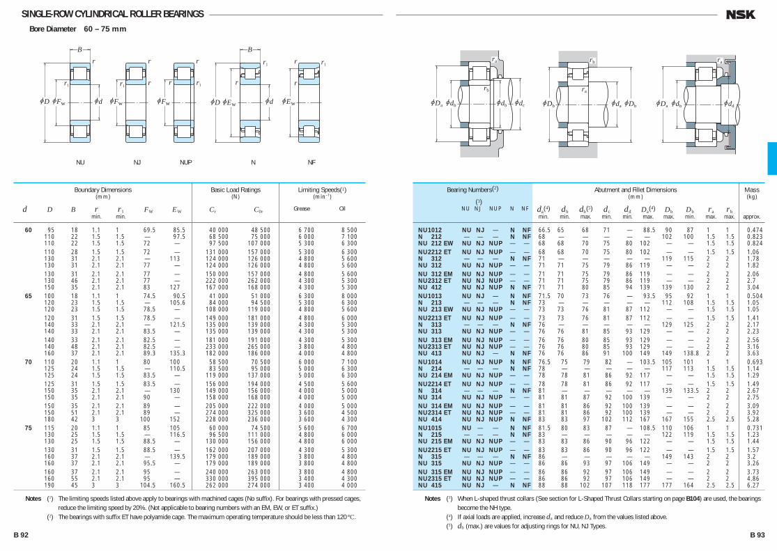
SINGLE-ROW CYLINDRICAL ROLLER BEARINGSBore Diameter 60 – 75 mm
60 95 18 1.1 1 69.5 85.5 40 000 48 500 6 700 8 500 110 22 1.5 1.5 — 97.5 68 500 75 000 6 000 7 100 110 22 1.5 1.5 72 — 97 500 107 000 5 300 6 300 110 28 1.5 1.5 72 — 131 000 157 000 5 300 6 300 130 31 2.1 2.1 — 113 124 000 126 000 4 800 5 600 130 31 2.1 2.1 77 — 124 000 126 000 4 800 5 600 130 31 2.1 2.1 77 — 150 000 157 000 4 800 5 600 130 46 2.1 2.1 77 — 222 000 262 000 4 300 5 300 150 35 2.1 2.1 83 127 167 000 168 000 4 300 5 300 65 100 18 1.1 1 74.5 90.5 41 000 51 000 6 300 8 000 120 23 1.5 1.5 — 105.6 84 000 94 500 5 300 6 300 120 23 1.5 1.5 78.5 — 108 000 119 000 4 800 5 600 120 31 1.5 1.5 78.5 — 149 000 181 000 4 800 6 000 140 33 2.1 2.1 — 121.5 135 000 139 000 4 300 5 300 140 33 2.1 2.1 83.5 — 135 000 139 000 4 300 5 300 140 33 2.1 2.1 82.5 — 181 000 191 000 4 300 5 300 140 48 2.1 2.1 82.5 — 233 000 265 000 3 800 4 800 160 37 2.1 2.1 89.3 135.3 182 000 186 000 4 000 4 800 70 110 20 1.1 1 80 100 58 500 70 500 6 000 7 100 125 24 1.5 1.5 — 110.5 83 500 95 000 5 000 6 300 125 24 1.5 1.5 83.5 — 119 000 137 000 5 000 6 300 125 31 1.5 1.5 83.5 — 156 000 194 000 4 500 5 600 150 35 2.1 2.1 — 130 149 000 156 000 4 000 5 000 150 35 2.1 2.1 90 — 158 000 168 000 4 000 5 000 150 35 2.1 2.1 89 — 205 000 222 000 4 000 5 000 150 51 2.1 2.1 89 — 274 000 325 000 3 600 4 500 180 42 3 3 100 152 228 000 236 000 3 600 4 300 75 115 20 1.1 1 85 105 60 000 74 500 5 600 6 700 130 25 1.5 1.5 — 116.5 96 500 111 000 4 800 6 000 130 25 1.5 1.5 88.5 — 130 000 156 000 4 800 6 000 130 31 1.5 1.5 88.5 — 162 000 207 000 4 300 5 300 160 37 2.1 2.1 — 139.5 179 000 189 000 3 800 4 800 160 37 2.1 2.1 95.5 — 179 000 189 000 3 800 4 800 160 37 2.1 2.1 95 — 240 000 263 000 3 800 4 800 160 55 2.1 2.1 95 — 330 000 395 000 3 400 4 300 190 45 3 3 104.5 160.5 262 000 274 000 3 400 4 000
Boundary Dimensions(mm)
d D B r r1 FW EW min. min.
Limiting Speeds(1)(min–1)
Grease Oil
Basic Load Ratings(N)
Cr C0r
NU 1012 NU NJ — N NF 66.5 65 68 71 — 88.5 90 87 1 1 0.474 N 212 — — — N NF 68 — — — — — 102 100 1.5 1.5 0.823 NU 212 EW NU NJ NUP — — 68 68 70 75 80 102 — — 1.5 1.5 0.824 NU 2212 ET NU NJ NUP — — 68 68 70 75 80 102 — — 1.5 1.5 1.06 N 312 — — — N NF 71 — — — — — 119 115 2 2 1.78 NU 312 NU NJ NUP — — 71 71 75 79 86 119 — — 2 2 1.82 NU 312 EM NU NJ NUP — — 71 71 75 79 86 119 — — 2 2 2.06 NU 2312 ET NU NJ NUP — — 71 71 75 79 86 119 — — 2 2 2.7 NU 412 NU NJ NUP N NF 71 71 80 85 94 139 139 130 2 2 3.04 NU 1013 NU NJ — N NF 71.5 70 73 76 — 93.5 95 92 1 1 0.504 N 213 — — — N NF 73 — — — — — 112 108 1.5 1.5 1.05 NU 213 EW NU NJ NUP — — 73 73 76 81 87 112 — — 1.5 1.5 1.05 NU 2213 ET NU NJ NUP — — 73 73 76 81 87 112 — — 1.5 1.5 1.41 N 313 — — — N NF 76 — — — — — 129 125 2 2 2.17 NU 313 NU NJ NUP — — 76 76 81 85 93 129 — — 2 2 2.23 NU 313 EM NU NJ NUP — — 76 76 80 85 93 129 — — 2 2 2.56 NU 2313 ET NU NJ NUP — — 76 76 80 85 93 129 — — 2 2 3.16 NU 413 NU NJ — N NF 76 76 86 91 100 149 149 138.8 2 2 3.63 NU 1014 NU NJ NUP N NF 76.5 75 79 82 — 103.5 105 101 1 1 0.693 N 214 — — — N NF 78 — — — — — 117 113 1.5 1.5 1.14 NU 214 EM NU NJ NUP — — 78 78 81 86 92 117 — — 1.5 1.5 1.29 NU 2214 ET NU NJ NUP — — 78 78 81 86 92 117 — — 1.5 1.5 1.49 N 314 — — — N NF 81 — — — — — 139 133.5 2 2 2.67 NU 314 NU NJ NUP — — 81 81 87 92 100 139 — — 2 2 2.75 NU 314 EM NU NJ NUP — — 81 81 86 92 100 139 — — 2 2 3.09 NU 2314 ET NU NJ NUP — — 81 81 86 92 100 139 — — 2 2 3.92 NU 414 NU NJ NUP N NF 83 83 97 102 112 167 167 155 2.5 2.5 5.28 NU 1015 NU — — N NF 81.5 80 83 87 — 108.5 110 106 1 1 0.731 N 215 — — — N NF 83 — — — — — 122 119 1.5 1.5 1.23 NU 215 EM NU NJ NUP — — 83 83 86 90 96 122 — — 1.5 1.5 1.44 NU 2215 ET NU NJ NUP — — 83 83 86 90 96 122 — — 1.5 1.5 1.57 N 315 — — — N NF 86 — — — — — 149 143 2 2 3.2 NU 315 NU NJ NUP — — 86 86 93 97 106 149 — — 2 2 3.26 NU 315 EM NU NJ NUP — — 86 86 92 97 106 149 — — 2 2 3.73 NU 2315 ET NU NJ NUP — — 86 86 92 97 106 149 — — 2 2 4.86 NU 415 NU NJ — N NF 88 88 102 107 118 177 177 164 2.5 2.5 6.27
Bearing Numbers(2)
(3) NU NJ NUP N NF
Abutment and Fillet Dimensions(mm)
da(4) db db(5) dc dd Da(4) Db Db ra rb min. min. max. min. min. max. max. min. max. max.
Mass(kg)
approx.
Notes (1) The limiting speeds listed above apply to bearings with machined cages (No suffix). For bearings with pressed cages, reduce the limiting speed by 20%. (Not applicable to bearing numbers with an EM, EW, or ET suffix.)
(2) The bearings with suffix ET have polyamide cage. The maximum operating temperature should be less than 120°C.
Notes (3) When L-shaped thrust collars (See section for L-Shaped Thrust Collars starting on page B104) are used, the bearings become the NH type.
(4) If axial loads are applied, increase da and reduce Da from the values listed above. (5) db (max.) are values for adjusting rings for NU, NJ Types.
r
r1 r
jFw
r1
jd
r
r1r
jEwjD
B
jEwjFw
r1r
rr
r
r1
jD jd
B
jFw
ra
rb
jdbjDa jdb jdc
rb
ra
jDb jdajDb
ra
jddjdbjDa
NU NJ NUP NFN
B 92 B 93
B084-109E.indd 92-93B084-109E.indd 92-93 11/20/13 4:56:12 PM11/20/13 4:56:12 PM
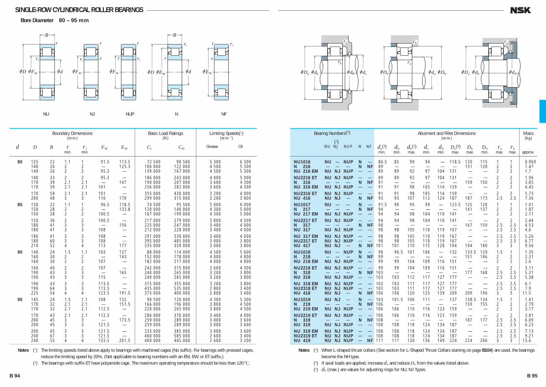
SINGLE-ROW CYLINDRICAL ROLLER BEARINGSBore Diameter 80 – 95 mm
80 125 22 1.1 1 91.5 113.5 72 500 90 500 5 300 6 300 140 26 2 2 — 125.3 106 000 122 000 4 500 5 300 140 26 2 2 95.3 — 139 000 167 000 4 500 5 300 140 33 2 2 95.3 — 186 000 243 000 4 000 5 000 170 39 2.1 2.1 — 147 190 000 207 000 3 600 4 300 170 39 2.1 2.1 101 — 256 000 282 000 3 600 4 300 170 58 2.1 2.1 101 — 355 000 430 000 3 200 4 000 200 48 3 3 110 170 299 000 315 000 3 200 3 800 85 130 22 1.1 1 96.5 118.5 74 500 95 500 5 000 6 000 150 28 2 2 — 133.8 120 000 140 000 4 300 5 000 150 28 2 2 100.5 — 167 000 199 000 4 300 5 000 150 36 2 2 100.5 — 217 000 279 000 3 800 4 500 180 41 3 3 — 156 225 000 247 000 3 400 4 000 180 41 3 3 108 — 212 000 228 000 3 400 4 000 180 41 3 3 108 — 291 000 330 000 3 400 4 000 180 60 3 3 108 — 395 000 485 000 3 000 3 800 210 52 4 4 113 177 335 000 350 000 3 000 3 800 90 140 24 1.5 1.1 103 127 88 000 114 000 4 500 5 600 160 30 2 2 — 143 152 000 178 000 4 000 4 800 160 30 2 2 107 — 182 000 217 000 4 000 4 800 160 40 2 2 107 — 242 000 315 000 3 600 4 300 190 43 3 3 — 165 240 000 265 000 3 200 3 800 190 43 3 3 115 — 240 000 265 000 3 200 3 800 190 43 3 3 113.5 — 315 000 355 000 3 200 3 800 190 64 3 3 113.5 — 435 000 535 000 2 800 3 400 225 54 4 4 123.5 191.5 375 000 400 000 2 800 3 400 95 145 24 1.5 1.1 108 132 90 500 120 000 4 300 5 300 170 32 2.1 2.1 — 151.5 166 000 196 000 3 800 4 500 170 32 2.1 2.1 112.5 — 220 000 265 000 3 800 4 500 170 43 2.1 2.1 112.5 — 286 000 370 000 3 400 4 000 200 45 3 3 — 173.5 259 000 289 000 3 000 3 600 200 45 3 3 121.5 — 259 000 289 000 3 000 3 600 200 45 3 3 121.5 — 335 000 385 000 3 000 3 600 200 67 3 3 121.5 — 460 000 585 000 2 600 3 400 240 55 4 4 133.5 201.5 400 000 445 000 2 600 3 200
Boundary Dimensions(mm)
d D B r r1 FW EW min. min.
Limiting Speeds(1)(min–1)
Grease Oil
Basic Load Ratings(N)
Cr C0r
NU 1016 NU — NUP N — 86.5 85 90 94 — 118.5 120 115 1 1 0.969 N 216 — — — N NF 89 — — — — — 131 128 2 2 1.47 NU 216 EM NU NJ NUP — — 89 89 92 97 104 131 — — 2 2 1.7 NU 2216 ET NU NJ NUP — — 89 89 92 97 104 131 — — 2 2 1.96 N 316 — — — N NF 91 — — — — — 159 150 2 2 3.85 NU 316 EM NU NJ NUP — — 91 91 98 105 114 159 — — 2 2 4.45 NU 2316 ET NU NJ NUP — — 91 91 98 105 114 159 — — 2 2 5.73 NU 416 NU NJ — N NF 93 93 107 112 124 187 187 173 2.5 2.5 7.36 NU 1017 NU — — N — 91.5 90 95 99 — 123.5 125 120 1 1 1.01 N 217 — — — N NF 94 — — — — — 141 137 2 2 1.87 NU 217 EM NU NJ NUP — — 94 94 98 104 110 141 — — 2 2 2.11 NU 2217 ET NU NJ NUP — — 94 94 98 104 110 141 — — 2 2 2.44 N 317 — — — N NF 98 — — — — — 167 159 2.5 2.5 4.53 NU 317 NU NJ NUP — — 98 98 105 110 119 167 — — 2.5 2.5 4.6 NU 317 EM NU NJ NUP — — 98 98 105 110 119 167 — — 2.5 2.5 5.26 NU 2317 ET NU NJ NUP — — 98 98 105 110 119 167 — — 2.5 2.5 6.77 NU 417 NU NJ — N NF 101 101 110 115 128 194 194 180 3 3 9.56 NU 1018 NU — NUP N — 98 96.5 101 106 — 132 133.5 129 1.5 1 1.35 N 218 — — — N NF 99 — — — — — 151 146 2 2 2.31 NU 218 EM NU NJ NUP — — 99 99 104 109 116 151 — — 2 2 2.6 NU 2218 ET NU NJ NUP — — 99 99 104 109 116 151 — — 2 2 3.11 N 318 — — — N NF 103 — — — — — 177 168 2.5 2.5 5.31 NU 318 NU NJ NUP — — 103 103 112 117 127 177 — — 2.5 2.5 5.38 NU 318 EM NU NJ NUP — — 103 103 111 117 127 177 — — 2.5 2.5 6.1 NU 2318 ET NU NJ NUP — — 103 103 111 117 127 177 — — 2.5 2.5 7.9 NU 418 NU NJ — N NF 106 106 120 125 139 209 209 196 3 3 11.5 NU 1019 NU NJ — N — 103 101.5 106 111 — 137 138.5 134 1.5 1 1.41 N 219 — — — N NF 106 — — — — — 159 155 2 2 2.79 NU 219 EM NU NJ NUP — — 106 106 110 116 123 159 — — 2 2 3.17 NU 2219 ET NU NJ NUP — — 106 106 110 116 123 159 — — 2 2 3.81 N 319 — — — N NF 108 — — — — — 187 177 2.5 2.5 6.09 NU 319 NU NJ NUP — — 108 108 118 124 134 187 — — 2.5 2.5 6.23 NU 319 EM NU NJ NUP — — 108 108 118 124 134 187 — — 2.5 2.5 7.13 NU 2319 ET NU NJ NUP — — 108 108 118 124 134 187 — — 2.5 2.5 9.21 NU 419 NU NJ NUP — NF 111 111 130 136 149 224 224 206 3 3 13.6
Bearing Numbers(2)
(3) NU NJ NUP N NF
Abutment and Fillet Dimensions(mm)
da(4) db db(5) dc dd Da(4) Db Db ra rb min. min. max. min. min. max. max. min. max. max.
Mass(kg)
approx.
Notes (1) The limiting speeds listed above apply to bearings with machined cages (No suffix). For bearings with pressed cages, reduce the limiting speed by 20%. (Not applicable to bearing numbers with an EM, EW, or ET suffix.)
(2) The bearings with suffix ET have polyamide cage. The maximum operating temperature should be less than 120°C.
Notes (3) When L-shaped thrust collars (See section for L-Shaped Thrust Collars starting on page B104) are used, the bearings become the NH type.
(4) If axial loads are applied, increase da and reduce Da from the values listed above. (5) db (max.) are values for adjusting rings for NU, NJ Types.
r1
jd
r
r1r
jEwjD
B
jEwjFw
r1r
rr
r
r1
r
r1 r
jD jd
B
jFwjFw
ra
rb
jdbjDa jdb jdc
rb
ra
jDb jdajDb
ra
jddjdbjDa
NU NJ NUP NFN
B 94 B 95
B084-109E.indd 94-95B084-109E.indd 94-95 11/20/13 4:56:14 PM11/20/13 4:56:14 PM

SINGLE-ROW CYLINDRICAL ROLLER BEARINGSBore Diameter 100 – 120 mm
100 150 24 1.5 1.1 113 137 93 000 126 000 4 300 5 300 180 34 2.1 2.1 — 160 183 000 217 000 3 600 4 300 180 34 2.1 2.1 119 — 249 000 305 000 3 600 4 300
180 46 2.1 2.1 119 — 335 000 445 000 3 200 3 800 215 47 3 3 — 185.5 299 000 335 000 2 800 3 400 215 47 3 3 129.5 — 299 000 335 000 2 800 3 400
215 47 3 3 127.5 — 380 000 425 000 2 800 3 400 215 73 3 3 127.5 — 570 000 715 000 2 400 3 000 250 58 4 4 139 211 450 000 500 000 2 600 3 000
105 160 26 2 1.1 119.5 145.5 109 000 149 000 4 000 4 800 190 36 2.1 2.1 — 168.8 201 000 241 000 3 400 4 000 190 36 2.1 2.1 125 — 262 000 310 000 3 400 4 000
225 49 3 3 — 195 340 000 390 000 2 600 3 200 225 49 3 3 133 — 425 000 480 000 2 600 3 200 260 60 4 4 144.5 220.5 495 000 555 000 2 400 3 000
110 170 28 2 1.1 125 155 131 000 174 000 3 800 4 500 200 38 2.1 2.1 — 178.5 229 000 272 000 3 200 3 800 200 38 2.1 2.1 132.5 — 293 000 365 000 3 200 3 800
200 53 2.1 2.1 132.5 — 385 000 515 000 2 800 3 400 240 50 3 3 — 207 380 000 435 000 2 600 3 000 240 50 3 3 143 — 450 000 525 000 2 600 3 000 280 65 4 4 155 — 550 000 620 000 2 200 2 800
120 180 28 2 1.1 135 165 139 000 191 000 3 400 4 300 215 40 2.1 2.1 — 191.5 260 000 320 000 3 000 3 400 215 40 2.1 2.1 143.5 — 335 000 420 000 3 000 3 400
215 58 2.1 2.1 143.5 — 450 000 620 000 2 600 3 200 260 55 3 3 — 226 450 000 510 000 2 200 2 800 260 55 3 3 154 — 530 000 610 000 2 200 2 800
260 86 3 3 154 — 795 000 1 030 000 2 000 2 600 310 72 5 5 170 260 675 000 770 000 2 000 2 400
Boundary Dimensions(mm)
d D B r r1 FW EW min. min.
Limiting Speeds(1)(min–1)
Grease Oil
Basic Load Ratings(N)
Cr C0r
NU 1020 NU NJ NUP N — 108 106.5 111 116 — 142 143.5 139 1.5 1 1.47 N 220 — — — N NF 111 — — — — — 169 163 2 2 3.36 NU 220 EM NU NJ NUP — — 111 111 116 122 130 169 — — 2 2 3.81
NU 2220 ET NU NJ NUP — — 111 111 116 122 130 169 — — 2 2 4.69 N 320 — — — N NF 113 — — — — — 202 190 2.5 2.5 7.59 NU 320 NU NJ NUP — — 113 113 126 132 143 202 — — 2.5 2.5 7.69
NU 320 EM NU NJ NUP — — 113 113 124 132 143 202 — — 2.5 2.5 8.63 NU 2320 ET NU NJ NUP — — 113 113 124 132 143 202 — — 2.5 2.5 11.8 NU 420 NU NJ — N NF 116 116 135 141 156 234 234 215 3 3 15.5
NU 1021 NU — — N NF 114 111.5 118 122 — 151 153.5 147 2 1 1.83 N 221 — — — N NF 116 — — — — — 179 172 2 2 4.0 NU 221 EM NU NJ NUP — — 116 116 121 129 137 179 — — 2 2 4.58
N 321 — — — N NF 118 — — — — — 212 199 2.5 2.5 8.69 NU 321 EM NU NJ NUP — — 118 118 131 137 149 212 — — 2.5 2.5 9.84 NU 421 NU NJ — N NF 121 121 141 147 162 244 244 225 3 3 17.3
NU 1022 NU NJ — N NF 119 116.5 123 128 — 161 163.5 157 2 1 2.27 N 222 — — — N NF 121 — — — — — 189 182 2 2 4.64 NU 222 EM NU NJ NUP — — 121 121 129 135 144 189 — — 2 2 5.37
NU 2222 EM NU NJ NUP — — 121 121 129 135 144 189 — — 2 2 7.65 N 322 — — — N NF 123 — — — — — 227 211 2.5 2.5 10.3 NU 322 EM NU NJ NUP — — 123 123 139 145 158 227 — — 2.5 2.5 11.8 NU 422 NU NJ — — — 126 126 151 157 173 264 — — 3 3 22.1
NU 1024 NU NJ NUP N — 129 126.5 133 138 — 171 173.5 167 2 1 2.43 N 224 — — — N NF 131 — — — — — 204 196 2 2 5.63 NU 224 EM NU NJ NUP — — 131 131 140 146 156 204 — — 2 2 6.43
NU 2224 EM NU NJ NUP — — 131 131 140 146 156 204 — — 2 2 9.51 N 324 — — — N NF 133 — — — — — 247 230 2.5 2.5 12.9 NU 324 EM NU NJ NUP — — 133 133 150 156 171 247 — — 2.5 2.5 15
NU 2324 EM NU NJ NUP — — 133 133 150 156 171 247 — — 2.5 2.5 25 NU 424 NU NJ NUP N — 140 140 166 172 190 290 290 266 4 4 30.2
Bearing Numbers(2)
(3) NU NJ NUP N NF
Abutment and Fillet Dimensions(mm)
da(4) db db(5) dc dd Da(4) Db Db ra rb min. min. max. min. min. max. max. min. max. max.
Mass(kg)
approx.
Notes (1) The limiting speeds listed above apply to bearings with machined cages (No suffix). For bearings with pressed cages, reduce the limiting speed by 20%. (Not applicable to bearing numbers with an EM, EW, or ET suffix.)
(2) The bearings with suffix ET have polyamide cage. The maximum operating temperature should be less than 120°C.
Notes (3) When L-shaped thrust collars (See section for L-Shaped Thrust Collars starting on page B104) are used, the bearings become the NH type.
(4) If axial loads are applied, increase da and reduce Da from the values listed above. (5) db (max.) are values for adjusting rings for NU, NJ Types.
r1
jd
r
r1r
jEwjD
B
jEwjFw
r1r
rr
r
r1
r
r1 r
jD jd
B
jFwjFw
ra
rb
jdbjDa jdb jdc
rb
ra
jDb jdajDb
ra
jddjdbjDa
NU NJ NUP NFN
B 96 B 97
B084-109E.indd 96-97B084-109E.indd 96-97 11/20/13 4:56:15 PM11/20/13 4:56:15 PM
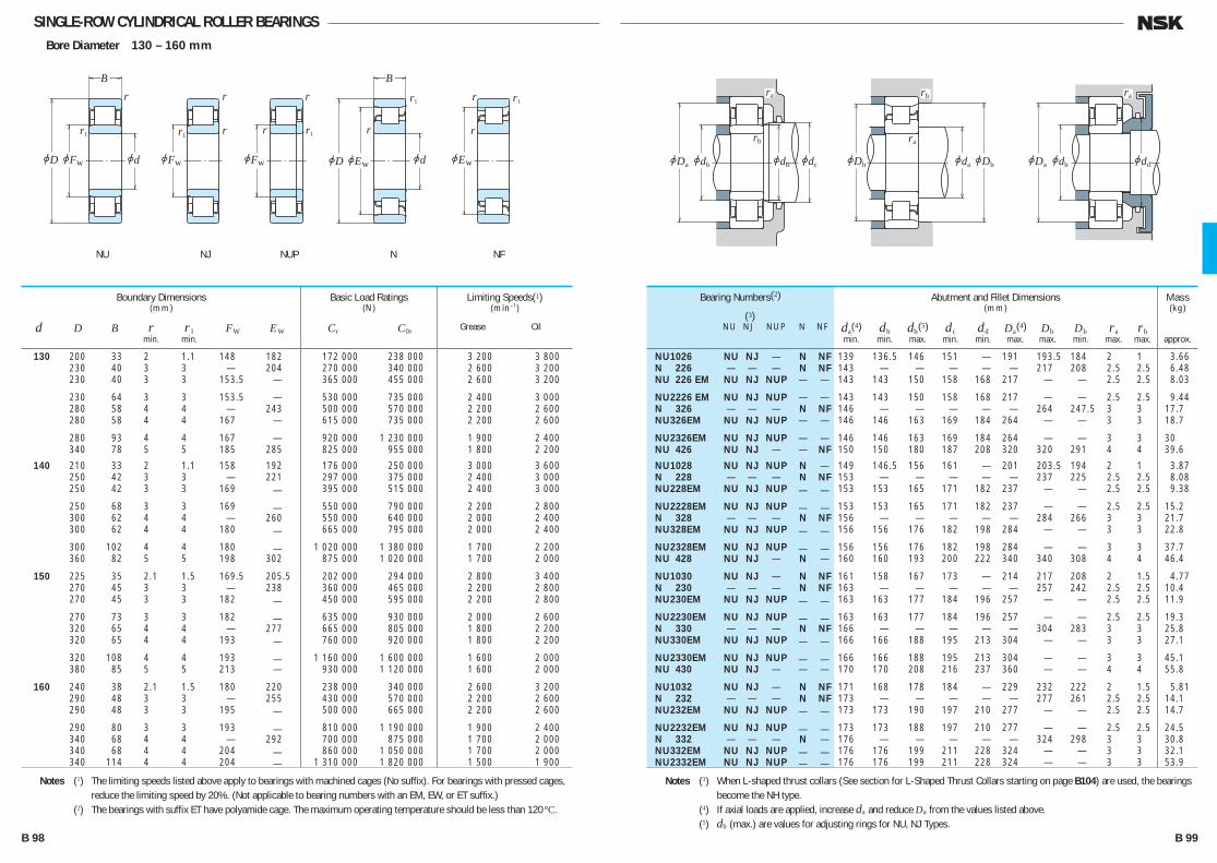
SINGLE-ROW CYLINDRICAL ROLLER BEARINGSBore Diameter 130 – 160 mm
130 200 33 2 1.1 148 182 172 000 238 000 3 200 3 800 230 40 3 3 — 204 270 000 340 000 2 600 3 200 230 40 3 3 153.5 — 365 000 455 000 2 600 3 200
230 64 3 3 153.5 — 530 000 735 000 2 400 3 000 280 58 4 4 — 243 500 000 570 000 2 200 2 600 280 58 4 4 167 — 615 000 735 000 2 200 2 600
280 93 4 4 167 — 920 000 1 230 000 1 900 2 400 340 78 5 5 185 285 825 000 955 000 1 800 2 200
140 210 33 2 1.1 158 192 176 000 250 000 3 000 3 600 250 42 3 3 — 221 297 000 375 000 2 400 3 000 250 42 3 3 169 — 395 000 515 000 2 400 3 000
250 68 3 3 169 — 550 000 790 000 2 200 2 800 300 62 4 4 — 260 550 000 640 000 2 000 2 400 300 62 4 4 180 — 665 000 795 000 2 000 2 400
300 102 4 4 180 — 1 020 000 1 380 000 1 700 2 200 360 82 5 5 198 302 875 000 1 020 000 1 700 2 000
150 225 35 2.1 1.5 169.5 205.5 202 000 294 000 2 800 3 400 270 45 3 3 — 238 360 000 465 000 2 200 2 800 270 45 3 3 182 — 450 000 595 000 2 200 2 800
270 73 3 3 182 — 635 000 930 000 2 000 2 600 320 65 4 4 — 277 665 000 805 000 1 800 2 200 320 65 4 4 193 — 760 000 920 000 1 800 2 200
320 108 4 4 193 — 1 160 000 1 600 000 1 600 2 000 380 85 5 5 213 — 930 000 1 120 000 1 600 2 000
160 240 38 2.1 1.5 180 220 238 000 340 000 2 600 3 200 290 48 3 3 — 255 430 000 570 000 2 200 2 600 290 48 3 3 195 — 500 000 665 000 2 200 2 600
290 80 3 3 193 — 810 000 1 190 000 1 900 2 400 340 68 4 4 — 292 700 000 875 000 1 700 2 000 340 68 4 4 204 — 860 000 1 050 000 1 700 2 000 340 114 4 4 204 — 1 310 000 1 820 000 1 500 1 900
Boundary Dimensions(mm)
d D B r r1 FW EW min. min.
Limiting Speeds(1)(min–1)
Grease Oil
Basic Load Ratings(N)
Cr C0r
NU 1026 NU NJ — N NF 139 136.5 146 151 — 191 193.5 184 2 1 3.66 N 226 — — — N NF 143 — — — — — 217 208 2.5 2.5 6.48 NU 226 EM NU NJ NUP — — 143 143 150 158 168 217 — — 2.5 2.5 8.03
NU 2226 EM NU NJ NUP — — 143 143 150 158 168 217 — — 2.5 2.5 9.44 N 326 — — — N NF 146 — — — — — 264 247.5 3 3 17.7 NU326EM NU NJ NUP — — 146 146 163 169 184 264 — — 3 3 18.7
NU2326EM NU NJ NUP — — 146 146 163 169 184 264 — — 3 3 30 NU 426 NU NJ — — NF 150 150 180 187 208 320 320 291 4 4 39.6
NU 1028 NU NJ NUP N — 149 146.5 156 161 — 201 203.5 194 2 1 3.87 N 228 — — — N NF 153 — — — — — 237 225 2.5 2.5 8.08 NU228EM NU NJ NUP — — 153 153 165 171 182 237 — — 2.5 2.5 9.38
NU2228EM NU NJ NUP — — 153 153 165 171 182 237 — — 2.5 2.5 15.2 N 328 — — — N NF 156 — — — — — 284 266 3 3 21.7 NU328EM NU NJ NUP — — 156 156 176 182 198 284 — — 3 3 22.8
NU2328EM NU NJ NUP — — 156 156 176 182 198 284 — — 3 3 37.7 NU 428 NU NJ — N — 160 160 193 200 222 340 340 308 4 4 46.4
NU 1030 NU NJ — N NF 161 158 167 173 — 214 217 208 2 1.5 4.77 N 230 — — — N NF 163 — — — — — 257 242 2.5 2.5 10.4 NU230EM NU NJ NUP — — 163 163 177 184 196 257 — — 2.5 2.5 11.9
NU2230EM NU NJ NUP — — 163 163 177 184 196 257 — — 2.5 2.5 19.3 N 330 — — — N NF 166 — — — — — 304 283 3 3 25.8 NU330EM NU NJ NUP — — 166 166 188 195 213 304 — — 3 3 27.1
NU2330EM NU NJ NUP — — 166 166 188 195 213 304 — — 3 3 45.1 NU 430 NU NJ — — — 170 170 208 216 237 360 — — 4 4 55.8
NU 1032 NU NJ — N NF 171 168 178 184 — 229 232 222 2 1.5 5.81 N 232 — — — N NF 173 — — — — — 277 261 2.5 2.5 14.1 NU232EM NU NJ NUP — — 173 173 190 197 210 277 — — 2.5 2.5 14.7
NU2232EM NU NJ NUP — — 173 173 188 197 210 277 — — 2.5 2.5 24.5 N 332 — — — N — 176 — — — — — 324 298 3 3 30.8 NU332EM NU NJ NUP — — 176 176 199 211 228 324 — — 3 3 32.1 NU2332EM NU NJ NUP — — 176 176 199 211 228 324 — — 3 3 53.9
Bearing Numbers(2)
(3) NU NJ NUP N NF
Abutment and Fillet Dimensions(mm)
da(4) db db(5) dc dd Da(4) Db Db ra rb min. min. max. min. min. max. max. min. max. max.
Mass(kg)
approx.
Notes (1) The limiting speeds listed above apply to bearings with machined cages (No suffix). For bearings with pressed cages, reduce the limiting speed by 20%. (Not applicable to bearing numbers with an EM, EW, or ET suffix.)
(2) The bearings with suffix ET have polyamide cage. The maximum operating temperature should be less than 120°C.
Notes (3) When L-shaped thrust collars (See section for L-Shaped Thrust Collars starting on page B104) are used, the bearings become the NH type.
(4) If axial loads are applied, increase da and reduce Da from the values listed above. (5) db (max.) are values for adjusting rings for NU, NJ Types.
r1
jd
r
r1r
jEwjD
B
jEwjFw
r1r
rr
r
r1
r
r1 r
jD jd
B
jFwjFw
ra
rb
jdbjDa jdb jdc
rb
ra
jDb jdajDb
ra
jddjdbjDa
NU NJ NUP NFN
B 98 B 99
B084-109E.indd 98-99B084-109E.indd 98-99 11/20/13 4:56:17 PM11/20/13 4:56:17 PM
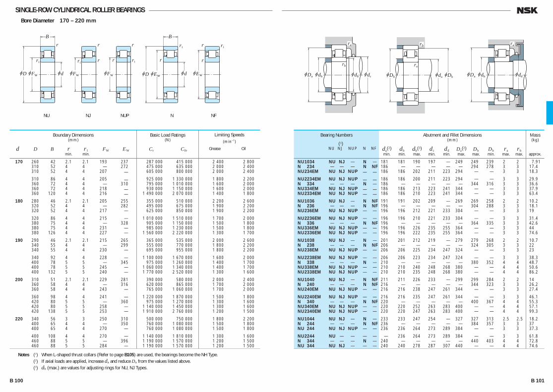
SINGLE-ROW CYLINDRICAL ROLLER BEARINGSBore Diameter 170 – 220 mm
170 260 42 2.1 2.1 193 237 287 000 415 000 2 400 2 800 310 52 4 4 — 272 475 000 635 000 2 000 2 400 310 52 4 4 207 — 605 000 800 000 2 000 2 400
310 86 4 4 205 — 925 000 1 330 000 1 800 2 200 360 72 4 4 — 310 795 000 1 010 000 1 600 2 000 360 72 4 4 218 — 930 000 1 150 000 1 600 2 000 360 120 4 4 216 — 1 490 000 2 070 000 1 400 1 800
180 280 46 2.1 2.1 205 255 355 000 510 000 2 200 2 600 320 52 4 4 — 282 495 000 675 000 1 900 2 200 320 52 4 4 217 — 625 000 850 000 1 900 2 200
320 86 4 4 215 — 1 010 000 1 510 000 1 700 2 000 380 75 4 4 — 328 905 000 1 150 000 1 500 1 800 380 75 4 4 231 — 985 000 1 230 000 1 500 1 800 380 126 4 4 227 — 1 560 000 2 220 000 1 300 1 700
190 290 46 2.1 2.1 215 265 365 000 535 000 2 000 2 600 340 55 4 4 — 299 555 000 770 000 1 800 2 200 340 55 4 4 230 — 695 000 955 000 1 800 2 200
340 92 4 4 228 — 1 100 000 1 670 000 1 600 2 000 400 78 5 5 — 345 975 000 1 260 000 1 400 1 700 400 78 5 5 245 — 1 060 000 1 340 000 1 400 1 700 400 132 5 5 240 — 1 770 000 2 520 000 1 300 1 600
200 310 51 2.1 2.1 229 281 390 000 580 000 2 000 2 400 360 58 4 4 — 316 620 000 865 000 1 700 2 000 360 58 4 4 243 — 765 000 1 060 000 1 700 2 000
360 98 4 4 241 — 1 220 000 1 870 000 1 500 1 800 420 80 5 5 — 360 975 000 1 270 000 1 300 1 600 420 80 5 5 258 — 1 140 000 1 450 000 1 300 1 600 420 138 5 5 253 — 1 910 000 2 760 000 1 200 1 500
220 340 56 3 3 250 310 500 000 750 000 1 800 2 200 400 65 4 4 — 350 760 000 1 080 000 1 500 1 800 400 65 4 4 270 — 760 000 1 080 000 1 500 1 800
400 108 4 4 270 — 1 140 000 1 810 000 1 300 1 600 460 88 5 5 — 396 1 190 000 1 570 000 1 200 1 500 460 88 5 5 284 — 1 190 000 1 570 000 1 200 1 500
Boundary Dimensions(mm)
d D B r r1 FW EW min. min.
Limiting Speeds(min–1)
Grease Oil
Basic Load Ratings(N)
Cr C0r
NU 1034 NU NJ — N — 181 181 190 197 — 249 249 239 2 2 7.91 N 234 — — — N NF 186 — — — — — 294 278 3 3 17.4 NU234EM NU NJ NUP — — 186 186 202 211 223 294 — — 3 3 18.3
NU2234EM NU NJ NUP — — 186 186 200 211 223 294 — — 3 3 29.9 N 334 — — — N — 186 — — — — — 344 316 3 3 36.6 NU334EM NU NJ NUP — — 186 186 213 223 241 344 — — 3 3 37.9 NU2334EM NU NJ NUP — — 186 186 210 223 241 344 — — 3 3 63.4
NU 1036 NU NJ — N NF 191 191 202 209 — 269 269 258 2 2 10.2 N 236 — — — N NF 196 — — — — — 304 288 3 3 18.1 NU236EM NU NJ NUP — — 196 196 212 221 233 304 — — 3 3 19
NU2236EM NU NJ NUP — — 196 196 210 221 233 304 — — 3 3 31.4 N 336 — — — N NF 196 — — — — — 364 335 3 3 42.6 NU336EM NU NJ NUP — — 196 196 226 235 255 364 — — 3 3 44 NU2336EM NU NJ NUP — — 196 196 222 235 255 364 — — 3 3 74.6
NU 1038 NU NJ — N — 201 201 212 219 — 279 279 268 2 2 10.7 N 238 — — — N NF 206 — — — — — 324 305 3 3 22 NU238EM NU NJ NUP — — 206 206 225 234 247 324 — — 3 3 23
NU2238EM NU NJ NUP — — 206 206 223 234 247 324 — — 3 3 38.3 N 338 — — — N — 210 — — — — — 380 352 4 4 48.7 NU338EM NU NJ NUP — — 210 210 240 248 268 380 — — 4 4 50.6 NU2338EM NU NJ NUP — — 210 210 235 248 268 380 — — 4 4 86.2
NU 1040 NU NJ — N NF 211 211 226 233 — 299 299 284 2 2 14 N 240 — — — N NF 216 — — — — — 344 323 3 3 26.2 NU240EM NU NJ NUP — — 216 216 238 247 261 344 — — 3 3 27.4
NU2240EM NU NJ NUP — — 216 216 235 247 261 344 — — 3 3 46.1 N 340 — — — N NF 220 — — — — — 400 367 4 4 55.3 NU340EM NU NJ NUP — — 220 220 252 263 283 400 — — 4 4 57.1 NU2340EM NU NJ NUP — — 220 220 247 263 283 400 — — 4 4 99.3
NU 1044 NU NJ — N — 233 233 247 254 — 327 327 313 2.5 2.5 18.2 N 244 — — — N NF 236 — — — — — 384 357 3 3 37 NU 244 NU NJ NUP — — 236 236 264 273 289 384 — — 3 3 37.3
NU 2244 NU — — — — — 236 264 273 289 384 — — 3 3 61.8 N 344 — — — N — 240 — — — — — 440 403 4 4 72.8 NU 344 NU NJ — — — 240 240 278 287 307 440 — — 4 4 74.6
Bearing Numbers
(1) NU NJ NUP N NF
Abutment and Fillet Dimensions(mm)
da(2) db db(3) dc dd Da(2) Db Db ra rb min. min. max. min. min. max. max. min. max. max.
Mass(kg)
approx.
Notes (1) When L-shaped thrust collars (Refer to page B105) are used, the bearings become the NH Type. (2) If axial loads are applied, increase da and reduce Da from the values listed above. (3) db (max.) are values for adjusting rings for NU, NJ Types.
r
r1 r
jFw
r1
jd
r
r1r
jEwjD
B
jEwjFw
r1r
rr
r
r1
jD jd
B
jFw
ra
rb
jdbjDa jdb jdc
rb
ra
jDb jdajDb
ra
jddjdbjDa
NU NJ NUP NFN
B 100 B 101
B084-109E.indd 100-101B084-109E.indd 100-101 11/20/13 4:56:19 PM11/20/13 4:56:19 PM

SINGLE-ROW CYLINDRICAL ROLLER BEARINGSBore Diameter 240 – 500 mm
240 360 56 3 3 270 330 530 000 820 000 1 600 2 000 440 72 4 4 — 385 935 000 1 340 000 1 300 1 600 440 72 4 4 295 — 935 000 1 340 000 1 300 1 600 440 120 4 4 295 — 1 440 000 2 320 000 1 200 1 500 500 95 5 5 — 430 1 360 000 1 820 000 1 100 1 300 500 95 5 5 310 — 1 360 000 1 820 000 1 100 1 300 260 400 65 4 4 296 364 645 000 1 000 000 1 500 1 800 480 80 5 5 — 420 1 100 000 1 580 000 1 200 1 500 480 80 5 5 320 — 1 100 000 1 580 000 1 200 1 500 480 130 5 5 320 — 1 710 000 2 770 000 1 100 1 300 540 102 6 6 336 — 1 540 000 2 090 000 1 000 1 200 280 420 65 4 4 316 384 660 000 1 050 000 1 400 1 700 500 80 5 5 — 440 1 140 000 1 680 000 1 100 1 400 500 80 5 5 340 — 1 140 000 1 680 000 1 100 1 400 300 460 74 4 4 340 420 885 000 1 400 000 1 300 1 500 540 85 5 5 364 — 1 400 000 2 070 000 1 100 1 300 320 480 74 4 4 360 440 905 000 1 470 000 1 200 1 400 580 92 5 5 — 510 1 540 000 2 270 000 950 1 200 580 92 5 5 390 — 1 540 000 2 270 000 950 1 200 340 520 82 5 5 385 475 1 080 000 1 740 000 1 100 1 300 360 540 82 5 5 405 495 1 110 000 1 830 000 1 000 1 300 380 560 82 5 5 425 — 1 140 000 1 910 000 1 000 1 200 400 600 90 5 5 450 550 1 360 000 2 280 000 900 1 100 420 620 90 5 5 470 570 1 390 000 2 380 000 850 1 100 440 650 94 6 6 493 — 1 470 000 2 530 000 800 1 000 460 680 100 6 6 516 624 1 580 000 2 740 000 750 950 480 700 100 6 6 536 644 1 620 000 2 860 000 750 900 500 720 100 6 6 556 664 1 660 000 2 970 000 710 850
Boundary Dimensions(mm)
d D B r r1 FW EW min. min.
Limiting Speeds(min–1)
Grease Oil
Basic Load Ratings(N)
Cr C0r
NU 1048 NU NJ — N — 253 253 266 275 — 347 347 333 2.5 2.5 19.5 N 248 — — — N NF 256 — — — — — 424 392 3 3 49.6 NU 248 NU NJ NUP — — 256 256 289 298 316 424 — — 3 3 50.4 NU 2248 NU — — — — — 256 289 298 316 424 — — 3 3 84.9 N 348 — — — N — 260 — — — — — 480 438 4 4 92.3 NU 348 NU NJ — — — 260 260 304 313 333 480 — — 4 4 94.6 NU 1052 NU NJ — N NF 276 276 292 300 — 384 384 367 3 3 29.1 N 252 — — — N — 280 — — — — — 460 428 4 4 66.2 NU 252 NU NJ — — — 280 280 314 323 343 460 — — 4 4 67.1 NU 2252 NU — NUP — — 280 280 314 323 343 460 — — 4 4 111 NU 352 NU NJ — — — 286 286 330 339 359 514 — — 5 5 118 NU 1056 NU NJ NUP N NF 296 296 312 320 — 404 404 387 3 3 30.8 N 256 — — — N NF 300 — — — — — 480 448 4 4 69.6 NU 256 NU NJ — — — 300 300 334 344 364 480 — — 4 4 70.7 NU 1060 NU NJ — N NF 316 316 336 344 — 444 444 424 3 3 43.7 NU 260 NU NJ — — — 320 320 358 368 391 520 — — 4 4 89.2 NU 1064 NU — — N NF 336 336 356 365 — 464 464 444 3 3 46.1 N 264 — — — N — 340 — — — — — 560 519 4 4 110 NU 264 NU NJ — — — 340 340 384 394 420 560 — — 4 4 112 NU 1068 NU NJ — N NF 360 360 381 390 — 500 500 479 4 4 61.8 NU 1072 NU — — N NF 380 380 400 410 — 520 520 499 4 4 64.6 NU 1076 NU — — — — — 400 420 430 — 540 — — 4 4 67.5 NU 1080 NU — NUP N — 420 420 445 455 — 580 580 554.5 4 4 88.2 NU 1084 NU — — N — 440 440 465 475 — 600 600 574.5 4 4 91.7 NU 1088 NU — — — — — 466 488 498 — 624 — — 5 5 105 NU 1092 NU — NUP N — 486 486 511 521 — 654 654 628.5 5 5 123 NU 1096 NU NJ — N — 506 506 531 541 — 674 674 654 5 5 127 NU10/500 NU — — N — 526 526 551 558 — 694 694 674 5 5 131
Bearing Numbers
(1) NU NJ NUP N NF
Abutment and Fillet Dimensions(mm)
da(2) db db(3) dc dd Da(2) Db Db ra rb min. min. max. min. min. max. max. min. max. max.
Mass(kg)
approx.
Notes (1) When L-shaped thrust collars (Refer to page B105) are used, the bearings become the NH Type. (2) If axial loads are applied, increase da and reduce Da from the values listed above. (3) db (max.) are values for adjusting rings for NU, NJ Types.
r
r1 r
jFw
r1
jd
r
r1r
jEwjD
B
jEwjFw
r1r
rr
r
r1
jD jd
B
jFw
ra
rb
jdbjDa jdb jdc
rb
ra
jDb jdajDb
ra
jddjdbjDa
NU NJ NUP NFN
B 102 B 103
B084-109E.indd 102-103B084-109E.indd 102-103 11/20/13 4:56:21 PM11/20/13 4:56:21 PM
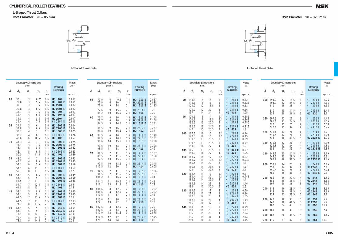
CYLINDRICAL ROLLER BEARINGSL-Shaped Thrust CollarsBore Diameter 20 – 85 mm Bore Diameter 90 – 320 mm
r1
jdjd1
B1
B2
L-Shaped Thrust Collar
r1
jdjd1
B1
B2
L-Shaped Thrust Collar
90 114.3 9 14 2 HJ 218 E 0.32 114.3 9 15 2 HJ 2218 E 0.325 124.2 12 18.5 3 HJ 318 E 0.63 124.2 12 22 3 HJ 2318 E 0.66 137 14 24 4 HJ 418 1.05 95 120.6 9 14 2.1 HJ 219 E 0.355 120.6 9 15.5 2.1 HJ 2219 E 0.365 132.2 13 20.5 3 HJ 319 E 0.785 132.2 13 24.5 3 HJ 2319 E 0.815 147 15 25.5 4 HJ 419 1.3 100 127.5 10 15 2.1 HJ 220 E 0.44 127.5 10 16 2.1 HJ 2220 E 0.45 139.6 13 20.5 3 HJ 320 E 0.89 139.6 13 23.5 3 HJ 2320 E 0.92 153.5 16 27 4 HJ 420 1.5 105 145 13 20.5 3 HJ 321 E 0.97 159.5 16 27 4 HJ 421 1.65 110 141.7 11 17 2.1 HJ 222 E 0.62 141.7 11 19.5 2.1 HJ 2222 E 0.645 155.8 14 22 3 HJ 322 E 1.21 155.8 14 26.5 3 HJ 2322 E 1.27 171 17 29.5 4 HJ 422 2.1 120 153.4 11 17 2.1 HJ 224 E 0.71 153.4 11 20 2.1 HJ 2224 E 0.745 168.6 14 22.5 3 HJ 324 E 1.41 168.6 14 26 3 HJ 2324 E 1.46 188 17 30.5 5 HJ 424 2.6 130 164.2 11 17 3 HJ 226 E 0.79 164.2 11 21 3 HJ 2226 E 0.84 182.3 14 23 4 HJ 326 E 1.65 182.3 14 28 4 HJ 2326 E 1.73 205 18 32 5 HJ 426 3.3 140 180 11 18 3 HJ 228 E 0.99 180 11 23 3 HJ 2228 E 1.07 196 15 25 4 HJ 328 E 2.04 196 15 31 4 HJ 2328 E 2.14 219 18 33 5 HJ 428 3.75
Bearing Numbers
Boundary Dimensions(mm)
d d1 B1 B2 r1 min.
Mass(kg)
approx.
150 193.7 12 19.5 3 HJ 230 E 1.26 193.7 12 24.5 3 HJ 2230 E 1.35 210 15 25 4 HJ 330 E 2.35
210 15 31.5 4 HJ 2330 E 2.48 234 20 36.5 5 HJ 430 4.7
160 207.3 12 20 3 HJ 232 E 1.48 206.1 12 24.5 3 HJ 2232 E 1.55 222 15 25 4 HJ 332 E 2.59 222.1 15 32 4 HJ 2332 E 2.76
170 220.8 12 20 4 HJ 234 E 1.7 219.5 12 24 4 HJ 2234 E 1.79 238 16 33.5 4 HJ 2334 E 3.25
180 230.8 12 20 4 HJ 236 E 1.79 229.5 12 24 4 HJ 2236 E 1.88 252 17 35 4 HJ 2336 E 3.85
190 244.5 13 21.5 4 HJ 238 E 2.19 243.2 13 26.5 4 HJ 2238 E 2.31 260.6 18 36.5 5 HJ 2338 E 4.45
200 258.2 14 23 4 HJ 240 E 2.65 258 14 34 4 HJ 2240 2.6 256.9 14 28 4 HJ 2240 E 2.78 280 18 30 5 HJ 340 E 5.0
220 286 15 27.5 4 HJ 244 3.55 286 15 36.5 4 HJ 2244 3.55 307 20 36 5 HJ 344 7.05
240 313 16 29.5 4 HJ 248 4.65 313 16 38.5 4 HJ 2248 4.65 334 22 39.5 5 HJ 348 8.2
260 340 18 33 5 HJ 252 6.2 340 18 40.5 5 HJ 2252 6.2 362 24 43 6 HJ 352 11.4
280 360 18 33 5 HJ 256 7.4
300 387 20 34.5 5 HJ 260 9.15
320 415 21 37 5 HJ 264 11.3
Bearing Numbers
Boundary Dimensions(mm)
d d1 B1 B2 r1 min.
Mass(kg)
approx.
20 30 3 6.75 0.6 HJ 204 0.012 29.8 3 5.5 0.6 HJ 204 E 0.011 30 3 7.5 0.6 HJ 2204 0.012 29.8 3 6.5 0.6 HJ 2204 E 0.012 31.7 4 7.5 0.6 HJ 304 0.017 31.4 4 6.5 0.6 HJ 304 E 0.017 31.8 4 8.5 0.6 HJ 2304 0.017 31.4 4 7.5 0.6 HJ 2304 E 0.018 25 34.8 3 6 0.6 HJ 205 E 0.014 34.8 3 6.5 0.6 HJ 2205 E 0.014 38.2 4 7 1.1 HJ 305 E 0.025 38.2 4 8 1.1 HJ 2305 E 0.026 43.6 6 10.5 1.5 HJ 405 0.057 30 41.3 4 7 0.6 HJ 206 E 0.025 41.4 4 7.5 0.6 HJ 2206 E 0.025 45.1 5 8.5 1.1 HJ 306 E 0.042 45.1 5 9.5 1.1 HJ 2306 E 0.043 50.5 7 11.5 1.5 HJ 406 0.080 35 48.2 4 7 0.6 HJ 207 E 0.033 48.2 4 8.5 0.6 HJ 2207 E 0.035 51.1 6 9.5 1.1 HJ 307 E 0.060 51.1 6 11 1.1 HJ 2307 E 0.062 59 8 13 1.5 HJ 407 0.12 40 54.1 5 8.5 1.1 HJ 208 E 0.049 54.1 5 9 1.1 HJ 2208 E 0.050 57.6 7 11 1.5 HJ 308 E 0.088 57.7 7 12.5 1.5 HJ 2308 E 0.091 64.8 8 13 2 HJ 408 0.14 45 59.1 5 8.5 1.1 HJ 209 E 0.055 59.1 5 9 1.1 HJ 2209 E 0.055 64.5 7 11.5 1.5 HJ 309 E 0.11 64.5 7 13 1.5 HJ 2309 E 0.113 71.7 8 13.5 2 HJ 409 0.175 50 64.1 5 9 1.1 HJ 210 E 0.061 64.1 5 9 1.1 HJ 2210 E 0.061 71.4 8 13 2 HJ 310 E 0.151 71.4 8 14.5 2 HJ 2310 E 0.155 78.8 9 14.5 2.1 HJ 410 0.23
Bearing Numbers
Boundary Dimensions(mm)
d d1 B1 B2 r1 min.
Mass(kg)
approx.
55 70.9 6 9.5 1.1 HJ 211 E 0.087 70.9 6 10 1.1 HJ 2211 E 0.088 77.6 9 14 2 HJ 311 E 0.195
77.6 9 15.5 2 HJ 2311 E 0.20 85.2 10 16.5 2.1 HJ 411 0.29
60 77.7 6 10 1.5 HJ 212 E 0.108 77.7 6 10 1.5 HJ 2212 E 0.108 84.5 9 14.5 2.1 HJ 312 E 0.231
84.5 9 16 2.1 HJ 2312 E 0.237 91.8 10 16.5 2.1 HJ 412 0.34
65 84.5 6 10 1.5 HJ 213 E 0.129 84.5 6 10.5 1.5 HJ 2213 E 0.131 90.6 10 15.5 2.1 HJ 313 E 0.288
90.6 10 18 2.1 HJ 2313 E 0.298 98.5 11 18 2.1 HJ 413 0.42
70 89.5 7 11 1.5 HJ 214 E 0.157 89.5 7 11.5 1.5 HJ 2214 E 0.158 97.5 10 15.5 2.1 HJ 314 E 0.33
97.5 10 18.5 2.1 HJ 2314 E 0.345 110.5 12 20 3 HJ 414 0.605
75 94.5 7 11 1.5 HJ 215 E 0.166 94.5 7 11.5 1.5 HJ 2215 E 0.167 104.2 11 16.5 2.1 HJ 315 E 0.41
104.2 11 19.5 2.1 HJ 2315 E 0.43 116 13 21.5 3 HJ 415 0.71
80 101.6 8 12.5 2 HJ 216 E 0.222 101.6 8 12.5 2 HJ 2216 E 0.222 110.6 11 17 2.1 HJ 316 E 0.46
110.6 11 20 2.1 HJ 2316 E 0.48 122 13 22 3 HJ 416 0.78
85 107.6 8 12.5 2 HJ 217 E 0.25 107.6 8 13 2 HJ 2217 E 0.252 117.9 12 18.5 3 HJ 317 E 0.575
117.9 12 22 3 HJ 2317 E 0.595 126 14 24 4 HJ 417 0.88
Bearing Numbers
Boundary Dimensions(mm)
d d1 B1 B2 r1 min.
Mass(kg)
approx.
B 104 B 105
B084-109E.indd 104-105B084-109E.indd 104-105 11/20/13 4:56:23 PM11/20/13 4:56:23 PM
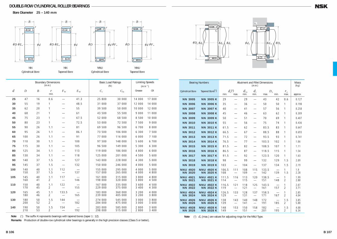
DOUBLE-ROW CYLINDRICAL ROLLER BEARINGSBore Diameter 25 – 140 mm
NN 3005 NN 3005 K 29 — 29 — 43 42 0.6 0.127
NN 3006 NN 3006 K 35 — 36 — 50 50 1 0.198
NN 3007 NN 3007 K 40 — 41 — 57 56 1 0.258
NN 3008 NN 3008 K 45 — 46 — 63 62 1 0.309
NN 3009 NN 3009 K 50 — 51 — 70 69 1 0.407
NN 3010 NN 3010 K 55 — 56 — 75 74 1 0.436
NN 3011 NN 3011 K 61.5 — 62 — 83.5 83 1 0.647
NN 3012 NN 3012 K 66.5 — 67 — 88.5 88 1 0.693
NN 3013 NN 3013 K 71.5 — 72 — 93.5 93 1 0.741
NN 3014 NN 3014 K 76.5 — 77 — 103.5 102 1 1.06
NN 3015 NN 3015 K 81.5 — 82 — 108.5 107 1 1.11
NN 3016 NN 3016 K 86.5 — 87 — 118.5 115 1 1.54
NN 3017 NN 3017 K 91.5 — 92 — 123.5 120 1 1.63
NN 3018 NN 3018 K 98 — 99 — 132 129 1.5 2.09
NN 3019 NN 3019 K 103 — 104 — 137 134 1.5 2.19
NNU 4920 NNU 4920 K 106.5 111 108 115 133.5 — 1 1.9 NN 3020 NN 3020 K 108 — 109 — 142 139 1.5 2.28
NNU 4921 NNU 4921 K 111.5 116 113 120 138.5 — 1 1.99 NN 3021 NN 3021 K 114 — 115 — 151 148 2 2.88
NNU 4922 NNU 4922 K 116.5 121 118 125 143.5 — 1 2.07 NN 3022 NN 3022 K 119 — 121 — 161 157 2 3.71
NNU 4924 NNU 4924 K 126.5 133 128 137 158.5 — 1 2.85 NN 3024 NN 3024 K 129 — 131 — 171 167 2 4.04
NNU 4926 NNU 4926 K 138 143 140 148 172 — 1.5 3.85 NN 3026 NN 3026 K 139 — 141 — 191 185 2 5.88
NNU 4928 NNU 4928 K 148 153 150 158 182 — 1.5 4.08 NN 3028 NN 3028 K 149 — 151 — 201 195 2 6.34
Bearing Numbers
Cylindrical Bore Tapered Bore(1)
Abutment and Fillet Dimensions(mm)
da(2) d1a dc Da ra min. max. min. min. max. min. max.
Mass(kg)
approx.
25 47 16 0.6 — 41.3 25 800 30 000 14 000 17 000
30 55 19 1 — 48.5 31 000 37 000 12 000 14 000
35 62 20 1 — 55 39 500 50 000 10 000 12 000
40 68 21 1 — 61 43 500 55 500 9 000 11 000
45 75 23 1 — 67.5 52 000 68 500 8 500 10 000
50 80 23 1 — 72.5 53 000 72 500 7 500 9 000
55 90 26 1.1 — 81 69 500 96 500 6 700 8 000
60 95 26 1.1 — 86.1 73 500 106 000 6 300 7 500
65 100 26 1.1 — 91 77 000 116 000 6 000 7 100
70 110 30 1.1 — 100 97 500 148 000 5 600 6 700
75 115 30 1.1 — 105 96 500 149 000 5 300 6 300
80 125 34 1.1 — 113 119 000 186 000 4 800 6 000
85 130 34 1.1 — 118 125 000 201 000 4 500 5 600
90 140 37 1.5 — 127 143 000 228 000 4 300 5 000
95 145 37 1.5 — 132 150 000 246 000 4 000 5 000
100 140 40 1.1 112 — 155 000 295 000 4 000 5 000 150 37 1.5 — 137 157 000 265 000 4 000 4 800
105 145 40 1.1 117 — 161 000 315 000 3 800 4 800 160 41 2 — 146 198 000 320 000 3 800 4 500
110 150 40 1.1 122 — 167 000 335 000 3 600 4 500 170 45 2 — 155 229 000 375 000 3 400 4 300
120 165 45 1.1 133.5 — 183 000 360 000 3 200 4 000 180 46 2 — 165 239 000 405 000 3 200 3 800
130 180 50 1.5 144 — 274 000 545 000 3 000 3 800 200 52 2 — 182 284 000 475 000 3 000 3 600
140 190 50 1.5 154 — 283 000 585 000 2 800 3 600 210 53 2 — 192 298 000 515 000 2 800 3 400
Boundary Dimensions(mm)
d D B r FW EW min.
Limiting Speeds(min–1)
Grease Oil
Basic Load Ratings(N)
Cr C0r
r
r
jDjE jd
B
w
r
jDjE jd
B
w
rr
jD jFjd
B
w
r
jD jFjd
B
w
NNCylindrical Bore
NNTapered Bore
NNUCylindrical Bore
NNUTapered Bore
Note (1) The suffix K represents bearings with tapered bores (taper 1 : 12).Remarks Production of double-row cylindrical roller bearings is generally in the high precision classes (Class 5 or better).
Note (2) da (max.) are values for adjusting rings for the NNU Type.
jDjDjd jd
ra ra
ra
a a a jda ajd1ajdc
B 106 B 107
B084-109E.indd 106-107B084-109E.indd 106-107 11/20/13 4:56:24 PM11/20/13 4:56:24 PM

DOUBLE-ROW CYLINDRICAL ROLLER BEARINGSBore Diameter 150 – 360 mm
NNU 4930 NNU 4930 K 159 166 162 171 201 — 2 6.39 NN 3030 NN 3030 K 161 — 162 — 214 209 2 7.77
NNU 4932 NNU 4932 K 169 176 172 182 211 — 2 6.76 NN 3032 NN 3032 K 171 — 172 — 229 222 2 9.41
NNU 4934 NNU 4934 K 179 186 182 192 221 — 2 7.12 NN 3034 NN 3034 K 181 — 183 — 249 239 2 12.8
NNU 4936 NNU 4936 K 189 199 193 205 241 — 2 10.4 NN 3036 NN 3036 K 191 — 193 — 269 258 2 16.8
NNU 4938 NNU 4938 K 199 211 203 217 251 — 2 10.9 NN 3038 NN 3038 K 201 — 203 — 279 268 2 17.8
NNU 4940 NNU 4940 K 211 222 214 228 269 — 2 15.3 NN 3040 NN 3040 K 211 — 214 — 299 285 2 22.7
NNU 4944 NNU 4944 K 231 242 234 248 289 — 2 16.6 NN 3044 NN 3044 K 233 — 236 — 327 313 2.5 29.6
NNU 4948 NNU 4948 K 251 262 254 269 309 — 2 18 NN 3048 NN 3048 K 253 — 256 — 347 334 2.5 32.7
NNU 4952 NNU 4952 K 271 288 275 295 349 — 2 31.1 NN 3052 NN 3052 K 276 — 278 — 384 368 3 47.7
NNU 4956 NNU 4956 K 291 308 295 315 369 — 2 33 NN 3056 NN 3056 K 296 — 298 — 404 388 3 51.1
NNU 4960 NNU 4960 K 313 335 318 343 407 — 2.5 51.9 NN 3060 NN 3060 K 316 — 319 — 444 422 3 70.7
NNU 4964 NNU 4964 K 333 355 338 363 427 — 2.5 54.9 NN 3064 NN 3064 K 336 — 340 — 464 442 3 76.6
NN 3068 NN 3068 K 360 — 365 — 500 477 4 102
NN 3072 NN 3072 K 380 — 385 — 520 497 4 106
Bearing Numbers
Cylindrical Bore Tapered Bore(1)
Abutment and Fillet Dimensions(mm)
da(2) d1a dc Da ra min. max. min. min. max. min. max.
Mass(kg)
approx.
150 210 60 2 167 — 350 000 715 000 2 600 3 200 225 56 2.1 — 206 335 000 585 000 2 600 3 000
160 220 60 2 177 — 365 000 760 000 2 400 3 000 240 60 2.1 — 219 375 000 660 000 2 400 2 800
170 230 60 2 187 — 375 000 805 000 2 400 2 800 260 67 2.1 — 236 450 000 805 000 2 200 2 600
180 250 69 2 200 — 480 000 1 020 000 2 200 2 600 280 74 2.1 — 255 565 000 995 000 2 000 2 400
190 260 69 2 211.5 — 485 000 1 060 000 2 000 2 600 290 75 2.1 — 265 595 000 1 080 000 2 000 2 400
200 280 80 2.1 223 — 570 000 1 220 000 1 900 2 400 310 82 2.1 — 282 655 000 1 170 000 1 800 2 200
220 300 80 2.1 243 — 600 000 1 330 000 1 700 2 200 340 90 3 — 310 815 000 1 480 000 1 700 2 000
240 320 80 2.1 263 — 625 000 1 450 000 1 600 2 000 360 92 3 — 330 855 000 1 600 000 1 500 1 800
260 360 100 2.1 289 — 935 000 2 100 000 1 400 1 800 400 104 4 — 364 1 030 000 1 920 000 1 400 1 700
280 380 100 2.1 309 — 960 000 2 230 000 1 300 1 700 420 106 4 — 384 1 080 000 2 080 000 1 300 1 500
300 420 118 3 336 — 1 230 000 2 870 000 1 200 1 500 460 118 4 — 418 1 290 000 2 460 000 1 200 1 400
320 440 118 3 356 — 1 260 000 3 050 000 1 100 1 400 480 121 4 — 438 1 350 000 2 670 000 1 100 1 300
340 520 133 5 — 473 1 670 000 3 300 000 1 000 1 200
360 540 134 5 — 493 1 700 000 3 450 000 950 1 200
Boundary Dimensions(mm)
d D B r FW EW min.
Limiting Speeds(min–1)
Grease Oil
Basic Load Ratings(N)
Cr C0r
r
r
jDjE jd
B
w
r
jDjE jd
B
w
rr
jD jFjd
B
w
r
jD jFjd
B
w
NNCylindrical Bore
NNTapered Bore
NNUCylindrical Bore
NNUTapered Bore
Note (1) The suffix K represents bearings with tapered bores (taper 1 : 12).Remarks Production of double-row cylindrical roller bearings is generally in the high precision classes (Class 5 or better).
Note (2) da (max.) are values for adjusting rings for the NNU Type.
jDjDjd jd
ra ra
ra
a a a jda ajd1ajdc
B 108 B 109
B084-109E.indd 108-109B084-109E.indd 108-109 11/20/13 4:56:25 PM11/20/13 4:56:25 PM

Contactangle
Example: T 7 F C 045 — — — — ——
Symbol RepresentingTapered RollerBearings
Contact Angle
New Series Symbols of ISO14444444244444443
(Bore diameter in mm)
DiameterSymbol
BoreDiameterSymbol
WidthSymbol
TAPERED ROLLER BEARINGSMETRIC DESIGN TAPERED ROLLER BEARINGS
Bore Diameter 15 – 100mm ·································································· B120
Bore Diameter 105 – 240mm ·································································· B128
Bore Diameter 260 – 440mm ·································································· B134
INCH DESIGN TAPERED ROLLER BEARINGS
Bore Diameter 12.000 – 47.625mm ···················································· B136
Bore Diameter 48.412 – 69.850mm ···················································· B150
Bore Diameter 70.000 – 206.375mm ···················································· B158The index for inch design tapered roller bearings is in Appendix 14 (Page C26).
DOUBLE-ROW TAPERED ROLLER BEARINGS
Bore Diameter 40 – 260mm ·································································· B172
Four-Row Tapered Roller Bearings are described on pages B334 to B339.
DESIGN, TYPES, AND FEATURES Tapered roller bearings are designed so the apices of the cones formed by the raceways of the cone and cup and the conical rollers all coincide at one point on the axis of the bearing. When a radial load is imposed, an axial force component occurs; therefore, it is necessary to use two bearings in opposition or some other multiple arrangement. For metric-design medium-angle and steep-angle tapered roller bearings, the respective contact angle symbol C or D is added after the bore number. For normal-angle tapered roller bearings, no contact angle symbol is used.Medium-angle tapered roller bearings are primarily used for the pinion shafts of differential gears of automobiles. Among those with high load capacity(HR series), some bearings have the basic number suffixed by J to conform to the specifications of ISO for the cup back face raceway diameter, cup width, and contact angle. Therefore, the cone assembly and cup of bearings with the same basic number suffixed by J are internationally interchangeable. Among metric-design tapered roller bearings specified by ISO 355, there are those having new dimensions that are different than the dimension series 3XX used in the past. Part of them are listed in the bearing tables. They conform to the specifications of ISO for the smaller end diameter of the cup and contact angle. The cone and cup assemblies are internationally interchangeable. The bearing number formulation, which is different than that for past metric design, is as follows:
B 110 B 111
B110-181E.indd 110-111B110-181E.indd 110-111 11/20/13 4:56:52 PM11/20/13 4:56:52 PM
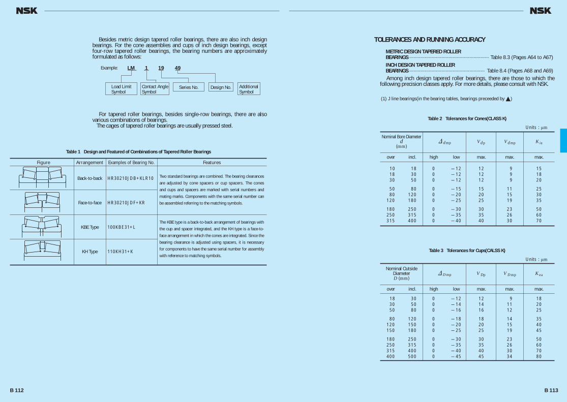
Besides metric design tapered roller bearings, there are also inch design bearings. For the cone assemblies and cups of inch design bearings, except four-row tapered roller bearings, the bearing numbers are approximately formulated as follows:
For tapered roller bearings, besides single-row bearings, there are also various combinations of bearings. The cages of tapered roller bearings are usually pressed steel.
Table 1 Design and Featured of Combinations of Tapered Roller Bearings
Table 2 Tolerances for Cones(CLASS K)
Figure Arrangement Examples of Bearing No. Features
Back-to-back HR30210JDB+KLR10
Face-to-face HR30210JDF+KR
KBE Type 100KBE31+L
KH Type 110KH31+K
TOLERANCES AND RUNNING ACCURACY
METRIC DESIGN TAPERED ROLLERBEARINGS ························································· Table 8.3 (Pages A64 to A67)INCH DESIGN TAPERED ROLLER BEARINGS ······················································ Table 8.4 (Pages A68 and A69)
Among inch design tapered roller bearings, there are those to which the following precision classes apply. For more details, please consult with NSK.
(1) J line bearings(in the bearing tables, bearings preceeded by �)
over incl. high low max. max. max.
10 18 0 — 12 12 9 15 18 30 0 — 12 12 9 18 30 50 0 — 12 12 9 20
50 80 0 — 15 15 11 25 80 120 0 — 20 20 15 30 120 180 0 — 25 25 19 35
180 250 0 — 30 30 23 50 250 315 0 — 35 35 26 60 315 400 0 — 40 40 30 70
Nominal Bore Diameterd
(mm)& dmp Vdp Vdmp K ia
Units : μm
Table 3 Tolerances for Cups(CALSS K)
over incl. high low max. max. max.
18 30 0 — 12 12 9 18 30 50 0 — 14 14 11 20 50 80 0 — 16 16 12 25
80 120 0 — 18 18 14 35 120 150 0 — 20 20 15 40 150 180 0 — 25 25 19 45
180 250 0 — 30 30 23 50 250 315 0 — 35 35 26 60 315 400 0 — 40 40 30 70 400 500 0 — 45 45 34 80
Nominal Outside DiameterD (mm)
& Dmp V Dp V Dmp K ea
Units : μm
Load LimitSymbol
Example: LM 1 19 49 —— — — —
Contact AngleSymbol
Series No. AdditionalSymbol
Design No.
Two standard bearings are combined. The bearing clearances
are adjusted by cone spacers or cup spacers. The cones
and cups and spacers are marked with serial numbers and
mating marks. Components with the same serial number can
be assembled referring to the matching symbols.
The KBE type is a back-to-back arrangement of bearings with
the cup and spacer integrated, and the KH type is a face-to-
face arrangement in which the cones are integrated. Since the
bearing clearance is adjusted using spacers, it is necessary
for components to have the same serial number for assembly
with reference to matching symbols.
B 112 B 113
B110-181E.indd 112-113B110-181E.indd 112-113 11/20/13 4:56:53 PM11/20/13 4:56:53 PM
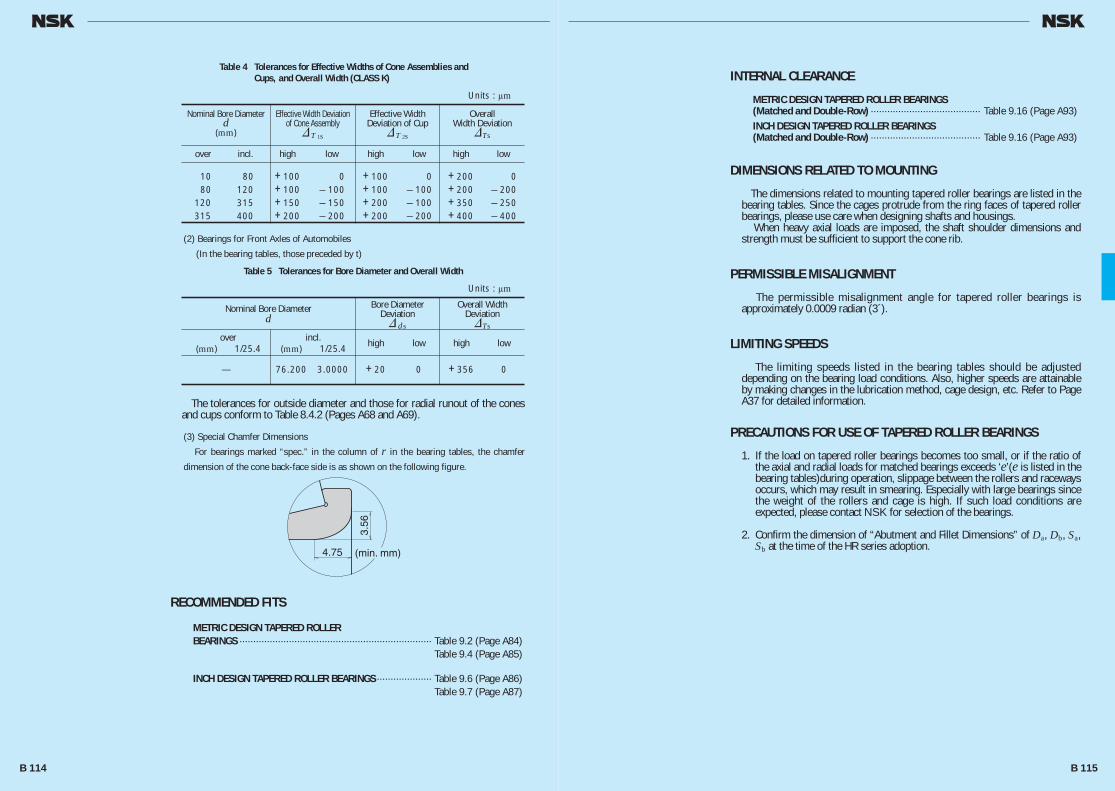
Table 4 Tolerances for Effective Widths of Cone Assemblies and Cups, and Overall Width (CLASS K)
RECOMMENDED FITS
METRIC DESIGN TAPERED ROLLER BEARINGS ······································································ Table 9.2 (Page A84) Table 9.4 (Page A85)
INCH DESIGN TAPERED ROLLER BEARINGS ···················· Table 9.6 (Page A86) Table 9.7 (Page A87)
(2) Bearings for Front Axles of Automobiles
(In the bearing tables, those preceded by t)
(3) Special Chamfer Dimensions
For bearings marked “spec.” in the column of r in the bearing tables, the chamfer
dimension of the cone back-face side is as shown on the following figure.
The tolerances for outside diameter and those for radial runout of the cones and cups conform to Table 8.4.2 (Pages A68 and A69).
over incl. high low high low high low
10 80 +100 0 +100 0 +200 0 80 120 +100 — 100 +100 — 100 +200 — 200 120 315 +150 — 150 +200 — 100 +350 — 250 315 400 +200 — 200 +200 — 200 +400 — 400
Nominal Bore Diameterd
(mm)
Effective Width Deviation of Cone Assembly& T 1s
Effective Width Deviation of Cup
& T 2s
OverallWidth Deviation
&Ts
Units : μm
Table 5 Tolerances for Bore Diameter and Overall Width
over incl. high low high low (mm) 1/25.4 (mm) 1/25.4
— 76.200 3.0000 +20 0 +356 0
Nominal Bore Diameterd
Bore DiameterDeviation& ds
Overall WidthDeviation&Ts
Units : μm
4.75
3.56
(min. mm)
INTERNAL CLEARANCE
METRIC DESIGN TAPERED ROLLER BEARINGS(Matched and Double-Row) ········································ Table 9.16 (Page A93)INCH DESIGN TAPERED ROLLER BEARINGS(Matched and Double-Row) ········································ Table 9.16 (Page A93)
DIMENSIONS RELATED TO MOUNTING
The dimensions related to mounting tapered roller bearings are listed in the bearing tables. Since the cages protrude from the ring faces of tapered roller bearings, please use care when designing shafts and housings. When heavy axial loads are imposed, the shaft shoulder dimensions and strength must be sufficient to support the cone rib.
PERMISSIBLE MISALIGNMENT
The permissible misalignment angle for tapered roller bearings is approximately 0.0009 radian (3´).
LIMITING SPEEDS
The limiting speeds listed in the bearing tables should be adjusted depending on the bearing load conditions. Also, higher speeds are attainable by making changes in the lubrication method, cage design, etc. Refer to Page A37 for detailed information.
PRECAUTIONS FOR USE OF TAPERED ROLLER BEARINGS
1. If the load on tapered roller bearings becomes too small, or if the ratio of the axial and radial loads for matched bearings exceeds ‘e’(e is listed in the bearing tables)during operation, slippage between the rollers and raceways occurs, which may result in smearing. Especially with large bearings since the weight of the rollers and cage is high. If such load conditions are expected, please contact NSK for selection of the bearings.
2. Confirm the dimension of “Abutment and Fillet Dimensions” of Da, Db, Sa, Sb at the time of the HR series adoption.
B 114 B 115
B110-181E.indd 114-115B110-181E.indd 114-115 11/20/13 4:56:54 PM11/20/13 4:56:54 PM
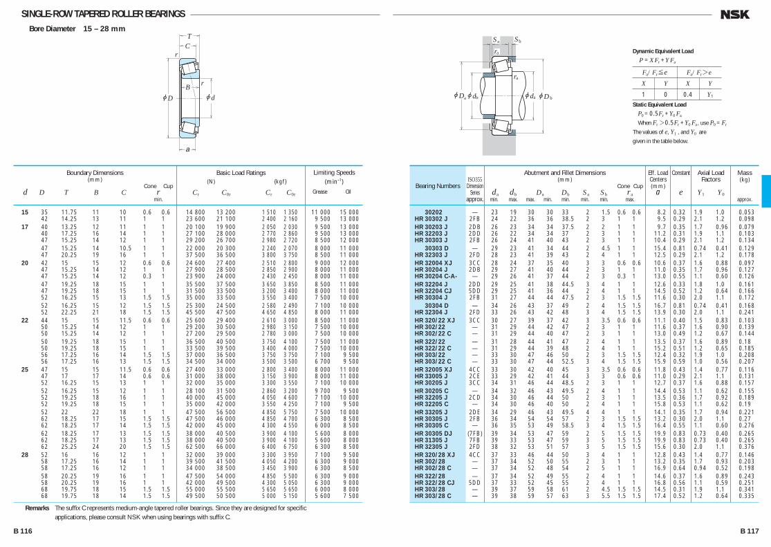
SINGLE-ROW TAPERED ROLLER BEARINGSBore Diameter 15 – 28 mm
jd
r
r
jD
TC
B
a
jDjd jd
ra
Sa Sb
ra
a b ajDb
15 35 11.75 11 10 0.6 0.6 14 800 13 200 1 510 1 350 11 000 15 000 42 14.25 13 11 1 1 23 600 21 100 2 400 2 160 9 500 13 000 17 40 13.25 12 11 1 1 20 100 19 900 2 050 2 030 9 500 13 000 40 17.25 16 14 1 1 27 100 28 000 2 770 2 860 9 500 13 000 47 15.25 14 12 1 1 29 200 26 700 2 980 2 720 8 500 12 000 47 15.25 14 10.5 1 1 22 000 20 300 2 240 2 070 8 000 11 000 47 20.25 19 16 1 1 37 500 36 500 3 800 3 750 8 500 11 000 20 42 15 15 12 0.6 0.6 24 600 27 400 2 510 2 800 9 000 12 000 47 15.25 14 12 1 1 27 900 28 500 2 850 2 900 8 000 11 000 47 15.25 14 12 0.3 1 23 900 24 000 2 430 2 450 8 000 11 000 47 19.25 18 15 1 1 35 500 37 500 3 650 3 850 8 500 11 000 47 19.25 18 15 1 1 31 500 33 500 3 200 3 400 8 000 11 000 52 16.25 15 13 1.5 1.5 35 000 33 500 3 550 3 400 7 500 10 000 52 16.25 15 12 1.5 1.5 25 300 24 500 2 580 2 490 7 100 10 000 52 22.25 21 18 1.5 1.5 45 500 47 500 4 650 4 850 8 000 11 000 22 44 15 15 11.5 0.6 0.6 25 600 29 400 2 610 3 000 8 500 11 000 50 15.25 14 12 1 1 29 200 30 500 2 980 3 150 7 500 10 000 50 15.25 14 12 1 1 27 200 29 500 2 780 3 000 7 500 10 000 50 19.25 18 15 1 1 36 500 40 500 3 750 4 100 7 500 11 000 50 19.25 18 15 1 1 33 500 39 500 3 400 4 000 7 500 10 000 56 17.25 16 14 1.5 1.5 37 000 36 500 3 750 3 750 7 100 9 500 56 17.25 16 13 1.5 1.5 34 500 34 000 3 500 3 500 6 700 9 500 25 47 15 15 11.5 0.6 0.6 27 400 33 000 2 800 3 400 8 000 11 000 47 17 17 14 0.6 0.6 31 000 38 000 3 150 3 900 8 000 11 000 52 16.25 15 13 1 1 32 000 35 000 3 300 3 550 7 100 10 000 52 16.25 15 12 1 1 28 100 31 500 2 860 3 200 9 700 9 500 52 19.25 18 16 1 1 40 000 45 000 4 050 4 600 7 100 10 000 52 19.25 18 15 1 1 35 000 42 000 3 550 4 250 7 100 9 500 52 22 22 18 1 1 47 500 56 500 4 850 5 750 7 500 10 000 62 18.25 17 15 1.5 1.5 47 500 46 000 4 850 4 700 6 300 8 500 62 18.25 17 14 1.5 1.5 42 000 45 000 4 300 4 550 6 000 8 500 62 18.25 17 13 1.5 1.5 38 000 40 500 3 900 4 100 5 600 8 000 62 18.25 17 13 1.5 1.5 38 000 40 500 3 900 4 100 5 600 8 000 62 25.25 24 20 1.5 1.5 62 500 66 000 6 400 6 750 6 300 8 500 28 52 16 16 12 1 1 32 000 39 000 3 300 3 950 7 100 9 500 58 17.25 16 14 1 1 39 500 41 500 4 050 4 200 6 300 9 000 58 17.25 16 12 1 1 34 000 38 500 3 450 3 900 6 300 8 500 58 20.25 19 16 1 1 47 500 54 000 4 850 5 500 6 300 9 000 58 20.25 19 16 1 1 42 000 49 500 4 300 5 050 6 300 9 000 68 19.75 18 15 1.5 1.5 55 000 55 500 5 650 5 650 6 000 8 000 68 19.75 18 14 1.5 1.5 49 500 50 500 5 000 5 150 5 600 7 500
Boundary Dimensions(mm)
Cone Cup d D T B C r min.
Limiting Speeds (min–1)
Grease Oil
Basic Load Ratings (N) {kgf}
Cr C0r Cr C0r
30202 — 23 19 30 30 33 2 1.5 0.6 0.6 8.2 0.32 1.9 1.0 0.053 HR 30302 J 2FB 24 22 36 36 38.5 2 3 1 1 9.5 0.29 2.1 1.2 0.098 HR 30203 J 2DB 26 23 34 34 37.5 2 2 1 1 9.7 0.35 1.7 0.96 0.079 HR 32203 J 2DD 26 22 34 34 37 2 3 1 1 11.2 0.31 1.9 1.1 0.103 HR 30303 J 2FB 26 24 41 40 43 2 3 1 1 10.4 0.29 2.1 1.2 0.134 30303 D — 29 23 41 34 44 2 4.5 1 1 15.4 0.81 0.74 0.41 0.129 HR 32303 J 2FD 28 23 41 39 43 2 4 1 1 12.5 0.29 2.1 1.2 0.178 HR 32004 XJ 3CC 28 24 37 35 40 3 3 0.6 0.6 10.6 0.37 1.6 0.88 0.097 HR 30204 J 2DB 29 27 41 40 44 2 3 1 1 11.0 0.35 1.7 0.96 0.127 HR 30204 C-A- — 29 26 41 37 44 2 3 0.3 1 13.0 0.55 1.1 0.60 0.126 HR 32204 J 2DD 29 25 41 38 44.5 3 4 1 1 12.6 0.33 1.8 1.0 0.161 HR 32204 CJ 5DD 29 25 41 36 44 2 4 1 1 14.5 0.52 1.2 0.64 0.166 HR 30304 J 2FB 31 27 44 44 47.5 2 3 1.5 1.5 11.6 0.30 2.0 1.1 0.172 30304 D — 34 26 43 37 49 2 4 1.5 1.5 16.7 0.81 0.74 0.41 0.168 HR 32304 J 2FD 33 26 43 42 48 3 4 1.5 1.5 13.9 0.30 2.0 1.1 0.241 HR 320/22 XJ 3CC 30 27 39 37 42 3 3.5 0.6 0.6 11.1 0.40 1.5 0.83 0.103 HR 302/22 — 31 29 44 42 47 2 3 1 1 11.6 0.37 1.6 0.90 0.139 HR 302/22 C — 31 29 44 40 47 2 3 1 1 13.0 0.49 1.2 0.67 0.144 HR 322/22 — 31 28 44 41 47 2 4 1 1 13.5 0.37 1.6 0.89 0.18 HR 322/22 C — 31 29 44 39 48 2 4 1 1 15.2 0.51 1.2 0.65 0.185 HR 303/22 — 33 30 47 46 50 2 3 1.5 1.5 12.4 0.32 1.9 1.0 0.208 HR 303/22 C — 33 30 47 44 52.5 3 4 1.5 1.5 15.9 0.59 1.0 0.56 0.207 HR 32005 XJ 4CC 33 30 42 40 45 3 3.5 0.6 0.6 11.8 0.43 1.4 0.77 0.116 HR 33005 J 2CE 33 29 42 41 44 3 3 0.6 0.6 11.0 0.29 2.1 1.1 0.131 HR 30205 J 3CC 34 31 46 44 48.5 2 3 1 1 12.7 0.37 1.6 0.88 0.157 HR 30205 C — 34 32 46 43 49.5 2 4 1 1 14.4 0.53 1.1 0.62 0.155 HR 32205 J 2CD 34 30 46 44 50 2 3 1 1 13.5 0.36 1.7 0.92 0.189 HR 32205 C — 34 30 46 40 50 2 4 1 1 15.8 0.53 1.1 0.62 0.19 HR 33205 J 2DE 34 29 46 43 49.5 4 4 1 1 14.1 0.35 1.7 0.94 0.221 HR 30305 J 2FB 36 34 54 54 57 2 3 1.5 1.5 13.2 0.30 2.0 1.1 0.27 HR 30305 C — 36 35 53 49 58.5 3 4 1.5 1.5 16.4 0.55 1.1 0.60 0.276 HR 30305 DJ (7FB) 39 34 53 47 59 2 5 1.5 1.5 19.9 0.83 0.73 0.40 0.265 HR 31305 J 7FB 39 33 53 47 59 3 5 1.5 1.5 19.9 0.83 0.73 0.40 0.265 HR 32305 J 2FD 38 32 53 51 57 3 5 1.5 1.5 15.6 0.30 2.0 1.1 0.376 HR 320/28 XJ 4CC 37 33 46 44 50 3 4 1 1 12.8 0.43 1.4 0.77 0.146 HR 302/28 — 37 34 52 50 55 2 3 1 1 13.2 0.35 1.7 0.93 0.203 HR 302/28 C — 37 34 52 48 54 2 5 1 1 16.9 0.64 0.94 0.52 0.198 HR 322/28 — 37 34 52 49 55 2 4 1 1 14.6 0.37 1.6 0.89 0.243 HR 322/28 CJ 5DD 37 33 52 45 55 2 4 1 1 16.8 0.56 1.1 0.59 0.251 HR 303/28 — 39 37 59 58 61 2 4.5 1.5 1.5 14.5 0.31 1.9 1.1 0.341 HR 303/28 C — 39 38 59 57 63 3 5.5 1.5 1.5 17.4 0.52 1.2 0.64 0.335
Bearing NumbersISO355
DimensionSeries
approx.
Abutment and Fillet Dimensions(mm)
Cone Cup da db Da Db Sa Sb ra min. max. max. min. min. min. min. max.
Mass(kg)
approx.
Eff. Load Centers(mm)
a
Constant
e
Axial Load Factors
Y1 Y0
Remarks The suffix C represents medium-angle tapered roller bearings. Since they are designed for specific applications, please consult NSK when using bearings with suffix C.
Fa/Fr≤e Fa/Fr>e
X Y X Y
1 0 0.4 Y1
Dynamic Equivalent Load
P =XFr +YFa
Static Equivalent Load
P0 =0.5Fr +Y0 Fa
When Fr>0.5Fr +Y0 Fa, use P0 =Fr
The values of e, Y1 , and Y0 are
given in the table below.
B 116 B 117
B110-181E.indd 116-117B110-181E.indd 116-117 11/20/13 4:56:54 PM11/20/13 4:56:54 PM

SINGLE-ROW TAPERED ROLLER BEARINGSBore Diameter 30 – 35 mm
jd
r
r
jD
TC
B
a
jDjd jd
ra
Sa Sb
ra
a b ajDb
30 47 12 12 9 0.3 0.3 17 600 24 400 1 800 2 490 7 500 10 000 55 17 17 13 1 1 36 000 44 500 3 700 4 550 6 700 9 000 55 20 20 16 1 1 42 000 54 000 4 250 5 500 6 700 9 000
62 17.25 16 14 1 1 43 000 47 500 4 400 4 850 6 000 8 000 62 17.25 16 12 1 1 35 500 37 000 3 650 3 800 5 600 7 500 62 21.25 20 17 1 1 52 000 60 000 5 300 6 150 6 000 8 500
62 21.25 20 16 1 1 48 000 56 000 4 900 5 750 6 000 8 000 62 25 25 19.5 1 1 66 500 79 500 6 800 8 100 6 000 8 000 72 20.75 19 16 1.5 1.5 59 500 60 000 6 050 6 100 5 300 7 500 72 20.75 19 14 1.5 1.5 56 500 55 500 5 800 5 650 5 300 7 100
72 20.75 19 14 1.5 1.5 49 000 52 500 5 000 5 350 4 800 6 700 72 20.75 19 14 1.5 1.5 49 000 52 500 5 000 5 350 4 800 6 800 72 28.75 27 23 1.5 1.5 80 000 88 500 8 150 9 000 5 600 7 500 72 28.75 27 23 1.5 1.5 76 000 86 500 7 750 8 800 5 600 7 500
32 58 17 17 13 1 1 37 500 47 000 3 800 4 800 6 300 8 500 58 21 20 16 1 1 41 000 50 000 4 150 5 100 6 300 8 500 65 18.25 17 15 1 1 48 500 54 000 4 950 5 500 5 600 8 000 65 18.25 17 14 1 1 45 500 52 500 4 650 5 350 5 600 7 500
65 22.25 21 18 1 1 56 000 65 000 5 700 6 650 6 000 8 000 65 22.25 21 17 1 1 49 500 60 000 5 050 6 100 5 600 7 500 65 26 26 20.5 1 1 70 000 86 500 7 150 8 850 5 600 8 000 75 21.75 20 17 1.5 1.5 56 000 56 000 5 700 5 700 5 300 7 100
35 55 14 14 11.5 0.6 0.6 27 400 39 000 2 790 3 950 6 300 8 500 62 18 18 14 1 1 43 500 55 500 4 400 5 650 5 600 8 000 62 21 21 17 1 1 49 000 65 000 4 950 6 650 5 600 8 000
72 18.25 17 15 1.5 1.5 54 000 59 500 5 500 6 050 5 300 7 100 72 18.25 17 13 1.5 1.5 47 000 54 500 4 750 5 550 5 000 6 700 72 24.25 23 19 1.5 1.5 70 500 83 500 7 150 8 550 5 300 7 100
72 24.25 23 18 1.5 1.5 60 500 71 500 6 200 7 300 5 000 7 100 72 28 28 22 1.5 1.5 86 500 108 000 8 850 11 100 5 300 7 100 80 22.75 21 18 2 1.5 76 000 79 000 7 750 8 050 4 800 6 700
80 22.75 21 16 2 1.5 68 000 70 500 6 900 7 200 4 800 6 300 80 22.75 21 15 2 1.5 62 000 68 000 6 350 6 950 4 300 6 000 80 22.75 21 15 2 1.5 62 000 68 000 6 350 6 950 4 300 6 000 80 32.75 31 25 2 1.5 99 000 111 000 10 100 11 300 5 000 6 700
Boundary Dimensions(mm)
Cone Cup d D T B C r min.
Limiting Speeds (min–1)
Grease Oil
Basic Load Ratings (N) {kgf}
Cr C0r Cr C0r
HR 32906 J 2BD 34 34 44 42 44 3 3 0.3 0.3 9.2 0.32 1.9 1.0 0.074 HR 32006 XJ 4CC 39 35 49 47 53 3 4 1 1 13.5 0.43 1.4 0.77 0.172 HR 33006 J 2CE 39 35 49 48 52 3 4 1 1 13.1 0.29 2.1 1.1 0.208
HR 30206 J 3DB 39 37 56 52 58 2 3 1 1 13.9 0.37 1.6 0.88 0.238 HR 30206 C — 39 36 56 49 59 2 5 1 1 17.8 0.68 0.88 0.49 0.221 HR 32206 J 3DC 39 36 56 51 58.5 2 4 1 1 15.4 0.37 1.6 0.88 0.297
HR 32206 C — 39 35 56 48 59 2 5 1 1 17.8 0.55 1.1 0.60 0.293 HR 33206 J 2DE 39 35 56 52 59.5 5 5.5 1 1 16.1 0.34 1.8 0.97 0.355 HR 30306 J 2FB 41 40 63 62 66 3 4.5 1.5 1.5 15.1 0.32 1.9 1.1 0.403 HR 30306 C — 41 38 63 59 67 3 6.5 1.5 1.5 18.5 0.55 1.1 0.60 0.383
HR 30306 DJ (7FB) 44 40 63 55 68 3 6.5 1.5 1.5 23.1 0.83 0.73 0.40 0.393 HR 31306 J 7FB 44 40 63 55 68 3 6.5 1.5 1.5 23.1 0.83 0.73 0.40 0.393 HR 32306 J 2FD 43 38 63 59 66 3 5.5 1.5 1.5 18.0 0.32 1.9 1.1 0.57 HR 32306 CJ 5FD 43 36 63 54 68 3 5.5 1.5 1.5 22.0 0.55 1.1 0.60 0.583
HR 320/32 XJ 4CC 41 37 52 49 55 3 4 1 1 14.2 0.45 1.3 0.73 0.191 330/32 — 41 37 52 50 55 2 4 1 1 13.8 0.31 1.9 1.1 0.225 HR 302/32 — 41 39 59 56 61 3 3 1 1 14.7 0.37 1.6 0.88 0.277 HR 302/32 C — 41 39 59 54 62 3 4 1 1 16.9 0.55 1.1 0.60 0.273
HR 322/32 — 41 38 59 54 61 3 4 1 1 15.9 0.37 1.6 0.88 0.336 HR 322/32 C — 41 39 59 51 62 3 5 1 1 20.2 0.59 1.0 0.56 0.335 HR 332/32 J 2DE 41 38 59 55 62 5 5.5 1 1 17.0 0.35 1.7 0.95 0.40 303/32 — 44 42 66 64 68 3 4.5 1.5 1.5 15.9 0.33 1.8 1.0 0.435
HR 32907 J 2BD 43 40 50 50 52.5 3 2.5 0.6 0.6 10.7 0.29 2.1 1.1 0.123 HR 32007 XJ 4CC 44 40 56 54 60 4 4 1 1 15.0 0.45 1.3 0.73 0.229 HR 33007 J 2CE 44 40 56 55 59 4 4 1 1 14.1 0.31 2.0 1.1 0.267
HR 30207 J 3DB 46 43 63 62 67 3 3 1.5 1.5 15.0 0.37 1.6 0.88 0.34 HR 30207 C — 46 44 63 59 68 3 5 1.5 1.5 19.6 0.66 0.91 0.50 0.331 HR 32207 J 3DC 46 42 63 61 67.5 3 5 1.5 1.5 17.9 0.37 1.6 0.88 0.456
HR 32207 C — 46 42 63 58 68.5 3 6 1.5 1.5 20.6 0.55 1.1 0.60 0.442 HR 33207 J 2DE 46 41 63 61 68 5 6 1.5 1.5 18.3 0.35 1.7 0.93 0.54 HR 30307 J 2FB 47 45 71 69 74 3 4.5 2 1.5 16.7 0.32 1.9 1.1 0.538
HR 30307 C — 47 44 71 65 74 3 6.5 2 1.5 20.3 0.55 1.1 0.60 0.518 HR 30307 DJ 7FB 51 44 71 62 77 3 7.5 2 1.5 25.2 0.83 0.73 0.40 0.519 HR 31307 J 7FB 51 44 71 62 77 3 7.5 2 1.5 25.2 0.83 0.73 0.40 0.52 HR 32307 J 2FE 49 43 71 66 74 3 7.5 2 1.5 20.7 0.32 1.9 1.1 0.765
Bearing NumbersISO355
DimensionSeries
approx.
Abutment and Fillet Dimensions(mm)
Cone Cup da db Da Db Sa Sb ra min. max. max. min. min. min. min. max.
Mass(kg)
approx.
Eff. Load Centers(mm)
a
Constant
e
Axial Load Factors
Y1 Y0
Remarks The suffix C represents medium-angle tapered roller bearings. Since they are designed for specific applications, please consult NSK when using bearings with suffix C.
Fa/Fr≤e Fa/Fr>e
X Y X Y
1 0 0.4 Y1
Dynamic Equivalent Load
P =XFr +YFa
Static Equivalent Load
P0 =0.5Fr +Y0 Fa
When Fr>0.5Fr +Y0 Fa, use P0 =Fr
The values of e, Y1 , and Y0 are
given in the table below.
B 118 B 119
B110-181E.indd 118-119B110-181E.indd 118-119 11/20/13 4:56:55 PM11/20/13 4:56:55 PM
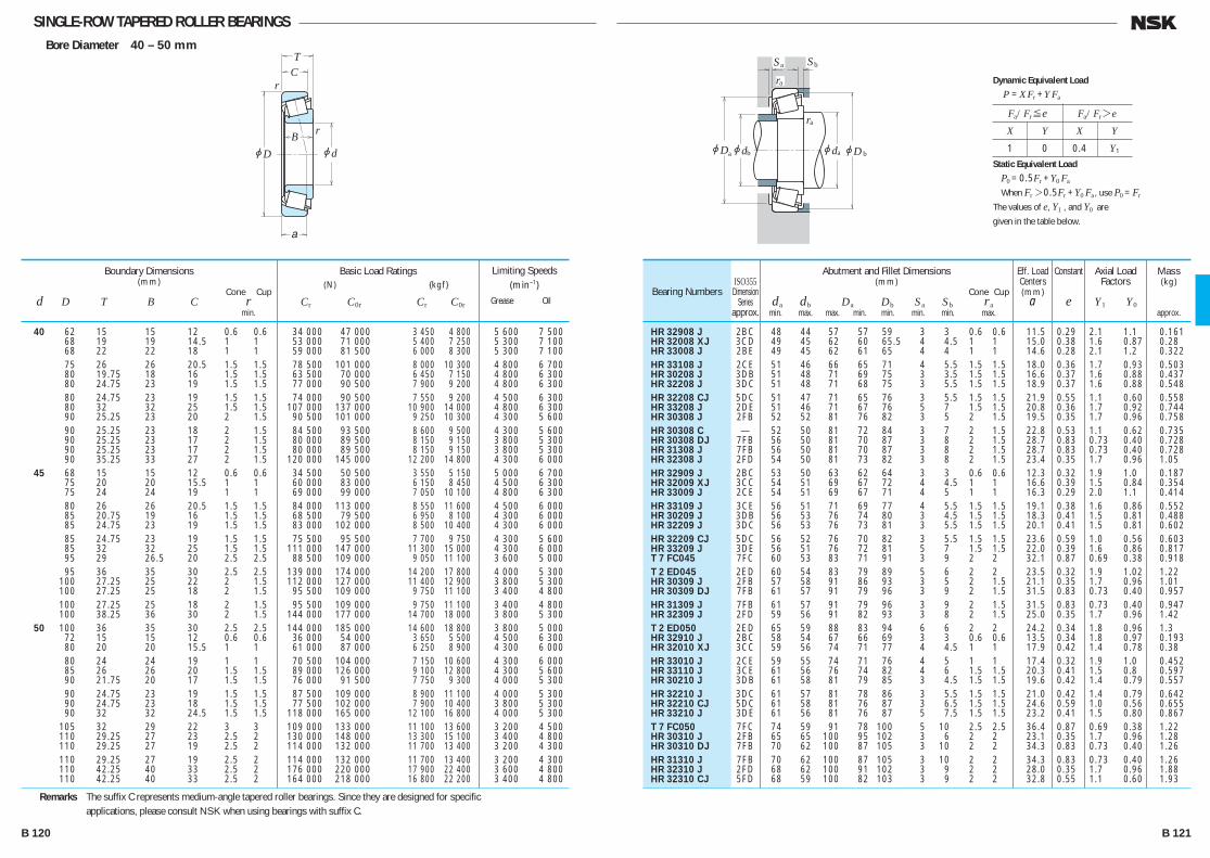
SINGLE-ROW TAPERED ROLLER BEARINGSBore Diameter 40 – 50 mm
jd
r
r
jD
TC
B
a
jDjd jd
ra
Sa Sb
ra
a b ajDb
40 62 15 15 12 0.6 0.6 34 000 47 000 3 450 4 800 5 600 7 500 68 19 19 14.5 1 1 53 000 71 000 5 400 7 250 5 300 7 100 68 22 22 18 1 1 59 000 81 500 6 000 8 300 5 300 7 100 75 26 26 20.5 1.5 1.5 78 500 101 000 8 000 10 300 4 800 6 700 80 19.75 18 16 1.5 1.5 63 500 70 000 6 450 7 150 4 800 6 300 80 24.75 23 19 1.5 1.5 77 000 90 500 7 900 9 200 4 800 6 300 80 24.75 23 19 1.5 1.5 74 000 90 500 7 550 9 200 4 500 6 300 80 32 32 25 1.5 1.5 107 000 137 000 10 900 14 000 4 800 6 300 90 25.25 23 20 2 1.5 90 500 101 000 9 250 10 300 4 300 5 600 90 25.25 23 18 2 1.5 84 500 93 500 8 600 9 500 4 300 5 600 90 25.25 23 17 2 1.5 80 000 89 500 8 150 9 150 3 800 5 300 90 25.25 23 17 2 1.5 80 000 89 500 8 150 9 150 3 800 5 300 90 35.25 33 27 2 1.5 120 000 145 000 12 200 14 800 4 300 6 000 45 68 15 15 12 0.6 0.6 34 500 50 500 3 550 5 150 5 000 6 700 75 20 20 15.5 1 1 60 000 83 000 6 150 8 450 4 500 6 300 75 24 24 19 1 1 69 000 99 000 7 050 10 100 4 800 6 300 80 26 26 20.5 1.5 1.5 84 000 113 000 8 550 11 600 4 500 6 000 85 20.75 19 16 1.5 1.5 68 500 79 500 6 950 8 100 4 300 6 000 85 24.75 23 19 1.5 1.5 83 000 102 000 8 500 10 400 4 300 6 000 85 24.75 23 19 1.5 1.5 75 500 95 500 7 700 9 750 4 300 5 600 85 32 32 25 1.5 1.5 111 000 147 000 11 300 15 000 4 300 6 000 95 29 26.5 20 2.5 2.5 88 500 109 000 9 050 11 100 3 600 5 000 95 36 35 30 2.5 2.5 139 000 174 000 14 200 17 800 4 000 5 300 100 27.25 25 22 2 1.5 112 000 127 000 11 400 12 900 3 800 5 300 100 27.25 25 18 2 1.5 95 500 109 000 9 750 11 100 3 400 4 800 100 27.25 25 18 2 1.5 95 500 109 000 9 750 11 100 3 400 4 800 100 38.25 36 30 2 1.5 144 000 177 000 14 700 18 000 3 800 5 300 50 100 36 35 30 2.5 2.5 144 000 185 000 14 600 18 800 3 800 5 000 72 15 15 12 0.6 0.6 36 000 54 000 3 650 5 500 4 500 6 300 80 20 20 15.5 1 1 61 000 87 000 6 250 8 900 4 300 6 000 80 24 24 19 1 1 70 500 104 000 7 150 10 600 4 300 6 000 85 26 26 20 1.5 1.5 89 000 126 000 9 100 12 800 4 300 5 600 90 21.75 20 17 1.5 1.5 76 000 91 500 7 750 9 300 4 000 5 300 90 24.75 23 19 1.5 1.5 87 500 109 000 8 900 11 100 4 000 5 300 90 24.75 23 18 1.5 1.5 77 500 102 000 7 900 10 400 3 800 5 300 90 32 32 24.5 1.5 1.5 118 000 165 000 12 100 16 800 4 000 5 300 105 32 29 22 3 3 109 000 133 000 11 100 13 600 3 200 4 500 110 29.25 27 23 2.5 2 130 000 148 000 13 300 15 100 3 400 4 800 110 29.25 27 19 2.5 2 114 000 132 000 11 700 13 400 3 200 4 300 110 29.25 27 19 2.5 2 114 000 132 000 11 700 13 400 3 200 4 300 110 42.25 40 33 2.5 2 176 000 220 000 17 900 22 400 3 600 4 800 110 42.25 40 33 2.5 2 164 000 218 000 16 800 22 200 3 400 4 800
Boundary Dimensions(mm)
Cone Cup d D T B C r min.
Limiting Speeds (min–1)
Grease Oil
Basic Load Ratings (N) {kgf}
Cr C0r Cr C0r
HR 32908 J 2BC 48 44 57 57 59 3 3 0.6 0.6 11.5 0.29 2.1 1.1 0.161 HR 32008 XJ 3CD 49 45 62 60 65.5 4 4.5 1 1 15.0 0.38 1.6 0.87 0.28 HR 33008 J 2BE 49 45 62 61 65 4 4 1 1 14.6 0.28 2.1 1.2 0.322 HR 33108 J 2CE 51 46 66 65 71 4 5.5 1.5 1.5 18.0 0.36 1.7 0.93 0.503 HR 30208 J 3DB 51 48 71 69 75 3 3.5 1.5 1.5 16.6 0.37 1.6 0.88 0.437 HR 32208 J 3DC 51 48 71 68 75 3 5.5 1.5 1.5 18.9 0.37 1.6 0.88 0.548 HR 32208 CJ 5DC 51 47 71 65 76 3 5.5 1.5 1.5 21.9 0.55 1.1 0.60 0.558 HR 33208 J 2DE 51 46 71 67 76 5 7 1.5 1.5 20.8 0.36 1.7 0.92 0.744 HR 30308 J 2FB 52 52 81 76 82 3 5 2 1.5 19.5 0.35 1.7 0.96 0.758 HR 30308 C — 52 50 81 72 84 3 7 2 1.5 22.8 0.53 1.1 0.62 0.735 HR 30308 DJ 7FB 56 50 81 70 87 3 8 2 1.5 28.7 0.83 0.73 0.40 0.728 HR 31308 J 7FB 56 50 81 70 87 3 8 2 1.5 28.7 0.83 0.73 0.40 0.728 HR 32308 J 2FD 54 50 81 73 82 3 8 2 1.5 23.4 0.35 1.7 0.96 1.05 HR 32909 J 2BC 53 50 63 62 64 3 3 0.6 0.6 12.3 0.32 1.9 1.0 0.187 HR 32009 XJ 3CC 54 51 69 67 72 4 4.5 1 1 16.6 0.39 1.5 0.84 0.354 HR 33009 J 2CE 54 51 69 67 71 4 5 1 1 16.3 0.29 2.0 1.1 0.414 HR 33109 J 3CE 56 51 71 69 77 4 5.5 1.5 1.5 19.1 0.38 1.6 0.86 0.552 HR 30209 J 3DB 56 53 76 74 80 3 4.5 1.5 1.5 18.3 0.41 1.5 0.81 0.488 HR 32209 J 3DC 56 53 76 73 81 3 5.5 1.5 1.5 20.1 0.41 1.5 0.81 0.602 HR 32209 CJ 5DC 56 52 76 70 82 3 5.5 1.5 1.5 23.6 0.59 1.0 0.56 0.603 HR 33209 J 3DE 56 51 76 72 81 5 7 1.5 1.5 22.0 0.39 1.6 0.86 0.817 T 7 FC045 7FC 60 53 83 71 91 3 9 2 2 32.1 0.87 0.69 0.38 0.918 T 2 ED045 2ED 60 54 83 79 89 5 6 2 2 23.5 0.32 1.9 1.02 1.22 HR 30309 J 2FB 57 58 91 86 93 3 5 2 1.5 21.1 0.35 1.7 0.96 1.01 HR 30309 DJ 7FB 61 57 91 79 96 3 9 2 1.5 31.5 0.83 0.73 0.40 0.957 HR 31309 J 7FB 61 57 91 79 96 3 9 2 1.5 31.5 0.83 0.73 0.40 0.947 HR 32309 J 2FD 59 56 91 82 93 3 8 2 1.5 25.0 0.35 1.7 0.96 1.42 T 2 ED050 2ED 65 59 88 83 94 6 6 2 2 24.2 0.34 1.8 0.96 1.3 HR 32910 J 2BC 58 54 67 66 69 3 3 0.6 0.6 13.5 0.34 1.8 0.97 0.193 HR 32010 XJ 3CC 59 56 74 71 77 4 4.5 1 1 17.9 0.42 1.4 0.78 0.38 HR 33010 J 2CE 59 55 74 71 76 4 5 1 1 17.4 0.32 1.9 1.0 0.452 HR 33110 J 3CE 61 56 76 74 82 4 6 1.5 1.5 20.3 0.41 1.5 0.8 0.597 HR 30210 J 3DB 61 58 81 79 85 3 4.5 1.5 1.5 19.6 0.42 1.4 0.79 0.557 HR 32210 J 3DC 61 57 81 78 86 3 5.5 1.5 1.5 21.0 0.42 1.4 0.79 0.642 HR 32210 CJ 5DC 61 58 81 76 87 3 6.5 1.5 1.5 24.6 0.59 1.0 0.56 0.655 HR 33210 J 3DE 61 56 81 76 87 5 7.5 1.5 1.5 23.2 0.41 1.5 0.80 0.867 T 7 FC050 7FC 74 59 91 78 100 5 10 2.5 2.5 36.4 0.87 0.69 0.38 1.22 HR 30310 J 2FB 65 65 100 95 102 3 6 2 2 23.1 0.35 1.7 0.96 1.28 HR 30310 DJ 7FB 70 62 100 87 105 3 10 2 2 34.3 0.83 0.73 0.40 1.26 HR 31310 J 7FB 70 62 100 87 105 3 10 2 2 34.3 0.83 0.73 0.40 1.26 HR 32310 J 2FD 68 62 100 91 102 3 9 2 2 28.0 0.35 1.7 0.96 1.88 HR 32310 CJ 5FD 68 59 100 82 103 3 9 2 2 32.8 0.55 1.1 0.60 1.93
Bearing NumbersISO355
DimensionSeries
approx.
Abutment and Fillet Dimensions(mm)
Cone Cup da db Da Db Sa Sb ra min. max. max. min. min. min. min. max.
Mass(kg)
approx.
Eff. Load Centers(mm)
a
Constant
e
Axial Load Factors
Y1 Y0
Remarks The suffix C represents medium-angle tapered roller bearings. Since they are designed for specific applications, please consult NSK when using bearings with suffix C.
Fa/Fr≤e Fa/Fr>e
X Y X Y
1 0 0.4 Y1
Dynamic Equivalent Load
P =XFr +YFa
Static Equivalent Load
P0 =0.5Fr +Y0 Fa
When Fr>0.5Fr +Y0 Fa, use P0 =Fr
The values of e, Y1 , and Y0 are
given in the table below.
B 120 B 121
B110-181E.indd 120-121B110-181E.indd 120-121 11/20/13 4:56:56 PM11/20/13 4:56:56 PM

SINGLE-ROW TAPERED ROLLER BEARINGSBore Diameter 55 – 65 mm
jd
r
r
jD
TC
B
a
jDjd jd
ra
Sa Sb
ra
a b ajDb
55 80 17 17 14 1 1 45 500 74 500 4 600 7 600 4 300 5 600 90 23 23 17.5 1.5 1.5 81 500 117 000 8 300 11 900 3 800 5 300 90 27 27 21 1.5 1.5 91 500 138 000 9 300 14 000 3 800 5 300
95 30 30 23 1.5 1.5 112 000 158 000 11 500 16 100 3 800 5 000 100 22.75 21 18 2 1.5 94 500 113 000 9 650 11 500 3 600 5 000 100 26.75 25 21 2 1.5 110 000 137 000 11 200 14 000 3 600 5 000
100 35 35 27 2 1.5 141 000 193 000 14 400 19 700 3 600 5 000 115 34 31 23.5 3 3 126 000 164 000 12 800 16 700 3 000 4 300 120 31.5 29 25 2.5 2 150 000 171 000 15 200 17 500 3 200 4 300
120 31.5 29 21 2.5 2 131 000 153 000 13 400 15 600 2 800 4 000 120 31.5 29 21 2.5 2 131 000 153 000 13 400 15 600 2 800 4 000 120 45.5 43 35 2.5 2 204 000 258 000 20 800 26 300 3 200 4 300 120 45.5 43 35 2.5 2 195 000 262 000 19 900 26 700 3 200 4 300
60 85 17 17 14 1 1 49 000 84 500 5 000 8 650 3 800 5 300 95 23 23 17.5 1.5 1.5 85 500 127 000 8 700 12 900 3 600 5 000 95 27 27 21 1.5 1.5 96 000 150 000 9 800 15 300 3 600 5 000
100 30 30 23 1.5 1.5 115 000 166 000 11 700 16 900 3 400 4 800 110 23.75 22 19 2 1.5 104 000 123 000 10 600 12 500 3 400 4 500 110 29.75 28 24 2 1.5 131 000 167 000 13 400 17 000 3 400 4 500
110 38 38 29 2 1.5 166 000 231 000 16 900 23 600 3 400 4 500 125 37 33.5 26 3 3 151 000 197 000 15 400 20 100 2 800 3 800 130 33.5 31 26 3 2.5 174 000 201 000 17 700 20 500 3 000 4 000
130 33.5 31 22 3 2.5 151 000 177 000 15 400 18 100 2 600 3 800 130 33.5 31 22 3 2.5 151 000 177 000 15 400 18 100 2 600 3 800 130 48.5 46 37 3 2.5 233 000 295 000 23 700 30 000 3 000 4 000 130 48.5 46 35 3 2.5 196 000 249 000 20 000 25 400 2 800 3 800
65 90 17 17 14 1 1 49 000 86 500 5 000 8 800 3 600 5 000 100 23 23 17.5 1.5 1.5 86 500 132 000 8 800 13 500 3 400 4 500 100 27 27 21 1.5 1.5 97 500 156 000 9 950 15 900 3 400 4 500
110 34 34 26.5 1.5 1.5 148 000 218 000 15 100 22 200 3 200 4 300 120 24.75 23 20 2 1.5 122 000 151 000 12 500 15 400 3 000 4 000 120 32.75 31 27 2 1.5 157 000 202 000 16 000 20 600 3 000 4 000
120 41 41 32 2 1.5 202 000 282 000 20 600 28 800 3 000 4 000 140 36 33 28 3 2.5 200 000 233 000 20 400 23 800 2 600 3 600 140 36 33 23 3 2.5 173 000 205 000 17 700 20 900 2 400 3 400
140 36 33 23 3 2.5 173 000 205 000 17 700 20 900 2 400 3 400 140 51 48 39 3 2.5 267 000 340 000 27 300 35 000 2 800 3 800
Boundary Dimensions(mm)
Cone Cup d D T B C r min.
Limiting Speeds (min–1)
Grease Oil
Basic Load Ratings (N) {kgf}
Cr C0r Cr C0r
HR 32911 J 2BC 64 60 74 73 76 4 3 1 1 14.6 0.31 1.9 1.1 0.282 HR 32011 XJ 3CC 66 62 81 80 86 4 5.5 1.5 1.5 19.7 0.41 1.5 0.81 0.568 HR 33011 J 2CE 66 62 81 80 86 5 6 1.5 1.5 19.2 0.31 1.9 1.1 0.657
HR 33111 J 3CE 66 62 86 82 91 5 7 1.5 1.5 22.4 0.37 1.6 0.88 0.877 HR 30211 J 3DB 67 64 91 89 94 4 4.5 2 1.5 20.9 0.41 1.5 0.81 0.736 HR 32211 J 3DC 67 63 91 87 95 4 5.5 2 1.5 22.7 0.41 1.5 0.81 0.859
HR 33211 J 3DE 67 62 91 86 96 6 8 2 1.5 25.2 0.40 1.5 0.83 1.18 T 7 FC055 7FC 73 66 101 86 109 4 10.5 2.5 2.5 39.0 0.87 0.69 0.38 1.58 HR 30311 J 2FB 70 71 110 104 111 4 6.5 2 2 24.6 0.35 1.7 0.96 1.63
HR 30311 DJ 7FB 75 67 110 94 114 4 10.5 2 2 37.0 0.83 0.73 0.40 1.58 HR 31311 J 7FB 75 67 110 94 114 4 10.5 2 2 37.0 0.83 0.73 0.40 1.58 HR 32311 J 2FD 73 67 110 99 111 4 10.5 2 2 29.9 0.35 1.7 0.96 2.39 HR 32311 CJ 5FD 73 65 110 91 112 4 10.5 2 2 35.8 0.55 1.1 0.60 2.47
HR 32912 J 2BC 69 65 79 78 81 4 3 1 1 15.5 0.33 1.8 1.0 0.306 HR 32012 XJ 4CC 71 66 86 85 91 4 5.5 1.5 1.5 20.9 0.43 1.4 0.77 0.608 HR 33012 J 2CE 71 66 86 85 90 5 6 1.5 1.5 20.0 0.33 1.8 1.0 0.713
HR 33112 J 3CE 71 68 91 88 96 5 7 1.5 1.5 23.6 0.40 1.5 0.83 0.91 HR 30212 J 3EB 72 69 101 96 103 4 4.5 2 1.5 22.0 0.41 1.5 0.81 0.930 HR 32212 J 3EC 72 68 101 95 104 4 5.5 2 1.5 24.1 0.41 1.5 0.81 1.18
HR 33212 J 3EE 72 68 101 94 105 6 9 2 1.5 27.6 0.40 1.5 0.82 1.56 T 7 FC060 7FC 78 72 111 94 119 4 11 2.5 2.5 41.4 0.82 0.73 0.40 2.03 HR 30312 J 2FB 78 77 118 112 120 4 7.5 2.5 2 26.0 0.35 1.7 0.96 2.03
HR 30312 DJ 7FB 84 74 118 103 125 4 11.5 2.5 2 40.3 0.83 0.73 0.40 1.98 HR 31312 J 7FB 84 74 118 103 125 4 11.5 2.5 2 40.3 0.83 0.73 0.40 1.98 HR 32312 J 2FD 81 74 118 107 120 4 11.5 2.5 2 31.4 0.35 1.7 0.96 2.96 32312 C — 81 74 116 102 125 4 13.5 2.5 2 39.9 0.58 1.0 0.57 2.86
HR 32913 J 2BC 74 70 84 82 86 4 3 1 1 16.8 0.35 1.7 0.93 0.323 HR 32013 XJ 4CC 76 71 91 90 97 4 5.5 1.5 1.5 22.4 0.46 1.3 0.72 0.646 HR 33013 J 2CE 76 71 91 90 96 5 6 1.5 1.5 21.1 0.35 1.7 0.95 0.76
HR 33113 J 3DE 76 73 101 96 106 6 7.5 1.5 1.5 26.0 0.39 1.5 0.85 1.32 HR 30213 J 3EB 77 78 111 106 113 4 4.5 2 1.5 23.8 0.41 1.5 0.81 1.18 HR 32213 J 3EC 77 75 111 104 115 4 5.5 2 1.5 27.1 0.41 1.5 0.81 1.55
HR 33213 J 3EE 77 74 111 102 115 6 9 2 1.5 29.2 0.39 1.5 0.85 2.04 HR 30313 J 2GB 83 83 128 121 130 4 8 2.5 2 27.9 0.35 1.7 0.96 2.51 HR 30313 DJ 7GB 89 80 128 111 133 4 13 2.5 2 43.2 0.83 0.73 0.40 2.43
HR 31313 J 7GB 89 80 128 111 133 4 13 2.5 2 43.2 0.83 0.73 0.40 2.43 HR 32313 J 2GD 86 80 128 116 130 4 12 2.5 2 34.0 0.35 1.7 0.96 3.6
Bearing NumbersISO355
DimensionSeries
approx.
Abutment and Fillet Dimensions(mm)
Cone Cup da db Da Db Sa Sb ra min. max. max. min. min. min. min. max.
Mass(kg)
approx.
Eff. Load Centers(mm)
a
Constant
e
Axial Load Factors
Y1 Y0
Remarks The suffix C represents medium-angle tapered roller bearings. Since they are designed for specific applications, please consult NSK when using bearings with suffix C.
Fa/Fr≤e Fa/Fr>e
X Y X Y
1 0 0.4 Y1
Dynamic Equivalent Load
P =XFr +YFa
Static Equivalent Load
P0 =0.5Fr +Y0 Fa
When Fr>0.5Fr +Y0 Fa, use P0 =Fr
The values of e, Y1 , and Y0 are
given in the table below.
B 122 B 123
B110-181E.indd 122-123B110-181E.indd 122-123 11/20/13 4:56:57 PM11/20/13 4:56:57 PM

SINGLE-ROW TAPERED ROLLER BEARINGSBore Diameter 70 – 80 mm
jd
r
r
jD
TC
B
a
jDjd jd
ra
Sa Sb
ra
a b ajDb
70 100 20 20 16 1 1 70 000 113 000 7 150 11 500 3 200 4 500 110 25 25 19 1.5 1.5 104 000 158 000 10 600 16 100 3 200 4 300 110 31 31 25.5 1.5 1.5 127 000 204 000 12 900 20 800 3 000 4 300
120 37 37 29 2 1.5 177 000 262 000 18 100 26 700 3 000 4 000 125 26.25 24 21 2 1.5 132 000 163 000 13 500 16 700 2 800 4 000 125 33.25 31 27 2 1.5 157 000 205 000 16 100 20 900 2 800 4 000
125 41 41 32 2 1.5 209 000 299 000 21 300 30 500 2 800 4 000 140 39 35.5 27 3 3 177 000 229 000 18 000 23 400 2 400 3 400 150 38 35 30 3 2.5 227 000 268 000 23 200 27 400 2 400 3 400
150 38 35 25 3 2.5 192 000 229 000 19 600 23 300 2 200 3 200 150 38 35 25 3 2.5 192 000 229 000 19 600 23 300 2 200 3 200 150 54 51 42 3 2.5 300 000 390 000 30 500 39 500 2 600 3 400 150 54 51 42 3 2.5 280 000 390 000 28 600 39 500 2 400 3 400
75 105 20 20 16 1 1 72 500 120 000 7 400 12 300 3 200 4 300 115 25 25 19 1.5 1.5 109 000 171 000 11 100 17 400 3 000 4 000 115 31 31 25.5 1.5 1.5 133 000 220 000 13 500 22 500 3 000 4 000
125 37 37 29 2 2 182 000 275 000 18 600 28 100 2 800 3 800 130 27.25 25 22 2 1.5 143 000 182 000 14 600 18 500 2 800 3 800 130 33.25 31 27 2 1.5 165 000 219 000 16 900 22 400 2 800 3 800
130 41 41 31 2 1.5 215 000 315 000 21 900 32 000 2 800 3 800 160 40 37 31 3 2.5 253 000 300 000 25 800 30 500 2 400 3 200 160 40 37 26 3 2.5 211 000 251 000 21 500 25 600 2 200 3 000
160 40 37 26 3 2.5 211 000 251 000 21 500 25 600 2 200 3 000 160 58 55 45 3 2.5 340 000 445 000 35 000 45 500 2 400 3 200 160 58 55 43 3 2.5 310 000 420 000 32 000 43 000 2 200 3 200
80 110 20 20 16 1 1 75 000 128 000 7 650 13 100 3 000 4 000 125 29 29 22 1.5 1.5 140 000 222 000 14 300 22 700 2 800 3 600 125 36 36 29.5 1.5 1.5 172 000 282 000 17 500 28 800 2 800 3 600
130 37 37 29 2 1.5 186 000 289 000 19 000 29 400 2 600 3 600 140 28.25 26 22 2.5 2 157 000 195 000 16 000 19 900 2 600 3 400 140 28.25 26 20 2.5 2 147 000 190 000 15 000 19 400 2 400 3 400
140 35.25 33 28 2.5 2 192 000 254 000 19 600 25 900 2 600 3 400 140 46 46 35 2.5 2 256 000 385 000 26 200 39 000 2 600 3 400 170 42.5 39 33 3 2.5 276 000 330 000 28 200 33 500 2 200 3 000
170 42.5 39 27 3 2.5 235 000 283 000 24 000 28 900 2 000 2 800 170 42.5 39 27 3 2.5 235 000 283 000 24 000 28 900 2 000 2 800 170 61.5 58 48 3 2.5 385 000 505 000 39 000 51 500 2 200 3 000 170 61.5 58 48 3 2.5 365 000 530 000 37 500 54 000 2 200 3 000
Boundary Dimensions(mm)
Cone Cup d D T B C r min.
Limiting Speeds (min–1)
Grease Oil
Basic Load Ratings (N) {kgf}
Cr C0r Cr C0r
HR 32914 J 2BC 79 76 94 93 96 4 4 1 1 17.6 0.32 1.9 1.1 0.494 HR 32014 XJ 4CC 81 77 101 98 105 5 6 1.5 1.5 23.7 0.43 1.4 0.76 0.869 HR 33014 J 2CE 81 78 101 100 105 5 5.5 1.5 1.5 22.2 0.28 2.1 1.2 1.11
HR 33114 J 3DE 82 79 111 104 115 6 8 2 1.5 27.9 0.38 1.6 0.87 1.71 HR 30214 J 3EB 82 81 116 110 118 4 5 2 1.5 25.6 0.42 1.4 0.79 1.3 HR 32214 J 3EC 82 80 116 108 119 4 6 2 1.5 28.6 0.42 1.4 0.79 1.66
HR 33214 J 3EE 82 78 116 107 120 7 9 2 1.5 30.4 0.41 1.5 0.81 2.15 T 7 FC070 7FC 88 79 126 106 133 5 12 2.5 2.5 46.4 0.87 0.69 0.38 2.55 HR 30314 J 2GB 88 89 138 132 140 4 8 2.5 2 29.7 0.35 1.7 0.96 3.03
HR 30314 DJ 7GB 94 85 138 118 142 4 13 2.5 2 45.8 0.83 0.73 0.40 2.94 HR 31314 J 7GB 94 85 138 118 142 4 13 2.5 2 45.8 0.83 0.73 0.40 2.94 HR 32314 J 2GD 91 86 138 124 140 4 12 2.5 2 36.1 0.35 1.7 0.96 4.35 HR 32314 CJ 5GD 91 84 138 115 141 4 12 2.5 2 43.3 0.55 1.1 0.60 4.47
HR 32915 J 2BC 84 81 99 98 101 4 4 1 1 18.7 0.33 1.8 0.99 0.53 HR 32015 XJ 4CC 86 82 106 103 110 5 6 1.5 1.5 25.1 0.46 1.3 0.72 0.925 HR 33015 J 2CE 86 83 106 104 110 6 5.5 1.5 1.5 23.0 0.30 2.0 1.1 1.18
HR 33115 J 3DE 87 83 115 109 120 6 8 2 2 29.2 0.40 1.5 0.83 1.8 HR 30215 J 4DB 87 85 121 115 124 4 5 2 1.5 27.0 0.44 1.4 0.76 1.43 HR 32215 J 4DC 87 84 121 113 125 4 6 2 1.5 29.8 0.44 1.4 0.76 1.72
HR 33215 J 3EE 87 83 121 111 125 7 10 2 1.5 31.6 0.43 1.4 0.77 2.25 HR 30315 J 2GB 93 95 148 141 149 4 9 2.5 2 31.8 0.35 1.7 0.96 3.63 HR 30315 DJ 7GB 99 91 148 129 152 6 14 2.5 2 48.8 0.83 0.73 0.40 3.47
HR 31315 J 7GB 99 91 148 129 152 6 14 2.5 2 48.8 0.83 0.73 0.40 3.47 HR 32315 J 2GD 96 91 148 134 149 4 13 2.5 2 38.9 0.35 1.7 0.96 5.31 32315 CA — 96 90 148 124 153 4 15 2.5 2 47.7 0.58 1.0 0.57 5.3
HR 32916 J 2BC 89 85 104 102 106 4 4 1 1 19.8 0.35 1.7 0.94 0.56 HR 32016 XJ 3CC 91 89 116 112 120 6 7 1.5 1.5 26.9 0.42 1.4 0.78 1.32 HR 33016 J 2CE 91 88 116 112 119 6 6.5 1.5 1.5 25.5 0.28 2.2 1.2 1.66
HR 33116 J 3DE 82 88 121 113 126 6 8 2 1.5 30.4 0.42 1.4 0.79 1.88 HR 30216 J 3EB 95 91 130 124 132 4 6 2 2 28.1 0.42 1.4 0.79 1.68 30216 CA — 95 92 130 122 133 4 8 2 2 33.8 0.58 1.0 0.57 1.66
HR 32216 J 3EC 95 90 130 122 134 4 7 2 2 30.6 0.42 1.4 0.79 2.13 HR 33216 J 3EE 95 89 130 119 135 7 11 2 2 34.8 0.43 1.4 0.78 2.93 HR 30316 J 2GB 98 102 158 150 159 4 9.5 2.5 2 34.0 0.35 1.7 0.96 4.27
HR 30316 DJ 7GB 104 97 158 136 159 6 15.5 2.5 2 51.8 0.83 0.73 0.40 4.07 HR 31316 J 7GB 104 97 158 136 159 6 15.5 2.5 2 51.8 0.83 0.73 0.40 4.07 HR 32316 J 2GD 101 98 158 143 159 4 13.5 2.5 2 41.4 0.35 1.7 0.96 6.35 HR 32316 CJ 5GD 101 95 158 132 160 4 13.5 2.5 2 49.3 0.55 1.1 0.60 6.59
Bearing NumbersISO355
DimensionSeries
approx.
Abutment and Fillet Dimensions(mm)
Cone Cup da db Da Db Sa Sb ra min. max. max. min. min. min. min. max.
Mass(kg)
approx.
Eff. Load Centers(mm)
a
Constant
e
Axial Load Factors
Y1 Y0
Remarks The suffix CA represents medium-angle tapered roller bearings. Since they are designed for specific applications, please consult NSK when using bearings with suffix CA.
Fa/Fr≤e Fa/Fr>e
X Y X Y
1 0 0.4 Y1
Dynamic Equivalent Load
P =XFr +YFa
Static Equivalent Load
P0 =0.5Fr +Y0 Fa
When Fr>0.5Fr +Y0 Fa, use P0 =Fr
The values of e, Y1 , and Y0 are
given in the table below.
B 124 B 125
B110-181E.indd 124-125B110-181E.indd 124-125 11/20/13 4:56:58 PM11/20/13 4:56:58 PM

SINGLE-ROW TAPERED ROLLER BEARINGSBore Diameter 85 – 100 mm
jd
r
r
jD
TC
B
a
jDjd jd
ra
Sa Sb
ra
a b ajDb
85 120 23 23 18 1.5 1.5 93 500 157 000 9 550 16 000 2 800 3 800 130 29 29 22 1.5 1.5 143 000 231 000 14 600 23 600 2 600 3 600 130 36 36 29.5 1.5 1.5 180 000 305 000 18 400 31 000 2 600 3 600 140 41 41 32 2.5 2 230 000 365 000 23 500 37 000 2 400 3 400 150 30.5 28 24 2.5 2 184 000 233 000 18 700 23 800 2 400 3 200 150 30.5 28 22 2.5 2 171 000 226 000 17 500 23 000 2 200 3 200 150 38.5 36 30 2.5 2 210 000 277 000 21 400 28 200 2 200 3 200 150 49 49 37 2.5 2 281 000 415 000 28 700 42 500 2 400 3 200 180 44.5 41 34 4 3 310 000 375 000 31 500 38 000 2 000 2 800 180 44.5 41 28 4 3 261 000 315 000 26 600 32 000 1 900 2 600 180 44.5 41 28 4 3 261 000 315 000 26 600 32 000 1 900 2 600 180 63.5 60 49 4 3 410 000 535 000 42 000 54 500 2 000 2 800 90 125 23 23 18 1.5 1.5 97 000 167 000 9 850 17 000 2 600 3 600 140 32 32 24 2 1.5 170 000 273 000 17 300 27 800 2 400 3 200 140 39 39 32.5 2 1.5 220 000 360 000 22 400 37 000 2 400 3 200 150 45 45 35 2.5 2 259 000 405 000 26 500 41 500 2 400 3 200 160 32.5 30 26 2.5 2 201 000 256 000 20 500 26 100 2 200 3 000 160 42.5 40 34 2.5 2 256 000 350 000 26 100 35 500 2 200 3 000 190 46.5 43 36 4 3 345 000 425 000 35 500 43 000 1 900 2 600 190 46.5 43 30 4 3 264 000 315 000 26 900 32 000 1 800 2 400 190 46.5 43 30 4 3 264 000 315 000 26 900 32 000 1 800 2 400 190 67.5 64 53 4 3 450 000 590 000 46 000 60 500 2 000 2 600 95 130 23 23 18 1.5 1.5 98 000 172 000 10 000 17 500 2 400 3 400 145 32 32 24 2 1.5 173 000 283 000 17 600 28 900 2 400 3 200 145 39 39 32.5 2 1.5 231 000 390 000 23 500 39 500 2 400 3 200 160 46 46 38 3 3 283 000 445 000 28 800 45 500 2 200 3 000 170 34.5 32 27 3 2.5 223 000 286 000 22 800 29 200 2 200 2 800 170 45.5 43 37 3 2.5 289 000 400 000 29 500 40 500 2 200 2 800 200 49.5 45 38 4 3 370 000 455 000 38 000 46 500 1 900 2 600 200 49.5 45 36 4 3 350 000 435 000 35 500 44 000 1 800 2 400 200 49.5 45 32 4 3 310 000 375 000 31 500 38 500 1 700 2 400 200 49.5 45 32 4 3 310 000 375 000 31 500 38 500 1 700 2 400 200 71.5 67 55 4 3 525 000 710 000 53 500 72 500 1 900 2 600 100 140 25 25 20 1.5 1.5 117 000 205 000 12 000 20 900 2 200 3 200 145 24 22.5 17.5 3 3 113 000 163 000 11 500 16 600 2 200 3 000 150 32 32 24 2 1.5 176 000 294 000 17 900 30 000 2 200 3 000 150 39 39 32.5 2 1.5 235 000 405 000 24 000 41 500 2 200 3 000 165 52 52 40 2.5 2 315 000 515 000 32 500 52 500 2 000 2 800 180 37 34 29 3 2.5 255 000 330 000 26 000 34 000 2 000 2 600 180 49 46 39 3 2.5 325 000 450 000 33 000 46 000 2 000 2 600 180 63 63 48 3 2.5 410 000 635 000 42 000 65 000 2 000 2 600 215 51.5 47 39 4 3 425 000 525 000 43 000 53 500 1 700 2 400 215 56.5 51 35 4 3 385 000 505 000 39 000 51 500 1 500 2 200 215 77.5 73 60 4 3 565 000 755 000 57 500 77 000 1 700 2 400
Boundary Dimensions(mm)
Cone Cup d D T B C r min.
Limiting Speeds (min–1)
Grease Oil
Basic Load Ratings (N) {kgf}
Cr C0r Cr C0r
HR 32917 J 2BC 96 92 111 111 115 5 5 1.5 1.5 20.9 0.33 1.8 1.0 0.8 HR 32017 XJ 4CC 96 94 121 116 125 6 7 1.5 1.5 28.2 0.44 1.4 0.75 1.38 HR 33017 J 2CE 96 94 121 117 125 6 6.5 1.5 1.5 26.5 0.29 2.1 1.1 1.75 HR 33117 J 3DE 100 94 130 122 135 7 9 2 2 32.7 0.41 1.5 0.81 2.51 HR 30217 J 3EB 100 97 140 133 141 5 6.5 2 2 30.3 0.42 1.4 0.79 2.12 30217 CA — 100 98 140 131 142 5 8.5 2 2 36.2 0.58 1.0 0.57 2.07 HR 32217 J 3EC 100 96 140 131 142 5 8.5 2 2 33.9 0.42 1.4 0.79 2.64 HR 33217 J 3EE 100 95 140 129 144 7 12 2 2 37.3 0.42 1.4 0.79 3.57 HR 30317 J 2GB 106 108 166 157 167 5 10.5 3 2.5 35.8 0.35 1.7 0.96 5.08 HR 30317 DJ 7GB 113 103 166 144 169 6 16.5 3 2.5 55.4 0.83 0.73 0.40 4.88 HR 31317 J 7GB 113 103 166 144 169 6 16.5 3 2.5 55.4 0.83 0.73 0.40 4.88 HR 32317 J 2GD 110 104 166 151 167 5 14.5 3 2.5 43.6 0.35 1.7 0.96 7.31 HR 32918 J 2BC 101 97 116 116 120 5 5 1.5 1.5 22.0 0.34 1.8 0.96 0.838 HR 32018 XJ 3CC 102 99 131 124 134 6 8 2 1.5 29.7 0.42 1.4 0.78 1.78 HR 33018 J 2CE 102 99 131 129 135 7 6.5 2 1.5 27.9 0.27 2.2 1.2 2.21 HR 33118 J 3DE 105 100 140 132 144 7 10 2 2 35.2 0.40 1.5 0.83 3.14 HR 30218 J 3FB 105 103 150 141 150 5 6.5 2 2 31.7 0.42 1.4 0.79 2.6 HR 32218 J 3FC 105 102 150 139 152 5 8.5 2 2 36.2 0.42 1.4 0.79 3.41 HR 30318 J 2GB 111 114 176 176 176 5 10.5 3 2.5 37.3 0.35 1.7 0.96 5.91 HR 30318 DJ 7GB 118 110 176 152 179 6 16.5 3 2.5 58.7 0.83 0.73 0.40 5.52 HR 31318 J 7GB 118 110 176 152 179 6 16.5 3 2.5 58.7 0.83 0.73 0.40 5.52 HR 32318 J 2GD 115 109 176 158 177 5 14.5 3 2.5 46.5 0.35 1.7 0.96 8.6 HR 32919 J 2BC 106 102 121 121 125 5 5 1.5 1.5 23.2 0.36 1.7 0.92 0.877 HR 32019 XJ 4CC 107 104 136 131 140 6 8 2 1.5 31.2 0.44 1.4 0.75 1.88 HR 33019 J 2CE 107 103 136 133 139 7 6.5 2 1.5 28.6 0.28 2.2 1.2 2.3 T 2 ED095 2ED 113 108 146 141 152 6 8 2.5 2.5 34.5 0.34 1.8 0.97 3.74 HR 30219 J 3FB 113 110 158 150 159 5 7.5 2.5 2 33.7 0.42 1.4 0.79 3.13 HR 32219 J 3FC 113 108 158 147 161 5 8.5 2.5 2 39.3 0.42 1.4 0.79 4.22 HR 30319 J 2GB 116 119 186 172 184 5 11.5 3 2.5 38.6 0.35 1.7 0.96 6.92 30319 CA — 116 119 186 168 188 5 13.5 3 2.5 48.6 0.54 1.1 0.61 6.71 HR 30319 DJ 7GB 123 115 186 158 187 6 17.5 3 2.5 61.9 0.83 0.73 0.40 6.64 HR 31319 J 7GB 123 115 186 158 187 6 17.5 3 2.5 61.9 0.83 0.73 0.40 6.64 HR 32319 J 2GD 120 115 186 167 186 5 16.5 3 2.5 48.6 0.35 1.7 0.96 10.4 HR 32920 J 2CC 111 109 132 132 134 5 5 1.5 1.5 24.2 0.33 1.8 1.0 1.18 T 4 CB100 4CB 118 108 135 135 142 6 6.5 2.5 2.5 30.1 0.47 1.3 0.70 1.18 HR 32020 XJ 4CC 112 109 141 136 144 6 8 2 1.5 32.5 0.46 1.3 0.72 1.95 HR 33020 J 2CE 112 107 141 137 143 7 6.5 2 1.5 29.3 0.29 2.1 1.2 2.38 HR 33120 J 3EE 115 110 155 144 159 8 12 2 2 40.5 0.41 1.5 0.81 4.32 HR 30220 J 3FB 118 116 168 158 168 5 8 2.5 2 36.1 0.42 1.4 0.79 3.78 HR 32220 J 3FC 118 115 168 155 171 5 10 2.5 2 41.5 0.42 1.4 0.79 5.05 HR 33220 J 3FE 118 113 168 152 172 10 15 2.5 2 46.0 0.40 1.5 0.82 6.76 HR 30320 J 2GB 121 128 201 185 197 5 12.5 3 2.5 41.4 0.35 1.7 0.96 8.41 HR 31320 J 7GB 136 125 201 169 202 7 21.5 3 2.5 67.7 0.83 0.73 0.40 9.02 HR 32320 J 2GD 125 125 201 178 200 5 17.5 3 2.5 53.2 0.35 1.7 0.96 12.7
Bearing NumbersISO355
DimensionSeries
approx.
Abutment and Fillet Dimensions(mm)
Cone Cup da db Da Db Sa Sb ra min. max. max. min. min. min. min. max.
Mass(kg)
approx.
Eff. Load Centers(mm)
a
Constant
e
Axial Load Factors
Y1 Y0
Remarks The suffix CA represents medium-angle tapered roller bearings. Since they are designed for specific applications, please consult NSK when using bearings with suffix CA.
Fa/Fr≤e Fa/Fr>e
X Y X Y
1 0 0.4 Y1
Dynamic Equivalent Load
P =XFr +YFa
Static Equivalent Load
P0 =0.5Fr +Y0 Fa
When Fr>0.5Fr +Y0 Fa, use P0 =Fr
The values of e, Y1 , and Y0 are
given in the table below.
B 126 B 127
B110-181E.indd 126-127B110-181E.indd 126-127 11/20/13 4:56:59 PM11/20/13 4:56:59 PM
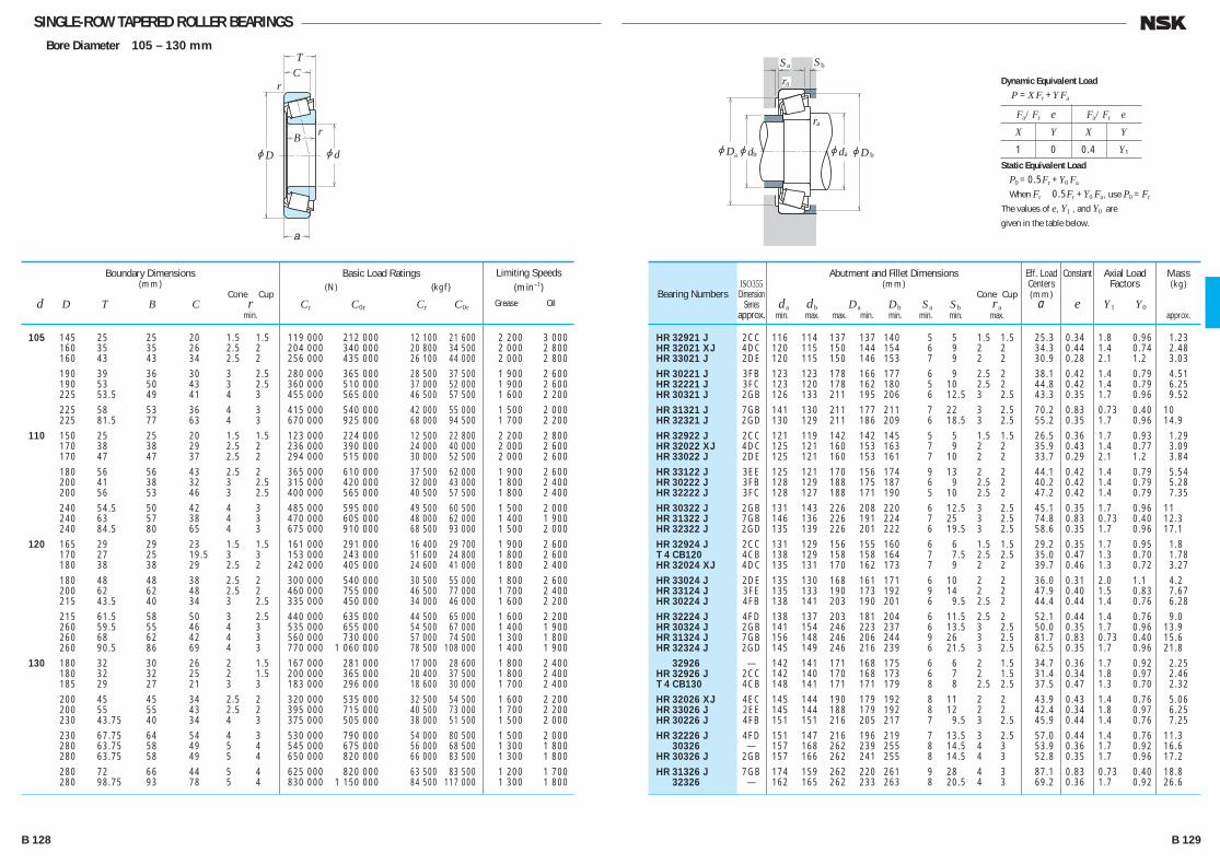
SINGLE-ROW TAPERED ROLLER BEARINGSBore Diameter 105 – 130 mm
jd
r
r
jD
TC
B
a
jDjd jd
ra
Sa Sb
ra
a b ajDb
105 145 25 25 20 1.5 1.5 119 000 212 000 12 100 21 600 2 200 3 000 160 35 35 26 2.5 2 204 000 340 000 20 800 34 500 2 000 2 800 160 43 43 34 2.5 2 256 000 435 000 26 100 44 000 2 000 2 800 190 39 36 30 3 2.5 280 000 365 000 28 500 37 500 1 900 2 600 190 53 50 43 3 2.5 360 000 510 000 37 000 52 000 1 900 2 600 225 53.5 49 41 4 3 455 000 565 000 46 500 57 500 1 600 2 200 225 58 53 36 4 3 415 000 540 000 42 000 55 000 1 500 2 000 225 81.5 77 63 4 3 670 000 925 000 68 000 94 500 1 700 2 200 110 150 25 25 20 1.5 1.5 123 000 224 000 12 500 22 800 2 200 2 800 170 38 38 29 2.5 2 236 000 390 000 24 000 40 000 2 000 2 600 170 47 47 37 2.5 2 294 000 515 000 30 000 52 500 2 000 2 600 180 56 56 43 2.5 2 365 000 610 000 37 500 62 000 1 900 2 600 200 41 38 32 3 2.5 315 000 420 000 32 000 43 000 1 800 2 400 200 56 53 46 3 2.5 400 000 565 000 40 500 57 500 1 800 2 400 240 54.5 50 42 4 3 485 000 595 000 49 500 60 500 1 500 2 000 240 63 57 38 4 3 470 000 605 000 48 000 62 000 1 400 1 900 240 84.5 80 65 4 3 675 000 910 000 68 500 93 000 1 500 2 000 120 165 29 29 23 1.5 1.5 161 000 291 000 16 400 29 700 1 900 2 600 170 27 25 19.5 3 3 153 000 243 000 51 600 24 800 1 800 2 600 180 38 38 29 2.5 2 242 000 405 000 24 600 41 000 1 800 2 400 180 48 48 38 2.5 2 300 000 540 000 30 500 55 000 1 800 2 600 200 62 62 48 2.5 2 460 000 755 000 46 500 77 000 1 700 2 400 215 43.5 40 34 3 2.5 335 000 450 000 34 000 46 000 1 600 2 200 215 61.5 58 50 3 2.5 440 000 635 000 44 500 65 000 1 600 2 200 260 59.5 55 46 4 3 535 000 655 000 54 500 67 000 1 400 1 900 260 68 62 42 4 3 560 000 730 000 57 000 74 500 1 300 1 800 260 90.5 86 69 4 3 770 000 1 060 000 78 500 108 000 1 400 1 900 130 180 32 30 26 2 1.5 167 000 281 000 17 000 28 600 1 800 2 400 180 32 32 25 2 1.5 200 000 365 000 20 400 37 500 1 800 2 400 185 29 27 21 3 3 183 000 296 000 18 600 30 000 1 700 2 400 200 45 45 34 2.5 2 320 000 535 000 32 500 54 500 1 600 2 200 200 55 55 43 2.5 2 395 000 715 000 40 500 73 000 1 700 2 200 230 43.75 40 34 4 3 375 000 505 000 38 000 51 500 1 500 2 000 230 67.75 64 54 4 3 530 000 790 000 54 000 80 500 1 500 2 000 280 63.75 58 49 5 4 545 000 675 000 56 000 68 500 1 300 1 800 280 63.75 58 49 5 4 650 000 820 000 66 000 83 500 1 300 1 800 280 72 66 44 5 4 625 000 820 000 63 500 83 500 1 200 1 700 280 98.75 93 78 5 4 830 000 1 150 000 84 500 117 000 1 300 1 800
Boundary Dimensions(mm)
Cone Cup d D T B C r min.
Limiting Speeds (min–1)
Grease Oil
Basic Load Ratings (N) {kgf}
Cr C0r Cr C0r
HR 32921 J 2CC 116 114 137 137 140 5 5 1.5 1.5 25.3 0.34 1.8 0.96 1.23 HR 32021 XJ 4DC 120 115 150 144 154 6 9 2 2 34.3 0.44 1.4 0.74 2.48 HR 33021 J 2DE 120 115 150 146 153 7 9 2 2 30.9 0.28 2.1 1.2 3.03 HR 30221 J 3FB 123 123 178 166 177 6 9 2.5 2 38.1 0.42 1.4 0.79 4.51 HR 32221 J 3FC 123 120 178 162 180 5 10 2.5 2 44.8 0.42 1.4 0.79 6.25 HR 30321 J 2GB 126 133 211 195 206 6 12.5 3 2.5 43.3 0.35 1.7 0.96 9.52 HR 31321 J 7GB 141 130 211 177 211 7 22 3 2.5 70.2 0.83 0.73 0.40 10 HR 32321 J 2GD 130 129 211 186 209 6 18.5 3 2.5 55.2 0.35 1.7 0.96 14.9 HR 32922 J 2CC 121 119 142 142 145 5 5 1.5 1.5 26.5 0.36 1.7 0.93 1.29 HR 32022 XJ 4DC 125 121 160 153 163 7 9 2 2 35.9 0.43 1.4 0.77 3.09 HR 33022 J 2DE 125 121 160 153 161 7 10 2 2 33.7 0.29 2.1 1.2 3.84 HR 33122 J 3EE 125 121 170 156 174 9 13 2 2 44.1 0.42 1.4 0.79 5.54 HR 30222 J 3FB 128 129 188 175 187 6 9 2.5 2 40.2 0.42 1.4 0.79 5.28 HR 32222 J 3FC 128 127 188 171 190 5 10 2.5 2 47.2 0.42 1.4 0.79 7.35 HR 30322 J 2GB 131 143 226 208 220 6 12.5 3 2.5 45.1 0.35 1.7 0.96 11 HR 31322 J 7GB 146 136 226 191 224 7 25 3 2.5 74.8 0.83 0.73 0.40 12.3 HR 32322 J 2GD 135 139 226 201 222 6 19.5 3 2.5 58.6 0.35 1.7 0.96 17.1 HR 32924 J 2CC 131 129 156 155 160 6 6 1.5 1.5 29.2 0.35 1.7 0.95 1.8 T 4 CB120 4CB 138 129 158 158 164 7 7.5 2.5 2.5 35.0 0.47 1.3 0.70 1.78 HR 32024 XJ 4DC 135 131 170 162 173 7 9 2 2 39.7 0.46 1.3 0.72 3.27 HR 33024 J 2DE 135 130 168 161 171 6 10 2 2 36.0 0.31 2.0 1.1 4.2 HR 33124 J 3FE 135 133 190 173 192 9 14 2 2 47.9 0.40 1.5 0.83 7.67 HR 30224 J 4FB 138 141 203 190 201 6 9.5 2.5 2 44.4 0.44 1.4 0.76 6.28 HR 32224 J 4FD 138 137 203 181 204 6 11.5 2.5 2 52.1 0.44 1.4 0.76 9.0 HR 30324 J 2GB 141 154 246 223 237 6 13.5 3 2.5 50.0 0.35 1.7 0.96 13.9 HR 31324 J 7GB 156 148 246 206 244 9 26 3 2.5 81.7 0.83 0.73 0.40 15.6 HR 32324 J 2GD 145 149 246 216 239 6 21.5 3 2.5 62.5 0.35 1.7 0.96 21.8 32926 — 142 141 171 168 175 6 6 2 1.5 34.7 0.36 1.7 0.92 2.25 HR 32926 J 2CC 142 140 170 168 173 6 7 2 1.5 31.4 0.34 1.8 0.97 2.46 T 4 CB130 4CB 148 141 171 171 179 8 8 2.5 2.5 37.5 0.47 1.3 0.70 2.32 HR 32026 XJ 4EC 145 144 190 179 192 8 11 2 2 43.9 0.43 1.4 0.76 5.06 HR 33026 J 2EE 145 144 188 179 192 8 12 2 2 42.4 0.34 1.8 0.97 6.25 HR 30226 J 4FB 151 151 216 205 217 7 9.5 3 2.5 45.9 0.44 1.4 0.76 7.25 HR 32226 J 4FD 151 147 216 196 219 7 13.5 3 2.5 57.0 0.44 1.4 0.76 11.3 30326 — 157 168 262 239 255 8 14.5 4 3 53.9 0.36 1.7 0.92 16.6 HR 30326 J 2GB 157 166 262 241 255 8 14.5 4 3 52.8 0.35 1.7 0.96 17.2 HR 31326 J 7GB 174 159 262 220 261 9 28 4 3 87.1 0.83 0.73 0.40 18.8 32326 — 162 165 262 233 263 8 20.5 4 3 69.2 0.36 1.7 0.92 26.6
Bearing NumbersISO355
DimensionSeries
approx.
Abutment and Fillet Dimensions(mm)
Cone Cup da db Da Db Sa Sb ra min. max. max. min. min. min. min. max.
Mass(kg)
approx.
Eff. Load Centers(mm)
a
Constant
e
Axial Load Factors
Y1 Y0
Fa/Fr e Fa/Fr e
X Y X Y
1 0 0.4 Y1
Dynamic Equivalent Load
P =XFr +YFa
Static Equivalent Load
P0 =0.5Fr +Y0 Fa
When Fr 0.5Fr +Y0 Fa, use P0 =Fr
The values of e, Y1 , and Y0 are
given in the table below.
B 128 B 129
B110-181E.indd 128-129B110-181E.indd 128-129 11/20/13 4:57:00 PM11/20/13 4:57:00 PM
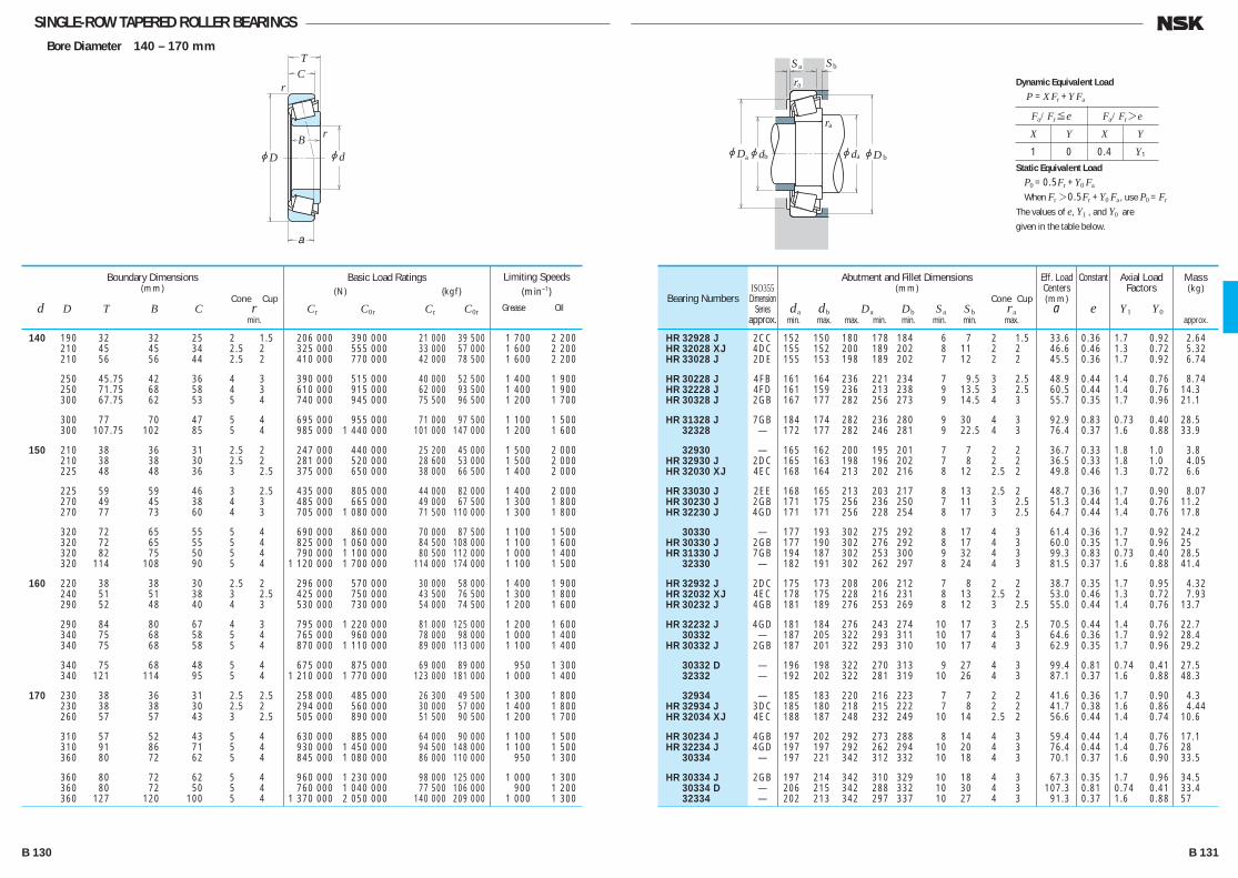
SINGLE-ROW TAPERED ROLLER BEARINGSBore Diameter 140 – 170 mm
jd
r
r
jD
TC
B
a
jDjd jd
ra
Sa Sb
ra
a b ajDb
140 190 32 32 25 2 1.5 206 000 390 000 21 000 39 500 1 700 2 200 210 45 45 34 2.5 2 325 000 555 000 33 000 57 000 1 600 2 200 210 56 56 44 2.5 2 410 000 770 000 42 000 78 500 1 600 2 200
250 45.75 42 36 4 3 390 000 515 000 40 000 52 500 1 400 1 900 250 71.75 68 58 4 3 610 000 915 000 62 000 93 500 1 400 1 900 300 67.75 62 53 5 4 740 000 945 000 75 500 96 500 1 200 1 700
300 77 70 47 5 4 695 000 955 000 71 000 97 500 1 100 1 500 300 107.75 102 85 5 4 985 000 1 440 000 101 000 147 000 1 200 1 600
150 210 38 36 31 2.5 2 247 000 440 000 25 200 45 000 1 500 2 000 210 38 38 30 2.5 2 281 000 520 000 28 600 53 000 1 500 2 000 225 48 48 36 3 2.5 375 000 650 000 38 000 66 500 1 400 2 000
225 59 59 46 3 2.5 435 000 805 000 44 000 82 000 1 400 2 000 270 49 45 38 4 3 485 000 665 000 49 000 67 500 1 300 1 800 270 77 73 60 4 3 705 000 1 080 000 71 500 110 000 1 300 1 800
320 72 65 55 5 4 690 000 860 000 70 000 87 500 1 100 1 500 320 72 65 55 5 4 825 000 1 060 000 84 500 108 000 1 100 1 600 320 82 75 50 5 4 790 000 1 100 000 80 500 112 000 1 000 1 400 320 114 108 90 5 4 1 120 000 1 700 000 114 000 174 000 1 100 1 500
160 220 38 38 30 2.5 2 296 000 570 000 30 000 58 000 1 400 1 900 240 51 51 38 3 2.5 425 000 750 000 43 500 76 500 1 300 1 800 290 52 48 40 4 3 530 000 730 000 54 000 74 500 1 200 1 600
290 84 80 67 4 3 795 000 1 220 000 81 000 125 000 1 200 1 600 340 75 68 58 5 4 765 000 960 000 78 000 98 000 1 000 1 400 340 75 68 58 5 4 870 000 1 110 000 89 000 113 000 1 100 1 400
340 75 68 48 5 4 675 000 875 000 69 000 89 000 950 1 300 340 121 114 95 5 4 1 210 000 1 770 000 123 000 181 000 1 000 1 400
170 230 38 36 31 2.5 2.5 258 000 485 000 26 300 49 500 1 300 1 800 230 38 38 30 2.5 2 294 000 560 000 30 000 57 000 1 400 1 800 260 57 57 43 3 2.5 505 000 890 000 51 500 90 500 1 200 1 700
310 57 52 43 5 4 630 000 885 000 64 000 90 000 1 100 1 500 310 91 86 71 5 4 930 000 1 450 000 94 500 148 000 1 100 1 500 360 80 72 62 5 4 845 000 1 080 000 86 000 110 000 950 1 300
360 80 72 62 5 4 960 000 1 230 000 98 000 125 000 1 000 1 300 360 80 72 50 5 4 760 000 1 040 000 77 500 106 000 900 1 200 360 127 120 100 5 4 1 370 000 2 050 000 140 000 209 000 1 000 1 300
Boundary Dimensions(mm)
Cone Cup d D T B C r min.
Limiting Speeds (min–1)
Grease Oil
Basic Load Ratings (N) {kgf}
Cr C0r Cr C0r
HR 32928 J 2CC 152 150 180 178 184 6 7 2 1.5 33.6 0.36 1.7 0.92 2.64 HR 32028 XJ 4DC 155 152 200 189 202 8 11 2 2 46.6 0.46 1.3 0.72 5.32 HR 33028 J 2DE 155 153 198 189 202 7 12 2 2 45.5 0.36 1.7 0.92 6.74
HR 30228 J 4FB 161 164 236 221 234 7 9.5 3 2.5 48.9 0.44 1.4 0.76 8.74 HR 32228 J 4FD 161 159 236 213 238 9 13.5 3 2.5 60.5 0.44 1.4 0.76 14.3 HR 30328 J 2GB 167 177 282 256 273 9 14.5 4 3 55.7 0.35 1.7 0.96 21.1
HR 31328 J 7GB 184 174 282 236 280 9 30 4 3 92.9 0.83 0.73 0.40 28.5 32328 — 172 177 282 246 281 9 22.5 4 3 76.4 0.37 1.6 0.88 33.9
32930 — 165 162 200 195 201 7 7 2 2 36.7 0.33 1.8 1.0 3.8 HR 32930 J 2DC 165 163 198 196 202 7 8 2 2 36.5 0.33 1.8 1.0 4.05 HR 32030 XJ 4EC 168 164 213 202 216 8 12 2.5 2 49.8 0.46 1.3 0.72 6.6
HR 33030 J 2EE 168 165 213 203 217 8 13 2.5 2 48.7 0.36 1.7 0.90 8.07 HR 30230 J 2GB 171 175 256 236 250 7 11 3 2.5 51.3 0.44 1.4 0.76 11.2 HR 32230 J 4GD 171 171 256 228 254 8 17 3 2.5 64.7 0.44 1.4 0.76 17.8
30330 — 177 193 302 275 292 8 17 4 3 61.4 0.36 1.7 0.92 24.2 HR 30330 J 2GB 177 190 302 276 292 8 17 4 3 60.0 0.35 1.7 0.96 25 HR 31330 J 7GB 194 187 302 253 300 9 32 4 3 99.3 0.83 0.73 0.40 28.5 32330 — 182 191 302 262 297 8 24 4 3 81.5 0.37 1.6 0.88 41.4
HR 32932 J 2DC 175 173 208 206 212 7 8 2 2 38.7 0.35 1.7 0.95 4.32 HR 32032 XJ 4EC 178 175 228 216 231 8 13 2.5 2 53.0 0.46 1.3 0.72 7.93 HR 30232 J 4GB 181 189 276 253 269 8 12 3 2.5 55.0 0.44 1.4 0.76 13.7
HR 32232 J 4GD 181 184 276 243 274 10 17 3 2.5 70.5 0.44 1.4 0.76 22.7 30332 — 187 205 322 293 311 10 17 4 3 64.6 0.36 1.7 0.92 28.4 HR 30332 J 2GB 187 201 322 293 310 10 17 4 3 62.9 0.35 1.7 0.96 29.2
30332 D — 196 198 322 270 313 9 27 4 3 99.4 0.81 0.74 0.41 27.5 32332 — 192 202 322 281 319 10 26 4 3 87.1 0.37 1.6 0.88 48.3
32934 — 185 183 220 216 223 7 7 2 2 41.6 0.36 1.7 0.90 4.3 HR 32934 J 3DC 185 180 218 215 222 7 8 2 2 41.7 0.38 1.6 0.86 4.44 HR 32034 XJ 4EC 188 187 248 232 249 10 14 2.5 2 56.6 0.44 1.4 0.74 10.6
HR 30234 J 4GB 197 202 292 273 288 8 14 4 3 59.4 0.44 1.4 0.76 17.1 HR 32234 J 4GD 197 197 292 262 294 10 20 4 3 76.4 0.44 1.4 0.76 28 30334 — 197 221 342 312 332 10 18 4 3 70.1 0.37 1.6 0.90 33.5
HR 30334 J 2GB 197 214 342 310 329 10 18 4 3 67.3 0.35 1.7 0.96 34.5 30334 D — 206 215 342 288 332 10 30 4 3 107.3 0.81 0.74 0.41 33.4 32334 — 202 213 342 297 337 10 27 4 3 91.3 0.37 1.6 0.88 57
Bearing NumbersISO355
DimensionSeries
approx.
Abutment and Fillet Dimensions(mm)
Cone Cup da db Da Db Sa Sb ra min. max. max. min. min. min. min. max.
Mass(kg)
approx.
Eff. Load Centers(mm)
a
Constant
e
Axial Load Factors
Y1 Y0
Fa/Fr≤e Fa/Fr>e
X Y X Y
1 0 0.4 Y1
Dynamic Equivalent Load
P =XFr +YFa
Static Equivalent Load
P0 =0.5Fr +Y0 Fa
When Fr>0.5Fr +Y0 Fa, use P0 =Fr
The values of e, Y1 , and Y0 are
given in the table below.
B 130 B 131
B110-181E.indd 130-131B110-181E.indd 130-131 11/20/13 4:57:01 PM11/20/13 4:57:01 PM
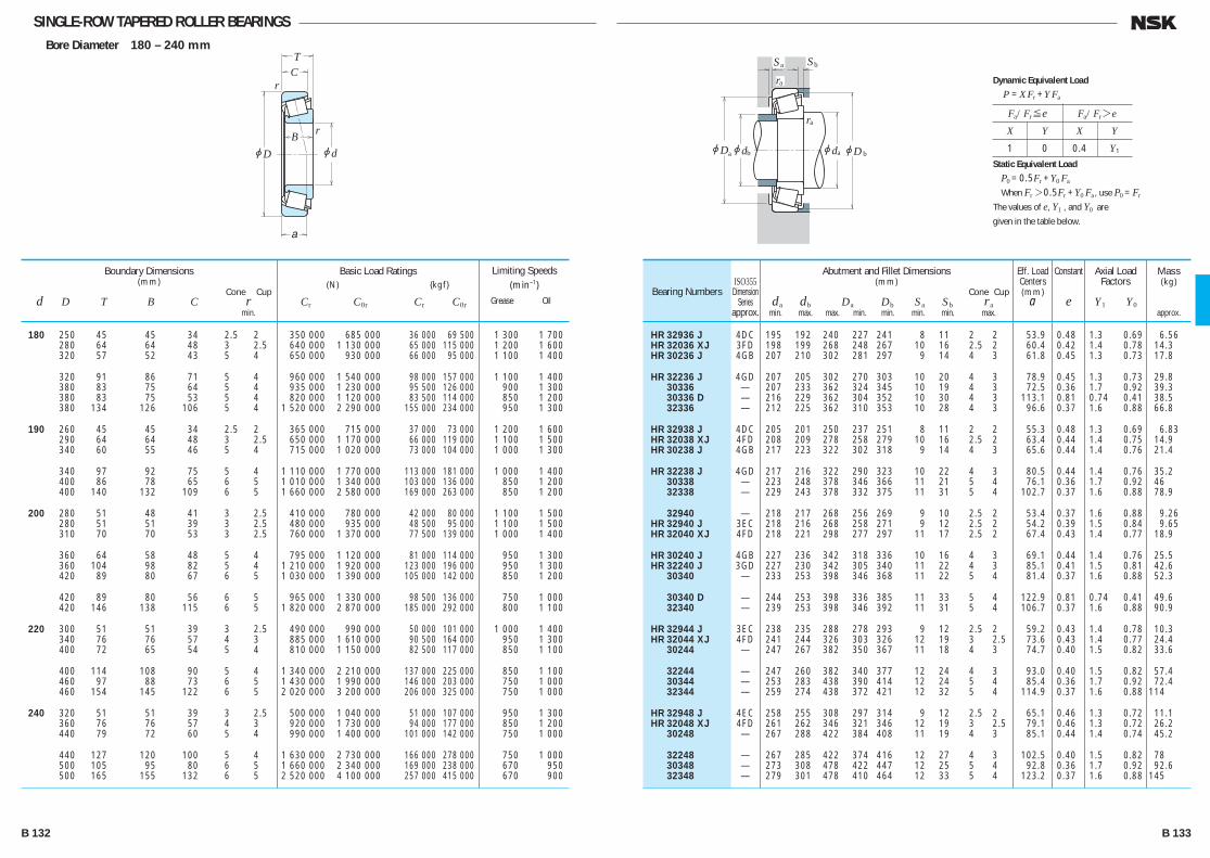
SINGLE-ROW TAPERED ROLLER BEARINGSBore Diameter 180 – 240 mm
jd
r
r
jD
TC
B
a
jDjd jd
ra
Sa Sb
ra
a b ajDb
180 250 45 45 34 2.5 2 350 000 685 000 36 000 69 500 1 300 1 700 280 64 64 48 3 2.5 640 000 1 130 000 65 000 115 000 1 200 1 600 320 57 52 43 5 4 650 000 930 000 66 000 95 000 1 100 1 400
320 91 86 71 5 4 960 000 1 540 000 98 000 157 000 1 100 1 400 380 83 75 64 5 4 935 000 1 230 000 95 500 126 000 900 1 300 380 83 75 53 5 4 820 000 1 120 000 83 500 114 000 850 1 200 380 134 126 106 5 4 1 520 000 2 290 000 155 000 234 000 950 1 300
190 260 45 45 34 2.5 2 365 000 715 000 37 000 73 000 1 200 1 600 290 64 64 48 3 2.5 650 000 1 170 000 66 000 119 000 1 100 1 500 340 60 55 46 5 4 715 000 1 020 000 73 000 104 000 1 000 1 300
340 97 92 75 5 4 1 110 000 1 770 000 113 000 181 000 1 000 1 400 400 86 78 65 6 5 1 010 000 1 340 000 103 000 136 000 850 1 200 400 140 132 109 6 5 1 660 000 2 580 000 169 000 263 000 850 1 200
200 280 51 48 41 3 2.5 410 000 780 000 42 000 80 000 1 100 1 500 280 51 51 39 3 2.5 480 000 935 000 48 500 95 000 1 100 1 500 310 70 70 53 3 2.5 760 000 1 370 000 77 500 139 000 1 000 1 400
360 64 58 48 5 4 795 000 1 120 000 81 000 114 000 950 1 300 360 104 98 82 5 4 1 210 000 1 920 000 123 000 196 000 950 1 300 420 89 80 67 6 5 1 030 000 1 390 000 105 000 142 000 850 1 200
420 89 80 56 6 5 965 000 1 330 000 98 500 136 000 750 1 000 420 146 138 115 6 5 1 820 000 2 870 000 185 000 292 000 800 1 100
220 300 51 51 39 3 2.5 490 000 990 000 50 000 101 000 1 000 1 400 340 76 76 57 4 3 885 000 1 610 000 90 500 164 000 950 1 300 400 72 65 54 5 4 810 000 1 150 000 82 500 117 000 850 1 100
400 114 108 90 5 4 1 340 000 2 210 000 137 000 225 000 850 1 100 460 97 88 73 6 5 1 430 000 1 990 000 146 000 203 000 750 1 000 460 154 145 122 6 5 2 020 000 3 200 000 206 000 325 000 750 1 000
240 320 51 51 39 3 2.5 500 000 1 040 000 51 000 107 000 950 1 300 360 76 76 57 4 3 920 000 1 730 000 94 000 177 000 850 1 200 440 79 72 60 5 4 990 000 1 400 000 101 000 142 000 750 1 000
440 127 120 100 5 4 1 630 000 2 730 000 166 000 278 000 750 1 000 500 105 95 80 6 5 1 660 000 2 340 000 169 000 238 000 670 950 500 165 155 132 6 5 2 520 000 4 100 000 257 000 415 000 670 900
Boundary Dimensions(mm)
Cone Cup d D T B C r min.
Limiting Speeds (min–1)
Grease Oil
Basic Load Ratings (N) {kgf}
Cr C0r Cr C0r
HR 32936 J 4DC 195 192 240 227 241 8 11 2 2 53.9 0.48 1.3 0.69 6.56 HR 32036 XJ 3FD 198 199 268 248 267 10 16 2.5 2 60.4 0.42 1.4 0.78 14.3 HR 30236 J 4GB 207 210 302 281 297 9 14 4 3 61.8 0.45 1.3 0.73 17.8
HR 32236 J 4GD 207 205 302 270 303 10 20 4 3 78.9 0.45 1.3 0.73 29.8 30336 — 207 233 362 324 345 10 19 4 3 72.5 0.36 1.7 0.92 39.3 30336 D — 216 229 362 304 352 10 30 4 3 113.1 0.81 0.74 0.41 38.5 32336 — 212 225 362 310 353 10 28 4 3 96.6 0.37 1.6 0.88 66.8
HR 32938 J 4DC 205 201 250 237 251 8 11 2 2 55.3 0.48 1.3 0.69 6.83 HR 32038 XJ 4FD 208 209 278 258 279 10 16 2.5 2 63.4 0.44 1.4 0.75 14.9 HR 30238 J 4GB 217 223 322 302 318 9 14 4 3 65.6 0.44 1.4 0.76 21.4
HR 32238 J 4GD 217 216 322 290 323 10 22 4 3 80.5 0.44 1.4 0.76 35.2 30338 — 223 248 378 346 366 11 21 5 4 76.1 0.36 1.7 0.92 46 32338 — 229 243 378 332 375 11 31 5 4 102.7 0.37 1.6 0.88 78.9
32940 — 218 217 268 256 269 9 10 2.5 2 53.4 0.37 1.6 0.88 9.26 HR 32940 J 3EC 218 216 268 258 271 9 12 2.5 2 54.2 0.39 1.5 0.84 9.65 HR 32040 XJ 4FD 218 221 298 277 297 11 17 2.5 2 67.4 0.43 1.4 0.77 18.9
HR 30240 J 4GB 227 236 342 318 336 10 16 4 3 69.1 0.44 1.4 0.76 25.5 HR 32240 J 3GD 227 230 342 305 340 11 22 4 3 85.1 0.41 1.5 0.81 42.6 30340 — 233 253 398 346 368 11 22 5 4 81.4 0.37 1.6 0.88 52.3
30340 D — 244 253 398 336 385 11 33 5 4 122.9 0.81 0.74 0.41 49.6 32340 — 239 253 398 346 392 11 31 5 4 106.7 0.37 1.6 0.88 90.9
HR 32944 J 3EC 238 235 288 278 293 9 12 2.5 2 59.2 0.43 1.4 0.78 10.3 HR 32044 XJ 4FD 241 244 326 303 326 12 19 3 2.5 73.6 0.43 1.4 0.77 24.4 30244 — 247 267 382 350 367 11 18 4 3 74.7 0.40 1.5 0.82 33.6
32244 — 247 260 382 340 377 12 24 4 3 93.0 0.40 1.5 0.82 57.4 30344 — 253 283 438 390 414 12 24 5 4 85.4 0.36 1.7 0.92 72.4 32344 — 259 274 438 372 421 12 32 5 4 114.9 0.37 1.6 0.88 114
HR 32948 J 4EC 258 255 308 297 314 9 12 2.5 2 65.1 0.46 1.3 0.72 11.1 HR 32048 XJ 4FD 261 262 346 321 346 12 19 3 2.5 79.1 0.46 1.3 0.72 26.2 30248 — 267 288 422 384 408 11 19 4 3 85.1 0.44 1.4 0.74 45.2
32248 — 267 285 422 374 416 12 27 4 3 102.5 0.40 1.5 0.82 78 30348 — 273 308 478 422 447 12 25 5 4 92.8 0.36 1.7 0.92 92.6 32348 — 279 301 478 410 464 12 33 5 4 123.2 0.37 1.6 0.88 145
Bearing NumbersISO355
DimensionSeries
approx.
Abutment and Fillet Dimensions(mm)
Cone Cup da db Da Db Sa Sb ra min. max. max. min. min. min. min. max.
Mass(kg)
approx.
Eff. Load Centers(mm)
a
Constant
e
Axial Load Factors
Y1 Y0
Fa/Fr≤e Fa/Fr>e
X Y X Y
1 0 0.4 Y1
Dynamic Equivalent Load
P =XFr +YFa
Static Equivalent Load
P0 =0.5Fr +Y0 Fa
When Fr>0.5Fr +Y0 Fa, use P0 =Fr
The values of e, Y1 , and Y0 are
given in the table below.
B 132 B 133
B110-181E.indd 132-133B110-181E.indd 132-133 11/20/13 4:57:02 PM11/20/13 4:57:02 PM
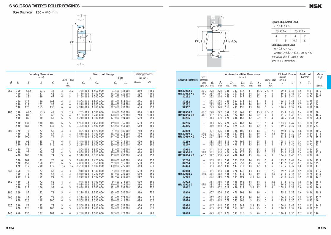
SINGLE-ROW TAPERED ROLLER BEARINGSBore Diameter 260 – 440 mm
jd
r
r
jD
TC
B
a
jDjd jd
ra
Sa Sb
ra
a b ajDb
260 360 63.5 63.5 48 3 2.5 730 000 1 450 000 74 500 148 000 850 1 100 400 87 87 65 5 4 1 160 000 2 160 000 118 000 220 000 800 1 100 480 89 80 67 6 5 1 190 000 1 700 000 121 000 174 000 670 900
480 137 130 106 6 5 1 900 000 3 300 000 194 000 335 000 670 950 540 113 102 85 6 6 1 870 000 2 640 000 190 000 269 000 630 850 540 176 165 136 6 6 2 910 000 4 800 000 297 000 490 000 630 850
280 380 63.5 63.5 48 3 2.5 765 000 1 580 000 78 000 162 000 800 1 100 420 87 87 65 5 4 1 180 000 2 240 000 120 000 228 000 710 1 000 500 89 80 67 6 5 1 240 000 1 900 000 127 000 194 000 630 850
500 137 130 106 6 5 1 950 000 3 450 000 199 000 355 000 630 850 580 187 175 145 6 6 3 300 000 5 400 000 335 000 550 000 560 800
300 420 76 72 62 4 3 895 000 1 820 000 91 000 186 000 710 950 420 76 76 57 4 3 1 010 000 2 100 000 103 000 214 000 710 950 460 100 100 74 5 4 1 440 000 2 700 000 147 000 275 000 670 900
540 96 85 71 6 5 1 440 000 2 100 000 147 000 214 000 600 800 540 149 140 115 6 5 2 220 000 3 700 000 226 000 380 000 600 800
320 440 76 72 63 4 3 900 000 1 880 000 92 000 192 000 970 900 440 76 76 57 4 3 1 040 000 2 220 000 106 000 227 000 670 900 480 100 100 74 5 4 1 510 000 2 910 000 153 000 297 000 630 850
580 104 92 75 6 5 1 640 000 2 420 000 168 000 247 000 530 750 580 159 150 125 6 5 2 860 000 5 050 000 292 000 515 000 530 750 670 210 200 170 7.5 7.5 4 200 000 7 100 000 430 000 725 000 480 670
340 460 76 72 63 4 3 910 000 1 940 000 93 000 197 000 630 850 460 76 76 57 4 3 1 050 000 2 220 000 107 000 226 000 630 850 520 112 106 92 6 5 1 650 000 3 400 000 168 000 345 000 560 750
360 480 76 72 62 4 3 945 000 2 100 000 96 500 214 000 600 800 480 76 76 57 4 3 1 080 000 2 340 000 110 000 239 000 560 800 540 112 106 92 6 5 1 680 000 3 500 000 171 000 355 000 530 750
380 520 87 82 71 5 4 1 210 000 2 550 000 124 000 260 000 560 750
400 540 87 82 71 5 4 1 250 000 2 700 000 128 000 276 000 530 710 600 125 118 100 6 5 1 960 000 4 050 000 200 000 415 000 480 670
420 560 87 82 72 5 4 1 300 000 2 810 000 132 000 287 000 500 670 620 125 118 100 6 5 2 000 000 4 200 000 204 000 430 000 450 630
440 650 130 122 104 6 6 2 230 000 4 600 000 227 000 470 000 430 600
Boundary Dimensions(mm)
Cone Cup d D T B C r min.
Limiting Speeds (min–1)
Grease Oil
Basic Load Ratings (N) {kgf}
Cr C0r Cr C0r
HR 32952 J 3EC 278 278 348 333 347 11 15.5 2.5 2 69.8 0.41 1.5 0.81 18.6 HR 32052 XJ 4FC 287 287 382 357 383 14 22 4 3 86.3 0.43 1.4 0.76 38.5 30252 — 293 316 458 421 447 12 22 5 4 94.6 0.44 1.4 0.74 60.7
32252 — 293 305 458 394 446 14 31 5 4 116.0 0.45 1.3 0.73 103 30352 — 293 336 512 460 487 16 28 5 5 101.6 0.36 1.7 0.92 114 32352 — 293 328 512 441 495 13 40 5 5 130.5 0.37 1.6 0.88 188
HR 32956 J 4EC 298 297 368 352 368 12 15.5 2.5 2 75.3 0.43 1.4 0.76 20 HR 32056 XJ 4FC 307 305 402 374 402 14 22 4 3 91.6 0.46 1.3 0.72 40.6 30256 — 313 339 478 436 462 12 22 5 4 98.5 0.44 1.4 0.74 66.3
32256 — 313 325 478 412 467 14 31 5 4 123.1 0.47 1.3 0.70 109 32356 — 319 353 552 475 532 14 42 5 5 139.6 0.37 1.6 0.89 224
32960 — 321 326 406 386 405 13 14 3 2.5 79.3 0.37 1.6 0.88 30.5 HR 32960 J 3FD 321 324 406 387 405 13 19 3 2.5 79.9 0.39 1.5 0.84 31.4 HR 32060 XJ 4GD 327 330 442 408 439 15 26 4 3 98.4 0.43 1.4 0.76 56.6
30260 — 333 355 518 470 499 14 25 5 4 105.1 0.44 1.4 0.74 80.6 32260 — 333 352 518 458 514 15 34 5 4 131.7 0.46 1.3 0.72 132
32964 — 341 345 426 404 425 13 13 3 2.5 84.3 0.39 1.5 0.84 32 HR 32964 J 3FD 341 344 426 406 426 13 19 3 2.5 85.0 0.42 1.4 0.79 33.3 HR 32064 XJ 4GD 347 350 462 430 461 15 26 4 3 104.5 0.46 1.3 0.72 60
30264 — 353 381 558 503 533 14 29 5 4 113.7 0.44 1.4 0.74 99.3 32264 — 353 383 558 487 550 15 34 5 4 141.7 0.46 1.3 0.72 175 32364 — 383 412 634 547 616 14 42 6 6 157.5 0.37 1.6 0.88 343
32968 — 361 364 446 426 446 13 13 3 2.5 89.2 0.41 1.5 0.80 33.6 HR 32968 J 4FD 361 362 446 427 446 13 19 3 2.5 91.0 0.44 1.4 0.75 34.3 32068 — 373 386 498 464 496 3.5 22 5 4 104.5 0.37 1.6 0.89 83.7
32972 — 381 386 466 445 465 14 14 3 2.5 91.4 0.40 1.5 0.82 35.8 HR 32972 J 4FD 381 381 466 445 466 13 19 3 2.5 96.8 0.46 1.3 0.72 36.1 32072 — 393 402 518 480 514 5.5 22 5 4 108.6 0.38 1.6 0.86 86.5
32976 — 407 406 502 478 501 16 16 4 3 95.2 0.39 1.6 0.86 49.5
32980 — 427 428 522 499 524 16 16 4 3 100.8 0.40 1.5 0.82 52.7 32080 — 433 443 578 533 565 5 25 5 4 115.3 0.36 1.7 0.92 116
32984 — 447 448 542 521 544 3.5 15 4 3 106.1 0.41 1.5 0.81 54.8 32084 — 453 463 598 552 586 6.5 25 5 4 120.0 0.37 1.6 0.88 121
32088 — 473 487 622 582 616 5 26 5 5 126.3 0.36 1.7 0.92 136
Bearing NumbersISO355
DimensionSeries
approx.
Abutment and Fillet Dimensions(mm)
Cone Cup da db Da Db Sa Sb ra min. max. max. min. min. min. min. max.
Mass(kg)
approx.
Eff. Load Centers(mm)
a
Constant
e
Axial Load Factors
Y1 Y0
Fa/Fr≤e Fa/Fr>e
X Y X Y
1 0 0.4 Y1
Dynamic Equivalent Load
P =XFr +YFa
Static Equivalent Load
P0 =0.5Fr +Y0 Fa
When Fr>0.5Fr +Y0 Fa, use P0 =Fr
The values of e, Y1 , and Y0 are
given in the table below.
B 134 B 135
B110-181E.indd 134-135B110-181E.indd 134-135 11/20/13 4:57:03 PM11/20/13 4:57:03 PM

SINGLE-ROW TAPERED ROLLER BEARINGS (INCH DESIGN)Bore Diameter 12.000 – 22.225 mm
jd
r
r
jD
TC
B
a
jD jd jd
ra
ra
a b ajDb
12.000 31.991 10.008 10.785 7.938 0.8 1.3 10 300 8 900 1 050 905 13 000 18 000 12.700 34.988 10.998 10.988 8.730 1.3 1.3 11 700 10 900 1 200 1 110 12 000 16 000 15.000 34.988 10.998 10.988 8.730 0.8 1.3 11 700 10 900 1 200 1 110 12 000 16 000 15.875 34.988 10.998 10.998 8.712 1.3 1.3 13 800 13 400 1 410 1 360 11 000 15 000 39.992 12.014 11.153 9.525 1.3 1.3 14 900 15 700 1 520 1 600 9 500 13 000 41.275 14.288 14.681 11.112 1.3 2.0 21 300 19 900 2 170 2 030 10 000 13 000 42.862 14.288 14.288 9.525 1.5 1.5 17 300 17 200 1 770 1 750 8 500 12 000 42.862 16.670 16.670 13.495 1.5 1.5 26 900 26 300 2 750 2 680 9 500 13 000 44.450 15.494 14.381 11.430 1.5 1.5 23 800 23 900 2 430 2 440 8 500 11 000 49.225 19.845 21.539 14.288 0.8 1.3 37 500 37 000 3 800 3 800 8 500 11 000 16.000 47.000 21.000 21.000 16.000 1.0 2.0 35 000 36 500 3 600 3 750 9 000 12 000 16.993 39.992 12.014 11.153 9.525 0.8 1.3 14 900 15 700 1 520 1 600 9 500 13 000 17.455 36.525 11.112 11.112 7.938 1.5 1.5 11 600 11 000 1 190 1 120 10 000 14 000 17.462 39.878 13.843 14.605 10.668 1.3 1.3 22 500 22 500 2 290 2 290 10 000 13 000 47.000 14.381 14.381 11.112 0.8 1.3 23 800 23 900 2 430 2 440 8 500 11 000 19.050 39.992 12.014 11.153 9.525 1.0 1.3 14 900 15 700 1 520 1 600 9 500 13 000 45.237 15.494 16.637 12.065 1.3 1.3 28 500 28 900 2 910 2 950 9 000 12 000 47.000 14.381 14.381 11.112 1.3 1.3 23 800 23 900 2 430 2 440 8 500 11 000 49.225 18.034 19.050 14.288 1.3 1.3 37 500 37 000 3 800 3 800 8 500 11 000 49.225 19.845 21.539 14.288 1.2 1.3 37 500 37 000 3 800 3 800 8 500 11 000 49.225 21.209 19.050 17.462 1.3 1.5 37 500 37 000 3 800 3 800 8 500 11 000 49.225 23.020 21.539 17.462 C1.5 3.5 37 500 37 000 3 800 3 800 8 500 11 000 53.975 22.225 21.839 15.875 1.5 2.3 40 500 39 500 4 150 4 000 7 500 10 000 19.990 47.000 14.381 14.381 11.112 1.5 1.3 23 800 23 900 2 430 2 440 8 500 11 000 20.000 51.994 15.011 14.260 12.700 1.5 1.3 26 000 27 900 2 650 2 840 7 500 10 000 20.625 49.225 23.020 21.539 17.462 1.5 1.5 37 500 37 000 3 800 3 800 8 500 11 000 20.638 49.225 19.845 19.845 15.875 1.5 1.5 36 000 37 000 3 650 3 750 8 000 11 000 21.430 50.005 17.526 18.288 13.970 1.3 1.3 38 500 40 000 3 950 4 100 8 000 11 000 22.000 45.237 15.494 16.637 12.065 1.3 1.3 29 200 33 500 2 980 3 400 8 500 11 000 45.975 15.494 16.637 12.065 1.3 1.3 29 200 33 500 2 980 3 400 8 500 11 000 22.225 50.005 13.495 14.260 9.525 1.3 1.0 26 000 27 900 2 650 2 840 7 500 10 000 50.005 17.526 18.288 13.970 1.3 1.3 38 500 40 000 3 950 4 100 8 000 11 000 52.388 19.368 20.168 14.288 1.5 1.5 40 500 43 000 4 100 4 400 7 500 10 000 53.975 19.368 20.168 14.288 1.5 1.5 40 500 43 000 4 100 4 400 7 500 10 000 56.896 19.368 19.837 15.875 1.3 1.3 38 000 40 500 3 900 4 150 7 100 9 500 57.150 22.225 22.225 17.462 0.8 1.5 48 000 50 000 4 850 5 100 7 100 9 500
Boundary Dimensions(mm)
Cone Cup d D T B C r min.
Limiting Speeds (min–1)
Grease Oil
Basic Load Ratings (N) {kgf}
Cr C0r Cr C0r
*A 2047 A 2126 16.5 15.5 26 29 0.8 1.3 6.8 0.41 1.5 0.81 0.023 0.017 A 4050 A 4138 18.5 17 29 32 1.3 1.3 8.2 0.45 1.3 0.73 0.033 0.022 *A 4059 A 4138 19.5 19 29 32 0.8 1.3 8.2 0.45 1.3 0.73 0.029 0.022 L 21549 L 21511 21.5 19.5 29 32.5 1.3 1.3 7.7 0.32 1.9 1.0 0.031 0.018 A 6062 A 6157 22 20.5 34 37 1.3 1.3 10.3 0.53 1.1 0.63 0.044 0.031 03062 03162 21.5 20 34 37.5 1.3 2 9.1 0.31 1.9 1.1 0.061 0.035 11590 11520 24.5 22.5 34.5 39.5 1.5 1.5 13.0 0.70 0.85 0.47 0.061 0.040 17580 17520 23 21 36.5 39 1.5 1.5 10.6 0.33 1.8 1.0 0.075 0.048 05062 05175 23.5 21 38 42 1.5 1.5 11.2 0.36 1.7 0.93 0.081 0.039 09062 09195 22 21.5 42 44.5 0.8 1.3 10.7 0.27 2.3 1.2 0.139 0.065 *HM 81649 **HM 81610 27.5 23 37.5 43 1 2 14.9 0.55 1.1 0.60 0.115 0.082 A 6067 A 6157 22 21 34 37 0.8 1.3 10.3 0.53 1.1 0.63 0.042 0.031 A 5069 A 5144 23.5 21.5 30 33.5 1.5 1.5 8.9 0.49 1.2 0.68 0.030 0.020 † LM 11749 † LM 11710 23 21.5 34 37 1.3 1.3 8.7 0.29 2.1 1.2 0.055 0.028 05068 05185 23 22.5 40.5 42.5 0.8 1.3 10.1 0.36 1.7 0.93 0.082 0.047 A 6075 A 6157 24 23 34 37 1 1.3 10.3 0.53 1.1 0.63 0.037 0.031 † LM 11949 † LM 11910 25 23.5 39.5 41.5 1.3 1.3 9.5 0.30 2.0 1.1 0.081 0.044 05075 05185 25 23.5 40.5 42.5 1.3 1.3 10.1 0.36 1.7 0.93 0.077 0.047 09067 09195 25.5 24 42 44.5 1.3 1.3 10.7 0.27 2.3 1.2 0.115 0.065 09078 09195 25.5 24 42 44.5 1.2 1.3 10.7 0.27 2.3 1.2 0.124 0.065 09067 09196 25.5 24 41.5 44.5 1.3 1.5 13.8 0.27 2.3 1.2 0.115 0.085 09074 09194 26 24 39 44.5 1.5 3.5 13.8 0.27 2.3 1.2 0.124 0.082 21075 21212 31.5 26 43 50 1.5 2.3 16.3 0.59 1.0 0.56 0.156 0.097 05079 05185 26.5 24 40.5 42.5 1.5 1.3 10.1 0.36 1.7 0.93 0.073 0.047 07079 07204 27.5 27 45 48 1.5 1.3 12.1 0.40 1.5 0.82 0.105 0.061 09081 09196 27.5 25.5 41.5 44.5 1.5 1.5 13.8 0.27 2.3 1.2 0.115 0.085 12580 12520 28.5 26 42.5 45.5 1.5 1.5 12.9 0.32 1.9 1.0 0.114 0.067 † M 12649 † M 12610 27.5 25.5 44 46 1.3 1.3 10.9 0.28 2.2 1.2 0.115 0.059 *† LM 12749 † LM 12710 27.5 26 39.5 42.5 1.3 1.3 10.0 0.31 2.0 1.1 0.078 0.038 *† LM 12749 † LM 12711 27.5 26 40 42.5 1.3 1.3 10.0 0.31 2.0 1.1 0.078 0.043 07087 07196 28.5 27 44.5 47 1.3 1 10.6 0.40 1.5 0.82 0.097 0.035 † M 12648 † M 12610 28.5 26.5 44 46 1.3 1.3 10.9 0.28 2.2 1.2 0.111 0.059 1380 1328 29.5 27 45 48.5 1.5 1.5 11.3 0.29 2.1 1.1 0.137 0.067 1380 1329 29.5 27 46 49 1.5 1.5 11.3 0.29 2.1 1.1 0.137 0.082 1755 1729 29 27.5 49 51 1.3 1.3 12.2 0.31 2.0 1.1 0.152 0.102 1280 1220 29.5 29 49 52 0.8 1.5 15.1 0.35 1.7 0.95 0.183 0.106
Bearing Numbers
CONE CUP
Abutment and Fillet Dimensions(mm)
Cone Cup da db Da Db ra max.
Mass(kg)
approx. CONE CUP
Eff. Load Centers(mm)
a
Constant
e
Axial Load Factors
Y1 Y0
Notes * The maximum bore diameter is listed and its tolerance is negative (See Table 8.4.1 on Page A68). ** The maximum outside diameter is listed and its tolerance is negative (See Table 8.4.2 on Pages A68 and A69). † The tolerances for the bore diameter and overall bearing width differ from the standard (See Table 5 on Page B114). * † The tolerance for the bore diameter is 0 to —20 μm, and for overall bearing width is +356 to 0 μm.
Fa/Fr≤e Fa/Fr>e
X Y X Y
1 0 0.4 Y1
Dynamic Equivalent Load
P =XFr +YFa
Static Equivalent Load
P0 =0.5Fr +Y0 Fa
When Fr>0.5Fr +Y0 Fa, use P0 =Fr
The values of e, Y1 , and Y0 are
given in the table below.
B 136 B 137
B110-181E.indd 136-137B110-181E.indd 136-137 11/20/13 4:57:04 PM11/20/13 4:57:04 PM
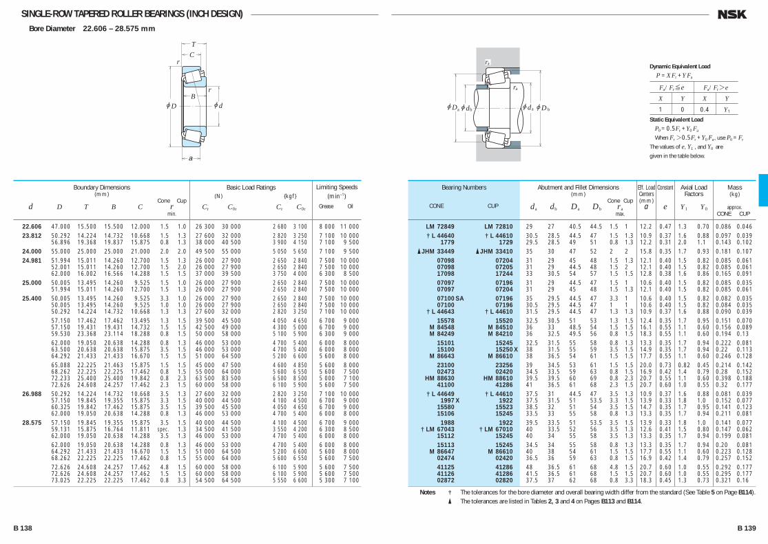
SINGLE-ROW TAPERED ROLLER BEARINGS (INCH DESIGN)Bore Diameter 22.606 – 28.575 mm
jd
r
r
jD
TC
B
a
jD jd jd
ra
ra
a b ajDb
22.606 47.000 15.500 15.500 12.000 1.5 1.0 26 300 30 000 2 680 3 100 8 000 11 000 23.812 50.292 14.224 14.732 10.668 1.5 1.3 27 600 32 000 2 820 3 250 7 100 10 000 56.896 19.368 19.837 15.875 0.8 1.3 38 000 40 500 3 900 4 150 7 100 9 500 24.000 55.000 25.000 25.000 21.000 2.0 2.0 49 500 55 000 5 050 5 650 7 100 9 500 24.981 51.994 15.011 14.260 12.700 1.5 1.3 26 000 27 900 2 650 2 840 7 500 10 000 52.001 15.011 14.260 12.700 1.5 2.0 26 000 27 900 2 650 2 840 7 500 10 000 62.000 16.002 16.566 14.288 1.5 1.5 37 000 39 500 3 750 4 000 6 300 8 500 25.000 50.005 13.495 14.260 9.525 1.5 1.0 26 000 27 900 2 650 2 840 7 500 10 000 51.994 15.011 14.260 12.700 1.5 1.3 26 000 27 900 2 650 2 840 7 500 10 000 25.400 50.005 13.495 14.260 9.525 3.3 1.0 26 000 27 900 2 650 2 840 7 500 10 000 50.005 13.495 14.260 9.525 1.0 1.0 26 000 27 900 2 650 2 840 7 500 10 000 50.292 14.224 14.732 10.668 1.3 1.3 27 600 32 000 2 820 3 250 7 100 10 000 57.150 17.462 17.462 13.495 1.3 1.5 39 500 45 500 4 050 4 650 6 700 9 000 57.150 19.431 19.431 14.732 1.5 1.5 42 500 49 000 4 300 5 000 6 700 9 000 59.530 23.368 23.114 18.288 0.8 1.5 50 000 58 000 5 100 5 900 6 300 9 000 62.000 19.050 20.638 14.288 0.8 1.3 46 000 53 000 4 700 5 400 6 000 8 000 63.500 20.638 20.638 15.875 3.5 1.5 46 000 53 000 4 700 5 400 6 000 8 000 64.292 21.433 21.433 16.670 1.5 1.5 51 000 64 500 5 200 6 600 5 600 8 000 65.088 22.225 21.463 15.875 1.5 1.5 45 000 47 500 4 600 4 850 5 600 8 000 68.262 22.225 22.225 17.462 0.8 1.5 55 000 64 000 5 600 6 550 5 600 7 500 72.233 25.400 25.400 19.842 0.8 2.3 63 500 83 500 6 500 8 500 5 000 7 100 72.626 24.608 24.257 17.462 2.3 1.5 60 000 58 000 6 100 5 900 5 600 7 500 26.988 50.292 14.224 14.732 10.668 3.5 1.3 27 600 32 000 2 820 3 250 7 100 10 000 57.150 19.845 19.355 15.875 3.3 1.5 40 000 44 500 4 100 4 500 6 700 9 000 60.325 19.842 17.462 15.875 3.5 1.5 39 500 45 500 4 050 4 650 6 700 9 000 62.000 19.050 20.638 14.288 0.8 1.3 46 000 53 000 4 700 5 400 6 000 8 000 28.575 57.150 19.845 19.355 15.875 3.5 1.5 40 000 44 500 4 100 4 500 6 700 9 000 59.131 15.875 16.764 11.811 spec. 1.3 34 500 41 500 3 550 4 200 6 300 8 500 62.000 19.050 20.638 14.288 3.5 1.3 46 000 53 000 4 700 5 400 6 000 8 000 62.000 19.050 20.638 14.288 0.8 1.3 46 000 53 000 4 700 5 400 6 000 8 000 64.292 21.433 21.433 16.670 1.5 1.5 51 000 64 500 5 200 6 600 5 600 8 000 68.262 22.225 22.225 17.462 0.8 1.5 55 000 64 000 5 600 6 550 5 600 7 500 72.626 24.608 24.257 17.462 4.8 1.5 60 000 58 000 6 100 5 900 5 600 7 500 72.626 24.608 24.257 17.462 1.5 1.5 60 000 58 000 6 100 5 900 5 600 7 500 73.025 22.225 22.225 17.462 0.8 3.3 54 500 64 500 5 550 6 600 5 300 7 100
Boundary Dimensions(mm)
Cone Cup d D T B C r min.
Limiting Speeds (min–1)
Grease Oil
Basic Load Ratings (N) {kgf}
Cr C0r Cr C0r
LM 72849 LM 72810 29 27 40.5 44.5 1.5 1 12.2 0.47 1.3 0.70 0.086 0.046 † L 44640 † L 44610 30.5 28.5 44.5 47 1.5 1.3 10.9 0.37 1.6 0.88 0.097 0.039 1779 1729 29.5 28.5 49 51 0.8 1.3 12.2 0.31 2.0 1.1 0.143 0.102 � JHM 33449 � JHM 33410 35 30 47 52 2 2 15.8 0.35 1.7 0.93 0.181 0.107 07098 07204 31 29 45 48 1.5 1.3 12.1 0.40 1.5 0.82 0.085 0.061 07098 07205 31 29 44.5 48 1.5 2 12.1 0.40 1.5 0.82 0.085 0.061 17098 17244 33 30.5 54 57 1.5 1.5 12.8 0.38 1.6 0.86 0.165 0.091 07097 07196 31 29 44.5 47 1.5 1 10.6 0.40 1.5 0.82 0.085 0.035 07097 07204 31 29 45 48 1.5 1.3 12.1 0.40 1.5 0.82 0.085 0.061 07100 SA 07196 35 29.5 44.5 47 3.3 1 10.6 0.40 1.5 0.82 0.082 0.035 07100 07196 30.5 29.5 44.5 47 1 1 10.6 0.40 1.5 0.82 0.084 0.035 † L 44643 † L 44610 31.5 29.5 44.5 47 1.3 1.3 10.9 0.37 1.6 0.88 0.090 0.039 15578 15520 32.5 30.5 51 53 1.3 1.5 12.4 0.35 1.7 0.95 0.151 0.070 M 84548 M 84510 36 33 48.5 54 1.5 1.5 16.1 0.55 1.1 0.60 0.156 0.089 M 84249 M 84210 36 32.5 49.5 56 0.8 1.5 18.3 0.55 1.1 0.60 0.194 0.13 15101 15245 32.5 31.5 55 58 0.8 1.3 13.3 0.35 1.7 0.94 0.222 0.081 15100 15250 X 38 31.5 55 59 3.5 1.5 14.9 0.35 1.7 0.94 0.22 0.113 M 86643 M 86610 38 36.5 54 61 1.5 1.5 17.7 0.55 1.1 0.60 0.246 0.128 23100 23256 39 34.5 53 61 1.5 1.5 20.0 0.73 0.82 0.45 0.214 0.142 02473 02420 34.5 33.5 59 63 0.8 1.5 16.9 0.42 1.4 0.79 0.28 0.152 HM 88630 HM 88610 39.5 39.5 60 69 0.8 2.3 20.7 0.55 1.1 0.60 0.398 0.188 41100 41286 41 36.5 61 68 2.3 1.5 20.7 0.60 1.0 0.55 0.32 0.177 † L 44649 † L 44610 37.5 31 44.5 47 3.5 1.3 10.9 0.37 1.6 0.88 0.081 0.039 1997 X 1922 37.5 31.5 51 53.5 3.3 1.5 13.9 0.33 1.8 1.0 0.152 0.077 15580 15523 38.5 32 51 54 3.5 1.5 14.7 0.35 1.7 0.95 0.141 0.123 15106 15245 33.5 33 55 58 0.8 1.3 13.3 0.35 1.7 0.94 0.211 0.081 1988 1922 39.5 33.5 51 53.5 3.5 1.5 13.9 0.33 1.8 1.0 0.141 0.077 † LM 67043 † LM 67010 40 33.5 52 56 3.5 1.3 12.6 0.41 1.5 0.80 0.147 0.062 15112 15245 40 34 55 58 3.5 1.3 13.3 0.35 1.7 0.94 0.199 0.081 15113 15245 34.5 34 55 58 0.8 1.3 13.3 0.35 1.7 0.94 0.20 0.081 M 86647 M 86610 40 38 54 61 1.5 1.5 17.7 0.55 1.1 0.60 0.223 0.128 02474 02420 36.5 36 59 63 0.8 1.5 16.9 0.42 1.4 0.79 0.257 0.152 41125 41286 48 36.5 61 68 4.8 1.5 20.7 0.60 1.0 0.55 0.292 0.177 41126 41286 41.5 36.5 61 68 1.5 1.5 20.7 0.60 1.0 0.55 0.295 0.177 02872 02820 37.5 37 62 68 0.8 3.3 18.3 0.45 1.3 0.73 0.321 0.16
Bearing Numbers
CONE CUP
Abutment and Fillet Dimensions(mm)
Cone Cup da db Da Db ra max.
Mass(kg)
approx. CONE CUP
Eff. Load Centers(mm)
a
Constant
e
Axial Load Factors
Y1 Y0
Notes † The tolerances for the bore diameter and overall bearing width differ from the standard (See Table 5 on Page B114). � The tolerances are listed in Tables 2, 3 and 4 on Pages B113 and B114.
Fa/Fr≤e Fa/Fr>e
X Y X Y
1 0 0.4 Y1
Dynamic Equivalent Load
P =XFr +YFa
Static Equivalent Load
P0 =0.5Fr +Y0 Fa
When Fr>0.5Fr +Y0 Fa, use P0 =Fr
The values of e, Y1 , and Y0 are
given in the table below.
B 138 B 139
B110-181E.indd 138-139B110-181E.indd 138-139 11/20/13 4:57:05 PM11/20/13 4:57:05 PM
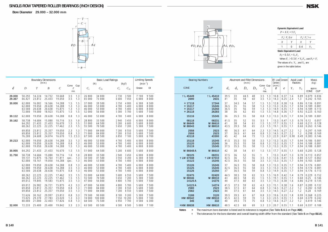
SINGLE-ROW TAPERED ROLLER BEARINGS (INCH DESIGN)Bore Diameter 29.000 – 32.000 mm
jd
r
r
jD
TC
B
a
jD jd jd
ra
ra
a b ajDb
29.000 50.292 14.224 14.732 10.668 3.5 1.3 26 800 34 000 2 730 3 500 7 100 9 500 29.367 66.421 23.812 25.433 19.050 3.5 1.3 65 000 73 000 6 600 7 450 6 000 8 000
30.000 62.000 16.002 16.566 14.288 1.5 1.5 37 000 39 500 3 750 4 000 6 300 8 500 62.000 19.050 20.638 14.288 1.3 1.3 46 000 53 000 4 700 5 400 6 000 8 000 63.500 20.638 20.638 15.875 1.3 1.3 46 000 53 000 4 700 5 400 6 000 8 000 72.000 19.000 18.923 15.875 1.5 1.5 52 000 56 000 5 300 5 700 5 600 7 500
30.112 62.000 19.050 20.638 14.288 0.8 1.3 46 000 53 000 4 700 5 400 6 000 8 000
30.162 58.738 14.684 15.080 10.716 3.5 1.0 28 800 33 500 2 940 3 450 6 000 8 000 64.292 21.433 21.433 16.670 1.5 1.5 51 000 64 500 5 200 6 600 5 600 8 000 68.262 22.225 22.225 17.462 2.3 1.5 55 500 70 500 5 650 7 200 5 300 7 500
69.850 23.812 25.357 19.050 2.3 1.3 71 000 84 000 7 200 8 550 5 600 7 500 69.850 23.812 25.357 19.050 0.8 1.3 71 000 84 000 7 200 8 550 5 600 7 500 76.200 24.608 24.074 16.670 1.5 C3.3 67 500 69 500 6 850 7 100 5 000 6 700
30.213 62.000 19.050 20.638 14.288 3.5 1.3 46 000 53 000 4 700 5 400 6 000 8 000 62.000 19.050 20.638 14.288 0.8 1.3 46 000 53 000 4 700 5 400 6 000 8 000 62.000 19.050 20.638 14.288 1.5 1.3 46 000 53 000 4 700 5 400 6 000 8 000
30.955 64.292 21.433 21.433 16.670 1.5 1.5 51 000 64 500 5 200 6 600 5 600 8 000
31.750 58.738 14.684 15.080 10.716 1.0 1.0 28 800 33 500 2 940 3 450 6 000 8 000 59.131 15.875 16.764 11.811 spec. 1.3 34 500 41 500 3 550 4 200 6 300 8 500 62.000 18.161 19.050 14.288 spec. 1.3 46 000 53 000 4 700 5 400 6 000 8 000
62.000 19.050 20.638 14.288 0.8 1.3 46 000 53 000 4 700 5 400 6 000 8 000 62.000 19.050 20.638 14.288 3.5 1.3 46 000 53 000 4 700 5 400 6 000 8 000 63.500 20.638 20.638 15.875 0.8 1.3 46 000 53 000 4 700 5 400 6 000 8 000
68.262 22.225 22.225 17.462 3.5 1.5 55 000 64 000 5 600 6 550 5 600 7 500 68.262 22.225 22.225 17.462 1.5 1.5 55 500 70 500 5 650 7 200 5 300 7 500 69.012 19.845 19.583 15.875 3.5 1.3 47 000 56 000 4 800 5 700 5 600 7 500
69.012 26.982 26.721 15.875 4.3 3.3 47 000 56 000 4 800 5 700 5 600 7 500 69.850 23.812 25.357 19.050 0.8 1.3 71 000 84 000 7 200 8 550 5 600 7 500 69.850 23.812 25.357 19.050 3.5 1.3 71 000 84 000 7 200 8 550 5 600 7 500
72.626 30.162 29.997 23.812 0.8 3.3 79 500 90 000 8 100 9 200 5 300 7 500 73.025 29.370 27.783 23.020 1.3 3.3 74 000 100 000 7 550 10 200 5 000 7 100 80.000 21.000 22.403 17.826 0.8 1.3 68 500 75 500 6 950 7 700 4 500 6 300
32.000 72.233 25.400 25.400 19.842 3.3 2.3 63 500 83 500 6 500 8 500 5 000 7 100
Boundary Dimensions(mm)
Cone Cup d D T B C r min.
Limiting Speeds (min–1)
Grease Oil
Basic Load Ratings (N) {kgf}
Cr C0r Cr C0r
† L 45449 † L 45410 39.5 33 44.5 48 3.5 1.3 10.8 0.37 1.6 0.89 0.079 0.036 2690 2631 41 35 58 60 3.5 1.3 14.3 0.25 2.4 1.3 0.242 0.165
* 17118 17244 37 34.5 54 57 1.5 1.5 12.8 0.38 1.6 0.86 0.136 0.091 * 15117 15245 36.5 35 55 58 1.3 1.3 13.3 0.35 1.7 0.94 0.189 0.081 * 15117 15250 36.5 35 56 59 1.3 1.3 14.9 0.35 1.7 0.94 0.189 0.113 * 26118 26283 38 36 62 65 1.5 1.5 14.8 0.36 1.7 0.92 0.225 0.163
15116 15245 36 35.5 55 58 0.8 1.3 13.3 0.35 1.7 0.94 0.189 0.081
08118 08231 41.5 35 52 55 3.5 1 13.3 0.47 1.3 0.70 0.12 0.057 M 86649 M 86610 41 38 54 61 1.5 1.5 17.7 0.55 1.1 0.60 0.211 0.128 M 88043 M 88010 43.5 39.5 58 65 2.3 1.5 19.1 0.55 1.1 0.60 0.263 0.146
2558 2523 40 36.5 61 64 2.3 1.3 14.5 0.27 2.2 1.2 0.297 0.169 2559 2523 37 36.5 61 64 0.8 1.3 14.5 0.27 2.2 1.2 0.298 0.169 43118 43300 45 42 64 73 1.5 3.3 22.9 0.67 0.90 0.49 0.383 0.146
15118 15245 41.5 35.5 55 58 3.5 1.3 13.3 0.35 1.7 0.94 0.186 0.081 15120 15245 36 35.5 55 58 0.8 1.3 13.3 0.35 1.7 0.94 0.188 0.081 15119 15245 37.5 35.5 55 58 1.5 1.3 13.3 0.35 1.7 0.94 0.188 0.081
M 86648 A M 86610 42 38 54 61 1.5 1.5 17.7 0.55 1.1 0.60 0.205 0.128
08125 08231 37.5 36 52 55 1 1 13.3 0.47 1.3 0.70 0.113 0.057 † LM 67048 † LM 67010 42.5 36 52 56 3.5 1.3 12.6 0.41 1.5 0.80 0.127 0.062 15123 15245 42.5 36.5 55 58 3.5 1.3 13.3 0.35 1.7 0.94 0.165 0.081
15126 15245 37 36.5 55 58 0.8 1.3 13.3 0.35 1.7 0.94 0.176 0.081 15125 15245 42.5 36.5 55 58 3.5 1.3 13.3 0.35 1.7 0.94 0.174 0.081 15126 15250 37 36.5 56 59 0.8 1.3 14.9 0.35 1.7 0.94 0.176 0.113
02475 02420 44.5 38.5 59 63 3.5 1.5 16.9 0.42 1.4 0.79 0.229 0.152 M 88046 M 88010 43 40.5 58 65 1.5 1.5 19.1 0.55 1.1 0.60 0.25 0.146 14125 A 14276 44 37.5 60 63 3.5 1.3 15.3 0.38 1.6 0.86 0.219 0.135
14123 A 14274 41.5 37.5 59 63 4.3 3.3 15.1 0.38 1.6 0.87 0.289 0.132 2580 2523 38.5 37.5 61 64 0.8 1.3 14.5 0.27 2.2 1.2 0.282 0.169 2582 2523 44 37.5 61 64 3.5 1.3 14.5 0.27 2.2 1.2 0.28 0.169
3188 3120 39.5 39.5 61 67 0.8 3.3 19.6 0.33 1.8 0.99 0.368 0.225 HM 88542 HM 88510 45.5 42.5 59 70 1.3 3.3 23.5 0.55 1.1 0.60 0.379 0.242 346 332 40 39.5 73 75 0.8 1.3 14.6 0.27 2.2 1.2 0.419 0.146
*HM 88638 HM 88610 48.5 42.5 60 69 3.3 2.3 20.7 0.55 1.1 0.60 0.337 0.188
Bearing Numbers
CONE CUP
Abutment and Fillet Dimensions(mm)
Cone Cup da db Da Db ra max.
Mass(kg)
approx. CONE CUP
Eff. Load Centers(mm)
a
Constant
e
Axial Load Factors
Y1 Y0
Notes * The maximum bore diameter is listed and its tolerance is negative (See Table 8.4.1 on Page A68). † The tolerances for the bore diameter and overall bearing width differ from the standard (See Table 5 on Page B114).
Fa/Fr≤e Fa/Fr>e
X Y X Y
1 0 0.4 Y1
Dynamic Equivalent Load
P =XFr +YFa
Static Equivalent Load
P0 =0.5Fr +Y0 Fa
When Fr>0.5Fr +Y0 Fa, use P0 =Fr
The values of e, Y1 , and Y0 are
given in the table below.
B 140 B 141
B110-181E.indd 140-141B110-181E.indd 140-141 11/20/13 4:57:06 PM11/20/13 4:57:06 PM
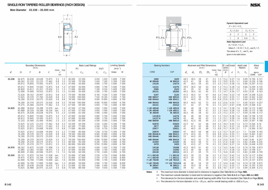
SINGLE-ROW TAPERED ROLLER BEARINGS (INCH DESIGN)Bore Diameter 33.338 – 35.000 mm
jd
r
r
jD
TC
B
a
jD jd jd
ra
ra
a b ajDb
33.338 66.675 20.638 20.638 15.875 3.5 1.5 46 000 53 500 4 650 5 450 5 600 7 500 68.262 22.225 22.225 17.462 0.8 1.5 55 500 70 500 5 650 7 200 5 300 7 500 69.012 19.845 19.583 15.875 3.5 3.3 47 000 56 000 4 800 5 700 5 600 7 500 69.012 19.845 19.583 15.875 0.8 1.3 47 000 56 000 4 800 5 700 5 600 7 500 69.850 23.812 25.357 19.050 3.5 1.3 71 000 84 000 7 200 8 550 5 600 7 500 72.000 19.000 18.923 15.875 3.5 1.5 52 000 56 000 5 300 5 700 5 600 7 500 72.626 30.162 29.997 23.812 0.8 3.3 79 500 90 000 8 100 9 200 5 300 7 500 73.025 29.370 27.783 23.020 0.8 3.3 74 000 100 000 7 550 10 200 5 000 7 100 76.200 29.370 28.575 23.020 3.8 0.8 78 500 106 000 8 000 10 800 4 800 6 700 76.200 29.370 28.575 23.020 0.8 3.3 78 500 106 000 8 000 10 800 4 800 6 700 79.375 25.400 24.074 17.462 3.5 1.5 67 500 69 500 6 850 7 100 5 000 6 700 34.925 65.088 18.034 18.288 13.970 spec. 1.3 47 500 57 500 4 850 5 900 5 600 7 500 65.088 20.320 18.288 16.256 spec. 1.3 47 500 57 500 4 850 5 900 5 600 7 500 66.675 20.638 20.638 16.670 3.5 2.3 53 000 62 500 5 400 6 400 5 600 7 500 69.012 19.845 19.583 15.875 3.5 1.3 47 000 56 000 4 800 5 700 5 600 7 500 69.012 19.845 19.583 15.875 1.5 1.3 47 000 56 000 4 800 5 700 5 600 7 500 72.233 25.400 25.400 19.842 2.3 2.3 63 500 83 500 6 500 8 500 5 000 7 100 73.025 22.225 22.225 17.462 0.8 3.3 54 500 64 500 5 550 6 600 5 300 7 100 73.025 22.225 23.812 17.462 3.5 3.3 63 500 77 000 6 500 7 850 5 300 7 100 73.025 23.812 24.608 19.050 1.5 0.8 71 000 86 000 7 250 8 750 5 300 7 100 73.025 23.812 24.608 19.050 3.5 2.3 71 000 86 000 7 250 8 750 5 300 7 100 76.200 29.370 28.575 23.020 0.8 0.8 78 500 106 000 8 000 10 800 4 800 6 700 76.200 29.370 28.575 23.020 3.5 0.8 78 500 106 000 8 000 10 800 4 800 6 700 76.200 29.370 28.575 23.020 3.5 3.3 78 500 106 000 8 000 10 800 4 800 6 700 76.200 29.370 28.575 23.812 1.5 3.3 80 500 96 500 8 200 9 850 5 000 6 700 79.375 29.370 29.771 23.812 3.5 3.3 88 000 106 000 8 950 10 800 4 800 6 700 34.976 68.262 15.875 16.520 11.908 1.5 1.5 45 000 53 500 4 600 5 450 5 300 7 100 72.085 22.385 19.583 18.415 1.3 2.3 47 000 56 000 4 800 5 700 5 600 7 500 80.000 21.006 20.940 15.875 1.5 1.5 56 500 64 500 5 750 6 600 5 000 6 700 35.000 59.131 15.875 16.764 11.938 spec. 1.3 35 000 47 000 3 550 4 750 6 000 8 000 59.975 15.875 16.764 11.938 spec. 1.3 35 000 47 000 3 550 4 750 6 000 8 000 62.000 16.700 17.000 13.600 spec. 1.0 38 000 50 000 3 900 5 100 5 600 8 000 62.000 16.700 17.000 13.600 spec. 1.5 38 000 50 000 3 900 5 100 5 600 8 000 65.987 20.638 20.638 16.670 3.5 2.3 53 000 62 500 5 400 6 400 5 600 7 500 73.025 26.988 26.975 22.225 3.5 0.8 75 500 88 500 7 650 9 050 5 300 7 500
Boundary Dimensions(mm)
Cone Cup d D T B C r min.
Limiting Speeds (min–1)
Grease Oil
Basic Load Ratings (N) {kgf}
Cr C0r Cr C0r
1680 1620 44.5 38.5 58 61 3.5 1.5 15.2 0.37 1.6 0.89 0.196 0.121 M 88048 M 88010 42.5 41 58 65 0.8 1.5 19.0 0.55 1.1 0.60 0.236 0.146 14130 14274 45 38.5 59 63 3.5 3.3 15.3 0.38 1.6 0.86 0.207 0.132 14131 14276 39.5 38.5 60 63 0.8 1.3 15.3 0.38 1.6 0.86 0.209 0.135 2585 2523 45 39 61 64 3.5 1.3 14.5 0.27 2.2 1.2 0.263 0.169 26131 26283 44.5 38.5 62 65 3.5 1.5 14.7 0.36 1.7 0.92 0.20 0.163 3197 3120 41.5 40.5 61 67 0.8 3.3 19.6 0.33 1.8 0.99 0.348 0.225 HM 88547 HM 88510 45.5 42.5 59 70 0.8 3.3 23.5 0.55 1.1 0.60 0.362 0.242 HM 89444 HM 89411 53 44.5 65 73 3.8 0.8 23.6 0.55 1.1 0.60 0.419 0.261 HM 89443 HM 89410 46.5 44.5 62 73 0.8 3.3 23.6 0.55 1.1 0.60 0.421 0.257 43131 43312 51 42 67 74 3.5 1.5 23.7 0.67 0.90 0.49 0.348 0.22 † LM 48548 † LM 48510 46 40 58 61 3.5 1.3 14.1 0.38 1.6 0.88 0.172 0.087 † LM 48548 † LM 48511 46 40 58 61 3.5 1.3 16.4 0.38 1.6 0.88 0.172 0.108 M 38549 M 38510 46.5 40 58 62 3.5 2.3 15.2 0.35 1.7 0.94 0.194 0.112 14138 A 14276 46 40 60 63 3.5 1.3 15.3 0.38 1.6 0.86 0.194 0.135 14137 A 14276 42 40 60 63 1.5 1.3 15.1 0.38 1.6 0.86 0.196 0.135 HM 88649 HM 88610 48.5 42.5 60 69 2.3 2.3 20.7 0.55 1.1 0.60 0.307 0.188 02878 02820 42.5 42 62 68 0.8 3.3 18.3 0.45 1.3 0.73 0.266 0.16 2877 2820 47 41.5 63 68 3.5 3.3 16.1 0.37 1.6 0.90 0.291 0.15 25877 25821 43 40.5 65 68 1.5 0.8 15.7 0.29 2.1 1.1 0.306 0.167 25878 25820 47 40.5 64 68 3.5 2.3 15.7 0.29 2.1 1.1 0.304 0.165 HM 89446 A HM 89411 47.5 44.5 65 73 0.8 0.8 23.6 0.55 1.1 0.60 0.403 0.261 HM 89446 HM 89411 53 44.5 65 73 3.5 0.8 23.6 0.55 1.1 0.60 0.40 0.261 HM 89446 HM 89410 53 44.5 62 73 3.5 3.3 23.6 0.55 1.1 0.60 0.40 0.257 31594 31520 46 43.5 64 72 1.5 3.3 21.6 0.40 1.5 0.82 0.404 0.235 3478 3420 50 43.5 67 74 3.5 3.3 20.0 0.37 1.6 0.90 0.448 0.259 19138 19268 42.5 40.5 61 65 1.5 1.5 14.5 0.44 1.4 0.74 0.196 0.073 14139 14283 41.5 40 60 65 1.3 2.3 17.7 0.38 1.6 0.87 0.198 0.21 28138 28315 43.5 41 69 73 1.5 1.5 16.0 0.40 1.5 0.82 0.308 0.199 *† L 68149 † L 68110 45.5 39 52 56 3.5 1.3 13.2 0.42 1.4 0.79 0.117 0.056 *† L 68149 † L 68111 45.5 39 53 56 3.5 1.3 13.2 0.42 1.4 0.79 0.117 0.064 * LM 78349 ** LM 78310 46 40 55 59 3.5 1 14.4 0.44 1.4 0.74 0.137 0.074 * LM 78349 ** LM 78310 A 46 40 54 59 3.5 1.5 14.4 0.44 1.4 0.74 0.138 0.073 M 38547 M 38511 46 39.5 59 61 3.5 2.3 15.2 0.35 1.7 0.94 0.193 0.103 23691 23621 49 42 63 68 3.5 0.8 18.1 0.37 1.6 0.89 0.309 0.212
Bearing Numbers
CONE CUP
Abutment and Fillet Dimensions(mm)
Cone Cup da db Da Db ra max.
Mass(kg)
approx. CONE CUP
Eff. Load Centers(mm)
a
Constant
e
Axial Load Factors
Y1 Y0
Notes * The maximum bore diameter is listed and its tolerance is negative (See Table 8.4.1 on Page A68). ** The maximum outside diameter is listed and its tolerance is negative (See Table 8.4.2 on Pages A68 and A69). † The tolerances for the bore diameter and overall bearing width differ from the standard (See Table 5 on Page B114). * † The tolerance for the bore diameter is 0 to —20 μm, and for overall bearing width is +356 to 0 μm.
Fa/Fr≤e Fa/Fr>e
X Y X Y
1 0 0.4 Y1
Dynamic Equivalent Load
P =XFr +YFa
Static Equivalent Load
P0 =0.5Fr +Y0 Fa
When Fr>0.5Fr +Y0 Fa, use P0 =Fr
The values of e, Y1 , and Y0 are
given in the table below.
B 142 B 143
B110-181E.indd 142-143B110-181E.indd 142-143 11/20/13 4:57:07 PM11/20/13 4:57:07 PM
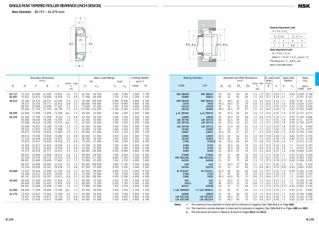
SINGLE-ROW TAPERED ROLLER BEARINGS (INCH DESIGN)Bore Diameter 35.717 – 41.275 mm
jd
r
r
jD
TC
B
a
jD jd jd
ra
ra
a b ajDb
35.717 72.233 25.400 25.400 19.842 3.5 2.3 63 500 83 500 6 500 8 500 5 000 7 100 36.487 73.025 23.812 24.608 19.050 1.5 0.8 71 000 86 000 7 250 8 750 5 300 7 100 36.512 76.200 29.370 28.575 23.020 3.5 3.3 78 500 106 000 8 000 10 800 4 800 6 700 79.375 29.370 29.771 23.812 0.8 3.3 88 000 106 000 8 950 10 800 4 800 6 700 88.501 25.400 23.698 17.462 2.3 1.5 73 000 81 000 7 450 8 250 4 000 5 600 93.662 31.750 31.750 26.195 1.5 3.3 110 000 142 000 11 200 14 400 4 000 5 600 38.000 63.000 17.000 17.000 13.500 spec. 1.3 38 500 52 000 3 900 5 300 5 600 7 500 38.100 63.500 12.700 11.908 9.525 1.5 0.8 24 100 30 500 2 460 3 100 5 300 7 100 65.088 18.034 18.288 13.970 2.3 1.3 42 500 55 000 4 300 5 650 5 300 7 500 65.088 18.034 18.288 13.970 spec. 1.3 42 500 55 000 4 300 5 650 5 300 7 500 65.088 19.812 18.288 15.748 2.3 1.3 42 500 55 000 4 300 5 650 5 300 7 500 68.262 15.875 16.520 11.908 1.5 1.5 45 000 53 500 4 600 5 450 5 300 7 100 69.012 19.050 19.050 15.083 2.0 2.3 49 000 61 000 4 950 6 250 5 300 7 100 69.012 19.050 19.050 15.083 3.5 0.8 49 000 61 000 4 950 6 250 5 300 7 100 72.238 20.638 20.638 15.875 3.5 1.3 48 500 59 500 4 950 6 050 5 300 7 100 73.025 23.812 25.654 19.050 3.5 0.8 73 500 91 000 7 500 9 300 5 000 6 700 76.200 23.812 25.654 19.050 3.5 3.3 73 500 91 000 7 500 9 300 5 000 6 700 76.200 23.812 25.654 19.050 3.5 0.8 73 500 91 000 7 500 9 300 5 000 6 700 79.375 29.370 29.771 23.812 3.5 3.3 88 000 106 000 8 950 10 800 4 800 6 700 80.035 24.608 23.698 18.512 0.8 1.5 69 000 84 500 7 000 8 600 4 500 6 300 82.550 29.370 28.575 23.020 0.8 3.3 87 000 117 000 8 850 11 900 4 500 6 000 88.501 25.400 23.698 17.462 2.3 1.5 73 000 81 000 7 450 8 250 4 000 5 600 88.501 26.988 29.083 22.225 3.5 1.5 96 500 109 000 9 800 11 100 4 500 6 000 95.250 30.958 28.301 20.638 1.5 0.8 87 500 97 000 8 950 9 850 3 600 5 300 39.688 73.025 25.654 22.098 21.336 0.8 2.3 62 500 80 000 6 400 8 150 5 000 6 700 76.200 23.812 25.654 19.050 3.5 3.3 73 500 91 000 7 500 9 300 5 000 6 700 80.167 29.370 30.391 23.812 0.8 3.3 92 500 108 000 9 450 11 000 4 800 6 300 40.000 80.000 21.000 22.403 17.826 3.5 1.3 68 500 75 500 6 950 7 700 4 500 6 300 80.000 21.000 22.403 17.826 0.8 1.3 68 500 75 500 6 950 7 700 4 500 6 300 88.501 25.400 23.698 17.462 2.3 1.5 73 000 81 000 7 450 8 250 4 000 5 600 41.000 68.000 17.500 18.000 13.500 spec. 1.5 43 500 58 000 4 450 5 950 5 300 7 100 41.275 73.025 16.667 17.462 12.700 3.5 1.5 44 500 54 000 4 550 5 500 4 800 6 700 73.431 19.558 19.812 14.732 3.5 0.8 54 500 67 000 5 550 6 850 4 800 6 700 73.431 21.430 19.812 16.604 3.5 0.8 54 500 67 000 5 550 6 850 4 800 6 700
Boundary Dimensions(mm)
Cone Cup d D T B C r min.
Limiting Speeds (min–1)
Grease Oil
Basic Load Ratings (N) {kgf}
Cr C0r Cr C0r
HM 88648 HM 88610 52 43 60 69 3.5 2.3 20.7 0.55 1.1 0.60 0.298 0.188 25880 25821 44 42 65 68 1.5 0.8 15.7 0.29 2.1 1.1 0.291 0.167 HM 89449 HM 89410 54 44.5 62 73 3.5 3.3 23.6 0.55 1.1 0.60 0.38 0.257 3479 3420 45.5 44.5 67 74 0.8 3.3 20.0 0.37 1.6 0.90 0.429 0.259 44143 44348 54 50 75 84 2.3 1.5 27.9 0.78 0.77 0.42 0.502 0.245 46143 46368 48.5 46.5 79 87 1.5 3.3 24.0 0.40 1.5 0.82 0.765 0.405 � JL 69349 � JL 69310 49 42.5 56 60 3.5 1.3 14.6 0.42 1.4 0.79 0.132 0.071 13889 13830 45 42.5 59 60 1.5 0.8 11.9 0.35 1.7 0.95 0.109 0.046 LM 29749 LM 29710 46 42.5 59 62 2.3 1.3 13.7 0.33 1.8 0.99 0.16 0.079 LM 29748 LM 29710 49 42.5 59 62 3.5 1.3 13.7 0.33 1.8 0.99 0.158 0.079 LM 29749 LM 29711 46 42.5 58 62 2.3 1.3 15.5 0.33 1.8 0.99 0.16 0.094 19150 19268 45 43 61 65 1.5 1.5 14.5 0.44 1.4 0.74 0.173 0.073 13687 13621 46.5 43 61 65 2 2.3 15.8 0.40 1.5 0.82 0.193 0.104 13685 13620 49.5 43 62 65 3.5 0.8 15.8 0.40 1.5 0.82 0.191 0.105 16150 16284 49.5 43 63 67 3.5 1.3 16.0 0.40 1.5 0.82 0.212 0.146 2788 2735 X 50 43.5 66 69 3.5 0.8 15.9 0.30 2.0 1.1 0.312 0.135 2788 2720 50 43.5 66 70 3.5 3.3 15.9 0.30 2.0 1.1 0.312 0.187 2788 2729 50 43.5 68 70 3.5 0.8 15.9 0.30 2.0 1.1 0.312 0.191 3490 3420 52 45.5 67 74 3.5 3.3 20.0 0.37 1.6 0.90 0.404 0.259 27880 27820 48 47 68 75 0.8 1.5 21.5 0.56 1.1 0.59 0.362 0.209 HM 801346 HM 801310 51 49 68 78 0.8 3.3 24.2 0.55 1.1 0.60 0.483 0.282 44150 44348 55 51 75 84 2.3 1.5 27.9 0.78 0.77 0.42 0.484 0.245 418 414 51 44.5 77 80 3.5 1.5 17.1 0.26 2.3 1.3 0.50 0.329 53150 53375 55 53 81 89 1.5 0.8 30.7 0.74 0.81 0.45 0.665 0.365 M 201047 M 201011 45.5 48 64 69 0.8 2.3 19.7 0.33 1.8 0.99 0.266 0.169 2789 2720 52 45 66 70 3.5 3.3 15.9 0.30 2.0 1.1 0.292 0.187 3386 3320 46.5 45.5 70 75 0.8 3.3 18.4 0.27 2.2 1.2 0.442 0.217 344 332 52 45.5 73 75 3.5 1.3 14.5 0.27 2.2 1.2 0.338 0.146 344 A 332 46 45.5 73 75 0.8 1.3 14.5 0.27 2.2 1.2 0.339 0.146 44157 44348 56 51 75 84 2.3 1.5 27.9 0.78 0.77 0.42 0.463 0.245 * LM 300849 ** LM 300811 52 45 61 65 3.5 1.5 13.9 0.35 1.7 0.95 0.16 0.082 18590 18520 53 46 66 69 3.5 1.5 14.0 0.35 1.7 0.94 0.199 0.086 LM 501349 LM 501310 53 46.5 67 70 3.5 0.8 16.3 0.40 1.5 0.83 0.226 0.108 LM 501349 LM 501314 53 46.5 66 70 3.5 0.8 18.2 0.40 1.5 0.83 0.226 0.129
Bearing Numbers
CONE CUP
Abutment and Fillet Dimensions(mm)
Cone Cup da db Da Db ra max.
Mass(kg)
approx. CONE CUP
Eff. Load Centers(mm)
a
Constant
e
Axial Load Factors
Y1 Y0
Notes * The maximum bore diameter is listed and its tolerance is negative (See Table 8.4.1 on Page A68). ** The maximum outside diameter is listed and its tolerance is negative (See Table 8.4.2 on Pages A68 and A69). � The tolerances are listed in Tables 2, 3 and 4 on Pages B113 and B114.
Fa/Fr≤e Fa/Fr>e
X Y X Y
1 0 0.4 Y1
Dynamic Equivalent Load
P =XFr +YFa
Static Equivalent Load
P0 =0.5Fr +Y0 Fa
When Fr>0.5Fr +Y0 Fa, use P0 =Fr
The values of e, Y1 , and Y0 are
given in the table below.
B 144 B 145
B110-181E.indd 144-145B110-181E.indd 144-145 11/20/13 4:57:08 PM11/20/13 4:57:08 PM
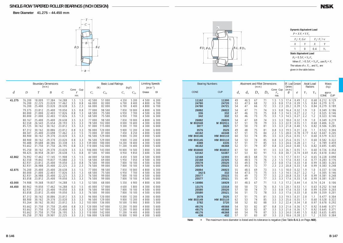
SINGLE-ROW TAPERED ROLLER BEARINGS (INCH DESIGN)Bore Diameter 41.275 – 44.450 mm
jd
r
r
jD
TC
B
a
jD jd jd
ra
ra
a b ajDb
41.275 76.200 18.009 17.384 14.288 1.5 1.5 42 500 51 000 4 350 5 200 4 500 6 300 76.200 22.225 23.020 17.462 3.5 0.8 66 000 82 000 6 700 8 400 4 800 6 700 76.200 25.400 23.020 20.638 3.5 2.3 66 000 82 000 6 700 8 400 4 800 6 700 79.375 23.812 25.400 19.050 3.5 0.8 77 000 98 500 7 850 10 000 4 800 6 300 80.000 21.000 22.403 17.826 0.8 1.3 68 500 75 500 6 950 7 700 4 500 6 300 80.000 21.000 22.403 17.826 3.5 1.3 68 500 75 500 6 950 7 700 4 500 6 300 80.167 25.400 25.400 20.638 3.5 3.3 77 000 98 500 7 850 10 000 4 800 6 300 82.550 26.543 25.654 20.193 3.5 3.3 78 500 102 000 8 000 10 400 4 300 6 000 85.725 30.162 30.162 23.812 3.5 3.3 91 000 115 000 9 300 11 700 4 300 6 000 87.312 30.162 30.886 23.812 0.8 3.3 96 000 120 000 9 800 12 200 4 300 6 000 88.501 25.400 23.698 17.462 2.3 1.5 73 000 81 000 7 450 8 250 4 000 5 600 88.900 30.162 29.370 23.020 3.5 3.3 96 500 129 000 9 800 13 200 4 000 5 600 88.900 30.162 29.370 23.020 0.8 3.3 96 500 129 000 9 800 13 200 4 000 5 600 90.488 39.688 40.386 33.338 3.5 3.3 139 000 180 000 14 200 18 400 4 300 5 600 93.662 31.750 31.750 26.195 0.8 3.3 110 000 142 000 11 200 14 400 4 000 5 600 95.250 30.162 29.370 23.020 3.5 3.3 106 000 143 000 10 800 14 500 3 800 5 300 98.425 30.958 28.301 20.638 1.5 0.8 87 500 97 000 8 950 9 850 3 600 5 300 42.862 76.992 17.462 17.145 11.908 1.5 1.5 44 000 54 000 4 450 5 500 4 500 6 000 82.550 19.842 19.837 15.080 2.3 1.5 58 500 69 000 5 950 7 050 4 500 6 300 82.931 23.812 25.400 19.050 2.3 0.8 76 500 99 000 7 800 10 100 4 500 6 000 82.931 26.988 25.400 22.225 2.3 2.3 76 500 99 000 7 800 10 100 4 500 6 000 42.875 76.200 25.400 25.400 20.638 3.5 1.5 77 000 98 500 7 850 10 000 4 800 6 300 80.000 21.000 22.403 17.826 3.5 1.3 68 500 75 500 6 950 7 700 4 500 6 300 82.931 26.988 25.400 22.225 3.5 2.3 76 500 99 000 7 800 10 100 4 500 6 000 83.058 23.812 25.400 19.050 3.5 3.3 76 500 99 000 7 800 10 100 4 500 6 000 43.000 74.988 19.368 19.837 14.288 1.5 1.3 52 500 68 000 5 350 6 900 4 800 6 300 44.450 80.962 19.050 17.462 14.288 0.3 1.5 45 000 57 000 4 600 5 800 4 300 6 000 82.931 23.812 25.400 19.050 3.5 0.8 76 500 99 000 7 800 10 100 4 500 6 000 83.058 23.812 25.400 19.050 3.5 3.3 76 500 99 000 7 800 10 100 4 500 6 000 87.312 30.162 30.886 23.812 3.5 3.3 96 000 120 000 9 800 12 200 4 300 6 000 88.900 30.162 29.370 23.020 3.5 3.3 96 500 129 000 9 800 13 200 4 000 5 600 93.264 30.162 30.302 23.812 3.5 3.2 103 000 136 000 10 500 13 900 3 800 5 300 93.662 31.750 31.750 25.400 0.8 3.3 120 000 147 000 12 200 15 000 4 000 5 600 93.662 31.750 31.750 25.400 3.5 3.3 120 000 147 000 12 200 15 000 4 000 5 600 93.662 31.750 31.750 26.195 3.5 3.3 110 000 142 000 11 200 14 400 4 000 5 600 95.250 27.783 29.901 22.225 3.5 2.3 106 000 126 000 10 800 12 900 4 300 5 600
Boundary Dimensions(mm)
Cone Cup d D T B C r min.
Limiting Speeds (min–1)
Grease Oil
Basic Load Ratings (N) {kgf}
Cr C0r Cr C0r
11162 11300 49 46.5 67 71 1.5 1.5 17.4 0.49 1.2 0.68 0.212 0.129 24780 24720 53 47.5 68 72 3.5 0.8 17.0 0.39 1.5 0.84 0.279 0.15 24780 24721 54 47 66 72 3.5 2.3 20.2 0.39 1.5 0.84 0.279 0.189 26882 26822 54 47 71 74 3.5 0.8 16.4 0.32 1.9 1.0 0.349 0.186 336 332 47 46 73 75 0.8 1.3 14.5 0.27 2.2 1.2 0.325 0.146 342 332 53 46 73 75 3.5 1.3 14.5 0.27 2.2 1.2 0.323 0.146 26882 26820 54 47 69 74 3.5 3.3 18.0 0.32 1.9 1.0 0.349 0.219 M 802048 M 802011 57 51 70 79 3.5 3.3 22.9 0.55 1.1 0.60 0.406 0.23 3877 3820 57 50 73 81 3.5 3.3 21.8 0.40 1.5 0.82 0.506 0.285 3576 3525 49 48 75 81 0.8 3.3 19.5 0.31 2.0 1.1 0.532 0.304 44162 44348 57 51 75 84 2.3 1.5 28.0 0.78 0.77 0.42 0.447 0.245 HM 803146 HM 803110 60 53 74 85 3.5 3.3 25.6 0.55 1.1 0.60 0.579 0.322 HM 803145 HM 803110 54 53 74 85 0.8 3.3 25.6 0.55 1.1 0.60 0.582 0.322 4388 4335 57 51 77 85 3.5 3.3 24.6 0.28 2.1 1.2 0.789 0.459 46162 46368 52 51 79 87 0.8 3.3 24.0 0.40 1.5 0.82 0.695 0.405 HM 804840 HM 804810 61 54 81 91 3.5 3.3 26.1 0.55 1.1 0.60 0.726 0.354 53162 53387 57 53 82 91 1.5 0.8 30.7 0.74 0.81 0.45 0.618 0.442 12168 12303 51 48.5 68 73 1.5 1.5 17.7 0.51 1.2 0.65 0.228 0.098 22168 22325 52 48.5 73 76 2.3 1.5 17.6 0.43 1.4 0.77 0.283 0.176 25578 25520 53 49.5 74 77 2.3 0.8 17.6 0.33 1.8 0.99 0.383 0.203 25578 25523 53 49.5 72 77 2.3 2.3 20.8 0.33 1.8 0.99 0.383 0.248 26884 26823 55 48.5 69 73 3.5 1.5 18.0 0.32 1.9 1.0 0.337 0.136 342 S 332 54 47.5 73 75 3.5 1.3 14.5 0.27 2.2 1.2 0.305 0.146 25577 25523 55 49 72 77 3.5 2.3 20.8 0.33 1.8 0.99 0.381 0.248 25577 25521 55 49 72 77 3.5 3.3 17.6 0.33 1.8 0.99 0.381 0.201 * 16986 16929 51 48.5 67 71 1.5 1.3 17.2 0.44 1.4 0.74 0.24 0.106 13175 13318 50 50 72 76 0.3 1.5 20.1 0.53 1.1 0.63 0.252 0.144 25580 25520 57 50 74 77 3.5 0.8 17.6 0.33 1.8 0.99 0.359 0.203 25580 25521 56 51 72 78 3.5 3.3 17.6 0.33 1.8 0.99 0.359 0.201 3578 3525 57 51 75 81 3.5 3.3 19.5 0.31 2.0 1.1 0.477 0.304 HM 803149 HM 803110 62 53 74 85 3.5 3.3 25.6 0.55 1.1 0.60 0.528 0.322 3782 3720 58 52 82 88 3.5 3.2 22.4 0.34 1.8 0.97 0.678 0.292 49176 49368 54 53 82 87 0.8 3.3 21.6 0.36 1.7 0.92 0.648 0.371 49175 49368 59 53 82 87 3.5 3.3 21.6 0.36 1.7 0.92 0.645 0.371 46176 46368 60 54 79 87 3.5 3.3 24.0 0.40 1.5 0.82 0.635 0.405 438 432 57 51 83 87 3.5 2.3 18.6 0.28 2.1 1.2 0.555 0.384
Bearing Numbers
CONE CUP
Abutment and Fillet Dimensions(mm)
Cone Cup da db Da Db ra max.
Mass(kg)
approx. CONE CUP
Eff. Load Centers(mm)
a
Constant
e
Axial Load Factors
Y1 Y0
Note * The maximum bore diameter is listed and its tolerance is negative (See Table 8.4.1 on Page A68).
Fa/Fr≤e Fa/Fr>e
X Y X Y
1 0 0.4 Y1
Dynamic Equivalent Load
P =XFr +YFa
Static Equivalent Load
P0 =0.5Fr +Y0 Fa
When Fr>0.5Fr +Y0 Fa, use P0 =Fr
The values of e, Y1 , and Y0 are
given in the table below.
B 146 B 147
B110-181E.indd 146-147B110-181E.indd 146-147 11/20/13 4:57:09 PM11/20/13 4:57:09 PM

SINGLE-ROW TAPERED ROLLER BEARINGS (INCH DESIGN)Bore Diameter 44.450 – 47.625 mm
jd
r
r
jD
TC
B
a
jD jd jd
ra
ra
a b ajDb
44.450 95.250 30.162 29.370 23.020 3.5 3.3 106 000 143 000 10 800 14 500 3 800 5 300 95.250 30.958 28.301 20.638 3.5 0.8 87 500 97 000 8 950 9 850 3 600 5 300 95.250 30.958 28.301 20.638 1.3 0.8 87 500 97 000 8 950 9 850 3 600 5 300 95.250 30.958 28.301 20.638 2.0 0.8 87 500 97 000 8 950 9 850 3 600 5 300 95.250 30.958 28.301 22.225 1.3 0.8 100 000 122 000 10 200 12 500 3 600 5 000 95.250 30.958 28.575 22.225 3.5 0.8 100 000 122 000 10 200 12 500 3 600 5 000 98.425 30.958 28.301 20.638 3.5 0.8 87 500 97 000 8 950 9 850 3 600 5 300 103.188 43.658 44.475 36.512 1.3 3.3 178 000 238 000 18 100 24 300 3 800 5 000 104.775 36.512 36.512 28.575 3.5 3.3 139 000 192 000 14 200 19 600 3 400 4 800 107.950 27.783 29.317 22.225 3.5 0.8 116 000 149 000 11 800 15 200 3 400 4 800 111.125 30.162 26.909 20.638 3.5 3.3 92 500 110 000 9 450 11 200 3 200 4 300 114.300 44.450 44.450 34.925 3.5 3.3 172 000 205 000 17 500 20 900 3 600 4 800 44.983 82.931 23.812 25.400 19.050 1.5 0.8 76 500 99 000 7 800 10 100 4 500 6 000 45.000 93.264 20.638 22.225 15.082 0.8 1.3 77 000 93 000 7 900 9 500 3 800 5 300 45.230 79.985 19.842 20.638 15.080 2.0 1.3 62 000 78 500 6 300 8 000 4 500 6 000 45.242 73.431 19.558 19.812 15.748 3.5 0.8 53 500 75 000 5 450 7 650 4 800 6 300 77.788 19.842 19.842 15.080 3.5 0.8 56 000 71 000 5 700 7 250 4 500 6 300 77.788 21.430 19.842 16.667 3.5 0.8 56 000 71 000 5 700 7 250 4 500 6 300 45.618 82.931 23.812 25.400 19.050 3.5 0.8 76 500 99 000 7 800 10 100 4 500 6 000 82.931 26.988 25.400 22.225 3.5 2.3 76 500 99 000 7 800 10 100 4 500 6 000 46.000 75.000 18.000 18.000 14.000 2.3 1.5 51 000 71 500 5 200 7 300 4 500 6 300 46.038 79.375 17.462 17.462 13.495 2.8 1.5 46 000 57 000 4 700 5 800 4 500 6 000 80.962 19.050 17.462 14.288 0.8 1.5 45 000 57 000 4 600 5 800 4 300 6 000 85.000 20.638 21.692 17.462 2.3 1.3 71 500 81 500 7 300 8 300 4 300 6 000 85.000 25.400 25.608 20.638 3.5 1.3 79 500 105 000 8 100 10 700 4 300 6 000 95.250 27.783 29.901 22.225 3.5 0.8 106 000 126 000 10 800 12 900 4 300 5 600 47.625 88.900 20.638 22.225 16.513 3.5 1.3 73 000 85 000 7 450 8 650 4 000 5 600 88.900 25.400 25.400 19.050 3.5 3.3 86 000 107 000 8 750 10 900 4 000 5 600 95.250 30.162 29.370 23.020 3.5 3.3 106 000 143 000 10 800 14 500 3 800 5 300 101.600 34.925 36.068 26.988 3.5 3.3 137 000 169 000 14 000 17 200 3 800 5 000 111.125 30.162 26.909 20.638 3.5 3.3 92 500 110 000 9 450 11 200 3 200 4 300 112.712 30.162 26.909 20.638 3.5 3.3 92 500 110 000 9 450 11 200 3 200 4 300 117.475 33.338 31.750 23.812 3.5 3.3 137 000 156 000 13 900 15 900 3 200 4 300 123.825 36.512 32.791 25.400 3.5 3.3 143 000 160 000 14 600 16 400 3 000 4 000
Boundary Dimensions(mm)
Cone Cup d D T B C r min.
Limiting Speeds (min–1)
Grease Oil
Basic Load Ratings (N) {kgf}
Cr C0r Cr C0r
HM 804843 HM 804810 63 57 81 91 3.5 3.3 26.1 0.55 1.1 0.60 0.677 0.354 53177 53375 63 53 81 89 3.5 0.8 30.7 0.74 0.81 0.45 0.572 0.365 53176 53375 59 53 81 89 1.3 0.8 30.7 0.74 0.81 0.45 0.574 0.365 53178 53375 60 53 81 89 2 0.8 30.7 0.74 0.81 0.45 0.574 0.365 HM 903247 HM 903210 61 54 81 91 1.3 0.8 31.5 0.74 0.81 0.45 0.651 0.389 HM 903249 HM 903210 65 54 81 91 3.5 0.8 31.5 0.74 0.81 0.45 0.635 0.389 53177 53387 63 53 82 91 3.5 0.8 30.7 0.74 0.81 0.45 0.568 0.442 5356 5335 58 56 89 97 1.3 3.3 27.0 0.30 2.0 1.1 1.23 0.637 HM 807040 HM 807010 66 59 89 100 3.5 3.3 29.7 0.49 1.2 0.68 1.14 0.502 460 453 A 60 54 97 100 3.5 0.8 20.7 0.34 1.8 0.98 0.93 0.42 55175 55437 67 60 92 105 3.5 3.3 37.3 0.88 0.68 0.37 0.867 0.514 65385 65320 65 59 97 107 3.5 3.3 32.2 0.43 1.4 0.77 1.39 0.894 25584 25520 53 51 74 77 1.5 0.8 17.6 0.33 1.8 0.99 0.354 0.203 376 374 54 54 85 88 0.8 1.3 17.1 0.34 1.8 0.97 0.492 0.174 17887 17831 57 52 68 74 2 1.3 15.9 0.37 1.6 0.90 0.274 0.136 LM 102949 LM 102910 56 50 68 70 3.5 0.8 14.6 0.31 2.0 1.1 0.213 0.102 LM 603049 LM 603011 57 50 71 74 3.5 0.8 17.2 0.43 1.4 0.77 0.249 0.119 LM 603049 LM 603012 57 50 70 74 3.5 0.8 18.8 0.43 1.4 0.77 0.249 0.137 25590 25520 58 51 74 77 3.5 0.8 17.6 0.33 1.8 0.99 0.343 0.203 25590 25523 58 51 72 77 3.5 2.3 20.8 0.33 1.8 0.99 0.343 0.248 * LM 503349 ** LM 503310 55 51 67 71 2.3 1.5 15.9 0.40 1.5 0.82 0.209 0.096 18690 18620 56 51 71 74 2.8 1.5 15.5 0.37 1.6 0.88 0.211 0.126 13181 13318 52 52 72 76 0.8 1.5 20.1 0.53 1.1 0.63 0.236 0.144 359 S 354 A 55 51 77 80 2.3 1.3 15.4 0.31 2.0 1.1 0.343 0.162 2984 2924 58 52 76 80 3.5 1.3 19.0 0.35 1.7 0.95 0.397 0.223 436 432 A 59 52 84 87 3.5 0.8 18.6 0.28 2.1 1.2 0.536 0.381 369 A 362 A 60 53 81 84 3.5 1.3 16.6 0.32 1.9 1.0 0.381 0.166 M 804049 M 804010 63 56 77 85 3.5 3.3 23.8 0.55 1.1 0.60 0.455 0.218 HM 804846 HM 804810 66 57 81 91 3.5 3.3 26.1 0.55 1.1 0.60 0.626 0.354 528 522 62 55 89 95 3.5 3.3 22.1 0.29 2.1 1.2 0.894 0.416 55187 55437 69 62 92 105 3.5 3.3 37.3 0.88 0.68 0.37 0.817 0.514 55187 55443 69 62 92 106 3.5 3.3 37.3 0.88 0.68 0.37 0.816 0.554 66187 66462 66 62 100 111 3.5 3.3 32.1 0.63 0.96 0.53 1.19 0.552 72187 72487 72 66 102 116 3.5 3.3 37.0 0.74 0.81 0.45 1.29 0.79
Bearing Numbers
CONE CUP
Abutment and Fillet Dimensions(mm)
Cone Cup da db Da Db ra max.
Mass(kg)
approx. CONE CUP
Eff. Load Centers(mm)
a
Constant
e
Axial Load Factors
Y1 Y0
Notes * The maximum bore diameter is listed and its tolerance is negative (See Table 8.4.1 on Page A68). ** The maximum outside diameter is listed and its tolerance is negative (See Table 8.4.2 on Pages A68 and A69).
Fa/Fr≤e Fa/Fr>e
X Y X Y
1 0 0.4 Y1
Dynamic Equivalent Load
P =XFr +YFa
Static Equivalent Load
P0 =0.5Fr +Y0 Fa
When Fr>0.5Fr +Y0 Fa, use P0 =Fr
The values of e, Y1 , and Y0 are
given in the table below.
B 148 B 149
B110-181E.indd 148-149B110-181E.indd 148-149 11/20/13 4:57:09 PM11/20/13 4:57:09 PM
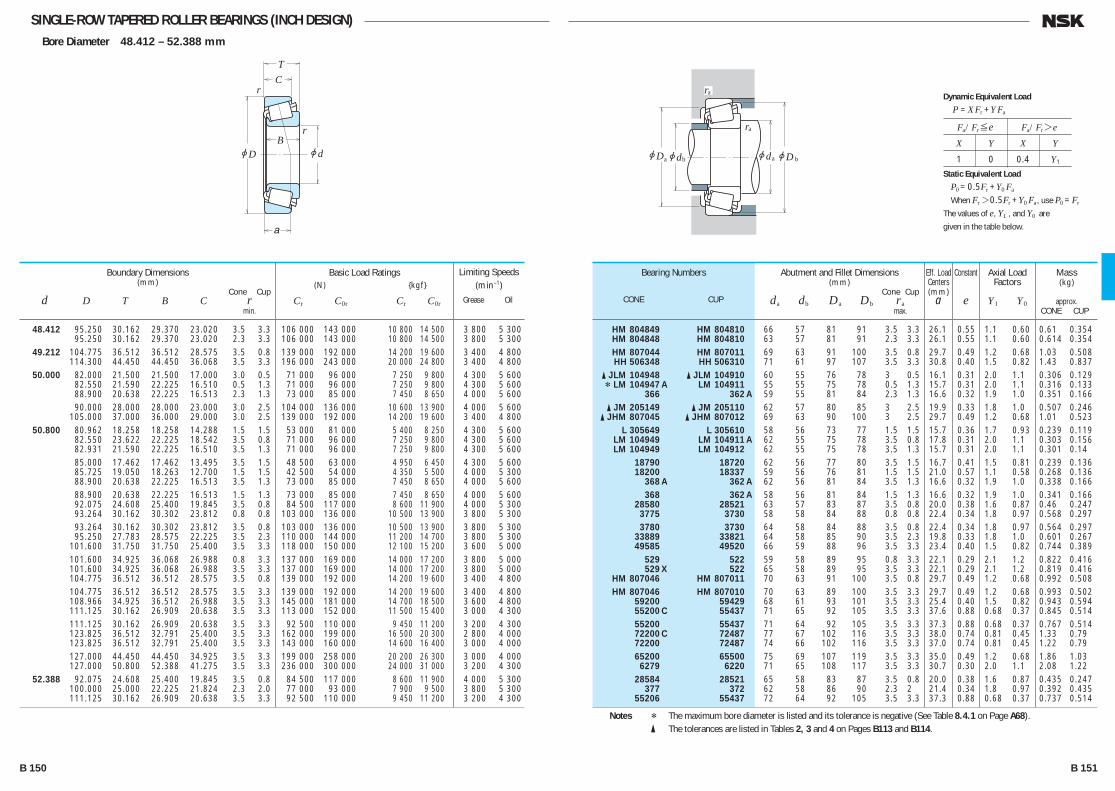
SINGLE-ROW TAPERED ROLLER BEARINGS (INCH DESIGN)Bore Diameter 48.412 – 52.388 mm
jd
r
r
jD
TC
B
a
jD jd jd
ra
ra
a b ajDb
48.412 95.250 30.162 29.370 23.020 3.5 3.3 106 000 143 000 10 800 14 500 3 800 5 300 95.250 30.162 29.370 23.020 2.3 3.3 106 000 143 000 10 800 14 500 3 800 5 300 49.212 104.775 36.512 36.512 28.575 3.5 0.8 139 000 192 000 14 200 19 600 3 400 4 800 114.300 44.450 44.450 36.068 3.5 3.3 196 000 243 000 20 000 24 800 3 400 4 800 50.000 82.000 21.500 21.500 17.000 3.0 0.5 71 000 96 000 7 250 9 800 4 300 5 600 82.550 21.590 22.225 16.510 0.5 1.3 71 000 96 000 7 250 9 800 4 300 5 600 88.900 20.638 22.225 16.513 2.3 1.3 73 000 85 000 7 450 8 650 4 000 5 600 90.000 28.000 28.000 23.000 3.0 2.5 104 000 136 000 10 600 13 900 4 000 5 600 105.000 37.000 36.000 29.000 3.0 2.5 139 000 192 000 14 200 19 600 3 400 4 800 50.800 80.962 18.258 18.258 14.288 1.5 1.5 53 000 81 000 5 400 8 250 4 300 5 600 82.550 23.622 22.225 18.542 3.5 0.8 71 000 96 000 7 250 9 800 4 300 5 600 82.931 21.590 22.225 16.510 3.5 1.3 71 000 96 000 7 250 9 800 4 300 5 600 85.000 17.462 17.462 13.495 3.5 1.5 48 500 63 000 4 950 6 450 4 300 5 600 85.725 19.050 18.263 12.700 1.5 1.5 42 500 54 000 4 350 5 500 4 000 5 300 88.900 20.638 22.225 16.513 3.5 1.3 73 000 85 000 7 450 8 650 4 000 5 600 88.900 20.638 22.225 16.513 1.5 1.3 73 000 85 000 7 450 8 650 4 000 5 600 92.075 24.608 25.400 19.845 3.5 0.8 84 500 117 000 8 600 11 900 4 000 5 300 93.264 30.162 30.302 23.812 0.8 0.8 103 000 136 000 10 500 13 900 3 800 5 300 93.264 30.162 30.302 23.812 3.5 0.8 103 000 136 000 10 500 13 900 3 800 5 300 95.250 27.783 28.575 22.225 3.5 2.3 110 000 144 000 11 200 14 700 3 800 5 300 101.600 31.750 31.750 25.400 3.5 3.3 118 000 150 000 12 100 15 200 3 600 5 000 101.600 34.925 36.068 26.988 0.8 3.3 137 000 169 000 14 000 17 200 3 800 5 000 101.600 34.925 36.068 26.988 3.5 3.3 137 000 169 000 14 000 17 200 3 800 5 000 104.775 36.512 36.512 28.575 3.5 0.8 139 000 192 000 14 200 19 600 3 400 4 800 104.775 36.512 36.512 28.575 3.5 3.3 139 000 192 000 14 200 19 600 3 400 4 800 108.966 34.925 36.512 26.988 3.5 3.3 145 000 181 000 14 700 18 500 3 600 4 800 111.125 30.162 26.909 20.638 3.5 3.3 113 000 152 000 11 500 15 400 3 000 4 300 111.125 30.162 26.909 20.638 3.5 3.3 92 500 110 000 9 450 11 200 3 200 4 300 123.825 36.512 32.791 25.400 3.5 3.3 162 000 199 000 16 500 20 300 2 800 4 000 123.825 36.512 32.791 25.400 3.5 3.3 143 000 160 000 14 600 16 400 3 000 4 000 127.000 44.450 44.450 34.925 3.5 3.3 199 000 258 000 20 200 26 300 3 000 4 000 127.000 50.800 52.388 41.275 3.5 3.3 236 000 300 000 24 000 31 000 3 200 4 300 52.388 92.075 24.608 25.400 19.845 3.5 0.8 84 500 117 000 8 600 11 900 4 000 5 300 100.000 25.000 22.225 21.824 2.3 2.0 77 000 93 000 7 900 9 500 3 800 5 300 111.125 30.162 26.909 20.638 3.5 3.3 92 500 110 000 9 450 11 200 3 200 4 300
Boundary Dimensions(mm)
Cone Cup d D T B C r min.
Limiting Speeds (min–1)
Grease Oil
Basic Load Ratings (N) {kgf}
Cr C0r Cr C0r
HM 804849 HM 804810 66 57 81 91 3.5 3.3 26.1 0.55 1.1 0.60 0.61 0.354 HM 804848 HM 804810 63 57 81 91 2.3 3.3 26.1 0.55 1.1 0.60 0.614 0.354 HM 807044 HM 807011 69 63 91 100 3.5 0.8 29.7 0.49 1.2 0.68 1.03 0.508 HH 506348 HH 506310 71 61 97 107 3.5 3.3 30.8 0.40 1.5 0.82 1.43 0.837 � JLM 104948 � JLM 104910 60 55 76 78 3 0.5 16.1 0.31 2.0 1.1 0.306 0.129 * LM 104947 A LM 104911 55 55 75 78 0.5 1.3 15.7 0.31 2.0 1.1 0.316 0.133 366 362 A 59 55 81 84 2.3 1.3 16.6 0.32 1.9 1.0 0.351 0.166 � JM 205149 � JM 205110 62 57 80 85 3 2.5 19.9 0.33 1.8 1.0 0.507 0.246 � JHM 807045 � JHM 807012 69 63 90 100 3 2.5 29.7 0.49 1.2 0.68 1.01 0.523 L 305649 L 305610 58 56 73 77 1.5 1.5 15.7 0.36 1.7 0.93 0.239 0.119 LM 104949 LM 104911 A 62 55 75 78 3.5 0.8 17.8 0.31 2.0 1.1 0.303 0.156 LM 104949 LM 104912 62 55 75 78 3.5 1.3 15.7 0.31 2.0 1.1 0.301 0.14 18790 18720 62 56 77 80 3.5 1.5 16.7 0.41 1.5 0.81 0.239 0.136 18200 18337 59 56 76 81 1.5 1.5 21.0 0.57 1.1 0.58 0.268 0.136 368 A 362 A 62 56 81 84 3.5 1.3 16.6 0.32 1.9 1.0 0.338 0.166 368 362 A 58 56 81 84 1.5 1.3 16.6 0.32 1.9 1.0 0.341 0.166 28580 28521 63 57 83 87 3.5 0.8 20.0 0.38 1.6 0.87 0.46 0.247 3775 3730 58 58 84 88 0.8 0.8 22.4 0.34 1.8 0.97 0.568 0.297 3780 3730 64 58 84 88 3.5 0.8 22.4 0.34 1.8 0.97 0.564 0.297 33889 33821 64 58 85 90 3.5 2.3 19.8 0.33 1.8 1.0 0.601 0.267 49585 49520 66 59 88 96 3.5 3.3 23.4 0.40 1.5 0.82 0.744 0.389 529 522 59 58 89 95 0.8 3.3 22.1 0.29 2.1 1.2 0.822 0.416 529 X 522 65 58 89 95 3.5 3.3 22.1 0.29 2.1 1.2 0.819 0.416 HM 807046 HM 807011 70 63 91 100 3.5 0.8 29.7 0.49 1.2 0.68 0.992 0.508 HM 807046 HM 807010 70 63 89 100 3.5 3.3 29.7 0.49 1.2 0.68 0.993 0.502 59200 59429 68 61 93 101 3.5 3.3 25.4 0.40 1.5 0.82 0.943 0.594 55200 C 55437 71 65 92 105 3.5 3.3 37.6 0.88 0.68 0.37 0.845 0.514 55200 55437 71 64 92 105 3.5 3.3 37.3 0.88 0.68 0.37 0.767 0.514 72200 C 72487 77 67 102 116 3.5 3.3 38.0 0.74 0.81 0.45 1.33 0.79 72200 72487 74 66 102 116 3.5 3.3 37.0 0.74 0.81 0.45 1.22 0.79 65200 65500 75 69 107 119 3.5 3.3 35.0 0.49 1.2 0.68 1.86 1.03 6279 6220 71 65 108 117 3.5 3.3 30.7 0.30 2.0 1.1 2.08 1.22 28584 28521 65 58 83 87 3.5 0.8 20.0 0.38 1.6 0.87 0.435 0.247 377 372 62 58 86 90 2.3 2 21.4 0.34 1.8 0.97 0.392 0.435 55206 55437 72 64 92 105 3.5 3.3 37.3 0.88 0.68 0.37 0.737 0.514
Bearing Numbers
CONE CUP
Abutment and Fillet Dimensions(mm)
Cone Cup da db Da Db ra max.
Mass(kg)
approx. CONE CUP
Eff. Load Centers(mm)
a
Constant
e
Axial Load Factors
Y1 Y0
Notes * The maximum bore diameter is listed and its tolerance is negative (See Table 8.4.1 on Page A68). � The tolerances are listed in Tables 2, 3 and 4 on Pages B113 and B114.
Fa/Fr≤e Fa/Fr>e
X Y X Y
1 0 0.4 Y1
Dynamic Equivalent Load
P =XFr +YFa
Static Equivalent Load
P0 =0.5Fr +Y0 Fa
When Fr>0.5Fr +Y0 Fa, use P0 =Fr
The values of e, Y1 , and Y0 are
given in the table below.
B 150 B 151
B110-181E.indd 150-151B110-181E.indd 150-151 11/20/13 4:57:10 PM11/20/13 4:57:10 PM

SINGLE-ROW TAPERED ROLLER BEARINGS (INCH DESIGN)Bore Diameter 53.975 – 58.738 mm
jd
r
r
jD
TC
B
a
jD jd jd
ra
ra
a b ajDb
53.975 104.775 39.688 40.157 33.338 3.5 3.3 148 000 207 000 15 100 21 100 3 600 4 800 107.950 36.512 36.957 28.575 3.5 3.3 144 000 182 000 14 700 18 500 3 600 4 800 122.238 33.338 31.750 23.812 3.5 3.3 135 000 156 000 13 800 15 900 3 000 4 000
123.825 36.512 32.791 25.400 3.5 3.3 143 000 160 000 14 600 16 400 3 000 4 000 123.825 36.512 32.791 25.400 3.5 3.3 162 000 199 000 16 500 20 300 2 800 4 000 123.825 38.100 36.678 30.162 3.5 3.3 161 000 221 000 16 400 22 500 3 000 4 000
127.000 44.450 44.450 34.925 3.5 3.3 199 000 258 000 20 200 26 300 3 000 4 000 127.000 50.800 52.388 41.275 3.5 3.3 236 000 300 000 24 000 31 000 3 200 4 300 130.175 36.512 33.338 23.812 3.5 3.3 133 000 154 000 13 600 15 700 2 600 3 600
55.000 90.000 23.000 23.000 18.500 1.5 0.5 79 000 111 000 8 050 11 300 3 800 5 300 95.000 29.000 29.000 23.500 1.5 2.5 111 000 152 000 11 300 15 500 3 800 5 000 96.838 21.000 21.946 15.875 2.3 0.8 80 500 100 000 8 200 10 200 3 600 5 000
110.000 39.000 39.000 32.000 3.0 2.5 177 000 225 000 18 000 23 000 3 400 4 500 115.000 41.021 41.275 31.496 3.0 3.0 172 000 214 000 17 500 21 800 3 200 4 500
55.562 97.630 24.608 24.608 19.446 3.5 0.8 89 000 129 000 9 100 13 100 3 600 5 000 122.238 43.658 43.764 36.512 1.3 3.3 198 000 292 000 20 200 29 700 3 000 4 000 123.825 36.512 32.791 25.400 3.5 3.3 143 000 160 000 14 600 16 400 3 000 4 000 123.825 36.512 32.791 25.400 3.5 3.3 162 000 199 000 16 500 20 300 2 800 4 000
57.150 96.838 21.000 21.946 15.875 3.5 0.8 80 500 100 000 8 200 10 200 3 600 5 000 96.838 21.000 21.946 15.875 2.3 0.8 80 500 100 000 8 200 10 200 3 600 5 000 96.838 25.400 21.946 20.275 3.5 2.3 80 500 100 000 8 200 10 200 3 600 5 000
98.425 21.000 21.946 17.826 3.5 0.8 80 500 100 000 8 200 10 200 3 600 5 000 104.775 30.162 29.317 24.605 3.5 3.3 116 000 149 000 11 800 15 200 3 400 4 800 104.775 30.162 29.317 24.605 2.3 3.3 116 000 149 000 11 800 15 200 3 400 4 800
104.775 30.162 30.958 23.812 0.8 3.3 130 000 170 000 13 300 17 400 3 400 4 800 104.775 30.162 30.958 23.812 0.8 0.8 130 000 170 000 13 300 17 400 3 400 4 800 122.238 33.338 31.750 23.812 3.5 3.3 135 000 156 000 13 800 15 900 3 000 4 000
123.825 36.512 32.791 25.400 3.5 3.3 162 000 199 000 16 500 20 300 2 800 4 000 123.825 38.100 36.678 30.162 3.5 3.3 161 000 221 000 16 400 22 500 3 000 4 000 140.030 36.512 33.236 23.520 3.5 2.3 152 000 183 000 15 500 18 700 2 600 3 600
144.983 36.000 33.236 23.007 3.5 3.5 152 000 183 000 15 500 18 700 2 600 3 600 149.225 53.975 54.229 44.450 3.5 3.3 287 000 410 000 29 300 41 500 2 600 3 400
57.531 96.838 21.000 21.946 15.875 3.5 0.8 80 500 100 000 8 200 10 200 3 600 5 000 58.738 112.712 33.338 30.048 26.988 3.5 3.3 120 000 173 000 12 200 17 700 3 200 4 300
Boundary Dimensions(mm)
Cone Cup d D T B C r min.
Limiting Speeds (min–1)
Grease Oil
Basic Load Ratings (N) {kgf}
Cr C0r Cr C0r
4595 4535 70 63 90 99 3.5 3.3 27.4 0.34 1.79 0.98 0.989 0.589 539 532 X 68 61 94 100 3.5 3.3 24.3 0.30 2.0 1.1 0.88 0.57 66584 66520 75 68 105 116 3.5 3.3 34.3 0.67 0.90 0.50 1.2 0.558
72212 72487 77 66 102 116 3.5 3.3 37.0 0.74 0.81 0.45 1.16 0.79 72212 C 72487 79 67 102 116 3.5 3.3 38.0 0.74 0.81 0.45 1.27 0.79 557 S 552 A 71 65 109 116 3.5 3.3 28.8 0.35 1.7 0.95 1.49 0.764
65212 65500 77 71 107 119 3.5 3.3 35.0 0.49 1.2 0.68 1.76 1.03 6280 6220 74 67 108 117 3.5 3.3 30.7 0.30 2.0 1.1 1.97 1.22 HM911242 HM911210 79 74 109 124 3.5 3.3 42.2 0.82 0.73 0.40 1.45 0.725
� JLM506849 � JLM506810 63 61 82 86 1.5 0.5 19.7 0.40 1.5 0.82 0.378 0.186 � JM207049 � JM207010 64 62 85 91 1.5 2.5 21.3 0.33 1.8 0.99 0.59 0.26 385 382 A 65 61 89 92 2.3 0.8 17.6 0.35 1.7 0.93 0.455 0.179
� JH307749 � JH307710 71 64 97 104 3 2.5 27.2 0.35 1.7 0.95 1.13 0.567 622 X 614 X 70 64 101 108 3 3 26.6 0.31 1.9 1.1 1.3 0.597
28680 28622 68 62 88 92 3.5 0.8 21.3 0.40 1.5 0.82 0.499 0.27 5566 5535 70 68 106 116 1.3 3.3 29.9 0.36 1.7 0.92 1.76 0.815 72218 72487 78 66 102 116 3.5 3.3 37.0 0.74 0.81 0.45 1.12 0.79 72218 C 72487 80 67 102 116 3.5 3.3 38.0 0.74 0.81 0.45 1.23 0.79
387 A 382 A 69 62 89 92 3.5 0.8 17.6 0.35 1.7 0.93 0.42 0.179 387 382 A 66 62 89 92 2.3 0.8 17.6 0.35 1.7 0.93 0.423 0.179 387 A 382 S 69 62 87 91 3.5 2.3 22.0 0.35 1.7 0.93 0.42 0.249
387 A 382 69 62 90 92 3.5 0.8 17.6 0.35 1.7 0.93 0.42 0.226 469 453 X 70 63 92 98 3.5 3.3 23.1 0.34 1.8 0.98 0.692 0.376 462 453 X 67 63 92 98 2.3 3.3 23.1 0.34 1.8 0.98 0.694 0.376
45289 45220 65 65 93 99 0.8 3.3 21.9 0.33 1.8 0.99 0.752 0.347 45289 45221 65 65 95 99 0.8 0.8 21.9 0.33 1.8 0.99 0.76 0.35 66587 66520 77 71 105 116 3.5 3.3 34.3 0.67 0.90 0.50 1.14 0.558
72225 C 72487 81 67 102 116 3.5 3.3 38.0 0.74 0.81 0.45 1.19 0.79 555 S 552 A 83 68 109 116 3.5 3.3 28.8 0.35 1.7 0.95 1.41 0.764 78225 78551 83 77 117 132 3.5 2.3 44.2 0.87 0.69 0.38 1.67 0.926
78225 78571 83 77 118 132 3.5 3.5 43.6 0.87 0.69 0.38 1.68 1.08 6455 6420 81 75 129 140 3.5 3.3 39.0 0.36 1.7 0.91 3.49 1.63
388 A 382 A 69 63 89 92 3.5 0.8 17.6 0.35 1.7 0.93 0.416 0.179 3981 3926 73 67 98 106 3.5 3.3 28.7 0.40 1.5 0.82 0.899 0.541
Bearing Numbers
CONE CUP
Abutment and Fillet Dimensions(mm)
Cone Cup da db Da Db ra max.
Mass(kg)
approx. CONE CUP
Eff. Load Centers(mm)
a
Constant
e
Axial Load Factors
Y1 Y0
Note � The tolerances are listed in Tables 2, 3 and 4 on Pages B113 and B114.
Fa/Fr≤e Fa/Fr>e
X Y X Y
1 0 0.4 Y1
Dynamic Equivalent Load
P =XFr +YFa
Static Equivalent Load
P0 =0.5Fr +Y0 Fa
When Fr>0.5Fr +Y0 Fa, use P0 =Fr
The values of e, Y1 , and Y0 are
given in the table below.
B 152 B 153
B110-181E.indd 152-153B110-181E.indd 152-153 11/20/13 4:57:11 PM11/20/13 4:57:11 PM
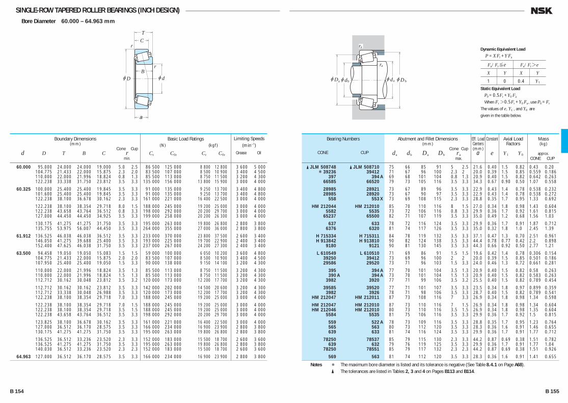
SINGLE-ROW TAPERED ROLLER BEARINGS (INCH DESIGN)Bore Diameter 60.000 – 64.963 mm
jd
r
r
jD
TC
B
a
jD jd jd
ra
ra
a b ajDb
60.000 95.000 24.000 24.000 19.000 5.0 2.5 86 500 125 000 8 800 12 800 3 600 5 000 104.775 21.433 22.000 15.875 2.3 2.0 83 500 107 000 8 500 10 900 3 400 4 500 110.000 22.000 21.996 18.824 0.8 1.3 85 500 113 000 8 750 11 500 3 200 4 300 122.238 33.338 31.750 23.812 3.5 3.3 135 000 156 000 13 800 15 900 3 000 4 000
60.325 100.000 25.400 25.400 19.845 3.5 3.3 91 000 135 000 9 250 13 700 3 400 4 800 101.600 25.400 25.400 19.845 3.5 3.3 91 000 135 000 9 250 13 700 3 400 4 800 122.238 38.100 36.678 30.162 2.3 3.3 161 000 221 000 16 400 22 500 3 000 4 000
122.238 38.100 38.354 29.718 8.0 1.5 188 000 245 000 19 200 25 000 3 000 4 000 122.238 43.658 43.764 36.512 0.8 3.3 198 000 292 000 20 200 29 700 3 000 4 000 127.000 44.450 44.450 34.925 3.5 3.3 199 000 258 000 20 200 26 300 3 000 4 000
130.175 41.275 41.275 31.750 3.5 3.3 195 000 263 000 19 800 26 800 2 800 3 800 135.755 53.975 56.007 44.450 3.5 3.3 264 000 355 000 27 000 36 000 2 800 3 800
61.912 136.525 46.038 46.038 36.512 3.5 3.3 233 000 370 000 23 800 37 500 2 600 3 400 146.050 41.275 39.688 25.400 3.5 3.3 193 000 225 000 19 700 22 900 2 400 3 400 152.400 47.625 46.038 31.750 3.5 3.3 237 000 267 000 24 200 27 300 2 400 3 400
63.500 94.458 19.050 19.050 15.083 1.5 1.5 59 000 100 000 6 050 10 200 3 600 4 800 104.775 21.433 22.000 15.875 2.0 2.0 83 500 107 000 8 500 10 900 3 400 4 500 107.950 25.400 25.400 19.050 1.5 3.3 90 000 138 000 9 150 14 100 3 200 4 300
110.000 22.000 21.996 18.824 3.5 1.3 85 500 113 000 8 750 11 500 3 200 4 300 110.000 22.000 21.996 18.824 1.5 1.3 85 500 113 000 8 750 11 500 3 200 4 300 112.712 30.162 30.048 23.812 3.5 3.2 120 000 173 000 12 200 17 700 3 200 4 300
112.712 30.162 30.162 23.812 3.5 3.3 142 000 202 000 14 500 20 600 3 200 4 300 112.712 33.338 30.048 26.988 3.5 3.3 120 000 173 000 12 200 17 700 3 200 4 300 122.238 38.100 38.354 29.718 7.0 3.3 188 000 245 000 19 200 25 000 3 000 4 000
122.238 38.100 38.354 29.718 7.0 1.5 188 000 245 000 19 200 25 000 3 000 4 000 122.238 38.100 38.354 29.718 3.5 1.5 188 000 245 000 19 200 25 000 3 000 4 000 122.238 43.658 43.764 36.512 3.5 3.3 198 000 292 000 20 200 29 700 3 000 4 000
123.825 38.100 36.678 30.162 3.5 3.3 161 000 221 000 16 400 22 500 3 000 4 000 127.000 36.512 36.170 28.575 3.5 3.3 166 000 234 000 16 900 23 900 2 800 3 800 130.175 41.275 41.275 31.750 3.5 3.3 195 000 263 000 19 800 26 800 2 800 3 800
136.525 36.512 33.236 23.520 2.3 3.3 152 000 183 000 15 500 18 700 2 600 3 600 136.525 41.275 41.275 31.750 3.5 3.3 195 000 263 000 19 800 26 800 2 800 3 800 140.030 36.512 33.236 23.520 2.3 2.3 152 000 183 000 15 500 18 700 2 600 3 600
64.963 127.000 36.512 36.170 28.575 3.5 3.3 166 000 234 000 16 900 23 900 2 800 3 800
Boundary Dimensions(mm)
Cone Cup d D T B C r min.
Limiting Speeds (min–1)
Grease Oil
Basic Load Ratings (N) {kgf}
Cr C0r Cr C0r
� JLM 508748 � JLM 508710 75 66 85 91 5 2.5 21.6 0.40 1.5 0.82 0.43 0.20 * 39236 39412 71 67 96 100 2.3 2 20.0 0.39 1.5 0.85 0.559 0.186 397 394 A 69 68 101 104 0.8 1.3 20.9 0.40 1.5 0.82 0.642 0.263 66585 66520 79 73 105 116 3.5 3.3 34.3 0.67 0.90 0.50 1.07 0.558
28985 28921 73 67 89 96 3.5 3.3 22.9 0.43 1.4 0.78 0.538 0.232 28985 28920 73 67 90 97 3.5 3.3 22.9 0.43 1.4 0.78 0.538 0.272 558 553 X 73 69 108 115 2.3 3.3 28.8 0.35 1.7 0.95 1.33 0.692
HM 212044 HM 212010 85 70 110 116 8 1.5 27.0 0.34 1.8 0.98 1.43 0.604 5582 5535 73 72 106 116 0.8 3.3 29.9 0.36 1.7 0.92 1.61 0.815 65237 65500 82 71 107 119 3.5 3.3 35.0 0.49 1.2 0.68 1.56 1.03
637 633 78 72 116 124 3.5 3.3 29.9 0.36 1.7 0.91 1.87 0.712 6376 6320 81 74 117 126 3.5 3.3 35.0 0.32 1.8 1.0 2.45 1.39
H 715334 H 715311 84 78 119 132 3.5 3.3 37.1 0.47 1.3 0.70 2.51 0.961 H 913842 H 913810 90 82 124 138 3.5 3.3 44.4 0.78 0.77 0.42 2.2 0.898 9180 9121 90 81 130 145 3.5 3.3 44.3 0.66 0.92 0.50 2.77 1.21
L 610549 L 610510 71 69 86 91 1.5 1.5 19.6 0.42 1.4 0.78 0.306 0.154 39250 39412 73 69 96 100 2 2 20.0 0.39 1.5 0.85 0.501 0.186 29586 29520 73 71 96 103 1.5 3.3 24.0 0.46 1.3 0.72 0.661 0.281
395 394 A 77 70 101 104 3.5 1.3 20.9 0.40 1.5 0.82 0.58 0.263 390 A 394 A 73 70 101 104 1.5 1.3 20.9 0.40 1.5 0.82 0.583 0.263 3982 3920 77 71 99 106 3.5 3.2 25.5 0.40 1.5 0.82 0.789 0.454
39585 39520 77 71 101 107 3.5 3.3 23.5 0.34 1.8 0.97 0.899 0.359 3982 3926 78 71 98 106 3.5 3.3 28.7 0.40 1.5 0.82 0.789 0.541 HM 212047 HM 212011 87 73 108 116 7 3.3 26.9 0.34 1.8 0.98 1.34 0.598
HM 212047 HM 212010 87 73 110 116 7 1.5 26.9 0.34 1.8 0.98 1.34 0.604 HM 212046 HM 212010 80 73 110 116 3.5 1.5 26.9 0.34 1.8 0.98 1.35 0.604 5584 5535 81 75 106 116 3.5 3.3 29.9 0.36 1.7 0.92 1.5 0.815
559 522 A 78 73 109 116 3.5 3.3 28.8 0.35 1.7 0.95 1.23 0.764 565 563 80 73 112 120 3.5 3.3 28.3 0.36 1.6 0.91 1.46 0.655 639 633 81 74 116 124 3.5 3.3 29.9 0.36 1.7 0.91 1.77 0.712
78250 78537 85 79 115 130 2.3 3.3 44.2 0.87 0.69 0.38 1.51 0.782 639 632 79 76 119 125 3.5 3.3 29.9 0.36 1.7 0.91 1.77 1.04 78250 78551 85 79 117 132 2.3 2.3 44.2 0.87 0.69 0.38 1.51 0.926
569 563 81 74 112 120 3.5 3.3 28.3 0.36 1.6 0.91 1.41 0.655
Bearing Numbers
CONE CUP
Abutment and Fillet Dimensions(mm)
Cone Cup da db Da Db ra max.
Mass(kg)
approx. CONE CUP
Eff. Load Centers(mm)
a
Constant
e
Axial Load Factors
Y1 Y0
Notes * The maximum bore diameter is listed and its tolerance is negative (See Table 8.4.1 on Page A68). � The tolerances are listed in Tables 2, 3 and 4 on Pages B113 and B114.
Fa/Fr≤e Fa/Fr>e
X Y X Y
1 0 0.4 Y1
Dynamic Equivalent Load
P =XFr +YFa
Static Equivalent Load
P0 =0.5Fr +Y0 Fa
When Fr>0.5Fr +Y0 Fa, use P0 =Fr
The values of e, Y1 , and Y0 are
given in the table below.
B 154 B 155
B110-181E.indd 154-155B110-181E.indd 154-155 11/20/13 4:57:12 PM11/20/13 4:57:12 PM
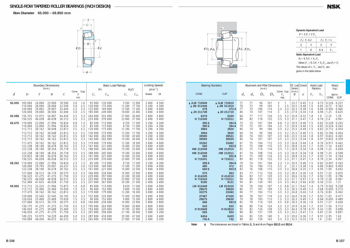
SINGLE-ROW TAPERED ROLLER BEARINGS (INCH DESIGN)Bore Diameter 65.000 – 69.850 mm
jd
r
r
jD
TC
B
a
jD jd jd
ra
ra
a b ajDb
65.000 105.000 24.000 23.000 18.500 3.0 1.0 93 000 126 000 9 500 12 900 3 400 4 500 110.000 28.000 28.000 22.500 3.0 2.5 120 000 173 000 12 200 17 700 3 200 4 300 120.000 29.002 29.007 23.444 2.3 3.3 123 000 169 000 12 500 17 200 3 000 4 000 120.000 39.000 38.500 32.000 3.0 2.5 185 000 249 000 18 800 25 400 3 000 4 000 65.088 135.755 53.975 56.007 44.450 3.5 3.3 264 000 355 000 27 000 36 000 2 800 3 800 136.525 46.038 46.038 36.512 3.5 3.3 233 000 370 000 23 800 37 500 2 600 3 400 66.675 110.000 22.000 21.996 18.824 0.8 1.3 85 500 113 000 8 750 11 500 3 200 4 300 110.000 22.000 21.996 18.824 3.5 1.3 85 500 113 000 8 750 11 500 3 200 4 300 112.712 30.162 30.048 23.812 3.5 3.2 120 000 173 000 12 200 17 700 3 200 4 300 112.712 30.162 30.048 23.812 5.5 3.2 120 000 173 000 12 200 17 700 3 200 4 300 112.712 30.162 30.162 23.812 3.5 0.8 142 000 202 000 14 500 20 600 3 200 4 300 112.712 30.162 30.162 23.812 3.5 3.3 142 000 202 000 14 500 20 600 3 200 4 300 117.475 30.162 30.162 23.812 3.5 3.3 119 000 179 000 12 200 18 300 3 000 4 000 122.238 38.100 36.678 30.162 3.5 3.3 161 000 221 000 16 400 22 500 3 000 4 000 122.238 38.100 38.354 29.718 3.5 1.5 188 000 245 000 19 200 25 000 3 000 4 000 122.238 38.100 38.354 29.718 3.5 3.3 188 000 245 000 19 200 25 000 3 000 4 000 123.825 38.100 36.678 30.162 3.5 3.3 161 000 221 000 16 400 22 500 3 000 4 000 136.525 46.038 46.038 36.512 3.5 3.3 233 000 370 000 23 800 37 500 2 600 3 400 68.262 110.000 22.000 21.996 18.824 2.3 1.3 85 500 113 000 8 750 11 500 3 200 4 300 120.000 29.795 29.007 24.237 3.5 2.0 123 000 169 000 12 500 17 200 3 000 4 000 122.238 38.100 36.678 30.162 3.5 3.3 161 000 221 000 16 400 22 500 3 000 4 000 127.000 36.512 36.170 28.575 3.5 3.3 166 000 234 000 16 900 23 900 2 800 3 800 136.525 41.275 41.275 31.750 3.5 3.3 229 000 297 000 23 300 30 500 2 600 3 600 136.525 46.038 46.038 36.512 3.5 3.3 233 000 370 000 23 800 37 500 2 600 3 400 152.400 47.625 46.038 31.750 3.5 3.3 237 000 267 000 24 200 27 300 2 400 3 400 69.850 112.712 22.225 21.996 15.875 1.5 0.8 85 000 113 000 8 650 11 500 3 000 4 000 112.712 25.400 25.400 19.050 1.5 3.3 96 000 152 000 9 800 15 500 2 800 4 000 117.475 30.162 30.162 23.812 3.5 3.3 119 000 179 000 12 200 18 300 3 000 4 000 120.000 32.545 32.545 26.195 3.5 3.3 152 000 225 000 15 500 22 900 3 000 4 000 120.650 25.400 25.400 19.050 1.5 3.3 96 000 152 000 9 800 15 500 2 800 4 000 127.000 36.512 36.170 28.575 3.5 0.8 166 000 234 000 16 900 23 900 2 800 3 800 130.175 41.275 41.275 31.750 3.5 3.3 195 000 263 000 19 800 26 800 2 800 3 800 146.050 41.275 39.688 25.400 3.5 3.3 193 000 225 000 19 700 22 900 2 400 3 400 146.050 41.275 41.275 31.750 3.5 3.3 207 000 296 000 21 100 30 000 2 400 3 200 149.225 53.975 54.229 44.450 5.0 3.3 287 000 410 000 29 300 41 500 2 600 3 400 150.089 44.450 46.672 36.512 3.5 3.3 265 000 370 000 27 000 37 500 2 400 3 200
Boundary Dimensions(mm)
Cone Cup d D T B C r min.
Limiting Speeds (min–1)
Grease Oil
Basic Load Ratings (N) {kgf}
Cr C0r Cr C0r
� JLM 710949 � JLM 710910 77 71 96 101 3 1 23.7 0.45 1.3 0.73 0.526 0.237 � JM 511946 � JM 511910 78 72 99 105 3 2.5 24.5 0.40 1.5 0.82 0.72 0.342 478 472 A 77 73 106 114 2.3 3.3 24.3 0.38 1.6 0.86 0.942 0.466 � JH 211749 � JH 211710 80 74 107 114 3 2.5 27.9 0.34 1.8 0.98 1.25 0.625 6379 6320 84 77 117 126 3.5 3.3 35.0 0.32 1.8 1.0 2.25 1.39 H 715340 H 715311 88 82 118 132 3.5 3.3 37.1 0.47 1.3 0.70 2.4 0.961 395 A 394 A 73 73 101 104 0.8 1.3 20.9 0.40 1.5 0.82 0.528 0.263 395 S 394 A 79 73 101 104 3.5 1.3 20.9 0.40 1.5 0.82 0.524 0.263 3984 3920 80 74 99 106 3.5 3.2 25.5 0.40 1.5 0.82 0.712 0.454 3994 3920 84 74 99 106 5.5 3.2 25.5 0.40 1.5 0.82 0.706 0.454 39590 39521 80 74 103 107 3.5 0.8 23.5 0.34 1.8 0.97 0.822 0.365 39590 39520 80 74 101 107 3.5 3.3 23.5 0.34 1.8 0.97 0.822 0.359 33262 33462 81 75 104 112 3.5 3.3 26.8 0.44 1.4 0.76 0.911 0.442 560 553 X 81 75 108 115 3.5 3.3 28.8 0.35 1.7 0.95 1.14 0.692 HM 212049 HM 212010 82 75 110 116 3.5 1.5 26.9 0.34 1.8 0.98 1.25 0.604 HM 212049 HM 212011 81 74 108 116 3.5 3.3 26.9 0.34 1.8 0.98 1.25 0.598 560 552 A 81 75 109 116 3.5 3.3 28.8 0.35 1.7 0.95 1.14 0.764 H 715341 H 715311 89 83 118 132 3.5 3.3 37.1 0.47 1.3 0.70 2.34 0.961 399 A 394 A 78 74 101 104 2.3 1.3 20.9 0.40 1.5 0.82 0.497 0.263 480 472 83 76 106 113 3.5 2 25.1 0.38 1.6 0.86 0.862 0.493 560 S 553 X 83 76 108 115 3.5 3.3 28.8 0.35 1.7 0.95 1.09 0.692 570 563 83 77 112 120 3.5 3.3 28.3 0.36 1.6 0.91 1.32 0.655 H 414245 H 414210 86 82 121 129 3.5 3.3 30.6 0.36 1.7 0.92 1.95 0.796 H 715343 H 715311 90 84 118 132 3.5 3.3 37.1 0.47 1.3 0.70 2.28 0.961 9185 9121 94 81 130 145 3.5 3.3 44.3 0.66 0.92 0.50 2.53 1.21 LM 613449 LM 613410 78 76 104 107 1.5 0.8 22.1 0.42 1.4 0.79 0.562 0.238 29675 29620 80 77 101 109 1.5 3.3 26.3 0.49 1.2 0.68 0.695 0.273 33275 33462 84 77 104 112 3.5 3.3 26.8 0.44 1.4 0.76 0.83 0.442 47487 47420 84 78 107 114 3.5 3.3 26.0 0.36 1.7 0.92 1.02 0.477 29675 29630 79 78 105 113 1.5 3.3 26.3 0.49 1.2 0.68 0.695 0.489 566 563 X 85 78 114 120 3.5 0.8 28.3 0.36 1.6 0.91 1.27 0.658 643 633 86 80 116 124 3.5 3.3 29.9 0.36 1.7 0.91 1.56 0.712 H 913849 H 913810 95 82 124 138 3.5 3.3 44.4 0.78 0.77 0.42 1.95 0.898 655 653 88 82 131 139 3.5 3.3 33.2 0.41 1.5 0.81 2.35 0.891 6454 6420 94 85 129 140 5 3.3 39.0 0.36 1.7 0.91 2.95 1.63 745 A 742 88 82 134 142 3.5 3.3 32.5 0.33 1.8 1.0 2.82 1.07
Bearing Numbers
CONE CUP
Abutment and Fillet Dimensions(mm)
Cone Cup da db Da Db ra max.
Mass(kg)
approx. CONE CUP
Eff. Load Centers(mm)
a
Constant
e
Axial Load Factors
Y1 Y0
Note � The tolerances are listed in Tables 2, 3 and 4 on Pages B113 and B114.
Fa/Fr≤e Fa/Fr>e
X Y X Y
1 0 0.4 Y1
Dynamic Equivalent Load
P =XFr +YFa
Static Equivalent Load
P0 =0.5Fr +Y0 Fa
When Fr>0.5Fr +Y0 Fa, use P0 =Fr
The values of e, Y1 , and Y0 are
given in the table below.
B 156 B 157
B110-181E.indd 156-157B110-181E.indd 156-157 11/20/13 4:57:13 PM11/20/13 4:57:13 PM

SINGLE-ROW TAPERED ROLLER BEARINGS (INCH DESIGN)Bore Diameter 70.000 – 76.200 mm
jd
r
r
jD
TC
B
a
jD jd jd
ra
ra
a b ajDb
70.000 110.000 26.000 25.000 20.500 1.0 2.5 98 500 152 000 10 000 15 500 3 000 4 000 115.000 29.000 29.000 23.000 3.0 2.5 126 000 177 000 12 900 18 100 3 000 4 000 120.000 29.795 29.007 24.237 2.0 2.0 123 000 169 000 12 500 17 200 3 000 4 000 71.438 117.475 30.162 30.162 23.812 3.5 3.3 119 000 179 000 12 200 18 300 3 000 4 000 120.000 32.545 32.545 26.195 3.5 3.3 152 000 225 000 15 500 22 900 3 000 4 000 127.000 36.512 36.170 28.575 6.4 3.3 166 000 234 000 16 900 23 900 2 800 3 800 127.000 36.512 36.170 28.575 3.5 3.3 166 000 234 000 16 900 23 900 2 800 3 800 130.175 41.275 41.275 31.750 6.4 3.3 195 000 263 000 19 800 26 800 2 800 3 800 136.525 41.275 41.275 31.750 3.5 3.3 195 000 263 000 19 800 26 800 2 800 3 800 136.525 41.275 41.275 31.750 3.5 3.3 229 000 297 000 23 300 30 500 2 600 3 600 136.525 46.038 46.038 36.512 3.5 3.3 233 000 370 000 23 800 37 500 2 600 3 400 73.025 112.712 25.400 25.400 19.050 3.5 3.3 96 000 152 000 9 800 15 500 2 800 4 000 117.475 30.162 30.162 23.812 3.5 3.3 119 000 179 000 12 200 18 300 3 000 4 000 127.000 36.512 36.170 28.575 3.5 3.3 166 000 234 000 16 900 23 900 2 800 3 800 146.050 41.275 41.275 31.750 3.5 3.3 207 000 296 000 21 100 30 000 2 400 3 200 149.225 53.975 54.229 44.450 3.5 3.3 287 000 410 000 29 300 41 500 2 600 3 400 73.817 127.000 36.512 36.170 28.575 0.8 3.3 166 000 234 000 16 900 23 900 2 800 3 800 74.612 150.000 41.275 41.275 31.750 3.5 3.0 207 000 296 000 21 100 30 000 2 400 3 200 75.000 115.000 25.000 25.000 19.000 3.0 2.5 101 000 150 000 10 300 15 300 3 000 4 000 120.000 31.000 29.500 25.000 3.0 2.5 129 000 198 000 13 100 20 200 2 800 3 800 145.000 51.000 51.000 42.000 3.0 2.5 283 000 410 000 28 900 41 500 2 600 3 400 76.200 121.442 24.608 23.012 17.462 2.0 2.0 89 000 124 000 9 100 12 600 2 800 3 800 127.000 30.162 31.000 22.225 3.5 3.3 134 000 195 000 13 700 19 900 2 800 3 800 127.000 30.162 31.001 22.225 6.4 3.3 134 000 195 000 13 700 19 900 2 800 3 800 133.350 33.338 33.338 26.195 0.8 3.3 154 000 237 000 15 700 24 200 2 600 3 600 135.733 44.450 46.101 34.925 3.5 3.3 216 000 340 000 22 000 35 000 2 600 3 600 136.525 30.162 29.769 22.225 3.5 3.3 130 000 192 000 13 300 19 600 2 600 3 400 136.525 30.162 29.769 22.225 6.4 3.3 130 000 192 000 13 300 19 600 2 600 3 400 139.992 36.512 36.098 28.575 3.5 3.3 175 000 260 000 17 800 26 500 2 600 3 400 149.225 53.975 54.229 44.450 3.5 3.3 287 000 410 000 29 300 41 500 2 600 3 400 152.400 39.688 36.322 30.162 3.5 3.2 183 000 285 000 18 700 29 100 2 200 3 200 152.400 41.275 41.275 31.750 3.5 3.3 207 000 296 000 21 100 30 000 2 400 3 200 161.925 49.212 46.038 31.750 3.5 3.3 248 000 290 000 25 300 29 600 2 200 3 000 161.925 53.975 55.100 42.862 3.5 3.3 325 000 480 000 33 000 49 000 2 200 3 000 161.925 53.975 55.100 42.862 6.4 3.3 325 000 480 000 33 000 49 000 2 200 3 000 161.925 53.975 55.100 42.862 6.4 0.8 325 000 480 000 33 000 49 000 2 200 3 000
Boundary Dimensions(mm)
Cone Cup d D T B C r min.
Limiting Speeds (min–1)
Grease Oil
Basic Load Ratings (N) {kgf}
Cr C0r Cr C0r
� JLM 813049 � JLM 813010 78 77 98 105 1 2.5 26.2 0.49 1.2 0.68 0.604 0.304 � JM 612949 � JM 612910 83 77 103 110 3 2.5 26.4 0.43 1.4 0.77 0.800 0.362 484 472 80 78 106 113 2 2 25.1 0.38 1.6 0.86 0.822 0.493 33281 33462 85 79 104 112 3.5 3.3 26.8 0.44 1.4 0.76 0.789 0.442 47490 47420 86 79 107 114 3.5 3.3 26.0 0.36 1.7 0.92 0.983 0.477 567 S 563 92 80 112 120 6.4 3.3 28.3 0.36 1.6 0.91 1.21 0.655 567 A 563 86 80 112 120 3.5 3.3 28.3 0.36 1.6 0.91 1.23 0.655 645 633 93 81 116 124 6.4 3.3 29.9 0.36 1.7 0.91 1.49 0.712 644 632 87 81 118 125 3.5 3.3 29.9 0.36 1.7 0.91 1.5 1.04 H 414249 H 414210 89 83 121 129 3.5 3.3 30.6 0.36 1.7 0.92 1.83 0.796 H 715345 H 715311 92 84 119 132 3.5 3.3 37.1 0.47 1.3 0.70 2.15 0.961 29685 29620 86 80 101 109 3.5 3.3 26.3 0.49 1.2 0.68 0.62 0.273 33287 33462 87 80 104 112 3.5 3.3 26.8 0.44 1.4 0.76 0.746 0.442 567 563 88 81 112 120 3.5 3.3 28.3 0.36 1.6 0.91 1.17 0.655 657 653 91 85 131 139 3.5 3.3 33.2 0.41 1.5 0.81 2.24 0.891 6460 6420 93 87 129 140 3.5 3.3 39.0 0.36 1.7 0.91 2.8 1.63 568 563 83 82 112 120 0.8 3.3 28.3 0.36 1.6 0.91 1.15 0.655 658 653 X 92 86 133 141 3.5 3 33.2 0.41 1.5 0.81 2.37 0.932 � JLM 714149 � JLM 714110 87 81 104 110 3 2.5 25.3 0.46 1.3 0.72 0.638 0.272 � JM 714249 � JM 714210 88 83 108 115 3 2.5 28.8 0.44 1.4 0.74 0.863 0.436 � JH 415647 � JH 415610 94 89 129 139 3 2.5 36.7 0.36 1.7 0.91 2.64 1.19 34300 34478 86 84 111 116 2 2 26.3 0.45 1.3 0.73 0.65 0.316 42687 42620 90 84 114 121 3.5 3.3 27.3 0.42 1.4 0.79 1.03 0.438 42688 42620 94 84 114 121 6.4 3.3 27.3 0.42 1.4 0.79 1.01 0.438 47680 47620 86 85 119 128 0.8 3.3 29.0 0.40 1.5 0.82 1.39 0.577 5760 5735 94 88 119 130 3.5 3.3 32.9 0.41 1.5 0.81 1.86 0.887 495 A 493 92 86 122 130 3.5 3.3 28.7 0.44 1.4 0.74 1.27 0.55 495 AX 493 98 86 122 130 6.4 3.3 28.7 0.44 1.4 0.74 1.26 0.55 575 572 92 86 125 133 3.5 3.3 31.1 0.40 1.5 0.82 1.61 0.788 6461 6420 96 89 129 140 3.5 3.3 39.0 0.36 1.7 0.91 2.64 1.63 590 A 592 A 95 89 135 145 3.5 3.2 37.1 0.44 1.4 0.75 2.2 1.06 659 652 93 87 134 141 3.5 3.3 33.2 0.41 1.5 0.81 2.11 1.26 9285 9220 103 90 138 153 3.5 3.3 49.8 0.71 0.85 0.47 2.82 1.4 6576 6535 99 92 141 154 3.5 3.3 40.7 0.40 1.5 0.82 3.74 1.67 6575 6535 104 92 141 154 6.4 3.3 40.7 0.40 1.5 0.82 3.73 1.67 6575 6536 104 92 144 154 6.4 0.8 40.7 0.40 1.5 0.82 3.73 1.68
Bearing Numbers
CONE CUP
Abutment and Fillet Dimensions(mm)
Cone Cup da db Da Db ra max.
Mass(kg)
approx. CONE CUP
Eff. Load Centers(mm)
a
Constant
e
Axial Load Factors
Y1 Y0
Note � The tolerances are listed in Tables 2, 3 and 4 on Pages B113 and B114.
Fa/Fr≤e Fa/Fr>e
X Y X Y
1 0 0.4 Y1
Dynamic Equivalent Load
P =XFr +YFa
Static Equivalent Load
P0 =0.5Fr +Y0 Fa
When Fr>0.5Fr +Y0 Fa, use P0 =Fr
The values of e, Y1 , and Y0 are
given in the table below.
B 158 B 159
B110-181E.indd 158-159B110-181E.indd 158-159 11/20/13 4:57:14 PM11/20/13 4:57:14 PM

SINGLE-ROW TAPERED ROLLER BEARINGS (INCH DESIGN)Bore Diameter 76.200 – 83.345 mm
jd
r
r
jD
TC
B
a
jD jd jd
ra
ra
a b ajDb
76.200 168.275 53.975 56.363 41.275 6.4 3.3 345 000 470 000 35 000 48 000 2 200 3 000 168.275 53.975 56.363 41.275 0.8 3.3 345 000 470 000 35 000 48 000 2 200 3 000 171.450 49.212 46.038 31.750 3.5 3.3 257 000 310 000 26 200 32 000 2 000 2 800 177.800 55.562 50.800 34.925 3.5 3.3 257 000 310 000 26 200 32 000 2 000 2 800
77.788 121.442 24.608 23.012 17.462 3.5 2.0 89 000 124 000 9 100 12 600 2 800 3 800 127.000 30.162 31.000 22.225 3.5 3.3 134 000 195 000 13 700 19 900 2 800 3 800 135.733 44.450 46.101 34.925 3.5 3.3 216 000 340 000 22 000 35 000 2 600 3 600
79.375 146.050 41.275 41.275 31.750 3.5 3.3 207 000 296 000 21 100 30 000 2 400 3 200 150.089 44.450 46.672 36.512 3.5 3.3 265 000 370 000 27 000 37 500 2 400 3 200
80.000 130.000 35.000 34.000 28.500 3.0 2.5 166 000 251 000 17 000 25 600 2 600 3 600
80.962 136.525 30.162 29.769 22.225 3.5 3.3 130 000 192 000 13 300 19 600 2 600 3 400 139.700 36.512 36.098 28.575 3.5 3.3 175 000 260 000 17 800 26 500 2 600 3 400 139.992 36.512 36.098 28.575 3.5 3.3 175 000 260 000 17 800 26 500 2 600 3 400
82.550 125.412 25.400 25.400 19.845 3.5 1.5 102 000 164 000 10 400 16 700 2 600 3 600 133.350 30.162 29.769 22.225 3.5 3.3 130 000 192 000 13 300 19 600 2 600 3 400 133.350 33.338 33.338 26.195 3.5 3.3 154 000 237 000 15 700 24 200 2 600 3 600
133.350 33.338 33.338 26.195 0.8 3.3 154 000 237 000 15 700 24 200 2 600 3 600 133.350 33.338 33.338 26.195 6.8 3.3 154 000 237 000 15 700 24 200 2 600 3 600 133.350 39.688 39.688 32.545 6.8 3.3 179 000 310 000 18 300 31 500 2 600 3 600
136.525 30.162 29.769 22.225 3.5 3.3 130 000 192 000 13 300 19 600 2 600 3 400 139.700 36.512 36.098 28.575 3.5 3.3 175 000 260 000 17 800 26 500 2 600 3 400 139.992 36.512 36.098 28.575 3.5 3.3 175 000 260 000 17 800 26 500 2 600 3 400
139.992 36.512 36.098 28.575 6.8 3.3 175 000 260 000 17 800 26 500 2 600 3 400 146.050 41.275 41.275 31.750 3.5 3.3 207 000 296 000 21 100 30 000 2 400 3 200 150.000 44.455 46.672 35.000 3.5 3.3 265 000 370 000 27 000 37 500 2 400 3 200
150.089 44.450 46.672 36.512 3.5 3.3 265 000 370 000 27 000 37 500 2 400 3 200 152.400 41.275 41.275 31.750 3.5 3.3 207 000 296 000 21 100 30 000 2 400 3 200 161.925 47.625 48.260 38.100 3.5 3.3 274 000 390 000 28 000 40 000 2 200 3 000
161.925 53.975 55.100 42.862 3.5 3.3 325 000 480 000 33 000 49 000 2 200 3 000 168.275 47.625 48.260 38.100 3.5 3.3 274 000 390 000 28 000 40 000 2 200 3 000 168.275 53.975 56.363 41.275 3.5 3.3 345 000 470 000 35 000 48 000 2 200 3 000
83.345 125.412 25.400 25.400 19.845 3.5 1.5 102 000 164 000 10 400 16 700 2 600 3 600 125.412 25.400 25.400 19.845 0.8 1.5 102 000 164 000 10 400 16 700 2 600 3 600
Boundary Dimensions(mm)
Cone Cup d D T B C r min.
Limiting Speeds (min–1)
Grease Oil
Basic Load Ratings (N) {kgf}
Cr C0r Cr C0r
843 832 101 89 149 155 6.4 3.3 35.2 0.30 2.0 1.1 4.11 1.74 837 832 90 89 149 155 0.8 3.3 35.2 0.30 2.0 1.1 4.13 1.74 9380 9321 105 98 147 164 3.5 3.3 54.1 0.76 0.79 0.43 3.47 1.51 9378 9320 105 98 148 164 3.5 3.3 57.3 0.76 0.79 0.43 3.71 2.24
34306 34478 90 84 110 116 3.5 2 26.3 0.45 1.3 0.73 0.612 0.316 42690 42620 91 85 114 121 3.5 3.3 27.3 0.42 1.4 0.79 0.976 0.438 5795 5735 96 89 119 130 3.5 3.3 32.9 0.41 1.5 0.81 1.79 0.887
661 653 96 90 131 139 3.5 3.3 33.2 0.41 1.5 0.81 1.99 0.891 750 742 96 90 134 142 3.5 3.3 32.5 0.33 1.8 1.0 2.42 1.07
� JM 515649 � JM 515610 94 88 117 125 3 2.5 29.9 0.39 1.5 0.85 1.18 0.583
496 493 95 89 122 130 3.5 3.3 28.7 0.44 1.4 0.74 1.13 0.55 581 572 X 96 90 125 133 3.5 3.3 31.1 0.40 1.5 0.82 1.44 0.774 581 572 96 90 125 133 3.5 3.3 31.1 0.40 1.5 0.82 1.44 0.788
27687 27620 96 89 115 120 3.5 1.5 25.7 0.42 1.4 0.79 0.747 0.348 495 492 A 97 90 120 128 3.5 3.3 28.7 0.44 1.4 0.74 1.08 0.434 47686 47620 97 90 119 128 3.5 3.3 29.0 0.40 1.5 0.82 1.18 0.577
47685 47620 90 90 119 128 0.8 3.3 29.0 0.40 1.5 0.82 1.18 0.577 47687 47620 103 90 119 128 6.8 3.3 29.0 0.40 1.5 0.82 1.16 0.577 HM 516448 HM 516410 105 92 118 128 6.8 3.3 32.4 0.40 1.5 0.82 1.35 0.767
495 493 97 90 122 130 3.5 3.3 28.7 0.44 1.4 0.74 1.08 0.55 580 572 X 98 91 125 133 3.5 3.3 31.1 0.40 1.5 0.82 1.39 0.774 580 572 98 91 125 133 3.5 3.3 31.1 0.40 1.5 0.82 1.39 0.788
582 572 104 91 125 133 6.8 3.3 31.1 0.40 1.5 0.82 1.37 0.788 663 653 99 92 131 139 3.5 3.3 33.2 0.41 1.5 0.81 1.85 0.891 749 A 743 99 93 134 142 3.5 3.3 32.5 0.33 1.8 1.0 2.26 1.04
749 A 742 98 93 135 143 3.5 3.3 32.5 0.33 1.8 1.0 2.26 1.07 663 652 99 92 134 141 3.5 3.3 33.2 0.41 1.5 0.81 1.85 1.26 757 752 100 94 144 150 3.5 3.3 35.6 0.34 1.8 0.97 2.79 1.61
6559 6535 104 98 141 154 3.5 3.3 40.7 0.40 1.5 0.82 3.4 1.67 757 753 100 94 147 150 3.5 3.3 35.6 0.34 1.8 0.97 2.79 2.1 842 832 101 94 149 155 3.5 3.3 35.2 0.30 2.0 1.1 3.76 1.74
27690 27620 96 90 115 120 3.5 1.5 25.7 0.42 1.4 0.79 0.727 0.348 27689 27620 90 90 115 120 0.8 1.5 25.7 0.42 1.4 0.79 0.732 0.348
Bearing Numbers
CONE CUP
Abutment and Fillet Dimensions(mm)
Cone Cup da db Da Db ra max.
Mass(kg)
approx. CONE CUP
Eff. Load Centers(mm)
a
Constant
e
Axial Load Factors
Y1 Y0
Note � The tolerances are listed in Tables 2, 3 and 4 on Pages B113 and B114.
Fa/Fr≤e Fa/Fr>e
X Y X Y
1 0 0.4 Y1
Dynamic Equivalent Load
P =XFr +YFa
Static Equivalent Load
P0 =0.5Fr +Y0 Fa
When Fr>0.5Fr +Y0 Fa, use P0 =Fr
The values of e, Y1 , and Y0 are
given in the table below.
B 160 B 161
B110-181E.indd 160-161B110-181E.indd 160-161 11/20/13 4:57:15 PM11/20/13 4:57:15 PM
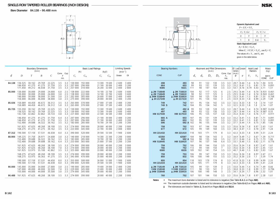
SINGLE-ROW TAPERED ROLLER BEARINGS (INCH DESIGN)Bore Diameter 84.138 – 90.488 mm
jd
r
r
jD
TC
B
a
jD jd jd
ra
ra
a b ajDb
84.138 136.525 30.162 29.769 22.225 3.5 3.3 130 000 192 000 13 300 19 600 2 600 3 400 146.050 41.275 41.275 31.750 3.5 3.3 207 000 296 000 21 100 30 000 2 400 3 200 171.450 49.212 46.038 31.750 3.5 3.3 257 000 310 000 26 200 32 000 2 000 2 800
85.000 130.000 30.000 29.000 24.000 6.0 2.5 138 000 222 000 14 100 22 700 2 600 3 600 130.000 30.000 29.000 24.000 3.0 2.5 138 000 222 000 14 100 22 700 2 600 3 600 140.000 39.000 38.000 31.500 3.0 2.5 202 000 305 000 20 600 31 000 2 400 3 400 150.000 46.000 46.000 38.000 3.0 2.5 275 000 390 000 28 000 40 000 2 400 3 200
85.026 150.089 44.450 46.672 36.512 3.5 3.3 265 000 370 000 27 000 37 500 2 400 3 200 150.089 44.450 46.672 36.512 5.0 3.3 265 000 370 000 27 000 37 500 2 400 3 200
85.725 133.350 30.162 29.769 22.225 3.5 3.3 130 000 192 000 13 300 19 600 2 600 3 400 136.525 30.162 29.769 22.225 3.5 3.3 130 000 192 000 13 300 19 600 2 600 3 400 142.138 42.862 42.862 34.133 4.8 3.3 221 000 360 000 22 500 36 500 2 400 3 400
146.050 41.275 41.275 31.750 6.4 3.3 207 000 296 000 21 100 30 000 2 400 3 200 146.050 41.275 41.275 31.750 3.5 3.3 207 000 296 000 21 100 30 000 2 400 3 200 152.400 39.688 36.322 30.162 3.5 3.2 183 000 285 000 18 700 29 100 2 200 3 200
161.925 47.625 48.260 38.100 3.5 3.3 274 000 390 000 28 000 40 000 2 200 3 000 168.275 41.275 41.275 30.162 3.5 3.3 223 000 345 000 22 700 35 000 2 000 2 800
87.312 190.500 57.150 57.531 46.038 8.0 3.3 390 000 520 000 39 500 53 500 1 900 2 600
88.900 149.225 31.750 28.971 24.608 3.0 3.3 140 000 218 000 14 300 22 300 2 200 3 000 152.400 39.688 36.322 30.162 3.5 3.2 183 000 285 000 18 700 29 100 2 200 3 200 152.400 39.688 39.688 30.162 6.4 3.3 253 000 365 000 25 800 37 500 2 200 3 200
161.925 47.625 48.260 38.100 3.5 3.3 274 000 390 000 28 000 40 000 2 200 3 000 161.925 47.625 48.260 38.100 7.0 3.3 274 000 390 000 28 000 40 000 2 200 3 000 161.925 53.975 55.100 42.862 3.5 3.3 325 000 480 000 33 000 49 000 2 200 3 000
168.275 47.625 48.260 38.100 3.5 3.3 274 000 390 000 28 000 40 000 2 200 3 000 168.275 53.975 56.363 41.275 3.5 3.3 345 000 470 000 35 000 48 000 2 200 3 000
190.500 57.150 57.531 44.450 8.0 3.3 355 000 500 000 36 000 51 000 1 900 2 600 190.500 57.150 57.531 46.038 8.0 3.3 390 000 520 000 39 500 53 500 1 900 2 600
90.000 145.000 35.000 34.000 27.000 3.0 2.5 190 000 285 000 19 400 29 000 2 400 3 200 147.000 40.000 40.000 32.500 7.0 3.5 229 000 345 000 23 400 35 000 2 400 3 200 155.000 44.000 44.000 35.500 3.0 2.5 274 000 395 000 28 000 40 000 2 200 3 000
90.488 161.925 47.625 48.260 38.100 3.5 3.3 274 000 390 000 28 000 40 000 2 200 3 000
Boundary Dimensions(mm)
Cone Cup d D T B C r min.
Limiting Speeds (min–1)
Grease Oil
Basic Load Ratings (N) {kgf}
Cr C0r Cr C0r
498 493 98 91 122 130 3.5 3.3 28.7 0.44 1.4 0.74 1.04 0.55 664 653 99 93 131 139 3.5 3.3 33.2 0.41 1.5 0.81 1.79 0.891 9385 9321 111 98 147 164 3.5 3.3 54.1 0.76 0.79 0.43 3.11 1.51
� JM 716648 � JM 716610 104 92 117 125 6 2.5 29.5 0.44 1.4 0.74 0.931 0.461 � JM 716649 � JM 716610 98 92 117 125 3 2.5 29.5 0.44 1.4 0.74 0.943 0.461 � JHM 516849 � JHM 516810 100 94 125 134 3 2.5 33.3 0.41 1.5 0.81 1.55 0.768 � JH 217249 � JH 217210 101 95 134 142 3 2.5 33.9 0.33 1.8 0.99 2.29 1.09
749 742 101 95 134 142 3.5 3.3 32.5 0.33 1.8 1.0 2.14 1.07 749 S 742 104 95 134 142 5 3.3 32.5 0.33 1.8 1.0 2.14 1.07
497 492 A 99 93 120 128 3.5 3.3 28.7 0.44 1.4 0.74 0.987 0.434 497 493 99 93 122 130 3.5 3.3 28.7 0.44 1.4 0.74 0.987 0.55 HM 617049 HM 617010 106 95 125 137 4.8 3.3 35.4 0.43 1.4 0.76 1.77 0.911
665 A 653 107 95 131 139 6.4 3.3 33.2 0.41 1.5 0.81 1.71 0.891 665 653 102 95 131 139 3.5 3.3 33.2 0.41 1.5 0.81 1.72 0.891 596 592 A 102 96 135 144 3.5 3.2 37.1 0.44 1.4 0.75 1.85 1.06
758 752 103 97 144 150 3.5 3.3 35.6 0.34 1.8 0.97 2.63 1.61 677 672 105 99 149 160 3.5 3.3 38.3 0.47 1.3 0.70 2.91 1.24
HH 221432 HH 221410 118 103 171 179 8 3.3 42.3 0.33 1.8 0.99 5.51 2.24
42350 42587 104 98 134 143 3 3.3 34.9 0.49 1.2 0.67 1.39 0.711 593 592 A 104 98 135 144 3.5 3.2 37.1 0.44 1.4 0.75 1.73 1.06 HM 518445 HM 518410 107 96 137 148 6.4 3.3 33.1 0.40 1.5 0.82 2.11 0.776
759 752 106 99 144 150 3.5 3.3 35.6 0.34 1.8 0.97 2.47 1.61 766 752 113 99 144 150 7 3.3 35.6 0.34 1.8 0.97 2.45 1.61 6580 6535 109 102 141 154 3.5 3.3 40.7 0.40 1.5 0.82 3.03 1.67
759 753 106 99 147 150 3.5 3.3 35.6 0.34 1.8 0.97 2.47 2.1 850 832 106 100 149 155 3.5 3.3 35.2 0.30 2.0 1.1 3.39 1.74
855 854 118 103 170 174 8 3.3 41.8 0.33 1.8 0.99 4.99 2.55 HH 221434 HH 221410 120 105 171 179 8 3.3 42.3 0.33 1.8 0.99 5.41 2.24
� JM 718149 � JM 718110 105 99 131 139 3 2.5 33.0 0.44 1.4 0.74 1.49 0.66 *HM 218248 **HM 218210 111 98 133 141 7 3.5 30.8 0.33 1.8 0.99 1.77 0.796 � JHM 318448 � JHM 318410 106 100 140 148 3 2.5 34.1 0.34 1.7 0.96 2.32 1.01
760 752 107 101 144 150 3.5 3.3 35.6 0.34 1.8 0.97 2.38 1.61
Bearing Numbers
CONE CUP
Abutment and Fillet Dimensions(mm)
Cone Cup da db Da Db ra max.
Mass(kg)
approx. CONE CUP
Eff. Load Centers(mm)
a
Constant
e
Axial Load Factors
Y1 Y0
Notes * The maximum bore diameter is listed and its tolerance is negative (See Table 8.4.1 on Page A68). ** The maximum outside diameter is listed and its tolerance is negative (See Table 8.4.2 on Pages A68 and A69). � The tolerances are listed in Tables 2, 3 and 4 on Pages B113 and B114.
Fa/Fr≤e Fa/Fr>e
X Y X Y
1 0 0.4 Y1
Dynamic Equivalent Load
P =XFr +YFa
Static Equivalent Load
P0 =0.5Fr +Y0 Fa
When Fr>0.5Fr +Y0 Fa, use P0 =Fr
The values of e, Y1 , and Y0 are
given in the table below.
B 162 B 163
B110-181E.indd 162-163B110-181E.indd 162-163 11/20/13 4:57:16 PM11/20/13 4:57:16 PM
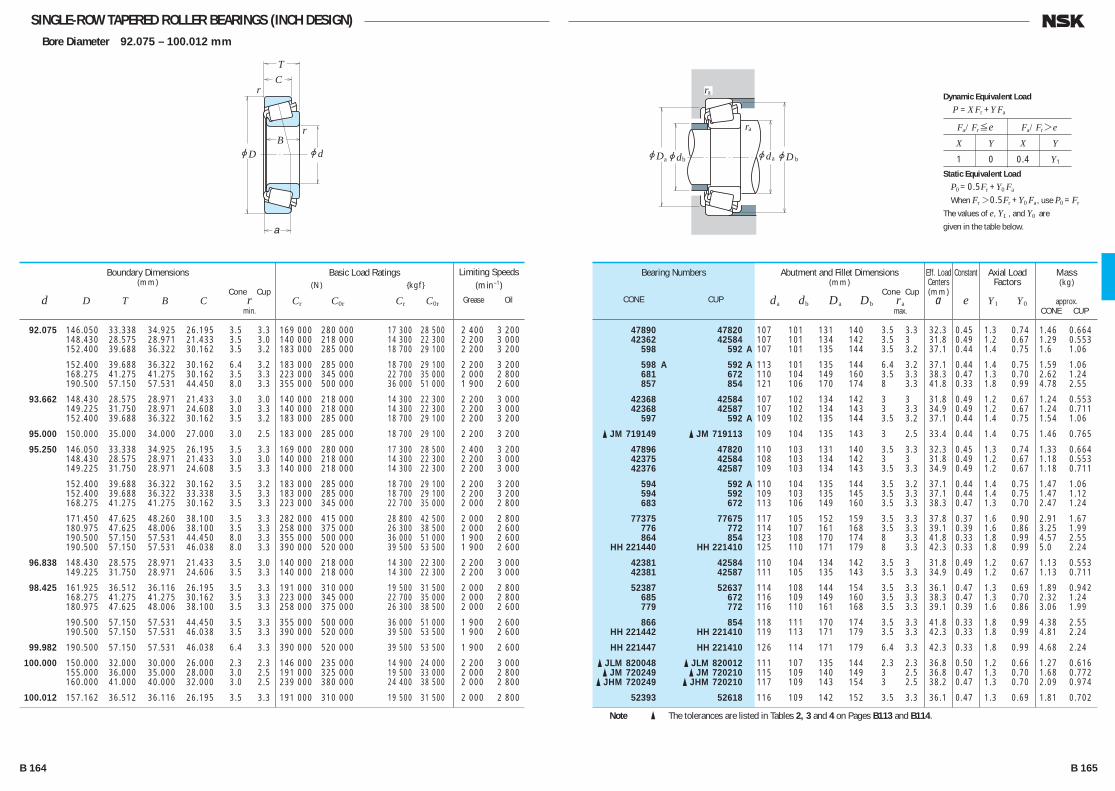
SINGLE-ROW TAPERED ROLLER BEARINGS (INCH DESIGN)Bore Diameter 92.075 – 100.012 mm
jd
r
r
jD
TC
B
a
jD jd jd
ra
ra
a b ajDb
92.075 146.050 33.338 34.925 26.195 3.5 3.3 169 000 280 000 17 300 28 500 2 400 3 200 148.430 28.575 28.971 21.433 3.5 3.0 140 000 218 000 14 300 22 300 2 200 3 000 152.400 39.688 36.322 30.162 3.5 3.2 183 000 285 000 18 700 29 100 2 200 3 200
152.400 39.688 36.322 30.162 6.4 3.2 183 000 285 000 18 700 29 100 2 200 3 200 168.275 41.275 41.275 30.162 3.5 3.3 223 000 345 000 22 700 35 000 2 000 2 800 190.500 57.150 57.531 44.450 8.0 3.3 355 000 500 000 36 000 51 000 1 900 2 600
93.662 148.430 28.575 28.971 21.433 3.0 3.0 140 000 218 000 14 300 22 300 2 200 3 000 149.225 31.750 28.971 24.608 3.0 3.3 140 000 218 000 14 300 22 300 2 200 3 000 152.400 39.688 36.322 30.162 3.5 3.2 183 000 285 000 18 700 29 100 2 200 3 200
95.000 150.000 35.000 34.000 27.000 3.0 2.5 183 000 285 000 18 700 29 100 2 200 3 200
95.250 146.050 33.338 34.925 26.195 3.5 3.3 169 000 280 000 17 300 28 500 2 400 3 200 148.430 28.575 28.971 21.433 3.0 3.0 140 000 218 000 14 300 22 300 2 200 3 000 149.225 31.750 28.971 24.608 3.5 3.3 140 000 218 000 14 300 22 300 2 200 3 000
152.400 39.688 36.322 30.162 3.5 3.2 183 000 285 000 18 700 29 100 2 200 3 200 152.400 39.688 36.322 33.338 3.5 3.3 183 000 285 000 18 700 29 100 2 200 3 200 168.275 41.275 41.275 30.162 3.5 3.3 223 000 345 000 22 700 35 000 2 000 2 800
171.450 47.625 48.260 38.100 3.5 3.3 282 000 415 000 28 800 42 500 2 000 2 800 180.975 47.625 48.006 38.100 3.5 3.3 258 000 375 000 26 300 38 500 2 000 2 600 190.500 57.150 57.531 44.450 8.0 3.3 355 000 500 000 36 000 51 000 1 900 2 600 190.500 57.150 57.531 46.038 8.0 3.3 390 000 520 000 39 500 53 500 1 900 2 600
96.838 148.430 28.575 28.971 21.433 3.5 3.0 140 000 218 000 14 300 22 300 2 200 3 000 149.225 31.750 28.971 24.606 3.5 3.3 140 000 218 000 14 300 22 300 2 200 3 000
98.425 161.925 36.512 36.116 26.195 3.5 3.3 191 000 310 000 19 500 31 500 2 000 2 800 168.275 41.275 41.275 30.162 3.5 3.3 223 000 345 000 22 700 35 000 2 000 2 800 180.975 47.625 48.006 38.100 3.5 3.3 258 000 375 000 26 300 38 500 2 000 2 600
190.500 57.150 57.531 44.450 3.5 3.3 355 000 500 000 36 000 51 000 1 900 2 600 190.500 57.150 57.531 46.038 3.5 3.3 390 000 520 000 39 500 53 500 1 900 2 600
99.982 190.500 57.150 57.531 46.038 6.4 3.3 390 000 520 000 39 500 53 500 1 900 2 600
100.000 150.000 32.000 30.000 26.000 2.3 2.3 146 000 235 000 14 900 24 000 2 200 3 000 155.000 36.000 35.000 28.000 3.0 2.5 191 000 325 000 19 500 33 000 2 000 2 800 160.000 41.000 40.000 32.000 3.0 2.5 239 000 380 000 24 400 38 500 2 000 2 800
100.012 157.162 36.512 36.116 26.195 3.5 3.3 191 000 310 000 19 500 31 500 2 000 2 800
Boundary Dimensions(mm)
Cone Cup d D T B C r min.
Limiting Speeds (min–1)
Grease Oil
Basic Load Ratings (N) {kgf}
Cr C0r Cr C0r
47890 47820 107 101 131 140 3.5 3.3 32.3 0.45 1.3 0.74 1.46 0.664 42362 42584 107 101 134 142 3.5 3 31.8 0.49 1.2 0.67 1.29 0.553 598 592 A 107 101 135 144 3.5 3.2 37.1 0.44 1.4 0.75 1.6 1.06
598 A 592 A 113 101 135 144 6.4 3.2 37.1 0.44 1.4 0.75 1.59 1.06 681 672 110 104 149 160 3.5 3.3 38.3 0.47 1.3 0.70 2.62 1.24 857 854 121 106 170 174 8 3.3 41.8 0.33 1.8 0.99 4.78 2.55
42368 42584 107 102 134 142 3 3 31.8 0.49 1.2 0.67 1.24 0.553 42368 42587 107 102 134 143 3 3.3 34.9 0.49 1.2 0.67 1.24 0.711 597 592 A 109 102 135 144 3.5 3.2 37.1 0.44 1.4 0.75 1.54 1.06
� JM 719149 � JM 719113 109 104 135 143 3 2.5 33.4 0.44 1.4 0.75 1.46 0.765
47896 47820 110 103 131 140 3.5 3.3 32.3 0.45 1.3 0.74 1.33 0.664 42375 42584 108 103 134 142 3 3 31.8 0.49 1.2 0.67 1.18 0.553 42376 42587 109 103 134 143 3.5 3.3 34.9 0.49 1.2 0.67 1.18 0.711
594 592 A 110 104 135 144 3.5 3.2 37.1 0.44 1.4 0.75 1.47 1.06 594 592 109 103 135 145 3.5 3.3 37.1 0.44 1.4 0.75 1.47 1.12 683 672 113 106 149 160 3.5 3.3 38.3 0.47 1.3 0.70 2.47 1.24
77375 77675 117 105 152 159 3.5 3.3 37.8 0.37 1.6 0.90 2.91 1.67 776 772 114 107 161 168 3.5 3.3 39.1 0.39 1.6 0.86 3.25 1.99 864 854 123 108 170 174 8 3.3 41.8 0.33 1.8 0.99 4.57 2.55 HH 221440 HH 221410 125 110 171 179 8 3.3 42.3 0.33 1.8 0.99 5.0 2.24
42381 42584 110 104 134 142 3.5 3 31.8 0.49 1.2 0.67 1.13 0.553 42381 42587 111 105 135 143 3.5 3.3 34.9 0.49 1.2 0.67 1.13 0.711
52387 52637 114 108 144 154 3.5 3.3 36.1 0.47 1.3 0.69 1.89 0.942 685 672 116 109 149 160 3.5 3.3 38.3 0.47 1.3 0.70 2.32 1.24 779 772 116 110 161 168 3.5 3.3 39.1 0.39 1.6 0.86 3.06 1.99
866 854 118 111 170 174 3.5 3.3 41.8 0.33 1.8 0.99 4.38 2.55 HH 221442 HH 221410 119 113 171 179 3.5 3.3 42.3 0.33 1.8 0.99 4.81 2.24
HH 221447 HH 221410 126 114 171 179 6.4 3.3 42.3 0.33 1.8 0.99 4.68 2.24
� JLM 820048 � JLM 820012 111 107 135 144 2.3 2.3 36.8 0.50 1.2 0.66 1.27 0.616 � JM 720249 � JM 720210 115 109 140 149 3 2.5 36.8 0.47 1.3 0.70 1.68 0.772 � JHM 720249 � JHM 720210 117 109 143 154 3 2.5 38.2 0.47 1.3 0.70 2.09 0.974
52393 52618 116 109 142 152 3.5 3.3 36.1 0.47 1.3 0.69 1.81 0.702
Bearing Numbers
CONE CUP
Abutment and Fillet Dimensions(mm)
Cone Cup da db Da Db ra max.
Mass(kg)
approx. CONE CUP
Eff. Load Centers(mm)
a
Constant
e
Axial Load Factors
Y1 Y0
Note � The tolerances are listed in Tables 2, 3 and 4 on Pages B113 and B114.
Fa/Fr≤e Fa/Fr>e
X Y X Y
1 0 0.4 Y1
Dynamic Equivalent Load
P =XFr +YFa
Static Equivalent Load
P0 =0.5Fr +Y0 Fa
When Fr>0.5Fr +Y0 Fa, use P0 =Fr
The values of e, Y1 , and Y0 are
given in the table below.
B 164 B 165
B110-181E.indd 164-165B110-181E.indd 164-165 11/20/13 4:57:17 PM11/20/13 4:57:17 PM
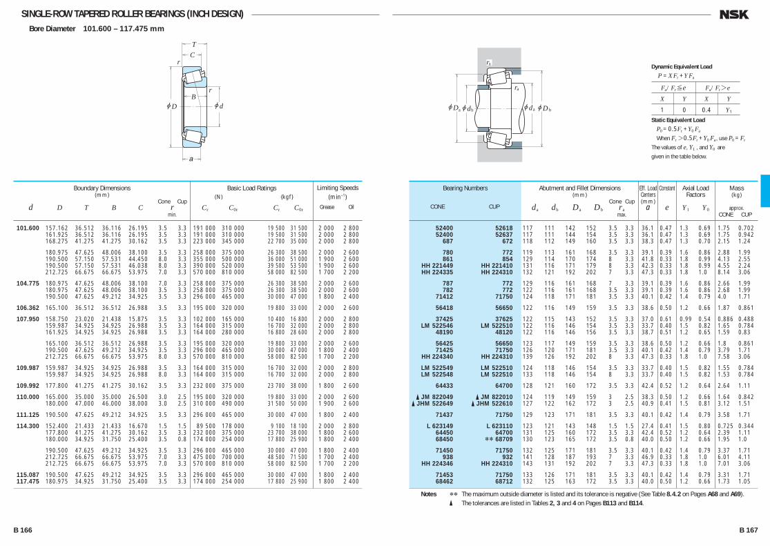
SINGLE-ROW TAPERED ROLLER BEARINGS (INCH DESIGN)Bore Diameter 101.600 – 117.475 mm
jd
r
r
jD
TC
B
a
jD jd jd
ra
ra
a b ajDb
101.600 157.162 36.512 36.116 26.195 3.5 3.3 191 000 310 000 19 500 31 500 2 000 2 800 161.925 36.512 36.116 26.195 3.5 3.3 191 000 310 000 19 500 31 500 2 000 2 800 168.275 41.275 41.275 30.162 3.5 3.3 223 000 345 000 22 700 35 000 2 000 2 800
180.975 47.625 48.006 38.100 3.5 3.3 258 000 375 000 26 300 38 500 2 000 2 600 190.500 57.150 57.531 44.450 8.0 3.3 355 000 500 000 36 000 51 000 1 900 2 600 190.500 57.150 57.531 46.038 8.0 3.3 390 000 520 000 39 500 53 500 1 900 2 600 212.725 66.675 66.675 53.975 7.0 3.3 570 000 810 000 58 000 82 500 1 700 2 200
104.775 180.975 47.625 48.006 38.100 7.0 3.3 258 000 375 000 26 300 38 500 2 000 2 600 180.975 47.625 48.006 38.100 3.5 3.3 258 000 375 000 26 300 38 500 2 000 2 600 190.500 47.625 49.212 34.925 3.5 3.3 296 000 465 000 30 000 47 000 1 800 2 400
106.362 165.100 36.512 36.512 26.988 3.5 3.3 195 000 320 000 19 800 33 000 2 000 2 600
107.950 158.750 23.020 21.438 15.875 3.5 3.3 102 000 165 000 10 400 16 800 2 000 2 800 159.987 34.925 34.925 26.988 3.5 3.3 164 000 315 000 16 700 32 000 2 000 2 800 161.925 34.925 34.925 26.988 3.5 3.3 164 000 280 000 16 800 28 600 2 000 2 800
165.100 36.512 36.512 26.988 3.5 3.3 195 000 320 000 19 800 33 000 2 000 2 600 190.500 47.625 49.212 34.925 3.5 3.3 296 000 465 000 30 000 47 000 1 800 2 400 212.725 66.675 66.675 53.975 8.0 3.3 570 000 810 000 58 000 82 500 1 700 2 200
109.987 159.987 34.925 34.925 26.988 3.5 3.3 164 000 315 000 16 700 32 000 2 000 2 800 159.987 34.925 34.925 26.988 8.0 3.3 164 000 315 000 16 700 32 000 2 000 2 800
109.992 177.800 41.275 41.275 30.162 3.5 3.3 232 000 375 000 23 700 38 000 1 800 2 600
110.000 165.000 35.000 35.000 26.500 3.0 2.5 195 000 320 000 19 800 33 000 2 000 2 600 180.000 47.000 46.000 38.000 3.0 2.5 310 000 490 000 31 500 50 000 1 900 2 600
111.125 190.500 47.625 49.212 34.925 3.5 3.3 296 000 465 000 30 000 47 000 1 800 2 400
114.300 152.400 21.433 21.433 16.670 1.5 1.5 89 500 178 000 9 100 18 100 2 000 2 800 177.800 41.275 41.275 30.162 3.5 3.3 232 000 375 000 23 700 38 000 1 800 2 600 180.000 34.925 31.750 25.400 3.5 0.8 174 000 254 000 17 800 25 900 1 800 2 400
190.500 47.625 49.212 34.925 3.5 3.3 296 000 465 000 30 000 47 000 1 800 2 400 212.725 66.675 66.675 53.975 7.0 3.3 475 000 700 000 48 500 71 500 1 700 2 400 212.725 66.675 66.675 53.975 7.0 3.3 570 000 810 000 58 000 82 500 1 700 2 200
115.087 190.500 47.625 49.212 34.925 3.5 3.3 296 000 465 000 30 000 47 000 1 800 2 400 117.475 180.975 34.925 31.750 25.400 3.5 3.3 174 000 254 000 17 800 25 900 1 800 2 400
Boundary Dimensions(mm)
Cone Cup d D T B C r min.
Limiting Speeds (min–1)
Grease Oil
Basic Load Ratings (N) {kgf}
Cr C0r Cr C0r
52400 52618 117 111 142 152 3.5 3.3 36.1 0.47 1.3 0.69 1.75 0.702 52400 52637 117 111 144 154 3.5 3.3 36.1 0.47 1.3 0.69 1.75 0.942 687 672 118 112 149 160 3.5 3.3 38.3 0.47 1.3 0.70 2.15 1.24
780 772 119 113 161 168 3.5 3.3 39.1 0.39 1.6 0.86 2.88 1.99 861 854 129 114 170 174 8 3.3 41.8 0.33 1.8 0.99 4.13 2.55 HH 221449 HH 221410 131 116 171 179 8 3.3 42.3 0.33 1.8 0.99 4.55 2.24 HH 224335 HH 224310 132 121 192 202 7 3.3 47.3 0.33 1.8 1.0 8.14 3.06
787 772 129 116 161 168 7 3.3 39.1 0.39 1.6 0.86 2.66 1.99 782 772 122 116 161 168 3.5 3.3 39.1 0.39 1.6 0.86 2.68 1.99 71412 71750 124 118 171 181 3.5 3.3 40.1 0.42 1.4 0.79 4.0 1.71
56418 56650 122 116 149 159 3.5 3.3 38.6 0.50 1.2 0.66 1.87 0.861
37425 37625 122 115 143 152 3.5 3.3 37.0 0.61 0.99 0.54 0.886 0.488 LM 522546 LM 522510 122 116 146 154 3.5 3.3 33.7 0.40 1.5 0.82 1.65 0.784 48190 48120 122 116 146 156 3.5 3.3 38.7 0.51 1.2 0.65 1.59 0.83
56425 56650 123 117 149 159 3.5 3.3 38.6 0.50 1.2 0.66 1.8 0.861 71425 71750 126 120 171 181 3.5 3.3 40.1 0.42 1.4 0.79 3.79 1.71 HH 224340 HH 224310 139 126 192 202 8 3.3 47.3 0.33 1.8 1.0 7.58 3.06
LM 522549 LM 522510 124 118 146 154 3.5 3.3 33.7 0.40 1.5 0.82 1.55 0.784 LM 522548 LM 522510 133 118 146 154 8 3.3 33.7 0.40 1.5 0.82 1.53 0.784
64433 64700 128 121 160 172 3.5 3.3 42.4 0.52 1.2 0.64 2.64 1.11
� JM 822049 � JM 822010 124 119 149 159 3 2.5 38.3 0.50 1.2 0.66 1.64 0.842 � JHM 522649 � JHM 522610 127 122 162 172 3 2.5 40.9 0.41 1.5 0.81 3.12 1.51
71437 71750 129 123 171 181 3.5 3.3 40.1 0.42 1.4 0.79 3.58 1.71
L 623149 L 623110 123 121 143 148 1.5 1.5 27.4 0.41 1.5 0.80 0.725 0.344 64450 64700 131 125 160 172 3.5 3.3 42.4 0.52 1.2 0.64 2.39 1.11 68450 ** 68709 130 123 165 172 3.5 0.8 40.0 0.50 1.2 0.66 1.95 1.0
71450 71750 132 125 171 181 3.5 3.3 40.1 0.42 1.4 0.79 3.37 1.71 938 932 141 128 187 193 7 3.3 46.9 0.33 1.8 1.0 6.01 4.11 HH 224346 HH 224310 143 131 192 202 7 3.3 47.3 0.33 1.8 1.0 7.01 3.06
71453 71750 133 126 171 181 3.5 3.3 40.1 0.42 1.4 0.79 3.31 1.71 68462 68712 132 125 163 172 3.5 3.3 40.0 0.50 1.2 0.66 1.73 1.05
Bearing Numbers
CONE CUP
Abutment and Fillet Dimensions(mm)
Cone Cup da db Da Db ra max.
Mass(kg)
approx. CONE CUP
Eff. Load Centers(mm)
a
Constant
e
Axial Load Factors
Y1 Y0
Notes ** The maximum outside diameter is listed and its tolerance is negative (See Table 8.4.2 on Pages A68 and A69). � The tolerances are listed in Tables 2, 3 and 4 on Pages B113 and B114.
Fa/Fr≤e Fa/Fr>e
X Y X Y
1 0 0.4 Y1
Dynamic Equivalent Load
P =XFr +YFa
Static Equivalent Load
P0 =0.5Fr +Y0 Fa
When Fr>0.5Fr +Y0 Fa, use P0 =Fr
The values of e, Y1 , and Y0 are
given in the table below.
B 166 B 167
B110-181E.indd 166-167B110-181E.indd 166-167 11/20/13 4:57:18 PM11/20/13 4:57:18 PM

SINGLE-ROW TAPERED ROLLER BEARINGS (INCH DESIGN)Bore Diameter 120.000 – 165.100 mm
jd
r
r
jD
TC
B
a
jD jd jd
ra
ra
a b ajDb
120.000 170.000 25.400 25.400 19.050 3.3 3.3 130 000 219 000 13 200 22 300 1 900 2 600 174.625 35.720 36.512 27.783 3.5 1.5 212 000 385 000 21 600 39 000 1 900 2 600
120.650 182.562 39.688 38.100 33.338 3.5 3.3 228 000 445 000 23 200 45 000 1 800 2 400 206.375 47.625 47.625 34.925 3.3 3.3 320 000 530 000 32 500 54 000 1 600 2 200
123.825 182.562 39.688 38.100 33.338 3.5 3.3 228 000 445 000 23 200 45 000 1 800 2 400 125.000 175.000 25.400 25.400 18.288 3.3 3.3 134 000 232 000 13 700 23 600 1 800 2 400
127.000 165.895 18.258 17.462 13.495 1.5 1.5 84 500 149 000 8 650 15 200 1 900 2 600 182.562 39.688 38.100 33.338 3.5 3.3 228 000 445 000 23 200 45 000 1 800 2 400 196.850 46.038 46.038 38.100 3.5 3.3 315 000 560 000 32 000 57 500 1 700 2 200 215.900 47.625 47.625 34.925 3.5 3.3 287 000 495 000 29 300 50 000 1 500 2 000
128.588 206.375 47.625 47.625 34.925 3.3 3.3 320 000 530 000 32 500 54 000 1 600 2 200 130.000 206.375 47.625 47.625 34.925 3.5 3.3 320 000 530 000 32 500 54 000 1 600 2 200
130.175 203.200 46.038 46.038 38.100 3.5 3.3 315 000 560 000 32 000 57 500 1 700 2 200 206.375 47.625 47.625 34.925 3.5 3.3 320 000 530 000 32 500 54 000 1 600 2 200
133.350 177.008 25.400 26.195 20.638 1.5 1.5 124 000 258 000 12 700 26 300 1 800 2 400 190.500 39.688 39.688 33.338 3.5 3.3 240 000 485 000 24 500 49 500 1 700 2 200 196.850 46.038 46.038 38.100 3.5 3.3 315 000 560 000 32 000 57 500 1 700 2 200 215.900 47.625 47.625 34.925 3.5 3.3 287 000 495 000 29 300 50 000 1 500 2 000
136.525 190.500 39.688 39.688 33.338 3.5 3.3 216 000 440 000 22 000 45 000 1 700 2 200 217.488 47.625 47.625 34.925 3.5 3.3 287 000 495 000 29 300 50 000 1 500 2 000
139.700 187.325 28.575 29.370 23.020 1.5 1.5 153 000 305 000 15 600 31 500 1 700 2 200 215.900 47.625 47.625 34.925 3.5 3.3 287 000 495 000 29 300 50 000 1 500 2 000 254.000 66.675 66.675 47.625 7.0 3.3 515 000 830 000 52 500 84 500 1 300 1 800
142.875 200.025 41.275 39.688 34.130 3.5 3.3 227 000 460 000 23 100 46 500 1 600 2 200
146.050 193.675 28.575 28.575 23.020 1.5 1.5 170 000 355 000 17 300 36 500 1 600 2 200 236.538 57.150 56.642 44.450 3.5 3.3 455 000 720 000 46 000 73 500 1 400 1 900 254.000 66.675 66.675 47.625 7.0 3.3 515 000 830 000 52 500 84 500 1 300 1 800
149.225 254.000 66.675 66.675 47.625 7.0 3.3 515 000 830 000 52 500 84 500 1 300 1 800 152.400 254.000 66.675 66.675 47.625 7.0 3.3 515 000 830 000 52 500 84 500 1 300 1 800
158.750 225.425 41.275 39.688 33.338 3.5 3.3 240 000 540 000 24 400 55 000 1 400 1 900 165.100 247.650 47.625 47.625 38.100 3.5 3.3 345 000 705 000 35 500 71 500 1 300 1 700
Boundary Dimensions(mm)
Cone Cup d D T B C r min.
Limiting Speeds (min–1)
Grease Oil
Basic Load Ratings (N) {kgf}
Cr C0r Cr C0r
� JL 724348 � JL 724314 132 127 156 163 3.3 3.3 32.9 0.46 1.3 0.72 1.08 0.591 * M 224748 M 224710 135 129 163 168 3.5 1.5 32.2 0.33 1.8 0.99 1.9 0.866
48282 48220 136 133 168 176 3.5 3.3 34.2 0.31 2.0 1.1 2.56 1.14 795 792 139 134 186 198 3.3 3.3 45.7 0.46 1.3 0.72 4.44 1.9
48286 48220 139 133 168 176 3.5 3.3 34.2 0.31 2.0 1.1 2.37 1.14 � JL 725346 � JL 725316 138 133 161 168 3.3 3.3 34.3 0.48 1.3 0.69 1.19 0.573
LL 225749 LL 225710 135 132 158 160 1.5 1.5 24.2 0.33 1.8 0.99 0.647 0.288 48290 48220 141 135 168 176 3.5 3.3 34.2 0.31 2.0 1.1 2.19 1.14 67388 67322 144 138 180 189 3.5 3.3 39.7 0.34 1.7 0.96 3.74 1.46 74500 74850 148 141 196 208 3.5 3.3 48.4 0.49 1.2 0.68 4.92 1.99
799 792 146 140 186 198 3.3 3.3 45.7 0.46 1.3 0.72 3.86 1.9 797 792 148 141 186 198 3.5 3.3 45.7 0.46 1.3 0.72 3.76 1.9
67389 67320 146 141 183 191 3.5 3.3 39.7 0.34 1.7 0.96 3.51 2.06 799 A 792 148 142 186 198 3.5 3.3 45.7 0.46 1.3 0.72 3.74 1.9
L 327249 L 327210 143 141 167 171 1.5 1.5 29.5 0.35 1.7 0.95 1.18 0.55 48385 48320 148 142 177 184 3.5 3.3 35.9 0.32 1.9 1.0 2.58 1.16 67390 67322 149 143 180 189 3.5 3.3 39.7 0.34 1.7 0.96 3.27 1.46 74525 74850 152 146 196 208 3.5 3.3 48.4 0.49 1.2 0.68 4.44 1.99
48393 48320 151 144 177 184 3.5 3.3 35.9 0.32 1.9 1.0 2.31 1.16 74537 74856 155 148 197 210 3.5 3.3 48.4 0.49 1.2 0.68 4.19 2.13
LM 328448 LM 328410 149 147 176 182 1.5 1.5 31.7 0.36 1.7 0.93 1.59 0.67 74550 74850 158 151 196 208 3.5 3.3 48.4 0.49 1.2 0.68 3.93 1.99 99550 99100 170 156 227 238 7 3.3 55.3 0.41 1.5 0.81 9.99 3.83
48685 48620 158 151 185 193 3.5 3.3 37.6 0.34 1.8 0.98 2.63 1.19
36690 36620 155 154 182 188 1.5 1.5 33.5 0.37 1.6 0.90 1.64 0.725 HM 231140 HM 231110 164 160 217 224 3.5 3.3 45.9 0.32 1.9 1.0 6.07 2.93 99575 99100 175 162 227 238 7 3.3 55.3 0.41 1.5 0.81 9.24 3.83
99587 99100 178 165 227 238 7 3.3 55.3 0.41 1.5 0.81 8.86 3.83 99600 99100 181 167 227 238 7 3.3 55.3 0.41 1.5 0.81 8.46 3.83
46780 46720 176 169 209 218 3.5 3.3 44.3 0.38 1.6 0.86 3.69 1.66 67780 67720 185 179 229 240 3.5 3.3 52.4 0.44 1.4 0.75 5.83 2.33
Bearing Numbers
CONE CUP
Abutment and Fillet Dimensions(mm)
Cone Cup da db Da Db ra max.
Mass(kg)
approx. CONE CUP
Eff. Load Centers(mm)
a
Constant
e
Axial Load Factors
Y1 Y0
Notes * The maximum bore diameter is listed and its tolerance is negative (See Table 8.4.1 on Page A68). � The tolerances are listed in Tables 2, 3 and 4 on Pages B113 and B114.
Fa/Fr≤e Fa/Fr>e
X Y X Y
1 0 0.4 Y1
Dynamic Equivalent Load
P =XFr +YFa
Static Equivalent Load
P0 =0.5Fr +Y0 Fa
When Fr>0.5Fr +Y0 Fa, use P0 =Fr
The values of e, Y1 , and Y0 are
given in the table below.
B 168 B 169
B110-181E.indd 168-169B110-181E.indd 168-169 11/20/13 4:57:19 PM11/20/13 4:57:19 PM
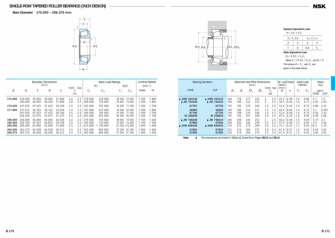
SINGLE-ROW TAPERED ROLLER BEARINGS (INCH DESIGN)Bore Diameter 170.000 – 206.375 mm
jd
r
r
jD
TC
B
a
jD jd jd
ra
ra
a b ajDb
170.000 230.000 39.000 38.000 31.000 3.0 2.5 278 000 520 000 28 300 53 000 1 300 1 800 240.000 46.000 44.500 37.000 3.0 2.5 380 000 720 000 39 000 73 000 1 300 1 800 174.625 247.650 47.625 47.625 38.100 3.5 3.3 345 000 705 000 35 500 71 500 1 300 1 700 177.800 227.012 30.162 30.162 23.020 1.5 1.5 181 000 415 000 18 500 42 000 1 300 1 800 247.650 47.625 47.625 38.100 3.5 3.3 345 000 705 000 35 500 71 500 1 300 1 700 260.350 53.975 53.975 41.275 3.5 3.3 455 000 835 000 46 500 85 000 1 200 1 700 190.000 260.000 46.000 44.000 36.500 3.0 2.5 370 000 730 000 38 000 74 500 1 100 1 600 190.500 266.700 47.625 46.833 38.100 3.5 3.3 345 000 720 000 35 000 73 000 1 100 1 500 200.000 300.000 65.000 62.000 51.000 3.5 2.5 615 000 1 130 000 62 500 116 000 1 000 1 400 203.200 282.575 46.038 46.038 36.512 3.5 3.3 365 000 800 000 37 500 81 500 1 000 1 400 206.375 282.575 46.038 46.038 36.512 3.5 3.3 365 000 800 000 37 500 81 500 1 000 1 400
Boundary Dimensions(mm)
Cone Cup d D T B C r min.
Limiting Speeds (min–1)
Grease Oil
Basic Load Ratings (N) {kgf}
Cr C0r Cr C0r
� JHM 534149 � JHM 534110 184 178 217 224 3 2.5 43.2 0.38 1.6 0.86 3.1 1.3 � JM 734449 � JM 734410 185 180 222 232 3 2.5 50.5 0.44 1.4 0.75 4.42 2.02 67787 67720 192 185 229 240 3.5 3.3 52.4 0.44 1.4 0.75 4.88 2.33 36990 36920 189 186 214 221 1.5 1.5 42.9 0.44 1.4 0.75 2.1 0.907 67790 67720 194 188 229 240 3.5 3.3 52.4 0.44 1.4 0.75 4.56 2.33 M 236849 M 236810 195 192 241 249 3.5 3.3 47.5 0.33 1.8 0.99 6.49 2.86 � JM 738249 � JM 738210 206 200 242 252 3 2.5 56.4 0.48 1.3 0.69 4.73 2.2 67885 67820 209 203 246 259 3.5 3.3 57.9 0.48 1.3 0.69 5.4 2.64 � JHM 840449 � JHM 840410 223 215 273 289 3.5 2.5 73.1 0.52 1.2 0.63 10.3 5.19 67983 67920 222 216 260 275 3.5 3.3 61.9 0.51 1.2 0.65 6.03 2.82 67985 67920 224 219 260 275 3.5 3.3 61.9 0.51 1.2 0.65 5.66 2.82
Bearing Numbers
CONE CUP
Abutment and Fillet Dimensions(mm)
Cone Cup da db Da Db ra max.
Mass(kg)
approx. CONE CUP
Eff. Load Centers(mm)
a
Constant
e
Axial Load Factors
Y1 Y0
Note � The tolerances are listed in Tables 2, 3 and 4 on Pages B113 and B114.
Fa/Fr≤e Fa/Fr>e
X Y X Y
1 0 0.4 Y1
Dynamic Equivalent Load
P =XFr +YFa
Static Equivalent Load
P0 =0.5Fr +Y0 Fa
When Fr>0.5Fr +Y0 Fa, use P0 =Fr
The values of e, Y1 , and Y0 are
given in the table below.
B 170 B 171
B110-181E.indd 170-171B110-181E.indd 170-171 11/20/13 4:57:20 PM11/20/13 4:57:20 PM
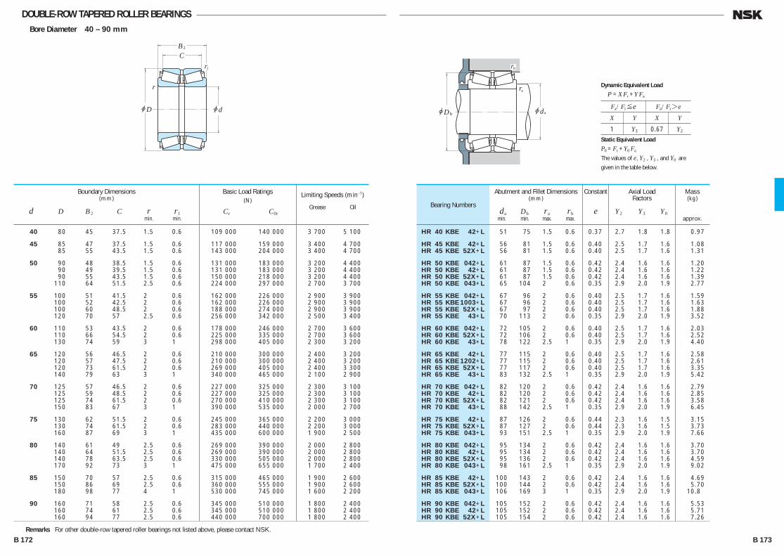
DOUBLE-ROW TAPERED ROLLER BEARINGSBore Diameter 40 – 90 mm
jd
r
r
jD
BC
2
1
jdjDb
rb
ra
a
Fa/Fr≤e Fa/Fr>e
X Y X Y
1 Y3 0.67 Y2
Dynamic Equivalent Load
P =XFr +YFa
Static Equivalent Load
P0 =Fr +Y0 Fa
The values of e, Y2 , Y3 , and Y0 are
given in the table below.
40 80 45 37.5 1.5 0.6 109 000 140 000 3 700 5 100
45 85 47 37.5 1.5 0.6 117 000 159 000 3 400 4 700 85 55 43.5 1.5 0.6 143 000 204 000 3 400 4 700
50 90 48 38.5 1.5 0.6 131 000 183 000 3 200 4 400 90 49 39.5 1.5 0.6 131 000 183 000 3 200 4 400 90 55 43.5 1.5 0.6 150 000 218 000 3 200 4 400 110 64 51.5 2.5 0.6 224 000 297 000 2 700 3 700
55 100 51 41.5 2 0.6 162 000 226 000 2 900 3 900 100 52 42.5 2 0.6 162 000 226 000 2 900 3 900 100 60 48.5 2 0.6 188 000 274 000 2 900 3 900 120 70 57 2.5 0.6 256 000 342 000 2 500 3 400
60 110 53 43.5 2 0.6 178 000 246 000 2 700 3 600 110 66 54.5 2 0.6 225 000 335 000 2 700 3 600 130 74 59 3 1 298 000 405 000 2 300 3 200
65 120 56 46.5 2 0.6 210 000 300 000 2 400 3 200 120 57 47.5 2 0.6 210 000 300 000 2 400 3 200 120 73 61.5 2 0.6 269 000 405 000 2 400 3 300 140 79 63 3 1 340 000 465 000 2 100 2 900
70 125 57 46.5 2 0.6 227 000 325 000 2 300 3 100 125 59 48.5 2 0.6 227 000 325 000 2 300 3 100 125 74 61.5 2 0.6 270 000 410 000 2 300 3 100 150 83 67 3 1 390 000 535 000 2 000 2 700
75 130 62 51.5 2 0.6 245 000 365 000 2 200 3 000 130 74 61.5 2 0.6 283 000 440 000 2 200 3 000 160 87 69 3 1 435 000 600 000 1 900 2 500
80 140 61 49 2.5 0.6 269 000 390 000 2 000 2 800 140 64 51.5 2.5 0.6 269 000 390 000 2 000 2 800 140 78 63.5 2.5 0.6 330 000 505 000 2 000 2 800 170 92 73 3 1 475 000 655 000 1 700 2 400
85 150 70 57 2.5 0.6 315 000 465 000 1 900 2 600 150 86 69 2.5 0.6 360 000 555 000 1 900 2 600 180 98 77 4 1 530 000 745 000 1 600 2 200
90 160 71 58 2.5 0.6 345 000 510 000 1 800 2 400 160 74 61 2.5 0.6 345 000 510 000 1 800 2 400 160 94 77 2.5 0.6 440 000 700 000 1 800 2 400
Boundary Dimensions(mm)
d D B2 C r r1 min. min.
Limiting Speeds (min–1)
Grease Oil
Basic Load Ratings(N)
Cr C0r
HR 40 KBE 42+L 51 75 1.5 0.6 0.37 2.7 1.8 1.8 0.97
HR 45 KBE 42+L 56 81 1.5 0.6 0.40 2.5 1.7 1.6 1.08 HR 45 KBE 52X+L 56 81 1.5 0.6 0.40 2.5 1.7 1.6 1.31
HR 50 KBE 042+L 61 87 1.5 0.6 0.42 2.4 1.6 1.6 1.20 HR 50 KBE 42+L 61 87 1.5 0.6 0.42 2.4 1.6 1.6 1.22 HR 50 KBE 52X+L 61 87 1.5 0.6 0.42 2.4 1.6 1.6 1.39 HR 50 KBE 043+L 65 104 2 0.6 0.35 2.9 2.0 1.9 2.77
HR 55 KBE 042+L 67 96 2 0.6 0.40 2.5 1.7 1.6 1.59 HR 55 KBE 1003+L 67 96 2 0.6 0.40 2.5 1.7 1.6 1.63 HR 55 KBE 52X+L 67 97 2 0.6 0.40 2.5 1.7 1.6 1.88 HR 55 KBE 43+L 70 113 2 0.6 0.35 2.9 2.0 1.9 3.52
HR 60 KBE 042+L 72 105 2 0.6 0.40 2.5 1.7 1.6 2.03 HR 60 KBE 52X+L 72 106 2 0.6 0.40 2.5 1.7 1.6 2.52 HR 60 KBE 43+L 78 122 2.5 1 0.35 2.9 2.0 1.9 4.40
HR 65 KBE 42+L 77 115 2 0.6 0.40 2.5 1.7 1.6 2.58 HR 65 KBE 1202+L 77 115 2 0.6 0.40 2.5 1.7 1.6 2.61 HR 65 KBE 52X+L 77 117 2 0.6 0.40 2.5 1.7 1.6 3.35 HR 65 KBE 43+L 83 132 2.5 1 0.35 2.9 2.0 1.9 5.42
HR 70 KBE 042+L 82 120 2 0.6 0.42 2.4 1.6 1.6 2.79 HR 70 KBE 42+L 82 120 2 0.6 0.42 2.4 1.6 1.6 2.85 HR 70 KBE 52X+L 82 121 2 0.6 0.42 2.4 1.6 1.6 3.58 HR 70 KBE 43+L 88 142 2.5 1 0.35 2.9 2.0 1.9 6.45
HR 75 KBE 42+L 87 126 2 0.6 0.44 2.3 1.6 1.5 3.15 HR 75 KBE 52X+L 87 127 2 0.6 0.44 2.3 1.6 1.5 3.73 HR 75 KBE 043+L 93 151 2.5 1 0.35 2.9 2.0 1.9 7.66
HR 80 KBE 042+L 95 134 2 0.6 0.42 2.4 1.6 1.6 3.70 HR 80 KBE 42+L 95 134 2 0.6 0.42 2.4 1.6 1.6 3.70 HR 80 KBE 52X+L 95 136 2 0.6 0.42 2.4 1.6 1.6 4.59 HR 80 KBE 043+L 98 161 2.5 1 0.35 2.9 2.0 1.9 9.02
HR 85 KBE 42+L 100 143 2 0.6 0.42 2.4 1.6 1.6 4.69 HR 85 KBE 52X+L 100 144 2 0.6 0.42 2.4 1.6 1.6 5.70 HR 85 KBE 043+L 106 169 3 1 0.35 2.9 2.0 1.9 10.8
HR 90 KBE 042+L 105 152 2 0.6 0.42 2.4 1.6 1.6 5.53 HR 90 KBE 42+L 105 152 2 0.6 0.42 2.4 1.6 1.6 5.71 HR 90 KBE 52X+L 105 154 2 0.6 0.42 2.4 1.6 1.6 7.26
Bearing Numbers
Abutment and Fillet Dimensions(mm)
da Db ra rb min. min. max. max.
Mass(kg)
approx.
Constant
e
Axial LoadFactors
Y2 Y3 Y0
Remarks For other double-row tapered roller bearings not listed above, please contact NSK.
B 172 B 173
B110-181E.indd 172-173B110-181E.indd 172-173 11/20/13 4:57:20 PM11/20/13 4:57:20 PM
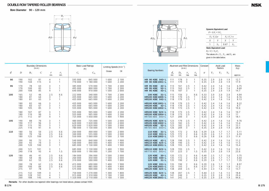
DOUBLE-ROW TAPERED ROLLER BEARINGSBore Diameter 90 – 120 mm
jd
r
r
jD
BC
2
1
jdjDb
rb
ra
a
Fa/Fr≤e Fa/Fr>e
X Y X Y
1 Y3 0.67 Y2
Dynamic Equivalent Load
P =XFr +YFa
Static Equivalent Load
P0 =Fr +Y0 Fa
The values of e, Y2 , Y3 , and Y0 are
given in the table below.
90 190 102 81 4 1 595 000 845 000 1 600 2 100 190 144 115 4 1 770 000 1 180 000 1 600 2 200
95 170 78 63 3 1 385 000 570 000 1 700 2 300 170 100 83 3 1 495 000 800 000 1 700 2 300 200 108 85 4 1 640 000 910 000 1 500 2 000
100 165 52 46 2.5 0.6 222 000 340 000 1 700 2 300 180 81 64 3 1 435 000 665 000 1 600 2 200 180 81 65 3 1 435 000 665 000 1 600 2 200
180 82 66 3 1 435 000 665 000 1 600 2 200 180 83 67 3 1 435 000 665 000 1 600 2 200 180 105 85 3 1 555 000 905 000 1 600 2 200
180 107 87 3 1 555 000 905 000 1 600 2 200 180 110 90 3 1 555 000 905 000 1 600 2 200 215 112 87 4 1 725 000 1 050 000 1 400 1 900
105 190 88 70 3 1 480 000 735 000 1 500 2 000 190 117 96 3 1 620 000 1 020 000 1 500 2 000 190 115 95 3 1 620 000 1 020 000 1 500 2 000 225 116 91 4 1 780 000 1 130 000 1 300 1 800
110 180 56 50 2.5 0.6 264 000 400 000 1 500 2 000 180 70 56 2.5 0.6 340 000 555 000 1 500 2 000 180 125 100 2.5 0.6 550 000 1 060 000 1 500 2 100
200 90 72 3 1 540 000 840 000 1 400 1 900 200 92 74 3 1 540 000 840 000 1 400 1 900 200 120 100 3 1 685 000 1 130 000 1 400 1 900
200 121 101 3 1 685 000 1 130 000 1 400 1 900 240 118 93 4 1.5 830 000 1 190 000 1 200 1 700
120 180 46 41 2.5 0.6 184 000 296 000 1 500 2 000 180 58 46 2.5 0.6 260 000 450 000 1 500 2 000 200 62 55 2.5 0.6 310 000 500 000 1 400 1 800
200 78 62 2.5 0.6 415 000 690 000 1 400 1 900 200 100 84 2.5 0.6 515 000 885 000 1 400 1 800 215 97 78 3 1 575 000 900 000 1 300 1 800
215 132 109 3 1 750 000 1 270 000 1 300 1 800 260 128 101 4 1 915 000 1 310 000 1 100 1 500 260 188 145 4 1 1 320 000 2 110 000 1 100 1 500
HR 90 KBE 043+L 111 178 3 1 0.35 2.9 2.0 1.9 12.7 HR 90 KBE 1901+L 111 179 3 1 0.35 2.9 2.0 1.9 17.9
HR 95 KBE 42+L 113 161 2.5 1 0.42 2.4 1.6 1.6 6.75 HR 95 KBE 52+L 113 163 2.5 1 0.42 2.4 1.6 1.6 8.60 HR 95 KBE 43+L 116 187 3 1 0.35 2.9 2.0 1.9 14.7
100 KBE 31+L 115 156 2 0.6 0.33 3.0 2.0 2.0 4.04 HR100 KBE 1805+L 118 170 2.5 1 0.42 2.4 1.6 1.6 8.16 HR100 KBE 042+L 118 170 2.5 1 0.42 2.4 1.6 1.6 8.13
HR100 KBE 1801+L 118 170 2.5 1 0.42 2.4 1.6 1.6 8.22 HR100 KBE 42+L 118 170 2.5 1 0.42 2.4 1.6 1.6 8.7 HR100 KBE 1802+L 118 173 2.5 1 0.42 2.4 1.6 1.6 10.6
HR100 KBE 52X+L 118 173 2.5 1 0.42 2.4 1.6 1.6 10.7 HR100 KBE 1804+L 118 173 2.5 1 0.42 2.4 1.6 1.6 11 HR100 KBE 043+L 121 200 3 1 0.35 2.9 2.0 1.9 18.1
HR105 KBE 42X+L 123 179 2.5 1 0.42 2.4 1.6 1.6 9.76 HR105 KBE 1902+L 123 182 2.5 1 0.42 2.4 1.6 1.6 13.4 HR105 KBE 52+L 123 182 2.5 1 0.42 2.4 1.6 1.6 13.1 HR105 KBE 043+L 126 209 3 1 0.35 2.9 2.0 1.9 20.4
110 KBE 31+L 125 172 2 0.6 0.39 2.6 1.7 1.7 5.11 110 KBE 031+L 125 172 2 0.6 0.39 2.6 1.7 1.7 6.33 110 KBE 1802+L 125 172 2 0.6 0.26 3.8 2.6 2.5 11.4
HR110 KBE 42+L 128 190 2.5 1 0.42 2.4 1.6 1.6 11.2 HR110 KBE 42X+L 128 190 2.5 1 0.42 2.4 1.6 1.6 11.5 HR110 KBE 2001+L 128 193 2.5 1 0.42 2.4 1.6 1.6 15.4
HR110 KBE 52X+L 128 193 2.5 1 0.42 2.4 1.6 1.6 15.2 HR110 KBE 043+L 131 223 3 1.5 0.35 2.9 2.0 1.9 23.6
120 KBE 30+L 135 172 2 0.6 0.40 2.5 1.7 1.6 3.75 120 KBE 030+L 135 172 2 0.6 0.39 2.6 1.7 1.7 4.64 120 KBE 31+L 135 190 2 0.6 0.39 2.6 1.7 1.7 7.35
120 KBE 031+L 135 190 2 0.6 0.39 2.6 1.7 1.7 8.97 120 KBE 2001+L 135 193 2 0.6 0.37 2.7 1.8 1.8 11.3 HR120 KBE 42X+L 138 204 2.5 1 0.44 2.3 1.6 1.5 13.7
HR120 KBE 52X+L 138 207 2.5 1 0.44 2.3 1.6 1.5 18.8 HR120 KBE 43+L 141 240 3 1 0.35 2.9 2.0 1.9 29.4 HR120 KBE 2601+L 141 242 3 1 0.35 2.9 2.0 1.9 44.6
Bearing Numbers
Abutment and Fillet Dimensions(mm)
da Db ra rb min. min. max. max.
Mass(kg)
approx.
Constant
e
Axial LoadFactors
Y2 Y3 Y0
Remarks For other double-row tapered roller bearings not listed above, please contact NSK.
Boundary Dimensions(mm)
d D B2 C r r1 min. min.
Limiting Speeds (min–1)
Grease Oil
Basic Load Ratings(N)
Cr C0r
B 174 B 175
B110-181E.indd 174-175B110-181E.indd 174-175 11/20/13 4:57:21 PM11/20/13 4:57:21 PM
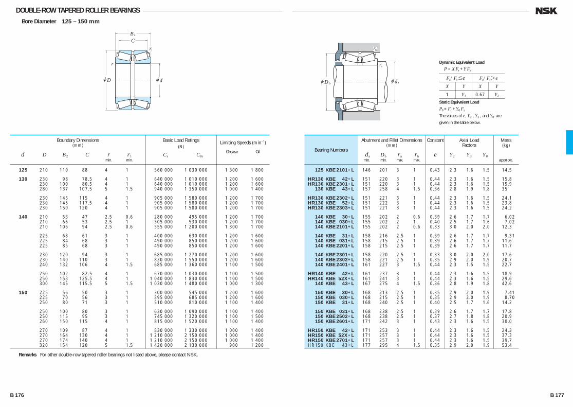
DOUBLE-ROW TAPERED ROLLER BEARINGSBore Diameter 125 – 150 mm
jd
r
r
jD
BC
2
1
jdjDb
rb
ra
a
Fa/Fr≤e Fa/Fr>e
X Y X Y
1 Y3 0.67 Y2
Dynamic Equivalent Load
P =XFr +YFa
Static Equivalent Load
P0 =Fr +Y0 Fa
The values of e, Y2 , Y3 , and Y0 are
given in the table below.
125 210 110 88 4 1 560 000 1 030 000 1 300 1 800
130 230 98 78.5 4 1 640 000 1 010 000 1 200 1 600 230 100 80.5 4 1 640 000 1 010 000 1 200 1 600 280 137 107.5 5 1.5 940 000 1 350 000 1 000 1 400
230 145 115 4 1 905 000 1 580 000 1 200 1 700 230 145 117.5 4 1 905 000 1 580 000 1 200 1 700 230 150 120 4 1 905 000 1 580 000 1 200 1 700
140 210 53 47 2.5 0.6 280 000 495 000 1 200 1 700 210 66 53 2.5 1 305 000 530 000 1 200 1 700 210 106 94 2.5 0.6 555 000 1 200 000 1 300 1 700
225 68 61 3 1 400 000 630 000 1 200 1 600 225 84 68 3 1 490 000 850 000 1 200 1 600 225 85 68 3 1 490 000 850 000 1 200 1 600
230 120 94 3 1 685 000 1 270 000 1 200 1 600 230 140 110 3 1 820 000 1 550 000 1 200 1 600 240 132 106 4 1.5 685 000 1 360 000 1 100 1 500
250 102 82.5 4 1 670 000 1 030 000 1 100 1 500 250 153 125.5 4 1 1 040 000 1 830 000 1 100 1 500 300 145 115.5 5 1.5 1 030 000 1 480 000 1 000 1 300
150 225 56 50 3 1 300 000 545 000 1 200 1 600 225 70 56 3 1 395 000 685 000 1 200 1 600 250 80 71 3 1 510 000 810 000 1 100 1 400
250 100 80 3 1 630 000 1 090 000 1 100 1 400 250 115 95 3 1 745 000 1 320 000 1 100 1 500 260 150 115 4 1 815 000 1 520 000 1 100 1 400
270 109 87 4 1 830 000 1 330 000 1 000 1 400 270 164 130 4 1 1 210 000 2 150 000 1 000 1 400 270 174 140 4 1 1 210 000 2 150 000 1 000 1 400 320 154 120 5 1.5 1 420 000 2 130 000 900 1 200
125 KBE 2101+L 146 201 3 1 0.43 2.3 1.6 1.5 14.5
HR130 KBE 42+L 151 220 3 1 0.44 2.3 1.6 1.5 15.8 HR130 KBE 2301+L 151 220 3 1 0.44 2.3 1.6 1.5 15.9 130 KBE 43+L 157 258 4 1.5 0.36 2.8 1.9 1.8 35
HR130 KBE 2302+L 151 221 3 1 0.44 2.3 1.6 1.5 24.1 HR130 KBE 52+L 151 222 3 1 0.44 2.3 1.6 1.5 23.8 HR130 KBE 2303+L 151 221 3 1 0.44 2.3 1.6 1.5 24.2
140 KBE 30+L 155 202 2 0.6 0.39 2.6 1.7 1.7 6.02 140 KBE 030+L 155 202 2 1 0.40 2.5 1.7 1.6 7.02 140 KBE 2101+L 155 202 2 0.6 0.33 3.0 2.0 2.0 12.3
140 KBE 31+L 158 216 2.5 1 0.39 2.6 1.7 1.7 9.31 140 KBE 031+L 158 215 2.5 1 0.39 2.6 1.7 1.7 11.6 140 KBE 2201+L 158 215 2.5 1 0.39 2.6 1.7 1.7 11.7
140 KBE 2301+L 158 220 2.5 1 0.33 3.0 2.0 2.0 17.6 140 KBE 2302+L 158 221 2.5 1 0.35 2.9 2.0 1.9 20.7 140 KBE 2401+L 161 227 3 1.5 0.44 2.3 1.5 1.5 22.7
HR140 KBE 42+L 161 237 3 1 0.44 2.3 1.6 1.5 18.9 HR140 KBE 52X+L 161 241 3 1 0.44 2.3 1.6 1.5 29.6 140 KBE 43+L 167 275 4 1.5 0.36 2.8 1.9 1.8 42.6
150 KBE 30+L 168 213 2.5 1 0.35 2.9 2.0 1.9 7.41 150 KBE 030+L 168 215 2.5 1 0.35 2.9 2.0 1.9 8.70 150 KBE 31+L 168 240 2.5 1 0.40 2.5 1.7 1.6 14.2
150 KBE 031+L 168 238 2.5 1 0.39 2.6 1.7 1.7 17.8 150 KBE 2502+L 168 238 2.5 1 0.37 2.7 1.8 1.8 20.9 150 KBE 2601+L 171 242 3 1 0.43 2.3 1.6 1.5 30.0
HR150 KBE 42+L 171 253 3 1 0.44 2.3 1.6 1.5 24.3 HR150 KBE 52X+L 171 257 3 1 0.44 2.3 1.6 1.5 37.3 HR150 KBE 2701+L 171 257 3 1 0.44 2.3 1.6 1.5 39.7 HR150 KBE 43+L 177 295 4 1.5 0.35 2.9 2.0 1.9 53.4
Bearing Numbers
Abutment and Fillet Dimensions(mm)
da Db ra rb min. min. max. max.
Mass(kg)
approx.
Constant
e
Axial LoadFactors
Y2 Y3 Y0
Remarks For other double-row tapered roller bearings not listed above, please contact NSK.
Boundary Dimensions(mm)
d D B2 C r r1 min. min.
Limiting Speeds (min–1)
Grease Oil
Basic Load Ratings(N)
Cr C0r
B 176 B 177
B110-181E.indd 176-177B110-181E.indd 176-177 11/20/13 4:57:22 PM11/20/13 4:57:22 PM

DOUBLE-ROW TAPERED ROLLER BEARINGS Bore Diameter 160 – 200 mm
jd
r
r
jD
BC
2
1
jdjDb
rb
ra
a
Fa/Fr≤e Fa/Fr>e
X Y X Y
1 Y3 0.67 Y2
Dynamic Equivalent Load
P =XFr +YFa
Static Equivalent Load
P0 =Fr +Y0 Fa
The values of e, Y2 , Y3 , and Y0 are
given in the table below.
160 240 60 53 3 1 355 000 580 000 1 100 1 500 240 75 60 3 1 395 000 710 000 1 100 1 500 240 110 90 3 1 650 000 1 290 000 1 100 1 500 270 86 76 3 1 540 000 885 000 1 000 1 300 270 108 86 3 1 775 000 1 380 000 1 000 1 300 270 140 120 3 1 990 000 1 880 000 1 000 1 300 280 150 125 4 1 1 100 000 2 020 000 1 000 1 300 290 115 91 4 1 800 000 1 220 000 900 1 300 290 178 144 4 1 1 360 000 2 440 000 1 000 1 300 340 160 126 5 1.5 1 310 000 1 920 000 800 1 100 165 290 150 125 4 1 1 140 000 2 130 000 900 1 300 170 250 85 65 3 1 435 000 845 000 1 000 1 400 260 67 60 3 1 400 000 700 000 1 000 1 300 260 84 67 3 1 575 000 1 030 000 1 000 1 300 280 88 78 3 1 630 000 1 040 000 900 1 300 280 110 88 3 1 820 000 1 450 000 900 1 300 280 150 130 3 1 1 110 000 2 160 000 1 000 1 300 310 192 152 5 1.5 1 590 000 2 910 000 900 1 200 180 280 74 66 3 1 455 000 810 000 900 1 300 280 93 74 3 1 655 000 1 220 000 900 1 200 300 96 85 4 1.5 725 000 1 210 000 900 1 200 300 120 96 4 1.5 940 000 1 690 000 900 1 200 320 127 99 5 1.5 895 000 1 390 000 800 1 200 320 192 152 5 1.5 1 640 000 3 050 000 900 1 200 340 180 140 5 1.5 1 410 000 2 510 000 800 1 100 190 290 75 67 3 1 490 000 845 000 900 1 200 290 94 75 3 1 670 000 1 230 000 900 1 200 320 104 92 4 1.5 800 000 1 380 000 800 1 100 320 130 104 4 1.5 1 070 000 1 960 000 800 1 100 340 133 105 5 1.5 990 000 1 580 000 800 1 100 340 204 160 5 1.5 1 910 000 3 550 000 800 1 100 200 310 152 123 3 1 1 300 000 2 740 000 800 1 100 320 146 110 5 1.5 990 000 2 120 000 800 1 100 330 180 140 5 1.5 1 390 000 2 730 000 800 1 100 340 112 100 4 1.5 940 000 1 670 000 800 1 000 340 140 112 4 1.5 1 260 000 2 250 000 800 1 000 360 142 110 5 1.5 1 100 000 1 780 000 700 1 000 360 218 174 5 1.5 2 070 000 3 850 000 800 1 000
160 KBE 30+L 178 231 2.5 1 0.37 2.7 1.8 1.8 8.56 160 KBE 030+L 178 230 2.5 1 0.40 2.5 1.7 1.6 10.5 160 KBE 2401+L 178 232 2.5 1 0.38 2.6 1.8 1.7 16.2 160 KBE 31+L 178 255 2.5 1 0.40 2.5 1.7 1.6 18.6 160 KBE 031+L 178 256 2.5 1 0.39 2.6 1.7 1.7 23.1 160 KBE 2701+L 178 261 2.5 1 0.39 2.6 1.7 1.7 30.6 160 KBE 2801+L 181 266 3 1 0.32 3.2 2.1 2.1 35.9 160 KBE 42+L 181 275 3 1 0.43 2.3 1.6 1.5 28.2 HR160 KBE 52X+L 181 277 3 1 0.44 2.3 1.6 1.5 47.3 160 KBE 43+L 187 314 4 1.5 0.36 2.8 1.9 1.8 60.4 165 KBE 2901+L 186 272 3 1 0.33 3.1 2.1 2.0 39.5 170 KBE 2501+L 188 241 2.5 1 0.44 2.3 1.5 1.5 12.3 170 KBE 30+L 188 248 2.5 1 0.40 2.5 1.7 1.6 11.8 170 KBE 030+L 188 249 2.5 1 0.39 2.6 1.7 1.7 14.4 170 KBE 31+L 188 266 2.5 1 0.39 2.6 1.7 1.7 19.7 170 KBE 031+L 188 268 2.5 1 0.39 2.6 1.7 1.7 24.2 170 KBE 2802+L 188 269 2.5 1 0.39 2.6 1.7 1.7 34.6 HR170 KBE 52X+L 197 297 4 1.5 0.44 2.3 1.6 1.5 57.3 180 KBE 30+L 198 265 2.5 1 0.40 2.5 1.7 1.6 15.4 180 KBE 030+L 198 265 2.5 1 0.35 2.9 2.0 1.9 14.4 180 KBE 31+L 201 284 3 1.5 0.39 2.6 1.7 1.7 24.8 180 KBE 031+L 201 287 3 1.5 0.39 2.6 1.7 1.7 31.1 180 KBE 42+L 207 300 4 1.5 0.44 2.3 1.5 1.5 36.5 HR180 KBE 52X+L 207 308 4 1.5 0.45 2.2 1.5 1.5 59.2 180 KBE 3401+L 207 305 4 1.5 0.43 2.3 1.6 1.5 68.1 190 KBE 30+L 208 279 2.5 1 0.39 2.6 1.7 1.7 16.2 190 KBE 030+L 208 279 2.5 1 0.40 2.5 1.7 1.6 20.1 190 KBE 31+L 211 301 3 1.5 0.40 2.5 1.7 1.6 30.9 190 KBE 031+L 211 302 3 1.5 0.39 2.6 1.7 1.7 39.0 190 KBE 42+L 217 320 4 1.5 0.40 2.5 1.7 1.6 43.9 HR190 KBE 52X+L 217 327 4 1.5 0.44 2.3 1.6 1.5 70.8 HR200 KBE 3101+L 218 301 2.5 1 0.43 2.3 1.6 1.5 40.1 200 KBE 3201+L 227 301 4 1.5 0.52 1.9 1.3 1.3 41.6 200 KBE 3301+L 227 316 4 1.5 0.42 2.4 1.6 1.6 54.4 200 KBE 31+L 221 321 3 1.5 0.40 2.5 1.7 1.6 38.8 200 KBE 031+L 221 324 3 1.5 0.39 2.6 1.7 1.7 47.0 200 KBE 42+L 227 338 4 1.5 0.40 2.5 1.7 1.6 52.6 HR200 KBE 52+L 227 344 4 1.5 0.41 2.5 1.7 1.6 88.3
Bearing Numbers
Abutment and Fillet Dimensions(mm)
da Db ra rb min. min. max. max.
Mass(kg)
approx.
Constant
e
Axial LoadFactors
Y2 Y3 Y0
Remarks For other double-row tapered roller bearings not listed above, please contact NSK.
Boundary Dimensions(mm)
d D B2 C r r1 min. min.
Limiting Speeds (min–1)
Grease Oil
Basic Load Ratings(N)
Cr C0r
B 178 B 179
B110-181E.indd 178-179B110-181E.indd 178-179 11/20/13 4:57:23 PM11/20/13 4:57:23 PM
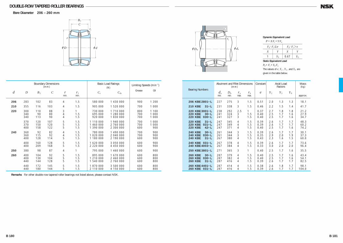
DOUBLE-ROW TAPERED ROLLER BEARINGS Bore Diameter 206 – 260 mm
jd
r
r
jD
BC
2
1
jdjDb
rb
ra
a
Fa/Fr≤e Fa/Fr>e
X Y X Y
1 Y3 0.67 Y2
Dynamic Equivalent Load
P =XFr +YFa
Static Equivalent Load
P0 =Fr +Y0 Fa
The values of e, Y2 , Y3 , and Y0 are
given in the table below.
Bearing Numbers
Abutment and Fillet Dimensions(mm)
da Db ra rb min. min. max. max.
Mass(kg)
approx.
Constant
e
Axial LoadFactors
Y2 Y3 Y0
Remarks For other double-row tapered roller bearings not listed above, please contact NSK.
Boundary Dimensions(mm)
d D B2 C r r1 min. min.
Limiting Speeds (min–1)
Grease Oil
Basic Load Ratings(N)
Cr C0r
206 283 102 83 4 1.5 580 000 1 430 000 900 1 200
210 355 116 103 4 1.5 905 000 1 520 000 700 1 000
220 300 110 88 3 1 730 000 1 710 000 800 1 100 340 90 80 4 1.5 695 000 1 280 000 700 1 000 340 113 90 4 1.5 920 000 1 830 000 700 1 000
370 120 107 5 1.5 1 110 000 1 940 000 700 1 000 370 150 120 5 1.5 1 460 000 2 760 000 700 1 000 400 158 122 5 1.5 1 390 000 2 300 000 600 900
240 360 92 82 4 1.5 780 000 1 490 000 700 900 360 115 92 4 1.5 1 020 000 2 040 000 700 900 400 128 114 5 1.5 1 180 000 2 190 000 600 900
400 160 128 5 1.5 1 620 000 3 050 000 600 900 400 209 168 5 1.5 2 220 000 4 450 000 600 900
250 380 98 87 4 1 795 000 1 460 000 600 900
260 400 104 92 5 1.5 895 000 1 670 000 600 800 400 130 104 5 1.5 1 210 000 2 460 000 600 800 440 144 128 5 1.5 1 540 000 2 760 000 600 800
440 172 145 5 1.5 1 870 000 3 500 000 600 800 440 180 144 5 1.5 2 110 000 4 150 000 600 800
206 KBE 2801+L 227 275 3 1.5 0.51 2.0 1.3 1.3 18.1
210 KBE 31+L 231 338 3 1.5 0.46 2.2 1.5 1.4 41.7
220 KBE 3001+L 238 292 2.5 1 0.37 2.7 1.8 1.8 21.2 220 KBE 30+L 241 324 3 1.5 0.40 2.5 1.7 1.6 27.9 220 KBE 030+L 241 327 3 1.5 0.40 2.5 1.7 1.6 34.7
220 KBE 31+L 247 345 4 1.5 0.39 2.6 1.7 1.7 48.3 220 KBE 031+L 247 349 4 1.5 0.39 2.6 1.7 1.7 60.2 220 KBE 42+L 247 371 4 1.5 0.40 2.5 1.7 1.6 74.2
240 KBE 30+L 261 344 3 1.5 0.39 2.6 1.7 1.7 30.1 240 KBE 030+L 261 344 3 1.5 0.35 2.9 2.0 1.9 37.3 240 KBE 31+L 267 380 4 1.5 0.43 2.3 1.6 1.5 60.0
240 KBE 031+L 267 378 4 1.5 0.39 2.6 1.7 1.7 73.6 240 KBE 4003+L 267 384 4 1.5 0.33 3.0 2.0 2.0 96.4
250 KBE 3801+L 271 365 3 1 0.40 2.5 1.7 1.6 35.5
260 KBE 30+L 287 379 4 1.5 0.40 2.5 1.7 1.6 43.4 260 KBE 030+L 287 382 4 1.5 0.40 2.5 1.7 1.6 54.1 260 KBE 31+L 287 416 4 1.5 0.39 2.6 1.7 1.7 82.5
260 KBE 4401+L 287 414 4 1.5 0.38 2.6 1.8 1.7 98.1 260 KBE 031+L 287 416 4 1.5 0.39 2.6 1.7 1.7 104.0
B 180 B 181
B110-181E.indd 180-181B110-181E.indd 180-181 11/20/13 4:57:24 PM11/20/13 4:57:24 PM
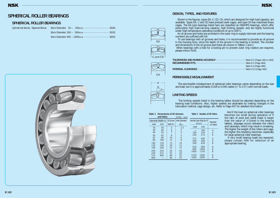
DESIGN, TYPES, AND FEATURES
Shown in the figures, types EA, C, CD, CA, which are designed for high load capacity, are available. Types EA, C and CD have pressed steel cages, and type CA has machined brass cages. The EA type bearings listed here are classified as NSKHPS bearings, which offer particularly high load-carrying capacity, high limiting speeds, and are highly functional under high-temperature operating conditions of up to 200°C. An oil groove and holes are provided in the outer ring to supply lubricant and the bearing numbers are suffixed with E4. To use bearings with oil grooves and holes, it is recommended to provide an oil groove in the housing bore, since the depth of the groove in the bearing is limited. The number and dimensions of the oil groove and holes are shown in Tables 1 and 2. When bearings with a hole for a locking pin to prevent outer ring rotation are required, please inform NSK.
TOLERANCES AND RUNNING ACCURACY ·········································· Table 8.2 (Pages A60 to A63)RECOMMENDED FITS········································································ Table 9.2 (Page A84) Table 9.4 (Page A85)INTERNAL CLEARANCE ····································································· Table 9.15 (Page A92)
PERMISSIBLE MISALIGNMENT
The permissible misalignment of spherical roller bearings varies depending on the size and load, but it is approximately 0.018 to 0.045 radian (1° to 2.5°) with normal loads.
LIMITING SPEEDS
The limiting speeds listed in the bearing tables should be adjusted depending on the bearing load conditions. Also, higher speeds are attainable by making changes in the lubrication method, cage design, etc. Refer to Page A37 for detailed information.
And if the load on spherical roller bearings becomes too small during operation or if the ratio of axial and radial loads is larger than the value of ‘e’(listed in the bearing tables), slippage occurs between the rollers and raceways, which may result in smearing. The higher the weight of the rollers and cage, the higher this tendency becomes, especially for large spherical roller bearings. If very small bearing loads are expected, please contact NSK for selection of an appropriate bearing.
W
B
OH
EA
C and CD
CA
d
Table 1 Dimensions of Oil Grooves and Holes
Nominal Width B Oil Groove Hole Diameter over incl. Width W dOH
18 30 5 2.5 30 40 6 3 40 50 7 4 50 65 8 5 65 80 10 6 80 100 12 8 100 120 15 10 120 160 20 12 160 200 25 15 200 250 30 20 250 315 35 20 315 400 40 25 400 — 40 25
Units : mmTable 2 Number of Oil Holes
Nominal Outer Ring Dia D Number (mm) of Holes over incl. — 180 4 180 250 6 250 315 6
315 400 6 400 500 6 500 630 8
630 800 8 800 1000 8 1000 1250 8
1250 1600 8 1600 2000 8
SPHERICAL ROLLER BEARINGSSPHERICAL ROLLER BEARINGSCylindrical Bores, Tapered Bores Bore Diameter 20 – 150mm ···································· B184
Bore Diameter 160 – 560mm ···································· B192
Bore Diameter 600 – 1400mm ···································· B202
B 182 B 183
B182-205E.indd 182-183B182-205E.indd 182-183 11/20/13 4:57:47 PM11/20/13 4:57:47 PM
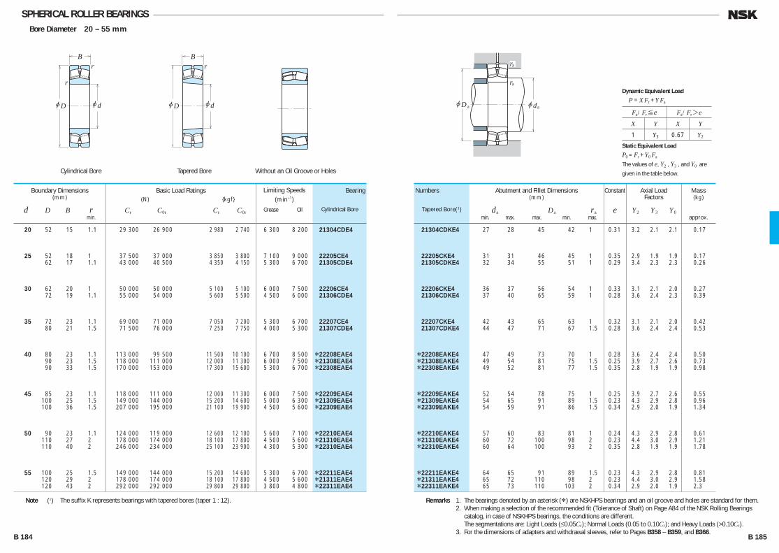
SPHERICAL ROLLER BEARINGSBore Diameter 20 – 55 mm
20 52 15 1.1 29 300 26 900 2 980 2 740 6 300 8 200 21304CDE4
25 52 18 1 37 500 37 000 3 850 3 800 7 100 9 000 22205CE4 62 17 1.1 43 000 40 500 4 350 4 150 5 300 6 700 21305CDE4
30 62 20 1 50 000 50 000 5 100 5 100 6 000 7 500 22206CE4 72 19 1.1 55 000 54 000 5 600 5 500 4 500 6 000 21306CDE4
35 72 23 1.1 69 000 71 000 7 050 7 200 5 300 6 700 22207CE4 80 21 1.5 71 500 76 000 7 250 7 750 4 000 5 300 21307CDE4
40 80 23 1.1 113 000 99 500 11 500 10 100 6 700 8 500 *22208EAE4 90 23 1.5 118 000 111 000 12 000 11 300 6 000 7 500 *21308EAE4 90 33 1.5 170 000 153 000 17 300 15 600 5 300 6 700 *22308EAE4
45 85 23 1.1 118 000 111 000 12 000 11 300 6 000 7 500 *22209EAE4 100 25 1.5 149 000 144 000 15 200 14 600 5 000 6 300 *21309EAE4 100 36 1.5 207 000 195 000 21 100 19 900 4 500 5 600 *22309EAE4
50 90 23 1.1 124 000 119 000 12 600 12 100 5 600 7 100 *22210EAE4 110 27 2 178 000 174 000 18 100 17 800 4 500 5 600 *21310EAE4 110 40 2 246 000 234 000 25 100 23 900 4 300 5 300 *22310EAE4
55 100 25 1.5 149 000 144 000 15 200 14 600 5 300 6 700 *22211EAE4 120 29 2 178 000 174 000 18 100 17 800 4 500 5 600 *21311EAE4 120 43 2 292 000 292 000 29 800 29 800 3 800 4 800 *22311EAE4
Boundary Dimensions(mm)
d D B r min.
Limiting Speeds (min–1)
Grease Oil
Basic Load Ratings (N) {kgf}
Cr C0r Cr C0r
21304CDKE4 27 28 45 42 1 0.31 3.2 2.1 2.1 0.17
22205CKE4 31 31 46 45 1 0.35 2.9 1.9 1.9 0.17 21305CDKE4 32 34 55 51 1 0.29 3.4 2.3 2.3 0.26
22206CKE4 36 37 56 54 1 0.33 3.1 2.1 2.0 0.27 21306CDKE4 37 40 65 59 1 0.28 3.6 2.4 2.3 0.39
22207CKE4 42 43 65 63 1 0.32 3.1 2.1 2.0 0.42 21307CDKE4 44 47 71 67 1.5 0.28 3.6 2.4 2.4 0.53
*22208EAKE4 47 49 73 70 1 0.28 3.6 2.4 2.4 0.50 *21308EAKE4 49 54 81 75 1.5 0.25 3.9 2.7 2.6 0.73 *22308EAKE4 49 52 81 77 1.5 0.35 2.8 1.9 1.9 0.98
*22209EAKE4 52 54 78 75 1 0.25 3.9 2.7 2.6 0.55 *21309EAKE4 54 65 91 89 1.5 0.23 4.3 2.9 2.8 0.96 *22309EAKE4 54 59 91 86 1.5 0.34 2.9 2.0 1.9 1.34
*22210EAKE4 57 60 83 81 1 0.24 4.3 2.9 2.8 0.61 *21310EAKE4 60 72 100 98 2 0.23 4.4 3.0 2.9 1.21 *22310EAKE4 60 64 100 93 2 0.35 2.8 1.9 1.9 1.78
*22211EAKE4 64 65 91 89 1.5 0.23 4.3 2.9 2.8 0.81 *21311EAKE4 65 72 110 98 2 0.23 4.4 3.0 2.9 1.58 *22311EAKE4 65 73 110 103 2 0.34 2.9 2.0 1.9 2.3
Numbers
Tapered Bore(1)
Bearing
Cylindrical Bore
Abutment and Fillet Dimensions(mm)
da Da ra min. max. max. min. max.
Axial LoadFactors
Y2 Y3 Y0
Constant
e
Mass(kg)
approx.
Note (1) The suffix K represents bearings with tapered bores (taper 1 : 12). Remarks 1. The bearings denoted by an asterisk (*) are NSKHPS bearings and an oil groove and holes are standard for them. 2. When making a selection of the recommended fit (Tolerance of Shaft) on Page A84 of the NSK Rolling Bearings
catalog, in case of NSKHPS bearings, the conditions are different. The segmentations are: Light Loads (≤0.05Cr); Normal Loads (0.05 to 0.10Cr); and Heavy Loads (>0.10Cr). 3. For the dimensions of adapters and withdrawal sleeves, refer to Pages B358 – B359, and B366.
jd
r
r
jD
B
jd
r
jD
B
jdjD
ra
ra
a a
Fa/Fr≤e Fa/Fr>e
X Y X Y
1 Y3 0.67 Y2
Dynamic Equivalent Load
P =XFr +YFa
Static Equivalent Load
P0 =Fr +Y0 Fa
The values of e, Y2 , Y3 , and Y0 are
given in the table below.Cylindrical Bore Tapered Bore Without an Oil Groove or Holes
B 184 B 185
B182-205E.indd 184-185B182-205E.indd 184-185 11/20/13 4:57:49 PM11/20/13 4:57:49 PM
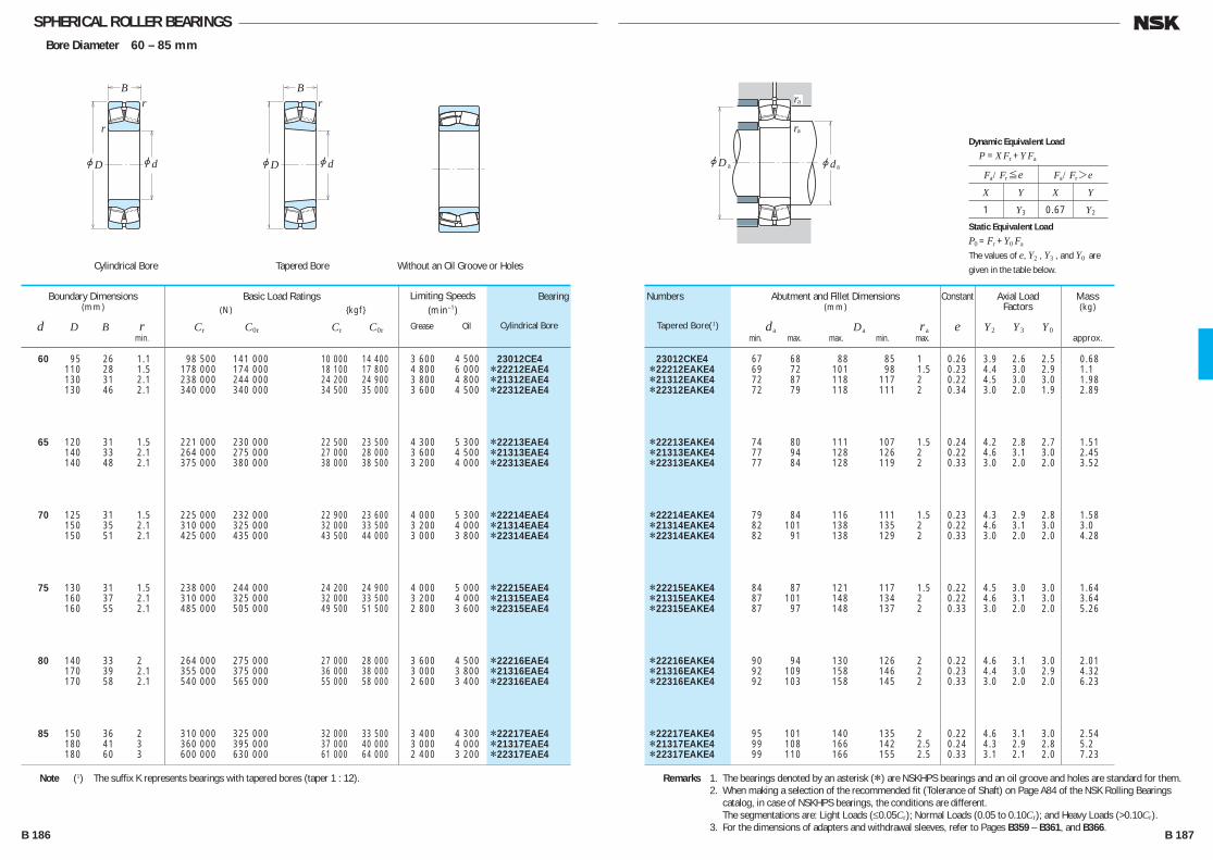
SPHERICAL ROLLER BEARINGSBore Diameter 60 – 85 mm
60 95 26 1.1 98 500 141 000 10 000 14 400 3 600 4 500 23012CE4 110 28 1.5 178 000 174 000 18 100 17 800 4 800 6 000 *22212EAE4 130 31 2.1 238 000 244 000 24 200 24 900 3 800 4 800 *21312EAE4 130 46 2.1 340 000 340 000 34 500 35 000 3 600 4 500 *22312EAE4
65 120 31 1.5 221 000 230 000 22 500 23 500 4 300 5 300 *22213EAE4 140 33 2.1 264 000 275 000 27 000 28 000 3 600 4 500 *21313EAE4 140 48 2.1 375 000 380 000 38 000 38 500 3 200 4 000 *22313EAE4
70 125 31 1.5 225 000 232 000 22 900 23 600 4 000 5 300 *22214EAE4 150 35 2.1 310 000 325 000 32 000 33 500 3 200 4 000 *21314EAE4 150 51 2.1 425 000 435 000 43 500 44 000 3 000 3 800 *22314EAE4
75 130 31 1.5 238 000 244 000 24 200 24 900 4 000 5 000 *22215EAE4 160 37 2.1 310 000 325 000 32 000 33 500 3 200 4 000 *21315EAE4 160 55 2.1 485 000 505 000 49 500 51 500 2 800 3 600 *22315EAE4
80 140 33 2 264 000 275 000 27 000 28 000 3 600 4 500 *22216EAE4 170 39 2.1 355 000 375 000 36 000 38 000 3 000 3 800 *21316EAE4 170 58 2.1 540 000 565 000 55 000 58 000 2 600 3 400 *22316EAE4
85 150 36 2 310 000 325 000 32 000 33 500 3 400 4 300 *22217EAE4 180 41 3 360 000 395 000 37 000 40 000 3 000 4 000 *21317EAE4 180 60 3 600 000 630 000 61 000 64 000 2 400 3 200 *22317EAE4
Boundary Dimensions(mm)
d D B r min.
Limiting Speeds (min–1)
Grease Oil
Basic Load Ratings (N) {kgf}
Cr C0r Cr C0r
23012CKE4 67 68 88 85 1 0.26 3.9 2.6 2.5 0.68 *22212EAKE4 69 72 101 98 1.5 0.23 4.4 3.0 2.9 1.1 *21312EAKE4 72 87 118 117 2 0.22 4.5 3.0 3.0 1.98 *22312EAKE4 72 79 118 111 2 0.34 3.0 2.0 1.9 2.89
*22213EAKE4 74 80 111 107 1.5 0.24 4.2 2.8 2.7 1.51 *21313EAKE4 77 94 128 126 2 0.22 4.6 3.1 3.0 2.45 *22313EAKE4 77 84 128 119 2 0.33 3.0 2.0 2.0 3.52
*22214EAKE4 79 84 116 111 1.5 0.23 4.3 2.9 2.8 1.58 *21314EAKE4 82 101 138 135 2 0.22 4.6 3.1 3.0 3.0 *22314EAKE4 82 91 138 129 2 0.33 3.0 2.0 2.0 4.28
*22215EAKE4 84 87 121 117 1.5 0.22 4.5 3.0 3.0 1.64 *21315EAKE4 87 101 148 134 2 0.22 4.6 3.1 3.0 3.64 *22315EAKE4 87 97 148 137 2 0.33 3.0 2.0 2.0 5.26
*22216EAKE4 90 94 130 126 2 0.22 4.6 3.1 3.0 2.01 *21316EAKE4 92 109 158 146 2 0.23 4.4 3.0 2.9 4.32 *22316EAKE4 92 103 158 145 2 0.33 3.0 2.0 2.0 6.23
*22217EAKE4 95 101 140 135 2 0.22 4.6 3.1 3.0 2.54 *21317EAKE4 99 108 166 142 2.5 0.24 4.3 2.9 2.8 5.2 *22317EAKE4 99 110 166 155 2.5 0.33 3.1 2.1 2.0 7.23
Numbers
Tapered Bore(1)
Bearing
Cylindrical Bore
Abutment and Fillet Dimensions(mm)
da Da ra min. max. max. min. max.
Axial LoadFactors
Y2 Y3 Y0
Constant
e
Mass(kg)
approx.
Note (1) The suffix K represents bearings with tapered bores (taper 1 : 12). Remarks 1. The bearings denoted by an asterisk (*) are NSKHPS bearings and an oil groove and holes are standard for them. 2. When making a selection of the recommended fit (Tolerance of Shaft) on Page A84 of the NSK Rolling Bearings
catalog, in case of NSKHPS bearings, the conditions are different. The segmentations are: Light Loads (≤0.05Cr); Normal Loads (0.05 to 0.10Cr); and Heavy Loads (>0.10Cr). 3. For the dimensions of adapters and withdrawal sleeves, refer to Pages B359 – B361, and B366.
jd
r
r
jD
B
jd
r
jD
B
jdjD
ra
ra
a a
Fa/Fr≤e Fa/Fr>e
X Y X Y
1 Y3 0.67 Y2
Dynamic Equivalent Load
P =XFr +YFa
Static Equivalent Load
P0 =Fr +Y0 Fa
The values of e, Y2 , Y3 , and Y0 are
given in the table below.Cylindrical Bore Tapered Bore Without an Oil Groove or Holes
B 186 B 187
B182-205E.indd 186-187B182-205E.indd 186-187 11/20/13 4:57:50 PM11/20/13 4:57:50 PM

SPHERICAL ROLLER BEARINGSBore Diameter 90 – 110 mm
90 160 40 2 360 000 395 000 37 000 40 000 3 200 4 000 *22218EAE4 160 52.4 2 340 000 490 000 34 500 50 000 1 800 2 400 23218CE4 190 43 3 415 000 450 000 42 000 46 000 2 800 3 600 *21318EAE4 190 64 3 665 000 705 000 68 000 72 000 2 400 3 000 *22318EAE4
95 170 43 2.1 415 000 450 000 42 000 46 000 3 000 3 800 *22219EAE4 170 55.6 2.1 370 000 525 000 37 500 53 500 1 700 2 200 23219CAE4 200 45 3 345 000 435 000 35 000 44 500 1 500 2 000 21319CE4 200 67 3 735 000 780 000 75 000 79 500 2 200 2 800 *22319EAE4
100 150 37 1.5 212 000 335 000 21 600 34 500 2 200 2 800 23020CDE4 150 50 1.5 276 000 470 000 28 100 48 000 1 800 2 400 24020CE4 165 52 2 345 000 530 000 35 500 54 000 1 700 2 200 23120CE4
165 65 2 345 000 535 000 35 000 55 000 1 700 2 200 24120CAE4 180 46 2.1 455 000 490 000 46 500 50 000 2 800 3 600 *22220EAE4 180 60.3 2.1 420 000 605 000 42 500 61 500 1 600 2 200 23220CE4
215 47 3 395 000 485 000 40 500 49 500 1 400 1 900 21320CE4 215 73 3 860 000 930 000 88 000 94 500 2 000 2 600 *22320EAE4
110 170 45 2 293 000 465 000 29 900 47 500 2 000 2 400 23022CDE4 170 60 2 380 000 645 000 38 500 66 000 1 600 2 200 24022CE4 180 56 2 385 000 630 000 39 500 64 000 1 600 2 000 23122CE4
180 69 2 460 000 750 000 47 000 76 500 1 600 2 000 24122CE4 200 53 2.1 605 000 645 000 61 500 66 000 2 600 3 200 *22222EAE4 200 69.8 2.1 515 000 760 000 52 500 77 500 1 500 1 900 23222CE4
240 50 3 450 000 545 000 46 000 55 500 1 300 1 700 21322CAE4 240 80 3 1030 000 1 120 000 105 000 115 000 1 900 2 400 *22322EAE4
Boundary Dimensions(mm)
d D B r min.
Limiting Speeds (min–1)
Grease Oil
Basic Load Ratings (N) {kgf}
Cr C0r Cr C0r
*22218EAKE4 100 108 150 142 2 0.24 4.3 2.9 2.8 3.3 23218CKE4 100 105 150 138 2 0.32 3.2 2.1 2.1 4.51 *21318EAKE4 104 115 176 152 2.5 0.24 4.3 2.9 2.8 6.1 *22318EAKE4 104 115 176 163 2.5 0.33 3.1 2.1 2.0 8.56
*22219EAKE4 107 115 158 152 2 0.24 4.3 2.9 2.8 4.04 23219CAKE4 107 — 158 146 2 0.32 3.1 2.1 2.0 5.33 21319CKE4 109 127 186 172 2.5 0.22 4.6 3.1 3.0 6.92 *22319EAKE4 109 121 186 172 2.5 0.33 3.1 2.1 2.0 9.91
23020CDKE4 109 112 141 136 1.5 0.22 4.6 3.1 3.0 2.31 24020CK30E4 109 110 141 132 1.5 0.30 3.4 2.3 2.2 3.08 23120CKE4 110 113 155 144 2 0.30 3.4 2.3 2.2 4.38
24120CAK30E4 110 — 155 143 2 0.35 2.9 1.9 1.9 5.42 *22220EAKE4 112 119 168 160 2 0.24 4.3 2.9 2.8 4.84 23220CKE4 112 118 168 155 2 0.32 3.2 2.1 2.1 6.6
21320CKE4 114 133 201 184 2.5 0.21 4.7 3.2 3.1 8.46 *22320EAKE4 114 130 201 184 2.5 0.33 3.0 2.0 2.0 12.7
23022CDKE4 120 124 160 153 2 0.24 4.2 2.8 2.8 3.76 24022CK30E4 120 121 160 148 2 0.32 3.1 2.1 2.1 4.96 23122CKE4 120 127 170 158 2 0.28 3.5 2.4 2.3 5.7
24122CK30E4 120 123 170 154 2 0.36 2.8 1.9 1.8 6.84 *22222EAKE4 122 129 188 178 2 0.25 4.0 2.7 2.6 6.99 23222CKE4 122 130 188 170 2 0.34 3.0 2.0 1.9 9.54
21322CAKE4 124 — 226 206 2.5 0.22 4.6 3.1 3.0 11.2 *22322EAKE4 124 145 226 206 2.5 0.33 3.1 2.1 2.0 17.6
Numbers
Tapered Bore(1)
Bearing
Cylindrical Bore
Abutment and Fillet Dimensions(mm)
da Da ra min. max. max. min. max.
Axial LoadFactors
Y2 Y3 Y0
Constant
e
Mass(kg)
approx.
Note (1) The suffix K or K30 represents bearings with tapered bores (taper 1 : 12 or 1 : 30). Remarks 1. The bearings denoted by an asterisk (*) are NSKHPS bearings and an oil groove and holes are standard for them. 2. When making a selection of the recommended fit (Tolerance of Shaft) on Page A84 of the NSK Rolling Bearings
catalog, in case of NSKHPS bearings, the conditions are different. The segmentations are: Light Loads (≤0.05Cr); Normal Loads (0.05 to 0.10Cr); and Heavy Loads (>0.10Cr). 3. For the dimensions of adapters and withdrawal sleeves, refer to Pages B360 – B361, and B366 – B367.
jd
r
r
jD
B
jd
r
jD
B
jdjD
ra
ra
a a
Fa/Fr≤e Fa/Fr>e
X Y X Y
1 Y3 0.67 Y2
Dynamic Equivalent Load
P =XFr +YFa
Static Equivalent Load
P0 =Fr +Y0 Fa
The values of e, Y2 , Y3 , and Y0 are
given in the table below.Cylindrical Bore Tapered Bore Without an Oil Groove or Holes
B 188 B 189
B182-205E.indd 188-189B182-205E.indd 188-189 11/20/13 4:57:51 PM11/20/13 4:57:51 PM

SPHERICAL ROLLER BEARINGSBore Diameter 120 – 150 mm
120 180 46 2 315 000 525 000 32 000 53 500 1 800 2 200 23024CDE4 180 60 2 395 000 705 000 40 500 72 000 1 500 2 000 24024CE4 200 62 2 465 000 720 000 47 500 73 500 1 400 1 800 23124CE4
200 80 2 575 000 950 000 58 500 96 500 1 400 1 800 24124CE4 215 58 2.1 685 000 765 000 70 000 78 000 2 400 3 000 *22224EAE4 215 76 2.1 630 000 970 000 64 500 99 000 1 300 1 700 23224CE4 260 86 3 1190 000 1 320 000 122 000 134 000 1 700 2 200 *22324EAE4
130 200 52 2 400 000 655 000 40 500 67 000 1 700 2 000 23026CDE4 200 69 2 495 000 865 000 50 500 88 000 1 400 1 800 24026CE4 210 64 2 505 000 825 000 51 500 84 500 1 300 1 700 23126CE4
210 80 2 590 000 1 010 000 60 000 103 000 1 300 1 700 24126CE4 230 64 3 820 000 940 000 83 500 96 000 2 200 2 600 *22226EAE4 230 80 3 700 000 1 080 000 71 500 110 000 1 200 1 600 23226CE4 280 93 4 995 000 1 350 000 101 000 137 000 1 300 1 600 22326CE4
140 210 53 2 420 000 715 000 43 000 73 000 1 600 1 900 23028CDE4 210 69 2 525 000 945 000 53 500 96 500 1 300 1 700 24028CE4 225 68 2.1 580 000 945 000 59 000 96 500 1 200 1 600 23128CE4
225 85 2.1 670 000 1 160 000 68 500 118 000 1 200 1 600 24128CE4 250 68 3 645 000 930 000 65 500 95 000 1 400 1 700 22228CDE4 250 88 3 835 000 1 300 000 85 000 133 000 1 100 1 500 23228CE4 300 102 4 1 160 000 1 590 000 118 000 162 000 1 200 1 500 22328CE4
150 225 56 2.1 470 000 815 000 48 000 83 000 1 400 1 800 23030CDE4 225 75 2.1 590 000 1 090 000 60 500 111 000 1 200 1 500 24030CE4 250 80 2.1 725 000 1 180 000 74 000 121 000 1 100 1 400 23130CE4
250 100 2.1 890 000 1 530 000 91 000 156 000 1 100 1 400 24130CE4 270 73 3 765 000 1 120 000 78 000 114 000 1 300 1 600 22230CDE4 270 96 3 975 000 1 560 000 99 500 159 000 1 100 1 400 23230CE4 320 108 4 1 220 000 1 690 000 125 000 172 000 1 100 1 400 22330CAE4
Boundary Dimensions(mm)
d D B r min.
Limiting Speeds (min–1)
Grease Oil
Basic Load Ratings (N) {kgf}
Cr C0r Cr C0r
23024CDKE4 130 134 170 163 2 0.22 4.5 3.0 2.9 4.11 24024CK30E4 130 131 170 158 2 0.32 3.2 2.1 2.1 5.33 23124CKE4 130 138 190 175 2 0.29 3.5 2.4 2.3 7.85
24124CK30E4 130 136 190 171 2 0.37 2.7 1.8 1.8 10 *22224EAKE4 132 142 203 190 2 0.25 3.9 2.7 2.6 8.8 23224CKE4 132 140 203 182 2 0.34 2.9 2.0 1.9 12.1 *22324EAKE4 134 157 246 222 2.5 0.32 3.1 2.1 2.0 22.2
23026CDKE4 140 147 190 180 2 0.23 4.3 2.9 2.8 5.98 24026CK30E4 140 143 190 175 2 0.31 3.2 2.2 2.1 7.84 23126CKE4 140 149 200 184 2 0.28 3.6 2.4 2.4 8.69
24126CK30E4 140 146 200 180 2 0.35 2.9 1.9 1.9 10.7 *22226EAKE4 144 152 216 204 2.5 0.26 3.8 2.6 2.5 11 23226CKE4 144 150 216 196 2.5 0.34 2.9 2.0 1.9 14.3 22326CKE4 148 166 262 236 3 0.34 2.9 2.0 1.9 28.1
23028CDKE4 150 157 200 190 2 0.22 4.5 3.0 2.9 6.49 24028CK30E4 150 154 200 186 2 0.29 3.4 2.3 2.2 8.37 23128CKE4 152 158 213 198 2 0.28 3.6 2.4 2.3 10.5
24128CK30E4 152 156 213 193 2 0.35 2.9 1.9 1.9 13 22228CDKE4 154 167 236 219 2.5 0.25 4.0 2.7 2.6 14.5 23228CKE4 154 163 236 213 2.5 0.35 2.9 1.9 1.9 18.8 22328CKE4 158 177 282 253 3 0.35 2.9 1.9 1.9 35.4
23030CDKE4 162 168 213 203 2 0.22 4.6 3.1 3.0 7.9 24030CK30E4 162 165 213 198 2 0.30 3.4 2.3 2.2 10.5 23130CKE4 162 174 238 218 2 0.30 3.4 2.3 2.2 15.8
24130CK30E4 162 169 238 212 2 0.38 2.6 1.8 1.7 19.8 22230CDKE4 164 179 256 236 2.5 0.26 3.9 2.6 2.5 18.4 23230CKE4 164 176 256 230 2.5 0.35 2.9 1.9 1.9 24.2 22330CAKE4 168 — 302 270 3 0.35 2.9 1.9 1.9 41.5
Numbers
Tapered Bore(1)
Bearing
Cylindrical Bore
Abutment and Fillet Dimensions(mm)
da Da ra min. max. max. min. max.
Axial LoadFactors
Y2 Y3 Y0
Constant
e
Mass(kg)
approx.
Note (1) The suffix K or K30 represents bearings with tapered bores (taper 1 : 12 or 1 : 30). Remarks 1. The bearings denoted by an asterisk (*) are NSKHPS bearings and an oil groove and holes are standard for them. 2. When making a selection of the recommended fit (Tolerance of Shaft) on Page A84 of the NSK Rolling Bearings
catalog, in case of NSKHPS bearings, the conditions are different. The segmentations are: Light Loads (≤0.05Cr); Normal Loads (0.05 to 0.10Cr); and Heavy Loads (>0.10Cr). 3. For the dimensions of adapters and withdrawal sleeves, refer to Pages B361 – B362, and B367 – B368.
jd
r
r
jD
B
jd
r
jD
B
jdjD
ra
ra
a a
Fa/Fr≤e Fa/Fr>e
X Y X Y
1 Y3 0.67 Y2
Dynamic Equivalent Load
P =XFr +YFa
Static Equivalent Load
P0 =Fr +Y0 Fa
The values of e, Y2 , Y3 , and Y0 are
given in the table below.Cylindrical Bore Tapered Bore Without an Oil Groove or Holes
B 190 B 191
B182-205E.indd 190-191B182-205E.indd 190-191 11/20/13 4:57:52 PM11/20/13 4:57:52 PM

SPHERICAL ROLLER BEARINGSBore Diameter 160 – 190 mm
160 220 45 2 360 000 675 000 37 000 69 000 1 400 1 800 23932CAE4 240 60 2.1 540 000 955 000 55 000 97 500 1 300 1 700 23032CDE4 240 80 2.1 680 000 1 260 000 69 000 128 000 1 100 1 400 24032CE4
270 86 2.1 855 000 1 400 000 87 000 143 000 1 000 1 300 23132CE4 270 109 2.1 1 040 000 1 760 000 106 000 179 000 1 000 1 300 24132CE4 290 80 3 910 000 1 320 000 93 000 135 000 1 200 1 500 22232CDE4
290 104 3 1 100 000 1 770 000 112 000 180 000 1 000 1 300 23232CE4 340 114 4 1 360 000 1 900 000 139 000 193 000 1 100 1 300 22332CAE4
170 230 45 2 350 000 660 000 35 500 67 500 1 400 1 800 23934BCAE4 260 67 2.1 640 000 1 090 000 65 000 112 000 1 200 1 600 23034CDE4 260 90 2.1 825 000 1 520 000 84 000 155 000 1 000 1 300 24034CE4
280 88 2.1 940 000 1 570 000 96 000 160 000 1 000 1 300 23134CE4 280 109 2.1 1 080 000 1 860 000 110 000 190 000 1 000 1 300 24134CE4 310 86 4 990 000 1 500 000 101 000 153 000 1 100 1 400 22234CDE4
310 110 4 1 200 000 1 910 000 122 000 195 000 900 1 200 23234CE4 360 120 4 1 580 000 2 110 000 161 000 215 000 1 000 1 200 22334CAE4
180 250 52 2 470 000 890 000 48 000 90 500 1 200 1 600 23936CAE4 280 74 2.1 750 000 1 270 000 76 000 129 000 1 200 1 400 23036CDE4 280 100 2.1 965 000 1 750 000 98 500 178 000 950 1 200 24036CE4
300 96 3 1 050 000 1 760 000 108 000 180 000 900 1 200 23136CE4 300 118 3 1 190 000 2 040 000 121 000 208 000 900 1 200 24136CE4 320 86 4 1 020 000 1 540 000 104 000 157 000 1 100 1 300 22236CDE4
320 112 4 1 300 000 2 110 000 133 000 215 000 850 1 100 23236CE4 380 126 4 1 740 000 2 340 000 177 000 238 000 950 1 200 22336CAE4
190 260 52 2 460 000 875 000 47 000 89 500 1 200 1 500 23938CAE4 290 75 2.1 775 000 1 350 000 79 000 138 000 1 100 1 400 23038CAE4 290 100 2.1 975 000 1 840 000 99 500 188 000 900 1 200 24038CE4
320 104 3 1 190 000 2 020 000 121 000 206 000 850 1 100 23138CE4 320 128 3 1 370 000 2 330 000 140 000 238 000 850 1 100 24138CE4 340 92 4 1 140 000 1 730 000 116 000 176 000 1 000 1 200 22238CAE4
340 120 4 1 440 000 2 350 000 147 000 240 000 800 1 100 23238CE4 400 132 5 1 890 000 2 590 000 193 000 264 000 900 1 100 22338CAE4
Boundary Dimensions(mm)
d D B r min.
Limiting Speeds (min–1)
Grease Oil
Basic Load Ratings (N) {kgf}
Cr C0r Cr C0r
23932CAKE4 170 — 210 203 2 0.18 5.6 3.8 3.7 4.97 23032CDKE4 172 179 228 216 2 0.22 4.5 3.0 2.9 9.66 24032CK30E4 172 177 228 212 2 0.30 3.4 2.3 2.2 12.7
23132CKE4 172 185 258 234 2 0.30 3.4 2.3 2.2 20.3 24132CK30E4 172 179 258 229 2 0.39 2.6 1.7 1.7 25.4 22232CDKE4 174 190 276 255 2.5 0.26 3.8 2.6 2.5 23.1
23232CKE4 174 189 276 245 2.5 0.34 2.9 2.0 1.9 30.5 22332CAKE4 178 — 322 287 3 0.35 2.9 1.9 1.9 49.3
23934BCAKE4 180 — 220 213 2 0.17 5.8 3.9 3.8 5.38 23034CDKE4 182 191 248 233 2 0.23 4.3 2.9 2.8 13 24034CK30E4 182 188 248 228 2 0.31 3.2 2.2 2.1 17.3
23134CKE4 182 194 268 245 2 0.29 3.5 2.3 2.3 21.8 24134CK30E4 182 190 268 239 2 0.37 2.7 1.8 1.8 26.6 22234CDKE4 188 206 292 270 3 0.26 3.8 2.6 2.5 28.8
23234CKE4 188 201 292 261 3 0.34 2.9 2.0 1.9 36.4 22334CAKE4 188 — 342 304 3 0.35 2.9 1.9 1.9 57.9
23936CAKE4 190 — 240 230 2 0.18 5.5 3.7 3.6 7.64 23036CDKE4 192 202 268 249 2 0.24 4.2 2.8 2.8 17.1 24036CK30E4 192 200 268 245 2 0.32 3.1 2.1 2.0 22.7
23136CKE4 194 206 286 260 2.5 0.30 3.4 2.3 2.2 27.5 24136CK30E4 194 202 286 255 2.5 0.37 2.7 1.8 1.8 33.1 22236CDKE4 198 212 302 278 3 0.26 3.9 2.6 2.6 30.2
23236CKE4 198 211 302 274 3 0.33 3.0 2.0 2.0 38.9 22336CAKE4 198 — 362 322 3 0.34 2.9 2.0 1.9 67
23938CAKE4 200 — 250 240 2 0.18 5.7 3.8 3.7 8.03 23038CAKE4 202 — 278 261 2 0.24 4.2 2.8 2.8 17.6 24038CK30E4 202 210 278 253 2 0.31 3.2 2.2 2.1 24
23138CKE4 204 219 306 276 2.5 0.31 3.3 2.2 2.2 34.5 24138CK30E4 204 211 306 269 2.5 0.40 2.5 1.7 1.6 41.5 22238CAKE4 208 — 322 296 3 0.26 3.8 2.6 2.5 35.5
23238CKE4 208 222 322 288 3 0.35 2.9 1.9 1.9 47.6 22338CAKE4 212 — 378 338 4 0.34 2.9 2.0 1.9 77.6
Numbers
Tapered Bore(1)
Bearing
Cylindrical Bore
Abutment and Fillet Dimensions(mm)
da Da ra min. max. max. min. max.
Axial LoadFactors
Y2 Y3 Y0
Constant
e
Mass(kg)
approx.
Note (1) The suffix K or K30 represents bearings with tapered bores (taper 1 : 12 or 1 : 30). Remarks For the dimensions of adapters and withdrawal sleeves, refer to Pages B362 and B368.
jd
r
r
jD
B
jd
r
jD
B
jdjD
ra
ra
a a
Fa/Fr≤e Fa/Fr>e
X Y X Y
1 Y3 0.67 Y2
Dynamic Equivalent Load
P =XFr +YFa
Static Equivalent Load
P0 =Fr +Y0 Fa
The values of e, Y2 , Y3 , and Y0 are
given in the table below.Cylindrical Bore Tapered Bore Without an Oil Groove and Holes
B 192 B 193
B182-205E.indd 192-193B182-205E.indd 192-193 11/20/13 4:57:53 PM11/20/13 4:57:53 PM

SPHERICAL ROLLER BEARINGSBore Diameter 200 – 260 mm
200 280 60 2.1 570 000 1 060 000 58 000 108 000 1 100 1 400 23940CAE4 310 82 2.1 940 000 1 700 000 96 000 174 000 1 000 1 300 23040CAE4 310 109 2.1 1 140 000 2 120 000 116 000 216 000 850 1 100 24040CE4
340 112 3 1 360 000 2 330 000 139 000 238 000 800 1 000 23140CE4 340 140 3 1 570 000 2 670 000 160 000 272 000 800 1 000 24140CE4 360 98 4 1 300 000 2 010 000 133 000 204 000 950 1 200 22240CAE4
360 128 4 1 660 000 2 750 000 169 000 281 000 750 1 000 23240CE4 420 138 5 2 000 000 2 990 000 204 000 305 000 850 1 000 22340CAE4
220 300 60 2.1 625 000 1 240 000 64 000 126 000 1 000 1 300 23944CAE4 340 90 3 1 090 000 1 980 000 111 000 202 000 950 1 200 23044CAE4 340 118 3 1 360 000 2 600 000 138 000 265 000 750 1 000 24044CE4
370 120 4 1 570 000 2 710 000 160 000 276 000 710 950 23144CE4 370 150 4 1 800 000 3 200 000 183 000 325 000 710 950 24144CE4 400 108 4 1 570 000 2 430 000 160 000 247 000 850 1 000 22244CAE4
400 144 4 2 020 000 3 400 000 206 000 350 000 670 900 23244CE4 460 145 5 2 350 000 3 400 000 240 000 345 000 750 950 22344CAE4
240 320 60 2.1 635 000 1 300 000 65 000 133 000 950 1 200 23948CAE4 360 92 3 1 160 000 2 140 000 118 000 218 000 850 1 100 23048CAE4 360 118 3 1 390 000 2 730 000 141 000 278 000 710 950 24048CE4
400 128 4 1 790 000 3 100 000 182 000 320 000 670 850 23148CE4 400 160 4 2 130 000 3 800 000 217 000 385 000 670 850 24148CE4 440 120 4 1 870 000 2 890 000 191 000 294 000 750 950 22248CAE4
440 160 4 2 440 000 4 050 000 249 000 415 000 630 800 23248CAE4 500 155 5 2 600 000 3 800 000 265 000 385 000 670 850 22348CAE4
260 360 75 2.1 930 000 1 870 000 95 000 191 000 850 1 000 23952CAE4 400 104 4 1 430 000 2 580 000 145 000 263 000 800 950 23052CAE4 400 140 4 1 810 000 3 500 000 185 000 360 000 630 850 24052CAE4
440 144 4 2 160 000 3 750 000 221 000 385 000 600 800 23152CAE4 440 180 4 2 560 000 4 700 000 261 000 480 000 600 800 24152CAE4 480 130 5 2 180 000 3 400 000 222 000 345 000 670 850 22252CAE4
480 174 5 2 740 000 4 550 000 279 000 460 000 560 750 23252CAE4 540 165 6 3 100 000 4 600 000 320 000 470 000 630 800 22352CAE4
Boundary Dimensions(mm)
d D B r min.
Limiting Speeds (min–1)
Grease Oil
Basic Load Ratings (N) {kgf}
Cr C0r Cr C0r
23940CAKE4 212 — 268 258 2 0.20 5.1 3.4 3.3 11 23040CAKE4 212 — 298 279 2 0.25 4.0 2.7 2.6 22.6 24040CK30E4 212 223 298 271 2 0.32 3.1 2.1 2.0 30.4
23140CKE4 214 232 326 293 2.5 0.31 3.2 2.2 2.1 42.7 24140CK30E4 214 226 326 290 2.5 0.39 2.6 1.8 1.7 51.3 22240CAKE4 218 — 342 315 3 0.26 3.8 2.6 2.5 42.6
23240CKE4 218 237 342 307 3 0.34 2.9 2.0 1.9 57.1 22340CAKE4 222 — 398 352 4 0.34 2.9 2.0 1.9 92.6
23944CAKE4 232 — 288 278 2 0.18 5.7 3.8 3.7 12.2 23044CAKE4 234 — 326 302 2.5 0.24 4.1 2.8 2.7 29.7 24044CK30E4 234 244 326 296 2.5 0.31 3.2 2.1 2.1 40.5
23144CKE4 238 254 352 320 3 0.30 3.3 2.2 2.2 53 24144CK30E4 238 248 352 313 3 0.39 2.6 1.7 1.7 66.7 22244CAKE4 238 — 382 348 3 0.27 3.7 2.5 2.4 59
23244CKE4 238 260 382 337 3 0.35 2.9 1.9 1.9 80.4 22344CAKE4 242 — 438 391 4 0.33 3.0 2.0 2.0 116
23948CAKE4 252 — 308 298 2 0.17 6.0 4.0 3.9 13.3 23048CAKE4 254 — 346 324 2.5 0.24 4.2 2.8 2.7 32.6 24048CK30E4 254 265 346 317 2.5 0.29 3.4 2.3 2.2 43.4
23148CKE4 258 275 382 347 3 0.30 3.3 2.2 2.2 66.9 24148CK30E4 258 268 382 341 3 0.38 2.7 1.8 1.8 79.5 22248CAKE4 258 — 422 383 3 0.27 3.7 2.5 2.4 80.2
23248CAKE4 258 — 422 372 3 0.37 2.7 1.8 1.8 106 22348CAKE4 262 — 478 423 4 0.32 3.2 2.1 2.1 147
23952CAKE4 272 — 348 333 2 0.19 5.4 3.6 3.5 23 23052CAKE4 278 — 382 356 3 0.25 4.1 2.7 2.7 46.6 24052CAK30E4 278 — 382 348 3 0.32 3.1 2.1 2.1 62.6
23152CAKE4 278 — 422 380 3 0.32 3.2 2.1 2.1 88.2 24152CAK30E4 278 — 422 371 3 0.39 2.6 1.7 1.7 109 22252CAKE4 282 — 458 418 4 0.27 3.7 2.5 2.5 104
23252CAKE4 282 — 458 406 4 0.37 2.7 1.8 1.8 137 22352CAKE4 288 — 512 462 5 0.32 3.2 2.1 2.1 180
Numbers
Tapered Bore(1)
Bearing
Cylindrical Bore
Abutment and Fillet Dimensions(mm)
da Da ra min. max. max. min. max.
Axial LoadFactors
Y2 Y3 Y0
Constant
e
Mass(kg)
approx.
Note (1) The suffix K or K30 represents bearings with tapered bores (taper 1 : 12 or 1 : 30). Remarks For the dimensions of adapters and withdrawal sleeves, refer to Pages B363 and B369.
jd
r
r
jD
B
jd
r
jD
B
jdjD
ra
ra
a a
Fa/Fr≤e Fa/Fr>e
X Y X Y
1 Y3 0.67 Y2
Dynamic Equivalent Load
P =XFr +YFa
Static Equivalent Load
P0 =Fr +Y0 Fa
The values of e, Y2 , Y3 , and Y0 are
given in the table below.Cylindrical Bore Tapered Bore Without an Oil Groove and Holes
B 194 B 195
B182-205E.indd 194-195B182-205E.indd 194-195 11/20/13 4:57:54 PM11/20/13 4:57:54 PM

SPHERICAL ROLLER BEARINGSBore Diameter 280 – 340 mm
280 380 75 2.1 925 000 1 950 000 94 500 199 000 800 950 23956CAE4 420 106 4 1 540 000 2 950 000 157 000 300 000 710 900 23056CAE4 420 140 4 1 880 000 3 800 000 191 000 385 000 600 800 24056CAE4
460 146 5 2 230 000 4 000 000 228 000 410 000 560 750 23156CAE4 460 180 5 2 640 000 5 000 000 269 000 505 000 560 750 24156CAE4 500 130 5 2 280 000 3 650 000 233 000 370 000 630 800 22256CAE4
500 176 5 2 880 000 4 900 000 294 000 500 000 530 670 23256CAE4 580 175 6 3 500 000 5 150 000 355 000 525 000 560 710 22356CAE4
300 420 90 3 1 230 000 2 490 000 125 000 254 000 710 900 23960CAE4 460 118 4 1 920 000 3 700 000 196 000 375 000 670 850 23060CAE4 460 160 4 2 310 000 4 600 000 235 000 470 000 530 710 24060CAE4
500 160 5 2 670 000 4 800 000 273 000 490 000 500 670 23160CAE4 500 200 5 3 100 000 5 800 000 315 000 595 000 500 670 24160CAE4
540 140 5 2 610 000 4 250 000 266 000 430 000 600 750 22260CAE4 540 192 5 3 400 000 5 900 000 350 000 600 000 480 630 23260CAE4
320 440 90 3 1 300 000 2 750 000 132 000 281 000 670 850 23964CAE4 480 121 4 1 960 000 3 850 000 200 000 395 000 630 800 23064CAE4 480 160 4 2 440 000 5 050 000 249 000 515 000 500 670 24064CAE4
540 176 5 3 050 000 5 500 000 315 000 560 000 480 600 23164CAE4 540 218 5 3 550 000 6 650 000 360 000 675 000 480 600 24164CAE4
580 150 5 2 990 000 4 850 000 305 000 495 000 530 670 22264CAE4 580 208 5 3 900 000 6 900 000 395 000 700 000 450 600 23264CAE4
340 460 90 3 1 330 000 2 840 000 136 000 289 000 630 800 23968CAE4 520 133 5 2 280 000 4 400 000 232 000 445 000 560 710 23068CAE4 520 180 5 2 920 000 6 050 000 298 000 615 000 480 600 24068CAE4
580 190 5 3 600 000 6 600 000 370 000 670 000 430 560 23168CAE4 580 243 5 4 250 000 7 900 000 430 000 810 000 430 560 24168CAE4 620 224 6 4 400 000 7 800 000 450 000 795 000 400 530 23268CAE4
Boundary Dimensions(mm)
d D B r min.
Limiting Speeds (min–1)
Grease Oil
Basic Load Ratings (N) {kgf}
Cr C0r Cr C0r
23956CAKE4 292 368 351 2 0.18 5.7 3.9 3.8 24.5 23056CAKE4 298 402 377 3 0.24 4.2 2.8 2.7 50.5 24056CAK30E4 298 402 369 3 0.31 3.3 2.2 2.2 66.4
23156CAKE4 302 438 400 4 0.30 3.3 2.2 2.2 94.3 24156CAK30E4 302 438 392 4 0.37 2.7 1.8 1.8 115 22256CAKE4 302 478 439 4 0.25 4.0 2.7 2.6 110
23256CAKE4 302 478 425 4 0.35 2.9 1.9 1.9 147 22356CAKE4 308 552 496 5 0.31 3.2 2.1 2.1 221
23960CAKE4 314 406 386 2.5 0.19 5.2 3.5 3.4 38.2 23060CAKE4 318 442 413 3 0.24 4.2 2.8 2.7 70.5 24060CAK30E4 318 442 400 3 0.32 3.1 2.1 2.0 93.6
23160CAKE4 322 478 433 4 0.31 3.3 2.2 2.2 125 24160CAK30E4 322 478 423 4 0.38 2.6 1.8 1.7 152
22260CAKE4 322 518 473 4 0.25 4.0 2.7 2.6 139 23260CAKE4 322 518 458 4 0.35 2.9 1.9 1.9 189
23964CAKE4 334 426 406 2.5 0.18 5.5 3.7 3.6 40.6 23064CAKE4 338 462 432 3 0.24 4.2 2.8 2.8 75.6 24064CAK30E4 338 462 422 3 0.31 3.3 2.2 2.2 99.7
23164CAKE4 342 518 466 4 0.31 3.2 2.1 2.1 162 24164CAK30E4 342 518 456 4 0.39 2.6 1.7 1.7 196
22264CAKE4 342 558 508 4 0.26 3.9 2.6 2.6 174 23264CAKE4 342 558 488 4 0.36 2.8 1.9 1.8 239
23968CAKE4 354 446 427 2.5 0.18 5.7 3.8 3.7 42.4 23068CAKE4 362 498 465 4 0.24 4.2 2.8 2.8 101 24068CAK30E4 362 498 454 4 0.32 3.2 2.1 2.1 135
23168CAKE4 362 558 499 4 0.31 3.2 2.1 2.1 206 24168CAK30E4 362 558 489 4 0.40 2.5 1.7 1.7 257 23268CAKE4 368 592 521 5 0.36 2.8 1.9 1.8 295
Numbers
Tapered Bore(1)
Bearing
Cylindrical Bore
Abutment and Fillet Dimensions(mm)
da Da ra min. max. min. max.
Axial LoadFactors
Y2 Y3 Y0
Constant
e
Mass(kg)
approx.
Note (1) The suffix K or K30 represents bearings with tapered bores (taper 1 : 12 or 1 : 30). Remarks For the dimensions of adapters and withdrawal sleeves, refer to Pages B363 – B364, and B369 – B370.
jd
r
r
jD
B
jd
r
jD
B
jdjD
ra
ra
a a
Fa/Fr≤e Fa/Fr>e
X Y X Y
1 Y3 0.67 Y2
Dynamic Equivalent Load
P =XFr +YFa
Static Equivalent Load
P0 =Fr +Y0 Fa
The values of e, Y2 , Y3 , and Y0 are
given in the table below.Cylindrical Bore Tapered Bore Without an Oil Groove and Holes
B 196 B 197
B182-205E.indd 196-197B182-205E.indd 196-197 11/20/13 4:57:55 PM11/20/13 4:57:55 PM

SPHERICAL ROLLER BEARINGSBore Diameter 360 – 440 mm
360 480 90 3 1 390 000 3 050 000 142 000 315 000 600 750 23972CAE4 540 134 5 2 390 000 4 700 000 244 000 480 000 530 670 23072CAE4 540 180 5 2 930 000 6 100 000 299 000 625 000 450 600 24072CAE4
600 192 5 3 800 000 7 100 000 390 000 725 000 400 530 23172CAE4 600 243 5 4 200 000 8 000 000 430 000 815 000 400 530 24172CAE4 650 232 6 4 800 000 8 550 000 490 000 870 000 380 500 23272CAE4
380 520 106 4 1 870 000 4 100 000 190 000 420 000 530 670 23976CAE4 560 135 5 2 500 000 5 100 000 255 000 520 000 530 630 23076CAE4 560 180 5 3 050 000 6 600 000 315 000 670 000 430 560 24076CAE4
620 194 5 4 000 000 7 600 000 405 000 775 000 400 500 23176CAE4 620 243 5 4 350 000 8 450 000 440 000 865 000 400 500 24176CAE4 680 240 6 5 150 000 9 200 000 525 000 940 000 360 480 23276CAE4
400 540 106 4 1 890 000 4 250 000 193 000 435 000 530 630 23980CAE4 600 148 5 2 970 000 5 900 000 305 000 605 000 480 600 23080CAE4 600 200 5 3 600 000 7 600 000 370 000 775 000 400 500 24080CAE4
650 200 6 4 150 000 7 900 000 420 000 805 000 380 480 23180CAE4 650 250 6 4 950 000 10 100 000 505 000 1 030 000 380 480 24180CAE4 720 256 6 5 800 000 10 400 000 590 000 1 060 000 340 450 23280CAE4
420 560 106 4 1 870 000 4 250 000 191 000 430 000 500 600 23984CAE4 620 150 5 2 910 000 5 850 000 297 000 595 000 450 560 23084CAE4 620 200 5 3 750 000 8 100 000 380 000 825 000 380 480 24084CAE4
700 224 6 5 000 000 9 400 000 510 000 960 000 340 450 23184CAE4 700 280 6 6 000 000 12 000 000 610 000 1 220 000 340 450 24184CAE4 760 272 7.5 6 450 000 11 700 000 660 000 1 190 000 320 430 23284CAE4
440 600 118 4 2 190 000 4 800 000 223 000 490 000 450 560 23988CAE4 650 157 6 3 150 000 6 350 000 320 000 645 000 430 530 23088CAE4 650 212 6 4 150 000 9 100 000 425 000 930 000 360 450 24088CAE4
720 226 6 5 300 000 10 300 000 540 000 1 060 000 320 430 23188CAE4 720 280 6 6 000 000 12 100 000 610 000 1 230 000 320 430 24188CAE4 790 280 7.5 6 900 000 12 800 000 705 000 1 300 000 300 400 23288CAE4
Boundary Dimensions(mm)
d D B r min.
Limiting Speeds (min–1)
Grease Oil
Basic Load Ratings (N) {kgf}
Cr C0r Cr C0r
23972CAKE4 374 466 447 2.5 0.17 6.0 4.1 4.0 44.7 23072CAKE4 382 518 485 4 0.24 4.2 2.8 2.8 106 24072CAK30E4 382 518 476 4 0.32 3.2 2.1 2.1 139
23172CAKE4 382 578 520 4 0.31 3.2 2.2 2.1 217 24172CAK30E4 382 578 507 4 0.40 2.5 1.7 1.7 264 23272CAKE4 388 622 549 5 0.36 2.8 1.9 1.8 342
23976CAKE4 398 502 482 3 0.18 5.5 3.7 3.6 65.4 23076CAKE4 402 538 506 4 0.22 4.5 3.0 3.0 113 24076CAK30E4 402 538 496 4 0.29 3.4 2.3 2.3 148
23176CAKE4 402 598 540 4 0.30 3.3 2.2 2.2 229 24176CAK30E4 402 598 529 4 0.38 2.6 1.8 1.7 275 23276CAKE4 408 652 578 5 0.35 2.9 1.9 1.9 372
23980CAKE4 418 522 501 3 0.18 5.7 3.9 3.8 69.1 23080CAKE4 422 578 540 4 0.23 4.4 3.0 2.9 146 24080CAK30E4 422 578 527 4 0.31 3.3 2.2 2.2 193
23180CAKE4 428 622 569 5 0.29 3.4 2.3 2.3 257 24180CAK30E4 428 622 551 5 0.37 2.7 1.8 1.8 316 23280CAKE4 428 692 610 5 0.36 2.8 1.9 1.9 449
23984CAKE4 438 542 521 3 0.17 6.0 4.0 3.9 71.6 23084CAKE4 442 598 562 4 0.23 4.3 2.9 2.8 151 24084CAK30E4 442 598 549 4 0.31 3.2 2.2 2.1 199
23184CAKE4 448 672 607 5 0.31 3.3 2.2 2.2 341 24184CAK30E4 448 672 598 5 0.38 2.6 1.8 1.7 421 23284CAKE4 456 724 644 6 0.35 2.9 1.9 1.9 534
23988CAKE4 458 582 555 3 0.18 5.7 3.9 3.8 96.3 23088CAKE4 468 622 587 5 0.23 4.3 2.9 2.8 173 24088CAK30E4 468 622 576 5 0.31 3.2 2.1 2.1 237
23188CAKE4 468 692 627 5 0.3 3.3 2.2 2.2 360 24188CAK30E4 468 692 617 5 0.37 2.7 1.8 1.8 433 23288CAKE4 476 754 669 6 0.35 2.9 1.9 1.9 594
Numbers
Tapered Bore(1)
Bearing
Cylindrical Bore
Abutment and Fillet Dimensions(mm)
da Da ra min. max. min. max.
Axial LoadFactors
Y2 Y3 Y0
Constant
e
Mass(kg)
approx.
Note (1) The suffix K or K30 represents bearings with tapered bores (taper 1 : 12 or 1 : 30). Remarks For the dimensions of adapters and withdrawal sleeves, refer to Pages B364, and B370 – B371.
jd
r
r
jD
B
jd
r
jD
B
jdjD
ra
ra
a a
Fa/Fr≤e Fa/Fr>e
X Y X Y
1 Y3 0.67 Y2
Dynamic Equivalent Load
P =XFr +YFa
Static Equivalent Load
P0 =Fr +Y0 Fa
The values of e, Y2 , Y3 , and Y0 are
given in the table below.Cylindrical Bore Tapered Bore Without an Oil Groove and Holes
B 198 B 199
B182-205E.indd 198-199B182-205E.indd 198-199 11/20/13 4:57:56 PM11/20/13 4:57:56 PM
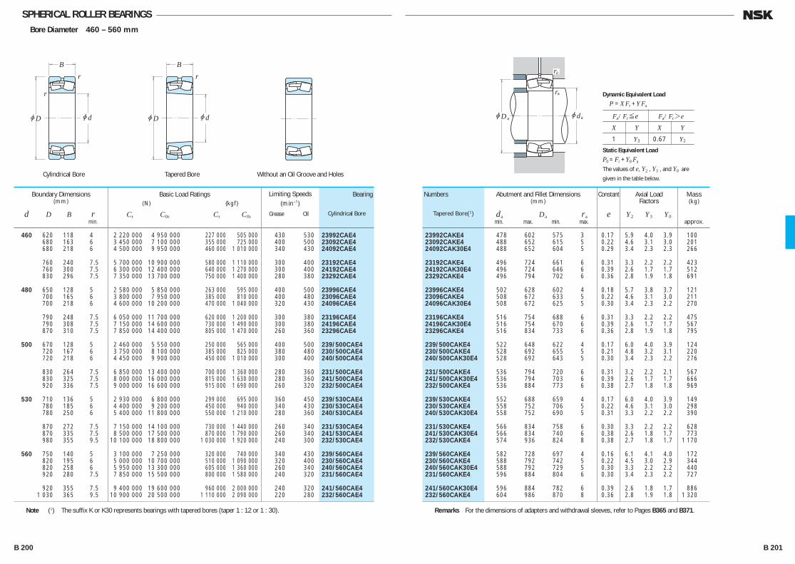
SPHERICAL ROLLER BEARINGSBore Diameter 460 – 560 mm
460 620 118 4 2 220 000 4 950 000 227 000 505 000 430 530 23992CAE4 680 163 6 3 450 000 7 100 000 355 000 725 000 400 500 23092CAE4 680 218 6 4 500 000 9 950 000 460 000 1 010 000 340 430 24092CAE4
760 240 7.5 5 700 000 10 900 000 580 000 1 110 000 300 400 23192CAE4 760 300 7.5 6 300 000 12 400 000 640 000 1 270 000 300 400 24192CAE4 830 296 7.5 7 350 000 13 700 000 750 000 1 400 000 280 380 23292CAE4
480 650 128 5 2 580 000 5 850 000 263 000 595 000 400 500 23996CAE4 700 165 6 3 800 000 7 950 000 385 000 810 000 400 480 23096CAE4 700 218 6 4 600 000 10 200 000 470 000 1 040 000 320 430 24096CAE4
790 248 7.5 6 050 000 11 700 000 620 000 1 200 000 300 380 23196CAE4 790 308 7.5 7 150 000 14 600 000 730 000 1 490 000 300 380 24196CAE4 870 310 7.5 7 850 000 14 400 000 805 000 1 470 000 260 360 23296CAE4
500 670 128 5 2 460 000 5 550 000 250 000 565 000 400 500 239/500CAE4 720 167 6 3 750 000 8 100 000 385 000 825 000 380 480 230/500CAE4 720 218 6 4 450 000 9 900 000 450 000 1 010 000 300 400 240/500CAE4
830 264 7.5 6 850 000 13 400 000 700 000 1 360 000 280 360 231/500CAE4 830 325 7.5 8 000 000 16 000 000 815 000 1 630 000 280 360 241/500CAE4 920 336 7.5 9 000 000 16 600 000 915 000 1 690 000 260 320 232/500CAE4
530 710 136 5 2 930 000 6 800 000 299 000 695 000 360 450 239/530CAE4 780 185 6 4 400 000 9 200 000 450 000 940 000 340 430 230/530CAE4 780 250 6 5 400 000 11 800 000 550 000 1 210 000 280 360 240/530CAE4
870 272 7.5 7 150 000 14 100 000 730 000 1 440 000 260 340 231/530CAE4 870 335 7.5 8 500 000 17 500 000 870 000 1 790 000 260 340 241/530CAE4 980 355 9.5 10 100 000 18 800 000 1 030 000 1 920 000 240 300 232/530CAE4
560 750 140 5 3 100 000 7 250 000 320 000 740 000 340 430 239/560CAE4 820 195 6 5 000 000 10 700 000 510 000 1 090 000 320 400 230/560CAE4 820 258 6 5 950 000 13 300 000 605 000 1 360 000 260 340 240/560CAE4 920 280 7.5 7 850 000 15 500 000 800 000 1 580 000 240 320 231/560CAE4
920 355 7.5 9 400 000 19 600 000 960 000 2 000 000 240 320 241/560CAE4 1 030 365 9.5 10 900 000 20 500 000 1 110 000 2 090 000 220 280 232/560CAE4
Boundary Dimensions(mm)
d D B r min.
Limiting Speeds (min–1)
Grease Oil
Basic Load Ratings (N) {kgf}
Cr C0r Cr C0r
23992CAKE4 478 602 575 3 0.17 5.9 4.0 3.9 100 23092CAKE4 488 652 615 5 0.22 4.6 3.1 3.0 201 24092CAK30E4 488 652 604 5 0.29 3.4 2.3 2.3 266
23192CAKE4 496 724 661 6 0.31 3.3 2.2 2.2 423 24192CAK30E4 496 724 646 6 0.39 2.6 1.7 1.7 512 23292CAKE4 496 794 702 6 0.36 2.8 1.9 1.8 691
23996CAKE4 502 628 602 4 0.18 5.7 3.8 3.7 121 23096CAKE4 508 672 633 5 0.22 4.6 3.1 3.0 211 24096CAK30E4 508 672 625 5 0.30 3.4 2.3 2.2 270
23196CAKE4 516 754 688 6 0.31 3.3 2.2 2.2 475 24196CAK30E4 516 754 670 6 0.39 2.6 1.7 1.7 567 23296CAKE4 516 834 733 6 0.36 2.8 1.9 1.8 795
239/500CAKE4 522 648 622 4 0.17 6.0 4.0 3.9 124 230/500CAKE4 528 692 655 5 0.21 4.8 3.2 3.1 220 240/500CAK30E4 528 692 643 5 0.30 3.4 2.3 2.2 276
231/500CAKE4 536 794 720 6 0.31 3.2 2.2 2.1 567 241/500CAK30E4 536 794 703 6 0.39 2.6 1.7 1.7 666 232/500CAKE4 536 884 773 6 0.38 2.7 1.8 1.8 969
239/530CAKE4 552 688 659 4 0.17 6.0 4.0 3.9 149 230/530CAKE4 558 752 706 5 0.22 4.6 3.1 3.0 298 240/530CAK30E4 558 752 690 5 0.31 3.3 2.2 2.2 390
231/530CAKE4 566 834 758 6 0.30 3.3 2.2 2.2 628 241/530CAK30E4 566 834 740 6 0.38 2.6 1.8 1.7 773 232/530CAKE4 574 936 824 8 0.38 2.7 1.8 1.7 1 170
239/560CAKE4 582 728 697 4 0.16 6.1 4.1 4.0 172 230/560CAKE4 588 792 742 5 0.22 4.5 3.0 2.9 344 240/560CAK30E4 588 792 729 5 0.30 3.3 2.2 2.2 440 231/560CAKE4 596 884 804 6 0.30 3.4 2.3 2.2 727
241/560CAK30E4 596 884 782 6 0.39 2.6 1.8 1.7 886 232/560CAKE4 604 986 870 8 0.36 2.8 1.9 1.8 1 320
Numbers
Tapered Bore(1)
Bearing
Cylindrical Bore
Abutment and Fillet Dimensions(mm)
da Da ra min. max. min. max.
Axial LoadFactors
Y2 Y3 Y0
Constant
e
Mass(kg)
approx.
Note (1) The suffix K or K30 represents bearings with tapered bores (taper 1 : 12 or 1 : 30). Remarks For the dimensions of adapters and withdrawal sleeves, refer to Pages B365 and B371.
jd
r
r
jD
B
jd
r
jD
B
jdjD
ra
ra
a a
Fa/Fr≤e Fa/Fr>e
X Y X Y
1 Y3 0.67 Y2
Dynamic Equivalent Load
P =XFr +YFa
Static Equivalent Load
P0 =Fr +Y0 Fa
The values of e, Y2 , Y3 , and Y0 are
given in the table below.Cylindrical Bore Tapered Bore Without an Oil Groove and Holes
B 200 B 201
B182-205E.indd 200-201B182-205E.indd 200-201 11/20/13 4:57:57 PM11/20/13 4:57:57 PM

SPHERICAL ROLLER BEARINGSBore Diameter 600 – 800 mm
Cylindrical Bore Tapered Bore
600 800 150 5 3 450 000 8 100 000 350 000 830 000 320 400 239/600CAE4 870 200 6 5 450 000 12 200 000 555 000 1 240 000 300 360 230/600CAE4 870 272 6 6 600 000 15 100 000 675 000 1 540 000 240 320 240/600CAE4 980 300 7.5 8 750 000 17 500 000 895 000 1 790 000 220 280 231/600CAE4
980 375 7.5 10 400 000 21 900 000 1 060 000 2 230 000 220 280 241/600CAE4 1 090 388 9.5 12 700 000 24 900 000 1 300 000 2 540 000 200 260 232/600CAE4
630 850 165 6 4 000 000 9 350 000 405 000 950 000 300 360 239/630CAE4 920 212 7.5 5 900 000 12 700 000 600 000 1 300 000 280 340 230/630CAE4 920 290 7.5 7 550 000 17 700 000 770 000 1 810 000 220 300 240/630CAE4
1 030 315 7.5 9 600 000 19 400 000 980 000 1 970 000 200 260 231/630CAE4 1 030 400 7.5 11 300 000 23 900 000 1 160 000 2 440 000 200 260 241/630CAE4 1 150 412 12 13 400 000 25 600 000 1 370 000 2 610 000 180 240 232/630CAE4
670 900 170 6 4 350 000 10 300 000 445 000 1 050 000 260 340 239/670CAE4 980 230 7.5 6 850 000 15 000 000 700 000 1 530 000 240 320 230/670CAE4 980 308 7.5 8 450 000 19 500 000 860 000 1 990 000 200 260 240/670CAE4 1 090 336 7.5 10 600 000 21 600 000 1 080 000 2 200 000 190 240 231/670CAE4
1 090 412 7.5 12 400 000 26 500 000 1 270 000 2 700 000 190 240 241/670CAE4 1 220 438 12 14 900 000 28 700 000 1 520 000 2 920 000 170 220 232/670CAE4
710 950 180 6 4 800 000 11 700 000 490 000 1 200 000 240 300 239/710CAE4 1 030 236 7.5 7 100 000 15 800 000 725 000 1 610 000 240 280 230/710CAE4 1 030 315 7.5 8 850 000 20 700 000 905 000 2 110 000 190 240 240/710CAE4
1 150 438 9.5 13 900 000 30 500 000 1 410 000 3 100 000 170 220 241/710CAE4 1 280 450 12 15 700 000 30 500 000 1 600 000 3 100 000 160 200 232/710CAE4
750 1 000 185 6 5 250 000 12 800 000 535 000 1 310 000 220 280 239/750CAE4 1 090 250 7.5 7 750 000 17 200 000 790 000 1 750 000 220 260 230/750CAE4
1 090 335 7.5 10 100 000 24 000 000 1 030 000 2 450 000 180 220 240/750CAE4 1 360 475 15 17 700 000 35 500 000 1 800 000 3 600 000 140 190 232/750CAE4
800 1 060 195 6 5 600 000 13 700 000 570 000 1 400 000 220 260 239/800CAE4 1 150 258 7.5 8 350 000 19 100 000 850 000 1 950 000 200 240 230/800CAE4 1 150 345 7.5 10 900 000 26 300 000 1 110 000 2 680 000 160 200 240/800CAE4
1 280 375 9.5 13 800 000 29 200 000 1 410 000 2 970 000 150 190 231/800CAE4 1 420 488 15 20 300 000 41 000 000 2 070 000 4 150 000 130 170 232/800CAE4
Boundary Dimensions(mm)
d D B r min.
Limiting Speeds (min–1)
Grease Oil
Basic Load Ratings (N) {kgf}
Cr C0r Cr C0r
239/600CAKE4 622 778 745 4 0.17 5.9 3.9 3.9 205 230/600CAKE4 628 842 794 5 0.21 4.8 3.3 3.2 389 240/600CAK30E4 628 842 772 5 0.30 3.3 2.2 2.2 529 231/600CAKE4 636 944 856 6 0.30 3.4 2.3 2.2 898
241/600CAK30E4 636 944 836 6 0.39 2.6 1.8 1.7 1 050 232/600CAKE4 644 1 046 923 8 0.36 2.8 1.9 1.8 1 590
239/630CAKE4 658 822 786 5 0.18 5.6 3.8 3.7 259 230/630CAKE4 666 884 835 6 0.22 4.7 3.1 3.1 468 240/630CAK30E4 666 884 815 6 0.30 3.3 2.2 2.2 637
231/630CAKE4 666 994 900 6 0.30 3.4 2.3 2.2 1 040 241/630CAK30E4 666 994 876 6 0.38 2.7 1.8 1.7 1 250 232/630CAKE4 684 1 096 970 10 0.36 2.8 1.9 1.8 1 850
239/670CAKE4 698 872 836 5 0.17 5.8 3.9 3.8 300 230/670CAKE4 706 944 891 6 0.22 4.7 3.1 3.1 571 240/670CAK30E4 706 944 868 6 0.30 3.3 2.2 2.2 773 231/670CAKE4 706 1 054 952 6 0.30 3.3 2.2 2.2 1 230
241/670CAK30E4 706 1 054 934 6 0.37 2.7 1.8 1.8 1 440 232/670CAKE4 724 1 166 1 024 10 0.37 2.7 1.8 1.8 2 210
239/710CAKE4 738 922 883 5 0.17 5.8 3.9 3.8 352 230/710CAKE4 746 994 936 6 0.22 4.6 3.1 3.0 647 240/710CAK30E4 746 994 916 6 0.29 3.4 2.3 2.2 861
241/710CAK30E4 754 1 106 981 8 0.38 2.6 1.8 1.7 1 730 232/710CAKE4 764 1 226 1 080 10 0.36 2.8 1.9 1.8 2 470
239/750CAKE4 778 972 931 5 0.17 6.0 4.1 4.0 398 230/750CAKE4 786 1 054 990 6 0.22 4.6 3.1 3.0 768
240/750CAK30E4 786 1 054 969 6 0.29 3.4 2.3 2.2 1 030 232/750CAKE4 814 1 296 1 148 12 0.36 2.8 1.9 1.8 2 980
239/800CAKE4 828 1 032 987 5 0.17 6.0 4.0 3.9 462 230/800CAKE4 836 1 114 1 045 6 0.21 4.7 3.2 3.1 870 240/800CAK30E4 836 1 114 1 029 6 0.27 3.7 2.5 2.5 1 130
231/800CAKE4 844 1 236 1 127 8 0.28 3.6 2.4 2.3 1870 232/800CAKE4 864 1 356 1 208 12 0.35 2.8 1.9 1.9 3 250
Numbers
Tapered Bore(1)
Bearing
Cylindrical Bore
Abutment and Fillet Dimensions(mm)
da Da ra min. max. min. max.
Axial LoadFactors
Y2 Y3 Y0
Constant
e
Mass(kg)
approx.
Note (1) The suffix K or K30 represents bearings with tapered bores (taper 1 : 12 or 1 : 30).
jdjD
ra
ra
a a
Fa/Fr≤e Fa/Fr>e
X Y X Y
1 Y3 0.67 Y2
Dynamic Equivalent Load
P =XFr +YFa
Static Equivalent Load
P0 =Fr +Y0 Fa
The values of e, Y2 , Y3 , and Y0 are
given in the table below.
jd
r
r
jD
B
jd
r
jD
B
B 202 B 203
B182-205E.indd 202-203B182-205E.indd 202-203 11/20/13 4:57:57 PM11/20/13 4:57:57 PM
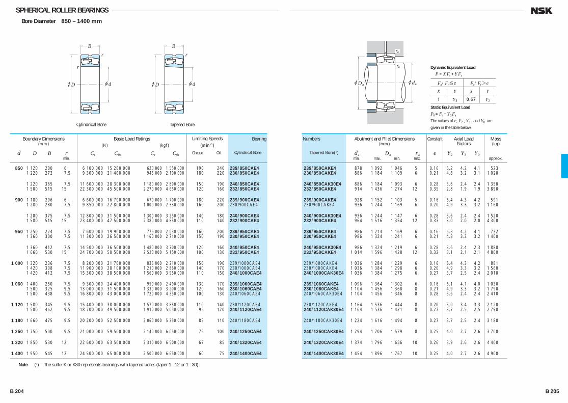
SPHERICAL ROLLER BEARINGSBore Diameter 850 – 1400 mm
Cylindrical Bore Tapered Bore
850 1 120 200 6 6 100 000 15 200 000 620 000 1 550 000 190 240 239/850CAE4 1 220 272 7.5 9 300 000 21 400 000 945 000 2 190 000 180 220 230/850CAE4
1 220 365 7.5 11 600 000 28 300 000 1 180 000 2 890 000 150 190 240/850CAE4 1 500 515 15 22 300 000 45 500 000 2 270 000 4 650 000 120 160 232/850CAE4
900 1 180 206 6 6 600 000 16 700 000 670 000 1 700 000 180 220 239/900CAE4 1 280 280 7.5 9 850 000 22 800 000 1 000 000 2 330 000 160 200 230/900CAE4
1 280 375 7.5 12 800 000 31 500 000 1 300 000 3 250 000 140 180 240/900CAE4 1 580 515 15 23 400 000 47 500 000 2 380 000 4 850 000 110 140 232/900CAE4
950 1 250 224 7.5 7 600 000 19 900 000 775 000 2 030 000 160 200 239/950CAE4 1 360 300 7.5 11 300 000 26 500 000 1 160 000 2 710 000 150 190 230/950CAE4
1 360 412 7.5 14 500 000 36 500 000 1 480 000 3 700 000 120 160 240/950CAE4 1 660 530 15 24 700 000 50 500 000 2 520 000 5 150 000 100 130 232/950CAE4
1 000 1 320 236 7.5 8 200 000 21 700 000 835 000 2 210 000 150 190 239/1000CAE4 1 420 308 7.5 11 900 000 28 100 000 1 210 000 2 860 000 140 170 230/1000CAE4 1 420 412 7.5 15 300 000 38 500 000 1 560 000 3 950 000 110 150 240/1000CAE4
1 060 1 400 250 7.5 9 300 000 24 400 000 950 000 2 490 000 130 170 239/1060CAE4 1 500 325 9.5 13 000 000 31 500 000 1 330 000 3 200 000 120 160 230/1060CAE4 1 500 438 9.5 16 800 000 43 000 000 1 720 000 4 350 000 100 130 240/1060CAE4
1 120 1 580 345 9.5 15 400 000 38 000 000 1 570 000 3 850 000 110 140 230/1120CAE4 1 580 462 9.5 18 700 000 49 500 000 1 910 000 5 050 000 95 120 240/1120CAE4
1 180 1 660 475 9.5 20 200 000 52 500 000 2 060 000 5 350 000 85 110 240/1180CAE4
1 250 1 750 500 9.5 21 000 000 59 500 000 2 140 000 6 050 000 75 100 240/1250CAE4
1 320 1 850 530 12 22 600 000 63 500 000 2 310 000 6 500 000 67 85 240/1320CAE4
1 400 1 950 545 12 24 500 000 65 000 000 2 500 000 6 650 000 60 75 240/1400CAE4
Boundary Dimensions(mm)
d D B r min.
Limiting Speeds (min–1)
Grease Oil
Basic Load Ratings (N) {kgf}
Cr C0r Cr C0r
239/850CAKE4 878 1 092 1 046 5 0.16 6.2 4.2 4.1 523 230/850CAKE4 886 1 184 1 109 6 0.21 4.8 3.2 3.1 1 020
240/850CAK30E4 886 1 184 1 093 6 0.28 3.6 2.4 2.4 1 350 232/850CAKE4 914 1 436 1 274 12 0.35 2.8 1.9 1.9 3 890
239/900CAKE4 928 1 152 1 103 5 0.16 6.4 4.3 4.2 591 230/900CAKE4 936 1 244 1 169 6 0.20 4.9 3.3 3.2 1 160
240/900CAK30E4 936 1 244 1 147 6 0.28 3.6 2.4 2.4 1 520 232/900CAKE4 964 1 516 1 354 12 0.33 3.0 2.0 2.0 4 300
239/950CAKE4 986 1 214 1 169 6 0.16 6.3 4.2 4.1 732 230/950CAKE4 986 1 324 1 241 6 0.21 4.8 3.2 3.2 1 400
240/950CAK30E4 986 1 324 1 219 6 0.28 3.6 2.4 2.3 1 880 232/950CAKE4 1 014 1 596 1 428 12 0.32 3.1 2.1 2.1 4 800
239/1000CAKE4 1 036 1 284 1 229 6 0.16 6.4 4.3 4.2 881 230/1000CAKE4 1 036 1 384 1 298 6 0.20 4.9 3.3 3.2 1 560 240/1000CAK30E4 1 036 1 384 1 275 6 0.27 3.7 2.5 2.4 2 010
239/1060CAKE4 1 096 1 364 1 302 6 0.16 6.1 4.1 4.0 1 030 230/1060CAKE4 1 104 1 456 1 368 8 0.21 4.9 3.3 3.2 1 790 240/1060CAK30E4 1 104 1 456 1 346 8 0.28 3.6 2.4 2.4 2 410
230/1120CAKE4 1 164 1 536 1 444 8 0.20 5.0 3.4 3.3 2 120 240/1120CAK30E4 1 164 1 536 1 421 8 0.27 3.7 2.5 2.5 2 790
240/1180CAK30E4 1 224 1 616 1 494 8 0.27 3.7 2.5 2.4 3 180
240/1250CAK30E4 1 294 1 706 1 579 8 0.25 4.0 2.7 2.6 3 700
240/1320CAK30E4 1 374 1 796 1 656 10 0.26 3.9 2.6 2.6 4 400
240/1400CAK30E4 1 454 1 896 1 767 10 0.25 4.0 2.7 2.6 4 900
Numbers
Tapered Bore(1)
Bearing
Cylindrical Bore
Abutment and Fillet Dimensions(mm)
da Da ra min. max. min. max.
Axial LoadFactors
Y2 Y3 Y0
Constant
e
Mass(kg)
approx.
Note (1) The suffix K or K30 represents bearings with tapered bores (taper 1 : 12 or 1 : 30).
jdjD
ra
ra
a a
Fa/Fr≤e Fa/Fr>e
X Y X Y
1 Y3 0.67 Y2
Dynamic Equivalent Load
P =XFr +YFa
Static Equivalent Load
P0 =Fr +Y0 Fa
The values of e, Y2 , Y3 , and Y0 are
given in the table below.
jd
r
r
jD
B
jd
r
jD
B
B 204 B 205
B182-205E.indd 204-205B182-205E.indd 204-205 11/20/13 4:57:58 PM11/20/13 4:57:58 PM
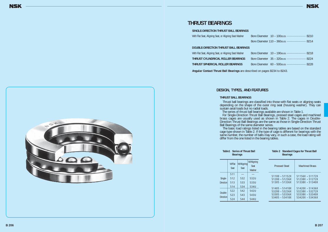
THRUST BEARINGSSINGLE-DIRECTION THRUST BALL BEARINGS
With Flat Seat, Aligning Seat, or Aligning Seat Washer Bore Diameter 10 – 100mm ························· B210
Bore Diameter 110 – 360mm ························· B214
DOUBLE-DIRECTION THRUST BALL BEARINGS
With Flat Seat, Aligning Seat, or Aligning Seat Washer Bore Diameter 10 – 190mm ························· B218
THRUST CYLINDRICAL ROLLER BEARINGS Bore Diameter 35 – 320mm ························· B224
THRUST SPHERICAL ROLLER BEARINGS Bore Diameter 60 – 500mm ························· B228
Angular Contact Thrust Ball Bearings are described on pages B234 to B243.
DESIGN, TYPES, AND FEATURES
THRUST BALL BEARINGS Thrust ball bearings are classified into those with flat seats or aligning seats depending on the shape of the outer ring seat (housing washer). They can sustain axial loads but no radial loads. The series of thrust ball bearings available are shown in Table 1. For Single-Direction Thrust Ball Bearings, pressed steel cages and machined brass cages are usually used as shown in Table 2. The cages in Double-Direction Thrust Ball Bearings are the same as those in Single-Direction Thrust Ball Bearings of the same diameter series. The basic load ratings listed in the bearing tables are based on the standard cage type shown in Table 2. If the type of cage is different for bearings with the same number, the number of balls may vary, in such a case, the load rating will differ from the one listed in the bearing tables.
Table1 Series of Thrust Ball Bearings
W/Flat W/Aligning
W/Aligning
Seat Seat Seat
Washer 511 — — Single- 512 532 532U Direction 513 533 533U 514 534 534U Double-
522 542 542U Direction
523 543 543U 524 544 544U
Table 2 Standard Cages for Thrust Ball Bearings
Pressed Steel Machined Brass
51100 – 51152X 51156X – 51172X 51200 – 51236X 51238X – 51272X 51305 – 51336X 51338X – 51340X
51405 – 51418X 51420X – 51436X 53200 – 53236X 53238X – 53272X 53305 – 53336X 53338X – 53340X 53405 – 53418X 53420X – 53436X
B 206 B 207
B206-233E.indd 206-207B206-233E.indd 206-207 11/20/13 4:58:19 PM11/20/13 4:58:19 PM
THRUST CYLINDRICAL ROLLER BEARINGS These are thrust bearings containing cylindrical rollers. They can sustain only axial loads, but they are suitable for heavy loads and have high axial rigidity. The cages are machined brass.
THRUST SPHERICAL ROLLER BEARINGS These are thrust bearings containing convex rollers. They have a self-aligning capability and are free of any influence of mounting error or shaft deflection. Besides the original type, the E type with pressed cages for high load capacity is also available. Their bearing numbers are suffixed by E. For horizontal shaft or high speed application, machined brass cages are recommended. For details, contact NSK. Since there are several places where lubrication is difficult, such as the area between the roller heads and inner ring rib, the sliding surfaces between cage and guide sleeve, etc., oil lubrication should be used even at low speed. The cages in the original type are machined brass.
TOLERANCES AND RUNNING ACCURACY
THRUST BALL BEARINGS ····································Table 8.6 (Pages A72 to A74)THRUST CYLINDRICAL ROLLER BEARINGS ························································According to Table 8.2 (Pages A72 to A74)THRUST SPHERICAL ROLLER BEARINGS ···········Table 8.7 (Pages A75)
RECOMMENDED FITS
THRUST BALL BEARINGS ············································Table 9.3 (Pages A84) Table 9.5 (Pages A85)THRUST CYLINDRICAL ROLLER BEARINGS ················Table 9.3 (Pages A84) Table 9.5 (Pages A85)THRUST SPHERICAL ROLLER BEARINGS ···················Table 9.3 (Pages A84) Table 9.5 (Pages A85)
DIMENSIONS RELATED TO MOUNTING
The dimensions related to mounting of thrust spherical roller bearings are listed in the Bearing Table. If the bearing load is heavy, it is necessary to design the shaft shoulder with ample strength in order to provide sufficient support for the shaft washer.
PERMISSIBLE MISALIGNMENT
The permissible misalignment of thrust spherical roller bearings varies depending on the size, but it is approximately 0.018 to 0.036 radian (1° to 2°) with average loads.
MINIMUM AXIAL LOAD
It is necessary to apply some axial load to thrust bearings to prevent slippage between the rolling elements and raceways. For more details, please refer to Page A99.
B 208 B 209
B206-233E.indd 208-209B206-233E.indd 208-209 11/20/13 4:58:19 PM11/20/13 4:58:19 PM
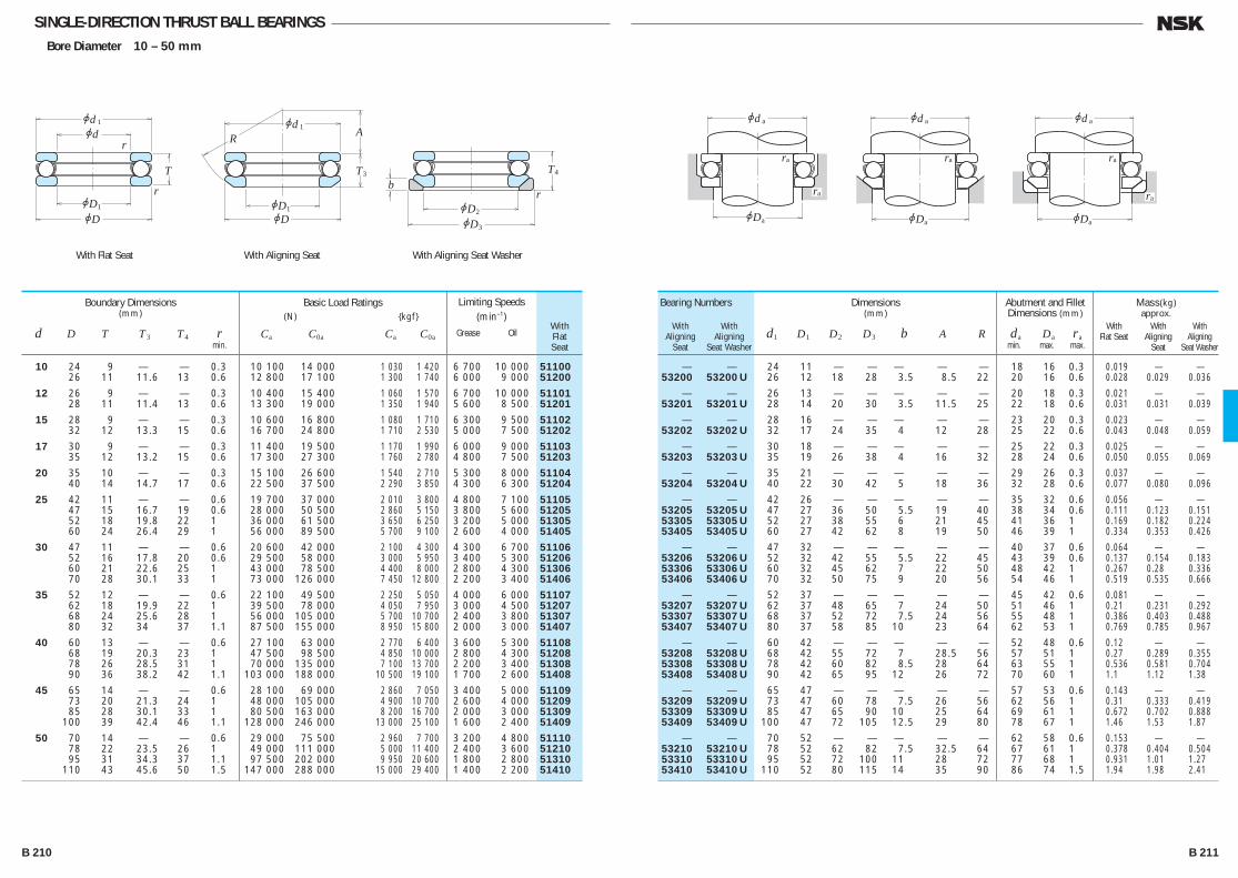
SINGLE-DIRECTION THRUST BALL BEARINGSBore Diameter 10 – 50 mm
— — 24 11 — — — — — 18 16 0.3 0.019 .— .— 53200 53200 U 26 12 18 28 3.5 8.5 22 20 16 0.6 0.028 0.029 0.036
— — 26 13 — — — — — 20 18 0.3 0.021 .— .— 53201 53201 U 28 14 20 30 3.5 11.5 25 22 18 0.6 0.031 0.031 0.039
— — 28 16 — — — — — 23 20 0.3 0.023 .— .— 53202 53202 U 32 17 24 35 4 12 28 25 22 0.6 0.043 0.048 0.059
— — 30 18 — — — — — 25 22 0.3 0.025 .— .— 53203 53203 U 35 19 26 38 4 16 32 28 24 0.6 0.050 0.055 0.069
— — 35 21 — — — — — 29 26 0.3 0.037 .— .— 53204 53204 U 40 22 30 42 5 18 36 32 28 0.6 0.077 0.080 0.096
— — 42 26 — — — — — 35 32 0.6 0.056 .— .— 53205 53205 U 47 27 36 50 5.5 19 40 38 34 0.6 0.111 0.123 0.151 53305 53305 U 52 27 38 55 6 21 45 41 36 1 0.169 0.182 0.224 53405 53405 U 60 27 42 62 8 19 50 46 39 1 0.334 0.353 0.426
— — 47 32 — — — — — 40 37 0.6 0.064 .— .— 53206 53206 U 52 32 42 55 5.5 22 45 43 39 0.6 0.137 0.154 0.183 53306 53306 U 60 32 45 62 7 22 50 48 42 1 0.267 0.28 0.336 53406 53406 U 70 32 50 75 9 20 56 54 46 1 0.519 0.535 0.666
— — 52 37 — — — — — 45 42 0.6 0.081 .— .— 53207 53207 U 62 37 48 65 7 24 50 51 46 1 0.21 0.231 0.292 53307 53307 U 68 37 52 72 7.5 24 56 55 48 1 0.386 0.403 0.488 53407 53407 U 80 37 58 85 10 23 64 62 53 1 0.769 0.785 0.967
— — 60 42 — — — — — 52 48 0.6 0.12 .— .— 53208 53208 U 68 42 55 72 7 28.5 56 57 51 1 0.27 0.289 0.355 53308 53308 U 78 42 60 82 8.5 28 64 63 55 1 0.536 0.581 0.704 53408 53408 U 90 42 65 95 12 26 72 70 60 1 1.1 1.12 1.38
— — 65 47 — — — — — 57 53 0.6 0.143 .— .— 53209 53209 U 73 47 60 78 7.5 26 56 62 56 1 0.31 0.333 0.419 53309 53309 U 85 47 65 90 10 25 64 69 61 1 0.672 0.702 0.888 53409 53409 U 100 47 72 105 12.5 29 80 78 67 1 1.46 1.53 1.87
— — 70 52 — — — — — 62 58 0.6 0.153 .— .— 53210 53210 U 78 52 62 82 7.5 32.5 64 67 61 1 0.378 0.404 0.504 53310 53310 U 95 52 72 100 11 28 72 77 68 1 0.931 1.01 1.27 53410 53410 U 110 52 80 115 14 35 90 86 74 1.5 1.94 1.98 2.41
Bearing Numbers
With With Aligning Aligning Seat Seat Washer
WithFlatSeat
Dimensions(mm)
d1 D1 D2 D3 b A R
Abutment and Fillet Dimensions (mm)
da Da ra min. max. max.
Mass(kg)approx.
With With With Flat Seat Aligning Aligning Seat Seat Washer
10 24 9 — — 0.3 10 100 14 000 1 030 1 420 6 700 10 000 51100 26 11 11.6 13 0.6 12 800 17 100 1 300 1 740 6 000 9 000 51200
12 26 9 — — 0.3 10 400 15 400 1 060 1 570 6 700 10 000 51101 28 11 11.4 13 0.6 13 300 19 000 1 350 1 940 5 600 8 500 51201
15 28 9 — — 0.3 10 600 16 800 1 080 1 710 6 300 9 500 51102 32 12 13.3 15 0.6 16 700 24 800 1 710 2 530 5 000 7 500 51202
17 30 9 — — 0.3 11 400 19 500 1 170 1 990 6 000 9 000 51103 35 12 13.2 15 0.6 17 300 27 300 1 760 2 780 4 800 7 500 51203
20 35 10 — — 0.3 15 100 26 600 1 540 2 710 5 300 8 000 51104 40 14 14.7 17 0.6 22 500 37 500 2 290 3 850 4 300 6 300 51204
25 42 11 — — 0.6 19 700 37 000 2 010 3 800 4 800 7 100 51105 47 15 16.7 19 0.6 28 000 50 500 2 860 5 150 3 800 5 600 51205 52 18 19.8 22 1 36 000 61 500 3 650 6 250 3 200 5 000 51305 60 24 26.4 29 1 56 000 89 500 5 700 9 100 2 600 4 000 51405
30 47 11 — — 0.6 20 600 42 000 2 100 4 300 4 300 6 700 51106 52 16 17.8 20 0.6 29 500 58 000 3 000 5 950 3 400 5 300 51206 60 21 22.6 25 1 43 000 78 500 4 400 8 000 2 800 4 300 51306 70 28 30.1 33 1 73 000 126 000 7 450 12 800 2 200 3 400 51406
35 52 12 — — 0.6 22 100 49 500 2 250 5 050 4 000 6 000 51107 62 18 19.9 22 1 39 500 78 000 4 050 7 950 3 000 4 500 51207 68 24 25.6 28 1 56 000 105 000 5 700 10 700 2 400 3 800 51307 80 32 34 37 1.1 87 500 155 000 8 950 15 800 2 000 3 000 51407
40 60 13 — — 0.6 27 100 63 000 2 770 6 400 3 600 5 300 51108 68 19 20.3 23 1 47 500 98 500 4 850 10 000 2 800 4 300 51208 78 26 28.5 31 1 70 000 135 000 7 100 13 700 2 200 3 400 51308 90 36 38.2 42 1.1 103 000 188 000 10 500 19 100 1 700 2 600 51408
45 65 14 — — 0.6 28 100 69 000 2 860 7 050 3 400 5 000 51109 73 20 21.3 24 1 48 000 105 000 4 900 10 700 2 600 4 000 51209 85 28 30.1 33 1 80 500 163 000 8 200 16 700 2 000 3 000 51309 100 39 42.4 46 1.1 128 000 246 000 13 000 25 100 1 600 2 400 51409
50 70 14 — — 0.6 29 000 75 500 2 960 7 700 3 200 4 800 51110 78 22 23.5 26 1 49 000 111 000 5 000 11 400 2 400 3 600 51210 95 31 34.3 37 1.1 97 500 202 000 9 950 20 600 1 800 2 800 51310 110 43 45.6 50 1.5 147 000 288 000 15 000 29 400 1 400 2 200 51410
Boundary Dimensions(mm)
d D T T3 T4 r min.
Limiting Speeds (min–1)
Grease Oil
Basic Load Ratings (N) {kgf}
Ca C0a Ca C0a
jdjd
jDjD
T
r
r1
1 jd
jDjD
T
AR
1
3
1
jDjD
T
2
3
4
br
With Flat Seat With Aligning Seat With Aligning Seat Washer
jd
jD
r
a
a
ra
a jd
jD
r
a
a
ra
a jd
jD
r
a
a
a
B 210 B 211
B206-233E.indd 210-211B206-233E.indd 210-211 11/20/13 4:58:20 PM11/20/13 4:58:20 PM
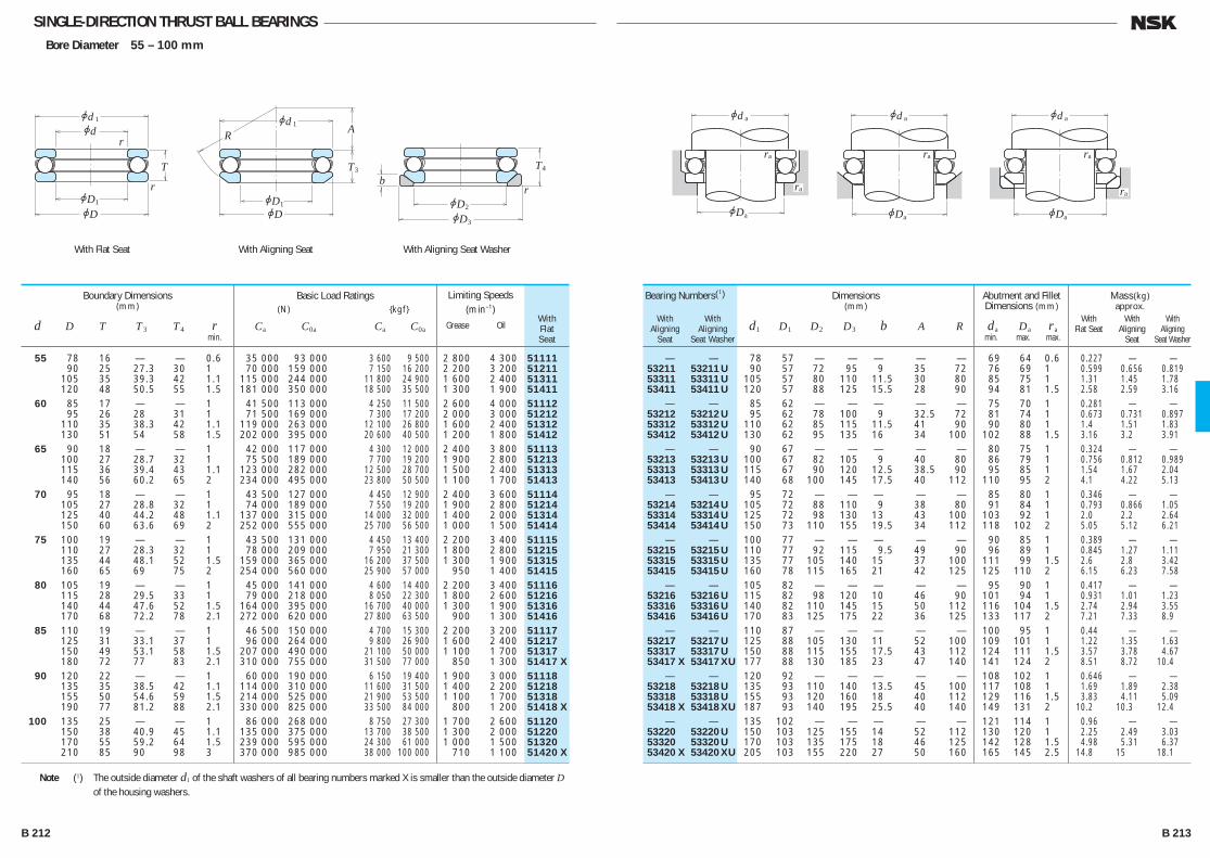
SINGLE-DIRECTION THRUST BALL BEARINGSBore Diameter 55 – 100 mm
— — 78 57 — — — — — 69 64 0.6 0.227 .— .— 53211 53211 U 90 57 72 95 9 35 72 76 69 1 0.599 0.656 0.819 53311 53311 U 105 57 80 110 11.5 30 80 85 75 1 1.31 1.45 1.78 53411 53411 U 120 57 88 125 15.5 28 90 94 81 1.5 2.58 2.59 3.16 — — 85 62 — — — — — 75 70 1 0.281 .— .— 53212 53212 U 95 62 78 100 9 32.5 72 81 74 1 0.673 0.731 0.897 53312 53312 U 110 62 85 115 11.5 41 90 90 80 1 1.4 1.51 1.83 53412 53412 U 130 62 95 135 16 34 100 102 88 1.5 3.16 3.2 3.91 — — 90 67 — — — — — 80 75 1 0.324 .— .— 53213 53213 U 100 67 82 105 9 40 80 86 79 1 0.756 0.812 0.989 53313 53313 U 115 67 90 120 12.5 38.5 90 95 85 1 1.54 1.67 2.04 53413 53413 U 140 68 100 145 17.5 40 112 110 95 2 4.1 4.22 5.13 — — 95 72 — — — — — 85 80 1 0.346 .— .— 53214 53214 U 105 72 88 110 9 38 80 91 84 1 0.793 0.866 1.05 53314 53314 U 125 72 98 130 13 43 100 103 92 1 2.0 2.2 2.64 53414 53414 U 150 73 110 155 19.5 34 112 118 102 2 5.05 5.12 6.21 — — 100 77 — — — — — 90 85 1 0.389 .— .— 53215 53215 U 110 77 92 115 9.5 49 90 96 89 1 0.845 1.27 1.11 53315 53315 U 135 77 105 140 15 37 100 111 99 1.5 2.6 2.8 3.42 53415 53415 U 160 78 115 165 21 42 125 125 110 2 6.15 6.23 7.58 — — 105 82 — — — — — 95 90 1 0.417 .— .— 53216 53216 U 115 82 98 120 10 46 90 101 94 1 0.931 1.01 1.23 53316 53316 U 140 82 110 145 15 50 112 116 104 1.5 2.74 2.94 3.55 53416 53416 U 170 83 125 175 22 36 125 133 117 2 7.21 7.33 8.9 — — 110 87 — — — — — 100 95 1 0.44 .— .— 53217 53217 U 125 88 105 130 11 52 100 109 101 1 1.22 1.35 1.63 53317 53317 U 150 88 115 155 17.5 43 112 124 111 1.5 3.57 3.78 4.67 53417 X 53417 XU 177 88 130 185 23 47 140 141 124 2 8.51 8.72 10.4 — — 120 92 — — — — — 108 102 1 0.646 .— .— 53218 53218 U 135 93 110 140 13.5 45 100 117 108 1 1.69 1.89 2.38 53318 53318 U 155 93 120 160 18 40 112 129 116 1.5 3.83 4.11 5.09 53418 X 53418 XU 187 93 140 195 25.5 40 140 149 131 2 10.2 10.3 12.4 — — 135 102 — — — — — 121 114 1 0.96 .— .— 53220 53220 U 150 103 125 155 14 52 112 130 120 1 2.25 2.49 3.03 53320 53320 U 170 103 135 175 18 46 125 142 128 1.5 4.98 5.31 6.37 53420 X 53420 XU 205 103 155 220 27 50 160 165 145 2.5 14.8 15 18.1
Bearing Numbers(1)
With With Aligning Aligning Seat Seat Washer
WithFlatSeat
Dimensions(mm)
d1 D1 D2 D3 b A R
Abutment and Fillet Dimensions (mm)
da Da ra min. max. max.
Mass(kg)approx.
With With With Flat Seat Aligning Aligning Seat Seat Washer
55 78 16 — — 0.6 35 000 93 000 3 600 9 500 2 800 4 300 51111 90 25 27.3 30 1 70 000 159 000 7 150 16 200 2 200 3 200 51211 105 35 39.3 42 1.1 115 000 244 000 11 800 24 900 1 600 2 400 51311 120 48 50.5 55 1.5 181 000 350 000 18 500 35 500 1 300 1 900 51411 60 85 17 — — 1 41 500 113 000 4 250 11 500 2 600 4 000 51112 95 26 28 31 1 71 500 169 000 7 300 17 200 2 000 3 000 51212 110 35 38.3 42 1.1 119 000 263 000 12 100 26 800 1 600 2 400 51312 130 51 54 58 1.5 202 000 395 000 20 600 40 500 1 200 1 800 51412 65 90 18 — — 1 42 000 117 000 4 300 12 000 2 400 3 800 51113 100 27 28.7 32 1 75 500 189 000 7 700 19 200 1 900 2 800 51213 115 36 39.4 43 1.1 123 000 282 000 12 500 28 700 1 500 2 400 51313 140 56 60.2 65 2 234 000 495 000 23 800 50 500 1 100 1 700 51413
70 95 18 — — 1 43 500 127 000 4 450 12 900 2 400 3 600 51114 105 27 28.8 32 1 74 000 189 000 7 550 19 200 1 900 2 800 51214 125 40 44.2 48 1.1 137 000 315 000 14 000 32 000 1 400 2 000 51314 150 60 63.6 69 2 252 000 555 000 25 700 56 500 1 000 1 500 51414 75 100 19 — — 1 43 500 131 000 4 450 13 400 2 200 3 400 51115 110 27 28.3 32 1 78 000 209 000 7 950 21 300 1 800 2 800 51215 135 44 48.1 52 1.5 159 000 365 000 16 200 37 500 1 300 1 900 51315 160 65 69 75 2 254 000 560 000 25 900 57 000 950 1 400 51415
80 105 19 — — 1 45 000 141 000 4 600 14 400 2 200 3 400 51116 115 28 29.5 33 1 79 000 218 000 8 050 22 300 1 800 2 600 51216 140 44 47.6 52 1.5 164 000 395 000 16 700 40 000 1 300 1 900 51316 170 68 72.2 78 2.1 272 000 620 000 27 800 63 500 900 1 300 51416
85 110 19 — — 1 46 500 150 000 4 700 15 300 2 200 3 200 51117 125 31 33.1 37 1 96 000 264 000 9 800 26 900 1 600 2 400 51217 150 49 53.1 58 1.5 207 000 490 000 21 100 50 000 1 100 1 700 51317 180 72 77 83 2.1 310 000 755 000 31 500 77 000 850 1 300 51417 X
90 120 22 — — 1 60 000 190 000 6 150 19 400 1 900 3 000 51118 135 35 38.5 42 1.1 114 000 310 000 11 600 31 500 1 400 2 200 51218 155 50 54.6 59 1.5 214 000 525 000 21 900 53 500 1 100 1 700 51318 190 77 81.2 88 2.1 330 000 825 000 33 500 84 000 800 1 200 51418 X
100 135 25 — — 1 86 000 268 000 8 750 27 300 1 700 2 600 51120 150 38 40.9 45 1.1 135 000 375 000 13 700 38 500 1 300 2 000 51220 170 55 59.2 64 1.5 239 000 595 000 24 300 61 000 1 000 1 500 51320 210 85 90 98 3 370 000 985 000 38 000 100 000 710 1 100 51420 X
Boundary Dimensions(mm)
d D T T3 T4 r min.
Limiting Speeds (min–1)
Grease Oil
Basic Load Ratings (N) {kgf}
Ca C0a Ca C0a
jdjd
jDjD
T
r
r1
1 jd
jDjD
T
AR
1
3
1
jDjD
T
2
3
4
br
With Flat Seat With Aligning Seat With Aligning Seat Washer
Note (1) The outside diameter d1 of the shaft washers of all bearing numbers marked X is smaller than the outside diameter D of the housing washers.
jd
jD
r
a
a
ra
a jd
jD
r
a
a
ra
a jd
jD
r
a
a
a
B 212 B 213
B206-233E.indd 212-213B206-233E.indd 212-213 11/20/13 4:58:21 PM11/20/13 4:58:21 PM

SINGLE-DIRECTION THRUST BALL BEARINGSBore Diameter 110 – 190 mm
— — 145 112 — — — — — 131 124 1 1.04 — — 53222 53222 U 160 113 135 165 14 65 125 140 130 1 2.42 2.65 3.2 53322 X 53322 XU 187 113 150 195 20.5 51 140 158 142 2 7.19 7.55 9.1 53422 X 53422 XU 225 113 170 240 29 59 180 181 159 2.5 20 20.5 24.3 — — 155 122 — — — — — 141 134 1 1.12 — — 53224 53224 U 170 123 145 175 15 61 125 150 140 1 2.7 2.94 3.58 53324 X 53324 XU 205 123 165 220 22 63 160 173 157 2 9.7 10.1 12.4 53424 X 53424 XU 245 123 185 260 32 70 200 196 174 3 26.2 26.5 31.3 — — 170 132 — — — — — 154 146 1 1.68 — — 53226 X 53226 XU 187 133 160 195 17 67 140 166 154 1.5 3.95 4.35 5.33 53326 X 53326 XU 220 134 177 235 26 53 160 186 169 2 12.1 12.7 15.8 53426 X 53426 XU 265 134 200 280 38 58 200 212 188 3 32.3 32.4 38.8 — — 178 142 — — — — — 164 156 1 1.83 — — 53228 X 53228 XU 197 143 170 210 17 87 160 176 164 1.5 4.3 4.74 5.89 53328 X 53328 XU 235 144 190 250 26 68 180 199 181 2 14.2 16.3 19.5 53428 X 53428 XU 275 144 206 290 38 83 225 222 198 3 34.7 34.8 41.4 — — 188 152 — — — — — 174 166 1 1.95 — — 53230 X 53230 XU 212 153 180 225 20.5 79 160 189 176 1.5 5.52 6.09 7.82 53330 X 53330 XU 245 154 200 260 26 89.5 200 209 191 2 15 17.3 20.5 53430 X 53430 XU 295 154 225 310 41 69 225 238 212 3 43.5 43.8 51.9 — — 198 162 — — — — — 184 176 1 2.07 — — 53232 X 53232 XU 222 163 190 235 21 74 160 199 186 1.5 6.04 6.78 8.7 53332 X 53332 XU 265 164 215 280 29 77 200 225 205 2.5 19.6 22.3 26.7 53432 X 53432 XU 315 164 240 330 41.5 84 250 254 226 4 52.7 52.9 62 — — 213 172 — — — — — 197 188 1 2.72 — — 53234 X 53234 XU 237 173 200 250 21.5 91 180 212 198 1.5 7.41 8.21 10.5 53334 X 53334 XU 275 174 220 290 29 105 225 235 215 2.5 20.3 23.2 28 53434 X 53434 XU 335 174 255 350 46 74 250 269 241 4 61.2 61.3 73 — — 222 183 — — — — — 207 198 1 2.79 — — 53236 X 53236 XU 247 183 210 260 21.5 112 200 222 208 1.5 7.94 8.57 10.8 53336 X 53336 XU 295 184 240 310 32 91 225 251 229 2.5 25.9 29.2 34.9 53436 X 53436 XU 355 184 270 370 46.5 97 280 285 255 4 70.5 72.1 84.9 — — 237 193 — — — — — 220 210 1 3.6 — — 53238 X 53238 XU 267 194 230 280 23 98 200 238 222 2 11.8 12.9 15.7 53338 X 53338 XU 315 195 255 330 33 104 250 266 244 3 36.5 38.1 44.7
Bearing Numbers(1)
With With Aligning Aligning Seat Seat Washer
WithFlatSeat
Dimensions(mm)
d1 D1 D2 D3 b A R
Abutment and Fillet Dimensions (mm)
da Da ra min. max. max.
Mass(kg)approx.
With With With Flat Seat Aligning Aligning Seat Seat Washer
110 145 25 — — 1 88 000 288 000 8 950 29 400 1 700 2 400 51122 160 38 40.2 45 1.1 136 000 395 000 13 900 40 000 1 300 1 900 51222 190 63 67.2 72 2 282 000 755 000 28 800 77 000 900 1 300 51322 X 230 95 99.7 109 3 415 000 1 150 000 42 000 118 000 630 950 51422 X
120 155 25 — — 1 90 000 310 000 9 150 31 500 1 600 2 400 51124 170 39 40.8 46 1.1 141 000 430 000 14 400 44 000 1 200 1 800 51224 210 70 74.1 80 2.1 330 000 930 000 33 500 95 000 800 1 200 51324 X 250 102 107.3 118 4 480 000 1 400 000 49 000 142 000 600 900 51424 X
130 170 30 — — 1 105 000 350 000 10 700 36 000 1 400 2 000 51126 190 45 47.9 53 1.5 183 000 550 000 18 700 56 000 1 100 1 600 51226 X 225 75 80.3 86 2.1 350 000 1 030 000 35 500 105 000 750 1 100 51326 X 270 110 115.2 128 4 525 000 1 590 000 53 500 162 000 530 800 51426 X
140 180 31 — — 1 107 000 375 000 11 000 38 500 1 300 2 000 51128 X 200 46 48.6 55 1.5 186 000 575 000 18 900 59 000 1 000 1 500 51228 X 240 80 84.9 92 2.1 370 000 1 130 000 37 500 115 000 670 1 000 51328 X 280 112 117 131 4 550 000 1 750 000 56 500 178 000 530 800 51428 X
150 190 31 — — 1 110 000 400 000 11 200 41 000 1 300 1 900 51130 X 215 50 53.3 60 1.5 238 000 735 000 24 300 75 000 950 1 400 51230 X 250 80 83.7 92 2.1 380 000 1 200 000 39 000 123 000 670 1 000 51330 X 300 120 125.9 140 4 620 000 2 010 000 63 000 205 000 480 710 51430 X
160 200 31 — — 1 113 000 425 000 11 500 43 500 1 200 1 900 51132 X 225 51 54.7 61 1.5 249 000 805 000 25 400 82 000 900 1 400 51232 X 270 87 91.7 100 3 475 000 1 570 000 48 500 160 000 600 900 51332 X 320 130 135.3 150 5 650 000 2 210 000 66 000 226 000 450 670 51432 X
170 215 34 — — 1.1 135 000 510 000 13 800 52 000 1 100 1 700 51134 X 240 55 58.7 65 1.5 280 000 915 000 28 500 93 000 850 1 300 51234 X 280 87 91.3 100 3 465 000 1 570 000 47 500 160 000 600 900 51334 X 340 135 141 156 5 715 000 2 480 000 73 000 253 000 430 630 51434 X
180 225 34 — — 1.1 136 000 530 000 13 800 54 000 1 100 1 700 51136 X 250 56 58.2 66 1.5 284 000 955 000 28 900 97 000 800 1 200 51236 X 300 95 99.3 109 3 480 000 1 680 000 49 000 171 000 560 850 51336 X 360 140 148.3 164 5 750 000 2 730 000 76 500 278 000 400 600 51436 X
190 240 37 — — 1.1 172 000 655 000 17 500 67 000 1 000 1 600 51138 X 270 62 65.7 73 2 320 000 1 110 000 32 500 113 000 750 1 100 51238 X 320 105 111 121 4 550 000 1 960 000 56 000 199 000 500 750 51338 X
Boundary Dimensions(mm)
d D T T3 T4 r min.
Limiting Speeds (min–1)
Grease Oil
Basic Load Ratings (N) {kgf}
Ca C0a Ca C0a
jdjd
jDjD
T
r
r1
1 jd
jDjD
T
AR
1
3
1
jDjD
T
2
3
4
br
With Flat Seat With Aligning Seat With Aligning Seat Washer
Note (1) The outside diameter d1 of the shaft washers of all bearing numbers marked X is smaller than the outside diameter D of the housing washers.
jd
jD
r
a
a
ra
a jd
jD
r
a
a
ra
a jd
jD
r
a
a
a
B 214 B 215
B206-233E.indd 214-215B206-233E.indd 214-215 11/20/13 4:58:22 PM11/20/13 4:58:22 PM
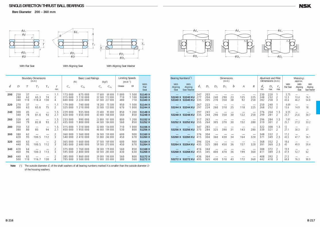
SINGLE-DIRECTION THRUST BALL BEARINGSBore Diameter 200 – 360 mm
— — 247 203 — — — — — 230 220 1 3.75 — — 53240 X 53240 XU 277 204 240 290 23 125 225 248 232 2 12.3 13.4 16.1 53340 X 53340 XU 335 205 270 350 38 92 250 282 258 3 43.6 46.2 54.8
— — 267 223 — — — — — 250 240 1 4.09 — — 53244 X 53244 XU 297 224 260 310 25 118 225 268 252 2 13.6 14.9 18
— — 297 243 — — — — — 276 264 1.5 6.55 — — 53248 X 53248 XU 335 244 290 350 30 122 250 299 281 2 23.7 25.6 30.7
— — 317 263 — — — — — 296 284 1.5 7.01 — — 53252 X 53252 XU 355 264 305 370 30 152 280 319 301 2 25.1 27.3 33.2
— — 347 283 — — — — — 322 308 1.5 12 — — 53256 X 53256 XU 375 284 325 390 31 143 280 339 321 2 27.1 30.3 37
— — 376 304 — — — — — 348 332 2 17.2 — — 53260 X 53260 XU 415 304 360 430 34 164 320 371 349 2.5 43.5 47.7 56.1
— — 396 324 — — — — — 368 352 2 18.6 — — 53264 X 53264 XU 435 325 380 450 36 157 320 391 369 2.5 45 49.9 59.4
— — 416 344 — — — — — 388 372 2 19.9 — — 53268 X 53268 XU 455 345 400 470 36 199 360 411 389 2.5 47.9 52.7 62
— — 436 364 — — — — — 408 392 2 21.5 — — 53272 X 53272 XU 495 365 430 510 43 172 360 442 418 3 68.8 76.3 90.9
Bearing Numbers(1)
With With Aligning Aligning Seat Seat Washer
WithFlatSeat
Dimensions(mm)
d1 D1 D2 D3 b A R
Abutment and Fillet Dimensions (mm)
da Da ra min. max. max.
Mass(kg)approx.
With With With Flat Seat Aligning Aligning Seat Seat Washer
200 250 37 — — 1.1 173 000 675 000 17 600 69 000 1 000 1 500 51140 X 280 62 65.3 74 2 315 000 1 110 000 32 500 113 000 710 1 100 51240 X 340 110 118.4 130 4 600 000 2 220 000 61 500 227 000 480 710 51340 X
220 270 37 — — 1.1 179 000 740 000 18 200 75 500 950 1 500 51144 X 300 63 65.6 75 2 325 000 1 210 000 33 500 123 000 670 1 000 51244 X
240 300 45 — — 1.5 229 000 935 000 23 400 95 000 850 1 200 51148 X 340 78 81.6 92 2.1 420 000 1 650 000 43 000 168 000 560 850 51248 X
260 320 45 — — 1.5 233 000 990 000 23 800 101 000 800 1 200 51152 X 360 79 82.8 93 2.1 435 000 1 800 000 44 500 184 000 560 850 51252 X
280 350 53 — — 1.5 315 000 1 310 000 32 000 134 000 710 1 000 51156 X 380 80 85 94 2.1 450 000 1 950 000 46 000 199 000 530 800 51256 X
300 380 62 — — 2 360 000 1 560 000 36 500 159 000 600 900 51160 X 420 95 100.5 112 3 540 000 2 410 000 55 000 246 000 450 670 51260 X
320 400 63 — — 2 365 000 1 660 000 37 500 169 000 600 900 51164 X 440 95 100.5 112 3 585 000 2 680 000 59 500 273 000 450 670 51264 X
340 420 64 — — 2 375 000 1 760 000 38 500 179 000 560 850 51168 X 460 96 100.3 113 3 595 000 2 800 000 60 500 285 000 430 630 51268 X
360 440 65 — — 2 385 000 1 860 000 39 000 190 000 560 800 51172 X 500 110 116.7 130 4 705 000 3 500 000 72 000 355 000 380 560 51272 X
Boundary Dimensions(mm)
d D T T3 T4 r min.
Limiting Speeds (min–1)
Grease Oil
Basic Load Ratings (N) {kgf}
Ca C0a Ca C0a
jdjd
jDjD
T
r
r1
1 jd
jDjD
T
AR
1
3
1
jDjD
T
2
3
4
br
With Flat Seat With Aligning Seat With Aligning Seat Washer
Note (1) The outside diameter d1 of the shaft washers of all bearing numbers marked X is smaller than the outside diameter D of the housing washers.
jd
jD
r
a
a
ra
a jd
jD
r
a
a
ra
a jd
jD
r
a
a
a
B 216 B 217
B206-233E.indd 216-217B206-233E.indd 216-217 11/20/13 4:58:23 PM11/20/13 4:58:23 PM
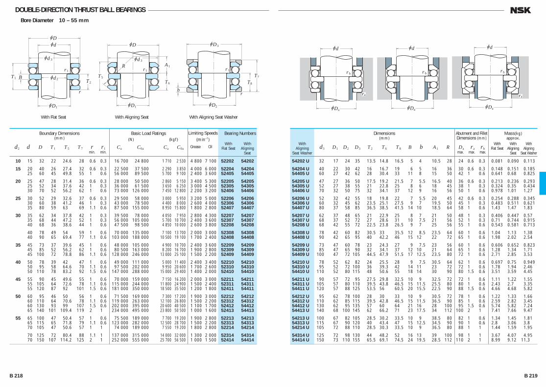
DOUBLE-DIRECTION THRUST BALL BEARINGSBore Diameter 10 – 55 mm
jd
jd
jd
jD
B
r
2
jD1
3 jd
jD
T
AR
6
T5T2
1
3
jD
T
3
8
T7
br
r1r1 r1
jD1 jD2
T1
jd
jDa
r b
ra
jd
jDa
r b
jd
jDa
r b
ra
54202 U 32 17 24 35 13.5 14.8 16.5 5 4 10.5 28 24 0.6 0.3 0.081 0.090 0.113
54204 U 40 22 30 42 16 16.7 19 6 5 16 36 30 0.6 0.3 0.148 0.151 0.185 54405 U 60 27 42 62 28 30.4 33 11 8 15 50 42 1 0.6 0.641 0.68 0.825
54205 U 47 27 36 50 17.5 19.2 21.5 7 5.5 16.5 40 36 0.6 0.3 0.213 0.236 0.293 54305 U 52 27 38 55 21 22.8 25 8 6 18 45 38 1 0.3 0.324 0.35 0.434 54406 U 70 32 50 75 32 34.1 37 12 9 16 56 50 1 0.6 0.978 1.01 1.27
54206 U 52 32 42 55 18 19.8 22 7 5.5 20 45 42 0.6 0.3 0.254 0.288 0.345 54306 U 60 32 45 62 23.5 25.1 27.5 9 7 19.5 50 45 1 0.3 0.483 0.511 0.621 54407 U 80 37 58 85 36.5 38.5 41.5 14 10 18.5 64 58 1 0.6 1.43 1.47 1.83
54207 U 62 37 48 65 21 22.9 25 8 7 21 50 48 1 0.3 0.406 0.447 0.57 54307 U 68 37 52 72 27 28.6 31 10 7.5 21 56 52 1 0.3 0.71 0.744 0.915 54208 U 68 42 55 72 22.5 23.8 26.5 9 7 25 56 55 1 0.6 0.543 0.581 0.713
54308 U 78 42 60 82 30.5 33 35.5 12 8.5 23.5 64 60 1 0.6 1.04 1.13 1.38 54408 U 90 42 65 95 40 42.2 46 15 12 22 72 65 1 0.6 1.98 2.02 2.54
54209 U 73 47 60 78 23 24.3 27 9 7.5 23 56 60 1 0.6 0.606 0.652 0.823 54309 U 85 47 65 90 32 34.1 37 12 10 21 64 65 1 0.6 1.28 1.34 1.71 54409 U 100 47 72 105 44.5 47.9 51.5 17 12.5 23.5 80 72 1 0.6 2.71 2.85 3.53
54210 U 78 52 62 82 24 25.5 28 9 7.5 30.5 64 62 1 0.6 0.697 0.75 0.949 54310 U 95 52 72 100 36 39.3 42 14 11 23 72 72 1 0.6 1.78 1.94 2.46 54410 U 110 52 80 115 48 50.6 55 18 14 30 90 80 1.5 0.6 3.51 3.59 4.45
54211 U 90 57 72 95 27.5 29.8 32.5 10 9 32.5 72 72 1 0.6 1.11 1.22 1.55 54311 U 105 57 80 110 39.5 43.8 46.5 15 11.5 25.5 80 80 1 0.6 2.43 2.7 3.35 54411 U 120 57 88 125 53.5 56 60.5 20 15.5 22.5 90 88 1.5 0.6 4.66 4.68 5.82
54212 U 95 62 78 100 28 30 33 10 9 30.5 72 78 1 0.6 1.22 1.33 1.66 54312 U 110 62 85 115 39.5 42.8 46.5 15 11.5 36.5 90 85 1 0.6 2.59 2.82 3.45 54412 U 130 62 95 135 57 60 64 21 16 28 100 95 1.5 0.6 5.74 5.82 7.24 54413 U 140 68 100 145 62 66.2 71 23 17.5 34 112 100 2 1 7.41 7.66 9.47
54213 U 100 67 82 105 28.5 30.2 33.5 10 9 38.5 80 82 1 0.6 1.34 1.45 1.81 54313 U 115 67 90 120 40 43.4 47 15 12.5 34.5 90 90 1 0.6 2.8 3.06 3.8 54214 U 105 72 88 110 28.5 30.3 33.5 10 9 36.5 80 88 1 1 1.44 1.59 1.95
54314 U 125 72 98 130 44 48.2 52 16 13 39 100 98 1 1 3.67 4.07 4.95 54414 U 150 73 110 155 65.5 69.1 74.5 24 19.5 28.5 112 110 2 1 8.99 9.12 11.3
WithAligning
Seat Washer
Bearing Numbers
With With Flat Seat Aligning Seat
Dimensions(mm)
d3 D1 D2 D3 T2 T6 T8 B b A1 R
Abutment and Fillet Dimensions (mm)
Da ra rb max. max. max.
Mass(kg)approx.
With With With Flat Seat Aligning Aligning Seat Seat Washer
10 15 32 22 24.6 28 0.6 0.3 16 700 24 800 1 710 2 530 4 800 7 100 52202 54202
15 20 40 26 27.4 32 0.6 0.3 22 500 37 500 2 290 3 850 4 000 6 000 52204 54204 25 60 45 49.8 55 1 0.6 56 000 89 500 5 700 9 100 2 400 3 600 52405 54405
20 25 47 28 31.4 36 0.6 0.3 28 000 50 500 2 860 5 150 3 400 5 300 52205 54205 25 52 34 37.6 42 1 0.3 36 000 61 500 3 650 6 250 3 000 4 500 52305 54305 30 70 52 56.2 62 1 0.6 73 000 126 000 7 450 12 800 2 200 3 200 52406 54406
25 30 52 29 32.6 37 0.6 0.3 29 500 58 000 3 000 5 950 3 200 5 000 52206 54206 30 60 38 41.2 46 1 0.3 43 000 78 500 4 400 8 000 2 600 4 000 52306 54306 35 80 59 63 69 1.1 0.6 87 500 155 000 8 950 15 800 1 800 2 800 52407 54407
30 35 62 34 37.8 42 1 0.3 39 500 78 000 4 050 7 950 2 800 4 300 52207 54207 35 68 44 47.2 52 1 0.3 56 000 105 000 5 700 10 700 2 400 3 600 52307 54307 40 68 36 38.6 44 1 0.6 47 500 98 500 4 850 10 000 2 600 3 800 52208 54208
40 78 49 54 59 1 0.6 70 000 135 000 7 100 13 700 2 000 3 000 52308 54308 40 90 65 69.4 77 1.1 0.6 103 000 188 000 10 500 19 100 1 700 2 400 52408 54408
35 45 73 37 39.6 45 1 0.6 48 000 105 000 4 900 10 700 2 400 3 600 52209 54209 45 85 52 56.2 62 1 0.6 80 500 163 000 8 200 16 700 1 900 2 800 52309 54309 45 100 72 78.8 86 1.1 0.6 128 000 246 000 13 000 25 100 1 500 2 200 52409 54409
40 50 78 39 42 47 1 0.6 49 000 111 000 5 000 11 400 2 400 3 400 52210 54210 50 95 58 64.6 70 1.1 0.6 97 500 202 000 9 950 20 600 1 700 2 600 52310 54310 50 110 78 83.2 92 1.5 0.6 147 000 288 000 15 000 29 400 1 400 2 000 52410 54410
45 55 90 45 49.6 55 1 0.6 70 000 159 000 7 150 16 200 2 000 3 000 52211 54211 55 105 64 72.6 78 1.1 0.6 115 000 244 000 11 800 24 900 1 500 2 400 52311 54311 55 120 87 92 101 1.5 0.6 181 000 350 000 18 500 35 500 1 200 1 800 52411 54411
50 60 95 46 50 56 1 0.6 71 500 169 000 7 300 17 200 1 900 3 000 52212 54212 60 110 64 70.6 78 1.1 0.6 119 000 263 000 12 100 26 800 1 500 2 200 52312 54312 60 130 93 99 107 1.5 0.6 202 000 395 000 20 600 40 500 1 100 1 700 52412 54412 65 140 101 109.4 119 2 1 234 000 495 000 23 800 50 500 1 000 1 600 52413 54413
55 65 100 47 50.4 57 1 0.6 75 500 189 000 7 700 19 200 1 900 2 800 52213 54213 65 115 65 71.8 79 1.1 0.6 123 000 282 000 12 500 28 700 1 500 2 200 52313 54313 70 105 47 50.6 57 1 1 74 000 189 000 7 550 19 200 1 800 2 800 52214 54214
70 125 72 80.4 88 1.1 1 137 000 315 000 14 000 32 000 1 300 2 000 52314 54314 70 150 107 114.2 125 2 1 252 000 555 000 25 700 56 500 1 000 1 500 52414 54414
Boundary Dimensions(mm)
d2 d D T1 T5 T7 r r1 min. min.
Limiting Speeds (min–1)
Grease Oil
Basic Load Ratings (N) {kgf}
Ca C0a Ca C0a
With Flat Seat With Aligning Seat With Aligning Seat Washer
B 218 B 219
B206-233E.indd 218-219B206-233E.indd 218-219 11/20/13 4:58:24 PM11/20/13 4:58:24 PM
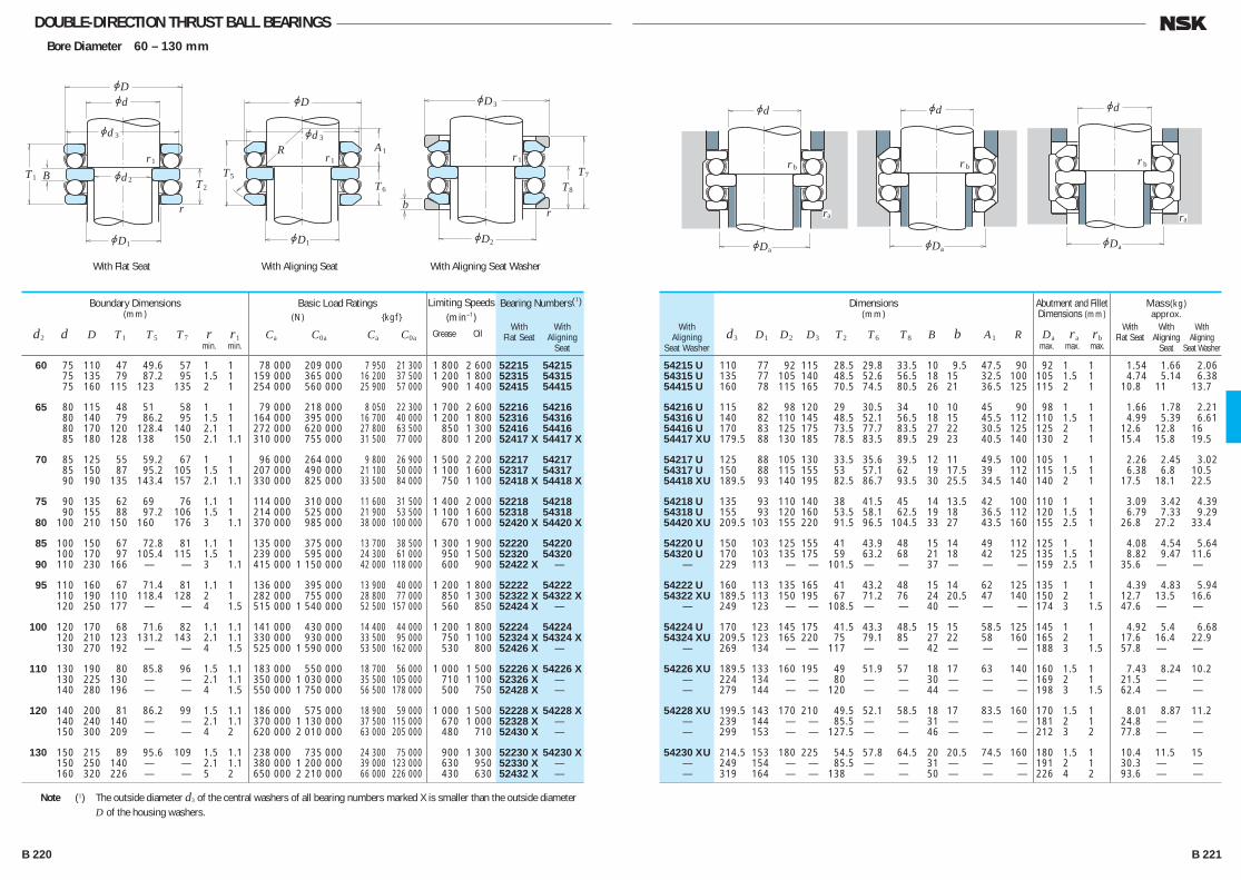
DOUBLE-DIRECTION THRUST BALL BEARINGSBore Diameter 60 – 130 mm
jd
jd
jd
jD
B
r
2
jD1
3 jd
jD
T
AR
6
T5T2
1
3
jD
T
3
8
T7
br
r1r1 r1
jD1 jD2
T1
jd
jDa
r b
ra
jd
jDa
r b
jd
jDa
r b
ra
54215 U 110 77 92 115 28.5 29.8 33.5 10 9.5 47.5 90 92 1 1 1.54 1.66 2.06 54315 U 135 77 105 140 48.5 52.6 56.5 18 15 32.5 100 105 1.5 1 4.74 5.14 6.38 54415 U 160 78 115 165 70.5 74.5 80.5 26 21 36.5 125 115 2 1 10.8 11 13.7
54216 U 115 82 98 120 29 30.5 34 10 10 45 90 98 1 1 1.66 1.78 2.21 54316 U 140 82 110 145 48.5 52.1 56.5 18 15 45.5 112 110 1.5 1 4.99 5.39 6.61 54416 U 170 83 125 175 73.5 77.7 83.5 27 22 30.5 125 125 2 1 12.6 12.8 16 54417 XU 179.5 88 130 185 78.5 83.5 89.5 29 23 40.5 140 130 2 1 15.4 15.8 19.5
54217 U 125 88 105 130 33.5 35.6 39.5 12 11 49.5 100 105 1 1 2.26 2.45 3.02 54317 U 150 88 115 155 53 57.1 62 19 17.5 39 112 115 1.5 1 6.38 6.8 10.5 54418 XU 189.5 93 140 195 82.5 86.7 93.5 30 25.5 34.5 140 140 2 1 17.5 18.1 22.5
54218 U 135 93 110 140 38 41.5 45 14 13.5 42 100 110 1 1 3.09 3.42 4.39 54318 U 155 93 120 160 53.5 58.1 62.5 19 18 36.5 112 120 1.5 1 6.79 7.33 9.29 54420 XU 209.5 103 155 220 91.5 96.5 104.5 33 27 43.5 160 155 2.5 1 26.8 27.2 33.4
54220 U 150 103 125 155 41 43.9 48 15 14 49 112 125 1 1 4.08 4.54 5.64 54320 U 170 103 135 175 59 63.2 68 21 18 42 125 135 1.5 1 8.82 9.47 11.6 — 229 113 — — 101.5 — — 37 — — — 159 2.5 1 35.6 — —
54222 U 160 113 135 165 41 43.2 48 15 14 62 125 135 1 1 4.39 4.83 5.94 54322 XU 189.5 113 150 195 67 71.2 76 24 20.5 47 140 150 2 1 12.7 13.5 16.6 — 249 123 — — 108.5 — — 40 — — — 174 3 1.5 47.6 — —
54224 U 170 123 145 175 41.5 43.3 48.5 15 15 58.5 125 145 1 1 4.92 5.4 6.68 54324 XU 209.5 123 165 220 75 79.1 85 27 22 58 160 165 2 1 17.6 16.4 22.9 — 269 134 — — 117 — — 42 — — — 188 3 1.5 57.8 — —
54226 XU 189.5 133 160 195 49 51.9 57 18 17 63 140 160 1.5 1 7.43 8.24 10.2 — 224 134 — — 80 — — 30 — — — 169 2 1 21.5 — — — 279 144 — — 120 — — 44 — — — 198 3 1.5 62.4 — —
54228 XU 199.5 143 170 210 49.5 52.1 58.5 18 17 83.5 160 170 1.5 1 8.01 8.87 11.2 — 239 144 — — 85.5 — — 31 — — — 181 2 1 24.8 — — — 299 153 — — 127.5 — — 46 — — — 212 3 2 77.8 — —
54230 XU 214.5 153 180 225 54.5 57.8 64.5 20 20.5 74.5 160 180 1.5 1 10.4 11.5 15 — 249 154 — — 85.5 — — 31 — — — 191 2 1 30.3 — — — 319 164 — — 138 — — 50 — — — 226 4 2 93.6 — —
WithAligning
Seat Washer
Bearing Numbers(1)
With With Flat Seat Aligning Seat
Dimensions(mm)
d3 D1 D2 D3 T2 T6 T8 B b A1 R
Abutment and Fillet Dimensions (mm)
Da ra rb max. max. max.
Mass(kg)approx.
With With With Flat Seat Aligning Aligning Seat Seat Washer
60 75 110 47 49.6 57 1 1 78 000 209 000 7 950 21 300 1 800 2 600 52215 54215 75 135 79 87.2 95 1.5 1 159 000 365 000 16 200 37 500 1 200 1 800 52315 54315 75 160 115 123 135 2 1 254 000 560 000 25 900 57 000 900 1 400 52415 54415
65 80 115 48 51 58 1 1 79 000 218 000 8 050 22 300 1 700 2 600 52216 54216 80 140 79 86.2 95 1.5 1 164 000 395 000 16 700 40 000 1 200 1 800 52316 54316 80 170 120 128.4 140 2.1 1 272 000 620 000 27 800 63 500 850 1 300 52416 54416 85 180 128 138 150 2.1 1.1 310 000 755 000 31 500 77 000 800 1 200 52417 X 54417 X
70 85 125 55 59.2 67 1 1 96 000 264 000 9 800 26 900 1 500 2 200 52217 54217 85 150 87 95.2 105 1.5 1 207 000 490 000 21 100 50 000 1 100 1 600 52317 54317 90 190 135 143.4 157 2.1 1.1 330 000 825 000 33 500 84 000 750 1 100 52418 X 54418 X
75 90 135 62 69 76 1.1 1 114 000 310 000 11 600 31 500 1 400 2 000 52218 54218 90 155 88 97.2 106 1.5 1 214 000 525 000 21 900 53 500 1 100 1 600 52318 54318 80 100 210 150 160 176 3 1.1 370 000 985 000 38 000 100 000 670 1 000 52420 X 54420 X
85 100 150 67 72.8 81 1.1 1 135 000 375 000 13 700 38 500 1 300 1 900 52220 54220 100 170 97 105.4 115 1.5 1 239 000 595 000 24 300 61 000 950 1 500 52320 54320 90 110 230 166 — — 3 1.1 415 000 1 150 000 42 000 118 000 600 900 52422 X —
95 110 160 67 71.4 81 1.1 1 136 000 395 000 13 900 40 000 1 200 1 800 52222 54222 110 190 110 118.4 128 2 1 282 000 755 000 28 800 77 000 850 1 300 52322 X 54322 X 120 250 177 — — 4 1.5 515 000 1 540 000 52 500 157 000 560 850 52424 X —
100 120 170 68 71.6 82 1.1 1.1 141 000 430 000 14 400 44 000 1 200 1 800 52224 54224 120 210 123 131.2 143 2.1 1.1 330 000 930 000 33 500 95 000 750 1 100 52324 X 54324 X 130 270 192 — — 4 1.5 525 000 1 590 000 53 500 162 000 530 800 52426 X —
110 130 190 80 85.8 96 1.5 1.1 183 000 550 000 18 700 56 000 1 000 1 500 52226 X 54226 X 130 225 130 — — 2.1 1.1 350 000 1 030 000 35 500 105 000 710 1 100 52326 X — 140 280 196 — — 4 1.5 550 000 1 750 000 56 500 178 000 500 750 52428 X —
120 140 200 81 86.2 99 1.5 1.1 186 000 575 000 18 900 59 000 1 000 1 500 52228 X 54228 X 140 240 140 — — 2.1 1.1 370 000 1 130 000 37 500 115 000 670 1 000 52328 X — 150 300 209 — — 4 2 620 000 2 010 000 63 000 205 000 480 710 52430 X —
130 150 215 89 95.6 109 1.5 1.1 238 000 735 000 24 300 75 000 900 1 300 52230 X 54230 X 150 250 140 — — 2.1 1.1 380 000 1 200 000 39 000 123 000 630 950 52330 X — 160 320 226 — — 5 2 650 000 2 210 000 66 000 226 000 430 630 52432 X —
Boundary Dimensions(mm)
d2 d D T1 T5 T7 r r1 min. min.
Limiting Speeds (min–1)
Grease Oil
Basic Load Ratings (N) {kgf}
Ca C0a Ca C0a
With Flat Seat With Aligning Seat With Aligning Seat Washer
Note (1) The outside diameter d3 of the central washers of all bearing numbers marked X is smaller than the outside diameter D of the housing washers.
B 220 B 221
B206-233E.indd 220-221B206-233E.indd 220-221 11/20/13 4:58:25 PM11/20/13 4:58:25 PM
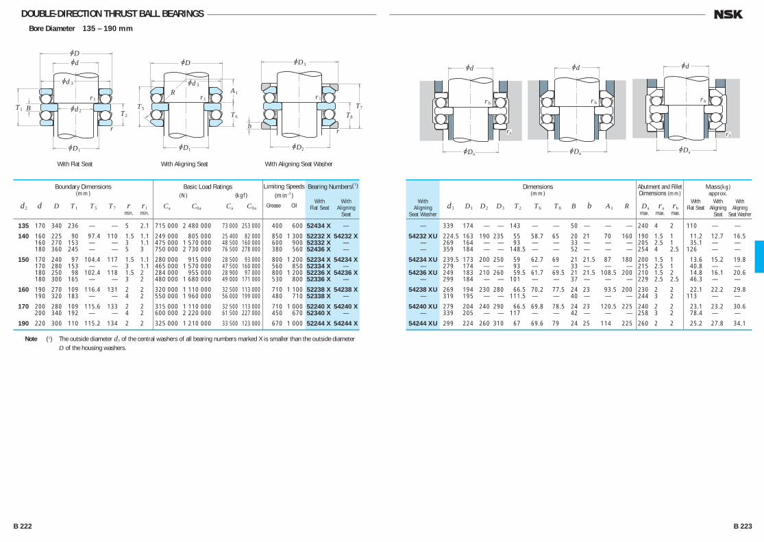
DOUBLE-DIRECTION THRUST BALL BEARINGSBore Diameter 135 – 190 mm
jd
jd
jd
jD
B
r
2
jD1
3 jd
jD
T
AR
6
T5T2
1
3
jD
T
3
8
T7
br
r1r1 r1
jD1 jD2
T1
jd
jDa
r b
ra
jd
jDa
r b
jd
jDa
r b
ra
— 339 174 — — 143 — — 50 — — — 240 4 2 110 — —
54232 XU 224.5 163 190 235 55 58.7 65 20 21 70 160 190 1.5 1 11.2 12.7 16.5 — 269 164 — — 93 — — 33 — — — 205 2.5 1 35.1 — — — 359 184 — — 148.5 — — 52 — — — 254 4 2.5 126 — —
54234 XU 239.5 173 200 250 59 62.7 69 21 21.5 87 180 200 1.5 1 13.6 15.2 19.8 — 279 174 — — 93 — — 33 — — — 215 2.5 1 40.8 — — 54236 XU 249 183 210 260 59.5 61.7 69.5 21 21.5 108.5 200 210 1.5 2 14.8 16.1 20.6 — 299 184 — — 101 — — 37 — — — 229 2.5 2.5 46.3 — —
54238 XU 269 194 230 280 66.5 70.2 77.5 24 23 93.5 200 230 2 2 22.1 22.2 29.8 — 319 195 — — 111.5 — — 40 — — — 244 3 2 113 — —
54240 XU 279 204 240 290 66.5 69.8 78.5 24 23 120.5 225 240 2 2 23.1 23.2 30.6 — 339 205 — — 117 — — 42 — — — 258 3 2 78.4 — —
54244 XU 299 224 260 310 67 69.6 79 24 25 114 225 260 2 2 25.2 27.8 34.1
WithAligning
Seat Washer
Bearing Numbers(1)
With With Flat Seat Aligning Seat
Dimensions(mm)
d3 D1 D2 D3 T2 T6 T8 B b A1 R
Abutment and Fillet Dimensions (mm)
Da ra rb max. max. max.
Mass(kg)approx.
With With With Flat Seat Aligning Aligning Seat Seat Washer
135 170 340 236 — — 5 2.1 715 000 2 480 000 73 000 253 000 400 600 52434 X —
140 160 225 90 97.4 110 1.5 1.1 249 000 805 000 25 400 82 000 850 1 300 52232 X 54232 X 160 270 153 — — 3 1.1 475 000 1 570 000 48 500 160 000 600 900 52332 X — 180 360 245 — — 5 3 750 000 2 730 000 76 500 278 000 380 560 52436 X —
150 170 240 97 104.4 117 1.5 1.1 280 000 915 000 28 500 93 000 800 1 200 52234 X 54234 X 170 280 153 — — 3 1.1 465 000 1 570 000 47 500 160 000 560 850 52334 X — 180 250 98 102.4 118 1.5 2 284 000 955 000 28 900 97 000 800 1 200 52236 X 54236 X 180 300 165 — — 3 2 480 000 1 680 000 49 000 171 000 530 800 52336 X —
160 190 270 109 116.4 131 2 2 320 000 1 110 000 32 500 113 000 710 1 100 52238 X 54238 X 190 320 183 — — 4 2 550 000 1 960 000 56 000 199 000 480 710 52338 X —
170 200 280 109 115.6 133 2 2 315 000 1 110 000 32 500 113 000 710 1 000 52240 X 54240 X 200 340 192 — — 4 2 600 000 2 220 000 61 500 227 000 450 670 52340 X —
190 220 300 110 115.2 134 2 2 325 000 1 210 000 33 500 123 000 670 1 000 52244 X 54244 X
Boundary Dimensions(mm)
d2 d D T1 T5 T7 r r1 min. min.
Limiting Speeds (min–1)
Grease Oil
Basic Load Ratings (N) {kgf}
Ca C0a Ca C0a
With Flat Seat With Aligning Seat With Aligning Seat Washer
Note (1) The outside diameter d3 of the central washers of all bearing numbers marked X is smaller than the outside diameter D of the housing washers.
B 222 B 223
B206-233E.indd 222-223B206-233E.indd 222-223 11/20/13 4:58:26 PM11/20/13 4:58:26 PM

THRUST CYLINDRICAL ROLLER BEARINGSBore Diameter 35 – 130 mm
jdjd
jDjD
T
r
r
t
t1
1
Dw
jd
jD
r
a
a
a
ra
35 TMP 14 80 37 12 10 71 46 1 0.97 40 TMP 93 78 42 8 7 71 48 1 0.525
45 TMP 11 65 47 6 4 60 49 0.6 0.144 45 TMP 93 85 47 8 8 78 53 1 0.665
50 TMP 74 109 52 11 8 100 61 1 1.52 50 TMP 93 93 52 11 8 89 57 1 0.94
55 TMP 93 105 55.2 11 9.5 98 63 1 1.28
60 TMP 12 95 62 10 8 88 67 1 0.735 60 TMP 93 110 62 11 9.5 103 68 1 1.36
65 TMP 12 100 67 12.5 7.25 93 71 1 0.805 65 TMP 93 115 65.2 11 9.5 108 73 1 1.44
70 TMP 74 149 72 15 10.5 137 84 2 3.8 70 TMP 93 125 72 14 10 117 78 1 1.95
75 TMP 11 100 77 8 5.5 96 79 1 0.41 75 TMP 93 135 77 14 11 125 84 1.5 2.42
80 TMP 12 115 82 11 8.5 109 86 1 1.02 80 TMP 93 138 82 14 11 130 91 1.5 2.54
85 TMP 11 110 87 7.5 5.75 105 89 1 0.46 85 TMP 12 125 88 14 8.5 118 92 1 1.36 85 TMP 93 148 87 14 12.5 140 95 1.5 3.2
90 TMP 11 119 91.5 9 6.5 114 95 1 0.725 90 TMP 93 155 90.2 16 11.5 144 101 1.5 3.3
100 TMP 93 170 103 16 13 159 110 1.5 4.25
110 TMP 12 160 113 15 11.5 150 119 1 2.66 110 TMP 93 190 113 19 14.5 179 120 2 6.15
120 TMP 12 170 123 15 12 160 129 1 2.93 120 TMP 93 210 123 22 16 199 129 2 8.55
130 TMP 12 187 133 19 13 177 142 1.5 4.5 130 TMP 93 225 133 22 18 214 140 2 10.4 130 TMP 94 270 133 32 26.5 254 150 3 26.2
Bearing NumbersDimensions
(mm)
d1 D1 Dw t
Abutment and Fillet Dimensions (mm)
da Da ra min. max. max.
Mass(kg)
approx.
35 80 32 1.1 95 500 247 000 1 000 3 000 40 78 22 1 63 000 194 000 1 200 3 600
45 65 14 0.6 33 000 100 000 1 700 5 000 85 24 1 71 000 233 000 1 100 3 400
50 110 27 1.1 139 000 470 000 900 2 800 95 27 1.1 113 000 350 000 1 000 3 000
55 105 30 1.1 134 000 450 000 900 2 600
60 95 26 1 99 000 325 000 1 000 3 000 110 30 1.1 139 000 480 000 850 2 600
65 100 27 1 110 000 325 000 950 2 800 115 30 1.1 145 000 515 000 850 2 600
70 150 36 2 259 000 935 000 670 2 000 125 34 1.1 191 000 635 000 750 2 200
75 100 19 1 63 500 221 000 1 100 3 400 135 36 1.5 209 000 735 000 710 2 200
80 115 28 1 120 000 420 000 900 2 600 140 36 1.5 208 000 740 000 710 2 000
85 110 19 1 75 000 298 000 1 100 3 200 125 31 1 151 000 485 000 800 2 400 150 39 1.5 257 000 995 000 630 1 900
90 120 22 1 96 000 370 000 950 3 000 155 39 1.5 250 000 885 000 630 1 900
100 170 42 1.5 292 000 1 110 000 560 1 700
110 160 38 1.1 228 000 855 000 630 1 900 190 48 2 390 000 1 490 000 500 1 500
120 170 39 1.1 233 000 895 000 600 1 800 210 54 2.1 505 000 1 930 000 450 1 400
130 190 45 1.5 300 000 1 090 000 530 1 600 225 58 2.1 585 000 2 370 000 430 1 300 270 85 4 895 000 3 300 000 320 950
Boundary Dimensions(mm)
d D T r min.
Limiting Speeds (min–1)
Grease Oil
Basic Load Ratings(N)
Ca C0a
Remarks For cylindrical roller thrust bearings not listed adove, please contact NSK.
B 224 B 225
B206-233E.indd 224-225B206-233E.indd 224-225 11/20/13 4:58:27 PM11/20/13 4:58:27 PM
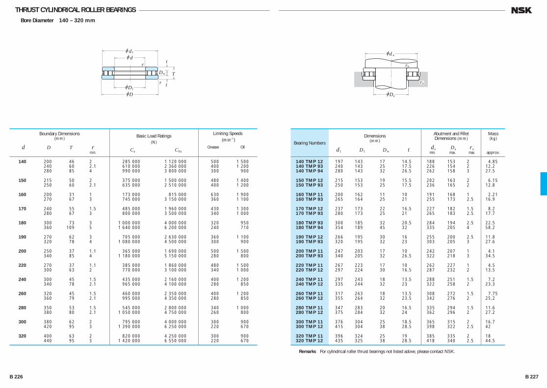
THRUST CYLINDRICAL ROLLER BEARINGSBore Diameter 140 – 320 mm
jdjd
jDjD
T
r
r
t
t1
1
Dw
jd
jD
r
a
a
a
ra
140 TMP 12 197 143 17 14.5 188 153 2 4.85 140 TMP 93 240 143 25 17.5 226 154 2 12.2 140 TMP 94 280 143 32 26.5 262 158 3 27.5
150 TMP 12 215 153 19 15.5 202 163 2 6.15 150 TMP 93 250 153 25 17.5 236 165 2 12.8
160 TMP 11 200 162 11 10 191 168 1 2.21 160 TMP 93 265 164 25 21 255 173 2.5 16.9
170 TMP 12 237 173 22 16.5 227 182 1.5 8.2 170 TMP 93 280 173 25 21 265 183 2.5 17.7
180 TMP 93 300 185 32 20.5 284 194 2.5 22.5 180 TMP 94 354 189 45 32 335 205 4 58.2
190 TMP 12 266 195 30 16 255 200 2.5 11.8 190 TMP 93 320 195 32 23 303 205 3 27.6
200 TMP 11 247 203 17 10 242 207 1 4.1 200 TMP 93 340 205 32 26.5 322 218 3 34.5
220 TMP 11 267 223 17 10 262 227 1 4.5 220 TMP 12 297 224 30 16.5 287 232 2 13.5
240 TMP 11 297 243 18 13.5 288 251 1.5 7.2 240 TMP 12 335 244 32 23 322 258 2 23.3
260 TMP 11 317 263 18 13.5 308 272 1.5 7.75 260 TMP 12 355 264 32 23.5 342 276 2 25.2
280 TMP 11 347 283 20 16.5 335 294 1.5 11.6 280 TMP 12 375 284 32 24 362 296 2 27.2
300 TMP 11 376 304 25 18.5 365 315 2 16.7 300 TMP 12 415 304 38 28.5 398 322 2.5 42
320 TMP 11 396 324 25 19 385 335 2 18 320 TMP 12 435 325 38 28.5 418 340 2.5 44.5
Bearing NumbersDimensions
(mm)
d1 D1 Dw t
Abutment and Fillet Dimensions (mm)
da Da ra min. max. max.
Mass(kg)
approx.
140 200 46 2 285 000 1 120 000 500 1 500 240 60 2.1 610 000 2 360 000 400 1 200 280 85 4 990 000 3 800 000 300 900
150 215 50 2 375 000 1 500 000 480 1 400 250 60 2.1 635 000 2 510 000 400 1 200
160 200 31 1 173 000 815 000 630 1 900 270 67 3 745 000 3 150 000 360 1 100
170 240 55 1.5 485 000 1 960 000 430 1 300 280 67 3 800 000 3 500 000 340 1 000
180 300 73 3 1 000 000 4 000 000 320 950 360 109 5 1 640 000 6 200 000 240 710
190 270 62 3 705 000 2 630 000 360 1 100 320 78 4 1 080 000 4 500 000 300 900
200 250 37 1.1 365 000 1 690 000 500 1 500 340 85 4 1 180 000 5 150 000 280 800
220 270 37 1.1 385 000 1 860 000 480 1 500 300 63 2 770 000 3 100 000 340 1 000
240 300 45 1.5 435 000 2 160 000 400 1 200 340 78 2.1 965 000 4 100 000 280 850
260 320 45 1.5 460 000 2 350 000 400 1 200 360 79 2.1 995 000 4 350 000 280 850
280 350 53 1.5 545 000 2 800 000 340 1 000 380 80 2.1 1 050 000 4 750 000 260 800
300 380 62 2 795 000 4 000 000 300 900 420 95 3 1 390 000 6 250 000 220 670
320 400 63 2 820 000 4 250 000 300 900 440 95 3 1 420 000 6 550 000 220 670
Boundary Dimensions(mm)
d D T r min.
Limiting Speeds (min–1)
Grease Oil
Basic Load Ratings(N)
Ca C0a
Remarks For cylindrical roller thrust bearings not listed adove, please contact NSK.
B 226 B 227
B206-233E.indd 226-227B206-233E.indd 226-227 11/20/13 4:58:27 PM11/20/13 4:58:27 PM

114.5 89 27 38 20 38 67 67 90 108 133 1.5 2.55 121.5 93 29.5 40.5 22 42 72 72 100 115 143 2 3.2
131.5 102 31 43 24 44 78 78 105 125 153 2 3.9 138 107 33.5 46 25 47 83 83 115 132 163 2 4.65
148 114.5 35 48.5 27 50 89 89 120 140 173 2 5.55 134.5 112 24.5 35.5 19 50 91 91 115 135 153 1.5 2.7 156.5 124 37 51.5 28 54 95 95 130 150 183 2 6.55
139.5 118 24.5 35 19 52 97 97 120 140 158 1.5 2.83 165.5 129.5 39 54.5 29 56 100 100 135 157 193 2 7.55
152 128 26.2 38 20.8 58 107 107 130 150 173 1.5 3.6 185 144 43 59.5 33 62 111 111 150 175 214 2.5 10.3
169.5 142.5 30.3 43.5 24 64 117 117 145 165 193 2 5.25 200 157 47 64.5 36 69 121 129 165 190 234 2.5 13.3
187.5 156.5 34 48.5 27 70 130 130 160 180 214 2 7.3 215 171 50.5 69.5 38 74 132 142 180 205 254 3 16.6
203.5 168.5 37 53.5 28 76 141 143 170 195 229 2 8.95 235 185 54 74.5 42 81 143 153 195 225 275 3 21.1
216.5 179 38.5 54 30 82 148 154 185 205 244 2 10.4 244.5 195.5 54 74.5 42 86 153 162 205 235 285 3 22.2
224 190 38 54.5 29 87 158 163 195 215 254 2 10.8 266 209 58 81 44 92 164 175 220 250 306 3 27.3
243 203 42 60 33 92 169 176 210 235 275 2.5 14.3 278 224.5 60.5 84.5 46 99 175 189 230 265 326 4 32.1
252 214.5 42.2 60.5 32 96 178 188 220 245 285 2.5 14.8 310 243 37 99 50 104 — — 245 285 — 4 43.5
270 227 46 65.5 36 103 189 195 235 260 306 2.5 19 330 255 39 105 52 110 — — 260 300 — 4 52
288.5 244 49 69 38 110 200 211 250 275 326 3 23 345 271 41 111 55 117 — — 275 320 — 4 60
266 236 15 46 24 108 — — 235 255 — 2 8.55 306.5 257 53.5 75 41 116 211 224 265 295 346 3 28.5 365 280 43 117 59 122 — — 290 335 — 4 69
THRUST SPHERICAL ROLLER BEARINGSBore Diameter 60 – 200 mm
jdjd
T
A
B BC
r
jDjD
r1
1
2
jdjd
T
A
BC
r
jDjD
r1
1
2B1
jd
jd
jD
jD
r
a
a
b
jd a
ra
30S1
S2
BearingNumbers
Dimensions(mm)
d1 D1 B,B1 B2 C A
Abutment and FilletDimensions (mm)
da(1) Da Db ra min. max. min. max.
Spacer Sleeve Dimensions (mm)
dS1 dS2 max. max.
Mass(kg)
approx.
60 130 42 1.5 330 000 885 000 33 500 90 000 2 600 29412 E 65 140 45 2 405 000 1 100 000 41 500 112 000 2 400 29413 E
70 150 48 2 450 000 1 240 000 46 000 126 000 2 400 29414 E 75 160 51 2 515 000 1 430 000 52 500 146 000 2 200 29415 E
80 170 54 2.1 575 000 1 600 000 58 500 163 000 2 000 29416 E 85 150 39 1.5 330 000 1 040 000 34 000 106 000 2 400 29317 E 180 58 2.1 630 000 1 760 000 64 500 179 000 1 900 29417 E
90 155 39 1.5 350 000 1 080 000 35 500 110 000 2 200 29318 E 190 60 2.1 695 000 1 950 000 70 500 199 000 1 800 29418 E
100 170 42 1.5 410 000 1 280 000 41 500 131 000 2 000 29320 E 210 67 3 840 000 2 400 000 86 000 245 000 1 600 29420 E
110 190 48 2 530 000 1 710 000 54 000 174 000 1 800 29322 E 230 73 3 1 010 000 2 930 000 103 000 299 000 1 500 29422 E
120 210 54 2.1 645 000 2 100 000 65 500 214 000 1 600 29324 E 250 78 4 1 160 000 3 400 000 119 000 350 000 1 400 29424 E
130 225 58 2.1 740 000 2 450 000 75 500 250 000 1 500 29326 E 270 85 4 1 330 000 3 900 000 135 000 400 000 1 200 29426 E
140 240 60 2.1 840 000 2 810 000 85 500 287 000 1 400 29328 E 280 85 4 1 370 000 4 200 000 140 000 425 000 1 200 29428 E
150 250 60 2.1 870 000 2 900 000 89 000 296 000 1 400 29330 E 300 90 4 1 580 000 4 900 000 162 000 500 000 1 100 29430 E
160 270 67 3 1 010 000 3 400 000 103 000 345 000 1 300 29332 E 320 95 5 1 740 000 5 400 000 178 000 550 000 1 100 29432 E
170 280 67 3 1 050 000 3 500 000 107 000 355 000 1 200 29334 E 340 103 5 1 680 000 5 800 000 171 000 595 000 1 000 29434
180 300 73 3 1 230 000 4 200 000 125 000 430 000 1 100 29336 E 360 109 5 1 870 000 6 500 000 190 000 660 000 900 29436
190 320 78 4 1 370 000 4 700 000 140 000 480 000 1 100 29338 E 380 115 5 2 100 000 7 450 000 215 000 760 000 850 29438
200 280 48 2 540 000 2 310 000 55 000 236 000 1 500 29240 340 85 4 1 570 000 5 450 000 160 000 555 000 1 000 29340 E 400 122 5 2 290 000 8 150 000 234 000 835 000 800 29440
Boundary Dimensions(mm)
d D T r min.
Limiting Speeds(min–1)
Oil
Basic Load Ratings (N) {kgf}
Ca C0a Ca C0a
Dynamic Equivalent Load
P =1.2Fr +Fa
Static Equivalent Load
P0 =2.8Fr +Fa
However, Fr /Fa≤0.55 must be
satisfied.
Note (1) For heavy load applications, a da value should be chosen which is large enough to support the shaft washer rib.
B 228 B 229
B206-233E.indd 228-229B206-233E.indd 228-229 11/20/13 4:58:28 PM11/20/13 4:58:28 PM
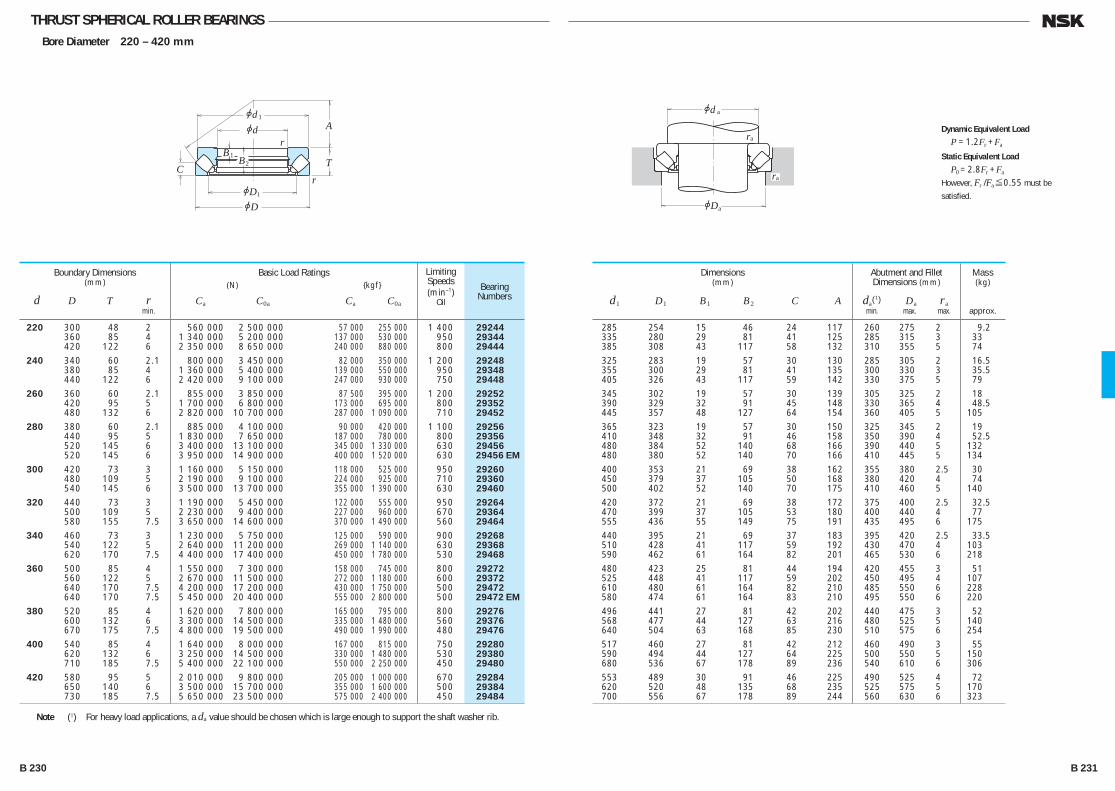
THRUST SPHERICAL ROLLER BEARINGSBore Diameter 220 – 420 mm
jdjd
T
A
BC
r
jDjD
r1
1
2B1
jD
r
a
a
jd a
ra
285 254 15 46 24 117 260 275 2 9.2 335 280 29 81 41 125 285 315 3 33 385 308 43 117 58 132 310 355 5 74 325 283 19 57 30 130 285 305 2 16.5 355 300 29 81 41 135 300 330 3 35.5 405 326 43 117 59 142 330 375 5 79 345 302 19 57 30 139 305 325 2 18 390 329 32 91 45 148 330 365 4 48.5 445 357 48 127 64 154 360 405 5 105 365 323 19 57 30 150 325 345 2 19 410 348 32 91 46 158 350 390 4 52.5 480 384 52 140 68 166 390 440 5 132 480 380 52 140 70 166 410 445 5 134 400 353 21 69 38 162 355 380 2.5 30 450 379 37 105 50 168 380 420 4 74 500 402 52 140 70 175 410 460 5 140 420 372 21 69 38 172 375 400 2.5 32.5 470 399 37 105 53 180 400 440 4 77 555 436 55 149 75 191 435 495 6 175 440 395 21 69 37 183 395 420 2.5 33.5 510 428 41 117 59 192 430 470 4 103 590 462 61 164 82 201 465 530 6 218 480 423 25 81 44 194 420 455 3 51 525 448 41 117 59 202 450 495 4 107 610 480 61 164 82 210 485 550 6 228 580 474 61 164 83 210 495 550 6 220 496 441 27 81 42 202 440 475 3 52 568 477 44 127 63 216 480 525 5 140 640 504 63 168 85 230 510 575 6 254 517 460 27 81 42 212 460 490 3 55 590 494 44 127 64 225 500 550 5 150 680 536 67 178 89 236 540 610 6 306 553 489 30 91 46 225 490 525 4 72 620 520 48 135 68 235 525 575 5 170 700 556 67 178 89 244 560 630 6 323
BearingNumbers
Dimensions(mm)
d1 D1 B1 B2 C A
Abutment and FilletDimensions (mm)
da(1) Da ra min. max. max.
Mass(kg)
approx.
220 300 48 2 560 000 2 500 000 57 000 255 000 1 400 29244 360 85 4 1 340 000 5 200 000 137 000 530 000 950 29344 420 122 6 2 350 000 8 650 000 240 000 880 000 800 29444
240 340 60 2.1 800 000 3 450 000 82 000 350 000 1 200 29248 380 85 4 1 360 000 5 400 000 139 000 550 000 950 29348 440 122 6 2 420 000 9 100 000 247 000 930 000 750 29448
260 360 60 2.1 855 000 3 850 000 87 500 395 000 1 200 29252 420 95 5 1 700 000 6 800 000 173 000 695 000 800 29352 480 132 6 2 820 000 10 700 000 287 000 1 090 000 710 29452
280 380 60 2.1 885 000 4 100 000 90 000 420 000 1 100 29256 440 95 5 1 830 000 7 650 000 187 000 780 000 800 29356 520 145 6 3 400 000 13 100 000 345 000 1 330 000 630 29456 520 145 6 3 950 000 14 900 000 400 000 1 520 000 630 29456 EM
300 420 73 3 1 160 000 5 150 000 118 000 525 000 950 29260 480 109 5 2 190 000 9 100 000 224 000 925 000 710 29360 540 145 6 3 500 000 13 700 000 355 000 1 390 000 630 29460
320 440 73 3 1 190 000 5 450 000 122 000 555 000 950 29264 500 109 5 2 230 000 9 400 000 227 000 960 000 670 29364 580 155 7.5 3 650 000 14 600 000 370 000 1 490 000 560 29464
340 460 73 3 1 230 000 5 750 000 125 000 590 000 900 29268 540 122 5 2 640 000 11 200 000 269 000 1 140 000 630 29368 620 170 7.5 4 400 000 17 400 000 450 000 1 780 000 530 29468
360 500 85 4 1 550 000 7 300 000 158 000 745 000 800 29272 560 122 5 2 670 000 11 500 000 272 000 1 180 000 600 29372 640 170 7.5 4 200 000 17 200 000 430 000 1 750 000 500 29472 640 170 7.5 5 450 000 20 400 000 555 000 2 800 000 500 29472 EM
380 520 85 4 1 620 000 7 800 000 165 000 795 000 800 29276 600 132 6 3 300 000 14 500 000 335 000 1 480 000 560 29376 670 175 7.5 4 800 000 19 500 000 490 000 1 990 000 480 29476
400 540 85 4 1 640 000 8 000 000 167 000 815 000 750 29280 620 132 6 3 250 000 14 500 000 330 000 1 480 000 530 29380 710 185 7.5 5 400 000 22 100 000 550 000 2 250 000 450 29480
420 580 95 5 2 010 000 9 800 000 205 000 1 000 000 670 29284 650 140 6 3 500 000 15 700 000 355 000 1 600 000 500 29384 730 185 7.5 5 650 000 23 500 000 575 000 2 400 000 450 29484
Boundary Dimensions(mm)
d D T r min.
Limiting Speeds(min–1)
Oil
Basic Load Ratings (N) {kgf}
Ca C0a Ca C0a
Dynamic Equivalent Load
P =1.2Fr +Fa
Static Equivalent Load
P0 =2.8Fr +Fa
However, Fr /Fa≤0.55 must be
satisfied.
Note (1) For heavy load applications, a da value should be chosen which is large enough to support the shaft washer rib.
B 230 B 231
B206-233E.indd 230-231B206-233E.indd 230-231 11/20/13 4:58:29 PM11/20/13 4:58:29 PM
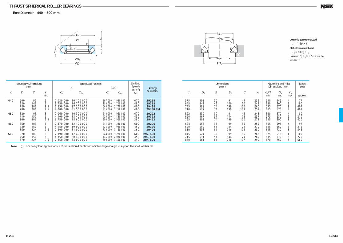
THRUST SPHERICAL ROLLER BEARINGSBore Diameter 440 – 500 mm
jdjd
T
A
BC
r
jDjD
r1
1
2B1
jD
r
a
a
jd a
ra
575 508 30 91 49 235 510 545 4 77 645 548 49 140 70 245 550 600 5 190 745 588 74 199 100 260 595 670 8 407 710 577 74 199 101 257 605 675 8 402 592 530 30 91 46 245 530 570 4 80 666 567 51 144 72 257 575 630 5 210 765 608 74 199 100 272 615 690 8 420 624 556 33 99 55 259 555 595 4 97 690 590 51 144 72 270 595 650 5 215 810 638 81 216 108 280 645 730 8 545 645 574 33 99 55 268 575 615 4 100 715 611 51 144 74 280 615 670 5 220 830 661 81 216 107 290 670 750 8 560
BearingNumbers
Dimensions(mm)
d1 D1 B1 B2 C A
Abutment and FilletDimensions (mm)
da(1) Da ra min. max. max.
Mass(kg)
approx.
440 600 95 5 2 030 000 10 100 000 207 000 1 030 000 670 29288 680 145 6 3 750 000 16 700 000 380 000 1 710 000 480 29388 780 206 9.5 6 550 000 27 200 000 665 000 2 770 000 400 29488 780 206 9.5 8 000 000 31 500 000 815 000 3 250 000 400 29488 EM
460 620 95 5 2 060 000 10 300 000 210 000 1 050 000 670 29292 710 150 6 4 100 000 18 400 000 420 000 1 880 000 450 29392 800 206 9.5 6 750 000 28 600 000 690 000 2 920 000 380 29492
480 650 103 5 2 370 000 12 100 000 241 000 1 240 000 600 29296 730 150 6 4 150 000 19 000 000 425 000 1 940 000 450 29396 850 224 9.5 7 200 000 31 000 000 730 000 3 150 000 360 29496
500 670 103 5 2 390 000 12 400 000 244 000 1 270 000 600 292/500 750 150 6 4 350 000 20 400 000 445 000 2 080 000 450 293/500 870 224 9.5 7 850 000 33 000 000 800 000 3 350 000 340 294/500
Boundary Dimensions(mm)
d D T r min.
Limiting Speeds(min–1)
Oil
Basic Load Ratings (N) {kgf}
Ca C0a Ca C0a
Dynamic Equivalent Load
P =1.2Fr +Fa
Static Equivalent Load
P0 =2.8Fr +Fa
However, Fr /Fa≤0.55 must be
satisfied.
Note (1) For heavy load applications, a da value should be chosen which is large enough to support the shaft washer rib.
B 232 B 233
B206-233E.indd 232-233B206-233E.indd 232-233 11/20/13 4:58:30 PM11/20/13 4:58:30 PM
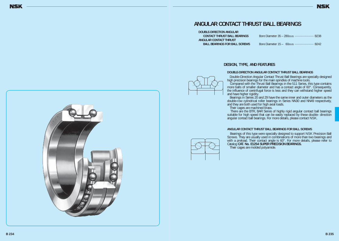
ANGULAR CONTACT THRUST BALL BEARINGSDOUBLE-DIRECTION ANGULAR
CONTACT THRUST BALL BEARINGS Bore Diameter 35 – 280mm ························ B238ANGULAR CONTACT THRUST
BALL BEARINGS FOR BALL SCREWS Bore Diameter 15 – 60mm ························ B242
DESIGN, TYPE, AND FEATURES
DOUBLE-DIRECTION ANGULAR CONTACT THRUST BALL BEARINGS Double-Direction Angular Contact Thrust Ball Bearings are specially designed high precision bearings for the main spindles of machine tools. Compared with the Thrust Ball Bearings in the 511 Series, this type contains more balls of smaller diameter and has a contact angle of 60°. Consequently, the influence of centrifugal force is less and they can withstand higher speed and have higher rigidity. Bearings in Series 20 and 29 have the same inner and outer diameters as the double-row cylindrical roller bearings in Series NN30 and NN49 respectively, and they are both used for high axial loads. Their cages are machined brass. There are the BTR, BAR Series of highly rigid angular contact ball bearings suitable for high speed that can be easily replaced by these double- direction angular contact ball bearings. For more details, please contact NSK.
ANGULAR CONTACT THRUST BALL BEARINGS FOR BALL SCREWS Bearings of this type were specially designed to support NSK Precision Ball Screws. They are usually used in combinations of more than two bearings and with a preload. Their contact angle is 60°. For more details, please refer to Catalog CAT. No. E1254 SUPER PRECISION BEARINGS. Their cages are molded polyamide.
B 234 B 235
B234-243E.indd 234-235B234-243E.indd 234-235 11/20/13 4:58:47 PM11/20/13 4:58:47 PM
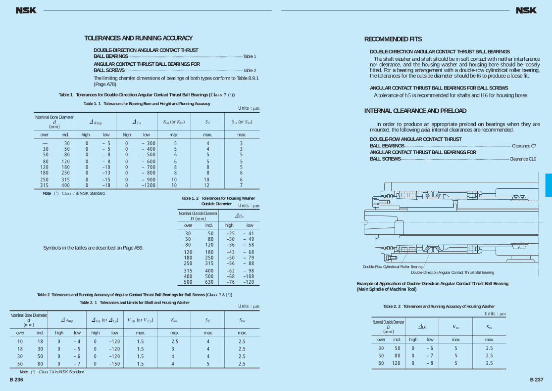
Double-Row Cylindrical Roller BearingDouble-Direction Angular Contact Thrust Ball Bearing
RECOMMENDED FITS
DOUBLE-DIRECTION ANGULAR CONTACT THRUST BALL BEARINGS The shaft washer and shaft should be in soft contact with neither interference nor clearance, and the housing washer and housing bore should be loosely fitted. For a bearing arrangement with a double-row cylindrical roller bearing, the tolerances for the outside diameter should be f6 to produce a loose fit.
ANGULAR CONTACT THRUST BALL BEARINGS FOR BALL SCREWS A tolerance of h5 is recommended for shafts and H6 for housing bores.
INTERNAL CLEARANCE AND PRELOAD
In order to produce an appropriate preload on bearings when they are mounted, the following axial internal clearances are recommended.
DOUBLE-ROW ANGULAR CONTACT THRUST BALL BEARINGS ······································································································ Clearance C7ANGULAR CONTACT THRUST BALL BEARINGS FOR BALL SCREWS ·······································································································Clearance C10
TOLERANCES AND RUNNING ACCURACY
DOUBLE-DIRECTION ANGULAR CONTACT THRUST BALL BEARINGS ·············································································································Table 1
ANGULAR CONTACT THRUST BALL BEARINGS FOR BALL SCREWS ················································································································Table 2
The limiting chamfer dimensions of bearings of both types conform to Table 8.9.1 (Page A78).
Symbols in the tables are described on Page A59.
Table 1. 1 Tolerances for Bearing Bore and Height and Running Accuracy
Table 1 Tolerances for Double-Direction Angular Contact Thrust Ball Bearings (Class 7 (1))
over incl. high low high low max. max. max.
— 30 0 – 5 0 – 300 5 4 3 30 50 0 – 5 0 – 400 5 4 3 50 80 0 – 8 0 – 500 6 5 5 80 120 0 – 8 0 – 600 6 5 5 120 180 0 –10 0 – 700 8 8 5 180 250 0 –13 0 – 800 8 8 6 250 315 0 –15 0 – 900 10 10 6 315 400 0 –18 0 –1200 10 12 7
Nominal Bore Diameterd
(mm)& dmp & Ts Kia (or Kea) Sd Sia (or Sea)
Units : μm
Note (1) Class 7 is NSK Standard.
Table 2. 1 Tolerances and Limits for Shaft and Housing Washer
Table 2 Tolerances and Running Accuracy of Angular Contact Thrust Ball Bearings for Ball Screws (Class 7A (1))
Note (1) Class 7A is NSK Standard.
over incl. high low high low max. max. max. max.
10 18 0 – 4 0 –120 1.5 2.5 4 2.5 18 30 0 – 5 0 –120 1.5 3 4 2.5 30 50 0 – 6 0 –120 1.5 4 4 2.5 50 80 0 – 7 0 –150 1.5 4 5 2.5
Nominal Bore Diameterd
(mm)& dmp & Bs (or &Cs) V Bs (or V Cs) Kia Sd Sia
Units : μm Table 2. 2 Tolerances and Running Accuracy of Housing Washer
Example of Application of Double-Direction Angular Contact Thrust Ball Bearing (Main Spindle of Machine Tool)
Kea Sea
over incl. high low max. max.
30 50 0 – 6 5 2.5 50 80 0 – 7 5 2.5 80 120 0 – 8 5 2.5
Nominal Outside DiameterD
(mm)&Ds
Units : μm
Table 1. 2 Tolerances for Housing Washer Outside Diameter
over incl. high low
30 50 –25 – 41 50 80 –30 – 49 80 120 –36 – 58 120 180 –43 – 68 180 250 –50 – 79 250 315 –56 – 88 315 400 –62 – 98 400 500 –68 –108 500 630 –76 –120
Nominal Outside DiameterD (mm)
&Ds
Units : μm
B 236 B 237
B234-243E.indd 236-237B234-243E.indd 236-237 11/20/13 4:58:48 PM11/20/13 4:58:48 PM

DOUBLE-DIRECTION ANGULAR CONTACT THRUST BALL BEARINGSBore Diameter 35 – 150 mm
r
r
jD jd
C
1
T
jdjDa a
ra
rb
35 TAC 20X+L 46 58 1 0.6 0.375 40 TAC 20X+L 51 63 1 0.6 0.460 45 TAC 20X+L 57 70 1 0.6 0.580
50 TAC 20X+L 62 75 1 0.6 0.625 55 TAC 20X+L 69 84 1 0.6 0.945
60 TAC 20X+L 74 89 1 0.6 1.000 65 TAC 20X+L 79 94 1 0.6 1.080
70 TAC 20X+L 87 104 1 0.6 1.460 75 TAC 20X+L 92 109 1 0.6 1.550
80 TAC 20X+L 99 117 1 0.6 2.110 85 TAC 20X+L 104 122 1 0.6 2.210
90 TAC 20X+L 110 131 1.5 1 2.930 95 TAC 20X+L 115 136 1.5 1 3.050
100 TAC 29X+L 117 134 1 0.6 1.950 100 TAC 20X+L 120 141 1.5 1 3.200
105 TAC 29X+L 122 139 1 0.6 2.040 105 TAC 20X+L 127 150 2 1 4.100
110 TAC 29X+L 127 144 1 0.6 2.120 110 TAC 20X+L 134 158 2 1 5.150
120 TAC 29X+L 139 157 1 0.6 2.940 120 TAC 20X+L 144 168 2 1 5.500
130 TAC 29X+L 150 170 1.5 1 3.950 130 TAC 20X+L 160 187 2 1 8.200
140 TAC 29D+L 158 182 1.5 1 4.200 140 TAC 20D+L 167 198 2 1 8.750
150 TAC 29D+L 172 200 2 1 6.600 150 TAC 20D+L 178 213 2 1 10.700
Bearing Numbers
Abutment and Fillet Dimensions(mm)
da Da ra rb max. max.
Mass(kg)
approx.
35 62 34 17 1 0.6 22 800 53 500 2 330 5 450 10 000 11 000 40 68 36 18 1 0.6 23 600 59 000 2 410 6 050 9 000 10 000 45 75 38 19 1 0.6 26 300 67 500 2 680 6 900 8 000 9 000
50 80 38 19 1 0.6 27 200 74 000 2 780 7 550 7 000 8 000 55 90 44 22 1.1 0.6 33 500 94 000 3 450 9 550 6 300 6 900
60 95 44 22 1.1 0.6 35 000 102 000 3 550 10 400 5 900 6 500 65 100 44 22 1.1 0.6 36 000 110 000 3 700 11 300 5 500 6 100
70 110 48 24 1.1 0.6 49 500 146 000 5 050 14 900 5 000 5 600 75 115 48 24 1.1 0.6 50 000 152 000 5 100 15 500 4 800 5 300
80 125 54 27 1.1 0.6 59 000 181 000 6 000 18 500 4 400 4 900 85 130 54 27 1.1 0.6 59 500 189 000 6 050 19 300 4 200 4 700
90 140 60 30 1.5 1 78 500 246 000 8 000 25 100 4 000 4 400 95 145 60 30 1.5 1 79 500 256 000 8 100 26 100 3 800 4 200
100 140 48 24 1.1 0.6 55 000 196 000 5 600 20 000 3 800 4 200 150 60 30 1.5 1 80 500 267 000 8 200 27 200 3 600 4 000
105 145 48 24 1.1 0.6 56 500 208 000 5 750 21 300 3 600 4 000 160 66 33 2 1 91 500 305 000 9 350 31 000 3 400 3 800
110 150 48 24 1.1 0.6 57 000 215 000 5 800 21 900 3 500 3 900 170 72 36 2 1 103 000 350 000 10 500 35 500 3 300 3 600
120 165 54 27 1.1 0.6 66 500 256 000 6 800 26 100 3 200 3 600 180 72 36 2 1 106 000 375 000 10 800 38 000 3 000 3 400
130 180 60 30 1.5 1 79 500 315 000 8 100 32 500 3 000 3 300 200 84 42 2 1 134 000 455 000 13 600 46 500 2 800 3 100
140 190 60 30 1.5 1 91 500 365 000 9 350 37 500 2 800 3 100 210 84 42 2 1 145 000 525 000 14 800 53 500 2 600 2 900
150 210 72 36 2 1 116 000 465 000 11 800 47 500 2 500 2 800 225 90 45 2.1 1.1 172 000 620 000 17 500 63 500 2 400 2 700
Boundary Dimensions(mm)
d D(1) T C r r1 min. min.
Limiting Speeds (min–1)
Grease Oil
Basic Load Ratings (N) {kgf}
Ca C0a Ca C0a
Remarks Nominal bearing bore and outside diameters for 20X · 20D and 29X · 29D bearing series are the same as those for the NN30 and NNU49 · NN49 bearing series respectively.
Note (1) Outside tolerance is f6.
B 238 B 239
B234-243E.indd 238-239B234-243E.indd 238-239 11/20/13 4:58:49 PM11/20/13 4:58:49 PM

DOUBLE-DIRECTION ANGULAR CONTACT THRUST BALL BEARINGSBore Diameter 160 – 280 mm
r
r
jD jd
C
1
T
jdjDa a
ra
rb
160 TAC 29D+L 182 210 2 1 7.000 160 TAC 20D+L 191 228 2 1 13.000
170 TAC 29D+L 192 219 2 1 7.350 170 TAC 20D+L 206 245 2 1 17.700
180 TAC 29D+L 207 238 2 1 10.700 180 TAC 20D+L 220 264 2 1 23.400
190 TAC 29D+L 217 247 2 1 11.200 190 TAC 20D+L 230 274 2 1 24.400
200 TAC 29D+L 230 267 2 1 15.700 200 TAC 20D+L 245 291 2 1 31.500
220 TAC 29D+L 250 287 2 1 17.000
240 TAC 29D+L 270 307 2 1 18.300
260 TAC 29D+L 300 344 2 1 31.500
280 TAC 29D+L 320 364 2 1 33.500
Bearing Numbers
Abutment and Fillet Dimensions(mm)
da Da ra rb max. max.
Mass(kg)
approx.
160 220 72 36 2 1 118 000 490 000 12 100 50 000 2 400 2 700 240 96 48 2.1 1.1 185 000 680 000 18 900 69 500 2 300 2 500
170 230 72 36 2 1 120 000 520 000 12 300 53 000 2 300 2 500 260 108 54 2.1 1.1 218 000 810 000 22 200 82 500 2 100 2 400
180 250 84 42 2 1 158 000 655 000 16 100 67 000 2 100 2 400 280 120 60 2.1 1.1 281 000 1 020 000 28 700 104 000 2 000 2 200
190 260 84 42 2 1 161 000 695 000 16 400 71 000 2 000 2 300 290 120 60 2.1 1.1 285 000 1 060 000 29 000 108 000 1 900 2 100
200 280 96 48 2.1 1.1 204 000 855 000 20 800 87 000 1 900 2 100 310 132 66 2.1 1.1 315 000 1 180 000 32 000 120 000 1 800 2 000
220 300 96 48 2.1 1.1 210 000 930 000 21 400 95 000 1 800 2 000
240 320 96 48 2.1 1.1 213 000 980 000 21 700 100 000 1 700 1 800
260 360 120 60 2.1 1.1 315 000 1 390 000 32 000 141 000 1 500 1 700
280 380 120 60 2.1 1.1 320 000 1 470 000 32 500 150 000 1 400 1 600
Boundary Dimensions(mm)
d D(1) T C r r1 min. min.
Limiting Speeds (min–1)
Grease Oil
Basic Load Ratings (N) {kgf}
Ca C0a Ca C0a
Remarks Nominal bearing bore and outside diameters for 20X · 20D and 29X · 29D bearing series are the same as those for the NN30 and NNU49 · NN49 bearing series respectively.
Note (1) Outside tolerance is f6.
B 240 B 241
B234-243E.indd 240-241B234-243E.indd 240-241 11/20/13 4:58:50 PM11/20/13 4:58:50 PM
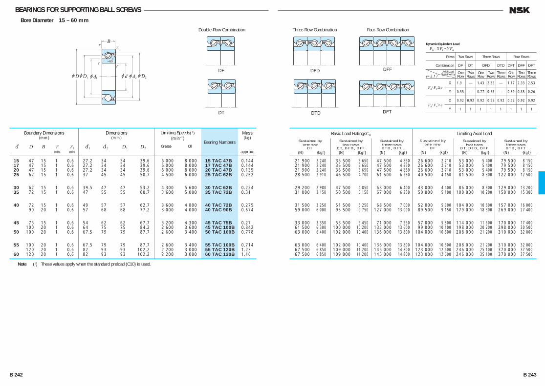
BEARINGS FOR SUPPORTING BALL SCREWSBore Diameter 15 – 60 mm
r
r
r
r
jdjd jD
B1
2 21 1jdjDjD
60
DF
DT
DFD DFF
DFTDTD
21 900 2 240 35 500 3 650 47 500 4 850 26 600 2 710 53 000 5 400 79 500 8 150 21 900 2 240 35 500 3 650 47 500 4 850 26 600 2 710 53 000 5 400 79 500 8 150 21 900 2 240 35 500 3 650 47 500 4 850 26 600 2 710 53 000 5 400 79 500 8 150 28 500 2 910 46 500 4 700 61 500 6 250 40 500 4 150 81 500 8 300 122 000 12 500
29 200 2 980 47 500 4 850 63 000 6 400 43 000 4 400 86 000 8 800 129 000 13 200 31 000 3 150 50 500 5 150 67 000 6 850 50 000 5 100 100 000 10 200 150 000 15 300
31 500 3 250 51 500 5 250 68 500 7 000 52 000 5 300 104 000 10 600 157 000 16 000 59 000 6 000 95 500 9 750 127 000 13 000 89 500 9 150 179 000 18 300 269 000 27 400
33 000 3 350 53 500 5 450 71 000 7 250 57 000 5 800 114 000 11 600 170 000 17 400 61 500 6 300 100 000 10 200 133 000 13 600 99 000 10 100 198 000 20 200 298 000 30 500 63 000 6 400 102 000 10 400 136 000 13 800 104 000 10 600 208 000 21 200 310 000 32 000
63 000 6 400 102 000 10 400 136 000 13 800 104 000 10 600 208 000 21 200 310 000 32 000 67 500 6 850 109 000 11 200 145 000 14 800 123 000 12 600 246 000 25 100 370 000 37 500 67 500 6 850 109 000 11 200 145 000 14 800 123 000 12 600 246 000 25 100 370 000 37 500
Bearing Numbers
Basic Load RatingsCa
Sustained byone row
DF (N) {kgf}
Sustained bytwo rows
DT, DFD, DFF (N) {kgf}
Sustained bythree rowsDTD, DFT
(N) {kgf}
Limiting Axial LoadSustained by
one rowDF
(N) {kgf}
Sustained bytwo rows
DT, DFD, DFF (N) {kgf}
Sustained bythree rowsDTD, DFT
(N) {kgf}
Mass(kg)
approx.
15 47 15 1 0.6 27.2 34 34 39.6 6 000 8 000 15 TAC 47B 0.144 17 47 15 1 0.6 27.2 34 34 39.6 6 000 8 000 17 TAC 47B 0.144 20 47 15 1 0.6 27.2 34 34 39.6 6 000 8 000 20 TAC 47B 0.135 25 62 15 1 0.6 37 45 45 50.7 4 500 6 000 25 TAC 62B 0.252
30 62 15 1 0.6 39.5 47 47 53.2 4 300 5 600 30 TAC 62B 0.224 35 72 15 1 0.6 47 55 55 60.7 3 600 5 000 35 TAC 72B 0.31
40 72 15 1 0.6 49 57 57 62.7 3 600 4 800 40 TAC 72B 0.275 90 20 1 0.6 57 68 68 77.2 3 000 4 000 40 TAC 90B 0.674
45 75 15 1 0.6 54 62 62 67.7 3 200 4 300 45 TAC 75B 0.27 100 20 1 0.6 64 75 75 84.2 2 600 3 600 45 TAC 100B 0.842 50 100 20 1 0.6 67.5 79 79 87.7 2 600 3 400 50 TAC 100B 0.778
55 100 20 1 0.6 67.5 79 79 87.7 2 600 3 400 55 TAC 100B 0.714 120 20 1 0.6 82 93 93 102.2 2 200 3 000 55 TAC 120B 1.23 60 120 20 1 0.6 82 93 93 102.2 2 200 3 000 60 TAC 120B 1.16
Boundary Dimensions(mm)
d D B r r1 min. min.
Dimensions(mm)
d1 d2 D1 D2
Limiting Speeds(1)(min–1)
Grease Oil
Double-Row Combination Three-Row Combination Four-Row Combination
Note (1) These values apply when the standard preload (C10) is used.
Rows Two Rows Three Rows Four Rows
Combination DF DT DFD DTD DFT DFF DFT
Fa/Fr≤e
X 1.90 — 1.43 2.33 — 1.17 2.33 2.53
Y 0.55 — 0.77 0.35 — 0.89 0.35 0.26
Fa/Fr>e
X 0.92 0.92 0.92 0.92 0.92 0.92 0.92 0.92
Y 1 1 1 1 1 1 1 1
Dynamic Equivalent Load
Pa=XFr +YFa
e=2.17One Row
Axial Load Sustained by Two
RowsOne Row
Two Rows
Three Rows
One Row
Two Rows
Three Rows
B 242 B 243
B234-243E.indd 242-243B234-243E.indd 242-243 11/20/13 4:58:50 PM11/20/13 4:58:50 PM

NEEDLE ROLLER BEARINGSCAGE & NEEDLE ROLLER ASSEMBLIES Inscribed Circle Diameter 5 – 100mm ···· B252
Cage & Needle Roller Assemblies for Connecting Rod Inscribed Circle Diameter 12 – 30mm ···· B256
DRAWN CUP NEEDLE ROLLER BEARINGSWith Cage Inscribed Circle Diameter 4 – 55mm ···· B258
Full Complement Type Inscribed Circle Diameter 8 – 55mm ···· B258
SOLID NEEDLE ROLLER BEARINGS Inscribed Circle Diameter 9 – 390mm ···· B264
THRUST NEEDLE ROLLER BEARINGS Bore Diameter 10 – 100mm ···· B274
CAM FOLLOWERS Outside Diameter 16 – 90mm ··· B276
ROLLER FOLLOWERS Bore Diameter 5 – 50mm ···· B278
DESIGN AND TYPES
For needle roller bearings, there are many designs and types bearings.Catalog Specified catalog, NSK Needle Roller Bearings CAT.No.E1419 lists bearings shown in Table 1. Representative examples selected from them, are shown in this catalog. (shown with in Table 1) For details, please refer individual specified catalog. For bearing selection, please contact NSK.
B 244 B 245
B244-279E.indd 244-245B244-279E.indd 244-245 11/20/13 4:59:11 PM11/20/13 4:59:11 PM
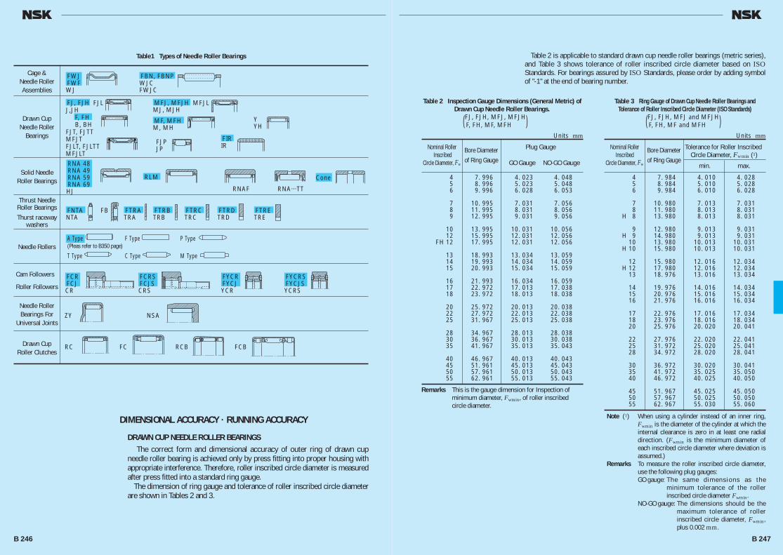
Table 2 is applicable to standard drawn cup needle roller bearings (metric series), and Table 3 shows tolerance of roller inscribed circle diameter based on ISO Standards. For bearings assured by ISO Standards, please order by adding symbol of "-1" at the end of bearing number.
Table 2 Inspection Gauge Dimensions (General Metric) of Drawn Cup Needle Roller Bearings.
(FJ, FJH, MFJ, MFJH) F, FH, MF, MFH
Nominal Roller Bore Diameter Plug Gauge Inscribed
of Ring Gauge Circle Diameter, Fw GO Gauge NO-GO Gauge
4 7. 996 4. 023 4. 048 5 8. 996 5. 023 5. 048 6 9. 996 6. 028 6. 053
7 10. 995 7. 031 7. 056 8 11. 995 8. 031 8. 056 9 12. 995 9. 031 9. 056
10 13. 995 10. 031 10. 056 12 15. 995 12. 031 12. 056 FH 12 17. 995 12. 031 12. 056
13 18. 993 13. 034 13. 059 14 19. 993 14. 034 14. 059 15 20. 993 15. 034 15. 059
16 21. 993 16. 034 16. 059 17 22. 972 17. 013 17. 038 18 23. 972 18. 013 18. 038
20 25. 972 20. 013 20. 038 22 27. 972 22. 013 22. 038 25 31. 967 25. 013 25. 038
28 34. 967 28. 013 28. 038 30 36. 967 30. 013 30. 038 35 41. 967 35. 013 35. 043
40 46. 967 40. 013 40. 043 45 51. 961 45. 013 45. 043 50 57. 961 50. 013 50. 043 55 62. 961 55. 013 55. 043
Units mm
Remarks This is the gauge dimension for Inspection of minimum diameter, Fwmin, of roller inscribed circle diameter.
Table 3 Ring Gauge of Drawn Cup Needle Roller Bearings and Tolerance of Roller Inscribed Circle Diameter (ISO Standards)
(FJ, FJH, MFJ and MFJH) F, FH, MF and MFH
Nominal Roller Bore Diameter Tolerance for Roller Inscribed Inscribed
of Ring Gauge Circle Diameter, Fwmin (1)
Circle Diameter, Fw min. max.
4 7. 984 4. 010 4. 028 5 8. 984 5. 010 5. 028 6 9. 984 6. 010 6. 028
7 10. 980 7. 013 7. 031 8 11. 980 8. 013 8. 031 H 8 13. 980 8. 013 8. 031
9 12. 980 9. 013 9. 031 H 9 14. 980 9. 013 9. 031 10 13. 980 10. 013 10. 031 H 10 15. 980 10. 013 10. 031
12 15. 980 12. 016 12. 034 H 12 17. 980 12. 016 12. 034 13 18. 976 13. 016 13. 034
14 19. 976 14. 016 14. 034 15 20. 976 15. 016 15. 034 16 21. 976 16. 016 16. 034
17 22. 976 17. 016 17. 034 18 23. 976 18. 016 18. 034 20 25. 976 20. 020 20. 041
22 27. 976 22. 020 22. 041 25 31. 972 25. 020 25. 041 28 34. 972 28. 020 28. 041
30 36. 972 30. 020 30. 041 35 41. 972 35. 025 35. 050 40 46. 972 40. 025 40. 050
45 51. 967 45. 025 45. 050 50 57. 967 50. 025 50. 050 55 62. 967 55. 030 55. 060
Units mm
Note (1) When using a cylinder instead of an inner ring, Fwmin is the diameter of the cylinder at which the internal clearance is zero in at least one radial direction. (Fwmin is the minimum diameter of each inscribed circle diameter where deviation is assumed.)
Remarks To measure the roller inscribed circle diameter, use the following plug gauges:
GO gauge: The same dimensions as the minimum tolerance of the roller inscribed circle diameter Fwmin.
NO-GO gauge: The dimensions should be the maximum tolerance of roller inscribed circle diameter, Fwmin, plus 0.002 mm.
Table1 Types of Needle Roller Bearings
DIMENSIONAL ACCURACY · RUNNING ACCURACY
DRAWN CUP NEEDLE ROLLER BEARINGS The correct form and dimensional accuracy of outer ring of drawn cup needle roller bearing is achieved only by press fitting into proper housing with appropriate interference. Therefore, roller inscribed circle diameter is measured after press fitted into a standard ring gauge. The dimension of ring gauge and tolerance of roller inscribed circle diameter are shown in Tables 2 and 3.
Cage & Needle Roller Assemblies
Drawn Cup Needle Roller
Bearings
Solid Needle Roller Bearings
Needle Rollers
Cam Followers
Roller Followers
Needle Roller Bearings For
Universal Joints
Drawn Cup Roller Clutches
Thrust Needle Roller BearingsThurst raceway
washers
FWJFWFWJ
FBN, FBNPWJCFWJC
FJ, FJH FJLJ,JH F, FH B, BHFJT, FJTTMFJTFJLT, FJLTTMFJLT
MFJ, MFJH MFJLMJ, MJH
RNA 48RNA 49RNA 59RNA 69HJ
RLM Cone
FNTANTA
A Type(Pleas refer to B350 page)
F Type P Type
T Type C Type M Type
FTRATRA
FCRFCJCR
FCRSFCJSCRS
FYCRFYCJYCR
FYCRSFYCJSYCRS
FTRBTRB
FTRCTRC
FTRDTRD
FTRETRE
FB
ZY
RC FC RCB FCB
NSA
MF, MFHM, MH
FIRIR
YYH
RNAF RNA···TT
FJPJP
B 246 B 247
B244-279E.indd 246-247B244-279E.indd 246-247 11/20/13 4:59:12 PM11/20/13 4:59:12 PM

SOLID NEEDLE ROLLER BEARINGS ········································· Table 8. 2 (A60-63 pages)
Tolerance of roller inscribed circle diameter for solid needle roller bearings without inner rings are shown in Table 4.
CAM FOLLOWERS · ROLLER FOLLOWERS ······························ Table 8. 2 (A60-63 pages)
The tolerance zone class of stud diameter d of cam followers is h7, and the tolerance of assembled width of inner ring of roller followers is shown in bearing table. These tolerances are applied to the bearings before surface treatment. Cam Follower Dimensional Tolerences is always applited to the bearing before surface treatment.
RECOMMENDED FITTING AND BEARING INTERNAL CLEARANCE CAGE & NEEDLE ROLLER ASSEMBLIES
Recommended fitting of cage & roller under typical operating condition is shown in Table 5. By combining cage & roller, shaft, and housing, appropriate radial internal clearance is obtained. However, the fitting and the radial internal clearance of cage & roller for connecting rod should be determined by the type of engine, characteristic, and driving condition etc.. For details, please refer to specified catalog.
Table 4 Inscribed Circle Diameter for Metric Solid Needle Roller Bearings
Nominal Inscribed Deviation (F6) of Minimum Circle Diameter, Fw
Diameter, Fw min, of Roller (mm)
Inscribed Circle Diameter Fw min(1)
&Fwmin
over incl. high low
6 10 + 22 +13 10 18 + 27 +16 18 30 + 33 +20
30 50 + 41 +25 50 80 + 49 +30 80 120 + 58 +36
120 180 + 68 +43 180 250 + 79 +50 250 315 + 88 +56
315 400 + 98 +62 400 500 +108 +68
Units μm
Note (1) When using a cylinder instead of an inner ring, Fw min is the diameter of the cylinder at which the internal clearance is zero in at least one radial direction. (Fw min is the minimum diameter of each inscribed circle diameter where deviation is assumed.)
Table 5 Fitting Tolerances for Shafts and Housing Bores
Fitting Tolerance shaft
housing bore Fw≤50 mm Fw>50 mm
High Accuracy, Oscillating Motion
js5 (j5) h5
Normal h5 g5 G6 High Temperature, Large Shaft Deflection
f6 and Mounting Error of Bearings
Operating Conditions
DRAWN CUP NEEDLE ROLLER BEARINGS For FJ, FJH, and MFJH types and F, FH, and MFH types, if tolerance of fitting such as shaft:h6, and housing bore:N7 (in case of thick steel housing), are applied under general operating condition, appropriate radial internal clearance is obtained. In case that outer ring rotation, the fitting of shaft : f6, housing bore : R7, and light alloy housing or steel housing of less than 6mm thickness, the housing bore should be smaller than N7 by 0.013 – 0.025 mm.
SOLID NEEDLE ROLLER BEARINGSRecommended fitting for solid needle roller bearings with inner rings Table 9. 2 (Page A84) Table 9. 4 (Page A85)Internal clearance of solid needle roller bearings with inner rings Table 9. 14 (Page A91)
However, for needle roller bearing of wider bearing width, and with long needle rollers, bearings with CN clearance are not necessarily common, but large clearance is selected frequently. For the solid needle roller bearing without inner ring, it is possible to select radial internal clearance shown in Table 6 by selecting tolerance class of shaft, which is fitting to the bearing.
THRUST NEEDLE ROLLER BEARINGS Recommended Fitting of Thrust Needle Roller Bearings and Thrust Raceway are shown in Table 7.
Units mm
Note (1) Dc represents outside diameter of the cage.Remarks If the cage is guided by outside diameter, to prevent the wear of housing
bore, it is necessary to harden the surface at least.
Table 7 Recommended Fitting of Thrust Needle Roller Bearings and Thrust Raceway
Classification Type
Cage or Tolerance class or dimension tolerance
raceway guide Shaft Housing bore
Thrust Needle Bearing Cage FNTA
Bore h8 Dc (1)+over 1.0 & Needle Roller Assemblies Outside — H10
Thrust Bearing Rings FTRA to FTRE Bore h8 Dc (1)+over 1.0
Outside — H10
Table 6 Fitting Tolerances and Radial Internal clearance of Shafts Assembled with Solid Needle Roller Bearings without Inner Rings
C2 CN C3 C4
over incl.
6 180 k5 g5 f6 e6
180 315 j6 f6 e6 d6
315 490 h6 e6 d6 c6
Nominal Roller Inscribed Circle Diameter Fw (mm)
B 248 B 249
B244-279E.indd 248-249B244-279E.indd 248-249 11/20/13 4:59:46 PM11/20/13 4:59:46 PM

CAM FOLLOWERS · ROLLER FOLLOWERS The recommended fittings for the mounting area of cam follower studs are shown in Table 8. Recommended shaft fittings of roller follower are shown in Table 9. Since cam followers are used with cantilevered mounting, they should be fixed with little clearance of the fitting surface as much as possible. Since a roller follower is generally used with outer ring rotation, the fitting with shaft is transition or loose fit. In case that heavy loads impose to the roller follower, it is recommended to use the shaft of quench hardening treatment, and with tight fit. For the details, please refer to specified catalog.
Table 8 Recommended Fitting for Stud Mounting Part of Cam Followers
Type
Fitting Tolerance of Mounting Hole FCR, FCRS
JS7 (J7) FCJ, FCJS
Table 12 Permissble Load Coefficient of Track
Hardness Coefficient (HRC)
20 0.4 25 0.5 30 0.6
35 0.8 40 1.0 45 1.4
50 1.9 55 2.6 58 3.2
Table 9 Recommended Staft Fittings of Roller Followers
Load Fitting Tolerance of Shaft
Light Load/Normal Load g6 or h6 Heavy Load k6
SHAFT AND HOUSING SPECIFICATIONS The specification of shaft and housing for radial needle roller bearings, which are used under general operating condition, is shown in Table 10.
LIMITING INCLINATION ANGLESThe limiting inclination angle of radial needle roller bearing under general load condition is 0.001 radian (3.4') approximately. For the detail, please refer to specified catalog.,
PERMISSBLE TRACK LOAD The permissble load of the track is determined by compression strength or hardness. The permissble load of the track shown in the bearing table is value of a track made of steel with a hardness of HRC40. Table 12 indicates the permissible load coefficient of the track for each hardness. The permissible load of the track for each hardness can be obtained by multiplying the permissible load coefficient of the track corresponding to each hardness.
PRE-PACKED GREASE The cam follower/roller follower with a seal is pre-lubricated with lithium soap-based grease. The range of operating temperature is –10 to +110°C. For the cam follower/roller follower without seal, please lubricate with suitable lubricant.
MAXIMUM PERMISSIBLE LOAD AND MAXIMUM CLAMP TORQUE OF CAM FOLLOWERS.
The maximum radial Load that the cam follower can carry is determined by the bearing strengh and shear strengh of the stud rather than the Load rating for neele bearings. This value is given in the bearing table as the maximum permissible Load. Since the stud of the cam follower receives bending stress and tensile stress from the bearing Load, the screw clamp torque should not exceed the value shown in the bearing table.
LIMITING SPEED The limiting speeds of bearings are shown in bearing tables. However, depending on load condition of the bearing, the limiting speeds are necessary to compensate. Also, improvement of lubrication method allows to take higher limiting speed. For the detail, please refer to A37 page.
Specifications of Thrust Bearings Raceway Surface are shown in Table 11.
Remarks 1. For the specification of shaft and housing of cage & needle roller assembly for connecting rod, please refer to specified catalog.
2. These are general recommendation by radius method. For the value of standard tolerance (IT), please refer to Appendix 11 (page C22)
Table 10 Shaft and housing Specifications of Radial Needle Roller Bearings(Cage & Needle Roller Assemblies/Drawn Cup Bearings/Solid Bearings)
Category
Shaft Housing Bore Raceway Surface Fitting Surface Raceway Surface Fitting Surface Out-of-Roundness Tolerance
IT32
IT 32 to
IT 42
IT 32
IT 42 to
IT 52
Cylindricity Tolerance
IT32
IT 32 to
IT 42
IT 32
IT 42 to
IT 52
Roughness 0.4 0.8 0.8 1.6
Ra (μm)
Hardness — —HRC58 to 64 Appropriate depth of hardening layer required
HRC58 to 64 Appropriate depth of hardening layer required
Table 11 Specifications of Thrust Bearings Raceway Surface
Squareness A 0.5/1000 incl (mm/mm)
Squareness B 1.0/1000 incl (mm/mm)
Roughness 0.4
— Ra (μm)
Hardness
HRC58 to 64 —
(HRC60 to 64 is fovorable)
B 250 B 251
B244-279E.indd 250-251B244-279E.indd 250-251 11/20/13 4:59:46 PM11/20/13 4:59:46 PM
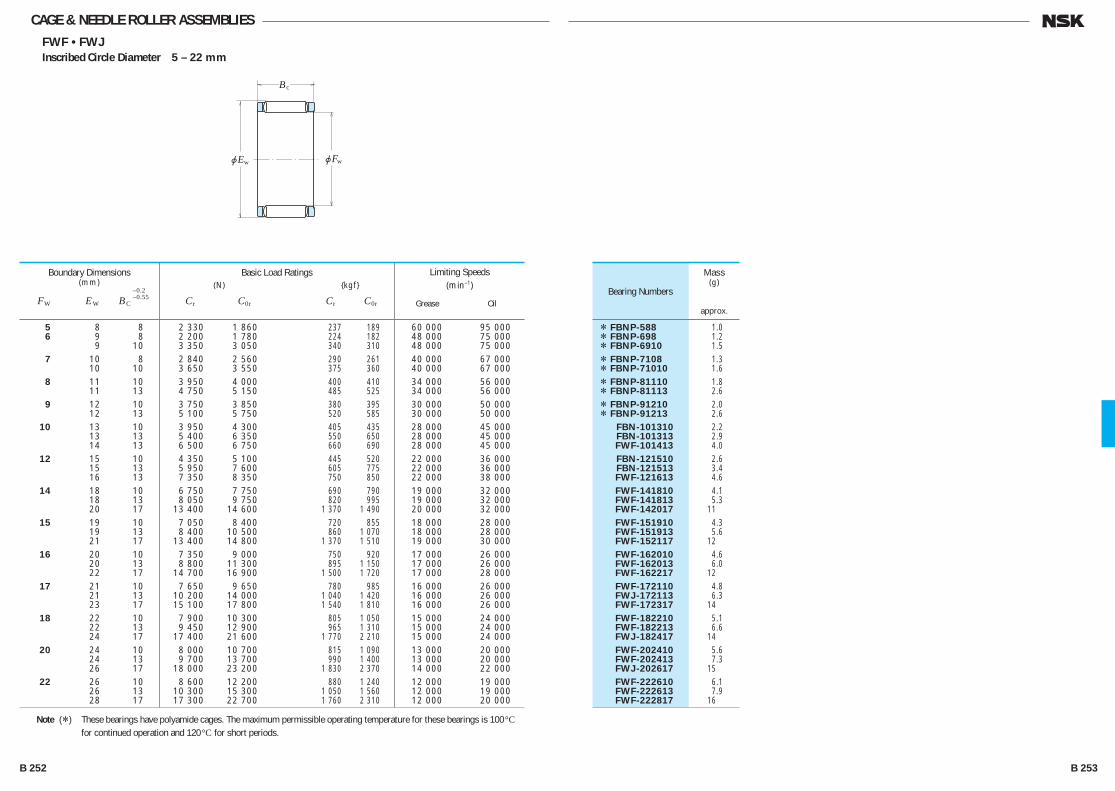
jE
B
jF
c
w w
CAGE & NEEDLE ROLLER ASSEMBLIESFWF • FWJ
Inscribed Circle Diameter 5 – 22 mm
5 8 8 2 330 1 860 237 189 60 000 95 000 6 9 8 2 200 1 780 224 182 48 000 75 000 9 10 3 350 3 050 340 310 48 000 75 000 7 10 8 2 840 2 560 290 261 40 000 67 000 10 10 3 650 3 550 375 360 40 000 67 000 8 11 10 3 950 4 000 400 410 34 000 56 000 11 13 4 750 5 150 485 525 34 000 56 000 9 12 10 3 750 3 850 380 395 30 000 50 000 12 13 5 100 5 750 520 585 30 000 50 000 10 13 10 3 950 4 300 405 435 28 000 45 000 13 13 5 400 6 350 550 650 28 000 45 000 14 13 6 500 6 750 660 690 28 000 45 000 12 15 10 4 350 5 100 445 520 22 000 36 000 15 13 5 950 7 600 605 775 22 000 36 000 16 13 7 350 8 350 750 850 22 000 38 000 14 18 10 6 750 7 750 690 790 19 000 32 000 18 13 8 050 9 750 820 995 19 000 32 000 20 17 13 400 14 600 1 370 1 490 20 000 32 000 15 19 10 7 050 8 400 720 855 18 000 28 000 19 13 8 400 10 500 860 1 070 18 000 28 000 21 17 13 400 14 800 1 370 1 510 19 000 30 000 16 20 10 7 350 9 000 750 920 17 000 26 000 20 13 8 800 11 300 895 1 150 17 000 26 000 22 17 14 700 16 900 1 500 1 720 17 000 28 000 17 21 10 7 650 9 650 780 985 16 000 26 000 21 13 10 200 14 000 1 040 1 420 16 000 26 000 23 17 15 100 17 800 1 540 1 810 16 000 26 000 18 22 10 7 900 10 300 805 1 050 15 000 24 000 22 13 9 450 12 900 965 1 310 15 000 24 000 24 17 17 400 21 600 1 770 2 210 15 000 24 000 20 24 10 8 000 10 700 815 1 090 13 000 20 000 24 13 9 700 13 700 990 1 400 13 000 20 000 26 17 18 000 23 200 1 830 2 370 14 000 22 000 22 26 10 8 600 12 200 880 1 240 12 000 19 000 26 13 10 300 15 300 1 050 1 560 12 000 19 000 28 17 17 300 22 700 1 760 2 310 12 000 20 000
Boundary Dimensions(mm)
FW EW BC
–0.2–0.55
Limiting Speeds (min–1)
Grease Oil
Basic Load Ratings (N) {kgf}
Cr C0r Cr C0r
* FBNP-588 1.0 * FBNP-698 1.2 * FBNP-6910 1.5 * FBNP-7108 1.3 * FBNP-71010 1.6 * FBNP-81110 1.8 * FBNP-81113 2.6 * FBNP-91210 2.0 * FBNP-91213 2.6 FBN-101310 2.2 FBN-101313 2.9 FWF-101413 4.0 FBN-121510 2.6 FBN-121513 3.4 FWF-121613 4.6 FWF-141810 4.1 FWF-141813 5.3 FWF-142017 11 FWF-151910 4.3 FWF-151913 5.6 FWF-152117 12 FWF-162010 4.6 FWF-162013 6.0 FWF-162217 12 FWF-172110 4.8 FWJ-172113 6.3 FWF-172317 14 FWF-182210 5.1 FWF-182213 6.6 FWJ-182417 14 FWF-202410 5.6 FWF-202413 7.3 FWJ-202617 15 FWF-222610 6.1 FWF-222613 7.9 FWF-222817 16
Bearing Numbers
Mass(g)
approx.
Note (*) These bearings have polyamide cages. The maximum permissible operating temperature for these bearings is 100°C for continued operation and 120°C for short periods.
B 252 B 253
B244-279E.indd 252-253B244-279E.indd 252-253 11/20/13 4:59:47 PM11/20/13 4:59:47 PM
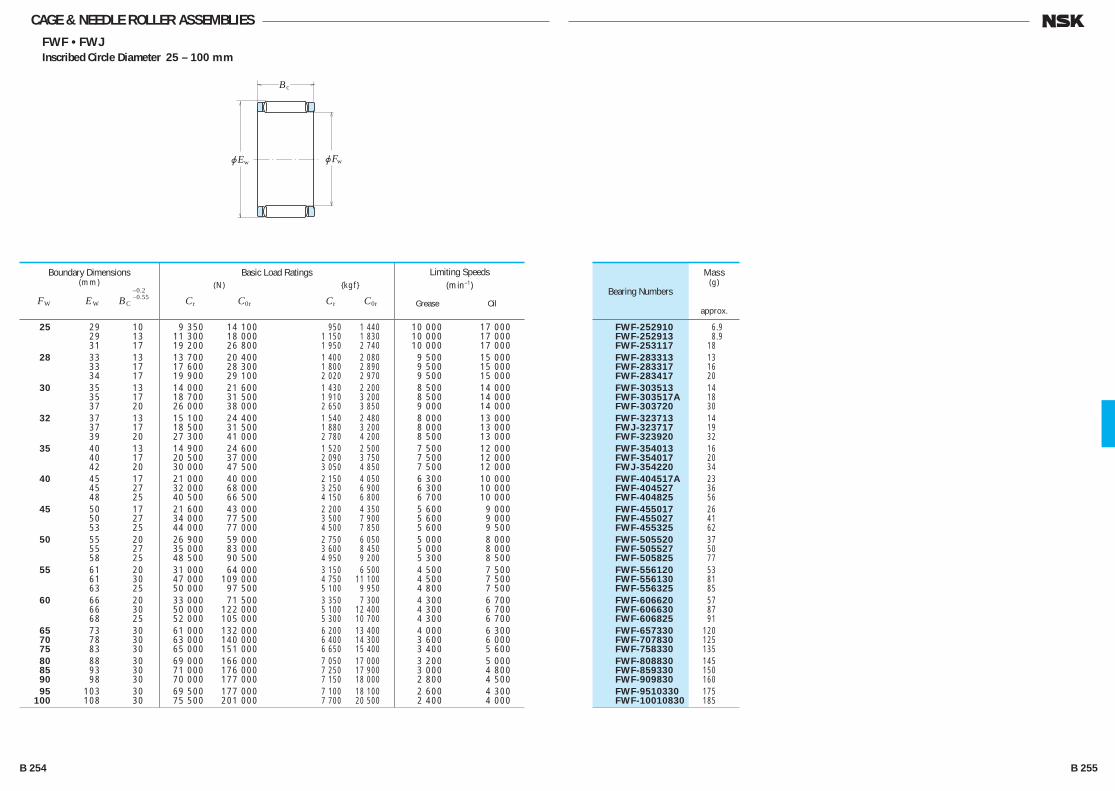
CAGE & NEEDLE ROLLER ASSEMBLIESFWF • FWJ
Inscribed Circle Diameter 25 – 100 mm
jE
B
jF
c
w w
25 29 10 9 350 14 100 950 1 440 10 000 17 000 29 13 11 300 18 000 1 150 1 830 10 000 17 000 31 17 19 200 26 800 1 950 2 740 10 000 17 000 28 33 13 13 700 20 400 1 400 2 080 9 500 15 000 33 17 17 600 28 300 1 800 2 890 9 500 15 000 34 17 19 900 29 100 2 020 2 970 9 500 15 000 30 35 13 14 000 21 600 1 430 2 200 8 500 14 000 35 17 18 700 31 500 1 910 3 200 8 500 14 000 37 20 26 000 38 000 2 650 3 850 9 000 14 000 32 37 13 15 100 24 400 1 540 2 480 8 000 13 000 37 17 18 500 31 500 1 880 3 200 8 000 13 000 39 20 27 300 41 000 2 780 4 200 8 500 13 000 35 40 13 14 900 24 600 1 520 2 500 7 500 12 000 40 17 20 500 37 000 2 090 3 750 7 500 12 000 42 20 30 000 47 500 3 050 4 850 7 500 12 000 40 45 17 21 000 40 000 2 150 4 050 6 300 10 000 45 27 32 000 68 000 3 250 6 900 6 300 10 000 48 25 40 500 66 500 4 150 6 800 6 700 10 000 45 50 17 21 600 43 000 2 200 4 350 5 600 9 000 50 27 34 000 77 500 3 500 7 900 5 600 9 000 53 25 44 000 77 000 4 500 7 850 5 600 9 500 50 55 20 26 900 59 000 2 750 6 050 5 000 8 000 55 27 35 000 83 000 3 600 8 450 5 000 8 000 58 25 48 500 90 500 4 950 9 200 5 300 8 500 55 61 20 31 000 64 000 3 150 6 500 4 500 7 500 61 30 47 000 109 000 4 750 11 100 4 500 7 500 63 25 50 000 97 500 5 100 9 950 4 800 7 500 60 66 20 33 000 71 500 3 350 7 300 4 300 6 700 66 30 50 000 122 000 5 100 12 400 4 300 6 700 68 25 52 000 105 000 5 300 10 700 4 300 6 700 65 73 30 61 000 132 000 6 200 13 400 4 000 6 300 70 78 30 63 000 140 000 6 400 14 300 3 600 6 000 75 83 30 65 000 151 000 6 650 15 400 3 400 5 600 80 88 30 69 000 166 000 7 050 17 000 3 200 5 000 85 93 30 71 000 176 000 7 250 17 900 3 000 4 800 90 98 30 70 000 177 000 7 150 18 000 2 800 4 500 95 103 30 69 500 177 000 7 100 18 100 2 600 4 300 100 108 30 75 500 201 000 7 700 20 500 2 400 4 000
Boundary Dimensions(mm)
FW EW BC
–0.2–0.55
Limiting Speeds (min–1)
Grease Oil
Basic Load Ratings (N) {kgf}
Cr C0r Cr C0r
FWF-252910 6.9 FWF-252913 8.9 FWF-253117 18 FWF-283313 13 FWF-283317 16 FWF-283417 20 FWF-303513 14 FWF-303517A 18 FWF-303720 30 FWF-323713 14 FWJ-323717 19 FWF-323920 32 FWF-354013 16 FWF-354017 20 FWJ-354220 34 FWF-404517A 23 FWF-404527 36 FWF-404825 56 FWF-455017 26 FWF-455027 41 FWF-455325 62 FWF-505520 37 FWF-505527 50 FWF-505825 77 FWF-556120 53 FWF-556130 81 FWF-556325 85 FWF-606620 57 FWF-606630 87 FWF-606825 91 FWF-657330 120 FWF-707830 125 FWF-758330 135 FWF-808830 145 FWF-859330 150 FWF-909830 160 FWF-9510330 175 FWF-10010830 185
Bearing Numbers
Mass(g)
approx.
B 254 B 255
B244-279E.indd 254-255B244-279E.indd 254-255 11/20/13 4:59:48 PM11/20/13 4:59:48 PM
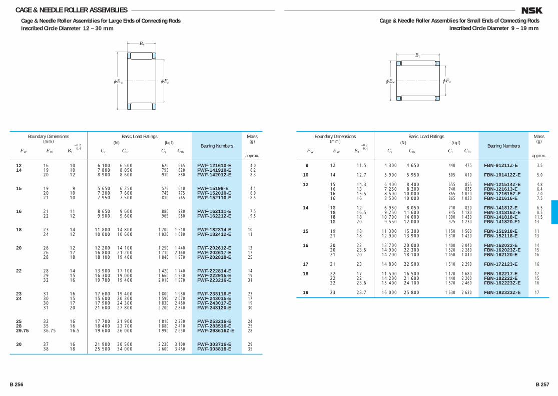
jE
B
jF
c
w w
CAGE & NEEDLE ROLLER ASSEMBLIESCage & Needle Roller Assemblies for Large Ends of Connecting RodsInscribed Circle Diameter 12 – 30 mm
Cage & Needle Roller Assemblies for Small Ends of Connecting Rods Inscribed Circle Diameter 9 – 19 mm
jE
B
jF
c
w w
12 16 10 6 100 6 500 620 665 FWF-121610-E 4.0 14 19 10 7 800 8 050 795 820 FWF-141910-E 6.2 20 12 8 900 8 600 910 880 FWF-142012-E 8.3
15 19 9 5 650 6 250 575 640 FWF-15199-E 4.1 20 10 7 300 7 600 745 775 FWF-152010-E 6.0 21 10 7 950 7 500 810 765 FWF-152110-E 8.5
16 21 11 8 650 9 600 880 980 FWF-162111-E 7.5 22 12 9 500 9 600 965 980 FWF-162212-E 9.5
18 23 14 11 800 14 800 1 200 1 510 FWF-182314-E 10 24 12 10 000 10 600 1 020 1 080 FWF-182412-E 11
20 26 12 12 200 14 100 1 250 1 440 FWF-202612-E 13 26 17 16 800 21 200 1 710 2 160 FWF-202617-E 17 28 18 18 100 19 400 1 840 1 970 FWF-202818-E 25
22 28 14 13 900 17 100 1 420 1 740 FWF-222814-E 14 29 15 16 300 19 000 1 660 1 930 FWF-222915-E 19 32 16 19 700 19 400 2 010 1 970 FWF-223216-E 31
23 31 16 17 600 19 400 1 800 1 980 FWF-233116-E 23 24 30 15 15 600 20 300 1 590 2 070 FWF-243015-E 17 30 17 17 900 24 300 1 830 2 480 FWF-243017-E 19 31 20 21 600 27 800 2 200 2 840 FWF-243120-E 30
25 32 16 17 700 21 900 1 810 2 230 FWF-253216-E 24 28 35 16 18 400 23 700 1 880 2 410 FWF-283516-E 25 29.75 36.75 16.5 19 600 26 000 1 990 2 650 FWF-293616Z-E 28
30 37 16 21 900 30 500 2 230 3 100 FWF-303716-E 29 38 18 25 500 34 000 2 600 3 450 FWF-303818-E 35
Boundary Dimensions(mm)
FW EW BC
–0.2–0.4
Basic Load Ratings (N) {kgf}
Cr C0r Cr C0r
Bearing Numbers
Mass(g)
approx.
9 12 11.5 4 300 4 650 440 475 FBN-91211Z-E 3.5
10 14 12.7 5 900 5 950 605 610 FBN-101412Z-E 5.0
12 15 14.3 6 400 8 400 655 855 FBN-121514Z-E 4.8 16 13 7 250 8 200 740 835 FBN-121613-E 6.4 16 15.5 8 500 10 000 865 1 020 FBN-121615Z-E 7.0 16 16 8 500 10 000 865 1 020 FBN-121616-E 7.5
14 18 12 6 950 8 050 710 820 FBN-141812-E 6.5 18 16.5 9 250 11 600 945 1 180 FBN-141816Z-E 8.5 18 18 10 700 14 000 1 090 1 430 FBN-141818-E 11.5 18 20 9 550 12 000 975 1 230 FBN-141820-E1 13
15 19 18 11 300 15 300 1 150 1 560 FBN-151918-E 11 21 18 12 900 13 900 1 310 1 420 FBN-152118-E 13
16 20 22 13 700 20 000 1 400 2 040 FBN-162022-E 14 20 23.5 14 900 22 300 1 520 2 280 FBN-162023Z-E 15 21 20 14 200 18 100 1 450 1 840 FBN-162120-E 16
17 21 23 14 800 22 500 1 510 2 290 FBN-172123-E 16
18 22 17 11 500 16 500 1 170 1 680 FBN-182217-E 12 22 22 14 200 21 600 1 440 2 200 FBN-182222-E 15 22 23.6 15 400 24 100 1 570 2 460 FBN-182223Z-E 16
19 23 23.7 16 000 25 800 1 630 2 630 FBN-192323Z-E 17
Boundary Dimensions(mm)
FW EW BC
–0.2–0.4
Basic Load Ratings (N) {kgf}
Cr C0r Cr C0r
Bearing Numbers
Mass(g)
approx.
B 256 B 257
B244-279E.indd 256-257B244-279E.indd 256-257 11/20/13 4:59:48 PM11/20/13 4:59:48 PM

jd
B
jFw
With Inner Ring
jda
HousingBoreN7
Shafth6
ra
jD
C
jFw
2
Open Type
jD
C
jFw
Open Type
jD
C
C1C
jFw
Closed Type Closed TypeWith Cage Full Complement Type
jD
C
jFw
DRAWN CUP NEEDLE ROLLER BEARINGSFJ • MFJ (With Cage)
F • MF (Full Complement Type)
Inscribed Circle Diameter 4 – 16 mm
4 8 8 0.8 1 720 175 675 69 45 000 75 000 * FJP-48 - 5 9 9 0.8 1 860 190 745 76 43 000 71 000 FJ-59 MFJ-59 6 10 9 0.8 2 320 237 985 101 36 000 56 000 FJ-69 MFJ-69 7 11 9 0.8 2 550 260 1 110 113 30 000 48 000 FJ-79 MFJ-79
8 12 10 0.8 2 840 289 1 270 130 26 000 43 000 FJ-810 MFJ-810 14 10 1.0 4 300 435 1 770 180 28 000 45 000 FJH-810 MFJH-810 14 10 1.9 5 550 565 2 980 305 6 300 10 000 - -
9 13 10 0.8 3 300 335 1 600 163 22 000 36 000 FJ-910 MFJ-910 15 10 1.0 4 550 465 1 910 194 24 000 40 000 FJH-910 MFJH-910 15 10 1.8 6 100 625 3 350 340 6 000 10 000 - -
10 14 10 0.8 3 500 360 1 760 179 20 000 32 000 FJ-1010 MFJ-1010 16 10 1.0 4 900 500 2 100 214 22 000 34 000 FJH-1010 MFJH-1010 16 10 1.9 6 650 680 3 700 375 5 600 9 000 - -
12 16 10 0.8 4 150 420 2 210 225 17 000 26 000 FJ-1210 MFJ-1210 18 12 1.0 6 450 655 3 050 310 17 000 28 000 FJH-1212 MFJH-1212 18 12 1.9 9 000 920 5 700 580 4 500 7 500 - -
13 19 12 1.0 6 950 710 3 400 345 16 000 26 000 FJ-1312 MFJ-1312 19 12 1.9 9 550 975 6 100 625 4 300 7 100 - -
14 20 12 1.0 6 500 665 3 250 335 15 000 24 000 FJ-1412 MFJ-1412 20 12 2.2 9 450 965 6 350 645 3 800 6 000 - - 20 16 1.0 9 500 970 5 300 540 15 000 24 000 FJ-1416 MFJ-1416 20 16 2.2 13 300 1 360 9 850 1 000 3 800 6 000 - -
15 21 12 1.0 7 650 780 3 900 400 14 000 22 000 FJ-1512 MFJ-1512 21 12 1.8 10 300 1 050 6 900 705 3 800 6 000 - - 21 14 1.8 12 400 1 270 8 800 895 3 800 6 000 - -
21 16 1.0 11 000 1 120 6 200 635 14 000 22 000 FJ-1516 MFJ-1516 21 16 1.8 14 500 1 480 10 700 1 090 3 800 6 000 - -
16 22 12 1.0 7 100 725 3 750 380 12 000 20 000 FJ-1612 MFJ-1612 22 12 2.2 10 200 1 040 7 100 725 3 400 5 300 - - 22 16 1.0 10 400 1 060 6 050 620 12 000 20 000 FJ-1616 MFJ-1616 22 16 2.2 14 400 1 460 11 100 1 130 3 400 5 300 - -
Boundary Dimensions(mm)
FW D C0
–0.25 C1,C2 max.
Basic Dynamic Load Ratings (N) {kgf}
Cr
Limiting Loads (N) {kgf}
Pmax
Bearing
With Cage
Open Closed
Numbers
Full Complement Type
Open Closed
Limiting Speeds (min–1)
Grease Oil
- - - — — — — 1.3 — - - - — — — — 1.7 1.9 - - - — — — — 2.2 2.4 - - - — — — — 2.3 2.7
- - - — — — — 2.7 3.2 - - - — — — — 5.2 5.5 FH-810 MFH-810 - — — — — 6.0 6.3
- - - — — — — 3.2 3.6 - - - — — — — 5.7 6.1 FH-910 MFH-910 - — — — — 6.4 6.8
- - FIR-71010 7 10.5 9 0.3 3.6 4.1 - - FIR-71010 7 10.5 9 0.3 6.1 6.6 FH-1010 MFH-1010 FIR-71010 7 10.5 9 0.3 6.9 7.3
- - FIR-81210 8 10.5 10 0.3 4.1 4.5 - - FIR-81212 8 12.5 10 0.3 7.7 8.2 FH-1212 MFH-1212 FIR-81212 8 12.5 10 0.3 10 11
- - FIR-101312 10 12.5 12 0.3 8.6 9.5 F-1312 MF-1312 FIR-101312 10 12.5 12 0.3 11 12
- - FIR-101412 10 12.5 12 0.3 10 11 F-1412 MF-1412 FIR-101412 10 12.5 12 0.3 12 14 - - FIR-101416 10 16.5 12 0.3 13 14 F-1416 MF-1416 FIR-101416 10 16.5 12 0.3 18 19
- - FIR-121512 12 12.5 14 0.3 10 11 F-1512 MF-1512 FIR-121512 12 12.5 14 0.3 12 14 F-1514 MF-1514 - — — — — 15 16
- - FIR-121516 12 16.5 14 0.3 13 14 F-1516 MF-1516 FIR-121516 12 16.5 14 0.3 17 18
- - FIR-121612 12 12.5 14 0.3 11 12 F-1612 MF-1612 FIR-121612 12 12.5 14 0.3 14 15 - - FIR-121616 12 16.5 14 0.3 14 15 F-1616 MF-1616 FIR-121616 12 16.5 14 0.3 18 20
In case of inner ring is used
Bearing Numbers Boundary Abutment and Fillet of Inner Ring Dimensions (mm) Dimensions (mm) d B da(min.) ra(max.)
Mass Without Inner Ring(g)
approx. Open Closed
Note (*) These bearing have polyamide cages. The maximum permissible operating temperature for these bearings is 100°C for continued operation and 120°C for short periods.
B 258 B 259
B244-279E.indd 258-259B244-279E.indd 258-259 11/20/13 4:59:49 PM11/20/13 4:59:49 PM

DRAWN CUP NEEDLE ROLLER BEARINGSFJ • MFJ (With Cage)
F • MF (Full Complement Type)
Inscribed Circle Diameter 17 – 28 mm
jd
B
jFw
With Inner Ring
jda
HousingBoreN7
Shafth6
ra
jD
C
jFw
2
Open Type
jD
C
jFw
Open Type
jD
C
C1C
jFw
Closed Type Closed TypeWith Cage Full Complement Type
jD
C
jFw
17 23 12 1.0 8 450 860 4 450 455 12 000 19 000 FJ-1712 MFJ-1712 23 12 1.8 11 300 1 150 7 750 790 3 400 5 600 - - 23 16 1.0 12 100 1 230 7 100 720 12 000 19 000 FJ-1716 MFJ-1716 23 16 1.8 15 800 1 610 12 000 1 220 3 400 5 600 - -
18 24 12 1.0 7 650 780 4 200 430 11 000 18 000 FJ-1812 MFJ-1812 24 12 2.2 10 900 1 110 7 900 805 3 000 5 000 - - 24 16 1.0 11 200 1 140 6 800 695 11 000 18 000 FJ-1816 MFJ-1816 24 16 2.2 15 300 1 560 12 300 1 250 3 000 5 000 - -
20 26 12 1.0 8 150 835 4 650 475 10 000 16 000 FJ-2012 MFJ-2012 26 12 2.2 11 500 1 170 8 700 885 2 800 4 500 - - 26 16 1.0 11 900 1 210 7 550 770 10 000 16 000 FJ-2016 MFJ-2016
26 16 2.2 16 200 1 650 13 500 1 380 2 800 4 500 - - 26 20 1.0 15 300 1 560 10 500 1 070 10 000 16 000 FJ-2020 MFJ-2020 26 20 2.2 20 500 2 090 18 300 1 870 2 800 4 500 - -
22 28 12 1.0 8 650 880 5 150 525 9 000 14 000 FJ-2212 MFJ-2212 28 12 2.2 12 100 1 230 9 500 970 2 400 4 000 - - 28 16 1.0 12 600 1 290 8 350 850 9 000 14 000 FJ-2216 MFJ-2216
28 16 2.2 17 100 1 740 14 800 1 510 2 400 4 000 - - 28 20 1.0 16 200 1 660 11 500 1 180 9 000 14 000 FJ-2220 MFJ-2220 28 20 2.2 21 600 2 200 20 000 2 040 2 400 4 000 - -
25 32 16 1.0 15 200 1 550 9 350 955 8 000 13 000 FJ-2516 MFJ-2516 32 16 2.5 20 200 2 060 16 200 1 650 2 800 4 500 - - 32 20 1.0 19 800 2 020 13 100 1 340 8 000 13 000 FJ-2520 MFJ-2520
32 20 2.5 25 900 2 640 22 200 2 260 2 800 4 500 - - 32 26 1.0 26 200 2 670 18 800 1 920 8 000 13 000 FJ-2526 MFJ-2526 32 26 2.5 34 000 3 450 31 500 3 200 2 800 4 500 - -
28 35 16 1.0 15 600 1 590 9 950 1 020 7 100 11 000 FJ-2816 MFJ-2816 35 16 2.5 21 300 2 170 17 900 1 820 2 400 4 000 - - 35 20 1.0 20 500 2 090 14 200 1 450 7 100 11 000 FJ-2820 MFJ-2820
35 20 2.5 27 300 2 780 24 600 2 510 2 400 4 000 - - 35 26 1.0 26 900 2 750 20 200 2 060 7 100 11 000 FJ-2826 MFJ-2826 35 26 2.5 35 500 3 650 34 500 3 550 2 400 4 000 - -
Boundary Dimensions(mm)
FW D C0
–0.25 C1,C2 max.
Basic Dynamic Load Ratings (N) {kgf}
Cr
Limiting Loads (N) {kgf}
Pmax
Bearing
With Cage
Open Closed
Numbers
Full Complement Type
Open Closed
Limiting Speeds (min–1)
Grease Oil
- - - - - - - 10 11 F-1712 MF-1712 - - - - - 14 15 - - - - - - - 14 16 F-1716 MF-1716 - - - - - 18 20
- - FIR-151812 15 12.5 17 0.3 12 14 F-1812 MF-1812 FIR-151812 15 12.5 17 0.3 14 16 - - FIR-151816 15 16.5 17 0.3 16 18 F-1816 MF-1816 FIR-151816 15 16.5 17 0.3 19 22
- - FIR-172012 17 12.5 19 0.3 13 15 F-2012 MF-2012 FIR-172012 17 12.5 19 0.3 17 19 - - FIR-172016 17 16.5 19 0.3 17 19
F-2016 MF-2016 FIR-172016 17 16.5 19 0.3 22 25 - - FIR-172020 17 20.5 19 0.3 22 24 F-2020 MF-2020 FIR-172020 17 20.5 19 0.3 28 30
- - FIR-172212 17 12.5 19 0.3 14 17 F-2212 MF-2212 FIR-172212 17 12.5 19 0.3 18 21 - - FIR-172216 17 16.5 19 0.3 19 22
F-2216 MF-2216 FIR-172216 17 16.5 19 0.3 24 27 - - FIR-172220 17 20.5 19 0.3 23 26 F-2220 MF-2220 FIR-172220 17 20.5 19 0.3 30 33
- - FIR-202516 20 16.5 22 0.3 24 27 F-2516 MF-2516 FIR-202516 20 16.5 22 0.3 31 35 - - FIR-202520 20 20.5 22 0.3 31 34
F-2520 MF-2520 FIR-202520 20 20.5 22 0.3 40 43 - - FIR-202526 20 26.5 22 0.3 40 43 F-2526 MF-2526 FIR-202526 20 26.5 22 0.3 52 55
- - FIR-222816 22 16.5 24 0.3 27 31 F-2816 MF-2816 FIR-222816 22 16.5 24 0.3 35 40 - - FIR-222820 22 20.5 24 0.3 34 38
F-2820 MF-2820 FIR-222820 22 20.5 24 0.3 44 48 - - FIR-222826 22 26.5 24 0.3 45 49 F-2826 MF-2826 FIR-222826 22 26.5 24 0.3 57 62
In case of inner ring is used
Bearing Numbers Boundary Abutment and Fillet of Inner Ring Dimensions (mm) Dimensions (mm) d B da(min.) ra(max.)
Mass Without Inner Ring(g)
approx. Open Closed
B 260 B 261
B244-279E.indd 260-261B244-279E.indd 260-261 11/20/13 4:59:50 PM11/20/13 4:59:50 PM
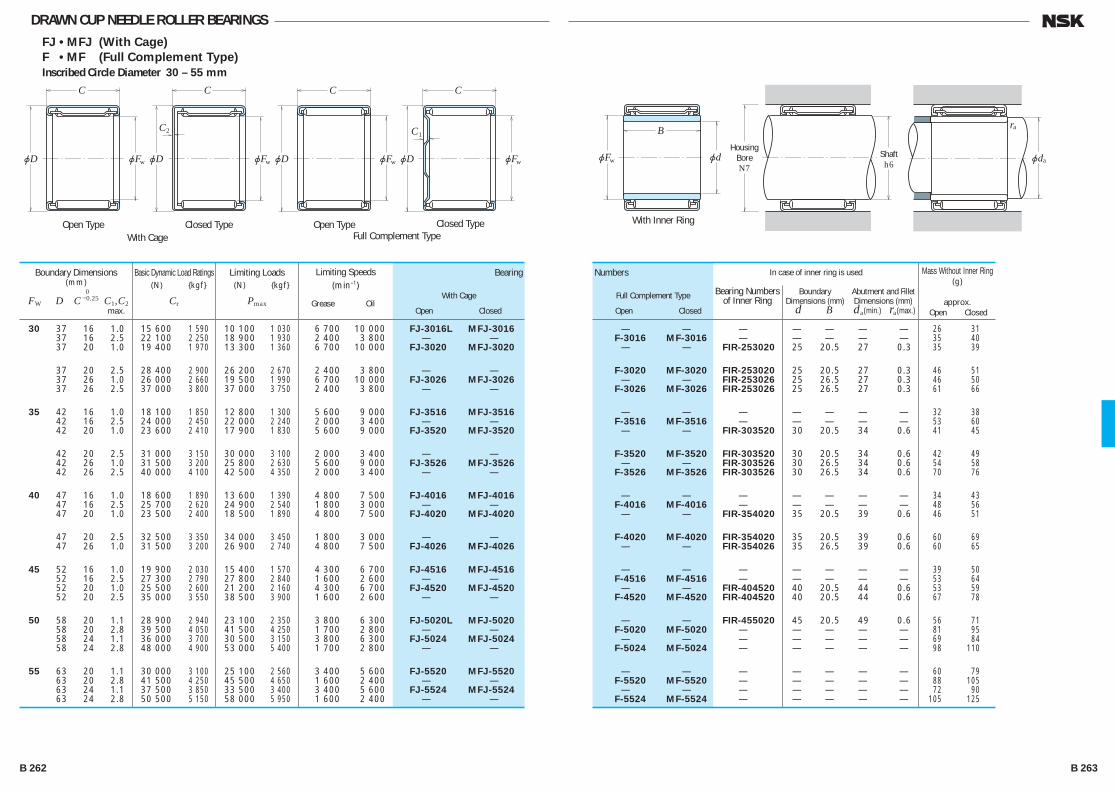
DRAWN CUP NEEDLE ROLLER BEARINGSFJ • MFJ (With Cage)
F • MF (Full Complement Type)
Inscribed Circle Diameter 30 – 55 mm
jd
B
jFw
With Inner Ring
jda
HousingBoreN7
Shafth6
ra
jD
C
jFw
2
Open Type
jD
C
jFw
Open Type
jD
C
C1C
jFw
Closed Type Closed TypeWith Cage Full Complement Type
jD
C
jFw
30 37 16 1.0 15 600 1 590 10 100 1 030 6 700 10 000 FJ-3016L MFJ-3016 37 16 2.5 22 100 2 250 18 900 1 930 2 400 3 800 - - 37 20 1.0 19 400 1 970 13 300 1 360 6 700 10 000 FJ-3020 MFJ-3020
37 20 2.5 28 400 2 900 26 200 2 670 2 400 3 800 - - 37 26 1.0 26 000 2 660 19 500 1 990 6 700 10 000 FJ-3026 MFJ-3026 37 26 2.5 37 000 3 800 37 000 3 750 2 400 3 800 - -
35 42 16 1.0 18 100 1 850 12 800 1 300 5 600 9 000 FJ-3516 MFJ-3516 42 16 2.5 24 000 2 450 22 000 2 240 2 000 3 400 - - 42 20 1.0 23 600 2 410 17 900 1 830 5 600 9 000 FJ-3520 MFJ-3520
42 20 2.5 31 000 3 150 30 000 3 100 2 000 3 400 - - 42 26 1.0 31 500 3 200 25 800 2 630 5 600 9 000 FJ-3526 MFJ-3526 42 26 2.5 40 000 4 100 42 500 4 350 2 000 3 400 - -
40 47 16 1.0 18 600 1 890 13 600 1 390 4 800 7 500 FJ-4016 MFJ-4016 47 16 2.5 25 700 2 620 24 900 2 540 1 800 3 000 - - 47 20 1.0 23 500 2 400 18 500 1 890 4 800 7 500 FJ-4020 MFJ-4020
47 20 2.5 32 500 3 350 34 000 3 450 1 800 3 000 - - 47 26 1.0 31 500 3 200 26 900 2 740 4 800 7 500 FJ-4026 MFJ-4026
45 52 16 1.0 19 900 2 030 15 400 1 570 4 300 6 700 FJ-4516 MFJ-4516 52 16 2.5 27 300 2 790 27 800 2 840 1 600 2 600 - - 52 20 1.0 25 500 2 600 21 200 2 160 4 300 6 700 FJ-4520 MFJ-4520 52 20 2.5 35 000 3 550 38 500 3 900 1 600 2 600 - -
50 58 20 1.1 28 900 2 940 23 100 2 350 3 800 6 300 FJ-5020L MFJ-5020 58 20 2.8 39 500 4 050 41 500 4 250 1 700 2 800 - - 58 24 1.1 36 000 3 700 30 500 3 150 3 800 6 300 FJ-5024 MFJ-5024 58 24 2.8 48 000 4 900 53 000 5 400 1 700 2 800 - -
55 63 20 1.1 30 000 3 100 25 100 2 560 3 400 5 600 FJ-5520 MFJ-5520 63 20 2.8 41 500 4 250 45 500 4 650 1 600 2 400 - - 63 24 1.1 37 500 3 850 33 500 3 400 3 400 5 600 FJ-5524 MFJ-5524 63 24 2.8 50 500 5 150 58 000 5 950 1 600 2 400 - -
Boundary Dimensions(mm)
FW D C0
–0.25 C1,C2 max.
Basic Dynamic Load Ratings (N) {kgf}
Cr
Limiting Loads (N) {kgf}
Pmax
Bearing
With Cage
Open Closed
Numbers
Full Complement Type
Open Closed
Limiting Speeds (min–1)
Grease Oil
- - - - - - - 26 31 F-3016 MF-3016 - - - - - 35 40 - - FIR-253020 25 20.5 27 0.3 35 39
F-3020 MF-3020 FIR-253020 25 20.5 27 0.3 46 51 - - FIR-253026 25 26.5 27 0.3 46 50 F-3026 MF-3026 FIR-253026 25 26.5 27 0.3 61 66
- - - - - - - 32 38 F-3516 MF-3516 - - - - - 53 60 - - FIR-303520 30 20.5 34 0.6 41 45
F-3520 MF-3520 FIR-303520 30 20.5 34 0.6 42 49 - - FIR-303526 30 26.5 34 0.6 54 58 F-3526 MF-3526 FIR-303526 30 26.5 34 0.6 70 76
- - - - - - - 34 43 F-4016 MF-4016 - - - - - 48 56 - - FIR-354020 35 20.5 39 0.6 46 51
F-4020 MF-4020 FIR-354020 35 20.5 39 0.6 60 69 - - FIR-354026 35 26.5 39 0.6 60 65
- - - - - - - 39 50 F-4516 MF-4516 - - - - - 53 64 - - FIR-404520 40 20.5 44 0.6 53 59 F-4520 MF-4520 FIR-404520 40 20.5 44 0.6 67 78
- - FIR-455020 45 20.5 49 0.6 56 71 F-5020 MF-5020 - - - - - 81 95 - - - - - - - 69 84 F-5024 MF-5024 - - - - - 98 110
- - - - - - - 60 79 F-5520 MF-5520 - - - - - 88 105 - - - - - - - 72 90 F-5524 MF-5524 - - - - - 105 125
In case of inner ring is used
Bearing Numbers Boundary Abutment and Fillet of Inner Ring Dimensions (mm) Dimensions (mm) d B da(min.) ra(max.)
Mass Without Inner Ring(g)
approx. Open Closed
B 262 B 263
B244-279E.indd 262-263B244-279E.indd 262-263 11/20/13 4:59:51 PM11/20/13 4:59:51 PM
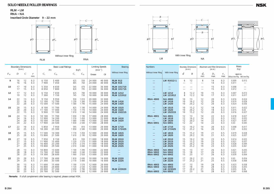
jD
Cr
jFw
Without Inner Ring
jD
C
r
jFw
RLM RNA
jD
CB
r
r
jd
With Inner Ring
jD
C
B
r
r
jd
LM NA
jD jd
ra
a a
ra
SOLID NEEDLE ROLLER BEARINGSRLM • LM
RNA • NA
Inscribed Circle Diameter 9 – 22 mm
9 16 12 0.3 6 150 5 400 625 550 24 000 40 000 RLM 912 16 16 0.3 7 900 7 450 805 760 24 000 40 000 RLM 916
10 17 10 0.3 5 350 4 650 545 470 22 000 36 000 RLM 101710 17 15 0.3 8 050 7 800 820 795 22 000 36 000 RLM 101715
12 17 12 0.3 6 150 7 650 625 780 18 000 30 000 RLM 1212 19 12 0.3 7 300 7 150 745 730 18 000 30 000 RLM 121912
14 22 13 0.3 9 150 9 950 930 1 010 20 000 32 000 — 22 16 0.3 12 100 12 700 1 230 1 300 15 000 24 000 RLM 1416 22 20 0.3 15 500 17 500 1 580 1 790 15 000 24 000 RLM 1420
15 20 15 0.3 8 100 11 700 825 1 190 14 000 24 000 RLM 1515 20 20 0.3 11 100 17 400 1 130 1 770 14 000 24 000 RLM 1520 22 15 0.3 9 900 11 100 1 010 1 140 14 000 24 000 RLM 152215
16 24 13 0.3 10 100 11 700 1 030 1 190 17 000 28 000 — 24 16 0.3 12 900 14 200 1 310 1 450 13 000 22 000 RLM 1616 24 20 0.3 16 500 19 500 1 680 1 990 13 000 22 000 RLM 1620 24 22 0.3 17 900 24 500 1 830 2 500 17 000 28 000 —
17 22 10 0.3 5 850 7 950 595 810 13 000 20 000 RLM 1710 24 25 0.5 18 200 25 300 1 850 2 580 13 000 20 000 RLM 172425
18 25 15 0.5 11 500 14 300 1 170 1 450 12 000 20 000 RLM 1815 25 20 0.5 15 800 21 500 1 610 2 190 12 000 20 000 RLM 1820
20 27 10 0.5 7 950 9 150 810 930 11 000 18 000 RLM 2010 27 15 0.5 11 900 15 400 1 220 1 570 11 000 18 000 RLM 2015 27 20 0.5 16 400 23 200 1 670 2 370 11 000 18 000 RLM 2020 27 25 0.5 19 800 29 500 2 010 3 000 11 000 18 000 RLM 2025
28 13 0.3 10 800 13 600 1 100 1 390 13 000 22 000 — 28 18 0.3 15 700 21 900 1 600 2 240 13 000 22 000 — 28 23 0.3 19 300 28 600 1 960 2 920 13 000 22 000 —
22 29 20 0.5 17 700 26 400 1 810 2 690 10 000 16 000 RLM 2220 29 25 0.5 21 300 33 500 2 170 3 400 10 000 16 000 RLM 2225
30 13 0.3 11 600 15 400 1 190 1 570 12 000 20 000 — 30 18 0.3 16 800 24 800 1 720 2 530 12 000 20 000 — 30 20 0.5 20 000 27 200 2 030 2 780 10 000 16 000 RLM 223020 30 23 0.3 20 700 32 500 2 110 3 300 12 000 20 000 —
Boundary Dimensions(mm)
FW D C r min.
Basic Load Ratings (N) {kgf}
Cr C0r Cr C0r
Bearing
Without Inner Ring
Numbers
Without Inner Ring With Inner Ring
Limiting Speeds (min–1)
Grease Oil
— LM 91612-1 6 12 8 14 0.3 0.009 0.013 — — — — — 14 0.3 0.011 .—
— — — — — 15 0.3 0.008 .— — — — — — 15 0.3 0.012 .—
— LM 1212 8 12.2 10 15 0.3 0.007 0.013 — LM 121912 8 12.2 10 17 0.3 0.011 0.017
RNA 4900 NA 4900 10 13 12 20 0.3 0.016 0.024 — LM 1416 10 16.2 12 20 0.3 0.019 0.028 — LM 1420 10 20.2 12 20 0.3 0.024 0.036
— LM 1515 10 15.2 12 18 0.3 0.011 0.022 — LM 1520 10 20.2 12 18 0.3 0.015 0.03 — LM 152215 10 15.2 12 20 0.3 0.016 0.027
RNA 4901 NA 4901 12 13 14 22 0.3 0.018 0.027 — LM 1616 12 16.2 14 22 0.3 0.021 0.032 — LM 1620 12 20.2 14 22 0.3 0.027 0.041 RNA 6901 NA 6901 12 22 14 22 0.3 0.03 0.045
— LM 1710 12 10.2 14 20 0.3 0.008 0.017 — LM 172425 12 25.2 16 20 0.5 0.03 0.052
— LM 1815 15 15.2 19 21 0.5 0.019 0.028 — LM 1820 15 20.2 19 21 0.5 0.025 0.037
— LM 2010 15 10.2 19 23 0.5 0.014 0.025 — LM 2015 15 15.2 19 23 0.5 0.021 0.037 — LM 2020 15 20.2 19 23 0.5 0.028 0.049 — LM 2025 15 25.2 19 23 0.5 0.035 0.061
RNA 4902 NA 4902 15 13 17 26 0.3 0.021 0.035 RNA 5902 NA 5902 15 18 17 26 0.3 0.032 0.051 RNA 6902 NA 6902 15 23 17 26 0.3 0.039 0.064
— LM 2220 17 20.2 21 25 0.5 0.03 0.054 — LM 2225 17 25.2 21 25 0.5 0.038 0.068
RNA 4903 NA 4903 17 13 19 28 0.3 0.023 0.038 RNA 5903 NA 5903 17 18 19 28 0.3 0.034 0.055 — LM 223020 17 20.2 21 26 0.5 0.035 0.06 RNA 6903 NA 6903 17 23 19 28 0.3 0.041 0.068
Abutment and Fillet Dimensions(mm)
da Da ra min. max. max.
Boundary Dimensions(mm)
d B
Mass(kg)
approx. Without Inner Ring With Inner Ring
Remarks If a full complement roller bearing is required, please contact NSK.
B 264 B 265
B244-279E.indd 264-265B244-279E.indd 264-265 11/20/13 4:59:52 PM11/20/13 4:59:52 PM
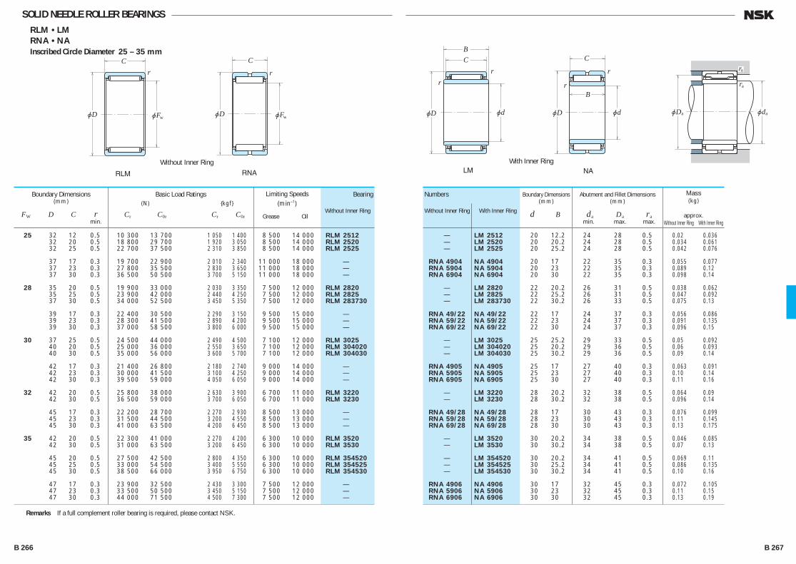
SOLID NEEDLE ROLLER BEARINGSRLM • LM
RNA • NA
Inscribed Circle Diameter 25 – 35 mm
jD
Cr
jFw
Without Inner Ring
jD
C
r
jFw
RLM RNA
jD
CB
r
r
jd
With Inner Ring
jD
C
B
r
r
jd
LM NA
jD jd
ra
a a
ra
25 32 12 0.5 10 300 13 700 1 050 1 400 8 500 14 000 RLM 2512 32 20 0.5 18 800 29 700 1 920 3 050 8 500 14 000 RLM 2520 32 25 0.5 22 700 37 500 2 310 3 850 8 500 14 000 RLM 2525
37 17 0.3 19 700 22 900 2 010 2 340 11 000 18 000 — 37 23 0.3 27 800 35 500 2 830 3 650 11 000 18 000 — 37 30 0.3 36 500 50 500 3 700 5 150 11 000 18 000 —
28 35 20 0.5 19 900 33 000 2 030 3 350 7 500 12 000 RLM 2820 35 25 0.5 23 900 42 000 2 440 4 250 7 500 12 000 RLM 2825 37 30 0.5 34 000 52 500 3 450 5 350 7 500 12 000 RLM 283730
39 17 0.3 22 400 30 500 2 290 3 150 9 500 15 000 — 39 23 0.3 28 300 41 500 2 890 4 200 9 500 15 000 — 39 30 0.3 37 000 58 500 3 800 6 000 9 500 15 000 —
30 37 25 0.5 24 500 44 000 2 490 4 500 7 100 12 000 RLM 3025 40 20 0.5 25 000 36 000 2 550 3 650 7 100 12 000 RLM 304020 40 30 0.5 35 000 56 000 3 600 5 700 7 100 12 000 RLM 304030
42 17 0.3 21 400 26 800 2 180 2 740 9 000 14 000 — 42 23 0.3 30 000 41 500 3 100 4 250 9 000 14 000 — 42 30 0.3 39 500 59 000 4 050 6 050 9 000 14 000 —
32 42 20 0.5 25 800 38 000 2 630 3 900 6 700 11 000 RLM 3220 42 30 0.5 36 500 59 000 3 700 6 050 6 700 11 000 RLM 3230
45 17 0.3 22 200 28 700 2 270 2 930 8 500 13 000 — 45 23 0.3 31 500 44 500 3 200 4 550 8 500 13 000 — 45 30 0.3 41 000 63 500 4 200 6 450 8 500 13 000 —
35 42 20 0.5 22 300 41 000 2 270 4 200 6 300 10 000 RLM 3520 42 30 0.5 31 000 63 500 3 200 6 450 6 300 10 000 RLM 3530
45 20 0.5 27 500 42 500 2 800 4 350 6 300 10 000 RLM 354520 45 25 0.5 33 000 54 500 3 400 5 550 6 300 10 000 RLM 354525 45 30 0.5 38 500 66 000 3 950 6 750 6 300 10 000 RLM 354530
47 17 0.3 23 900 32 500 2 430 3 300 7 500 12 000 — 47 23 0.3 33 500 50 500 3 450 5 150 7 500 12 000 — 47 30 0.3 44 000 71 500 4 500 7 300 7 500 12 000 —
Boundary Dimensions(mm)
FW D C r min.
Basic Load Ratings (N) {kgf}
Cr C0r Cr C0r
Bearing
Without Inner Ring
Numbers
Without Inner Ring With Inner Ring
Limiting Speeds (min–1)
Grease Oil
— LM 2512 20 12.2 24 28 0.5 0.02 0.036 — LM 2520 20 20.2 24 28 0.5 0.034 0.061 — LM 2525 20 25.2 24 28 0.5 0.042 0.076
RNA 4904 NA 4904 20 17 22 35 0.3 0.055 0.077 RNA 5904 NA 5904 20 23 22 35 0.3 0.089 0.12 RNA 6904 NA 6904 20 30 22 35 0.3 0.098 0.14
— LM 2820 22 20.2 26 31 0.5 0.038 0.062 — LM 2825 22 25.2 26 31 0.5 0.047 0.092 — LM 283730 22 30.2 26 33 0.5 0.075 0.13
RNA 49/22 NA 49/22 22 17 24 37 0.3 0.056 0.086 RNA 59/22 NA 59/22 22 23 24 37 0.3 0.091 0.135 RNA 69/22 NA 69/22 22 30 24 37 0.3 0.096 0.15
— LM 3025 25 25.2 29 33 0.5 0.05 0.092 — LM 304020 25 20.2 29 36 0.5 0.06 0.093 — LM 304030 25 30.2 29 36 0.5 0.09 0.14
RNA 4905 NA 4905 25 17 27 40 0.3 0.063 0.091 RNA 5905 NA 5905 25 23 27 40 0.3 0.10 0.14 RNA 6905 NA 6905 25 30 27 40 0.3 0.11 0.16
— LM 3220 28 20.2 32 38 0.5 0.064 0.09 — LM 3230 28 30.2 32 38 0.5 0.096 0.14
RNA 49/28 NA 49/28 28 17 30 43 0.3 0.076 0.099 RNA 59/28 NA 59/28 28 23 30 43 0.3 0.11 0.145 RNA 69/28 NA 69/28 28 30 30 43 0.3 0.13 0.175
— LM 3520 30 20.2 34 38 0.5 0.046 0.085 — LM 3530 30 30.2 34 38 0.5 0.07 0.13
— LM 354520 30 20.2 34 41 0.5 0.069 0.11 — LM 354525 30 25.2 34 41 0.5 0.086 0.135 — LM 354530 30 30.2 34 41 0.5 0.10 0.16
RNA 4906 NA 4906 30 17 32 45 0.3 0.072 0.105 RNA 5906 NA 5906 30 23 32 45 0.3 0.11 0.15 RNA 6906 NA 6906 30 30 32 45 0.3 0.13 0.19
Abutment and Fillet Dimensions(mm)
da Da ra min. max. max.
Boundary Dimensions(mm)
d B
Mass(kg)
approx. Without Inner Ring With Inner Ring
Remarks If a full complement roller bearing is required, please contact NSK.
B 266 B 267
B244-279E.indd 266-267B244-279E.indd 266-267 11/20/13 4:59:53 PM11/20/13 4:59:53 PM
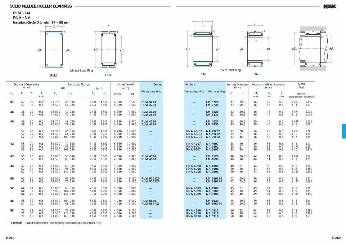
SOLID NEEDLE ROLLER BEARINGSRLM • LM
RNA • NA
Inscribed Circle Diameter 37 – 58 mm
jD
Cr
jFw
Without Inner Ring
jD
C
r
jFw
RLM RNA
jD
CB
r
r
jd
With Inner Ring
jD
C
B
r
r
jd
LM NA
jD jd
ra
a a
ra
37 47 20 0.6 28 200 45 000 2 880 4 550 6 000 9 500 RLM 3720 47 30 0.6 39 500 69 500 4 050 7 100 6 000 9 500 RLM 3730
38 48 20 0.6 29 000 47 000 2 960 4 800 5 600 9 000 RLM 3820 48 30 0.6 41 000 73 000 4 150 7 450 5 600 9 000 RLM 3830
40 50 20 0.6 29 700 49 000 3 050 5 000 5 300 9 000 RLM 4020 50 30 0.6 42 000 76 500 4 250 7 800 5 300 9 000 RLM 4030
52 20 0.6 29 900 45 000 3 050 4 600 6 700 10 000 — 52 27 0.6 40 500 66 000 4 100 6 750 6 700 10 000 — 52 36 0.6 56 000 101 000 5 700 10 300 6 700 10 000 —
42 55 20 0.6 30 500 47 500 3 100 4 800 6 300 10 000 — 55 27 0.6 41 500 69 500 4 200 7 100 6 300 10 000 — 55 36 0.6 57 500 106 000 5 850 10 900 6 300 10 000 —
45 55 20 0.6 31 000 53 500 3 150 5 500 4 800 8 000 RLM 4520 55 30 0.6 43 500 83 500 4 450 8 500 4 800 8 000 RLM 4530
48 62 22 0.6 39 000 61 500 3 950 6 300 5 600 9 000 — 62 30 0.6 54 500 95 000 5 550 9 700 5 600 9 000 — 62 40 0.6 72 000 137 000 7 350 13 900 5 600 9 000 —
50 62 20 0.6 35 500 60 500 3 600 6 150 4 300 7 100 RLM 506220 62 25 0.6 43 000 77 500 4 400 7 900 4 300 7 100 RLM 506225
52 68 22 0.6 41 000 67 500 4 150 6 900 5 000 8 000 — 68 30 0.6 57 000 104 000 5 800 10 600 5 000 8 000 — 68 40 0.6 76 000 149 000 7 750 15 200 5 000 8 000 —
55 65 30 0.6 49 000 104 000 5 000 10 600 4 000 6 300 RLM 5530 67 20 0.6 38 000 68 000 3 850 6 900 4 000 6 300 RLM 556720
58 72 22 0.6 42 500 73 500 4 350 7 500 4 500 7 100 — 72 30 0.6 59 500 113 000 6 050 11 500 4 500 7 100 — 72 40 0.6 79 000 163 000 8 050 16 600 4 500 7 100 —
Boundary Dimensions(mm)
FW D C r min.
Basic Load Ratings (N) {kgf}
Cr C0r Cr C0r
Bearing
Without Inner Ring
Numbers
Without Inner Ring With Inner Ring
Limiting Speeds (min–1)
Grease Oil
— LM 3720 32 20.3 36 43 0.6 0.072 0.115 — LM 3730 32 30.3 36 43 0.6 0.11 0.17
— LM 3820 32 20.3 36 44 0.6 0.074 0.125 — LM 3830 32 30.3 36 44 0.6 0.11 0.195
— LM 4020 35 20.3 39 46 0.6 0.078 0.125 — LM 4030 35 30.3 39 46 0.6 0.12 0.19
RNA 49/32 NA 49/32 32 20 36 48 0.6 0.092 0.16 RNA 59/32 NA 59/32 32 27 36 48 0.6 0.15 0.24 RNA 69/32 NA 69/32 32 36 36 48 0.6 0.17 0.29
RNA 4907 NA 4907 35 20 39 51 0.6 0.11 0.17 RNA 5907 NA 5907 35 27 39 51 0.6 0.175 0.25 RNA 6907 NA 6907 35 36 39 51 0.6 0.20 0.315
— LM 4520 40 20.3 44 51 0.6 0.086 0.14 — LM 4530 40 30.3 44 51 0.6 0.13 0.21
RNA 4908 NA 4908 40 22 44 58 0.6 0.15 0.24 RNA 5908 NA 5908 40 30 44 58 0.6 0.23 0.355 RNA 6908 NA 6908 40 40 44 58 0.6 0.265 0.435
— LM 506220 42 20.3 46 58 0.6 0.12 0.21 — LM 506225 42 25.3 46 58 0.6 0.155 0.265
RNA 4909 NA 4909 45 22 49 64 0.6 0.19 0.28 RNA 5909 NA 5909 45 30 49 64 0.6 0.27 0.39 RNA 6909 NA 6909 45 40 49 64 0.6 0.335 0.495
— LM 5530 45 30.3 49 61 0.6 0.16 0.34 — LM 556720 45 20.3 49 63 0.6 0.13 0.25
RNA 4910 NA 4910 50 22 54 68 0.6 0.18 0.295 RNA 5910 NA 5910 50 30 54 68 0.6 0.25 0.405 RNA 6910 NA 6910 50 40 54 68 0.6 0.32 0.53
Abutment and Fillet Dimensions(mm)
da Da ra min. max. max.
Boundary Dimensions(mm)
d B
Mass(kg)
approx. Without Inner Ring With Inner Ring
Remarks If a full complement roller bearing is required, please contact NSK.
B 268 B 269
B244-279E.indd 268-269B244-279E.indd 268-269 11/20/13 4:59:54 PM11/20/13 4:59:54 PM

Without Inner Ring
jD
C
r
jFw
RNAWith Inner Ring
jD
C
B
r
r
jd
NA
jD jd
ra
a a
ra
SOLID NEEDLE ROLLER BEARINGSRNA • NA
Inscribed Circle Diameter 63 – 120 mm
63 80 25 1 53 500 87 500 5 450 8 950 4 000 6 700 RNA 4911 80 34 1 73 500 133 000 7 500 13 600 4 000 6 700 RNA 5911 80 45 1 93 500 181 000 9 550 18 500 4 000 6 700 RNA 6911
68 85 25 1 56 000 95 500 5 700 9 750 3 800 6 300 RNA 4912 85 34 1 77 500 145 000 7 900 14 800 3 800 6 300 RNA 5912 85 45 1 98 000 197 000 10 000 20 100 3 800 6 300 RNA 6912
72 90 25 1 58 500 103 000 5 950 10 500 3 600 5 600 RNA 4913 90 34 1 81 000 157 000 8 250 16 000 3 600 5 600 RNA 5913 90 45 1 103 000 213 000 10 500 21 800 3 600 5 600 RNA 6913
80 100 30 1 80 500 143 000 8 200 14 600 3 200 5 300 RNA 4914 100 40 1 107 000 206 000 10 900 21 000 3 200 5 300 RNA 5914 100 54 1 143 000 298 000 14 500 30 500 3 200 5 300 RNA 6914
85 105 30 1 84 000 155 000 8 600 15 800 3 000 5 000 RNA 4915 105 40 1 112 000 222 000 11 400 22 700 3 000 5 000 RNA 5915 105 54 1 149 000 325 000 15 200 33 000 3 000 5 000 RNA 6915
90 110 30 1 87 500 166 000 8 950 17 000 2 800 4 500 RNA 4916 110 40 1 116 000 239 000 11 900 24 400 2 800 4 500 RNA 5916 110 54 1 157 000 350 000 16 000 36 000 2 800 4 500 RNA 6916
100 120 35 1.1 104 000 214 000 10 600 21 800 2 600 4 000 RNA 4917 120 46 1.1 138 000 310 000 14 100 31 500 2 600 4 000 RNA 5917 120 63 1.1 174 000 415 000 17 800 42 500 2 600 4 000 RNA 6917
105 125 35 1.1 108 000 228 000 11 000 23 300 2 400 4 000 RNA 4918 125 46 1.1 143 000 330 000 14 600 33 500 2 400 4 000 RNA 5918 125 63 1.1 181 000 445 000 18 400 45 000 2 400 4 000 RNA 6918
110 130 35 1.1 111 000 242 000 11 400 24 700 2 200 3 800 RNA 4919 130 46 1.1 148 000 350 000 15 100 35 500 2 200 3 800 RNA 5919 130 63 1.1 187 000 470 000 19 100 48 000 2 200 3 800 RNA 6919
115 140 40 1.1 144 000 295 000 14 700 30 000 2 200 3 600 RNA 4920 140 54 1.1 193 000 430 000 19 700 43 500 2 200 3 600 RNA 5920 120 140 30 1 99 500 214 000 10 100 21 900 2 000 3 400 RNA 4822
Boundary Dimensions(mm)
FW D C r min.
Basic Load Ratings (N) {kgf}
Cr C0r Cr C0r
Bearing
Without Inner Ring
Numbers
With Inner Ring
Limiting Speeds (min–1)
Grease Oil
NA 4911 55 25 60 75 1 0.26 0.40 NA 5911 55 34 60 75 1 0.37 0.56 NA 6911 55 45 60 75 1 0.475 0.73
NA 4912 60 25 65 80 1 0.28 0.435 NA 5912 60 34 65 80 1 0.415 0.625 NA 6912 60 45 65 80 1 0.485 0.76
NA 4913 65 25 70 85 1 0.32 0.465 NA 5913 65 34 70 85 1 0.48 0.675 NA 6913 65 45 70 85 1 0.53 0.79
NA 4914 70 30 75 95 1 0.47 0.74 NA 5914 70 40 75 95 1 0.69 1.05 NA 6914 70 54 75 95 1 0.89 1.4
NA 4915 75 30 80 100 1 0.5 0.79 NA 5915 75 40 80 100 1 0.735 1.1 NA 6915 75 54 80 100 1 0.96 1.5
NA 4916 80 30 85 105 1 0.53 0.835 NA 5916 80 40 85 105 1 0.75 1.15 NA 6916 80 54 85 105 1 0.99 1.55
NA 4917 85 35 91.5 113.5 1 0.68 1.25 NA 5917 85 46 91.5 113.5 1 0.99 1.75 NA 6917 85 63 91.5 113.5 1 1.2 2.25
NA 4918 90 35 96.5 118.5 1 0.72 1.35 NA 5918 90 46 96.5 118.5 1 1.05 1.85 NA 6918 90 63 96.5 118.5 1 1.35 2.45
NA 4919 95 35 101.5 123.5 1 0.74 1.4 NA 5919 95 46 101.5 123.5 1 1.15 2.0 NA 6919 95 63 101.5 123.5 1 1.5 2.65
NA 4920 100 40 106.5 133.5 1 1.15 1.95 NA 5920 100 54 106.5 133.5 1 1.8 2.85 NA 4822 110 30 115 135 1 0.67 1.1
Abutment and Fillet Dimensions(mm)
da Da ra min. max. max.
Boundary Dimensions(mm)
d B
Mass(kg)
approx. Without Inner Ring With Inner Ring
Remarks If a full complement roller bearing is required, please contact NSK.
B 270 B 271
B244-279E.indd 270-271B244-279E.indd 270-271 11/20/13 4:59:55 PM11/20/13 4:59:55 PM
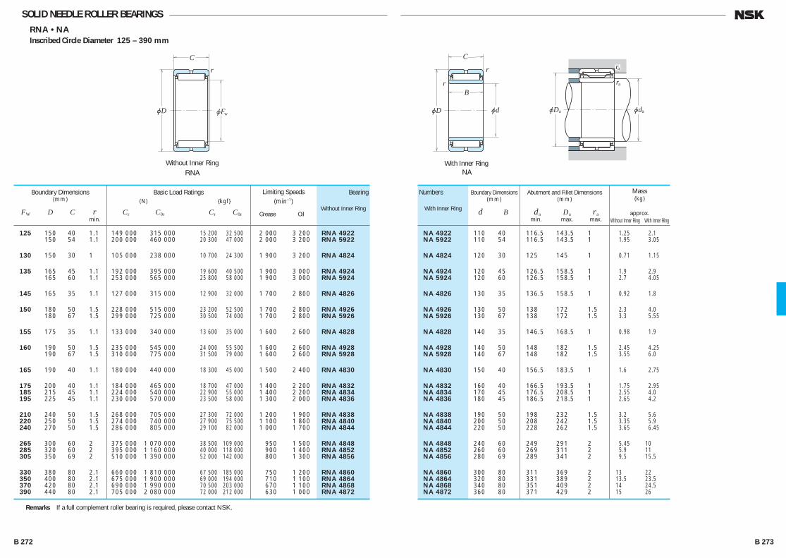
SOLID NEEDLE ROLLER BEARINGSRNA • NA
Inscribed Circle Diameter 125 – 390 mm
Without Inner Ring
jD
C
r
jFw
RNAWith Inner Ring
jD
C
B
r
r
jd
NA
jD jd
ra
a a
ra
125 150 40 1.1 149 000 315 000 15 200 32 500 2 000 3 200 RNA 4922 150 54 1.1 200 000 460 000 20 300 47 000 2 000 3 200 RNA 5922
130 150 30 1 105 000 238 000 10 700 24 300 1 900 3 200 RNA 4824
135 165 45 1.1 192 000 395 000 19 600 40 500 1 900 3 000 RNA 4924 165 60 1.1 253 000 565 000 25 800 58 000 1 900 3 000 RNA 5924
145 165 35 1.1 127 000 315 000 12 900 32 000 1 700 2 800 RNA 4826
150 180 50 1.5 228 000 515 000 23 200 52 500 1 700 2 800 RNA 4926 180 67 1.5 299 000 725 000 30 500 74 000 1 700 2 800 RNA 5926
155 175 35 1.1 133 000 340 000 13 600 35 000 1 600 2 600 RNA 4828
160 190 50 1.5 235 000 545 000 24 000 55 500 1 600 2 600 RNA 4928 190 67 1.5 310 000 775 000 31 500 79 000 1 600 2 600 RNA 5928
165 190 40 1.1 180 000 440 000 18 300 45 000 1 500 2 400 RNA 4830
175 200 40 1.1 184 000 465 000 18 700 47 000 1 400 2 200 RNA 4832 185 215 45 1.1 224 000 540 000 22 900 55 000 1 400 2 200 RNA 4834 195 225 45 1.1 230 000 570 000 23 500 58 000 1 300 2 000 RNA 4836
210 240 50 1.5 268 000 705 000 27 300 72 000 1 200 1 900 RNA 4838 220 250 50 1.5 274 000 740 000 27 900 75 500 1 100 1 800 RNA 4840 240 270 50 1.5 286 000 805 000 29 100 82 000 1 000 1 700 RNA 4844
265 300 60 2 375 000 1 070 000 38 500 109 000 950 1 500 RNA 4848 285 320 60 2 395 000 1 160 000 40 000 118 000 900 1 400 RNA 4852 305 350 69 2 510 000 1 390 000 52 000 142 000 800 1 300 RNA 4856
330 380 80 2.1 660 000 1 810 000 67 500 185 000 750 1 200 RNA 4860 350 400 80 2.1 675 000 1 900 000 69 000 194 000 710 1 100 RNA 4864 370 420 80 2.1 690 000 1 990 000 70 500 203 000 670 1 100 RNA 4868 390 440 80 2.1 705 000 2 080 000 72 000 212 000 630 1 000 RNA 4872
Boundary Dimensions(mm)
FW D C r min.
Basic Load Ratings (N) {kgf}
Cr C0r Cr C0r
Bearing
Without Inner Ring
Numbers
With Inner Ring
Limiting Speeds (min–1)
Grease Oil
NA 4922 110 40 116.5 143.5 1 1.25 2.1 NA 5922 110 54 116.5 143.5 1 1.95 3.05
NA 4824 120 30 125 145 1 0.71 1.15
NA 4924 120 45 126.5 158.5 1 1.9 2.9 NA 5924 120 60 126.5 158.5 1 2.7 4.05
NA 4826 130 35 136.5 158.5 1 0.92 1.8
NA 4926 130 50 138 172 1.5 2.3 4.0 NA 5926 130 67 138 172 1.5 3.3 5.55
NA 4828 140 35 146.5 168.5 1 0.98 1.9
NA 4928 140 50 148 182 1.5 2.45 4.25 NA 5928 140 67 148 182 1.5 3.55 6.0
NA 4830 150 40 156.5 183.5 1 1.6 2.75
NA 4832 160 40 166.5 193.5 1 1.75 2.95 NA 4834 170 45 176.5 208.5 1 2.55 4.0 NA 4836 180 45 186.5 218.5 1 2.65 4.2
NA 4838 190 50 198 232 1.5 3.2 5.6 NA 4840 200 50 208 242 1.5 3.35 5.9 NA 4844 220 50 228 262 1.5 3.65 6.45
NA 4848 240 60 249 291 2 5.45 10 NA 4852 260 60 269 311 2 5.9 11 NA 4856 280 69 289 341 2 9.5 15.5
NA 4860 300 80 311 369 2 13 22 NA 4864 320 80 331 389 2 13.5 23.5 NA 4868 340 80 351 409 2 14 24.5 NA 4872 360 80 371 429 2 15 26
Abutment and Fillet Dimensions(mm)
da Da ra min. max. max.
Boundary Dimensions(mm)
d B
Mass(kg)
approx. Without Inner Ring With Inner Ring
Remarks If a full complement roller bearing is required, please contact NSK.
B 272 B 273
B244-279E.indd 272-273B244-279E.indd 272-273 11/20/13 4:59:56 PM11/20/13 4:59:56 PM

jDC
jDW00.005
jDC1 E11C12
FNTA FTRA FTRB
(1) (1)
–
jD
s
P– 0.25– 0.75 jDP1
+ 0.30+ 0.05 jDeijD
FTRC FTRD FTRE
THRUST NEEDLE ROLLER BEARINGSFNTA (Thrust Cage & Needle Roller Assemblies)
Thrust raceway washersFTRA (s=1.0)FTRB (s=1.5)FTRC (s=2.0)
FTRD (s=2.5)FTRE (s=3.0)
Bore Diameter 10 – 100 mm
10 24 2 7 750 23 000 790 2 350 17 000 FNTA-1024 *FTRA-1024 12 26 2 8 350 26 300 855 2 680 16 000 FNTA-1226 FTRA-1226 15 28 2 7 950 25 800 810 2 630 15 000 FNTA-1528 FTRA-1528
16 29 2 8 200 27 100 835 2 770 14 000 FNTA-1629 FTRA-1629 17 30 2 8 400 28 400 855 2 900 14 000 FNTA-1730 FTRA-1730 18 31 2 8 600 29 700 875 3 050 13 000 FNTA-1831 FTRA-1831
20 35 2 11 900 47 000 1 220 4 800 12 000 FNTA-2035 FTRA-2035 25 42 2 14 800 66 000 1 510 6 750 9 500 FNTA-2542 FTRA-2542 30 47 2 16 500 79 000 1 680 8 100 8 500 FNTA-3047 FTRA-3047
35 52 2 17 300 88 000 1 770 8 950 8 000 FNTA-3552 FTRA-3552 40 60 3 26 900 122 000 2 740 12 400 6 700 FNTA-4060 FTRA-4060 45 65 3 28 700 137 000 2 930 14 000 6 300 FNTA-4565 FTRA-4565
50 70 3 30 500 152 000 3 100 15 500 5 600 FNTA-5070 FTRA-5070 55 78 3 37 000 201 000 3 750 20 500 5 300 FNTA-5578 FTRA-5578 60 85 3 43 000 252 000 4 400 25 700 4 800 FNTA-6085 FTRA-6085
65 90 3 45 500 274 000 4 600 28 000 4 500 FNTA-6590 FTRA-6590 70 95 4 59 000 320 000 6 000 33 000 4 300 FNTA-7095 FTRA-7095 75 100 4 60 000 335 000 6 150 34 500 4 000 FNTA-75100 FTRA-75100
80 105 4 63 000 365 000 6 450 37 500 3 800 FNTA-80105 FTRA-80105 85 110 4 64 500 380 000 6 550 39 000 3 600 FNTA-85110 FTRA-85110 90 120 4 80 000 515 000 8 150 52 500 3 400 FNTA-90120 FTRA-90120 100 135 4 98 500 695 000 10 000 71 000 3 000 FNTA-100135 FTRA-100135
Boundary Dimensions(mm)
Dc1,Dp1 Dc,Dp DW
Basic Load Ratings (N) {kgf}
Ca C0a Ca C0a
Bearing Numbers
Limiting Speeds (min–1)
Oil
FTRB-1024 FTRC-1024 — — 22.0 11.5 2.3 2.9 FTRB-1226 FTRC-1226 — — 24.0 13.5 3.4 3.3 FTRB-1528 FTRC-1528 FTRD-1528 FTRE-1528 26.0 16.5 3.5 3.5
FTRB-1629 FTRC-1629 FTRD-1629 FTRE-1629 27.0 17.5 3.7 3.6 FTRB-1730 FTRC-1730 FTRD-1730 FTRE-1730 28.0 18.5 3.8 3.8 FTRB-1831 FTRC-1831 FTRD-1831 FTRE-1831 29.0 19.5 4 3.9
FTRB-2035 FTRC-2035 FTRD-2035 FTRE-2035 33.0 21.5 5.4 5.1 FTRB-2542 FTRC-2542 FTRD-2542 FTRE-2542 40.0 26.5 7.7 7 FTRB-3047 FTRC-3047 FTRD-3047 FTRE-3047 45.0 31.5 8.9 7.9
FTRB-3552 FTRC-3552 FTRD-3552 FTRE-3552 50.5 36.5 9.7 9.1 FTRB-4060 FTRC-4060 FTRD-4060 FTRE-4060 57.0 42.0 18 12 FTRB-4565 FTRC-4565 FTRD-4565 FTRE-4565 62.0 47.0 20 13
FTRB-5070 FTRC-5070 FTRD-5070 FTRE-5070 67.0 51.5 22 15 FTRB-5578 FTRC-5578 FTRD-5578 FTRE-5578 75.0 57.0 29 19 FTRB-6085 FTRC-6085 FTRD-6085 FTRE-6085 82.0 61.5 35 22
FTRB-6590 FTRC-6590 FTRD-6590 FTRE-6590 87.5 66.5 38 24 FTRB-7095 FTRC-7095 FTRD-7095 FTRE-7095 92.5 71.5 52 25 FTRB-75100 FTRC-75100 FTRD-75100 FTRE-75100 97.5 76.5 54 27
FTRB-80105 FTRC-80105 FTRD-80105 FTRE-80105 102.5 81.5 58 28 FTRB-85110 FTRC-85110 FTRD-85110 FTRE-85110 107.5 86.5 63 30 FTRB-90120 FTRC-90120 FTRD-90120 FTRE-90120 117.5 91.5 80 38 FTRB-100135 FTRC-100135 FTRD-100135 FTRE-100135 132.5 101.5 105 50
Roller Contact Surfaces(mm)
Outside Diameter Bore Diameter De Di min. max.
s=1.0±0.05
Bearing Numbers of Matching Bearing Rings
s=1.50
–0.08 s=2.00
–0.08 s=2.50
–0.08 s=3.00
–0.08
Mass(g)
approx. FNTA FTRA
Note (1) For tolerance classes C12 and E11, please refer to ISO 286-1 and 286-2 (ISO system of limits and fits), respectively. (*) The tolerance of this bearing bore diameter is +0.025 to +0.175mm and outside diameter tolerance is
–0.040 to –0.370mm
B 274 B 275
B244-279E.indd 274-275B244-279E.indd 274-275 11/20/13 4:59:57 PM11/20/13 4:59:57 PM

jD jd
B
C
G
G
B
jM1
jM2
jM1
1
1
B3
2
Full Complement
FCR
r
X
Full Complement,Sealed
With Thrust Washer
FCRS
Full Complement,With Hexagonal Socket
FCRB
Full Complement,With Eccentric Bush
FCRE
jd
jFB
E
r ( )
4
1
a4
0– 0.25
0– 0.05
CAM FOLLOWERSFCR (Full Complement)
FCRS ⎧Full Complement, Sealed ⎫
⎩With Thrust Washer ⎭FCJ (With Cage)
FCJS ⎧Sealed, with Cage and ⎫
⎩Thrust Washer ⎭Outside Diameter 16 – 90 mm
16 11 6 M 6×1 8 28 16 — — 4(1) 0.3 FCR-16 FCRS-16 11 6 M 6×1 8 28 16 — — 4(1) 0.3 FCJ-16 FCJS-16
19 11 8 M 8×1.25 10 32 20 — — 4(1) 0.3 FCR-19 FCRS-19 11 8 M 8×1.25 10 32 20 — — 4(1) 0.3 FCJ-19 FCJS-19
22 12 10 M10×1.25 12 36 23 — — 4(1) 0.3 FCR-22 FCRS-22 12 10 M10×1.25 12 36 23 — — 4(1) 0.3 FCJ-22 FCJS-22
26 12 10 M10×1.25 12 36 23 — — 4(1) 0.3 FCR-26 FCRS-26 12 10 M10×1.25 12 36 23 — — 4(1) 0.3 FCJ-26 FCJS-26
30 14 12 M12×1.5 13 40 25 6 3 6 0.6 FCR-30 FCRS-30 14 12 M12×1.5 13 40 25 6 3 6 0.6 FCJ-30 FCJS-30
32 14 12 M12×1.5 13 40 25 6 3 6 0.6 FCR-32 FCRS-32 14 12 M12×1.5 13 40 25 6 3 6 0.6 FCJ-32 FCJS-32
35 18 16 M16×1.5 17 52 32.5 8 3 6 0.6 FCR-35 FCRS-35 18 16 M16×1.5 17 52 32.5 8 3 6 0.6 FCJ-35 FCJS-35
40 20 18 M18×1.5 19 58 36.5 8 3 6 1 FCR-40 FCRS-40 20 18 M18×1.5 19 58 36.5 8 3 6 1 FCJ-40 FCJS-40
47 24 20 M20×1.5 21 66 40.5 9 4 8 1 FCR-47 FCRS-47 24 20 M20×1.5 21 66 40.5 9 4 8 1 FCJ-47 FCJS-47
52 24 20 M20×1.5 21 66 40.5 9 4 8 1 FCR-52 FCRS-52 24 20 M20×1.5 21 66 40.5 9 4 8 1 FCJ-52 FCJS-52
62 29 24 M24×1.5 25 80 49.5 11 4 8 1 FCR-62 FCRS-62 29 24 M24×1.5 25 80 49.5 11 4 8 1 FCJ-62 FCJS-62
72 29 24 M24×1.5 25 80 49.5 11 4 8 1 FCR-72 FCRS-72 29 24 M24×1.5 25 80 49.5 11 4 8 1 FCJ-72 FCJS-72
80 35 30 M30×1.5 32 100 63 15 4 8 1 FCR-80 FCRS-80 35 30 M30×1.5 32 100 63 15 4 8 1 FCJ-80 FCJS-80
85 35 30 M30×1.5 32 100 63 15 4 8 1 FCR-85 FCRS-85 35 30 M30×1.5 32 100 63 15 4 8 1 FCJ-85 FCJS-85
90 35 30 M30×1.5 32 100 63 15 4 8 1 FCR-90 FCRS-90 35 30 M30×1.5 32 100 63 15 4 8 1 FCJ-90 FCJS-90
Boundary Dimensions(mm)
D C d
Dimensions(mm)
Screw G G1 B1 B2 B3 M2 M1 r min.
Eccentric Bush Dimensions (3)(mm)
B4 d1 E
Bearing Numbers
FCR FCRS FCJ FCJS
5 800 590 2 360 240 3 350 340 0.020 4 8 9 0.5 11 226 23 2 830 288 2 360 240 3 350 340 0.018 4 8 9 0.5 11 226 23
6 600 670 4 200 425 4 150 425 0.031 4 10 11 0.5 13 550 56 3 450 355 4 200 425 4 150 425 0.030 4 10 11 0.5 13 550 56
8 550 875 6 550 665 5 300 540 0.047 5 11 13 0.5 15 1 060 108 4 350 445 6 550 665 5 300 540 0.045 5 11 13 0.5 15 1 060 108
8 550 875 6 550 665 6 000 610 0.060 5 11 13 0.5 15 1 060 108 4 350 445 6 550 665 6 000 610 0.058 5 11 13 0.5 15 1 060 108
12 500 1 280 9 250 945 7 800 795 0.088 6 12 17 1 20 1 450 148 7 200 735 9 250 945 7 800 795 0.086 6 12 17 1 20 1 450 148
12 500 1 280 9 250 945 8 050 820 0.099 6 12 17 1 20 1 450 148 7 200 735 9 250 945 8 050 820 0.096 6 12 17 1 20 1 450 148
18 600 1 900 17 000 1 740 11 800 1 200 0.17 10 15.5 22 1 24 4 000 410 9 700 990 17 000 1 740 11 800 1 200 0.165 10 15.5 22 1 24 4 000 410
20 500 2 090 21 700 2 220 14 300 1 460 0.25 10 17.5 24 1 26 5 950 605 10 300 1 050 21 700 2 220 14 300 1 460 0.24 10 17.5 24 1 26 5 950 605
28 200 2 880 26 400 2 690 20 800 2 120 0.39 12 19.5 27 1 31 8 450 860 19 200 1 950 26 400 2 690 20 800 2 120 0.38 12 19.5 27 1 31 8 450 860
28 200 2 880 26 400 2 690 22 900 2 340 0.47 12 19.5 27 1 31 8 450 860 19 200 1 950 26 400 2 690 22 900 2 340 0.455 12 19.5 27 1 31 8 450 860
40 000 4 100 38 500 3 950 34 000 3 450 0.80 14 24.5 34 1 45 15 200 1 550 24 900 2 540 38 500 3 950 34 000 3 450 0.79 14 24.5 34 1 45 15 200 1 550
40 000 4 100 38 500 3 950 38 000 3 860 1.05 14 24.5 34 1 45 15 200 1 550 24 900 2 540 38 500 3 950 38 000 3 860 1.05 14 24.5 34 1 45 15 200 1 550
60 500 6 200 61 000 6 200 52 000 5 300 1.55 17 31 40 1.5 52 30 500 3 120 39 000 4 000 61 000 6 200 52 000 5 300 1.55 17 31 40 1.5 52 30 500 3 120
60 500 6 200 61 000 6 200 55 500 5 650 1.75 17 31 40 1.5 52 30 500 3 120 39 000 4 000 61 000 6 200 55 500 5 650 1.75 17 31 40 1.5 52 30 500 3 120
60 500 6 200 61 000 6 200 59 000 6 000 1.95 17 31 40 1.5 52 30 500 3 120 39 000 4 000 61 000 6 200 59 000 6 000 1.95 17 31 40 1.5 52 30 500 3 120
Tightening Torque (N·cm) {kgf·cm}
(max.) (max.)
Mass(kg)
approx.
Shoulder Dimensions(mm)
F(min.)
Dimensions of Hexagonal Socket
(2)(width across flats)
(mm)X
Basic Dynamic Load Ratings (N) {kgf}
Cr
Limiting Loads (N) {kgf}
Pmax
Limiting Track Loads (N) {kgf}
Notes (1) Only the head of the stud has on oil hole. (2) Applicable to FCRB only.Remarks Standard grease is packed in sealed cam followers, but not in cam followers without seals.
Notes (3) Applicable to FCRE only. (4) Should not be greater than r (min).
B 276 B 277
B244-279E.indd 276-277B244-279E.indd 276-277 11/20/13 4:59:58 PM11/20/13 4:59:58 PM
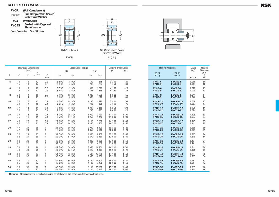
jFjD jd
CB
Full Complement
FYCR FYCRS
r
jD jd
CB
Full Complement, Sealedwith Thrust Washer
r
ROLLER FOLLOWERSFYCR (Full Complement)
FYCRS ⎧Full Complement, Sealed ⎫
⎩with Thrust Washer ⎭FYCJ (With Cage)
FYCJS ⎧Sealed, with Cage and ⎫
⎩Thrust Washer ⎭Bore Diameter 5 – 50 mm
5 16 11 12 0.3 5 800 8 000 590 815 3 350 340 16 11 12 0.3 2 830 2 620 288 267 3 350 340
6 19 11 12 0.3 6 550 9 900 665 1 010 4 150 425 19 11 12 0.3 3 450 3 600 355 365 4 150 425
8 24 14 15 0.3 10 100 15 000 1 030 1 530 6 500 665 24 14 15 0.3 5 700 6 000 580 610 6 500 665
10 30 14 15 0.6 11 700 18 500 1 190 1 890 7 800 795 30 14 15 0.6 6 950 8 200 705 835 7 800 795
12 32 14 15 0.6 12 600 21 000 1 280 2 140 8 050 820 32 14 15 0.6 7 650 9 650 780 985 8 050 820
15 35 18 19 0.6 18 700 29 300 1 910 2 990 11 800 1 200 35 18 19 0.6 12 200 14 100 1 250 1 440 11 800 1 200
17 40 20 21 0.6 21 100 35 000 2 160 3 600 14 300 1 460 40 20 21 0.6 13 700 16 700 1 390 1 700 14 300 1 460
20 47 24 25 1 28 900 50 000 2 940 5 100 20 800 2 120 47 24 25 1 18 200 22 600 1 850 2 310 20 800 2 120
25 52 24 25 1 32 500 60 000 3 300 6 100 22 900 2 340 52 24 25 1 22 200 31 000 2 270 3 150 22 900 2 340
30 62 28 29 1 47 500 96 000 4 800 9 800 33 000 3 350 62 28 29 1 31 500 47 000 3 200 4 800 33 000 3 350
35 72 28 29 1 49 500 106 000 5 050 10 800 36 500 3 700 72 28 29 1 33 000 52 500 3 400 5 350 36 500 3 700
40 80 30 32 1 54 500 126 000 5 600 12 800 43 500 4 450 80 30 32 1 38 500 67 500 3 950 6 900 43 500 4 450
45 85 30 32 1 57 500 139 000 5 850 14 100 46 500 4 750 85 30 32 1 40 000 73 000 4 100 7 450 46 500 4 750
50 90 30 32 1 60 500 152 000 6 150 15 500 49 500 5 050 90 30 32 1 41 500 78 000 4 200 7 950 49 500 5 050
Boundary Dimensions(mm)
d D C B0
–0.38 r min.
Bearing Numbers
FYCR FYCRS FYCJ FYCJS
FYCR-5 FYCRS-5 0.016 10 FYCJ-5 FYCJS-5 0.014 10
FYCR-6 FYCRS-6 0.022 12 FYCJ-6 FYCJS-6 0.020 12
FYCR-8 FYCRS-8 0.044 14 FYCJ-8 FYCJS-8 0.042 14
FYCR-10 FYCRS-10 0.069 17 FYCJ-10 FYCJS-10 0.067 17
FYCR-12 FYCRS-12 0.076 19 FYCJ-12 FYCJS-12 0.074 19
FYCR-15 FYCRS-15 0.105 23 FYCJ-15 FYCJS-15 0.097 23
FYCR-17 FYCRS-17 0.145 25 FYCJ-17 FYCJS-17 0.14 25
FYCR-20 FYCRS-20 0.255 29 FYCJ-20 FYCJS-20 0.245 29
FYCR-25 FYCRS-25 0.285 34 FYCJ-25 FYCJS-25 0.275 34
FYCR-30 FYCRS-30 0.48 51 FYCJ-30 FYCJS-30 0.47 51
FYCR-35 FYCRS-35 0.64 58 FYCJ-35 FYCJS-35 0.635 58
FYCR-40 FYCRS-40 0.88 66 FYCJ-40 FYCJS-40 0.865 66
FYCR-45 FYCRS-45 0.93 72 FYCJ-45 FYCJS-45 0.91 72
FYCR-50 FYCRS-50 0.995 76 FYCJ-50 FYCJS-50 0.965 76
Mass(kg)
approx.
Shoulder Dimensions
(mm)F
min.
Basic Load Ratings (N) {kgf}
Cr C0r Cr C0r
Limiting Track Loads (N) {kgf}
Remarks Standard grease is packed in sealed cam followers, but not in cam followers without seals.
B 278 B 279
B244-279E.indd 278-279B244-279E.indd 278-279 11/20/13 4:59:59 PM11/20/13 4:59:59 PM
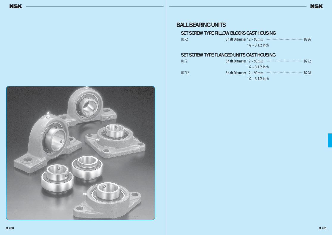
BALL BEARING UNITSSET SCREW TYPE PILLOW BLOCKS CAST HOUSINGUCP2 Shaft Diameter 12 – 90mm ··········································· B286 1/2 – 3 1/2 inch
SET SCREW TYPE FLANGED UNITS CAST HOUSINGUCF2 Shaft Diameter 12 – 90mm ··········································· B292 1/2 – 3 1/2 inchUCFL2 Shaft Diameter 12 – 90mm ··········································· B298 1/2 – 3 1/2 inch
B 280 B 281
B280-303E.indd 280-281B280-303E.indd 280-281 11/20/13 5:00:41 PM11/20/13 5:00:41 PM
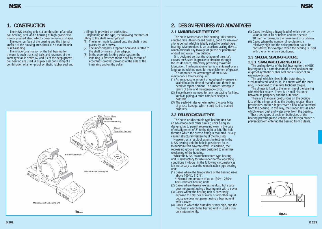
The NSK bearing unit is a combination of a radial ball bearing, seal, and a housing of high-grade cast iron or pressed steel, which comes in various shapes. The outer surface of the bearing and the internal surface of the housing are spherical, so that the unit is self-aligning. The inside construction of the ball bearing for the unit is such that steel balls and retainers of the same type as in series 62 and 63 of the deep groove ball bearing are used. A duplex seal consisting of a combination of an oil-proof synthetic rubber seal and
a slinger is provided on both sides. Depending on the type, the following methods of fitting to the shaft are employed:(1) The inner ring is fastened onto the shaft in two
places by set screws.(2) The inner ring has a tapered bore and is fitted to
the shaft by means of an adapter.(3) In the eccentric locking collar system the
inns ring is fastened to the shaft by means of eccentrics grooves provided at the side of the inner ring and on the collar.
1. CONSTRUCTION2.1 MAINTENANCE FREE TYPE The NSK Maintenance free bearing unit contains a high-grade lithium-based grease, good for use over a long period, which is ideally suited to sealed-type bearing. Also provided is an excellent sealing device, which prevents any leakage of grease or penetration of dust and water from outside. It is designed so that the rotation of the shaft causes the sealed-in grease to circulate through the inside space, effectively providing maximum lubrication. The lubrication effect is maintained over a long period with no need for replenishment of grease. To summarize the advantages of the NSK maintenance free bearing unit:(1) As an adequate amount of good quality grease is
sealed in at the time of manufacture, there is no need for replenishment. This means savings in terms of time and maintenance costs.
(2) Since there is no need for any regreasing facilities, such as piping, a more compact design is possible.
(3) The sealed-in design eliminates the possibility of grease leakage, which could lead to stained products.
2.2 RELUBRICATABLE TYPE The NSK relubricatable type bearing unit has an advantage over other similar, units being so designed as to permit regreasing even in the case of misalignment of 2° to the right or left. The hole through which the grease fitting is mounted usually causes structural weakening of the housing. However, as a result of extensive testing, in the NSK bearing unit the hole is positioned so as to minimize this adverse effect. In addition, the regreasing groove has been designed to minimize weakening of the housing. While the NSK maintenance free type bearing unit is satisfactory for use under normal operating conditions in-doors, in the following circumstances it is necessary to use the relubricatable type bearing unit:(1) Cases where the temperature of the bearing rises
above 100°C, 212°F: *-Normal temperature of up to 130°C, 266°F
heat-resistant bearing units.(2) Cases where there is excessive dust, but space
does not permit using a bearing unit with a cover.(3) Cases where the bearing unit is constantly
exposed to splashes of water or any other liquid, but space does not permit using a bearing unit with a cover.
(4) Cases in which the humidity is very high, and the machine in which the bearing unit is used is run only intermittently.
(5) Cases involving a heavy load of which the Cr/Pr value is about 10 or below, and the speed is 10 min–1 or below, or the movement is oscillatory.
(6) Cases where the number of revolutions is relatively high and the noise problem has to be considered; for example, when the bearing is used with the fan of an air conditioner.
2.3 SPECIAL SEALING FEATURE2.3.1 STANDARD BEARING UNITS The sealing device of the ball bearing for the NSK bearing unit is a combination of a heat-resistant and oil-proof synthetic rubber seal and a slinger of an exclusive design. The seal, which is fixed in the outer ring, is steel-reinforced, and its lip, in contact with the inner ring, is designed to minimize frictional torque. The slinger is fixed to the inner ring of the bearing with which it rotates. There is a small clearance between its periphery and the outer ring. There are triangular protrusions on the outside face of the slinger and, as the bearing rotates, these protrusions on the slinger create a flow of air outward from the bearing. In this way, the slinger acts as a fan which-keeps dust and water away from the bearing. These two types of seals on both sides of the bearing prevent grease leakage, and foreign matter is prevented from entering the bearing from outside.
2. DESIGN FEATURES AND ADVANTAGES
Grease fittingHousing
Spherical outer ring
Slinger
Special rubber seal
Ball end set screw
Relubricatable bearing unit
Maintenance free bearing unit
Fig.2.1Fig.1.1
B 282 B 283
B280-303E.indd 282-283B280-303E.indd 282-283 11/20/13 5:00:42 PM11/20/13 5:00:42 PM
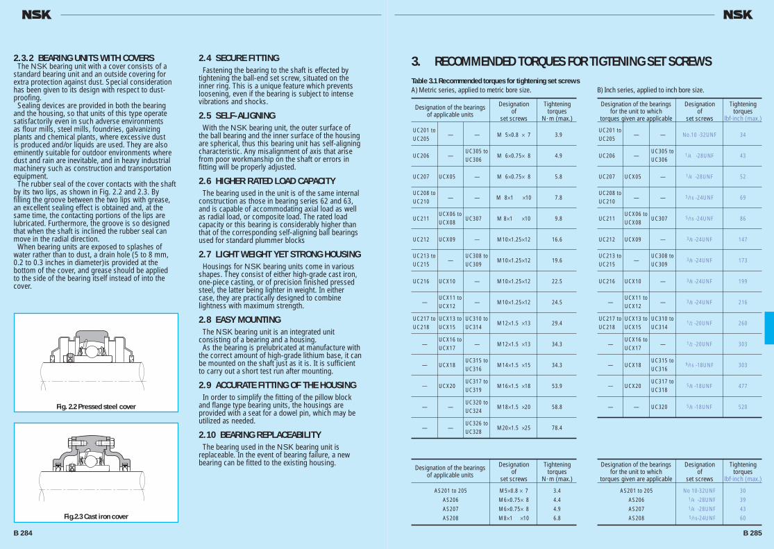
2.3.2 BEARING UNITS WITH COVERS The NSK bearing unit with a cover consists of a standard bearing unit and an outside covering for extra protection against dust. Special consideration has been given to its design with respect to dust-proofing. Sealing devices are provided in both the bearing and the housing, so that units of this type operate satisfactorily even in such adverse environments as flour mills, steel mills, foundries, galvanizing plants and chemical plants, where excessive dust is produced and/or liquids are used. They are also eminently suitable for outdoor environments where dust and rain are inevitable, and in heavy industrial machinery such as construction and transportation equipment. The rubber seal of the cover contacts with the shaft by its two lips, as shown in Fig. 2.2 and 2.3. By filling the groove between the two lips with grease, an excellent sealing effect is obtained and, at the same time, the contacting portions of the lips are lubricated. Furthermore, the groove is so designed that when the shaft is inclined the rubber seal can move in the radial direction. When bearing units are exposed to splashes of water rather than to dust, a drain hole (5 to 8 mm, 0.2 to 0.3 inches in diameter)is provided at the bottom of the cover, and grease should be applied to the side of the bearing itself instead of into the cover.
2.4 SECURE FITTING Fastening the bearing to the shaft is effected by tightening the ball-end set screw, situated on the inner ring. This is a unique feature which prevents loosening, even if the bearing is subject to intense vibrations and shocks.
2.5 SELF-ALIGNING With the NSK bearing unit, the outer surface of the ball bearing and the inner surface of the housing are spherical, thus this bearing unit has self-aligning characteristic. Any misalignment of axis that arise from poor workmanship on the shaft or errors in fitting will be properly adjusted.
2.6 HIGHER RATED LOAD CAPACITY The bearing used in the unit is of the same internal construction as those in bearing series 62 and 63, and is capable of accommodating axial load as well as radial load, or composite load. The rated load capacity or this bearing is considerably higher than that of the corresponding self-aligning ball bearings used for standard plummer blocks
2.7 LIGHT WEIGHT YET STRONG HOUSING Housings for NSK bearing units come in various shapes. They consist of either high-grade cast iron, one-piece casting, or of precision finished pressed steel, the latter being lighter in weight. In either case, they are practically designed to combine lightness with maximum strength.
2.8 EASY MOUNTING The NSK bearing unit is an integrated unit consisting of a bearing and a housing. As the bearing is prelubricated at manufacture with the correct amount of high-grade lithium base, it can be mounted on the shaft just as it is. It is sufficient to carry out a short test run after mounting.
2.9 ACCURATE FITTING OF THE HOUSING In order to simplify the fitting of the pillow block and flange type bearing units, the housings are provided with a seat for a dowel pin, which may be utilized as needed.
2.10 BEARING REPLACEABILITY The bearing used in the NSK bearing unit is replaceable. In the event of bearing failure, a new bearing can be fitted to the existing housing.
3. RECOMMENDED TORQUES FOR TIGTENING SET SCREWS
Fig. 2.2 Pressed steel cover
Fig.2.3 Cast iron cover
Table 3.1 Recommended torques for tightening set screwsA) Metric series, applied to metric bore size.
Designation of the bearings Designation Tightening of applicable units of torques set screws N ·m (max.)
UC201 to —
— M 5×0.8 × 7 3.9
UC205
UC206
—
UC305 to M 6×0.75× 8 4.9
UC306
UC207 UCX05
— M 6×0.75× 8 5.8
UC208 to —
— M 8×1 ×10 7.8
UC210
UC211
UCX06 to UC307 M 8×1 ×10 9.8
UCX08
UC212 UCX09
— M10×1.25×12 16.6
UC213 to —
UC308 to M10×1.25×12 19.6
UC215 UC309
UC216 UCX10
— M10×1.25×12 22.5
—
UCX11 to — M10×1.25×12 24.5
UCX12
UC217 to UCX13 to UC310 to M12×1.5 ×13 29.4
UC218 UCX15 UC314
—
UCX16 to — M12×1.5 ×13 34.3
UCX17
— UCX18
UC315 to M14×1.5 ×15 34.3
UC316
— UCX20
UC317 to M16×1.5 ×18 53.9
UC319
—
—
UC320 to M18×1.5 ×20 58.8
UC324
—
—
UC326 to M20×1.5 ×25 78.4
UC328
B) Inch series, applied to inch bore size.
Designation of the bearings Designation Tightening for the unit to which of torques torques given are applicable set screws lbf·inch (max.)
UC201 to — — No.10 -32UNF 34
UC205
UC206 —
UC305 to 1/4 -28UNF 43
UC306
UC207 UCX05 — 1/4 -28UNF 52
UC208 to — — 5/16 -24UNF 69
UC210
UC211
UCX06 to UC307 5/16 -24UNF 86
UCX08
UC212 UCX09 — 3/8 -24UNF 147
UC213 to —
UC308 to 3/8 -24UNF 173
UC215 UC309
UC216 UCX10 — 3/8 -24UNF 199
—
UCX11 to — 3/8 -24UNF 216
UCX12
UC217 to UCX13 to UC310 to 1/2 -20UNF 260
UC218 UCX15 UC314
—
UCX16 to — 1/2 -20UNF 303
UCX17
— UCX18
UC315 to 9/16 -18UNF 303
UC316
— UCX20
UC317 to 5/8 -18UNF 477
UC318
— — UC320 5/8 -18UNF 520
Designation of the bearings Designation Tightening of applicable units of torques set screws N ·m (max.)
AS201 to 205 M5×0.8 × 7 3.4
AS206 M6×0.75× 8 4.4
AS207 M6×0.75× 8 4.9
AS208 M8×1 ×10 6.8
Designation of the bearings Designation Tightening for the unit to which of torques torques given are applicable set screws lbf·inch (max.)
AS201 to 205 No 10-32UNF 30
AS206 1/4 -28UNF 39
AS207 1/4 -28UNF 43
AS208 5/16-24UNF 60
B 284 B 285
B280-303E.indd 284-285B280-303E.indd 284-285 11/20/13 5:00:43 PM11/20/13 5:00:43 PM
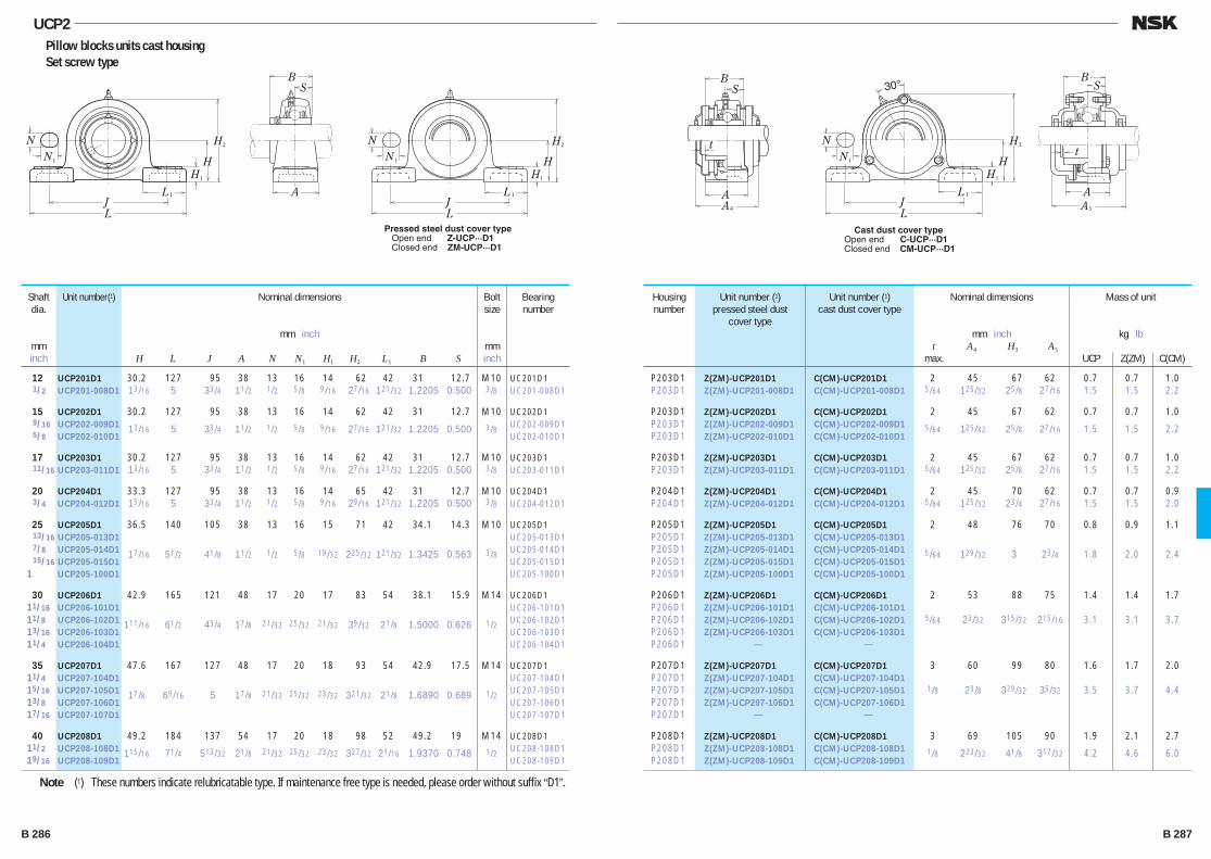
A
B
t
S
A4
A
B
t
S
A5
NN1
L
LJ
1
H
H
3
H1
30°
Cast dust cover typeOpen end C-UCP···D1Closed end CM-UCP···D1
NN1
L
LJ
1
BS
A
H
H
2
H1
NN1
L
LJ
1
H
H
2
H1
Pressed steel dust cover type Open end Z-UCP···D1 Closed end ZM-UCP···D1
UCP2Pillow blocks units cast housing Set screw type
12 UCP201D1 30.2 127 95 38 13 16 14 62 42 31 12.7 M10 UC201D1 1/2 UCP201-008D1 13/16 5 33/4 11/2 1/2 5/8 9/16 27/16 121/32 1.2205 0.500 3/8 UC201-008D1
15 UCP202D1 30.2 127 95 38 13 16 14 62 42 31 12.7 M10 UC202D1 9/16 UCP202-009D1 13/16 5 33/4 11/2 1/2 5/8 9/16 27/16 121/32 1.2205 0.500 3/8 UC202-009D1 5/8 UCP202-010D1 UC202-010D1
17 UCP203D1 30.2 127 95 38 13 16 14 62 42 31 12.7 M10 UC203D1 11/16 UCP203-011D1 13/16 5 33/4 11/2 1/2 5/8 9/16 27/16 121/32 1.2205 0.500 3/8 UC203-011D1
20 UCP204D1 33.3 127 95 38 13 16 14 65 42 31 12.7 M10 UC204D1 3/4 UCP204-012D1 15/16 5 33/4 11/2 1/2 5/8 9/16 29/16 121/32 1.2205 0.500 3/8 UC204-012D1
25 UCP205D1 36.5 140 105 38 13 16 15 71 42 34.1 14.3 M10 UC205D1 13/16 UCP205-013D1 UC205-013D1 7/8 UCP205-014D1 17/16 51/2 41/8 11/2 1/2 5/8 19/32 225/32 121/32 1.3425 0.563 3/8 UC205-014D1 15/16 UCP205-015D1 UC205-015D1 1 UCP205-100D1 UC205-100D1
30 UCP206D1 42.9 165 121 48 17 20 17 83 54 38.1 15.9 M14 UC206D1 11/16 UCP206-101D1 UC206-101D1 11/8 UCP206-102D1 111/16 61/2 43/4 17/8 21/32 25/32 21/32 39/32 21/8 1.5000 0.626 1/2 UC206-102D1 13/16 UCP206-103D1 UC206-103D1 11/4 UCP206-104D1 UC206-104D1
35 UCP207D1 47.6 167 127 48 17 20 18 93 54 42.9 17.5 M14 UC207D1 11/4 UCP207-104D1 UC207-104D1 15/16 UCP207-105D1 17/8 69/16 5 17/8 21/32 25/32 23/32 321/32 21/8 1.6890 0.689 1/2 UC207-105D1 13/8 UCP207-106D1 UC207-106D1 17/16 UCP207-107D1 UC207-107D1
40 UCP208D1 49.2 184 137 54 17 20 18 98 52 49.2 19 M14 UC208D1 11/2 UCP208-108D1 115/16 71/4 513/32 21/8 21/32 25/32 23/32 327/32 21/16 1.9370 0.748 1/2 UC208-108D1 19/16 UCP208-109D1 UC208-109D1
Shaft dia.
mminch
Unit number(1) Housing number
Unit number (1)pressed steel dust
cover type
Unit number (1)cast dust cover type
Nominal dimensions
mm inch t A4 H3 A5
max.
Mass of unit
kg lb
UCP Z(ZM) C(CM)
Bolt size
mminch
Bearing number
Nominal dimensions
mm inch
H L J A N N1 H1 H2 L1 B S
P203D1 Z(ZM)-UCP201D1 C(CM)-UCP201D1 2 45 67 62 0.7 0.7 1.0 P203D1 Z(ZM)-UCP201-008D1 C(CM)-UCP201-008D1 5/64 125/32 25/8 27/16 1.5 1.5 2.2
P203D1 Z(ZM)-UCP202D1 C(CM)-UCP202D1 2 45 67 62 0.7 0.7 1.0 P203D1 Z(ZM)-UCP202-009D1 C(CM)-UCP202-009D1 5/64 125/32 25/8 27/16 1.5 1.5 2.2 P203D1 Z(ZM)-UCP202-010D1 C(CM)-UCP202-010D1
P203D1 Z(ZM)-UCP203D1 C(CM)-UCP203D1 2 45 67 62 0.7 0.7 1.0 P203D1 Z(ZM)-UCP203-011D1 C(CM)-UCP203-011D1 5/64 125/32 25/8 27/16 1.5 1.5 2.2
P204D1 Z(ZM)-UCP204D1 C(CM)-UCP204D1 2 45 70 62 0.7 0.7 0.9 P204D1 Z(ZM)-UCP204-012D1 C(CM)-UCP204-012D1 5/64 125/32 23/4 27/16 1.5 1.5 2.0
P205D1 Z(ZM)-UCP205D1 C(CM)-UCP205D1 2 48 76 70 0.8 0.9 1.1 P205D1 Z(ZM)-UCP205-013D1 C(CM)-UCP205-013D1
P205D1 Z(ZM)-UCP205-014D1 C(CM)-UCP205-014D1 5/64 129/32 3 23/4 1.8 2.0 2.4 P205D1 Z(ZM)-UCP205-015D1 C(CM)-UCP205-015D1
P205D1 Z(ZM)-UCP205-100D1 C(CM)-UCP205-100D1
P206D1 Z(ZM)-UCP206D1 C(CM)-UCP206D1 2 53 88 75 1.4 1.4 1.7 P206D1 Z(ZM)-UCP206-101D1 C(CM)-UCP206-101D1
P206D1 Z(ZM)-UCP206-102D1 C(CM)-UCP206-102D1 5/64 23/32 315/32 215/16 3.1 3.1 3.7 P206D1 Z(ZM)-UCP206-103D1 C(CM)-UCP206-103D1
P206D1 — —
P207D1 Z(ZM)-UCP207D1 C(CM)-UCP207D1 3 60 99 80 1.6 1.7 2.0 P207D1 Z(ZM)-UCP207-104D1 C(CM)-UCP207-104D1
P207D1 Z(ZM)-UCP207-105D1 C(CM)-UCP207-105D1 1/8 23/8 329/32 35/32 3.5 3.7 4.4 P207D1 Z(ZM)-UCP207-106D1 C(CM)-UCP207-106D1
P207D1 — —
P208D1 Z(ZM)-UCP208D1 C(CM)-UCP208D1 3 69 105 90 1.9 2.1 2.7 P208D1 Z(ZM)-UCP208-108D1 C(CM)-UCP208-108D1 1/8 223/32 41/8 317/32 4.2 4.6 6.0 P208D1 Z(ZM)-UCP208-109D1 C(CM)-UCP208-109D1
Note (1) These numbers indicate relubricatable type. If maintenance free type is needed, please order without suffix “D1”.
B 286 B 287
B280-303E.indd 286-287B280-303E.indd 286-287 11/20/13 5:00:44 PM11/20/13 5:00:44 PM

UCP2Pillow blocks units cast housing Set screw type
A
B
t
S
A4
A
B
t
S
A5
NN1
L
LJ
1
H
H
3
H1
30°
Cast dust cover typeOpen end C-UCP···D1Closed end CM-UCP···D1
NN1
L
LJ
1
BS
A
H
H
2
H1
NN1
L
LJ
1
H
H
2
H1
Pressed steel dust cover type Open end Z-UCP···D1 Closed end ZM-UCP···D1
45 UCP209D1 54 190 146 54 17 20 20 106 60 49.2 19 M14 UC209D1 15/8 UCP209-110D1 UC209-110D1 111/16 UCP209-111D1 21/8 715/32 53/4 21/8 21/32 25/32 25/32 43/16 23/8 1.9370 0.748 1/2 UC209-111D1 13/4 UCP209-112D1 UC209-112D1
50 UCP210D1 57.2 206 159 60 20 23 21 114 65 51.6 19 M16 UC210D1 113/16 UCP210-113D1 UC210-113D1 17/8 UCP210-114D1 21/4 81/8 61/4 23/8 25/32 29/32 13/16 41/2 29/16 2.0315 0.748 5/8 UC210-114D1 115/16 UCP210-115D1 UC210-115D1 2 UCP210-200D1 UC210-200D1
55 UCP211D1 63.5 219 171 60 20 23 23 126 65 55.6 22.2 M16 UC211D1 2 UCP211-200D1 UC211-200D1 21/16 UCP211-201D1 21/2 85/8 623/32 23/8 25/32 29/32 29/32 431/32 29/16 2.1890 0.874 5/8 UC211-201D1 21/8 UCP211-202D1 UC211-202D1 23/16 UCP211-203D1 UC211-203D1
60 UCP212D1 69.8 241 184 70 20 23 25 138 70 65.1 25.4 M16 UC212D1 21/4 UCP212-204D1 UC212-204D1 25/16 UCP212-205D1 23/4 91/2 71/4 23/4 25/32 29/32 31/32 57/16 23/4 2.5630 1.000 5/8 UC212-205D1 23/8 UCP212-206D1 UC212-206D1 27/16 UCP212-207D1 UC212-207D1
65 UCP213D1 76.2 265 203 70 25 28 27 151 77 65.1 25.4 M20 UC213D1 21/2 UCP213-208D1 3 107/16 8 23/4 31/32 13/32 11/16 515/16 31/32 2.5630 1.000 3/4 UC213-208D1 29/16 UCP213-209D1 UC213-209D1
70 UCP214D1 79.4 266 210 72 25 28 27 157 77 74.6 30.2 M20 UC214D1 25/8 UCP214-210D1 UC214-210D1 211/16 UCP214-211D1 31/8 1015/32 89/32 227/32 31/32 13/32 11/16 63/16 31/32 2.9370 1.189 3/4 UC214-211D1 23/4 UCP214-212D1 UC214-212D1
Shaft dia.
mminch
Unit number(1) Housing number
Unit number (1)pressed steel dust
cover type
Unit number (1)cast dust cover type
Nominal dimensions
mm inch t A4 H3 A5
max.
Mass of unit
kg lb
UCP Z(ZM) C(CM)
Bolt size
mminch
Bearing number
Nominal dimensions
mm inch
H L J A N N1 H1 H2 L1 B S
P209D1 Z(ZM)-UCP209D1 C(CM)-UCP209D1 3 69 113 95 2.2 2.4 3.1 P209D1 Z(ZM)-UCP209-110D1 C(CM)-UCP209-110D1
P209D1 Z(ZM)-UCP209-111D1 C(CM)-UCP209-111D1 1/8 223/32 47/16 33/4 4.9 5.3 6.8 P209D1 Z(ZM)-UCP209-112D1 C(CM)-UCP209-112D1
P210D1 Z(ZM)-UCP210D1 C(CM)-UCP210D1 3 76 119 100 2.7 2.8 3.6 P210D1 Z(ZM)-UCP210-113D1 C(CM)-UCP210-113D1
P210D1 Z(ZM)-UCP210-114D1 C(CM)-UCP210-114D1 1/8 3 411/16 315/16 6.0 6.2 7.9 P210D1 Z(ZM)-UCP210-115D1 C(CM)-UCP210-115D1
P210D1 — C(CM)-UCP210-200D1
P211D1 Z(ZM)-UCP211D1 C(CM)-UCP211D1 4 77 130 100 3.5 3.5 4.4 P211D1 Z(ZM)-UCP211-200D1 C(CM)-UCP211-200D1
P211D1 Z(ZM)-UCP211-201D1 C(CM)-UCP211-201D1 5/32 31/32 51/8 315/16 7.7 7.7 9.7 P211D1 Z(ZM)-UCP211-202D1 C(CM)-UCP211-202D1
P211D1 Z(ZM)-UCP211-203D1 C(CM)-UCP211-203D1
P212D1 Z(ZM)-UCP212D1 C(CM)-UCP212D1 4 89 143 115 4.7 5.0 6.0 P212D1 Z(ZM)-UCP212-204D1 C(CM)-UCP212-204D1
P212D1 Z(ZM)-UCP212-205D1 C(CM)-UCP212-205D1 5/32 31/2 55/8 417/32 10 11 13 P212D1 Z(ZM)-UCP212-206D1 C(CM)-UCP212-206D1
P212D1 — C(CM)-UCP212-207D1
P213D1 Z(ZM)-UCP213D1 C(CM)-UCP213D1 4 91 155 120 5.6 5.8 7.2 P213D1 Z(ZM)-UCP213-208D1 C(CM)-UCP213-208D1 5/32 319/32 63/32 423/32 12 13 16 P213D1 Z(ZM)-UCP213-209D1 C(CM)-UCP213-209D1
P214D1 — C(CM)-UCP214D1 4 — 162 135 6.5 — 8.3 P214D1 C(CM)-UCP214-210D1
P214D1 — C(CM)-UCP214-211D1 5/32 — 63/8 55/16 14 — 18 P214D1 C(CM)-UCP214-212D1
Note (1) These numbers indicate relubricatable type. If maintenance free type is needed, please order without suffix “D1”.
B 288 B 289
B280-303E.indd 288-289B280-303E.indd 288-289 11/20/13 5:00:46 PM11/20/13 5:00:46 PM

UCP2Pillow blocks units cast housing Set screw type
A
B
t
S
A4
A
B
t
S
A5
NN1
L
LJ
1
H
H
3
H1
30°
Cast dust cover typeOpen end C-UCP···D1Closed end CM-UCP···D1
NN1
L
LJ
1
BS
A
H
H
2
H1
NN1
L
LJ
1
H
H
2
H1
Pressed steel dust cover type Open end Z-UCP···D1 Closed end ZM-UCP···D1
75 UCP215D1 82.6 275 217 74 25 28 28 163 80 77.8 33.3 M20 UC215D1 213/16 UCP215-213D1 UC215-213D1 27/8 UCP215-214D1 31/4 1013/16 817/32 229/32 31/32 13/32 13/32 613/32 35/32 3.0630 1.311 3/4 UC215-214D1 215/16 UCP215-215D1 UC215-215D1 3 UCP215-300D1 UC215-300D1
80 UCP216D1 88.9 292 232 78 25 28 30 175 85 82.6 33.3 M20 UC216D1 31/16 UCP216-301D1 UC216-301D1 31/8 UCP216-302D1 31/2 111/2 91/8 31/16 31/32 13/32 13/16 67/8 311/32 3.2520 1.311 3/4 UC216-302D1 33/16 UCP216-303D1 UC216-303D1
85 UCP217D1 95.2 310 247 83 25 28 32 187 85 85.7 34.1 M20 UC217D1 31/4 UCP217-304D1 UC217-304D1 35/16 UCP217-305D1 33/4 127/32 923/32 39/32 31/32 13/32 11/4 73/8 311/32 3.3740 1.343 3/4 UC217-305D1 37/16 UCP217-307D1 UC217-307D1
90 UCP218D1 101.6 327 262 88 27 30 33 200 90 96 39.7 M22 UC218D1 31/2 UCP218-308D1 4 127/8 105/16 315/32 11/16 13/16 15/16 77/8 317/32 3.7795 1.563 7/8 UC218-308D1
Shaft dia.
mminch
Unit number(1) Housing number
Unit number (1)pressed steel dust
cover type
Unit number (1)cast dust cover type
Nominal dimensions
mm inch t A4 H3 A5
max.
Mass of unit
kg lb
UCP Z(ZM) C(CM)
Bolt size
mminch
Bearing number
Nominal dimensions
mm inch
H L J A N N1 H1 H2 L1 B S
P215D1 — C(CM)-UCP215D1 4 — 168 135 7.2 — 9.3 P215D1 C(CM)-UCP215-213D1
P215D1 C(CM)-UCP215-214D1 5/32 — 65/8 55/16 16 — 21 P215D1 — C(CM)-UCP215-215D1
P215D1 C(CM)-UCP215-300D1
P216D1 — C(CM)-UCP216D1 4 — 181 145 8.7 — 11 P216D1 C(CM)-UCP216-301D1
P216D1 — C(CM)-UCP216-302D1 5/32 — 71/8 523/32 19 — 24 P216D1 C(CM)-UCP216-303D1
P217D1 — C(CM)-UCP217D1 5 — 191 155 11 — 13 P217D1 C(CM)-UCP217-304D1 P217D1 — C(CM)-UCP217-305D1 13/64 — 717/32 63/32 24 — 29 P217D1 C(CM)-UCP217-307D1
P218D1 — C(CM)-UCP218D1 5 — 204 165 13 — 16 P218D1 — C(CM)-UCP218-308D1 13/64 — 81/32 61/2 29 — 35
Note (1) These numbers indicate relubricatable type. If maintenance free type is needed, please order without suffix “D1”.
B 290 B 291
B280-303E.indd 290-291B280-303E.indd 290-291 11/20/13 5:00:47 PM11/20/13 5:00:47 PM

N
AL
L
J
J
4
BS
A A2
A1
N
L
L
J
Jt t
A5
BS
A 2
A 1
Pressed steel dust cover type Open end Z-UCF···D1 Closed end ZM-UCF···D1
Cast dust cover typeOpen end C-UCF···D1Closed end CM-UCF···D1
N
A
L
L
J
J
0
BS
AA 2
A 1
UCF2Square flanged units cast housing Set screw type
12 UCF201D1 86 64 15 11 25.5 12 33.3 31 12.7 M10 UC201D1 1/2 UCF201-008D1 33/8 233/64 19/32 7/16 1 15/32 15/16 1.2205 0.500 3/8 UC201-008D1
15 UCF202D1 86 64 15 11 25.5 12 33.3 31 12.7 M10 UC202D1 9/16 UCF202-009D1 33/8 233/64 19/32 7/16 1 15/32 15/16 1.2205 0.500 3/8 UC202-009D1 5/8 UCF202-010D1 UC202-010D1
17 UCF203D1 86 64 15 11 25.5 12 33.3 31 12.7 M10 UC203D1 11/16 UCF203-011D1 33/8 233/64 19/32 7/16 1 15/32 15/16 1.2205 0.500 3/8 UC203-011D1
20 UCF204D1 86 64 15 11 25.5 12 33.3 31 12.7 M10 UC204D1 3/4 UCF204-012D1 33/8 233/64 19/32 7/16 1 15/32 15/16 1.2205 0.500 3/8 UC204-012D1
25 UCF205D1 95 70 16 13 27 12 35.8 34.1 14.3 M10 UC205D1 13/16 UCF205-013D1 UC205-013D1 7/8 UCF205-014D1 33/4 23/4 5/8 1/2 11/16 15/32 113/32 1.3425 0.563 3/8 UC205-014D1 15/16 UCF205-015D1 UC205-015D1 1 UCF205-100D1 UC205-100D1
30 UCF206D1 108 83 18 13 31 12 40.2 38.1 15.9 M10 UC206D1 11/16 UCF206-101D1 UC206-101D1 11/8 UCF206-102D1 41/4 317/64 45/64 1/2 17/32 15/32 137/64 1.5000 0.626 3/8 UC206-102D1 13/16 UCF206-103D1 UC206-103D1 11/4 UCF206-104D1 UC206-104D1
35 UCF207D1 117 92 19 15 34 14 44.4 42.9 17.5 M12 UC207D1 11/4 UCF207-104D1 UC207-104D1 15/16 UCF207-105D1 419/32 35/8 3/4 19/32 111/32 35/64 13/4 1.6890 0.689 7/16
UC207-105D1 13/8 UCF207-106D1 UC207-106D1 17/16 UCF207-107D1 UC207-107D1
40 UCF208D1 130 102 21 15 36 16 51.2 49.2 19 M14 UC208D1 11/2 UCF208-108D1 51/8 41/64 53/64 19/32 113/32 5/8 21/64 1.9370 0.748 1/2 UC208-108D1 19/16 UCF208-109D1 UC208-109D1
Shaft dia.
mminch
Unit number(1) Housing number
Unit number (1)pressed steel dust
cover type
Unit number (1)cast dust cover type
Nominal dimensions
mm inch t A4 A5
max.
Mass of unit
kg lb
UCP Z(ZM) C(CM)
Bolt size
mminch
Bearingnumber
Nominal dimensions
mm inch
L J A2 A1 A N A0 B S
F204D1 Z(ZM)-UCF201D1 C(CM)-UCF201D1 2 38 46 0.6 0.6 0.8 F204D1 Z(ZM)-UCF201-008D1 C(CM)-UCF201-008D1 5/64 11/2 113/16 1.3 1.3 1.8
F204D1 Z(ZM)-UCF202D1 C(CM)-UCF202D1 2 38 46 0.6 0.6 0.8 F204D1 Z(ZM)-UCF202-009D1 C(CM)-UCF202-009D1 5/64 11/2 113/16 1.3 1.3 1.8 F204D1 Z(ZM)-UCF202-010D1 C(CM)-UCF202-010D1
F204D1 Z(ZM)-UCF203D1 C(CM)-UCF203D1 2 38 46 0.6 0.6 0.8 F204D1 Z(ZM)-UCF203-011D1 C(CM)-UCF203-011D1 5/64 11/2 113/16 1.3 1.3 1.8
F204D1 Z(ZM)-UCF204D1 C(CM)-UCF204D1 2 38 46 0.6 0.6 0.7 F204D1 Z(ZM)-UCF204-012D1 C(CM)-UCF204-012D1 5/64 11/2 113/16 1.3 1.3 1.5
F205D1 Z(ZM)-UCF205D1 C(CM)-UCF205D1 2 40 51 0.8 0.8 0.9 F205D1 Z(ZM)-UCF205-013D1 C(CM)-UCF205-013D1 F205D1 Z(ZM)-UCF205-014D1 C(CM)-UCF205-014D1 5/64 119/32 2 1.8 1.8 2.0 F205D1 Z(ZM)-UCF205-015D1 C(CM)-UCF205-015D1 F205D1 Z(ZM)-UCF205-100D1 C(CM)-UCF205-100D1
F206D1 Z(ZM)-UCF206D1 C(CM)-UCF206D1 2 45 56 1.1 1.1 1.3 F206D1 Z(ZM)-UCF206-101D1 C(CM)-UCF206-101D1 F206D1 Z(ZM)-UCF206-102D1 C(CM)-UCF206-102D1 5/64 13/4 27/32 2.4 2.4 2.9 F206D1 Z(ZM)-UCF206-103D1 C(CM)-UCF206-103D1 F206D1 — C(CM)-UCF206-104D1
F207D1 Z(ZM)-UCF207D1 C(CM)-UCF207D1 3 49 59 1.5 1.5 1.8 F207D1 Z(ZM)-UCF207-104D1 C(CM)-UCF207-104D1 F207D1 Z(ZM)-UCF207-105D1 C(CM)-UCF207-105D1 1/8 115/16 25/16 3.3 3.3 4.0 F207D1 Z(ZM)-UCF207-106D1 C(CM)-UCF207-106D1 F207D1 — C(CM)-UCF207-107D1
F208D1 Z(ZM)-UCF208D1 C(CM)-UCF208D1 3 56 66 1.7 1.8 2.2 F208D1 Z(ZM)-UCF208-108D1 C(CM)-UCF208-108D1 1/8 23/16 219/32 3.7 4.0 4.9 F208D1 Z(ZM)-UCF208-109D1 C(CM)-UCF208-109D1
Note (1) These numbers indicate relubricatable type. If maintenance free type is needed, please order without suffix “D1”.
B 292 B 293
B280-303E.indd 292-293B280-303E.indd 292-293 11/20/13 5:00:48 PM11/20/13 5:00:48 PM
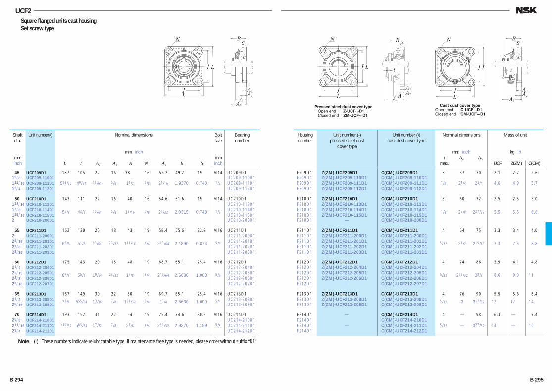
UCF2Square flanged units cast housing Set screw type
N
AL
L
J
J
4
BS
A A2
A1
N
L
L
J
Jt t
A5
BS
A 2
A 1
Pressed steel dust cover type Open end Z-UCF···D1 Closed end ZM-UCF···D1
Cast dust cover typeOpen end C-UCF···D1Closed end CM-UCF···D1
N
A
L
L
J
J
0
BS
AA 2
A 1
45 UCF209D1 137 105 22 16 38 16 52.2 49.2 19 M14 UC209D1 15/8 UCF209-110D1 UC209-110D1 111/16 UCF209-111D1 513/32 49/64 55/64 5/8 11/2 5/8 21/16 1.9370 0.748 1/2 UC209-111D1 13/4 UCF209-112D1 UC209-112D1
50 UCF210D1 143 111 22 16 40 16 54.6 51.6 19 M14 UC210D1 113/16 UCF210-113D1 UC210-113D1 17/8 UCF210-114D1 55/8 43/8 55/64 5/8 19/16 5/8 25/32 2.0315 0.748 1/2 UC210-114D1 115/16 UCF210-115D1 UC210-115D1 2 UCF210-200D1 UC210-200D1
55 UCF211D1 162 130 25 18 43 19 58.4 55.6 22.2 M16 UC211D1 2 UCF211-200D1 UC211-200D1 21/16 UCF211-201D1 63/8 51/8 63/64 23/32 111/16 3/4 219/64 2.1890 0.874 5/8 UC211-201D1 21/8 UCF211-202D1 UC211-202D1 23/16 UCF211-203D1 UC211-203D1
60 UCF212D1 175 143 29 18 48 19 68.7 65.1 25.4 M16 UC212D1 21/4 UCF212-204D1 UC212-204D1 25/16 UCF212-205D1 67/8 55/8 19/64 23/32 17/8 3/4 245/64 2.5630 1.000 5/8 UC212-205D1 23/8 UCF212-206D1 UC212-206D1 27/16 UCF212-207D1 UC212-207D1
65 UCF213D1 187 149 30 22 50 19 69.7 65.1 25.4 M16 UC213D1 21/2 UCF213-208D1 73/8 555/64 13/16 7/8 131/32 3/4 23/4 2.5630 1.000 5/8 UC213-208D1 29/16 UCF213-209D1 UC213-209D1
70 UCF214D1 193 152 31 22 54 19 75.4 74.6 30.2 M16 UC214D1 25/8 UCF214-210D1 UC214-210D1 211/16 UCF214-211D1 719/32 563/64 17/32 7/8 21/8 3/4 231/32 2.9370 1.189 5/8 UC214-211D1 23/4 UCF214-212D1 UC214-212D1
Shaft dia.
mminch
Unit number(1) Housing number
Unit number (1)pressed steel dust
cover type
Unit number (1)cast dust cover type
Nominal dimensions
mm inch t A4 A5
max.
Mass of unit
kg lb
UCF Z(ZM) C(CM)
Bolt size
mminch
Bearingnumber
Nominal dimensions
mm inch
L J A2 A1 A N A0 B S
F209D1 Z(ZM)-UCF209D1 C(CM)-UCF209D1 3 57 70 2.1 2.2 2.6 F209D1 Z(ZM)-UCF209-110D1 C(CM)-UCF209-110D1 F209D1 Z(ZM)-UCF209-111D1 C(CM)-UCF209-111D1 1/8 21/4 23/4 4.6 4.9 5.7 F209D1 Z(ZM)-UCF209-112D1 C(CM)-UCF209-112D1
F210D1 Z(ZM)-UCF210D1 C(CM)-UCF210D1 3 60 72 2.5 2.5 3.0 F210D1 Z(ZM)-UCF210-113D1 C(CM)-UCF210-113D1 F210D1 Z(ZM)-UCF210-114D1 C(CM)-UCF210-114D1 1/8 23/8 227/32 5.5 5.5 6.6 F210D1 Z(ZM)-UCF210-115D1 C(CM)-UCF210-115D1 F210D1 — C(CM)-UCF210-200D1
F211D1 Z(ZM)-UCF211D1 C(CM)-UCF211D1 4 64 75 3.3 3.4 4.0 F211D1 Z(ZM)-UCF211-200D1 C(CM)-UCF211-200D1 F211D1 Z(ZM)-UCF211-201D1 C(CM)-UCF211-201D1 5/32 21/2 215/16 7.3 7.5 8.8 F211D1 Z(ZM)-UCF211-202D1 C(CM)-UCF211-202D1 F211D1 Z(ZM)-UCF211-203D1 C(CM)-UCF211-203D1
F212D1 Z(ZM)-UCF212D1 C(CM)-UCF212D1 4 74 86 3.9 4.1 4.8 F212D1 Z(ZM)-UCF212-204D1 C(CM)-UCF212-204D1 F212D1 Z(ZM)-UCF212-205D1 C(CM)-UCF212-205D1 5/32 229/32 33/8 8.6 9.0 11 F212D1 Z(ZM)-UCF212-206D1 C(CM)-UCF212-206D1 F212D1 — C(CM)-UCF212-207D1
F213D1 Z(ZM)-UCF213D1 C(CM)-UCF213D1 4 76 90 5.5 5.6 6.4 F213D1 Z(ZM)-UCF213-208D1 C(CM)-UCF213-208D1 5/32 3 317/32 12 12 14 F213D1 Z(ZM)-UCF213-209D1 C(CM)-UCF213-209D1
F214D1 — C(CM)-UCF214D1 4 — 98 6.3 — 7.4 F214D1 C(CM)-UCF214-210D1 F214D1 — C(CM)-UCF214-211D1 5/32 — 327/32 14 — 16 F214D1 C(CM)-UCF214-212D1
Note (1) These numbers indicate relubricatable type. If maintenance free type is needed, please order without suffix “D1”.
B 294 B 295
B280-303E.indd 294-295B280-303E.indd 294-295 11/20/13 5:00:50 PM11/20/13 5:00:50 PM
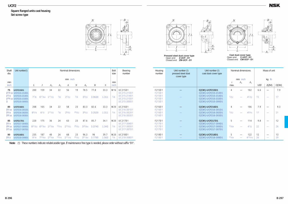
UCF2Square flanged units cast housing Set screw type
N
AL
L
J
J
4
BS
A A2
A1
N
L
L
J
Jt t
A5
BS
A 2
A 1
Pressed steel dust cover type Open end Z-UCF···D1 Closed end ZM-UCF···D1
Cast dust cover typeOpen end C-UCF···D1Closed end CM-UCF···D1
N
A
L
L
J
J
0
BS
AA 2
A 1
75 UCF215D1 200 159 34 22 56 19 78.5 77.8 33.3 M16 UC215D1 213/16 UCF215-213D1 UC215-213D1 27/8 UCF215-214D1 77/8 617/64 111/32 7/8 27/32 3/4 33/32 3.0630 1.311 5/8 UC215-214D1 215/16 UCF215-215D1 UC215-215D1 3 UCF215-300D1 UC215-300D1
80 UCF216D1 208 165 34 22 58 23 83.3 82.6 33.3 M20 UC216D1 31/16 UCF216-301D1 UC216-301D1 31/8 UCF216-302D1 83/16 61/2 111/32 7/8 29/32 29/32 39/32 3.2520 1.311 3/4 UC216-302D1 33/16 UCF216-303D1 UC216-303D1
85 UCF217D1 220 175 36 24 63 23 87.6 85.7 34.1 M20 UC217D1 31/4 UCF217-304D1 UC217-304D1 35/16 UCF217-305D1 821/32 657/64 127/64 15/16 215/32 29/32 329/64 3.3740 1.343 3/4 UC217-305D1 37/16 UCF217-307D1 UC217-307D1
90 UCF218D1 235 187 40 24 68 23 96.3 96 39.7 M20 UC218D1 31/2 UCF218-308D1 91/4 723/64 137/64 15/16 211/16 29/32 351/64 3.7795 1.563 3/4 UC218-308D1
Shaft dia.
mminch
Unit number(1) Housing number
Unit number (1)pressed steel dust
cover type
Unit number (1)cast dust cover type
Nominal dimensions
mm inch t A4 A5
max.
Mass of unit
kg lb
UCF Z(ZM) C(CM)
Bolt size
mminch
Bearingnumber
Nominal dimensions
mm inch
L J A2 A1 A N A0 B S
F215D1 — C(CM)-UCF215D1 4 — 102 6.6 — 7.9 F215D1 C(CM)-UCF215-213D1 F215D1 — C(CM)-UCF215-214D1 5/32 — 41/32 15 — 17 F215D1 C(CM)-UCF215-215D1 F215D1 C(CM)-UCF215-300D1
F216D1 — C(CM)-UCF216D1 4 — 106 7.9 — 9.3 F216D1 C(CM)-UCF216-301D1 F216D1 — C(CM)-UCF216-302D1 5/32 — 43/16 17 — 21 F216D1 C(CM)-UCF216-303D1
F217D1 — C(CM)-UCF217D1 5 — 114 9.8 — 12 F217D1 C(CM)-UCF217-304D1 F217D1 — C(CM)-UCF217-305D1 13/64 — 41/2 22 — 26 F217D1 C(CM)-UCF217-307D1
F218D1 — C(CM)-UCF218D1 5 — 122 12 — 13 F218D1 — C(CM)-UCF218-308D1 13/64 — 413/16 26 — 29
Note (1) These numbers indicate relubricatable type. If maintenance free type is needed, please order without suffix “D1”.
B 296 B 297
B280-303E.indd 296-297B280-303E.indd 296-297 11/20/13 5:00:51 PM11/20/13 5:00:51 PM
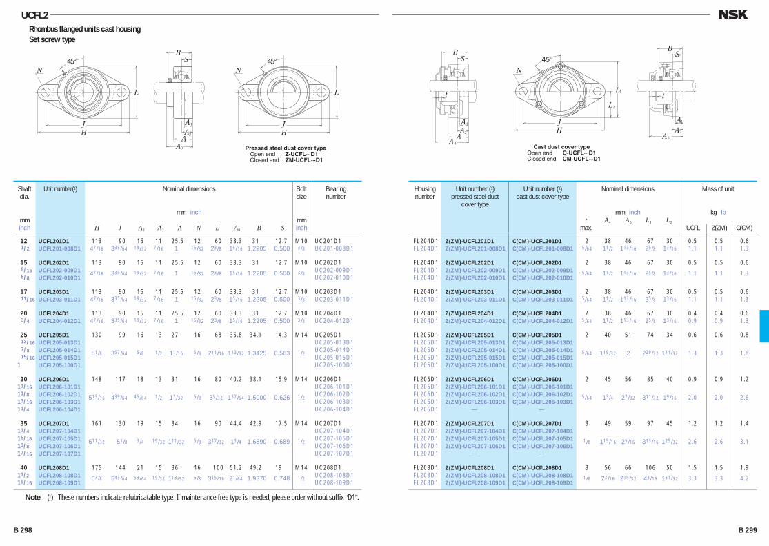
UCFL2Rhombus flanged units cast housing Set screw type
12 UCFL201D1 113 90 15 11 25.5 12 60 33.3 31 12.7 M10 UC201D1 1/2 UCFL201-008D1 47/16 335/64 19/32 7/16 1 15/32 23/8 15/16 1.2205 0.500 3/8 UC201-008D1
15 UCFL202D1 113 90 15 11 25.5 12 60 33.3 31 12.7 M10 UC202D1 9/16 UCFL202-009D1 47/16 335/64 19/32 7/16 1 15/32 23/8 15/16 1.2205 0.500 3/8 UC202-009D1 5/8 UCFL202-010D1 UC202-010D1
17 UCFL203D1 113 90 15 11 25.5 12 60 33.3 31 12.7 M10 UC203D1 11/16 UCFL203-011D1 47/16 335/64 19/32 7/16 1 15/32 23/8 15/16 1.2205 0.500 3/8 UC203-011D1
20 UCFL204D1 113 90 15 11 25.5 12 60 33.3 31 12.7 M10 UC204D1 3/4 UCFL204-012D1 47/16 335/64 19/32 7/16 1 15/32 23/8 15/16 1.2205 0.500 3/8 UC204-012D1
25 UCFL205D1 130 99 16 13 27 16 68 35.8 34.1 14.3 M14 UC205D1 13/16 UCFL205-013D1 UC205-013D1 7/8 UCFL205-014D1 51/8 357/64 5/8 1/2 11/16 5/8 211/16 113/32 1.3425 0.563 1/2 UC205-014D1 15/16 UCFL205-015D1 UC205-015D1 1 UCFL205-100D1 UC205-100D1
30 UCFL206D1 148 117 18 13 31 16 80 40.2 38.1 15.9 M14 UC206D1 11/16 UCFL206-101D1 UC206-101D1 11/8 UCFL206-102D1 513/16 439/64 45/64 1/2 17/32 5/8 35/32 137/64 1.5000 0.626 1/2 UC206-102D1 13/16 UCFL206-103D1 UC206-103D1 11/4 UCFL206-104D1 UC206-104D1
35 UCFL207D1 161 130 19 15 34 16 90 44.4 42.9 17.5 M14 UC207D1 11/4 UCFL207-104D1 UC207-104D1 15/16 UCFL207-105D1 611/32 51/8 3/4 19/32 111/32 5/8 317/32 13/4 1.6890 0.689 1/2 UC207-105D1 13/8 UCFL207-106D1 UC207-106D1 17/16 UCFL207-107D1 UC207-107D1
40 UCFL208D1 175 144 21 15 36 16 100 51.2 49.2 19 M14 UC208D1 11/2 UCFL208-108D1 67/8 543/64 53/64 19/32 113/32 5/8 315/16 21/64 1.9370 0.748 1/2 UC208-108D1 19/16 UCFL208-109D1 UC208-109D1
Shaft dia.
mminch
Unit number(1) Housing number
Unit number (1)pressed steel dust
cover type
Unit number (1)cast dust cover type
Nominal dimensions
mm inch t A4 A5 L1 L2
max.
Mass of unit
kg lb
UCFL Z(ZM) C(CM)
Bolt size
mminch
Bearingnumber
Nominal dimensions
mm inch
H J A2 A1 A N L A0 B S
FL204D1 Z(ZM)-UCFL201D1 C(CM)-UCFL201D1 2 38 46 67 30 0.5 0.5 0.6 FL204D1 Z(ZM)-UCFL201-008D1 C(CM)-UCFL201-008D1 5/64 11/2 113/16 25/8 13/16 1.1 1.1 1.3
FL204D1 Z(ZM)-UCFL202D1 C(CM)-UCFL202D1 2 38 46 67 30 0.5 0.5 0.6 FL204D1 Z(ZM)-UCFL202-009D1 C(CM)-UCFL202-009D1 5/64 11/2 113/16 25/8 13/16 1.1 1.1 1.3 FL204D1 Z(ZM)-UCFL202-010D1 C(CM)-UCFL202-010D1
FL204D1 Z(ZM)-UCFL203D1 C(CM)-UCFL203D1 2 38 46 67 30 0.5 0.5 0.6 FL204D1 Z(ZM)-UCFL203-011D1 C(CM)-UCFL203-011D1 5/64 11/2 113/16 25/8 13/16 1.1 1.1 1.3
FL204D1 Z(ZM)-UCFL204D1 C(CM)-UCFL204D1 2 38 46 67 30 0.4 0.4 0.6 FL204D1 Z(ZM)-UCFL204-012D1 C(CM)-UCFL204-012D1 5/64 11/2 113/16 25/8 13/16 0.9 0.9 1.3
FL205D1 Z(ZM)-UCFL205D1 C(CM)-UCFL205D1 2 40 51 74 34 0.6 0.6 0.8 FL205D1 Z(ZM)-UCFL205-013D1 C(CM)-UCFL205-013D1 FL205D1 Z(ZM)-UCFL205-014D1 C(CM)-UCFL205-014D1 5/64 119/32 2 229/32 111/32 1.3 1.3 1.8 FL205D1 Z(ZM)-UCFL205-015D1 C(CM)-UCFL205-015D1 FL205D1 Z(ZM)-UCFL205-100D1 C(CM)-UCFL205-100D1
FL206D1 Z(ZM)-UCFL206D1 C(CM)-UCFL206D1 2 45 56 85 40 0.9 0.9 1.2 FL206D1 Z(ZM)-UCFL206-101D1 C(CM)-UCFL206-101D1 FL206D1 Z(ZM)-UCFL206-102D1 C(CM)-UCFL206-102D1 5/64 13/4 27/32 311/32 19/16 2.0 2.0 2.6 FL206D1 Z(ZM)-UCFL206-103D1 C(CM)-UCFL206-103D1 FL206D1 — —
FL207D1 Z(ZM)-UCFL207D1 C(CM)-UCFL207D1 3 49 59 97 45 1.2 1.2 1.4 FL207D1 Z(ZM)-UCFL207-104D1 C(CM)-UCFL207-104D1
FL207D1 Z(ZM)-UCFL207-105D1 C(CM)-UCFL207-105D1 1/8 115/16 25/16 313/16 125/32 2.6 2.6 3.1 FL207D1 Z(ZM)-UCFL207-106D1 C(CM)-UCFL207-106D1 FL207D1 — —
FL208D1 Z(ZM)-UCFL208D1 C(CM)-UCFL208D1 3 56 66 106 50 1.5 1.5 1.9 FL208D1 Z(ZM)-UCFL208-108D1 C(CM)-UCFL208-108D1 1/8 23/16 219/32 43/16 131/32 3.3 3.3 4.2 FL208D1 Z(ZM)-UCFL208-109D1 C(CM)-UCFL208-109D1
Note (1) These numbers indicate relubricatable type. If maintenance free type is needed, please order without suffix “D1”.
A4
BS
AA2
A1
1
2
N
45°
H
L
L
J
t
B
t
S
A5
A2
A1
Cast dust cover typeOpen end C-UCFL···D1Closed end CM-UCFL···D1
N
A
H
L
J
0
BS
AA2
A1
45°N
H
L
J
45°
Pressed steel dust cover type Open end Z-UCFL···D1 Closed end ZM-UCFL···D1
B 298 B 299
B280-303E.indd 298-299B280-303E.indd 298-299 11/20/13 5:00:52 PM11/20/13 5:00:52 PM
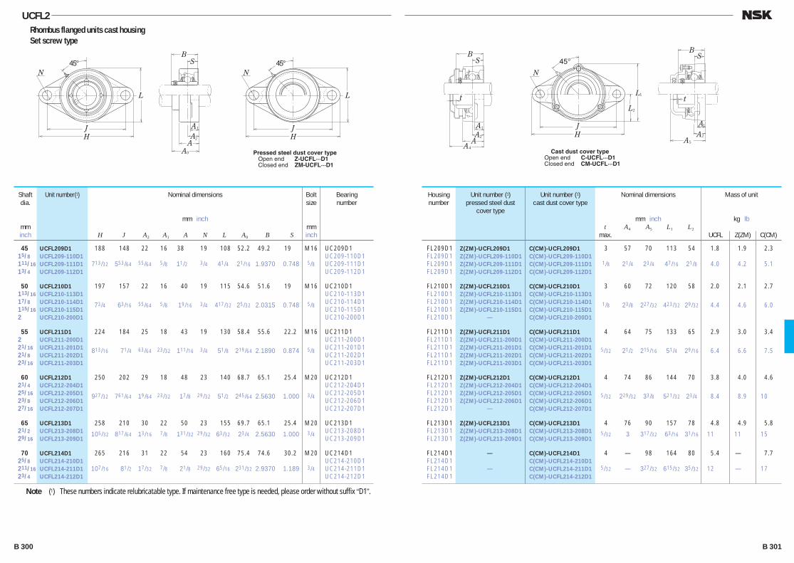
UCFL2Rhombus flanged units cast housing Set screw type
45 UCFL209D1 188 148 22 16 38 19 108 52.2 49.2 19 M16 UC209D1 15/8 UCFL209-110D1 UC209-110D1 111/16 UCFL209-111D1 713/32 553/64 55/64 5/8 11/2 3/4 41/4 21/16 1.9370 0.748 5/8 UC209-111D1 13/4 UCFL209-112D1 UC209-112D1
50 UCFL210D1 197 157 22 16 40 19 115 54.6 51.6 19 M16 UC210D1 113/16 UCFL210-113D1 UC210-113D1 17/8 UCFL210-114D1 73/4 63/16 55/64 5/8 19/16 3/4 417/32 25/32 2.0315 0.748 5/8 UC210-114D1 115/16 UCFL210-115D1 UC210-115D1 2 UCFL210-200D1 UC210-200D1
55 UCFL211D1 224 184 25 18 43 19 130 58.4 55.6 22.2 M16 UC211D1 2 UCFL211-200D1 UC211-200D1 21/16 UCFL211-201D1 813/16 71/4 63/64 23/32 111/16 3/4 51/8 219/64 2.1890 0.874 5/8 UC211-201D1 21/8 UCFL211-202D1 UC211-202D1 23/16 UCFL211-203D1 UC211-203D1
60 UCFL212D1 250 202 29 18 48 23 140 68.7 65.1 25.4 M20 UC212D1 21/4 UCFL212-204D1 UC212-204D1 25/16 UCFL212-205D1 927/32 761/64 19/64 23/32 17/8 29/32 51/2 245/64 2.5630 1.000 3/4 UC212-205D1 23/8 UCFL212-206D1 UC212-206D1 27/16 UCFL212-207D1 UC212-207D1
65 UCFL213D1 258 210 30 22 50 23 155 69.7 65.1 25.4 M20 UC213D1 21/2 UCFL213-208D1 105/32 817/64 13/16 7/8 131/32 29/32 63/32 23/4 2.5630 1.000 3/4 UC213-208D1 29/16 UCFL213-209D1 UC213-209D1
70 UCFL214D1 265 216 31 22 54 23 160 75.4 74.6 30.2 M20 UC214D1 25/8 UCFL214-210D1 UC214-210D1 211/16 UCFL214-211D1 107/16 81/2 17/32 7/8 21/8 29/32 65/16 231/32 2.9370 1.189 3/4 UC214-211D1 23/4 UCFL214-212D1 UC214-212D1
Shaft dia.
mminch
Unit number(1) Housing number
Unit number (1)pressed steel dust
cover type
Unit number (1)cast dust cover type
Nominal dimensions
mm inch t A4 A5 L1 L2
max.
Mass of unit
kg lb
UCFL Z(ZM) C(CM)
Bolt size
mminch
Bearingnumber
Nominal dimensions
mm inch
H J A2 A1 A N L A0 B S
FL209D1 Z(ZM)-UCFL209D1 C(CM)-UCFL209D1 3 57 70 113 54 1.8 1.9 2.3 FL209D1 Z(ZM)-UCFL209-110D1 C(CM)-UCFL209-110D1 FL209D1 Z(ZM)-UCFL209-111D1 C(CM)-UCFL209-111D1 1/8 21/4 23/4 47/16 21/8 4.0 4.2 5.1 FL209D1 Z(ZM)-UCFL209-112D1 C(CM)-UCFL209-112D1
FL210D1 Z(ZM)-UCFL210D1 C(CM)-UCFL210D1 3 60 72 120 58 2.0 2.1 2.7 FL210D1 Z(ZM)-UCFL210-113D1 C(CM)-UCFL210-113D1 FL210D1 Z(ZM)-UCFL210-114D1 C(CM)-UCFL210-114D1 1/8 23/8 227/32 423/32 29/32 4.4 4.6 6.0 FL210D1 Z(ZM)-UCFL210-115D1 C(CM)-UCFL210-115D1 FL210D1 — C(CM)-UCFL210-200D1
FL211D1 Z(ZM)-UCFL211D1 C(CM)-UCFL211D1 4 64 75 133 65 2.9 3.0 3.4 FL211D1 Z(ZM)-UCFL211-200D1 C(CM)-UCFL211-200D1 FL211D1 Z(ZM)-UCFL211-201D1 C(CM)-UCFL211-201D1 5/32 21/2 215/16 51/4 29/16 6.4 6.6 7.5 FL211D1 Z(ZM)-UCFL211-202D1 C(CM)-UCFL211-202D1 FL211D1 Z(ZM)-UCFL211-203D1 C(CM)-UCFL211-203D1
FL212D1 Z(ZM)-UCFL212D1 C(CM)-UCFL212D1 4 74 86 144 70 3.8 4.0 4.6 FL212D1 Z(ZM)-UCFL212-204D1 C(CM)-UCFL212-204D1 FL212D1 Z(ZM)-UCFL212-205D1 C(CM)-UCFL212-205D1 5/32 229/32 33/8 521/32 23/4 8.4 8.9 10 FL212D1 Z(ZM)-UCFL212-206D1 C(CM)-UCFL212-206D1 FL212D1 — C(CM)-UCFL212-207D1
FL213D1 Z(ZM)-UCFL213D1 C(CM)-UCFL213D1 4 76 90 157 78 4.8 4.9 5.8 FL213D1 Z(ZM)-UCFL213-208D1 C(CM)-UCFL213-208D1 5/32 3 317/32 63/16 31/16 11 11 15 FL213D1 Z(ZM)-UCFL213-209D1 C(CM)-UCFL213-209D1
FL214D1 — C(CM)-UCFL214D1 4 — 98 164 80 5.4 — 7.7 FL214D1 C(CM)-UCFL214-210D1 FL214D1 — C(CM)-UCFL214-211D1 5/32 — 327/32 615/32 35/32 12 — 17 FL214D1 C(CM)-UCFL214-212D1
Note (1) These numbers indicate relubricatable type. If maintenance free type is needed, please order without suffix “D1”.
A4
BS
AA2
A1
1
2
N
45°
H
L
L
J
t
B
t
S
A5
A2
A1
Cast dust cover typeOpen end C-UCFL···D1Closed end CM-UCFL···D1
N
A
H
L
J
0
BS
AA2
A1
45°N
H
L
J
45°
Pressed steel dust cover type Open end Z-UCFL···D1 Closed end ZM-UCFL···D1
B 300 B 301
B280-303E.indd 300-301B280-303E.indd 300-301 11/20/13 5:00:53 PM11/20/13 5:00:53 PM
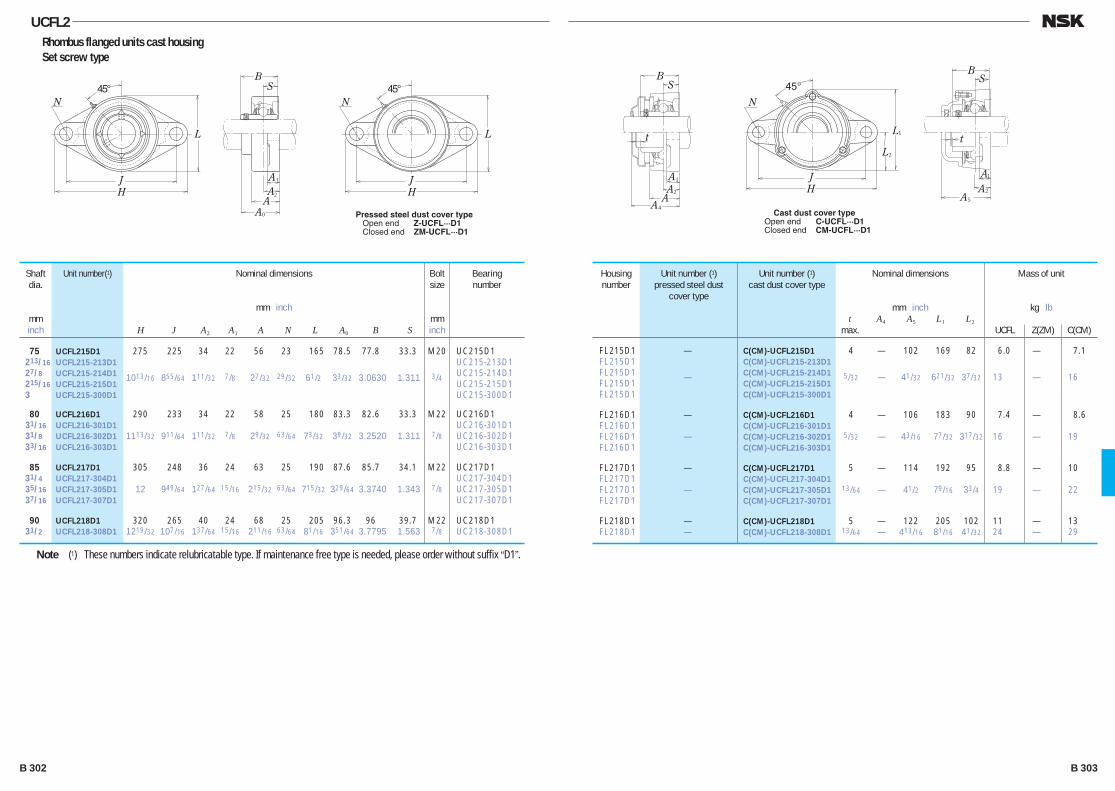
UCFL2Rhombus flanged units cast housing Set screw type
75 UCFL215D1 275 225 34 22 56 23 165 78.5 77.8 33.3 M20 UC215D1 213/16 UCFL215-213D1 UC215-213D1 27/8 UCFL215-214D1 1013/16 855/64 111/32 7/8 27/32 29/32 61/2 33/32 3.0630 1.311 3/4 UC215-214D1 215/16 UCFL215-215D1 UC215-215D1 3 UCFL215-300D1 UC215-300D1
80 UCFL216D1 290 233 34 22 58 25 180 83.3 82.6 33.3 M22 UC216D1 31/16 UCFL216-301D1 UC216-301D1 31/8 UCFL216-302D1 1113/32 911/64 111/32 7/8 29/32 63/64 73/32 39/32 3.2520 1.311 7/8 UC216-302D1 33/16 UCFL216-303D1 UC216-303D1
85 UCFL217D1 305 248 36 24 63 25 190 87.6 85.7 34.1 M22 UC217D1 31/4 UCFL217-304D1 UC217-304D1 35/16 UCFL217-305D1 12 949/64 127/64 15/16 215/32 63/64 715/32 329/64 3.3740 1.343 7/8 UC217-305D1 37/16 UCFL217-307D1 UC217-307D1
90 UCFL218D1 320 265 40 24 68 25 205 96.3 96 39.7 M22 UC218D1 31/2 UCFL218-308D1 1219/32 107/16 137/64 15/16 211/16 63/64 81/16 351/64 3.7795 1.563 7/8 UC218-308D1
Shaft dia.
mminch
Unit number(1) Housing number
Unit number (1)pressed steel dust
cover type
Unit number (1)cast dust cover type
Nominal dimensions
mm inch t A4 A5 L1 L2
max.
Mass of unit
kg lb
UCFL Z(ZM) C(CM)
Bolt size
mminch
Bearingnumber
Nominal dimensions
mm inch
H J A2 A1 A N L A0 B S
FL215D1 — C(CM)-UCFL215D1 4 — 102 169 82 6.0 — 7.1 FL215D1 C(CM)-UCFL215-213D1 FL215D1 — C(CM)-UCFL215-214D1 5/32 — 41/32 621/32 37/32 13 — 16 FL215D1 C(CM)-UCFL215-215D1 FL215D1 C(CM)-UCFL215-300D1
FL216D1 — C(CM)-UCFL216D1 4 — 106 183 90 7.4 — 8.6 FL216D1 C(CM)-UCFL216-301D1 FL216D1 — C(CM)-UCFL216-302D1 5/32 — 43/16 77/32 317/32 16 — 19 FL216D1 C(CM)-UCFL216-303D1
FL217D1 — C(CM)-UCFL217D1 5 — 114 192 95 8.8 — 10 FL217D1 C(CM)-UCFL217-304D1 FL217D1 — C(CM)-UCFL217-305D1 13/64 — 41/2 79/16 33/4 19 — 22 FL217D1 C(CM)-UCFL217-307D1
FL218D1 — C(CM)-UCFL218D1 5 — 122 205 102 11 — 13 FL218D1 — C(CM)-UCFL218-308D1 13/64 — 413/16 81/16 41/32 24 — 29
Note (1) These numbers indicate relubricatable type. If maintenance free type is needed, please order without suffix “D1”.
A4
BS
AA2
A1
1
2
N
45°
H
L
L
J
t
B
t
S
A5
A2
A1
Cast dust cover typeOpen end C-UCFL···D1Closed end CM-UCFL···D1
N
A
H
L
J
0
BS
AA2
A1
45°N
H
L
J
45°
Pressed steel dust cover type Open end Z-UCFL···D1 Closed end ZM-UCFL···D1
B 302 B 303
B280-303E.indd 302-303B280-303E.indd 302-303 11/20/13 5:00:55 PM11/20/13 5:00:55 PM

PLUMMER BLOCKSSTANDARD TYPE PLUMMER BLOCKS ·········································································· B306
LARGE PLUMMER BLOCKS ········································································································ B312
DUSTPROOF PLUMMER BLOCKS ······················································································· B316
STEPPED-SHAFT TYPE PLUMMERBLOCKS ······························································································································································ B318
DESIGN, TYPES AND FEATURES
There are numerous types and sizes of plummer blocks. In this catalog, only the types marked by are shown.
SN 5SN 6SN 30SN 31SN 2SN 3SN 2CSN 3C
These are the most common type.Models SN30 and SN31 are for medium loads. For types SN2C and SN3C, the bore diameters on the two sides are different.
SD 30SSD 31SSD 5SD 6SD 2SD 3SD 2CSD 3C
These are large and made for heavy loads. The standard ones have double seals and four mounting bolt holes. For types SD2C and SD3C, the bore diameters on the two sides are different.
SG 5
Dustproof plummer blocks have a combination of oil seals, labyrinth seals, and oil groove seals, therefore, they are suitable for environments with much dust and other foreign matter.
SD31TSSD32TS
These are provided with labyrinth seals, so they are suitable for high speed applications.
V · C Single-piece plummer blocks(integrated type roller bearing unit)have higher rigidity and precision than split type plummer blocks.
SN 5BSN 6BSN 30BSN 31BSN 2BSN 3BSN 2BCSN 3BC
These have the same dimensions as those of types SN5 and SN6. To increase the bearing box strength, no material is removed from the top or bottom of the base, so mounting holes can be drilled anywhere.
B 304 B 305
B304-325E.indd 304-305B304-325E.indd 304-305 11/20/13 5:01:16 PM11/20/13 5:01:16 PM
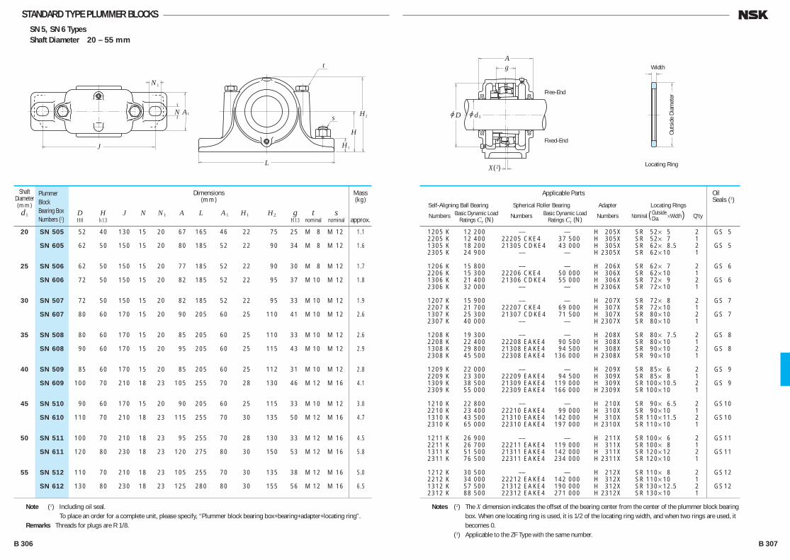
STANDARD TYPE PLUMMER BLOCKSSN 5, SN 6 TypesShaft Diameter 20 – 55 mm
N
N1
L
J
H
H
s
t
2A1
H1
Free-End
Fixed-End
Width
Locating Ring
Outs
ide
Diam
eter
jD
Ag
jd1
2X( )
20 SN 505 52 40 130 15 20 67 165 46 22 75 25 M 8 M 12 1.1
SN 605 62 50 150 15 20 80 185 52 22 90 34 M 8 M 12 1.6
25 SN 506 62 50 150 15 20 77 185 52 22 90 30 M 8 M 12 1.7
SN 606 72 50 150 15 20 82 185 52 22 95 37 M 10 M 12 1.8
30 SN 507 72 50 150 15 20 82 185 52 22 95 33 M 10 M 12 1.9
SN 607 80 60 170 15 20 90 205 60 25 110 41 M 10 M 12 2.6
35 SN 508 80 60 170 15 20 85 205 60 25 110 33 M 10 M 12 2.6
SN 608 90 60 170 15 20 95 205 60 25 115 43 M 10 M 12 2.9
40 SN 509 85 60 170 15 20 85 205 60 25 112 31 M 10 M 12 2.8
SN 609 100 70 210 18 23 105 255 70 28 130 46 M 12 M 16 4.1
45 SN 510 90 60 170 15 20 90 205 60 25 115 33 M 10 M 12 3.0
SN 610 110 70 210 18 23 115 255 70 30 135 50 M 12 M 16 4.7
50 SN 511 100 70 210 18 23 95 255 70 28 130 33 M 12 M 16 4.5
SN 611 120 80 230 18 23 120 275 80 30 150 53 M 12 M 16 5.8
55 SN 512 110 70 210 18 23 105 255 70 30 135 38 M 12 M 16 5.0
SN 612 130 80 230 18 23 125 280 80 30 155 56 M 12 M 16 6.5
Shaft Diameter(mm)d1
PlummerBlockBearing BoxNumbers (1)
Dimensions(mm)
D H J N N1 A L A1 H1 H2 g t s H8 h13 H13 nominal nominal
1205 K 12 200 — — — H 205X SR 52× 5 2 GS 5 2205 K 12 400 22205 CKE4 37 500 H 305X SR 52× 7 1 1305 K 18 200 21305 CDKE4 43 000 H 305X SR 62× 8.5 2 GS 5 2305 K 24 900 — — — H 2305X SR 62× 10 1
1206 K 15 800 — — — H 206X SR 62× 7 2 GS 6 2206 K 15 300 22206 CKE4 50 000 H 306X SR 62× 10 1 1306 K 21 400 21306 CDKE4 55 000 H 306X SR 72× 9 2 GS 6 2306 K 32 000 — — — H 2306X SR 72× 10 1
1207 K 15 900 — — — H 207X SR 72× 8 2 GS 7 2207 K 21 700 22207 CKE4 69 000 H 307X SR 72× 10 1 1307 K 25 300 21307 CDKE4 71 500 H 307X SR 80× 10 2 GS 7 2307 K 40 000 — — — H 2307X SR 80× 10 1
1208 K 19 300 — — — H 208X SR 80× 7.5 2 GS 8 2208 K 22 400 22208 EAKE4 90 500 H 308X SR 80× 10 1 1308 K 29 800 21308 EAKE4 94 500 H 308X SR 90× 10 2 GS 8 2308 K 45 500 22308 EAKE4 136 000 H 2308X SR 90× 10 1
1209 K 22 000 — — — H 209X SR 85× 6 2 GS 9 2209 K 23 300 22209 EAKE4 94 500 H 309X SR 85× 8 1 1309 K 38 500 21309 EAKE4 119 000 H 309X SR 100× 10.5 2 GS 9 2309 K 55 000 22309 EAKE4 166 000 H 2309X SR 100× 10 1
1210 K 22 800 — — — H 210X SR 90× 6.5 2 GS 10 2210 K 23 400 22210 EAKE4 99 000 H 310X SR 90× 10 1 1310 K 43 500 21310 EAKE4 142 000 H 310X SR 110× 11.5 2 GS 10 2310 K 65 000 22310 EAKE4 197 000 H 2310X SR 110× 10 1
1211 K 26 900 — — — H 211X SR 100× 6 2 GS 11 2211 K 26 700 22211 EAKE4 119 000 H 311X SR 100× 8 1 1311 K 51 500 21311 EAKE4 142 000 H 311X SR 120× 12 2 GS 11 2311 K 76 500 22311 EAKE4 234 000 H 2311X SR 120× 10 1
1212 K 30 500 — — — H 212X SR 110× 8 2 GS 12 2212 K 34 000 22212 EAKE4 142 000 H 312X SR 110× 10 1 1312 K 57 500 21312 EAKE4 190 000 H 312X SR 130× 12.5 2 GS 12 2312 K 88 500 22312 EAKE4 271 000 H 2312X SR 130× 10 1
Applicable Parts
Self-Aligning Ball Bearing Spherical Roller Bearing Adapter Locating Rings Numbers Basic Dynamic Load Numbers Basic Dynamic Load Numbers Nominal ( Outside ×WidthDia. ) Q'ty Ratings Cr (N) Ratings Cr (N)
OilSeals (3)
Mass(kg)
approx.
Note (1) Including oil seal. To place an order for a complete unit, please specify, “Plummer block bearing box+bearing+adapter+locating ring”.Remarks Threads for plugs are R 1/8.
Notes (2) The X dimension indicates the offset of the bearing center from the center of the plummer block bearing box. When one locating ring is used, it is 1/2 of the locating ring width, and when two rings are used, it becomes 0.
(3) Applicable to the ZF Type with the same number.B 306 B 307
B304-325E.indd 306-307B304-325E.indd 306-307 11/20/13 5:01:18 PM11/20/13 5:01:18 PM
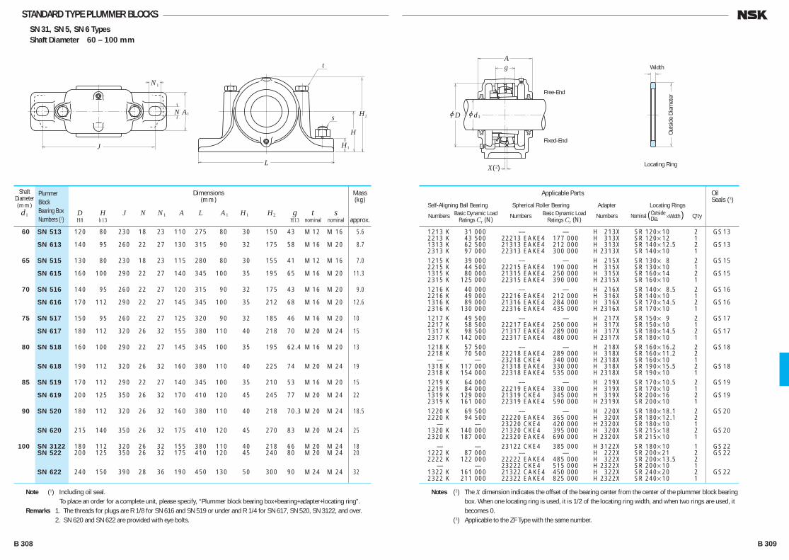
STANDARD TYPE PLUMMER BLOCKSSN 31, SN 5, SN 6 TypesShaft Diameter 60 – 100 mm
N
N1
L
J
H
H
s
t
2A1
H1
Free-End
Fixed-End
Width
Locating Ring
Outs
ide
Diam
eter
jD
Ag
jd1
2X( )
60 SN 513 120 80 230 18 23 110 275 80 30 150 43 M 12 M 16 5.6
SN 613 140 95 260 22 27 130 315 90 32 175 58 M 16 M 20 8.7
65 SN 515 130 80 230 18 23 115 280 80 30 155 41 M 12 M 16 7.0
SN 615 160 100 290 22 27 140 345 100 35 195 65 M 16 M 20 11.3
70 SN 516 140 95 260 22 27 120 315 90 32 175 43 M 16 M 20 9.0
SN 616 170 112 290 22 27 145 345 100 35 212 68 M 16 M 20 12.6
75 SN 517 150 95 260 22 27 125 320 90 32 185 46 M 16 M 20 10
SN 617 180 112 320 26 32 155 380 110 40 218 70 M 20 M 24 15
80 SN 518 160 100 290 22 27 145 345 100 35 195 62.4 M 16 M 20 13
SN 618 190 112 320 26 32 160 380 110 40 225 74 M 20 M 24 19
85 SN 519 170 112 290 22 27 140 345 100 35 210 53 M 16 M 20 15
SN 619 200 125 350 26 32 170 410 120 45 245 77 M 20 M 24 22
90 SN 520 180 112 320 26 32 160 380 110 40 218 70.3 M 20 M 24 18.5
SN 620 215 140 350 26 32 175 410 120 45 270 83 M 20 M 24 25
100 SN 3122 180 112 320 26 32 155 380 110 40 218 66 M 20 M 24 18 SN 522 200 125 350 26 32 175 410 120 45 240 80 M 20 M 24 20
SN 622 240 150 390 28 36 190 450 130 50 300 90 M 24 M 24 32
Shaft Diameter(mm)d1
PlummerBlockBearing BoxNumbers (1)
Dimensions(mm)
D H J N N1 A L A1 H1 H2 g t s H8 h13 H13 nominal nominal
1213 K 31 000 — — — H 213X SR 120× 10 2 GS 13 2213 K 43 500 22213 EAKE4 177 000 H 313X SR 120× 12 1 1313 K 62 500 21313 EAKE4 212 000 H 313X SR 140× 12.5 2 GS 13 2313 K 97 000 22313 EAKE4 300 000 H 2313X SR 140× 10 1 1215 K 39 000 — — — H 215X SR 130× 8 2 GS 15 2215 K 44 500 22215 EAKE4 190 000 H 315X SR 130× 10 1 1315 K 80 000 21315 EAKE4 250 000 H 315X SR 160× 14 2 GS 15 2315 K 125 000 22315 EAKE4 390 000 H 2315X SR 160× 10 1 1216 K 40 000 — — — H 216X SR 140× 8.5 2 GS 16 2216 K 49 000 22216 EAKE4 212 000 H 316X SR 140× 10 1 1316 K 89 000 21316 EAKE4 284 000 H 316X SR 170× 14.5 2 GS 16 2316 K 130 000 22316 EAKE4 435 000 H 2316X SR 170× 10 1 1217 K 49 500 — — — H 217X SR 150× 9 2 GS 17 2217 K 58 500 22217 EAKE4 250 000 H 317X SR 150× 10 1 1317 K 98 500 21317 EAKE4 289 000 H 317X SR 180× 14.5 2 GS 17 2317 K 142 000 22317 EAKE4 480 000 H 2317X SR 180× 10 1 1218 K 57 500 — — — H 218X SR 160× 16.2 2 GS 18 2218 K 70 500 22218 EAKE4 289 000 H 318X SR 160× 11.2 2 — — 23218 CKE4 340 000 H 2318X SR 160× 10 1 1318 K 117 000 21318 EAKE4 330 000 H 318X SR 190× 15.5 2 GS 18 2318 K 154 000 22318 EAKE4 535 000 H 2318X SR 190× 10 1 1219 K 64 000 — — — H 219X SR 170× 10.5 2 GS 19 2219 K 84 000 22219 EAKE4 330 000 H 319X SR 170× 10 1 1319 K 129 000 21319 CKE4 345 000 H 319X SR 200× 16 2 GS 19 2319 K 161 000 22319 EAKE4 590 000 H 2319X SR 200× 10 1 1220 K 69 500 — — — H 220X SR 180× 18.1 2 GS 20 2220 K 94 500 22220 EAKE4 365 000 H 320X SR 180× 12.1 2 — — 23220 CKE4 420 000 H 2320X SR 180× 10 1 1320 K 140 000 21320 CKE4 395 000 H 320X SR 215× 18 2 GS 20 2320 K 187 000 22320 EAKE4 690 000 H 2320X SR 215× 10 1 — — 23122 CKE4 385 000 H 3122X SR 180× 10 1 GS 22 1222 K 87 000 — — — H 222X SR 200× 21 2 GS 22 2222 K 122 000 22222 EAKE4 485 000 H 322X SR 200× 13.5 2 — — 23222 CKE4 515 000 H 2322X SR 200× 10 1 1322 K 161 000 21322 CAKE4 450 000 H 322X SR 240× 20 2 GS 22 2322 K 211 000 22322 EAKE4 825 000 H 2322X SR 240× 10 1
Applicable Parts
Self-Aligning Ball Bearing Spherical Roller Bearing Adapter Locating Rings Numbers Basic Dynamic Load Numbers Basic Dynamic Load Numbers Nominal ( Outside ×WidthDia. ) Q'ty Ratings Cr (N) Ratings Cr (N)
OilSeals (3)
Mass(kg)
approx.
Note (1) Including oil seal. To place an order for a complete unit, please specify, “Plummer block bearing box+bearing+adapter+locating ring”.Remarks 1. The threads for plugs are R 1/8 for SN 616 and SN 519 or under and R 1/4 for SN 617, SN 520, SN 3122, and over. 2. SN 620 and SN 622 are provided with eye bolts.
Notes (2) The X dimension indicates the offset of the bearing center from the center of the plummer block bearing box. When one locating ring is used, it is 1/2 of the locating ring width, and when two rings are used, it becomes 0.
(3) Applicable to the ZF Type with the same number.
B 308 B 309
B304-325E.indd 308-309B304-325E.indd 308-309 11/20/13 5:01:19 PM11/20/13 5:01:19 PM
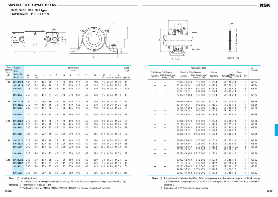
STANDARD TYPE PLUMMER BLOCKSSN 30, SN 31, SN 5, SN 6 TypesShaft Diameter 110 – 140 mm
N
N1
L
J
H
H
s
t
2A1
H1
Free-End
Fixed-End
Width
Locating Ring
Outs
ide
Diam
eter
jD
Ag
jd1
2X( )
110 SN 3024 180 112 320 26 32 150 380 110 40 218 56 M 20 M 24 16 SN 3124 200 125 350 26 32 165 410 120 45 245 72 M 20 M 24 20 SN 524 215 140 350 26 32 185 410 120 45 270 86 M 20 M 24 24.5
SN 624 260 160 450 33 42 200 530 160 60 320 96 M 24 M 30 48
115 SN 3026 200 125 350 26 32 160 410 120 45 240 62 M 20 M 24 19 SN 3126 210 140 350 26 32 170 410 120 45 270 74 M 20 M 24 26 SN 526 230 150 380 28 36 190 445 130 50 290 90 M 24 M 24 30
SN 626 280 170 470 33 42 210 550 160 60 340 103 M 24 M 30 56
125 SN 3028 210 140 350 26 32 170 410 120 45 270 63 M 20 M 24 25 SN 3128 225 150 380 28 36 180 445 130 50 290 78 M 24 M 24 32 SN 528 250 150 420 33 42 205 500 150 50 305 98 M 24 M 30 38
SN 628 300 180 520 35 45 235 610 170 65 365 112 M 30 M 30 72
135 SN 3030 225 150 380 28 36 175 445 130 50 290 66 M 24 M 24 29 SN 3130 250 150 420 33 42 200 500 150 50 305 90 M 24 M 30 38 SN 530 270 160 450 33 42 220 530 160 60 325 106 M 24 M 30 46
SN 630 320 190 560 35 45 245 650 180 65 385 118 M 30 M 30 98
140 SN 3032 240 150 390 28 36 190 450 130 50 300 70 M 24 M 24 32 SN 3132 270 160 450 33 42 215 530 160 60 325 96 M 24 M 30 48 SN 532 290 170 470 33 42 235 550 160 60 345 114 M 24 M 30 50
SN 632 340 200 580 42 50 255 680 190 70 405 124 M 30 M 36 115
Shaft Diameter(mm)d1
PlummerBlockBearing BoxNumbers (1)
Dimensions(mm)
D H J N N1 A L A1 H1 H2 g t s H8 h13 H13 nominal nominal
— — 23024 CDKE4 315 000 H 3024 SR 180× 10 1 GS 24 — — 23124 CKE4 465 000 H 3124 SR 200× 10 1 GS 24 — — 22224 EAKE4 550 000 H 3124 SR 215× 14 2 GS 24 — — 23224 CKE4 630 000 H 2324 SR 215× 10 1
— — 22324 EAKE4 955 000 H 2324 SR 260× 10 1 GS 24
— — 23026 CDKE4 400 000 H 3026 SR 200× 10 1 GS 26 — — 23126 CKE4 505 000 H 3126 SR 210× 10 1 GS 26 — — 22226 EAKE4 655 000 H 3126 SR 230× 13 2 GS 26 — — 23226 CKE4 700 000 H 2326 SR 230× 10 1
— — 22326 CKE4 995 000 H 2326 SR 280× 10 1 GS 26
— — 23028 CDKE4 420 000 H 3028 SR 210× 10 1 GS 28 — — 23128 CKE4 580 000 H 3128 SR 225× 10 1 GS 28 — — 22228 CDKE4 645 000 H 3128 SR 250× 15 2 GS 28 — — 23228 CKE4 835 000 H 2328 SR 250× 10 1
— — 22328 CKE4 1 160 000 H 2328 SR 300× 10 1 GS 28
— — 23030 CDKE4 470 000 H 3030 SR 225× 10 1 GS 30 — — 23130 CKE4 725 000 H 3130 SR 250× 10 1 GS 30 — — 22230 CDKE4 765 000 H 3130 SR 270× 16.5 2 GS 30 — — 23230 CKE4 975 000 H 2330 SR 270× 10 1
— — 22330 CAKE4 1 220 000 H 2330 SR 320× 10 1 GS 30
— — 23032 CDKE4 540 000 H 3032 SR 240× 10 1 GS 32 — — 23132 CKE4 855 000 H 3132 SR 270× 10 1 GS 32 — — 22232 CDKE4 910 000 H 3132 SR 290× 17 2 GS 32 — — 23232 CKE4 1 100 000 H 2332 SR 290× 10 1
— — 22332 CAKE4 1 360 000 H 2332 SR 340× 10 1 GS 32
Applicable Parts
Self-Aligning Ball Bearing Spherical Roller Bearing Adapter Locating Rings Numbers Basic Dynamic Load Numbers Basic Dynamic Load Numbers Nominal ( Outside ×WidthDia. ) Q'ty Ratings Cr (N) Ratings Cr (N)
OilSeals (3)
Mass(kg)
approx.
Note (1) Including oil seal. To place an order for a complete unit, please specify, “Plummer block bearing box+bearing+adapter+locating ring”.Remarks 1. The threads for plugs are R 1/4. 2. The bearing boxes for SN 524, SN 624, SN 3126, SN 3028, and over are provided with eye bolts.
Notes (2) The X dimension indicates the offset of the bearing center from the center of the plummer block bearing box. When one locating ring is used, it is 1/2 of the locating ring width, and when two rings are used, it becomes 0.
(3) Applicable to the ZF Type with the same number.B 310 B 311
B304-325E.indd 310-311B304-325E.indd 310-311 11/20/13 5:01:20 PM11/20/13 5:01:20 PM
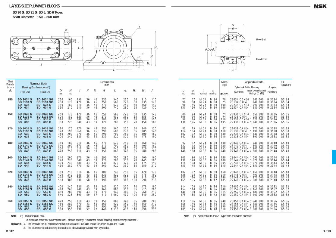
LARGE-SIZE PLUMMER BLOCKSSD 30 S, SD 31 S, SD 5, SD 6 TypesShaft Diameter 150 – 260 mm
N
N1
L
J
H
Hs
t
2A1J 1
H1
Free-End
Fixed-End
jD
Ag
g
jd1
1
150 SD 3034 S SD 3034 SG 260 160 450 36 46 230 540 200 50 315 110 SD 3134 S SD 3134 SG 280 170 470 36 46 250 560 220 50 335 120 SD 534 SD 534 G 310 180 510 36 46 270 620 250 60 360 140 SD 634 SD 634 G 360 210 610 36 46 300 740 290 65 420 170
160 SD 3036 S SD 3036 SG 280 170 470 36 46 250 560 220 50 335 120 SD 3136 S SD 3136 SG 300 180 520 36 46 270 630 250 55 355 140 SD 536 SD 536 G 320 190 540 36 46 280 650 260 60 380 150 SD 636 SD 636 G 380 225 640 43 59 320 780 310 70 450 180
170 SD 3038 S SD 3038 SG 290 170 470 36 46 250 560 220 50 340 120 SD 3138 S SD 3138 SG 320 190 560 36 46 290 680 270 55 385 140 SD 538 SD 538 G 340 200 570 36 46 290 700 280 65 400 160 SD 638 SD 638 G 400 240 680 43 59 330 820 320 70 475 190
180 SD 3040 S SD 3040 SG 310 180 510 36 46 270 620 250 60 360 140 SD 3140 S SD 3140 SG 340 200 570 36 46 310 700 280 65 400 160 SD 540 SD 540 G 360 210 610 36 46 300 740 290 65 420 170 SD 640 SD 640 G 420 250 710 43 59 350 860 340 85 500 200
200 SD 3044 S SD 3044 SG 340 200 570 36 46 290 700 280 65 400 160 SD 3144 S SD 3144 SG 370 225 640 43 59 320 780 310 70 445 180 SD 544 SD 544 G 400 240 680 43 59 330 820 320 70 475 190 SD 644 SD 644 G 460 280 770 43 59 360 920 350 85 550 210
220 SD 3048 S SD 3048 SG 360 210 610 36 46 300 740 290 65 420 170 SD 3148 S SD 3148 SG 400 240 680 43 59 330 820 320 70 475 190 SD 548 SD 548 G 440 260 740 43 59 340 880 330 85 515 200 SD 648 SD 648 G 500 300 830 50 67 390 990 380 100 590 230
240 SD 3052 S SD 3052 SG 400 240 680 43 59 340 820 320 70 475 190 SD 3152 S SD 3152 SG 440 260 740 43 59 360 880 350 85 515 200 SD 552 SD 552 G 480 280 790 43 59 370 940 360 85 560 210 SD 652 SD 652 G 540 325 890 50 67 410 1 060 400 100 640 250
260 SD 3056 S SD 3056 SG 420 250 710 43 59 350 860 340 85 500 200 SD 3156 S SD 3156 SG 460 280 770 43 59 360 920 350 85 550 210 SD 556 SD 556 G 500 300 830 50 67 390 990 380 100 590 230 SD 656 SD 656 G 580 355 930 57 77 440 1 110 430 110 690 270
Shaft Diameter(mm)d1
Plummer BlockBearing Box Numbers (1)
Free-End Fixed-End
Dimensions(mm)
D H J N N1 A L A1 H1 H2 J1 H8 h13
g g1 t s H13 H13 nominal nominal
77 67 M 24 M 30 70 23034 CDKE4 640 000 H 3034 GS 34 98 88 M 24 M 30 75 23134 CKE4 940 000 H 3134 GS 34 96 86 M 24 M 30 100 22234 CDKE4 990 000 H 3134 GS 34 130 120 M 30 M 30 160 22334 CAKE4 1 580 000 H 2334 GS 34
84 74 M 24 M 30 79 23036 CDKE4 750 000 H 3036 GS 36 106 96 M 24 M 30 94 23136 CKE4 1 050 000 H 3136 GS 36 96 86 M 24 M 30 110 22236 CDKE4 1 020 000 H 3136 GS 36 136 126 M 30 M 36 195 22336 CAKE4 1 740 000 H 2336 GS 36
85 75 M 24 M 30 87 23038 CAKE4 775 000 H 3038 GS 38 114 104 M 24 M 30 110 23138 CKE4 1 190 000 H 3138 GS 38 102 92 M 30 M 30 130 22238 CAKE4 1 140 000 H 3138 GS 38 142 132 M 30 M 36 210 22338 CAKE4 1 890 000 H 2338 GS 38
92 82 M 24 M 30 100 23040 CAKE4 940 000 H 3040 GS 40 122 112 M 30 M 30 130 23140 CKE4 1 360 000 H 3140 GS 40 108 98 M 30 M 30 155 22240 CAKE4 1 300 000 H 3140 GS 40 148 138 M 36 M 36 240 22340 CAKE4 2 000 000 H 2340 GS 40
100 90 M 30 M 30 130 23044 CAKE4 1 090 000 H 3044 GS 44 130 120 M 30 M 36 180 23144 CKE4 1 570 000 H 3144 GS 44 118 108 M 30 M 36 205 22244 CAKE4 1 570 000 H 3144 GS 44 155 145 M 36 M 36 315 22344 CAKE4 2 350 000 H 2344 GS 44
102 92 M 30 M 30 160 23048 CAKE4 1 160 000 H 3048 GS 48 138 128 M 30 M 36 210 23148 CKE4 1 790 000 H 3148 GS 48 130 120 M 36 M 36 240 22248 CAKE4 1 870 000 H 3148 GS 48 165 155 M 36 M 42 405 22348 CAKE4 2 600 000 H 2348 GS 48
114 104 M 30 M 36 210 23052 CAKE4 1 430 000 H 3052 GS 52 154 144 M 36 M 36 240 23152 CAKE4 2 160 000 H 3152 GS 52 140 130 M 36 M 36 315 22252 CAKE4 2 180 000 H 3152 GS 52 175 165 M 36 M 42 480 22352 CAKE4 3 100 000 H 2352 GS 52
116 106 M 36 M 36 240 23056 CAKE4 1 540 000 H 3056 GS 56 156 146 M 36 M 36 315 23156 CAKE4 2 230 000 H 3156 GS 56 140 130 M 36 M 42 390 22256 CAKE4 2 280 000 H 3156 GS 56 185 175 M 42 M 48 610 22356 CAKE4 3 500 000 H 2356 GS 56
Applicable Parts
Spherical Roller Bearing Adapter Numbers Basic Dynamic Load Numbers Ratings Cr (N)
OilSeals (2)
Mass(kg)
approx.
Note (1) Including oil seal. To place an order for a complete unit, please specify, “Plummer block bearing box+bearing+adapter”.Remarks 1. The threads for oil replenishing hole plugs are R 1/4 and those for drain plugs are R 3/8. 2. The plummer block bearing boxes listed above are provided with eye bolts.
Note (2) Applicable to the ZF Type with the same number.
B 312 B 313
B304-325E.indd 312-313B304-325E.indd 312-313 11/20/13 5:01:20 PM11/20/13 5:01:20 PM
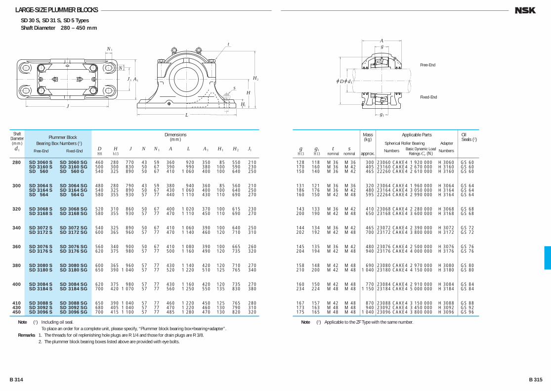
SD 30 S, SD 31 S, SD 5 TypesShaft Diameter 280 – 450 mm
LARGE-SIZE PLUMMER BLOCKS
N
N1
L
J
H
Hs
t
2A1J 1
H1
Free-End
Fixed-End
jD
Ag
g
jd1
1
280 SD 3060 S SD 3060 SG 460 280 770 43 59 360 920 350 85 550 210 SD 3160 S SD 3160 SG 500 300 830 50 67 390 990 380 100 590 230 SD 560 SD 560 G 540 325 890 50 67 410 1 060 400 100 640 250
300 SD 3064 S SD 3064 SG 480 280 790 43 59 380 940 360 85 560 210 SD 3164 S SD 3164 SG 540 325 890 50 67 430 1 060 400 100 640 250 SD 564 SD 564 G 580 355 930 57 77 440 1 110 430 110 690 270
320 SD 3068 S SD 3068 SG 520 310 860 50 67 400 1 020 370 100 615 230 SD 3168 S SD 3168 SG 580 355 930 57 77 470 1 110 450 110 690 270
340 SD 3072 S SD 3072 SG 540 325 890 50 67 410 1 060 390 100 640 250 SD 3172 S SD 3172 SG 600 365 960 57 77 470 1 140 460 120 710 310
360 SD 3076 S SD 3076 SG 560 340 900 50 67 410 1 080 390 100 665 260 SD 3176 S SD 3176 SG 620 375 980 57 77 500 1 160 490 120 735 320
380 SD 3080 S SD 3080 SG 600 365 960 57 77 430 1 140 420 120 710 270 SD 3180 S SD 3180 SG 650 390 1 040 57 77 520 1 220 510 125 765 340
400 SD 3084 S SD 3084 SG 620 375 980 57 77 430 1 160 420 120 735 270 SD 3184 S SD 3184 SG 700 420 1 070 57 77 560 1 250 550 135 830 380
410 SD 3088 S SD 3088 SG 650 390 1 040 57 77 460 1 220 450 125 765 280 430 SD 3092 S SD 3092 SG 680 405 1 040 57 77 470 1 220 460 130 790 310 450 SD 3096 S SD 3096 SG 700 415 1 100 57 77 485 1 280 470 130 820 320
Shaft Diameter(mm)d1
Plummer BlockBearing Box Numbers (1)
Free-End Fixed-End
Dimensions(mm)
D H J N N1 A L A1 H1 H2 J1 H8 h13
g g1 t s H13 H13 nominal nominal
128 118 M 36 M 36 300 23060 CAKE4 1 920 000 H 3060 GS 60 170 160 M 36 M 42 405 23160 CAKE4 2 670 000 H 3160 GS 60 150 140 M 36 M 42 465 22260 CAKE4 2 610 000 H 3160 GS 60
131 121 M 36 M 36 320 23064 CAKE4 1 960 000 H 3064 GS 64 186 176 M 36 M 42 480 23164 CAKE4 3 050 000 H 3164 GS 64 160 150 M 42 M 48 595 22264 CAKE4 2 990 000 H 3164 GS 64
143 133 M 36 M 42 410 23068 CAKE4 2 280 000 H 3068 GS 68 200 190 M 42 M 48 650 23168 CAKE4 3 600 000 H 3168 GS 68
144 134 M 36 M 42 465 23072 CAKE4 2 390 000 H 3072 GS 72 202 192 M 42 M 48 700 23172 CAKE4 3 800 000 H 3172 GS 72
145 135 M 36 M 42 480 23076 CAKE4 2 500 000 H 3076 GS 76 204 194 M 42 M 48 940 23176 CAKE4 4 000 000 H 3176 GS 76
158 148 M 42 M 48 690 23080 CAKE4 2 970 000 H 3080 GS 80 210 200 M 42 M 48 1 040 23180 CAKE4 4 150 000 H 3180 GS 80
160 150 M 42 M 48 770 23084 CAKE4 2 910 000 H 3084 GS 84 234 224 M 48 M 48 1 150 23184 CAKE4 5 000 000 H 3184 GS 84
167 157 M 42 M 48 870 23088 CAKE4 3 150 000 H 3088 GS 88 173 163 M 48 M 48 940 23092 CAKE4 3 450 000 H 3092 GS 92 175 165 M 48 M 48 1 040 23096 CAKE4 3 800 000 H 3096 GS 96
Applicable Parts
Spherical Roller Bearing Adapter Numbers Basic Dynamic Load Numbers Ratings Cr (N)
OilSeals (2)
Mass(kg)
approx.
Note (1) Including oil seal. To place an order for a complete unit, please specify, “Plummer block bearing box+bearing+adapter”.Remarks 1. The threads for oil replenishing hole plugs are R 1/4 and those for drain plugs are R 3/8. 2. The plummer block bearing boxes listed above are provided with eye bolts.
Note (2) Applicable to the ZF Type with the same number.
B 314 B 315
B304-325E.indd 314-315B304-325E.indd 314-315 11/20/13 5:01:21 PM11/20/13 5:01:21 PM
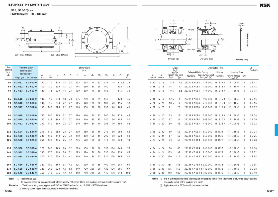
DUSTPROOF PLUMMER BLOCKSSG 5, SG 5-0 TypesShaft Diameter 50 – 180 mm
N
N
N
1 N1
L
J
H
Hs
t
2A1J1
H1
Bolt Holes, 4 PlacesBolt Holes, 2 Places
2
Through Type End Cover Type
Free-End
Fixed-End
Width
Locating Ring
Outs
ide
Diam
eter
jD
Ag
jd1
2X( )
AA
jd1
2
2X( )
50 SG 511 SG 511-0 100 70 210 18 23 125 255 70 23 137 — 112.5 29
55 SG 512 SG 512-0 110 80 230 18 23 145 290 80 25 160 — 135 32
60 SG 513 SG 513-0 120 83 230 18 23 130 290 70 25 155 — 115 36
65 SG 515 SG 515-0 130 90 230 18 23 135 290 80 25 168 — 120 36
70 SG 516 SG 516-0 140 95 270 22 27 165 340 120 30 180 70 155 38
75 SG 517 SG 517-0 150 100 280 22 27 170 350 120 30 190 70 160 41
80 SG 518 SG 518-0 160 100 290 22 27 180 360 120 35 200 70 170 45
90 SG 520 SG 520-0 180 125 340 22 27 200 410 130 35 240 70 185 51
100 SG 522 SG 522-0 200 140 380 22 27 210 460 130 40 265 70 190 58
110 SG 524 SG 524-0 215 140 380 22 27 230 460 130 45 275 80 200 63
115 SG 526 SG 526-0 230 150 410 26 32 240 490 160 45 295 80 220 69
125 SG 528 SG 528-0 250 160 435 26 32 245 520 160 50 310 80 220 73
135 SG 530 SG 530-0 270 160 465 26 32 265 550 170 50 330 100 240 78
140 SG 532 SG 532-0 290 170 490 26 32 285 580 170 50 350 100 250 85
150 SG 534 SG 534-0 310 180 550 33 42 300 640 180 55 380 100 265 91
160 SG 536 SG 536-0 320 190 600 33 42 325 690 190 55 400 110 285 91
170 SG 538 SG 538-0 340 200 620 42 52 340 730 200 60 420 120 295 97
180 SG 540 SG 540-0 360 210 635 42 52 350 750 210 60 445 130 310 103
Shaft Diameter(mm)d1
Plummer BlockBearing BoxNumbers (1)
Through Type End Cover Type
Dimensions(mm)
D H J N N1 A L A1 H1 H2 J1 A2 g H8 h13 H13
t s nominal nominal
M 12 M 16 8.5 7.5 22211 EAKE4 119 000 H 311 X SR 100×4 1 GS 11
M 16 M 16 15 14 22212 EAKE4 142 000 H 312 X SR 110×4 1 GS 12
M 16 M 16 9.5 8.5 22213 EAKE4 177 000 H 313 X SR 120×5 1 GS 13
M 16 M 16 12.5 11 22215 EAKE4 190 000 H 315 X SR 130×5 1 GS 15
M 20 M 20 18.5 17 22216 EAKE4 212 000 H 316 X SR 140×5 1 GS 16
M 20 M 20 21 20 22217 EAKE4 250 000 H 317 X SR 150×5 1 GS 17
M 20 M 20 25 23 22218 EAKE4 289 000 H 318 X SR 160×5 1 GS 18
M 20 M 20 37 34 22220 EAKE4 365 000 H 320 X SR 180×5 1 GS 20
M 20 M 20 50 45 22222 EAKE4 485 000 H 322 X SR 200×5 1 GS 22
M 20 M 20 59 53 22224 EAKE4 550 000 H 3124 SR 215×5 1 GS 24
M 24 M 24 67 62 22226 EAKE4 655 000 H 3126 SR 230×5 1 GS 26
M 24 M 24 73 68 22228 CDKE4 645 000 H 3128 SR 250×5 1 GS 28
M 24 M 24 90 80 22230 CDKE4 765 000 H 3130 SR 270×5 1 GS 30
M 24 M 24 105 92 22232 CDKE4 910 000 H 3132 SR 290×5 1 GS 32
M 30 M 30 130 115 22234 CDKE4 990 000 H 3134 SR 310×5 1 GS 34
M 30 M 30 155 135 22236 CDKE4 1 020 000 H 3136 SR 320×5 1 GS 36
M 36 M 36 175 155 22238 CAKE4 1 140 000 H 3138 SR 340×5 1 GS 38
M 36 M 36 210 180 22240 CAKE4 1 300 000 H 3140 SR 360×5 1 GS 40
Applicable Parts
Spherical Roller Bearing Adapter Locating Ring Numbers Basic Dynamic Load Numbers Nominal (Outside Q'ty Ratings Cr (N) Dia.×Width)
OilSeals (3)
Mass(kg)
approx. Through End Cover Type Type
Note (1) Including oil seal. To place an order for a complete unit, please specify, “Plummer block bearing box+bearing+adapter+locating ring”.Remarks 1. The threads for grease nipples are R 1/8 for SG518 and under, and R 1/4 for SG520 and over. 2. Bearing boxes larger than SG520 are provided with eye bolts.
Notes (2) The X dimension indicates the offset of the bearing center from the center of plummer block bearing box, and it is 1/2 of the locating ring width.
(3) Applicable to the ZF Type with the same number.
B 316 B 317
B304-325E.indd 316-317B304-325E.indd 316-317 11/20/13 5:01:22 PM11/20/13 5:01:22 PM

STEPPED-SHAFT TYPE PLUMMER BLOCKSSN 2 C, SN 3 C TypesShaft Diameter 25 – 55 mm
N
N1
L
J
H
H
s
t
2A1
H1
Free-End
Fixed-End
Width
Locating Ring
Outs
ide
Diam
eter
jD
Ag
jd jd jd2 1
2X( )
25 SN 205 C 30 20 52 40 130 15 20 67 165 46 22 75 25 M 8 M 12
SN 305 C 30 20 62 50 150 15 20 80 185 52 22 90 34 M 8 M 12
30 SN 206 C 35 25 62 50 150 15 20 77 185 52 22 90 30 M 8 M 12
SN 306 C 35 25 72 50 150 15 20 82 185 52 22 95 37 M 10 M 12
35 SN 207 C 45 30 72 50 150 15 20 82 185 52 22 95 33 M 10 M 12
SN 307 C 45 30 80 60 170 15 20 90 205 60 25 110 41 M 10 M 12
40 SN 208 C 50 35 80 60 170 15 20 85 205 60 25 110 33 M 10 M 12
SN 308 C 50 35 90 60 170 15 20 95 205 60 25 115 43 M 10 M 12
45 SN 209 C 55 40 85 60 170 15 20 85 205 60 25 112 31 M 10 M 12
SN 309 C 55 40 100 70 210 18 23 105 255 70 28 130 46 M 12 M 16
50 SN 210 C 60 45 90 60 170 15 20 90 205 60 25 115 33 M 10 M 12
SN 310 C 60 45 110 70 210 18 23 115 255 70 30 135 50 M 12 M 16
55 SN 211 C 65 50 100 70 210 18 23 95 255 70 28 130 33 M 12 M 16
SN 311 C 65 50 120 80 230 18 23 120 275 80 30 150 53 M 12 M 16
Shaft Diameter(mm)
d
Plummer BlockBearing BoxNumbers (1)
Dimensions(mm)
d1 d2 D H J N N1 A L A1 H1 H2 g t s H8 h13 H13 nominal nominal
1.1 1205 12 200 — — AN 05 AW 05X SR 52 × 5 2 GS 7 GS 5 2205 12 400 22205 CE4 37 500 AN 05 AW 05X SR 52 × 7 1
1.6 1305 18 200 21305 CDE4 43 000 AN 05 AW 05X SR 62 × 8.5 2 GS 7 GS 5 2305 24 900 — — AN 05 AW 05X SR 62 × 10 1
1.7 1206 15 800 — — AN 06 AW 06X SR 62 × 7 2 GS 8 GS 6 2206 15 300 22206 CE4 50 000 AN 06 AW 06X SR 62 × 10 1
1.8 1306 21 400 21306 CDE4 55 000 AN 06 AW 06X SR 72 × 9 2 GS 8 GS 6 2306 32 000 — — AN 06 AW 06X SR 72 × 10 1
1.9 1207 15 900 — — AN 07 AW 07X SR 72 × 8 2 GS 10 GS 7 2207 21 700 22207 CE4 69 000 AN 07 AW 07X SR 72 × 10 1
2.6 1307 25 300 21307 CDE4 71 500 AN 07 AW 07X SR 80 × 10 2 GS 10 GS 7 2307 40 000 — — AN 07 AW 07X SR 80 × 10 1
2.6 1208 19 300 — — AN 08 AW 08X SR 80 × 7.5 2 GS 11 GS 8 2208 22 400 22208 EAE4 90 500 AN 08 AW 08X SR 80 × 10 1
2.9 1308 29 800 21308 EAE4 94 500 AN 08 AW 08X SR 90 × 10 2 GS 11 GS 8 2308 45 500 22308 EAE4 136 000 AN 08 AW 08X SR 90 × 10 1
2.8 1209 22 000 — — AN 09 AW 09X SR 85 × 6 2 GS 12 GS 9 2209 23 300 22209 EAE4 94 500 AN 09 AW 09X SR 85 × 8 1
4.1 1309 38 500 21309 EAE4 119 000 AN 09 AW 09X SR 100 × 10.5 2 GS 12 GS 9 2309 55 000 22309 EAE4 166 000 AN 09 AW 09X SR 100 × 10 1
3.0 1210 22 800 — — AN 10 AW 10X SR 90 × 6.5 2 GS 13 GS 10 2210 23 400 22210 EAE4 99 000 AN 10 AW 10X SR 90 × 10 1
4.7 1310 43 500 21310 EAE4 142 000 AN 10 AW 10X SR 110 × 11.5 2 GS 13 GS 10 2310 65 000 22310 EAE4 197 000 AN 10 AW 10X SR 110 × 10 1
4.5 1211 26 900 — — AN 11 AW 11X SR 100 × 6 2 GS 15 GS 11 2211 26 700 22211 EAE4 119 000 AN 11 AW 11X SR 100 × 8 1
5.8 1311 51 500 21311 EAE4 142 000 AN 11 AW 11X SR 120 × 12 2 GS 15 GS 11 2311 76 500 22311 EAE4 234 000 AN 11 AW 11X SR 120 × 10 1
Applicable Parts
Self-Aligning Ball Bearing Spherical Roller Bearing Nut Lock-washer Locating Ring Numbers B. D. L. R. (4) Numbers B. D. L. R. (4) Numbers Numbers Nominal (Outside Q'ty Cr (N) Cr (N) Dia.×Width)
Oil Seals (3)
Side d1 Side d2
Mass(kg)
approx.
Note (1) Including oil seal. To place an order for a complete unit, please specify, “Plummer block bearing box+bearing+nut+Lock-washer+locating ring”.Remarks The threads for plugs are R 1/8.
Notes (2) The X dimension indicates the offset of the bearing center from the center of the plummer block bearing box. When one locating ring is used, it is 1/2 of the locating ring width, and when two rings are used, it becomes 0.
(3) Applicable to the ZF Type with the same number. (4) B. D. L. R. : Basic Dynamic Load RatingsB 318 B 319
B304-325E.indd 318-319B304-325E.indd 318-319 11/20/13 5:01:23 PM11/20/13 5:01:23 PM
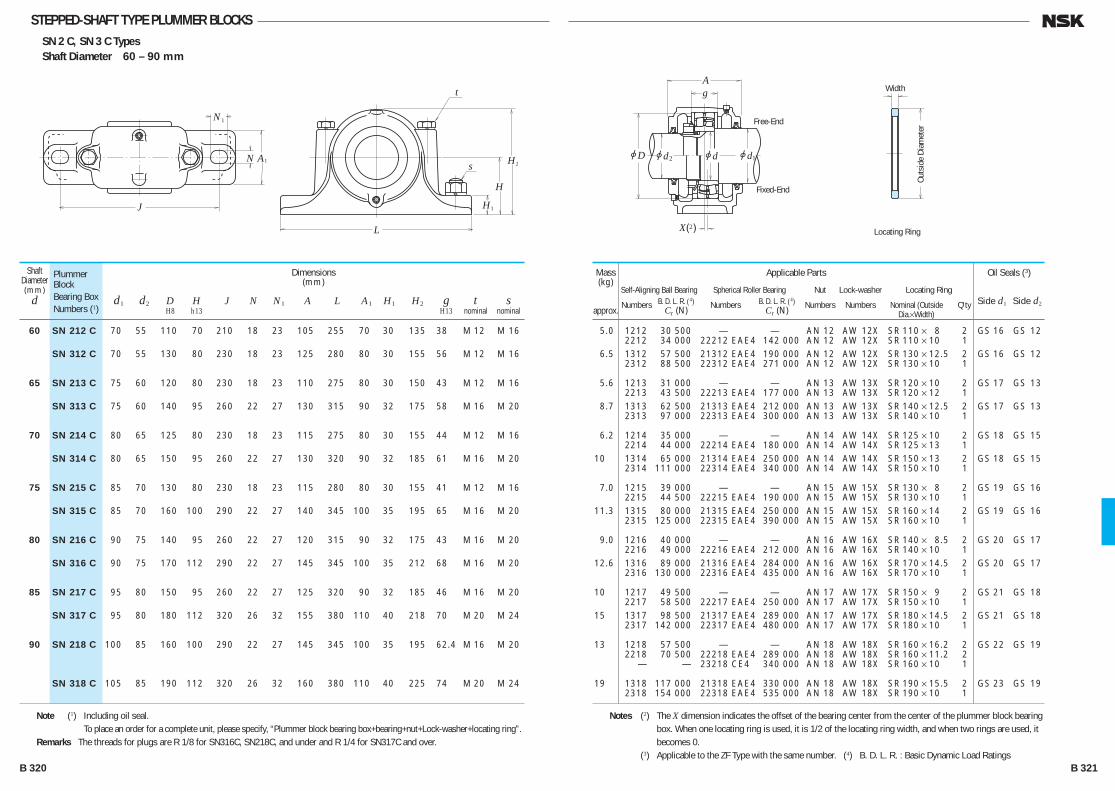
STEPPED-SHAFT TYPE PLUMMER BLOCKSSN 2 C, SN 3 C TypesShaft Diameter 60 – 90 mm
N
N1
L
J
H
H
s
t
2A1
H1
Free-End
Fixed-End
Width
Locating Ring
Outs
ide
Diam
eter
jD
Ag
jd jd jd2 1
2X( )
60 SN 212 C 70 55 110 70 210 18 23 105 255 70 30 135 38 M 12 M 16
SN 312 C 70 55 130 80 230 18 23 125 280 80 30 155 56 M 12 M 16
65 SN 213 C 75 60 120 80 230 18 23 110 275 80 30 150 43 M 12 M 16
SN 313 C 75 60 140 95 260 22 27 130 315 90 32 175 58 M 16 M 20
70 SN 214 C 80 65 125 80 230 18 23 115 275 80 30 155 44 M 12 M 16
SN 314 C 80 65 150 95 260 22 27 130 320 90 32 185 61 M 16 M 20
75 SN 215 C 85 70 130 80 230 18 23 115 280 80 30 155 41 M 12 M 16
SN 315 C 85 70 160 100 290 22 27 140 345 100 35 195 65 M 16 M 20
80 SN 216 C 90 75 140 95 260 22 27 120 315 90 32 175 43 M 16 M 20
SN 316 C 90 75 170 112 290 22 27 145 345 100 35 212 68 M 16 M 20
85 SN 217 C 95 80 150 95 260 22 27 125 320 90 32 185 46 M 16 M 20
SN 317 C 95 80 180 112 320 26 32 155 380 110 40 218 70 M 20 M 24
90 SN 218 C 100 85 160 100 290 22 27 145 345 100 35 195 62.4 M 16 M 20
SN 318 C 105 85 190 112 320 26 32 160 380 110 40 225 74 M 20 M 24
Shaft Diameter(mm)
d
Plummer BlockBearing BoxNumbers (1)
Dimensions(mm)
d1 d2 D H J N N1 A L A1 H1 H2 g t s H8 h13 H13 nominal nominal
5.0 1212 30 500 — — AN 12 AW 12X SR 110 × 8 2 GS 16 GS 12 2212 34 000 22212 EAE4 142 000 AN 12 AW 12X SR 110 × 10 1 6.5 1312 57 500 21312 EAE4 190 000 AN 12 AW 12X SR 130 × 12.5 2 GS 16 GS 12 2312 88 500 22312 EAE4 271 000 AN 12 AW 12X SR 130 × 10 1
5.6 1213 31 000 — — AN 13 AW 13X SR 120 × 10 2 GS 17 GS 13 2213 43 500 22213 EAE4 177 000 AN 13 AW 13X SR 120 × 12 1 8.7 1313 62 500 21313 EAE4 212 000 AN 13 AW 13X SR 140 × 12.5 2 GS 17 GS 13 2313 97 000 22313 EAE4 300 000 AN 13 AW 13X SR 140 × 10 1
6.2 1214 35 000 — — AN 14 AW 14X SR 125 × 10 2 GS 18 GS 15 2214 44 000 22214 EAE4 180 000 AN 14 AW 14X SR 125 × 13 1 10 1314 65 000 21314 EAE4 250 000 AN 14 AW 14X SR 150 × 13 2 GS 18 GS 15 2314 111 000 22314 EAE4 340 000 AN 14 AW 14X SR 150 × 10 1
7.0 1215 39 000 — — AN 15 AW 15X SR 130 × 8 2 GS 19 GS 16 2215 44 500 22215 EAE4 190 000 AN 15 AW 15X SR 130 × 10 1 11.3 1315 80 000 21315 EAE4 250 000 AN 15 AW 15X SR 160 × 14 2 GS 19 GS 16 2315 125 000 22315 EAE4 390 000 AN 15 AW 15X SR 160 × 10 1
9.0 1216 40 000 — — AN 16 AW 16X SR 140 × 8.5 2 GS 20 GS 17 2216 49 000 22216 EAE4 212 000 AN 16 AW 16X SR 140 × 10 1 12.6 1316 89 000 21316 EAE4 284 000 AN 16 AW 16X SR 170 × 14.5 2 GS 20 GS 17 2316 130 000 22316 EAE4 435 000 AN 16 AW 16X SR 170 × 10 1
10 1217 49 500 — — AN 17 AW 17X SR 150 × 9 2 GS 21 GS 18 2217 58 500 22217 EAE4 250 000 AN 17 AW 17X SR 150 × 10 1 15 1317 98 500 21317 EAE4 289 000 AN 17 AW 17X SR 180 × 14.5 2 GS 21 GS 18 2317 142 000 22317 EAE4 480 000 AN 17 AW 17X SR 180 × 10 1
13 1218 57 500 — — AN 18 AW 18X SR 160 × 16.2 2 GS 22 GS 19 2218 70 500 22218 EAE4 289 000 AN 18 AW 18X SR 160 × 11.2 2 — — 23218 CE4 340 000 AN 18 AW 18X SR 160 × 10 1
19 1318 117 000 21318 EAE4 330 000 AN 18 AW 18X SR 190 × 15.5 2 GS 23 GS 19 2318 154 000 22318 EAE4 535 000 AN 18 AW 18X SR 190 × 10 1
Applicable Parts
Self-Aligning Ball Bearing Spherical Roller Bearing Nut Lock-washer Locating Ring Numbers B. D. L. R. (4) Numbers B. D. L. R. (4) Numbers Numbers Nominal (Outside Q'ty Cr (N) Cr (N) Dia.×Width)
Oil Seals (3)
Side d1 Side d2
Mass(kg)
approx.
Note (1) Including oil seal. To place an order for a complete unit, please specify, “Plummer block bearing box+bearing+nut+Lock-washer+locating ring”.Remarks The threads for plugs are R 1/8 for SN316C, SN218C, and under and R 1/4 for SN317C and over.
Notes (2) The X dimension indicates the offset of the bearing center from the center of the plummer block bearing box. When one locating ring is used, it is 1/2 of the locating ring width, and when two rings are used, it becomes 0.
(3) Applicable to the ZF Type with the same number. (4) B. D. L. R. : Basic Dynamic Load RatingsB 320 B 321
B304-325E.indd 320-321B304-325E.indd 320-321 11/20/13 5:01:24 PM11/20/13 5:01:24 PM

STEPPED-SHAFT TYPE PLUMMER BLOCKSSN 2 C, SN 3 C TypesShaft Diameter 95 – 160 mm
N
N1
L
J
H
H
s
t
2A1
H1
Free-End
Fixed-End
Width
Locating Ring
Outs
ide
Diam
eter
jD
Ag
jd jd jd2 1
2X( )
95 SN 219 C 110 90 170 112 290 22 27 140 345 100 35 210 53 M 16 M 20
SN 319 C 110 90 200 125 350 26 32 170 410 120 45 245 77 M 20 M 24
100 SN 220 C 115 95 180 112 320 26 32 160 380 110 40 218 70.3 M 20 M 24
SN 320 C 115 95 215 140 350 26 32 175 410 120 45 270 83 M 20 M 24
110 SN 222 C 125 105 200 125 350 26 32 175 410 120 45 240 80 M 20 M 24
SN 322 C 125 105 240 150 390 28 36 190 450 130 50 300 90 M 24 M 24
120 SN 224 C 135 115 215 140 350 26 32 185 410 120 45 270 86 M 20 M 24
SN 324 C 135 115 260 160 450 33 42 200 530 160 60 320 96 M 24 M 30
130 SN 226 C 145 125 230 150 380 28 36 190 445 130 50 290 90 M 24 M 24
SN 326 C 150 125 280 170 470 33 42 210 550 160 60 340 103 M 24 M 30
140 SN 228 C 155 135 250 150 420 33 42 205 500 150 50 305 98 M 24 M 30
SN 328 C 160 135 300 180 520 35 45 235 610 170 65 365 112 M 30 M 30
150 SN 230 C 165 145 270 160 450 33 42 220 530 160 60 325 106 M 24 M 30
SN 330 C 170 145 320 190 560 35 45 245 650 180 65 385 118 M 30 M 30
160 SN 232 C 175 150 290 170 470 33 42 235 550 160 60 345 114 M 24 M 30
SN 332 C 180 150 340 200 580 42 50 255 680 190 70 405 124 M 30 M 36
Shaft Diameter(mm)
d
Plummer BlockBearing BoxNumbers (1)
Dimensions(mm)
d1 d2 D H J N N1 A L A1 H1 H2 g t s H8 h13 H13 nominal nominal
15 1219 64 000 — — AN 19 AW 19X SR 170 × 10.5 2 GS 24 GS 20 2219 84 000 22219 EAE4 330 000 AN 19 AW 19X SR 170 × 10 1 22 1319 129 000 21319 CE4 345 000 AN 19 AW 19X SR 200 × 16 2 GS 24 GS 20 2319 161 000 22319 EAE4 590 000 AN 19 AW 19X SR 200 × 10 1
18.5 1220 69 500 — — AN 20 AW 20X SR 180 × 18.1 2 GS 26 GS 21 2220 94 500 22220 EAE4 365 000 AN 20 AW 20X SR 180 × 12.1 2 — — 23220 CE4 420 000 AN 20 AW 20X SR 180 × 10 1 25 1320 140 000 21320 CE4 395 000 AN 20 AW 20X SR 215 × 18 2 GS 26 GS 21 2320 187 000 22320 EAE4 690 000 AN 20 AW 20X SR 215 × 10 1
20 1222 87 000 — — AN 22 AW 22X SR 200 × 21 2 GS 28 GS 23 2222 122 000 22222 EAE4 485 000 AN 22 AW 22X SR 200 × 13.5 2 — — 23222 CE4 515 000 AN 22 AW 22X SR 200 × 10 1 32 1322 161 000 21322 CAE4 395 000 AN 22 AW 22X SR 240 × 20 2 GS 28 GS 23 2322 211 000 22322 EAE4 825 000 AN 22 AW 22X SR 240 × 10 1
24.5 — — 22224 EAE4 550 000 AN 24 AW 24 SR 215 × 14 2 GS 30 GS 26 — — 23224 CE4 630 000 AN 24 AW 24 SR 215 × 10 1 48 — — 22324 EAE4 955 000 AN 24 AW 24 SR 260 × 10 1 GS 30 GS 26
30 — — 22226 EAE4 655 000 AN 26 AW 26 SR 230 × 13 2 GS 33 GS 28 — — 23226 CE4 700 000 AN 26 AW 26 SR 230 × 10 1 56 — — 22326 CE4 995 000 AN 26 AW 26 SR 280 × 10 1 GS 34 GS 28
38 — — 22228 CDE4 645 000 AN 28 AW 28 SR 250 × 15 2 GS 35 GS 30 — — 23228 CE4 835 000 AN 28 AW 28 SR 250 × 10 1 72 — — 22328 CE4 1 160 000 AN 28 AW 28 SR 300 × 10 1 GS 36 GS 30
46 — — 22230 CDE4 765 000 AN 30 AW 30 SR 270 × 16.5 2 GS 37 GS 33 — — 23230 CE4 975 000 AN 30 AW 30 SR 270 × 10 1 98 — — 22330 CAE4 1 220 000 AN 30 AW 30 SR 320 × 10 1 GS 38 GS 33
50 — — 22232 CDE4 910 000 AN 32 AW 32 SR 290 × 17 2 GS 39 GS 34 — — 23232 CE4 1 100 000 AN 32 AW 32 SR 290 × 10 1 115 — — 22332 CAE4 1 360 000 AN 32 AW 32 SR 340 × 10 1 GS 40 GS 34
Applicable Parts
Self-Aligning Ball Bearing Spherical Roller Bearing Nut Lock-washer Locating Ring Numbers B. D. L. R. (4) Numbers B. D. L. R. (4) Numbers Numbers Nominal (Outside Q'ty Cr (N) Cr (N) Dia.×Width)
Oil Seals (3)
Side d1 Side d2
Mass(kg)
approx.
Note (1) Including oil seal. To place an order for a complete unit, please specify, “Plummer block bearing box+bearing+nut+Lock-washer+locating ring”.Remarks 1. The threads for plugs are R 1/8 for SN219C, and R 1/4 for SN319C and SN220C and over. 2. Bearing boxes larger than SN320C and SN224C are provided with eye bolts.
Notes (2) The X dimension indicates the offset of the bearing center from the center of the plummer block bearing box. When one locating ring is used, it is 1/2 of the locating ring width, and when two rings are used, it becomes 0.
(3) Applicable to the ZF Type with the same number. (4) B. D. L. R. : Basic Dynamic Load RatingsB 322 B 323
B304-325E.indd 322-323B304-325E.indd 322-323 11/20/13 5:01:24 PM11/20/13 5:01:24 PM
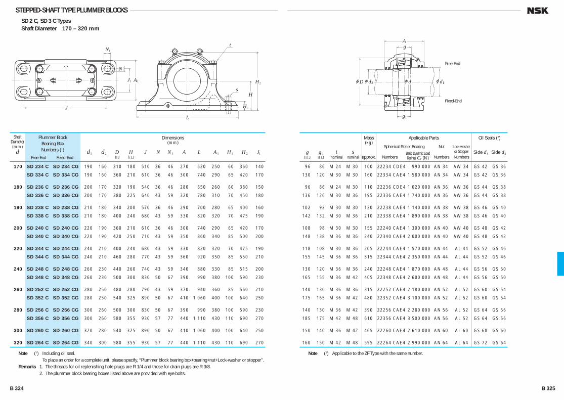
STEPPED-SHAFT TYPE PLUMMER BLOCKSSD 2 C, SD 3 C TypesShaft Diameter 170 – 320 mm
N
N1
L
J
H
Hs
t
2A1J 1
H1
1
Free-End
Fixed-End
jD
Ag
g
jd2 jdjd 1
1
170 SD 234 C SD 234 CG 190 160 310 180 510 36 46 270 620 250 60 360 140
SD 334 C SD 334 CG 190 160 360 210 610 36 46 300 740 290 65 420 170
180 SD 236 C SD 236 CG 200 170 320 190 540 36 46 280 650 260 60 380 150
SD 336 C SD 336 CG 200 170 380 225 640 43 59 320 780 310 70 450 180
190 SD 238 C SD 238 CG 210 180 340 200 570 36 46 290 700 280 65 400 160
SD 338 C SD 338 CG 210 180 400 240 680 43 59 330 820 320 70 475 190
200 SD 240 C SD 240 CG 220 190 360 210 610 36 46 300 740 290 65 420 170
SD 340 C SD 340 CG 220 190 420 250 710 43 59 350 860 340 85 500 200
220 SD 244 C SD 244 CG 240 210 400 240 680 43 59 330 820 320 70 475 190
SD 344 C SD 344 CG 240 210 460 280 770 43 59 360 920 350 85 550 210
240 SD 248 C SD 248 CG 260 230 440 260 740 43 59 340 880 330 85 515 200
SD 348 C SD 348 CG 260 230 500 300 830 50 67 390 990 380 100 590 230
260 SD 252 C SD 252 CG 280 250 480 280 790 43 59 370 940 360 85 560 210
SD 352 C SD 352 CG 280 250 540 325 890 50 67 410 1 060 400 100 640 250
280 SD 256 C SD 256 CG 300 260 500 300 830 50 67 390 990 380 100 590 230
SD 356 C SD 356 CG 300 260 580 355 930 57 77 440 1 110 430 110 690 270
300 SD 260 C SD 260 CG 320 280 540 325 890 50 67 410 1 060 400 100 640 250
320 SD 264 C SD 264 CG 340 300 580 355 930 57 77 440 1 110 430 110 690 270
Shaft Diameter(mm)
d
Plummer BlockBearing BoxNumbers (1)
Free-End Fixed-End
Dimensions(mm)
d1 d2 D H J N N1 A L A1 H1 H2 J1 H8 h13
g g1 t s H13 H13 nominal nominal
96 86 M 24 M 30 100 22234 CDE4 990 000 AN 34 AW 34 GS 42 GS 36
130 120 M 30 M 30 160 22334 CAE4 1 580 000 AN 34 AW 34 GS 42 GS 36
96 86 M 24 M 30 110 22236 CDE4 1 020 000 AN 36 AW 36 GS 44 GS 38
136 126 M 30 M 36 195 22336 CAE4 1 740 000 AN 36 AW 36 GS 44 GS 38
102 92 M 30 M 30 130 22238 CAE4 1 140 000 AN 38 AW 38 GS 46 GS 40
142 132 M 30 M 36 210 22338 CAE4 1 890 000 AN 38 AW 38 GS 46 GS 40
108 98 M 30 M 30 155 22240 CAE4 1 300 000 AN 40 AW 40 GS 48 GS 42
148 138 M 36 M 36 240 22340 CAE4 2 000 000 AN 40 AW 40 GS 48 GS 42
118 108 M 30 M 36 205 22244 CAE4 1 570 000 AN 44 AL 44 GS 52 GS 46
155 145 M 36 M 36 315 22344 CAE4 2 350 000 AN 44 AL 44 GS 52 GS 46
130 120 M 36 M 36 240 22248 CAE4 1 870 000 AN 48 AL 44 GS 56 GS 50
165 155 M 36 M 42 405 22348 CAE4 2 600 000 AN 48 AL 44 GS 56 GS 50
140 130 M 36 M 36 315 22252 CAE4 2 180 000 AN 52 AL 52 GS 60 GS 54
175 165 M 36 M 42 480 22352 CAE4 3 100 000 AN 52 AL 52 GS 60 GS 54
140 130 M 36 M 42 390 22256 CAE4 2 280 000 AN 56 AL 52 GS 64 GS 56
185 175 M 42 M 48 610 22356 CAE4 3 500 000 AN 56 AL 52 GS 64 GS 56
150 140 M 36 M 42 465 22260 CAE4 2 610 000 AN 60 AL 60 GS 68 GS 60
160 150 M 42 M 48 595 22264 CAE4 2 990 000 AN 64 AL 64 GS 72 GS 64
Applicable Parts
Spherical Roller Bearing Nut Lock-washer Basic Dynamic Load or Stopper Numbers Ratings Cr (N) Numbers Numbers
Oil Seals (2)
Side d1 Side d2
Mass(kg)
approx.
Note (1) Including oil seal. To place an order for a complete unit, please specify, “Plummer block bearing box+bearing+nut+Lock-washer or stopper”.Remarks 1. The threads for oil replenishing hole plugs are R 1/4 and those for drain plugs are R 3/8. 2. The plummer block bearing boxes listed above are provided with eye bolts.
Note (2) Applicable to the ZF Type with the same number.
B 324 B 325
B304-325E.indd 324-325B304-325E.indd 324-325 11/20/13 5:01:25 PM11/20/13 5:01:25 PM

CYLINDRICAL ROLLER BEARINGS FOR SHEAVESCYLINDRICAL ROLLER BEARINGS FOR SHEAVESOpen Type Bore Diameter 50 – 560mm ······························· B328
Prelubricated Type Bore Diameter 40 – 400mm ······························· B332
DESIGN, TYPES, AND FEATURES
Cylindrical Roller Bearings for sheaves are specially designed thin-walled, broad-width, full-complement type double-row cylindrical roller bearings, but they are widely used also for general industrial machines running at low speed and under heavy loads. There are several series as shown in Table 1.
Since all are non-separable type bearings, the inner and outer rings cannot be separated, but the RSF type can be used as a free-end bearing. In this case, the permissible axial displacement is listed in the bearing tables. Since cylindrical roller bearings for sheaves are a double-row, full- complement type, they can withstand heavy shock loads and moments and have sufficient axial load capacity for use in sheaves. Since the shielded type is a kind of bearing unit, the number of parts surrounding the bearing can be reduced, so it allows for a simple compact design. The surface of these bearings is treated for rust prevention.
TOLERANCES ANDRUNNING ACCURACY······························· Table 8.2 (Pages A60 to A63)
RECOMMENDED FITS AND INTERNAL CLEARANGES When used with outer ring rotation for sheaves or wheels, the fit and radial internal clearance should conform to Table 2.
The fits listed in Tables 9.2 (Page A84) and 9.4 (Page A85) apply when they are used with inner ring rotation in general applications, and the internal clearance should conform to Table 3.
Table 2 Fits and Internal Clearances for Cylindrical Roller Bearings for Sheaves
Operating Conditions Fitting between Fitting between Outer Recommended Inner Ring and Shaft Ring and Housing Bore Internal Clearance
Thin walled housings and heavy loads g6 or h6 P7 C3 Outer Ring Rotation Normal to heavy loads g6 or h6 N7 C3
Light or fluctuating loads g6 or h6 M7 CN
Table 1 Series of Cylindrical Roller Bearings for Sheaves
Bearing Type Fixed-End Free-End
Open Type Without Snap Ring
RS-48E4 RSF-48E4 RS-49E4 RSF-49E4
Shielded Type
Without Snap Ring RS-50 —
With Snap Ring RS-50NR
Table 3
Clearances
CN C3
over incl. min. max. min. max.
30 40 15 50 35 70 40 50 20 55 40 75 50 65 20 65 45 90
65 80 25 75 55 105 80 100 30 80 65 115 100 120 35 90 80 135
120 140 40 105 90 155 140 160 50 115 100 165 160 180 60 125 110 175
180 200 65 135 125 195 200 225 75 150 140 215 225 250 90 165 155 230
250 280 100 180 175 255 280 315 110 195 195 280 315 355 125 215 215 305
355 400 140 235 245 340 400 450 155 275 270 390 450 500 180 300 300 420
NominalBore Dia.d (mm)
Units : μm
B 326 B 327
B326-333E.indd 326-327B326-333E.indd 326-327 11/20/13 5:01:43 PM11/20/13 5:01:43 PM
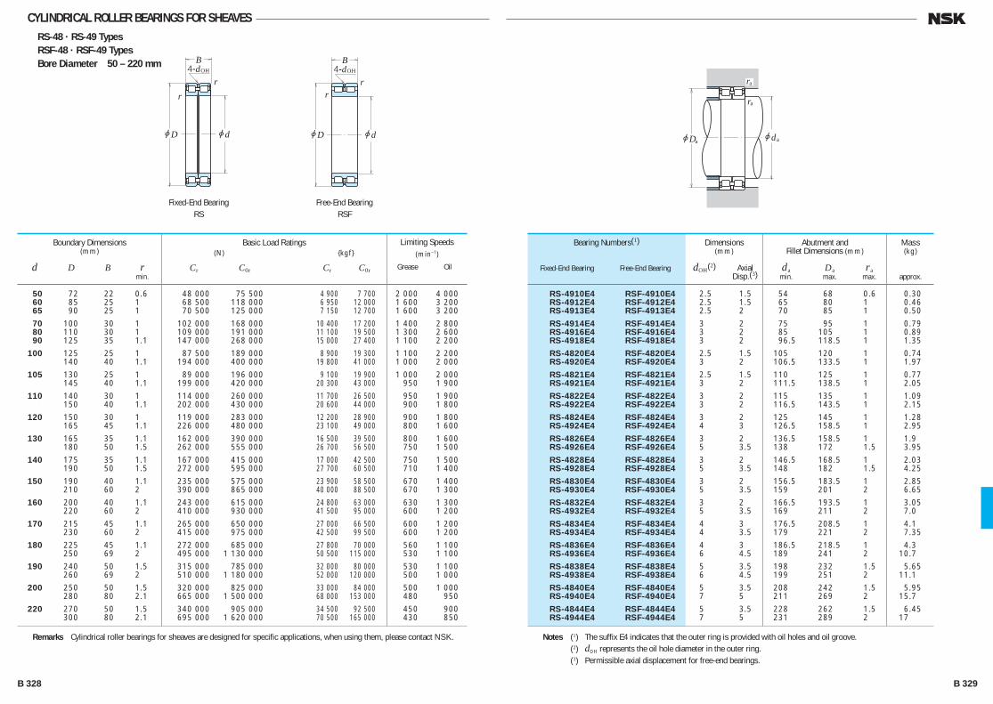
CYLINDRICAL ROLLER BEARINGS FOR SHEAVESRS-48 · RS-49 TypesRSF-48 · RSF-49 TypesBore Diameter 50 – 220 mm
50 72 22 0.6 48 000 75 500 4 900 7 700 2 000 4 000 60 85 25 1 68 500 118 000 6 950 12 000 1 600 3 200 65 90 25 1 70 500 125 000 7 150 12 700 1 600 3 200
70 100 30 1 102 000 168 000 10 400 17 200 1 400 2 800 80 110 30 1 109 000 191 000 11 100 19 500 1 300 2 600 90 125 35 1.1 147 000 268 000 15 000 27 400 1 100 2 200
100 125 25 1 87 500 189 000 8 900 19 300 1 100 2 200 140 40 1.1 194 000 400 000 19 800 41 000 1 000 2 000
105 130 25 1 89 000 196 000 9 100 19 900 1 000 2 000 145 40 1.1 199 000 420 000 20 300 43 000 950 1 900
110 140 30 1 114 000 260 000 11 700 26 500 950 1 900 150 40 1.1 202 000 430 000 20 600 44 000 900 1 800
120 150 30 1 119 000 283 000 12 200 28 900 900 1 800 165 45 1.1 226 000 480 000 23 100 49 000 800 1 600
130 165 35 1.1 162 000 390 000 16 500 39 500 800 1 600 180 50 1.5 262 000 555 000 26 700 56 500 750 1 500
140 175 35 1.1 167 000 415 000 17 000 42 500 750 1 500 190 50 1.5 272 000 595 000 27 700 60 500 710 1 400
150 190 40 1.1 235 000 575 000 23 900 58 500 670 1 400 210 60 2 390 000 865 000 40 000 88 500 670 1 300
160 200 40 1.1 243 000 615 000 24 800 63 000 630 1 300 220 60 2 410 000 930 000 41 500 95 000 600 1 200
170 215 45 1.1 265 000 650 000 27 000 66 500 600 1 200 230 60 2 415 000 975 000 42 500 99 500 600 1 200
180 225 45 1.1 272 000 685 000 27 800 70 000 560 1 100 250 69 2 495 000 1 130 000 50 500 115 000 530 1 100
190 240 50 1.5 315 000 785 000 32 000 80 000 530 1 100 260 69 2 510 000 1 180 000 52 000 120 000 500 1 000
200 250 50 1.5 320 000 825 000 33 000 84 000 500 1 000 280 80 2.1 665 000 1 500 000 68 000 153 000 480 950
220 270 50 1.5 340 000 905 000 34 500 92 500 450 900 300 80 2.1 695 000 1 620 000 70 500 165 000 430 850
Boundary Dimensions(mm)
d D B r min.
Limiting Speeds(min–1)
Grease Oil
Basic Load Ratings (N) {kgf}
Cr C0r Cr C0r
RS-4910E4 RSF-4910E4 2.5 1.5 54 68 0.6 0.30 RS-4912E4 RSF-4912E4 2.5 1.5 65 80 1 0.46 RS-4913E4 RSF-4913E4 2.5 2 70 85 1 0.50
RS-4914E4 RSF-4914E4 3 2 75 95 1 0.79 RS-4916E4 RSF-4916E4 3 2 85 105 1 0.89 RS-4918E4 RSF-4918E4 3 2 96.5 118.5 1 1.35
RS-4820E4 RSF-4820E4 2.5 1.5 105 120 1 0.74 RS-4920E4 RSF-4920E4 3 2 106.5 133.5 1 1.97
RS-4821E4 RSF-4821E4 2.5 1.5 110 125 1 0.77 RS-4921E4 RSF-4921E4 3 2 111.5 138.5 1 2.05
RS-4822E4 RSF-4822E4 3 2 115 135 1 1.09 RS-4922E4 RSF-4922E4 3 2 116.5 143.5 1 2.15
RS-4824E4 RSF-4824E4 3 2 125 145 1 1.28 RS-4924E4 RSF-4924E4 4 3 126.5 158.5 1 2.95
RS-4826E4 RSF-4826E4 3 2 136.5 158.5 1 1.9 RS-4926E4 RSF-4926E4 5 3.5 138 172 1.5 3.95
RS-4828E4 RSF-4828E4 3 2 146.5 168.5 1 2.03 RS-4928E4 RSF-4928E4 5 3.5 148 182 1.5 4.25
RS-4830E4 RSF-4830E4 3 2 156.5 183.5 1 2.85 RS-4930E4 RSF-4930E4 5 3.5 159 201 2 6.65
RS-4832E4 RSF-4832E4 3 2 166.5 193.5 1 3.05 RS-4932E4 RSF-4932E4 5 3.5 169 211 2 7.0
RS-4834E4 RSF-4834E4 4 3 176.5 208.5 1 4.1 RS-4934E4 RSF-4934E4 4 3.5 179 221 2 7.35
RS-4836E4 RSF-4836E4 4 3 186.5 218.5 1 4.3 RS-4936E4 RSF-4936E4 6 4.5 189 241 2 10.7
RS-4838E4 RSF-4838E4 5 3.5 198 232 1.5 5.65 RS-4938E4 RSF-4938E4 6 4.5 199 251 2 11.1
RS-4840E4 RSF-4840E4 5 3.5 208 242 1.5 5.95 RS-4940E4 RSF-4940E4 7 5 211 269 2 15.7
RS-4844E4 RSF-4844E4 5 3.5 228 262 1.5 6.45 RS-4944E4 RSF-4944E4 7 5 231 289 2 17
Bearing Numbers(1)
Fixed-End Bearing Free-End Bearing
Abutment andFillet Dimensions (mm)
da Da ra min. max. max.
Dimensions(mm)
dOH(2) Axial Disp.(3)
Mass(kg)
approx.
Remarks Cylindrical roller bearings for sheaves are designed for specific applications, when using them, please contact NSK. Notes (1) The suffix E4 indicates that the outer ring is provided with oil holes and oil groove. (2) dOH represents the oil hole diameter in the outer ring. (3) Permissible axial displacement for free-end bearings.
jd
4-d
r
r
jD
BOH
jd
4-d
rr
jD
BOH
jdjD
ra
ra
a a
Fixed-End BearingRS
Free-End BearingRSF
B 328 B 329
B326-333E.indd 328-329B326-333E.indd 328-329 11/20/13 5:01:43 PM11/20/13 5:01:43 PM
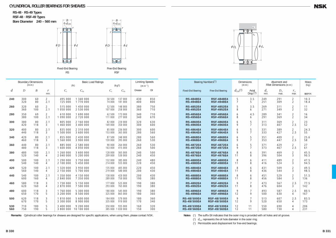
CYLINDRICAL ROLLER BEARINGS FOR SHEAVESRS-48 · RS-49 TypesRSF-48 · RSF-49 TypesBore Diameter 240 – 560 mm
240 300 60 2 495 000 1 340 000 50 500 137 000 430 850 320 80 2.1 725 000 1 770 000 74 000 181 000 400 800
260 320 60 2 515 000 1 450 000 52 500 148 000 380 750 360 100 2.1 1 050 000 2 530 000 107 000 258 000 360 710
280 350 69 2 610 000 1 690 000 62 500 173 000 340 710 380 100 2.1 1 090 000 2 720 000 111 000 277 000 340 670
300 380 80 2.1 805 000 2 160 000 82 000 220 000 320 630 420 118 3 1 460 000 3 400 000 149 000 350 000 300 600
320 400 80 2.1 835 000 2 310 000 85 000 236 000 300 600 440 118 3 1 500 000 3 600 000 153 000 365 000 280 560
340 420 80 2.1 855 000 2 430 000 87 500 248 000 280 560 460 118 3 1 560 000 3 900 000 159 000 395 000 260 530
360 440 80 2.1 885 000 2 580 000 90 000 264 000 260 530 480 118 3 1 600 000 4 050 000 163 000 415 000 260 500
380 480 100 2.1 1 260 000 3 600 000 128 000 365 000 240 500 520 140 4 2 040 000 5 200 000 209 000 530 000 240 450
400 500 100 2.1 1 290 000 3 750 000 132 000 385 000 240 480 540 140 4 2 100 000 5 450 000 214 000 555 000 220 450
420 520 100 2.1 1 320 000 3 950 000 135 000 405 000 220 450 560 140 4 2 150 000 5 700 000 219 000 580 000 200 430
440 540 100 2.1 1 350 000 4 150 000 138 000 420 000 200 430 600 160 4 2 840 000 7 350 000 289 000 750 000 190 380
460 580 118 3 1 730 000 5 150 000 177 000 525 000 190 380 620 160 4 2 870 000 7 500 000 293 000 765 000 190 380
480 600 118 3 1 760 000 5 300 000 180 000 545 000 190 380 650 170 5 3 200 000 8 500 000 325 000 865 000 180 360
500 620 118 3 1 810 000 5 600 000 184 000 570 000 180 360 670 170 5 3 300 000 8 900 000 335 000 910 000 170 340
530 710 180 5 3 400 000 9 200 000 350 000 935 000 160 320 560 750 190 5 3 800 000 10 100 000 385 000 1 030 000 150 300
Boundary Dimensions(mm)
d D B r min.
Limiting Speeds(min–1)
Grease Oil
Basic Load Ratings (N) {kgf}
Cr C0r Cr C0r
RS-4848E4 RSF-4848E4 5 3.5 249 291 2 10.3 RS-4948E4 RSF-4948E4 7 5 251 309 2 18.4
RS-4852E4 RSF-4852E4 5 3.5 269 311 2 11 RS-4952E4 RSF-4952E4 8 6 271 349 2 32
RS-4856E4 RSF-4856E4 6 4.5 289 341 2 16 RS-4956E4 RSF-4956E4 8 6 291 369 2 34
RS-4860E4 RSF-4860E4 6 5 311 369 2 23 RS-4960E4 RSF-4960E4 9 7 313 407 2.5 52
RS-4864E4 RSF-4864E4 6 5 331 389 2 24.3 RS-4964E4 RSF-4964E4 9 7 333 427 2.5 55
RS-4868E4 RSF-4868E4 6 5 351 409 2 25.6 RS-4968E4 RSF-4968E4 9 7 353 447 2.5 58
RS-4872E4 RSF-4872E4 6 5 371 429 2 27 RS-4972E4 RSF-4972E4 9 7 373 467 2.5 61
RS-4876E4 RSF-4876E4 8 6 391 469 2 45.5 RS-4976E4 RSF-4976E4 11 8 396 504 3 90.5
RS-4880E4 RSF-4880E4 8 6 411 489 2 47.5 RS-4980E4 RSF-4980E4 11 8 416 524 3 94.5
RS-4884E4 RSF-4884E4 8 6 431 509 2 49.5 RS-4984E4 RSF-4984E4 11 8 436 544 3 98.5
RS-4888E4 RSF-4888E4 8 6 451 529 2 51.5 RS-4988E4 RSF-4988E4 11 8 456 584 3 136
RS-4892E4 RSF-4892E4 9 7 473 567 2.5 77.5 RS-4992E4 RSF-4992E4 11 8 476 604 3 142
RS-4896E4 RSF-4896E4 9 7 493 587 2.5 80.5 RS-4996E4 RSF-4996E4 12 9 500 630 4 167
RS-48/500E4 RSF-48/500E4 9 7 513 607 2.5 83.5 RS-49/500E4 RSF-49/500E4 12 9 520 650 4 173
RS-49/530E4 RSF-49/530E4 12 11 550 690 4 206 RS-49/560E4 RSF-49/560E4 12 11 580 730 4 231
Bearing Numbers(1)
Fixed-End Bearing Free-End Bearing
Abutment andFillet Dimensions (mm)
da Da ra min. max. max.
Dimensions(mm)
dOH(2) Axial Disp.(3)
Mass(kg)
approx.
Remarks Cylindrical roller bearings for sheaves are designed for specific applications, when using them, please contact NSK. Notes (1) The suffix E4 indicates that the outer ring is provided with oil holes and oil groove. (2) dOH represents the oil hole diameter in the outer ring. (3) Permissible axial displacement for free-end bearings.
jd
4-d
r
r
jD
BOH
jd
4-d
rr
jD
BOH
jdjD
ra
ra
a a
Fixed-End BearingRS
Free-End BearingRSF
B 330 B 331
B326-333E.indd 330-331B326-333E.indd 330-331 11/20/13 5:01:44 PM11/20/13 5:01:44 PM
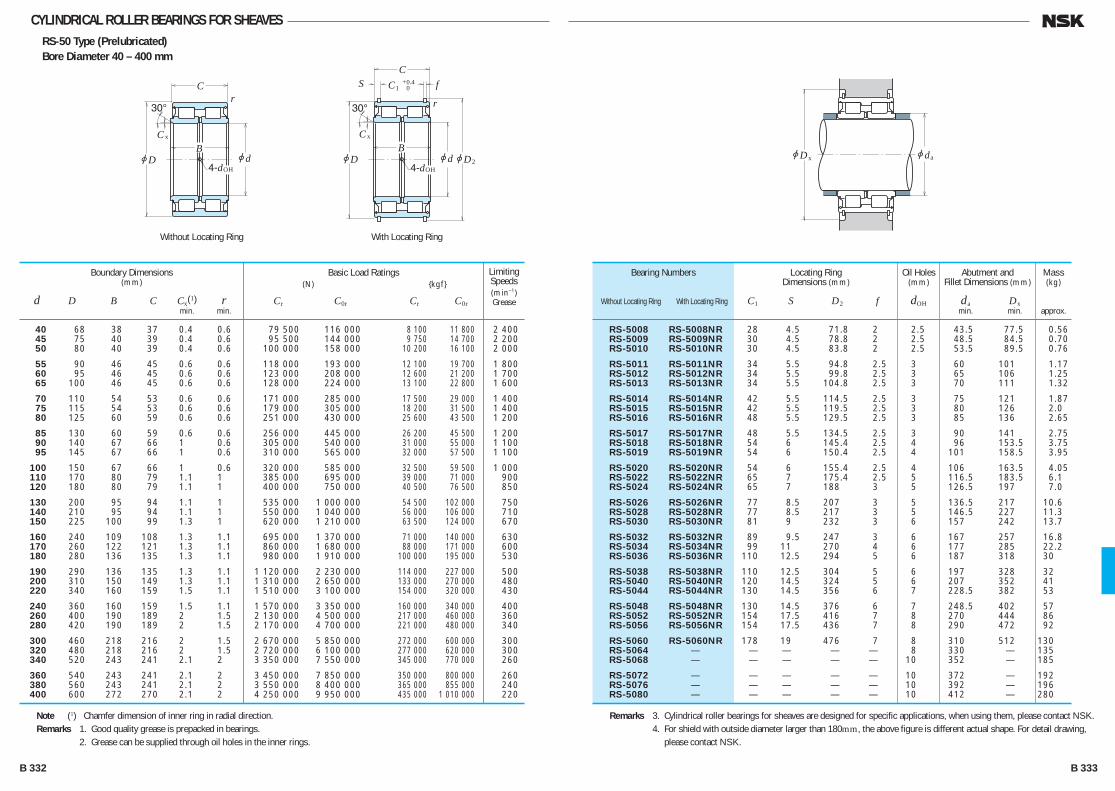
CYLINDRICAL ROLLER BEARINGS FOR SHEAVESRS-50 Type (Prelubricated)Bore Diameter 40 – 400 mm
RS-5008 RS-5008NR 28 4.5 71.8 2 2.5 43.5 77.5 0.56 RS-5009 RS-5009NR 30 4.5 78.8 2 2.5 48.5 84.5 0.70 RS-5010 RS-5010NR 30 4.5 83.8 2 2.5 53.5 89.5 0.76
RS-5011 RS-5011NR 34 5.5 94.8 2.5 3 60 101 1.17 RS-5012 RS-5012NR 34 5.5 99.8 2.5 3 65 106 1.25 RS-5013 RS-5013NR 34 5.5 104.8 2.5 3 70 111 1.32
RS-5014 RS-5014NR 42 5.5 114.5 2.5 3 75 121 1.87 RS-5015 RS-5015NR 42 5.5 119.5 2.5 3 80 126 2.0 RS-5016 RS-5016NR 48 5.5 129.5 2.5 3 85 136 2.65
RS-5017 RS-5017NR 48 5.5 134.5 2.5 3 90 141 2.75 RS-5018 RS-5018NR 54 6 145.4 2.5 4 96 153.5 3.75 RS-5019 RS-5019NR 54 6 150.4 2.5 4 101 158.5 3.95
RS-5020 RS-5020NR 54 6 155.4 2.5 4 106 163.5 4.05 RS-5022 RS-5022NR 65 7 175.4 2.5 5 116.5 183.5 6.1 RS-5024 RS-5024NR 65 7 188 3 5 126.5 197 7.0
RS-5026 RS-5026NR 77 8.5 207 3 5 136.5 217 10.6 RS-5028 RS-5028NR 77 8.5 217 3 5 146.5 227 11.3 RS-5030 RS-5030NR 81 9 232 3 6 157 242 13.7
RS-5032 RS-5032NR 89 9.5 247 3 6 167 257 16.8 RS-5034 RS-5034NR 99 11 270 4 6 177 285 22.2 RS-5036 RS-5036NR 110 12.5 294 5 6 187 318 30
RS-5038 RS-5038NR 110 12.5 304 5 6 197 328 32 RS-5040 RS-5040NR 120 14.5 324 5 6 207 352 41 RS-5044 RS-5044NR 130 14.5 356 6 7 228.5 382 53
RS-5048 RS-5048NR 130 14.5 376 6 7 248.5 402 57 RS-5052 RS-5052NR 154 17.5 416 7 8 270 444 86 RS-5056 RS-5056NR 154 17.5 436 7 8 290 472 92
RS-5060 RS-5060NR 178 19 476 7 8 310 512 130 RS-5064 — — — — — 8 330 — 135 RS-5068 — — — — — 10 352 — 185
RS-5072 — — — — — 10 372 — 192 RS-5076 — — — — — 10 392 — 196 RS-5080 — — — — — 10 412 — 280
Bearing Numbers
Without Locating Ring With Locating Ring
Abutment andFillet Dimensions (mm)
da Dx min. min.
Locating Ring Dimensions (mm)
C1 S D2 f
Oil Holes(mm)
dOH
Mass(kg)
approx.
Remarks 3. Cylindrical roller bearings for sheaves are designed for specific applications, when using them, please contact NSK. 4. For shield with outside diameter larger than 180mm, the above figure is different actual shape. For detail drawing,
please contact NSK.
Note (1) Chamfer dimension of inner ring in radial direction.Remarks 1. Good quality grease is prepacked in bearings. 2. Grease can be supplied through oil holes in the inner rings.
jdjDx ajd
r
jD
C
BC
4-dOH
30°
x
jd
r
jD jD
CC
BC
S
4-dOH
30°
x
2
10.40
+ f
40 68 38 37 0.4 0.6 79 500 116 000 8 100 11 800 2 400 45 75 40 39 0.4 0.6 95 500 144 000 9 750 14 700 2 200 50 80 40 39 0.4 0.6 100 000 158 000 10 200 16 100 2 000
55 90 46 45 0.6 0.6 118 000 193 000 12 100 19 700 1 800 60 95 46 45 0.6 0.6 123 000 208 000 12 600 21 200 1 700 65 100 46 45 0.6 0.6 128 000 224 000 13 100 22 800 1 600
70 110 54 53 0.6 0.6 171 000 285 000 17 500 29 000 1 400 75 115 54 53 0.6 0.6 179 000 305 000 18 200 31 500 1 400 80 125 60 59 0.6 0.6 251 000 430 000 25 600 43 500 1 200
85 130 60 59 0.6 0.6 256 000 445 000 26 200 45 500 1 200 90 140 67 66 1 0.6 305 000 540 000 31 000 55 000 1 100 95 145 67 66 1 0.6 310 000 565 000 32 000 57 500 1 100
100 150 67 66 1 0.6 320 000 585 000 32 500 59 500 1 000 110 170 80 79 1.1 1 385 000 695 000 39 000 71 000 900 120 180 80 79 1.1 1 400 000 750 000 40 500 76 500 850
130 200 95 94 1.1 1 535 000 1 000 000 54 500 102 000 750 140 210 95 94 1.1 1 550 000 1 040 000 56 000 106 000 710 150 225 100 99 1.3 1 620 000 1 210 000 63 500 124 000 670
160 240 109 108 1.3 1.1 695 000 1 370 000 71 000 140 000 630 170 260 122 121 1.3 1.1 860 000 1 680 000 88 000 171 000 600 180 280 136 135 1.3 1.1 980 000 1 910 000 100 000 195 000 530
190 290 136 135 1.3 1.1 1 120 000 2 230 000 114 000 227 000 500 200 310 150 149 1.3 1.1 1 310 000 2 650 000 133 000 270 000 480 220 340 160 159 1.5 1.1 1 510 000 3 100 000 154 000 320 000 430
240 360 160 159 1.5 1.1 1 570 000 3 350 000 160 000 340 000 400 260 400 190 189 2 1.5 2 130 000 4 500 000 217 000 460 000 360 280 420 190 189 2 1.5 2 170 000 4 700 000 221 000 480 000 340
300 460 218 216 2 1.5 2 670 000 5 850 000 272 000 600 000 300 320 480 218 216 2 1.5 2 720 000 6 100 000 277 000 620 000 300 340 520 243 241 2.1 2 3 350 000 7 550 000 345 000 770 000 260
360 540 243 241 2.1 2 3 450 000 7 850 000 350 000 800 000 260 380 560 243 241 2.1 2 3 550 000 8 400 000 365 000 855 000 240 400 600 272 270 2.1 2 4 250 000 9 950 000 435 000 1 010 000 220
Boundary Dimensions(mm)
d D B C Cx(1) r min. min.
LimitingSpeeds(min–1)Grease
Basic Load Ratings (N) {kgf}
Cr C0r Cr C0r
Without Locating Ring With Locating Ring
B 332 B 333
B326-333E.indd 332-333B326-333E.indd 332-333 11/20/13 5:01:45 PM11/20/13 5:01:45 PM
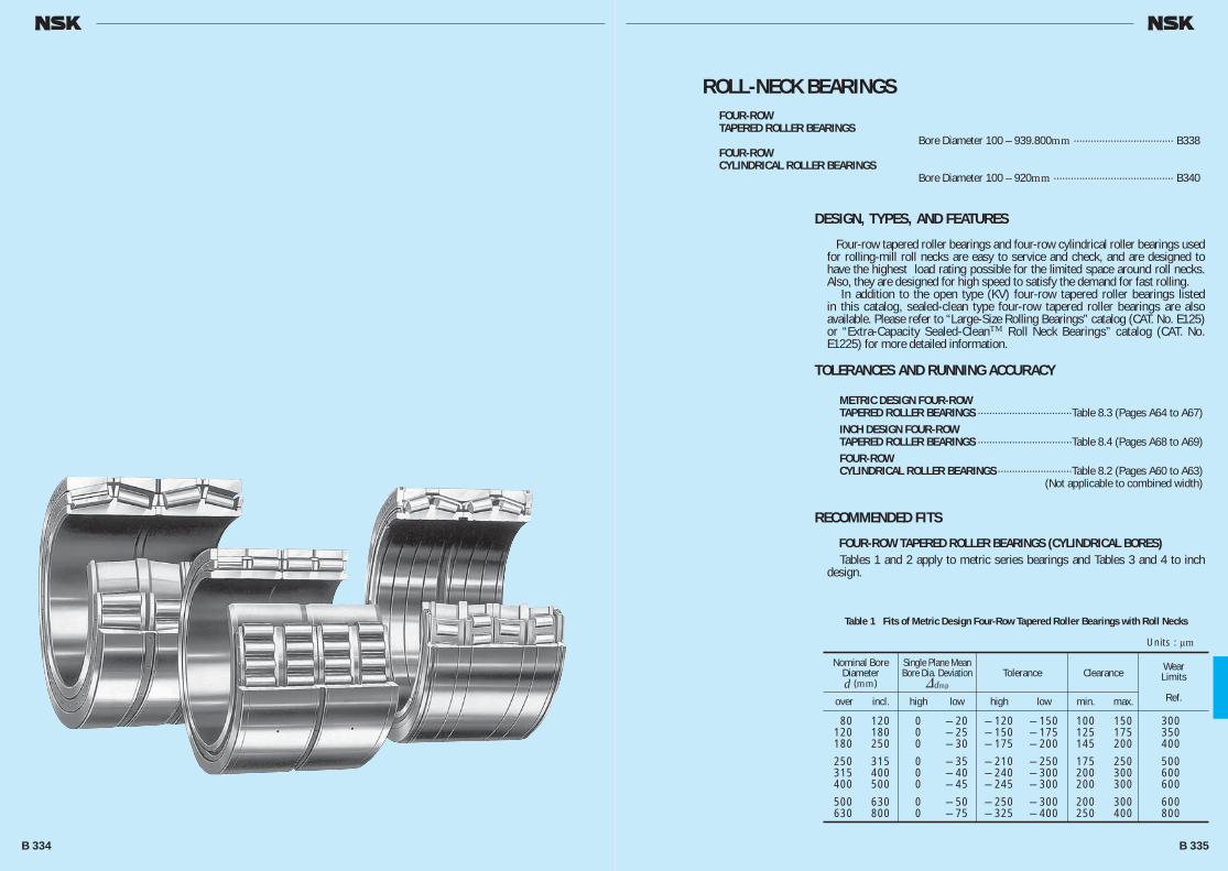
ROLL-NECK BEARINGSFOUR-ROWTAPERED ROLLER BEARINGS Bore Diameter 100 – 939.800mm ··································· B338FOUR-ROWCYLINDRICAL ROLLER BEARINGS Bore Diameter 100 – 920mm ·········································· B340
DESIGN, TYPES, AND FEATURES
Four-row tapered roller bearings and four-row cylindrical roller bearings used for rolling-mill roll necks are easy to service and check, and are designed to have the highest load rating possible for the limited space around roll necks. Also, they are designed for high speed to satisfy the demand for fast rolling. In addition to the open type (KV) four-row tapered roller bearings listed in this catalog, sealed-clean type four-row tapered roller bearings are also available. Please refer to “Large-Size Rolling Bearings” catalog (CAT. No. E125) or “Extra-Capacity Sealed-CleanTM Roll Neck Bearings” catalog (CAT. No. E1225) for more detailed information.
TOLERANCES AND RUNNING ACCURACY
METRIC DESIGN FOUR-ROWTAPERED ROLLER BEARINGS ·································Table 8.3 (Pages A64 to A67)INCH DESIGN FOUR-ROWTAPERED ROLLER BEARINGS ·································Table 8.4 (Pages A68 to A69)FOUR-ROWCYLINDRICAL ROLLER BEARINGS ··························Table 8.2 (Pages A60 to A63) (Not applicable to combined width)
RECOMMENDED FITS
FOUR-ROW TAPERED ROLLER BEARINGS (CYLINDRICAL BORES) Tables 1 and 2 apply to metric series bearings and Tables 3 and 4 to inch design.
Table 1 Fits of Metric Design Four-Row Tapered Roller Bearings with Roll Necks
Tolerance ClearanceWearLimits
Ref.
over incl. high low high low min. max.
80 120 0 — 20 — 120 — 150 100 150 300 120 180 0 — 25 — 150 — 175 125 175 350 180 250 0 — 30 — 175 — 200 145 200 400
250 315 0 — 35 — 210 — 250 175 250 500 315 400 0 — 40 — 240 — 300 200 300 600 400 500 0 — 45 — 245 — 300 200 300 600
500 630 0 — 50 — 250 — 300 200 300 600 630 800 0 — 75 — 325 — 400 250 400 800
Nominal BoreDiameterd (mm)
Single Plane Mean Bore Dia. Deviation
&dmp
Units : μm
B 334 B 335
B334-343E.indd 334-335B334-343E.indd 334-335 11/20/13 5:02:01 PM11/20/13 5:02:01 PM
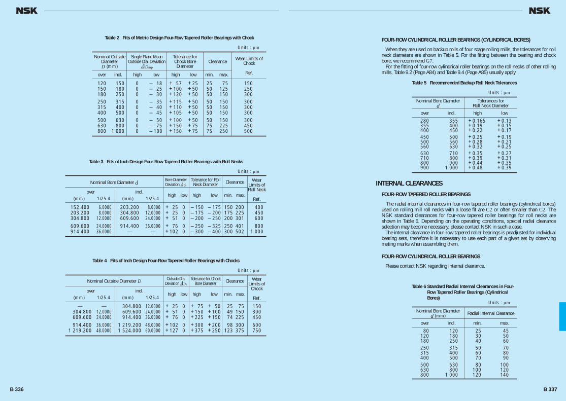
FOUR-ROW CYLINDRICAL ROLLER BEARINGS (CYLINDRICAL BORES)
When they are used on backup rolls of four stage rolling mills, the tolerances for roll neck diameters are shown in Table 5. For the fitting between the bearing and chock bore, we recommend G7. For the fitting of four-row cylindrical roller bearings on the roll necks of other rolling mills, Table 9.2 (Page A84) and Table 9.4 (Page A85) usually apply.
INTERNAL CLEARANCES
FOUR-ROW TAPERED ROLLER BEARINGS
The radial internal clearances in four-row tapered roller bearings (cylindrical bores) used on rolling mill roll necks with a loose fit are C2 or often smaller than C2. The NSK standard clearances for four-row tapered roller bearings for roll necks are shown in Table 6. Depending on the operating conditions, special radial clearance selection may become necessary, please contact NSK in such a case. The internal clearance in four-row tapered roller bearings is peadjusted for individual bearing sets, therefore it is necessary to use each part of a given set by observing mating marks when assembling them.
FOUR-ROW CYLINDRICAL ROLLER BEARINGS
Please contact NSK regarding internal clearance.
Table 2 Fits of Metric Design Four-Row Tapered Roller Bearings with Chock
Tolerance for Chock Bore Diameter
ClearanceWear Limits of
Chock
Ref.
over incl. high low high low min. max.
120 150 0 — 18 + 57 +25 25 75 150 150 180 0 — 25 +100 +50 50 125 250 180 250 0 — 30 +120 +50 50 150 300 250 315 0 — 35 +115 +50 50 150 300 315 400 0 — 40 +110 +50 50 150 300 400 500 0 — 45 +105 +50 50 150 300 500 630 0 — 50 +100 +50 50 150 300 630 800 0 — 75 +150 +75 75 225 450 800 1 000 0 — 100 +150 +75 75 250 500
Nominal OutsideDiameterD (mm)
Single Plane Mean Outside Dia. Deviation
&Dmp
Units : μm
Table 3 Fits of Inch Design Four-Row Tapered Roller Bearings with Roll Necks
Tolerance for Roll Neck Diameter Clearance Wear
Limits of Roll Neck
Ref.
over incl. high low high low min. max.
(mm) 1/25.4 (mm) 1/25.4
152.400 6.0000 203.200 8.0000 + 25 0 — 150 — 175 150 200 400 203.200 8.0000 304.800 12.0000 + 25 0 — 175 — 200 175 225 450 304.800 12.0000 609.600 24.0000 + 51 0 — 200 — 250 200 301 600 609.600 24.0000 914.400 36.0000 + 76 0 — 250 — 325 250 401 800 914.400 36.0000 — — +102 0 — 300 — 400 300 502 1 000
Nominal Bore Diameter d Bore Diameter Deviation &ds
Units : μm
Table 5 Recommended Backup Roll Neck Tolerances
Tolerances forRoll Neck Diameter
over incl. high low
280 355 +0.165 +0.13 355 400 +0.19 +0.15 400 450 +0.22 +0.17 450 500 +0.25 +0.19 500 560 +0.28 +0.21 560 630 +0.32 +0.25 630 710 +0.35 +0.27 710 800 +0.39 +0.31 800 900 +0.44 +0.35 900 1 000 +0.48 +0.39
Nominal Bore Diameterd
Units : μm
Table 6 Standard Radial Internal Clearances in Four-Row Tapered Roller Bearings (Cylindrical Bores)
Radial Internal Clearance
over incl. min. max.
80 120 25 45 120 180 30 50 180 250 40 60 250 315 50 70 315 400 60 80 400 500 70 90 500 630 80 100 630 800 100 120 800 1 000 120 140
Nominal Bore Diameterd (mm)
Units : μm
Table 4 Fits of Inch Design Four-Row Tapered Roller Bearings with Chocks
Tolerance for Chock Bore Diameter Clearance Wear
Limits of Chock
Ref.
over incl. high low high low min. max.
(mm) 1/25.4 (mm) 1/25.4
— — 304.800 12.0000 + 25 0 + 75 + 50 25 75 150 304.800 12.0000 609.600 24.0000 + 51 0 +150 +100 49 150 300 609.600 24.0000 914.400 36.0000 + 76 0 +225 +150 74 225 450 914.400 36.0000 1 219.200 48.0000 +102 0 +300 +200 98 300 600 1 219.200 48.0000 1 524.000 60.0000 +127 0 +375 +250 123 375 750
Nominal Outside Diameter D Outside Dia. Deviation &Ds
Units : μm
B 336 B 337
B334-343E.indd 336-337B334-343E.indd 336-337 11/20/13 5:02:02 PM11/20/13 5:02:02 PM
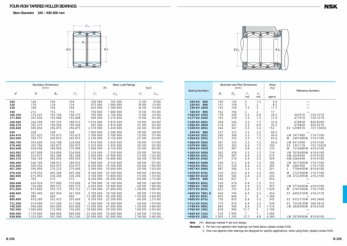
FOUR-ROW TAPERED ROLLER BEARINGSBore Diameter 100 – 939.800 mm
100 140 104 104 320 000 765 000 32 500 78 000 120 170 124 124 475 000 1 080 000 48 000 110 000 135 180 160 160 455 000 1 280 000 46 500 130 000 150 212 155 155 750 000 1 880 000 76 500 192 000 165.100 225.425 165.100 168.275 705 000 2 160 000 72 000 220 000 177.800 247.650 192.088 192.088 950 000 2 570 000 97 000 262 000 190.500 266.700 187.325 188.912 1 010 000 2 870 000 103 000 293 000 206.375 282.575 190.500 190.500 995 000 2 870 000 101 000 292 000 228.600 400.050 296.875 296.875 2 570 000 5 450 000 262 000 555 000 240 338 248 248 1 960 000 5 300 000 199 000 540 000 244.475 327.025 193.675 193.675 1 300 000 3 700 000 132 000 375 000 254.000 358.775 269.875 269.875 2 230 000 6 150 000 227 000 630 000 266.700 355.600 230.188 228.600 1 810 000 5 050 000 185 000 515 000 279.400 393.700 269.875 269.875 2 010 000 5 450 000 205 000 555 000 304.648 438.048 280.990 279.400 2 600 000 6 750 000 265 000 685 000 343.052 457.098 254.000 254.000 2 520 000 7 250 000 256 000 740 000 368.300 523.875 382.588 382.588 5 050 000 14 900 000 515 000 1 520 000 384.175 546.100 400.050 400.050 5 750 000 16 600 000 585 000 1 700 000 406.400 546.100 288.925 288.925 2 960 000 8 550 000 300 000 875 000 415.925 590.550 434.975 434.975 6 450 000 19 500 000 655 000 1 990 000 457.200 596.900 276.225 279.400 3 300 000 10 000 000 335 000 1 020 000 479.425 679.450 495.300 495.300 8 200 000 25 500 000 840 000 2 600 000 482.600 615.950 330.200 330.200 4 100 000 13 800 000 415 000 1 410 000 500 705 515 515 8 350 000 26 600 000 850 000 2 710 000 509.948 654.924 377.000 379.000 4 700 000 16 100 000 480 000 1 640 000 558.800 736.600 409.575 409.575 6 050 000 19 400 000 620 000 1 980 000 571.500 812.800 593.725 593.725 11 700 000 37 000 000 1 200 000 3 800 000 609.600 787.400 361.950 361.950 5 750 000 18 700 000 585 000 1 910 000 635 900 660 660 13 300 000 43 500 000 1 350 000 4 400 000 685.800 876.300 352.425 355.600 6 350 000 22 200 000 645 000 2 270 000 711.200 914.400 317.500 317.500 5 500 000 19 300 000 560 000 1 970 000 749.300 990.600 605.000 605.000 13 000 000 47 000 000 1 330 000 4 800 000 762.000 1 066.800 723.900 736.600 18 000 000 59 500 000 1 840 000 6 050 000 840.000 1 170.000 840.000 840.000 22 200 000 76 000 000 2 260 000 7 750 000 939.800 1 333.500 952.500 952.500 26 900 000 92 000 000 2 740 000 9 400 000
Boundary Dimensions(mm)
d D B4 C4
Basic Load Ratings (N) {kgf}
Cr C0r Cr C0r
100 KV 895 109 130 2 1.5 4.9 — 120 KV 895 131 158 2 2 8.5 — 135 KV 1802 145 169 1.5 2 11.1 — 150 KV 895 162 196 2 2 17 — *165 KV 2252 178 209 3.3 0.8 20.2 46791D -720-721D *177 KV 2452 192 228 3.3 1.5 27.9 67791D -720-721D *190 KV 2651 204 246 3.3 1.5 32.8 67885D -820-820D *206 KV 2854 218 261 3.3 0.8 35.2 67986D -920-921D *228 KV 4051 264 367 3.3 3.3 152 EE 529091D -157-158XD 240 KV 895 257 315 2.5 2.5 68.5 — *244 KV 3251 260 306 3.3 1.5 44.6 LM 247748D -710-710D *254 KV 3551 272 335 3.3 1.5 85.6 M 249748DW -710-710D *266 KV 3552 281 335 3.3 1.5 60.6 LM 451349D -310-310D *279 KV 3951 302 363 6.4 1.5 100 EE 135111D -155-156XD *304 KV 4353 329 407 4.8 3.3 133 M 757448DW -410-410D *343 KV 4555 362 430 3.3 1.5 114 LM 761649DW -610-610D *368 KV 5251 396 487 6.4 3.3 274 HM 265049D -010-010D *384 KV 5452 417 510 6.4 3.3 309 HM 266449D -410-410D *406 KV 5455 430 512 6.4 1.5 186 LM 767749DW -710-710D *415 KV 5951 451 550 6.4 3.3 395 M 268749D -710-710D *457 KV 5952 487 566 3.3 1.5 201 L 770849DW -810-810D *479 KV 6751 520 635 6.4 3.3 595 M 272749DW -710-710D *482 KV 6152 508 582 6.4 3.3 242 LM 272249DW -210-210D 500 KV 895 544 657 5 5 654 — *509 KV 6551 536 619 6.4 1.5 312 — *558 KV 7352 588 697 6.4 3.3 457 LM 377449DW -410-410D *571 KV 8151 622 755 6.4 3.3 1 020 M 278749DW -710-710D *609 KV 7851 A 644 745 6.4 3.3 454 EE 649241DW -310-311D 635 KV 9001 695 840 5 4 1 380 — *685 KV 8751 730 833 6.4 3.3 543 EE 655271DW -345-346D *711 KV 9151 770 870 6.4 3.3 549 EE 755281DW -360-361D *749 KV 9951 804 940 6.4 3.3 1 310 LM 283649DW -610-610D *762 KV 1051 828 996 12.7 5 2 100 — *840 KV 1151 910 1 095 7 7 2 900 — *939 KV 1351 1 035 1 245 12.7 4.8 4 380 LM 287849DW -810-810D
Bearing Numbers
Abutment and Fillet Dimensions(mm)
da Da ra rb max. max.
Mass(kg)
approx.
Reference Numbers
Note (*) Bearings marked * are inch design.Remarks 1. For four-row tapered roller bearings not listed above, please contact NSK. 2. Four-row tapered roller bearings are designed for specific applications, when using them, please contact NSK.
jdjD
C4
B4
jdjD
ra
rb
a a
B 338 B 339
B334-343E.indd 338-339B334-343E.indd 338-339 11/20/13 5:02:02 PM11/20/13 5:02:02 PM

FOUR-ROW CYLINDRICAL ROLLER BEARINGSBore Diameter 100 – 330 mm
jdjD
C
Br1
r2
jFW
2
jdjD
C
Br1
r 2
2
jFW
2
100 140 104 104 111 1.5 1.1 345 000 820 000 35 000 84 000 145 225 156 156 169 2 2 835 000 1 820 000 85 000 185 000
150 220 150 150 168 2 2 770 000 1 700 000 78 500 174 000 230 156 156 174 2 2 825 000 1 810 000 84 500 185 000
160 230 130 130 178 2 2 665 000 1 340 000 68 000 136 000 230 168 168 180 2 2 895 000 2 200 000 91 500 225 000
170 250 168 168 192 2.1 2.1 1 040 000 2 320 000 106 000 237 000 255 180 180 193 2.1 2.1 1 130 000 2 500 000 115 000 255 000
180 250 156 156 200 2 2 880 000 2 230 000 89 500 227 000 260 168 168 202 2.1 2.1 990 000 2 300 000 101 000 235 000
190 260 168 168 212 2 2 980 000 2 600 000 100 000 265 000 270 200 200 212 2.1 2.1 1 260 000 3 100 000 128 000 315 000
200 280 200 200 224 2.1 2.1 1 210 000 3 200 000 123 000 325 000 290 192 192 226 2.1 2.1 1 220 000 3 000 000 124 000 305 000
220 310 192 192 247 2.1 2.1 1 320 000 3 450 000 134 000 350 000 310 225 225 245 2.1 2.1 1 500 000 3 900 000 153 000 395 000 320 210 210 248 2.1 2.1 1 530 000 3 650 000 156 000 375 000
230 330 206 206 260 2.1 2.1 1 510 000 3 900 000 154 000 395 000 340 260 260 261 3 3 2 050 000 5 100 000 209 000 520 000
240 330 220 220 270 3 3 1 520 000 4 400 000 155 000 445 000 250 350 220 220 278 3 3 1 660 000 4 200 000 169 000 430 000
260 370 220 220 292 3 3 1 760 000 4 450 000 179 000 455 000 380 280 280 294 3 3 2 420 000 6 250 000 247 000 635 000
270 380 230 230 298 2.1 2.1 2 000 000 5 050 000 204 000 515 000 280 390 220 220 312 3 3 1 820 000 4 800 000 186 000 490 000
300 400 300 300 328 2 2 2 330 000 6 900 000 238 000 700 000 420 240 240 332 3 3 2 280 000 5 750 000 233 000 585 000
310 430 240 240 344.5 3 3 2 240 000 5 950 000 228 000 605 000 320 450 240 240 355 3 3 2 320 000 5 750 000 237 000 585 000 330 460 340 340 365 4 4 3 050 000 8 650 000 310 000 880 000
Boundary Dimensions(mm)
d D B, B2 C2 Fw r1 r2 min. min.
Basic Load Ratings (N) {kgf}
Cr C0r Cr C0r
100 RV 1401 4 2 — 145 RV 2201 23 1 313924A
150 RV 2201 20 1 — 150 RV 2302 23 1 313891A
160 RV 2301 16 1 — 160 RV 2302 22 1 —
170 RV 2501 27 1 — 170 RV 2503 31 1 —
180 RV 2501 23 1 — 180 RV 2601 29 1 313812
190 RV 2601 26 1 — 190 RV 2701 36 1 314199B
200 RV 2801 38 1 — 200 RV 2901 42 1 313811
220 RV 3101 46 1 — 220 RV 3102 52 1 — 220 RV 3201 56 1 —
230 RV 3301 58 1 313824 230 RV 3401 81 1 —
240 RV 3301 57 1 313921 250 RV 3501 64 1 —
260 RV 3701 76 1 313823 260 RV 3801 107 1 —
270 RV 3801 83 1 — 280 RV 3901 80 1 313822
300 RV 4021 103 2 — 300 RV 4201 101 1 —
310 RV 4301 107 1 — 320 RV 4502 116 1 — 330 RV 4601 174 1 —
Bearing Numbers Figures
Mass(kg)
approx.
Reference Bearing
Numbers
Remarks 1. For four-row cylindrical roller bearings not listed above, please contact NSK. 2. Four-row cylindrical roller bearings are designed for specific applications, when using them, please contact NSK.
Figure 1 Figure 2
B 340 B 341
B334-343E.indd 340-341B334-343E.indd 340-341 11/20/13 5:02:03 PM11/20/13 5:02:03 PM
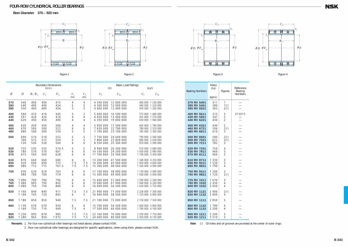
FOUR-ROW CYLINDRICAL ROLLER BEARINGSBore Diameter 370 – 920 mm
jdjD
C
Br1
r2
jFW
2
jdjD
C
Br1
r 2
2
jFW
2
jdjD
C
B
r1
r2
2
jFW
4
jdjD
C
B
r1
r2
2
jFW
4
Figure 1 Figure 2 Figure 3 Figure 4
370 540 400 400 415 4 4 4 500 000 12 000 000 460 000 1 230 000 380 540 400 400 424 5 5 4 300 000 12 000 000 440 000 1 220 000 390 550 400 400 434 5 5 4 400 000 12 400 000 450 000 1 260 000
400 560 410 410 445 5 2 5 600 000 16 500 000 575 000 1 680 000 430 591 420 420 476 4 4 4 450 000 13 400 000 455 000 1 370 000 440 620 450 450 490 4 4 6 350 000 19 000 000 650 000 1 940 000
450 630 450 450 500 4 4 5 950 000 17 500 000 605 000 1 780 000 460 670 500 500 522 6 6 7 650 000 22 700 000 780 000 2 320 000 480 680 500 500 534 5 5 7 700 000 23 100 000 785 000 2 360 000
500 690 510 510 552 5 5 7 750 000 24 600 000 790 000 2 500 000 700 515 515 554 5 5 7 800 000 23 800 000 800 000 2 430 000 720 530 530 560 6 6 8 550 000 25 300 000 870 000 2 580 000
520 735 535 535 574.5 5 5 8 900 000 26 300 000 910 000 2 680 000 530 780 570 570 601 6 6 10 100 000 29 200 000 1 030 000 2 980 000 570 815 594 594 628 6 6 11 700 000 33 500 000 1 190 000 3 450 000
610 870 660 660 680 6 6 13 200 000 41 500 000 1 340 000 4 250 000 650 920 690 690 723 7.5 7.5 14 200 000 45 000 000 1 450 000 4 600 000 690 980 715 715 767.5 7.5 7.5 15 300 000 48 000 000 1 560 000 4 900 000
700 930 620 620 763 6 6 11 100 000 38 000 000 1 130 000 3 900 000 980 700 700 774 6 6 15 300 000 49 000 000 1 560 000 5 000 000
725 1 000 700 700 796 6 6 15 600 000 51 000 000 1 590 000 5 200 000 760 1 080 805 790 845 6 6 19 000 000 61 000 000 1 940 000 6 200 000 800 1 080 750 750 880 6 6 16 000 000 56 500 000 1 630 000 5 750 000
820 1 160 840 840 911 7.5 7.5 21 900 000 71 500 000 2 230 000 7 300 000 1 100 745 720 892 6 3 16 900 000 58 500 000 1 720 000 6 000 000
850 1 180 850 850 940 7.5 7.5 21 100 000 72 000 000 2 150 000 7 350 000
860 1 130 670 670 934 6 6 15 700 000 56 500 000 1 600 000 5 800 000 1 160 735 710 940 7.5 4 17 500 000 60 000 000 1 780 000 6 100 000
900 1 230 895 870 985 7.5 7.5 22 100 000 76 000 000 2 250 000 7 750 000 920 1 280 865 850 1 015 7.5 7.5 24 000 000 80 000 000 2 450 000 8 150 000
Boundary Dimensions(mm)
d D B, B2 C2 Fw r1 r2 min. min.
Basic Load Ratings (N) {kgf}
Cr C0r Cr C0r
370 RV 5401 311 1 — 380 RV 5401 280 1(1) — 390 RV 5521 303 2(1) —
400 RV 5611 315 3 313015 430 RV 5921 347 2 — 440 RV 6221 430 2 —
450 RV 6321 440 2 — 460 RV 6721 596 2(1) — 480 RV 6811 610 3 —
500 RV 6921 580 2(1) — 500 RV 7021 622 2(1) — 500 RV 7211 782 3 —
520 RV 7331 750 4 — 530 RV 7811 960 3 — 570 RV 8111 960 3 —
610 RV 8711 1 330 3 — 650 RV 9211 1 520 3 — 690 RV 9831 1 790 4 —
700 RV 9311 1 200 3 — 700 RV 9821 1 720 2(1) —
725 RV 1011 1 670 3 — 760 RV 1032 2 430 4 — 800 RV 1032 2 050 4 —
820 RV 1121 2 900 2(1) — 820 RV 1132 2 000 4 —
850 RV 1111 2 850 3 —
860 RV 1132 1 780 4 — 860 RV 1133 2 200 4 —
900 RV 1211 3 200 3 — 920 RV 1211 3 510 3 —
Bearing Numbers Figures
Mass(kg)
approx.
Reference Bearing
Numbers
Remarks 1. For four-row cylindrical roller bearings not listed above, please contact NSK. 2. Four-row cylindrical roller bearings are designed for specific applications, when using them, please contact NSK.
Note (1) Oil holes and oil grooves are provided at the center of outer rings.
B 342 B 343
B334-343E.indd 342-343B334-343E.indd 342-343 11/20/13 5:02:04 PM11/20/13 5:02:04 PM
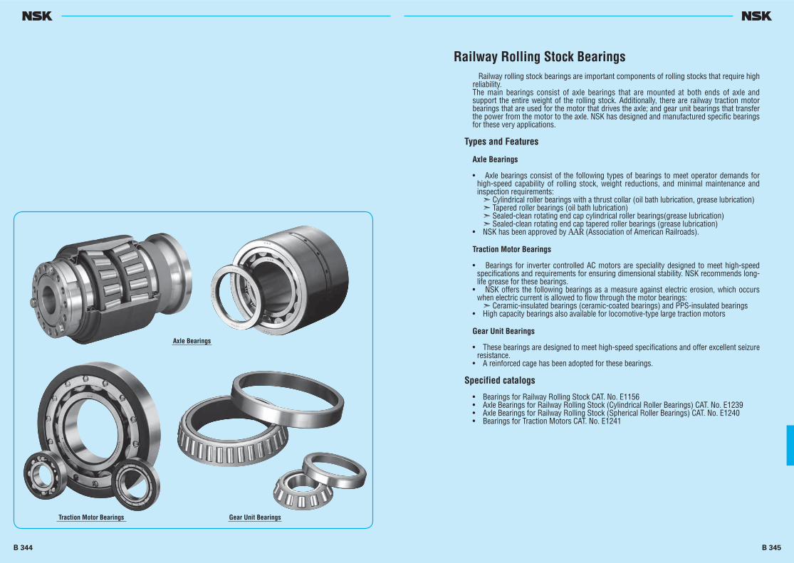
Railway Rolling Stock Bearings Railway rolling stock bearings are important components of rolling stocks that require high reliability.The main bearings consist of axle bearings that are mounted at both ends of axle and support the entire weight of the rolling stock. Additionally, there are railway traction motor bearings that are used for the motor that drives the axle; and gear unit bearings that transfer the power from the motor to the axle. NSK has designed and manufactured specific bearings for these very applications.
Types and Features
Axle Bearings
• Axle bearings consist of the following types of bearings to meet operator demands for high-speed capability of rolling stock, weight reductions, and minimal maintenance and inspection requirements:
➣ Cylindrical roller bearings with a thrust collar (oil bath lubrication, grease lubrication)➣ Tapered roller bearings (oil bath lubrication)➣ Sealed-clean rotating end cap cylindrical roller bearings(grease lubrication)➣ Sealed-clean rotating end cap tapered roller bearings (grease lubrication)
• NSK has been approved by AAR (Association of American Railroads).
Traction Motor Bearings
• Bearings for inverter controlled AC motors are speciality designed to meet high-speed specifications and requirements for ensuring dimensional stability. NSK recommends long-life grease for these bearings.
• NSK offers the following bearings as a measure against electric erosion, which occurs when electric current is allowed to flow through the motor bearings:
➣ Ceramic-insulated bearings (ceramic-coated bearings) and PPS-insulated bearings• High capacity bearings also available for locomotive-type large traction motors
Gear Unit Bearings
• These bearings are designed to meet high-speed specifications and offer excellent seizure resistance.
• A reinforced cage has been adopted for these bearings.
Specified catalogs
• Bearings for Railway Rolling Stock CAT. No. E1156• Axle Bearings for Railway Rolling Stock (Cylindrical Roller Bearings) CAT. No. E1239• Axle Bearings for Railway Rolling Stock (Spherical Roller Bearings) CAT. No. E1240• Bearings for Traction Motors CAT. No. E1241
Axle Bearings
Traction Motor Bearings Gear Unit Bearings
B 344 B 345

STEEL BALLS AND ROLLERSSTEEL BALLSFOR BALL BEARINGS Nominal Diameter 0.3 – 114.3mm ······················ B348
CYLINDRICAL ROLLERSFOR ROLLER BEARINGS Nominal Diameter 3 – 80mm ························· B350
LONG CYLINDRICAL ROLLERSFOR ROLLER BEARINGS Nominal Diameter 5.5 – 15mm ························· B352
NEEDLE ROLLERSFOR ROLLER BEARINGS Nominal Diameter 1 – 5mm ························· B354
B 346 B 347
B346-355E.indd 346-347B346-355E.indd 346-347 11/20/13 5:02:37 PM11/20/13 5:02:37 PM
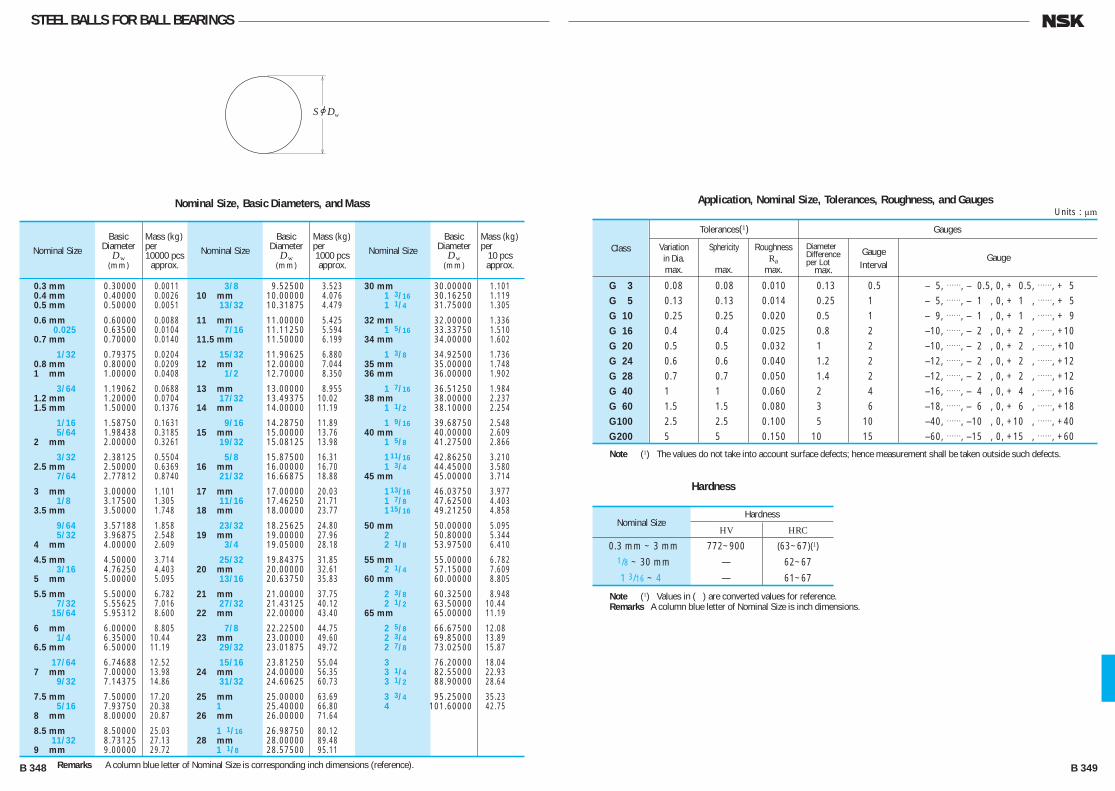
STEEL BALLS FOR BALL BEARINGS
SjDw
Nominal Size, Basic Diameters, and Mass
Nominal SizeBasic
DiameterDw
(mm)
Mass (kg) per10000 pcs
approx.Nominal Size
Basic Diameter
Dw(mm)
Mass (kg) per1000 pcs approx.
Nominal SizeBasic
DiameterDw
(mm)
Mass (kg) per
10 pcs approx.
30 mm 30.00000 1.101 1 3/16 30.16250 1.119 1 1/4 31.75000 1.305
32 mm 32.00000 1.336 1 5/16 33.33750 1.510 34 mm 34.00000 1.602
1 3/8 34.92500 1.736 35 mm 35.00000 1.748 36 mm 36.00000 1.902
1 7/16 36.51250 1.984 38 mm 38.00000 2.237 1 1/2 38.10000 2.254
1 9/16 39.68750 2.548 40 mm 40.00000 2.609 1 5/8 41.27500 2.866
1 11/16 42.86250 3.210 1 3/4 44.45000 3.580 45 mm 45.00000 3.714
1 13/16 46.03750 3.977 1 7/8 47.62500 4.403 1 15/16 49.21250 4.858
50 mm 50.00000 5.095 2 50.80000 5.344 2 1/8 53.97500 6.410
55 mm 55.00000 6.782 2 1/4 57.15000 7.609 60 mm 60.00000 8.805
2 3/8 60.32500 8.948 2 1/2 63.50000 10.44 65 mm 65.00000 11.19
2 5/8 66.67500 12.08 2 3/4 69.85000 13.89 2 7/8 73.02500 15.87
3 76.20000 18.04 3 1/4 82.55000 22.93 3 1/2 88.90000 28.64
3 3/4 95.25000 35.23 4 101.60000 42.75
3/8 9.52500 3.523 10 mm 10.00000 4.076 13/32 10.31875 4.479
11 mm 11.00000 5.425 7/16 11.11250 5.594 11.5 mm 11.50000 6.199
15/32 11.90625 6.880 12 mm 12.00000 7.044 1/2 12.70000 8.350
13 mm 13.00000 8.955 17/32 13.49375 10.02 14 mm 14.00000 11.19
9/16 14.28750 11.89 15 mm 15.00000 13.76 19/32 15.08125 13.98
5/8 15.87500 16.31 16 mm 16.00000 16.70 21/32 16.66875 18.88
17 mm 17.00000 20.03 11/16 17.46250 21.71 18 mm 18.00000 23.77
23/32 18.25625 24.80 19 mm 19.00000 27.96 3/4 19.05000 28.18
25/32 19.84375 31.85 20 mm 20.00000 32.61 13/16 20.63750 35.83
21 mm 21.00000 37.75 27/32 21.43125 40.12 22 mm 22.00000 43.40
7/8 22.22500 44.75 23 mm 23.00000 49.60 29/32 23.01875 49.72
15/16 23.81250 55.04 24 mm 24.00000 56.35 31/32 24.60625 60.73
25 mm 25.00000 63.69 1 25.40000 66.80 26 mm 26.00000 71.64
1 1/16 26.98750 80.12 28 mm 28.00000 89.48 1 1/8 28.57500 95.11
0.3 mm 0.30000 0.0011 0.4 mm 0.40000 0.0026 0.5 mm 0.50000 0.0051
0.6 mm 0.60000 0.0088 0.025 0.63500 0.0104 0.7 mm 0.70000 0.0140
1/32 0.79375 0.0204 0.8 mm 0.80000 0.0209 1 mm 1.00000 0.0408
3/64 1.19062 0.0688 1.2 mm 1.20000 0.0704 1.5 mm 1.50000 0.1376
1/16 1.58750 0.1631 5/64 1.98438 0.3185 2 mm 2.00000 0.3261
3/32 2.38125 0.5504 2.5 mm 2.50000 0.6369 7/64 2.77812 0.8740
3 mm 3.00000 1.101 1/8 3.17500 1.305 3.5 mm 3.50000 1.748
9/64 3.57188 1.858 5/32 3.96875 2.548 4 mm 4.00000 2.609
4.5 mm 4.50000 3.714 3/16 4.76250 4.403 5 mm 5.00000 5.095
5.5 mm 5.50000 6.782 7/32 5.55625 7.016 15/64 5.95312 8.600
6 mm 6.00000 8.805 1/4 6.35000 10.44 6.5 mm 6.50000 11.19
17/64 6.74688 12.52 7 mm 7.00000 13.98 9/32 7.14375 14.86
7.5 mm 7.50000 17.20 5/16 7.93750 20.38 8 mm 8.00000 20.87
8.5 mm 8.50000 25.03 11/32 8.73125 27.13 9 mm 9.00000 29.72
Tolerances(1) Gauges
Class Gauge
G 3 0.08 0.08 0.010 0.13 0.5 — 5, TT, — 0.5, 0, + 0.5, TT, + 5 G 5 0.13 0.13 0.014 0.25 1 — 5, TT, — 1 , 0, + 1 , TT, + 5 G 10 0.25 0.25 0.020 0.5 1 — 9, TT, — 1 , 0, + 1 , TT, + 9 G 16 0.4 0.4 0.025 0.8 2 —10, TT, — 2 , 0, + 2 , TT, +10 G 20 0.5 0.5 0.032 1 2 —10, TT, — 2 , 0, + 2 , TT, +10 G 24 0.6 0.6 0.040 1.2 2 —12, TT, — 2 , 0, + 2 , TT, +12 G 28 0.7 0.7 0.050 1.4 2 —12, TT, — 2 , 0, + 2 , TT, +12 G 40 1 1 0.060 2 4 —16, TT, — 4 , 0, + 4 , TT, +16 G 60 1.5 1.5 0.080 3 6 —18, TT, — 6 , 0, + 6 , TT, +18 G 100 2.5 2.5 0.100 5 10 —40, TT, —10 , 0, +10 , TT, +40 G 200 5 5 0.150 10 15 —60, TT, —15 , 0, +15 , TT, +60
Application, Nominal Size, Tolerances, Roughness, and Gauges
Variationin Dia.max.
Sphericity
max.
RoughnessRa
max.
Diameter Difference per Lot
max.
Gauge Interval
Units : μm
Note (1) The values do not take into account surface defects; hence measurement shall be taken outside such defects.
Remarks A column blue letter of Nominal Size is corresponding inch dimensions (reference).
Hardness
Note (1) Values in ( ) are converted values for reference.Remarks A column blue letter of Nominal Size is inch dimensions.
Nominal Size
Hardness
HV HRC
0.3 mm ~ 3 mm 772~900 (63~67)(1)
1/8 ~ 30 mm — 62~67
1 3/16 ~ 4 — 61~67
B 348 B 349
B346-355E.indd 348-349B346-355E.indd 348-349 11/20/13 5:02:40 PM11/20/13 5:02:40 PM

CYLINDRICAL ROLLERS FOR ROLLER BEARINGS
jDw
L w
r r
rr
Units : mm
Units : mm
Accuracy of Cylindrical Rollers
DW
(mm)Length Deviation(3)
&LWS
Out-of-Roundness
(1)&Rmax.
Single Plane Mean Roller Diameter
Variation(2)VDWmp
max.
Roller Gauge Lot Diameter Variation(1)
VDWL
max.
Roller Gauge Lot Length Variation
VLWL
max.
End Face Runout
SW
max.
Units : μm
Notes (1) Applicable to roller center (length direction). (2) Applicable to cylindrical outside surface. (3) To find the IT9 standard tolerance according to the LW size classification, refer to the IT9 column of the Appendix Table 11
on Page C22. (4) The value for low of length deviation is subtracted 10 μm from the value of the standard tolerance for each roller length.
Class
over incl. high low(4)
1 3 18 0.5 0.8 1 +10 — [ ( I T 9) — 10] 5 3 1A 3 30 0.7 1 1.5 +10 — [ ( I T 9) — 10] 7 5 2 3 50 1 1.5 2 +10 — [ ( I T 9) — 10] 10 6 2A 10 80 1.3 2 2.5 +10 — [ ( I T 9) — 10] 13 8 3 18 80 1.5 3 3 +10 — [ ( I T 9) — 10] 15 10 5 30 80 2.5 4 5 +10 — [ ( I T 9) — 10] 25 15
Units : mm
r Mass (kg) Nominal Size DW LW
min. per 100 pcs
approx.
42 × 42 42 42 1 45
45 × 45 45 45 1 55.5
48 × 48 48 48 1 67
50 × 50 50 50 1 76
52 × 52 52 52 1.5 85
54 × 54 54 54 1.5 95.5
56 × 56 56 56 1.5 107
60 × 60 60 60 1.5 131
64 × 64 64 64 1.5 159
68 × 68 68 68 1.5 191
75 × 75 75 75 2 256
80 × 80 80 80 2 310
r Mass (kg) Nominal Size DW LW
min. per 100 pcs
approx.
15 × 15 15 15 0.5 2.04 15 × 22 15 22 0.5 3.0 16 × 16 16 16 0.5 2.48 16 × 24 16 24 0.5 3.75 17 × 17 17 17 0.5 2.97 17 × 24 17 24 0.5 4.2 18 × 18 18 18 0.5 3.55 18 × 26 18 26 0.5 5.1 19 × 19 19 19 0.6 4.16 19 × 28 19 28 0.6 6.1 20 × 20 20 20 0.6 4.85 20 × 30 20 30 0.6 7.3 21 × 21 21 21 0.6 5.6 21 × 30 21 30 0.6 8.0 22 × 22 22 22 0.6 6.4 22 × 34 22 34 0.6 10 23 × 23 23 23 0.6 7.4 23 × 34 23 34 0.6 11.2 24 × 24 24 24 0.6 8.4 24 × 36 24 36 0.6 12.6 25 × 25 25 25 0.7 9.5 25 × 36 25 36 0.7 13.7 26 × 26 26 26 0.7 10.7 26 × 40 26 40 0.7 16.4 28 × 28 28 28 0.7 13.3 28 × 44 28 44 0.7 21 30 × 30 30 30 0.7 16.3 30 × 48 30 48 0.7 26.2 32 × 32 32 32 1 19.9 32 × 52 32 52 1 32.5 34 × 34 34 34 1 23.9 34 × 55 34 55 1 38.5 36 × 36 36 36 1 28.3 36 × 58 36 58 1 45.5 38 × 38 38 38 1 33.5 38 × 62 38 62 1 55 40 × 40 40 40 1 39 40 × 65 40 65 1 63
Units : mm
r Mass (kg) Nominal Size DW LW
min. per 100 pcs
approx.
3 × 3 3 3 0.1 0.016 3 × 5 3 5 0.1 0.027 3.5× 5 3.5 5 0.2 0.037 4 × 4 4 4 0.2 0.039 4 × 6 4 6 0.2 0.058 4 × 8 4 8 0.2 0.078 4.5× 4.5 4.5 4.5 0.2 0.055 4.5× 6 4.5 6 0.2 0.073 5 × 5 5 5 0.2 0.075 5 × 8 5 8 0.2 0.121 5 ×10 5 10 0.2 0.152 5.5× 5.5 5.5 5.5 0.2 0.10 5.5× 8 5.5 8 0.2 0.146 6 × 6 6 6 0.2 0.13 6 × 8 6 8 0.2 0.178 6 ×12 6 12 0.2 0.261 6.5× 6.5 6.5 6.5 0.3 0.166 6.5× 9 6.5 9 0.3 0.23 7 × 7 7 7 0.3 0.206 7 ×10 7 10 0.3 0.296 7 ×14 7 14 0.3 0.415 7.5× 7.5 7.5 7.5 0.3 0.254 7.5×11 7.5 11 0.3 0.375 8 × 8 8 8 0.3 0.31 8 ×12 8 12 0.3 0.465 9 × 9 9 9 0.3 0.44 9 ×14 9 14 0.3 0.68 10 ×10 10 10 0.3 0.60 10 ×14 10 14 0.3 0.85 11 ×11 11 11 0.3 0.81 11 ×15 11 15 0.3 1.1 12 ×12 12 12 0.3 1.04 12 ×18 12 18 0.3 1.57 13 ×13 13 13 0.3 1.33 13 ×20 13 20 0.3 2.04 14 ×14 14 14 0.3 1.66 14 ×20 14 20 0.3 2.38
Tolerances for Cylindrical Roller Chamfers
Note (1) If D W exceeds 40 mm,r (max.) is 2.7 mm.
min. max.
0.1 0.3 0.2 0.5 0.3 0.8 0.5 1.2 0.6 1.5 0.7 1.7 1 2.2(1) 1.5 3.5 2 4
B 350 B 351
B346-355E.indd 350-351B346-355E.indd 350-351 11/20/13 5:02:41 PM11/20/13 5:02:41 PM

LONG CYLINDRICAL ROLLERS FOR ROLLER BEARINGS
r (1) Mass (kg)
Nominal Size DW LW min.
per 100 pcs approx.
5.5×18 5.5 18 0.2 0.333 5.5×22.4 5.5 22.4 0.2 0.414 5.5×28 5.5 28 0.2 0.518
6 ×20 6 20 0.2 0.44 6 ×25 6 25 0.2 0.55 6 ×31.5 6 31.5 0.2 0.693 6 ×40 6 40 0.2 0.88 6 ×50 6 50 0.2 1.1
6.5×20 6.5 20 0.3 0.516 6.5×25 6.5 25 0.3 0.645 6.5×31.5 6.5 31.5 0.3 0.813
7 ×22.4 7 22.4 0.3 0.671 7 ×28 7 28 0.3 0.838 7 ×35.5 7 35.5 0.3 1.06 7 ×45 7 45 0.3 1.35 7 ×56 7 56 0.3 1.68
7.5×31.5 7.5 31.5 0.3 1.08 7.5×40 7.5 40 0.3 1.38
Units : mm
Note (1) Only for flat-end rollers.
Remarks The figure shows an example of a flat-end long cylindrical roller.
jDw
L w
r r
rr
Units : mmTolerance for Length Deviation
Length h12 h13
over incl. high low high low
3 6 — 0 — 0.18 6 10 — 0 — 0.22 10 18 — 0 — 0.27 18 30 0 — 0.21 0 — 0.33 30 50 0 — 0.25 0 — 0.39 50 80 0 — 0.30 — 80 120 0 — 0.35 —
Accuracy of Long Cylindrical Rollers
Out-of-Roundness
(1)&Rmax.
Single Plane MeanRoller Diameter
Variation (3)VDWmp
max.
Roller Gauge Lot Diameter Variation(1)
VDWL
max.
Length Deviation(2)
&LWS
Units : μm
Notes (1) Applicable to roller center (length direction). (2) Classified by LW. Refer to Tolerauce for Length Doviation. (3) Applicable to cylindrical outside surface.
Class
3 1.5 3 3 h12
5 2 5 5 h12
Units : mmTolerances for Long Cylindrical Roller Chamfers
min. max.
0.2 0.5 0.3 0.8 0.5 1.2
Units : mm
r (1) Mass (kg)
Nominal Size DW LW min.
per 100 pcs approx.
8 ×25 8 25 0.3 0.978 8 ×31.5 8 31.5 0.3 1.23 8 ×40 8 40 0.3 1.56 8 ×50 8 50 0.3 1.96 8 ×63 8 63 0.3 2.46
9 ×28 9 28 0.3 1.39 9 ×35.5 9 35.5 0.3 1.76 9 ×45 9 45 0.3 2.23 9 ×56 9 56 0.3 2.77
10×31.5 10 31.5 0.3 1.93 10×40 10 40 0.3 2.44 10×50 10 50 0.3 3.06 10×63 10 63 0.3 3.85
12×40 12 40 0.3 3.52 12×50 12 50 0.3 4.4 12×63 12 63 0.3 5.54
15×45 15 45 0.5 6.16 15×56 15 56 0.5 7.68 15×71 15 71 0.5 9.74 15×90 15 90 0.5 12.4
B 352 B 353
B346-355E.indd 352-353B346-355E.indd 352-353 11/20/13 5:02:42 PM11/20/13 5:02:42 PM
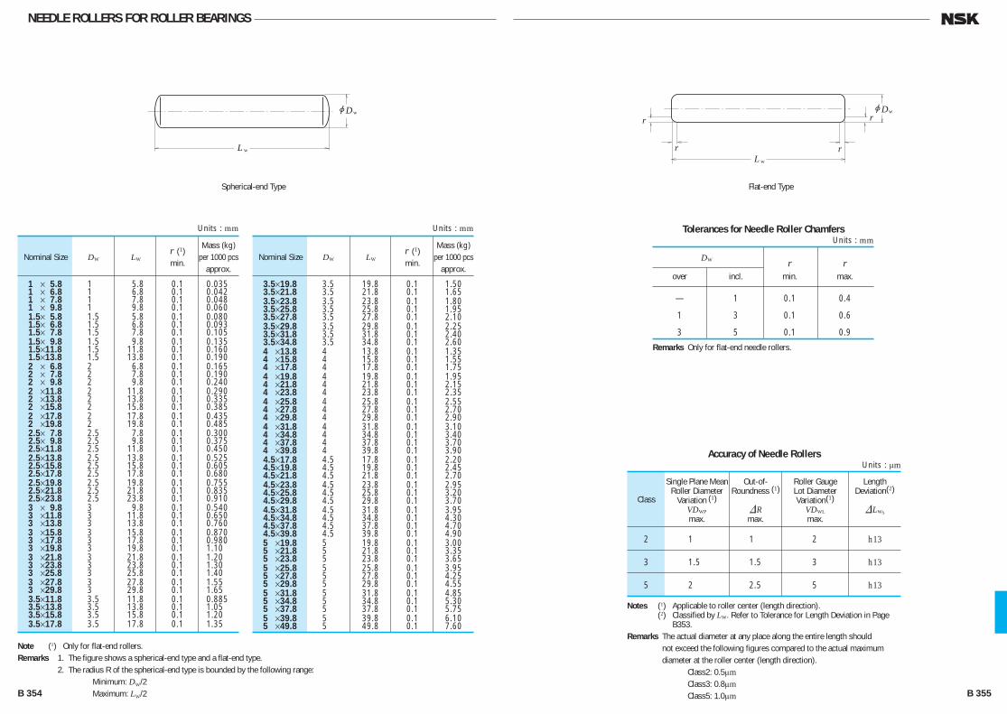
NEEDLE ROLLERS FOR ROLLER BEARINGS
r (1) Mass (kg)
Nominal Size DW LW min.
per 1000 pcs approx.
1 × 5.8 1 5.8 0.1 0.035 1 × 6.8 1 6.8 0.1 0.042 1 × 7.8 1 7.8 0.1 0.048 1 × 9.8 1 9.8 0.1 0.060 1.5× 5.8 1.5 5.8 0.1 0.080 1.5× 6.8 1.5 6.8 0.1 0.093 1.5× 7.8 1.5 7.8 0.1 0.105 1.5× 9.8 1.5 9.8 0.1 0.135 1.5×11.8 1.5 11.8 0.1 0.160 1.5×13.8 1.5 13.8 0.1 0.190 2 × 6.8 2 6.8 0.1 0.165 2 × 7.8 2 7.8 0.1 0.190 2 × 9.8 2 9.8 0.1 0.240 2 ×11.8 2 11.8 0.1 0.290 2 ×13.8 2 13.8 0.1 0.335 2 ×15.8 2 15.8 0.1 0.385 2 ×17.8 2 17.8 0.1 0.435 2 ×19.8 2 19.8 0.1 0.485 2.5× 7.8 2.5 7.8 0.1 0.300 2.5× 9.8 2.5 9.8 0.1 0.375 2.5×11.8 2.5 11.8 0.1 0.450 2.5×13.8 2.5 13.8 0.1 0.525 2.5×15.8 2.5 15.8 0.1 0.605 2.5×17.8 2.5 17.8 0.1 0.680 2.5×19.8 2.5 19.8 0.1 0.755 2.5×21.8 2.5 21.8 0.1 0.835 2.5×23.8 2.5 23.8 0.1 0.910 3 × 9.8 3 9.8 0.1 0.540 3 ×11.8 3 11.8 0.1 0.650 3 ×13.8 3 13.8 0.1 0.760 3 ×15.8 3 15.8 0.1 0.870 3 ×17.8 3 17.8 0.1 0.980 3 ×19.8 3 19.8 0.1 1.10 3 ×21.8 3 21.8 0.1 1.20 3 ×23.8 3 23.8 0.1 1.30 3 ×25.8 3 25.8 0.1 1.40 3 ×27.8 3 27.8 0.1 1.55 3 ×29.8 3 29.8 0.1 1.65 3.5×11.8 3.5 11.8 0.1 0.885 3.5×13.8 3.5 13.8 0.1 1.05 3.5×15.8 3.5 15.8 0.1 1.20 3.5×17.8 3.5 17.8 0.1 1.35
Units : mm
Note (1) Only for flat-end rollers.Remarks 1. The figure shows a spherical-end type and a flat-end type. 2. The radius R of the spherical-end type is bounded by the following range: Minimum: DW/2 Maximum: LW/2
r (1) Mass (kg)
Nominal Size DW LW min.
per 1000 pcs approx.
3.5×19.8 3.5 19.8 0.1 1.50 3.5×21.8 3.5 21.8 0.1 1.65 3.5×23.8 3.5 23.8 0.1 1.80 3.5×25.8 3.5 25.8 0.1 1.95 3.5×27.8 3.5 27.8 0.1 2.10 3.5×29.8 3.5 29.8 0.1 2.25 3.5×31.8 3.5 31.8 0.1 2.40 3.5×34.8 3.5 34.8 0.1 2.60 4 ×13.8 4 13.8 0.1 1.35 4 ×15.8 4 15.8 0.1 1.55 4 ×17.8 4 17.8 0.1 1.75 4 ×19.8 4 19.8 0.1 1.95 4 ×21.8 4 21.8 0.1 2.15 4 ×23.8 4 23.8 0.1 2.35 4 ×25.8 4 25.8 0.1 2.55 4 ×27.8 4 27.8 0.1 2.70 4 ×29.8 4 29.8 0.1 2.90 4 ×31.8 4 31.8 0.1 3.10 4 ×34.8 4 34.8 0.1 3.40 4 ×37.8 4 37.8 0.1 3.70 4 ×39.8 4 39.8 0.1 3.90 4.5×17.8 4.5 17.8 0.1 2.20 4.5×19.8 4.5 19.8 0.1 2.45 4.5×21.8 4.5 21.8 0.1 2.70 4.5×23.8 4.5 23.8 0.1 2.95 4.5×25.8 4.5 25.8 0.1 3.20 4.5×29.8 4.5 29.8 0.1 3.70 4.5×31.8 4.5 31.8 0.1 3.95 4.5×34.8 4.5 34.8 0.1 4.30 4.5×37.8 4.5 37.8 0.1 4.70 4.5×39.8 4.5 39.8 0.1 4.90 5 ×19.8 5 19.8 0.1 3.00 5 ×21.8 5 21.8 0.1 3.35 5 ×23.8 5 23.8 0.1 3.65 5 ×25.8 5 25.8 0.1 3.95 5 ×27.8 5 27.8 0.1 4.25 5 ×29.8 5 29.8 0.1 4.55 5 ×31.8 5 31.8 0.1 4.85 5 ×34.8 5 34.8 0.1 5.30 5 ×37.8 5 37.8 0.1 5.75 5 ×39.8 5 39.8 0.1 6.10 5 ×49.8 5 49.8 0.1 7.60
Units : mm
jDw
L w
jDw
L w
r r
rr
Accuracy of Needle Rollers
Class
2 1 1 2 h13
3 1.5 1.5 3 h13
5 2 2.5 5 h13
Out-of-Roundness (1)
&Rmax.
Single Plane MeanRoller Diameter
Variation (1)VDWP
max.
Roller Gauge Lot Diameter Variation(1)
VDWL
max.
Length Deviation(2)
&LWS
Units : μm
Notes (1) Applicable to roller center (length direction). (2) Classified by LW. Refer to Tolerance for Length Deviation in Page
B353.Remarks The actual diameter at any place along the entire length should
not exceed the following figures compared to the actual maximum diameter at the roller center (length direction).
Class2: 0.5μm Class3: 0.8μm Class5: 1.0μm
Tolerances for Needle Roller Chamfers
DW r r over incl. min. max.
— 1 0.1 0.4
1 3 0.1 0.6
3 5 0.1 0.9
Units : mm
Remarks Only for flat-end needle rollers.
Spherical-end Type Flat-end Type
B 354 B 355
B346-355E.indd 354-355B346-355E.indd 354-355 11/20/13 5:02:43 PM11/20/13 5:02:43 PM

ACCESSORIES FOR ROLLING BEARINGSADAPTERSFOR ROLLING BEARINGS Shaft Diameter 17 – 470mm ··························· B358
WITHDRAWAL SLEEVESFOR ROLLING BEARINGS Shaft Diameter 35 – 480mm ··························· B366
NUTS FOR ROLLING BEARINGS ········································································ B372
STOPPERS FOR ROLLING BEARINGS ································································· B377
LOCK-WASHERS FOR ROLLING BEARINGS ······················································ B378
B 356 B 357
B356-379E.indd 356-357B356-379E.indd 356-357 11/20/13 5:03:01 PM11/20/13 5:03:01 PM
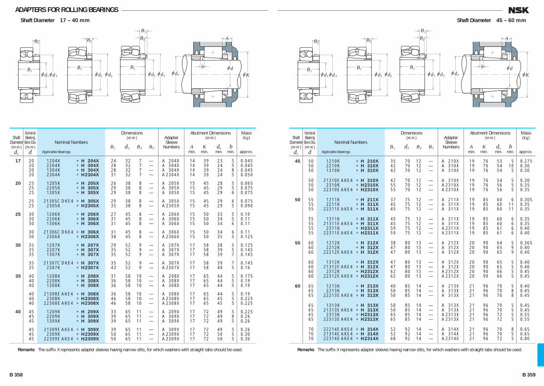
ADAPTERS FOR ROLLING BEARINGSShaft Diameter 17 – 40 mm
jd 2jd1 jd2jd1jd2jd1
jdjd
jKeB1
B1
B2B2
B1
B2
B5
b
A
Nominal Numbers
Applicable Bearings
Shaft Diameter(mm)d1
Nominal Bearing
Bore Dia.(mm)
d
Dimensions(mm)
B1 d2 B2 B5
Abutment Dimensions(mm)
A K de b min. min. min. min.
Mass(kg)
approx.
Adapter Sleeve
Numbers
17 20 1204K + H 204X 24 32 7 — A 204X 14 39 23 5 0.045 20 2204K + H 304X 28 32 7 — A 304X 14 39 24 5 0.045 20 1304K + H 304X 28 32 7 — A 304X 14 39 24 8 0.045 20 2304K + H 2304X 31 32 7 — A 2304X 14 39 24 5 0.050
20 25 1205K + H 205X 26 38 8 — A 205X 15 45 28 5 0.065 25 2205K + H 305X 29 38 8 — A 305X 15 45 29 5 0.075 25 1305K + H 305X 29 38 8 — A 305X 15 45 29 6 0.075
25 21305C DKE4 + H 305X 29 38 8 — A 305X 15 45 29 6 0.075 25 2305K + H 2305X 35 38 8 — A 2305X 15 45 29 5 0.090
25 30 1206K + H 206X 27 45 8 — A 206X 15 50 33 5 0.10 30 2206K + H 306X 31 45 8 — A 306X 15 50 34 5 0.11 30 1306K + H 306X 31 45 8 — A 306X 15 50 34 6 0.11
30 21306C DKE4 + H 306X 31 45 8 — A 306X 15 50 34 6 0.11 30 2306K + H 2306X 38 45 8 — A 2306X 15 50 35 5 0.125
30 35 1207K + H 207X 29 52 9 — A 207X 17 58 38 5 0.125 35 2207K + H 307X 35 52 9 — A 307X 17 58 39 5 0.145 35 1307K + H 307X 35 52 9 — A 307X 17 58 39 7 0.145
35 21307C DKE4 + H 307X 35 52 9 — A 307X 17 58 39 7 0.145 35 2307K + H 2307X 43 52 9 — A 2307X 17 58 40 5 0.16
35 40 1208K + H 208X 31 58 10 — A 208X 17 65 44 5 0.175 40 2208K + H 308X 36 58 10 — A 308X 17 65 44 5 0.19 40 1308K + H 308X 36 58 10 — A 308X 17 65 44 5 0.19
40 21308E AKE4 + H 308X 36 58 10 — A 308X 17 65 44 5 0.19 40 2308K + H 2308X 46 58 10 — A 2308X 17 65 45 5 0.225 40 22308E AKE4 + H 2308X 46 58 10 — A 2308X 17 65 45 5 0.225
40 45 1209K + H 209X 33 65 11 — A 209X 17 72 49 5 0.225 45 2209K + H 309X 39 65 11 — A 309X 17 72 49 8 0.26 45 1309K + H 309X 39 65 11 — A 309X 17 72 49 5 0.26
45 21309E AKE4 + H 309X 39 65 11 — A 309X 17 72 49 5 0.26 45 2309K + H 2309X 50 65 11 — A 2309X 17 72 50 5 0.30 45 22309E AKE4 + H 2309X 50 65 11 — A 2309X 17 72 50 5 0.30
Shaft Diameter 45 – 60 mm
jd 2jd1 jd2jd1jd2jd1
jdjd
jKeB1
B1
B2B2
B1
B2
B5
b
A
Nominal Numbers
Applicable Bearings
Shaft Diameter(mm)d1
Nominal Bearing
Bore Dia.(mm)
d
Dimensions(mm)
B1 d2 B2 B5
Abutment Dimensions(mm)
A K de b min. min. min. min.
Mass(kg)
approx.
Adapter Sleeve
Numbers
45 50 1210K + H 210X 35 70 12 — A 210X 19 76 53 5 0.275 50 2210K + H 310X 42 70 12 — A 310X 19 76 54 10 0.30 50 1310K + H 310X 42 70 12 — A 310X 19 76 54 5 0.30
50 21310E AKE4 + H 310X 42 70 12 — A 310X 19 76 54 5 0.30 50 2310K + H 2310X 55 70 12 — A 2310X 19 76 56 5 0.35 50 22310E AKE4 + H 2310X 55 70 12 — A 2310X 19 76 56 5 0.35
50 55 1211K + H 211X 37 75 12 — A 211X 19 85 60 6 0.305 55 2211K + H 311X 45 75 12 — A 311X 19 85 60 11 0.35 55 22211E AKE4 + H 311X 45 75 12 — A 311X 19 85 60 11 0.35
55 1311K + H 311X 45 75 12 — A 311X 19 85 60 6 0.35 55 21311E AKE4 + H 311X 45 75 12 — A 311X 19 85 60 6 0.35 55 2311K + H 2311X 59 75 12 — A 2311X 19 85 61 6 0.40 55 22311E AKE4 + H 2311X 59 75 12 — A 2311X 19 85 61 6 0.40
55 60 1212K + H 212X 38 80 13 — A 212X 20 90 64 5 0.365 60 2212K + H 312X 47 80 13 — A 312X 20 90 65 9 0.40 60 22212E AKE4 + H 312X 47 80 13 — A 312X 20 90 65 9 0.40
60 1312K + H 312X 47 80 13 — A 312X 20 90 65 5 0.40 60 21312E AKE4 + H 312X 47 80 13 — A 312X 20 90 65 5 0.40 60 2312K + H 2312X 62 80 13 — A 2312X 20 90 66 5 0.45 60 22312E AKE4 + H 2312X 62 80 13 — A 2312X 20 90 66 5 0.45
60 65 1213K + H 213X 40 85 14 — A 213X 21 96 70 5 0.40 65 2213K + H 313X 50 85 14 — A 313X 21 96 70 8 0.45 65 22213E AKE4 + H 313X 50 85 14 — A 313X 21 96 70 8 0.45
65 1313K + H 313X 50 85 14 — A 313X 21 96 70 5 0.45 65 21313E AKE4 + H 313X 50 85 14 — A 313X 21 96 70 5 0.45 65 2313K + H 2313X 65 85 14 — A 2313X 21 96 72 5 0.55 65 22313E AKE4 + H 2313X 65 85 14 — A 2313X 21 96 72 5 0.55
70 22214E AKE4 + H 314X 52 92 14 — A 314X 21 96 70 8 0.65 70 21314E AKE4 + H 314X 52 92 14 — A 314X 21 96 70 5 0.65 70 22314E AKE4 + H 2314X 68 92 14 — A 2314X 21 96 72 5 0.80
Remarks The suffix X represents adapter sleeves having narrow slits, for which washers with straight tabs should be used.Remarks The suffix X represents adapter sleeves having narrow slits, for which washers with straight tabs should be used.
B 358 B 359
B356-379E.indd 358-359B356-379E.indd 358-359 11/20/13 5:03:02 PM11/20/13 5:03:02 PM
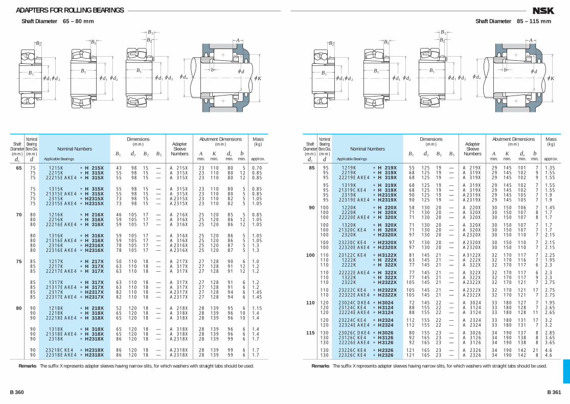
ADAPTERS FOR ROLLING BEARINGSShaft Diameter 65 – 80 mm
jd 2jd1 jd2jd1jd2jd1
jdjd
jKeB1
B1
B2B2
B1
B2
B5
b
A
Nominal Numbers
Applicable Bearings
Shaft Diameter(mm)d1
Nominal Bearing
Bore Dia.(mm)
d
Dimensions(mm)
B1 d2 B2 B5
Abutment Dimensions(mm)
A K de b min. min. min. min.
Mass(kg)
approx.
Adapter Sleeve
Numbers
65 75 1215K + H 215X 43 98 15 — A 215X 23 110 80 5 0.70 75 2215K + H 315X 55 98 15 — A 315X 23 110 80 12 0.85 75 22215E AKE4 + H 315X 55 98 15 — A 315X 23 110 80 12 0.85
75 1315K + H 315X 55 98 15 — A 315X 23 110 80 5 0.85 75 21315E AKE4 + H 315X 55 98 15 — A 315X 23 110 80 5 0.85 75 2315K + H 2315X 73 98 15 — A 2315X 23 110 82 5 1.05 75 22315E AKE4 + H 2315X 73 98 15 — A 2315X 23 110 82 5 1.05
70 80 1216K + H 216X 46 105 17 — A 216X 25 120 85 5 0.85 80 2216K + H 316X 59 105 17 — A 316X 25 120 86 12 1.05 80 22216E AKE4 + H 316X 59 105 17 — A 316X 25 120 86 12 1.05
80 1316K + H 316X 59 105 17 — A 316X 25 120 86 5 1.05 80 21316E AKE4 + H 316X 59 105 17 — A 316X 25 120 86 5 1.05 80 2316K + H 2316X 78 105 17 — A 2316X 25 120 87 5 1.3 80 22316E AKE4 + H 2316X 78 105 17 — A 2316X 25 120 87 5 1.3
75 85 1217K + H 217X 50 110 18 — A 217X 27 128 90 6 1.0 85 2217K + H 317X 63 110 18 — A 317X 27 128 91 12 1.2 85 22217E AKE4 + H 317X 63 110 18 — A 317X 27 128 91 12 1.2
85 1317K + H 317X 63 110 18 — A 317X 27 128 91 6 1.2 85 21317E AKE4 + H 317X 63 110 18 — A 317X 27 128 91 6 1.2 85 2317K + H 2317X 82 110 18 — A 2317X 27 128 94 6 1.45 85 22317E AKE4 + H 2317X 82 110 18 — A 2317X 27 128 94 6 1.45
80 90 1218K + H 218X 52 120 18 — A 218X 28 139 95 6 1.15 90 2218K + H 318X 65 120 18 — A 318X 28 139 96 10 1.4 90 22218E AKE4 + H 318X 65 120 18 — A 318X 28 139 96 10 1.4
90 1318K + H 318X 65 120 18 — A 318X 28 139 96 6 1.4 90 21318E AKE4 + H 318X 65 120 18 — A 318X 28 139 96 6 1.4 90 2318K + H 2318X 86 120 18 — A 2318X 28 139 99 6 1.7
90 23218C KE4 + H 2318X 86 120 18 — A 2318X 28 139 99 6 1.7 90 22318E AKE4 + H 2318X 86 120 18 — A 2318X 28 139 99 6 1.7
Remarks The suffix X represents adapter sleeves having narrow slits, for which washers with straight tabs should be used.
Shaft Diameter 85 – 115 mm
jd 2jd1 jd2jd1jd2jd1
jdjd
jKeB1
B1
B2B2
B1
B2
B5
b
A
Nominal Numbers
Applicable Bearings
Shaft Diameter(mm)d1
Nominal Bearing
Bore Dia.(mm)
d
Dimensions(mm)
B1 d2 B2 B5
Abutment Dimensions(mm)
A K de b min. min. min. min.
Mass(kg)
approx.
Adapter Sleeve
Numbers
85 95 1219K + H 219X 55 125 19 — A 219X 29 145 101 7 1.35 95 2219K + H 319X 68 125 19 — A 319X 29 145 102 9 1.55 95 22219E AKE4 + H 319X 68 125 19 — A 319X 29 145 102 9 1.55
95 1319K + H 319X 68 125 19 — A 319X 29 145 102 7 1.55 95 21319C KE4 + H 319X 68 125 19 — A 319X 29 145 102 7 1.55 95 2319K + H 2319X 90 125 19 — A 2319X 29 145 105 7 1.9 95 22319E AKE4 + H 2319X 90 125 19 — A 2319X 29 145 105 7 1.9
90 100 1220K + H 220X 58 130 20 — A 220X 30 150 106 7 1.45 100 2220K + H 320X 71 130 20 — A 320X 30 150 107 8 1.7 100 22220E AKE4 + H 320X 71 130 20 — A 320X 30 150 107 8 1.7
100 1320K + H 320X 71 130 20 — A 320X 30 150 107 7 1.7 100 21320C KE4 + H 320X 71 130 20 — A 320X 30 150 107 7 1.7 100 2320K + H 2320X 97 130 20 — A 2320X 30 150 110 7 2.15
100 23220C KE4 + H 2320X 97 130 20 — A 2320X 30 150 110 7 2.15 100 22320E AKE4 + H 2320X 97 130 20 — A 2320X 30 150 110 7 2.15
100 110 23122C KE4 + H 3122X 81 145 21 — A 3122X 32 170 117 7 2.25 110 1222K + H 222X 63 145 21 — A 222X 32 170 116 7 1.95 110 2222K + H 322X 77 145 21 — A 322X 32 170 117 6 2.3
110 22222E AKE4 + H 322X 77 145 21 — A 322X 32 170 117 6 2.3 110 1322K + H 322X 77 145 21 — A 322X 32 170 117 9 2.3 110 2322K + H 2322X 105 145 21 — A 2322X 32 170 121 7 2.75
110 23222C KE4 + H 2322X 105 145 21 — A 2322X 32 170 121 17 2.75 110 22322E AKE4 + H 2322X 105 145 21 — A 2322X 32 170 121 7 2.75
110 120 23024C DKE4 + H 3024 72 145 22 — A 3024 33 180 127 7 1.95 120 23124C KE4 + H 3124 88 155 22 — A 3124 33 180 128 7 2.65 120 22224E AKE4 + H 3124 88 155 22 — A 3124 33 180 128 11 2.65
120 23224C KE4 + H 2324 112 155 22 — A 2324 33 180 131 17 3.2 120 22324E AKE4 + H 2324 112 155 22 — A 2324 33 180 131 7 3.2
115 130 23026C DKE4 + H 3026 80 155 23 — A 3026 34 190 137 8 2.85 130 23126C KE4 + H 3126 92 165 23 — A 3126 34 190 138 8 3.65 130 22226E AKE4 + H 3126 92 165 23 — A 3126 34 190 138 8 3.65
130 23226C KE4 + H 2326 121 165 23 — A 2326 34 190 142 21 4.6 130 22326C KE4 + H 2326 121 165 23 — A 2326 34 190 142 8 4.6
Remarks The suffix X represents adapter sleeves having narrow slits, for which washers with straight tabs should be used.
B 360 B 361
B356-379E.indd 360-361B356-379E.indd 360-361 11/20/13 5:03:03 PM11/20/13 5:03:03 PM

ADAPTERS FOR ROLLING BEARINGSShaft Diameter 125 – 170 mm
jd2jd1jd
jdjKe
B1
B2
B5
jd2jd1
B1
B2
b
A
Nominal Numbers
Applicable Bearings
Shaft Diameter(mm)d1
Nominal Bearing
Bore Dia.(mm)
d
Dimensions(mm)
B1 d2 B2 B5
Abutment Dimensions(mm)
A K de b min. min. min. min.
Mass(kg)
approx.
Adapter Sleeve
Numbers
125 140 23028C DKE4 + H 3028 82 165 24 — A 3028 36 205 147 8 3.15 140 23128C KE4 + H 3128 97 180 24 — A 3128 36 205 149 8 4.35 140 22228C DKE4 + H 3128 97 180 24 — A 3128 36 205 149 8 4.35 140 23228C KE4 + H 2328 131 180 24 — A 2328 36 205 152 22 5.55 140 22328C KE4 + H 2328 131 180 24 — A 2328 36 205 152 8 5.55 135 150 23030C DKE4 + H 3030 87 180 26 — A 3030 37 220 158 8 3.9 150 23130C KE4 + H 3130 111 195 26 — A 3130 37 220 160 8 5.5 150 22230C DKE4 + H 3130 111 195 26 — A 3130 37 220 160 15 5.5 150 23230C KE4 + H 2330 139 195 26 — A 2330 37 220 163 20 6.6 150 22330C AKE4 + H 2330 139 195 26 — A 2330 37 220 163 8 6.6 140 160 23932C AKE4 + H 3932 78 190 28 — A 3932 39 205 168 8 4.64 160 23032C DKE4 + H 3032 93 190 28 — A 3032 39 230 168 8 5.2 160 23132C KE4 + H 3132 119 210 28 — A 3132 39 230 170 8 7.65 160 22232C DKE4 + H 3132 119 210 28 — A 3132 39 230 170 14 7.65 160 23232C KE4 + H 2332 147 210 28 — A 2332 39 230 174 18 9.15 160 22332C AKE4 + H 2332 147 210 28 — A 2332 39 230 174 8 9.15 150 170 23934B CAKE4 + H 3934 79 200 29 — A 3934 40 215 179 8 5.07 170 23034C DKE4 + H 3034 101 200 29 — A 3034 40 250 179 8 6.0 170 23134C KE4 + H 3134 122 220 29 — A 3134 40 250 180 8 8.4 170 22234C DKE4 + H 3134 122 220 29 — A 3134 40 250 180 10 8.4 170 23234C KE4 + H 2334 154 220 29 — A 2334 40 250 185 18 10 170 22334C AKE4 + H 2334 154 220 29 — A 2334 40 250 185 8 10 160 180 23936C AKE4 + H 3936 87 210 30 — A 3936 41 230 189 8 5.87 180 23036C DKE4 + H 3036 109 210 30 — A 3036 41 260 189 8 6.85 180 23136C KE4 + H 3136 131 230 30 — A 3136 41 260 191 8 9.5 180 22236C DKE4 + H 3136 131 230 30 — A 3136 41 260 191 18 9.5 180 23236C KE4 + H 2336 161 230 30 — A 2336 41 260 195 22 11.5 180 22336C AKE4 + H 2336 161 230 30 — A 2336 41 260 195 8 11.5 170 190 23938C AKE4 + H 3938 89 220 31 — A 3938 43 240 199 9 6.35 190 23038C AKE4 + H 3038 112 220 31 — A 3038 43 270 199 9 7.45 190 23138C KE4 + H 3138 141 240 31 — A 3138 43 270 202 9 11 190 22238C AKE4 + H 3138 141 240 31 — A 3138 43 270 202 21 11 190 23238C KE4 + H 2338 169 240 31 — A 2338 43 270 206 21 12.5 190 22338C AKE4 + H 2338 169 240 31 — A 2338 43 270 206 9 12.5
Shaft Diameter 180 – 260 mm
jd2jd1jd
jdjKe
B1
B2
B5
jd2jd1
B1
B2
b
A
Nominal Numbers
Applicable Bearings
Shaft Diameter(mm)d1
Nominal Bearing
Bore Dia.(mm)
d
Dimensions(mm)
B1 d2 B2 B5
Abutment Dimensions(mm)
A K de b min. min. min. min.
Mass(kg)
approx.
Adapter Sleeve
Numbers
180 200 23940C AKE4 + H 3940 98 240 32 — A 3940 46 260 210 10 8.0 200 23040C AKE4 + H 3040 120 240 32 — A 3040 46 280 210 10 9.2 200 23140C KE4 + H 3140 150 250 32 — A 3140 46 280 212 10 12
200 22240C AKE4 + H 3140 150 250 32 — A 3140 46 280 212 24 12 200 23240C KE4 + H 2340 176 250 32 — A 2340 46 280 216 20 14 200 22340C AKE4 + H 2340 176 250 32 — A 2340 46 280 216 10 14
200 220 23944C AKE4 + H 3944 96 260 30 41 A 3944 55 280 231 10 8.32 220 23044C AKE4 + H 3044 128 260 30 41 A 3044 55 320 231 12 10.5 220 23144C KE4 + H 3144 158 280 32 44 A 3144 55 320 233 10 14.5
220 22244C AKE4 + H 3144 158 280 32 44 A 3144 55 320 233 22 14.5 220 23244C KE4 + H 2344 183 280 32 44 A 2344 55 320 236 11 16.5 220 22344C AKE4 + H 2344 183 280 32 44 A 2344 55 320 236 10 16.5
220 240 23948C AKE4 + H 3948 101 290 34 46 A 3948 60 300 251 11 11.2 240 23048C AKE4 + H 3048 133 290 34 46 A 3048 60 340 251 11 13 240 23148C KE4 + H 3148 169 300 34 46 A 3148 60 340 254 11 17.5
240 22248C AKE4 + H 3148 169 300 34 46 A 3148 60 340 254 19 17.5 240 23248C AKE4 + H 2348 196 300 34 46 A 2348 60 340 257 6 19.5 240 22348C AKE4 + H 2348 196 300 34 46 A 2348 60 340 257 11 19.5
240 260 23952C AKE4 + H 3952 116 310 34 46 A 3952 60 330 272 11 13.4 260 23052C AKE4 + H 3052 147 310 34 46 A 3052 60 370 272 13 15.5 260 23152C AKE4 + H 3152 187 330 36 49 A 3152 60 370 276 11 22
260 22252C AKE4 + H 3152 187 330 36 49 A 3152 60 370 276 25 22 260 23252C AKE4 + H 2352 208 330 36 49 A 2352 60 370 278 2 24 260 22352C AKE4 + H 2352 208 330 36 49 A 2352 60 370 278 11 24
260 280 23956C AKE4 + H 3956 121 330 38 50 A 3956 65 350 292 12 15.5 280 23056C AKE4 + H 3056 152 330 38 50 A 3056 65 390 292 12 17.5 280 23156C AKE4 + H 3156 192 350 38 51 A 3156 65 390 296 12 24.5
280 22256C AKE4 + H 3156 192 350 38 51 A 3156 65 390 296 28 24.5 280 23256C AKE4 + H 2356 221 350 38 51 A 2356 65 390 299 11 28 280 22356C AKE4 + H 2356 221 350 38 51 A 2356 65 390 299 12 28
B 362 B 363
B356-379E.indd 362-363B356-379E.indd 362-363 11/20/13 5:03:04 PM11/20/13 5:03:04 PM
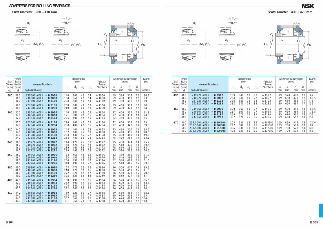
ADAPTERS FOR ROLLING BEARINGSShaft Diameter 280 – 410 mm
jd2jd1jd
jdjKe
B1
B2
B5
jd2jd1
B1
B2
b
A
Nominal Numbers
Applicable Bearings
Shaft Diameter(mm)d1
Nominal Bearing
Bore Dia.(mm)
d
Dimensions(mm)
B1 d2 B2 B5
Abutment Dimensions(mm)
A K de b min. min. min. min.
Mass(kg)
approx.
Adapter Sleeve
Numbers
280 300 23960C AKE4 + H 3960 140 360 42 54 A 3960 69 380 313 12 20.7 300 23060C AKE4 + H 3060 168 360 42 54 A 3060 69 430 313 12 23 300 23160C AKE4 + H 3160 208 380 40 53 A 3160 69 430 317 12 30
300 22260C AKE4 + H 3160 208 380 40 53 A 3160 69 430 317 32 30 300 23260C AKE4 + H 3260 240 380 40 53 A 3260 69 430 321 12 34
300 320 23964C AKE4 + H 3964 140 380 42 55 A 3964 72 400 334 13 21.8 320 23064C AKE4 + H 3064 171 380 42 55 A 3064 72 450 334 13 24.5 320 23164C AKE4 + H 3164 226 400 42 56 A 3164 72 450 339 13 35
320 22264C AKE4 + H 3164 226 400 42 56 A 3164 72 450 339 39 35 320 23264C AKE4 + H 3264 258 400 42 56 A 3264 72 450 343 13 39.5
320 340 23968C AKE4 + H 3968 144 400 45 58 A 3968 75 430 354 14 24.6 340 23068C AKE4 + H 3068 187 400 45 58 A 3068 75 490 355 14 28.5 340 23168C AKE4 + H 3168 254 440 55 72 A 3168 75 490 360 14 49.5 340 23268C AKE4 + H 3268 288 440 55 72 A 3268 75 490 364 14 54.5
340 360 23972C AKE4 + H 3972 144 420 45 58 A 3972 75 450 374 14 25.7 360 23072C AKE4 + H 3072 188 420 45 58 A 3072 75 510 375 14 30.5 360 23172C AKE4 + H 3172 259 460 58 75 A 3172 75 510 380 14 54 360 23272C AKE4 + H 3272 299 460 58 75 A 3272 75 510 385 14 60.5
360 380 23976C AKE4 + H 3976 164 450 48 62 A 3976 82 480 396 15 31.9 380 23076C AKE4 + H 3076 193 450 48 62 A 3076 82 540 396 15 36 380 23176C AKE4 + H 3176 264 490 60 77 A 3176 82 540 401 15 61.5 380 23276C AKE4 + H 3276 310 490 60 77 A 3276 82 540 405 15 69.5
380 400 23980C AKE4 + H 3980 168 470 52 66 A 3980 86 500 417 15 35.2 400 23080C AKE4 + H 3080 210 470 52 66 A 3080 86 580 417 15 41.5 400 23180C AKE4 + H 3180 272 520 62 82 A 3180 86 580 421 15 70.5 400 23280C AKE4 + H 3280 328 520 62 82 A 3280 86 580 427 15 81
400 420 23984C AKE4 + H 3984 168 490 52 66 A 3984 86 520 437 16 36.6 420 23084C AKE4 + H 3084 212 490 52 66 A 3084 86 600 437 16 43.5 420 23184C AKE4 + H 3184 304 540 70 90 A 3184 86 600 443 16 84 420 23284C AKE4 + H 3284 352 540 70 90 A 3284 86 600 448 16 94
410 440 23988C AKE4 + H 3988 189 520 60 77 A 3988 99 550 458 17 58.6 440 23088C AKE4 + H 3088 228 520 60 77 A 3088 99 620 458 17 65 440 23188C AKE4 + H 3188 307 560 70 90 A 3188 99 620 464 17 104 440 23288C AKE4 + H 3288 361 560 70 90 A 3288 99 620 469 17 118
Shaft Diameter 430 – 470 mm
jd2jd1jd
jdjKe
B1
B2
B5
jd2jd1
B1
B2
b
A
Nominal Numbers
Applicable Bearings
Shaft Diameter(mm)d1
Nominal Bearing
Bore Dia.(mm)
d
Dimensions(mm)
B1 d2 B2 B5
Abutment Dimensions(mm)
A K de b min. min. min. min.
Mass(kg)
approx.
Adapter Sleeve
Numbers
430 460 23992C AKE4 + H 3992 189 540 60 77 A 3992 99 570 478 17 62 460 23092C AKE4 + H 3092 234 540 60 77 A 3092 99 650 478 17 69.5 460 23192C AKE4 + H 3192 326 580 75 95 A 3192 99 650 485 17 116 460 23292C AKE4 + H 3292 382 580 75 95 A 3292 99 650 491 17 132
450 480 23996C AKE4 + H 3996 200 560 60 77 A 3996 99 600 499 18 67.5 480 23096C AKE4 + H 3096 237 560 60 77 A 3096 99 690 499 18 73.5 480 23196C AKE4 + H 3196 335 620 75 95 A 3196 99 690 505 18 133 480 23296C AKE4 + H 3296 397 620 75 95 A 3296 99 690 512 18 152
470 500 239/500C AKE4 + H 39/500 208 580 68 85 A 39/500 109 620 519 18 74.6 500 230/500C AKE4 + H 30/500 247 580 68 85 A 30/500 109 700 519 18 82 500 231/500C AKE4 + H 31/500 356 630 80 100 A 31/500 109 700 527 18 143 500 232/500C AKE4 + H 32/500 428 630 80 100 A 32/500 109 700 534 18 166
B 364 B 365
B356-379E.indd 364-365B356-379E.indd 364-365 11/20/13 5:03:05 PM11/20/13 5:03:05 PM
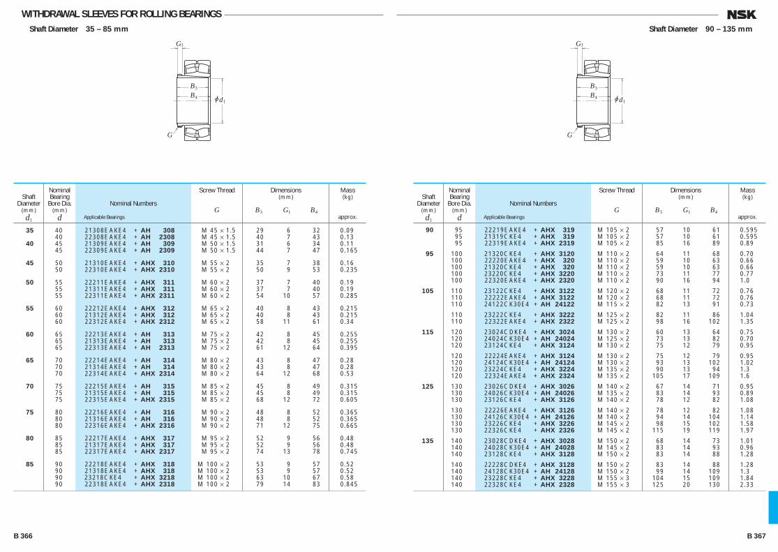
WITHDRAWAL SLEEVES FOR ROLLING BEARINGSShaft Diameter 35 – 85 mm
jd1
B3
B4
G
G1
Nominal Numbers
Applicable Bearings
Shaft Diameter
(mm)d1
Nominal Bearing
Bore Dia.(mm)
d
Dimensions(mm)
B3 G1 B4
Screw Thread
G
Mass(kg)
approx.
35 40 21308E AKE4 + AH 308 M 45 × 1.5 29 6 32 0.09 40 22308E AKE4 + AH 2308 M 45 × 1.5 40 7 43 0.13 40 45 21309E AKE4 + AH 309 M 50 × 1.5 31 6 34 0.11 45 22309E AKE4 + AH 2309 M 50 × 1.5 44 7 47 0.165
45 50 21310E AKE4 + AHX 310 M 55 × 2 35 7 38 0.16 50 22310E AKE4 + AHX 2310 M 55 × 2 50 9 53 0.235
50 55 22211E AKE4 + AHX 311 M 60 × 2 37 7 40 0.19 55 21311E AKE4 + AHX 311 M 60 × 2 37 7 40 0.19 55 22311E AKE4 + AHX 2311 M 60 × 2 54 10 57 0.285
55 60 22212E AKE4 + AHX 312 M 65 × 2 40 8 43 0.215 60 21312E AKE4 + AHX 312 M 65 × 2 40 8 43 0.215 60 22312E AKE4 + AHX 2312 M 65 × 2 58 11 61 0.34
60 65 22213E AKE4 + AH 313 M 75 × 2 42 8 45 0.255 65 21313E AKE4 + AH 313 M 75 × 2 42 8 45 0.255 65 22313E AKE4 + AH 2313 M 75 × 2 61 12 64 0.395
65 70 22214E AKE4 + AH 314 M 80 × 2 43 8 47 0.28 70 21314E AKE4 + AH 314 M 80 × 2 43 8 47 0.28 70 22314E AKE4 + AHX 2314 M 80 × 2 64 12 68 0.53
70 75 22215E AKE4 + AH 315 M 85 × 2 45 8 49 0.315 75 21315E AKE4 + AH 315 M 85 × 2 45 8 49 0.315 75 22315E AKE4 + AHX 2315 M 85 × 2 68 12 72 0.605
75 80 22216E AKE4 + AH 316 M 90 × 2 48 8 52 0.365 80 21316E AKE4 + AH 316 M 90 × 2 48 8 52 0.365 80 22316E AKE4 + AHX 2316 M 90 × 2 71 12 75 0.665
80 85 22217E AKE4 + AHX 317 M 95 × 2 52 9 56 0.48 85 21317E AKE4 + AHX 317 M 95 × 2 52 9 56 0.48 85 22317E AKE4 + AHX 2317 M 95 × 2 74 13 78 0.745
85 90 22218E AKE4 + AHX 318 M 100 × 2 53 9 57 0.52 90 21318E AKE4 + AHX 318 M 100 × 2 53 9 57 0.52 90 23218C KE4 + AHX 3218 M 100 × 2 63 10 67 0.58 90 22318E AKE4 + AHX 2318 M 100 × 2 79 14 83 0.845
Nominal Numbers
Applicable Bearings
Shaft Diameter
(mm)d1
Nominal Bearing
Bore Dia.(mm)
d
Dimensions(mm)
B3 G1 B4
Screw Thread
G
Mass(kg)
approx.
90 95 22219E AKE4 + AHX 319 M 105 × 2 57 10 61 0.595 95 21319C KE4 + AHX 319 M 105 × 2 57 10 61 0.595 95 22319E AKE4 + AHX 2319 M 105 × 2 85 16 89 0.89
95 100 21320C KE4 + AHX 3120 M 110 × 2 64 11 68 0.70 100 22220E AKE4 + AHX 320 M 110 × 2 59 10 63 0.66 100 21320C KE4 + AHX 320 M 110 × 2 59 10 63 0.66 100 23220C KE4 + AHX 3220 M 110 × 2 73 11 77 0.77 100 22320E AKE4 + AHX 2320 M 110 × 2 90 16 94 1.0
105 110 23122C KE4 + AHX 3122 M 120 × 2 68 11 72 0.76 110 22222E AKE4 + AHX 3122 M 120 × 2 68 11 72 0.76 110 24122C K30E4 + AH 24122 M 115 × 2 82 13 91 0.73
110 23222C KE4 + AHX 3222 M 125 × 2 82 11 86 1.04 110 22322E AKE4 + AHX 2322 M 125 × 2 98 16 102 1.35
115 120 23024C DKE4 + AHX 3024 M 130 × 2 60 13 64 0.75 120 24024C K30E4 + AH 24024 M 125 × 2 73 13 82 0.70 120 23124C KE4 + AHX 3124 M 130 × 2 75 12 79 0.95
120 22224E AKE4 + AHX 3124 M 130 × 2 75 12 79 0.95 120 24124C K30E4 + AH 24124 M 130 × 2 93 13 102 1.02 120 23224C KE4 + AHX 3224 M 135 × 2 90 13 94 1.3 120 22324E AKE4 + AHX 2324 M 135 × 2 105 17 109 1.6
125 130 23026C DKE4 + AHX 3026 M 140 × 2 67 14 71 0.95 130 24026C K30E4 + AH 24026 M 135 × 2 83 14 93 0.89 130 23126C KE4 + AHX 3126 M 140 × 2 78 12 82 1.08
130 22226E AKE4 + AHX 3126 M 140 × 2 78 12 82 1.08 130 24126C K30E4 + AH 24126 M 140 × 2 94 14 104 1.14 130 23226C KE4 + AHX 3226 M 145 × 2 98 15 102 1.58 130 22326C KE4 + AHX 2326 M 145 × 2 115 19 119 1.97
135 140 23028C DKE4 + AHX 3028 M 150 × 2 68 14 73 1.01 140 24028C K30E4 + AH 24028 M 145 × 2 83 14 93 0.96 140 23128C KE4 + AHX 3128 M 150 × 2 83 14 88 1.28
140 22228C DKE4 + AHX 3128 M 150 × 2 83 14 88 1.28 140 24128C K30E4 + AH 24128 M 150 × 2 99 14 109 1.3 140 23228C KE4 + AHX 3228 M 155 × 3 104 15 109 1.84 140 22328C KE4 + AHX 2328 M 155 × 3 125 20 130 2.33
Shaft Diameter 90 – 135 mm
jd1
B3
B4
G
G1
B 366 B 367
B356-379E.indd 366-367B356-379E.indd 366-367 11/20/13 5:03:06 PM11/20/13 5:03:06 PM

WITHDRAWAL SLEEVES FOR ROLLING BEARINGSShaft Diameter 145 – 180 mm
jd1
B3
B4
G
G1
Nominal Numbers
Applicable Bearings
Shaft Diameter
(mm)d1
Nominal Bearing
Bore Dia.(mm)
d
Dimensions(mm)
B3 G1 B4
Screw Thread
G
Mass(kg)
approx.
145 150 23030C DKE4 + AHX 3030 M 160 × 3 72 15 77 1.15 150 24030C K30E4 + AH 24030 M 155 × 3 90 15 101 1.11 150 23130C KE4 + AHX 3130 M 165 × 3 96 15 101 1.79 150 22230C DKE4 + AHX 3130 M 165 × 3 96 15 101 1.79 150 24130C K30E4 + AH 24130 M 160 × 3 115 15 126 1.63 150 23230C KE4 + AHX 3230 M 165 × 3 114 17 119 2.22 150 22330C AKE4 + AHX 2330 M 165 × 3 135 24 140 2.82 150 160 23032C DKE4 + AH 3032 M 170 × 3 77 16 82 2.05 160 24032C K30E4 + AH 24032 M 170 × 3 95 15 106 2.28 160 23132C KE4 + AH 3132 M 180 × 3 103 16 108 3.2 160 22232C DKE4 + AH 3132 M 180 × 3 103 16 108 3.2 160 24132C K30E4 + AH 24132 M 170 × 3 124 15 135 3.03 160 23232C KE4 + AH 3232 M 180 × 3 124 20 130 4.1 160 22332C AKE4 + AH 2332 M 180 × 3 140 24 146 4.7 160 170 23034C DKE4 + AH 3034 M 180 × 3 85 17 90 2.45 170 24034C K30E4 + AH 24034 M 180 × 3 106 16 117 2.74 170 23134C KE4 + AH 3134 M 190 × 3 104 16 109 3.4 170 22234C DKE4 + AH 3134 M 190 × 3 104 16 109 3.4 170 24134C K30E4 + AH 24134 M 180 × 3 125 16 136 3.26 170 23234C KE4 + AH 3234 M 190 × 3 134 24 140 4.8 170 22334C AKE4 + AH 2334 M 190 × 3 146 24 152 5.25 170 180 23036C DKE4 + AH 3036 M 190 × 3 92 17 98 2.8 180 24036C K30E4 + AH 24036 M 190 × 3 116 16 127 3.19 180 23136C KE4 + AH 3136 M 200 × 3 116 19 122 4.2 180 24136C K30E4 + AH 24136 M 190 × 3 134 16 145 3.74 180 22236C DKE4 + AH 2236 M 200 × 3 105 17 110 3.75 180 23236C KE4 + AH 3236 M 200 × 3 140 24 146 5.3 180 22336C AKE4 + AH 2336 M 200 × 3 154 26 160 5.85 180 190 23038C AKE4 + AH 3038 Tr 205 × 4 96 18 102 3.35 190 24038C K30E4 + AH 24038 M 200 × 3 118 18 131 3.47 190 23138C KE4 + AH 3138 Tr 210 × 4 125 20 131 4.9 190 24138C K30E4 + AH 24138 M 200 × 3 146 18 159 4.38 190 22238C AKE4 + AH 2238 Tr 210 × 4 112 18 117 4.25 190 23238C KE4 + AH 3238 Tr 210 × 4 145 25 152 5.9 190 22338C AKE4 + AH 2338 Tr 210 × 4 160 26 167 6.65
Nominal Numbers
Applicable Bearings
Shaft Diameter
(mm)d1
Nominal Bearing
Bore Dia.(mm)
d
Dimensions(mm)
B3 G1 B4
Screw Thread
G
Mass(kg)
approx.
190 200 23040C AKE4 + AH 3040 Tr 215 × 4 102 19 108 3.8 200 24040C K30E4 + AH 24040 Tr 210 × 4 127 18 140 3.92 200 23140C KE4 + AH 3140 Tr 220 × 4 134 21 140 5.5 200 24140C K30E4 + AH 24140 Tr 210 × 4 158 18 171 5.0 200 22240C AKE4 + AH 2240 Tr 220 × 4 118 19 123 4.7 200 23240C KE4 + AH 3240 Tr 220 × 4 153 25 160 6.7 200 22340C AKE4 + AH 2340 Tr 220 × 4 170 30 177 7.55 200 220 23044C AKE4 + AH 3044 Tr 235 × 4 111 20 117 7.4 220 24044C K30E4 + AH 24044 Tr 230 × 4 138 20 152 8.23 220 23144C KE4 + AH 3144 Tr 240 × 4 145 23 151 10.5 220 24144C K30E4 + AH 24144 Tr 230 × 4 170 20 184 10.3 220 22244C AKE4 + AH 2244 Tr 240 × 4 130 20 136 9.1 220 23244C KE4 + AH 2344 Tr 240 × 4 181 30 189 13.5 220 22344C AKE4 + AH 2344 Tr 240 × 4 181 30 189 13.5 220 240 23048C AKE4 + AH 3048 Tr 260 × 4 116 21 123 8.75 240 24048C K30E4 + AH 24048 Tr 250 × 4 138 20 153 9.0 240 23148C KE4 + AH 3148 Tr 260 × 4 154 25 161 12 240 24148C K30E4 + AH 24148 Tr 260 × 4 180 20 195 12.6 240 22248C AKE4 + AH 2248 Tr 260 × 4 144 21 150 11 240 23248C AKE4 + AH 2348 Tr 260 × 4 189 30 197 15.5 240 22348C AKE4 + AH 2348 Tr 260 × 4 189 30 197 15.5 240 260 23052C AKE4 + AH 3052 Tr 280 × 4 128 23 135 10.5 260 24052C AK30E4 + AH 24052 Tr 270 × 4 162 22 178 11.7 260 23152C AKE4 + AH 3152 Tr 290 × 4 172 26 179 16 260 24152C AK30E4 + AH 24152 Tr 280 × 4 202 22 218 15.5 260 22252C AKE4 + AH 2252 Tr 290 × 4 155 23 161 14 260 23252C AKE4 + AH 2352 Tr 290 × 4 205 30 213 19.5 260 22352C AKE4 + AH 2352 Tr 290 × 4 205 30 213 19.5 260 280 23056C AKE4 + AH 3056 Tr 300 × 4 131 24 139 12 280 24056C AK30E4 + AH 24056 Tr 290 × 4 162 22 179 12.6 280 23156C AKE4 + AH 3156 Tr 310 × 5 175 28 183 17.5 280 24156C AK30E4 + AH 24156 Tr 300 × 4 202 22 219 16.8 280 22256C AKE4 + AH 2256 Tr 310 × 5 155 24 163 15 280 23256C AKE4 + AH 2356 Tr 310 × 5 212 30 220 21.5 280 22356C AKE4 + AH 2356 Tr 310 × 5 212 30 220 21.5
Shaft Diameter 190 – 260 mm
jd1
B3
B4
G
G1
B 368 B 369
B356-379E.indd 368-369B356-379E.indd 368-369 11/20/13 5:03:07 PM11/20/13 5:03:07 PM
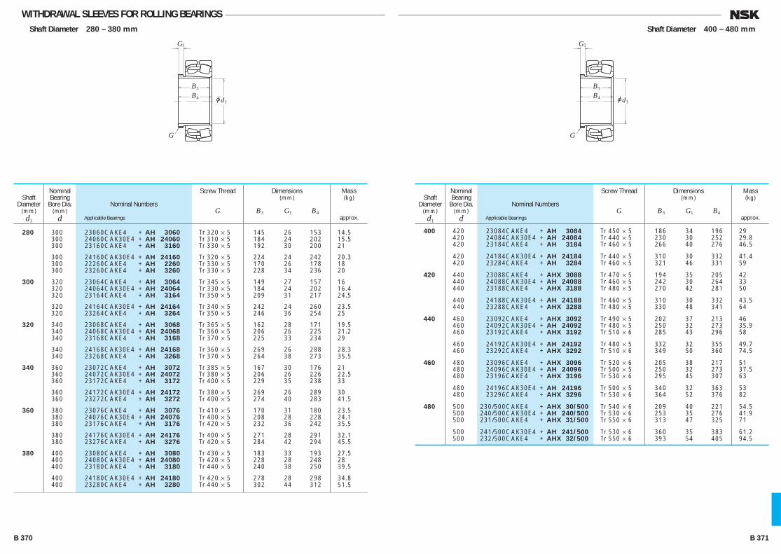
WITHDRAWAL SLEEVES FOR ROLLING BEARINGSShaft Diameter 280 – 380 mm
jd1
B3
B4
G
G1
Nominal Numbers
Applicable Bearings
Shaft Diameter
(mm)d1
Nominal Bearing
Bore Dia.(mm)
d
Dimensions(mm)
B3 G1 B4
Screw Thread
G
Mass(kg)
approx.
280 300 23060C AKE4 + AH 3060 Tr 320 × 5 145 26 153 14.5 300 24060C AK30E4 + AH 24060 Tr 310 × 5 184 24 202 15.5 300 23160C AKE4 + AH 3160 Tr 330 × 5 192 30 200 21
300 24160C AK30E4 + AH 24160 Tr 320 × 5 224 24 242 20.3 300 22260C AKE4 + AH 2260 Tr 330 × 5 170 26 178 18 300 23260C AKE4 + AH 3260 Tr 330 × 5 228 34 236 20
300 320 23064C AKE4 + AH 3064 Tr 345 × 5 149 27 157 16 320 24064C AK30E4 + AH 24064 Tr 330 × 5 184 24 202 16.4 320 23164C AKE4 + AH 3164 Tr 350 × 5 209 31 217 24.5
320 24164C AK30E4 + AH 24164 Tr 340 × 5 242 24 260 23.5 320 23264C AKE4 + AH 3264 Tr 350 × 5 246 36 254 25
320 340 23068C AKE4 + AH 3068 Tr 365 × 5 162 28 171 19.5 340 24068C AK30E4 + AH 24068 Tr 360 × 5 206 26 225 21.2 340 23168C AKE4 + AH 3168 Tr 370 × 5 225 33 234 29
340 24168C AK30E4 + AH 24168 Tr 360 × 5 269 26 288 28.3 340 23268C AKE4 + AH 3268 Tr 370 × 5 264 38 273 35.5
340 360 23072C AKE4 + AH 3072 Tr 385 × 5 167 30 176 21 360 24072C AK30E4 + AH 24072 Tr 380 × 5 206 26 226 22.5 360 23172C AKE4 + AH 3172 Tr 400 × 5 229 35 238 33
360 24172C AK30E4 + AH 24172 Tr 380 × 5 269 26 289 30 360 23272C AKE4 + AH 3272 Tr 400 × 5 274 40 283 41.5
360 380 23076C AKE4 + AH 3076 Tr 410 × 5 170 31 180 23.5 380 24076C AK30E4 + AH 24076 Tr 400 × 5 208 28 228 24.1 380 23176C AKE4 + AH 3176 Tr 420 × 5 232 36 242 35.5
380 24176C AK30E4 + AH 24176 Tr 400 × 5 271 28 291 32.1 380 23276C AKE4 + AH 3276 Tr 420 × 5 284 42 294 45.5
380 400 23080C AKE4 + AH 3080 Tr 430 × 5 183 33 193 27.5 400 24080C AK30E4 + AH 24080 Tr 420 × 5 228 28 248 28 400 23180C AKE4 + AH 3180 Tr 440 × 5 240 38 250 39.5
400 24180C AK30E4 + AH 24180 Tr 420 × 5 278 28 298 34.8 400 23280C AKE4 + AH 3280 Tr 440 × 5 302 44 312 51.5
Nominal Numbers
Applicable Bearings
Shaft Diameter
(mm)d1
Nominal Bearing
Bore Dia.(mm)
d
Dimensions(mm)
B3 G1 B4
Screw Thread
G
Mass(kg)
approx.
400 420 23084C AKE4 + AH 3084 Tr 450 × 5 186 34 196 29 420 24084C AK30E4 + AH 24084 Tr 440 × 5 230 30 252 29.8 420 23184C AKE4 + AH 3184 Tr 460 × 5 266 40 276 46.5
420 24184C AK30E4 + AH 24184 Tr 440 × 5 310 30 332 41.4 420 23284C AKE4 + AH 3284 Tr 460 × 5 321 46 331 59
420 440 23088C AKE4 + AHX 3088 Tr 470 × 5 194 35 205 42 440 24088C AK30E4 + AH 24088 Tr 460 × 5 242 30 264 33 440 23188C AKE4 + AHX 3188 Tr 480 × 5 270 42 281 50
440 24188C AK30E4 + AH 24188 Tr 460 × 5 310 30 332 43.5 440 23288C AKE4 + AHX 3288 Tr 480 × 5 330 48 341 64
440 460 23092C AKE4 + AHX 3092 Tr 490 × 5 202 37 213 46 460 24092C AK30E4 + AH 24092 Tr 480 × 5 250 32 273 35.9 460 23192C AKE4 + AHX 3192 Tr 510 × 6 285 43 296 58
460 24192C AK30E4 + AH 24192 Tr 480 × 5 332 32 355 49.7 460 23292C AKE4 + AHX 3292 Tr 510 × 6 349 50 360 74.5
460 480 23096C AKE4 + AHX 3096 Tr 520 × 6 205 38 217 51 480 24096C AK30E4 + AH 24096 Tr 500 × 5 250 32 273 37.5 480 23196C AKE4 + AHX 3196 Tr 530 × 6 295 45 307 63
480 24196C AK30E4 + AH 24196 Tr 500 × 5 340 32 363 53 480 23296C AKE4 + AHX 3296 Tr 530 × 6 364 52 376 82
480 500 230/500C AKE4 + AHX 30/500 Tr 540 × 6 209 40 221 54.5 500 240/500C AK30E4 + AH 240/500 Tr 530 × 6 253 35 276 41.9 500 231/500C AKE4 + AHX 31/500 Tr 550 × 6 313 47 325 71
500 241/500C AK30E4 + AH 241/500 Tr 530 × 6 360 35 383 61.2 500 232/500C AKE4 + AHX 32/500 Tr 550 × 6 393 54 405 94.5
Shaft Diameter 400 – 480 mm
jd1
B3
B4
G
G1
B 370 B 371
B356-379E.indd 370-371B356-379E.indd 370-371 11/20/13 5:03:07 PM11/20/13 5:03:07 PM
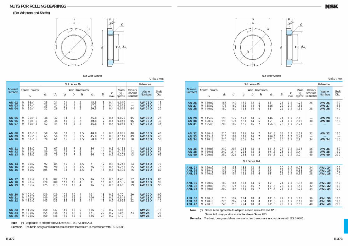
NUTS FOR ROLLING BEARINGS(For Adapters and Shafts)
gb
hr
2d3 1jdjdg
G
B30°
Nominal Numbers
Nut Series AN Reference
Screw Threads
G
Basic Dimensions r d2 d1 g b h d3 B max.
Mass(kg)
approx.
Adapter (1) Sleeve Bore
Dia. NumbersShaft Dia.
Washer Numbers
AN 02 M 15×1 25 21 21 4 2 15.5 5 0.4 0.010 — AW 02 X 15 AN 03 M 17×1 28 24 24 4 2 17.5 5 0.4 0.013 — AW 03 X 17 AN 04 M 20×1 32 26 28 4 2 20.5 6 0.4 0.019 04 AW 04 X 20
AN 05 M 25×1.5 38 32 34 5 2 25.8 7 0.4 0.025 05 AW 05 X 25 AN 06 M 30×1.5 45 38 41 5 2 30.8 7 0.4 0.043 06 AW 06 X 30 AN 07 M 35×1.5 52 44 48 5 2 35.8 8 0.4 0.053 07 AW 07 X 35
AN 08 M 40×1.5 58 50 53 6 2.5 40.8 9 0.5 0.085 08 AW 08 X 40 AN 09 M 45×1.5 65 56 60 6 2.5 45.8 10 0.5 0.119 09 AW 09 X 45 AN 10 M 50×1.5 70 61 65 6 2.5 50.8 11 0.5 0.148 10 AW 10 X 50
AN 11 M 55×2 75 67 69 7 3 56 11 0.5 0.158 11 AW 11 X 55 AN 12 M 60×2 80 73 74 7 3 61 11 0.5 0.174 12 AW 12 X 60 AN 13 M 65×2 85 79 79 7 3 66 12 0.5 0.203 13 AW 13 X 65
AN 14 M 70×2 92 85 85 8 3.5 71 12 0.5 0.242 14 AW 14 X 70 AN 15 M 75×2 98 90 91 8 3.5 76 13 0.5 0.287 15 AW 15 X 75 AN 16 M 80×2 105 95 98 8 3.5 81 15 0.6 0.395 16 AW 16 X 80
AN 17 M 85×2 110 102 103 8 3.5 86 16 0.6 0.45 17 AW 17 X 85 AN 18 M 90×2 120 108 112 10 4 91 16 0.6 0.555 18 AW 18 X 90 AN 19 M 95×2 125 113 117 10 4 96 17 0.6 0.66 19 AW 19 X 95
AN 20 M 100×2 130 120 122 10 4 101 18 0.6 0.70 20 AW 20 X 100 AN 21 M 105×2 140 126 130 12 5 106 18 0.7 0.845 21 AW 21 X 105 AN 22 M 110×2 145 133 135 12 5 111 19 0.7 0.965 22 AW 22 X 110
AN 23 M 115×2 150 137 140 12 5 116 19 0.7 1.01 — AW 23 . 115 AN 24 M 120×2 155 138 145 12 5 121 20 0.7 1.08 24 AW 24 . 120 AN 25 M 125×2 160 148 150 12 5 126 21 0.7 1.19 — AW 25 . 125
Note (1) Applicable to adapter sleeve Series A31, A2, A3, and A23.Remarks The basic design and dimensions of screw threads are in accordance with JIS B 0205.
Units : mmNut with Washer
gb
hr
2d3 1jdjdg
G
B30°
Nominal Numbers
Nut Series AN
Nut Series ANL
Reference
Screw Threads
G
Basic Dimensions r d2 d1 g b h d3 B max.
Mass(kg)
approx.
Adapter (1) Sleeve Bore
Dia. NumbersShaft Dia.
Washer Numbers
AN 26 M 130×2 165 149 155 12 5 131 21 0.7 1.25 26 AW 26 130 AN 27 M 135×2 175 160 163 14 6 136 22 0.7 1.55 — AW 27 135 AN 28 M 140×2 180 160 168 14 6 141 22 0.7 1.56 28 AW 28 140
AN 29 M 145×2 190 172 178 14 6 146 24 0.7 2.0 — AW 29 145 AN 30 M 150×2 195 171 183 14 6 151 24 0.7 2.03 30 AW 30 150 AN 31 M 155×3 200 182 186 16 7 156.5 25 0.7 2.21 — — —
AN 32 M 160×3 210 182 196 16 7 161.5 25 0.7 2.59 32 AW 32 160 AN 33 M 165×3 210 193 196 16 7 166.5 26 0.7 2.43 — — — AN 34 M 170×3 220 193 206 16 7 171.5 26 0.7 2.8 34 AW 34 170
AN 36 M 180×3 230 203 214 18 8 181.5 27 0.7 3.05 36 AW 36 180 AN 38 M 190×3 240 214 224 18 8 191.5 28 0.7 3.4 38 AW 38 190 AN 40 M 200×3 250 226 234 18 8 201.5 29 0.7 3.7 40 AW 40 200
ANL 24 M 120×2 145 133 135 12 5 121 20 0.7 0.78 24 AWL 24 120 ANL 26 M 130×2 155 143 145 12 5 131 21 0.7 0.88 26 AWL 26 130 ANL 28 M 140×2 165 151 153 14 6 141 22 0.7 0.99 28 AWL 28 140
ANL 30 M 150×2 180 164 168 14 6 151 24 0.7 1.38 30 AWL 30 150 ANL 32 M 160×3 190 174 176 16 7 161.5 25 0.7 1.56 32 AWL 32 160 ANL 34 M 170×3 200 184 186 16 7 171.5 26 0.7 1.72 34 AWL 34 170
ANL 36 M 180×3 210 192 194 18 8 181.5 27 0.7 1.95 36 AWL 36 180 ANL 38 M 190×3 220 202 204 18 8 191.5 28 0.7 2.08 38 AWL 38 190 ANL 40 M 200×3 240 218 224 18 8 201.5 29 0.7 2.98 40 AWL 40 200
Note (1) Series AN is applicable to adapter sleeve Series A31 and A23.Series ANL is applicable to adapter sleeve Series A30.
Remarks The basic design and dimensions of screw threads are in accordance with JIS B 0205.
Units : mmNut with Washer
B 372 B 373
B356-379E.indd 372-373B356-379E.indd 372-373 11/20/13 5:03:08 PM11/20/13 5:03:08 PM
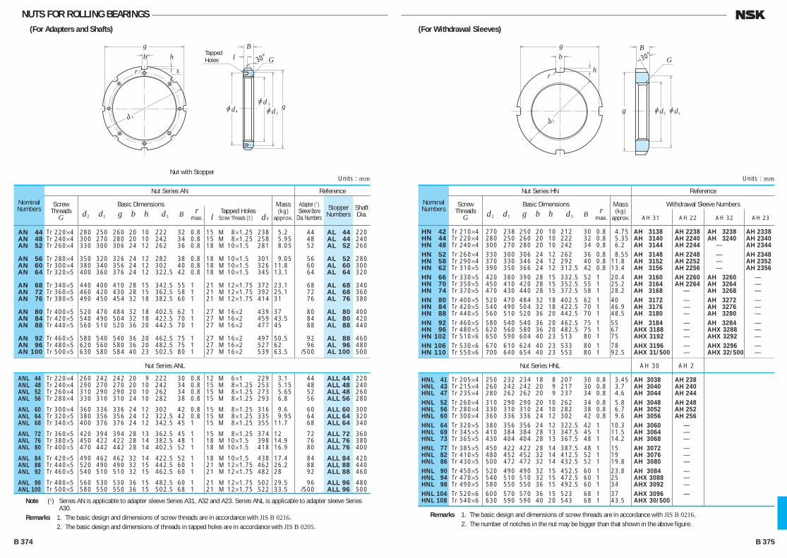
NUTS FOR ROLLING BEARINGS(For Adapters and Shafts)
gb h
sr
2d
3
1jdjd
4jd g
l G
B
30°TappedHoles
Nominal Numbers
Nut Series AN
Nut Series ANL
Reference
Screw Threads
G
Basic Dimensions r d2 d1 g b h d3 B max.
Tapped Holes l Screw Threads (S ) d4
Mass(kg)
approx.
Adapter (1) Sleeve Bore
Dia. NumbersShaft Dia.
Stopper Numbers
AN 44 Tr 220×4 280 250 260 20 10 222 32 0.8 15 M 8×1.25 238 5.2 44 AL 44 220 AN 48 Tr 240×4 300 270 280 20 10 242 34 0.8 15 M 8×1.25 258 5.95 48 AL 44 240 AN 52 Tr 260×4 330 300 306 24 12 262 36 0.8 18 M 10×1.5 281 8.05 52 AL 52 260
AN 56 Tr 280×4 350 320 326 24 12 282 38 0.8 18 M 10×1.5 301 9.05 56 AL 52 280 AN 60 Tr 300×4 380 340 356 24 12 302 40 0.8 18 M 10×1.5 326 11.8 60 AL 60 300 AN 64 Tr 320×5 400 360 376 24 12 322.5 42 0.8 18 M 10×1.5 345 13.1 64 AL 64 320
AN 68 Tr 340×5 440 400 410 28 15 342.5 55 1 21 M 12×1.75 372 23.1 68 AL 68 340 AN 72 Tr 360×5 460 420 430 28 15 362.5 58 1 21 M 12×1.75 392 25.1 72 AL 68 360 AN 76 Tr 380×5 490 450 454 32 18 382.5 60 1 21 M 12×1.75 414 31 76 AL 76 380
AN 80 Tr 400×5 520 470 484 32 18 402.5 62 1 27 M 16×2 439 37 80 AL 80 400 AN 84 Tr 420×5 540 490 504 32 18 422.5 70 1 27 M 16×2 459 43.5 84 AL 80 420 AN 88 Tr 440×5 560 510 520 36 20 442.5 70 1 27 M 16×2 477 45 88 AL 88 440
AN 92 Tr 460×5 580 540 540 36 20 462.5 75 1 27 M 16×2 497 50.5 92 AL 88 460 AN 96 Tr 480×5 620 560 580 36 20 482.5 75 1 27 M 16×2 527 62 96 AL 96 480 AN 100 Tr 500×5 630 580 584 40 23 502.5 80 1 27 M 16×2 539 63.5 /500 AL 100 500
ANL 44 Tr 220×4 260 242 242 20 9 222 30 0.8 12 M 6×1 229 3.1 44 ALL 44 220 ANL 48 Tr 240×4 290 270 270 20 10 242 34 0.8 15 M 8×1.25 253 5.15 48 ALL 48 240 ANL 52 Tr 260×4 310 290 290 20 10 262 34 0.8 15 M 8×1.25 273 5.65 52 ALL 48 260 ANL 56 Tr 280×4 330 310 310 24 10 282 38 0.8 15 M 8×1.25 293 6.8 56 ALL 56 280
ANL 60 Tr 300×4 360 336 336 24 12 302 42 0.8 15 M 8×1.25 316 9.6 60 ALL 60 300 ANL 64 Tr 320×5 380 356 356 24 12 322.5 42 0.8 15 M 8×1.25 335 9.95 64 ALL 64 320 ANL 68 Tr 340×5 400 376 376 24 12 342.5 45 1 15 M 8×1.25 355 11.7 68 ALL 64 340
ANL 72 Tr 360×5 420 394 394 28 13 362.5 45 1 15 M 8×1.25 374 12 72 ALL 72 360 ANL 76 Tr 380×5 450 422 422 28 14 382.5 48 1 18 M 10×1.5 398 14.9 76 ALL 76 380 ANL 80 Tr 400×5 470 442 442 28 14 402.5 52 1 18 M 10×1.5 418 16.9 80 ALL 76 400
ANL 84 Tr 420×5 490 462 462 32 14 422.5 52 1 18 M 10×1.5 438 17.4 84 ALL 84 420 ANL 88 Tr 440×5 520 490 490 32 15 442.5 60 1 21 M 12×1.75 462 26.2 88 ALL 88 440 ANL 92 Tr 460×5 540 510 510 32 15 462.5 60 1 21 M 12×1.75 482 28 92 ALL 88 460
ANL 96 Tr 480×5 560 530 530 36 15 482.5 60 1 21 M 12×1.75 502 29.5 96 ALL 96 480 ANL 100 Tr 500×5 580 550 550 36 15 502.5 68 1 21 M 12×1.75 522 33.5 /500 ALL 96 500
Note (1) Series AN is applicable to adapter sleeve Series A31, A32 and A23. Series ANL is applicable to adapter sleeve Series A30.
Remarks 1. The basic design and dimensions of screw threads are in accordance with JIS B 0216. 2. The basic design and dimensions of threads in tapped holes are in accordance with JIS B 0205.
Units : mmNut with Stopper
(For Withdrawal Sleeves)
gb
hr
2d3 1jdjdg
G
B30°
Nominal Numbers
Nut Series HN
Nut Series HNL
Reference
Screw Threads
G
Basic Dimensions r d2 d1 g b h d3 B max.
Mass(kg)
approx.
Withdrawal Sleeve Numbers
AH 31 AH 22 AH 32 AH 23
HN 42 Tr 210×4 270 238 250 20 10 212 30 0.8 4.75 AH 3138 AH 2238 AH 3238 AH 2338 HN 44 Tr 220×4 280 250 260 20 10 222 32 0.8 5.35 AH 3140 AH 2240 AH 3240 AH 2340 HN 48 Tr 240×4 300 270 280 20 10 242 34 0.8 6.2 AH 3144 AH 2244 — AH 2344
HN 52 Tr 260×4 330 300 306 24 12 262 36 0.8 8.55 AH 3148 AH 2248 — AH 2348 HN 58 Tr 290×4 370 330 346 24 12 292 40 0.8 11.8 AH 3152 AH 2252 — AH 2352 HN 62 Tr 310×5 390 350 366 24 12 312.5 42 0.8 13.4 AH 3156 AH 2256 — AH 2356
HN 66 Tr 330×5 420 380 390 28 15 332.5 52 1 20.4 AH 3160 AH 2260 AH 3260 — HN 70 Tr 350×5 450 410 420 28 15 352.5 55 1 25.2 AH 3164 AH 2264 AH 3264 — HN 74 Tr 370×5 470 430 440 28 15 372.5 58 1 28.2 AH 3168 — AH 3268 — HN 80 Tr 400×5 520 470 484 32 18 402.5 62 1 40 AH 3172 — AH 3272 — HN 84 Tr 420×5 540 490 504 32 18 422.5 70 1 46.9 AH 3176 — AH 3276 — HN 88 Tr 440×5 560 510 520 36 20 442.5 70 1 48.5 AH 3180 — AH 3280 — HN 92 Tr 460×5 580 540 540 36 20 462.5 75 1 55 AH 3184 — AH 3284 — HN 96 Tr 480×5 620 560 580 36 20 482.5 75 1 67 AHX 3188 — AHX 3288 — HN 102 Tr 510×6 650 590 604 40 23 513 80 1 75 AHX 3192 — AHX 3292 — HN 106 Tr 530×6 670 610 624 40 23 533 80 1 78 AHX 3196 — AHX 3296 — HN 110 Tr 550×6 700 640 654 40 23 553 80 1 92.5 AHX 31/500 — AHX 32/500 —
HNL 41 Tr 205×4 250 232 234 18 8 207 30 0.8 3.45 AH 3038 AH 238 HNL 43 Tr 215×4 260 242 242 20 9 217 30 0.8 3.7 AH 3040 AH 240 HNL 47 Tr 235×4 280 262 262 20 9 237 34 0.8 4.6 AH 3044 AH 244
HNL 52 Tr 260×4 310 290 290 20 10 262 34 0.8 5.8 AH 3048 AH 248 HNL 56 Tr 280×4 330 310 310 24 10 282 38 0.8 6.7 AH 3052 AH 252 HNL 60 Tr 300×4 360 336 336 24 12 302 42 0.8 9.6 AH 3056 AH 256
HNL 64 Tr 320×5 380 356 356 24 12 322.5 42 1 10.3 AH 3060 — HNL 69 Tr 345×5 410 384 384 28 13 347.5 45 1 11.5 AH 3064 — HNL 73 Tr 365×5 430 404 404 28 13 367.5 48 1 14.2 AH 3068 — HNL 77 Tr 385×5 450 422 422 28 14 387.5 48 1 15 AH 3072 — HNL 82 Tr 410×5 480 452 452 32 14 412.5 52 1 19 AH 3076 — HNL 86 Tr 430×5 500 472 472 32 14 432.5 52 1 19.8 AH 3080 — HNL 90 Tr 450×5 520 490 490 32 15 452.5 60 1 23.8 AH 3084 — HNL 94 Tr 470×5 540 510 510 32 15 472.5 60 1 25 AHX 3088 — HNL 98 Tr 490×5 580 550 550 36 15 492.5 60 1 34 AHX 3092 — HNL 104 Tr 520×6 600 570 570 36 15 523 68 1 37 AHX 3096 — HNL 108 Tr 540×6 630 590 590 40 20 543 68 1 43.5 AHX 30/500
AH 30 AH 2
Remarks 1. The basic design and dimensions of screw threads are in accordance with JIS B 0216. 2. The number of notches in the nut may be bigger than that shown in the above figure.
Units : mm
B 374 B 375
B356-379E.indd 374-375B356-379E.indd 374-375 11/20/13 5:03:09 PM11/20/13 5:03:09 PM
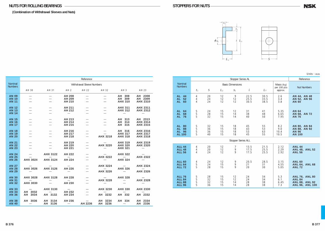
NUTS FOR ROLLING BEARINGS(Combination of Withdrawal Sleeves and Nuts)
STOPPERS FOR NUTS
Nominal Numbers
Reference
Withdrawal Sleeve Numbers
AH 30 AH 31 AH 2 AH 22 AH 32 AH 3 AH 23
AN 09 — — AH 208 — — AH 308 AH 2308 AN 10 — — AH 209 — — AH 309 AH 2309 AN 11 — — AH 210 — — AHX 310 AHX 2310
AN 12 — — AH 211 — — AHX 311 AHX 2311 AN 13 — — AH 212 — — AHX 312 AHX 2312 AN 14 — — — — — — —
AN 15 — — AH 213 — — AH 313 AH 2313 AN 16 — — AH 214 — — AH 314 AHX 2314 AN 17 — — AH 215 — — AH 315 AHX 2315
AN 18 — — AH 216 — — AH 316 AHX 2316 AN 19 — — AH 217 — — AHX 317 AHX 2317 AN 20 — — AH 218 — AHX 3218 AHX 318 AHX 2318
AN 21 — — AH 219 — — AHX 319 AHX 2319 AN 22 — — AH 220 — AHX 3220 AHX 320 AHX 2320 AN 23 — — AH 221 — — AHX 321 —
AN 24 — AHX 3122 AH 222 — — AHX 322 — AN 25 — — — — AHX 3222 — AHX 2322 AN 26 AHX 3024 AHX 3124 AH 224 — — AHX 324 —
AN 27 — — — — AHX 3224 — AHX 2324 AN 28 AHX 3026 AHX 3126 AH 226 — — AHX 326 — AN 29 — — — — AHX 3226 — AHX 2326
AN 30 AHX 3028 AHX 3128 AH 228 — — AHX 328 — AN 31 — — — — AHX 3228 — AHX 2328 AN 32 AHX 3030 — AH 230 — — — —
AN 33 — AHX 3130 — — AHX 3230 AHX 330 AHX 2330 AN 34 AH 3032 — AH 232 — — — — AN 36 AH 3034 AH 3132 AH 234 — AH 3232 AH 332 AH 2332
AN 38 AH 3036 AH 3134 AH 236 — AH 3234 AH 334 AH 2334 AN 40 — AH 3136 — AH 2236 AH 3236 — AH 2336
Nominal Numbers
Stopper Series AL
Stopper Series ALL
Reference
Basic Dimensions
t1 S L2 s1 i L3
Mass (kg)per 100 pcs
approx.Nut Numbers
AL 44 4 20 12 9 22.5 30.5 2.6 AN 44, AN 48 AL 52 4 24 12 12 25.5 33.5 3.4 AN 52, AN 56 AL 60 4 24 12 12 30.5 38.5 3.8 AN 60
AL 64 5 24 15 12 31 41 5.35 AN 64 AL 68 5 28 15 14 38 48 6.65 AN 68, AN 72 AL 76 5 32 15 14 40 50 7.95 AN 76
AL 80 5 32 15 18 45 55 8.2 AN 80, AN 84 AL 88 5 36 15 18 43 53 9.0 AN 88, AN 92 AL 96 5 36 15 18 53 63 10.4 AN 96 AL 100 5 40 15 18 45 55 10.5 AN 100
ALL 44 4 20 12 7 13.5 21.5 2.12 ANL 44 ALL 48 4 20 12 9 17.5 25.5 2.29 ANL 48, ANL 52 ALL 56 4 24 12 9 17.5 25.5 2.92 ANL 56
ALL 60 4 24 12 9 20.5 28.5 3.15 ANL 60 ALL 64 5 24 15 9 21 31 4.55 ANL 64, ANL 68 ALL 72 5 28 15 9 20 30 5.05 ANL 72
ALL 76 5 28 15 12 24 34 5.3 ANL 76, ANL 80 ALL 84 5 32 15 12 24 34 6.1 ANL 84 ALL 88 5 32 15 14 28 38 6.45 ANL 88, ANL 92 ALL 96 5 36 15 14 28 38 7.3 ANL 96, ANL 100
Units : mm
1 3L
2L S
1t
1t
ijs
B 376 B 377
B356-379E.indd 376-377B356-379E.indd 376-377 11/20/13 5:03:11 PM11/20/13 5:03:11 PM
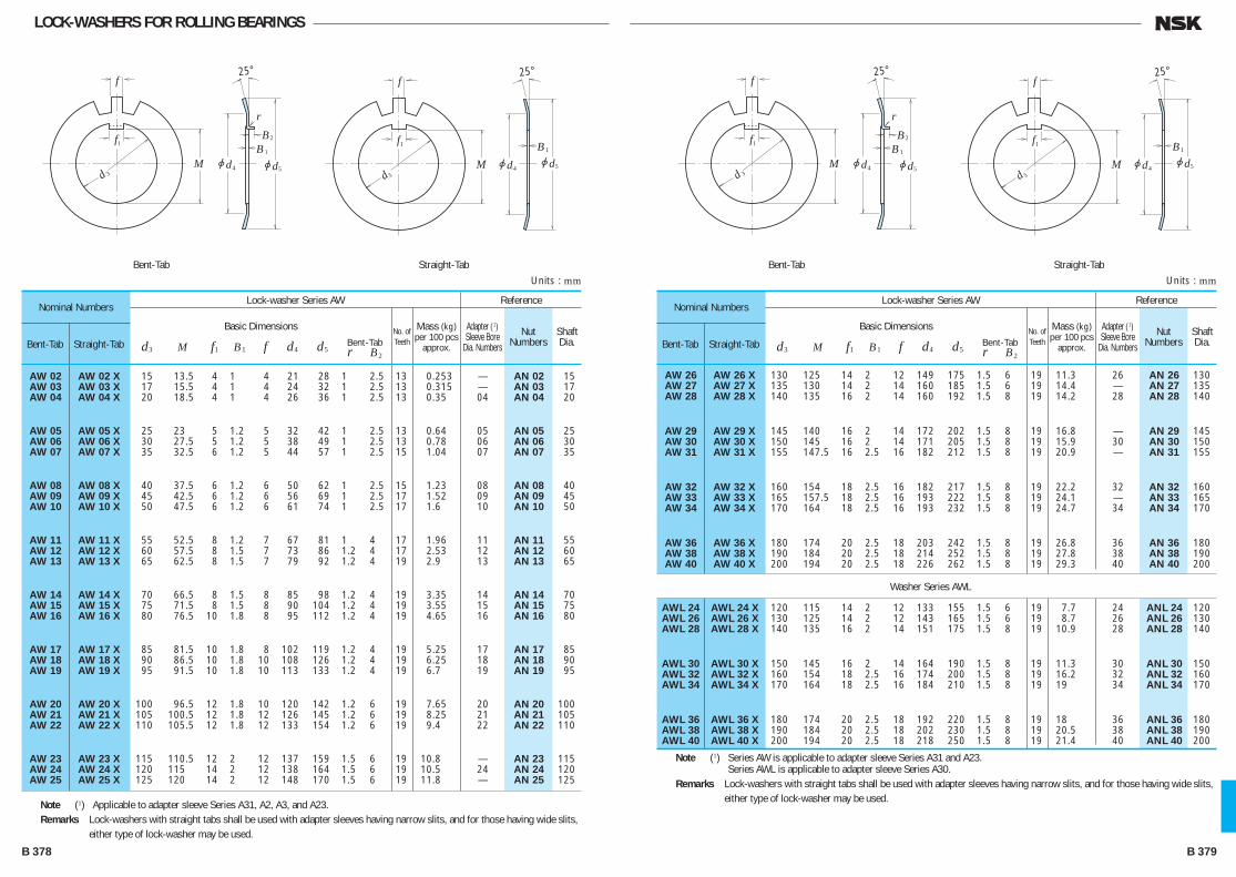
LOCK-WASHERS FOR ROLLING BEARINGS
f
f
r
3d
1
4jd 5
2
jdM
B1B
25°
f
f
3d
1
4jd 5jdM1B
25°
Nominal Numbers
Bent-Tab Straight-Tab
Lock-washer Series AW Reference
Basic Dimensions
d3 M f1 B1 f d4 d5 Bent-Tab
r B2
Mass (kg)per 100 pcs
approx.
Adapter (1) Sleeve Bore
Dia. NumbersShaft Dia.
No. of Teeth
Nut Numbers
AW 02 AW 02 X 15 13.5 4 1 4 21 28 1 2.5 13 0.253 — AN 02 15 AW 03 AW 03 X 17 15.5 4 1 4 24 32 1 2.5 13 0.315 — AN 03 17 AW 04 AW 04 X 20 18.5 4 1 4 26 36 1 2.5 13 0.35 04 AN 04 20
AW 05 AW 05 X 25 23 5 1.2 5 32 42 1 2.5 13 0.64 05 AN 05 25 AW 06 AW 06 X 30 27.5 5 1.2 5 38 49 1 2.5 13 0.78 06 AN 06 30 AW 07 AW 07 X 35 32.5 6 1.2 5 44 57 1 2.5 15 1.04 07 AN 07 35
AW 08 AW 08 X 40 37.5 6 1.2 6 50 62 1 2.5 15 1.23 08 AN 08 40 AW 09 AW 09 X 45 42.5 6 1.2 6 56 69 1 2.5 17 1.52 09 AN 09 45 AW 10 AW 10 X 50 47.5 6 1.2 6 61 74 1 2.5 17 1.6 10 AN 10 50
AW 11 AW 11 X 55 52.5 8 1.2 7 67 81 1 4 17 1.96 11 AN 11 55 AW 12 AW 12 X 60 57.5 8 1.5 7 73 86 1.2 4 17 2.53 12 AN 12 60 AW 13 AW 13 X 65 62.5 8 1.5 7 79 92 1.2 4 19 2.9 13 AN 13 65
AW 14 AW 14 X 70 66.5 8 1.5 8 85 98 1.2 4 19 3.35 14 AN 14 70 AW 15 AW 15 X 75 71.5 8 1.5 8 90 104 1.2 4 19 3.55 15 AN 15 75 AW 16 AW 16 X 80 76.5 10 1.8 8 95 112 1.2 4 19 4.65 16 AN 16 80
AW 17 AW 17 X 85 81.5 10 1.8 8 102 119 1.2 4 19 5.25 17 AN 17 85 AW 18 AW 18 X 90 86.5 10 1.8 10 108 126 1.2 4 19 6.25 18 AN 18 90 AW 19 AW 19 X 95 91.5 10 1.8 10 113 133 1.2 4 19 6.7 19 AN 19 95
AW 20 AW 20 X 100 96.5 12 1.8 10 120 142 1.2 6 19 7.65 20 AN 20 100 AW 21 AW 21 X 105 100.5 12 1.8 12 126 145 1.2 6 19 8.25 21 AN 21 105 AW 22 AW 22 X 110 105.5 12 1.8 12 133 154 1.2 6 19 9.4 22 AN 22 110
AW 23 AW 23 X 115 110.5 12 2 12 137 159 1.5 6 19 10.8 — AN 23 115 AW 24 AW 24 X 120 115 14 2 12 138 164 1.5 6 19 10.5 24 AN 24 120 AW 25 AW 25 X 125 120 14 2 12 148 170 1.5 6 19 11.8 — AN 25 125
Note (1) Applicable to adapter sleeve Series A31, A2, A3, and A23.Remarks Lock-washers with straight tabs shall be used with adapter sleeves having narrow slits, and for those having wide slits,
either type of lock-washer may be used.
Units : mmBent-Tab Straight-Tab
f
f
r
3d
1
4jd 5
2
jdM
B1B
25°
f
f
3d
1
4jd 5jdM1B
25°
Bent-Tab Straight-Tab
Nominal Numbers
Bent-Tab Straight-Tab
Lock-washer Series AW
Washer Series AWL
Reference
Basic Dimensions
d3 M f1 B1 f d4 d5 Bent-Tab
r B2
Mass (kg)per 100 pcs
approx.
Adapter (1) Sleeve Bore
Dia. NumbersShaft Dia.
No. of Teeth
Nut Numbers
AW 26 AW 26 X 130 125 14 2 12 149 175 1.5 6 19 11.3 26 AN 26 130 AW 27 AW 27 X 135 130 14 2 14 160 185 1.5 6 19 14.4 — AN 27 135 AW 28 AW 28 X 140 135 16 2 14 160 192 1.5 8 19 14.2 28 AN 28 140
AW 29 AW 29 X 145 140 16 2 14 172 202 1.5 8 19 16.8 — AN 29 145 AW 30 AW 30 X 150 145 16 2 14 171 205 1.5 8 19 15.9 30 AN 30 150 AW 31 AW 31 X 155 147.5 16 2.5 16 182 212 1.5 8 19 20.9 — AN 31 155
AW 32 AW 32 X 160 154 18 2.5 16 182 217 1.5 8 19 22.2 32 AN 32 160 AW 33 AW 33 X 165 157.5 18 2.5 16 193 222 1.5 8 19 24.1 — AN 33 165 AW 34 AW 34 X 170 164 18 2.5 16 193 232 1.5 8 19 24.7 34 AN 34 170
AW 36 AW 36 X 180 174 20 2.5 18 203 242 1.5 8 19 26.8 36 AN 36 180 AW 38 AW 38 X 190 184 20 2.5 18 214 252 1.5 8 19 27.8 38 AN 38 190 AW 40 AW 40 X 200 194 20 2.5 18 226 262 1.5 8 19 29.3 40 AN 40 200
AWL 24 AWL 24 X 120 115 14 2 12 133 155 1.5 6 19 7.7 24 ANL 24 120 AWL 26 AWL 26 X 130 125 14 2 12 143 165 1.5 6 19 8.7 26 ANL 26 130 AWL 28 AWL 28 X 140 135 16 2 14 151 175 1.5 8 19 10.9 28 ANL 28 140
AWL 30 AWL 30 X 150 145 16 2 14 164 190 1.5 8 19 11.3 30 ANL 30 150 AWL 32 AWL 32 X 160 154 18 2.5 16 174 200 1.5 8 19 16.2 32 ANL 32 160 AWL 34 AWL 34 X 170 164 18 2.5 16 184 210 1.5 8 19 19 34 ANL 34 170
AWL 36 AWL 36 X 180 174 20 2.5 18 192 220 1.5 8 19 18 36 ANL 36 180 AWL 38 AWL 38 X 190 184 20 2.5 18 202 230 1.5 8 19 20.5 38 ANL 38 190 AWL 40 AWL 40 X 200 194 20 2.5 18 218 250 1.5 8 19 21.4 40 ANL 40 200
Note (1) Series AW is applicable to adapter sleeve Series A31 and A23.Series AWL is applicable to adapter sleeve Series A30.
Remarks Lock-washers with straight tabs shall be used with adapter sleeves having narrow slits, and for those having wide slits, either type of lock-washer may be used.
Units : mm
B 378 B 379
B356-379E.indd 378-379B356-379E.indd 378-379 11/20/13 5:03:11 PM11/20/13 5:03:11 PM
INTRODUCTION OF NSK PRODUCTS·APPENDICES
INTRODUCTION OF NSK PRODUCTSPage
Photos of NSK Products ·························································································C 2
APPENDICES
Appendix Table 1 Conversion from SI (International Units) System ·····················C 8
Appendix Table 2 N—kgf Force Conversion Table ················································· C10
Appendix Table 3 kg—lb Mass Conversion Table ·················································· C11
Appendix Table 4 °C—°F Temperature Conversion Table ····································· C12
Appendix Table 5 Viscosity Conversion Table ······················································· C13
Appendix Table 6 inch—mm Dimension Conversion Table ··································· C14
Appendix Table 7 Hardness Conversion Table ······················································ C16
Appendix Table 8 Physical and Mechanical Properties of Materials ···················· C17
Appendix Table 9 Tolerances for Shaft Diameters ················································ C18
Appendix Table 10 Tolerances for Housing Bore Diameters ··································· C20
Appendix Table 11 Values of Standard Tolerance Grades IT ·································· C22
Appendix Table 12 Speed Factor fn ········································································· C24
Appendix Table 13 Fatigue Life Factor fh and Fatigue Life L · Lh ························· C25
Appendix Table 14 Index of Inch Design Tapered Roller Bearings ························· C26
C 1
C001-034E.indd 1 C001-034E.indd 1 11/20/13 5:03:32 PM11/20/13 5:03:32 PM

AUTOMOTIVE PRODUCTS PRECISION MACHINE COMPONENTS
BALL SCREWS
Column Type Electric Power Steering(CAT.No. E4102)
Pinion Type Electric Power Steering(CAT.No. E4102)
Offeet Ball Screw Type Electric Power Steering(CAT.No. E4102)
Long Life Water Pump Bearings(CAT.No. E396, E4102)
Hub Unit Bearings(CAT.No. E4201)
One-Way Clutch
MONOCARRIERS
Ball Screws for Twin-Drive SystemsTW Series
(CAT. No. E3162)
Ball Screws, NSK Linear Guides with E-DFO Thin-Film Lubrication for
Vacuum Environments(CAT. No. E1258)
Highly Dust-Resistant Ball Screws, NSK Linear Guides
V1 Series(CAT. No. E3162)
NSK Standard Ball ScrewsCompact FA Series
(CAT. No. E3239, E3162)
High-Speed, Low-Noise Ball ScrewsBSS Series
(CAT. No. E3162)
Ball Screws for High-Speed Machine ToolsHMD Series
(CAT. No. E3162)
Ball Screws for High-Load DriveHTF-SRC Series, HTF-SRD Series,
HTF Series, A1 Series(CAT. No. E3238, E3162)
Monocarriers(CAT. No. E3419, E3162)
Ball Screws, NSK Linear Guides with NSK K1™ Lubrication Unit(CAT. No. E3331, E3162)
Toughcarrier(CAT. No. E3421)
NSK Standard Ball ScrewsHigh Speed SS Series
(CAT.No.E3241)
C 2 C 3
C001-034E.indd 2-3 C001-034E.indd 2-3 11/20/13 5:03:33 PM11/20/13 5:03:33 PM

PRECISION MACHINE COMPONENTS PRECISION MACHINE COMPONENTS
LINEAR BEARINGS MECHATRONIC ACTUATORS
High Speed Integrated Motor Spindles
Standard Type Precision Boring Heads
(CAT.No. E2202)
Spindles for Electrical and Electric Equipment
Precision Grinding Spindles
(CAT.No. E2202)
Oil/Air Lubricating Unit, Fine Lube
(CAT.No. E1254/A1387)
Live Centers (CAT.No. E2202)
ASSORTED SPINDLES
NSK Linear GuidesHigh-Accuracy Series
(CAT. No. E3329, E3162)
NSK Linear GuidesLH Series, LS Series
(CAT. No. E3162)
NSK Linear GuidesTS Series
(CAT. No. E3324, E3162)
NSK Linear Guides Miniature PU Series, PE Series
(CAT. No. E3327, E3162)
NSK Linear GuidesRoller Guides RA Series(CAT. No. E3328, E3162)
NSK Low-Noise Linear GuidesSH Series, SS Series
(CAT. No. E3162)
Megatorque Motor™ (CAT.No. E3511)
Megapositioner™
XY Modules
Positioning Actuator™
XY Tables
Air Bearing Slides
C 4 C 5
C001-034E.indd 4-5 C001-034E.indd 4-5 11/20/13 5:03:45 PM11/20/13 5:03:45 PM

Extra Small Bearing Monitor NB-4
(Bearing Abnormality Detector) (CAT.No. E410)
Air Cleaner Unit
AIR SPINDLES RELATED PRODUCT WITH BEARING
Large Size Proximity Stepper RZ Series
Bearing Induction Heater (CAT.No. E398)
Air-spindle
C 6 C 7
C001-034E.indd 6-7 C001-034E.indd 6-7 11/20/13 5:03:52 PM11/20/13 5:03:52 PM
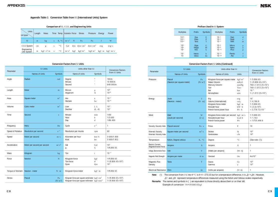
APPENDICES
Note (1) The conversion from TK into θ °C is θ =T—273.15 but for a temperature difference, it is &T =&θ . However,&T and &θ represent temperature differences measured using the Kelvin and Celsius scales respectively.
Remarks The names and symbols in ( ) are equivalent to those directly above them or on their left. Example of conversion 1N=1/9.806 65kgf
Appendix Table 1 Conversion Table from SI (International Units) System
Comparison of SI, CGS, and Engineering Units
Units Length Mass Time Temp. Acceleration Force Stress Pressure Energy Power
Unit System
SI m kg s K, °C m/s2 N Pa Pa J W
CGS System cm g s °C Gal dyn dyn/cm2 dyn/cm2 erg erg/s
m kgf · s2/m s °C m/s2 kgf kgf/m2 kgf/m2 kgf · m kgf · m/s
Conversion Factors from SI Units
SI Units Units other than SI Parameter Conversion Factors
Names of Units Symbols Name of Units Symbols from SI Units
Angle Radian rad Degree ° 180/π Minute ´ 10 800/π Second ˝ 648 000/π Length Meter m Micron μ 106
Angstrom Å 1010
Area Square meter m2 Are a 10—2
Hectare ha 10—4
Volume Cubic meter m3 Liter l, L 103
Deciliter dl, dL 104
Time Second s Minute min 1/60 Hour h 1/3 600 Day d 1/86 400 Frequency Hertz Hz Cycle s—1 1 Speed of Rotation Revolution per second s—1 Revolution per miunte rpm 60 Speed Meter per second m/s Kilometer per hour km/h 3 600/1 000 Knot kn 3 600/1 852 Acceleration Meter per second per second m/s2 Gal Gal 102
g G 1/9.806 65 Mass Kilogram kg Ton t 10—3
Force Newton N Kilogram-force kgf 1/9.806 65 Ton-force tf 1/ (9.806 65×103) Dyne dyn 105
Torque or Moment Newton · meter N · m Kilogram-force meter kgf · m 1/9.806 65
Stress Pascal Pa Kilogram-force per square centimeter kgf/cm2 1/ (9.806 65×104) (N/m2) Kilogram-force per square millimeter kgf/mm2 1/ (9.806 65×106)
Prefixes Used In SI System
Multiples Prefix Symbols Multiples Prefix Symbols
1018 Exa E 10—1 Deci d 1015 Peta P 10—2 Centi c 1012 Tera T 10—3 Milli m
109 Giga G 10—6 Micro μ 106 Mega M 10—9 Nano n 103 Kilo k 10—12 Pico p
102 Hecto h 10—15 Femto f 10 Deca da 10—18 Ato a
Conversion Factors from SI Units (Continued)
SI Units Units other than SI Parameter Conversion Factors
Names of Units Symbols Names of Units Units from SI Units
Pressure Pascal Pa Kilogram-force per square meter kgf/m2 1/9.806 65 (Newton per square meter) (N/m2) Water Column mH2O 1/(9.806 65×103) Mercury Column mmHg 760/(1.013 25×105) Torr Torr 760/(1.013 25×105) Bar bar 10—5
Atmosphere atm 1/(1.013 25×105)
Energy Joule J Erg erg 107
(Newton · meter) (N · m) Calorie (International) calIT 1/4.186 8 Kilogram-force meter kgf · m 1/9.806 65 Kilowatt hour kW · h 1/(3.6×106) French horse power hour PS · h ≈ 3.776 72×10—7
Work Watt W Kilogram-force meter per second kgf · m/s 1/9.806 65 (Joule per second) (J/s) Kilocalorie per hour kcal/h 1/1.163 French horse power PS ≈ 1/735.498 8
Viscosity, Viscosity Index Pascal second Pa · s Poise P 10
Kinematic Viscosity, Square meter per second m2/s Stokes St 104
Kinematic Viscosity Index Centistokes cSt 106
Temperature Kelvin, Degree celsius K, °C Degree °C (See note (1))
Ampere A Ampere A 1
Voltage, Electromotive Force Volt V (Watts per ampere) (W/A) 1
Magnetic Field Strength Ampere per meter A/m Oersted Oe 4π/103
Magnetic Flux Tesla T Gauss Gs 104
Density Gamma γ 109
Electrical Resistance Ohm Ω (Volts per ampere) (V/A) 1
Engineering Unit System
Electric Current, Magnetomotive Force
C 8 C 9
C001-034E.indd 8-9 C001-034E.indd 8-9 11/20/13 5:03:53 PM11/20/13 5:03:53 PM
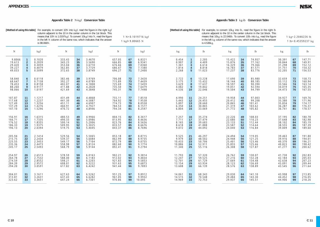
APPENDICES
Appendix Table 2 N-kgf Conversion Table
[Method of using this table] For example, to convert 10N into kgf, read the figure in the right kgf column adjacent to the 10 in the center column in the 1st block. This means that 10N is 1.0197kgf. To convert 10kgf into N, read the figure in the left N column of the same row, which indicates that the answer is 98.066N.
1 N=0.1019716 kgf
1 kgf=9.80665 N
Appendix Table 3 kg-lb Conversion Table
[Method of using this table] For example, to convert 10kg into lb, read the figure in the right lb column adjacent to the 10 in the center column in the 1st block. This means that 10kg is 22.046lb. To convert 10lb into kg, read the figure in the left kg column of the same row, which indicates that the answer is 4.536kg.
1 kg=2.2046226 lb
1 lb=0.45359237 kg
N kgf
9.8066 1 0.1020 19.613 2 0.2039 29.420 3 0.3059 39.227 4 0.4079 49.033 5 0.5099
58.840 6 0.6118 68.647 7 0.7138 78.453 8 0.8158 88.260 9 0.9177 98.066 10 1.0197
107.87 11 1.1217 117.68 12 1.2237 127.49 13 1.3256 137.29 14 1.4276 147.10 15 1.5296
156.91 16 1.6315 166.71 17 1.7335 176.52 18 1.8355 186.33 19 1.9375 196.13 20 2.0394
205.94 21 2.1414 215.75 22 2.2434 225.55 23 2.3453 235.36 24 2.4473 245.17 25 2.5493
254.97 26 2.6513 264.78 27 2.7532 274.59 28 2.8552 284.39 29 2.9572 294.20 30 3.0591
304.01 31 3.1611 313.81 32 3.2631 323.62 33 3.3651
N kgf
657.05 67 6.8321 666.85 68 6.9341 676.66 69 7.0360 686.47 70 7.1380 696.27 71 7.2400
706.08 72 7.3420 715.89 73 7.4439 725.69 74 7.5459 735.50 75 7.6479 745.31 76 7.7498
755.11 77 7.8518 764.92 78 7.9538 774.73 79 8.0558 784.53 80 8.1577 794.34 81 8.2597
804.15 82 8.3617 813.95 83 8.4636 823.76 84 8.5656 833.57 85 8.6676 843.37 86 8.7696
853.18 87 8.8715 862.99 88 8.9735 872.79 89 9.0755 882.60 90 9.1774 892.41 91 9.2794
902.21 92 9.3814 912.02 93 9.4834 921.83 94 9.5853 931.63 95 9.6873 941.44 96 9.7893
951.25 97 9.8912 961.05 98 9.9932 970.86 99 10.095
N kgf
333.43 34 3.4670 343.23 35 3.5690 353.04 36 3.6710 362.85 37 3.7729 372.65 38 3.8749
382.46 39 3.9769 392.27 40 4.0789 402.07 41 4.1808 411.88 42 4.2828 421.69 43 4.3848
431.49 44 4.4868 441.30 45 4.5887 451.11 46 4.6907 460.91 47 4.7927 470.72 48 4.8946
480.53 49 4.9966 490.33 50 5.0986 500.14 51 5.2006 509.95 52 5.3025 519.75 53 5.4045
529.56 54 5.5065 539.37 55 5.6084 549.17 56 5.7104 558.98 57 5.8124 568.79 58 5.9144
578.59 59 6.0163 588.40 60 6.1183 598.21 61 6.2203 608.01 62 6.3222 617.82 63 6.4242
627.63 64 6.5262 637.43 65 6.6282 647.24 66 6.7301
kg lb
0.454 1 2.205 0.907 2 4.409 1.361 3 6.614 1.814 4 8.818 2.268 5 11.023
2.722 6 13.228 3.175 7 15.432 3.629 8 17.637 4.082 9 19.842 4.536 10 22.046
4.990 11 24.251 5.443 12 26.455 5.897 13 28.660 6.350 14 30.865 6.804 15 33.069
7.257 16 35.274 7.711 17 37.479 8.165 18 39.683 8.618 19 41.888 9.072 20 44.092
9.525 21 46.297 9.979 22 48.502 10.433 23 50.706 10.886 24 52.911 11.340 25 55.116
11.793 26 57.320 12.247 27 59.525 12.701 28 61.729 13.154 29 63.934 13.608 30 66.139
14.061 31 68.343 14.515 32 70.548 14.969 33 72.753
kg lb
30.391 67 147.71 30.844 68 149.91 31.298 69 152.12 31.751 70 154.32 32.205 71 156.53
32.659 72 158.73 33.112 73 160.94 33.566 74 163.14 34.019 75 165.35 34.473 76 167.55
34.927 77 169.76 35.380 78 171.96 35.834 79 174.17 36.287 80 176.37 36.741 81 178.57
37.195 82 180.78 37.648 83 182.98 38.102 84 185.19 38.555 85 187.39 39.009 86 189.60
39.463 87 191.80 39.916 88 194.01 40.370 89 196.21 40.823 90 198.42 41.277 91 200.62
41.730 92 202.83 42.184 93 205.03 42.638 94 207.23 43.091 95 209.44 43.545 96 211.64
43.998 97 213.85 44.452 98 216.05 44.906 99 218.26
kg lb
15.422 34 74.957 15.876 35 77.162 16.329 36 79.366 16.783 37 81.571 17.237 38 83.776
17.690 39 85.980 18.144 40 88.185 18.597 41 90.390 19.051 42 92.594 19.504 43 94.799
19.958 44 97.003 20.412 45 99.208 20.865 46 101.41 21.319 47 103.62 21.772 48 105.82
22.226 49 108.03 22.680 50 110.23 23.133 51 112.44 23.587 52 114.64 24.040 53 116.84
24.494 54 119.05 24.948 55 121.25 25.401 56 123.46 25.855 57 125.66 26.308 58 127.87
26.762 59 130.07 27.216 60 132.28 27.669 61 134.48 28.123 62 136.69 28.576 63 138.89
29.030 64 141.10 29.484 65 143.30 29.937 66 145.51
C 10 C 11
C001-034E.indd 10-11 C001-034E.indd 10-11 11/20/13 5:03:54 PM11/20/13 5:03:54 PM

APPENDICES
Appendix Table 4 °C-°F Conversion Table Appendix Table 5 Viscosity Conversion Table
[Method of using this table] For example, to convert 38°C into °F, read the figure in the right °F column adjacent to the 38 in the center column in the 2nd block. This means that 38°C is 100.4°F. To convert 38°F into °C, read the figure in the left °C column of the same row, which indicates that the answer is 3.3°C.
C= 59
(F—32)
F=32+ 95
C
°C °F
—73.3 —100 —148.0 —62.2 — 80 —112.0 —51.1 — 60 — 76.0 —40.0 — 40 — 40.0 —34.4 — 30 — 22.0
—28.9 — 20 — 4.0 —23.3 — 10 14.0 —17.8 0 32.0 —17.2 1 33.8 —16.7 2 35.6
—16.1 3 37.4 —15.6 4 39.2 —15.0 5 41.0 —14.4 6 42.8 —13.9 7 44.6
—13.3 8 46.4 —12.8 9 48.2 —12.2 10 50.0 —11.7 11 51.8 —11.1 12 53.6
—10.6 13 55.4 —10.0 14 57.2 — 9.4 15 59.0 — 8.9 16 60.8 — 8.3 17 62.6
— 7.8 18 64.4 — 7.2 19 66.2 — 6.7 20 68.0 — 6.1 21 69.8 — 5.6 22 71.6
— 5.0 23 73.4 — 4.4 24 75.2 — 3.9 25 77.0 — 3.3 26 78.8 — 2.8 27 80.6
— 2.2 28 82.4 — 1.7 29 84.2 — 1.1 30 86.0 — 0.6 31 87.8
°C °F
0.0 32 89.6 0.6 33 91.4 1.1 34 93.2 1.7 35 95.0 2.2 36 96.8
2.8 37 98.6 3.3 38 100.4 3.9 39 102.2 4.4 40 104.0 5.0 41 105.8
5.6 42 107.6 6.1 43 109.4 6.7 44 111.2 7.2 45 113.0 7.8 46 114.8
8.3 47 116.6 8.9 48 118.4 9.4 49 120.2 10.0 50 122.0 10.6 51 123.8
11.1 52 125.6 11.7 53 127.4 12.2 54 129.2 12.8 55 131.0 13.3 56 132.8
13.9 57 134.6 14.4 58 136.4 15.0 59 138.2 15.6 60 140.0 16.1 61 141.8
16.7 62 143.6 17.2 63 145.4 17.8 64 147.2 18.3 65 149.0 18.9 66 150.8
19.4 67 152.6 20.0 68 154.4 20.6 69 156.2 21.1 70 158.0
°C °F
21.7 71 159.8 22.2 72 161.6 22.8 73 163.4 23.3 74 165.2 23.9 75 167.0
24.4 76 168.8 25.0 77 170.6 25.6 78 172.4 26.1 79 174.2 26.7 80 176.0
27.2 81 177.8 27.8 82 179.6 28.3 83 181.4 28.9 84 183.2 29.4 85 185.0
30.0 86 186.8 30.6 87 188.6 31.1 88 190.4 31.7 89 192.2 32.2 90 194.0
32.8 91 195.8 33.3 92 197.6 33.9 93 199.4 34.4 94 201.2 35.0 95 203.0
35.6 96 204.8 36.1 97 206.6 36.7 98 208.4 37.2 99 210.2 37.8 100 212.0
38.3 101 213.8 38.9 102 215.6 39.4 103 217.4 40.0 104 219.2 40.6 105 221.0
41.1 106 222.8 41.7 107 224.6 42.2 108 226.4 42.8 109 228.2
°C °F
43.3 110 230 46.1 115 239 48.9 120 248 51.7 125 257 54.4 130 266
57.2 135 275 60.0 140 284 65.6 150 302 71.1 160 320 76.7 170 338
82.2 180 356 87.8 190 374 93.3 200 392 98.9 210 410 104.4 220 428
110.0 230 446 115.6 240 464 121.1 250 482 148.9 300 572 176.7 350 662
204 400 752 232 450 842 260 500 932 288 550 1022 316 600 1112
343 650 1202 371 700 1292 399 750 1382 427 800 1472 454 850 1562
482 900 1652 510 950 1742 538 1000 1832 593 1100 2012 649 1200 2192
704 1300 2372 760 1400 2552 816 1500 2732 871 1600 2912
Saybolt No.1 Type Kinematic Universal Redwood Engler Viscosity SUS (sec) R (sec) E (degree) mm2/s 100°F 210°F 50°C 100°C
2 32.6 32.8 30.8 31.2 1.14 3 36.0 36.3 33.3 33.7 1.22 4 39.1 39.4 35.9 36.5 1.31 5 42.3 42.6 38.5 39.1 1.40 6 45.5 45.8 41.1 41.7 1.48
7 48.7 49.0 43.7 44.3 1.56 8 52.0 52.4 46.3 47.0 1.65 9 55.4 55.8 49.1 50.0 1.75 10 58.8 59.2 52.1 52.9 1.84 11 62.3 62.7 55.1 56.0 1.93
12 65.9 66.4 58.2 59.1 2.02 13 69.6 70.1 61.4 62.3 2.12 14 73.4 73.9 64.7 65.6 2.22 15 77.2 77.7 68.0 69.1 2.32 16 81.1 81.7 71.5 72.6 2.43
17 85.1 85.7 75.0 76.1 2.54 18 89.2 89.8 78.6 79.7 2.64 19 93.3 94.0 82.1 83.6 2.76 20 97.5 98.2 85.8 87.4 2.87 21 102 102 89.5 91.3 2.98
22 106 107 93.3 95.1 3.10 23 110 111 97.1 98.9 3.22 24 115 115 101 103 3.34 25 119 120 105 107 3.46 26 123 124 109 111 3.58
27 128 129 112 115 3.70 28 132 133 116 119 3.82 29 137 138 120 123 3.95 30 141 142 124 127 4.07 31 145 146 128 131 4.20
32 150 150 132 135 4.32 33 154 155 136 139 4.45 34 159 160 140 143 4.57
Saybolt No.1 Type Kinematic Universal Redwood Engler Viscosity SUS (sec) R (sec) E (degree) mm2/s 100°F 210°F 50°C 100°C
35 163 164 144 147 4.70 36 168 170 148 151 4.83 37 172 173 153 155 4.96 38 177 178 156 159 5.08 39 181 183 160 164 5.21
40 186 187 164 168 5.34 41 190 192 168 172 5.47 42 195 196 172 176 5.59 43 199 201 176 180 5.72 44 204 205 180 185 5.85
45 208 210 184 189 5.98 46 213 215 188 193 6.11 47 218 219 193 197 6.24 48 222 224 197 202 6.37 49 227 228 201 206 6.50
50 231 233 205 210 6.63 55 254 256 225 231 7.24 60 277 279 245 252 7.90 65 300 302 266 273 8.55 70 323 326 286 294 9.21
75 346 349 306 315 9.89 80 371 373 326 336 10.5 85 394 397 347 357 11.2 90 417 420 367 378 11.8 95 440 443 387 399 12.5
100 464 467 408 420 13.2 120 556 560 490 504 15.8 140 649 653 571 588 18.4 160 742 747 653 672 21.1 180 834 840 734 757 23.7
200 927 933 816 841 26.3 250 1 159 1 167 1 020 1 051 32.9 300 1 391 1 400 1 224 1 241 39.5
Remarks 1mm2/s=1cSt
C 12 C 13
C001-034E.indd 12-13 C001-034E.indd 12-13 11/20/13 5:03:55 PM11/20/13 5:03:55 PM
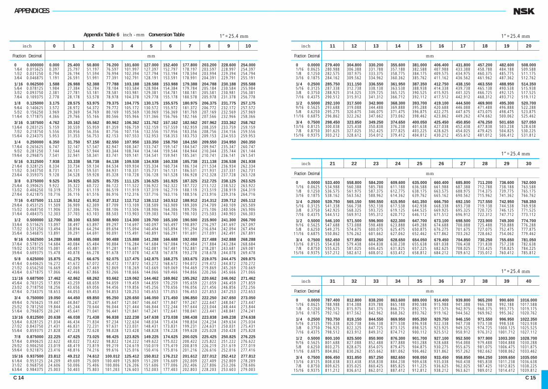
APPENDICES
Appendix Table 6 inch - mm Conversion Table 1”=25.4 mm
inch 0 1 2 3 4 5 6 7 8 9 10
Fraction Decimal mm
0 0.000000 0.000 25.400 50.800 76.200 101.600 127.000 152.400 177.800 203.200 228.600 254.000 1/64 0.015625 0.397 25.797 51.197 76.597 101.997 127.397 152.797 178.197 203.597 228.997 254.397 1/32 0.031250 0.794 26.194 51.594 76.994 102.394 127.794 153.194 178.594 203.994 229.394 254.794 3/64 0.046875 1.191 26.591 51.991 77.391 102.791 128.191 153.591 178.991 204.391 229.791 255.191 1/16 0.062500 1.588 26.988 52.388 77.788 103.188 128.588 153.988 179.388 204.788 230.188 255.588 5/64 0.078125 1.984 27.384 52.784 78.184 103.584 128.984 154.384 179.784 205.184 230.584 255.984 3/32 0.093750 2.381 27.781 53.181 78.581 103.981 129.381 154.781 180.181 205.581 230.981 256.381 7/64 0.109375 2.778 28.178 53.578 78.978 104.378 129.778 155.178 180.578 205.978 231.378 256.778 1/8 0.125000 3.175 28.575 53.975 79.375 104.775 130.175 155.575 180.975 206.375 231.775 257.175 9/64 0.140625 3.572 28.972 54.372 79.772 105.172 130.572 155.972 181.372 206.772 232.172 257.572 5/32 0.156250 3.969 29.369 54.769 80.169 105.569 130.969 156.369 181.769 207.169 232.569 257.969 11/64 0.171875 4.366 29.766 55.166 80.566 105.966 131.366 156.766 182.166 207.566 232.966 258.366 3/16 0.187500 4.762 30.162 55.562 80.962 106.362 131.762 157.162 182.562 207.962 233.362 258.762 13/64 0.203125 5.159 30.559 55.959 81.359 106.759 132.159 157.559 182.959 208.359 233.759 259.159 7/32 0.218750 5.556 30.956 56.356 81.756 107.156 132.556 157.956 183.356 208.756 234.156 259.556 15/64 0.234375 5.953 31.353 56.753 82.153 107.553 132.953 158.353 183.753 209.153 234.553 259.953 1/4 0.250000 6.350 31.750 57.150 82.550 107.950 133.350 158.750 184.150 209.550 234.950 260.350 17/64 0.265625 6.747 32.147 57.547 82.947 108.347 133.747 159.147 184.547 209.947 235.347 260.747 9/32 0.281250 7.144 32.544 57.944 83.344 108.744 134.144 159.544 184.944 210.344 235.744 261.144 19/64 0.296875 7.541 32.941 58.341 83.741 109.141 134.541 159.941 185.341 210.741 236.141 261.541 5/16 0.312500 7.938 33.338 58.738 84.138 109.538 134.938 160.338 185.738 211.138 236.538 261.938 21/64 0.328125 8.334 33.734 59.134 84.534 109.934 135.334 160.734 186.134 211.534 236.934 262.334 11/32 0.343750 8.731 34.131 59.531 84.931 110.331 135.731 161.131 186.531 211.931 237.331 262.731 23/64 0.359375 9.128 34.528 59.928 85.328 110.728 136.128 161.528 186.928 212.328 237.728 263.128 3/8 0.375000 9.525 34.925 60.325 85.725 111.125 136.525 161.925 187.325 212.725 238.125 263.525 25/64 0.390625 9.922 35.322 60.722 86.122 111.522 136.922 162.322 187.722 213.122 238.522 263.922 13/32 0.406250 10.319 35.719 61.119 86.519 111.919 137.319 162.719 188.119 213.519 238.919 264.319 27/64 0.421875 10.716 36.116 61.516 86.916 112.316 137.716 163.116 188.516 213.916 239.316 264.716 7/16 0.437500 11.112 36.512 61.912 87.312 112.712 138.112 163.512 188.912 214.312 239.712 265.112 29/64 0.453125 11.509 36.909 62.309 87.709 113.109 138.509 163.909 189.309 214.709 240.109 265.509 15/32 0.468750 11.906 37.306 62.706 88.106 113.506 138.906 164.306 189.706 215.106 240.506 265.906 31/64 0.484375 12.303 37.703 63.103 88.503 113.903 139.303 164.703 190.103 215.503 240.903 266.303 1/2 0.500000 12.700 38.100 63.500 88.900 114.300 139.700 165.100 190.500 215.900 241.300 266.700 33/64 0.515625 13.097 38.497 63.897 89.297 114.697 140.097 165.497 190.897 216.297 241.697 267.097 17/32 0.531250 13.494 38.894 64.294 89.694 115.094 140.494 165.894 191.294 216.694 242.094 267.494 35/64 0.546875 13.891 39.291 64.691 90.091 115.491 140.891 166.291 191.691 217.091 242.491 267.891 9/16 0.562500 14.288 39.688 65.088 90.488 115.888 141.288 166.688 192.088 217.488 242.888 268.288 37/64 0.578125 14.684 40.084 65.484 90.884 116.284 141.684 167.084 192.484 217.884 243.284 268.684 19/32 0.593750 15.081 40.481 65.881 91.281 116.681 142.081 167.481 192.881 218.281 243.681 269.081 39/64 0.609375 15.478 40.878 66.278 91.678 117.078 142.478 167.878 193.278 218.678 244.078 269.478 5/8 0.625000 15.875 41.275 66.675 92.075 117.475 142.875 168.275 193.675 219.075 244.475 269.875 41/64 0.640625 16.272 41.672 67.072 92.472 117.872 143.272 168.672 194.072 219.472 244.872 270.272 21/32 0.656250 16.669 42.069 67.469 92.869 118.269 143.669 169.069 194.469 219.869 245.269 270.669 43/64 0.671875 17.066 42.466 67.866 93.266 118.666 144.066 169.466 194.866 220.266 245.666 271.066 11/16 0.687500 17.462 42.862 68.262 93.662 119.062 144.462 169.862 195.262 220.662 246.062 271.462 45/64 0.703125 17.859 43.259 68.659 94.059 119.459 144.859 170.259 195.659 221.059 246.459 271.859 23/32 0.718750 18.256 43.656 69.056 94.456 119.856 145.256 170.656 196.056 221.456 246.856 272.256 47/64 0.734375 18.653 44.053 69.453 94.853 120.253 145.653 171.053 196.453 221.853 247.253 272.653 3/4 0.750000 19.050 44.450 69.850 95.250 120.650 146.050 171.450 196.850 222.250 247.650 273.050 49/64 0.765625 19.447 44.847 70.247 95.647 121.047 146.447 171.847 197.247 222.647 248.047 273.447 25/32 0.781250 19.844 45.244 70.644 96.044 121.444 146.844 172.244 197.644 223.044 248.444 273.844 51/64 0.796875 20.241 45.641 71.041 96.441 121.841 147.241 172.641 198.041 223.441 248.841 274.241 13/16 0.812500 20.638 46.038 71.438 96.838 122.238 147.638 173.038 198.438 223.838 249.238 274.638 53/64 0.828125 21.034 46.434 71.834 97.234 122.634 148.034 173.434 198.834 224.234 249.634 275.034 27/32 0.843750 21.431 46.831 72.231 97.631 123.031 148.431 173.831 199.231 224.631 250.031 275.431 55/64 0.859375 21.828 47.228 72.628 98.028 123.428 148.828 174.228 199.628 225.028 250.428 275.828 7/8 0.875000 22.225 47.625 73.025 98.425 123.825 149.225 174.625 200.025 225.425 250.825 276.225 57/64 0.890625 22.622 48.022 73.422 98.822 124.222 149.622 175.022 200.422 225.822 251.222 276.622 29/32 0.906250 23.019 48.419 73.819 99.219 124.619 150.019 175.419 200.819 226.219 251.619 277.019 59/64 0.921875 23.416 48.816 74.216 99.616 125.016 150.416 175.816 201.216 226.616 252.016 277.416 15/16 0.937500 23.812 49.212 74.612 100.012 125.412 150.812 176.212 201.612 227.012 252.412 277.812 61/64 0.953125 24.209 49.609 75.009 100.409 125.809 151.209 176.609 202.009 227.409 252.809 278.209 31/32 0.968750 24.606 50.006 75.406 100.806 126.206 151.606 177.006 202.406 227.806 253.206 278.606 63/64 0.984375 25.003 50.403 75.803 101.203 126.603 152.003 177.403 202.803 228.203 253.603 279.003
1”=25.4 mm
inch 11 12 13 14 15 16 17 18 19 20
Fraction Decimal mm
0 0.0000 279.400 304.800 330.200 355.600 381.000 406.400 431.800 457.200 482.600 508.000 1/16 0.0625 280.988 306.388 331.788 357.188 382.588 407.988 433.388 458.788 484.188 509.588 1/8 0.1250 282.575 307.975 333.375 358.775 384.175 409.575 434.975 460.375 485.775 511.175 3/16 0.1875 284.162 309.562 334.962 360.362 385.762 411.162 436.562 461.962 487.362 512.762 1/4 0.2500 285.750 311.150 336.550 361.950 387.350 412.750 438.150 463.550 488.950 514.350 5/16 0.3125 287.338 312.738 338.138 363.538 388.938 414.338 439.738 465.138 490.538 515.938 3/8 0.3750 288.925 314.325 339.725 365.125 390.525 415.925 441.325 466.725 492.125 517.525 7/16 0.4375 290.512 315.912 341.312 366.712 392.112 417.512 442.912 468.312 493.712 519.112 1/2 0.5000 292.100 317.500 342.900 368.300 393.700 419.100 444.500 469.900 495.300 520.700 9/16 0.5625 293.688 319.088 344.488 369.888 395.288 420.688 446.088 471.488 496.888 522.288 5/8 0.6250 295.275 320.675 346.075 371.475 396.875 422.275 447.675 473.075 498.475 523.875 11/16 0.6875 296.862 322.262 347.662 373.062 398.462 423.862 449.262 474.662 500.062 525.462 3/4 0.7500 298.450 323.850 349.250 374.650 400.050 425.450 450.850 476.250 501.650 527.050 13/16 0.8125 300.038 325.438 350.838 376.238 401.638 427.038 452.438 477.838 503.238 528.638 7/8 0.8750 301.625 327.025 352.425 377.825 403.225 428.625 454.025 479.425 504.825 530.225 15/16 0.9375 303.212 328.612 354.012 379.412 404.812 430.212 455.612 481.012 506.412 531.812
1”=25.4 mm
inch 21 22 23 24 25 26 27 28 29 30
Fraction Decimal mm
0 0.0000 533.400 558.800 584.200 609.600 635.000 660.400 685.800 711.200 736.600 762.000 1/16 0.0625 534.988 560.388 585.788 611.188 636.588 661.988 687.388 712.788 738.188 763.588 1/8 0.1250 536.575 561.975 587.375 612.775 638.175 663.575 688.975 714.375 739.775 765.175 3/16 0.1875 538.162 563.562 588.962 614.362 639.762 665.162 690.562 715.962 741.362 766.762 1/4 0.2500 539.750 565.150 590.550 615.950 641.350 666.750 692.150 717.550 742.950 768.350 5/16 0.3125 541.338 566.738 592.138 617.538 642.938 668.338 693.738 719.138 744.538 769.938 3/8 0.3750 542.925 568.325 593.725 619.125 644.525 669.925 695.325 720.725 746.125 771.525 7/16 0.4375 544.512 569.912 595.312 620.712 646.112 671.512 696.912 722.312 747.712 773.112 1/2 0.5000 546.100 571.500 596.900 622.300 647.700 673.100 698.500 723.900 749.300 774.700 9/16 0.5625 547.688 573.088 598.488 623.888 649.288 674.688 700.088 725.488 750.888 776.288 5/8 0.6250 549.275 574.675 600.075 625.475 650.875 676.275 701.675 727.075 752.475 777.875 11/16 0.6875 550.862 576.262 601.662 627.062 652.462 677.862 703.262 728.662 754.062 779.462 3/4 0.7500 552.450 577.850 603.250 628.650 654.050 679.450 704.850 730.250 755.650 781.050 13/16 0.8125 554.038 579.438 604.838 630.238 655.638 681.038 706.438 731.838 757.238 782.638 7/8 0.8750 555.625 581.025 606.425 631.825 657.225 682.625 708.025 733.425 758.825 784.225 15/16 0.9375 557.212 582.612 608.012 633.412 658.812 684.212 709.612 735.012 760.412 785.812
1”=25.4 mm
inch 31 32 33 34 35 36 37 38 39 40
Fraction Decimal mm
0 0.0000 787.400 812.800 838.200 863.600 889.000 914.400 939.800 965.200 990.600 1016.000 1/16 0.0625 788.988 814.388 839.788 865.188 890.588 915.988 941.388 966.788 992.188 1017.588 1/8 0.1250 790.575 815.975 841.375 866.775 892.175 917.575 942.975 968.375 993.775 1019.175 3/16 0.1875 792.162 817.562 842.962 868.362 893.762 919.162 944.562 969.962 995.362 1020.762 1/4 0.2500 793.750 819.150 844.550 869.950 895.350 920.750 946.150 971.550 996.950 1022.350 5/16 0.3125 795.338 820.738 846.138 871.538 896.938 922.338 947.738 973.138 998.538 1023.938 3/8 0.3750 796.925 822.325 847.725 873.125 898.525 923.925 949.325 974.725 1000.125 1025.525 7/16 0.4375 798.512 823.912 849.312 874.712 900.112 925.512 950.912 976.312 1001.712 1027.112 1/2 0.5000 800.100 825.500 850.900 876.300 901.700 927.100 952.500 977.900 1003.300 1028.700 9/16 0.5625 801.688 827.088 852.488 877.888 903.288 928.688 954.088 979.488 1004.888 1030.288 5/8 0.6250 803.275 828.675 854.075 879.475 904.875 930.275 955.675 981.075 1006.475 1031.875 11/16 0.6875 804.862 830.262 855.662 881.062 906.462 931.862 957.262 982.662 1008.062 1033.462 3/4 0.7500 806.450 831.850 857.250 882.650 908.050 933.450 958.850 984.250 1009.650 1035.050 13/16 0.8125 808.038 833.438 858.838 884.238 909.638 935.038 960.438 985.838 1011.238 1036.638 7/8 0.8750 809.625 835.025 860.425 885.825 911.225 936.625 962.025 987.425 1012.825 1038.225 15/16 0.9375 811.212 836.612 862.012 887.412 912.812 938.212 963.621 989.012 1014.412 1039.812
C 14 C 15
C001-034E.indd 14-15 C001-034E.indd 14-15 11/20/13 5:03:56 PM11/20/13 5:03:56 PM
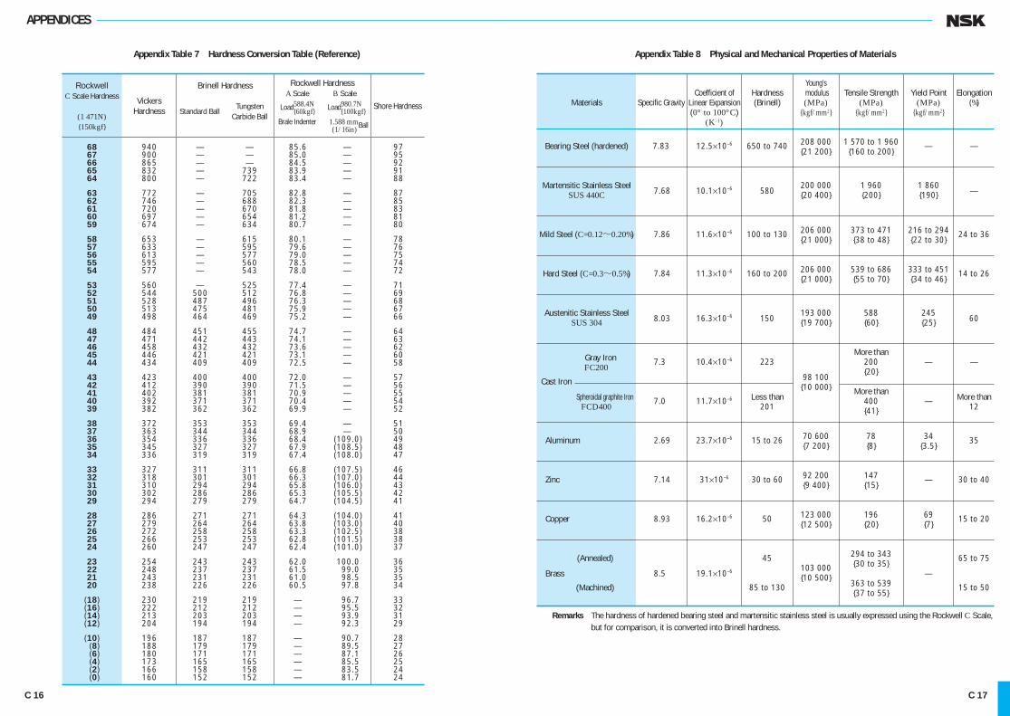
APPENDICES
Appendix Table 7 Hardness Conversion Table (Reference)
68 940 — — 85.6 — 97 67 900 — — 85.0 — 95 66 865 — — 84.5 — 92 65 832 — 739 83.9 — 91 64 800 — 722 83.4 — 88
63 772 — 705 82.8 — 87 62 746 — 688 82.3 — 85 61 720 — 670 81.8 — 83 60 697 — 654 81.2 — 81 59 674 — 634 80.7 — 80
58 653 — 615 80.1 — 78 57 633 — 595 79.6 — 76 56 613 — 577 79.0 — 75 55 595 — 560 78.5 — 74 54 577 — 543 78.0 — 72
53 560 — 525 77.4 — 71 52 544 500 512 76.8 — 69 51 528 487 496 76.3 — 68 50 513 475 481 75.9 — 67 49 498 464 469 75.2 — 66
48 484 451 455 74.7 — 64 47 471 442 443 74.1 — 63 46 458 432 432 73.6 — 62 45 446 421 421 73.1 — 60 44 434 409 409 72.5 — 58
43 423 400 400 72.0 — 57 42 412 390 390 71.5 — 56 41 402 381 381 70.9 — 55 40 392 371 371 70.4 — 54 39 382 362 362 69.9 — 52
38 372 353 353 69.4 — 51 37 363 344 344 68.9 — 50 36 354 336 336 68.4 (109.0) 49 35 345 327 327 67.9 (108.5) 48 34 336 319 319 67.4 (108.0) 47
33 327 311 311 66.8 (107.5) 46 32 318 301 301 66.3 (107.0) 44 31 310 294 294 65.8 (106.0) 43 30 302 286 286 65.3 (105.5) 42 29 294 279 279 64.7 (104.5) 41
28 286 271 271 64.3 (104.0) 41 27 279 264 264 63.8 (103.0) 40 26 272 258 258 63.3 (102.5) 38 25 266 253 253 62.8 (101.5) 38 24 260 247 247 62.4 (101.0) 37
23 254 243 243 62.0 100.0 36 22 248 237 237 61.5 99.0 35 21 243 231 231 61.0 98.5 35 20 238 226 226 60.5 97.8 34
(18) 230 219 219 — 96.7 33 (16) 222 212 212 — 95.5 32 (14) 213 203 203 — 93.9 31 (12) 204 194 194 — 92.3 29
(10) 196 187 187 — 90.7 28 (8) 188 179 179 — 89.5 27 (6) 180 171 171 — 87.1 26 (4) 173 165 165 — 85.5 25 (2) 166 158 158 — 83.5 24 (0) 160 152 152 — 81.7 24
RockwellC Scale Hardness
(1 471N){150kgf}
Vickers Hardness
Brinell Hardness
Standard Ball
Tungsten Carbide Ball
Rockwell Hardness A Scale B Scale Load588.4N Load980.7N {60kgf} {100kgf} Brale Indenter 1.588 mmBall (1/16in)
Shore Hardness
Appendix Table 8 Physical and Mechanical Properties of Materials
Young’s Coefficient of Hardness modulus Tensile Strength Yield Point Elongation Materials Specific Gravity Linear Expansion (Brinell) (MPa) (MPa) (MPa) (%) (0° to 100°C) {kgf/mm2} {kgf/mm2} {kgf/mm2} (K–1)
Bearing Steel (hardened) 7.83 12.5×10—6 650 to 740 208 000 1 570 to 1 960 — — {21 200} {160 to 200}
Martensitic Stainless Steel 200 000 1 960 1 860 SUS 440C 7.68 10.1×10—6 580 {20 400} {200} {190} —
Mild Steel (C=0.12~0.20%) 7.86 11.6×10—6 100 to 130 206 000 373 to 471 216 to 294 24 to 36 {21 000} {38 to 48} {22 to 30}
Hard Steel (C=0.3~0.5%) 7.84 11.3×10—6 160 to 200 206 000 539 to 686 333 to 451 14 to 26 {21 000} {55 to 70} {34 to 46}
Austenitic Stainless Steel 193 000 588 245 SUS 304 8.03 16.3×10—6 150 {19 700} {60} {25} 60
More than Gray Iron 7.3 10.4×10—6 223 200 — — FC200 {20} Cast Iron 98 100 {10 000} More than Spheroidal graphite Iron 7.0 11.7×10—6 Less than 400 — More than FCD400 201 {41} 12
Aluminum 2.69 23.7×10—6 15 to 26 70 600 78 34 35 {7 200} {8} {3.5}
Zinc 7.14 31×10—6 30 to 60 92 200 147 — 30 to 40 {9 400} {15}
Copper 8.93 16.2×10—6 50 123 000 196 69 15 to 20 {12 500} {20} {7}
(Annealed) 45 294 to 343 65 to 75 103 000 {30 to 35} Brass 8.5 19.1×10—6 {10 500} — (Machined) 85 to 130 363 to 539 15 to 50 {37 to 55}
Remarks The hardness of hardened bearing steel and martensitic stainless steel is usually expressed using the Rockwell C Scale, but for comparison, it is converted into Brinell hardness.
C 16 C 17
C001-034E.indd 16-17 C001-034E.indd 16-17 11/20/13 5:03:57 PM11/20/13 5:03:57 PM

APPENDICES
Appendix Table 9 Tolerances for Shaft Diameters
d6 e6 f6 g5 g6 h5 h6 h7 h8 h9 h10 js5 js6 over incl.
3 6 0 — 30 — 20 — 10 — 4 — 4 0 0 0 0 0 0 ± 2.5 ± 4.0 — 8 — 38 — 28 — 18 — 9 — 12 — 5 — 8 — 12 — 18 — 30 — 48 6 10 0 — 40 — 25 — 13 — 5 — 5 0 0 0 0 0 0 ± 3.0 ± 4.5 — 8 — 49 — 34 — 22 — 11 — 14 — 6 — 9 — 15 — 22 — 36 — 58 10 18 0 — 50 — 32 — 16 — 6 — 6 0 0 0 0 0 0 ± 4.0 ± 5.5 — 8 — 61 — 43 — 27 — 14 — 17 — 8 — 11 — 18 — 27 — 43 — 70 18 30 0 — 65 — 40 — 20 — 7 — 7 0 0 0 0 0 0 ± 4.5 ± 6.5 — 10 — 78 — 53 — 33 — 16 — 20 — 9 — 13 — 21 — 33 — 52 — 84 30 50 0 — 80 — 50 — 25 — 9 — 9 0 0 0 0 0 0 ± 5.5 ± 8.0 — 12 — 96 — 66 — 41 — 20 — 25 — 11 — 16 — 25 — 39 — 62 — 100
50 80 0 — 100 — 60 — 30 — 10 — 10 0 0 0 0 0 0 ± 6.5 ± 9.5 — 15 — 119 — 79 — 49 — 23 — 29 — 13 — 19 — 30 — 46 — 74 — 120
80 120 0 — 120 — 72 — 36 — 12 — 12 0 0 0 0 0 0 ± 7.5 ± 11.0 — 20 — 142 — 94 — 58 — 27 — 34 — 15 — 22 — 35 — 54 — 87 — 140
120 180 0 — 145 — 85 — 43 — 14 — 14 0 0 0 0 0 0 ± 9.0 ± 12.5 — 25 — 170 — 110 — 68 — 32 — 39 — 18 — 25 — 40 — 63 — 100 — 160
180 250 0 — 170 — 100 — 50 — 15 — 15 0 0 0 0 0 0 ± 10.0 ± 14.5 — 30 — 199 — 129 — 79 — 35 — 44 — 20 — 29 — 46 — 72 — 115 — 185
250 315 0 — 190 — 110 — 56 — 17 — 17 0 0 0 0 0 0 ± 11.5 ± 16.0 — 35 — 222 — 142 — 88 — 40 — 49 — 23 — 32 — 52 — 81 — 130 — 210
315 400 0 — 210 — 125 — 62 — 18 — 18 0 0 0 0 0 0 ± 12.5 ± 18.0 — 40 — 246 — 161 — 98 — 43 — 54 — 25 — 36 — 57 — 89 — 140 — 230
400 500 0 — 230 — 135 — 68 — 20 — 20 0 0 0 0 0 0 ± 13.5 ± 20.0 — 45 — 270 — 175 — 108 — 47 — 60 — 27 — 40 — 63 — 97 — 155 — 250
500 630 0 — 260 — 145 — 76 — — 22 — 0 0 0 0 0 — ± 22.0 — 50 — 304 — 189 — 120 — 66 — 44 — 70 — 110 — 175 — 280
630 800 0 — 290 — 160 — 80 — — 24 — 0 0 0 0 0 — ± 25.0 — 75 — 340 — 210 — 130 — 74 — 50 — 80 — 125 — 200 — 320
800 1 000 0 — 320 — 170 — 86 — — 26 — 0 0 0 0 0 — ± 28.0 — 100 — 376 — 226 — 142 — 82 — 56 — 90 — 140 — 230 — 360
1 000 1 250 0 — 350 — 195 — 98 — — 28 — 0 0 0 0 0 — ± 33.0 — 125 — 416 — 261 — 164 — 94 — 66 — 105 — 165 — 260 — 420
1 250 1 600 0 — 390 — 220 — 110 — — 30 — 0 0 0 0 0 — ± 39.0 — 160 — 468 — 298 — 188 — 108 — 78 — 125 — 195 — 310 — 500
1 600 2 000 0 — 430 — 240 — 120 — — 32 — 0 0 0 0 0 — ± 46.0 — 200 — 522 — 332 — 212 — 124 — 92 — 150 — 230 — 370 — 600
Single Plane Mean B.D. Deviation
(Normal)&dmp
j5 j6 j7 k5 k6 k7 m5 m6 n6 p6 r6 r7 over incl.
+ 3 + 6 + 8 + 6 + 9 + 13 + 9 + 12 + 16 + 20 + 23 + 27 3 6 — 2 — 2 — 4 + 1 + 1 + 1 + 4 + 4 + 8 + 12 + 15 + 15 + 4 + 7 + 10 + 7 + 10 + 16 + 12 + 15 + 19 + 24 + 28 + 34 6 10 — 2 — 2 — 5 + 1 + 1 + 1 + 6 + 6 + 10 + 15 + 19 + 19 + 5 + 8 + 12 + 9 + 12 + 19 + 15 + 18 + 23 + 29 + 34 + 41 10 18 — 3 — 3 — 6 + 1 + 1 + 1 + 7 + 7 + 12 + 18 + 23 + 23 + 5 + 9 + 13 + 11 + 15 + 23 + 17 + 21 + 28 + 35 + 41 + 49 18 30 — 4 — 4 — 8 + 2 + 2 + 2 + 8 + 8 + 15 + 22 + 28 + 28 + 6 + 11 + 15 + 13 + 18 + 27 + 20 + 25 + 33 + 42 + 50 + 59 30 50 — 5 — 5 — 10 + 2 + 2 + 2 + 9 + 9 + 17 + 26 + 34 + 34 + 60 + 71 50 65 + 6 + 12 + 18 + 15 + 21 + 32 + 24 + 30 + 39 + 51 + 41 + 41 — 7 — 7 — 12 + 2 + 2 + 2 + 11 + 11 + 20 + 32 + 62 + 73 65 80 + 43 + 43 + 73 + 86 80 100 + 6 + 13 + 20 + 18 + 25 + 38 + 28 + 35 + 45 + 59 + 51 + 51 — 9 — 9 — 15 + 3 + 3 + 3 + 13 + 13 + 23 + 37 + 76 + 89 100 120 + 54 + 54 + 88 + 103 120 140 + 63 + 63 + 7 + 14 + 22 + 21 + 28 + 43 + 33 + 40 + 52 + 68 + 90 + 105 140 160 — 11 — 11 — 18 + 3 + 3 + 3 + 15 + 15 + 27 + 43 + 65 + 65 + 93 + 108 160 180 + 68 + 68 + 106 + 123 180 200 + 77 + 77 + 7 + 16 + 25 + 24 + 33 + 50 + 37 + 46 + 60 + 79 + 109 + 126 200 225 — 13 — 13 — 21 + 4 + 4 + 4 + 17 + 17 + 31 + 50 + 80 + 80 + 113 + 130 225 250 + 84 + 84 + 126 + 146 250 280 + 7 ± 16 ± 26 + 27 + 36 + 56 + 43 + 52 + 66 + 88 + 94 + 94 — 16 + 4 + 4 + 4 + 20 + 20 + 34 + 56 + 130 + 150 280 315 + 98 + 98 + 144 + 165 315 355 + 7 ± 18 + 29 + 29 + 40 + 61 + 46 + 57 + 73 + 98 + 108 + 108 — 18 — 28 + 4 + 4 + 4 + 21 + 21 + 37 + 62 + 150 + 171 355 400 + 114 + 114 + 166 + 189 400 450 + 7 ± 20 + 31 + 32 + 45 + 68 + 50 + 63 + 80 + 108 + 126 + 126 — 20 — 32 + 5 + 5 + 5 + 23 + 23 + 40 + 68 + 172 + 195 450 500 + 132 + 132 + 194 + 220 500 560 — — — — + 44 + 70 — + 70 + 88 + 122 + 150 + 150 0 0 + 26 + 44 + 78 + 199 + 225 560 630 + 155 + 155 + 225 + 255 630 710 — — — — + 50 + 80 — + 80 + 100 + 138 + 175 + 175 0 0 + 30 + 50 + 88 + 235 + 265 710 800 + 185 + 185 + 266 + 300 800 900 — — — — + 56 + 90 — + 90 + 112 + 156 + 210 + 210 0 0 + 34 + 56 + 100 + 276 + 310 900 1 000 + 220 + 220 + 316 + 355 1 000 1 120 — — — — + 66 + 105 — + 106 + 132 + 186 + 250 + 250 0 0 + 40 + 66 + 120 + 326 + 365 1 120 1 250 + 260 + 260 + 378 + 425 1 250 1 400 — — — — + 78 + 125 — + 126 + 156 + 218 + 300 + 300 0 0 + 48 + 78 + 140 + 408 + 455 1 400 1 600 + 330 + 330 + 462 + 520 1 600 1 800 — — — — + 92 + 150 — + 150 + 184 + 262 + 370 + 370 0 0 + 58 + 92 + 170 + 492 + 550 1 800 2 000 + 400 + 400
Units : μm
Diameter Classification (mm)
Diameter Classification (mm)
C 18 C 19
C001-034E.indd 18-19 C001-034E.indd 18-19 11/20/13 5:03:57 PM11/20/13 5:03:57 PM

APPENDICES
Appendix Table 10 Tolerances for Housing Bore Diameters
E6 F6 F7 G6 G7 H6 H7 H8 J6 J7 JS6 JS7 over incl.
10 18 0 + 43 + 27 + 34 + 17 + 24 + 11 + 18 + 27 + 6 + 10 ± 5.5 ± 9 — 8 + 32 + 16 + 16 + 6 + 6 0 0 0 — 5 — 8
18 30 0 + 53 + 33 + 41 + 20 + 28 + 13 + 21 + 33 + 8 + 12 ± 6.5 ± 10.5 — 9 + 40 + 20 + 20 + 7 + 7 0 0 0 — 5 — 9
30 50 0 + 66 + 41 + 50 + 25 + 34 + 16 + 25 + 39 + 10 + 14 ± 8 ± 12.5 — 11 + 50 + 25 + 25 + 9 + 9 0 0 0 — 6 — 11
50 80 0 + 79 + 49 + 60 + 29 + 40 + 19 + 30 + 46 + 13 + 18 ± 9.5 ± 15 — 13 + 60 + 30 + 30 + 10 + 10 0 0 0 — 6 — 12
80 120 0 + 94 + 58 + 71 + 34 + 47 + 22 + 35 + 54 + 16 + 22 ± 11 ± 17.5 — 15 + 72 + 36 + 36 + 12 + 12 0 0 0 — 6 — 13
0 120 150 — 18 + 110 + 68 + 83 + 39 + 54 + 25 + 40 + 63 + 18 + 26 ± 12.5 ± 20 150 180 0 + 85 + 43 + 43 + 14 + 14 0 0 0 — 7 — 14 — 25
180 250 0 + 129 + 79 + 96 + 44 + 61 + 29 + 46 + 72 + 22 + 30 ± 14.5 ± 23 — 30 + 100 + 50 + 50 + 15 + 15 0 0 0 — 7 — 16
250 315 0 + 142 + 88 + 108 + 49 + 69 + 32 + 52 + 81 + 25 + 36 ± 16 ± 26 — 35 + 110 + 56 + 56 + 17 + 17 0 0 0 — 7 — 16
315 400 0 + 161 + 98 + 119 + 54 + 75 + 36 + 57 + 89 + 29 + 39 ± 18 ± 28.5 — 40 + 125 + 62 + 62 + 18 + 18 0 0 0 — 7 — 18
400 500 0 + 175 + 108 + 131 + 60 + 83 + 40 + 63 + 97 + 33 + 43 ± 20 ± 31.5 — 45 + 135 + 68 + 68 + 20 + 20 0 0 0 — 7 — 20
500 630 0 + 189 + 120 + 146 + 66 + 92 + 44 + 70 + 110 — — ± 22 ± 35 — 50 + 145 + 76 + 76 + 22 + 22 0 0 0
630 800 0 + 210 + 130 + 160 + 74 + 104 + 50 + 80 + 125 — — ± 25 ± 40 — 75 + 160 + 80 + 80 + 24 + 24 0 0 0
800 1 000 0 + 226 + 142 + 176 + 82 + 116 + 56 + 90 + 140 — — ± 28 ± 45 — 100 + 170 + 86 + 86 + 26 + 26 0 0 0
1 000 1 250 0 + 261 + 164 + 203 + 94 + 133 + 66 + 105 + 165 — — ± 33 ± 52.5 — 125 + 195 + 98 + 98 + 28 + 28 0 0 0
1 250 1 600 0 + 298 + 188 + 235 + 108 + 155 + 78 + 125 + 195 — — ± 39 ± 62.5 — 160 + 220 + 110 + 110 + 30 + 30 0 0 0
1 600 2 000 0 + 332 + 212 + 270 + 124 + 182 + 92 + 150 + 230 — — ± 46 ± 75 — 200 + 240 + 120 + 120 + 32 + 32 0 0 0
2 000 2 500 0 + 370 + 240 + 305 + 144 + 209 + 110 + 175 + 280 — — ± 55 ± 87.5 — 250 + 260 + 130 + 130 + 34 + 34 0 0 0
Single Plane Mean O.D. Deviation
(Normal)&Dmp
K5 K6 K7 M5 M6 M7 N5 N6 N7 P6 P7 over incl.
+ 2 + 2 + 6 — 4 — 4 0 — 9 — 9 — 5 — 15 — 11 10 18 — 6 — 9 — 12 — 12 — 15 — 18 — 17 — 20 — 23 — 26 — 29
+ 1 + 2 + 6 — 5 — 4 0 — 12 — 11 — 7 — 18 — 14 18 30 — 8 — 11 — 15 — 14 — 17 — 21 — 21 — 24 — 28 — 31 — 35
+ 2 + 3 + 7 — 5 — 4 0 — 13 — 12 — 8 — 21 — 17 30 50 — 9 — 13 — 18 — 16 — 20 — 25 — 24 — 28 — 33 — 37 — 42
+ 3 + 4 + 9 — 6 — 5 0 — 15 — 14 — 9 — 26 — 21 50 80 — 10 — 15 — 21 — 19 — 24 — 30 — 28 — 33 — 39 — 45 — 51
+ 2 + 4 + 10 — 8 — 6 0 — 18 — 16 — 10 — 30 — 24 80 120 — 13 — 18 — 25 — 23 — 28 — 35 — 33 — 38 — 45 — 52 — 59
+ 3 + 4 + 12 — 9 — 8 0 — 21 — 20 — 12 — 36 — 28 120 180 — 15 — 21 — 28 — 27 — 33 — 40 — 39 — 45 — 52 — 61 — 68
+ 2 + 5 + 13 — 11 — 8 0 — 25 — 22 — 14 — 41 — 33 180 250 — 18 — 24 — 33 — 31 — 37 — 46 — 45 — 51 — 60 — 70 — 79
+ 3 + 5 + 16 — 13 — 9 0 — 27 — 25 — 14 — 47 — 36 250 315 — 20 — 27 — 36 — 36 — 41 — 52 — 50 — 57 — 66 — 79 — 88
+ 3 + 7 + 17 — 14 — 10 0 — 30 — 26 — 16 — 51 — 41 315 400 — 22 — 29 — 40 — 39 — 46 — 57 — 55 — 62 — 73 — 87 — 98
+ 2 + 8 + 18 — 16 — 10 0 — 33 — 27 — 17 — 55 — 45 400 500 — 25 — 32 — 45 — 43 — 50 — 63 — 60 — 67 — 80 — 95 — 108
— 0 0 — — 26 — 26 — — 44 — 44 — 78 — 78 500 630 — 44 — 70 — 70 — 96 — 88 — 114 — 122 — 148
— 0 0 — — 30 — 30 — — 50 — 50 — 88 — 88 630 800 — 50 — 80 — 80 — 110 — 100 — 130 — 138 — 168
— 0 0 — — 34 — 34 — — 56 — 56 — 100 — 100 800 1 000 — 56 — 90 — 90 — 124 — 112 — 146 — 156 — 190
— 0 0 — — 40 — 40 — — 66 — 66 — 120 — 120 1 000 1 250 — 66 — 105 — 106 — 145 — 132 — 171 — 186 — 225
— 0 0 — — 48 — 48 — — 78 — 78 — 140 — 140 1 250 1 600 — 78 — 125 — 126 — 173 — 156 — 203 — 218 — 265
— 0 0 — — 58 — 58 — — 92 — 92 — 170 — 170 1 600 2 000 — 92 — 150 — 150 — 208 — 184 — 242 — 262 — 320
— 0 0 — — 68 — 68 — — 110 — 110 — 195 — 195 2 000 2 500 — 110 — 175 — 178 — 243 — 220 — 285 — 305 — 370
Units : μm
DiameterClassification (mm)
Diameter Classification (mm)
C 20 C 21
C001-034E.indd 20-21 C001-034E.indd 20-21 11/20/13 5:03:59 PM11/20/13 5:03:59 PM

Grades Basic Size
IT12 IT13 IT14 IT15 IT16 IT17 IT18 (mm)
Tolerances (mm) over incl.
0.10 0.14 0.25 0.40 0.60 1.00 1.40 — 3
0.12 0.18 0.30 0.48 0.75 1.20 1.80 3 6
0.15 0.22 0.36 0.58 0.90 1.50 2.20 6 10
0.18 0.27 0.43 0.70 1.10 1.80 2.70 10 18
0.21 0.33 0.52 0.84 1.30 2.10 3.30 18 30
0.25 0.39 0.62 1.00 1.60 2.50 3.90 30 50
0.30 0.46 0.74 1.20 1.90 3.00 4.60 50 80
0.35 0.54 0.87 1.40 2.20 3.50 5.40 80 120
0.40 0.63 1.00 1.60 2.50 4.00 6.30 120 180
0.46 0.72 1.15 1.85 2.90 4.60 7.20 180 250
0.52 0.81 1.30 2.10 3.20 5.20 8.10 250 315
0.57 0.89 1.40 2.30 3.60 5.70 8.90 315 400
0.63 0.97 1.55 2.50 4.00 6.30 9.70 400 500
0.70 1.10 1.75 2.80 4.40 7.00 11.00 500 630
0.80 1.25 2.00 3.20 5.00 8.00 12.50 630 800
0.90 1.40 2.30 3.60 5.60 9.00 14.00 800 1 000
1.05 1.65 2.60 4.20 6.60 10.50 16.50 1 000 1 250
1.25 1.95 3.10 5.00 7.80 12.50 19.50 1 250 1 600
1.50 2.30 3.70 6.00 9.20 15.00 23.00 1 600 2 000
1.75 2.80 4.40 7.00 11.00 17.50 28.00 2 000 2 500
2.10 3.30 5.40 8.60 13.50 21.00 33.00 2 500 3 150
APPENDICES
Appendix Table 11 Values of Standard Tolerance Grades IT
Remarks 1. Standard tolerance grades IT14 to IT18 shall not be used for basic sizes less than or equal to 1 mm. 2. Values for standard tolerance grades IT1 to IT5 for basic sizes over 500 mm are included for experimental use.
Basic Size Standard
(mm) IT1 IT2 IT3 IT4 IT5 IT6 IT7 IT8 IT9 IT10 IT11
over incl. Tolerances ( μm)
— 3 0.8 1.2 2 3 4 6 10 14 25 40 60
3 6 1 1.5 2.5 4 5 8 12 18 30 48 75
6 10 1 1.5 2.5 4 6 9 15 22 36 58 90
10 18 1.2 2 3 5 8 11 18 27 43 70 110
18 30 1.5 2.5 4 6 9 13 21 33 52 84 130
30 50 1.5 2.5 4 7 11 16 25 39 62 100 160
50 80 2 3 5 8 13 19 30 46 74 120 190
80 120 2.5 4 6 10 15 22 35 54 87 140 220
120 180 3.5 5 8 12 18 25 40 63 100 160 250
180 250 4.5 7 10 14 20 29 46 72 115 185 290
250 315 6 8 12 16 23 32 52 81 130 210 320
315 400 7 9 13 18 25 36 57 89 140 230 360
400 500 8 10 15 20 27 40 63 97 155 250 400
500 630 9 11 16 22 32 44 70 110 175 280 440
630 800 10 13 18 25 36 50 80 125 200 320 500
800 1 000 11 15 21 28 40 56 90 140 230 360 560
1 000 1 250 13 18 24 33 47 66 105 165 260 420 660
1 250 1 600 15 21 29 39 55 78 125 195 310 500 780
1 600 2 000 18 25 35 46 65 92 150 230 370 600 920
2 000 2 500 22 30 41 55 78 110 175 280 440 700 1 100
2 500 3 150 26 36 50 68 96 135 210 330 540 860 1 350
C 22 C 23
C001-034E.indd 22-23 C001-034E.indd 22-23 11/20/13 5:04:00 PM11/20/13 5:04:00 PM

APPENDICES
Appedix Table 12 Speed Factor fnBall Bearings fn= (0.03 n) —1/3
Roller Bearings fn= (0.03 n) —3/10
Speed Speed Factor fn
n (min–1) Ball Bearings Roller Bearings
10 1.49 1.44 11 1.45 1.39 12 1.41 1.36 13 1.37 1.33 14 1.34 1.30
15 1.30 1.27 16 1.28 1.25 17 1.25 1.22 18 1.23 1.20 19 1.21 1.18
20 1.19 1.17 21 1.17 1.15 22 1.15 1.13 23 1.13 1.12 24 1.12 1.10
25 1.10 1.09 26 1.09 1.08 27 1.07 1.07 28 1.06 1.05 29 1.05 1.04
30 1.04 1.03 31 1.02 1.02 32 1.01 1.01 33.3 1.00 1.00 34 0.993 0.994
36 0.975 0.977 38 0.957 0.961 40 0.941 0.947 42 0.926 0.933 44 0.912 0.920
46 0.898 0.908 48 0.886 0.896 50 0.874 0.885 55 0.846 0.861 60 0.822 0.838
65 0.800 0.818 70 0.781 0.800 75 0.763 0.784 80 0.747 0.769 85 0.732 0.755
90 0.718 0.742 95 0.705 0.730 100 0.693 0.719 110 0.672 0.699 120 0.652 0.681
130 0.635 0.665 140 0.620 0.650 150 0.606 0.637 160 0.593 0.625 170 0.581 0.613
Appendix Table 13 Fatigue Life Factor fn and Fatigue Life L · Lh
Ball Bearings L=(C / P)3 Lh=500 fh3
Roller Bearings L=(C / P)10/3 Lh=500 fh10/3
Ball Bearing Life Roller Bearing Life
C/P or fh L Lh L Lh
(106 rev) (h) (106 rev) (h)
0.70 0.34 172 0.30 152 0.75 0.42 211 0.38 192 0.80 0.51 256 0.48 238 0.85 0.61 307 0.58 291 0.90 0.73 365 0.70 352
0.95 0.86 429 0.84 421 1.00 1.00 500 1.00 500 1.05 1.16 579 1.18 588 1.10 1.33 665 1.37 687 1.15 1.52 760 1.59 797
1.20 1.73 864 1.84 918 1.25 1.95 977 2.10 1 050 1.30 2.20 1 100 2.40 1 200 1.35 2.46 1 230 2.72 1 360 1.40 2.74 1 370 3.07 1 530
1.45 3.05 1 520 3.45 1 730 1.50 3.38 1 690 3.86 1 930 1.55 3.72 1 860 4.31 2 150 1.60 4.10 2 050 4.79 2 400 1.65 4.49 2 250 5.31 2 650
1.70 4.91 2 460 5.86 2 930 1.75 5.36 2 680 6.46 3 230 1.80 5.83 2 920 7.09 3 550 1.85 6.33 3 170 7.77 3 890 1.90 6.86 3 430 8.50 4 250
1.95 7.41 3 710 9.26 4 630 2.00 8.00 4 000 10.1 5 040 2.05 8.62 4 310 10.9 5 470 2.10 9.26 4 630 11.9 5 930 2.15 9.94 4 970 12.8 6 410
2.20 10.6 5 320 13.8 6 920 2.25 11.4 5 700 14.9 7 460 2.30 12.2 6 080 16.1 8 030 2.35 13.0 6 490 17.3 8 630 2.40 13.8 6 910 18.5 9 250
2.45 14.7 7 350 19.8 9 910 2.50 15.6 7 810 21.2 10 600 2.55 16.6 8 290 22.7 11 300 2.60 17.6 8 790 24.2 12 100 2.65 18.6 9 300 25.8 12 900
2.70 19.7 9 840 27.4 13 700 2.75 20.8 10 400 29.1 14 600 2.80 22.0 11 000 30.9 15 500 2.85 23.1 11 600 32.8 16 400 2.90 24.4 12 200 34.8 17 400
2.95 25.7 12 800 36.8 18 400 3.00 27.0 13 500 38.9 19 500 3.05 28.4 14 200 41.1 20 600 3.10 29.8 14 900 43.4 21 700 3.15 31.3 15 600 45.8 22 900
3.20 32.8 16 400 48.3 24 100 3.25 34.3 17 200 50.8 25 400 3.30 35.9 18 000 53.5 26 800 3.35 37.6 18 800 56.3 28 100 3.40 39.3 19 700 59.1 29 600
Speed Speed Factor fn
n (min–1) Ball Bearings Roller Bearings
180 0.570 0.603 190 0.560 0.593 200 0.550 0.584 220 0.533 0.568 240 0.518 0.553
260 0.504 0.540 280 0.492 0.528 300 0.481 0.517 320 0.471 0.507 340 0.461 0.498
360 0.452 0.490 380 0.444 0.482 400 0.437 0.475 420 0.430 0.468 440 0.423 0.461
460 0.417 0.455 480 0.411 0.449 500 0.405 0.444 550 0.393 0.431 600 0.382 0.420
650 0.372 0.410 700 0.362 0.401 750 0.354 0.393 800 0.347 0.385 850 0.340 0.378
900 0.333 0.372 950 0.327 0.366 1 000 0.322 0.360 1 050 0.317 0.355 1 100 0.312 0.350
1 150 0.307 0.346 1 200 0.303 0.341 1 250 0.299 0.337 1 300 0.295 0.333 1 400 0.288 0.326
1 500 0.281 0.319 1 600 0.275 0.313 1 700 0.270 0.307 1 800 0.265 0.302 1 900 0.260 0.297
2 000 0.255 0.293 2 100 0.251 0.289 2 200 0.247 0.285 2 300 0.244 0.281 2 400 0.240 0.277
2 500 0.237 0.274 2 600 0.234 0.271 2 700 0.231 0.268 2 800 0.228 0.265 2 900 0.226 0.262
Speed Speed Factor fn
n (min–1) Ball Bearings Roller Bearings
3 000 0.223 0.259 3 200 0.218 0.254 3 400 0.214 0.250 3 600 0.210 0.245 3 800 0.206 0.242
4 000 0.203 0.238 4 200 0.199 0.234 4 400 0.196 0.231 4 600 0.194 0.228 4 800 0.191 0.225
5 000 0.188 0.222 5 200 0.186 0.220 5 400 0.183 0.217 5 600 0.181 0.215 5 800 0.179 0.213
6 000 0.177 0.211 6 200 0.175 0.209 6 400 0.173 0.207 6 600 0.172 0.205 6 800 0.170 0.203
7 000 0.168 0.201 7 200 0.167 0.199 7 400 0.165 0.198 7 600 0.164 0.196 7 800 0.162 0.195
8 000 0.161 0.193 8 500 0.158 0.190 9 000 0.155 0.186 9 500 0.152 0.183 10 000 0.149 0.181
11 000 0.145 0.176 12 000 0.141 0.171 13 000 0.137 0.167 14 000 0.134 0.163 15 000 0.130 0.160
16 000 0.128 0.157 17 000 0.125 0.154 18 000 0.123 0.151 19 000 0.121 0.149 20 000 0.119 0.147
22 000 0.115 0.143 24 000 0.112 0.139 26 000 0.109 0.136 28 000 0.106 0.133 30 000 0.104 0.130
32 000 0.101 0.127 34 000 0.099 0.125 36 000 0.097 0.123 38 000 0.096 0.121 40 000 0.094 0.119
Ball Bearing Life Roller Bearing Life
C/P or fh L Lh L Lh
(106 rev) (h) (106 rev) (h)
3.45 41.1 20 500 62.0 31 000 3.50 42.9 21 400 65.1 32 500 3.55 44.7 22 400 68.2 34 100 3.60 46.7 23 300 71.5 35 800 3.65 48.6 24 300 74.9 37 400
3.70 50.7 25 300 78.3 39 200 3.75 52.7 26 400 81.9 41 000 3.80 54.9 27 400 85.6 42 800 3.85 57.1 28 500 89.4 44 700 3.90 59.3 29 700 93.4 46 700
3.95 61.6 30 800 97.4 48 700 4.00 64.0 32 000 102 50 800 4.05 66.4 33 200 106 52 900 4.10 68.9 34 500 110 55 200 4.15 71.5 35 700 115 57 400
4.20 74.1 37 000 120 59 800 4.25 76.8 38 400 124 62 200 4.30 79.5 39 800 129 64 600 4.35 82.3 41 200 134 67 200 4.40 85.2 42 600 140 69 800
4.45 88.1 44 100 145 72 500 4.50 91.1 45 600 150 75 200 4.55 94.2 47 100 156 78 000 4.60 97.3 48 700 162 80 900 4.65 101 50 300 168 83 900
4.70 104 51 900 174 87 000 4.75 107 53 600 180 90 100 4.80 111 55 300 187 93 300 4.85 114 57 000 193 96 600 4.90 118 58 800 200 99 900
4.95 121 60 600 207 103 000 5.00 125 62 500 214 107 000 5.10 133 66 300 228 114 000 5.20 141 70 300 244 122 000 5.30 149 74 400 260 130 000
5.40 157 78 700 276 138 000 5.50 166 83 200 294 147 000 5.60 176 87 800 312 156 000 5.70 185 92 600 331 165 000 5.80 195 97 600 351 175 000
5.90 205 103 000 371 186 000 6.00 216 108 000 392 196 000 6.50 275 137 000 513 256 000 7.00 343 172 000 656 328 000 7.50 422 211 000 826 413 000
8.00 512 256 000 1 020 512 000 8.50 614 307 000 1 250 627 000 9.00 729 365 000 1 520 758 000 9.50 857 429 000 1 820 908 000 10.0 1 000 — 2 150 —
11.0 1 330 — 2 960 — 12.0 1 730 — 3 960 — 13.0 2 200 — 5 170 — 14.0 2 740 — 6 610 — 15.0 3 380 — 8 320 —
C 24 C 25
C001-034E.indd 24-25 C001-034E.indd 24-25 11/20/13 5:04:00 PM11/20/13 5:04:00 PM

APPENDICES
Appendix Table14 Index of Inch Design Tapered Roller Bearings
Bearing No. Nominal Dimension (mm) CONE, CUP d :CONE (Bore Dia.) Pages D:CUP (Outside Dia.)
332 D 80.000 B140,B144,B146 336 d 41.275 B146 342 d 41.275 B146
342 S d 42.875 B146 344 d 40.000 B144 344 A d 40.000 B144
346 d 31.750 B140 354 A D 85.000 B148 359 S d 46.038 B148
362 A D 88.900 B148,B150 366 d 50.000 B150 368 d 50.800 B150
368 A d 50.800 B150 369 A d 47.625 B148 372 D 100.000 B150
374 D 93.264 B148 376 d 45.000 B148 377 d 52.388 B150
382 D 98.425 B152 382 A D 96.838 B152 382 S D 96.838 B152
385 d 55.000 B152 387 d 57.150 B152 387 A d 57.150 B152
388 A d 57.531 B152 390 A d 63.500 B154 394 A D 110.000 B154,B156
395 d 63.500 B154 395 A d 66.675 B156 395 S d 66.675 B156
397 d 60.000 B154 399 A d 68.262 B156 414 D 88.501 B144
418 d 38.100 B144 432 D 95.250 B146 432 A D 95.250 B148
436 d 46.038 B148 438 d 44.450 B146 453 A D 107.950 B148
453 X D 104.775 B152 460 d 44.450 B148 462 d 57.150 B152
469 d 57.150 B152 472 D 120.000 B156,B158 472 A D 120.000 B156
478 d 65.000 B156 480 d 68.262 B156 484 d 70.000 B158
492 A D 133.350 B160,B162 493 D 136.525 B158,B160,B162 495 d 82.550 B160
495 A d 76.200 B158 495 AX d 76.200 B158 496 d 80.962 B160
Bearing No. Nominal Dimension (mm) CONE, CUP d :CONE (Bore Dia.) Pages D:CUP (Outside Dia.)
497 d 85.725 B162 498 d 84.138 B162 522 D 101.600 B148,B150
528 d 47.625 B148 529 d 50.800 B150 529 X d 50.800 B150
532 X D 107.950 B152 539 d 53.975 B152 552 A D 123.825 B152,B154,B156
553 X D 122.238 B154,B156 555 S d 57.150 B152 557 S d 53.975 B152
558 d 60.325 B154 559 d 63.500 B154 560 d 66.675 B156
560 S d 68.262 B156 563 D 127.000 B154,B156,B158 563 X D 127.000 B156
565 d 63.500 B154 566 d 69.850 B156 567 d 73.025 B158
567 A d 71.438 B158 567 S d 71.438 B158 568 d 73.817 B158
569 d 64.963 B154 570 d 68.262 B156 572 D 139.992 B158,B160
572 X D 139.700 B160 575 d 76.200 B158 580 d 82.550 B160
581 d 80.962 B160 582 d 82.550 B160 590 A d 76.200 B158
592 D 152.400 B164 592 A D 152.400 B158,B162,B164 593 d 88.900 B162
594 d 95.250 B164 596 d 85.725 B162 597 d 93.662 B164
598 d 92.075 B164 598 A d 92.075 B164 614 X D 115.000 B152
622 X d 55.000 B152 632 D 136.525 B154,B158 633 D 130.175 B154,B156,B158
637 d 60.325 B154 639 d 63.500 B154 643 d 69.850 B156
644 d 71.438 B158 645 d 71.438 B158 652 D 152.400 B158,B160
653 D 146.050 B156,B158,B160,B162 653 X D 150.000 B158 655 d 69.850 B156
Bearing No. Nominal Dimension (mm) CONE, CUP d :CONE (Bore Dia.) Pages D:CUP (Outside Dia.)
657 d 73.025 B158 658 d 74.612 B158 659 d 76.200 B158
661 d 79.375 B160 663 d 82.550 B160 664 d 84.138 B162
665 d 85.725 B162 665 A d 85.725 B162 672 D 168.275 B162,B164,B166
677 d 85.725 B162 681 d 92.075 B164 683 d 95.250 B164
685 d 98.425 B164 687 d 101.600 B166 742 D 150.089 B156,B160,B162
743 D 150.000 B160 745 A d 69.850 B156 749 d 85.026 B162
749 A d 82.550 B160 749 S d 85.026 B162 750 d 79.375 B160
752 D 161.925 B160,B162 753 D 168.275 B160,B162 757 d 82.550 B160
758 d 85.725 B162 759 d 88.900 B162 760 d 90.488 B162
766 d 88.900 B162 772 D 180.975 B164,B166 776 d 95.250 B164
779 d 98.425 B164 780 d 101.600 B166 782 d 104.775 B166
787 d 104.775 B166 792 D 206.375 B168 795 d 120.650 B168
797 d 130.000 B168 799 d 128.588 B168 799 A d 130.175 B168
832 D 168.275 B160,B162 837 d 76.200 B160 842 d 82.550 B160
843 d 76.200 B160 850 d 88.900 B162 854 D 190.500 B162,B164,B166
855 d 88.900 B162 857 d 92.075 B164 861 d 101.600 B166
864 d 95.250 B164 866 d 98.425 B164 932 D 212.725 B166
938 d 114.300 B166 1220 D 57.150 B136 1280 d 22.225 B136
Bearing No. Nominal Dimension (mm) CONE, CUP d :CONE (Bore Dia.) Pages D:CUP (Outside Dia.)
1328 D 52.388 B136 1329 D 53.975 B136 1380 d 22.225 B136
1620 D 66.675 B142 1680 d 33.338 B142 1729 D 56.896 B136,B138
1755 d 22.225 B136 1779 d 23.812 B138 1922 D 57.150 B138
1988 d 28.575 B138 1997 X d 26.988 B138 A2047 d 12.000 B136
A2126 D 31.991 B136 2523 D 69.850 B140,B142 2558 d 30.162 B140
2559 d 30.162 B140 2580 d 31.750 B140 2582 d 31.750 B140
2585 d 33.338 B142 2631 D 66.421 B140 2690 d 29.367 B140
2720 D 76.200 B144 2729 D 76.200 B144 2735 X D 73.025 B144
2788 d 38.100 B144 2789 d 39.688 B144 2820 D 73.025 B142
2877 d 34.925 B142 2924 D 85.000 B148 2984 d 46.038 B148
3120 D 72.626 B140,B142 3188 d 31.750 B140 3197 d 33.338 B142
3320 D 80.167 B144 3386 d 39.688 B144 3420 D 79.375 B142,B144
3478 d 34.925 B142 3479 d 36.512 B144 3490 d 38.100 B144
3525 D 87.312 B146 3576 d 41.275 B146 3578 d 44.450 B146
3720 D 93.264 B146 3730 D 93.264 B150 3775 d 50.800 B150
3780 d 50.800 B150 3782 d 44.450 B146 3820 D 85.725 B146
3877 d 41.275 B146 3920 D 112.712 B154,B156 3926 D 112.712 B152,B154
3981 d 58.738 B152 3982 d 63.500 B154 3984 d 66.675 B156
C 26 C 27
C001-034E.indd 26-27 C001-034E.indd 26-27 11/20/13 5:04:01 PM11/20/13 5:04:01 PM

APPENDICES
Bearing No. Nominal Dimension (mm) CONE, CUP d :CONE (Bore Dia.) Pages D:CUP (Outside Dia.)
19150 d 38.100 B144 19268 D 68.262 B142,B144 21075 d 19.050 B136
21212 D 53.975 B136 L21511 D 34.988 B136 L21549 d 15.875 B136
22168 d 42.862 B146 22325 D 82.550 B146 23100 d 25.400 B138
23256 D 65.088 B138 23621 D 73.025 B142 23691 d 35.000 B142
24720 D 76.200 B146 24721 D 76.200 B146 24780 d 41.275 B146
25520 D 82.931 B146,B148 25521 D 83.058 B146 25523 D 82.931 B146,B148
25577 d 42.875 B146 25578 d 42.862 B146 25580 d 44.450 B146
25584 d 44.983 B148 25590 d 45.618 B148 25820 D 73.025 B142
25821 D 73.025 B142,B144 25877 d 34.925 B142 25878 d 34.925 B142
25880 d 36.487 B144 26118 d 30.000 B140 26131 d 33.338 B142
26283 D 72.000 B140,B142 26820 D 80.167 B146 26822 D 79.375 B146
26823 D 76.200 B146 26882 d 41.275 B146 26884 d 42.875 B146
27620 D 125.412 B160 27687 d 82.550 B160 27689 d 83.345 B160
27690 d 83.345 B160 27820 D 80.035 B144 27880 d 38.100 B144
28138 d 34.976 B142 28315 D 80.000 B142 28521 D 92.075 B150
28580 d 50.800 B150 28584 d 52.388 B150 28622 D 97.630 B152
28680 d 55.562 B152 28920 D 101.600 B154 28921 D 100.000 B154
28985 d 60.325 B154 29520 D 107.950 B154 29586 d 63.500 B154
Bearing No. Nominal Dimension (mm) CONE, CUP d :CONE (Bore Dia.) Pages D:CUP (Outside Dia.)
13685 d 38.100 B144 13687 d 38.100 B144 13830 D 63.500 B144
13889 d 38.100 B144 14123 A d 31.750 B140 14125 A d 31.750 B140
14130 d 33.338 B142 14131 d 33.338 B142 14137 A d 34.925 B142
14138 A d 34.925 B142 14139 d 34.976 B142 14274 D 69.012 B140,B142
14276 D 69.012 B140,B142 14283 D 72.085 B142 15100 d 25.400 B138
15101 d 25.400 B138 15106 d 26.988 B138 15112 d 28.575 B138
15113 d 28.575 B138 15116 d 30.112 B140 15117 d 30.000 B140
15118 d 30.213 B140 15119 d 30.213 B140 15120 d 30.213 B140
15123 d 31.750 B140 15125 d 31.750 B140 15126 d 31.750 B140
15245 D 62.000 B138,B140 15250 D 63.500 B140 15250 X D 63.500 B138
15520 D 57.150 B138 15523 D 60.325 B138 15578 d 25.400 B138
15580 d 26.988 B138 16150 d 38.100 B144 16284 D 72.238 B144
16929 D 74.988 B146 16986 d 43.000 B146 17098 d 24.981 B138
17118 d 30.000 B140 17244 D 62.000 B138,B140 17520 D 42.862 B136
17580 d 15.875 B136 17831 D 79.985 B148 17887 d 45.230 B148
18200 d 50.800 B150 18337 D 85.725 B150 18520 D 73.025 B144
18590 d 41.275 B144 18620 D 79.375 B148 18690 d 46.038 B148
18720 D 85.000 B150 18790 d 50.800 B150 19138 d 34.976 B142
Bearing No. Nominal Dimension (mm) CONE, CUP d :CONE (Bore Dia.) Pages D:CUP (Outside Dia.)
02820 D 73.025 B138,B142 02872 d 28.575 B138 02878 d 34.925 B142
03062 d 15.875 B136 03162 D 41.275 B136 05062 d 15.875 B136
05068 d 17.462 B136 05075 d 19.050 B136 05079 d 19.990 B136
05175 D 44.450 B136 05185 D 47.000 B136 07079 d 20.000 B136
07087 d 22.225 B136 07097 d 25.000 B138 07098 d 24.981 B138
07100 d 25.400 B138 07100 SA d 25.400 B138 07196 D 50.005 B136,B138
07204 D 51.994 B136,B138 07205 D 52.001 B138 08118 d 30.162 B140
08125 d 31.750 B140 08231 D 58.738 B140 09062 d 15.875 B136
09067 d 19.050 B136 09074 d 19.050 B136 09078 d 19.050 B136
09081 d 20.625 B136 09194 D 49.225 B136 09195 D 49.225 B136
09196 D 49.225 B136 11162 d 41.275 B146 11300 D 76.200 B146
11520 D 42.862 B136 11590 d 15.875 B136 LM11710 D 39.878 B136
LM11749 d 17.462 B136 LM11910 D 45.237 B136 LM11949 d 19.050 B136
12168 d 42.862 B146 12303 D 76.992 B146 12520 D 49.225 B136
12580 d 20.638 B136 M12610 D 50.005 B136 M12648 d 22.225 B136
M12649 d 21.430 B136 LM12710 D 45.237 B136 LM12711 D 45.975 B136
LM12749 d 22.000 B136 13175 d 44.450 B146 13181 d 46.038 B148
13318 D 80.962 B146,B148 13620 D 69.012 B144 13621 D 69.012 B144
Bearing No. Nominal Dimension (mm) CONE, CUP d :CONE (Bore Dia.) Pages D:CUP (Outside Dia.)
3994 d 66.675 B156 A4050 d 12.700 B136 A4059 d 15.000 B136
A4138 D 34.988 B136 4335 D 90.488 B146 4388 d 41.275 B146
4535 D 104.775 B152 4595 d 53.975 B152 A5069 d 17.455 B136
A5144 D 36.525 B136 5335 D 103.188 B148 5356 d 44.450 B148
5535 D 122.238 B152,B154 5566 d 55.562 B152 5582 d 60.325 B154
5584 d 63.500 B154 5735 D 135.733 B158,B160 5760 d 76.200 B158
5795 d 77.788 B160 A6062 d 15.875 B136 A6067 d 16.993 B136
A6075 d 19.050 B136 A6157 D 39.992 B136 6220 D 127.000 B150,B152
6279 d 50.800 B150 6280 d 53.975 B152 6320 D 135.755 B154,B156
6376 d 60.325 B154 6379 d 65.088 B156 6420 D 149.225 B152,B156,B158
6454 d 69.850 B156 6455 d 57.150 B152 6460 d 73.025 B158
6461 d 76.200 B158 6535 D 161.925 B158,B160,B162 6536 D 161.925 B158
6559 d 82.550 B160 6575 d 76.200 B158 6576 d 76.200 B158
6580 d 88.900 B162 9121 D 152.400 B154,B156 9180 d 61.912 B154
9185 d 68.262 B156 9220 D 161.925 B158 9285 d 76.200 B158
9320 D 177.800 B160 9321 D 171.450 B160,B162 9378 d 76.200 B160
9380 d 76.200 B160 9385 d 84.138 B162 02420 D 68.262 B138,B140
02473 d 25.400 B138 02474 d 28.575 B138 02475 d 31.750 B140
C 28 C 29
C001-034E.indd 28-29 C001-034E.indd 28-29 11/20/13 5:04:02 PM11/20/13 5:04:02 PM
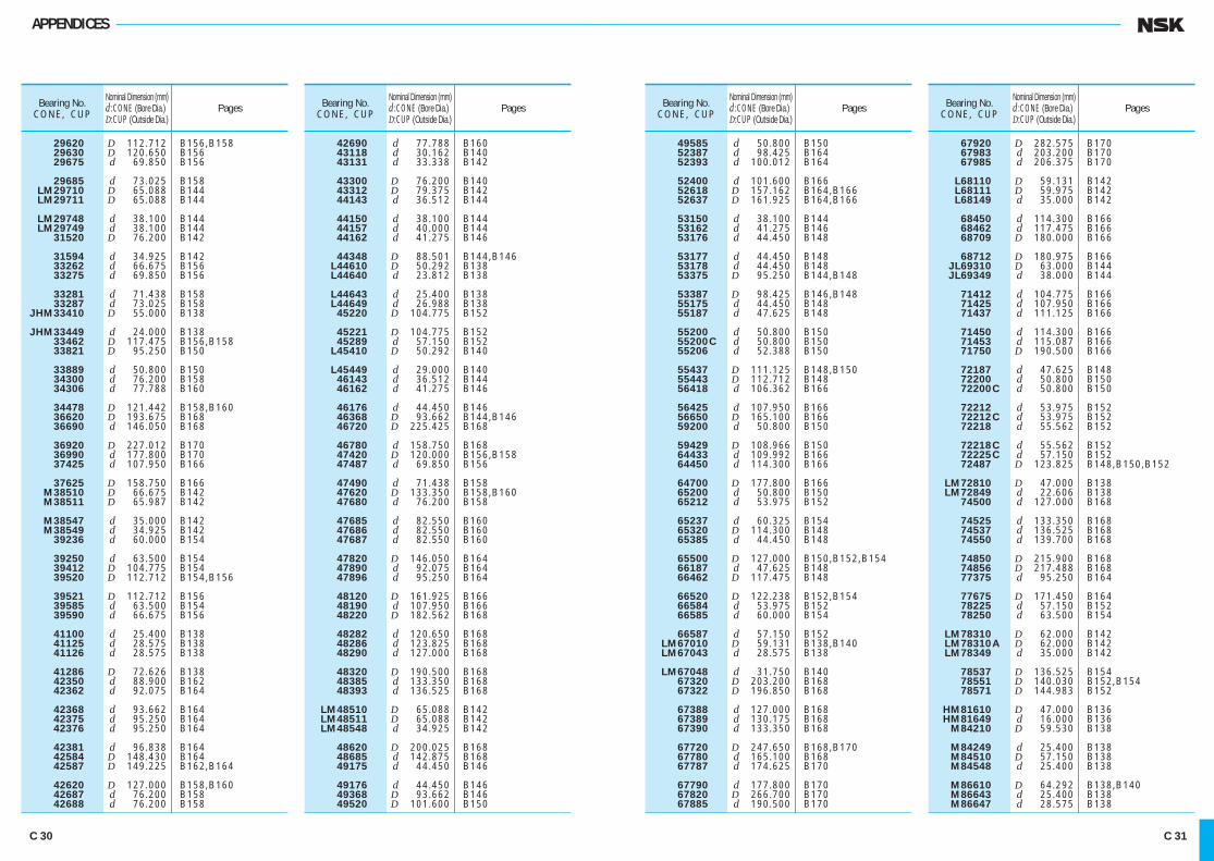
APPENDICES
Bearing No. Nominal Dimension (mm) CONE, CUP d :CONE (Bore Dia.) Pages D:CUP (Outside Dia.)
29620 D 112.712 B156,B158 29630 D 120.650 B156 29675 d 69.850 B156
29685 d 73.025 B158 LM29710 D 65.088 B144 LM29711 D 65.088 B144
LM29748 d 38.100 B144 LM29749 d 38.100 B144 31520 D 76.200 B142
31594 d 34.925 B142 33262 d 66.675 B156 33275 d 69.850 B156
33281 d 71.438 B158 33287 d 73.025 B158 JHM33410 D 55.000 B138
JHM33449 d 24.000 B138 33462 D 117.475 B156,B158 33821 D 95.250 B150
33889 d 50.800 B150 34300 d 76.200 B158 34306 d 77.788 B160
34478 D 121.442 B158,B160 36620 D 193.675 B168 36690 d 146.050 B168
36920 D 227.012 B170 36990 d 177.800 B170 37425 d 107.950 B166
37625 D 158.750 B166 M38510 D 66.675 B142 M38511 D 65.987 B142
M38547 d 35.000 B142 M38549 d 34.925 B142 39236 d 60.000 B154
39250 d 63.500 B154 39412 D 104.775 B154 39520 D 112.712 B154,B156
39521 D 112.712 B156 39585 d 63.500 B154 39590 d 66.675 B156
41100 d 25.400 B138 41125 d 28.575 B138 41126 d 28.575 B138
41286 D 72.626 B138 42350 d 88.900 B162 42362 d 92.075 B164
42368 d 93.662 B164 42375 d 95.250 B164 42376 d 95.250 B164
42381 d 96.838 B164 42584 D 148.430 B164 42587 D 149.225 B162,B164
42620 D 127.000 B158,B160 42687 d 76.200 B158 42688 d 76.200 B158
Bearing No. Nominal Dimension (mm) CONE, CUP d :CONE (Bore Dia.) Pages D:CUP (Outside Dia.)
42690 d 77.788 B160 43118 d 30.162 B140 43131 d 33.338 B142
43300 D 76.200 B140 43312 D 79.375 B142 44143 d 36.512 B144
44150 d 38.100 B144 44157 d 40.000 B144 44162 d 41.275 B146
44348 D 88.501 B144,B146 L44610 D 50.292 B138 L44640 d 23.812 B138
L44643 d 25.400 B138 L44649 d 26.988 B138 45220 D 104.775 B152
45221 D 104.775 B152 45289 d 57.150 B152 L45410 D 50.292 B140
L45449 d 29.000 B140 46143 d 36.512 B144 46162 d 41.275 B146
46176 d 44.450 B146 46368 D 93.662 B144,B146 46720 D 225.425 B168
46780 d 158.750 B168 47420 D 120.000 B156,B158 47487 d 69.850 B156
47490 d 71.438 B158 47620 D 133.350 B158,B160 47680 d 76.200 B158
47685 d 82.550 B160 47686 d 82.550 B160 47687 d 82.550 B160
47820 D 146.050 B164 47890 d 92.075 B164 47896 d 95.250 B164
48120 D 161.925 B166 48190 d 107.950 B166 48220 D 182.562 B168
48282 d 120.650 B168 48286 d 123.825 B168 48290 d 127.000 B168
48320 D 190.500 B168 48385 d 133.350 B168 48393 d 136.525 B168
LM48510 D 65.088 B142 LM48511 D 65.088 B142 LM48548 d 34.925 B142
48620 D 200.025 B168 48685 d 142.875 B168 49175 d 44.450 B146
49176 d 44.450 B146 49368 D 93.662 B146 49520 D 101.600 B150
Bearing No. Nominal Dimension (mm) CONE, CUP d :CONE (Bore Dia.) Pages D:CUP (Outside Dia.)
49585 d 50.800 B150 52387 d 98.425 B164 52393 d 100.012 B164
52400 d 101.600 B166 52618 D 157.162 B164,B166 52637 D 161.925 B164,B166
53150 d 38.100 B144 53162 d 41.275 B146 53176 d 44.450 B148
53177 d 44.450 B148 53178 d 44.450 B148 53375 D 95.250 B144,B148
53387 D 98.425 B146,B148 55175 d 44.450 B148 55187 d 47.625 B148
55200 d 50.800 B150 55200 C d 50.800 B150 55206 d 52.388 B150
55437 D 111.125 B148,B150 55443 D 112.712 B148 56418 d 106.362 B166
56425 d 107.950 B166 56650 D 165.100 B166 59200 d 50.800 B150
59429 D 108.966 B150 64433 d 109.992 B166 64450 d 114.300 B166
64700 D 177.800 B166 65200 d 50.800 B150 65212 d 53.975 B152
65237 d 60.325 B154 65320 D 114.300 B148 65385 d 44.450 B148
65500 D 127.000 B150,B152,B154 66187 d 47.625 B148 66462 D 117.475 B148
66520 D 122.238 B152,B154 66584 d 53.975 B152 66585 d 60.000 B154
66587 d 57.150 B152 LM67010 D 59.131 B138,B140 LM67043 d 28.575 B138
LM67048 d 31.750 B140 67320 D 203.200 B168 67322 D 196.850 B168
67388 d 127.000 B168 67389 d 130.175 B168 67390 d 133.350 B168
67720 D 247.650 B168,B170 67780 d 165.100 B168 67787 d 174.625 B170
67790 d 177.800 B170 67820 D 266.700 B170 67885 d 190.500 B170
Bearing No. Nominal Dimension (mm) CONE, CUP d :CONE (Bore Dia.) Pages D:CUP (Outside Dia.)
67920 D 282.575 B170 67983 d 203.200 B170 67985 d 206.375 B170
L68110 D 59.131 B142 L68111 D 59.975 B142 L68149 d 35.000 B142
68450 d 114.300 B166 68462 d 117.475 B166 68709 D 180.000 B166
68712 D 180.975 B166 JL69310 D 63.000 B144 JL69349 d 38.000 B144
71412 d 104.775 B166 71425 d 107.950 B166 71437 d 111.125 B166
71450 d 114.300 B166 71453 d 115.087 B166 71750 D 190.500 B166
72187 d 47.625 B148 72200 d 50.800 B150 72200 C d 50.800 B150
72212 d 53.975 B152 72212 C d 53.975 B152 72218 d 55.562 B152
72218 C d 55.562 B152 72225 C d 57.150 B152 72487 D 123.825 B148,B150,B152
LM72810 D 47.000 B138 LM72849 d 22.606 B138 74500 d 127.000 B168
74525 d 133.350 B168 74537 d 136.525 B168 74550 d 139.700 B168
74850 D 215.900 B168 74856 D 217.488 B168 77375 d 95.250 B164
77675 D 171.450 B164 78225 d 57.150 B152 78250 d 63.500 B154
LM78310 D 62.000 B142 LM78310 A D 62.000 B142 LM78349 d 35.000 B142
78537 D 136.525 B154 78551 D 140.030 B152,B154 78571 D 144.983 B152
HM81610 D 47.000 B136 HM81649 d 16.000 B136 M84210 D 59.530 B138
M84249 d 25.400 B138 M84510 D 57.150 B138 M84548 d 25.400 B138
M86610 D 64.292 B138,B140 M86643 d 25.400 B138 M86647 d 28.575 B138
C 30 C 31
C001-034E.indd 30-31 C001-034E.indd 30-31 11/20/13 5:04:03 PM11/20/13 5:04:03 PM
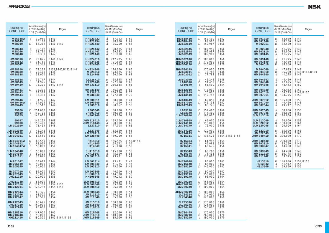
APPENDICES
Bearing No. Nominal Dimension (mm) CONE, CUP d :CONE (Bore Dia.) Pages D:CUP (Outside Dia.)
HM801310 D 82.550 B144 HM801346 d 38.100 B144 M802011 D 82.550 B146
M802048 d 41.275 B146 HM803110 D 88.900 B146 HM803145 d 41.275 B146
HM803146 d 41.275 B146 HM803149 d 44.450 B146 M804010 D 88.900 B148
M804049 d 47.625 B148 HM804810 D 95.250 B146,B148,B150 HM804840 d 41.275 B146
HM804843 d 44.450 B148 HM804846 d 47.625 B148 HM804848 d 48.412 B150
HM804849 d 48.412 B150 HM807010 D 104.775 B148,B150 HM807011 D 104.775 B150
JHM807012 D 105.000 B150 HM807040 d 44.450 B148 HM807044 d 49.212 B150
JHM807045 d 50.000 B150 HM807046 d 50.800 B150 JLM813010 D 110.000 B158
JLM813049 d 70.000 B158 JLM820012 D 150.000 B164 JLM820048 d 100.000 B164
JM822010 D 165.000 B166 JM822049 d 110.000 B166 JHM840410 D 300.000 B170
JHM840449 d 200.000 B170 HM903210 D 95.250 B148 HM903247 d 44.450 B148
HM903249 d 44.450 B148 HM911210 D 130.175 B152 HM911242 d 53.975 B152
H913810 D 146.050 B154,B156 H913842 d 61.912 B154 H913849 d 69.850 B156
Bearing No. Nominal Dimension (mm) CONE, CUP d :CONE (Bore Dia.) Pages D:CUP (Outside Dia.)
HM518410 D 152.400 B162 HM518445 d 88.900 B162 LM522510 D 159.987 B166
LM522546 d 107.950 B166 LM522548 d 109.987 B166 LM522549 d 109.987 B166
JHM522610 D 180.000 B166 JHM522649 d 110.000 B166 JHM534110 D 230.000 B170
JHM534149 d 170.000 B170 LM603011 D 77.788 B148 LM603012 D 77.788 B148
LM603049 d 45.242 B148 L610510 D 94.458 B154 L610549 d 63.500 B154
JM612910 D 115.000 B158 JM612949 d 70.000 B158 LM613410 D 112.712 B156
LM613449 d 69.850 B156 HM617010 D 142.138 B162 HM617049 d 85.725 B162
L623110 D 152.400 B166 L623149 d 114.300 B166 JLM710910 D 105.000 B156
JLM710949 d 65.000 B156 JLM714110 D 115.000 B158 JLM714149 d 75.000 B158
JM714210 D 120.000 B158 JM714249 d 75.000 B158 H715311 D 136.525 B154,B156,B158
H715334 d 61.912 B154 H715340 d 65.088 B156 H715341 d 66.675 B156
H715343 d 68.262 B156 H715345 d 71.438 B158 JM716610 D 130.000 B162
JM716648 d 85.000 B162 JM716649 d 85.000 B162 JM718110 D 145.000 B162
JM718149 d 90.000 B162 JM719113 D 150.000 B164 JM719149 d 95.000 B164
JM720210 D 155.000 B164 JHM720210 D 160.000 B164 JM720249 d 100.000 B164
JHM720249 d 100.000 B164 JL724314 D 170.000 B168 JL724348 d 120.000 B168
JL725316 D 175.000 B168 JL725346 d 125.000 B168 JM734410 D 240.000 B170
JM734449 d 170.000 B170 JM738210 D 260.000 B170 JM738249 d 190.000 B170
Bearing No. Nominal Dimension (mm) CONE, CUP d :CONE (Bore Dia.) Pages D:CUP (Outside Dia.)
HH221432 d 87.312 B162 HH221434 d 88.900 B162 HH221440 d 95.250 B164
HH221442 d 98.425 B164 HH221447 d 99.982 B164 HH221449 d 101.600 B166
HH224310 D 212.725 B166 HH224335 d 101.600 B166 HH224340 d 107.950 B166
HH224346 d 114.300 B166 M224710 D 174.625 B168 M224748 d 120.000 B168
LL225710 D 165.895 B168 LL225749 d 127.000 B168 HM231110 D 236.538 B168
HM231140 d 146.050 B168 M236810 D 260.350 B170 M236849 d 177.800 B170
LM300811 D 68.000 B144 LM300849 d 41.000 B144 L305610 D 80.962 B150
L305649 d 50.800 B150 JH307710 D 110.000 B152 JH307749 d 55.000 B152
JHM318410 D 155.000 B162 JHM318448 d 90.000 B162 L327210 D 177.008 B168
L327249 d 133.350 B168 LM328410 D 187.325 B168 LM328448 d 139.700 B168
H414210 D 136.525 B156,B158 H414245 d 68.262 B156 H414249 d 71.438 B158
JH415610 D 145.000 B158 JH415647 d 75.000 B158 LM501310 D 73.431 B144
LM501314 D 73.431 B144 LM501349 d 41.275 B144 LM503310 D 75.000 B148
LM503349 d 46.000 B148 HH506310 D 114.300 B150 HH506348 d 49.212 B150
JLM506810 D 90.000 B152 JLM506849 d 55.000 B152 JLM508710 D 95.000 B154
JLM508748 d 60.000 B154 JM511910 D 110.000 B156 JM511946 d 65.000 B156
JM515610 D 130.000 B160 JM515649 d 80.000 B160 HM516410 D 133.350 B160
HM516448 d 82.550 B160 JHM516810 D 140.000 B162 JHM516849 d 85.000 B162
Bearing No. Nominal Dimension (mm) CONE, CUP d :CONE (Bore Dia.) Pages D:CUP (Outside Dia.)
M86648 A d 30.955 B140 M86649 d 30.162 B140 M88010 D 68.262 B140,B142
M88043 d 30.162 B140 M88046 d 31.750 B140 M88048 d 33.338 B142
HM88510 D 73.025 B140,B142 HM88542 d 31.750 B140 HM88547 d 33.338 B142
HM88610 D 72.233 B138,B140,B142,B144 HM88630 d 25.400 B138 HM88638 d 32.000 B140
HM88648 d 35.717 B144 HM88649 d 34.925 B142 HM89410 D 76.200 B142,B144
HM89411 D 76.200 B142 HM89443 d 33.338 B142 HM89444 d 33.338 B142
HM89446 d 34.925 B142 HM89446 A d 34.925 B142 HM89449 d 36.512 B144
99100 D 254.000 B168 99550 d 139.700 B168 99575 d 146.050 B168
99587 d 149.225 B168 99600 d 152.400 B168 LM102910 D 73.431 B148
LM102949 d 45.242 B148 JLM104910 D 82.000 B150 LM104911 D 82.550 B150
LM104911 A D 82.550 B150 LM104912 D 82.931 B150 LM104947 A d 50.000 B150
JLM104948 d 50.000 B150 LM104949 d 50.800 B150 M201011 D 73.025 B144
M201047 d 39.688 B144 JM205110 D 90.000 B150 JM205149 d 50.000 B150
JM207010 D 95.000 B152 JM207049 d 55.000 B152 JH211710 D 120.000 B156
JH211749 d 65.000 B156 HM212010 D 122.238 B154,B156 HM212011 D 122.238 B154,B156
HM212044 d 60.325 B154 HM212046 d 63.500 B154 HM212047 d 63.500 B154
HM212049 d 66.675 B156 JH217210 D 150.000 B162 JH217249 d 85.000 B162
HM218210 D 147.000 B162 HM218248 d 90.000 B162 HH221410 D 190.500 B162,B164,B166
C 32 C 33
C001-034E.indd 32-33 C001-034E.indd 32-33 11/20/13 5:04:04 PM11/20/13 5:04:04 PM

C001-034E.indd 34 C001-034E.indd 34 11/20/13 5:04:05 PM11/20/13 5:04:05 PM
H3E.indd 1-2H3E.indd 1-2 11/20/13 5:04:51 PM11/20/13 5:04:51 PM

Rolling Bearings
Rolling
Bearings
CAT. No. E1102m 2013 C-11 Printed in Japan ©NSK Ltd. First edition published in MAR. 2005
2013/10/16