THREAD ROLLING SOLUTIONS - HubSpot
20
THREAD ROLLING SOLUTIONS A GUIDE TO THREAD ROLLING BASICS AND THREAD ROLLING STYLES 167 Ames Street | Rochester, NY 14611 p: 585.429.5000 | f: 585.429.5095 www.cjwinter.com
-
Upload
khangminh22 -
Category
Documents
-
view
1 -
download
0
Transcript of THREAD ROLLING SOLUTIONS - HubSpot

THREAD ROLLINGSOLUTIONS
A GUIDE TO THREAD ROLLING BASICS ANDTHREAD ROLLING STYLES
167 Ames Street | Rochester, NY 14611p: 585.429.5000 | f: 585.429.5095
www.cjwinter.com

Second EdgeLocating Edge
Chamfer
Figure #1
A B
F
L
P = Pitch (1÷TPI)
L = Length of Rolled Thread
How to Determine the Correct Working Face
Figure #1 and #3 - F=(2.25xP)+L
B = Shoulder Side
A = Chamfer Side
end of the blank by at least 1 ¼ threads (root to root or crest to crest = 1 thread).
Figure #2 and #4 - F=(2.50xP)+L
2
of the thread that needs to be rolled. The general rule is to allow the thread to overhang each
Figures 1 through 4 are intended to help you calculate the working face “F” for various 1.
thread rolling applications, and how to position the roll properly.
The working face (or “F” dimension) of the thread roll must always be greater than the length2.
A=1.50xP
B=1.25xP
Figure #4
A
F
L
Figure #3
L
F
B
Figure #2
A
L
F
A

Cut Off
threads, multiple leads.
Optional:
3) Position of attachment in relation to collet is not important.
4) Sufficient clearance is available on either side of working face.
3
breakouts, bronze
Special bevels, machined
bushings, left handed
Standard: Working face as listed above.
When to Use C-1 Style
1) Rolling on outboard end of work.
2) Standard Working Face is satisfactory for length of thread
to be rolled.
Type C-1Rolls for Straight Threads
Model Std. W.F. Model Std. W.F. Model Std. W.F.
125-SA 0.552 14GA 0.625 76000 (0-375) 0.468
134-SA 0.625 18GA 0.844 76100 (6-625) 0.625
141-SA 0.875 20GA 1.000 76200 (10-750) 0.812
151-SA 0.875 22GA 1.375 76300 (30-1000) 0.812
160-SA 1.530 24GA 1.500 76400 (25-1125) 1.062
162/163-SA 1.265
170-SA 1.530 Model Std. W.F. Model Std. W.F.
172/173-SA 1.265 B-5 0.500 CBL 0.812
B-8 0.500 BBL 1.062
Model Std. W.F. B-10 (500-G2A) 0.625 DBL 1.312
1421-SA 0.625 B-13 (750-G2A) 0.875
1431-SA 0.625 B-18 (1000-G2A) 1.125 Model Std. W.F.
1448-SA 0.625 B-36 1.125 T12 0.610
T18 0.846
T27 1.220
Fette
Davenport
Reed Salvo
C-1 Standard Workface
Winter Landis Detroit
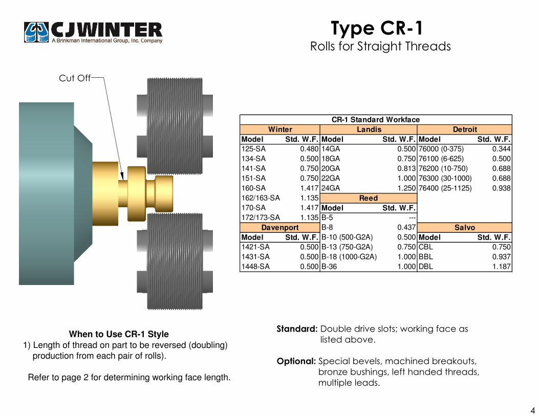
Type CR-1 Rolls for Straight Threads
bronze bushings, left handed threads,
multiple leads.
Optional: Special bevels, machined breakouts,
Refer to page 2 for determining working face length.
Standard: Double drive slots; working face as
listed above. When to Use CR-1 Style
1) Length of thread on part to be reversed (doubling)
production from each pair of rolls).
4
Cut Off
Model Std. W.F. Model Std. W.F. Model Std. W.F.
125-SA 0.480 14GA 0.500 76000 (0-375) 0.344
134-SA 0.500 18GA 0.750 76100 (6-625) 0.500
141-SA 0.750 20GA 0.813 76200 (10-750) 0.688
151-SA 0.750 22GA 1.000 76300 (30-1000) 0.688
160-SA 1.417 24GA 1.250 76400 (25-1125) 0.938
162/163-SA 1.135
170-SA 1.417 Model Std. W.F.
172/173-SA 1.135 B-5 ---
B-8 0.437
Model Std. W.F. B-10 (500-G2A) 0.500 Model Std. W.F.
1421-SA 0.500 B-13 (750-G2A) 0.750 CBL 0.750
1431-SA 0.500 B-18 (1000-G2A) 1.000 BBL 0.937
1448-SA 0.500 B-36 1.000 DBL 1.187
Davenport
Reed
Salvo
CR-1 Standard Workface
Winter Landis Detroit

Cut Off
Working face must be specified when ordering C-2 or C-3 Style.Refer to page 2 for determining working face length.
When to Use C-2 Style
3) Attachment to be positioned as close to collet as possible.
1) Rolling threads behind a shoulder at cut-off end.
Optional
double drive slots, left handed threads, multiple leads.
Type C-2 Rolls for Straight Threads
2) Narrow width required due to part configuration.
3) Attachment to be positioned as close to collet as possible.
double drive slots, left handed threads, multiple leads.
: Special bevels, machined breakouts, bronze bushings,
Type C-3 Rolls for Straight Threads
: Special bevels, machined breakouts, bronze bushings, Optional
When to Use C-3 Style
1) Rolling threads behind a shoulder at cut-off end.
2) Narrow width required due to part configuration.
5
Cut Off

Cut Off
left handed threads, multiple leads.
2) Need to maintain the position of the cut-off end of the part relative to the collet
Optional: Special bevels, machined breakouts, bronze bushings,
Working face must be specified when ordering C-4 Style as well as the length of hub opposite the drive slot.
When to Use C-4 Style1) It is important to maintain position of attachment on the
cross slide.
double drive slots, left handed threads, multiple leads.
Working face must be specified when ordering DR-5 Style as well as groove diameter and/or stock diameter.
When to Use DR-5 Style1) When rolling two threads of the same diameter and pitch which are separated by a shoulder2) Rolling behind a shoulder where length of thread permits rolls to be reversed (doubling production of 1 pair of rolls).
Standard: Recessed double drive slots.Optional: Special bevels, machined breakouts, bronze bushings,
6
Cut Off
Type C-4 Rolls for Straight ThreadsRolls for Straight ThreadsRolls for Straight ThreadsRolls for Straight Threads
Type DR-5 Rolls for Straight ThreadsRolls for Straight ThreadsRolls for Straight ThreadsRolls for Straight Threads

Cut Off
Type D-1 Rolls for Straight Threads
Refer to page 2 for determining working face length.
When to Use D-1 Style
sufficient for length of thread required.
left handed threads, multiple leads.
1) Working face of rolls with standard hubs is not Standard: Recessed drive slot, extended standard
working face as listed above.
Optional: Special bevels, machined breakouts, bronze bushings,
7
Reed
Model Std. W.F. Model Std. W.F. Model Std. W.F.
125-SA .636* B-5 --- 76000 (0-375) 0.593
134-SA .750* B-8 0.560 76100 (6-625) 0.750
141-SA 1.000* B-10 (500-G2A) 0.750 76200 (10-750) 0.938
151-SA 1.000* B-13 (750-G2A) 1.000 76300 (30-1000) 0.938
160-SA 1.656* B-18 (1000-G2A) 1.250 76400 (25-1125) 1.188
162/163-SA 1.395* B-36 1.250
170-SA 1.656*
172/173-SA 1.395* Model Std. W.F.
CBL 0.937
Model Std. W.F. BBL 1.187
1421-SA .750* DBL 1.437
1431-SA .750*
1448-SA .750** Gear Guard must be removed when installing
Davenport
Salvo
D-1 Standard Workface
Winter Detroit

When to Use DR-1 Style
1) Length of thread on part permits rolls to be reversed
(doubling production on 1 pair of rolls).
Refer to page 2 for determining working face length.
Special bevels, machined breakouts, bronze bushings,
left handed threads, multiple leads.
Rolls for Straight Threads
Standard: Recessed drive slots, working face as listed above.
Optional:
Type DR-1
8
Cut Off
Reed
Model Std. W.F. Model Std. W.F. Model Std. W.F.
125-SA 0.636* B-5 --- 76000 (0-375) 0.593
134-SA 0.750* B-8 0.560 76100 (6-625) 0.750
141-SA 1.000* B-10 (500-G2A) 0.750 76200 (10-750) 0.938
151-SA 1.000* B-13 (750-G2A) 1.000 76300 (30-1000) 0.938
160-SA 1.656* B-18 (1000-G2A) 1.250 76400 (25-1125) 1.188
162/163-SA 1.395* B-36 1.250
170-SA 1.656*
172/173-SA 1.395* Model Std. W.F.
CBL 0.937
Model Std. W.F. BBL 1.187
1421-SA 0.750* DBL 1.437
1431-SA 0.750*
1448-SA 0.750** Gear Guard must be removed when installing
Davenport
Salvo
DR-1 Standard Workface
Winter Detroit

Cut Off
When to use K-2 Style
1) Rolling taper pipe threads with small1) Rolling taper pipe threads with small
end of work away from collet.
Type K-2 Rolls for Taper Pipe Threads
When to use Q-2 Style
end of work towards the collet.
Type Q-2Rolls for Taper Pipe Threads
Special working face, bronze bushings.
Standard: NPT or NPTF as specified 45° Chamfer,
working face as listed in table.
Standard Taper Angle: 1° 47'
Optional:
9
Cut Off
1/16 - 27 NPT/NPTF 0.375 3/4 - 14 NPT/NPTF 0.724
1/8 - 27 NPT/NPTF 0.375 1 - 11 1/2 NPT/NPTF 0.900
1/4 - 18 NPT/NPTF 0.562 1 1/4 - 11 1/2 NPT/NPTF 0.924
3/8 - 18 NPT/NPTF 0.562 1 1/2 - 11 1/2 NPT/NPTF 0.941
1/2 - 14 NPT/NPTF 0.712
K-2 and Q-2 Standard Working Face

Cutoff
Rolls for Straight Threads
Refer to page 2 for determining working face length.
Working face must be specified with ordering H-2 Style.
Using a Reed B-5 attachment.
2. Requires being within 1/8" of collet face.
1.
When to Use H-2 Style
Standard: Counterbored roll rather than hub
at collet side, bronze bushing.
Type H-2
10

Type OBR-1Quick Change Thread Rolls
for Straight Threads
When to use OBR-1 Style
Using outboard style attachment.1.
Length of thread on part permits 2. rolls to be reversed (Doubling production on 1 pair of rolls).
Model WF
145-OB .625
165-OB .787
OBR-1 Standard Working Face
11
Cutoff

Standard: NPT or NPT as specified working face listed
Optional: Special working face
OB Standard Working Face
1/16-27 .375 1/8-27 .375 1/4-18 .562
3/8-18 .562 1/2-14 .712 3/4-14 .724
Type OBRQ-2 Quick Change For Taper Pipe ThreadsQuick Change For Taper Pipe ThreadsQuick Change For Taper Pipe ThreadsQuick Change For Taper Pipe Threads
When to Use OBR-Q-2 Style
Using outboard style attachment1.
Rolling taper pipe threads with2.
small end of work away from collet
12
Cutoff

Overhung Die Holder for A22 and A23
10C
20C
30C
50C
90C
120C
220C
Standard: 30° Chamfer from axis.
Optional: 45° or 60° chamfer machined
breakout, left hand thread,
multiple leads.
Width of holder must be specified when ordering.
Refer to page 2 for determining working face length
* Rolls also available for othermachine sizes not listed
Overhung Die Holders 3-Die Cylindrical Rolling Machine
- Straight Threads - Keyway -
13
Overhung Die Holder for A22 and A23
10C
20C
30C
50C
90C
120C
220C

Overhung Die Holder for A22 and A23
10C
20C
30C
50C
90C
120C
220C
Standard: 30° Chamfer from axis.
Optional: 45° or 60° chamfer machined
breakout, left hand thread,
multiple leads.
Width of holder must be specified when ordering.
* Rolls also available for othermachine sizes not listed
Overhung Die Holders 3-Die Cylindrical Rolling Machine
- Tapered Threads - Keyway -
14
Styles
Double Taper(Reversible)
Single Taper
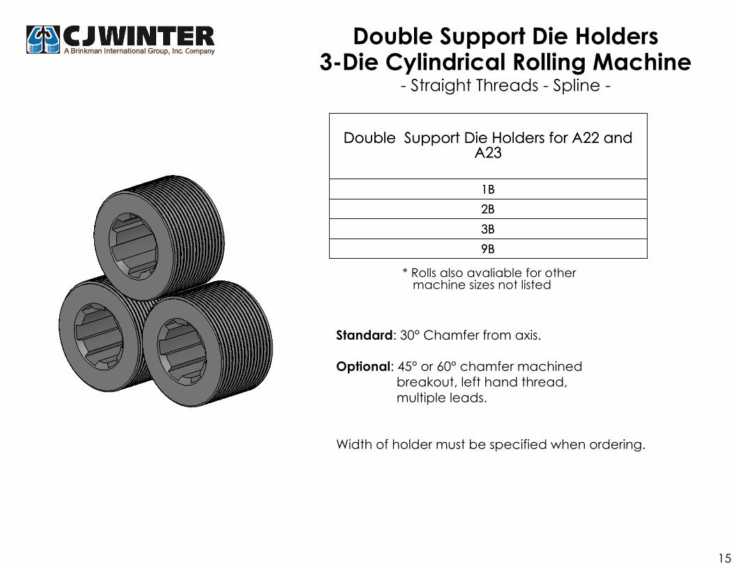
Double Support Die Holders3-Die Cylindrical Rolling Machine
- Straight Threads - Spline -
Double Support Die Holders for A22 and A23
1B
2B
3B
9B
* Rolls also avaliable for other machine sizes not listed
Standard: 30° Chamfer from axis.
Optional: 45° or 60° chamfer machined
breakout, left hand thread,
multiple leads.
Width of holder must be specified when ordering.
15
Double Support Die Holders for A22 and A23
1B
2B
3B
9B

Double Taper(Reversible)
Double Support Die Holders3-Die Cylindrical Rolling Machine
- Tapered Threads - Spline -
Double Support Die Holders for A22 and A23
1B
2B
3B
9B
* Rolls also avaliable for other machine sizes not listed
Standard: 30° Chamfer from axis.
Optional: 45° or 60° chamfer machined
breakout, left hand thread,
multiple leads.
Width of holder must be specified when ordering.
16
Styles
B
Single Taper
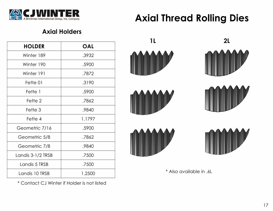
* Also available in .6L
Axial Thread Rolling Dies
1L 2LHOLDER OAL
Winter 189 .3932
Winter 190 .5900
Winter 191 .7872
Fette 01 .3190
Fette 1 .5900
Fette 2 .7862
Fette 3 .9840
Fette 4 1.1797
Geometric 7/16 .5900
Geometric 5/8 .7862
Geometric 7/8 .9840
Landis 3-1/2 TRSB .7500
Landis 5 TRSB .7500
Landis 10 TRSB 1.2500
* Contact CJ Winter if Holder is not listed
Axial Holders
17

Type F-1Rolls for Straight Threads
When to use F-1 Style:1) Standard working face of roll is satisfactory for the length of thread to be rolled.
When to use F-2 Style:1) Narrow width required due to part configuration.
* Working Face must be specified when ordering F-2 Style. Refer to page 2 for determining working face length
Model F-1-44 F-1-54 F-1-66 F-1-86 F-1-88 F-1-108 F-1-1210 F-2-44 F-2-54 F-2-66 F-2-86 F-2-88 F-2-108 F-2-1210
O.A.L. .250 .3125 .375 .500 .500 .625 .750 .250 .3125 .375 .500 .500 .625 .750
ID .250 .250 .375 .375 .500 .500 .625 .250 .250 .375 .375 .500 .500 .625
18
Cut Off
OAL
ID
Cut Off
Type F-2Rolls for Straight Threads
*WF
ID Hub Dia.
OAL

(Rolls Supplied as Pairs)
Refer to page 2 for determining correct working face length
Type E 2727
Davenport Double Roll Holders
Type E-2903Type E-2910
Davenport Single Roll Holders
Standard: Dimensions as shown.
Working face "F" must be specified when ordering this style.
19
A
.875.438
.438
"F"
.313
.313 .625
"F"
"L"
.394 .625
"F"

Holder STD. Work Face
E08 .4560
E10 .7712
E13 .9675
E16 1.1650
E23 1.3615
* Due to the nature of these rolls, consult
factory for price and delivery.
Thread size and work face required upon ordering.
Refer to page 2 for determining working face length.
20
"E" Style Rolls
FETTE E SERIES