
Basic Electronics Principles - HubSpot
11
Basic Electronics Principles
-
Upload
khangminh22 -
Category
Documents
-
view
4 -
download
0
Transcript of Basic Electronics Principles - HubSpot
Basic Electronics Principles

2460 Harley Knox Blvd | Perris, CA 92571 | Tel: 951.277.0757 | www.triadmagnetics.com
BASIC ELECTRONICS PRINCIPLES FROM TRIAD MAGNETICS
Back to BasicsIn any industry, it can be easy to lose touch with the basics. This is particularly true in the electronics field — as theory, products, and applications increase in complexity, practitioners find themselves farther and farther away from the basics.
Basic principles, such as resistance, current, voltage, and power, are the building blocks upon which all electrical components are built. This includes, of course, the complex magnetics components that we manufacture here at Triad Magnetics.
This guide is designed to provide a brief refresher course on basic electronics. Anyone — from students to junior team members, and from recent graduates to seasoned industry professionals — will find an occasional review of the basics to be beneficial.
ElectronsAll matter is composed of atoms which, in turn, are composed of protons, neutrons, and electrons.
Protons and neutrons are composed of quarks, while electrons are point particles — particles that lack spatial extension, or are zero-dimensional, but have a nonzero mass. Protons are positively charged, neutrons have zero charge, and electrons are negatively charged. Protons and electrons naturally balance themselves, so the majority of stable atoms have zero charge.
Because of their zero-dimensional size, electrons are prone to moving between atoms. “Free electrons,” as they are called, travel more readily in some materials, particularly certain metals, than in others — these materials are called conductors.
A large number of free electrons flowing through a material constitutes a current, which is typically measured in amperes. A single ampere of current equates to 6.3x10¹⁸ electrons — 6,300,000,000,000,000,000 or 6.3 quintillion, in other words — moving through a conductor per second.
The force that frees electrons from their original atom is voltage.
Resistance is most simply described as electrical friction; resistance opposes flow of current in the same way that mechanical friction opposes movement of objects. Every material, even the best conductors, offers some form of opposition to the flow of free electrons.
Good conductors — copper and aluminum, for example — have very low resistance, so current flows easily. Poor conductors — such as tungsten and lead — have very high resistance. The flow of current through resistance creates heat; the greater the current, the more heat produced.
460 Harley Knox Blvd | Perris, CA 92571 | Tel: 951.277.0757 | www.triadmagnetics.com 3
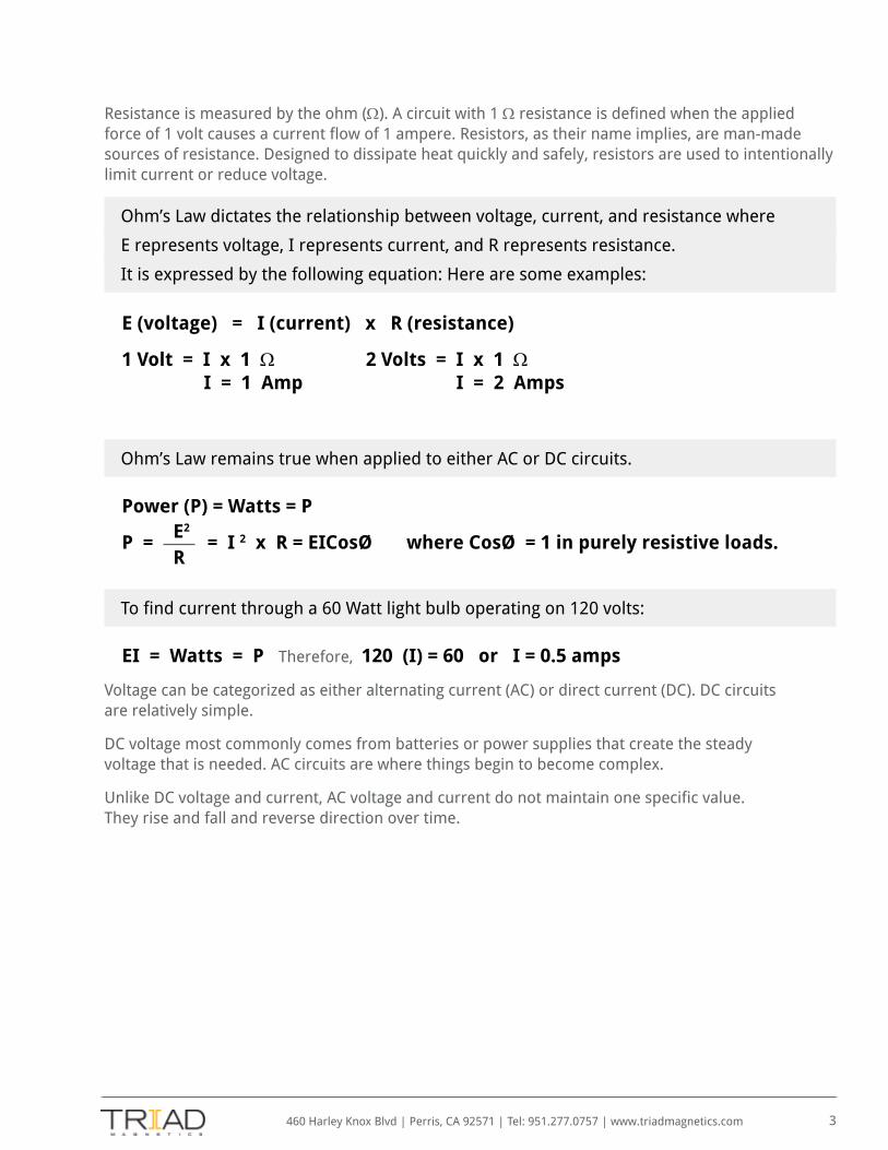
Resistance is measured by the ohm (Ω). A circuit with 1 Ω resistance is defined when the applied force of 1 volt causes a current flow of 1 ampere. Resistors, as their name implies, are man-made sources of resistance. Designed to dissipate heat quickly and safely, resistors are used to intentionally limit current or reduce voltage.
Ohm’s Law dictates the relationship between voltage, current, and resistance where
E represents voltage, I represents current, and R represents resistance.
It is expressed by the following equation: Here are some examples:
E (voltage) = I (current) x R (resistance)
1 Volt = I x 1 Ω 2 Volts = I x 1 Ω I = 1 Amp I = 2 Amps
Ohm’s Law remains true when applied to either AC or DC circuits.
Power (P) = Watts = P
P = = I 2 x R = EICosØ where CosØ = 1 in purely resistive loads.
To find current through a 60 Watt light bulb operating on 120 volts:
EI = Watts = P Therefore, 120 (I) = 60 or I = 0.5 amps
Voltage can be categorized as either alternating current (AC) or direct current (DC). DC circuits are relatively simple.
DC voltage most commonly comes from batteries or power supplies that create the steady voltage that is needed. AC circuits are where things begin to become complex.
Unlike DC voltage and current, AC voltage and current do not maintain one specific value. They rise and fall and reverse direction over time.
E2
R
460 Harley Knox Blvd | Perris, CA 92571 | Tel: 951.277.0757 | www.triadmagnetics.com 4
AC voltage and current is by far the more common type. It is found everywhere: the 120 volt outlets in homes and offices, the voltage of telephone lines that changes in according to an audio signal, and so on. Essentially all electronic equipment will use or include AC voltage or current.
AC voltage intended for power transmission is the most commonly the sine-wave waveform.
AC ParametersHaving discussed AC current, we can now move on to discussion of more complex electrical components — namely, transformers and inductors.
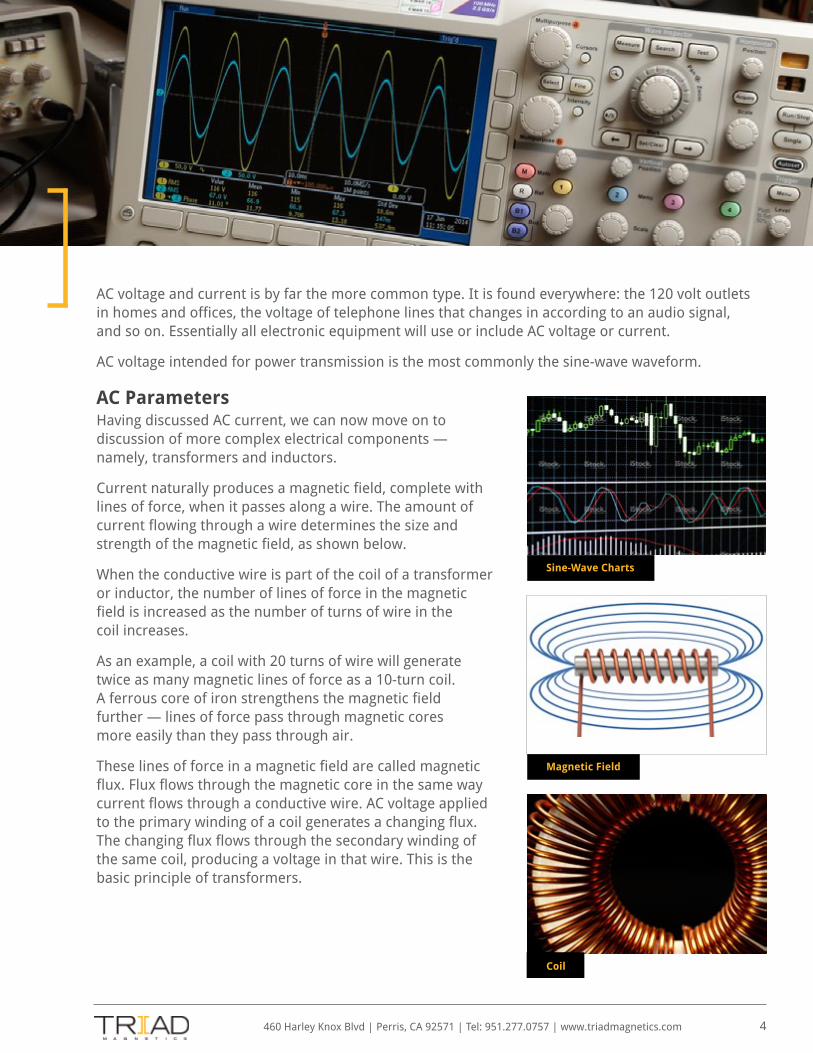
Current naturally produces a magnetic field, complete with lines of force, when it passes along a wire. The amount of current flowing through a wire determines the size and strength of the magnetic field, as shown below.
When the conductive wire is part of the coil of a transformer or inductor, the number of lines of force in the magnetic field is increased as the number of turns of wire in the coil increases.
As an example, a coil with 20 turns of wire will generate twice as many magnetic lines of force as a 10-turn coil. A ferrous core of iron strengthens the magnetic field further — lines of force pass through magnetic cores more easily than they pass through air.
These lines of force in a magnetic field are called magnetic flux. Flux flows through the magnetic core in the same way current flows through a conductive wire. AC voltage applied to the primary winding of a coil generates a changing flux. The changing flux flows through the secondary winding of the same coil, producing a voltage in that wire. This is the basic principle of transformers.
Sine-Wave Charts
Magnetic Field
Coil

InductanceThe property of a coil to oppose a change of current through it is called inductance, measured with a unit called a Henry.
A current that changes by 1 ampere per second to induce a 1 volt voltage has an inductance of 1 Henry. The higher the inductance of a coil, the more opposition the coil has to current changes. In equations, inductance is represented as L.
The following is the equation for determining the inductance of a coil:
L = 1.25 x (N)2 x (µ) x (A) 108 x (1)
In this formula, N represents turns in the coil, L represents inductance in Henrys, µ represents permeability of the core material, A represents the cross-sectional area of the core, and 1 is the length of the magnetic path.
Inductive ReactanceInductive reactance is a property very similar to resistance. In fact, both are measured in ohms. Inductive reactance is determined by the inductance value and the frequency of the applied voltage. A coil with a high inductance will also have a high inductive reactance. The higher the frequency, the higher the reactance.
In equations, inductive reactance is represented by XL. To determine the inductive
reactance of a coil, use this formula:
XL = 2 x ∏ x f x L
where L represents inductance in Henrys, f represents frequency cycles per second, and 2
x ∏, or 6.28, is constant. To determine inductance when inductive reactance is the known
factor, use this formula:
L = XL 2 x ∏ x f
460 Harley Knox Blvd | Perris, CA 92571 | Tel: 951.277.0757 | www.triadmagnetics.com 5
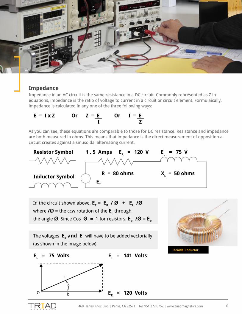
ImpedanceImpedance in an AC circuit is the same resistance in a DC circuit. Commonly represented as Z in equations, impedance is the ratio of voltage to current in a circuit or circuit element. Formulaically, impedance is calculated in any one of the three following ways:
E = I x Z Or Z = E Or I = E I Z
As you can see, these equations are comparable to those for DC resistance. Resistance and impedance are both measured in ohms. This means that impedance is the direct measurement of opposition a circuit creates against a sinusoidal alternating current.
Resistor Symbol 1 . 5 Amps ER = 120 V EL = 75 V
Inductor Symbol
In the circuit shown above, ET = ER / Ø + EL /Ø
where /Ø = the ccw rotation of the EL through
the angle Ø. Since Cos Ø = 1 for resistors: ER /Ø = ER
The voltages ER and EL will have to be added vectorially
(as shown in the image below)
EL = 75 Volts ET = 141 Volts
ER = 120 Volts
460 Harley Knox Blvd | Perris, CA 92571 | Tel: 951.277.0757 | www.triadmagnetics.com 6
Toroidal Inductor
R = 80 ohms XL = 50 ohms
ET
c
bO
Where V1 V2
N1
N2

This means that the impedance of the circuit is not 80 + 50 = 130 ohms, but rather 141 /1.5A . /320 or 94 /320. To be more technically accurate, it is the vector sum of 80 + 50 /900, which is 94 /320.
TransformersTransformers are devices used to change the level of AC voltage in a circuit. Transformers cannot be used with DC voltages. A transformer is composed of two separate coils which are both wound around a single core. The coil connected to the voltage source is the primary coil; the coil connected to the voltage output is the secondary.
Power TransformersStandard linear power transformers operate at one of three basic frequencies: 50 hertz, 60 hertz, or sometimes 400 hertz, where hertz is the number of cycles per second. Switcher power transformers can operate at frequencies as high as 2.5 megahertz and greater.
Power transformers transform line voltage, either increasing or decreasing it as needed. After being increased or decreased, the AC voltage is often converted to DC voltage — this way, the voltage can be used to operate integrated circuits and other types of circuits.
Rectification to create DC voltages is a highly complex issue. Contact Triad engineers for assistance.
460 Harley Knox Blvd | Perris, CA 92571 | Tel: 951.277.0757 | www.triadmagnetics.com 7
I1 I2
V1 V2 N1 N2
Flux
Equation 1: V2 = N2 x V Or V1 = N1 • Also I2 = N1 x I1 Or I2 = N1
N1 V2 N2 N2 I1 N2
= Primary voltage, I1 = Primary Current= Secondary voltage, I2 = Secondary Current= Primary turns= Secondary turns
Where V1 V2
N1
N2
Transformer

460 Harley Knox Blvd | Perris, CA 92571 | Tel: 951.277.0757 | www.triadmagnetics.com 8
For example, using Equation 1 with a 120 volt AC input on the primary and 12 volts AC
needed on the output, it would be necessary to step the voltage down by a turns ratio
of 120/12 or 10 to 1. This means that for every 10 turns on the primary, the secondary
requires 1 turn. As the voltage is stepped down, the current is stepped up by the same
ratio, and vice versa. If in the example, the primary was to draw 1 amp of current then
the secondary would draw 10 X 1 or 10 amps, since the current is stepped up by the
turns ratio which is 10 X 1. If a full wave bridge (capacitor filter) was being used to rectify
the 12 VAC @ 10 amps above, the following approximate DC outputs would be achieved
where K is approximately 0.85:
VAC = K VDC or VDC = VAC = 12 = 14 volts DC K .85
Iac = 1.65 IDC or IDC = Iac = 6 ADC 1.65
The amount of current a transformer can handle is a function of the size of the wire, the size of the core, and the components’ abilities to dissipate heat. Heat is caused both by current running through the wire and by the energy lost in the core due to flux density. Flux density decreases inverse to hertz: flux density at 50 hertz is greater than at 60 hertz. In larger cores, those with 50 VA (VA being secondary volts x secondary amps) of output or more, heating due to core loss and wire loss are approximately the same.
Because dual secondaries are independent, they can be connected in series or parallel. Two 12 volt windings rated at .450 amps each can be hooked up to a single output, connected to each other in series to add their voltages, or connected to each other in parallel to add their currents.
To order a power transformer, you must know the primary voltage and frequency, the secondary RMS voltage and current, and the mounting characteristics. If other than the standard 1500V the primary-to-secondary breakdown voltage should also be known.
PC Mount Split Pack Power Transformer
Isolation Transformer vs. AutoformersIsolation transformers have primary and secondary windings that are wound independently of each other. They are used in scenarios where a direct connection between the primary and the secondary is neither required nor desired.
Autoformers are transformers that utilize a part of the primary winding as the secondary winding, creating a direct copper connection to the line voltage. Autoformers use less copper than isolation transformers, which makes them less expensive. They are used often in US-made appliances destined for overseas use, where the input line voltage is 230V and must be decreased to 115V.
When ordering transformers, you must specify if isolation is required, the primary voltage and frequency, the secondary voltage, the power required, and how it is mounted and connected.
Audio TransformersAudio transformers are designed to convert electrical signals that are carrying sound. At frequencies from 20 to 20,000 hertz, wire coils have different impedances depending on both the number of turns and the core material used; audio transformers are designed with this in mind.
To transfer the maximum amount of power from one circuit to another, the output impedance of the first must match the input impedance of the second. For example, a push-pull vacuum tube amplifier may have an output of 8000 ohms and need to connect to an 8 ohm speaker — an audio transformer rated at 8000 to 8 would have to be used in this scenario. The 8000 ohm end of the transformer would connect to the amplifier tubes, and the 8 ohm end would connect with the speaker.
Pulse TransformersPulse transformers are designed explicitly to process pulses of very high frequency electricity without allowing any distortion into the signal. They can simultaneously step up or step down the pulse, the capability of which is determined by the turn ratio of the transformer. Additionally, pulse transformers can couple an AC pulse from one circuit to another while blocking any DC signals.
To specify a pulse transformer during purchase, it is best to know the impedance of the source and load, the amount of step up or step down required (if any), the pulse repetition rate, and the desired output parameters.
The rise time of a pulse in any given pulse transformer will be the same, regardless of the pulse width it receives. The droop characteristics increase linearly in proportion to the pulse width — if a 1 microsecond pulse yields a 10% droop, a 2 microsecond pulse will yield a 20% droop, and so on.
The flux density of pulse transformers is determined by not only the voltage level but by the pulse width as well, normally represented in equations as the ET constant in volt microseconds. Pulse transformers with a particular ET constant can be used with wider pulses and with lower voltages without saturating the core.
460 Harley Knox Blvd | Perris, CA 92571 | Tel: 951.277.0757 | www.triadmagnetics.com 9

460 Harley Knox Blvd | Perris, CA 92571 | Tel: 951.277.0757 | www.triadmagnetics.com 10
Filter Chokes (Inductors)Filter chokes are components that use the action of an inductor to filter out, or “choke,” unwanted AC voltages from a circuit. They are often found in use with DC power supplies, as many circuits are particularly sensitive to AC changes. Chokes can be designed to work in particular frequency ranges and, when used with additional components, can pass or choke signals in very specific frequency ranges.
Design of filter chokes depend on the current ratings, inductance ratings, and filtering requirements. Core materials and inductances are dependent particularly on the frequencies that must be filtered.
Military TransformersWhile MIL-T-27 has been deactivated and is no longer the official governing military specification for inductors, audio transformers, power transformers, and pulse transformers, it remains a highly regarded and often-referenced standard in many specifications. Similar to MIL-T-27, MIL-T-21038 lays out guidelines for pulse transformers.
All of Triad Magnetics’ hermetically sealed units, in addition to many of our other transformers and inductors, can be manufactured to meet the stringent guidelines laid out in these two military specifications.
ConclusionFor more than 70 years, Triad Magnetics has dedicated its energy to innovation and fulfilling the promises of consistency and quality that we make to our customers. Today, we are a leading manufacturer and distributor of high quality, cutting edge magnetics components.
To learn more about Triad Magnetics’ custom magnetics components and design services, visit our Custom Magnetics page or Contact Us today.

460 Harley Knox Blvd | Perris, CA 92571 | Tel: 951.277.0757 | www.triadmagnetics.com
ABOUT TRIAD MAGNETICS EXPERIENCEWith more than 500 transformer manufacturers in the world, we realize you have a choice. Why choose Triad Magnetics?
Having served the needs of our industry for more than half a century, we believe our experience makes the difference.
If there is one point our experience has taught us, it is that we must remain flexible and adaptable to the changing needs
of the market.
STANDARD OR CUSTOMOver 1,000 part numbers mean you will probably find the component you need in our standard product line. If not,
the creative thinkers of Triad Magnetics can offer powerful custom solutions. Whether it’s Switchmode/High Frequency,
Wall Plug-In, Power Transformers, Inductors or Audio Transformers, each product is backed up by the industry’s most
resourceful and organized magnetic supplier organization.
DESIGN INNOVATIONTriad Magnetics’ pioneering design process promotes innovation. There are thousands of Triad Magnetics designs
providing application solutions throughout the world, from data processing to telecommunications to power conversion.
Our engineers are experienced in all packaging styles, even paper encapsulated units. Each engineer has direct ownership
and manages projects from initial concept through production.
WORLD-CLASS MANUFACTURINGAdvanced cellular production techniques provide the shortest cycle times in the business and minimize material handling.
The industry’s most comprehensive array of production tools include automated fly winding and stick winding processes
for bobbin and paper type construction. State-of-the-art welding and impregnation facilities add speed and flexibility.
View Our Product Demonstrations Contact Us Today
in