LINEAR BEARINGS - Rollico
144
LINEAR BEARINGS and Recirculating Units Product catalogue 2016
-
Upload
khangminh22 -
Category
Documents
-
view
0 -
download
0
Transcript of LINEAR BEARINGS - Rollico

LINEAR BEARINGS
and Recirculating Units
Product catalogue 2016

Disclaimer
This publication has been compiled with great care and all information has been checked for accuracy. However, we can assume no liability for incorrect or incomplete information. We reserve the right to make changes to the information and technical data as a result of enhancements to our products. Reprinting or reproducing, even in part, is not permitted without our written consent.

1
1
2
3
4
5
6
7
8
Tab
le o
f co
nten
ts
Foreword 3
Useful guidelines 4
2.1 2D- and 3D-drawings 42.2 Regulations governing substances and limit values 42.3 Index and type designations 52.4 Description of the units 9
Product overview 11
3.1 Overview of linear guideways 113.2 Overview of recirculating units 133.3 Earlier generations of the product 143.4 Slideways 153.5 Application-specific solutions 15
Applications 17
Linear guideway product specifications 21
5.1 Type R and RD 215.2 Type RN 315.3 Type RNG 375.4 Type N/O 455.5 Type M/V 53
Recirculating unit product specifications 62
6.1 Type SK and SKD 626.2 Type SKC 656.3 Type SR 686.4 Type NRT (with NRV) 71
Options for linear guideways 75
7.1 Quality classes (SQ and SSQ) 757.2 Guideways made of corrosion-resistant steel 757.3 Run-ins rounded 767.4 Multi-part linear guideways 767.5 Height-matched guideways 777.6 DURALLOY ® coating 777.7 DryRunner coating 787.8 Cage control FORMULA-S 797.9 Cage control types N/O and M/V 807.10 Fixing holes 80
Options for recirculating units 85
8.1 Matched recirculating units 858.2 Central lubricating system for NRT recirculating units 86
Table of contents
Page number

2
9
10
11
12
13
14
Standard parameters for linear guideways 87
9.1 Quality classes 879.2 Tolerance of the supporting surface to the track 879.3 Length tolerances and distances between fixing holes 889.4 Operating temperatures 889.5 Speeds and accelerations 889.6 Friction, running accuracy and smoothness 88
Standard parameters for recirculating units 89
10.1 Operating temperatures 8910.2 Speeds and accelerations 8910.3 Friction, running accuracy and smoothness 89
Design 90
11.1 Linear guideways 9011.2 Recirculating units 93
Load carrying capacity and service life 95
12.1 Basic principles 9512.2 Short strokes 9612.3 Calculating service life 9712.4 Example calculations 10212.5 Elastic deformation and rigidity of linear bearings 11112.6 Elastic deformation and rigidity of recirculating units 113
Construction and installation guidelines 117
13.1 Connecting structure 11713.2 Configuring the connecting structure 11713.3 Installation methods 12013.4 Fastening 12413.5 Torque settings for fastening screws 12513.6 Preloading 12613.7 Sealing and covers 13313.8 Lubrication 13413.9 Transport, handling and storage 13613.10 Assembly guidelines 136
Order descriptions 140
Table of contents
Page number
3
1
1 F
ore
wo
rd
In 1923 SCHNEEBERGER laid the foundation of what is today global linear motion technology. SCHNEEBERGER standards then made it possible to build linear guide-ways, which in terms of loading capacity, reliability and cost-effectiveness set new standards and soon defined what is today the definitive industry standard.
The same principles that were the foundation for our success, informing our way of thinking and acting apply today as previously: the spirit of innovation, a no-compro-mise approach to quality and the ambition to deliver to our customers products that are technically and economically superior again and again. Both then and today the name SCHNEEBERGER throughout the world is synonymous with modern linear guide technology. Our core competencies, development, production and application know-how make us a well respected business partner. Together with our committed, customer-oriented and unique employees, we are global leaders.
We have developed a broad and deep expert knowledge from many successful projects in a variety of industries. Together with customers we evaluate the best products from the standard range or define project-specific solutions. Thanks to many years of experience and consistent focus on linear motion technology, we have been able to continuously develop our products and solutions and so provide our customers with technical advantages.
State-of-the-art production technologies and highly specialised employees are re-sponsible for the highest possible quality standards. Our production is subject to stringent specifications and tests.
Our high-precision products are suitable for use in a variety of fields of application:• Biotechnology• Semiconductor industry• Laboratory automation• Medical technology• Pick and place machines• Measuring technology• Micro-automation• Nanotechnology• Surface finishing• Optics industry• Processing machines for the micro-sector
Our linear guideways and recirculating units are available in many designs, sizes and standard lengths and depending on the specific application can be equipped with balls, rollers or needles.
The use of SCHNEEBERGER linear guideways and recirculating units makes it pos-sible to build cost-effective linear guideway systems. The strengths of our products:• High level of smoothness and consistent accuracy• No stick-slip effect• Rapid travelling speeds• Minimal wear• High level of reliability• High rigidity• High load carrying capacity• Used in vacuum and clean room
Our skilled and committed employees will be pleased to advise you at any time on how to develop your applications.
Foreword

4
2
Drawings and models are available on the Cadenas Part Server free of charge in all formats.
The required download area with additional product information can be found on the web site www.schneeberger.com.
The products presented in this catalogue do not include any forbidden substances based on the RoHs guidelines and do not release chemical substances in accordance with the REACH guidelines.
2.1 2D- and 3D-drawings
2.2 Regulations governing substances and limit values
Useful guidelines
Our website www.schneeberger.com

5
2
2.1
/ 2.
2 /
2.3
Use
ful g
uid
elin
es
A Chapter
A rail 3.3
AA-RF 5.1
AC 5.1
Accelerations 5 / 6 / 9.5 / 10.2
Accuracy and accuracy classes 7.1 / 9.2
AK 5.1
Angular error 13.2
Application-specific solutions 3.5
Assembly guidelines 13.9
B
B rail 3.3
C
C rail 3.3
Cage 5
Cage length 11.1
Cage control 5.2 / 5.3 / 7.8 / 7.9
Centralised lubricating system 8.2 / 13.7
Chemical substances 2.2
Coating 7.6 / 7.7
Connecting structure 13.1 / 13.2
Cover 13.6
Correction factor 12.3
Corrosion-resistant steel 7.2
Customer-specific design 3.5
D
Design 11
Design guidelines 13
D hole 7.10
D rail 3.3
Double V-shaped guide 5.1
DR 7.7
Drawings (2D and 3D) 2.1
DRC1 7.7
Dry run 7.7
Dry Runner 7.7
DU 7.6
DURALLOY® 7.6
Dynamically equivalent load 12.3
E
EAM 5.5
Earlier generations of the product 3.3
EAV 5.5
EE 5.1
Effective load carrying capacity 12.3
EG 7.3
Elastic deformation 12.5
EM 5.5
2.3 Index and type designations
Useful guidelines

6
2
E Chapter
Emergency running characteristic 7.6
Enclosed configuration 13.3
End pieces 5
End screws 5
E rail 3.3
EV 5.5
Event probability 12.3
Example calculations 12.4
Examples of use 4
F
Fastening 13.4
Fastening screws with thin shaft 5.1 / 5.2 / 5.3 / 5.4
Fixing holes 5 / 6 / 7.10 / 9.3
FORMULA-S 5.2 / 5.3 / 7.8
Friction 9.6 / 10.3
G
GA 5.1 / 5.2
GAN 5.2
GB 5.1
GBN 5.3
GC 5.1
GC-A 5.1
GCN 5.3
GCN-A 5.3
GD 5.1 / 5.2 / 5.4
GDN 5.3
GFN 5.4
GFO 5.4
GH 5.4
GH-A 5.4
G hole 7.10
GP 8.1
GW 5.4
GW-A 5.4
H / I / J
HA 7.5
Handling 13.8
Hardness 5 / 6
Hardness factor 12.3
Height-matched linear guideways 7.5
Height offset 13.2
Hole types 5 / 6 / 7.10
Stroke 11.1
HW 5.4 / 5.5
Installation methods 13.3
Installation guidelines 13
J/K 3.3
Useful guidelines

7
2
K Chapter
KBN 5.2 / 5.3
KBS 5.2 / 5.3
KS 5.2 / 5.3 / 7.8
KZST 5.4 / 5.5 / 7.9
L
Linear guideways ground together 7.4
L/M 3.3
Load carrying capacity 12
Loading capacity 5 / 6 / 12
Locating surface 7.1 / 13.1 / 13.2
Lubrication 12.2 / 13.7
Lubricating stroke 12.2
M
Matched recirculating units 8.1
Materials 5 / 6
Multi-part linear guideways 7.4
Moment loads 5 / 6
M/V 3.1 / 5.5
N
N/O 3.1 / 5.4
Normal quality 7.1
NQ 7.1
NRT 3.2 / 6.4
NRV 3.2 / 6.4
Number of rolling elements 11.1
O
Open configuration 13.3
Operating temperatures 5 / 6 / 9.4 / 10.1
Options 7 / 8
Order descriptions 14
Oscillating motion 12.2
Overrunning cage 5 / 11.1
Overview of products 3
P / Q
Parallelism tolerances 7.1
Part Server 2.1
Preload 13.5
Preload wedge 6.4
Product specifications 5 / 6
Product overview 3
Quality classes 7.1
R
Ra value 13.2
RD 3.1 / 5.1
REACH 2.2
Recirculating unit 3.2 / 6 / 11.2
RF 7.2
Rigidity 12.5
Useful guidelines
2.3
Use
ful g
uid
elin
es

8
2
R Chapter
R linear guideway 3.1 / 5.1
RN 3.1 / 5.2
RNG 3.1 / 5.3
RoHS 2.2
Run-ins rounded 7.3
S
Seal 13.6
Sealing rings 13.7
Service life 12.1 / 12.2 / 12.3 / 13.1
Short stroke 12.2
SHW 5.4 / 5.5
SK 3.2 / 6.1
SKC 3.2 / 6.2
SKD 3.2 / 6.1
Sliding guideway 3.4
Spacings between fixing holes 9.3
Speeds 5 / 6 / 9.5 / 10.2
Special versions 7 / 8
SQ 7.1
SR 3.2 / 6.3
SSQ 7.1
Standard parameter 9 / 10
Storage 13.8
Subsequent lubrication 13.7
Supporting surface 7.1 / 9.2 / 13.2
Surface quality 13.2
T
Temperatures 5 / 6 / 9.4 / 10.1
Temperature factor 12.3
Tolerance of the supporting surface to the track 9.2
Torque settings for adjusting screws 13.5
Torque settings for fastening screws 13.5
Transport 13.8
U / V / W / X / Z
Units 2.4
Vacuum suitability 5.1 / 5.2 / 5.3 / 6.2 / 7.6 / 7.7 / 7.8
V hole 7.10
Web site 2.1
Wipers 5.1 / 5.3 / 5.4 / 5.5 / 6.1 / 6.2 / 6.4
W/Z 3.3
ZG 7.4
ZS 8.2
Useful guidelines

9
2
Name Description Unit
a Event probability Factor
C Dynamic loading capacity for a 100'000 m travel distance N
C0 Static loading capacity N
C100 Dynamic loading capacity for a 100'000 m travel distance N
C50 Dynamic loading capacity for a 50'000 m travel distance N
Ceff Effective load carrying capacity per rolling element N
Dw Diameter of the rolling element mm
F Operating load, load of the linear guideway N
F1... F2... Individual loads N
fh Hardness factor Factor
ft Temperature factor Factor
H Stroke mm
K Cage length mm
Kt Load-bearing (cage) length mm
L Length mm
L Nominal service life m
L1 ... L2 ... Partial travel distance mm
M Moment load longitudinally and laterally Nm
Mds Tightening torque Ncm
ML Permissible moment load longitudinally and laterally Nm
MQ Permissible moment load transversely Nm
P Dynamically equivalent load N
PL Dynamically equivalent load longitudinally N
PQ Dynamically equivalent load transversely N
Pvs Infeed force N
Q Medium linear guideway distance mm
RA Number of rolling elements Item
RT Number of load-bearing rolling elements Item
RTmin Correction factor Factor
t Cage division mm
t2 Length of the middle section mm
w Distance Cage start to the middle of the first rolling element mm
δS Deformation of the connecting structure µm
δA Deformation of the rolling element including the guide rail µm
2.4 Description of the units
Useful guidelines
2.3
/ 2.
4 U
sefu
l gui
del
ines

10
3 Overview of product
Linear guideway type R Linear guideway type RD Linear guideway type RN
Linear guideway type RNG Linear guideway type N/O Linear guideway type M/V
Recirculating unit type SK Recirculating unit type SKD Recirculating unit type SKC
Recirculating unit type SR Recirculating unit type NRT Preload wedge NRV

11
3
The SCHNEEBERGER range of linear guideways offers you perfect solutions for your specific applications.
R RD RN RNG N/O M/VFor features and dimension table, see chapter 5.1 5.1 5.2 5.3 5.4 5.5
Assessment of the advantages
Parameter: displacement force & high level of smoothness
- balls ++++ ++++
- rollers +++ +++ +++ +++
- needles ++ ++
Parameter: High loading capacity
- balls + +
- rollers ++ ++ +++ +++
- needles ++++ ++++
Legend:
++++ best choice++++++ good choice
Performance parameters
Maximum acceleration in m/s2 50 50 50 50 50 50
Maximum acceleration with cage control in m/s2
Not available Not available 300 300 200 200
Maximum speed in m/s 1 1 1 1 1 1
Maximum speed with cage control in m/s
Not available Not available 1 1 1 1
Quality classes see chapter 9.1 see chapter 9.1 see chapter 9.1 see chapter 9.1 see chapter 9.1 see chapter 9.1
Operating temperature in degrees Celsius -40o C – +80o C -40o C – +80o C -40o C – +80o C -40o C – +80o C -40o C – +80o C -40o C – +80o C
Material (standard)
Rail made of tool steel, hardness in HRC 58 - 62 58 - 62 58 - 62 58 - 62 58 - 62 58 - 62
Rolling element made of tool steel, hardness in HRC 58 - 64 58 - 64 58 - 64 58 - 64 58 - 64 58 - 64
Material (corrosion-resistant)
Rail made of tool steel, hardness in HRC min. 54 min. 54 min. 54 min. 54 min. 54 min. 54
Rolling element made of tool steel, hardness in HRC min. 56 min. 56 min. 56 min. 56 min. 56 min. 56
3.1 An overview of linear guideways
Overview of product
3.1
Ove
rvie
w o
f p
rod
ucts

12
3
The following special versions do not apply in respect of every rail cross-section or every rail length. For details and technical information, see chapter 7.
Orde
r cod
eSpecial versions R RD RN RNG N/O M/V
Precision in special quality (1) SQ P P P P P P
Precision in super special quality (1) SSQ P P P P P PLinear guideways made of corrosion-resis-tant steel (2)
RFP P P P P P
Run-ins rounded EG P P P P P PPrepared for roller cage type EE EE P P --- --- --- ---Multi-part linear guideways ZG P P P P P PPair of height-matched guideways HA P P P P P PDURALLOY® coating (3) DU P P P P P P
DryRunner coating (4) DR --- --- P P --- ---Cage control FORMULA-S KS --- --- P P --- ---Cage control KZST --- --- --- --- P PVarious versions of fixing holes V, G, D P P P P P P
(1) There are limitations relating to:– corrosion-resistant steel– coatings– maximum rail length
(2) There are limitations relating to:– Maximum rail length (in normal quality as well as in options SQ and SSQ)– Hardness of the steel. This is reduced to a min. 54 HRC, which affects the service life of the linear guideway
(3) – The special versions ZG and SSQ are not possible– Special quality (SQ) only on request
(4) – DryRunner® supports operating without a lubricant. Due to increased cage creep we recommend the additional use of the option «cage control FORMULA-S»
– Options ZG and SSQ cannot be supplied. Option SQ on request– There are limitations concerning maximum rail length
Overview of product

13
3
The SCHNEEBERGER range of recirculating units offers you perfect solutions for your specific applications
SK SKD SKC SR NRTFor features and dimension table, see chapter 6 6.1 6.1 6.2 6.3 6.4
Assessment of the advantages
Parameter: Low displacement force & high level of smoothness
- balls +++ ++++ ++++
- rollers ++ ++
Parameter: High loading capacity
- balls ++ ++ +
- rollers +++ ++++
Legend:
++++ best choice++++++ good choice
Performance parameters
Max. acceleration in m/s2 50 50 50 50 50
Max. speed in m/s 2 2 2 2 1
Operating temperature in degrees Celsius -40o C – +80o C -40o C – +80o C -150o C to +200o C -40o C – +80o C -40o C – +80o C
Material (standard)
Supporting structure of tool steel, hardness in HRC 58 - 62 58 - 62 58 - 62 coated 58 - 62 58 - 62
Rolling element made of tool steel, hardness in HRC 58 - 64 58 - 64 (Damping elements
made of plastic)---
58 - 64 58 - 64
Rolling element made of ceramic (Balls made of Teflon® are situated between the ceramic balls)
--- --- P --- ---
Redirection unit Size 1, 2, 9 and 12 made of anodized
aluminiumSizes 3 and 6
depending on the length
made of plastic or aluminium
Depending on the length
made of plastic or aluminium
tool steel, coated Depending on the length
made of plastic or aluminium
Plastic
Special versionsDetailed technical information on the options listed below can be found in chapter 8
Order code
Matched (height-matched) GP P P P P P
Connection for centralised lubrication ZS --- --- --- --- P
3.2 An overview of recirculating units
Overview of product
3.1
/ 3.
2 O
verv
iew
of
pro
duc
ts

14
33.3 Earlier generations of the product
Overview of product
Examples of earlier generations of the product, which we are also pleased to manufacture for you today:
Linear guideway type W/Z Linear guideway type L/M or J/K
Linear guideway type A Linear guideway type B Linear guideway type C
Linear guideway type D Linear guideway type E

15
33.4 Slideways
Overview of product
3.3
/ 3.
4 O
verv
iew
of
pro
duc
ts
In some applications slideways/slide bearings are more suitable than roller-contact bearings. For such applications SCHNEEBERGER produces steel strips, which are produced with a slideway lining selected by the customer (e.g. Turcite B, Glycodur or Ampco) and then re-ground.
The slideways can be supplied in standardised dimensions for the roller-contact bearing or on a customer-specific basis too.
Slideways Flat strips
3.5 Application-specific solutions
Our linear guideways can be universally deployed, but can also be configured on a customer-specific basis ex works.Amongst other things, SCHNEEBERGER offers the following services: – modified standard – customer-specific design – special greasing (cleanroom, vacuum, extraordinary
temperature ranges, etc.) – special packaging

16

17
4
BA
4
4 E
xam
ple
s o
f us
e
Linear guideway for a tool grinding machine table
Precision-grinding on tool grinding machines requires a stick-slip-free and frictionless guideway to allow longitudinal move-ment of the table.
Possible SCHNEEBERGER products:4 linear guideways type R 9-8002 roller cages AC 9 x 33 rollers8 end pieces GA 9, GB 9
Table bearing for an internal cylindrical grinding machine
Internal cylindrical grinding robots require absolutely zero-back-lash table guiding in order to meet the stringent requirements of today's grinding technology. The grinding table displayed is mounted with type N/O linear guideways whose V-shaped needle cages are connected to an oil impulse lubrication system. This creates the conditions need-ed to control high table speeds with minimal force applied.
Possible SCHNEEBERGER products:2 linear guideways type O 2535-10002 linear guideways type N 2535-10002 needle cages HW 20 x 7254 end pieces GH 2535 without wipers
Open configuration (floating bearings) for heavy surface grinding machine
Surface-mounted roller guides then come into play particularly when large and heavy workpieces are being machined. The weights of table and workpiece and the grinding pressure have a vertical action on the roller guides.
Cost-effectiveness, simple assembly and a high level of running accuracy characterise this configuration. Expansion of the table resulting from the effect of heat without limitations is also prevented thanks to characterize expansion options.
Its construction is simple and cost-effective. The N/O linear guideway assumes the task of being the lateral linear guideway for the table. As the surface guideway is adjusted level with the N/O, the linear guideway systems can be interchanged - depending on whether the grinding spindle is mounted to the right or left.
Possible SCHNEEBERGER products: 1 linear guideway spec. 45 x 35 x 600-EG * 1 linear guideway spec. 45 x42.5 x1'000 1 roller cage H 25 x 810 mm 2 end pieces special * Run-ins rounded
AA 1 linear guideway type N 3555-600-EG * 1 linear guideway type O 3555-1000 1 needle cage SHW 30 x 810 mm 2 end pieces GW 3555* Run-ins rounded
BB
Applications

18
B
B
A
A
44
Closed V guideway for surface grinding machines
Economic perspectives also determine the structural design of the tables guideways for surface grinding machines. The V-shaped arrangement of the roller guideways creates a closed linear guideway that can be loaded for forces and moments from all directions.
The few components ensure rapid and simple assembly. The stroke and table length ratios are optimal for the use of roller guideways. The basic surfaces of the roof-shaped linear guideways can be machined with extreme efficiency and precision because they are on the same plane. These surfaces also form the basis for achieving high levels of running accuracy.
V guideway for heavy tool grinding machines
Tool grinding machines place very high demands on the roller guideway system of the machine table. High level of running accuracy, minimal friction, no stick-slip effect and protected arrangement of the roller guideways are the most important requirements.
The RNG roller guideways used here are ideally suited to this task thanks to their high load carrying capacity. The table construc-tion allows drive mechanisms to be accommodated; the upper part of the table can also be installed with great ease. The preload of the linear guideway system can also be easily set subsequently.
Infeed device The infeed device working in vacuum places high demands on the linear guideway system. A U-shaped support forms the supporting element and also acts as the take-up for the linear guideways. The whole system is made of a non-corrosive material and works vertically with a stroke of 2'700 mm.
Linear guideways, which are assembled in the U-shaped basic component, and 4 type SK rolling elements form the actual guide system. Two of the four rolling elements can be adjusted ex ternally and so support optimal preload setting. All individual components of the rolling elements are made out of stainless steel or aluminium.
Possible SCHNEEBERGER products: A 4 linear guideways R 9-1400-RF *-ZG ** B 4 recirculating units SK 9-150-RF *
* non-corrosive** multi-part linear guideways
Possible SCHNEEBERGER products:
2 linear guideways N 3045-9002 linear guideways O 3045-9002 needle cages SHW 25 x730 mm8 end pieces GF 3045
Possible SCHNEEBERGER products:
2 linear guideways RNG 9-7002 linear guideways RNG 9-450-EG *2 roller cages KBN 9 x 43 rollers4 end pieces GCN 9
* Run-ins rounded
Applications

19
44
Patient tables Highly developed, automatic patient tables are used, amongst other things, in computer tomography (CT), magnetic resonance tomography (MRT) or radiotherapy.
All kinematic processes place the highest demands on the linear guideway systems in terms of running accuracy, smoothness, maintenance-free operation, rigidity, ease of installation and radiation resistance.
Possible SCHNEEBERGER products:R 9 linear guideways
Microtome Microtomes are cutting devices use to create wafer-thin sections. They are used for microscopic preparations (for example, biological tissue) or analysis of plastics.
Biological material is normally hardened before being cut by means of fixing and then made sliceable by means of «embedding», i.e. inclusion with a fluid substance such as paraffin or synthetic resin. The thickness of the slices is significantly smaller than the diameter of a human hair and is typically around 1 to 100 µm.
Due to these extraordinary requirements, the most stringent demands in terms of smoothness and precision are placed on the linear guideway systems.
Possible SCHNEEBERGER products:RNG 4 linear guideways
Applications
4 E
xam
ple
s o
f us
e

20
4
AAB B
4
Wire bonder Wire bonding is the preferred method for making bonds between an integrated circuit (IC) and a printed circuit board. Wire bonding generally represents the most cost-effective and flexible bonding technology with which the thinnest wires are used for bonding electrical connec-tions.Aluminium, copper or gold wire from 15 µm in diameter is usually used for this technology. The requirements in respect of the linear guideway system for a wire bonder are correspondingly stringent.• The highest precision and rigidity• The highest speeds• The highest level of smoothness• The highest level of reliability.
Possible SCHNEEBERGER products:SCHNEEBERGER supplies prestigious manufacturers of wire bonders with cus-tomer-specific linear guideway systems.
Large-scale machining center To ensure that it is possible to manu-facture with high precision under the most stringent loads, rigid and precise linear guideway systems are critical.
Possible SCHNEEBERGER products:A MONORAIL MR 65B recirculating unit NRT with preload wedge NRV
Aluminium wires with a diameter of 25 µm bond the electrodes of microchip with the conductor tracks of a carrier substrate.
Applications

21
5 5 Product specifications
With its type R, SCHNEEBERGER has developed the first standardized cross roller guide, which has defined the global industry standard.
The RD double V-shaped guide supplements the R linear guideway and supports space-saving and cost-effective solutions.
Type R benchmark dataTrack and surface quality• Finely ground supporting and/or locating surfaces and tracks (90o V-profile)
Materials (standard)• Rails from through hardened tool steel 1.2842, hardness 58 – 62 HRC
The sizes R/RD 1 and 2 are made out of tool steel 1.3505• For non-corrosive guideways tool steel 1.4034 is used• Rolling element made of through hardened roller bearing steel,
hardness 58 – 64 HRC
Rolling element• Ball or roller
Speed• 1 m/s
Acceleration• 50 m/s2
Accuracy• R and RD linear guideways are available in three quality classes (see chapter 9)
Operating temperatures• -40o C to +80o C
The R and RD design can be combined with the following products:• recirculating unit type SK, SKC and SR
5.1
Typ
e R
and
RD
5.1 Type R and RD
Type R with balls Typ R with rollers Type RD

22
5
A-AA
AL2 L2L1
L
e1
q
d NJ
g
B
m
Dw
feA
+0 - 0,3
Type
Size
L in
mm
Wei
ght i
n g A B Dw J L
1L
2N d e e
1f g m q
Optio
ns(s
ee c
hapt
er 7
)
Accessories
mm
R 1
20 3
8.5 4 1.5 3.9 10 5 1.8 3 M2 M1.7 1.65 2.6 1.9 2.5
SQSSQRFEGZGHADU
Cage: - AA-RF 1 - AC 1 - AK 1
End screw:- GA 1 End piece: - GB 1
30 4
40 5
50 6
60 7
70 8
80 9
100 12
120 14
R 2
30 8
12 6 2 5.5 15 7.5 2.5 4.4 M3 M2.5 2.55 4 2.7 3.5
SQSSQRFEGZGHADU
Cage: - AA-RF 2 - AC 2 - AK 2
End screw:- GA 2 End piece: - GB 2
45 11
60 14
75 17
90 20
105 23
120 26
150 34
180 40
R 3
50 23
18 8 3 8.3 25 12.5 3.5 6 M4 M3 3.3 4.8 4.1 7
SQSSQRFEGZGHADU
Cage: - AA-RF 3 - AC 3 - AK 3 End pieces: - GB 3 - GC 3 - GC-A 3 End screw: - GA 3Fasteningscrew - GD 6
75 34
100 45
125 56
150 67
175 78
200 89
225 100
250 111
275 122
300 133
350 156
400 178
500 222600 267
Dimensions and load capacities type R
Linear guideways
* The lengths shown are standard; other lengths can of course be delivered. The maximum lengths are listed on page 26.

23
5
A-AA
AL2 L2L1
L
e1
q
d NJ
g
B
m
Dw
feA
+0 - 0,3
Type
Size
L in
mm
Wei
ght i
n g A B Dw J L
1L
2N d e e
1f g m q
Optio
ns(s
ee c
hapt
er 7
)
Accessories
mm
R 6
100 145
31 15 6 13.9 50 25 6 9.5 M6 M5 5.2 9.8 6.9 9
SQSSQRFEGEEZGHADU
Cage:- AA-RF 6- AC 6- AK 6- EE 6End pieces- GB 6- GC 6- GC-A 6End screw:- GA 6Fasteningscrew - GD 6
150 220200 295250 370300 445350 520400 595450 670500 745600 895700 1'045800 1'195
1'000 1'500
R 9
200 630
44 22 9 19.7 100 50 9 10.5 M8 M6 6.8 15.8 9.8 9
SQSSQRFEGEEZGHADU
Cage:- AC 9- AK 9- EE 9End pieces- GB 9- GC 9- GC-A 9End screw:- GA 9Fasteningscrew - GD 9
300 945400 1'260500 1'575600 1'890700 2'205800 2'520900 2'835
1'000 3'1501'100 3'4651'200 3'7801'400 4'410
R 12
200 1'040
58 28 12 25.9 100 50 12 13.5 M10 M8 8.5 19.8 12.9 12
SQSSQRFEGZGHADU
Cage: - AC 12 - AK 12 End pieces: - GB 12 - GC 12 - GC-A 12 End screw: - GA 12Fasteningscrew: - GD 12
300 1'560400 2'090500 2'615600 3'140700 3'665800 4'190900 4'715
1'000 5'2401'100 5'7651'200 6'290
Linear guideways
5.1
Typ
e R
and
RD
* The lengths shown are standard; other lengths can of course be delivered. The maximum lengths are listed on page 26.

24
A -A
B -B
A
A
B
BL4L4 L3
L2 L1 L2
f1d1
g1
f e JdQA*
B1
B/2
B k
B2
Dw
g
L
= ½ (L - 2 x L4)
5 Ty
pe
Size
L in
mm
Wei
ght i
n g A B B
1B
2Dw J L
1L
2L
4Q d d
1e f f
1g g
1k
Optio
ns
(see
cha
pter
7)
Acce
ssor
ies
mm
RD 1
100 50
22 4 5.5 6 1.5 12.8 25 12.5 5 13.5 4.4 - M3 2.55 3 H7 3.5 - 2
SQ SSQRFEG ZGDU
Cage: - AA-RF 1 - AC 1 - AK 1
150 70
200 100
RD 2
200 220
30 6 8.5 9 2 17 50 25 12.5 18 6 - M4 3.35 3 H7 5.4 - 3
SQ SSQ RF EG ZG DU
Cage: - AA-RF 2 - AC 2 - AK 2
300 320
400 430
RD 3
300 690
46 8 11.5 12 3 26.6 50 25 12.5 28 7.5 3.5 M5 4.2 3 H7 7.3 6.5 4
SQ SSQ RF EG ZG DU
Cage: - AA-RF 3 - AC 3 - AK 3
400 920
500 1'150
600 1'380
800 1'840
Dimensions and load capacities of type RD
Linear guideways
* The lengths shown are standard; other lengths can of course be delivered. The maximum lengths are listed on page 26.

25
A -A
B -B
A
A
B
BL4L4 L3
L2 L1 L2
f1d1
g1
f e JdQA*
B1
B/2
B k
B2
Dw
g
L
= ½ (L - 2 x L4)
5 Ty
pe
Size
L in
mm
Wei
ght i
n g A B B
1B
2Dw J L
1L
2L
4Q d d
1e f f
1g g
1k
Optio
ns
(see
cha
pter
7)
Acce
ssor
ies
mm
RD 6On
requestOn
request76 15 19 20 6 41.8 100 50 25 45 9.5 6.5 M6 5.2 6 H7 13.8 12 5
SQ SSQ RF EG EE ZGDU
Cage: - AA-RF 6 - AC 6 - AK 6 - EE 6
RD 9On
requestOn
request116 22 27 28 9 67.4 100 50 25 72 10.5 8.5 M8 6.8 8 H7 20.8 16 6
SQ SSQ RF EG EE ZG DU
Cage: - AC 9 - AK 9 - EE 9
RD 12On
requestOn
request135 28 34 35 12 70.8 100 50 25 77 13.5 10.5 M10 8.5 10 H7 25.8 20 7
SQ SSQ RF EG ZGDU
Cage: - AC 12 - AK 12
* with linear guideways type R
Linear guideways
5.1
Typ
e R
and
RD
* The lengths shown are standard; other lengths can of course be delivered. The maximum lengths are listed on page 26.

26
5 Linear guideways
Maximum lengths for type R Maximum lengths for type RD
Type / Size
Quality classMax. lengths in
standard material (in mm)
Max lengths in non-corrosive
material (in mm)
R 1
NQ180 150
SQ
SSQ 120 120
R 2
NQ 300 300
SQ 300 300
SSQ 180 180
R 3
NQ700
600SQ
SSQ 600
R 6
NQ1500
1400
SQ 1200
SSQ 1200 900
R 9
NQ1500
1400
SQ 1200
SSQ 1200 900
R 12
NQ1500
1400
SQ 1200
SSQ 1200 900
Type / Size
Quality classMax. lengths in
standard material (in mm)
Max lengths in non-corrosive
material (in mm)
RD 1
NQ
300 300SQ
SSQ
RD 2
NQ
500 500SQ
SSQ
RD 3
NQ
1200 600SQ
SSQ
RD 6
NQ1500
900SQ
SSQ 1200
RD 9
NQ1500
900SQ
SSQ 1200
RD 12
NQ1500
900SQ
SSQ 1200
Rail chamfer
Type / Size Rail chamfer of reference edges in mm
R 1 0.3 x 45°
R 2 0.3 x 45°
R 3 0.6 x 45°
R 6 0.8 x 45°
R 9 0.8 x 45°
R 12 1.0 x 45º
The detail of the rail chamfer is shown in the chart below. Please note that the part number and company logo are marked opposite to the datum and supporting surfaces.

27
5
d
eC
C
Dw
wt
d
eC
C
Dw
wt
Roller cage type AC
Compatible with: Linear guideway type R and RD, Sizes 1 to 12
Design: Rollers fixed in place
Installation method:For normal application and certain overrunning cage applications
Material:Sizes 1, 2 POMSize 3 PA GF 30%As from size 6 PA GF 30%, plastic/steel wire composite construction. The wire is made out of stainless steel.
Option:Corrosion-resistant rollers
Roller cage type AA-RF
Compatible with: Linear guideway type R and RD, Sizes 1, 2, 3 and 6
Design: Rollers fixed in place
Installation method:Not suitable as an overrunning cage
Material:Cage and rollers made of corrosion-re-sistant steel and thus also suitable for use in vacuum
Type Size Dw d e t wC per roller
in Nmax. length
in mm
AC
1 1.5 0.45 3.5 3 approx. 1.5 50 80
2 2 0.75 5 4 approx. 2 85 170
3 3 1 7 5 approx. 2.5 130 1'200
6 6 2.5 14 9 approx. 6 530 1'500
9 9 3.5 20 14 approx. 9 1'300 1'500
12 12 4.5 25 18 approx. 11 2'500 1'500
Type Size Dw d e t wC* per roller
in Nmax. length
in mm
AA-RF
1 1.5 0.2 3.8 3 approx. 1.5 44 90
2 2 0.25 5.9 4 approx. 2 75 150
3 3 0.3 7.5 5 approx. 2.5 115 350
6 6 0.8 14 12 approx. 6 465 1'200
*The loading capacity C already includes the hardness factor fH as set out in chapter 12.3
Accessories for type R and RD
Linear guideways
5.1
Typ
e R
and
RD

28
5
d
e
wt
2C
C
Dw
d
e
t
C
C
Dw
Ball cage type AK
Compatible with: Linear guideway type R and RD, Sizes 1 to 12
Design: Balls retained
Installation method:For normal application and certain overrunning cage applications
Material:Sizes 1, 2 and 3 POMAs from size 65 PA GF 30%, plastic/steel wire composite construction. The wire is made out of stainless steel.
Roller cage type EE
Compatible with: Linear guideway type R and RD, Sizes 6 and 9
Design: - The clearances of the guide rails are
matched with the EE roller cage, which consequently works as a contaminant wiper. Displacement resistance is increased by the wiper function.
- Rollers fixed in place - Only used with linear guideways with
add-on designation EE - Select end pieces of type GB or GC
Installation method:Not suitable as an overrunning cage and for freely surface-mounted guideways
Material:PE
Type Size Dw d e t wC per roller
in Nmax. length
in mm
AK
1 1.5 0.45 3.5 2.2 approx. 1.5 9 80
2 2 0.75 5 4 approx. 2 15 100
3 3 1 7 4.2 approx. 2.5 25 180
6 6 2.5 14 9 approx. 6 65 1'500
9 9 3.5 20 14 approx. 9 150 1'500
12 12 4.5 25 18 approx. 11 260 1'500
Type Size Dw d e tC per roller
in Nmax. length
in mm
EE6 6 3.2 13.5 12 530 1'500
9 9 4.6 19 18 1'300 1'500
Linear guideways
Accessories for type R and RD

29
5
a1 a1
a1 a1
a1a1
a1 a1
End screws type GA
Compatible with: Linear guideway R 3 to R 12
Installation method:For horizontal installation
End piece type GB 1
Compatible with: Linear guideway R 1
Installation method:No restrictions
Scope of supply:Including fastening screws
End piece type GB 2
Compatible with: Linear guideway R 2
Installation method:No restrictions
Scope of supply:Including fastening screws
End piece type GB 3 to 12
Compatible with: Linear guideway R 3 to R 12
Installation method:No restrictions
Scope of supply:Including fastening screws
Size GA 1 GA 2 GA 3 GA 6 GA 9 GA 12
a1 1.2 1.6 2 3 3 3
Size GB 3 GB 6 GB 9 GB 12
a1 2 3 4 5
Size GB 2
a1 2
Size GB 1
a1 1.7
Linear guideways
Accessories for type R and RD
5.1
Typ
e R
and
RD
30
5
a1 a1
a1a1
bb1
Lk
d2
d3
d1
S
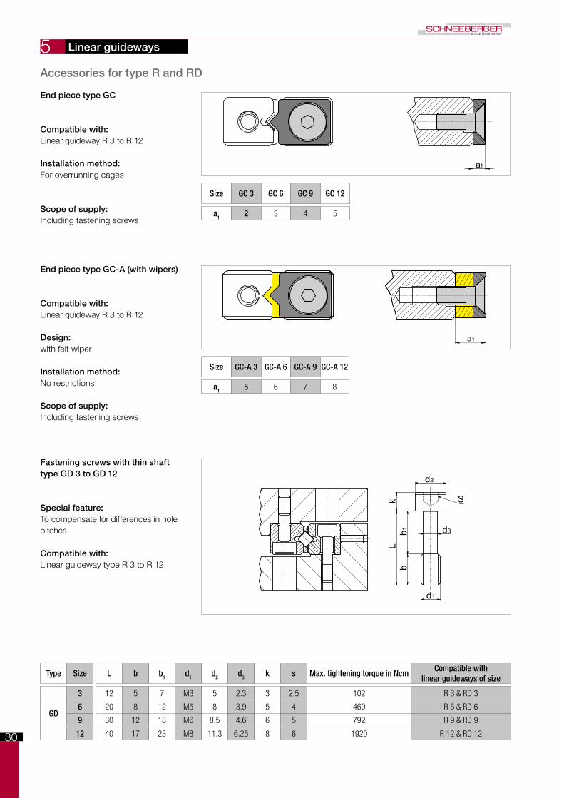
End piece type GC
Compatible with: Linear guideway R 3 to R 12
Installation method:For overrunning cages
Scope of supply:Including fastening screws
End piece type GC-A (with wipers)
Compatible with: Linear guideway R 3 to R 12
Design:with felt wiper
Installation method:No restrictions
Scope of supply:Including fastening screws
Fastening screws with thin shaft type GD 3 to GD 12
Special feature: To compensate for differences in hole pitches
Compatible with:Linear guideway type R 3 to R 12
Size GC 3 GC 6 GC 9 GC 12
a1 2 3 4 5
Size GC-A 3 GC-A 6 GC-A 9 GC-A 12
a1 5 6 7 8
Linear guideways
Accessories for type R and RD
Type Size L b b1 d1 d2 d3 k s Max. tightening torque in NcmCompatible with
linear guideways of size
GD
3 12 5 7 M3 5 2.3 3 2.5 102 R 3 & RD 3
6 20 8 12 M5 8 3.9 5 4 460 R 6 & RD 6
9 30 12 18 M6 8.5 4.6 6 5 792 R 9 & RD 9
12 40 17 23 M8 11.3 6.25 8 6 1920 R 12 & RD 12
31
5
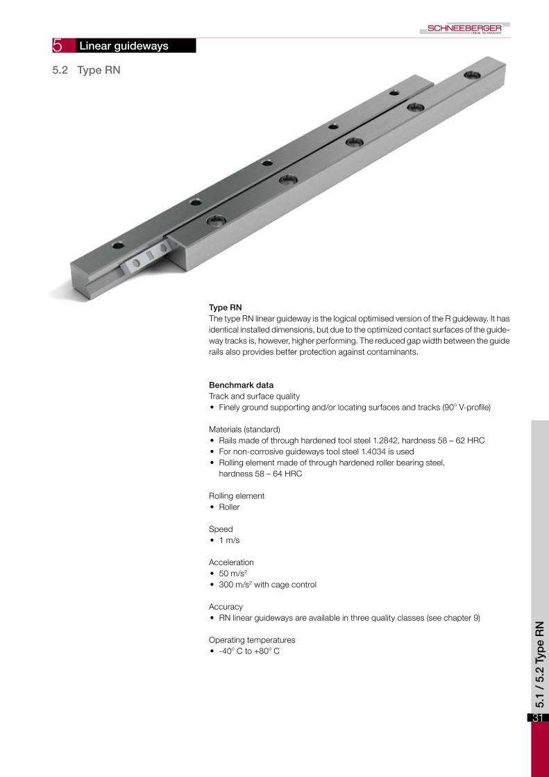
Type RNThe type RN linear guideway is the logical optimised version of the R guideway. It has identical installed dimensions, but due to the optimized contact surfaces of the guide-way tracks is, however, higher performing. The reduced gap width between the guide rails also provides better protection against contaminants.
Benchmark dataTrack and surface quality• Finely ground supporting and/or locating surfaces and tracks (90o V-profile)
Materials (standard)• Rails made of through hardened tool steel 1.2842, hardness 58 – 62 HRC• For non-corrosive guideways tool steel 1.4034 is used• Rolling element made of through hardened roller bearing steel,
hardness 58 – 64 HRC
Rolling element• Roller
Speed• 1 m/s
Acceleration• 50 m/s2
• 300 m/s2 with cage control
Accuracy• RN linear guideways are available in three quality classes (see chapter 9)
Operating temperatures• -40o C to +80o C
5.2 Type RN
5.1
/ 5.
2 Ty
pe
RN
Linear guideways

32
5
B-B
A
A
B
B
L2 L1 L2
L
e1
q
m
A-A
d N
J
g
s
s
B
fe
A+0 -
0.3
B-B
A
A
B
B
L2 L1 L2
L
e1
q
m
A-A
d N
J
g
s
s
B
fe
A+0 -
0.3
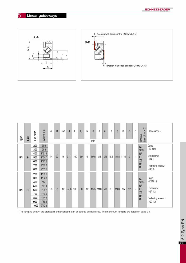
Dimensions and load capacities of type RN
Linear guideways Ty
pe
Size
L in
mm
*
Wei
ght i
n g A B Dw J L
1L
2N d e e
1f g m q s
Optio
ns
(see
cha
pter
7)
Accessories
mm
RN 3
50 24
18 8 3 8.7 25 12.5 3.5 6 M4 M3 3.3 4.8 4.8 7 0.85
SQ SSQ RF EG ZG HA DU DR KS
Cage: - KBN 3 - KBS 3 End screw: - GAN 3 Fastening screw: - GD 3
75 35100 47125 59150 71175 82200 94225 106250 118275 129300 141
RN 4
80 62
22 11 4.5 10.5 40 20 4.5 8 M5 M3 4.3 6.9 5.5 7 0.85
SQ SSQ RF EG ZG HA DU DR KS
Cage:- KBN 4- KBS 4
End screw:- GAN 4
Fastening screw:- GD 4
120 93160 124200 155240 186280 217320 248360 279400 310
RN 6
100 151
31 15 6.5 14.8 50 25 6 9.5 M6 M5 5.2 9.8 7.5 9 0.85
SQ SSQ RF EG ZG HA DU DR KS
Cage:- KBN 6- KBS 6
End screw:- GA 6
Fastening screw:- GD 6
150 226200 301250 377300 452350 527400 603450 678500 753
* The lengths shown are standard; other lengths can of course be delivered. The maximum lengths are listed on page 34.
33
5
B-B
A
A
B
B
L2 L1 L2
L
e1
q
m
A-A
d N
Jg
s
s
B
fe
A+0 -
0.3
B-B
A
A
B
B
L2 L1 L2
L
e1
q
m
A-A
d N
J
g
s
s
B
fe
A+0 -
0.3
Linear guideways Ty
pe
Size
L in
mm
*
Wei
ght i
n g A B Dw J L
1L
2N d e e
1f g m q s
Optio
ns
(see
cha
pter
7)
Accessories
mm
RN 9
200 659
44 22 9 21.1 100 50 9 10.5 M8 M6 6.8 15.8 11.5 9 -
SQ SSQ RF EG ZG HA DU
Cage:- KBN 9
End screw:- GA 9
Fastening screw:- GD 9
300 988400 1'318500 1'647600 1'976700 2'306800 2'635
RN 12
200 1'086
58 28 12 27.6 100 50 12 13.5 M10 M8 8.5 19.8 15 12 -
SQ SSQ RF EG ZG HA DU
Cage:- KBN 12
End screw:- GA 12
Fastening screw:- GD 12
300 1'628400 2'171500 2'714600 3'257700 3'800800 4'342900 4'885
1'000 5'428
5.2
Typ
e R
N
* The lengths shown are standard; other lengths can of course be delivered. The maximum lengths are listed on page 34.
(Design with cage control FORMULA-S)
(Design with cage control FORMULA-S)

34
5
Type / Size Quality classMax. lengths in standard material
(in mm)Max lengths in non-corrosive material
(in mm)
RN 3
NQ700
600SQ
SSQ 600
RN 4
NQ900 900
SQ
SSQ 600 600
RN 6
NQ1'500
1'400
SQ 1'200
SSQ 1'200 900
RN 9
NQ1'500
1'400
SQ 1'200
SSQ 1'200 900
RN 12
NQ1'500
1'400
SQ 1'200
SSQ 1'200 900
Linear guideways
Maximum lengths for type RN
Rail chamfer
Type / Size Rail chamfer of reference edges in mm
RN 3 0.6 x 45°
RN 4 0.6 x 45°
RN 6 0.8 x 45°
RN 9 0.8 x 45°
RN 12 1.0 x 45°
The detail of the rail chamfer is shown in the chart below. Please note that the part number and company logo are marked opposite to the datum and supporting surfaces.

35
5
t C
C
Dw
w
wttz C
C
Dw
Roller cage type KBN
Compatible with: Linear guideway type RN Sizes 3 to 12
Design: Rollers fixed in place
Installation method:For normal application and certain overrunning cage applications
Material:POM (Vacuum-compatible up to 10-7 mbar)
Option:Corrosion-resistant rollers
Type KBS roller cage for the cage control FORMULA-S
Detailed information on FORMULA-S is listed under chapter 7.8.
Compatible with: Linear guideway type RN Sizes 3 to 6
Design: Rollers fixed in placeWith integral pinion
Installation method:For normal application and certain overrunning cage applications
Material:POM (Vacuum-compatible up to 10-7 mbar)
Option:Corrosion-resistant rollers
Type Size Dw t wC per roller
in NMax. length
in mm
KBN
3 3 5 approx. 3.5 410 900
4 4.5 6.5 approx. 4 850 900
6 6.5 8.5 approx. 5 1'800 1'500
9 9 12 approx. 7.5 3'900 1'500
12 12 15 approx. 9 6'500 1'500
Type Size Dw t tz wC per roller
in NMax. length
in mm
KBS
3 3 5 18 approx. 3.5 410 900
4 4.5 6.5 23 approx. 4 850 900
6 6.5 8.5 27 approx. 5 1'800 1'500
Linear guideways
Accessories for type RN
5.2
Typ
e R
N

36
5
a1
a1
bb1
Lk
d2
d3
d1
S
End screws type GAN
Compatible with: Linear guideway RN 3 and RN 4
Installation method:For horizontal installation
End screws type GA
Compatible with: Linear guideway RN 6 to RN 12
Installation method:For horizontal installation
Fastening screws with thin shaft type GD 3 to GD 12
Special feature: To compensate for differences in hole pitches
Compatible with:Linear guideway type RN 3 to RN 12
Size GAN 3 GAN 4
a1 2 2
Size GA 6 GA 9 GA 12
a1 3 3 3
Linear guideways
Accessories for type RN
Type Size L b b1 d1 d2 d3 k s Max. tightening torque in NcmCompatible with
linear guideways of size
GD
3 12 5 7 M3 5 2.3 3 2.5 102 RN 3
4 16 7 9 M4 6.5 3 4 3 232 RN 4
6 20 8 12 M5 8 3.9 5 4 460 RN 6
9 30 12 18 M6 8.5 4.6 6 5 792 RN 9
12 40 17 23 M8 11.3 6.25 8 6 1920 RN 12

37
5
Type RNGLike type RN, the type RNG linear guideway is based on the type R linear guideway. Like type RN, it has larger contact surfaces for the guideway tracks, which means its performance is significantly enhanced. Compared with types R and RN its cross-section is, however, smaller, which means that it represents a cost-effective solution without compromise.
Benchmark dataTrack and surface quality• Finely ground supporting and/or locating surfaces and tracks (90o V-profile)
Materials (standard)• Rails from through hardened tool steel 1.2842, hardness 58 - 62 HRC. • For non-corrosive guideways tool steel 1.4034 is used.• Rolling element made of through hardened roller bearing steel, hardness 58 - 64
HRC.
Rolling element• Roller
Speed• 1 m/s
Acceleration• 50 m/s2
• 300 m/s2 with cage control
Accuracy• RNG linear guideways are available in three quality classes (see chapter 9)
Operating temperatures• -40o C to +80o C
5.2
/ 5.
3 Ty
pe
RN
G
5.3 Type RNG
Linear guideways

38
5
A-A
B-B
A
A
B
B
L2 L1 L2
L
e1
q
d N
J
g
B
m
fe
A+0 - 0
.3
m
u
RNG 4-6 RNG 9-12
s
s
A-A
B-B
A
A
B
B
L2 L1 L2
L
e1
q
d N
J
g
B
m
fe
A+0 - 0
.3
m
u
RNG 4-6 RNG 9-12
s
s
Dimensions and load capacities of type RNG
Linear guideways Ty
pe
Size
L in
mm
*
Wei
ght i
n g A B Dw J L
1L
2N d e e
1f g m q u s
Optio
ns
(see
cha
pter
7)
Accessories
mm
RNG 4
50 27
19 9 4.5 9 25 12.5 3.5 5.5 M3 M3 2.65 6.3 3.5 6 - 0.85
SQ SSQ RF EG ZG HA DU DR KS
Cage: - KBN 4 - KBS 4
End pieces: - GBN 4 - GCN 4 - GCN-A 4
Fastening screw: - GDN 4
75 41100 55125 69150 83175 97200 111225 125250 139275 153300 167
RNG 6
100 92
25 12 6.5 12 25 12.5 5 7 M4 M3 3.3 8.8 5 6 - 0.85
SQ SSQ RF EG ZG HA DU DR KS
Cage: - KBN 6 - KBS 6
End pieces: - GBN 6 - GCN 6 - GCN-A 6
Fastening screw: - GDN 6
150 138
200 184
250 230
300 276
350 322
400 368
* The lengths shown are standard; other lengths can of course be delivered. The maximum lengths are listed on page 40.

39
5
A-A
B-B
A
A
B
B
L2 L1 L2
L
e1
q
d N
J
g
B
m
fe
A+0 - 0
.3
m
u
RNG 4-6 RNG 9-12
s
s
A-A
B-B
A
A
B
B
L2 L1 L2
L
e1
q
d N
J
g
B
m
fe
A+0 - 0
.3
m
u
RNG 4-6 RNG 9-12
s
s
Linear guideways Ty
pe
Size
L in
mm
*
Wei
ght i
n g A B Dw J L
1L
2N d e e
1f g m q u s
Optio
ns
(see
cha
pter
7)
Accessories
mm
RNG 9
100 150
33 16 9 16 25 12.5 6 8.5 M5 M3 4.4 11.8 8 6 8 0.85
SQ SSQ RF EG ZG HA DU DR KS
Cage: - KBN 9 - KBS 9
End pieces: - GBN 9 - GCN 9 - GCN-A 9
Fastening screw: - GDN 9
150 230200 310250 390300 470350 550400 630450 710500 790
RNG 12
200 600
45 22 12 22 50 25 8 12 M8 M5 6.8 15.8 11 7.5 10 -
SQ SSQ RF EG ZG HA DU
Cage: - KBN 12
End pieces: - GBN 12 - GCN 12 - GCN-A 12
Fastening screw: - GDN 12
300 905
400 1'207
500 1'508
600 1'810
700 2'125
800 2'430
900 2'734
1'000 3'038 5.3
Typ
e R
NG
* The lengths shown are standard; other lengths can of course be delivered. The maximum lengths are listed on page 40.
(Design with cage control FORMULA-S)
(Design with cage control FORMULA-S)

40
5
Type / Size Quality classMax. lengths in standard material
(in mm)Max lengths in non-corrosive material
(in mm)
RNG4
NQ900 900
SQ
SSQ 600 600
RNG6
NQ1'500
1'400
SQ 1'200
SSQ 1'200 900
RNG9
NQ1'500
1'400
SQ 1'200
SSQ 1'200 900
RNG12
NQ1'500
1'400
SQ 1'200
SSQ 1'200 900
Linear guideways
Maximum lengths for type RNG
Rail chamfer
Type / Size Rail chamfer of reference edges in mm
RNG 4 0.4 x 45°
RNG 6 0.5 x 45°
RNG 9 0.8 x 45°
RN 12 0.8 x 45°
The detail of the rail chamfer is shown in the chart below. Please note that the part number and company logo are marked op-posite to the datum and supporting surfaces.

41
5
t C
C
Dw
w
wttz C
C
Dw
Roller cage type KBN
Compatible with: Type RNG linear guideway Sizes 4 to 12
Design: Rollers fixed in place
Installation method:For normal application and certain overrunning cage applications
Material:POM (Vacuum-compatible up to 10-7
mbar)
Option:Corrosion-resistant rollers
Type KBS roller cage for the cage control FORMULA-S
Detailed information on FORMULA-S is listed under chapter 7.8.
Compatible with: Type RNG linear guideway Sizes 4 to 9
Design: Rollers fixed in placeWith integral pinion
Installation method:For normal application and certain overrunning cage applications
Material:POM (Vacuum-compatible up to 10-7
mbar)
Option:Corrosion-resistant rollers
Type Size Dw t wC per roller
in NMax. length
in mm
KBN
4 4.5 6.5 approx. 4 850 900
6 6.5 8.5 approx. 5 1'800 1'500
9 9 12 approx. 7.5 3'900 1'500
12 12 15 approx. 9 6'500 1'500
Type Size Dw t tz wC per roller
in NMax. length
in mm
KBS
4 4.5 6.5 23 approx. 4 850 900
6 6.5 8.5 27 approx. 5 1'800 1'500
9 9 12 40 approx. 7.5 3'900 1'500
Type RNG accessories
Linear guideways
5.3
Typ
e R
NG

42
5
a1
a1 a1
a1 a1
a1 a1
End piece type GBN 4 and GBN 6
Compatible with:Linear guideway RNG 4 and RNG 6
Installation method:No restrictions
Scope of supply:Including fastening screws
End piece type GBN 9 and GBN 12
Compatible with:Linear guideway RNG 9 and RNG 12
Installation method:No restrictions
Scope of supply:Including fastening screws
End piece type GCN 4 and GCN 6
Special feature:For overrunning cage
Compatible with: Linear guideway RNG 4 and RNG 6
Installation method:No restrictions
Scope of supply:Including fastening screws
End piece type GCN 9 and GCN 12
Special feature:For overrunning cage
Compatible with: Linear guideway RNG 9 and RNG 12
Installation method:No restrictions
Scope of supply:Including fastening screws
Size GBN 9 GBN 12
a1 4 8.5
Size GBN 4 GBN 6
a1 4 4
Size GCN 9 GCN 12
a1 4 8.5
Size GCN 4 GCN 6
a1 4 4
Linear guideways
Type RNG accessories

43
5
a1
bL
kb1
d2
d3
d1
s
a1 a1
End piece type GCN-A 4 and GCN-A 6
Special feature:With wipers made of felt
Compatible with: Linear guideway RNG 4 and RNG 6
Installation method:No restrictions
Scope of supply:Including fastening screws
End piece type GCN-A 9 and GCN-A 12
Special feature:With wipers made of teflon
Compatible with:Linear guideway RNG 9 and RNG 12
Installation method:No restrictions
Scope of supply:Including fastening screws
Fastening screws with thin shaft type GDN 4 to GDN 12
Special feature: To even out differences in the hole spacings
Compatible with:Linear guideway type RNG 4 to RNG 12
Size GCN-A 9 GCN-A 12
a1 5.5 10
Size GCN-A 4 GCN-A 6
a1 5.5 5.5
Linear guideways
Type RNG accessories
5.3
Typ
e R
NG
Type Size L b b1 d1 d2 d3 k s Max. tightening torque in NcmCompatible with
linear guideways of size
GDN
4 12 5 7 M2.5 4.5 1.85 2.5 2 58 RNG 4
6 16 5 11 M3 5.5 2.3 3 2.5 102 RNG 6
9 25 11 14 M4 7 3 4 3 232 RNG 9
12 30 12 18 M6 10 4.6 6 5 792 RNG 12

44

45
5
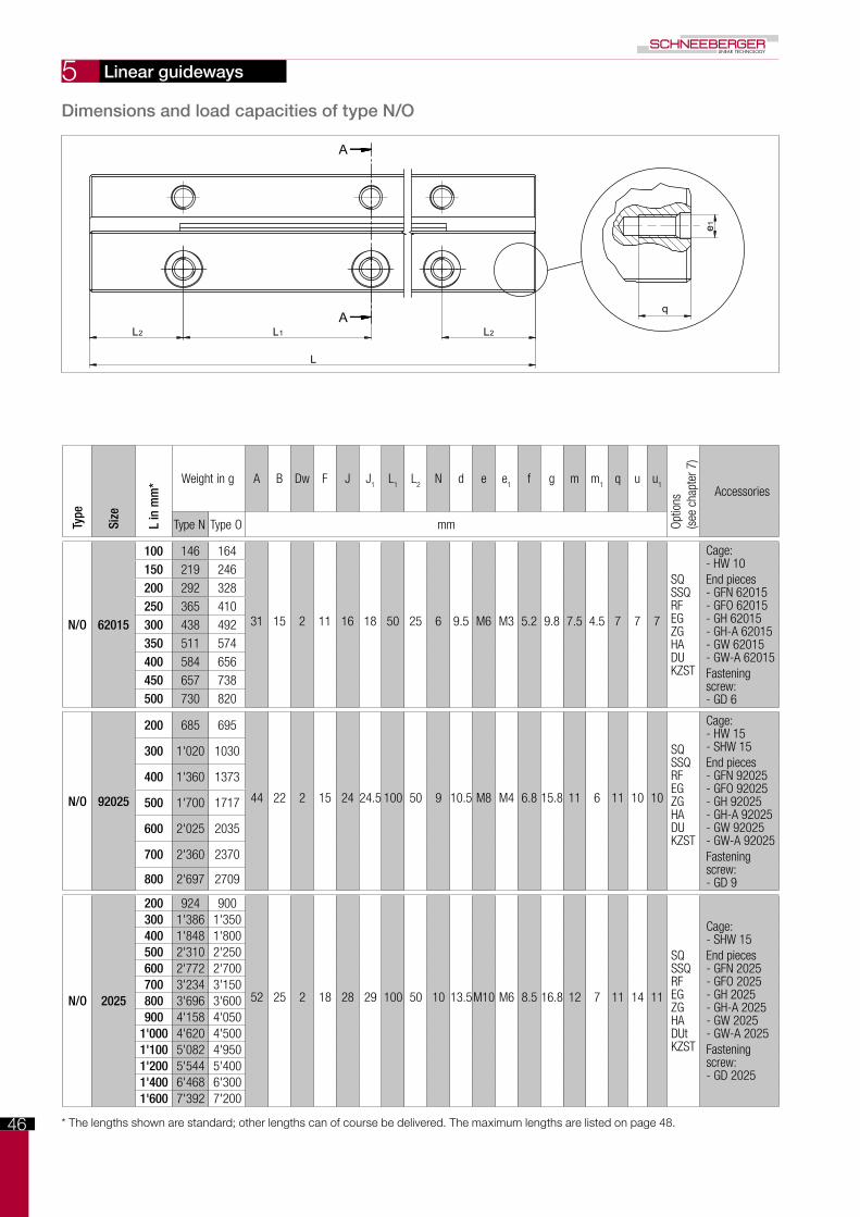
Type N/OThe type N/O linear guideways are equipped with needle cages and are particularly suitable for applications involving high loads. SCHNEEBERGER N/O bearings have a lower moving resistance due to our composite cage.
Benchmark dataTrack and surface quality• Finely ground supporting and/or locating surfaces and tracks (90o V-profile)
Materials (standard)• Rails from through hardened tool steel 1.2842, hardness 58 – 62 HRC.• For non-corrosive guideways tool steel 1.4034 is used.• Rolling element made of through hardened roller bearing steel,
hardness 58 – 64 HRC.
Rolling element• Needle
Speed• 1 m/s
Acceleration• 50 m/s2
• 200 m/s2 with cage control
Accuracy• Type N/O linear guideways are available in three quality classes (see chapter 9)
Operating temperatures• -40o C to +80o C
5.4 Type N/O
Linear guideways
5.4
Typ
e N
/O
46
5
A-A A
A
e1
q
L2 L1 L2
L
m1
u1m
u
N
J1
Fd
N
g
B
f eJ
Dw
A+0 - 0,3
N
O
Dimensions and load capacities of type N/O
Linear guideways Ty
pe
Size
L in
mm
* Weight in g A B Dw F J J1
L1
L2
N d e e1
f g m m1
q u u1
Optio
ns
(see
cha
pter
7)
Accessories
Type N Type O mm
N/O 62015
100 146 164
31 15 2 11 16 18 50 25 6 9.5 M6 M3 5.2 9.8 7.5 4.5 7 7 7
SQ SSQ RF EG ZG HA DU KZST
Cage:- HW 10End pieces- GFN 62015- GFO 62015- GH 62015- GH-A 62015- GW 62015- GW-A 62015Fasteningscrew:- GD 6
150 219 246200 292 328250 365 410300 438 492350 511 574400 584 656450 657 738500 730 820
N/O 92025
200 685 695
44 22 2 15 24 24.5 100 50 9 10.5 M8 M4 6.8 15.8 11 6 11 10 10
SQ SSQ RF EG ZG HA DU KZST
Cage:- HW 15- SHW 15End pieces- GFN 92025- GFO 92025- GH 92025- GH-A 92025- GW 92025- GW-A 92025 Fastening screw:- GD 9
300 1'020 1030
400 1'360 1373
500 1'700 1717
600 2'025 2035
700 2'360 2370
800 2'697 2709
N/O 2025
200 924 900
52 25 2 18 28 29 100 50 10 13.5M10 M6 8.5 16.8 12 7 11 14 11
SQ SSQ RF EG ZG HA DUt KZST
Cage:- SHW 15End pieces- GFN 2025- GFO 2025- GH 2025- GH-A 2025- GW 2025- GW-A 2025Fasteningscrew:- GD 2025
300 1'386 1'350400 1'848 1'800500 2'310 2'250600 2'772 2'700700 3'234 3'150800 3'696 3'600900 4'158 4'050
1'000 4'620 4'5001'100 5'082 4'9501'200 5'544 5'4001'400 6'468 6'3001'600 7'392 7'200
* The lengths shown are standard; other lengths can of course be delivered. The maximum lengths are listed on page 48.

47
5
A-A A
A
e1
q
L2 L1 L2
L
m1
u1m
u
N
J1
Fd
N
g
B
f eJ
Dw
A+0 - 0,3
N
O
Linear guideways Ty
pe
Size
L in
mm
* Weight in g A B Dw F J J1
L1
L2
N d e e1
f g m m1
q u u1
Optio
ns
(see
cha
pter
7)
Accessories
Type N Type O mm
N/O 2535
300 1'905 1'995
62 30 2.5 22 34 35 100 50 12 16.5M12 M6 10.519.8 15 8 11 18 12
SQ SSQ RF EG ZG HA DU KZST
Cage:- HW 20- SHW 20End pieces- GFN 2535- GFO 2535- GH 2535- GH-A 2535- GW 2535- GW-A 2535Fasteningscrew:- GD 2535
400 2'540 2'660500 3'175 3'325600 3'810 3'990700 4'445 4'655800 5'080 5'320900 5'715 5'985
1'000 6'350 6'6501'100 6'985 7'3151'200 7'620 7'9801'400 8'890 9'3101'600 10'160 10'640
N/O 3045
400 3'660 3'460
74 35 3 25 42.5 40 100 50 14 18.5M14 M6 12.522.8 18 10 11 19 16
SQ SSQ RF EG ZG HA DU KZST
Cage:- HW 25- SHW 25End pieces- GFN 3045- GFO 3045- GH 3045- GH-A 3045- GW 3045- GW-A 3045Fasteningscrew:- GD 3045
500 4'575 4'325600 5'490 5'190700 6'405 6'055800 7'320 6'920900 8'235 7'785
1'000 9'150 8'6501'100 1'007 9'5151'200 10'980 10'3801'400 12'810 12'1101'600 14'640 13'840
N/O 3555
500 6'156 6'088
78 45 3.5 25 45 45 100 50 14 18.5M14 M6 12.532.5 18 12 11 29 20
SQ SSQ RF EG ZG HA DU KZST
Cage:- HW 30- SHW 30End pieces- GFN 3555- GFO 3555- GH 3555- GH-A 3555- GW 3555- GW-A 3555Fasteningscrew:- GD 3555
600 7'387 7'306
700 8'618 8'523
800 9'850 9'741
900 11'081 10'958
1'000 12'312 12'176
1'100 13'543 13'394
1'200 14'774 14'611
1'400 17'237 17'046
1'600 19'699 19'482 5.4
Typ
e N
/O
* The lengths shown are standard; other lengths can of course be delivered. The maximum lengths are listed on page 48.

48
5
Type /SizeQuality class
(see chapter 9)Max. lengths in standard material
(in mm)Max lengths in non-corrosive material
(in mm)
N/O 62015
NQ 1'500
900SQ1'200
SSQ
N/O 92025
NQ
3'000 1'300SQ
SSQ
N/O 2025
NQ
3'000 1'300SQ
SSQ
N/O 2535
NQ
3'000 1'300SQ
SSQ
N/O 3045
NQ
3'000 1'300SQ
SSQ
N/O 3555
NQ
3'000 1'300SQ
SSQ
Linear guideways
Maximum lengths type N/O
Rail chamfer
Type / Size Rail chamfer of reference edges in mm
N/O 62015 0.5 x 45°
N/O 92025 0.5 x 45°
N/O 2025 0.5 x 45°
N/O 2535 0.5 x 45°
N/O 3045 1.0 x 45°
N/O 3555 1.0 x 45°
The detail of the rail chamfer is shown in the chart below. Please note that the part number and company logo are marked op-posite to the datum and supporting surfaces.

49
5
wt
e
Dw
Lw
C
2C
e
Dw
Lw
C
2C
wt
Needle cage type SHW
Design: Needles fixed in plastic provides lower displacement forces and smoother running
Installation method: For normal application and certain overrunning cage applications
Material:Stainless steel and plastic PA 12 GF 30 %
Needle cage type SHW with cage control (KZST)
Detailed information on the cage control is listed under Chapter 7.9.
Design: Needles fixed in plastic. Thus smaller displacement forces and smoother running.
Installation method: For normal application and certain overrunning cage applications
Material:Stainless steel and plastic PA 12 GF 30 %
Type Size Dw Lw e t wC
per needle in N
Compatible with linear guideways
type
max. length in mm
SHW
15 2 6.8 14 4 approx. 2.9 750 N/O 92025 and 2025 1'500
20 2.5 9.8 19 4.75 approx. 3.4 1'375 N/O 2535 1'500
25 3 13.8 25 5.2 approx. 3.6 2'350 N/O 3045 1'500
30 3.5 17.8 30 6.1 approx. 4.3 3'600 N/O 3555 1'500
Accessories for type N/O
Linear guideways
5.4
Typ
e N
/O

50
5
wt
e Dw
Lw
C
2C
wt
e Dw
Lw
C
2C
wt
e Dw
Lw
C
2C
Needle cage type HW
Design: Needles fixed
Installation method: For normal application and certain overrunning cage applications
Material:- Size HW 10 is made out of tool steel- All other sizes in aluminium
Needle cage type HW with cage control (KZST)
Detailed information on the cage control is listed under Chapter 7.9.
Design: Needles fixed
Installation method: For normal application and certain overrunning cage applications
Material:- Size HW 10 is made out of tool steel- All other sizes in aluminium
Type Size Dw Lw e t wC
per needle in N
Compatible with linear guideways
type
max. length in mm
HW
10 2 4.8 10 4 approx. 3 530 N/O 62015 1'980
15 2 6.8 14 4.5 approx. 3.5 750 N/O 92025 1'950
20 2.5 9.8 20 5.5 approx. 4 1'375 N/O 2535 1'970
25 3 13.8 25 6 approx. 4.5 2'350 N/O 3045 1'940
30 3.5 17.8 30 7 approx. 5 3'600 N/O 3555 1'980
Linear guideways
Accessories for type N/O

51
5
a1GFN GFO
a1 a1
a1 a1
a1 a1
End piece type GH
Special feature:For overrunning cage
Installation method:No restrictions
Scope of supply:Including fastening screws
End piece type GH-A
Special feature:Wipers made of felt
Installation method:No restrictions
Scope of supply:Including fastening screws
End piece type GFN/GFO
Special feature:Wipers made of felt
Installation method:No restrictions
Scope of supply:Including fastening screws
End piece type GW
Special feature:For overrunning cage
Installation method:No restrictions
Scope of supply:Including fastening screws
Size 62'015 92'025 2'025 2'535 3'045 3'555
a1 6 7 10 10 10 11
Size 62'015 92'025 2'025 2'535 3'045 3'555
a1 9 10 13 13 13 14
Size 62015 92025 2025 2535 3045 3555
a1 6 7 10 10 10 11
Size 62015 92025 2025 2535 3045 3555
a1 6 7 10 10 10 11
Linear guideways
Accessories for type N/O
5.4
Typ
e N
/O

52
5
bb1
Lk
d2
d3
d1
s
a1 a1
End piece type GW-A
Special feature:Felt Wipers
Installation method:No restrictions
Scope of supply:Including fastening screws
Fastening screws with thin shaft type GD
Special feature: To compensate for differences in hole pitches
Size 62015 92025 2025 2535 3045 3555
a1 9 10 13 13 13 14
Linear guideways
Accessories for type N/O
Type Size L b b1 d1 d2 d3 k sMax. tightening torque in
NcmCompatible with
linear guideways type
GD
6 20 8 12 M5 8 3.9 5 4 460 N/O 62015
9 30 12 18 M6 8.5 4.6 6 5 792 N/O 92025
2025 35 16 19 M8 11.3 6.25 8 6 1920 N/O 2025
2535 40 18 22 M10 13.9 7.9 10 8 3840 N/O 2535
3045 50 25 25 M12 15.8 9.6 12 10 6640 N/O 3045
3555 60 25 35 M12 15.8 9.6 12 12 6640 N/O 3555

53
5
Type M/Vthe type M/V linear guideway is similar to type N/O, but differs in its external dimen-sions. Equipped with needle cages, its is particularly suitable for applications involv-ing a higher load. SCHNEEBERGER M/V bearings have a lower moving resistance due to our composite cage.
Benchmark dataTrack and surface quality• Finely ground supporting and/or locating surfaces and tracks (90o V-profile)
Materials (standard)• Rails from through hardened tool steel 1.2842, hardness 58 – 62 HRC.• For non-corrosive guideways tool steel 1.4034 is used.• Rolling element made of through hardened roller bearing steel,
hardness 58 – 64 HRC.
Rolling element• Needle
Speed• 1 m/s
Acceleration• 50 m/s2
• 200 m/s2 with cage control
Accuracy• Type M/V linear guideways are available in three quality classes (see chapter 9)
Operating temperatures• -40o C to +80o C
5.5 Type M/V
Linear guideways
5.4
/ 5.
5 Ty
pe
M/V

54
A-A A
A
e1
q
L2 L1 L2
L
m1
u1m
u
N
J1
F
d
N
g
B
f J
Dw
A+0 - 0,3
M
V
5 Dimensions and load capacities type M/V
Linear guideways Ty
pe
Size
L in
mm
* Weight in g A B Dw F J J1
L1
L2
N a d e e1
f g m m1
q t u u1
Optio
ns
(see
cha
pter
7)
Accessories
Type M Type V mm
M/V 3015
100 136 154
30 15 2 10.515.517.4 1)40 3) 5.5 0.7 8.5 M4 M3 5.3 10.5 8 5.5 7 15 7 7
SQ SSQ RF EG ZG HA KZST
Cage:- HW 10
End pieces- EM 3015- EV 3015- EAM 3015- EAV 3015
150 204 231200 272 308300 420 473400 560 631500 700 788600 840 946
M/V 4020
100 261 274
40 20 2 13.522.5 22 2)80 4) 7.5 1.3 11.5 M6 M5 7.5 13.2 10 5.5 8 20 11 10.5
SQ SSQ RF EG ZG HA KZST
Cage:- HW 15- SHW 15
End pieces- EM 4020- EV 4020- EAM 4020- EAV 4020
150 392 411
200 522 548
300 820 815
400 1'093 1'087
500 1'367 1'358
600 1'640 1'630
M/V 5025
100 446 437
50 25 2 17 28 28 2)80 4) 10 1.3 11.5 M6 M6 7.5 18.2 12 7 9 15 13 13
SQ SSQ RF EG ZG HA KZST
Cage:- HW 15- HW 16- SHW 15
End pieces- EM 5025- EV 5025- EAM 5025- EAV 5025
200 893 874
300 1'339 1'311
400 1'786 1'748
500 2'232 2'185
600 2'678 2'622
700 3'125 3'059
800 3'571 3'496
900 4'018 3'933
1'000 4'464 4'370
1) for the 100 mm length, the following applies: L1 = 35 mm (2 x ) 2) for the length 100 mm, the following applies: L1 = 50 mm
3) min. 15 mm 4) min. 20 mm
* The lengths shown are standard; other lengths can of course be delivered. The maximum lengths are listed on page 56.

55
5
A-A A
A
e1
q
L2 L1 L2
L
m1
u1m
u
N
J1
F
d
N
g
B
f J
Dw
A+0 - 0,3
M
V
Linear guideways Ty
pe
Size
L in
mm
* Weight in g A B Dw F J J1
L1
L2
N a d e e1
f g m m1
q t u u1
Optio
ns
(see
cha
pter
7)
Accessories
Type M Type V mm
M/V 6035
200 1'450 1'510
60 35 2.5 20 35 35.5 100 50 11 1.3 15 M8 M6 10 26 14 8 9 20 20 18
SQ SSQ RF EG ZG HA KZST
Cage:- HW 20- SHW20
End pieces- EM 6035- EV 6035- EAM 6035- EAV 6035
300 2'176 2'265400 2'901 3'020500 3'626 3'775600 4'351 4'530700 5'076 5'285800 5'802 6'040900 6'527 6'795
1'000 7'252 7'550
M/V 7040
200 1'934 2'008
70 40 3 24 40 41.5 100 50 13 1.3 18.5 M10 M6 12.5 29 16 10 9 25 20 20
SQ SSQ RF EG ZG HA KZST
Cage:- HW 25- SHW 25
End pieces- EM 7040- EV 7040- EAM 7040- EAV 7040
300 2'807 3'019400 3'743 4'025500 4'678 5'032600 5'821 6'038700 6'791 7'044800 7'499 8'051900 8'436 9'057
1'000 9'374 10'321
M/V 8050
300 4'014 4'271
80 50 3.5 26 45 48 100 50 14 1.3 20 M12 M6 14 37 20 10 9 30 30 25
SQ SSQ RF EG ZG HA KZST
Cage:- HW 30- SHW 30
End pieces- EM 8050- EV 8050- EAM 8050- EAV 8050
400 5'352 5'694
500 6'690 7'118
600 8'290 8'544
700 9'672 9'968
800 10'700 11'530
900 12'038 12'822
1'000 13'375 14'247
5.5
Typ
e M
/V
* The lengths shown are standard; other lengths can of course be delivered. The maximum lengths are listed on page 56.

56
5
Type / Size Quality class Max. lengths in standard material (in mm)Max lengths in non-corrosive material
(in mm)
M/V 3015
NQ 1'500
900SQ1'200
SSQ
M/V 4020
NQ 1'500
900SQ1'200
SSQ
M/V 5025
NQ 1'500
900SQ1'200
SSQ
M/V 6035
NQ 1'500
900SQ1'200
SSQ
M/V 7040
NQ1'500
900SQ
SSQ 1'200
M/V 8050
NQ1'500
900SQ
1'200
Linear guideways
Maximum lengths type M/V
Rail chamfer
Type / Size Rail chamfer of reference edges in mm
M/V 3015 0.5 x 45°
M/V 4020 0.5 x 45°
M/V 5025 0.5 x 45°
M/V 6035 0.5 x 45°
M/V 7040 1.0 x 45°
M/V 8050 1.0 x 45°
The detail of the rail chamfer is shown in the chart below. Please note that the part number and company logo are marked opposite to the datum and supporting surfaces.

57
5
e
Dw
Lw
C
2C
wt
wt
e
Dw
Lw
C
2C
Needle cage type SHW
Compatible with: Linear guideway type M/V
Design: Needles fixed in plastic provides lower displacement forces and smoother running
Installation method: For normal application and certain overrunning cage applications
Material:Stainless steel and plastic PA 12 GF 30 %
Needle cage type SHW with cage control (KZST)
Detailed information on the cage control is listed under Chapter 7.9.
Compatible with: Linear guideway type M/V
Design: Needles fixed in plastic. Thus smaller displacement forces and smoother running.
Installation method: For normal application and certain overrunning cage applications
Material:Stainless steel and plastic PA 12 GF 30 %
Type Size Dw Lw e t wC
per needle in N
Compatible with linear guideways
type
max. length in mm
SHW
15 2 6.8 14 4 approx. 2.9 750 M/V 4020 and M/V 5025 1'500
20 2.5 9.8 19 4.75 approx. 3.4 1'375 M/V 6035 1'500
25 3 13.8 25 5.2 approx. 3.6 2'350 M/V 7040 1'500
30 3.5 17.8 30 6.1 approx. 4.3 3'600 M/V 8050 1'500
Linear guideways
Accessories type M/V
5.5
Typ
e M
/V

58
5
wt
e Dw
Lw
C
2C
wt
e Dw
Lw
C
2C
wt
e Dw
Lw
C
2C
Needle cage type HW
Compatible with: Linear guideway type M/V
Design: Needles fixed
Installation method: Specifically suitable as an overrunning cage
Material:- Size HW 10 is made out of tool steel- All other sizes in aluminium
Needle cage type HW with cage control (KZST)
Detailed information on the cage control is listed under Chapter 7.9.
Compatible with: Linear guideway type M/V
Design: Needles fixed
Installation method: Specifically suitable as an overrunning cage
Material:- Size HW 10 is made out of tool steel- All other sizes in aluminium
Type Size Dw Lw e t wC
per needle in N
Compatible with linear guideways
type
max. length in mm
HW
10 2 4.8 10 4 approx. 3 530 M/V 3015 1'980
15 2 6.8 14 4.5 approx. 3.5 750 M/V 4020 and M/V 5025 1'950
16 2 8.8 16 3.8 approx. 2.8 970 M/V 5025 1'990
20 2.5 9.8 20 5.5 approx. 4 1'375 M/V 6035 1'970
25 3 13.8 25 6 approx. 4.5 2'350 M/V 7040 1'940
30 3.5 17.8 30 7 approx. 5 3'600 M/V 8050 1'980
Type Size Dw Lw e t wC
per needle in N
Compatible withlinear guideways
type
max. length in mm
HW
10 2 4.8 10 4 approx. 3 530 M/V 3015 1'980
15 2 6.8 14 4.5 approx. 3.5 750 M/V 4020 and M/V 5025 1'950
16 2 8.8 16 3.8 approx. 2.8 970 M/V 5025 1'990
20 2.5 9.8 20 5.5 approx. 4 1'375 M/V 6035 1'970
25 3 13.8 25 6 approx. 4.5 2'350 M/V 7040 1'940
30 3.5 17.8 30 7 approx. 5 3'600 M/V 8050 1'980
Linear guideways
Accessories type M/V

59
5
a1 a1
a1 a1
a1 a1
End piece type EM/EV
Compatible with: For all M/V rail sizes
Installation method:No restrictions
Scope of supply:Including fastening screws
End piece type EAM
Special feature:Felt wipers
Compatible with: For all M/V rail sizes
Installation method:No restrictions
Scope of supply:Including fastening screws
End piece type EAV
Special feature:Felt wipers
Compatible with: For all M/V rail sizes
Installation method:No restrictions
Scope of supply:Including fastening screws
Size 3'015 4'020 5'025 6'035 7'040 8'050
a1 5 8 9 9 9 9
Size 3015 4020 5025 6035 7040 8050
a1 7 10 11 11 11 11
Size 3015 4020 5025 6035 7040 8050
a1 7 10 11 11 11 11
Linear guideways
Accessories type M/V
5.5
Typ
e M
/V

60
61
6 Recirculating unit
6 P
rod
uct
spec
ifica
tions
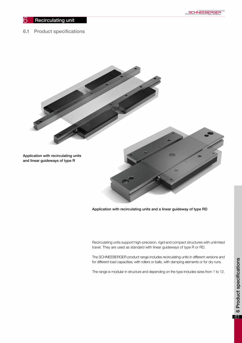
Application with recirculating units and linear guideways of type R
Application with recirculating units and a linear guideway of type RD
Recirculating units support high-precision, rigid and compact structures with unlimited travel. They are used as standard with linear guideways of type R or RD.
The SCHNEEBERGER product range includes recirculating units in different versions and for different load capacities; with rollers or balls, with damping elements or for dry runs.
The range is modular in structure and depending on the type includes sizes from 1 to 12.
6.1 Product specifications

62
6 Recirculating unit
The type SK recirculating unit is equipped with balls and is suitable for small to medi-um loads.
This recirculating unit is used combined with SCHNEEBERGER linear guideways of type R and/or RD. The SK units can be used in space saving designs that have equal loading in all directions.
Sizes 6 and 9 (size 12 on request) can additionally be equipped with damping elements (type designation SKD). These provide improved smoothness with slightly reduced load carrying capacity.
Benchmark data
Supporting structure• Hardened and ground with high precision
Materials• Supporting structure made of through hardened tool steel, hardness 58 - 62 HRC• Rolling element made of through hardened roller bearing steel, hardness 58 - 64 HRC• Transmission part in sizes 1, 2, 9 and 12 made of anodized aluminium• Transmission part in sizes 3 and 6t depending on the length made of plastic or aluminium• Non-corrosive version on request• Damping elements for SKD made of plastic• Wipers made of plastic
Wipers• From size 3 interchangeable track wipers are made from plastic as standard fitted
Speed• 2 m/s
Acceleration• 50 m/s2
Operating temperatures• -40o C to +80o C
Same installation with the following recirculating units• SKC and SR
Can be combined with the following products• Linear guideway type R and RD
6.1 Type SK and SKD
Type SK Type SKD

63
6
B-B
A-A
B
B
A
A
L1
L3
Kt
L
f1
m
2 1
a
B/2 Dw
f e
J F
o
g
BN
dH
L3 L3
L1
2C
C
1
2
Recirculating unit
6.1
Typ
e S
K a
nd S
KD
Type and size Wei
ght i
n g
B Dw F H J Kt
L L1
L3
N a d e f f1
g m o
C in N
Optio
ns
(see
cha
pter
8)
SK SKD
SK 1-022 5 4 1.5 8.4 7.25 6.9 9 22 10 - 4.8 0.3 3 M2 1.65 - 2.6 - 1.2 63 GP
SK 2-032 10 6 2 11 9.5 9 16 32 15 - 6 0.3 4.4 M3 2.55 - 4 - 1.9 135 GP
SK 3-075 45 8 3 16.9 14.5 13.8 48 75 25 12.5 9 0.5 6 M4 3.3 1.5 4.9 11.5 2.4 425 GP
SK 6-100 SKD 6-100 20015 6 28.9 24.5 22.9
60 100 5025 15 1 9.5 M6 5.2 2 9.8 19.7 4.4
715 650GP
SK 6-150 SKD 6-150 300 102 150 2 x 50 1'170 1'100
SK 9-150 SKD 9-150 67022 9 45.1 39 36.7
90 150100 50 26 1.5 10.5 M8 6.8 3 15.8 32.4 6.3
1'650 1'500GP
SK 9-200 SKD 9-200 940 144 200 2'550 2'400
SK 12-200 SKD 12-200 1'470 28 12 57.1 49 45.9 120 200 100 50 32 2 13.5 M10 8.5 3 19.8 40.2 7.7 2'860 2'600 GP
The types in bold are standard. Types SK12 and SKD 12 are available on request
Retaining web may not be used as a stop
Wiper from size SK 3-075
Dimensions and load capacities type SK and SKD
Lube hole

64
6
A
e1
A1+- 0.5
0
+- 0.3
0
R
RD
SK/SKD
SK/SKD SK/SKD
Q
MQ ML
ML
Installed dimensions for type SK and SKD
Type Size A A1
e1
SK1-022 11.5 28 M1.62-032 15.5 37 M2.53-075 23.5 57 M3
SK and SKD
6-100 40 94 M56-150 40 94 M59-150 61 150 M69-200 61 150 M6
SK and SKD 12-200 78 175 M8 The types in bold are standard. Types SK12 and SKD 12 are available on request
Permissible torques for type SK and SKD
Type Size QML
in Nm MQ in Nm
SK SKD SK SKD
SK
1-023 13.5 0.4 0.8
2-033 18.0 1.4 2.4
3-076 28.0 7.2 12.0
SK and SKD
6-10045.0
23.0 23.0 32.0 29.0
6-150 40.0 40.0 53.0 50.0
9-15072.0
81.0 81.0 119.0 108.0
9-200 130.0 130.0 184.0 173.0
SK and SKD 12-200 77.0 187.0 187.0 220.0 200.0 The types in bold are standard. Types SK12 and SKD 12 are available on request
Recirculating unit
Installed dimensions and permissible torque for type SK and SKD

65
6
The recirculating unit type SKC was developed for dry running, vacuum and clean room applications. It is made out of DURALLOY® coated steel and has ceramic balls, which are separated from one another by balls made out of TEFLON®.
This recirculating unit is used combined with SCHNEEBERGER linear guideways of type R and/or RD. The SKC units can be used in space saving designs that have equal loading in all directions. It is suitable for small to medium loads.
Benchmark data
Supporting structure• Hardened and ground and coated with high precision
Materials• Supporting structure made of stainless steel 1.4034, DURALLOY® coated, hardness min. 54 HRC• Transmission part made out of stainless steel 1.4034• Rolling element made of ceramic (balls made of TEFLON® between the ceramic balls are responsible for minimal friction)
Speed• 2 m/s
Acceleration• 50 m/s2
Operating temperatures• -150o C to +200o C
Same installation with the following recirculating units• SK, SKD and SR
Can be combined with the following products• Linear guideway type R and RD
Recirculating unit
6.2 Type SKC
6.1
/ 6.
2 Ty
pe
SK
C

66
6
A - A
A
A
L 1
Kt
L
a
B /2 Dw
f e
J
F
o
g
B
N
d
H
2C
C
Recirculating unit
Dimensions and load capacities of type SKCTy
pe a
nd s
ize
Wei
ght i
n g
B Dw F H J Kt
L L1
N a d e f g o C in N Optio
ns
(see
cha
pter
8)
SKC 3-075 44 8 3 16.9 14.5 13.8 48 75 25 9 0.5 6 M4 3.3 4.9 2.4 75 GP
SKC 6-100 212 15 6 28.9 24.5 22.9 60 100 50 15 1 9.5 M6 5.2 9.8 4.4 125 GP * Loading capacity for dry running

67
6
A
e1
A1+- 0.5
0
+- 0.3
0
R
RD
SK/SKD
SK/SKD SK/SKD
Q
MQ ML
ML
Installed dimensions for type SKC
Type Size A A1
e1
SKC 3-075 23.5 57 M3
SKC 6-100 40 94 M5
Permissible torques for type SKC
Type Size Q ML in Nm M
Q in Nm
SKC 3-075 28.0 0.9 2.1
SKC 6-100 45.0 3.0 5.6
Recirculating unit
Installed dimensions and permissible torques for type SKC
6.2
Typ
e S
KC

68
6
The SR recirculating units has cross rollers and is suitable for medium to high loads.
This recirculating unit is used combined with SCHNEEBERGER linear guideways of type R and/or RD. In this way space-saving designs can be created that can be equally loaded in all directions.
Benchmark data
Supporting structure• Hardened and ground with high precision
Materials• Supporting structure made of through hardened tool steel, hardness 58 – 62 HRC• Rolling element made of through hardened roller bearing steel, hardness 58 – 64 HRC• Transmission part depending on the length made of plastic or anodized aluminium• Stainless steel on request• From size 3 the rollers are laid in plastic shoes
Speed• 2 m/s
Acceleration• 50 m/s2
Operating temperatures• -40o C to +80o C
Same installation with the following recirculating units• SK, SKD and SKC
Can be combined with the following products• Linear guideway type R and RD
Recirculating unit
6.3 Type SR

69
6
A-A
B-B
A
A
B
BL3
L1
Kt
L
L3L3
L1
f1m
f e J
o
g
B
N
dF
Dw
B/2
2C
C
6.3
Typ
e S
R
Lube hole
Recirculating unit
Dimensions and load capacities of type SR
Type and size Wei
ght i
n g
B Dw F J Kt
L L1
L3
N d e f f1
g m o C in N Optio
ns
(see
cha
pter
8)
SR 2-032 10 6 2 9.8 9.5 16 32 15 - 6 4.4 M3 2.55 - 4 - 1 380 GP
SR 3-075 50 8 3 15 14.5 46 75 25 12.5 9 6 M4 3.3 1.5 4.9 11.8 1.3 850 GP
SR 6-100 21015 6 25.7 24.5
56 100 5025 15 9.5 M6 5.2 2 9.8 19.7 2.5
2'150GP
SR 6-150 310 105 150 50 3'750
SR 9-150 750 22 9 40.5 39 92 150 100 50 26 10.5 M8 6.8 3 15.8 32.4 3.5 5'850 GP
SR 12-200 1'580 28 12 51.5 49 112 200 100 50 32 13.5 M10 8.5 3 19.8 40.2 4 10'000 GP The types in bold are standard. Type SR 12 is available on request

70
6
A
e1
A1+- 0.5
0
+- 0.3
0
R
RD
SR
SR SR
Q
MQ ML
MLTorques for type SR
Type and size Q ML in Nm M
Q in Nm
SR 2-032 18.0 3.0 7.0SR 3-075 28.0 12.0 24.0SR 6-100
45.060.0 97.0
SR 6-150 112.0 169.0SR 9-150 72.0 241.0 421.0SR 12-200 77.0 553.0 770.0
The types in bold are standard. Type SR 12 is available on request
Installed dimensions for type SR
Type and size A A1
e1
SR 2-032 15.5 37 M2.5SR 3-075 23.5 57 M3SR 6-100 40 94 M5SR 6-150 40 94 M5SR 9-150 61 150 M6SR 12-200 78 175 M8
The types in bold are standard. Type SR 12 is available on request
Installed dimensions and permissible torques for type SR
Recirculating unit

71
6
This roller recirculating unit is designed for medium to heavy loads. Solutions to de-manding applications can be created using NRT, NRV, and suitable guideways.
Advantages/benefits of the NRT
• Two independent tracks, the small amount of roller play and the optimal ratio of roller length and roller diameter are responsible for minimal lateral forces.
• The large number of rollers and the optimised roller run-ins are responsible for minimal travel pulsation and a low coefficient of rolling friction
• High degree of rigidity thanks to three-point support on the rear• Protected roller return• Double-lipped wipers on each side• Can also be supplied matched as an option, sorted within 5µm
Advantages/benefits of the preload wedge NRV
This preload wedge is used for setting preload. The NRV with its concave and convex supporting surfaces is also able to even out minor angular errors and deformations in the connecting structure.
Benchmark data
Supporting structure• Hardened and ground with high precision
Materials• Supporting structure made of through hardened tool steel, hardness 58 – 62 HRC• Rolling element made of through hardened roller bearing steel, hardness 58 – 64 HRC• Transmission parts and wipers made of plastic
Speed• 1 m/s
Acceleration• 50 m/s2
Operating temperatures• -40o C to +80o C
Recirculating unit type NRT Preload wedge type NRV
6.4 Type NRT (with NRV)
6.3
/ 6.
4 Ty
pe
NR
T (w
ith N
RV
)
Recirculating unit

72
6 N
L1
Kt
L2
L
m
11
2G
Dw
d
Lw
f eB
g1
g
A
+ -
+-
0 .01
00.025
+- 0.1
f1
C+ - . 01
A
A
A-A
lubricating nipple Ø 4 type D1a on both sides
Lubricating hole
Dimensions and load capacities of type NRT
Recirculating unit
Recirculating unit type NRT
Type and size Wei
ght i
n g
A B Dw G Kt
L L1
L2
Lw
N d e f f1
g g1
m C in N Optio
ns
(see
cha
pter
8)
NRT 19077 185 19 27 5 18.85 45 77 25.5 49.2 13 20.6 6 M4 3.3 6 15.5 6 5.3 43'000GPZS
NRT 26111 57026 40 7 25.85
70 111 44 75.619 30 8 M6 5 9
2010 10.3
98'000GPZS
NRT 26132 721 91 132 68 96.6 20.6 120'000GPZS
NRT 38144 1'390 38 52 10 37.8 90 144 51 96.8 26 41 11 M8 6.8 11 29 14 14.5 181'000GPZS
2
1

73
6
73
bb1
L1 L3
d1 N
d 2
1
3
+- 0.1
+ - . 01
A
H L6
e1
fe
B
g
+0- 0.2
A
A
A-A
L5
L2 L1
L4
L
N
+- 0.1
+ -. 01
Setting screw
Lubricating hole
Locking and jacking screws
Dimensions and load capacities of type NRV
Recirculating unit
Preload wedge NRV
Type and size W
eigh
t in
g
A B H max. L max. L1
L2
L3
L4 max. L
5L
6N b b
1d d
1e e
1f g
NRV 19077 195 16 27 7 72 25.5 22.5 16.5 68 61 56 20.6 7 9 7 9 M4 M3 3.3 4.5
NRV 26111 67025 40 8
105 44 29 21 98 90 8330 9
17.58 11 M6 M4 5 8
NRV 26132 837 126 68 27.5 19.5 119 111 104 29.5
NRV 38144 1'300 30 52 8 130 51 37.5 28.5 121 113 105 41 10 20.5 11 14 M8 M6 6.8 8 6.4
Typ
e N
RT
(with
NR
V)
1
2
3

74

75
7
0 200 400 600 800 1000
L (mm)
10
8
6
4
2
(µm)
2000 2200 2400 2600 2800 30001800160014001200
12
14
16
18
20
NQ
SQ
SSQ
Options for linear guideways
7.1
/ 7.
2 O
ptio
ns f
or
linea
r g
uid
eway
s
7.1 Quality classes (SQ and SSQ)
Depending upon the application different levels of accuracy are required. SCHNEEBERGER linear guideways are available in three quality classes to address a variety of applications:
NQ* Normal quality Represents normal requirements in mechanical engineeringSQ Special quality In case of very stringent requirementsSSQ Super special quality In case of the most stringent requirements
Note:*NQ represents standard quality and is not subsequently listed as an order code
The corresponding tolerance values (Δ) for parallelism of the running surfaces in rela-tion to the reference and locating surfaces can be seen in the diagram below.
In terms of the quality classes SQ and SSQ the following limitations technically exist: - Max. lengths according to the table „Dimensions and load capacities“ of the res-
pective product. - Coatings (see chapter 7.6 and 7.7).
7.2 Guideways made of corrosion-resistant steel (RF)
For certain applications such as, for example, medical technology, food industry or in a vacuum, the guide rails can be made of corrosion-resistant steel.
Notes: - The max. rail length in normal quality as well as in options SQ and SSQ is limited
(see „dimensions and load capacities“ of the respective product). - The hardness of the steel reduces compared with tool steel to min. 54 HRC, which
should be taken into account in the food calculation.

76
7
1 1 2 2
3 3 4 4
L
7.3 Run-ins rounded (EG)
Overrunning cages are expedient to used if a short table is to be moved on a long guideway track. As a result the upper part is at any time supported over its entire length, which has a positive effect on the load carrying capacity and rigidity.
7.4 Multi-part linear guideways (ZG)
Is the desired overall length of the guideway is greater than the maximum length listed in this catalogue, individual rails can be ground together. The offset between the indi-vidual guideway tracks for this is max. 0.002 mm. The length tolerance L is within +/- 2 mm.
During installation it is important to pay attention to the numbering at the butt joint.
So that the cage run-in causes as little pulsation as possible, the short rails are pro-vided with rounded run-ins. The run-ins are ground following manufacture of the guide-way track.
Note:On rare occasions (e.g. under very high preload), in spite of rounded run-ins the pul-sation of the overrunning cage can have a disruptive effect on the application. This phenomenon can be largely eliminated by taking appropriate measures (on request).
Options for linear guideways

77
7
A2
A1
2
2
1
1
A2
A1
2
2
1
1
7.6 DURALLOY ® coating (DU)
For applications in which a corrosion protection and/or increased wear resistance of the surfaces is required, it is recommended to coat the guideways with DURALLOY®.
Technical information - Max. rail length 900 mm - Hardness HRC 64 - 74 - Coating thickness 2.5 – 4.0 µm - Structure "Pearlescent" (see figure) - Vacuum-compatible 10-7 mbar
The advantages of DURALLOY®
- Increased wear resistance - Corrosion protection - The pearl structure acts as a lubricant reservoir - Good emergency running characteristics - Protection from abrasive corrosion - High degree of chemical resistance
Options for linear guideways
7.5 Height-matched guideways (HA)
The tolerance of height A is as standard 0/-0.3 mm. In the case of surface-mounted guideways, which must be matched to the same height, A (and/or A1 and A2) is made in consignments with a tolerance of +/- 0.01 mm.
The rails are identified/numbered correspondingly. If multiple consignments are supplied, they are given serial numbers.
Notes: - The ZG special versions (multi-part linear guideway) and the maximum quality grade SSQ are not possible.
- Special quality SQ only on request
7.5
/ 7.
6 O
ptio
ns f
or
linea
r g
uid
eway
s

78
7 7.7 DryRunner coating (DR and DRC1)
Without lubrication the running surfaces of linear guideways are completely destroyed after only 10'000 passes.
A guideway coated with DryRunner supports more than 100 million passes and thus a service life extended by 10'000 times - without lubrication. In vacuum an unlubricat-ed guideway coated with DryRunner supports more than 50 million passes.
DryRunner coated linear guideways can of course be used with standard lubricants, which means the previously listed running performance statistics increase considera-bly.
Technical information
Area of use Order code Film thicknessMax. length of the
guideway
Air DR 1.5 – 3.0 µm 900 mm
Vacuum (up to 10-7 mbar)
DRC1 1.0 – 2.0 µm 900 mm
- The coating is only applied to the running surfaces. From a production technology standpoint, it is possible that other exterior surfaces are coated; but not the support-ing and locating surface of the guideway. - DryRunner does not provide any protection against corrosion. If corrosion resistance
is required, the guideway must be ordered in a non-corrosive material.
The advantages of DryRunner - Supports dry running - Suitable for applications in air or vacuum - Minimal wear as a result of abrasion
Notes - DryRunner supports operation without a lubricant, which is why we recommend the
use of the cage control FORMULA-S (KS) option (see chapter 7.8). - The special versions of multi-part linear guideways ZG and the quality class SSQ
are not possible. Quality class SQ on request (see chapter 7.4 and 7.1).
Options for linear guideways
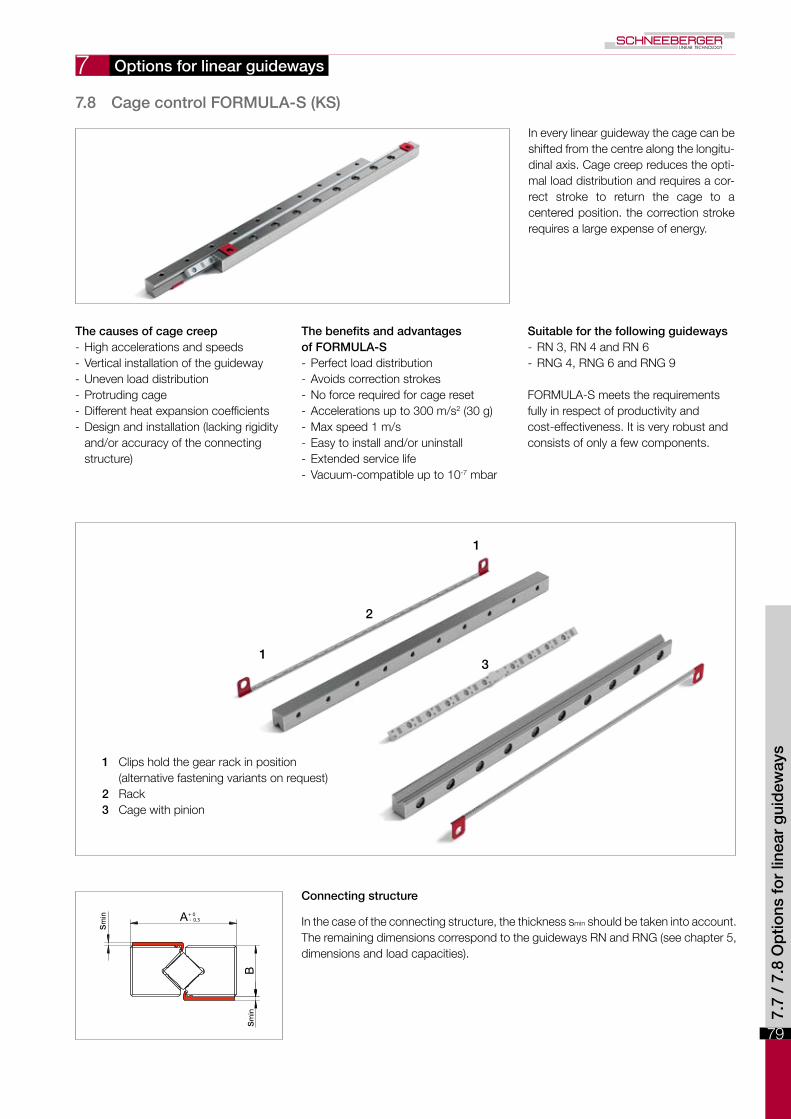
79
1
1
2
3
smin
B
A+ 0 - 0.3
smin
7
In every linear guideway the cage can be shifted from the centre along the longitu-dinal axis. Cage creep reduces the opti-mal load distribution and requires a cor-rect stroke to return the cage to a centered position. the correction stroke requires a large expense of energy.
The causes of cage creep - High accelerations and speeds - Vertical installation of the guideway - Uneven load distribution - Protruding cage - Different heat expansion coefficients - Design and installation (lacking rigidity and/or accuracy of the connecting structure)
The benefits and advantages of FORMULA-S - Perfect load distribution - Avoids correction strokes - No force required for cage reset - Accelerations up to 300 m/s2 (30 g) - Max speed 1 m/s - Easy to install and/or uninstall - Extended service life - Vacuum-compatible up to 10-7 mbar
Suitable for the following guideways - RN 3, RN 4 and RN 6 - RNG 4, RNG 6 and RNG 9
FORMULA-S meets the requirements fully in respect of productivity and cost-effectiveness. It is very robust and consists of only a few components.
1 Clips hold the gear rack in position (alternative fastening variants on request)
2 Rack3 Cage with pinion
Connecting structure
In the case of the connecting structure, the thickness smin should be taken into account. The remaining dimensions correspond to the guideways RN and RNG (see chapter 5, dimensions and load capacities).
7.8 Cage control FORMULA-S (KS)
Options for linear guideways
7.7
/ 7.
8 O
ptio
ns f
or
linea
r g
uid
eway
s

80
7 7.9 Cage control for N/O and M/V guideways (KZST)
The needle guideways of type N/O and M/V can be fitted with a cage control which ensures that process security is significantly increased. The causes and effects of cage creep are set out in chapter 7.8.
The benefits and advantages
- Perfect load distribution - Avoids correction strokes - No force required for cage reset - Accelerations up to 200 m/s2 (20 g) - Max. speed 1 m/s - Extended service life
This type of cage control fully meets the requirements in terms of productivity and cost-effectiveness. It is very robust, has a simple structure and consists of only a few components: A A gear rack made of tool steel per guide rail B Two pinions made of tool steel per cage
7.10 Fixing Hole Variants (V, G, or D)
The SCHNEEBERGER standardAll SCHNEEBERGER guideways have as standard a counterbore with thread (not suitable for linear guideways of type M/V). This design supports the use of a tapped fixing hole as well as the through fixing hole. The dimensions can be seen in the respective product specifications (chapter 5).
Options for linear guideways

81
7
N
n d
T
n d
1n
d1
n d
T
N
n d
2
n d
1
T
N
n d
1
N
n d
2
T
Special versions type V (standard for linear guideway of type M/V)
Dimensions for R-guideways
Type N Ø d T Ø d1
R 1 1.8 3 1.4 1.65R 2 2.5 4.4 2 2.55R 3 3.5 6 3.2 3.5R 6 6 9.5 5.2 5.5R 9 9 10.5 6.2 6.5R 12 12 13.5 8.2 8.5R 15 14 16.5 10.2 10.5R 18 18 18.5 12.2 12.5R 24 24 22.5 14.2 14.5
Options for linear guideways
Dimensions for RNG guideways with a cage control system (KS)
Type N Ø d T Ø d1
RNG 4-KS 3.5 6 3.2 3.5RNG 6-KS 5 7.8 3.5 3.8RNG 9-KS 6 8.5 4.2 4.8
Dimensions for N/O-guideways
Type N Ø d1 T Ø d2
N/O 62015 6 9.5 5.2 5.5N/O 92025 9 10.5 6.2 6.8N/O 2025 10 13.5 8.2 8.5N/O 2535 12 16.5 10.2 10.5N/O 3045 14 18.5 12.2 12.5N/O 3555 14 18.5 12.2 12.5
Dimensions for RNG-guideways
Type N Ø d T Ø d1
RNG 4 3.5 6 3.2 3.5RNG 6 5 7 3.2 4RNG 9 6 8.5 4.2 4.8RNG 12 8 12 6.2 7RNG 15 10 15 8.2 9RNG 20 12 18 11 10.5
Dimensions for RN-guideways
Type N Ø d T Ø d1
RN 3 3.5 6 3.2 3.5RN 4 4.5 8 4.1 4.5RN 6 6 9.5 5.2 5.5RN 9 9 10.5 6.2 6.5RN 12 12 13.5 8.2 8.5RN 15 14 16.5 10.2 10.5RN 18 18 18.5 12.2 12.5RN 24 24 22.5 14.2 14.5
7.9
/ 7.
10 O
ptio
ns f
or
linea
r g
uid
eway
s

82
7
N
en d
f3
N
e2n
N
e2
f3n
Special versions type G
Dimensions for R-guideways
Type N e Ø d
R 1 1.8 M2 1.65
R 2 2.5 M3 2.55
R 3 3.5 M4 3.3
R 6 6 M6 5.2
R 9 9 M8 6.8
R 12 12 M10 8.5
R 15 14 M12 10.5
R 18 18 M14 12.5
R 24 24 M16 14.5
Dimensions for RN-guideways
Type N e Ø d
RN 3 3.5 M4 3.3
RN 4 4.5 M5 4.3
RN 6 6 M6 5.2
RN 9 9 M8 6.8
RN 12 12 M10 8.5
RN 15 14 M12 10.5
RN 18 18 M14 12.5
RN 24 24 M16 14.5
Dimensions for RNG-guideways
Type N e Ø d
RNG 4 3.5 M3 2.65
RNG 6 5 M4 3.3
RNG 9 6 M5 4.4
RNG 12 8 M8 6.8
RNG 15 10 M10 8.5
RNG 20 12 M12 10.5
Dimensions for N/O-guideways
Type N e2 Ø f3
N/O 62015 6 M6 5.2
N/O 92025 9 M8 6.8
N/O 2025 10 M10 8.5
N/O 2535 12 M12 10.5
N/O 3045 14 M14 12.5
N/O 3555 14 M14 12.5
Options for linear guideways
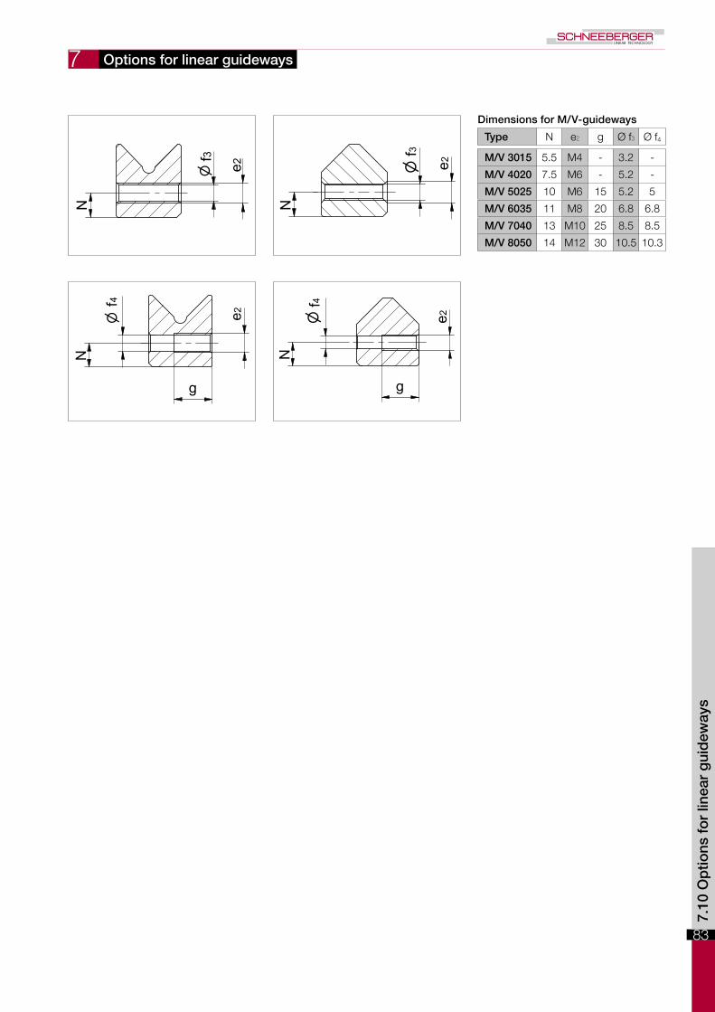
83
7 N
f 3
e2n
e2
g
n f4
N
N
e2
f3n
e2
g
n f4
N
Dimensions for M/V-guideways
Type N e2 g Ø f3 Ø f4
M/V 3015 5.5 M4 - 3.2 -
M/V 4020 7.5 M6 - 5.2 -
M/V 5025 10 M6 15 5.2 5
M/V 6035 11 M8 20 6.8 6.8
M/V 7040 13 M10 25 8.5 8.5
M/V 8050 14 M12 30 10.5 10.3
Options for linear guideways
7.10
Op
tions
fo
r lin
ear
gui
dew
ays

84
7
n d
1
N
n f2
N N
n f2
Special versions type D
Options for linear guideways
Dimensions for R-guideways
Type N Ø d1
R 1 1.8 1.65R 2 2.5 2.55R 3 3.5 3.5R 6 6 5.5R 9 9 6.5R 12 12 8.5R 15 14 10.5R 18 18 12.5R 24 24 14.5
Dimensions for RN-guidewaysType N Ø d1
RN 3 3.5 3.5RN 4 4.5 4.5RN 6 6 5.5RN 9 9 6.5RN 12 12 8.5RN 15 14 10.5RN 18 18 12.5RN 24 24 14.5
Dimensions for RNG-guidewaysType N Ø d1
RNG 4 3.5 3.5RNG 6 5 4RNG 9 6 4.8RNG 12 8 7RNG 15 10 9RNG 20 12 10.5
Dimensions for N/O-guideways
Type N Ø f2
N/O 62015 6 5.5N/O 92025 9 6.5N/O 2025 10 8.5N/O 2535 12 10.5N/O 3045 14 12.5N/O 3555 14 12.5
Dimensions for M/V-guideways
Type N Ø f2
M/V 3015 5.5 5.3M/V 4020 7.5 7.5M/V 5025 10 7.5M/V 6035 11 10M/V 7040 13 12.5M/V 8050 14 14

85
8 B
A
A
SK, SKD, SKC, SR
NRT
If two or more recirculating units are arranged next to or behind one another, they need to be ordered (matched in pairs) with the add-on designation GP.
Markings:The recirculating units in the same group are designated with a number, i.e. the same number corresponds to the exact same tolerance group.
Markings:Colored rings around the lube nipple mark the relevant tolerance group.
Recirculating unit options
8.1 Matched recirculating units (GP)
Type
Manufacturing tolerances in mm
Group tolerances in µm within pairs
A B A B
SK 1, 2 0/-0.1 +/-0.005 2 2
SK 3, 6, 9, 12 0/-0.1 +/-0.005 3 3
SKD 6, 9, 12 0/-0.1 +/-0.005 3 3
SKC 6, 9 0/-0.1 +/-0.005 3 3
SR 2 0/-0.1 +/-0.005 2 2
SR 3, 6, 9, 12 0/-0.1 +/-0.005 3 3
TypeManufacturing
tolerance ASorts in µm Markings
NRT -0.025
-20 to -25 white
-15 to -20 green
-10 to -15 yellow
-5 to -10 blue
0 to - 5 red
The types in bold are standard. The types in size 12 are available on request
8.1
Op
tions
fo
r re
circ
ulat
ing
uni
ts
Colored rings

86
8
z
s s1
m
f
L
Connection variants
8.2 Centralised lubricating system (ZS) for recirculating units NRT
Recirculating unit options
Wrench size
Type Size L f m s s1 z
NRT 19077ZS-2 13 2
5.3 8 710.5
ZS-3 14.5 3 11
NRT 26111 NRT 26132
ZS-2 13 2
10.3
8 710.5
ZS-3 14.5 3 11
ZS-4 18.5 410 8
14ZS-5 19 5
ZS-6 20 6 12 10
NRT 38144
ZS-2 13 2
14.5
8 710.5
ZS-3 14.5 3 11
ZS-4 18.5 410 8
14ZS-5 19 5
ZS-6 20 6 12 10

87
9
f ɅA
±0.005
f ɅBA
B
±0.005
B
A f Δ B
f Δ A
f Δ
±0.005
f Δ B
f Δ A
A
B
The running and positioning accuracy of an application directly depends on the geo metric precision of the guideway (see chapter 7.1), its careful orientation (see chapter 14.9) and the accuracy and rigidity of the surrounding structure (see chapter 14.1 / 14.2).
9.2 Tolerance of the supporting surface to the track
In addition to the previously mentioned geometric precision as set out in chapter 7.1, SCHNEEBERGER guideways are also manufactured to the dimensions of the sup-porting surface in relation to the track within a very tight tolerance (+/- 0.005mm).
Advantages:• Interchangeability is guaranteed at all times.• In most cases additional matching of the guideways is surplus to requirement.
Linear guideways standard parameters
9.1 Quality classes
8.2
/ 9.
1 S
td. p
aram
eter
s fo
r lin
ear
gui
dew
ays
Type R, RN and RNG
Type N/O and M/V
Type RD

88
9
L1
L
0X1
X2
X3
X4
Xn
9.4 Operating temperatures
SCHNEEBERGER linear guideways can be used at operating temperatures from –40º C to +80º C. For brief periods temperatures up to +120º C are possible.
9.5 Speeds and accelerations
The following limit values apply for the standard designs:
Product Max. speed Max. acceleration
Linear guideways R, RD, RN,RNG, N/O and M/V 1 m/s 50 m/s2
Linear guideways RN and RNG withCage control FORMULA-S 1 m/s 300 m/s2
Linear guideways N/O and M/V withcage control 1 m/s 200 m/s2
9.6 Friction, running accuracy and smoothness
When manufacturing the linear guideways, SCHNEEBERGER places great value on a high level of smoothness. Transitions, run-ins and run-outs or the quality of the syn-thetic materials and synthetic composite cages are given top priority. This also applies in respect of the rolling elements used, which must satisfy the most stringent quality demands.
For guideways with cages under normal operating conditions a friction factor of 0.0005 to 0.0030 can be assumed.
Length L ≤300 mm: ±0.3 mmLength L >300 mm: ±0.1 % of LHole pitch L1: ±0.3 mmMass Xn ≤350 mm: ±0.3 mmMass Xn >350 mm: ±0.08 % of xn
The fixing holes are manufactured before the hardening process, which is why the length tolerances and spacings differ from the usual standards. The deviations can be offset using undercut fastening screws of type GD or GDN (see chapter 5) and/or by choosing a suitable hole (see chapter 7.10).
9.3 Length tolerances and distances between fixing holes
Linear guideways standard parameters

89
10
SCHNEEBERGER recirculating units can be used at operating temperatures from –40º C to +80º C (for brief periods temperatures up to +120º C are possible). For type SKC the temperature range is –150º C to +200º C.
10.2 Speeds and accelerations
The following limit values apply for the standard designs:
Product max. speed max. acceleration
SK, SKD, SKC and SR 2 m/s 50 m/s2
NRT 1 m/s 50 m/s2
10.3 Friction, running accuracy and smoothness
When manufacturing the recirculating units, SCHNEEBERGER places great value on a high level of smoothness. Transitions, run-ins and run-outs or the quality of the synthetic materials are given top priority. This also applies in respect of the rolling ele-ments used, which must satisfy the most stringent quality demands.
For recirculating units under normal operating conditions a friction factor of 0.005 can be assumed.
Recirculating unit standard parameters
10.1 Operating temperatures
9.3
/ 10
.1 S
td. p
aram
eter
s fo
r re
circ
ulat
ing
uni
ts

90
11
wttz
K
Kt
Design
The versatile areas of application assume different characteristics from linear guideways and recirculating units.Various parameters and considerations essential for product selection. These are set out in detail below.
11.1 Linear guideways
Relationship between stroke H and length of the guideway L
If the stroke is below 400 mm, the following formula applies:
H < 0.7L
If the stroke is above 400 mm, the following formula applies:
H < 1L
LH
= Length of the linear guideway in mm= Stroke in mm
Calculating the cage length K
K < L H2
KLH
= Cage length in mm= Length of the linear guideway in mm= Stroke in mm
The stroke must be limited by means of stops on the table and not by the cages. The stops should preferably be fitted along the axis of symmetry of the guideways to avoid additional forces acting on the linear guideways.
Calculating the number of rolling elements (RA) per cage
a) For cage types KBN, AC, AK, EE, SHW, HW
RA = K - 2w + 1t
or
RA = Kt + 1t b) For cage type KBS
RA = K - (2w + tz) + 2t
KRA
wtKt
tz
= Cage length in mm= Total available rolling element per cage= Distance from cage start to the middle of the first rolling element in mm= cage division in mm= Load-bearing length in mm= Length of the middle section for the KBS cage

91
11
Q
K
L
L1
Design
11.1
Des
ign
The relationship between the cage length K and the average guideway spacing Q
K > 1Q
KQ
= Cage length in mm= Average linear guideway spacing in mm
The maximum permissible installation ratio in the case of overrunning cages
Overrunning cages are expedient if a short table is to be moved on a long guideway track. In each case the short rail for the guideway must have a rounded run-in (special version EG, see chapter 7.3) so that the overrunning cage causes as little pulsation as possible.
Not every cage is suitable for this application. The maximum cage overrun depends on the position of the rails and on the cage material.
Maximum permitted installation ratios L to L1:– for fixed guideways 1 : 2– for laid on guideways 1 : 4

92
11
H/2L
Ltot
an anK
L
H/2
L1
Ltot
anan K H/2
L
H H
Design
Installation variants for linear guideways with wipers
For different linear guideways wipers can be used in the form of end pieces (an). Two installation variants are possible for this. In both instances this results in the following length ratios:
Variant 1
Roller guideways with end pieces/wipers and rails equal in length:K = L – H/2 – an
Ltot = L + H/2 + an
With this design the linear guideways must be fitted offset by the amount an.
Variant 2
Roller guideways with end pieces/wipers and rails not equal in length:K = L – H/2Ltot = L1 + H (if the long guideway moves)Ltot = L1 (if the short guideway moves)
KHLL1
Ltot
an
= Cage length in mm= Stroke in mm= Length in mm= Length in mm= Total length in mm= Thickness of the end piece in mm

93
11
Kt
K
Q
Design
11.2 Recirculating units
11.2
Des
ign
When using recirculating units, theoretically there is not restriction in stroke. The stroke is only restricted by the length of the guide rails.
In terms of the spacing K between the recirculating units and the rail spacing Q, the following ratios are recommended as a guideline:
When using one recirculating unit per rail: Kt > 1Q
When using more than one recirculating unit per rail: K > 1Q
KKt
Q
= Spacing between the recirculating units in mm= Load-bearing length in mm= Average rail spacing in mm

94

95
12
The load capacities are based on DIN ISO standard 14728 for roller-contact bearings.
In accordance with DIN, in most applications a permanent overall deformation of 0.0001 times the rolling element diameter can be permitted without adversely affecting the operating behavior of the bearing. This is referred to as the static capacity, C0. When designing a new application, we recommend the equivalent static load be in line with the dynamic load capacity ( C ) to avoid plastic deformation.
The dynamic loading capacity C is the load at which a nominal service life L of 100,000 meters of travel is achieved. It is important to note when calculating the service life that not only the load, which acts vertically on the guideway, should be taken into account but the load range of all acting forces and moments.
The service life corresponds to the travel distance in meters, which is travelled from a guideway. This is before the first sign of material fatigue occurs within the roller guide-way elements. The nominal service life is achieved when 90 % of the guideways of identical construction reach or exceed the corresponding travel distances under nor-mal operating conditions.
Critical for the dimensioning of the guideways are the loads occurring in the ratio with the dynamic loading capacity C.
Definition of service life
As previously mentioned, the dynamic loading capacity C100 is based on a service life of 100,000 meters. Other manufacturers frequently indicate the loading capacity C50 for a service life of 50,000 meters. The resulting load capacities from this are more than 20 % higher than specified in the DIN ISO standard.
Conversion examples
For ballsConvert load capacities in accordance with DIN ISO standard to C50:C50 = 1.26 ∙ C100
Convert C50 load capacities in accordance with DIN ISO standard to:C100 = 0.79 ∙ C50
For rollers and needlesConvert load capacities in accordance with DIN ISO standard to C50:C50 = 1.23 ∙ C100
Convert C50 load capacities in accordance with DIN ISO standard to:C100 = 0.81 ∙ C50
C50 C100
= dynamic loading capacity C in N for 50,000 meters of travel distance= dynamic loading capacity C in N for 100,000 meters of travel distance
defined in accordance with DIN ISO standard
Load carrying capacity and service life
12.1 Basic principles
12.1
Lo
ad c
arry
ing
cap
acity
and
ser
vice
life

96
12
1
1 2 3 4
2 3
1
1
2
2
3
3
4
4
Load carrying capacity and service life
We talk about short stroke applications when a rolling element does not travel past the position of the next rolling element during a stroke.
Because the tracks are concentrated at these points (depressions from wear and tear form), the precision and service life of the guideway is reduced. When the strokes are highly frequent, a standard lubricant is no longer able to reach the points of contact.
Wear and tear can be deferred with suitable lubricants and regular lubrication strokes.
Short strokes curtail the service life of the guideway considerably. The service life of the guideway(s) can only be determined by means of testing.
12.2 Short strokes
Normal stroke
Short stroke
A continuous lubricating film forms below the rolling element
Local depressions from wear and tear form on the tracks. At highly frequent strokes the lubricating film is also interrupted

97
12
The formulas for calculating service life are:
For rollers and needles:
L = a∙�Ceff �10
∙ 105 m3
P
For balls:
L = a∙�Ceff �3
∙ 105 mP
aCeff
PL
= Event probability factor= Effective load carrying capacity per rolling element in N= Dynamic, equivalent load in N= Nominal service life in m
Event probability factor a
The load carrying capacities for roller-contact bearings correspond to the DIN ISO standard. This represents a value from the service life calculation, which is exceeded with a probability of 90 % during operational use of the guideway.
If the previously mentioned theoretical service life probability factor of 90% is not adequate, the service life values will need to be adjusted by a factor a.
Event probability in % 90 95 96 97 98 99
Factor a 1 0.62 0.53 0.44 0.33 0.21
Effective load carrying capacity Ceff
External influences such as track hardness and temperature can reduce the loading capacity C which means that Ceff needs to be calculated.
Ceff = fH · fT · C
Ceff
fHfTC
= Effective load carrying capacity per rolling element in N= Hardness factor= Temperature factor= Max. permissible load carrying capacity per rolling element in N
Load carrying capacity and service life
12.3 Calculating the service life L in accordance with the DIN ISO standard
12.2
/ 12
.3 L
oad
carr
ying
cap
acity
and
ser
vice
life

98
12 Load carrying capacity and service life
Hardness factor fH
Materials in a frictionless guideway, which deviate from the standard conditions (HRC 58 - 62), can be recorded with the factor fH:
Track hardness in HRC 20 30 40 50 55 56 57 58-62
Hardness factor fH 0.1 0.2 0.3 0.6 0.8 0.88 0.95 1
Temperature factor fT
Increased temperatures influence the operating conditions (material properties) and must be taken into account using the factor fT.
Temperature of the guideway in °C 150 200 250 300
Temperature factor fT 1 0.9 0.75 0.6
Example calculation for Ceff
Guideway type R6 => Hardness 58 - 62 HRC => fH = 1Temperature 200°C => fT = 0.9Cage AA 6 => C = 530 N per roller
Ceff = fH · fT · C = 1 · 0.9 · 530 = 477 N

99
12
F1
L1 LnL2
F2
Fn
Dynamically equivalent load P
The loads (F) acting on a linear guideway system are subject to frequent fluctuations during operation. This set of circumstances should be taken into account when calculating service life. The varying load absorption of the guideway at varying operating con-ditions during the travel distance is described as being the dynamic equivalent load P.
Stepped loadFormula for rollers and needles:
P =10
�1(F1
10·L1 +F2
10·L2 +...F𝑛
10·L𝑛)3 3 3 3
L
Formula for balls:
P =3
�1(F1
3·L1 +F2
3·L2 + ... F𝑛
3·L𝑛)L
Sinusoidal loadP = 0.7 Fmax
PF1... Fn
Fmax
LL1... Ln
= Equivalent load in NIndividual load in N during the partial travel distance L …. Ln
= Max. load in N= L1 + …+ Ln = total travel during one load cycle in mm= partial travel distance in mm of one individual load during a load cycle
Example calculation with a linear guideway of type RNG 6-300 with KBN 6 cage
• an event probability of 97% is selected; the corresponds to a factor a of 0.44• the dynamic loading capacity of a roller (for KBN 6 cage) is 1'800 N. If 16 rollers are used, the loading capacity of the guideway
is 16 ∙ 1'800 N = (28'800 N)• the application generates a total load on to the guideway of 10'000 N
With the previously mentioned values, the following calculation for service life L is:
L = a ∙� Ceff �10
∙ 1053
P
L = 0.44 ∙�28'800 N�10
∙ 105 = 1'495'412 𝓂3
10'000 N
If the service life is requested in hours, the travelled stroke H (in meters) and the time t (in seconds) required for the stroke movement must be known.
The service life Lh is calculated as follows:
Lh = L ∙ � = Service life in hoursH ∙ 3'600
Load carrying capacity and service life
Total travel distance L
Total travel distance L
Load
PLo
ad P
12.3
Lo
ad c
arry
ing
cap
acity
and
ser
vice
life

100
12
Kt
X F
Fsδ
Load carrying capacity and service life
The correction factor RTmin
It was explained on the above pages how service life should be calculated from the given load carrying capacity and the occurring load. In doing so, the number of load bearing rolling elements per cage (RT) should be taken into account.
Similarly important is estimating the behavior of the surrounding structure when trans-mitting forces to the frictionless guideway. Then an elastic deformation or a geometric error in a machine bed lead to the fact that only a part of the installed rolling element effectively absorbs load.
Reliable statements on this application-specific issue can usually only be made with a great deal of difficulty, for example by taking measurements on functioning models or using calculations based on the method of finite elements. The result of this is that normally dimensioning takes place by taking simplified measures, i.e. the external load is divided up on to few rolling elements using the correction factor RTmin.
To determine RTmin first of all the connecting structure must be assessed based on the following values from historical experience:
A = Rigid structure δS ≤ 0.1 ∙ δA
B = Normal structure δS > δA
δS
δA
FXKt
= deformation of the connecting structure in µm= deformation of the rolling element including the guide rail in µm (see chapter 12.5)= load in N= distance in mm= load-bearing cage length in mm

101
12
A
B
RT
RT/2
RT/4
0,25Kt 0,5Kt 0,75Kt Kt
Load carrying capacity and service life
To calculate RTmin according to the diagram applies
structure A (rigid) B (normal)
X > Kt RTmin to RT/4 RTmin
X < Kt as per diagram as per diagram
For RTmin the following applies
Rolling element type
Cage types
2 Balls AK
1 RollersAA, AC, EE, KBN
and KBS5 Needles SHW and HW
0.5Recirculating unit
with rollersSR and NRT
1Recirculating unit
with ballsSK, SKD and SKC
Example calculation No. 1
AK 6 cageX measures 200 mmKt measures 90 mmConsequently the method of calculation applies in accordance with "X > Kt"
Calculation for a rigid structure:
• In accordance with the table, a ball count applies of RTmin to RT/4
• RTmin corresponds to 2 balls• RT/4 corresponds to 2.25 balls
Calculation for a normal structure:• In accordance with the table RTmin
RTmin corresponds to 2 balls
Example calculation No. 2
AK 6 cageX measures 80 mmKt measures 90 mmConsequently the method of calculation applies in accordance with "X < Kt"
Calculation for a rigid structure:• In accordance with the diagram, X 0.88 from Kt is
corresponding (80 mm : 90 mm) and consequently RT/2 For 9 load bearing balls, this results in 4.5 balls (9 load bearing balls : 2)
Calculation for a normal structure:The following applies in accordance with diagram RTmin, which corresponds to 2 balls in accordance with the table 12
.3 L
oad
car
ryin
g c
apac
ity a
nd s
ervi
ce li
fe
Lever arm X

102
X
Kt
F
F
12 12.4 Example calculations
Example 1
Searched for:Equivalent load P per roller
Assumption:Linear guides type R 6AC 6 cage with 8 rollers (= RA)F = 350 N X = 120 mm
For the roller cage type AC 6 the following applies:Kt = (RA – 1) ∙ t = (8 – 1) ∙ 9 = 63RTmin = 1 rollerC = 530 N (see technical data for the AC 6 cage)
Note:The asymmetric distribution of force is most safely taken into account when the load on the number of load bearing rolling elements (RTmin) for the guideway is reduced.
Calculation for P per roller
P = F ∙ x ∙1
Kt ∙ 2 RTmin
= 350 ∙ 120 ∙1 = 334 N63 ∙ 2 1
P is smaller than C. The design is correct in this way.
PFC
XRTmin
RA
tKt
= Equivalent load in N per roller= load in N= Max. permissible load carrying capacity per rolling element in N= distance in mm= Correction factor= Total available rolling element per cage= cage division in mm= Load-bearing length in mm
Load carrying capacity and service life
The following example calculations illustrate the procedure for some typical problems.

103
12
F
F
Load carrying capacity and service life
12.3
/ 12
.4 L
oad
carr
ying
cap
acity
and
ser
vice
life
Example 2
Searched for:Equivalent load P per roller
Assumption:Linear guides type R 6Roller cage type AC 6 cage with 20 rollers (= RA)F = 6500 NC = 530 N (according to techn. data for the AC 6 cage)
RT = RA
2
= 20 = 10 rollers2
Calculation for P per roller
P = F∙
12 RT
= 6'500∙
1 = 325 N2 10
P is smaller than C. The design is correct in this way.
w
tPFC
RT
= Distance from cage start to the middle of the first rolling element in mm= cage division in mm= Equivalent load in N per roller= load in N= Max. permissible load carrying capacity per rolling element in N= Number of load-bearing rolling elements per cage

104
Kt
X
F
F
12
Example 3
Searched for:Equivalent load P per ball
Assumption:Rigid slide structureLinear guides type R 6Cage type AK 6 with 12 balls (= RA); t = 9 mm (according to techn. data for the AK 6 cage)
RA = RT = 12 ballsRTmin = 3 = RT/4 according to diagram on page 101Kt = (RA – 1) ∙ tF = 240 NX = 75 mm (distance F to opposing force)C = 65 N (according to chapter 5.1, technical data for the AK 6 cage)
Calculation for P per ball:
P = F ∙ X ∙ 1Kt 2 RTmin
= 240 ∙ 75 ∙ 1 = 30 N99 2 3
P is smaller than C. The design is correct in this way.
tPFC
RTmin
RA
RT
Kt
= cage division in mm= Equivalent load in N per ball= load in N= Max. permissible load carrying capacity per rolling element in N= Correction factor= Total available rolling element per cage= Number of load-bearing rolling elements per cage= Load-bearing length in mm
Load carrying capacity and service life

105
12
X
F
FQ
Load carrying capacity and service life
12.4
Lo
ad c
arry
ing
cap
acity
and
ser
vice
life
Example 4
Searched for:Equivalent load P per roller and the suitable size RNG guideways
Assumption:Type RNG linear guidewaysRoller cage type KBN with 10 rollers (RA)F = 15'000 NX = 50 mmQ = 100 mm
RT = RA
2
= 10 = 5 rollers2
Calculation for P per roller
P1 = F ∙ X ∙1
Q RT
=15'000 ∙ 50∙
1 = 1'500 N100 5
P2 = FRA
= 15'000 = 1'500 N10P = P1 + P2
= 1'500 +1'500 = 3'000 N
P (P1, P2)FXQC
RT
RA
= Equivalent loads in N per roller= load in N= distance in mm= Medium linear guideway distance in mm= Max. permissible load carrying capacity per rolling element in N= Number of load-bearing rolling elements per cage= Total available rolling element per cage
Definition of the suitable guideway size:According to product specification for the KBN cage (chapter 5.2 or 5.3) if C = 3'900 N were to be selected
Type Size Dw t wC per roller
in N
KBN
4 4.5 6.5 approx. 4 8506 6.5 8.5 approx. 5 18009 9 12 approx. 7.5 390012 12 15 approx. 9 6500
The roller size 9 is suitable. Thus select cage KBN 9 and the linear guideway RNG 9, provided the service life has been fulfilled.

106
K
QX
F
F
12
Example 5
Searched for:Equivalent load P per needle
Assumption:Linear guideways type N/O 2025SHW 15 cage, cage length K = 194 mm(w = 2.9 mm according to techn. specifications of the SHW 15 cage)
F = 5'000 NX = 280 mmQ = 75 mmC = 750 N (according to techn. specifications for the AC 15
cage)
RA = � K - 2w + 1 � ∙ 2t
= � 194 - 5.8 + 1 � ∙ 2 = 96 needles4
RT =RA = 48 needles2
Calculation for P per needle:
P = F ∙ X ∙1
Q RT
= 5'000 ∙ 280 ∙1 = 389 N75 48
P is smaller than C. The design is correct in this way.
w
tPFXQC
RT
RA
K
= Distance from cage start to the middle of the first rolling element in mm= cage division in mm= Equivalent load in N per needle= load in N= distance in mm= Medium linear guideway distance in mm= Max. permissible load carrying capacity per rolling element in N= Number of load-bearing rolling elements per cage= Total available rolling element per cage= Cage length in mm
Load carrying capacity and service life

107
12
K
X
F
F
KtQ
X1
Load carrying capacity and service life
12.4
Lo
ad c
arry
ing
cap
acity
and
ser
vice
life
Example 6
Searched for:Equivalent load P per roller
Assumption:Rigid structureLinear guides type R 12Cage type AC 12, length K = 400 mmF = 2'000 NX = 500 mmX1 = 200 mmQ = 100 mmC = 2'500 N (see chapter 5.1, technical specifications for the AC 12 cage)
For the roller cage AC 12 the following applies:
Kt = K - 2w= 400 - 22 = 378 mm
RA = Kt + 1t
= 378 + 1 = 22 rollers18
RT = RA 2
= 22 = 11 rollers2X > Kt = RT/4 (according to the diagram on page 101)RTQ = RT
RTL = RT = 11= 2.75 rollers (rounded down to 2)4 4
Calculation for P per roller
Load laterally
PQ = F ∙ X1 ∙1
Q RTQ
=2'000 ∙
200 ∙1 = 364 N
100 11
Load longitudinally
PL = F ∙ X ∙1
Kt ∙ 2 RTL
=2'000 ∙
500 ∙1 = 662 N
378 ∙ 2 2
P = PQ + PL
= 364 + 662 = 1'026 NP is smaller than C. The design is correct in this way.
w
tPFXX1
QCRT
RA
KKt
...L
...Q
= Distance from cage start to the middle of the first rollingelement in mm
= cage division in mm= Equivalent load in N per roller= load in N= distance in mm= distance in mm= Medium linear guideway distance in mm= Max. permissible load carrying capacity per rolling
element in N= Number of load-bearing rolling elements per cage= Total available rolling element per cage= Cage length in mm= Load-bearing length in mm= Longitudinally= Laterally
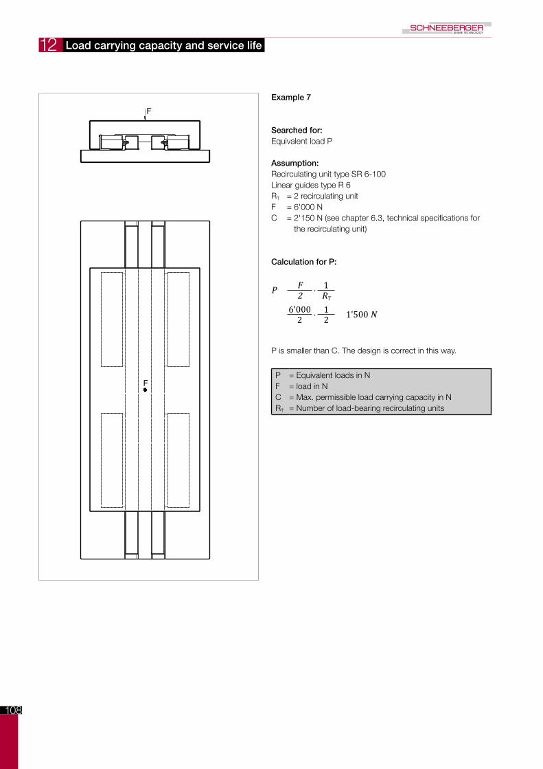
108
F
F
12
Example 7
Searched for:Equivalent load P
Assumption:Recirculating unit type SR 6-100Linear guides type R 6RT = 2 recirculating unitF = 6'000 NC = 2'150 N (see chapter 6.3, technical specifications for
the recirculating unit)
Calculation for P:
P = F∙
12 RT
= 6'000∙
1 = 1'500 N2 2
P is smaller than C. The design is correct in this way.
PFCRT
= Equivalent loads in N= load in N= Max. permissible load carrying capacity in N= Number of load-bearing recirculating units
Load carrying capacity and service life
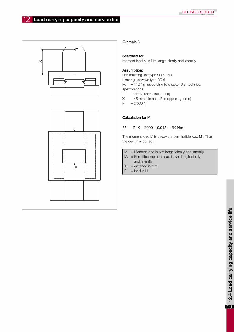
109
12
F
F
X
Load carrying capacity and service life
12.4
Lo
ad c
arry
ing
cap
acity
and
ser
vice
life
Example 8
Searched for:Moment load M in Nm longitudinally and laterally
Assumption:Recirculating unit type SR 6-150Linear guideways type RD 6ML = 112 Nm (according to chapter 6.3, technical specifications for the recirculating unit)X = 45 mm (distance F to opposing force)F = 2'000 N
Calculation for M:
M = F ∙ X = 2000 ∙ 0,045 = 90 Nm
The moment load M is below the permissible load ML. Thus the design is correct.
MML
XF
= Moment load in Nm longitudinally and laterally= Permitted moment load in Nm longitudinally
and laterally= distance in mm= load in N
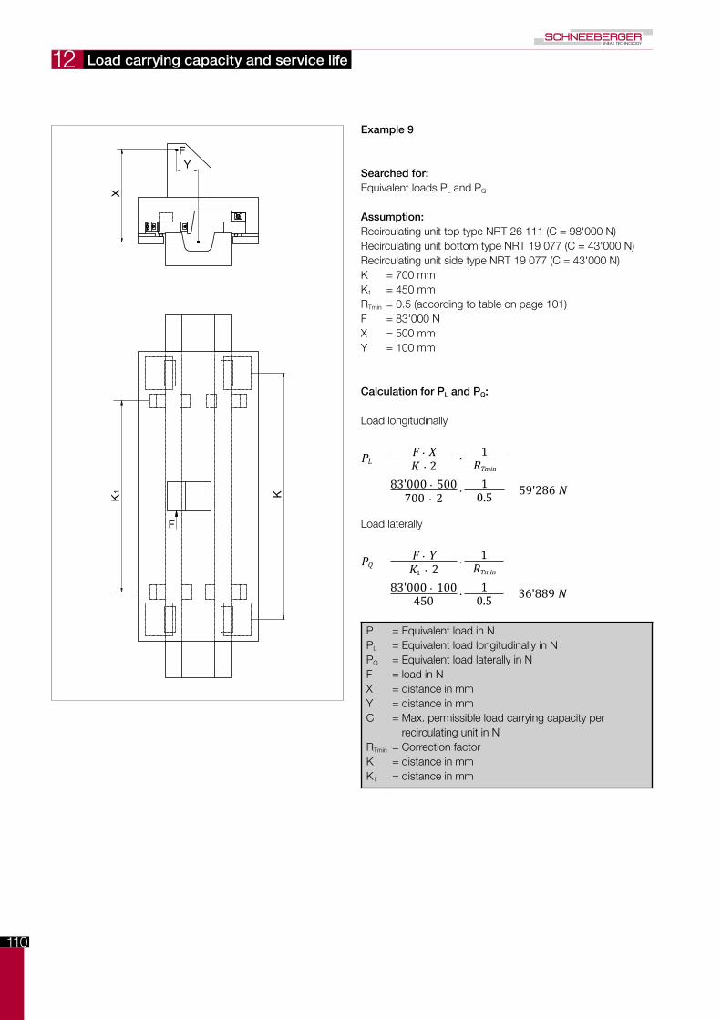
110
K1 K
F
F
X
Y
12
Example 9
Searched for:Equivalent loads PL and PQ
Assumption:Recirculating unit top type NRT 26 111 (C = 98'000 N)Recirculating unit bottom type NRT 19 077 (C = 43'000 N)Recirculating unit side type NRT 19 077 (C = 43'000 N)K = 700 mmK1 = 450 mmRTmin = 0.5 (according to table on page 101)F = 83'000 NX = 500 mmY = 100 mm
Calculation for PL and PQ:
Load longitudinally
PL = F ∙ X ∙1
K ∙ 2 RTmin
= 83'000 ∙ 500 ∙1 = 59'286 N700 ∙ 2 0.5
Load laterally
PQ = F ∙ Y ∙1
K1 ∙ 2 RTmin
= 83'000 ∙ 100 ∙1 = 36'889 N450 0.5
PPL
PQ
FXYC
RTmin
KK1
= Equivalent load in N= Equivalent load longitudinally in N= Equivalent load laterally in N= load in N= distance in mm= distance in mm= Max. permissible load carrying capacity per
recirculating unit in N= Correction factor= distance in mm= distance in mm
Load carrying capacity and service life

111
12
1
10
100
10 100 1000 10`000
δ A (µ
m)
P (N)
2
5
50
20
20 200 200050 500 5000
A
A
P
δ
1
10
100
1 10 100 1'000
δA (µ
m)
P (N)
2
5
50
50
2 5 20 50 200 500
A
A
P
δ
Load carrying capacity and service life
12.4
Lo
ad c
arry
ing
cap
acity
and
ser
vice
life
12.5 Elastic deformation and rigidity of linear bearings
Linear guideways
The total deformation δA (that is the deformation of the rolling element in connection with hardened tracks (min. 58 HRC) ) can be deduced from the following diagrams.
The elastic deformation of the linear guideways of type R with rollers
In relation to the load P per ball
In relation to the load P per roller
The elastic deformation of the linear guideways of type R with balls

112
1
10
100
10 100 1'000 10'000
δA (µ
m)
P (N) 20 50
2
5
200 500
20
50
2'000 5'000
A
A
P
δ
1
10
100
10 100 1'000 10'000
δ A (µ
m)
P (N) 20 50
20
50
2
5
200 500 2'000 5'000
A
A
P
δ
12
The elastic deformation of the linear guideways for type RN and RNG.
The elastic deformation of the linear guideways of types N/O and M/V upon use with the following types of cages
Load carrying capacity and service life
In relation to the load P per roller
In relation to the load P per pair of needles

113
12
1
10
100
100 1'000 10'000
δ A (µ
m)
P (N) 200 500 2'000 5'000
2
5
20
50A
A
P
δ
1
10
100
10 100 1'000 10'000
δ A (µ
m)
P (N)
2
5
20
50
20 50 200 500 2'000 5'000
A
A
P
δ
Load carrying capacity and service life
12.5
Lo
ad c
arry
ing
cap
acity
and
ser
vice
life
The elastic deformation of the recirculating unit of type SKD in connection with linear guideways type R or RD.
12.6 Elastic deformation and rigidity of recirculating units
The elastic deformation of the recirculating unit of type SK in connection with linear guideways type R or RD.

114
1
10
10 100 1'000
δ A (µ
m)
P (N) 20 50 200 500
2
5
20
A
A
P
δ
1
10
100
10 100 1'000 10'000 100'000
δ A (µ
m)
P (N)
2
5
20
50
20 50 200 500 2'000 5'000 20'000 50'000
A
A
P
δ
12
The elastic deformation of the recirculating unit of type SKC in connection with linear guideways type R or RD The total length of the straight lines applies for lubricated recirculating units, the dotted straight line for unlubricated ones.
The elastic deformation of the recirculating unit of type SR in connection with linear guideways type R or RD.
Load carrying capacity and service life
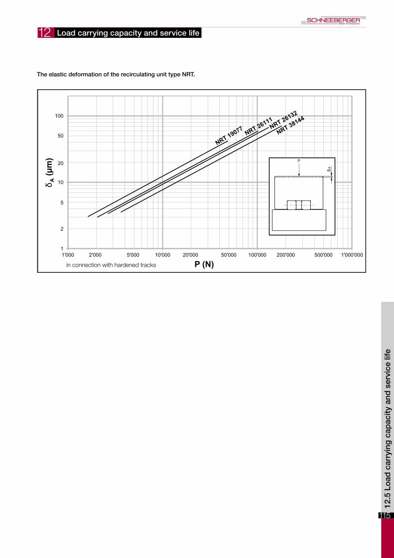
115
12
1
10
100
1'000 10'000 100'000 1'000'000
δ A (µ
m)
P (N)
2
5
20
50
2'000 5'000 20'000 50'000 200'000 500'000
A
P
δ
Load carrying capacity and service life
12.5
Lo
ad c
arry
ing
cap
acity
and
ser
vice
life
The elastic deformation of the recirculating unit type NRT.
in connection with hardened tracks

116

117
13
0 200 400 600 800 1000L (mm)
10
8
6
4
2
(µm)
2000 2200 2400 2600 2800 30001800160014001200
12
14
16
18
20
NQ
SQ
SSQ
Linear guideways are high-precision components. The requirements for theconnecting structure are also high to ensure the accuracy of the guideways are maximized.
The quality of the reference and supporting surfaces as well as the rigidity of the connecting structure must meet the most stringent requirements. If this is not the case, smoothness, precision and service life of the guideway will be significantly affected.
To exploit the full potential of the linear guideways, assembly on a rigid and ground substrate is recommended. Connecting structures made of light metal are only suit able in certain instances - due to their lower rigidity and limited machining accuracy.
Parallelism of the reference and locating surfaces
They must be compatible with those of the linear guideway (also applies when using linear guideways with recirculating units):
NQ Normal qualitySQ Special qualitySSQ Super special quality
Surface quality
The accuracy of the application critically determines the required surface quality of the reference and locating surfaces. For high-precision applications they must demon-strate a maximum Ra value of 0.4. An Ra value of 1.6 may not be exceeded for standard applications.
Construction and installation guidelines
13.1 The connecting structure and its influence on service life
13.2 Configuration of the connecting structure
13.1
/ 1
3.2
Con
stru
ctio
n &
inst
alla
tion
guid
elin
es

118
13
b 0.3µm/mm
α
0 1 0 0 2 0 0 3 0 0
0
1 0
20
3 0
L (mm)
Δ (µ
m)
Angular error
Height offset for linear guideways
Parallelism of the supporting and locating surfaces in the case of the recircu-lating unit
The parallelism of the supporting and locating surfaces in relation to the mating track can be derived from the diagram below:
Construction and installation guidelines
The angular errors for the supporting and locating surface should not exceed 0.3 µm/mm.
The angular errors resulting from height offset and/or elastic deformations may not exceed the following values:
Balls or rollers: 0.3 µm/mmNeedles 0.1 µm/mm
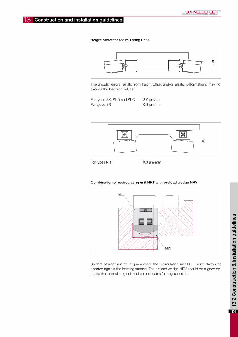
119
13
α
α
NRT
NRV
Height offset for recirculating units
Combination of recirculating unit NRT with preload wedge NRV
Construction and installation guidelines
The angular errors results from height offset and/or elastic deformations may not exceed the following values:
So that straight run-off is guaranteed, the recirculating unit NRT must always be oriented against the locating surface. The preload wedge NRV should be aligned op-posite the recirculating unit and compensates for angular errors.
For types SK, SKD and SKC 3.0 µm/mmFor types SR 0.3 µm/mm
For types NRT 0.3 µm/mm
13.2
Co
nstr
uctio
n &
inst
alla
tion
gui
del
ines

120
13 Construction and installation guidelines
SCHNEEBERGER linear guideways are not designed to be load-bearing structural components, but as guideway components.
Horizontal installation indicates direction of movement runs horizontally. Likewise, vertical installation indicates direction of movement deviates from the horizontal plane.
Enclosed configuration
The enclosed configuration is a fixed/fixed bearing. It can be loaded by moments and forces in any direction. Rigidity and running accuracy can be influenced by a change in the preload.
The advantages and characteristics of an enclosed configuration: - Supports any operation position, load direction and moment load - Supports a small guideway base - Must be preloaded. Consequently, rigidity and accuracy are increased.
An example involving linear guideways of type R, RN or RNG
An example involving linear guideways of type N/O or M/V
13.3 Installation methods

121
13 Construction and installation guidelines
Example with recirculating units of type SK, SKD, SKD or SR combined with the double V-shaped guide RD
Example involving recirculating unit of type SK and linear guideways of type R
Example involving recirculating unit of type NRT and surface guideways
13.3
Co
nstr
uctio
n &
inst
alla
tion
gui
del
ines
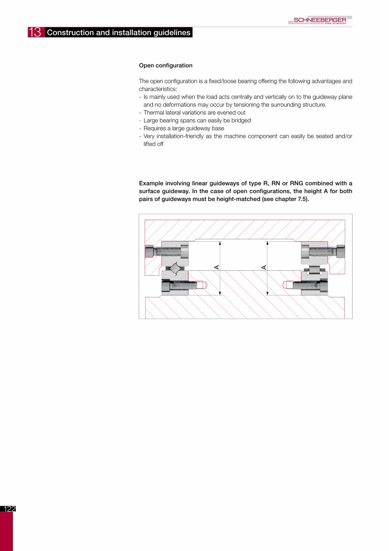
122
13
A A
Construction and installation guidelines
Open configuration
The open configuration is a fixed/loose bearing offering the following advantages and characteristics: - Is mainly used when the load acts centrally and vertically on to the guideway plane and no deformations may occur by tensioning the surrounding structure.
- Thermal lateral variations are evened out - Large bearing spans can easily be bridged - Requires a large guideway base - Very installation-friendly as the machine component can easily be seated and/or lifted off
Example involving linear guideways of type R, RN or RNG combined with a surface guideway. In the case of open configurations, the height A for both pairs of guideways must be height-matched (see chapter 7.5).

123
13
B
A
Construction and installation guidelines
Example of a suspended linear guideway of type N/O or M/V combined with a surface guideway. The dimensions A and B must be height-matched.
Example involving recirculating unit of type NRT The vertical load is born by height-matched NRT
13.3
Co
nstr
uctio
n &
inst
alla
tion
gui
del
ines

124
13
A
A
B
B
A
A
B
B
Construction and installation guidelines
13.4 Fastening
Fastening variants
The SCHNEEBERGER linear guideways and recirculating units can be fastened to the connecting structure in two dif-ferent ways:
A The use of the tapped boreholesB The use of through holes
Method A is preferred because a powerful fastening is possi-ble based on the screw size
Method B provides added flexibility combined with the fas-tening screws with a thin shaft (see chapter 5).
Linear guideways
Recirculating units
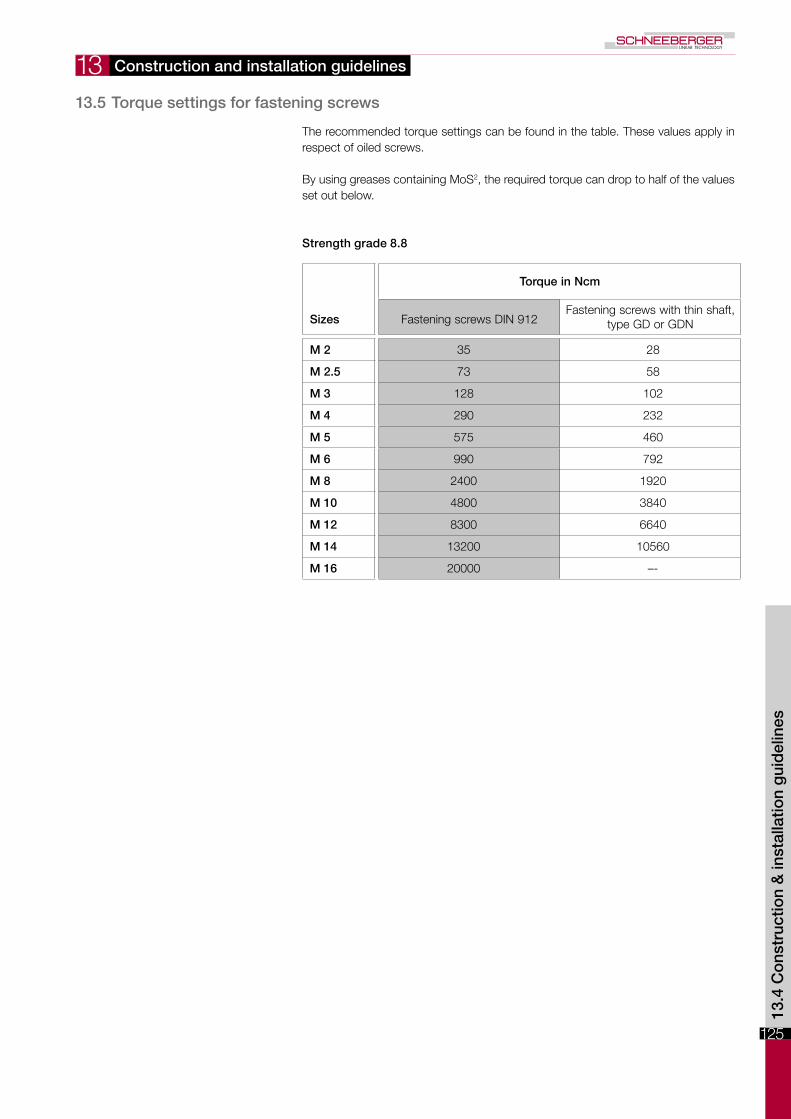
125
13 Construction and installation guidelines
The recommended torque settings can be found in the table. These values apply in respect of oiled screws.
By using greases containing MoS2, the required torque can drop to half of the values set out below.
Strength grade 8.8
Sizes
Torque in Ncm
Fastening screws DIN 912Fastening screws with thin shaft,
type GD or GDN
M 2 35 28
M 2.5 73 58
M 3 128 102
M 4 290 232
M 5 575 460
M 6 990 792
M 8 2400 1920
M 10 4800 3840
M 12 8300 6640
M 14 13200 10560
M 16 20000 –-
13.4
Co
nstr
uctio
n &
inst
alla
tion
gui
del
ines
13.5 Torque settings for fastening screws

126
13 Construction and installation guidelines
13.6 Preload
The size of the preload is guided by the intended use of the guideways. A high preload …… increases rigidity of the guideway and guarantees zero-backlash… reduces moment loads, maximum loads on the rolling element… increases displacement resistance… reduces the service life
A positive effect of preload is achieved with 5 % - 20 % of the permissible load C.
General approach
The preload can be consistently set using a torque wrench. In so doing the friction between screw and tapped fixing hole must be taken into account (to be determined by means of tests).
When using wedge adjusters or adjusting plates, the ideal preload must be deter-mined based on the elastic total deformation δA (see chapter 12.5) and the deformation of the connecting structure.
When setting an R-guideway with cage type EE, the cage must first be slightly com-pressed before the rollers are applied.
As mentioned above, the preload increases the rigidity of the guideway. A high preload, however, requires a stable connecting structure. Otherwise unwanted edge loads occur to rollers and needles as a result of angular errors, which in turn has a negative impact on load carrying capacity.
Procedure for linear guideways
A guideway is normally set with zero-backlash using adjusting screws. A zero-back-lash, uniform sequence is only achieved when advancing exclusively takes place where the cage with the rolling elements is located (see also chapter 13.9).
A linear guideway is normally set with zero-backlash using adjusting screws. At least one adjusting screw must be provided per fastening screw, the thread size of which should match the fastening screw. In the case of overrunning cages, the shorter rail should preferably be advanced.
Fastening screwsAdjusting screws

127
13
t
M... L1Pvs
Construction and installation guidelines
Example calculation for the infeed force per adjusting screw (Pvs) of their tightening torque (Mds)
Required information per calculation:
- Linear guide type R 3 L1 = 25 mm- Roller cage type AC 3 t = 5 mm
C = 130 N- Diameter of the adjusting screw = M4- Factor f (for rollers = 1; for balls / needles = 2) f = 1- Preload p (2 % to 20 % of C) p = 10 %- Factor a in cm (as per the following table)
Thread Factor a
M2 0.0238
M2.5 0.0294
M3 0.035
M4 0.0469
M5 0.058
M6 0.0699
M8 0.0926
M10 0.1152
M12 0.1378
M14 0.1591
M16 0.1811
Calculation of the infeed force per adjusting screw Pvs
Pvs = L1 / t ∙ C ∙ p / 100 ∙ f= 25 / 5 ∙ 130 ∙ 10/ 100 ∙1 = 65 N
Calculation of tightening torque Mds
Mds = Pvs ∙ a= 65 ∙ 0.0469 = 3.05 Ncm
13.6
Co
nstr
uctio
n &
inst
alla
tion
gui
del
ines

128
13 Construction and installation guidelines
Other technical possibilities for preloading linear guideways include:
Setting using an adjusting strip
Setting using a wedge adjuster
Setting using a cylinder adjuster
Setting using a longitudinal wedge
Setting using a double longitudinal wedge

129
13
Kt
Construction and installation guidelines
13.6
Co
nstr
uctio
n &
inst
alla
tion
gui
del
ines
Procedure when preloading recirculating units (SK, SKD, SKC and SR)
A recirculating unit is normally set with zero-backlash using adjusting screws. At least one adjusting screw must be provided per fastening screw, the thread size of which should match the fastening screw.
Example calculation for the infeed force per adjusting screw (Pvs) of their tighten ing torque (Mds)
Required information per calculation:
- Recirculating unit SK 6-100 C = 715 N- Diameter of the adjusting screw = M4- Number of adjusting screws N = 2- Factor f ("1" for roller, "2" for balls) = 2- Preload p (5 % to 20 % of C) = 10%- Factor a in cm as per the following table
Thread Factor a
M2 0.0238
M2.5 0.0294
M3 0.035
M4 0.0469
M5 0.058
M6 0.0699
M8 0.0926
M10 0.1152
M12 0.1378
M14 0.1591
M16 0.1811
Calculation of the infeed force per adjusting screw Pvs
Pvs = C / N ∙ p / 100 ∙ f= 715/ 2 ∙ 10/ 100 ∙2 = 71.5 N
Calculation of tightening torque Mds
Mds = Pvs ∙ a= 71.5 ∙ 0.0469 = 3.35 Ncm
Its advance must always remain within the load-bearing length Kt !
Fastening screwsAdjusting screws

130
13
NRTNRV
Kt
Procedure for recirculating unit NRT with preload wedge type NRV
For preload using preload wedge NRV the following infeed values apply:
Type SizeMax adjustment range in terms of height (mm)
Height difference per revolution of the preload screw A
NRV
19077 0.35 0.0350
26111 0.40 0.0625
26132 0.40 0.0625
38144 0.40 0.0750
After successfully setting the preload, always tighten the two lock nuts alternately and use the wrench applying the same amount of torque!
Lock nuts for securing the preload screw
Preload screw
Construction and installation guidelines
If preloading takes place without preload wedge NRV it is important to ensure that the advance must always remain within the load-bearing length Kt.

131
13 Construction and installation guidelines
13.6
Co
nstr
uctio
n &
inst
alla
tion
gui
del
ines
Other technical possibilities for preloading the NRT include:
Setting using an intermediate plate
Setting using a wedge adjuster
Setting using a double longitudinal wedge

132
13
A
D
B
C E
F
G
The method of sealing or covering is significant for the smooth operation and service life of the guideways.
Where there is only a small amount of dirt, wipers are sufficient to keep the tracks clean. Their braking effect can generally remain unattended. We offer a variety of standard wipers, which are described in detail in the respective product specifications.
Covers are used when there is some danger of harmful contamination of the guideway. While wipers only push the dirt off the running surfaces in the area of their movement, covers provide the opportunity of also keeping penetrating dirt away at the sides.
Some design options are listed below:
A = Wiper sidewaysB = Diverting swarf and coolant away using a coverC = Labyrinth seals offer an effective and economically viable protectionD = Simple metal coverE = Roll-up coverF = Bellows above or belowG = Telescopic cover
13.7 Sealing and covers
Construction and installation guidelines

133
13 Construction and installation guidelines
13.7
/ 1
3.8
Co
nstr
uctio
n &
inst
alla
tion
gui
del
ines
Lubrication is a design element and must therefore be defined during the development phase of a machine or application. If the lubrication is only selected after design and construction is complete, based on experience this is likely to lead to considerable difficulties. A carefully thought out lubrication concept is therefore a sign of a state-of-the-art and well devised design.
Parameters to be taken into account in selecting the lubricant, amongst others, include:
– Operating conditions (speed, accelerations, stroke, load, installation orientation)
– External influences (temperature, aggressive media or radiation, dirt accumulating, moisture)
– Subsequent lubrication (period of time, quantity, compatibility with other lubricants)
– Compatibility (with corrosion protection, with integrated materials such as plastic cages)
– Tracks (geometry, surface roughness, hardness, material, coating, wettability)
Technical and economic considerations determine the lubricant and process to be used. Generally lithium-soap-based roller bearing grease are used to lubricate (alloyed greases KP2K in accordance with DIN 51502 or DIN 51825). Oil dispensers or occa-sional oiling via oil nipples fully meet the demands of the guideways. For minimal roller frictional resistance lubrication with mineral-oil-based oils is recommended (CLP or HLP in viscosities of ISO VG 15 to 100 in accordance with DIN 51519).
The lubricants are normally applied through the spacing between the linear guideways and the recirculating units or through the lubrication holes in some instances available as standard or lube nipples in the recirculating units. If this is not supported by the design (e.g. in the case of vertical installation), on request linear guideways with lube holes can also be supplied. Particularly advantageous are oil mist lubrication methods, which help to prevent dirt accumulating on the guideways with their slight excess pressure. Their acceptability is greatly limited, however, due to their environmental impact. Cutting-oils or water soluble coolants are to be kept away from the guideways, however, because they dilute or wash away the available lubricant. In addition, coolants tend to stick when drying out. Lubricants with solid additives are inappropriate.
Subsequent lubrication intervals depend on the aforementioned operating condi-tions and external influences and cannot be therefore be calculated. That is why the lubrication point must be observed over a lengthy period of time.
Values based on historical experience show that with normal use subsequent lubrica-tion of up to 2 to 5 times is sufficient, spread over the calculated service life.
13.8 Lubrication

134
13
Lubrication of the recirculating unit NRT
There are three ways of lubricating the NRT
Variant A: Lube nipple on each end faceVariant B: Lube opening on the topVariant C: Optional connection for a centralised lubricating system
Variant A: Lubrication by means of the lube nipple
Variants B:Oil delivery through the lube opening on the top
Oil delivery through the lube opening on the top through the preload wedge NRV
Variant C: Centralized lubricating system (option ZS)
Construction and installation guidelines

135
13
2 1 1 3
Construction and installation guidelines
13.9
/ 1
3.10
Co
nstr
uctio
n &
inst
alla
tion
gui
del
ines
Linear guideways and recirculating units are high-precision components and should therefore be handled with care. They should always be transported in their original packaging to protect them from damage and be stored at room temperature and in a dry environment.
Improper handling of the guideways can lead to preliminary damage and thus to pre-mature failure. That is why their assembly may only be undertaken by expert profes-sional staff.
Linear guideways
With careful, clean preparation and a step by step approach, by adopting a rational procedure you will achieve a perfect guide system.
The following installation instructions applies by analogy for all types of SCHNEEBERGER linear guideways.
• To guarantee a perfect support for the guide rails, any remaining burrs or ridges are to be removed with a fine whetstone.
• Before installation, the linear guideways and supporting surfaced should be cleaned. By means of a subsequent light lubrication they will be protected from any consequential damage. Tip for long or multi-part guide rails: Due to the bore hole tolerances of the rails, the fastening holes in the supporting surfaces should be drilled according to the holes in the linear guideways. By using fastening screws with a thin shaft differences in hole spacings can also be evened out (see chapter 5).
• The marked side of the guide rail may not be used as a supporting surface!
13.9 Transport, handling and storage
13.10 Installation guidelines
Marked side
Marked side

136
13
11
11
Δ P
Δ A
2
Construction and installation guidelines
• The fixed pair of linear guideways (1) is pressed against the supports using an appropriate clamping element and the fastening screws are tightened (use a torque wrench! For tightening torque see chapter 13.5.)
Check parallelism ΔA and ΔP. The parallelisms measured must fall within the tolerances of the linear guideway (see chapter 7.1)
• Install the fixed rail (2) of the opposing pair.

137
13
2 3
44
Construction and installation guidelines
• Install the rail (3) and in so doing only lightly tighten the fastening screws.• Lubricating (see chapter 13.8)
• Insert and center the cages (4). After that the linear bearings must be preloaded (please refer to the following page).
13.1
0 C
ons
truc
tion
& in
stal
latio
n g
uid
elin
es

138
13
2. 1. 3.
4.
5.
6.
7.
2 1 1 3• Tighten the fastening screws for the
rail (3).
• Install the end pieces
Construction and installation guidelines
• Set and/or preload the linear guideway with zero-backlash (see chapter 13.5).
Application of the preload using the adjusting screws should be carried out from the centre of the rail outwards using the following steps (the sequence can be worked out from the figures):
Adjusting screws
1. Step
2. Step
3. Step
4. Step
5. Step

139
14
13.8
/ 1
4 O
rder
des
crip
tions
Order descriptions
Examples for linear guideways
Example recirculating unit
Example 1 QuantityType and
sizeLength in mm
Options
Guide rails 80 RNG 6 - 300 -SSQ-KS-RF
Cage 40 KBS 6 x 20*
Example 2 QuantityType and
sizeLength in mm
Options
Guide rails 20 R 9 - 800
Guide rails 20 R 9 - 600 -EG
Cage 20 AC 9 x 22*
End pieces 40 GC 9
* corresponds to the number of rolling elements Note: In the case of cage types HW and SHW the cage length must be indicated in mm! (e.g. SHW 20 x 155 mm)
Quantity Type and size Options
Recirculating units 150 NRT 26111 -GP
Preload wedge 150 NRV 26111

140

SCHNEEBERGER AGENCIES
EUROPE
AUSTRIALocations of Haberkorn Ulmer GmbHAntriebstechnik in:
1030 WienPhone +43 174 074 - 0Fax +43 174 074 - [email protected]
6961 WolfurtPhone +43 557 469 5 - 0Fax +43 557 469 5 - 99E-Mail: [email protected]
6063 InnsbruckPhone +43 512 244 00 - 0Fax +43 512 244 00 - 99E-Mail: [email protected]
4060 LeondingPhone +43 722 968 7 - 0Fax +43 722 968 7 - 99E-Mail: [email protected]
9500 VillachPhone +43 424 242 038 - 0Fax +43 424 242 038 - 99E-Mail: [email protected]
8055 GrazPhone +43 316 287 082 - 0Fax +43 316 287 082 - 99E-Mail: [email protected]
BOSNIA-HERZEGOVINA/SLOVENIA/SERBIA/MONTENEGROHaberkorn ULMER d.o.o.Vodovodna ul. 72000 MariborPhone +386 232 067 10Fax +386 232 067 30E-Mail: [email protected]
BULGARIAAtlas Technik EOODHippodroma, Bl. 139B, Eing. A, App. 61612 Sofia, PB 51BulgarienPhone +359 285 976 81Fax +359 285 976 81Mobile +359 885 232 59 5E-Mail: [email protected]
CROATIAHaberkorn Ulmer CRO d.o.o.10431 Sveta NedeljaPhone +385 133 358 70Fax. +385 133 739 02E-Mail: [email protected]
DENMARKHERSTAD + PIPER A/SJernholmen 48c2650 HvidovrePhone +45 367 740 00Fax +45 367 777 40E-Mail: [email protected]
FINLANDEIE Maskin OYPL, 80 Asematie 110601 TammisaariPhone +358 192 239 100Fax +358 192 239 199E-Mail: [email protected]
EUROPE
GERMANY/BOSNIA-HERZEGOVINA/CROATIA/SERBIA/SLOVENIABGP-Blazevic Geradlinige PräzisionstechnikStipo BlazevicHochstiftstrasse 3193055 RegensburgPhone +49 941 569 996 20Fax +49 941 569 950 97Mobile +49 151 401 126 25E-Mail: [email protected]
GREAT BRITAINLG Motion Ltd. Unit 1 Telford RoadHoundmills Estate, BasingstokeHampshire RG21 6YUPhone +44 012 563 656 00Fax +44 012 563 656 45E-Mail: [email protected]
ITALYNadella S.r.I.Via Melette, 1620128 MilanoPhone +39 022 709 329 7Fax +39 022 551 768E-Mail: [email protected] NORWAYElmeko AS (s. EIE Maskin)Tvetenveien 1640671 OsloPhone +47 675 722 70Fax +47 675 722 80E-Mail: [email protected]
POLANDTECHNIKA LINIOWARollico Rolling ComponentsUI. Cegielniana 2142-700 LubliniecPhone +48 343 510 430 Fax +48 343 510 431E-Mail: [email protected]
RUMANIAMeximpex SRL4, Burebista Blvd., bl. D13 sc. A et 2 ap. 9-10031108 BucharestPhone +40 213 166 843 /44Fax +40 213 166 846E-Mail: [email protected]
SLOVAKIAKBM, s.r.o.Juraj HajovskyZitná 13010 04 ZilinaPhone +421 417 070 324Fax +421 417 070 333Mobile +421 090 585 146 5E-Mail: [email protected]
SWEDENEIE Maskin ABBox 1303140251 GoeteborgPhone +46 317 074 800Fax +46 311 952 55E-Mail: [email protected]
TURKEYBirlik Rulman (Paz.ltd.sti.)Mumhane Cad. No: 1680030 Karakoy-IstanbulPhone +90 212 249 54 95Fax +90 212 244 21 40E-Mail: [email protected]
AUSTRALIA/NEW ZEALAND RJM Engineering SuppliesTamar Street 13VIC 3134 RingwoodPhone +61 398 794 881Fax +61 398 793 700E-Mail: [email protected]
ASIA
TAIWAN / Republic of ChinaEver Bright Precisiton Ltd.1 F,nr.52 Lane 10 Chi-hu Road114 Taipei Phone +886 226 595 586Fax +886 226 595 587E-Mail: [email protected]
KOREAIntech Automation Inc.1-1108, Ace Hitech City 55-20 Mullae-Dong 3-GaYoungdeungpo-Ku150-972 SeoulPhone +82 2 3439 0070 - 4Fax +82 2 3439 0080E-Mail: [email protected]
Lineartech Inc. 369 Geumgok-ri, Dongtan-myeon Hwaseong-si, Gyeonggi-do 445-811 KoreaPhone +82 31 274 0485Fax +82 31 274 0486E-Mail: [email protected]
SOUTH AFRICA
Fischli & Fuhrmann Ltd.P.O Box 2531600 Isando TransvaalPhone +27 119 745 571Fax +27119745574 E-Mail: [email protected]
SOUTH AMERICA
Ibatech Tecnologia Ltda.Av. Amazonas, 97690240 542 Porto Alegre RSBrazilPhone +55 513 337 14 81Fax +55 513 337 52 65 E-Mail: [email protected]

10.1
065/
01/1
15/e
/1.0
/SR
O/E
G/P
rinte
d in
Sw
itzer
land
. Sub
ject
to te
chni
cal c
hang
es.
• AUTOMATION
• COMPANY BROCHURE
• CUSTOMIZED BEARINGS
• GEAR RACKS
• LINEAR BEARINGS AND RECIRCULATING UNITS
• MINERAL CASTING SCHNEEBERGER
• MINIRAIL the miniature guideway
• MINISCALE miniature guideway with integrated measuring system
• MINISLIDE micro frictionless tables
• MONORAIL AND AMS profiled linear guideways with integrated measuring system
• MONORAIL AND AMS application catalog
• POSITIONING SYSTEMS
• SLIDES
PROSPECTUSES
SCHNEEBERGER COMPANIES
SWITZERLAND GERMANY ITALY USA INDIA
SCHNEEBERGER AGSt. Urbanstrasse 124914 Roggwil/BE
SCHNEEBERGER GmbHGräfenau75339 Höfen/Enz
SCHNEEBERGER S.r.l.Via Soldani 1021021 Angera (VA)
SCHNEEBERGER Inc.11 DeAngelo DriveBedford, MA 01730
SCHNEEBERGER India Private Limited404, 4th Floor, Satra Plaza Palm Beach Road, Sector 19DVashi, New Mumbai 400 703
PhoneFax
+41 62 918 41 11+41 62 918 41 00
PhoneFax
+49 7081 782 0+49 7081 782 124
PhoneFax
+39 0331 93 2010+39 0331 93 1655
PhoneFax
+1 781 271 0140+1 781 275 4749
Phone +91 22 6461 0646+91 22 6461 1756
E-Mail:[email protected]
E-Mail:[email protected]
E-Mail:[email protected]
E-Mail:[email protected]
E-Mail:[email protected]
JAPAN CHINA KOREA SINGAPORE
Nippon SCHNEEBERGER K.K.Shimouma Miyagawa Bld 4F1-49-12 Shimouma, Setagaya-ku154-0002 Tokyo
SCHNEEBERGER (Shanghai) Co., Ltd.Rm 606, Shang Gao International BuildingNo. 137 XianXia Road200051 Shanghai
SCHNEEBERGER Korea LTDPOSCO Center BldgWest Tower 11th FL892 Daech 4-DongKangnam-gu135-777 Seoul
SCHNEEBERGER LINEAR TECHNOLOGY PTE. Ltd. 160 Paya Lebar Road, #05-04Orion Industrial Building409022 Singapore
PhoneFax
+81 3 5779 7339+81 3 3487 6010
PhoneFax
+86 21 6209 0037 / 27+86 21 6209 0102
PhoneFax
+82 2 559 073 5+82 2 442 297 1
PhoneFax
+ 65 6841 2385+ 65 6841 3408
E-Mail:[email protected]
E-Mail:[email protected]
E-Mail: [email protected]
E-Mail: [email protected]
JAPAN CHINA KOREA
日本シュネーベルガー株式会社〒154-0002東京都世田谷区下馬1-49-12下馬MIYAGAWAビル 1階(ショースペース)4階(営業部)
施耐博格(上海)传动技术有限公司上海市长宁区仙霞路137号盛高国际大厦606室,上海 200051
슈니베거코리아 유한회사서울특별시 강남구 대치4동 892 포스코센터빌딩 서관 11층 1134호
電話ファクス
03 5779 733903 3487 6010
电话传真
+86 21 6209 0027 +86 21 6209 0102
전화 팩스
+82 2 559 073 5+82 2 442 297 1
Eメール:[email protected]
SCHNEEBERGER MINERAL CASTING
CZECH REPUBLIC CHINA CHINA
SCHNEEBERGER Mineralgusstechnik s.r.oPrumyslový park 32/20350 02 Cheb – Dolní Dvory
SCHNEEBERGER Changzhou Precision Systems Co. Ltd. 137 Hanjiang Road Changzhou New district 213000 Changzhou, Jiangsu
施耐博格(常州)测试系统有限公司汉江路137,常州新区,常州213022
PhoneFax
+420 354 400 941+420 354 400 940
PhoneFax
+86 519 8988 3938+86 519 8988 5115
电话传真
+86 519 8988 3938+86 519 8988 5115
E-Mail:[email protected]
E-Mail: [email protected]
SCHNEEBERGER SALES DEPARTMENTS
AUSTRIA BENELUX DENMARK, SWEDEN FRANCE GREAT BRITAIN
Mobile +43 676 935 1035 Mobile +31 6 5326 3929 Mobile +31 6 5326 3929 Mobile +33 6 0941 6269 Mobile+44 77 8814 5645
E-Mail:[email protected]
E-Mail:[email protected]
E-Mail:[email protected]
E-Mail:[email protected]
E-Mail:[email protected]
ISRAEL POLAND, SLOVAKIA,CZECH REPUBLIC
RUSSIA, BELARUS, UKRAINE
SPAIN, PORTUGAL
Mobile +972 5 0551 7920 Mobile +420 6 0278 4077 MobileMobileMobile
+7 985 960 85 53+38 050 407 6789+37 529 860 0410
Mobile +34 629 918 302
E-Mail:[email protected]
E-Mail:[email protected]
E-Mail:[email protected]
E-Mail:[email protected]
www.schneeberger.com