Pressure relief dampers – Type ARK2
14
Closed blade Open blade 11/2017 – DE/en Pressure relief dampers Type ARK2 Pressure relief dampers for gas fire extinguishing systems and transformer substations ■ Air leakage with back pressure to EN 1751, class 4 ■ Maximum differential pressure: 5000 Pa ■ Differential pressure can be adjusted from 50 – 1000 Pa (B > 600 mm: 600 Pa max.) ■ Blades made of aluminium, casing made of galvanised steel ■ Blades open when the maximum differential pressure is exceeded and close automatically when the pressure drops ■ Blade locking with permanent magnet ■ Robust, maintenance-free construction ■ Available in standard sizes and many intermediate sizes ■ Operating temperature 0 to 80 °C Optional equipment and accessories ■ Installation subframe ■ Powder coating (RAL or DB) ■ Stainless steel construction with stainless steel casing; blades made of aluminium X XARK2 testregistrierung PD – ARK2 – 1 For the prevention of excess pressure in rooms
-
Upload
khangminh22 -
Category
Documents
-
view
0 -
download
0
Transcript of Pressure relief dampers – Type ARK2

Closed blade
Open blade
11/2017 – DE/en
Pressure relief dampersType ARK2
Pressure relief dampers for gas fire extinguishing systems and transformer substations
■ Air leakage with back pressure to EN 1751, class 4 ■ Maximum differential pressure: 5000 Pa ■ Differential pressure can be adjusted from 50 – 1000 Pa (B > 600 mm: 600 Pa
max.) ■ Blades made of aluminium, casing made of galvanised steel ■ Blades open when the maximum differential pressure is exceeded and close
automatically when the pressure drops ■ Blade locking with permanent magnet ■ Robust, maintenance-free construction ■ Available in standard sizes and many intermediate sizes ■ Operating temperature 0 to 80 °C
Optional equipment and accessories ■ Installation subframe ■ Powder coating (RAL or DB) ■ Stainless steel construction with stainless steel casing; blades made of
aluminium
X XARK2testregistrierung
PD – ARK2 – 1
For the prevention of excess pressure in rooms

Pressure relief dampersGeneral information
11/2017 –
ARK2
DE/en
Type
ARK2 General information ARK2 – 2Function ARK2 – 4Technical data ARK2 – 6Quick sizing ARK2 – 7Specification text ARK2 – 8Order code ARK2 – 9Dimensions and weight ARK2 – 10Product details ARK2 – 12Installation details ARK2 – 13Basic information and nomenclature ARK2 – 14
Application– Pressure relief dampers of Type ARK2 for the
protection of internal spaces from differential pressures in excess of set maximum levels
– When the set maximum differential pressure is exceeded, the blades automatically open to relieve the excess pressure
– Pressure peaks will be reliably controlled– Differential pressure can be adjusted from
50 – 1000 Pa (B > 600 mm: 600 Pa max.)
Special characteristics– Robust, maintenance-free construction– Maximum differential pressure: 5000 Pa– Air leakage with back pressure, in closing
direction, to EN 1751, class 4– Damper for negative or positive pressure (air
extract or discharge)– Operating temperature 0 to 80 °C– Maintenance-free DU bearings with Teflon
coating, bearing shafts made of stainless steel– Each blade is locked with a factory set
permanent magnet– Adjustable differential pressure for blade
opening: 50 – 1000 Pa, depending on width
Nominal sizes– B: 200, 400, 600, 800, 1000, 1200 mm
(intermediate sizes: 201 – 1199 mm, in increments of 1 mm)
– H: 345, 675, 1005, 1335, 1665, 1995 mm (intermediate sizes 355 – 505, 685 – 835, 1015 – 1165, 1345 – 1495, 1675 – 1825 mm in increments of 1 mm)
– Any combination of B × H
Construction– Galvanised sheet steel, duct connection
without flange holes– A2: Stainless steel– G: Duct connection with flange holes
Parts and characteristics– Ready-to-install pressure relief damper– Blades with low-friction bearings– One retaining element with a permanent
magnet for each blade– Seal– Travel stop (angle section)
Construction features– Rectangular casing, material thickness 2 mm– Blades, material thickness 3 mm– Flanges on both sides, suitable for duct
connection, with or without flange holes– Adjustable retaining element to adapt to
different pressures (factory set as ordered)– Blades can be moved independent of
complementary to one another
– Blades with perimeter seal, pressed against travel stop (angle section) when closed
– Blade shafts with maintenance-free metal- polymer bearings
Materials and surfaces– Casing and travel stop (angle section) made of
galvanised sheet steel, material no. EN 10327- DX51D+Z150-200-NAC
– A2 construction: Casing and travel stop (angle section) made of stainless steel, material no. 1.4301
– Blades made of aluminium, material no. AlMg3– Blade holders made of stainless steel, material
no. 1.4301– Blade shafts made of stainless steel, material
no. 1.4104– Plate of the retaining element made of steel,
material no. 1.0718– Blade bearings made of metal-polymer
composite, with an antifriction lining of PTEE/ Pb
Page
PD – ARK2 – 2
Application
Description

Pressure relief dampersGeneral information
11/2017 – DE/en
ARK2
– Neoprene seals– P1: Powder-coated, RAL CLASSIC colour– PS: Powder-coated, DB colour
Standards and guidelines– Closed blade air leakage (against the intended
airflow direction) to EN 1751, class 4– Casing air leakage to EN 1751, class C
Maintenance– Maintenance-free as construction and
materials are not subject to wear– Contamination should be removed as it may
lead to corrosion and to increased closed blade air leakage
PD – ARK2 – 3

Pressure relief dampersFunction
11/2017 –
ARK2
DE/en
Functional descriptionPressure-relief dampers open and close automatically.The blades are kept closed by magnets.If the differential pressure exceeds the set maximum value, the magnetic force is overcome, and the blades open. The airflow by which the
excess pressure has been caused can now flow through the damper. The pressure peak is immediately and reliably controlled. The blade opening angle depends on the differential pressure and the volume flow rate.When the differential pressure drops below approx. 30 Pa, the blades close again.
PD – ARK2 – 4
Schematic illustration of ARK2
④
①
②
③
⑤
① Casing② Blade③ Seal④ Retaining element⑤ Travel stop (angle section)
Closed blade

Pressure relief dampersFunction
11/2017 – DE/en
ARK2
PD – ARK2 – 5
Open blade

Pressure relief dampersTechnical data
11/2017 –
ARK2
DE/enPD – ARK2 – 6
Nominal sizes 200 × 345 to 1200 × 1995 mmVolume flow rate range 140 – 4790 l/s or 504 – 17244 m³/h at 50 Pa and 2 m/sAdjustable differential pressure range 50 – 1000 Pa (B > 600 mm: 600 Pa max.)Airflow velocity 2 m/s at 50 PaMaximum differential pressure in closing direction 5000 PaOperating temperature 0 – 80 °C
Geometric free area – ARK2
HB [mm]
200 400 600 800 1000 1200mm m²345 0.031 0.085 0.139 0.194 0.248 0.302675 0.063 0.174 0.284 0.394 0.504 0.6141005 0.096 0.262 0.428 0.594 0.761 0.9271335 0.128 0.350 0.572 0.795 1.017 1.2391665 0.160 0.438 0.717 0.995 1.273 1.5521995 0.192 0.527 0.861 1.195 1.530 1.864Intermediate sizes: Intermediate widths can be interpolated

Pressure relief dampersQuick sizing
11/2017 – DE/en
ARK2
Quick sizing tables provide a good overview of the volume flow rates with 50 Pa differential pressure and an airflow velocity of 2 m/s. Values for intermediate widths can be interpolated.
Sizing example
Given dataPressure relief damper ARK2/600×1005Maximum differential pressure 400 PaDifferential pressure when the blade is open: 50 Pa
Quick sizingMaximum volume flow rate 1210 l/s (4356 m³/h)
Calculation procedureA = 0.600 × 1.005 = 0.603 m² = v × A = 2.0 × 0.603 (× 1000) = 1206 l/s or 4342 m³/hResult: Up to 1206 l/s or 4342 m³/h may overflow at 50 Pa
PD – ARK2 – 7
ARK2: Maximum volume flow rate
HB [mm]
200 400 600 800 1000 1200mm l/s m³/h l/s m³/h l/s m³/h l/s m³/h l/s m³/h l/s m³/h345 140 504 275 990 415 1494 550 1980 690 2484 830 2988675 270 972 540 1944 810 2916 1080 3888 1350 4860 1620 5832
1005 400 1440 805 2898 1210 4356 1610 5796 2010 7236 2410 86761335 535 1926 1070 3852 1600 5760 2140 7704 2670 9612 3200 115201665 665 2394 1330 4788 2000 7200 2660 9576 3330 11988 4000 144001995 800 2880 1600 5760 2390 8604 3190 11484 3990 14364 4790 17244
Airflow velocityΔpt vPa m/s35 150 265 380 490 5
Horizontal airflow
H B

Pressure relief dampersSpecification text
11/2017 –
ARK2
DE/en
This specification text describes the general properties of the product. Texts for variants can be generated with our Easy Product Finder design programme.
Rectangular pressure relief dampers for the protection of internal spaces from differential pressures in excess of set maximum levels.Ready-to-install component which consists of a casing, blades with low-friction bearings, magnets, and travel stop and sealing parts.
Special characteristics– Robust, maintenance-free construction– Maximum differential pressure: 5000 Pa– Air leakage with back pressure, in closing
direction, to EN 1751, class 4– Damper for negative or positive pressure (air
extract or discharge)– Operating temperature 0 to 80 °C– Maintenance-free DU bearings with Teflon
coating, bearing shafts made of stainless steel– Each blade is locked with a factory set
permanent magnet– Adjustable differential pressure for blade
opening: 50 – 1000 Pa, depending on width
Materials and surfaces– Casing and travel stop (angle section) made of
galvanised sheet steel, material no. EN 10327- DX51D+Z150-200-NAC
– A2 construction: Casing and travel stop (angle section) made of stainless steel, material no. 1.4301
– Blades made of aluminium, material no. AlMg3– Blade holders made of stainless steel, material
no. 1.4301– Blade shafts made of stainless steel, material
no. 1.4104– Plate of the retaining element made of steel,
material no. 1.0718– Blade bearings made of metal-polymer
composite, with an antifriction lining of PTEE/ Pb
– Neoprene seals– P1: Powder-coated, RAL CLASSIC colour– PS: Powder-coated, DB colour
Construction– Galvanised sheet steel, duct connection
without flange holes– A2: Stainless steel– G: Duct connection with flange holes
Technical data– Nominal sizes: 200 × 345 to 1200 × 1995 mm– Volume flow rate range: 140 – 4790 l/s or
504 – 17244 m³/h at 50 Pa, 2 m/s– Adjustable differential pressure range:
50 – 1000 Pa (B > 600 mm: 600 Pa max.)– Airflow velocity: 2 m/s at 50 Pa– Maximum differential pressure: 5000 Pa– Operating temperature: 0 to 80 °C
Sizing data– Δpzul _______________ __________________
[Pa]– _________________ __________________
[m³/h]– Δpst _______________ __________________
[Pa]
PD – ARK2 – 8
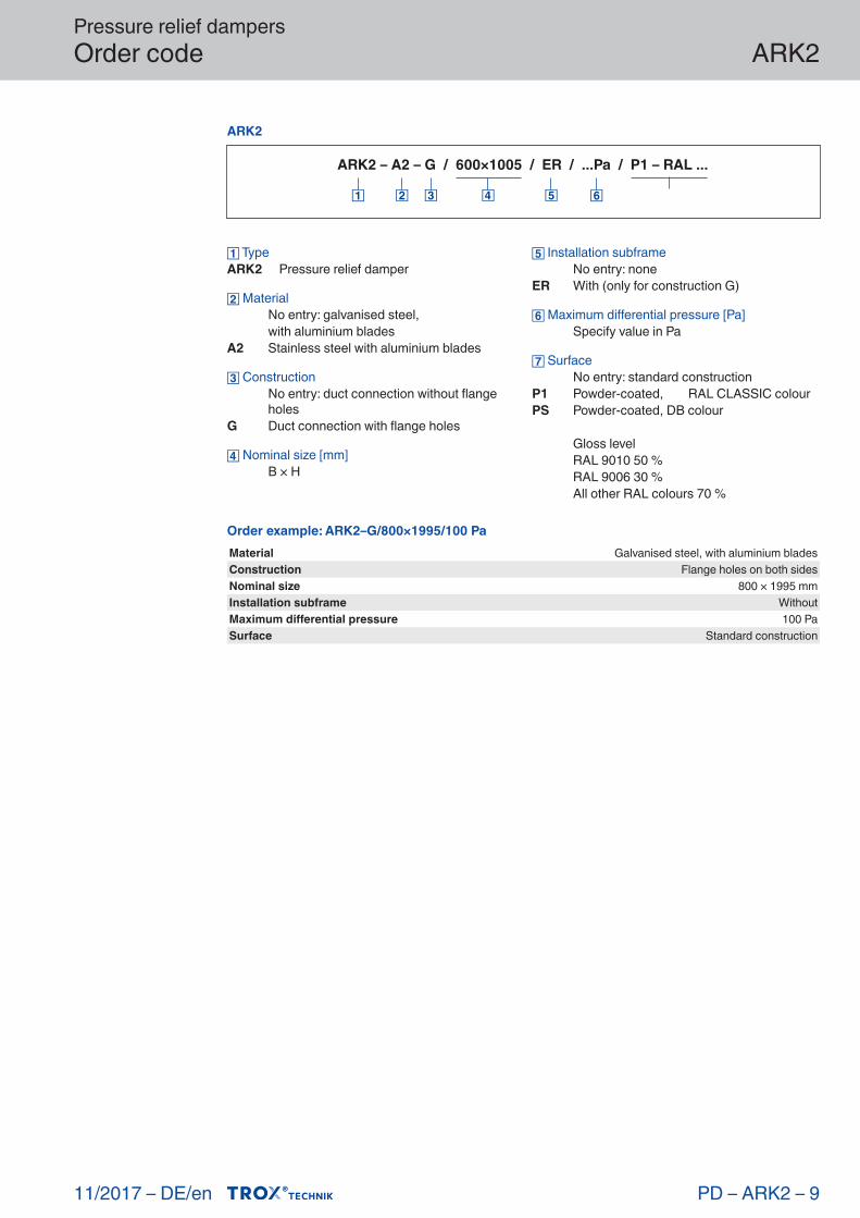
Pressure relief dampersOrder code
11/2017 – DE/en
ARK2
PD – ARK2 – 9
ARK2
ARK2 – A2 – G / 600×1005 / ER / ...Pa / P1 – RAL ...
TypeARK2 Pressure relief damper
Material No entry: galvanised steel, with aluminium bladesA2 Stainless steel with aluminium blades
Construction No entry: duct connection without flange
holesG Duct connection with flange holes
Nominal size [mm] B × H
Installation subframe No entry: noneER With (only for construction G)
Maximum differential pressure [Pa] Specify value in Pa
Surface No entry: standard constructionP1 Powder-coated, RAL CLASSIC colourPS Powder-coated, DB colour
Gloss level RAL 9010 50 % RAL 9006 30 % All other RAL colours 70 %
Order example: ARK2–G/800×1995/100 PaMaterial Galvanised steel, with aluminium bladesConstruction Flange holes on both sidesNominal size 800 × 1995 mmInstallation subframe WithoutMaximum differential pressure 100 PaSurface Standard construction
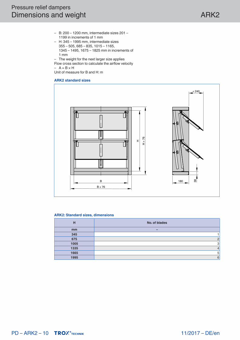
Pressure relief dampersDimensions and weight
11/2017 –
ARK2
DE/en
– B: 200 – 1200 mm, intermediate sizes 201 – 1199 in increments of 1 mm
– H: 345 – 1995 mm, intermediate sizes 355 – 505, 685 – 835, 1015 – 1165, 1345 – 1495, 1675 – 1825 mm in increments of 1 mm
– The weight for the next larger size appliesFlow cross section to calculate the airflow velocity– A = B × HUnit of measure for B and H: m
PD – ARK2 – 10
ARK2: Standard sizes, dimensions
H No. of blades
mm –345 1675 2
1005 31335 41665 51995 6
ARK2 standard sizes
38
< 240
180B
H
B + 76
H +
76
Pressure relief dampersDimensions and weight
11/2017 – DE/en
ARK2
PD – ARK2 – 11
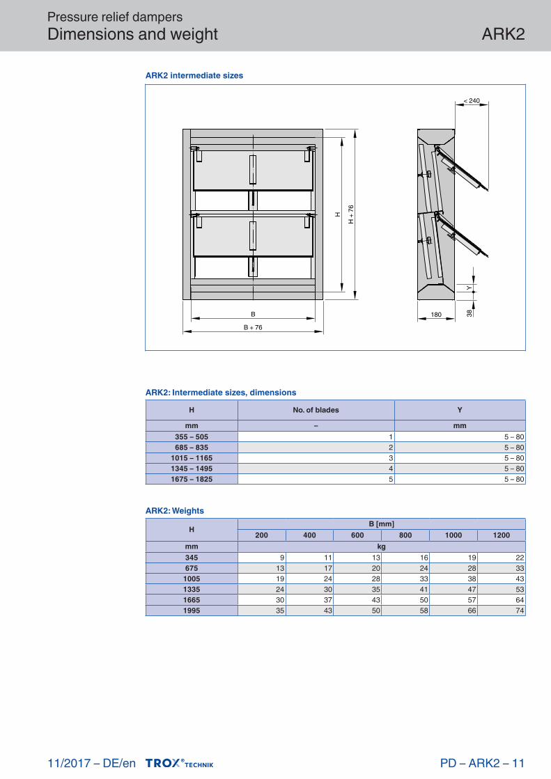
ARK2: Intermediate sizes, dimensions
H No. of blades Y
mm – mm355 – 505 1 5 – 80685 – 835 2 5 – 80
1015 – 1165 3 5 – 801345 – 1495 4 5 – 801675 – 1825 5 5 – 80
ARK2: Weights
HB [mm]
200 400 600 800 1000 1200mm kg345 9 11 13 16 19 22675 13 17 20 24 28 33
1005 19 24 28 33 38 431335 24 30 35 41 47 531665 30 37 43 50 57 641995 35 43 50 58 66 74
ARK2 intermediate sizes
< 240
180B
HB + 76
H +
76
38Y

Pressure relief dampersProduct details
11/2017 –
ARK2
DE/enPD – ARK2 – 12
ARK, ARK-1, ARK2: width, no. of flange holes
BNo. of holes
nmm –
200 – 287 1288 – 537 2538 – 787 3
788 – 1037 41038 – 1200 5
ARK, ARK-1, ARK2: height, no. of flange holes
HNo. of holes
nmm –
345 – 461 2462 – 711 3712 – 961 4
962 – 1211 51212 – 1461 61462 – 1711 71712 – 1961 81962 – 1995 9
Flange holes – ARK, ARK-1, ARK2
B
H
B + 76
H +
76
Ø9.5
38
2038
20
X
X
B
H
B + 76
H +
76
X
① ②
① Even number of holes (hole pitch = 250 mm) ② Uneven number of holes (hole pitch = 250 mm)

Pressure relief dampersInstallation details
01/2019 – DE/en
ARK2
Installation and commissioning– Installation orientation: Horizontal airflow– For installation in internal spaces– Type ARK2 pressure relief dampers are not
suitable for use in the protection of air ducts or similar. designed as vibration, turbulence and tolerances have a negative impact on the set opening pressure of the flap
– To avoid malfunctions, any disturbing effects should be kept to a minimum, and there should be a sufficient difference between the permit-ted maximum differential pressure and the 'nor-mal' system pressure.
PD – ARK2 – 13
Illustration shows ARK2 Illustration shows ARK2
Installation into an internal wall, without installation subframe
① Blade movement area must be kept clear
H B
< 240
①
Duct installation
H B
< 240
①
① Blade movement area must be kept clear
Note
Tolerances:– System or system-related influences can not
be taken into account when adjusting the open-ing pressure, which can lead to deviations on site
– Temperature fluctuations (in the released tem-perature range) have influences on the holding torque of the holding element, which can lead to tolerances on the set opening pressure

Pressure relief dampersBasic information and nomenclature
11/2017 –
ARK2
DE/en
Nomenclature
LWA [dB(A)]A-weighted sound power level of air-regenerated noise for the mechanically self-powered damper
A [m²]Upstream cross section
v [m/s]Airflow velocity based on the upstream cross section
[m³/h] and [l/s]Volume flow rate
Δpst [Pa]Static differential pressure
Δpt [Pa]Total differential pressure
All sound power levels are based on 1 pW.
Principal dimensions
B [mm]Duct width
H [mm]Duct height
n [ ]Number of flange screw holes
m [kg]Weight
PD – ARK2 – 14