Analytical Model of Viscoelastic Fluid Dampers
16
ANALYTICAL MODEL OF VISCOELASTIC FLUID DAMPERS By Nicos Makris, ~ M. C. Constantinou, 2 Associate Member, ASCE, and G. F. Dargush 3 ABSTRACT: An analytical approximate constitutive relation is derived for a form of fluid damper, which exhibits viscoelastic behavior. The damper is used for vi- bration isolation of piping systems and industrial equipment, as well as for vibration and seismic isolation of building structures. The damper consists of an open pot, filled with highly viscous fluid, and a piston that moves within the fluid. The analytical solution relates the damping constant of the unit at vanishingly small frequencies with the material constants of the fluid used in the damper and the geometric characteristics of the damper. With the determination of the damping constant, a macroscopic model may be constructed that describes the damper be- havior over a large frequency range. The other parameters of the macroscopic model are identical to those in the corresponding constitutive relation of the damper fluid. The results of the analytical solution are in very good agreement with ex- perimental data and with numerical solutions based on boundary-element analysis. INTRODUCTION Viscous dampers consisting of a moving piston immersed in highly viscous fluid (Fig. 1) have found wide application in the shock and vibration isolation of industrial machines, equipment, pipework systems, and buildings. Fur- thermore, they have been recently used in combined vibration and seismic isolation of buildings (Huffman 1985; Makris and Constantinou 1991, 1992). Modeling the behavior of the viscous dampers is an increasingly important problem because of their wide range of applicability. Attempts have been made in modeling viscous dampers either as simple linear viscous elements ("Pipework" 1986) or by models of the classical theory of viscoelasticity (Schwann et al. 1988). The writers (Makris and Constantinou 1991) pro- posed a fractional derivative model for these devices and showed that the model is capable of describing their behavior with very good accuracy. The model has the following form: a.(r a dqP(l) co -- P(t) + dl q = dt ................................... (1) in which P = force applied at the piston; u = piston displacement; Co = zero-frequency damping coefficient; h = relaxation fractional time; and q = order of derivative in the range (0, 1). It was anticipated and indeed verified (Makris and Constantinou 1991) that values for the order of time derivative and relaxation fractional time of the force-displacement model for the damper unit are almost the same as the corresponding values in the 1Asst. Prof., Dept. of Civ. Engrg. and Geological Sci., Univ. of Notre Dame, Notre Dame, IN 46556-0767. 2Assoc. Prof., Dept. of Civ. Engrg., State Univ. of New York, Buffalo, NY 14260. 3Res. Assoc. Prof., Dept. of Civ. Engrg., State Univ. of New York, Buffalo, NY. Note. Discussion open until April 1, 1994. To extend the closing date one month, a written request must be filed with the ASCE Manager of Journals. The manuscript for this paper was submitted for review and possible publication on February 18, 1992. This paper is part of the Journal of Structural Engineering, Vol. 119, No. 11, November, 1993. ISSN 0733-9445/93/0011-3310/$1.00 + $.15 per page. Paper No. 3476. 3310 J. Struct. Eng. 1993.119:3310-3325. Downloaded from ascelibrary.org by Walter Serials Process on 08/08/12. For personal use only. No other uses without permission. Copyright (c) 2012. American Society of Civil Engineers. All rights reserved.
-
Upload
independent -
Category
Documents
-
view
0 -
download
0
Transcript of Analytical Model of Viscoelastic Fluid Dampers

A N A L Y T I C A L M O D E L O F V I S C O E L A S T I C
F L U I D D A M P E R S
By Nicos Makris, ~ M. C. Constantinou, 2 Associate Member, ASCE, and G. F. Dargush 3
ABSTRACT: An analytical approximate constitutive relation is derived for a form of fluid damper, which exhibits viscoelastic behavior. The damper is used for vi- bration isolation of piping systems and industrial equipment, as well as for vibration and seismic isolation of building structures. The damper consists of an open pot, filled with highly viscous fluid, and a piston that moves within the fluid. The analytical solution relates the damping constant of the unit at vanishingly small frequencies with the material constants of the fluid used in the damper and the geometric characteristics of the damper. With the determination of the damping constant, a macroscopic model may be constructed that describes the damper be- havior over a large frequency range. The other parameters of the macroscopic model are identical to those in the corresponding constitutive relation of the damper fluid. The results of the analytical solution are in very good agreement with ex- perimental data and with numerical solutions based on boundary-element analysis.
INTRODUCTION
Viscous dampers consisting of a moving piston immersed in highly viscous fluid (Fig. 1) have found wide appl icat ion in the shock and vibrat ion isolation of industrial machines, equipment , p ipework systems, and buildings. Fur- thermore, they have been recent ly used in combined vibrat ion and seismic isolation of buildings (Huffman 1985; Makris and Constant inou 1991, 1992).
Modeling the behavior of the viscous dampers is an increasingly impor tant problem because of their wide range of applicabili ty. At t empts have been made in modeling viscous dampers ei ther as simple l inear viscous e lements ("Pipework" 1986) or by models of the classical theory of viscoelasticity (Schwann et al. 1988). The writers (Makris and Constant inou 1991) pro- posed a fractional derivative model for these devices and showed that the model is capable of describing their behavior with very good accuracy. The model has the following form:
a.(r a dqP(l) co - - P(t) + dl q = dt . . . . . . . . . . . . . . . . . . . . . . . . . . . . . . . . . . . ( 1 )
in which P = force appl ied at the piston; u = piston displacement; Co = zero-frequency damping coefficient; h = relaxat ion fractional t ime; and q = order of derivative in the range (0, 1). It was ant ic ipated and indeed verified (Makris and Constant inou 1991) that values for the o rder of t ime derivative and relaxat ion fractional t ime of the force-displacement model for the damper unit are almost the same as the corresponding values in the
1Asst. Prof., Dept. of Civ. Engrg. and Geological Sci., Univ. of Notre Dame, Notre Dame, IN 46556-0767.
2Assoc. Prof., Dept. of Civ. Engrg., State Univ. of New York, Buffalo, NY 14260. 3Res. Assoc. Prof., Dept. of Civ. Engrg., State Univ. of New York, Buffalo, NY. Note. Discussion open until April 1, 1994. To extend the closing date one month,
a written request must be filed with the ASCE Manager of Journals. The manuscript for this paper was submitted for review and possible publication on February 18, 1992. This paper is part of the Journal of Structural Engineering, Vol. 119, No. 11, November, 1993. �9 ISSN 0733-9445/93/0011-3310/$1.00 + $.15 per page. Paper No. 3476.
3310
J. S
truc
t. E
ng. 1
993.
119:
3310
-332
5.D
ownl
oade
d fr
om a
scel
ibra
ry.o
rg b
y W
alte
r Se
rial
s Pr
oces
s on
08/
08/1
2. F
or p
erso
nal u
se o
nly.
No
othe
r us
es w
ithou
t per
mis
sion
. Cop
yrig
ht (
c) 2
012.
Am
eric
an S
ocie
ty o
f C
ivil
Eng
inee
rs. A
ll ri
ghts
res
erve
d.
1_ I
I
@ -"
]
(a) (b)
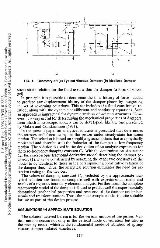
FIG. 1. Geometry of: (a) Typical Viscous Damper; (b) Idealized Damper
stress-strain relation for the fluid used within the damper (a form of silicon gel).
In principle it is possible to determine the time history of force needed to produce any displacement history of the damper piston by integrating the set of governing equations. This set includes the fluid constitutive re- lation, along with the dynamic equilibrium and continuity equations. Such an approach is impractical for dynamic analysis of isolated structures. How- ever, it is very useful for determining the mechanical properties of dampers, from which macroscopic models can be developed, like the one presented by Makris and Constantinou (1991).
In the present paper an analytical solution is presented that determines the stresses and force acting on the piston under steady-state harmonic motion. The solution is based on simplifying assumptions that are physically motivated and describe well the behavior of the damper at low-frequency motion. The solution is used in the derivation of an analytic expression for the zero-frequency damping constant Co. With the determination of constant Co, the macroscopic fractional derivative model describing the damper be- havior, (1), may be constructed by assuming the other two constants of the model to be identical to those in the corresponding constitutive relation of the damper fluid. Thus, the analytical solution eliminates the need for ex- tensive testing of the devices.
The values of damping constant Co predicted by the approximate ana- lytical solution are found to compare well with experimental results and results of a rigorous boundary-element analysis. Furthermore, the complete macroscopic model of the damper is found to predict well the experimentally determined mechanical properties and response of the damper under har- monic and transient motion. Thus, the macroscopic model is quite suitable for use as part of the design process.
ASSUMPTIONS IN APPROXIMATE SOLUTION
The solution derived herein is for the vertical motion of the piston. Ver- tical motion occurs not only in the vertical mode of vibration but also in the rocking mode, which is the fundamental mode of vibration of spring- viscous damper isolated structures.
3311
J. S
truc
t. E
ng. 1
993.
119:
3310
-332
5.D
ownl
oade
d fr
om a
scel
ibra
ry.o
rg b
y W
alte
r Se
rial
s Pr
oces
s on
08/
08/1
2. F
or p
erso
nal u
se o
nly.
No
othe
r us
es w
ithou
t per
mis
sion
. Cop
yrig
ht (
c) 2
012.
Am
eric
an S
ocie
ty o
f C
ivil
Eng
inee
rs. A
ll ri
ghts
res
erve
d.

Fig. l(a) shows the geometry of a typical viscous damper. The outer surface of the piston features a smooth top portion and a lower portion containing ribs. The ribs serve the purpose of preventing slippage of fluid during motion of piston. The bottom of the piston is hollow and contains a large number of inner pipes of small diameter (usually 15 to 20 mm diameter). This arrangement allows for penetration of the fluid into the pipes and ensures full contact of the fluid with the bottom surface of the piston.
In this simplified mathematical model, the piston is assumed to be cylin- drical with radius
r l e n l e + r u H u . . . . . . . . . . . . . . . . . . . . . . . . . . . . . . . . . . . . . . . . . . (2) rl = n l
which represents the weighted average radius of the actual piston. Fig. l(b) shows the idealized damper in its deformed position where it has undergone vertical displacement equal to amplitude u0. During this motion, stresses at the side and the bottom of the idealized piston result in the force needed to maintain the imposed motion. These two components of the piston force are evaluated separately by assuming that: (1) The fluid between the lateral faces of the piston and housing is subjected to pure shearing; and (2) the fluid between the bottom of the piston and the housing is subjected to compression-extension.
The vertical motion of the piston is harmonic and described by
U = n o d it~ . . . . . . . . . . . . . . . . . . . . . . . . . . . . . . . . . . . . . . . . . . . . . . . . . . (3)
where to = frequency of the motion. The force required to maintain this motion is evaluated under steady-state conditions so that
P = Poe ~ ' . . . . . . . . . . . . . . . . . . . . . . . . . . . . . . . . . . . . . . . . . . . . . . . . . . (4)
in which Po = complex amplitude of force. Under steady-state conditions, the exponential time-dependent terms drop out and the analysis involves only amplitudes.
FORCE ACTING ON LATERAL SURFACE OF PISTON
It is assumed that the vertical displacement profile uz of the fluid between the lateral piston surface and the housing is parabolic and that the radial displacement of the fluid is zero. Furthermore, it is assumed that this dis- placement pattern prevails over the entire height of the piston. Thus
u z ( r ) = u o f ( r ) = uo(e t r 2 + fSr + 3') . . . . . . . . . . . . . . . . . . . . . . . . . . . . (5)
where constants et, 1~, and 3' are determined from the boundary conditions and volume conservation. That is
u z ( r , ) = -Uo . . . . . . . . . . . . . . . . . . . . . . . . . . . . . . . . . . . . . . . . . . . . . . (6a)
u~(r2) = 0 . . . . . . . . . . . . . . . . . . . . . . . . . . . . . . . . . . . . . . . . . . . . . . . . . (6b)
uo 2 ~ r r f ( r ) d r - ~rr~uo = 0 . . . . . . . . . . . . . . . . . . . . . . . . . . . . . . . . . (7) !
The third condition is based on the assumption of fluid incompressibility.
3312
J. S
truc
t. E
ng. 1
993.
119:
3310
-332
5.D
ownl
oade
d fr
om a
scel
ibra
ry.o
rg b
y W
alte
r Se
rial
s Pr
oces
s on
08/
08/1
2. F
or p
erso
nal u
se o
nly.
No
othe
r us
es w
ithou
t per
mis
sion
. Cop
yrig
ht (
c) 2
012.
Am
eric
an S
ocie
ty o
f C
ivil
Eng
inee
rs. A
ll ri
ghts
res
erve
d.

Eqs. (6)-(7) form the following system of algebraic equations with ct, [3, and ~/as unknowns.
I t 2 rx 1 t ( [ 3 ) a O)1 r22 re 1 = . . . . . . . . . . . . . . . . (8)
2 r2 (r 4 - r 4 ) ~ ( r23 - r 3)(r 2 - r 2
The stress-strain relation of the fluid in the frequency domain is
"r,z(Oa) = G*(to)~/r~(to) . . . . . . . . . . . . . . . . . . . . . . . . . . . . . . . . . . . . . . . . (9)
where "rr~ and Yrz = amplitudes of the harmonic shear stress and strain; and G*(to) = complex frequency-dependent shear modulus
itotx G*(co) = . . . . . . . . . . . . . . . . . . (10)
where I~ = fluid zero-shear rate viscosity. Eqs. (9) and (10) are derived from the time-domain fractional derivative model by application of Fourier transform (Makris and Constantinou 1991).
Using (4) and the assumption of zero radial displacement, the following equation is derived for the shear stress:
rrz = G*uo d f . . . . . . . . . . . . . . . . . . . . . . . . . . . . . . . . . . . . . . . . . . . . . . (11) dr
The amplitude of force exerted by the fluid on the lateral face of the piston is evaluated from the stresses Vrz at r = rl after multiplication by the surface area of the idealized piston
PoL = 2~rrlH1G*uo d f ( rO dr . . . . . . . . . . . . . . . . . . . . . . . . . . . . . . . . . . . . (12)
FORCE ACTING ON BOTTOM SURFACE OF PISTON
The bottom surface of the piston is imposing a compression-extension type of deformation. The fluid displaced from the moving piston tends to move radially. The solution to this two dimensional problem is approximated by a one-dimensional model. It is assumed that only the fluid within a truncated cone is primarily affected by the motion of the piston. This cone is limited by the base of the damper and the bottom of the piston. Its axis of symmetry is the vertical axis z [Fig. l(b)]. This simplified model has been extensively used in deriving approximate expressions for the dynamic stiff- ness and radiation damping of foundations (Gazetas 1984; Wolf 1988).
Under this simplifying assumption, dynamic equilibrium of a horizontal slice of the cone along the vertical direction takes the form
_ _ aeuz(z, t) Z20Tzz(Z , t) + 2z%z( z , t) = pz 2 OZ 82t
. . . . . . . . . . . . . . . . . . . . . . (13)
where u~(z, t) = vertical displacement of the slice at depth z and time t;
3313
J. S
truc
t. E
ng. 1
993.
119:
3310
-332
5.D
ownl
oade
d fr
om a
scel
ibra
ry.o
rg b
y W
alte
r Se
rial
s Pr
oces
s on
08/
08/1
2. F
or p
erso
nal u
se o
nly.
No
othe
r us
es w
ithou
t per
mis
sion
. Cop
yrig
ht (
c) 2
012.
Am
eric
an S
ocie
ty o
f C
ivil
Eng
inee
rs. A
ll ri
ghts
res
erve
d.

and P = fluid mass density. Under harmonic, steady-state conditions, (13) reduces to an ordinary differential equation in terms now of the amplitudes of the stress ,r= and displacement Uz
z2&zz(Z) dz
+ 2z%z(z) + O t o 2 Z 2 U z ( Z ) = 0 . . . . . . . . . . . . . . . . . . . . . . . (14)
The deformation pattern of the slice is reminiscent of biaxial stretching flow (Bird 1987). In this type of flow, the normal stress difference %z - "r,r is related to the rate of normal strain ~ through the elongation viscosity "q. At low rate of strain (~ < 10 -2 s-1), the elongation viscosity -q approaches the value of 3tx. This result is valid not only for Newtonian fluids (Trouton viscosity), but also for non-Newtonian viscoelastic fluids (Bird 1987). At low strain rates, the elastic component of the viscoelastic fluid vanishes and the fluid tends to behave as a Newtonian fluid. Accordingly, at low strain rates and for a harmonic input motion of frequency to, the difference of normal stresses is given by
Tzz(Z ) -- Trr (Z ) = 3G* a(~vu.,z, . . . . . . . . . . . . . . . . . . . . . . . . . . . . . . . . . (15) Oz
where 3G* = elongation modulus. At this point, the radial stresses within the cone have to be approximated.
This is achieved by balancing the tractions exerted on the portion of the fluid located above the truncated cone. Fig. 2 illustrates a cross section of this fluid portion (areas A B C D and EFGH) and the shear stresses acting on its inner and outer boundaries for a downward motion of the piston. It is assumed that for vertical equilibrium only the illustrated stresses contrib- ute.
Under these simplifying assumptions, the total vertical force, Fv, that is transmitted to the truncated cone from the fluid above is
df(rl) df(r2)] Fv = 2~rHiG*uo r, dr r 2 - - - ~ r J . . . . . . . . . . . . . . . . . . . . . . . . (16)
This vertical force is balanced by the vertical component of the resultant of normal stresses acting on the inclined surface of the upper fluid portion. The radial component Fr of the resultant of those normal stresses is
Fr = F~tan O = F ~ - - r 2 - r I
. . . . . . . . . . . . . . . . . . . . . . . . . . . . . . . . . . . (17)
where 0 = angle between vertical and normal to the inclined surface di- rections.
Substituting Fv (16), into (17) yields
df(rl) F~ = 2~rH1G*uo rl dr
df(r2) 1 H2 - - - - r2 dr J r2 - rl - - . . . . . . . . . . . . . . . . . . ( 1 8 )
The radial stress within the cone is, of course, a function of the radial coordinate r. Nevertheless a representative average value may be obtained by dividing the total radial force Fr by the lateral area A = 2 " r r r l H 2. Ac- cordingly, the radial stress may be approximated by
3314
J. S
truc
t. E
ng. 1
993.
119:
3310
-332
5.D
ownl
oade
d fr
om a
scel
ibra
ry.o
rg b
y W
alte
r Se
rial
s Pr
oces
s on
08/
08/1
2. F
or p
erso
nal u
se o
nly.
No
othe
r us
es w
ithou
t per
mis
sion
. Cop
yrig
ht (
c) 2
012.
Am
eric
an S
ocie
ty o
f C
ivil
Eng
inee
rs. A
ll ri
ghts
res
erve
d.

A ]3
s I'I', ~ I'I'I'I' l II l I
U 0
E H
l
l H1
C-
~ 2
FIG. 2. Schematic Representation of Stresses Acting on Fluid within Damper
G*uo H, r[ df(rO r= df(r2,|~] . . . . . . . . . . . . (19) Fr ~" = -~ = - r ~ ( r ~ - ~,) ~ d- - - ; - - d r I
where the minus sign indicates compression. Substitution of %, into (15) results in
%z(z) = 3G* Ou~(z) G*uo H1 [ df(r2)] d/(r,) Oz rl(r-~- r,) rl dr re--~r ] "'" (20)
Returning to the governing equation (14) and using (20), the following equation is derived in terms of only the vertical fluid displacement:
d2uz(z) duz(z) p~02 2 H A [ dr(r,) z 2 d2------ ~ - + 2z dz + ~ zZuz(Z) = 5 u~ rl(r ~ - r,) [_r' dr
3315
J. S
truc
t. E
ng. 1
993.
119:
3310
-332
5.D
ownl
oade
d fr
om a
scel
ibra
ry.o
rg b
y W
alte
r Se
rial
s Pr
oces
s on
08/
08/1
2. F
or p
erso
nal u
se o
nly.
No
othe
r us
es w
ithou
t per
mis
sion
. Cop
yrig
ht (
c) 2
012.
Am
eric
an S
ocie
ty o
f C
ivil
Eng
inee
rs. A
ll ri
ghts
res
erve
d.

df(r2)] . . . . . . . . . . . . . . . . . . . . . . . . . . . . . . . . . . . . . . . . . . . . . . . (21) - r 2 d r J
A solution of the homogeneous part of (21) is
uztt(z) = A1 1_ e(_ikz ) Jr- A2 1 e(ikz) . . . . . . . . . . . . . . . . . . . . . . . . . . . . (22) Z Z
where
P ~1/2
k = to \~G-g ] . . . . . . . . . . . . . . . . . . . . . . . . . . . . . . . . . . . . . . . . . . . . (23)
is the complex wave number and A1, A2 are integration constants to be determined from boundary conditions. A particular solution of (21) is
1 uze(z) = A o -
Z . . . . . . . . . . . . . . . . . . . . . . . . . . . . . . . . . . . . . . . . . . . . . (24)
where
G* H 1 ~ dr(r1) Ao = 2 - - Uo - - rl
DO) 2 rl(F 2 -- q ) [ dr df(r2)] . . . . . . . . . . . . . . . . (25)
- - - r2 dr _]
The boundary conditions are uz(z 0 = uo and uz(z2) = 0 where zl and z2 are the coordinates of the bo t tom of the piston and of the bot tom surface of the housing, respectively [Fig. l(b)] . Coordinates Zl and z2 are, respec- tively, given by
7,1 //2 rl ~- - - , Z 2 = Z 1 ~- n 2 . . . . . . . . . . . . . . . . . . . . . . . . . . . ( 2 6 ) r2 - rl
Application of the boundary conditions results in the following constants in (22):
A1 UoZl - A0(1 - e -ik~I2) = e ikz2 . . . . . . . . . . . . . . . . . . . . . . . . . . . . . (27) 2i sin(kH2)
A2 = UoZl - A0(1 - e i~/42) e_ikz2 . . . . . . . . . . . . . . . . . . . . . . . . . . . (28) 2i sin(kH2)
The solution of (21) is the superposit ion of the homogeneous , (22), and particular, (24), solutions. The substitution of the values of the integration constants into (22) produces
zl sin[k(z2 - z)] Ao {sin[k(z2 - z)] + sin[k(z - zl)] } U z ( Z ) = U o - - 1
z sin(kH2) z sin(kH2) . . . . . . . . . . . . . . . . . . . . . . . . . . . . . . . . . . . . . . . . . . . . . . . . . . . . . . . . . . (29)
The second term in (29) corresponds to the contribution of the particular solution. It vanishes for both values z = Zl and z = z2 and can be neglected within the accuracy of this approximate method.
With this last approximation, the normal stress in the fluid is determined from (20)
3316
J. S
truc
t. E
ng. 1
993.
119:
3310
-332
5.D
ownl
oade
d fr
om a
scel
ibra
ry.o
rg b
y W
alte
r Se
rial
s Pr
oces
s on
08/
08/1
2. F
or p
erso
nal u
se o
nly.
No
othe
r us
es w
ithou
t per
mis
sion
. Cop
yrig
ht (
c) 2
012.
Am
eric
an S
ocie
ty o
f C
ivil
Eng
inee
rs. A
ll ri
ghts
res
erve
d.

3G'u~ z {~ sin[k(z2- z)] + k cos[k(z2- z)]} r~z(Z) - sin(kH2) zl
I G ~ Uo r,(r2-- r,) Jr' dr dr(r2)] . . . . . . . . . . . . . . . . . . . . . . (30)
- - - r2 dr J
The stresses on the piston are given by (30) at z = Za and with the negative sign replaced by positive sign. Accordingly, the amplitude of force that the fluid exerts on the bottom circular surface of the piston is given by
[ 1 cos(kH2)] Po8 = ~rr~G*uo 3 ~ + k sin(kH2)J
H1 [ dr(r1) + r,(rz -~ r,) rl dr - - - r 2 d r jj
For harmonic input motion, the predicted total force on the piston is
P(t) = (Pot + PoB) ei~ �9 . . . . . . . . . . . . . . . . . . . . . . . . . . . . . . . . . . . . . (32)
where PoL and P0B are given by (12) and (31).
MACROSCOPIC MODEL OF DAMPER
The macroscopic model of the damper undergoing vertical motion is the fractional derivative model of (1). The model parameters )t, q, and Co are normally determined by fitting experimental data from tests on dampers. Herein, parameter h and q are assumed to be same as those of the consti- tutive relation of the fluid and constant Co is determined from the approx- imate analytical solution. In this respect, prediction of the behavior of the damper is accomplished without the need for testing of the damper. Rather, only testing of the fluid is needed.
For the fractional derivative Maxwell model (1), the damping coefficient is given by
c ( t o ) =
qcos(Vl]
1+ + cos . . . . . . . . . . . . . . . . . . . . . . . . . . (33)
The presented analysis, valid for small frequencies, is used to calculate C(to). Then at the limit of to tending to zero, C(to) converges to the value Co, which is the zero-frequency damping constant.
In harmonic motion of frequency to and amplitude uo, the damping coef- ficient is given by
WD C(to) - r176 2 . . . . . . . . . . . . . . . . . . . . . . . . . . . . . . . . . . . . . . . . . . . . . . (34)
where Wn = energy dissipated per cycle and is given by
3317
J. S
truc
t. E
ng. 1
993.
119:
3310
-332
5.D
ownl
oade
d fr
om a
scel
ibra
ry.o
rg b
y W
alte
r Se
rial
s Pr
oces
s on
08/
08/1
2. F
or p
erso
nal u
se o
nly.
No
othe
r us
es w
ithou
t per
mis
sion
. Cop
yrig
ht (
c) 2
012.
Am
eric
an S
ocie
ty o
f C
ivil
Eng
inee
rs. A
ll ri
ghts
res
erve
d.

[du(t)] 147o = J0 Re[P(t)]Re L---~-- j dt (35)
where Re = the real part of a complex quantity; T = period of one cycle (T = 2~r/oJ), and P(t) and u(t) are given by (32) and (3), respectively. The real part of force P(t) is of the form
Re[P(t)] = Pc cos m t - P, sin o~t . . . . . . . . . . . . . . . . . . . . . . . . . . . . . (36)
where Pc and P, = force components independent of time. The real part of the velocity of the piston is
Integration of (35) yields
w o = . . . . . . . . . . . . . . . . . . . . . . . . . . . . . . . . . . . . . . . . . . . . . . . (38) In the limit of small frequencies, the expression for Ps, after a lengthy algebra, reduces to
Ps = tOUoix 27trail1 ~ + 3= H-~zJ . . . . . . . . . . . . . . . . . . . . . . . . . (39)
Substitution of (38) and (39) into (35) gives the damping constant, which in the limit of zero frequency takes the form
df(rl) r jr2 Co = limC(~0) = Ix 2 * r r l H , ~ + 3= H2
urn,0
H1 [ df(q) r2df(r2)]'~ . . . . . . . . . . . . . . . . . . . . . . . . . (40) q- ,rrr 1 - - r 1
r2 - q dr dr _~ J
Eq. (40) is a dosed-form expression for Ca. The first term in (40) is the contribution to the damping constant from stresses developing on the lateral surface of the piston. The second term in (40) is the contribution to the damping constant from the stresses that develop on the bottom of the piston in the absence of radial stresses, and the third term is the contribution to the damping constant from the additional stresses that develop on the bottom of the piston due to the presence of radial stresses. Only the zero shear rate viscosity Ix and the geometric characteristics of the damper appear in (40). The density of the fluid is not present because the inertia terms vanish at zero frequency.
The range of validity of (40) is now investigated. The second term in (40) accounts for the contribution of the stresses at the bottom of the moving piston when the radial stress, "rrr in (15) and (19), is neglected. This term should always be larger than or equal to the damping constant obtained from the solution of the problem of a slowly moving circular disc of radius ra in an infinite medium of viscosity Ix. The drag force on the circular disc is (Landau and Lifshitz 1987)
P = 16Ixqv . . . . . . . . . . . . . . . . . . . . . . . . . . . . . . . . . . . . . . . . . . . . . . . . (41)
where v is the velocity of the disc. The damping constant is
3318
J. S
truc
t. E
ng. 1
993.
119:
3310
-332
5.D
ownl
oade
d fr
om a
scel
ibra
ry.o
rg b
y W
alte
r Se
rial
s Pr
oces
s on
08/
08/1
2. F
or p
erso
nal u
se o
nly.
No
othe
r us
es w
ithou
t per
mis
sion
. Cop
yrig
ht (
c) 2
012.
Am
eric
an S
ocie
ty o
f C
ivil
Eng
inee
rs. A
ll ri
ghts
res
erve
d.

C0e = 161xrl . . . . . . . . . . . . . . . . . . . . . . . . . . . . . . . . . . . . . . . . . . . . . . . (42)
which represents the lower bound of the contribution to Co from the bottom of the piston when radial stresses are neglected. Accordingly, (40) is valid for
r2 16 > . . . . . . . . . . . . . . . . . . . . . . . . . . . . . . . . . . . . . . . . . . . . . . . . . . (43)
H2 3~r
For values of r2/H2 less than 16/3~r, the cone model is invalid and constant Co may be determined from the contribution of the outside stresses together with the Landau and Lifshitz (1987) solution. That is,
df(rl) Co = 2~p~rlHx T + 161~r1 . . . . . . . . . . . . . . . . . . . . . . . . . . . . . . . . (44)
RIGOROUS ANALYSIS AT ZERO FREQUENCY LIMIT
The equations of motion and continuity for an incompressible fluid are
vj . . . . . . . . . . . . . . . . . . . . . . . . . . . . . . . . . . . (45) P \or oxj/ oxj ox,
Ovj = 0 . . . . . . . . . . . . . . . . . . . . . . . . . . . . . . . . . . . . . . . . . . . . . . . . . . . (46) axj where vi = velocity vector, T o = stress tensor; and p = pressure at a point. The fractional derivative constitutive model of the fluid is now rewritten in tensor form
dq (Ovi Ovit . . . . . . . . . . . . . . . . . . . . . . . . . . . . . . . (47) 'Ti] -~ ~k ~ "rij : ~L ~OXj -~ OXi/
The model of (47) is valid only for infinitesimal displacement gradients (uo/rl << 1). Under this condition, the nonlinear terms in the substantial derivative are negligible for all values of Reynolds number (Landau and Lifshitz 1987) and (45) become linear. In the limit of vanishingly small frequencies, the entire left side of (45) vanishes resulting to the so-called creeping motion of Stokes flow. Furthermore, the dynamic viscosity reduces to the zero-shear-rate viscosity Ix. At this limit, the governing equations of motion (45) reduce to
OZv' 012 = 0 . . . . . . . . . . . . . . . . . . . . . . . . . . . . . . . . . . . . . . . . . . . (48) 3xix ~ Ox~
The infinite-space fundamental solution for Stokes flow governed by (46) and (48) exists. In fact, it is equivalent to the Kelvin fundamental solution for incompressible elastostatics (Banerjee and Butterfield 1981) with the shear modulus replaced by the viscosity. As a consequence, boundary-ele- ment methods are directly applicable for a rigorous numerical solution at zero frequency.
With a boundary-element approach, the complexity of the damper ge- ometry presents no particular difficulty, because discretization is required only on the surface of the fluid. Furthermore, since the fundamental solution automatically enforces incompressibility, there is no need to introduce pen-
3319
J. S
truc
t. E
ng. 1
993.
119:
3310
-332
5.D
ownl
oade
d fr
om a
scel
ibra
ry.o
rg b
y W
alte
r Se
rial
s Pr
oces
s on
08/
08/1
2. F
or p
erso
nal u
se o
nly.
No
othe
r us
es w
ithou
t per
mis
sion
. Cop
yrig
ht (
c) 2
012.
Am
eric
an S
ocie
ty o
f C
ivil
Eng
inee
rs. A
ll ri
ghts
res
erve
d.

alty methods, as is done in other numerical techniques. Details on the implementation of boundary-element methods for steady incompressible viscous flow can be found in Dargush and Banerjee (1991).
For present purposes, an axisymmetric formulation, available in the com- puter code GPBEST (Banerjee 1991), was employed to analyze vertical motion of the damper. As discussed in the next section, the boundary- element results were used principally to verify the values of the constant Co. However, the calculated velocity profiles and stress distribution also provided some physical insight beneficial to the development of the ap- proximate analytical macroscopic model.
VERIFICATION OF MACROSCOPIC MODEL
The accuracy of the approximate analytical solution in describing the steady-state response of viscous dampers is investigated first. Makris and Constantinou (1990, 1991) reported on the experimental behavior of the viscous damper with the geometry of the damper No. 1 in Table 1. The damper was filled with silicon gel having density p = 930 Kg/m 3, zero-shear rate viscosity ~ = 1,930 Pa. s, fractional relaxation time X -- 0.26 (s)q and fractional order q = 0.57. Steady-state force-displacement loops, as pre- dicted by the analytical model of (12), (31), and (32), are compared to experimental loops in Fig. 3. The two sets of loops, at frequencies of 0.05 and 1 Hz, are in excellent agreement. Further results reported by Makris (1991) demonstrated the validity of the analytical solution for frequencies below 4 Hz. This indicates that the predictions of the analytical solution for the zero-frequency damping constant Co will be accurate.
For the verification of the macroscopic model of (1), three viscous dampers were tested and their mechanical properties determined. The ex- perimental results for constant Co were then compared to the predictions of the analytical macroscopic model and to the results of the rigorous bound- ary-element formulation. For the latter analysis the axisymmetric model involved a detailed representation of the piston, including the ribs (in all cases, mesh was refined until converged solutions were obtained). The piston was subjected to motion of very low velocity equal to 0.5 mm/s. The stresses were integrated to obtain the force needed to maintain the motion, which--
TABLE 1. Geometric Characteristics of Tested and Analyzed Dampers
Damper (1)
1 2 3 4 5 6 7 8 9
10 11 12
Construction (2)
Standard piston Standard piston Hollow piston Standard piston Standard piston Standard piston Standard piston Standard piston Standard piston Standard piston Standard piston Standard piston
rl r2 r3 H1 H2 (m) (m) (m) (m) (m) (3) (4) (5) (6) (7)
0.058 0.130 - - 0.120 0.060 0.062 0.116 - - 0.070 0.061 0.051 0.116 0.047 0.098 0.032 0.047 0.095 - - 0.090 0.050 0.052 0.105 - - 0.100 0.050 0.062 0.130 - - 0.120 0.060 0.080 0.160 - - 0.150 0.065 0.095 0.190 - - 0.170 0.075 0.100 0.200 - - 0.180 0.080 0.110 0.220 - - 0.200 0.085 0.125 0.250 - - 0.230 0.090 O. 130 0.260 - - 0.240 0.095
3320
J. S
truc
t. E
ng. 1
993.
119:
3310
-332
5.D
ownl
oade
d fr
om a
scel
ibra
ry.o
rg b
y W
alte
r Se
rial
s Pr
oces
s on
08/
08/1
2. F
or p
erso
nal u
se o
nly.
No
othe
r us
es w
ithou
t per
mis
sion
. Cop
yrig
ht (
c) 2
012.
Am
eric
an S
ocie
ty o
f C
ivil
Eng
inee
rs. A
ll ri
ghts
res
erve
d.

'7
i,I r,.)
0 LL
25-
20-
15-
10-
5-
0-
-5-
-10,
-15-
-20.
-25 .-6
FREQUENCY = 0.05 Hz
:4 -'2 o ~ ;, DISPLACEMENT ( m m )
I.L
300"T
Lt --6 -4 -2 0 2 4 6
DISPLACEMENT ( m m )
FIG. 3. Comparison of Experimental and Analytical Steady-State Force-Displace- ment Loops
upon division by the velocity--resulted in the zero-frequency damping con- stant Co.
Two of the tested dampers had their piston constructed with 16 inner pipes of 15 mm diameter so that the bottom part of the piston could be assumed to be in full contact with the fluid below. The two pistons were identical, however they were placed in different-size containers and had different embedment in the fluid (height H1). The third damper had a hollow piston. In the analytical solution for the hollow piston, the contribution from
3321
J. S
truc
t. E
ng. 1
993.
119:
3310
-332
5.D
ownl
oade
d fr
om a
scel
ibra
ry.o
rg b
y W
alte
r Se
rial
s Pr
oces
s on
08/
08/1
2. F
or p
erso
nal u
se o
nly.
No
othe
r us
es w
ithou
t per
mis
sion
. Cop
yrig
ht (
c) 2
012.
Am
eric
an S
ocie
ty o
f C
ivil
Eng
inee
rs. A
ll ri
ghts
res
erve
d.

TABLE 2. Comparison of Values Co of Viscous Dampers
Boundary-element Analytical model solution Experimental
Damper (N s/m) (N s/m) (N s/m) (1) (2) (3) (4)
1 2 3 4 5 6 7 8 9
10 11 12
13,973 15,783 8,331
14,331 16,196 17,225 25,713 29,460 31,104 34,686 40,250 41,881
14,541 15,071 9,870
14,480 16,440 17,560 26,840 31,160 32,760 36,800 43,540 45,060
15,000 15,200 9,400
E
Z
Co u3 LLI Z LL LL i - Ll)
Lt.J L_9 <~ Cts O F-- (/3
10~_-
10 2
10
1 0 -1
10 20 30 I I I [ t I t
K1
* EXPERIMENTAL ANALYTICAL MACROSCOPIC
- - FRACTIONAL DERIVATIVE MODEL
4O 50 I ~ 10 ~
Z
1 0 2 I-- Z LLI LP
LL 1 0 LL
LLI O r.D
L_9 ,- -1 Z
EL
s
10 -~ 50 0 ' 1 {0 2~0 ,3'0 4to
FREQUENCY Hz
FIG. 4. Mechanical Properties of Viscous Damper No. 1 and Properties Predicted by Macroscopic Fractional Derivative Maxwell Model
below is replaced with the contribution from inside. The interested reader is referred to Makris (1991). The geometric properties (with reference to Fig. 1) of these dampers are listed in Table 1. All dampers were filled with the silicon gel described earlier.
Table 2 presents a comparison of the analytical, numerical (boundary- element solution) and experimental values of constant Co. It is seen that the agreement between the three sets of values is very good. It should be noted that the boundary-element solution predicts the damping constant with excellent accuracy (difference of less than 5% of experimental value).
3322
J. S
truc
t. E
ng. 1
993.
119:
3310
-332
5.D
ownl
oade
d fr
om a
scel
ibra
ry.o
rg b
y W
alte
r Se
rial
s Pr
oces
s on
08/
08/1
2. F
or p
erso
nal u
se o
nly.
No
othe
r us
es w
ithou
t per
mis
sion
. Cop
yrig
ht (
c) 2
012.
Am
eric
an S
ocie
ty o
f C
ivil
Eng
inee
rs. A
ll ri
ghts
res
erve
d.

E
z w"
0o oo LLI Z LL LL
Lf)
Ld 0 < n" 0 F-- O9
3 I 10 :
10 ~
10
1 O 2 0 i I i I t
/
* *~ - .L . . ._ .L . * , * f C , , , , ,
* EXPERIMENTAL ANALYTICAL MACROSCOPIC
- -FRACTIONAL DERIVATIVE MODEL
3O 10 3 s
r.n
Z 10 2
Z W (..)
L 10 L_
lml 0
(_9 1 z
D_
<
1 0 -1 0 1'0 2'0 30 1 0 -1
FREQUENCY Hz
FIG. 5. Mechanical Properties of Viscous Damper No. 2 and Properties Predicted by Macroscopic Fractional Derivative Maxwell Model
E
z
6O Cf) L I Z L L I-- CO
LLI �9 .< Od 0
(/3
10 3
1 0 2,
10
1 0 -1
1 0 2 2 50 , , 1 0 3
* EXPERIMENTAL - - ANALYTICAL MACROSCOPIC
FRACTIONAL DERIVATIVE MODEL
1 0 2
1 0 LO O L_)
(D 1 Z
<
Jo t 0 -4
E
O3
z .2s
p-- z Ld
O L LL
1 '0 2'0 FREQUENCY Hz
FIG. 6. Mechanical Properties of Viscous Damper No. 3 and Properties Predicted by Macroscopic Fractional Derivative Maxwell Model
In an extension of this comparison study, nine more dampers of sub- stantially different dimensions were studied. All were of the standard type with closed bottom. Their geometrical properties are also listed in Table 1. The damping constant Co of these dampers was determined by the numerical boundary-element procedure and values are listed in Table 2. Assuming that the boundary-element solution is accurate, it is apparent in the results of Table 2 that the analytical solution predicts the value of constant Co with error of no more than 7.5% of the exact.
Having verified the accuracy of the analytical model in predicting the
3323
J. S
truc
t. E
ng. 1
993.
119:
3310
-332
5.D
ownl
oade
d fr
om a
scel
ibra
ry.o
rg b
y W
alte
r Se
rial
s Pr
oces
s on
08/
08/1
2. F
or p
erso
nal u
se o
nly.
No
othe
r us
es w
ithou
t per
mis
sion
. Cop
yrig
ht (
c) 2
012.
Am
eric
an S
ocie
ty o
f C
ivil
Eng
inee
rs. A
ll ri
ghts
res
erve
d.

0.6~
0.34
Z
I_.LI 0.00 C,_) n / �9 LL
-0 .34
- 0 . 6 8
E X P E R I M E N T A L M A C R O S C O P I C M O D E L
//
i I i i I
- 8 - 4 0 4 8
D SPLACEMENT (ram) FIG. 7. Recorded Force-Displacement Loop of Damper No. 1 for Four-Cycle-Beat Displacement Input and Comparison to Loop Predicted by Macroscopic Fractional Derivative Maxwell Model
parameter Co, the verification proceeds with an examination of the mac- roscopic model over the entire range of frequencies. The macroscopic model is given by (1) with parameters Co, X, and q. Parameter Co is evaluated by the approximate analytical model, whereas parameters X and q are assumed equal to those of the damper fluid (for silicon gel X = 0.26 (s)q, q = 0.57). Figs. 4-6 compare the experimentally and analytically determined mechan- ical properties of storage modulus K1 and damping constant C of the three tested dampers (Table 1). Evidently, the analytical macroscopic model pre- dicts well the mechanical properties over a wide range of frequencies.
Finally, Fig. 7 compares experimental and analytical loops of force versus displacement of damper 1 for a beat displacement input--see Makris and Constantinou (1990) for test description. The analytical and experimental loops are in excellent agreement.
CONCLUSIONS
In this paper an approximate analytical solution is presented to calculate the force that develops on the piston of viscous dampers when subjected to low frequency motions. The tractions of the viscoelastic fluid on the damper piston are computed using physically motivated approximations.
3324
J. S
truc
t. E
ng. 1
993.
119:
3310
-332
5.D
ownl
oade
d fr
om a
scel
ibra
ry.o
rg b
y W
alte
r Se
rial
s Pr
oces
s on
08/
08/1
2. F
or p
erso
nal u
se o
nly.
No
othe
r us
es w
ithou
t per
mis
sion
. Cop
yrig
ht (
c) 2
012.
Am
eric
an S
ocie
ty o
f C
ivil
Eng
inee
rs. A
ll ri
ghts
res
erve
d.
At the zero-frequency limit, the presented solution provides a closed- form expression for the zero-frequency damping constant. With the deter- mination of this constant, a macroscopic fractional derivative model can be constructed. This model describes accurately the behavior of viscous dampers over a wide frequency range, and consequently could prove to be a useful tool within the design process.
ACKNOWLEDGMENTS
Financial support for this work has been provided by the National Science Foundation (Grant No. BCS-8857080). GERB Vibration Control, Inc. do- nated the viscous dampers used in the experiments.
APPENDIX. REFERENCES
Banerjee, P. K., and Butterfield, R. (1981). Boundary element methods in engineering science. McGraw-Hill, London, U.K.
Banerjee, P. K. (1991). GPBEST users manual. BEST Software Corp., Getzville, N.Y.
Bird, B., Armstrong, R., and Hassager, O. (1987). Dynamics of polymeric liquids. J. Wiley, New York, N.Y.
Dargush, G. F., and Banerjee, P. K. (1991). "Steady thermoviscous flow by the boundary element method." Int. J. Numer. Meth. in Engrg., 31(8), 1605-1626.
Gazetas, G. (1984). "Simple physical methods for foundation impedances." Dynamic behavior of foundations and buried structures, P. K. Banerjee and R. Butterfield, eds. Elsevier Applied Science, London, U.K.
Huffman, G. (1985). "Full base isolation for earthquake protection by helical springs and viscodampers." Nuclear engineering and design, 84, 331-338.
Landau, L. D., and Lifshitz, E. M. (1987). "Fluid mechanics." Course of theoretical physics, Vol. 6, Pergamon Press, Oxford, U.K.
Makris, N. (1991). "Theoretical and experimental investigation of viscous dampers in applications of seismic and vibration isolation," PhD thesis, State University of New York at Buffalo, Buffalo, N.Y.
Makris, N., and Constantinou, M. C. (1990). "Viscous dampers: testing modeling and application in vibration and seismic isolation." Rep. No. NCEER-90-O028, National Center for Earthquake Engineering Research, Buffalo, N.Y.
Makris, N., and Constantinou, M. C. (1991). "Fractional derivative model for viscous dampers." J. Struct. Engrg., ASCE, 117(9), 2708-2724.
Makris, N., and Constantinou, M. C. (1992). "Spring-viscous damper system for combined seismic and vibration isolation." Earthquake Engrg. and Struct. Dyn., 21(8), 649-664.
"Pipework dampers." (1986). Tech. Rep., GERB Vibration Control, Westmont, Ill. Schwann, K. J., Reinsch, H. H., and Weber, F. M. (1988). "Description of the
features of viscous dampers on the basis of equivalent rheological models, pre- sented for pipeworks dampers." Proc., Pressure, Vessel and Piping Conf., ASME, Vol. 127,477-484.
Wolf, J. P. (1988). Soil-structure-interaction analysis in time domain. Prentice-Hall, Englewood Cliffs, N.J.
3325
J. S
truc
t. E
ng. 1
993.
119:
3310
-332
5.D
ownl
oade
d fr
om a
scel
ibra
ry.o
rg b
y W
alte
r Se
rial
s Pr
oces
s on
08/
08/1
2. F
or p
erso
nal u
se o
nly.
No
othe
r us
es w
ithou
t per
mis
sion
. Cop
yrig
ht (
c) 2
012.
Am
eric
an S
ocie
ty o
f C
ivil
Eng
inee
rs. A
ll ri
ghts
res
erve
d.