Investigation of Tensile and Stiffness Properties of Composite ...
Upload
khangminh22Category
view
0download
0
������������� ���� ���� ��������������������������������
�� ��� ��������������� �!�"��#$%&�
EXPERIMENTAL VALIDATION OF HIGH POST-YIELD STIFFNESS DAMPERS FOR RESIDUAL DRIFT REDUCTION
Marco BAIGUERAa, George VASDRAVELLISa, David REICHARDTa and Theodore L. KARAVASILISb
���'���(��� ������'��(��(���)��*�� ������� �+,������*�'��-���)��(�������������'.���/%%0�12��2(3��425�')��*���'0�12��2(3��)�#"0�12��2(3�
����� �� ������������*�'��-� ��,��1��3��� *��-����������.��2����*�'���'01��1��32��2(3�
Keywords.���'�����'��6��'�)(���)������������� 6���'����)��7�6������''�'��6��-������'���6��(����������(�2�
Abstract. Seismic dampers made of duplex stainless steel with high post-yield stiffness have beenrecently proposed as the main energy-dissipative system in a dual steel frame. Nonlinear dynamic analyses have shown that these devices provide high post-yield stiffness to the frame, minimizing residual drifts and damage after a major earthquake. This paper presents the experimental evaluation of the proposed dampers. Monotonic and cyclic coupon tests were first conducted to characterise thehardening and fracture parameters of the material. Full-scale component tests were carried out on two prototype dampers using several cyclic loading protocols up to fracture. The results demonstrated that the dampers can withstand severe seismic input without failing, due to their excellent ductility and fracture capacity. Complementary numerical analyses were used to simulate the behaviour of the dampers and preliminary results are presented.
1 INTRODUCTION
���� ����8(�3'�� '(��� �'� ��� #$%$9#$%%� ����'���(���� ����8(�3'�� ��*� '� 1� ������ *�� ���'��� ����'�)'��)���� �)��� � ��(����'�'����7� *�'� '�7�*��� ���7'��)�'(�� ���� '���-2� � 1*���)�����)(� � �7�����)� ����� '� ������ '��(��(��������'�1�'� �'�*)���'(�������' ����''���������7����� '�'��)�:�''�*�)�'�(7�� �� ��(��)��� ('� �� ��(7��� � ;%<2� �� �)�� � � ��7� *� ��� �'����� �� '�'���+�'�'���� '���'��(��(�'�� �� �����*� )'��� �77� ���� �'� � � � ������ )����� �� '��� -��)��� )*��'��7� �������������'��(��(��������'��)�����'��������-�)�''�7��� ���7����-� �����'��(��(�2���������-7'� ��'���-��)���)*��'���*���7� 7 ')�'������%" $'��'(����'��+'��7)� '��� '���7'� �� ��:(�� ;#<2� ���7�'� ��)� �� �(���7�� '��� 7���'� 1���� 7����=)�'��7�� '(��� �'� ��� �)))� )��7��� �)� '����''� >����?� ��:(���+���� )��7�� ;/<�� 1��)*� 7)��)���7���)�����������������-� ��� ��������-�����)�����'2��������(����*�'� � ��������3 1��'��+������1�'�7� 7 ')��-��'����)����;@<2�A����:��7�'����()������B����� -� ���)��7����7���)���C�7��;D<������+'��7)�'���'���7'��3 1��'������� � ��� '�� )*� 7)� �-� 5�-�'� �)� ��� 7 (� '� ;&<� � �� � ��������-� ����)�����'���)������'�+�� �-��)��������'-'���7� 7 ')��-�4��-�����2�; <2�
Edited by B. Young & Y. Cai
Marco BAIGUERA et al.
2
Another major drawback of conventional steel systems is that they experience significant
residual storey drifts following a strong seismic event. Residual storey drifts pose further
complications: a recent study on the economic impact of residual drifts showed that direct and
indirect repair costs are not financially viable when residual drifts are >0.5% [8,9]. Braced
frames represent a system with enhanced seismic performance due to their high initial stiffness,
which can effectively reduce storey drifts. However, conventional braced frames, such as
concentrically braced frames (CBFs), exhibit a degrading hysteretic behaviour, which results
in damage concentration to certain stories, fracture, and increased collapse potential. Buckling-
restrained braced frames (BRBFs) represent an improved class of braced frames [10]. The
buckling-restrained braces (BRBs) exhibit a stable hysteretic response and the ability to
withstand significant ductility demands. They may be susceptible to large residual drifts and
damage concentrations due to their low post-yield stiffness [11]. Previous analytical studies
have shown that BRBFs designed according to current seismic codes do not meet the immediate
occupancy performance level under the design-basis earthquake (10% probability of occurrence
in 50 years; denoted as DBE), due to residual drifts greater than 0.5% [12]. Simple approaches
to mitigate residual drifts have been studied in [13]. Among these, providing high post-yield
stiffness is recognized as an effective strategy to reduce residual drifts.
A dual seismic-resistant steel frame, which consists of a moment-resisting frame equipped
with concentric braces, has been recently proposed and numerically evaluated by the authors
[14]. High post-yield stiffness is provided by yielding devices made of duplex stainless steel,
which are installed in series with the braces. This paper presents the experimental validation of
the proposed dampers. The results of sixteen full-scale component tests conducted using two
geometries and different cyclic loading protocols are presented. The load histories are
representative of earthquake loadings. The hysteretic behaviour and fracture capacity are
assessed. The hardening and fracture parameters of duplex stainless steel are also evaluated
using monotonic and cyclic tests on round and circumferentially notched bars. Complementary
finite element models of the seismic dampers and coupon specimens are developed and
validated against the experimental tests.
2 PROTOTYPE DUAL CBF-MRF
Figure 1a shows the configuration of the dual system proposed by Baiguera et al. [14]. A
moment resisting frame (MRF) equipped with concentric braces, denoted as dual CBF-MRF,
uses simple structural details to provide enhanced seismic performance, i.e.: a) seismic dampers
made of duplex stainless steel (SSD) with high post-yield stiffness, designated as SSD-WHPs,
are placed in series with the concentric braces; and b) replaceable fuses are placed at the
locations of the beams where plastic hinges are expected to develop. WHPs were previously
used in a steel beam-column post-tensioned connection for self-centering MRFs as the main
energy dissipation system [15]. Component tests conducted in that study as well as cyclic and
monotonic tests performed in [16] showed that WHPs made of duplex stainless steel possess
the most favourable performance for seismic design. SSD-WHPs also have a high post-yield
stiffness, which contributes to reduce residual drifts after a strong earthquake [13]. Therefore,
SSD-WHPs are used in the proposed CBF-MRF and additional tests are carried out to further
evaluate their seismic response in a braced frame.
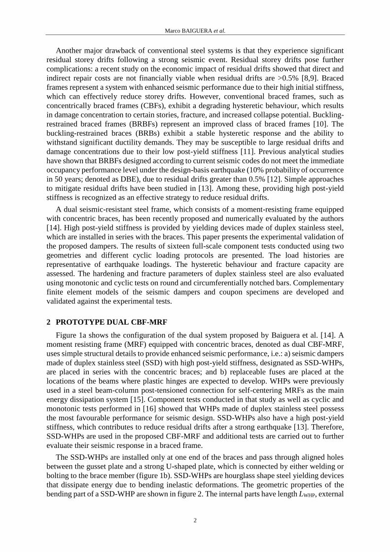
The SSD-WHPs are installed only at one end of the braces and pass through aligned holes
between the gusset plate and a strong U-shaped plate, which is connected by either welding or
bolting to the brace member (figure 1b). SSD-WHPs are hourglass shape steel yielding devices
that dissipate energy due to bending inelastic deformations. The geometric properties of the
bending part of a SSD-WHP are shown in figure 2. The internal parts have length LWHP, external
Marco BAIGUERA et al.
3
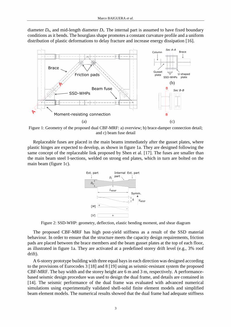
diameter De, and mid-length diameter Di. The internal part is assumed to have fixed boundary
conditions as it bends. The hourglass shape promotes a constant curvature profile and a uniform
distribution of plastic deformations to delay fracture and increase energy dissipation [16].
(b)
(a) (c)
Figure 1: Geometry of the proposed dual CBF-MRF: a) overview; b) brace-damper connection detail;
and c) beam fuse detail
Replaceable fuses are placed in the main beams immediately after the gusset plates, where
plastic hinges are expected to develop, as shown in figure 1a. They are designed following the
same concept of the replaceable link proposed by Shen et al. [17]. The fuses are smaller than
the main beam steel I-sections, welded on strong end plates, which in turn are bolted on the
main beam (figure 1c).
Figure 2: SSD-WHP: geometry, deflection, elastic bending moment, and shear diagram
The proposed CBF-MRF has high post-yield stiffness as a result of the SSD material
behaviour. In order to ensure that the structure meets the capacity design requirements, friction
pads are placed between the brace members and the beam gusset plates at the top of each floor,
as illustrated in figure 1a. They are activated at a predefined storey drift level (e.g., 3% roof
drift).
A 6-storey prototype building with three equal bays in each direction was designed according
to the provisions of Eurocodes 3 [18] and 8 [19] using as seismic-resistant system the proposed
CBF-MRF. The bay width and the storey height are 6 m and 3 m, respectively. A performance-
based seismic design procedure was used to design the dual frame, and details are contained in
[14]. The seismic performance of the dual frame was evaluated with advanced numerical
simulations using experimentally validated shell-solid finite element models and simplified
beam element models. The numerical results showed that the dual frame had adequate stiffness
Brace
SSD-WHPs
Moment-resisting connection
Beam fuse
Friction pads
Sec A-ABraceColumn
SSD-WHPs
U-shaped plate
Gusset plate
B
B
Sec B-B
+
-
+[V]
[M]
Ext. part
Symm.
Ext. part Internalpart

Marco BAIGUERA et al.
4
and energy dissipation capacity to control peak storey drifts (i.e. non-structural damage), while
plastic deformations (i.e. structural damage) were isolated within the SSD-WHPs and the beam
fuses. In addition, the high post-yield stiffness of the SSD-WHPs, combined with the
appreciable elastic deformation capacity of the moment-resisting frame, resulted in significant
reduction of residual storey drifts, which were found to have a mean value of 0.06% under the
DBE and a mean value of 0.12% under the maximum considered earthquake (2% probability
of exceedance in 50 years; denoted as MCE), as described in detail in [14]. These values
indicate a superior residual storey drift performance compared to steel frames equipped with
buckling restrained braces, and highlight the potential of the proposed dual frame to help steel
buildings to return to service within an acceptable short time in the aftermath of a strong
earthquake.
3 EXPERIMENTAL PROGRAMME
An extensive testing programme was conducted to evaluate the seismic behaviour of the
SSD-WHPs using similar loading and support conditions as expected in a braced frame.
Figure 3: Geometry of the test specimens (all dimensions in mm)
3.1 Test specimens
Full-scale tests on SSD-WHPs were carried out in order to investigate their seismic
performance and fracture capacity. Figure 3 shows the geometry of the specimens, which are
representative of the SSD-WHP geometries at the first and last three stories of the 6-storey
prototype building. The first geometry (large SSD-WHP) has De = 50 mm, Di = 24 mm, and
LWHP = 225 mm, while the second one (small SSD-WHP) has De = 40 mm, Di = 18 mm, and
LWHP = 225 mm. The two geometries are denoted as SSD-WHP1 and SSD-WHP2, respectively.
The specimens have been fabricated to have a minimum clearance (i.e., 0.2 mm) between their
external surfaces and the holes of the supporting plates (figure 4). In order to axially restrain
the SSD-WHPs, steel washers were welded to the external parts of the pin (figure 5b).
Figure 4: Test setup
SSD-WHP1
SSD-WHP2
110 235 235 110
24R
5
50
50
740
60
R5
18
110 235 235 110
40
50
740
50
Marco BAIGUERA et al.
5
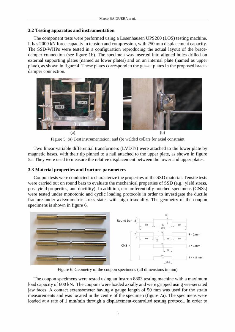
3.2 Testing apparatus and instrumentation
The component tests were performed using a Losenhausen UPS200 (LOS) testing machine.
It has 2000 kN force capacity in tension and compression, with 250 mm displacement capacity.
The SSD-WHPs were tested in a configuration reproducing the actual layout of the brace-
damper connection (see figure 1b). The specimen was inserted into aligned holes drilled on
external supporting plates (named as lower plates) and on an internal plate (named as upper
plate), as shown in figure 4. These plates correspond to the gusset plates in the proposed brace-
damper connection.
(a) (b)
Figure 5: (a) Test instrumentation; and (b) welded collars for axial constraint
Two linear variable differential transformers (LVDTs) were attached to the lower plate by
magnetic bases, with their tip pinned to a nail attached to the upper plate, as shown in figure
5a. They were used to measure the relative displacement between the lower and upper plates.
3.3 Material properties and fracture parameters
Coupon tests were conducted to characterize the properties of the SSD material. Tensile tests
were carried out on round bars to evaluate the mechanical properties of SSD (e.g., yield stress,
post-yield properties, and ductility). In addition, circumferentially-notched specimens (CNSs)
were tested under monotonic and cyclic loading protocols in order to investigate the ductile
fracture under axisymmetric stress states with high triaxiality. The geometry of the coupon
specimens is shown in figure 6.
Figure 6: Geometry of the coupon specimens (all dimensions in mm)
The coupon specimens were tested using an Instron 8803 testing machine with a maximum
load capacity of 600 kN. The coupons were loaded axially and were gripped using vee-serrated
jaw faces. A contact extensometer having a gauge length of 50 mm was used for the strain
measurements and was located in the centre of the specimen (figure 7a). The specimens were
loaded at a rate of 1 mm/min through a displacement-controlled testing protocol. In order to
Round bar
R = 2 mm
R = 3 mm
R = 4.5 mm
CNS
60 6080
200
16
37
38
16
12
35.5
R4.5
R3
R2
12
60 60

Marco BAIGUERA et al.
6
protect the extensometer from being damaged by the sudden fracture of the specimen, it was
removed after necking, as shown in figure 7b.
(a) (b)
Figure 7: Coupon test setup: (a) extensometer with 50 mm gauge length; and (b) necking
Table 1: Summary of mechanical properties of SSD
Coupon fy [MPa] fu [MPa] 𝜀f [%] E [MPa]
Round bar 1 530 752.4 45.7 189,655
Round bar 2 513 750.9 47.5 181,250
Round bar 3 518 745.8 47.9 187,500
Average 520 749.7 47.0 186,135
3.3.1 Round bars
Three uniaxial tensile tests were carried out on round bars, which were designed in
accordance with EN 1002-1 [20]. As shown in figure 6, the tested specimens have a nominal
external diameter of 16 mm and are tapered to a reduced diameter of 12 mm. Fracture was
observed in all the three tests. Table 1 summarizes the mechanical properties of SSD obtained
from each test, i.e., the yield stress fy (defined by the 0.2% offset strain), the ultimate stress fu,
the elongation at fracture 𝜀f, and the Young's modulus E. Figure 8a shows the force-
displacement curves from the tensile tests and figure 9a shows the corresponding stress-strain
curves.
(a) (b)
Figure 8: Load-displacement curves from tensile tests: (a) round bars; and (b) CNSs
The results show that SSD has an average yield stress equal to 520 MPa, which is 15% higher
than the minimum nominal value of S31803/S32205 duplex stainless steel (450 MPa). Figure
9a shows that SSD is characterised by large ductility and high post-yield stiffness. The ratio of
the post-yield stiffness to the elastic stiffness is 1/125. The engineering stress-strain curve is
used to define the true stress-strain curve (figure 9b), which provides a true representation of
the material behaviour and the input for the material properties as required by finite element
(FEM) software.
0 10 20 30 40 500
20
40
60
80
100
Displacement (mm)
Load (
kN
)
Round bar 1
Round bar 2
Round bar 3
0 1 2 3 4 50
10
20
30
40
50
60
Displacement (mm)
Forc
e (
kN
)
R = 2 mm
R = 3 mm
R = 4.5 mm

Marco BAIGUERA et al.
7
(a) (b)
Figure 9: (a) Engineering stress-strain curves from tensile tests; and (b) true stress-strain curve
3.3.2 Circumferentially-notched specimens
CNSs were tested to investigate the ductile fracture parameters under axisymmetric stress
states with high triaxiality [21]. Three different radii were used, i.e. R = 2, 3, and 4.5 mm (figure
6b) to create the notch, thus introducing three different levels of triaxiality. For each geometry,
three specimens were tested under monotonic tensile loading. Cyclic protocols were also used
since they are more representative of earthquake loadings. As summarized in table 2, increasing
amplitude and constant amplitude (CA) tests were performed under displacement control, based
on the measurement from the extensometer with a loading rate of 1 mm/min.
(a) (b)
Figure 10: CA test on CNS (R = 3 mm): (a) load-displacement curve; and (b) ductile fracture
Table 2: Cyclic loading protocols for CNSs
CNS Test Loading protocol
R = 2 mm (uy = 0.14 mm) 1 (4)x[0;4uy]+(4)x[0;6uy]+(4)x[0;8 uy]
2 (22)x[0;5uy]
3 (24)x[0;6uy]
R = 3 mm (uy = 0.094 mm) 1 (4)x[0;4uy]+(4)x[0;6uy]+(4)x[0;8uy]+(4)x[0;10uy]+(1) x[0;12uy]
2 (21)x[0;8uy]
3 (39)x[0;5uy]
R = 4.5 mm (uy = 0.063 mm) 1 (41)x[0;5uy]
2 (4)x[0;4uy]+(4)x[0;6uy]+(4)x[0;8uy]+(4)x[0;10uy]+(2)x[0;12uy]
3 (19)x[0;8uy]
Note: the number in parentheses indicates the number of cycles, followed by the prescribed cyclic
amplitude in square brackets. For example, (22)x[0;5uy] refers to a specimen subjected to twenty-two
cycles between 0 and 5 times uy.
0 0.1 0.2 0.3 0.4 0.5 0.60
200
400
600
800
(
MP
a)
Round bar 1
Round bar 2
Round bar 3
0 0.5 1 1.5 20
500
1000
1500
2000
2500
pl
(
MP
a)
0 0.1 0.2 0.3 0.4 0.5 0.6-40
-20
0
20
40
Displacement (mm)
Load (
kN
)
CNS (R = 3 mm) test 3

Marco BAIGUERA et al.
8
3.4 Loading protocols
Specimens SSD-WHP1 and SSD-WHP2 were tested under different loading protocols,
which are listed in table 4. The AISC protocol is derived from ANSI/AISC 341-10 Annex K
[22], and it is intended for the validation of buckling-restrained braces. It can be used for the
proposed dampers, since they are designed to provide a full and stable hysteresis to the bracing
members, yielding in both tension and compression. This loading protocol, presented in table
3, is defined by the yield displacement Δby and the DBE brace demand Δbm, which are
determined in the pushover simulations described in detail in [14]. The displacement demands
are Δbm = 17 mm for SSD-WHP1 (i.e., the demand at the third storey of the prototype frame),
and Δbm = 14 mm for SSD-WHP2 (i.e., the demand at the top storey).
Table 3: AISC protocol
Phase No of
cycles
Amplitude (mm)
SSDWHP1 SSDWHP2
1 2 Δby 8 5
2 2 0.5Δbm 8.5 7
3 2 Δbm 17 14
4 2 1.5Δbm 25.5 21
5 2 2Δbm 34 28
In order to assess the behaviour of SSD-WHPs under ultra-low cycle fatigue, CA protocols
were used. The imposed displacements were equal to 4uy (i.e., 4 times the yield displacement),
5uy, 6uy, and 7uy. Specimen SSD-WHP2 was subjected to one more CA test at 8uy. In addition,
cyclic protocols with randomly-generated number of cycles and amplitude were used. Figure
11 shows the random protocols applied to SSD-WHP1 specimens. Monotonic loading was also
used to evaluate the ultimate behaviour of SSD-WHPs. The displacement-controlled protocols
were applied at a rate ranging from 5 to 40 mm/min, depending on the imposed amplitude.
Figure 11: Random loading protocols
4 EXPERIMENTAL RESULTS
Sixteen full-scale component tests were conducted, as summarized in Table 4. For both the
specimens, the AISC tests were first performed, followed by a set of CA tests and random tests.
Finally, monotonic tests were conducted to assess the ultimate performance of the dampers
under very large displacements.
Figure 12 shows the force-displacement curves of SSD-WHP1 and SSD-WHP2 under the
AISC protocol. Both the specimens successfully met the intended displacement history,
showing stable and full hysteresis. No cracks or early deterioration were observed. The
hysteresis of the SSD-WHPs is characterized by a slight pinching at zero force, due to the small
clearance that allows the pins to slip.
0 5 10 15 20 25 30 35 40-10
-5
0
5
10
Cycle
Am
plit
ud
e (u
y)
SSD-WHP1 Random-1
0 10 20 30 40 50-10
-5
0
5
10SSD-WHP1 Random-2
Cycle
Am
plit
ud
e (u
y)

Marco BAIGUERA et al.
9
Table 4: Test matrix for full-scale component tests
Specimen uy
(mm)
Fy
(kN)
Test Test protocol No of
cycles
Failure mode
SSD-WHP1 7 160 1 AISC 10 No failure
2 CA at 7uy 28 Ductile fracture
3 CA at 6uy 35 Ductile fracture
4 CA at 5uy 43 Ductile fracture
5 CA at 4uy 78 Ductile fracture
6 Random-1 59 Ductile fracture
7 Random-2 45 Ductile fracture
8 Monotonic - No failure
SSD-WHP2 7 75 9 AISC 10 No failure
10 CA at 8uy 33 Ductile fracture
11 CA at 7uy 42 Ductile fracture
12 CA at 6uy 59 Ductile fracture
13 CA at 5uy 76 Ductile fracture
14 CA at 4uy 89 Ductile fracture
15 Random 49 Ductile fracture
16 Monotonic - No failure
The deformed shape of SSD-WHPs, illustrated in figure 13, shows their large ductility under
bending. The hourglass shape that promotes a uniform distribution of plastic deformations
provided large energy dissipation and delayed fracture. Based on the results from the AISC
tests, the yield displacement uy was assumed 7 mm for both the specimens.
Figure 12: Hysteretic behaviour of SSD-WHP1 and SSD-WHP2 under AISC protocol
Figure 14 illustrates the force-displacement response of SSD-WHP1 and SSD-WHP2 under
two constant amplitude protocols (5uy and 7uy), which are representative of the CA test set. The
results indicate that SSD-WHPs have stable hysteretic behaviour and large fracture capacity.
Under the CA protocols at 49 mm (7uy) and 35 mm (5uy), SSD-WHP1 reached full fracture
after 28 and 43 cycles, while SSD-WHP2 fractured after 42 and 76 cycles. The cyclic envelopes
from CA tests show significant hardening, especially under large imposed displacements.
Figure 13: Deformed shape of SSD-WHP1 at ±49 mm (7uy) under Random-1 protocol
-40 -20 0 20 40-300
-200
-100
0
100
200
300SSD-WHP1
Displacement (mm)
Forc
e (
kN
)
-30 -20 -10 0 10 20 30-300
-200
-100
0
100
200
300SSD-WHP2
Displacement (mm)
Forc
e (
kN
)

Marco BAIGUERA et al.
10
(a) (b)
Figure 14: Hysteresis of SSD-WHP1 and SSD-WHP2: (a) CA tests at 5uy; and (b) CA tests at 7uy;
The CA tests were performed to study the ultra-low cycle fatigue of the seismic dampers.
The results summarized in table 4 are used to calibrate the parameters of a Coffin-Manson
equation that correlates the imposed displacement amplitude, Δf, to the number of cycles
applied to reach fracture, Nf [16]:
∆f = ∆0 × (𝑁f)𝑚 (1)
The estimated values of ∆0 and m are 350 mm and -0.6 for SSD-WHP1 (figure 16a), and
455 mm and -0.6 for SSD-WHP-2 (figure 16b).
(a) (b)
Figure 16: Low-cycle fatigue life of SSD-WHPs
The low-cycle fatigue curves are also used to approximately estimate the failure of SSD-
WHPs under loading protocols of variable amplitude. The Palmgren-Miner linear damage
accumulation rule is used:
= ∑𝑛
𝑁f,
𝑗
𝑖=1
(2)
-40 -20 0 20 40-300
-200
-100
0
100
200
300SSD-WHP1
Displacement (mm)
Forc
e (
kN
)
-60 -40 -20 0 20 40 60-300
-200
-100
0
100
200
300SSD-WHP1
Displacement (mm)
Forc
e (
kN
)-40 -20 0 20 40
-200
-100
0
100
200SSD-WHP2
Displacement (mm)
Forc
e (
kN
)
-60 -40 -20 0 20 40 60-200
-100
0
100
200SSD-WHP2
Displacement (mm)
Forc
e (
kN
)
0 20 40 60 80 100 1200
20
40
60
80
100SSD-WHP1
Nf
Am
plit
ude (
mm
)
Coffin-Manson eq.
CA tests
0 20 40 60 80 100 1200
20
40
60
80
100SSD-WHP2
Nf
Am
plit
ud
e (
mm
)
Coffin-Manson eq.
CA tests

Marco BAIGUERA et al.
11
where 𝑛 is the number of cycles applied at a given amplitude, Nf,i is the number of cycles
applied at a given amplitude to reach fracture, and D is the damage index, which is equal to 1
when the fatigue life is reached [11]. As shown in table 5, the experimental fracture of SSD-
WHP1and SSD-WHP2 under two different random protocols occurs at end of phases 14 and 9,
where Miner’s rule gives a value of D equal to 1.14 and 0.99, respectively. Therefore, the
damage accumulation computed using a linear rule provides an acceptable agreement with the
experimental results. The estimation of the Coffin-Manson equation parameters along with the
use of Miner’s rule is useful for the development of FEM models that incorporate the fracture
of SSD-WHPs. For example, in OpenSees [23] the fatigue material model, which accounts for
the effects of low cycle fatigue, uses the Miner’s rule, based on Coffin-Manson relationships,
and it can be incorporated in a spring-like model that simulates the behaviour of the seismic
damper.
Table 5: Miner’s linear damage rule
Phase SSD-WHP1 Random-1 SSD-WHP2 Random ∆f n Nf ∆f n Nf
1 3uy 8 109 0.07 6uy 9 59 0.15
2 6uy 1 35 0.10 7uy 8 42 0.34
3 4uy 9 78 0.22 8uy 2 33 0.40
4 7uy 2 28 0.29 7uy 6 42 0.55
5 6uy 5 35 0.43 5uy 4 76 0.60
6 5uy 3 43 0.50 8uy 6 33 0.78
7 3uy 4 109 0.54 3uy 4 168 0.80
8 7uy 7 28 0.79 5uy 5 76 0.87
9 3uy 2 109 0.81 7uy 5 42* 0.99
10 7uy 3 28 0.91
11 3uy 2 109 0.93
12 4uy 2 78 0.96
13 2uy 4 214 0.98
14 5uy 7 43* 1.14
*Experimental fracture
Figure 17a illustrates the fracture mode of SSD-WHPs. Extensive plastic deformations due
to bending concentrated in Sections 1 (close to the upper plate) and 2 (close to the lower plate).
After several cycles, cracks propagated in those sections. Figures 17b and 18b show the final
cycle of SSD-WHP1 under Random-2 test protocol and SSD-WHP2 under CA protocol at 28
mm. The specimens eventually failed due to complete fracture in Section 2.
(a) (b)
Figure 17: Fracture of SSD-WHP1 (Random-2 test): (a) fracture locations; and (b) final cycle

Marco BAIGUERA et al.
12
(a) (b)
Figure 18: SSD-WHP2 (CA test at 4uy): (a) axial expansion; and (b) final cycle with full fracture
Due to extensive plastic deformations spread over the length of the steel pins, a significant
axial expansion was observed, as illustrated in figure 18a. After several cycles, this expansion
was large, in the range of 15-20 mm for SSD-WHP1 and 30-40 mm for SSD-WHP2. This is in
agreement with the experimental observations: cracks were spread on a larger area in SSD-
WHP2 (figure 19) than in SSD-WHP1 (figure 17b), where a single large crack propagated.
Cycle no. 48 Cycle no. 51 Cycle no. 54 Cycle no. 59 (final)
Figure 19: CA test at 6uy: fracture evolution
The monotonic behaviour of SSD-WHP1 is illustrated in figure 20a. It exhibited a high post-
yield stiffness, equal to 1/10 of the elastic stiffness. Figure 20b shows the specimen at 110 mm
imposed displacement, which corresponds to 6.5 times Δbm. At this displacement the test was
stopped, since no fracture of the SSD-WHP1 occurred. The lower supporting steel plates
sustained significant bending, without weld failure. A similar behaviour was observed for SSD-
WHP2, which exhibited a post-yield modulus equal to 2/10 of the elastic modulus. The
excellent ductility of the SSD-WHPs under excessive monotonic loading suggests that they
represent a potentially superior way to provide increased robustness under progressive collapse
of the frame, on top of their excellent seismic performance.
(a) (b)
Figure 20: SSD-WHP1 monotonic test: (a) force-displacement behaviour; and (b) deformed shape
at 110 mm displacement
0 20 40 60 80 100 1200
100
200
300
400
500
Displacement (mm)
Forc
e (
kN
)

Marco BAIGUERA et al.
13
5 NUMERICAL SIMULATIONS
5.1 Calibration of SSD cyclic hardening model
Numerical simulations were carried out to calibrate the material properties that define the
cyclic plastic behaviour of SSD. Nonlinear FEM models of CNSs were created using the
commercial software Abaqus [24]. Figure 21 shows the geometry of the model, which
reproduces the gauge length section and takes into account the symmetry of the specimen.
Elements with reduced integration, namely CAX4R in Abaqus, were used. A refined mesh was
applied in the notch region with an element size of 0.25 mm, as recommended by Kanvinde and
Deierlein [25]. The extensometer displacement history was applied to the FEM model.
Figure 21: Axisymmetric FEM model of CNS with R = 3 mm
The accuracy of the FEM model was first assessed by simulating the CNS tensile tests. An
isotropic hardening model was defined using the true stress-strain curve obtained from the
tensile tests on round bars (figure 9b). The comparison of the numerical and experimental force-
displacement curves for all the three CNSs is illustrated in figure 22. A good agreement is found
for CNSs with R = 2 and 3 mm, where the results for CNS with R = 4.5 mm show significant
differences between the experimental and numerical curves. Small geometry inconsistencies in
the notch region and hardening due to the tapering process might have influenced the
experimental results.
Figure 22: CNS tensile tests: experimental-numerical comparison
The hysteretic behaviour of SSD is simulated by an elastoplastic material model with
combined isotropic and kinematic hardening. The material model is defined by the yield surface
φ(σ) defined as [24]:
𝜑(𝝈) = √3
2(𝑺 − 𝜶)𝑡(𝑺 − 𝜶) − 𝜎0 (3)
0 1 2 3 4 50
10
20
30
40
50
60CNS - R = 2 mm
Displacement (mm)
Fo
rce
(kN
)
Test 1
Test 2
Test 3
FEM
0 1 2 3 40
5
10
15
20
25
30
35CNS - R = 3 mm
Displacement (mm)
Fo
rce
(kN
)
Test 1
Test 2
Test 3
FEM
0 0.5 1 1.5 2 2.50
2
4
6
8
10CNS - R = 4.5 mm
Displacement (mm)
Fo
rce
(kN
)
Test 1
Test 2
Test 3
FEM

Marco BAIGUERA et al.
14
where σ0 is the yield stress, t is the transposition operation, S is the stress deviator, σ is the stress
vector and α is the backstress vector. The hardening laws for each backstress are defined as:
𝜶 = ∑ 𝜶k
B
k=1
(4)
�̇�k =
𝐶k
𝜎0(𝝈 − 𝜶) 𝜀 ̅̇𝑝 − 𝛾k 𝜶k 𝜀 ̅̇𝑝 (5)
where a superimposed dot indicates an incremental quantity, B is the total number of the
backstresses, Ck and γk are the constitutive material parameters to be calibrated against the
experimental results, and 𝜀̅̇𝑝 is the equivalent plastic strain rate. The evolution of σ0 (isotropic
hardening component) is defined by the following exponential law:
𝜎0 = 𝜎|0 + 𝑄∞(1 − 𝑒−𝑏�̅�𝑝) (8)
where 𝜎|0 is the yield stress at zero plastic strain, b defines the rate at which the size of φ(σ)
changes for increasing plastic strains, and 𝑄∞ is the maximum change in the size of φ(σ).
Several simulations were conducted to identify the values of the parameters that define the
aforementioned constitutive model. A good agreement is achieved adopting the following
values: 𝜎|0 = 400 MPa, C1 = 6,500 MPa, γ1 = 30, C2 = 100,000 MPa, γ2 = 700, b = 5, 𝑄∞ = 200
MPa. Figure 23 shows the experimental and FEM simulated hysteretic behaviour from cyclic
tests on CNS with R = 2 and 3 mm.
Figure 23: CNS cyclic tests: experimental-numerical comparison
5.2 SSD-WHP1 model
A three-dimensional FEM model was developed in Abaqus Explicit to simulate the
hysteretic behaviour of SSD-WHP1. Figure 24 shows an overview of the FEM model along
with the boundary conditions. Only half of the test setup was reproduced in full detail due to its
symmetric geometry. The SSD-WHP1 and the supporting steel plates were modelled using
solid elements with reduced integration, namely C3D8R. The mesh density is more refined in
the SSD-WHP1 than in the steel plates, as shown in figure 24. The general contact algorithm
was used to define the interaction between the external surfaces of SSD-WHP1 and the holes
of the supporting plates. A contact property with normal and tangential behaviour was applied,
assigning a friction coefficient of 0.2. In order to capture the pinching behaviour at zero force
observed in the experimental force-displacement curves (figures 12 and 14), a small clearance,
equal to 0.2 mm, was left between the SSD-WHP1 and the surrounding holes.
0 0.2 0.4 0.6 0.8 1 1.2-60
-40
-20
0
20
40
60CNS - R = 2 mm
Displacement (mm)
Fo
rce
(kN
)
Test 3
FEM
0 0.1 0.2 0.3 0.4 0.5 0.6-40
-20
0
20
40CNS - R = 3 mm
Displacement (mm)
Fo
rce
(kN
)
Test 3
FEM

Marco BAIGUERA et al.
15
Displacement-controlled analyses were conducted under quasi-static loading conditions in
the large displacement/strain nonlinear regime. For a first calibration of the model, the CA test
at 7uy (i.e., 28 cycles at 49 mm) was simulated. The cyclic loading protocol was applied to the
upper supporting plate. To avoid dynamic effects, the loading rate used was relatively low (3
mm/s). In order to ensure a stable analysis, the density of the material was decreased and the
displacement history was applied with a periodic amplitude. The material hardening parameters
calibrated for SSD were adopted.
Figure 24: FEM model of half of a SSD-WHP1
Figure 25a shows the contour plots of the equivalent plastic strain on the deformed shapes
of the SSD-WHP1 and the steel plates at 49 mm imposed displacement, along with a
comparison with the experimental test. As illustrated in figure 25b, the maximum PEEQ is
located at the centre of the half bending part (Sections 1 and 2), where fracture initiation and
evolution was experimentally observed (figure 17). The FEM model was able to capture the
axial expansion due to extensive plastic deformations (figure 25c), in agreement with the
experimental observations (figure 18a).
(b)
(a) (c)
Figure 25: (a) Numerical and experimental deformed shape of SSD-WHP1; (b) PEEQ contour plots
after 10 cycles; and (c) PEEQ contour plots after 19 cycles

Marco BAIGUERA et al.
16
Figure 26 plots the force-displacement hysteresis of the FEM model against the experimental
curve. The results indicate that FEM model is capable of tracing the nonlinear cyclic behaviour
of SSD-WHP1 with good accuracy. The pinching effect at zero force due to the small clearance
was captured accurately.
Figure 26: Experimental and numerical hystereses of SSD-WHP1 under CA at 7uy
This model will be used to study the fracture behaviour of SSD-WHPs. The parameters that
define the fracture criteria (namely ductile damage and damage evolution in Abaqus Explicit)
will be validated against the CNS tests and the full component tests. The fracture model will be
then used to predict the fracture of SSD-WHPs under any loading protocol.
6 CONCLUSIONS
Duplex stainless steel seismic dampers with an hourglass shape, named SSD-WHPs, were
used in a novel CBF-MRF to reduce residual drifts after a strong earthquake, taking advantage
of their high post-yield stiffness. The SSD-WHPs were further validated in this study by means
of full scale components tests replicating the loading and boundary conditions of a braced
frame. The hardening and fracture parameters of duplex stainless steel were identified
performing coupon tests on round and circumferentially-notched bars. Based on the results
presented herein, the following conclusions are drawn:
SSD-WHPs possess excellent ductility and fracture capacity under cyclic loading. They
pass the standard protocol for braced frames and they are able to sustain much larger cyclic
deformations than those expected under the maximum considered earthquake.
The optimised hourglass shape of the SSD-WHPs results in a widespread distribution of
plastic strains over their length and in a significant axial elongation.
Coffin-Manson relationships are calibrated for the two geometries of SSD-WHPs. The
linear damage accumulation model (Miner’s rule) gives an acceptable estimation of
fracture under random loading protocols.
SSD-WHPs do not fracture under excessive monotonic loading, indicating that they are
able to provide enhanced ductility and robustness to a frame in progressive collapse
loading conditions.
Accurate cyclic hardening parameters of the material were identified using the results from
monotonic and cyclic tests on round and circumferentially-notched bars. Complementary
finite element analyses provided a good correlation with the experimental tests.
A finite element model of the SSD-WHPs developed using Abaqus Explicit showed an
excellent agreement with the test. By using the results from the coupon tests, the fracture
parameters will be identified and used to develop fracture simulations of SSD-WHPs
subjected to any cyclic loading. Collapse simulations of the proposed frame with SSD-
WHPs will be then carried out.
-60 -30 0 30 60-400
-200
0
200
400
Displacement (mm)
Fo
rce (
kN
)
Test FEM

Marco BAIGUERA et al.
17
REFERENCES
[1] Clifton G.C., Nashid H., Ferguson G., Hodgson M., Seal C., Bruneau M., MacRae G.A. and
Gardiner S., “Performance of eccentrically braced framed buildings in the Christchurch
earthquake series of 2010/2011”, Proceedings of the 15th World Conference on Earthquake
Engineering (15 WCEE), Lisbon, Portugal, Paper 2502, 2012.
[2] Skinner R.I., Kelly J.M. and Heine A.J., “Hysteretic dampers for earthquake-resistant structures”,
Earthquake Engineering & Structural Dynamics, 3, 287-296, 1974.
[3] Whittaker A.S., Bertero V.V., Thompson C.L. and Alonso L.J., “Earthquake simulator testing of
steel plate added damping and stiffness elements”, Technical Report, Earthquake Engineering
Research Center, University of California, Berkeley, CA, 1989.
[4] Tsai K.C., Chen H.W., Hong C.P. and Su Y.F., “Design of steel triangular plate energy absorbers
for seismic-resistant construction”, Earthquake Spectra, 9, 505-528, 1993.
[5] Kajima, Honeycomb Damper System, Japan, Kajima Corporation, 1991.
[6] Vayas I. and Thanopoulos P., “Innovative dissipative (INERD) pin connections for seismic
resistant braced frames”, International Journal of Steel Structures, 5, 453-464, 2005.
[7] Gray M., Christopoulos C. and Packer J., “Cast steel yielding brace system for concentrically
braced frames: concept development and experimental validations”, Journal of Structural
Engineering, 140, 04013095, 2014.
[8] Iwata M., Kato T. and Wada A., “Buckling-restrained braces as hysteretic dampers”, Proceedings
of 3rd International Conference STESSA, Montreal, Canada, 2000.
[9] McCormick J., Aburano H., Ikenaga M. and Nakashima M., “Permissible residual deformation
levels for building structures considering both safety and human elements”, Proceedings of 14th
World Conference on Earthquake Engineering, Beijing, China, 2008.
[10] Watanabe A., Hitomi Y., Saeki E., Wada A. and Fujimoto M., “Properties of brace encased in
buckling–restraining concrete and steel tube”, Proceedings of 9th World Conference on
Earthquake Engineering, Tokyo-Kyoto, Japan, 1988.
[11] Bruneau M., Uang C.M. and Sabelli R., Ductile design of steel structures, McGraw Hill, Inc,
2011.
[12] Erochko J., Christopoulos C., Tremblay R. and Choi H., “Residual drift response of SMRFs and
BRB frames in steel buildings designed according to ASCE 7-05”, Journal of Structural
Engineering, 137, 589-599, 2011.
[13] Pettinga D., Christopoulos C., Pampanin S. and Priestley N., “Effectiveness of simple approaches
in mitigating residual deformations in buildings”, Earthquake Engineering & Structural
Dynamics, 36, 1763-1783, 2008.
[14] Baiguera M., Vasdravellis G. and Karavasilis T.L., “Dual seismic-resistant steel frame with high
post-yield stiffness energy-dissipative braces for residual drift reduction”, Journal of
Constructional Steel Research, 122, 198-212, 2016.
[15] Vasdravellis G., Karavasilis T.L. and Uy B., “Large-scale experimental validation of steel
posttensioned connections with web hourglass pins”, Journal of Structural Engineering, 139,
1033-1042, 2013.
[16] Vasdravellis G., Karavasilis T.L. and Uy B., “Design rules, experimental evaluation, and fracture
models for high-strength and stainless steel hourglass shape energy dissipation devices”, Journal
of Structural Engineering, 140, 04014087, 2014.
[17] Shen Y., Christopoulos N., Mansour C. and Tremblay R., “Seismic design and performance of
steel moment-resisting frames with nonlinear replaceable links”, Journal of Structural
Engineering, 137, 1107-1017, 2014.
[18] Eurocode 3: Design of Steel Structures - Part 1-1: General Rules and Rules for Building, CEN,
Brussels, European Committee for Standardization, 2004.

Marco BAIGUERA et al.
18
[19] Eurocode 8: Design Provisions for Earthquake Resistance of Structures - Part 1: General Rules,
Seismic Actions and Rules for Building. CEN, Brussels, European Committee for Standardization,
2004.
[20] Metallic Materials. Tensile Testing. Part 1: Tests at ambient temperature. EN 1002-1, CEN,
Brussels, European Committee for Standardization, 2001.
[21] Smith C.M., Deierlein G.G. and Kanvinde A.M., “A stress-weighted damage model for ductile
fracture initiation in structural steel under cyclic loading and generalized stress states”, Technical
Report, The John A. Blume Earthquake Engineering Center, Stanford University, 2014.
[22] Seismic Provisions for Structural Steel Buildings. ANSI/AISC 341-10, Chicago, AISC, 2010.
[23] McKenna F., Fenves G., Scott M., and Jeremic B., Open System for Earthquake Engineering
Simulation (OpenSees). Pacific Earthquake Engineering Research Center, University of
California, Berkley, CA, 2000.
[24] Hibbit D., Karlsson B. and Sorensen P., ABAQUS users’s manual. 6.14 edition, Providence, RI,
2013
[25] Kanvinde A.M. and Deierlein G.G., “The void growth model and the stress modified critical strain
model to predict ductile fracture in structural steel”, Journal of Structural Engineering, 132, 701-
712, 2006.
Copyright © 2022 FDOKUMEN