SCC control dampers for circular duct - Madel
11
The SCC series dampers are designed to be used for altering the flow volume rate and pressure in air-conditioning, ventilation and heating systems. Airtight damper suitable for circular duct mounting M A D E L ® we shape the air SCC control dampers for circular duct 1 M A D E L V-04/17
-
Upload
khangminh22 -
Category
Documents
-
view
4 -
download
0
Transcript of SCC control dampers for circular duct - Madel

The SCC series dampers are designed to be used for altering the
flow volume rate and pressure in air-conditioning, ventilation and
heating systems. Airtight damper suitable for circular duct mounting
M A D E L ®we shape the air
SCC control dampers for circular duct
1 M A D E L V-04/17
SCC-MA
SCC-MO
SCC-…/AIS/
2 M A D E L V-04/17
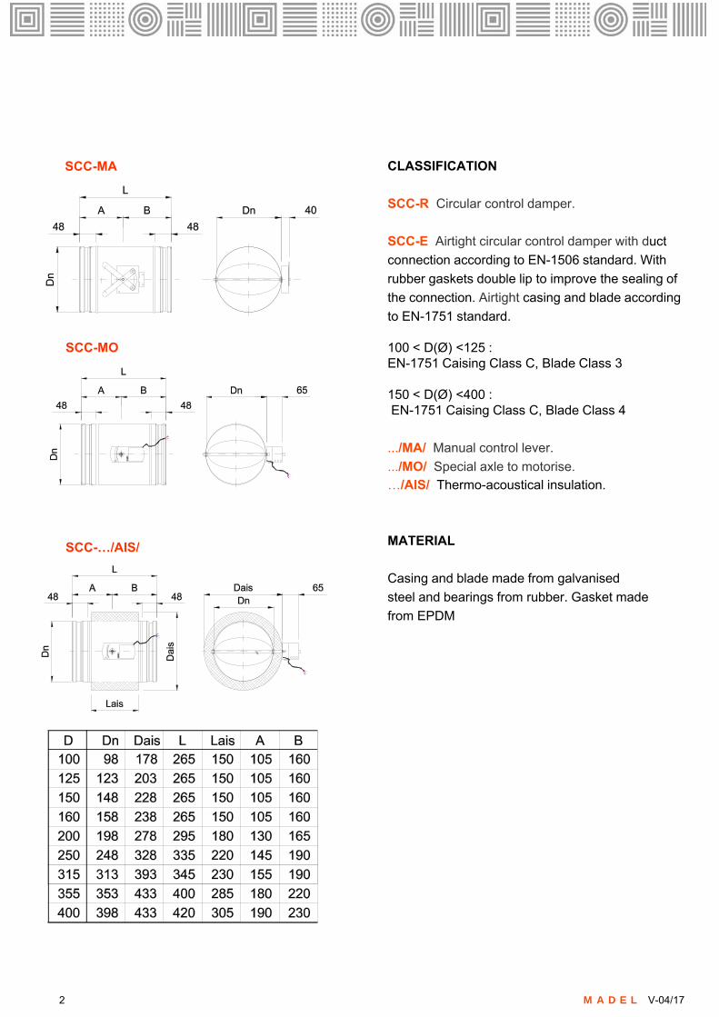
CLASSIFICATION
SCC-R Circular control damper.
SCC-E Airtight circular control damper with duct
connection according to EN-1506 standard. With
rubber gaskets double lip to improve the sealing of
the connection. Airtight casing and blade according
to EN-1751 standard.
100 < D(Ø) <125 :EN-1751 Caising Class C, Blade Class 3
150 < D(Ø) <400 :EN-1751 Caising Class C, Blade Class 4
.../MA/ Manual control lever.
.../MO/ Special axle to motorise.
…/AIS/ Thermo-acoustical insulation.
MATERIAL
Casing and blade made from galvanised
steel and bearings from rubber. Gasket made
from EPDM

ACTUATORS
ON/OFF actuators
GDB141.1E 24 VAC/VDC 5N Siemens actuator. GDB341.1E 100... 230 VAC 5N Siemens actuator.
LM24A 24 VAC/VDC 5N Belimo actuator.LM230A 230 VAC 5N Belimo actuator.
ON/OFF actuators with switches device
GDB146.1E 24 VAC/VDV 5N 2FC Siemens actuator. GDB346.1E 100...230 VAC 5N 2FC Siemens actuator.
LM24A-S 24 VAC/VDC 5N 1FC Belimo actuator (*)LM230A-S 5N 1FC Belimo actuator (*)* Belimo actuators with end of course swicth for 2 contacts. To consult.
ON/OFF actuators with spring return
GMA121.1E 24 VAC/VDC 7N Siemens actuator. GMA321.1E 230 VAC 7N Siemens actuator.
LF-24 24 VAC/VDC 4N Belimo actuator. LF-230 230 VAC 4N Belimo actuator.
Proportional actuators
GDB161.1E 24 VAC/VDC 5N Siemens actuator.
LM24A-SR 24 VAC/VDC 5N Belimo actuator. LM230A-SR 230 VAC 5N Belimo actuator.
Communicating actuators
Consult actuator models with Modbus / KNX / LONWorks and Bacnet communications protocols
Siemens GDB/GLB
Belimo LM/NM Belimo LF/NF
Siemens GMA
3 M A D E L V-04/17

TF RDG 400
CO2-WPCO2-WR
CO2-D
OS-360
4 M A D E L V-04/17
TEMPERATURE CONTROL
TF Thermostat with cables for temperature control of 1 zone, using On/Off actuator. Manual seasonal change over.
RDG 400 Proportional temperature controller ambiance 0..10Vcc power supply 24vac with backlit digital display, selector comfort eco/off; for proportional damper actuators.
CO2-WP 24vdc vac wall-mounting detector .With LED indicator. Analog output 0-10Vdc. Setpoint600 - 800 -1000 ppm (proportional actuator required)
CO2-D Sensor for duct mounting 24vdc-vac with an output 0-10Vdc IP54 (proportional actuator required)
CO2-WR CO2 Detector with relay output (ON/OFF actuator required). Wall-mounting . With LED indicator.Digital output (relay 5A) Setpoint 800 - 1000 -1200.
OS-360 Occupancy sensor . Ceiling mount occupancy sensor, for automatic operation control of HVAC devices. 24 Vac/Vdc current drain relay signal output.Selectable ON /OFF delays.
FIXING SYSTEMS
1) The casing of damper has been designed inorder to be jointed in circular ducts. according to EN-1506 standard.
SPECIFICATION TEXT
Supply and mounting of airtight damper to control the air flow volume in circular ducts with manual control lever series SCC-E-MA dim. 100 with duct connection according to EN-1506 standard. With rubber gaskets double lip to improve the sealing of the connection. The damper is airtight according to EN-1751 standard. Caising Class C, Blade 3. Constructed from galvanised steel and bearings from nylon. Manufacturer MADEL.

5 M A D E L V-04/17
V k (m/s)
31.5 2
AK
(m
2)
4 20765 9 108 1512 17
1.5 2 3 4
DP
t (P
a)
0,005
50
6 75 9 108 1512 17 20
Q (m3/h)
0,0314250315
0,0491
100
200
125
D
0,0078
0,02010,0123
160
0,0779
Ak(m2)
0,006
0,008
0,01
0,015
0,02
0,025
0,03
0,04
0,05
0,060,070,080,090,1
10070
150
200
250
300
400
500
600
700
900
1100
1300
1600
2000
2500
V k (m/s)
2
54
3
11
10080
40
60
10
30
20
15 L wa1
= (
dB (A
))
40
35
30
25020
0160
125
100
315
45
50
8
DPt = Kp x DPt
01Kp 1,5
15 3020
6045140
1
355 0,0962
355
NECK VELOCITY, PRESSURE LOSS AND SOUND POWER LEVEL.
NECK AREA m2.
CORRECTION FACTOR FOR DPt : Kp

SIEMENS Wiring diagrams
ON/OFF – 3P CONTROL.
SPRING RETURN - ON/OFF – Two-position control
MODULATING control 0-10 V
Wiring Code Nº Color Description
ActuatorsAC 24 V�DC 24..48V
GG0Y1Y2
YU
1267
89
RD RedBK BlackVT PurpleOG Orange
GY GreyPK Pink
System potential 24 AC/DCSystem NeutralPositioning AC/DC 0V. CW
Positioning AC/DC 0V. CCW
Signal in (0-10V)Signal out (0-10 V)
ActuatorsAC 230 V�
LNY1Y2
G+G-YU
3467
1289
BR BrownBU Blue BK BlackWH White
RD RedBK BlackGY GreyPK Pink
Line 100 .. 240 ACNeutral conductorPositioning AC 230V. CW
Positioning AC 230V. CCW
Potential aux. 24 AC/DCNeutral aux. 24 AC/DCSignal in (0-10V)Signal out (0-10 V)
Auxiliarycontacts
Q11Q12Q14Q21Q22Q24
S1S2S3S4S5S6
GY/RDGY/BUGY/PKBK/RDBK/BUBK/PK
Input switch AContact NC switch AContact NO switch AInput switch BContact NC switch BContact NO switch B
This information is provided by way of indication. Consult the manufacturer catalogue for all updated documentation.
https://www.buildingtechnologies.siemens.com/bt/global/en/products/HVAC-Products/Damper-actuators/Actuators-for-HVAC-applications/Pages/Actuators-for-HVAC-applications-default.aspx
N1*. Accessory control. See wiring diagrams accessories.
L
AC 100 ... 240 V
GMA 321.1E
1 B
R2
BU
Two-position control
S1 S4
S2 S3 S5 S6
GY
/RD
BK
/RD
GY
/BU
GY
/PK
BK
/BU
BK
/PK
Only for 326.1E
N
N
Go
G
DC 24 V ... 48 V ꞏꞏꞏ
AC 24 V
1 R
D2
BK
S1 S4
S2 S3 S5 S6
GY
/RD
BK
/RD
GY
/BU
GY
/PK
BK
/BU
BK
/PK
Only for 126.1E
Two-position controlGMA 121.1E
N1*
N1*
Go
G
DC 24 V ... 48 V ꞏꞏꞏ
AC 24 V
GDB 16..1E
1 R
D2
BK
Modulating control
L
AC 100 ... 240 V
GDB 36..1E
3 B
R4
BU
N
N
Y U
8 G
Y
9 P
K
DC 0..35 V DC 0/2..10 V
Y U
8 G
Y
9 P
K
DC 0/2..10 V
G-
G+
DC 24 VꞏꞏꞏSELV/PELV
1 R
D2
BK
DC 0/2..10 V
Modulating control
Go
G
Y1 Y2
DC 24 V ... 48 V ꞏꞏꞏ
AC 24 V
GDB 14..1E
1 R
D2
BK
6 V
T
7 O
G
Open-close, Single wire control Open-close, Two wire control Three-position control
DC 24 V ... 48 V ꞏꞏꞏ
AC 24 V
1 R
D2
BK
6 V
T
7 O
G
S1 S4
S2 S3 S5 S6
GY
/RD
BK
/RD
GY
/BU
GY
/PK
BK
/BU
BK
/PK
GDB 14..1E GDB 14..1E
Only for 146.1E
6 V
T
7 O
G
Go
G
Y1 Y2
DC 24 V ... 48 V ꞏꞏꞏ
AC 24 V
1 R
D2
BK
S1 S4
S2 S3 S5 S6
GY
/RD
BK
/RD
GY
/BU
GY
/PK
BK
/BU
BK
/PK
Only for 146.1E
Go
G
Y1 Y2
S1 S4
S2 S3 S5 S6
GY
/RD
BK
/RD
GY
/BU
GY
/PK
BK
/BU
BK
/PK
Only for 146.1E
N1*N1* N1*
L Y1 Y2
AC 100 ... 240 V
GDB 34..1E
1 B
R2
BU
Open-close, Single wire control Open-close, Two wire control Three-position control
S1 S4
S2 S3 S5 S6
GY
/RD
BK
/RD
GY
/BU
GY
/PK
BK
/BU
BK
/PK
GDB 34..1E GDB 34..1E
Only for 346.1E
N
6 B
K
7 W
H
N
L Y1 Y2
AC 100 ... 240 V
1 B
R2
BU
S1 S4
S2 S3 S5 S6
GY
/RD
BK
/RD
GY
/BU
GY
/PK
BK
/BU
BK
/PK
Only for 346.1E
N
6 B
K
7 W
H
N
L
AC 100 ... 240 V
1 B
R2
BU
S1 S4
S2 S3 S5 S6
GY
/RD
BK
/RD
GY
/BU
GY
/PK
BK
/BU
BK
/PK
Only for 346.1E
N
N
Y1 Y2
6 B
K
7 W
H
N1* N1* N1*
6 M A D E L V-04/17

BELIMO Wiring diagrams
ON/OFF – 3P CONTROL.
SPRING RETURN - ON/OFF – Two-position control
MODULATING control 0-10 V
Wiring Code Nº Color Description
ActuatorsOpen-closeAC 24 V�DC 24..48V
-+
123
BK BlackRD RedWH White
System NeutralSystem potential 24 AC/DCPositioning AC/DC 0V.
ActuatorsmodulatingAC-DC 24 VAC 230V
-+
1235
BK BlackRD RedWH WhiteOG Orange
System NeutralSystem potential 24 AC/DCSignal in (0) 2-10VSignal out 2-10V
ActuatorsAC 230 V�
LN
G+G-YU
12
1235
BU Blue BR Brown
BK BlackRD RedWH WhiteOG Orange
Line 100 .. 240 ACNeutral conductor
Neutral aux. 24 AC/DCSG..24Signal in (0-10V)Signal out (0-10 V)
Auxiliarycontacts
S1S2S3
S1S2S3
VT VioletRD RedWH White
Input switch AContact NC switch AContact NO switch A
This information is provided by way of indication. Consult the manufacturer catalogue for all updated documentation.
http://www.belimo.ch/CH/EN/PDF/index.cfm
N1*. Accessory control. See wiring diagrams accessories.
LM-24A..(S)AC/DC 24 V, Open-close
0
1
1 2 3
- +
S1 S2 S3
0...100%01
1 B
K
2 R
D
3 W
H
S1
VT
S2
RD
S3
WH
N1*
Only for LM24AS
LM-24A..(S)AC/DC 24 V, 3-point
0
1
1 2 3
- +
S1 S2 S3
0...100%01
1 B
K
2 R
D
3 W
H
S1
VT
S2
RD
S3
WH
N1*
Only for LM24AS
0
LM-230A..(S)AC 230 V, Open-close
0
1
1 2 3 S1 S2 S3
0...100%01
1 B
L
2 B
R
3 W
H
S1
VT
S2
RD
S3
WH
N1*
Only for LM230AS
LM-230A..(S)AC 230V, 3-point
0
1
1 2 3 S1 S2 S3
0...100%01
3 W
H
S1
VT
S2
RD
S3
WH
N1*
Only for LM230AS
0
N L N L
1 B
L
2 B
R
AC/DC 24 V, Open-close
1 2
- +
1 B
K
2 R
D
N1*
LF230
1 2
N1*
1 B
L
2 B
R
N L
AC 230 V, Open-close
LF24
LM24A-SRAC/DC 24 V, modulating
1 2
- +
1 B
K
2 R
D
LM230A-SRAC 230 V, Open-close
3 5
3 W
H
5 O
G
DC (0)2...10VY
U DC 2...10V
1 2 3 5
3 W
H
5 O
G
Y
U
1 B
L
2 B
R
N L
1 2
1 B
K
2 R
D
SG24
7 M A D E L V-04/17
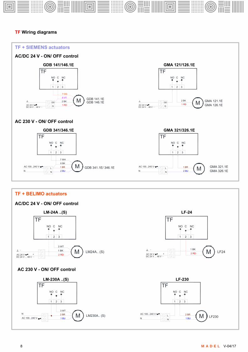
TF Wiring diagrams
1 2 3
NO C NC
TF
2 BK
1 RD
M
7 OG
6 VT
G
G0
GDB 141.1E
1 2 3
NO C NC
M GMA 121.1E
DC 24 V ... 48 V ꞏꞏꞏAC 24 V G
G0
DC 24 V ... 48 V ꞏꞏꞏAC 24 V
2 BK
1 RD
TF
GDB 146.1EGMA 126.1E
TF + SIEMENS actuators
AC/DC 24 V - ON/ OFF control
GDB 141/146.1E GMA 121/126.1E
1 2 3
NO C NC
AC 100...240 V 1 BR
2 BUN
M
7 WH
6 BK
N
L GDB 341.1E/ 346.1E
1 2 3
NO C NC
AC 100...240 V 1 BR
2 BUN MN
L
TFTF
GMA 321.1EGMA 326.1E
AC 230 V - ON/ OFF control
GDB 341/346.1E GMA 321/326.1E
TF + BELIMO actuators
AC/DC 24 V - ON/ OFF control
LM-24A ..(S) LF-24
2 BR
1 BUM
3 WT
LM230A.. (S) LF230
1 2 3
NO C NC
AC 100...240 V
N
1 2 3
NO C NC
AC 100...240 V 2 BR
1 BUN MN
L
TFTF
AC 230 V - ON/ OFF control
LM-230A ..(S) LF-230
1 2 3
NO C NC
TF
1 BK
2 RDM
3 WT
LM24A.. (S)
1 2 3
NO C NC
MDC 24 V ... 48 V ꞏꞏꞏAC 24 V
DC 24 V ... 48 V ꞏꞏꞏAC 24 V
1 BK
2 RD
TF
LF24-
+
-
+
8 M A D E L V-04/17

RDG400 Wiring diagrams
RDG 400 + SIEMENS actuators
Modulating control + manual changeover
GDB 161.1E
Go
G
Y1 Y2
X1 M X2 D1 GND
Y10RDG400
Go
G
DC 24 V ... 48 V ꞏꞏꞏ
AC 24 V
1 R
D2
BK
Y U
8 G
Y
9 P
K
DC 0/2..10 V
L
AC 100 ... 240 V
3 B
R4
BU
N
N
Y U
8 G
Y
9 P
K
G-
G+
1 R
D2
BK
DC 0/2..10 V
Go
G
Y1 Y2
X1 M X2 D1 GND
Y10RDG400
DC 24 Vꞏꞏꞏ SELV/PELV
DC 0/2..10 V
GDB 361.1E
CO2-WR Wiring diagrams
1 2
CO2-WR
2 BK
1 RD
M
7 OG
6 VT
G
G0
GDB 141.1E
DC 24 V ... 48 V ꞏꞏꞏAC 24 V
GDB 146.1E
1 BK
2 RDM
3 WT
LM24A.. (S)DC 24 V ... 48 V ꞏꞏꞏAC 24 V
-
+
4 5
24 VAC24 VDC
1 2
CO2-WR
4 5
24 VAC24 VDC
COM ONCOM ON
CO2-WR+ SIEMENS GDB 141.1E
On/OFF control
CO2-WR+ BELIMO LM24A.. (S)
On/OFF control
J4 J5
J4
800 ppm disconnected disconnected
J5
1000 ppm disconnected
1200 ppm (default) connected
1400 ppm connected
disconnected
connected
connected
Relay
CO2> 900 ppm. Relay ON; CO2 < 700 ppm Relay OFF
CO2> 1100 ppm. Relay ON; CO2 < 900 ppm Relay OFF
CO2> 1200 ppm. Relay ON; CO2 < 1100 ppm Relay OFF
CO2> 1500 ppm. Relay ON; CO2 < 1300 ppm Relay OFF
RDG 400 + BELIMO actuatorsModulating control + manual changeover
1 2
1 B
K
2 R
D
3 5
3 W
H
5 O
G
DC (0)2...10V
U
Go
G
Y1 Y2
X1 M X2 D1 GND
Y10RDG400
DC 24 V ... 48 V ꞏꞏꞏ
AC 24 V
BELIMO LM24A-SR
YDC 2...10V
1 2
1 B
K
2 R
D
3 53
WH
5 O
G
DC (0)2...10V
U
Go
G
Y1 Y2
X1 M X2 D1 GND
Y10RDG400
BELIMO LM230A-SR
YDC 2...10V
SG24
AC 100 ... 240 V
N
1 2
1 B
L
2 B
R
LM-24A -SR LM230A-SR
9 M A D E L V-04/17
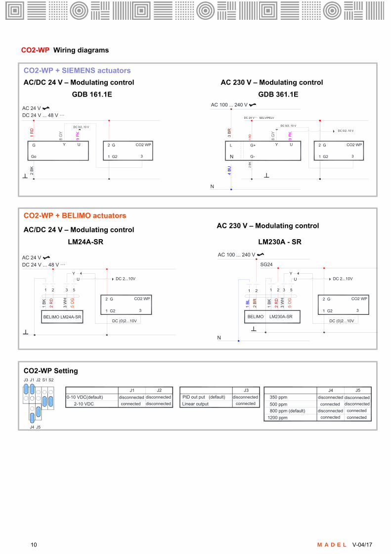
CO2-WP Wiring diagrams
J1J3 S1J2 S2
J4 J5
J1
0-10 VDC(default) disconnected disconnected
J2
PID out put (default) disconnected
J3
Linear output connected
J4
350 ppm disconnected disconnected
J5
2-10 VDC connected disconnected 500 ppm disconnected
800 ppm (default) connected
1200 ppm connected
disconnected
connected
connected
GDB 161.1E GDB 361.1E
Go
G
DC 24 V ... 48 V ꞏꞏꞏ
AC 24 V
1 R
D2
BK
Y U
8 G
Y
9 P
K
DC 0/2..10 V
L
AC 100 ... 240 V
3 B
R4
BU
N
N
Y U
8 G
Y
9 P
K
DC 0/2..10 V
G-
G+
1 R
D2
BK
DC 0/2..10 V
DC 24 Vꞏꞏꞏ SELV/PELV
2 G
1 G2 3
CO2 WP 2 G
1 G2 3
CO2 WP
CO2-WP + SIEMENS actuators
AC/DC 24 V – Modulating control AC 230 V – Modulating control
LM24A-SR LM230A - SR
CO2-WP + BELIMO actuators
CO2-WP Setting
AC 230 V – Modulating control
1 2
1 B
K
2 R
D
3 5
3 W
H
5 O
G
U
DC 24 V ... 48 V ꞏꞏꞏ
AC 24 V
BELIMO LM24A-SR
YDC 2...10V
1 2
1 B
K
2 R
D
3 5
3 W
H
5 O
G
U
BELIMO LM230A-SR
YDC 2...10V
SG24
AC 100 ... 240 V
N
1 2
1 B
L
2 B
R2 G
1 G2 3
CO2 WP
DC (0)2...10V
2 G
1 G2 3
CO2 WP
DC (0)2...10V
AC/DC 24 V – Modulating control
10 M A D E L V-04/17

CO2-D Wiring diagrams
GDB 161.1E GDB 361.1E
CO2-WD + SIEMENS actuators
AC/DC 24 V – Modulating control AC 230 V – Modulating control
Go
G
DC 24 V ... 48 V ꞏꞏꞏ
AC 24 V
1 R
D2
BK
Y U
8 G
Y
9 P
K
DC 0/2..10 V
L
AC 100 ... 240 V
3 B
R4
BU
N
N
Y U
8 G
Y
9 P
K
DC 0/2..10 V
G-
G+
1 R
D2
BK
DC 0/2..10 V
DC 24 Vꞏꞏꞏ SELV/PELV
24 V GND V I
CO2-WD
LM24A-SR LM230A - SR
CO2-WD + BELIMO actuatorsAC 230 V – Modulating control
AC/DC 24 V – Modulating control
1 2
1 B
K
2 R
D
3 5
3 W
H
5 O
G
U
DC 24 V ... 48 V ꞏꞏꞏ
AC 24 V
BELIMO LM24A-SR
YDC 2...10V
1 2
1 B
K
2 R
D3 5
3 W
H
5 O
G
U
BELIMO LM230A-SR
YDC 2...10V
SG24
AC 100 ... 240 V
N
1 2
1 B
L
2 B
R
DC (0)2...10V
24 V GND V I
CO2-WD
24 V GND V I
CO2-WD
DC (0)2...10V
OS-360 Wiring diagrams
OS360+ SIEMENS GDB 141.1E OS360+BELIMO LM24A.. (S)
NCCOM NO
+24V0 V
NCCOM NO
+24V0 V
OS363OS363
2 BK
1 RD
M
7 OG
6 VT
G
G0
GDB 141.1E
DC 24 V ... 48 V ꞏꞏꞏAC 24 V
GDB 146.1E1 BK
2 RDM
3 WT
LM24A.. (S)DC 24 V ... 48 V ꞏꞏꞏAC 24 V
-
+
On/OFF control On/OFF control
FEDCBA
FEDCBA
ON
A
ON
OFF
OFF
B C D E F
0 sec 10 sec 30 sec 1 min 5 min 10 min
10 sec 1 min 5 min 10 min 20 min 30 min
DELAY SETTING
11 M A D E L V-04/17