Duct Construction Commonly Used Materials - Portal Ct Gov
33
DUCT CONSTRUCTION 9/15/99 INTERNATIONAL TRAINING INSTITUTE 1 Duct Construction Duct Construction Commonly Used Materials Galvanized Steel APPLICATIONS – Widely used as duct material for most air handling systems. Advantages – High strength, rigidity, durability, rust resistant, availability, non-porous, workability and weldability
-
Upload
khangminh22 -
Category
Documents
-
view
1 -
download
0
Transcript of Duct Construction Commonly Used Materials - Portal Ct Gov

DUCT CONSTRUCTION 9/15/99
INTERNATIONAL TRAINING INSTITUTE 1
Duct ConstructionDuct Construction
Commonly Used yMaterials
Galvanized Steel
APPLICATIONS– Widely used as duct material for most air
handling systems.g y
Advantages– High strength, rigidity, durability, rust
resistant, availability, non-porous, workability and weldability

DUCT CONSTRUCTION 9/15/99
INTERNATIONAL TRAINING INSTITUTE 2
Carbon Steel
APPLICATIONS– Breechings, flues, stacks, hoods, other high
temperature duct systems, kitchen exhaust t d t i i i t i l tisystems, ducts requiring paint or a special coating.
ADVANTAGES– High strength, rigidity, durability, availability,
paintability, weldability and non porous

DUCT CONSTRUCTION 9/15/99
INTERNATIONAL TRAINING INSTITUTE 3
Aluminum
APPLICATIONS– Duct systems for moisture laden air,
louvers, special exhaust systems and p yornamental duct systems
ADVANTAGES– Light weight, resistance to moisture,
corrosion and availability
ALUMINUM DUCT

DUCT CONSTRUCTION 9/15/99
INTERNATIONAL TRAINING INSTITUTE 4
Stainless Steel
APPLICATIONS– Duct systems for kitchen exhaust, moisture
laden air and fume exhaust.
ADVANTAGES– High resistance to corrosion from moisture
and most chemicals and the ability to take a high polish
STAINLESS STEEL DUCTWORK

DUCT CONSTRUCTION 9/15/99
INTERNATIONAL TRAINING INSTITUTE 5
Welded Stainless Steel with # 4 Finish
Stainless Steel with # 8 Finish
Copper
APPLICATIONS– Duct systems for exposure to outside
elements and moisture laden air, certain chemical exhaust, ornamental ductwork, hoods and architectural sheet metal.
ADVANTAGES– Accepts solder readily, durable, resists
corrosion and non magnetic

DUCT CONSTRUCTION 9/15/99
INTERNATIONAL TRAINING INSTITUTE 6
Fiberglass Reinforced Plastic
APPLICATIONS– Chemical fume exhaust, scrubbers, and
underground duct systemsg y
ADVANTAGES– Resistance to corrosion and strength
Polyvinyl Chloride (PVC)
APPLICATONS– Exhaust systems for chemical fumes and
hospitals, underground duct systems.p g y
ADVANTAGES– Resistance to corrosion, weight, weldability
and ease of modification
Polyvinyl Steel
APPLICATIONS– Underground duct systems, moisture laden
air and corrosive air systems.y
ADVANTAGES– Resistance to corrosion and availability.

DUCT CONSTRUCTION 9/15/99
INTERNATIONAL TRAINING INSTITUTE 7
Concrete
APPLICATIONS– Underground ducts and air shafts.
ADVANTAGES ADVANTAGES– Compression strength and corrosion
resistance
Asbestos Cement (Transite)
APPLICATIONS (Former)– Underground duct systems, Kitchen
exhaust, chemical exhaust, high gtemperature duct systems, flues and vents.
ADVANTAGES– Resistance to most chemicals and can be
used up to 2000 deg. F
Sheetrock
APPLICATIONS– Ceiling plenums, corridor air passageways
and air shafts.
ADVANTAGES– Cost and availability

DUCT CONSTRUCTION 9/15/99
INTERNATIONAL TRAINING INSTITUTE 8
Sheet MetalGGage
Gage Definitions
Different types of sheet metal use different gaging methods. The gage of the sheet metal is determined by the size of the duct and the pressure class the duct system is designed to handle.
Carbon (Black Iron), Galvanized Steel & Stainless Steel
These metals are commonly measured by gage. In general, the thickness is halved about every 6 gages. 10 gage is approximately 1/8”, 16 gage is approximately 1/16” and 22 gage is approximately 1/32”.

DUCT CONSTRUCTION 9/15/99
INTERNATIONAL TRAINING INSTITUTE 9
Typical Sheet Metal Gage
Aluminum
Aluminum sheet metal is gaged or measured in decimals of an inch, such as .024, .032, .040 etc. The range of thickness for Aluminum sheet metal is commonly .020 to .120.
Copper
Copper is gaged by ounces per square foot, such as 16 oz. The normal range is from 10 oz. to 48 oz.

DUCT CONSTRUCTION 9/15/99
INTERNATIONAL TRAINING INSTITUTE 10
Seams, Locks andSeams, Locks and Connectors
PITTSBURGH LOCK

DUCT CONSTRUCTION 9/15/99
INTERNATIONAL TRAINING INSTITUTE 11
SNAP LOCK
STANDING SEAM
STANDING SEAM

DUCT CONSTRUCTION 9/15/99
INTERNATIONAL TRAINING INSTITUTE 12
LAP SEAM
Spot weld Spot weld
Pop Rivet
Solder
Weld
ACME LOCK/PIPE SEAM
FLAT “S” CLEAT

DUCT CONSTRUCTION 9/15/99
INTERNATIONAL TRAINING INSTITUTE 13
STANDING “S” CLEAT
DRIVE CLEAT
“S” & DRIVE CONSTRUCTION

DUCT CONSTRUCTION 9/15/99
INTERNATIONAL TRAINING INSTITUTE 14
“S” & DRIVE CONSTRUCTION
STANDING “S” & DRIVE CONSTUCTION
STANDING “S” & DRIVE CONSTUCTION

DUCT CONSTRUCTION 9/15/99
INTERNATIONAL TRAINING INSTITUTE 15
DUCT MATE
DUCTMATE CONSTRUCTION

DUCT CONSTRUCTION 9/15/99
INTERNATIONAL TRAINING INSTITUTE 16
TDCTransverse Duct Connector
COMPANION FLANGE

DUCT CONSTRUCTION 9/15/99
INTERNATIONAL TRAINING INSTITUTE 17
Outside Straight Tap
DUCT CONSTRUCTION 9/15/99
INTERNATIONAL TRAINING INSTITUTE 18
45 Degree Tap
Crimp & Bead
BEADED COLLAR

DUCT CONSTRUCTION 9/15/99
INTERNATIONAL TRAINING INSTITUTE 19
Duct Sealants & DuctDuct Sealants & Duct Leakage Tests
Ducts should be sufficiently airtight, to ensure economical and quiet system performance. However ducts are not nor doHowever, ducts are not, nor do they need to be absolutely airtight. Proper sealing can be verified by performing a Duct Leakage Test.
There are seven Pressure Test classes listed by inches of water gauge (in. wg), ½ in, 1 in, 2 in, 3 in, 4 in, 6 in and 10 in. If the designer doesn’t designate the pressure class, g pthe basis for compliance is 2 in. wg for all ducts between the supply fan and the VAV (variable air volume) boxes and 1 in. wg for all other ducts in the system.

DUCT CONSTRUCTION 9/15/99
INTERNATIONAL TRAINING INSTITUTE 20
It is generally not recommended to leakage test duct systems that are constructed to 3 in. wg or less, as git is normally not cost effective when adequate assembly and sealing methods are used.
Sealing Requirements Table 1-2
TABLE 1-2DUCT SEALING REQUIREMENTS
SEAL CLASS SEALING REQUIREDSTATIC PRESSURE
CONSTRUCTION CLASS
AAll transverse joints,
longitudinal seams and duct wall penetrations
4" w.g. and up
BAll transverse joints and
longitudinal seams3" w.g.
C Transverse joints 2" w.g.
In addition to the above any variable air volume system duct of 1" and 1/2" w.g. construction class that is upstream of the VAV boxes shall also meet
Seal Class "C"

DUCT CONSTRUCTION 9/15/99
INTERNATIONAL TRAINING INSTITUTE 21
Rectangular Duct ReinforcementReinforcement

DUCT CONSTRUCTION 9/15/99
INTERNATIONAL TRAINING INSTITUTE 22
Cross Breaking or Beading
Must be Cross Broken or Beaded if:– The duct is 19” wide and larger and has more
than 10 square feet of unbraced panel.q p
– Applicable to 20 gage or less and 3” w.g or less
– It is unnecessary to break or bead all sides unless each duct dimension requires it
Cross Break
Joints
Beaded DuctFirst bead 6”in from end
TypicalBeads
Joints
Beads at 12” spacing

DUCT CONSTRUCTION 9/15/99
INTERNATIONAL TRAINING INSTITUTE 23
BeadedBeaded Sheets
BEADED DUCT

DUCT CONSTRUCTION 9/15/99
INTERNATIONAL TRAINING INSTITUTE 24
Transverse Joint Reinforcement
IntermediateReinforcement
R is an allowed reinforcement interval
R
R
Tie
Tie ends of reinforcementat 4” W.G. and up
Unreinforced side
REINFORCEMENT
Accoustical Duct Lining

DUCT CONSTRUCTION 9/15/99
INTERNATIONAL TRAINING INSTITUTE 25
Duct Liner Air flow
Detail “A”
Detail “A”
Detail A
Air flow
When velocity exceeds4000 FPM use metalnosing on every leadingedge.
Pin Spotting
DUCT CONSTRUCTION 9/15/99
INTERNATIONAL TRAINING INSTITUTE 26
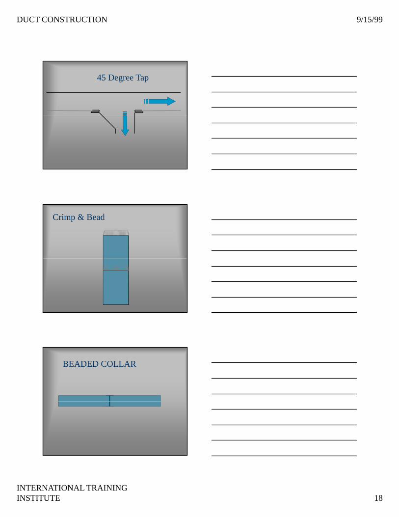
Good FittingsB d FittiBad Fittings
Static Pressure
The pressure exerted in all directions
Restrictions in the duct system cause static pressurestatic pressure
Static pressure ( if not by design ) is the number one enemy of the duct system
Increasing Static Pressure
Reasons Static Pressure is Increased– Friction Loss
– Dynamic LossDynamic Loss

DUCT CONSTRUCTION 9/15/99
INTERNATIONAL TRAINING INSTITUTE 27
RESISTANCE
FRICTION LOSS
CAUSED BY THE AIR RUBBINGTHE WALLS OF THE DUCT
DYNAMIC LOSS
CAUSED WHEN AIR IS FORCEDTO CHANGE DIRECTION ORFLOW AROUND OBSTRUCTIONS
ASPECT RATIO
20”PERIMETER = 62.83”AREA = 324 sq.. in
18 PERIMETER = 72”AREA = 324 sq.. inRATIO = 1 - 1
18
12
27
PERIMETER = 78”AREA = 324 sq.. inRATIO 2.25 - 1
9
36
PERIMETER = 90”AREA = 324 sq.. inRATIO 4 - 1
SMACNA FRICTION LOSS IN FITTINGS
The next slides are based on:– a typical low pressure system
– Duct area = 650 Sq.. In. or approximatelyDuct area 650 Sq.. In. or approximately 36” by 18”
– CFM = 6580 at 1850 FPM
– shown in equivalent feet of duct

DUCT CONSTRUCTION 9/15/99
INTERNATIONAL TRAINING INSTITUTE 28
Round ElbowsRadius elbows should use a minimum of 1 duct Radius elbows should use a minimum of 1 duct diameter for the throat radiusdiameter for the throat radius
Stamped ElbowStamped Elbow10’ of Duct10’ of Duct
3 Gore Elbow3 Gore Elbow22’ of Duct22’ of Duct
Round Elbows
Stamped ElbowStamped Elbow10’ of Duct10’ of Duct
4 Gore Elbow4 Gore Elbow18’ of Duct18’ of Duct
Round Elbows
Stamped ElbowStamped Elbow10’ of Duct10’ of Duct
5 Gore Elbow5 Gore Elbow16’ of Duct16’ of Duct
DUCT CONSTRUCTION 9/15/99
INTERNATIONAL TRAINING INSTITUTE 29
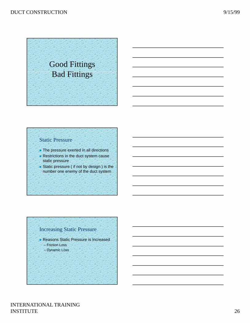
Mitered Elbow
2 Gore Mitered Elbow2 Gore Mitered ElbowEquivalent toEquivalent to79’ of Duct79’ of Duct
Rectangular Elbows
Sq.. Elbow no vanesSq.. Elbow no vanes79’ of Duct79’ of Duct Sq.. Elbow with vanesSq.. Elbow with vanes
10’ of Duct (Double Vanes)10’ of Duct (Double Vanes)
1H1HRadius ElbowRadius Elbow10’ of Duct10’ of Duct

DUCT CONSTRUCTION 9/15/99
INTERNATIONAL TRAINING INSTITUTE 30
TURNING VANES
Rectangular Elbows
Rectangular RadiusRectangular RadiusElbowElbow10’ of Duct10’ of Duct
Rectangular ElbowRectangular ElbowNo VanesNo Vanes79’ of Duct79’ of Duct

DUCT CONSTRUCTION 9/15/99
INTERNATIONAL TRAINING INSTITUTE 31
Rectangular Elbows
Rectangular ElbowRectangular ElbowNo VanesNo Vanes85’ of Duct85’ of Duct
Rectangular ElbowRectangular ElbowRadius Throat and HeelRadius Throat and Heel14’ of Duct14’ of Duct
Rectangular Elbows
1H1HRadius ElbowRadius Elbow10’ f D t10’ f D t1H1H 10’ of Duct10’ of Duct
Radius Heel ElbowRadius Heel ElbowW/ Square ThroatW/ Square Throat79’ of Duct79’ of Duct
Rectangular Elbows
Double ElbowDouble ElbowNo VanesNo Vanes171’ Duct171’ Duct
Double Elbow Double Elbow No VanesNo Vanes276’ Duct276’ Duct

DUCT CONSTRUCTION 9/15/99
INTERNATIONAL TRAINING INSTITUTE 32
OFFSETSOFFSETS
OFFSETSOFFSETS

DUCT CONSTRUCTION 9/15/99
INTERNATIONAL TRAINING INSTITUTE 33
Two manuals which you might find
helpful.
HVAC Duct Systems Inspection Guide
&HVAC Duct ConstructionHVAC Duct Construction
Standards
Available from SMACNA
Thank You !!Thank You !!